Perception E&ex I/M Digital PBX Installation And Maintenance Manual E EX
User Manual: Perception e&ex Digital PBX Installation and Maintenance Manual www.TelecomUserGuides.com Access User Guides, Manuals and Brochures
Open the PDF directly: View PDF ![]() .
.
Page Count: 112 [warning: Documents this large are best viewed by clicking the View PDF Link!]
Pe&ex
All rights reserved. No part of this manual, covered by the
copyrights hereon, may be reproduced in any form or by any
means—graphic, electronic, or mechanical, including record-
ing, taping, photocopying, or information retrieval systems—
without express written permission of the publisher of this
material.
PERCEPTIONe&ex
DIGITAL PBX
INSTALLATION AND MAINTENANCE MANUAL
© COPYRIGHT 1991
TOSHIBA AMERICA INFORMATION SYSTEMS, INC.
Telecommunication Systems Division
SERIAL NO._____________________


INSTALLATION INSTRUCTIONS
SECTION 200-255-200
FEBRUARY 1992
PERCEPTION
INSTALLATION INSTRUCTIONS
TABLE OF CONTENTS
PARAGRAPH SUBJECT PAGE
CHAPTER 1 INTRODUCTION ............................................................................................... 1-1
1. PURPOSE .......................................................................................................... 1-1
2. ORGANIZATION ................................................................................................ 1-1
3. REFERENCE DOCUMENTATION..................................................................... 1-1
4. SYSTEM MNEMONICS ..................................................................................... 1-1
5. INSPECTION, PACKING AND STORAGE ........................................................ 1-2
5.00 Inspection ....................................................................................................... 1-2
5.10 Packing and Storage ...................................................................................... 1-2
5.20 Required Tools ............................................................................................... 1-2
CHAPTER 2 SYSTEM DESCRIPTION .................................................................................. 2-1
1. PERCEPTION ................................................................................................. 2-1
1.00 Basic Equipment Cabinet ............................................................................... 2-1
1.10 Expansion Cabinet ......................................................................................... 2-1
1.20 Power Supply ................................................................................................. 2-1
2. PERCEPTION ................................................................................................ 2-1
2.00 Basic Equipment Cabinet ............................................................................... 2-1
2.10 Expansion Cabinet ......................................................................................... 2-1
2.20 Power Supply ................................................................................................. 2-2
3. PEAK LOAD BATTERY...................................................................................... 2-2
4. EXTENDED RESERVE POWER ....................................................................... 2-3
5. POWER FAILURE/EMERGENCY TRANSFER .................................................. 2-3
6. PRINTED CIRCUIT BOARD DESCRIPTION...................................................... 2-4
NFDU (Floppy Disk Drive Unit)....................................................................... 2-4
LCCU (Central Control Unit) ........................................................................... 2-4
NTWU (Time Switch Unit) .............................................................................. 2-4
NPRU (Paging and Music-on-Hold Unit) ........................................................ 2-5
NRCU (Receiver Unit) .................................................................................... 2-5
NEKU (Electronic Telephone Unit) ................................................................. 2-5
NDKU (Digital Telephone Unit)....................................................................... 2-5
NSTU (Standard Telephone Unit) .................................................................. 2-6
NDSU (DSS Console Controller Unit) ............................................................ 2-6
NDCU (Data Control Unit) .............................................................................. 2-6
NMDU (Modem Pooling Unit) ......................................................................... 2-6
NCOU (Central Office Trunk Unit) .................................................................. 2-6
NEMU (E & M TIE Trunk Unit)........................................................................ 2-6
NLSU (DID Trunk Interface Unit) .................................................................... 2-6
NDTU (T1 Interface) ....................................................................................... 2-6
NOCU (Off-hook Call Announce Interface Unit) .............................................. 2-6
HVSU/HVSI (Off-hook Call Announce PCBs) ................................................. 2-6
DVSI (Digital Off-hook Call Announce PCB) ................................................... 2-6
-i-

INSTALLATION INSTRUCTIONS
SECTION 200-255-200
FEBRUARY 1992
7. SYSTEM INDICATORS AND CONTROLS ........................................................ 2-7
NFDU.............................................................................................................. 2-7
LCCU .............................................................................................................. 2-7
NTWU ............................................................................................................. 2-7
NPRU ............................................................................................................. 2-7
NCOU/NEMU/NLSU ....................................................................................... 2-7
NDTU.............................................................................................................. 2-7
NEKU/NSTU/NOCU/NDKU ............................................................................ 2-8
NDSU ............................................................................................................. 2-8
NDCU ............................................................................................................. 2-8
NMDU ............................................................................................................. 2-8
NPSA-M/LPSA-M ........................................................................................... 2-8
NPSA-S .......................................................................................................... 2-8
8. PERIPHERAL EQUIPMENT .............................................................................. 2-8
8.00 Electronic and Digital Telephone .................................................................... 2-8
8.10 Headset Upgrade (HHEU) .............................................................................. 2-9
8.20 Attendant Console .......................................................................................... 2-9
8.30 DSS Console .................................................................................................. 2-9
8.40 Standard Telephone ....................................................................................... 2-9
8.50 DDIU/PDIU ..................................................................................................... 2-9
8.60 Paging Equipment .......................................................................................... 2-9
8.70 Music-on-Hold ................................................................................................ 2-9
8.80 Universal Night Answer .................................................................................. 2-9
8.90 Station Message Detail Recording ................................................................. 2-9
CHAPTER 3 INSTALLATION SITE REQUIREMENTS .......................................................... 3-1
1. COMMERCIAL POWER..................................................................................... 3-1
2. ENVIRONMENTAL REQUIREMENTS............................................................... 3-1
3. EQUIPMENT ROOM RECOMMENDATIONS..................................................... 3-1
4. CABLING CONSIDERATIONS .......................................................................... 3-1
5. GROUNDING ..................................................................................................... 3-2
CHAPTER 4 SYSTEM INSTALLATION ................................................................................. 4-1
1. PERCEPTION ................................................................................................. 4-1
1.00 Power Supply Installation ............................................................................... 4-1
1.10 Expansion Cabinet Installation ....................................................................... 4-3
2. PERCEPTION ................................................................................................ 4-4
2.00 Power Supply Installation ............................................................................... 4-4
2.10 First Expansion Cabinet Installation ............................................................... 4-6
2.20 Second Expansion Cabinet Installation .......................................................... 4-8
3. PRINTED CIRCUIT BOARD INSTALLATION..................................................... 4-9
3.00 NFDU.............................................................................................................. 4-9
3.10 LCCU .............................................................................................................. 4-10
3.20 NTWU ............................................................................................................. 4-10
3.30 NPRU ............................................................................................................. 4-10
3.40 NEKU, NDKU, and NOCU .............................................................................. 4-10
3.50 NSTU .............................................................................................................. 4-12
3.60 NDSU ............................................................................................................. 4-12
PARAGRAPH SUBJECT PAGE
-ii-
INSTALLATION INSTRUCTIONS
SECTION 200-255-200
FEBRUARY 1992
PARAGRAPH SUBJECT PAGE
3.70 NEMU, NCOU, and NLSU .............................................................................. 4-13
3.80 NDTU.............................................................................................................. 4-15
3.90 NMDU and NDCU .......................................................................................... 4-18
4. CABLE CONNECTIONS .................................................................................... 4-19
5. ELECTRONIC TELEPHONE STATION EQUIPMENT INSTALLATION ............. 4-20
5.00 Electronic Telephone Connections ................................................................. 4-20
5.10 Electronic Telephone Wall Mounting .............................................................. 4-20
5.20 Off-hook Call Announce ................................................................................. 4-20
5.30 Carbon Handset Transmitter Installation ........................................................ 4-23
5.40 HHEU Installation ........................................................................................... 4-23
5.50 Attendant Console Connection ....................................................................... 4-25
5.60 DSS Console Connections ............................................................................. 4-26
5.70 Digital Data Interface Unit Connections (DDIU) .............................................. 4-26
5.80 DDIU-MAT ...................................................................................................... 4-28
5.90 DDIU-MA ........................................................................................................ 4-30
6. DIGITAL TELEPHONE STATION EQUIPMENT INSTALLATION ...................... 4-32
6.00 Digital Telephone Connections....................................................................... 4-32
6.10 Digital Telephone Wall Mounting .................................................................... 4-32
6.20 Off-hook Call Announce ................................................................................. 4-34
6.30 Carbon Handset Transmitter Installation ........................................................ 4-35
6.40 Beep Strap Removal ...................................................................................... 4-36
6.50 Microphone/Speaker Threshold Adjustment (Speakerphone only) ................. 4-36
6.60 HHEU Installation ........................................................................................... 4-36
6.70 Attendant Console Connection ....................................................................... 4-37
6.80 DSS Console Connections ............................................................................. 4-37
6.90 Digital Data Interface Unit Installation (PDIU) ................................................. 4-37
6.100 Common DIU Connections ............................................................................. 4-39
6.110 EIA Interface Leads (Signals) ......................................................................... 4-39
6.120 DIP Switch Options......................................................................................... 4-46
6.130 PDIU-DI Installation ........................................................................................ 4-46
6.140 PDIU-DI to Personal Computer (PC) Installation............................................. 4-47
6.150 PDIU-DS to Printer Installation ....................................................................... 4-47
6.160 PDIU-DS to Modem Installation...................................................................... 4-51
6.170 PDIU-DS Disassembly and Assembly ............................................................ 4-52
6.180 PDIU-DI/PDIU-DS Installation Tests .............................................................. 4-52
7. STANDARD TELEPHONE EQUIPMENT INSTALLATION ................................. 4-58
7.00 Standard Telephone Connections .................................................................. 4-58
8.00 TRUNK CONNECTIONS.................................................................................... 4-58
9. PERIPHERAL EQUIPMENT INSTALLATION..................................................... 4-58
9.00 Modem Pooling Connections (DDIU-MA only) ................................................ 4-58
9.10 Power Failure/Emergency Transfer ................................................................ 4-58
9.20 Reserve Power ............................................................................................... 4-60
9.30 Paging Equipment .......................................................................................... 4-61
9.40 Music-on-Hold ................................................................................................ 4-62
9.50 Universal Night Answer .................................................................................. 4-62
9.60 Station Message Detail Recording ................................................................. 4-63
9.80 Lodging/Health Care Data Audit ..................................................................... 4-67
-iii-

INSTALLATION INSTRUCTIONS
SECTION 200-255-200
FEBRUARY 1992
10. SYSTEM POWER UP ........................................................................................ 4-67
10.00 General ........................................................................................................... 4-67
CHAPTER 5 MDF ARRANGEMENT ...................................................................................... 5-1
TABLE LIST
TABLE SUBJECT PAGE
5-1 CARD SLOT/CABLE CONNECTOR MATRIX ........................................................ 5-4
5-2 LIST OF CONNECTOR CABLES .......................................................................... 5-5
5-3 ATTENDANT CONSOLE #0 & #1 .......................................................................... 5-6
5-4 PAGING, MUSIC & UNA RINGING ....................................................................... 5-7
5-5 NDSU/NDKU (DSS CONSOLE) "C" SLOT ............................................................ 5-8
5-6 NDSU/NEKU/NDKU/NSTU/NDCU/NMDU/NOCU (L00 ~ L03/L15 ~ L18) .............. 5-9
5-7 NDSU/NEKU/NDKU/NSTU/NDCU/NMDU/NOCU (L04 ~ L11/L19 ~ L26) or
NCOU/NLSU/NEMU (T07 ~ T00/T15 ~ T08) ......................................................... 5-10
5-8 CENTRAL OFFICE LINE CONNECTION & PFT CONTROL J1............................. 5-11
5-9 STATION LINE CONNECTION J2 ......................................................................... 5-12
5-10 ATTENDANT CONSOLE #0 & #1 .......................................................................... 5-13
5-11 PAGING, MUSIC & UNA RINGING ....................................................................... 5-14
5-12 NCOU/NEMU/NLSU/NDTU (T00 ~ T15) ................................................................ 5-15
5-13 NDSU/NEKU/NDKU/NSTU/NDCU/NMDU/NOCU (U00 ~ U31) or
NCOU/NEMU/NLSU (T16 ~ T31) ........................................................................... 5-16
5-14 CENTRAL OFFICE LINE CONNECTION & PFT CONTROL J1............................. 5-17
5-15 STATION LINE CONNECTION J2 ......................................................................... 5-18
FIGURE LIST
FIGURE SUBJECT PAGE
2-1 PERCEPTION BASIC CABINET.......................................................................... 2-1
2-2 PERCEPTION EXPANSION CABINET ............................................................... 2-1
2-3 PERCEPTION BASIC CABINET ........................................................................ 2-2
2-4 PERCEPTION WITH EXPANSION CABINETS .................................................. 2-2
2-5 PERCEPTION MAIN POWER SUPPLY............................................................. 2-2
2-6 DPFT FUNCTIONAL DIAGRAM ............................................................................ 2-3
2-7 PERCEPTION PCB INSTALLATION ................................................................... 2-4
2-8 PERCEPTION PCB INSTALLATION ................................................................. 2-5
3-1 PERCEPTION MINIMUM FLOOR SPACE .......................................................... 3-1
3-2 PERCEPTION MINIMUM FLOOR SPACE......................................................... 3-1
3-3 UL GROUNDING DIAGRAM.................................................................................. 3-2
4-1 PERCEPTION BASIC CABINET REAR COVER .................................................. 4-1
4-2 PERCEPTION CABLE CONNECTIONS.............................................................. 4-1
4-3 PERCEPTION VOLTAGE CHECKS .................................................................... 4-2
4-4 PEAK LOAD BATTERY ......................................................................................... 4-3
4-5 PERCEPTION POWER SUPPLY CONTROLS AND INDICATORS .................... 4-3
-iv-
PARAGRAPH SUBJECT PAGE

INSTALLATION INSTRUCTIONS
SECTION 200-255-200
FEBRUARY 1992
4-6 PERCEPTION EXPANSION CABINET INSTALLATION ...................................... 4-3
4-7 PERCEPTION BASIC CABINET REAR COVER ................................................ 4-5
4-8 PERCEPTION CABLE CONNECTIONS ............................................................ 4-5
4-9 PERCEPTION VOLTAGE CHECKS .................................................................. 4-6
4-10 PERCEPTION POWER SUPPLY CONTROLS AND INDICATORS ................... 4-7
4-11 PERCEPTION EXPANSION CABINET INSTALLATION .................................... 4-8
4-12 NFDU STRAPPING................................................................................................ 4-10
4-13 LCCU STRAPPING ................................................................................................ 4-10
4-14 NTWU STRAPPING ............................................................................................... 4-11
4-15 NPRU STRAPPING................................................................................................ 4-11
4-16 NRCU MOUNTING................................................................................................. 4-11
4-17 NDKU SWITCH OPTIONS ..................................................................................... 4-12
4-18 NEMU STRAPPING ............................................................................................... 4-14
4-19 NCOU STRAPPING ............................................................................................... 4-14
4-20 NLSU STRAPPING ................................................................................................ 4-16
4-21 NDTU STRAPPING................................................................................................ 4-16
4-22 NMDU STRAPPING ............................................................................................... 4-19
4-23 ELECTRONIC TELEPHONE CONNECTION ........................................................ 4-21
4-24 REMOVAL OF ELECTRONIC TELEPHONE BASE ............................................... 4-22
4-25 REMOVAL OF HANDSET HANGER ..................................................................... 4-22
4-26 INSTALLATION OF MOUNTING BASE FOR WALL-MOUNT INSTALLATION ..... 4-22
4-27 HVSI/HVSU INSTALLATION ................................................................................. 4-23
4-28 ELECTRONIC TELEPHONE PCB CONNECTIONS .............................................. 4-23
4-29 OFF-HOOK CALL ANNOUNCE CONNECTION (NOCU)....................................... 4-24
4-30 LOCATION OF CARBON STRAPS ....................................................................... 4-24
4-31 REMOVAL OF HHEU MODULAR CONNECTOR ACCESS TAB........................... 4-24
4-32 INSTALLATION OF HHEU UPGRADE OPTION .................................................... 4-25
4-33 ATTENDANT CONSOLE #0 CONNECTION ......................................................... 4-25
4-34 ATTENDANT CONSOLE #1 CONNECTION ......................................................... 4-26
4-35 DSS CONSOLE CONNECTION FOR PERCEPTION "C" SLOT.......................... 4-27
4-36 DSS CONSOLE CONNECTION FOR PERCEPTION "U" SLOTS AND
PERCEPTION "L" SLOTS .................................................................................... 4-27
4-37 DIGITAL DATA INTERFACE UNIT CONNECTION (DDIU-MA and DDIU-MAT) ... 4-28
4-38 INSTALLING DDIU-MAT ........................................................................................ 4-29
4-39 DDIU-MAT DIP SWITCHES ................................................................................... 4-29
4-40 DDIU-MA DIUA PCB .............................................................................................. 4-31
4-41 DIUB PCB............................................................................................................... 4-31
4-42 DIGITAL TELEPHONE CONNECTION ................................................................. 4-33
4-43 REMOVAL OF DIGITAL TELEPHONE BASE ........................................................ 4-34
4-44 REMOVAL OF HANDSET HANGER ..................................................................... 4-34
4-45 INSTALLATION OF MOUNTING BASE FOR WALL-MOUNT INSTALLATION ..... 4-34
4-46 DVSU INSTALLATION ........................................................................................... 4-35
4-47 TELEPHONE PCB CONNECTIONS AND STRAPS............................................... 4-35
4-48 HHEU INSTALLATION FOR DIGITAL TELEPHONE ............................................. 4-36
4-49 DIGITAL DSS CONSOLE CONNECTION FOR PERCEPTION “C” SLOT ........... 4-38
4-50 DIGITAL DSS CONSOLE CONNECTION FOR PERCEPTION “U” SLOTS
AND PERCEPTION “L” SLOTS ........................................................................... 4-38
-v-
FIGURE SUBJECT PAGE

INSTALLATION INSTRUCTIONS
SECTION 200-255-200
FEBRUARY 1992
4-51 PERCEPTION DATA INSTALLATION EXAMPLE BLOCK DIAGRAM ................... 4-40
4-52 PDIU-DI/PDIU-DS MODULAR CABLE/RJ-45 ADAPTER CONNECTIONS ........... 4-41
4-53 PDIU-DI/PDIU-DS MODULAR CORDS AND RJ-45/RS-232 ADAPTER PIN
CONNECTIONS ..................................................................................................... 4-42
4-54 PDIU-DS JUMPER PLUG OPTIONS/RS-232 CONNECTOR INFORMATION ...... 4-43
4-55 PDIU-DI/PDIU-DS SW1 DIP SWITCH INFORMATION .......................................... 4-44
4-56 PDIU-DI PCB/DIGITAL TELEPHONE INSTALLATION .......................................... 4-46
4-57 PDIU-DS TO TOSHIBA PRINTER, RS-232 CONNECTOR/CABLE
CONNECTIONS ..................................................................................................... 4-48
4-58 PDIU-DI TO IBM XT-TYPE COMPUTER, RS-232 CONNECTOR/CABLE
CONNECTIONS ..................................................................................................... 4-49
4-59 PDIU-DI TO IBM AT-TYPE COMPUTER, RS-232 CONNECTOR/CABLE
CONNECTIONS ..................................................................................................... 4-50
4-60 PDIU-DS TO HAYES-TYPE SMART MODEM, RS-232 CONNECTOR/CABLE
CONNECTIONS ..................................................................................................... 4-53
4-61 PDIU-DS DISASSEMBLY/ASSEMBLY DIAGRAM ................................................. 4-54
4-62 PC TO PC TEST CALL USING AT COMMANDS ................................................... 4-55
4-63 PC TO PRINTER TEST CALL USING MANUAL DIALING..................................... 4-55
4-64 INTERNAL PC TO EXTERNAL PC TEST CALL USING AT COMMANDS ............ 4-55
4-65 EXTERNAL PC TO INTERNAL PC TEST CALL USING AT COMMANDS ............ 4-56
4-66 STANDARD TELEPHONE CONNECTION............................................................ 4-59
4-67 MODEM POOLING CONNECTION (DDIU-MA ONLY) .......................................... 4-60
4-68 RESERVE POWER INSTALLATION ..................................................................... 4-61
4-69 PAGING WITH MUSIC OVER EXTERNAL SPEAKER FROM SAME AMPLIFIER 4-62
4-70 PAGING WITH ONE AMPLIFIER .......................................................................... 4-63
4-71 PAGING WITH MULTIPLE AMPLIFIERS .............................................................. 4-64
4-72 LCCU SWITCHES .................................................................................................. 4-65
4-73 EXAMPLE: SMDR CALL RECORD ....................................................................... 4-66
4-74 EXAMPLE: AUDIT PRINTOUT (LODGING/HEALTH CARE) ................................. 4-68
4-75 INSERTING DISK (PERCEPTION ONLY) ......................................................... 4-69
4-76 INSERTING DISK (PERCEPTION ONLY) ........................................................... 4-69
5-1 CONNECTOR LOCKING BAR............................................................................... 5-1
5-2 MAIN DISTRIBUTION FRAME LAYOUT ............................................................... 5-2
5-3 SECONDARY PROTECTOR DIAGRAM ............................................................... 5-3
-vi-
FIGURE SUBJECT PAGE

1-1
INSTALLATION INSTRUCTIONS
SECTION 200-255-201
FEBRUARY 1992
CHAPTER 1
INTRODUCTION
1. PURPOSE
1.00 This section describes the installation proce-
dures necessary to ensure proper operation of the
PERCEPTION system.
2. ORGANIZATION
2.00 The organization of this manual is as follows:
1. INTRODUCTION
2. SYSTEM DESCRIPTION
3. INSTALLATION SITE REQUIREMENTS
4. SYSTEM INSTALLATION
5. MDF ARRANGEMENTS
3. REFERENCE DOCUMENTATION
3.00 The PERCEPTION system is supported
by a complete set of documentation. A list of the
reference documentation associated with the
PERCEPTION system is provided below:
Document Section Number
Fault Finding 200-255-500
General Description
Operating Procedures 200-255-400
Programming 200-255-300
System Record
4. SYSTEM MNEMONICS
4.00 The system is provided with a complete set of
mnemonics that relate directly to its operation and
features. The following alphabetical list describes
the mnemonics used in this manual.
DATT—Attendant Console
DDIU—Digital Data Interface Unit PCB (Electronic
Telephone)
DDIU-MA—Digital Data Interface Unit (Stand-alone)
DDIU-MAT—Digital Data Interface Unit (Electronic
Telephone)
DDSS—Digital Direct Station Selection Console
DKT—Digital Telephone
DPFT—Power Failure/Emergency Transfer Unit
DSS—Direct Station Selection Console (Electronic
Telephone)
DVSU—PCB for Off-hook Call Announce (installed
inside the digital telephone)
EKT—Electronic Telephone
FDD0—Floppy Disk Drive 0
FDD1—Floppy Disk Drive 1
GND—Ground
HHEU—Optional Headset Module
HVSI—PCB for Off-hook Call Announce (installed
inside the electronic telephone)
HVSU—PCB for Off-hook Call Announce (installed
inside the electronic telephone)
LCCU—Central Control Unit
LCD—Liquid Crystal Display
LCEC-M—PERCEPTION Basic Cabinet
LCEC-S—PERCEPTION Expansion Cabinet
LPSA-M—PERCEPTION Main Power Supply
MDF—Main Distribution Frame
NCEC-M—PERCEPTION Basic Cabinet
NCEC-S—PERCEPTION Expansion Cabinet
NCOU—Central Office Trunk Unit

1-2
INSTALLATION INSTRUCTIONS
SECTION 200-255-201
FEBRUARY 1992
NDCU—Data Control Unit
NDKU—Digital Telephone, Digital DSS, PDIU-DI,
PDIU-DS Unit
NDSU—DSS Console Controller Unit (Electronic
Telephone)
NDTU—Digital Trunk Unit
NEKU—Electronic Telephone Unit
NEMU—E & M TIE Trunk Unit
NFDU—Floppy Disk Drive Unit
NLSU—DID Trunk Interface Unit
NMDU—Modem Pooling Unit
NOCU—Off-hook Call Announce Interface Unit
NPRU—Paging and Music-on-Hold Unit
NPSA-M—PERCEPTION Main Power Supply
NPSA-S—PERCEPTION Expansion Power
Supply
NRCU—Receiver Unit
NSTU—Standard Telephone Unit
NTWU—Time Switch Unit
PCB—Printed Circuit Board
PDIU-DI—Integrated Data Interface Unit (Digital
Telephone)
PDIU-DS—Stand-alone Data Interface Unit (Key-
board Dial)
PFT—Power Fail Transfer
SMDR—Station Message Detail Recording
TTY—Teletypewriter
UNA—Universal Night Answer
5. INSPECTION, PACKING and STORAGE
5.00 Inspection
5.01 When the system is received, examine all
packages and make careful note of any visible
damage. If any damage is found, bring it to the
attention of the delivery carrier and make the proper
claims.
5.02 Check the system against the purchase order
and packing slip. If it is determined that equipment
is missing, contact your supplier immediately.
5.03 After unpacking (and before installing), in-
spect all equipment for damage. If any is detected,
contact your supplier immediately.
CAUTION!
When handling (installing, removing, ex-
amining, etc.) printed circuit boards (PCBs),
do not touch the back (soldered) side or
edge connector. Always hold the PCB by
its edge whenever handling it.
5.10 Packing and Storage
5.11 When storing or shipping PCBs, be sure they
are packed in their original antistatic bags for pro-
tection against static discharge.
5.20 Required Tools
5.21 Installation of the PERCEPTION sys-
tems requires standard telephony tools. A 13mm
socket wrench and extension is recommended for
ease of expansion cabinet installation.
2-1
INSTALLATION INSTRUCTIONS
SECTION 200-255-202
FEBRUARY 1992
CHAPTER 2
SYSTEM DESCRIPTION
1. PERCEPTION
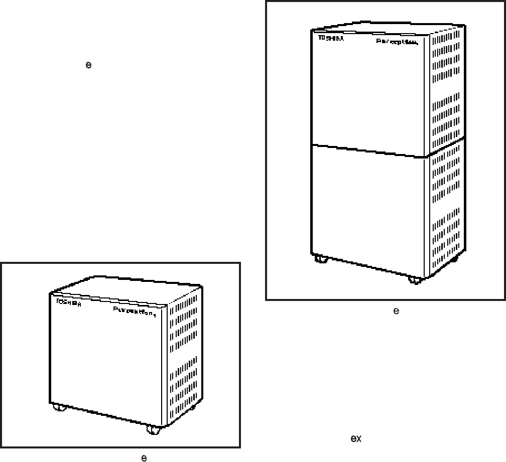
1.00 Basic Equipment Cabinet
1.01 The basic equipment cabinet (NCEC-M) con-
sists of a single, free-standing cabinet mounted on
casters for easy movement. Once system installa-
tion has been completed and the cabinet has been
positioned, the casters can be locked to prevent
movement. The interior of the cabinet houses two
shelves for printed circuit card installation. A sepa-
rate area is provided for installation of the power
supply and peak load battery. MDF connections
are facilitated by amphenol connectors located on
the rear of the cabinet (Figure 2-1).
FIGURE 2-1—PERCEPTION BASIC CABINET
1.10 Expansion Cabinet
1.11 The expansion cabinet (NCEC-S) is a single
cabinet that mounts on top of the basic cabinet and
is secured in place with four bolts. The cabinet
houses two shelves for printed circuit card installa-
tion. MDF connections are facilitated by amphenol
connectors located on the rear of the cabinet (Fig-
ure 2-2).
1.20 Power Supply
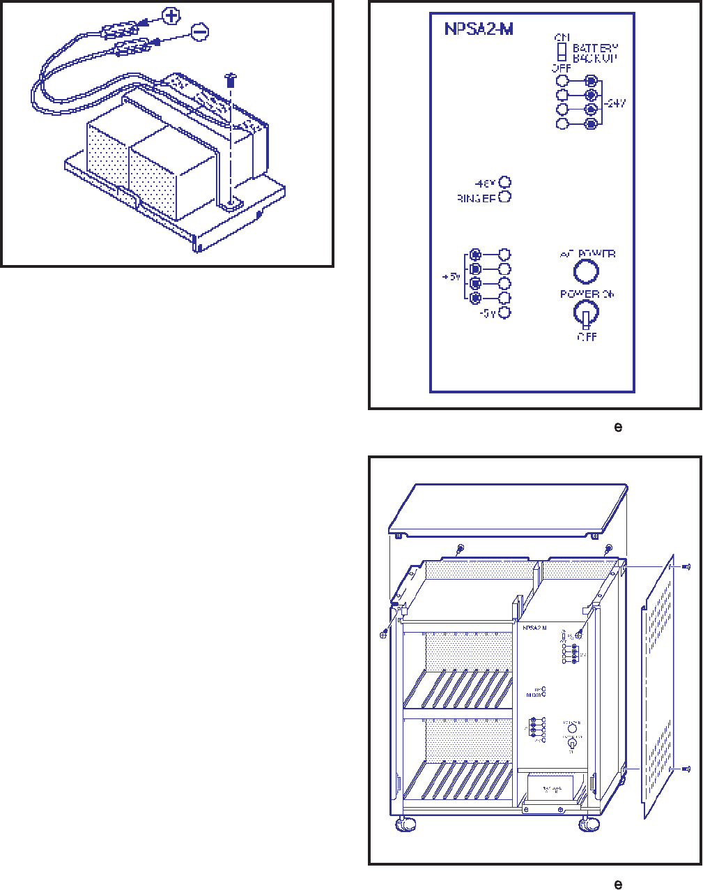
1.21 The Main Power Supply (NPSA-M) consists
of a single metal chassis. In addition to the power
FIGURE 2-2—PERCEPTION EXPANSION CABINET
supply, this chassis contains the system ring gen-
erator and a charger/inverter for Reserve Power.
Located on the front of the chassis are a circuit
breaker and LED indicator for each power supply
output, and an AC power indicator, and the system
power switch. The battery switch is also on the front
of the NPSA-M.
2. PERCEPTION
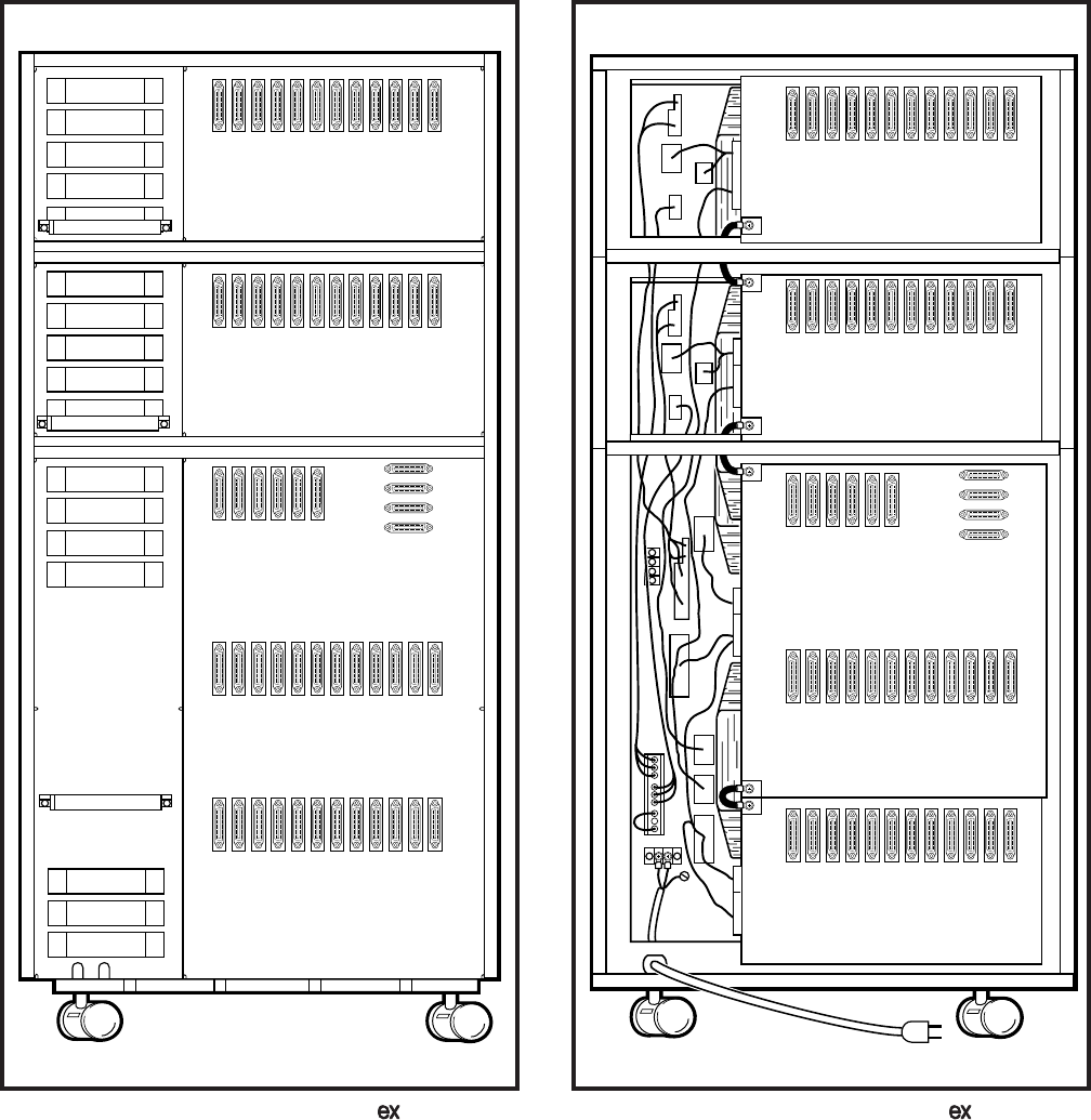
2.00 Basic Equipment Cabinet
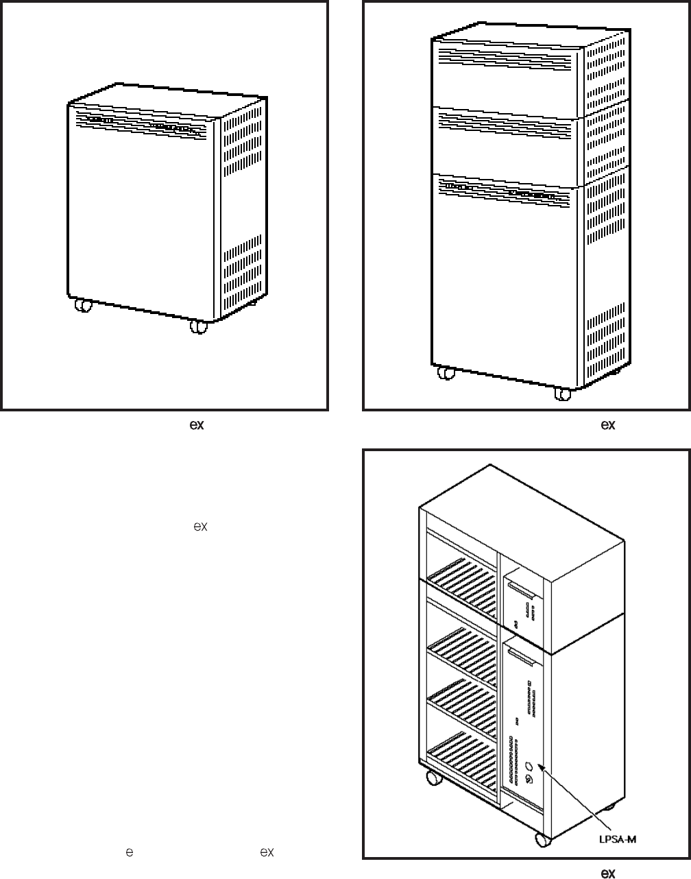
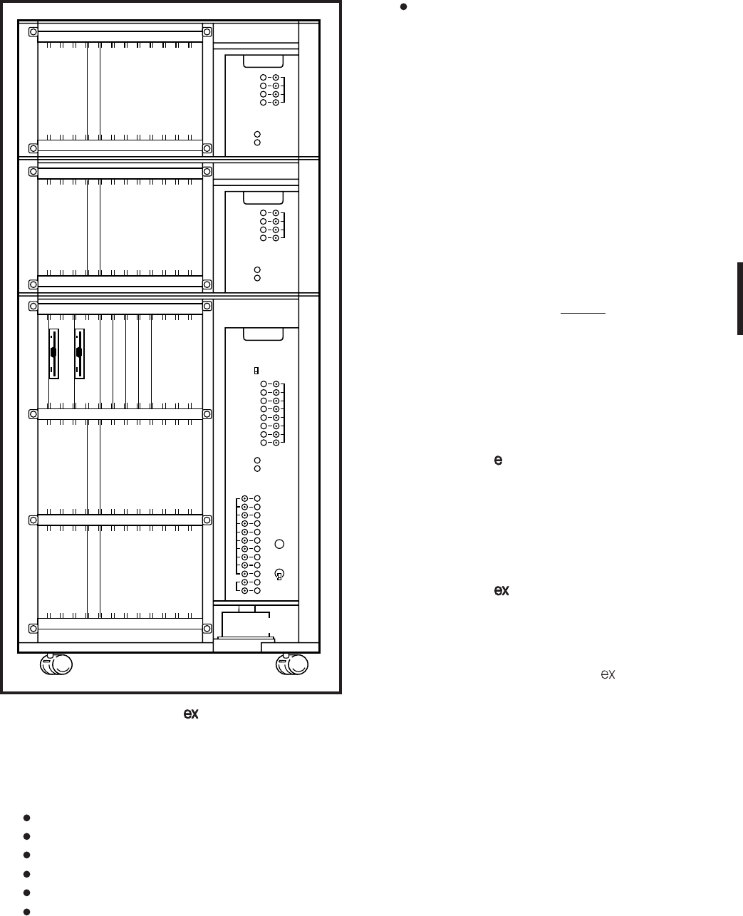
2.01 The basic equipment cabinet (LCEC-M) is a
single free-standing cabinet mounted on casters
for easy movement. The cabinet contains three
shelves for printed circuit card installation. A sepa-
rate area is provided for power supply and peak
load battery installation. MDF connections are fa-
cilitated by amphenol connectors located on the
rear of the cabinet (Figure 2-3).
2.10 Expansion Cabinet
2.11 The expansion cabinet (LCEC-S) is a single
cabinet that houses a single printed circuit card
2-2
INSTALLATION INSTRUCTIONS
SECTION 200-255-202
FEBRUARY 1992
FIGURE 2-3—PERCEPTION BASIC CABINET FIGURE 2-4—PERCEPTION
WITH EXPANSION CABINETS
shelf. MDF connections are facilitated by amphe-
nol connectors located on the rear of the cabinet
(Figure 2-4). Up to two expansion cabinets may be
added to the PERCEPTION basic equipment
cabinet.
2.20 Power Supply
2.21 The Main Power Supply (LPSA-M) consists
of a single metal chassis which contains the system
ring generator and charger/inverter for the Reserve
Power. A circuit breaker switch, LED indicators, AC
power indicator and system power switch are lo-
cated on the front of the chassis. For ease in
installation a handle is located at the top front of the
power supply (Figure 2-5).
3. PEAK LOAD BATTERY
3.00 The peak load battery will maintain call proc-
essing for a maximum of two minutes in the event
the PERCEPTION or PERCEPTION experi-
ences a power failure. Additionally, when the sys-
tem is under heavy usage the peak load battery will FIGURE 2-5—PERCEPTION
MAIN POWER SUPPLY
2-3
INSTALLATION INSTRUCTIONS
SECTION 200-255-202
FEBRUARY 1992
avoid power degradation by supplementing the -24
volts, maintaining a constant power level.
4. EXTENDED RESERVE POWER
4.00 The power supply is equipped, as a standard
feature, with an internal battery charger/inverter.
Full reserve power can be provided for any system
by connecting an appropriate, customer-supplied
24-volt battery pack. During normal operation, the
power supply charger/inverter will maintain the
proper charge in the battery pack. In the event of an
AC power failure, switchover to battery power will
be automatic. There will be no loss of system
operation as a result of power switchover. When
AC power is restored, switchback to the power
supply will be automatic.
4.01 Battery selection and size will depend on
system size and desired reserve operating time.
The maximum power consumption of the basic
cabinet is 11.5 amps at -24 VDC. For both a basic
and expansion cabinet configuration, the maxi-
mum will be 19 amps at -24 VDC. The selected
batteries must be compatible with the system’s
charger float voltage of 27.3 VDC.
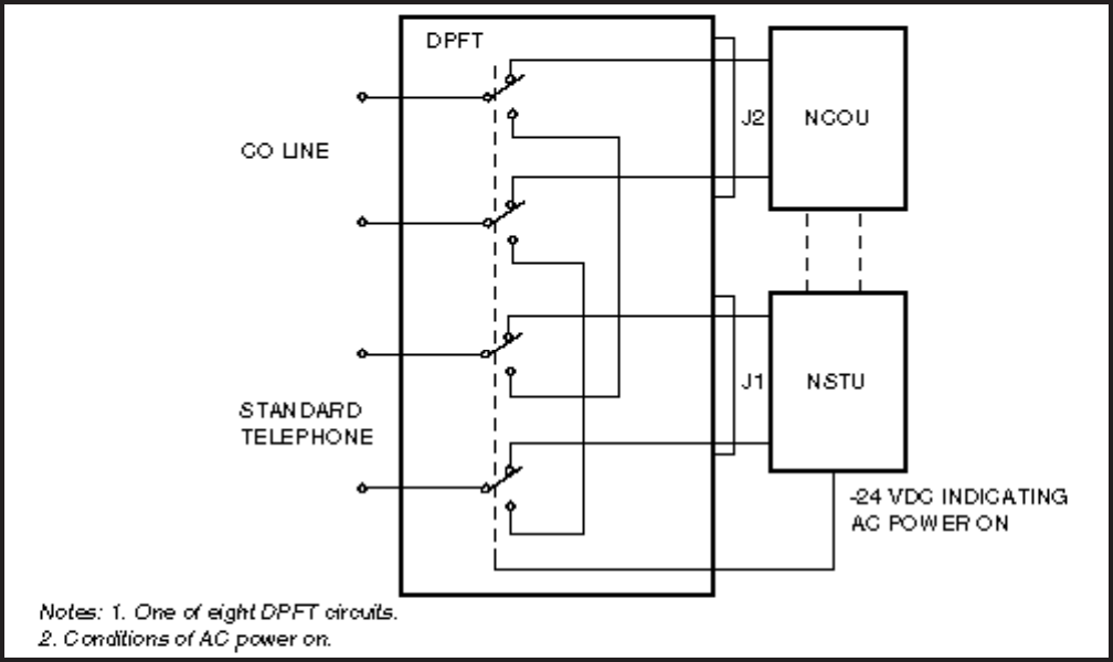
5. POWER FAILURE/EMERGENCY TRANSFER
5.00 The function of the Power Failure/Emergency
Transfer Unit (DPFT) is to automatically connect
selected trunks to selected standard telephones in
the event of system failure while permitting normal
operation when the system is in service (maximum
of 1 per cabinet).
5.01 The DPFT is a self-contained module that
mounts externally to the basic cabinet, typically on
the MDF. Connections to the trunks, stations and
basic cabinet are made via two 50-pin amphenol-
type connectors (J1 and J2) on the DPFT (see
functional diagram in Figure 2-6).
5.02 The module consists of eight relays that are
normally operated, connecting the telephones to
NSTU circuits and the trunks to NCOU circuits. If a
power failure (or other emergency) occurs, the
relays release, connecting the telephones directly
to the trunks. Calls can then be placed from the
telephones over the CO trunks, bypassing the
system (which is out of service).
5.03 Power Fail Transfer (PFT) telephones con-
FIGURE 2-6—DPFT FUNCTIONAL DIAGRAM
2-4
INSTALLATION INSTRUCTIONS
SECTION 200-255-202
FEBRUARY 1992
nected to ground-start trunks must have ground
taps (tap buttons) in order to make outgoing calls
during power fail transfer conditions.
5.04 A transfer can be caused by a loss of power
or triggered manually by either of two buttons, one
of which is located on the underside of the atten-
dant console and the other on the front of the NPRU
PCB. A transfer that is caused by a power failure
will be reset automatically when power is restored;
a manual transfer must be reset manually.
5.05 When the DPFT is reset after a transfer,
existing PFT conversations will be protected. Indi-
vidual circuits will be restored only when they
become idle.
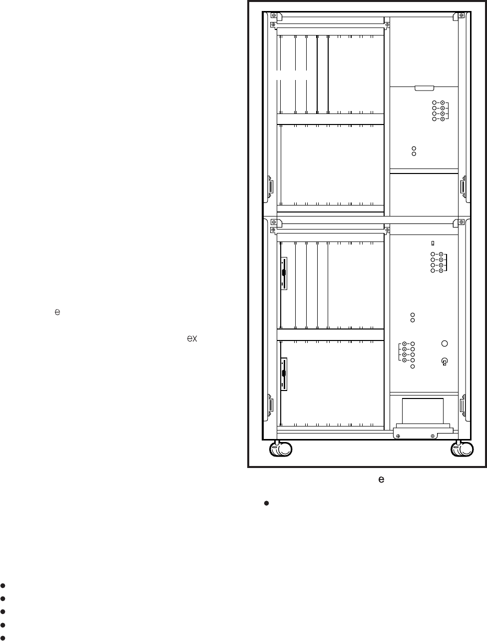
6. PRINTED CIRCUIT BOARD DESCRIPTION
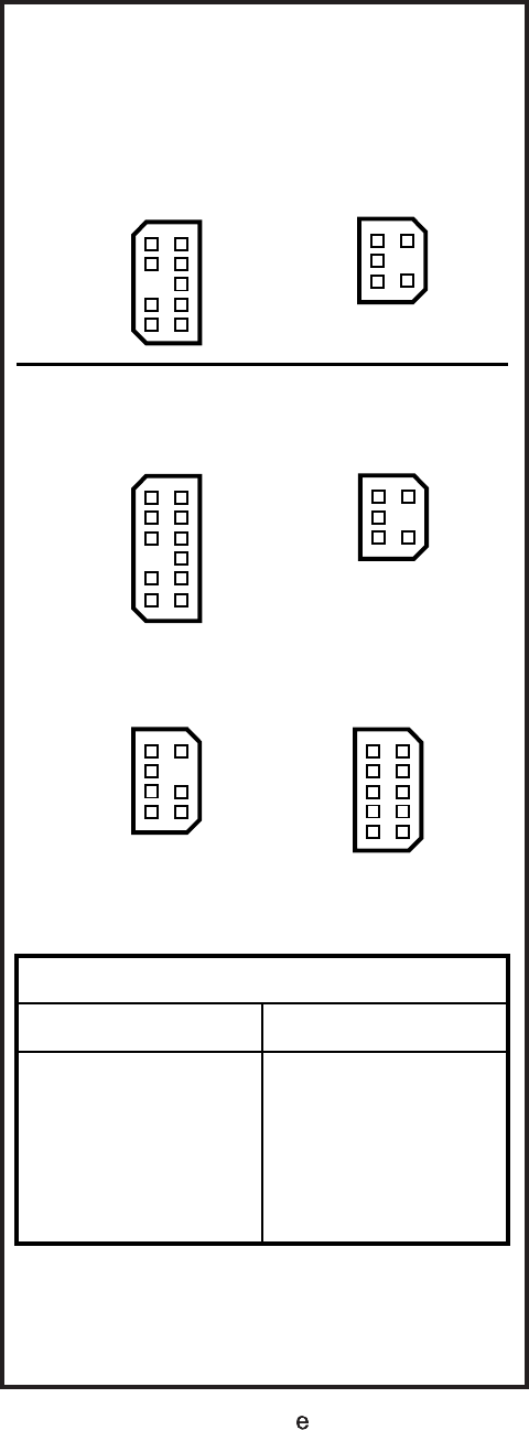
6.00 Sixteen different types of PCBs are available
for use in both PERCEPTION systems (Figures 2-
7 & 2-8). The universal port architecture enables
multiple installation of trunk cards. The
PERCEPTION can support a maximum of 16
trunk cards; 8 in the basic cabinet, and 8 in the
expansion cabinet. The PERCEPTION can
support a maximum of 32 trunk cards; 24 in the
basic cabinet, and 8 in each expansion cabinet.
NFDU (Floppy Disk Drive Unit)—One or two per
system: This card houses a 3.5 inch, 1.2 Mbyte
disk drive. One disk contains system program
and customer data. The second disk stores the
Maintenance and Administration programs. (Two
NFDUs are required in D.02 and later version
software using Remote Maintenance.)
LCCU (Central Control Unit)—One per system:
The LCCU card contains the circuitry which,
under the direction of the system program, pro-
vides centralized control for the entire system.
Additionally, the LCCU performs data transmis-
sion and receiving functions between the central
control and all peripheral equipment, including:
Station PCBs
Trunk PCBs
TTY interface
SMDR interface
Lodging/Health Care audit interface
FIGURE 2-7—PERCEPTION PCB INSTALLATION
Modem interface
This circuitry consists of a 16-bit 80C88 main
processor, an 8-bit Z-80 secondary processor,
and 1Mbyte of memory.
NTWU (Time Switch Unit)—One per system: This
card performs the time slot interchange function
for call processing and the conference features,
provides the digital speech paths with digital
padding, timing and control for time slot switch-
ing and generates system tones.
-48V
RINGER
ON
OFF
BATTERY
BACK-UP
NPSA2-S
P01 C01 L15 L16 L17 L18
FDD0 CCU TWU P00 C00 L00 L01 L02 L03
T15 T14 T13 T12 T11 T10 T09 T08
L19 L20 L21 L22 L23 L24 L25 L26
FDD1 L04 L05 L06 L07 L08 L09 L10 L11
T07 T06 T05 T04 T03 T02 T01 T00
-24V
-24V
+5V
-5V
AC POWER
POWER
ON
OFF
-48V
RINGER
PEAK LOAD
BATTERY
NPSA2-M
NOT USED
STATION,
DATA,
DSS,
OR OCA
CARDS
ONLY
NOT USED
STATION, DATA,
TRUNK, DSS, OR
OCA CARDS ONLY
NDSU
NPRU
NTWU
NPRU
NDSU
STATION,
DATA,
DSS,
OR OCA
CARDS
ONLY
NFDU
STATION, DATA,
TRUNK, DSS, OR
OCA CARDS ONLY
NFDU
LCCU
2-5
INSTALLATION INSTRUCTIONS
SECTION 200-255-202
FEBRUARY 1992
Digitized voice message for Automatic Wake-
up (optional)
NRCU (Receiver Unit)—Two per NPRU (4 per
system maximum): This card provides DTMF
receivers, which are required for receiving tone
dialing from standard telephone ports (including
voice mail ports) and some incoming trunk (DID,
TIE and CCSA) types. It also provides the capa-
bility for remote access to service. It mounts
piggy-back on the NPRU PCB, where there is
available space for two NRCUs. Each NRCU
provides four DTMF receiver circuits, with a
system maximum of 16.
NOTE:
When using the Call Forward No Answer to
Trunk feature, an NRCU MUST be installed in
the system.
NEKU (Electronic Telephone Unit)—One per
eight electronic telephones: Interfaces electronic
telephone to the system. It also serves as an
attendant console interface. Each attendant con-
sole requires one electronic telephone circuit.
PERCEPTION
ATT #0-PCB position L00 circuit #1
ATT #1-PCB position L15 circuit #1
A maximum of 12 NEKU/NDKU PCBs may be
installed in each cabinet (24 NEKU/NDKU PCBs
maximum per system).
PERCEPTION
ATT #0-PCB position U00 circuit #1
ATT #1-PCB position U01 circuit #1
A maximum of 16 NEKU/NDKU PCBs can be
installed in the PERCEPTION basic cabinet,
and eight in each expansion cabinet.
NDKU (Digital Telephone Unit)—A 2B+D archi-
tecture is used to interface up to 8 or 16 circuits
for the Digital Telephone and Integrated Data
Interface Unit (PDIU-DI), Stand-alone Data In-
terface Unit (PDIU-DS), or Digital Direct Station
Selection Console. Digital telephones and digital
DSS consoles cannot be interfaced to the same
NDKU PCB. Four configuration options are
switch-selectable as follows:
1) Option 1: Eight digital telephones only.
2) Option 2: Eight digital telephones with
T12 T13 T14 T15 U31 U30 U29 U28 U27 U26 U25 U24
T08 T09 T10 T11 U23 U22 U21 U20 U19 U18 U17 U16
T00 T01 T02 T03 U07 U06 U05 U04 U03 U02 U01 U00
T04 T05 T06 T07 U15 U14 U13 U12 U11 U10 U09 U08
FD01 FD00 CCU2 NTWU P01 P00
-48V
RINGER
-24V
ON
OFF
BAT. BACK UP
-24V
+5V
-5V
AC POWER
POWER
ON
OFF
-48V
RINGER
-24V
-48V
RINGER
TRUNK
CARDS
TRUNK
CARDS
TRUNK
CARDS
TRUNK
CARDS
STATION,
DATA, DSS,
TRUNK, OR
OCA CARDS
NOT
USED
NFDU
NFDU
LCCU
NTWU
NPRU
NPRU
BATTERY
STATION,
DATA, DSS,
TRUNK, OR
OCA CARDS
STATION,
DATA, DSS,
TRUNK, OR
OCA CARDS
STATION,
DATA, DSS,
TRUNK, OR
OCA CARDS
FIGURE 2-8—PERCEPTION PCB INSTALLATION
NPRU (Paging and Music-on-hold Unit)—Houses
program load and initialization control switches
and performs several miscellaneous functions
(up to two per system):
Paging interface and control
Music-on-hold interface
UNA control
Interface for the NRCU
Attendant Console Functions
Power Failure/Emergency transfer control

2-6
INSTALLATION INSTRUCTIONS
SECTION 200-255-202
FEBRUARY 1992
Integrated Data Interface Unit (PDIU-DI)
or Off-hook Call Announce. This position
also supports Stand-alone Data Inter-
face Units (PDIU-DS).
3) Option 3: Four digital DSS consoles. In
PERCEPTION C00 and C01 may be
used for this option only.
4) Option 4: Eight digital DSS consoles.
NOTE:
When using Option 2 or 4, the next highest
number adjacent card slot cannot be used.
For example: If an NDKU is installed in L01 or
U01, the card slot L02 or U02 respectively,
must be left vacant.
NSTU (Standard Telephone Unit)—Interfaces
eight standard telephones (DTMF or rotary dial)
to the system.
NDSU (DSS Console Controller Unit)—Interfaces
four DSS consoles to the system. The NDSU is
installed in the C00 or C01, or any line slot for
PERCEPTION ; or in any universal slot for
PERCEPTION . A maximum of two NDSU
PCBs are allowed per system, and both can be
installed in the same cabinet.
NDCU (Data Control Unit)—Interfaces eight Digi-
tal Data Interface Units (DDIUs) to the system.
The NDCU controls data transmission between
the DDIU and the cabinet. A maximum of four
NDCU PCBs may be installed in each
PERCEPTION cabinet. In the PERCEPTION ,
four PCBs per shelf can be installed.
NMDU (Modem Pooling Unit)—Interfaces up to
four modems and their associated DDIU-MAs.
Any of the four DDIU circuits not required by a
modem can be used with a standard DDIU (-MA
or -MAT). A maximum of four NMDU PCBs may
be installed in each PERCEPTION cabinet. In
the PERCEPTION , four PCBs can be installed
per shelf.
NOTE:
The system maximum of NDCU or NMDU
PCBs consists of any combination of the two
PCBs totaling four per cabinet for
PERCEPTION and four per shelf for
PERCEPTION .
NCOU (Central Office Trunk Unit)—One per four
CO trunks: Provides the signaling supervisory
functions on loop- and ground-start trunks. Inter-
faces four CO trunks to the system. These trunks
can be incoming, outgoing, or both way CO
trunks; WATS trunks, or Foreign Exchange (FX)
trunks.
NEMU (E & M TIE Trunk Unit)—One per four E &
M TIE trunks: Each TIE trunk can be individually
strapped for Type I or II operation with either 2-
wire or 4-wire connection.
NLSU (DID Trunk Interface Unit)—One per four
DID trunks: Each NLSU connects four Direct
Inward Dialing (DID) trunks to the system.
NDTU (T1 Interface)—Maximum of two per sys-
tem (one in the main cabinet, one in the expan-
sion cabinet): Each NDTU provides a maximum
of 24 trunk lines. The Digital Trunk printed circuit
card enables the PERCEPTION systems
to use DS1 signaling to connect directly to either
T1 span lines which connect to the telco (through
a Channel Service Unit), or to a private network.
NOCU (Off-hook Call Announce Interface Unit)—
One per eight electronic telephones. Each NOCU
provides eight Off-hook Call Announce circuits
for up to eight electronic telephones. Each NOCU
takes a station PCB location in the cabinet.
HVSU2 (Off-hook Call Announce PCBs)—Install
inside the electronic telephone. The HVSI PCB
is installed piggy-back on the HVSU. One unit
per electronic telephone is required to receive
off-hook call annnounce.
DVSU (Digital Off-hook Call Announce PCB)—
Installs inside the digital telephone. One unit per
digital telephone is required to receive off-hook
call announce.
7. SYSTEM INDICATORS AND CONTROLS

2-7
INSTALLATION INSTRUCTIONS
SECTION 200-255-202
FEBRUARY 1992
7.00 Several system indicators and controls are
located on the various PCBs and assemblies. The
locations and functions are:
NFDU
Disk Drive LED—Will light to indicate when
the disk is being accessed.
PUSH Button—Used to eject the diskette
from the drive.
LCCU
MAJ LED—Lights when a MAJOR alarm
exists in the system.
MDR LED—Lights when the DTR signal from
the SMDR device is not present. An MDR
alarm on the attendant console lights simul-
taneously if enabled in programming.
AUX LED—Lights when the DTR signal from
the MIS system is not present.
TTY switch—Slide switch used to select 300
or 1,200 bps speed for TTY port. This port is
used for either programming and mainte-
nance and/or the Lodging/Health Care Audit.
MDR switch—Slide switch used to select 300
or 1,200 bps speed for the SMDR port. This
port is used for SMDR and/or the Lodging/
Health Care Audit.
AUX switch—This switch is used with MIS
system. Must be set at 1200 bps.
NTWU
CLOCK LED—Flashes continuously when
the system is functioning as usual.
NPRU
FALT LED—Indicates software-detected
faults concerning MOH or Paging circuits.
BSY LED 1 & 2
#1 lights when any page is in progress.
#2 indicates when MOH is in use (a call is on
hold or camp-on).
MOH volume control—Adjust, Music-on-hold
volume level.
LOAD switch—A momentary switch used in
an emergency condition to reload system
program and data from disk. All existing calls
will be dropped when this switch is pushed.
INT switch—A momentary switch used in
emergency conditions to reset system logic.
All existing calls will be dropped when this
switch is pushed.
PFT switch—A locking switch used to manu-
ally activate a transfer with the DPFT unit. A
transfer activated by this switch can only be
reset by this switch.
MDM LED—Not currently used.
PFT LED—LED is ON whenever a power fail
transfer condition has been manually initi-
ated.
NRCU FALT LEDs 1, 2, 3 & 4—Used to
indicate software-detected faults or a dis-
abled state caused by an input command
from the maintenance terminal (TPER Pro-
gram). Each LED indicates two of the four
circuits on each of the two NRCUs that can
mount on the NPRU.
FALT #1 = Circuits 1 & 2, NRCU2 1
FALT #2 = Circuits 3 & 4, NRCU2 1
FALT #3 = Circuits 1 & 2, NRCU2 2
FALT #4 = Circuits 3 & 4, NRCU2 2
NCOU/NEMU/NLSU
FALT LEDs 1 & 2—Indicate software-de-
tected faults or a disabled state caused by an
input command from the maintenance termi-
nal (TPER Program) or while ports are pro-
grammed. Each LED indicates two of the
four circuits on the NCOU, NEMU or NLSU:
FALT #1 = Circuits 1 & 2
FALT #2 = Circuits 3 & 4
BSY LEDs 1 ~ 4—Indicate the busy/idle
status of each of the four circuits on the
NCOU, NEMU or NLSU. LED is ON when
circuit is busy.
NDTUFALT LED—Indicates software-detected
faults or a disabled state caused by an input
command from the maintenance terminal
(TPER Program) or while ports are pro-
grammed. LED indicates fault occuring in
more than one channel.
BSY LED—Indicates the busy/idle status of
the 24 channels on the NDTU. LED is ON
when more than one channel is busy.
FALM LED—Indicates NDTU has not
achieved Synchronization.
MFALM LED—Indicates NDTU has not

2-8
INSTALLATION INSTRUCTIONS
SECTION 200-255-202
FEBRUARY 1992
achieved Frame Synchronization.
YALM LED—Indicates a Yellow Alarm is
detected by the NDTU.
BALM LED—Indicates a Blue Alarm is de-
tected by the NDTU.
Signaling Type Selection Switches S4 ~
S11—Six-element DIP switches used to se-
lect one of four available signaling modes, on
a per channel basis, for each of the 24 NDTU
channels. Available signaling modes are:
CO (Loop Start) mode
CO (Ground Start) mode
DID (2-wire signaling)
TIE Line mode (4-wire E&M)
NEKU/NSTU/NOCU/NDKU
FALT LEDs 1 & 2—Indicate software-de-
tected faults or a disabled state caused by an
input command from the maintenance termi-
nal (TPER Program) or while ports are pro-
grammed. Each LED indicates four of the
eight circuits on the NEKU, NSTU, NOCU, or
NDKU: FALT #1 = Circuits 1 ~ 4
FALT #2 = Circuits 5 ~ 8
NDSU
FALT LEDs 1 & 2—Indicate software-de-
tected faults or a disabled state caused by an
input command from the maintenance termi-
nal (TPER Program) or while ports are pro-
grammed. Each LED represents two of the
four ports on the NDSU:
FALT #1 = Circuits 1 & 2
FALT #2 = Circuits 3 & 4
NDCU
FALT LEDs 1 & 2—Indicate software-de-
tected faults or a disabled state caused by an
input command from the maintenance termi-
nal (TPER Program) and while ports are
programmed. Each LED indicates four of the
eight circuits on the NDCU:
FALT #1 = Circuits 1 ~ 4
FALT #2 = Circuits 5 ~ 8
NOT READY LEDs DIU 1 ~ 4 and DIU 5 ~ 8—
Indicate the DDIU’s (-MA or -MAT) power
switch is not in the ON position or tip and ring
line polarity is reversed.
NMDU
FALT LEDs 1 & 2—Indicate software-de-
tected faults or a disabled state caused by an
input command from the maintenance termi-
nal (TPER Program) and while ports are
programmed:
FALT #1 = DIU Circuits 1 ~ 4
FALT #2 = Modem Circuits 1 ~ 4
NOT READY LEDs DIU 1 ~ 4—Indicate the
DDIU’s (-MA or -MAT) power switch is not in
the ON position or tip and ring line polarity is
reversed.
BSY LEDs (Modem) 1 ~ 4—Indicate the
busy/idle status of each of the four modem
circuits (the LED is ON when the circuit is
busy).
NPSA-M/LPSA-M
LEDs indicate the presence of: Ringer and
-48, -24, -12, +12, -5, +5 voltages.
AC Power LED—Indicates the presence of
AC power to the NPSA-M.
NPSA-S
LEDs indicate the presence of: -48 and -24
voltages.
8. PERIPHERAL EQUIPMENT
8.00 Electronic and Digital Telephone
8.01 Four different electronic telephones and two
different digital telephones may be used in the
system.
8.02 All electronic telephones share the same
dimensions:
Height: 3.7 in. (94mm)
Width: 7.1 in. (180mm)
Depth: 9.5 in. (241mm)
8.03 All digital telephones share the same dimen-
sions: Height: 3.6 in. (92mm)
Width: 7.3 in. (184mm)
Depth: 9.0 in. (229mm)
8.04 Both electronic and digital telephones feature
modular handset cords. Electronic telephones are
connected to the system via 4-conductor modular
line cords. Digital telephones are connected to the

2-9
INSTALLATION INSTRUCTIONS
SECTION 200-255-202
FEBRUARY 1992
system via 2-conductor modular line cords. In ad-
dition, all models may be used at any or all stations.
8.10 Headset Upgrade (HHEU)
8.11 Each electronic/digital telephone may also
be upgraded to provide a modular headset jack
by installing a headset upgrade assembly. The
assembly consists of a small PCB (HHEU) which
installs on the main PCB, inside the electronic or
digital telephone, with a plug-in connector. Most
standard headsets are compatible with the HHEU
jack.
8.20 Attendant Console
8.21 The Attendant Console is available with face-
plates for the Business and Lodging/Health Care
applications. The console consists of a plastic
housing with handset/headset modular jacks. Two
horizontal rows of non-locking buttons, LEDs and
a 12-button dialpad enable call processing.
8.30 DSS Console
8.31 As an option both electronic and digital Direct
Station Selection (DSS) consoles can be used with
systems that do not require attendant consoles, or
require distributed call-handling positions. Two DSS
consoles per electronic/digital telephone, up to a
system maximum of eight DSS consoles, can be
installed.
8.40 Standard Telephone
8.41 Standard telephones can be mixed with elec-
tronic telephones as required by the user’s applica-
tion. Standard telephones can access all telephone
features using dial code access.
8.50 DDIU/PDIU
8.51 There are four types of Digital Data Interface
Units (DDIUs/PDIUs), DDIU-MAT, DDIU-MA, PDIU-
DI, and PDIU-DS. The DDIU-MAT is a built-in unit
that attaches directly to the bottom of a 10- or
20-button electronic telephone (replacing the base).
The PDIU-DI is a built-in unit that attaches directly
to the bottom of both digital telephones (replacing
the base). The DDIU-MA and PDIU-DS are stand-
alone units. Each unit is equipped with a female
RS-232C connector and operation switches. Both
the DDIU-MAT and DDIU-MA are equipped with a
power supply that connects to the DDIUs via a 6'
cord, and plugs into a standard 117 VAC wall outlet.
8.60 Paging Equipment
8.61 A customer-supplied paging amplifier can
work in conjunction with the system’s paging inter-
face and speaker zone switching to provide a
system paging capability.
8.70 Music-on-Hold
8.71 A standard interface enables a customer-
provided music source to be connected to the
system. This music is connected to all calls placed
in the hold, camp-on or call waiting condition by a
station or the attendant. The same music source
can also be used by the Automatic Wake-up fea-
ture for wake-up calls.
8.80 Universal Night Answer
8.81 Incoming calls, when the system is in night
operation, can be programmed to go either to a
night answer station or to a Universal Night Answer
device such as a bell or loud ringer. Any station user
can pick up a UNA call by either pressing a UNA
button on the telephone or by dialing an access
code. Up to two UNA zones can be programmed
per system, when the system is in tenant service.
8.90 Station Message Detail Recording
8.91 PERCEPTION automatically record call
data (such as call duration, digits dialed, originating
station and account codes) of calls made to and
from the system. Lodging/Health Care feature ac-
tivation (Automatic Wake-up, Message Registra-
tion, etc.) is also recorded. This data can then
output to a printer, recording device or call account-
ing system. The Lodging/Health Care feature audit
can be combined with SMDR or can be output
separately. SMDR helps the user reduce tele-
phone costs and monitor employee telephone
usage.
3-1
INSTALLATION INSTRUCTIONS
SECTION 200-255-203
FEBRUARY 1992
CHAPTER 3
INSTALLATION SITE REQUIREMENTS
1. COMMERCIAL POWER
1.00 The system requires a power source of 100 ~
120 VAC, 50/60 Hz. The AC outlet
must be dedi-
cated
to system use, grounded and fused. To avoid
accidental power turn-off, it is recommended that
an ON/OFF wall switch not be used on this dedi-
cated AC circuit.
1.01 If reserve power is to be installed, the battery
pack requires a well-ventilated location adjacent to
the equipment cabinet.
2. ENVIRONMENTAL REQUIREMENTS
2.00 Humidity at the equipment cabinet should be
within 20 ~ 80% (non-condensing), and the tem-
perature should be relatively constant within 32 ~
104°F (0 ~ 40°C). Exposure to dust and airborne
chemicals should be avoided.
3. EQUIPMENT ROOM RECOMMENDATIONS
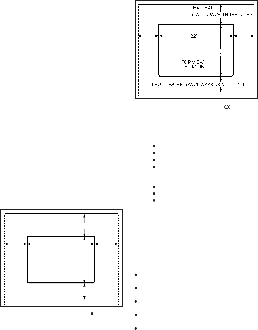
3.00 The minimum floor and maintenance space
required for installation of each of the two equip-
ment cabinets is shown in Figures 3-1 and 3-2.
3.01 The following requirements must be consid-
FIGURE 3-1—PERCEPTION
MINIMUM FLOOR SPACE
REAR WALL
6" AIR SPACE THREE SIDES
17 3/4"
12"
TOP VIEW
NCEC202-M UNIT
FRONT WORK SPACE APPROXIMATELY 36"
ered when selecting a location for the equipment
cabinet:
The location MUST BE:
Dry and clean.
Well ventilated.
Well lit.
Easily accessible.
The location MUST NOT BE:
Subject to extreme heat or cold.
Subject to corrosive fumes.
Next to a reproducing or copying ma-
chine.
4. CABLING CONSIDERATIONS
4.00 The equipment cabinet must be located close
to the facility Main Distribution Frame (MDF). Maxi-
mum house cable run distances for station and
peripheral equipment must also be considered
when choosing the location of the equipment cabi-
net. The limit for each type of equipment is:
Electronic/Digital Telephone - 1,000 cable feet
(305 M), 24 AWG
Standard Telephone - 500-ohms (including tele-
phone)
Stand-alone DDIU-MA/PDIU-DS - 3, 280 cable
feet (1,000 M), 24 AWG
Attendant Console - 1,000 cable feet (305 M),
24 AWG
Electronic DSS - 500 cable feet, 24 AWG
FIGURE 3-2—PERCEPTION
MINIMUM FLOOR SPACE
3-2
INSTALLATION INSTRUCTIONS
SECTION 200-255-203
FEBRUARY 1992
Digital DSS - 1,000 cable feet (305 M), 24 AWG
4.01 Acceptable cable for all telephones is 22 or 24
AWG twisted pair inside telephone station cable
(jacketed but not shielded). Two twisted pairs are
required for the electronic telephone, one pair for a
standard telephone, and one twisted pair for the
digital telephone, even if equipped with a PDIU-DI.
Three twisted pairs are required for an electronic
telephone equipped with a DDIU-MAT. The stand-
alone DDIU-MA/PDIU-DS requires one twisted
pair.
4.02 A 25-pair cable is required for the attendant
console. The console is equipped with a male 50-
pin amphenol-type connector.
WARNING!
1. Never install telephone wiring during a
lightning storm.
2. Never install telephone jacks in wet
locations, unless the jacks are specifi-
cally designed for wet locations.
3. Never touch uninsulated telephone
wires or terminals unless the telephone
line has been disconnected at the inter-
face.
4. Use caution when installing or modify-
ing telephone lines.
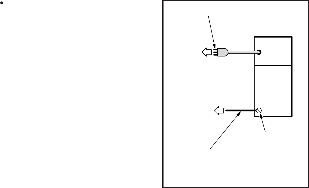
5. GROUNDING
5.00 The following grounding directions are re-
quired in order to comply with the Underwriters'
Laboratories’ Standard 1459 2nd edition:
1) Redundant and independent equipment
grounding conductors are to be installed be-
tween the product and the wiring system
ground.
2) One of the equipment grounding conductors
(ground 1) shall be an insulated grounding
conductor. Its size shall not be smaller than
the size of the grounded and ungrounded
branch-circuit supply conductors. It shall also
have their equivalent insulation material and
thickness, except that it is green with, or
wilthout, one or more yellow stripes. This
FIGURE 3-3—UL GROUNDING DIAGRAM
POWER
SUPPLY
EXT GND
DEDICATED
AC OUTLET
WITH THIRD
WIRE GROUND
GROUND 1; THIRD WIRE GROUND
TO AC POWER CORD
GROUND 2; PER GENERAL RULES
OF ARTICLE 250 OF
THE NATIONAL
ELECTRICAL CODE, NFPA70
TO GROUND
ROD OR WIRING
SYSTEM GROUND
EXTERNAL GROUND SCREW
ON PERCEPTION CABINET
Perception
insulated grounding conductor is to be in-
stalled as part of the circuit that supplies the
system, and it is to be connected to ground at
the service equipment.
3) The other conductor (ground 2) shall comply
with the general rules for grounding contained
in Article 250 of the National Electrical Code,
NFPA 70, but shall not depend on the cord and
plug of the product.
4-1
INSTALLATION INSTRUCTIONS
SECTION 200-255-204
FEBRUARY 1992
CHAPTER 4
SYSTEM INSTALLATION
1. PERCEPTION
1.00 Power Supply Installation
1.01 Install the main power supply as follows:
1) Remove the two screws securing the basic
cabinet front cover. Lift the cover off the cabi-
net.
2) Loosen two screws, remove and retain four
screws securing the basic cabinet rear cover
plate, and remove the rear cover plate (Figure
6) Check the 15-amp fuse (F1) located at the top
of the power supply to verify that it is in working
order.
7) Remove plastic cover from AC connection
terminal TB1 by removing two screws.
8) Connect the white and black leads to the AC
terminal (black to L and white to N) and the
green lead (ground) to the GND screw on the
main power supply (Figure 4-2). Replace the
plastic cover and secure with two screws.
4-1).
3) Unpack the main power supply and inspect it
carefully for any visible damage. Verify that all
connectors are securely attached.
4) Remove and retain the three corner screws
from the back of the main power supply.
5) Slide the main power supply into the basic
cabinet from the front and secure in place with
three screws at the rear. FIGURE 4-2—PERCEPTION
CABLE CONNECTIONS
J508 ~ J501
AUX
SMDR
TTY
POWER
CABLE
SURGE
TEST
J703
P1
J203
AC
TB1 L N
GND
EXT
GND
J7 J6 J5 J4 J3 J2 J1
J15 J14 J13 J12 J11 J10 J9 J8
J201
(24V)
BAT.
TB2
-
+
F1 F2
P3
P2
J202J401
J402
GND
P1
J702
J701
P3
P2
125V
15A
GROUND STRAP
J515 ~ J509
FIGURE 4-1—PERCEPTION
BASIC CABINET REAR COVER
4-2
INSTALLATION INSTRUCTIONS
SECTION 200-255-204
FEBRUARY 1992
9) With the main power supply turned OFF, plug
the AC power cord into the AC outlet.
10) Momentarily press each circuit breaker to
verify that it is not tripped.
11) Place the main power supply power switch in
the ON position.
WARNING!
Hazardous voltage that may cause death
or injury is exposed at the power supply
AC terminal.
12) Verify that all main power supply power indi-
cator LEDs are on (RINGER LED should be
pulsating rapidly). If any of the LEDs are not
on, replace the main power supply.
13) Using a multimeter (set to the appropriate
ranges), check the pins on connectors J201,
J202, J203 and J703 for the voltages shown
in Figure 4-3. (The connectors are on the rear
of the power supply chassis.) Measure be-
tween the voltage pin and a ground pin. (All
ground leads are tied to a single point, so any
can be used.) Figure 4-3 also shows the
acceptable range for each output voltage. If a
measured voltage falls outside of the accept-
able range, replace the main power supply.
14) Turn the power supply OFF and then connect
J201, J202 and J203, respectively, as shown
in Figure 4-2.
15) Remove and retain the two screws securing
the peak load battery mounting bracket and
slide the bracket out the front of the basic
cabinet.
16) Install the peak load battery as shown in
Figure 4-4. Secure the battery to the mounting
bracket with the retaining strap and a single
screw.
WARNING!
Hazardous voltage that may cause death
or injury is exposed at the peak load bat-
tery cables. DO NOT touch wires together.
17) Connect the peak load battery cables to TB2
on the rear of the basic power supply (see
Figure 4-2). Ensure that the correct polarity is
observed as follows:
blue to positive (+)
yellow to negative (-) FIGURE 4-3—PERCEPTION VOLTAGE CHECKS
J201
J203
-5V G
-5V
+5V
+5V G
FPSA ACCEPTABLE VOLTAGE RANGES
NOMINAL (VDC) RANGE (VDC)
-48
-24
+12
-12
+5
-5
-47.52 ~ -48.96
-26.75 ~ -28.12
+11.76 ~ +12.48
-11.76 ~ -12.48
+5.0 ~ +5.4
-5.0 ~ -5.4
-24V G
-24V G
G
-24V G
-24V G
J701
SIG2 SIG 1
RNG CK
-48V G
J702
EXPANSION CABINET
BASIC CABINET
BACK UP
AC DOWN
-24V
-24V
-24V
PS ALM
G
G
G
-24V
G
SIG2 SIG 1
RNG CK
-48V G
J202
-5V
G
G
J703
-5V
+5V
+5V
G
+5V G
G
4-3
INSTALLATION INSTRUCTIONS
SECTION 200-255-204
FEBRUARY 1992
18) Slide the mounting bracket/battery assembly
in place and secure with two screws.
19) Set the BATTERY BACKUP switch to ON
(Figure 4-5).
1.10 Expansion Cabinet Installation
WARNING!
Hazardous voltage that may cause death
or injury is present in the system during
operation. Ensure that AC power to both
cabinets is turned off prior to performing
this procedure.
NOTE:
A 13mm socket wrench and extension is rec-
ommended for ease of expansion cabinet
installation.
1) Remove and retain the four screws securing
the basic cabinet top cover and lift the cover
off the cabinet (Figure 4-6).
2) Remove and retain the two screws securing
each of the expansion cabinet side panels.
Pull the side panels off.
3) Place the four casters on the basic cabinet in
the lock position to ensure cabinet stability
during the expansion cabinet installation.
4) On both the basic and expansion cabinets,
remove and retain two screws securing the
cabinet doors. Remove and retain the six
screws securing the rear panel on each cabi-
net.
FIGURE 4-4—PEAK LOAD BATTERY
FIGURE 4-5—PERCEPTION
POWER SUPPLY CONTROLS AND INDICATORS
FIGURE 4-6—PERCEPTION
EXPANSION CABINET INSTALLATION

4-4
INSTALLATION INSTRUCTIONS
SECTION 200-255-204
FEBRUARY 1992
5) Place the expansion cabinet on top of the
basic cabinet, ensuring proper alignment of
the four mounting holes. Secure in place with
four metric bolts, flat washers and lockwash-
ers.
6) Reinstall the two side covers on the expansion
cabinet and secure in place using four screws
(two per side).
7) Install the top cover on the expansion cabinet
and secure with four screws.
8) Connect the intercabinet ground wire in accor-
dance with Figure 4-2.
9) Route the expansion cabinet ribbon cable
from J402 in the expansion cabinet through
the opening provided in the cabinet bottom
and connect to the basic cabinet backplane at
J401.
10) Remove three screws from the secondary
power supply. From the front of the expansion
cabinet slide the power supply into the rack
and secure in place with the three rear screws.
NOTE:
Prior to routing intercabinet cabling, check the
15-amp fuse (F2) located at the top of the main
power supply to verify that it is in working
order.
11) Route the power supply cabling through the
hole in the expansion cabinet and connect
both power supplies at the P1, P2 and P3
receptacles.
12) With the main power supply turned OFF, plug
the AC power cord into the AC outlet.
13) Momentarily press each secondary power
supply circuit breaker to verify that it is not
tripped.
14) Place the main power supply power switch in
the ON position.
15) Verify that all secondary power supply power
indicator LEDs are on. If any of the LEDs are
not
on, replace the NPSA-S (RINGER LED
should be pulsating rapidly).
16) Using a multimeter (set to the appropriate
ranges), check the pins on connectors J701
and J702 on the secondary power supply for
the voltages shown in Figure 4-3. (The con-
nectors are on the rear of the power supply
chassis.) Measure between the voltage pin
and a ground pin. (All ground leads are tied to
a single point, so any can be used.) Figure 4-
3 also shows the acceptable range for each
output voltage. If a measured voltage falls
outside of the acceptable range, replace the
secondary power supply.
17) Turn the power supply OFF.
18) Plug in connectors J701 and J702.
19) Route cable J703 into the basic cabinet and
plug it into connector J703.
20) Reinstall the rear panels and doors on both
cabinets and secure in place with screws.
2. PERCEPTION
2.00 Power Supply Installation
2.01 Install the main power supply as follows:
1) Remove the two screws securing the basic
cabinet front cover. Lift the cover off the cabi-
net.
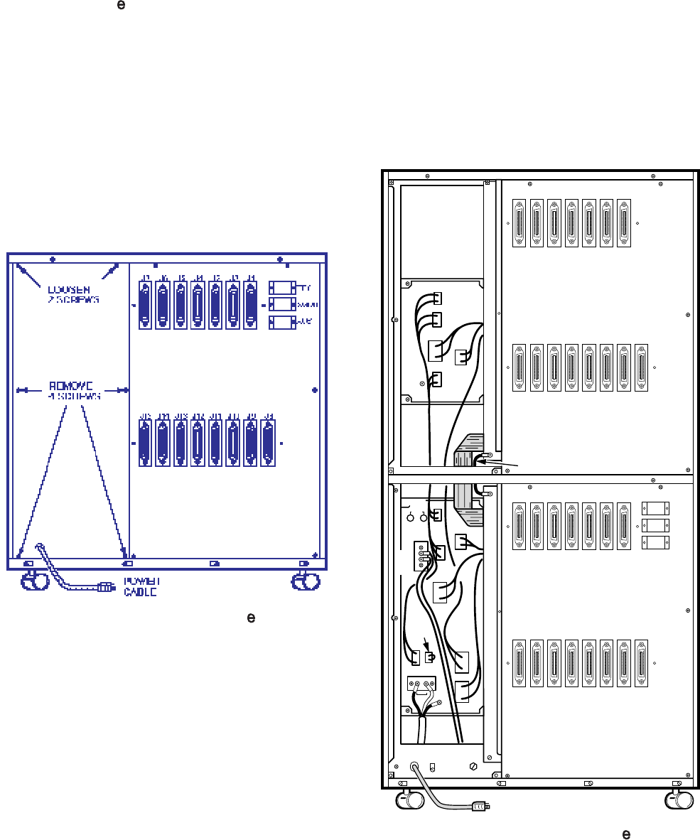
2) Remove and retain six screws securing the
basic cabinet rear cover plate and remove the
rear cover plate (Figure 4-7).
3) Unpack the main power supply and inspect it
carefully for any visible damage. Verify that all
connectors are securely attached.
4) Remove and retain the three corner screws
from the back of the main power supply.
5) Slide the main power supply into the basic
cabinet from the front and secure in place with
three screws at the rear.
6) Check the two 30-amp fuses (F1 and F2)
located at the top of the power supply to verify
that they are in working order.
7) Remove plastic cover from AC connection
terminal TB1 by removing two screws.
8) Connect the white and black leads to the AC
terminal (black to L and white to N) and the
4-5
INSTALLATION INSTRUCTIONS
SECTION 200-255-204
FEBRUARY 1992
FIGURE 4-7—PERCEPTION
BASIC CABINET REAR COVER FIGURE 4-8—PERCEPTION
CABLE CONNECTIONS
green lead (ground) to the GND screw on the
main power supply (Figure 4-8). Replace the
plastic cover and secure with two screws.
9) With the main power supply turned OFF, plug
the AC power cord into the AC outlet.
10) Momentarily press each circuit breaker to
verify that it is not tripped.
11) Place the main power supply power switch in
the ON position.
WARNING!
Hazardous voltage that may cause death
or injury is exposed at the power supply
AC terminal.
J524
J523
J522
J521
J520
J519
J518
J517
J516
J515
J514
J513
J512
J511
J510
J509
J508
J507
J506
J505
J504
J503
J502
J501
J6
J5
J4
J3
J2
J18
J17
J16
J15
J14
J13
J12
J11
J10
J9
J8
J7
J30
J29
J28
J27
J26
J25
J24
J23
J22
J21
J20
J19
J1
TTY
AUX
SMDR
MODEM
J524
J523
J522
J521
J520
J519
J518
J517
J516
J515
J514
J513
J512
J511
J510
J509
J508
J507
J506
J505
J504
J503
J502
J501
J6
J5
J4
J3
J2
J18
J17
J16
J15
J14
J13
J12
J11
J10
J9
J8
J7
J30
J29
J28
J27
J26
J25
J24
J23
J22
J21
J20
J19
TBI LN
GND
J203
J703
J803
J201
J202
J702
J701
J702
J701
J1
TTY
AUX
SMDR
MODEM
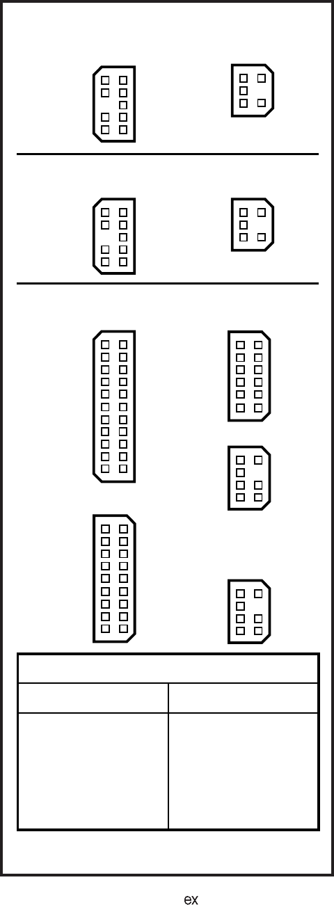
4-6
INSTALLATION INSTRUCTIONS
SECTION 200-255-204
FEBRUARY 1992
12) Verify that all main power supply power indi-
cator LEDs are on (RINGER LED should be
pulsating rapidly). If any of the LEDs are not
on, replace the main power supply.
13) Using a multimeter (set to the appropriate
ranges), check the pins on connectors J201,
J202, J203, J703 and J803 for the voltages
shown in Figure 4-9. (The connectors are on
the rear of the power supply chassis.) Meas-
ure between the voltage pin and a ground pin.
(All ground leads are tied to a single point, so
any can be used.) Figure 4-9 also shows the
acceptable range for each output voltage. If a
measured voltage falls outside of the accept-
able range, replace the main power supply.
14) Turn the power supply OFF and then connect
J201, J202 and J203, respectively, as shown
in Figure 4-9.
15) Remove and retain the two screws securing
the peak load battery mounting bracket and
slide the bracket out the front of the basic
cabinet.
16) Install the peak load battery as shown in
Figure 4-4. Secure the battery to the mounting
bracket with the retaining strap and a single
screw.
WARNING!
Hazardous voltage that may cause death
or injury is exposed at the peak load bat-
tery cables. DO NOT touch wires together.
17) Connect the peak load battery cables to TB2
on the rear of the basic power supply (see
Figure 4-4). Ensure that the correct polarity is
observed as follows:
blue to positive (+)
yellow to negative (-)
18) Slide the mounting bracket/battery assembly
in place and secure with two screws.
19) Set the BATTERY BACKUP switch to OFF
Figure 4-10.
2.10 First Expansion Cabinet Installation
WARNING!
Hazardous voltage that may cause death
or injury is present in the system during
FIGURE 4-9—PERCEPTION VOLTAGE CHECKS
-24V G
-24V G
G
-24V G
-24V G
J701
-24V G
-24V G
G
-24V G
-24V G
J701
PSA-M
BACK UP G
G
-24V G
-24V G
J201
-24V
-24V G
-24V G
G
-24V G
-24V G
-24V
G
AC DOWN
J203
+5V G
+5V G
+5V G
+5V G
+5V G+5V
+5V G
G
-5V G
SIG2 SIG 1
RNG CK
-48V G
J702
SIG2 SIG 1
RNG CK
-48V G
J702
J202
GG
SIG 1
SIG 2
SIG 1
SIG 2
G
J803
-5V G
-5V
+5V G
+5V G
RNG CK
G
G
-48V
-48V
J703
-5V G
-5V
+5V G
+5V G
FPSA ACCEPTABLE VOLTAGE RANGES
NOMINAL (VDC) RANGE (VDC)
-48
-24
+12
-12
+5
-5
-47.52 ~ -48.96
-26.75 ~ -28.12
+11.76 ~ +12.48
-11.76 ~ -12.48
+5.0 ~ +5.4
-5.0 ~ -5.4
EXPANSION CABINET
EXPANSION CABINET
BASIC CABINET
-5V
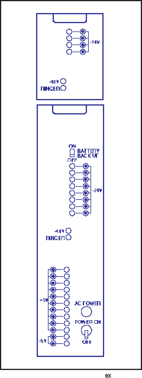
4-7
INSTALLATION INSTRUCTIONS
SECTION 200-255-204
FEBRUARY 1992
FIGURE 4-10—PERCEPTION
POWER SUPPLY CONTROLS AND INDICATORS
operation. Ensure that AC power to both
cabinets is turned off prior to performing
this procedure.
NOTE:
A 13mm socket wrench and extension is rec-
ommended for ease of expansion cabinet
installation. Two expansion cabinets can be
installed.
1) Remove and retain the four screws securing
the basic cabinet top cover and lift the cover
off the cabinet (Figure 4-11).
2) Remove and retain the two screws securing
each of the expansion cabinet side panels.
Pull the side panels off.
3) Place the four casters on the basic cabinet in
the lock position to ensure cabinet stability
during the expansion cabinet installation.
4) On both the basic and expansion cabinets,
remove and retain two screws securing the
cabinets doors. Remove and retain the six
screws securing the rear panel on each cabi-
net.
5) Place the expansion cabinet on top of the
basic cabinet, ensuring proper alignment of
the four mounting holes. Secure in place with
four metric bolts, flat washers and lockwash-
ers.
6) Reinstall the two side covers on the expansion
cabinet and secure in place using four screws
(two per side).
7) Install the top cover on the expansion cabinet
and secure with four screws.
8) Connect the intercabinet ground wire in accor-
dance with Figure 4-8.
9) Route the expansion cabinet ribbon cable
from J405 in the expansion cabinet through
the opening provided in the cabinet bottom
and connect to the basic cabinet backplane at
J402.
10) Remove three screws from the secondary
power supply. From the front of the expansion
cabinet, slide the power supply into the rack
and secure in place with the three rear screws.
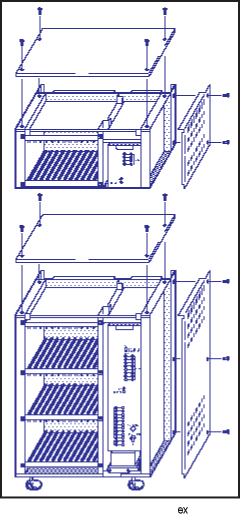
4-8
INSTALLATION INSTRUCTIONS
SECTION 200-255-204
FEBRUARY 1992
both power supplies to the lower connectors
at the P1, P2 and P3 receptacles.
12) With the main power supply turned OFF, plug
the AC power cord into the AC outlet.
13) Momentarily press each secondary power
supply circuit breaker to verify that it is not
tripped.
14) Place the main power supply power switch in
the ON position.
15) Verify that all secondary power supply power
indicator LEDs are on. If any of the LEDs are
not
on, replace the NPSA-S (RINGER LED
should be pulsating rapidly).
16) Using a multimeter (set to the appropriate
ranges), check the pins on connectors J701
and J702 on the secondary power supply for
the voltages shown in Figure 4-9. (The con-
nectors are on the rear of the power supply
chassis.) Measure between the voltage pin
and a ground pin. (All ground leads are tied to
a single point, so any can be used.) Figure 4-
9 also shows the acceptable range for each
output voltage. If a measured voltage falls
outside of the acceptable range, replace the
secondary power supply.
17) Turn the power supply OFF.
18) Plug in connectors J701 and J702.
19) Route cable J703 into the basic cabinet and
plug it into connector J703.
20) Reinstall the rear panels and doors on both
cabinets and secure in place with screws.
2.20 Second Expansion Cabinet Installation
WARNING!
Hazardous voltage that may cause death
or injury is present in the system during
operation. Ensure that AC power to both
cabinets is turned off prior to performing
this procedure.
NOTE:
A 13mm socket wrench and extension is rec-
ommended for ease of expansion cabinet
NOTE:
Prior to routing intercabinet cabling, check the
15-amp fuse (F2) located at the top of the main
power supply to verify that it is in working
order.
11) Route the power supply cabling through the
hole in the expansion cabinet and connect
FIGURE 4-11—PERCEPTION
EXPANSION CABINET INSTALLATION
4-9
INSTALLATION INSTRUCTIONS
SECTION 200-255-204
FEBRUARY 1992
installation. Two expansion cabinets can be
installed.
1) Remove and retain the four screws securing
the basic cabinet top cover and lift the cover
off the cabinet (Figure 4-11).
2) Remove and retain the two screws securing
each of the expansion cabinet side panels.
Pull the side panels off.
3) Place the four casters on the basic cabinet in
the lock position to ensure cabinet stability
during the expansion cabinet installation.
4) On both the basic and expansion cabinets,
remove and retain two screws securing the
cabinets' doors. Remove and retain the six
screws securing the rear panel on each cabi-
net.
5) Place the expansion cabinet on top of the
basic cabinet, ensuring proper alignment of
the four mounting holes. Secure in place with
four metric bolts, flat washers and lockwash-
ers.
6) Reinstall the two side covers on the expansion
cabinet and secure in place using four screws
(two per side).
7) Install the top cover on the expansion cabinet
and secure with four screws.
8) Connect the intercabinet ground wire in accor-
dance with Figure 4-8.
9) Route the expansion cabinet ribbon cable
from J406 in the expansion cabinet through
the opening provided in the cabinet bottom
and connect to the basic cabinet backplane at
J403.
10) Remove three screws from the secondary
power supply. From the front of the expansion
cabinet, slide the power supply into the rack
and secure in place with the three rear screws.
NOTE:
Prior to routing intercabinet cabling, check the
15-amp fuse (F2) located at the top of the main
power supply to verify that it is in working
order.
11) Route the power supply cabling through the
hole in the expansion cabinet and connect
both power supplies to the upper connectors
at the P1, P2 and P3 receptacles.
12) With the main power supply turned OFF, plug
the AC power cord into the AC outlet.
13) Momentarily press each secondary power
supply circuit breaker to verify that it is not
tripped.
14) Place the main power supply power switch in
the ON position.
15) Verify that all secondary power supply power
indicator LEDs are on. If any of the LEDs are
not
on, replace the NPSA-S (RINGER LED
should be pulsating rapidly).
16) Using a multimeter (set to the appropriate
ranges), check the pins on connectors J701
and J702 on the secondary power supply for
the voltages shown in Figure 4-9. (The con-
nectors are on the rear of the power supply
chassis.) Measure between the voltage pin
and a ground pin. (All ground leads are tied to
a single point, so any can be used.) Figure 4-
9 also shows the acceptable range for each
output voltage. If a measured voltage falls
outside of the acceptable range, replace the
secondary power supply.
17) Turn the power supply OFF.
18) Plug in connectors J701 and J702.
19) Route cable J703 into the basic cabinet and
plug it into connector J803.
20) Reinstall the rear panels and doors on both
cabinets and secure in place with screws.
3. PRINTED CIRCUIT BOARD INSTALLATION
3.00 NFDU
3.01 Install an NFDU in the FDD0 slot in the basic
cabinet. If the system uses D.02 or later version
software and Remote Maintenance, a second NFDU
must be installed in the FDD1 slot in the basic
cabinet. There is one strap selection on the NFDU,
depending on the slot in which the PCB is installed.
The jumper block on the rear of the NFDU must be
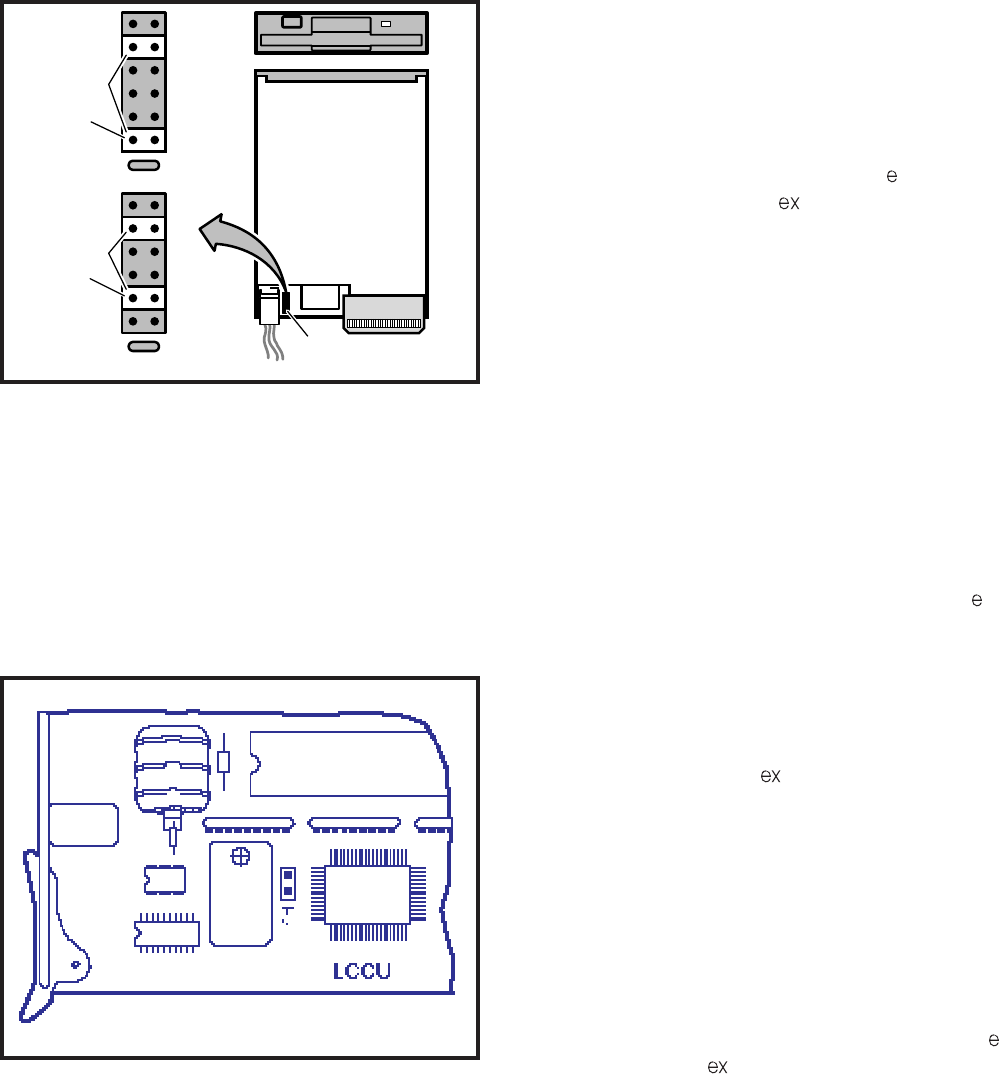
4-10
INSTALLATION INSTRUCTIONS
SECTION 200-255-204
FEBRUARY 1992
FIGURE 4-12—NFDU STRAPPING
FIGURE 4-13—LCCU STRAPPING
3.21 The NTWU has one strap that must be veri-
fied before installation (Figure 4-14). Install the
NTWU in the TWU slot of the basic cabinet. Ensure
that the strap is as follows:
TBC5: pins 1 & 2 must be strapped
3.30 NPRU
3.31 The NPRU has one strap that requires verifi-
cation before installation (Figure 4-15). If Auto-
matic Wake-up is required, verify that the DROM is
installed in the IC15 socket. Install the NPRU in the
P00 slot. (An NPRU must be installed in the P00
card slot.) If a second NPRU PCB is used, install it
in the P01 slot in the PERCEPTION expansion
cabinet. In PERCEPTION , both NPRUs are in-
stalled in the basic cabinet. Verify that TB1 is
strapped as follows:
TB1: pins 1 and 2 must be strapped.
NOTE:
DROM only required for digitized voice on
automated wake-up calls.
3.32 If NRCUs are to be installed, mount them on
the NPRU. The first NRCU mounts on connector
J3, the second on J4 (see Figure 4-16).
3.40 NEKU, NDKU, and NOCU
3.41 Install the NEKU in any of the line designated
slots L00 ~ L11 or L15 ~ L26 in PERCEPTION . If
an attendant console is used, an NEKU must be
installed in slot L00. If a second attendant console
is installed, a second NEKU must be installed in slot
L15. Attendant consoles must be installed on cir-
cuit 1 in both slots.
3.42 For PERCEPTION , install the NEKU in any
designated slot U00 ~ U31. To utilize attendant
consoles, install NEKUs in the following slots:
ATT#0-PCB position U00 Circuit #1
ATT#1-PCB position U01 Circuit #1
3.43 There are no straps on the NEKU PCB for
either system.
3.44 Install the NDKU in any of the line designated
slots L00 ~ L11 or L15 ~ L26 in PERCEPTION .
For PERCEPTION , install the NDKU in any des-
ignated slots U00 ~ U31. Some options require
adjacent PCB slots be left vacant.
3.45 The NDKU employs a 2B+D architecture for
each circuit that must be configured for one of four
different operating options using the dip switch S1
(Figure 4-17) as follows:
1) OPTION 1; Eight digital telephones only: this
set as shown in Figure 4-12.
3.10 LCCU
3.11 Install the LCCU in the CCU slot of the basic
cabinet. There are no straps on this PCB; however,
there is a plug (P5). Verify that the connection plug
is in place in accordance with Figure 4-13.
3.20 NTWU
HHO
OP
LHI
HHI
D1
D0
FG
HHO
OP
LHI
HHI
D1
D0
FG
FDD0
FDD1
STRAPS
STRAPS
STRAP
FDD
(FD-235GF-121-U)
TOP VIEW
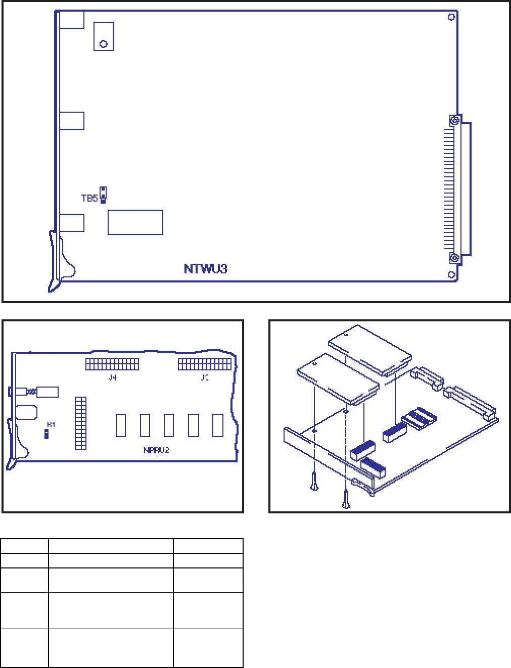
4-11
INSTALLATION INSTRUCTIONS
SECTION 200-255-204
FEBRUARY 1992
FIGURE 4-14—NTWU STRAPPING
option uses one of the two B channels for each
circuit to interface up to eight 1000-series
digital telephones.
2) OPTION 2; Eight digital telephones with DIU
or OCA: this option uses both B channels for
each circuit to interface up to eight 1000-
series digital telephones; plus each telephone
may have an integrated Data Interface Unit
(PDIU-DI) or Off-hook Call Announce PCB
(DVSU) installed. In addition, this option sup-
FIGURE 4-15—NPRU STRAPPING FIGURE 4-16—NRCU MOUNTING
OPTION OPERATION
S-1 POSITION
1
2
3
4
DKT only
DKT with DIU
or OCA
4 DSS
8 DSS
DIP switches 1 ~ 4: ON
DIP switches 2 ~ 4: ON
DIP switch 1: OFF
DIP switches 1, 3, and 4:
ON
DIP switch 2: OFF
DIP switches 1 and 2:
OFF
DIP switches 3 and 4: ON
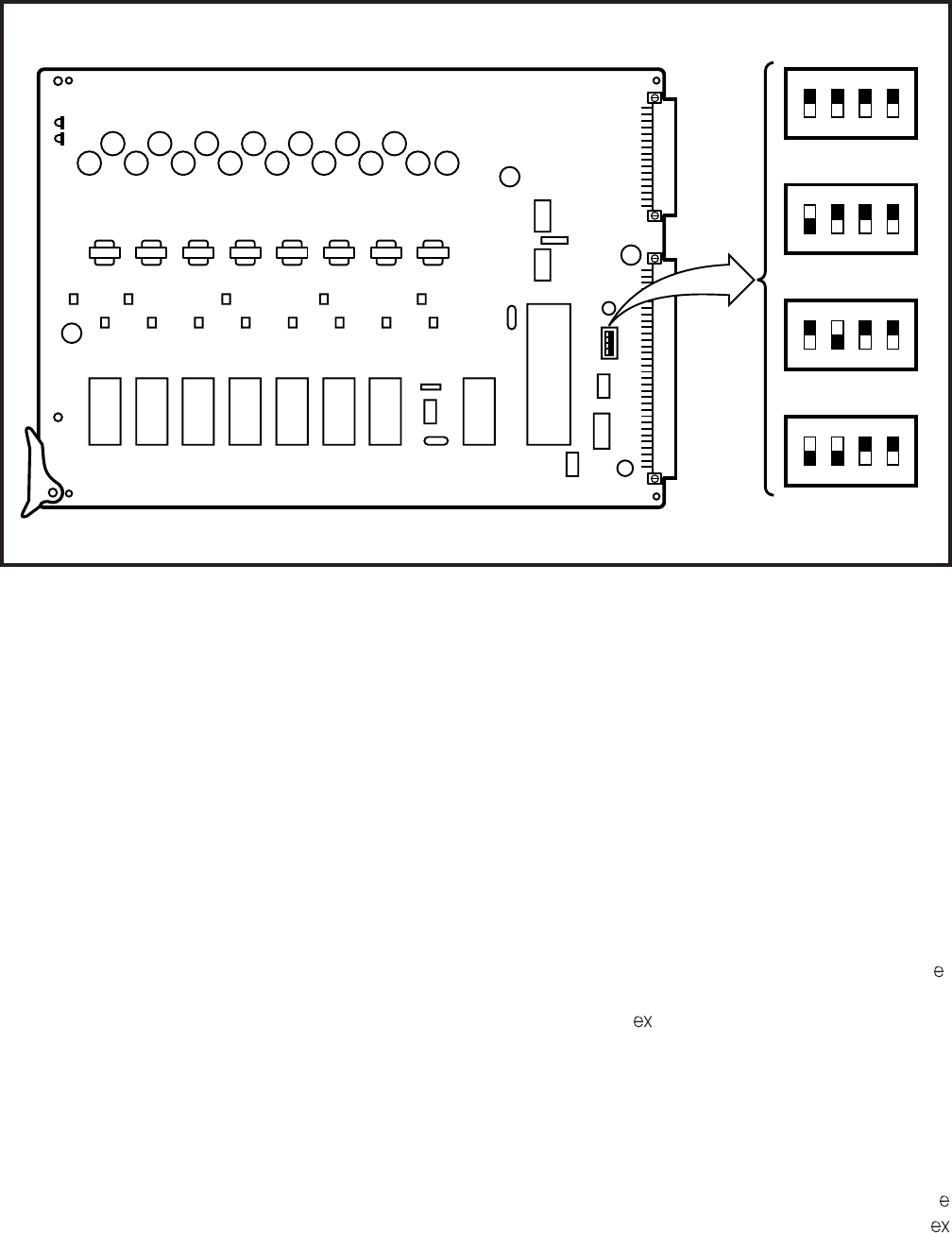
4-12
INSTALLATION INSTRUCTIONS
SECTION 200-255-204
FEBRUARY 1992
FIGURE 4-17—NDKU SWITCH OPTIONS
ports the Stand-alone Data Interface Unit
(PDIU-DS). One B channel for each circuit
interfaces a single PDIU-DS. The other B
channel of this circuit cannot be used. A
single PDIU-DS only may be installed per
each circuit.
3) OPTION 3; Four digital DSS consoles: this
option uses one of the B channels for each of
the two circuits to interface up to four 1000-
series digital DSS consoles.
4) OPTION 4; Eight digital DSS consoles: this
option uses both B channels for each of the
two circuits to interface up to eight 1000-
series digital DSS consoles.
NOTE:
1. When using option 2 or 4, the next highest
number adjacent PCB slot cannot be
used. For example, if an NDKU is installed
in L01 or U01, the PCB slot L02 or U02
respectively, must be left vacant.
2. When using option 4, program the first
four DDSSs on circuits 1, 3, 5 and 7 on the
NDKU PCB. Program the second four
DDSSs on cirucits 1, 3, 5 and 7 on the
adjacent slot next to the NDKU PCB.
3. When using option 4, wire the first four
DDSSs to circuits 1, 2, 3 and 4 on the
NDKU PCB (these are the NDKU as-
signed DDSSs) and the second four
DDSSs to circuits 5, 6, 7 and 8 (these are
the DDSSs assigned to the adjacent slot)
on the NDKU PCB.
3.46 The NOCU PCB is installed at a rate of one
PCB for each group of eight electronic telephones.
There are no strapping options on this PCB. The
NOCU is installed in any of the line designated slots
L00 ~ L11 and/or L15 ~ L26 in PERCEPTION ,
and in any designated slots U00 ~ U31 in
PERCEPTION . If any of the eight circuits is not
used for Off-hook Call Announce, the remaining
circuits
CANNOT
be used for other electronic tele-
phone assignments.
3.50 NSTU
3.51 Install the NSTU in any of the line designated
slots L00 ~ L11 or L15 ~ L26 in the PERCEPTION
system. The designated slots in PERCEPTION
NDKU2
1 2 3 4
1 2 3 4
OFF MCC
1 2 3 4
OFF MCC
1 2 3 4
OFF MCC
1 2 3 4
OFF MCC
DSS8
DSS4
OCA/DIU
DKT
OFF MCC
SWITCH
POSITIONS
Black shading indicates
switch position
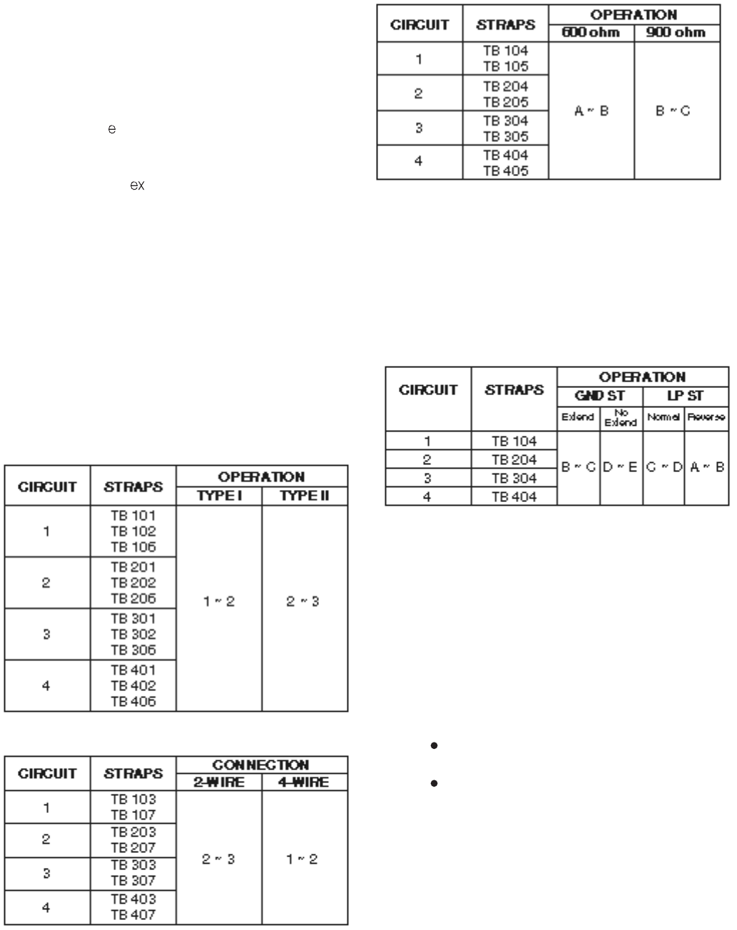
4-13
INSTALLATION INSTRUCTIONS
SECTION 200-255-204
FEBRUARY 1992
are U00 ~ U31. There are no straps on the PCB for
either system.
3.60 NDSU
3.61 Install the NDSU PCB either in the C00 or C01
slots or in any of slots L00 ~ L11 or L15 ~ L26 in the
PERCEPTION system. Two NDSUs can be
installed in the same cabinet. There are no straps
on this PCB. There are no C slots resident within
the PERCEPTION system so NDSU PCB instal-
lation will be in any U slot .
3.70 NEMU, NCOU, and NLSU
3.71 Trunk PCBs (NEMU, NCOU, and NLSU) may
be installed in any T slot. Additionally, up to 16 U
slots may also be used for trunk PCBs.
3.72 There are four circuits on the NEMU PCB,
and each circuit has its own set of straps (Figure 4-
18). On a circuit-by-circuit basis, strap the PCB as
follows:
1) For Type I/II operation:
2) For 2-wire/4-wire connection:
3) For 600-/900-ohm operation:
3.73 The NCOU PCBs have Ground-/Loop-start,
600/900-ohm termination, and 2dB pad strap se-
lections that must be made before they are installed
(Figure 4-19).
1) Each NCOU circuit is individually strapped for
either Ground Start or Loop Start operation.
The strapping location and options for each
circuit are shown as follows:
NOTES:
1. The GROUND START “EXTEND/NO EX-
TEND” options refer to “loop extenders”
on long trunk loops. If a battery boost is
used on the trunk, select EXTEND, other-
wise NO EXTEND should be selected.
2. The LOOP START “NORMAL/REVERSE”
options refer to the system’s ability to
detect a pre-ring supervision signal in the
form of a battery polarity reversal on the
CO TIP and RING.
If NORMAL is selected, the system will
not be sensitive to CO trunk polarity.
If REVERSE is selected, the CO cir-
cuit will be “made busy” when the CO
reverses polarity prior to ringing on an
incoming call.
2) Determine the proper impedance for each
trunk and then strap its NCOU circuit for either
600- or 900-ohm operation. Install the short-
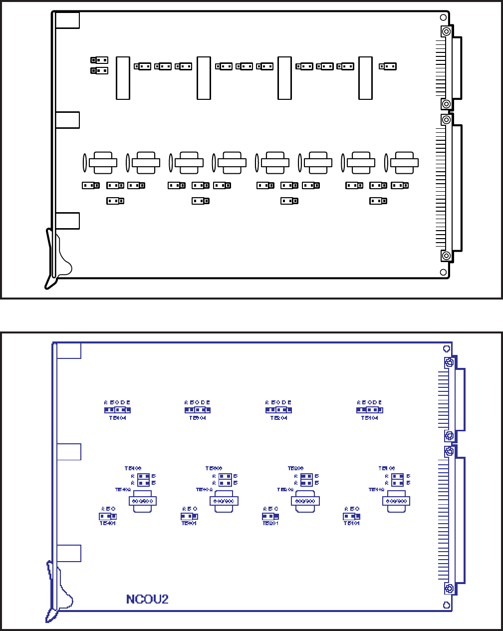
4-14
INSTALLATION INSTRUCTIONS
SECTION 200-255-204
FEBRUARY 1992
FIGURE 4-18—NEMU STRAPPING
FIGURE 4-19—NCOU STRAPPING
NEMU2
600/900 600/900 600/900 600/900 600/900 600/900 600/900
TB406
TB401
TB402 TB306 TB301 TB302 TB206 TB201 TB202 TB106 TB101 TB102
TB404
A B C A B CTB403
TB405TB407 TB305TB307TB304
A B C TB303A B C
TB205TB207TB204
A B C TB203A B C
TB105TB107TB104
A B C TB103A B C
600/900
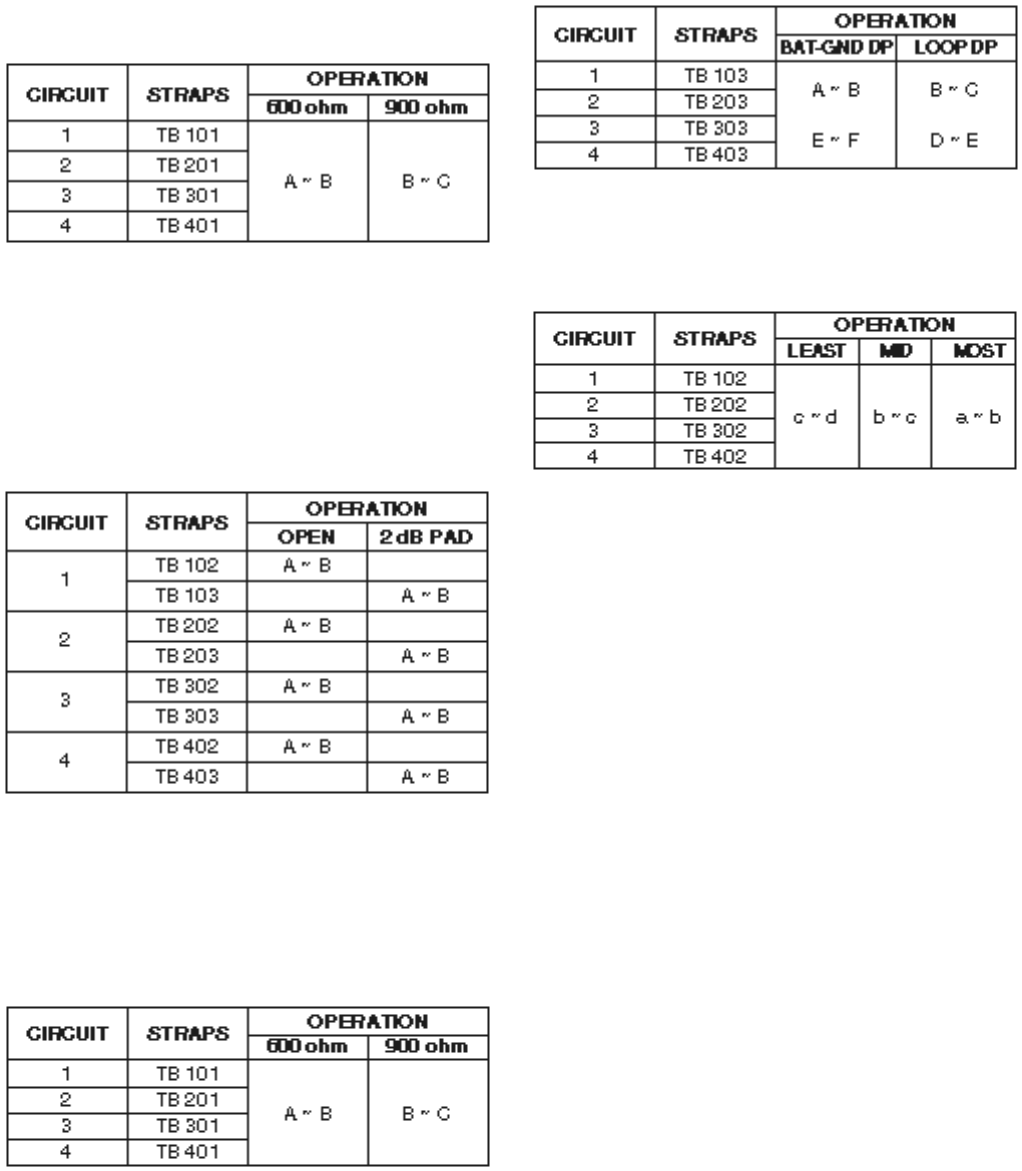
4-15
INSTALLATION INSTRUCTIONS
SECTION 200-255-204
FEBRUARY 1992
ing should be used. For a distance of less than
2,000-ohm loop resistance, use Loop Dial
Pulsing. Strap each circuit as follows:
3) Each NLSU circuit must be adjusted for CO
trunk loop resistance to ensure proper detec-
ing bar across the center pin and the outer pin
labeled either 600 or 900 at each strapping
location (Figure 4-19). Each circuit’s strap-
ping location is shown as follows:
3) In some installations, particularly those near
the serving Central Office, noise may be intro-
duced over the CO trunk that will appear as
sidetone at the telephone. In such situations,
a 2dB pad can be inserted into the line to
reduce the sidetone. The following table shows
the strapping position for each circuit to either
insert or remove the 2dB pad.
3.74 Three separate strappings must be made for
each of the four circuits on the NLSU PCB (Figure
4-20).
tion of incoming digits. Each circuit adjust-
ment is made by strapping as follows:
NOTE:
This strapping should be made only after the
1) Determine the proper impedance for the trunk
line to be used, and then set the 600-ohm/900-
ohm loop termination for each circuit as fol-
lows:
2) When the CO distance exceeds 2,000-ohm
loop resistance, Battery-to-Ground Dial Puls-
appropriate CO distance strapping (step 2)
has been made. The CO trunk loop resistance
values are arbitrary and are used as an initial
strapping guide. If the incoming digits are not
being detected properly, move the strap to the
next most sensitive position and test again for
proper operation.
3.80 NDTU
3.81 A maximum of two NDTU PCBs (Figure 4-21)
may be installed. The system must be equipped
with an NTWU-3 to ensure proper operation of the
NDTU. The NDTU is connected to the telco through
a customer-supplied Channel Service Unit (CSU).
A separate CSU is required for each NDTU. Each
NDTU has 11 DIP switches and 8 strapping op-
tions, which must be verified before installation.
NOTE:
The factory-default switch settings and strap-
ping options are indicated by an asterisk (*).
1) Select the desired operating mode using mode
selection switch S1 (4-element DIP switch)
as follows:
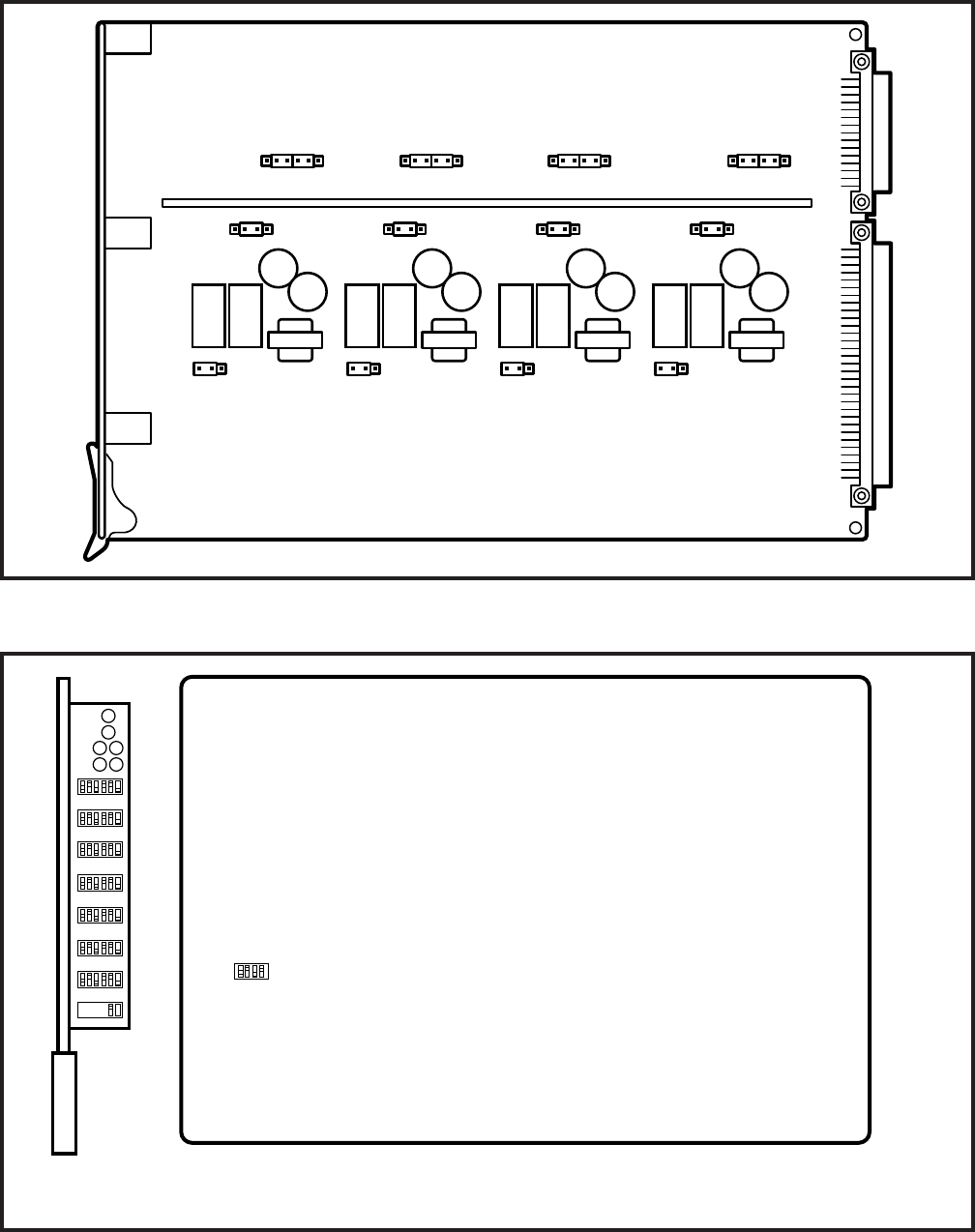
4-16
INSTALLATION INSTRUCTIONS
SECTION 200-255-204
FEBRUARY 1992
FIGURE 4-20—NLSU STRAPPING
NLSU
600/900
TB401 A B C
A B C D E F
TB103
A B C D E F
TB203
A B C D E F
TB303
A B C D E F
TB403
TB402
a b c d
600/900
TB301 A B C
TB302
a b c d
600/900
TB201 A B C
TB202
a b c d
600/900
TB101 A B C
TB102
a b c d
FIGURE 4-21—NDTU STRAPPING
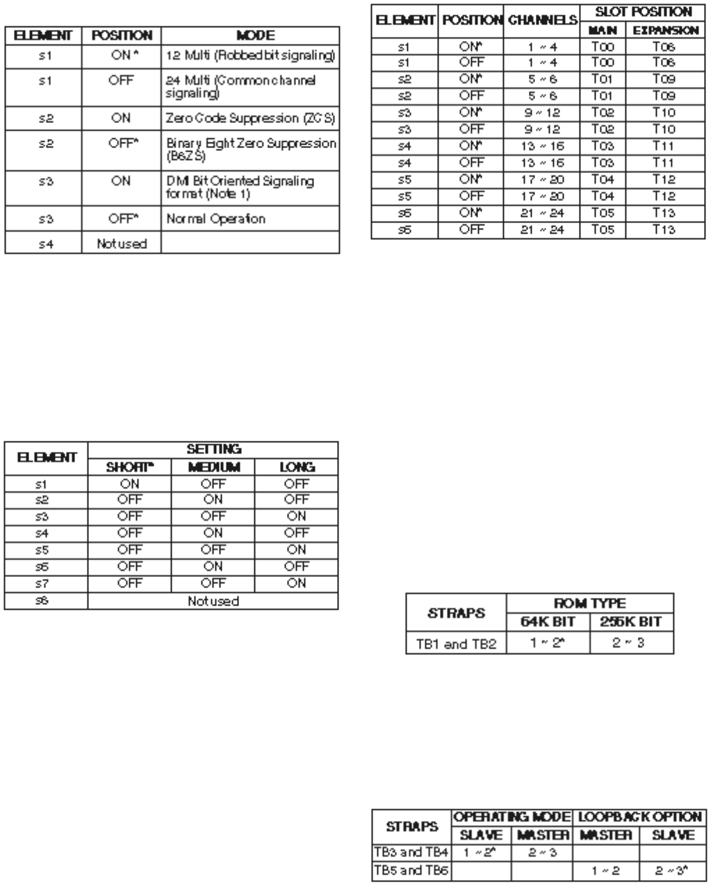
4-17
INSTALLATION INSTRUCTIONS
SECTION 200-255-204
FEBRUARY 1992
priate channels using slot enable/disable
switch S3 (6-element DIP switch) as follows:
NOTE:
Set switch element to ON to enable associ-
ated digital trunk channels; OFF to disable
channels.
4) Signaling modes are individually selectable
for each active channel. Determine the appro-
priate signaling mode for each channel; either
CO (Loop Start) mode, CO (Ground Start)
mode, DID (2-wire loop signaling), or TIE
trunk (Type II 4-wire E&M) mode; then assign
the selected signaling modes using signaling
type selection switches S4 ~ S11 (6-element
DIP switches) see Loop/Ground Start Mode.
5) Configure the NDTU for the appropriate ROM
ping options are indicated by an asterisk (*).
1) Select the desired operating mode using mode
selection switch S1 (4-element DIP switch)
as follows:
NOTE:
Digital Multiplexed Interface BOS.
2) Determine the proper transmit equalizer set-
ting; either short (0 ~ 150 feet), medium (150
~ 450 feet), or long (450 ~ 655 feet); then
select the appropriate setting using transmit
equalizer setting switch S2 (8-element DIP
switch) as follows:
3) The NDTU is installed in the T00 slot. A
second NDTU may be installed in the T08 slot.
Each NDTU provides a maximum of 24 chan-
nels, divided into groups consisting of four
channels each. The first group would fill trunk
slot T00, the second T01 with the remaining
four groups occupying trunk slots T02 ~ T05
for a total of six groups. For example, if eight
channels are active on the NDTU then slots
T00 and T01 are active i.e., no PCB may be
installed in slot T01. However, PCBs may be
installed in slots T02 ~ T05. Enable the appro-
type, either 64 Kbit or 256 Kbit, using the
strappings shown below.
6) When configured for normal operation, the
NDTU is in the slave mode, and the central
office serves as the master clock. For CO
testing purposes, the NDTU may be config-
ured as the master. Configure the NDTU for
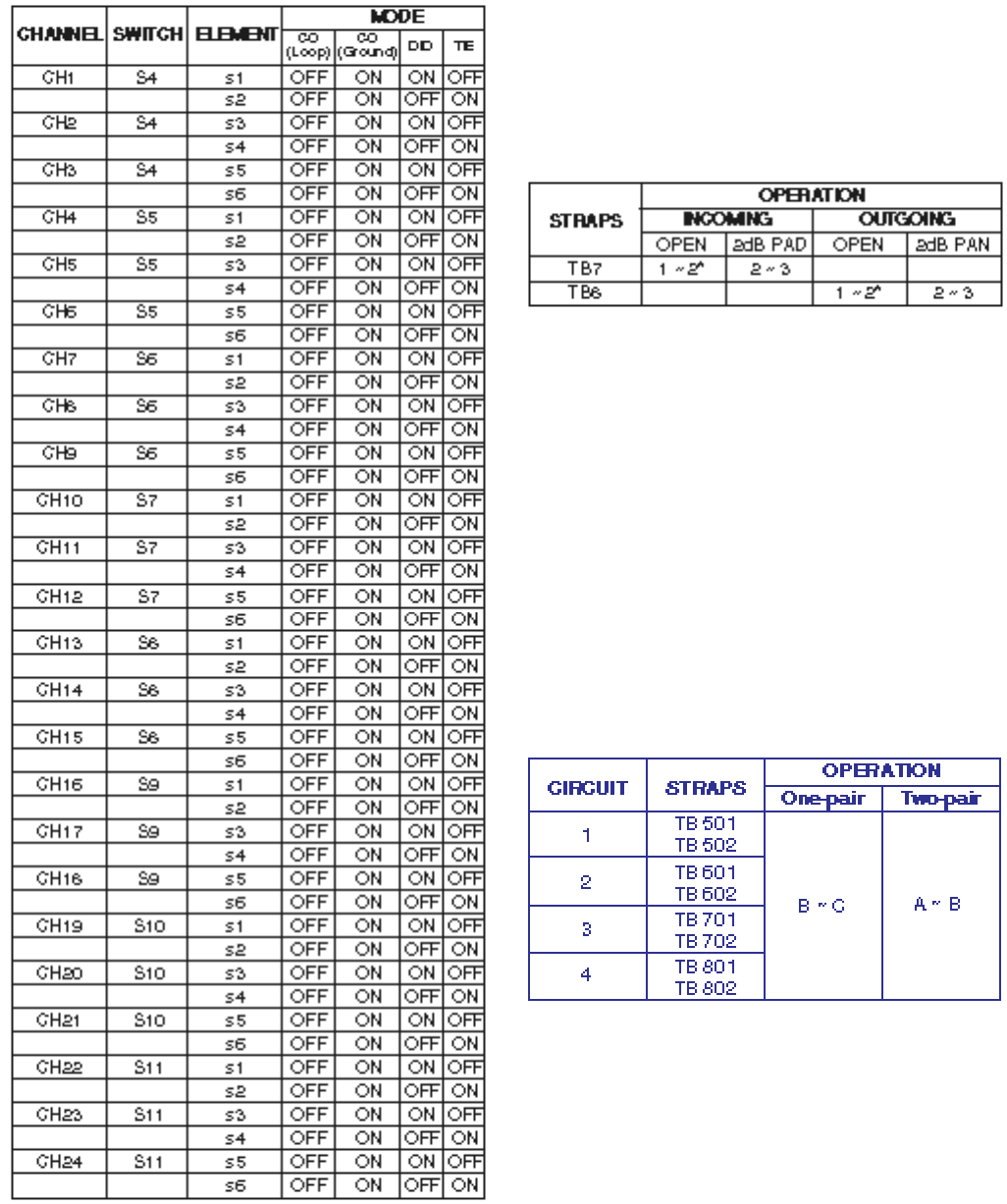
4-18
INSTALLATION INSTRUCTIONS
SECTION 200-255-204
FEBRUARY 1992
the appropriate operating mode using the
strapping options shown below.
7) In some installations, particularly those near
the serving Central Office, noise may be intro-
duced over the CO trunk that will appear as
sidetone at the telephone. In such situations,
a 2dB pad can be inserted into the line, for
either incoming voice or outgoing voice, to
reduce the sidetone. Strapping options for the
2dB pad are shown below.
8) Install the NDTU in the T00 slot in the main
cabinet. If applicable, install a second NDTU
in the T08 slot. Connect the NDTU to the CSU
using the Toshiba-supplied cable.
9) The NDTU contains an on-board 12.288 MHz
clock used to synchronize the NDTU with the
NTWU-3. Connect a coaxial clock cable from
NDTU connector J3 to NTWU connector J2.
3.90 NMDU and NDCU
3.91 The NMDU (Figure 4-22) must be strapped
for operation with either a one-pair or two-pair
Loop/Ground Start Mode
modem connection. The two strapping positions for
each modem are shown below.
3.92 To change the strap positions on TB 801/802
it is necessary to lift the small piggy-back PCB off
the NMDU. Replace the PCB once the straps have
been changed.
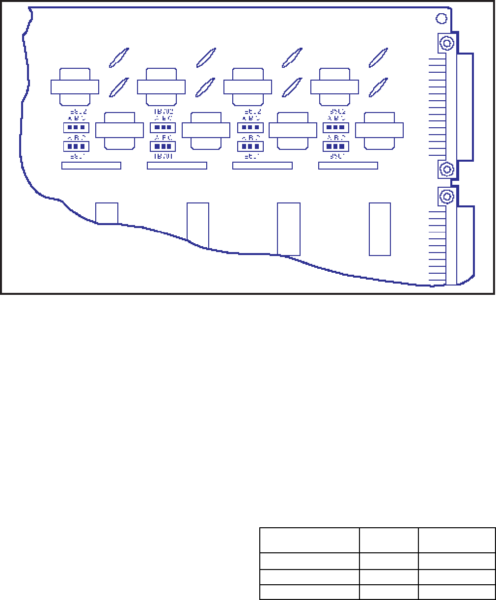
4-19
INSTALLATION INSTRUCTIONS
SECTION 200-255-204
FEBRUARY 1992
MODEM connectors (which require male RS-232C
DB25-pin connectors).
4.01 Detailed connection information for each cable
is shown in Chapter 5.
IMPORTANT!
Note the station, trunk, DSS console, and
DDIU/PDIU connections are identified by
the PCB location and circuit number on
that PCB. These numbers combine to form
a Port Number and are used in the pro-
gramming section as the station, DSS con-
sole, or trunk circuit’s identifier when di-
rectory numbers and features are assigned.
4.02 Determine the station and DSS console (or
3.93 If any of the first four NMDU circuits are not
used for Modem Pooling, the corresponding DDIU
circuit may be used for a DDIU (-MA or -MAT)
connection. Use the DDIU Program in Section
200-255-300,
Programming
, to assign the desired
port (1 ~ 4) on the NMDU.
3.94 The NDCU PCB is installed at a rate of one
PCB for each group of eight DDIUs. There are no
strapping options on this PCB.
NOTE:
The NMDU and NDCU PCBs are not used
with the PDIUs. PDIUs use the NDKU PCB.
4. CABLE CONNECTIONS
4.00 All connections to the system are made on
the rear of the basic and expansion cabinets and on
the Power Failure Transfer Unit. Cables with stan-
dard male 25-pair amphenol-type connectors are
used for everything except the TTY, SMDR and
FIGURE 4-22—NMDU STRAPPING
PCB
LOCATION PORT NO.
PCB
CIRCUIT
P L00 ~ L26 or C00
P U00 ~ U31
Example: L01
1 ~ 8
1 ~ 8
2 L012
ex
e

4-20
INSTALLATION INSTRUCTIONS
SECTION 200-255-204
FEBRUARY 1992
5.11 All electronic telephones are wall-mounted in
the same manner, and they may be mounted on a
wall or any other flat, vertical surface to which the
base can be secured. When selecting the mounting
site, consider the electronic telephone’s weight and
the additional stresses to which the mounting will
be subjected.
5.12 Loosen the four captive screws securing the
electronic telephone's base, and remove the base
(Figure 4-24).
5.13 Using a cutter, remove the handset hanger
from the base. Insert the handset hanger in the slot
provided on the front of the telephone (Figure 4-
25). The hanger fits in the notch on the handset.
5.14 Rotate the mounting base 180° and secure to
the telephone with the four captive screws (Figure
4-26).
5.15 Connect the electronic telephone to the wall
modular connector with a short cord (approximately
3 inch length). Route the cord into the hollow
portion of the base, then mount the electronic
telephone on the wall mounting connector. Test
each electronic telephone using the TTRM Pro-
gram, Section 200-255-300,
Programming
.
5.20 Off-hook Call Announce
5.21 The Off-hook Call Announce (OCA) feature
enables an electronic telephone to originate and
receive voice announcement when the station’s
handset is off-hook. Standard telephones can origi-
nate off-hook call announces, however, it cannot
receive them. A station user is allowed or denied
the ability to originate the Off-hook Call Announce
feature in the DCOS Program. In order to receive
the Off-hook Call Announce feature, PCBs are
required to be installed in each affected electronic
telephone and the cabinet.
5.22 A PCB called NOCU is required to be installed
in the cabinet. Each NOCU provides eight Off-hook
Call Announce circuits. This PCB takes up a station
slot. Therefore, for each NOCU installed, station
capacity is decreased by eight stations.
5.23 HVSU and HVSI PCBs inside a 6500-series
electronic telephone allow the electronic telephone
data) port numbers as follows (DSS consoles as-
signed to L or U slots use circuits 1, 3, 5, & 7):
PCB
LOCATION PORT NO.
PCB
CIRCUIT
P T00 ~ T15
P T00 ~ T15
U00 ~ U31
Example: T02
1 ~ 4
1 ~ 4
3T023
ex
e
4.03 Determine trunk port numbers as follows:
5. ELECTRONIC TELEPHONE STATION
EQUIPMENT INSTALLATION
5.00 Electronic Telephone Connections
5.01 See the DEKT Program in Section 200-255-
300,
Programming
, for instructions on program-
ming electronic telephones. The system must be
told which type of electronic telephone (10- or 20-
button, LCD) and what button assignment is re-
quired.
5.02 Electronic telephones are connected to the
MDF via standard twisted-pair jacketed telephone
cable. (Two-pair wiring is required; however, 3-pair
wiring is strongly recommended to permit future
upgrades, such as data, etc.) To accommodate the
electronic telephone line cord, terminate the cable
in a modular station connector block (RJ25) at the
station location. The standard modular electronic
telephone cord length is 7 feet (the maximum
allowed length is 25 feet).
5.03 The overall length of the electronic telephone
cable run from equipment cabinet to phone must
not exceed 1,000 feet (305 M), 24 AWG cable.
IMPORTANT!
When installing the electronic telephone
cable, do not run parallel to and within 3
feet of an AC power line. Such power lines
should be crossed at right angles (90
°
)
only.
5.04 Electronic telephone connection details are
shown in Figure 4-23.
5.10 Electronic Telephone Wall Mounting
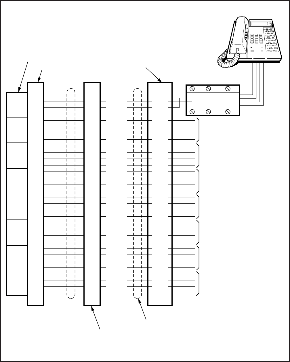
4-21
INSTALLATION INSTRUCTIONS
SECTION 200-255-204
FEBRUARY 1992
FIGURE 4-23—ELECTRONIC TELEPHONE CONNECTION
TL1
RL1
DTL1
DRL1
TL2
RL2
DTL2
DRL2
TL3
RL3
DTL3
DRL3
TL4
RL4
DTL4
DRL4
TL5
RL5
DTL5
DRL5
TL6
RL6
DTL6
DRL6
TL7
RL7
DTL7
DRL7
TL8
RL8
DTL8
DRL8
TL1
RL1
DTL1
DRL1
TL2
RL2
DTL2
DRL2
TL3
RL3
DTL3
DRL3
TL4
RL4
DTL4
DRL4
TL5
RL5
DTL5
DRL5
TL6
RL6
DTL6
DRL6
TL7
RL7
DTL7
DRL7
TL8
RL8
DTL8
DRL8
(W-BL)
(BL-W)
(W-O)
(O-W)
(W-G)
(G-W)
(W-BR)
(BR-W)
(W-S)
(S-W)
(R-BL)
(BL-R)
(R-O)
(O-R)
(R-G)
(G-R)
(R-BR)
(BR-R)
(S-R)
(BK-BL)
(BL-BK)
(BK-O)
(O-BK)
(BK-G)
(G-BK)
(BK-BR)
(BR-BK)
(BK-S)
(Y-BL)
(BL-Y)
(R-S)
(S-BK)
CKT
1
CKT
2
CKT
3
CKT
4
CKT
5
CKT
6
CKT
7
CKT
8
G
R1
R(W)
AUX R2
GRD T2
(BL)
Y
B
TO TELEPHONE #2
TO TELEPHONE #3
TO TELEPHONE #4
TO TELEPHONE #5
TO TELEPHONE #6
TO TELEPHONE #7
TO TELEPHONE #8
MODULAR
STATION
TAILCORD
ELECTRONIC
TELEPHONE
#1
RJ25
MODULAR JACK
CROSS-CONNECT
BLOCK
PCB CONNECTOR
NEKU PCB
"J" CABLE CONNECTOR PINS
25-PAIR CABLE
26
1
27
2
28
3
29
4
30
5
31
6
32
7
33
8
34
9
35
10
36
11
37
12
38
13
39
14
40
15
41
16
T1
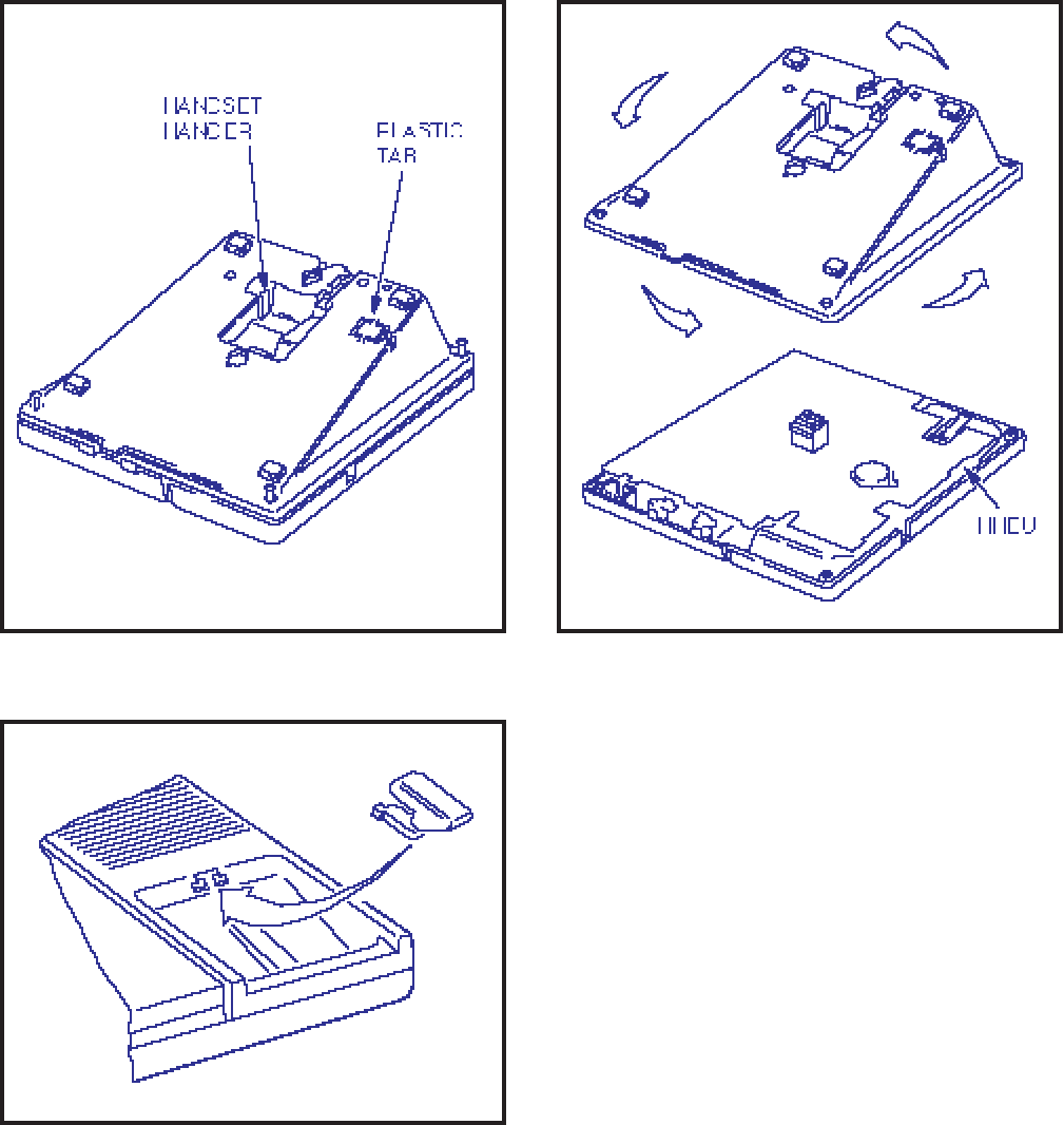
4-22
INSTALLATION INSTRUCTIONS
SECTION 200-255-204
FEBRUARY 1992
FIGURE 4-26—INSTALLATION OF
MOUNTING BASE FOR WALL-MOUNT INSTALLATION
FIGURE 4-24—REMOVAL OF
ELECTRONIC TELEPHONE BASE
FIGURE 4-25—REMOVAL OF HANDSET HANGER
to receive the Off-hook Call Announce feature.
NOTE:
It is not recommended to equip electronic
telephones with both Off-hook Call Announce
and the headset option at the same time.
5.24 The installation of the HVSU/HVSI PCBs has
to be done in accordance with the following steps:
1) Remove the base as described in Paragraph
5.12.
NOTE:
Exercise care when assembling the HVSU
PCB to the HVSI PCB to prevent damage to
the connector pins
.
2) Align the P5 connector on the HVSI PCB with
its receptacle on the HVSU PCB (Figure 4-
27). Apply firm, even pressure to the PCBs to
ensure that the connectors mate properly (they
click when mated properly).
3) Position the HVSU/HVSI assembly on the
standoffs inside the base, and secure with the
two screws provided.
4) Connect the HVSU/HVSI PCBs to the elec-
tronic telephone PCB as shown in Figure 4-
28.
5) Reinstall the electronic telephone base and
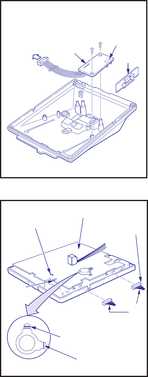
4-23
INSTALLATION INSTRUCTIONS
SECTION 200-255-204
FEBRUARY 1992
secure it with its four captive screws.
5.25 Two pairs of the provided 3-pair modular line
connector connect the electronic telephone to the
DEKT port, and the other pair connects it to the
NOCU PCB.
5.26 NOCU connection details are shown in Figure
4-29.
5.30 Carbon Handset Transmitter Installation
5.31 If a customer-supplied carbon-type handset
is used with the 6500-series electronic telephone,
it is necessary to cut two jumper straps located on
the main PCB inside the telephone. Cut the jump-
ers as follows:
5.32 Loosen the four captive screws securing the
electronic telephone's base, and remove the base
(Figure 4-24).
5.33 Locate the two carbon straps W201 and W202
(Figure 4-30). Cut both straps.
5.34 Cut the W401 strap for proper LCD functions
in A.05 (and below) software.
5.35 Reinstall the electronic telephone's base and
secure using the four captive screws.
5.36 Remove the Toshiba handset and connect
the carbon-type handset.
5.40 HHEU Installation
5.41 The HHEU option provides the interface and
control for a customer-supplied headset.
5.42 Loosen the four captive screws securing the
electronic telephone's mounting base, and remove
the base as shown in Figure 4-24.
5.43 Using a screwdriver or other suitable tool,
remove the plastic access tab located on the back
of the mounting base (Figure 4-31). The HHEU
modular connector is accessed through this open-
ing.
5.44 Set HEADSET/EXT IO switch SW601 on
the HHEU PCB (Figure 4-32) to the HEADSET
TO HVSU
CONNECTOR
ON MAIN PCB
INSIDE
TELEPHONE HSVI
P5
HVSU
FIGURE 4-27—HVSI/HVSU INSTALLATION
FIGURE 4-28
ELECTRONIC TELEPHONE PCB CONNECTIONS
HKT65-20KSD
HHEU
CONNECTOR
HVSU
CONNECTOR
ROOM NOISE
BEEP
HI
~
CARBON STRAPS
W201
W202
CARBON
HHEU STRAP
W203
RED
WIRE
RED
RED
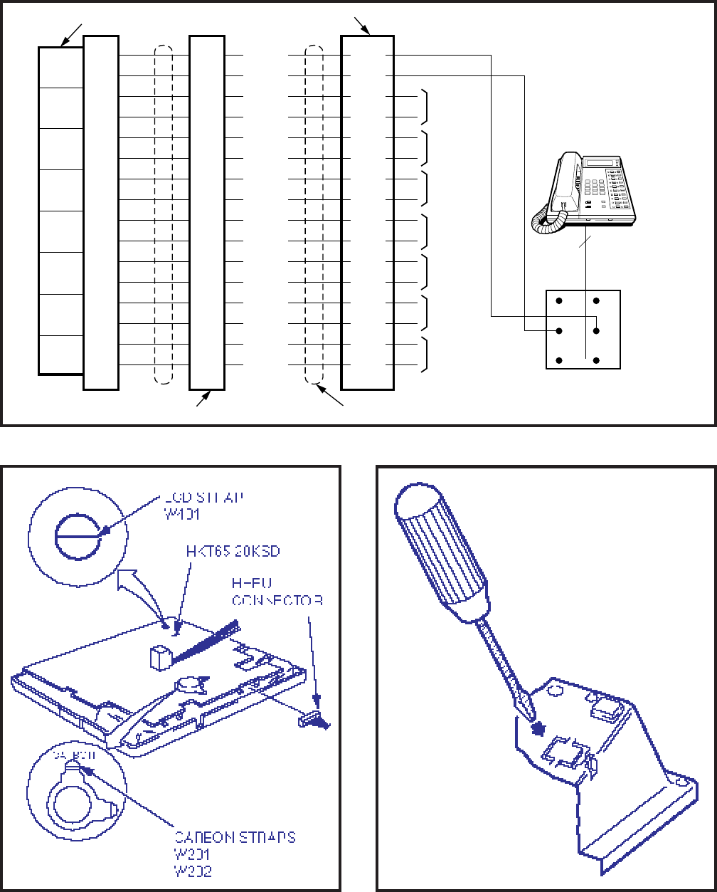
4-24
INSTALLATION INSTRUCTIONS
SECTION 200-255-204
FEBRUARY 1992
FIGURE 4-29—OFF-HOOK CALL ANNOUNCE CONNECTION (NOCU)
FIGURE 4-30—LOCATION OF CARBON STRAPS FIGURE 4-31—REMOVAL OF
HHEU MODULAR CONNECTOR ACCESS TAB
R G
BL W
Y B
RJ-25
TL8
RL8
TL1
RL1
TL2
RL2
TL3
RL3
TL4
RL4
TL5
RL5
TL6
RL6
TL7
RL7
TL8
RL8
(W-BL)
(BL-W)
(W-G)
(G-W)
(W-S)
(S-W)
(R-O)
(O-R)
(R-BR)
(BR-R)
(BK-BL)
(BL-BK)
(BK-G)
(G-BK)
(BK-S)
(S-BK)
CKT
1
CKT
2
CKT
3
CKT
4
CKT
5
CKT
6
CKT
7
CKT
8
TO
EKT #3
TO
EKT #4
TO
EKT #5
TO
EKT #6
TO
EKT #7
TO
EKT #8
CROSS-CONNECT BLOCK
NOCU PCB
"J" CABLE CONNECTOR PINS 25-PAIR CABLE
*
*
*
*
*
*
*
*
CORRECT POLARITY
EKT WITH HVSU
3 PAIR:
2 PAIR FOR EKT
1 PAIR FOR OCA
*
34
9
36
11
38
13
40
15
32
7
26
1
28
3
30
5
TO
EKT #2
TL1
RL1
TL2
RL2
TL3
RL3
TL4
RL4
TL5
RL5
TL6
RL6
TL7
RL7
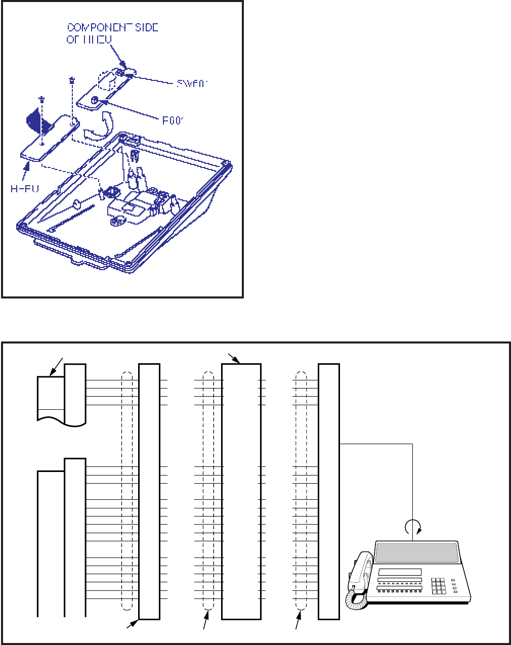
4-25
INSTALLATION INSTRUCTIONS
SECTION 200-255-204
FEBRUARY 1992
FIGURE 4-32—INSTALLATION OF
HHEU UPGRADE OPTION
position.
5.45 Position the HHEU PCB on the standoffs
inside the mounting base, and secure in place
using the two screws provided.
5.46 Connect the HHEU PCB to the electronic
telephone PCB (Figure 4-30).
5.47 Connect the headset modular cord through
the access hole created in Paragraph 5.43 of this
procedure.
5.48 Reinstall the electronic telephone's base and
secure in place using the four captive screws.
5.50 Attendant Console Connection
5.51 The attendant console is connected to the
MDF via an industry-standard 25-pair cable
equipped with a female amphenol-type connector
at the console location.
5.52 Connection details for the attendant console(s)
are shown in Figures 4-33 and 4-34.
FIGURE 4-33—ATTENDANT CONSOLE #0 CONNECTION
TL001
RL001
DTL001
DRL001
(W-BL)
(BL-W)
(W-O)
(O-W)
CROSS-CONNECT BLOCK
26
1
27
2
EMT0
INIT0
MAJINO
(W-BR)29
4
5
ATT0 EG
EG 44
45
46
47
48
49
EG
EG
EG
EG
TL001
RL001
DTL001
DRL001
(W-BL)
(BL-W)
(W-O)
26
1
27
2
(S-W)
(BR-W)
EMT0
INIT0
MAJINO
29
4
5
(W-BR)
(BR-W)
(Y-BR)
(Y-S)
(V-BL)
(V-O)
(V-G)
(V-BR)
ATT0 EG
EG
EG
EG
EG
EG
8
9
10
11
12
13
(G-R)
(BR-R)
(S-R)
(BL-BK)
(O-BK)
(G-BK)
(G-R)
(BR-R)
(S-R)
(BL-BK)
(O-BK)
(G-BK)
(O-W)
(S-W)
(Y-BR)
(Y-S)
(V-BL)
(V-O)
(V-G)
(V-BR)
44
45
46
47
48
49
8
9
10
11
12
13
NPRU
NEKU (L001)
ATTENDANT
CONSOLE #0
CONSOLE
CONNECTOR CORD
CONNECTOR J1-Pe
CONNECTOR J6-Pex
ATT0 -24V
-24V
-24V
-24V
-24V
-24V
25-PAIR CABLE
ATT0 -24V
-24V
-24V
-24V
-24V
-24V
CKT
1
25-PAIR CABLE
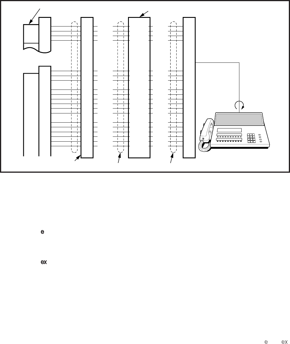
4-26
INSTALLATION INSTRUCTIONS
SECTION 200-255-204
FEBRUARY 1992
FIGURE 4-34—ATTENDANT CONSOLE #1 CONNECTION
5.53 Each attendant console requires a port on an
NEKU PCB to provide a speech path. The NEKUs
must be installed as follows:
PERCEPTION
Att#0-PCB position L00 Circuit #1
Att#1-PCB position L15 Circuit #1
PERCEPTION
Att#0-PCB position L00 Circuit #1
Att#1-PCB position L01 Circuit #1
NOTE:
DO NOT cross connect an electronic tele-
phone with either of these ports if the associ-
ated attendant console is installed.
5.60 DSS Console Connections
5.61 See the DSS Program in Section 200-255-
300,
Programming
, to input information concerning
the electronic DSS consoles.
5.62 The DSS console must be positioned adja-
cent to an electronic telephone (preferably an LCD
model). DSS consoles use 2-pair wiring and are
connected to the MDF via standard twisted-pair
telephone cables. The console connection is made
using only the data pair. An RJ25 modular connec-
tor should be attached to the instrument-end of the
telephone cable to permit connection to the DSS
console.
5.63 The overall length of the DSS console cable
run from the equipment cabinet must not exceed
500 feet (152.5 M), 24 AWG cable.
IMPORTANT!
When installing the DSS console cable, do
not run parallel to and within 3' of an AC
power line. Such power lines should be
crossed at right angles (90
°
) only.
5.64 DSS console(s) connection details are shown
in Figures 4-35 and 4-36, PERCEPTION and ,
respectively.
5.70 Digital Data Interface Unit Connections
(DDIU)
TL
RL
DTL
DRL
(W-BL)
(BL-W)
(W-O)
(O-W)
CROSS-CONNECT BLOCK
26
1
27
2
EMT1
INIT1
MAJIN1
(W-BR)29
4
5
44
45
46
47
48
49
(W-BL)
(BL-W)
(W-O)
26
1
27
2
(S-W)
(BR-W)
29
4
5
(W-BR)
(BR-W)
(Y-BR)
(Y-S)
(V-BL)
(V-O)
(V-G)
(V-BR)
8
9
10
11
12
13
(G-R)
(BR-R)
(S-R)
(BL-BK)
(O-BK)
(G-BK)
(G-R)
(BR-R)
(S-R)
(BL-BK)
(O-BK)
(G-BK)
(O-W)
(S-W)
(Y-BR)
(Y-S)
(V-BL)
(V-O)
(V-G)
(V-BR)
44
45
46
47
48
49
8
9
10
11
12
13
NPRU
NEKU Pe (L151)
Pex(L011)
ATTENDANT
CONSOLE #1
25-PAIR CABLE
CONSOLE
CONNECTOR CORD
CONNECTOR J501-Pe
CONNECTOR J5-Pex
ATT1 -24V
-24V
-24V
-24V
-24V
-24V
25-PAIR CABLE
TL
RL
DTL
DRL
ATT1 EG
EG
EG
EG
EG
EG
ATT1 EG
EG
EG
EG
EG
EG
ATT1 -24V
-24V
-24V
-24V
-24V
-24V
EMT1
INIT1
MAJIN1
CKT
1
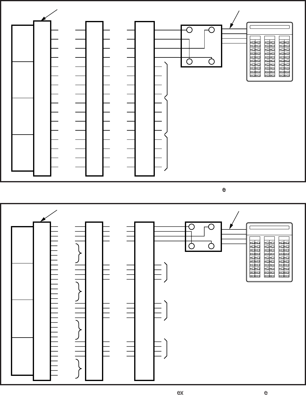
4-27
INSTALLATION INSTRUCTIONS
SECTION 200-255-204
FEBRUARY 1992
FIGURE 4-35—DSS CONSOLE CONNECTION FOR PERCEPTION "C" SLOT
FIGURE 4-36—DSS CONSOLE CONNECTION FOR PERCEPTION "U" SLOTS AND PERCEPTION "L" SLOTS
26
1
27
2
28
3
29
4
30
5
31
6
32
7
33
8
W-BL
BL-W
W-O
O-W
W-G
G-W
W-BR
BR-W
W-S
S-W
R-BL
BL-R
R-O
O-R
R-G
G-R
TL1
RL1
DTL1
DRL1
TL2
RL2
DTL2
DRL2
TL3
RL3
DTL3
DRL3
TL4
RL4
DTL4
DRL4
TL1
RL1
DTL1
DRL1
TL2
RL2
DTL2
DRL2
TL3
RL3
DTL3
DRL3
TL4
RL4
DTL4
DRL4
219209
208 218
207 217
206 216
205 215
204 214
203 213
202 212
201 211
200 210 220 230
231221
222 232
223 233
224 234
225 235
226 236
237
227
228 238
229 239 249 NT1
AC
248
247 257
256
246
245 255
254
244
253
243
242 252
241 251
240 250
GB
RY
TO DSS
CONSOLE #3
RJ11
MODULAR JACK MODULAR
STATION CORD
DSS CONSOLE #1
NDSU PCB CONNECTOR
TO DSS
CONSOLE #2
TO DSS
CONSOLE #4
CKT
1
CKT
2
CKT
3
CKT
4
26
1
27
2
NOT
USED
30
5
31
10
NOT
USED
34
9
35
10
NOT
USED
38
13
39
14
NOT
USED
W-BL
BL-W
W-O
O-W
W-S
S-W
R-BL
BL-R
R-BR
BR-R
R-S
S-R
BK-G
G-BK
BK-BR
BR-BK
TL1
RL1
DTL1
DRL1
TL2
RL2
DTL2
DRL2
TL3
RL3
DTL3
DRL3
TL4
RL4
DTL4
DRL4
TL5
RL5
DTL5
DRL5
TL6
RL6
DTL6
DRL6
TL7
RL7
DTL7
DRL7
TL8
RL8
DTL8
DRL8
TL1
RL1
DTL1
DRL1
TL3
RL3
DTL3
DRL3
TL5
RL5
DTL5
DRL5
TL7
RL7
DTL7
DRL7
219209
208 218
207 217
206 216
205 215
204 214
203 213
202 212
201 211
200 210 220 230
231221
222 232
223 233
224 234
225 235
226 236
237
227
228 238
229 239 249 NT1
AC
248
247 257
256
246
245 255
254
244
253
243
242 252
241 251
240 250
GB
RY
TO DSS
CONSOLE #2
TO DSS
CONSOLE #3
TO DSS
CONSOLE #4
RJ11
MODULAR JACK MODULAR
STATION CORD
DSS CONSOLE #1
CKT
1
CKT
3
CKT
5
CKT
7
NDSU PCB CONNECTOR
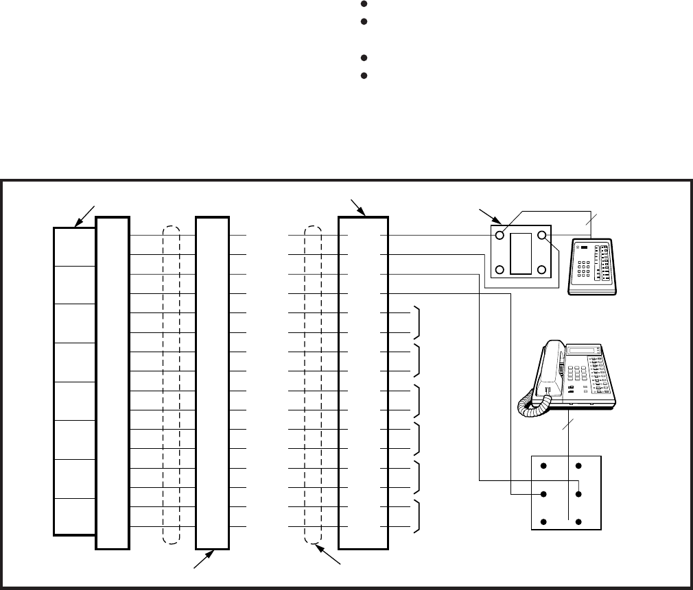
4-28
INSTALLATION INSTRUCTIONS
SECTION 200-255-204
FEBRUARY 1992
5.71 See the DDIU Program in Section 200-255-
300,
Programming
, to input information concerning
Digital Data Interface Units. The system
must
be
told which type of DDIU (-MA or -MAT) is installed
at each location.
5.72 Digital Data Interface Units require only single-
pair wiring and are connected to the MDF via
standard twisted-pair telephone cables.
NOTE:
The DDIU-MAT requires an additional two-
pair for electronic telephone operation. (For
this reason, three-pair cable should be used at
locations where a DDIU-MAT may be installed.)
5.73 Digital Data Interface Unit connection details
are shown in Figure 4-37.
5.80 DDIU-MAT
5.81 The DDIU-MAT (Figure 4-38) mounts directly
on the bottom of an electronic telephone (forming a
single unit) as follows:
1) Remove the electronic telephone base (see
Paragraph 5.12).
2) Replace the telephone base with the DDIU-
MAT.
NOTE:
An electronic telephone with a DDIU-MAT
attached cannot be wall-mounted.
5.82 The DDIU-MAT requires four types of con-
nections for proper operation.
Power supply (to power outlet).
25-pin female RS-232C connector (to data de-
vice).
2-pair modular line cord (to electronic telephone).
3-pair modular connector (to LCEC/NCEC).
5.83 The power supply (provided) connects the
DDIU-MAT to a 117 VAC wall outlet. The 25-pin
female RS-232C connector interfaces with the cus-
tomer-supplied Data Terminal Equipment (DTE)
FIGURE 4-37—DIGITAL DATA INTERFACE UNIT CONNECTION (DDIU-MA and DDIU-MAT)
R G
BL W
Y B
RJ-25
T
TL1
RL1
TL2
RL2
TL3
RL3
TL4
RL4
TL5
RL5
TL6
RL6
TL7
RL7
TL8
RL8
TL1
RL1
TL2
RL2
TL3
RL3
TL4
RL4
TL5
RL5
TL6
RL6
TL7
RL7
TL8
RL8
(W-BL)
(BL-W)
(W-G)
(G-W)
(W-S)
(S-W)
(R-O)
(O-R)
(R-BR)
(BR-R)
(BK-BL)
(BL-BK)
(BK-G)
(G-BK)
(BK-S)
(S-BK)
CKT
1
CKT
2
CKT
3
CKT
4
CKT
5
CKT
6
CKT
7
CKT
8
TO
DDIU #3
TO
DDIU #4
TO
DDIU #5
TO
DDIU #6
TO
DDIU #7
TO
DDIU #8
CROSS-CONNECT BLOCK
NDCU PCB
"J" CABLE
CONNECTOR PINS 25-PAIR CABLE
RJ11
BLOCK
G
BR
Y
*
*
*
*
*
*
*
TOSHIBA
DDIU-MA
1 PAIR
*CORRECT POLARITY
DDIU-MAT
3 PAIR
*R
34
9
36
11
38
13
40
15
32
7
26
1
28
3
30
5
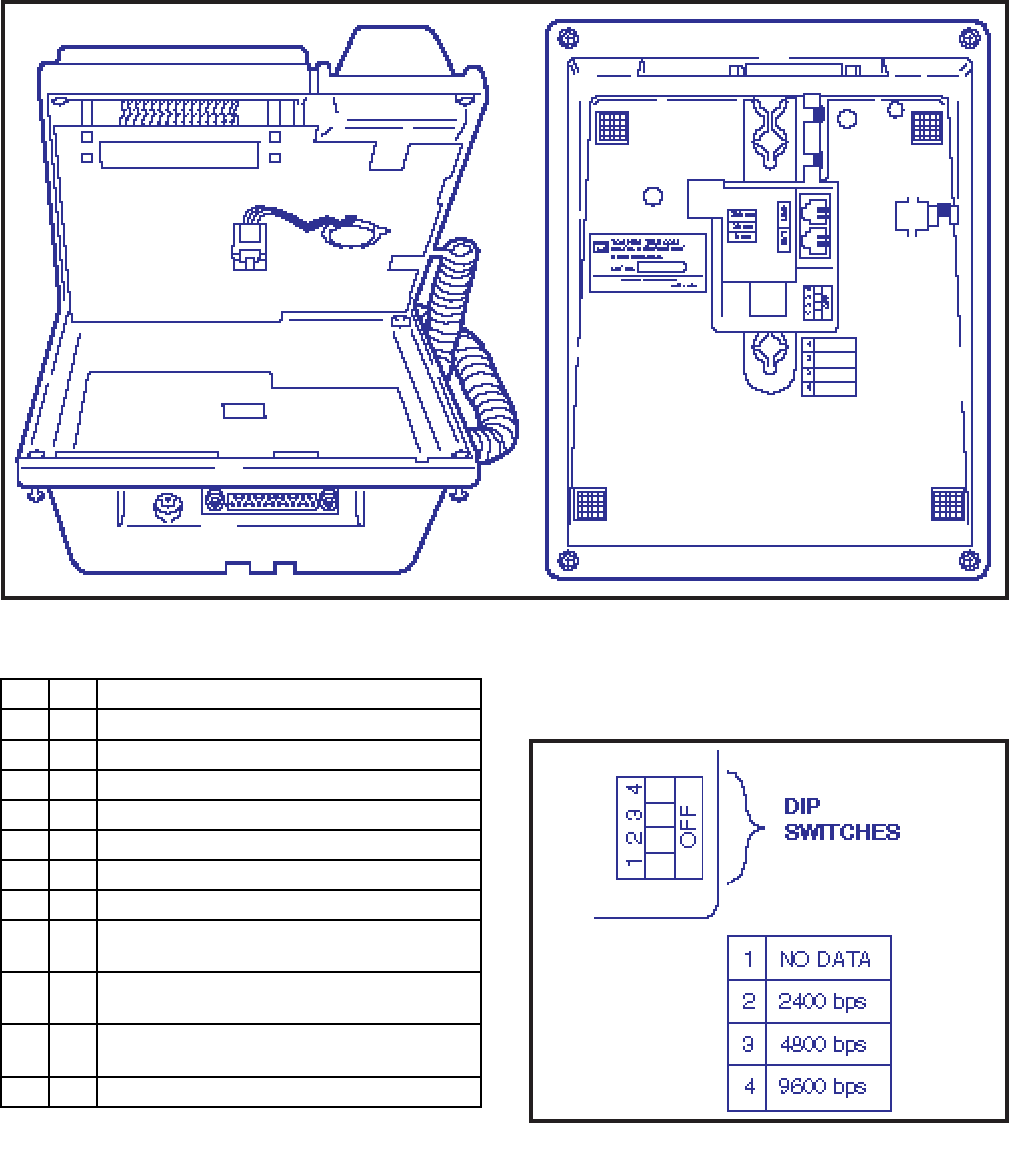
4-29
INSTALLATION INSTRUCTIONS
SECTION 200-255-204
FEBRUARY 1992
FIGURE 4-38—INSTALLING DDIU-MAT
nections, Paragraph 5.70).
5.85 Several DIP switches found on the bottom of
the DDIU-MAT must be set for proper operation
and uses the following pins:
5.84 The provided 2-pair modular line cord con-
nects the DDIU-MAT to the electronic telephone
line connector. The 3-pair modular line connector
connects to the 3-pair house cable run from the
LCEC/NCEC (see Digital Data Interface Unit Con-
(Figure 4-39).
5.86 When the DATA DETECTION switch (Switch
1) is placed in the ON position, the automatic data
release feature will be activated (data connection is
automatically released if no data is transmitted for
Pin No. Designation
FG
SD
RD
RTS
CTS
DSR
SG
RCD
1
2
3
4
5
6
7
8
Protective Ground/Frame
Transmitted Data (to DDIU)
Receive Data (from DDIU)
Request to Send (to DDIU)
Clear to Send (from DDIU)
Data Set Ready (from DDIU)
Signal Ground/Common Return
Receive Carrier Detect (from DDIU)
Transmission Signal Element Timing
(from DDIU)
15 ST2
Transmission Signal Element Timing
(from DDIU)
17 RT
Data Terminal Ready/Equipment
Ready (to DDIU)
20 DTR
Ring Indicator (from DDIU)22 CI
FIGURE 4-39—DDIU-MAT DIP SWITCHES
4-30
INSTALLATION INSTRUCTIONS
SECTION 200-255-204
FEBRUARY 1992
ON-Data device provides an Equip-
ment Ready signal to the DDIU (the
Terminal Ready LED will light only
when the signal is received).
OFF-Data device does not provide an
Equipment Ready signal to the DDIU
(the Terminal Ready LED will remain
lit continuously).
Switch 2 = not used.
Switch 3 = not used.
Switch 4 = ON (Enables automatic answer mode of
operation.)
Switch 5 = ON (Activates Automatic Data Release
feature. The data connection is auto-
matically released if no data is transmit-
ted for a period of 18 minutes.)
Switch 6 = 2400 BPS **
Switch 7 = 4800 BPS **
Switch 8 = 9600 BPS **
*A data path cannot be established if the
Terminal Ready light is OFF (even though a
DDIU-MA can be answered manually). The
Terminal Ready light must be ON to establish
a data path when answering manually.
**Select the appropriate speed for synchro-
nous data transmission. If the asynchronous
mode of operation is used, these switches
have no effect and the DDIU-MA will automati-
cally adjust to the appropriate speed (to a
maximum of 19.2 kbps).
5.95 Two switches on the DIUB PCB must be set
for either DTE or MODEM (DCE) operation. The pin
assignments shown in Paragraph 5.83 explain the
RS-232C cable signaling differences between DTE
and DCE devices. (Typically, a DTE is a terminal
device such as a personal computer or printer,
while a DCE is an intermediate device such as a
modem or protocol converter connected to a host.
Refer to the data device manufacturer’s documen-
tation for its signaling information.) Set the DIUB
PCB switches as follows:
1) Loosen the two screws found under the DDIU-
MA’s faceplate on the right side (top and
bottom) of the DIUA PCB (Figure 4-40).
2) Carefully separate the two halves of the DDIU-
5.87 Switches 2, 3, and 4 select the data speed for
synchronous transmission only.
Switch 2 = 2400 bps
Switch 3 = 4800 bps
Switch 4 = 9600 bps
5.88 If asynchronous operation is used, the
switches will have no effect and the data speed will
self-adjust to a maximum speed of 19.2 kbps or
less.
5.89 A power ON/OFF switch that appears on
some early DDIU-MAT models controls power to
the DDIU-MAT from the power supply. If the switch
is OFF, the DDIU-MAT will not function, but the
electronic telephone will continue functioning nor-
mally. When the switch is ON, both DDIU-MAT and
electronic telephone are functional. In later models,
the DDIU-MAT is operational when the power sup-
ply is plugged in.
IMPORTANT!
All connections to DDIUs (-MA or -MAT)
must observe correct tip and ring polarity
for proper operation.
5.90 DDIU-MA
5.91 The DDIU-MA is a stand-alone unit that incor-
porates both the manual dialing and auto-answer-
ing features of the DDIU-MAT, but is used as a data
transceiver only.
5.92 The DDIU-MA has several internal and exter-
nal switches that must be set for proper operation.
5.93 The power ON/OFF switch, on the bottom of
the DDIU-MA, must be turned ON for the DDIU-MA
to operate. When the switch is ON, an LED on the
front faceplate will light.
5.94 The DDIU-MA’s faceplate must be removed
to set the internal DIP switches. Remove the face-
plate by carefully lifting the lower right corner and
then pulling the faceplate away from the base. Set
the following parameters as required at switch S26
on the internal DIUA PCB (Figure 4-40):
Switch 1* = Equipment Ready Supervision
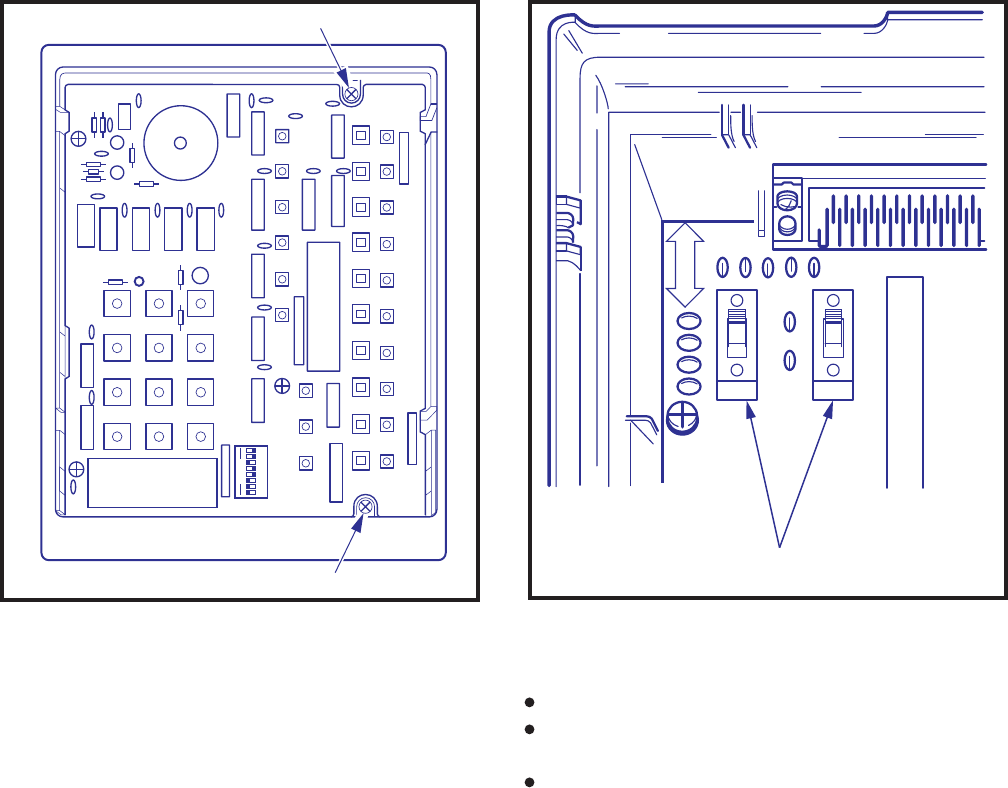
4-31
INSTALLATION INSTRUCTIONS
SECTION 200-255-204
FEBRUARY 1992
12345678
OFF
TOSHIBA DIUA
ER SUP
AUTOANS
NODATADET
2400 BPs
4800 BPs
9600 BPs
R12
S26
MADE IN
JAPAN
TOSHIBA
LOOSEN
LOOSEN
HKTD001A
DTE MODEM
P3
P1.
S2 S3
S2
S3
FIGURE 4-41—DIUB PCBFIGURE 4-40—DDIU-MA DIUA PCB
nections for proper operation:
Power supply (to facility power).
25-pin female RS-232C connector (DDIU-MA to
LCEC/NCEC).
Single-pair modular connector (DDIU-MA to
LCEC/NCEC).
5.98 The power supply (provided) connects the
DDIU-MA to a 117 VAC wall outlet. The 25-pin
female RS-232C connector connects to the cus-
tomer-supplied data device and is configured for
either DTE or DCE operation as follows:
5.99 The DDIU-MA connects to the LCEC/NCEC
MA to expose the S2 and S3 (DTE/MODEM)
switches (Figure 4-41) in the upper left corner
of the DIUB PCB.
3) If the DDIU-MA is to be connected to a DTE,
both switches must be in the DTE position. If
it will be connected to a DCE, both switches
must be in the MODEM position.
4) Reassemble the DDIU-MA.
5.96 See
Operating Procedures
or DDIU-MA and
Electronic Telephone
User Guides
for information
on the DDIU dialpad, LED/button operation and
functions.
5.97 The DDIU-MA requires three types of con-

4-32
INSTALLATION INSTRUCTIONS
SECTION 200-255-204
FEBRUARY 1992
EQUIPMENT INSTALLATION
6.00 Digital Telephone Connections
6.01 See the DEKT Program in Section 200-255-
300,
Programming
, for instructions on program-
ming digital telephones. When installing digital
telephones, digital DSS consoles, PDIU-DI, or PDIU-
DS, Version D.04 software or higher must be in-
stalled. The system must be told the type of digital
telephone (20-button, or 20-button with LCD) and
what button assignment is required.
6.02 Digital telephones are connected to the MDF
via standard twisted-pair jacketed telephone cable.
(Single-pair wiring is required; however, 2- or 3-pair
wiring is strongly recommended to permit expected
distances for data, spare pair, etc.) To accommo-
date the digital telephone line cord, terminate the
cable in a modular station connector block (RJ25)
at the station location. The standard modular digital
telephone cord length is 7 feet (the maximum
allowed length is 25 feet).
6.03 The overall length of the digital telephone
cable run from equipment cabinet to phone must
not exceed 1,000 feet (305 M), 24 AWG cable.
IMPORTANT!
When installing the digital telephone cable,
do not run parallel to and within 3 feet of an
AC power line. Such power lines should be
crossed at right angles (90
°
) only.
6.04 Digital telephone connection details are shown
in Figure 4-42.
6.10 Digital Telephone Wall Mounting
6.11 Both telephones are wall-mounted in the same
manner, and they may be mounted on a wall or any
other flat, vertical surface to which the base can be
secured. When selecting the mounting site, con-
sider the digital telephone’s weight and the addi-
tional stresses to which the mounting will be sub-
jected.
6.12 Loosen the four captive screws securing the
with a single-pair station line cable that plugs into
the modular connector on the back of the base (see
Digital Data Interface Unit Connections, Paragraph
5.70).
IMPORTANT!
All connections to DDIUs (-MA or -MAT)
must observe correct tip and ring polarity
for proper operation.
6. DIGITAL TELEPHONE STATION
DCE (MODEM) Position:
Designation
FG
TD
RD
RTS
CTS
DSR
SG
1
2
3
4
5
6
7
Protective Ground/Frame
Transmitted Data (from DDIU)
Receive Data (to DDIU)
Request to Send (from DDIU)
Clear to Send (to DDIU)
Data Set Ready (to DDIU)
Signal Ground/Common Return
Data Terminal Ready/Equipment
Ready (from DDIU)
20 ER
Transmit Signal Element Timing 1
(to DDIU)
24 ST1
Pin No.
DTE Position:
Designation
FG
SD
RD
RTS
CTS
DSR
SG
RCD
1
2
3
4
5
6
7
8
Protective Ground/Frame
Transmitted Data (to DDIU)
Receive Data (from DDIU)
Request to Send (to DDIU)
Clear to Send (from DDIU)
Data Set Ready (from DDIU)
Signal Ground/Common Return
Receive Carrier Detect (from DDIU)
Transmission Signal Element Timing 2
(from DDIU)
15 ST2
Transmission Signal Element Timing 2
(from DDIU)
17 RT
Data Terminal Ready/Equipment
Ready (to DDIU)
20 DTR
Ring Indicator (from DDIU)22 CI
Pin No.
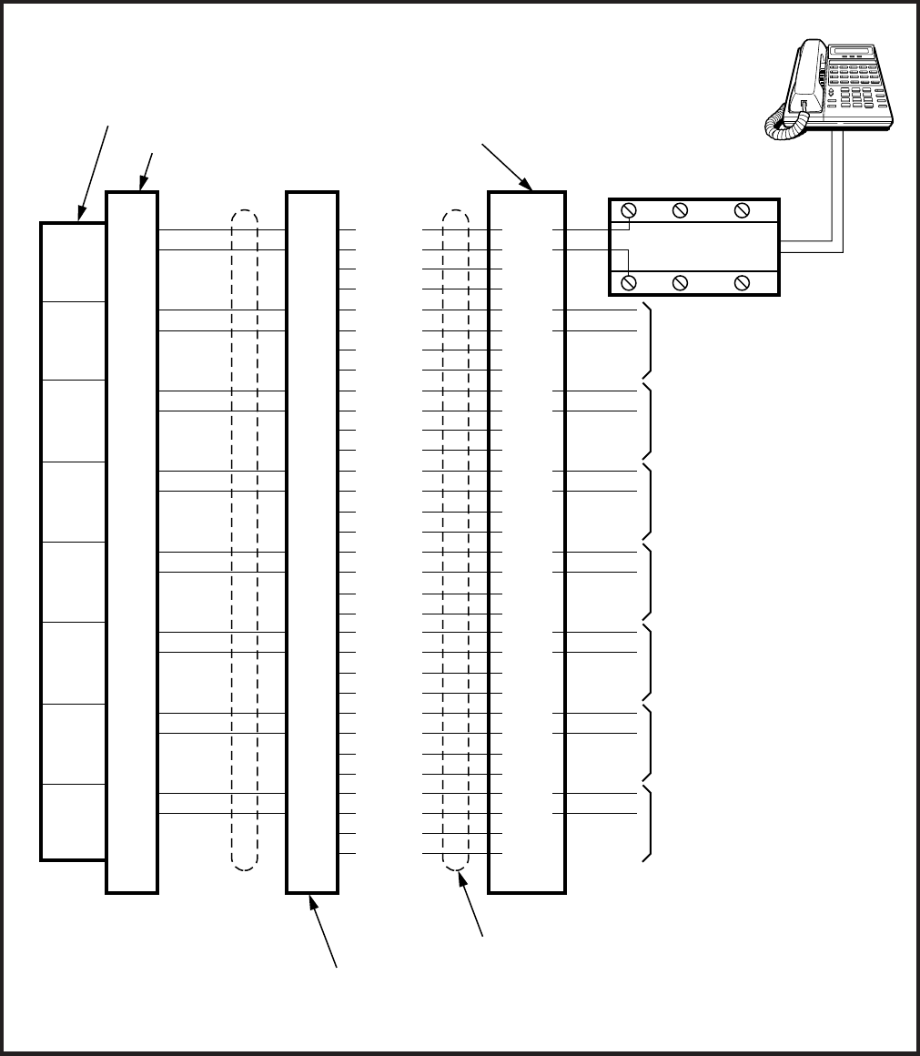
4-33
INSTALLATION INSTRUCTIONS
SECTION 200-255-204
FEBRUARY 1992
FIGURE 4-42—DIGITAL TELEPHONE CONNECTION
NOTE:
Digital Telephones with Data Interface Units (PDIU-DI) or Off-hook Call Announce (DVSU), and Stand-
alone Data Interface Units (PDIU-DS) are connected, per Figure 4-42, using single-pair wiring.
TL1
RL1
TL2
RL2
TL3
RL3
TL4
RL4
TL5
RL5
TL6
RL6
TL7
RL7
TL8
RL8
(W-BL)
(BL-W)
(W-O)
(O-W)
(W-G)
(G-W)
(W-BR)
(BR-W)
(W-S)
(S-W)
(R-BL)
(BL-R)
(R-O)
(O-R)
(R-G)
(G-R)
(R-BR)
(BR-R)
(S-R)
(BK-BL)
(BL-BK)
(BK-O)
(O-BK)
(BK-G)
(G-BK)
(BK-BR)
(BR-BK)
(BK-S)
(Y-BL)
(BL-Y)
(R-S)
(S-BK)
CKT
1
CKT
2
CKT
3
CKT
4
CKT
5
CKT
6
CKT
7
CKT
8
G
R1
R(W)
AUX R2
GRD T2
(BL)
Y
B
TO TELEPHONE #2
TO TELEPHONE #3
TO TELEPHONE #4
TO TELEPHONE #5
TO TELEPHONE #6
TO TELEPHONE #7
TO TELEPHONE #8
MODULAR
STATION
TAILCORD
DIGITAL
TELEPHONE
#1 or
PDIU-DS
RJ25
MODULAR JACK
CROSS-CONNECT
BLOCK
PCB CONNECTOR
NDKU PCB
"J" CABLE CONNECTOR PINS
25-PAIR CABLE
26
1
27
2
28
3
29
4
30
5
31
6
32
7
33
8
34
9
35
10
36
11
37
12
38
13
39
14
40
15
41
16
TL1
RL1
TL2
RL2
TL3
RL3
TL4
RL4
TL5
RL5
TL6
RL6
TL7
RL7
TL8
RL8
T1
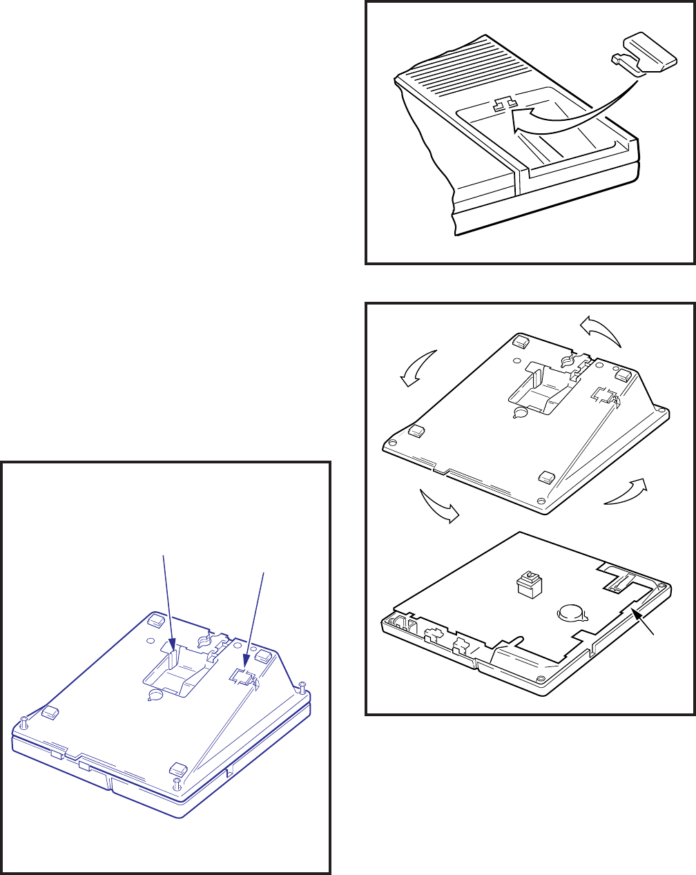
4-34
INSTALLATION INSTRUCTIONS
SECTION 200-255-204
FEBRUARY 1992
digital telephone's base, and remove the base
(Figure 4-43).
6.13 Using a cutter, remove the handset hanger
from the base. Insert the handset hanger in the slot
provided on the front of the telephone (Figure 4-
44). The hanger fits in the notch on the handset.
6.14 Rotate the mounting base 180° and secure to
the telephone with the four captive screws (Figure
4-45).
6.15 Connect the electronic telephone to the wall
modular connector with a short cord (approximately
3 inch length). Route the cord into the hollow
portion of the base, then mount the digital tele-
phone on the wall mounting connector. Test each
digital telephone using the TTRM Program, Sec-
tion 200-255-300,
Programming
.
6.20 Off-hook Call Announce
6.21 The Off-hook Call Announce (OCA) feature
enables a digital telephone to originate and receive
voice announcement when the station’s handset is
FIGURE 4-44—REMOVAL OF HANDSET HANGER
FIGURE 4-45—INSTALLATION OF
MOUNTING BASE FOR WALL-MOUNT INSTALLATION
PLASTIC
TAB
HANDSET
HANGER
FIGURE 4-43—REMOVAL OF
DIGITAL TELEPHONE BASE
off-hook. Standard telephones can originate off-
hook call announces, however, it cannot receive
them. A station user is allowed or denied the ability
to originate the Off-hook Call Announce feature in
the DCOS Program. In order to receive the Off-
hook Call Announce feature, a PCB (DVSU) is
required to be installed in each affected digital
telephone, and the NDKU must be set for option 2
HHEU

4-35
INSTALLATION INSTRUCTIONS
SECTION 200-255-204
FEBRUARY 1992
(see Paragraph 3.45 of this chapter).
6.22 A DVSU PCB inside a 1000-series digital
telephone allows the digital telephone to receive
the Off-hook Call Announce feature.
NOTE:
It is not recommended to equip digital tele-
phones with both Off-hook Call Announce and
the headset option at the same time.
6.23 The installation of the DVSU PCB must be
done in accordance with the following steps:
1) Loosen the four captive screws securing the
telephone's mounting base (Figure 4-43), and
remove the base.
2) Loosen the four captive screws securing the
metal plate to the standoffs inside the base
where the DVSU PCB will be installed (Figure
4-46). Remove the metal plate and discard it.
3) Position the DVSU PCB on the standoffs
(Figure 4-46), and secure it with the four
screws provided.
4) Connect the DVSU wire plugs to the connec-
tors labelled “DVSU” on both telephone’s PCBs
(Figures 4-46 and 4-47).
IMPORTANT NOTE!
Make sure that the DVSU wire plugs are
connected to the proper connectors.
5) Reinstall the telephone’s mounting base (Fig-
ure 4-43), and secure it with its four captive
screws.
6.24 A single pair of wires are required to connect
the digital telephone to the NDKU port. OCA con-
nection details are shown in Figure 4-42, the Digital
Telephone Connection diagram.
6.30 Carbon Handset Transmitter Installation
6.31 If a customer-supplied carbon-type handset
is used with the 1000-series digital telephone, the
two jumper straps on the telephone’s upper PCB,
labelled “PERCEPTION-SUB (SPF),” must be cut.
To cut the straps:
1) Loosen the four captive screws securing the
telephone’s mounting base (Figure 4-43), and
remove the base.
2) Refer to Figure 4-47, and locate the CARBON
straps, W301 and W302, and cut them.
FIGURE 4-46—DVSU INSTALLATION
TO DVSU
CONNECTOR
ON LOWER PCB
INSIDE
TELEPHONE
TO DVSU
CONNECTOR
ON UPPER PCB
INSIDE
TELEPHONE
IMPORTANT!
Make sure that the DVSU wire
plugs are inserted into the
correct UPPER and LOWER
PCB connectors of the
telephone. Do not plug DVSU
into HHEU connector.
FIGURE 4-47
TELEPHONE PCB CONNECTIONS AND STRAPS
DKTO-20KD
HHEU W303
CARBON
W301
CARBON
W302
W304 BEEP
ROOM
NOISE
DVSU
DKT10-SUB(SPF) TOSHIBA
DVSU
HHEU
EXSP
STRAP
DIU STRAP:
W401-1020SD
W302-1020H
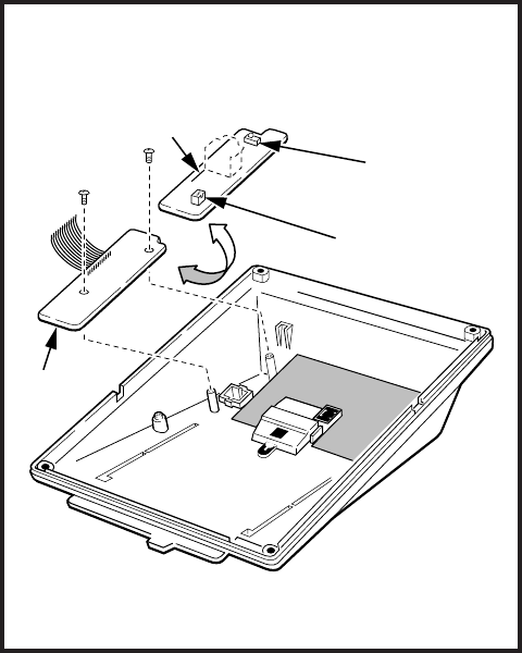
4-36
INSTALLATION INSTRUCTIONS
SECTION 200-255-204
FEBRUARY 1992
3) Reinstall the telephone base (Figure 4-43),
and secure it with its four captive screws.
6.40 Beep Strap Removal
6.41 A beep is emitted whenever a dialpad button
or flexible button is pressed. This beep can be
eliminated if the beep strap is cut. To cut the strap:
1) Loosen the four captive screws securing the
telephone’s mounting base (Figure 4-43), and
remove the base.
2) Refer to Figure 4-47, and locate the BEEP
strap, W304, labelled “PERCEPTION10-SUB
(SPF)” on the telephone’s upper PCB, and cut
it.
3) Reinstall the telephone’s mounting base (Fig-
ure 4-43), and secure it with its four captive
screws.
6.50 Microphone/Speaker Threshold Adjust-
ment (Speakerphone only)
6.51 If the speaker frequently cuts off during
handsfree operation, because of high ambient noise
levels, set the ROOM NOISE switch to the high
position. To set the switch:
1) Loosen the four captive screws securing the
telephone’s mounting base (Figure 4-43), and
remove the base.
2) Refer to Figure 4-47, and locate the ROOM
NOISE switch, labelled “PERCEPTION10-
SUB (SPF)” on the telephone’s upper PCB.
Carefully push the switch to the HIGH (H)
position.
3) Reinstall the telephone’s mounting base (Fig-
ure 4-43), and secure it with its four captive
screws.
6.60 HHEU Installation
6.61 The HHEU option provides the interface and
control for a customer-supplied headset. It is in-
stalled in accordance with the following steps:
1) Loosen the four captive screws securing the
telephone’s mounting base (Figure 4-43), and
remove the base.
2) Using a screw driver or other suitable tool,
remove the plastic tab located on the back of
the mounting base (Figure 4-43). The HHEU
modular connector for the headset is accessed
through this opening.
3) Set the SW601 switch on the HHEU PCB to
the HEADSET position (Figure 4-48).
4) If the headset receiver is not to receive OCA
caller voice announcements, cut both sides of
the R607 resistor on the HHEU PCB (Figure 4-
48), then remove the resistor.
5) Position the HHEU PCB on the standoffs
inside the base (Figure 4-48), and secure with
the two screws provided.
6) Connect the HHEU PCB to the telephone’s
upper PCB, labelled “PERCEPTION10-SUB
(SPF).” See Figure 4-47.
7) Refer to Figure 4-47, and locate the HHEU
strap, W303, on the upper PCB. Cut the
strap if the HHEU PCB is to be connected to
FIGURE 4-48
HHEU INSTALLATION FOR DIGITAL TELEPHONE
HHEU
COMPONENT SIDE OF HHEU (V.3 or later)
SW601
P601
R607

4-37
INSTALLATION INSTRUCTIONS
SECTION 200-255-204
FEBRUARY 1992
a headset.
8) Reinstall the telephone’s mounting base
and secure it with its four captive screws.
6.70 Attendant Console Connection
6.71 See Paragraph 5.50 for the attendant con-
sole connection.
6.80 DSS Console Connections
6.81 See the DSS Program in Section 200-255-
300,
Programming
, to input information concern-
ing the digital DSS consoles.
6.82 The DSS console must be positioned adja-
cent to a digital telephone (preferably an LCD
model). DSS consoles use 2-pair wiring and are
connected to the MDF via standard twisted-pair
telephone cables. An RJ25 modular connector
should be attached to the instrument-end of the
telephone cable to permit connection to the DSS
console.
6.83 The overall length of the DSS console cable
run from the equipment cabinet must not exceed
1000 feet (304 M), 24 AWG cable.
IMPORTANT!
When installing the DSS console cable, do
not run parallel to and within 3' of an AC
power line. Such power lines should be
crossed at right angles (90
°
) only.
6.84 DSS console(s) connection details are
shown in Figures 4-49 and 4-50, for both
PERCEPTION and .
6.90 DIGITAL DATA INTERFACE UNIT
(PDIU)
6.91 The Perception with D.04 software
provides two new style digital Data Interface
Units (DIUs) that enable digital telephone users
to simultaneously transmit and receive data on
the same NDKU station port and wire pair while
communicating on a voice call. One unit, called
the integrated DIU (PDIU-DI) replaces the digital
telephone’s base; the other unit is a small self-
contained box called the stand-alone DIU (PDIU-
DS). Each DIU is powered by the NDKU PCB it is
connected to; therefore, no external power is
required.
6.92 Both PDIUs can be connected to standard
Electronic Industries Association (EIA) RS-232
asynchronous serial data devices. EIA devices
are divided into two categories:
Data communication equipment (DCE). Com-
mon DCE devices are modems and some
printers.
Data terminal equipment (DTE). Common DTE
devices are personal computers, ASCII termi-
nals, and some printers.
The PDIU-DI operates like a DCE, and it con-
nects directly to DTE devices using standard RS-
232 cables. Depending on how its internal jumper
plugs are configured, the PDIU-DS can either
operate like a DTE and connect to DCE devices,
or operate like a DCE device and connect to a
DTE device. In most applications, DTE and DCE
devices exchange data between each other via
the standard RS-232 cable connection.
6.93 PDIUs can function with DCE and DTE
devices at data speeds of up to 19.2kbps; how-
ever, keyboard dialing using AT commands (from
a PC or a terminal connected to a PDIU) is limited
up to 9.6kbps. PDIU data transmission speed is
set by the first AT command that the PDIU re-
ceives once it is in the command mode. The
transmission speed is transparent to the PDIU if
data is being sent via manual dialing or if the
PDIU is receiving calls.
NOTES:
1. See the DDIU Program in Section 200-
255-300 for information on programming
the Digital Data Interface Units. The sys-
tem must be told which type of PDIU (-DI
or -DS) is installed at each location.
2. Digital Data Interface Unit (PDIU-DI and
PDIU-DS) connection details are shown
in Figure 4-42, the Digital Telephone
Connection diagram.
IMPORTANT NOTE!
To use the PDIU-DI or PDIU-DS with AT
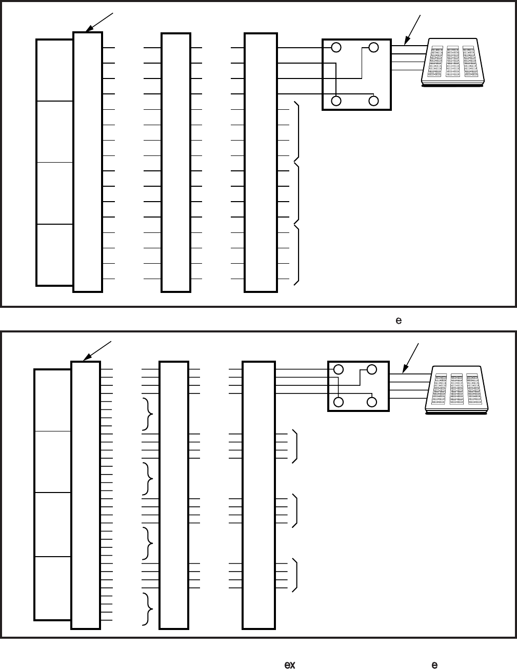
4-38
INSTALLATION INSTRUCTIONS
SECTION 200-255-204
FEBRUARY 1992
FIGURE 4-49—DIGITAL DSS CONSOLE CONNECTION FOR PERCEPTION "C" SLOT
FIGURE 4-50
DIGITAL DSS CONSOLE CONNECTION FOR PERCEPTION "U" SLOTS AND PERCEPTION "L" SLOTS
26
1
27
2
28
3
29
4
30
5
31
6
32
7
33
8
W-BL
BL-W
W-O
O-W
W-G
G-W
W-BR
BR-W
W-S
S-W
R-BL
BL-R
R-O
O-R
R-G
G-R
TL1
RL1
DTL1
DRL1
TL2
RL2
DTL2
DRL2
TL3
RL3
DTL3
DRL3
TL4
RL4
DTL4
DRL4
TL1
RL1
DTL1
DRL1
TL2
RL2
DTL2
DRL2
TL3
RL3
DTL3
DRL3
TL4
RL4
DTL4
DRL4
GB
RY
TO DSS
CONSOLE #3
RJ11
MODULAR JACK MODULAR
STATION CORD
NDKU PCB CONNECTOR
TO DSS
CONSOLE #2
TO DSS
CONSOLE #4
CKT
1
CKT
2
CKT
3
CKT
4
DIGITAL DSS
CONSOLE #1
26
1
27
2
NOT
USED
30
5
31
10
NOT
USED
34
9
35
10
NOT
USED
38
13
39
14
NOT
USED
W-BL
BL-W
W-O
O-W
W-S
S-W
R-BL
BL-R
R-BR
BR-R
R-S
S-R
BK-G
G-BK
BK-BR
BR-BK
TL1
RL1
DTL1
DRL1
TL2
RL2
DTL2
DRL2
TL3
RL3
DTL3
DRL3
TL4
RL4
DTL4
DRL4
TL5
RL5
DTL5
DRL5
TL6
RL6
DTL6
DRL6
TL7
RL7
DTL7
DRL7
TL8
RL8
DTL8
DRL8
TL1
RL1
DTL1
DRL1
TL3
RL3
DTL3
DRL3
TL5
RL5
DTL5
DRL5
TL7
RL7
DTL7
DRL7
GB
RY
TO DSS
CONSOLE #2
TO DSS
CONSOLE #3
TO DSS
CONSOLE #4
RJ11
MODULAR JACK MODULAR
STATION CORD
DIGITAL DSS
CONSOLE #1
CKT
1
CKT
3
CKT
5
CKT
7
NDKU PCB CONNECTOR

4-39
INSTALLATION INSTRUCTIONS
SECTION 200-255-204
FEBRUARY 1992
commands, communications software or
some program that performs “terminal
emulation” must be loaded in the com-
puter. The AT commands cannot be issued
from the computer’s operating system
prompt.
6.100 Common DIU Connections
6.101 The block diagram in Figure 4-51 illustrates
common DIU connections. In this example, PDIU-
DIs are connected to laptop personal computers
(PC1 and PC2), and the PDIU-DS’s are connected
to a serial printer and modems. The PC users can
transfer files internally, print files on the same
printer, and access the modem to send/receive
data to/from an external personal computer, or dial
up a data service.
6.102 To access these devices, a data call connec-
tion must be established between the DIUs. This is
accomplished by dialing the destination DIU from a
digital telephone dialpad or from a PC keyboard
using standard AT dial commands. PDIU-DIs have
port and DATA DN assignments adjacent to the
digital telephones that they are connected to, while
PDIU-DS’s have separate port and DATA DN as-
signments. The DN and DATA buttons on the
digital telephone tell the system whether a voice or
data call is being made: The DN button indicates
voice calls, and the DATA button indicates data
calls. When dialing from a keyboard with AT com-
mands, enter ATD for data calls. Only DATA calls
can be made through keyboard dialing.
6.103 Installation instructions for these devices are
provided in Paragraphs 6.140 ~ 6.160. Call paths
and scenarios for four types of data calls are
provided in Paragraphs 6.181 ~ 6.185. Step-by-
step data calling procedures are provided in the
PDIU User Guide
.
6.110 EIA Interface Leads (Signals)
6.111 Both DIUs operate with the ten standard EIA
RS-232 interface leads (signals) on which signal-
ing data is transmitted and received. DIUs connect
to serial data devices’ signals with standard RS-
232 cables, available from telephone supply stores.
The PDIU-DI/PDIU-DS Data Units require ten sig-
nals for some applications, but can function with
eight, using modular cords and connectors with
RJ45/DB25 adapters for other applications (Fig-
ures 4-52 and 4-53). If uncertain which signals are
necessary for an application, all ten should be
connected.
IMPORTANT NOTES!
1. The PDIU-DI is always a DCE device;
the PDIU-DS may be a DTE or DCE,
depending on how its internal jumpers
(1 ~ 9) are configured (see Figure 4-54).
2. In the descriptions below, when a sig-
nal is ON, its potential is about seven
volts positive, relative to signal ground
(pin 7); when a signal is OFF, it is about
7 volts negative, relative to the signal
ground (pin 7).
Frame Ground (FG, Pin 1): The FG
signal (EIA circuit AA) is a protective or
safety ground which is bonded to the
PDIU-DI/PDIU-DS. If required by local
codes, the FG may be connected to
external ground.
Transmit Data (TD, Pin 2): DTE devices
transmit, and DCE devices receive data
on the TD lead (EIA circuit BA). Before
the DTE device can transmit the TD
signal, the RTS, CTS, DSR, and DTR
signals (all discussed later in this sec-
tion) must be ON. The TD signal is OFF
in the idle state.
Receive Data (RD, Pin 3): The DCE
device transmits data to the DTE device
on the RD lead (EIA circuit BB).
Request to Send (RTS, Pin 4): Some
DTE devices send an RTS signal (EIA
circuit CA) to the DCE device when they
are ready to transmit data on the TD
lead. If the DTE device generates the
RTS signal, the DIU DIP switch SW1-4
should be set to ON to inform the PDIU.
Sometimes, the DTE/DCE device may
use RTS/CTS for Ready/Busy-type flow
control. In these cases, DIP switch SW1-
4 should be set to OFF (see Figure 4-55
for the DIP switch information).
FIGURE 4-52—PDIU-DI/PDIU-DS MODULAR CABLE/
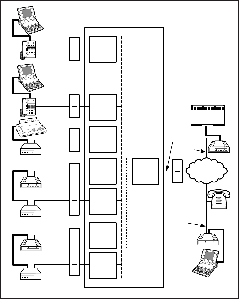
4-40
INSTALLATION INSTRUCTIONS
SECTION 200-255-204
FEBRUARY 1992
NDKU
NSTU
NDKU
NDKU
TOSHIBA
1
#
*
2ABC 3DEF
4GHI 5JKL 6MNO
7PRS 8TUV 9WXY
0OPER
PAGE MODE SCRL
MESSAGE
TRNS/CONF
REDIAL
HOLD
MIC
SPEAKER
VOLUME
TOSHIBA
1
#
*
2ABC 3DEF
4GHI 5JKL 6MNO
7PRS 8TUV 9WXY
0OPER
PAGE MODE SCRL
MESSAGE
TRNS/CONF
REDIAL
HOLD
MIC
SPEAKER
VOLUME
NDKU
TOSHIBA
DIU
POWER READY CONNECT
TOSHIBA
NSTU
NDKU
DIU
POWER READY CONNECT
TOSHIBA
DIU
POWER READY CONNECT
TOSHIBA
LAPTOP, PC 1
RS-232
1
DKT/PDIU-DI
MDF
2
MDF
2
MDF
2
MDF
3
MDF
3
RS-232
1
RS-232
1
RS-232
1
RS-232
1
LAPTOP, PC 2
DKT/PDIU-DI
SERIAL
PRINTER
PDIU-DS
MODEM
PDIU-DS
MODEM 1
PDIU-DS
MODEM
MDF
NCOU
PUBLIC
TELEPHONE
NETWORK
TELEPHONE
LINE X
TELEPHONE
LINE Y RS-232
1
LAPTOP,
PC 3
DIAL-UP
COMPUTER
SERVICE
NOTES:
1. RS-232 cable and connector
information is provided in
Figures 4-53 to 4-54.
2. PDIU-DI/PDIU-DS MDF
station wiring to NDKU is in
Section 200-255-205.
3. Modem MDF station wiring to
NSTU is in Section 200-255-
205.
PERCEPTIONe&ex
MODEM
RS-232
1
LINE Z
STANDARD
TELEPHONE
FIGURE 4-51—PERCEPTION DATA INSTALLATION EXAMPLE BLOCK DIAGRAM
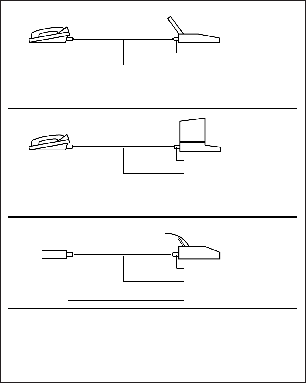
4-41
INSTALLATION INSTRUCTIONS
SECTION 200-255-204
FEBRUARY 1992
RJ-45 ADAPTER CONNECTIONS
CONNECTION EXAMPLE 1
DIGITAL TELEPHONE TOSHIBA LAPTOP OR IBM AT TYPE
PERSONAL COMPUTER (PC)
PDIU-DI BASE TYPE 1 MODULAR ADAPTER
1
TYPE B MODULAR CORD (CROSSED)
1
(50 ft max, 24AWG)
TYPE 2 MODULAR ADAPTER
1
IMPORTANT!
Will not function with applications that require the Ring Indicator signal to PC.
CONNECTION EXAMPLE 2
DIGITAL TELEPHONE IBM PC OR XT TYPE
PERSONAL COMPUTER (PC)
PDIU-DI BASE TYPE 3 MODULAR ADAPTER
1
TYPE A MODULAR CORD (STRAIGHT)
1
(50 ft max, 24AWG)
TYPE 2 MODULAR ADAPTER
1
IMPORTANT!
Will not function with applications that require the Ring Indicator signal to PC.
CONNECTION EXAMPLE 3
STAND-ALONE DIU
TOSHIBA P321SL OR SIMILAR
STANDARD TYPE SERIAL PRINTER
PDIU-DS TYPE 2 MODULAR ADAPTER
1
TYPE A MODULAR CORD
1
(50 ft max, 24AWG)
TYPE 2 MODULAR ADAPTER
1
NOTES:
1. See Figure 4-53 for detailed pin out information of modular cords and adapters.
2. Never use modular cords and adapters when connecting a PDIU-DI/PDIU-DS to a modem.
3. Connection examples 1 and 2 work when using the PDIU-DI to make calls with personal computer
applications (printer sharing, outgoing modem calls, etc). If the PC PDIU-DI must receive calls, the RI
lead is normally required; therefore, a standard RS-232 cable must be used (see Figures 4-54 and 4-55).
4. In Connection example 3, PDIU-DS must be in the "connect to DTE mode" (P1 ~ P9, strapped A-B).
5. All modular cords and adapters are customer-supplied.
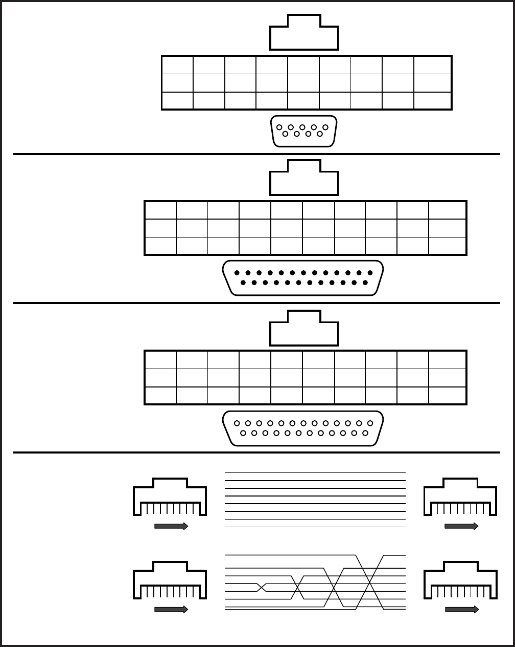
4-42
INSTALLATION INSTRUCTIONS
SECTION 200-255-204
FEBRUARY 1992
6789
23451
8 7 6 5 4 3 2 1
8
DSR
6
7
RTS
7
6
RD
2
5
DCD
1
4
TD
3
2
GND
5
1
CTS
8
2345678
20
8 7 6 5 4 3 2 1
2345678
20
8 7 6 5 4 3 2 1
8
CTS
5
7
SG
7
6
DTR
20
5
TD
2
3
RD
3
2
RTS
4
1
DSR
6
4
DCD
8
8
CTS
5
7
SG
7
6
DTR
20
5
TD
2
3
RD
3
2
RTS
4
1
DSR
6
4
DCD
8
TYPE 1
RJ45 TO DB9 (FEMALE) ADAPTER
TYPE 2
RJ45 TO DB25 (MALE) ADAPTER
TYPE 3
RJ45 TO DB25 (FEMALE) ADAPTER
TYPE A
RJ45 FLAT MODULAR
CORD (STRAIGHT)
RJ45 STRAIGHT THROUGH
1
2
3
4
5
6
7
8
1
2
3
4
5
6
7
8
1
8
FRONT
1
2
3
4
5
6
7
8
1
2
3
4
5
6
7
8
1
8
FRONT
1
8
FRONT
1
8
FRONT
RJ45 CROSS PINNING
TYPE B
RJ45 FLAT MODULAR
CORD (CROSSED)
N/C
RI
9
RJ45
DB9
LEAD
NAME
N/C
RI
22
RJ45
DB25
LEAD
NAME
LEAD
NAME
N/C
RI
22
RJ45
DB25
Modular Cords
(
50 ft max, 24AWG; customer supplied
)
FIGURE 4-53—PDIU-DI/PDIU-DS MODULAR CORDS AND RJ-45/RS-232 ADAPTER PIN CONNECTIONS
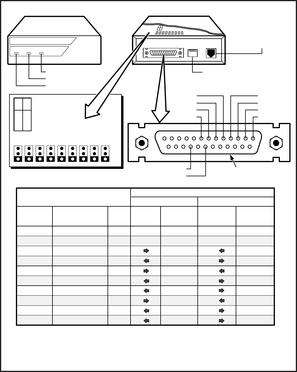
4-43
INSTALLATION INSTRUCTIONS
SECTION 200-255-204
FEBRUARY 1992
1234
DATA
ON
MODULAR JACK
FOR CONNECTING
1- OR 2-PAIR
TO NDKU CIRCUIT
DIU
POWER READY CONNECT
PDIU-DS (REAR VIEW)
SW1: SEE FIGURE 4-55 FOR
SWITCH (1 ~ 4) OPTIONS
INFORMATION
12345678910111213
141516171819202122232425
CTS
DSR
SG
DCD
RTS
RD
TD
FG
RI
DTR RS-232, DB25
(FEMALE) CONNECTOR
P5
P1
P2
P7
P4
P3
P6
P8
P9
ABC
A-B DTE
B-C MODEM
SIGNAL
ABBREVIATON
SIGNAL DIRECTION AND FUNCTION OF P1 ~ P9
PDIU-DS CONNECTED TO DTE PDIU-DS CONNECTED TO DCE
FUNCTION:
A-B
(DTE MODE)
FG
SG
TD
RD
RTS
CTS
DSR
DTR
DCD
RI
P1
P2
P6
P7/P5
P4
P3
P8
P9
P1
P2
P6
P7/P5
P4
P3
P8
P9
SIGNAL NAME/
FUNCTION
FRAME GROUND
SIGNAL GROUND
TRANSMIT DATA
RECEIVE DATA
REQUEST TO SEND
CLEAR TO SEND
DATA SET READY
DATA TERMINAL READY
DATA CARRIER DETECT
RING INDICATOR
PDIU-DS
PIN NO.
1
7
2
3
4
5
6
20
8
22
SIGNAL
DIRECTION
DTE DIU
DTE DIU
DTE DIU
DTE DIU
DTE DIU
DTE DIU
DTE DIU
DTE DIU
FUNCTION:
B-C
(MODEM MODE)
SIGNAL
DIRECTION
MODEM DIU
MODEM DIU
MODEM DIU
MODEM DIU
MODEM DIU
MODEM DIU
MODEM DIU
MODEM DIU
NOTES:
1. Mode select (P1 ~ P9) “A-B” if PDIU-DS is connected to a terminal-type device (DTE).
2. Mode select (P1 ~ P9) “B-C” if PDIU-DS is connected to a modem-type device (DCE).
3. See Figure 4-61 to disassemble/assemble PDIU-DI.
4. Some RS-232 leads go by different names depending on the equipment manufacturer.
P1 ~ P9 LOCATED ON PCB INSIDE
OF PDIU-DS UNIT (SEE NOTES)
PDIU-DS (FRONT VIEW)
CONNECT LED
READY LED
POWER LED
FIGURE 4-54—PDIU-DS JUMPER PLUG OPTIONS/RS-232 CONNECTOR INFORMATION
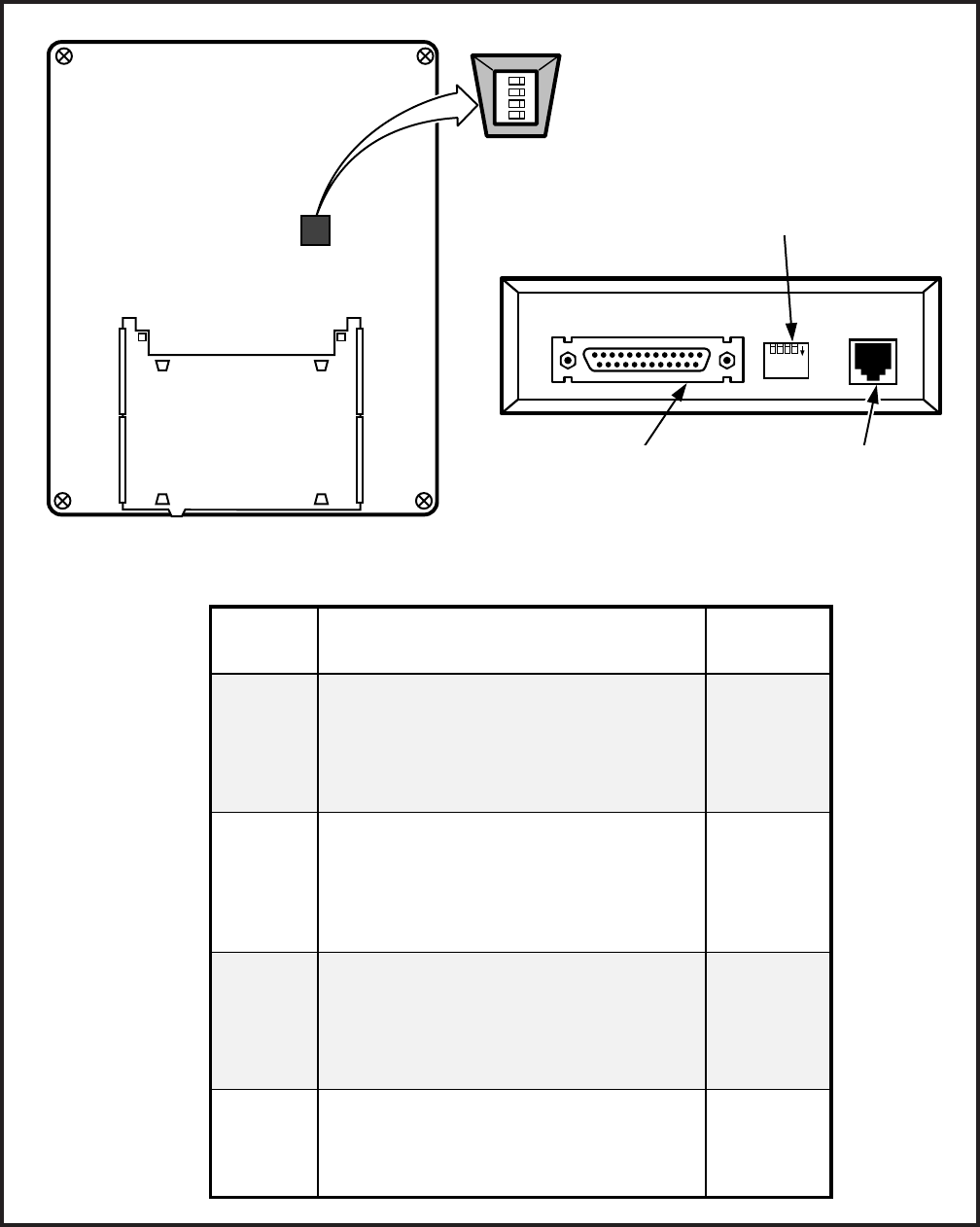
4-44
INSTALLATION INSTRUCTIONS
SECTION 200-255-204
FEBRUARY 1992
SWITCH
SW1
(1)
SW1
(2)
SW1
(3)
SW1
(4)
FUNCTION
Forced hang up when DIU does not
detect space signal on TD or RD for
about 9 minutes
ON: enable (auto-disconnect)
OFF: disable
DCD, DSR control
ON: continuous on
OFF: DSR depends on DTR
(DCD is on during
communication state)
RI control
ON: RI is on continuously during
ringing state
OFF: RI is 1 sec ON/3 sec OFF
during ringing state
RTS control
ON: DTE doesn't have RTS signal
OFF: DTE has RTS signal (ready/busy
flow control: RTS/CTS:DCD)
INITIAL
POSITION
OFF
OFF
OFF
OFF
PDIU-DI AND -DS SW1 DIP SWITCH (1 ~ 4) FUNCTIONS
ACCESS FROM BOTTOM
— OUTSIDE OF PDIU-DI
DIP SWITCH
PDIU-DI DIGITAL TELEPHONE BASE
PDIU-DI (BOTTOM VIEW)
1 2 3 4
DIP SWITCH SWI BACK VIEW
(ACCESS FROM BACK
— OUTSIDE OF PDIU-DS)
1234
DATA
ON
PDIU-DS (REAR VIEW)
DB25 CONNECTOR (FEMALE)
FOR DTE OR DCE RS-232
CABLE CONNECTION
MODULAR
CONNECTOR
FOR NDKU LINE
CONNECTION
DIRECTORY TRAY:
REMOVE FROM ORIGINAL
TELEPHONE BASE AND
INSTALL ON PDIU-DI BASE
OFF
FIGURE 4-55—PDIU-DI/PDIU-DS SW1 DIP SWITCH INFORMATION

4-45
INSTALLATION INSTRUCTIONS
SECTION 200-255-204
FEBRUARY 1992
Clear to Send (CTS, Pin 5): The DCE
device sends the CTS signal (EIA circuit
CB) which indicates that it is prepared to
transmit data to the DTE device. The
DCE device sends this signal, only when
it receives the RTS signal from the DTE
device. Sometimes, the DTE/DCE de-
vice may use RTS/CTS for Ready/Busy-
type flow control; in these cases, dip
switch SW1-4 should be set to OFF (see
Figure 4-55 for the DIP switch informa-
tion).
Data Set Ready (DSR, Pin 6): When
connected to the communication chan-
nel and prepared to exchange control
characters to initiate data transmission,
the DCE device sends the DSR signal
(EIA circuit CC) to the DTE device. If the
PDIU DIP switch SW1-1 is set to OFF,
DSR and DCD (see DCD description
below) will be ON continuously; if the
switch is set to ON, the PDIU generates
DSR only after receiving the DTR signal.
Sometimes, DTE/DCE devices use DTR/
DSR for Ready/Busy flow control; in these
cases, DIP switch SW1-2 should be set
to OFF (see Figure 4-55 for the DIP
switch information).
Signal Ground (SG, Pin 7): The SG
signal (EIA circuit AB) establishes the
common ground reference for all other
PDIU and data device signals, and must
be wired for all applications.
Data Carrier Detect (DCD, Pin 8): The
DCE device sends the DCD signal (DCD,
Pin 8) when receiving the carrier signal
on the line side. Before transmitting or
receiving data, most DTE devices re-
quire that the DCD be ON. If the carrier
signal is removed by the remote end or
lost due to a fault condition on the line,
the DCE notifies the DTE device by an
OFF condition with the DCD signal. To
set the DCD on continuously, PDIU DIP
switch SW1-2 is set to ON; if set to OFF,
the DCD signal will be on during the
communication state only. SW1-2 is set
to OFF when the DTE/DCE uses the
DTR/DSR signals for Ready/Busy flow
control (see Figure 4-55 for the DIP switch
information).
Data Terminal Ready (DTR, Pin 20):
The DTE device sends the DTR signal
(EIA circuit CD) to the DCE device,
prompting the DCE device to open the
communication line. The line is closed
and the call disconnected when the DTE
device quits sending the DTR signal.
DTR may be sent any time to indicate
that the DTE is ready to transmit or re-
ceive data. Sometimes, DTE/DCE de-
vices use DTR/DSR for Ready/Busy flow
control; in these cases, DIP switch SW1-
2 should be set to OFF (see Figure 4-55
for the DIP switch information).
Ring Indicator (R1, Pin 22): The RI
signal (EIA circuit CE) is sent by the DCE
device to the DTE device. Whenever the
DCE device receives a ringing signal on
the line side, it turns the RI signal on. If
PDIU DIP switch SW1-3 is set to ON, the
RI signal will be on continuously; if the
switch is set to OFF, the RI signal will be
one second on/three seconds off.
Pin No. Designation
FG
SD
RD
RTS
CTS
DSR
SG
RCD
1
2
3
4
5
6
7
8
Protective Ground/Frame
Transmitted Data (to PDIU)
Receive Data (from PDIU)
Request to Send (to PDIU)
Clear to Send (from PDIU)
Data Set Ready (from PDIU)
Signal Ground/Common Return
Receive Carrier Detect (from PDIU)
Transmission Signal Element Timing
(from PDIU)
15 ST2
Transmission Signal Element Timing
(from PDIU)
17 RT
Data Terminal Ready/Equipment
Ready (to PDIU)
20 DTR
Ring Indicator (from PDIU)22 CI
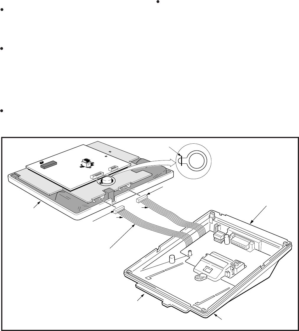
4-46
INSTALLATION INSTRUCTIONS
SECTION 200-255-204
FEBRUARY 1992
6.120 DIP Switch Options
6.121 Each of the PDIU-DI and the PDIU-DS data
units has a four-control DIP switch which can be
configured for signaling options. The switch is
located on the bottom of the PDIU-DI, and on the
back panel of the PDIU-DS (see Figure 4-55).
SW1-1: Normally, this switch is set to OFF.
When set to ON, it automatically disconnects
devices from the PDIUs if no data is exchanged
between the devices and PDIU for an interval of
eight to nine minutes.
SW1-2: This switch is placed in the ON position
when the PDIU-DI (or PDIU-DS configured like a
DCE) must hold DCD and DSR on continuously.
Sometimes, a computer may use DTR/DSR for
Ready/Busy flow control; in these cases, this
switch should be OFF. Consult the DTE/DCE
device or application software documentation to
determine which type of flow control is required.
SW1-3: The PDIU-DI (or PDIU-DS configured as
a DCE) sends the Ring Indicate signal (RI) to the
computer to tell the computer (DTE) that the
PDIU is receiving an incoming call. SW1-3 should
be set to ON for the DCE to send RI continuously,
and OFF to send at one-second-ON/three-sec-
onds-OFF intervals. Consult the DTE/DCE de-
vice or application software documentation to
determine which type of flow control is required.
SW1-4: This switch is placed in the ON position
if the computer does not output the RTS signal.
Sometimes, the computer may use RTS/CTS for
Ready/Busy flow control; in these cases, SW1-4
should be OFF. Consult the DTE/DCE device or
application software documentation to deter-
mine which type of flow control is required.
6.130 PDIU-DI INSTALLATION
6.131 The PDIU-DI (Figure 4-56) mounts directly
on the bottom of a digital telephone (forming a
single unit) as follows:
1) Remove the digital telephone base (see Para-
graph 6.12).
2) Replace the telephone base with the PDIU-DI.
TO P2 OF
BOTTOM
PCB
RED
WIRE
DKTO-20KD
PDIU/
DVSU
DKT10-SUB(SPF) TOSHIBA
DVSU
HHEU
DIGITAL TELEPHONE
TOP ASSEMBLY
PDIU
TO P1 OF
BOTTOM
PCB
RS-232 (FEMALE)
DB-25 CONNECTOR
RED
WIRE
PDIU-DI
DIGITAL TELEPHONE BASE
PDIU-DI PCB
IMPORTANT: DO NOT CONNECT DIU
CABLES TO HHEU CONNECTOR
RED
RED
DIU
DIU STRAP:
1020H: W302
1020SD: W401
DIRECTORY
TRAY
FIGURE 4-56—PDIU-DI PCB/DIGITAL TELEPHONE INSTALLATION

4-47
INSTALLATION INSTRUCTIONS
SECTION 200-255-204
FEBRUARY 1992
NOTE:
A digital telephone with a PDIU-DI attached
cannot be wall-mounted.
6.140 PDIU-DI to Personal Computer (PC)
Installation
6.141 The PDIU-DI always functions as a DCE
device; it transmits data on the Receive Data lead
(RD) and receives data on the Transmit Data lead
(TD). Most personal computers function as DTE
devices; PCs transmit data on the TD lead and
receive data on the RD lead. Follow the steps below
to install the PDIU-DI to a DTE or DCE PC:
NOTES:
1. Use the steps below when installing an
ASCII terminal, or any other DTE device to
a PDIU-DI.
2. The PDIU-DI can connect to a DCE com-
puter or any other DCE-type device using
a specially configured RS-232 cable or
adapter; however, this application is rarely
required.
1) Install the digital telephone that is to be
equipped with PDIU-DI in accordance with the
instructions in Section 200-255-205, MDF
Arrangement, Paragraph 1.01 and in Figure
5-2.
2) Install the PDIU-DI in the digital telephone’s
base in accordance with the instructions in
Paragraph 6.130.
NOTE:
The PDIU-DI operates only as a DCE device;
therefore, unlike the PDIU-DS, it has no inter-
nal jumpers.
3) Connect the appropriate RS-232 cable be-
tween the PDIU-DI DB-25 female connector
and the PC’s appropriate asynchronous serial
communications port connector.
IMPORTANT NOTE!
Check the PC manufacturer’s serial com-
munication port interface documentation
for correct RS-232 pin requirements; re-
quirements vary with each manufacturer.
The number of EIA RS-232 signals re-
quired (8, 9, or 10 wires) will depend on
the application. When EIA signal require-
ments are not known, connect the 10 EIA
signals listed in Paragraph 6.110. Fig-
ures 4-57, 4-58, and 4-59 provide dia-
grams for connecting RS-232 cables be-
tween PDIU-DIs and a Toshiba printer
and laptop computer, IBM XT-type and
AT-type personal computers.
4) Set the PDIU-DI/PDIU-DS DIP switch (SW1-
1 ~ 4) for the desired application. Figure 4-55
shows the DIP switch locations and Para-
graph 6.120 describes the switch functions.
5) Access the DEKT and DDIU Programs for
PDIU port connection and data button assign-
ments.
The port number entered for the PDIU-DI
in the DDIU Program is the adjacent port
number of the digital telephone.
Example: DKT port number = L024, PDIU-
DI port number = L034
IMPORTANT NOTE!
The eighth port (circuit) of the NDKU can-
not be used for data switching connec-
tions (PDIU-DI or PDIU-DS).
6.150 PDIU-DS To Printer Installation
6.151 PERCEPTION enables serial printers
(laser, dot matrix, or other types) to be connected
to stand-alone data interface units (PDIU-DS). Digi-
tal telephones equipped with PDIU-DI and Elec-
tronic Telephones equipped with DDIU-MAT can
share access to these printers. Serial printers oper-
ate as DCE or DTE devices, depending on the
vendor. The PDIU-DS can be connected to either
type, since it can be configured as a DTE or DCE
device. (The PDIU-DS comes from the factory
configured as a DCE device.) Follow the steps
below to install the PDIU-DS to a serial printer.
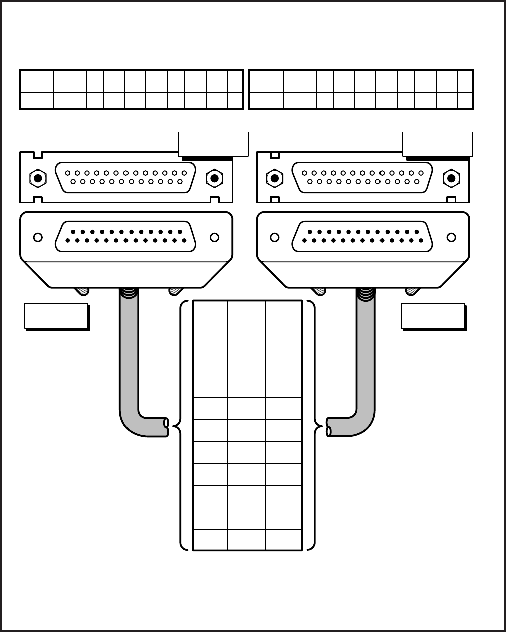
4-48
INSTALLATION INSTRUCTIONS
SECTION 200-255-204
FEBRUARY 1992
FIGURE 4-57—PDIU-DS TO TOSHIBA PRINTER, RS-232 CONNECTOR/CABLE CONNECTIONS
DB25
PIN #
8
3
2
20
7
6
4
N/C
N/C
1
NAME
DCD
RD
TD
DTR
SG
DSR
RTS
CTS
RI
FG
DB25
PIN #
8
3
2
20
7
6
4
5
22
1
12345678
2022
12345678
2022
Rear view of printer
or ASCII terminal DB25,
RS-232 connector.
Rear view of PDIU-DI DB25,
RS-232 female connector
TOSHIBA PS321SL PRINTER
(FUNCTIONS LIKE A DTE) PDIU-DS
(CONFIGURED IN THE "CONNECT TO DTE" MODE:
P1 ~ P9 = A-B SO PDIU FUNCTIONS LIKE A DCE)
NOTES:
1. The printer receives data on pin 3 (RD) and transmits data on pin 2 (TD).
2. The PDIU-DS should be in the connect to DTE mode (P1 ~ P9 are strapped A-B),
so that it transmits data on pin 3 (RD) and receives data on pin 2 (TD).
DB25 PIN DESIGNATIONS
PDIU-DS
PIN #
NAME
1
FG
3
RD
4
RTS
5
CTS
6
DSR
7
SG
8
DCD
20
DTR
22
RI
DB25 PIN DESIGNATIONS
2
TD
PRINTER
PIN #
NAME
1
FG
3
RD
4
RTS
5
N/C
6
DSR
7
SG
8
DCD
20
DTR
22
RI
2
TD
20
DB25 FEMALE
CONNECTOR
DB25 FEMALE
CONNECTOR
2022
RS-232 CABLE
DB25 MALE
CONNECTOR
1234678
51234678
DB25 MALE
CONNECTOR
(50 ft max, 24 AWG;
customer supplied).
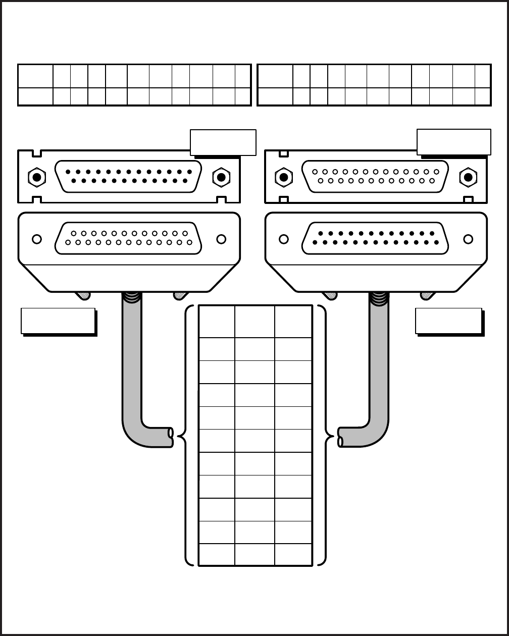
4-49
INSTALLATION INSTRUCTIONS
SECTION 200-255-204
FEBRUARY 1992
FIGURE 4-58—PDIU-DI TO IBM XT-TYPE COMPUTER, RS-232 CONNECTOR/CABLE CONNECTIONS
DB25
PIN #
8
3
2
20
7
6
4
5
22
1
NAME
DCD
RD
TD
DTR
SG
DSR
RTS
CTS
RI
FG
DB25
PIN #
8
3
2
20
7
6
4
5
22
1
12345678
2022
12345678
2022
Rear view of personal computer
or ASCII terminal DB25,
RS-232 connector
Rear view of PDIU-DI DB25,
RS-232 female connector
IBM XT PERSONAL COMPUTER
OR ASCII TERMINAL
(FUNCTIONS LIKE A DTE)
PDIU-DI
(FUNCTIONS LIKE A DCE)
NOTE:
The PC/ASCII terminal receives data on pin 3 (RD) and transmits data on pin 2 (TD).
DB25 PIN DESIGNATIONS
PDIU-DI
PIN #
NAME
1
FG
3
RD
4
RTS
5
CTS
6
DSR
7
SG
8
DCD
20
DTR
22
RI
DB25 PIN DESIGNATIONS
2
TD
PDIU-DI
PIN #
NAME
1
FG
3
RD
4
RTS
5
CTS
6
DSR
7
SG
8
DCD
20
DTR
22
RI
2
TD
12 345 6 78
20 22
DB25 FEMALE
CONNECTOR
DB25 MALE
CONNECTOR
20 22
12 345 6 78
RS-232 CABLE
DB25 FEMALE
CONNECTOR DB25 MALE
CONNECTOR
IBM PC XT modem style (serial)
DB25 to DB25 (M/F) RS-232
cable (50 ft max, 24 AWG,
customer supplied).
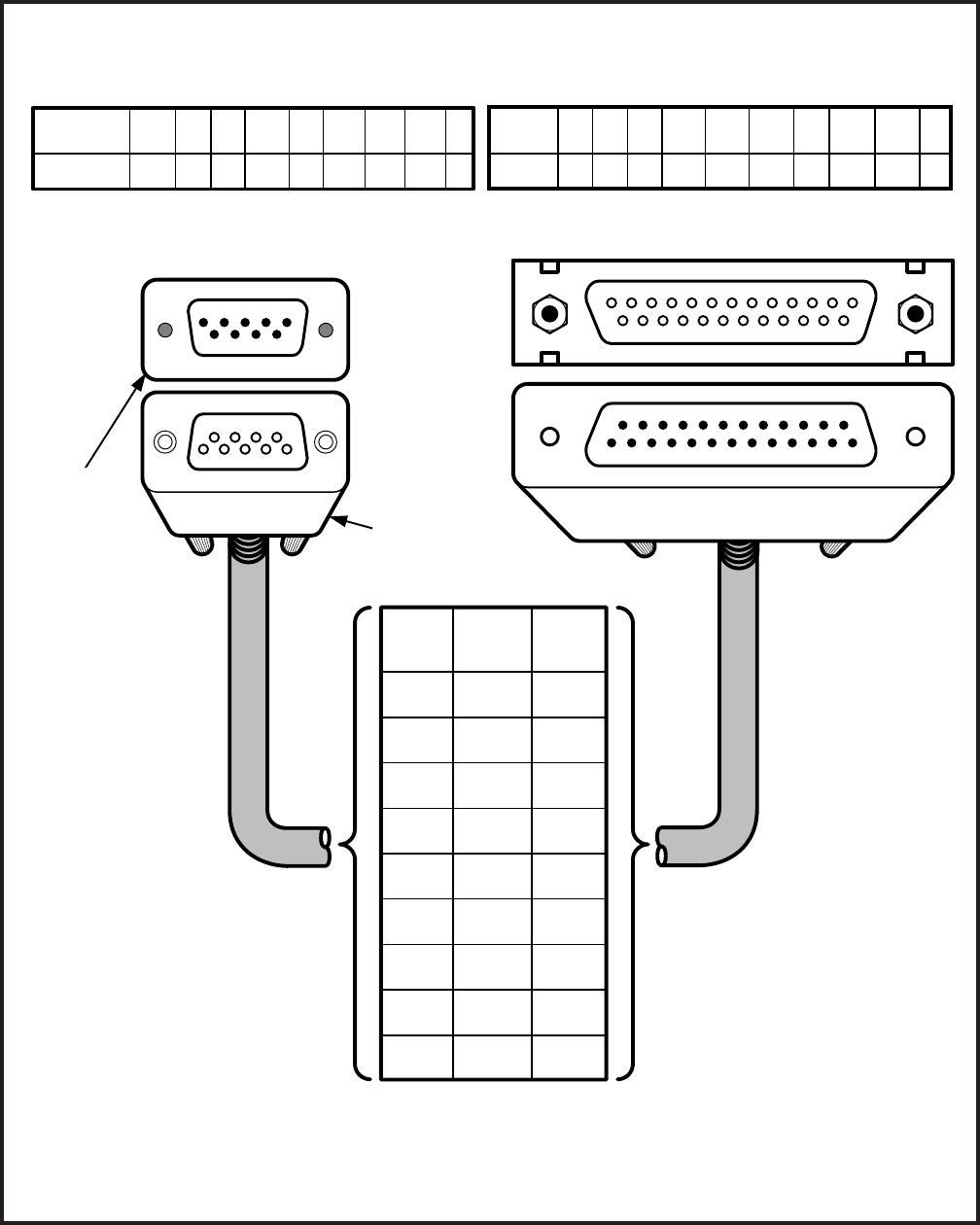
4-50
INSTALLATION INSTRUCTIONS
SECTION 200-255-204
FEBRUARY 1992
IBM PC AT modem style (serial)
DB25 to DB9, RS-232 cable.
Pin to pin connections are
configured as a straight cable,
not as a null modem cable
(50 ft max, 24AWG;
customer supplied).
6789
23451
6789
23451
DB9
PIN #
1
2
3
4
5
6
7
8
9
NAME
DCD
RD
TD
DTR
SG
DSR
RTS
CTS
RI
DB25
PIN #
8
3
2
20
7
6
4
5
22
12345678
2022
12345678
2022
Rear view of asynchronous (serial)
communication interface connector (DB9) of
Toshiba laptop or IBM AT personal computer
Rear view of PDIU-DI DB25,
RS-232 female connector
TOSHIBA LAPTOP OR IBM AT-TYPE
PERSONAL COMPUTER (DTE)
PDIU-DI
(FUNCTIONS LIKE A DCE)
DB25
FEMALE
CONNECTOR
DB25
MALE
CONNECTOR
DB9
MALE
CONNECTOR DB9
FEMALE
CONNECTOR
NOTES:
1. Some RS-232 EIA leads may be called by other names by some manufacturers.
2. The computer receives data on pin 2 (RD) and sends data on pin 3 (TD).
PIN DESIGNATIONS
COM PORT
PIN #
NAME
1
DCD
2
RD
3
TD
4
DTR
5
SG
6
DSR
7
RTS
8
CTS
9
RI
PDIU-DI
PIN #
NAME
1
FG
3
RD
4
RTS
5
CTS
6
DSR
7
SG
8
DCD
20
DTR
22
RI
PIN DESIGNATIONS
2
TD
FIGURE 4-59—PDIU-DI TO IBM AT-TYPE COMPUTER, RS-232 CONNECTOR/CABLE CONNECTIONS

4-51
INSTALLATION INSTRUCTIONS
SECTION 200-255-204
FEBRUARY 1992
NOTES:
1. Only serial printers that conform to EIA
RS-232 signaling requirements can be
connected to PDIU-DS units.
2. In rare applications, printers can be con-
nected to PDIU-DIs. Refer to the printer’s
installation instructions.
1) Consult the serial printer’s documentation,
and determine if the printer operates as a DCE
or DTE device:
As a DCE device:
a) Disassemble the PDIU-DS, and con-
figure it to operate like a DTE device
by placing the jumper plugs P1 ~ P9
in the “B-C” (MODEM) position.
b) Reassemble the PDIU-DS, and mark
“B-C” on the bottom identification la-
bel for future reference. (Paragraph
6.170 provides PDIU-DS disassem-
bly/assembly instructions, and Fig-
ure 4-54 provides jumper plug infor-
mation).
As a DTE device:
It may not be necessary to disassemble
the PDIU-DS, since it comes direct from
the factory configured as a DCE device.
However, if uncertain,
a) Disassemble the PDIU-DS, and verify
that jumper plugs P1 ~ P9 are in the
“A-B” (DTE) position for DTE opera-
tion.
b) Reassemble the PDIU-DS and mark
“A-B” on the bottom identification la-
bel for future reference. (Paragraph
6.170 provides PDIU-DS disassem-
bly/assembly instructions, and Fig-
ure 4-54 provides jumper plug infor-
mation).
2) Connect the PDIU-DS to the appropriate NDKU
circuit in accordance with the wiring diagrams
in Section 200-255-205.
3) Connect the appropriate RS-232 cable be-
tween the printer and the PDIU-DS.
4) If steps 2 and 3 are properly done, the POWER
and READY LEDs on the PDIU-DS should
light when the printer is turned on.
IMPORTANT NOTE!
Check the printer’s serial documentation
for correct RS-232 pin requirements. The
requirements vary with each manufacturer.
5) Refer to the DDIU Program for PDIU-DS data
assignments.
IMPORTANT NOTE!
The eighth port (circuit) of the NDKU can-
not be used for data switching connection
(PDIU-DI or PDIU-DS).
6.160 PDIU-DS To Modem Installation
6.161 With D.04 software, PERCEPTION
enables asynchronous-type (not synchronous)
modems to be connected to PDIU-DS’s. This al-
lows PDIU-DI-equipped digital telephones that are
connected to PCs, terminals, and other devices to
share access to a modem.
6.162 Modems can be accessed internally for out-
going data calls or externally for incoming data
calls. Modems operate as DCE devices, so the
PDIU-DS must be configured to operate like DTE
devices. The installation example in Figure 4-51
shows that two modems are connected to NSTU
ports; however, the line side of modems can be
directly connected to a dedicated CO line. The
modem connects to the PDIU-DS with a standard
RS-232 connector; the PDIU-DS line side (RJ-11
connector) always connects to its own individual
NDKU port. Use the following instructions to con-
nect modems to PDIU-DS’s.
1) Configure the PDIU-DS as a DTE device:
a) Disassemble the PDIU-DS, and place
jumper plugs P1 ~ P9 in the “B-C” position
(MODEM).
b) Reassemble the PDIU-DS, and mark “B-C”
on the bottom identification label for future
reference (Paragraph 6.170 provides

4-52
INSTALLATION INSTRUCTIONS
SECTION 200-255-204
FEBRUARY 1992
PDIU-DS disassembly/assembly instruc-
tions, and Figure 4-54 provides jumper
plug information).
2) Connect the PDIU-DS to the appropriate NDKU
circuit in accordance with the wiring diagrams
in Section 200-255-205.
3) Connect the appropriate RS-232 cable be-
tween the modem and the PDIU-DS. Figure
4-60 shows an example of PDIU-DS to a
Hayes modem RS-232 connection.
IMPORTANT NOTE!
All ten PDIU-DS EIA leads (signals) should
be connected to the modem. Consult the
modem’s documentation for correct RS-
232 pin requirements. The requirements
may vary with each manufacturer.
4) Connect the line side of the modem to a NSTU
standard telephone circuit, or a dedicated CO
line (Consult the modem’s documentation to
connect it to a CO line). Section 200-255-205
provides NSTU station port wiring informa-
tion.
5) Refer to the DDIU Program for PDIU-DS
connection assignments.
IMPORTANT NOTE!
The eighth port (circuit) of the NDKU can-
not be used for data switching connec-
tions (PDIU-DI or PDIU-DS).
6.170 PDIU-DS Disassembly and Assembly
6.171 To set the jumper plugs P1 ~ P9 on the sub-
assembly inside the PDIU-DS for DCE or DTE
operation, the PDIU-DS must be disassembled
(Figure 4-61). Disassemble the PDIU-DS in accor-
dance with the steps in Paragraph 6.172.
6.172 Disassembling the PDIU-DS
1) Remove the four screws securing the bottom
panel to the rest of the unit. These screws are
not captive, so place them together where
they can be easily accessed.
2) Remove the bottom panel.
3) Remove the PCB by lifting the back panel from
its side grooves.
4) Turn the PCB over and set jumper plugs P1 ~
P9 as follows:
If the PDIU-DS is connected to a DTE,
set the plugs to the “A-B” position.
If the PDIU-DS is connected to a DCE
device, set the plugs to the “B-C” posi-
tion.
6.173 Assembling the PDIU-DS
1) Position the back panel to the PCB.
2) Slide the back panel down into its side grooves.
3) Attach the bottom panel, and secure it with the
four noncaptive screws.
6.180 PDIU-DI/PDIU-DS Installation Tests
6.181 Figures 4-62 ~ 4-65 provide tests for four
PDIU call applications. The telephone and port
numbers used in these figures are provided for
explanation purposes only. When actually testing,
use port and telephone numbers appropriate for
the system. Each of these tests can be conducted
with either manual dialing from a telephone dialpad,
or AT dialing from a personal computer keyboard;
however, only the preferred method of dialing for
the application is presented. The
PDIU User Guide
has additional information on the tests, which are
listed below:
Figure 4-62—PC to PC Test Call Using AT
Commands
Figure 4-63—PC to Printer Test Call Using
Manual Dialing
Figure 4-64—Internal PC to External PC Test
Call Using AT Commands
Figure 4-65—External PC to Internal PC Test
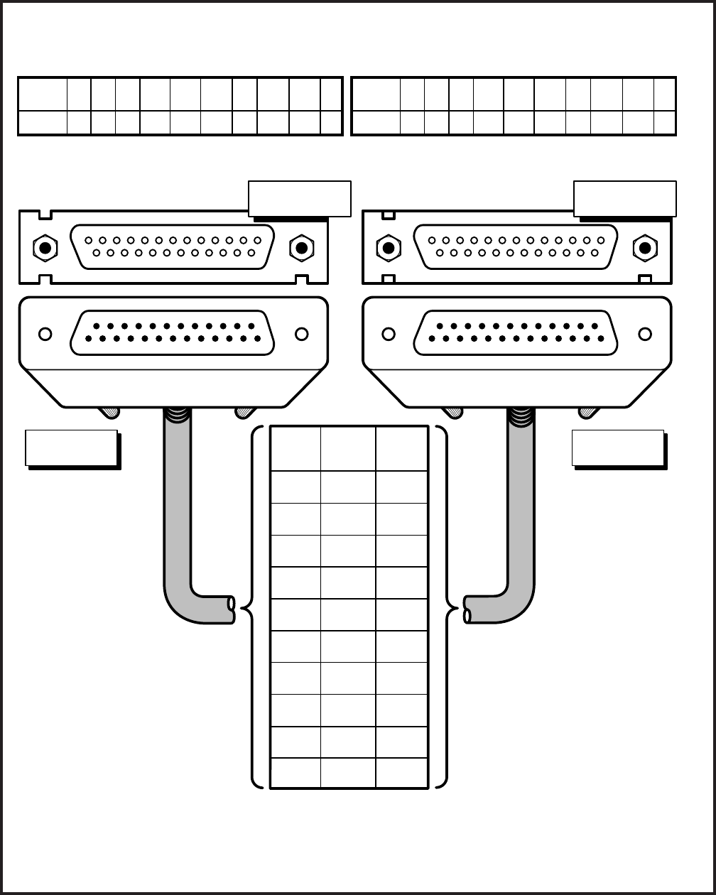
4-53
INSTALLATION INSTRUCTIONS
SECTION 200-255-204
FEBRUARY 1992
DB25
PIN #
8
3
2
20
7
6
4
5
22
1
NAME
DCD
RD
TD
DTR
SG
DSR
RTS
CTS
RI
FG
DB25
PIN #
8
3
2
20
7
6
4
5
22
1
123456785
2022
12345678
2022
Rear view of modem DB25 connector Rear view of PDIU-DS DB25, connector
HAYES-TYPE SMART MODEM
(FUNCTIONS LIKE A DCE) PDIU-DS
(CONFIGURED IN THE "CONNECT TO MODEM"
MODE, P1 ~ P9 = B-C, SO IT FUNCTIONS LIKE A DTE)
NOTES:
1. Modem receives data on pin 2 (TD) and transmits data on pin 3 (RD).
2. The PDIU-DS must be in the connect to modem mode (P1 ~ P9 strapped B-C) so that it transmits
data on pin 2 (TD) and receives data on pin 3 (RD).
20
DB25 FEMALE
CONNECTOR
DB25 FEMALE
CONNECTOR
2022
RS-232 CABLE
DB25 MALE
CONNECTOR
1234678
51234678
DB25 MALE
CONNECTOR
22
PDIU-DS
PIN #
NAME
1
FG
3
RD
4
RTS
5
CTS
6
DSR
7
SG
8
DCD
20
DTR
22
RI
2
TD
MODEM
PIN #
NAME
1
FG
3
RD
4
RTS
5
CTS
6
DSR
7
SG
8
DCD
20
DTR
22
RI
2
TD
(50 ft max, 24 AWG;
customer supplied)
FIGURE 4-60—PDIU-DS TO HAYES-TYPE SMART MODEM, RS-232 CONNECTOR/CABLE CONNECTIONS
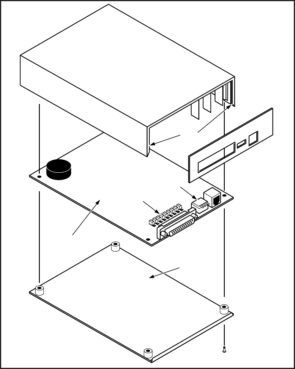
4-54
INSTALLATION INSTRUCTIONS
SECTION 200-255-204
FEBRUARY 1992
PDIU-DS
PCB
DTE/MODEM
JUMPER PLUGS
P1~P9
SW-1
SIDE
GROOVES
BOTTOM
PANEL
FIGURE 4-61—PDIU-DS DISASSEMBLY/ASSEMBLY DIAGRAM
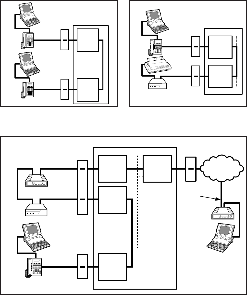
4-55
INSTALLATION INSTRUCTIONS
SECTION 200-255-204
FEBRUARY 1992
NSTU
NDKU
DIU
POWER READY CONNECT
TOSHIBA
MDF
RS-232
INTERNAL
MODEM
PDIU-DS EXTERNAL
MODEM
(AUTO
ANSWER)
MDF
NCOU
TRUNK
CIRCUIT
PUBLIC
TELEPHONE
NETWORK
TELEPHONE
LINE
LAPTOP
PC 2
PERCEPTIONe&ex
NDKU
TOSHIBA
1
#
*
2
ABC
3
DEF
4
GHI
5
JKL
6
MNO
7
PRS
8
TUV
9
WXY
0
OPER
PAGE
MODE
SCRL
MESSAGE
TRNS/CONF
REDIAL
HOLD
MIC
SPEAKER
VOLUME
LAPTOP PC 1
RS-232 DKT/PDIU-DI
MDF
RS-232
FIGURE 4-64—INTERNAL PC TO EXTERNAL PC TEST CALL USING AT COMMANDS
NDKU
TOSHIBA
1
#
*
2
ABC
3
DEF
4
GHI
5
JKL
6
MNO
7
PRS
8
TUV
9
WXY
0
OPER
PAGE MODE SCRL
MESSAGE
TRNS/CONF
REDIAL
HOLD
MIC
SPEAKER
VOLUME
TOSHIBA
1
#
*
2
ABC
3
DEF
4
GHI
5
JKL
6
MNO
7
PRS
8
TUV
9
WXY
0
OPER
PAGE MODE SCRL
MESSAGE
TRNS/CONF
REDIAL
HOLD
MIC
SPEAKER
VOLUME
NDKU
LAPTOP PC 1
RS-232 DKT/PDIU-DI
MDF
MDF
RS-232
LAPTOP PC 2
DKT/PDIU-DI
PERCEPTIONe&ex
FIGURE 4-62
PC TO PC TEST CALL USING AT COMMANDS FIGURE 4-63
PC TO PRINTER TEST CALL USING MANUAL DIALING
TOSHIBA
1
#
*
2ABC 3DEF
4GHI 5JKL 6MNO
7PRS 8TUV 9WXY
0OPER
PAGE MODE SCRL
MESSAGE
TRNS/CONF
REDIAL
HOLD
MIC
SPEAKER
VOLUME
TOSHIBA
DIU
POWER READY CONNECT
TOSHIBA
MDF
MDF
RS-232
RS-232
LAPTOP PC
DKT/PDIU-DI
SERIAL
PRINTER
PDIU-DS
PERCEPTIONe&ex
NDKU
NDKU
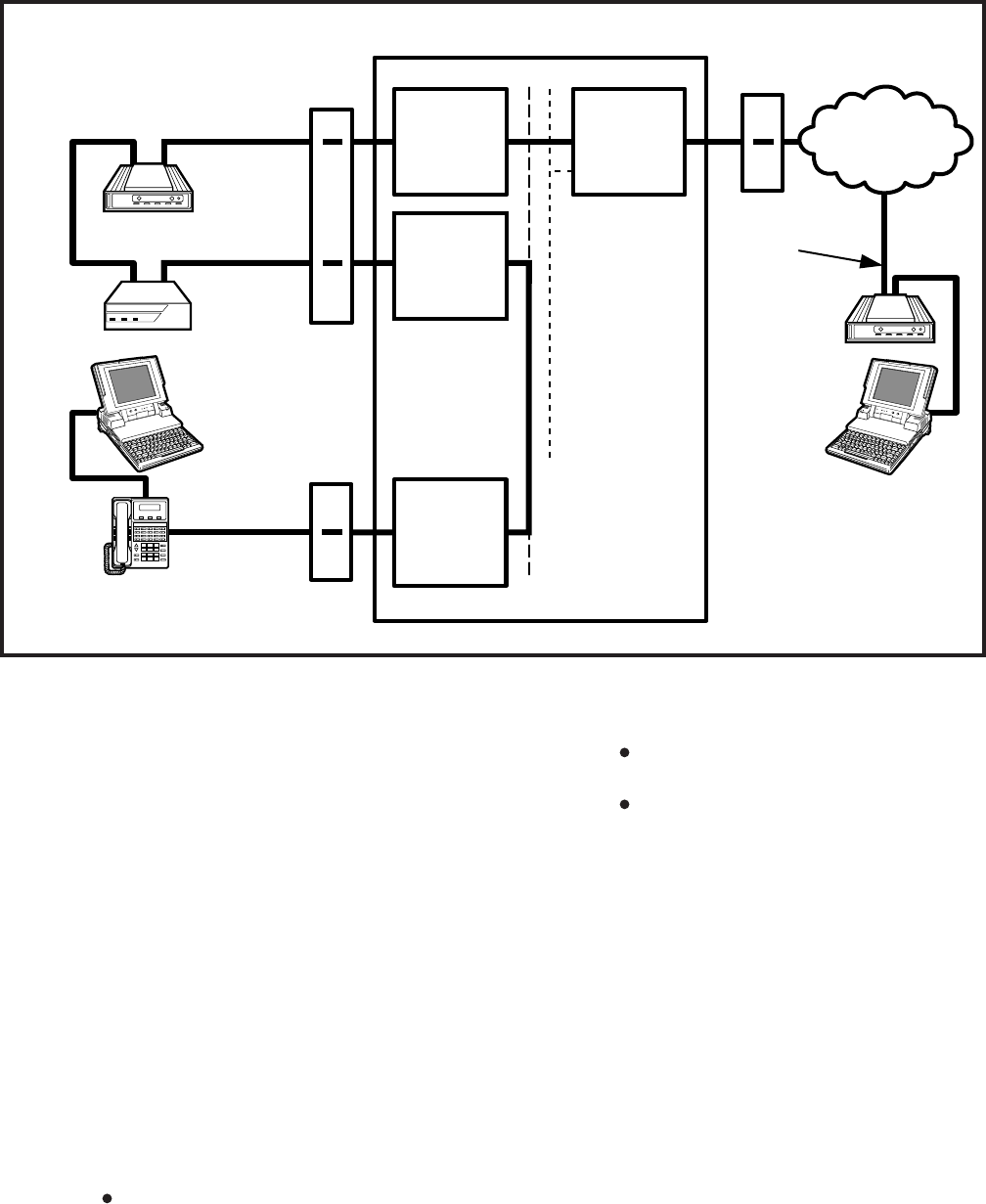
4-56
INSTALLATION INSTRUCTIONS
SECTION 200-255-204
FEBRUARY 1992
NSTU
NDKU
DIU
POWER READY CONNECT
TOSHIBA
MDF
RS-232
INTERNAL
MODEM
PDIU-DS EXTERNAL
MODEM
MDF
NCOU
TRUNK
CIRCUIT
PUBLIC
TELEPHONE
NETWORK
TELEPHONE
LINE RS-232
LAPTOP
PC 2
PERCEPTIONe&ex
NDKU
TOSHIBA
1
#
*
2
ABC
3
DEF
4
GHI
5
JKL
6
MNO
7
PRS
8
TUV
9
WXY
0
OPER
PAGE
MODE
SCRL
MESSAGE
TRNS/CONF
REDIAL
HOLD
MIC
SPEAKER
VOLUME
LAPTOP PC 1
RS-232 DKT/PDIU-DI
MDF
FIGURE 4-65—EXTERNAL PC TO INTERNAL PC TEST CALL USING AT COMMANDS
Call Using AT Commands
6.182 PC to PC Test Call Using AT Commands
1) Make sure that PC 1 and PC 2 are equipped
with a communication software package, and
that the communication parameters of each
PC and the communication software package
are set to the same values (data transmission
rate, flow control, etc.).
2) From either PC keyboard, type A T D X X X X
and press ENTER, where XXXX is the Data
Extension number. (AT commands must be
capital letters.)
3) To terminate the call:
a) Type + + + from either PC keyboard.
The PC screen displays “OK.”
b) Type A T H from the PC keyboard used
in step 3a.
PC 1 and PC 2 screens both display
“NO CARRIER.”
The DATA LED on each DKT will be
off.
6.183 PC to Printer Test Call Using Manual
Dialing
1) Make sure that the PC is configured to print
data from its serial COM port (the PC COM
port is connected to DKT/PDIU-DI). This is
normally accomplished using the DOS and
MODE commands.
2) Using the manufacturer’s documentation,
make sure that the communication param-
eters (data speed, data bits, etc.) of the PC
COM port match the printer’s serial interface
parameters.
3) To connect the PC to the printer, press the

4-57
INSTALLATION INSTRUCTIONS
SECTION 200-255-204
FEBRUARY 1992
DKT’s DATA button and dial X X X, where
XXX is the Data Extension number.
The CONNECT LED on the PDIU-DS will
light.
The connection between the PC and the
printer is complete.
If busy tone is sent to the DKT, the
connection is not complete. Try step 3
again.
4) Operate the PC to print data as required.
5) To terminate the call, press the DKT’s DRS
button.
6.184 Internal PC to External PC Test Call Using
AT Commands
1) Make sure PC 1 and PC 2 are equipped with
a communication software package, and that
the communication parameters of each PC
and communication software package are set
to the same values (data transmission rate,
flow control, etc.).
2) From PC 1’s keyboard, type A T D X X X X and
press ENTER, where XXXX is Data Exten-
sion number. (AT commands must be capital
letters.)
The DATA LED on the DKT will light.
The CONNECT LED on the PDIU-DS will
light.
The screen on PC 1 displays “CON-
NECT XXXX,” where XXXX is the data
transmission speed set by the communi-
cation software.
At this time, PC 1 and the PDIU-DS are
connected.
3) From PC 1’s keyboard, type A T D T X X X X
X X X X X X and press ENTER, where
XXXXXXXXXXX is the trunk access code and
modem telephone number.
The internal modem goes off-hook, dials
the access code to seize the trunk, and
then dials the external modem’s tele-
phone number.
The external modem rings and auto an-
swers, the modems handshake and es-
tablish communications.
If the external modem sends result codes,
the screen on PC 1 displays “CONNECT
XXXX,” where XXXX is the data trans-
mission speed set by the communication
software.
At this time PC 1 and PC 2 are con-
nected, and can exchange data (file trans-
fers, type messages, etc.).
4) To terminate the call:
a) Type + + + from either PC keyboard.
The PC screen displays “OK.”
b) Type A T H from the PC keyboard used
in step 5a.
PC 1 and PC 2 screens both display
“NO CARRIER.”
The DATA LEDs on each DKT will go
out.
6.185 External PC to Internal PC Test Call Using
AT Commands
1) Make sure PC 1 and PC 2 are equipped with
a communication software package, and that
the communication parameters of each PC
and communication software package are set
to the same values (data transmission rate,
flow control, etc.).
2) From PC 2’s keyboard, type A T D X X X X X
X X and press ENTER, where XXXXXXX is
telephone number.
The external modem originates the call.
Trunk rings incoming call to the internal
modem.
The internal modem rings and auto an-
swers, the modems handshake and es-
tablish communications.
If the internal modem sends result codes,
PC 2’s screen displays “CONNECT
XXXX,” where XXXX is the data trans-
mission speed set by the communication
software.
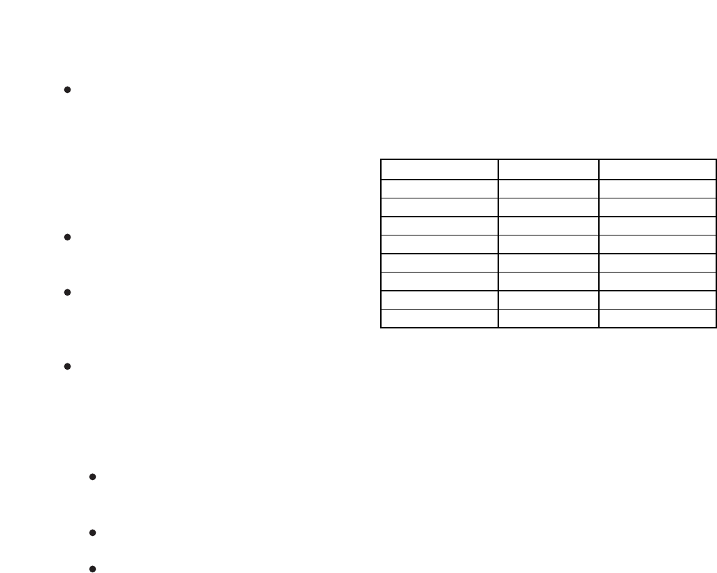
4-58
INSTALLATION INSTRUCTIONS
SECTION 200-255-204
FEBRUARY 1992
At this time, PC 2 is connected to the
PDIU-DS.
3) From PC 2’s keyboard, type A T D X X X X and
press ENTER, where XXXX is the Data Ex-
tension number. (AT commands must be capi-
tal letters.) This prompts the PDIU-DS to dial
and connect to the PDIU-DI.
The CONNECT LED on the PDIU-DS
will light, the DATA LED on the DKT
will also light.
The screens on PC 1 and PC 2 dis-
play “CONNECT XXXX,” where XXXX
is the data transmission speed set by
the communication software.
At this time PC 1 and PC 2 are con-
nected and they exchange data (file
transfers, typed messages, etc.).
4) To terminate the call:
a) Type + + + from either PC keyboard.
The PC screen displays “OK.”
b) Type A T H from the PC keyboard used
in step 5a.
PC 1’s and PC 2’s screens both
display “NO CARRIER.”
The DATA LED on each DKT will go
out.
7. STANDARD TELEPHONE EQUIPMENT
INSTALLATION
7.00 Standard Telephone Connections
7.01 See the DSTT Program in Section 200-255-
300,
Programming
, for instructions on program-
ming standard telephones. The system must be
told at which ports standard telephones are in-
stalled.
7.02 Standard telephones require single-pair wire
and are connected to the MDF via standard twisted-
pair telephone cables.
7.03 Standard telephone connection details are
shown in Figure 4-66.
8. TRUNK CONNECTIONS
8.10 Connections from the telephone company
jack (RJ21X for CO/FX/WATS/DID trunks and
RJ2EX for E & M TIE trunk) should be terminated
on a 66-block, and then cross-connected to the
appropriate leads on the CO portion of the MDF,
using the Tables 5-7, 5-8, and 5-13 ~ 5-15 as
guides. Connection requirements for each type of
trunk are shown below.
9. PERIPHERAL EQUIPMENT INSTALLATION
9.00 Modem Pooling Connections (DDIU-MA
only)
9.01 See the NMDM Program in Section 200-
255-300,
Programming
, to input information con-
cerning
Modem Pooling for the DDIU-MA only
.
9.02 Most modems require only single-pair wiring
and are connected to the MDF via standard twisted-
pair telephone cables. However, some modems
may require a two-pair connection (one for trans-
mit—one for receive). For this type of connec-
tion, use the next wire pair (which is not nor-
mally used). Modem Pooling Connection de-
tails are shown in Figure 4-67.
IMPORTANT!
All connections to DDIUs (-MA or -MAT)
must observe correct tip and ring po-
larity for proper operation.
9.10 Power Failure/Emergency Transfer
9.11 One DPFT can be installed in a two-
cabinet system. Install the DPFT as follows:
1) Mount the DPFT near the MDF.
DESIGNATOR TRUNK TYPEFUNCTION
T
R
T1
R1
E
SG
M
SB
Tip
Ring
Tip 1
Ring 1
E
Sig. Gnd.
M
Sig. Bat.
CO, DID, TIE
CO, DID, TIE
TIE (4-wire)
TIE (4-wire)
TIE
TIE (Type II)
TIE
TIE (Type II)
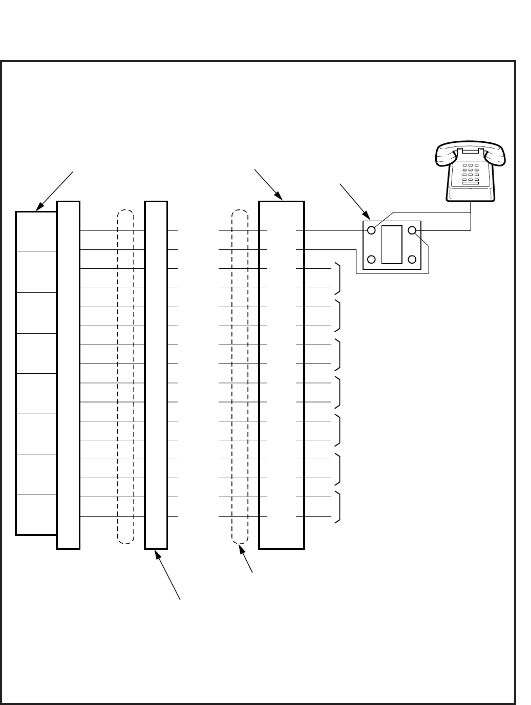
4-59
INSTALLATION INSTRUCTIONS
SECTION 200-255-204
FEBRUARY 1992
FIGURE 4-66—STANDARD TELEPHONE CONNECTION
TO TELEPHONE #5
T
TL1
RL1
TL2
RL2
TL3
RL3
TL4
RL4
TL5
RL5
TL6
RL6
TL7
RL7
TL8
RL8
TL1
RL1
TL2
RL2
TL3
RL3
TL4
RL4
TL5
RL5
TL6
RL6
TL7
RL7
TL8
RL8
(W-BL)
(BL-W)
(W-G)
(G-W)
(W-S)
(S-W)
(R-O)
(O-R)
(R-BR)
(BR-R)
(BK-BL)
(BL-BK)
(BK-G)
(G-BK)
(BK-S)
(S-BK)
CKT
1
CKT
2
CKT
3
CKT
4
CKT
5
CKT
6
CKT
7
CKT
8
TO TELEPHONE #3
TO TELEPHONE #4
TO TELEPHONE #6
TO TELEPHONE #7
TO
TELEPHONE
#8
CROSS-CONNECT
BLOCK
NMDU PCB
"J" CABLE CONNECTOR PINS
25-PAIR CABLE
RJ11
BLOCK
500/2500-TYPE
TELEPHONE #1
R
TO TELEPHONE #2
34
9
36
11
38
13
40
15
32
7
26
1
28
3
30
5
G
BR
Y
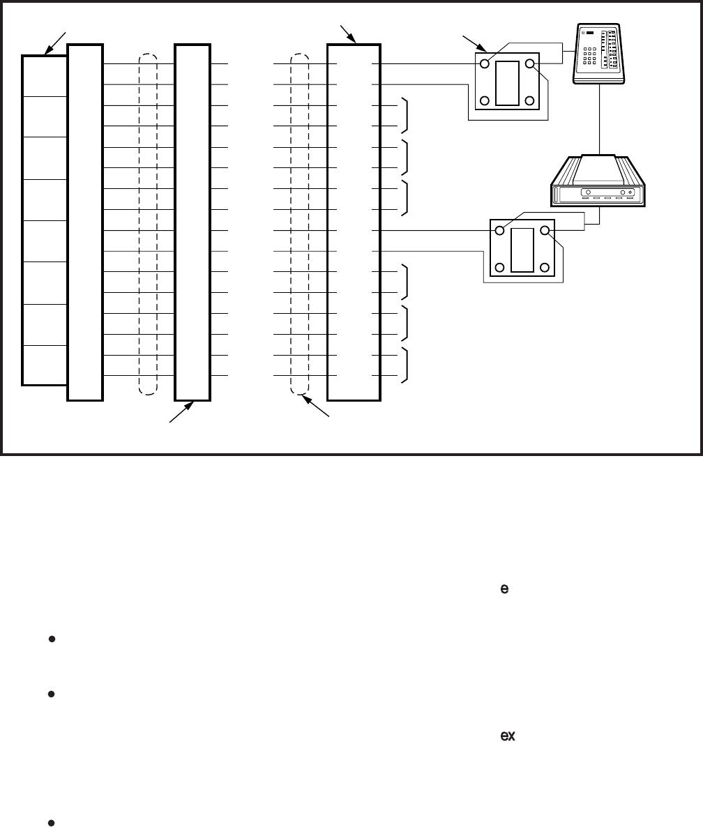
4-60
INSTALLATION INSTRUCTIONS
SECTION 200-255-204
FEBRUARY 1992
5) At the MDF, connect the DPFT to the system
as follows:
PERCEPTION
DPFT J1 (trunk) = LCEC/NCEC-M & S J8-
J15/J508-J515
Pin 25 (S-V) = Pin 25 (S-V)*
Pin 50 (V-S) = Pin 50 (V-S)*
DPFT J2 (station) = LCEC/NCEC-M & S J4-
J15/J504-J515
PERCEPTION
Any trunk position
*On the J1 connector, the pin 25 connection
provides the -24 VDC input required to drive
the DPFT and the pin 50 connection provides
ground. There are no power connections on
connector J2.
9.20 Reserve Power
T
TL1
RL1
TL2
RL2
TL3
RL3
TL4
RL4
TL5
RL5
TL6
RL6
TL7
RL7
TL8
RL8
TL1
RL1
TL2
RL2
TL3
RL3
TL4
RL4
TL5
RL5
TL6
RL6
TL7
RL7
TL8
RL8
(W-BL)
(BL-W)
(W-G)
(G-W)
(W-S)
(S-W)
(R-O)
(O-R)
(R-BR)
(BR-R)
(BK-BL)
(BL-BK)
(BK-G)
(G-BK)
(BK-S)
(S-BK)
CKT
1
CKT
2
CKT
3
CKT
4
CKT
5
CKT
6
CKT
7
CKT
8
TO
DDIU #3
TO
DDIU #4
TO
MODEM #2
TO
MODEM #3
TO
MODEM #4
CROSS-CONNECT BLOCK
NMDU PCB
"J" CABLE
CONNECTOR PINS 25-PAIR CABLE
RJ11
BLOCK
G
BR
Y
*
*
*
TOSHIBA
DDIU-MA
*
CORRECT
POLARITY
*
R
TO
DDIU #2
T
G
BR
Y
R
MODEM
RS-232C
34
9
36
11
38
13
40
15
32
7
26
1
28
3
30
5
2) Using 25-pair cables with amphenol-type
connectors (female for J1, male for J2),
connect the DPFT to two 66-type cross-
connect blocks.
3) Using Tables 5-8 and 5-15 for guides:
Connect the trunks selected for emer-
gency use to the J1 block “CO Tip” and
“CO Ring” terminals.
Connect the NCOU circuits supporting
the emergency trunks to the J1 block
“NCOU Tip” and “NCOU Ring” termi-
nals.
4) Using Tables 5-6, 5-7, 5-9, 5-14 and 5-16 for
guides:
Connect the standard telephone stations,
designated for emergency use, to the
proper terminals on the J2 block “TEL
Tip” and “TEL Ring” terminals.
FIGURE 4-67—MODEM POOLING CONNECTION (DDIU-MA ONLY)
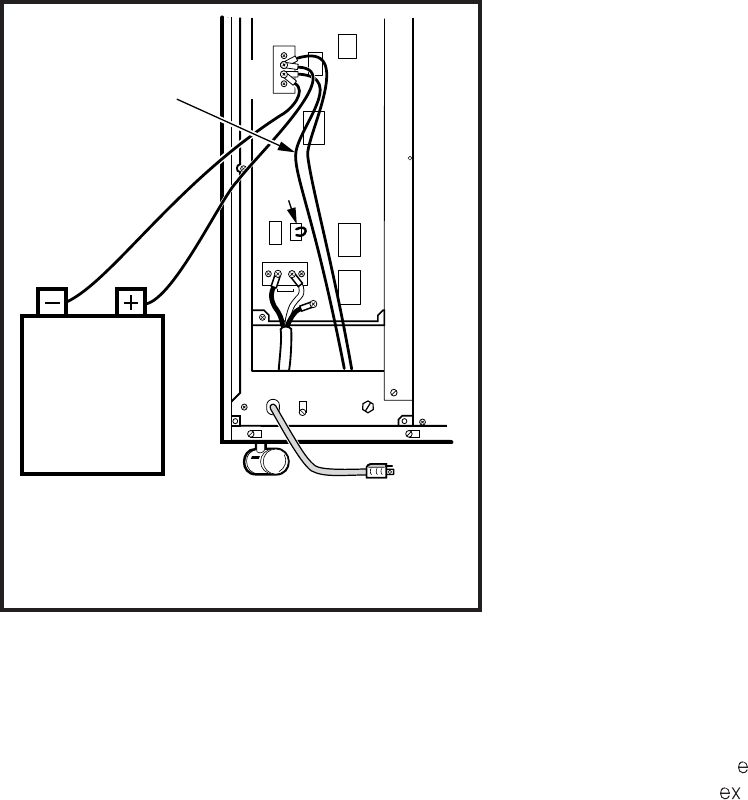
4-61
INSTALLATION INSTRUCTIONS
SECTION 200-255-204
FEBRUARY 1992
9.21 Install Reserve Power as follows (Figure 4-
68):
1) Place the customer-supplied battery pack
where it will be located.
CAUTION!
Batteries can emit fumes that are poison-
ous to people, potentially explosive, and
corrosive to electronic components. Lo-
cate batteries so that any fumes are ade-
quately vented per local fire codes.
2) Place the POWER switch (on the front of the
main power supply) in the OFF position and
remove the AC power cable from the outlet.
3) Connect the battery pack leads (customer-
supplied) to TB2 BAT on the NPSA-M or
LPSA (Figure 4-68). Observe the correct po-
larity. Leave the leads from the peak load
battery connected.
4) Connect the leads to the battery pack (Figure
FIGURE 4-68—RESERVE POWER INSTALLATION
POWER
CABLE
SURGE
TEST
J703
P1
J203
AC
TB1 L N
GND
EXT
GND
J201
(24V)
BAT.
TB2
-
+
P3
J202
NOTE:
Ensure that the correct
polarity is maintained.
PEAK LOAD
BATTERY
CABLES
24 VDC
BATTERY
PACK
4-67). Observe the correct polarity. Fix battery
leads to the cabinet using the clamp.
5) Place the BAT BACK UP switch on the front
of the main power supply in the ON position.
6) Plug the AC cable into the outlet and turn the
POWER switch ON.
9.30 Paging Equipment
9.31 By combining a single customer-supplied pag-
ing amplifier with the system’s paging interface and
speaker zone switching, it is possible to provide a
paging system of up to five zones with All Zone
Page capability.
9.32 Figures 4-69, 4-70 and 4-71 show possible
paging arrangements. As a standard feature (part
of the NPRU PCB), the system provides a 600-ohm
output to a paging amplifier. If more than one
paging zone is required, the output of the amplifier
can be routed back to the NPRU PCB where it will
be switched to one of five sets of speakers. The
speaker operated is determined by the access
code dialed by the station user. The actual access
code is assigned in software (see Section 200-255-
300,
Programming
).
9.33 An All Page code can also be defined in
software. When that code is dialed, all relays will be
activated simultaneously to permit paging to all
speaker zones.
9.34 If the power loads of the different zones are
such that a single amplifier is not suitable, multiple
amplifiers (up to one for each zone) can be con-
nected as shown in Figure 4-71.
9.35 If music is to be broadcast over the paging
system, two arrangements are possible:
1) If the music is supplied from a separate ampli-
fier (as in Figures 4-70 and 4-71), it can be
connected between the speaker common line
and the PG GND input to the NPRU
(PERCEPTION J2/J502 and pin 2 or
PERCEPTION J1/J2 and pin 2). The music
will be connected to all speaker zones when
no page is in progress. When a page access
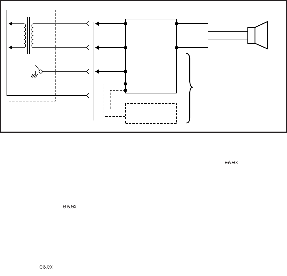
4-62
INSTALLATION INSTRUCTIONS
SECTION 200-255-204
FEBRUARY 1992
MUSIC
SOURCE
IN-
PUT
#1 OUT-
PUT
MUTE #2
INPUT #2
V
O
I
C
E
OPTIONAL CONNECTION
FOR MUSIC OVER
EXTERNAL SPEAKER
PG1
600
PGGND
PR1
PT1 26
1
27
2
P -J2/J502
P -J1/J2
Ω
e
ex
FIGURE 4-69—PAGING WITH MUSIC OVER EXTERNAL SPEAKER FROM SAME AMPLIFIER
pins 4 and 29 (Br-W and W-BR) of J2 or J502 / J1
or J2 for the PERCEPTION systems, respec-
tively (see Tables 5-4 and 5-10). The input imped-
ance is 600 ohms. (This cannot be the same
source used to provide music over external speak-
ers.)
9.43 Adjust the MOH volume with the MOH vol-
ume control on the front of the NPRU PCB. Maxi-
mum volume is limited by internal circuits in order
to comply with FCC regulations.
9.50 Universal Night Answer
9.51 The Universal Night Answer (UNA) feature
provides an output of interrupted ringing voltage
(85 +10 VRMS, 20 Hz superimposed on -24 VDC)
whenever the system is in Night Service and an
incoming call is received by a trunk designated for
UNA. Any station user, upon hearing the chime or
bell, can dial the UNA access code and be con-
nected to the caller.
9.52 The ringing voltage output is intended to
control a strategically located chime or loud ring-
ing bell. The available power is five ringer equiva-
lents.
9.53 Two UNA zones can be installed in tenant
systems. Either zone can be assigned in pro-
code is dialed, the music is disconnected from
the zone and the page amplifier output is
connected.
2) If the music is connected to a second input of
the paging amplifier (Figure 4-69), the PG1
control lead (J2 and J502 pin 27 or J1 and J2
for PERCEPTION , respectively) can be
connected to the MUTE terminal of the page
amplifier music channel. When any page ac-
cess code is dialed, a ground output is applied
to the PG1 lead to mute the music.
9.36 All paging connections are made at the J2
and J502 or J1 and J2 connectors on the
PERCEPTION systems, respectively. The con-
nectors are located on the rear of the basic and
expansion cabinets. See Tables 5-4 and 5-10 for
details.
9.40 Music-on-Hold
9.41 A Music-on-Hold (MOH) interface is a stan-
dard feature on the system. The circuitry occupies
part of the NPRU PCB. If MOH is equipped, it will be
heard by any station or trunks on-hold in the sys-
tem, or by any trunk put into the camp-on state.
9.42 A tuner or other program source, supplied by
the customer, is connected to the MOH input via
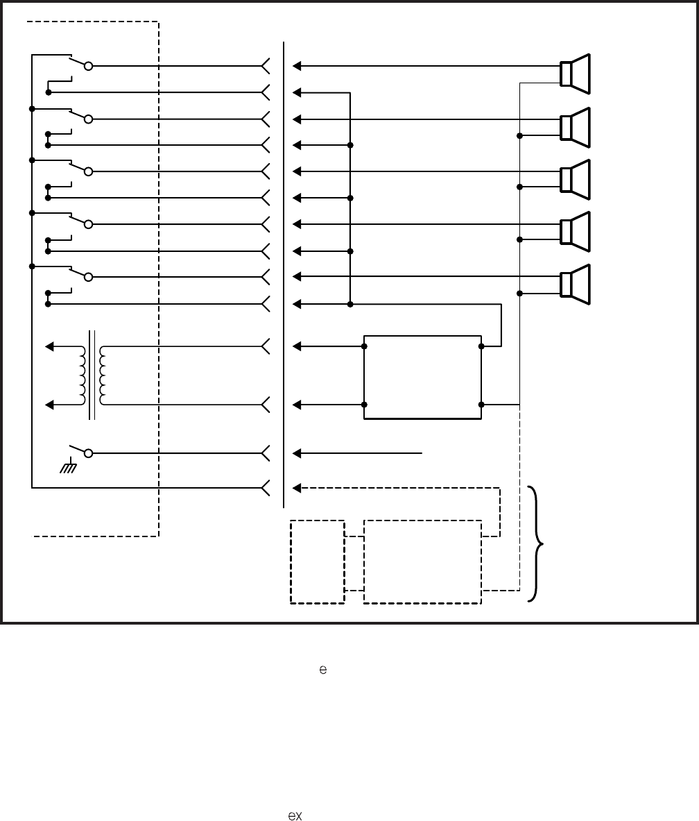
4-63
INSTALLATION INSTRUCTIONS
SECTION 200-255-204
FEBRUARY 1992
OPTIONAL
CONNECTION
FOR MUSIC
OVER EXTERNAL
SPEAKER
V
O
I
C
E
PGOUT 1
PGOUT 2
PGIN 2
PGOUT 3
PGIN 3
PGOUT 4
PGIN 4
600
PGIN 1
PGOUT 5
PGIN 5
PT1
PR1
PG1
PGGND
NPRU
PAGING AMP
IN-
PUT OUT-
PUT
6
31
7
32
8
33
9
34
10
35
26
2
27
1
IN-
PUT OUT-
PUT
MUSIC AMP
MUSIC
SOURCE
ZONE 1
ZONE 2
ZONE 3
ZONE 4
ZONE 5
Pe-J2/J502
Pex-J1/J2
Ω
FIGURE 4-70—PAGING WITH ONE AMPLIFIER
9.60 Station Message Detail Recording
9.61 The Station Message Detail Recording
(SMDR) feature enables a business to monitor and
control its telephone costs. Data can be collected
for each outgoing and/or incoming trunk call. Each
such call generates a call record that is output at the
SMDR connector on the connector panel at the
upper rear of the LCEC-M or NCEC-M. (In Lodging/
Health Care applications, data specific to those
applications are included in the SMDR output.)
9.62 SMDR output can be connected to a variety of
gramming to either tenant. For PERCEPTION ,
connections to the UNA ringing signal are via
pins 12 and 37 (O-BK, BK-O) of J2. This connec-
tion is to J502 in the expansion cabinet for UNA
Zone 1 (see Tables 5-4 and 5-10). UNA zone 1
requires a second NPRU PCB in the expansion
cabinet.
9.54 UNA connections for PERCEPTION are
made at pins 12 and 37 connectors J1 and J2 on
the basic cabinet. A second UNA device requires a
second NPRU to be installed in the basic cabinet.
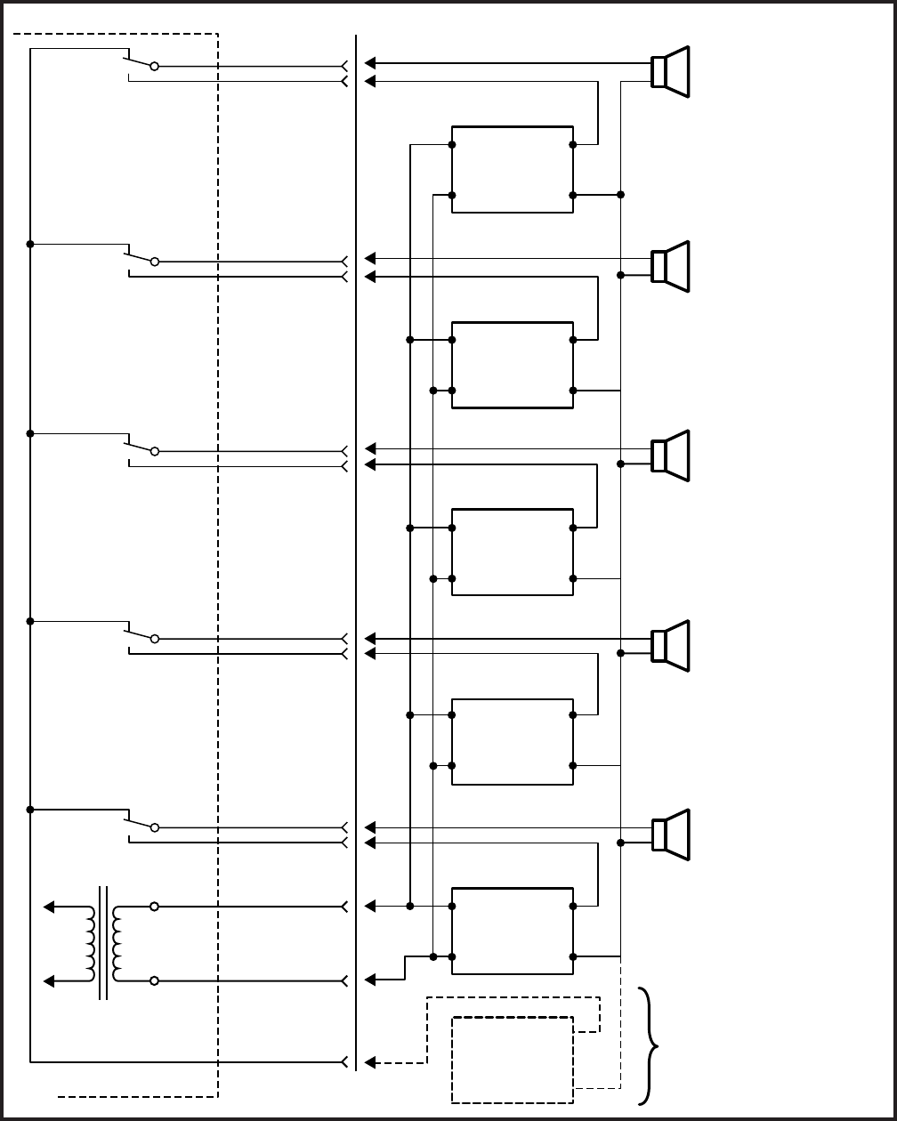
4-64
INSTALLATION INSTRUCTIONS
SECTION 200-255-204
FEBRUARY 1992
FIGURE 4-71—PAGING WITH MULTIPLE AMPLIFIERS
26
35
32
10
34
33
7
9
8
OPTIONAL CONNECTION
FOR MUSIC OVER
EXTERNAL SPEAKER
ZONE 1
ZONE 2
ZONE 3
ZONE 4
ZONE 5
V
O
I
C
E
600
31
6
PGOUT 1
PGIN 1
PGOUT 2
PGIN 2
PGOUT 3
PGIN 3
PGOUT 4
PGIN 4
PGOUT 5
PGIN 5
PTI
PRI
PGGND
AMP
#1
OUTPUT
INPUT
AMP
#4
OUTPUT
INPUT
OUTPUT
INPUT
AMP
#5
AMP
#3
OUTPUT
INPUT
AMP
#2
OUTPUT
INPUT
J2
1
2
NPRU
MUSIC
SOURCE
Ω
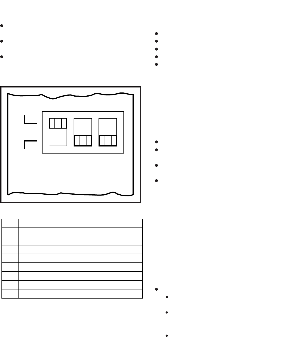
4-65
INSTALLATION INSTRUCTIONS
SECTION 200-255-204
FEBRUARY 1992
9.66 SMDR can be programmed to record data
under any one of the following conditions:
Incoming calls only.
Outgoing calls only.
Incoming and outgoing calls.
Outgoing toll calls only.
All incoming calls and outgoing toll calls.
9.67 When outgoing calls are chosen, all calls
seizing a trunk will be recorded regardless of dura-
tion. On incoming calls, all answered calls will be
recorded. Calls disconnected by Toll or Code Re-
striction features are not recorded.
9.68 Timing for recorded calls will start as follows
(Figure 4-73):
Outgoing—when trunk is seized.
Incoming to attendant only—when attendant
answers.
Incoming and extended by the attendant—when
attendant answers.
Incoming to a station—when answered.
9.69 A station user can enter a charge account
code of up to 12 digits for each call. This code is
included in the SMDR output.
9.70 The recording criteria and account code length
are defined in DMDR Program (see Section 200-
255-300,
Programming
).
9.71 Each time a trunk is seized, data is collected
for that call until the trunk is released. This data is
output at the SMDR port in the following format (see
Figure 4-73).
Time
Start of Call Hour - tens - units
Minute - tens - units
Call Duration Hour - units
Minute - tens- units
Seconds - tens - units
Condition Code (see table)
A = Attendant handled
D = Call > 10 hours
E = Maintenance (SMDR port)
F = Maintenance (trunk test)
I = Incoming call
K = Outgoing call
L = Conference Attendant or 3-party
customer-provided equipment:
A local 80-column printer for an on-line printout
at the termination of each trunk call.
A recording device to store data for subsequent
processing, either on-site or by a service bureau.
Call accounting equipment to provide custom-
ized call reports.
9.63 Refer to the external device manufacturer’s
documentation for information on its SMDR con-
nector pin assignments.
9.64 The SMDR output speed can be set for either
300 bps or 1200 bps by the MDR switch on the front
panel of the LCCU PCB (Figure 4-72). SMDR pin
assignments are as follows:
9.65 The code used by SMDR is standard 7-level
ASCII using one start bit, one stop bit and one parity
bit (even parity).
FIGURE 4-72—LCCU SWITCHES
1200
300 T
T
Y
M
D
R
A
U
X
2
3
4
5
6
7
8
20
PIN SIGNAL
Receive Data (from SMDR device)
Transmit Data (to SMDR device)
Request to Send (to SMDR device)
Clear to Send (to SMDR device)
Data Set Ready
Signal Ground
Carrier Detect
Data Terminal Ready (from SMDR device)
AUGUST 1991
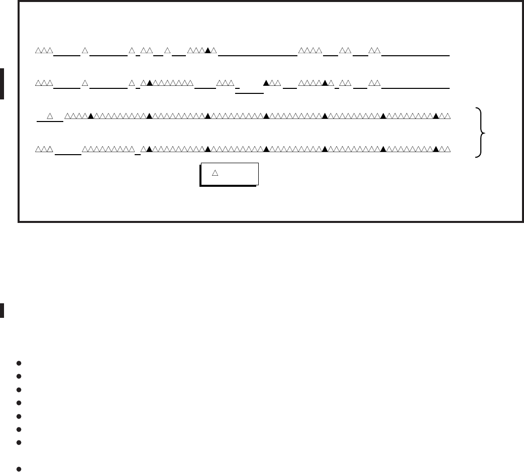
4-66
INSTALLATION INSTRUCTIONS
SECTION 200-255-204
FEBRUARY 1992
FIGURE 4-73—EXAMPLE: SMDR CALL RECORD
M = Transfer or Call Forward
N = SPCC #1
O = SPCC #2
P = Date/Time change
Q = System Initialize
R = Incomplete call
S = Date printed (every hour)
Access Code 3 digits maximum
Dialed Number 15 digits maximum
Calling DN 4 digits maximum
Trunk Port 3 digits maximum
DNIS Digits 4 digits maximum
Calling Port No. 3 digits maximum
Account Code 12 digits maximum
or
Stroke Count 4 digits maximum
9.72 The format of the special record, for Initialize/
Reload and Time Change, is as follows:
Initialize/Reload:
NNNN etc. (previous records-usual call)
00 (initialize or reload)
9.73 Any record printed after the initialize record
will appear on the same line and be offset three
columns from the usual record.
Example:
NNNN (previous record)
00 NNNNN (initialize and next record)
NNNNNN
Time Change:
MM DD (old date)
HH : MM (old time)
MM DD (new date)
HH : MM (new time)
9.74 Some complex calls will cause multiple call
records (CR) for the same station or trunk.
Examples:
1) Station 1 transfers Trunk 1 to Station 2
CR for Station 1 ~ Trunk 1
= Condition Code I or K
CR for Station 2 ~ Trunk 1
= Condition Code M
2) Station 1 transfers Trunk 1 to Trunk 2
CR for Station 1 ~ Trunk 1
= Condition Code I or K
CR for Station 1 ~ Trunk 2
= Condition Code L
CR for Trunk 1 ~ Trunk 2
= Condition Code M
3) Station 1 holds Trunk 1 and calls Trunk 2
CR for Station 1 ~ Trunk 1
= Condition Code I or K
123456789101112131415161718192021
22 2324 25 2627 28 2930 31 3233 3435 36 3738 3940 41 4243 44 4546 4748 49 50 5152 5354 55 5657 5859 60 61 6263 6465 66 6768 6970 71
02:13 0 :00 :25 K X9 001 1-516 -669 -1234 201 020 12345 7890126CR LF
72 73
ACCOUNT CODE OR STROKE COUNTPORTSTATIONDIALED PHONE NUMBERACCESSCONDITIONCALL DURATIONSTART OF CALL
OUTGOING
02: 34 0 :01:33 I 9 12345 7890356CR LF
ACCOUNT CODE OR STROKE COUNTACCESS
001
TPNCONDITIONCALL DURATIONSTART OF CALL
INCOMING
L005
PORT
TPN
200
STATION
11 21 CR LF
DATE
CR LF
0
START OF CALL
9:14 P
CONDITON
DATE/TIME
CHANGE
= ONE SPACE
DNIS DIGITS
RECEIVED
3574

4-67
INSTALLATION INSTRUCTIONS
SECTION 200-255-204
FEBRUARY 1992
CR for Station 1 ~ Trunk 2
= Condition Code K
9.75 All connections to miscellaneous equip-
ment are made via J2, J1, TTY, SMDR, and
MODEM connectors on the connector panels
of the system.
9.80 Lodging/Health Care Data Audit
9.81 The Lodging/Health Care Data Audit feature
enables the user to record and analyze the registra-
tion and operation of specific features in Lodging/
Health Care applications.
9.82 Lodging/Health Care audit data is output at
either the SMDR (as part of the SMDR printout) or
the TTY (as a separate report) connector on the
upper rear of the basic cabinet. (Because the TTY
connector is required for on-site programming and
maintenance procedures, it is recommended that
the SMDR port be used.) The selection of data to be
output and the connector choice (TTY or SMDR)
are software-controlled (see DHMF Program in
Section 200-255-300,
Programming
).
9.83 The SMDR or TTY output can be connected
to either:
A local 80-column printer for an on-line printout.
Compatible call accounting or property manage-
ment interface equipment, supplied by another
vendor.
9.84 The audit pin-out assignments at the SMDR
or the TTY connector are not identical. Refer to
Paragraph 9.64 for the pin-out assignments of each
connector. For instruction on connecting equip-
ment provided by other vendors, refer to the
manufacturer’s documentation.
9.85 The audit data output rate can be set for either
300 bps or 1200 bps (depending on the configura-
tion of the receiving equipment) at either the SMDR
switch or the TTY switch on the front panel of the
LCCU PCB.
CAUTION!
If the TTY connector is used for program-
ming and maintenance operations, (either
with an on-site teleprinter or remotely via a
modem) be careful not to change the data
rate setting of the TTY switch so that it is
incompatible with programming equip-
ment.
9.86 Figure 4-74 shows a typical Lodging/Health
Care audit printout. Notes on the figure explain the
possible value for each column.
10. SYSTEM POWER UP
10.00 General
10.01 Upon initial power up, the system will
automatically load its operating system and cus-
tomer data from the disk. Two sets of disks are
provided with each system; one set should always
be mounted in the drive, the other kept as a spare.
10.02 Activate the system as follows:
1) Be sure the main power switch on the NPSA-
M is in the OFF position, and plug the AC cord
into the outlet.
2) If the system uses D.02 or later version soft-
ware, insert the SYSTEM disk in FDD0. If two
drives are used, insert the MAINTENANCE
disk (Figure 4-75) in FDD1. If the system uses
D.01 software, insert the program disk in FDD0.
3) Turn the main power switch on the NPSA-M to
the ON position.
4) The floppy disk will run: LED will come on.
LCCU MAJ ALARM LED will be on.
NPRU PFT LED will be on.
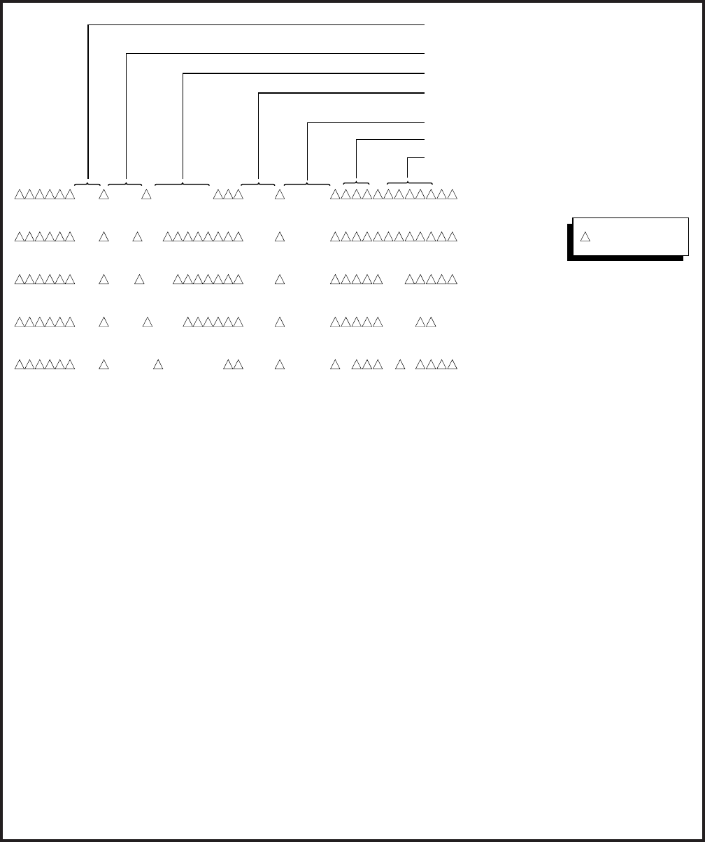
4-68
INSTALLATION INSTRUCTIONS
SECTION 200-255-204
FEBRUARY 1992
202 AWU CANCEL 14:40 030786
400 MW ON 14:45 030786
400 MW OFF 14:50 030786 MC
202 AWU 15:11 030786SET 15:15
202 ROOM 10:18 031086STATUS 4MD
ROOM/DIRECTORY
NUMBER
TIME FEATURE WAS
REGISTERED/ACTIVATED
FEATURE
OPERATION
ROOM STATUS CODE
DATE
TELEPHONE SET STATUS/AGENT
REGISTERING OR CANCELLING FEATURE
CR LF
CR LF
CR LF
CR LF
CR LF
1
2
4
3
= ONE SPACE
NOTES:
1. FEATURE
MW
AWU
MRA
Room Status
= Message Waiting
= Automatic Wake-up
= Message Registration
Audit
= Room Status Audit
2. OPERATION
ON
OFF
SET
CANCEL
= Set at Attendant Console
= Cancelled at either
Attendant Console or
Station
= Set at either Attendant
Console or Station
= Cancelled at either
Attendant Console or
Station
RNA
Bsy
$XXX.XX
M
XX:XX
= Ring No-Answer
= Busy
= Total call charges for
this station
= Maid in Room
= Time Wake-up Call
Scheduled for
STATUS
4.This column shows either the status of
the station accessed for feature opera-
tion (for example, a wake-up call) or
the agent who registered the feature.
MC
EXT= Message Center
= Station
AGENT
3. ROOM STATUS CODE
1
2
3
4
= Vacant and clean
= Occupied and clean
= Vacant and needs cleaning
= Occupied and needs cleanin
g
FIGURE 4-74—EXAMPLE: AUDIT PRINTOUT (LODGING/HEALTH CARE)
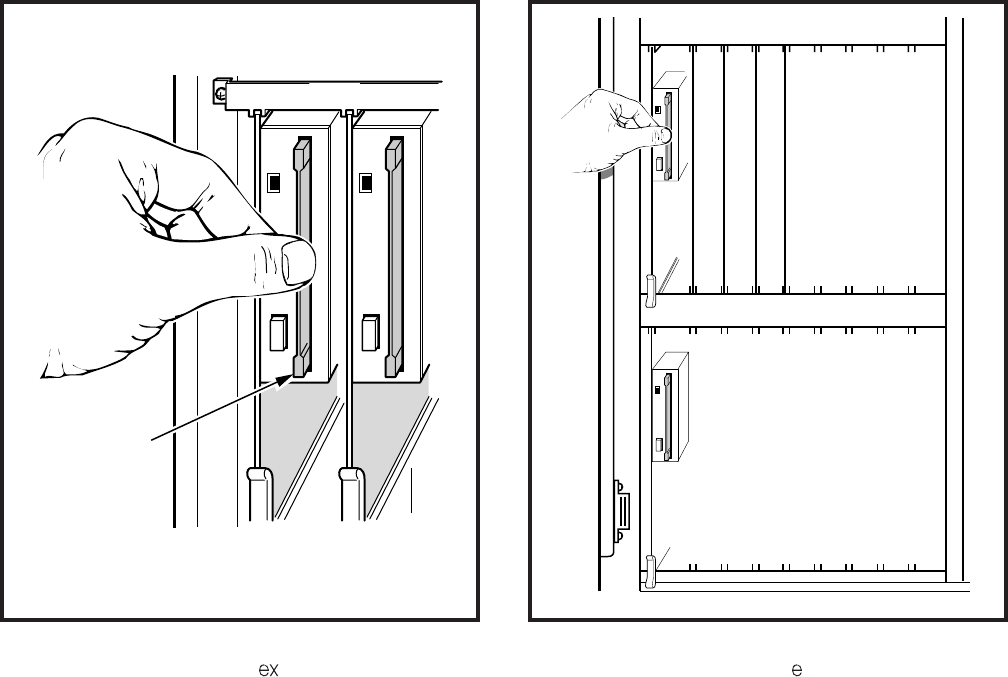
4-69
INSTALLATION INSTRUCTIONS
SECTION 200-255-204
FEBRUARY 1992
FDD0 CCU TWU P00 C00 L00 L01 L02 L03
FDD1 L04 L05 L06 L07 L08 L09 L10 L11
T07 T06 T05 T04 T03 T02 T01 T00
NDSU
NPRU
NTWU
NFDU
NFDU
LCCU
FDD1 FDD0
LABEL
SIDE
FIGURE 4-75—INSERTING DISK
(PERCEPTION ONLY) FIGURE 4-76—INSERTING DISK
(PERCEPTION ONLY)
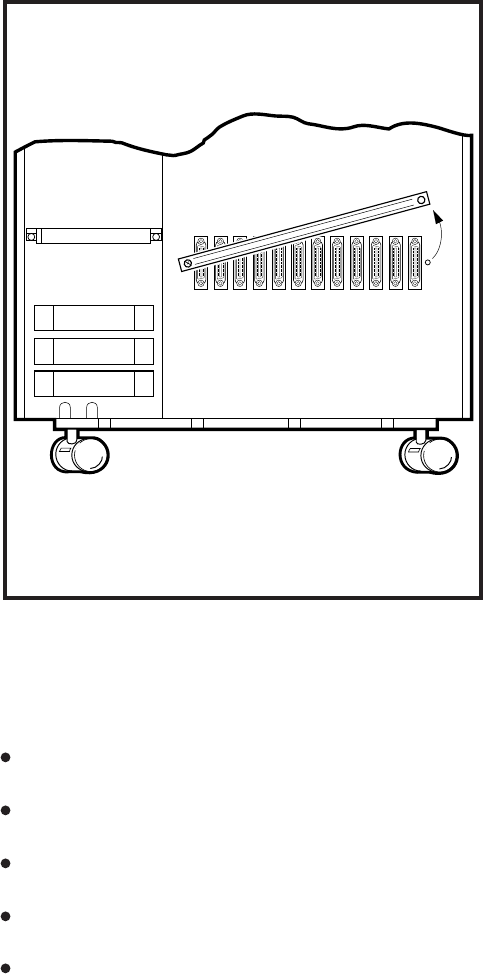
5-1
INSTALLATION INSTRUCTIONS
SECTION 200-255-205
FEBRUARY 1992
CHAPTER 5
MDF ARRANGEMENT
1.00 All connections from the system to external
equipment, such as trunks, stations, data interface
units, etc., are made via a customer-provided main
distribution frame (MDF).
1.01 Cables with male amphenol-type connectors
are attached to the connector panels of the basic
and expansion cabinets and secured with the con-
nector locking bar (Figure 5-1). Plastic cable clamps
are provided along the base of the basic cabinet to
secure cables. The opposite ends of the cables are
then terminated on 66-type quick-connect terminal
blocks on the MDF (split blocks with bridging clips
should be used to allow for fault isolation). A typical
MDF layout is shown in Figure 5-2. Connect each
cable from the basic and expansion cabinets to one
side of the block and external equipment cables to
the other side. Use bridge clips to make the connec-
tions.
1.02 FCC regulations prohibit unregistered equip-
ment from being terminated on the same block as
CO trunks. It is good practice to separate trunks
from all other equipment at the MDF.
1.03 Table 5-1 shows the connector-card slot
match-up. Table 5-2 lists the connector cables
required for the system. Each connector provides
the interface for only a single card slot.
1.04 To protect against transient voltages and
currents beyond what is provided by simple primary
protectors, the Underwriters’ Laboratories’ Standard
1459 2nd edition lists secondary protectors that
should be installed if there are outside leads. See
Figure 5-3 for these conditions.
J30
J29
J28
J27
J26
J25
J24
J23
J22
J21
J20
J19
Install and test the secondary protectors per the
installation instructions of the applicable U.L. listed
manufacturers:
Centron Corp., Anaheim, California 92807: Model
08450.
Curtis Mfg. Co. Inc., Jaffrey, New Hampshire
03452: Model Diamond Chip.
Oneac Corp., Libertyville, Illinois 60048: Models
OnLine 614 and OnLine DG/S.
Siemon Co., Watertown, Connecticut 06795:
Models PM-2305 and CPM-2 Plus.
Simplex Time Recorder Co., Gardener, Massa-
chusetts 01440: Models 2081-9027 and 2081-
9028.
FIGURE 5-1—CONNECTOR LOCKING BAR
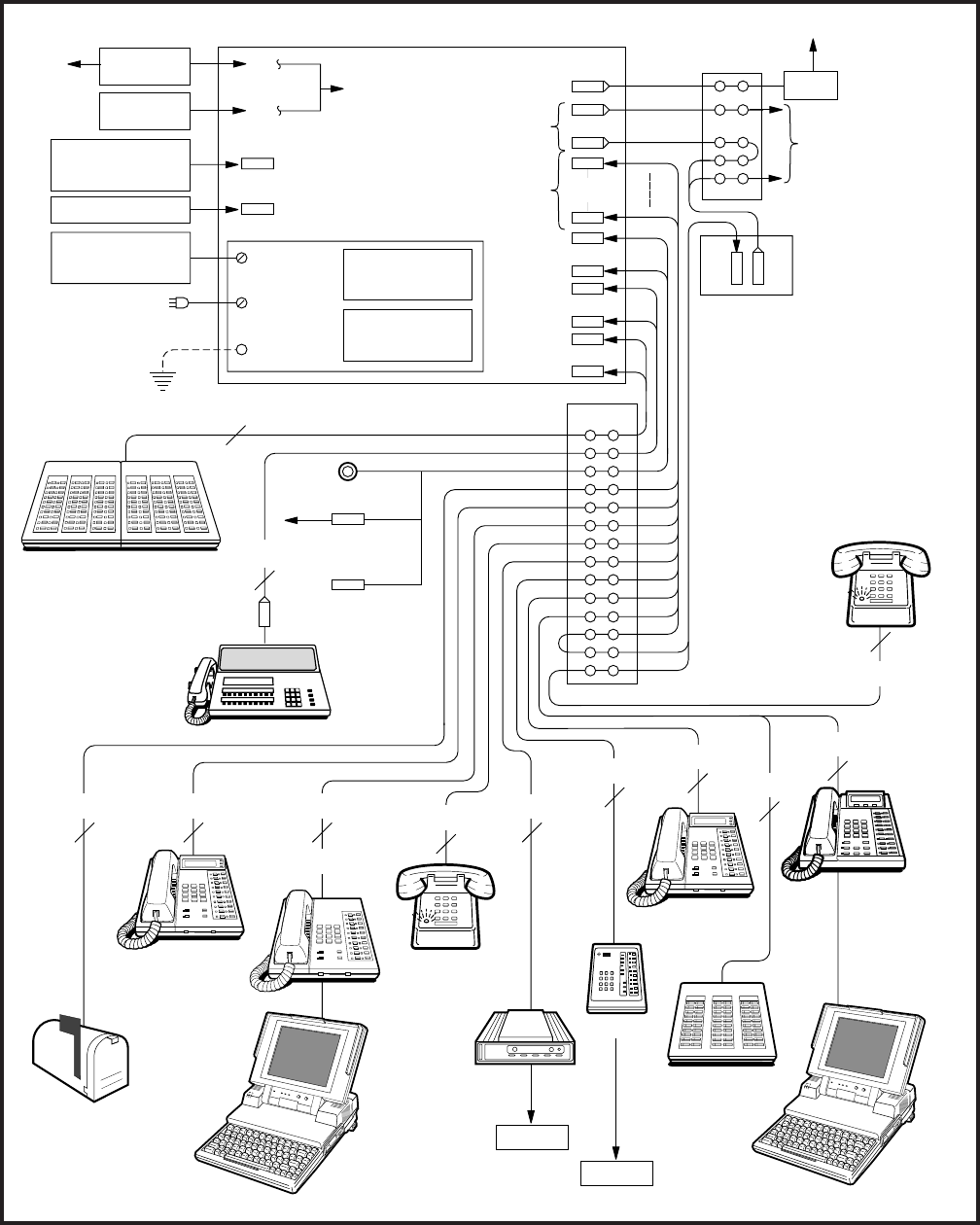
5-2
INSTALLATION INSTRUCTIONS
SECTION 200-255-205
FEBRUARY 1992
FIGURE 5-2—MAIN DISTRIBUTION FRAME LAYOUT
CALL
ACCOUNTING
TTY
(P ONLY)
SMDR
POWER SUPPLY
CHARGER
RINGING
GENERATOR
EXTERNAL
BATTERY
EXT GND
117 VAC
POWER
–24V
TTY
NCOU
NEMU
NLSU
117 VAC
NDTU
NSTU
NEKU
NOCU
NDKU
NDCU
NMDU
NPRU
DATT
NDSU
16
24
2
2
2
e&ex
J2 J1
PFT
TO CO, DID,
OR
TIE TRUNK
MDF B
TO T1 LINE
CSU
MDF A
UNA BELL
PAGING
EQUIP.
MUSIC SOURCE
ELECTRONIC
DSS CONSOLES
ATTENDANT
CONSOLE
DATA
EQUIPMENT
POWER
FAILURE/
EMERGENCY
TELEPHONE
25-PAIR
1-PAIR
MODEM
e
EXTERNAL
GROUND
PERCEPTION CABINETS
VOICE MAIL/
AUTOMATED
ATTENDANT
LCD
ELECTRONIC
TELEPHONE
STANDARD
TELEPHONE
PDIU-DS
RS-232
DDIU-MA
1-PAIR 2-PAIR
1-PAIR
TOSHIBA
RS-232C
DDIU-MAT
3-PAIR 1-PAIR
3-PAIR
EKT W/OCA
MIS AUX
DIGITAL DSS
CONSOLE
DIGITAL
TELEPHONE
WITH PDIU-DI
OR OCA
2-PAIR
1-PAIR
RS-232
DATA
EQUIPMENT
T5100
5100
1-PAIR
T5100
5100
RS-232
2-PAIR
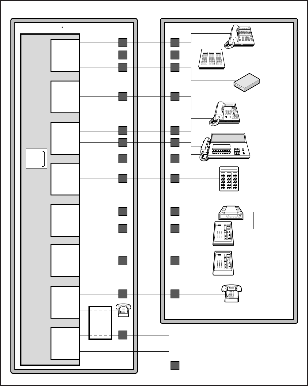
5-3
INSTALLATION INSTRUCTIONS
SECTION 200-255-205
FEBRUARY 1992
FIGURE 5-3—SECONDARY PROTECTOR DIAGRAM
BUILDING #1 BUILDING #2
ELECTRONIC
TELEPHONE
Perceptione
&
ex
R
ATTENDANT
CONSOLE
ELECTRONIC
DIU
-24V
GND
DPFT
102
ELECTRONIC
DSS
CONSOLE
219209
208 218
207 217
206 216
205 215
204 214
203 213
202 212
201 211
200 210 220 230
231221
222 232
223 233
224 234
225 235
226 236
237
227
228 238
229 239 249 NT1
AC
248
247 257
256
246
245 255
254
244
253
243
242 252
241 251
240 250
MODEM
C. O. LINE
C. O. LINE
Shows Secondary Protectors
ELECTRONIC
DIU
STANDARD
TELEPHONE
NOCU
NDCU
NEKU
NMDU
NSTU
NDSU
NCOU
DIGITAL
TELEPHONE
DIGITAL DSS
CONSOLE
DIGITAL
DIU
TOSHIBA
TOSHIBA
POWER
POWER READY CONNECT TEST
DIU
TOSHIBA
NDKU
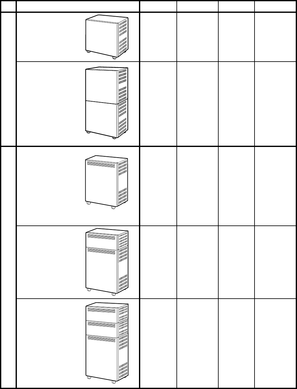
5-4
INSTALLATION INSTRUCTIONS
SECTION 200-255-205
FEBRUARY 1992
TABLE 5-1
CARD SLOT/CABLE CONNECTOR MATRIX
C00
L00
L01
L02
L03
L04/T07
L05/T06
BASIC
EXPANDED
BASIC
EXPANDED
(ONE
EXPANSION
UNIT)
EXPANDED
(TWO
EXPANSION
UNITS)
PERCEPTIONePERCEPTIONex
CONFIGURATION CARD SLOT CONNECTOR CARD SLOT CONNECTOR
L06/T05
L07/T04
L08/T03
L09/T02
L10/T01
L11/T00
J3
J4
J5
J6
J7
J8
J9
J10
J11
J12
J13
J14
J15
C01
L15
L16
L17
L18
L19/T15
L20/T14
L21/T13
L22/T12
L23/T11
L24/T10
L25/T09
L26/T08
J503
J504
J505
J506
J507
J508
J509
J510
J511
J512
J513
J514
J515
U00
U01
U02
U03
U04
U05
U06
U07
T03
T02
T01
T00
U08
U09
U10
U11
U12
U13
U14
U15
T07
T06
T05
T04
J18
J17
J16
J15
J14
J13
J12
J11
J10
J09
J08
J07
J30
J29
J28
J27
J26
J25
J24
J23
J22
J21
J20
J19
U16
U17
U18
U19
U20
U21
U22
U23
T11
T10
T09
T08
J512
J511
J510
J509
J508
J507
J506
J505
J504
J503
J502
J501
U24
U25
U26
U27
U28
U29
U30
U31
T15
T14
T13
T12
J524
J523
J522
J521
J520
J519
J518
J517
J516
J515
J514
J513
TOSHIBA
Perception
e
TOSHIBA
Perceptionex
TOSHIBA
Perceptionex
TOSHIBA
Perception
e
TOSHIBA
Perceptionex
5-5
NOTES:
1. In PERCEPTION the J connector cabinet is determined by 1- and 2-digit numbers indicating the
basic cabinet. Three-digit number connectors are located in the expansion cabinet.
2. In PERCEPTION the J connector cabinet is determined by 1- and 2-digit numbers indicating the
basic cabinet. Three-digit numbers J501 ~ J512 identify expansion cabinet #1. Three-digit
numbers J513 ~ J524 identify expansion cabinet #2.
TABLE 5-2
LIST OF CONNECTOR CABLES
MDF
MDF
MDF
MDF
MDF
From PFT
to MDF
From PFT
to MDF
MDF
MDF
MDF
MDF
From PFT
to MDF
From PFT
to MDF
5-3
5-4
5-5
5-6
5-7
5-8
5-9
5-11
5-10
5-10
5-12
5-13
5-14
5-15
CARD SLOT CONN. NO. CONTENT OF CONNECTOR DESC. TABLE
ATT0 & ATT1
Paging, Music & UNA Ringing
NDSU
NDSU/NEKU/NDKU/NSTU/NDCU/NMDU/NOCU
NDSU/NEKU/NDKU/NSTU/NDCU/NMDU/NOCU
or NCOU/NLSU/NEMU/NDTU
CO Line & NCOU 00~07
(Maximum: 8) (Maximum: 8)
STT Line & NSTU 00~14
(Maximum: 8) (Maximum: 8)
Paging, Music & UNA Ringing
ATT0
ATT1
NCOU/NEMU/NLSU/NDTU
NDSU/NEKU/NDKU/NSTU/NDCU/NMDU/NOCU
or NCOU/NEMU/NLSU
CO Line & NCOU 00~07
(Maximum: 8) (Maximum: 8)
STT Line & NSTU 00~14
(Maximum: 8) (Maximum: 8)
J1 & J501
J2 & J502
J3 & J503
J4~J7 & J504~J507
J8~J15 & J508~J515
PFT Conn. No.
PFT Conn. No.
J1 & J2
J6
J5
J07~J10/J19~J22/
J501~J504/J513~J518
J11~J18/J23~J30/
J505~J512/J517~J524
PFT Conn. No.
PFT Conn. No.
PERCEPTIONe
PERCEPTIONex
1
1
2

5-6
INSTALLATION INSTRUCTIONS
SECTION 200-255-205
FEBRUARY 1992

5-7
PERCEPTION
CONNECTOR TABLES

5-8
INSTALLATION INSTRUCTIONS
SECTION 200-255-205
FEBRUARY 1992
5-5
TABLE 5-3
TERMINAL SEQUENCE & DESIGNATIONS
CONNECTOR NO. J1/J501
ATTENDANT CONSOLE #0 & #1
1T
R
2T
R
3T
R
4T
R
5T
R
6T
R
7T
R
8T
R
9T
R
10T
R
11T
R
12T
R
13T
R
14T
R
15T
R
16T
R
17T
R
18T
R
19T
R
20T
R
21T
R
22T
R
23T
R
24T
R
25T
R
26
1
27
2
28
3
29
4
30
5
31
6
32
7
33
8
34
9
35
10
36
11
37
12
38
13
39
14
40
15
41
16
42
17
43
18
44
19
45
20
46
21
47
22
48
23
49
24
50
25
W-Bl
Bl-W
W-O
O-W
W-G
G-W
W-Br
Br-W
W-S
S-W
R- Bl
Bl-R
R-O
O-R
R-G
G-R
R-Br
Br-R
R-S
S-R
Bk-Bl
Bl-Bk
Bk-O
O-Bk
Bk-G
G-Bk
Bk-Br
Br-Bk
Bk-S
S-Bk
Y-Bl
Bl-Y
Y-O
O-Y
Y-G
G-Y
Y-Br
Br-Y
Y-S
S-Y
V-Bl
Bl-V
V-O
O-V
V-G
G-V
V-Br
Br-V
V-S
S-V
TL
RL
DTL
DRL
Spare
Spare
EMT 0
INIT 0
Spare
MAJ IN 0
Spare
Spare
Spare
Spare
Spare
ATT0-24V
Spare
ATT0-24V
Spare
ATT0-24V
Spare
ATT0-24V
Spare
ATT0-24V
Spare
ATT0-24V
Spare
Spare
Spare
Spare
Spare
Spare
Spare
Spare
Spare
Spare
ATT0 EG
Spare
ATT0 EG
Spare
ATT0 EG
Spare
ATT0 EG
Spare
ATT0 EG
Spare
ATT0 EG
Spare
Spare
Spare
Tip-Line
Ring-Line
Data Tip-Line
Data Ring-Line
Emergency Transfer SWT
Initialize Switch
Major Alarm
-24V
-24V
-24V
-24V
-24V
-24V
Ground
Ground
Ground
Ground
Ground
Ground
NEKU L00/L15
NEKU L00/L15
NEKU L00/L15
NEKU L00/L15
NPRU
NPRU
NPRU
NPRU
NPRU
NPRU
NPRU
NPRU
NPRU
NPRU
NPRU
NPRU
NPRU
NPRU
NPRU
PAIR PIN COLOR
CODE LEAD
DESIGNATION FUNCTION PCB POSITION
001/151
001/151
001/151
001/151
CKT 001
CKT 001
CKT 001
CKT 001
5-6

5-9
TABLE 5-4
TERMINAL SEQUENCE & DESIGNATIONS
CONNECTOR NO. J2/J502
PAGING, MUSIC & UNA RINGING
1T
R
2T
R
3T
R
4T
R
5T
R
6T
R
7T
R
8T
R
9T
R
10T
R
11T
R
12T
R
13T
R
14T
R
15T
R
16T
R
17T
R
18T
R
19T
R
20T
R
21T
R
22T
R
23T
R
24T
R
25T
R
26
1
27
2
28
3
29
4
30
5
31
6
32
7
33
8
34
9
35
10
36
11
37
12
38
13
39
14
40
15
41
16
42
17
43
18
44
19
45
20
46
21
47
22
48
23
49
24
50
25
W-Bl
Bl-W
W-O
O-W
W-G
G-W
W-Br
Br-W
W-S
S-W
R- Bl
Bl-R
R-O
O-R
R-G
G-R
R-Br
Br-R
R-S
S-R
Bk-Bl
Bl-Bk
Bk-O
O-Bk
Bk-G
G-Bk
Bk-Br
Br-Bk
Bk-S
S-Bk
Y-Bl
Bl-Y
Y-O
O-Y
Y-G
G-Y
Y-Br
Br-Y
Y-S
S-Y
V-Bl
Bl-V
V-O
O-V
V-G
G-V
V-Br
Br-V
V-S
S-V
PAIR PIN COLOR
CODE LEAD
DESIGNATION FUNCTION PCB POSITION
PT 1
PR 1
PG 1
PG Gnd
Spare
Spare
MT
MR
Spare
Spare
PG In
PG Out
PG In
PG Out
PG In
PG Out
PG In
PG Out
PG In
PG Out
Spare
Spare
UNA B
UNA A
Spare
Spare
Spare
Spare
Spare
Spare
Spare
Spare
Spare
Spare
Spare
Spare
Spare
Spare
Spare
Spare
Spare
Spare
Spare
Spare
Spare
Spare
Spare
Spare
Spare
Spare
Paging Tip
Paging Ring
Paging Equip. Control
Paging Equip. Common
MOH Source Tip
MOH Source RIng
Paging Amp
Page Zone
Paging Amp
Page Zone
Paging Amp
Page Zone
Paging Amp
Page Zone
Paging Amp
Page Zone
UNA Ringing Ground
UNA Ringing 20 Hz
NPRU
NPRU
NPRU
NPRU
NPRU
NPRU
NPRU
NPRU
NPRU
NPRU
NPRU
NPRU
NPRU
NPRU
NPRU
NPRU
NPRU
NPRU
1
1
2
2
3
3
4
4
5
5
#1 Out
#1 Out
#2 Out
#2 Out
#3 Out
#3 Out
#4 Out
#4 Out
#5 Out
#5 Out
PFT-24 Volts (Ground)
(Power) NPRU
NPRU
5-7
5-10
INSTALLATION INSTRUCTIONS
SECTION 200-255-205
FEBRUARY 1992
5-8
TABLE 5-5
TERMINAL SEQUENCE & DESIGNATIONS FOR PERCEPTION ONLY
CONNECTOR NO. J3.503
NDSU/NDKU (DSS CONSOLES) "C" SLOT
1T
R
2T
R
3T
R
4T
R
5T
R
6T
R
7T
R
8T
R
26
1
27
2
28
3
29
4
30
5
31
6
32
7
33
8
W-Bl
Bl-W
W-O
O-W
W-G
G-W
W-Br
Br-W
W-S
S-W
R- Bl
Bl-R
R-O
O-R
R-G
G-R
PAIR PIN STATION FUNCTION LINE CIRCUITCOLOR CODE
Tip-Line
Ring-Line
Data Tip-Line
Data Ring-Line
Tip-Line
Ring-Line
Data Tip-Line
Data Ring-Line
Tip-Line
Ring-Line
Data Tip-Line
Data Ring-Line
Tip-Line
Ring-Line
Data Tip-Line
Data Ring-Line
CXX1
CXX2
CXX3
CXX4

5-11
5-9
TABLE 5-6
TERMINAL SEQUENCE & DESIGNATIONS
CONNECTOR NO. J4 ~ J7/J504 ~ J507
NDSU/NEKU/NDKU/NSTU/NDCU/NMDU/NOCU (L00 ~ L03/L15 ~ L18)
1T
R
2T
R
3T
R
4T
R
5T
R
6T
R
7T
R
8T
R
9T
R
10T
R
11T
R
12T
R
13T
R
14T
R
15T
R
16T
R
26
1
27
2
28
3
29
4
30
5
31
6
32
7
33
8
34
9
35
10
36
11
37
12
38
13
39
14
40
15
41
16
W-Bl
Bl-W
W-O
O-W
W-G
G-W
W-Br
Br-W
W-S
S-W
R- Bl
Bl-R
R-O
O-R
R-G
G-R
R-Br
Br-R
R-S
S-R
Bk-Bl
Bl-Bk
Bk-O
O-Bk
Bk-G
G-Bk
Bk-Br
Br-Bk
Bk-S
S-Bk
Y-Bl
Bl-Y
PAIR PIN STATION FUNCTION LINE CIRCUITCOLOR CODE
Tip-Line
Ring-Line
Data Tip-Line
Data Ring-Line
Tip-Line
Ring-Line
Data Tip-Line
Data Ring-Line
Tip-Line
Ring-Line
Data Tip-Line
Data Ring-Line
Tip-Line
Ring-Line
Data Tip-Line
Data Ring-Line
Tip-Line
Ring-Line
Data Tip-Line
Data Ring-Line
Tip-Line
Ring-Line
Data Tip-Line
Data Ring-Line
Tip-Line
Ring-Line
Data Tip-Line
Data Ring-Line
Tip-Line
Ring-Line
Data Tip-Line
Data Ring-Line
LXX1
LXX2
LXX3
LXX4
LXX5
LXX6
LXX7
LXX8

5-12
INSTALLATION INSTRUCTIONS
SECTION 200-255-205
FEBRUARY 1992
5-10
TABLE 5-7
TERMINAL SEQUENCE & DESIGNATIONS
CONNECTOR NO. J8 ~ J15/J508 ~ J515
NDSU/NEKU/NDKU/NSTU/NDCU/NMDU/NOCU (L04 ~ L11/L19 ~ L26)
or NCOU/NLSU/NEMU (T07 ~ T00/T15 ~ T08)
1T
R
2T
R
3T
R
4T
R
5T
R
6T
R
7T
R
8T
R
9T
R
10T
R
11T
R
12T
R
13T
R
14T
R
15T
R
16T
R
26
1
27
2
28
3
29
4
30
5
31
6
32
7
33
8
34
9
35
10
36
11
37
12
38
13
39
14
40
15
41
16
W-Bl
Bl-W
W-O
O-W
W-G
G-W
W-Br
Br-W
W-S
S-W
R- Bl
Bl-R
R-O
O-R
R-G
G-R
R-Br
Br-R
R-S
S-R
Bk-Bl
Bl-Bk
Bk-O
O-Bk
Bk-G
G-Bk
Bk-Br
Br-Bk
Bk-S
S-Bk
Y-Bl
Bl-Y
PAIR PIN STATION FUNCTION LINE CIRCUITCOLOR CODE
Tip-Line
Ring-Line
Data Tip-Line
Data Ring-Line
Tip-Line
Ring-Line
Data Tip-Line
Data Ring-Line
Tip-Line
Ring-Line
Data Tip-Line
Data Ring-Line
Tip-Line
Ring-Line
Data Tip-Line
Data Ring-Line
Tip-Line
Ring-Line
Data Tip-Line
Data Ring-Line
Tip-Line
Ring-Line
Data Tip-Line
Data Ring-Line
Tip-Line
Ring-Line
Data Tip-Line
Data Ring-Line
Tip-Line
Ring-Line
Data Tip-Line
Data Ring-Line
LXX1
LXX2
LXX3
LXX4
LXX5
LXX6
LXX7
LXX8
T
R
T1
R1
E
SG
M
SB
T
R
T1
R1
E
SG
M
SB
T
R
T1
R1
E
SG
M
SB
T
R
T1
R1
E
SG
M
SB
TXX1
TXX2
TXX3
TXX4
TRUNK
FUNCTION TRUNK CIRCUIT

5-13
5-11
TABLE 5-8
TERMINAL SEQUENCE & DESIGNATIONS
CENTRAL OFFICE LINE CONNECTION & PFT CONTROL
J1
1T
R
2T
R
3T
R
4T
R
5T
R
6T
R
7T
R
8T
R
9T
R
10T
R
11T
R
12T
R
13T
R
14T
R
15T
R
16T
R
17T
R
18T
R
19T
R
20T
R
21T
R
22T
R
23T
R
24T
R
25T
R
26
1
27
2
28
3
29
4
30
5
31
6
32
7
33
8
34
9
35
10
36
11
37
12
38
13
39
14
40
15
41
16
42
17
43
18
44
19
45
20
46
21
47
22
48
23
49
24
50
25
W-Bl
Bl-W
W-O
O-W
W-G
G-W
W-Br
Br-W
W-S
S-W
R- Bl
Bl-R
R-O
O-R
R-G
G-R
R-Br
Br-R
R-S
S-R
Bk-Bl
Bl-Bk
Bk-O
O-Bk
Bk-G
G-Bk
Bk-Br
Br-Bk
Bk-S
S-Bk
Y-Bl
Bl-Y
Y-O
O-Y
Y-G
G-Y
Y-Br
Br-Y
Y-S
S-Y
V-Bl
Bl-V
V-O
O-V
V-G
G-V
V-Br
Br-V
V-S
S-V
PAIR PIN COLOR
CODE LEAD
DESIGNATION FUNCTION PCB POSITION
T
R
T
R
T
R
T
R
T
R
T
R
T
R
T
R
T
R
T
R
T
R
T
R
T
R
T
R
T
R
T
R
Spare
Spare
Spare
Spare
Spare
Spare
Spare
Spare
Spare
Spare
Spare
Spare
Spare
Spare
Spare
Spare
PFT EG
PFT -24V
Tip-CO
Ring-CO
Tip-NCOU
Ring-NCOU
Tip-CO
Ring-CO
Tip-NCOU
Ring-NCOU
Tip-CO
Ring-CO
Tip-NCOU
Ring-NCOU
Tip-CO
Ring-CO
Tip-NCOU
Ring-NCOU
Tip-CO
Ring-CO
Tip-NCOU
Ring-NCOU
Tip-CO
Ring-CO
Tip-NCOU
Ring-NCOU
Tip-CO
Ring-CO
Tip-NCOU
Ring-NCOU
Tip-CO
Ring-CO
Tip-NCOU
Ring-NCOU
#1
#1
#1
#1
#2
#2
#2
#2
#3
#3
#3
#3
#4
#4
#4
#4
#5
#5
#5
#5
#6
#6
#6
#6
#7
#7
#7
#7
#8
#8
#8
#8
PFT Ground (Input)
PFT -24V (Input) NPRU
NPRU

5-14
INSTALLATION INSTRUCTIONS
SECTION 200-255-205
FEBRUARY 1992
5-12
TABLE 5-9
TERMINAL SEQUENCE & DESIGNATIONS
STATION LINE CONNECTION
J2
1T
R
2T
R
3T
R
4T
R
5T
R
6T
R
7T
R
8T
R
9T
R
10T
R
11T
R
12T
R
13T
R
14T
R
15T
R
16T
R
17T
R
18T
R
19T
R
20T
R
21T
R
22T
R
23T
R
24T
R
25T
R
26
1
27
2
28
3
29
4
30
5
31
6
32
7
33
8
34
9
35
10
36
11
37
12
38
13
39
14
40
15
41
16
42
17
43
18
44
19
45
20
46
21
47
22
48
23
49
24
50
25
W-Bl
Bl-W
W-O
O-W
W-G
G-W
W-Br
Br-W
W-S
S-W
R- Bl
Bl-R
R-O
O-R
R-G
G-R
R-Br
Br-R
R-S
S-R
Bk-Bl
Bl-Bk
Bk-O
O-Bk
Bk-G
G-Bk
Bk-Br
Br-Bk
Bk-S
S-Bk
Y-Bl
Bl-Y
Y-O
O-Y
Y-G
G-Y
Y-Br
Br-Y
Y-S
S-Y
V-Bl
Bl-V
V-O
O-V
V-G
G-V
V-Br
Br-V
V-S
S-V
PAIR PIN COLOR
CODE LEAD
DESIGNATION FUNCTION PCB POSITION
T
R
T
R
T
R
T
R
T
R
T
R
T
R
T
R
T
R
T
R
T
R
T
R
T
R
T
R
T
R
T
R
Spare
Spare
Spare
Spare
Spare
Spare
Spare
Spare
Spare
Spare
Spare
Spare
Spare
Spare
Spare
Spare
Spare
Spare
#1
#1
#1
#1
#2
#2
#2
#2
#3
#3
#3
#3
#4
#4
#4
#4
#5
#5
#5
#5
#6
#6
#6
#6
#7
#7
#7
#7
#8
#8
#8
#8
Tip-TEL
Ring-TEL
Tip-NSTU2
Ring-NSTU2
Tip-TEL
Ring-TEL
Tip-NSTU2
Ring-NSTU2
Tip-TEL
Ring-TEL
Tip-NSTU2
Ring-NSTU2
Tip-TEL
Ring-TEL
Tip-NSTU2
Ring-NSTU2
Tip-TEL
Ring-TEL
Tip-NSTU2
Ring-NSTU2
Tip-TEL
Ring-TEL
Tip-NSTU2
Ring-NSTU2
Tip-TEL
Ring-TEL
Tip-NSTU2
Ring-NSTU2
Tip-TEL
Ring-TEL
Tip-NSTU2
Ring-NSTU2

5-15
PERCEPTION
CONNECTOR TABLES

5-16
INSTALLATION INSTRUCTIONS
SECTION 200-255-205
FEBRUARY 1992
THIS PAGE INTENTIONALLY LEFT BLANK

5-175-13
TABLE 5-10
TERMINAL SEQUENCE & DESIGNATIONS
CONNECTOR NO. J6/J5
ATTENDANT CONSOLE #0 & #1
1T
R
2T
R
3T
R
4T
R
5T
R
6T
R
7T
R
8T
R
9T
R
10T
R
11T
R
12T
R
13T
R
14T
R
15T
R
16T
R
17T
R
18T
R
19T
R
20T
R
21T
R
22T
R
23T
R
24T
R
25T
R
26
1
27
2
28
3
29
4
30
5
31
6
32
7
33
8
34
9
35
10
36
11
37
12
38
13
39
14
40
15
41
16
42
17
43
18
44
19
45
20
46
21
47
22
48
23
49
24
50
25
W-Bl
Bl-W
W-O
O-W
W-G
G-W
W-Br
Br-W
W-S
S-W
R- Bl
Bl-R
R-O
O-R
R-G
G-R
R-Br
Br-R
R-S
S-R
Bk-Bl
Bl-Bk
Bk-O
O-Bk
Bk-G
G-Bk
Bk-Br
Br-Bk
Bk-S
S-Bk
Y-Bl
Bl-Y
Y-O
O-Y
Y-G
G-Y
Y-Br
Br-Y
Y-S
S-Y
V-Bl
Bl-V
V-O
O-V
V-G
G-V
V-Br
Br-V
V-S
S-V
PAIR PIN COLOR
CODE LEAD
DESIGNATION FUNCTION PCB POSITION
TL
RL
DTL
DRL
Spare
Spare
EMT 0
INIT 0
Spare
MAJ IN 0
Spare
Spare
Spare
Spare
Spare
ATT0 -24V
Spare
ATT0 -24V
Spare
ATT0 -24V
Spare
ATT0 -24V
Spare
ATT0 -24V
Spare
ATT0 -24V
Spare
Spare
Spare
Spare
Spare
Spare
Spare
Spare
Spare
Spare
ATT0 EG
Spare
ATT0 EG
Spare
ATT0 EG
Spare
ATT0 EG
Spare
ATT0 EG
Spare
ATT0 EG
Spare
Spare
Spare
NEKU U00/U01
NEKU U00/U01
NEKU U00/U01
NEKU U00/U01
NPRU
NPRU
NPRU
NPRU
NPRU
NPRU
NPRU
NPRU
NPRU
NPRU
NPRU
NPRU
NPRU
NPRU
NPRU
Tip-Line
Ring-Line
Data Tip-Line
Data Ring-Line
Emergency Transfer SWT
Intialize Switch
Major Alarm
-24V
-24V
-24V
-24V
-24V
-24V
Ground
Ground
Ground
Ground
Ground
Ground
001
001
001
001
CKT 001
CKT 001
CKT 001
CKT 001

5-18
INSTALLATION INSTRUCTIONS
SECTION 200-255-205
FEBRUARY 1992
5-14
TABLE 5-11
TERMINAL SEQUENCE & DESIGNATIONS
CONNECTOR NO. J1 & J2
PAGING, MUSIC & UNA RINGING
1T
R
2T
R
3T
R
4T
R
5T
R
6T
R
7T
R
8T
R
9T
R
10T
R
11T
R
12T
R
13T
R
14T
R
15T
R
16T
R
17T
R
18T
R
19T
R
20T
R
21T
R
22T
R
23T
R
24T
R
25T
R
26
1
27
2
28
3
29
4
30
5
31
6
32
7
33
8
34
9
35
10
36
11
37
12
38
13
39
14
40
15
41
16
42
17
43
18
44
19
45
20
46
21
47
22
48
23
49
24
50
25
W-Bl
Bl-W
W-O
O-W
W-G
G-W
W-Br
Br-W
W-S
S-W
R- Bl
Bl-R
R-O
O-R
R-G
G-R
R-Br
Br-R
R-S
S-R
Bk-Bl
Bl-Bk
Bk-O
O-Bk
Bk-G
G-Bk
Bk-Br
Br-Bk
Bk-S
S-Bk
Y-Bl
Bl-Y
Y-O
O-Y
Y-G
G-Y
Y-Br
Br-Y
Y-S
S-Y
V-Bl
Bl-V
V-O
O-V
V-G
G-V
V-Br
Br-V
V-S
S-V
PAIR PIN COLOR
CODE LEAD
DESIGNATION FUNCTION PCB POSITION
PT 1
PR 1
PG 1
PG Gnd
Spare
Spare
MT
MR
Spare
Spare
PG In
PG Out
PG In
PG Out
PG In
PG Out
PG In
PG Out
PG In
PG Out
Spare
Spare
UNA B
UNA A
Spare
Spare
Spare
Spare
Spare
Spare
Spare
Spare
Spare
Spare
Spare
Spare
Spare
Spare
Spare
Spare
Spare
Spare
Spare
Spare
Spare
Spare
Spare
Spare
Spare
Spare PFT-24 Volts (Ground)
(Power)
1
1
2
2
3
3
4
4
5
5
#1 Out
#1 Out
#2 Out
#2 Out
#3 Out
#3 Out
#4 Out
#4 Out
#5 Out
#5 Out
NPRU
NPRU
Paging Tip
Paging Ring
Paging Equip. Control
Paging Equip. Common
MOH Source Tip
MOH Source Ring
Paging Amp
Paging Zone
Paging Amp
Paging Zone
Paging Amp
Paging Zone
Paging Amp
Paging Zone
Paging Amp
Paging Zone
UNA Ringing Ground
UNA Ringing 20 Hz
NPRU
NPRU
NPRU
NPRU
NPRU
NPRU
NPRU
NPRU
NPRU
NPRU
NPRU
NPRU
NPRU
NPRU
NPRU
NPRU
NPRU
NPRU

5-19
NOTE:
The NDTU may be installed in T00 or T08, connectors J07 and J501 respectively. It may not be used
in universal slots.
5-15
TABLE 5-12
TERMINAL SEQUENCE & DESIGNATIONS
CONNECTOR NO. J07 ~ J10/J19 ~ J22/J501 ~ J504/J513 ~ J518
NCOU/NEMU/NLSU/NDTU (T00 ~ T15)
1T
R
2T
R
3T
R
4T
R
5T
R
6T
R
7T
R
8T
R
9T
R
10T
R
11T
R
12T
R
13T
R
14T
R
15T
R
16T
R
26
1
27
2
28
3
29
4
30
5
31
6
32
7
33
8
34
9
35
10
36
11
37
12
38
13
39
14
40
15
41
16
W-Bl
Bl-W
W-O
O-W
W-G
G-W
W-Br
Br-W
W-S
S-W
R- Bl
Bl-R
R-O
O-R
R-G
G-R
R-Br
Br-R
R-S
S-R
Bk-Bl
Bl-Bk
Bk-O
O-Bk
Bk-G
G-Bk
Bk-Br
Br-Bk
Bk-S
S-Bk
Y-Bl
Bl-Y
PAIR PIN COLOR CODE
T
R
T1
R1
E
SG
M
SB
T
R
T1
R1
E
SG
M
SB
T
R
T1
R1
E
SG
M
SB
T
R
T1
R1
E
SG
M
SB
TXX1
TXX2
TXX3
TXX4
TRUNK
FUNCTION TRUNK CIRCUIT

5-20
INSTALLATION INSTRUCTIONS
SECTION 200-255-205
FEBRUARY 1992
5-16
TABLE 5-13
TERMINAL SEQUENCE & DESIGNATIONS
CONNECTOR NO. J11 ~ J18/J23 ~ J30/J505 ~ J512/J517 ~ J524
NDSU/NEKU/NDKU/NSTU/NDCU/NMDU/NOCU (U00 ~ U31) or NCOU/NEMU/NLSU (T16 ~ T31)
1T
R
2T
R
3T
R
4T
R
5T
R
6T
R
7T
R
8T
R
9T
R
10T
R
11T
R
12T
R
13T
R
14T
R
15T
R
16T
R
26
1
27
2
28
3
29
4
30
5
31
6
32
7
33
8
34
9
35
10
36
11
37
12
38
13
39
14
40
15
41
16
W-Bl
Bl-W
W-O
O-W
W-G
G-W
W-Br
Br-W
W-S
S-W
R- Bl
Bl-R
R-O
O-R
R-G
G-R
R-Br
Br-R
R-S
S-R
Bk-Bl
Bl-Bk
Bk-O
O-Bk
Bk-G
G-Bk
Bk-Br
Br-Bk
Bk-S
S-Bk
Y-Bl
Bl-Y
PAIR PIN STATION FUNCTION LINE CIRCUITCOLOR CODE
Tip-Line
Ring-Line
Data Tip-Line
Data Ring-Line
Tip-Line
Ring-Line
Data Tip-Line
Data Ring-Line
Tip-Line
Ring-Line
Data Tip-Line
Data Ring-Line
Tip-Line
Ring-Line
Data Tip-Line
Data Ring-Line
Tip-Line
Ring-Line
Data Tip-Line
Data Ring-Line
Tip-Line
Ring-Line
Data Tip-Line
Data Ring-Line
Tip-Line
Ring-Line
Data Tip-Line
Data Ring-Line
Tip-Line
Ring-Line
Data Tip-Line
Data Ring-Line
LXX1
LXX2
LXX3
LXX4
LXX5
LXX6
LXX7
LXX8
T
R
T1
R1
E
SG
M
SB
T
R
T1
R1
E
SG
M
SB
T
R
T1
R1
E
SG
M
SB
T
R
T1
R1
E
SG
M
SB
TXX1
TXX2
TXX3
TXX4
TRUNK
FUNCTION TRUNK CIRCUIT

5-215-17
TABLE 5-14
TERMINAL SEQUENCE & DESIGNATIONS
CENTRAL OFFICE LINE CONNECTION & PFT CONTROL
J1
1T
R
2T
R
3T
R
4T
R
5T
R
6T
R
7T
R
8T
R
9T
R
10T
R
11T
R
12T
R
13T
R
14T
R
15T
R
16T
R
17T
R
18T
R
19T
R
20T
R
21T
R
22T
R
23T
R
24T
R
25T
R
26
1
27
2
28
3
29
4
30
5
31
6
32
7
33
8
34
9
35
10
36
11
37
12
38
13
39
14
40
15
41
16
42
17
43
18
44
19
45
20
46
21
47
22
48
23
49
24
50
25
W-Bl
Bl-W
W-O
O-W
W-G
G-W
W-Br
Br-W
W-S
S-W
R- Bl
Bl-R
R-O
O-R
R-G
G-R
R-Br
Br-R
R-S
S-R
Bk-Bl
Bl-Bk
Bk-O
O-Bk
Bk-G
G-Bk
Bk-Br
Br-Bk
Bk-S
S-Bk
Y-Bl
Bl-Y
Y-O
O-Y
Y-G
G-Y
Y-Br
Br-Y
Y-S
S-Y
V-Bl
Bl-V
V-O
O-V
V-G
G-V
V-Br
Br-V
V-S
S-V
PAIR PIN COLOR
CODE LEAD
DESIGNATION FUNCTION PCB POSITION
Tip-CO
Ring-CO
Tip-NCOU
Ring-NCOU
Tip-CO
Ring-CO
Tip-NCOU
Ring-NCOU
Tip-CO
Ring-CO
Tip-NCOU
Ring-NCOU
Tip-CO
Ring-CO
Tip-NCOU
Ring-NCOU
Tip-CO
Ring-CO
Tip-NCOU
Ring-NCOU
Tip-CO
Ring-CO
Tip-NCOU
Ring-NCOU
Tip-CO
Ring-CO
Tip-NCOU
Ring-NCOU
Tip-CO
Ring-CO
Tip-NCOU
Ring-NCOU
T
R
T
R
T
R
T
R
T
R
T
R
T
R
T
R
T
R
T
R
T
R
T
R
T
R
T
R
T
R
T
R
Spare
Spare
Spare
Spare
Spare
Spare
Spare
Spare
Spare
Spare
Spare
Spare
Spare
Spare
Spare
Spare
PFT EG
PFT -24V PFT Ground (Input)
PFT -24V (Input) NPRU
NPRU
#1
#1
#1
#1
#2
#2
#2
#2
#3
#3
#3
#3
#4
#4
#4
#4
#5
#5
#5
#5
#6
#6
#6
#6
#7
#7
#7
#7
#8
#8
#8
#8

5-22
INSTALLATION INSTRUCTIONS
SECTION 200-255-205
FEBRUARY 1992
5-18
TABLE 5-15
TERMINAL SEQUENCE & DESIGNATIONS
STATION LINE CONNECTION
J2
1T
R
2T
R
3T
R
4T
R
5T
R
6T
R
7T
R
8T
R
9T
R
10T
R
11T
R
12T
R
13T
R
14T
R
15T
R
16T
R
17T
R
18T
R
19T
R
20T
R
21T
R
22T
R
23T
R
24T
R
25T
R
26
1
27
2
28
3
29
4
30
5
31
6
32
7
33
8
34
9
35
10
36
11
37
12
38
13
39
14
40
15
41
16
42
17
43
18
44
19
45
20
46
21
47
22
48
23
49
24
50
25
W-Bl
Bl-W
W-O
O-W
W-G
G-W
W-Br
Br-W
W-S
S-W
R- Bl
Bl-R
R-O
O-R
R-G
G-R
R-Br
Br-R
R-S
S-R
Bk-Bl
Bl-Bk
Bk-O
O-Bk
Bk-G
G-Bk
Bk-Br
Br-Bk
Bk-S
S-Bk
Y-Bl
Bl-Y
Y-O
O-Y
Y-G
G-Y
Y-Br
Br-Y
Y-S
S-Y
V-Bl
Bl-V
V-O
O-V
V-G
G-V
V-Br
Br-V
V-S
S-V
PAIR PIN COLOR
CODE LEAD
DESIGNATION FUNCTION PCB POSITION
T
R
T
R
T
R
T
R
T
R
T
R
T
R
T
R
T
R
T
R
T
R
T
R
T
R
T
R
T
R
T
R
Spare
Spare
Spare
Spare
Spare
Spare
Spare
Spare
Spare
Spare
Spare
Spare
Spare
Spare
Spare
Spare
Spare
Spare
#1
#1
#1
#1
#2
#2
#2
#2
#3
#3
#3
#3
#4
#4
#4
#4
#5
#5
#5
#5
#6
#6
#6
#6
#7
#7
#7
#7
#8
#8
#8
#8
Tip-TEL
Ring-TEL
Tip-NSTU2
Ring-NSTU2
Tip-TEL
Ring-TEL
Tip-NSTU2
Ring-NSTU2
Tip-TEL
Ring-TEL
Tip-NSTU2
Ring-NSTU2
Tip-TEL
Ring-TEL
Tip-NSTU2
Ring-NSTU2
Tip-TEL
Ring-TEL
Tip-NSTU2
Ring-NSTU2
Tip-TEL
Ring-TEL
Tip-NSTU2
Ring-NSTU2
Tip-TEL
Ring-TEL
Tip-NSTU2
Ring-NSTU2
Tip-TEL
Ring-TEL
Tip-NSTU2
Ring-NSTU2
AUGUST 1991
