022 PETRO Gauge Veeder Root TLS4 Operators Manual
User Manual: manual pdf -FilePursuit
Open the PDF directly: View PDF ![]() .
.
Page Count: 41

Manual No: 577014-022 ● Revision: B
Site Prep Certification Manual
8601 Series Console

ii
Notice
Veeder-Root makes no warranty of any kind with regard to this publication, including, but not limited to, the implied warranties of
merchantability and fitness for a particular purpose.
Veeder-Root shall not be liable for errors contained herein or for incidental or consequential damages in connection with the furnishing,
performance, or use of this publication.
Veeder-Root reserves the right to change system options or features, or the information contained in this publication.
This publication contains proprietary information which is protected by copyright. All rights reserved. No part of this publication may be
photocopied, reproduced, or translated to another language without the prior written consent of Veeder-Root.
Contact TLS Systems Technical Support for additional troubleshooting information at 800-323-1799.
DAMAGE CLAIMS / LOST EQUIPMENT
Thoroughly examine all components and units as soon as they are received. If any cartons are damaged or missing, write a complete
and detailed description of the damage or shortage on the face of the freight bill. The carrier's agent must verify the inspection and sign
the description. Refuse only the damaged product, not the entire shipment.
Veeder-Root must be notified of any damages and/or shortages within 30 days of receipt of the shipment, as stated in our Terms and
Conditions.
VEEDER-ROOT’S PREFERRED CARRIER
1. Contact Veeder-Root Customer Service at 800-873-3313 with the specific part numbers and quantities that were missing or
received damaged.
2. Fax signed Bill of Lading (BOL) to Veeder-Root Customer Service at 800-234-5350.
3. Veeder-Root will file the claim with the carrier and replace the damaged/missing product at no charge to the customer. Customer
Service will work with production facility to have the replacement product shipped as soon as possible.
CUSTOMER’S PREFERRED CARRIER
1. It is the customer’s responsibility to file a claim with their carrier.
2. Customer may submit a replacement purchase order. Customer is responsible for all charges and freight associated with
replacement order. Customer Service will work with production facility to have the replacement product shipped as soon as
possible.
3. If “lost” equipment is delivered at a later date and is not needed, Veeder-Root will allow a Return to Stock without a restocking fee.
4. Veeder-Root will NOT be responsible for any compensation when a customer chooses their own carrier.
RETURN SHIPPING
For the parts return procedure, please follow the appropriate instructions in the "General Returned Goods Policy” pages in the
"Policies and Literature" section of the Veeder-Root North American Environmental Products price list. Veeder-Root will not accept
any return product without a Return Goods Authorization (RGA) number clearly printed on the outside of the package.
©Veeder-Root 2014. All rights reserved.

Table of Contents
iii
Introduction
Related Documents ...................................................................................................................................1
Documents Required to Install Equipment ................................................................................1
Related Manuals .........................................................................................................................................1
Safety Symbols ...........................................................................................................................................2
National Electrical Code Compliance ...................................................................................................3
Probe- and Sensor-to-Console Wiring.......................................................................................3
AC Power Wiring.............................................................................................................................3
DC Power Wiring ............................................................................................................................3
Component Identification .........................................................................................4
Console Wiring Inputs ................................................................................................7
Probe And Sensor Field Wiring ..........................................................................10
Console Installation
Console Location .................................................................................................................................... 11
Mounting the Console ........................................................................................................................... 11
Wiring the Console ................................................................................................................................ 11
AC Input Power............................................................................................................................. 12
DC Input Power ............................................................................................................................ 13
Probe and Sensor Conduit Installation
Wiring Run Methods .............................................................................................................................. 14
Buried Rigid Conduit ................................................................................................................... 14
Direct Burial Cable ....................................................................................................................... 15
Initial Startup Procedure
TLS4 GUI Navigation................................................................................................................... 17
TLS4 Initial Setup ......................................................................................................................... 17
Appendix A: Universal Sensor Mounting Kit
Introduction .............................................................................................................................................A-1
Product Description ..............................................................................................................................A-1
Kit Contents ..................................................................................................................................A-1
Mounting Sensors .................................................................................................................................A-1
Appendix B: Enabling The TLS4 To Function As A Datalogger
BIR Protocol DIM .................................................................................................................................. B-1
POS System Requirements and Limitations ........................................................................ B-1
Datalogger Site Connection and Initialization ................................................................................ B-1
Figures
Figure 1. TLS4/8601 Series Console - Dimensions .......................................................4
Figure 2. Component Locations (Front Cover Removed) ..............................................5
Figure 3. Component Locations Underside Of Display/CPU Board Ass’y. ....................6
Figure 4. Field Wiring Probe And Sensor Cables To Console Cables .........................10
Figure 5. Wiring AC Power to the Console ...................................................................12
Figure 6. Wiring DC Power to the Console ..................................................................13
Figure 7. Example Probe Wiring Run in Buried Rigid Conduit .....................................15
Figure 8. Example Probe Wiring Run via Direct Burial Cable ......................................16
Figure A-1. Universal Mounting Kit Contents ................................................................. A-1
Figure A-2. Mounting the Sensor in a Stabilizer Tube to a Support Bar ........................ A-2

Table of Contents
iv
Figure A-3. Mounting the Sensor in the Dispenser Pan ................................................. A-3
Figure A-4. Mounting the Sensor using Two Extension Brackets .................................. A-4
Figure A-5. Mounting the Sensor to Rigid Conduit ........................................................ A-5
Figure A-6. Mounting the Sensor to a Supply Line ........................................................ A-6
Figure A-7. Mounting the Sensor in a Containment Sump ............................................ A-7
Figure B-1. Configuring LAN .......................................................................................... B-2
Figure B-2. Local Area Connection ‘X’ Properties dialog box selections ....................... B-3
Figure B-3. Internet Protocol Version 4 (TCP/IPv4) Properties dialog box selections ... B-4
Figure B-4. Ethernet Port Setup ..................................................................................... B-6
Figure B-5. Serial Port Setup, SERIAL 2- POS ............................................................. B-6
Figure B-6. Entering ATG Command ............................................................................. B-7
Figure B-7. Deleting ATG Command ............................................................................. B-7
Figure B-8. TDIM Setup ................................................................................................. B-8
Figure B-9. Entering Host name .................................................................................... B-8
Figure B-10. Verifying DIM Communication ..................................................................... B-9
Figure B-11. Entering Date and Time .............................................................................. B-9
Figure B-12. Selecting System Units ............................................................................... B-9
Figure B-13. Switching to DL Setup ............................................................................... B-10
Figure B-14. Example FMS ID Entry .............................................................................. B-10
Figure B-15. Inventory Command Results ..................................................................... B-11
Figure B-16. POS Protocol Type Query ......................................................................... B-11
Figure B-17. POS Protocol Type Results ...................................................................... B-11
Figure B-18. FMS Heartbeat Screen ............................................................................. B-12
Tables
Table 1. TLS4 Wiring Inputs .....................................................................................................7
Table B-1. POS Systems Using V-R Protocol* ..................................................................... B-1
Table B-2. Datalogger User Interface Screens ..................................................................... B-5
1
Introduction
This manual assumes that you are installing the console in a new site (before pavement is put down and with no
wiring runs in place). Among the topics covered are:
• Related documents
• Installing the console
• Component locations
• Console specifications/features
• Connecting wiring from the AC power panel or DC power source
• Installing wiring conduit between the console and probes and sensors
If installing ATEX (European) approved Mag Probes use Manual No. 577014-031, if installing UL/cUL
approved Mag Probes use Manual No. 577013-744.
Related Documents
DOCUMENTS REQUIRED TO INSTALL EQUIPMENT
This equipment must be installed according to the applicable installation document:
Related Manuals
577013-578 TLS Monitoring Systems Contractor’s Site Preparation Guide
576013-858 Direct Burial Cable Installation Guide
577013-034 TLS4 Quick Start Guide
Equipment
ATEX
Descriptive System
IECEx
Descriptive System
UL/cUL
Control Drawing
Document No. Document No. Document No.
Associated Apparatus
8601 Series Console 331940-017 331940-117 331940-018
Intrinsically Safe Apparatus for Wireless Applications
Tank Gauge Accessories 331940-005 331940-105 331940-012
Introduction Safety Symbols
2
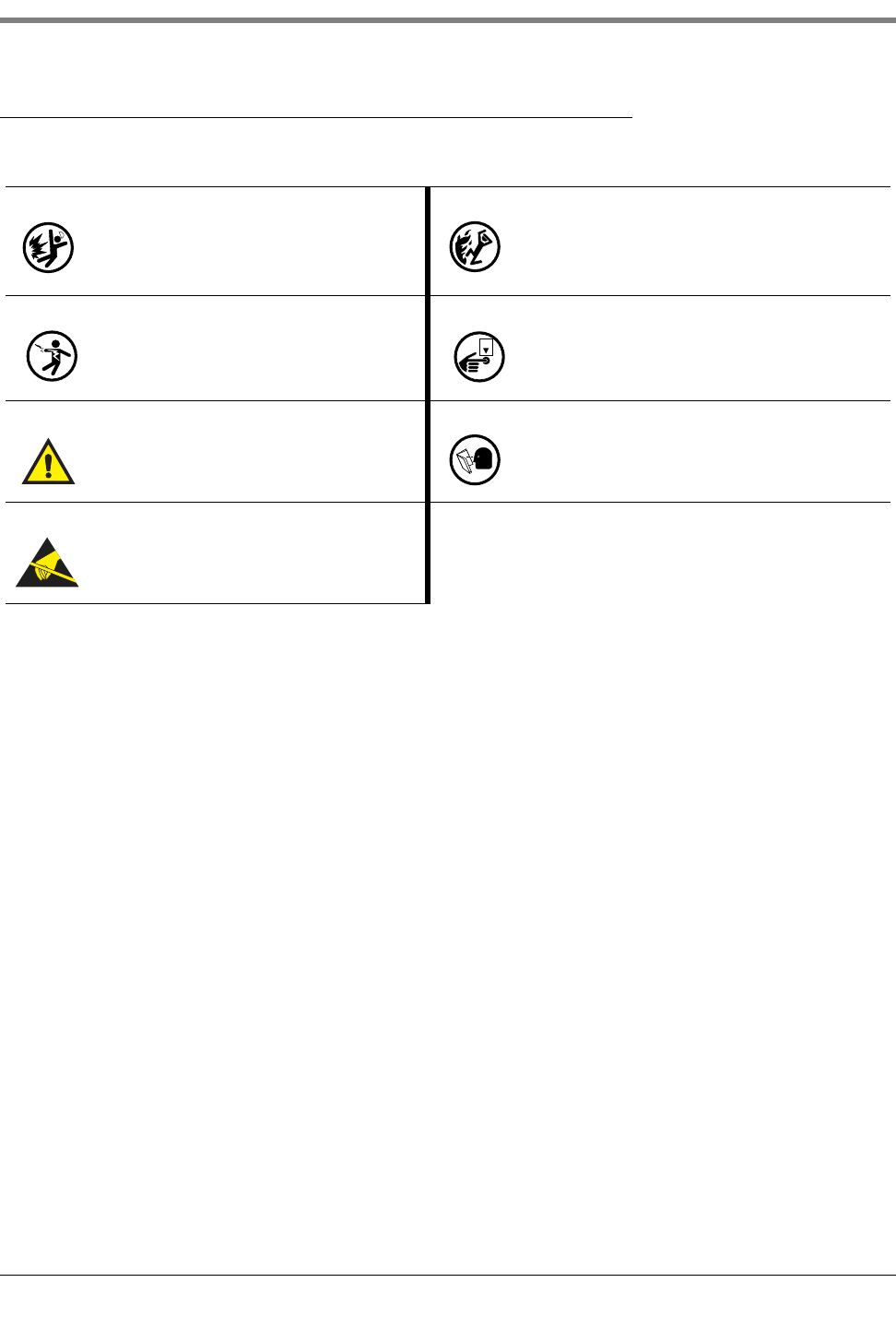
Safety Symbols
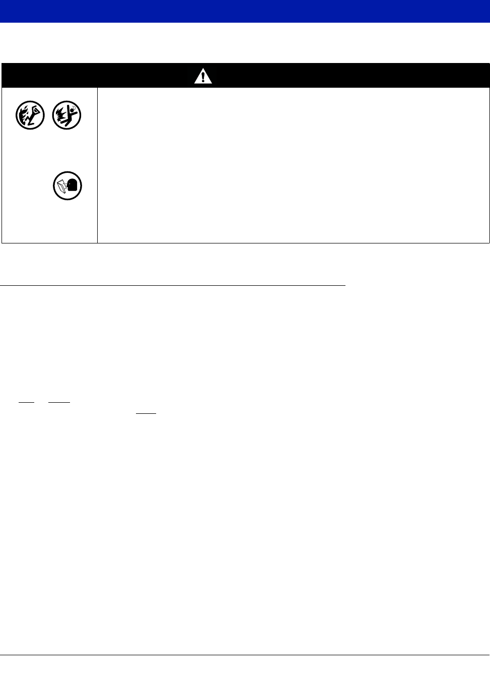
The following safety symbols are used in this manual to alert you to important safety hazards and precautions.
EXPLOSIVE
Fuels and their vapors are extremely explosive if
ignited.
FLAMMABLE
Fuels and their vapors are extremely flammable.
ELECTRICITY
High voltage exists in, and is supplied to, the
device. A potential shock hazard exists.
TURN POWER OFF
Live power to a device creates a potential shock haz-
ard. Turn Off power to the device and associated
accessories when servicing the unit.
WARNING
Heed the adjacent instructions to avoid damage to
equipment, property, environment or personal
injury.
READ ALL RELATED MANUALS
Knowledge of all related procedures before you begin
work is important. Read and understand all manuals
thoroughly. If you do not understand a procedure, ask
someone who does.
STATIC SENSITIVE COMPONENTS
Wear grounded anti-static wrist strap before han-
dling the printed circuit boards and mounted com-
ponents.
OFF

Introduction National Electrical Code Compliance
3
National Electrical Code Compliance
The following information is for general reference and is not intended to replace recommended National Electric
Code (NEC) procedures. It is important for the installer to understand that electrical equipment and wiring located
in Class I, Division 1 and 2 installations shall comply with the latest appropriate Articles found in the National
Electric Code (NFPA 70), the Code for Motor Fuel Dispensing Facilities and Repair Garages (NFPA 30A), CEC
codes and all applicable local codes.
PROBE- AND SENSOR-TO-CONSOLE WIRING
Wire Type
To ensure the best operating systems available, Veeder-Root REQUIRES the use of shielded cable for all probes
and sensors regardless of conduit material or application. In these installations, shielded cable must be rated less
than 100 picofarad per foot and be manufactured with a material suitable for the environment, such as Carol™
C2534 or Belden™ 88760, 8760, or 8770.
Note: Throughout this manual, when mentioning any cable or wire being used for probe and sensor to console
wiring, it will be referring to shielded cable.
Wire Length
Improper system operation could result in undetected potential environmental and health hazards if the probe- or
sensor-to-console wire runs exceed 1000 feet. Wire runs must be less than 1000 feet to meet intrinsic safety
requirements.
Wire Gauges - Color coded
Shielded cable must be used in all installations. Sensor-to-console wires should be #14-#18 AWG stranded
copper wire and installed as Class 2 circuits. As an alternate method when approved by the local authority having
jurisdiction, #22 AWG wire such as Belden 88761 may be suitable in installations with the following provisions:
• Wire run is less than 750 feet
• Capacitance does not exceed 100 pF/foot
• Inductance does not exceed 0.2 μH/foot
AC POWER WIRING
Wires carrying 120 or 240 Vac from the power panel to the console should be #14 AWG (or larger) wire for line,
neutral and chassis ground (3); and 4 sq. mm, rated for at least 90°C, for barrier ground.
DC POWER WIRING
Wires carrying +24 and +5 Vdc from the DC power source to the console should be #14 AWG wire. For barrier
ground, 4 sq. mm wire, rated for at least 90°C.
4
Component Identification
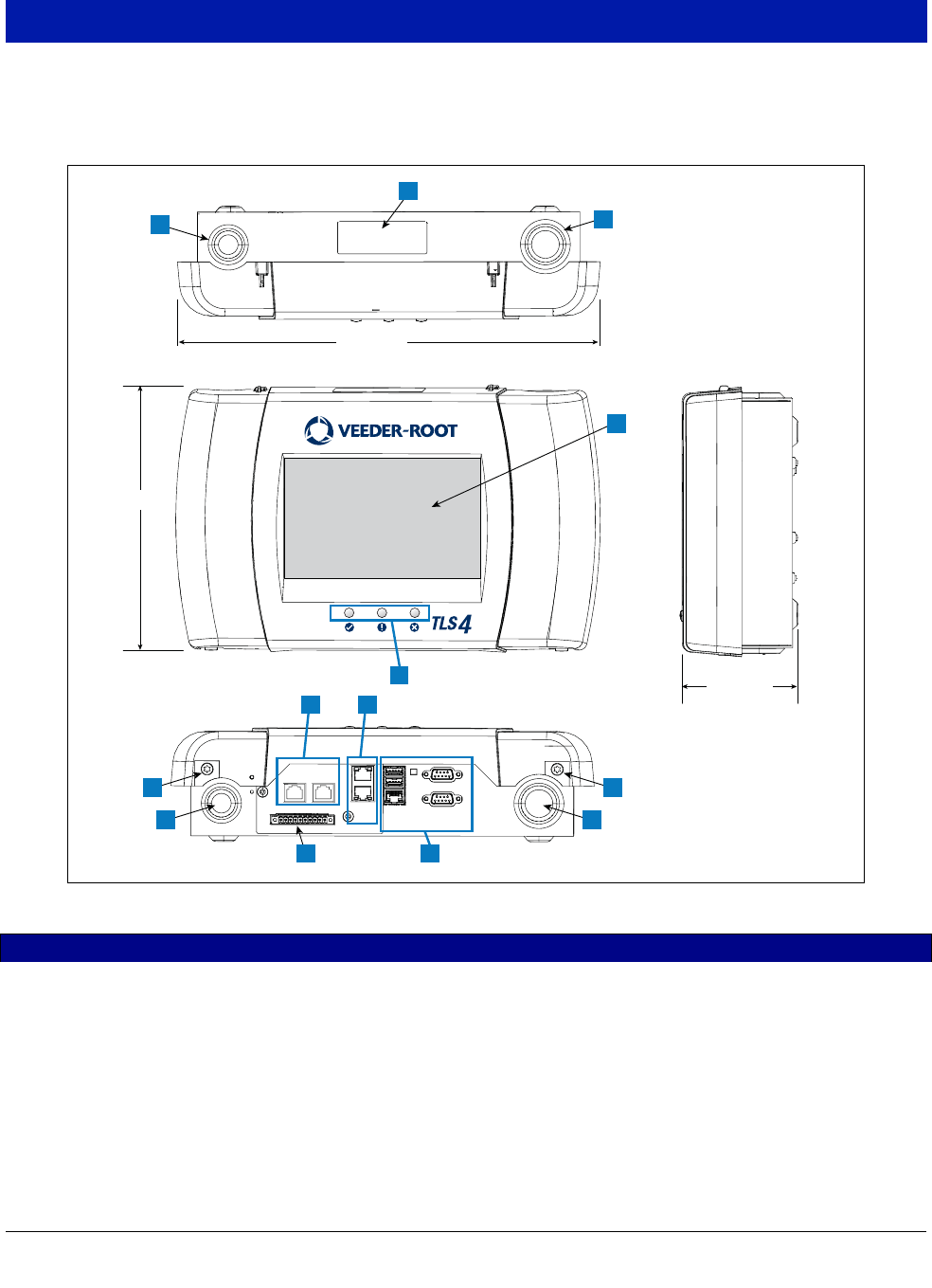
Figure 1 through Figure 3 show assembly and component locations referenced in the troubleshooting section of
this manual.
Figure 1. TLS4/8601 Series Console - Dimensions and Hardware
LEGEND FOR NUMBERED BOXES IN Figure 1
1. Power conduit knockout (1 top/1 bottom)
2. Console label contains input power ratings and Form and Serial
number
3. Intrinsically safe wiring conduit knockout (1 top/1 bottom)
4. Optional touch screen display
5. Status LEDs
6. T15 screws secure cover (2 places)
7. Communication ports - Standard:
Serial Ports 1 and 2
USB ports 1 and 2
Ethernet port 1
8. Communication ports - Optional:
Integrated Ethernet Switch ports 2 and 3
9. CDIM ports 1 and 2 (optional)
10.Expansion port
8” (204mm)
3.5” (89mm)
13” (331mm)
1
66
1 3
3
CDIM 1 CDIM 2
ETH 2
ETH 3 USB 1
USB 2
ETH 1
SERIAL 1
SERIAL 2
EXPANSION
2
7
9
10
5
4
110
8

Component Identification National Electrical Code Compliance
5
Figure 2. Component Locations (Front Cover Removed)
LEGEND FOR NUMBERED BOXES IN Figure 2
1. AC or DC input power connector (as ordered)
2. High voltage output relay connector
3. Low voltage external input connector
4. T15 screw secures Display/CPU assembly
5. Rechargeable 3V Lithium battery (battery backup)
6. RS232/485 selection jumpers SERIAL 1 (P1) and SERIAL 2
(P2)(factory set to RS232 position)
7. T20 screw secures Display/CPU assembly
8. Optional 6-device intrinsically safe input connector (7 - 12)
9. Standard 6-device intrinsically safe input connector (1 - 6)
10.Optional Graphical User Interface (GUI) display (on non-dis-
play consoles, the GUI display is replaced with the Alarm
Reset (Acknowledge) button panel shown below):
11.Battery Isolator - Remove and discard prior to startup.
12.Mounting Holes - 0.28” (7mm) diameter holes - (2 hole versions -
upper left and lower right corners; 4 hole versions - all four cor-
ners) .
3
1
12
2
467
8
P2 RS485
J39
J38
P2 RS232
P1 RS485
P1 RS232
9
+
+
10
5 11
ALARM
RESET
Component Identification National Electrical Code Compliance
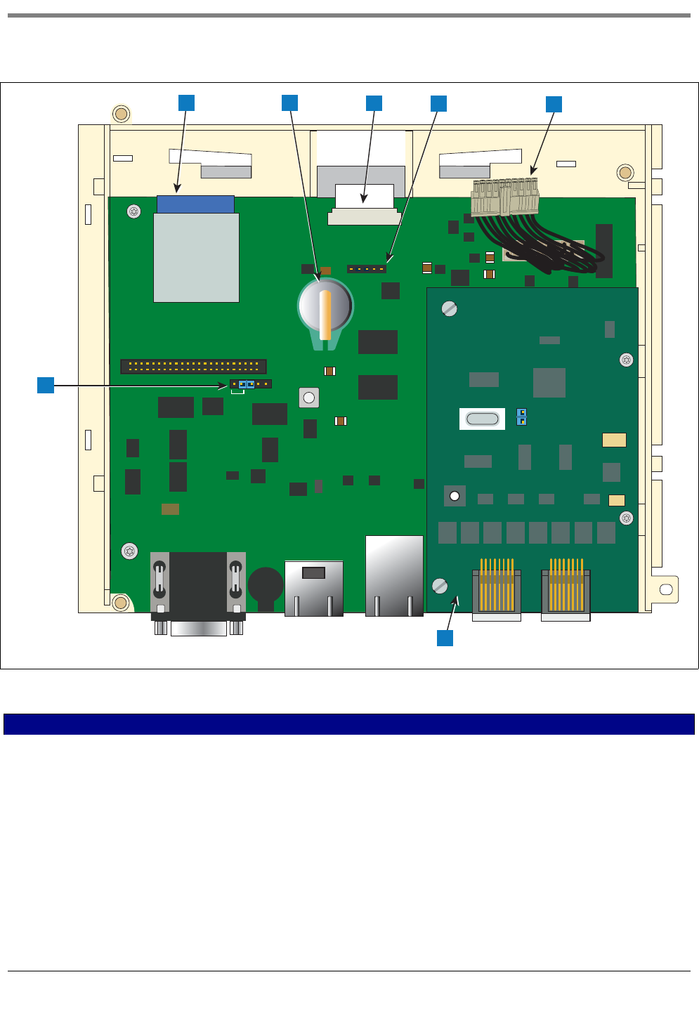
6
Figure 3. Component Locations Underside Of Display/CPU Board Ass’y.
LEGEND FOR NUMBERED BOXES IN Figure 3
1. J36 Mode Jumper (shown in Operating Mode Position)
2. SD Card
3. Software Features iButton
4. Display ribbon cable connector - Consoles with GUI display only
5. Acknowledge switch cable connector (J40) - Consoles without
GUI display only
6. 20-pin Display/CPU-to-USIOM board cable
7. Optional CDIM card
J36
J40
Tec h
1
1
2 3 456
7

7
Console Wiring Inputs
This section details TLS4 power, communication, and device input connections and requirements.
Table 1. TLS4 Wiring Inputs
Connector Description
Input Power
(Item 1, Figure 2) NOTE: The TLS4/8601 Series console is factory configured for either AC input power or DC input
power, but not both.
Universal AC power supply:100 to 249Vac, 50/60Hz, 2A maximum; or
DC power supply (optional): +24Vdc, 2A max. and +5Vdc, 4A max.
Um <= 250Vrms or 250Vdc
240 Vac input: 1 - N/L2 (black), 2 - Ground (green), 3 - L1 (red)
120 Vac Input: 1 - N/L2 (white), 2 - Ground (green), 3 - L1 (black)
+24/+5 Vdc Input: 1 - +24 (white), 2 - Ground (green), 3 - +5 (black). NOTE: This input wiring diagram is
only for consoles with DC Power option.
HV Relay
Outputs
(Item 2, Figure 2)
2 Relay Outputs:
120/240 Vac, 5A; 30 Vdc, 5A;
Fuse ratings 5A, 250 Vac Type T (Slo-Blo)
1
2
3
1
2
3
1
2
3
2
022-9
1
Console Wiring Inputs National Electrical Code Compliance
8
Low Voltage
Inputs
(Item 3, Figure 2)
1 Low Voltage Input:
Maximum contact closure circuit ratings 12 Vdc, 0.015A
Class I wiring is required for these 12 volt closure circuits.
Legend Pin Input
Dry Contact Switch 1 RTN
212V
For Future Use 3 PWR STAT
4PWR INT
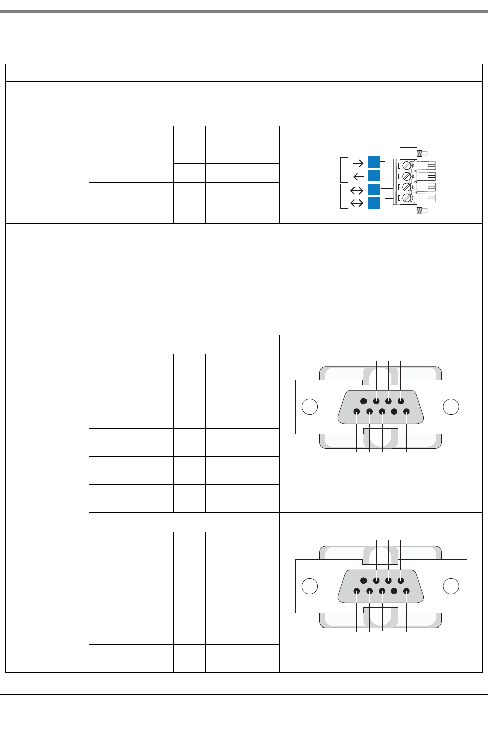
RS-232 Ports
(Item 7 in Figure 1)
2 optically isolated serial ports standard, labeled SERIAL 1 supporting full handshaking and SERIAL 2.
The RS-232 D-connector is a panel mount, 9-pin female type, wired in a Data Terminal Equipment (DTE) configura-
tion. For example, any RS-232 port in any TLS consoles is also a DTE, therefore, a Null Cable is needed in order for
communication to happen between the two consoles.
A Data Communication Equipment (DCE) device such as a modem may be connected directly to the interface using
a straight-through cable (modem support may not be available on all ATGs). Handshake signals in the system are
configurable.
RS-232 signals are wired to the female D-connectors as follows:
SERIAL1 (Full Handshake)
Pin Signal Pin Signal
1 Data Carrier
Detect
6 Data Set Ready
2 Received
Data
7 Request to Send
3 Transmitted
Data
8 Clear to Send
4Data Termi-
nal Ready
9Ring Indicator
5 Signal
Ground
SERIAL 2
Pin Signal Pin Signal
1 6
2 Received
Data
7
3 Transmitted
Data
8
49
5 Signal
Ground
Table 1. TLS4 Wiring Inputs
Connector Description
1
2
1
2
3
4
022-6
54321
9876
022-6
54321
9876
Console Wiring Inputs National Electrical Code Compliance
9
Ethernet Ports 3 Ethernet ports, labeled ETH 1 Standard, ETH 2 and ETH 3 (provided on an optional integrated switch) (Item 8 in
Figure 1)
CDIM Ports Optional RJ-45/RJ-485 serial ports, labeled CDIM 1 and CDIM 2 (Item 9 in Figure 1)
USB Ports 2 USB ports, labeled USB 1 and USB 2 (Item 7 in Figure 1)
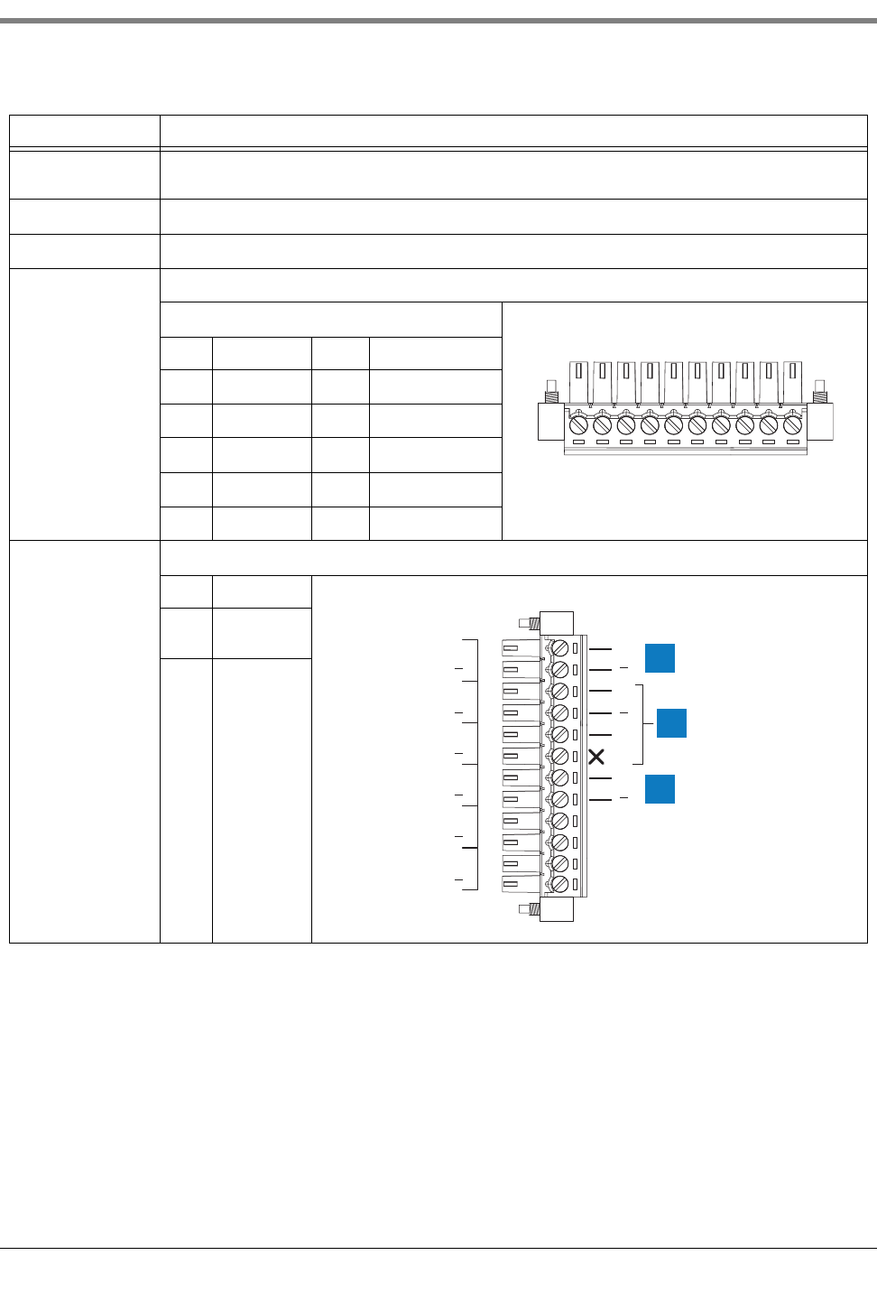
Expansion Port 10-pin connector VR bus, labeled EXPANSION (Item 10 in Figure 1)
Legend
Pin Signal Pin Signal
1 +W 6 Ground
2-W 7 +24 Vdc
3 +15 Vdc 8 +Expansion Bus
4 Ground 9 – Expansion Bus
5 N/C 10 Expansion Reset
Intrinsically Safe
inputs 6 or 12 universal intrinsically safe inputs as ordered (Items 8 and 9 in Figure 2)
Item Description
1 Typical 2-
wire device
2 Typical 3-
wire device
Table 1. TLS4 Wiring Inputs
Connector Description
12345678910
( )
(+) (+)
(+)
(+)
( )
(+)
( )
(+)
( )
( )
( )
(+)
( )
(+)
( )
(+)
( )
(+)
1
2
3
4
5
6
1
1
2
10
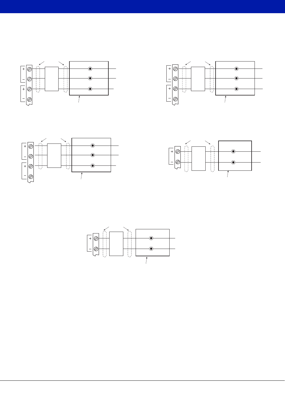
Probe And Sensor Field Wiring
Figure 4 contains diagrams for connecting, at the field junction box, cables from the probes and sensors to cables
from the console. Check diagrams closely for polarity requirements.
Figure 4. Field Wiring Probe And Sensor Cables To Console Cables
Black
Vapor Sensor
Red
Green
White
From
Sensor
Groundwater Sensor
Epoxy sealed connections in a
weatherproof junction box
1/2'' rigid
conduit 1/2'' rigid
conduit
1/2'' rigid
conduit
Seal-off
1/2'' rigid
conduit
1/2'' rigid
conduit
Position Sensitive Interstitial Sensor for Steel Tanks
Interstitial Sensor For Steel Tanks
CSTP Liquid Switch
Black
From
Sensor
White
Epoxy sealed connections in a
weatherproof junction box
Seal-off
1
2
TLS4
I.S.
Te r m i n als
1
2
TLS4
I.S.
Te r m i n als
1
2
TLS4
I.S.
Te r m i n alsRed
Black
White
From
Sensor
Epoxy sealed connections in a
weatherproof junction box
Seal-off
Green
Black
White
From
Sensor
Epoxy sealed connections in a
weatherproof junction box
Seal-off
Black
Red
From
Sensor
Epoxy sealed connections in a
weatherproof junction box
Seal-off
1
TLS4
I.S.
Terminals
1
TLS4
I.S.
Terminals
Magnetostrictive Probe
Position-Sensitive Sensor
Solid-State Containment Sump Sensor
Sump Sensor
Solid-State Dispenser Pan Sensor
Solid-State Discriminating Interstitial Liquid Sensor For Fiberglass Tanks
Discriminating Containment Sump Sensor
Hydrostatic Sensors For Fiberglass Tanks
Interstitial Sensor For Fiberglass Tanks
Microsensor
4SITE Solid-State Discriminating Containment Sump Sensor
4SITE Solid-State Discriminating Dispenser Pan Sensor
Not used with
3-wire sensor
Not used with
3-wire sensor
Not used with
3-wire sensor
11
Console Installation
Console Location
For console location, refer to the ‘System Consoles’ section of manual 577013-578 on the Veeder-Root Tech Docs
CD-ROM prior to installing the 8601 Series Console.
Mounting the Console
To mount the console remove the two T15 screws in the bottom of the cover (see Figure 1). As you lift up the
bottom of the cover it pivots on two tabs that project from the top of the console’s chassis into slots in the top of
the cover. Lift the cover off the chassis tabs and set it aside. Notice the corner mounting holes in the base of the
chassis (Item 12 in Figure 2). Locate the chassis on the wall in the desired mounting location, mark the hole
locations, drill the appropriate pilot holes; and using 1/4-inch (6mm) maximum fasteners (customer supplied),
attach the chassis to the mounting surface at all four locations.
Figure 1 shows the two designated knockouts through which power wiring can safely enter the console.
Wiring the Console
The 8601 Series Console can be operated using either AC or DC power.
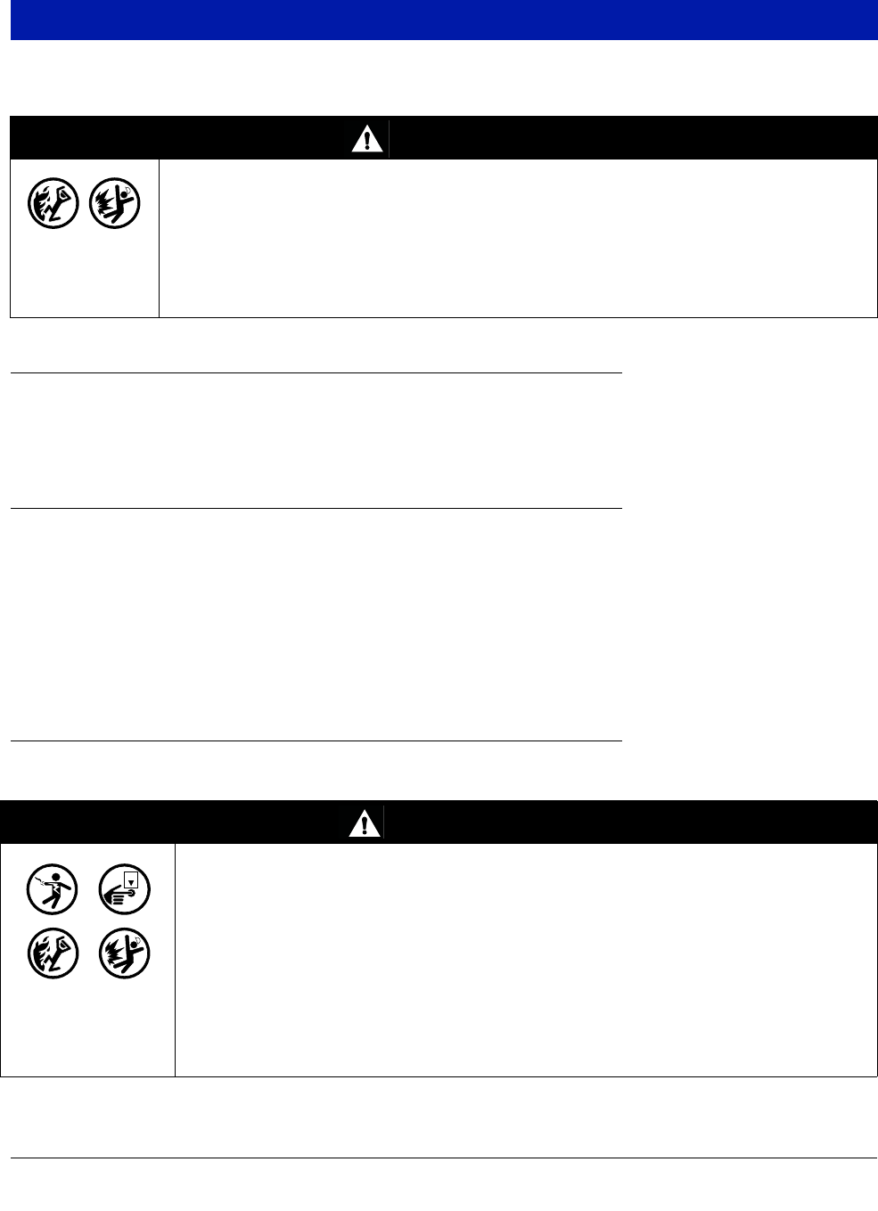
WARNING
Explosive vapors or flammable liquids could be present near locations where fuels are
stored or being dispensed.
This console is not explosion proof. Do not install this console in a volatile, combustible,
or explosive atmosphere.
An explosion or fire resulting in serious injury or death, property loss and equipment
damage could occur if the console is installed in a volatile, combustible or explosive
atmosphere (Class I, Division 1 or 2).
WARNING
This console contains high voltages which can be lethal. It is also connected to low
power devices that must be kept intrinsically safe.
1. Turn power off at the circuit breaker. Do not connect the console AC power
supply wires at the breaker until all devices are installed.
2. Attach conduit from the power panel to the console's Power Area
knockouts only.
Connecting power wires to a live circuit can cause electrical shock that may result in
serious injury or death.
Routing conduit for power wires into the intrinsically safe compartment can result in fire
or explosion resulting in serious injury or death.
OFF
Console Installation Wiring the Console
12
AC INPUT POWER
1. Check the Input power rating on the label affixed to the underside of the console to verify whether input power
requirements are 120 Vac or 240 Vac.
2. Pull four wires between the power panel and the console; three #14 AWG or larger color-coded wires for AC
line (hot), AC neutral and chassis ground; and one 4 sq. mm wire, rated for at least 90°C, for barrier ground.
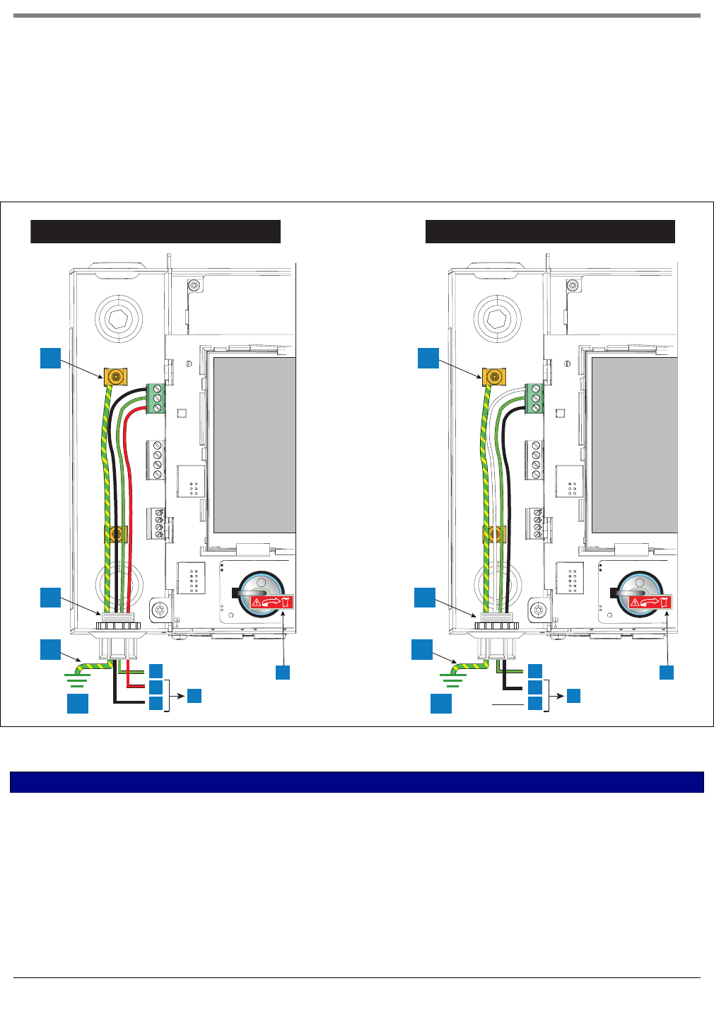
3. Connect the input 120 or 240 Vac power wires as shown in Figure 5.
Figure 5. Wiring AC Power to the Console
LEGEND FOR NUMBERED BOXES IN Figure 5
1. Attach barrier wire to grounding clamp
2. Power connector conduit entry
3. Equipotential bonding conductor (4 sq. mm min.)
4. Earth ground
5. GND (green)
6. L1 (Red)
7. N/L2 (black)
8. (To 240 Vac breaker in power panel)
9. L1 (black)
10. N/L2 (white)
11. (To 120 Vac breaker in power panel)
12. Battery Isolator - Remove and discard prior to startup.
240 Vac 120 Vac
1
2
3
4
2
3
4
1
5
6
78
5
9
10 11
++
12 12
Console Installation Wiring the Console
13
DC INPUT POWER
1. Check the Input Power Rating on the label affixed to the underside of the console to verify whether input
power requirements are +24Vdc and +5Vdc.
1. Pull three wires between the DC power source and the console; three #14 AWG or larger color-coded wires
for +24 Vdc, +5Vdc and Ground; and one 4 sq. mm wire, rated for at least 90°C, for barrier ground.
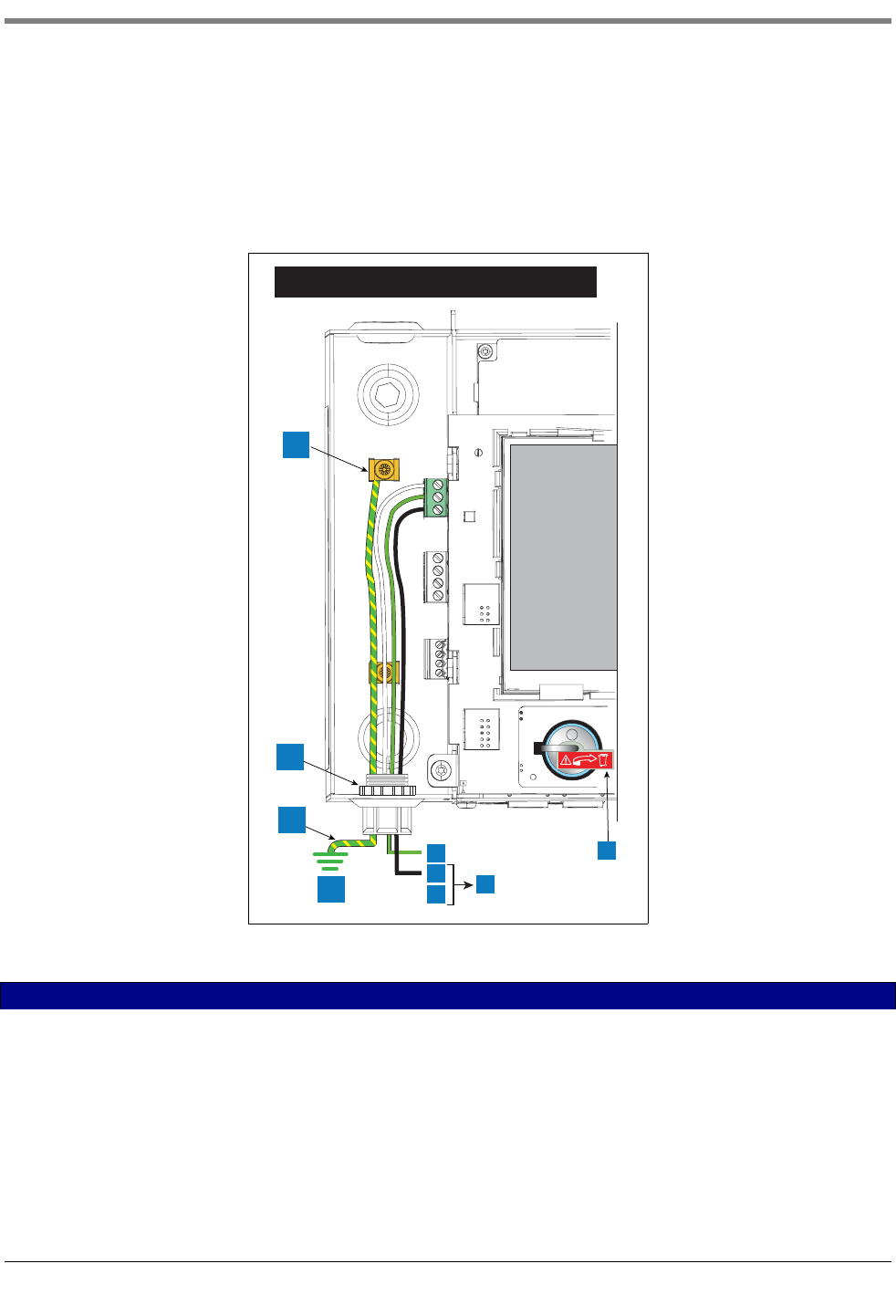
2. Connect the DC power wires as shown in Figure 6.
Figure 6. Wiring DC Power to the Console
LEGEND FOR NUMBERED BOXES IN Figure 6
1. Attach barrier wire to grounding clamp
2. Power connector conduit entry
3. Equipotential bonding conductor (4 sq. mm min.)
4. Earth ground
5. GND (green)
6. +5 Vdc (black)
7. +24 Vdc (white)
8. To DC power source
9. Battery Isolator - Remove and discard prior to startup.
+24 and +5 Vdc
1
2
3
4
5
6
78
+
9
14
Probe and Sensor Conduit Installation
Wiring Run Methods
Two wiring run methods are commonly used for probes and sensors - Wiring pulled through buried, sealed 1/2”
conduit; or direct burial cable. NOTE: PVC conduit is an acceptable alternate where accepted by local codes [ref.
“National Electrical Code Compliance” on page 3 for more detail on cable requirements].
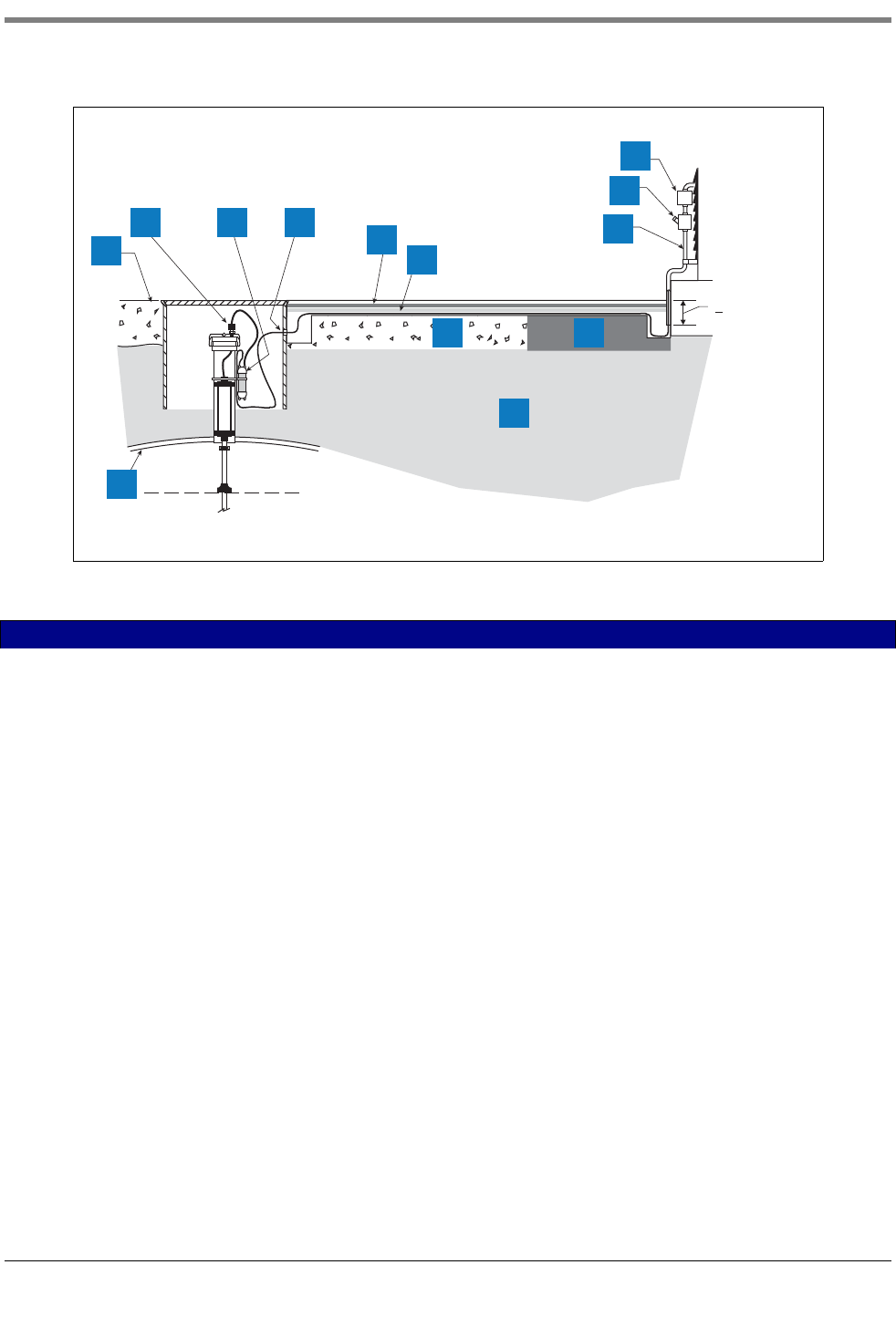
BURIED RIGID CONDUIT
The preferred method, especially in new sites before driveway surfaces are paved, is to pull probe and sensor
wiring through buried 1/2” rigid conduit [Figure 7].
Pull two or three conductors shielded cable (as required). Individual wires should be color-coded between the
console and the junction box at each probe and sensor location (do not gang wires together, i.e., splicing all sump
sensor + wires together to run one wire back to console). Use single lengths of wire with no splices to ensure
optimum signal strength.
WARNING
Probes and sensors operate in areas where flammable liquids and explosive vapors
may be present.
Improper installation may result in fire or explosion causing serious injury or death.
Practice the following:
1. Read thoroughly and follow the instructions shipped with each probe and
sensor.
2. Probe and sensor wiring conduit must not contain any other wires.
3. Probe and sensor wiring and conduits must enter the console only
through their designated areas.
4. Power and communication wires must not enter the intrinsically safe
compartment of the console.
Probe and Sensor Conduit Installation Wiring Run Methods
15
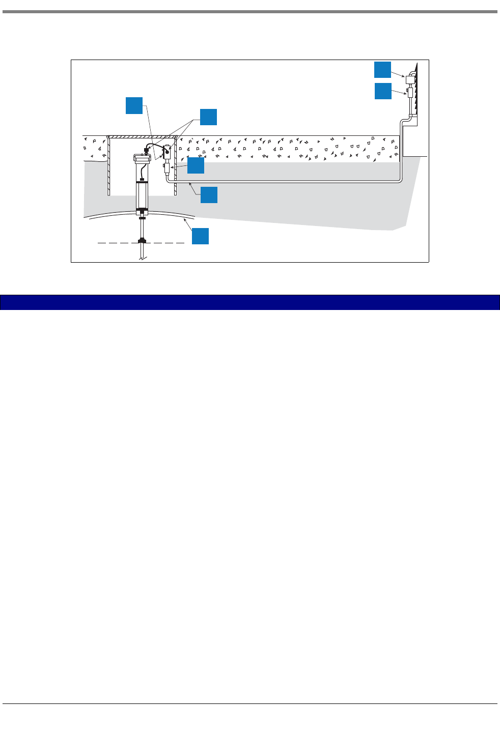
Figure 7. Example Probe Wiring Run in Buried Rigid Conduit
CAUTION: Since wires for multiple sensors may enter the console through a single conduit, it is recommended
that you use a different color-code for each wire or individually mark each wire to identify sensor inputs. Also, if the
intrinsically safe wires enter the building in a wiring trough, only Veeder-Root intrinsically safe wire can be in the
trough. Keep all low power (intrinsically safe) wiring isolated from high power wires in all wiring troughs.
DIRECT BURIAL CABLE
An alternative to trenching through existing pavement is to use direct burial cable. Before considering the direct
burial method, check to be sure that direct burial practices are acceptable by the authority having jurisdiction at
this location. The direct burial method requires grinding using an abrasive wheel, a 1/4” to 3/8” wide by 1-1/4”
deep groove (adding 1/4” of depth for each additional cable) in the pavement surface, laying Veeder-Root supplied
direct burial cable down in the bottom of the groove, laying an expanded polyethylene foam backer rod over the
cable(s), and then a placing a 1/4” to 1/2” bead of silicone sealant over the backer rod to within a minimum of 3/8”
below the pavement surface [see Figure 8].
If you decide upon the direct burial method, consult the direct burial cable installation manual for detailed
installation instructions (reference manual 576013-858).
LEGEND FOR NUMBERED BOXES IN Figure 7
1. Weatherproof junction box with 1/2-inch N.P.T. threads (16
cubic inch minimum)
2. Cord grip seals
3. Splice Closure
4. Seal-Off
5. Epoxy seal per NFPA spec
6. 1/2'' rigid conduit (to console)
7. Tank
022-12
.
..
.
.
..
.
.
.
..
.
.
.
..
.
.
.
.
..
.
.
..
..
.
.
..
.
.
.
.
..
.
.
.
..
.
.
.
..
.
.
..
.
.
.
..
.
.
.
..
.
.
..
.
.
.
..
.
.
.
..
.
.
.
.
..
.
.
..
.
.
.
..
.
.
.
.
.
..
.
.
..
.
.
.
.
.
.
..
.
.
.
.
..
.
.
..
.
.
.
..
.
.
..
.
.
.
.
..
.
.
..
.
.
.
..
.
..
.
..
.
.
.
.
.
.
.
.
.
..
.
..
.
.
.
.
..
.
.
..
.
.
.
..
.
.
1
2
3
5
6
7
4
Probe and Sensor Conduit Installation Wiring Run Methods
16
Figure 8. Example Probe Wiring Run via Direct Burial Cable
LEGEND FOR NUMBERED BOXES IN Figure 8
1. Grade
2. Cord grip
3. Epoxy filled splice enclosure
4. Drill oversized hole in sump for DB cable
5. Dow Corning 890-SL silicone Pavement Sealant
6. Expanded polyethylene foam backer rod, e.g., Applied-Extru-
sion Technologies SOF ROD
7. Splice closure
8. Seal-off
9. Rigid conduit
10. Concrete
11. Asphalt
12. Earth
13. Tank
.
..
.
.
..
.
.
.
..
.
.
.
..
.
.
..
.
.
.
..
.
.
.
..
.
.
..
.
.
.
..
.
.
.
..
.
.
..
.
.
.
..
.
.
.
..
.
.
.
.
..
.
.
..
.
.
.
..
.
.
..
.
.
.
.
..
.
.
..
.
.
.
..
.
022-13
.
..
.
.
..
.
.
.
..
.
..
.
.
.
.
.
.
....
.
.....
.
1
2 3 4 5
6
7
8
9
10 11
12
13
>3'' (76mm)

17
Initial Startup Procedure
Once the probes, sensors, communication devices, etc., are connected to the console, remove and discard the
backup battery isolator strip (item 11 in Figure 2).
Replace front cover. Attach a label to the breaker feeding the console. This allows others to know how to
disconnect power to the console when servicing the system. Communicate to facility personnel which breaker
feeds the console.
Switch the dedicated circuit breaker ON to apply power to the console.
TLS4 GUI NAVIGATION
If the operation of the TLS4 is unfamiliar, review the TLS4 Quick Help Guide (P/N 577014-034) or, after the home
screen displays, touch the Actions icon , then the Help icon to open the TLS4 console’s online help.
Once online help displays, touch the Show TOC link in the top left of the display to view the online help’s Table Of
Contents. Read the Welcome, Explanation of Screen Icons, How to Use On-Screen Keyboard and Using
Touchscreen with Help topics.
TLS4 INITIAL SETUP
In the online help Table Of Contents, touch the Configuration and Maintenance book and then open the Initial
Console Setup Sequence topic and follow the console setup procedures therein.
A-1
Appendix A: Universal Sensor Mounting Kit
Introduction
This addendum describes installation procedures for the Universal Mounting Kit for Dispenser Pan and
Containment Sump Sensors, Part Number 331144-001.
Since you can use the Universal Mounting Kit in a variety of ways, only the most commonly used mounting
methods are described.
Product Description
The Universal Mounting Kit is compatible with most manufacturer’s dispenser pans and containment sumps and
provides added flexibility when mounting the sensors.
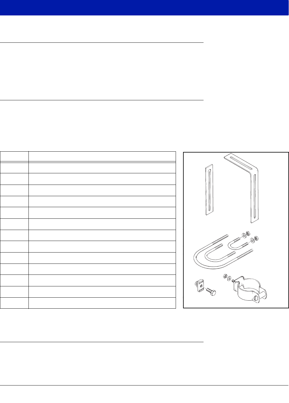
KIT CONTENTS
The Universal Mounting Kit, Part No. 331144-001 consists of:
Figure A-1. Universal Mounting Kit Contents
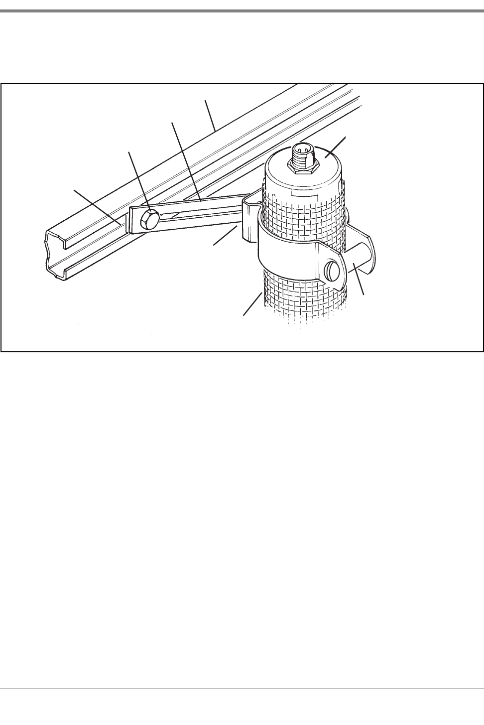
Mounting Sensors
Depending on the type of pan you are using, you can configure the Universal Mounting Kit in several different
ways. Some of the more frequently used mounting methods are illustrated in the following figures using selected
components from the kit as required. The spacer for the1-1/2 inch machine screw is only needed with a stabilizer
Quantity Description
2 Extension brackets (see Item 1, Figure A-1)
1 L-bracket (see Item 2, Figure A-1)
1 3/4-inch U-bolt (see Item 3, Figure A-1)
1 1-inch U-bolt (see Item 3, Figure A-1)
1 2-inch U-bolt (see Item 3, Figure A-1)
1 3/8-inch spring nut (see Item 4, Figure A-1)
1 3/8-16 X 7/8-inch bolt (see Item 4, Figure A-1)
4 1/4-20 nut
3 1/4-20 x 3/4-inch bolt
4 1/4 flat washer
1 1/4-20 x 1-1/2 inch machine screw (See Item 5, Figure A-1)
1 2-inch sensor clamp (See Item 5, Figure A-1)
1 1/4 X 1-inch spacer (See Item 5, Figure A-1)
1
3
4
5
2
sensors\unsnkt.eps
Appendix A: Universal Sensor Mounting Kit Mounting Sensors
A-2
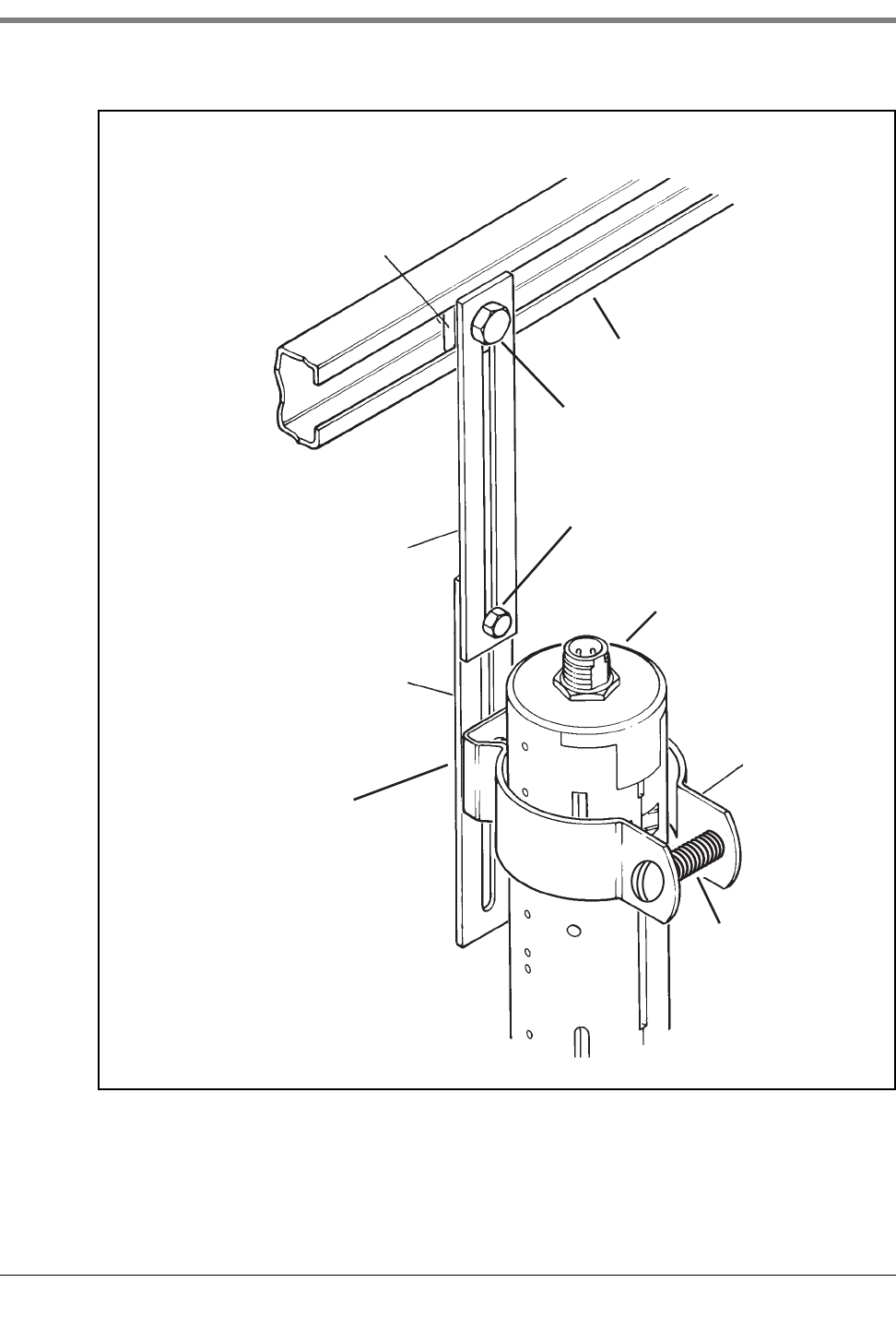
tube to prevent excess clamping pressure on the sensor (see Figure A-2).
Figure A-2. Mounting the Sensor in a Stabilizer Tube to a Support Bar
Sensor stabilizer tube
Sensor
Support bar
sensors\snstbtb.eps
Spacer
w/ 1/4-20 x 1-1/2" lg
machine screw and
washer and nut
3/8-16 Spring nut
3/8-16 x 7/8 hex bolt
Extender bracket
1/4-20 x 3/4 hex bolt
w/ washer and nut
(not shown)
Appendix A: Universal Sensor Mounting Kit Mounting Sensors
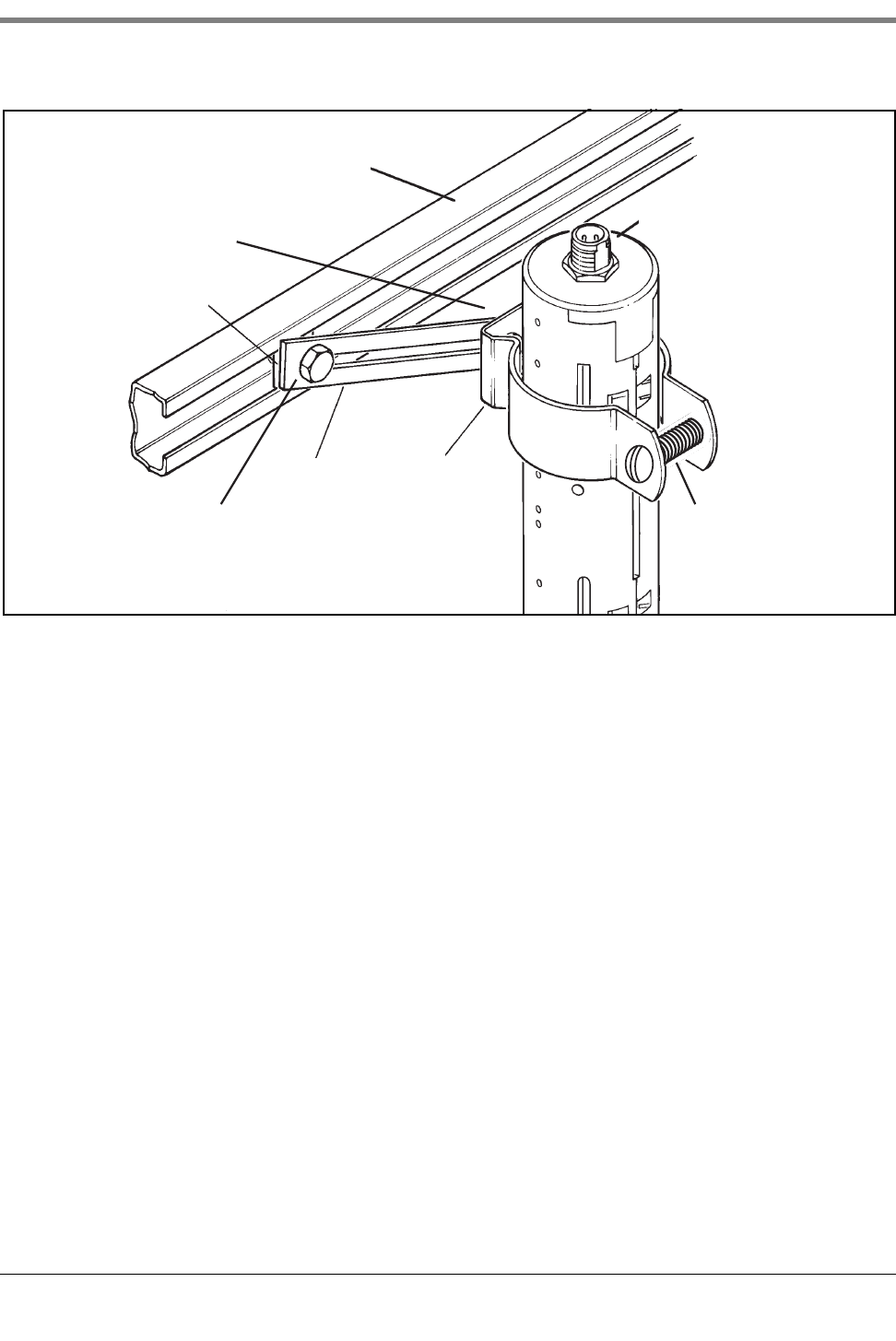
A-3
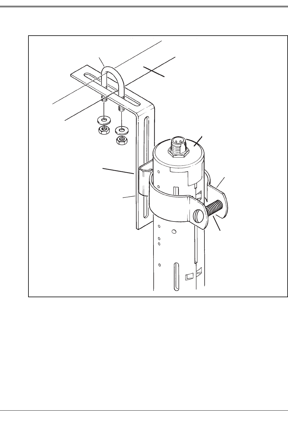
Figure A-3. Mounting the Sensor in the Dispenser Pan
sensors\mntsndp.eps
Sensor
Clamp
Extender
bracket
Support bar
3/8-16 Spring nut
3/8-16 x 7/8 hex bolt
1/4-20 x 3/4 hex bolt
w/ washer and nut
(not shown)
1/4-20 x 1-1/2
machine screw w/
washer and nut
Appendix A: Universal Sensor Mounting Kit Mounting Sensors
A-4
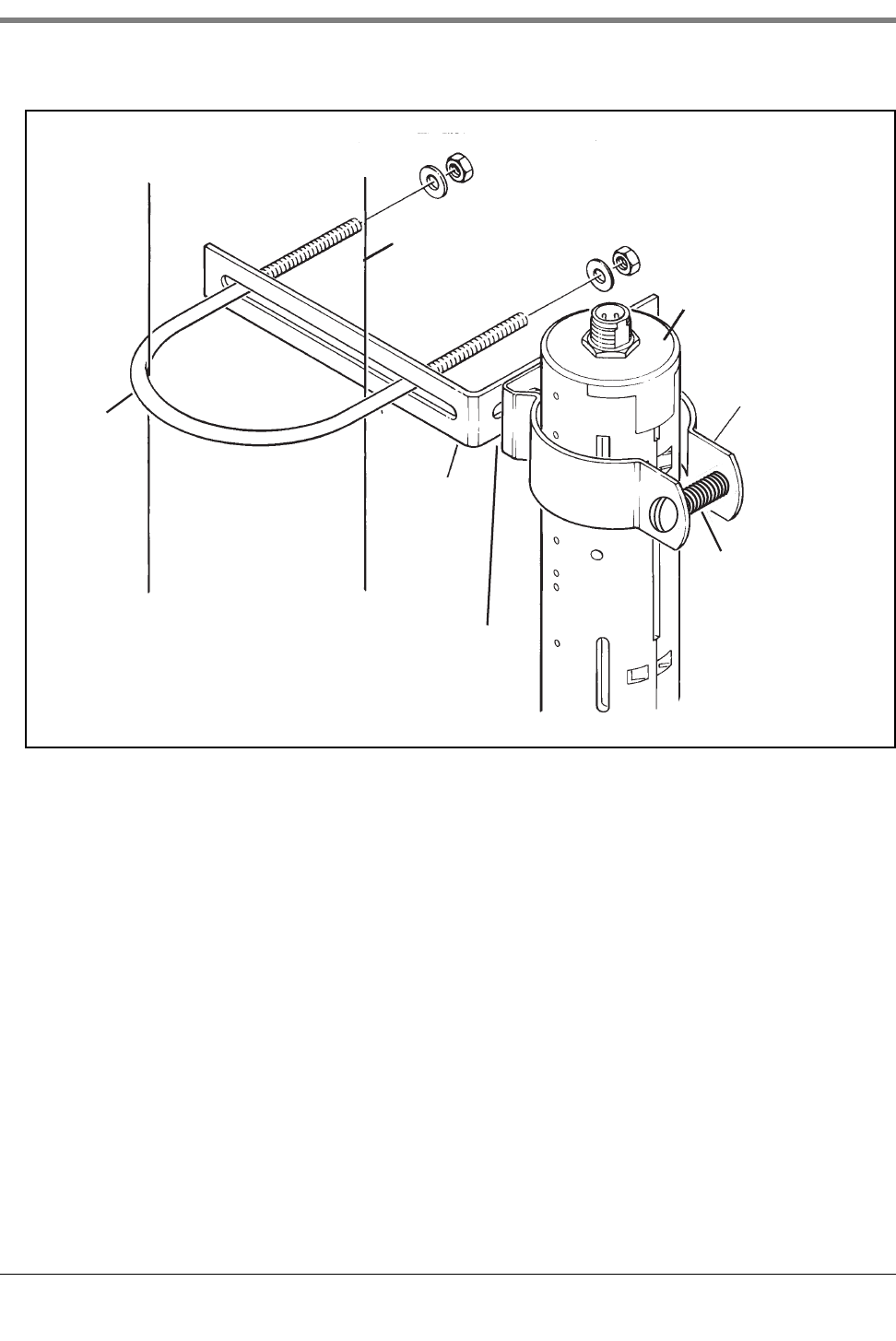
Figure A-4. Mounting the Sensor using Two Extension Brackets
3/8-16 Spring nut
Support bar
Extension
bracket
Extension
bracket
Clamp
sensors\extbkt.eps
Sensor
1/4-20 x 3/4 hex bolt w/
washer and nut
3/8-16 x 7/8 hex bolt
1/4-20 x 3/4 hex bolt
w/ washer and nut
(not shown)
1/4-20 x 1-1/2
machine screw w/
washer and nut
Appendix A: Universal Sensor Mounting Kit Mounting Sensors
A-5
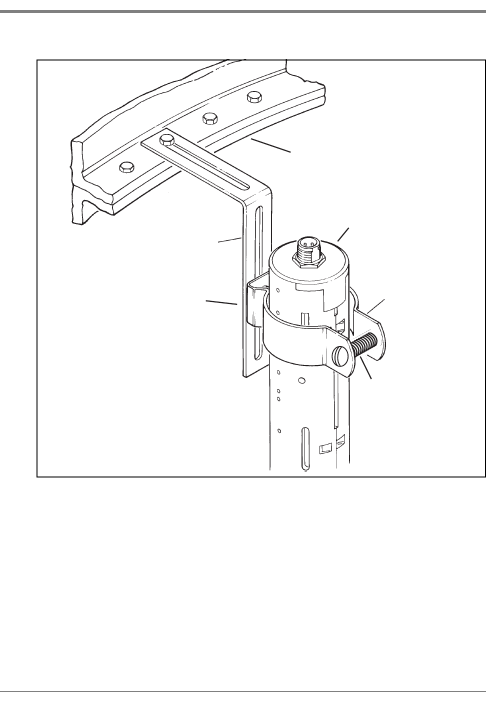
Figure A-5. Mounting the Sensor to Rigid Conduit
U-Bolt
U-bolt
L-bracket
Clamp
Sensor
Rigid conduit
sensors\snlbkt.eps
1/4-20 x 3/4 hex bolt
w/ washer and nut
(not shown)
1/4-20 x 1-1/2
machine screw w/
washer and nut
Appendix A: Universal Sensor Mounting Kit Mounting Sensors
A-6
Figure A-6. Mounting the Sensor to a Supply Line
Supply line
U-bolt
L-bracket
Sensor
Clamp
sensors\snsupln.eps
1/4-20 x 3/4 hex bolt
w/ washer and nut
(not shown)
1/4-20 x 1-1/2
machine screw w/
washer and nut
Appendix A: Universal Sensor Mounting Kit Mounting Sensors
A-7
Figure A-7. Mounting the Sensor in a Containment Sump
Clamp
L-bracket
Sensor
Containment sump
wall
sensors\sncntmnt.eps
1/4-20 x 3/4 hex bolt
w/ washer and nut
(not shown)
1/4-20 x 1-1/2
machine screw w/
washer and nut
B-1
Appendix B: Enabling The TLS4 To Function As A Datalogger
This document explains how to enable a TLS4 to function as a Datalogger. A laptop, an ethernet crossover cable
and a FMS ID number will be required.
NOTE: Several of the steps below may have been completed when the TLS4 was originally setup, in which case,
you can verify the settings as you step through the complete enabling process.
BIR Protocol DIM
POS SYSTEM REQUIREMENTS AND LIMITATIONS
For sites using the Datalogger DIM, the Point of Sales (POS) system must conform to established Veeder-Root
protocol and allow the Datalogger to collect the metered sales data necessary for it to perform its Business
Inventory Reconciliation (BIR) and Wet Stock Management (WSM) tasks. This protocol is separate and distinct
from the inventory protocol commonly used by POS and other systems to collect inventory data from Veeder-Root
TLS consoles.
The following POS systems (Table B-1) are known to have implemented the Veeder-Root protocol and thus
support BIR protocol DIM (Dispenser Interface Module).
Datalogger Site Connection and Initialization
After you are connected the Datalogger to the appropriate site equipment follow the steps below to setup the
Datalogger.
NOTE: You must wait at least 5 minutes after powering on the Datalogger before starting this procedure.
1. Using an ethernet crossover cable, connect a laptop PC to ethernet port ETH 1 on the Datalogger (see Figure
1 on page 1 of this manual).
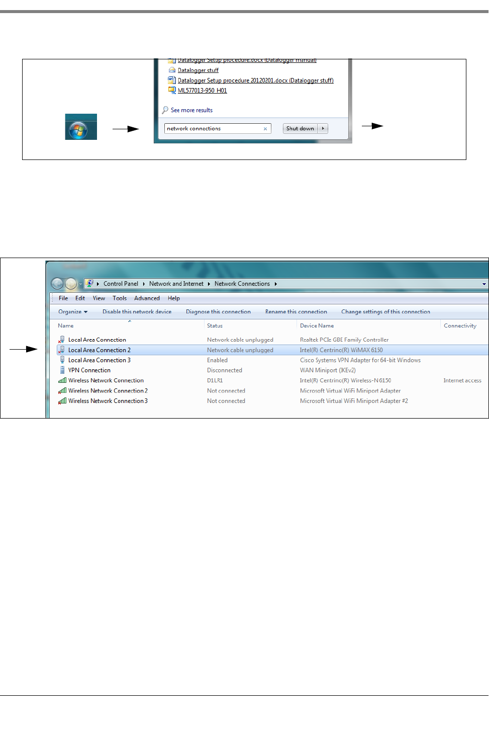
2. You must configure the laptop’s wired integrated Local Area Network by clicking on the Windows Globe in the
lower right of the task bar, and typing in network connections in the ‘Search programs and files’ field and then
pressing Enter (see below):
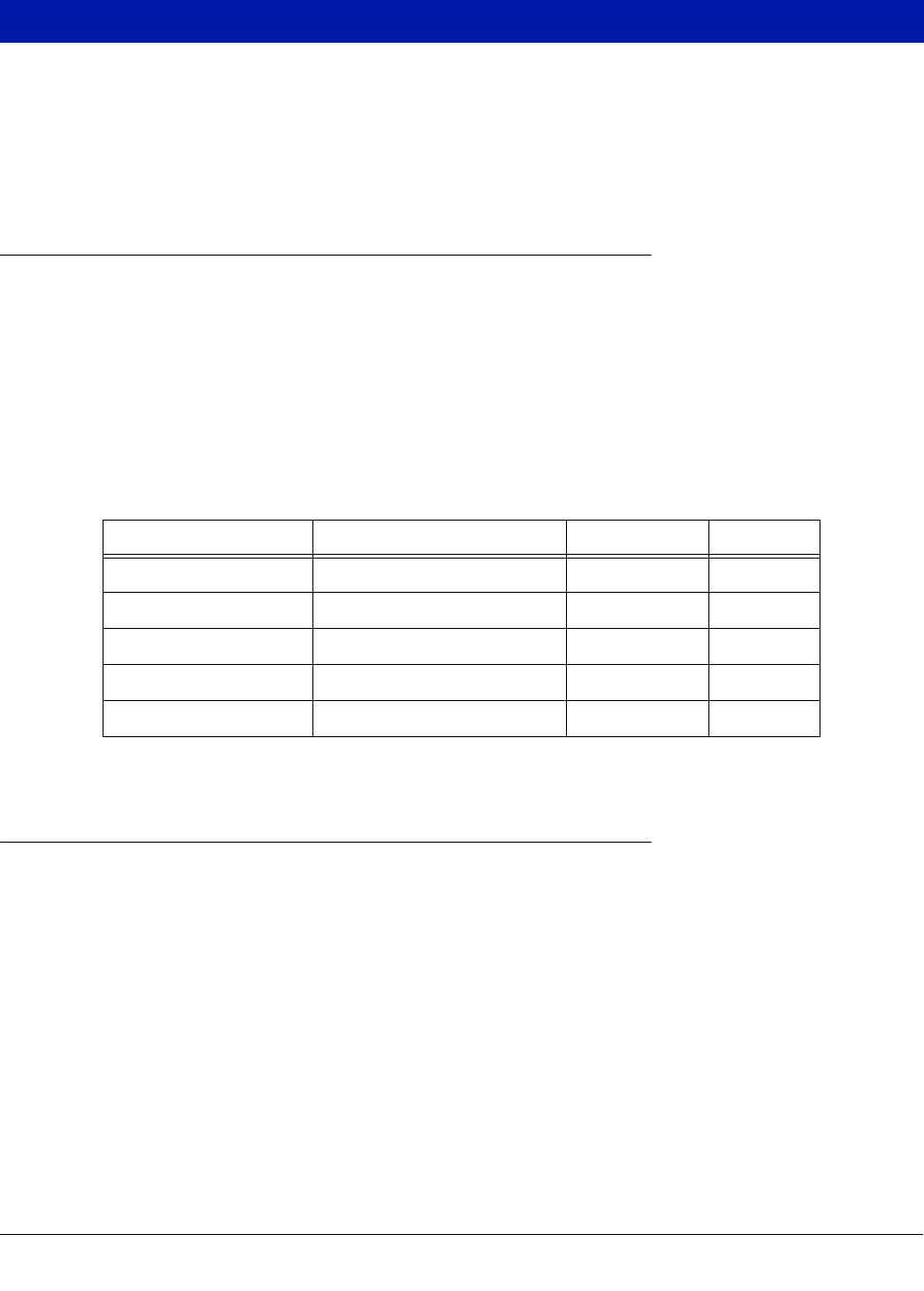
Table B-1. POS Systems Using V-R Protocol*
Forecourt Controller Protocol Name TLS-350R TLS-450
Allied Station Site Controller (SSC) X X
Gilbarco T-4 (Australia) X
PEC 8850 X
POSTEC RCC X
Wayne Marketer 2000 (Sweden) X
*When the proper hardware/software combinations are used.
Appendix B Datalogger Site Connection and Initialization
B-2
3. NOTE: The screen shots contained in this appendix are for reference purposes only. The actual settings and
data shown in the following examples are dependent on the laptop or PC operating system used to
configure this hardware.
In the Network Connections screen, double click on the wired (not wireless) integrated Local Area
Connection. In the example below (Figure B-1), you would double-click Local Area Connection 2.
Figure B-1. Configuring LAN
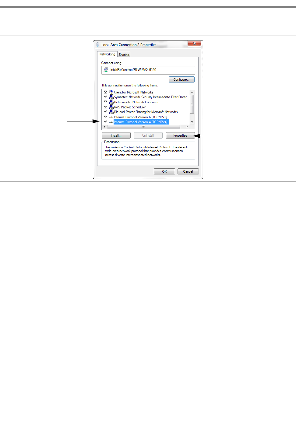
4. When the selected Local Area Connection Properties dialog box opens make the selection shown in Figure B-
2.
click
type: network connections
Press Enter
Appendix B Datalogger Site Connection and Initialization
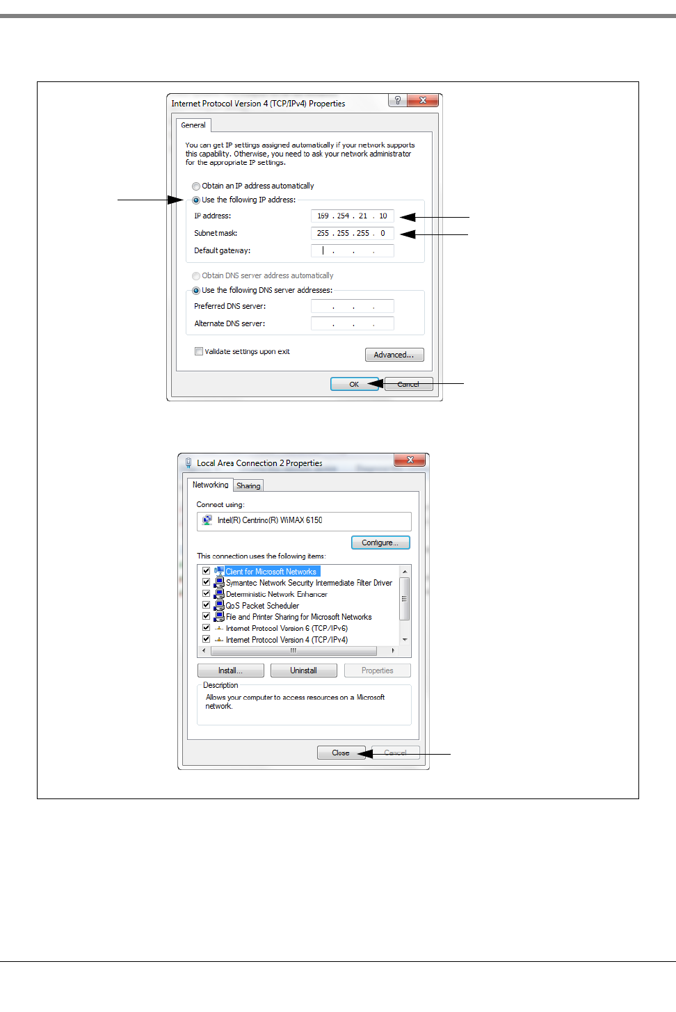
B-4
Figure B-3. Internet Protocol Version 4 (TCP/IPv4) Properties dialog box selections
Click this
radio button Enter this address
Click OK button to save
Click Close button
changes, close his dialog
and return to the one
below:
Default is 255.255.0.0
change to 255.255.255.0

Appendix B Datalogger Site Connection and Initialization
B-5
6. On the laptop, open an internet browser and enter the IP address https://169.254.21.12/GeneralSetup in
the browser’s address bar. When the login page displays, enter ‘guest’ for both User name and Password.
NOTE: The Datalogger simultaneously runs two applications; one programs the general communication proto-
cols (GeneralSetup), and the other programs how the Datalogger gathers its information (DLSetup). Pressing
the blue arrow at the top middle of the screen will toggle you between the two programs (see Figure B-4). Af-
ter entering selections/changes to fields on any page, click the Save button to save your entries, or Cancel to
discard them. Programming screens used to setup the Datalogger are listed in Table B-2.
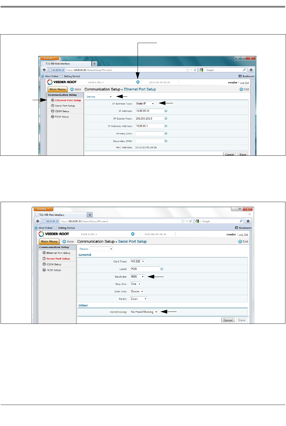
7. On the “Communication Setup” page (see Figure B-4), click on “Ethernet Port Setup” (1) and select the
Device type “ETH 1” (2) from the drop-down menu. In the IP Address Type field (3):
If the site is using a static IP address, select “Static IP”; and enter the IP address assigned by your network
administrator. Once this is complete, click the “Save” button to keep these settings (see example in Figure B-
4).
If the site is using a dynamic IP address, select “Dynamic IP” (the remaining parameters will auto-fill once the
Datalogger is reconnected to the site network). Click “Save” (4) to accept your entries.
NOTE: If you receive an error message after clicking “Save”, click “OK” and refresh the page.
Table B-2. Datalogger User Interface Screens
GeneralSetup
Application Pages
See
Example
DLSetup
Application Pages
See
Example
Communication
Setup
Ethernet Port
Setup Step 7. System Setup FMS Identification Step 16.
Serial Port Setup Step 8.
CDIM Setup Diag. use only ATG Commands Step 9.
TDIM Setup Step 10. DIM Commands Step 11.
Site Id Server
Setup Diag. use only
Communication Testing
FMS Heartbeat Step 19.
System Setup Hostname Step 11. ATG Step 17.
Date and Time Step 13. POS Step 18.
Units Step 14. DIM Diag. use only
Alarm Filtering Diag. use only
Diagnostics
DIM Communica-
tions Step 12.
Ping
Diag. use only
Traceroute
Software Mainte-
nance
DB Backup
DB Restore
Download New
Version
Activate/Revert
Upgrade Fea-
tures
Appendix B Datalogger Site Connection and Initialization
B-6
Figure B-4. Ethernet Port Setup
8. On the Serial Port Setup page, in the “Device” field, select “SERIAL 2”. Use this connection for the
connection to the POS, and enter “POS” for the Label. Set the correct communications parameters for the
POS using the drop down menus. For HandShaking, select “No Hand Shaking”.Click the “Save” button to
keep these settings (see example in Figure B-5).
.
Figure B-5. Serial Port Setup, SERIAL 2- POS
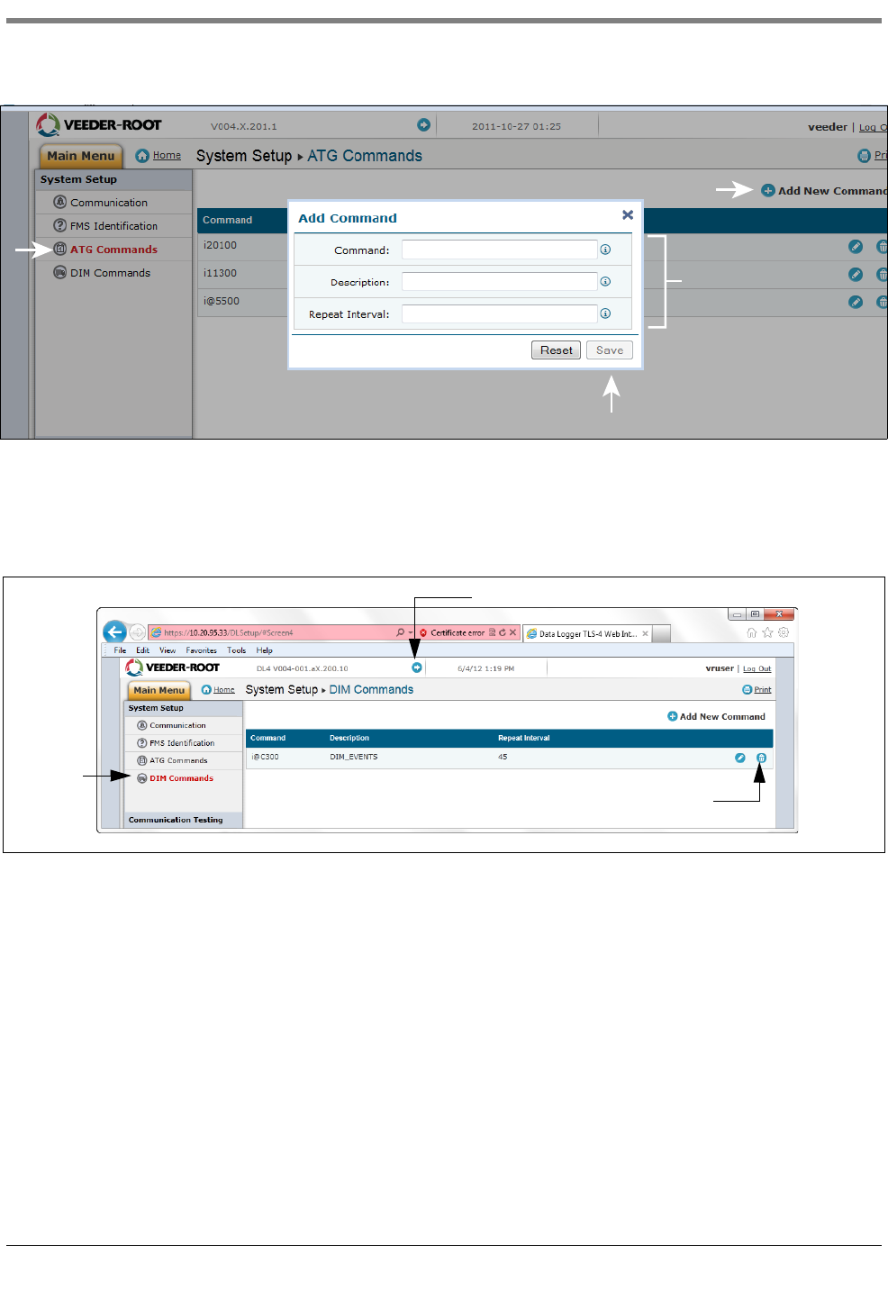
9. Go to the “DLSetup” application by clicking on white arrow in blue circle top center of screen (see Figure B-
6), and under “System Setup”, click on “ATG Commands (1 in Figure B-6)”. Then click on the “+ Add New
Command” text at top right of screen (2 in figure). When the Add Command dialog box appears enter the
command “i@C300”, add the Description “DIM_EVENTS”, set the Repeat Interval to “60” (3 in figure) and
click Save (4 in figure).
Click this arrow to switch between the
GeneralSetup and DLSetup applications
12
3
ETH 1
Recommended Baudrate
Select No
SERIAL 2:POS
Appendix B Datalogger Site Connection and Initialization
B-7
Figure B-6. Entering ATG Command
Click on the DIM Command page and then click on the trash can icon on the right end of the i@C300 command
line to delete the i@C300 command (see Figure B-7). Jump back to the “General Setup” application by clicking on
arrow top center of screen.
Figure B-7. Deleting ATG Command
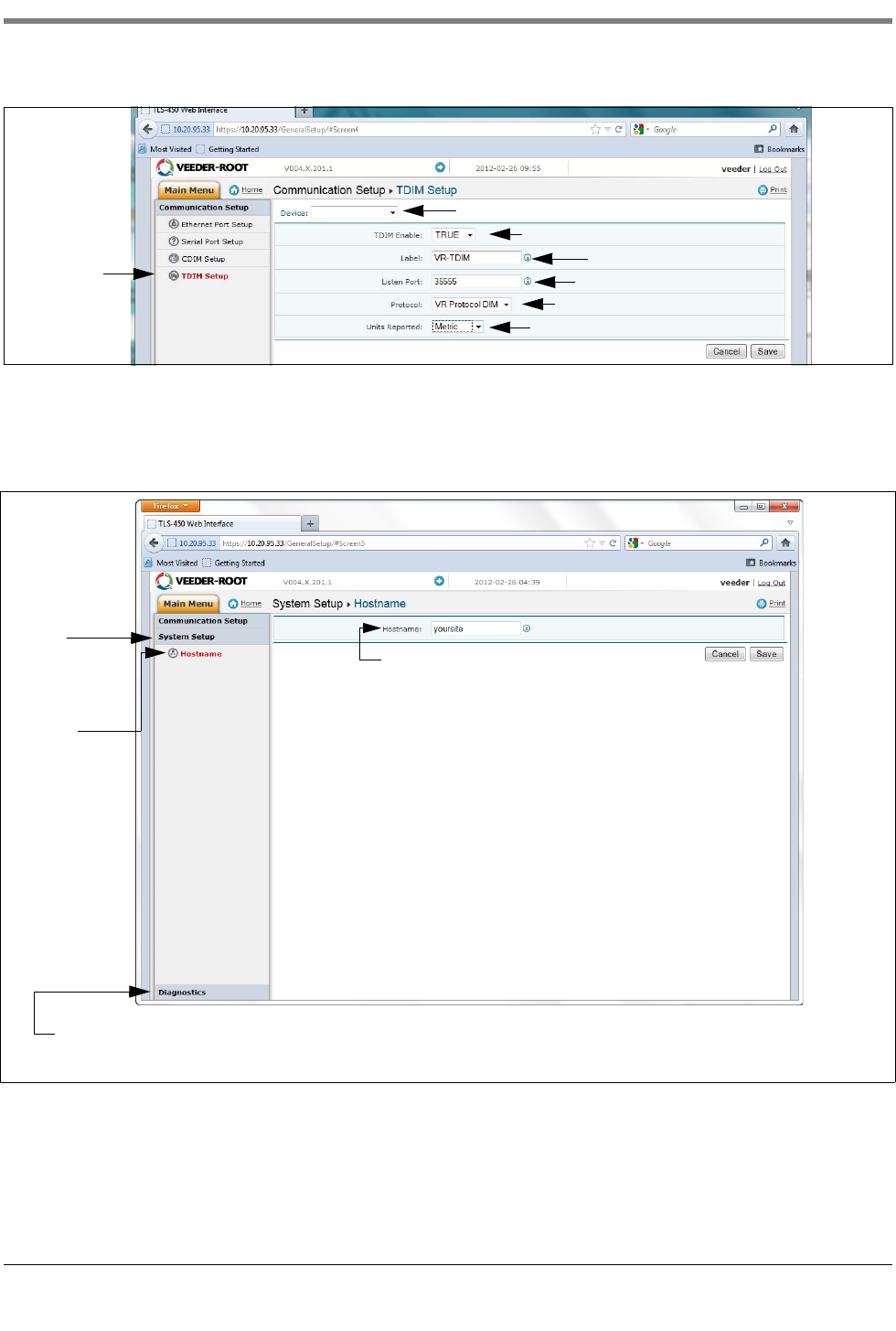
10. Select “TDIM” set-up. Select “TDIM (ETH1)” from the drop-down menu. On the “TDIM Enable” drop down,
select “TRUE” and type in a label (maximum of 20 characters). Then select the DIM protocol being used and
click “Save”. Accept the default Listen Port (unless there is a conflict with another device) and select the
desired units (see example in Figure B-8). Once this is complete, click on “Save” to keep these settings.
i@C300
DIM_EVENTS
60
1
2
4
3
Select
Click and delete
Click to jump to the GeneralSetup application
Appendix B Datalogger Site Connection and Initialization
B-8
Figure B-8. TDIM Setup
11. Select the “System Setup” page and type in the Host name and then click the “Save” button (see example in
Figure B-9). It is recommended that you use the network name assigned by the network administrator or some
other name that identifies the location. While on this page click the Diagnostic Page link (bottom Left).
Figure B-9. Entering Host name
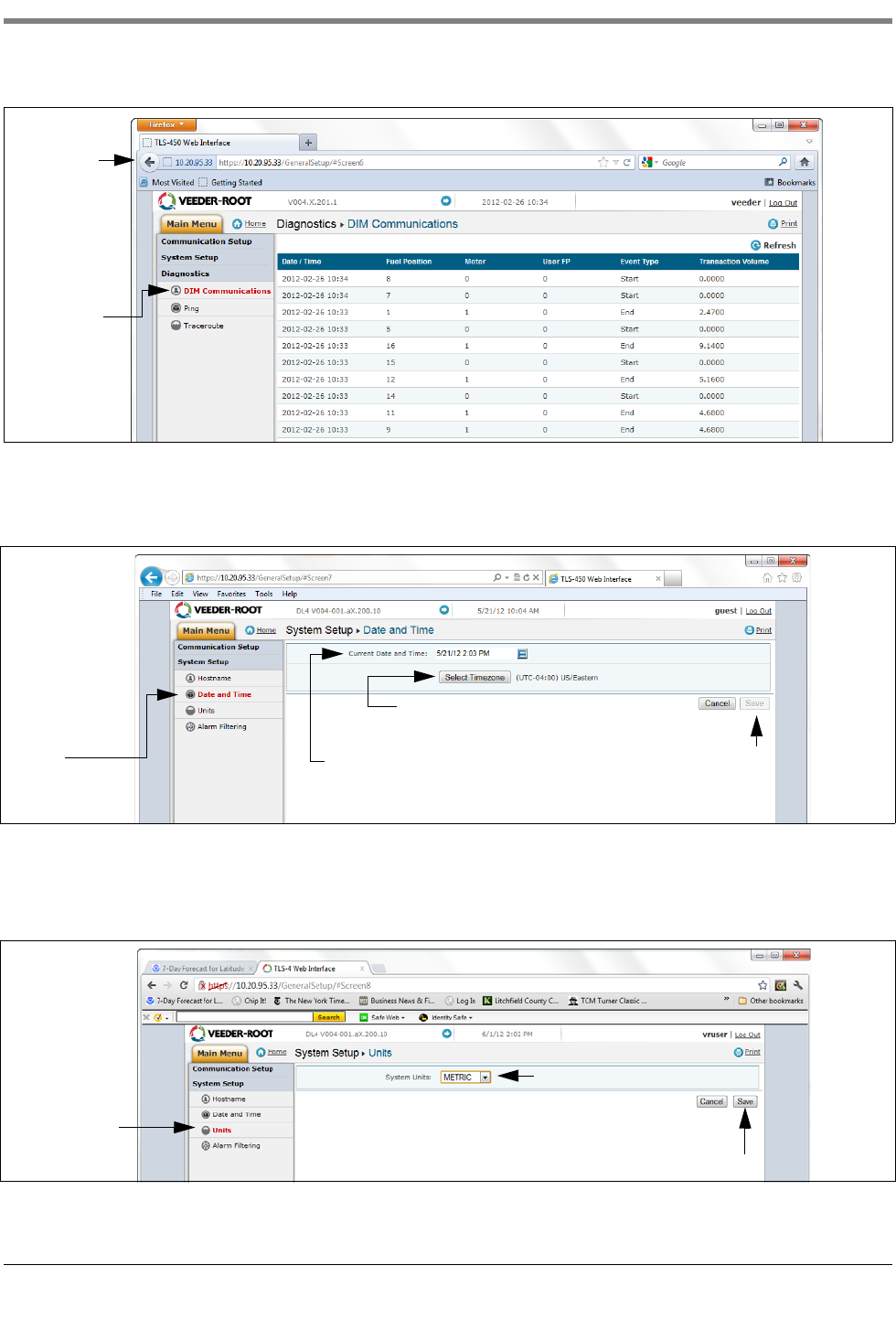
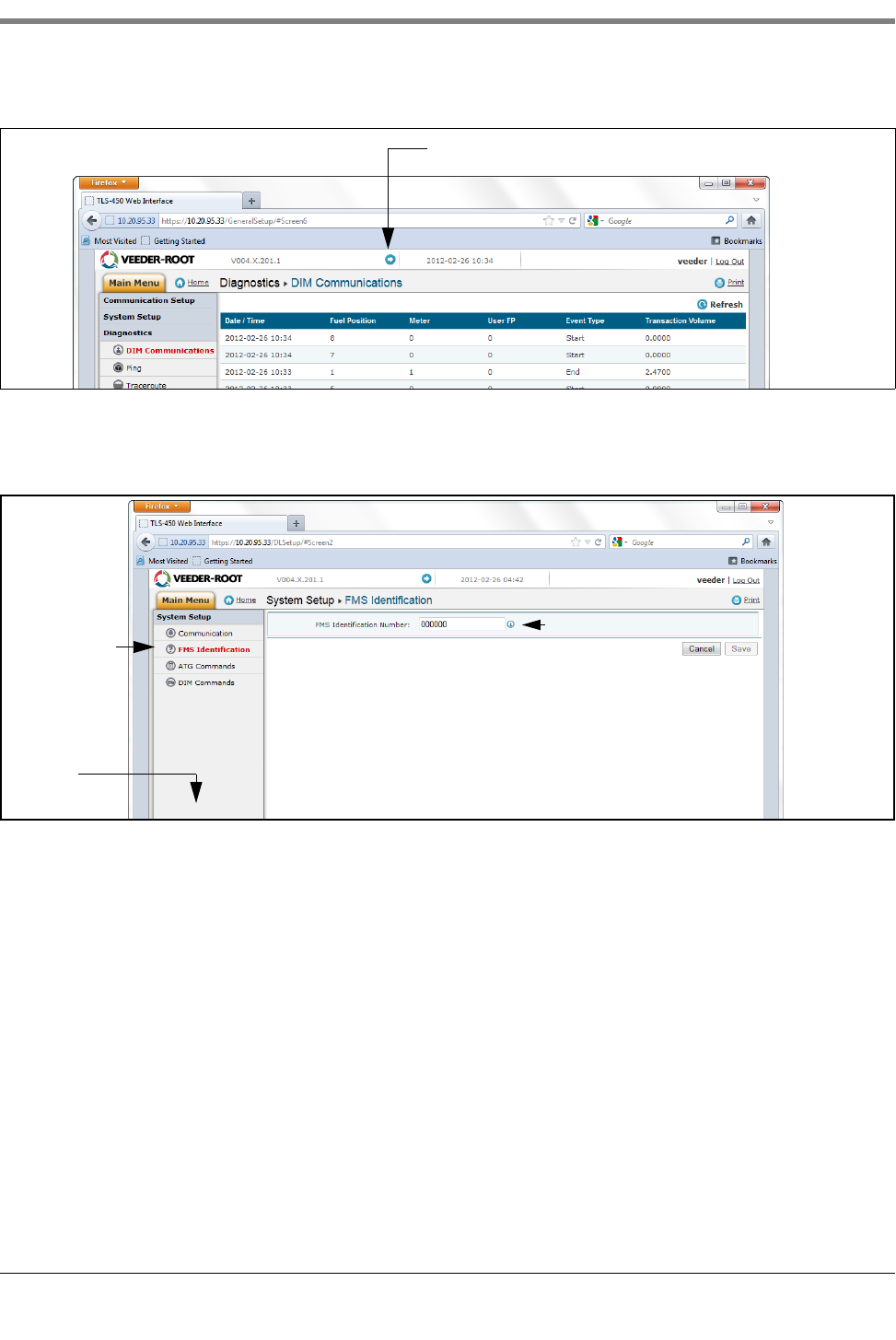
12. In the “Diagnostics” page (lower left in above figure), click on “DIM Communications” to verify that the DIM
communications are successfully being recorded by the Datalogger. Any transactions occurring after the
Datalogger was configured will be shown on the screen (see example in Figure B-10).
Select
Select
Enter label
Select DIM Protocol
Enter desired units
Select True
Accept default unless there is a conflict
TDIM (ETH1)
First select
System Setup
Page
Click on
host name
to open this
page
Enter Host name
(e.g., Site Name)
After saving the “Hostname” entry, click on the “Diagnostics” link
to verify DIM communications
Appendix B Datalogger Site Connection and Initialization
B-9
Figure B-10. Verifying DIM Communication
13. From the System Setup menu, select Date and Time link to access the current date/time entry screen (see
example in Figure B-11).
.
Figure B-11. Entering Date and Time
14. From the System Setup menu, click on the Units page(1), select the desired units (2), click Save (3) (see
example in Figure B-12).
.
Figure B-12. Selecting System Units
Select
Click back
arrow to return
to System Set-
up screen
Click on
Date and Time
to open this
page
Click on this button and
select the site’s time zone
Click Save
Click the down arrow to open the date
and time calendar. Select the current
date and time.
to accept
1
2
3
Appendix B Datalogger Site Connection and Initialization
B-10
15. Click on arrow just to the left of the date to switch to DLSetup application (see Figure B-13).
Figure B-13. Switching to DL Setup
16. Select the “FMS Identification” screen and enter the six-digit FMS site identification number. Then click on the
“Save” button (see Figure B-14).
Figure B-14. Example FMS ID Entry
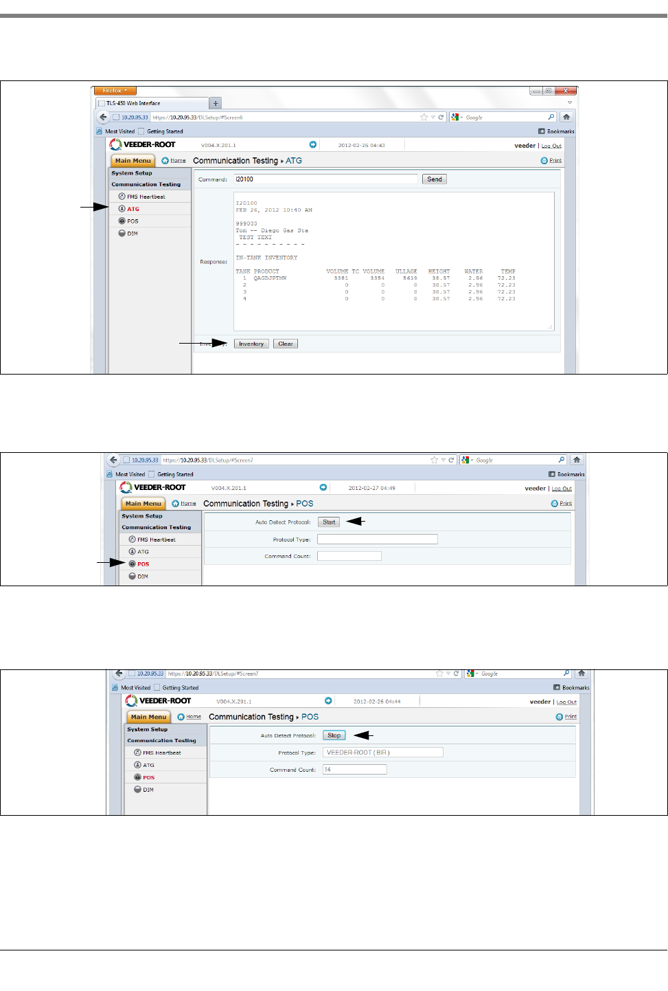
17. Wait at least 30 seconds from the completion of the previous step to allow for the system to re-initialize with
the new settings. Then click on the “Communication Testing” link at the lower left bottom of the System Setup
column (see above figure), then click on “ATG”. Click on the “Inventory” button, which will enter the command
“I20100”. After several seconds, a Response should appear providing the current inventory data from the ATG.
If no response is received, there is a problem in the setup parameters.
Click on this arrow icon to jump to DLSetup
Select
Enter applicable FMS ID
Communication
testing Link at
bottom of this
column
Appendix B Datalogger Site Connection and Initialization
B-11
Figure B-15. Inventory Command Results
18. Click on “POS” to detect the POS protocol. Click the “START” button next to “Auto Detect Protocol” and wait
for the Protocol Type to appear (see example in Figure B-16.
Figure B-16. POS Protocol Type Query
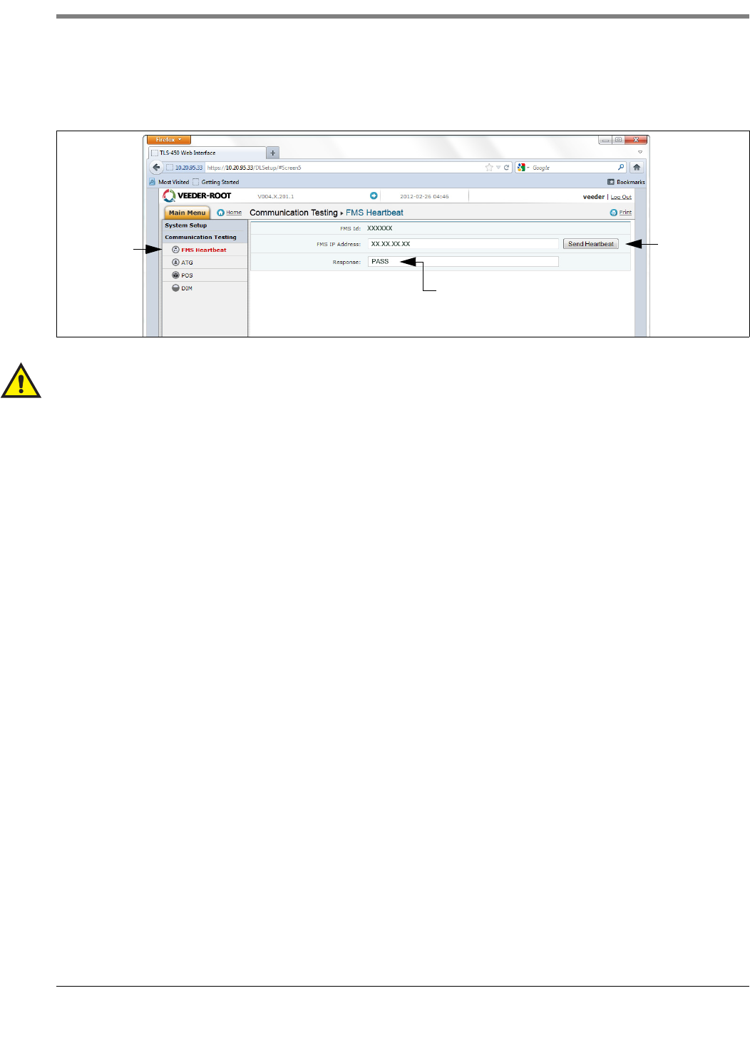
Verify that this is the correct protocol that was entered in the DIM setup in Step 10. Then click on the “Stop”
button (see example in Figure B-17).
Figure B-17. POS Protocol Type Results
19. The Datalogger should now be configured to collect inventory and transactional data, which will be
periodically retrieved by FMS. To verify connectivity with FMS, reconnect the Datalogger to the network or cell
modem. Go to the “DLSetup” application’s Communication Testing screen, click on “FMS Heartbeat”, then
click on the “Send Heartbeat” button (see Figure B-18). Wait for the “Response” text to indicate PASS or
Select
Click on Inventory button
Select
Click on Start button
Click Stop button when done
Appendix B Datalogger Site Connection and Initialization
B-12
FAIL. A PASS confirms that the Datalogger is successfully communicating with FMS. A FAIL indicates that the
connection has failed and you will need to contact FMS or the network administrator for troubleshooting
assistance.
Figure B-18. FMS Heartbeat Screen
IMPORTANT! Connectivity between the Datalogger and FMS must be verified prior to completing the
installation.
Return your laptop PC to the network settings originally set prior to the changes you made in Step 5.
Select Click to test
Test results

For technical support, sales or
other assistance, please visit:
www.veeder.com
