RMS PM Hardware User Manual And RM User's (V3 0)
User Manual:
Open the PDF directly: View PDF ![]() .
.
Page Count: 43

7929 SW Burns Way Phone: 503 344-5085
Suite F Fax: 503 855-4540
Wilsonville, OR sales@rinehartmotion.com
1/17/2018 RMS PM Hardware User Manual 1 of 43
RMS PM/RM
Hardware User Manual
Revision 3.0
0A-0001-01
Everything you need to know to install, set up, and calibrate the PM
family of AC drives on asynchronous and PM synchronous motors in
your Electric or Hybrid vehicle

7929 SW Burns Way Phone: 503 344-5085
Suite F Fax: 503 855-4540
Wilsonville, OR sales@rinehartmotion.com
1/17/2018 RMS PM Hardware User Manual 2 of 43
Table of Contents
1. SAFETY FIRST: ............................................................................................................ 3
2. FUNCTIONAL OVERVIEW: ......................................................................................... 4
3. INSTALLING THE PM DRIVE: ..................................................................................... 5
3.1 Liquid Cooling Connections: ...................................................................................................................7
3.2 PM100/PM150 External Signal Connectors: ........................................................................................ 10
3.2.1 J1 – 35p AMPSEAL Plug 776164-1 with crimp contact 770854-1 .................................................. 10
3.2.2 J2 – 23p AMPSEAL Plug 770680-1 with crimp contact 770854-1 .................................................. 12
3.3 PM250 External Connections: ............................................................................................................... 13
3.4 RM100 Signal Connections ................................................................................................................... 16
3.5 External Power Connections: ............................................................................................................... 19
3.5.1 DC+ / DC-: ....................................................................................................................................... 19
3.5.2 Phase A / Phase B / Phase C: ......................................................................................................... 21
3.5.3 Pre-Charge Circuit: .......................................................................................................................... 21
3.5.4 Main Contactor: ............................................................................................................................... 22
3.5.5 Main Fuse: ....................................................................................................................................... 23
3.5.6 Passive Discharge of the High Voltage DC Bus: ............................................................................. 23
3.5.7 12V Power: ...................................................................................................................................... 24
3.5.8 Grounding ........................................................................................................................................ 25
3.6 Typical Application Wiring Diagram: .................................................................................................... 26
3.6.1 Controller 12V Power Wiring ........................................................................................................... 27
3.6.2 Pre-charge Circuit ............................................................................................................................ 29
3.6.3 Analog/Digital Vehicle Control ......................................................................................................... 30
3.6.4 Motor Control (Typical Wiring) ......................................................................................................... 31
3.6.5 CAN Interface .................................................................................................................................. 32
3.6.6 RS-232 Interface .............................................................................................................................. 32
3.6.7 Encoder Interface (Not included on RM100): .............................................................................. 33
3.6.8 Resolver Interface: ........................................................................................................................... 34
4. VEHICLE INTERFACE SETUP .................................................................................. 35
4.1 Analog Inputs: ........................................................................................................................................ 35
4.2 Digital Inputs: .......................................................................................................................................... 37
4.3 Digital Outputs ........................................................................................................................................ 40
REVISION HISTORY ......................................................................................................... 42
7929 SW Burns Way Phone: 503 344-5085
Suite F Fax: 503 855-4540
Wilsonville, OR sales@rinehartmotion.com
1/17/2018 RMS PM Hardware User Manual 3 of 43
1. Safety First:
ATTENTION
When you see this sign, PAY ATTENTION! This indicates that something
important is about to be said, that concerns your safety and the proper
operation of the equipment.
DANGER
When you see this sign, you are being alerted to an IMMEDIATE
DANGER that could cause severe injury or even death. You MUST review
these sections carefully an do everything possible to comply with
installation and operation requirements, or you risk injury or death to
yourself or anyone else who uses the equipment or the vehicle. Failure to
comply with safety requirements will void all warranties and could expose
you as the installer to liability in the event of an injury. Use the equipment
in the manner in which it was intended.
CAUTION
When you see this sign, you are being advised that the issue under
discussion has a serious safety or equipment reliability implication. Use
caution and be conservative. Use equipment in the manner described in
this User’s Manual.
Safety is entirely the responsibility of the installer of this equipment. RMS has done
everything it can to ensure that the traction controller itself conforms to international
standards for safety. This does NOT mean that your installation will be safe, or that it
will not interfere with other systems on board your vehicle. It is your responsibility as the
installer to review this entire User’s Manual, to understand the implications of each and
every section, and to know what might be unique about your system application that
presents a unique hazard or potential safety issue – and to solve it.
RMS is committed to helping you solve these problems, but cannot take responsibility
for the application of this traction controller. We can only promise to meet the
specifications for this product and that it meets international safety standards when
used in accordance with the instructions in this Manual.

7929 SW Burns Way Phone: 503 344-5085
Suite F Fax: 503 855-4540
Wilsonville, OR sales@rinehartmotion.com
1/17/2018 RMS PM Hardware User Manual 4 of 43
2. Functional Overview:
The PM controller family is intended as a traction controller for EV and HEV drive
systems, and includes both the motor control function and a rudimentary vehicle
controller strategy in the same box. The motor control is a torque commanded, vector
control technology has been used on AC Induction and PM Synchronous motors in
many applications.
The RM100 controller family is intended for the same type of EV/HEV applications
however it has a much more limited set of inputs and outputs. The limited set of I/O
prevents it from being properly used in the VSM mode where analog and digital inputs
are used to control the operation of the inverter. The RM100 controller is intended for
applications where CAN communications is used to control the controller.
The motor control subsystem firmware is mated to a vehicle controller firmware
implemented in the DSP controller. This vehicle controller subsystem handles the
driver interface (accel and decel / brake pedal inputs, Fwd/Rev controls, etc) and the
vehicle interface (power sequencing, built in test, fault handling and safety issues). It
is essentially a state machine in front of the motor controller firmware with a defined
interface between the two software processes.
By default, out of the box the parameters are set up in Torque Control Mode, with
default motor parameters loaded. The parameters must be changed to match the load
motor and operating characteristics before running for the first time. These parameters
personalize the drive to the motor and the vehicle.
User Controls
Vehicle Control
Firmware
Motor Control
Firmware
Motor
7929 SW Burns Way Phone: 503 344-5085
Suite F Fax: 503 855-4540
Wilsonville, OR sales@rinehartmotion.com
1/17/2018 RMS PM Hardware User Manual 5 of 43
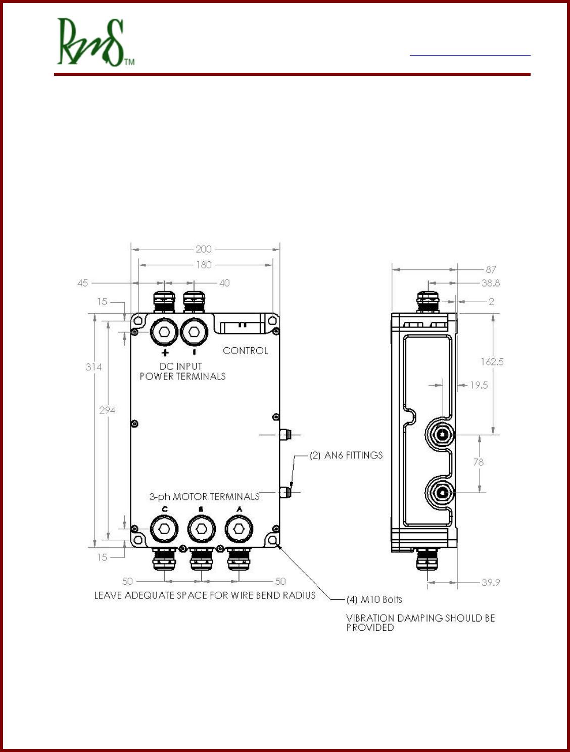
3. Installing the PM Drive:
The PM controller has 4 mounting locations, one at each corner. Mounting orientation
is not critical. The controller should be mounted in a location that is not exposed to
direct spray from water. Each mounting hole is sized to handle up to a M10 socket
head cap screw.
See PM250 Datasheet for more information on mounting the PM250.
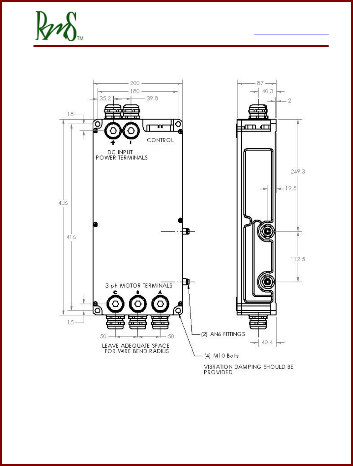
PM100 Dimensions – top and side views

7929 SW Burns Way Phone: 503 344-5085
Suite F Fax: 503 855-4540
Wilsonville, OR sales@rinehartmotion.com
1/17/2018 RMS PM Hardware User Manual 7 of 43
3.1 Liquid Cooling Connections:
The controller must be cooled by passing liquid through it. The controller includes two ports
to be used for liquid cooling. The fluid direction for the PM250 inverter is marked into the
case of the inverter. The PM100 and PM150 has a more symmetrical design and is less
sensitive to fluid direction. However, it is preferred that the rearmost plenum (the ports
furthest from the 3 AC output terminals) be the fluid inlet, as this keeps the coolest fluid
near the DC Link capacitor assembly. The PM250 has markings on the housing that
indicate the required direction of the coolant through the inverter. See table below for
coolant specifications:
Coolant Type
50/50 mix ethylene glycol (antifreeze) / water or propylene
glycol / water; with Aluminum corrosion inhibitor additive
Coolant Temperature
-30°C to +80°C full power
Operation -40.. -30; +80.. +100°C with de-rated output
Coolant Flow Rate
8 – 12 LPM (2 – 3 GPM), PM100/PM150/RM100
20 – 30 LPM (5 – 6 GPM), PM250
Pressure Drop
PM100, 0.3 bar (4.4 psi) @ 8 LPM @ 25°C
PM150, 0.4 bar (5.8 psi) @ 8 LPM @ 25°C
PM250, 0.9 bar (13 psi) @ 20 LPM @ 25°C
RM100, 0.06 bar (0.8 psi) @ 8 LPM @ 25°C
Port Size
PM100 and PM150, AN-6
PM250, SAE ORB -10
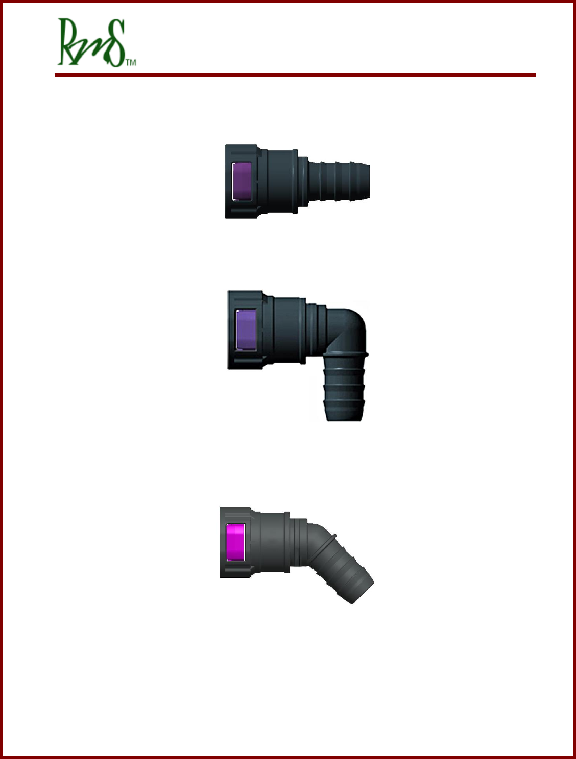
RM100, Custom O-ring port, the following options are
provided to be installed in the unit, each kit includes materials
for both ports.
- ARaymond NT100 / 16mm Straight, RMS p/n G1-0023-01
- ARaymond NT100 / 16mm 45deg, RMS p/n G1-0024-01
- ARaymond NT100 / 16mm 90deg, RMS p/n G1-0025-01
- 16mm / 5/8” Hose Barb, RMS p/n G1-0026-01
7929 SW Burns Way Phone: 503 344-5085
Suite F Fax: 503 855-4540
Wilsonville, OR sales@rinehartmotion.com
1/17/2018 RMS PM Hardware User Manual 8 of 43
ARaymond NT100 / J20 Straight, RMS Kit G1-0023-01
ARaymond NT100 / J29 90 degree, RMS kit G1-0025-01
ARaymond NT100 / J30 45 degree, RMS kit G1-0024-01

7929 SW Burns Way Phone: 503 344-5085
Suite F Fax: 503 855-4540
Wilsonville, OR sales@rinehartmotion.com
1/17/2018 RMS PM Hardware User Manual 9 of 43
For proper operation of the inverter the coolant must flow at a rate equal to or above the
minimum specified flow rate at all times that the motor is enabled. The flow rate should
not be reduced when the inverter is “not being run hard”. The design of the heat
exchanger does not allow for reduced or no coolant flow. It is possible to adjust the fan
speed on the coolant radiator as needed depending on the operating conditions of the
inverter.
Since the maximum coolant temperature is less than the boiling point of water the cooling
system does not need to be operated under pressure. Other devices (e.g. motor, charger,
DC/DC converter) that are added in series with the inverter increase the total pressure drop
of the system. Even simple fittings and hose length will contribute to the total system
pressure drop. The total system pressure may add up to a level that is beyond the
capability of the chosen pump. The best practice is to measure the actual coolant flow
after the system has been assembled.
Certain pump types are not capable of driving any significant pressure. A pump may have
a high flow rate, but it may not be able to drive any substantial pressure. The PM250 unit
has an especially high pressure drop. An example pump suitable for the PM250 is the
EMP WP 29. Pumps suitable for the PM100/PM150/RM100 are the Bosch 0 392 022 010
and the Pierburg CWA 50.
As noted above proper coolant flow is essential to the operation of the inverter. If the flow
rate is not sufficient the power module internal to the inverter can be damaged even though
the indicated power module temperatures are below an over-temperature threshold. The
power module temperature sensors are located in such a way that they are much
closer to the temperature of the coolant than they are to the temperature of the
transistors and diodes used inside the power module.
Loss of coolant for even a few seconds can result in failure of the power module.
RMS recommends that the user install a device to ensure that the coolant pump is
operating properly at all times when the inverter is enabled. The inverter should be
immediately stopped if the coolant is not flowing.
There are many ways that coolant flow could be measured. A flow sensor could be added
to the cooling loop. Often these types of sensors produce a pulse output. To read the
pulse output would require the use of a device to interpret this signal (RMS does not supply
this).

7929 SW Burns Way Phone: 503 344-5085
Suite F Fax: 503 855-4540
Wilsonville, OR sales@rinehartmotion.com
1/17/2018 RMS PM Hardware User Manual 10 of 43
Another option is to monitor the pressure in the cooling system. Typically the inverter would
be placed near the end of the cooling loop, just before the radiator. So a typical cooling
loop might look like pump outlet, inverter, radiator/reservoir, pump inlet. Typically the
reservoir is at ambient error pressure. So the inverter should be at a pressure that is
higher than ambient. If a pressure switch is placed at the input coolant port of the inverter
it should be able to detect that coolant is flowing.
Various types of coolant pressure switches exist. If a type is used that closes the switch
when the pressure is above a certain level is used then this could be inserted in series with
the ground connection of the forward/reverse switches (for VSM mode applications) or just
connected directly to one of the inputs for monitoring via CAN.
A pressure switch that closes when the pressure is above about 6 psi (~0.4 bar) should be
suitable for the PM100 and PM150. For the PM250 the required pressure is higher and
should be about 10 psi (~ 0.7 bar).
3.2 PM100/PM150 External Signal Connectors:
Two sealed automotive connectors are provided to connect to the internal I/O resources. J1
and J2 are standard AMPSEAL connectors by AMP/Tyco:
3.2.1 J1 – 35p AMPSEAL Plug 776164-1 with crimp contact 770854-1
GEN2 refers to PM100 Units w/ serial number less than 344
GEN3 refers to PM100 Units w/ serial number of 344 or greater and all PM150 units
Pin #
Pin Name
Description
Notes
1
XDCR_PWR
+5V @ 80mA max
Accel Pedal Power
13
AIN1
Analog Input 1 0-5VFS
Accel Pedal wiper
24
AIN2
Analog Input 2 0-5VFS
Motor Temperature Sensor
2
AGND
Analog Ground
Accel Pedal GND
14
XDCR_PWR
+5V @ 80mA max
Spare 5V transducer power
25
AIN3
Analog Input 3 0-5VFS
Brake Pedal
3
AIN4
Analog Input 4 0-5VFS
15
AGND
Analog Ground
26
XDCR_PWR
+5V @ 80mA max
Spare 5V transducer power
4
RTD1
1000 Ohm RTD Input

7929 SW Burns Way Phone: 503 344-5085
Suite F Fax: 503 855-4540
Wilsonville, OR sales@rinehartmotion.com
1/17/2018 RMS PM Hardware User Manual 11 of 43
GEN2
4
GEN3
AOUT
Analog Output 0 – 5V
16
GEN2
RTD2
1000 Ohm RTD Input
16
GEN3
AIN6
Analog Input 6 0-5VFS
Available for user-defined
functionality
27
GEN2
RTD3
1000 Ohm RTD Input
27
GEN3
RLY6
Hi-Side Relay Driver
Available for user-defined
functionality, CAN control.
5
GEN2
RTD4
100 Ohm RTD Input
5
GEN3
RTD1
RTD Input (PT100 or
PT1000)
Software selectable input type.
17
AGND
Analog Ground
28
XDCR_PWR
+5V @ 80mA max
Spare 5V transducer power
6
GEN2
RTD5
100 Ohm RTD Input
6
GEN3
RTD2
RTD Input (PT100 or
PT1000)
Software selectable input type.
18
GEN2
<reserved>
DO NOT CONNECT
18
GEN3
AIN5
Analog Input 5 0-5VFS
Available for user-defined
functionality
29
GEN2
<reserved>
DO NOT CONNECT
29
GEN3
RLY5
Hi-Side Relay Driver
Available for user-defined
functionality, CAN control.
7
/PROG_ENA
Serial Boot Loader enable
19
AGND
Analog Ground
30
DIN1
Digital Input 1 – STG(1)
Forward Enable Switch
8
DIN2
Digital Input 2 - STG
Reverse Enable Switch

7929 SW Burns Way Phone: 503 344-5085
Suite F Fax: 503 855-4540
Wilsonville, OR sales@rinehartmotion.com
1/17/2018 RMS PM Hardware User Manual 12 of 43
20
DIN3
Digital Input 3 - STG
Brake Switch
31
DIN4
Digital Input 4 - STG
REGEN Disable Input (if used)
9
DIN5
Digital Input 5 – STB(2)
Ignition Input (if used)
21
DIN6
Digital Input 6 - STB
Start Input (if used)
32
GEN2
<reserved>
DO NOT CONNECT
32
GEN3
DIN7
Digital Input 7 - STB
Available for user-defined
function.
10
GEN2
<reserved>
DO NOT CONNECT
10
GEN3
DIN8
Digital Input 8 - STB
Available for user-defined
function.
22
GND
Ground
33
CANA_H
CAN Channel A Hi
11
CANA_L
CAN Channel A Low
23
CANB_H
CAN Channel B Hi
34
CANB_L
CAN Channel B Low
12
TXD
RS-232 Transmit
35
RXD
RS-232 Receive
(1)– Switch to GND; (2) – Switch to Battery
3.2.2 J2 – 23p AMPSEAL Plug 770680-1 with crimp contact 770854-1
Pin#
Pin Name
Description
Notes
1
XDCR_PWR
+5V @ 80mA max
Encoder Power
9
ENCA
Encoder Channel A input
Used with Induction Motors
16
ENCB
Encoder Channel B input
2
ENCZ
Encoder Channel Z input
(Index)
10
GND
GND
Encoder GND
17
EXC
Resolver excitation output
Used with PM Motors
3
GND
Resolver excitation return

7929 SW Burns Way Phone: 503 344-5085
Suite F Fax: 503 855-4540
Wilsonville, OR sales@rinehartmotion.com
1/17/2018 RMS PM Hardware User Manual 13 of 43
11
SIN
Resolver Sine winding +
18
/SIN
Resolver Sine winding -
4
COS
Resolver Cosine winding +
12
/COS
Resolver Cosine winding -
19
GND
Resolver Shield GND
5
<reserved>
DO NOT CONNECT
13
<reserved>
DO NOT CONNECT
20
<reserved>
DO NOT CONNECT
6
GND
Main 12V return
Chassis GND
14
GND
Main 12V return
Chassis GND
21
RLY1
Hi-Side Relay Driver
Pre-Charge Contactor Drive
7
RLY2
Hi-Side Relay Driver
Main Relay Drive
15
RLY3
Lo-Side Relay Driver
OK Indicator Drive / 12V Power
Relay Drive
22
RLY4
Lo-Side Relay Driver
Fault Indicator Drive
8
BATT+
Main 12V power source
12V Ignition Power Input
23
BATT+
Main 12V power source
12V Ignition Power Input
3.3 PM250 External Connections:
The PM250 has two external connectors. J2 is a 41 pin circular connector, J1 is a 26 pin
circular connector. J2 contains mostly signals that would go to the vehicle harness. J1
contains mostly signals that would go to the motor. A connector kit that contains both J1
and J2 can be purchased from RMS as G1-0016-01.
J1 Connections
Pin#
Pin Name
Description
Notes
A
EXC
Resolver excitation output
Used with PM Motors
B
GND
Resolver excitation return
C
SIN
Resolver Sine winding +
D
/SIN
Resolver Sine winding -
E
COS
Resolver Cosine winding +
F
/COS
Resolver Cosine winding -
G
RTD1P
RTD1 Positive
Can be either PT100 or PT1000

7929 SW Burns Way Phone: 503 344-5085
Suite F Fax: 503 855-4540
Wilsonville, OR sales@rinehartmotion.com
1/17/2018 RMS PM Hardware User Manual 14 of 43
H
RTD1N
RTD1 Negative
J
GND
GND
Encoder GND
K
HALL C
Hall Input C
L
HALL A
Hall Input A
For use with certain motors that
support Hall encoders.
M
ENCZ
Encoder Channel Z input
(Index)
N
ENC A
Encoder Channel A input
Quadrature encoder used with
Induction Motors
P
XDCR_PWR
+5V @ 80mA max
Encoder Power
R
RTD2P
RTD2 Positive
Can be either PT100 or PT1000
S
RTD2N
RTD2 Negative
T
GND
Resolver Shield GND
U
AIN2
Analog Input 2
Used with certain motors for
temperature sensing.
V
AIN4
Analog Input 4
Used with certain motors for
temperature sensing.
W
AGND
Analog Ground
Ground reference for use with
AIN2 and AIN4
X
XDCR_PWR
+5V @ 80mA max
For use with pull-up resistor.
Y
HALL B
Hall Input B
Z
GND
AA or a
ENCB
Encoder Channel B input
AB or b
AIN2PU
Pull-up resistor on AIN2
If connected to XDCR_PWR will
enable a 1K ohm pull-up resistor
to be connected to AIN2.
AC or c
AIN4PU
Pull-up resistor on AIN4
If connected to XDCR_PWR will
enable a 1K ohm pull-up resistor
to be connected to AIN4.
J2 Connections
Pin #
Pin Name
Description
Notes
A
CANB_H
CAN Channel B Hi

7929 SW Burns Way Phone: 503 344-5085
Suite F Fax: 503 855-4540
Wilsonville, OR sales@rinehartmotion.com
1/17/2018 RMS PM Hardware User Manual 15 of 43
B
CANB_L
CAN Channel B Low
C
RLY2
Hi-Side Relay Driver
Main Relay Drive
D
RLY3
Lo-Side Relay Driver
OK Indicator Drive / 12V Power
Relay Drive
E
RLY5
Hi-Side Relay Driver
Available for user-defined
functionality, CAN control.
F
DIN1
Digital Input 1 – STG(1)
Forward Enable Switch
G
DIN2
Digital Input 2 - STG
Reverse Enable Switch
H
DIN5
Digital Input 5 – STB(2)
Ignition Input (if used)
J
DIN7
Digital Input 7 - STB
Available for user-defined
function.
K
GND
Main 12V return
L
GND
Main 12V return
M
BATT+
Main 12V power source
12V Ignition Power Input
N
BATT+
Main 12V power source
12V Ignition Power Input
P
AIN1
Analog Input 1 0-5VFS
Accel Pedal wiper
R
AGND
Analog Ground
Accel Pedal GND
S
AIN3
Analog Input 3 0-5VFS
Brake Pedal
T
AIN5
Analog Input 5 0-5VFS
Available for user-defined
functionality
U
AIN6
Analog Input 6 0-5VFS
Available for user-defined
functionality
V
AGND
Analog Ground
W
CANA_H
CAN Channel A Hi
X
GND
Ground
CAN B Shield
Y
RLY1
Hi-Side Relay Driver
Pre-Charge Contactor Drive
Z
RLY4
Lo-Side Relay Driver
Fault Indicator Drive
AA or a
RLY6
Hi-Side Relay Driver
Available for user-defined
functionality, CAN control.
AB or b
DIN3
Digital Input 3 - STG
Brake Switch
AC or c
DIN6
Digital Input 6 - STB
Start Input (if used)
AD or d
GND
Main 12V return
AE or e
BATT+
Main 12V power source
12V Ignition Power Input

7929 SW Burns Way Phone: 503 344-5085
Suite F Fax: 503 855-4540
Wilsonville, OR sales@rinehartmotion.com
1/17/2018 RMS PM Hardware User Manual 16 of 43
AF or f
XDCR_PWR
+5V @ 80mA max
Accel Pedal Power
AG or g
AGND
Analog Ground
AH or h
XDCR_PWR
+5V @ 80mA max
Spare 5V transducer power
AI or i
XDCR_PWR
+5V @ 80mA max
Spare 5V transducer power
AJ or j
CANA_L
CAN Channel A Low
AK or k
GND
Ground
CAN A Shield
AM or m
RXD
RS-232 Receive
AN or n
DIN4
Digital Input 4 - STG
REGEN Disable Input (if used)
AP or p
DIN8
Digital Input 8 - STB
Available for user-defined
function.
AQ or q
/PROG_ENA
Serial Boot Loader enable
AR or r
TXD
RS-232 Transmit
AS or s
AOUT
Analog Output 0 – 5V
AT or t
GND
Ground
Serial I/O GND
3.4 RM100 Signal Connections
The RM100 uses a single 35 pin Ampseal connector for the I/O Signals. Mating connector
is Tyco part number 776164-1, mating contact is 770854-3 for 16-20 AWG wire. Must use
Tyco crimper 58529-1 (AMP Pro-Crimper II). A kit of the connector and contacts is
available from RMS as part number G1-0021-01.
Pin #
Pin Name
Description
Notes
1
RLY1 (Pre-
charge)
High Side Driver
If pre-charge function is used this
output serves as the pre-charge
contactor output.
2
AIN1
Analog Input 1 0-5VFS
Accel Pedal wiper
3
AIN2
Analog Input 2 0-5VFS
Motor Temperature Sensor
4
/PROG_ENA
Serial Boot Loader enable
This pin is grounded when power
is applied to enable
reprogramming of the firmware.
5
CANA_H
CAN Channel A Hi
CAN Communications channel
6
CANA_L
CAN Channel A Low

7929 SW Burns Way Phone: 503 344-5085
Suite F Fax: 503 855-4540
Wilsonville, OR sales@rinehartmotion.com
1/17/2018 RMS PM Hardware User Manual 17 of 43
7
CANB_H
CAN Channel B Hi
Secondary CAN Communications
channel, currently not used.
8
CANB_L
CAN Channel B Low
9
CAN Shield
Connection of CAN cable shield.
10
TXD
RS-232 Transmit
Used for RMS GUI and C2prog
11
RXD
RS-232 Receive
Used for RMS GUI and C2prog
12
GND
RS-232 Ground
13
RLY2 (Main)
High Side Driver
If the pre-charge function is used
this output serves as the main
contactor output.
14
AIN3
Analog Input 3 0-5VFS
Brake Pedal
15
DIN1
Digital Input 1 – STG
Forward Enable Switch
16
DIN2
Digital Input 2 - STG
Reverse Enable Switch
17
/EXC
Resolver excitation return
18
COS
Resolver COS winding
19
SIN
Resolver SIN winding
20
RTD1-
Return side of RTD1
21
RTD2+
Positive side of RTD2
Temperature Sensor software
configurable for PT100 or
PT1000.
22
RTD2-
Return side of RTD2
23
XDCR_PWR
+5V @
Transducer power output
24
BATT+
12V/24V Input
Input power for inverter. Must
be on a switched connection as
this input will always draw
current.
25
BATT+
12V/24V Input
Redundant connection can be
used if desired of needed for
additional current capability.
26
BATT_RTN
12/24V Return
Normally tied to vehicle power
system chassis.

7929 SW Burns Way Phone: 503 344-5085
Suite F Fax: 503 855-4540
Wilsonville, OR sales@rinehartmotion.com
1/17/2018 RMS PM Hardware User Manual 18 of 43
27
BATT_RTN
12/24V Return
Redundant connection can be
used if desired of needed for
additional current capability.
28
EXC
Resolver excitation
29
SHIELD
Resolver Cable Shield
connection
Resolver cable shield should
connected to this pin. Do not
connect the shield to the case of
the motor.
30
/COS
Resolver COS winding
return
31
/SIN
Resolver SIN winding return
32
RTD1+
Positive side of RTD1
Temperature Sensor software
configurable for PT100 or
PT1000.
33
HVIL IN
High Voltage Interlock Input
HVIL IN to HVIL OOUT is a circuit
loop that will read shorted when
all HV connectors are plugged in.
34
HVIL OUT
High Voltage Interlock
Output
35
AGND
Analog Ground
Ground reference from analog
inputs.
7929 SW Burns Way Phone: 503 344-5085
Suite F Fax: 503 855-4540
Wilsonville, OR sales@rinehartmotion.com
1/17/2018 RMS PM Hardware User Manual 19 of 43
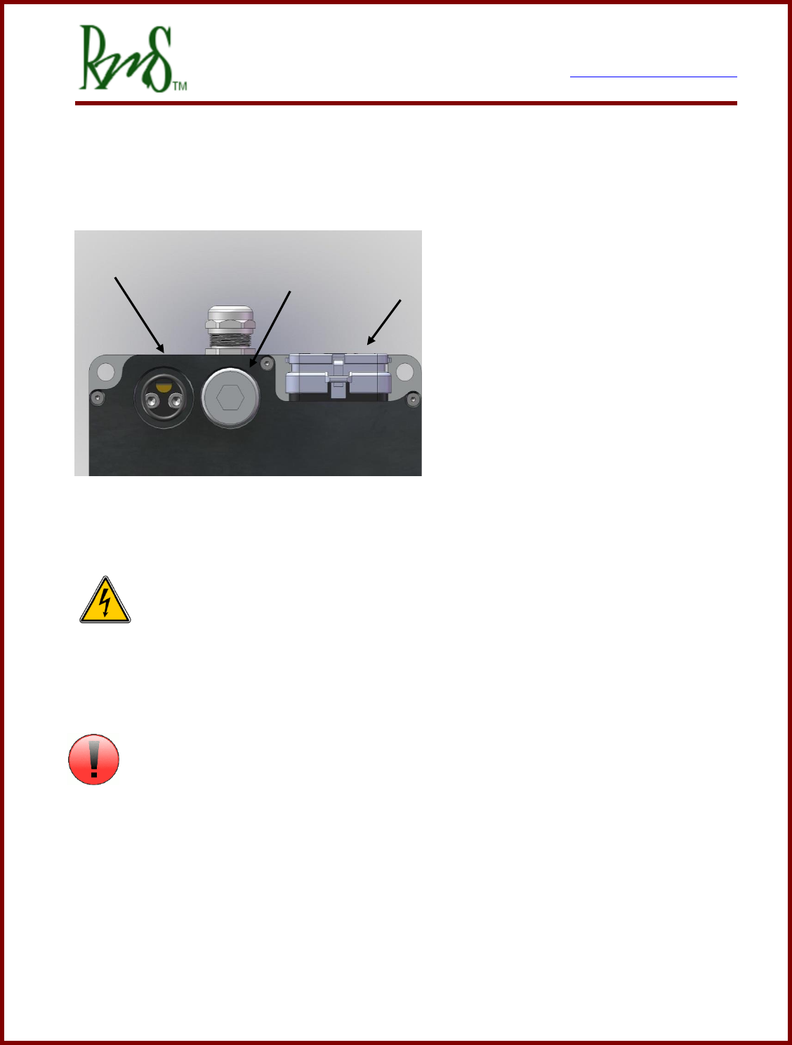
3.5 External Power Connections:
3.5.1 DC+ / DC-:
DC/Battery power is provided to the controller via two wire ports located at the rear of the
controller (PM100 and PM150 shown).
The DC power ports are marked clearly
on the front face of the PM250
controller. The DC power must be run
through an external pre-charge circuit
to safely charge the capacitors inside
the controller before the main contactor
engages (refer to application
schematic). The main contactor
provides a safety disconnect of the DC
power in case of a fault condition. Make
sure that the wire to the drive is sized properly to handle the current.
DANGER: Before changing the wiring make sure that the internal DC bus
capacitors are discharged. The voltage should be measured at the terminals before
disconnecting. If there is any doubt about the safety wait at least 1 hour after power has
been removed before touching the terminals.
ATTENTION
Refer to the PM100 HV Connection Manual for more information on how to install the wires
into the inverter.
On the PM250 unit the DC connections are marked “+” for the DC+ and “-“ for the DC-.
DC+
DC-
J1 & J2

7929 SW Burns Way Phone: 503 344-5085
Suite F Fax: 503 855-4540
Wilsonville, OR sales@rinehartmotion.com
1/17/2018 RMS PM Hardware User Manual 20 of 43
The RM100 Unit uses the Amphenol PowerLok™ 300 for the high voltage connections.
These connectors utilize the Amphenol RADSOK™ technology. Each connection is a
specific color and keying so that the cables cannot be interchanged.
Inverter
Connection
PowerLok™
Color
PowerLok™ Key
DC+
Red
W
DC-
Black
Y
Phase U
Green
V
Phase V
Orange
X
Phase W
Yellow
U
The housing of the RM100 is marked with the HV Connection designations. The PM
Family of inverters uses the Phase A, B, C designation instead of the RM Family U, V, W.
References in documentation to Phase A refer to Phase U, Phase B to Phase V, and Phase
C to Phase W.
The PowerLok™ 300 is available for many different sizes of wires. Contact RMS for more
information about ordering connectors/cables.
7929 SW Burns Way Phone: 503 344-5085
Suite F Fax: 503 855-4540
Wilsonville, OR sales@rinehartmotion.com
1/17/2018 RMS PM Hardware User Manual 21 of 43
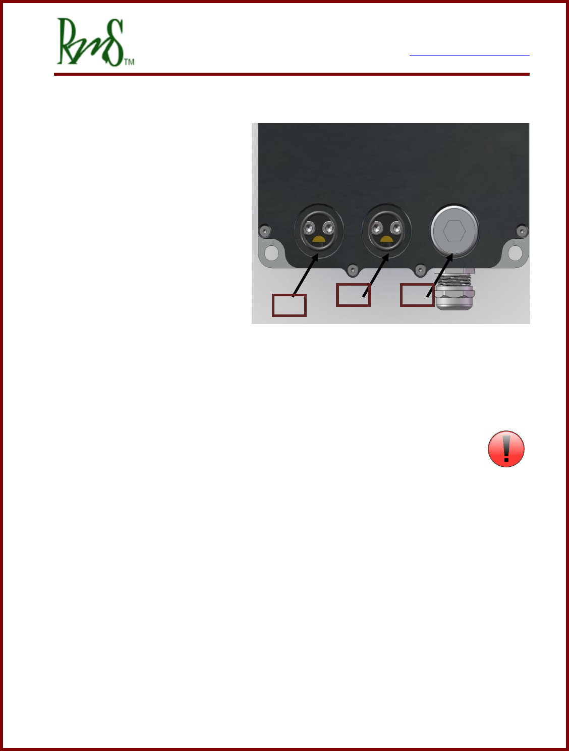
3.5.2 Phase A / Phase B / Phase C:
Phase A, Phase B, and Phase C
are wired to the motor. It is
important the 3 wires be wired to
the motor such that they give the
proper direction of rotation. The
motor wires are the most likely to
generate EMI and they also carry a
higher average current than the DC
power wires. When installed in the
vehicle these wires should be kept
as short as possible. It is also
recommended that shielded wire be
used for the motor wires. This can be done by adding a copper braid over the wires, or
using wire that includes a shield. All of the PM100/150/250 family units are shipped with
cable glands that are metallic and designed to accommodate shielded wire.
The PM250 AC motor connections are marked on the unit with the letters “A”, “B”, and “C”.
On the RM100 the phases are marked with “U”, “V”, and “W”.
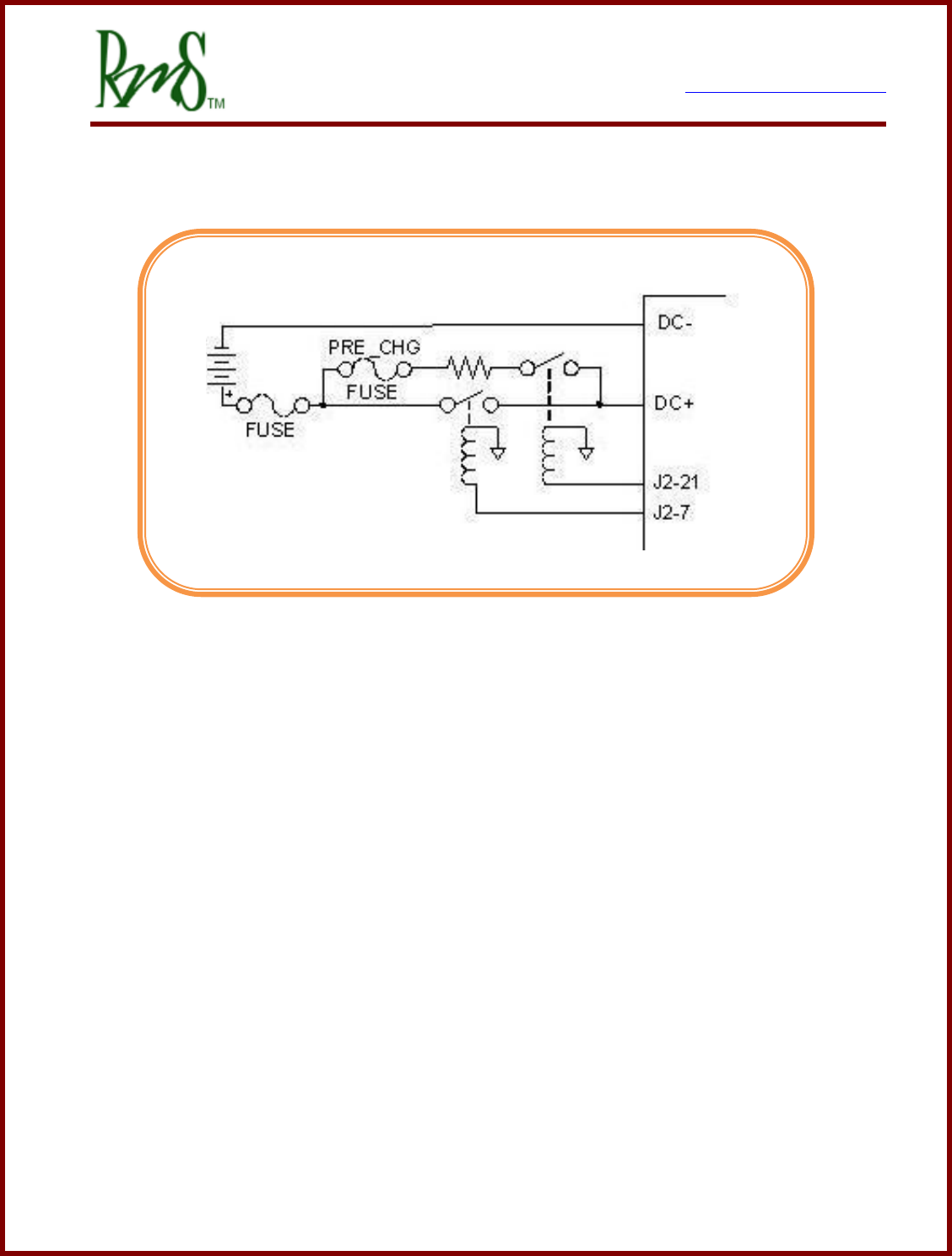
3.5.3 Pre-Charge Circuit:
An external pre-charge circuit must be used with the controller. The circuit limits
peak inrush current into the controller when the main contactor is engaged. The pre-charge
circuit adds a resistor, relay, and fuse in parallel with the main contactor. When the
controller is powered on the controller will first engage the pre-charge relay to charge the
capacitors internal to the controller. If the capacitors charge properly then the main
contactor will engage.
The pre-charge resistor should be sized to rapidly charge the capacitor, but not dissipate
too much power in a fault condition. The pre-charge resistor should be sized so that if the
controller had a short on its input the pre-charge resistor would not fail. The pre-charge
relay will only remain closed for about 3 seconds. The pre-charge sequence must complete
before this time or the inverter will declare a fault condition and open the pre-charge relay.
The pre-charge circuit should be fused with a small fuse appropriate to the wire used. Since
the pre-charge current is generally very low, approximately 0.5 amps in the example below,
A
B
C

7929 SW Burns Way Phone: 503 344-5085
Suite F Fax: 503 855-4540
Wilsonville, OR sales@rinehartmotion.com
1/17/2018 RMS PM Hardware User Manual 22 of 43
small wire can be used (recommend 18 AWG). A 5 amp fuse would be appropriate for this
wire.
Sizing Example:
A typical application could have a maximum DC bus voltage of 320 volts. If a 600 ohm
resistor were chosen this would result in a power dissipation of 171 watts. This is within the
short term rating of a 50 watt wire-wound resistor. The internal capacitance of the controller
is approximately 500uF. It takes approximately 3 time constants before the controller will
close the main contactor, thus in this example it will take 0.9 seconds for the pre-charge to
complete.
RMS can provide the following parts if needed. Reference the following:
Pre-charge Relay (30A, 12V COIL): RMS p/n 77-0026 for DX inverters
Pre-charge Relay (50A/1000V, 12V COIL): RMS p/n 77-0034 for DZ inverters
Pre-charge Resistor (600 ohm 50W): RMS p/n 53-0006 for DX inverters
Pre-charge Resistor (1K ohm 100W): RMS p/n 53-0008 for DZ inverters
Pre-charge Fuse (5A 500V): RMS p/n G1-0013-01 for DX inverters
Pre-charge Fuse (5A 1000V): RMS p/n G1-0015-01 for DZ inverters
Model
Internal
Capacitance
Maximum Pre-
charge Resistor
RMS
Part
PM100DX/PM100DXR
440uF
1200 ohms
53-0006
PM100DZ/PM100DZR
280uF
2000 ohms
53-0008
PM150DX/PM150DX
880uF
600 ohms
53-0006
PM150DZ/PM150DZR
560uF
1000 ohms
53-0008
PM250DZ
645uF
1000 ohms
53-0008
PM250DX
1500uF
400 ohms
n/a
RM100DX
570uF
1000 ohms
53-0006
RM100DZ
250uF
2000 ohms
53-0008
3.5.4 Main Contactor:
The main contactor is the switching element between the DC high-voltage power source
(typically a battery) and the controller. The main contactor must be sized to handle the
operating currents of the controller. In addition the main contactor must be able to open
under a fault condition. Generally only one contactor is needed, the application schematic
7929 SW Burns Way Phone: 503 344-5085
Suite F Fax: 503 855-4540
Wilsonville, OR sales@rinehartmotion.com
1/17/2018 RMS PM Hardware User Manual 23 of 43
shows the main contactor in series with the positive path from the battery to the controller.
RMS has successfully used the following: Tyco/Kilovac p/n EV200AAANA. This contactor is
available from RMS, contact us for more information (RMS p/n 77-0025). The contactor
must be rated to handle DC voltage, AC only rated contactors and relays must not be used.
DC rated contactors are usually polarity sensitive. That is the normal operating current
should flow in a particular direction. Refer to the contactor data sheet for more information.
3.5.5 Main Fuse:
The DC Power input to the controller must be fused. The fuse must be
rated for the voltage of the battery as well as rated to open under the short
circuit current that the battery can produce. Generally, this fuse (or equivalent fusible link)
may be a part of the battery pack, but if the pack protection is not present or adequate, this
fuse is required to prevent a potential battery pack fire. The fuse should be rated to handle
the maximum DC input current of the controller. A semiconductor type fuse is
recommended. Bussmann type FWP-400A is a suitable choice in many applications.
3.5.6 Passive Discharge of the High Voltage DC Bus:
As noted above the inverter contains a large amount of DC bus
capacitance. This capacitance will store energy long after the high
voltage has been removed from the unit. If other provisions have not
been made for discharging these capacitors then the unit wiring should not be touched for
at least 5 minutes after the high voltage has been removed from it.
The voltage will slowly decay due to internal resistors inside the unit. The resistor values
are shown in the table below:
Model
Resistance Value
Capacitance
3 Time Constants
PM100DX/PM100DXR
120K ohms
440uF
158 s
PM100DZ/PM100DZR
120K ohms
280uF
101 s
PM150DX/PM150DX
120K ohms
880uF
317 s
PM150DZ/PM150DZR
120K ohms
560uF
202 s
PM250DZ
188K ohms
645uF
364 s
PM250DX
188K ohms
1500uF
846 s
RM100DX
40K ohms
570uF
68 s

7929 SW Burns Way Phone: 503 344-5085
Suite F Fax: 503 855-4540
Wilsonville, OR sales@rinehartmotion.com
1/17/2018 RMS PM Hardware User Manual 24 of 43
RM100DZ
40K ohms
250uF
30 s
For reference the value of 3 time constants is shown. This time would dissipate the
voltage to less than 5% of the original value. Three time constants would allow the
voltage to decay to a value that is normally safe to touch. However, the capacitors will still
have some energy stored in them.
The passive resistance value shown in the table in connected to the high voltage DC bus at
all times. The inverter will draw a corresponding amount of current from the high voltage
at all times. For example if a PM100DX is being used at 320V it would draw 320/120K =
2.7mA even when the inverter is disabled.
If it is desired to have the DC bus voltage discharge faster the user must either provide an
external method of discharge or consider the use of the Active Discharge feature of the
inverter. Consultant the manual RMS Inverter Discharge Process.
3.5.7 12V Power:
The inverter requires a source of 12V power to operate. Normally, this power will be on a
switched circuit. The inverter will turn on and communicate without high voltage present.
This allows setup of parameters without high voltage.
When the vehicle is turned OFF - the 12V power is removed from the controller by a switch.
This switched 12V power is connected to the BATT+ terminals (refer to pin list for pin
designation). The ground return for 12V power is connected to the GND terminals (refer
to pin list for pin designation). For normal applications only one pin is necessary. If
necessary more than one pin can be used for applications that push higher 12V or GND
currents through the controller.
Input currents:
12V Operating Power Input Range
Input Current
12V Input Current @ 9V, operating
2.1A_typ PM100
2.5 A_typ PM150
2.1 A_typ PM250DZ
7929 SW Burns Way Phone: 503 344-5085
Suite F Fax: 503 855-4540
Wilsonville, OR sales@rinehartmotion.com
1/17/2018 RMS PM Hardware User Manual 25 of 43
12V Input Current @ 14V, operating
1.5A_typ PM100
1.8 A_typ PM150
1.6 A_typ PM250DZ
12V Input Current @ 14V, non-operating (PWM off)
0.5 A_typ PM100
0.6 A_typ PM150
0.8 A_typ PM250DZ
The RM100 allows for operation from both 12V and 24V systems (the PM family does not
have this capability). Valid range of operation for the RM100 is 9 to 32V. RM100 typical
operating currents are shown below.
RM100DX @ 12V, non-operating
0.9 A
RM100DX @ 12V, operating
1.7A
RM100DX @ 24V, non-operating
0.44A
RM100DX @ 24V, operating
0.80A
RM100DZ @ 12V, non-operating
0.9A
RM100DZ @ 12V, operating
1.3A
RM100DZ @ 24V, non-operating
0.5A
RM100DZ @ 24V, operating
0.6A
These currents do not include any high-side or low-side drivers:
Any hi-side driver output currents, including the main and pre-charge contactor relay
drive currents, will come through the BATT+ pins and will add to the above currents.
Any low-side driver output currents, including indicator lamp current, will come through
the GND pins, and should be considered in sizing this connection.
3.5.8 Grounding
The inverter housing has a location for connecting the case to ground. The inverter
housing must be connected to the motor case. It must also be connected to the vehicle
chassis and this assumes that the vehicle chassis is at the same potential as the 12V GND.
The inverter housing should not be allowed to be more than a few volts above the 12V
GND. If the inverter housing was disconnected hazardous voltages could develop on the
housing.

7929 SW Burns Way Phone: 503 344-5085
Suite F Fax: 503 855-4540
Wilsonville, OR sales@rinehartmotion.com
1/17/2018 RMS PM Hardware User Manual 26 of 43
3.6 Typical Application Wiring Diagram:
The wiring diagrams covers following areas:
Starter & Power Generation
Precharge Circuit
Motor & Encoder
Transmission Control
RS232 Programming
CAN Interface
Motor Temperature Sensor
PM Controller
Starter & Power Generation
Vehicle Control
Pre-charge Circuit
RS232
Programming
CAN
Interface
Motor
Control
7929 SW Burns Way Phone: 503 344-5085
Suite F Fax: 503 855-4540
Wilsonville, OR sales@rinehartmotion.com
1/17/2018 RMS PM Hardware User Manual 27 of 43
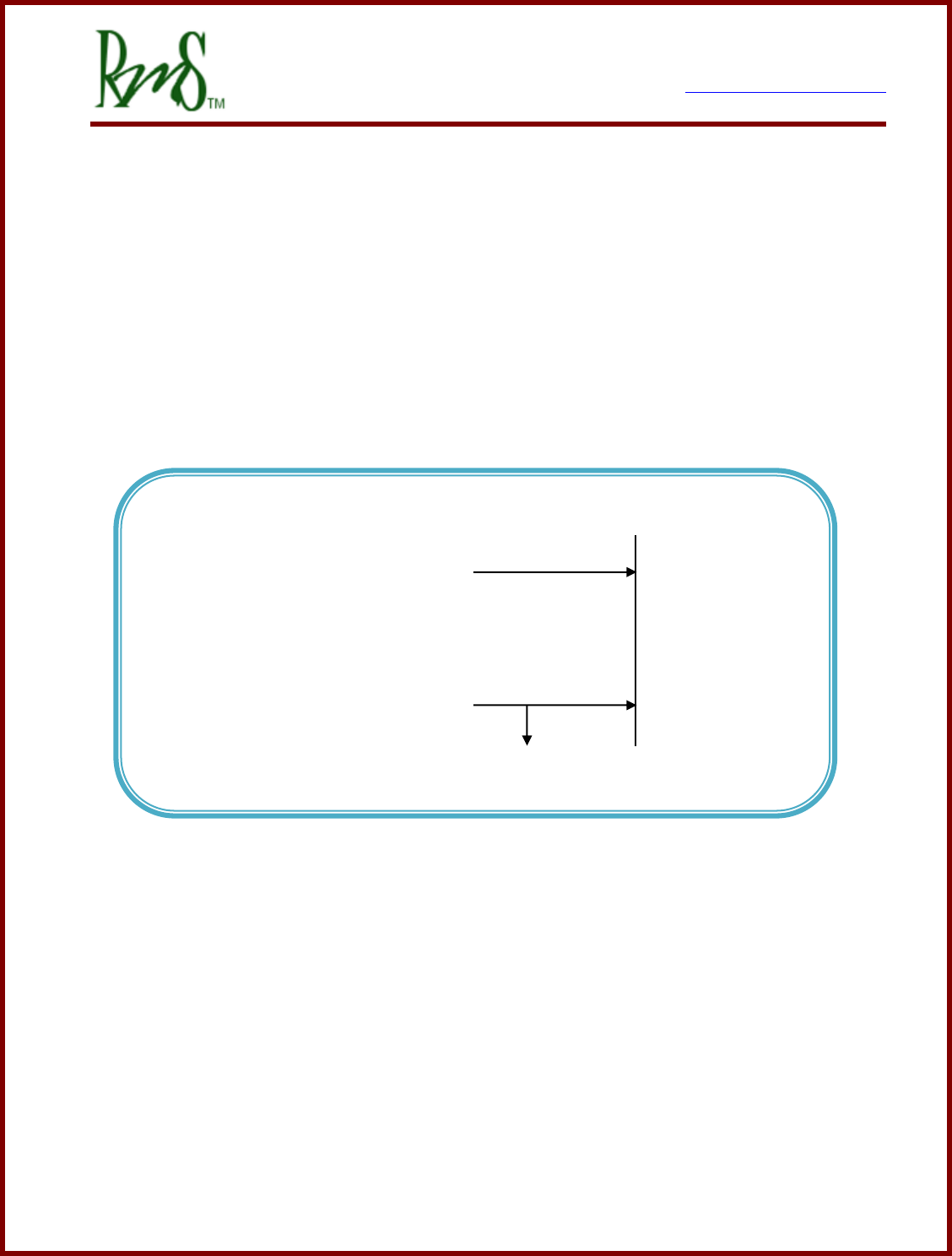
3.6.1 Controller 12V Power Wiring
This circuit can be configured in two different ways:
NOTE: RM100 can only use the Simple ON/OFF Configuration.
(a) Simple ON/OFF Configuration
In this configuration an external switch or controller is responsible for control of the
12V power. Thus the inverter will have a less controlled shutdown process as power
could be removed while it is actively controlling the motor. When using this
configuration set the EEPROM parameter Key_Switch_Mode_EEPROM to 0.
Controller 12V Power Wiring - Configuration 0
+12 V Power
Switched ON when Inverter ON
BATT+
GND
12 V Return / Vehicle Chassis
7929 SW Burns Way Phone: 503 344-5085
Suite F Fax: 503 855-4540
Wilsonville, OR sales@rinehartmotion.com
1/17/2018 RMS PM Hardware User Manual 28 of 43
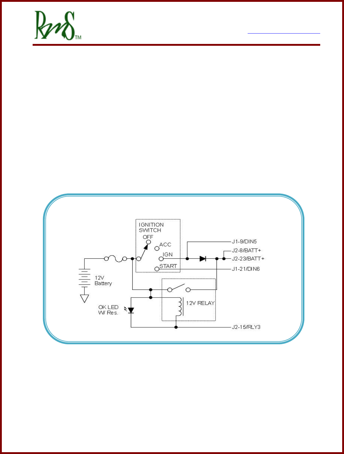
(b) Typical Ignition Configuration (PM Products Only)
In this configuration an external, user supplied relay, diode, and switch are used to
control power. When the Ignition Switch is put into the IGN position power is supplied
through the diode. Once the controller completes an initial power up sequence it then
turns on the RLY3 output to turn on the external 12V relay. The controller monitors
DIN5 to control the relay. When it is detected that Ignition has been removed (via
DIN5) an orderly shutdown process is initiated. When the process is completed the
RLY3 output is turned off and power is removed from the controller. In this mode the
START position of the switch is used to actively turn on PWM to the motor (VSM
mode).
The diode should have a current rating of at least 3 amps.
Note: Only PM100/PM150 Connections shown, refer to PM250 connector for
equivalent pins.
Starter & Power Generation - Configuration 1
7929 SW Burns Way Phone: 503 344-5085
Suite F Fax: 503 855-4540
Wilsonville, OR sales@rinehartmotion.com
1/17/2018 RMS PM Hardware User Manual 30 of 43
3.6.3 Analog/Digital Vehicle Control
If using VSM Mode then analog / digital signals can be used to control the operation of the
inverter. The limited I/O of the RM100 prevents this functionality.
Brake
DIN3
Forward DIN1
Reverse DIN2
Regen Disable DIN4
GND
Brake
AGND
AIN3
XDCR_PWR
Accel
AGND
AIN1
XDCR_PWR

7929 SW Burns Way Phone: 503 344-5085
Suite F Fax: 503 855-4540
Wilsonville, OR sales@rinehartmotion.com
1/17/2018 RMS PM Hardware User Manual 32 of 43
3.6.5 CAN Interface
The PM controller has one active CAN interface CAN A. The controller contains hardware
to support a second CAN interface (CAN B), but currently only CAN A is active. CAN B is
reserved for future use. Refer to the RMS CAN Protocol document for the various ways that
the CAN bus can be configured.
The CAN interface has multiple purposes:
Provides direct control of the motor
Provides diagnostic and monitoring capabilities
Provides user-adjustable configuration
The user can change the following hardware related configuration parameters:
Inverter Command Mode: Setting this parameter to 1 allows the CAN mode to become
active.
CAN Bus Speed: Allowed speeds are 125 Kbps, 250 Kbps, 500 Kbps, or 1 Mbps.
Enter 125, 250, 500, or 1000 to program the configuration parameter.
CAN Terminator Resistor: The resistor can be applied or opened (PM Family only).
For more information on CAN interface and messages, please refer to the “RMS CAN
Protocol” document.
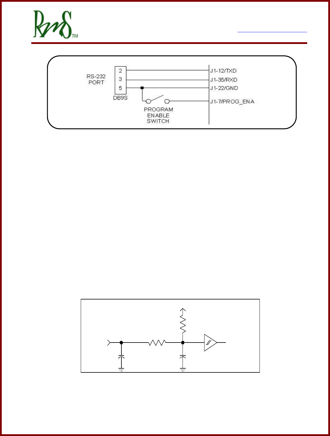
3.6.6 RS-232 Interface
There is one RS-232 serial interface. This port can be used to set up and tune the
controller, and to download controller software updates from a PC. RMS provides a simple
Windows PC based software package for monitoring and changing parameters (RMS GUI).
The drive can also be placed in a data-logging mode, and used with a PC or other serial
device the unit broadcasts datasets at 3Hz of a number of parameters that allow
performance and energy consumption data to be gathered in real time.
For more information on RS232 data logging refer to the “RMS SCI Data Acquisition”
document.
7929 SW Burns Way Phone: 503 344-5085
Suite F Fax: 503 855-4540
Wilsonville, OR sales@rinehartmotion.com
1/17/2018 RMS PM Hardware User Manual 33 of 43
Note: Only PM100/PM150 Connections shown, refer to PM250/RM100 connector for
equivalent pins.
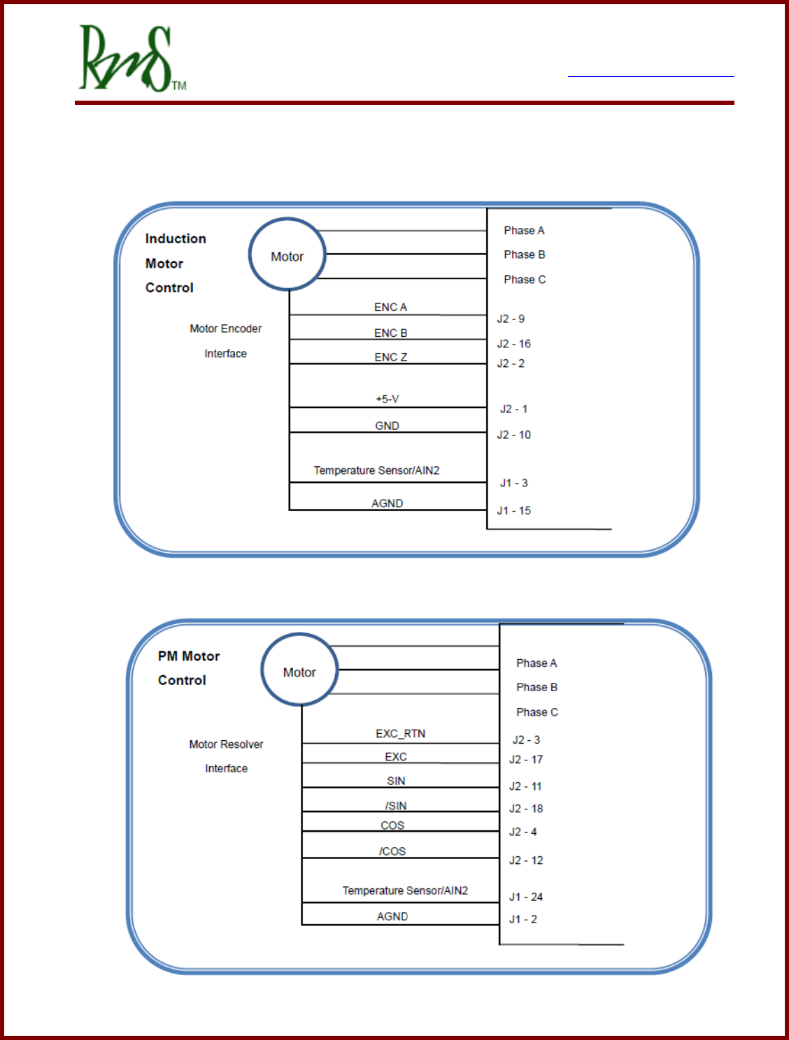
3.6.7 Encoder Interface (Not included on RM100):
The induction motor control software currently mandates the use of a position encoder on
the motor. The encoder provides information about motor speed that is used by the
induction motor control software. The controller provides a 5V interface to power the
external encoder and to receive, level translate, and filter the signals from A, B and INDEX
channels. For induction motor applications the INDEX channel is not used, but it may be
wired. The encoder is connected internally to the TI DSP QEP Module (Quadrature
Encoder Peripheral), which has special hardware for wide dynamic range speed and angle
calculation from the encoder data. The drive has internal pull-up resistors on these inputs,
and works with encoders that have either bi-polar or open-collector outputs.
Schematic of Encoder Inputs
+5V
1.0K
100R
1500pF
ENC_x TO DSP
1000pF

7929 SW Burns Way Phone: 503 344-5085
Suite F Fax: 503 855-4540
Wilsonville, OR sales@rinehartmotion.com
1/17/2018 RMS PM Hardware User Manual 34 of 43
3.6.8 Resolver Interface:
A resolver is a position sensor that is often used with Permanent Magnet type motors.
There are various types of resolvers. The resolver requires an excitation voltage and
provides a SIN and COS feedback. Currently all PM type motors used with the RMS
controller require a resolver for position feedback.
The PM Controllers have a resolver excitation frequency that matches the PWM frequency
(12kHz). The excitation voltage from the PM controller can be adjusted as needed.
The RM Controllers have an excitation frequency of 10kHz that is not synchronized with the
PWM frequency. The RM controllers use a dedicated Resolver to Digital Converter.
7929 SW Burns Way Phone: 503 344-5085
Suite F Fax: 503 855-4540
Wilsonville, OR sales@rinehartmotion.com
1/17/2018 RMS PM Hardware User Manual 35 of 43
4. Vehicle Interface Setup
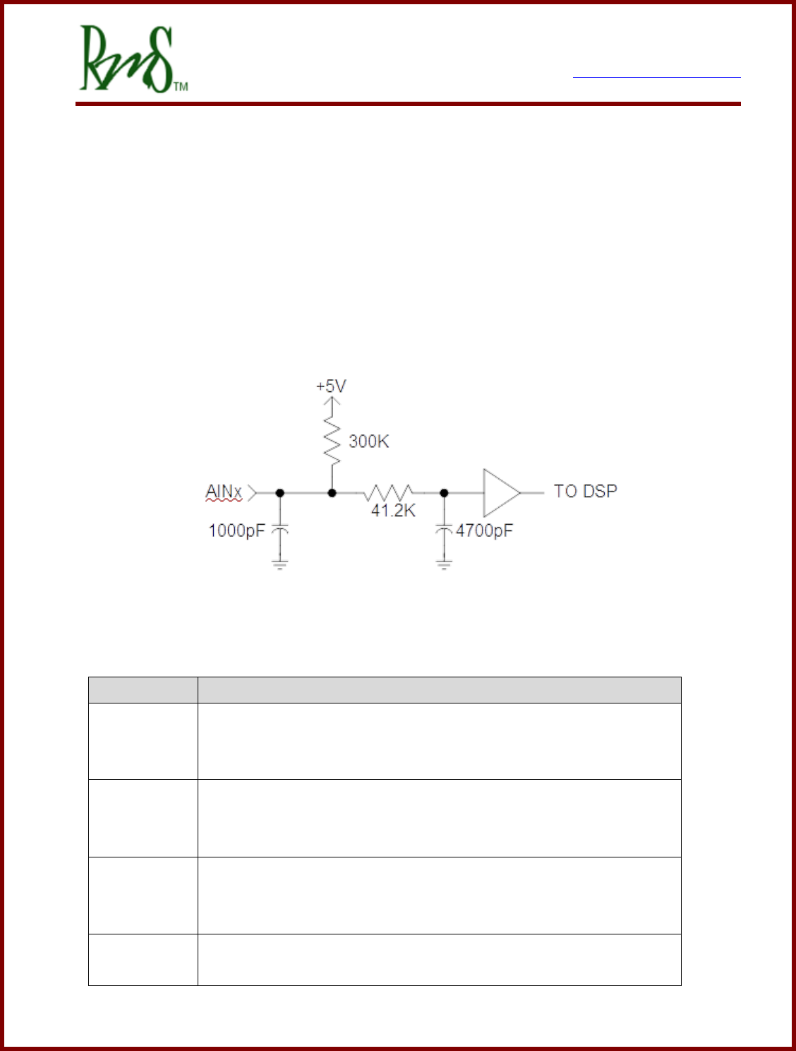
4.1 Analog Inputs:
There are 4 analog inputs on GEN 2 units (AIN1-4), 6 analog inputs on GEN 3 units
(PM100/PM150/PM250) as AIN1-6, and 3 analog inputs on the RM100 (AIN1-3). The
inputs are intended for general analog signal sensing (0 – 5V). There are 5 dedicated RTD
sensor inputs (three 1,000 Ohm and two 100 Ohm calibrated RTD channels) on GEN 2
units. There are 2 RTD inputs on GEN 3 units and RM100, selectable as PT 100 or
PT1000 by software.
Schematic of Analog Inputs
The vehicle control system assigns the analog inputs as follows:
Input Name
Function
AIN1
ACCEL
The input should be tied to the vehicle accelerator. The input can be
used with either a 0-5V signal or a potentiometer.
AIN2
Motor thermistor
The motor thermistor can be connected between this input and
analog ground. An external pull-up resistor will be required.
AIN3
BRAKE
The input should be tied to the brake pedal.
The input can be used with either a 0-5V signal or a potentiometer.
AIN4
Not assigned. For some motor types may be assigned to a
secondary motor temperature.

7929 SW Burns Way Phone: 503 344-5085
Suite F Fax: 503 855-4540
Wilsonville, OR sales@rinehartmotion.com
1/17/2018 RMS PM Hardware User Manual 36 of 43
AIN5
Not assigned.
AIN6
Not assigned.
A 5V power supply (XDCR_PWR) is provided for powering sensors or potentiometers. This
supply is available on several pins of J1 and J2 to ease connection. However, the total
supply current available from this supply is limited to 80mA.
The analog signals should be referenced to one of the analog ground (AGND) pins
available on J1. This will reduce noise. Analog ground should NOT be connected to GND or
the vehicle chassis.
Description
Parameter
Value
Analog Inputs
Input Range
Vrange
0 - 5.00V
Offset Voltage
Vofs
+50mV
Gain Accuracy
G
+5%
ADC Resolution
12b
Pull-up Resistance
Rpu
300 k Ω
RTD Inputs – PT 1000 type
1000 Ω / 0ºC
Offset – 25ºC ambient
±3ºC
Temperature error – additional error over
temperature
±3ºC
RTD Inputs – PT 100 type
100 Ω / 0ºC
Offset – 25ºC ambient
±3ºC
Temperature error – additional error over
temperature
±3°C
The controller uses two-wire type RTDs. One side of the RTD should be connected to the
RTD input. The other side should be connected to Analog Ground or the dedicated RTD
ground pin (RTDxN).
7929 SW Burns Way Phone: 503 344-5085
Suite F Fax: 503 855-4540
Wilsonville, OR sales@rinehartmotion.com
1/17/2018 RMS PM Hardware User Manual 37 of 43
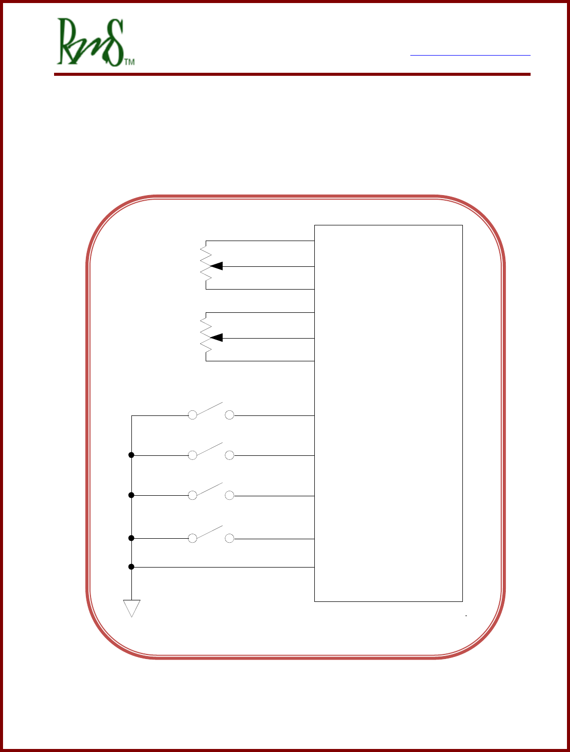
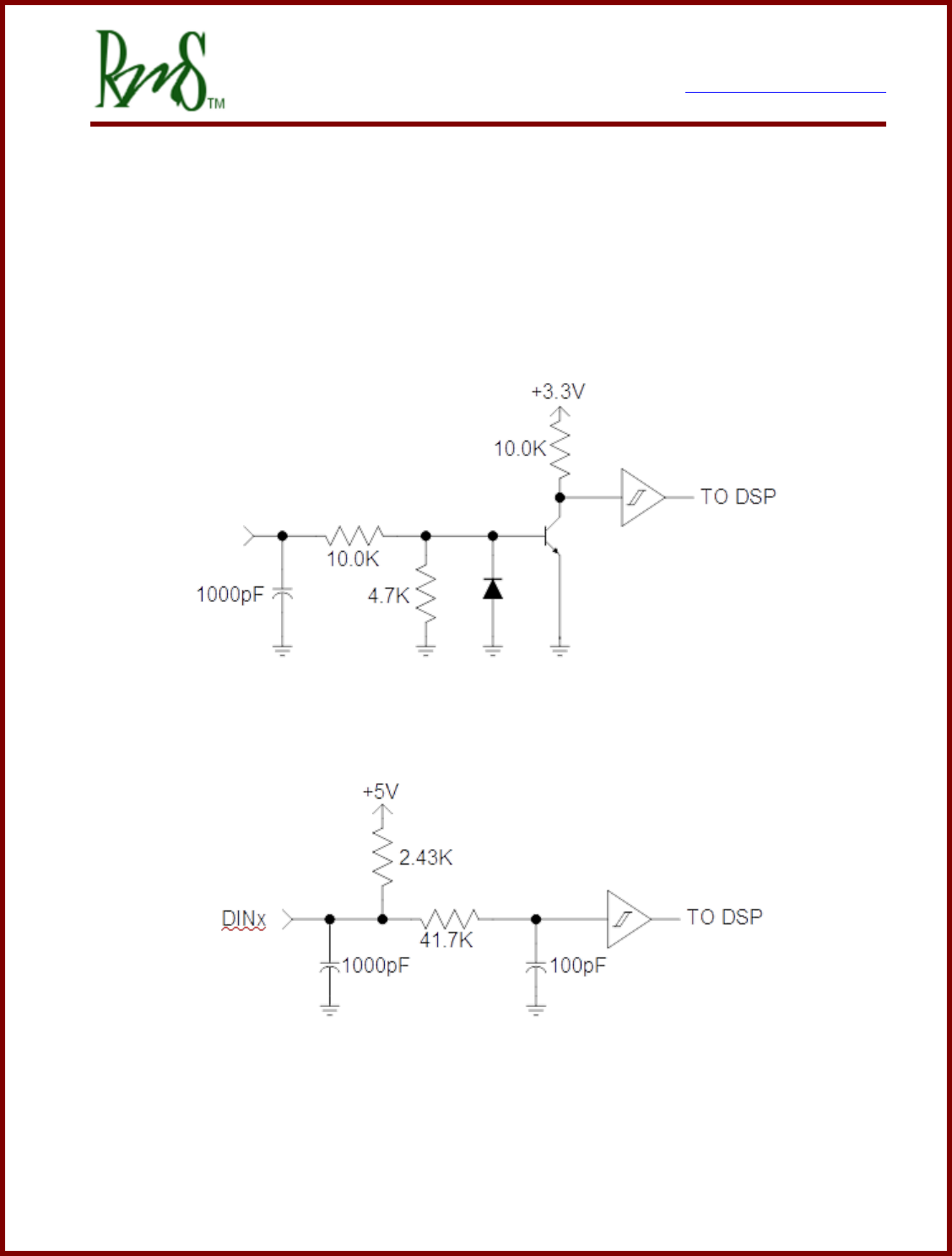
4.2 Digital Inputs:
There are up to 8 digital inputs for general interface to the vehicle and for feedback from
external contactors and switchgear as required in the application. Some inputs are “Switch
To Battery” (STB) inputs. These inputs are designed to be used in an application that
switches the input to a positive battery potential. Some of the inputs are “Switch To Ground”
(STG) inputs. These STG inputs are designed to be used in an application that switches
the input to ground.
Switch to Battery (STB) Input Schematic
Switch To Ground (STG) Input Schematic

7929 SW Burns Way Phone: 503 344-5085
Suite F Fax: 503 855-4540
Wilsonville, OR sales@rinehartmotion.com
1/17/2018 RMS PM Hardware User Manual 38 of 43
The vehicle control system software currently assigns these inputs as follows:
Input
Type
Signal Name
Function
DIN1
STG
FWD_ENA
This input should be connected to a switch
that grounds this input when the user is
commanding forward direction.
DIN2
STG
REV_ENA
This input should be connected to a switch
that grounds this input when the user is
commanding reverse direction.
DIN3
STG
BRAKE
This input should be connected to a switch
that grounds the input when the brake is
pressed.
DIN4
STG
REGEN Disable
This input should be connected to a switch
that grounds the input to enable this feature
(that is, disable REGEN).
DIN5
STB
IGNITION
If used, this input is assigned to the IGNITION
feature.
DIN6
STB
START
If used, this input is assigned to the START
feature.
DIN7
STB
Not assigned
Input available for user.
DIN8
STB
Not assigned
Input available for user.
Not all inputs are available on each unit. Below is a table showing which inputs are
available (n/a indicates not available).
Input
Type
PM100 (Gen2)
PM100 (Gen3)
PM150
PM250
RM100
DIN1
STG
Yes
Yes
Yes
DIN2
STG
Yes
Yes
Yes
DIN3
STG
Yes
Yes
n/a
DIN4
STG
Yes
Yes
n/a
DIN5
STB
Yes
Yes
n/a
DIN6
STB
Yes
Yes
n/a

7929 SW Burns Way Phone: 503 344-5085
Suite F Fax: 503 855-4540
Wilsonville, OR sales@rinehartmotion.com
1/17/2018 RMS PM Hardware User Manual 39 of 43
DIN7
STB
n/a
Yes
n/a
DIN8
STB
n/a
Yes
n/a
The electrical parameters of the digital inputs are shown in the table below.
Description
Parameter
Value
Switch to Ground Inputs ( DIN1-4 )
Voltage level for “ON”
VSTG-ON
<0.9 V
Voltage level for “OFF”
VSTG-OFF
>4.2 V
Pull-up resistor to 5V
VSTG-PU
2.4 kΩ
Maximum Voltage on Input
VSTG-MAX
18 V
Switch to Battery Inputs ( DIN5-8 )
Voltage level for “ON”
VSTB-ON
>2.5 V
Voltage level for “OFF”
VSTB-OFF
<1.3 V
Pull-down resistor
RSTB-PD
10 kΩ
Maximum Voltage on Input
VSTB-MAX
18 V
7929 SW Burns Way Phone: 503 344-5085
Suite F Fax: 503 855-4540
Wilsonville, OR sales@rinehartmotion.com
1/17/2018 RMS PM Hardware User Manual 40 of 43
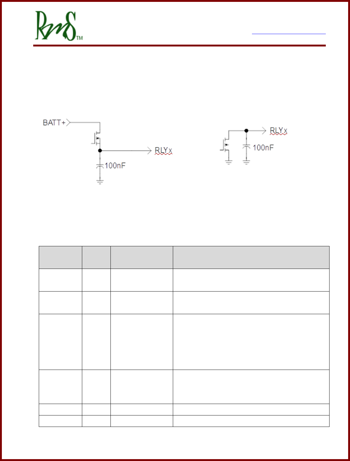
4.3 Digital Outputs
There are up to 6 digital outputs available. See the table below for more specifics on
availability across each model. There are two types of outputs available depending on the
particular model.
Schematic of High-Side Driver Schematic of Low-Side Driver
The vehicle control system assigns the outputs as follows:
Output
Name
Type
Function Name
Function
RLY1
HSD
PRECHARGE
DRIVE
This output provides power to the pre-charge
relay.
RLY2
HSD
MAIN
DRIVE
This output provides power to the main contactor.
RLY3
LSD
OK
INDICATOR
This output provides a grounded signal to the OK
indicator. The indicator turns on when power is
applied to the drive and the drive has completed
the pre-charge sequence. If used, this output is
also used to power the external 12V power relay.
RLY4
LSD
FAULT
INDICATOR
This output provides a grounded signal to a fault
indicator. The indicator will blink a fault code if
the drive has detected a fault.
RLY5
HSD
n/a
Not assigned. Available for use through CAN.
RLY6
HSD
n/a
Not assigned. Available for use through CAN.
7929 SW Burns Way Phone: 503 344-5085
Suite F Fax: 503 855-4540
Wilsonville, OR sales@rinehartmotion.com
1/17/2018 RMS PM Hardware User Manual 41 of 43
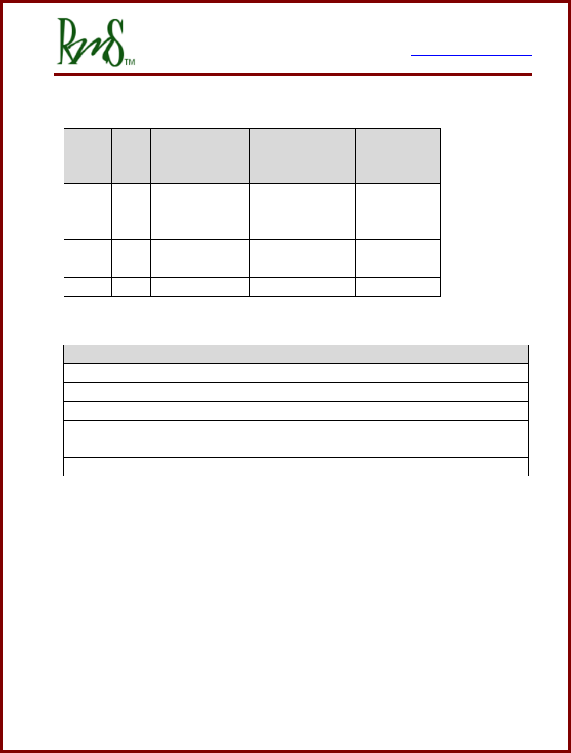
The table below documents the availability of each output type across the different inverter
models.
Input
Type
PM100 (Gen2)
PM100 (Gen3)
PM150
PM250
RM100
RLY1
HSD
Yes
Yes
Yes
RLY2
HSD
Yes
Yes
Yes
RLY3
LSD
Yes
Yes
n/a
RLY4
LSD
Yes
Yes
n/a
RLY5
HSD
n/a
Yes
n/a
RLY6
HSD
n/a
Yes
n/a
Description
Parameter
Value
Hi-Side Drivers (RLY1-2 and RLY 5-6)
Output Current - Continuous
Io_cont
1.5A
Output Current – Surge
Io_pk
7A
Low-Side Drivers (RLY3-4)
Output Current - Continuous
Io_cont
1.5A
Output Current - Surge
Io_pk
3A

7929 SW Burns Way Phone: 503 344-5085
Suite F Fax: 503 855-4540
Wilsonville, OR sales@rinehartmotion.com
1/17/2018 RMS PM Hardware User Manual 42 of 43
Revision History
Version
Description of Versions/ Changes
Updated by
Date
1.8
Added that RTDs should be connected to analog
ground.
Azam Khan
9/18/12
1.9
Updated diagrams that show the dimensions of
PM100 and PM150 drives.
Rearranged subsections in section 3.4, PM Motor
Controller
Azam Khan
1/15/14
2.0
Distinguished Gen2 connections on J1 – 35p
AmpSeal connector from that of Gen 3.
Chris Brune
2/20/14
2.1
Added connector information for the PM250.
Updated signal information to reflect the Gen 3
control board used in the PM100, PM150, and
PM250.
Chris Brune
3/24/15
2.2
Added additional comments about the cooling system
and pressure switches. Added notes about the
passive resistor on the DC bus.
Chris Brune
5/11/16
2.3
Added lower case pin designations to the PM250
connectors. Clarified the schematic images only
show the PM100/150 pinouts.
Chris Brune
11/29/2016
2.4
Added note about housing grounding. Removed
references that are PM100 specific. Improved clarity
across different PM Family members.
Chris Brune
12/6/2016
2.5
Corrected wording about pressure switch.
Chris Brune
12/19/2016
2.6
Removed reference to 3/8” NPT. Clarified
information about cooling.
Chris Brune
4/5/2017
2.7
Added information about RM100
Chris Brune
6/8/2017
2.8
Corrected the color/key information about the RM100.
Chris Brune
8/29/2017
2.9
Added information about RM100 cooling. Clarified
that VSM mode is not available for RM100.
Additional clarifications of I/O capability of RM100.
Chris Brune
9/13/2017

7929 SW Burns Way Phone: 503 344-5085
Suite F Fax: 503 855-4540
Wilsonville, OR sales@rinehartmotion.com
1/17/2018 RMS PM Hardware User Manual 43 of 43
3.0
Formatting on RM100 coolant ports. Added RM100
input current info. Updated the Digital Input section
to clearly show which inputs are available. Updated
Digital outputs section to show which are available.
Clarified analog inputs availability.
Chris Brune
1/17/2018
