PN532 Manual V3 1
User Manual:
Open the PDF directly: View PDF ![]() .
.
Page Count: 13
www.elechouse.com
PN532 NFC RFID Module User Guide
Version 3
Introduction
NFC is a popular technology in recent years. We often heard this word while smart phone company such as Samsung or HTC
introduces their latest high-end phones. Almost all the high-end phones in the market support NFC.
Near field communication (NFC) is a set of standards for smartphones and similar devices to establish radio communication with
each other by touching them together or bringing them into close proximity, usually no more than a few centimeters.
For electronics geeks, we also want to use NFC technology to make our own things. So we build this NFC RFID module. This module is
built around NXP PN532. NXP PN532 is very popular in NFC area. And the company offers much technology document to help
developers. We developed this module based on the official document. To make things easier, we also build library for this module.
We almost break out all the IO pins of NXP532 on this module. Users could easily connect and play. With our Arduino Sensor Shield ,
it is very easy to plug and play. However, if users want to use other interface such as UART or SPI, this module also makes it easy to
connect those pins.
www.elechouse.com
We have updated this module to version 3. Compared with V2, V3 have the following improvement:
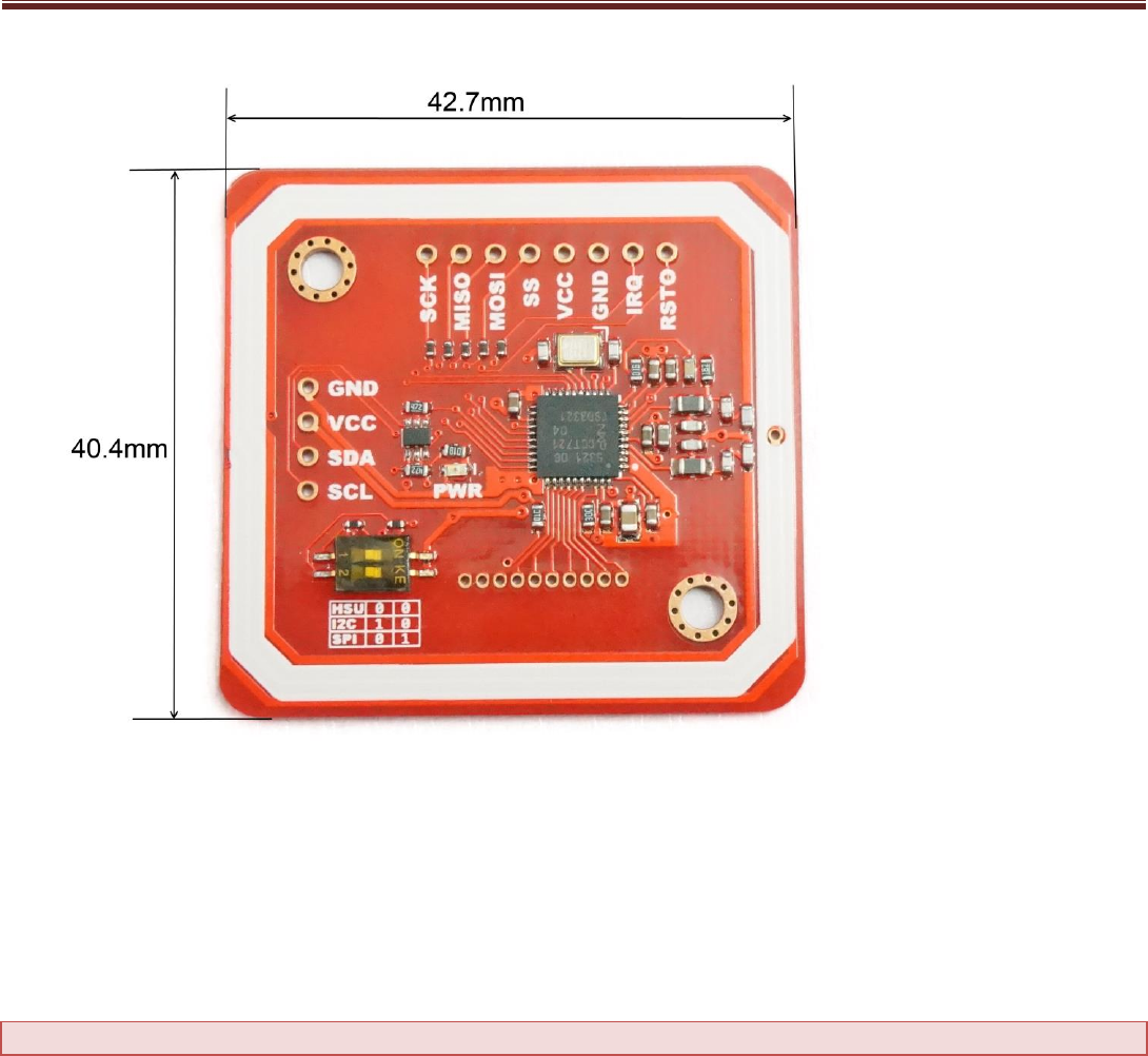
1. Smaller: the size now is as small as 42.7mm*40.4mm*4mm
2. Easy to change mode: with a small SMD toggle Switch, it becomes very easy to change among IIC, SPI and HSU modes
3. Longer distance: the reading distance becomes 5~7cm, compared with 4~6 cm of last version
4. Add software to support NFC with Android Phone
Features
1. Support II2, SPI and HSU (High Speed UART)
2. RFID reader/writer mode support
Mifare 1k, 4k, Ultralight, and DesFire cards
ISO/IEC 14443-4 cards such as CD97BX, CD light, DesFire, P5CN072 (SMX)
Innovision Jewel cards such as IRT5001 card
FeliCa cards such as RCS_860 and RCS_854
3. Plug and play, Arduino compatible
4. Built in PCB Antenna, with 5cm~7cm communication distance
5. On-board level shifter, Standard 5V TTL for I2C and UART, 3.3V TTL SPI
6. Work as RFID reader/writer
7. Work as 1443-A card or a virtual card
8. Support NFC with Android phone
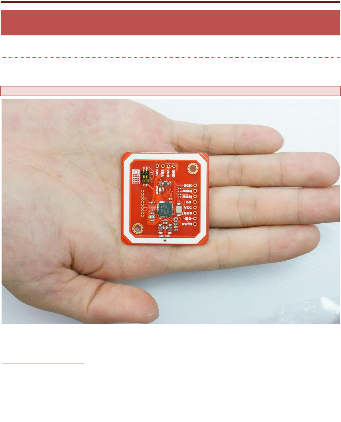
9. Small size: 43mm*41mm*4mm
www.elechouse.com
Interface
VCC: 3.3V~5V
I2C/UART: 3.3V~24V TTL
SPI: 3.3V TTL with 100 ohm resistors in series. It could be connected directly to 5V interface of microcontroller such as
Arduino.
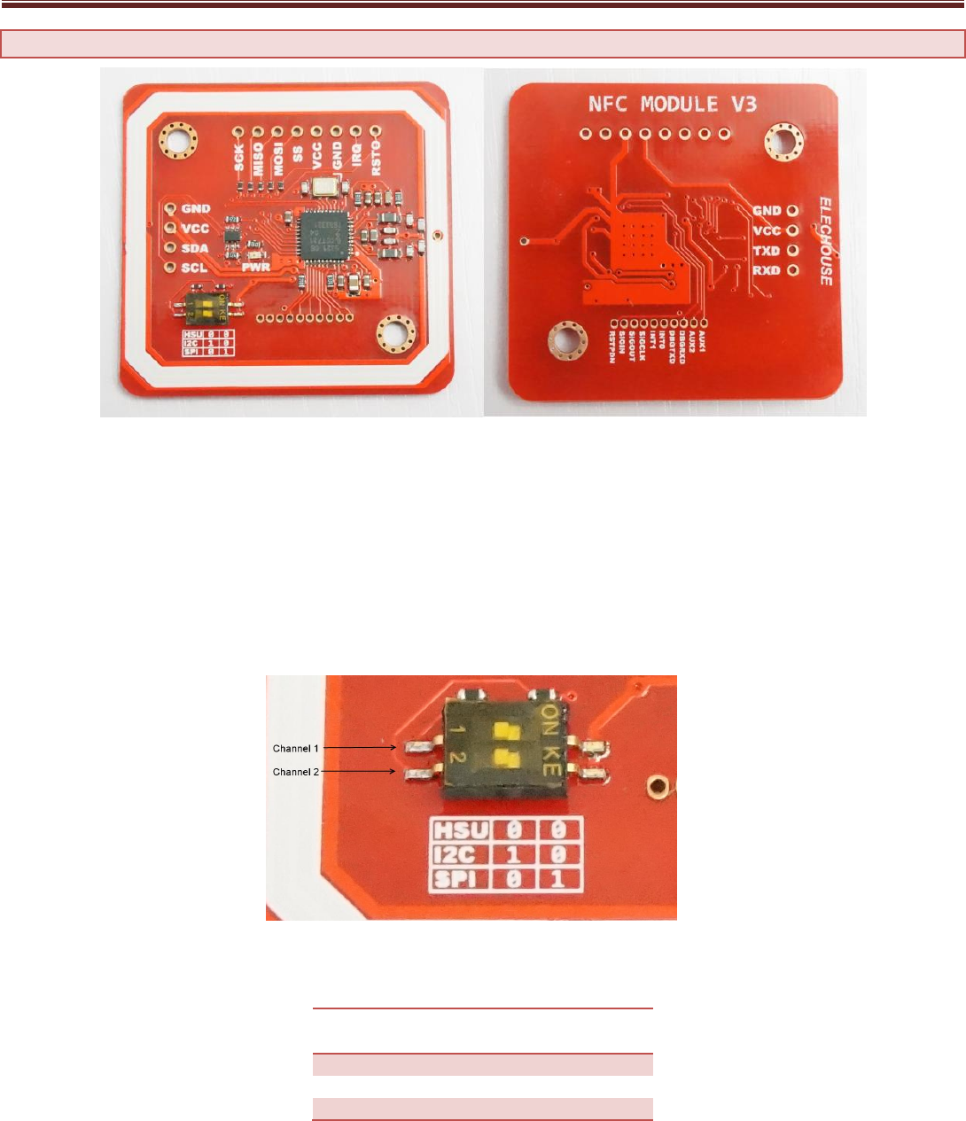
The I2C and HSU shares the same pins. The definition of IIC pins is printed at front and the HSU’s is printed at the back. The HSU mode
is configured as the default mode. But you could change the interface by setting the toggle switch.
The switch setting is shown as follows:
Working Interface
Channel
1
Channel
2
HSU
OFF
OFF
I2C
ON
OFF
SPI
OFF
ON
We break all the PN532 pins out. The 1.27mm connector hole contains those pins which might not be used for most users. If some
developers need to connect those pins, we could supply connectors.
www.elechouse.com
You could find this product here.
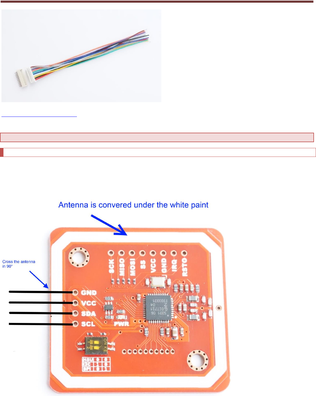
Hardware Installation
Solder the connector
The bended male pins come with the NFC board.
Some users might need soldering other types of connectors or directly solder wires on it. Anyway, make sure the wires go across the
antenna lines in 90 degree.
www.elechouse.com
Connect with Arduino
If without the sensor shield, please connect as following:
Mode
PN532
Module
Arduino UNO
Arduino Leonardo
Arduino Mega
(2560)
Arduino Due
Power
VCC
5V
5V
5V
5V
GND
GND
GND
GND
GND
IIC/I2C Mode
SDA
A4/SDA
Pin 2 /SDA
Pin 20 /SDA
Pin 20 /SDA
SCL
A5/SCL
Pin 3/SCL
Pin 21/SCL
Pin 21/SCL
HSU Mode
TXD
Pin 0
Could not
present
message in
Serial
Monitor on
PC
Pin 0
Pin 19
Pin 19
RXD
Pin 1
Pin 1
Pin 18
Pin 18
SPI Mode
SCK
Pin 13 or ICSP-3
ICSP-3
Pin 52 or ICSP-3
ICSP-3
Note: SPI
on Due is
still in
developing
MISO
Pin 12 or ICSP-1
ICSP-1
Pin 50 or ICSP-1
ICSP-1
MOSI
Pin 11 or ICSP-4
ICSP-4
Pin 51 or ICSP-4
ICSP-4
SS
Pin 10
Pin 10
Pin 10
Pin 10
Arduino UNO only has one serial interface which is also connected to USB port to PC. In HSU mode, the serial monitor could not be
used as message displaying windows.
Function Test
RFID Reader/Writer
Here we show how to read and write RFID card with this module.
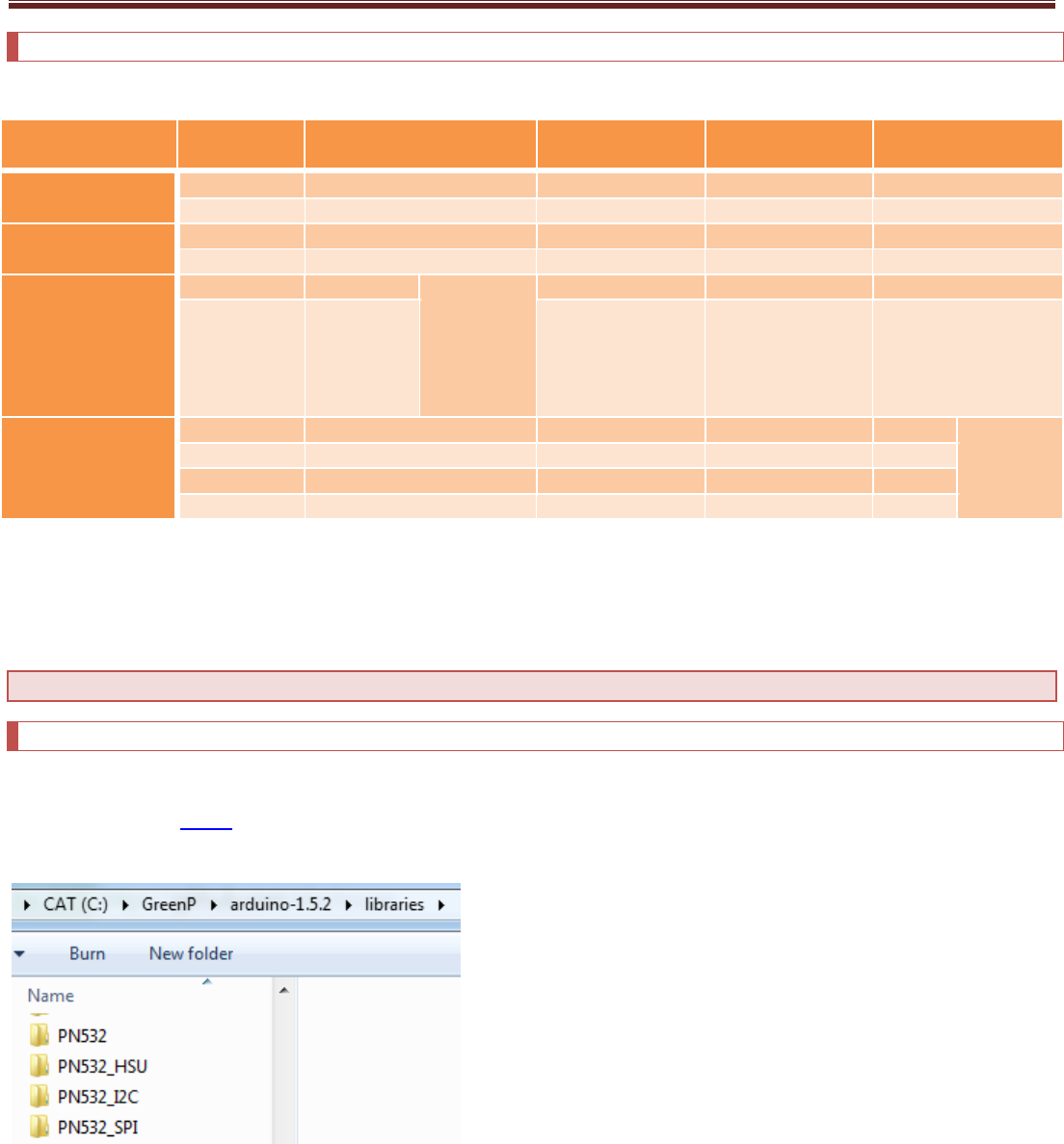
Download the library PN532 at our github page. You could find 4 folders in the library. Unzip the 4 folders at the library folder in
Arduino IDE.
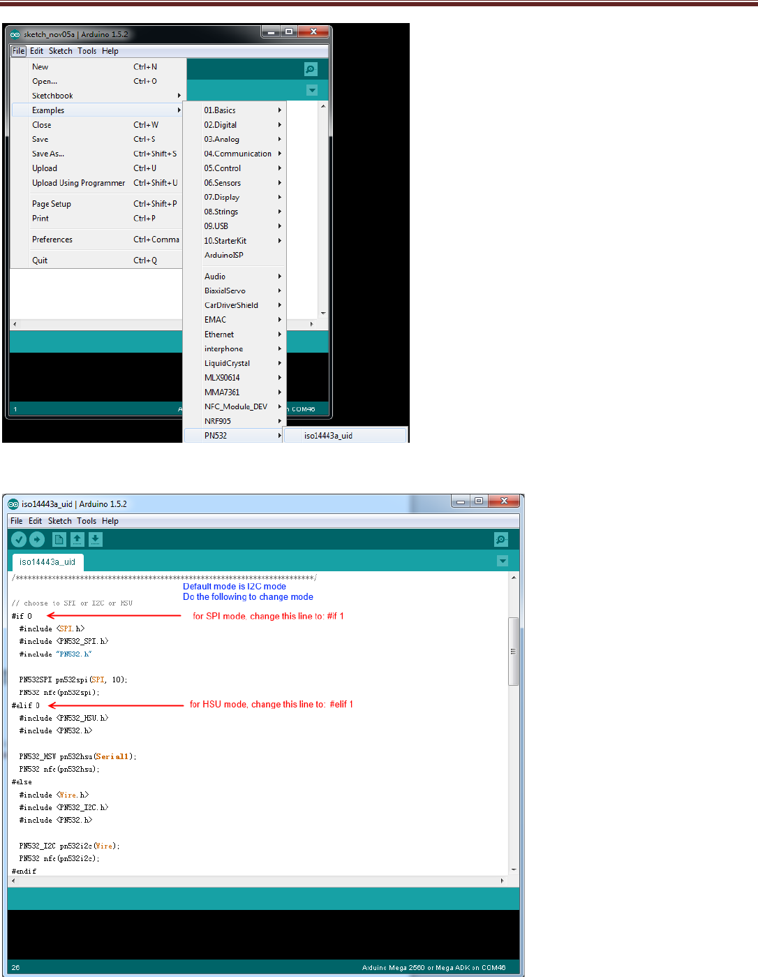
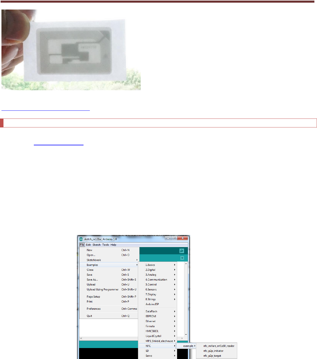
Start Arduino IDE and choose the example:
www.elechouse.com
Modify the code to choose the right mode:
www.elechouse.com
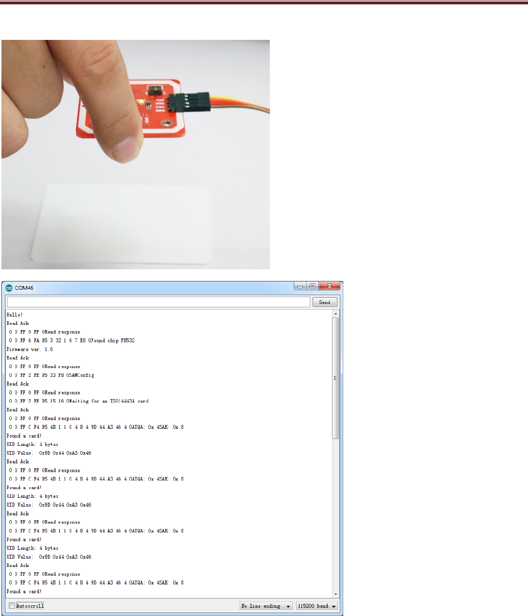
Upload the code to Arduino and open Serial monitor. Put a card on it:
You could also try other reading/writing example code in the library.
www.elechouse.com
It also supports reading flexible tag. We tested flexible tags of Mifare 1 S50 and Ultralight. The reading distance is up to 5cm.
You could find those flexible tags here.
P2P NFC
Currently we are still developing the software. The P2P NFC communication between two PN532 modules is only supported by I2C
mode. Please download this library.
Note, while testing this library, please remove the libraries in the testing above (or other PN532 libraries) to other folders.
Otherwise they might conflict.
Here we need two Arduino boards to test this function. Basically we will program one NFC module as Initiator, and the other as
Target.
Please upload the following two examples to the two Arduino board:
NFC_p2p_initiator
NFC_p2p_target
After uploading the sketches, open the Serial Monitor. Please note that Arduino IDE doesn’t support opening 2 Serial Monitors. So
you need another Serial Tool. Here we have 2 versions of Arduino IDE installed in my PC: Arduino 0022 and Arduino 1.0. We open the
two and could have two Serial Monitor working. Note the baud rate is 115200.
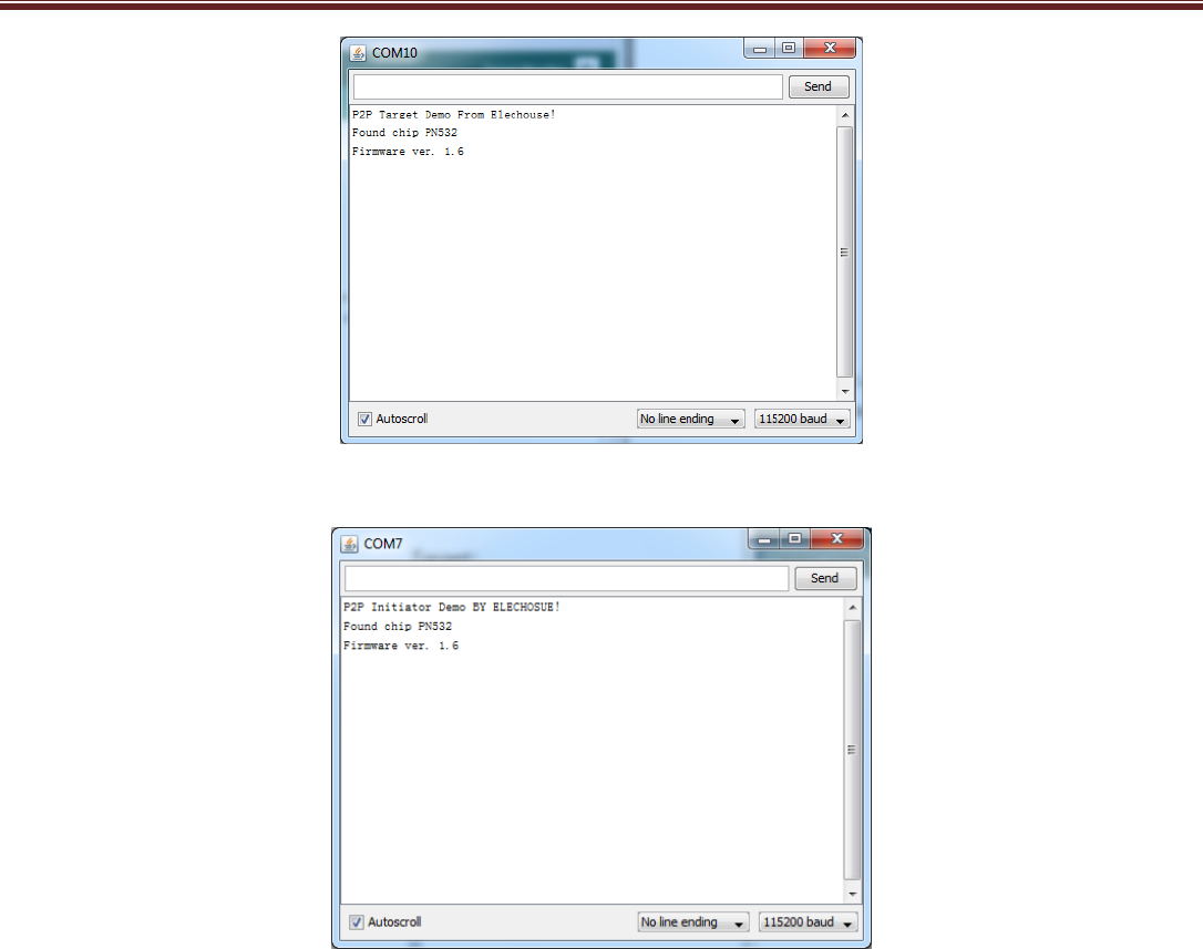
Target:
www.elechouse.com
Initiator:
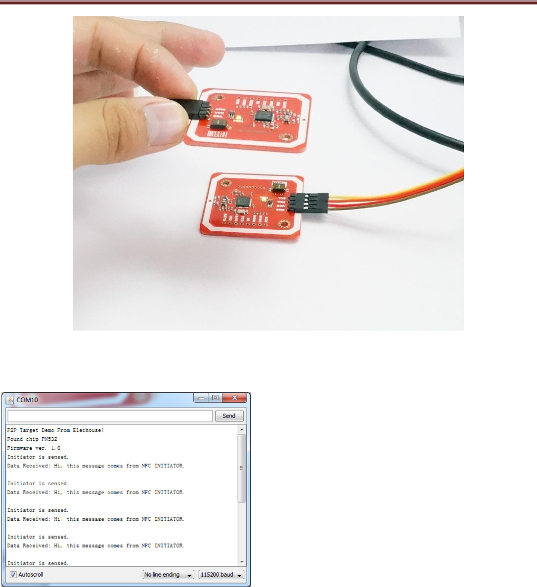
Then put one module above the other:
www.elechouse.com
Finally we get
:
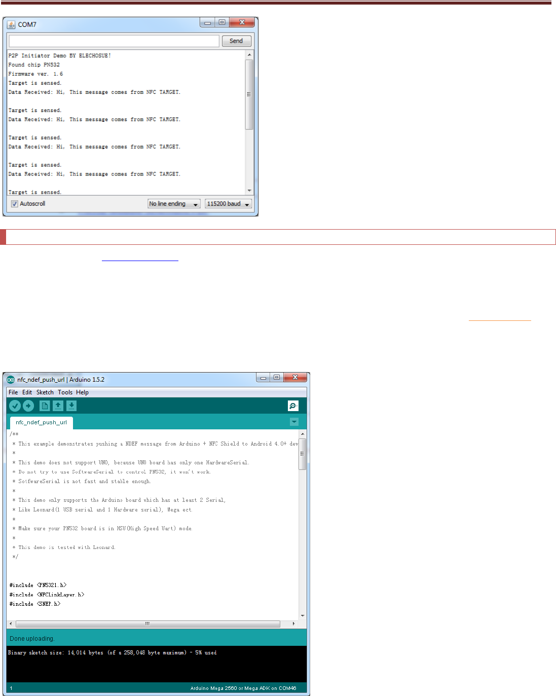
Target:
Initiator:
www.elechouse.com
NFC with Android phone
Download the library of NFC_Module_DEV from our github page.
Note, while testing this library, please remove the libraries in the testing above (or other PN532 libraries) to other folders. Otherwise they might
conflict.
Currently this library only supports HSU mode. We are still working on more modes. If you want to use SPI mode, you could try NFC_Shield_DEV. Just
connect Arduino with our PN532 module through SPI interface in the way shown in the table above.
Open the example in Arduino Due:
www.elechouse.com
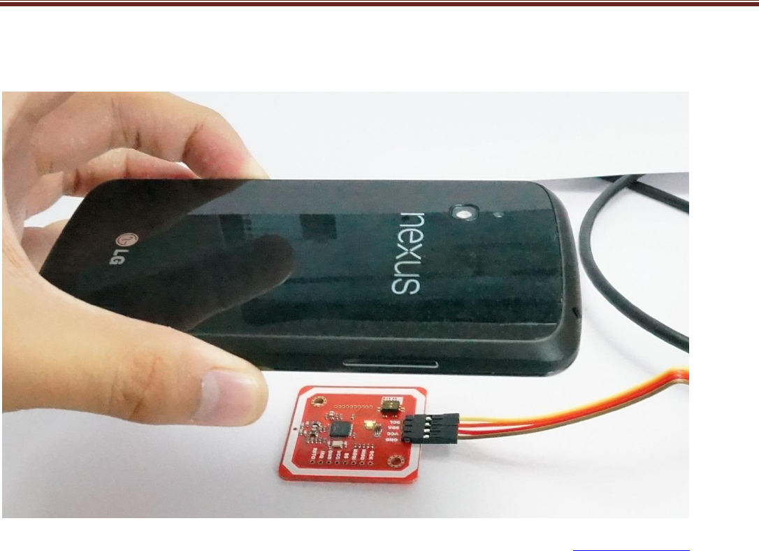
Upload the code to Arduino, and open Serial Monitor:
Put a NFC-support phone on the module (the following phone is Nexus 4):
On Android phone, if you have set the default browser, it will start the browser and visit our website: www.elechouse.com
If it doesn’t start the browser, please open the browser and try again. Here we tested HTC one and Google Nexus 4. They all work
very well. Different NFC phones might have different NFC ICs. If your phone doesn’t work with it, try to google information to check if
your phone NFC chip is compatible with PN532.
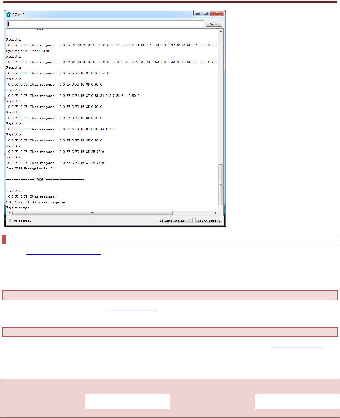
On Serial Monitor you could get the following result:
www.elechouse.com
Useful link
PN532 Module Schematic PDF
NXP PN532 User Manual
Library: PN532 or NFC_Module_DEV
Where to buy
Please visit this page to buy this product: PN532 NFC module
Disclaimer and Revisions
The information in this document may change without notice. If you have any problem about it, please visit www.elechouse.com to
contact us.
Revision History
Rev.
Date
Author
Description
A
Oct. 25th , 2012
Wilson
Initial version
B
Nov. 5th, 2013
Wilson
Modify information for V3
