POWERSHOTA80 Canon
User Manual: POWERSHOTA80 canon
Open the PDF directly: View PDF ![]() .
.
Page Count: 144 [warning: Documents this large are best viewed by clicking the View PDF Link!]
- GENERAL DESCRIPTION OF PRODUCT
- Cover
- CONTENS
- 1 Development Background
- 2 Features
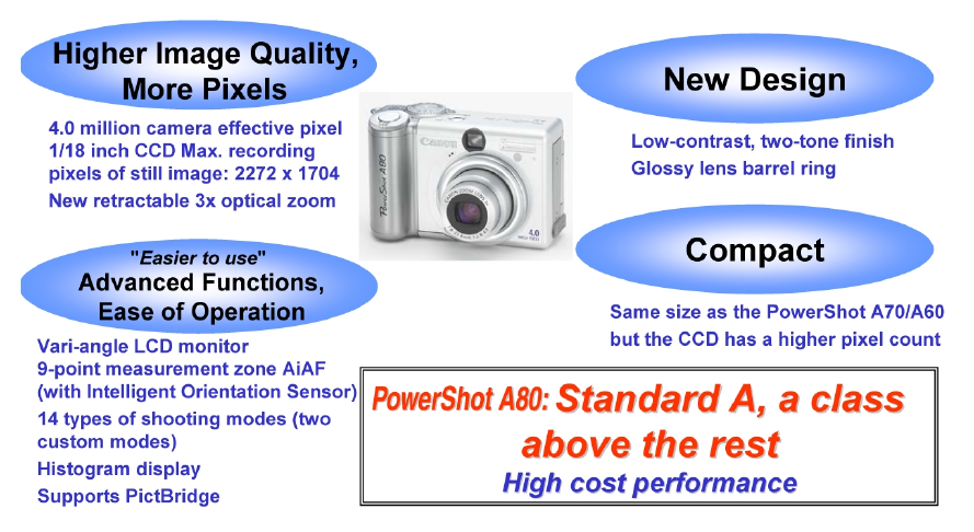
- 2-1 Higher Image Quality/More Pixels
- 2-2 Advanced Functions
- - Supports PictBridge, which enables direct printing from other-vendor printers
- - 9-point AiAF and 1-point AF selectable
- - 14 shooting modes (with two custom modes)
- - Digital zoom function with continuously changing angle of view
- - Automatic detection of vertical/horizontal shooting by Intelligent Orientation Sensor
- - Histogram display (during rec-review/playback)
- 2-3 Ease of Operation
- - Vari-angle LCD monitor that can disable mirror imaging
- - Mute mode disabling all sounds except the warning sound
- - Display Off mode that switches off the LCD monitor after a certain time
- - Large buttons for easier operation
- - Choice of High Speed mode or Normal mode in continuous shooting
- - Switchable MF zoom display
- 2-4 Compact
- 2-5 High Quality Design
- 2-6 System Accessories
- 3 Exterior
- 4 Specifications
- 5 System
- TECHNICAL DESCRIPTION
- REPAIR INSTRUCTION
- Cover
- CONTENTS
- 1. Before Starting the Repair Work
- 2. Disassembly/Assembly
- 2.1 Procedure
- 2.2 TOP COVER UNIT, CF COVER
- 2.3 REAR COVER UNIT, JACK COVER
- 2.4 SIDE COVER, FRONT COVER SECTION, LENS BARREL SHEET
- 2.5 BAYONET CUP UNIT, FRONT COVER UNIT
- 2.6 BATTERY COVER SHAFT, BATTERY COVER SPRING, BATTERY COVER UNIT
- 2.7 HINGE COVER, LCD UNIT
- 2.8 LCD REAR COVER, LCD FRONT COVER.
- 2.9 FLASH UNIT
- 2.10 OPERATION MODULE UNIT
- 2.11 CF UNIT, MAIN-FLASH FPC
- 2.12 FLASH UNIT
- 2.13 MAIN-LCD MODULE UNIT, SUB FRAME
- 2.14 MICRPHONE UNIT, MICROPHONE BUSH
- 2.15 LITHIUM (2ND) BATTERY, MAIN PCB SECTION
- 2.16 MAIN A SHIELD UNIT, MAIN B SHIELD UNIT, MAIN PCB ASS’Y
- 2.17 OPTICAL UNIT
- 2.18 FRONT CAP SECTION, BARRIER PLATE
- 2.19 FRONT CAP, BARRIER COVER
- 2.20 BARRIER BASE
- 2.21 BARRIER DRIVE PLATE, BARRIER DRIVE RING
- 2.22 MAIN-DC FPC, DC/JACK UNIT
- 2.23 BATTERY BOX UNIT, MAIN FRAME UNIT
- 2.24 Screw List
- 3. Adjustments
- PARTS CATALOG
- DIAGRAMS

GENERAL DESCRIPTION
OF PRODUCT
Trademarks
The product names and company names described in this CD-ROM are the registered
trademarks of the individual companies.
Copyright
Canon Inc. retains the copyright to all data contained on this CD-ROM.
Reproduction, publication (including on the World Wide Web) alteration, translation into
another language, or other use of the data in whole or part, contained on this CD-ROM
without the written consent of Canon Inc., is prohibited.

CONTENTS
1 Development Background
1-1 Development Objectives -----------------------------------------------------------------------------------------------------1
1-2 Product Concept ---------------------------------------------------------------------------------------------------------------1
1-3 Design Concept --------------------------------------------------------------------------------------------------------------- 5
1-4 Product Specification Comparison -----------------------------------------------------------------------------------------6
2 Features
2-1 Higher Image Quality/More Pixels ------------------------------------------------------------------------------------------8
- New high resolution 3x optical zoom lens --------------------------------------------------------------------------------8
- Approx. 4.0 million camera effective pixel 1/1.8 inch CCD
(Total number of pixels: Approx. 4.1 million; Max. recording pixels of still image: 2272 x 1704) --------------------------- 8
- AF/AE/AWB that relies on an Intelligent Orientation Sensor to detect vertical/horizontal orientation ----------8
2-2 Advanced Functions -----------------------------------------------------------------------------------------------------------9
- Supports PictBridge, which enables direct printing from other-vendor printers -------------------------------------9
- 9-point AiAF and 1-point AF selectable ----------------------------------------------------------------------------------9
- 14 shooting modes (with two custom modes) ----------------------------------------------------------------------------9
- Digital zoom function with continuously changing angle of view
(Approx. 3.6x. Approx. 11x when used in combination with the optical zoom) ------------------------------------------------- 10
- Automatic detection of vertical/horizontal shooting by Intelligent Orientation Sensor -------------------------- 10
- Histogram display (during rec-review/playback) ---------------------------------------------------------------------- 10
2-3 Ease of Operation ------------------------------------------------------------------------------------------------------------11
- Vari-angle LCD monitor that can disable mirror imaging ------------------------------------------------------------ 11
- Mute mode disabling all sounds except the warning sound ---------------------------------------------------------- 11
- Display Off mode that switches off the LCD monitor after a certain time ----------------------------------------- 11
- Large buttons for easier operation---------------------------------------------------------------------------------------- 11
- Choice of High Speed mode or Normal mode in continuous shooting --------------------------------------------- 12
- Switchable MF zoom display --------------------------------------------------------------------------------------------- 12
2-4 Compact ----------------------------------------------------------------------------------------------------------------------- 13
- Compact, new high resolution 3x optical zoom lens ------------------------------------------------------------------ 13
- Space-saving 2-blade lens cover inside the lens barrel ---------------------------------------------------------------- 13
2-5 High Quality Design --------------------------------------------------------------------------------------------------------- 13
- High-grade design suitable for the flagship model of the PowerShot A series ------------------------------------ 13
2-6 System Accessories ---------------------------------------------------------------------------------------------------------- 13
- Tel-Convertor for shooting at 200 mm telephoto angle (35mm film equivalent) ------------------------------------------------ 13
- Waterproof case submersible to 40 m (Equipped with double glass and flash light diffusion plate) -------------------------- 13
3 Exterior
3-1 Exterior Photos --------------------------------------------------------------------------------------------------------------- 14
3-2 6-dimensional diagram ------------------------------------------------------------------------------------------------------ 15
3-3 Nomenclature -----------------------------------------------------------------------------------------------------------------16
3-4 UI Information ---------------------------------------------------------------------------------------------------------------- 17
4 Specifications
4-1 Camera Specifications ------------------------------------------------------------------------------------------------------- 20
4-2 Accessory Specifications ---------------------------------------------------------------------------------------------------- 29
4-3 Functions Available in Each Shooting Mode ---------------------------------------------------------------------------- 30
1) Settings saved at power off ---------------------------------------------------------------------------------------------- 30
2) Settings saved when changing shooting modes ----------------------------------------------------------------------- 31
4-4 Playback compatibility ------------------------------------------------------------------------------------------------------ 32
5 System
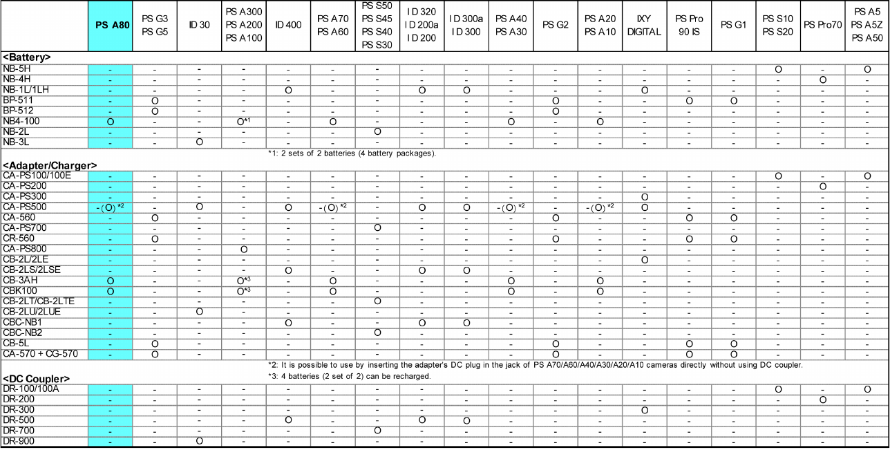
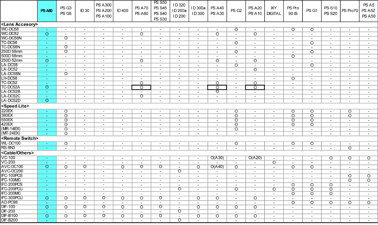
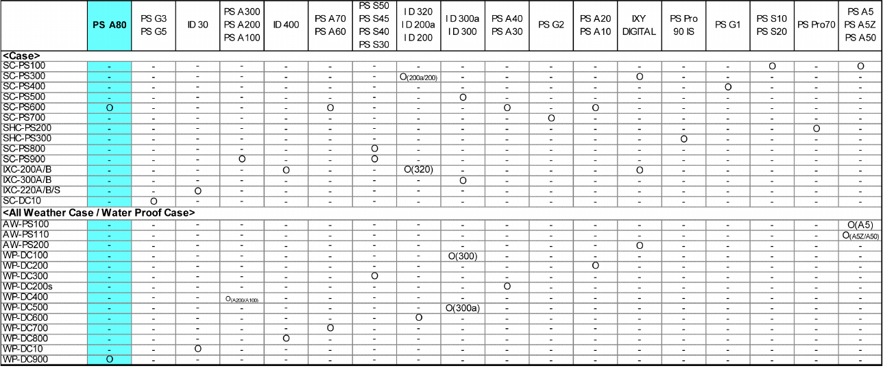
5-1 Accessory compatibility ----------------------------------------------------------------------------------------------------- 33
5-2 System Diagram -------------------------------------------------------------------------------------------------------------- 36
1
1 Development Background
1-1 Development Objectives
The PowerShot A series was designed based on the concept of affordable pricing and simple operation but
with image quality and features to match high-end models, and is characterized by its orthodox design
similar to conventional 35mm cameras, its handy size for superb operability, and its versatility in being able
to take AA batteries. In addition, with superb image quality, advanced features, and stylish design that
outstrip all other products in the popular price bracket, the PowerShot A series, from the PowerShot A20/
A10 released in spring 2001 to the PowerShot A70/A60 released in spring 2003, has consistently won
popular acclaim from the market and carved out a stable share.
However, competitors have begun offering their own affordable digital cameras using 4.0 million pixel
CCDs, threatening Canon’s lead in the market. Consequently, Canon plans to release its new Powershot A80
in autumn 2003, taking the design ideals of the PowerShot A70/A60 to the next level to outdo the
competition in the same class by producing a 4.0 megapixel CCD camera with even more functions.
The PowerShot A80 was developed as the flagship model of the PowerShot A series with the aim of
enhancing the overall image of the PowerShot A series and expanding its market.
1-2 Product Concept
The concept behind the PowerShot A80 was to achieve a stylish and powerful digital camera distinct from
competing models and from the PowerShot A70 in the highly competitive popular price bracket, with the
aim of establishing the PowerShot A80 as the “PowerShot A series flag-ship model with features above and
beyond the standard specifications.”
Specifically, the PowerShot A80 is based on the PowerShot A70 with the following additional specifications.

2
New features unique to the PS A80 (Fall 2003 model)
z Improved features from the PS A70 (Features already provided on other spring 2003 models)
Red characters indicate elements the development section would especially like to promote.
Features carried over from the PS A70 PS: PowerShot
Higher Image Quality / More Pixels
Advanced Functions
New high resolution 3x zoom lens (38 - 114mm (35mm film equivalent), F2.8 - 4.9, Retractable)
z Approx. 4.0 million camera effective pixel 1/1.8 inch type CCD (Total number of pixel: approx. 4.1million)
z Maximum recording pixels of still image: 2272 X 1704
z AF/AE/AWB that relies on an Intelligent Orientation Sensor to detect vertical / horizontal orientation
High-definition and fast processing with the Digital Imaging Processor “DIGIC”
High-speed AF and high-definition AE/AWB based on iSAPS technology
Fine color reproduction owing to primary color filters
Iris-type aperture enables multi-stop iris control and elegant blur
Wide range of ISO-equivalent speed settings, including the high-image-quality ISO 50
(AUTO/ISO 50/100/200/400 equivalent)
(Auto + Five preset positions + Custom)
Total of 12 image quality modes (recording pixels (4) x compression (3))
Exif 2.2 (Exif Print) compliant
Supports PictBridge, which enables direct printing to other-vendor printers
z 9-point AiAF and 1-point AF selectable
z 14 shooting modes (with two customizable modes)
z Digital zoom function with continuously changing angle of view (Approx. 3.6x.
Approx. 11x when used in combination with the optical zoom)
z Automatic detection of vertical/horizontal shooting by Intelligent Orientation Sensor
z Histogram display (during rec-review/playback)
Macro function focuses close to 5 cm (wide-end) and 25 cm (telephoto-end)
Real image type 3x optical viewfinder
On/Off selection of AF-assist beam available
Three metering functions (Evaluative metering, Center-weighted average metering and Spot metering)
From 15-second to 1/2000-second shutter speeds
Built-in flash with 3 flashing modes (Auto, On and Off) with combination of red-eye reduction
(Flash range: 45 cm - 4.4 m (W), 45 cm - 2.5 m (T), 25 - 45 cm (macro))
Use of power-saving LED for emitter of red-eye reduction
Flash strength can be adjusted manually
5 photo effect modes
Noise reduction function reduces noise with slow shutter speed
Settable display times for rec review (Off, 2 to 10 seconds)(Images can be erased during display)
Self-timer function for approximately 2 or approximately 10 seconds

3
Compact
Ease of Operation
Manual settings functions designed to meet user needs (Focus, Shutter speed, Aperture value,
Exposure compensation)
Two types of recording pixels for movie mode (QVGA/QQVGA)
Long movie recording with audio (internal microphone and speaker, max. of 3 minutes)
Sound memos of up to 60 seconds can be appended during replay
Supports DPOF format image transfer
Canon Direct Print function compatible (Card Photo printers (CP Series) and Bubble Jet printers)
Selectable video output format (NTSC/PAL)
UI can be displayed in twelve languages
My Camera function (Start-up image, start-up sound, shutter sound, operation sound and selftimer sound
can be customized; on-camera contents can also be created)
Vari-angle LCD monitor that can disable mirror imaging
Mute mode disabling all sounds except the warning sound
Display Off mode that switches off the LCD monitor after a certain time
z Large buttons for easier operation (including zoom lever, shooting mode dial)
z Omni Selector provides easy operation
z Choice of High speed mode (approx. 2.4 shots/sec) or Normal mode (approx. 1.6 shots/sec.) in
continuous shooting (Under Large/Fine conditions and LCD monitor off)
z Switchable MF zoom display
Mode switch toggles instantly between shooting and replay
Easy operation with a function button
Reset all settings with one-touch operation
Volume of each operation sound can be adjusted manually
Magnified playback at approx. 2x to 10x zoom for convenient image viewing (Also available
during rec-review)
High-speed image transfer during replay
Index replay (9-images)
First frame, Last frame, Next frame, Previous frame, Fast forward and Rewind available during
movie replay
Unwanted scenes can be deleted in movie replay mode (image and audio)
USB Interface with multi-use connector (mini-B jack)
Computer connections with Picture Transfer Protocol (PTP) support
Use of widely available size AA batteries (4 cells) (Primary: alkaline; secondary: NiMH)
Compact, new high resolution 3x optical zoom lens
z Space-saving 2-blade lens cover inside the lens barrel
Thin 1.5 inch amorphous silicon TFT LCD monitor with low power consumption back light
Small highly reliable and highly efficient light-guide flash

4
High Quality Design
Note: See “1-3 Design Concept”
High-grade design suitable for the flagship model of the PowerShot A series
??
Large size grip with high-quality metallic-finish zoom lever on the tip
New Tele-Convertor for shooting of 200 mm telephoto angle (35mm film equivalent)*1
z Waterproof case submersible to 40 m (Equipped with double glass and flash light diffusion plate)
New Wide Convertor for shooting of 26.6 mm wide angle (35mm film equivalent)*1
(Adopted from PowerShot A70/A60, A40/A30)
Close-up lens for improved macro shooting
Size AA NiMH rechargeable batteries and charger
*1 The Tele-Convertor / Wide Convertor 35mm equivalent focusing range are the values when a bayonet
type conversion lens adapter*2 is also used.
*2 The Tele-Convertor and conversion lens adapter are both new designs.
Win: Windows, Mac: Macintosh
z Full Featured Application Software*1
Digital Camera Solution Disk
ArcSoft Camera Suite
• ZoomBrowser EX (Win) / ImageBrowser (Mac), with it’s proven image control and
display functionality, improved by integrating RemoteCapture.
• PhotoRecord (Win) for easy layout and printing of many pictures (using the new UI of
ZoomBrowser EX)
• PhotoStitch (Win/Mac) for creating panoramic pictures with precision
• TWAIN Driver/WIA Driver (Win)
• Adobe Acrobat Reader (Win/Mac) for reading manual
• Proven third-party software
• ArcSoft PhotoImpression (Win/Mac) for processing/editing still images
• ArcSoft VideoImpression (Win/Mac) for processing/editing movies
• Apple QuickTime (Win) for replaying movies
*1 For more information on application software, see the Software Configuration Guide scheduled for
future release.
Application Software
System Accessories
5
1-3 Design Concept
The concept was to give the PowerShot A80 a fresh, elegant look that would mark it as a higher-end model
to the PowerShot A70. We planned to achieve this by using gently curved surfaces, a fine balance between
the interwoven parts, and inspirational two-tone coloring.
- Design points
- High quality look of the leading model in the PowerShot A series
While retaining the simplicity of low-end models, the PowerShot A80 also exudes an elegance associated
with quality.
Since both the front and top covers are made from aluminum, the product name can be diamond-cut
into the top surface. This aluminum finish gives the product a robust feel and high-grade appearance.
The plated ring around the lens is also a sophisticated-looking design feature.
- Larger buttons for easier use
The tilted zoom lever and shutter button and the user-friendly mode dial were all designed for easy
operation. The operation buttons stand in relief against the gently concave surrounding surface, making
the buttons easy to locate and also a design feature. The large-size grip aims to make the PowerShot A80
easy to hold.
- Compact design
The crosswise ridged R was made as large as possible to make it appear thinner and smaller. The
coloring also adds to the compact appearance of the PowerShot A80.
- Two-tone silver
The elegant appearance of the PowerShot A80 comes from its sophisticated two-tone coloring, which
emphasizes the simple design lines of the camera by giving the grip and buttons a dark silver sheen, and
the lens barrel a light silver sheen.
6
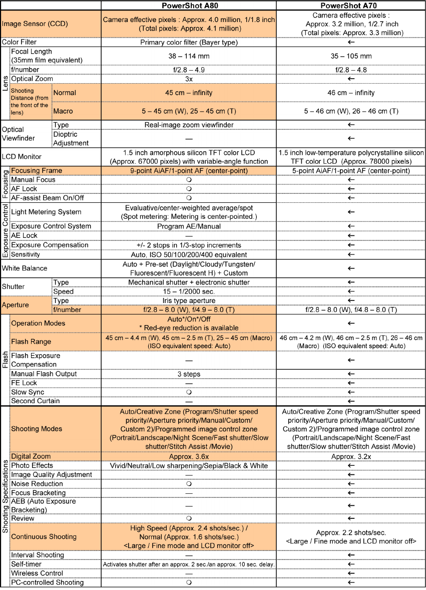
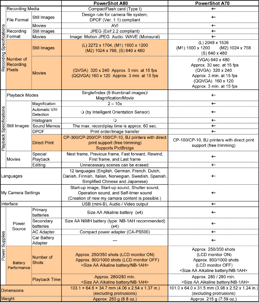
1-4 Product Specification Comparison
Comparison of the main features of the PowerShot A80 and the PowerShot A70
Note) Highlighted table items show changes from the PowerShot A70.
7
8
2 Features
2-1 Higher Image Quality/More Pixels
- New high resolution 3x optical zoom lens
The PowerShot A80 has a 3x zoom lens with focal length of 7.8 - 23.4 mm (35mm film equivalent: 38 -
114mm) for shooting everything from landscapes to close-up portraits. While the PowerShot A80
demonstrates the high resolution expected of a 4.0 million-pixel CCD, we optimized the positions of the
lenses in the lens groups and reviewed the shapes of the lenses in order to reduce the radius of the foremost
lens and the overall retraction length. The result was a compact configuration of 6 lenses in 5 groups
including 2 aspherical lenses, which is 3 lenses fewer than in the PowerShot A70/A60. As a result, though
the CCD itself is larger than in the PowerShot A70/60 (1/2.7 inch vs 1/1.8 inch), the lenses are smaller.
By adopting a rear-focus technique that moves only 1 lens in group 3, it was possible to minimize the
number of focusing lenses.
The compact lens configuration made more room for accommodating the open lens cover, and the
conventional 4-blade lens cover inside the lens barrel was replaced by a simpler 2-blade lens cover.
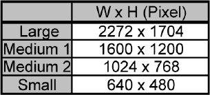
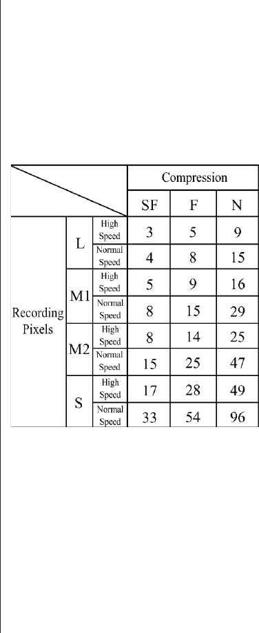
- Approx. 4.0 million camera effective pixel 1/1.8 inch CCD
(Total number of pixels: Approx. 4.1 million; Max. recording pixels of still image: 2272 x 1704)
The PowerShot A80 uses the CCD sensor with approx. 4.0 million
camera effective pixels (approx. 4.1 million total pixels) that was
featured in the PowerShot S45 and the IXY DIGITAL 400. This CCD
sensor allows the PowerShot A80 to capture still images with a
recording pixel as large as 2272 x 1704. (The user can select from
four recording pixel settings and three compression settings.) Table 2-1 Number of recording
pixels in the PowerShot A80
- AF/AE/AWB that relies on an Intelligent Orientation Sensor to detect vertical/horizontal
orientation
The PowerShot A80 uses the same Intelligent Orientation Sensor as the PowerShot G series and S series.
- Benefits for AF:
Weighting the AF frame differently for horizontal and vertical shooting reduces the incidence of
incorrect selected measurement zone, which tends to occur during vertical shooting where the focal
point is often the ground.
- Benefits for AE/AWB control:
When the sky takes up a significant portion of the upper half of a shot, the entire picture can look dim
because of the brightness of the sky or can take on a yellowish tinge because of the blueness of the sky.
In such cases, the high-precision control of the PowerShot A80 minimizes the effect of the sky on the
rest of the shot thanks to the Intelligent Orientation Sensor, which can detect the orientation of the shot.

9
2-2 Advanced Functions
- Supports PictBridge, which enables direct printing from other-vendor printers
In order to make the PowerShot A80 compliant with the PictBridge standard*1, enacted in February 2003,
the camera was designed to allow direct printing even from non-Canon printers*2.
*1 The PictBridge standard enables connection between any camera and any printer regardless of the
manufacturers.See the PictBridge Technical Guidance for details.
*2 The connected printer must support the PictBridge standard.
- 9-point AiAF and 1-point AF selectable
The PowerShot A80 increases the number of AiAF measurement zones, based on which the camera
automatically selects the appropriate AF frame, from the 5 available on the PowerShot A70 to 9. *This
improved AiAF system makes focusing even more precise regardless of the position of the subject or the
shooting orientation (vertical or horizontal).
The camera is also equipped with standard single center-point AF, enabling users to select the easiest AF
function to suit the shooting conditions.
* Features shared with the PowerShot A70:
• When focusing, the positions of the focused measurement zones are displayed in green (when two or
more positions are in focus, all focused measurement zones are displayed).
- 14 shooting modes (with two custom modes)
The PowerShot A80 has additional custom shooting modes. Using these custom modes, the user can save
their shooting settings, the parameters of the shot such as focus and exposure. By saving often-used
settings, the user can automatically recall those settings with a simple turn of the shooting mode dial. Two
different shot settings can be saved.
(Savable parameters are shown on page 30, in 4-3 Functions Available in Each Shooting Mode)
Figure 2-1 Shooting mode dial
10
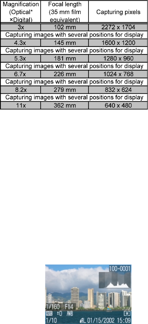
- Digital zoom function with continuously changing angle of view (Approx. 3.6x. Approx. 11x
when used in combination with the optical zoom)
The PowerShot A80 uses a 4.0 million pixel CCD,
thereby increasing the digital zoom
magnification from the approx. 3.2x
employed on the PowerShot A70 to approx.
3.6x. The field of view can be adjusted to a
maximum of approximately 11x (35mm film
equivalent: 35 - 383 mm) by combining the
3.6x digital zoom magnification with the 3x
optical zoom.
In addition, because it is essential that the
image displays smoothly on the LCD
monitor when the digital zoom feature is
used, there are several dozen image fetch
positions for the monitor display.
The functions provided by the “DIGIC”
imaging engine allow digital zoom and * Optical zoom is always set to telephoto-end when using
optical zoom to be performed at equivalent digital zoom.
zoom speeds, so that there is no noticeable Table 2-2 Digital zoom focal length and
difference between the two during actual use. capture pixel resolution
- Automatic detection of vertical/horizontal shooting by Intelligent Orientation Sensor
During playback, images shot vertically or horizontally are so displayed on the LCD monitor. The Card Photo
printer (CP-series) will automatically determine the orientation of a shot, and allow the user to add a date to
the lower right corner of the image during printout. ZoomBrowser EX (ImageBrowser) also detects the
picture orientation and lays out the pictures accordingly.
- Histogram display (during rec-review/playback)
The PowerShot A80 includes a histogram display function.
A histogram is a graph indicating brightness along its horizontal axis and the number of pixels of brightness
along its vertical axis, with brighter images distributed towards the right side of the graph. The histogram
allows the user to check the brightness distribution of an image,
making it possible to know the approximate degree of exposure.
Figure 2-2 Example of
histogram display
11
2-3 Ease of Operation
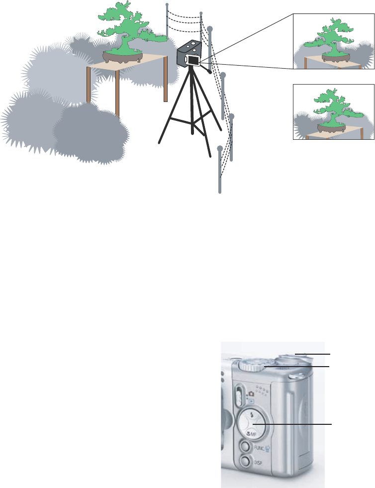
- Vari-angle LCD monitor that can disable mirror imaging
The PowerShot A80 features a Vari-angle LCD monitor also featured in the PowerShot G series.
When you shoot while looking at the LCD monitor from the lens side or from the side of the camera, the
display shows a mirror image (reversed laterally). However, in previous models, images displayed in the
monitor sometimes appeared unnatural.
The PowerShot A80 has been improved to provide a menu setting whereby the user can elect to disable
mirror imaging. (See the example in Figure 2-3.)
Figure 2-3 Example of using the Vari-angle LCD monitor
- Mute mode disabling all sounds except the warning sound
The PowerShot A80 has a mute function that can be used to disable all sounds (except the warning sound)
with one-touch operation. This allows shooting even in locations where silence is needed.
- Display Off mode that switches off the LCD monitor after a certain time
The PowerShot A80 has a Display Off mode that switches off the relatively power-hungry LCD monitor
when the camera is not operated for a certain period of time, thereby saving energy.
- Large buttons for easier operation
The PowerShot A80 features an Omni selector and larger
operating buttons than the PowerShot A70/60,
including a zoom lever and shooting mode dial for
an improved look and easier camera operation.
See 1-3 Design Concept on page 5.
Figure 2-4 Large buttons
Zoom lever
Shoo ting mo de di a
l
Omni Sele ctor
12
- Choice of High Speed mode or Normal mode in continuous shooting
Similar to the PowerShot G series, the PowerShot A80 comes equipped with two selectable continuous
shooting modes, the High Speed mode and the Normal mode.
In High Speed mode, the camera saves image data temporarily to a buffer, enabling high-speed continuous
shooting. However, past a certain shooting speed, the display can no longer keep up, and the LCD monitor
blacks out.
While Normal mode has a slower continuous shooting speed than High Speed mode, the display can handle
the a greater number of successive shots than in High Speed mode, allowing the user to view images on the
LCD monitor during shooting.
In either mode, the continuous shooting speed slows when the image buffer becomes full due to the need to
create additional space for each picture while continuing to shoot. Shooting can still continue at this pace
until the CF card becomes full.
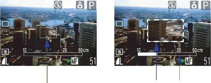
- Switchable MF zoom display
The PowerShot A80 offers the same MF zoom function as the PowerShot G series and S series. This allows
precise zoom focus positioning.
Figure 2-5 MF zoom example
MF magnified display: Off MF magnified display: On
AF frame Indicator
Magnified display
13
2-4 Compact
- Compact, new high resolution 3x optical zoom lens
See New high resolution 3x optical zoom lens on page 8.
- Space-saving 2-blade lens cover inside the lens barrel
See New high resolution 3x optical zoom lens on page 8.
2-5 High Quality Design
- High-grade design suitable for the flagship model of the PowerShot A series
See 1-3 Design Concept on page 5.
2-6 System Accessories
- Tel-Convertor for shooting at 200 mm telephoto angle (35mm film equivalent)
The PowerShot A80 is equipped with a 38 - 114 mm (35mm film equivalent) lens, but the newly developed
Tele-convertor TC-DC52A makes it possible to shoot at telescopic range.
The TC-DC52A increases the focal length of the master lens by approximately 1.75x, allowing the equivalent
of 200 mm*1 telescopic shooting*2 (maximum of 720 mm equivalent*1 when the digital zoom is also used).
This allows a shooting magnification of approximately 7.5x with just the optical system, from 26.6 mm
equivalent*1 when the WC-DC52 Wide convertor is used, to 200 mm equivalent*1 when the TC-DC52A
Tele-Convertor is used.
Both the Tele-convertor and Wide Convertor require the new LA-DC52D conversion lens adapter for
mounting onto the camera, but this new adapter uses the same bayonet ring as the previous model LA-
DC52C, allowing for one-touch mount and dismount.
In addition, TC-DC52A can be used for the previous PowerShot A series (A70/60/40/30/20/10)*3.
*1 All are 35mm film equivalent
*2 Optical viewfinder cannot be used in combination with the Tele-Convertor (use the LCD monitor).
In addition, the flash cannot be used due to shading.
*3 If the previous model TC-DC52 is used for PowerShot A80, the performance is not guaranteed.
- Waterproof case submersible to 40 m (Equipped with double glass and flash light diffusion plate)
The PowerShot A80 differs in shape from the PowerShot A70/A60, so a new waterproof case WP-DC900
was developed.*
* This case is functionally identical to the waterproof case for the PowerShot A70/A60 (WP-DC700).
For more information on the waterproof case, see the technical guidance scheduled for future release.
14
3 Exterior
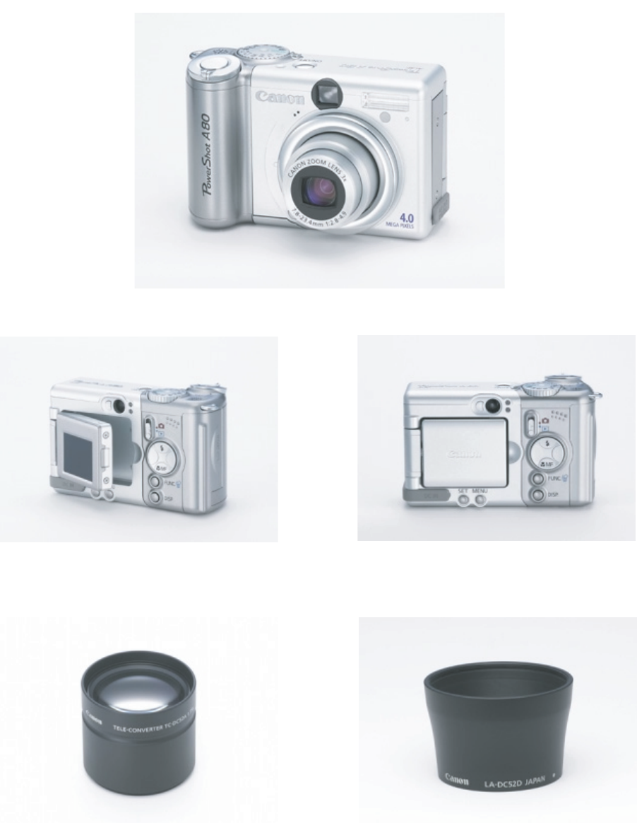
3-1 Exterior Photos
Photo 3-1 PowerShot A80 Front
Photo 3-2 PowerShot A80 Back Photo 3-3 PowerShot A80 Back
(with LCD Monitor opened)
Photo 3-4 Tele-Convertor Photo 3-5 Conversion Lens Adapter
(TC-DC52A) (LA-DC52D)
15
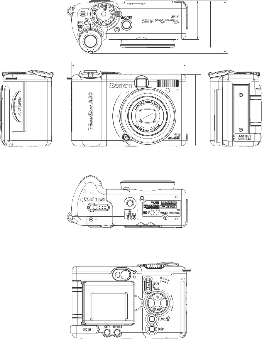
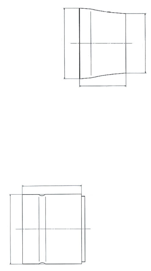
3-2 6-dimensional diagram
Unit: mm (inch)
42.5 (1.67)
46.0 (1.81)
34.7 (1.37)
64.6 (2.54)
103.1 (4.06)
16
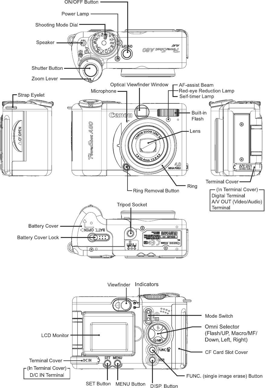
3-3 Nomenclature
17
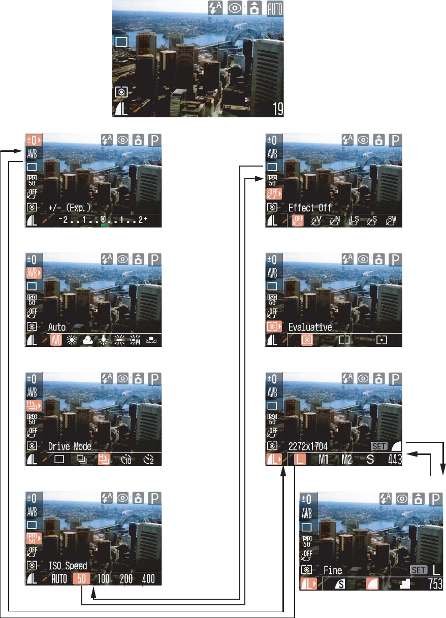
Exposure Photo Effect
Compensation
White Balance
Drive Mode Number of
Recording
Pixels
(still images)
Speed
(ISO equivalent)
Compression
3-4 UI Information
- Shooting Menu (Shooting mode: Auto)
- FUNC.Menu (Shooting mode: Program)
Light Metering
System
↑ ↓
↑ ↓
↑ ↓
↑ ↓
↑ ↓
18
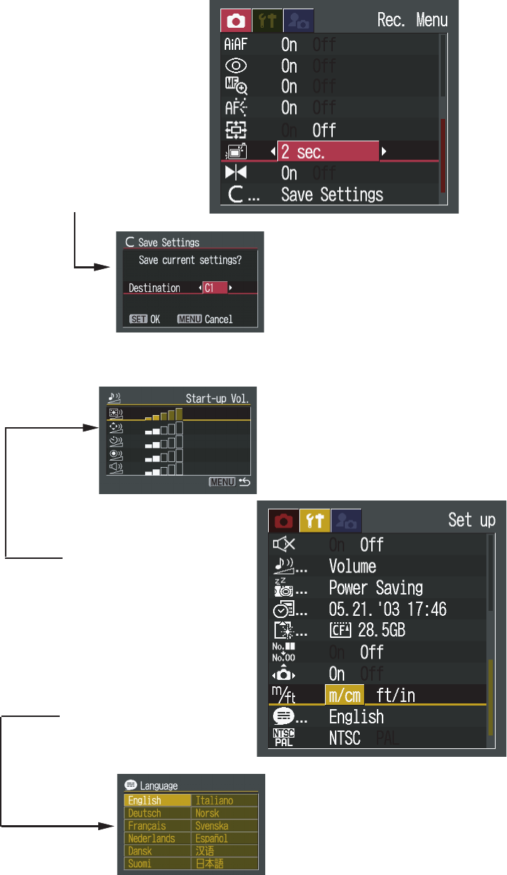
- Rec. Menu
• AiAF --------------------------
• Red-eye -----------------------
• AF-assist Beam -------------
• MF-Point Zoom -------------
• Digital Zoom -----------------
• Review -----------------------
• Reverse display -------------
• Save settings ----------------
* All menu items are displayed on the
above screen, some items may not
appear in certain shooting modes.
- Set up Menu
• Start-up Vol.
• Operation Vol.
• Self timer Vol.
• Sutter Volume
• Playback Vol.
• Beep ------------------------------
• Volume ---------------------------
• Auto Power Down ------------
• Date/Time -----------------------
• Format ---------------------------
• File No. Reset ------------------
• Rotate ----------------------------
• Distance Units ------------------
• Language ------------------------
• Video System (NTSC/PAL) --
* All menu items are displayed on the
above screen, some items may not
appear in certain shooting modes.
19
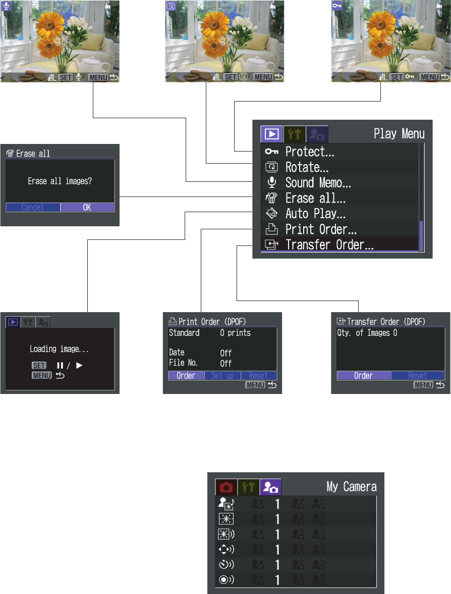
- Play Menu
* All menu items are displayed on the above
screen, some items may not appear in certain
shooting modes.
- My Camera Menu
• Theme ------------------------
• Start-up Image --------------
• Start-up Sound --------------
• Operation Sound ------------
• Self-timer Sound ------------
• Shutter Sound ---------------

20
Approx. 4.0 million pixels
Approx. 4.1 million pixels
Interline
1/1.8 in.
4:3
Primary color filter (Bayer type)
7.8 (W) – 23.4 (T) mm (35mm film equivalent: 38 (W) – 114 (T) mm)
f/2.8 (W) – 4.9 (T)
6 elements in 5 groups (including 2 aspherical lenses)
3 x
Normal : 45 cm (1.5 ft.) – infinity
Macro : 5 – 45 cm (2.0 in. – 1.5 ft.)(W),
25 – 45 cm (9.8 in. – 1.5 ft.)(T)
Manual : 5 cm (2.0 in.) – infinity, 25 cm (9.8 in.) – infinity
56 x 42 mm (2.2 x 1.6 in.)(W), 87 x 65 mm (3.4 x 2.6 in.)(T)
* When close-up lens 250D (52 mm) is attached : 45 x 34 mm (W)
(1.75 x 1.31 in.)
<8 cm (3.1 in.) from tip of the lens>
0.64 x (W) , 0.40 x (T)(35mm film equivalent)
Real-image zoom viewfinder
16 mm
Not available
Amorphous silicon TFT color LCD (Vari-angle type)
Approx. 67 K pixels
37 mm diagonal (1.5 in.)
100%
Not available
4 Specifications
4-1 Camera Specifications
Image Sensor (CCD)
Camera Effective Pixels
Total Pixels
Transfer Method
Chip Size
Aspect Ratio
Filter Type
Lens
Focal Length
f/number
Lens Construction
Optical Zoom
Shooting Distance
(from the front of the lens)
Area of Photograph
(at the minimum focal
distance: W x H)
Magnification of Photograph
(at the minimum Shooting
Distance)
Optical Viewfinder
Type
Eye point
Dioptric Adjustment
LCD Monitor
Type
Effective Pixels
Display Size
Picture Coverage
Brightness Adjustment

21
Focusing
Control System
Manual Focus
Focusing Frame
Focusing Range
AF Lock
AF-assist Beam On/Off
Exposure Control
Light Metering System
Exposure control System
AE Lock
Exposure Compensation
Sensitivity
On/Off Selection of ND
(Neutral Density) Filter
White Balance
Modes
TTL Auto focus
Available
9-point AiAF/1-point AF
1-point AF: Center
Normal/Macro
Available
Available
Evaluative/Center-weighted average/Spot
*Metering frame with Spot mode: Center
Program AE/Shutter speed-priority AE/Aperture priority AE/Manual
exposure
Not available
+/- 2 stops in 1/3-stop increments
Auto, ISO 50/100/200/400 equivalent
*Camera automatically sets optimum speed when “Auto” is selected.
Not available
TTL auto/Pre-set (Daylight/Cloudy/Tungsten/Fluorescent/Fluorescent H )
/Custom

22
Shutter and Aperture
Shutter Type
Aperture Type
Shutter Speed
f/number
Flash (Built-in)
Operation Modes
Flash Range
Flash Sync Speed
Recycling Time (Full flash)
Flash Exposure
Manual Flash Output setting
FE Lock
Slow Sync
Second Curtain
Mechanical shutter and electronic shutter
Iris type aperture
15 – 1/2,000 sec.
• 1.3 – 15.0 sec. shutter speed is only available in Shutter speed-priority
mode or Manual mode.
• Values in the table below are available in Shutter speed-priority mode
or Manual mode.
1/2000, 1/1600, 1/1250, 1/1000, 1/800, 1/640, 1/500, 1/400, 1/320,
1/250, 1/200, 1/160, 1/125, 1/100, 1/80, 1/60, 1/50, 1/40, 1/30, 1/25,
1/20, 1/15, 1/13, 1/10, 1/8, 1/6, 1/5, 1/4, 0"3, 0"4, 0"5, 0"6, 0"8, 1",
1"3, 1"6, 2", 2"5, 3"2 , 4", 5", 6", 8", 10", 13", 15"
• The shutter speed set by camera in relation to f/number in Aperture-
priority mode or settable shutter speed in relation to f/number in
Manual mode is as shown in the table below.
f/2.8 – 8.0 (W), f/4.9 – 8.0 (T)
• Settable values in Aperture-priority mode or Manual mode
W: f/2.8, 3.2, 3.5, 4.0, 4.5, 5.0, 5.6, 6.3, 7.1, 8.0
T : f/4.9, 5.6, 6.3, 7.1, 8.0
Auto*/On*/Off
* Red-eye reduction is available.
45 cm – 4.4 m (1.5 – 14 ft.)(W), 45 cm – 2.5 m (1.5 – 8.2 ft.)(T)
25 – 45cm (9.8 in. – 1.5 ft.)(Macro)(When sensitivity is set to Auto)
1/60 – 1/500 sec.
(15 – 1/500 sec. when in Shutter priority AE or manual mode)
10 sec. or less (battery voltage = 6.0 V (Type AA alkaline battery))
Not available
3 steps (strong [100 % flash]/normal/low)
Not available
Available
Not available

23
Flash (External)
Flash Contacts
Recommended Flashes
Flash Exposure Compensation
FE Lock
Slow Sync
Second-curtain Sync
Shooting Specifications
Shooting Modes
Shooting Functions
Digital Zoom
Photo Effects
Image Quality Adjustment
Noise Reduction
Bracketing
Focus Bracketing
AEB (Auto Exposure
Bracketing)
Review
Camera start-up Time
/Release Time Lag
Shooting Interval
Not available
Auto/Creative zone (Program/Shutter speed priority/Aperture priority/
Manual/Custom 1/Custom 2)
Programmed image control zone (Portrait/Landscape/Night Scene/Fast
shutter/Slow shutter/Stitch Assist/Movie)
Approx. 3.6x (Maximum of approx. 11 x zoom is available when
combined with optical zoom.)
Vivid/Neutral/Low sharpening/Sepia/Black & White
Not available
When shutter speed is set between 1.3 sec and 15 sec.
Not available
Off / 2–10 sec. (1 sec. increments)
1.9 sec. (LCD monitor On) / 2.2 sec. (LCD monitor Off)
*Focus : Normal range and wide angle
*The actual shooting interval time consists of the shutter speed time
added to the above times.
24
Shooting Specifications
Continuous Shooting
Speed Mode Selection
Speed
Number of Shots
Interval Shooting
Self-timer
Wireless Control
PC-controlled Shooting
High speed*/Normal
*Shooting operation with LCD monitor as viewfinder is not possible in
high speed mode.
High speed: approx. 2.4 shots/sec., Normal: approx. 1.6 shots/sec.
(Large/Fine mode and LCD monitor is Off)
*The above data shows the maximum number of shots for recording
pixels and compression setting.
*After exceeding the maximum number of shots, continuous shooting
is still available. However the shooting speed is reduced.
Not available
Activates shutter after an approx. 2-sec./10-sec. delay.
Not available
Shooting operation is possible with the use of “Remote Capture” software
when camera is connected to the PC.
25
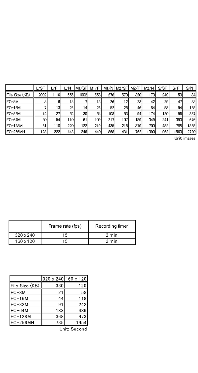
Recording Specifications
<Still Image>
File Format
Recording Format
JPEG compression mode
Number of Recording Pixels
Recording Capacity*
<Movies>
File Format
Recording Format
Number of Recording
Pixels
Frame Rate/Recording
Time
Recording Capacity
<Common>
Recording Media
Design rule for camera file system,
Digital Print Order Format (DPOF) Version 1.1 compliant
JPEG (Exif 2.2)
Super Fine/Fine/Normal
Large: 2272 x 1704, Medium 1: 1600 x 1200,
Medium 2: 1024 x 768, Small: 640 x 480
* The above data is measured under Canon testing standard and may
vary depending on the scene, subjects or camera settings.
AV I
Image: Motion JPEG, Audio: WAVE (Monaural)
QVGA: 320 x 240 QQVGA: 160 x 120
* The maximum recording time with an individual movie clip
* The SD memory card is required to contain the fixed space or over.
* Above data is measured under Canon’s testing standard and may vary
depending on the scene, subjects or camera settings.
CompactFlashTM (CF) card (Type I)

26
Playback Specifications
Playback Modes
<Still Image>
Magnification
Automatic Vertical/
Horizontal Detection
Image Rotation
Histogram Display
Sound Memos
Auto Play
DPOF
Direct Print
Canon Direct Print
PictBridge
<Movies>
Special Playback
Editing
Erasing Specifications
Erasing Modes
Protection (Camera)
Single/Index (9 thumbnail images)/Magnification/Movie
Approx. 2 – 10x
Possible (Owing to IO sensor)
* Images are displayed vertically or horizontally according to the
camera’s shooting position.
Rotate image to 90 degrees or 270 degrees
Display brightness allocation of image. (Available during Rec review.)
Maximum of 60 sec. sound recording and sound replaying per image.
Interval time: 3 sec.
Repeat: Always set to On
Print order/Image transfer
Card photo printers: CP-300, CP-200, CP-100, CP-10
BJ printers with Direct print support:
(for Japan) BJ 895PD, BJ 535PD, PIXUS 50i, PIXUS 450i, PIXUS
470PD
(for overseas) S830D, S530D, i70, i450, i470D
Supported
First frame/Last frame/Next frame/Previous frame/Fast forward/Rewind
Unnecessary scenes (image + sound) can be erased. (Refer to Erasing
modes.)
Still images: Single image/All images
* The image data recorded with the Design rule for camera file
system’s format can be erased. However, protected images can not
be erased.
Movies: Part of movie*/All of movie
* Can be erased from start-point to mid-point or from mid-point to end-
point with the movie editing function. Furthermore, can be erased
both from start-point to mid-point and from mid-point to end-point.
Erase prohibited (Set in playback modes.)
27
Interface
Computer I/F
Communication Settings
Video Out
Audio Out
Others
Languages
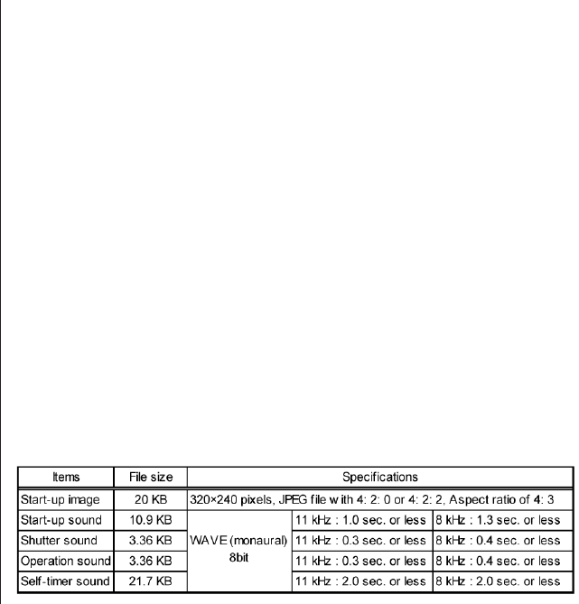
My Camera Settings
Selectable Items
Specifications
USB* (mini-B jack)
* All procedures performed with a connection to a USB 2.0 compliant
board are not guaranteed.
PTP
NTSC/PAL
Monaural
12 languages are available for menu and messages.
English, German, French, Dutch, Danish, Finnish, Italian, Norwegian,
Swedish,Spanish, Simplified Chinese, and Japanese
Start-up image, Start-up sound, Shutter sound, Operation sound, and
Self-timer sound
* Each item can be created by users with the camera.

28
Power Supplies
Primary Batteries
Secondary Batteries
AC Adapter
Car Battery Adapter
Sub-battery
Battery Performance
Number of Shots
Playback time
Battery Charging Time
Inside the Camera
Charger
Power-saving Function On/Off
Camera Specifications
Operating Temperature
Operating Humidity
Dimensions
Weight
Type AA alkaline battery (x 4)
NiMH battery (x 4)(type: NB-1AH is recommended)
Compact Power Adapter (CA-PS500)*
Not available
Coin-type secondary lithium battery (MS614S)
Use of type AA alkaline battery (Panasonic brand)*
LCD monitor On: Approx. 250 shots
LCD monitor Off: Approx. 800 shots
Use of NiMH battery (NB-1AH)*
LCD monitor On: Approx. 350 shots
LCD monitor Off: Approx. 1000 shots
* Under Canon testing standard:
Normal temperature (23°C). Shoot images at wide angle and at
telephoto end alternately with 20 seconds intervals. Use flash at every
fourth shot.
Turn camera off and on at every eight shot.
Use of type AA alkaline battery (Panasonic brand)*
Approx. 280 min.
Use of NiMH battery (NB-1AH)*
Approx. 280 min.
* Under Canon standard conditions:
Normal temperature (23°C). Repeat replay automatically at a speed of
1 image per 3 seconds. Factory default brightness setting.
Not available
Approx. 220 minutes. (CB-3AH)
Available
Shooting modes: Powers down approx. 3 minutes after last operation.
Playback modes: Powers down approx. 5 minutes after last operation.
Does not power down in Auto Play mode.
Printer connection: Power down approx. 5 minutes after last operation.
PC connection: Does not powers down even if power-saving function
is On.
0 – 40°C
10 – 90 %
103.1 x 64.6 x 34.7 mm (4.06 x 2.54 x 1.37 in.)(Excluding protrusions)
Approx. 250 g (8.8 oz.)(Camera body only)
29
4-2 Accessory Specifications
- Conversion Lens Adapter (LA-DC52D)
Dimensions : See Figure 4-1.
Weight : Approx.14 g (2.6 oz)
Attachment method : Bayonet type
Figure 4-1 Conversion Lens Adapter
(LA-DC52D)
- Tele-Convertor (TC-DC52A)
Magnification : Approx. 1.75x (shooting of 200 mm telephoto angle, 35mm film equivalent)
Lens construction : 3 elements in 2 groups (Multicoat finishing)
Dimensions : See Figure 4-2.
Weight : Approx. 86 g (3.0 oz)
Thread diameter : Diameter 52 mm (via conversion lens adapter)
Figure 4-2 Tele-Convertor
(TC-DC52A)
- Wide Convertor (WC-DC52)
Magnification : Approx. 0.7x (shooting of 26.6 mm telephoto angle, 35mm film equivalent)
Lens construction : 2 elements in 2 groups (Multicoat finishing)
Dimensions : Ø55.7 x 23.7 mm
Weight : Approx. 74 g (2.6 oz)
Thread diameter : Diameter 52 mm (via conversion lens adapter)
* Adopted from PowerShot A70/A60/A40/A30/A20/A10
Ø55.6 (2.19)
Ø36.6 (1.44)
Ø46.8 (1.84)
Unit: mm (inch)
Ø46.7 (1.84)
Ø55.2 (2.17)
Unit: mm (inch)
30
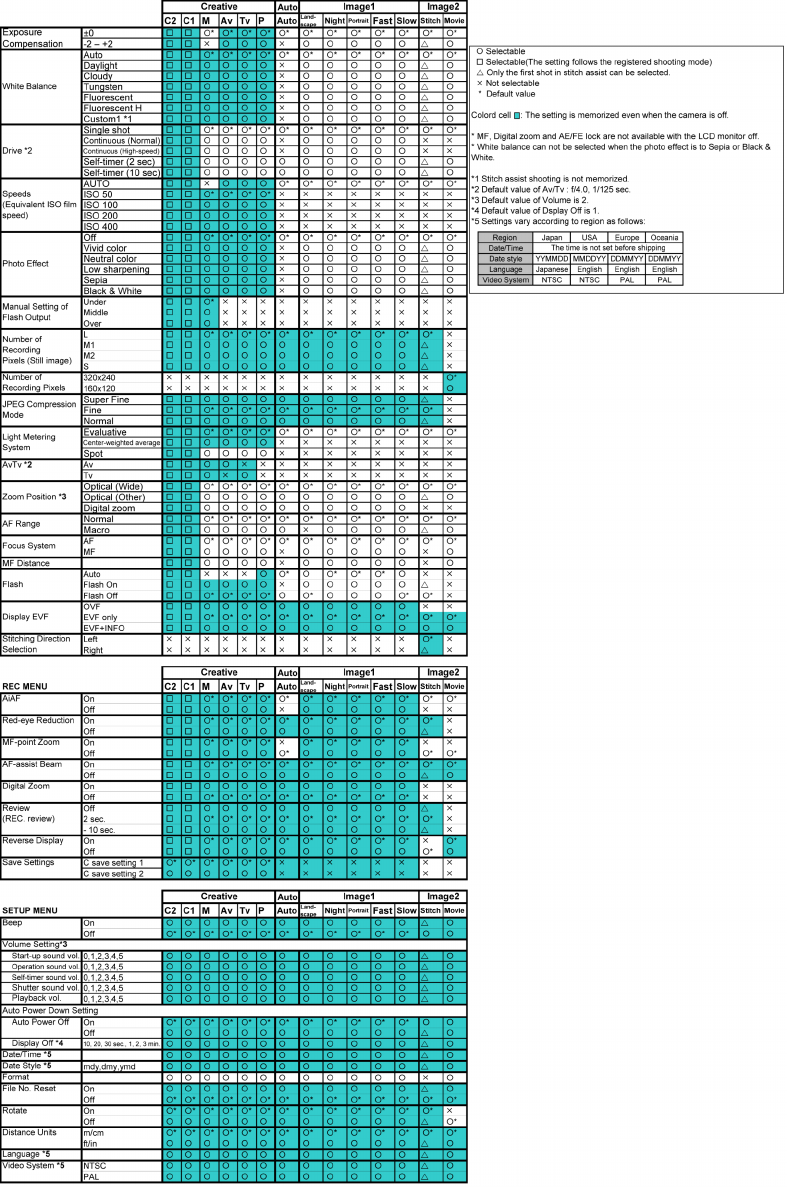
4-3 Functions Available in Each Shooting Mode
1) Settings saved at power off
31
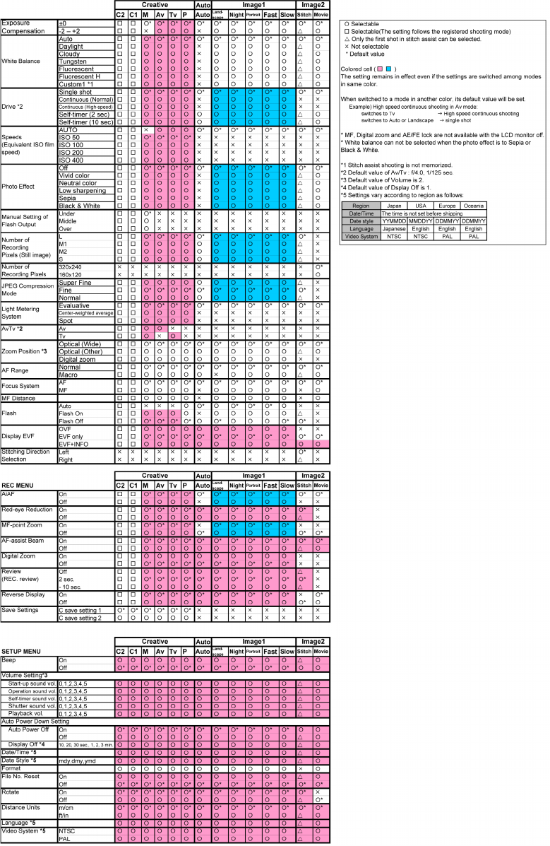
2) Settings saved when changing shooting modes
32
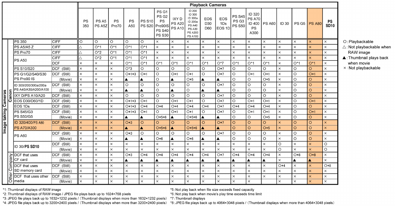
4-4 Playback compatibility
33
5 System
5-1 Accessory compatibility
34
35
36
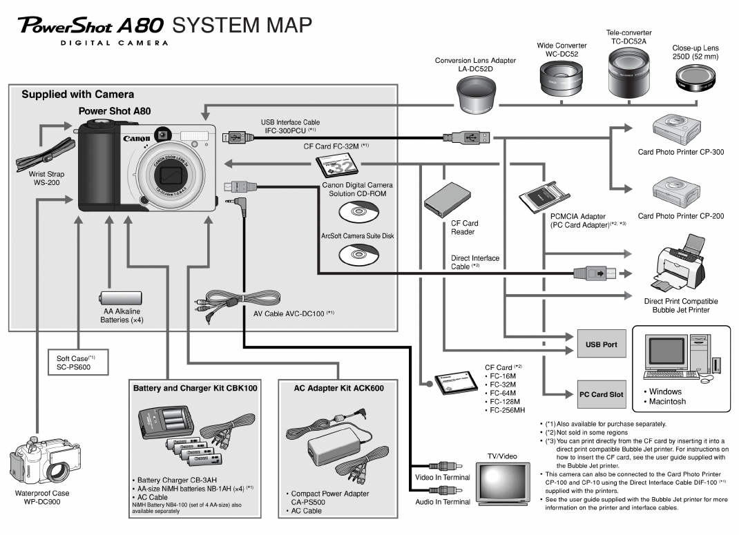
5-2 System Diagram

Trademarks
The product names and company names described in this CD-ROM are the registered
trademarks of the individual companies.
Copyright
Canon Inc. retains the copyright to all data contained on this CD-ROM.
Reproduction, publication (including on the World Wide Web) alteration, translation into
another language, or other use of the data in whole or part, contained on this CD-ROM
without the written consent of Canon Inc., is prohibited.
TECHNICAL DESCRIPTION

1. Functions of each unit
1.1 MAIN PCB ASS’Y ------------------------------------------------------------------------------------------------------------1
1.2 DC/JACK UNIT----------------------------------------------------------------------------------------------------------------1
1.3 LCD UNIT ----------------------------------------------------------------------------------------------------------------------1
1.3 FLASH UNIT-------------------------------------------------------------------------------------------------------------------1
2. Outline of Circuits
2.1 Power Supply Control ---------------------------------------------------------------------------------------------------------2
2.1.1 Power Supply Block Diagram --------------------------------------------------------------------------------------2
2.1.2 Power Control Sequence ---------------------------------------------------------------------------------------------2
2.2 Signal Processing---------------------------------------------------------------------------------------------------------------3
2.2.1 System Control --------------------------------------------------------------------------------------------------------3
2.2.2 Picture Processing ----------------------------------------------------------------------------------------------------4
2.2.3 Audio Processing (During record and playback) -----------------------------------------------------------------4
3. Troubleshooting
3.1 When an Error Code is Displayed -------------------------------------------------------------------------------------------5
3.2 When a Problem Occurs-------------------------------------------------------------------------------------------------------7
CONTENTS

1
TECHNICAL DESCRIPTION
1. Functions of each unit
1.1 MAIN PCB ASS’Y
1) Driving the CCD Sensor.
2) Conversion of the image signal from the analog signal to the digital signal.
3) Controlling the power supply and the system by CPU. (Refer to Sections 2.1 and 2.2.)
4) Image processing, and reading and writing the image signal to and from the CF card using DSP.
(Refer to Section 2.2.2.)
5) Amplification of the video and audio output. (Refer to Section 2.2.3.)
1.2 DC/JACK UNIT
1) Power supply drive (DC/DC converter).
2) Backlight for LCD drive.
1.3 LCD UNIT
1) LCD panel drive and Backlight for LCD drive.
1.4 FLASH UNIT
1) Flash drive and charging circuit for the flash.
Fig. 1
MAIN PCB ASS'Y
DC/JACK UNIT (DCJ PCB ASS'Y)
FLASH UNIT (ST PCB ASS'Y)
LCD UNIT
(LCD PCB ASS'Y)
2
TECHNICAL DESCRIPTION
2. Outline of Circuits
2.1 Power Supply Control
The power supply is controlled by the CPU mounted on the main PCB ass’y.
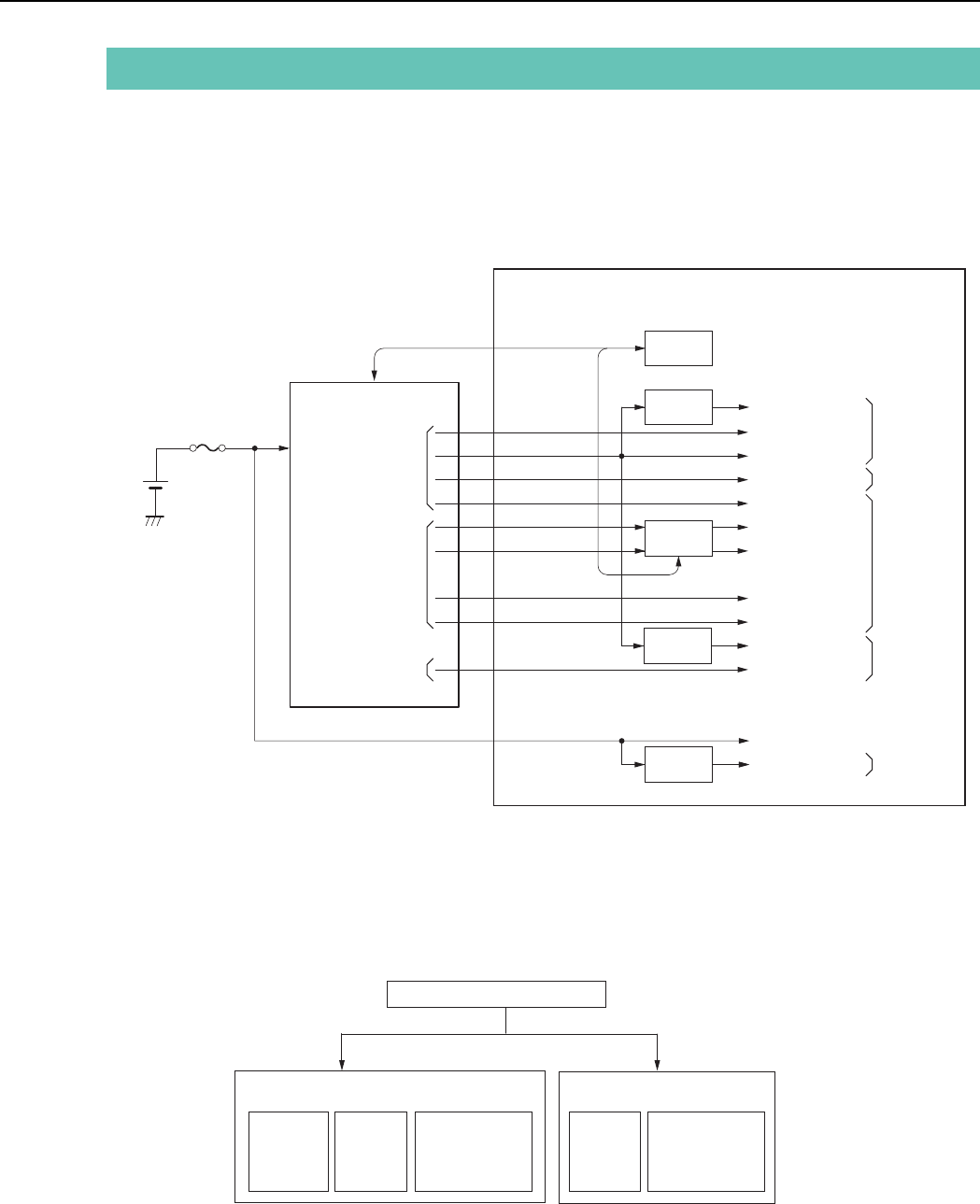
2.1.1 Power Supply Block Diagram
Fig. 2 Power System Block Diagram
BATTERY
or
DC IN
DC/DC
CONVERTER
CPU
VBATT
FUSE
E1
OUTPUT
E2
OUTPUT
E3
OUTPUT
for System
Control
for Image
Process
(CCD etc.)
E1, E2, E3
MAIN PCB ASS'Y
REG VCC1A.3 (3V)
VCC1 (3.3V)
VCC1A (3.3V)
VCC1M (3.3V)
VCC1L (1.5V)
VDD (15V)
VL (-7.5V)
VCC2AFE (3.3V)
VCC2HDR (4.75V)
VCC1A3 (3.0V)
VDD3 (13.5V)
VBATT
(3.3V)
REG
REG
REG
VDD2 (16V)
VEE2 (-9V)
for LCD
E21
for RTC
Motor Drive
2.1.2 Power Control Sequence
Main Switch ON (E1)
Shooting Mode Playback Mode
LCD OFF
(E1)
LCD ON
(E2, E3)
Audio/Video
out (E1, E2)
LCD ON
(E3)
Audio/Video
out (E1)
3
TECHNICAL DESCRIPTION
2.2 Signal Processing
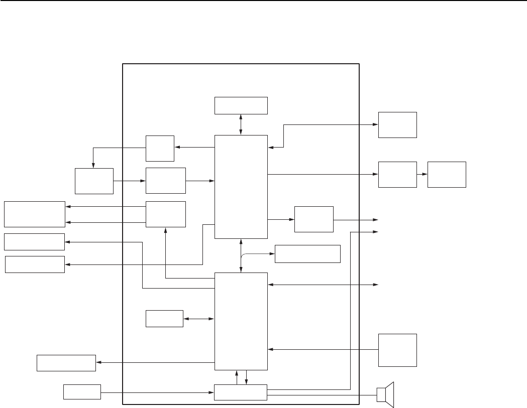
Fig. 3 Signal System Block Diagram
2.2.1 System Control
The CPU on the main PCB ass’y controls the lens (motor, shutter), operation switch receiver, USB com-
munication and flowing circuits.
•TG: Creation of the CCD drive pulse
•CDS, A/D: CCD signal processing and conversion of the digital data
•LCD Driver: Driving the LCD
•FLASH MEMORY: Firmware memory
•DSP: Picture processing
•RTC: Clock count for watch
•AF Support LED: AF auxiliary, self-timer and red-eye protection also serves as a lamp
•Electric Flash: Flash and charging circuit
CDS, A/D
LCD
Driver
CCD
Sensor
LENS Motor
Driver
AF Support LED
FINDER LED
Electric FLASH
CF card
LCD
TG
VIDEO
AMP
RTC
MIC
FLASH MEMORY
AUDIO AMP
DSP
CPU
SW
DIAL
KEY
HD, VD
CLKDrive Pulse
MAIN PCB ASS'Y
SDRAM
USB
VIDEO OUT
AUDIO OUT
SPEAKER

4
TECHNICAL DESCRIPTION
2.2.2 Picture Processing
1) The drive pulse of the CCD sensor is created by both clock from DSP and TG that is operated by
sync. signal.
The picture signal by the drive pulse is output from CCD sensor.
The output signal of the CCD picture is converted to the signal processing and the digital data by
the CDS and A/D converter, and is sent to the DSP.
2) The DSP circuit performs the following signal processing.
•Processes the picture data (using the SDRAM).
•Writes and reads the picture data to and from the CF card.
•Outputs analog video signal to the LCD and VIDEO OUT.
3) The video signal that is supplied form the DSP is controlled by the LCD driver and is displayed
on the LCD panel. The video amplifier is activated when the video jack is inserted to the AV jack
and drives the video signal in 75 Ω.
2.2.3 Audio Processing (During record and playback)
1) During animation recording.
•The microphone audio signal is converted to the digital data by CPU and is recorded.
2) During playback, the data is converted back to the analog audio signal and is output to the AV
jack and speaker from AUDIO/SP anplifier.

5
TECHNICAL DESCRIPTION
Error Code
E02
E03
E04
E09
E14
E16
E18
E23
E24
E25
Name
AF
TIME OUT
EF
TIME OUT
AWB
TIME OUT
JPEG DMA
TIME OUT
UNKOWN
IMAGING TIME
OUT
ZOOM LENS
ERROR
CF NO SPACE
POWER ON
ERROR
FOCUS PI
ERROR
Occurrence Conditions
AF processing did not end within the
specified time.
The focus lens was not driven.
Auto Flash Control did not end within the
specified time.
AWB processing did not end within the
specified time.
JPEG processing did not end within the
specified time.
When unkown error, cause of which is
not known, occurs.
When communication between CPU and
peripheral IC is not completed within the
specified time during recording using
EVF or after completion of recording.
Movement of the lens barrel did not end
within the specified time.
When the CF becomes full during writing
of photographed images to CF, writing is
repeatedly performed with the JPEG
compression ratio successively increased
to reduce the size of the image file until it
can be successfully written to CF.
This error occurs when writing of the
JPEG image file fails after 10 retries at
increasingly higher compression ratios.
The power of the imaging circuit on the
MAIN PCB ASS’Y was not detected.
Detection of the focus PI (photo-
interrupter) failed.
Cause and Probable Faulty Part
MAIN PCB ASS’Y
OPTICAL UNIT
MAIN PCB ASS’Y
OPTICAL UNIT
MAIN PCB ASS’Y
OPTICAL UNIT
MAIN PCB ASS’Y
MAIN PCB ASS’Y
UNKOWN
MAIN PCB ASS’Y
MAIN PCB ASS’Y
OPTICAL UNIT
MAIN PCB ASS’Y
MAIN PCB ASS’Y
DC/JACK UNIT
OPTICAL UNIT
MAIN PCB ASS’Y
3. Troubleshooting
3.1 When an Error Code is Displayed
[Remedy]
• Check for any abnormalities in the mounting of probable faulty parts or connector connections referring
to the table below.
• Try replacing probable faulty parts referring to the below.
[NOTE]
• The error code is displayed on the LCD Monitor.
• Adjustments must be performed after the part has been replaced. For details, see the chapter of
“Adjustments”.

6
TECHNICAL DESCRIPTION
Error Code
E26
E27
E30
E50
E51
E52
Name
CAPTURE
TIME OUT
CF WRITE
TIME OVER
POWER OFF
ERROR
CF FORMAT
ERROR
CF ACCESS
ERROR
QUICK REVIEW
ERROR
Occurrence Conditions
Writing of the photograph image to
SDRAM did not end within the specified
time.
Free area could not be secured in the
buffer for the photograph image within
the specified time in the continuous
shooting mode.
The camera power was turned OFF while
the image was being recorded to the CF
Card. (The error code is displayed when
the camera is next turned ON.)
* This error may occur after E23.
The CF Card could not be formatted
properly.
When image data cannot be read from
CF normally.
Review of the photograph image failed.
Cause and Probable Faulty Part
MAIN PCB ASS’Y
CF CARD
MAIN PCB ASS’Y
The battery or DC plug was removed
while the image was being recorded to
the CF Card.
→ Remedy: Restart the camera.
CF CARD
CF CARD
MAIN PCB ASS’Y

7
TECHNICAL DESCRIPTION
3.2 When a Problem Occurs
[Remedy]
•Check for any abnormalities in the mounting of probable faulty parts or connector connections referring
to the table below.
•Try replacing probable faulty parts referring to the table below.
[NOTE]
•Adjustments must be performed after the part has been replaced. For details, see the chapter of
“Adjustments”.
Cause and Probable Faulty Part
MAIN PCB ASS’Y
DC/JACK UNIT
BATTERY BOX UNIT
MAIN PCB ASS’Y
LCD UNIT
OPTICAL UNIT
MAIN PCB ASS’Y
OPTICAL UNIT
MAIN PCB ASS’Y
TOP COVER UNIT
OPERATION MODULE UNIT
FLASH UNIT
DC/JACK UNIT
MAIN PCB ASS’Y
DC/JACK UNIT
MAIN PCB ASS’Y
DC/JACK UNIT
MAIN PCB ASS’Y
CF CARD
CF UNIT
MAIN PCB ASS’Y
TOP COVER UNIT
OPERATION MODULE UNIT
MAIN PCB ASS’Y
REAR COVER UNIT
Problem (when an error code is not displayed)
The camera does not work.
The image is not displayed on the LCD Monitor.
The photograph image is abnormal.
The zoom does not function.
The Built-in Flash does not fire.
Video output is strange.
Communications with the personal computer is not possible.
The CF card or Micro Drives is not recognized.
Buttons/The Mode dial do not work.

REPAIR INSTRUCTION
Trademarks
The product names and company names described in this CD-ROM are the registered
trademarks of the individual companies.
Copyright
Canon Inc. retains the copyright to all data contained on this CD-ROM.
Reproduction, publication (including on the World Wide Web) alteration, translation into
another language, or other use of the data in whole or part, contained on this CD-ROM
without the written consent of Canon Inc., is prohibited.

CONTENTS
1. Before Starting the Repair Work ---------------------------------------------------------------------------------------------------1
1.1 Precaution on Flash High Tension Circuit ----------------------------------------------------------------------------------1
1.2 List of Tools --------------------------------------------------------------------------------------------------------------------1
1.3 List of Supplies -----------------------------------------------------------------------------------------------------------------1
1.4 Flexible Connectors ------------------------------------------------------------------------------------------------------------2
2. Disassembly/Assembly --------------------------------------------------------------------------------------------------------------3
2.1 Procedure ------------------------------------------------------------------------------------------------------------------------3
2.2 TOP COVER UNIT, CF COVER -------------------------------------------------------------------------------------------4
2.3 REAR COVER UNIT, JACK COVER -------------------------------------------------------------------------------------5
2.4 SIDE COVER, FRONT COVER SECTION, LENS BARREL SHEET -----------------------------------------------6
2.5 BAYONET CUP UNIT, FRONT COVER UNIT -------------------------------------------------------------------------7
2.6 BATTERY COVER SHAFT, BATTERY COVER SPRING, BATTERY COVER UNIT -------------------------8
2.7 HINGE COVER, LCD UNIT ------------------------------------------------------------------------------------------------9
2.8 LCD REAR COVER, LCD FRONT COVER. -------------------------------------------------------------------------- 10
2.9 FLASH UNIT----------------------------------------------------------------------------------------------------------------- 11
2.10 OPERATION MODULE UNIT ------------------------------------------------------------------------------------------- 12
2.11 CF UNIT, MAIN-FLASH FPC-------------------------------------------------------------------------------------------- 13
2-12 FLASH UNIT----------------------------------------------------------------------------------------------------------------14
2-13 MAIN-LCD MODULE UNIT, SUB FRAME ------------------------------------------------------------------------- 15
2-14 MICRPHONE UNIT, MICROPHONE BUSH ------------------------------------------------------------------------- 16
2.15 LITHIUM (2ND) BATTERY, MAIN PCB SECTION ---------------------------------------------------------------- 17
2.16 MAIN A SHIELD UNIT, MAIN B SHIELD UNIT, MAIN PCB ASS’Y ------------------------------------------ 18
2-17 OPTICAL UNIT ------------------------------------------------------------------------------------------------------------ 19
2-18 FRONT CAP SECTION, BARRIER PLATE -------------------------------------------------------------------------- 20
2-19 FRONT CAP, BARRIER COVER --------------------------------------------------------------------------------------- 21
2-20 BARRIER BASE ----------------------------------------------------------------------------------------------------------- 22
2-21 BARRIER DRIVE PLATE, BARRIER DRIVE RING --------------------------------------------------------------- 23
2-22 DC JACK UNIT ------------------------------------------------------------------------------------------------------------- 24
2-23 BATTERY BOX UNIT, MAIN FRAME UNIT------------------------------------------------------------------------ 25
2.24 Screw List -------------------------------------------------------------------------------------------------------------------- 26
3. Adjustments ------------------------------------------------------------------------------------------------------------------------- 27
3.1 Replacement Parts and Adjustment Items -------------------------------------------------------------------------------- 27
3.2 Adjustment Tools ------------------------------------------------------------------------------------------------------------ 28
3.3 Before Starting Electrical Adjustments ----------------------------------------------------------------------------------- 29
3.3.1 TWAIN Driver Installation ---------------------------------------------------------------------------------------- 29
3.3.2 Factory Mode Driver Installation --------------------------------------------------------------------------------- 29
3.3.3 Adjustment Software Installation --------------------------------------------------------------------------------- 31
3.3.4 Preparation ----------------------------------------------------------------------------------------------------------- 32
3.3.5 Starting up the Adjustment Software ----------------------------------------------------------------------------- 33
3.3.6 Menu Window------------------------------------------------------------------------------------------------------- 33
3.3.7 How to Use the Adjustment Software --------------------------------------------------------------------------- 33
3.4 Calibration -------------------------------------------------------------------------------------------------------------------- 34
3.4.1 Calibration ----------------------------------------------------------------------------------------------------------- 34
3.5 Adjustment Procedure ------------------------------------------------------------------------------------------------------- 39
3.5.1 CCD Adjustment ---------------------------------------------------------------------------------------------------- 39
3.5.2 Optical Unit Adjustment ------------------------------------------------------------------------------------------- 41
3.5.3 Imaging Process Adjustment -------------------------------------------------------------------------------------- 43
3.5.4 Color Adjustment --------------------------------------------------------------------------------------------------- 46
3.5.5 Pixel Dot Adjustment ---------------------------------------------------------------------------------------------- 48
3.5.6 LCD Adjustment ---------------------------------------------------------------------------------------------------- 50
3.5.7 Flash Adjustment --------------------------------------------------------------------------------------------------- 51
3.5.8 Checking of sound recording/output ----------------------------------------------------------------------------- 53
1
REPAIR INSTRUCTION
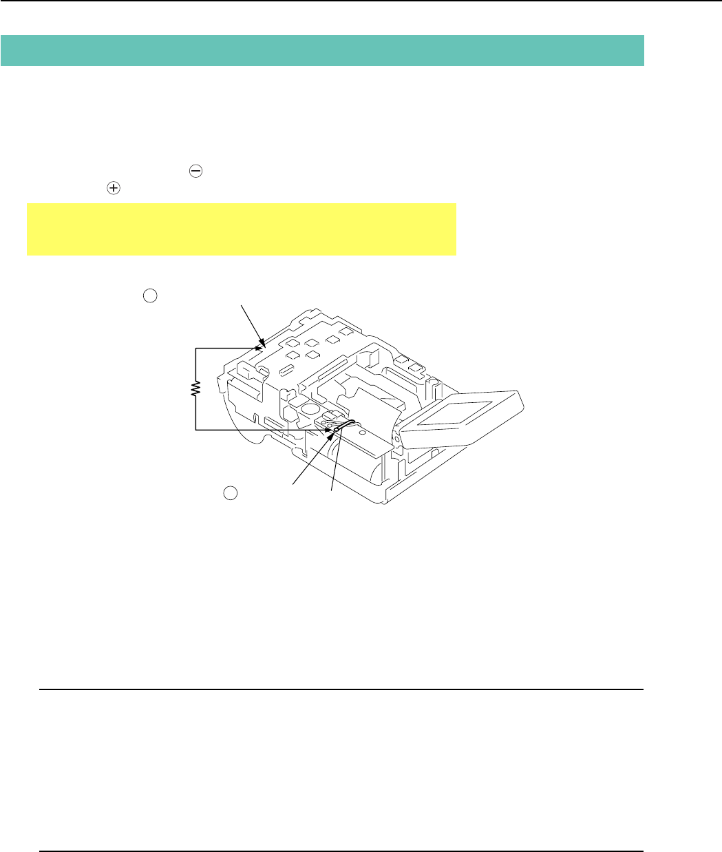
Fig. 1 Precaution on flash high tension circuit
1. Before Starting the Repair Work
Be sure to read the following precaution before starting the repair work.
1.1 Precaution on Flash High Tension Circuit
• After the REAR COVER UNIT is removed, be sure to discharge the main capacitor.
(Discharging resistor : 1 kΩ, approx. 5 W.)
• First contact the GND terminal of the main capacitor with the discharging resistor. Then contact the
positive terminal of the main capacitor.
CAUTION:
Be careful of electric shock because the circuit is the high tension circuit.
1.2 List of Tools
The following tools are used for the re-assembling during service.
(1) List of tools
New Name of tools Part No. Remarks
Screwdriver (Local Purchase)
Tweezers (Local Purchase)
Soldering iron (Local Purchase)
1.3 List of Supplies
The following supplies are used for the re-assembling during service.
(1) List of supplies
New Name of supplies Part No. Remarks
ADHESIVE TAPE SONY T4000 CY4-6012-000 Double-sided Tape
DIA BOND No.1663G CY9-8129-000
LOGENEST RAMBDA A-74 CY9-8102-000
Solder (Local Purchase)
+ terminal
– terminal (the metal plate of the CF UNIT)
(1 kΩ/5 W)
Yellow

2
REPAIR INSTRUCTION
CAUTIONS:
1. For the connectors of Type C, Type D and Type E, set them to the
unlocked state before removing and inserting flexible card. After flex-
ible card is inserted, set them to the locked state.
2. The flexible card is equipped with the holes as shown. Use them for
removal and insertion by inserting the tweezers into them as required.
1.4 Flexible Connectors
This product uses the five types of the flexible connectors.
Fig. 3 Holes for removal
Fig. 2 Flexible connectors
The contact-piece
should face
upwards
LOCK
UNLOCK
The contact-piece
should face
downwards
5 Type E
4 Type D
Unlocked state Locked state
Unlocked state Locked state
1 Type A
3 Type C
2 Type B
Holes
LOCK
UNLOCK
UNLOCK
The contact-piece
should face
downwards
LOCK
Unlocked state Locked state
Unconnected state Connected state
Unconnected state Connected state
3
REPAIR INSTRUCTION
2. Disassembly/Assembly
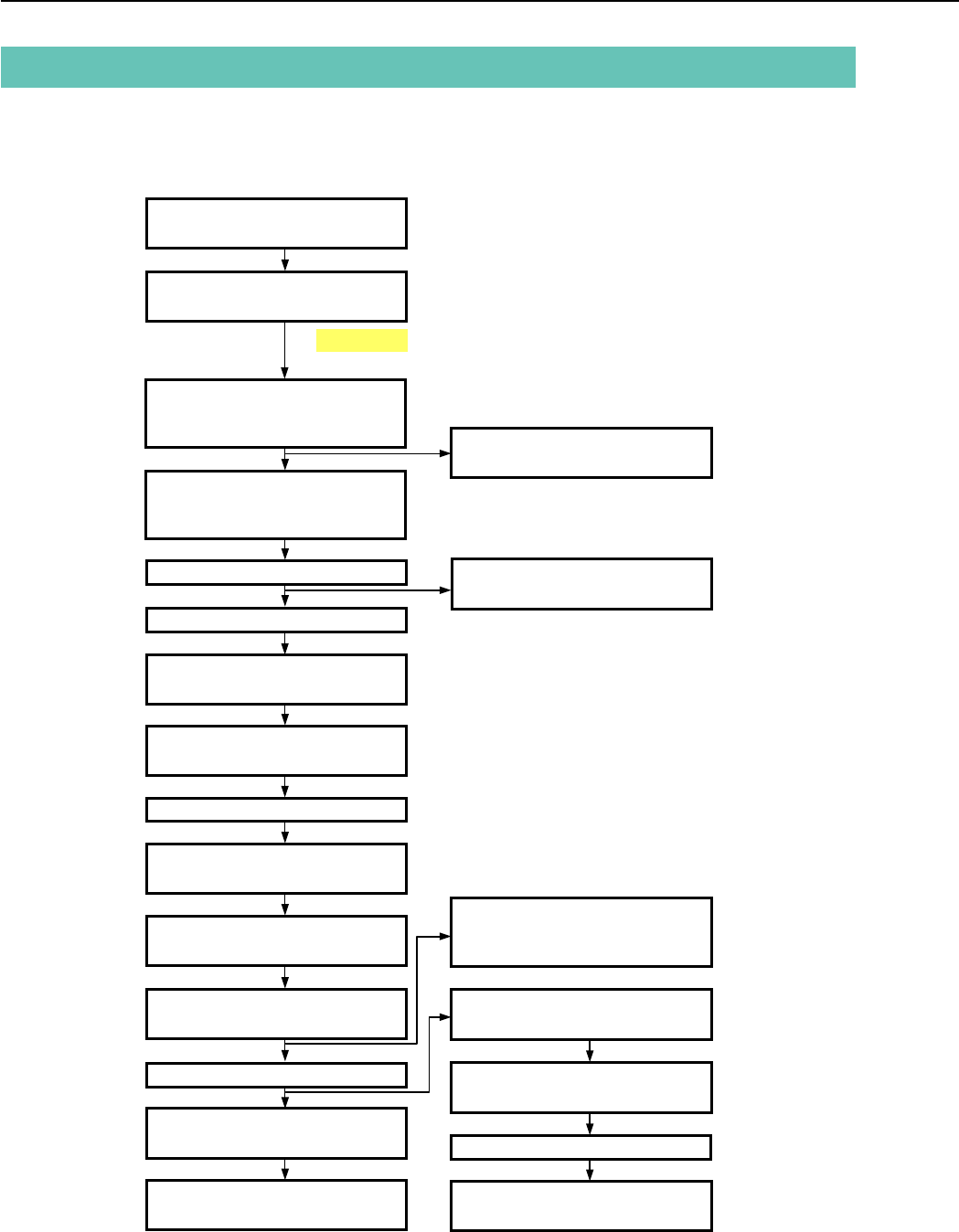
2.1 Procedure
Disassembling procedure of PowerShot A80 is shown by the following flowchart.
Reverse the disassembling procedure to reassemble them. ∗ The pages to refer are shown in parenthesis ( ).
CAUTION
Be careful high tension
TOP COVER UNIT,
CF COVER (P-4)
REAR COVER UNIT,
JACK COVER (P-5)
HINGE COVER, LCD UNIT (P-9) LCD REAR COVER,
LCD FRONT COVER (P-10)
CF UNIT,
MAIN-FLASH FPC (P-13)
MAIN-LCD MODULE UNIT,
SUB FRAME (P-15)
FRONT CAP SECTION,
BARRIER PLATE (P-20)
FRONT CAP,
BARRIER COVER (P-21)
BARREL DRIVE PLATE,
BARRIER DRIVE RING (P-23)
MICROPHONE UNIT,
MICROPHONE BUSH (P-16)
LITHIUM (2ND) BATTERY,
MAIN PCB SECTION (P-17)
BATTERY BOX UNIT,
MAIN FRAME UNIT (P-25)
BAYONET CUP UNIT,
FRONT COVER UNIT (P-7)
SIDE COVER,
FRONT COVER SECTION,
LENS BARREL SHEET (P-6)
BATTERY COVER SHAFT,
BATTERY COVER SPRING,
BATTERY COVER UNIT (P-8)
MAIN A SHIELD UNIT,
MAIN B SHIELD UNIT,
MAIN PCB ASS'Y (P-18)
FLASH UNIT (P-11)
OPTICAL UNIT (P-19)
MAIN DC FPC,
DC/JACK UNIT (P-24)
FINDER UNIT (P-14)
BARRIER BASE (P-22)
OPERATION MODULE UNIT
(P-12)
4
REPAIR INSTRUCTION
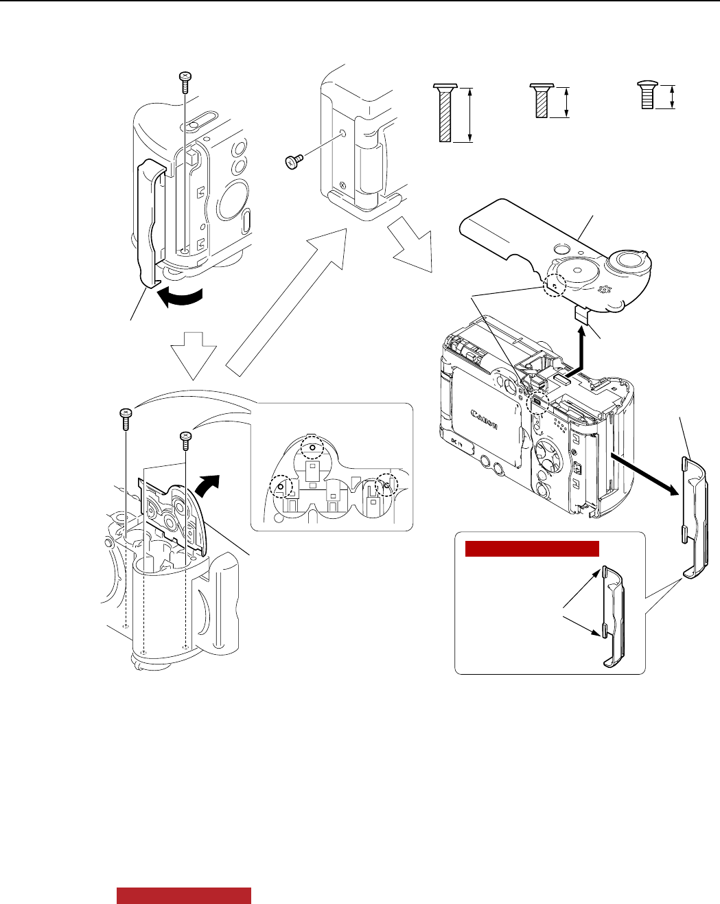
Fig. 4 TOP COVER UNIT, CF COVER
2.2 TOP COVER UNIT, CF COVER
(1) TOP COVER UNIT
1. Open the CF COVER and remove the screw of a.
2. Open the BATTERY COVER UNIT and remove the screw of a and the two screws of b.
3. Remove the screw of c.
4. Disengage the claw and remove the connector, then remove the TOP COVER UNIT.
(2) CF COVER
1. Remove the CF COVER.
NOTE (Assembling)
Apply the LOGENEST RAMBDA A-74 to the shafts.
a
XA4-9170-707
7.0mm
SILVER
M1.7
(SELF TAP)
XA4-9170-407
4.0mm
SILVER
M1.7
(SELF TAP)
b
CD3-1440-000
3.0mm
DARK SILVER
M1.7
C
a
c
a
a
b
b
b
(1)-1
(1)-2
(1)-2
(1)-3
(1)-4
(2)-1
(1)-4 (1)-4
(1)-2
(1)-1
CF COVER
CF COVER
TOP COVER UNIT
BATTERY COVER
UNIT
Claw
NOTE (Assembling)
LOGENEST
RAMBDA A-74
5
REPAIR INSTRUCTION
Fig. 5 REAR COVER UNIT, JACK COVER
2.3 REAR COVER UNIT, JACK COVER
(1) REAR COVER UNIT
1. Remove the screw of c, the screw of d, the screw of e and the screw of f.
2. Open the LCD UNIT and the JACK COVER.
3. Remove the REAR COVER UNIT.
CAUTION
Never touch the positive (+) terminal of the capacitor.
Be sure to discharge the capacitor using the discharging resistor (about 1kΩ/5W).
NOTE (Assembling)
When assembling, check the switch is in the correct position.
(2) JACK COVER
1. Disengage the hooked portion on the backside of the REAR COVER UNIT, and then the JACK COVER.
CAUTION
CD3-1440-000
3.0mm
DARK SILVER
M1.7
C
CD3-1445-000
1.8mm
DARK SILVER
M1.7
d
CD3-1444-000
1.8mm
DARK SILVER
M1.7
e
CD3-1441-000
3.0mm
SILVER
M1.7
f
(1)-2
(1)-3
(1)-1
(1)-1
(1)-1
(2)-1
(2)-1
(1)-1
(1)-2
LCD UNIT
REAR COVER UNIT
REAR
COVER UNIT
Make sure that the
switch is on the right
position.
REAR COVER UNIT
JACK COVER
JACK
COVER
d
e
f
c
Hooked portion
NOTE (Assembling)
– terminal (the metal plate of the CF UNIT)
+ terminal Yellow
Never touch the
positive (+) terminal
of the capacitor.
Be sure to discharge
the capacitor using the
discharging resistor
(about 1 kΩ/5W).
(1 kΩ/5 W)
6
REPAIR INSTRUCTION
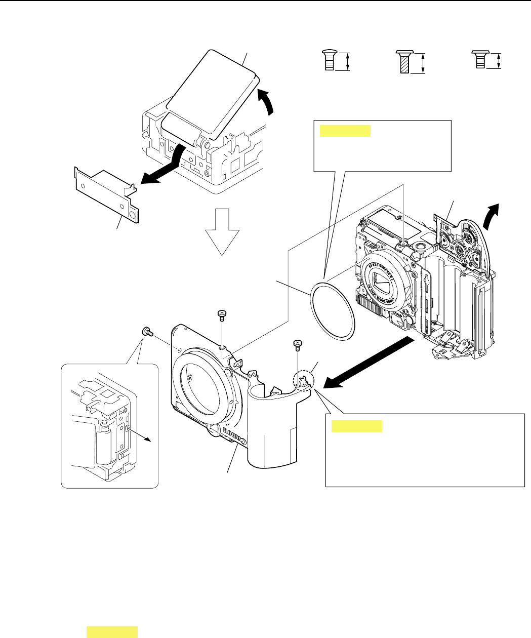
Fig. 6 SIDE COVER, FRONT COVER SECTION, LENS BARREL SHEET
2.4 SIDE COVER, FRONT COVER SECTION, LENS BARREL SHEET
(1) SIDE COVER
1. Open the LCD UNIT slightly and remove the SIDE COVER.
(2) FRONT COVER SECTION, LENS BARREL SHEET
1. Open the BATTERY COVER UNIT.
2. Remove the screw of f, the screw of g, and the screw of h .
3. Remove the FRONT COVER SECTION.
CAUTION
Half-open the BATTERY COVER UNIT and carefully remove the FRONT COVER SECTION so that the
portion A will not hinder removal.
Be careful not to drop the LENS BARREL SHEET.
4. Remove the LENS BARREL SHEET.
CD3-1441-000
3.0mm
SILVER
M1.7
f
XA4-9170-357
3.5mm
SILVER
M1.7
(SELF TAP)
g
XA1-7170-257
2.5mm
SILVER
M1.7
h
(1)-1
(1)-1
LCD UNIT
SIDE COVER
f
h
g
BATTERY COVER UNIT
Portion A
Half-open the BATTERY COVER UNIT
and carefully remove the FRONT COVER
SECTION so that the Portion A will not
hinder removal.
FRONT COVER SECTION
LENS BARREL SHEET
Be careful not to drop
the LENS BARREL SHEET.
(2)-1
(2)-2
(2)-2
(2)-2
(2)-3
(2)-4
CAUTION
CAUTION
7
REPAIR INSTRUCTION
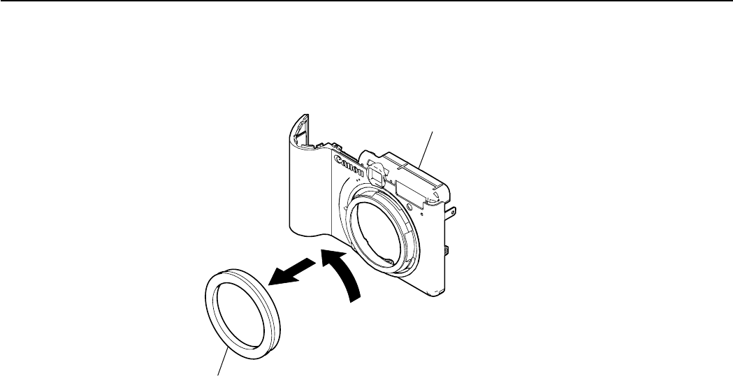
Fig. 7 BAYONET CUP UNIT, FRONT COVER UNIT
2.5 BAYONET CUP UNIT, FRONT COVER UNIT
(1) BAYONET CUP UNIT, FRONT COVER UNIT
1. Rotate the BAYONET CUP UNIT in the direction of the arrow A and separate the BAYONET CUP UNIT
from the FRONT COVER UNIT.
BAYONET CUP UNIT
FRONT COVER UNIT
A
(1)-1
8
REPAIR INSTRUCTION
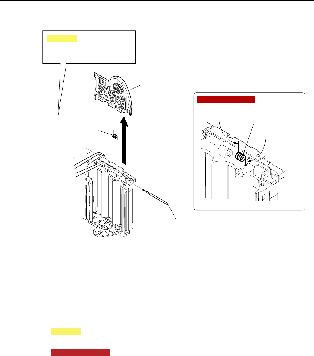
Fig. 8 BATTERY COVER SHAFT, BATTERY COVER SPRING,
BATTERY COVER UNIT
2.6 BATTERY COVER SHAFT, BATTERY COVER SPRING, BATTERY
COVER UNIT
(1) BATTERY COVER SHAFT, BATTERY COVER SPRING, BATTERY COVER UNIT
1. Remove the BATTERY COVER SHAFT by pushing the BATTERY COVER SHAFT with a tweezers or
the like.
CAUTION
Be careful not to drop the BATTERY COVER SPRING.
2. Remove the BATTERY COVER UNIT and the BATTERY COVER SPRING.
NOTE (Assembling)
Mount the BATTERY COVER SPRING on the MAIN BODY with the longer foot up.
(The foot has a bent-processed part on the top as the mark.)
(1)-1
BATTERY
COVER SHAFT
(1)-2
BATTERY COVER
SPRING
BATTERY COVER
SPRING
Longer foot
Shorter foot
(1)-2
BATTERY
COVER UNIT
Tweezers
or the like
Be careful not to drop
the BATTERY COVER SPRING.
CAUTION
NOTE (Assembling)
9
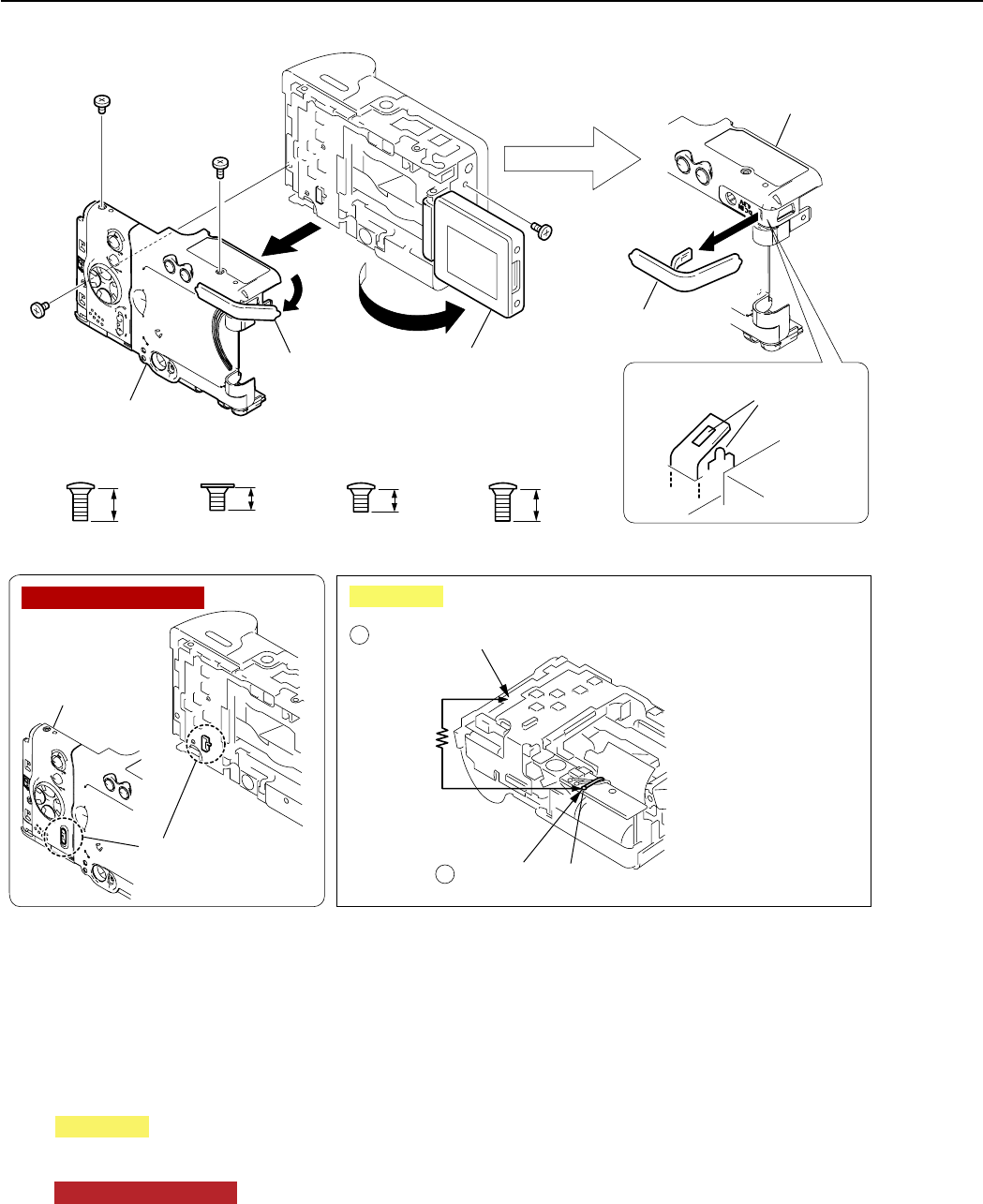
REPAIR INSTRUCTION
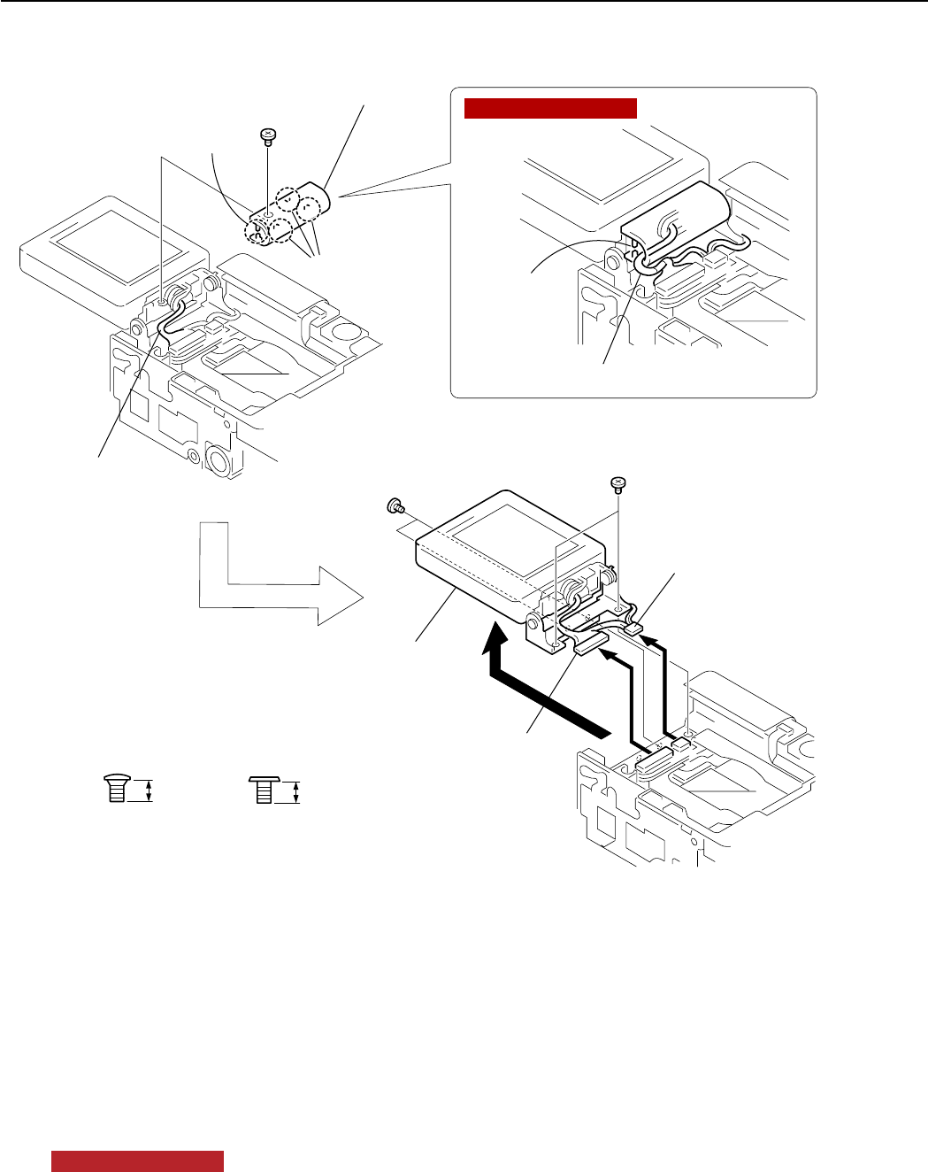
Fig. 9 HINGE COVER, LCD UNIT
2.7 HINGE COVER, LCD UNIT
(1) HINGE COVER
1. Remove the screw of i.
2. Disengage the three claws, then remove the connector cable from the hooked portion A and remove the
HINGE COVER.
(2) LCD UNIT
1. Remove the four screws of j.
2. Remove the two connector cables.
3. Remove the LCD UNIT.
NOTE (Assembling)
Hitch the connector cable to the hooked portion A and route the cable as shown in the figure.
(1)-2
(2)-1
(2)-1
(2)-2
(1)-1
HINGE COVER
Claws
Connector cable
Connector cable (from the LCD UNIT)
(2)-2
(2)-3
LCD UNIT
i
j
j
CD3-1443-000
2.0mm
SILVER
M1.7
i
CD3-1400-000
2.2mm
METAL
M1.7
j
Hooked portion A
Hooked
portion A
NOTE (Assembling)
10
REPAIR INSTRUCTION
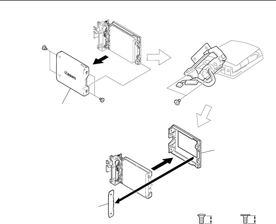
Fig. 10 LCD REAR COVER, LCD FRONT COVER
2.8 LCD REAR COVER, LCD FRONT COVER
(1) LCD REAR COVER
1. Remove the four screws of k.
2. Remove the LCD REAR COVER.
(2) LCD FRONT COVER
1. Rotate the HINGE as shown in the figure and remove the two screws of m.
2. Remove the LCD NUT PLATE.
3. Remove the LCD FRONT COVER.
(1)-1
(2)-1
(1)-1
(1)-2
LCD REAR COVER
LCD FRONT COVER
(2)-2
(2)-3
LCD NUT PLATE
k
m
k
CD3-1442-000
2.5mm
SILVER
M1.7
k
CD3-1446-000
2.5mm
SILVER
M1.4
m
11
REPAIR INSTRUCTION
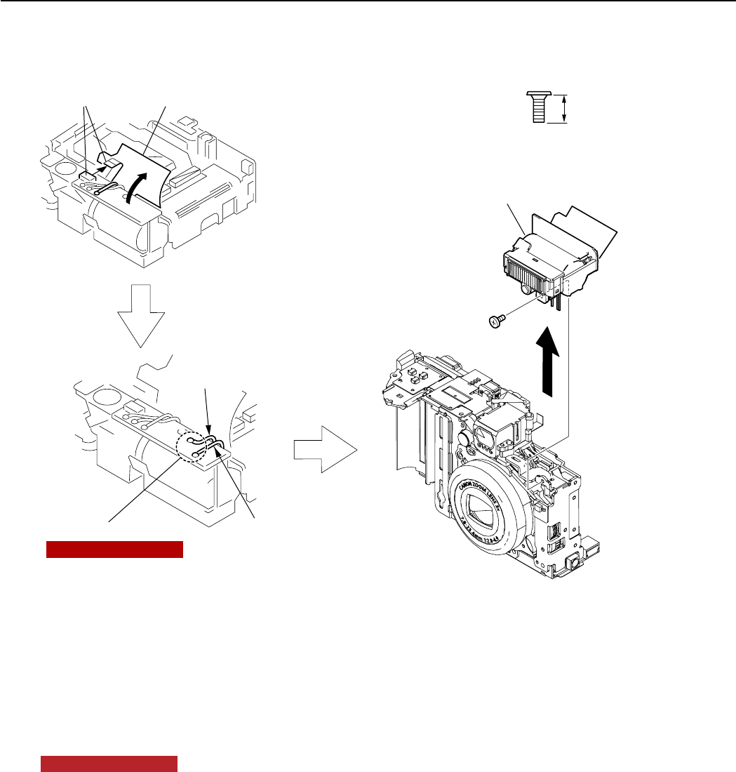
Fig. 11 FLASH UNIT
2.9 FLASH UNIT
(1) FLASH UNIT
1. Disconnect the connector.
2. Peel back the ST CAUTION LABEL.
3. Remove the soldering in two places, then remove the two lead wires (red and black).
NOTE (Assembling)
Apply the DIA BOND 1663G after soldering.
4. Remove the screw of l.
5. Remove the FLASH UNIT.
XA1-7170-357
3.5mm
SILVER
M1.7
l
l
(1)-1
(1)-2
ST CAUTION LABEL
(1)-3
Lead wire (Black)
Soldering
Lead wire (Red)
(1)-3
(1)-4
(1)-5
FLASH UNIT
NOTE (Assembling)
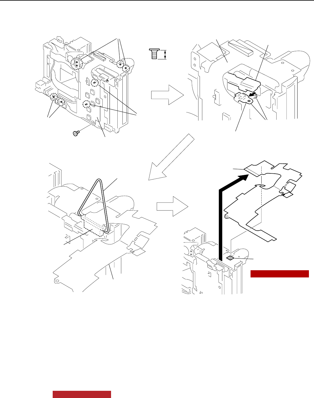
12
REPAIR INSTRUCTION
Fig. 12 OPERATION MODULE UNIT
2.10 OPERATION MODULE UNIT
(1) OPERATION MODULE UNIT
1. Remove the screw of h.
2. Disengage the eight dowels.
3. Slightly move the portion A upward and disengage the dowel, then pull the switch block out of the MAIN
BODY.
4. Hook the bent wire to the both sides of the connector to release the lock as shown in the figure.
5. Remove the OPERAION MODULE UNIT.
NOTE (Assembling)
Secure the top portion with the double-sided adhesive tape (6mm x 6mm)
XA1-7170-257
2.5mm
SILVER
M1.7
h
(1)-2
(1)-2
(1)-1
Dowels
Dowel
Switch block
Dowels Dowels
Wire
Connector
(1)-3
(1)-3
(1)-5
OPERATION
MODULE UNIT
OPERATION
MODULE UNIT
Double-sided
adhesive tape
OPERATION
MODULE UNIT
OPERATION
MODULE UNIT
(1)-4
(1)-2
h
Portion A
NOTE (Assembling)
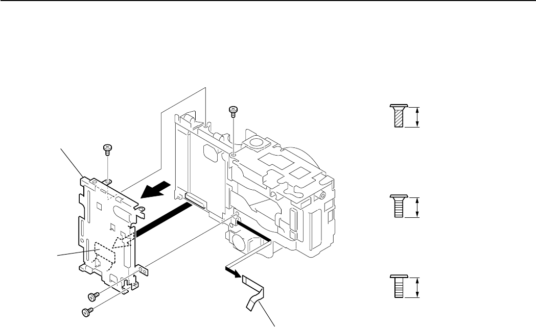
13
REPAIR INSTRUCTION
Fig. 13 CF UNIT, MAIN-FLASH FPC
2.11 CF UNIT, MAIN-FLASH FPC
(1) CF UNIT
1. Remove the screw of g, the two screws of l, and the screw of o .
2. Disconnect the connector.
3. Remove the CF UNIT.
(2) MAIN-FLASH FPC
1. Remove the MAIN FLASH FPC.
CF UNIT
(1)-1
(1)-1
(1)-3
MAIN-FLASH FPC
(2)-1
(1)-1
(1)-1
(1)-2
g
o
l
lXA4-9170-357
3.5mm
SILVER
M1.7
(SELF TAP)
g
XA1-7170-357
3.5mm
SILVER
M1.7
l
CD3-1447-000
3.5mm
METAL
M1.7
o
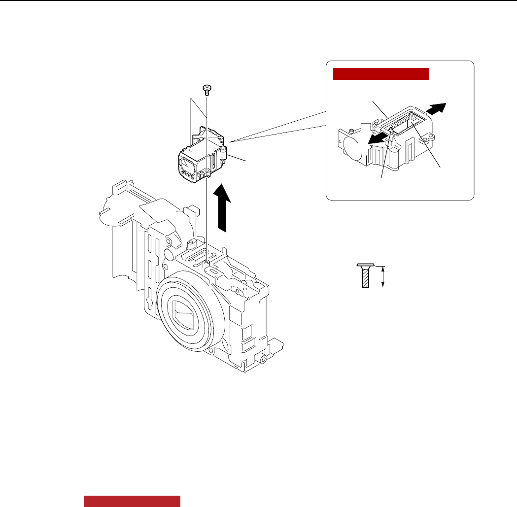
14
REPAIR INSTRUCTION
Fig. 14 FLASH UNIT
2.12 FLASH UNIT
(1) FINDER UNIT
1. Remove the two screws of n.
2. Remove the FINDER UNIT.
NOTE (Assembling)
Confirm that the LENS A is pushed in the very end of the direction A and LENS B is pushed in the very end
of the direction B as shown in figure, and install the FINDER UNIT in the barrel that has been moved in the
retracted position.
XA4-9140-407
4.0mm
SILVER
M1.4
(SELF TAP)
n
n
FINDER UNIT
FINDER UNIT
LENS A
LENS B
A
B
(1)-1
(1)-2
NOTE (Assembling)
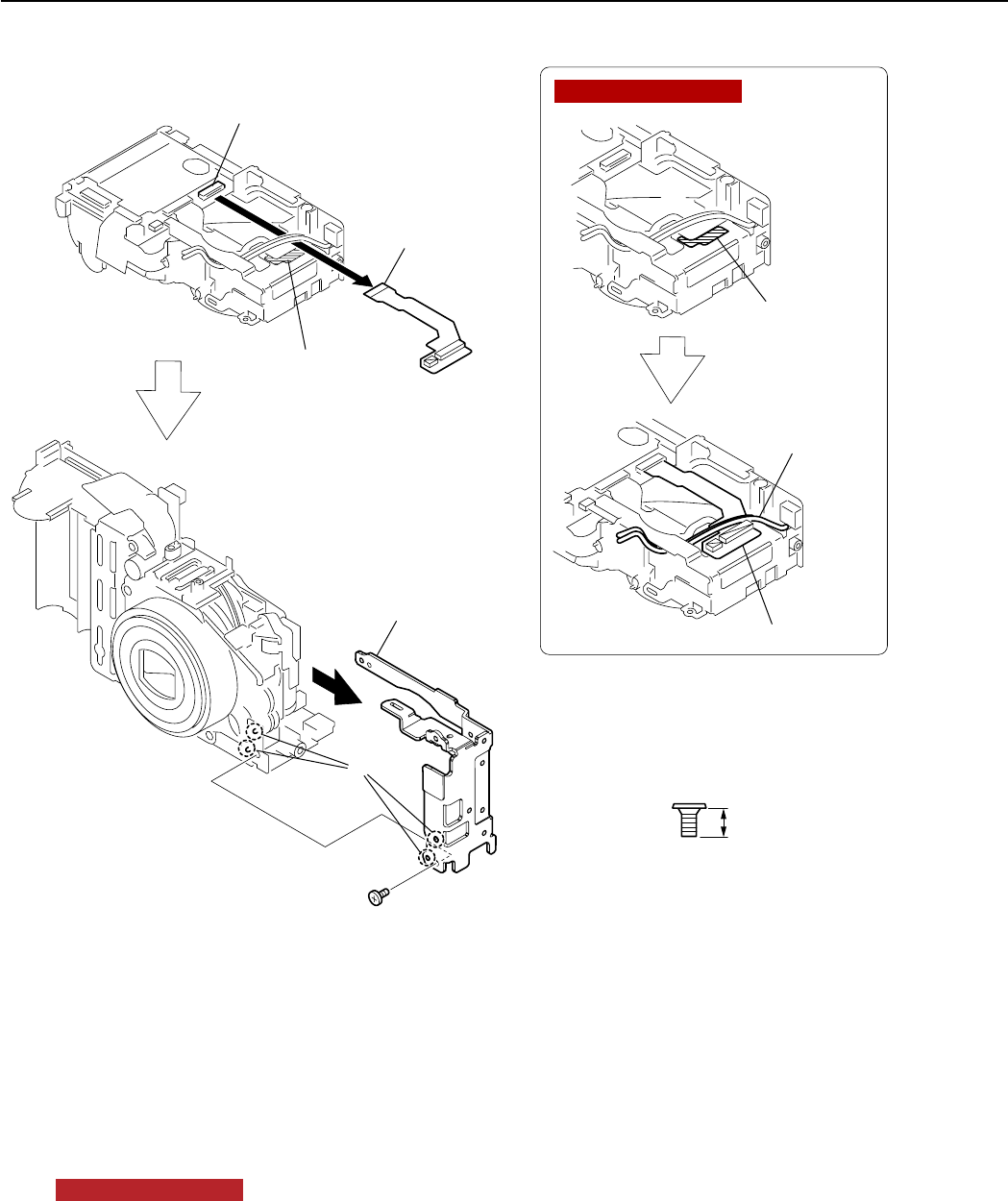
15
REPAIR INSTRUCTION
Fig. 15 MAIN-LCD MODULE UNIT, SUB FRAME
2.13 MAIN-LCD MODULE UNIT, SUB FRAME
(1) MAIN-LCD MODULE UNIT
1. Remove the MAIN-LCD MODULE UNIT by disconnecting the connector and by peeling off the adhesion
part from the SUB FRAME TAPE.
NOTE (Assembling)
Attach the SUB FRAME TAPE to the position as shown in the figure, and install the MAIN-LCD MOUDULE
UNIT by setting it under the two lead wires.
(2) SUB FRAME
1. Remove the screw of h.
2. Disengage the two dowels and remove the SUB FRAME.
XA1-7170-257
2.5mm
SILVER
M1.7
h
h
SUB FRAME TAPE
SUB FRAME
SUB FRAME TAPE
MAIN-LCD
MODULE UNIT
MAIN-LCD MODULE UNIT
(1)-1
(2)-1
(2)-2
(2)-2
Connector
NOTE (Assembling)
Lead wires
Dowels
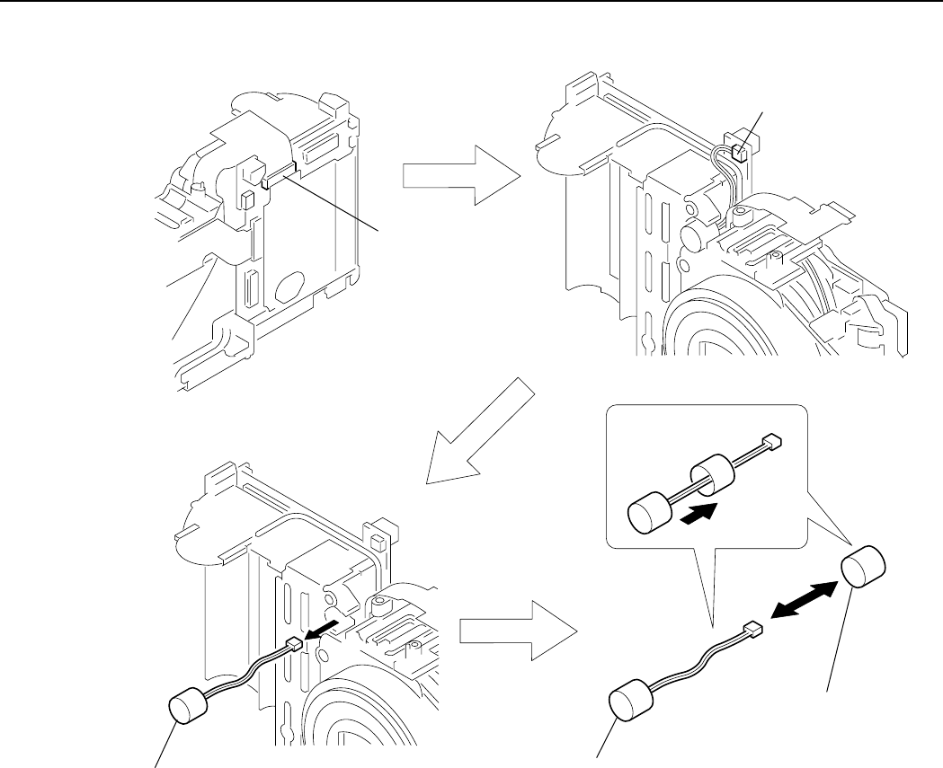
16
REPAIR INSTRUCTION
Fig. 16 MICRPHONE UNIT, MICROPHONE BUSH
2.14 MICRPHONE UNIT, MICROPHONE BUSH
(1) MICRPHONE UNIT, MICROPHONE BUSH
1. Disconnect the connector.
2. Disconnect the connector.
3. Remove the MICORPHONE UNIT and MICROPHONE BUSH together as an assembled unit.
4. Separate the MICROPHONE BUSH from the MICROPHONE UNIT.
MICROPHONE UNIT,
MICROPHONE BUSH
(1)-1
(1)-3 MICROPHONE UNIT
(1)-4
MICROPHONE
BUSH
(1)-4
(1)-2
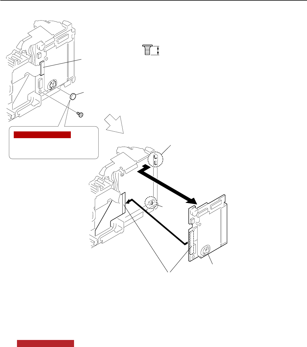
17
REPAIR INSTRUCTION
Fig. 17 LITHIUM (2ND) BATTERY, MAIN PCB SECTION
2.15 LITHIUM (2ND) BATTERY, MAIN PCB SECTION
(1) LITHIUM (2ND) BATTERY
1. Remove the LITHIUM (2ND) BATTERY.
NOTE (Assembling)
Be careful not to make mistake about + and - direction.
(2) MAIN PCB SECTION
1. Disconnect the connector and remove the screw of h.
2. Disengage the dowel and the two hooked portions.
3. Disconnect the connector.
4. Remove the MAIN PCB SECTION.
XA1-7170-257
2.5mm
SILVER
M1.7
h
(2)-1
(2)-3
(2)-2
(2)-2
(2)-1
LITHIUM (2ND)
BATTERY
Hooked portions
Be careful not to make mistake
about + and - direction.
(1)-1
MAIN PCB SECTION
(2)-4
h
NOTE (Assembling)
Dowel
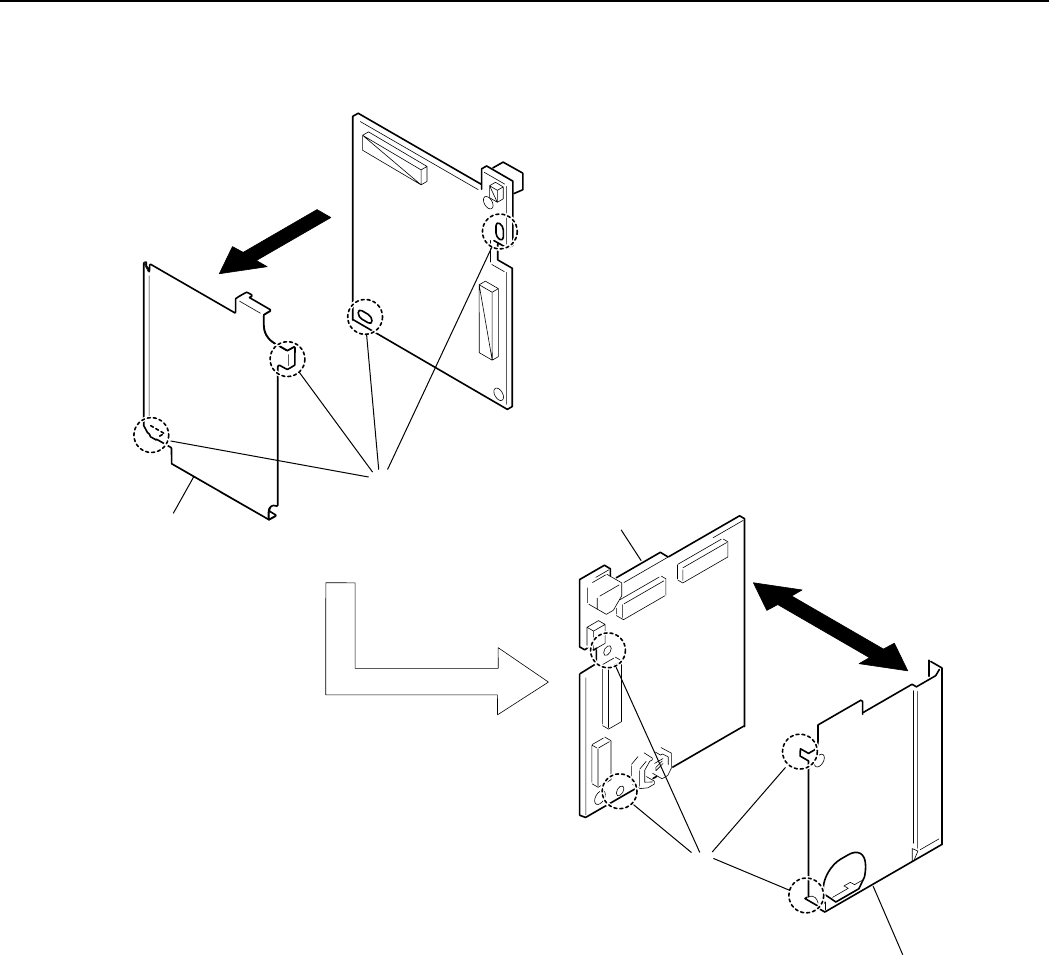
18
REPAIR INSTRUCTION
Fig. 18 MAIN A SHIELD UNIT, MAIN B SHIELD UNIT, MAIN PCB ASS’Y
2.16 MAIN A SHIELD UNIT, MAIN B SHIELD UNIT, MAIN PCB ASS’Y
(1) MAIN A SHIELD UNIT, MAIN B SHIELD UNIT, MAIN PCB ASS’Y
1. Remove the soldering in two places and remove the MAIN A SHIELD UNIT.
2. Remove the soldering in two places and separate the MAIN B SHIELD UNIT from the MAIN PCB ASS’Y.
MAIN B SHIELD UNIT
MAIN A SHIELD UNIT
(1)-1 MAIN PCB ASS'Y
(1)-2
(1)-2
Soldering
Soldering
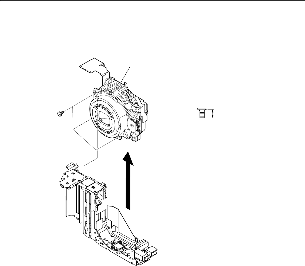
19
REPAIR INSTRUCTION
Fig. 19 OPTICAL UNIT
2.17 OPTICAL UNIT
(1) OPTICAL UNIT
1. Remove the three screws of h.
2. Remove the OPTICAL UNIT.
XA1-7170-257
2.5mm
SILVER
M1.7
h
OPTICAL UNIT
(1)-1
(1)-2
h
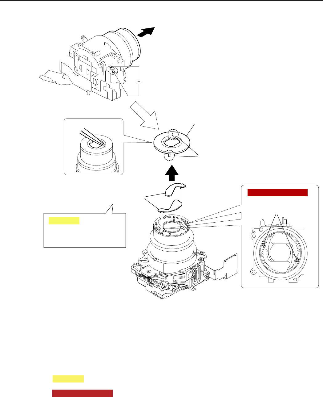
20
REPAIR INSTRUCTION
Fig. 20 FRONT CAP SECTION, BARRIER PLATE
2.18 FRONT CAP SECTION, BARRIER PLATE
(1) FRONT CAP SECTION
1. Apply the voltage (DC 2.5V) across the motor terminal to drive the motor until the motor stops and the
barrel fully comes out.
2. Insert a tweezers inside of the FRONT CAP SECTION as shown in the figure to disengage the two claws
and two portions adhered with DIA BOND and remove the FRONT CAP SECTION.
CAUTION
Be careful not to drop the BARRIER PLATES.
NOTE (Assembling)
Apply the DIA BOND No. 1663G to the positions as shown in the figure.
(2) BARRIER PLATE
1. Remove the two BARRIER PLATES.
(1)-1
DC2.5V
(1)-2
(1)-2
(2)-1
FRONT CAP SECTION
DIA BOND
No.1663G
BARRIER PLATES
Be careful not to drop the
BARRIER PLATES.
CAUTION
Claws
NOTE (Assembling)

21
REPAIR INSTRUCTION
Fig. 21 FRONT CAP, BARRIER COVER
2.19 FRONT CAP, BARRIER COVER
(1) FRONT CAP, BARRIER COVER
1. Separate the FRONT CAP from the BARRIER COVER that are attached each other by the FRONT CAP
TAPE.
FRONT CAP
BARRIER COVER
FRONT CAP TAPE
(1)-1
(1)-1
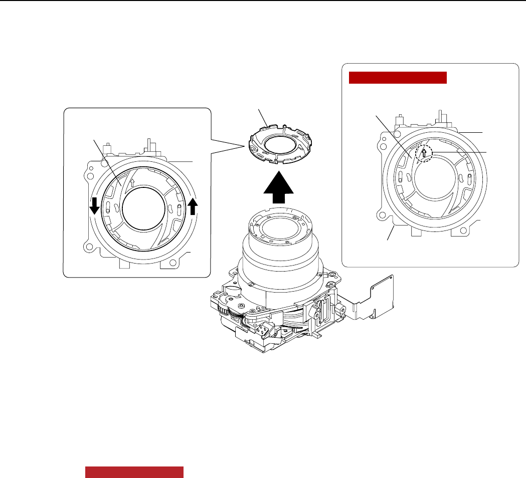
22
REPAIR INSTRUCTION
Fig. 22 BARRIER BASE
2.20 BARRIER BASE
(1) BARRIER BASE
1. Rotate the BARRIER BASE in the direction of the arrow A and remove it.
NOTE (Assembling)
Install the BARRIER BASE to the OPTICAL UNIT while aligning the arrow mark on the BARRIER BASE
with the upper part of the OPTICAL UNIT.
(1)-1
BARRIER BASE
BARRIER
BASE
Upper
Arrow
mark
Bottom
(1)-1
BARRIER BASE
OPTICAL
UNIT
AA
NOTE (Assembling)
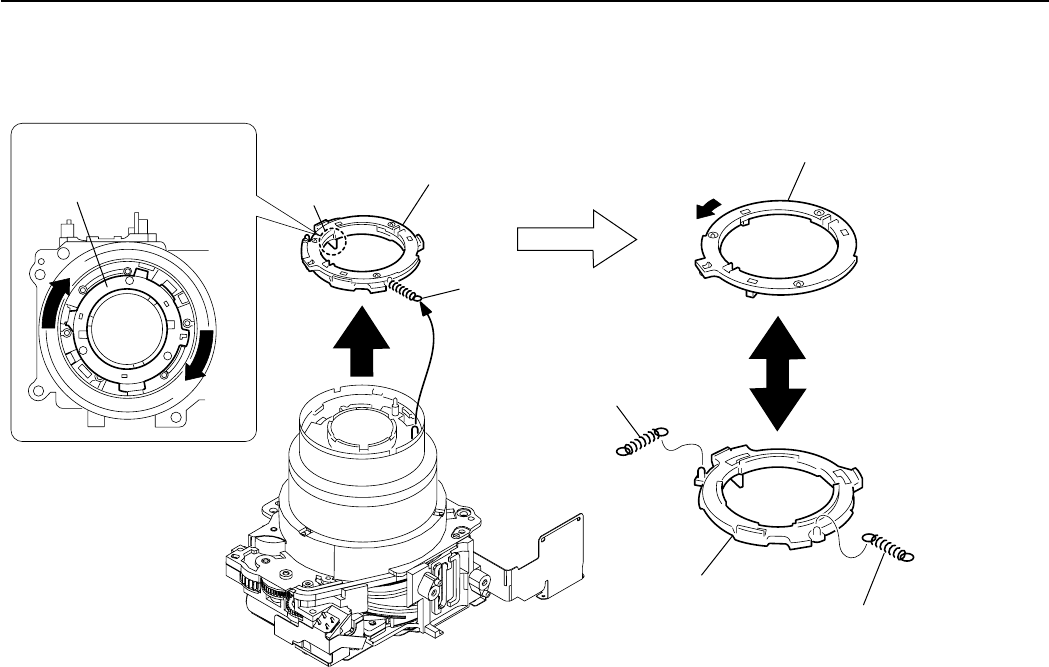
23
REPAIR INSTRUCTION
Fig. 23 BARRIER DRIVE PLATE, BARRIER DRIVE RING
2.21 BARRIER DRIVE PLATE, BARRIER DRIVE RING
(1) BARRIER DRIVE PLATE, BARRIER DRIVE RING
1. Remove the BARRIER DRIVE PLATE and the BARRIER DRIVE RING as an assembled unit by rotating
them in the direction of the arrow A and by disengaging the hook and the claw.
2. Remove the BARRIER OPEN SPRING and the BARRIER CLOSE SPRING.
3. Rotate the BARRIER DRIVE PLATE in the direction of the arrow B, then separate it from the BARRIER
DRIVE RING.
Hook
(1)-1
(1)-1
BARRIER DRIVE PLATE,
BARRIER DRIVE RING
BARRIER DRIVE PLATE,
BARRIER DRIVE RING
(2)-3
BARRIER DRIVE PLATE
(1)-3
BARRIER
DRIVE RING (1)-2
BARRIER
CLOSE
SPRING
(1)-2
BARRIER
OPEN
SPRING
A
A
B
Claw
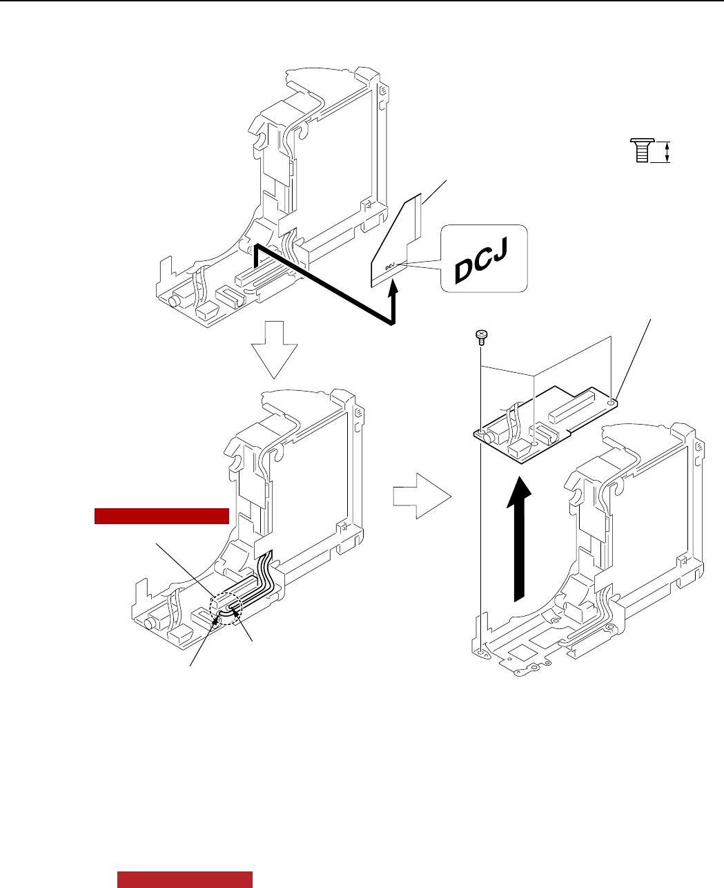
24
REPAIR INSTRUCTION
Fig. 24 MAIN-DC FPC, DC/JACK UNIT
2.22 MAIN-DC FPC, DC/JACK UNIT
(1) MAIN-DC FPC, DC/JACK UNIT
1. Remove the MAIN-DC FPC.
2. Remove the soldering in two places, and remove the two lead wires (red and black) that are from the
BATTERY BOX UNIT.
NOTE (Assembling)
Apply the DIA BOND 1663G after soldering.
3. Remove the three screws of h.
4. Remove the DC/JACK UNIT.
XA1-7170-257
2.5mm
SILVER
M1.7
h
h
(1)-2
(1)-1
MAIN-DC FPC
(1)-4
DC/JACK UNIT
(1)-2
(1)-3
NOTE (Assembling)
Soldering
Lead wire (Black) Lead wire (Red)
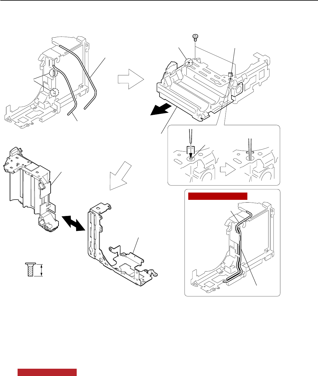
25
REPAIR INSTRUCTION
Fig. 25 BATTERY BOX UNIT, MAIN FRAME UNIT
2.23 BATTERY BOX UNIT, MAIN FRAME UNIT
(1) BATTERY BOX UNIT, MAIN FRAME UNIT
1. Remove the two lead wires (red and black) from the two grooves.
NOTE (Assembling)
Route the lead wires (red and black) as shown in the figure.
2. Remove the two screws of g.
3. Disengage the dowel, while pushing the portion A downward with a stick or the like. Then separate the
MAIN FRAME UNIT by sliding the BATTERY BOX UNIT in the direction of the arrow B.
XA4-9170-357
3.5mm
SILVER
M1.7
(SELF TAP)
g
g
BATTERY
BOX UNIT
(1)-1
(1)-1
Grooves
(1)-2
(1)-3
(1)-3
BATTERY
BOX UNIT
(1)-3
MAIN FRAME UNIT
(1)-3
B
NOTE (Assembling)
Lead wire (Black)
Lead wire (Black)
Lead wire (Red)
Lead wire (Red)
Dowel Portion A
Portion A
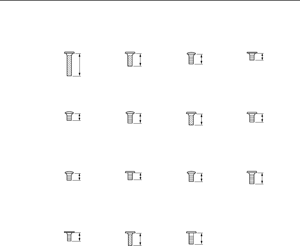
26
REPAIR INSTRUCTION
2.24 Screw List
a
XA4-9170-707
7.0mm
SILVER
M1.7
(SELF TAP)
XA4-9170-407
4.0mm
SILVER
M1.7
(SELF TAP)
b
CD3-1440-000
3.0mm
DARK SILVER
M1.7
C
CD3-1445-000
1.8mm
DARK SILVER
M1.7
d
CD3-1444-000
1.8mm
DARK SILVER
M1.7
e
CD3-1441-000
3.0mm
SILVER
M1.7
f
XA4-9170-357
3.5mm
SILVER
M1.7
(SELF TAP)
g
XA1-7170-257
2.5mm
SILVER
M1.7
h
CD3-1443-000
2.0mm
SILVER
M1.7
i
CD3-1400-000
2.2mm
METAL
M1.7
j
CD3-1442-000
2.5mm
SILVER
M1.7
k
XA1-7170-357
3.5mm
SILVER
M1.7
l
CD3-1446-000
2.5mm
SILVER
M1.4
m
XA4-9140-407
4.0mm
SILVER
M1.4
(SELF TAP)
n
CD3-1447-000
3.5mm
METAL
M1.7
o
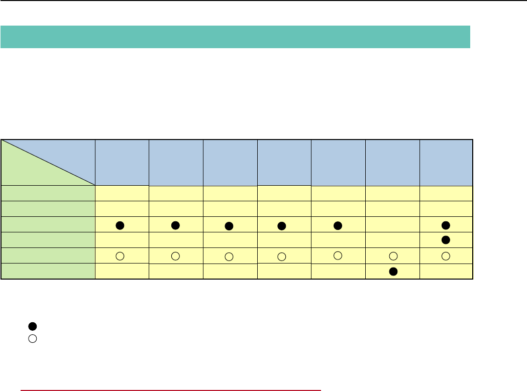
27
REPAIR INSTRUCTION
3. Adjustments
3.1 Replacement Parts and Adjustment Items
PowerShot A80 requires electrical adjustments when certain parts are replaced.
The table below indicates the adjustments required for the respective part replacements.
For all other parts not listed below, no electrical adjustments are necessary after replacement.
: Adjustment is necessary after replacement.
: Adjustment is necessary after replacement.
(Adjustment is not necessary, only if the adjustment data has been saved and then transferred
after the part is replaced.)
Blank : Adjustment is unnecessary.
∗OPTICAL UNIT is replaced, adjust certainly at the procedure as below.
#1. CCD Adjustment
#2. Optical Unit Adjustment
#3. Imaging Process Adjustment
#4. Color Adjustment
#5. Pixel Dot Adjustment
#6. Flash Adjustment
CCD
Adjustment
#1
Optical Unit
Adjustment
#2
Imaging
Process
Adjustment
#3
Pixel Dot
Adjustment
#5
Flash
Adjustment
#6
LCD
Adjustment
Color
Adjustment
#4
Adjustment Items
Replacement Part
BATTERY BOX UNIT
DC/JACK UNIT
OPTICAL UNIT
FLASH UNIT
MAIN PCB ASS’Y
LCD UNIT

28
REPAIR INSTRUCTION
3.2 Adjustment Tools
The following tools are required for electrical adjustment.
*1 2pcs. required.
*2 The file containing “How to print out” and Chart for print-out is in the Service Manual APPENDIX.
DESCRIPTION
PC/AT-Compatible Machine
(Windows2000 or 98 pre-installed Model, USB port)
SERVICE MANUAL (CD-ROM)
ADJUSTMENT SOFTWARE
Compact Power Adapter CA-PS500
AC Cable
INTERFACE CABLE IFC-300PCU
Brightness Box (light source A)
Color Viewer (5600° K)
Color Bar Chart
18% Gray Chart
Auto Focus Chart
W-10 Filter *1
C-12 Filter
FL-W Filter
ND-2 Filter
ND-4 Filter
ND-8 Filter
Light-Shielding Cloth (500 × 500 or larger)
Tripod
Reference Camera
DIGITAL CAMERA SolutionDisk
PARTS NO.
—
CY8-4388-031
—
—
—
—
—
DY9-2039-100
DY9-2002-000
CY4-6016-000
—
CY9-1556-000
CY9-1555-000
CY9-1557-000
CY9-1552-000
CY9-1553-000
CY9-1554-000
—
—
—
—
REMARKS
Local purchase
Download
Enclosed in
“AC Adapter Kit ACK600”
Enclosed in
“AC Adapter Kit ACK600”
(or Local purchase)
(Verified with EF-5000)
Attached to “SERVICE MANUAL
(CD-ROM)” 2 types *2
Local purchase
Local purchase
Merchandise
Enclosed in Merchandise
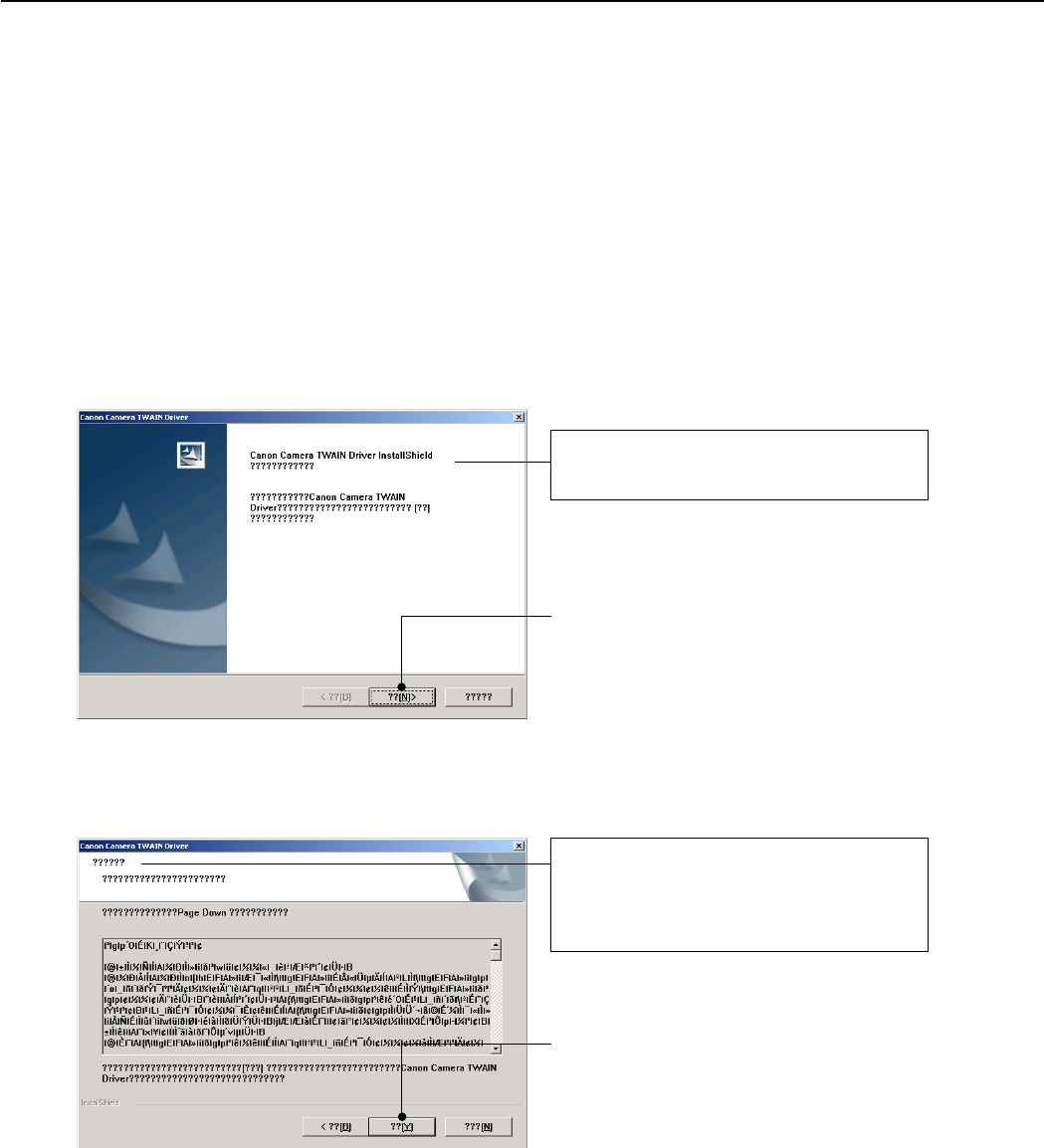
29
REPAIR INSTRUCTION
3.3 Before Starting Electrical Adjustments
3.3.1 TWAIN Driver Installation
Install the USB Driver for Adjustment in the CD-ROM to PC.
(“This Adjustment Software” is impossible when the RS-232C TWAIN driver is used.)
3.3.2 Factory Mode Driver Installation
After downloading and extracting Factory Mode Driver, double-click Setup.exe
(\Factory Mode Driver\Win 2000_98\Setup.exe) to install it.
If InstallShield Wizard appears as shown in the first picture below, install the TWAIN (Factory Mode) Driver
by following the instructions.
)
1
2
The InstallShield Wizard will install TWAIN
Driver on your computer.
Click the “??[N]>” button.
)
License Agreement
See the file “Service Manual/English/Ch6/
License.pdf” for the contents of the License.
Click the “??[Y]” button.
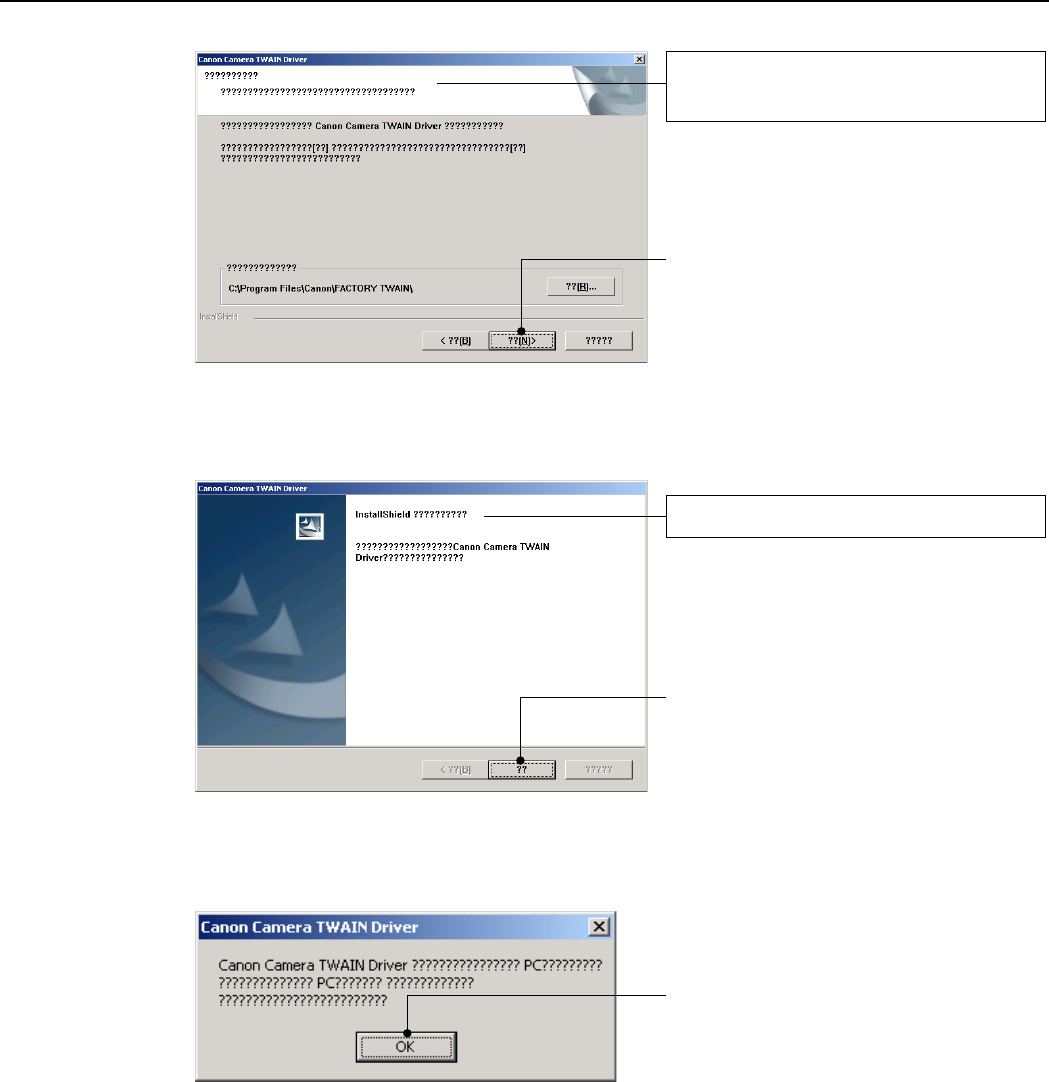
30
REPAIR INSTRUCTION
3
4
5
)
Choose Destination Location
Select folder where Setup will install files.
Click the “??[N]>” button.
)
InstallShield Wizard Complete
Click the “??” button.
Click the “OK” button.
Installing TWAIN (Factory Mode)
Driver is completed.
If you cannot install Factory Mode Driver in above procedure, install it in the following procedure.
1. Change the camera to Factory mode.
2. Install Wizard of new hardware starts up.
3. Select the option that directly chooses the driver’s place.
4. Choose CAP_FACT.INF
(Factory Mode Driver\Win2000_98\Win_2k98\CAP_FACT.INF).
5. Installment starts. When the Wizard finishes, the installment finishes.
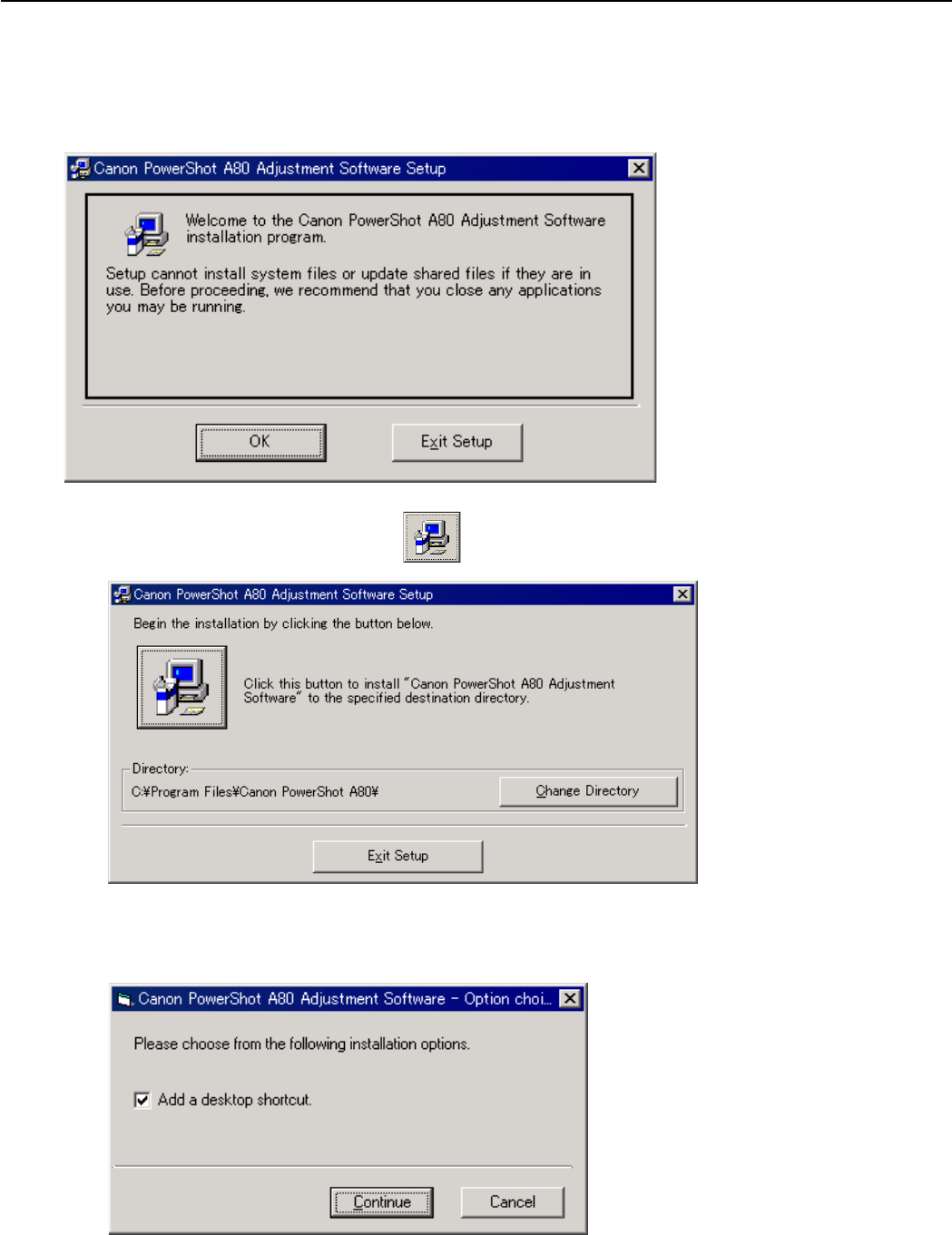
31
REPAIR INSTRUCTION
4. When the dialog box below appears, click the “Continue” button.
(In the case that you do not add a shortcut on desktop, remove clicking from the check box.)
3. When the dialog box below appears, click the button. (Software installation will then begin.)
3.3.3 Adjustment Software Installation
1. After downloading and extracting Adjustment Software, double-click Setup.exe to install it.
(Adjustment Softwares are different according to the model of camera that you are going to adjust.)
2. When the dialog box below appears, click the “OK” button.
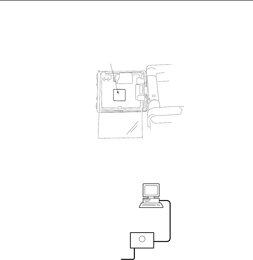
32
REPAIR INSTRUCTION
3.3.4 Preparation
Before starting up the Adjustment Software, follow the preparatory steps below:
1. Obtain all the tools necessary for the adjustment.
2. For the LCD Adjustment, jot down the data written on the PCB ASS’Y inside the LCD Unit.
You will need it later.
3 Connect the Camera to the Power Source with the Compact Power Adapter CA-PS500 and AC Cable.
4. Set the Replay Mode on the camera and turn on.
Personal Computer
USB
INTERFACE CABLE
IFC-300PCU
DIGITAL
Compact Power Adapter
CA-PS500
CAMERA BODY
5. Connect the Camera’s Digital terminal to the PC’s USB Port with INTERFACE CABLE IFC-300 PCU.
Note: Perform the preparation in the following order otherwise the camera won’t work properly.
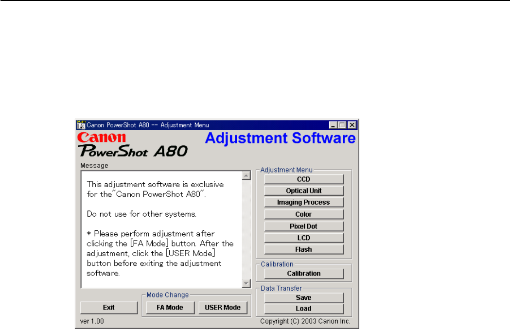
33
REPAIR INSTRUCTION
3.3.5 Starting up the Adjustment Software
After completing the preparatory steps, click Start and move the cursor to Program; then select Canon
Digital Camera and click PowerShot A80 Adjustment.
3.3.6 Menu Window
When the Adjustment Software starts up, the Menu Window below will appear.
3.3.7 How to Use the Adjustment Software
■Mode change
This camera uses normally PTP for communication with PC. Because calibration and adjustment
become impossible depending on the condition of PTP, select the TWAIN mode of the PTP before
starting calibration and adjustment.
• “FA Mode” button: This button is used to change the mode from the USER mode to the FA mode.
(PTP to TWAIN)
* Before starting calibration and adjustment, be sure to set the FA mode.
• “USER Mode” button: This button is used to change the mode from the FA mode to the USER
mode. (TWAIN to PTP)
* When calibration and adjustment are completed, be sure to change the mode to the USER mode
before quitting the software.
■Calibration/Adjustment
For starting, click the button related with calibration/adjustment.
* Whenever you use your light source for the adjustment for the first time, be sure to click the “Cali-
bration” Button.
■Quitting the Adjustment Software
Click the “Exit” button.
■Saving or Loading data
• “Save” button : This button saves all adjustment data stored on the camera in text format.
• “Load” button : This button loads all adjustment data saved in text format to the camera.
■Notes
• If the adjustment fails, a message indicating the failure will appear on each product. If this happens,
do the adjustment again.
• The Adjustment Software is dedicated only to Canon Digital Camera PowerShot A80.
Never use it for any other camera.
• The Windows2000 or 98 must be pre-installed on the computer that is equipped with the USB
terminal.
* Operations on the other Operating Systems such as Windows95, Windows XP and others are not
guaranteed. (Because Windows95 does not support USB.)
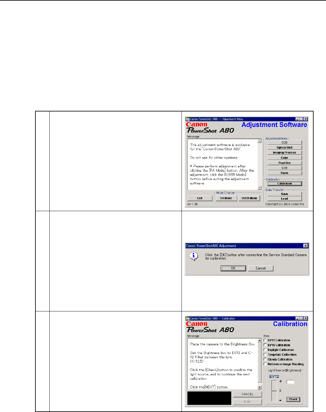
34
REPAIR INSTRUCTION
3.4 Calibration
3.4.1 Calibration
■Tools Used
• Personal Computer • Brightness Box
(light source A)
• ND-2 Filter
•
SERVICE MANUAL (CD-ROM)
• Color Viewer
(5600° K)
• ND-4 Filter
•
ADJUSTMENT SOFTWARE
• Color Bar Chart • ND-8 Filter
• Compact Power Adapter CA-PS500 • W-10 Filter
(2pcs.)
• Reference Camera
(Merchandise)
• AC Cable • C-12 Filter • DIGITAL CAMERA Solution Disk
• INTERFACE CABLE IFC-300PCU • FL-W Filter
1 Click the “Calibration” button.
2 1. When the message on the right appears, check
that the reference camera (Merchandise) is con-
nected to the computer.
2. Click the “OK” button.
3 When the message on the right appears, go to 4.
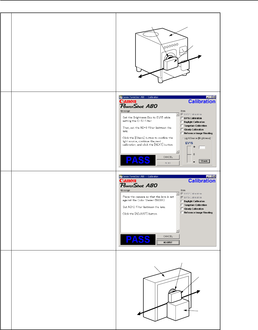
35
REPAIR INSTRUCTION
5 1. When the message on the right appears, Set the
Brightness Box to EV15 and attach the ND-8
Filter while setting the C-12 Filter between the
lens.
2. Click the “Check” button.
3. Check the Brightness level if it is within
0 ± 5.
* If not, calibrate the Brightness Box until it
becomes within 0 ± 5.
4. Click the “NEXT” button.
6 When the message on the right appears go to 7.
7 1. Attach the ND-2 Filters between the Lens and
the Color Viewer.
2. Place the camera so that the lens is set against
the center part of the Color Viewer.
3. Click the “ADJUST” button.
Personal
Computer
Power
Source
Brightness
Box
CAMERA
BODY
C-12 Filter
Power
Source
Stand
Color Viewer
Personal
Computer
CAMERA
BODY
ND-2
Filter
4 1. Place the camera so that lens is set against the
light source surface of the Brightness Box via
the C-12 Filter.
2. Set the Brightness Box to EV12.
3. Click the “Check” button.
4. Check the Brightness level if it is within
0 ± 5.
* If not, calibrate the Brightness Box until it
becomes within 0 ± 5.
5. Click the “NEXT” button.
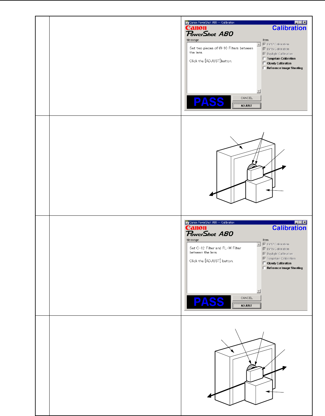
36
REPAIR INSTRUCTION
Power
Source
Stand
Color Viewer
Personal
Computer
CAMERA
BODY
W-10
Filter
Power
Source
Stand
Color Viewer
Personal
Computer
CAMERA
BODY
C-12 Filter FL-W Filter
8 When the message on the right appears go to 9.
9 1. Remove the ND-2 Filter.
2. Attach the two W-10 Filters between the Lens
and the Color Viewer.
Place the camera so that the lens is set against
the center part of the Color Viewer.
3. Click the “ADJUST” button.
10 When the message on the right appears go to 11.
11 1. Remove the two W-10 Filters.
2. Attach the C-12 and FL-W Filter between the
Lens and the Color Viewer.
Place the camera so that the lens is set against
the center part of the Color Viewer.
3. Click the “ADJUST” button.
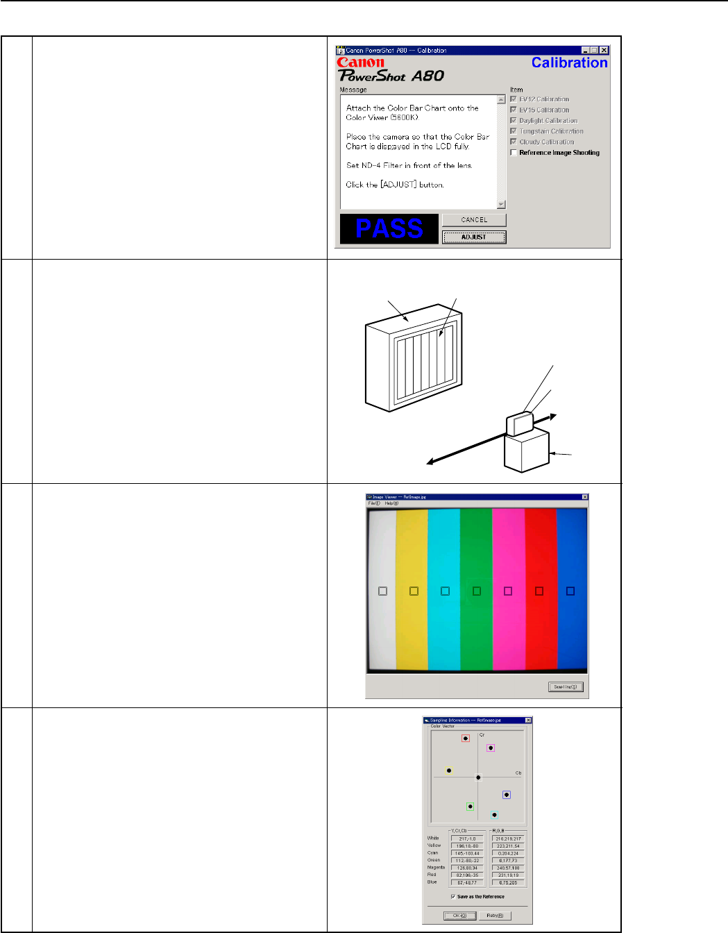
37
REPAIR INSTRUCTION
Color Viewer Color Bar Chart
Personal
Computer
CAMERA
BODY
Power
Source
Stand
ND-4
Filter
12 When the message on the right appears go to 13.
13 1. Attach the Color Bar Chart to the Color Viewer.
2. Place the camera so that the Viewing image of
the color bar chart is the full of LCD with the
ND-4 Filter attached.
3. Click the “ADJUST” button.
14 1. Shift a frame on the displayed screen
with a mouse to choose a color of color bar.
2. Click the “Sampling” button.
15 Check “Save as the Reference”, and click the
“OK” button to store the data.
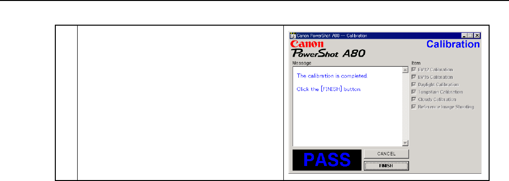
38
REPAIR INSTRUCTION
16 When the message on the right appears, click the
“FINISH” button.
(This ends the “Calibration”.)
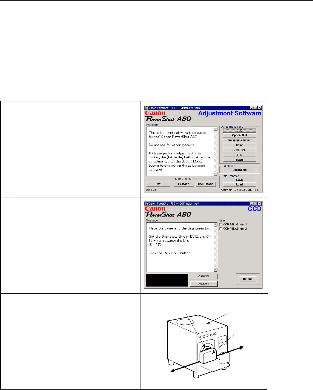
39
REPAIR INSTRUCTION
3.5 Adjustment Procedure
3.5.1 CCD Adjustment
■Tools Used
• Personal Computer • INTERFACE CABLE IFC-300PCU
•
SERVICE MANUAL (CD-ROM)
• Brightness Box
(light source A)
•
ADJUSTMENT SOFTWARE
• C-12 Filter
• Compact Power Adapter CA-PS500 • DIGITAL CAMERA Solution Disk
• AC Cable
Personal
Computer
Power
Source
Brightness
Box
CAMERA
BODY
C-12 Filter
1 Click the “CCD” button.
2 When the message on the right appears, go to 3.
3 1. Place the camera so that lens is set against the
light source surface of the Brightness Box via
the C-12 Filter.
2. Set the Brightness Box to EV12.
3. Click the “ADJUST” button.
* When the adjustment does not work, click the
“Default” button.
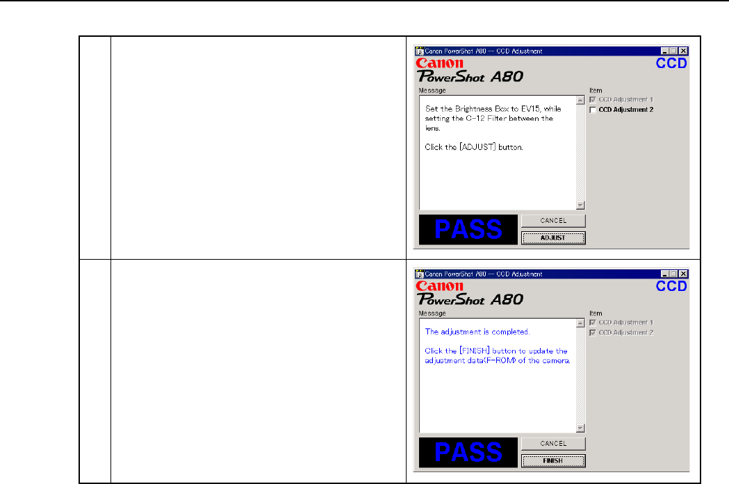
40
REPAIR INSTRUCTION
4 When the message on the right appears, Set the
Brightness Box to EV15 while setting the C-12
Filter between the lens.
Click the “ADJUST” button.
5 When the message on the right appears, click the
“FINISH” button.
(This ends the “CCD” Adjustment.)
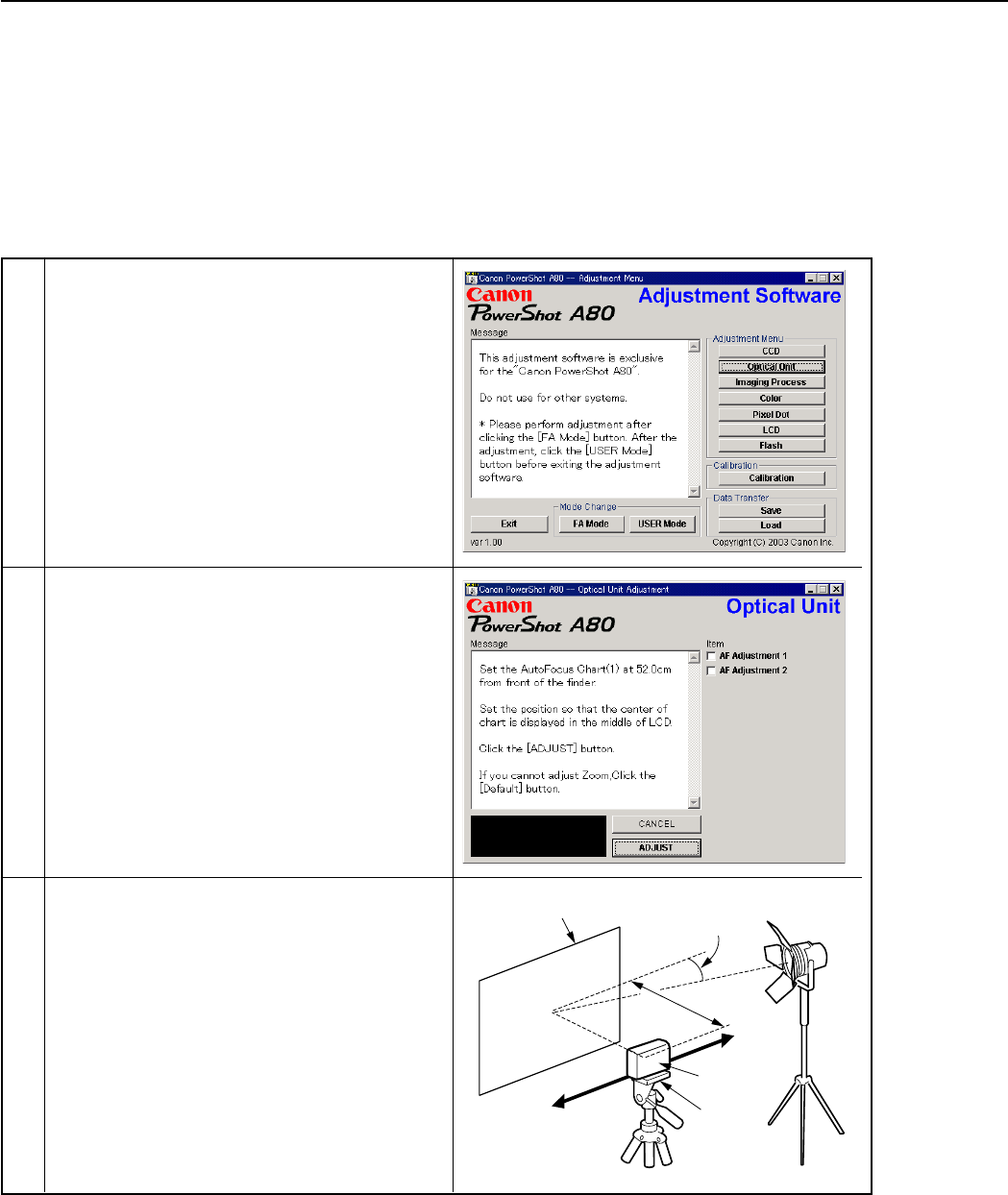
41
REPAIR INSTRUCTION
3.5.2 Optical Unit Adjustment
■Tools Used
• Personal Computer • INTERFACE CABLE IFC-300PCU
•
SERVICE MANUAL (CD-ROM)
• Auto Focus Chart (2 types)
•
ADJUSTMENT SOFTWARE
• Tripod
• Compact Power Adapter CA-PS500 • DIGITAL CAMERA Solution Disk
• AC Cable
1 Click the “Optical Unit” button.
2 When the message on the right appears, go to 3.
3 1. Place the Auto Focus Chart (1) at 52.0cm away
from the front of the camera finder.
* Place the Auto Foucs Chart (1) on a plain
color wall or equivalent.
* Adjust the light so that the brightness of the
chart will be about EV9.0.
The ray of the light should come in at a
narrow angle as seen from the chart.
2. Adjust the position of the camera finely so that
the center of the Auto Focus Chart is aligned
with the center of the LCD.
3. Click the “ADJUST” button.
Personal
Computer
Power
Source
52.0cm
Auto Focus
Chart (1)
About 15
degrees Lighting
CAMERA
BODY
Tripod
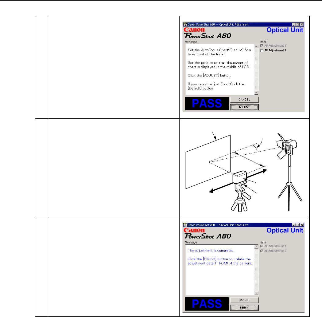
42
REPAIR INSTRUCTION
4 When the message on the right appears, go to 5.
5 1. Place the Auto Focus Chart (2) at 127.5cm away
from the front of the camera finder.
* Place the Auto Focus Chart on a plain color
wall or equivalent.
* Adjust the light so that the brightness of the
chart will be about EV9.0.
The ray of the light should come in at a
narrow angle as seen from the chart.
2. Adjust the position of the camera finely so that
the center of the Auto Focus Chart is aligned
with the center of the LCD.
3. Click the “ADJUST” button.
Personal
Computer
Power
Source
127.5cm
Auto Focus
Chart (2)
About 15
degrees Lighting
CAMERA
BODY
Tripod
6 When the message on the right appears, click the
“FINISH” button.
(This ends the “Optical Unit” Adjustment.)

43
REPAIR INSTRUCTION
3.5.3 Imaging Process Adjustment
■Tools Used
• Personal Computer • Color Viewer (5600° K)
•
SERVICE MANUAL (CD-ROM)
• W-10 Filter (2 pcs.)
•
ADJUSTMENT SOFTWARE
• C-12 Filter
• Compact Power Adapter CA-PS500 • FL-W Filter
• AC Cable • ND-2 Filter
• INTERFACE CABLE IFC-300PCU • DIGITAL CAMERA Solution Disk
Power
Source
Stand
Color Viewer
Personal
Computer
CAMERA
BODY
ND-2
Filter
1 Click the “Imaging Process” button.
3 1. Attach the ND-2 Filters between the Lens and
the Color Viewer.
2. Place the camera so that the lens is set against
the center part of the Color Viewer.
3. Click the “ADJUST” button.
2 When the message on the right appears, go to 3.
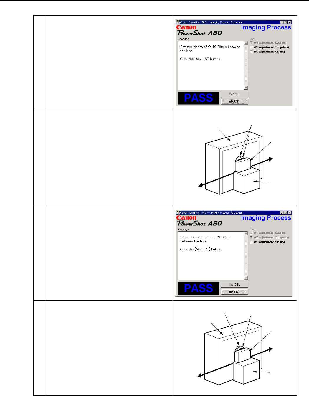
44
REPAIR INSTRUCTION
5 1. Remove the ND-2 Filter.
2. Attach the two W-10 Filters between the Lens
and the Color Viewer.
Place the camera so that the lens is set against
the center part of the Color Viewer.
3. Click the “ADJUST” button.
4 When the message on the right appears, go to 5.
6 When the message on the right appears, go to 7.
7 1. Remove the W-10 Filters.
2. Attach the C-12 and FL-W Filter between the
Lens and the Color Viewer.
Place the camera so that the lens is set against
the center part of the Color Viewer.
3. Click the “ADJUST” button.
Power
Source
Stand
Color Viewer
Personal
Computer
CAMERA
BODY
W-10
Filter
Power
Source
Stand
Color Viewer
Personal
Computer
CAMERA
BODY
C-12 Filter FL-W Filter

45
REPAIR INSTRUCTION
8 When the message on the right appears, click the
“FINISH” button.
(This ends the “Imaging Process” Adjustment.)
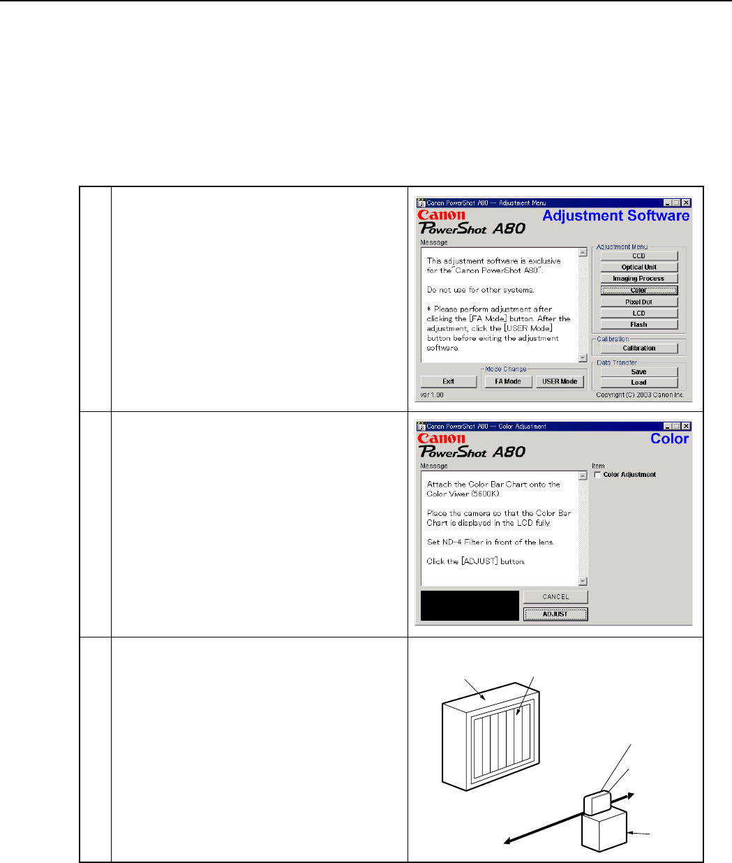
46
REPAIR INSTRUCTION
3.5.4 Color Adjustment
■Tools Used
• Personal Computer • INTERFACE CABLE IFC-300PCU
•
SERVICE MANUAL (CD-ROM)
• Color Viewer (5600° K)
•
ADJUSTMENT SOFTWARE
• Color Bar Chart
• Compact Power Adapter CA-PS500 • ND-4 Filter
• AC Cable • DIGITAL CAMERA Solution Disk
1 Click the “Color” button.
Color Viewer Color Bar Chart
Personal
Computer
CAMERA
BODY
Power
Source
Stand
ND-4
Filter
2 When the message on the right appears, go to 3.
3 1. Attach the Color Bar Chart to the Color Viewer.
2. Place the camera so that the Viewing image of
the color bar chart is the full of LCD with the
ND-4 Filter attached.
3. Click the “ADJUST” button.
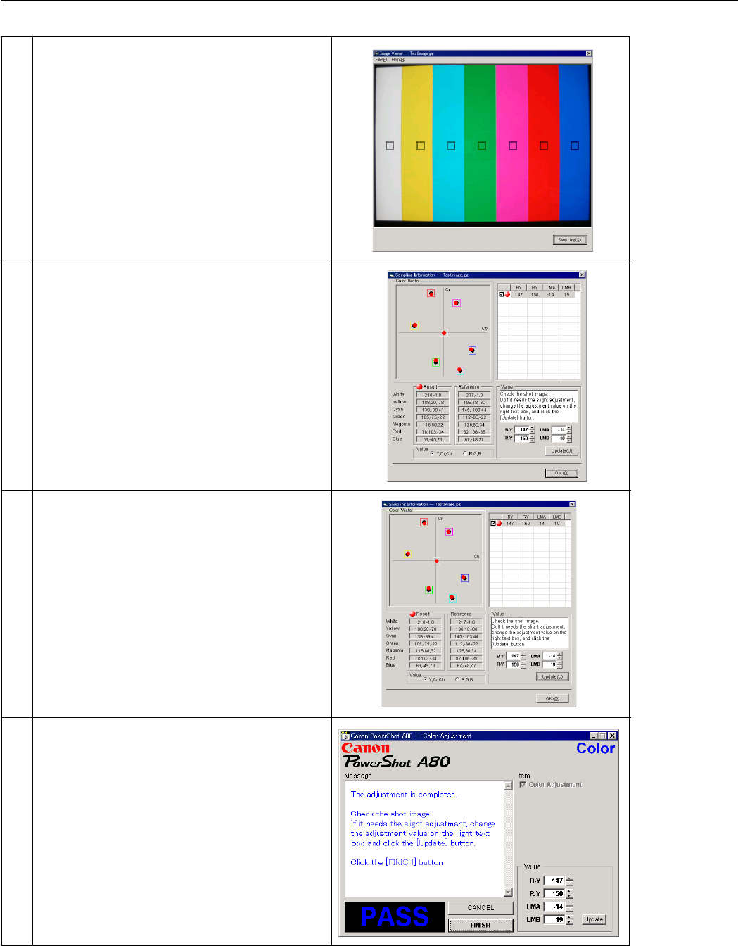
47
REPAIR INSTRUCTION
5 Check “Yellow and Red”, and click the “OK”
button.
If these data are within specifications, go to 7.
* Specification
Ave_Cr = Reference Camera ± 10
Ave_Cb = Reference Camera ± 10
6 1. Confirm to see that the image on the PC moni-
tor satisfies the specifications.
2. If the image on the PC monitor does not satisfy
the specifications, change the data using UP,
DOWN button or change the data directly by
typing the data in the text box. Then click the
“UPDATE” button.
4 1.Shift a frame on the displayed screen with
a mouse to choose a color of color bar.
2. Click the “Sampling” button.
7 When the adjustment is completed, click the
“FINISH” button.
(This ends the “Color” Adjustment.)
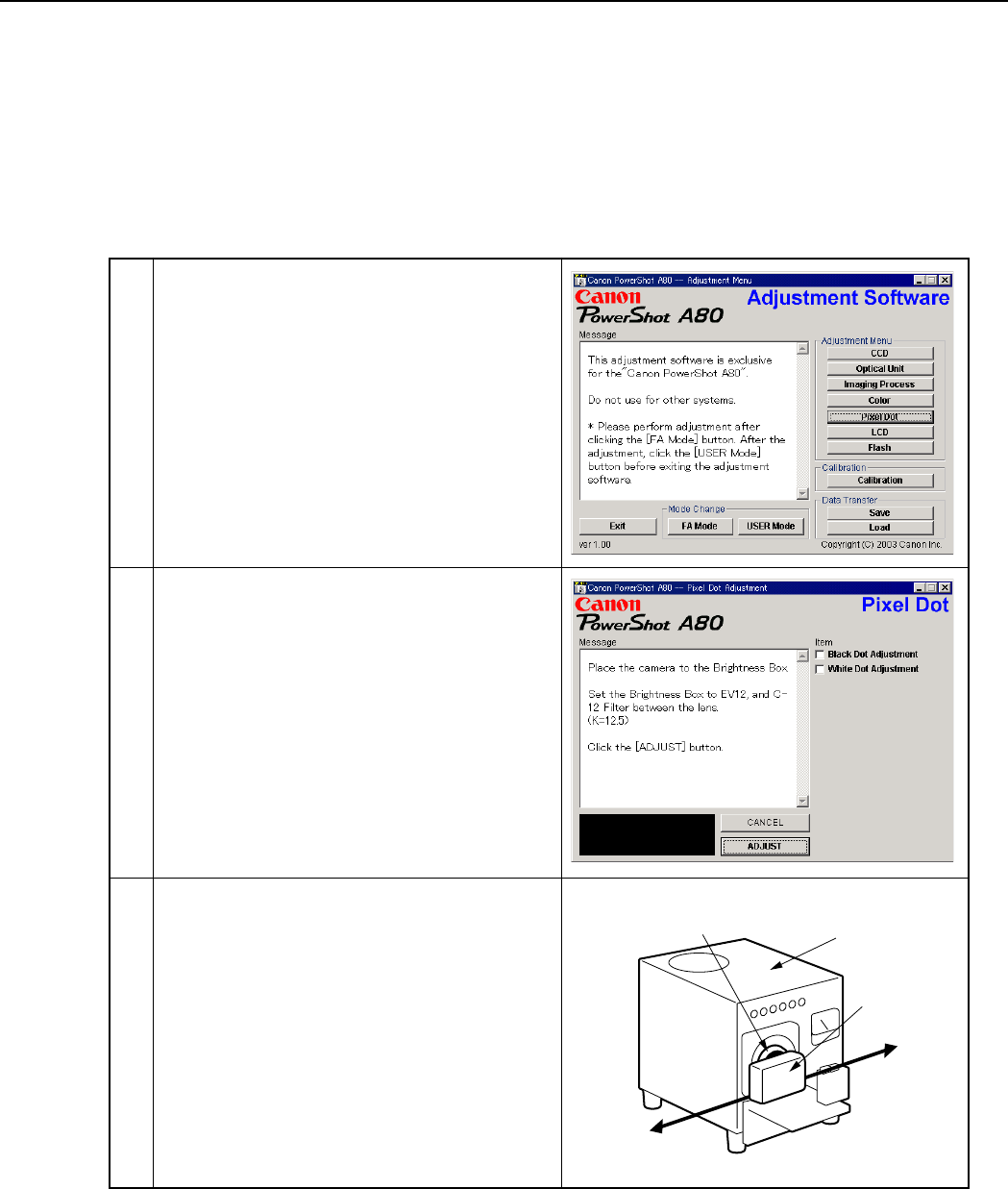
48
REPAIR INSTRUCTION
3.5.5 Pixel Dot Adjustment
■Tools Used
• Personal Computer • INTERFACE CABLE IFC-300PCU
•
SERVICE MANUAL (CD-ROM)
• Brightness Box (Light source A)
•
ADJUSTMENT SOFTWARE
• C-12 Filter
• Compact Power Adapter CA-PS500 •
Light-Shielding Cloth (500 × 500 mm or larger)
• AC Cable • DIGITAL CAMERA Solution Disk
1 Click the “Pixel Dot” button.
Personal
Computer
Power
Source
Brightness
Box
CAMERA
BODY
C-12 Filter
2 When the message on the right appears, go to 3.
3 1. Place the camera so that lens is set against the
light source surface of the Brightness Box via
the C-12 Filter.
2. Set the Brightness Box to EV12.
3. Click the “ADJUST” button.
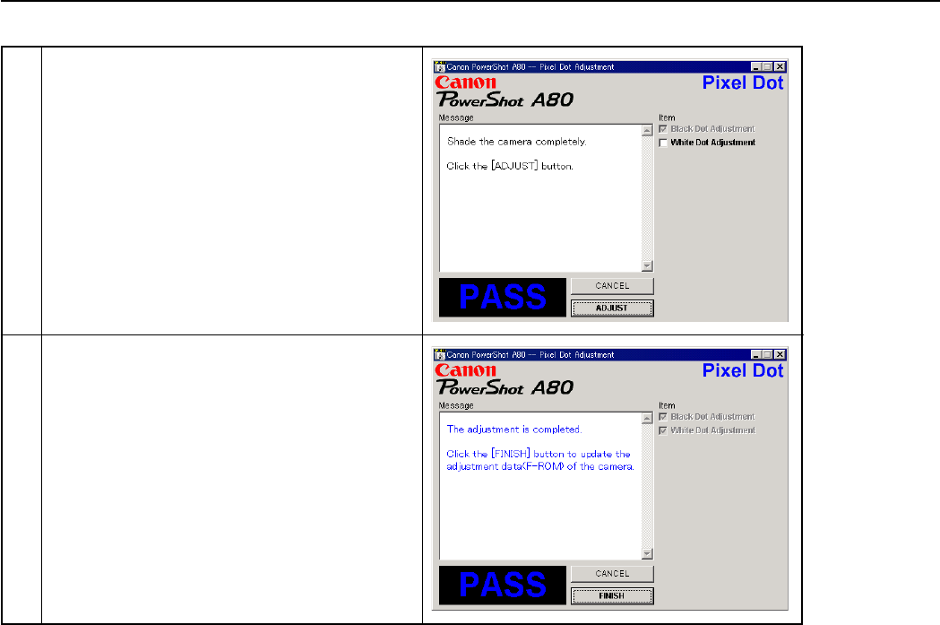
49
REPAIR INSTRUCTION
4 1. When the message on the right appears, cover
the camera with the Light-Shielding Cloth so
that the no light reasons the CCD.
2. Click the “ADJUST” button.
5 When the message on the right appears, click the
“FINISH” button.
(This ends the “Pixel Dot” Adjustment.)

50
REPAIR INSTRUCTION
1 Click the “LCD” button.
2 1. When the message on the right appears, enter
in the text boxes the data written on the data-
sheet attached on the PCB ASS’Y inside the
LCD UNIT. Click the “Update” button.
2. Compare the image with that of the reference
camera. If it has a different color tint. adjust it
by repeating clicking the Yellow/Blue button
and the “Update” button alternately.
3. Click the “FINISH” button. (This ends the
“LCD” Adjustment.)
3.5.6 LCD Adjustment
■Tools Used
• Personal Computer • AC Cable
•
SERVICE MANUAL (CD-ROM)
• INTERFACE CABLE IFC-300PCU
•
ADJUSTMENT SOFTWARE
• Reference Camera (Merchandise)
• Compact Power Adapter CA-PS500 • DIGITAL CAMERA SolutionDisk
■Preparation
1. Insert the blank CF Card into the reference camera.
2. Connect the reference camera with the PC.
3. Add the “Gray.jpeg” image to the CF card of the refernce camera using Zoom Browser EX. (Gray.jpg is in
the folder of Adjustment Software downloaded.)
4. Finish the ZoomBrowser EX.
5. Disconnect the reference camera from the PC, and display the “Gray.jpg” image in PLAY mode.
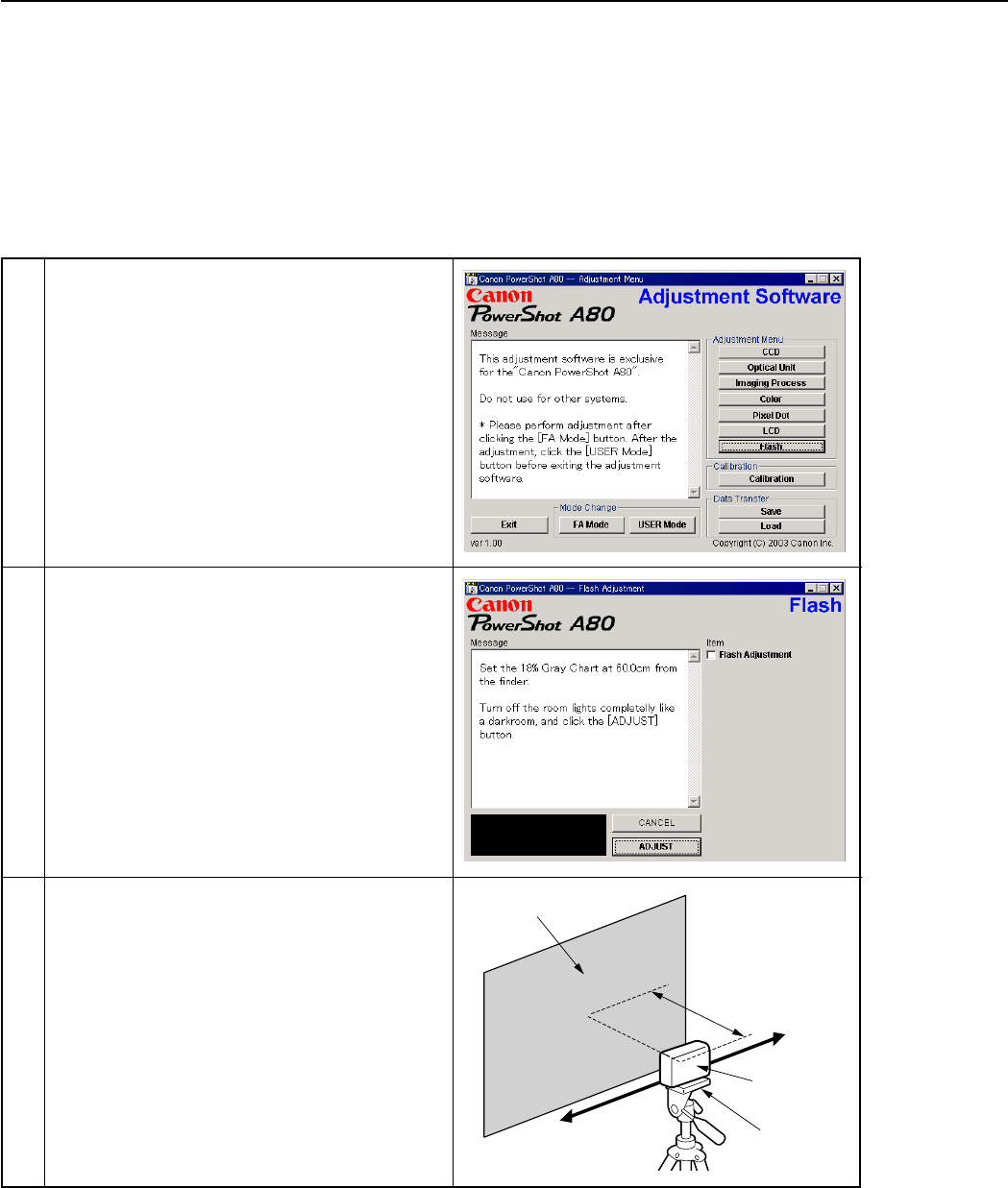
51
REPAIR INSTRUCTION
3.5.7 Flash Adjustment
■Tools Used
• Personal Computer • INTERFACE CABLE IFC-300PCU
•
SERVICE MANUAL (CD-ROM)
• 18% Gray Chart
•
ADJUSTMENT SOFTWARE
• Tripod
• Compact Power Adapter CA-PS500 • DIGITAL CAMERA Solution Disk
• AC Cable
1 Click the “Flash” button.
2 When the message on the right appears, go to 3.
3 1. Set 18% Gray Chart 60.0cm from the Finder
front.
2. Make the room as dark as a darkroom.
3. Click the “ADJUST” button.
Personal
Computer
Power
Source
18% Gray Chart
60.0cm
CAMERA
BODY
Tripod

52
REPAIR INSTRUCTION
4 When the message on the right appears, click the
“FINISH” button.
(This ends the “Flash” Adjustment.)

53
REPAIR INSTRUCTION
3.5.8 Checking of sound recording/output
It is not required to adjust the recording/output (volume, etc.) of sound.
Check the camera if the sound is recorded/play-backed properly.

c CANON INC., 2003
PARTS CATALOG
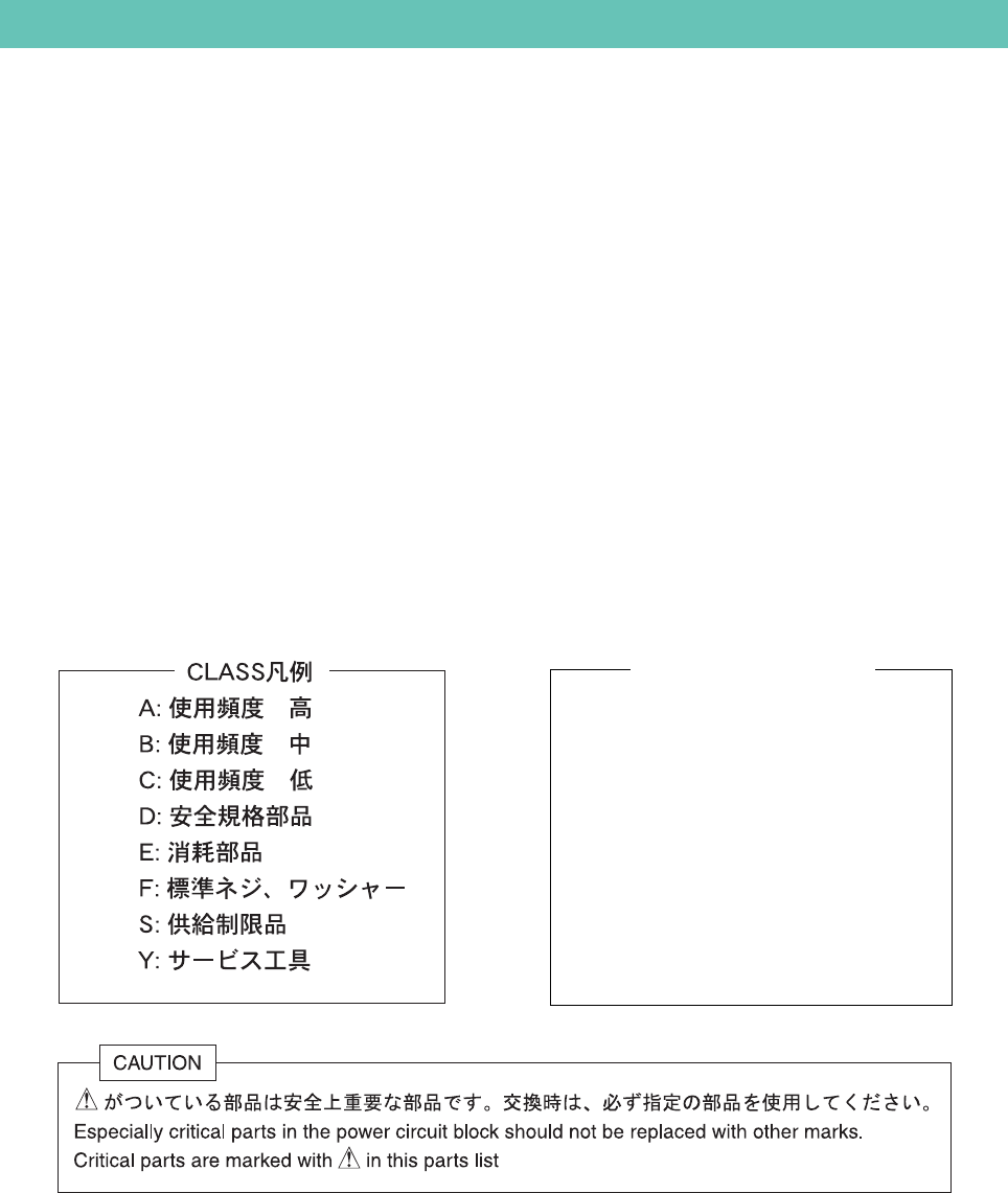
CONTENTS
PowerShot A80
Casing Parts ----------------------------------------------------------------------------------------------------------------------- Pg1
Internal Parts-1 ------------------------------------------------------------------------------------------------------------------- Pg2
Internal Parts-2 ------------------------------------------------------------------------------------------------------------------- Pg3
Optical Unit ----------------------------------------------------------------------------------------------------------------------- Pg4
Fuse -------------------------------------------------------------------------------------------------------------------------------- Pg5
Accessories-1 ------------------------------------------------------------------------------------------------------------------------- Pg6
Accessories-2 ------------------------------------------------------------------------------------------------------------------------- Pg7
Service Tools-1 ----------------------------------------------------------------------------------------------------------------------- Pg8
Service Tools-2 ----------------------------------------------------------------------------------------------------------------------- Pg9
Category of CLASS
A: Frequency of use: High
B: Frequency of use: Middle
C: Frequency of use: Low
D: Safety-related critical parts
E: Consumable parts
F: Standard screws and washers
S: Supply of the parts is limited
Y: Service Tools
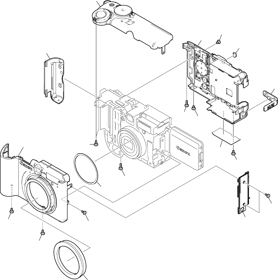
PowerShot A80
Pg1 Casing Parts
11
14
15
1
9
10
2
12
13
16
17
18
12
14
3
4
6
5
8
7

PARTS LIST
SYMBOL PARTS NO. CLASS QTY DESCRIPTION REMARKS
PowerShot A80
Pg1
1 CM1-2215-000 B 1 FRONT COVER UNIT
2 CD3-1424-000 B 1 COVER, CF
3 CM1-2217-000 B 1 TOP COVER UNIT
4 CM1-2216-000 B 1 REAR COVER UNIT
5 CD3-1425-000 B 1 COVER, HOLE
6 CD3-1304-000 B 1 COVER, JACK
7 CY1-6297-000 B 1 PLATE, BODY NUMBER (J) #13111xxxxx
CY1-6298-000 B 1 PLATE, BODY NUMBER (N) #13211xxxxx
CY1-6299-000 B 1 PLATE, BODY NUMBER (E) #13311xxxxx
CY1-6310-000 B 1 PLATE, BODY NUMBER (J), CHINA #13161xxxxx
CY1-6311-000 B 1 PLATE, BODY NUMBER (N), CHINA #13261xxxxx
CY1-6312-000 B 1 PLATE, BODY NUMBER (E), CHINA #13361xxxxx
8 CD3-1423-000 B 1 COVER, SIDE
9 CD3-1204-000 C 1 SHEET, LENS BARREL
10 CM1-2299-000 B 1 BAYONET CUP UNIT
11 XA1-7170-257 F 1 SCREW
12 CD3-1441-000 B 2 SCREW
13 XA4-9170-357 F 1 SCREW
14 XA4-9170-707 F 2 SCREW
15 XA4-9170-407 F 2 SCREW
16 CD3-1444-000 B 1 SCREW
17 CD3-1445-000 B 1 SCREW
18 CD3-1440-000 B 2 SCREW
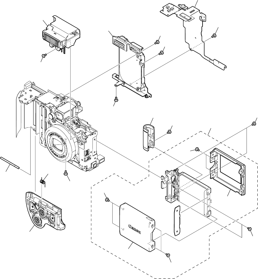
PowerShot A80
Pg2 Internal Parts-1
11
16
1
2
3
4
5
6
7
8
17
9
11
18
12
11
14
15
15
16
13
10

PARTS LIST
SYMBOL PARTS NO. CLASS QTY DESCRIPTION REMARKS
PowerShot A80
Pg2
1 CM1-2218-000 B 1 BATTERY COVER UNIT
2 CD3-1347-000 C 1 SPRING, BATTERY COVER
3 CD3-1348-000 C 1 SHAFT, BATTERY COVER
4 CM1-2214-000 B 1 FLASH UNIT
5 CM1-2220-000 C 1 CF UNIT
6 CM1-2201-000 C 1 OPERATION MODULE UNIT
7 CD3-1399-000 B 1 COVER, HINGE
8 CM1-2222-000 B 1 LCD UNIT
CM1-2222-001 B 1 LCD UNIT (SELECTION)
9 CD3-1380-000 B 1 COVER, LCD FRONT
10 CD3-1381-000 B 1 COVER, LCD REAR
11 XA1-7170-357 F 3 SCREW
12 XA4-9170-357 F 1 SCREW
13 XA1-7170-257 F 1 SCREW
14 CD3-1443-000 B 1 SCREW
15 CD3-1400-000 C 4 SCREW
16 CD3-1442-000 B 4 SCREW
17 CD3-1446-000 C 2 SCREW
18 CD3-1447-000 C 1 SCREW


PARTS LIST
SYMBOL PARTS NO. CLASS QTY DESCRIPTION REMARKS
PowerShot A80
Pg3
1 CD3-1430-000 C 1 TAPE, SUB FRAME
2 CD3-1422-000 C 1 FRAME, SUB
3 CM1-2298-000 C 1 MAIN FRAME UNIT
4 CD3-1377-000 C 1 BUSH, MICROPHONE
5 CM1-2213-000 C 1 MICROPHONE UNIT
6 CM1-2120-000 C 1 FINDER UNIT
7 CM1-2228-000 C 1 SHIELD UNIT, MAIN A
8 CM1-2194-000 C 1 PCB ASS’Y, MAIN
9 CM1-2229-000 C 1 SHIELD UNIT, MAIN B
10 CK2-2081-000 C 1 FPC, MAIN-FLASH
11 WK1-5140-000 C 1 BATTERY, LITHIUM (2ND)
12 CM1-2204-000 C 1 MAIN-LCD MODULE UNIT
13 CM1-2219-000 C 1 BATTERY BOX UNIT
14 CK1-1062-000 C 1 FPC, MAIN-DC
15 CM1-2196-000 C 1 DC/JACK UNIT
16 XA4-9170-357 F 2 SCREW
17 XA1-7170-257 F 8 SCREW
18 XA4-9140-407 F 2 SCREW
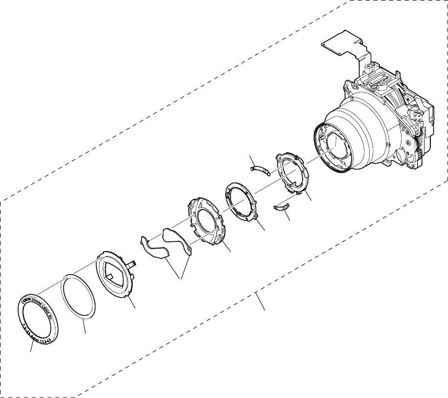
PowerShot A80
Pg4 Optical Unit
1
2
3
4
5
67
9
8
10

PARTS LIST
SYMBOL PARTS NO. CLASS QTY DESCRIPTION REMARKS
PowerShot A80
Pg4
1 CD3-1198-000 B 1 CAP, FRONT
2 CD3-1214-000 C 1 TAPE, FRONT CAP SIZE(015)
3 CD3-1180-000 B 1 COVER, BARRIER
4 CD3-1179-000 B 2 PLATE, BARRIER
5 CD3-1178-000 C 1 BASE, BARRIER
6 CD3-1177-000 C 1 PLATE, BARRIER DRIVE
7 CD3-1206-000 C 1 SPRING, BARRIER CLOSE
8 CD3-1205-000 C 1 SPRING, BARRIER OPEN
9 CD3-1176-000 C 1 RING, BARRIER DRIVE
10 CM1-2119-000 C 1 OPTICAL UNIT
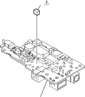
PowerShot A80
Fuse
Pg5
1
DC/JACK UNIT

PARTS LIST
SYMBOL PARTS NO. CLASS QTY DESCRIPTION REMARKS
PowerShot A80
1 CY4-6076-000 D 1 FUSE, MATSU.DENKI UNHS205
Pg5
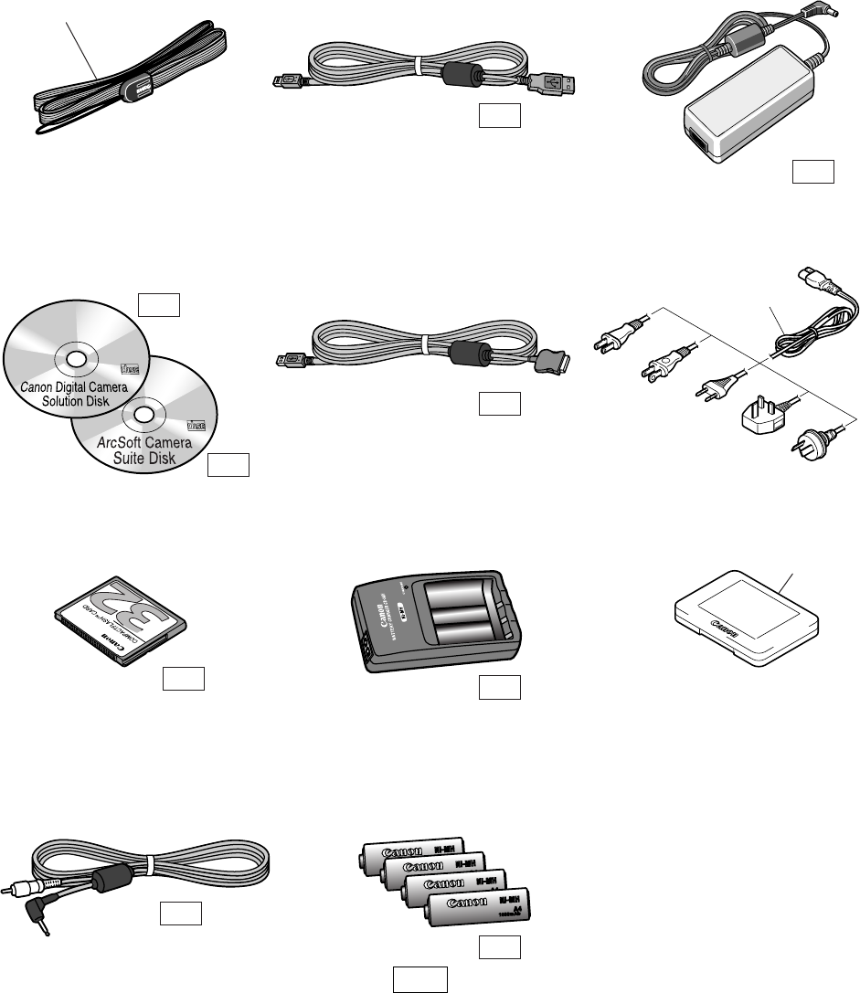
PowerShot A80
Accessories-1
Pg6
Wrist Strap WS-200
Battery Charger
CB-3AH
NiMH Battery NB4-100
USB Interface Cable
IFC-300PCU
AC Cable
Compact Power Adapter
CA-PS500
Direct Interface Cable
DIF-100
Video Cable AVC-100
N.S
N.S
N.S
N.S
N.S
1
N.S
FC-32M
N.S
CF CASE
3
CF Card FC-32M
2
PLUG TYPE
N
J
E
B
A
Canon Digital Camera
Solution Disk,
ArcSoft Camera Suite Disk
N.S
N.S
N.Sl : N.S Stand for No Stock (Product available)

PARTS LIST
SYMBOL PARTS NO. CLASS QTY DESCRIPTION REMARKS
PowerShot A80
Pg6
1 C84-1060-000 B 1 WRIST STRAP WS-200
2 D82-0641-000 C 1 AC CABLE (J) FOR JAPAN
WT3-5063-000 C 1 AC CABLE (N) FOR USA/CANADA
D82-0643-000 C 1 AC CABLE (E) FOR EUROPE/ASIA
D82-0644-000 C 1 AC CABLE (B) FOR ASIA
D82-0645-000 C 1 AC CABLE (A) FOR AUSTRALIA
3 FC2-9610-000 B 1 CASE, CF
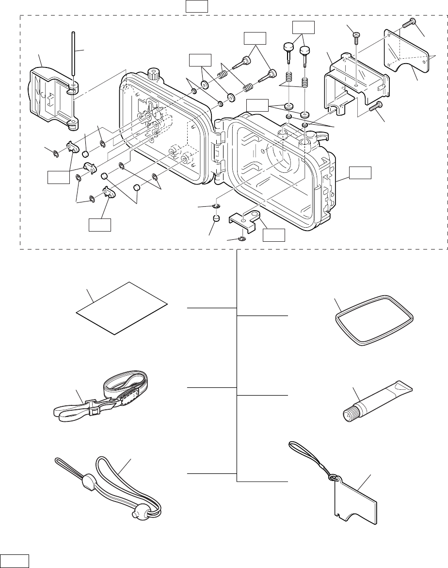
PowerShot A80
Pg7
N.Sl : N.S Stand for No Stock (Product available)
Accessories-2
Waterproof Case WP-DC900 N.S
N.S
N.S
N.S
N.S
N.S
N.S
Waterproof Seal
Silicone Grease
Diffusion Plate Unit
4
4
4
3
3
3
3
3
3
5
16
6
27
10
9
8
10
5
12
13
16
14
15
11
Sheet
Neck Strap
Wrist Strap
N.S
N.S

PARTS LIST
SYMBOL PARTS NO. CLASS QTY DESCRIPTION REMARKS
PowerShot A80
Pg7
1 CY1-6171-000 C 1 BUCKLE ASS’Y
2 CY1-6203-000 C 1 SHAFT, BUCKLE
3 CY1-6168-000 C 10 E RING
4 CY1-6169-000 C 5 CAP, BUTTON
5 CY1-6252-000 C 10 O RING
6 CY1-6167-000 C 10 SPRING, COIL
7 CY1-6303-000 C 1 HOLDER, DEFUSION PLATE
8 CY1-6304-000 C 1 PROTECTOR, DEFUSION PLATE
9 CY6-3210-000 C 3 SCREW
10 CY6-3211-000 C 2 SCREW
11 CY1-6300-000 C 1 SHEET FOR JAPAN
12 CY1-6099-000 B 1 STRAP, NECK
13 CY1-6174-000 B 1 STRAP, WRIST
14 CY1-6272-000 B 1 PACKING, RUBBER
15 DY9-3029-000 C 1 GREASE PACKING
16 CY1-6302-000 B 1 DIFFUSION PLATE UNIT
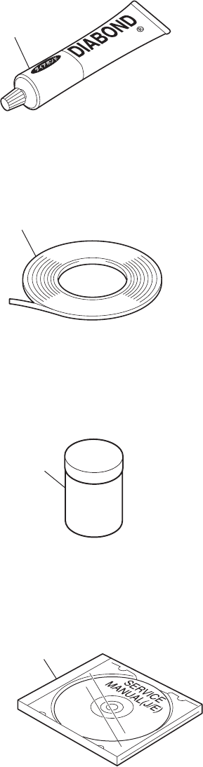
PowerShot A80
Pg8
Adhesive Tape SONY T4000
1
2
DIA Bond NO.1663G Black
Logenest Rambda A-74
3
Service Manual CD-ROM
4
Service Tools-1

PARTS LIST
SYMBOL PARTS NO. CLASS QTY DESCRIPTION REMARKS
PowerShot A80
Pg8
1 CY9-8129-000 Y 1 BOND, DIA BOND NO.1663G BLACK
2 CY4-6012-000 Y 1 ADHESIVE TAPE, SONY T4000 6mm × 50m roll
3 CY9-8102-000 Y 1 LUBE, LOGENEST RAMBDA A-74 80g
4 CY8-4388-031 Y 1 CD-ROM, SERVICE MANUAL (J/E)
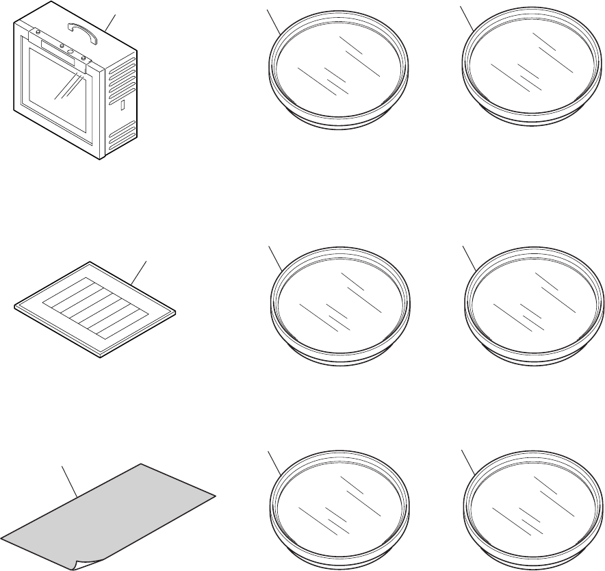
PowerShot A80
Pg9
Service Tools-2
W-10 Filter
18% Gray Chart
C-12 Filter
4
ND-2 Filter
7
5
FL-W Filter
Color Viewer (5600° K)
Standard Color Bar Chart
6
2
1
ND-4 Filter
8
ND-8 Filter
9
3

PARTS LIST
SYMBOL PARTS NO. CLASS QTY DESCRIPTION REMARKS
PowerShot A80
Pg9
1 DY9-2039-100 Y 1 COLOR VIEWER 5600K
2 DY9-2002-000 Y 1 COLOR BAR CHART
3 CY4-6016-000 Y 1 CHART, 18% GRAY
4 CY9-1555-000 Y 1 FILTER, C-12
5 CY9-1556-000 Y 2 FILTER, W-10
6 CY9-1557-000 Y 1 FILTER, FL-W
7 CY9-1552-000 Y 1 FILTER, ND-2
8 CY9-1553-000 Y 1 FILTER, ND-4
9 CY9-1554-000 Y 1 FILTER, ND-8

DIAGRAMS
Trademarks
The product names and company names described in this CD-ROM are the registered
trademarks of the individual companies.
Copyright
Canon Inc. retains the copyright to all data contained on this CD-ROM.
Reproduction, publication (including on the World Wide Web) alteration, translation into
another language, or other use of the data in whole or part, contained on this CD-ROM
without the written consent of Canon Inc., is prohibited.

CONTENTS
1. INTERCONNECTION DIAGRAM
2. BLOCK DIAGRAMS
2-1. OVERALL
2-2. MAIN PCB ASS’Y (1/3)
2-3. MAIN PCB ASS’Y (2/3)
2-4. MAIN PCB ASS’Y (3/3)
2-5. POWER BLOCK
2-6. Abbreviation in Block Diagrams
3. P.C.B. DIAGRAMS
3-1. MAIN PCB ASS’Y
3-2. DCJ PCB ASS’Y
3-3. ST PCB ASS’Y
3-4. LCD PCB ASS’Y
3-5. SW PCB ASS’Y
3-6. OSW PCB ASS’Y
3-7. CF FPC
3-8. TOP FPC
3-9. ML FPC
3-10. OPR FPC
3-11. SH FPC
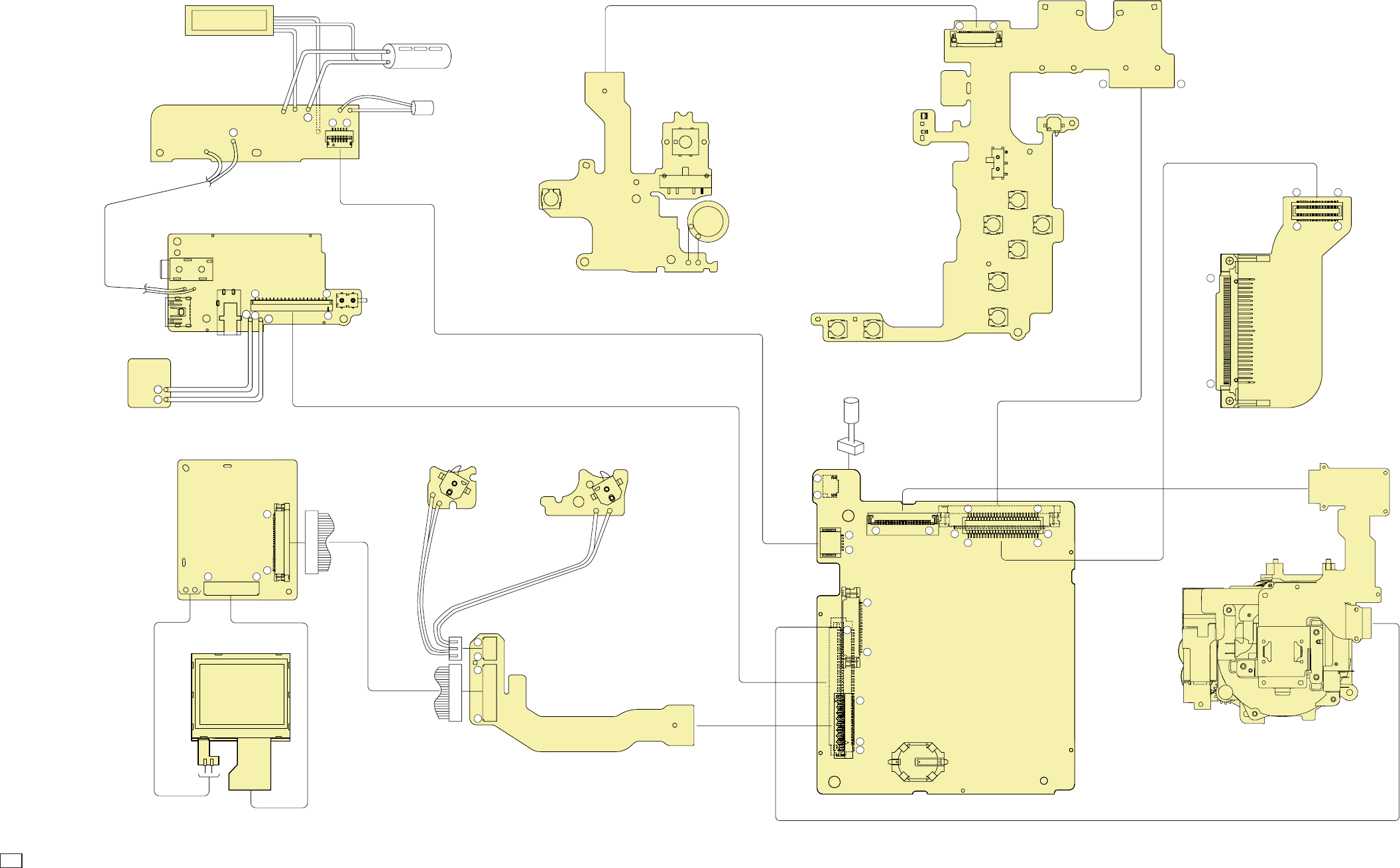
C CANON INC., 2003
01 OCT, 2003
1. INTERCONNECTION DIAGRAM
LCD PANEL
LCD PCB ASS'Y
DCJ PCB ASS'Y
LCD UNIT
DC/JACK UNIT
FLASH UNIT
ST PCB ASS'Y
OPTICAL UNIT
MAIN PCB ASS'Y
ML FPC UNIT
SW PCB OSW PCB
CF UNIT
OPERATION MODULE UNIT
FO FPC
CF FPC
CN601
CN602
CN1003
CN1005
CN701
CN1002
CN1301
CN1004
CN1006
CN1CN2
CN1501
BT1001
(LITHIUM BATTERY)
CN1901
OPR FPC
TOP FPC SPEAKER
SW403
SW402
SW401
CN202
RED
BLK
FINDER
LED
CN401
LED403
LED402 SW411
SW408
SW410
SW402
SW403
SW405SW404
SW409 SW407
SW412
MICROPHONE
Board to Board
Harness
FPC MAIN-DC
FPC MAIN-FLASH
CN1502
CN102 SW100
BATTERY Open
Detect SW
BATTERY
BOX
UNIT BLK
CN101
CN100
CN103
DC IN
USB
RED
BLK RED
BLK
AUDIO/VIDEO
XENON TUBE
BLK
BLU
WHT GRY
BRN
GRN
YEL
AF SUPPORT LED
SELF LED
RED EYE LED
ELECTLIC
CAPACITOR
RED
SW1
BASE POSITION
Detect SW
SW1
PANEL POSITION
Detect SW
CF Card
Open Detect
SW
CCD FPC
OPTICAL UNIT
TOP COVER UNIT
61
2140
20 1
+
+
+
-
-
+
14
1
128
4
1
14
1
118
1
50
1
32
1
1
2
1
1
40
1
18
18
6
B25 B1
A25
1
133 32
A1
B25 B1
A25 A1
CCD FPC
FO FPC

C CANON INC., 2003
01 OCT, 2003
CONNECTORS
CN1901
1 ZMRST_CO
2 RST_COM
3 ZMRST_AN
4 AFRST_AN
5 ZM+
6 ZM+
7 ZM+
8 ZM+
9 ZM-
10 ZM-
11 ZM-
12 ZM-
13 AFRST_CO
14 ZMPO_COM
15 ZMPO1_AN
16 ZMPO0_AN
17 ZMPO1_CO
18 ZMPO0_CO
19 C_GND
20 C_GND
21 AFB+
22 AFA+
23 AFB-
24 AFA-
25 THM+
26 IRB+
27 IRB-
28 IRA-
29 IRA+
30 SHT+
31 SHT+
32 SHT-
33 SHT-
CN401
1 WEAK_AN
2 LED_WEAK
3 SP+
4 SP-
5 POWER
6 VBATT_R
7 M_GND
8 M_GND
9 M_GND
10 DIAL3
11 DIAL0
12 DIAL1
13 DIAL2
14 SCAN
15 SW2
16 SW1
17 TELE
18 WIDE
OPR FPC
ML FPC
CN1
1 BASE_POS
2 SCAN
3 SCAN
4 ROTATE_SW
CN2
1 LTG_CS
2 LDR_CS
3 SDATA3
4 SCLK3
5 GND
6 LED_BLC
7 LCD_BY/COMP
8 LCD_RY
9 GND
10 LCD_YS
11 GND
12 CSYNC
13 VDD3
14 VCC1A_3
CN1501
1 HDB
2 PSAVE
3 DSAVE
4 CKI
5 FRP
6 POCB
7 Not connected
8PD
9 XVD
10 CS
11 CLK
12 DI
13 HDI
14 VDD
15 VGH
16 VDC
17 VSS
18 C1
19 C2
20 VGL
21 VSS
22 VDD
23 VSH
24 R
25 B
26 G
27 VBC
28 VCOM
CN1502
1 LTG_CS
2 LDR_CS
3 SDATA3
4 SCLK3
5 GND
6 LED_BLC
7 LCD_BY/COMP
8 LCD_RY
9 GND
10 LCD_YS
11 GND
12 CSYNC
13 VDD3
14 VCC1A_3
LCD PCB CF FPC UNIT
CN601
A1 C_GND
A2 /CD1
A3 D03
A4 D11
A5 D04
A6 D12
A7 D05
A8 D13
A9 D06
A10 D14
A11 D07
A12 D15
A13 /REG
A14 A00
A15 Not connected
A16 D00
A17 Not connected
A18 D01
A19 D08
A20 D02
A21 D09
A22 /IOIS16
A23 D10
A24 /CD2
A25 C_GND
B1 /CE1
B2 /CE2
B3 A10
B4 Not connected
B5 /OE
B6 /IORD
B7 A09
B8 /IOWR
B9 A08
B10 /WE
B11 A07
B12 IREQ
B13 VCC1
B14 VCC1
B15 A06
B16 Not connected
B17 A05
B18 Not connected
B19 A04
B20 RESET
B21 A03
B22 /WAIT
B23 A02
B24 Not connected
B25 A01
CN602
1 GND
2 D03
3 D04
4 D05
5 D06
6 D07
7 /CE1
8 A10
9 /OE
10 A09
11 A08
12 A07
13 VCC
14 A06
15 A05
16 A04
17 A03
18 A02
19 A01
20 A00
21 D00
22 D01
23 D02
24 /IOIS16
25 /CD2
26 /CD1
27 D11
28 D12
29 D13
30 D14
31 D15
32 /CE2
33 /VS1
34 /IORD
35 /IOWR
36 /WE
37 IREQ
38 VCC
39 /CSEL
40 /VS2
41 RESET
42 /WAIT
43 /INPACK
44 /REG
45 /SPKR
46 /STSCHG
47 D08
48 D09
49 D10
50 GND
CN1004
1 VBUS
2D+
3 C_GND
4D-
5 C_GND
6 C_GND
7 VIDEO
8 AUDIO
9 C_GND
10 C_GND
11 VC_DET
12 C_GND
13 C_GND
14 VEE2
15 VBATT
16 VCC2AFE
17 VBATT
18 VCC2AFE
19 VBATT
20 VCC2HDR
21 E1PLAT
22 VCC1M
23 VCC1M
24 VCC1M
25 VCC1L
26 VCC1L
27 VCC1A
28 VCC1A
29 VDD2
30 VCC1
31 VCC1
32 VCC1
33 C_GND
34 VDD3
35 E3LAT
36 E2LAT
37 BTOP
38 M_GND
39 M_GND
40 M_GND
CN1005
A1 C_GND
A2 /CD1
A3 D03
A4 D11
A5 D04
A6 D12
A7 D05
A8 D13
A9 D06
A10 D14
A11 D07
A12 D15
A13 /REG
A14 A00
A15 Not connected
A16 D00
A17 Not connected
A18 D01
A19 D08
A20 D02
A21 D09
A22 /IOIS16
A23 D10
A24 /CD2
A25 C_GND
B1 /CE1
B2 /CE2
B3 A10
B4 Not connected
B5 /OE
B6 /IORD
B7 A09
B8 /IOWR
B9 A08
B10 /WE
B11 A07
B12 IREQ
B13 VCC1
B14 VCC1
B15 A06
B16 Not connected
B17 A05
B18 Not connected
B19 A04
B20 RESET
B21 A03
B22 /WAIT
B23 A02
B24 Not connected
B25 A01
CN1006
1 M_GND
2 BASE_POS
3 SCAN
4 ROTATE_SW
5 LTG_CS
6 LDR_CS
7 SDATA3
8 SCLK3
9 C_GND
10 LED_BLC
11 LCD_BY/COMP
12 LCD_RY
13 C_GND
14 LCD_YS
15 C_GND
16 CSYNC
17 VDD3
18 VCC1A_3
CN1301
1 C_GND
2V4
3 V3A
4 V3B
5V2
6 V1A
7 V1B
8VL
9 CSUB
10 SUB
11 C_GND
12 H1
13 H2
14 RG
15 VDD
16 C_GND
17 C_GND
18 VOUT
CN1701
1 MIC
2 MIC_GND
DCJ PCB UNIT
CN100
1 BATT+
2 GND
3 BATT-
CN101
1 VBUS
2D-
3D+
4 Not connected
5 UV_GND
CN102
1 GND
2 GND
3 GND
4 BTOP
5 E2LAT
6 E3LAT
7 VDD3
8 GND
9 VCC1
10 VCC1
11 VCC1
12 VDD2
13 VCC1A
14 VCC1A
15 VCC1L
16 VCC1L
17 VCC1M
18 VCC1M
19 VCC1M
20 E1PLAT
21 VCC2HDR
22 VBATT
23 VCC2AFE
24 VBATT
25 VCC2AFE
26 VBATT
27 VEE2
28 GND
29 GND
30 VC_DET
31 GND
32 Audio_GND
33 Audio
34 Video
35 Vi deo_GND
36 UV_GND
37 D-
38 UV_GND
39 D+
40 VBUS
CN103
1 GND
2 AUDIO
3 VIDEO
4 VC_DET
ST PCB UNIT
CN202
1 UV_GND
2 STSP
3 VCHGLVL
4 EFCHG
5 LEDS_AN
6 LED_SELF
MAIN PCB
CN1002
1 M_GND
2 STSP
3 VCHGLVL
4 EFCHG
5 AFLEDAN
6 AFLEDC
CN1003
1 M_GND
2 CFOP
3 M_GND
4 MODE
5 POWER
6 VBATT_R
7 DIAL0
8 DIAL1
9 DIAL2
10 DIAL3
11 MENU
12 SET
13 DISP
14 EXP/WB/
ERASE
15 LEFT
16 RIGHT
17 UP
18 DOWN
19 VCC1
20 LED_MACRO
21 LED_ORANGE
22 LED_GREEN
23 WIDE
24 TELE
25 SW1
26 SW2
27 SCAN
28 LED_WEAK
29 C_GND
30 VBATTMP
31 SP-
32 SP+
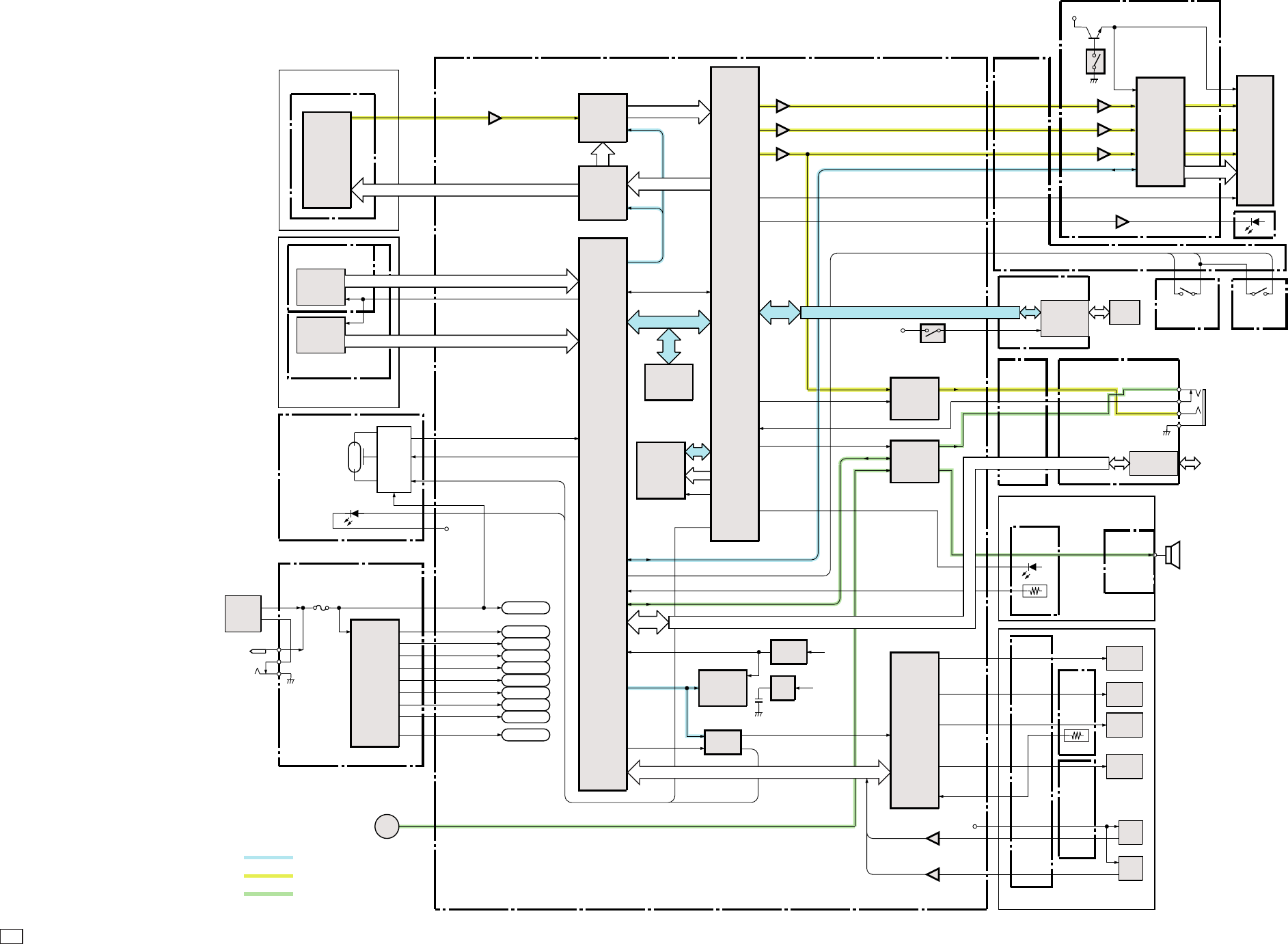
C CANON INC., 2003
01 OCT, 2003
2. BLOCK DIAGRAMS
2.1 OVERALL
OPTICAL UNIT 1/2
TOP COVER UNIT 1/2
TOP FPC 1/2
OPR FPC 1/2
CCD FPC
CCD
SENSOR
DIAL/ZOOM
SWITCH
BATTRY
BOX UNIT
CN100
DC IN
FUNCTION
KEY
DCJ PCB ASS´Y 1/2
IC100
DC/DC
CONVERTER
VCC1
VCC1A
VCC1L
VCC1M
VCC2AFE
VCC2HDR
VDD2
VEE2
V BATT
VDD3
IC1302
CDS, A/D
IC1305
TG
MAIN PCB ASS´Y
IC1001
CPU
EXPORT
EXPORT
SDATA2
SCLK2
SDATA3
SCLK3
SDATA1
SCLK1
IC1005
FLASH
PROM
IC1012
SDRAM
IC1011
DIGITAL
SIGNAL
PROCESSOR
TG MCK,HD,VD
LCD-YS
LCD-RY
LCD-BY/COMP
CSYNC
IC1501
LCD
CONTROL
VDD3
LCD
R
G
B
PANEL
IC1018
75Ω
DRIVER
PS
IC1702
AUDIO/SP
AMP
MJ FPC
BACK
LIGHT
PANEL ROT
SW PCB UNIT
DCJ PCB ASS'Y 2/2
CN103
AUDIO/VIDEO
CN101 USB
IC1007
REAL TIME
CLOCK
3.3V
REG
IC1008
BAT1001
VBATT_ORI
OPR FPC
2/2
TH401
TOP COVER UNIT 2/2
OPTICAL UNIT 2/2
TOP FPC
2/2
EXPORT
IC1002
RESET VCC1
IC1004
D/A
IC1901
MOTOR
DRIVE
MIC
ZOOM
FPC
ZOOM
MOTOR
SH FPC
FO FPC
IRIS
MOTOR
SHUTTER
MOTOR
AF
MOTOR
TH401
AF
PI
ZOOM
PI
VCC1
IC1902
SP +,-
ST PCB UNIT
FLASH
TUBE
AF SUPPORT LED
SELF LED
RED EYE LED
VDD3
HV/OSC/
EX
DRIVE
CF FPC UNIT
LCD PCB ASS'Y
ML FPC
CN602 CF
CARD
VCC1
SPEAKER
DATA COMMUNICATION
ANALOG IMAGE SIGNAL
ANALOG AUDIO SIGNAL
BASE POS1
OSW PCB UNIT
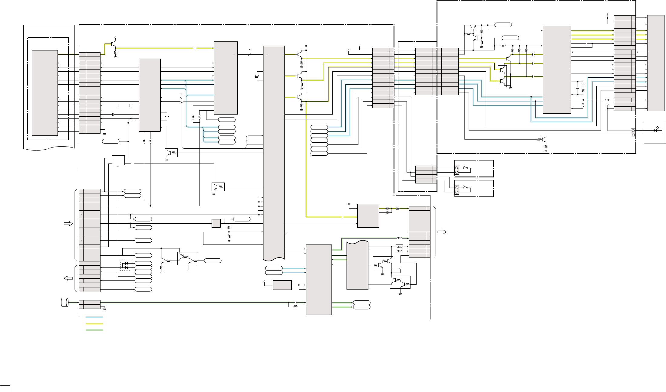
C CANON INC., 2003
01 OCT, 2003
2.2 MAIN PCB ASS’Y (1/3)
OPTICAL UNIT 1/3
CCD FPC
CCD SENSER
V OUT
CN1301
VOUT
18
V1A V1A
6
V1B V1B
7
V2 V2
5
V3A V3A
3
V3B V3B
4
V4 V4
2
H1 17 H1
12
H2 18 H2
13
SUB SUB
10
CSUB CSUB
9
RG RG
14
VL VL
8
VDD VDD
15
GND 1 11
GND C_GND
16 17
MAIN PCB ASS´Y (1/3)
Q1303
VSUB CONT
PDTC144EE
Q1024
VBATT CONT
2SD1664
Q1025
VBATT CONT
XP03311
IC1303
12V/-8V REG
BD3988FV
C1325 C1321
C1333
PBLK 1941 V1A
IC1305
TG
CXD3605R
Q1301
BUFFER
2SC4627J
XSHP 1643 V1B
XSHD 1739 V2
ADCLK 2344 V3A
SSI 3146 V3B
SCK 3240 V4
SEN 33
12 H1
13 H2
RST 2
47 SUB
OSCI 28
9RG
45 VL OSCO 27
42 VH
Q1302
RESET
PDTC144EE
X1301
36MHz
MCKO 30
HD 35
VD 34
TG MCK
TG HD
TG VD
TG CS
SCLK2
SDATA2
14 PBLK
IC1302
CDS,A/D
HD49340NP
AD LD
22 CDS IN
16 SPBLK
PBLK
17 SPSIG
12 ADCLK
34 SDATA
35 SCK
33 CS
15 OBP
AVDD1,2
DVDD1.2,DRDVDD
D0
D9 10
AD D0
AD D9
EX10
VCC2AD
EX9
EX11
EX12
TG CS
SCLK2
AD LD
SDATA2
IC1011 (1/3)
DIGITAL SIGNAL
PROCESSING IC
T8F80XBG-0002
X1002
27MHz
TG MCK
TG HD
TG VD
CLPOB2
TGRST
VSUB CONT
Q1013
BUFFER
2SC4617
VDD
VCC1AL
Q1011
BUFFER
2SC4617
Q1012
BUFFER
2SC4617
R OUT
VCC3
VCC1,4
IC1501
LCD CONTROL
CM7300F2
C1318
EX1
EX0
G/Y
R/R-Y/CR
B/B-Y/CB
36
35
21
22
23
1
5
18
16
14
25
32
30
20
3
4
7
8
6
29
19
EX13
DI
CLK
CS
EX8
EX41
SCAN
EX43
Q1508,1509
REG
2SC4617
Q1501
G/Y BUFFER
2SA1774
Q1502
R/B BUFFER
HN2A01FU-GR
4
6
IC1018
75Ω DRIVER
NJM2576RB1
Q1008
SWITCH
XP03311
Q1009
SWITCH
XP03311
7PS
5V+
VIN
VCC1A 3
5
VCC1A
VCC1A_3
VDD34_12V
VDD3
VSAG
VOUT
IC1703
3V REG
TK11130 CSC
VIN VOUT
3
C1152
C1153
18VCCIA_3
CN1006
G OUT
17VDD3
B OUT
14LCD_YS
COM_OUT
12LCD_RY
DAC_OUT
SYNC_IN
11LCD_BY/COMP
16CSYNC
FRP
10LCD_BLC
CK
7SDATA3
RPD
8SCLK3
P_SAVE
6LDR_CS
D_SAVE
5LTG_CS
4ROTATE_SW
OPOUT
3SCAN
2BASE_POS
OPIN
VDD
CN1501
24R
9XVD
VCC1A_3
26G
25B
28VCOM
1HDB
5FRP
4CKI
8PD
2PSAVE
3DSAVE
11CLK
12DI
13HDI
10CS
23VSH
16VDC
14VCCIA_3
CN2
13VDD3
10LCD_YS
8LCD_RY
7LCD_BY/COMP
12CSYNC
6LCD_BLC
3SDATA3
4SCLK3
2LDR_CS
1LTG_CS
14
3
5
2
4
1
6
VCCIA_3
CN1502
13 VDD3
10 LCD_YS
8 LCD_RY
7 LCD_BY/COMP
12 CSYNC
6 LCD_BLC
3 SDATA3
4 SCLK3
2 LDR_CS
1 LTG_CS
4ROTATE_SW
CN1
3SCAN
2SCAN
1BASE_POS
VOUT
VCC2
LCD
PANEL
P4U 3
VDD2
29
2
4
1
3
6
VEE2
14
VCC2AFE
18
16
.
30
32 VCC1
IC1014
TK1125CSC
2,5V
REG
5
4
3
2
1
4
Q1510
BACK LIGHT DRIVE
2SC4081R
SW1
PANEL
ROTATION
APVD0-2
DPVD
VDD3 0-10
VDDOSCI
VDDOSCO
VDD_SDO 0-5
VDD_SDI
VREF0-2
VDDC0-5
VCC1A
28
27
.
19
.
.
VCC1L
26
25
.
22
24 VCC1M VCC1M
EX40
VDD3
34
VCC2HDR
20
VDD3
CN1004(1/2)
15
17 VBATT VBATT_ORI
POWER
EX35
E1PLAT
21
EX36
E2LAT
36
EX37
EX38
E3LAT
35
EX27
BTOP
37
From
DCJ PCB ASS´Y
TO
DCJ PCB ASS´Y
To
DCJ PCB ASS´Y
MIC
1
GND
2
CN1701
MIC
P2 3
P2 4 13
IC1702
AUDIO/SP AMP
LA7430IFN
4STANDBY_H
EX5
EX4
7CS
9DATA
8
4
CLOCK
21
C1708
22 MIC IN
MIC DCC
VCCD,VCCL
VCC SP
PB_IN 11
LINE OUT 5
2
13
3
2
1
4
4
IC1001 (1/2)
CPU
UPD82518F1-021-EN6-A
AIN2
AOUT
D_P
D_N
EX3
USB_VBUS
SP_IN 2EX2
SP+
SPK_OUT+ 27
SP-
SPK_OUT- 25
VDD2
VDD
VCC1AL
7VIDE0
CN1004 (2/2)
11VC DET
8AUDIO
2D +
4D -
1VBUS
LCD PCB ASS'Y
ML FPC UNIT
VCC1
VCC1A
DATA COMMUNICATION
ANALOG IMAGE SIGNAL
ANALOG AUDIO SIGNAL
P3 5
AOUTP 0
AOUTP 2
AOUTP 1
P4L 2
P3 6
CCD2
CCD11
CCDCLK
SSGOUT0
SSGOUT1
SSGOUT5
P3 [4]
P3 0
REC_OUT
VDD34_12V
VCC1A_3
22
14
.
BACK LIGHT
SW PCB UNIT
SW1
BASE
POSITION
OSW PCB UNIT
C1149
C1506
C1509
C1505
C1507
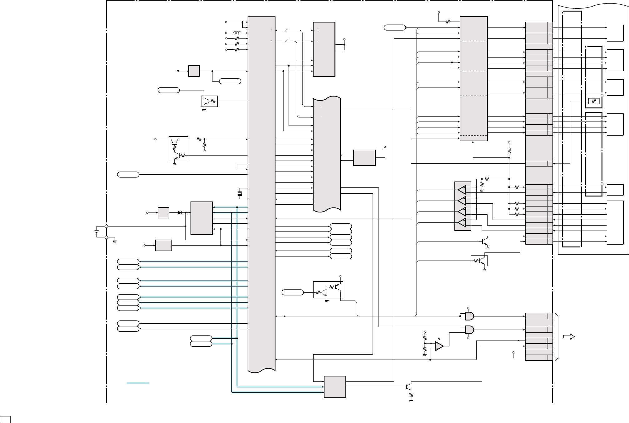
C CANON INC., 2003
01 OCT, 2003
2.3 MAIN PCB ASS’Y (2/3)
OPTICAL UNIT 2/3
To
ST PCB UNIT
MAIN PCB ASS´Y (2/3)
IC1001 (2/2)
CPU
UPD82518F1-021-EN6-A
X1001
24MHz
BAT1001
OSC X1
OSC X2
EX41
OUT5A 274 IN5A
IC1901
M50234FP
DATA
IC1007
REAL TIME CLOCK
RTC-4574NB
ZM -
CN1901
29IRA +
28IRA -
26IRB +
27IRB -
22AFA +
24
AFA -
21
AFB +
23
AFB -
25THM +
4AF RST AN
VDD 1-22
PLL AVDD
AVDD
VCC1
VCC1A
AIN4
VCC2_AD
AIN5
VDD3
AIN7
VCC1_CF
3V
REG
IC1006
TK11130 CSC
5AVREF
EX34
4
VCC1A
Q1003
SWITCH
XPO3311
VCCIA_3
SCAN
2
43
VBATT ADIN 0
EX39
RESET
IC1002
S-80927CNMC-GBX
2RESETB
1
VCC1
3.3V
REG
IC1008
S-817A33ANB
23
VBATT_ORI
EX5
5
VDD CLK
DATA
EX4
6
FOUT 32KIN
10
CE0 EX7
9
CE1 CS2
4
LIVDD
11
IC1005
FLASH PROM
MBM29LV160BE90PBT-E1
/CE
31
DQ0
DQ15
D0
DI5 16
A0
A19
A1
A20 20
CSHEMB
/WE
4
MWRB
/OEMRDB 37
IC1011 (2/3)
DIITAL SIGNAL
PROCESSING IC
T8F80XBG-0002
CPUAD 0
CPUAD 15
CPUADR 0
CPUADR 3
CPURDWR
CPUMEMIO
TDO TDI
TCK TCK
TMS TMS
TRST TRST
CSENGB NCSE
UBEB UBEB
ALE ALE
ECLK BUSCLK
ESDT ESDT
ESREQ ESREQ
EX42 NRESET
INTP1 INTR
WAITB NWAIT
P3 1
P3 7
P4U 1
P4U 2
IC1004
D/A
BH2220FVM
1
LD
AO1
8
EX16-26,28-34
EX39,41-63
AIN6
POWER
EX35
EX36
EX37
EX38
EX35
EX36
EX37
EX38
DI
6
CLK
7
EX8
EX53
AO2
IC1019
SLANT
D68-1-2
OUT1
OUT2
VZMCNT
2
Q1023
LED DRIVE
2SC4617
IRIS DRIVE
ZOOM MOTOR
DRIVE
3IN5B
OUT5B 29
11 IN1
12 EN1
10 EN2
OUT1A 15
OUT1B 17
OUT2A 19
OUT2B 21
SHUTTER DRIVE
EX54 ZM1
EX55 ZM2
EX60 IR1
EX45 IRENA
OUT6A 322 IN6A
AF MOTOR DRIVE
1IN6B
OUT6B 34
EX62 SHCLS
EX44 SHOP
OUT3A 42
OUT3B 40
OUT4A 46
OUT4B 44
7IN3
5IN4
EX56 AF1
EX57 AF2
13 PS
9IN2
EX61 IR2
8EN3
6EN4
EX58 AFENA1
EX59 AFENA2
9
12
5
8
ZM +
SHT -
SHT +
33
32
.
31
30
.
ZOOM
FPC
FO
FPC
SH
FPC
ZOOM
MOTOR
-
+
IRIS
MOTOR
+
+
-
-
SHUTTER
MOTOR
-
+
AF
MOTOR
+
+
-
-
TH101
THERMISTOR
AF PI
16ZM PO0 AN
ZOOM PI
15ZM PO1 AN
3ZM RST AN
13AF RST CO
1ZM RST CO
18ZM PO0 CO
17ZM PO1 CO
14ZM PO COM
2RST COM
VCC1
VCC1M
1
2
IC1902
COMPARATOR
BA10339FV-F
14
13 10
11
8
9
6
7
4
5
MPS
VOPT TEMP
EX46 ZM RST
EX47 AF RST
EX33 ZM PO1
EX32 ZM PO0
Q1901
SWITCH
DTC143ZE
Q1902
BUFFER
2SC4617
EX15 RSTENA
EX14 ENCENA
Q1004
SWITCH
DTC144EE
1
24
1
24
IC1013
AND GATE
74LV1GTO8A
IC1016
74LV1GTO8A
EX63 STSPC
VCC1A 3
VDD2
VCC1
4
1
3
IC1015
COMPARATOR
TC75S51FU
VCC1
2STSP
4EFCHG
3VCHGLVL
6AFLEDC
5AFLEDAN
CN1002
Q1005
LEVEL SHIFT
XPO3311
1
2
4
3
VCC1
EX6
TOUT3
INTP0
INTP2 INTP2
CF IREQ
1
EX10 EX10
SDATA2
EX9 SCLK2 EX9
EX11 EX11
TG CS
EX12 AD LD EX12
EX1 EX1
SDATA3
EX0 SCLK3 EX0
EX13 LDR_CS EX13
EX41 EX41
EX43
EX5
EX4
EX43
AIN3
EX27 EX27
EX40 EX40
EXPORT
AIN1
4
/
P2 6
26 VC5
DATA COMMUNICATION
VCC
VCC1
VCCIA_3
/BYTE
VCC1
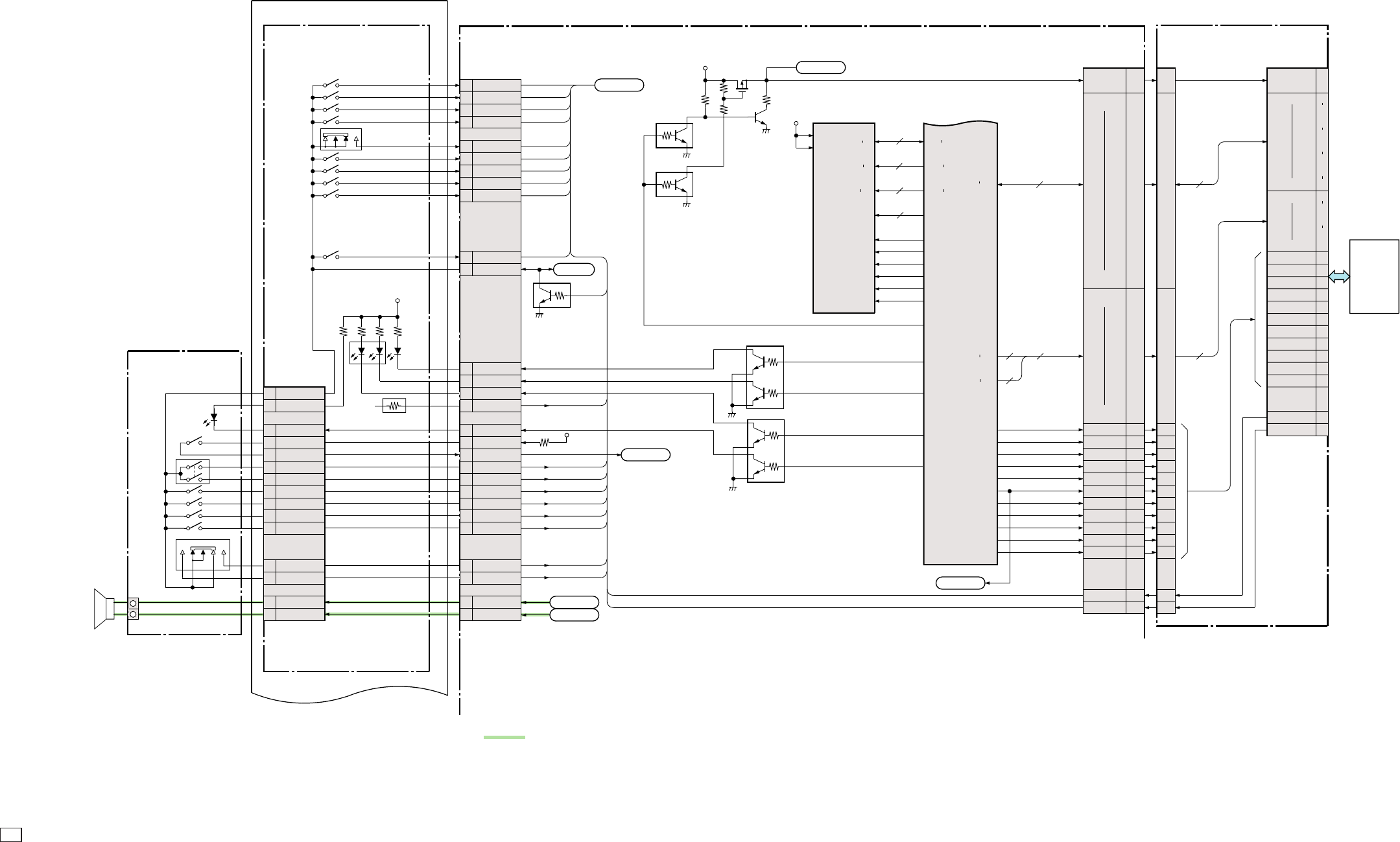
C CANON INC., 2003
01 OCT, 2003
2.4 MAIN PCB ASS’Y (3/3)
EX30
MAIN PCB ASS´Y (3/3)
EXPORT
POWER
SCAN
VCC1_CE
IC1011 (3/3)
DIITAL SIGNAL
PROCESSING IC
T8F80XBG-0002
TOP COVER UNIT 3/3
TOP FPC
OPR FPC
CN1003 (2/2)
DISP
13 EX28
SET
12 EX17
MENU
11 EX16
EXP/WB/ERASE
14 EX29
MODE
4EX52
LEFT
15 EX21
RIGHT
16 EX18
UP
17 EX19
DOWN
18 EX20
CFOP
2EX26
DISP BUTTON
SET BUTTON
MENU BUTTON
EXP/WP/ERASE BUTTON
VBATT_R
6
POWER
5
SW1
25
26 SW2
10
EX25
EX24
DIAL3 EX51
DIAL2
9EX50
DIAL1
8EX49
DIAL0
7EX48
LED_MACRO
20
LED_ORANGE
21
LED_GREEN
22
VBATTP
30 AIN6
LED_WEAK
28
SCAN
27
SW403
SW404
SW405
SW402
SW411
SW409
SW407
SW408
SW410
SW412
EX34
4
2
6
3
5
1
Q1004
SWITCH DRIVE
DTC144EE Q1007
LED DRIVE
XP6213
Q1020
LED DRIVE
XP6213
EX22
EX23
SP+
SP-
Q1017
CF POWER CONT
DTC144EE
Q1016
CF POWER CONT
DTC144EE
4
2
6
3
5
1
4
3
1,2
5,6
VCC1
VCC1
SW401
SW403
SW402
RELEASE
SPEAKER
LED401
CN401
OG LED402
LED403
TH401 THERMISTOR
VBATT
Q1018
CF POWER CONT
2SC4617
Q1015
SWITCHING
UPA650TT-E1
DQ0
DQ31 32
VDD1-4
VCC1
VDDQ1-10
IC1012
16M SDRAM
K4S283233E-DNIH
A0
A11
DQ0
DQ31
DQM0
DQM3
BA0
BA1
12
4
2
/WE
/CAS
/RAS
/CS
CLK
WIDE
23
TELE
24
32 SP+
SP-
31
VBATT_R
6
POWER
5
SW1
16
15 SW2
10 DIAL3
DIAL2
13
DIAL1
12
DIAL0
11
SCAN
14
WEAK_AN
1
LED_WEAK
2
WIDE
18
TELE
17
3SP+
SP-
4
CKE
PCDT 0
PCDT 15
SDWE
SDDT 0
SDDT 31
SDADR 0
SDADR 11
SDBS 0
SDBS 1
SDDQM 0
SDDQM 3
PCDT 0
PCDT 15
SDCAS
SDRAS
SDCS 0
SDCLK
SDCKE
P2 5
P3 3
P3 2
P2 7
P2 2
P1 0
P1 7
NPC RD
PCADR 0
PCADR 2
8
3
16
11
CF D 0-15
CF A 0-10
CN1005
B14
B13
.
VCC1
A18
A16
.
.
A3
A20
.
.
A7
A5
.
.
A11
A9
.
.
A21
A19
.
.
A4
A23
.
.
A8
A6
.
.
A12
A10
.
B25
A14
.
.
B21
B23
.
.
B17
B19
.
.
B11
B15
.
.
B7
B9
.
.
B6
B3
D00
D15
A00
A10
/IORD
NPC WR B8
/IOWR
PCCE1
B1
/CE1
PCCE2 B2
/CE2
PCRDY B22
/WAIT
PCIRQ B12
IREQ
PCIOIS A22
/IOIS16
P0 5 B10
/WE
P0 1 B20
RESET
P0 0 A13
/REG
P0 4 B5
/OE
A2
/CD1
A24
/CD2
INTP2
EX31
CN602
B14
B13
.
A18
A16
.
.
A3
A20
.
.
A7
A5
.
.
A11
A9
.
.
A21
A19
.
.
A4
A23
.
.
A8
A6
.
.
A12
A10
.
B25
A14
.
.
B21
B23
.
.
B17
B19
.
.
B11
B15
.
.
B7
B9
.
.
B6
B3
B8
B1
B2
B22
B12
A22
B10
B20
A13
B5
A2
A24
16
11
20
14
38
13
.
.
12
10
.
8
21
23
.
2
6
.
47
49
.
27
31
VCC
D00
D15
A10
A00
CN601
/IORD
/IOWR
/CE1
/CE2
/WAIT
IREQ
/IOIS16
/WE
RESET
/REG
/OE
34
35
7
32
42
37
24
36
41
44
9
/CD1
/CD2
26
25
CF CARD
CF FPC UNIT
ANALOG AUDIO SIGNAL
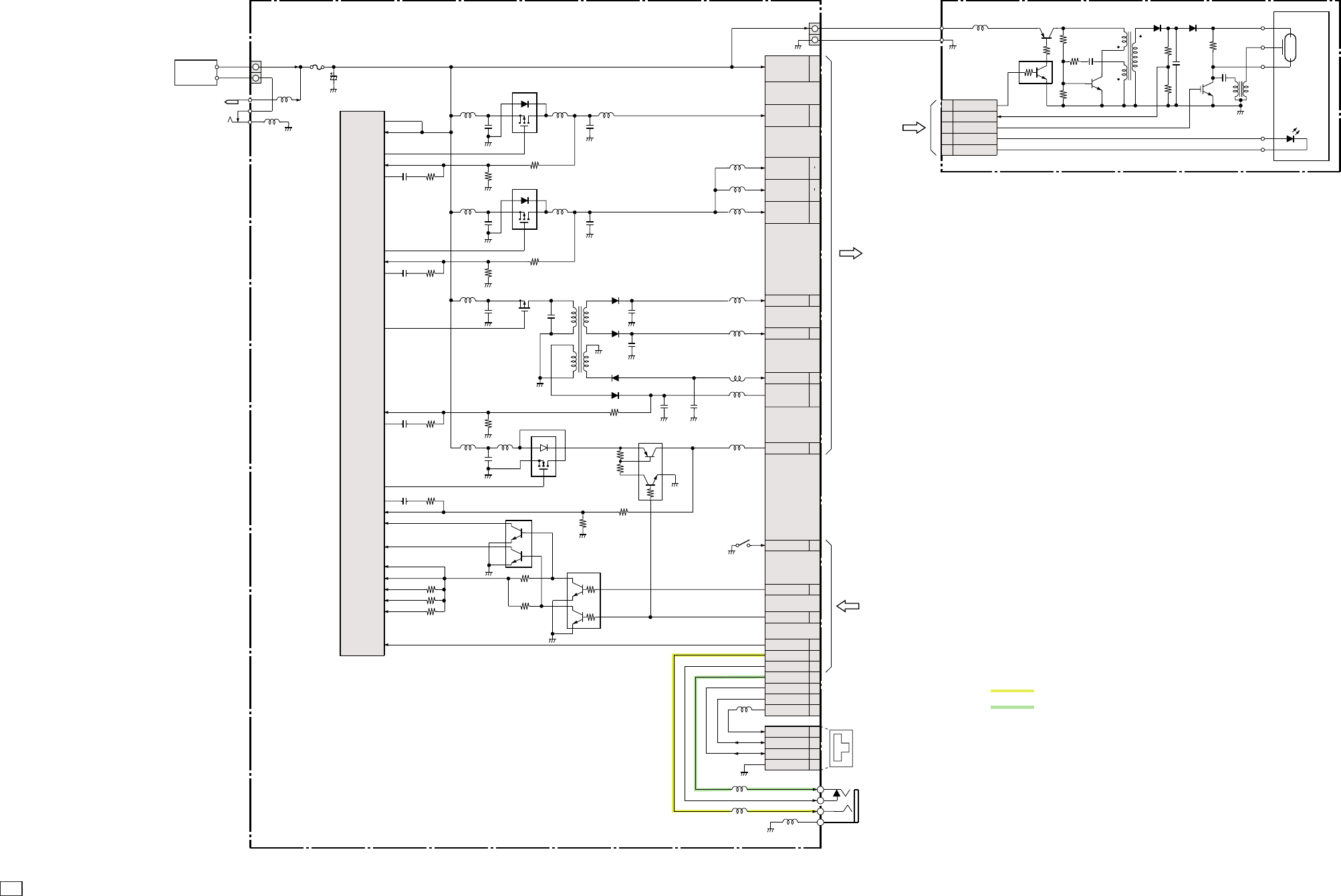
C CANON INC., 2003
01 OCT, 2003
2.5 POWER BLOCK
DCJ PCB UNIT
IC100
SW REG CONTROL
MB39A102PFT-E1
CN102
15
.
.
.
16
VCC1L
VEE2 27
CN100
DC IN
BATT +
BATT +
BATT -
BATTERY
BOX UNIT
FU100
C106
1
3
2
OUT2 24
C115
C117
Q104
PWM SW
CPH5802
-INE2
FB2
2
3
C125
C126
VCC 5
VCCO 26
L116
L104
L105
OUT1
-INE1
FB1
OUT3 23
Q102
PWM SW
MCH3306
-INE3 14
T100
8
1
2
75
6
1
2
3
6
4
5
3
4D100
D101
D103
D102
L111
-INE4 17
6
1
43
5
5
4
1
2
3
3
5
2
6
1
4
2
CS3 15
CS4 16
Q100
SWITCH
XP6501
DTC1 27
DTC2 4
DTC3 12
DTC4 19
VREF 7
Q101
SWITCH
XP6213
22
24
26
VBATT
VCC1A 13
.
14
VCC2AFE 23
.
25
L115
VCC1 9
11
VCC1M 17
19
L109
L110
L114
L113
L201
VDD2 12
VCCHDR 21
CTL 6
VDD3 7
E2 LAT 5
E3 LAT 6
E1P LAT 20
VIDEO 34
VC_DET 30
AUDIO 33
D- 37
D+ 39
VBUS 40
VBUS 1
D+ 3
D- 2
UV_GND
AUDIO
CN101
USB
CN103
AUDIO/VIDEO
VC_DET
VIDEO
5
1
3
4
2
From
MAIN PCB ASS´Y
To
MAIN PCB ASS´Y
Q204
XE DRIVE
GT8G132
4
CN202
EFCHG
3VCHGLVL
2STSP
5LEDS AN
6LED SELF
ST PCB UNIT
13
2
1
3
F4
T201
5
Q202
EF CHAGE
2SB1197K
Q201
SWITCH
DTC144EE
Q203
OSC
2SC4672
T201 D204
D203
T202
FLASH TUBE
AF SUPPORT LED
SELF LED
RED EYE LED
From
MAIN PCB ASS´Y
BTOP 4
SW100
L108
L112
L117
25
C114 Q103
PWM SW
CPH5802
29
28
C121
C124
C129
C122
C123 C130
C120
L102
FB3 13
FB4 18
L107
OUT4 22
C116
Q105
PWM SW
CPH5824 Q106
12V REG
UMF5NFS
L103 L106
5
4
3
2
1
5
4
3
2
1
ANALOG IMAGE SIGNAL
ANALOG AUDIO SIGNAL

2.6 Abbreviation in Block Diagrams
Abbreviation Nominal name Description
ADC Analog-to-Digital (A/D) Converter
AE Automatic Exposure control
AF Automatic Focussing control
AND Logic AND circuit
R-Y/B-Y Color difference signals of TV system
BPF Band-Pass Filter
BUFFER Buffer circuit
C Chrominance signal Color component signal of TV system
CCD Charge-Coupled Device CCD imager
CDS Correlated Double Sampling system
COMP.VIDEO Composite video signal
COMPARATOR Voltage comparator
CPU Central Processing Unit
DAC Digital-to-Analog (D/A) Converter
DRAM Dynamic Random Access Memory Memory with which read and write are freely possible.
DSP Digital Signal Processing Typically DSP device
EEPROM Electrically Erasable PROM PROM that is electrically erasable.
EVF Electronic View Finder
FET Field Effect Transistor
FLASH MEMORY Non-volatile memory with which write and read are freely
possible.
HPF High-Pass Filter
I/F InterFace The circuit that interconnects 2 devices or circuits.
IGBT Insulated Gate Bipolar Transistor Conductivity-modulation type FET transistor
INV. Logic Inverter circuit
IR InfraRed ray
IRIS Iris
LCD Liquid Crystal Device Typically LCD display
LED Light Emitting Diode Typically LED display
LPF Low-Pass Filter
NTSC National Television System Committees NTSC color TV system developed in USA
OP Amp OPerational Amplifier
OR Logic OR circuit
OSC OSCillator
PAL Phase Alternating by Line PAL color TV system developed in Germany
PLL Phase Locked Loop
PROM Programmable Read Only Memory Non-volatile memory in which program can be written.
PWM Pulse Width Modulation
REG. REGulated power supply
RTC Real Time Clock Reference clock oscillator
SDRAM Synchronous Dynamic RAM DRAM whose bus interface is synchronous.
SECAM SEquential Colour À Mémoire SECAM color TV system developed in France
SW REG SWitching REGulator Switching type regulated power supply device
TG Timing Generator
USB Universal Serial Bus USB type serial data communication system
VCO Voltage Controlled Oscillator
VCXO Voltage Controlled X’tal Oscillator
XE Xenon Tube
Y Y-signal Luminance component signal of TV system
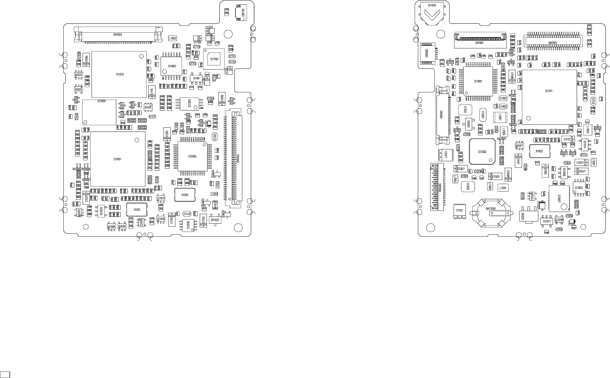
C CANON INC., 2003
01 OCT, 2003
3. P.C.B. DIAGRAMS
3.1 MAIN PCB ASS’Y
MAIN PCB ASS’Y (COMPONENT SIDE) MAIN PCB ASS’Y (CONDUCTOR SIDE)
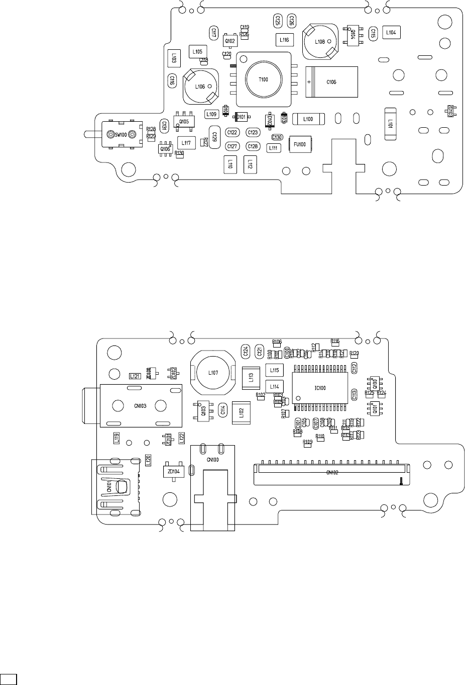
C CANON INC., 2003
01 OCT, 2003
3.2 DCJ PCB ASS’Y
DCJ PCB ASS’Y (COMPONENT SIDE)
DCJ PCB ASS’Y (CONDUCTOR SIDE)
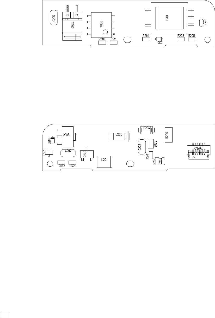
C CANON INC., 2003
01 OCT, 2003
3.3 ST PCB ASS’Y
ST PCB ASS’Y (COMPONENT SIDE)
ST PCB ASS’Y (CONDUCTOR SIDE)
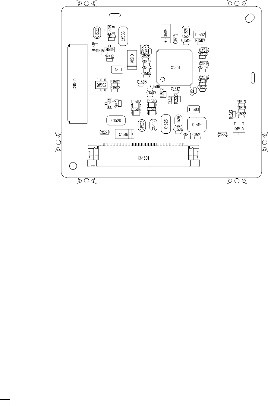
C CANON INC., 2003
01 OCT, 2003
3.4 LCD PCB ASS’Y

C CANON INC., 2003
01 OCT, 2003
3.5 SW PCB ASS’Y
SW1
SW1
3.6 OSW PCB ASS’Y
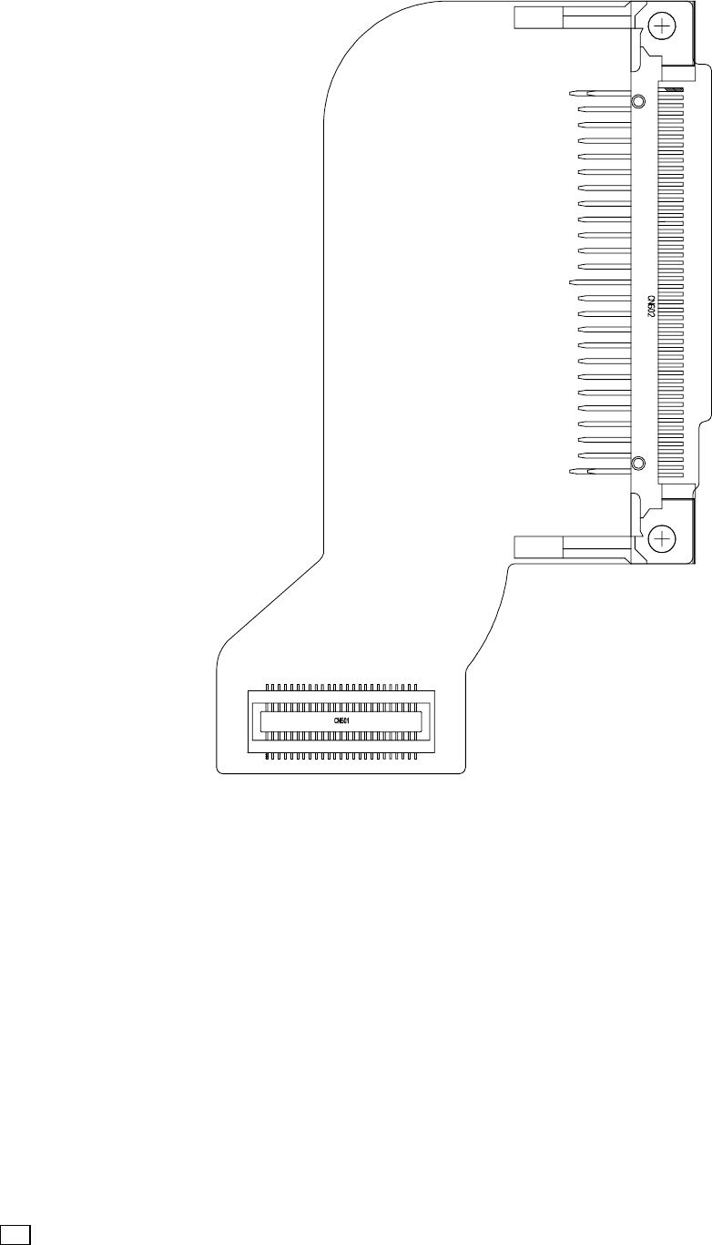
C CANON INC., 2003
01 OCT, 2003
3.7 CF FPC
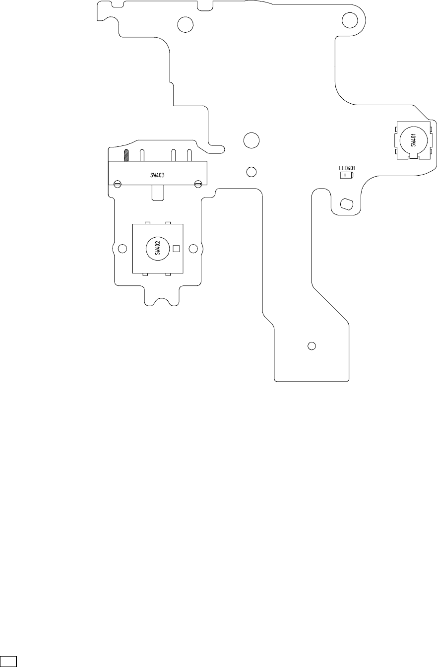
C CANON INC., 2003
01 OCT, 2003
3.8 TOP FPC

C CANON INC., 2003
01 OCT, 2003
3.9 ML FPC
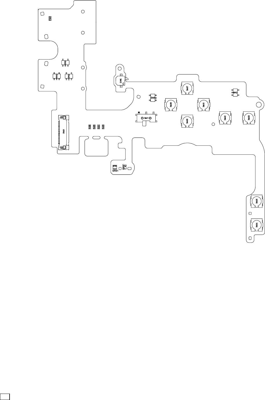
C CANON INC., 2003
01 OCT, 2003
3.10 OPR FPC

C CANON INC., 2003
01 OCT, 2003
3.11 SH FPC
