020683 PP 1104C G Power Supply
User Manual: PP-1104C-G-Power-Supply Igor's of metalworking and electrical manuals
Open the PDF directly: View PDF ![]() .
.
Page Count: 57
TM 11-6130-246-12
DEPARTMENT OF THE ARMY TECHNICAL MANUAL
OPERATOR AND ORGANIZATIONAL MAINTENANCE MANUAL,
POWER SUPPLY PP-1104C/G
6 November 1964
CHAPTER 1.
Section I.
II.
CHAPTER 2.
Section I.
II.
III.
. . . . . . . . . . . . . . . . . . . . . . . . .
CHAPTER 3.
DANGEROUS VOLTAGES EXIST IN THIS EQUIPMENT
High voltages and currents exist in this equipment. Serious injury or
death may result from contact with the input or output connections. Re-
energize the equipment before connecting or disconnecting the load to be
powered and before performing any maintenance.
INTRODUCTION
General . . . . . . . . . . . . . . . . . . . . . . . . . . . . . . . . . . . .
Scope. . . . . . . . . . . . . . . . . . . . . . . . . . . . . . . . . . . .
Index of equipment publication. . . . . . . . . . . . . . . .
Forms and records . . . . . . . . . . . . . . . . . . . . . . . . . . . . . .
Description and data. . . . . . . . . . . . . . . . . . . . . . . . . . . . . .
Purpose and use . . . . . . . . . . . . . . . . . . . . . . . . . . . . . . . .
Technical characteristics . . . . . . . . . . . . . . . . . . . . . . . . .
Description of Power Supply PP-l104C/G . . . . . . . . . . . . . . . . . . .
INSTALLATION AND OPERATING INSTRUCTIONS. . . . . . . . . .
Service upon receipt of equipment . . . . . . . . . . . . . . . . . . . . . . . . .
Unpacking . . . . . . . . . . . . . . . . . . . . . . . . . . . . . . . .
Checking unpacked equipment . . . . . . . . . . . . . . . . . . . . . . . . .
Placement of equipment. . . . . . . . . . . . . . . . . . . . . . . . . .
Installation procedure . . . . . . . . . . . . . . . . . . . . . . . . . . . . . . .
Connections . . . . . . . . . . . . . . . . . . . . . . . . . . . . . . . . . .
Initial adjustment of equipment . . . . . . . . . . . . . . . . . . . . . . . . .
Operation . . . . . . . . . . . . . . . . . . . . . . . . . . . . . .
Operator’s controls and indicators. . . . . . . . . . . . . . . . . . . .. .
Preparation for operation . . . . . . . . . . . . . . . . . . . . . . .
Operating procedure. . . . . . . . . . . . . . . . . . . . .
Stopping procedure. . . . . . . . . . . . . . . . . . . . . . . . . . . . . . .
MAINTENANCE INSTRUCTIONS. . . . . . . . . . . . . . . . . . . . .
Scope of maintenance . . . . . . . . . . . . . . . . . . . . . . . . . . . . . .
Preventive maintenance. . . . . . . . . . . . . . . . . . . .
Preventive maintenance checks an services periods . . . . . . . . . . . . . . . . .
Daily preventive maintenance checks and services chart . . . . . . . . . . . . . . . .
Weekly preventive maintenance checks and services chart . . . . . . . .
Money preventive maintenance checks services chart . . . . . . . . . . . .
This reprint includes all changes in effect at the time of
publication; changes 1 through 6.
Paragraph
1
2
3
4
5
6
7
8
9
10
11
12
l3
14
15
16
17
18
19
20
21
Page
5
5
5
5
5
6
7
7
7
7
9
9
9
11
11
12
12
12
12
13
13
1

CHAPTER 4.
Section I.
II.
APPENDIX I.
II.
III.
Quarterly preventive maintenance checks and services chart. . . . . . . . . .
Cleaning . . . . . . . . . . . . . . . . . . . . . . . . . . . . . .
Touchup painting instruction. . . . . . . . . . . . . . . . . . . . . . . . . . . . . . .
General troubleshooting information . . . . . . . . . . . . . . . . . . . . .
Troubleshooting chart . . . . . . . . . . . . . . . . . . . . . . . . . . . . . . . . . . . .
Replaement of indicator lamp . . . . . . . . . . . . . . .
SHIPMENT, LIMITED STORAGE, AND DEMOLITION TO
PREVENT ENEMY USE
Shipment and limited storage
Repackaging for shipment or limited storage
Packing . . . . . . . . . . . . . . . . . . . . . . . . . . . . . . . . . . . . .
Demolition of materiel to prevent enemy use
Authority for demolition . . .. . . . . . . . . . . . . . . . . . . . . . . . . . . . . . . . . .. . . . . . . . . .
Methods of destruction . . . . . . . . . . . . . . . . . . . . . . . . . . . . . . . . . . . . . . . . . . . . ..
REFERENCES. . . . . . . . . . . . . . . . . . . . . . . . . . . . . . . . . . . .
MAINTENANCE ALLOCATION. . . . . . . . . . . . . . . . . . . . . . . . . . . . . . . . . .
BASIC ISSUE ITEMS LIST .. . . . . . . . . . . . . . . . . . . . . . . . . . . . . . . . . . . . . . . .
Paragraph
22
23
24
25
26
27
28
29
30
31
Page
14
14
14
14
15
15
16
16
17
17
18
19
23
. . . . . . . . . . . . . .
. . . . . . . . . . . . . .
. . . . . . . . . . . . . .
2

CHANGE
No. 1
TM 11-6130-246-12
C1
HEADQUARTERS
DEPARTMENT OF THE ARMY
WASHINGTON, D. C., 28 February 1968
Operator and Organizational Maintenance Manual
POWER SUPPLY PP-1104C/G (WITH INSTRUCTIONS
FOR USE AS BATTERY CHARGER)
TM 11-6130-246-12, 6 November 1964, is changed as follows:
The title of the manual is changed as shown above.
Page 5. Chapter 1 is superseded as follows:
CHAPTER 1
INTRODUCTION
Section I. GENERAL
1. Scope
This manual describes Power Supply PP-l104-
C/G (fig. 1) and provides instruction for installa-
tion, power supply operation, battery charger
operation, and operator and organizational main-
tenance. It includes instructions for cleaning and
inspection of the equipment and replacement of
parts available to the operator and organizational
repairman. Power Supply PP–1104C/G is referred
to as the power supply in this manual.
2. Indexes of Equipment Publications
a. DA Pam 310-4. Refer to DA Pam 310-4 to
determine whether there are new editions, changes,
or additional publications pertaining to the equip-
ment.
b. DA Pam 310-7. Refer to DA Pam 310-7 to
determine whether there are Modification Work
Orders (MWO’s) pertaining to the equipment.
3. Forms and Records
a. Reports of Maintenance and Unsatisfactory
Equipment. Use equipment forms and records in
accordance with instructions given in TM 38-750.
b. Report of Packaging and Handling Deficiencies.
Fill out and forward DD Form 6 (Report of
Packaging and Handling Deficiencies) as pre-
scribed in AR 700–58 (Army), NAVSUP Publica-
tion 378 (Navy), AFR 71-4 (Air Force), and
MCO P4610-5 (Marine Corps).
c. Discrepancy in Shipment Report (DISREP)
(SF361). Fill out and forward Discrepancy in
Shipment Report (DISREP) (SF361) as pre-
scribed in AR 55–38 (Army), NAVSUP Pub 459
(Navy), AFM 75-34 (Air Force), and MCO
P4610-19 (Marine Corps).
d. Report of Equipment Publication Improve-
ments. Report of errors, omissions, and recom-
mendations for improving this publication by the
individual user is encouraged. Reports should be
submitted on DA Form 2028 (Recommended
Changes to DA Publications) and forwarded
direct to Commanding General, U. S. Army
Electronics Command, ATTN: AMSEL-ME-
NMP-AD, Fort Monmouth, N.J. 07703.
4. Purpose and Use
Power Supply PP-l104C/G (fig. 1) converts
115 or 230 volts alternating current (ac) to 14
or 28 volts direct current (dc). This power supply
is used in maintenance shops as a general purpose
low-voltage dc power source.
5. Technical Characteristics
Power input:
Voltage. . . . . . . . . . . . . . . 115 volts or 230 volts, 60 cps.
Phase, . . . . . . . . . . . . . Single.
Current (full load) . . . . . . . . 24 amperes for 115-volt ac
input power or 12 amperes
for 230-volt ac input power
1
Page 11. After Chapter 2 add chapter 2.1.
CHAPTER
2.1
USING POWER SUPPLY PP-1104C/G AS A BATTERY CHARGER
15.1. Purpose of Reverse Current Cutoff
A reverse current cutoff device is required to
permit use of Power Supply PP-1104C/G as a
battery charger, A battery connected to the out-
put terminals of an inactivated PP-1104C/G can
result in the battery discharging its stored power
through the PP-1104C/G. Use Relay, Reverse Cur-
rent Cutoff (FSN 5945-824–5585) connected be-
tween the output of the PP-1104C/G and the
battery to be charged to prevent the battery from
discharging through the PP-1104C/G. The special
equipment required is given in paragraph 15.2.
The connection instructions are given in para-
graph 15.3.
15.2. Special Equipment Required
The special equipment required for use of the
PP–l104C/G as a battery charger is given in a
through e below.
a. Relay, Reverse Current Cutoff (FSN 5945-
824-5585).
b. Wire, single conductor #16 AWG (FSN
6145-174-1107), length as required.
c. Wire, electrical, stranded #2 AWG (FSN
6145-854-7872), length as required for 100
amperes maximum at 14-volt operation.
d. Wire, electrical, stranded #4 AWG (FSN
6145-337-3188) length as required for 50 amperes
maximum at 28-volt operation.
e. Mounting plywood board approximately
three eighths inch thick, 10 inches long, and 10
inches wide.
15.3. Connections for Battery Charger
Operation
(fig. 4.1)
a. Make sure that the circuit breaker switch on
the PP-l104C/G is set to OFF. Connect #16 AWG
wire from the GEN terminal to the SW terminal
on the reverse current cutoff relay.
b. Connect #2 or #4 AWG wire from the
positive terminal on the PP-l104C/G to the
GEN terminal on the reverse current cutoff relay.
c. Connect #2 or #4 AWG wire from the BAT
terminal on the reverse current cutoff relay to
the positive terminal of the battery to be charged.
d. Connect #16 AWG wire from the negative
terminal of the PP-1104C/G to the NEG terminal
on the reverse current cutoff relay.
e. Connect #2 or #4 AWG wire from the nega-
tive terminal of the PP-1104C/G to the negative
terminal of the battery to be charged.
15.4 Charging Procedure
a. Perform the procedures given in paragraphs
10 and 11.
b. Connect the links for the desired output as
shown on the front panel placard (fig. 4).
c. Perform the connection procedures given in
paragraph 15.3.
Caution: A continuous flow of air through
Power Supply PP-1104C/G is necessary during
operation to prevent damage from overheating.
Do not obstruct the louvers on each side of Power
Supply PP1104C/G or at the rear panel. If the
fan fails to operate, discontinue operation.
d. Set the circuit breaker switch to ON. (Indi-
cator lamp should glow.)
e. Check the VOLTS D.C. meter indication,
and rotate the increase voltage switch clockwise
until the desired output voltage is obtained.
Check the output voltage at intervals during
operation. When necessary, adjust the increase
voltage switch to maintain the desired output
voltage.
15.5 Stopping Procedure
Stop the battery charging operation as follows:
a. Set the circuit breaker switch to OFF. (Indi-
cator lamp should extinguish,)
b. Set the increase voltage switch to 1.
c. Disconnect the battery from the equipment.
2
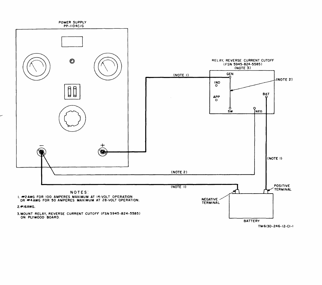
Figure 4.1. Battery charging connection diagram.
3
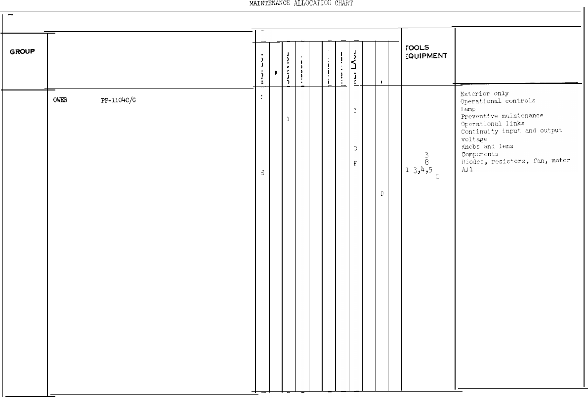
Page 19. Delete appendix II and add new appendix II.
APPENDIX II
MAINTENANCE ALLOCATION
Section I. INTRODUCTION
1. General
This appendix provides a summary of the
maintenance operations covered in the equipment
literature for Power Supply PP-1104C/G. It
authorizes categories of maintenance for specific
maintenance functions on repairable items and
components and the tools and equipment required
to perform each function. This appendix may be
used as an aid in planning maintenance operations.
2. Explanation of Format for Maintenance
Allocation Chart.
a. Group Number. Not used.
b. Component Assembly Nomenclature. This col-
umn lists the item names of component units,
assemblies, subassemblies, and modules on which
maintenance is authorized.
c. Maintenance Function. This column indicates
the maintenance category at which performance
of the specific maintenance function is authorized.
Authorization to perform a function at any cate-
gory also includes authorization to perform that
function at higher categories. The codes used
represent the various maintenance categories as
follows:
Code
Mainentance Category
C
Operator/Crew
O
Organizational Maintenance
FDirect Support Maintenance
HGeneral Support Maintenance
DDepot Maintenance
d. Tools and Equipment. The numbers appearing
in this column refer to specific tools and equipment
which are identified by these numbers in section
III.
e. Remarks. Self explanatory.
3. Explanation of Format for Tool and Test
Equipment Requirements
The columns in the tool and test equipment
requirements chart are as follows:
a. Tools and Equipment. The numbers in this
column coincide with the numbers used in the
tools and equipment column of the MAC. The
numbers indicate the applicable tool for the main-
tenance function.
b. Maintenance Category. The codes in this col-
umn indicate the maintenance category normally
allocated the facility.
c. Nomenclature. This column lists tools, test,
and maintenance equipment required to perform
the maintenance functions.
d. Federal Stock Number. This column lists the
Federal stock number.
e. Tool Number. Not used.
4
SECTION II.
MAINTENA?WCE
ALLOCATTCJ-:
CHAF.T
—
MAINTENANCE ALLOCATION CHART
GROUP
NUMBER COMPONENT ASSEMBLY
NOMENCLATURE
OWER
SUPPLY
PP-l104C/G
MAINTENANCE FUNCTIONS
I
I
D
rooLS
AND
:QUIPMENT
1
7
7
7
;
3,4,5
6,
8,9,
CJ
8
8
REMARKS
5

6
SECTION III. TOOL AND TEST EQUIPMENT REQUIREMENTS
6625-752-8817
6625-581-2036
6625-553-0142
6625-581-2466
6625-092-9136
6625-229-1060
5180-064-5178
5180-610-8177
5950-503-0632
6625-669-0742
Page 23. Delete appendix III and add new appendix III.
APPENDIX Ill
BASIC ISSUE ITEMS
Section I. INTRODUCTION
1. Scope
This appendix lists items comprising an oper-
able equipment and those required for installation,
operation, or operator’s maintenance for Power
Supply PP-l104C/G.
2. Explanation of Columns
The following is a list of explanations of columns
in section II.
a. Source, Maintenance, and Recoverability Codes
(SMR) Column.
(1) Source Code (S). The selection status and
source for the listed item is the first code indicated
in this column. The source code and its explana-
tion is:
Code
Explanation
PApplies to repair parts that are stocked in or
supplied from GSA/DSA, or Army Supply
system, and authorized for use at indicated
maintenance categories.
(2) Maintenance code (M). The lowest cate-
gory of maintenance authorized to install the item
is indicated by the second code in the column. The
maintenance category code and its explanation is:
Code
Explanation
O
Organizational Maintenance
(3) Recoverability code (R). Not used.
Note.
When no code is indicated in the recoverability
column, the part will be considered expendable.
b. Federal Stock Number Column. This column
indicates the Federal stock number for the item.
c. Description Column. This column includes
the Federal item name and any additional descrip-
tion of the item which may be required. A part
number or other reference number is followed by
the applicable five-digit Federal Supply Code for
Manufacturers. Usable on code column is not used.
d. Unit of Issue Column. The unit used as a
basis of issue (e.g., ea, pr, ft, yd, etc. ) is given in
this column.
e. Quantity Incorporated in Unit Pack Column.
Not used.
f. Quantity Incorporated in Unit Column. The
total quantity of the item used in the equipment is
given in this column.
g. Quantity Furnished With Equipment Column.
This column indicates the quantity of an item
furnished with the equipment in excess of the
quantity incorporated in the unit.
h. Quantity Authorized Column. Not used.
i. Illustrations Column. Not used.
3. Federal Supply Codes
This paragraph lists the Federal supply code
with the associated manufacturer’s name.
Code
Manufacturer
00197 General Electric Distribution Corp.
7

SECTION II BASIC ISSUE ITEMS
8
6130-542-6385
6240-223-9100
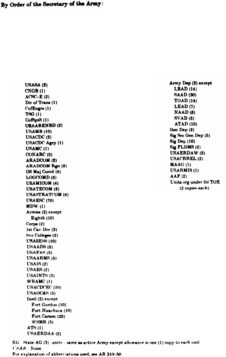
By Order of the Secretary of the Army:
Official:
KENNETH G. WICKHAM,
Major General, United States Army,
The Adjutant General.
Distribution:
Active Army:
USASA (2)
CNGB (1)
OACSC-E (7)
Dir of Trans (1)
CofEngrs (1)
TSG (1)
CofsptS (1)
USAARENBD (2)
USACDCEA (1)
USACDCCBRA (1)
USACDCCEA (1)
USACDCCEA, Ft. Huachuca (1)
USACDCTA (1)
USACDCADA (1)
USACDCARMA (1)
USACDCAVNA (1)
USACDCARTYA (1)
USACDCSWA (1)
USAMC (5)
USCONARC (5)
ARADCOM (5)
ARADCOM Rgn (2)
OS Maj Cored (4)
LOGCOMD (2)
USAMICOM (4)
USASTRATCOM (4)
USAESC (70)
MDW (1)
Armies (2) except
Eighth USA (5)
Corps (2)
USAC (3)
Svc Colleges (2)
USAADS (8)
USAAMS (2)
USAARMS (8)
USAIS (2)
USAES (2)
USASESS (8)
USAOC&S (8)
USATC Armor (2)
USATC Inf (2)
USASTC (2)
WRAMC (1)
Army Pic Cen (2)
USACDCEC (10)
Instl (2) except
Fort Hancock (4)
Fort Gordon (10)
HAROLD K. JOHNSON,
General, United States Army,
Chief of Staff.
Fort Huachuca (10)
WSMR (5)
Fort Carson (25)
Fort Knox (12)
Army Dep (2) except
LBAD (14)
SAAD (30)
TOAD (14)
LEAD (7)
SHAD (3)
NAAD (5)
SVAD (5)
CHAD (3)
ATAD (10)
Gen Dep (2)
Sig Sec Gen Dep (5)
Sig Dep (12)
Sig FLDMS (2)
AMS (1)
USAERDAA (2)
USAERDAW (13)
USACRREL (2)
MAAG (2)
USARMIS (2)
USARMA (2)
AAF (USARPAC) (5)
Units org under fol TOE
(2 copies each):
1-127
1-137
6-615
6-616
7
11-5
11-6
11-35
11-38
11-56
11-57
11-85
11-86
11-87
11-97
11-98
11-117
11-127
11-155
11-157
11-158
9
11-500 (AA-AC) 29-55
(KC, KD,RD,RP) 29-57
11-587 29-134
11-592 29-138
11-597 29-205
17
29-207
29-1 32-56
29-11 32-57
29-15 32-67
29-16 32-68
29-17 32-77
29-21
37
29-25 55-89
29-35 55-99
29-36 55-457
29-37 55-458
29-51
57
NG: State AG (3); units-same as active Army except allowance is one copy per unit.
USAR: None.
For explanation of abbreviations used, see AR 320-50.
10

Changes in force: C 1 and C 2
TM 11-6130-246-12
C2
CHANGE
HEADQUARTERS
DEPARTMENT OF THE ARMY
No. 2
W
ASHINGTON
, D, C., 20
January 1971
Operator’s and Organizational Maintenance Manual
POWER SUPPLY PP-1104C/G (WITH INSTRUCTIONS FOR USE
AS BATTERY CHARGER)
TM 11-6130-246-12, 6 November 1964, is changed
as
follows:
NOTE
Page 11.
paragraph 15.1, line 7 (page 2 of C1).
The parenthetical reference to a previous
Paragraph 15.2a, line 2 (page 2 of C 1).
change (example page 5 of C 1) indicates
Figure 4.1 (page 3 of C 1), in the upper right-
that pertinent material was published in hand section of the illustration under RELAY,
that change. REVERSE CURRENT CUTOFF.
Change
"FSN 5945-824-5585" to "FSN 5945-
Figure 4.1 (page 3 of C 1), note 3, line 1.
824-5575" in the following places:
1
Official:
KENNETH G. WICKHAM,
Major GeneraL United
States
Army,
The Adjutant General.
Distribution:
Active Army:
W. C. WE8TMORELAND,
General, United States Amy,
Chief of Staff
1-127
1-137
6-615
6-616
7
11-15
11-16
11-56
11-85
11-87
11-97
11-98
11-117
11-158
11-500 (AA-AC,
KC, KD, RD. RP)
17
29-1
29-11
29-15
29-16
20-17
20-21
29-25
29-26
29-27
29-35
29-36
29-37
29-51
29-55
29-57
29-134
29-!36
2-138
29-206
29-207
32-56
32-57
32-67
32-77
37
55 89)
55 99
55 457
55 458
57
2

CHANGE
No. 3
Changes in force: C 1, C 2, and C 3
TM 11-6130-246-12
C3
HEADQUARTERS
DEPARTMENT OF THE ARMY
WASHINTON, D.C., 12 December 1973
Operator’s and Organizational Maintenance Manual
POWER SUPPLY PP-1104C/G
(WITH INSTRUCTIONS FOR USE AS A BATTERY CHARGER)
TM 11-6130-246-12, 6 November 1964, is
changed as follows:
Page 5. Paragraph 3 is superseded as follows:
3. Forms and Records
a. Reports of Maintenance and Unsatisfac-
tory Equipment. Maintenance forms, records,
and reports which are to be used by mainte-
nance personnel at all maintenance levels are
listed in and prescribed by TM 38-750.
b. Report of Packaging and Handling Defi-
ciencies. Fill out and forward DD Form 6 (Re-
port of Packaging and Handling Deficiencies)
as prescribed in AR 700–58 (Army)/NAVSUP
PUB 378 (Navy)/AFR 71–4 (Air Force)/ and
MCO P4030.29 (Marine Corps).
c. Discrepancy in Shipment Report (DIS-
REF) (SF 361). Fill out and forward Discrep-
ancy in Shipment Report (DISREP) (SF 361)
as prescribed in AR 55-38 (Army)/NAVSUP
PUB 459 (Navy)/AFM 75-34 (Air Force)/and
MCO P4610.19 (Marine Corps).
Paragraph 3.1 is added as follows:
3.1. Reporting of Equipment Publication
Improvements
The reporting of errors, omissions, and recom-
mendations for improving this publication by
the individual user is encouraged. Reports
should be submitted on DA Form 2028 (Recom-
mended Changes to Publications) and for-
warded direct to Commander, US Army Elec-
tronics Command, ATTN: AMSEL-MA-C,
Fort Monmouth, NY 07703.
Page 6. Paragraph 6.1 is added as follows.
6.1. Item Comprising an Operable Power
Supply PP–1104C/G
Power Supply PP-l104C/G (FSN 6130-542-
6385) comprises an operable equipment and is
shown in figure 1.
Page 7. The paragraph 8, subparagraph a, de-
lete “(para 3)” from the second sentence.
In subparagraph b, delete the second sen-
tence.
Page 23. Appendix III is deleted in its entirety.
TAGO 3368A 1
By Order of the secretary of the Army:
Official:
VERNE L. BOWERS
Major General United States Army
The Adjutant General
Distribution:
CREIGHTON W. ABRAMS
General, United States Army
Chief of Staff
(1 cy each):
1-127
1-137
6-615
6-616
7
11-16
l1-16
11-85
11-86
11-87
11-97
11-98
11-117
11-168
11-500 (AA-AC)
17
29-1
29-11
29-15
29-16
29-17
29-21
20-25
20-26
29-27
29-36
29-36
29-37
29-51
29-55
29-57
29-134
29-136
29-207
32-56
32-57
32-67
32-77
37
65-89
55-99
55-457
55-458
57
For explanation of abbreviations used, see AR 310-50.

CHANGE
No. 4
Changes in force: C1, C2, C3, and C4
TM 11-6130-246-12
C4
HEADQUARTERS
DEPARTMENT OF THE ARMY
WASHINGTON, DC, 10 January 1978
Operator’s and Organizational Maintenance Manual
POWER SUPPLY PP-1104C/G
(NSN 6130-00-542-6385)
(WITH INSTRUCTIONS FOR USE AS BATTERY CHARGER)
TM 11-6130-246-12, 6 November 1964, is changed as follows:
The title of the manual is changed as indicated above.
Page 4. Add figure 1.1 after figure 1:
1
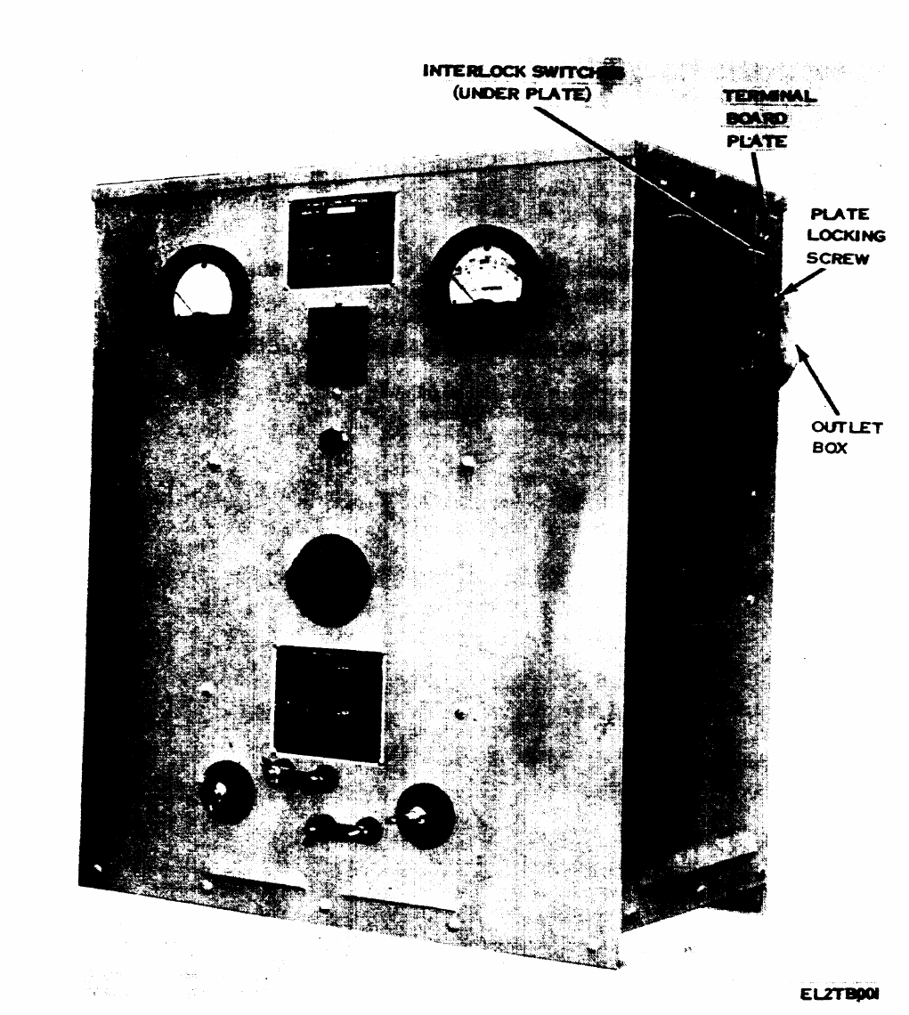
Figure 1-1. Power Supply PP-1104C/G (procured
under Contract No. DAAB07-76-C-1363).
2

Page 5, paragraph 3, Paragraph 3 is super-
seded as follows:
3. Forms and Records
a. Reports of Maintenance and Unsatisfactory
Equipment. Maintenance forms, records, and
reports which are to be used by maintenance
personnel at all maintenance levels are listed in
and prescribed by TM 38-750.
b. Reports of Packaging and Handling De-
ficiencies. Fill out and forward DD Form 6
(Packaging Improvement Report) as prescribed
in AR 700-58/NAVSUPINST 4030.291AFR 71-
13/MCO P4030.29A, and DSAR 4145.8.
c. Discrepancy in Shipment Report (DISREP)
(SF 361). Fill out and forward Discrepancy in
Shipment Report (DISREP) (SF 361) as pre-
scribed in AR 55-38/NAVSUPINST 4610,33M
AFR 76-18/MC0 P4610.19B, and DSAR 4500-15.
Page 6, paragraph 6. After the last sentence,
add:
On units procured on Contract No. DAAB07-
76-C-1363, interlock switches are located under
the terminal board plate (fig. 1.1). These inter-
lock switches disconnect ac power from the ter-
minal board (fig. 3) when the terminal board
plate is opened.
Page 7, paragraph 10, heading. Under the
heading, add:
Warning. Equipment must be grounded in ac-
cordance with ANSI-CI-1975 National Electric
Code.
Page 9, paragraph 10. Subparagraphs b
through f are superseded as follows:
b. On units other than those procured on Con-
tract No. DAAB07-76-C-1363, remove the screws
and
c.
lift off the top cover of the power supply.
WARNING!
Insure that the power input cable is
disconnected from any source of ac
power. If the ac power is connected di-
rectly to the power input cable, discon-
nect power by operating the main
power switch in the building or shelter.
Remove the cover and appropriate knockout
plug from the outlet box (figs. 1 and 1.1) on the
rear of the power supply. Pass the power input
cable through the knockout hole and attach to
the outlet box with a cable clamp. Make sure the
cable clamp nut is tightened securely.
d. Attach the ground wire of the power input
cable to the outlet box, using the screw provided.
e. On units procured on Contract No.
DAAB07-76-C-1363, attach the white and black
leads extending from the grommet in the outlet
box to the two remaining wires of the power
input cable. On all other units, connect one lead
of the power input cable to terminal 1 of the
terminal board (fig. 3) and the other lead to ter-
minal 4.
f. If removed in b above, replace the top cover
of the power supply and secure with the previ-
ously removed screws.
g. Open the hinged board plate (figs. 1 and 1.1)
to check the terminal board connections (fig. 3).
If the input power is 115-volts ac, terminal 1
must be strapped to terminal 3 and terminal 2
must be strapped to terminal 4 (A, fig. 3). If the
input power is 230-volts ac, terminal 2 must be
strapped to terminal 3 (B, fig. 3).
NOTE
Terminals 4 and 5 must always be
strapped together to assure operation
of the fan motor.
h. Close the terminal board plate (figs. 1 and
1.1) and tighten the plate locking screw until the
plate is secured.
NOTE
On units procured on Contract No.
DAAB07-76-C-1363, interlock switches
are located under the terminal board
plate. The power supply will not oper-
ate until the terminal board plate is
secured tightly and the interlock
switches engaged.
Page 11. Paragraph 14a is superseded as fol-
lows:
a. Assure the locking plate screw (figs. 1 and
1.1) is tightened securely. Units procured on
Contract No. DAAB07-76-C1363 have interlock
switches located under the terminal board plate
and will not operate unless they are engaged
(pushed in by the terminal board plate). Set the
circuit breaker switch (fig. 4) to ON. The indi-
cator lamp should glow.
Page 15, paragraph 26, troubleshooting chart.
Item 8a is superseded as follows:
Trouble-symptom Probable cause Checks and corrective measures
a. Indicator lamp does not glow. a. No power input, loose inter- a. Check input power. If correct,
lock switch, or defective tighten screw on terminal board
indicator lamp. plate. Replace indicator lamp.
3
Page 14, paragraph 23. The Warning notice is
superseded as follows:
WARNING!
The fumes of TRICHLOROETHANE
are toxic. Provide thorough ventilation
whenever it is used; avoid prolonged or
repeated breathing of vapor. Do not use
near an open flame or hot surface;
trichloroethane is non-flammable but
heat converts the fumes to a highly
toxic phosgene gas the inhalation of
which could result in serious injury or
death. Prolonged or repeated skin con-
tact with trichloroethane can cause
skin inflammation. When necessary,
use gloves, sleeves, and aprons which
solvent cannot penetrate.
Subparagraph b, third line. Delete “Cleaning
Compound (FSN 7930-395-9542)” and substitute:
Trichloroethane.
Page 19. Appendix II is superseded as follows:
4

APPENDIX II
MAINTENANCE ALLOCATION
Section I. INTRODUCTION
1. General
This appendix provides a summary of the main-
tenance operations for PP-l104C/G. It au-
thorizes categories of maintenance for specific
maintenance functions on repairable items and
components and the tools and equipment re-
quired to perform each function. This appendix
may be used as an aid in planning maintenance
operations.
2. Maintenance Function.
Maintenance functions will be limited to and
defined as follows:
a. Inspect. To determine the serviceability of
an item by comparing its physical, mechanical,
and/or electrical characteristics with estab-
lished standards through examination.
b. Test. To verify serviceability and to detect
incipient failure by measuring the mechanical
or electrical characteristics of an item and com-
paring those characteristics with prescribed
standards.
c. Service. Operations required periodically to
keep an item in proper operating condition, i.e.,
to clean (decontaminate), to preserve, to drain,
to paint, or to replenish fuel, lubricants, hydrau-
lic fluids, or compressed air supplies.
d. Adjust. To maintain, within prescribed limits,
by bringing into proper or exact position, or by
setting the operating characteristics to the
specified parameters.
e. Align. To adjust specified variable elements
of an item to bring about optimum or desired
performance.
f. Calibrate. To determine and cause correc-
tions to be made or to be adjusted on instru-
ments or test measuring and diagnostic
equipments used in precision measurement.
Consists of comparisons of two instruments, one
of which is a certified standard of known accu-
racy, to detect and adjust any discrepancy in the
accuracy of the instrument being compared.
g. Install. The act of emplacing, seating, or
fixing into position an item, part, module (com-
ponent or assembly) in a manner to allow the
proper functioning of the equipment or system.
h. Replace. The act of substituting a service-
able like type part, subassembly, or module
(component or assembly) for an unserviceable
counterpart.
i. Repair. The application of maintenance
services (inspect, test, service, adjust, align, cal-
ibrate, replace) or other maintenance actions
(welding, grinding, riveting, straightening, fac-
ing, remachining, or resurfacing) to restore
serviceability to an item by correcting specific
damage, fault, malfunction, or failure in a part,
subassembly, module (component or assembly),
end item, or system.
j. Overhaul.
That maintenance effort
(service/action) necessary to restore an item to a
completely serviceable/operational condition as
prescribed by maintenance standards (i.e.,
DMWR) in appropriate technical publications.
Overhaul is normally the highest degree of
maintenance performed by the Army. Overhaul
does not normally return an item to like new
condition.
k. Rebuild. Consists of those services/actions
necessary for the restoration of unserviceable
equipment to a like new condition in accordance
with original manufacturing standards. Re-
build is the highest degree of materiel mainte-
nance applied to Army equipment. The rebuild
operation includes the act of returning to zero
those age measurements (hours, miles, etc) con-
sidered in classifying Army equipments/
components.
3. Column Entries
a. Column 1, Group Number. Column 1 lists
group numbers, the purpose of which is to iden-
tify components, assemblies, subassemblies,
and modules with the next higher assembly.
b. Column 2, ComponentlAssembly. Column 2
contains the noun names of components, as-
semblies, subassemblies, and modules for which
maintenance is authorized.
c. Column 3, Maintenance Functions. Column
3 lists the functions to be performed on the item
listed in column 2. When items are listed without
maintenance functions, it is solely for purpose of
having the group numbers in the MAC and
RPSTL coincide.
d. Column 4, Maintenance Category. Column 4
specifies, by the listing of a “worktime” figure in
5
the appropriate subcolumn (s), the lowest level
of maintenance authorized to perform the func-
tion listed in column 3. This figure represents
the active time required to perform that main-
tenance function at the indicated category of
maintenance. If the number or complexity of the
tasks within the listed maintenance function
vary at different maintenance categories, ap-
propriate “worktime” figures will be shown for
each category. The number of task-hours
specified by the “worktime” figure represents
the average time required to restore an item
(assembly, subassembly, component, module,
end item or system) to a serviceable condition
under typical field operating conditions. This
time includes preparation time, troubleshooting
time, and quality assurance/quality control time
in addition to the time required to perform the
specific tasks identified for the maintenance
functions authorized in the maintenance alloca-
tion chart. Subcolumns of column 4 are as fol-
lows:
C — Operator/Crew
O — Organizational
F— Direct Support
H — General Support
D
— Depot
e. Column 5, Tools and Equipment. Column 5
specifies by code, those common tool sets (not
individual tools) and special tools, test, and sup-
port equipment required to perform the desig-
nated function.
f. Column 6, Remarks. Column 6 contains an
alphabetic code which leads to the remark in
section IV, Remarks, which is pertinent to the
item opposite the particular code.
4. Tool and Test Equipment
Requirements (See Ill)
a. Tool or Test Equipment Reference Code. The
numbers in this column coincide with the num-
bers used in the tools and equipment column of
the MAC. The numbers indicate the applicable
tool or test equipment for the maintenance
functions.
b. Maintenance Category. The codes in this
column indicate the maintenance category allo-
cated the tool or test equipment.
c. Nomenclature. This column lists the noun
names and nomenclature of the tools and test
equipment required to perform the mainte-
nance functions.
d. National/NATO Stock Number. This column
lists the National/NATO stock number of the
specific tool or test equipment.
e. Tool Number. This column lists the manu-
facturer’s part number of the tool followed by
the Federal Supply Code for manufacturers (5-
digit) in parentheses.
5. Remarks (See IV)
a. Reference Code. This code refers to the ap
propriate item in section II, column 6.
b. Remarks. This column provides the re-
quired explanatory information necessary to
clarify items appearing in section II.
6

SECTION II MAINTENANCE ALLOCATlON CHART
FOR
POWER SUPPLY PP-1104C/G
7
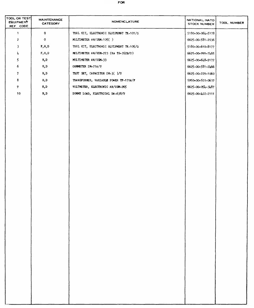
SECTION III. TOOL AND TEST EQUIPMENT REQUIREMENTS
POWER SUPPLY PP-1104C/G
8
5180-00-064-5178
6625-00-581-2036
5180-00-610-8177
6625-00-999-7465
6625-00-648-9172
6625-00-581-2466
6625-00-229-1060
5950-00-503-0632
6625-00-054-3487
6625-00-422-2111

SECTION IV. REMARKS
9

By Order of the Secretary of the Army:
Official:
J. C. PENNINGTON
Brigadier General, United States Army
The Adjutant General
Distribution:
BERNARD W. ROGERS
General, United States Army
Chief of Staff
1-137
6-615
6-616
7
11-15
11-16
11-85
11-86
11-87
11-97
11-98
11-117
11-500(AA-AC)
17
29-1
29-11
29-15
29-16
29-17
29-21
29-25
29-26
29-27
29-35
29-36
29-37
29-51
29-55
29-57
29-134
29-136
29-207
32-56
32-57
37
55-89
55-99
55-457
55-458
57
NG: State
AG
(3);
Units — Same as Active Army
USAR:
None
For explanation of abbreviations used see, AR 310-50

CHANGE
No. 5
TM 11-6130-246-12
C5
HEADQUARTERS
DEPARTMENT OF THE ARMY
WASHINGTON, DC, 13 November 1979
Operator’s and Organizational Maintenance Manual
POWER SUPPLY PP-1104C/G
(NSN 6130-00-542-6385)
(WITH INSTRUCTIONS FOR USE AS BATTERY CHARGER)
TM 11-6130-246-12, 6 November 1964, is changed as follows:
Page 1. WARNING. Above “DON’T TAKE CHANCES,” add:
Adequate ventilation should be provided while using TRICHLOROTRIF-
LUOROETHANE. Prolonged breathing of vapor should be avoided. The
solvent should not be used near heat or open flame; the products of
decomposition are toxic and irritating. Since TRICHLOROTRI-
FLUOROETHANE dissolves natural oils, prolonged contact with skin
should be avoided. When necessary, use gloves which the solvent cannot
penetrate. If the solvent is taken internally, consult a physician im-
mediately.
THE PP-1104C/G IS EXTREMELY HEAVY!
The PP-1104C/G is extremely heavy and requires a two-man lift. Use
extreme care in handling the unit to avoid serious personnel injury and
protect the unit from damage. If the PP-l104C/G does not have handles,
ensure a good grip before lifting.
Below “DON’T TAKE CHANCES”, add:
REPORTING OF ERRORS
You can help improve this manual. If you find any mistakes or if you know of a
way to improve the procedures, please let us know. Mail your letter or DA Form
2028 directly to Commander, US Army Communications and Electronics
Materiel Readiness Command, ATTN: DRSEL-ME-MQ, Fort Monmouth, NJ
07703. A reply will be furnished to you.
Page 5. Add paragraph 3.1 after paragraph 3.
3.1. Reporting Equipment Improvement
Recommendations (EIR’s)
EIR’s can and must be submitted by anyone
who is aware of an unsatisfactory condition with
the equipment design or use. It is not necessary
to show a new design or list a better way to
perform a procedure, just simply tell why the
design is unfavorable or why a procedure is
difficult. EIR’s may be submitted on Standard
Form (SF) 368, Quality Deficiency Report. Mail
directly to Commander, US Army Communica-
tions and Electronics Materiel Readiness Com-
mand, ATTN:DRSEL-ME-MQ, Fort Mon-
mouth, NJ 07703. A reply will be furnished
directly to you.
Page 14, paragraph 23. The warning notice
and subparagraph b are superseded as follows:
WARNING
Adequate ventilation should be pro-
vided while using TRICHLOROTRI-
FLUOROETHANE. Prolonged breath-
ing of vapor should be avoided. The
solvent should not be near heat or open
flame; the products of decomposition
are toxic and irritating. Since
TRICHLOROTRIFLUOROETHANE
dissolves natural oils, prolonged con-
tact with skin should be avoided. When
necessary, use gloves which the solvent
cannot penetrate., If the solvent is
taken internally, consult a physician
immediately.
b. Remove grease, fungus, and ground-in dirt
from the case; use a cloth dampened with
1

Cleaning Compound, Freon type TF (NSN
6850-00-105-3084).
By Order of the Secretary of the Army:
Official:
J. C. PENNINGTON
Major General, United States Army
The Adjutant General
Distribution:
Active Army: Army Dep (1) except:
HISA (Ft Monmouth) (21) LBAD (14)
USAINSCOM (2) SAAD (30)
COE (1) SHAD (3)
TSG (1) TOAD (14)
USAARENBD (1) USA Dep (1)
DARCOM (1) Sig Sec USA Dep (1)
TRADOC (2) Units org under fol TOE:
OS MAJ COMD (4) 29-207 (2)
TECOM (2) 29-610 (2)
USACC (4)
1-127 (1)
MDW (1)
1-137 (1)
Armies (2) 6-615 (1)
Corps (2) 6-616 (1)
Svc Colleges (1)
7- (1)
USASIGS (5) 11-15(1)
USAADS (2)
11-16 (1)
USAFAS (2) 11-85(1)
USAARMS (2) 11-86(1)
USAIS (2)
11-87 (1)
USAES (2)
11-97 (1)
USAICS (3) 11-98(1)
MAAG (1) 11-117(1)
USARMIS (1) 11-500 (AA-AC) (1)
USAERDAA (1)
17- (1)
USAERDAW (1)
29-1 (1)
USAOC&S (2) 29-11 (1)
Ft Carson (5) 29-15 (1)
Ft Gillem (10) 29-16 (1)
Ft Gordon (10) 29-17 (1)
Ft Richardson (CERCOM Ofc) (2) 29-21 (1)
ARNG: State AG (3); Units — Same as Active Army.
USAR, None.
For explanation of abbreviations used, see AR 310-50.
29-25 (1)
29-26 (1)
29-27 (1)
29-35 (1)
29-36 (1)
E. C. MEYER
General, United States Army
Chief of Staff
29-37 (1)
29-51 (1)
29-55 (1)
29-134 (1)
29-136 (1)
29-207 (1)
32-56 (1)
32-57 (1)
37- (1)
55-89 (1)
55-99 (1)
55-99 (1)
55-457 (1)
55-458 (1)
57-(1)
2

TM 11-6130-246-12
C6
Change
No. 6
HEADQUARTERS
DEPARTMENT OF THE ARMY
Washington, DC, 29 April 1982
Operator’s and Organizational Maintenance Manual
POWER SUPPLY PP-1104C/G
(NSN 6130-00-542-6385)
(WITH INSTRUCTIONS FOR USE AS BATTERY CHARGER)
TM 11-6130-246-12, 6 November 1964, is changed as follows:
Page 1. Second WARNING, THE PP-1104C/G IS EXTREMELY HEAVY! is superseded as follows:
WARNING
Power Supply PP-1104C/G weighs 152 pounds. Be careful when moving. Mechanical lift required.
Page 2. After table of contents add the following safety steps.
1

SAFETY STEPS TO FOLLOW IF SOMEONE
IS THE VICTIM OF ELECTRICAL SHOCK
DO NOT TRY TO PULL OR GRAB THE INDIVIDUAL
IF POSSIBLE,
TURN OFF THE ELECTRICAL POWER
IF YOU CANNOT TURN OFF THE ELECTRICAL
POWER, PULL, PUSH, OR LIFT THE PERSON TO
SAFETY USING A WOODEN POLE OR A ROPE OR
SOME OTHER INSULATING MATERIAL
SEND FOR HELP AS SOON AS POSSIBLE
AFTER THE INJURED PERSON IS FREE OF
CONTACT WITH THE SOURCE OF ELECTRICAL
SHOCK, MOVE THE PERSON A SHORT DISTANCE
AWAY AND IMMEDIATELY START ARTIFICIAL
RESUSCITATION
2
Change 6

Page 7. Paragraph 7b. The following is added after “Removing Contents.”
WARNING
Power Supply PP-1104/G weighs 152 pounds. Be careful when moving. Mechanical lift required.
Page 11. Paragraph 15.1, line 7. Delete (FSN 5945-824-5585) and substitute (NSN 5945-00-824-5575).
Paragraph 15.2a. Delete (FSN 5945-824-5585) and substitute (NSN 5945-00-824-5575).
Figure 4-1 is superseded as follows:
Figure 4-1. Battery charging connection diagram.
Change 6
3
By Order of the Secretary of the Army:
Official:
ROBERT M. JOYCE
Brigadier General, United States Army
The Adjutant General
E. C. MEYER
General, United States Army
Chief of Staff
Distribution:
To be distributed in accordance with Special Mailing List.

TM 11-6130-246-12
Figure 1. Power Supply PP-l104C/G.
4

TM 11-6130-246-12
CHAPTER 1
INTRODUCTION
Section I.
1. Scope
This manual describes Power Supply PP-
1104C/G (fig. 1) and provides instruction for
installation, operation, and operator and or-
ganizational maintenance. It includes in-
structions for cleaning and inspection of the
equipment, and replacement of parts available
to the operator and organizational repairman.
Power Supply PP–l104C/G is referred to as
power supply in this manual.
2. Index of Equipment Publications
Refer to the latest issue of DA Pam 310–4
to determine whether there are new editions,
changes, or additional publications pertaining
to the equipment. Department of the Army
Pamphlet No. 310-4 is a current index of tech-
cal manuals,technical bulletins, supply
manuals, supply catalogs, supply bulletins,
lubrication orders, and modification work or-
ders available through publications supply
channels. The index lists the individual parts
(-10, -20, -35P, etc) and the latest changes
and revisions of each equipment publication.
3. Forms and Records
a. Reports of Maintenance and Unsatisfac-
GENERAL
tory Equipment. Use equipment forms and rec-
ords in accordance with instructions in TM
38-750.
b. Reporting of Damaged or improper Ship-
ment. Fill out and forward DD Form 6 (Report
of Damaged or Improper Shipment) as pre-
scribed in AR 700–58 (Army), NAVSANDA
Publication 378 (Navy). and AFR 71–4 (Air
Force).
c. Reporting of Equipment Manual improve-
ments. The direct reporting, by the individual
user, of errors, omissions, and recommenda-
tions for improving this equipment manual is
authorized and encouraged. DA Form 2028
will be used for reporting these improvements.
This form may be completed by the use of
pencil, pen, or typewriter. DA Form 2028 will
be completed in triplicate and forwarded by the
individual using the manual. The original and
one copy will be forwarded direct to: Com-
manding General, U. S. Army Electronics
Command, ATTN: AMSEL-MR-MA, Fort
Monmouth, New Jersey 07703. One informa-
tion copy will be provided to the individual’s
immediate supervisor
(officer, noncommis-
sioned officer, supervisor, etc).
Section II. DESCRIPTION AND DATA
4. Purpose and Use
Power Supply PP-1104C/G (fig. 1) converts
115 or 230 volts alternating current (ac) to 14
or 28 volts direct current- (dc). This power
supply is used in maintenance shops as a gen-
eral purpose low-voltage dc power source.
5. Technical Characteristics
Power input:
Voltage 116 volts or 230 volts,
60 cps.
Phase Single.
Current (full load) 24 amperes for 115-
volt ac input power
or 12 amperes for
230-volt ac input
power.
5

Power output
Voltage Variable from 11.5 to
17.5 volts dc (14-
volt operation) or
variable from 23
to 35 volts dc (28-
volt operation),
Maximum current 100 amperes at 14-volt
operation or 50 am-
peres at 28-volt
operation.
Ripple voltage 0.9 percent (root
mean square).
Regulation 6 percent (14-volt op-
eration) or 4 Per-
cent (28-volt
operation).
Operating temperature +32° F (0° C) to
115° F (51.7° C).
6. Description of Power Supply
PP-1104C/G
The power supply is a self-contained unit in
a metal cabinet, 23¼ inches high, 19 3/8 inches
wide, and 13 1/8 inches deep. All operating con-
trols are mounted on the front panel (fig. 1).
Louvers on each side and the rear, and a grill
at the bottom of the cabinet are provided for
air circulation. A metal outlet box is mounted
on the rear panel for connection of the input
cable. The power supply weighs 152 pounds
and includes one spare indicator lamp and two
technical manuals. The spare indicator lamp is
padded and taped to the lower rear skid channel
on the right side of the power supply.
6

TM 11-6130-246-12
CHAPTER 2
lNSTALLATION AND OPERATING lNSTRUCTlONS
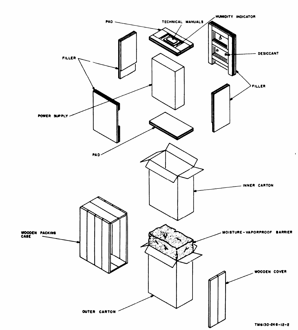
7. Unpacking
a. Packaging Data. When packed for ship
ment, Power Supply PP-1104C/G is placed in
cartons and packed in a 30¾ by 25¼,-by 18½-
inch wooden packing case. A typical wooden
packing case and its contents are shown in fig-
ure 2. The volume is 8.3 cubic feet and the
total weight is 225 pounds.
b. Removing Contents.
(1)
(2)
(3)
Remove the nails from the top and
one side of the wooden packing case
with a nailpuller. Remove the top and
side.
Tilt the wooden packing case toward
the open side and slide the wooden
packing crate free from the power
supply.
Caution: Remove the power supply
from the cartons carefully to prevent
damage to the meters or operating
controls on the front panel.
Open the outer carton, moisture-
vaporproof barrier, and the inner car-
ton and remove the power supply.
8. Checking Unpacked Equipment
a. Inspect the equipment for damage in-
Section I SERVICE UPON RECEIPT OF EQUIPMENT
curred during shipment. If the equipment has
been damaged, report the damage on DD Form
6 (para 3).
b. See that the equipment is complete as
listed on the packing ship. If a packing slip is
not available, check the equipment against the
basic issue items list (appx III). Report all
discrepancies in accordance with TM 38-750.
Shortage of a minor assembly or part that does
not affect proper functioning of the equipment
should not prevent use of the equipment.
c. If the equipment has been used or recon-
ditioned, see whether it has been changed by a
modification work order (MWO). If the equip
ment has been modified, the MWO number will
appear on the front panel near the nomencla-
ture plate. If modified, see that any operational
instruction changes resulting from the modific-
ation have been entered in the equipment
manual.
Note:
Current MWO's applicable to the equipment
are listed in DA Pam 310-4.
9. Placement of Equipment
Select a location that is convenient to the
power input source and for connection of the
load to the power supply. Provide at least 8
inches of space behind and on each side of the
power supply for air circulation.
Section Il. INSTALLATION PROCEDURE
10. Connections (1)
Note.
The power input line electrical connections are
made by authorized installation personnel and should
be protected with a 30-ampere fuse for 115-volt ac
input and 15-ampere fuse for 230-volt ac input and
controlled by an external switch for convenient removal
(2)
of power from the power supply during maintenance.
a. Prepare the power input cable as follows:
If armored cable is used, remove ap-
proximately 6 inches of armor from
the end of the cable. If nonarmored
cable is used, remove 6 inches of the
outer insulation.
Separate the input leads and strip
three-fourths inch of the insulation
from the end of each lead.
7
TM 11-6130-246-12
Figure 2. Packaging of Power Supply PP-1104C/G.
8

TM 11-6130-246-12
(3) Attach a standard cable clamp to the
cable.
b. Open the hinged terminal board plate (fig.
1) on the right side panel of the power supply
and remove the top panel of the power supply.
c. Remove the cover and one of the knockout
plugs from the outlet box (fig. 1) on the rear
of the power supply. Attach the power input
cable to the outlet box with the cable clamp.
d. Pass the input leads through the hole in
the rear panel and attach one lead to terminal
1 (fig. 3) of the terminal board mounted on
the terminal board plate (fig. 1) on the right
side of the power supply. Attach the other in-
put lead to terminal 4 (fig. 3).
e. If the power input is 115 volts, be sure that
terminal 1 is strapped to terminal 3, and ter-
minal 2 is strapped to terminal 4 on the termi-
nal board (A, fig. 3).
f. If the power input is 230 volts, be sure
that terminal 2 is strapped to terminal 3 on
the terminal board (B, fig. 3).
11. Initial Adjustment of Equipment
a. Set the power supply on a level surface at
the location (para 9). Use wedges to steady
the power supply if necessary.
b. Set the circuit breaker switch on the
front panel to OFF (fig. 4).
c. Set the increase voltage switch to 1. Figure 3. Terminal board input connections.
Section Ill. OPERATION
12 Operator’s Controls and Indicators
(fig. 4)
The following chart lists the controls and
indicators and their functions:
Control or indicator
Increase voltage switch
(8-position rotary)
Circuit breaker switch
Function
Adjusts the dc output voltage
in 8 equal steps from 11.5
volts to 17.5 volts (14-volt
operation) l nd from 23 volts
to 35 volts (28-volt opera-
tion).
Turns power supply on and
off manually. (Two circuit
breakers connected internally
to circuit breaker switch
Control or indicator
Function
shut power supply off auto-
matically when input current
is excessive.)
Indicator lamp Glows when power supply is on.
VOLTS D.C. meter Indicator output voltage.
D.C. AMPERES meter Indicates output current.
13. Preparation for Operation
After initial adjustment (para 11), prepare
the power supply for operation as follows:
a. Connect the links for the desired output
as shown on the front panel placard (fig. 4).
b. Connect the equipment to be powered to
the negative and positive output terminals on
9
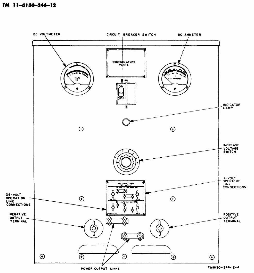
Figure 4. Power Supply PP-1104C/G, operator's control and indicators.
10

the front panel of the power supply. Be sure
to observe correct polarity.
14. Operating Procedure
After performing the procedures in para-
graph 13, proceed as follows:
a. Set the circuit breaker switch to ON.
(Indicator lamp should glow.)
b. Observe the VOLTS D.C. meter indication
and rotate the increase voltage switch clock-
wise until the desired output voltage is ob-
tained. Turn on the equipment to be powered
and readjust the output voltage by rotating the
increase voltage switch. Check the output volt-
age a intervals during operation of the power
supply. When necessary, adjust the increase
voltage knob to maintain the desired output
voltage.
Caution: A continuous flow of air through
the power supply is necessary during operation
to prevent damage due to overheating. Do not
obstruct the louvers on each side of the power
supply or l the rear panel. If the fan should
fail to operate, do not continue operation of the
power supply.
15. Stopping Procedure
Stop the power supply as follows:
a. Turn off the equipment connected to the
power supply output terminals.
b. Set the circuit breaker switch to OFF.
(The fan should stop, the pilot lamp should
extinguish, and the VOLTS D.C. and D. C.
AMPERES output meters should indicate no
output.)
c. Set the increase voltage switch to 1.
11
TM 11-6130-246-12
CHAPTER 3
MAINTENANCE INSTRUCTIONS
16. Scope of Maintenance
The maintenance duties assigned to
erator and organizational repairman
equipment are listed below together
the op-
of the
with a
reference to the paragraphs covering the spe-
cific maintenance functions. The tools and test
equipment required are listed in appendix II.
a. Daily preventive maintenance checks and
services (para 19).
b. Weekly preventive maintenance checks
and services (para 20).
c. Monthly preventive maintenance checks
and services (para 21).
d. Quarterly preventive maintenance checks
and services (para 22).
e.
f.
g.
h.
17.
Cleaning (para 23).
Touchup painting (para 24).
Troubleshooting (para 25 and 26).
Replacement of indicator lamp (para 27).
Preventive Malntenance
Preventive maintenance is the systematic
care, servicing, and inspection of equipment to
prevent the occurrence of trouble, to reduce
downtime, and to assure that the equipment is
serviceable.
a. Systematic Care. The procedures given in
paragraphs 19 through 23 cover routine sys-
tematic care and cleaning essential to proper
upkeep and operation of the equipment.
b. Preventive Maintenance Chech and Serv-
ices. The preventive maintenance checks and
services charts (para 19-22) outline functions
to be performed at specific intervals. These
checks and services are to maintain Army elec-
tronic equipment in a combat serviceable condi-
tion; that is in good general (physical) condition
and in good operating condition. To assist
operators in maintaining combat serviceability,
the chart indicates what to check, how to check,
and what the normal conditions are. The Ref-
erences column lists the paragraphs, figures, or
manuals that contain detailed repair or replace-
ment procedures. If the defect cannot be
remedied by performing the corrective actions
listed, higher echelon maintenance or repair is
required. Records and reports of these checks
and services must be made in accordance with
the requirements set forth in TM 38-760.
18. Preventive Maintenance Checks
and Services Periods
Preventive maintenance checks and services
of the equipment are required daily, weekly,
monthly, and quarterly.
a. Paragraph 19 specifies the checks and
services that must be accomplished daily (or at
Ieast once each week if the equipment is main-
tained in standby condition).
b. Pargaraphs 20, 21, and 22 specify
additional checks and services that must be
performed on a weekly, monthly, and quarterly
basic, respectively.
19. Daily Preventive Maintenance Checks and Services Chart
Sequence
No.
Item Procedure
References
1
Completeness . . . . . . . . . . . . . See that the equipment is complete (appx
III).
2
Exterior surfaces. . . . . . . . Clean the exterior surfaces including the
panel and meter glasses(para 28). Check
all meterglasses and indicator lenses for
cracks.
3
Connectors . . . . . . . . . . . . . . Check the tightness of all connectors.
12

TM 11-6130-246-12
4
5
6
7
. . . . . . . . . .
8
9
10
11
Item
Controls and indicators . . . .
Links . . . . . . . . . . . . . . . .
Load
Increase voltage switch . . . . . . . . .
Circuit breaker switch . . . . . . . .
Increase voltage switch . . . . . . . .
Circuit breaker switch . . . . . .
Increase voltage switch . . . . .
Procedure
While making the operating checks (items 5
through 11), observe that the mechanical
action of each knob and switch is smooth
and free of external or internal binding,
and that there is no excessive looseness.
Aim, check the meters for sticking or
bent pointers.
Connect links for desired output.
Connect load to output terminals.
Set to 1.
Set to ON. Note that:
a. Indicator lamp glows.
b. Fan starts.
c. VOLTS D.C. meter and D.C. AMPERES
meter indicate output voltage and cur-
rent, respectively.
Rotate in steps to position 8. Note that
voltage and current readings on VOLTS
D.C. meter and D.C. AMPERES meter
increase at each step.
Set to OFF, Note that:
a. VOLTS D.C. and D.C. AMPERES
meters indicate zero.
b. Fan stops.
c. Indicator lamp goes off.
Set to 1.
References
Figure 4.
Paragraph 13b.
20. Weekly Preventive Maintenance Checks and ServiCeS Chart
Sequence
No. Item Procedure References
1
Cables . . . . . . . . . .Inspect cords, cables, and wires for chafed,
cracked, or frayed insulation. Replace con-
nectors that are broken, arced, stripped,
or worn excessively.
2
Metal surfaces . . . . . . . . Inspect exposed metal surfaces for rust and Para 24.
corrosion, Clean and touchup paint as
required (para 24.)
21. Monthly Preventive Maintenance Checks and Servics Chart
Sequence
No. Item Procedure References
1
Indicator lamp . . . . . . . . Inspect seating of indicator lamp.
2Trandformer terminalsInspect terminals on power transformer.
All nuts must be tight. There should be
no evidence of dirt or corrosion.
8Terminal blocks, . . . . . . . . . . Inspect terminal blocks for loose connections
and cracked or broken insulation.
13
Sequence
Item
Procedurc References
4
Resistors and capacitors . . . .
Inspect resistors and capacitors for cracks,
blistering, or other detrimental defects.
5Gaskets and insulators . . . . . .
Inspect gaskets, insulators, bushings, and
sleeves for cracks, chipping, and excessive
wear.
6
Fan motor . . . . . . . . . . . Inspect fan motor for signs of overheating.
7
Interior . . . . . . . . . . . . . . . . . . Clean interior of chassis and cabinet.
22. Quarterly Preventive Maintenance Checks and Services Chart
Sequence
No.
Item Procedure
1
Publications . . . . . . See that all publications are complete, serv-
iceable, and current.
2
Modifications . . .
Check DA Pam 3104 to determine if new
applicable MWO’s have been published.
All URGENT MWO’s must be applied
immediately. All NORMAL MWO’s must
be scheduled.
Reference
DA Pam 310-4.
TM 36-750 and
DA Pam 910-4.
3
Spare part . . . .
Check spare part for general condition and Appx III.
method of storage. No overstock should
be evident and all shortages must be on
valid requisitions,
23. Cleaning
Inspect the exterior of the equipment,
exterior surfaces should be free of dust,
grease, and fungus.
The
dirt,
a. Remove dust and loose dirt with a clean
soft cloth.
Warning: Cleaning compound is flammable
and its fumes are toxic. Provide adequate ven-
tilation. Do not use near a flame.
b. Remove grease, fungus, and ground-in dirt
from the case; use a cloth dampened (not wet)
with cleaning Compound (FSN 7930-395-
9542).
c. Remove dust or dirt from plugs and jacks
with l brush.
come damaged.
Caution:Do not press on the meter faces
(glasses) when cleaning; the meters may be-
d. Clean the front panel, meters and control
knob; use a soft clean cloth. If necessary,
dampen the cloth with water; mild soap may
be used for more effective cleaning.
14
24. Touchup Painting Instructions
Remove rust and corrosion from metal sur
faces by lightly sanding them with fine sand-
paper. Brush two thin coats of paint on the
bare metal to protect it from further corrosion.
Refer to the applicable cleaning and refinish-
ing practices specified in TM 9-218.
25. General Troubleshooting
Information
Troubleshooting the power supply is based
upon the operational check contained in the
daily preventive maintenance checks and serv-
ices chart (pare 19). To troubleshoot the power
supply, perform all functions starting with
item No. 5 in the daily preventive maintenance
checks and services chart (para 19) and proceed
through the items until an abnormal indication
is observed; note the item number and turn to
the corresponding item number in the trouble-
shooting chart (para 26). Perform the checks
and corrective actions indicated in the trouble-
shooting chart. If the corrective measures indi-
cated do not result in correction of the trouble,
higher level maintenance is required.

26. Troubleshooting Chart
Item No.
8
9
10
Trouble symptom
a. Indicator lamp does
not glow.
b. Fan does not start.
c. VOLTS D.C. meter or
D.C. AMPERES meter
do not indicate prop-
erly.
Voltage or current indication
on VOLTS D.C. meter or
D.C. AMPERES meter
does not increase at each
step.
VOLTS D.C. or D.C. AM-
PERES meters do not in-
dicate zero, fan does not
stop and pilot lamp does
not go off.
Probable Cause
a. Defective indicator lamp or no
power input.
b. Defective fan motor.
c. Connections to meters faulty or
defective.
Defective increase voltage switch.
Short circuit across circuit breaker.
Checks and Corrective measures
a. Check power input. If correct,
replace indicator lamp (para
27) .
b. Higher level maintenance is re-
quired.
c. If both meters show zero read-
ing, check for loose connection
in output circuit. If only one
meter shows zero, check con-
nections to that meter. If
meter connections are not
faulty, higher level mainte-
nance is required.
Higher level maintenance is re-
quired.
Higher level maintenance is re-
quired.
27. Replacement of Indicator Lampb. Press in on the indicator lamp and turn it
counterclockwise to unlock it.
a. Turn the glass indicator jewel counter- C. Pull the defective indicator lamp out and
clockwise and pull it out to expose the defective replace it with a new one. Push the indicator
lamp. lamp in and twist it clockwise to lock it.
15

TM 11-6130-246-12
SHIPMENT, LIMITED STORAGE,
CHAPTER 4
AND DEMOLITION TO PREVENT
ENEMY USE
Section I. SHIPMENT AND LIMITED STORAGE
28. Repackaging for Shipment or
Limited Storage
The exact procedure for repackaging depends
on the material available and the conditions
under which the equipment is to be shipped or
stored. Adapt the procedure outlined below
whenever circumstances permit. The informa-
tion concerning the original packaging (para
7) will also be helpful.
a. Material Requirement. The following
materials are required for packaging the power
supply. For stock numbers of materials, refer
to SB 38-100.
Material
I
Quanitity
Corrugated single-face flexible paper 100 sq ft
Gummed paper tape 30 sq ft
Pressure-sensitive tape 26 ft
Waterproof paper80 sq ft
Wooden packing case (Inside dimen- 1
sions 26 x 21 x 16 in.)
b. Packaging (fig. 2). Package the items of
the power supply as outlined below.
(1) Main unit. Cushion the main unit on
all sides with fillers and pads made up
of corrugated single-face flexible pa-
per. Secure the cushioning with
gummed paper tape.Wrap the
(2)
cushioned unit with flexible corru-
gated single-face flexible paper and
secure the wrap with gummed paper
tape.
Spare indicator lamp and technical
manuals. Wrap the indicator lamp in
corrugated single-face flexible paper
and secure with gummed paper tape.
Wrap the technical manuals in water-
proof paper and seal the package with
pressure-sensitive tape. Fasten the
package containing the technical man-
uals to the top of the power supply
with pressure-sensitive tape. Fasten
the spare indicator lamp package to
the rear panel of the main unit with
preassure-sensitive tape.
29. Packing
Pack the equipment as follows:
a. Use waterproof paper and pressure-sensi-
tive tape to make a waterproof liner for the
wooden packing case.
b. Place the consolidated package into the
wooden packing case, cushion the top with
corrugated single-face flexible paper, and seal
the top of the waterproof liner with pressure-
sensitve tape,
c. Nail the top to the wooden packing case.
16
Section Il. DEMOLITION OF
30. Authority for Demolition
The demolition procedures given in para-
graph 31 will be used to prevent the enemy
from using or salvaging this equipment. Demo-
lition of the equipment will be accomplished
only upon the order of the commander.
31. Methods of Destruction
The tactical situation and time available will
determine the method to be used when destruc-
tion of equipment is ordered. In most cases, it
is preferable to demolish completely some por-
tions of the equipment rather than partially
destroy all the equipment components.
a. Smash. Use sledges, axes, hammers, crow-
bars, and any other heavy tools available to
smash the cabinet, meters, and controls. Re-
move the top and side panels, and smash the
internal component.
TM 11-6130-246-12
MATERIEL TO PREVENT ENEMY USE
b. Cut. Use axes, handaxes, machetes and
similar tools to cut the wiring of the power
supply.
Warning: Be extremely careful with explo-
sives and incendiary devices. Use these items
only when the need is urgent.
c. Burn. Burn the technical manuals first.
Burn as much of the equipment as is flammable;
use gasoline, oil, flamethrowers, and similar
materials. Pour gasoline on the cut cables and
internal wiring and ignite it. Use a flame-
thrower to burn spare parts, or pour gasoline
on the spares and ignite them. Use incendiary
grenades to complete the destruction of the
unit.
d. Dispose. Bury or scatter destroyed parts
or throw them into nearby waterways. This is
particularly important if a number of parts
have not been completely destroyed.
17

APPENDIX I
REFERENCES
Following is a list of references available
the operator and organizational repairman of
Power supply PP-1104C/G:
DA Pam 310-4 Index of Technical
Manuals Technical
Bulletins, Supply
Manuals (types 4,
6, 7, 8, and 9), Sup-
ply Catalogs (type
CL), Supply Bulle-
tins, Lubrication
Orders, and Modi-
fication Work
Orders.
SB 38-100 Preservation, Packag-
ing, and Packing
Materials, Supplies,
and Equipment
Used by the Army.
TM 9-213 Painting Instructions
for Field Use.
TM 11-6625-203-12 Operator and Organi-
zational Main-
nance: Multimeter
AN/URM-105, in-
cluding Multimeter
ME-77/U.
Army Equipment Rec-
ord Procedures.
TM 38-750
18

APPENDIX II
MAINTENANCE ALLOCATION
1. General
a. This appendix assigns
Section I. INTRODUCTION
maintenance
functions to be performed on components,
assemblies, and subassemblies by the lowest
appropriate maintenance category.
b. Columns in the maintenance allocation
chart are as follows:
(1)
(2)
Part or component. This column shows
only the nomenclature or standard
item name. Additional descriptive
data are included only where clarifi-
cation is necessary to identify the com-
ponent. Components, assemblies, and
subassemblies are listed in top-down
order. That is, the assemblies which
are part of a component are listed im-
mediately below that component, and
the subassemblies which are part of
an assembly are listed immediately
below that assembly. Each generation
breakdown (components, assemblies,
or subassemblies) is listed in dis-
assembly order or alphabetical order.
Maintenance function. This column in.
dicates the various maintenance func-
tions allocated to the categories.
(a)
(b)
(c)
(d)
(e)
Service. TO clean, to preserve, and
to replenish lubricants.
Adjust. To regulate periodically to
prevent malfunction.
Inspect. To verify serviceability
and to detect incipient electrical or
mechanical failure by scrutiny.
Test. To verify serviceability and
to detect incipient electrical or me-
chanical failure by use of special
equipment such as gages, meters,
etc.
Replace. To substitute serviceable
Components, assemblies, or subas-
(f)
(g)
(h)
(i)
(j)
semblies, for unserviceable compo-
nents, assemblies, or subassemblies.
Repair. To restore an item to serv-
iceable condition through correction
of a specific failure or unserviceable
condition. This function includes
but is not limited to welding, grind-
ing, riveting, straightening, and re-
placement of parts other than the
trial and error replacement of run-
ning spare type items such as fuses,
lamps, or electron tubes.
Align. To adjust two or more com-
ponents of an electrical system so
their functions are properly syn-
chronized.
Calibrate. To determine, check, or
rectify the graduation of an instru-
ment, weapon, or weapons system,
or components of a weapons system.
Overhaul. To restore an item to
completely serviceable condition as
prescribed by serviceability stand-
ards developed and published by
heads of technical services. This is
accomplished through employment
of the technique of “Inspect and Re-
pair Only as Necessary” (IROAN).
Maximum utilization of diagnostic
and test equipment is combined with
minimum disassembly of the item
during the overhaul process.
Rebuild. TO restore an item to a
standard as near as possible to
original or new condition in appear-
ance, performance, and life expect-
ancy. This is accomplished through
the maintenance technique of com-
plete disassembly of the item, in-
spection of all parts or components,
repair or replacement of worn
19

(3)
(4)
(6)
or unserviceable elements using
original manufacturing tolerances
and/or specifications and subse-
quent reassembly of the item.
Operator, organization, direct support
general support, and depot. The sym-
bol X indicates the categories respon-
sible for performing that particular
maintenance operation, but does not
necessarily indicate that repair parts
will be stocked at that level. Cate-
gories higher than those marked by X
are authorized to perform the indi-
cated operation.
Tool required. This column indicates
codes assigned to each individual tool
equipment, test equipment, and main-
tenance equipment referenced. The
grouping of codes in this column of
the maintenance allocation chart indi-
cates the tool, test, and maintenance
equipment required to perform the
maintenance function.
Remarks. Entries in this column will
be utilized when necessary to clarify
any of the data cited in the preceding
column.
C. Columns in the allocation of tools for
maintenance functions are as follows:
(1)
(2)
(3)
Tool required for maintenance func-
tion. This column lists tools, test,
and maintenance equipment required
to perform the maintenance functions.
Operator, organization, direct support,
general support, and depot. The dag-
ger
(t)
symbol in these columns indi-
cates the categories normally allocated
the facility.
Tool code. This column lists the tool
code assigned.
2. Maintenance by Using Organizations
When this equipment is used by signal serv-
ices organizations organic to theater headquar-
ters or communication zones to provide theater
communications, those maintenance functions
allocated up to and including general support
are authorized to the organization operating
this equipment.
20

21
SECTION II MANTENANCE ALLOCATION CHART

22
SECTION III ALLOCATION OF TOOLS FOR MAINTENANCE FUNCTIONS

TM 11-6130-246-12
APPENDIX III
BASIC ISSUE ITEMS LIST
Section I. INTRODUCTION
1. General
This appendix lists items supplied for initial
operation and for running spares. The list
includes tools, parts, and material issued as
part of the major end item. The list includes
all items authorized for basic operator mainte-
nance of the equipment. End items of equip-
ment are issued on the basis of allowances
prescribed in an equipment authorization tables
and other documents that are a basis for
requisitioning.
2. Columns
Columns are as follows:
a. Federal stock number. This column lists
the 1l-digit Federal stock number.
b. Designation by model. Not used.
c. Description. Nomenclature or the stand-
ard item name and brief identifying data for
each item are listed in this column. When requi-
sitioning, enter the nomenclature and descrip-
tion.
d. Unit of issue. The unit of issue is each
unless otherwise indicated and is the supply
term by which the individual item is counted
for procurement, storage, requisitioning, allow-
ances, and issue purposes.
e. Expendability. Nonexpendable items are
indicated by NX. Expendable item are not
annotated.
f. Quantity authorized. Under “Items Com-
prising an Operable Equipment,” the column
lists the quantity of items supplied for the
initial operation of the equipment. Under
“Running Spare Items,” the quantities listed
are those issued initially with the equipment as
spare parts. This quantities are authorized to
be kept on hand by the operator for mainte-
nance of the equipment.
g. Illustration. Not used.
23

SECTION II FUNCTIONAL PARTS LIST
24
6130-542-6385
6240-223-9100
TM 11-6130-246-12
By Order of the Secretary of the Army:
Official:
J. C. LAMBERT,
Major General, United States Army,
The Adjutant General.
Distribution:
Active Army:
USASA (2)
CNGB (1)
OCC-E (7)
CofT (1)
Cof Engrs (1)
TSG (1)
CofSpts (1)
USACDCCEA (1)
USACDCCEA,
Ft Monmouth (1)
USCONARC (5)
ARADCOM (2)
ARADCOM Rgn (2)
USAMC (5)
USAECOM (7)
USAMICOM (4)
USASMC (2)
USAAVCOM (1)
USASCC (4)
OS Maj Cored (3)
LOGCOMD (2)
MDW (1)
Armies (2) except
Corps (2)
USAC (3)
llth Air Aslt Div (3)
USATC AD (2)
USATC Arm (2j
USATC Engr (2)
USATC Inf (2)
USASTC (3)
Svc Colleges (2)
Br Svc Sch (2)
HAROLD K. JOHNSON,
General, United States Army,
Chief of Staff.
Army Dep (2) except
LXAD (14) SAAD (30)
TOAD (14) FTWOAD (10)
LEAD (5) SHAD (3)
NAAD (5) SVAD (5)
CHAD (3) ATAD (4)
GENDEP (OS) (2)
Sig Sec, GENDEP(OS) (5)
Sig Dep (12)
Instl (2) except Ft Monmouth (63)
Ft Hancock (4) Ft Gordon (5)
Ft Huachuca (10)
Army Tml (1) except Oakland (5)
POE (1)
Sig Fld Maint Shops (2)
WRAMC (1)
USA Pic Cen (2)
Chicago Proc Dist (1)
AMS (1)
USAERDAA (2)
USAERDAW (13)
Units org under fol TOE: (2 each UNOINDC)
11-16
11-57
11-97
11-98
11-117
11-166
11-157
11-500 AA-AE (4)
11-557
11-587
11-592
11-597
NC: State AG (3) Units same as active Army except allowance is one copy each unit.
NSAR: None.
For explanation of abbreviations used, see AR 620-50.
*U.S. GOVERNMENT PRINTING OFFICE: 1994 - 300-421/01198
25


THE METRIC SYSTEM AND EQUIVALENTS
PIN: 020683-006
