PP PE Product Range International
User Manual: PP - PE Product Range International
Open the PDF directly: View PDF ![]() .
.
Page Count: 500 [warning: Documents this large are best viewed by clicking the View PDF Link!]
Product Range
International
2008
PP/PE
Plastic Piping
Systems
EE"=6eegdkVah
E:&%%6eegdkVah
EGD<:;
KIF
<:7
E:"=9;^ii^c\h!O)%#'(Ä'-'
EE"=KVakZh!O)%#'(Ä'+*
EE"=;^ii^c\h!O)%#'(Ä'+)
EE"=E^eZh
O)%#'(")
DkZg*%nZVghd[6eea^XVi^dc@cdl=dl
Djgadc\ZmeZg^ZcXZ^ceaVhi^Xe^e^c\hnhiZbh
Veea^XVi^dch^hVahd[dgndjghZXjg^in#
6eegdkVahVcYi]^gYeVginXdcigdahVgZ
\jVgVciZZ[dgXdci^cjdjhan]^\]
fjVa^in#BVcnd[djgegdYjXih]VkZi]Z
cZXZhhVgnVeegdkVahd[i]ZgZaZkVci^chi^ijiZh
VcYi]Vc`hidi]ZWViX]^YZci^ÒXVi^dci]ZnVgZ
igVXZVWaZ#
;^ZaYhd[Veea^XVi^dch
DjgheZX^Va^hihVgZegdk^c\i]Z^gl^YZ
bViZg^Va`cdlaZY\ZVcYi]Z^gVeea^XVi^dc
ZmeZg^ZcXZYVnWnYVn^ckVg^djh^cYjhig^Zh/
LViZgigZVibZci
LVhiZlViZgigZVibZci
<VakVc^Xh
8]Zb^XVa^cYjhign
6jidbdi^kZ^cYjhign
:aZXigdc^X^cYjhign
:cZg\n
Hl^bb^c\eddah
8ZaajadhZVcYeVeZg^cYjhign
E]did^cYjhign
IZmi^aZ^cYjhign
H]^eWj^aY^c\
7ZkZgV\Z^cYjhign
:m]Vjhi\VhXaZVc^c\
8]adg^cZ^cYjhign
8dda^c\VcYV^gXdcY^i^dc^c\
GZ[g^\ZgVi^dceaVcih
;ddY
B^c^c\
9dndjb^hhndjgVeea^XVi^dc^ci]ZVWdkZ
a^hi4CdegdWaZb#
EaZVhZXVaajh!VcYlZl^aaÒcYVhdaji^dc
VXXdgY^c\idndjgheZX^ÒXVi^dch#
HiZZa 8deeZg=9E:
:cZg\ngZfj^gZY[dg&%%begZhhjg^hZYe^eZ
FjZaaZ/&8>
FjVa^inEgdYjXihl^i]6YkVciV\Zh
FjVa^inbVcV\ZbZcihnhiZb
XZgi^ÒZYVXXdgY^c\id
>HD.%%&$:C'.%%&
VcY>HD)%%&
6YkVciV\Z
d[L^YZEgdYjXiGVc\Zh
;^ii^c\h
=VcYDeZgViZYKVakZh
E^eZh
?d^ci^c\HnhiZbh
6XijViZYKVakZh
BZVhjgZVcY8dcigdaIZX]cdad\n
BVX]^cZhVcYIddah
6YkVciV\Zd[FjVa^in
8dbedjcY
DjgdlcXdbedjcYVcYhig^XifjVa^inXdcigdah
[dgZVX]gVlbViZg^VaYZa^kZgn[dgbi]ZWVh^h
[dg<;E^e^c\HnhiZbh]^\]fjVa^inegdYjXih#
EgdYjXi^dc@cdl"=dl
9jZid`cdl"]dl\Vi]ZgZYdkZg
*%nZVghlZVgZVWaZidegdYjXZ
djgegdYjXihidZmXZei^dcVaan]^\]idaZgVcXZh#
6YkVciV\Z
[dgi]Z:ck^gdcbZci
>cVYY^i^dcidi]ZZXdcdb^XVaVYkVciV\Zd[EE
VcYE:i]ZgZVgZVahdZXdad\^XVaVYkVciV\Zh/
EgZhZgk^c\Y^b^c^h]^c\cVijgVagZhdjgXZh
AZhhZcZg\ngZfj^gZY
Edhh^W^a^ind[gZXnXa^c\
KZgnadc\a^[ZheVc
6YkVciV\Zd[EgdYjXi^dc
FjVa^in8dcigdaIZhih
EgZhhjgZEjahVi^dcIZhi^c\&%%%]IZhi
8]Zb^XVaGZh^hiVcXZ
;jcXi^dch
IZbeZgVijgZ8nXa^c\IZhi
8nXa^X7ZcY^c\IZhi
>cYZeZcYZcianVXXgZY^iZYiZhiaVWdgVidgn[dg
XdbedcZcihd[
eaVhi^Xe^e^c\hnhiZbhVXXdgY^c\
idHC:C>HD)*%%&

[dgEgd[Zhh^dcVaJhZgh
6YkVciV\Z^cEaVcc^c\
DcZ"hide"h]dee^c\[dgXdbeaZiZhnhiZbh
BVcnXjhidbZghegZ[ZgidejgX]VhZi]Z
XdbeaZiZe^e^c\hnhiZb[gdbdcZhjeea^Zg#
7ZXVjhZdcanhnhiZbhi]ViVgZYZh^\cZYid
XdbeaZbZciZVX]di]Zg\jVgVciZZZVhn
eaVcc^c\!^chiVaa^c\VcYZ[ÒX^Zci[jcXi^dc^c\
d[i]Ze^e^c\hnhiZb#
869EgdYjXiA^WgVgn
;dgYgVl^c\VcYegdk^Y^c\Va^hid[dgYZgh
<;E^e^c\HnhiZbh869EgdYjXiA^WgVgn^hVc
dei^bVahdaji^dc#8VcWZjhZYl^i]6jid869
VcYdi]Zg869hnhiZbh#
6YkVciV\Zd[
8]ddh^c\i]ZG^\]iBViZg^Va
;dgbVm^bjbhV[ZinVcYdei^bVaYjgVW^a^in
d[Ve^e^c\hnhiZbi]ZX]d^XZd[gVlbViZg^Va
VcYegZhhjgZXaVhhd[i]Ze^eZeVgih^h]^\]an
^bedgiVci#I]ZgVlbViZg^VaÈhhj^iVW^a^inid
i]ZbZY^jbXVcWZX]ZX`ZYl^i]i]Z]Zaed[
djgX]Zb^XVagZh^hiVcXZa^hi#
6YkVciV\Zd[
>chiVaaVi^dcIZX]c^fjZ
8ZbZci_d^ci^c\^hh^beaZ![Vhi!ZXdcdb^XVa
VcYkZgngZa^VWaZ#
DkZg&%%b^aa^dc]dbd\Zcdjh_d^cih]VkZ
WZZcbVYZdkZgi]ZidiVaa^[Zi^bZd[e^e^c\
hnhiZbh!VX]^Zk^c\i]Z]^\]ZhifjVa^in
gZfj^gZbZcih#
6YkVciV\Zd[Hjeedgi
IgV^c^c\
<;E^e^c\HnhiZbhd[[ZghigV^c^c\edhh^W^a^i^Zh
VidjggZ\^dcVahVaZhXdbeVc^Zh!^cdjgdlc
igV^c^c\XZciZg^cHX]V[[]VjhZcdgVindjg
egZb^hZh#;dgXZbZci_d^ci^c\lZXVcVahd
egdk^YZndjl^i]VigV^c^c\k^YZd#
LdgaYl^YZ9^hig^Wji^dc
HVaZhXdbeVc^Zh!gZegZhZciVi^kZhVcY
YZVaZgh[gdb<;E^e^c\HnhiZbhXVchjeean
ndjl^i]XdbeaZiZiZX]c^XVaVYk^XZ!ejcXijVa
Y^hig^Wji^dcVcY[VhihZgk^XZ^cVabdhiZkZgn
XdgcZgd[i]ZldgaY#

;dgbjaV :mVbeaZ
H9GÄHiVcYVgY9^bZch^dcGVi^d H9G2Y$Z H9G2&&%$&%2&&
E^eZhZg^ZhH H9G2'H & H9G2'm* &2&&
<;E^e^c\HnhiZbhfjVa^in^hcdXd^cX^YZcXZ
<;E^e^c\HnhiZbh]VhcdidcaniV`ZcV
e^dcZZg^c\gdaZ^ci]ZeVhi[dgi]ZgVc\Z
d[EK8Òii^c\hVcYZfj^ebZci!WjiVahd
^ci]ZhZXidgd[[jh^WaZeaVhi^Xh#
<;E^e^c\HnhiZbhYZkZadeZYi]ZhdX`Zi
[jh^dc_d^ci^c\egdXZhh(%nZVghV\dVcY
aViZgVahdi]ZZaZXigd[jh^dchnhiZb[dgYd"
bZhi^X^chiVaaVi^dchVcYY^hig^Wji^dc#
I]ZYZkZadebZciVcY^cigdYjXi^dcd[^c[gVgZY
[jh^dciZX]cdad\n^hbdgZZk^YZcXZd[
<;E^e^c\HnhiZbh[dXjhdcYZkZade^c\cZl
iZX]cdad\^Zh[dgi]ZXjhidbZgÉhWZcZÒi#
E^eZhXaVhh^ÒZYVhH9G,#'*XVcWZ[jhZY
igdjWaZ"[gZZl^i]e^eZhd[i]ZXaVhh^ÒXVi^dc
H9G,#)#I]ZhVbZVeea^Zhidi]Z[jh^c\
XdbeVi^W^a^ind[e^eZhVcYÒii^c\hH9G&,
VcYH9G&,#+#I]ZYZk^Vi^dchVgZl^i]^ci]Z
VYb^hh^WaZidaZgVcXZh#
>ckVg^djhhiVcYVgYh[dgEGD<:;VcYE:lZ
ÒcYYZh^\c[VXidgh[dgbZganXVaaZYhV[Zin
[VXidghhiViZY!i]ZhZVgZ[dglViZg#
I]ZnVgZadlZgi]Vci]ZYZh^\c[VXidgh
gZXdbbZcYZYWn<;E^e^c\HnhiZbh[dg
^cYjhig^VaVeea^XVi^dch#>cdgYZgidegdiZXi
]jbVcWZ^c\hVcYi]ZZck^gdcbZci!i]dhZ
hV[Zin[VXidghXVccdiWZVeea^ZY[dg
^cYjhig^VaVeea^XVi^dch#LZi]ZgZ[dgZ
gZXdbbZcYidjhZhV[Zin[VXidgh[dg
EGD<:;VcYE:&%%ejWa^h]ZY^ci]Z
[daadl^c\\gVe]h![dgi]ZXVaXjaVi^dch
d[e^e^c\hnhiZbegZhhjgZh[dg^cYjhig^Va
Veea^XVi^dch#
?d^ci^c\bZi]dY EGD<:;
HiVcYVgY$Eajh
EGD<:;
CVijgVa
E:&%%
=ZVi^c\ZaZbZcihdX`Zi[jh^dc=B M M M&
=ZVi^c\ZaZbZciWjii[jh^dc=H M M M
>c[gVgZY>G"Eajh[jh^dc M M M'
7ZVYVcYXgZk^XZ[gZZ78;[jh^dc M
:aZXigd[jh^dcl^i]^ciZ\gVa]ZVi^c\ M M M
&HdX`Zi[jh^dcegd\gVbbZVkV^aVWaZ^cE:-%'^cegZeVgVi^dc[dgH9G&&
<;E^e^c\HnhiZbhegdYjXigVc\Z^ci]ZÒZaYd[[jh^WaZeaVhi^Xh
HZaZXi^dcVcYXVaXjaVi^dcWVh^h
I]ZjhZd[ECidheZX^[ni]Ze^eZ
Y^bZch^dc!VegVXi^XZXdbbdcanVeea^ZY
i]gdj\]djii]ZldgaY!edhZhXdch^YZgVWaZ
YVc\Zgd[Xdc[jh^dc[dgWjii[jh^dc#
Y2Djih^YZe^eZY^VbZiZg^cbb
Z2LVaai]^X`cZhh^cbb
H2E^eZhZg^Zh
LZi]ZgZ[dgZgZXdbbZcYi]ViY^bZch^dc
VcYlVaai]^X`cZhh!^cVYY^i^dcid>HDhZg^Zh
dgH9G!VgZValVnh^cY^XViZY#
9Zh^\c[VXidghVcYYZg^kZYdeZgVi^c\egZhhjgZh
A^hid[VWWgZk^Vi^dch
6CH> 6bZg^XVcCVi^dcVaHiVcYVgY
6HIB 6bZg^XVcHdX^Zin[dgIZhi^c\VcY
BViZg^Vah
7H 7g^i^h]HiVcYVgY
9>C 9ZjihX]Z>cYjhig^Z"CdgbZc
>HD >ciZgcVi^dcVaHiVcYVgY^oVi^dc
Dg\Vc^hVi^dc
67H 6Xgnac^ig^a7jiVY^ZcHingZcZ
EK8"J Edank^cna8]adg^YZ
EK8"8 Edank^cna8]adg^YZX]adg^cViZY
EE EdanegdenaZcZ!]ZVihiVW^a^hZY
EE"C EdanegdenaZcZ!GVcYdb
XdedanbZgjce^\bZciZY
E: EdanZi]naZcZ
EK9; Edank^cna^YZcZÓjdg^YZ
:E9B :i]naZcZEgdenaZcZGjWWZg
;EB ;ajdg^cZGjWWZg!Z#\#K^idc
C7G C^ig^aZGjWWZg
>>G 7jinaGjWWZg
8HB 8]adgZHjae]dcnaEdani]ZcZ!Z#\#
=neVadc
8G 8]adgdegZcZGjWWZg!Z#\#
CZdegZcZ
EGD<:; <;d[EE
EI;: EdaniZigVÓjdgZi]naZcZ!Z#\#IZÓdc
JE"<; JchVijgViZYedanZhiZggZh^c
\aVhhÒWgZgZ^c[dgXZY
Hi HiZZa
Bh 7gVhh
I\ BVaaZVWaZ>gdc
Y E^eZdjih^YZY^VbZiZg
;B ;jh^dcBZi]dY
9C Cdb^cVaWdgZ
EC Cdb^cVaegZhhjgZVi'%8!lViZg
`\ LZ^\]i^c`^ad\gVbh
\ LZ^\]i^c\gVbh
HE HiVcYVgYeVX`#I]ZÒ\jgZ\^kZc
^cY^XViZhi]ZfjVci^ind[Òii^c\h
XdciV^cZY^cVhiVcYVgYeVX`
<E <gdhheVX`#I]ZÒ\jgZ\^kZc
^cY^XViZhi]ZfjVci^ind[Òii^c\h
XdciV^cZY^cV\gdhheVX`
< E^eZi]gZVY!cdiegZhhjgZi^\]i
^ci]Zi]gZVYid>HD''-$&
CEI IVeZgbVaZi]gZVYegZhhjgZi^\]i^c
i]Zi]gZVYid6CH>7&#'%#&
G IVeZgbVaZi]gZVY!egZhhjgZi^\]i
^ci]Zi]gZVYid>HD,$9>C'...$&
GX IVeZg[ZbVaZi]gZVY!egZhhjgZi^\]i
^ci]Zi]gZVYid>HD,$&
Ge EVgVaaZa[ZbVaZi]gZVY!egZhhjgZ
i^\]i^ci]Zi]gZVYid>HD,$9>C...$&
Ig IgVeZod^Yi]gZVY
H8 H^oZd[]ZmV\dcWdaih
h 6$;
Z LVaai]^X`cZhh
6A CjbWZgd[Wdai]daZh
GZ\^hiZgZYigVYZ"bVg`

8

Contents
Page
PROGEF Standard General Information 10
PROGEF Standard Pipes, Fittings, Unions, Flanges and Flange Adaptors 13
PROGEF Standard Hand-Operated and Actuated Valves 67
PROGEF Natural General Information 316
PROGEF Natural Pipes, Fittings, Unions, Flanges and Flange Adaptors 319
PROGEF Natural Hand-Operated and Actuated Valves 335
PROGEF Plus General Information 347
PROGEF Plus Pipes, Fittings, Unions, Flanges and Flange Adaptors 349
PROGEF Plus Hand-Operated and Actuated Valves 363
PE Industrial Systems General Information 379
PE Industrial Systems Pipes, Fittings, Unions, Flanges and Flange Adaptors 383
Pipe Clips 466
Fusion Jointing Machines 469
Accessories and Tools for Installation and Jointings 498
General Conditions 499
9
EGD<:;HiVcYVgY
ÄE^eZh
ÄHdX`Zi;jh^dcHnhiZb
Ä7jii;jh^dcHnhiZb
PROGEF® Standard
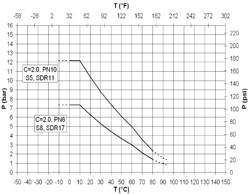
P Permissible pressure in bar, psi
T Temperature in °C, °F
Pressure/temperature diagram for PP
PP-H
The following pressure/temperature diagrams for PP-H
pipes and ttings are valid for a lifetime of 25 years.
The design factor of 2.0 recommended by GF is
incorporated.
They can be used for water or media resembling water,
in other words, media which have no derating factor
regarding the chemical resistance.
Remark: Please take into account the pressure/
temperature diagrams for valves and special ttings.
Becauseof the construction and/or sealing material
used, differences are possible when compared with
pipes and ttings. This information can be found in the
planning fundamentals of the relevant types of valves,
respectively special ttings.
According to the 10 °C line in the hydrostatic strength
curve for PP-H, a permissible pressure of 12.2 bar /
7.4 bar in the temperature range of -10° to +10° C for
the PN10 / PN6 system can be applied.
In case of applications with temperatures in the range
of the dotted lines please contact your GF representa-
tive.

Material
Dimension
Pressure Rating
Temperature Rating
Production
Marking
Testing and Inspection
(EN ISO 15494)
Material- and Product
Approvals/Conformance(1)
Welding Technology
Documentation(2)
Packing
Labeling
(3)
Main Applications
(1) (2) (3)
PROGEF Standard – System Specication
PROGEF Standard Pipes, Fittings, Unions,
Flanges and Flange Adaptors
Page
PP-H Pipes 14
Fittings for Socket Fusion 16
Adaptor Fittings for Socket Fusion 20
Unions for Socket Fusion 23
Adaptor Unions for Socket Fusion 26
Flange Adaptors, Flanges and Gaskets for Socket Fusion 31
Fittings for Butt Fusion 36
Adaptor Fittings for Butt Fusion 47
Unions for Butt Fusion 51
Flange Adaptors, Flanges and Gaskets for Butt Fusion 57
13
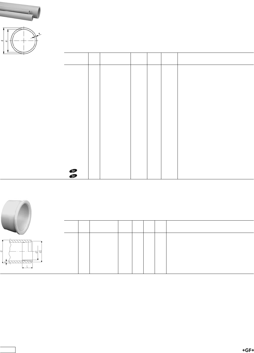
PP-H Pipes
67 48 07 PROGEF Standard, Pipes, S5/SDR11 (PN10)
Model:
ÏMaterial: PP-H
ÏDimension: DIN 8077
ÏColour: RAL 7032 gravel grey
ÏLength: Lengths of 5 m
* In these two sizes, stiffeners Code No. 727 900 006 (20 x 1,9) ad 727 900 007 (25 x
2,3) must be used with socket fusion joints.
¹Traded product, not +GF+ labelled
d
[mm]
PN Code kg/m e
[mm]
di
[mm]
16 10 167 480 710 0.080 1,8 12.4
*20 10 167 480 711 0.107 1,9 16.2
*25 10 167 480 712 0.164 2,3 20.4
32 10 167 480 713 0.261 2,9 26.2
40 10 167 480 714 0.412 3,7 32.6
50 10 167 480 715 0.638 4,6 40.8
63 10 167 480 716 1.010 5,8 51.4
75 10 167 480 717 1.410 6,8 61.4
90 10 167 480 718 2.030 8,2 73.6
110 10 167 480 719 3.010 10,0 90.0
125 10 167 480 720 3.910 11,4 102.2
140 10 167 480 721 4.870 12,7 114.6
160 10 167 480 722 6.380 14,6 130.8
180 10 167 480 723 8.070 16,4 147.2
200 10 167 480 724 9.950 18,2 163.6
225 10 167 480 725 12.600 20,5 184.0
250 10 167 480 726 15.500 22,7 224.6
280 10 167 480 727 19.400 25,4 229.2
315 10 167 480 728 24.600 28,6 257.8
355 10 167 480 729 31.200 32,2 290.6
400 10 167 480 730 39.600 36,3 327.4
1450 10 167 480 731 32.500 40.9 368.2
1500 10 167 480 732 40.200 45.4 409.2
27 90 00 PROGEF Standard, Stiffeners
Model:
ÏMaterial: PP-H
ÏUsed as support during d20 and d25 socket fusion jointing to prevent the pipe from
collapsing suring the heating and jointing process.
d
[mm]
e
[mm]
Code kg L
[mm]
d1
[mm]
d2
[mm]
20 1,9 727 900 006 0.002 10 14 18
25 2,3 727 900 007 0.003 11 18 23
14
67 48 10 PROGEF Standard, Pipes S3,2/SDR7,4 (PN16)
Model:
ÏMaterial: Polypropylene (PP-H) DIN 8078
ÏDimension: DIN 8077
ÏColour: RAL 7032 gravel grey
ÏLength: Lengths of 5 m
Ïfor socket fusion without stiffeners
d
[mm]
PN Code kg/m e
[mm]
di
[mm]
20 16 167 481 028 0.148 2,8 14.4
25 16 167 481 029 0.230 3,5 18.0
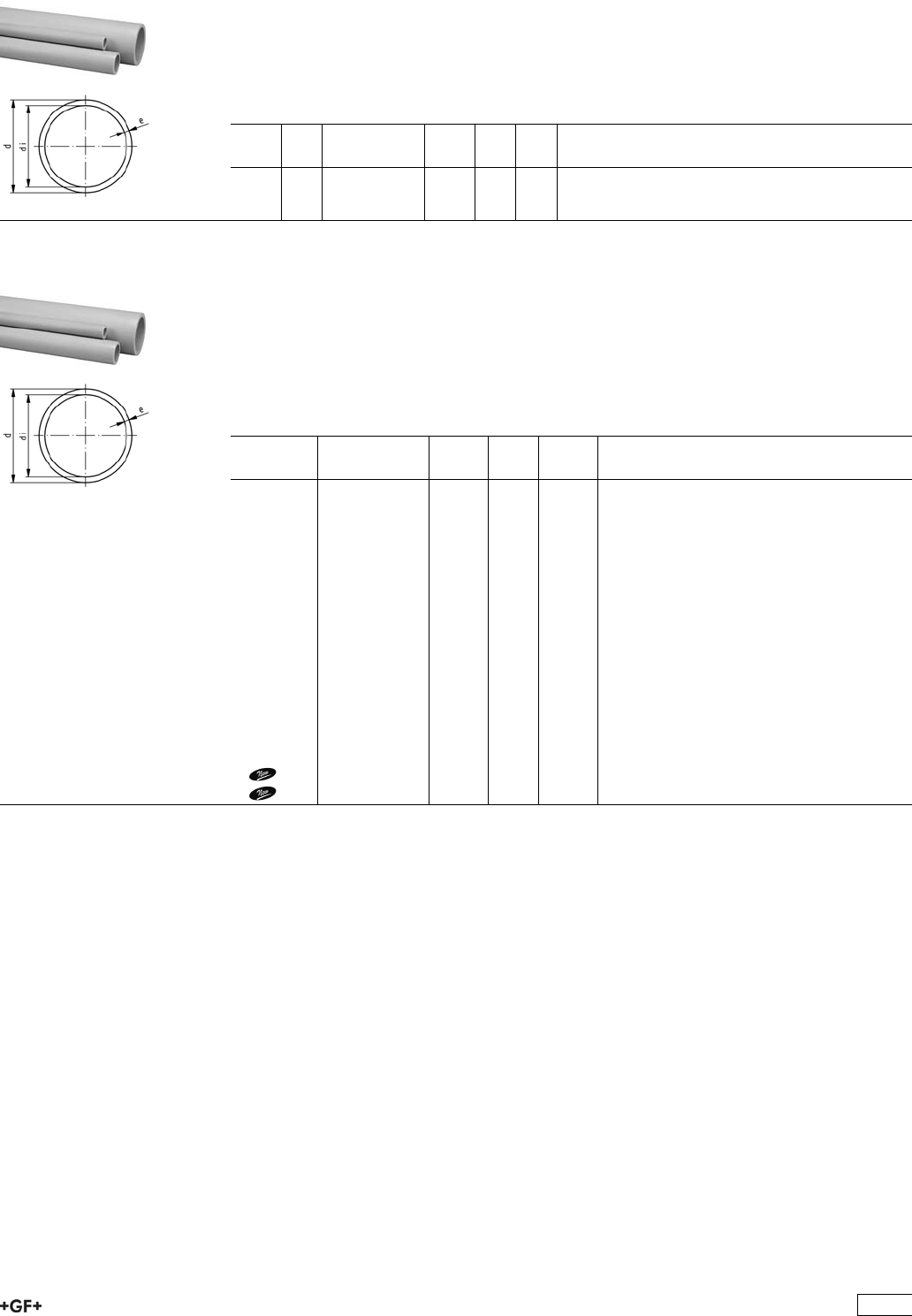
67 48 06 PROGEF Standard, Pipes, S8,3/SDR17,6 (PN6)
Model:
ÏMaterial: PP-H
ÏDimension: DIN 8077
ÏColour: RAL 7032 gravel grey
ÏLength: Lengths of 5 m
¹Traded product, not +GF+ labelled
d
[mm]
Code kg/m e
[mm]
di
[mm]
50 167 480 680 0.422 2,9 44.2
63 167 480 681 0.659 3,6 55.8
75 167 480 682 0.935 4,3 66.4
90 167 480 683 1.330 5,1 79.8
110 167 480 684 1.990 6,3 97.4
125 167 480 685 2.550 7,1 110.8
140 167 480 686 3.200 8,0 124.0
160 167 480 687 4.170 9,1 141.8
180 167 480 688 5.250 10,2 159.6
200 167 480 689 6.500 11,4 187.2
225 167 480 690 8.190 13 199.0
250 167 480 691 10.100 14,2 221.6
280 167 480 692 12.600 15,9 248.2
315 167 480 693 16.000 17,9 279.2
355 167 480 694 20.300 20,1 314.8
400 167 480 695 25.700 22,7 354.6
1450 167 480 696 32.500 25.5 399.0
1500 167 480 697 40.200 28.4 443.2
15
Fittings for Socket Fusion
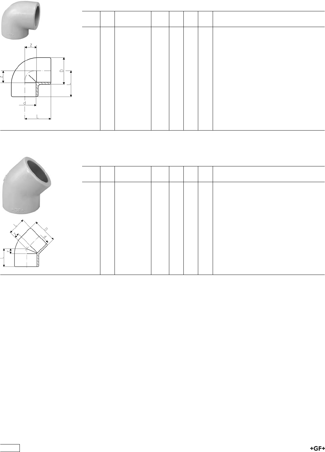
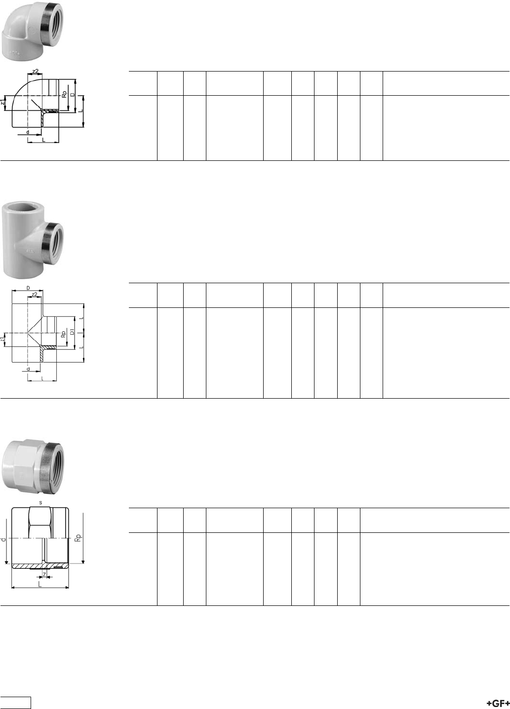
27 10 01 PROGEF Standard, Elbows 90°
Model:
ÏMaterial: PP-H
d
[mm]
PN Code kg D
[mm]
L
[mm]
z
[mm]
16 10 727 100 105 0.015 26 25 12
20 10 727 100 106 0.020 31 28 14
25 10 727 100 107 0.029 36 32 16
32 10 727 100 108 0.044 44 38 20
40 10 727 100 109 0.074 54 44 24
50 10 727 100 110 0.128 66 51 28
63 10 727 100 111 0.230 82 62 35
75 10 727 100 112 0.317 93 76 45
90 10 727 100 113 0.512 110 88 53
110 10 727 100 114 0.874 134 106 65
27 15 01 PROGEF Standard, Elbows 45°
Model:
ÏMaterial: PP-H
d
[mm]
PN Code kg D
[mm]
L
[mm]
z
[mm]
16 10 727 150 105 0.008 23 20 7
20 10 727 150 106 0.016 31 21 7
25 10 727 150 107 0.024 36 24 8
32 10 727 150 108 0.036 44 28 10
40 10 727 150 109 0.059 53 33 13
50 10 727 150 110 0.084 64 36 13
63 10 727 150 111 0.185 82 43 16
75 10 727 150 112 0.234 93 51 20
90 10 727 150 113 0.405 114 58 23
110 10 727 150 114 0.657 134 68 27
16
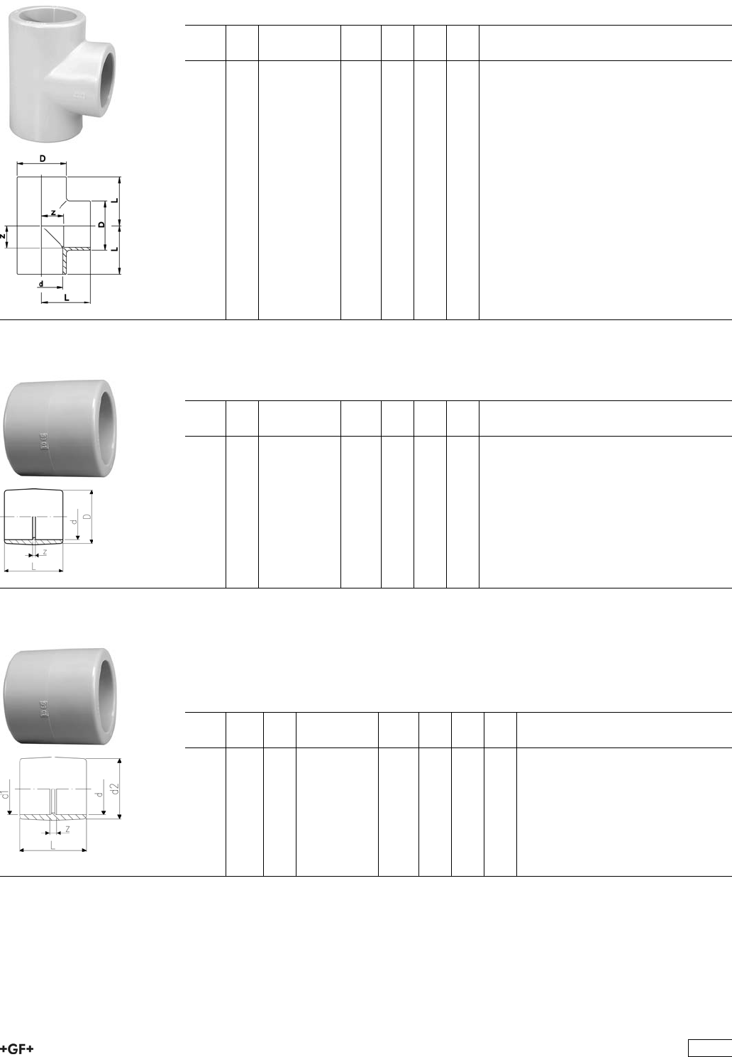
27 20 01 PROGEF Standard, Tees 90° equal
Model:
ÏMaterial: PP-H
d
[mm]
PN Code kg D
[mm]
L
[mm]
z
[mm]
16 10 727 200 105 0.019 26 25 12
20 10 727 200 106 0.027 31 28 14
25 10 727 200 107 0.038 36 32 16
32 10 727 200 108 0.058 44 38 20
40 10 727 200 109 0.094 54 44 24
50 10 727 200 110 0.158 66 51 28
63 10 727 200 111 0.288 82 62 35
75 10 727 200 112 0.380 93 76 45
90 10 727 200 113 0.739 114 88 53
110 10 727 200 114 1.070 134 106 65
27 91 01 PROGEF Standard, Sockets equal
Model:
ÏMaterial: PP-H
d
[mm]
PN Code kg D
[mm]
L
[mm]
z
[mm]
16 10 727 910 105 0.010 26 33 7
20 10 727 910 106 0.013 31 35 7
25 10 727 910 107 0.019 36 39 7
32 10 727 910 108 0.026 44 43 7
40 10 727 910 109 0.042 54 48 8
50 10 727 910 110 0.075 66 54 8
63 10 727 910 111 0.129 82 62 8
75 10 727 910 112 0.144 93 70 8
90 10 727 910 113 0.257 112 81 11
110 10 727 910 114 0.405 134 96 14
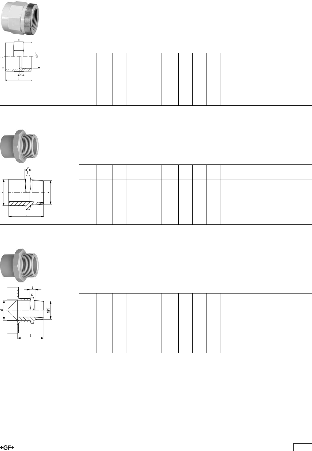
27 91 30 Adaptor Sockets, PP-H
metric - Inch BS
Model:
ÏMaterial: PP-H
ÏWith fusion socket metric and BS Inch (ASTM)
d
[mm]
d1
[inch]
PN Code kg d2
[mm]
L
[mm]
z
[mm]
20 1
/210 727 913 006 0.013 31 35 7
25 3
/410 727 913 007 0.010 36 39 7
32 1 10 727 913 008 0.025 44 43 7
40 1 1
/410 727 913 009 0.040 54 48 8
50 1 1
/210 727 913 010 0.100 66 54 8
63 2 10 727 913 011 0.130 82 62 8
90 3 10 727 913 013 0.260 112 81 10
110 4 10 727 913 014 0.389 134 96 12
17
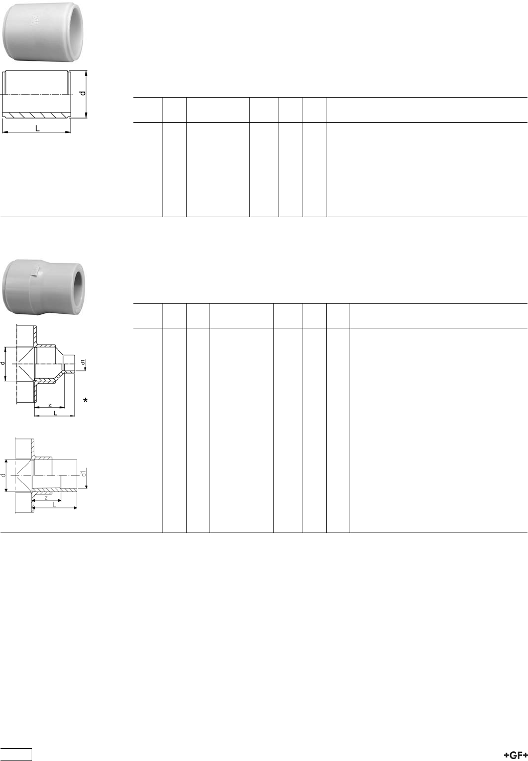
27 91 09 PROGEF Standard, Barrel Nipples
Model:
ÏMaterial: PP-H
ÏWith fusion sockets on both sides
ÏFor the shortest possible distance between fittings
ÏOverall length L = 2 x fusion length
* In these two sizes, stiffeners Code No. 727 900 006 (20 x 1,9) ad 727 900 007 (25 x
2,3) must be used with socket fusion joints.
d
[mm]
PN Code kg L
[mm]
e
[mm]
*20 10 727 910 906 0.005 37 1.9
*25 10 727 910 907 0.006 41 2.3
32 10 727 910 908 0.010 45 2.9
40 10 727 910 909 0.017 50 3.7
50 10 727 910 910 0.029 55 4.6
63 10 727 910 911 0.058 64 5.8
75 10 727 910 912 0.096 76 6.8
90 10 727 910 913 0.167 90 8.2
110 10 727 910 914 0.305 108 10.0
27 91 03 PROGEF Standard, Reducers
Model:
ÏMaterial: PP-H
Note:
Ï* Fusion spigot and socket
d
[mm]
d1
[mm]
PN Code kg L
[mm]
z
[mm]
20 16 10 727 910 334 0.009 35 22
25 16 10 727 910 338 0.010 38 25
25 20 10 727 910 337 0.014 37 23
32 20 10 727 910 342 0.016 43 29
32 25 10 727 910 341 0.020 43 27
*40 20 10 727 910 348 0.022 48 34
*40 25 10 727 910 347 0.026 48 32
40 32 10 727 910 346 0.031 48 30
*50 20 10 727 910 355 0.034 54 40
*50 25 10 727 910 354 0.035 54 38
*50 32 10 727 910 353 0.040 54 36
50 40 10 727 910 352 0.047 54 34
*63 25 10 727 910 361 0.058 64 48
*63 32 10 727 910 360 0.061 64 46
*63 40 10 727 910 359 0.068 64 44
63 50 10 727 910 358 0.082 64 41
75 63 10 727 910 364 0.098 62 35
*90 63 10 727 910 371 0.181 88 61
90 75 10 727 910 370 0.134 70 39
110 90 10 727 910 376 0.247 81 46
18
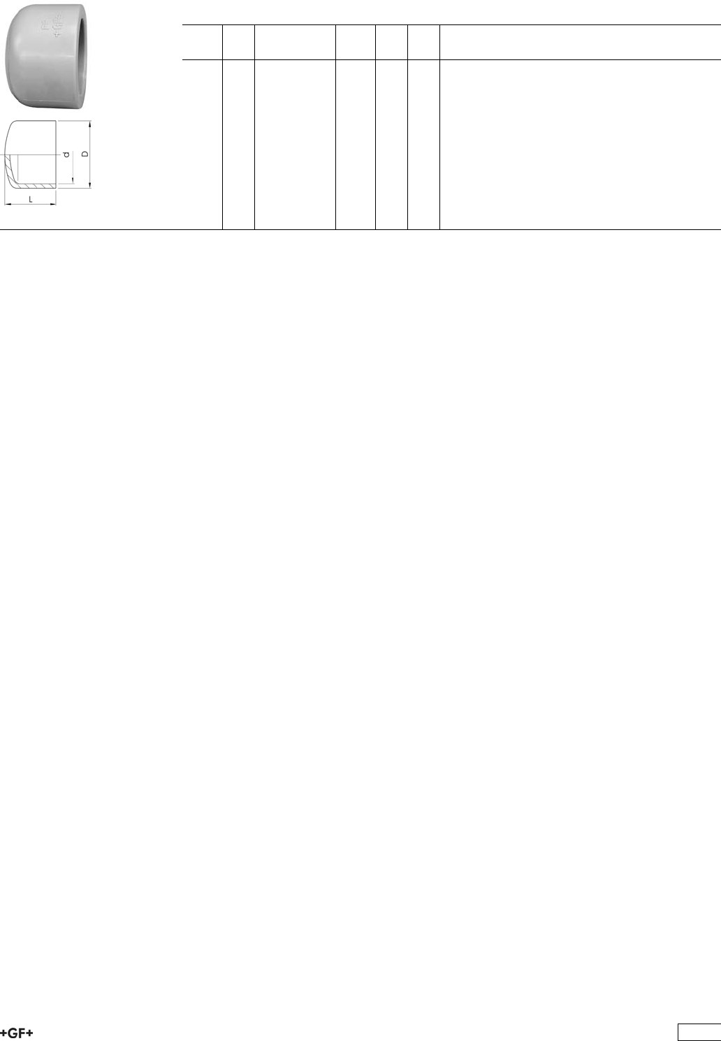
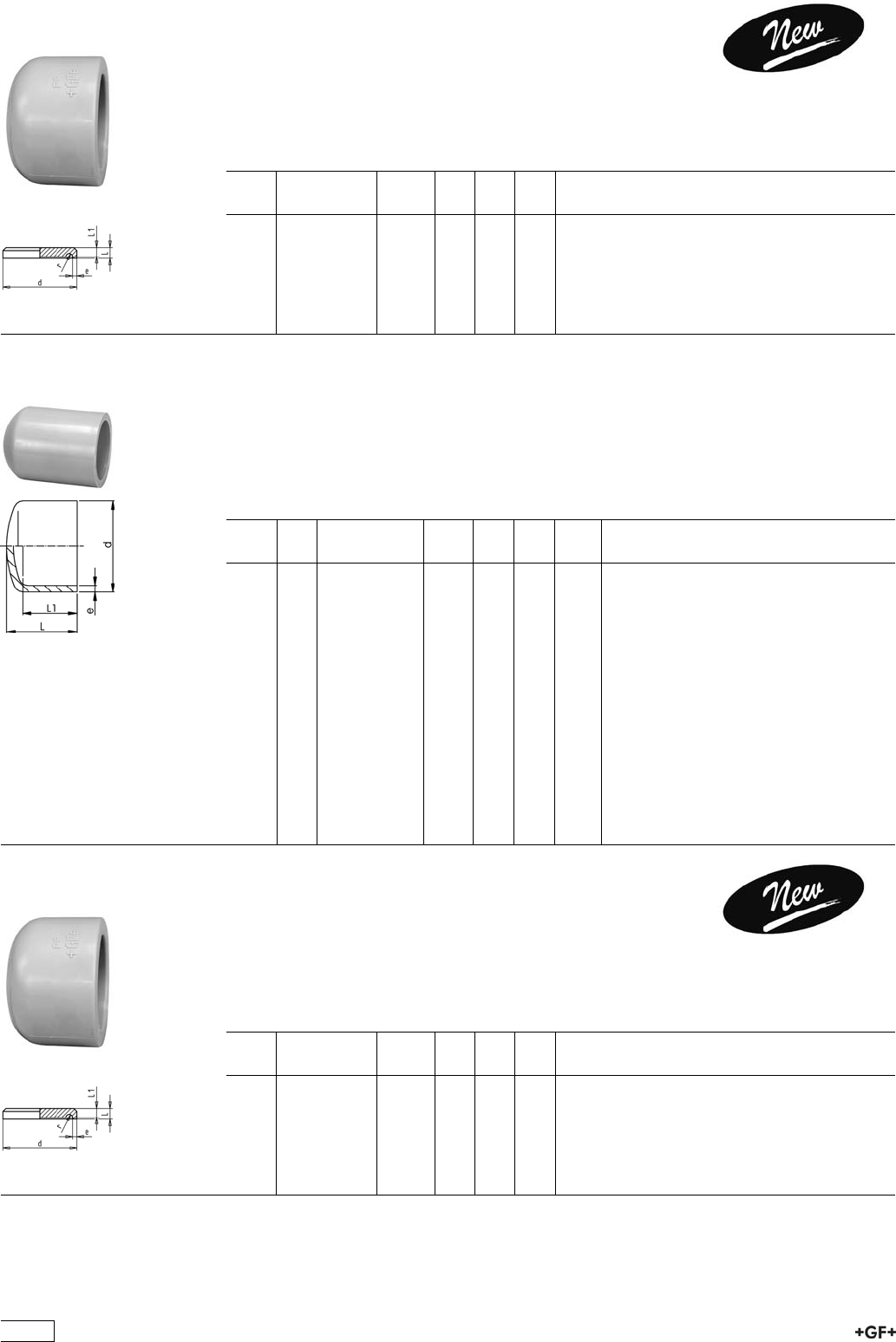
27 96 01 PROGEF Standard, End Caps
Model:
ÏMaterial: PP-H
d
[mm]
PN Code kg D
[mm]
L
[mm]
16 10 727 960 105 0.006 25 20
20 10 727 960 106 0.010 30 27
25 10 727 960 107 0.015 36 30
32 10 727 960 108 0.024 44 34
40 10 727 960 109 0.036 53 38
50 10 727 960 110 0.061 65 44
63 10 727 960 111 0.098 80 51
75 10 727 960 112 0.146 91 65
90 10 727 960 113 0.273 111 77
110 10 727 960 114 0.417 137 93
19
Adaptor Fittings for Socket Fusion
27 10 02 PROGEF Standard, Elbows 90°, metric - Rp
Model:
ÏMaterial: PP-H
ÏWith fusion socket metric and parallel female thread Rp, reinforced
ÏConnection to plastic or metal
ÏReinforcing ring stainless (A2)
ÏDo not use thread sealing pastes that are harmful to PP
d
[mm]
Rp
[inch]
PN Code kg D
[mm]
L
[mm]
z1
[mm]
z2
[mm]
20 1
/210 727 100 206 0.022 30 28 14 14
25 3
/410 727 100 207 0.029 35 32 16 16
32 1 10 727 100 208 0.054 44 38 20 20
40 1 1
/410 727 100 209 0.087 54 44 24 24
27 20 02 PROGEF Standard, Tees 90°, metric - Rp
Model:
ÏMaterial: PP-H
ÏLine, with fusion socket metric
ÏBranch, with BSP parallel female thread Rp, reinforced
ÏConnection to plastic or metal
ÏReinforcing ring stainless (A2)
ÏDo not use thread sealing pastes that are harmful to PP
d
[mm]
Rp
[inch]
PN Code kg D
[mm]
L
[mm]
z1
[mm]
z2
[mm]
20 1
/210 727 200 206 0.030 31 28 14 14
25 3
/410 727 200 207 0.042 36 32 16 16
32 1 10 727 200 208 0.069 44 38 20 20
40 1 1
/410 727 200 209 0.107 54 44 24 24
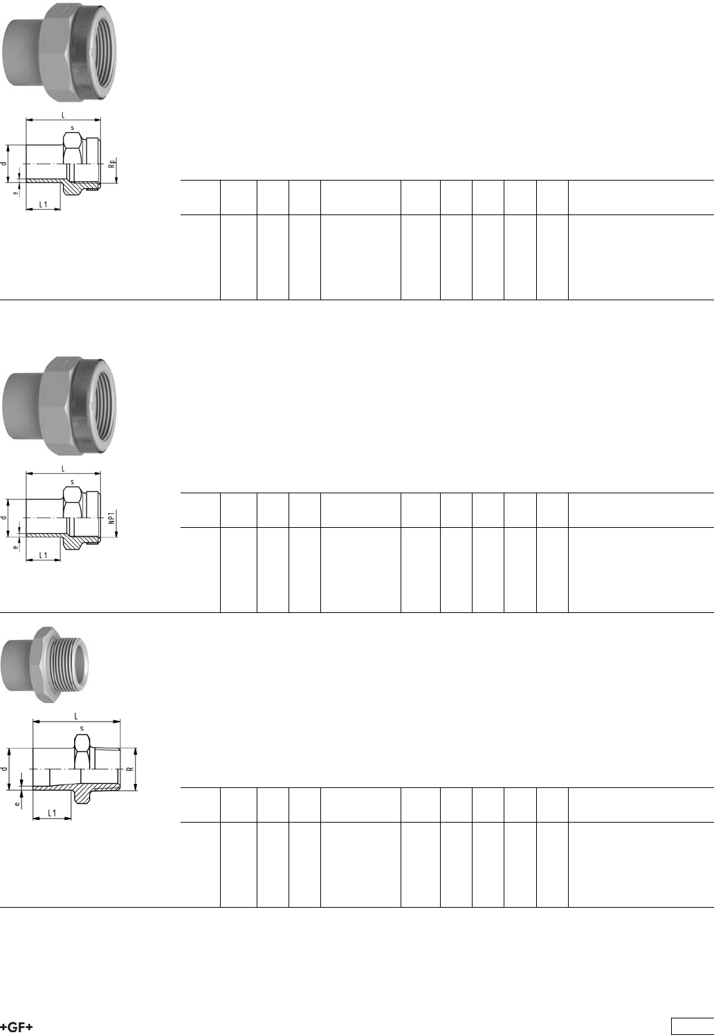
27 91 02 PROGEF Standard, Adaptor Sockets, metric - Rp
Model:
ÏMaterial: PP-H
ÏWith fusion socket metric and parallel female thread Rp, reinforced
ÏConnection to plastic or metal
ÏReinforcing ring stainless (A2)
ÏDo not use thread sealing pastes that are harmful to PP
d
[mm]
Rp
[inch]
PN Code kg L
[mm]
s
[mm]
z
[mm]
20 3
/810 727 910 205 0.017 35 32 7
20 1
/210 727 910 206 0.017 40 32 7
25 3
/410 727 910 207 0.023 42 36 7
32 1 10 727 910 208 0.038 48 46 7
40 1 1
/410 727 910 209 0.056 53 55 7
50 1 1
/210 727 910 210 0.089 54 65 9
63 2 10 727 910 211 0.137 62 80 9
20
27 91 42 Adaptor Sockets, PP-H
metric - NPT
Model:
ÏMaterial: PP-H
ÏWith fusion socket metric and NPT tapered female thread, reinforced
ÏConnection to plastic or metal
ÏReinforcing ring stainless (A2)
ÏDo not use thread sealing pastes that are harmful to PP
d
[mm]
NPT
[inch]
PN Code kg L
[mm]
s
[mm]
z
[mm]
20 1
/210 727 914 266 0.017 40 32 7
25 3
/410 727 914 267 0.023 42 36 7
32 1 10 727 914 268 0.038 48 46 7
40 1 1
/410 727 914 269 0.056 53 55 7
50 1 1
/210 727 914 270 0.092 54 65 9
63 2 10 727 914 271 0.146 62 80 9
27 91 05 PROGEF Standard, Adaptor Nipples, metric - R
Model:
ÏMaterial: PP-H
ÏWith fusion spigot metric and BSP tapered male thread
ÏConnection to plastic thread only
ÏDo not use thread sealing pastes that are harmful to PP
d
[mm]
R
[inch]
PN Code kg L
[mm]
s
[mm]
z
[mm]
16 3
/810 727 910 505 0.008 37 27 13
20 1
/210 727 910 506 0.012 42 32 13
25 3
/410 727 910 507 0.016 46 36 13
32 1 10 727 910 508 0.027 52 46 12
40 1 1
/410 727 910 509 0.041 56 55 14
50 1 1
/210 727 910 510 0.062 60 65 15
63 2 10 727 910 511 0.100 69 80 16
27 91 45 PROGEF Standard, Adaptor Nipples
metric - NPT
Model:
ÏMaterial: PP-H
ÏWith fusion spigot metric and NPT tapered male thread
ÏConnection to plastic thread only
ÏDo not use thread sealing pastes that are harmful to PP
d
[mm]
NPT
[inch]
PN Code kg s
[mm]
L
[mm]
z
[mm]
16 3
/810 727 914 555 0.008 27 37 13
20 1
/210 727 914 556 0.012 32 42 13
25 3
/410 727 914 557 0.016 36 46 13
32 1 10 727 914 558 0.027 46 52 12
40 1 1
/410 727 914 559 0.041 55 56 14
50 1 1
/210 727 914 560 0.100 65 60 15
63 2 10 727 914 561 0.185 80 69 16
21
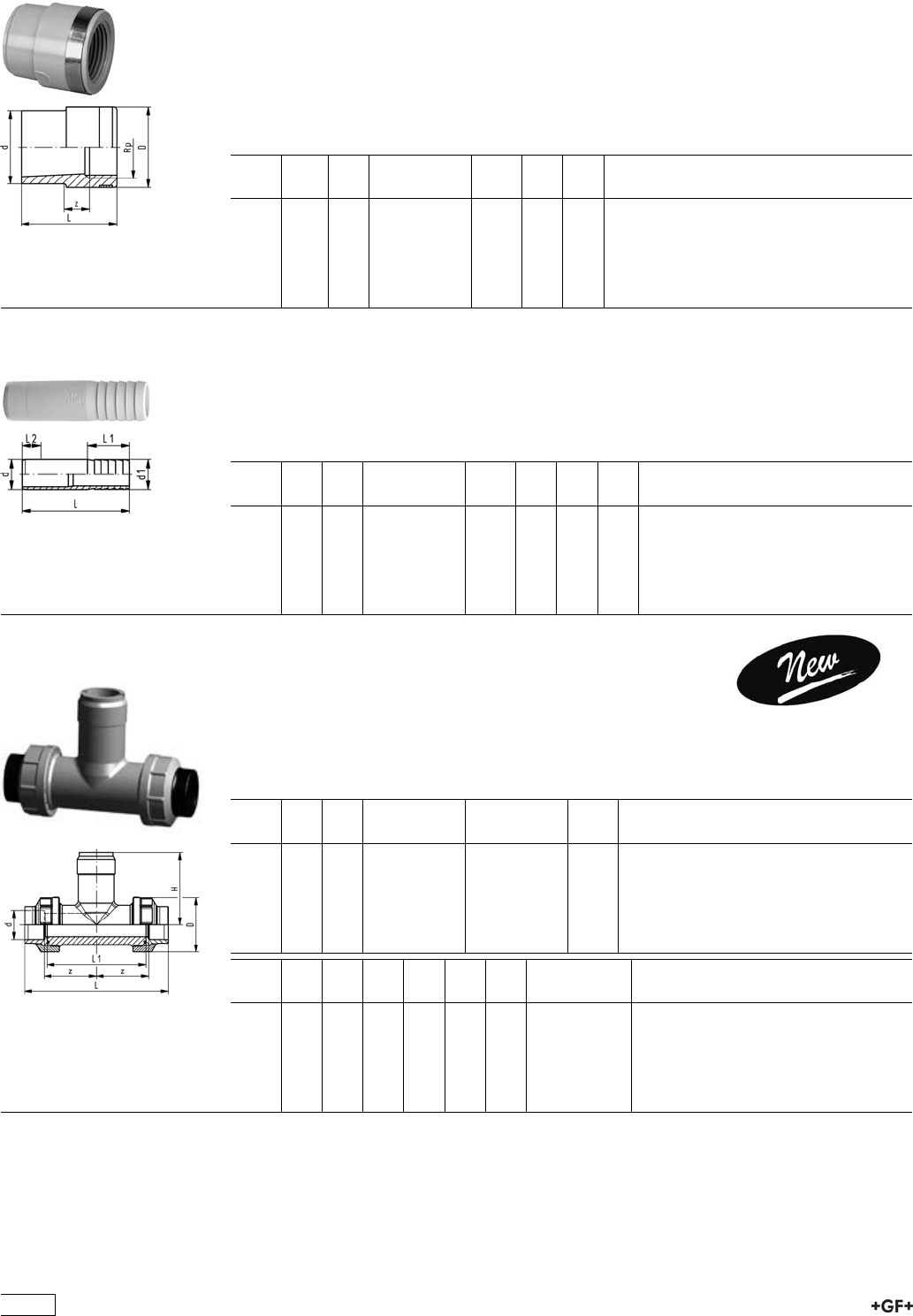
27 91 04 PROGEF Standard, Reducing Bushes
metric - Rp
Model:
ÏMaterial: PP-H
ÏWith fusion spigot metric and BSP parallel female thread, reinforced
ÏConnection to plastic or metal
ÏReinforcing ring stainless (A2)
ÏDo not use thread sealing pastes that are harmful to PP
d
[mm]
Rp
[inch]
PN Code kg L
[mm]
z
[mm]
20 1
/410 727 910 433 0.008 36 7
20 3
/810 727 910 434 0.011 36 7
25 1
/210 727 910 437 0.015 45 6
32 3
/410 727 910 441 0.023 47 8
40 1 10 727 910 446 0.039 53 9
50 1 1
/410 727 910 452 0.061 55 10
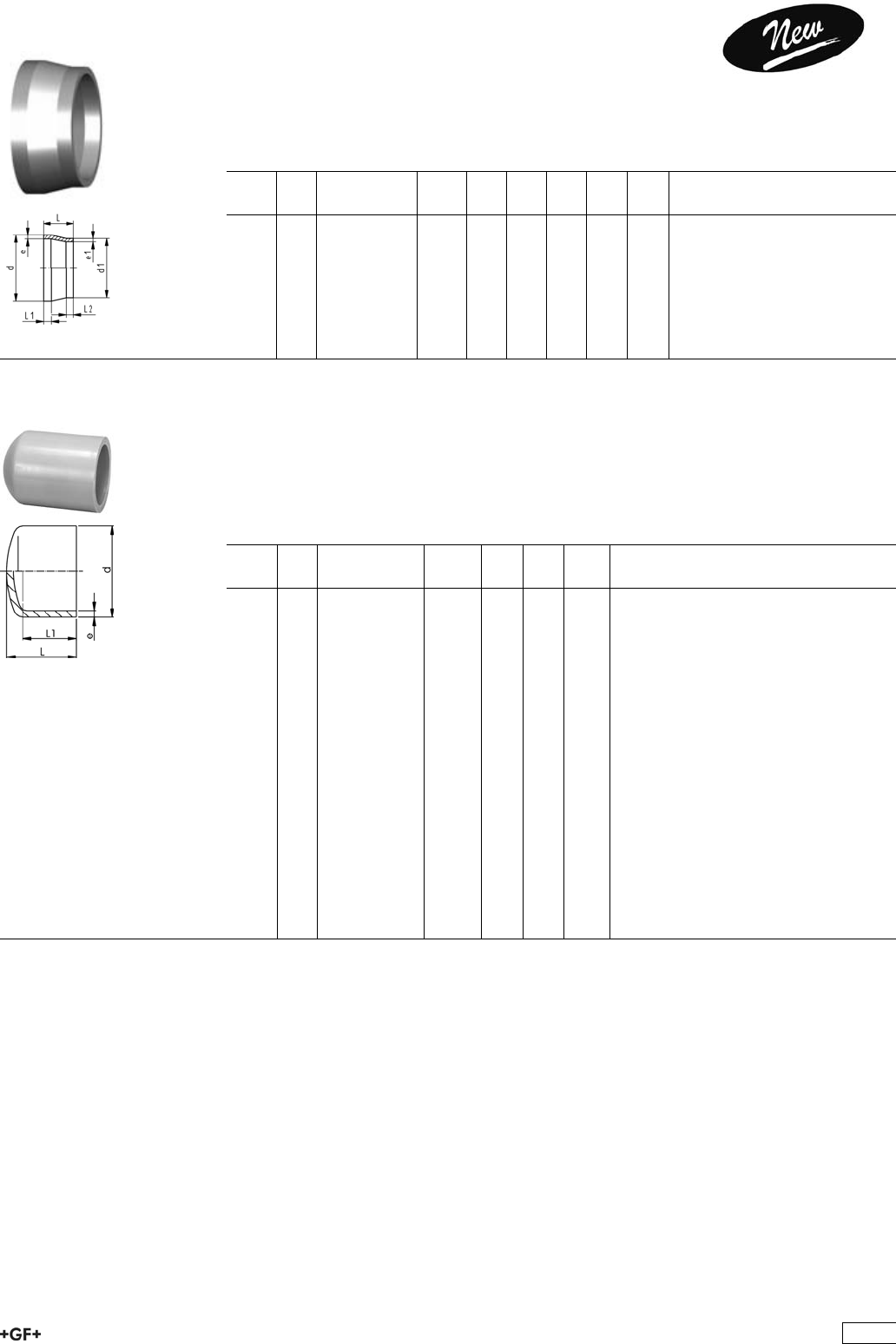
27 96 04 PROGEF Standard, Hose Connectors
metric
Model:
ÏMaterial: PP-H
ÏWith socket fusion spigot metric and parallel hose connection
d
[mm]
d1
[mm]
PN Code kg L
[mm]
L1
[mm]
L2
[mm]
20 20 10 727 960 406 0.009 78 27 14
25 25 10 727 960 407 0.015 91 36 16
32 32 10 727 960 408 0.026 100 36 18
40 40 10 727 960 409 0.040 104 42 20
50 50 10 727 960 410 0.061 90 48 23
63 60 10 727 960 411 0.096 100 50 27
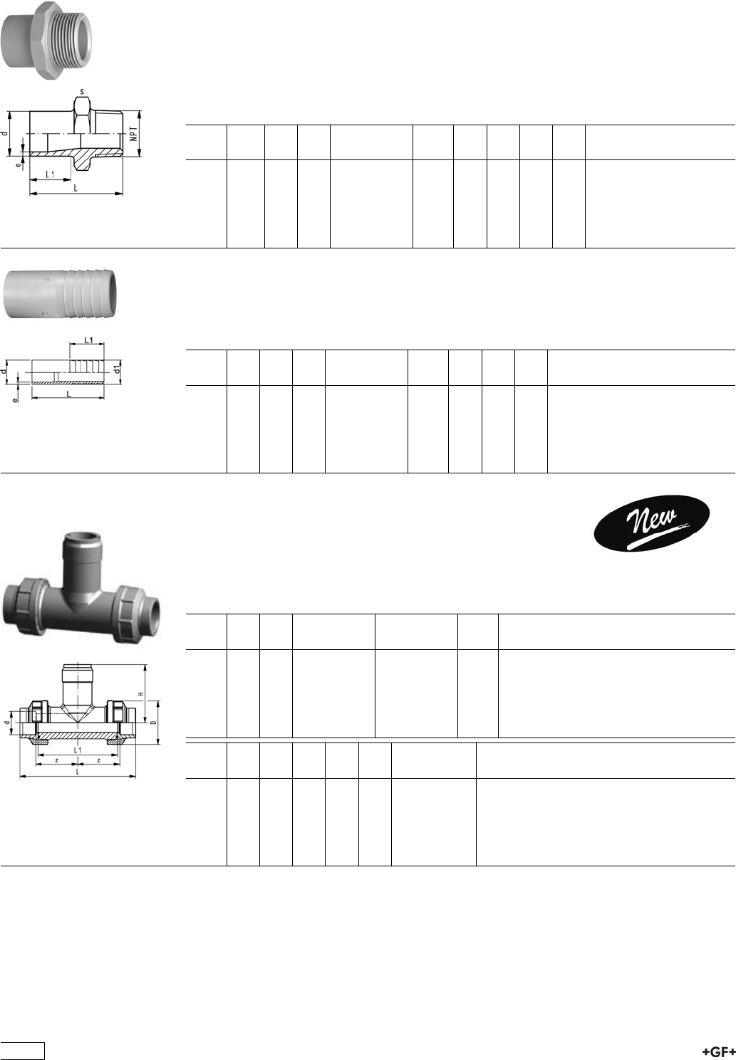
33 31 00 Installation Fitting Type 310, PE80
for Socket Systems metric
Model:
ÏFor Signet Paddlewheel Sensors Type -X0 (104 mm)
ÏBody and union nut PP-H
ÏUnion end with fusion socket PE80
d
[mm]
DN
[mm]
PN EPDM
Code
FPM
Code
kg
20 15 10 733 310 006 733 310 036 0.136
25 20 10 733 310 007 733 310 037 0.190
32 25 10 733 310 008 733 310 038 0.250
40 32 10 733 310 009 733 310 039 0.356
50 40 10 733 310 010 733 310 040 0.510
63 50 10 733 310 011 733 310 041 0.800
d
[mm]
DN
[mm]
D
[mm]
z
[mm]
L
[mm]
L1
[mm]
H
[mm]
Sensor Type
20 15 48 50 128 90 76 X0
25 20 58 55 142 100 78 X0
32 25 65 60 156 110 81 X0
40 32 79 60 160 110 85 X0
50 40 91 65 176 120 89 X0
63 50 105 70 194 130 95 X0
22
Unions for Socket Fusion
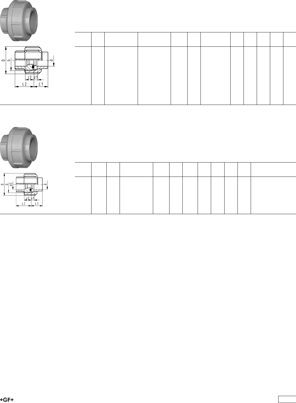
EPDM 27 51 01
FPM 27 52 01
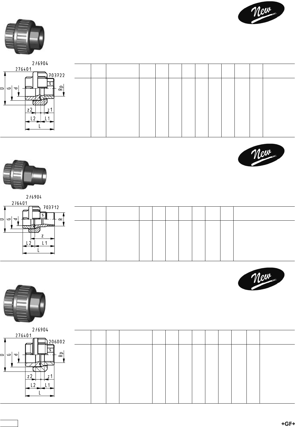
PROGEF Standard, Unions, metric
Model:
ÏMaterial: PP-H
ÏWith fusion sockets metric
ÏD75-110 with new thread geometry, now rated PN10 up to d110
ÏJointing face: with O-ring groove
ÏFor the dimensions d75-110 please see instructions for the installation
d
[mm]
PN EPDM
Code
FPM
Code
kg D
[mm]
G
[inch]
L1
[mm]
L2
[mm]
z
[mm]
z1
[mm]
16 10 727 510 155 727 520 155 0.020 35 3/4 18 24 5 11
20 10 727 510 156 727 520 156 0.038 48 1 19 26 5 12
25 10 727 510 157 727 520 157 0.062 58 1 1/4 21 28 5 12
32 10 727 510 158 727 520 158 0.079 65 1 1/2 23 30 5 12
40 10 727 510 159 727 520 159 0.137 79 2 25 34 5 14
50 10 727 510 160 727 520 160 0.180 91 2 1/4 28 39 5 16
63 10 727 510 161 727 520 161 0.312 111 2 3/4 32 47 5 20
75 10 727 510 172 727 520 172 0.450 135 S107,5x3,6 36 51 5 20
90 10 727 510 173 727 520 173 0.645 158 S127,5x3,6 42 55 7 20
110 10 727 510 174 727 520 174 1.020 188 S152,5x3,6 49 54 7 12
27 51 30 PROGEF Standard, Adapter Unions, metric - Inch BS
(ASTM)
Model:
ÏMaterial: PP-H
ÏWith fusion sockets metric
ÏJointing face: with O-ring groove
d
[mm]
d2 PN Code kg D
[mm]
G
[inch]
L1
[mm]
L2
[mm]
z1
[mm]
z2
[mm]
20 1
/210 727 513 006 0.036 48 1 19 26 5 12
25 3
/410 727 513 007 0.060 58 1 1/4 21 28 5 12
32 1 10 727 513 008 0.079 65 1 1/2 23 30 5 12
40 1 1
/410 727 513 009 0.112 79 2 25 34 5 14
50 1 1
/210 727 513 010 0.182 91 2 1/4 28 39 5 16
63 2 10 727 513 011 0.315 111 2 3/4 32 47 5 20
23
I]ZcZlZhi\ZcZgVi^dcd[eaVhi^Xjc^dch^ci]ZVWdkZbViZg^VahVcYY^bZch^dch]VhWZZcÒiiZY
l^i]VhiViZ"d["i]Z"Vgi!eaVhi^Xh"dg^ZciZYWjiigZhhi]gZVY#Ndji]ZgZ[dgZ]VkZVegdYjXi^cl]^X]
i]Zcdb^cVaegZhhjgZVcYi]ZhV[ZingZhZgkZ]VkZWZZcYgVbVi^XVaan^cXgZVhZY#6ahdcZlVgZi]Z
Wjii[jh^dckZgh^dch#>ci]^hXdccZXi^dc!i]ZgZVgZV[Zled^cihl]^X]ndjbjhiWZVlVgZd[#
8Vji^dc
I]Zi]gZVYhd[i]Zjc^dccjiVcYWjh]]VkZWZZcgZldg`ZY[dgEE!EK9;VcYE:L]Zc
jh^c\^cY^k^YjVaeVgih!eaZVhZX]ZX`eg^dgid^chiVaaVi^dc^[i]Zi]gZVYhd[i]Zjc^dcWjh]VcY
i]Zjc^dccjiXd^cX^YZ#
Jc^dcWjh]l^i]igVeZod^Yi]gZVYdcjc^dccjil^i]igVeZod^Yi]gZVY
dg
Jc^dcWjh]l^i]WjiigZhhi]gZVYdcjc^dccjil^i]WjiigZhhi]gZVY
I^e
IdbV`Z^chiVaaVi^dcd[i]Zjc^dcZVh^Zg!lZii]Zjc^dccji#
;dgi]ZY^bZch^dchY.%VcYY&&%lZVYk^hZ[jh^c\i]ZXdbeaZiZjc^dc!^[edhh^WaZdgha^YZ
i]Zjc^dccjiidi]ZXdaaVgd[i]Zjc^dcZcYWZXVjhZV[iZg[jh^dci]Zjc^dccjiXVccdiWZ
ha^YdkZgi]Z[jh^dcWZVY#;^\#&
S ;dgYZh^\cgZVhdch!^i^hi]ZdgZi^XVaanedhh^WaZidXdbW^cZY^[[ZgZcicdb^cVaY^VbZiZghd[
jc^dcZcYhVcYcjih#IdbV`ZhjgZXdbW^cVi^dchVgZiZX]c^XVaanXdggZXi!ndjXVcÒcYi]Z
XdYZcjbWZghd[i]Zh^c\aZeVgihVcYheVgZeVgih[dgZVX]jc^dc^ci]ZIVWaZh&"(#
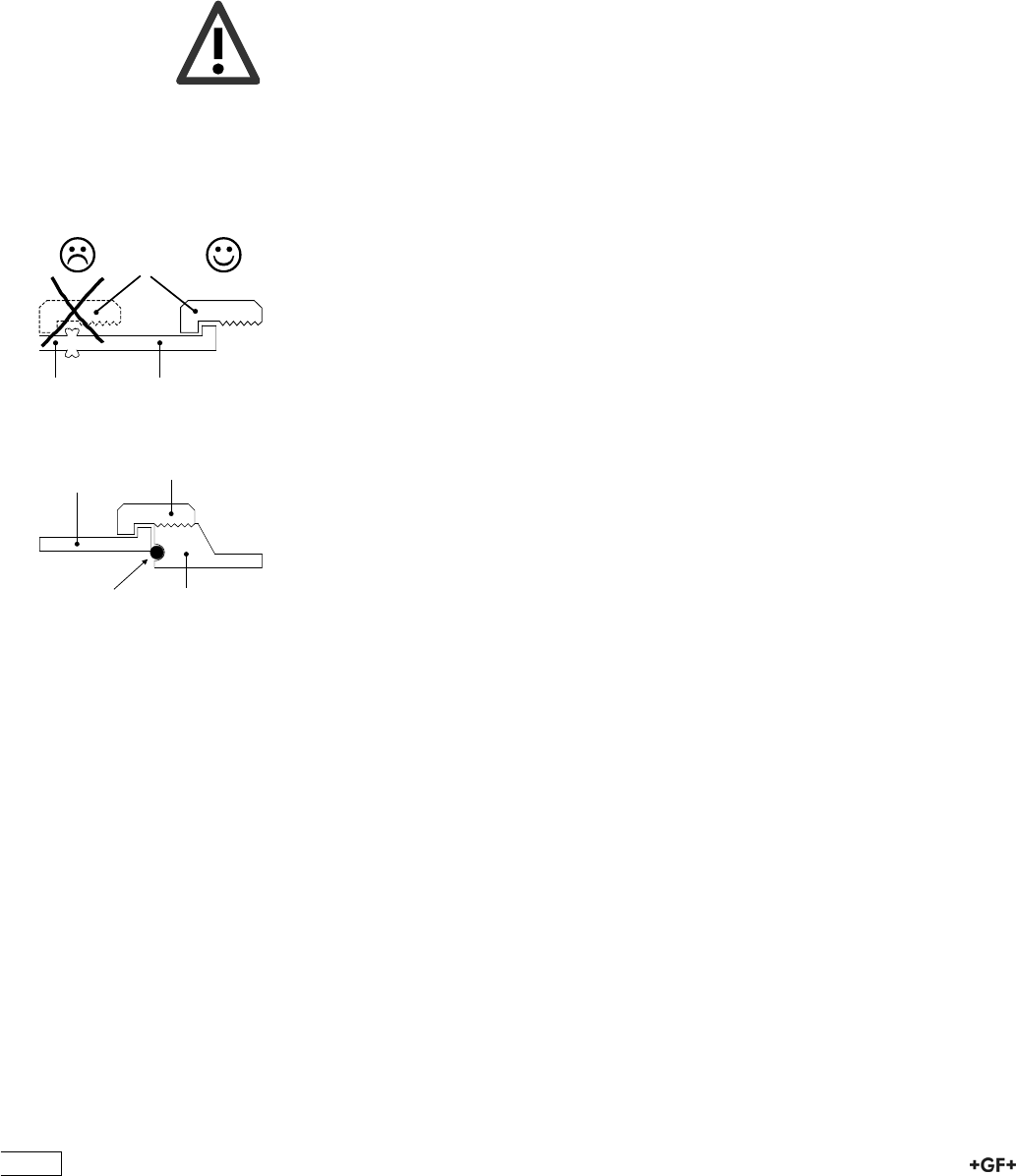
8Vji^dc
DcanjhZjc^dcWjh]ZhVcYjc^dcZcYhl^i]i]ZhVbZcdb^cVaY^VbZiZg
6Wjii[jh^dcjc^dcWjh]Y,*bVncdiWZXdbW^cZYl^i]VWjii[jh^dcjc^dcZcYY.%id[dgbV
gZYjXZgWZXVjhZi]^hXVcXVjhZaZV`V\Z!Vh^aajhigViZYidi]ZaZ[i#;^\#'
BVg`^c\hdci]Zjc^dccjih
H;$BH2hdX`Zi[jh^dc!7;$HI2Wjii[jh^dc
H;$BH,* heZX^ÒZY[dghdX`Zi[jh^dcY,*
7;$HI,*Ä.% heZX^ÒZY[dgWjii[jh^dcY,*Ä,*VcYY.%Ä.%
H;$BH.% heZX^ÒZYhdX`Zi[jh^dcY.%
7;$HI&&% heZX^ÒZYWjii[jh^dcY&&%
&&% heZX^ÒZY[dghdX`Zi[jh^dcY&&%
I^e
LZgZXdbbZcYX]Vc\^c\bViZg^Vahdcan[dgi]Zjc^dcZcY[dg^chiVaaVi^dcgZVhdch#
>chigjXi^dch[dgi]Z^chiVaaVi^dcd[jc^dch^cEE!
E:Y,*!Y.%VcYY&&%
butt fusion
union bush d 75
butt fusion
union end d 90
union nut d 75
insufficient
seal
;^\#'
union endpipe
union nut
;^\#&
24

HZaZXi^dciVWaZh[dgh^c\aZeVgihVcYheVgZeVgih
IVWaZ&
H^c\aZeVgih[dgEE"=jc^dchY,*!Y.%VcYY&&%
Y 7;$HI H;$BH H9G EC 8dYZjc^dcZcY 8dYZjc^dcWjh] 8dYZjc^dccji
,* && &% ,',+%-*&' ,',+)-*&' ,',+.%)''
&,#+ + ,',+%-)&' ,',+)-)&' ,',+.%)''
Å &% ,',+%%&&' ,',+)%&,' ,',+.%)''
.% && &% ,',+%-*&( ,',+)-*&( ,',+.%)''
&,#+ + ,',+%-)&( ,',+)-)&( ,',+.%)''
Å &% ,',+%%&&( ,',+)%&,( ,',+.%)'(
&&% && &% ,',+%-*&) ,',+)-*&) ,',+.%)'(
&,#+ + ,',+%-)&) ,',+)-)&) ,',+.%)'(
Å &% ,',+%%&&) ,',+)%&,) ,',+.%)')
IVWaZ'
H^c\aZeVgih[dgE:&%%jc^dchY,*!Y.%VcYY&&%
Y 7;$HI H;$BH H9G EC 8dYZjc^dcZcY 8dYZjc^dcWjh] 8dYZjc^dccji
,* && &% ,*(+%-+&' ,*(+)-+&' ,',+.%))'
&,#+ &% ,*(+%-)&' ,*(+)-)&' ,',+.%))'
.% && &% ,*(+%-+&( ,*(+)-+&( ,',+.%))'
&,#+ &% ,*(+%-)&( ,*(+)-)&( ,',+.%))'
&&% && &% ,*(+%-+&) ,*(+)-+&) ,',+.%))(
&,#+ &% ,*(+%-)&) ,*(+)-)&) ,',+.%))(
IVWaZ(
D"G^c\h[dgEE"=!E:&%%
Y 7;$HI H;$BH H9G EC 8dYZD"G^c\:E9B& 8dYZD"G^c\;EB&
,* &+ ,)-)&%%&( ,).)&%%&(
&+ ,)-)&%%&) ,).)&%%&)
.% &+ ,)-)&%%&) ,).)&%%&)
&+ ,)-)&%%&* ,).)&%%&*
&&% &+ ,)-)&%%&* ,).)&%%&*
&+ ,)-)&%%&+ ,).)&%%&+
Jc^dccjihdkZgaVehZkZgVaY^bZch^dch
& ;aVc\ZVYVeidgD"g^c\h!dcZh^oZhbVaaZg^ccdb^cVaY^bZch^dch!VgZjhZY[dgi]ZY,*Ä&&%Wjii"[jh^dc
jc^dch
7jii[jh^dc
HdX`Zi[jh^dc
25
Adaptor Unions for Socket Fusion
27 53 03 Adaptor Unions, PP-H / malleable iron
metric - Rp
Model:
ÏUnion Nut: PP-H
ÏUnion Bush: fusion socket PP-H metric
ÏUnion End: malleable iron with parallel female thread Rp
ÏGasket: O-Ring EPDM No. 48 41 00
d
[mm]
Rp
[inch]
Code kg D
[mm]
L
[mm]
L1
[mm]
L2
[mm]
z1
[mm]
z2
[mm]
G
[inch]
s
[mm]
20 1
/2727 530 306 0.073 43 48 22 26 9 10 1 25
25 3
/4727 530 307 0.118 51 50 22 28 7 10 1 1/4 31
32 1 727 530 308 0.199 58 56 26 30 9 10 1 1/2 38
40 1 1
/4727 530 309 0.276 72 65 31 34 12 12 2 48
50 1 1
/2727 530 310 0.357 83 72 33 39 14 14 2 1/4 54
63 2 727 530 311 0.579 100 82 35 47 11 18 2 3/4 67
27 53 08 Adaptor Unions, PP-H / malleable iron
metric - R
Model:
ÏUnion Nut: PP-H
ÏUnion Bush: fusion socket PP-H metric
ÏUnion End: malleable iron with taper male thread R
ÏGasket: O-Ring EPDM No. 48 41 00
d
[mm]
R
[inch]
Code D
[mm]
L
[mm]
L1
[mm]
L2
[mm]
z
[mm]
G
[inch]
s
[mm]
20 1
/2727 530 806 43 66 40 26 50 1 25
25 3
/4727 530 807 51 71 43 28 53 1 1/4 31
32 1 727 530 808 58 78 48 30 58 1 1/2 38
40 1 1
/4727 530 809 72 91 57 34 69 2 48
50 1 1
/2727 530 810 83 98 59 39 73 2 1/4 54
63 2 727 530 811 100 109 62 47 80 2 3/4 67
27 55 03 Adaptor Unions, PP-H / Brass
metric - Rp
Model:
ÏUnion Nut: PP-H
ÏUnion Bush: fusion socket PP-H metric
ÏUnion End: brass with parallel female thread Rp
ÏGasket: O-Ring EPDM No. 48 41 00
d
[mm]
Rp
[inch]
PN Code D
[mm]
L
[mm]
L1
[mm]
L2
[mm]
z1
[mm]
z2
[mm]
G
[inch]
s
[mm]
20 1
/210 727 550 306 48 48 22 26 10 10 1 25
25 3
/410 727 550 307 58 50 22 28 6 10 1 1/4 31
32 1 10 727 550 308 65 57 27 30 8 10 1 1/2 38
40 1 1
/410 727 550 309 79 65 31 34 10 12 2 48
50 1 1
/210 727 550 310 91 69 30 39 9 14 2 1/4 54
63 2 10 727 550 311 105 81 34 47 8 18 2 3/4 67
26
27 55 08 Adaptor Unions, PP-H / Brass
metric - R
Model:
ÏUnion Nut: PP-H
ÏUnion Bush: fusion socket PP-H metric
ÏUnion End: brass with taper male thread R
ÏGasket: O-Ring EPDM No. 48 41 00
d
[mm]
R
[inch]
PN Code D
[mm]
L
[mm]
L1
[mm]
L2
[mm]
z
[mm]
G
[inch]
s
[mm]
20 1
/210 727 550 806 48 63 37 26 47 1 25
25 3
/410 727 550 807 58 68 40 28 50 1 1/4 31
32 1 10 727 550 808 65 73 43 30 53 1 1/2 38
40 1 1
/410 727 550 809 79 82 48 34 60 2 48
50 1 1
/210 727 550 810 91 89 50 39 64 2 1/4 54
63 2 10 727 550 811 105 104 57 47 75 2 3/4 67
67 05 02 Tank Adaptors, PP
Model:
ÏMaterial: PP-H
ÏEnd connection: Union with fusion socket metric
ÏGasket: flat gasket EPDM
d
[mm]
Code kg G
[inch]
D
[mm]
L
[mm]
L1
[mm]
L2
[mm]
L3
max
[mm]
L4
[mm]
s
[mm]
Diameter
of bore in
tank side
[mm]
20 167 050 226 0.083 1 56 89 67 11 30 16 38 35
25 167 050 227 0.135 1 1
/465 96 72 12 32 18 47 43
32 167 050 228 0.158 1 1
/270 100 75 12 33 20 53 49
40 167 050 229 0.305 2 95 106 78 12 32 22 75 61
50 167 050 230 0.325 2 1
/495 112 82 13 32 25 75 67
63 167 050 231 0.325 2 3
/4115 112 87 13 33 29 101 83
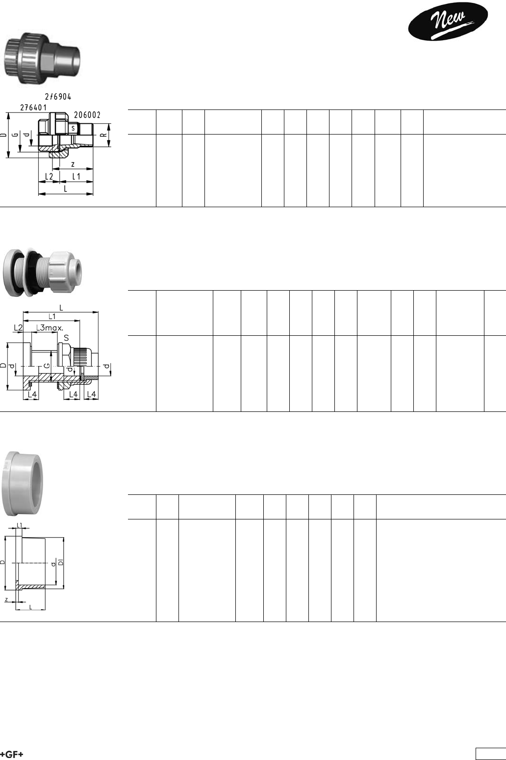
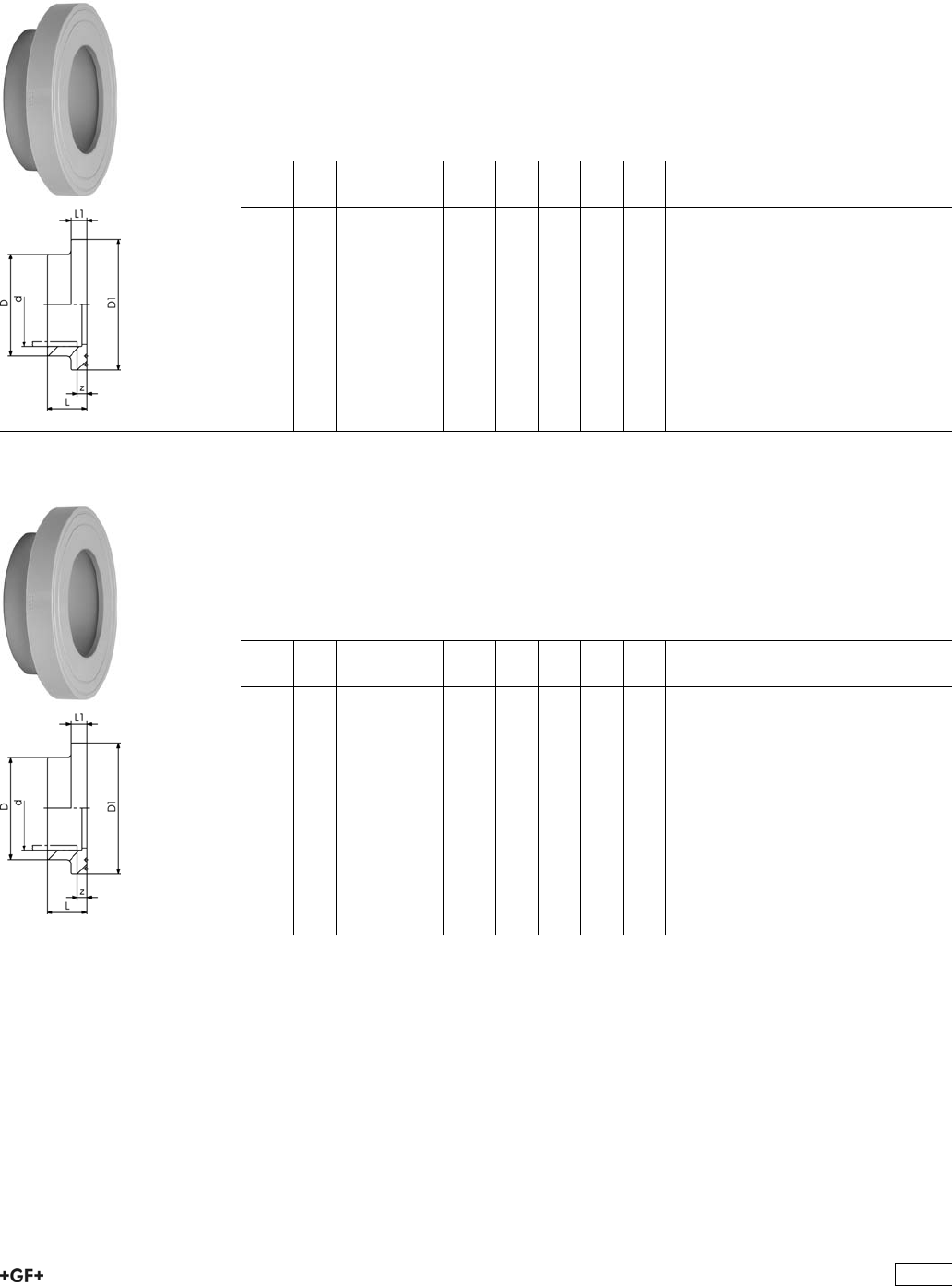
27 60 01 Union Ends, PP-H
Model:
ÏMaterial: PP-H
ÏWith fusion sockets metric
ÏSuitable for unions, diaphragm valves Type 314, tank adaptors and Vortex sensors
d
[mm]
PN Code kg D
[mm]
D1
[mm]
L
[mm]
L1
[mm]
z
[mm]
16 10 727 600 105 0.004 24 22 18 4 3
20 10 727 600 106 0.006 30 28 19 5 3
25 10 727 600 107 0.011 39 36 21 5 3
32 10 727 600 108 0.014 45 42 23 6 3
40 10 727 600 109 0.025 57 53 25 6 3
50 10 727 600 110 0.024 63 59 28 7 3
63 10 727 600 111 0.042 79 74 32 8 3
75 10 727 600 112 0.085 101 91 36 10 3
90 10 727 600 113 0.130 121 108 42 11 5
110 10 727 600 114 0.220 146 131 49 12 6
27
34 60 01 Union Ends, PE80
Model:
ÏWith fusion socket metric
ÏSuitable for unions, tank connectors and diaphragm valves Type 314
d
[mm]
PN Code kg d1
[mm]
d2
[mm]
L
[mm]
L1
[mm]
z
[mm]
20 10 734 600 106 0.006 28 30 19 5 5
25 10 734 600 107 0.012 36 39 21 5 5
32 10 734 600 108 0.015 42 45 23 6 5
40 10 734 600 109 0.026 53 57 25 6 5
50 10 734 600 110 0.027 59 63 28 7 5
63 10 734 600 111 0.045 74 79 32 8 5
27 64 01 Union Bushes, PP-H
Model:
ÏMaterial: PP-H
ÏWith fusion sockets metric
ÏD75-110 with new thread geometry, now rated PN10 up to d110
ÏJointing face: with O-ring groove
ÏFor the dimensions d75-110 please see instructions for the installation
d
[mm]
PN Code kg G
[inch]
L
[mm]
z
[mm]
16 10 727 640 155 0.006 3/4 24 11
20 10 727 640 156 0.011 1 26 12
25 10 727 640 157 0.018 1 1/4 28 12
32 10 727 640 158 0.024 1 1/2 30 12
40 10 727 640 159 0.040 2 34 14
50 10 727 640 160 0.052 2 1/4 39 16
63 10 727 640 161 0.096 2 3/4 47 20
75 10 727 640 172 0.080 S107,5x3,6 51 18
90 10 727 640 173 0.220 S127,5x3,6 55 18
110 10 727 640 174 0.289 S152,5x3,6 54 22
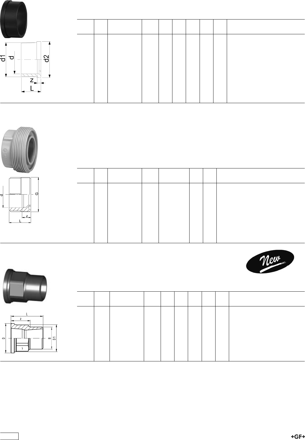
70 37 12 Union Ends, Malleable Iron Galvanized
R
Model:
ÏUnion End: malleable iron with taper male thread R
d
[mm]
R
[inch]
Code kg D
[mm]
D1
[mm]
L
[mm]
z
[mm]
s
[mm]
20 1
/2724 600 806 0.085 30 27 40 25 23
25 3
/4724 600 807 0.147 39 36 43 27 30
32 1 724 600 808 0.210 44 41 48 29 36
40 1 1
/4724 600 809 0.315 56 52 57 36 48
50 1 1
/2724 600 810 0.411 62 58 59 37 54
63 2 724 600 811 0.665 78 73 62 36 66
28
70 37 22 Union Ends, Malleable Iron Galvanized
Rp
Model:
ÏUnion End: malleable iron with parallel female thread Rp
d
[mm]
Rp
[inch]
Code kg D
[mm]
D1
[mm]
L
[mm]
z
[mm]
s
[mm]
20 1
/2724 600 206 0.058 30 27 22 9 25
25 3
/4724 600 207 0.096 39 36 22 7 31
32 1 724 600 208 0.127 44 41 26 9 38
32 1 1
/4724 600 209 0.204 56 52 31 12 48
50 1 1
/2724 600 210 0.268 62 58 33 14 54
63 2 724 600 211 0.443 78 73 35 11 67
20 60 02 Union Ends, Brass
Rp
Model:
ÏUnion End: brass with parallel female thread Rp
d
[mm]
Rp
[inch]
Code kg D
[mm]
D1
[mm]
z
[mm]
L
[mm]
20 1
/2720 600 206 0.059 30 28 7 22
25 3
/4720 600 207 0.094 39 36 6 22
32 1 720 600 208 0.138 45 42 8 27
40 1 1
/4720 600 209 0.250 56 53 10 31
50 1 1
/2720 600 210 0.282 62 59 10 30
63 2 720 600 211 0.480 78 74 8 34
75 2 1
/2720 600 212 0.796 100 91 8 38
90 3 720 600 213 1.238 121 110 7 40
20 60 02 Union Ends, Brass
R
Model:
ÏUnion End: brass with taper male thread R
d
[mm]
R
[inch]
Code kg D
[mm]
D1
[mm]
L
[mm]
z
[mm]
s
[mm]
20 1
/2720 600 226 0.097 30 27 37 24 25
25 3
/4720 600 227 0.148 39 36 40 26 31
32 1 720 600 228 0.224 45 42 43 26 38
32 1 1
/4720 600 229 0.384 56 53 48 29 48
50 1 1
/2720 600 230 0.468 62 59 50 31 54
63 2 720 600 231 0.746 78 74 57 34 67
75 2 1
/2720 600 232 1.285 100 92 70 43 83
90 3 720 600 233 1.809 121 110 72 42 96
29
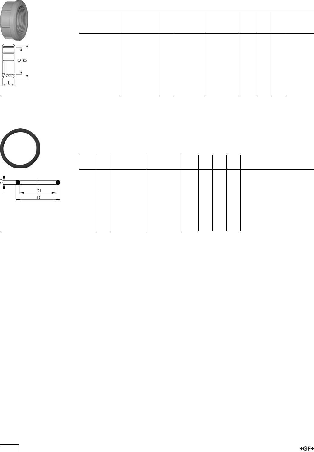
27 69 04 Union Nut, PP-GF
Model:
ÏPP glass-fibre reinforced
Socket
Fusion d
[mm]
Butt Fusion d
[mm]
PN G
[inch]
Code kg D
[mm]
L
[mm]
16 16 10 3/4 727 690 405 0.008 35 21
20 20 10 1 727 690 406 0.021 48 24
25 25 10 1 1/4 727 690 407 0.034 58 26
32 32 10 1 1/2 727 690 408 0.042 65 28
40 40 10 2 727 690 409 0.045 79 31
50 50 10 2 1/4 727 690 410 0.060 91 35
63 63 10 2 3/4 727 690 411 0.168 111 39
75 75 - 90 10 S107,5x3,6 727 690 422 0.205 135 40
90 110 10 S127,5x3,6 727 690 423 0.288 158 43
110 - 10 S152,5x3,6 727 690 424 0.460 188 48
EPDM 48 41 00
FPM 49 41 00
O-Ring Gaskets
Model:
ÏFor unions and adaptor unions
ÏHardness approx. 65° Shore
ÏEPDM minimum temperature -40°C
ÏFPM minimum temperature -15°C
d
[mm]
DN
[mm]
EPDM
Code
FPM
Code
kg D
[mm]
D1
[mm]
D2
[mm]
16 10 748 410 005 749 410 005 0.002 21 16 3
20 15 748 410 006 749 410 006 0.002 27 20 4
25 20 748 410 007 749 410 007 0.002 35 28
32 25 748 410 008 749 410 008 0.002 40 33 4
40 32 748 410 009 749 410 009 0.006 51 41 5
50 40 748 410 010 749 410 010 0.007 58 47 5
63 50 748 410 011 749 410 011 0.010 70 60 5
75 65 748 410 014 749 410 014 0.012 93 82
90 80 748 410 015 749 410 015 0.015 112 101
110 100 748 410 016 749 410 016 0.031 134 120
30
Flange Adaptors, Flanges and Gaskets for
Socket Fusion
27 79 02 PROGEF Standard, Flange Adaptor
Jointing face flat/serrated
Model:
ÏMaterial: PP-H
ÏCounterpart: Flange Adaptor flat/serrated or with O-ring groove
ÏConnection: according to EN ISO 15494-1
ÏGasket: Profile flange gasket EPDM No. 48 44 07, FPM No. 49 44 07
ÏFlanges: PP with steel core, No. 27 70 02, PP-V, No. 27 70 04
d
[mm]
PN Code kg D
[mm]
D1
[mm]
L
[mm]
L1
[mm]
z
[mm]
20 10 727 790 206 0.011 27 45 19 7 5
25 10 727 790 207 0.022 33 58 21 9 5
32 10 727 790 208 0.033 41 68 23 10 5
40 10 727 790 209 0.046 50 78 25 11 5
50 10 727 790 210 0.062 61 88 28 12 5
63 10 727 790 211 0.090 76 102 32 14 5
75 10 727 790 212 0.163 90 122 36 16 5
90 10 727 790 213 0.233 108 138 42 17 7
110 10 727 790 214 0.319 131 158 48 18 7
27 79 02 PROGEF Standard, Flange Adaptor
Jointing face serrated ANSI
Model:
ÏMaterial: PP-H
ÏCounterpart: Flange adaptor serrated
ÏGasket: Profile flange gasket EPDM No. 48 44 05, FPM No. 49 44 05
ÏFlanges: PP with steel core, No. 27 70 02, PP-V, No 27 70 04
d
[mm]
PN Code kg D
[mm]
D1
[mm]
L
[mm]
L1
[mm]
z
[mm]
25 10 727 790 257 0.019 33 54 21 7 5
32 10 727 790 258 0.028 41 63 23 7 5
40 10 727 790 259 0.040 50 73 25 8 5
50 10 727 790 260 0.053 61 82 28 8 5
90 10 727 790 263 0.233 108 133 36 16 5
31
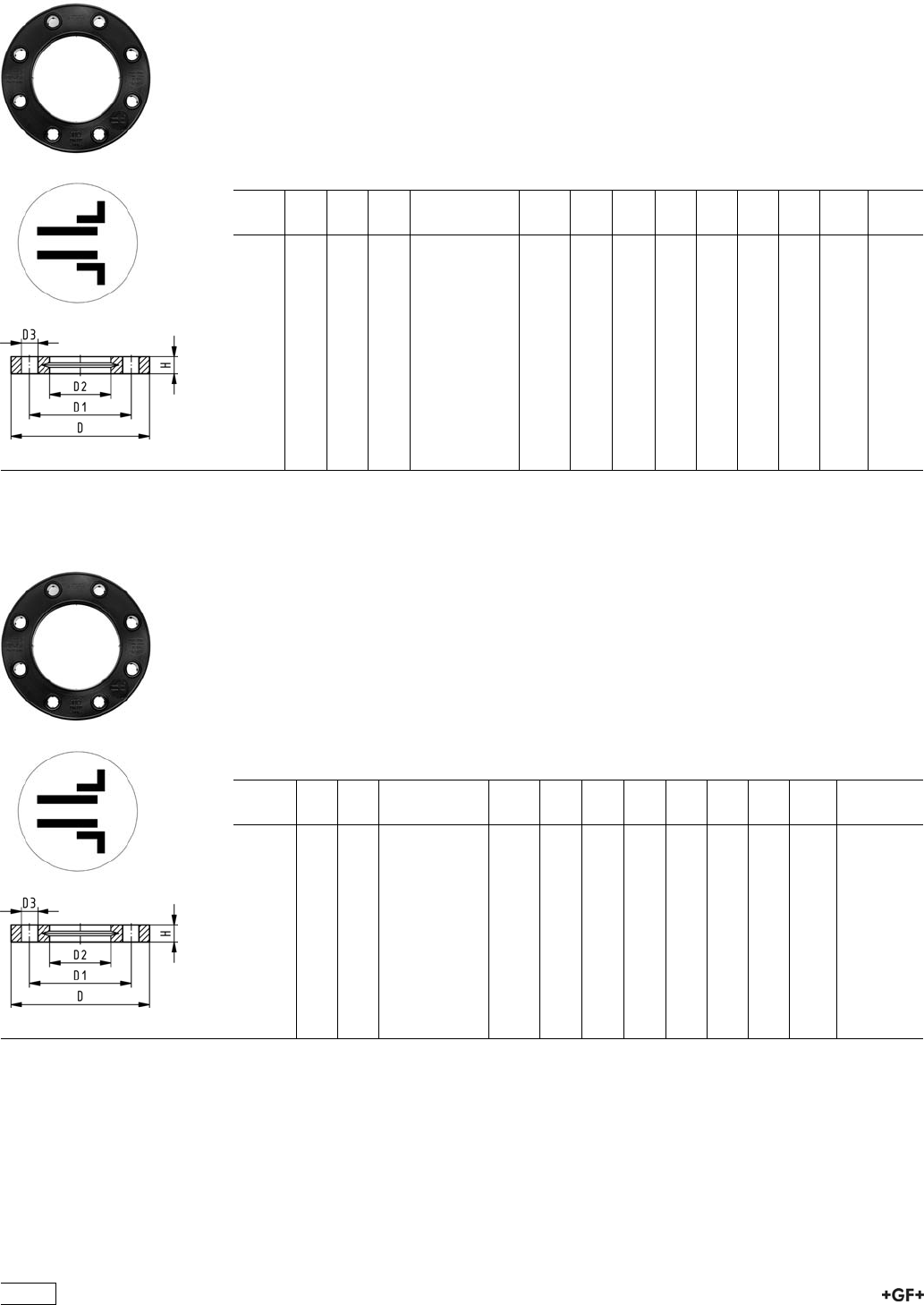
27 70 04
27 70 05
Backing Flanges, PP-V
for Socket Systems metric
Model:
ÏModern full-plastic flange PP-GF (30 % glass-fibre reinforced)
ÏWith V-groove which applies force evenly on collar
ÏWith integrated bolt retainers as an assembly aid
ÏConnecting dimension: ISO 7005, EN 1092, BS 4504, DIN 2501
ÏBolt circle PN 10
¹) Suitable for socket- and butt fusion systems (no pictograph on flange)
AL: number of holes
d
[mm]
Inch DN
[mm]
PN Code kg D
[mm]
D1
[mm]
D2
[mm]
D3
[mm]
H
[mm]
AL SC
¹20 15 16 727 700 406 0.080 95 65 28 14 16 4 M12
¹25 20 16 727 700 407 0.100 105 75 34 14 17 4 M12
¹32 25 16 727 700 408 0.140 115 85 42 14 18 4 M12
¹40 32 16 727 700 409 0.220 140 100 51 18 20 4 M16
¹50 40 16 727 700 410 0.210 150 110 62 18 22 4 M16
¹63 50 16 727 700 411 0.380 165 125 78 18 24 4 M16
¹75 65 16 727 700 412 0.480 185 145 92 18 26 4 M16
90 80 16 727 700 413 0.520 200 160 110 18 27 8 M16
110 100 16 727 700 414 0.680 220 180 133 18 28 8 M16
27 70 14
27 70 15
Backing Flanges, PP-V
for Socket Systems Inch/ANSI
Model:
ÏModern full-plastic flange PP-GF (30 % glass-fibre reinforced)
ÏWith V-groove which applies force evenly on collar
ÏWith integrated bolt-fixing as an assembly aid
ÏConnecting dimension: ANSI/ASME B 16.5 class 150, ASTM D 4024, BS 1560, BS
EN 1759
ÏBolt circle class 150
¹) Suitable for socket- and butt fusion systems (no pictograph on flange)
AL: number of holes
Inch DN
[mm]
PN Code kg D
[mm]
D1
[mm]
D2
[mm]
D3
[mm]
H
[mm]
AL SC
¹1
/215 16 727 701 406 0.080 95 60 28 16 16 4 M12
¹3
/420 16 727 701 407 0.100 105 70 34 16 17 4 M12
¹1 25 16 727 701 408 0.140 115 79 42 16 18 4 M12
¹11
/432 16 727 701 409 0.220 140 89 51 16 20 4 M16
¹11
/240 16 727 701 410 0.210 150 98 62 16 22 4 M16
¹2 50 16 727 701 411 0.380 165 121 78 19 24 4 M16
¹21
/265 16 727 701 412 0.480 185 140 92 19 26 4 M16
3 80 16 727 701 413 0.520 200 152 110 19 27 4 M16
4 100 16 727 701 414 0.680 229 190 133 19 28 8 M16
32
27 70 02 Backing Flanges, PP/Steel
for Socket Systems metric
Model:
ÏPP-GF (30% glass-fibre reinforced) with steel ring
ÏConnecting dimension: ISO 7005, EN 1092, BS 4504, DIN 2501
ÏBolt circle PN 10
¹ Connecting dimension: ISO 2536 DN125
* Connecting dimension: ISO 2536
AL: number of holes
d
[mm]
d
[inch]
DN
[mm]
PN Code kg D
[mm]
D1
[mm]
D2
[mm]
D3
[mm]
H
[mm]
AL SC
20 15 16 727 700 206 0.220 95 65 28 14 12 4 M12
25 20 16 727 700 207 0.260 105 75 34 14 12 4 M12
32 25 16 727 700 208 0.430 115 85 42 14 16 4 M12
40 32 16 727 700 209 0.650 140 100 51 18 16 4 M16
50 40 16 727 700 210 0.820 150 110 62 18 18 4 M16
63 50 16 727 700 211 0.940 165 125 78 18 18 4 M16
75 65 16 727 700 212 1.300 185 145 92 18 18 4 M16
90 80 16 727 700 213 1.400 200 160 110 18 20 8 M16
110 100 16 727 700 214 1.560 220 180 133 18 20 8 M16
27 70 12 Backing Flanges, PP/Steel
for Socket Systems Inch/ANSI
Model:
ÏFor Flange Adaptors BS/ANSI
ÏMaterial: PP (30 % glass-fibre reinforced) with steel ring
ÏConnecting dimension: ANSI/ASME B 16.5 class 150, ASTM D 4024, BS 1560, BS
EN 1759
ÏBolt circle class 150
ÏDN100 and DN150: only for use with original metric flange adaptors
AL: number of holes
d
[inch]
DN
[mm]
d
[mm]
PN Code kg D1
[mm]
D2
[mm]
D3
[mm]
D
[mm]
H
[mm]
AL
1
/215 20 16 727 701 206 0.210 60 28 16 95 12 4
3
/420 25 16 727 701 207 0.250 70 34 16 105 12 4
1 25 32 16 727 701 208 0.420 79 42 16 115 16 4
11
/432 40 16 727 701 209 0.670 89 51 16 140 16 4
11
/240 50 16 727 701 210 0.860 98 62 16 150 18 4
2 50 63 16 727 701 211 0.930 121 78 19 165 18 4
21
/265 75 16 727 701 212 1.340 140 92 19 185 18 4
3 80 90 16 727 701 213 1.550 152 110 19 200 20 4
4 100 110 16 727 701 214 1.810 190 133 19 229 20 8
33
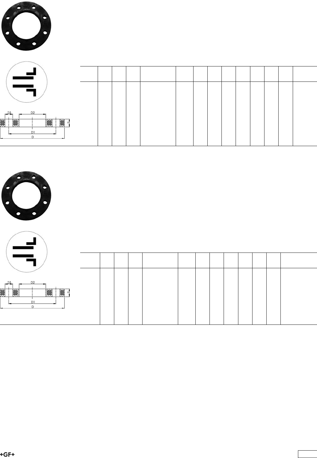
27 30 10
27 40 10
Fixed Flanges, PP-H metric
Jointing Face flat
Model:
ÏWith fusion socket metric
ÏConnecting dimension: ISO 7005 PN 10, EN 1092 PN 10, DIN 2501 PN 10, BS 4504
PN 10
AL: number of holes
d
[mm]
DN
[mm]
Inch PN Code kg D1
[mm]
D2
[mm]
D3
[mm]
D4
[mm]
H
[mm]
H1
[mm]
AL z
[mm]
20 15 1/2 10 727 730 106 0.069 27 65 94 14 12 19 4 5
25 20 3/4 10 727 730 107 0.094 33 75 103 14 13 21 4 5
32 25 1 10 727 730 108 0.129 40 85 115 14 14 23 4 5
40 32 11/4 10 727 730 109 0.203 50 100 138 18 15 25 4 5
50 40 11/2 10 727 730 110 0.246 61 110 148 18 16 27 4 5
63 50 2 10 727 730 111 0.330 76 125 163 18 18 31 4 5
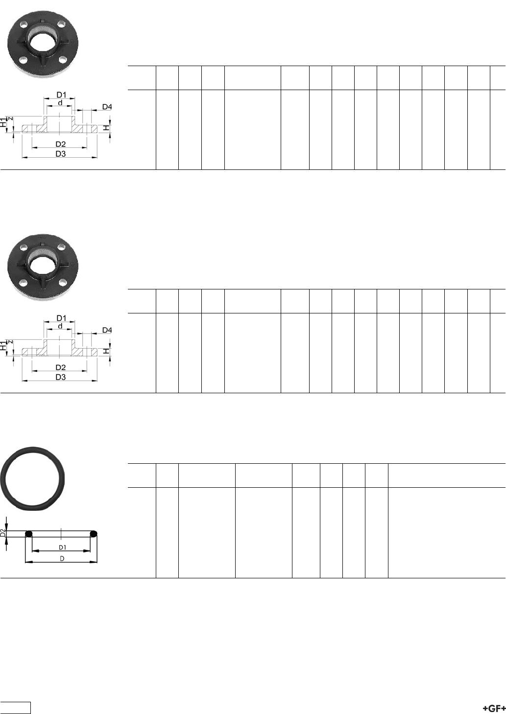
27 30 10
27 40 10
Fixed Flanges, PP-H metric
Combined jointing face: flat and serrated
Model:
ÏWith fusion socket metric
ÏConnecting dimension: ISO 7005 PN 10, EN 1092 PN 10, DIN 2501 PN 10, BS 4504
PN 10
AL: number of holes
d
[mm]
DN
[mm]
Inch PN Code kg D1
[mm]
D2
[mm]
D3
[mm]
D4
[mm]
H
[mm]
H1
[mm]
AL z
[mm]
20 15 1/2 10 727 740 106 0.065 27 65 94 14 12 19 4 5
25 20 3/4 10 727 740 107 0.083 33 75 103 14 13 21 4 5
32 25 1 10 727 740 108 0.117 40 85 115 14 14 23 4 5
40 32 11/4 10 727 740 109 0.175 50 100 138 18 15 25 4 5
50 40 11/2 10 727 740 110 0.212 61 110 148 18 16 27 4 5
63 50 2 10 727 740 111 0.330 76 125 163 18 18 31 4 5
EPDM 48 41 01
FPM 49 41 01
O-Ring Gaskets
Model:
ÏFor Flange Adaptors
ÏHardness approx. 65° Shore
d
[mm]
DN
[mm]
EPDM
Code
FPM
Code
kg D
[mm]
D1
[mm]
D2
[mm]
20 15 748 410 001 749 410 001 0.002 31 23 3.53
25 20 748 410 007 749 410 007 0.002 35 28 3.53
32 25 748 410 002 749 410 002 0.003 43 36 3.53
40 32 748 410 003 749 410 003 0.007 55 44 5.34
50 40 748 410 012 749 410 012 0.008 64 53 5.34
63 50 748 410 013 749 410 013 0.011 80 69 5.34
75 65 748 410 014 749 410 014 0.012 93 82 5.34
90 80 748 410 015 749 410 015 0.015 112 101 5.34
110 100 748 410 016 749 410 016 0.031 134 120 6.99
34
Flange Gaskets metric
Model:
ÏProfile Gasket with steel insert (type G-ST-P/K)
ÏHardness: 70° Shore EPDM, 75° Shore FPM
ÏFor Flange Adaptors
ÏFor flange adaptors only in combination with butterfly valves
d
[mm]
EPDM
Code
FPM
Code
kg D
[mm]
D1
[mm]
H
[mm]
H1
[mm]
20 748 440 101 749 440 101 0.008 51 20 4 3
25 748 440 102 749 440 102 0.011 61 25 4 3
32 748 440 103 749 440 103 0.014 71 32 4 3
40 748 440 104 749 440 104 0.020 82 40 4 3
50 748 440 105 749 440 105 0.021 92 50 4 3
63 748 440 106 749 440 106 0.040 107 63 5 4
75 748 440 107 749 440 107 0.054 127 75 5 4
90 748 440 108 749 440 108 0.060 142 90 5 4
110 748 440 109 749 440 109 0.083 162 110 6 5
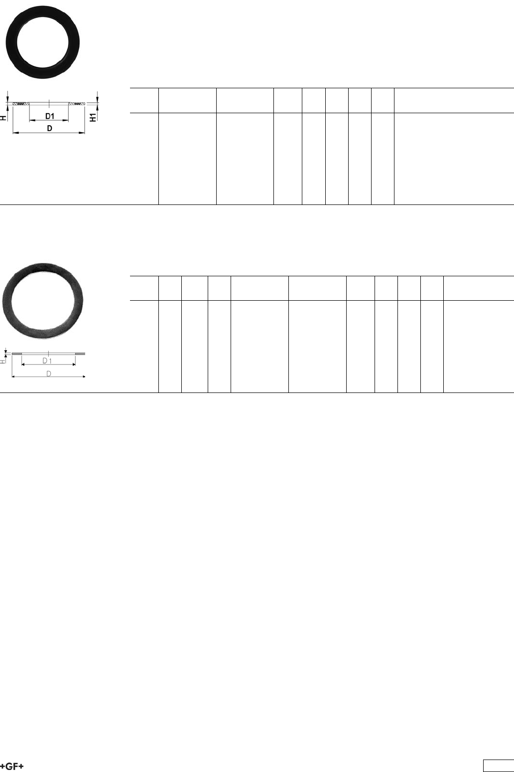
EPDM 48 40 00
FPM 49 40 00
Flat Gaskets
Model:
ÏFor Flange Adaptors 21 79 01/21 80 01
ÏHardness: 70° Shore EPDM, 75° Shore FPM
d
[mm]
DN
[mm]
Inch PN EPDM
Code
FPM
Code
kg D
[mm]
D1
[mm]
H
[mm]
20 15 1
/210 748 400 015 749 400 015 0.003 32 20 2
25 20 3
/410 748 400 016 749 400 016 0.003 39 25 2
32 25 1 10 748 400 017 749 400 017 0.004 48 32 2
40 32 1 1
/410 748 400 018 749 400 018 0.008 59 40 3
50 40 1 1
/210 748 400 019 749 400 019 0.012 71 50 3
63 50 2 10 748 400 020 749 400 020 0.017 88 63 3
75 65 2 1
/210 748 400 021 749 400 021 0.024 104 75 3
90 80 3 10 748 400 022 749 400 022 0.032 123 90 3
110 100 4 10 748 400 023 749 400 023 0.062 148 110 4
35
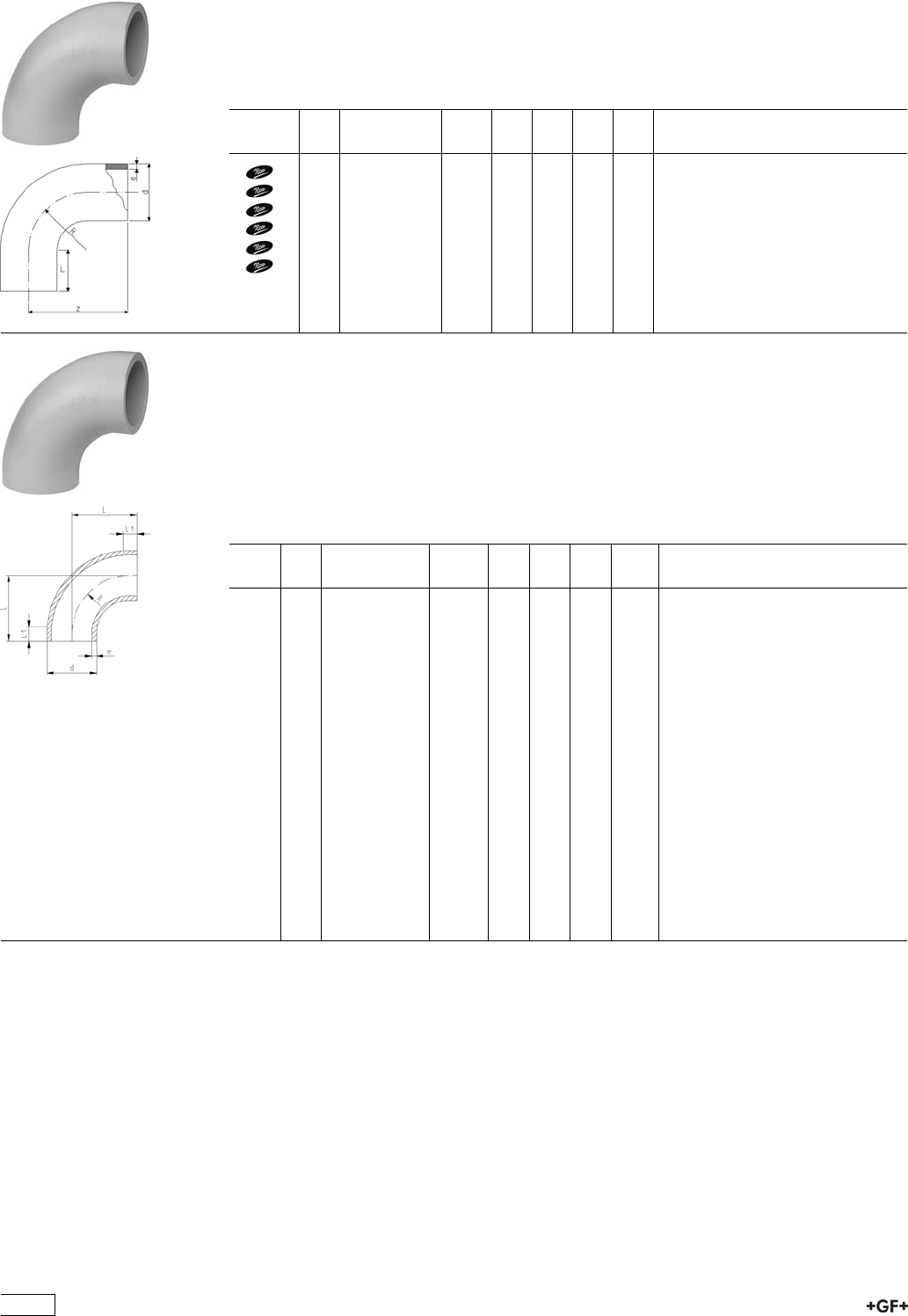
Fittings for Butt Fusion
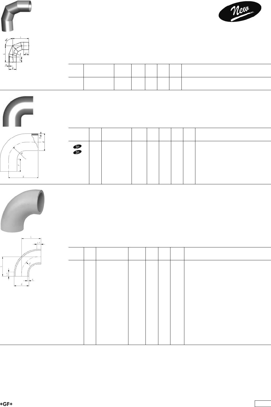
Bends 90°, PP-H S5/SDR11 - 0.75d
Model:
ÏConventional butt-welding according to DVS 2207 part 11
ÏIR = Infrared-(IR Plus®) compatible. Please choose fusion parameters: PP-H
d
[mm]
FM Code kg z
[mm]
L
[mm]
R
[mm]
e
[mm]
20 IR 727 018 606 0.007 38 23 15 1.9
25 IR 727 018 607 0.012 42 23 19 2.3
32 IR 727 018 608 0.021 46 22 24 2.9
40 IR 727 018 609 0.072 51 21 30 3.7
50 IR 727 018 610 0.063 58 21 37 4.6
63 IR 727 018 611 0.113 66 21 45 5.8
PROGEF Standard, Bends 90°, S5/SDR11 - Type B
Model:
ÏMaterial: PP-H
ÏBends with new geometry
ÏConventional butt-welding according to DVS 2207 part 11
ÏIR = Infrared-(IR Plus®) compatible. Please choose fusion parameters: PP-H
¹ Material: PP-R
d
[mm]
FM Code kg L
[mm]
L1
[mm]
R
[mm]
e
[mm]
20 IR 727 018 481 0.005 28 5 22 1,9
25 IR 727 018 482 0.009 33 7 27 2,3
32 IR 727 018 483 0.017 41 7 35 2,9
40 IR 727 018 484 0.036 52 10 44 3,7
50 IR 727 018 485 0.066 63 10 55 4,6
63 IR 727 018 486 0.126 77 10 69 5,8
75 IR 727 018 612 0.229 100 20 90 6,8
90 IR 727 018 613 0.335 100 20 90 8,2
110 IR 727 018 614 0.607 141 25 130 10,0
125 IR 727 018 490 0.790 140 15 125 11,4
140 IR 727 018 491 1.080 155 15 140 12,7
160 IR 727 018 492 1.600 175 15 160 14,6
180 IR 727 018 493 2.600 195 15 180 16,4
200 IR 727 018 494 3.130 215 15 200 18,2
225 IR 727 018 495 4.230 245 20 225 20,5
250 -- 727 018 521 6.450 256 48 232 22,7
280 -- 727 018 522 9.500 286 48 262 25,4
315 -- 727 018 523 12.800 321 48 297 28,6
¹355 -- 727 018 574 19.400 380 15 355 32,2
¹400 -- 727 018 575 28.500 435 25 400 36,3
36
PROGEF Standard, Bends 90°, S5/SDR11
Model:
ÏProduction process: segment welded
ÏMaterial: PP-H
ÏConventional butt-welding according to DVS 2207 part 11
ÏSegment welded fittings have a pressure reduction factor of 0.8
d
[mm]
Code kg L
[mm]
L1
[mm]
R
[mm]
e
[mm]
450 727 018 576 55.400 975 300 675 40,9
500 727 018 577 77.400 1100 350 750 45,4
Bends 90°, PP-H S8,3/SDR17,6 - 0.75d
Model:
ÏConventional butt-welding according to DVS 2207 part 11
ÏIR = Infrared-(IR Plus®) compatible. Please choose fusion parameters: PP-H
d
[mm]
FM Code kg z
[mm]
L
[mm]
R
[mm]
e
[mm]
50 727 018 635 0.050 58 21 37 2.9
63 IR 727 018 636 0.081 66 21 45 3.6
PROGEF Standard, Bend 90°, S8,3/SDR17,6 - Type B
Model:
ÏMaterial: PP-H
ÏConventional butt-welding according to DVS 2207 part 11
ÏIR = Infrared-(IR Plus®) compatible. Please choose fusion parameters: PP-H
ÏBends with new geometry
¹ Material: PP-R
d
[mm]
FM Code kg L
[mm]
L1
[mm]
e
[mm]
50 -- 727 018 435 0.047 63 10 2.9
63 IR 727 018 436 0.089 77 10 3.6
75 IR 727 018 637 0.161 100 20 4.3
90 IR 727 018 638 0.229 100 20 5.1
110 IR 727 018 639 0.486 141 25 6.3
125 IR 727 018 440 0.590 140 15 7.1
140 IR 727 018 441 0.820 155 15 8.0
160 IR 727 018 442 1.200 175 15 9.1
180 IR 727 018 443 1.690 195 15 10.2
200 IR 727 018 444 2.300 215 15 11.4
225 IR 727 018 445 3.200 245 20 12.8
250 -- 727 018 421 4.400 256 48 14.2
280 -- 727 018 422 6.200 286 48 15.9
315 -- 727 018 423 8.800 321 48 17.9
¹355 -- 727 018 549 13.300 355 15 20.1
¹400 -- 727 018 550 18.600 400 25 22.7
37
PROGEF Standard, Bend 90°,
S8,3/SDR17,6
Model:
ÏMaterial: PP-H
ÏConventional butt-welding according to DVS 2207 part 11
ÏProduction process: segment welded
ÏSegment welded fittings have a pressure reduction factor of 0.8
d
[mm]
Code kg L
[mm]
L1
[mm]
e
[mm]
R
[mm]
450 727 018 551 55.400 975 300 25,5 675
500 727 018 552 77.400 1100 350 28,4 750
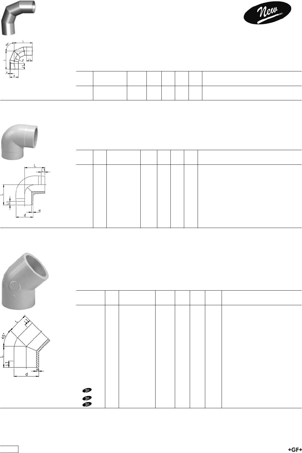
27 10 85 PROGEF Standard, Elbows 90°, S5/SDR11
Model:
ÏMaterial: PP-H
ÏConventional butt-welding according to DVS 2207 part 11
ÏIR = Infrared-(IR Plus®) compatible. Please choose fusion parameters: PP-H
d
[mm]
FM Code kg L
[mm]
L1
[mm]
e
[mm]
20 IR 727 108 506 0.007 38 25 1,9
25 IR 727 108 507 0.012 42 26 2,3
32 IR 727 108 508 0.022 46 27 2,9
40 IR 727 108 509 0.044 51 22 3,7
50 IR 727 108 510 0.077 58 23 4,6
63 IR 727 108 511 0.138 66 21 5,8
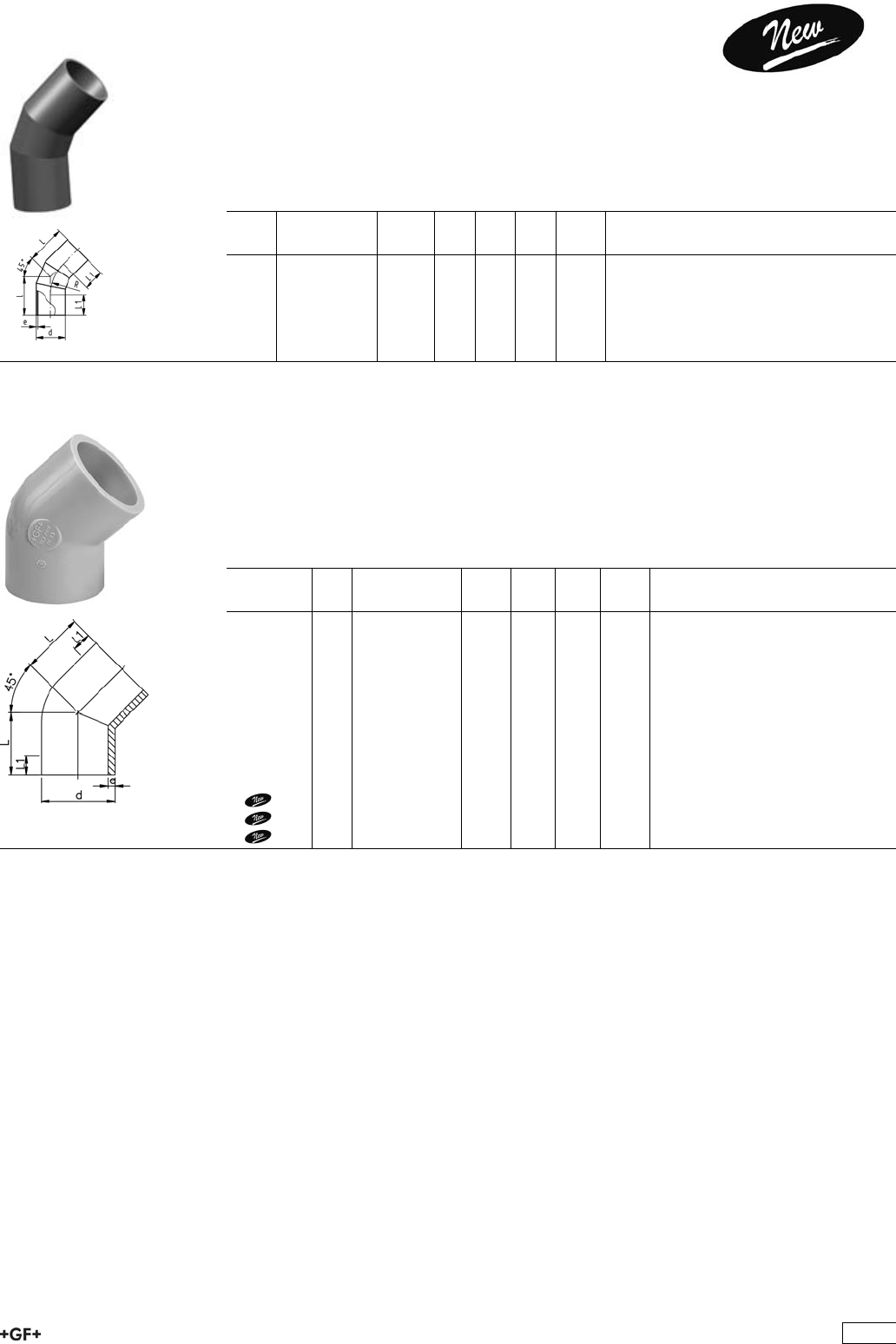
27 15 85 PROGEF Standard, Elbows 45°, S5/SDR11
Model:
ÏMaterial: PP-H
ÏConventional butt-welding according to DVS 2207 part 11
ÏIR = Infrared-(IR Plus®) compatible. Please choose fusion parameters: PP-H
¹ Material: PP-R
d
[mm]
FM Code kg L
[mm]
L1
[mm]
e
[mm]
20 IR 727 158 506 0.006 32 24 1,9
25 IR 727 158 507 0.010 34 25 2,3
32 IR 727 158 508 0.020 36 25 2,9
40 IR 727 158 509 0.037 39 25 3,7
50 IR 727 158 510 0.054 42 26 4,6
63 IR 727 158 511 0.097 47 29 5,8
75 IR 727 158 512 0.135 49 29 6,8
90 IR 727 158 513 0.224 57 34 8,2
110 IR 727 158 514 0.415 70 43 10,0
125 IR 727 158 515 0.607 79 48 11,4
140 IR 727 158 516 0.860 88 55 12,7
160 IR 727 158 517 1.260 100 60 14,6
200 IR 727 158 519 2.460 124 75 18,2
225 IR 727 158 520 3.400 140 85 20,5
1250 727 158 521 7.890 225 133 22,7
1280 727 158 522 10.170 235 143 25,4
1315 727 158 523 11.690 255 154 28,6
38
27 15 85 PROGEF Standard, Bend 45°, S5/SDR11
Model:
ÏMaterial: PP-H
ÏConventional butt-welding according to DVS 2207 part 11
ÏProduction process: segment welded
ÏSegment welded fittings have a pressure reduction factor of 0.8
d
[mm]
Code kg L
[mm]
L1
[mm]
e
[mm]
R
[mm]
355 727 158 524 32.300 520 300 32,2 532.5
400 727 158 525 43.200 548 300 36,3 600.0
450 727 158 526 57.700 580 300 40,9 675.0
500 727 158 527 87.200 665 350 45,4 750.0
27 15 85 PROGEF Standard, Elbows 45°, S8,3/SDR17,6
Model:
ÏMaterial: PP-H
ÏConventional butt-welding according to DVS 2207 part 11
ÏIR = Infrared-(IR Plus®) compatible. Please choose fusion parameters: PP-H
¹ Material: PP-R
*Machined from S5/SDR11
d
[mm]
FM Code kg L
[mm]
L1
[mm]
e
[mm]
*50 -- 727 158 535 0.042 42 26 2,9
*63 IR 727 158 536 0.083 47 29 3,6
75 IR 727 158 412 0.099 49 29 4,3
90 IR 727 158 413 0.164 57 34 5,1
110 IR 727 158 414 0.296 70 43 6,3
*125 IR 727 158 540 0.570 79 48 7,1
*140 IR 727 158 541 0.825 88 55 8,0
*160 IR 727 158 542 1.190 100 60 9,1
*200 IR 727 158 544 2.300 124 75 11,4
*225 IR 727 158 545 3.200 140 85 12,8
1250 727 158 546 4.970 225 133 14,2
1280 727 158 547 7.130 235 143 15,9
1315 727 158 548 9.600 255 154 17,9
39
27 15 85 PROGEF Standard, Bend 45°,
S8,3/SDR17,6
Model:
ÏMaterial: PP-H
ÏConventional butt-welding according to DVS 2207 part 11
ÏProduction process: segment welded
ÏSegment welded fittings have a pressure reduction factor of 0.8
d
[mm]
Code kg L
[mm]
L1
[mm]
e
[mm]
R
[mm]
355 727 158 549 21.000 520 300 20,1 532.5
400 727 158 550 28.100 548 300 22,7 600.0
450 727 158 551 37.400 580 300 25,5 675.0
500 727 158 552 52.600 665 350 28,4 750.0
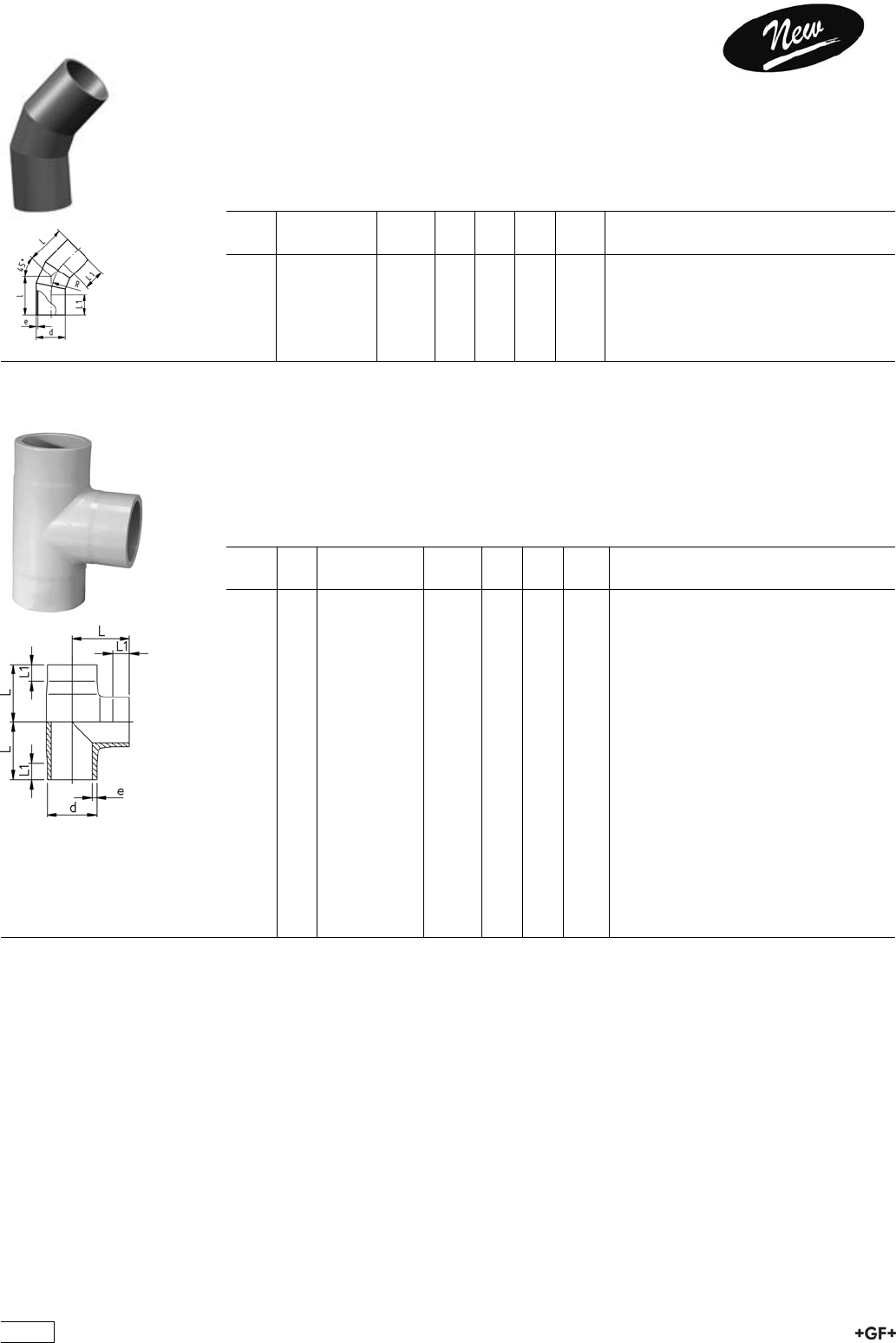
27 20 85 PROGEF Standard, Tee 90° equal, S5/SDR11
Model:
ÏMaterial: PP-H
ÏConventional butt-welding according to DVS 2207 part 11
ÏIR = Infrared-(IR Plus®) compatible. Please choose fusion parameters: PP-H
¹ Material: PP-R
d
[mm]
FM Code kg L
[mm]
L1
[mm]
e
[mm]
20 IR 727 208 506 0.011 38 24 1,9
25 IR 727 208 507 0.018 42 26 2,3
32 IR 727 208 508 0.030 46 26 2,9
40 IR 727 208 509 0.059 51 22 3,7
50 IR 727 208 510 0.103 58 22 4,6
63 IR 727 208 511 0.200 66 21 5,8
75 IR 727 208 512 0.300 75 20 6,8
90 IR 727 208 513 0.530 90 20 8,2
110 IR 727 208 514 0.950 110 20 10,0
125 IR 727 208 515 1.400 125 25 11,4
140 IR 727 208 516 1.980 140 28 12,7
160 IR 727 208 517 2.900 160 28 14,6
180 IR 727 208 568 4.430 194 74 16,4
200 IR 727 208 519 5.570 200 35 18,2
225 IR 727 208 520 7.820 220 35 20,5
250 -- 727 208 571 12.480 276 92 22,7
280 -- 727 208 572 17.250 318 110 25,4
315 -- 727 208 573 24.060 353 118 28,6
¹355 -- 727 208 574 31.100 345 103 32,2
¹400 -- 727 208 575 38.000 360 105 36,3
40
27 20 85 PROGEF Standard, Tee 90° equal,
S5/SDR11
Model:
ÏInjection moulded
ÏMaterial: PP-R
ÏConventional butt-welding according to DVS 2207 part 11
d
[mm]
Code kg L
[mm]
L1
[mm]
z
[mm]
e
[mm]
450 727 208 576 58.000 970 195 485 40,9
500 727 208 577 73.000 1060 215 530 45,4
27 20 85 PROGEF Standard, Tee 90° equal, S8,3/SDR17,6
Model:
ÏMaterial: PP-H
ÏConventional butt-welding according to DVS 2207 part 11
ÏIR = Infrared-(IR Plus®) compatible. Please choose fusion parameters: PP-H
¹ Material: PP-R
d
[mm]
FM Code kg L
[mm]
L1
[mm]
e
[mm]
50 -- 727 208 535 0.090 59 26 2,9
63 IR 727 208 536 0.160 73 31 3,6
75 IR 727 208 412 0.230 75 20 4,3
90 IR 727 208 413 2.200 90 20 5,1
110 IR 727 208 414 0.723 110 20 6,3
125 IR 727 208 540 1.066 125 30 7,1
140 IR 727 208 541 1.449 140 35 8,0
160 IR 727 208 542 2.240 160 43 9,1
180 IR 727 208 543 3.090 194 70 10,2
200 IR 727 208 544 4.360 210 70 11,4
225 IR 727 208 545 6.030 235 82 12,8
250 -- 727 208 546 8.610 276 92 14,2
280 -- 727 208 547 11.660 318 110 15,9
315 -- 727 208 548 16.230 353 118 17,9
¹355 -- 727 208 549 21.000 345 103 20,1
¹400 -- 727 208 550 26.000 360 105 22,7
27 20 85 PROGEF Standard, Tee 90° equal,
S8,3/SDR17,6
Model:
ÏInjection moulded
ÏMaterial: PP-R
ÏConventional butt-welding according to DVS 2207 part 11
d
[mm]
Code kg L
[mm]
L1
[mm]
z
[mm]
e
[mm]
450 727 208 551 58.000 525 1050 525 25,5
500 727 208 552 73.000 600 1200 600 28,4
41
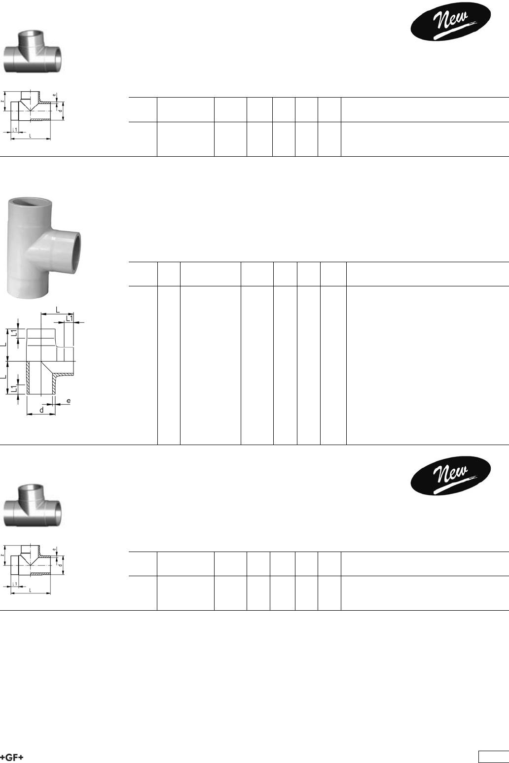
27 20 83 PROGEF Standard, Tee 90° reduced, S5/SDR11
Model:
ÏMaterial: PP-H
ÏConventional butt-welding according to DVS 2207 part 11
ÏIR = Infrared-(IR Plus®) compatible. Please choose fusion parameters: PP-H
d
[mm]
d1
[mm]
FM Code kg L
[mm]
L1
[mm]
L2
[mm]
L3
[mm]
e
[mm]
e1
[mm]
63 32 IR 727 208 351 0.160 65 70 25 25 5,8 2,9
63 50 IR 727 208 352 0.170 65 70 25 25 5,8 4,6
75 32 IR 727 208 353 0.240 70 75 25 25 6,8 2,9
75 50 IR 727 208 354 0.250 70 75 25 25 6,8 4,6
75 63 IR 727 208 355 0.260 70 75 25 25 6,8 5,8
90 50 IR 727 208 357 0.410 80 85 25 25 8,2 4,6
90 63 IR 727 208 358 0.420 80 85 25 25 8,2 5,8
90 75 IR 727 208 359 0.440 80 85 25 25 8,2 6,8
110 32 IR 727 208 360 0.650 90 95 30 25 10 2,9
110 50 IR 727 208 361 0.670 90 95 30 25 10,0 4,6
110 63 IR 727 208 362 0.680 90 95 30 25 10,0 5,8
110 75 IR 727 208 363 0.690 90 95 30 25 10,0 6,8
110 90 IR 727 208 364 0.700 90 95 30 25 10,0 8,2
160 63 IR 727 208 371 2.125 142 135 50 30 14,6 5,8
160 75 IR 727 208 372 2.140 142 135 50 30 14,6 6,8
160 90 IR 727 208 373 2.160 142 135 50 30 14,6 8,2
160 110 IR 727 208 374 2.200 142 135 50 30 14,6 10,0
225 90 IR 727 208 388 4.530 155 165 40 30 20,5 8,2
225 110 IR 727 208 389 4.520 155 165 40 30 20,5 10,0
225 160 IR 727 208 391 4.530 155 165 40 30 20,5 14,6
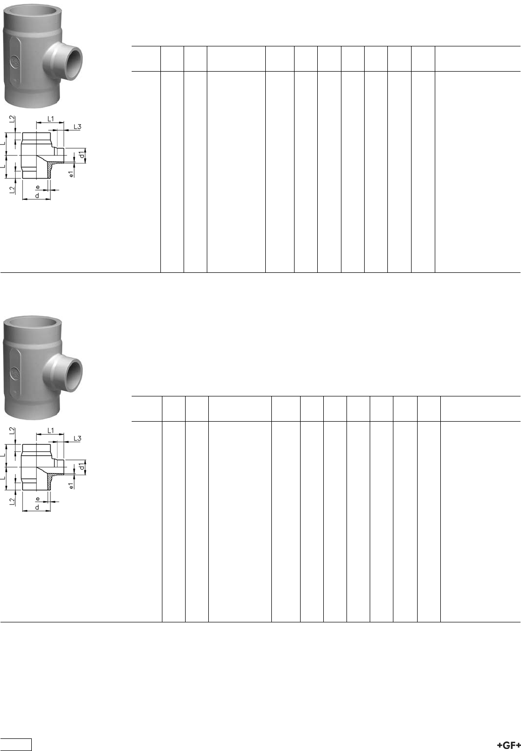
27 20 83 PROGEF Standard, Tee 90° reduced,
S8,3/SDR17,6
Model:
ÏMaterial: PP-H
ÏConventional butt-welding according to DVS 2207 part 11
ÏIR = Infrared-(IR Plus®) compatible. Please choose fusion parameters: PP-H
* Branch SDR11
d
[mm]
d1
[mm]
FM Code kg L
[mm]
L1
[mm]
L2
[mm]
L3
[mm]
e
[mm]
e1
[mm]
*63 32 IR 727 208 301 0.120 65 70 25 25 3,6 2,9
63 50 IR 727 208 302 0.125 65 70 25 25 3,6 2,9
*75 32 IR 727 208 303 0.180 70 75 25 25 4,3 2,9
75 50 IR 727 208 304 0.180 70 75 25 25 4,3 2,9
75 63 IR 727 208 305 0.190 70 75 25 25 4,3 3,6
90 50 IR 727 208 307 0.310 80 85 25 25 5,1 2,9
90 63 IR 727 208 308 0.310 80 85 25 25 5,1 3,6
90 75 IR 727 208 309 0.320 80 85 25 25 5,1 4,3
*110 32 IR 727 208 310 0.490 90 95 30 25 6,3 2,9
110 50 IR 727 208 311 0.490 90 95 30 25 6,3 2,9
110 63 IR 727 208 312 0.500 90 95 30 25 6,3 3,6
110 75 IR 727 208 313 0.500 90 95 30 25 6,3 4,3
110 90 IR 727 208 314 0.510 90 95 30 25 6,3 5,1
160 63 IR 727 208 321 1.560 142 135 50 30 9,1 3,6
160 75 IR 727 208 322 1.570 142 135 50 30 9,1 4,3
160 90 IR 727 208 323 1.580 142 135 50 30 9,1 5,1
160 110 IR 727 208 324 1.600 142 135 50 30 9,1 6,3
225 90 IR 727 208 338 3.330 155 165 40 30 12,8 5,1
225 110 IR 727 208 339 3.310 155 165 40 30 12,8 6,3
225 160 IR 727 208 341 3.330 155 165 40 30 12,8 9,1
42
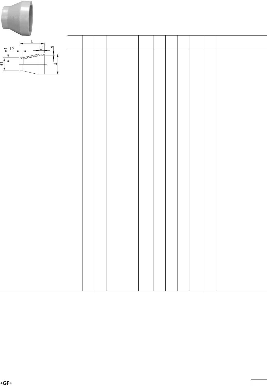
27 90 89 PROGEF Standard, Reducers, S5/SDR11
Model:
ÏMaterial: PP-H
ÏConventional butt-welding according to DVS 2207 part 11
ÏIR = Infrared-(IR Plus®) compatible. Please choose fusion parameters: PP-H
¹ Material: PP-R
d
[mm]
d1
[mm]
FM Code kg L
[mm]
L1
[mm]
L2
[mm]
e
[mm]
e1
[mm]
25 20 IR 727 908 537 0.007 50 20 20 2,3 1,9
32 20 IR 727 908 542 0.010 50 20 20 2,9 1,9
32 25 IR 727 908 541 0.011 50 20 20 2,9 2,3
40 20 IR 727 908 548 0.015 58 20 23 3,7 1,9
40 25 IR 727 908 547 0.016 55 20 20 3,7 2,3
40 32 IR 727 908 546 0.019 55 20 20 3,7 2,9
50 25 IR 727 908 554 0.025 60 20 20 4,6 2,3
50 32 IR 727 908 553 0.027 60 20 20 4,6 2,9
50 40 IR 727 908 552 0.030 60 20 20 4,6 3,7
63 32 IR 727 908 560 0.043 65 20 20 5,8 2,9
63 40 IR 727 908 559 0.047 65 20 20 5,8 3,7
63 50 IR 727 908 558 0.052 65 20 20 5,8 4,6
75 40 IR 727 908 566 0.058 68 20 20 6,8 3,7
75 50 IR 727 908 565 0.065 65 20 20 6,8 4,6
75 63 IR 727 908 564 0.074 65 20 20 6,8 5,8
90 63 IR 727 908 571 0.107 75 22 19 8,2 5,8
90 75 IR 727 908 570 0.117 75 22 19 8,2 6,8
110 75 IR 727 908 577 0.193 90 28 18 10,0 6,8
110 90 IR 727 908 576 0.216 90 28 30 10,0 8,2
125 110 IR 727 908 580 0.325 100 32 30 11,4 10,0
140 110 IR 727 908 585 0.405 110 33 29 12,7 10,0
140 125 IR 727 908 584 0.447 110 34 30 12,7 11,4
160 110 IR 727 908 590 0.550 120 39 27 14,6 10,0
160 140 IR 727 908 588 0.625 120 40 35 14,6 12,7
180 90 IR 727 908 978 0.670 157 45 22 16,4 8,2
180 110 IR 727 908 977 0.550 157 45 28 16,4 10,0
180 125 IR 727 908 976 0.520 136 45 32 16,4 11,4
180 140 IR 727 908 975 0.520 136 45 35 16,4 12,7
180 160 IR 727 908 974 0.530 136 45 35 16,4 14,6
200 160 IR 727 908 592 1.120 145 50 40 18,2 14,6
200 180 IR 727 908 979 0.710 151 50 45 18,2 16,4
225 110 IR 727 908 595 1.330 160 55 35 20,5 10,0
225 160 IR 727 908 596 1.470 160 55 40 20,5 14,6
225 180 IR 727 908 983 0.941 171 55 45 20,5 16,4
225 200 IR 727 908 597 1.650 160 55 50 20,5 18,2
250 160 -- 727 908 990 1.483 194 60 55 22,7 14,6
250 225 -- 727 908 987 1.041 182 60 55 22,7 20,5
¹280 225 -- 727 908 992 1.804 105 30 20 25,4 20,5
¹280 250 -- 727 908 991 1.311 70 30 18 25,4 22,7
¹315 225 -- 727 908 997 2.615 130 30 20 28,6 20,5
¹315 250 -- 727 908 996 2.204 100 30 20 28,6 22,7
¹315 280 -- 727 908 995 1.590 63 30 18 28,6 25,4
355 250 -- 727 908 963 4.400 245 90 60 32,3 22,7
355 280 -- 727 908 962 4.100 245 90 70 32,2 25,4
355 315 -- 727 908 961 3.700 245 90 80 32,2 28,6
400 315 -- 727 908 966 5.300 260 95 80 36,3 28,6
400 355 -- 727 908 965 4.800 260 95 90 36,3 32,2
43
27 90 89 PROGEF Standard, Reducers, S5/SDR11
Model:
ÏMachined
ÏMaterial: PP-R
ÏConventional butt-welding according to DVS 2207 part 11
d
[mm]
d1
[mm]
Code kg L
[mm]
L1
[mm]
L2
[mm]
e
[mm]
e1
[mm]
450 280 727 908 960 5.000 230 60 70 40,9 25,4
450 315 727 908 948 5.000 230 60 80 40,9 28,6
450 355 727 908 950 5.000 230 60 90 40,9 32,2
450 400 727 908 951 5.000 230 60 95 40,9 36,3
500 315 727 908 953 5.000 230 60 80 45,4 28,6
500 355 727 908 954 5.000 230 60 90 45,4 32,2
500 400 727 908 956 5.000 230 60 95 45,4 36,3
500 450 727 908 964 5.000 230 60 60 45,4 40,9
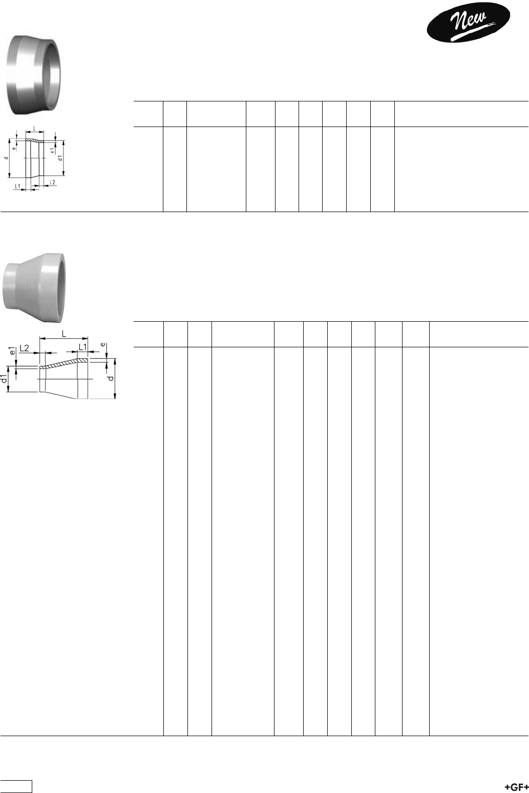
27 90 89 PROGEF Standard, Reducers, S8,3/SDR17,6
Model:
ÏMaterial: PP-H
ÏConventional butt-welding according to DVS 2207 part 11
ÏIR = Infrared-(IR Plus®) compatible. Please choose fusion parameters: PP-H
¹ Material: PP-R
d
[mm]
d1
[mm]
FM Code kg L
[mm]
L1
[mm]
L2
[mm]
e
[mm]
e1
[mm]
50 40 -- 727 908 949 0.010 55 12 12 2,9 2,3
63 40 -- 727 908 901 0.020 65 16 12 3,6 2,3
63 50 -- 727 908 900 0.020 65 16 12 3,6 2,9
75 40 -- 727 908 904 0.041 65 20 20 4,3 2,3
75 50 -- 727 908 465 0.054 65 20 20 4,3 2,9
75 63 IR 727 908 464 0.064 65 20 20 4,3 3,6
90 63 IR 727 908 471 0.092 75 22 19 5,1 3,6
90 75 IR 727 908 470 0.089 75 21 19 5,1 4,3
110 75 IR 727 908 477 0.144 90 28 18 6,3 4,3
110 90 IR 727 908 476 0.158 90 28 20 6,3 5,1
125 110 IR 727 908 912 0.151 108 32 28 7,1 6,3
140 110 IR 727 908 917 0.144 115 35 28 8,0 6,3
140 125 IR 727 908 916 0.150 115 35 32 8,0 7,1
160 110 IR 727 908 922 0.287 124 40 28 9,1 6,3
160 140 IR 727 908 920 0.245 124 40 35 9,1 8,0
180 90 IR 727 908 928 0.440 157 45 22 10,2 5,1
180 110 IR 727 908 927 0.360 157 45 28 10,2 6,3
180 125 IR 727 908 926 0.340 136 45 32 10,2 7,1
180 140 IR 727 908 925 0.340 136 45 35 10,2 8,0
180 160 IR 727 908 924 0.350 136 45 40 10,2 9,1
200 160 IR 727 908 930 0.461 151 50 40 11,4 9,1
200 180 IR 727 908 929 0.600 151 50 45 11,4 10,2
225 110 IR 727 908 936 0.960 171 55 40 12,8 6,3
225 160 IR 727 908 934 0.620 171 55 45 12,8 9,1
225 180 IR 727 908 933 0.600 171 55 45 12,8 10,2
225 200 IR 727 908 932 0.614 184 60 40 12,8 11,4
250 160 IR 727 908 940 0.975 194 60 40 14,2 9,1
250 225 IR 727 908 937 0.681 182 60 55 14,2 12,8
¹280 225 -- 727 908 942 1.180 105 30 20 15,9 12,8
¹280 250 -- 727 908 941 0.858 70 30 18 15,9 14,2
¹315 225 -- 727 908 947 1.715 130 30 20 17,9 12,8
¹315 250 -- 727 908 946 1.446 100 30 20 17,9 14,2
¹315 280 -- 727 908 945 1.040 63 30 18 17,9 15,9
355 250 -- 727 908 959 3.000 245 90 60 20,1 14,2
355 280 -- 727 908 958 2.700 245 90 70 20,1 15,9
355 315 -- 727 908 957 2.400 245 90 80 20,1 17,9
400 315 -- 727 908 972 3.600 260 95 80 22,7 17,9
400 355 -- 727 908 971 3.100 260 95 90 22,7 20,1
44
27 90 89 PROGEF Standard, Reducers,
S8,3/SDR17,6
Model:
ÏMachined
ÏMaterial: PP-R
ÏConventional butt-welding according to DVS 2207 part 11
d
[mm]
d1
[mm]
Code kg L
[mm]
L1
[mm]
L2
[mm]
e
[mm]
e1
[mm]
450 280 727 908 967 5.000 230 60 70 25,5 15,9
450 315 727 908 984 5.000 230 60 80 25,5 17,9
450 355 727 908 988 5.000 230 60 90 25,5 20,1
450 400 727 908 989 5.000 230 60 95 25,5 22,7
500 315 727 908 993 5.000 230 60 80 28,4 17,9
500 355 727 908 994 5.000 230 60 95 28,4 20,1
500 400 727 908 998 5.000 230 60 95 28,4 22,7
500 450 727 908 999 5.000 230 60 60 28,4 25,5
27 96 89 PROGEF Standard, End Caps, S5/SDR11
Model:
ÏMaterial: PP-H
ÏConventional butt-welding according to DVS 2207 part 11
ÏIR = Infrared-(IR Plus®) compatible. Please choose fusion parameters: PP-H
¹ Material: PP-R
d
[mm]
FM Code kg L
[mm]
L1
[mm]
e
[mm]
20 IR 727 968 931 0.004 42 30 1,9
25 IR 727 968 932 0.005 50 35 2,3
32 IR 727 968 933 0.010 55 40 2,9
40 IR 727 968 934 0.018 65 45 3,7
50 IR 727 968 935 0.029 70 50 4,6
63 IR 727 968 936 0.049 80 55 5,8
75 IR 727 968 937 0.065 90 60 6,8
90 IR 727 968 938 0.107 105 70 8,2
110 IR 727 968 939 0.174 120 80 10,0
125 IR 727 968 940 0.210 50 25 11,4
140 IR 727 968 941 0.323 60 30 12,7
160 IR 727 968 942 0.570 76 40 14,6
180 IR 727 968 943 1.580 125 88 16,4
200 IR 727 968 944 1.060 100 50 18,2
225 IR 727 968 945 1.710 103 60 20,5
¹250 -- 727 968 946 2.700 220 140 22,7
¹280 -- 727 968 947 3.100 238 151 25,4
¹315 -- 727 968 948 6.600 258 158 28,6
¹355 -- 727 968 949 9.000 291 175 32,2
¹400 -- 727 968 950 12.500 318 195 36,3
45
27 96 89 PROGEF Standard, End Caps, S5/SDR11
Model:
ÏMachined
ÏMaterial: PP-H
ÏConventional butt-welding according to DVS 2207 part 11
d
[mm]
Code kg L
[mm]
L1
[mm]
e
[mm]
450 727 968 951 10.000 80 66 40,9
500 727 968 952 10.000 85 74 74,5
27 96 89 PROGEF Standard, End Caps, S8,3/SDR17,6
Model:
ÏMaterial: PP-H
ÏConventional butt-welding according to DVS 2207 part 11
ÏIR = Infrared-(IR Plus®) compatible. Please choose fusion parameters: PP-H
¹ Material: PP-R
d
[mm]
FM Code kg L
[mm]
L1
[mm]
e
[mm]
50 -- 727 968 910 0.030 75 53 2,9
63 IR 727 968 911 0.050 85 58 3,6
75 IR 727 968 912 0.045 90 60 4,3
90 IR 727 968 913 0.073 105 70 5,1
110 IR 727 968 914 0.118 120 80 6,3
125 IR 727 968 915 0.176 50 25 7,1
140 IR 727 968 916 0.194 60 30 8,0
160 IR 727 968 917 0.408 76 40 9,1
180 IR 727 968 918 1.580 125 88 10,2
200 IR 727 968 919 0.730 100 50 11,4
225 IR 727 968 920 0.965 103 60 12,8
¹250 -- 727 968 921 2.300 220 140 14,2
¹280 -- 727 968 922 3.000 238 152 15,9
¹315 -- 727 968 923 4.500 258 158 17,9
¹355 -- 727 968 924 6.100 291 175 20,1
¹400 -- 727 968 925 8.700 318 195 22,7
27 96 89 PROGEF Standard, End Caps,
S8,3/SDR17,6
Model:
ÏMachined
ÏMaterial: PP-H
ÏConventional butt-welding according to DVS 2207 part 11
d
[mm]
Code kg L
[mm]
L1
[mm]
e
[mm]
450 727 968 926 10.000 70 56 25,5
500 727 968 927 10.000 75 62 28,4
46
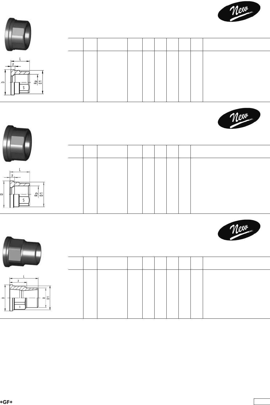
Adaptor Fittings for Butt Fusion
PROGEF Standard, Adaptor Sockets,
metric - Rp
Model:
ÏMaterial: PP-H
ÏWith butt fusion spigot SDR11 and BSP parallel female thread Rp, reinforced
ÏConnection to plastic or metal
ÏReinforcing ring stainless (A2)
ÏDo not use thread sealing pastes that are harmful to PP
ÏInstall with low mechanical stress and avoid large cyclic temperature changes
d
[mm]
Rp
[inch]
PN FM Code kg L
[mm]
L1
[mm]
s
[mm]
e
[mm]
20 1
/210 IR 727 910 266 0.017 48 23 32 1,9
25 3
/410 IR 727 910 267 0.022 50 23 36 2,3
32 1 10 IR 727 910 268 0.038 54 23 46 2,9
40 1 1
/410 IR 727 910 269 0.066 56 23 55 3,7
50 1 1
/210 IR 727 910 270 0.090 60 23 65 4,6
63 2 10 IR 727 910 271 0.140 62 23 80 5,8
27 91 43 Adaptor Sockets, PP-H
metric - NPT
Model:
ÏMaterial: PP-H
ÏWith butt fusion spigot SDR11 and NPT tapered female thread, reinforced
ÏConnection to plastic or metal
ÏReinforcing ring stainless (A2)
ÏDo not use thread sealing pastes that are harmful to PP
ÏInstall with low mechanical stress and avoid large cyclic temperature changes
d
[mm]
NPT
[inch]
PN FM Code kg L
[mm]
L1
[mm]
s
[mm]
e
[mm]
20 1
/210 IR 727 914 356 0.017 49 23 32 1,9
25 3
/410 IR 727 914 357 0.022 51 23 36 2,3
32 1 10 IR 727 914 358 0.039 54 23 46 2,9
40 1 1
/410 IR 727 914 359 0.066 56 23 55 3,7
50 1 1
/210 IR 727 914 360 0.085 60 23 65 4,6
63 2 10 IR 727 914 361 0.122 62 23 80 5,8
PROGEF Standard, Adaptor Nipples,
metric - R
Model:
ÏMaterial: PP-H
ÏWith butt fusion spigot and BSP tapered male thread
ÏConnection to plastic thread only
ÏDo not use thread sealing pastes that are harmful to PP
ÏInstall with low mechanical stress and avoid large cyclic temperature changes
d
[mm]
R
[inch]
PN FM Code kg L
[mm]
L1
[mm]
s
[mm]
e
[mm]
20 1
/210 IR 727 910 556 0.013 51 23 32 1,9
25 3
/410 IR 727 910 557 0.026 52 23 36 2,3
32 1 10 IR 727 910 558 0.028 55 23 46 2,9
40 1 1
/410 IR 727 910 559 0.041 58 23 55 3,7
50 1 1
/210 IR 727 910 560 0.062 60 23 65 4,6
63 2 10 IR 727 910 561 0.096 67 26 80 5,8
47
27 91 46 PROGEF Standard, Adaptor Nipples,
metric - NPT
Model:
ÏMaterial: PP-H
ÏWith butt fusion spigot SDR11 and NPT tapered male thread
ÏConnection to plastic thread only
ÏDo not use thread sealing pastes that are harmful to PP
ÏInstall with low mechanical stress and avoid large cyclic temperature changes
d
[mm]
NPT
[inch]
PN FM Code kg L
[mm]
L1
[mm]
s
[mm]
e
[mm]
20 1
/210 IR 727 914 656 0.013 51 23 32 1,9
25 3
/410 IR 727 914 657 0.026 52 23 36 2,3
32 1 10 IR 727 914 658 0.028 55 23 46 2,9
40 1 1
/410 IR 727 914 659 0.041 58 24 55 3,7
50 1 1
/210 IR 727 914 660 0.062 60 23 65 4,6
63 2 10 IR 727 914 661 0.096 67 26 80 5,8
PROGEF Standard, Hose connectors, metric
Model:
ÏMaterial: PP-H
ÏWith butt fusion spigot SDR11 and parallel hose connection
d
[mm]
d1
[mm]
PN FM Code kg L
[mm]
L1
[mm]
e
[mm]
20 20 10 IR 727 968 606 0.008 64 27 1,9
25 25 10 IR 727 968 607 0.012 75 36 2,3
32 32 10 IR 727 968 608 0.022 82 36 2,9
40 40 10 IR 727 968 609 0.030 84 42 3,7
50 50 10 IR 727 968 610 0.060 90 48 4,6
63 60 10 IR 727 968 611 0.095 100 50 5,8
27 31 00 Installation Fitting Type 310
PROGEF Standard, S5/SDR11
for Socket Systems metric
Model:
ÏFor Signet Paddlewheel Sensors Type -X0 (104 mm)
ÏUnion end with fusion socket PP-H
d
[mm]
DN
[mm]
PN EPDM
Code
FPM
Code
kg
20 15 10 727 310 006 727 310 036 0.136
25 20 10 727 310 007 727 310 037 0.190
32 25 10 727 310 008 727 310 038 0.250
40 32 10 727 310 009 727 310 039 0.356
50 40 10 727 310 010 727 310 040 0.510
63 50 10 727 310 011 727 310 041 0.800
d
[mm]
D
[mm]
z
[mm]
L
[mm]
L1
[mm]
H
[mm]
Sensor Type
20 48 50 128 90 76 X0
25 58 55 142 100 78 X0
32 65 60 156 110 81 X0
40 79 60 160 110 85 X0
50 91 65 176 120 89 X0
63 105 70 194 130 95 X0
48
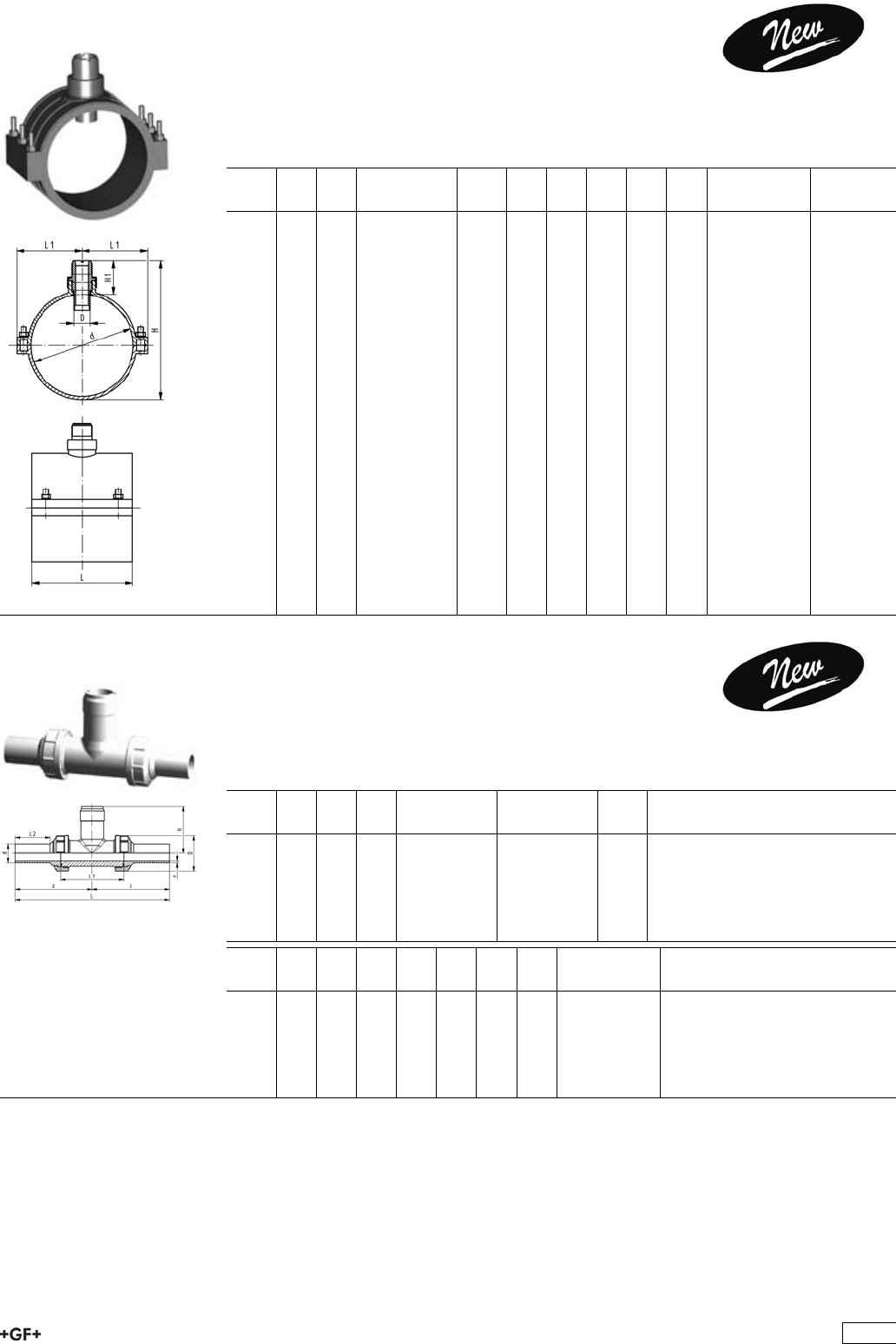
27 31 20 Installation Fitting Type 312
PP-H metric
Model:
ÏFor Signet paddlewheel sensors Type -X1 (137 mm) and Type -X2 (213 mm)
ÏTop saddle with EPDM gasket
ÏStainless steel bolts and nuts
d
[mm]
DN
[mm]
PN Code kg D
[mm]
L
[mm]
L1
[mm]
H
[mm]
H1
[mm]
Sensor Type
75 65 8 727 312 072 0.458 34 78 62 172 88 X1
90 80 8 727 312 073 0.514 34 86 69 186 87 X1
110 100 8 727 312 074 0.598 34 98 79 206 86 X1
125 100 8 727 312 075 0.667 34 101 85 212 78 X1
140 125 6 727 312 076 0.911 34 114 104 227 75 X1
160 150 6 727 312 077 0.985 34 114 114 243 72 X1
180 150 6 727 312 078 2.085 34 168 134 348 144 X2
200 200 6 727 312 079 2.045 34 168 132 357 142 X2
225 200 5 727 312 080 2.142 34 174 146 375 136 X2
250 250 5 727 312 081 2.566 34 179 159 397 131 X2
280 250 5 727 312 082 3.594 34 179 167 426 127 X2
315 300 5 727 312 083 4.250 34 248 202 450 120 X2
27 31 80 Installation Fitting Type 318
PROGEF Standard, S5/SDR11
for Butt Fusion Systems metric
Model:
ÏFor Signet Paddlewheel Sensors Type -X0 (104 mm)
ÏUnion end with butt fusion spigot PP-H
d
[mm]
DN
[mm]
PN FM EPDM
Code
FPM
Code
kg
20 15 10 IR 727 318 006 727 318 036 0.136
25 20 10 IR 727 318 007 727 318 037 0.190
32 25 10 IR 727 318 008 727 318 038 0.250
40 32 10 IR 727 318 009 727 318 039 0.356
50 40 10 IR 727 318 010 727 318 040 0.510
63 50 10 IR 727 318 011 727 318 041 0.800
d
[mm]
D
[mm]
z
[mm]
L
[mm]
L1
[mm]
L2
[mm]
H
[mm]
e
[mm]
Sensor Type
20 48 112 224 90 52 76 1.9 X0
25 58 121 242 100 53 78 2.3 X0
32 65 128 256 110 55 81 2.9 X0
40 79 136 272 110 60 85 3.7 X0
50 91 147 294 120 66 89 4.6 X0
63 105 158 316 130 70 95 5.8 X0
49

53 31 80 Installation Fitting Type 318, PE100
for Butt Fusion Systems metric
Model:
ÏFor Signet Paddlewheel Sensors Type -X0 (104 mm)
ÏBody and union nut PP-H
ÏUnion end with butt fusion spigot PE100
d
[mm]
DN
[mm]
PN FM EPDM
Code
FPM
Code
kg
20 15 10 IR 753 318 006 753 318 036 0.136
25 20 10 IR 753 318 007 753 318 037 0.190
32 25 10 IR 753 318 008 753 318 038 0.250
40 32 10 IR 753 318 009 753 318 039 0.356
50 40 10 IR 753 318 010 753 318 040 0.510
63 50 10 IR 753 318 011 753 318 041 0.800
d
[mm]
D
[mm]
z
[mm]
L
[mm]
L1
[mm]
L2
[mm]
H
[mm]
e
[mm]
Sensor Type
20 48 112 224 90 52 76 1.9 X0
25 58 121 242 100 53 78 2.3 X0
32 65 128 256 110 55 81 2.9 X0
40 79 136 272 110 60 85 3.7 X0
50 91 147 294 120 66 89 4.6 X0
63 105 158 316 130 70 95 5.8 X0
50
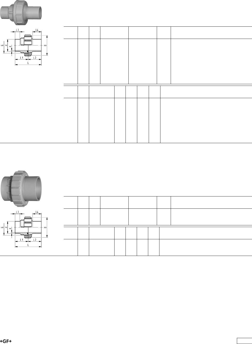
Unions for Butt Fusion
EPDM 27 51 85
FPM 27 52 85
PROGEF Standard, Unions, S5/SDR11
Model:
ÏMaterial: PP-H
ÏWith butt fusion ends
ÏConventional butt fusion and (IR Plus®) compatible
ÏGasket: O-Ring EPDM No. 48 41 00, FPM No. 49 41 00
ÏFor the dimensions d75-110 please see instructions for the installation
d
[mm]
PN FM EPDM
Code
FPM
Code
kg
20 10 IR 727 518 506 727 528 506 0.046
25 10 IR 727 518 507 727 528 507 0.074
32 10 IR 727 518 508 727 528 508 0.102
40 10 IR 727 518 509 727 528 509 0.169
50 10 IR 727 518 510 727 528 510 0.227
63 10 IR 727 518 511 727 528 511 0.382
75 10 IR 727 518 512 727 528 512 0.560
90 10 IR 727 518 513 727 528 513 0.588
110 10 IR 727 518 514 727 528 514 0.828
d
[mm]
D
[mm]
G
[inch]
L
[mm]
L1
[mm]
L2
[mm]
e
[mm]
20 48 1 107 54.0 53.0 1,9
25 58 1 1/4 113 57.0 56.0 2,3
32 65 1 1/2 119 60.0 59.0 2,9
40 79 2 126 63.0 63.0 3,7
50 91 2 1/4 131 65.5 65.5 4,6
63 111 2 3/4 137 69.0 68.0 5,8
75 135 S107,5x3,6 131 66.0 65.5 6,8
90 135 S107,5x3,6 131 65.5 65.5 8,2
110 158 S127,5x3,6 131 65.5 65.5 10,0
EPDM 27 51 84
FPM 27 52 84
PROGEF Standard, Unions, S8,3/SDR17,6
Model:
ÏMaterial: PP-H
ÏWith butt fusion ends
ÏConventional butt fusion and (IR Plus®) compatible
ÏGasket: O-Ring EPDM No. 48 41 00, FPM No. 49 41 00
ÏFor the dimensions d75-110 please see instructions for the installation
d
[mm]
PN FM EPDM
Code
FPM
Code
kg
75 6 IR 727 518 412 727 528 412 0.476
90 6 IR 727 518 413 727 528 413 0.483
110 6 IR 727 518 414 727 528 414 0.663
d
[mm]
D
[mm]
G
[inch]
L
[mm]
L1
[mm]
L2
[mm]
e
[mm]
75 135 S107,5x3,6 132 66 24 4,3
90 135 S107,5x3,6 131 66 24 5,1
110 158 S127,5x3,6 131 66 25 6,3
51

I]ZcZlZhi\ZcZgVi^dcd[eaVhi^Xjc^dch^ci]ZVWdkZbViZg^VahVcYY^bZch^dch]VhWZZcÒiiZY
l^i]VhiViZ"d["i]Z"Vgi!eaVhi^Xh"dg^ZciZYWjiigZhhi]gZVY#Ndji]ZgZ[dgZ]VkZVegdYjXi^cl]^X]
i]Zcdb^cVaegZhhjgZVcYi]ZhV[ZingZhZgkZ]VkZWZZcYgVbVi^XVaan^cXgZVhZY#6ahdcZlVgZi]Z
Wjii[jh^dckZgh^dch#>ci]^hXdccZXi^dc!i]ZgZVgZV[Zled^cihl]^X]ndjbjhiWZVlVgZd[#
8Vji^dc
I]Zi]gZVYhd[i]Zjc^dccjiVcYWjh]]VkZWZZcgZldg`ZY[dgEE!EK9;VcYE:L]Zc
jh^c\^cY^k^YjVaeVgih!eaZVhZX]ZX`eg^dgid^chiVaaVi^dc^[i]Zi]gZVYhd[i]Zjc^dcWjh]VcY
i]Zjc^dccjiXd^cX^YZ#
Jc^dcWjh]l^i]igVeZod^Yi]gZVYdcjc^dccjil^i]igVeZod^Yi]gZVY
dg
Jc^dcWjh]l^i]WjiigZhhi]gZVYdcjc^dccjil^i]WjiigZhhi]gZVY
I^e
IdbV`Z^chiVaaVi^dcd[i]Zjc^dcZVh^Zg!lZii]Zjc^dccji#
;dgi]ZY^bZch^dchY.%VcYY&&%lZVYk^hZ[jh^c\i]ZXdbeaZiZjc^dc!^[edhh^WaZdgha^YZ
i]Zjc^dccjiidi]ZXdaaVgd[i]Zjc^dcZcYWZXVjhZV[iZg[jh^dci]Zjc^dccjiXVccdiWZ
ha^YdkZgi]Z[jh^dcWZVY#;^\#&
S ;dgYZh^\cgZVhdch!^i^hi]ZdgZi^XVaanedhh^WaZidXdbW^cZY^[[ZgZcicdb^cVaY^VbZiZghd[
jc^dcZcYhVcYcjih#IdbV`ZhjgZXdbW^cVi^dchVgZiZX]c^XVaanXdggZXi!ndjXVcÒcYi]Z
XdYZcjbWZghd[i]Zh^c\aZeVgihVcYheVgZeVgih[dgZVX]jc^dc^ci]ZIVWaZh&"(#
8Vji^dc
DcanjhZjc^dcWjh]ZhVcYjc^dcZcYhl^i]i]ZhVbZcdb^cVaY^VbZiZg
6Wjii[jh^dcjc^dcWjh]Y,*bVncdiWZXdbW^cZYl^i]VWjii[jh^dcjc^dcZcYY.%id[dgbV
gZYjXZgWZXVjhZi]^hXVcXVjhZaZV`V\Z!Vh^aajhigViZYidi]ZaZ[i#;^\#'
BVg`^c\hdci]Zjc^dccjih
H;$BH2hdX`Zi[jh^dc!7;$HI2Wjii[jh^dc
H;$BH,* heZX^ÒZY[dghdX`Zi[jh^dcY,*
7;$HI,*Ä.% heZX^ÒZY[dgWjii[jh^dcY,*Ä,*VcYY.%Ä.%
H;$BH.% heZX^ÒZYhdX`Zi[jh^dcY.%
7;$HI&&% heZX^ÒZYWjii[jh^dcY&&%
&&% heZX^ÒZY[dghdX`Zi[jh^dcY&&%
I^e
LZgZXdbbZcYX]Vc\^c\bViZg^Vahdcan[dgi]Zjc^dcZcY[dg^chiVaaVi^dcgZVhdch#
>chigjXi^dch[dgi]Z^chiVaaVi^dcd[jc^dch^cEE!
E:Y,*!Y.%VcYY&&%
butt fusion
union bush d 75
butt fusion
union end d 90
union nut d 75
insufficient
seal
;^\#'
union endpipe
union nut
;^\#&
52
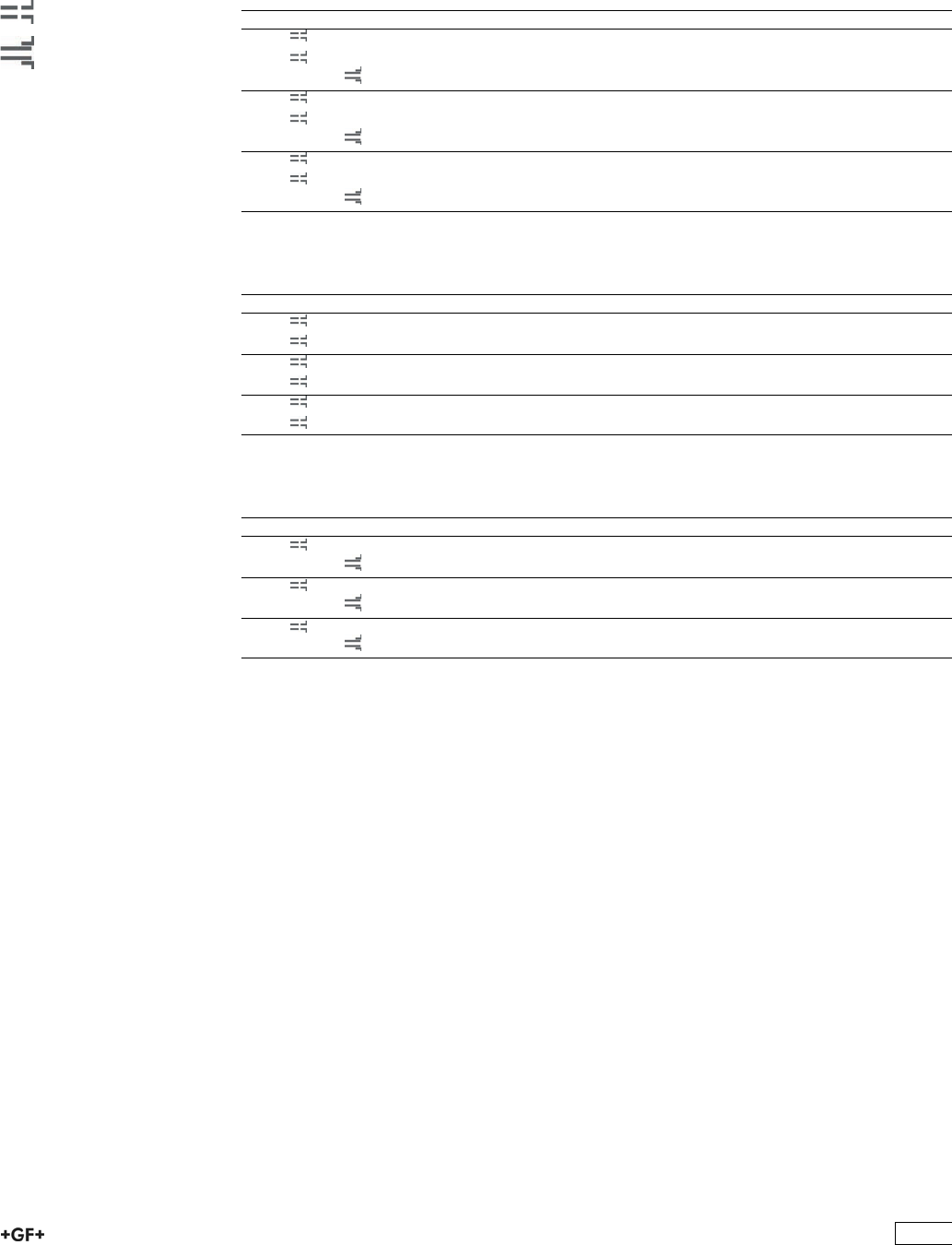
HZaZXi^dciVWaZh[dgh^c\aZeVgihVcYheVgZeVgih
IVWaZ&
H^c\aZeVgih[dgEE"=jc^dchY,*!Y.%VcYY&&%
Y 7;$HI H;$BH H9G EC 8dYZjc^dcZcY 8dYZjc^dcWjh] 8dYZjc^dccji
,* && &% ,',+%-*&' ,',+)-*&' ,',+.%)''
&,#+ + ,',+%-)&' ,',+)-)&' ,',+.%)''
Å &% ,',+%%&&' ,',+)%&,' ,',+.%)''
.% && &% ,',+%-*&( ,',+)-*&( ,',+.%)''
&,#+ + ,',+%-)&( ,',+)-)&( ,',+.%)''
Å &% ,',+%%&&( ,',+)%&,( ,',+.%)'(
&&% && &% ,',+%-*&) ,',+)-*&) ,',+.%)'(
&,#+ + ,',+%-)&) ,',+)-)&) ,',+.%)'(
Å &% ,',+%%&&) ,',+)%&,) ,',+.%)')
IVWaZ'
H^c\aZeVgih[dgE:&%%jc^dchY,*!Y.%VcYY&&%
Y 7;$HI H;$BH H9G EC 8dYZjc^dcZcY 8dYZjc^dcWjh] 8dYZjc^dccji
,* && &% ,*(+%-+&' ,*(+)-+&' ,',+.%))'
&,#+ &% ,*(+%-)&' ,*(+)-)&' ,',+.%))'
.% && &% ,*(+%-+&( ,*(+)-+&( ,',+.%))'
&,#+ &% ,*(+%-)&( ,*(+)-)&( ,',+.%))'
&&% && &% ,*(+%-+&) ,*(+)-+&) ,',+.%))(
&,#+ &% ,*(+%-)&) ,*(+)-)&) ,',+.%))(
IVWaZ(
D"G^c\h[dgEE"=!E:&%%
Y 7;$HI H;$BH H9G EC 8dYZD"G^c\:E9B& 8dYZD"G^c\;EB&
,* &+ ,)-)&%%&( ,).)&%%&(
&+ ,)-)&%%&) ,).)&%%&)
.% &+ ,)-)&%%&) ,).)&%%&)
&+ ,)-)&%%&* ,).)&%%&*
&&% &+ ,)-)&%%&* ,).)&%%&*
&+ ,)-)&%%&+ ,).)&%%&+
Jc^dccjihdkZgaVehZkZgVaY^bZch^dch
& ;aVc\ZVYVeidgD"g^c\h!dcZh^oZhbVaaZg^ccdb^cVaY^bZch^dch!VgZjhZY[dgi]ZY,*Ä&&%Wjii"[jh^dc
jc^dch
7jii[jh^dc
HdX`Zi[jh^dc
53
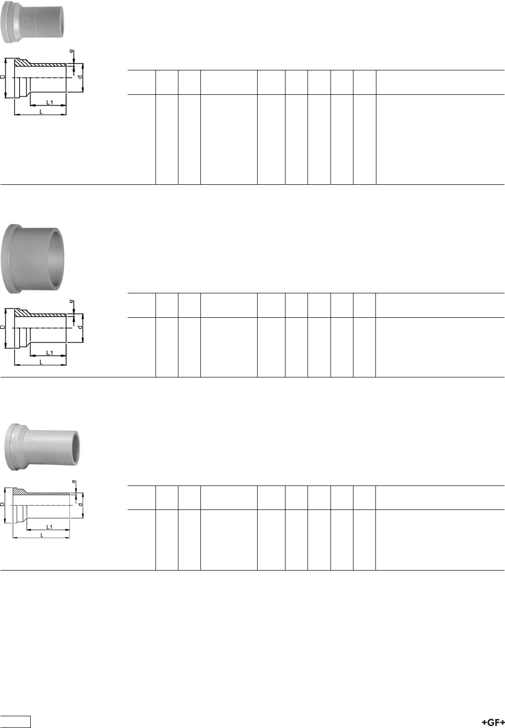
27 60 85 PROGEF Standard, Union Ends IR Plus, SDR11
Model:
ÏMaterial: PP-H
ÏConventional butt-welding according to DVS 2207 part 11
ÏIR = Infrared-(IR Plus®) compatible. Please choose fusion parameters: PP-H
ÏSuitable for unions, diaphragm valves Type 314, tank adaptors and Vortex sensors
ÏFor the dimensions d75-110 please see instructions for the installation
d
[mm]
PN FM Code kg D
[mm]
L
[mm]
L1
[mm]
e
[mm]
20 10 IR 727 608 506 0.010 30 54 38 1,9
25 10 IR 727 608 507 0.017 39 57 42 2,3
32 10 IR 727 608 508 0.024 45 60 41 2,9
40 10 IR 727 608 509 0.041 57 63 42 3,7
50 10 IR 727 608 510 0.054 63 66 44 4,6
63 10 IR 727 608 511 0.092 78 69 45 5,8
75 10 IR 727 608 512 0.146 101 66 34 6,8
90 10 IR 727 608 513 0.158 101 66 45 8,2
110 10 IR 727 608 514 0.233 121 66 40 10,0
27 60 84 PROGEF Standard, Union Ends IR Plus, SDR17,6
Model:
ÏMaterial: PP-H
ÏConventional butt-welding according to DVS 2207 part 11
ÏIR = Infrared-(IR Plus®) compatible. Please choose fusion parameters: PP-H
ÏSuitable for unions
ÏFor the dimensions d75-110 please see instructions for the installation
d
[mm]
PN FM Code kg D
[mm]
L
[mm]
L1
[mm]
e
[mm]
75 6 IR 727 608 412 0.114 101 66 34 4,3
90 6 IR 727 608 413 0.116 101 66 45 5,1
110 6 IR 727 608 414 0.165 121 66 40 6,3
27 60 85 PROGEF Standard, Union ends long, SDR11
Model:
ÏMaterial: PP-H
ÏConventional butt-welding according to DVS 2207 part 11
ÏIR = Infrared-(IR Plus®) compatible. Please choose fusion parameters: PP-H
ÏSpigot for electro fusion
ÏSuitable for unions, diaphragm valves Type 314 and Vortex sensors
d
[mm]
PN FM Code kg D
[mm]
L
[mm]
L1
[mm]
e
[mm]
20 10 IR 727 608 516 0.010 30 67 52 1,9
25 10 IR 727 608 517 0.017 39 71 53 2,3
32 10 IR 727 608 518 0.024 45 73 55 2,9
40 10 IR 727 608 519 0.041 57 81 60 3,7
50 10 IR 727 608 520 0.054 63 87 66 4,6
63 10 IR 727 608 521 0.092 78 93 70 5,8
54
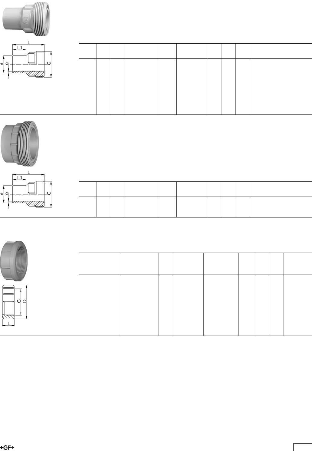
27 64 85 PROGEF Standard, Union Bushes, SDR11
Model:
ÏMaterial: PP-H
ÏConventional butt-welding according to DVS 2207 part 11
ÏIR = Infrared-(IR Plus®) compatible. Please choose fusion parameters: PP-H
ÏSpigot for electro fusion
ÏSuitable for unions, diaphragm valves Type 314, tank adaptors and Vortex sensors
d
[mm]
PN FM Code kg G
[inch]
L
[mm]
L1
[mm]
e
[mm]
20 10 IR 727 648 506 0.012 1 54 26 1,9
25 10 IR 727 648 507 0.020 1 1/4 57 26 2,3
32 10 IR 727 648 508 0.029 1 1/2 60 25 2,9
40 10 IR 727 648 509 0.047 2 63 25 3,7
50 10 IR 727 648 510 0.064 21/4 66 25 4,6
63 10 IR 727 648 511 0.104 23/4 69 25 5,8
75 10 IR 727 648 512 0.172 S107.5x3.6 66 24 6,8
90 10 IR 727 648 513 0.182 S107.5x3.6 66 24 8,2
110 10 IR 727 648 514 0.258 S127.5x3.6 66 25 10,0
Union Bushes, PP-H SDR17,6
Model:
ÏMaterial: PP-H
ÏConventional butt-welding according to DVS 2207 part 11
ÏIR = Infrared-(IR Plus®) compatible. Please choose fusion parameters: PP-H
ÏGasket: O-Ring EPDM No. 48 41 00, FPM No. 49 41 00
ÏFor the dimensions d75-110 please see instructions for the installation
d
[mm]
PN FM Code kg G
[inch]
L
[mm]
L1
[mm]
e
[mm]
75 6 IR 727 648 412 0.152 S127.5x3.6 65.5 24 4.3
90 6 IR 727 648 413 0.154 S107.5x3.6 66.0 24 5.1
110 6 IR 727 648 414 0.207 S127.5x3.6 66.0 24 6.3
27 69 04 Union Nut, PP-GF
Model:
ÏPP glass-fibre reinforced
Socket
Fusion d
[mm]
Butt Fusion d
[mm]
PN G
[inch]
Code kg D
[mm]
L
[mm]
16 16 10 3/4 727 690 405 0.008 35 21
20 20 10 1 727 690 406 0.021 48 24
25 25 10 1 1/4 727 690 407 0.034 58 26
32 32 10 1 1/2 727 690 408 0.042 65 28
40 40 10 2 727 690 409 0.045 79 31
50 50 10 2 1/4 727 690 410 0.060 91 35
63 63 10 2 3/4 727 690 411 0.168 111 39
75 75 - 90 10 S107,5x3,6 727 690 422 0.205 135 40
90 110 10 S127,5x3,6 727 690 423 0.288 158 43
110 - 10 S152,5x3,6 727 690 424 0.460 188 48
55
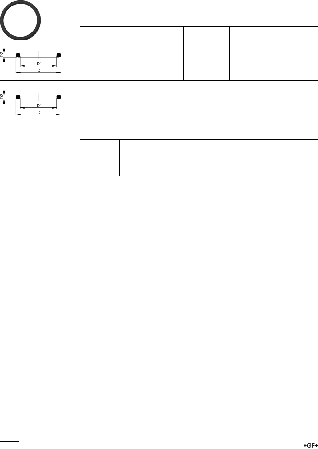
EPDM 48 41 00
FPM 49 41 00
O-Ring Gaskets
Model:
ÏFor unions and adaptor unions
ÏHardness approx. 65° Shore
ÏEPDM minimum temperature -40°C
ÏFPM minimum temperature -15°C
d
[mm]
DN
[mm]
EPDM
Code
FPM
Code
kg D
[mm]
D1
[mm]
D2
[mm]
20 15 748 410 006 749 410 006 0.002 27 20 4
25 20 748 410 007 749 410 007 0.002 35 28
32 25 748 410 008 749 410 008 0.002 40 33 4
40 32 748 410 009 749 410 009 0.006 51 41 5
50 40 748 410 010 749 410 010 0.007 58 47 5
63 50 748 410 011 749 410 011 0.010 70 60 5
O-Ring Gasket
Model:
Ïfor unions PP-H, PE100 and PVDF butt fusion
Ïd75 748 410 013 (EPDM), 749 410 013 (FPM)
d90 748 410 014 (EPDM), 749 410 014 (FPM)
d110 748 410 015 (EPDM), 749 410 015 (FPM)
EPDM
Code
FPM
Code
kg D
[mm]
D1
[mm]
D2
[mm]
748 410 013 749 410 013 0.011 80
748 410 014 749 410 014 0.012 93
748 410 015 749 410 015 0.015 112
56
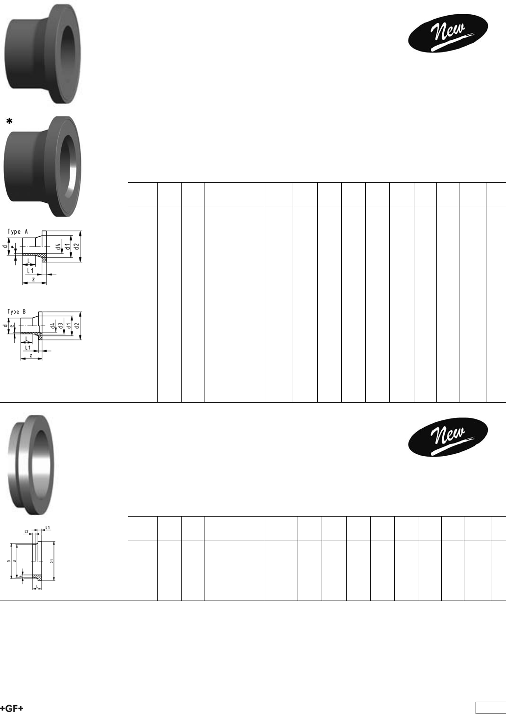
Flange Adaptors, Flanges and Gaskets for
Butt Fusion
PROGEF Standard, Flange Adaptor,
S5/SDR11
Combined Jointing Face:
Flat and Serrated
Model:
ÏMaterial: PP-H
ÏConventional butt-welding according to DVS 2207 part 11
ÏIR = Infrared-(IR Plus®) compatible. Please choose fusion parameters: PP-H
ÏSuitable for flange connections to metric (from d110 also to ANSI/ASME B16.5)
ÏUp to d315, suitable for butterfly valve type 567, 568 and 037
ÏGasket: Profile flange gasket EPDM No. 48 44 07, FPM No. 49 44 07
* Type B with chamfer
d
[mm]
DN
[mm]
FM Code kg z
[mm]
d1
[mm]
d2
[mm]
d3
[mm]
d4
[mm]
L
[mm]
L1
[mm]
e
[mm]
20 15 IR 727 798 706 0.015 50 26 45 16 29 7 1.9
25 20 IR 727 798 707 0.028 52 32 58 20 27 9 2.3
32 25 IR 727 798 708 0.042 54 40 68 26 28 10 3.0
40 32 IR 727 798 709 0.064 56 49 78 32 25 11 3.7
50 40 IR 727 798 710 0.088 62 60 88 40 32 12 4.6
63 50 IR 727 798 711 0.144 68 75 102 51 38 14 5.8
*75 65 IR 727 798 712 0.243 80 89 122 66 61 43 16 6.9
*90 80 IR 727 798 713 0.326 80 105 138 78 73 41 17 8.2
*110 100 IR 727 798 714 0.441 80 125 158 100 90 40 18 10.0
*125 100 IR 727 798 715 0.520 82 132 158 114 102 35 25 11.4
*140 125 IR 727 798 716 0.800 89 155 188 127 114 39 25 12.8
*160 150 IR 727 798 717 0.920 92 175 212 151 131 45 25 14.6
*180 150 IR 727 798 718 0.900 80 180 212 154 147 45 30 16.4
*200 200 IR 727 798 719 1.670 100 232 268 203 163 30 32 18.2
*225 200 IR 727 798 720 1.700 100 235 268 210 184 35 32 20.5
*250 250 727 798 721 2.790 100 285 320 250 204 25 35 22.7
*280 250 727 798 722 2.610 100 291 320 265 229 35 35 25.4
*315 300 727 798 723 3.410 100 335 370 300 257 25 35 28.6
*355 350 727 798 724 5.600 180 373 430 340 290 20 40 32.3
*400 400 727 798 725 8.300 187 427 482 385 327 29 46 36.6
PROGEF Standard, Flange Adaptors,
S5/SDR11
Jointing Face serrated, metric
Model:
ÏInjection moulded
ÏMaterial: PP-R
ÏConventional butt-welding according to DVS 2207 part 11
d
[mm]
DN
[mm]
FM Code kg z
[mm]
d1
[mm]
d2
[mm]
d3
[mm]
d4
[mm]
L
[mm]
L1
[mm]
e
[mm]
*450 400 727 798 726 13.000 138 514 585 400 368 44 60 40.9
*500 450 727 798 727 13.000 138 530 585 440 409 44 60 45.4
57
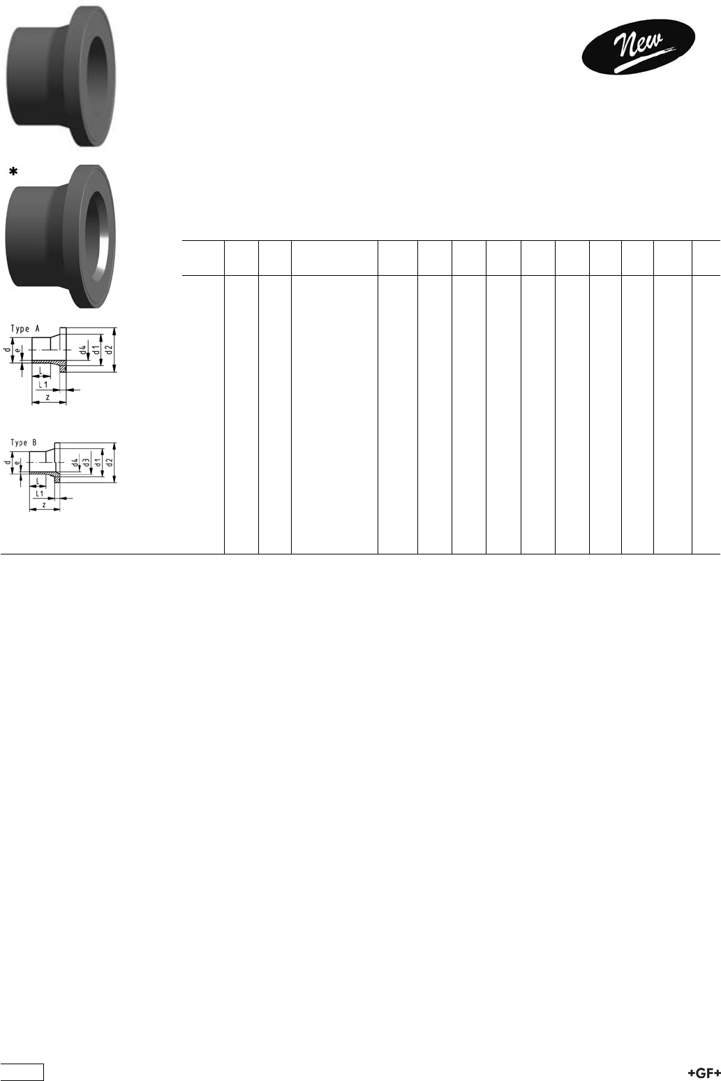
PROGEF Standard, Flange Adaptor,
PP-H S5/SDR11
Combined Jointing Face:
Flat and Serrated
Model:
ÏConventional butt-welding according to DVS 2207 part 11
ÏIR = Infrared-(IR Plus®) compatible. Please choose fusion parameters: PP-H
ÏSuitable for flange connections to ANSI/ASME B 16.5
ÏUp to d315, suitable for butterfly valve type 567, 568 and 037
ÏGasket: Profile flange gasket EPDM No. 48 44 07, FPM No. 49 44 07
* Type B with chamfer
d
[mm]
DN
[mm]
FM Code kg z
[mm]
d1
[mm]
d2
[mm]
d3
[mm]
d4
[mm]
L
[mm]
L1
[mm]
e
[mm]
20 15 IR 727 798 706 0.015 50 26 45 16 29 7 1.9
25 20 IR 727 798 757 0.025 85 33 54 20 41 9 2.3
32 20 IR 727 798 758 0.039 85 40 63 26 44 10 3.0
40 20 IR 727 798 759 0.058 85 50 73 32 49 11 3.7
50 20 IR 727 798 760 0.082 85 61 82 40 55 12 4.6
63 50 IR 727 798 711 0.144 68 75 102 51 38 14 5.8
*75 65 IR 727 798 712 0.243 80 89 122 66 61 43 16 6.9
*90 20 IR 727 798 763 0.297 140 105 133 78 73 85 17 8.2
*110 100 IR 727 798 714 0.441 80 125 158 100 90 40 18 10.0
*125 100 IR 727 798 715 0.520 82 132 158 114 102 35 25 11.4
*140 125 IR 727 798 716 0.800 89 155 188 127 114 39 25 12.8
*160 150 IR 727 798 717 0.920 92 175 212 151 131 45 25 14.6
*180 150 IR 727 798 718 0.900 80 180 212 154 147 45 30 16.4
*200 200 IR 727 798 719 1.670 100 232 268 203 163 30 32 18.2
*225 200 IR 727 798 720 1.700 100 235 268 210 184 35 32 20.5
*250 250 727 798 721 2.790 100 285 320 250 204 25 35 22.7
*280 250 727 798 722 2.610 100 291 320 265 229 35 35 25.4
*315 300 727 798 723 3.410 100 335 370 300 257 25 35 28.6
*355 350 727 798 724 5.600 180 373 430 340 290 20 40 32.3
*400 400 727 798 725 8.300 187 427 482 385 327 29 46 36.6
58
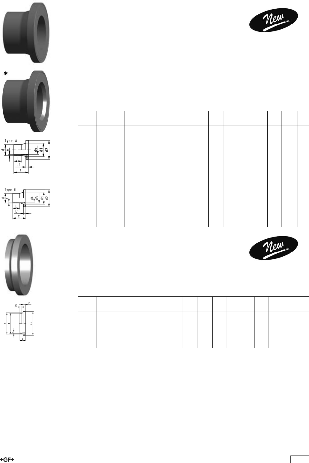
PROGEF Standard, Flange Adaptor,
S8.3/SDR17.6
Combined Jointing Face:
Flat and Serrated
Model:
ÏMaterial: PP-H
ÏConventional butt-welding according to DVS 2207 part 11
ÏIR = Infrared-(IR Plus®) compatible. Please choose fusion parameters: PP-H
ÏSuitable for flange connections to metric (from d110 also to ANSI/ASME B16.5)
ÏUp to d315, suitable for butterfly valve type 567, 568 and 037
ÏGasket: Profile flange gasket EPDM No. 48 44 07, FPM No. 49 44 07
* Type B with chamfer
d
[mm]
DN
[mm]
FM Code kg z
[mm]
d1
[mm]
d2
[mm]
d3
[mm]
d4
[mm]
L
[mm]
L1
[mm]
e
[mm]
50 40 IR 727 798 785 0.070 50 61 88 42 21 12 3.0
63 50 IR 727 798 786 0.100 50 75 102 53 16 14 3.8
75 65 IR 727 798 787 0.203 80 89 122 65 43 16 4.5
90 80 IR 727 798 788 0.273 80 105 138 78 41 17 5.4
110 100 IR 727 798 789 0.363 80 125 158 96 40 18 6.6
*125 100 IR 727 798 790 0.335 80 132 158 114 107 42 18 7.4
*140 125 IR 727 798 791 0.499 80 155 188 127 120 34 18 8.3
*160 150 IR 727 798 792 0.770 92 175 212 158 142 45 25 9.1
180 150 IR 727 798 793 0.630 80 180 212 156 30 20 10.2
*200 200 IR 727 798 794 1.380 100 232 268 203 177 30 32 11.4
*225 200 IR 727 798 795 1.350 100 235 268 210 199 35 32 12.8
*250 250 727 798 796 1.800 100 285 320 250 216 25 25 14.8
*280 250 727 798 797 2.030 100 291 320 265 243 45 25 16.6
*315 300 727 798 798 2.200 100 335 370 300 274 35 25 18.7
*355 350 727 798 799 5.800 182 374 431 340 314 100 30 21.4
*400 400 727 798 800 7.700 199 428 484 385 353 110 33 23.2
PROGEF Standard, Flange Adaptors,
S8,3/SDR17,6
Jointing Face serrated, metric
Model:
ÏInjection moulded
ÏMaterial: PP-R
ÏConventional butt-welding according to DVS 2207 part 11
d
[mm]
DN
[mm]
Code kg z
[mm]
d1
[mm]
d2
[mm]
d3
[mm]
d4
[mm]
L
[mm]
L1
[mm]
e
[mm]
*450 400 727 798 801 13.000 140 514 585 396 60 46 25.5
*500 450 727 798 802 13.000 140 530 585 440 60 46 28.4
59
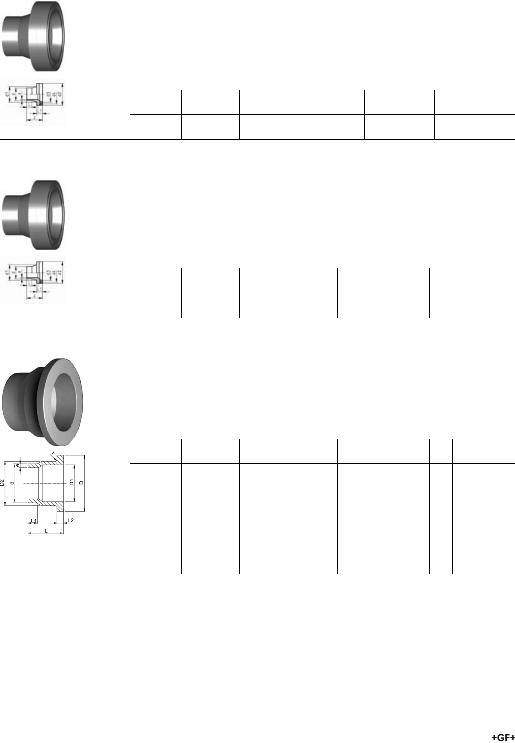
27 79 88 PROGEF Standard, Flange Adaptors, S5/SDR11
Jointing Face, combination serrated / flat
metric for Butterfly Valves
Model:
ÏConventional butt-welding according to DVS 2207 part 11
ÏSuitable for most common butterfly valves
ÏChamfered and ready for use
ÏIncluding spacer and O-Ring EPDM
d
[mm]
DN
[mm]
Code kg d1
[mm]
d2
[mm]
d3
[mm]
z
[mm]
L
[mm]
L1
[mm]
e
[mm]
355 350 727 798 824 7.500 373 430 346 118 40 75 32.2
400 400 727 798 825 10.300 427 482 404 140 55 82 36.3
27 79 88 PROGEF Standard, Flange Adaptor, S8,3/SDR17,6
Jointing face, combination serrated / flat
metric
Model:
ÏConventional butt-welding according to DVS 2207 part 11
ÏSuitable for most common butterfly valves
ÏChamfered and ready for use
ÏIncluding spacer and O-Ring EPDM
d
[mm]
DN
[mm]
Code kg d1
[mm]
d2
[mm]
d3
[mm]
L
[mm]
L1
[mm]
z
[mm]
e
[mm]
355 350 727 798 849 5.800 373 430 346 156 66 118 20.1
400 400 727 798 850 7.700 427 482 404 176 69 140 22.7
27 80 80 PROGEF Standard, Outlet Flange Adaptors, S5/SDR11
Model:
ÏMaterial: PP-R unpigmented
ÏConventional butt-welding according to DVS 2207 part 11
ÏTo wafer check valves Type 369
Attention:
ÏIn conjunction with outlet flange adaptors, flange rings for socket systems must
be used.
d
[mm]
DN
[mm]
Code kg D
[mm]
D1
[mm]
D2
[mm]
L
[mm]
L1
[mm]
L2
[mm]
e
[mm]
r
[mm]
40 32 727 808 034 0.064 80 37 50 64 30 11 3,7 3
50 40 727 808 035 0.088 90 43 61 67 30 12 4,6 3
63 50 727 808 036 0.126 105 54 76 74 30 14 5,8 4
75 65 727 808 037 0.187 125 70 90 78 30 16 6,8 4
90 80 727 808 038 0.346 140 82 108 87 35 17 8,2 4
110 100 727 808 039 0.500 160 105 131 102 41 18 10,0 4
140 125 727 808 041 0.710 190 130 165 124 47 25 12,7 4
160 150 727 808 042 0.910 215 158 188 149 52 25 14,6 4
225 200 727 808 045 1.830 270 206 248 180 55 32 20,5 4
280 250 727 808 047 3.550 325 259 308 240 63 35 25,4 4
315 300 727 808 048 4.960 375 308 346 272 66 35 28,6 4
60
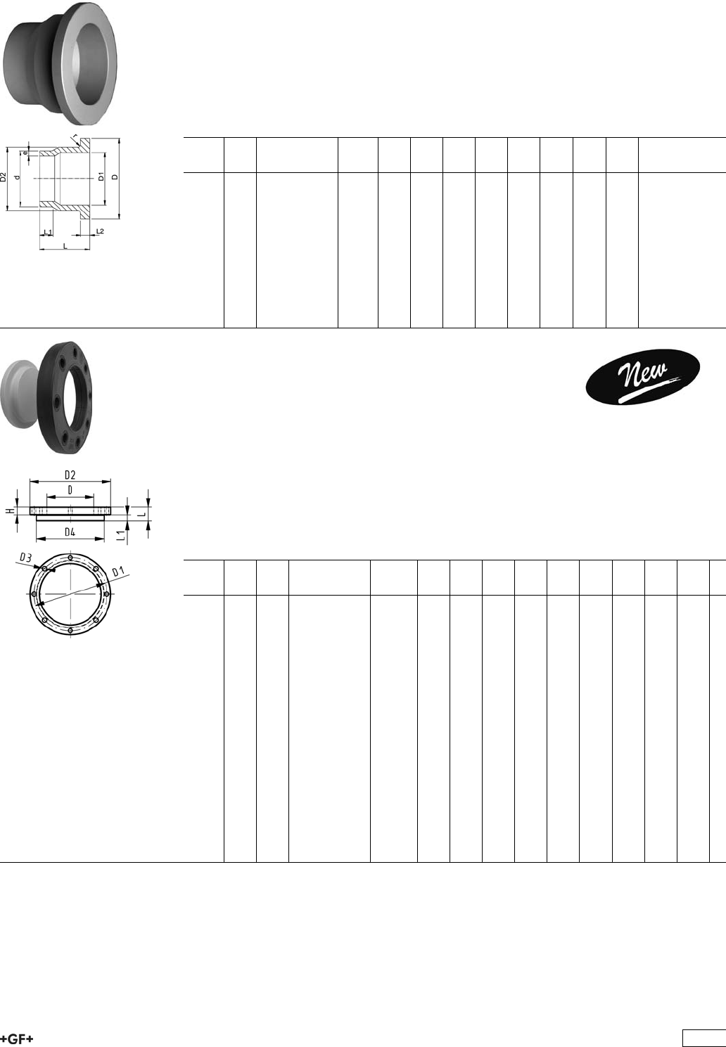
27 80 80 PROGEF Standard, Outlet Flange Adaptors,
S8,3/SDR17,6
Model:
ÏMaterial: PP-R unpigmented
ÏConventional butt-welding according to DVS 2207 part 11
ÏTo wafer check valves Type 369
Attention:
ÏIn conjunction with outlet flange adaptors, flange rings for socket systems must
be used.
d
[mm]
DN
[mm]
Code kg D
[mm]
D1
[mm]
D2
[mm]
L
[mm]
L1
[mm]
L2
[mm]
e
[mm]
r
[mm]
40 32 727 808 009 0.048 80 37 50 64 30 11 2,3 3
50 40 727 808 010 0.067 90 43 61 67 30 12 2,9 3
63 50 727 808 011 0.096 105 54 76 74 30 14 3,6 4
75 65 727 808 012 0.170 125 70 90 78 30 16 4,3 4
90 80 727 808 013 0.260 140 82 108 87 35 17 5,1 4
110 100 727 808 014 0.355 160 105 131 102 41 18 6,3 4
140 125 727 808 016 0.500 190 130 165 124 47 18 8,0 4
160 150 727 808 017 0.630 215 158 188 149 52 18 9,1 4
225 200 727 808 020 1.225 270 206 248 180 55 24 12,7 4
280 250 727 808 022 2.230 325 259 308 240 63 25 15,9 4
315 300 727 808 023 2.450 375 308 346 272 66 25 17,9 4
Blanking Flange Set, PP-H
Combined Jointing face flat and serrated
metric
Model:
Ïd63 - d315: Backing Flange PP-V with End Blank PP-H
Ïd355 - d630: Backing Flange PP/Steel with End Blank PP-H
ÏConnecting dimensions: ISO 7005, EN 1092, DIN 2501
ÏBolt circle PN 10
AL: number of holes
L: length of the End Blank
d
[mm]
DN
[mm]
PN Code kg D
[mm]
D1
[mm]
D2
[mm]
D3
[mm]
D4
[mm]
H
[mm]
L
[mm]
L1
[mm]
AL
63 50 10 727 700 611 0.668 75 125 165 18 102 24 30 14 4
75 65 10 727 700 612 0.901 89 145 185 18 122 26 30 16 4
90 80 10 727 700 613 1.054 105 160 200 18 138 27 30 17 8
110 100 10 727 700 614 1.199 125 180 220 18 158 28 30 18 8
125 100 10 727 700 615 1.658 132 180 220 18 158 28 35 25 8
140 125 10 727 700 616 1.883 155 210 250 18 188 30 40 25 8
160 150 10 727 700 617 2.312 175 240 285 22 212 32 40 25 8
180 150 10 727 700 618 2.386 180 240 285 22 212 32 45 30 8
200 200 10 727 700 619 3.419 232 295 340 22 268 34 50 32 8
225 200 10 727 700 620 3.658 235 295 340 22 268 34 50 32 8
250 250 10 727 700 621 5.425 285 350 395 22 320 38 55 35 12
280 250 10 727 700 622 19.781 291 350 395 22 320 38 60 35 12
315 300 10 727 700 623 24.348 335 400 445 22 370 42 65 35 12
355 350 10 727 700 624 22.874 373 460 515 22 430 40 70 40 16
400 400 10 727 700 625 30.304 427 515 574 26 482 40 75 46 16
450 500 10 727 700 626 43.485 510 620 684 26 585 49 80 60 20
500 500 10 727 700 627 46.203 530 620 684 26 585 49 90 60 20
560 600 10 727 700 628 65.823 615 725 796 30 685 58 100 60 20
630 600 10 727 700 629 67.056 642 725 796 30 685 68 110 60 20
61

27 70 04
27 70 05
Backing Flanges, PP-V
for Butt Fusion Systems metric
Model:
ÏModern full-plastic flange PP-GF (30 % glass-fibre reinforced)
ÏWith V-groove which applies force evenly on collar
ÏWith integrated bolt retainers as an assembly aid
ÏConnecting dimension: ISO 7005, EN 1092, BS 4504, DIN 2501
ÏBolt circle PN 10
¹) Suitable for socket- and butt fusion systems (no pictograph on flange)
AL: number of holes
d
[mm]
Inch DN
[mm]
PN Code kg D
[mm]
D1
[mm]
D2
[mm]
D3
[mm]
H
[mm]
AL SC
¹20 15 16 727 700 406 0.080 95 65 28 14 16 4 M12
¹25 20 16 727 700 407 0.100 105 75 34 14 17 4 M12
¹32 25 16 727 700 408 0.140 115 85 42 14 18 4 M12
¹40 32 16 727 700 409 0.220 140 100 51 18 20 4 M16
¹50 40 16 727 700 410 0.210 150 110 62 18 22 4 M16
¹63 50 16 727 700 411 0.380 165 125 78 18 24 4 M16
¹75 65 16 727 700 412 0.480 185 145 92 18 26 4 M16
90 80 16 727 700 513 0.520 200 160 108 18 27 8 M16
110 100 16 727 700 514 0.680 220 180 128 18 28 8 M16
125 100 16 727 700 515 0.760 220 180 135 18 28 8 M16
140 125 16 727 700 516 0.800 250 210 158 18 30 8 M16
160 6 150 16 727 700 517 1.200 285 241 178 22 32 8 M20
180 150 16 727 700 518 1.200 285 240 188 22 32 8 M20
200 8 200 16 727 700 519 1.400 340 295 235 22 34 8 M20
225 9 200 16 727 700 520 1.400 340 295 238 22 34 8 M20
250 250 16 727 700 521 1.700 395 350 288 22 38 12 M20
280 250 16 727 700 522 1.700 395 350 294 22 38 12 M20
315 300 16 727 700 523 2.400 445 400 338 22 42 12 M20
355 350 10 727 700 524 3.000 515 460 376 22 46 16 M20
400 400 10 727 700 525 3.500 574 515 442 26 50 16 M24
62

27 70 04
27 70 05
Backing Flanges, PP-V
for Socket Systems metric
Model:
ÏModern full-plastic flange PP-GF (30 % glass-fibre reinforced)
ÏWith V-groove which applies force evenly on collar
ÏWith integrated bolt retainers as an assembly aid
ÏConnecting dimension: ISO 7005, EN 1092, BS 4504, DIN 2501
ÏBolt circle PN 10
¹) Suitable for socket- and butt fusion systems (no pictograph on flange)
AL: number of holes
d
[mm]
Inch DN
[mm]
PN Code kg D
[mm]
D1
[mm]
D2
[mm]
D3
[mm]
H
[mm]
AL SC
¹20 15 16 727 700 406 0.080 95 65 28 14 16 4 M12
¹25 20 16 727 700 407 0.100 105 75 34 14 17 4 M12
¹32 25 16 727 700 408 0.140 115 85 42 14 18 4 M12
¹40 32 16 727 700 409 0.220 140 100 51 18 20 4 M16
¹50 40 16 727 700 410 0.210 150 110 62 18 22 4 M16
¹63 50 16 727 700 411 0.380 165 125 78 18 24 4 M16
¹75 65 16 727 700 412 0.480 185 145 92 18 26 4 M16
90 80 16 727 700 413 0.520 200 160 110 18 27 8 M16
110 100 16 727 700 414 0.680 220 180 133 18 28 8 M16
140 125 16 727 700 416 0.800 250 210 167 18 30 8 M16
160 6 150 16 727 700 417 1.200 285 241 190 22 32 8 M20
200 200 16 727 700 419 1.500 340 296 226 22 34 8 M20
225 8 200 16 727 700 420 1.400 340 295 250 22 34 8 M20
250 250 16 727 700 421 1.700 395 350 277 22 38 12 M20
280 250 16 727 700 422 1.700 395 350 310 22 38 12 M20
315 300 16 727 700 423 2.400 445 400 348 22 42 12 M20
355 350 10 727 700 424 3.000 515 460 388 22 46 16 M20
400 400 10 727 700 425 3.500 574 515 442 26 50 16 M24
63
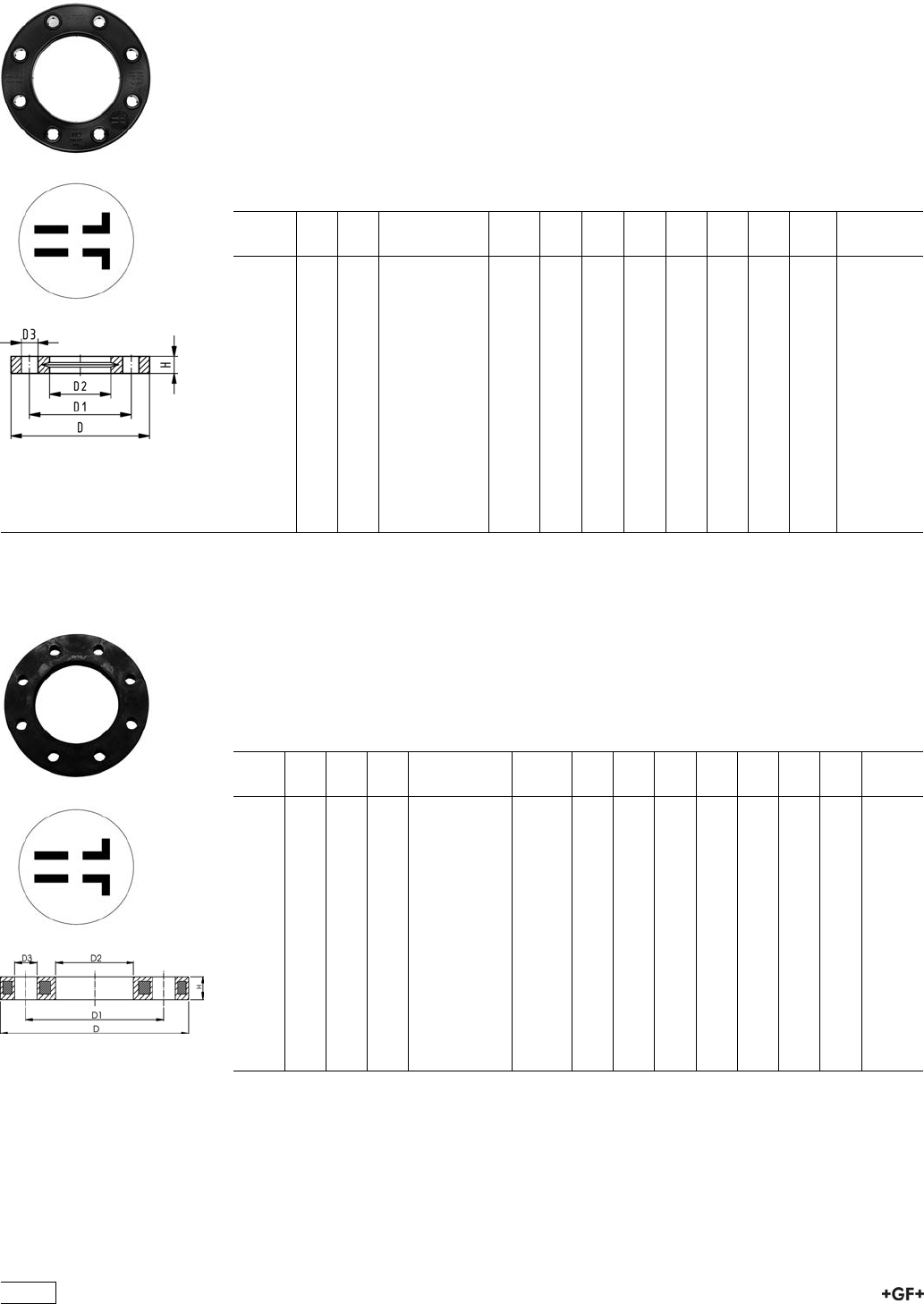
27 70 14
27 70 15
Backing Flanges, PP-V
for Butt Fusion Systems Inch/ANSI
Model:
ÏModern full-plastic flange PP-GF (30 % glass-fibre reinforced)
ÏWith V-groove which applies force evenly on collar
ÏWith integrated bolt-fixing as an assembly aid
ÏConnecting dimension: ANSI/ASME B 16.5 class 150, ASTM D 4024, BS 1560, BS
EN 1759
ÏBolt circle class 150
¹) Suitable for socket- and butt fusion systems (no pictograph on flange)
AL: number of holes
Inch DN
[mm]
PN Code kg D
[mm]
D1
[mm]
D2
[mm]
D3
[mm]
H
[mm]
AL SC
¹1
/215 16 727 701 406 0.080 95 60 28 16 16 4 M12
¹3
/420 16 727 701 407 0.100 105 70 34 16 17 4 M12
¹1 25 16 727 701 408 0.140 115 79 42 16 18 4 M12
¹11
/432 16 727 701 409 0.220 140 89 51 16 20 4 M16
¹11
/240 16 727 701 410 0.210 150 98 62 16 22 4 M16
¹2 50 16 727 701 411 0.380 165 121 78 19 24 4 M16
¹21
/265 16 727 701 412 0.480 185 140 92 19 26 4 M16
3 80 16 727 701 513 0.520 200 152 108 19 27 4 M16
4 100 16 727 701 514 0.680 229 190 128 19 28 8 M16
6 150 16 727 700 517 1.200 285 241 178 22 32 8 M20
8 200 16 727 700 519 1.400 340 295 235 22 34 8 M20
9 200 16 727 700 520 1.400 340 295 238 22 34 8 M20
10 250 16 727 701 521 1.800 406 362 288 26 38 12 M20
10 250 16 727 701 522 1.700 406 362 294 26 38 12 M20
12 300 16 727 701 523 2.400 483 432 338 26 42 12 M20
27 70 02
27 70 03
Backing Flanges, PP/Steel
for Butt Fusion Systems metric
Model:
ÏMaterial: PP (30 % glass-fibre reinforced) with steel ring
ÏConnecting dimension: ISO 7005, EN 1092, BS 4504, DIN 2501
ÏBolt circle PN 10
AL: number of holes
d
[mm]
d
[inch]
DN
[mm]
PN Code kg D
[mm]
D1
[mm]
D2
[mm]
D3
[mm]
H
[mm]
AL SC
20 15 16 727 700 206 0.220 95 65 28 14 12 4 M12
25 20 16 727 700 207 0.260 105 75 34 14 12 4 M12
32 25 16 727 700 208 0.430 115 85 42 14 16 4 M12
40 32 16 727 700 209 0.650 140 100 51 18 16 4 M16
50 40 16 727 700 210 0.820 150 110 62 18 18 4 M16
63 50 16 727 700 211 0.940 165 125 78 18 18 4 M16
75 65 16 727 700 212 1.300 185 145 92 18 18 4 M16
90 80 16 727 700 313 1.400 200 160 108 18 20 8 M16
110 100 16 727 700 314 1.580 220 180 128 18 20 8 M16
125 100 16 727 700 315 1.550 220 180 135 18 20 8 M16
140 125 16 727 700 316 2.360 250 210 158 18 24 8 M16
160 6 150 16 727 700 317 3.890 285 240 178 22 24 8 M20
180 150 16 727 700 318 3.410 285 240 188 22 24 8 M20
200 200 16 727 700 319 5.180 340 295 235 22 27 8 M20
225 200 16 727 700 320 5.150 340 295 238 22 27 8 M20
64
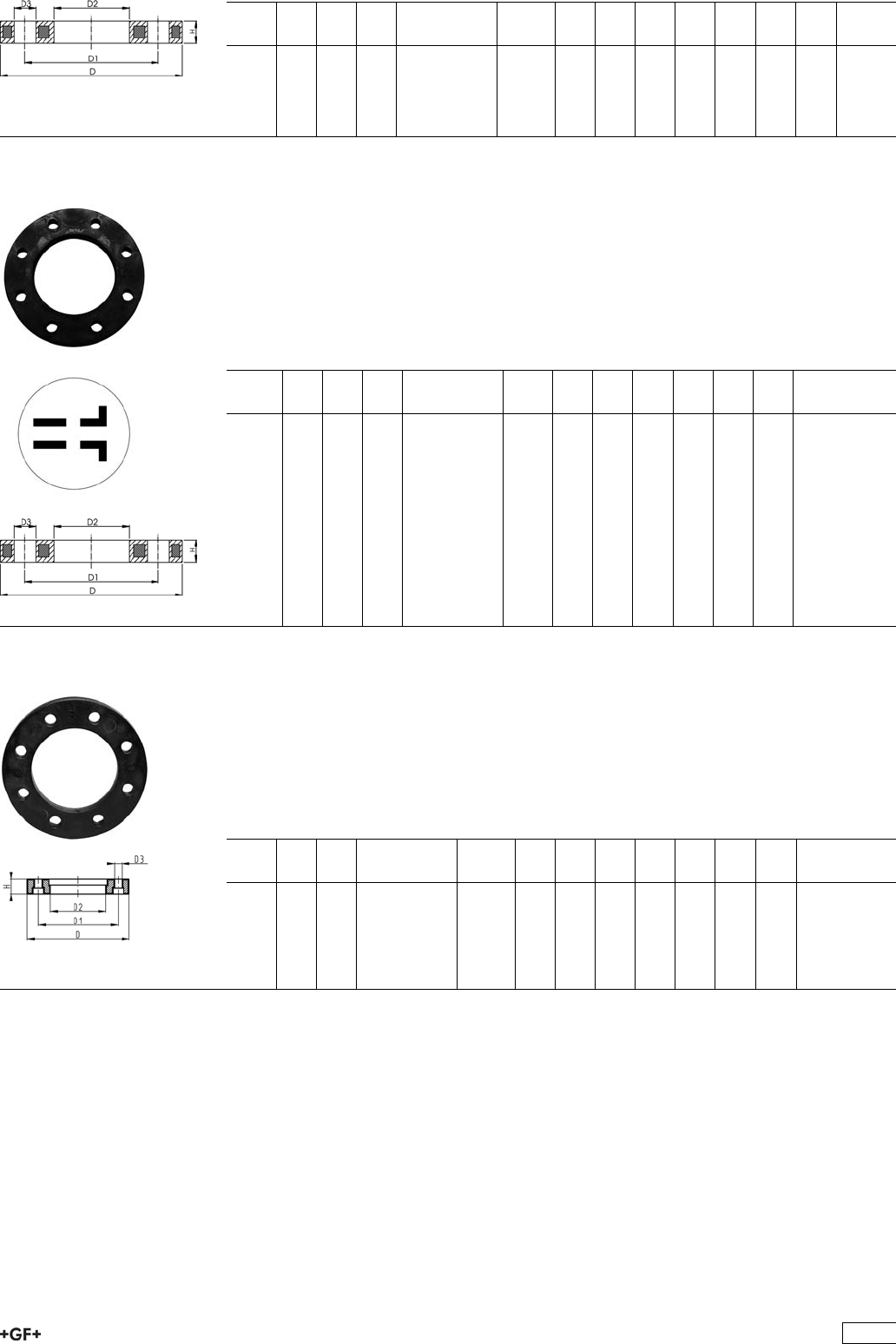
d
[mm]
d
[inch]
DN
[mm]
PN Code kg D
[mm]
D1
[mm]
D2
[mm]
D3
[mm]
H
[mm]
AL SC
250 250 16 727 700 321 6.680 395 350 288 22 30 12 M20
280 250 16 727 700 322 6.580 395 350 294 22 30 12 M20
315 300 16 727 700 323 8.420 445 400 338 22 34 12 M20
355 350 16 727 700 324 15.790 515 460 376 22 40 16 M20
400 400 16 727 700 325 19.320 574 515 430 26 40 16 M24
27 70 12 Backing Flanges, PP/Steel
for Butt Fusion Systems Inch/ANSI
Model:
ÏMaterial: PP (30 % glass-fibre reinforced) with steel ring
ÏConnecting dimension: ANSI/ASME B 16.5 class 150, ASTM D 4024, BS 1560, BS
EN 1759
ÏBolt circle class 150
AL: number of holes
d
[inch]
DN
[mm]
d
[mm]
PN Code kg D1
[mm]
D2
[mm]
D3
[mm]
D
[mm]
H
[mm]
AL
1
/215 20 16 727 701 206 0.210 60 28 16 95 12 4
3
/420 25 16 727 701 207 0.250 70 34 16 105 12 4
1 25 32 16 727 701 208 0.420 79 42 16 115 16 4
11
/432 40 16 727 701 209 0.670 89 51 16 140 16 4
11
/240 50 16 727 701 210 0.860 98 62 16 150 18 4
2 50 63 16 727 701 211 0.930 121 78 19 165 18 4
21
/265 75 16 727 701 212 1.340 140 92 19 185 18 4
3 80 90 16 727 701 313 1.550 152 108 19 200 20 4
4 100 110 16 727 701 314 1.840 190 128 19 229 20 8
6 150 160 16 727 700 317 3.890 240 178 22 285 24 8
8 200 200 16 727 701 319 5.180 298 235 22 340 27 8
8 200 225 16 727 701 320 5.150 298 238 22 340 27 8
24 70 04 Profiled Backing Flanges, PP/Steel
for Butt Fusion Systems metric
Model:
ÏPP with glass-fibre reinforcement and GGG 50 insert
ÏConnecting dimensions: ISO 7005, EN 1092, DIN 2501
ÏBolt circle PN 10
AL: number of holes
d
[mm]
DN
[mm]
PN Code kg D
[mm]
D1
[mm]
D2
[mm]
D3
[mm]
H
[mm]
AL SC
355 350 10 724 700 424 15.570 521 460 376 22 48 16 M20
400 400 10 724 700 425 19.800 582 515 430 26 51 16 M24
450 500 10 724 700 426 25.600 684 620 517 26 49 20 M24
500 500 10 724 700 427 24.300 684 620 533 26 49 20 M24
560 600 10 724 700 428 35.700 796 725 618 30 58 20 M27
630 600 10 724 700 429 32.500 796 725 645 30 68 20 M27
65
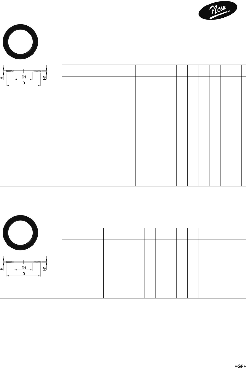
EPDM 48 44 07
FPM 49 44 07 Profile Flange Gaskets metric
EPDM / FPM
Model:
ÏFor all GF Flange Adaptors
ÏProfile Gasket with steel insert (type G-ST-P/K)
ÏHardness: 70° Shore EPDM, 75° Shore FPM
ÏCentering on the inner diameter of the screw crown
di FA are the suitable inner diameters of flange adaptors
d
[mm]
DN
[mm]
PN EPDM
Code
FPM
Code
kg D
[mm]
D1
[mm]
H
[mm]
H1
[mm]
di FA
[mm]
20 15 16 748 440 706 749 440 706 0.008 51 20 4 3 10 - 20
25 20 16 748 440 707 749 440 707 0.011 61 22 4 3 12 - 22
32 25 16 748 440 708 749 440 708 0.014 71 28 4 3 18 - 28
40 32 16 748 440 709 749 440 709 0.021 82 40 4 3 30 - 40
50 40 16 748 440 710 749 440 710 0.022 92 46 4 3 36 - 46
63 50 16 748 440 711 749 440 711 0.041 107 58 5 4 48 - 58
75 65 16 748 440 712 749 440 712 0.055 127 69 5 4 59 - 69
90 80 16 748 440 713 749 440 713 0.062 142 84 5 4 73 - 84
110 100 16 748 440 714 749 440 714 0.085 162 104 6 5 94 - 104
125 100 16 748 440 715 749 440 715 0.158 162 123 6 5 113 - 123
140 125 16 748 440 716 749 440 716 0.118 192 137 6 5 127 - 137
160 / 180 150 16 748 440 717 749 440 717 0.153 218 160 8 6 150 - 160
200 200 16 748 440 719 749 440 719 0.263 273 203 8 6 192 - 203
225 200 16 748 440 720 749 440 720 0.181 273 220 8 6 207 - 220
250 250 16 748 440 721 749 440 721 0.410 328 252 8 6 238 - 252
280 250 16 748 440 722 749 440 722 0.226 328 274 8 6 264 - 274
315 300 16 748 440 723 749 440 723 0.334 378 306 8 6 296 - 306
355 350 16 748 440 724 749 440 724 0.410 438 355 10 7 340 - 355
400 400 16 748 440 725 749 440 725 0.513 489 400 10 7 385 - 400
450 500 16 748 440 726 749 440 726 0.718 594 403 10 7 393 - 403
500 500 16 748 440 727 749 440 727 0.718 594 447 10 7 437 - 447
560 600 16 748 440 728 749 440 728 0.923 695 494 10 7 484 - 494
630 600 16 748 440 729 749 440 729 0.923 695 555 10 7 545 - 555
EPDM 48 44 03
FPM 49 44 03
Profile flange gaskets
for Flange connections, metric
Model:
ÏHardness: 70° Shore EPDM, 75° Shore FPM
Ïsuitable for flange adaptors
d
[mm]
EPDM
Code
FPM
Code
kg D
[mm]
D1
[mm]
H
[mm]
H1
[mm]
110 748 440 309 749 440 309 0.112 162 83 - 93 6 5
125 748 440 310 749 440 310 0.110 162 95 - 105 6 5
140 748 440 311 749 440 311 0.146 192 107 - 117 6 5
160 748 440 312 749 440 312 0.207 218 125 - 135 8 6
180 748 440 313 749 440 313 0.260 218 141 - 151 8 6
200 748 440 314 749 440 314 0.430 273 158 - 168 8 6
225 748 440 315 749 440 315 0.365 273 178 - 188 8 6
250 748 440 316 749 440 316 0.520 328 298 - 208 8 6
280 748 440 317 749 440 317 0.496 328 223 - 233 8 6
315 748 440 318 749 440 318 0.600 378 252 - 262 8 6
355 748 440 319 749 440 319 0.750 438 284 - 294 8 6
400 748 440 320 749 440 320 0.750 489 321 - 331 8 6
66
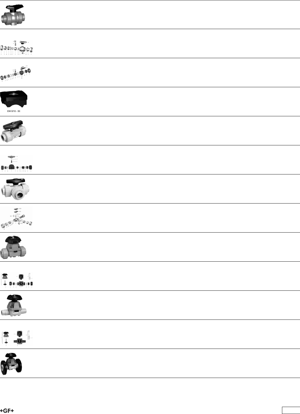
PROGEF Standard Hand-Operated and
Actuated Valves
Page
Ball Valves 546 71
Spare parts for ball valve type 546 PP-H (DN10/15-50) 90
Spare parts for ball valve type 546 PP-H (DN65-100) 94
Accessories for Ball Valve 546 97
Ball Valves 323 102
Spare Parts for Ball Valve 323 104
Ball Valves 343 105
Spare Parts for Ball Valve 343 116
Diaphragm Valves 314 119
Spare Parts for Diaphragm Valve 314 123
Diaphragm Valves 315 124
Spare Parts for Diaphragm Valve 315 126
Diaphragm Valves 317 127
67
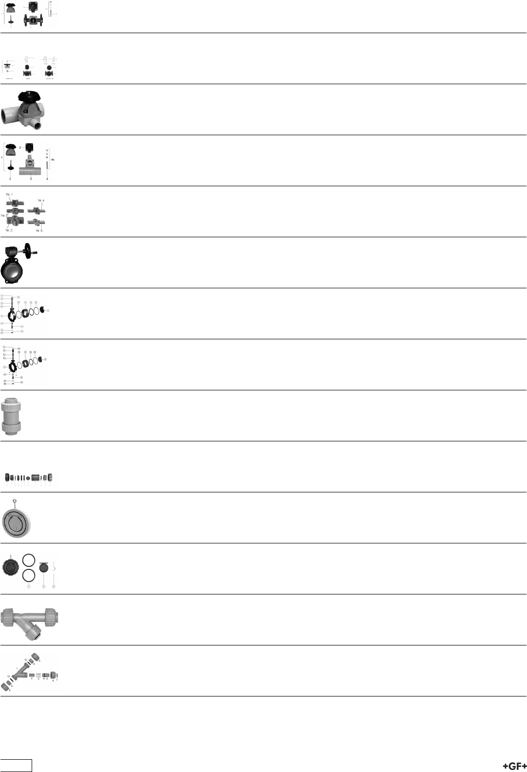
Spare Parts for Diaphragm Valve 317
(DN15-65)
132
Spare Parts for Diaphragm Valve 317
(DN80-150)
133
Diaphragm Valves 319 134
Spare Parts for Diaphragm Valves 319 135
Accessories for Diaphragm Valves 138
Butterfly valves 139
Spare parts for butterfly valve type 567 PP-H
Hand lever with index plate
148
Spare parts for butterfly valve type 568 PP-H
Hand lever with index plate
150
Ball Check Valves 360 151
Spare Parts for Ball Check Valve 360 158
Wafer Check Valves 369 160
Spare parts for wafer check valve type 369 PP-H 165
Strainers 305 167
Spare Parts for Line Strainer 305 168
68
Solenoid valves 169
Ball Valves Electric 177
Ball Valves Pneumatic 217
Diaphragm Valves Pneumatic 260
Butterfly Valves Electric 287
Butterfly Valves Pneumatic 299
Process Control Valves 308
69
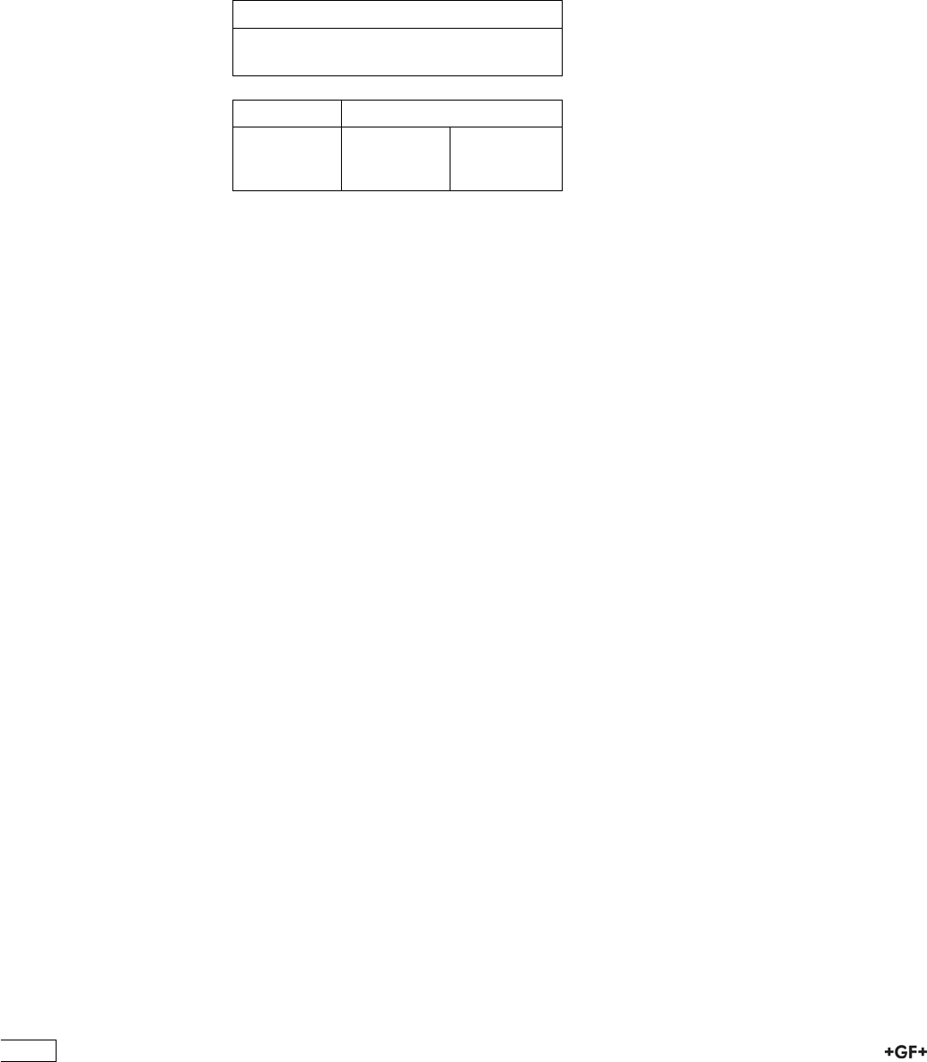
Hand-Operated Valves
General Information
Material
The material PP-H conforms with the corresponding
recommendations of the German Federal board of
Health.
Standards
All the main dimensions, such as nominal bore,
z dimensions, socket depth and diameter, are in
accordance with ISO Recommendations, ISO Draft
Resolutions for millimetre pipes and DIN 3442.
Overall length
Yjgp" wugf" ykvj" Þcpig" cfcrvqtu" qt" wpkqp" gpfu"
from GF Piping Systems, the lengths of volves
correspond to EN 558-1 (org. DIN 3202) or VSM
standard 19431 and NF.E 29492.
Dimensions
All dimensions are given in mm.
Information Service
For detailed information see our Catalogue “Plastic
Piping Systems“.
Quality control conforming to DIN 3442, Part 1
The function and tightness of every valve are
factory-tested. Testing is carried out with air under
water.
Orders
Always quote the GF Piping Systems code number
when placing orders.
Ordering example
8 ball valves 167 346 005
Jointing
Fusion jointing:
Pipes with outside diameter tolerances in accor-
dance with DIN 8077 can be readily jointed with
GF Piping Systems Valves.
Threaded joint:
BSP parallel female threads are in accordance
with ISO 7/1 or DIN 2999. Threaded plastic Valves
should be jointed to plastics pipe or to other
rncuvkeu" rctvu0" Lqkpvkpi" vq" ogvcn" rkrg" qt" Ývvkpiu" ku"
permissible only where there is little stress, and
should be carried out with great care.
Nominal Pressure
see column PN
Marking
GF Piping Systems valves are marked as follows:
• +GF+
• pipe o.d.
• pipe nominal bore
• material
• pressure rating: PN ...
Fusion joints
EN 558-1
DIN 3442
Thread joint Flange joint
ISO 7/1 on request
DIN 2999 DIN 2501/8063 ANSI B 16.5
BSI 21 JIS
70
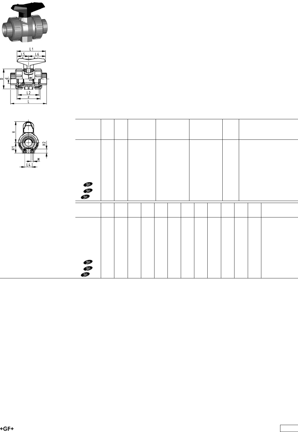
Ball Valves 546
Ball valve type 546 PP-H
With mounting inserts
With fusion sockets metric
Model:
ÏMaterial: PP-H
ÏFor easy installation and removal
ÏBall seals PTFE
ÏIntegrated stainless steel mounting inserts
ÏImage and drawing DN65-100 please see ''New product ball valve DN65-100''
Ïz-dimension, valve end and union nut are not compatible with type 346
(DN10/15-50) resp. type 370 (DN65-100)
Option:
ÏIndividual configuration of the valve (see form)
ÏMultifunctional module with integrated limit switches
ÏPneumatic or electric actuators from +GF+
d
[mm]
DN
[mm]
PN kv-value
(”p=1 bar)
[l/min]
EPDM
Code
FPM
Code
kg
16 10 10 71 167 546 401 167 546 411 0.115
20 15 10 185 167 546 402 167 546 412 0.115
25 20 10 350 167 546 403 167 546 413 0.180
32 25 10 700 167 546 404 167 546 414 0.255
40 32 10 1000 167 546 405 167 546 415 0.440
50 40 10 1600 167 546 406 167 546 416 0.610
63 50 10 3100 167 546 407 167 546 417 1.145
75 65 10 5000 167 546 408 167 546 418 3.700
90 80 10 7000 167 546 409 167 546 419 5.500
110 100 10 11000 167 546 410 167 546 420 8.700
d
[mm]
D
[mm]
H
[mm]
H1
[mm]
H2
[mm]
L
[mm]
L1
[mm]
L2
[mm]
L4
[mm]
L5
[mm]
L6
[mm]
M z
[mm]
16 50 57 27 12 93 77 56 25 32 45 M6 67
20 50 57 27 12 95 77 56 25 32 45 M6 66
25 58 67 30 12 109 97 65 25 39 58 M6 77
32 68 73 36 12 119 97 71 25 39 58 M6 83
40 84 90 44 15 135 128 85 45 54 74 M8 99
50 97 97 51 15 147 128 89 45 54 74 M8 105
63 124 116 64 15 168 152 101 45 66 87 M8 117
75 166 149 85 15 233 270 136 70 64 206 M8 167
90 200 161 105 15 254 270 141 70 64 206 M8 180
110 238 178 123 22 301 320 164 120 64 256 M12 215
71
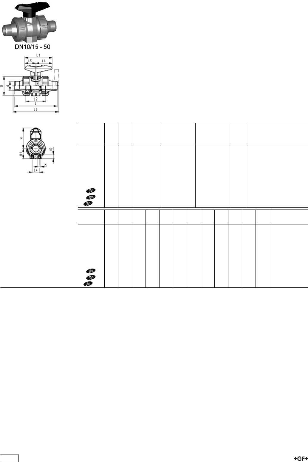
Ball valve type 546 PP-H
With mounting inserts
With socket fusion spigots metric
Model:
ÏMaterial: PP-H
ÏFor easy installation and removal
ÏBall seals PTFE
ÏIntegrated stainless steel mounting inserts
ÏImage and drawing DN65-100 please see ''New product ball valve DN65-100''
Ïz-dimension, valve end and union nut are not compatible with type 346
(DN10/15-50) resp. type 370 (DN65-100)
Option:
ÏIndividual configuration of the valve (see form)
ÏMultifunctional module with integrated limit switches
ÏPneumatic or electric actuators from +GF+
d
[mm]
DN
[mm]
PN kv-value
(”p=1 bar)
[l/min]
EPDM
Code
FPM
Code
kg
16 10 10 71 167 546 041 167 546 051 0.120
20 15 10 185 167 546 042 167 546 052 0.120
25 20 10 350 167 546 043 167 546 053 0.180
32 25 10 700 167 546 044 167 546 054 0.260
40 32 10 1000 167 546 045 167 546 055 0.450
50 40 10 1600 167 546 046 167 546 056 0.640
63 50 10 3100 167 546 047 167 546 057 1.210
75 65 10 5000 167 546 048 167 546 058 3.800
90 80 10 7000 167 546 049 167 546 059 5.600
110 100 10 11000 167 546 050 167 546 060 8.800
d
[mm]
D
[mm]
H
[mm]
H1
[mm]
H2
[mm]
L
[mm]
L1
[mm]
L2
[mm]
L3
[mm]
L4
[mm]
L5
[mm]
L6
[mm]
M
16 50 57 27 12 110 77 56 25 32 45 M6
20 50 57 27 12 120 77 56 130 25 32 45 M6
25 58 67 30 12 139 97 65 150 25 39 58 M6
32 68 73 36 12 150 97 71 160 25 39 58 M6
40 84 90 44 15 170 128 85 180 45 54 74 M8
50 97 97 51 15 190 128 89 200 45 54 74 M8
63 124 116 64 15 220 152 101 230 45 66 87 M8
75 166 149 85 15 280 270 136 290 70 64 206 M8
90 200 161 105 15 296 270 141 310 70 64 206 M8
110 238 178 123 22 336 320 164 350 120 64 256 M12
72
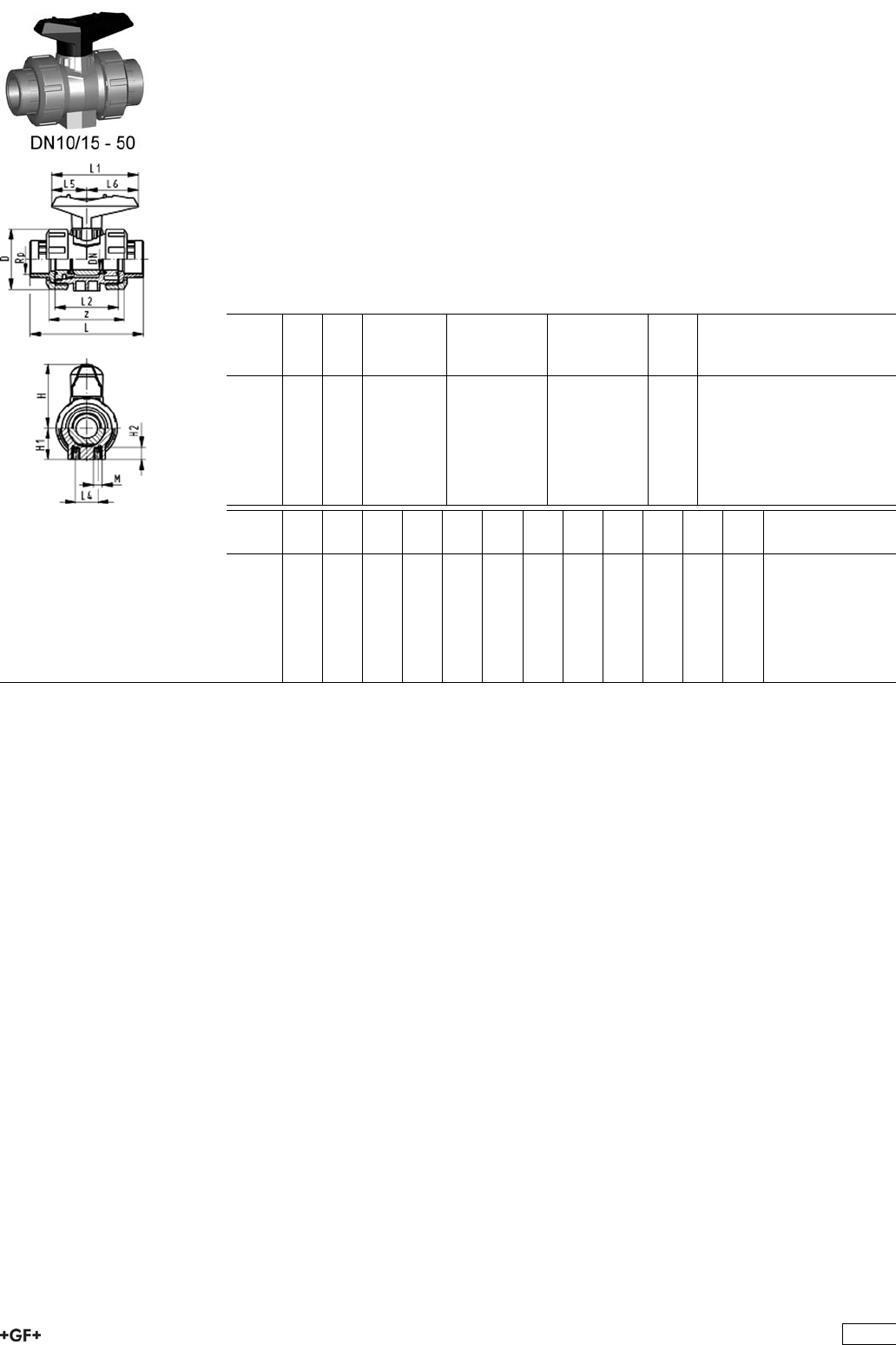
Ball valve type 546 PP-H
With mounting inserts
With threaded sockets Rp
Model:
ÏMaterial: PP-H
ÏFor easy installation and removal
ÏBall seals PTFE
ÏIntegrated stainless steel mounting inserts
Ïz-dimension, valve end and union nut are not compatible with type 346
Option:
ÏIndividual configuration of the valve (see form)
ÏMultifunctional module with integrated limit switches
ÏPneumatic or electric actuators from +GF+
Rp
[inch]
DN
[mm]
PN kv-value
(”p=1 bar)
[l/min]
EPDM
Code
FPM
Code
kg
3
/810 10 71 167 546 021 167 546 031 0.120
1
/215 10 185 167 546 022 167 546 032 0.120
3
/420 10 350 167 546 023 167 546 033 0.180
1 25 10 700 167 546 024 167 546 034 0.270
11
/432 10 1000 167 546 025 167 546 035 0.460
11
/240 10 1600 167 546 026 167 546 036 0.635
2 50 10 3100 167 546 027 167 546 037 1.190
Rp
[inch]
D
[mm]
H
[mm]
H1
[mm]
H2
[mm]
L
[mm]
L1
[mm]
L2
[mm]
L4
[mm]
L5
[mm]
L6
[mm]
M z
[mm]
3
/850 57 27 12 96 77 56 25 32 45 M6 69
1
/250 57 27 12 99 77 56 25 32 45 M6 67
3
/458 67 30 12 111 97 65 25 39 58 M6 78
1 68 73 36 12 127 97 71 25 39 58 M6 85
11
/484 90 44 15 146 128 85 45 54 74 M8 100
11
/297 97 51 15 157 128 89 45 54 74 M8 106
2 124 116 64 15 183 152 101 45 66 87 M8 121
73
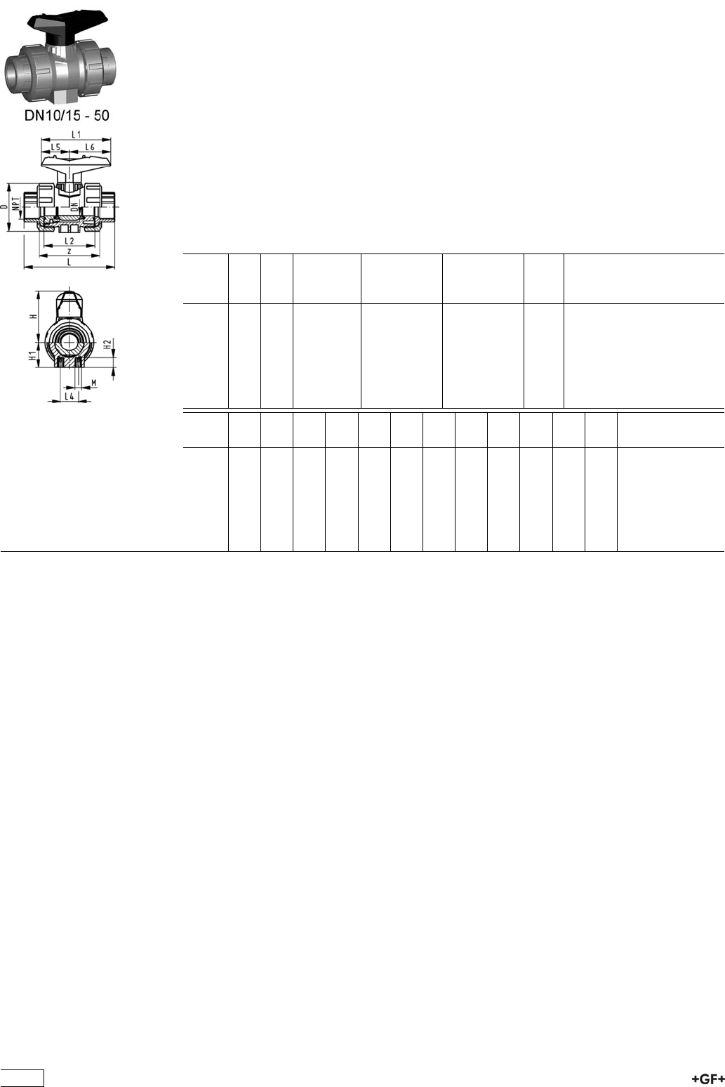
Ball valve type 546 PP-H
With mounting inserts
With threaded sockets NPT
Model:
ÏMaterial: PP-H
ÏFor easy installation and removal
ÏBall seals PTFE
ÏIntegrated stainless steel mounting inserts
Ïz-dimension, valve end and union nut are not compatible with type 346
Option:
ÏIndividual configuration of the valve (see form)
ÏMultifunctional module with integrated limit switches
ÏPneumatic or electric actuators from +GF+
NPT
[inch]
DN
[mm]
PN kv-value
(”p=1 bar)
[l/min]
EPDM
Code
FPM
Code
kg
3
/810 10 71 167 546 321 167 546 331 0.120
1
/215 10 185 167 546 322 167 546 332 0.120
3
/420 10 350 167 546 323 167 546 333 0.180
1 25 10 700 167 546 324 167 546 334 0.270
11
/432 10 1000 167 546 325 167 546 335 0.460
11
/240 10 1600 167 546 326 167 546 336 0.635
2 50 10 3100 167 546 327 167 546 337 1.190
NPT
[inch]
D
[mm]
H
[mm]
H1
[mm]
H2
[mm]
L
[mm]
L1
[mm]
L2
[mm]
L4
[mm]
L5
[mm]
L6
[mm]
M z
[mm]
3
/850 57 27 12 96 77 56 25 32 45 M6 71
1
/250 57 27 12 99 77 56 25 32 45 M6 64
3
/458 67 30 12 111 97 65 25 39 58 M6 76
1 68 73 36 12 127 97 71 25 39 58 M6 83
11
/484 90 44 15 146 128 85 45 54 74 M8 100
11
/297 97 51 15 157 128 89 45 54 74 M8 111
2 124 116 64 15 183 152 101 45 66 87 M8 134
74
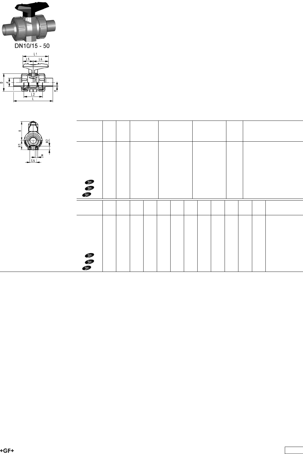
Ball valve type 546 PP-H
With mounting inserts
With butt fusion spigots IR-Plus SDR11 metric
Model:
ÏMaterial: PP-H
ÏFor easy installation and removal
ÏBall seals PTFE
ÏIntegrated stainless steel mounting inserts
ÏImage and drawing DN65-100 please see ''New product ball valve DN65-100''
Ïz-dimension, valve end and union nut are not compatible with type 346
(DN10/15-50) resp. type 370 (DN65-100)
Option:
ÏIndividual configuration of the valve (see form)
ÏMultifunctional module with integrated limit switches
ÏPneumatic or electric actuators from +GF+
d
[mm]
DN
[mm]
PN kv-value
(”p=1 bar)
[l/min]
EPDM
Code
FPM
Code
kg
20 15 10 185 167 546 442 167 546 452 0.120
25 20 10 350 167 546 443 167 546 453 0.180
32 25 10 700 167 546 444 167 546 454 0.255
40 32 10 1000 167 546 445 167 546 455 0.440
50 40 10 1600 167 546 446 167 546 456 0.620
63 50 10 3100 167 546 447 167 546 457 1.200
75 65 10 5000 167 546 448 167 546 458 3.800
90 80 10 7000 167 546 449 167 546 459 5.500
110 100 10 11000 167 546 450 167 546 460 8.700
d
[mm]
D
[mm]
H
[mm]
H1
[mm]
H2
[mm]
L
[mm]
L1
[mm]
L2
[mm]
L4
[mm]
L5
[mm]
L6
[mm]
M e
[mm]
20 50 57 27 12 130 77 56 25 32 45 M6 1,9
25 58 67 30 12 143 97 65 25 39 58 M6 2,3
32 68 73 36 12 150 97 71 25 39 58 M6 3
40 84 90 44 15 171 128 85 45 54 74 M8 3,7
50 97 97 51 15 191 128 89 45 54 74 M8 4,6
63 124 116 64 15 220 152 101 45 66 87 M8 5,8
75 166 149 85 15 266 270 136 70 64 206 M8 8.2
90 200 161 105 15 264 270 141 70 64 206 M8 9.9
110 238 178 123 22 301 320 164 120 64 256 M12 12
75
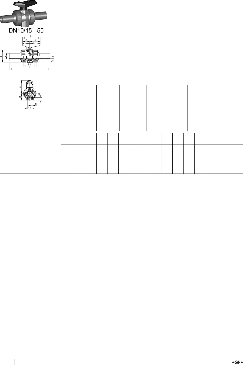
Ball valve type 546 PP-H
With mounting inserts
With butt fusion spigots long SDR11 metric
Model:
ÏMaterial: PP-H
ÏFor easy installation and removal
ÏBall seals PTFE
ÏIntegrated stainless steel mounting inserts
Ïz-dimension, valve end and union nut are not compatible with type 346
Option:
ÏIndividual configuration of the valve (see form)
ÏMultifunctional module with integrated limit switches
ÏPneumatic or electric actuators from +GF+
d
[mm]
DN
[mm]
PN kv-value
(”p=1 bar)
[l/min]
EPDM
Code
FPM
Code
kg
20 15 10 185 167 546 262 167 546 272 0.130
25 20 10 350 167 546 263 167 546 273 0.195
32 25 10 700 167 546 264 167 546 274 0.280
40 32 10 1000 167 546 265 167 546 275 0.480
50 40 10 1600 167 546 266 167 546 276 0.700
63 50 10 3100 167 546 267 167 546 277 1.320
d
[mm]
D
[mm]
H
[mm]
H1
[mm]
H2
[mm]
L
[mm]
L1
[mm]
L2
[mm]
L4
[mm]
L5
[mm]
L6
[mm]
M e
[mm]
20 50 57 27 12 193 77 56 25 32 45 M6 2,3
25 58 67 30 12 216 97 65 25 39 58 M6 2,3
32 68 73 36 12 223 97 71 25 39 58 M6 3
40 84 90 44 15 249 128 85 45 54 74 M8 3,7
50 97 97 51 15 271 128 89 45 54 74 M8 4,6
63 124 116 64 15 321 152 101 45 66 87 M8 5,8
76
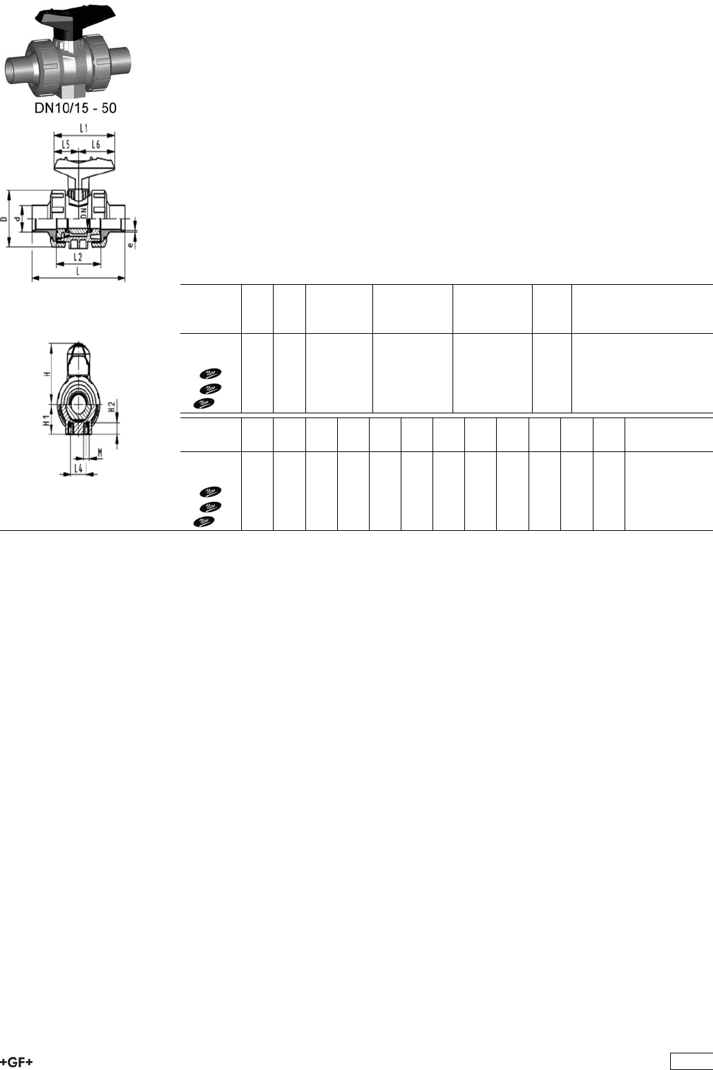
Ball valve type 546 PP-H
With mounting inserts
With butt fusion spigots SDR17.6 metric
Model:
ÏMaterial: PP-H
ÏFor easy installation and removal
ÏBall seals PTFE
ÏIntegrated stainless steel mounting inserts
ÏImage and drawing DN65-100 please see ''New product ball valve DN65-100''
Ïz-dimension, valve end and union nut are not compatible with type 346
(DN10/15-50) resp. type 370 (DN65-100)
Option:
ÏIndividual configuration of the valve (see form)
ÏMultifunctional module with integrated limit switches
ÏPneumatic or electric actuators from +GF+
d
[mm]
DN
[mm]
PN kv-value
(”p=1 bar)
[l/min]
EPDM
Code
FPM
Code
kg
50 40 6 1600 167 546 066 167 546 076 0.635
63 50 6 3100 167 546 067 167 546 077 1.200
75 65 6 5000 167 546 068 167 546 078 3.800
90 80 6 7000 167 546 069 167 546 079 5.500
110 100 6 11000 167 546 070 167 546 080 8.600
d
[mm]
D
[mm]
H
[mm]
H1
[mm]
H2
[mm]
L
[mm]
L1
[mm]
L2
[mm]
L4
[mm]
L5
[mm]
L6
[mm]
M e
[mm]
50 97 97 51 15 191 128 89 45 54 74 M8 2,9
63 124 116 64 15 220 152 101 45 66 87 M8 3,6
75 166 149 85 15 266 270 136 70 64 206 M8 4.7
90 200 161 105 15 264 270 141 70 64 206 M8 5.5
110 238 178 123 22 301 320 164 120 64 256 M12 6.8
77
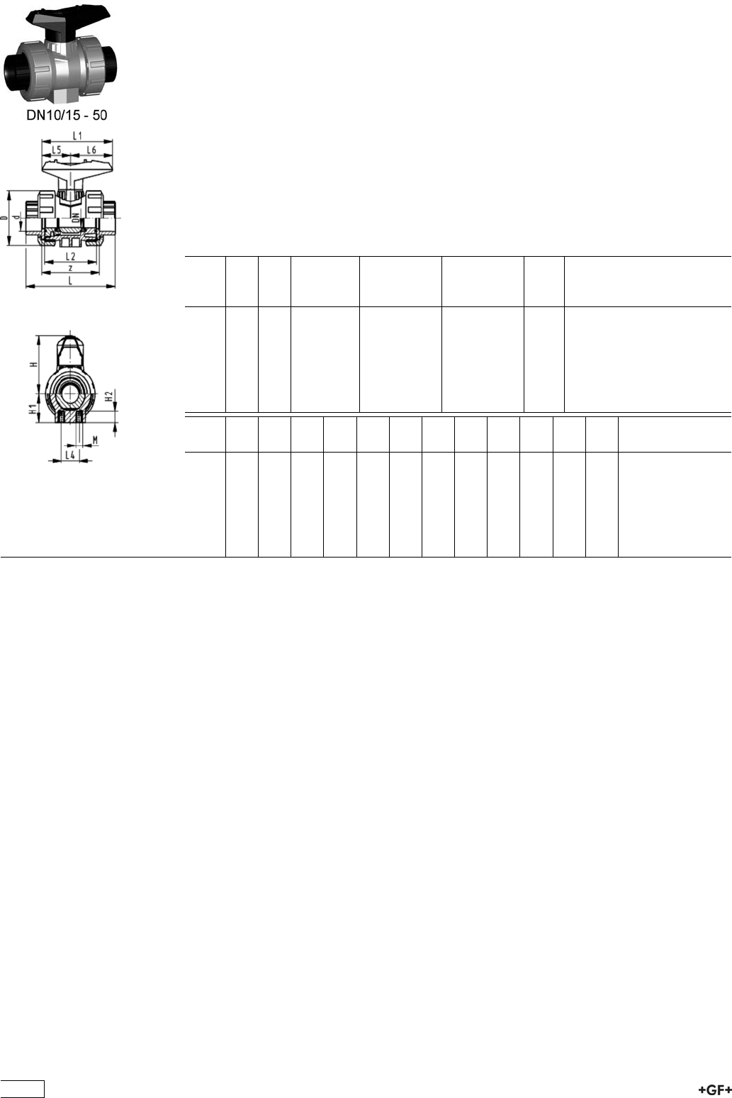
Ball valve type 546 PP-H
With mounting inserts
With fusion sockets PE100 metric
Model:
ÏMaterial: PP-H
ÏFor easy installation and removal
ÏBall seals PTFE
ÏIntegrated stainless steel mounting inserts
Ïz-dimension, valve end and union nut are not compatible with type 346
Option:
ÏIndividual configuration of the valve (see form)
ÏMultifunctional module with integrated limit switches
ÏPneumatic or electric actuators from +GF+
d
[mm]
DN
[mm]
PN kv-value
(”p=1 bar)
[l/min]
EPDM
Code
FPM
Code
kg
16 10 10 71 167 546 161 167 546 171 0.120
20 15 10 185 167 546 162 167 546 172 0.120
25 20 10 350 167 546 163 167 546 173 0.180
32 25 10 700 167 546 164 167 546 174 0.260
40 32 10 1000 167 546 165 167 546 175 0.450
50 40 10 1600 167 546 166 167 546 176 0.630
63 50 10 3100 167 546 167 167 546 177 1.195
d
[mm]
D
[mm]
H
[mm]
H1
[mm]
H2
[mm]
L
[mm]
L1
[mm]
L2
[mm]
L4
[mm]
L5
[mm]
L6
[mm]
M z
[mm]
16 50 57 27 12 93 77 56 25 32 45 M6 67
20 50 57 27 12 95 77 56 25 32 45 M6 67
25 58 67 30 12 109 97 65 25 39 58 M6 77
32 68 73 36 12 119 97 71 25 39 58 M6 83
40 84 90 44 15 135 128 85 45 54 74 M8 99
50 97 97 51 15 147 128 89 45 54 74 M8 105
63 124 116 64 15 168 152 101 45 66 87 M8 113
78

Ball valve type 546 PP-H
With mounting inserts
With butt fusion spigots PE100 SDR11 metric
Model:
ÏMaterial: PP-H
ÏFor easy installation and removal
ÏBall seals PTFE
ÏIntegrated stainless steel mounting inserts
Ïz-dimension, valve end and union nut are not compatible with type 346
Option:
ÏIndividual configuration of the valve (see form)
ÏMultifunctional module with integrated limit switches
ÏPneumatic or electric actuators from +GF+
d
[mm]
DN
[mm]
PN kv-value
(”p=1 bar)
[l/min]
EPDM
Code
FPM
Code
kg
20 15 10 185 167 546 142 167 546 152 0.120
25 20 10 350 167 546 143 167 546 153 0.180
32 25 10 700 167 546 144 167 546 154 0.255
40 32 10 1000 167 546 145 167 546 155 0.440
50 40 10 1600 167 546 146 167 546 156 0.620
63 50 10 3100 167 546 147 167 546 157 1.200
d
[mm]
D
[mm]
H
[mm]
H1
[mm]
H2
[mm]
L
[mm]
L1
[mm]
L2
[mm]
L3
[mm]
L4
[mm]
L5
[mm]
L6
[mm]
M e
[mm]
20 50 57 27 12 130 77 56 130 25 32 45 M6 1,9
25 58 67 30 12 143 97 65 150 25 39 58 M6 2,3
32 68 73 36 12 150 97 71 160 25 39 58 M6 3
40 84 90 44 15 171 128 85 180 45 54 74 M8 3,7
50 97 97 51 15 191 128 89 200 45 54 74 M8 4,6
63 124 116 64 15 220 152 101 230 45 66 87 M8 5,8
79
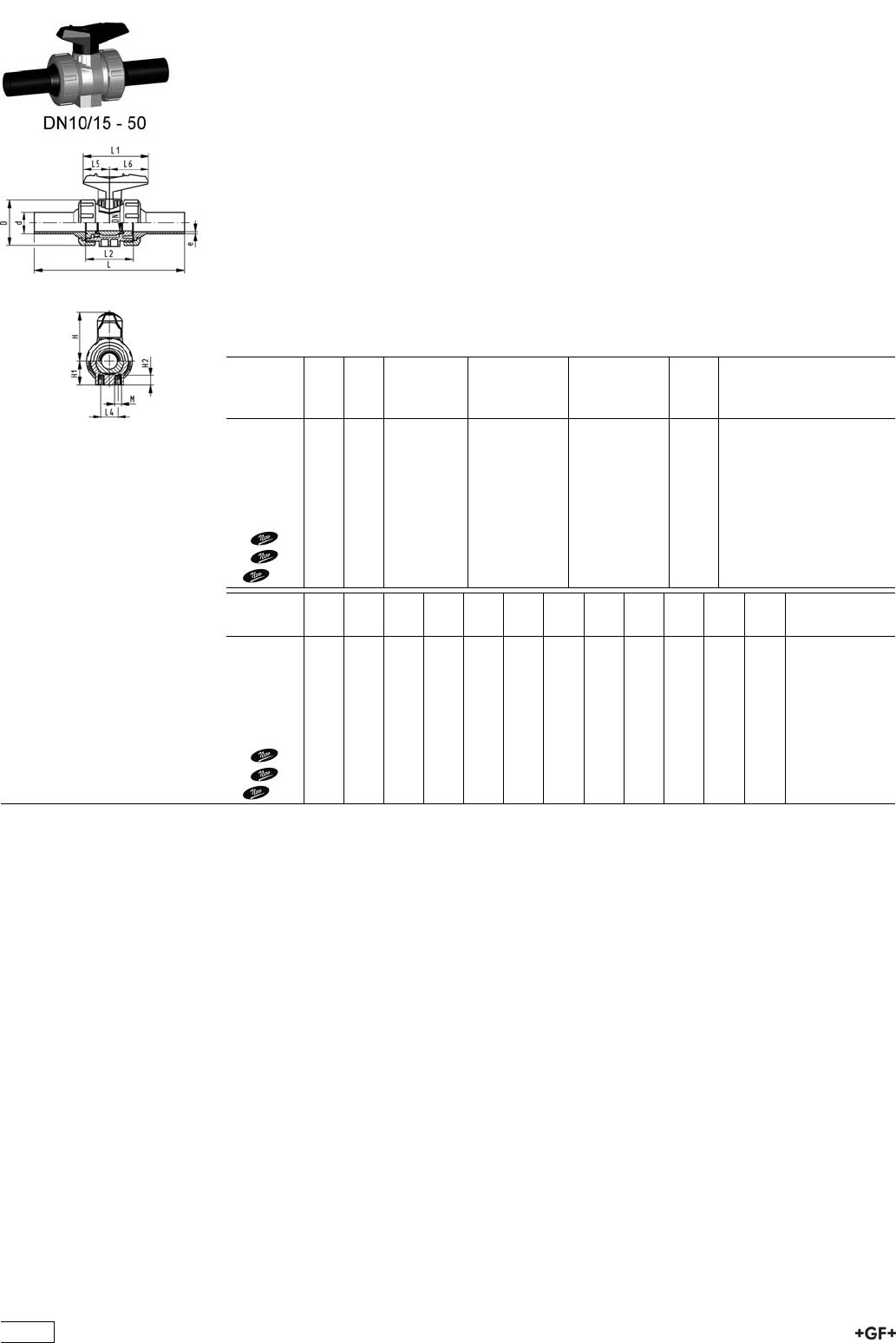
Ball valve type 546 PP-H
With mounting inserts
With butt fusion spigots long PE100 SDR11 metric
Model:
ÏMaterial: PP-H
ÏFor easy installation and removal
ÏBall seals PTFE
ÏIntegrated stainless steel mounting inserts
ÏImage and drawing DN65-100 please see ''New product ball valve DN65-100''
Ïz-dimension, valve end and union nut are not compatible with type 346
(DN10/15-50) resp. type 370 (DN65-100)
Option:
ÏIndividual configuration of the valve (see form)
ÏMultifunctional module with integrated limit switches
ÏPneumatic or electric actuators from +GF+
d
[mm]
DN
[mm]
PN kv-value
(”p=1 bar)
[l/min]
EPDM
Code
FPM
Code
kg
20 15 10 185 167 546 282 167 546 292 0.130
25 20 10 350 167 546 283 167 546 293 0.195
32 25 10 700 167 546 284 167 546 294 0.280
40 32 10 1000 167 546 285 167 546 295 0.485
50 40 10 1600 167 546 286 167 546 296 0.695
63 50 10 3100 167 546 287 167 546 297 1.320
75 65 10 5000 167 546 288 167 546 298 3.900
90 80 10 7000 167 546 289 167 546 299 5.900
110 100 10 11000 167 546 290 167 546 300 9.300
d
[mm]
D
[mm]
H
[mm]
H1
[mm]
H2
[mm]
L
[mm]
L1
[mm]
L2
[mm]
L4
[mm]
L5
[mm]
L6
[mm]
M e
[mm]
20 50 57 27 12 193 77 56 25 32 45 M6 2,3
25 58 67 30 12 216 97 65 25 39 58 M6 2,3
32 68 73 36 12 223 97 71 25 39 58 M6 3
40 84 90 44 15 249 128 85 45 54 74 M8 3,7
50 97 97 51 15 271 128 89 45 54 74 M8 4,6
63 124 116 64 15 321 152 101 45 66 87 M8 5,8
75 166 149 85 15 386 270 136 70 64 206 M8 6.8
90 200 161 105 15 421 270 141 70 64 206 M8 8.2
110 238 178 123 22 484 320 164 120 64 256 M12 10
80
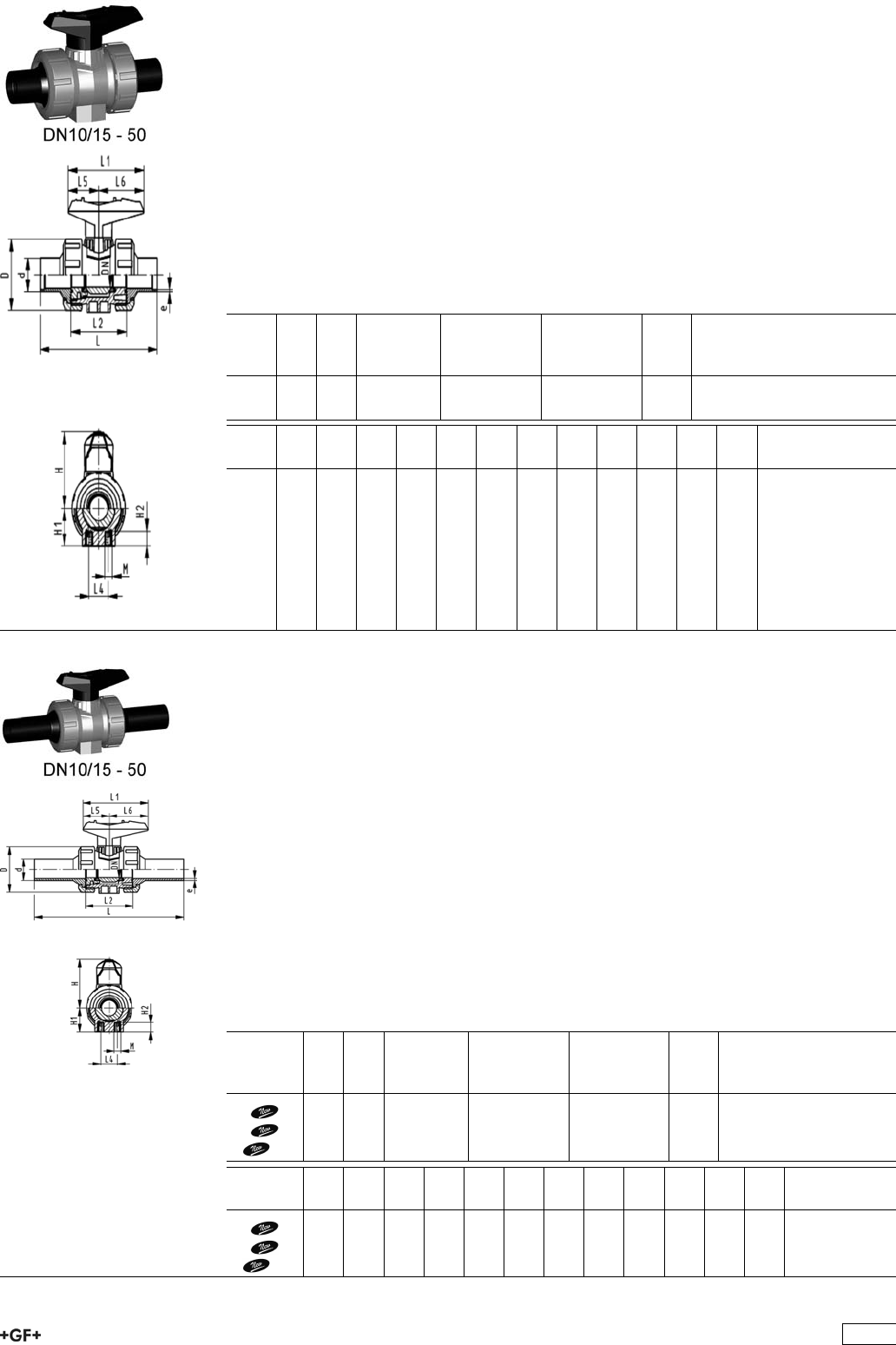
Ball valve type 546 PP-H
With mounting inserts
With butt fusion spigots PE100 SDR17.6 metric
Model:
ÏMaterial: PP-H
ÏFor easy installation and removal
ÏBall seals PTFE
ÏIntegrated stainless steel mounting inserts
Ïz-dimension, valve end and union nut are not compatible with type 346
Option:
ÏIndividual configuration of the valve (see form)
ÏMultifunctional module with integrated limit switches
ÏPneumatic or electric actuators from +GF+
d
[mm]
DN
[mm]
PN kv-value
(”p=1 bar)
[l/min]
EPDM
Code
FPM
Code
kg
50 40 6 1600 167 546 126 167 546 136 0.620
63 50 6 3100 167 546 127 167 546 137 1.200
d
[mm]
D
[mm]
H
[mm]
H1
[mm]
H2
[mm]
L
[mm]
L1
[mm]
L2
[mm]
L4
[mm]
L5
[mm]
L6
[mm]
M e
[mm]
50 97 97 51 15 191 128 89 45 54 74 M8 2,9
63 124 116 64 15 220 152 101 45 66 87 M8 3,6
PROGEF Standard
Ball valve type 546
With mounting inserts
With butt fusion spigots long PE100 SDR17,6 metric
Model:
ÏMaterial: PP-H
ÏFor easy installation and removal
ÏBall seals PTFE
ÏIntegrated stainless steel mounting inserts
ÏImage and drawing DN65-100 please see ''New product ball valve DN65-100''
Ïz-dimension, valve end and union nut are not compatible with type 346
(DN10/15-50) resp. type 370 (DN65-100)
Option:
ÏIndividual configuration of the valve (see form)
ÏMultifunctional module with integrated limit switches
ÏPneumatic or electric actuators from +GF+
d
[mm]
DN
[mm]
PN kv-value
(”p=1 bar)
[l/min]
EPDM
Code
FPM
Code
kg
75 65 10 5000 167 546 308 167 546 318 3.900
90 80 10 7000 167 546 309 167 546 319 5.800
110 100 10 11000 167 546 310 167 546 320 9.200
d
[mm]
D
[mm]
H
[mm]
H1
[mm]
H2
[mm]
L
[mm]
L1
[mm]
L2
[mm]
L4
[mm]
L5
[mm]
L6
[mm]
M e
[mm]
75 166 149 85 15 386 270 136 70 64 206 8 4.3
90 200 161 105 15 421 270 141 70 64 206 8 5.1
110 238 178 123 22 484 320 164 120 64 256 12 6.3
81
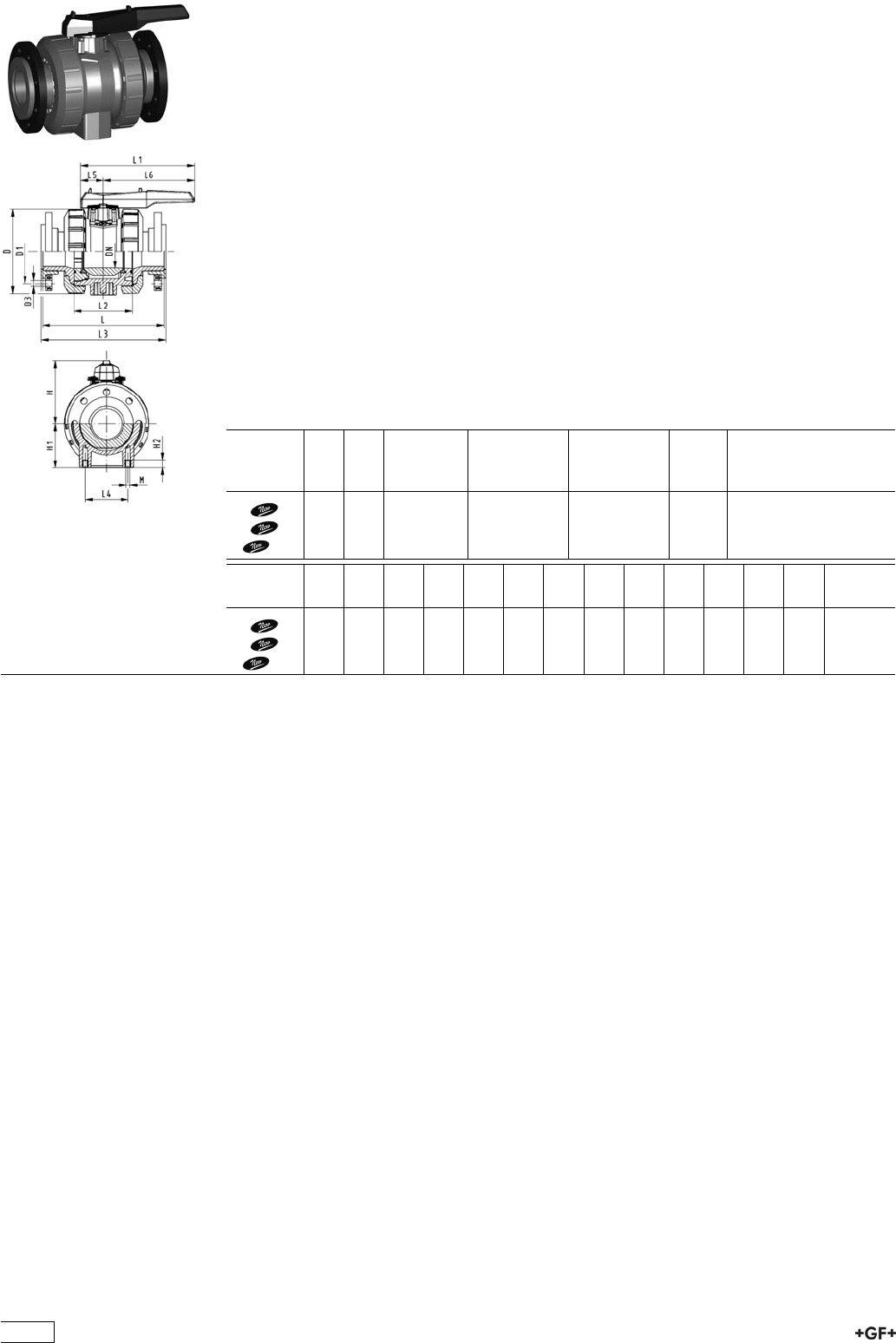
PROGEF Standard
Ball valve type 546
With mounting inserts
With backing flanges PP-st metric
Model:
ÏMaterial: PP-H
ÏFor easy installation and removal
ÏBall seals PTFE
ÏIntegrated stainless steel mounting inserts
ÏImage and drawing DN65-100 please see ''New product ball valve DN65-100''
Ïz-dimension, valve end and union nut are not compatible with type 346
(DN10/15-50) resp. type 370 (DN65-100)
ÏOverall length according to EN 558
ÏConnecting dimension: ISO 7005, EN 1092, BS 4504, DIN 2501
Option:
ÏIndividual configuration of the valve (see form)
ÏMultifunctional module with integrated limit switches
ÏPneumatic or electric actuators from +GF+
d
[mm]
DN
[mm]
PN kv-value
(”p=1 bar)
[l/min]
EPDM
Code
FPM
Code
kg
75 65 10 5000 167 546 808 167 546 818 4.300
90 80 10 7000 167 546 809 167 546 819 6.400
110 100 10 11000 167 546 810 167 546 820 10.000
d
[mm]
D
[mm]
D1
[mm]
D3
[mm]
L
[mm]
L1
[mm]
L2
[mm]
L3
[mm]
L4
[mm]
L5
[mm]
L6
[mm]
H
[mm]
H1
[mm]
M
75 166 145 18 280 270 136 290 70 64 206 149 85 8
90 200 160 18 296 270 141 310 70 64 206 161 105 8
110 238 180 18 336 320 164 350 120 64 256 178 123 12
82
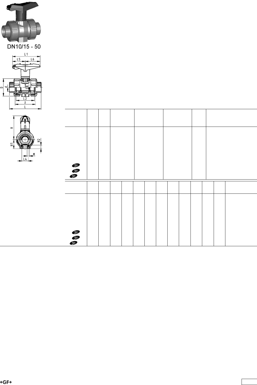
Ball valve type 546 PP-H
With lockable handle
With fusion sockets metric
Model:
ÏMaterial: PP-H
ÏImage and drawing DN65-100 please see ''New product ball valve DN65-100''
ÏFor easy installation and removal
Ïz-dimension, valve end and union nut are not compatible with type 346
(DN10/15-50) resp. type 370 (DN65-100)
ÏBall seals PTFE
ÏIntegrated stainless steel mounting inserts
ÏLockable hand lever with ratchet settings
Option:
ÏIndividual configuration of the valve (see form)
ÏMultifunctional module with integrated limit switches
ÏPneumatic or electric actuators from +GF+
d
[mm]
DN
[mm]
PN kv-value
(”p=1 bar)
[l/min]
EPDM
Code
FPM
Code
kg
16 10 10 71 167 546 421 167 546 431 0.125
20 15 10 185 167 546 422 167 546 432 0.125
25 20 10 350 167 546 423 167 546 433 0.195
32 25 10 700 167 546 424 167 546 434 0.270
40 32 10 1000 167 546 425 167 546 435 0.465
50 40 10 1600 167 546 426 167 546 436 0.635
63 50 10 3100 167 546 427 167 546 437 1.175
75 65 10 5000 167 546 428 167 546 438 4.000
90 80 10 7000 167 546 429 167 546 439 5.900
110 100 10 11000 167 546 430 167 546 440 9.100
d
[mm]
D
[mm]
H
[mm]
H1
[mm]
H2
[mm]
L
[mm]
L1
[mm]
L2
[mm]
L4
[mm]
L5
[mm]
L6
[mm]
M z
[mm]
16 50 79 27 12 93 77 56 25 32 45 M6 67
20 50 79 27 12 95 77 56 25 32 45 M6 66
25 58 88 30 12 109 97 65 25 39 58 M6 77
32 68 94 36 12 119 97 71 25 39 58 M6 83
40 84 113 44 15 135 128 85 45 54 74 M8 99
50 97 119 51 15 147 128 89 45 54 74 M8 105
63 124 141 64 15 168 152 101 45 66 87 M8 117
75 166 224 85 15 233 270 136 70 64 206 M8 167
90 200 235 105 15 254 270 141 70 64 206 M8 180
110 238 245 123 22 301 320 164 120 64 256 M12 215
83
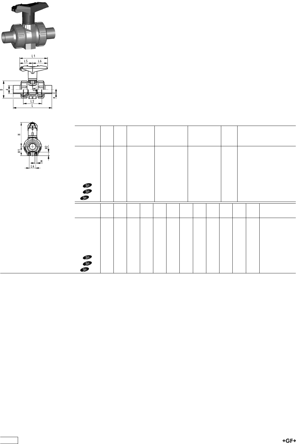
Ball valve type 546 PP-H
With lockable handle
With butt fusion spigots IR-Plus SDR11 metric
Model:
ÏMaterial: PP-H
ÏImage and drawing DN65-100 please see ''New product ball valve DN65-100''
ÏFor easy installation and removal
Ïz-dimension, valve end and union nut are not compatible with type 346
(DN10/15-50) resp. type 370 (DN65-100)
ÏBall seals PTFE
ÏIntegrated stainless steel mounting inserts
ÏLockable hand lever with ratchet settings
Option:
ÏIndividual configuration of the valve (see form)
ÏMultifunctional module with integrated limit switches
ÏPneumatic or electric actuators from +GF+
d
[mm]
DN
[mm]
PN kv-value
(”p=1 bar)
[l/min]
EPDM
Code
FPM
Code
kg
20 15 10 185 167 546 462 167 546 472 0.130
25 20 10 350 167 546 463 167 546 473 0.195
32 25 10 700 167 546 464 167 546 474 0.270
40 32 10 1000 167 546 465 167 546 475 0.465
50 40 10 1600 167 546 466 167 546 476 0.645
63 50 10 3100 167 546 467 167 546 477 1.230
75 65 10 5000 167 546 468 167 546 478 4.100
90 80 10 7000 167 546 469 167 546 479 5.900
110 100 10 11000 167 546 470 167 546 480 9.000
d
[mm]
D
[mm]
H
[mm]
H1
[mm]
H2
[mm]
L
[mm]
L1
[mm]
L2
[mm]
L4
[mm]
L5
[mm]
L6
[mm]
M e
[mm]
20 50 79 27 12 130 87 56 25 42 45 M6 1,9
25 58 88 30 12 143 108 65 25 50 58 M6 2,3
32 68 94 36 12 150 108 71 25 50 58 M6 3
40 84 113 44 15 171 140 85 45 66 75 M8 3,7
50 97 119 51 15 191 140 89 45 66 75 M8 4,6
63 124 141 64 15 220 165 101 45 78 87 M8 5,8
75 166 149 85 15 266 270 136 70 64 206 M8 8.2
90 200 161 105 15 264 270 141 70 64 206 M8 9.9
110 238 178 123 22 301 320 164 120 64 256 M12 12
84
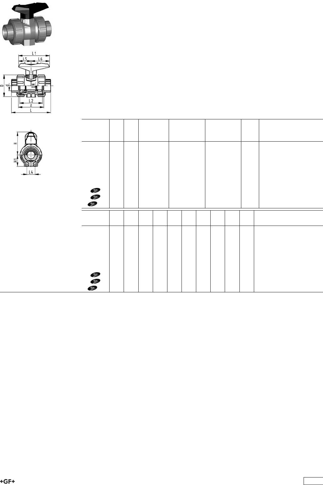
Ball valve type 546 PP-H
With fusion sockets metric
Model:
ÏMaterial: PP-H
ÏImage and drawing DN65-100 please see ''New product ball valve DN65-100''
ÏFor easy installation and removal
Ïz-dimension, valve end and union nut are not compatible with type 346
(DN10/15-50) resp. type 370 (DN65-100)
ÏBall seals PTFE
ÏWithout mounting inserts
Option:
ÏIndividual configuration of the valve (see form)
ÏMultifunctional module with integrated limit switches
ÏPneumatic or electric actuators from +GF+
d
[mm]
DN
[mm]
PN kv-value
(”p=1 bar)
[l/min]
EPDM
Code
FPM
Code
kg
16 10 10 71 167 546 001 167 546 011 0.115
20 15 10 185 167 546 002 167 546 012 0.115
25 20 10 350 167 546 003 167 546 013 0.180
32 25 10 700 167 546 004 167 546 014 0.255
40 32 10 1000 167 546 005 167 546 015 0.440
50 40 10 1600 167 546 006 167 546 016 0.610
63 50 10 3100 167 546 007 167 546 017 1.145
75 65 10 5000 167 546 008 167 546 018 3.700
90 80 10 7000 167 546 009 167 546 019 5.500
110 100 10 11000 167 546 010 167 546 020 8.700
d
[mm]
D
[mm]
H
[mm]
H1
[mm]
L
[mm]
L1
[mm]
L2
[mm]
L4
[mm]
L5
[mm]
L6
[mm]
z
[mm]
16 50 57 27 93 77 56 25 32 45 67
20 50 57 27 95 77 56 25 32 45 66
25 58 67 30 109 97 65 25 39 58 77
32 68 73 36 119 97 71 25 39 58 83
40 84 90 44 135 128 85 45 54 74 99
50 97 97 51 147 128 89 45 54 74 105
63 124 116 64 168 152 101 45 66 87 117
75 166 149 85 233 270 136 70 64 206 167
90 200 161 105 254 270 141 70 64 206 180
110 238 178 123 301 320 164 120 64 256 215
85
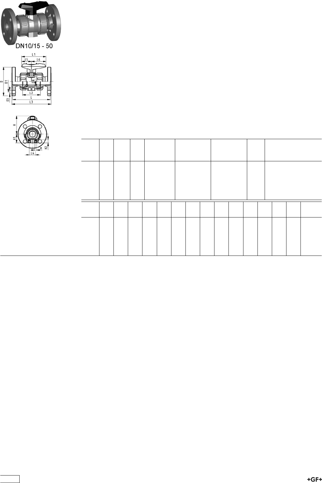
PROGEF Standard
Ball valve type 546
With mounting inserts
With fixed flanges PP-H serrated metric
Model:
ÏMaterial: PP-H
ÏFor easy installation and removal
ÏBall seals PTFE
ÏIntegrated stainless steel mounting inserts
Ïz-dimension, valve end and union nut are not compatible with type 346
ÏOverall length EN 558
ÏConnecting dimensions: ISO 7005 / EN 1092 / DIN 2501 PN10 / BS4504
Option:
ÏIndividual configuration of the valve (see form)
ÏMultifunctional module with integrated limit switches
ÏPneumatic or electric actuators from +GF+
d
[mm]
DN
[mm]
Inch PN kv-value
(”p=1 bar)
[l/min]
EPDM
Code
FPM
Code
kg
20 15 1
/210 185 167 546 182 167 546 192 0.245
25 20 3
/410 350 167 546 183 167 546 193 0.345
32 25 1 10 700 167 546 184 167 546 194 0.495
40 32 1 1
/410 1000 167 546 185 167 546 195 0.830
50 40 1 1
/210 1600 167 546 186 167 546 196 1.100
63 50 2 10 3100 167 546 187 167 546 197 1.830
d
[mm]
D
[mm]
D1
[mm]
D3
[mm]
H
[mm]
H1
[mm]
H2
[mm]
L
[mm]
L1
[mm]
L2
[mm]
L3
[mm]
L4
[mm]
L5
[mm]
L6
[mm]
M
20 95 65 14 57 27 12 120 77 56 130 25 32 45 M6
25 105 75 14 67 30 12 140 97 65 150 25 39 58 M6
32 115 85 14 73 36 12 150 97 71 160 25 39 58 M6
40 140 100 18 90 44 15 170 128 85 180 45 54 74 M8
50 150 110 18 97 51 15 190 128 89 200 45 54 74 M8
63 165 125 18 116 64 15 220 152 101 230 45 66 87 M8
86

Component Parts for Flange Assembly
Ball Valves Type 546
27 79 02 PROGEF Standard, Flange Adaptor
Jointing face flat/serrated
d
[mm]
PN Code kg
20 10 727 790 206 0.011
25 10 727 790 207 0.022
32 10 727 790 208 0.033
40 10 727 790 209 0.046
50 10 727 790 210 0.062
63 10 727 790 211 0.090
75 10 727 790 212 0.163
90 10 727 790 213 0.233
110 10 727 790 214 0.319
PROGEF Standard, Special Flange Adaptors, PP-H
S5/SDR11
Jointing Face, combination serrated / flat
metric
d
[mm]
DN
[mm]
FM Code kg
75 65 IR 727 798 512 0.243
90 80 IR 727 798 513 0.326
90 80 IR 727 798 663 0.346
110 100 IR 727 798 514 0.441
125 100 IR 727 798 515 0.520
140 125 IR 727 798 516 0.800
160 150 IR 727 798 517 0.920
180 150 IR 727 798 568 0.900
200 200 IR 727 798 519 1.670
225 200 IR 727 798 520 1.700
250 250 -- 727 798 571 2.790
280 250 -- 727 798 572 2.610
315 300 -- 727 798 573 3.410
355 350 -- 727 798 574 5.600
400 400 -- 727 798 575 8.300
87

EPDM 48 44 07
FPM 49 44 07 Profile Flange Gaskets metric
EPDM / FPM
d
[mm]
DN
[mm]
PN EPDM
Code
FPM
Code
kg
16 10 16 748 440 705 749 440 705 0.007
20 15 16 748 440 706 749 440 706 0.008
25 20 16 748 440 707 749 440 707 0.011
32 25 16 748 440 708 749 440 708 0.014
40 32 16 748 440 709 749 440 709 0.021
50 40 16 748 440 710 749 440 710 0.022
63 50 16 748 440 711 749 440 711 0.041
75 65 16 748 440 712 749 440 712 0.055
90 80 16 748 440 713 749 440 713 0.062
110 100 16 748 440 714 749 440 714 0.085
125 100 16 748 440 715 749 440 715 0.158
140 125 16 748 440 716 749 440 716 0.118
160 / 180 150 16 748 440 717 749 440 717 0.153
200 200 16 748 440 719 749 440 719 0.263
225 200 16 748 440 720 749 440 720 0.181
250 250 16 748 440 721 749 440 721 0.410
280 250 16 748 440 722 749 440 722 0.226
315 300 16 748 440 723 749 440 723 0.334
355 350 16 748 440 724 749 440 724 0.410
400 400 16 748 440 725 749 440 725 0.513
27 70 04
27 70 05
Backing Flanges, PP-V
for Socket Systems metric
d
[mm]
Inch DN
[mm]
PN Code kg
20 15 16 727 700 406 0.080
25 20 16 727 700 407 0.100
32 25 16 727 700 408 0.140
40 32 16 727 700 409 0.220
50 40 16 727 700 410 0.210
63 50 16 727 700 411 0.380
75 65 16 727 700 412 0.480
90 80 16 727 700 413 0.520
110 100 16 727 700 414 0.680
27 30 10
27 40 10
Fixed Flanges, PP-H metric
Jointing Face flat
d
[mm]
DN
[mm]
Inch PN Code kg
20 15 1/2 10 727 730 106 0.069
25 20 3/4 10 727 730 107 0.094
32 25 1 10 727 730 108 0.129
40 32 11/4 10 727 730 109 0.203
50 40 11/2 10 727 730 110 0.246
63 50 2 10 727 730 111 0.330
88

27 30 10
27 40 10
Fixed Flanges, PP-H metric
Combined jointing face: flat and serrated
d
[mm]
DN
[mm]
Inch PN Code kg
20 15 1/2 10 727 740 106 0.065
25 20 3/4 10 727 740 107 0.083
32 25 1 10 727 740 108 0.117
40 32 11/4 10 727 740 109 0.175
50 40 11/2 10 727 740 110 0.212
63 50 2 10 727 740 111 0.330
89
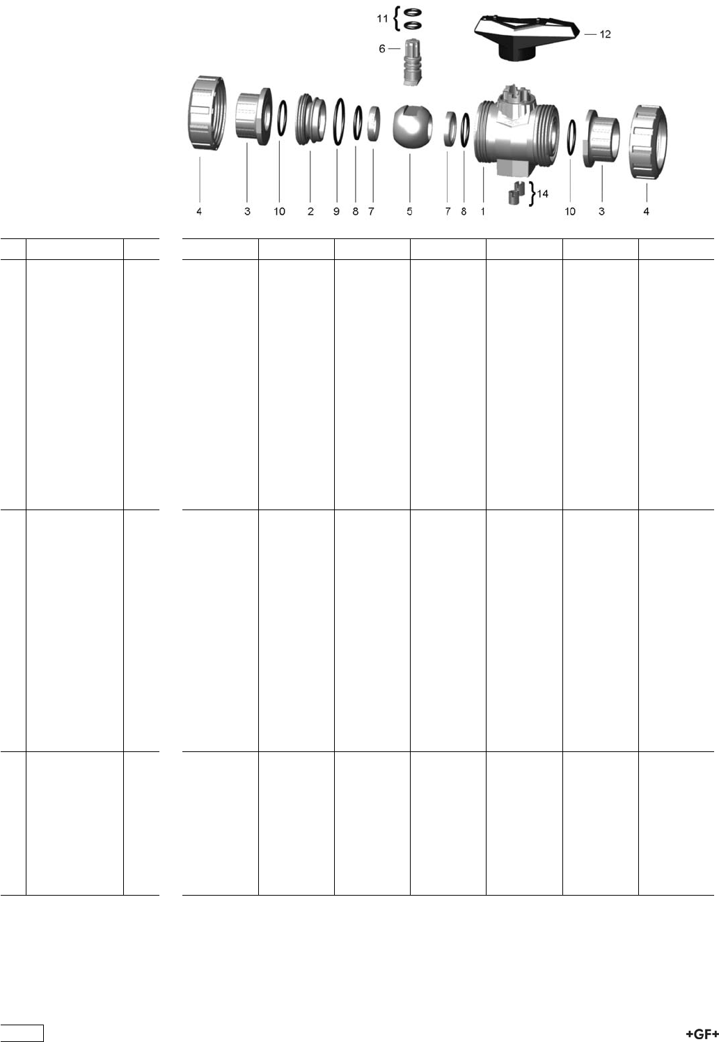
Spare parts for ball valve type 546 PP-H (DN10/15-50)
No. Article / Material Pieces d16 DN10 d20 DN15 d25 DN20 d32 DN25 d40 DN32 d50 DN40 d63 DN50
Central part 167 482 876 167 482 876 167 482 877 167 482 878 167 482 879 167 482 880 167 482 881
1 Body PP 1
2 PP 1
5 Ball PP 1
6 Stem PP 1
7 Ball seal PTFE 2
8 Backing seal
EPDM
1
9 Body seal EPDM 1
10 Face seal EPDM 2
11 Stem seal
EPDM
2
12 Lever PP
black
1
14 Threaded bush
Stainless steel
3
Central part 167 482 888 167 482 888 167 482 889 167 482 890 167 482 891 167 482 892 167 482 893
1 Body PP 1
2 PP 1
5 Ball PP 1
6 Stem PP 1
7 Ball seal PTFE 2
8 Backing seal
FPM
1
9 Body seal FPM 1
10 Face seal FPM 2
11 Stem seal FPM 2
12 Lever PP
black
1
14 Threaded bush
Stainless steel
3
Ball set 167 484 125 167 484 125 167 484 126 167 484 127 167 484 128 167 484 129 167 484 130
5 Ball PP 1
6 Stem PP 1
7 Ball seal PTFE 2
8 Backing seal
EPDM
2
9 Body seal EPDM 1
11 Stem seal
EPDM
2
90

No. Article / Material Pieces d16 DN10 d20 DN15 d25 DN20 d32 DN25 d40 DN32 d50 DN40 d63 DN50
Ball set 167 484 135 167 484 135 167 484 136 167 484 137 167 484 138 167 484 139 167 484 140
5 Ball PP 1
6 Stem PP 1
7 Ball seal PTFE 2
8 Backing seal
FPM
2
9 Body seal FPM 1
11 Stem seal FPM 2
Seal set 161 486 400 161 486 400 161 486 401 161 486 402 161 486 403 161 486 404 161 486 405
8 Backing seal
EPDM
2
9 Body seal EPDM 1
10 Face seal EPDM 2
11 Stem seal
EPDM
2
Seal set 161 486 410 161 486 410 161 486 411 161 486 412 161 486 413 161 486 414 161 486 415
8 Backing seal
FPM
2
9 Body seal FPM 1
10 Face seal FPM 2
11 Stem seal FPM 2
3 Connecting
piece 546 PP-H
(G30) with fusion
socket metric
1 167 482 900 167 482 901 167 482 902 167 482 903 167 482 904 167 482 905 167 482 906
3 Connecting
piece 546 PP-H
(G32) with
socket fusion
spigot metric
1 167 482 922 167 482 923 167 482 924 167 482 925 167 482 926 167 482 927 167 482 928
3 Connecting
piece 546 PP-H
(G33) with
threaded socket
Rp fortified
1 167 482 911 167 482 912 167 482 913 167 482 914 167 482 915 167 482 916 167 482 917
3 Connecting
piece 546 PP-H
(G34) with
threaded socket
NPT fortified
1 167 482 966 167 482 967 167 482 968 167 482 969 167 482 970 167 482 971 167 482 972
3 Connecting
piece 546 PP-H
(G63)
subassembly
with fixed flange
serrated PP-H
metric
1 - 167 484 160 167 484 161 167 484 162 167 484 163 167 484 164 167 484 165
3 Connecting
piece 546 PP-H
(G73)
subassembly
with backing
flange PP-ST
ANSI
1 - 167 482 956 167 482 957 167 482 958 167 482 959 - -
3 Connecting
piece 546 PP-H
(G35) with butt
fusion spigot IR
Plus®SDR11
metric
1 - 167 482 945 167 482 946 167 482 947 167 482 948 167 482 949 167 482 950
3 Connecting
piece 546 PP-H
(G36) with butt
fusion spigot
SDR17,6 metric
1 - - - - 167 482 937 167 482 938 167 482 939
91

No. Article / Material Pieces d16 DN10 d20 DN15 d25 DN20 d32 DN25 d40 DN32 d50 DN40 d63 DN50
3 Connecting
piece 546 PP-H
(G37) with butt
fusion spigot
long SDR11
metric
1 - 167 482 956 167 482 957 167 482 958 167 482 959 167 482 960 167 482 961
3 Connecting
piece 546 PE
100
(G43) with butt
fusion spigot
long SDR11
metric
1 - 193 480 152 193 480 153 193 480 154 193 480 155 193 480 156 193 480 157
3 Connecting
piece 546 PE
100
(G40) with fusion
socket metric
1 193 480 175 193 480 176 193 480 177 193 480 178 193 480 179 193 480 180 193 480 181
3 Connecting
piece 546 PE
100
(G41) with butt
fusion spigot
SDR11 metric
1 - 193 480 102 193 480 103 193 480 104 193 480 105 193 480 106 193 480 107
3 Connecting
piece 546 PE
100
(G42) with butt
fusion spigot
SDR17,6 metric
1 - - - - 193 480 086 193 480 087 193 480 088
3 Connecting
piece 546
PVC-C
(G15) with
threaded socket
Rp
1 163 481 286 163 481 287 163 481 288 163 481 289 163 481 290 163 481 291 163 481 292
3 Connecting
piece 546
PVC-C
(G16) with
threaded socket
Rp fortified
1 163 481 400 163 481 401 163 481 402 163 481 403 163 481 404 163 481 405 163 481 406
3 Connecting
piece 546
PVC-C
(G17) with
threaded socket
NPT
1 163 481 322 163 481 323 163 481 324 163 481 325 163 481 326 163 481 327 163 481 328
3 Connecting
piece 546
PVC-C
(G13) with
solvent cement
socket Inch
ASTM
1 163 481 311 163 481 312 163 481 313 163 481 314 163 481 315 163 481 316 163 481 317
3 Connecting
piece 546
PVC-C
(G11) with
solvent cement
socket metric
1 163 481 275 163 481 276 163 481 277 163 481 278 163 481 279 163 481 280 163 481 281
3 Connecting
piece 546
PVC-C
(G14) with
solvent cement
spigot metric
1 163 481 300 163 481 301 163 481 302 163 481 303 163 481 304 163 481 305 163 481 306
4 Union nut 546
PP-H
1 167 482 712 167 482 712 167 482 713 167 482 714 167 482 715 167 482 716 167 482 717
12 Standard handle
546
black (K02)
1 167 484 076 167 484 076 167 484 077 167 484 078 167 484 079 167 484 080 167 484 081
92

No. Article / Material Pieces d16 DN10 d20 DN15 d25 DN20 d32 DN25 d40 DN32 d50 DN40 d63 DN50
12 Standard handle
546
red (K01)
1 167 484 088 167 484 088 167 484 089 167 484 090 167 484 091 167 484 092 167 484 093
22 Multifunction
handle 546
red (K11) with
ratchet settings
lockable
1 167 484 100 167 484 100 167 484 101 167 484 102 167 484 103 167 484 104 167 484 105
10 Face seal EPDM 1 748 410 059 748 410 059 748 410 106 748 410 151 748 410 062 748 410 003 748 410 231
10 Face seal FPM 1 749 410 059 749 410 059 749 410 106 749 410 151 749 410 062 749 410 003 749 410 231
93
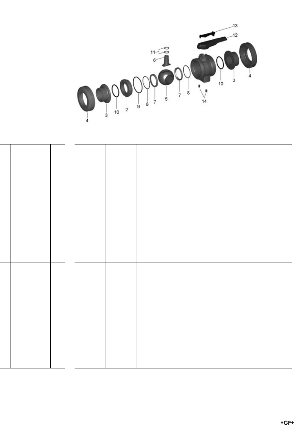
Spare parts for ball valve type 546 PP-H (DN65-100)
No. Article / Material Pieces d75 DN65 d90 DN80 d110 DN100
Central part 167 482 882 167 482 883 167 482 884
1 Body PP 1
2 PP 1
5 Ball PP 1
6 Stem PP 1
7 Ball seal PTFE 2
8 Backing seal
EPDM
1
9 Body seal EPDM 1
10 Face seal EPDM 2
11 Stem seal
EPDM
2
12 Lever PP
black
1
13 handle clip 1
14 Threaded bush
Stainless steel
3
Central part 167 482 894 167 482 895 167 482 896
1 Body PP 1
2 PP 1
5 Ball PP 1
6 Stem PP 1
7 Ball seal PTFE 2
8 Backing seal
FPM
1
9 Body seal FPM 1
10 Face seal FPM 2
11 Stem seal FPM 2
12 Lever PP
black
1
13 handle clip 1
14 Threaded bush
Stainless steel
3
94

No. Article / Material Pieces d75 DN65 d90 DN80 d110 DN100
Ball set 167 484 131 167 484 132 167 484 133
5 Ball PP 1
6 Stem PP 1
7 Ball seal PTFE 2
8 Backing seal
EPDM
2
9 Body seal EPDM 1
11 Stem seal
EPDM
2
Ball set 167 484 141 167 484 142 167 484 143
5 Ball PP 1
6 Stem PP 1
7 Ball seal PTFE 2
8 Backing seal
FPM
2
9 Body seal FPM 1
11 Stem seal FPM 2
Seal set 161 486 406 161 486 407 161 486 408
8 Backing seal
EPDM
2
9 Body seal EPDM 1
10 Face seal EPDM 2
11 Stem seal
EPDM
2
Seal set 161 486 416 161 486 417 161 486 418
8 Backing seal
FPM
2
9 Body seal FPM 1
10 Face seal FPM 2
11 Stem seal FPM 2
3 Connecting
piece 546 PP-H
(G30) with fusion
socket metric
1 167 482 907 167 482 908 167 482 909
3 Connecting
piece 546 PP-H
(G32) with
socket fusion
spigot metric
1 167 482 929 167 482 930 167 482 931
3 Connecting
piece 546 PP-H
(G35) with butt
fusion spigot IR
Plus®SDR11
metric
1 167 482 951 167 482 952 167 482 953
3 Connecting
piece 546 PP-H
(G36) with butt
fusion spigot
SDR17,6 metric
1 167 482 940 167 482 941 167 482 942
3 Connecting
piece 546
(G73)
subassembly
with backing
flange PP-ST
ANSI
1 167 484 071 167 484 072 167 484 073
3 Connecting
piece 546
(G77)
subassembly
with backing
flange PP-GF
JIS
1 167 484 481 167 484 482 167 484 483
95
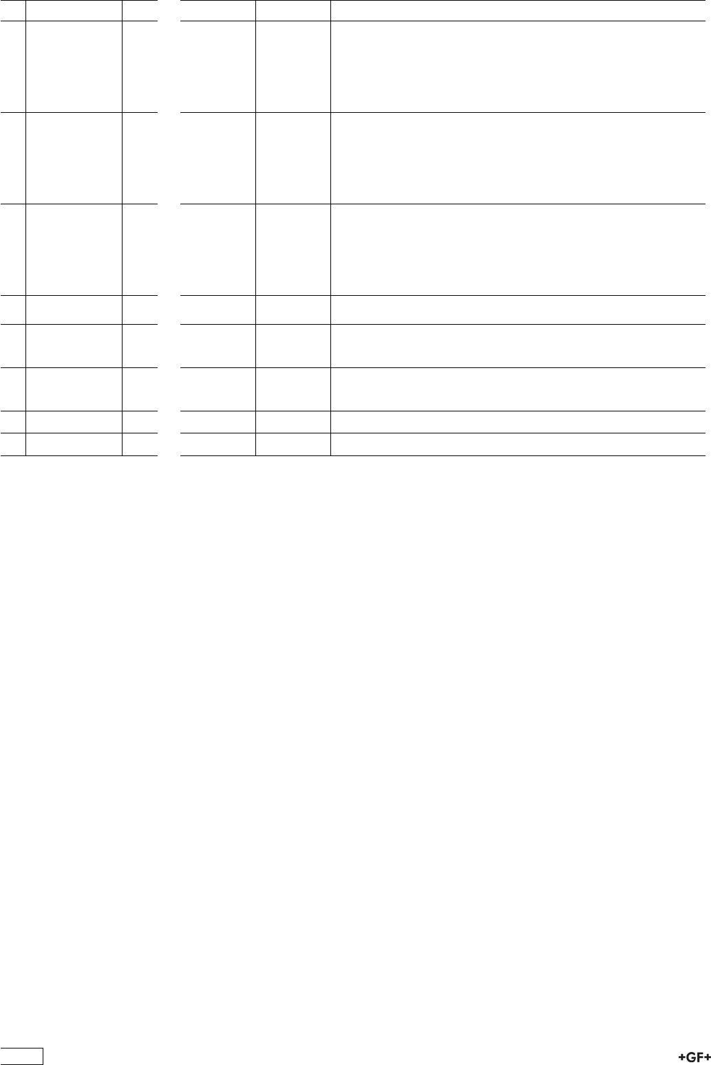
No. Article / Material Pieces d75 DN65 d90 DN80 d110 DN100
3 Connecting
piece 546
(G72)
subassembly
with backing
flange PP-ST
ISO BS
1 167 484 418 167 484 419 167 484 420
3 Connecting
piece 546 PE
100
(G43) with butt
fusion spigot
long SDR11
metric
1 193 480 158 193 480 159 193 480 160
3 Connecting
piece 546 PE
100
(G44) with butt
fusion spigot
long SDR17,6
metric
1 193 480 168 193 480 169 193 480 170
4 Union nut 546
PP-H
1 167 482 718 167 482 719 167 482 720
12 Standard handle
546
red (K01)
1 167 484 094 167 484 095 167 484 096
12 Standard handle
546
black (K02)
1 167 484 082 167 484 083 167 484 084
10 Face seal EPDM 1 748 410 119 748 410 023 748 410 254
10 Face seal FPM 1 749 410 119 749 410 023 749 410 254
96
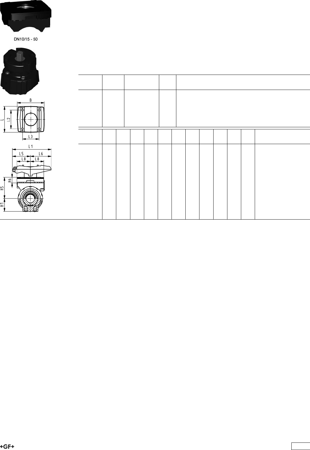
Accessories for Ball Valve 546
Multifunctional module (I02) PP-GF
Module empty
Model:
ÏAccessory to Ball Valve Type 546
ÏMultifunctional module acts as an intermediate element for actuators
ÏIncluding screws to mount the module and stainless steel coupling piece (V2A) for
dimension DN65-100
ÏThe multifunctional module from d75 - d110 has a master gauge F07 according to
EN ISO 5211.
d-d
[mm]
DN-DN
[mm]
Code kg
16 - 20 10 - 15 167 482 680 0.055
25 - 32 20 - 25 167 482 681 0.070
40 - 50 32 - 40 167 482 682 0.080
- 63 - 50 167 482 683 0.120
75 - 90 65 - 80 167 482 684 0.135
- 110 - 100 167 482 685 0.175
d-d
[mm]
B
[mm]
H1
[mm]
H5
[mm]
H6
[mm]
L
[mm]
L1
[mm]
L2
[mm]
L3
[mm]
L5
[mm]
L6
[mm]
L8
[mm]
16 - 20 67 27 50 17 72 87 54 40 42 45 34
25 - 32 75 30 53 16 72 108 52 46 50 58 38
40 - 50 81 44 72 16 80 140 60 50 66 75 41
- 63 91 64 94 19 93 165 68 65 78 87 46
75 - 90 90 85 157 23 85 270 64 206
- 110 106 123 175 23 97 320 64 256
97
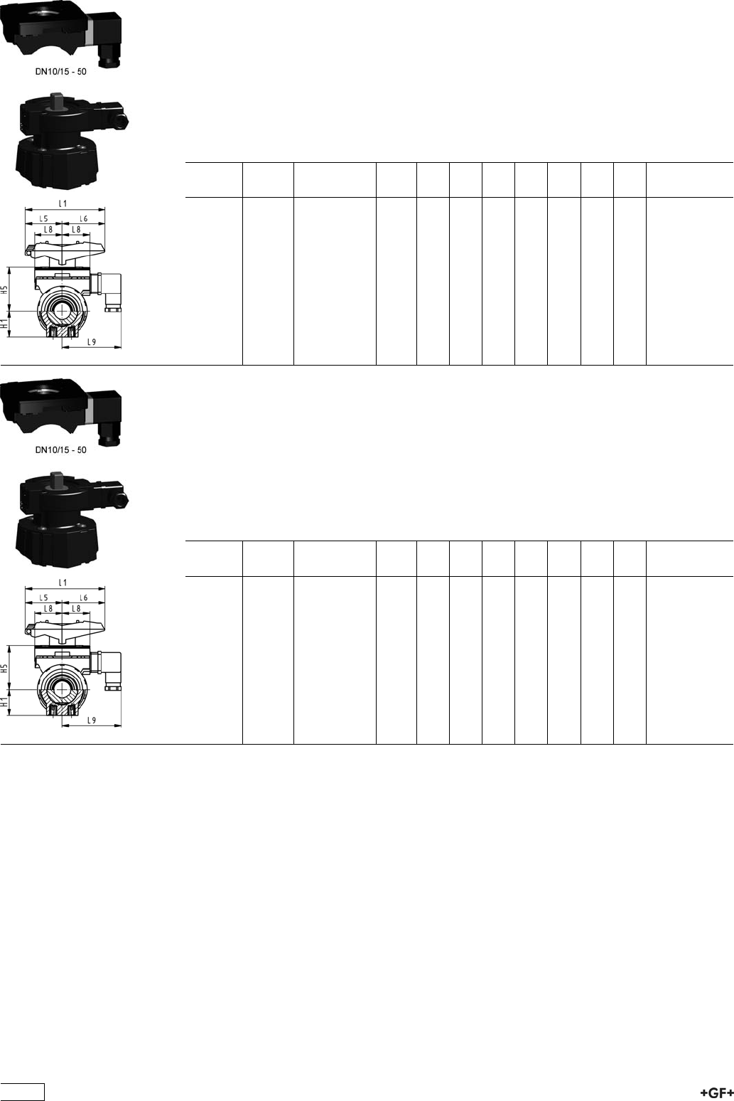
Multifunctional module (I03) PP-GF
With mechanical limit switches Ag Ni
Model:
ÏAccessory to Ball Valve Type 546
ÏMultifunctional module acts as an intermediate element for actuators
ÏIncluding Plug 3P+E / Protection: IP65
ÏIncluding screws to mount the module and stainless steel coupling piece (V2A) for
dimension DN65-100
d-d
[mm]
DN-DN
[mm]
Code kg H1
[mm]
H5
[mm]
L1
[mm]
L5
[mm]
L6
[mm]
L8
[mm]
L9
[mm]
16 - 20 10 - 15 167 482 626 0.110 27 50 87 42 45 34 73
25 - 32 20 - 25 167 482 627 0.120 30 53 108 50 58 38 77
40 - 50 32 - 40 167 482 628 0.135 44 72 140 66 75 41 80
- 63 - 50 167 482 629 0.175 64 94 165 78 87 46 85
75 - 90 65 - 80 167 482 630 0.460 85 157 270 64 206
- 110 - 100 167 482 631 0.480 123 175 320 64 256
Multifunctional module (I04) PP-GF
With mechanical limit switches Au
Model:
ÏAccessory to Ball Valve Type 546
ÏMultifunctional module acts as an intermediate element for actuators
ÏIncluding Plug 3P+E / Protection: IP65
ÏIncluding screws to mount the module and stainless steel coupling piece (V2A) for
dimension DN65-100
d-d
[mm]
DN-DN
[mm]
Code kg H1
[mm]
H5
[mm]
L1
[mm]
L5
[mm]
L6
[mm]
L8
[mm]
L9
[mm]
16 - 20 10 - 15 167 482 635 0.110 27 50 87 42 45 34 73
25 - 32 20 - 25 167 482 636 0.120 30 53 108 50 58 38 77
40 - 50 32 - 40 167 482 637 0.135 44 72 140 66 75 41 80
- 63 - 50 167 482 638 0.175 64 94 165 78 87 46 85
75 - 90 65 - 80 167 482 639 0.460 85 157 270 64 206
- 110 - 100 167 482 640 0.480 123 175 320 64 256
98
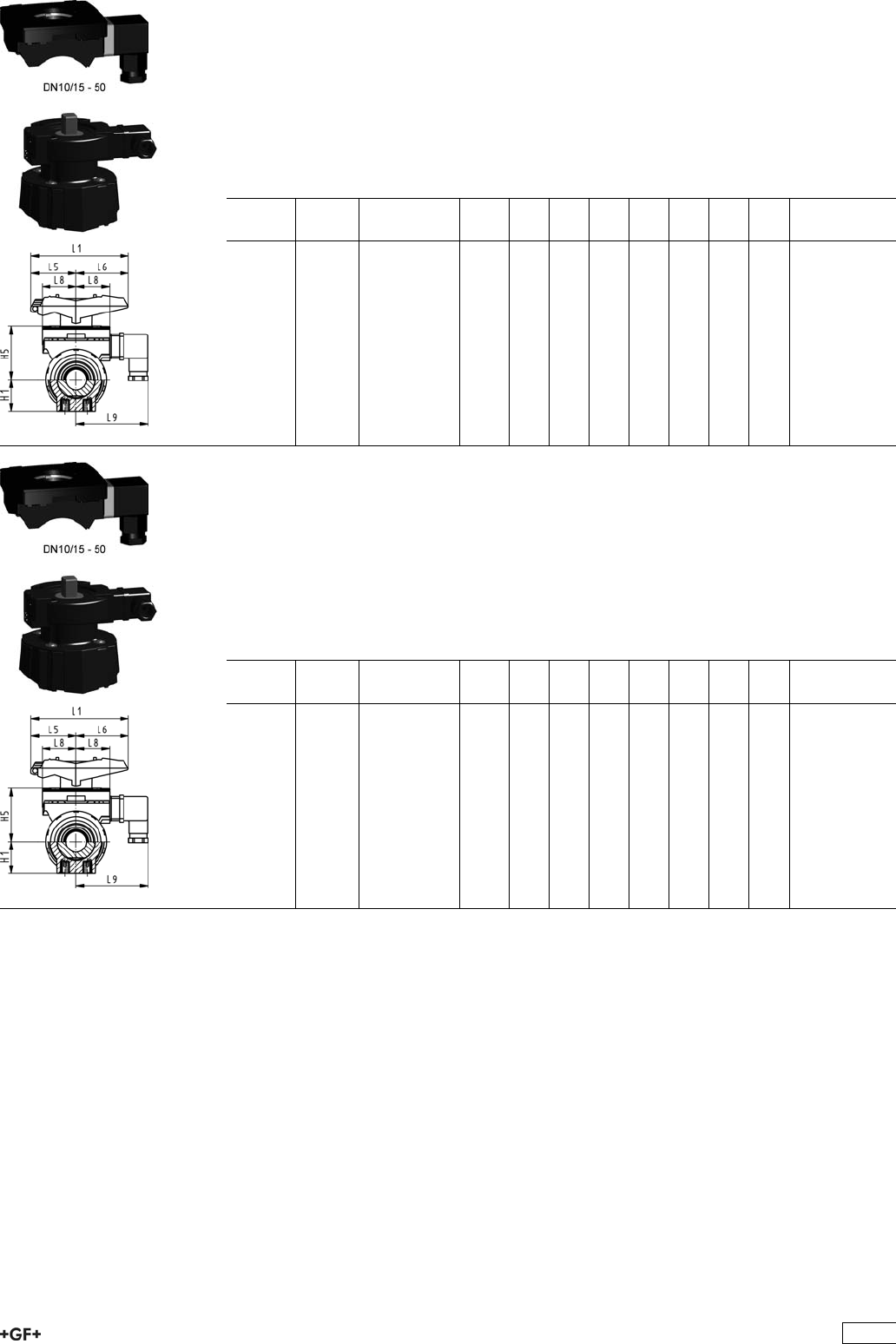
Multifunctional module (I05) PP-GF
With inductive limit switches Namur
Model:
ÏAccessory to Ball Valve Type 546
ÏMultifunctional module acts as an intermediate element for actuators
ÏIncluding Plug 3P+E / Protection: IP65
ÏIncluding screws to mount the module and stainless steel coupling piece (V2A) for
dimension DN65-100
d-d
[mm]
DN-DN
[mm]
Code kg H1
[mm]
H5
[mm]
L1
[mm]
L5
[mm]
L6
[mm]
L8
[mm]
L9
[mm]
16 - 20 10 - 15 167 482 671 0.110 27 50 87 42 45 34 73
25 - 32 20 - 25 167 482 672 0.120 30 53 108 50 58 38 77
40 - 50 32 - 40 167 482 673 0.135 44 72 140 66 75 41 80
- 63 - 50 167 482 674 0.175 64 94 165 78 87 46 85
75 - 90 65 - 80 167 482 675 0.460 85 157 270 64 206
- 110 - 100 167 482 676 0.480 123 175 320 64 256
Multifunctional module (I06) PP-GF
With inductive limit switches PNP
Model:
ÏAccessory to Ball Valve Type 546
ÏMultifunctional module acts as an intermediate element for actuators
ÏIncluding Plug 3P+E / Protection: IP65
ÏIncluding screws to mount the module and stainless steel coupling piece (V2A) for
dimension DN65-100
d-d
[mm]
DN-DN
[mm]
Code kg H1
[mm]
H5
[mm]
L1
[mm]
L5
[mm]
L6
[mm]
L8
[mm]
L9
[mm]
16 - 20 10 - 15 167 482 662 0.110 27 50 87 42 45 34 73
25 - 32 20 - 25 167 482 663 0.120 30 53 108 50 58 38 77
40 - 50 32 - 40 167 482 664 0.135 44 72 140 66 75 41 80
- 63 - 50 167 482 665 0.175 64 94 165 78 87 46 85
75 - 90 65 - 80 167 482 666 0.460 85 157 270 64 206
- 110 - 100 167 482 667 0.480 123 175 320 64 256
99
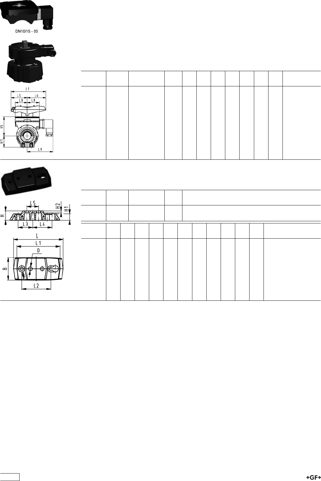
Multifunctional module (I07) PP-GF
With inductive limit switches NPN
Model:
ÏAccessory to Ball Valve Type 546
ÏMultifunctional module acts as an intermediate element for actuators
ÏIncluding Plug 3P+E / Protection: IP65
ÏIncluding screws to mount the module and stainless steel coupling piece (V2A) for
dimension DN65-100
d-d
[mm]
DN-DN
[mm]
Code kg H1
[mm]
H5
[mm]
L1
[mm]
L5
[mm]
L6
[mm]
L8
[mm]
L9
[mm]
16 - 20 10 - 15 167 482 653 0.110 27 50 87 42 45 34 73
25 - 32 20 - 25 167 482 654 0.120 30 53 108 50 58 38 77
40 - 50 32 - 40 167 482 655 0.135 44 72 140 66 75 41 80
- 63 - 50 167 482 656 0.175 64 94 165 78 87 46 85
75 - 90 65 - 80 167 482 657 0.460 85 157 270 64 206
- 110 - 100 167 482 658 0.480 123 175 320 64 256
Mounting plate 546 PP-GF (L02)
Ï2 mounting screws inclusive
d-d
[mm]
DN-DN
[mm]
Code kg
16 - 32 10 - 25 167 484 110 0.055
40 - 63 32 - 50 167 484 111 0.086
d-d
[mm]
B
[mm]
D
[mm]
H
[mm]
H1
[mm]
H2
[mm]
L
[mm]
L1
[mm]
L2
[mm]
L3
[mm]
L4
[mm]
L5
[mm]
16 - 32 48 8 20 14 4 106 92 62 31 41 25
40 - 63 54 9 20 14 4 149 134 104 52 62 45
100
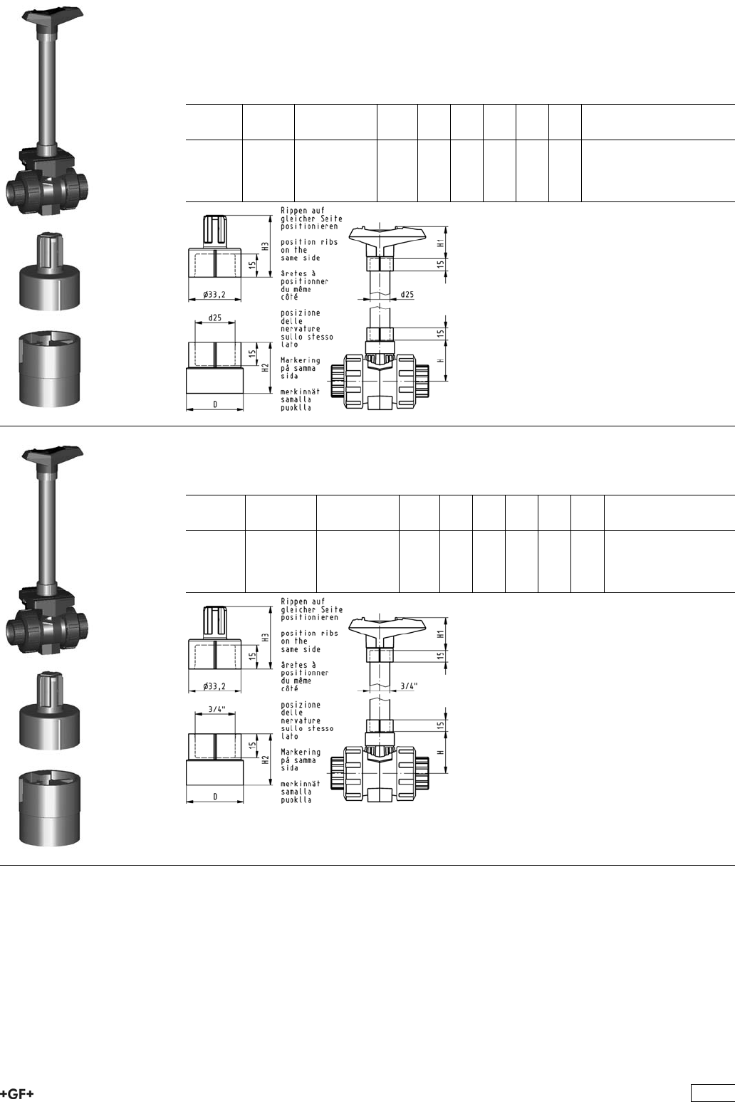
Handle extension 546 PVC-U metric
Model:
ÏFor Ball Valve Type 546
ÏComposed of adapter sockets for handle connection and stem connection
ÏPVC-U pipe in suitable length has to be obtained on site
d-d
[mm]
DN-DN
[mm]
Code kg H
[mm]
H1
[mm]
H2
[mm]
H3
[mm]
D
[mm]
16 - 20 10 - 15 161 486 435 0.032 41 52 29 36 26
25 - 32 20 - 25 161 486 436 0.037 50 62 32 39 36
40 - 50 32 - 40 161 486 437 0.047 65 76 34 44 40
- 63 - 50 161 486 438 0.058 84 87 37 48 44
Handle extension 546 PVC-U inch BS/ASTM
ÏFor Ball Valve Type 546
DN-DN
[mm]
Inch Code kg H
[mm]
H1
[mm]
H2
[mm]
H3
[mm]
D
[mm]
10 - 15 3/8-1/2 161 486 443 0.032 41 52 29 36 26
20 - 25 3/4-1 161 486 444 0.037 50 62 32 39 36
32 - 40 1 1/4-1 1/2 161 486 445 0.047 65 76 34 44 40
50 - 2 161 486 446 0.058 84 87 37 48 44
101
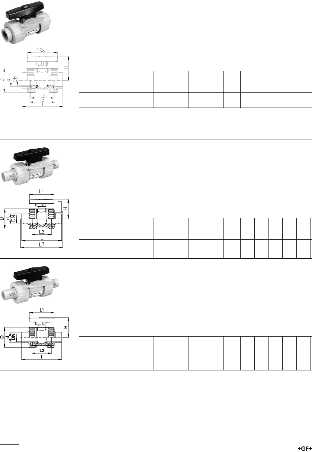
Ball Valves 323
PROGEF Standard
Metering ball valve type 323
With fusion sockets
Model:
ÏMaterial: PP-H
ÏFor easy installation and removal
ÏBall seals PTFE
ÏAngle of operation 180° with scale
d
[mm]
DN
[mm]
PN kv-value
(”p=1 bar)
[l/min]
EPDM
Code
FPM
Code
kg
16 10 10 11 167 323 401 167 323 411 0.103
20 15 10 20 167 323 402 167 323 412 0.104
d
[mm]
D
[mm]
H
[mm]
L
[mm]
L1
[mm]
L2
[mm]
z
[mm]
16 46 50 98 78 62 72
20 46 50 101 78 62 73
PROGEF Standard
Metering ball valve type 323
With socket fusion spigots
Model:
ÏMaterial: PP-H
ÏFor easy installation and removal
ÏBall seals PTFE
ÏAngle of operation 180° with scale
d
[mm]
DN
[mm]
PN kv-value
(”p=1 bar)
[l/min]
EPDM
Code
FPM
Code
kg D
[mm]
H
[mm]
L
[mm]
L1
[mm]
L2
[mm]
16 10 10 11 167 323 441 167 323 451 0.100 46 50 109 78 62
20 15 10 20 167 323 442 167 323 452 0.100 46 50 124 78 62
PROGEF Standard
Metering ball valve type 323
With butt fusion spigots SDR11
Model:
ÏMaterial: PP-H
ÏFor easy installation and removal
ÏBall seals PTFE
ÏAngle of operation 180° with scale
d
[mm]
DN
[mm]
PN kv-value
(”p=1 bar)
[l/min]
EPDM
Code
FPM
Code
kg D
[mm]
H
[mm]
L
[mm]
L1
[mm]
L2
[mm]
20 15 10 20 167 323 482 167 323 492 0.106 46 50 130 78 62
102
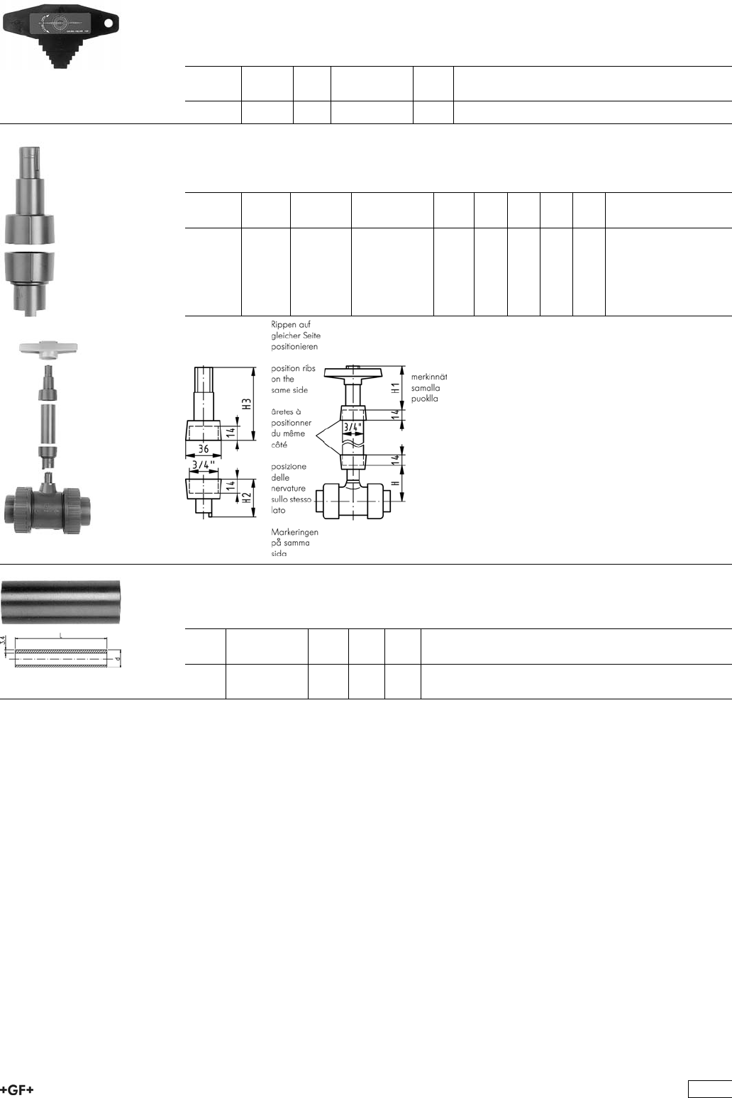
Key PBTP black
ÏFor assembly and disassembly of the union bush of ball valves type 323, 343, 346
and ball check valves 360
d-d
[mm]
DN-DN
[mm]
Inch Code kg
16 - 63 10 - 50 3/8-2 160 480 106 0.038
Handle extension type 615 PVC-U
ÏFor Ball Valves Type 323, 343 and 346
d
[mm]
DN
[mm]
Inch
[inch]
Code kg H
[mm]
H1
[mm]
H2
[mm]
H3
[mm]
16 - 20 10 - 15 3
/8-1
/2161 483 561 0.160 102 102 37 59
25 20 3
/4161 483 562 0.170 114 114 40 62
32 25 1 161 483 563 0.280 127 127 42 65
40 32 1 1
/4161 483 564 0.400 137 137 43 67
50 40 1 1
/2161 483 565 0.055 152 152 46 69
63 50 2 161 483 566 0.056 175 175 51 71
Pipe PVC-U
ÏFor Handle Extension Type 615
d
[inch]
Code kg I
[mm]
l
[mm]
3
/4161 483 570 0.075 200 200
3
/4161 483 571 0.200 1000 1000
103
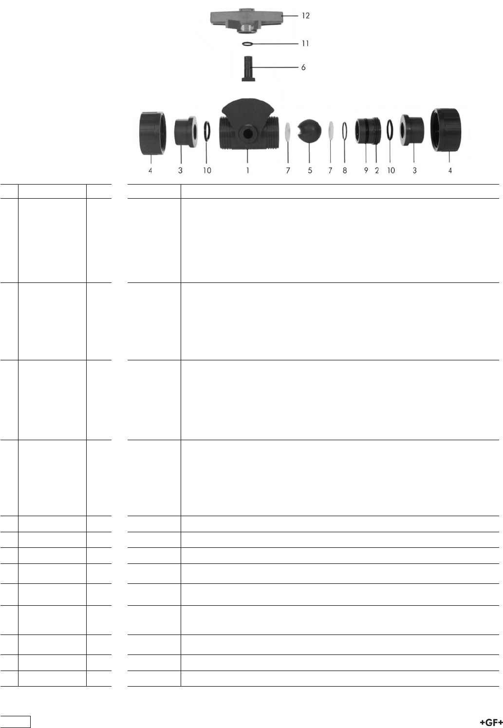
Spare parts for metering ball valve type 323 PP-H
No. Article / Material Pieces d16 DN10 d20 DN15
Ball set 167 480 901 167 480 902
5 Ball PP 1
7 Ball seal PTFE 2
6 Stem PP 1
11 Stem seal
EPDM
1
12 Lever ASA 1
Ball set 167 480 904 197 480 905
5 Ball PP 1
7 Ball seal PTFE 2
6 Stem PP 1
11 Stem seal FPM 1
12 Lever ASA 1
Seal set 161 482 883 161 482 883
8 Backing seal
EPDM
2No. 11, 1
Piece
No. 11, 1
Piece
9 Body seal EPDM 1
10 Face seal EPDM 1
11 Stem seal
EPDM
2
Seal set 161 482 892 161 482 892
8 Backing seal
FPM
2No. 11, 1
Piece
No. 11, 1
Piece
9 Body seal FPM 1
10 Face seal FPM 1
11 Stem seal FPM 2
2 PP-H 1 167 480 519 167 480 519
10 Face seal EPDM 2 748 410 042 748 410 042
10 Face seal FPM 2 749 410 042 749 410 042
3 Fusion socket
PP-H
1 167 480 159 167 480 160
3 Socket fusion
spigot PP-H
1 167 480 527 167 480 528
3 Butt fusion
spigot PP-H
SDR11
1 - 167 480 546
3 Fusion socket
PE 80
1 173 480 000 173 480 001
4 Union nut PP-H 1 167 480 786 167 480 786
12 Lever ASA 1 160 480 130 160 480 130
104
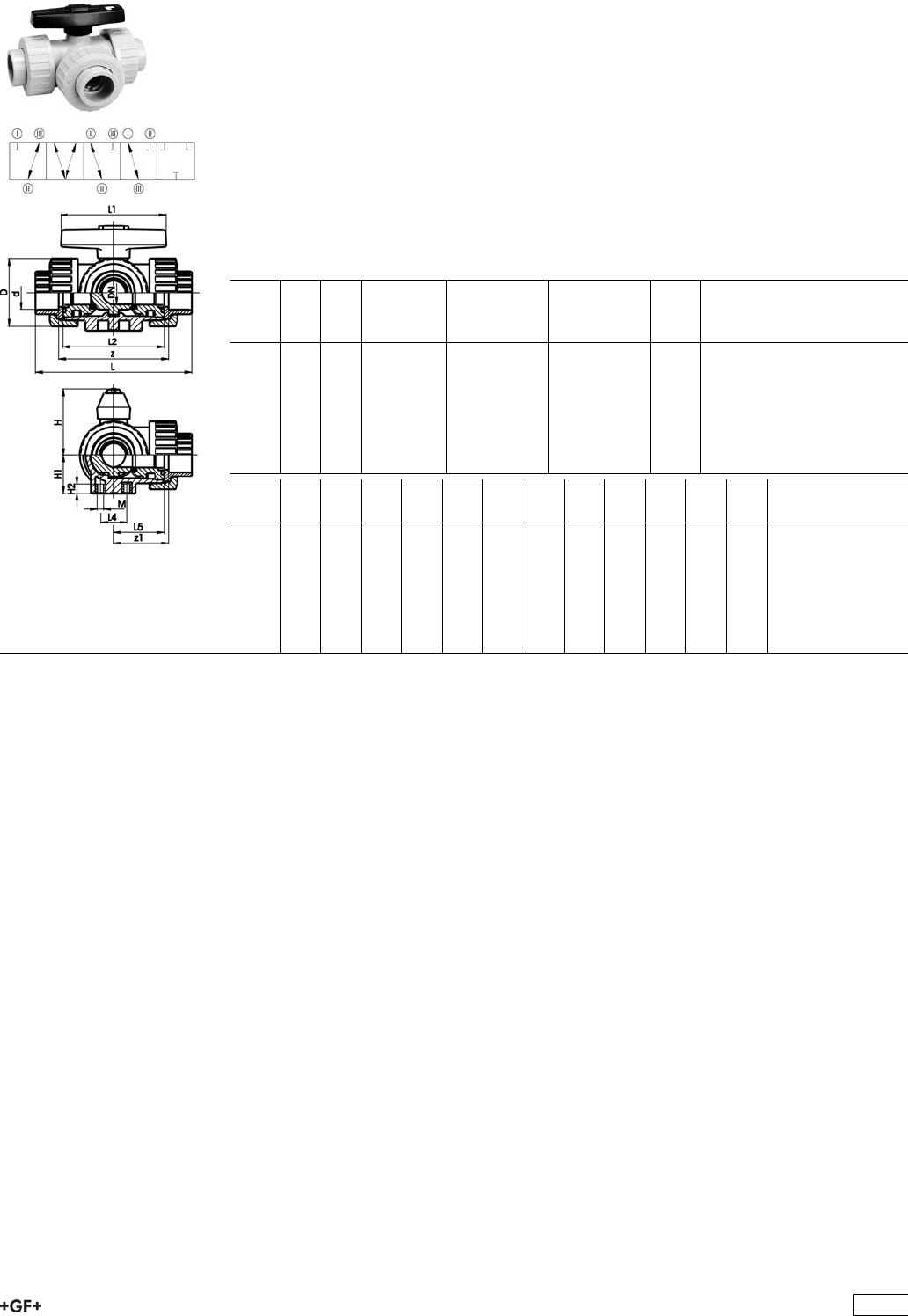
Ball Valves 343
PROGEF Standard
3-Way ball valve type 343
Horizontal/L-port
With fusion sockets metric
Model:
ÏMaterial: PP-H
ÏL-port ball
ÏFor easy installation and removal
ÏBall seals PTFE
ÏPneumatic or electric actuator available separately
ÏAngle of operation 360° without turn limiter
d
[mm]
DN
[mm]
PN kv-value
(”p=1 bar)
[l/min]
EPDM
Code
FPM
Code
kg
16 10 10 49 167 343 001 167 343 011 0.141
20 15 10 77 167 343 002 167 343 012 0.141
25 20 10 146 167 343 003 167 343 013 0.254
32 25 10 260 167 343 004 167 343 014 0.346
40 32 10 437 167 343 005 167 343 015 0.568
50 40 10 667 167 343 006 167 343 016 0.919
63 50 10 1293 167 343 007 167 343 017 1.758
d
[mm]
z
[mm]
z1
[mm]
D
[mm]
H
[mm]
H1
[mm]
H2
[mm]
L
[mm]
L1
[mm]
L2
[mm]
L4
[mm]
L5
[mm]
M
16 78 39 46 50 27 8 108 78 70 25 36 6
20 79 40 46 50 27 8 111 78 70 25 36 6
25 95 48 56 60 33 8 131 92 86 25 43 6
32 108 54 67 68 36 8 148 100 96 25 48 6
40 133 67 82 79 44 9 177 110 114 45 58 8
50 155 78 98 90 49 9 205 120 137 45 69 8
63 203 102 121 109 61 9 261 146 179 45 90 8
105
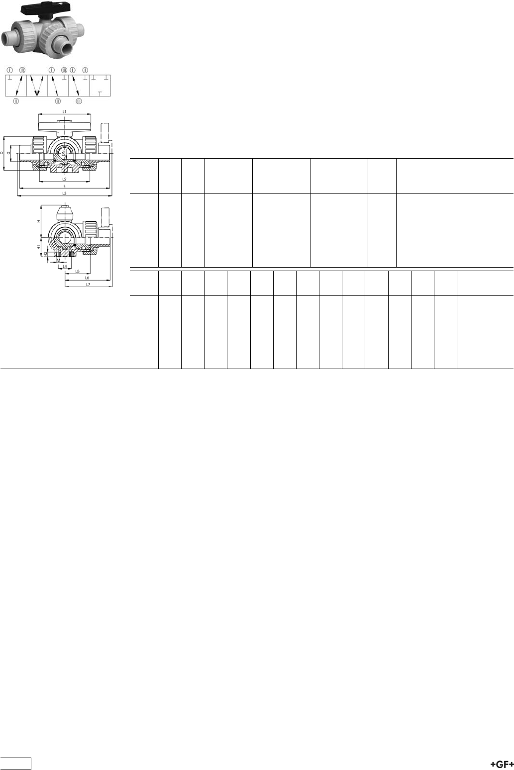
PROGEF Standard
3-Way ball valve type 343
Horizontal/L-port
With socket fusion spigots metric
Model:
ÏMaterial: PP-H
ÏL-port ball
ÏFor easy installation and removal
ÏBall seals PTFE
ÏPneumatic or electric actuator available separately
ÏAngle of operation 360° without turn limiter
d
[mm]
DN
[mm]
PN kv-value
(”p=1 bar)
[l/min]
EPDM
Code
FPM
Code
kg
16 10 10 49 167 343 021 167 343 031 0.141
20 15 10 77 167 343 022 167 343 032 0.141
25 20 10 146 167 343 023 167 343 033 0.254
32 25 10 260 167 343 024 167 343 034 0.346
40 32 10 437 167 343 025 167 343 035 0.568
50 40 10 667 167 343 026 167 343 036 0.919
63 50 10 1293 167 343 027 167 343 037 1.758
d
[mm]
D
[mm]
H
[mm]
H1
[mm]
H2
[mm]
L
[mm]
L1
[mm]
L2
[mm]
L3
[mm]
L4
[mm]
L5
[mm]
L6
[mm]
L7
[mm]
M
16 46 50 27 8 119 78 70 25 36 60 6
20 46 50 27 8 133 78 70 143 25 36 67 72 6
25 56 60 33 8 155 92 86 165 25 43 78 83 6
32 67 68 36 8 170 100 96 180 25 48 85 90 6
40 82 79 44 9 201 110 114 211 45 58 101 106 8
50 98 90 49 9 236 120 137 246 45 69 118 123 8
63 121 109 61 9 286 146 179 296 45 90 143 148 8
106
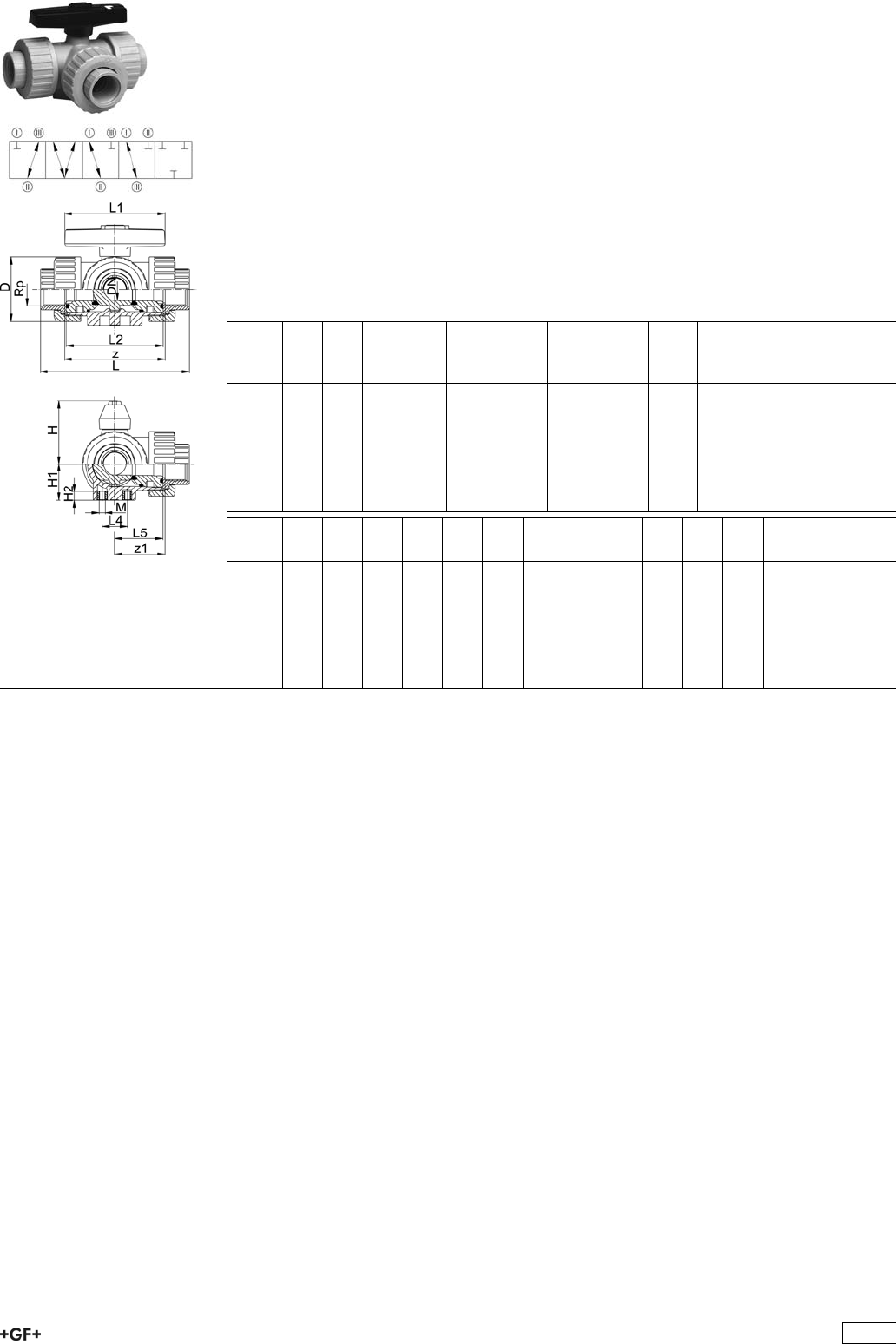
PROGEF Standard
3-Way ball valve type 343
Horizontal/L-port
With threaded sockets Rp
Model:
ÏMaterial: PP-H
ÏL-port ball
ÏFor easy installation and removal
ÏBall seals PTFE
ÏPneumatic or electric actuator available separately
ÏAngle of operation 360° without turn limiter
ÏParallel female thread Rp
Rp
[inch]
DN
[mm]
PN kv-value
(”p=1 bar)
[l/min]
EPDM
Code
FPM
Code
kg
3
/810 10 49 167 343 081 167 343 091 0.199
1
/215 10 77 167 343 082 167 343 092 0.199
3
/420 10 146 167 343 083 167 343 093 0.370
1 25 10 260 167 343 084 167 343 094 0.504
11
/432 10 437 167 343 085 167 343 095 0.838
11
/240 10 667 167 343 086 167 343 096 1.359
2 50 10 1293 167 343 087 167 343 097 2.622
Rp
[inch]
z
[mm]
z1
[mm]
D
[mm]
H
[mm]
H1
[mm]
H2
[mm]
L
[mm]
L1
[mm]
L2
[mm]
L4
[mm]
L5
[mm]
M
3
/876 38 46 50 27 8 108 78 70 25 36 6
1
/276 38 46 50 27 8 111 78 70 25 36 6
3
/490 45 56 60 33 8 131 92 86 25 43 6
1 100 50 67 68 36 8 148 100 96 25 48 6
11
/4122 61 82 79 44 9 176 110 114 45 58 8
11
/2152 76 98 90 49 9 206 120 137 45 69 8
2 200 100 121 109 61 9 262 146 179 45 90 8
107
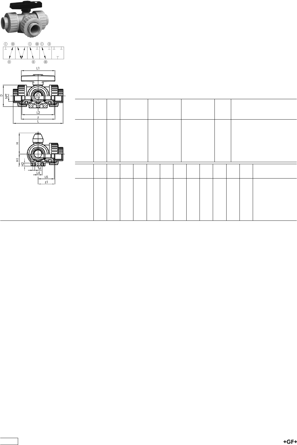
PROGEF Standard
3-Way ball valve type 343
Horizontal/L-port
With threaded sockets NPT
Model:
ÏMaterial: PP-H
ÏL-port ball
ÏFor easy installation and removal
ÏBall seals PTFE
ÏPneumatic or electric actuator available separately
ÏAngle of operation 360° without turn limiter
ÏTapered female thread NPT
NPT
[inch]
DN
[mm]
PN kv-value
(”p=1 bar)
[l/min]
EPDM
Code
FPM
Code
kg
3
/810 10 49 167 343 161 167 343 171 0.199
1
/215 10 77 167 343 162 167 343 172 0.199
3
/420 10 146 167 343 163 167 343 173 0.370
1 25 10 260 167 343 164 167 343 174 0.504
11
/432 10 437 167 343 165 167 343 175 0.838
11
/240 10 667 167 343 166 167 343 176 1.359
2 50 10 1293 167 343 167 167 343 177 2.622
NPT
[inch]
z
[mm]
z1
[mm]
D
[mm]
H
[mm]
H1
[mm]
H2
[mm]
L
[mm]
L1
[mm]
L2
[mm]
L4
[mm]
L5
[mm]
M
3
/876 38 46 50 27 8 108 78 70 25 36 6
1
/276 38 46 50 27 8 111 78 70 25 36 6
3
/490 45 56 60 33 8 131 92 86 25 43 6
1 100 50 67 68 36 8 148 100 96 25 48 6
11
/4122 61 82 79 44 9 176 110 114 45 58 8
11
/2152 76 98 90 49 9 206 120 137 45 69 8
2 200 100 121 109 61 9 262 146 179 45 90 8
108
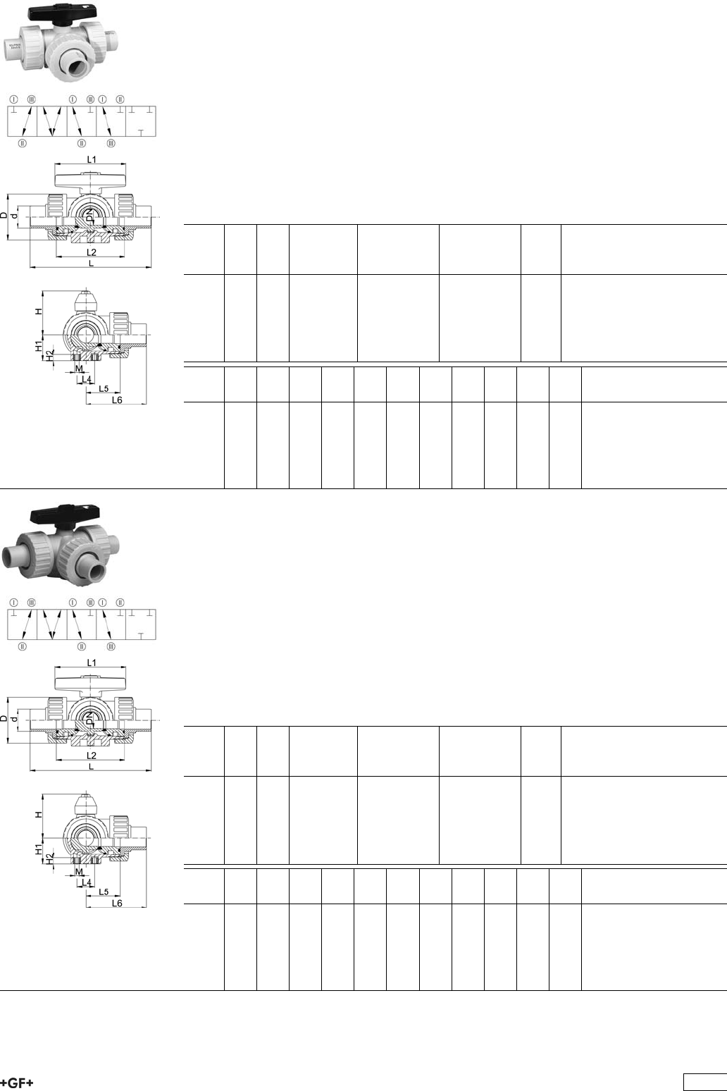
PROGEF Standard
3-Way ball valve type 343
Horizontal/L-port
With butt fusion spigots SDR11
Model:
ÏMaterial: PP-H
ÏL-port ball
ÏFor easy installation and removal
ÏBall seals PTFE
ÏPneumatic or electric actuator available separately
ÏAngle of operation 360° without turn limiter
d
[mm]
DN
[mm]
PN kv-value
(”p=1 bar)
[l/min]
EPDM
Code
FPM
Code
kg
20 15 10 77 167 343 062 167 343 072 0.141
25 20 10 146 167 343 063 167 343 073 0.254
32 25 10 260 167 343 064 167 343 074 0.346
40 32 10 437 167 343 065 167 343 075 0.568
50 40 10 667 167 343 066 167 343 076 0.919
63 50 10 1293 167 343 067 167 343 077 1.758
d
[mm]
D
[mm]
H
[mm]
H1
[mm]
H2
[mm]
L
[mm]
L1
[mm]
L2
[mm]
L4
[mm]
L5
[mm]
L6
[mm]
M
20 46 50 27 8 140 78 70 25 36 70 6
25 56 60 33 8 156 92 86 25 43 78 6
32 67 68 36 8 168 100 96 25 48 84 6
40 82 79 44 9 198 110 114 45 58 99 8
50 98 90 49 9 233 120 137 45 69 117 8
63 121 109 61 9 284 146 179 45 90 142 8
PROGEF Standard
3-Way ball valve type 343
Horizontal/L-port
With butt fusion spigots SDR17
Model:
ÏMaterial: PP-H
ÏL-port ball
ÏFor easy installation and removal
ÏBall seals PTFE
ÏPneumatic or electric actuator available separately
ÏAngle of operation 360° without turn limiter
d
[mm]
DN
[mm]
PN kv-value
(”p=1 bar)
[l/min]
EPDM
Code
FPM
Code
kg
20 15 6 77 167 343 042 167 343 052 0.141
25 20 6 146 167 343 043 167 343 053 0.254
32 25 6 260 167 343 044 167 343 054 0.346
40 32 6 437 167 343 045 167 343 055 0.568
50 40 6 667 167 343 046 167 343 056 0.919
63 50 6 1293 167 343 047 167 343 057 1.758
d
[mm]
D
[mm]
H
[mm]
H1
[mm]
H2
[mm]
L
[mm]
L1
[mm]
L2
[mm]
L4
[mm]
L5
[mm]
L6
[mm]
M
20 46 50 27 8 140 78 70 25 36 70 6
25 56 60 33 8 156 92 86 25 43 78 6
32 67 68 36 8 168 100 96 25 48 84 6
40 82 79 44 9 198 110 114 45 58 99 8
50 98 90 49 9 233 120 137 45 69 117 8
63 121 109 61 9 284 146 179 45 90 142 8
109
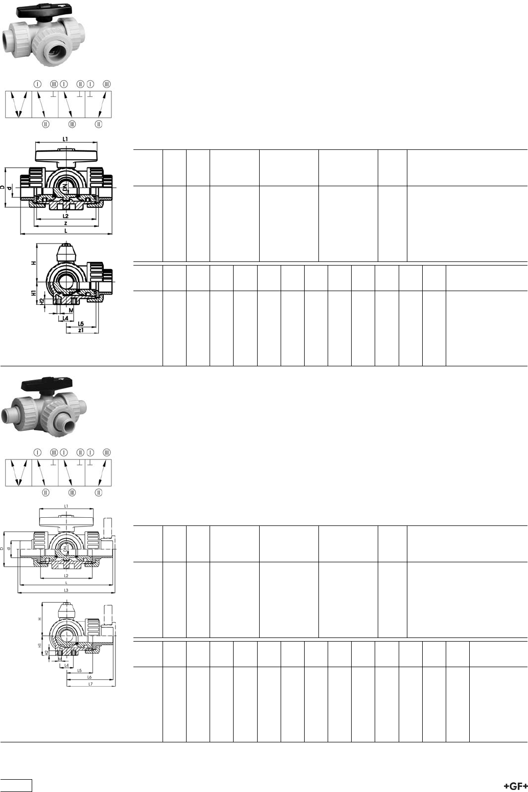
PROGEF Standard
3-Way ball valve type 343
Horizontal/T-port
With fusion sockets metric
Model:
ÏMaterial: PP-H
ÏFor easy installation and removal
ÏBall seals PTFE
ÏPneumatic or electric actuator available separately
ÏAngle of operation 90°, without turn limiter
d
[mm]
DN
[mm]
PN kv-value
(”p=1 bar)
[l/min]
EPDM
Code
FPM
Code
kg
16 10 10 140 167 343 201 167 343 211 0.141
20 15 10 200 167 343 202 167 343 212 0.141
25 20 10 470 167 343 203 167 343 213 0.254
32 25 10 793 167 343 204 167 343 214 0.346
40 32 10 1290 167 343 205 167 343 215 0.568
50 40 10 1910 167 343 206 167 343 216 0.919
63 50 10 3100 167 343 207 167 343 217 1.758
d
[mm]
z
[mm]
z1
[mm]
D
[mm]
H
[mm]
H1
[mm]
H2
[mm]
L
[mm]
L1
[mm]
L2
[mm]
L4
[mm]
L5
[mm]
M
16 78 39 46 50 27 8 108 78 70 25 36 6
20 79 40 46 50 27 8 111 78 70 25 36 6
25 95 48 56 60 33 8 131 92 86 25 43 6
32 108 54 67 68 36 8 148 100 96 25 48 6
40 133 67 82 79 44 9 177 110 114 45 58 8
50 155 78 98 90 49 9 205 120 137 45 69 8
63 203 102 121 109 61 9 261 146 179 45 90 8
PROGEF Standard
3-Way ball valve type 343
Horizontal/T-port
With socket fusion spigots metric
Model:
ÏMaterial: PP-H
ÏFor easy installation and removal
ÏBall seals PTFE
ÏPneumatic or electric actuator available separately
ÏAngle of operation 90°, without turn limiter
d
[mm]
DN
[mm]
PN kv-value
(”p=1 bar)
[l/min]
EPDM
Code
FPM
Code
kg
16 10 10 140 167 343 221 167 343 231 0.141
20 15 10 200 167 343 222 167 343 232 0.141
25 20 10 470 167 343 223 167 343 233 0.254
32 25 10 793 167 343 224 167 343 234 0.346
40 32 10 1290 167 343 225 167 343 235 0.568
50 40 10 1910 167 343 226 167 343 236 0.919
63 50 10 3100 167 343 227 167 343 237 1.758
d
[mm]
D
[mm]
H
[mm]
H1
[mm]
H2
[mm]
L
[mm]
L1
[mm]
L2
[mm]
L3
[mm]
L4
[mm]
L5
[mm]
L6
[mm]
L7
[mm]
M
16 46 50 27 8 119 78 70 25 36 60 6
20 46 50 27 8 133 78 70 143 25 36 67 72 6
25 56 60 33 8 155 92 86 165 25 43 78 83 6
32 67 68 36 8 170 100 96 180 25 48 85 90 6
40 82 79 44 9 201 110 114 211 45 58 101 106 8
50 98 90 49 9 236 120 137 246 45 69 118 123 8
63 121 109 61 9 286 146 179 296 45 90 143 148 8
110
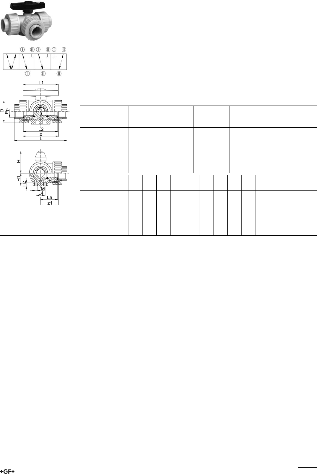
PROGEF Standard
3-Way ball valve type 343
Horizontal/T-port
With threaded sockets Rp
Model:
ÏMaterial: PP-H
ÏFor easy installation and removal
ÏBall seals PTFE
ÏPneumatic or electric actuator available separately
ÏAngle of operation 90°, without turn limiter
ÏParallel female thread Rp
Rp
[inch]
DN
[mm]
PN kv-value
(”p=1 bar)
[l/min]
EPDM
Code
FPM
Code
kg
3
/810 10 140 167 343 281 167 343 291 0.199
1
/215 10 200 167 343 282 167 343 292 0.199
3
/420 10 470 167 343 283 167 343 293 0.370
1 25 10 793 167 343 284 167 343 294 0.504
11
/432 10 1290 167 343 285 167 343 295 0.838
11
/240 10 1910 167 343 286 167 343 296 1.359
2 50 10 3100 167 343 287 167 343 297 2.622
Rp
[inch]
z
[mm]
z1
[mm]
D
[mm]
H
[mm]
H1
[mm]
H2
[mm]
L
[mm]
L1
[mm]
L2
[mm]
L4
[mm]
L5
[mm]
M
3
/876 38 46 50 27 8 108 78 70 25 36 6
1
/276 38 46 50 27 8 111 78 70 25 36 6
3
/490 45 56 60 33 8 131 92 86 25 43 6
1 100 50 67 68 36 8 148 100 96 25 48 6
11
/4122 61 82 79 44 9 176 110 114 45 58 8
11
/2152 76 98 90 49 9 206 120 137 45 69 8
2 200 100 121 109 61 9 262 146 179 45 90 8
111
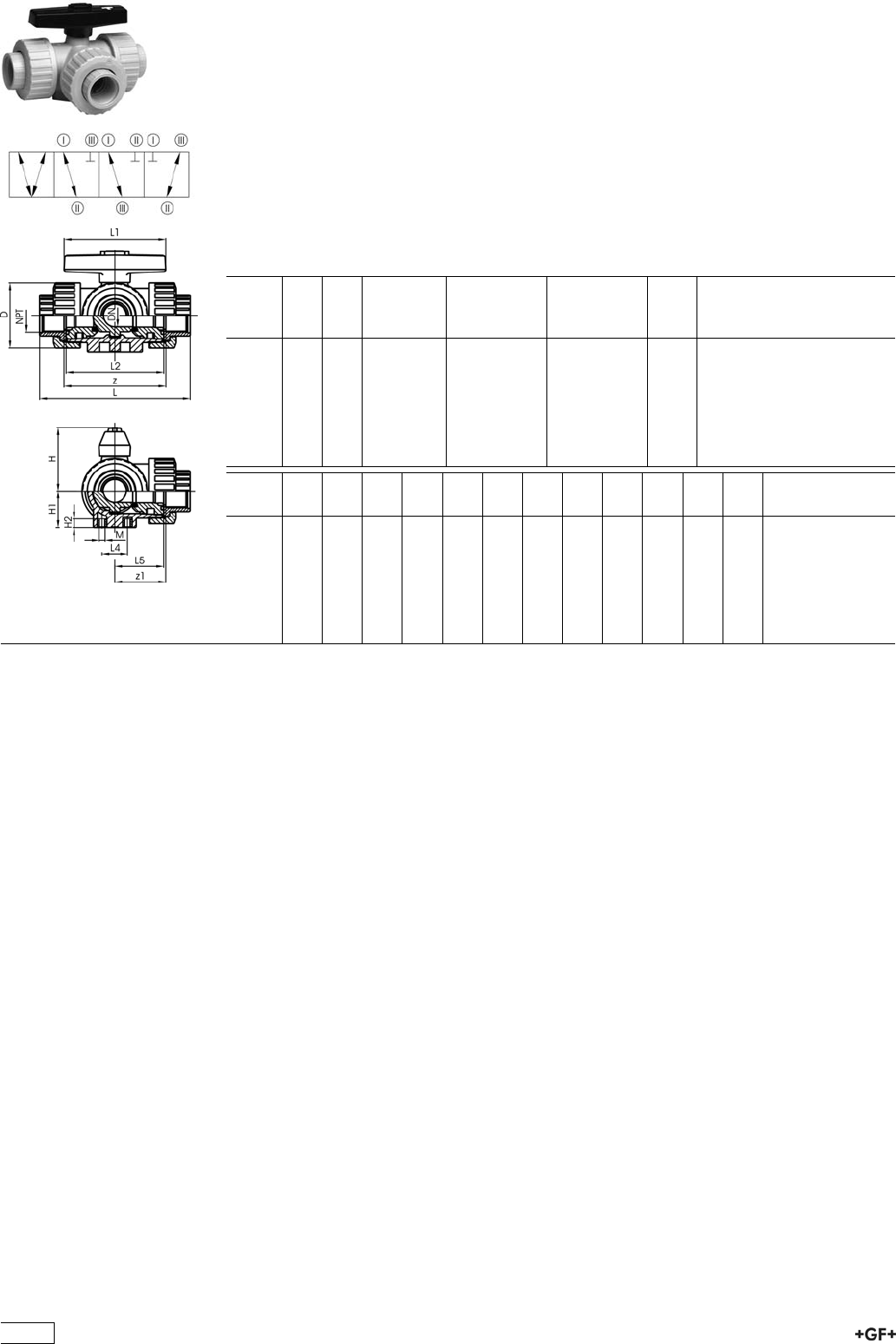
PROGEF Standard
3-Way ball valve type 343
Horizontal/T-port
With threaded sockets NPT
Model:
ÏMaterial: PP-H
ÏFor easy installation and removal
ÏBall seals PTFE
ÏPneumatic or electric actuator available separately
ÏAngle of operation 90°, without turn limiter
ÏTapered female thread NPT
NPT
[inch]
DN
[mm]
PN kv-value
(”p=1 bar)
[l/min]
EPDM
Code
FPM
Code
kg
3
/810 10 140 167 343 361 167 343 371 0.199
1
/215 10 200 167 343 362 167 343 372 0.199
3
/420 10 470 167 343 363 167 343 373 0.370
1 25 10 793 167 343 364 167 343 374 0.504
11
/432 10 1290 167 343 365 167 343 375 0.838
11
/240 10 1910 167 343 366 167 343 376 1.359
2 50 10 3100 167 343 367 167 343 377 2.622
NPT
[inch]
z
[mm]
z1
[mm]
D
[mm]
H
[mm]
H1
[mm]
H2
[mm]
L
[mm]
L1
[mm]
L2
[mm]
L4
[mm]
L5
[mm]
M
3
/876 38 46 50 27 8 108 78 70 25 36 6
1
/276 38 46 50 27 8 111 78 70 25 36 6
3
/490 45 56 60 33 8 131 92 86 25 43 6
1 100 50 67 68 36 8 148 100 96 25 48 6
11
/4122 61 82 79 44 9 176 110 114 45 58 8
11
/2152 76 98 90 49 9 206 120 137 45 69 8
2 200 100 121 109 61 9 262 146 179 45 90 8
112
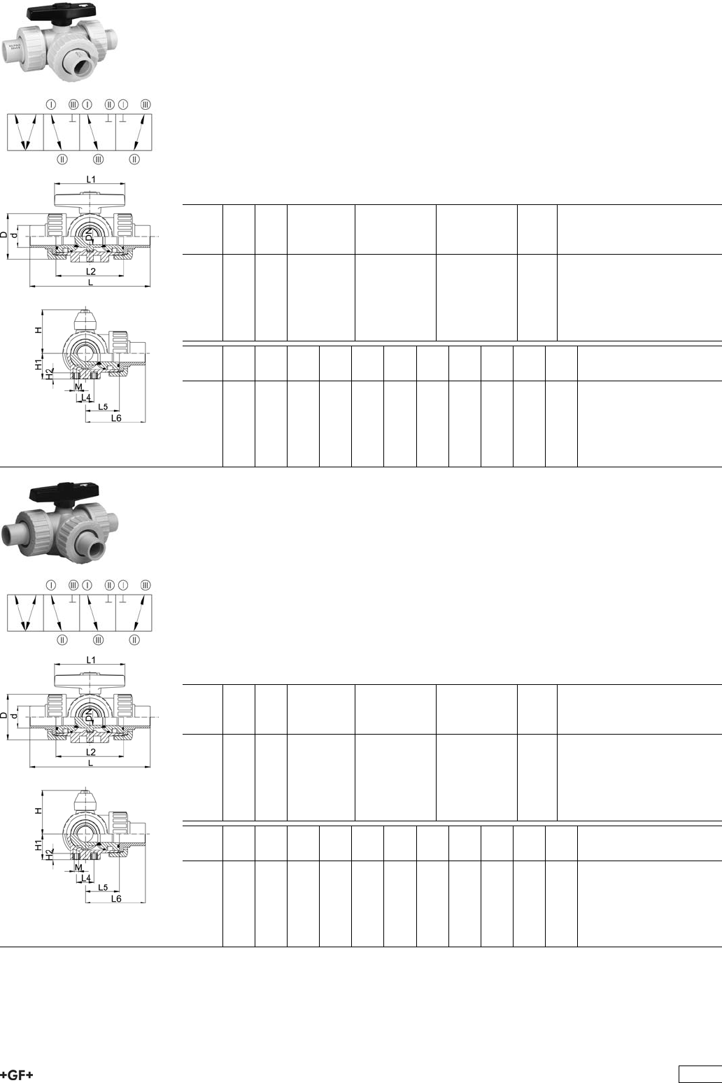
PROGEF Standard
3-Way ball valve type 343
Horizontal/T-port
With butt fusion spigots SDR11
Model:
ÏMaterial: PP-H
ÏFor easy installation and removal
ÏBall seals PTFE
ÏPneumatic or electric actuator available separately
ÏAngle of operation 90°, without turn limiter
d
[mm]
DN
[mm]
PN kv-value
(”p=1 bar)
[l/min]
EPDM
Code
FPM
Code
kg
20 15 10 200 167 343 262 167 343 272 0.141
25 20 10 470 167 343 263 167 343 273 0.254
32 25 10 793 167 343 264 167 343 274 0.346
40 32 10 1290 167 343 265 167 343 275 0.568
50 40 10 1910 167 343 266 167 343 276 0.919
63 50 10 3100 167 343 267 167 343 277 1.758
d
[mm]
D
[mm]
H
[mm]
H1
[mm]
H2
[mm]
L
[mm]
L1
[mm]
L2
[mm]
L4
[mm]
L5
[mm]
L6
[mm]
M
20 46 50 27 8 140 78 70 25 36 70 6
25 56 60 33 8 156 92 86 25 43 78 6
32 67 68 36 8 168 100 96 25 48 84 6
40 82 79 44 9 198 110 114 45 58 99 8
50 98 90 49 9 233 120 137 45 69 117 8
63 121 109 61 9 284 146 179 45 90 142 8
PROGEF Standard
3-Way ball valve type 343
Horizontal/T-port
With butt fusion spigots SDR17
Model:
ÏMaterial: PP-H
ÏFor easy installation and removal
ÏBall seals PTFE
ÏPneumatic or electric actuator available separately
ÏAngle of operation 90°, without turn limiter
d
[mm]
DN
[mm]
PN kv-value
(”p=1 bar)
[l/min]
EPDM
Code
FPM
Code
kg
20 15 6 200 167 343 242 167 343 252 0.141
25 20 6 470 167 343 243 167 343 253 0.254
32 25 6 793 167 343 244 167 343 254 0.346
40 32 6 1290 167 343 245 167 343 255 0.568
50 40 6 1910 167 343 246 167 343 256 0.919
63 50 6 3100 167 343 247 167 343 257 1.758
d
[mm]
D
[mm]
H
[mm]
H1
[mm]
H2
[mm]
L
[mm]
L1
[mm]
L2
[mm]
L4
[mm]
L5
[mm]
L6
[mm]
M
20 46 50 27 8 140 78 70 25 36 70 6
25 56 60 33 8 156 92 86 25 43 78 6
32 67 68 36 8 168 100 96 25 48 84 6
40 82 79 44 9 198 110 114 45 58 99 8
50 98 90 49 9 233 120 137 45 69 117 8
63 121 109 61 9 284 146 179 45 90 142 8
113
Key PBTP black
ÏFor assembly and disassembly of the union bush of ball valves type 323, 343, 346
and ball check valves 360
d-d
[mm]
DN-DN
[mm]
Inch Code kg
16 - 63 10 - 50 3/8-2 160 480 106 0.038
Mounting block PP
ÏFor diaphragm valve to be compatible with pipe clips type 061 and one spacer type
061
ÏFor 3-way ball valve type 343 to be compatible with pipe clips type 061 and one
spacer type 061
ÏFor dimensions DN 10-15, the two mounting blocks (No 2+6) have to be
ordered separately. They are to be assembled together.
d-d
[mm]
DN-DN
[mm]
Inch Block no. Code kg
16 - 20 10 - 15 3/8-1/2 2 167 480 423 0.003
25 - 32 20 - 25 3/4-1 6 167 482 238 0.017
40 - 63 32 - 50 11/4-2 7 167 482 239 0.030
d-d
[mm]
D
[mm]
H
[mm]
H1
[mm]
L
[mm]
L1
[mm]
L2
[mm]
L3
[mm]
16 - 20 8 7 4 47 42 25 17
25 - 32 8 15 15 47 42 25 17
40 - 63 10 11 11 80 67 45 22
Handle extension type 615 PVC-U
ÏFor Ball Valves Type 323, 343 and 346
d
[mm]
DN
[mm]
Inch
[inch]
Code kg H
[mm]
H1
[mm]
H2
[mm]
H3
[mm]
16 - 20 10 - 15 3
/8-1
/2161 483 561 0.160 102 102 37 59
25 20 3
/4161 483 562 0.170 114 114 40 62
32 25 1 161 483 563 0.280 127 127 42 65
40 32 1 1
/4161 483 564 0.400 137 137 43 67
50 40 1 1
/2161 483 565 0.055 152 152 46 69
63 50 2 161 483 566 0.056 175 175 51 71
114
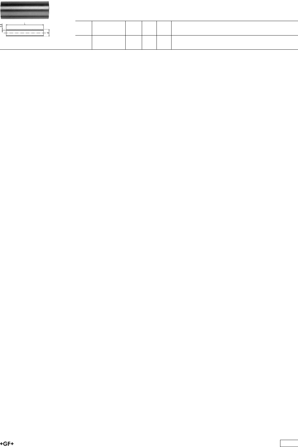
Pipe PVC-U
ÏFor Handle Extension Type 615
d
[inch]
Code kg I
[mm]
l
[mm]
3
/4161 483 570 0.075 200 200
3
/4161 483 571 0.200 1000 1000
115

Spare parts for ball valve type 343 PP-H
No. Article / Material Pieces d16 DN 10 d20 DN 15 d25 DN 20 d32 DN 25 d40 DN 32 d50 DN 40 d63 DN 50
Seal set 161 484 941 161 484 941 161 484 942 161 484 943 161 484 944 161 484 945 161 484 946
8 Backing seal
EPDM
3
9 Body seal EPDM 3
10 Face seal EPDM 3
11 Stem seal
EPDM
2
Seal set 161 484 951 161 484 951 161 484 952 161 484 953 161 484 954 161 484 955 161 484 956
8 Backing seal
FPM
3
9 Body seal FPM 3
10 Face seal FPM 3
11 Stem seal FPM 2
Ball set L-port 167 482 190 167 482 190 167 482 191 167 482 192 167 482 193 167 482 194 167 482 195
5.1 L-port ball PP 1
7 Ball seal PTFE 3
6.1 Stem PP 1
11 Stem seal
EPDM
2
12.1 Lever ASA 1
Ball set L-port 167 482 202 167 482 202 167 482 203 167 482 204 167 482 205 167 482 206 167 482 207
5.1 L-port ball PP 1
7 Ball seal PTFE 3
6.1 Stem PP 1
11 Stem seal FPM 2
12.1 Lever ASA 1
Ball set T-port 167 482 214 167 482 214 167 482 215 167 482 216 167 482 217 167 482 218 167 482 219
5.2 T-port ball PP 1
7 Ball seal PTFE 3
6.2 Stem PP 1
11 Stem seal
EPDM
2
12.2 Lever ASA 1
116

No. Article / Material Pieces d16 DN 10 d20 DN 15 d25 DN 20 d32 DN 25 d40 DN 32 d50 DN 40 d63 DN 50
Ball set T-port 167 482 226 167 482 226 167 482 227 167 482 228 167 482 229 167 482 230 167 482 231
5.2 T-port ball PP 1
7 Ball seal PTFE 3
6.2 Stem PP 1
11 Stem seal FPM 2
12.2 Lever ASA 1
Central part
L-port
167 482 137 167 482 137 167 482 138 167 482 139 167 482 140 167 482 141 167 482 142
1 Body PP 1
5.1 L-port ball PP 1
7 Ball seal PTFE 3
8 Backing seal
EPDM
3
9 Body seal EPDM 3
2 PP 3
6.1 Stem PP 1
11 Stem seal
EPDM
2
12.1 Lever ASA 1
Central part
L-port
167 482 148 167 482 148 167 482 149 167 482 150 167 482 151 167 482 152 167 482 153
1 Body PP 1
5.1 L-port ball PP 1
7 Ball seal PTFE 3
8 Backing seal
FPM
3
9 Body seal FPM 3
2 PP 3
6.1 Stem PP 1
11 Stem seal FPM 2
12.1 Lever ASA 1
Central part
T-port
167 482 159 167 482 159 167 482 160 167 482 161 167 482 162 167 482 163 167 482 164
1 Body PP 1
5.2 T-port ball PP 1
7 Ball seal PTFE 3
8 Backing seal
EPDM
3
9 Body seal EPDM 3
2 PP 3
6.2 Stem PP 1
11 Stem seal
EPDM
2
12.2 Lever ASA 1
Central part
T-port
167 482 170 167 482 170 167 482 171 167 482 172 167 482 173 167 482 174 167 482 175
1 Body PP 1
5.2 T-port ball PP 1
7 Ball seal PTFE 3
8 Backing seal
FPM
3
9 Body seal FPM 3
2 PP 3
6.2 Stem PP 1
11 Stem seal FPM 2
12.2 Lever ASA 1
117

No. Article / Material Pieces d16 DN 10 d20 DN 15 d25 DN 20 d32 DN 25 d40 DN 32 d50 DN 40 d63 DN 50
3 Fusion socket
PP-H
1 167 480 159 167 480 160 167 480 161 167 480 162 167 480 163 167 480 164 167 480 165
3 Socket fusion
spigot PP-H
1 167 480 527 167 480 528 167 480 529 167 480 530 167 480 531 167 480 532 167 480 533
3 Threaded socket
PP-H
1 167 480 166 167 480 167 167 480 168 167 480 169 167 480 170 167 480 171 167 480 172
3 Threaded socket
PP-H
1 167 480 452 167 480 453 167 480 454 167 480 455 167 480 456 167 480 457 167 480 458
3 Butt fusion
spigot long PP-H
SDR11
1 - 167 482 546 167 482 547 167 482 548 167 482 549 167 482 550 167 482 551
3 Butt fusion
spigot PP-H
1 - 167 480 546 167 480 547 167 480 548 167 480 549 167 480 550 167 480 551
3 Butt fusion
spigot PP-H
1 - 167 480 537 167 480 538 167 480 539 167 480 540 167 480 541 167 480 542
3 Fusion socket
PE 80
1 173 480 000 173 480 001 173 480 002 173 480 003 173 480 004 173 480 005 173 480 006
3 Butt fusion
spigot long PE
100
SDR11
1 - 193 480 127 193 480 128 193 480 129 193 480 130 193 480 131 193 480 132
3 Butt fusion
spigot PE 100
1 193 480 026 193 480 027 193 480 028 193 480 029 193 480 030 193 480 031 193 480 032
3 Butt fusion
spigot PE 100
1 - - 193 480 014 193 480 015 193 480 016 193 480 017 193 480 018
10 Face seal EPDM 748 410 042 748 410 042 748 410 116 748 410 103 748 410 027 748 410 010 748 410 011
10 Face seal FPM 749 410 042 749 410 042 749 410 116 749 410 103 749 410 027 749 410 010 749 410 011
4 Union nut PP-H 1 167 480 786 167 480 786 167 480 787 167 480 788 167 480 789 167 480 790 167 480 791
12 Lever ASA 1 160 480 115 160 480 115 160 480 116 160 480 117 160 480 118 160 480 119 160 480 120
118
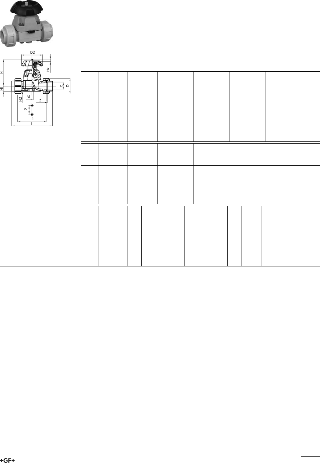
Diaphragm Valves 314
PROGEF Standard Diaphragm valve type 314
With fusion sockets metric
Model:
ÏMaterial: PP-H
ÏFor easy installation and removal
ÏShort overall length
Option:
ÏHandwheel with built in locking mechanism
d
[mm]
DN
[mm]
PN kv-value
(”p=1 bar)
[l/min]
NBR
Code
EPDM
Code
CSM
Code
PTFE with
EPDM
supporting
diaphragm
Code
20 15 10 72 167 314 402 167 314 417 167 314 447 167 314 432
25 20 10 137 167 314 403 167 314 418 167 314 448 167 314 433
32 25 10 207 167 314 404 167 314 419 167 314 449 167 314 434
40 32 10 354 167 314 405 167 314 420 167 314 450 167 314 435
50 40 10 517 167 314 406 167 314 421 167 314 451 167 314 436
63 50 10 713 167 314 407 167 314 422 167 314 452 167 314 437
d
[mm]
DN
[mm]
PN kv-value
(”p=1 bar)
[l/min]
FPM
Code
kg
20 15 10 72 167 314 462 0.380
25 20 10 137 167 314 463 0.560
32 25 10 207 167 314 464 0.760
40 32 10 354 167 314 465 1.220
50 40 10 517 167 314 466 1.600
63 50 10 713 167 314 467 2.780
d
[mm]
z
[mm]
D
[mm]
D2
[mm]
L
[mm]
L1
[mm]
L2
[mm]
H
[mm]
H1
[mm]
H2
[mm]
M Lift =
Hx
[mm]
20 100 47 80 128 90 25 90 14 12 M6 8
25 118 57 80 150 108 25 101 18 12 M6 11
32 126 64 94 162 116 25 117 21 12 M6 13
40 144 78 117 184 134 45 127 26 15 M8 16
50 164 89 117 210 154 45 139 33 15 M8 21
63 194 109 152 248 184 45 172 39 15 M8 28
119
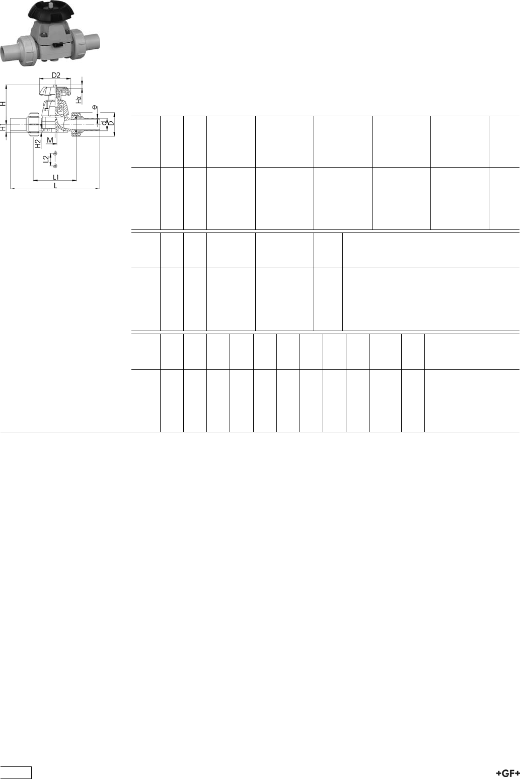
PROGEF Standard Diaphragm valve type 314
With butt fusion spigots SDR11
Model:
ÏMaterial: PP-H
ÏFor easy installation and removal
ÏShort overall length
Option:
ÏHandwheel with built in locking mechanism
d
[mm]
DN
[mm]
PN kv-value
(”p=1 bar)
[l/min]
NBR
Code
EPDM
Code
CSM
Code
PTFE with
EPDM
supporting
diaphragm
Code
20 15 10 72 167 314 502 167 314 517 167 314 547 167 314 532
25 20 10 137 167 314 503 167 314 518 167 314 548 167 314 533
32 25 10 207 167 314 504 167 314 519 167 314 549 167 314 534
40 32 10 354 167 314 505 167 314 520 167 314 550 167 314 535
50 40 10 517 167 314 506 167 314 521 167 314 551 167 314 536
63 50 10 713 167 314 507 167 314 522 167 314 552 167 314 537
d
[mm]
DN
[mm]
PN kv-value
(”p=1 bar)
[l/min]
FPM
Code
kg
20 15 10 72 167 314 562 0.395
25 20 10 137 167 314 563 0.590
32 25 10 207 167 314 564 0.800
40 32 10 354 167 314 565 1.270
50 40 10 517 167 314 566 1.670
63 50 10 713 167 314 567 2.890
d
[mm]
D
[mm]
D2
[mm]
L
[mm]
L1
[mm]
L2
[mm]
H
[mm]
H1
[mm]
H2
[mm]
M Lift =
Hx
[mm]
e
[mm]
20 47 80 196 90 25 90 14 12 M6 8 1,9
25 57 80 221 108 25 102 18 12 M6 11 2,3
32 64 94 234 116 25 119 21 12 M6 13 3
40 78 117 260 134 45 126 26 15 M8 16 3,7
50 89 117 284 154 45 139 33 15 M8 21 4,6
63 109 152 321 184 45 172 39 15 M8 28 5,8
120
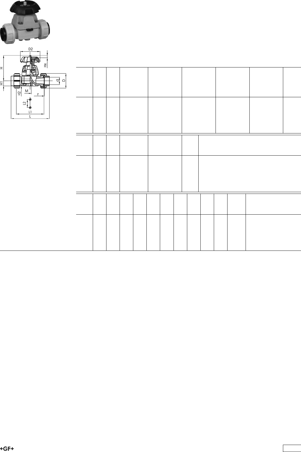
PROGEF Standard Diaphragm valve type 314
With fusion sockets PE80 metric
Model:
ÏMaterial: PP-H
ÏFor easy installation and removal
ÏShort overall length
Option:
ÏHandwheel with built in locking mechanism
d
[mm]
DN
[mm]
PN kv-value
(”p=1 bar)
[l/min]
NBR
Code
EPDM
Code
CSM
Code
PTFE with
EPDM
supporting
diaphragm
Code
20 15 10 72 167 314 602 167 314 617 167 314 647 167 314 632
25 20 10 137 167 314 603 167 314 618 167 314 648 167 314 633
32 25 10 207 167 314 604 167 314 619 167 314 649 167 314 634
40 32 10 354 167 314 605 167 314 620 167 314 650 167 314 635
50 40 10 517 167 314 606 167 314 621 167 314 651 167 314 636
63 50 10 713 167 314 607 167 314 622 167 314 652 167 314 637
d
[mm]
DN
[mm]
PN kv-value
(”p=1 bar)
[l/min]
FPM
Code
kg
20 15 10 72 167 314 662 0.380
25 20 10 137 167 314 663 0.560
32 25 10 207 167 314 664 0.760
40 32 10 354 167 314 665 1.220
50 40 10 517 167 314 666 1.600
63 50 10 713 167 314 667 2.780
d
[mm]
z
[mm]
D
[mm]
D2
[mm]
L
[mm]
L1
[mm]
L2
[mm]
H
[mm]
H1
[mm]
H2
[mm]
M Lift =
Hx
[mm]
20 100 47 80 128 90 25 90 14 12 M6 8
25 118 57 80 150 108 25 101 18 12 M6 11
32 126 64 94 162 116 25 117 21 12 M6 13
40 144 78 117 184 134 45 127 26 15 M8 16
50 164 89 117 210 154 45 139 33 15 M8 21
63 194 109 152 248 184 45 172 39 15 M8 28
121
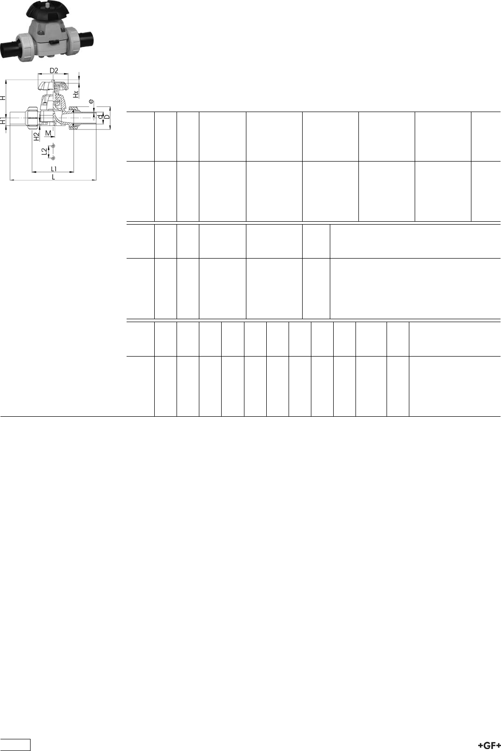
PROGEF Standard Diaphragm valve type 314
With butt fusion spigots PE100 SDR11
Model:
ÏMaterial: PP-H
ÏFor easy installation and removal
ÏShort overall length
Option:
ÏHandwheel with built in locking mechanism
d
[mm]
DN
[mm]
PN kv-value
(”p=1 bar)
[l/min]
NBR
Code
EPDM
Code
CSM
Code
PTFE with
EPDM
supporting
diaphragm
Code
20 15 10 72 167 314 702 167 314 717 167 314 747 167 314 732
25 20 10 137 167 314 703 167 314 718 167 314 748 167 314 733
32 25 10 207 167 314 704 167 314 719 167 314 749 167 314 734
40 32 10 354 167 314 705 167 314 720 167 314 750 167 314 735
50 40 10 517 167 314 706 167 314 721 167 314 751 167 314 736
63 50 10 713 167 314 707 167 314 722 167 314 752 167 314 737
d
[mm]
DN
[mm]
PN kv-value
(”p=1 bar)
[l/min]
FPM
Code
kg
20 15 10 72 167 314 762 0.395
25 20 10 137 167 314 763 0.590
32 25 10 207 167 314 764 0.800
40 32 10 354 167 314 765 1.270
50 40 10 517 167 314 766 1.270
63 50 10 713 167 314 767 2.890
d
[mm]
D
[mm]
D2
[mm]
L
[mm]
L1
[mm]
L2
[mm]
H
[mm]
H1
[mm]
H2
[mm]
M Lift =
Hx
[mm]
e
[mm]
20 47 80 196 90 25 90 14 12 M6 8 1,9
25 57 80 221 108 25 102 18 12 M6 11 2,3
32 64 94 234 116 25 119 21 12 M6 13 3
40 78 117 260 134 45 126 26 15 M8 16 3,7
50 89 117 284 154 45 139 33 15 M8 21 4,6
63 109 152 321 184 45 172 39 15 M8 28 5,8
122
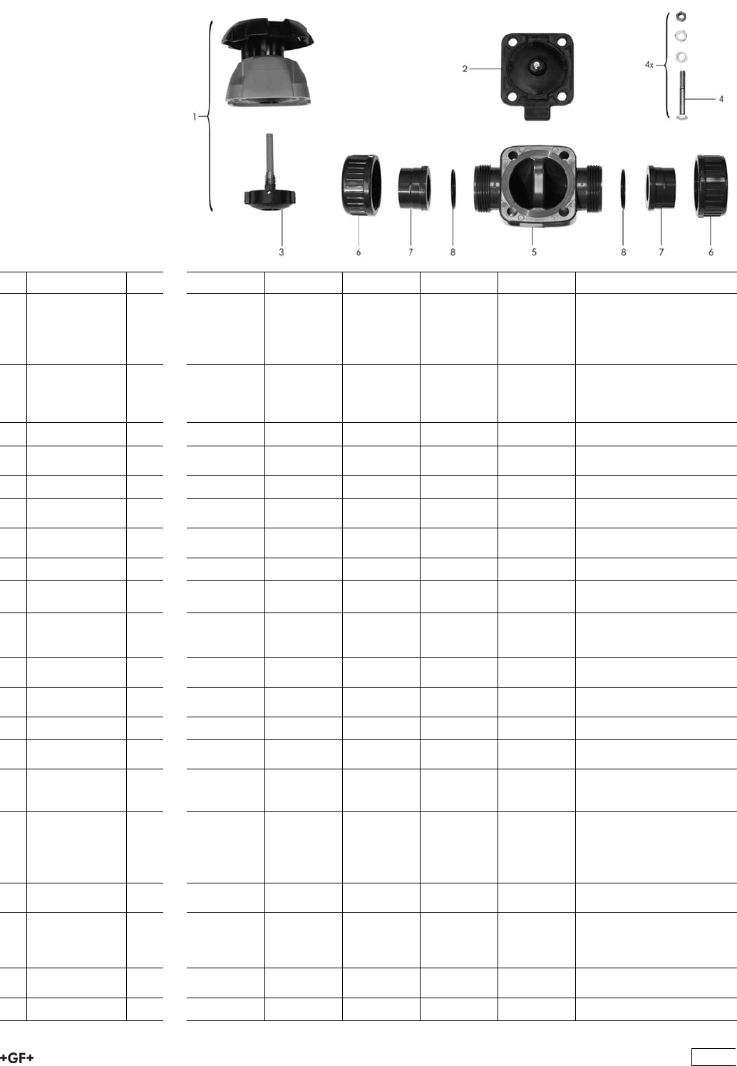
Spare parts for diaphragm valve type 314 PP-H
No. Article / Material Pieces d20 DN 15 d25 DN 20 d32 DN 25 d40 DN 32 d50 DN 40 d63 DN 50
1 Bonnet complete
(without
diaphragm)
elastomer
diaphragm
1 161 484 625 161 484 626 161 484 627 161 484 628 161 484 629 161 484 630
1 Bonnet complete
(without
diaphragm)
PTFE diaphragm
1 161 484 632 161 484 633 161 484 634 161 484 635 161 484 636 161 484 637
2 Diaphragm NBR 1 161 311 710 161 311 711 161 311 712 161 311 713 161 311 714 161 311 715
2 Diaphragm
EPDM
1 161 481 022 161 481 023 161 481 024 161 481 025 161 481 026 161 481 027
2 Diaphragm FPM 1 161 481 092 161 481 093 161 481 094 161 481 095 161 481 096 161 481 097
2 Diaphragm
PTFE/EPDM
1 161 311 698 161 311 699 161 311 700 161 311 701 161 311 702 161 311 703
2 Diaphragm
PTFE/FPM
1 161 481 926 161 481 927 161 481 928 161 481 929 161 481 930 161 481 931
2 Diaphragm CSM 1 161 311 728 161 311 729 161 311 730 161 311 731 161 311 732 161 311 733
3 Pressure spindel
PTFE diaphragm
1 161 484 696 161 484 697 161 484 698 161 484 699 161 484 700 161 484 701
3 Pressure spindel
elastomer
diaphragm
1 161 484 688 161 484 689 161 484 690 161 484 691 161 484 692 161 484 693
4 Fastening set
Stainless steel
1 161 484 704 161 484 705 161 484 706 161 484 707 161 484 708 161 484 709
5 Valve body
PP-H
1 167 481 977 167 481 978 167 481 979 167 481 980 167 481 981 167 481 982
6 Union nut PP 1 727 690 406 727 690 407 727 690 408 727 690 409 727 690 410 727 690 411
3 Fusion socket
PP-H
1 727 600 106 727 600 107 727 600 108 727 600 109 727 600 110 727 600 111
7 Butt fusion
spigot PE 100
SDR11
1 753 608 606 753 608 607 753 608 608 753 608 609 753 608 610 753 608 611
7 Butt fusion
spigot PP-H
SDR11
(IR-Plus®)
compatible
1 727 608 506 727 608 507 727 608 508 727 608 509 727 608 510 727 608 511
7 Fusion socket
PE 80
1 734 600 106 734 600 107 734 600 108 734 600 109 734 600 110 734 600 111
7 Butt fusion
spigot long PE
100
SDR11
1 753 608 616 753 608 617 753 608 618 753 608 619 753 608 620 753 608 621
8 O-ring seal
EPDM
1 748 410 006 748 410 007 748 410 008 748 410 009 748 410 010 748 410 011
8 O-ring seal FPM 1 749 410 006 749 410 007 749 410 008 749 410 009 749 410 010 749 410 011
123

Diaphragm Valves 315
PROGEF Standard Diaphragm valve type 315
With socket fusion spigots
Model:
ÏMaterial: PP-H
ÏOverall length EN 558
Option:
ÏHandwheel with built in locking mechanism
d
[mm]
DN
[mm]
PN kv-value
(”p=1 bar)
[l/min]
NBR
Code
EPDM
Code
CSM
Code
PTFE with
EPDM
supporting
diaphragm
Code
20 15 10 72 167 315 402 167 315 417 167 315 447 167 315 432
25 20 10 137 167 315 403 167 315 418 167 315 448 167 315 433
32 25 10 207 167 315 404 167 315 419 167 315 449 167 315 434
40 32 10 354 167 315 405 167 315 420 167 315 450 167 315 435
50 40 10 517 167 315 406 167 315 421 167 315 451 167 315 436
63 50 10 713 167 315 407 167 315 422 167 315 452 167 315 437
d
[mm]
DN
[mm]
PN kv-value
(”p=1 bar)
[l/min]
FPM
Code
kg
20 15 10 72 167 315 492 0.267
25 20 10 137 167 315 493 0.370
32 25 10 207 167 315 494 0.673
40 32 10 354 167 315 495 0.795
50 40 10 517 167 315 496 1.168
63 50 10 713 167 315 497 2.088
d
[mm]
D2
[mm]
H
[mm]
H1
[mm]
H2
[mm]
L
[mm]
L2
[mm]
M Lift =
Hx
[mm]
20 80 90 14 12 124 25 M6 7
25 80 101 18 12 144 25 M6 10
32 94 117 22 12 154 25 M6 12
40 117 127 26 15 174 45 M8 16
50 117 139 32 15 194 45 M8 19
63 152 172 39 15 223 45 M8 27
124
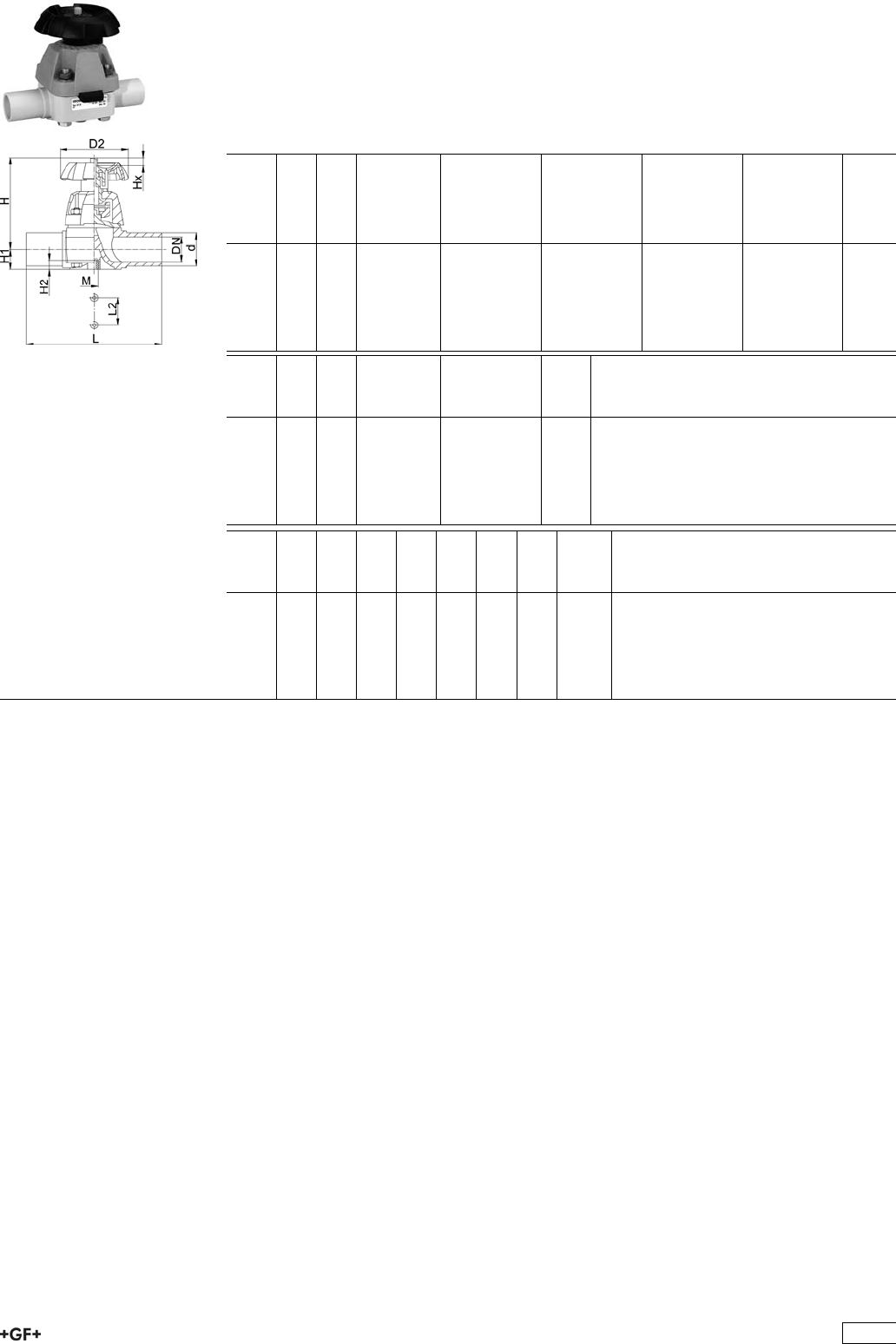
PROGEF Standard Diaphragm valve type 315
With butt fusion spigots SDR11
Model:
ÏMaterial: PP-H
Option:
ÏHandwheel with built in locking mechanism
d
[mm]
DN
[mm]
PN kv-value
(”p=1 bar)
[l/min]
NBR
Code
EPDM
Code
CSM
Code
PTFE with
EPDM
supporting
diaphragm
Code
20 15 10 72 167 315 502 167 315 517 167 315 547 167 315 532
25 20 10 137 167 315 503 167 315 518 167 315 548 167 315 533
32 25 10 207 167 315 504 167 315 519 167 315 549 167 315 534
40 32 10 354 167 315 505 167 315 520 167 315 550 167 315 535
50 40 10 517 167 315 506 167 315 521 167 315 551 167 315 536
63 50 10 713 167 315 507 167 315 522 167 315 552 167 315 537
d
[mm]
DN
[mm]
PN kv-value
(”p=1 bar)
[l/min]
FPM
Code
kg
20 15 10 72 167 315 592 0.260
25 20 10 137 167 315 593 0.382
32 25 10 207 167 315 594 0.660
40 32 10 354 167 315 595 0.779
50 40 10 517 167 315 596 1.137
63 50 10 713 167 315 597 2.061
d
[mm]
D2
[mm]
H
[mm]
H1
[mm]
H2
[mm]
L
[mm]
L2
[mm]
M Lift =
Hx
[mm]
20 80 90 14 12 124 25 M6 7
25 80 101 18 12 144 25 M6 10
32 94 117 22 12 154 25 M6 12
40 117 127 26 15 174 45 M8 16
50 117 139 32 15 194 45 M8 19
63 152 172 39 15 223 45 M8 27
125
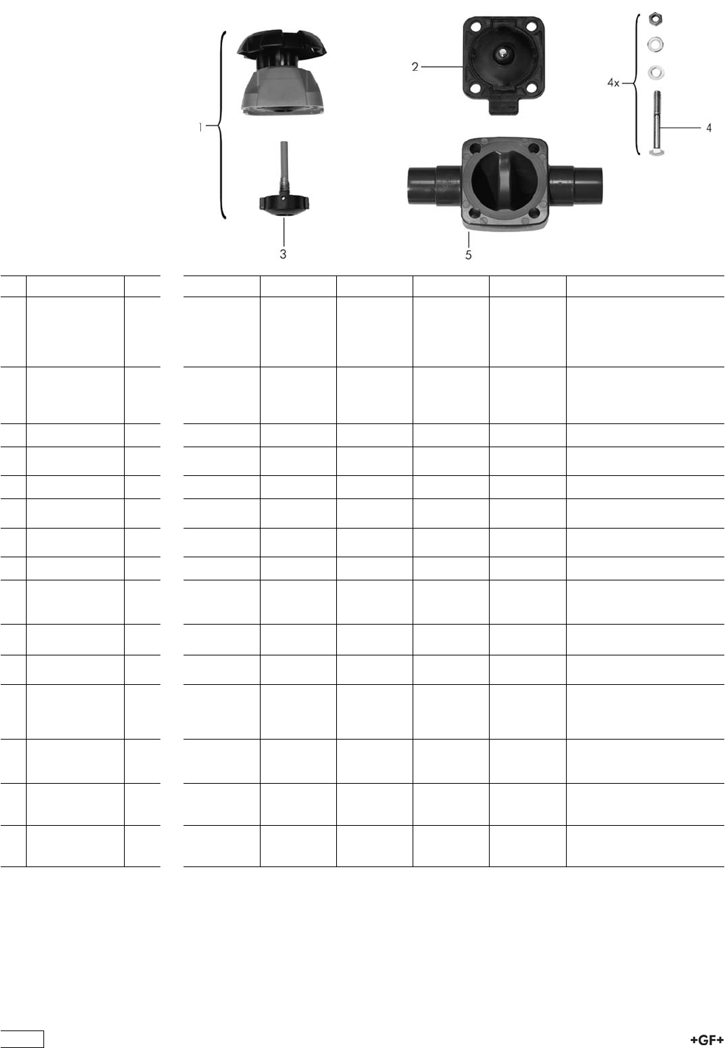
Spare parts for diaphragm valve type 315 PP-H
No. Article / Material Pieces d20 DN 15 d25 DN 20 d32 DN 25 d40 DN 32 d50 DN 40 d63 DN 50
1 Bonnet complete
(without
diaphragm)
elastomer
diaphragm
1 161 484 625 161 484 626 161 484 627 161 484 628 161 484 629 161 484 630
1 Bonnet complete
(without
diaphragm)
PTFE diaphragm
1 161 484 632 161 484 633 161 484 634 161 484 635 161 484 636 161 484 637
2 Diaphragm NBR 1 161 311 710 161 311 711 161 311 712 161 311 713 161 311 714 161 311 715
2 Diaphragm
EPDM
1 161 481 022 161 481 023 161 481 024 161 481 025 161 481 026 161 481 027
2 Diaphragm FPM 1 161 481 092 161 481 093 161 481 094 161 481 095 161 481 096 161 481 097
2 Diaphragm
PTFE/EPDM
1 161 311 698 161 311 699 161 311 700 161 311 701 161 311 702 161 311 703
2 Diaphragm
PTFE/FPM
1 161 481 926 161 481 927 161 481 928 161 481 929 161 481 930 161 481 931
2 Diaphragm CSM 1 161 311 728 161 311 729 161 311 730 161 311 731 161 311 732 1613117233
3 Pressure spindel
elastomer
diaphragm
1 161 484 688 161 484 689 161 484 690 161 484 691 161 484 692 161 484 693
3 Pressure spindel
PTFE diaphragm
1 161 484 696 161 484 697 161 484 698 161 484 699 161 484 700 161 484 701
4 Fastening set
Stainless steel
1 161 484 704 161 484 705 161 484 706 161 484 707 161 484 708 161 484 709
4 Fastening set
Stainless steel
PROGEF
Natural
1 198 000 504 198 000 505 198 000 506 198 000 507 198 000 508 198 000 509
5 Valve body with
socket fusion
spigot PP-H
1 167 480 328 167 480 329 167 480 330 167 480 331 167 480 332 167 480 333
5 Valve body with
butt fusion spigot
PP-natur
1 168 480 125 168 480 126 168 480 127 168 480 128 168 480 129 168 480 130
5 Valve body with
butt fusion spigot
PP-H
1 167 481 175 167 481 176 167 481 177 167 481 178 167 481 179 167 481 180
126
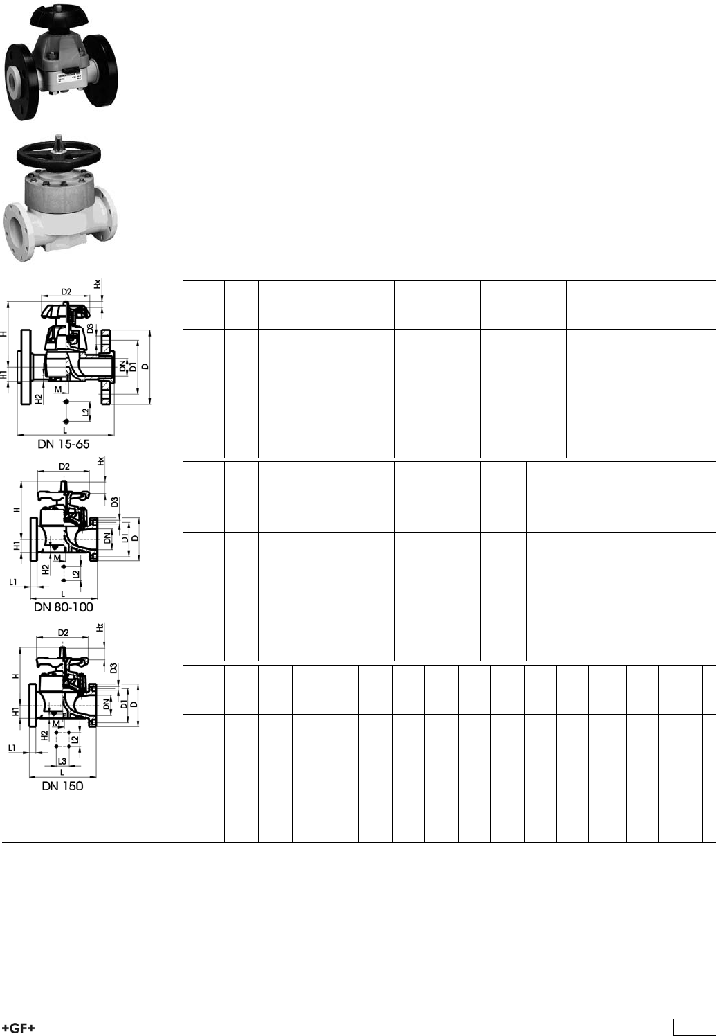
Diaphragm Valves 317
PROGEF Standard Diaphragm valve type 317
With backing flanges PP-V metric
Model:
ÏMaterial: PP-H
ÏJointing faces flat/serrated
ÏOverall length according to EN 558
ÏConnecting dimensions: ISO 7005 / EN 1092 / DIN 2501 PN10 / BS4504
ÏDN 15-65 with backing flange
ÏDN 80-150 with fixed flange
Option:
ÏHandwheel lockable DN15-65 (basic version not lockable)
* With PP fixed flanges, jointing faces flat
* DN80 and DN150 fixed flanges metric and Inch ANSI B16.5
d
[mm]
DN
[mm]
Inch PN kv-value
(”p=1 bar)
[l/min]
NBR
Code
EPDM
Code
CSM
Code
20 15 1
/210 72 167 317 152 167 317 167 167 317 197
25 20 3
/410 137 167 317 153 167 317 168 167 317 198
32 25 1 10 207 167 317 154 167 317 169 167 317 199
40 32 1 1
/410 354 167 317 155 167 317 170 167 317 200
50 40 1 1
/210 517 167 317 156 167 317 171 167 317 201
63 50 2 10 713 167 317 157 167 317 172 167 317 202
75 65 2 1
/210 992 167 317 158 167 317 173 167 317 203
*90 80 3 10 1700 167 317 009 - 167 317 054
*110 100 4 10 2700 167 317 010 167 317 025 167 317 055
d
[mm]
DN
[mm]
Inch PN kv-value
(”p=1 bar)
[l/min]
PTFE with
EPDM
supporting
diaphragm
Code
kg
20 15 1
/210 72 167 317 182 0.532
25 20 3
/410 137 167 317 183 0.844
32 25 1 10 207 167 317 184 1.236
40 32 1 1
/410 354 167 317 185 1.446
50 40 1 1
/210 517 167 317 186 2.456
63 50 2 10 713 167 317 187 3.664
75 65 2 1
/210 992 167 317 188 5.480
*90 80 3 10 1700 167 317 039 8.600
*110 100 4 10 2700 167 317 040 11.360
d
[mm]
D
[mm]
D1
[mm]
D2
[mm]
D3
[mm]
L
[mm]
L1
[mm]
L2
[mm]
L3
[mm]
H
[mm]
H1
[mm]
H2
[mm]
M AL Lift =
Hx
[mm]
20 95 65 80 14 130 25 90 14 12 M6 4 7
25 105 75 80 14 150 25 101 18 12 M6 4 10
32 115 85 94 14 160 25 117 22 12 M6 4 12
40 140 100 117 18 180 45 127 26 15 M8 4 16
50 150 110 117 18 200 45 139 32 15 M8 4 19
63 165 125 152 18 230 45 172 39 15 M8 4 27
75 185 145 152 18 290 70 210 46 15 M8 4 35
*90 200 160 270 18 310 35 120 265 57 23 M12 8 40
*110 225 180 270 18 350 38 120 304 69 23 M12 8 50
127
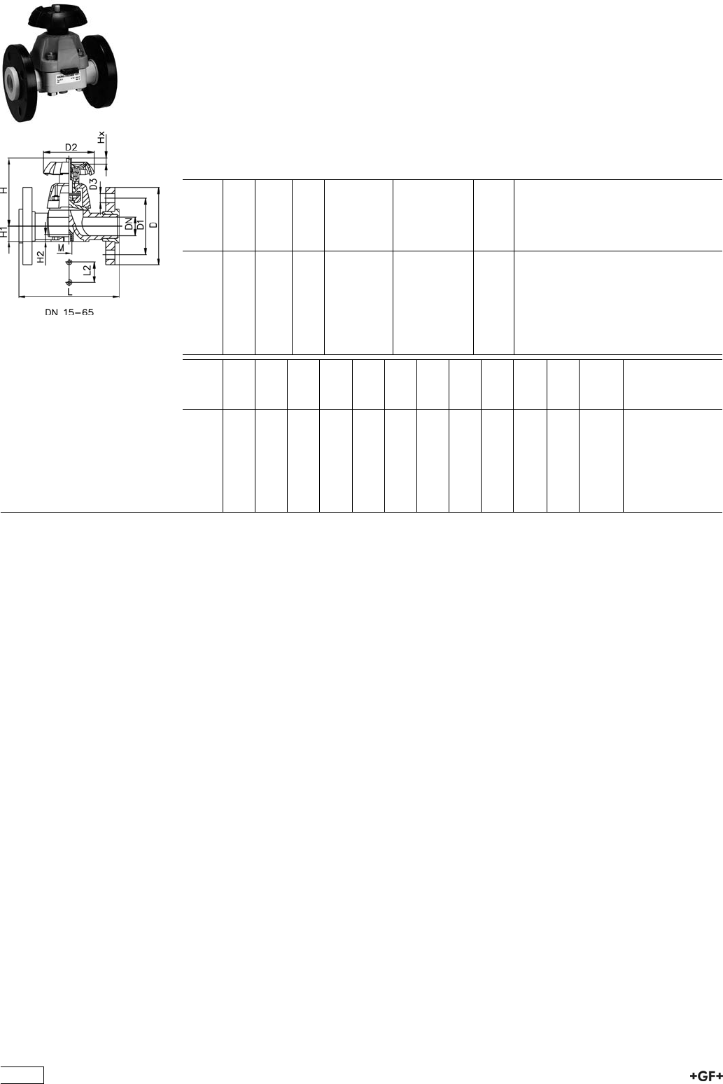
PROGEF Standard Diaphragm valve type 317
With backing flanges PP-st metric
Model:
ÏMaterial: PP-H
ÏJointing faces flat/serrated
ÏOverall length according to EN 558
ÏConnecting dimensions: ISO 7005 / EN 1092 / DIN 2501 PN10 / BS4504
Option:
ÏHandwheel lockable DN15-65 (basic version not lockable)
d
[mm]
DN
[mm]
Inch PN kv-value
(”p=1 bar)
[l/min]
PTFE with
EPDM
supporting
diaphragm
Code
kg
20 15 1
/210 72 167 317 272 0.810
25 20 3
/410 137 167 317 273 1.200
32 25 1 10 207 167 317 274 1.850
40 32 1 1
/410 354 167 317 275 2.410
50 40 1 1
/210 517 167 317 276 3.500
63 50 2 10 713 167 317 277 5.000
75 65 2 1
/210 992 167 317 278 7.040
d
[mm]
D
[mm]
D1
[mm]
D2
[mm]
D3
[mm]
L
[mm]
L2
[mm]
H
[mm]
H1
[mm]
H2
[mm]
M AL Lift =
Hx
[mm]
20 95 65 80 14 130 25 90 14 12 M6 4 7
25 105 75 80 14 150 25 101 18 12 M6 4 10
32 115 85 94 14 160 25 117 22 12 M8 4 12
40 140 100 117 18 180 45 127 26 15 M8 4 16
50 150 110 117 18 200 45 139 32 15 M10 4 19
63 165 125 152 18 230 45 172 39 15 M8 4 27
75 185 145 152 18 290 70 210 46 15 M8 4 35
128
Component Parts for Flange Assembly
Diaphragm Valves Type 317
27 79 02 PROGEF Standard, Flange Adaptor
Jointing face flat/serrated
d
[mm]
PN Code kg
20 10 727 790 206 0.011
25 10 727 790 207 0.022
32 10 727 790 208 0.033
40 10 727 790 209 0.046
50 10 727 790 210 0.062
63 10 727 790 211 0.090
75 10 727 790 212 0.163
90 10 727 790 213 0.233
110 10 727 790 214 0.319
PROGEF Standard, Special Flange Adaptors, PP-H
S5/SDR11
Jointing Face, combination serrated / flat
metric
d
[mm]
DN
[mm]
FM Code kg
75 65 IR 727 798 512 0.243
90 80 IR 727 798 513 0.326
90 80 IR 727 798 663 0.346
110 100 IR 727 798 514 0.441
125 100 IR 727 798 515 0.520
140 125 IR 727 798 516 0.800
160 150 IR 727 798 517 0.920
180 150 IR 727 798 568 0.900
200 200 IR 727 798 519 1.670
225 200 IR 727 798 520 1.700
250 250 -- 727 798 571 2.790
280 250 -- 727 798 572 2.610
315 300 -- 727 798 573 3.410
355 350 -- 727 798 574 5.600
400 400 -- 727 798 575 8.300
129
EPDM 48 44 07
FPM 49 44 07 Profile Flange Gaskets metric
EPDM / FPM
d
[mm]
DN
[mm]
PN EPDM
Code
FPM
Code
kg
16 10 16 748 440 705 749 440 705 0.007
20 15 16 748 440 706 749 440 706 0.008
25 20 16 748 440 707 749 440 707 0.011
32 25 16 748 440 708 749 440 708 0.014
40 32 16 748 440 709 749 440 709 0.021
50 40 16 748 440 710 749 440 710 0.022
63 50 16 748 440 711 749 440 711 0.041
75 65 16 748 440 712 749 440 712 0.055
90 80 16 748 440 713 749 440 713 0.062
110 100 16 748 440 714 749 440 714 0.085
125 100 16 748 440 715 749 440 715 0.158
140 125 16 748 440 716 749 440 716 0.118
160 / 180 150 16 748 440 717 749 440 717 0.153
200 200 16 748 440 719 749 440 719 0.263
225 200 16 748 440 720 749 440 720 0.181
250 250 16 748 440 721 749 440 721 0.410
280 250 16 748 440 722 749 440 722 0.226
315 300 16 748 440 723 749 440 723 0.334
355 350 16 748 440 724 749 440 724 0.410
400 400 16 748 440 725 749 440 725 0.513
27 70 04
27 70 05
Backing Flanges, PP-V
for Butt Fusion Systems metric
d
[mm]
Inch DN
[mm]
PN Code kg
20 15 16 727 700 406 0.080
25 20 16 727 700 407 0.100
32 25 16 727 700 408 0.140
40 32 16 727 700 409 0.220
50 40 16 727 700 410 0.210
63 50 16 727 700 411 0.380
75 65 16 727 700 412 0.480
90 80 16 727 700 513 0.520
110 100 16 727 700 514 0.680
27 70 04
27 70 05
Backing Flanges, PP-V
for Socket Systems metric
d
[mm]
Inch DN
[mm]
PN Code kg
20 15 16 727 700 406 0.080
25 20 16 727 700 407 0.100
32 25 16 727 700 408 0.140
40 32 16 727 700 409 0.220
50 40 16 727 700 410 0.210
63 50 16 727 700 411 0.380
75 65 16 727 700 412 0.480
90 80 16 727 700 413 0.520
110 100 16 727 700 414 0.680
130
27 70 14
27 70 15
Backing Flanges, PP-V
for Butt Fusion Systems Inch/ANSI
Inch DN
[mm]
PN Code kg
1
/215 16 727 701 406 0.080
3
/420 16 727 701 407 0.100
1 25 16 727 701 408 0.140
11
/432 16 727 701 409 0.220
11
/240 16 727 701 410 0.210
2 50 16 727 701 411 0.380
21
/265 16 727 701 412 0.480
3 80 16 727 701 513 0.520
4 100 16 727 701 514 0.680
27 70 14
27 70 15
Backing Flanges, PP-V
for Socket Systems Inch/ANSI
Inch DN
[mm]
PN Code kg
1
/215 16 727 701 406 0.080
3
/420 16 727 701 407 0.100
1 25 16 727 701 408 0.140
11
/432 16 727 701 409 0.220
11
/240 16 727 701 410 0.210
2 50 16 727 701 411 0.380
21
/265 16 727 701 412 0.480
3 80 16 727 701 413 0.520
4 100 16 727 701 414 0.680
131
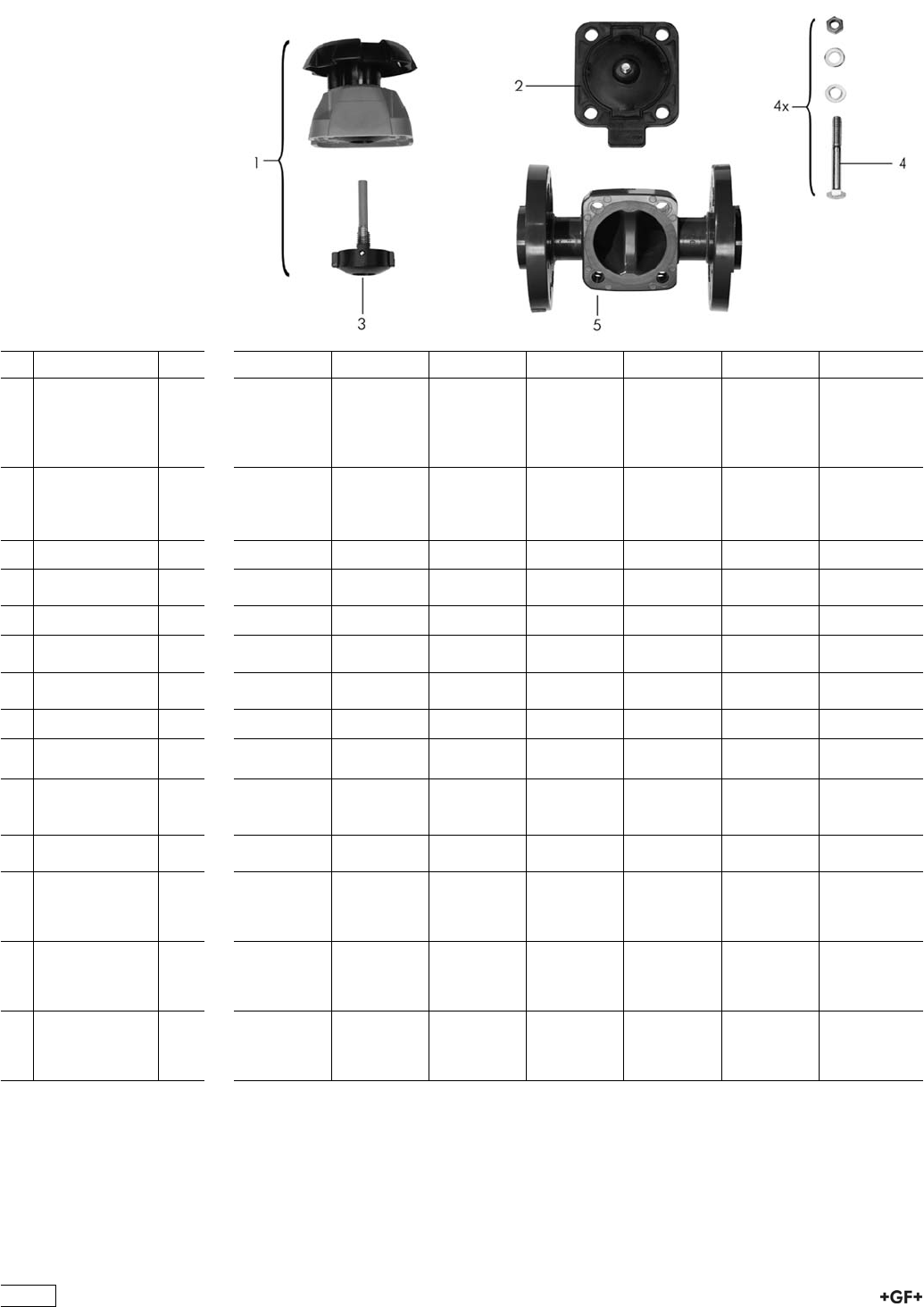
Spare parts for diaphragm valve type 317
(DN15-65) PP-H
No. Article / Material Pieces d20 DN 15 d25 DN 20 d32 DN 25 d40 DN 32 d50 DN 40 d63 DN 50 d75 DN 65
1 Bonnet complete
(without
diaphragm)
elastomer
diaphragm
1 161 484 625 161 484 626 161 484 627 161 484 628 161 484 629 161 484 630 161 484 631
1 Bonnet complete
(without
diaphragm)
PTFE diaphragm
1 161 484 632 161 484 633 161 484 634 161 484 635 161 484 636 161 484 637 161 484 638
2 Diaphragm NBR 1 161 311 710 161 311 711 161 311 712 161 311 713 161 311 714 161 311 715 161 480 241
2 Diaphragm
EPDM
1 161 481 022 161 481 023 161 481 024 161 481 025 161 481 026 161 481 027 161 481 028
2 Diaphragm FPM 1 161 481 092 161 481 093 161 481 094 161 481 095 161 481 096 161 481 097 161 481 098
2 Diaphragm
PTFE/EPDM
1 161 311 698 161 311 699 161 311 700 161 311 701 161 311 702 161 311 703 161 480 240
2 Diaphragm
PTFE/FPM
1 161 481 926 161 481 927 161 481 928 161 481 929 161 481 930 161 481 931 161 481 932
2 Diaphragm CSM 1 161 311 728 161 311 729 161 311 730 161 311 731 161 311 732 161 311 733 161 480 237
3 Pressure spindel
PTFE diaphragm
1 161 484 696 161 484 697 161 484 698 161 484 699 161 484 700 161 484 701 161 484 702
3 Pressure spindel
elastomer
diaphragm
1 161 484 688 161 484 689 161 484 690 161 484 691 161 484 692 161 484 693 161 484 694
4 Fastening set
Stainless steel
1 161 484 704 161 484 705 161 484 706 161 484 707 161 484 708 161 484 709 161 483 032
5 Valve body
PP-H
backing flange
Inch ANSI
1 167 484 035 167 484 036 167 484 037 167 484 038 167 484 039 167 484 040 167 484 041
5 Valve body
PP-H
backing flange
PP-GF JIS
1 167 481 552 167 481 553 167 481 554 167 481 555 167 481 556 167 481 557 -
5 Valve body
PP-H
backing flange
metric
1 167 484 025 167 484 026 167 484 027 167 484 028 167 484 029 167 484 030 167 484 031
132
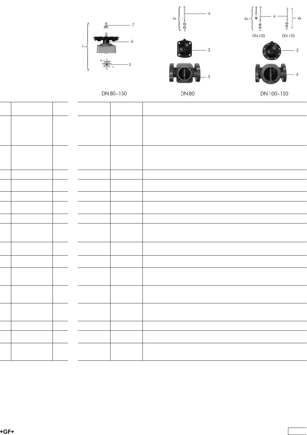
Spare parts for diaphragm valve type 317
(DN80-150) PP-H
No. Article / Material Pieces d90 DN 80 d110 DN
100
d160 DN
150
1 Bonnet complete
(without
diaphragm)
elastomer
diaphragm
1 161 482 514 161 482 515 161 482 901
1 Bonnet complete
(without
diaphragm)
PTFE diaphragm
1 161 482 516 161 482 517 161 482 906
2 Diaphragm NBR 1 161 480 232 161 480 233 161 482 751
2 Diaphragm
EPDM
1 161 481 029 161 481 030 161 482 754
2 Diaphragm FPM 1 161 481 099 161 481 100 161 481 102
2 Diaphragm
PTFE/EPDM
1 161 480 241 161 480 242 161 482 760
2 Diaphragm CSM 1 161 480 238 161 480 239 161 482 757
3 Pressure spindel
elastomer
diaphragm
1 161 483 008 161 483 009 161 483 011
3 Pressure spindel
PTFE diaphragm
1 161 483 020 161 483 021 161 483 023
4 Fastening set
Stainless steel
1 161 483 033 161 483 034 161 483 037
5 Valve body with
PP-fixed flange
metric PP-H
1 167 480 427 167 480 428 167 480 577
5 Valve body with
PP-fixed flange
ANSI PP-H
1 167 480 427 167 480 478 167 480 577
5 Valve body with
PP-fixed flange
JIS PP-H
1 - 167 480 476 167 480 577
6 O-ring seal NBR 1 745 410 107 745 410 107 -
6 O-ring seal
EPDM
1 - - 748 410 121
7 Covering cap
PVC-U
SAN
1 161 481 759 161 481 760 161 482 744
133
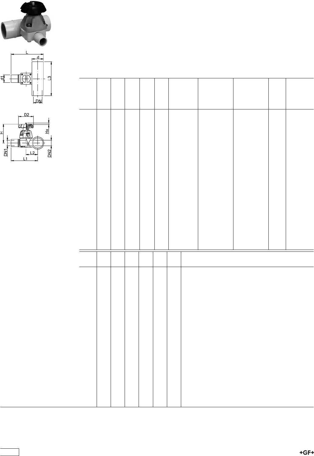
Diaphragm Valves 319
PROGEF Standard Diaphragm valve type 319
With butt fusion spigots
Model:
ÏMaterial: PP-H
ÏValve body injection molded, compact design
ÏMinimized static zone (dead leg)
Ïd20-d63 SDR11, d90-d110 SDR17,6
Option:
ÏHandwheel with built in locking mechanism
d
[mm]
d1
[mm]
DN
[mm]
DN1
[mm]
DN2
[mm]
PN kv-value
(”p=1 bar)
[l/min]
PTFE with
EPDM
supporting
diaphragm
Code
EPDM
Code
kg
20 20 15 15 15 10 47 167 319 301 167 319 401 0.329
25 20 20 15 20 10 69 167 319 303 167 319 403 0.361
25 25 20 20 20 10 91 167 319 304 167 319 404 0.361
32 20 25 15 25 10 86 167 319 307 167 319 407 0.619
32 25 25 20 25 10 126 167 319 308 167 319 408 0.618
32 32 25 25 25 10 156 167 319 309 167 319 409 0.618
40 20 32 15 25 10 84 167 319 312 167 319 412 0.634
50 20 40 15 25 10 82 167 319 318 167 319 418 0.701
50 25 40 20 25 10 124 167 319 319 167 319 419 0.701
50 32 40 25 25 10 159 167 319 320 167 319 420 0.700
63 20 50 15 25 10 81 167 319 325 167 319 425 0.750
63 25 50 20 25 10 115 167 319 326 167 319 426 0.749
63 32 50 25 25 10 156 167 319 327 167 319 427 0.746
90 20 80 15 20 6 88 167 319 341 167 319 441 0.871
90 25 80 20 25 6 133 167 319 342 167 319 442 1.062
90 32 80 25 25 6 162 167 319 343 167 319 443 0.907
90 50 80 40 50 6 504 167 319 345 167 319 445 2.285
90 63 80 50 50 6 530 167 319 346 167 319 446 2.285
110 20 100 15 25 6 89 167 319 351 167 319 451 0.888
110 25 100 20 25 6 123 167 319 352 167 319 452 0.887
110 32 100 25 25 6 159 167 319 353 167 319 453 0.886
110 50 100 40 50 6 503 167 319 355 167 319 455 2.400
110 63 100 50 50 6 543 167 319 356 167 319 456 2.426
d
[mm]
D2
[mm]
H
[mm]
L
[mm]
L1
[mm]
L2
[mm]
L3
[mm]
20 80 83 106 96 30 140
25 80 91 121 108 36 150
25 80 91 121 108 36 150
32 94 105 137 120 43 160
32 94 105 137 120 43 160
32 94 105 137 120 43 160
40 94 105 149 128 51 180
50 94 105 159 134 57 180
50 94 105 159 134 57 180
50 94 105 159 134 57 180
63 94 105 175 144 67 180
63 94 105 175 144 67 180
63 94 105 175 144 67 180
90 94 105 204 159 82 160
90 94 105 204 159 82 160
90 94 105 204 159 82 160
90 152 151 252 207 95 220
90 152 151 252 207 95 220
110 94 105 226 171 94 160
110 94 105 226 171 94 160
110 94 105 226 171 94 160
110 152 151 274 219 107 220
110 152 151 274 219 107 220
134
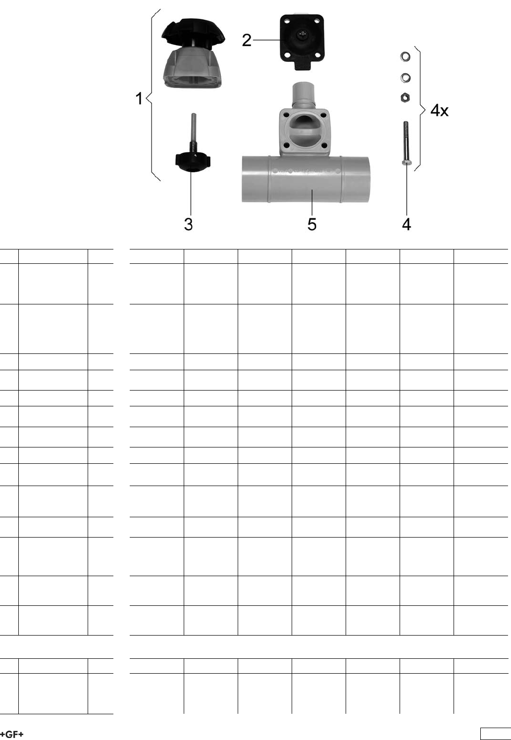
Spare parts for diaphragm valve type 319 PP-H
No. Article / Material Pieces 20x20 25x20 25x25 32x20 32x25 32x32 40x20
1 Bonnet complete
(without
diaphragm)
PTFE diaphragm
1 161 484 632 161 484 633 161 484 633 161 484 634 161 484 634 161 484 634 161 484 634
1 Bonnet complete
(without
diaphragm)
elastomer
diaphragm
1 161 484 625 161 484 626 161 484 626 161 484 627 161 484 627 161 484 627 161 484 627
2 Diaphragm NBR 1 161 311 710 161 311 711 161 311 711 161 311 712 161 311 712 161 311 712 161 311 712
2 Diaphragm
EPDM
1 161 481 022 161 481 023 161 481 023 161 481 024 161 481 024 161 481 024 161 481 024
2 Diaphragm FPM 1 161 481 092 161 481 093 161 481 093 161 481 094 161 481 094 161 481 094 161 481 094
2 Diaphragm
PTFE/EPDM
1 161 311 698 161 311 699 161 311 699 161 311 700 161 311 700 161 311 700 161 311 700
2 Diaphragm
PTFE/FPM
1 161 481 926 161 481 927 161 481 927 161 481 928 161 481 928 161 481 928 161 481 928
2 Diaphragm CSM 1 161 311 728 161 311 729 161 311 729 161 311 730 161 311 730 161 311 730 161 311 730
3 Pressure spindel
PTFE diaphragm
1 161 484 696 161 484 697 161 484 697 161 484 698 161 484 698 161 484 698 161 484 698
3 Pressure spindel
elastomer
diaphragm
1 161 484 688 161 484 689 161 484 689 161 484 690 161 484 690 161 484 690 161 484 690
4 Fastening set
Stainless steel
1 161 484 704 161 484 705 161 484 705 161 484 706 161 484 706 161 484 706 161 484 706
4 Fastening set
Stainless steel
PROGEF
Natural
1 198 000 516 198 000 517 198 000 517 198 000 518 198 000 518 198 000 518 198 000 519
5 Valve body with
butt fusion spigot
PP-H
1 167 482 252 167 482 254 167 482 255 167 482 257 167 482 258 167 482 259 167 482 261
5 Valve body with
butt fusion spigot
PP-natur
1 168 480 177 168 480 179 168 480 180 168 480 182 168 480 183 168 480 184 168 480 186
No. Article / Material Pieces 50x20 50x25 50x32 63x20 63x25 63x32 90x20
1 Bonnet complete
(without
diaphragm)
PTFE diaphragm
1 161 484 634 161 484 634 161 484 634 161 484 634 161 484 634 161 484 634 161 484 634
135

No. Article / Material Pieces 50x20 50x25 50x32 63x20 63x25 63x32 90x20
1 Bonnet complete
(without
diaphragm)
elastomer
diaphragm
1 161 484 627 161 484 627 161 484 627 161 484 627 161 484 627 161 484 627 161 484 627
2 Diaphragm NBR 1 161 311 712 161 311 712 161 311 712 161 311 712 161 311 712 161 311 712 161 311 712
2 Diaphragm
EPDM
1 161 481 024 161 481 024 161 481 024 161 481 024 161 481 024 161 481 024 161 481 024
2 Diaphragm FPM 1 161 481 094 161 481 094 161 481 094 161 481 094 161 481 094 161 481 094 161 481 094
2 Diaphragm
PTFE/EPDM
1 161 311 700 161 311 700 161 311 700 161 311 700 161 311 700 161 311 700 161 311 700
2 Diaphragm
PTFE/FPM
1 161 481 928 161 481 928 161 481 928 161 481 928 161 481 928 161 481 928 161 481 928
2 Diaphragm CSM 1 161 311 730 161 311 730 161 311 730 161 311 730 161 311 730 161 311 730 161 311 730
3 Pressure spindel
PTFE diaphragm
1 161 484 698 161 484 698 161 484 698 161 484 698 161 484 698 161 484 698 161 484 698
3 Pressure spindel
elastomer
diaphragm
1 161 484 690 161 484 690 161 484 690 161 484 690 161 484 690 161 484 690 161 484 690
4 Fastening set
Stainless steel
1 161 484 706 161 484 706 161 484 706 161 484 706 161 484 706 161 484 706 161 484 706
4 Fastening set
Stainless steel
PROGEF
Natural
1 198 000 520 198 000 520 198 000 520 198 000 521 198 000 521 198 000 521 198 000 522
5 Valve body with
butt fusion spigot
PP-H
1 167 482 266 167 482 267 167 482 268 167 482 272 167 482 273 167 482 274 167 482 287
5 Valve body with
butt fusion spigot
PP-natur
1 168 480 191 168 480 192 168 480 193 168 480 197 168 480 198 168 480 199 168 480 212
No. Article / Material Pieces 90x25 90x32 90x50 90x63 110x20 110x25 110x32
1 Bonnet complete
(without
diaphragm)
PTFE diaphragm
1 161 484 634 161 484 634 161 484 636 161 484 636 161 484 634 161 484 634 161 484 634
1 Bonnet complete
(without
diaphragm)
elastomer
diaphragm
1 161 484 627 161 484 627 161 484 630 161 484 630 161 484 627 161 484 627 161 484 627
2 Diaphragm NBR 1 161 311 712 161 311 712 161 311 715 161 311 715 161 311 712 161 311 712 161 311 712
2 Diaphragm
EPDM
1 161 481 024 161 481 024 161 481 027 161 481 027 161 481 024 161 481 024 161 481 024
2 Diaphragm FPM 1 161 481 094 161 481 094 161 481 097 161 481 097 161 481 094 161 481 094 161 481 094
2 Diaphragm
PTFE/EPDM
1 161 311 700 161 311 700 161 311 703 161 311 703 161 311 700 161 311 700 161 311 700
2 Diaphragm
PTFE/FPM
1 161 481 928 161 481 928 161 481 931 161 481 931 161 481 928 161 481 928 161 481 928
2Diaphragm CSM 1 161 311 730 161 311 730 161 311 733 161 311 733 161 311 730 161 311 730 161 311 730
3 Pressure spindel
PTFE diaphragm
1 161 484 698 161 484 698 161 484 701 161 484 701 161 484 698 161 484 698 161 484 698
3 Pressure spindel
elastomer
diaphragm
1 161 484 690 161 484 690 161 484 693 161 484 693 161 484 690 161 484 690 161 484 690
4 Fastening set
Stainless steel
1 161 484 706 161 484 706 161 484 709 161 484 709 161 484 706 161 484 706 161 484 706
4 Fastening set
Stainless steel
PROGEF
Natural
1 198 000 522 198 000 522 198 000 523 198 000 523 198 000 524 198 000 524 198 000 524
5 Valve body with
butt fusion spigot
PP-H
1 167 482 288 167 482 289 167 482 291 167 482 292 167 482 296 167 482 297 167 482 298
136
No. Article / Material Pieces 90x25 90x32 90x50 90x63 110x20 110x25 110x32
5 Valve body with
butt fusion spigot
PP-natur
1 168 480 213 168 480 214 168 480 216 168 480 217 168 480 221 168 480 222 168 480 223
No. Article / Material Pieces 110x50 110x63
1 Bonnet complete
(without
diaphragm)
PTFE diaphragm
1 161 484 636 161 484 636
1 Bonnet complete
(without
diaphragm)
elastomer
diaphragm
1 161 484 630 161 484 630
2 Diaphragm NBR 1 161 311 715 161 311 715
2 Diaphragm
EPDM
1 161 481 027 161 481 027
2 Diaphragm FPM 1 161 481 097 161 481 097
2 Diaphragm
PTFE/EPDM
1 161 311 703 161 311 703
2 Diaphragm
PTFE/FPM
1 161 481 931 1614819231
2 Diaphragm CSM 1 161 311 733 161 311 733
3 Pressure spindel
PTFE diaphragm
1 161 484 701 161 484 701
3 Pressure spindel
elastomer
diaphragm
1 161 484 693 161 484 693
4 Fastening set
Stainless steel
1 161 484 709 161 484 709
4 Fastening set
Stainless steel
PROGEF
Natural
1 198 000 525 198 000 525
5 Valve body with
butt fusion spigot
PP-H
1 167 482 300 167 482 301
5 Valve body with
butt fusion spigot
PP-natur
1 168 480 225 168 480 226
137
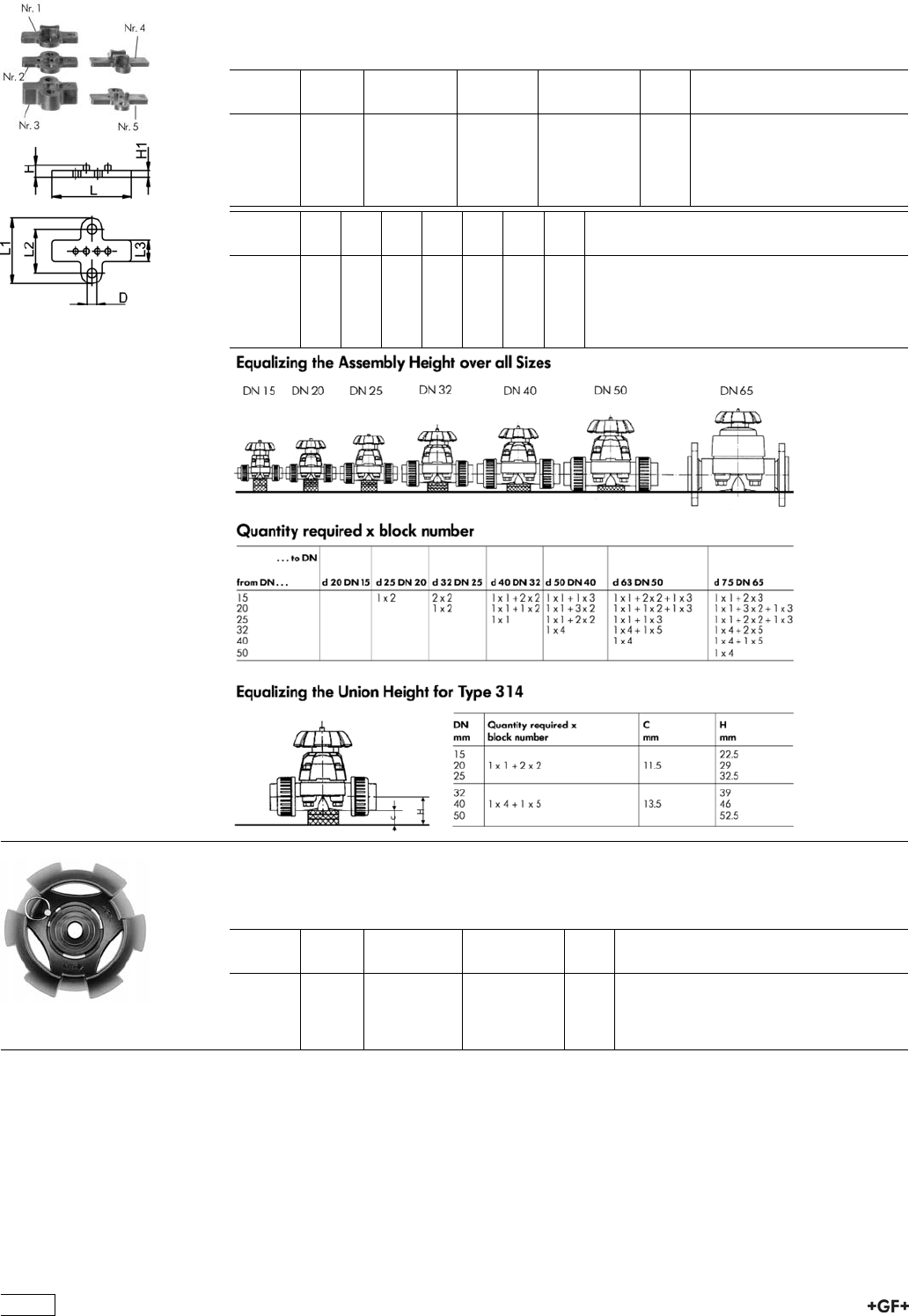
Accessories for Diaphragm Valves
Mounting block PP
ÏFor Diaphragm Valves 314, 315 and 317 (DN 15-50)
d-d
[mm]
DN-DN
[mm]
Inch Block no. Code kg
20 - 32 15 - 20 1/2 -1 1 167 480 422 0.005
16 - 20 10 - 15 3/8-1/2 2 167 480 423 0.003
- - 3 167 480 424 0.012
40 - 63 32 - 50 1 1/4 -2 1/2 4 167 480 425 0.017
- - 5 167 480 426 0.015
d-d
[mm]
D
[mm]
H
[mm]
H1
[mm]
L
[mm]
L1
[mm]
L2
[mm]
L3
[mm]
20 - 32 8 11 5 47 42 25 17
16 - 20 8 7 4 47 42 25 17
- 8 17 14 47 42 25 17
40 - 63 10 18 7 81 67 45 22
- 10 13 7 81 67 45 22
Handwheel with built-in locking mechanism
For diaphragm valve type 314 / 315 / 317 / 319
d-d
[mm]
DN-DN
[mm]
d-d
[inch]
Code kg
20 - 25 15 - 20 1
/2-3
/4167 481 943 0.032
32 - 25 - 1 - 167 481 944 0.043
40 - 50 32 - 40 1 1
/4- 1 1
/2167 481 945 0.071
63 - 75 50 - 65 2 - 2 1
/2167 481 946 0.217
138
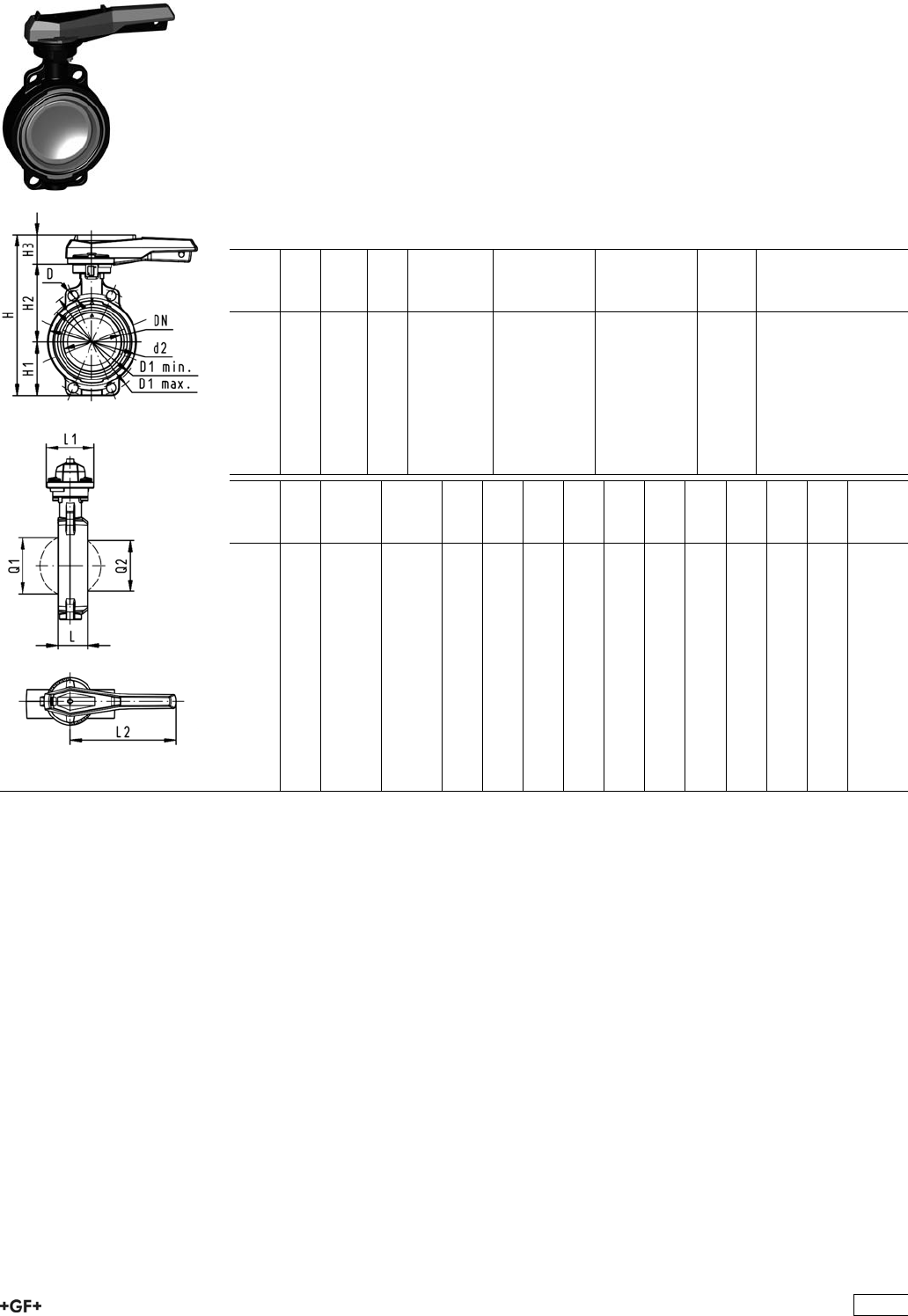
Butterfly valves
PROGEF Standard
Butterfly valve type 567
Hand lever with ratchet settings
Model:
ÏMaterial: PP-H
ÏConnecting dimension: ISO 7005 PN 10, EN 1092 PN 10, DIN 2501 PN 10,
ANSI/ASME B 16.5 Class 150, BS 1560: 1989, BS 4504, JIS B 2220
ÏOverall length according to EN 558, ISO 5752
ÏWe recommend for the dimensions DN250 and DN300 only 6 bar maximum system
pressure for the hand lever version
d
[mm]
DN
[mm]
Inch PN kv-value
(”p=1 bar)
[l/min]
EPDM
Code
FPM
Code
kg
63 50 2 10 1470 167 567 002 167 567 022 0.969
75 65 2 1
/210 2200 167 567 003 167 567 023 1.061
90 80 3 10 3000 167 567 004 167 567 024 1.191
110 100 4 10 6500 167 567 005 167 567 025 1.751
140 125 5 10 11500 167 567 006 167 567 026 2.199
160 150 6 10 16600 167 567 007 167 567 027 2.989
225 200 8 10 39600 167 567 008 167 567 028 4.706
280 250 10 8 55200 167 567 009 167 567 029 11.841
315 300 12 8 80000 167 567 010 167 567 030 14.816
d
[mm]
D
[mm]
D1
min.
[mm]
D1
max.
[mm]
d2
[mm]
H
[mm]
H1
[mm]
H2
[mm]
H3
[mm]
L
[mm]
L1
[mm]
L2
[mm]
Q1
[mm]
Q2
[mm]
63 19 120.0 125.0 104 264 77 134 54 45 106 205 40
75 19 139.7 145.0 115 277 83 140 54 46 106 205 54 35
90 19 150.0 160.0 131 289 89 146 54 49 106 205 67 50
110 19 175.0 190.5 161 325 104 167 55 56 106 255 88 74
140 23 210.0 215.9 187 352 117 181 55 64 106 255 113 97
160 24 241.3 241.3 215 373 130 189 55 72 106 255 139 123
225 23 290.0 295.0 267 435 158 210 67 73 140 408 178 169
280 25 353.0 362.0 329 554 205 264 85 113 149 408 210 207
315 25 400.0 432.0 379 598 228 285 85 113 149 408 256 253
139
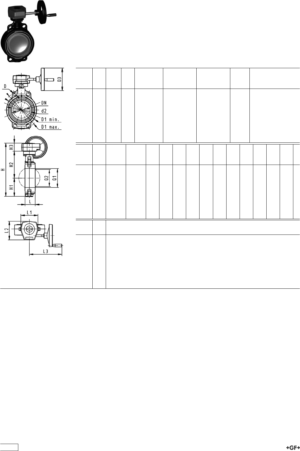
PROGEF Standard
Butterfly valve type 567
Reduction gear with handwheel
Model:
ÏMaterial: PP-H
ÏConnecting dimension: ISO 7005 PN 10, EN 1092 PN 10, DIN 2501 PN 10,
ANSI/ASME B 16.5 Class 150, BS 1560: 1989, BS 4504, JIS B 2220
ÏOverall length according to EN 558, ISO 5752
d
[mm]
DN
[mm]
Inch PN kv-value
(”p=1 bar)
[l/min]
EPDM
Code
FPM
Code
kg
63 50 2 10 1470 167 567 042 167 567 062 3.007
75 65 2 1
/210 2200 167 567 043 167 567 063 3.099
90 80 3 10 3000 167 567 044 167 567 064 3.229
110 100 4 10 6500 167 567 045 167 567 065 3.741
140 125 5 10 11500 167 567 046 167 567 066 4.189
160 150 6 10 16600 167 567 047 167 567 067 4.979
225 200 8 10 39600 167 567 048 167 567 068 6.159
280 250 10 8 55200 167 567 049 167 567 069 13.091
315 300 12 8 80000 167 567 050 167 567 070 16.066
d
[mm]
D
[mm]
D1
min.
[mm]
D1
max.
[mm]
d2
[mm]
D3
[mm]
H
[mm]
H1
[mm]
H2
[mm]
H3
[mm]
L
[mm]
L1
[mm]
L2
[mm]
L3
[mm]
Q1
[mm]
63 19 120.0 125.0 104 160 278 77 134 60 45 120 132 236 40
75 19 139.7 145.0 115 160 291 83 140 60 46 120 132 236 54
90 19 150.0 160.0 131 160 303 89 146 60 49 120 132 236 67
110 19 175.0 190.5 160 160 339 104 167 60 56 120 132 236 88
140 23 210.0 215.9 187 160 365 117 181 60 64 120 132 236 113
160 24 241.3 241.3 215 160 387 130 189 60 72 120 132 236 139
225 23 290.0 295.0 267 160 436 158 210 60 73 120 132 236 178
280 25 353.0 362.0 329 160 529 205 264 60 113 134 151 261 210
315 25 400.0 432.0 379 160 573 228 285 60 113 134 151 261 256
d
[mm]
Q2
[mm]
63
75 35
90 50
110 74
140 97
160 123
225 169
280 207
315 253
140
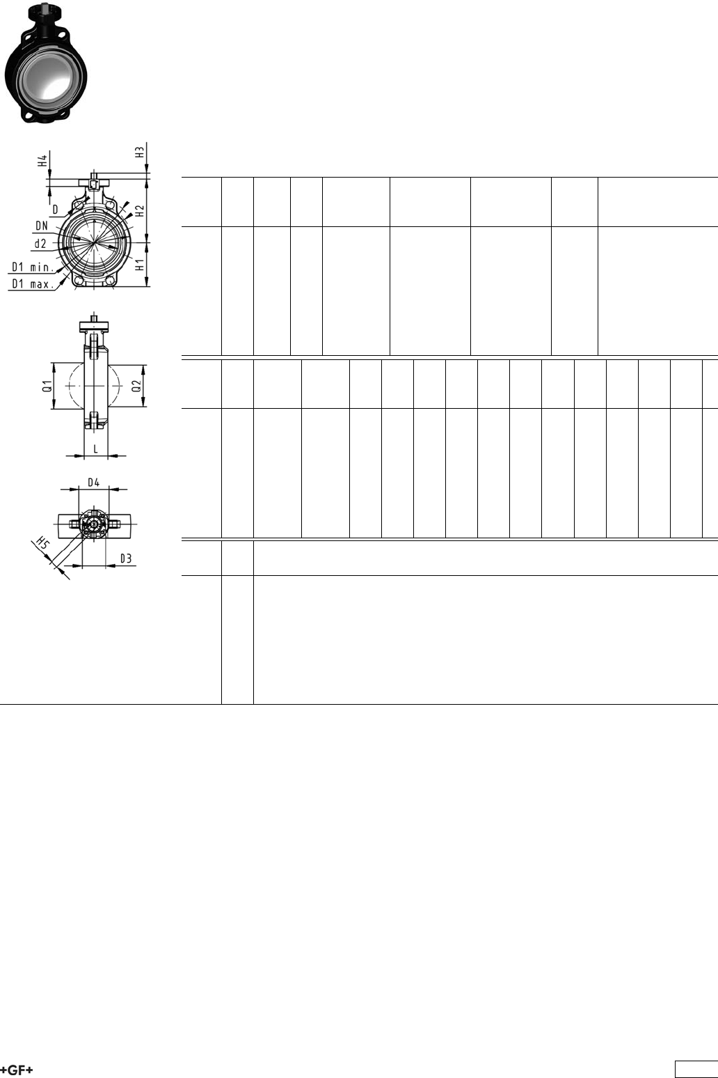
Butterfly valve type 567 PP-H
Bare shaft
Model:
ÏMaterial: PP-H
ÏConnecting dimension: ISO 7005 PN 10, EN 1092 PN 10, DIN 2501 PN 10,
ANSI/ASME B 16.5 Class 150, BS 1560: 1989, BS 4504, JIS B 2220
ÏOverall length according to EN 558, ISO 5752
ÏInterface F07 for the dimensions DN50-200 according to DIN/ISO 5211
ÏInterface F10 for the dimensions DN250-300 according to DIN/ISO 5211
d
[mm]
DN
[mm]
Inch PN kv-value
(”p=1 bar)
[l/min]
EPDM
Code
FPM
Code
kg
63 50 2 10 1470 167 567 802 167 567 822 0.747
75 65 2 1
/210 2200 167 567 803 167 567 823 0.839
90 80 3 10 3000 167 567 804 167 567 824 0.969
110 100 4 10 6500 167 567 805 167 567 825 1.481
140 125 5 10 11500 167 567 806 167 567 826 1.929
160 150 6 10 16600 167 567 807 167 567 827 2.719
225 200 8 10 39600 167 567 808 167 567 828 3.899
280 250 10 8 55200 167 567 809 167 567 829 10.251
315 300 12 8 80000 167 567 810 167 567 830 13.226
d
[mm]
D
[mm]
D1
min.
[mm]
D1
max.
[mm]
d2
[mm]
D3
[mm]
D4
[mm]
H
[mm]
H1
[mm]
H2
[mm]
H3
[mm]
H4
[mm]
H5
[mm]
L
[mm]
Q1
[mm]
63 19 120.0 125.0 104 70 90 222 77 134 27 23 11 45 40
75 19 139.7 145.0 115 70 90 235 83 140 27 23 11 46 54
90 19 150.0 160.0 131 70 90 247 89 146 27 23 11 49 67
110 19 175.0 190.5 161 70 90 287 104 167 16 23 14 56 88
140 23 210.0 215.9 187 70 90 313 117 181 16 23 14 64 113
160 24 241.3 241.3 215 70 90 335 130 189 19 23 17 72 139
225 23 290.0 295.0 267 70 90 387 158 210 19 23 17 73 178
280 25 353.0 362.0 329 102 125 509 205 264 40 23 22 113 210
315 25 400.0 432.0 379 102 125 553 228 285 40 23 22 113 256
d
[mm]
Q2
[mm]
63
75 35
90 50
110 74
140 97
160 123
225 169
280 207
315 253
141

PROGEF Standard
Lugstyle butterfly valve type 568
Hand lever with ratchet settings
Model:
ÏMaterial: PP-H
ÏOuter body in GGG-40.3 epoxy-coated
ÏConnecting dimension: ISO 7005 PN10, EN 1092 PN10, DIN 2501 PN10
ÏOverall length according to EN 558, ISO 5752
d
[mm]
DN
[mm]
Inch PN kv-value
(”p=1 bar)
[l/min]
EPDM
Code
FPM
Code
kg
63 50 2 10 1470 167 568 002 167 568 022 3.055
75 65 2 1
/210 2200 167 568 003 167 568 023 3.397
90 80 3 10 3000 167 568 004 167 568 024 4.402
110 100 4 10 6500 167 568 005 167 568 025 5.835
140 125 5 10 11500 167 568 006 167 568 026 7.665
160 150 6 10 16600 167 568 007 167 568 027 9.449
225 200 8 10 39600 167 568 008 167 568 028 14.654
d
[mm]
d2
[mm]
D D1
[mm]
H
[mm]
H1
[mm]
H2
[mm]
H3
[mm]
L
[mm]
L1
[mm]
L2
[mm]
L3
[mm]
Q1
[mm]
Q2
[mm]
63 150 M16 125 265 77 134 54 45 106 205 150 40
75 170 M16 145 277 83 140 54 46 106 205 160 54 35
90 184 M16 160 289 89 146 54 49 106 205 205 67 50
110 216 M16 180 326 104 167 55 56 106 255 244 88 74
140 246 M16 210 353 117 181 55 64 106 255 272 113 97
160 273 M20 240 374 130 189 55 72 106 255 297 139 123
225 334 M20 295 435 158 210 67 73 140 408 360 178 169
142
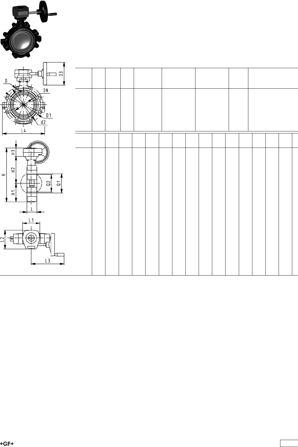
PROGEF Standard
Lugstyle butterfly valve type 568
Reduction gear with handwheel
Model:
ÏMaterial: PP-H
ÏOuter body in GGG-40.3 epoxy-coated
ÏConnecting dimension: ISO 7005 PN10, EN 1092 PN10, DIN 2501 PN10
ÏOverall length according to EN 558, ISO 5752
d
[mm]
DN
[mm]
Inch PN kv-value
(”p=1 bar)
[l/min]
EPDM
Code
FPM
Code
kg
63 50 2 10 1470 167 568 042 167 568 062 5.093
75 65 2 1
/210 2200 167 568 043 167 568 063 5.435
90 80 3 10 3000 167 568 044 167 568 064 6.440
110 100 4 10 6500 167 568 045 167 568 065 7.825
140 125 5 10 11500 167 568 046 167 568 066 9.655
160 150 6 10 16600 167 568 047 167 568 067 11.439
225 200 8 10 39600 167 568 048 167 568 068 16.107
d
[mm]
d2
[mm]
D D1
[mm]
D3
[mm]
H
[mm]
H1
[mm]
H2
[mm]
H3
[mm]
L
[mm]
L1
[mm]
L2
[mm]
L3
[mm]
L4
[mm]
Q1
[mm]
Q2
[mm]
63 150 M16 125 160 279 77 134 60 45 120 132 236 150 40
75 170 M16 145 160 291 83 140 60 46 120 132 236 160 54 35
90 184 M16 160 160 303 89 146 60 49 120 132 236 205 67 50
110 216 M16 180 160 339 104 167 60 56 120 132 236 244 88 74
140 246 M16 210 160 366 117 181 60 64 120 132 236 272 113 97
160 273 M20 240 160 387 130 189 60 72 120 132 236 297 139 123
225 334 M20 295 160 436 158 210 60 73 120 132 236 360 178 169
143
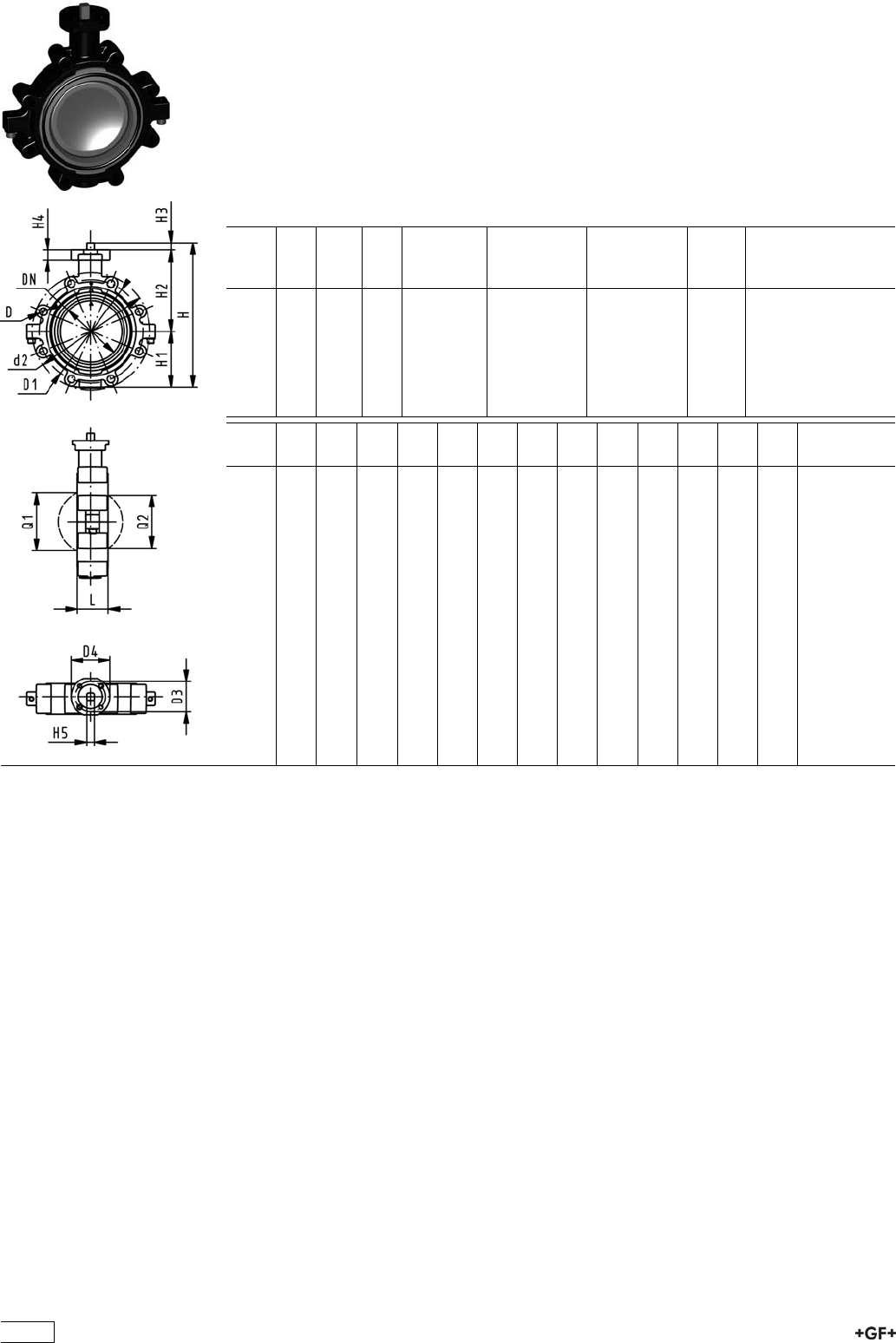
PROGEF Standard
Lugstyle butterfly valve type 568
Bare shaft
Model:
ÏMaterial: PP-H
ÏOuter body in GGG-40.3 epoxy-coated
ÏConnecting dimension: ISO 7005 PN10, EN 1092 PN10, DIN 2501 PN10
ÏOverall length according to EN 558, ISO 5752
ÏInterface F07 according to DIN/ISO 5211
d
[mm]
DN
[mm]
Inch PN kv-value
(”p=1 bar)
[l/min]
EPDM
Code
FPM
Code
kg
63 50 2 10 1470 167 568 802 167 568 822 2.833
75 65 2 1
/210 2200 167 568 803 167 568 823 3.175
90 80 3 10 3000 167 568 804 167 568 824 4.180
110 100 4 10 6500 167 568 805 167 568 825 5.565
140 125 5 10 11500 167 568 806 167 568 826 7.395
160 150 6 10 16600 167 568 807 167 568 827 9.179
225 200 8 10 39600 167 568 808 167 568 828 13.847
d
[mm]
d2
[mm]
D D1
[mm]
D3
[mm]
D4
[mm]
H
[mm]
H1
[mm]
H2
[mm]
H3
[mm]
H4
[mm]
L
[mm]
Q1
[mm]
Q2
[mm]
63 150 M16 125 70 90 222 77 134 27 23 45 40
75 170 M16 145 70 90 235 83 140 27 23 46 54 35
90 184 M16 160 70 90 247 89 146 27 23 49 67 50
110 216 M16 180 70 90 287 104 167 16 23 56 88 74
140 246 M16 210 70 90 313 117 181 16 23 64 113 97
160 273 M20 240 70 90 335 130 189 19 23 72 139 123
225 334 M20 295 70 90 387 158 210 19 23 73 178 169
144
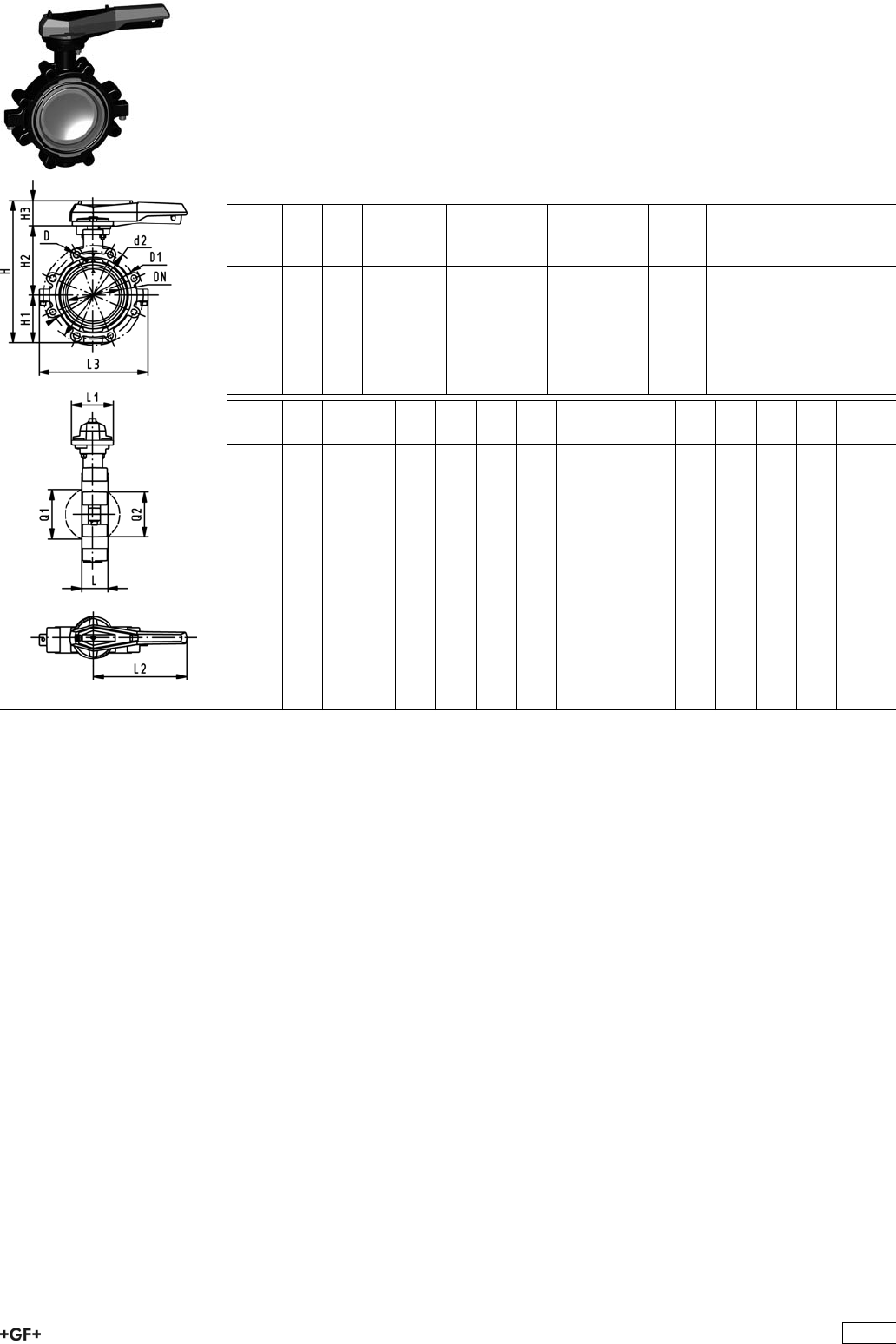
PROGEF Standard
Lugstyle butterfly valve type 568
Hand lever with ratchet settings
Model:
ÏMaterial: PP-H
ÏOuter body in GGG-40.3 epoxy-coated
ÏConnecting dimension ANSI/ASME B 16.5 Class 150
ÏOverall length according to EN 558, ISO 5752
Inch DN
[mm]
PN kv-value
(”p=1 bar)
[l/min]
EPDM
Code
FPM
Code
kg
2 50 10 1470 167 568 102 167 568 122 3.055
21
/265 10 2200 167 568 103 167 568 123 3.397
3 80 10 3000 167 568 104 167 568 124 3.773
4 100 10 6500 167 568 105 167 568 125 5.835
5 125 10 11500 167 568 106 167 568 126 7.665
6 150 10 16600 167 568 107 167 568 127 9.449
8 200 10 39600 167 568 108 167 568 128 14.654
Inch d2
[mm]
D D1
[mm]
H
[mm]
H1
[mm]
H2
[mm]
H3
[mm]
L
[mm]
L1
[mm]
L2
[mm]
L3
[mm]
Q1
[mm]
Q2
[mm]
2 150 UNC 5/8 121 265 77 134 54 45 106 205 150 40
21
/2170 UNC 5/8 138 277 83 140 54 46 106 205 160 54 35
3 177 UNC 5/8 152 289 89 146 54 49 106 205 175 67 50
4 216 UNC 5/8 191 326 104 167 55 56 106 255 244 88 74
5 246 UNC 3/4 216 353 117 181 55 64 106 255 272 113 97
6 273 UNC 3/4 241 374 130 189 55 72 106 255 297 139 123
8 334 UNC 3/4 298 435 158 210 67 73 140 408 360 178 169
145
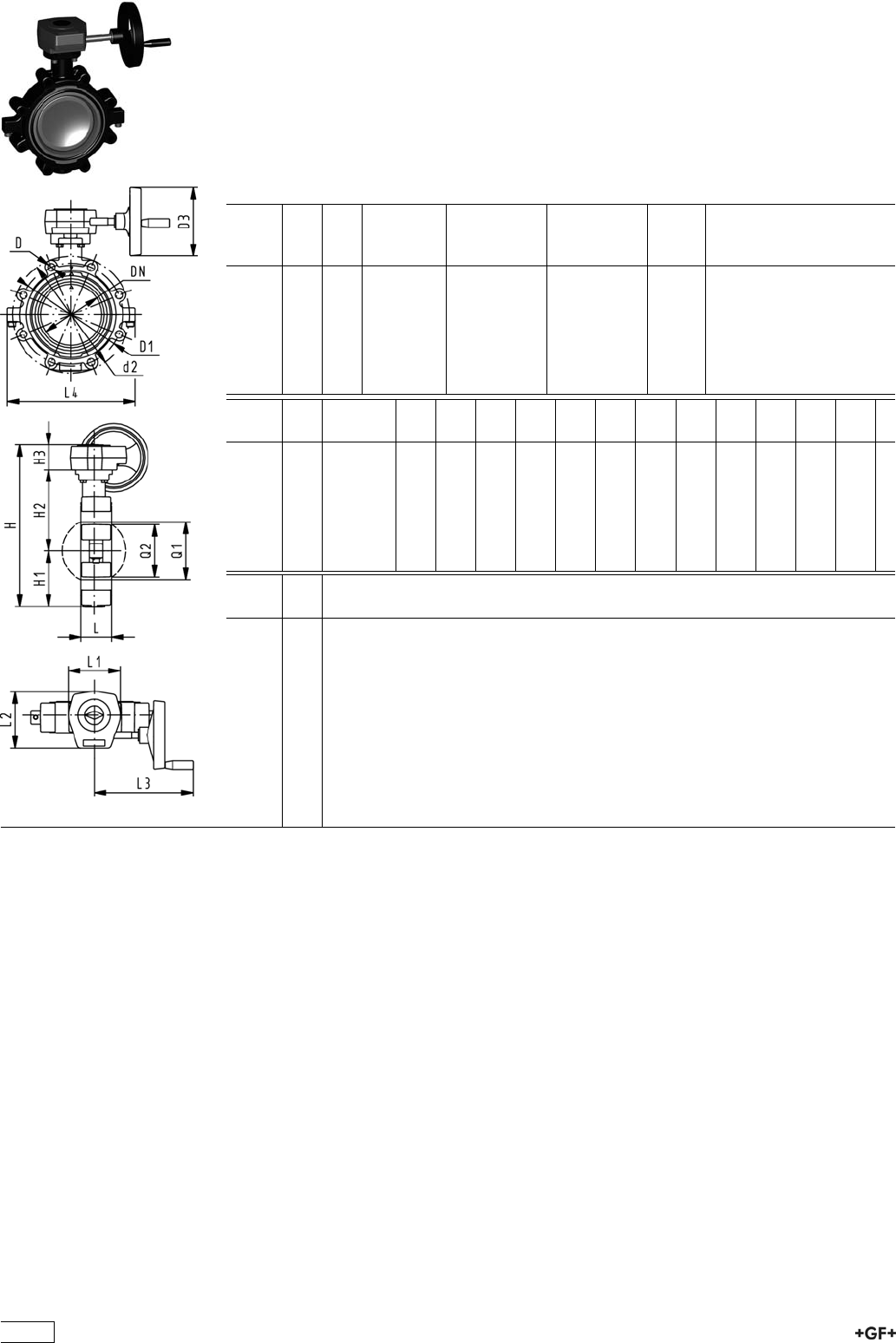
PROGEF Standard
Lugstyle butterfly valve type 568
Reduction gear with handwheel
Model:
ÏMaterial: PP-H
ÏOuter body in GGG-40.3 epoxy-coated
ÏConnecting dimension ANSI/ASME B 16.5 Class 150
ÏOverall length according to EN 558, ISO 5752
Inch DN
[mm]
PN kv-value
(”p=1 bar)
[l/min]
EPDM
Code
FPM
Code
kg
2 50 10 1470 167 568 142 167 568 162 5.093
21
/265 10 2200 167 568 143 167 568 163 5.435
3 80 10 3000 167 568 144 167 568 164 5.811
4 100 10 6500 167 568 145 167 568 165 7.825
5 125 10 11500 167 568 146 167 568 166 9.655
6 150 10 16600 167 568 147 167 568 167 11.439
8 200 10 39600 167 568 148 167 568 168 16.107
Inch d2
[mm]
D D1
[mm]
D3
[mm]
H
[mm]
H1
[mm]
H2
[mm]
H3
[mm]
L
[mm]
L1
[mm]
L2
[mm]
L3
[mm]
L4
[mm]
Q1
[mm]
2 150 UNC 5/8 121 160 279 77 134 60 45 120 132 236 150 40
21
/2170 UNC 5/8 138 160 291 83 140 60 46 120 132 236 160 54
3 177 UNC 5/8 152 160 303 89 146 60 49 120 132 236 175 67
4 216 UNC 5/8 191 160 339 104 167 60 56 120 132 236 244 88
5 246 UNC 3/4 216 160 366 117 181 60 64 120 132 236 272 113
6 273 UNC 3/4 241 160 387 130 189 60 72 120 132 236 297 139
8 334 UNC 3/4 298 160 436 158 210 60 73 120 132 236 360 178
Inch Q2
[mm]
2
21
/235
3 50
4 74
5 97
6 123
8 169
146
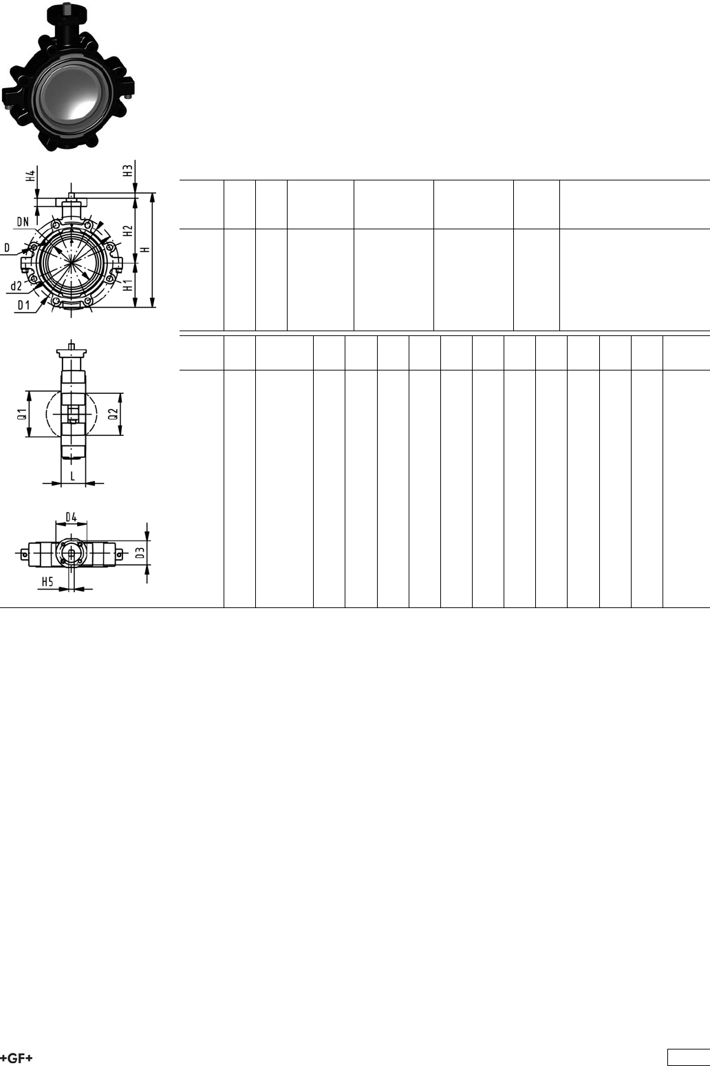
PROGEF Standard
Lugstyle butterfly valve type 568
Bare shaft
Model:
ÏMaterial: PP-H
ÏOuter body in GGG-40.3 epoxy-coated
ÏConnecting dimension ANSI/ASME B 16.5 Class 150
ÏOverall length according to EN 558, ISO 5752
ÏInterface F07 according to DIN/ISO 5211
Inch DN
[mm]
PN kv-value
(”p=1 bar)
[l/min]
EPDM
Code
FPM
Code
kg
2 50 10 1470 167 568 902 167 568 922 2.833
21
/265 10 2200 167 568 903 167 568 923 3.175
3 80 10 3000 167 568 904 167 568 924 3.551
4 100 10 6500 167 568 905 167 568 925 5.565
5 125 10 11500 167 568 906 167 568 926 7.395
6 150 10 16600 167 568 907 167 568 927 9.179
8 200 10 39600 167 568 908 167 568 928 13.847
Inch d2
[mm]
D D1
[mm]
D3
[mm]
D4
[mm]
H
[mm]
H1
[mm]
H2
[mm]
H3
[mm]
H4
[mm]
L
[mm]
Q1
[mm]
Q2
[mm]
2 150 UNC 5/8 121 70 90 222 77 134 27 23 45 40
21
/2170 UNC 5/8 138 70 90 235 83 140 27 23 46 54 35
3 177 UNC 5/8 152 70 90 247 89 146 27 23 49 67 50
4 216 UNC 5/8 191 70 90 287 104 167 16 23 56 88 74
5 246 UNC 3/4 216 70 90 313 117 181 16 23 64 113 97
6 273 UNC 3/4 241 70 90 335 130 189 19 23 72 139 123
8 334 UNC 3/4 298 70 90 387 158 210 19 23 73 178 169
147
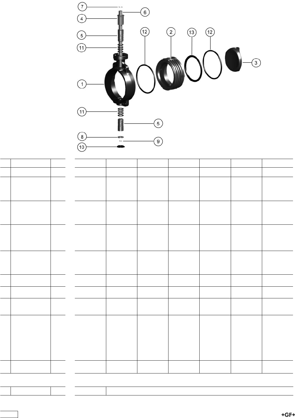
Spare parts for butterfly valve type 567 PP-H
Hand lever with index plate
No. Article / Material Pieces d63 DN50 d75 DN65 d90 DN80 d110 DN100 d140 DN125 d160 DN150 d225 DN200
3 Disc PP-H 1 167 483 226 167 483 227 167 483 228 167 483 229 167 483 230 167 483 231 167 483 232
Bearing bush 167 484 259 167 484 259 167 484 259 167 484 260 167 484 260 167 484 261 167 484 261
5 Bush PP-H 2
11 O-ring EPDM
Bearing bush 167 484 265 167 484 265 167 484 265 167 484 266 167 484 266 167 484 267 167 484 267
5 Bush PP-H 2
11 O-ring FPM
Inner body 167 484 271 167 484 272 167 484 273 167 484 274 167 484 275 167 484 276 167 484 277
2 Body PP-H 1
13 Profile seal
EPDM
1
Inner body 167 484 286 167 484 287 167 484 288 167 484 289 167 484 290 167 484 291 167 484 292
2 Body PP-H 1
13 Profile seal FPM 1
12 Flange gasket
EPDM
2 161 486 959 161 486 960 161 486 961 161 486 962 161 486 963 161 486 964 161 486 965
12 Flange gasket
FPM
2 161 486 979 161 486 980 161 486 981 161 486 982 161 486 983 161 486 984 161 486 985
4 End stop PP
Glasfiber
Reinforced
1 167 483 251 167 483 251 167 483 251 167 483 252 167 483 252 167 483 253 167 483 253
Shaft set 161 486 899 161 486 900 161 486 901 161 486 902 161 486 903 161 486 904 161 486 905
6 Shaft Chrom
Steel 1.4301
AISI 304
1
7+9 Retention ring 2
8 Washer 1
Lever with index
plate
1 161 486 690 161 486 690 161 486 690 161 486 691 161 486 691 161 486 694 161 486 695
No. Article / Material Pieces d280 DN250 d315 DN300
148
No. Article / Material Pieces d280 DN250 d315 DN300
3 Disc PP-H 1 167 483 233 167 483 234
Bearing bush 167 484 262 167 484 262
5 Bush PP-H 2
11 O-ring EPDM
Bearing bush 167 484 268 167 484 268
5 Bush PP-H 2
11 O-ring FPM
Inner body 167 484 278 167 484 279
2 Body PP-H 1
13 Profile seal
EPDM
1
Inner body 167 484 293 167 484 294
2 Body PP-H 1
13 Profile seal FPM 1
12 Flange gasket
EPDM
2 161 486 966 161 486 967
12 Flange gasket
FPM
2 161 486 986 161 486 987
4 End stop PP
Glasfiber
Reinforced
1 167 483 254 167 483 254
Shaft set 161 486 906 161 486 907
6 Shaft Chrom
Steel 1.4301
AISI 304
1
7+9 Retention ring 2
8 Washer 1
Lever with index
plate
1 161 486 697 161 486 697
149
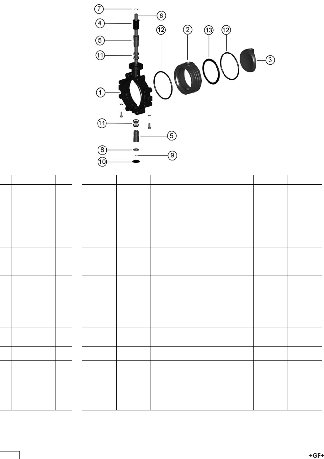
Spare parts for butterfly valve type 568 PP-H
Hand lever with index plate
No. Article / Material Pieces d63 DN50 d75 DN65 d90 DN80 d110 DN100 d140 DN125 d160 DN150 d225 DN200
3 Disc PP-H 1 167 483 226 167 483 227 167 483 228 167 483 229 167 483 230 167 483 231 167 483 232
Bearing bush 167 484 259 167 484 259 167 484 259 167 484 260 167 484 260 167 484 261 167 484 261
5 Bush PP-H 2
11 O-ring EPDM
Bearing bush 167 484 265 167 484 265 167 484 265 167 484 266 167 484 266 167 484 267 167 484 267
5 Bush PP-H 2
11 O-ring FPM
Inner body 167 484 271 167 484 272 167 484 273 167 484 274 167 484 275 167 484 276 167 484 277
2 Body PP-H 1
13 Profile seal
EPDM
1
Inner body 167 484 286 167 484 287 167 484 288 167 484 289 167 484 290 167 484 291 167 484 292
2 Body PP-H 1
13 Profile seal FPM 1
12 Flange gasket
EPDM
2 161 486 959 161 486 960 161 486 961 161 486 962 161 486 963 161 486 964 161 486 965
12 Flange gasket
FPM
2 161 486 979 161 486 980 161 486 981 161 486 982 161 486 983 161 486 984 161 486 985
4 End stop PP
Glasfiber
Reinforced
1 167 486 251 167 486 251 167 486 251 167 483 252 167 483 252 167 483 253 167 483 253
Lever with index
plate
1 161 486 690 161 486 690 161 486 690 161 486 691 161 486 691 161 486 694 161 486 695
Shaft set 161 486 899 161 486 900 161 486 901 161 486 902 161 486 903 161 486 904 161 486 905
6 Shaft Chrom
Steel 1.4301
AISI 304
1
7+9 Retention ring 2
8 Washer 1
150
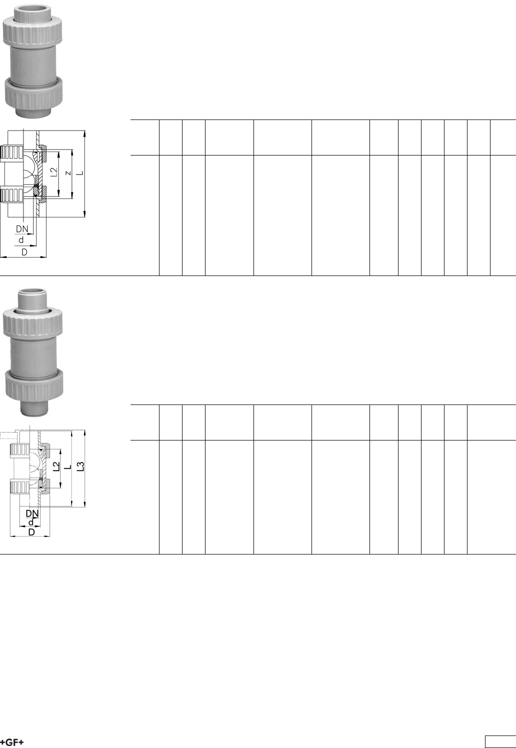
Ball Check Valves 360
PROGEF Standard
Ball check valve type 360
With fusion sockets metric
Model:
ÏMaterial: PP-H
ÏFor easy installation and removal
ÏThe ball seals at a minimum water column of 2 m
ÏVibration free even at high flow velocity
d
[mm]
DN
[mm]
PN kv-value
(”p=1 bar)
[l/min]
EPDM
Code
FPM
Code
kg D
[mm]
L
[mm]
L2
[mm]
z
[mm]
16 10 10 170 167 360 401 167 360 411 0.079 46 98 62 72
20 15 10 150 167 360 402 167 360 412 0.079 46 101 62 73
25 20 10 330 167 360 403 167 360 413 0.134 56 119 74 87
32 25 10 390 167 360 404 167 360 414 0.203 67 130 78 94
40 32 10 710 167 360 405 167 360 415 0.380 82 149 88 109
50 40 10 900 167 360 406 167 360 416 0.612 98 162 94 118
63 50 10 1390 167 360 407 167 360 417 1.116 120 195 113 143
PROGEF Standard
Ball check valve type 360
With socket fusion spigots metric
Model:
ÏMaterial: PP-H
ÏFor easy installation and removal
ÏThe ball seals at a minimum water column of 2 m
ÏVibration free even at high flow velocity
d
[mm]
DN
[mm]
PN kv-value
(”p=1 bar)
[l/min]
EPDM
Code
FPM
Code
kg D
[mm]
L
[mm]
L2
[mm]
16 10 10 170 167 360 441 167 360 451 0.080 46 109 62
20 15 10 150 167 360 442 167 360 452 0.080 46 119 62
25 20 10 330 167 360 443 167 360 453 0.136 56 140 74
32 25 10 390 167 360 444 167 360 454 0.208 67 150 78
40 32 10 710 167 360 445 167 360 455 0.386 82 171 88
50 40 10 900 167 360 446 167 360 456 0.631 97 191 94
63 50 10 1390 167 360 447 167 360 457 1.149 119 220 113
151
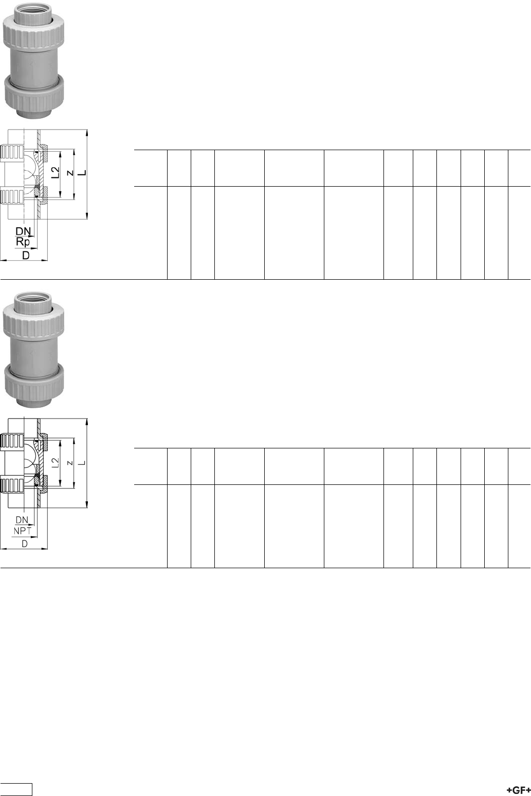
PROGEF Standard
Ball check valve type 360
With threaded sockets Rp
Model:
ÏMaterial: PP-H
ÏFor easy installation and removal
ÏThe ball seals at a minimum water column of 2 m
ÏVibration free even at high flow velocity
ÏParallel female thread Rp
Rp
[inch]
DN
[mm]
PN kv-value
(”p=1 bar)
[l/min]
EPDM
Code
FPM
Code
kg z
[mm]
D
[mm]
L
[mm]
L2
[mm]
3
/810 10 170 167 360 421 167 360 431 0.078 66 46 98 62
1
/215 10 150 167 360 422 167 360 432 0.078 66 46 101 62
3
/420 10 330 167 360 423 167 360 433 0.131 78 56 119 74
1 25 10 390 167 360 424 167 360 434 0.199 82 67 130 78
11
/432 10 710 167 360 425 167 360 435 0.372 95 82 149 88
11
/240 10 900 167 360 426 167 360 436 0.618 108 98 162 94
2 50 10 1390 167 360 427 167 360 437 1.129 134 120 195 113
PROGEF Standard
Ball check valve type 360
With threaded sockets NPT
Model:
ÏMaterial: PP-H
ÏFor easy installation and removal
ÏThe ball seals at a minimum water column of 2 m
ÏVibration free even at high flow velocity
ÏWith tapered female thread NPT*
* Not available from stock
NPT
[inch]
DN
[mm]
PN kv-value
(”p=1 bar)
[l/min]
EPDM
Code
FPM
Code
kg z
[mm]
D
[mm]
L
[mm]
L2
[mm]
3
/810 10 170 167 360 581 167 360 591 0.078 75 46 111 62
1
/215 10 150 167 360 582 167 360 592 0.078 68 46 111 62
3
/420 10 330 167 360 583 167 360 593 0.131 89 56 130 74
1 25 10 330 167 360 584 167 360 594 0.199 88 67 140 78
11
/432 10 710 167 360 585 167 360 595 0.372 111 82 165 88
11
/240 10 900 167 360 586 167 360 596 0.618 109 98 169 94
2 50 10 1390 167 360 587 167 360 597 1.129 136 120 199 113
152

Ball check valve type 360 PP-H
With butt fusion spigots SDR11
Model:
ÏMaterial: PP-H
ÏFor easy installation and removal
ÏThe ball seals at a minimum water column of 2 m
ÏVibration free even at high flow velocity
d
[mm]
DN
[mm]
PN kv-value
(”p=1 bar)
[l/min]
EPDM
Code
FPM
Code
kg D
[mm]
L
[mm]
L2
[mm]
20 15 10 150 167 360 482 167 360 492 0.080 46 130 62
25 20 10 330 167 360 483 167 360 493 0.136 56 144 74
32 25 10 390 167 360 484 167 360 494 0.208 67 150 78
40 32 10 710 167 360 485 167 360 495 0.386 82 171 88
50 40 10 900 167 360 486 167 360 496 0.631 97 191 94
63 50 10 1390 167 360 487 167 360 497 1.149 119 220 113
PROGEF Standard
Ball check valve type 360
With butt fusion spigots SDR17
Model:
ÏMaterial: PP-H
ÏFor easy installation and removal
ÏThe ball seals at a minimum water column of 2 m
ÏVibration free even at high flow velocity
d
[mm]
DN
[mm]
PN kv-value
(”p=1 bar)
[l/min]
EPDM
Code
FPM
Code
kg D
[mm]
L
[mm]
L2
[mm]
25 20 6 330 167 360 463 167 360 473 0.136 56 144 74
32 25 6 390 167 360 464 167 360 474 0.208 67 150 78
40 32 6 710 167 360 465 167 360 475 0.386 82 171 88
50 40 6 900 167 360 466 167 360 476 0.631 97 191 94
63 50 6 1390 167 360 467 167 360 477 1.149 119 220 113
153
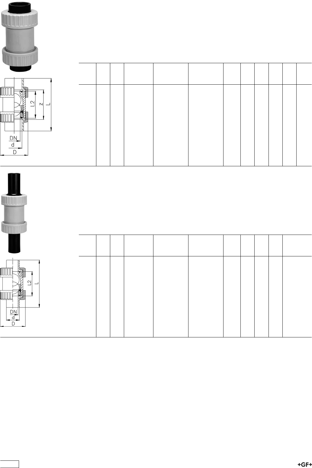
Ball check valve type 360 PP-H
With fusion sockets PE80 metric
Model:
ÏMaterial: PP-H
ÏFor easy installation and removal
ÏThe ball seals at a minimum water column of 2 m
ÏVibration free even at high flow velocity
d
[mm]
DN
[mm]
PN kv-value
(”p=1 bar)
[l/min]
EPDM
Code
FPM
Code
kg D
[mm]
L
[mm]
L2
[mm]
z
[mm]
16 10 10 170 167 360 721 167 360 731 0.079 46 98 62 72
20 15 10 150 167 360 722 167 360 732 0.079 46 101 62 73
25 20 10 330 167 360 723 167 360 733 0.134 56 119 74 87
32 25 10 390 167 360 724 167 360 734 0.203 67 130 78 94
40 32 10 710 167 360 725 167 360 735 0.380 82 149 88 109
50 40 10 900 167 360 726 167 360 736 0.612 98 162 94 118
63 50 10 1390 167 360 727 167 360 737 1.116 120 195 113 143
Ball check valve type 360 PP-H
With spigots for electro fusion PE100 SDR11
Model:
ÏMaterial: PP-H
ÏFor easy installation and removal
ÏThe ball seals at a minimum water column of 2 m
ÏVibration free even at high flow velocity
d
[mm]
DN
[mm]
PN kv-value
(”p=1 bar)
[l/min]
EPDM
Code
FPM
Code
kg D
[mm]
L
[mm]
L2
[mm]
20 15 10 150 167 360 682 167 360 692 0.080 46 196 62
25 20 10 330 167 360 683 167 360 693 0.136 56 216 74
32 25 10 390 167 360 684 167 360 694 0.208 67 224 78
40 32 10 710 167 360 685 167 360 695 0.386 82 250 88
50 40 10 900 167 360 686 167 360 696 0.631 97 268 94
63 50 10 1390 167 360 687 167 360 697 1.149 119 299 113
154
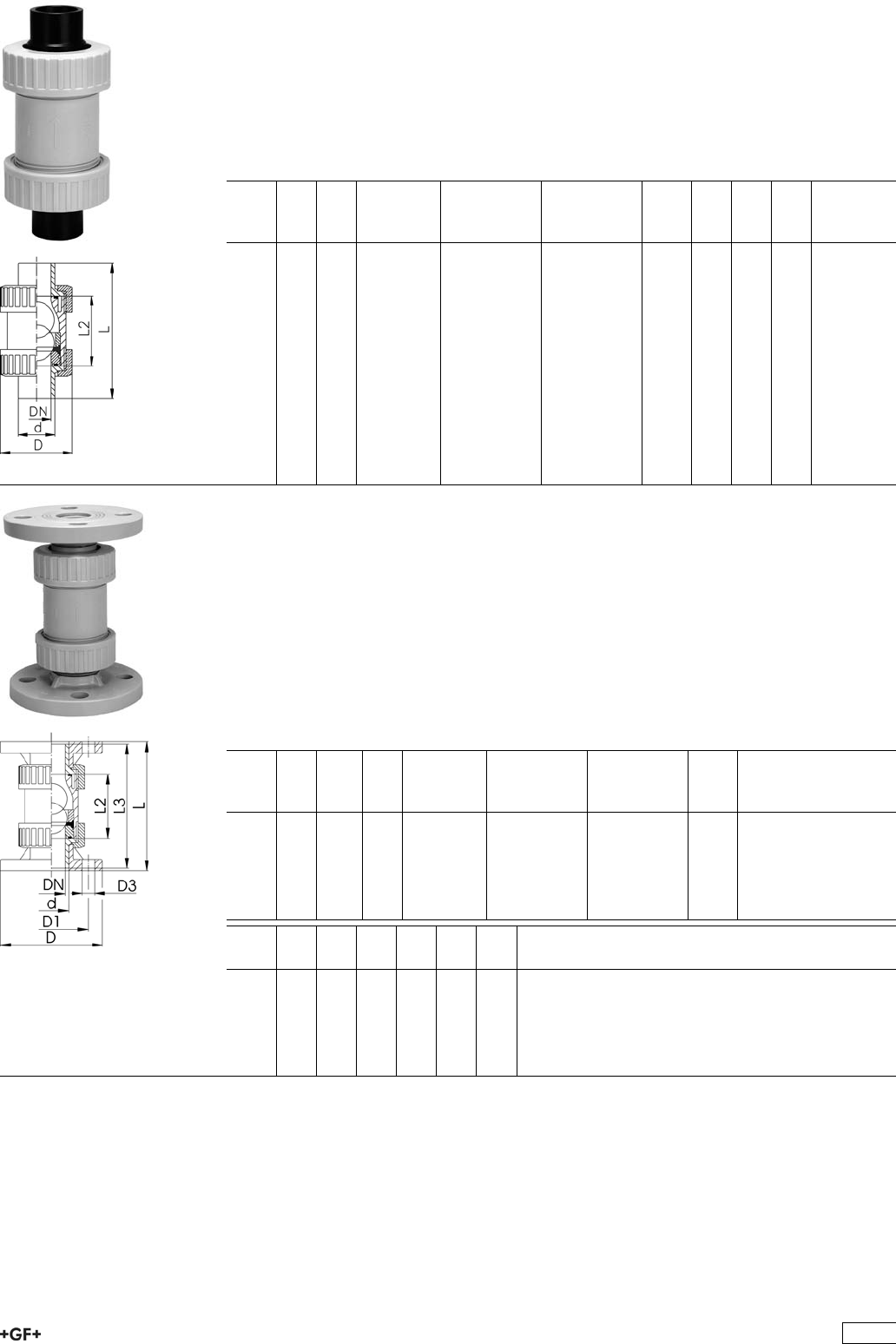
Ball check valve type 360 PP-H
With butt fusion spigots PE100 SDR17
Model:
ÏMaterial: PP-H
ÏFor easy installation and removal
ÏThe ball seals at a minimum water column of 2 m
ÏVibration free even at high flow velocity
d
[mm]
DN
[mm]
PN kv-value
(”p=1 bar)
[l/min]
EPDM
Code
FPM
Code
kg D
[mm]
L
[mm]
L2
[mm]
40 32 6 710 167 360 665 167 360 675 0.386 82 171 88
50 40 6 900 167 360 666 167 360 676 0.631 97 191 94
63 50 6 1390 167 360 667 167 360 677 1.149 119 220 113
PROGEF Standard
Ball check valve type 360
With fixed flanges serrated metric
Model:
ÏMaterial: PP-H
ÏFor easy installation and removal
ÏThe ball seals at a minimum water column of 2 m
ÏVibration free even at high flow velocity
ÏOverall length EN 558
ÏConnecting dimensions: ISO 7005 / EN 1092 / DIN 2501 PN10 / BS4504
d
[mm]
DN
[mm]
Inch PN kv-value
(”p=1 bar)
[l/min]
EPDM
Code
FPM
Code
kg
20 15 1
/210 150 167 360 502 167 360 512 0.206
25 20 3
/410 330 167 360 503 167 360 513 0.299
32 25 1 10 390 167 360 504 167 360 514 0.437
40 32 1 1
/410 710 167 360 505 167 360 515 0.731
50 40 1 1
/210 900 167 360 506 167 360 516 1.044
63 50 2 10 1390 167 360 507 167 360 517 1.711
d
[mm]
D
[mm]
D1
[mm]
D3
[mm]
L
[mm]
L2
[mm]
L3
[mm]
20 95 65 14 130 62 119
25 105 75 14 150 74 140
32 115 85 14 160 78 150
40 140 100 18 180 88 171
50 150 110 18 200 94 191
63 165 125 18 230 113 220
155
Component Parts for Flange Assembly Ball
Check Valves Type 360
27 79 02 PROGEF Standard, Flange Adaptor
Jointing face flat/serrated
d
[mm]
PN Code kg
20 10 727 790 206 0.011
25 10 727 790 207 0.022
32 10 727 790 208 0.033
40 10 727 790 209 0.046
50 10 727 790 210 0.062
63 10 727 790 211 0.090
75 10 727 790 212 0.163
90 10 727 790 213 0.233
110 10 727 790 214 0.319
PROGEF Standard, Special Flange Adaptors, PP-H
S5/SDR11
Jointing Face, combination serrated / flat
metric
d
[mm]
DN
[mm]
FM Code kg
75 65 IR 727 798 512 0.243
90 80 IR 727 798 513 0.326
90 80 IR 727 798 663 0.346
110 100 IR 727 798 514 0.441
125 100 IR 727 798 515 0.520
140 125 IR 727 798 516 0.800
160 150 IR 727 798 517 0.920
180 150 IR 727 798 568 0.900
200 200 IR 727 798 519 1.670
225 200 IR 727 798 520 1.700
250 250 -- 727 798 571 2.790
280 250 -- 727 798 572 2.610
315 300 -- 727 798 573 3.410
355 350 -- 727 798 574 5.600
400 400 -- 727 798 575 8.300
156
EPDM 48 44 07
FPM 49 44 07 Profile Flange Gaskets metric
EPDM / FPM
d
[mm]
DN
[mm]
PN EPDM
Code
FPM
Code
kg
16 10 16 748 440 705 749 440 705 0.007
20 15 16 748 440 706 749 440 706 0.008
25 20 16 748 440 707 749 440 707 0.011
32 25 16 748 440 708 749 440 708 0.014
40 32 16 748 440 709 749 440 709 0.021
50 40 16 748 440 710 749 440 710 0.022
63 50 16 748 440 711 749 440 711 0.041
75 65 16 748 440 712 749 440 712 0.055
90 80 16 748 440 713 749 440 713 0.062
110 100 16 748 440 714 749 440 714 0.085
125 100 16 748 440 715 749 440 715 0.158
140 125 16 748 440 716 749 440 716 0.118
160 / 180 150 16 748 440 717 749 440 717 0.153
200 200 16 748 440 719 749 440 719 0.263
225 200 16 748 440 720 749 440 720 0.181
250 250 16 748 440 721 749 440 721 0.410
280 250 16 748 440 722 749 440 722 0.226
315 300 16 748 440 723 749 440 723 0.334
355 350 16 748 440 724 749 440 724 0.410
400 400 16 748 440 725 749 440 725 0.513
27 70 04
27 70 05
Backing Flanges, PP-V
for Butt Fusion Systems metric
d
[mm]
Inch DN
[mm]
PN Code kg
20 15 16 727 700 406 0.080
25 20 16 727 700 407 0.100
32 25 16 727 700 408 0.140
40 32 16 727 700 409 0.220
50 40 16 727 700 410 0.210
63 50 16 727 700 411 0.380
27 70 04
27 70 05
Backing Flanges, PP-V
for Socket Systems metric
d
[mm]
Inch DN
[mm]
PN Code kg
20 15 16 727 700 406 0.080
25 20 16 727 700 407 0.100
32 25 16 727 700 408 0.140
40 32 16 727 700 409 0.220
50 40 16 727 700 410 0.210
63 50 16 727 700 411 0.380
157
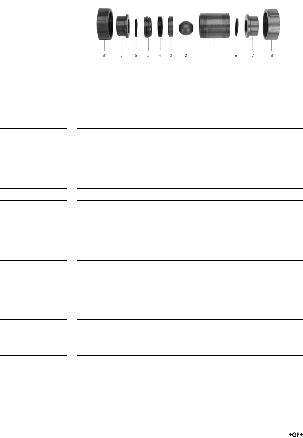
Spare parts for ball check valve type 360 PP-H
No. Article / Material Pieces d16 DN 10 d20 DN 15 d25 DN 20 d32 DN 25 d40 DN 32 d50 DN 40 d63 DN 50
Central part 167 481 125 167 481 126 167 481 127 167 481 128 167 481 129 167 481 130 167 481 131
1 Body PP 1
2 Ball PP 1
3 Support ring PP 1
4 Sealing ring
EPDM
1
5 Union bush PP 1
Central part 167 481 135 167 481 136 167 481 137 167 481 138 167 481 139 167 481 140 167 481 141
1 Body PP 1
2 Ball PP 1
3 Support ring PP 1
4 Sealing ring
FPM
1
5 Union bush PP 1
8 Union nut PP-H 1 167 480 786 167 480 786 167 480 787 167 480 788 167 480 789 167 480 790 167 480 791
7 Fusion socket
PP-H
1 167 480 159 167 480 160 167 480 161 167 480 162 167 480 163 167 480 164 167 480 165
7 Socket fusion
spigot PP-H
1 167 480 527 167 480 528 167 480 529 167 480 530 167 480 531 167 480 532 167 480 533
7 Butt fusion
spigot long PP-H
SDR11
1 - 167 482 546 167 482 547 167 482 548 167 482 549 167 482 550 167 482 551
7 Butt fusion
spigot PP-H
SDR11
(IR-Plus®)
compatible
1 - 167 480 546 167 480 547 167 480 548 167 480 549 167 480 550 167 480 551
7 Butt fusion
spigot PP-H
SDR 17
1 - 167 480 537 167 480 538 167 480 539 167 480 540 167 480 541 167 480 542
7 Threaded socket
PP-H
1 167 480 166 167 480 167 167 480 168 167 480 169 167 480 170 167 480 171 167 480 172
7 Threaded socket
PP-H
1 167 480 452 167 480 453 167 480 454 167 480 455 167 480 456 167 480 457 167 480 458
7 Valve end with
fusion socket PE
80
1 173 480 000 173 480 001 173 480 002 173 480 003 173 480 004 173 480 005 173 480 006
7 Butt fusion
spigot long PE
100
SDR11
1 - 193 480 127 193 480 128 193 480 129 193 480 130 193 480 131 193 480 132
7 Butt fusion
spigot PE 100
1 193 480 026 193 480 027 193 480 028 193 480 029 193 480 030 193 480 031 193 480 032
7 Butt fusion
spigot PE 100
1 - - 193 480 014 193 480 015 193 480 016 193 480 017 193 480 018
7 Fixed flange
PP-H
serrated
1 - 727 740 106 727 740 107 727 740 108 727 740 109 727 740 110 727 740 111
2 Ball PP-H
100% y 0.9
1 167 480 024 167 480 024 167 480 025 167 480 026 167 480 027 167 480 028 167 480 029
2 Ball PP-H
filled with talc y
1.24
1 167 481 165 167 481 165 167 481 166 167 481 167 167 481 168 167 481 169 167 481 170
158

No. Article / Material Pieces d16 DN 10 d20 DN 15 d25 DN 20 d32 DN 25 d40 DN 32 d50 DN 40 d63 DN 50
4 Sealing ring
EPDM
1 161 483 259 161 483 259 161 483 260 161 483 261 161 483 262 161 483 263 161 483 264
4 Sealing ring
FPM
1 161 483 265 161 483 265 161 483 266 161 483 267 161 483 268 161 483 269 161 483 270
6 Union end seal
EPDM
1 748 410 042 748 410 042 748 410 116 748 410 103 748 410 027 748 410 010 748 410 011
6 Union end seal
FPM
1 749 410 042 749 410 042 749 410 116 749 410 103 749 410 027 749 410 010 749 410 011
159

Wafer Check Valves 369
PROGEF Standard
Wafer check valve type 369
Without spring
Model:
ÏMaterial: PP-H
ÏSupporting eyelets for simple fitting
ÏSuitable for vertical and horizontal mounting
Installation instruction:
ÏInstallation between metric flange adaptors
ÏIt is necessary to use a special outlet flange adaptor PP or PE on the outgoing side
of the wafer check valve
ÏCentering by body diameter
ÏSealing with special flange gasket (except DN32, o-ring)
ÏA stabilizing zone of at least 5 times nominal diameter (DN) should be provided
before and after the wafer check valve (10 times DN is recommended)
ÏNo direct installation on pump flange or following bend allowed
ÏWafer check valves without reset spring are not recommended for pulsating
flows (production of noise)
Available with flange gasket from Q4 2008 on
d
[mm]
DN
[mm]
PN EPDM
Code
FPM
Code
kg
40 32 6 167 369 002 167 369 022 0.090
50 40 6 167 369 003 167 369 023 0.100
63 50 6 167 369 004 167 369 024 0.170
75 65 6 167 369 005 167 369 025 0.220
90 80 6 167 369 006 167 369 026 0.260
110 100 6 167 369 007 167 369 027 0.370
140 125 6 167 369 009 167 369 029 0.500
160 150 6 167 369 010 167 369 030 0.740
225 200 6 167 369 011 167 369 031 1.400
280 250 6 167 369 012 167 369 032 2.400
315 300 6 167 369 013 167 369 033 3.520
d
[mm]
D
[mm]
D1
[mm]
D2
[mm]
H
[mm]
L
[mm]
L1
[mm]
Opening
pressure
vertical
[mbar]
Opening
pressure
horizontal
[mbar]
Minimum
water
column for
sealing
[m]
40 85 59 18 25 15 22 10 1 3.0
50 95 72 22 28 16 27 10 1 3.0
63 109 86 32 29 18 40 10 1 3.0
75 129 105 40 31 20 55 10 1 3.0
90 144 119 54 32 20 67 10 1 3.0
110 164 146 70 31 23 67 10 1 3.0
140 195 173 92 35 23 94 10 1 3.0
160 220 197 105 42 26 100 10 1 3.0
225 275 255 154 38 35 152 18 1 3.0
280 330 312 192 41 40 180 18 1 3.0
315 380 363 227 41 45 215 18 1 3.0
160
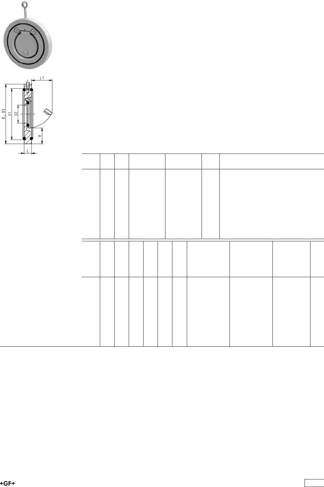
PROGEF Standard
Wafer check valve type 369
With V4A spring (stainless steel 316)
Model:
ÏMaterial: PP-H
ÏSupporting eyelets for simple fitting
ÏSuitable for vertical and horizontal mounting
Installation instruction:
ÏInstallation between metric flange adaptors
ÏIt is necessary to use a special outlet flange adaptor PP or PE on the outgoing side
of the wafer check valve
ÏCentering by body diameter
ÏSealing with special flange gasket (except DN32, o-ring)
ÏA stabilizing zone of at least 5 times nominal diameter (DN) should be provided
before and after the wafer check valve (10 times DN is recommended)
ÏNo direct installation on pump flange or following bend allowed
Available with flange gasket from Q4 2008 on
d
[mm]
DN
[mm]
PN EPDM
Code
FPM
Code
kg
40 32 6 167 369 042 167 369 062 0.090
50 40 6 167 369 043 167 369 063 0.100
63 50 6 167 369 044 167 369 064 0.170
75 65 6 167 369 045 167 369 065 0.220
90 80 6 167 369 046 167 369 066 0.260
110 100 6 167 369 047 167 369 067 0.370
140 125 6 167 369 049 167 369 069 0.500
160 150 6 167 369 050 167 369 070 0.740
225 200 6 167 369 051 167 369 071 1.400
280 250 6 167 369 052 167 369 072 2.400
315 300 6 167 369 053 167 369 073 3.520
d
[mm]
D
[mm]
D1
[mm]
D2
[mm]
H
[mm]
L
[mm]
L1
[mm]
Opening
pressure
vertical
[mbar]
Opening
pressure
horizontal
[mbar]
Minimum
water
column for
sealing
[m]
40 85 59 18 25 15 22 30 20 3.0
50 95 72 22 28 16 27 30 20 3.0
63 109 86 32 29 18 40 30 20 3.0
75 129 105 40 31 20 55 30 20 3.0
90 144 119 54 32 20 67 30 20 3.0
110 164 146 70 31 23 67 30 20 3.0
140 195 173 92 35 23 94 30 20 3.0
160 220 197 105 42 26 100 30 20 3.0
225 275 255 154 38 35 152 38 20 3.0
280 330 312 192 41 40 180 38 20 3.0
315 380 363 227 41 45 215 38 20 3.0
161
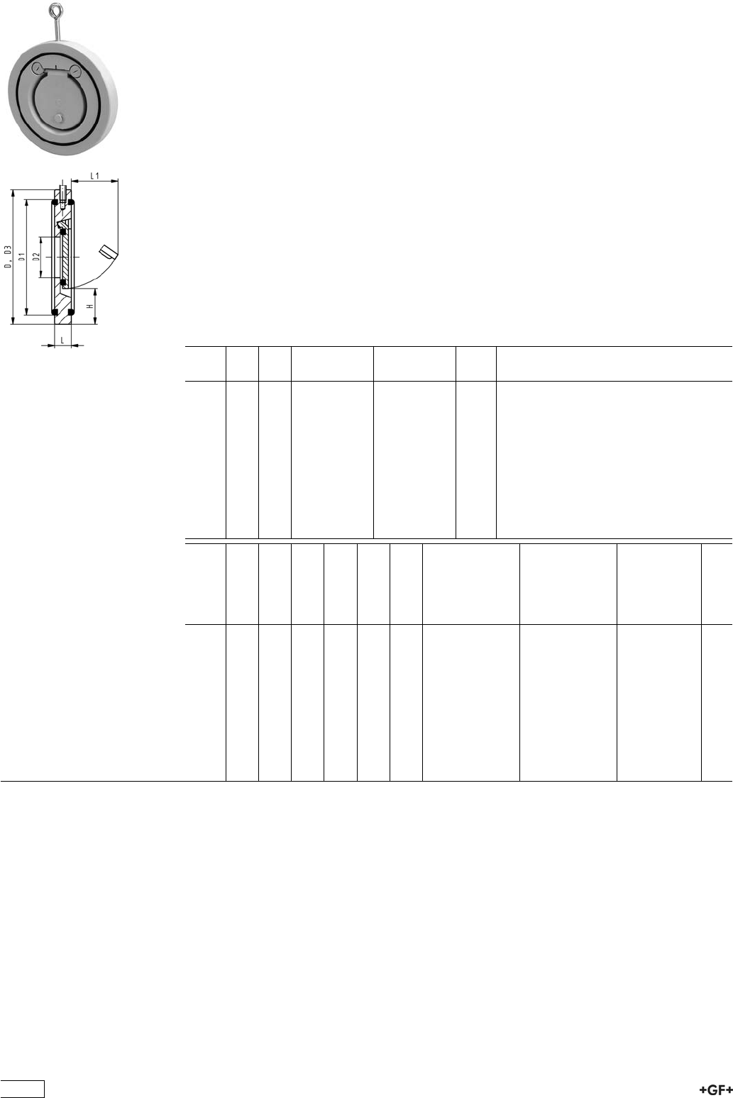
PROGEF Standard
Wafer check valve type 369
With Hastelloy C spring
Model:
ÏMaterial: PP-H
ÏSupporting eyelets for simple fitting
ÏSuitable for vertical and horizontal mounting
Installation instruction:
ÏInstallation between metric flange adaptors
ÏIt is necessary to use a special outlet flange adaptor PP or PE on the outgoing side
of the wafer check valve
ÏCentering by body diameter
ÏSealing with special flange gasket (except DN32, o-ring)
ÏA stabilizing zone of at least 5 times nominal diameter (DN) should be provided
before and after the wafer check valve (10 times DN is recommended)
ÏNo direct installation on pump flange or following bend allowed
Available with flange gasket from Q4 2008 on
d
[mm]
DN
[mm]
PN EPDM
Code
FPM
Code
kg
40 32 6 167 369 082 167 369 102 0.090
50 40 6 167 369 083 167 369 103 0.100
63 50 6 167 369 084 167 369 104 0.170
75 65 6 167 369 085 167 369 105 0.220
90 80 6 167 369 086 167 369 106 0.260
110 100 6 167 369 087 167 369 107 0.370
140 125 6 167 369 089 167 369 109 0.500
160 150 6 167 369 090 167 369 110 0.740
225 200 6 167 369 091 167 369 111 1.400
280 250 6 167 369 092 167 369 112 2.400
315 300 6 167 369 093 167 369 113 3.520
d
[mm]
D
[mm]
D1
[mm]
D2
[mm]
H
[mm]
L
[mm]
L1
[mm]
Opening
pressure
vertical
[mbar]
Opening
pressure
horizontal
[mbar]
Minimum
water
column for
sealing
[m]
40 85 59 18 25 15 22 30 20 3.0
50 95 72 22 28 16 27 30 20 3.0
63 109 86 32 29 18 40 30 20 3.0
75 129 105 40 31 20 55 30 20 3.0
90 144 119 54 32 20 67 30 20 3.0
110 164 146 70 31 23 67 30 20 3.0
140 195 173 92 35 23 94 30 20 3.0
160 220 197 105 42 26 100 30 20 3.0
225 275 255 154 38 35 152 38 20 3.0
280 330 312 192 41 40 180 38 20 3.0
315 380 363 227 41 45 215 38 20 3.0
162
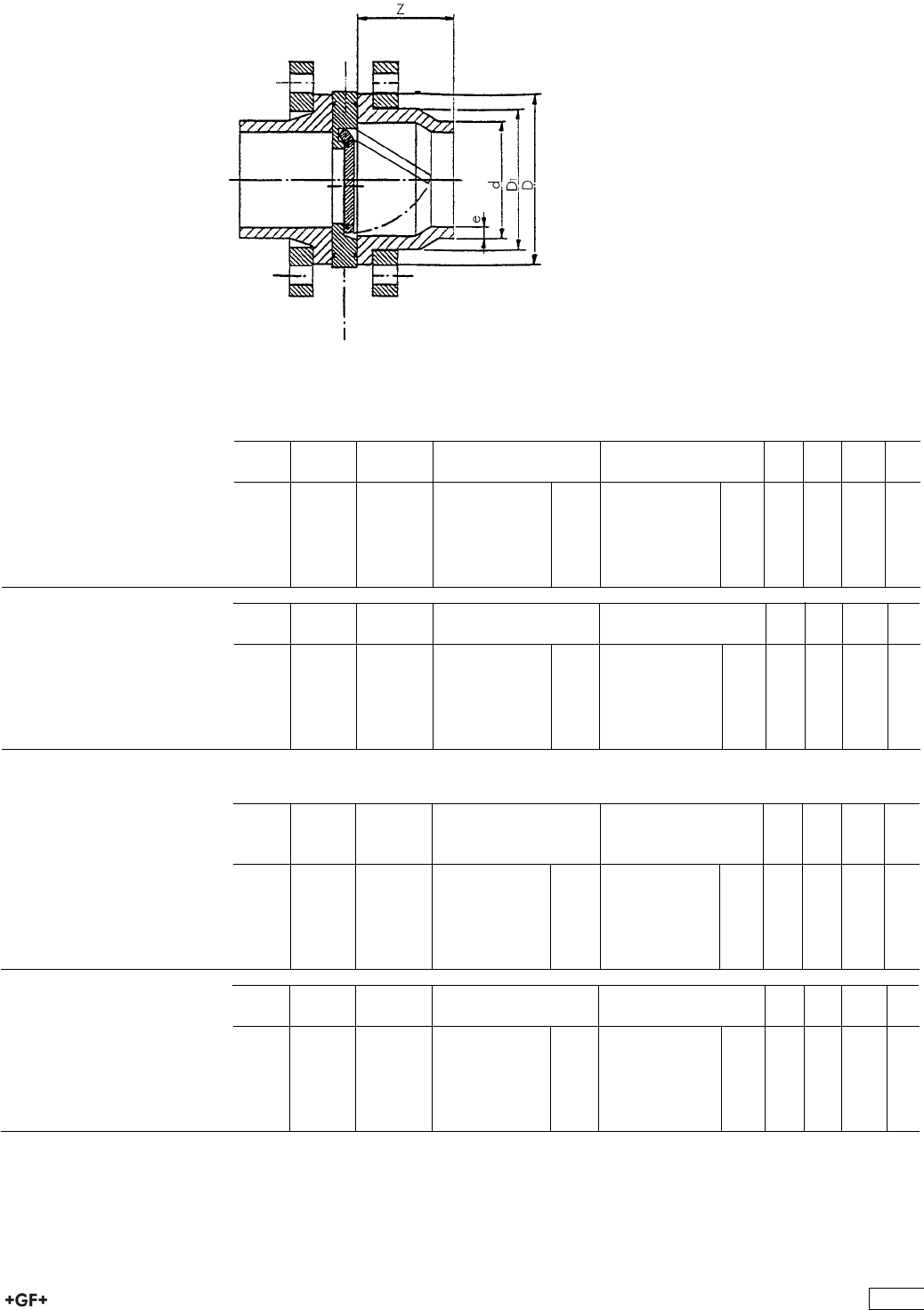
LVgc^c\/I]^hdjiaZiÓVc\Z
VYVeidg]VhidWZ ^chiVaaZYdc
i]ZdjiaZih^YZ
8dbedcZciEVgih[dg;aVc\Z 6hhZbWan!IneZ(+.EE
>caZih^YZ DjiaZih^YZ
HdX`Zi;jh^dcHnhiZbEE$E:
>caZih^YZ
Y 9C
('
)%
*%
+*
-%
&%%
)%
*%
+(
,*
.%
&&%
E:
8dYZ
EE
8dYZ
,',,.% '%.
,',,.% '&%
,',,.% '&&
,',,.% '&'
,',,.% '&(
,',,.% '&)
,*(,.% '%.
,*(,.% '&%
,*(,.% '&&
,*(,.% '&'
,*(,.% '&(
,*(,.% '&)
>cX]
&&$)
&&$'
'
'&$'
(
)
EE$E:
;aVc\ZVYVeidg
bZig^X
Y 9C
('
)%
*%
+*
-%
&%%
)%
*%
+(
,*
.%
&&%
[dgÓVc\Z VYVeidgbZig^X
EEl^i] hiZZag^c\
[dgÓVc\Z VYVeidgbZig^X
EE"KWaVX`
,',,%% )%.
,',,%% )&%
,',,%% )&&
,',,%% )&'
,',,%% )&(
,',,%% )&)
,',,%% '%.
,',,%% '&%
,',,%% '&&
,',,%% '&'
,',,%% '&(
,',,%% '&)
>cX]
&&$)
&&$'
'
'&$'
(
)
7VX`^c\ÓVc\Z bZig^X
[dghdX`Zi [jh^dc hnhiZbh
8dccZXi^c\Y^bZch^dc
9>C'*%& EC&%
DjiaZih^YZ
Y 9C
('
)%
*%
+*
-%
&%%
)%
*%
+(
,*
.%
&&%
?d^ci^c\[VXZÓVi
E:
8dYZ
?d^ci^c\[VXZÓVi
EE
8dYZ
,',-%% %%.
,',-%% %&%
,',-%% %&&
,',-%% %&'
,',-%% %&(
,',-%% %&)
,((-%% %%.
,((-%% %&%
,((-%% %&&
,((-%% %&'
,((-%% %&(
,((-%% %&)
>cX]
&&$)
&&$'
'
'&$'
(
)
EE$E:
DjiaZiÓVc\Z VYVeidg
l^i][jh^dc hdX`Zi
bZig^X
Y 9C
('
)%
*%
+*
-%
&%%
)%
*%
+(
,*
.%
&&%
[dgdjiaZiÓVc\Z VYVeidg
EEl^i] hiZZag^c\
[dgdjiaZiÓVc\Z VYVeidg
EE"KWaVX`
,',,%% )%.
,',,%% )&%
,',,%% )&&
,',,%% )&'
,',,%% )&(
,',,%% )&)
,',,%% '%.
,',,%% '&%
,',,%% '&&
,',,%% '&'
,',,%% '&(
,',,%% '&)
>cX]
&&$)
&&$'
'
'&$'
(
)
7VX`^c\ÓVc\Z bZig^X
[dghdX`Zi [jh^dc hnhiZbh
8dccZXi^c\Y^bZch^dc
9>C'*%& EC&%
99&
+&
,(
.%
&%+
&'*
&*%
*%
+&
,+
.%
&%-
&(%
O
(*
(-
)&
).
+*
+'
163
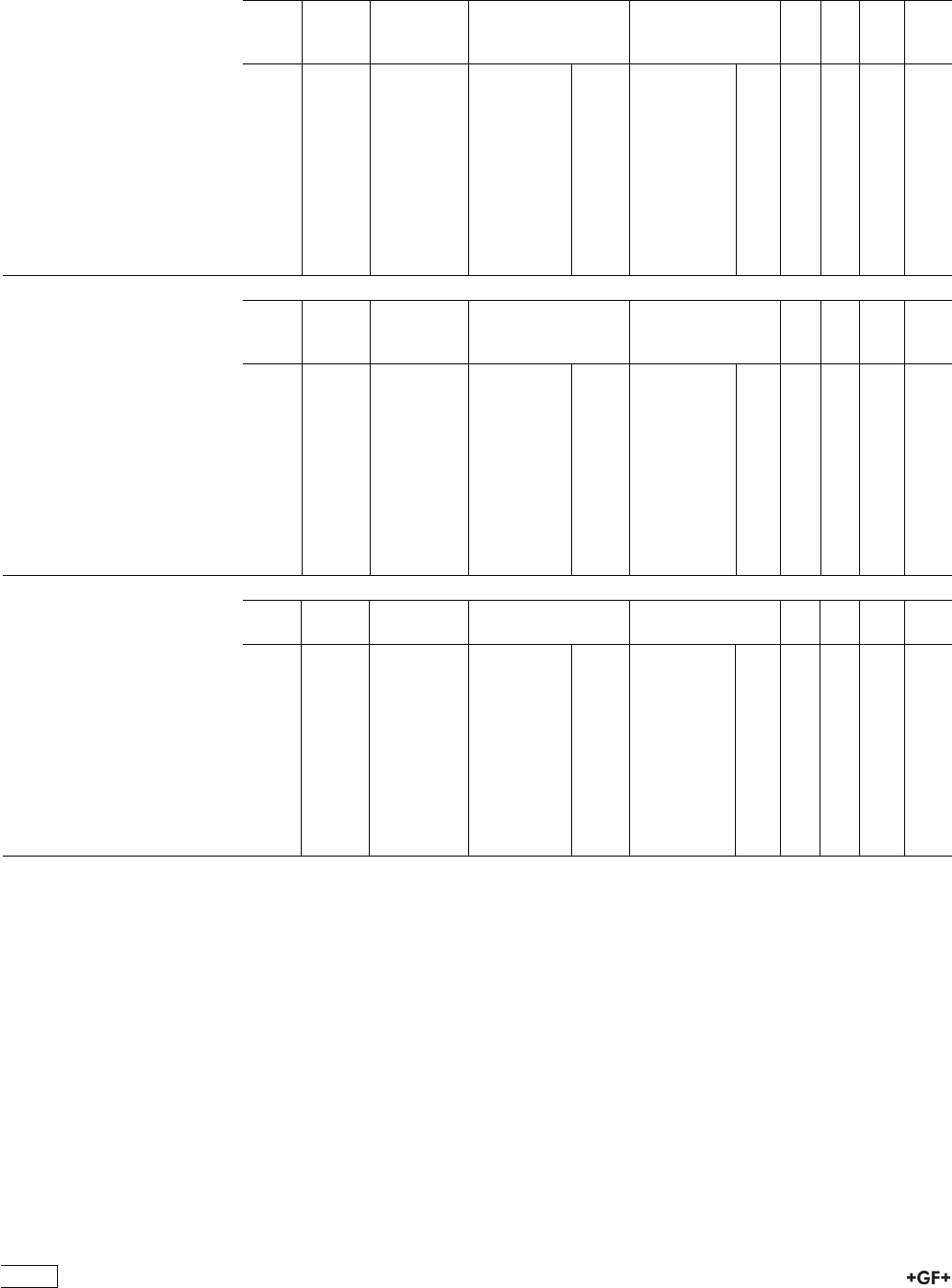
Y
9C
('
)%
*%
+*
-%
&%%
&'*
&*%
'%%
'*%
(%%
)%
*%
+(
,*
.%
&&%
&)%
&+%
''*
'-%
(&*
E:
8dYZ
EE
8dYZ
,',,.- *%.
,',,.- *&%
,',,.- *&&
,',,.- *&'
,',,.- *&(
,',,.- *&)
,',,.- *&+
,',,.- *&,
,',,.- *'%
,',,.- *,'
,',,.- *,(
,*(,.- +%.
,*(,.- +&%
,*(,.- +&&
,*(,.- +&'
,*(,.- +&(
,*(,.- +&)
,*(,.- +&+
,*(,.- +&,
,*(,.- +'%
,*(,.- +,'
,*(,.- +,(
>cX]
&&$)
&&$'
'
'&$'
(
)
*
+
-
&%
&'
8dbedcZciEVgih[dg;aVc\Z6hhZbWan!IneZ(+.EE
EE$E:
;aVc\Z6YVeiZg
bZig^XH9G &&
7jii;jh^dcHnhiZbEE$E:
>caZih^YZ
Y
9C
('
)%
*%
+*
-%
&%%
&'*
&*%
'%%
'*%
(%%
)%
*%
+(
,*
.%
&&%
&)%
&+%
''*
'-%
(&*
E:
8dYZ
EE
8dYZ
ÄÄ
,',,.- *(*
,',,.- *(+
,',,.- )&'
,',,.- )&(
,',,.- )&)
,',,.- *)&
,',,.- *)'
,',,.- *)*
,',,.- *),
,',,.- *)-
ÄÄ
,*(,.- *(*
,*(,.- *(+
,*(,.- *&'
,*(,.- *&(
,*(,.- *&)
,*(,.- *)&
,*(,.- *)'
,*(,.- *)*
,*(,.- *),
,*(,.- *)-
>cX]
&&$)
&&$'
'
'&$'
(
)
*
+
-
&%
&'
EE$E:
;aVc\Z6YVeiZg
bZig^XH9G &,!+
Y
9C
('
)%
*%
+*
-%
&%%
&'*
&*%
'%%
'*%
(%%
)%
*%
+(
,*
.%
&&%
&)%
&+%
''*
'-%
(&*
[dg;aVc\Z6YVeiZg
EEl^i] hiZZag^c\
[dg;aVc\Z6YVeiZg
EE"KWaVX`
,',,%% )%.
,',,%% )&%
,',,%% )&&
,',,%% )&'
,',,%% *&(
,',,%% *&)
,',,%% *&+
,',,%% *&,
,',,%% *'%
,',,%% *''
,',,%% *'(
,',,%% '%.
,',,%% '&%
,',,%% '&&
,',,%% '&'
,',,%% (&(
,',,%% (&)
,',,%% (&+
,',,%% (&,
,',,%% ('%
,',,%% (''
,',,%% ('(
>cX]
&&$)
&&$'
'
'&$'
(
)
*
+
-
&%
&'
7VX`^c\ÓVc\Z bZig^X
[dgWjii [jh^dchnhiZbh
8dccZXi^c\Y^bZch^dc
9>C'*%& EC&%
164
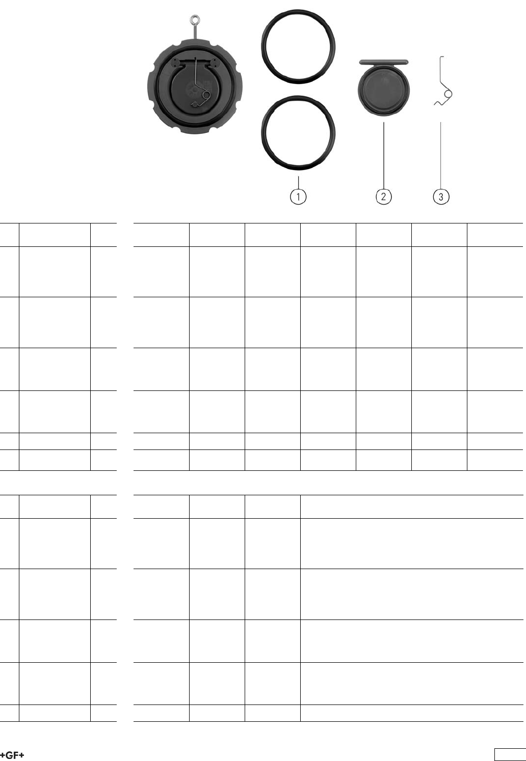
Spare parts for wafer check valve type 369 PP-H
No. Article / Material Pieces d40 DN 32 d50 DN 40 d63 DN 50 d75 DN 65 d90 DN 80 d110 DN
100
d140 DN
125
1 Flange gasket
EPDM
Available for
PP-H from
4.quarter 2008
2 161 484 875 161 486 959 161 486 960 161 486 961 161 486 962 161 486 962 161 486 964
1 Flange gasket
FPM
Available for
PP-H from
4.quarter 2008
2 161 484 887 161 486 979 161 486 980 161 486 981 161 486 982 161 486 982 161 486 984
Disc set 167 369 122 167 369 123 167 369 124 167 369 125 167 369 126 167 369 127 167 369 128
2 Disc PP-H 1
2 Seal EPDM 1
Disc set 167 369 142 167 369 143 167 369 144 167 369 145 167 369 146 167 369 147 167 369 148
2 Disc PP-H 1
2 Seal FPM 1
3 Spring V4A 1 161 484 900 161 484 901 161 484 902 161 484 903 161 484 904 161 484 905 161 484 905
3 Spring Hastelloy
C
1 161 484 912 161 484 913 161 484 914 161 484 915 161 484 916 161 484 917 161 484 917
No. Article / Material Pieces d160 DN
150
d225 DN
200
d280 DN
250
d315 DN
300
1 Flange gasket
EPDM
Available for
PP-H from
4.quarter 2008
2 161 486 964 161 486 974 161 486 966 161 486 967
1 Flange gasket
FPM
Available for
PP-H from
4.quarter 2008
2 161 486 984 161 486 993 161 486 986 161 486 987
Disc set 167 369 129 167 369 130 167 369 131 167 369 132
2 Disc PP-H 1
2 Seal EPDM 1
Disc set 167 369 149 167 369 150 167 369 151 167 369 152
2 Disc PP-H 1
2 Seal FPM 1
3 Spring V4A 1 161 484 907 161 484 908 161 484 909 161 484 910
165

No. Article / Material Pieces d160 DN
150
d225 DN
200
d280 DN
250
d315 DN
300
3 Spring Hastelloy
C
1 161 484 919 161 484 920 161 484 921 161 484 922
166
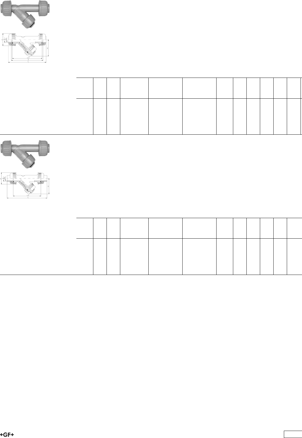
Strainers 305
PROGEF Standard
Line strainer type 305
With fusion sockets metric
Model:
ÏMaterial: PP-H
ÏFor easy installation and removal
ÏProtects valves, pumps, etc. from becoming soiled
ÏScreen perforation 0.5 mm
ÏOverall length according to EN 558
d
[mm]
DN
[mm]
PN kv-value
(”p=1 bar)
[l/min]
EPDM
Code
FPM
Code
kg D
[mm]
L
[mm]
L2
[mm]
H
[mm]
z
[mm]
20 15 10 35 167 305 000 167 305 049 0.245 52 168 130 75 140
25 20 10 65 167 305 050 167 305 099 0.295 62 192 150 80 160
32 25 10 90 167 305 100 167 305 149 0.360 68 206 160 90 170
40 32 10 155 167 305 150 167 305 199 0.660 85 230 180 110 190
50 40 10 225 167 305 200 167 305 249 0.810 85 256 200 125 210
63 50 10 370 167 305 250 167 305 299 1.330 102 294 230 150 240
PROGEF Standard
Line strainer type 305
With butt fusion spigots SDR11 metric
Model:
ÏMaterial: PP-H
ÏFor easy installation and removal
ÏProtects valves, pumps, etc. from becoming soiled
ÏScreen perforation 0.5 mm
ÏOverall length according to EN 558
d
[mm]
DN
[mm]
PN kv-value
(”p=1 bar)
[l/min]
EPDM
Code
FPM
Code
kg D
[mm]
L
[mm]
L2
[mm]
H
[mm]
20 15 10 35 167 305 300 167 305 349 0.245 52 238 130 75
25 20 10 65 167 305 350 167 305 399 0.295 62 264 150 80
32 25 10 90 167 305 400 167 305 449 0.360 68 280 160 90
40 32 10 155 167 305 450 167 305 499 0.660 85 306 180 110
50 40 10 225 167 305 500 167 305 549 0.810 85 332 200 125
63 50 10 370 167 305 550 167 305 599 1.330 102 368 230 150
167
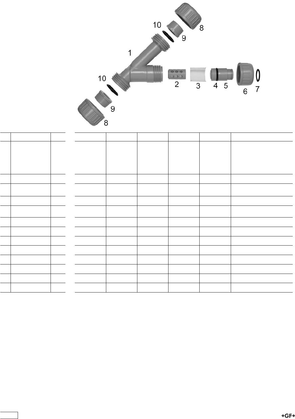
Spare parts for line strainer type 305
(DN15-50) PP-H
No. Article / Material Pieces d20 DN 15 d25 DN 20 d32 DN 25 d40 DN 32 d50 DN 40 d63 DN 50
Screen basket
compl. without
screen
167 305 001 167 305 002 167 305 003 167 305 004 167 305 005 167 305 006
2 Screen cage 1
7 Circlip 1
1 Body PP-H 1 167 305 010 167 305 011 167 305 012 167 305 013 167 305 014 167 305 015
3 Screen
perforation PP-H
1 167 305 030 167 305 031 167 305 032 167 305 033 167 305 034 167 305 035
2 Screen cage 1 167 305 020 167 305 021 167 305 022 167 305 023 167 305 024 167 305 025
5 Screen cage
bracket
1 167 305 040 167 305 041 167 305 042 167 305 043 167 305 044 167 305 045
6 Valve nut PP-H 1 167 305 060 167 305 061 167 305 062 167 305 063 167 305 064 167 305 065
7 Circlip PP-H 1 161 482 017 161 482 018 161 482 019 161 482 020 161 482 021 161 482 022
4 Body seal EPDM 1 748 410 001 748 410 001 748 410 007 748 410 002 748 410 172 748 410 012
4 Body seal FPM 1 749 410 001 749 410 001 749 410 007 749 410 002 749 410 172 749 410 012
8 Union nut PP-H 2 167 305 070 167 305 071 167 305 072 167 305 073 167 305 074 167 305 075
9 Union end PP-H 2 727 608 506 727 608 507 727 608 508 727 608 509 727 608 510 727 608 511
9 Union end PP-H 2 727 600 106 727 600 107 727 600 108 727 600 109 727 600 110 727 600 111
10 O-ring EPDM 2 748 410 006 748 410 103 748 410 002 748 410 009 748 410 010 748 410 011
168

Solenoid valves
PROGEF Standard
Solenoid valve type 166
Function A straight-through valve 2/2 ways
Nominal voltage 24V DC
With G 1/4 line connection
Model:
ÏMaterial: PP-H
ÏWith manual override
ÏElectrical connection: cable plug
ÏProtection class IP 65
DN
[mm]
D1_G
[inch]
Function PN
[bar]
kv-value
(”p=1 bar)
[l/min]
EPDM
Code
FPM
Code
kg
31
/4A 0.0 - 8.0 4 199 166 000 199 166 005 0.400
41
/4A 0.0 - 4.0 5 199 166 001 199 166 006 0.400
51
/4A 0.0 - 3.0 6 199 166 002 199 166 007 0.400
169

PROGEF Standard
Solenoid valve type 166
Function A straight-through valve 2/2 ways
Nominal voltage 230V 50Hz ±10%
With G 1/4 line connection
Model:
ÏMaterial: PP-H
ÏWith manual override
ÏElectrical connection: cable plug
ÏProtection class IP 65
DN
[mm]
D1_G
[inch]
Function PN
[bar]
kv-value
(”p=1 bar)
[l/min]
EPDM
Code
FPM
Code
kg
31
/4A 0.0 - 10.0 4 199 166 010 199 166 015 0.400
41
/4A 0.0 - 5.0 5 199 166 011 199 166 016 0.400
51
/4A 0.0 - 4.5 6 199 166 012 199 166 017 0.400
170

PROGEF Standard
Solenoid valve type 166
Function E mixing valve 3/2 ways
Nominal voltage 24V DC
With G 1/4 line connection
Model:
ÏMaterial: PP-H
ÏWith manual override
ÏElectrical connection: cable plug
ÏProtection class IP 65
DN
[mm]
D1_G
[inch]
Function PN
[bar]
kv-value
(”p=1 bar)
[l/min]
EPDM
Code
FPM
Code
kg
31
/4E 0.0 - 4.0 4 199 166 150 199 166 155 0.400
41
/4E 0.0 - 2.0 5 199 166 151 199 166 156 0.400
171
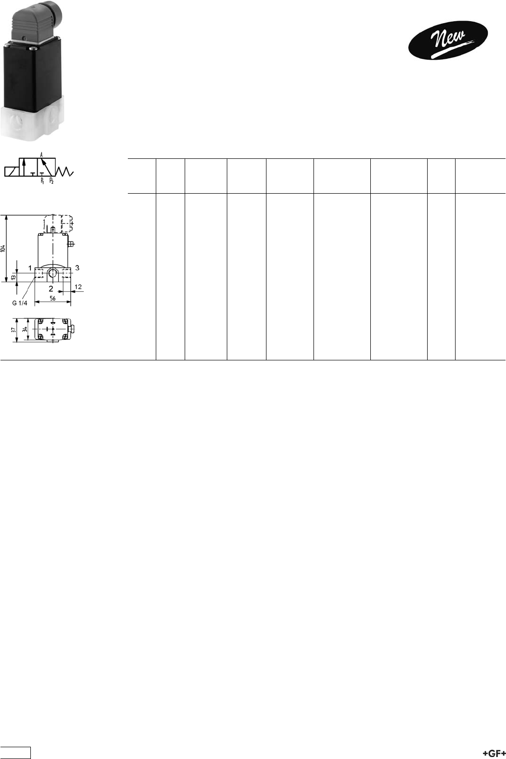
PROGEF Standard
Solenoid valve type 166
Function E mixing valve 3/2 ways
Nominal voltage 230V 50Hz ±10%
With G 1/4 line connection
Model:
ÏMaterial: PP-H
ÏWith manual override
ÏElectrical connection: cable plug
ÏProtection class IP 65
DN
[mm]
D1_G
[inch]
Function PN
[bar]
kv-value
(”p=1 bar)
[l/min]
EPDM
Code
FPM
Code
kg
31
/4E 0.0 - 6.0 4 199 166 160 199 166 165 0.400
41
/4E 0.0 - 3.0 5 199 166 161 199 166 166 0.400
172
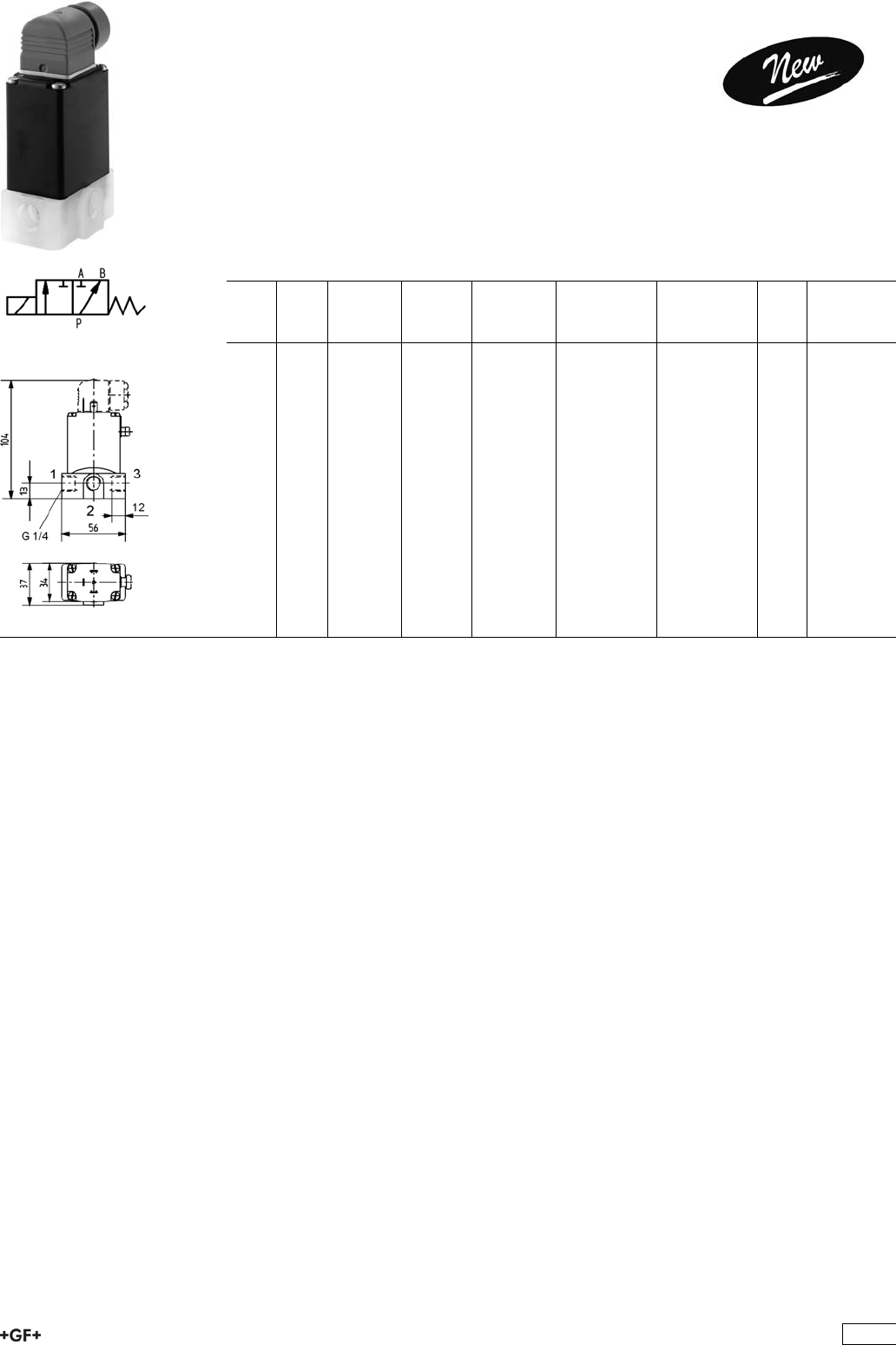
PROGEF Standard
Solenoid valve type 166
Function F distribution valve 3/2 ways
Nominal voltage 24V DC
With G 1/4 line connection
Model:
ÏMaterial: PP-H
ÏWith manual override
ÏElectrical connection: cable plug
ÏProtection class IP 65
DN
[mm]
D1_G
[inch]
Function PN
[bar]
kv-value
(”p=1 bar)
[l/min]
EPDM
Code
FPM
Code
kg
41
/4F 0.0 - 4.0 5 199 166 201 199 166 206 0.400
173

PROGEF Standard
Solenoid valve type 166
Function F distribution valve 3/2 ways
Nominal voltage 230V 50Hz ±10%
With G 1/4 line connection
Model:
ÏMaterial: PP-H
ÏWith manual override
ÏElectrical connection: cable plug
ÏProtection class IP 65
DN
[mm]
D1_G
[inch]
Function PN
[bar]
kv-value
(”p=1 bar)
[l/min]
EPDM
Code
FPM
Code
kg
41
/4F 0.0 - 5.0 5 199 166 211 199 166 216 0.400
174
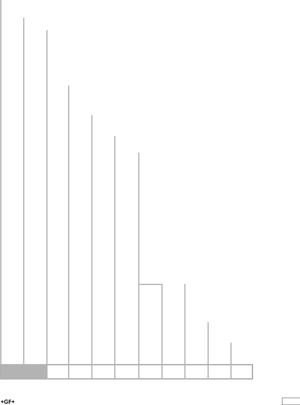
9ef_WXb[
9edÓ]khWjeh=<XWbblWbl[jof[+*,FHE=;<IjWdZWhZ
7&' 8&+ 9 : ; < = = ? A B
b[\j h_]^j
8WbbLWbl[
6%& 7VaaKVakZ*)+
6%' A^cZVg7VaaKVakZ
CWj[h_Wb
7%* EE"=
:_c[di_ed
8%* Y&+9C&%($-
8%+ Y'%9C&*&$'
8%, Y'*9C'%($)
8%- Y('9C'*&
8%. Y)%9C('&&$)
8&% Y*%9C)%&&$'
8&& Y+(9C*%'
8&'9C+*'&$'
8&(9C-%(
8&)9C&%%)
8&*9C&*%+
L[hi_ed
9%& HiVcYVgY!EI;:WVaahZVa
9%' d^a[gZZ!EI;:WVaahZVadcanl^i]heZX^ÒXXdccZXi^c\eVgih
9%( h^a^Xdc"[gZZ!EI;:WVaahZVadcanl^i]heZX^ÒXXdccZXi^c\eVgih
9%) h^a^Xdc"[gZZ!EK9;WVaahZVa[dgbZig^Xdcanl^i]heZX^ÒXXdccZXi^c\eVgih
I[Wbi
:%& :E9BhZVah
:%' ;EBhZVah
:%( ;;EB$@6AG:OhZVah
J^h[WZ[Z_di[hji
;%& l^i]djii]gZVYZY^chZgih
;%' l^i]i]gZVYZY^chZgih
9edd[Yj_d]fWhji
<(% EE"=;jh^dchdX`ZibZig^X
<(' EE"=HdX`Zi[jh^dche^\dibZig^X
<(( EE"=I]gZVYZYhdX`ZiGegZ^c[dgXZY
<() EE"=I]gZVYZYhdX`ZiCEIgZ^c[dgXZY
<(* EE"=7jii[jh^dche^\diH9G&&bZig^X>G"EAJH
<(+ EE"=7jii[jh^dche^\diH9G&,#+bZig^X
l^i]i]^hkVakZZcYi]ZbVm^bjbcdb^cVaegZhhjgZ
^hgZYjXZYidEC+
<(, EE"=7jii[jh^dche^\diadc\H9G&&bZig^X
<)( E:"&%%7jii[jh^dche^\diadc\H9G&&bZig^X
<)) E:"&%%7jii[jh^dche^\diadc\H9G&,#+bZig^X
<+( ;^mZYÓVc\ZEE"=hZggViZYbZig^X
<,' 7VX`^c\ÓVc\ZEE"hiZZabZig^X
<,( 7VX`^c\ÓVc\ZEE"hiZZa^cX]6CH>
<,, 7VX`^c\ÓVc\ZEE?>Hl^i]XdccZXi^c\eVgih
<,- 7VX`^c\ÓVc\ZEE"<;?>H
<-( EE"=KVakZZcYWaVc`
<)% E:"&%%;jh^dchdX`ZibZig^X
<)& E:"&%%7jii[jh^dche^\diH9G&&bZig^X
<)' E:"&%%7jii[jh^dche^\diH9G&,#+bZig^X
<)( E:"&%%7jii[jh^dche^\diadc\H9G&&bZig^X
<&& EK8"88ZbZcihdX`ZibZig^X
<&( EK8"88ZbZcihdX`Zi^cX]6HIB
<&) EK8"88ZbZcihe^\dibZig^X
<&* EK8"8I]gZVYZYhdX`ZiGe
<&+ EK8"8I]gZVYZYhdX`ZiGegZ^c[dgXZY
<&, EK8"8I]gZVYZYhdX`ZiCEI
Ckbj_#\kdYj_edWbceZkb[
>%& Cdbjai^"[jcXi^dcVabdYjaZ
>%' :beinbdYjaZ
>%( BdYjaZl^i]'ZcYhl^iX]Zh6\!C^
>%) BdYjaZl^i]'ZcYhl^iX]Zh6j
>%* BdYjaZl^i]'^cYjXi^kZhl^iX]ZhCVbjg
>%+ BdYjaZl^i]'^cYjXi^kZhl^iX]ZhECE
>%, BdYjaZl^i]'^cYjXi^kZhl^iX]ZhCEC
B[l[h
@%& HiVcYVgYaZkZggZY
@%' HiVcYVgYaZkZgWaVX`
@&& Bjai^"[jcXi^dcVaaZkZggZY
Cekdj_d]fbWj[
A%& l^i]djibdjci^c\eaViZ
A%' l^i]bdjci^c\eaViZ
Ndjl^aaÒcYVaVg\ZhZaZXi^dcd[Y^[[ZgZcikZg"
h^dch^cdjggVc\Zd[egdYjXih#CZlhnhiZb
ZaZbZcihVahdegdk^YZndjl^i]cZldeedgij"
c^i^Zh[dgjhZ#>cdgYZg[dgjhidhjeeanZmVXian
i]ZWVaakVakZndjcZZY[dgndjVeea^XVi^dc!lZ
]VkZXgZViZYVhZaZXi^dcbZcj[dgndj#
9ZgbVm^bVaoja~hh^\Z7Zig^ZWhYgjX`YZh
@j\Za]V]ch^hiEC&%#
M[ikffbom^Wjoekfkjje][j^[h$
175
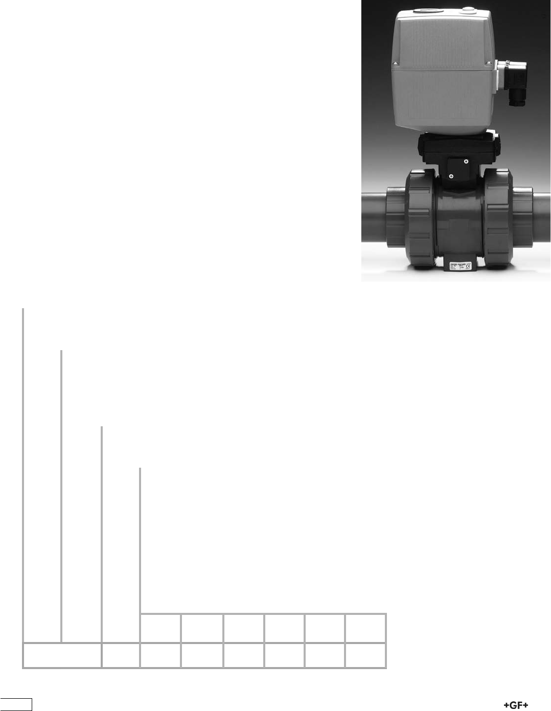
;b[Yjh_Y7YjkWjeh;7''
I%& :6&&')K
I%' :6&&&%%Ä'(%K
7YY[iieh_[i;7''
J%& CdVXXZhhdg^Zh
J%' 'a^b^ihl^iX]Zh6\!C^
J%( =ZVi^c\ZaZbZci
J%) ;V^a"hV[ZgZijgc
J%* 'a^b^ihl^iX]Zh6\!C^cdgbVaandeZc
;b[Yjh_Y7YjkWjeh;7('%)'
I%( :6'&$(&')K
I%) :6'&$(&&%%Ä'(%K
7YY[iieh_[i;7('
L%& CdVXXZhhdg^Zh
L%' =ZVi^c\ZaZbZci
L%( 8nXaZi^bZbdYjaZ
L%) 8nXaZi^bZbdc^idg^c\
L%* 8nXaZhbdc^idg^c\
L%+ BdidgXjggZcibdc^idg^c\
L%, 'a^b^ihl^iX]Zh6\!C^
L%- 'a^b^ihl^iX]Zh<daY
L%. 'a^b^ihl^iX]ZhCEC
L&% 'a^b^ihl^iX]ZhECE
L&& Edh^i^dcZg
L&' :aZXig^Xedh^i^dc^cY^XVidg
L&) ;V^a"hV[ZgZijgcjc^i
L&* Hl^iX]^ciZgbZY^ViZedh^i^dc
L', 'a^b^ihl^iX]Zh6\!C^cdgbVaandeZcl^i]XdccZXidg
L(& Edh^i^dcZgE:'*l^i]\Vak#hZeVgVi^dc
?jiie[WiojeWYjkWj[
j^[jof[+*,0
L^i]i]ZXdcÒ\jgVidg!ndj]VkZVX]d^XZd[
cZlZaZXig^XVXijVidgh!i]Z:6&&[dghiVcYVgY
Veea^XVi^dchVcYi]Z:6'&l^i]bdYjaVg
YZh^\cVcYVXXZhhdg^Zh![dgegVXi^XVaanVcY
ineZd[deZgVi^dc#
M[ikffbom^Wjoekfkjje][j^[h$
9ef_WXb[
=<XWbblWbl[jof[+*,m_j^[b[Yjh_Y7YjkWjeh
J K J M M M M M M
176

Ball Valves Electric
PROGEF Standard
Ball valve type 107 100-230V
With manual emergency override
With fusion sockets metric
Model:
ÏMaterial: PP-H
ÏBuilt on with electric actuator EA11
ÏVoltage 100-230 V, 50-60 Hz
ÏControl range 90°<)
ÏControl time 5 s/90°<)
ÏFor easy installation and removal
ÏIntegrated stainless steel mounting inserts
Option:
ÏIndividual configuration of the valve (see form)
d
[mm]
DN
[mm]
PN kv-value
(”p=1 bar)
[l/min]
EPDM
Code
FPM
Code
kg
16 10 10 70 199 107 502 199 107 512 2.100
20 15 10 185 199 107 503 199 107 513 2.100
25 20 10 350 199 107 504 199 107 514 2.200
32 25 10 700 199 107 505 199 107 515 2.300
40 32 10 1000 199 107 506 199 107 516 2.600
50 40 10 1600 199 107 507 199 107 517 3.000
63 50 10 3100 199 107 508 199 107 518 3.800
d
[mm]
D
[mm]
H
[mm]
H1
[mm]
H2
[mm]
H3
[mm]
H5
[mm]
L
[mm]
L1
[mm]
L2
[mm]
L4
[mm]
L5
[mm]
L6
[mm]
L7
[mm]
L8
[mm]
z
[mm]
16 50 200 27 64 64 137 93 161 56 25 77 83 122 33 67
20 50 200 27 64 64 137 95 161 56 25 77 83 122 33 66
25 58 209 30 73 64 137 108 161 65 25 77 83 122 33 77
32 68 209 36 73 64 137 118 161 71 25 77 83 122 33 83
40 84 220 44 84 64 137 137 161 85 45 77 83 122 33 99
50 97 220 51 84 64 137 147 161 89 45 77 83 122 33 105
63 124 243 64 106 64 137 168 161 101 45 77 83 122 33 117
177
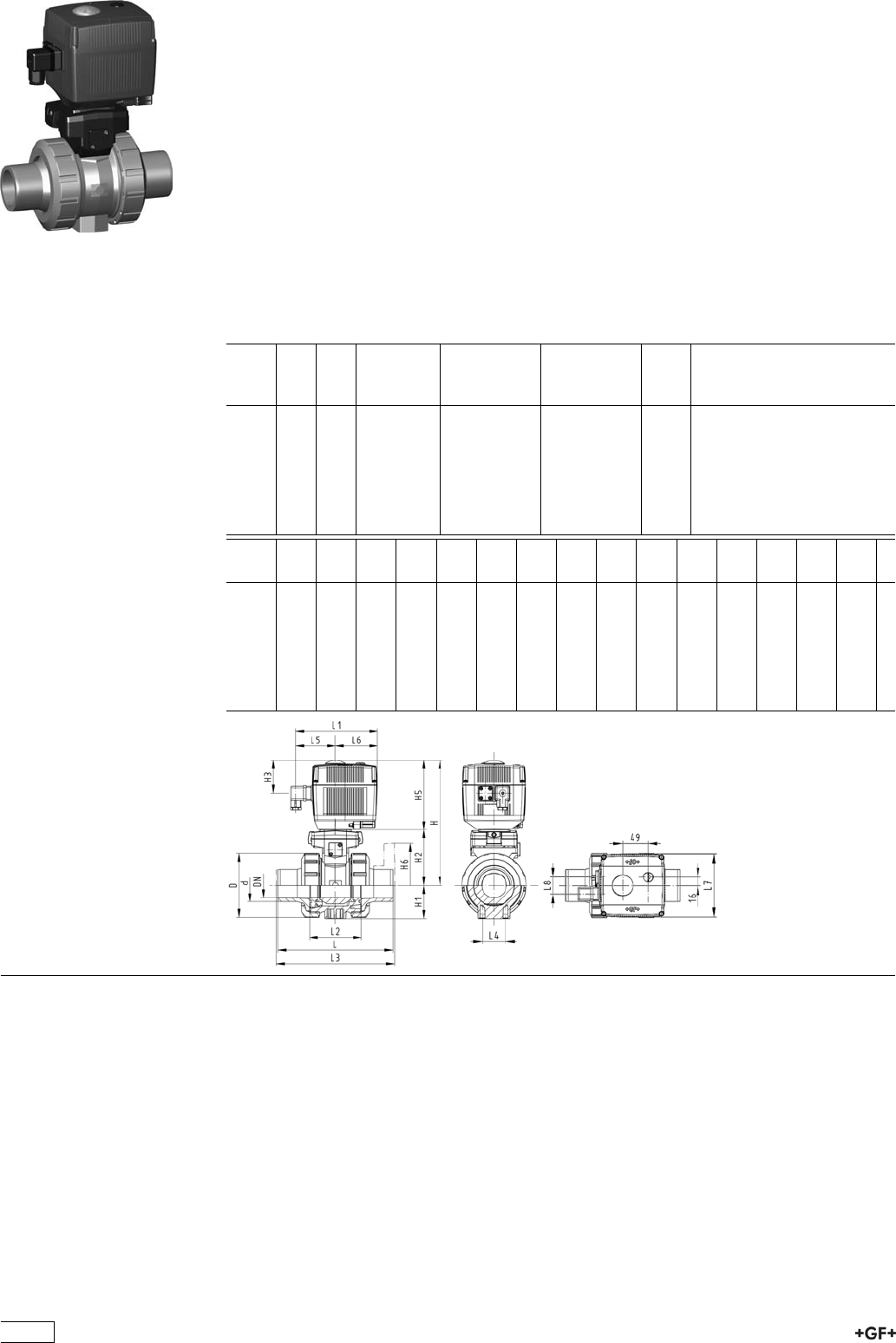
PROGEF Standard
Ball valve type 107 100-230V
With manual emergency override
With fusion spigots metric
Model:
ÏMaterial: PP-H
ÏBuilt on with electric actuator EA11
ÏVoltage 100-230 V, 50-60 Hz
ÏControl range 90°<)
ÏControl time 5 s/90°<)
ÏFor easy installation and removal
ÏIntegrated stainless steel mounting inserts
Option:
ÏIndividual configuration of the valve (see form)
d
[mm]
DN
[mm]
PN kv-value
(”p=1 bar)
[l/min]
EPDM
Code
FPM
Code
kg
16 10 10 70 199 107 522 199 107 532 2.100
20 15 10 185 199 107 523 199 107 533 2.100
25 20 10 350 199 107 524 199 107 534 2.200
32 25 10 700 199 107 525 199 107 535 2.300
40 32 10 1000 199 107 526 199 107 536 2.600
50 40 10 1600 199 107 527 199 107 537 3.000
63 50 10 3100 199 107 528 199 107 538 3.800
d
[mm]
D
[mm]
H
[mm]
H1
[mm]
H2
[mm]
H3
[mm]
H5
[mm]
L
[mm]
L1
[mm]
L2
[mm]
L3
[mm]
L4
[mm]
L5
[mm]
L6
[mm]
L7
[mm]
L8
[mm]
16 50 200 27 64 64 137 110 161 56 130 25 77 83 122 33
20 50 200 27 64 64 137 120 161 56 130 25 77 83 122 33
25 58 209 30 73 64 137 139 161 65 150 25 77 83 122 33
32 68 209 36 73 64 137 150 161 71 160 25 77 83 122 33
40 84 220 44 84 64 137 170 161 85 180 45 77 83 122 33
50 97 220 51 84 64 137 190 161 89 200 45 77 83 122 33
63 124 243 64 106 64 137 220 161 101 230 45 77 83 122 33
178
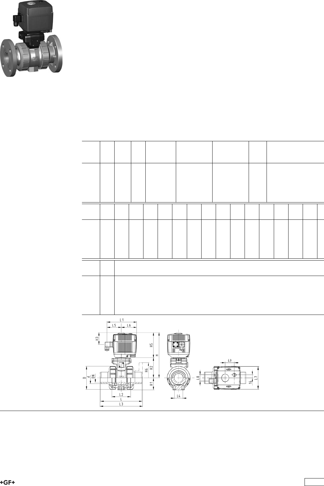
PROGEF Standard
Ball valve type 107 100-230V
With manual emergency override
With fixed flanges PP-H serrated metric
Model:
ÏMaterial: PP-H
ÏBuilt on with electric actuator EA11
ÏVoltage 100-230 V, 50-60 Hz
ÏControl range 90°<)
ÏControl time 5 s/90°<)
ÏFor easy installation and removal
ÏIntegrated stainless steel mounting inserts
ÏOverall length according to EN 558
ÏConnecting dimensions: ISO 7005 / EN 1092 / DIN 2501 PN10 / BS4504
Option:
ÏIndividual configuration of the valve (see form)
d
[mm]
DN
[mm]
Inch PN kv-value
(”p=1 bar)
[l/min]
EPDM
Code
FPM
Code
kg
20 15 1
/210 185 199 107 583 199 107 593 2.300
25 20 3
/410 350 199 107 584 199 107 594 2.500
32 25 1 10 700 199 107 585 199 107 595 2.700
40 32 1 1
/410 1000 199 107 586 199 107 596 3.200
50 40 1 1
/210 1600 199 107 587 199 107 597 3.700
63 50 2 10 3100 199 107 588 199 107 598 4.800
d
[mm]
D
[mm]
H
[mm]
H1
[mm]
H2
[mm]
H3
[mm]
H5
[mm]
H6
[mm]
L
[mm]
L1
[mm]
L2
[mm]
L3
[mm]
L4
[mm]
L5
[mm]
L6
[mm]
L7
[mm]
20 50 200 27 64 64 137 48 120 161 56 130 25 77 83 122
25 58 209 30 73 64 137 53 140 161 65 150 25 77 83 122
32 68 209 36 73 64 137 58 150 161 71 160 25 77 83 122
40 84 220 44 84 64 137 70 170 161 85 180 45 77 83 122
50 97 220 51 84 64 137 75 190 161 89 200 45 77 83 122
63 124 243 64 106 64 137 165 220 161 101 230 45 77 83 122
d
[mm]
L8
[mm]
20 33
25 33
32 33
40 33
50 33
63 33
179
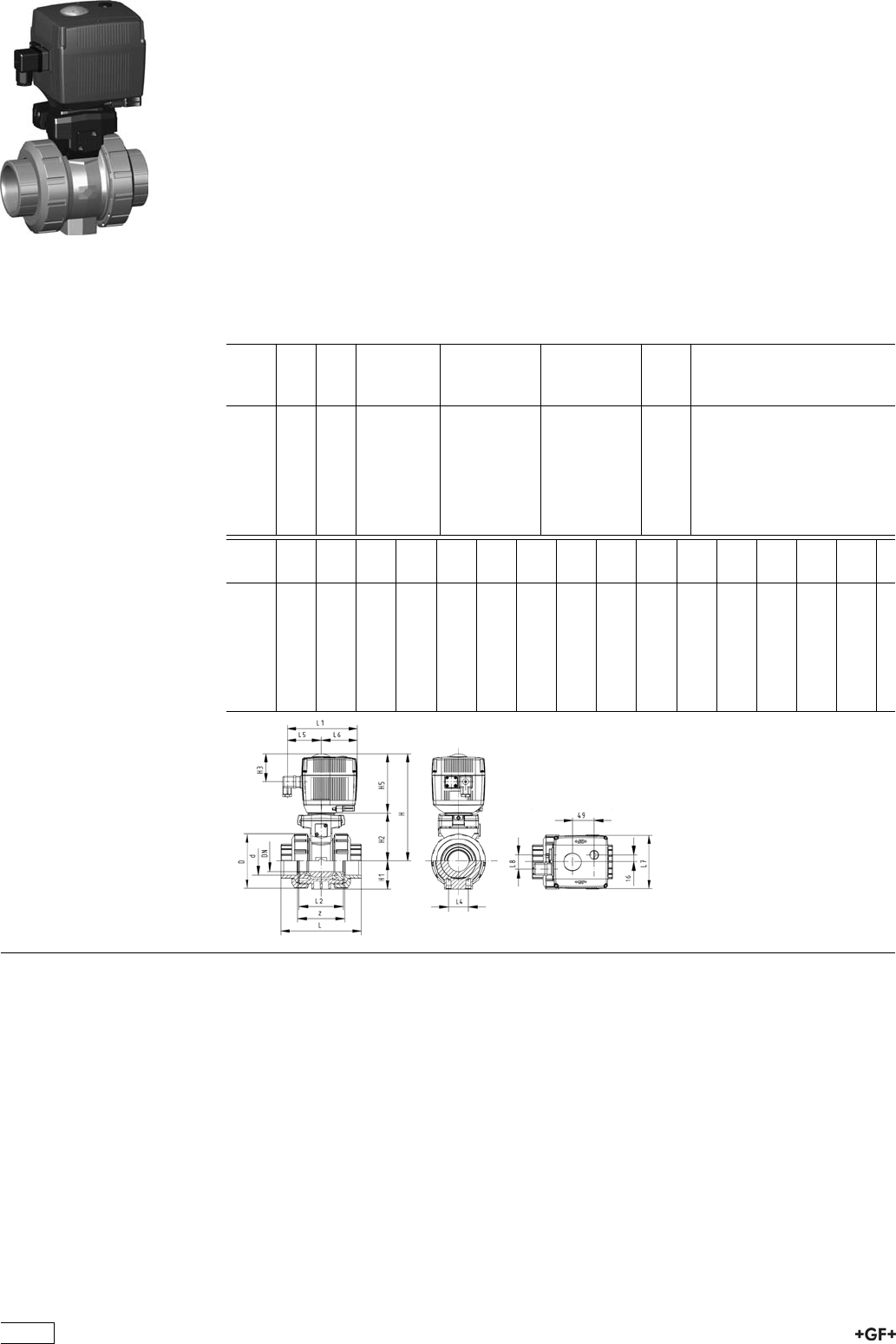
PROGEF Standard
Ball valve type 107 24V
With manual emergency override
With fusion sockets metric
Model:
ÏMaterial: PP-H
ÏBuilt on with electric actuator EA11
ÏVoltage 24 V AC/DC
ÏControl range 90°<)
ÏControl time 5 s/90°<)
ÏFor easy installation and removal
ÏIntegrated stainless steel mounting inserts
Option:
ÏIndividual configuration of the valve (see form)
d
[mm]
DN
[mm]
PN kv-value
(”p=1 bar)
[l/min]
EPDM
Code
FPM
Code
kg
16 10 10 70 199 107 542 199 107 552 2.100
20 15 10 185 199 107 543 199 107 553 2.100
25 20 10 350 199 107 544 199 107 554 2.200
32 25 10 700 199 107 545 199 107 555 2.300
40 32 10 1000 199 107 546 199 107 556 2.600
50 40 10 1600 199 107 547 199 107 557 3.000
63 50 10 3100 199 107 548 199 107 558 3.800
d
[mm]
D
[mm]
H
[mm]
H1
[mm]
H2
[mm]
H3
[mm]
H5
[mm]
L
[mm]
L1
[mm]
L2
[mm]
L4
[mm]
L5
[mm]
L6
[mm]
L7
[mm]
L8
[mm]
z
[mm]
16 50 200 27 64 64 137 93 161 56 25 77 83 122 33 67
20 50 200 27 64 64 137 95 161 56 25 77 83 122 33 66
25 58 209 30 73 64 137 108 161 65 25 77 83 122 33 77
32 68 209 36 73 64 137 118 161 71 25 77 83 122 33 83
40 84 220 44 84 64 137 137 161 85 45 77 83 122 33 99
50 97 220 51 84 64 137 147 161 89 45 77 83 122 33 105
63 124 243 64 106 64 137 168 161 101 45 77 83 122 33 117
180
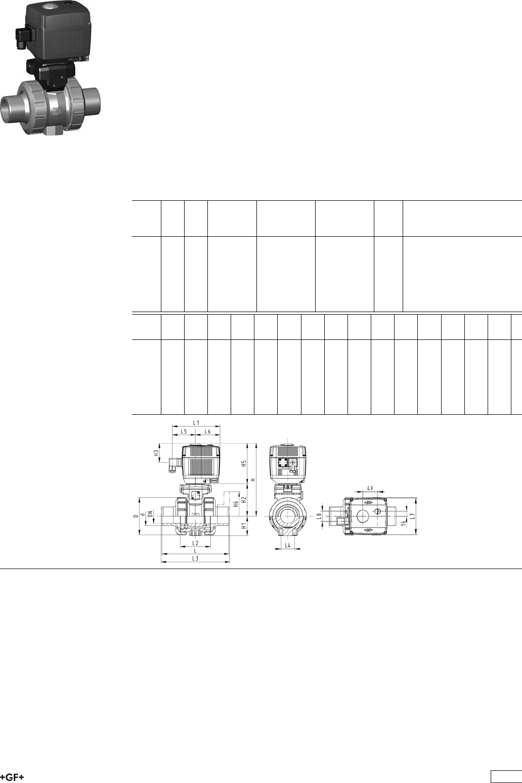
PROGEF Standard
Ball valve type 107 24V
With manual emergency override
With fusion spigots metric
Model:
ÏMaterial: PP-H
ÏBuilt on with electric actuator EA11
ÏVoltage 24 V AC/DC
ÏControl range 90°<)
ÏControl time 5 s/90°<)
ÏFor easy installation and removal
ÏIntegrated stainless steel mounting inserts
Option:
ÏIndividual configuration of the valve (see form)
d
[mm]
DN
[mm]
PN kv-value
(”p=1 bar)
[l/min]
EPDM
Code
FPM
Code
kg
16 10 10 70 199 107 562 199 107 572 2.100
20 15 10 185 199 107 563 199 107 573 2.100
25 20 10 350 199 107 564 199 107 574 2.200
32 25 10 700 199 107 565 199 107 575 2.300
40 32 10 1000 199 107 566 199 107 576 2.600
50 40 10 1600 199 107 567 199 107 577 3.000
63 50 10 3100 199 107 568 199 107 578 3.800
d
[mm]
D
[mm]
H
[mm]
H1
[mm]
H2
[mm]
H3
[mm]
H5
[mm]
L
[mm]
L1
[mm]
L2
[mm]
L3
[mm]
L4
[mm]
L5
[mm]
L6
[mm]
L7
[mm]
L8
[mm]
16 50 200 27 64 64 137 110 161 56 130 25 77 83 122 33
20 50 200 27 64 64 137 120 161 56 130 25 77 83 122 33
25 58 209 30 73 64 137 139 161 65 150 25 77 83 122 33
32 68 209 36 73 64 137 156 161 71 160 25 77 83 122 33
40 84 220 44 84 64 137 170 161 85 180 45 77 83 122 33
50 97 220 51 84 64 137 190 161 89 200 45 77 83 122 33
63 124 243 64 106 64 137 220 161 101 230 45 77 83 122 33
181

PROGEF Standard
Ball valve type 107 24V
With manual emergency override
With fixed flanges PP-H serrated metric
Model:
ÏMaterial: PP-H
ÏBuilt on with electric actuator EA11
ÏVoltage 24 V AC/DC
ÏControl range 90°<)
ÏControl time 5 s/90°<)
ÏFor easy installation and removal
ÏIntegrated stainless steel mounting inserts
ÏOverall length according to EN 558
ÏConnecting dimensions: ISO 7005 / EN 1092 / DIN 2501 PN10 / BS4504
Option:
ÏIndividual configuration of the valve (see form)
d
[mm]
DN
[mm]
Inch PN kv-value
(”p=1 bar)
[l/min]
EPDM
Code
FPM
Code
kg
20 15 1
/210 185 199 107 783 199 107 793 2.300
25 20 3
/410 350 199 107 784 199 107 794 2.500
32 25 1 10 700 199 107 785 199 107 795 2.700
40 32 1 1
/410 1000 199 107 786 199 107 796 3.200
50 40 1 1
/210 1600 199 107 787 199 107 797 3.700
63 50 2 10 3100 199 107 788 199 107 798 4.800
d
[mm]
D
[mm]
H
[mm]
H1
[mm]
H2
[mm]
H3
[mm]
H5
[mm]
H6
[mm]
L
[mm]
L1
[mm]
L2
[mm]
L3
[mm]
L4
[mm]
L5
[mm]
L6
[mm]
L7
[mm]
20 50 200 27 64 64 137 48 120 161 56 130 25 77 83 122
25 58 209 30 73 64 137 53 140 161 65 150 25 77 83 122
32 68 209 36 73 64 137 58 150 161 71 160 25 77 83 122
40 84 220 44 84 64 137 70 170 161 85 180 45 77 83 122
50 97 220 51 84 64 137 75 190 161 89 200 45 77 83 122
63 124 243 64 106 64 137 165 220 161 101 230 45 77 83 122
d
[mm]
L8
[mm]
20 33
25 33
32 33
40 33
50 33
63 33
182
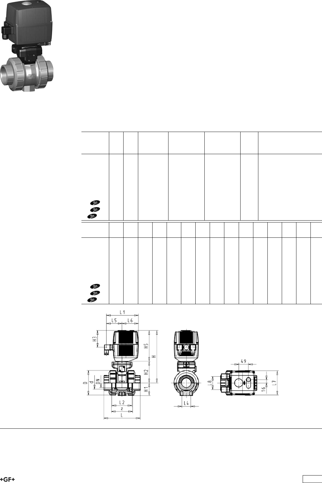
PROGEF Standard
Ball valve type 131 100-230V
With manual emergency override
With fusion sockets metric
Model:
ÏMaterial: PP-H
ÏFor easy installation and removal
ÏIntegrated stainless steel mounting inserts
ÏVoltage 100-230 V, 50-60 Hz
ÏControl range 90°<)
ÏAssignment of actuators: EA21 (DN10/15-50), EA31 (DN65-100 if available)
ÏImage and drawing DN65-100 please see ''New product ball valve DN65-100''
ÏControl time: EA21: 5s/90°<), EA31: 15s/90°<)
Option:
ÏIndividual configuration of the valve (see form)
d
[mm]
DN
[mm]
PN kv-value
(”p=1 bar)
[l/min]
EPDM
Code
FPM
Code
kg
16 10 10 70 199 131 002 199 131 012 2.100
20 15 10 185 199 131 003 199 131 013 2.100
25 20 10 350 199 131 004 199 131 014 2.200
32 25 10 700 199 131 005 199 131 015 2.300
40 32 10 1000 199 131 006 199 131 016 2.600
50 40 10 1600 199 131 007 199 131 017 3.000
63 50 10 3100 199 131 008 199 131 018 3.800
75 65 10 5000 199 131 009 199 131 019 3.600
90 80 10 7000 199 131 010 199 131 020 4.300
110 100 10 11000 199 131 011 199 131 021 5.500
d
[mm]
D
[mm]
H
[mm]
H1
[mm]
H2
[mm]
H3
[mm]
H5
[mm]
L
[mm]
L1
[mm]
L2
[mm]
L4
[mm]
L5
[mm]
L6
[mm]
L7
[mm]
z
[mm]
16 50 231 27 64 94 167 93 180 56 25 97 83 122 67
20 50 231 27 64 94 167 95 180 56 25 97 83 122 66
25 58 240 30 73 94 167 108 180 65 25 97 83 122 77
32 68 240 36 73 94 167 118 180 71 25 97 83 122 83
40 84 251 44 84 94 167 137 180 85 45 97 83 122 99
50 97 251 51 84 94 167 147 180 89 45 97 83 122 105
63 124 273 64 106 94 167 168 180 101 45 97 83 122 117
75 166 346 85 156 94 190 233 180 136 70 98 83 122 167
90 200 358 105 168 94 190 254 180 141 70 98 83 122 180
110 238 365 123 175 94 190 301 180 164 120 98 83 122 215
183

PROGEF Standard
Ball valve type 131 100-230V
With manual emergency override
With socket fusion spigots metric
Model:
ÏMaterial: PP-H
ÏFor easy installation and removal
ÏIntegrated stainless steel mounting inserts
ÏVoltage 100-230 V, 50-60 Hz
ÏControl range 90°<)
ÏAssignment of actuators: EA21 (DN10/15-50), EA31 (DN65-100 if available)
ÏImage and drawing DN65-100 please see ''New product ball valve DN65-100''
ÏControl time: EA21: 5s/90°<), EA31: 15s/90°<)
Option:
ÏIndividual configuration of the valve (see form)
d
[mm]
DN
[mm]
PN kv-value
(”p=1 bar)
[l/min]
EPDM
Code
FPM
Code
kg
16 10 10 70 199 131 022 199 131 032 2.100
20 15 10 185 199 131 023 199 131 033 2.100
25 20 10 350 199 131 024 199 131 034 2.200
32 25 10 700 199 131 025 199 131 035 2.300
40 32 10 1000 199 131 026 199 131 036 2.600
50 40 10 1600 199 131 027 199 131 037 3.000
63 50 10 3100 199 131 028 199 131 038 3.800
75 65 10 5000 199 131 029 199 131 039 3.600
90 80 10 7000 199 131 030 199 131 040 4.400
110 100 10 11000 199 131 031 199 131 041 5.500
d
[mm]
D
[mm]
H
[mm]
H1
[mm]
H2
[mm]
H3
[mm]
H5
[mm]
L
[mm]
L1
[mm]
L2
[mm]
L3
[mm]
L4
[mm]
L5
[mm]
L6
[mm]
L7
[mm]
16 50 231 27 64 94 167 110 180 56 130 25 97 83 122
20 50 231 27 64 94 167 120 180 56 130 25 97 83 122
25 58 240 30 73 94 167 139 180 65 150 25 97 83 122
32 68 240 36 73 94 167 150 180 71 160 25 97 83 122
40 84 251 44 84 94 167 170 180 85 180 45 97 83 122
50 97 251 51 84 94 167 190 180 89 200 45 97 83 122
63 124 273 64 106 94 167 220 180 101 230 45 97 83 122
75 166 346 85 156 94 190 280 180 136 290 70 98 83 122
90 200 358 105 168 94 190 296 180 141 310 70 98 83 122
110 238 365 123 175 94 190 336 180 164 350 120 98 83 122
184

PROGEF Standard
Ball valve type 131 100-230V
With manual emergency override
With fixed flanges PP-H serrated metric
Model:
ÏMaterial: PP-H
ÏFor easy installation and removal
ÏIntegrated stainless steel mounting inserts
ÏVoltage 100-230 V, 50-60 Hz
ÏControl range 90°<)
ÏBuilt on with electric actuator EA21
ÏControl time 5 s/90°<)
ÏOverall length according to EN 558
ÏConnecting dimensions: ISO 7005 / EN 1092 / DIN 2501 PN10 / BS4504
Option:
ÏIndividual configuration of the valve (see form)
d
[mm]
DN
[mm]
Inch PN kv-value
(”p=1 bar)
[l/min]
EPDM
Code
FPM
Code
kg
20 15 1
/210 185 199 131 083 199 131 093 2.300
25 20 3
/410 350 199 131 084 199 131 094 2.500
32 25 1 10 700 199 131 085 199 131 095 2.700
40 32 1 1
/410 1000 199 131 086 199 131 096 3.200
50 40 1 1
/210 1600 199 131 087 199 131 097 3.700
63 50 2 10 3100 199 131 088 199 131 098 4.800
d
[mm]
D
[mm]
H
[mm]
H1
[mm]
H2
[mm]
H3
[mm]
H5
[mm]
H6
[mm]
L
[mm]
L1
[mm]
L2
[mm]
L3
[mm]
L4
[mm]
L5
[mm]
L6
[mm]
L7
[mm]
20 50 231 27 64 94 167 48 120 180 56 130 25 97 83 122
25 58 240 30 73 94 167 53 140 180 65 150 25 97 83 122
32 68 240 36 73 94 167 58 150 180 71 160 25 97 83 122
40 84 251 44 84 94 167 70 170 180 85 180 45 97 83 122
50 97 251 51 84 94 167 75 190 180 89 200 45 97 83 122
63 124 273 64 106 94 167 165 220 180 101 230 45 97 83 122
d
[mm]
L8
[mm]
20 66
25 66
32 66
40 66
50 66
63 66
185

PROGEF Standard
Ball valve type 131 100-230V
With manual emergency override
With backing flanges PP-st metric
Model:
ÏMaterial: PP-H
ÏFor easy installation and removal
ÏIntegrated stainless steel mounting inserts
ÏVoltage 100-230 V, 50-60 Hz
ÏControl range 90°<)
ÏAssignment of actuators: EA21 (DN10/15-50), EA31 (DN65-100 if available)
ÏImage and drawing DN65-100 please see ''New product ball valve DN65-100''
ÏControl time: EA21: 5s/90°<), EA31: 15s/90°<)
ÏOverall length according to EN 558
ÏConnecting dimension: ISO 7005, EN 1092, BS 4504, DIN 2501
Option:
ÏIndividual configuration of the valve (see form)
d
[mm]
DN
[mm]
Inch PN kv-value
(”p=1 bar)
[l/min]
EPDM
Code
FPM
Code
kg
75 65 2 1
/210 5000 199 131 129 199 131 139 7.900
90 80 3 10 7000 199 131 130 199 131 140 9.600
110 100 4 10 11000 199 131 131 199 131 141 12.700
d
[mm]
D
[mm]
H
[mm]
H1
[mm]
H2
[mm]
H3
[mm]
H5
[mm]
H6
[mm]
L
[mm]
L1
[mm]
L2
[mm]
L3
[mm]
L4
[mm]
L5
[mm]
L6
[mm]
75 166 346 85 156 94 190 93 280 180 136 290 70 98 83
90 200 358 105 168 94 190 100 296 180 141 310 70 98 83
110 238 365 123 175 94 190 110 336 180 164 350 120 98 83
d
[mm]
L7
[mm]
L8
[mm]
75 122 66
90 122 66
110 122 66
186
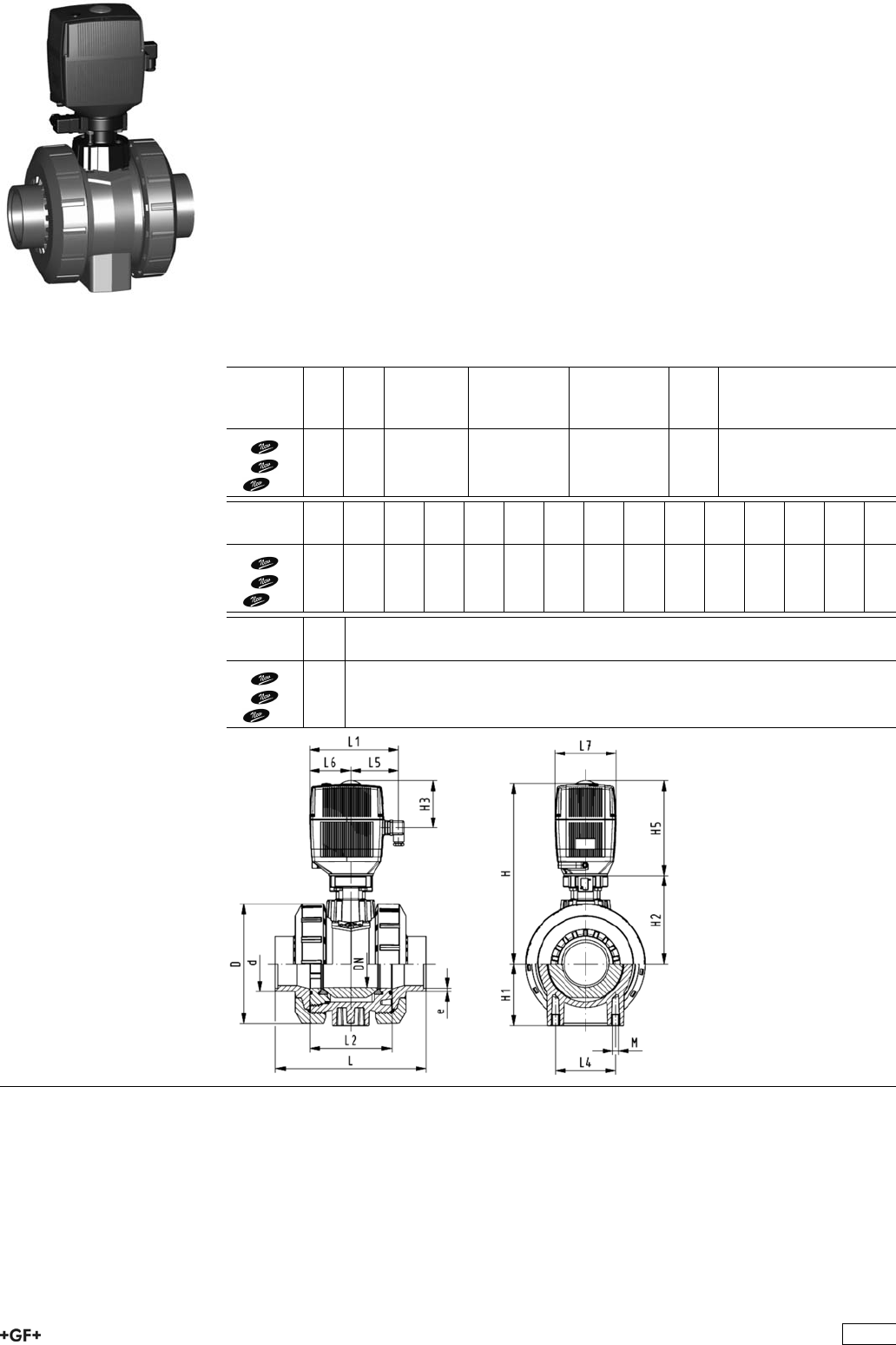
PROGEF Standard
Ball valve type 131 100-230V
With manual emergency override
With butt fusion spigots IR-Plus SDR11 metric
Model:
ÏMaterial: PP-H
ÏFor easy installation and removal
ÏIntegrated stainless steel mounting inserts
ÏVoltage 100-230 V, 50-60 Hz
ÏControl range 90°<)
ÏAssignment of actuators: EA21 (DN10/15-50), EA31 (DN65-100 if available)
ÏImage and drawing DN65-100 please see ''New product ball valve DN65-100''
ÏControl time: EA21: 5s/90°<), EA31: 15s/90°<)
Option:
ÏIndividual configuration of the valve (see form)
d
[mm]
DN
[mm]
PN kv-value
(”p=1 bar)
[l/min]
EPDM
Code
FPM
Code
kg
75 65 10 5000 199 131 329 199 131 339 3.600
90 80 10 7000 199 131 330 199 131 340 4.400
110 100 10 11000 199 131 331 199 131 341 5.500
d
[mm]
D
[mm]
H
[mm]
H1
[mm]
H2
[mm]
H3
[mm]
H5
[mm]
L
[mm]
L1
[mm]
L2
[mm]
L3
[mm]
L4
[mm]
L5
[mm]
L6
[mm]
L7
[mm]
75 166 346 85 156 94 190 266 180 136 290 70 98 83 122
90 200 358 105 168 94 190 264 180 141 310 70 98 83 122
110 238 365 123 175 94 190 301 180 164 350 120 98 83 122
d
[mm]
e
[mm]
75 8.2
90 9.9
110 12.0
187

PROGEF Standard
Ball valve type 131 100-230V
With manual emergency override
With butt fusion spigots SDR17.6 metric
Model:
ÏMaterial: PP-H
ÏFor easy installation and removal
ÏIntegrated stainless steel mounting inserts
ÏVoltage 100-230 V, 50-60 Hz
ÏControl range 90°<)
ÏAssignment of actuators: EA21 (DN10/15-50), EA31 (DN65-100 if available)
ÏImage and drawing DN65-100 please see ''New product ball valve DN65-100''
ÏControl time: EA21: 5s/90°<), EA31: 15s/90°<)
Option:
ÏIndividual configuration of the valve (see form)
d
[mm]
DN
[mm]
PN kv-value
(”p=1 bar)
[l/min]
EPDM
Code
FPM
Code
kg
75 65 10 5000 199 131 729 199 131 739 3.600
90 80 10 7000 199 131 730 199 131 740 4.400
110 100 10 11000 199 131 731 199 131 741 5.500
d
[mm]
D
[mm]
H
[mm]
H1
[mm]
H2
[mm]
H3
[mm]
H5
[mm]
L
[mm]
L1
[mm]
L2
[mm]
L3
[mm]
L4
[mm]
L5
[mm]
L6
[mm]
L7
[mm]
75 166 346 85 156 94 190 266 180 136 290 70 98 83 122
90 200 358 105 168 94 190 264 180 141 310 70 98 83 122
110 238 365 123 175 94 190 301 180 164 350 120 98 83 122
d
[mm]
e
[mm]
75 4.6
90 5.5
110 6.7
188

PROGEF Standard
Ball valve type 131 24V
With manual emergency override
With fusion sockets metric
Model:
ÏMaterial: PP-H
ÏFor easy installation and removal
ÏIntegrated stainless steel mounting inserts
ÏVoltage 24 V AC/DC
ÏControl range 90°<)
ÏAssignment of actuators: EA21 (DN10/15-50), EA31 (DN65-100 if available)
ÏImage and drawing DN65-100 please see ''New product ball valve DN65-100''
ÏControl time: EA21: 5s/90°<), EA31: 15s/90°<)
Option:
ÏIndividual configuration of the valve (see form)
d
[mm]
DN
[mm]
PN kv-value
(”p=1 bar)
[l/min]
EPDM
Code
FPM
Code
kg
16 10 10 70 199 131 042 199 131 052 2.100
20 15 10 185 199 131 043 199 131 053 2.100
25 20 10 350 199 131 044 199 131 054 2.200
32 25 10 700 199 131 045 199 131 055 2.300
40 32 10 1000 199 131 046 199 131 056 2.600
50 40 10 1600 199 131 047 199 131 057 3.000
63 50 10 3100 199 131 048 199 131 058 3.800
75 65 10 5000 199 131 049 199 131 059 3.600
90 80 10 7000 199 131 050 199 131 060 4.300
110 100 10 11000 199 131 051 199 131 061 5.500
d
[mm]
D
[mm]
H
[mm]
H1
[mm]
H2
[mm]
H3
[mm]
H5
[mm]
L
[mm]
L1
[mm]
L2
[mm]
L4
[mm]
L5
[mm]
L6
[mm]
L7
[mm]
z
[mm]
16 50 231 27 64 94 167 93 180 56 25 97 83 122 67
20 50 231 27 64 94 167 95 180 56 25 97 83 122 66
25 58 240 30 73 94 167 108 180 65 25 97 83 122 77
32 68 240 36 73 94 167 118 180 71 25 97 83 122 83
40 84 251 44 84 94 167 137 180 85 45 97 83 122 99
50 97 251 51 84 94 167 147 180 89 45 97 83 122 105
63 124 273 64 106 94 167 168 180 101 45 97 83 122 117
75 166 346 85 156 94 190 233 180 136 70 98 83 122 167
90 200 358 105 168 94 190 254 180 141 70 98 83 122 180
110 238 365 123 175 94 190 301 180 164 120 98 83 122 215
189
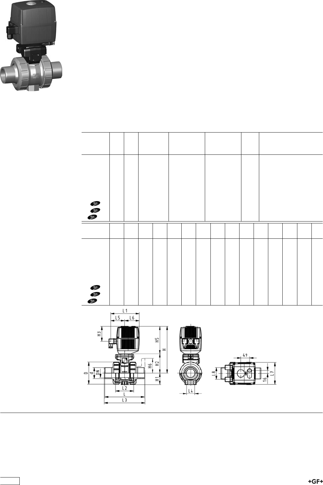
PROGEF Standard
Ball valve type 131 24V
With manual emergency override
With socket fusion spigots metric
Model:
ÏMaterial: PP-H
ÏFor easy installation and removal
ÏIntegrated stainless steel mounting inserts
ÏVoltage 24 V AC/DC
ÏControl range 90°<)
ÏAssignment of actuators: EA21 (DN10/15-50), EA31 (DN65-100 if available)
ÏImage and drawing DN65-100 please see ''New product ball valve DN65-100''
ÏControl time: EA21: 5s/90°<), EA31: 15s/90°<)
Option:
ÏIndividual configuration of the valve (see form)
d
[mm]
DN
[mm]
PN kv-value
(”p=1 bar)
[l/min]
EPDM
Code
FPM
Code
kg
16 10 10 70 199 131 062 199 131 072 2.100
20 15 10 185 199 131 063 199 131 073 2.100
25 20 10 350 199 131 064 199 131 074 2.200
32 25 10 700 199 131 065 199 131 075 2.300
40 32 10 1000 199 131 066 199 131 076 2.600
50 40 10 1600 199 131 067 199 131 077 3.000
63 50 10 3100 199 131 068 199 131 078 3.800
75 65 10 5000 199 131 069 199 131 079 3.600
90 80 10 7000 199 131 070 199 131 080 4.400
110 100 10 11000 199 131 071 199 131 081 5.500
d
[mm]
D
[mm]
H
[mm]
H1
[mm]
H2
[mm]
H3
[mm]
H5
[mm]
L
[mm]
L1
[mm]
L2
[mm]
L3
[mm]
L4
[mm]
L5
[mm]
L6
[mm]
L7
[mm]
16 50 231 27 64 94 167 110 180 56 130 25 97 83 122
20 50 231 27 64 94 167 120 180 56 130 25 97 83 122
25 58 240 30 73 94 167 139 180 65 150 25 97 83 122
32 68 240 36 73 94 167 150 180 71 160 25 97 83 122
40 84 251 44 84 94 167 170 180 85 180 45 97 83 122
50 97 251 51 84 94 167 190 180 89 200 45 97 83 122
63 124 273 64 106 94 167 220 180 101 230 45 97 83 122
75 166 346 85 156 94 190 280 180 136 290 70 98 83 122
90 200 358 105 168 94 190 296 180 141 310 70 98 83 122
110 238 365 123 175 94 190 336 180 164 350 120 98 83 122
190
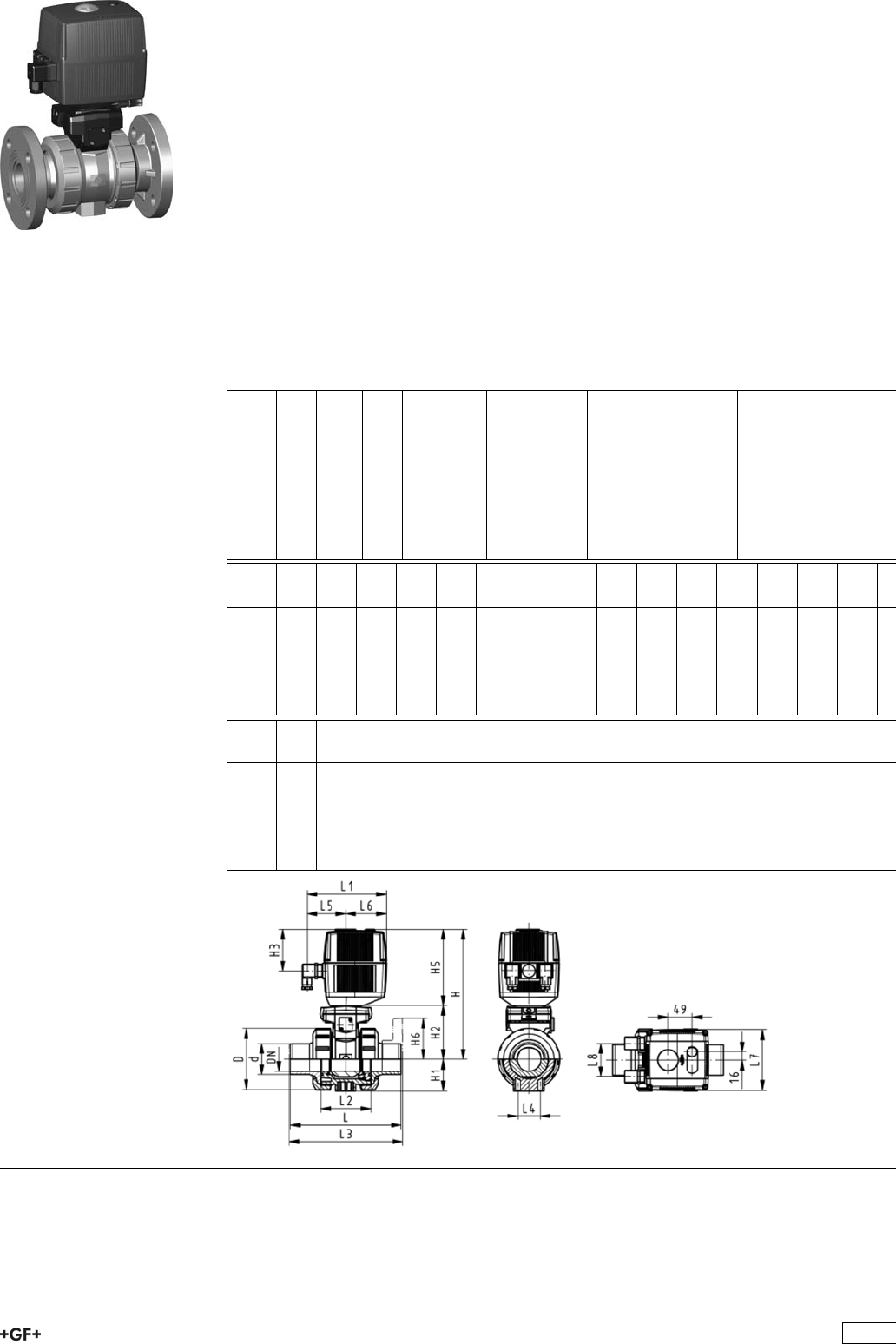
PROGEF Standard
Ball valve type 131 24V
With manual emergency override
With fixed flanges PP-H serrated metric
Model:
ÏMaterial: PP-H
ÏFor easy installation and removal
ÏIntegrated stainless steel mounting inserts
ÏVoltage 24 V AC/DC
ÏControl range 90°<)
ÏBuilt on with electric actuator EA21
ÏControl time 5 s/90°<)
ÏOverall length according to EN 558
ÏConnecting dimensions: ISO 7005 / EN 1092 / DIN 2501 PN10 / BS4504
Option:
ÏIndividual configuration of the valve (see form)
d
[mm]
DN
[mm]
Inch PN kv-value
(”p=1 bar)
[l/min]
EPDM
Code
FPM
Code
kg
20 15 1
/210 185 199 131 103 199 131 113 2.300
25 20 3
/410 350 199 131 104 199 131 114 2.500
32 25 1 10 700 199 131 105 199 131 115 2.700
40 32 1 1
/410 1000 199 131 106 199 131 116 3.200
50 40 1 1
/210 1600 199 131 107 199 131 117 3.700
63 50 2 10 3100 199 131 108 199 131 118 4.800
d
[mm]
D
[mm]
H
[mm]
H1
[mm]
H2
[mm]
H3
[mm]
H5
[mm]
H6
[mm]
L
[mm]
L1
[mm]
L2
[mm]
L3
[mm]
L4
[mm]
L5
[mm]
L6
[mm]
L7
[mm]
20 50 231 27 64 94 167 48 120 180 56 130 25 97 83 122
25 58 240 30 73 94 167 53 140 180 65 150 25 97 83 122
32 68 240 36 73 94 167 58 150 180 71 160 25 97 83 122
40 84 251 44 84 94 167 70 170 180 85 180 45 97 83 122
50 97 251 51 84 94 167 75 190 180 89 200 45 97 83 122
63 124 273 64 106 94 167 165 220 180 101 230 45 97 83 122
d
[mm]
L8
[mm]
20 66
25 66
32 66
40 66
50 66
63 66
191

PROGEF Standard
Ball valve type 131 24V
With manual emergency override
With backing flanges PP-st metric
Model:
ÏMaterial: PP-H
ÏFor easy installation and removal
ÏIntegrated stainless steel mounting inserts
ÏVoltage 24 V AC/DC
ÏControl range 90°<)
ÏAssignment of actuators: EA21 (DN10/15-50), EA31 (DN65-100 if available)
ÏImage and drawing DN65-100 please see ''New product ball valve DN65-100''
ÏControl time: EA21: 5s/90°<), EA31: 15s/90°<)
ÏOverall length according to EN 558
ÏConnecting dimension: ISO 7005, EN 1092, BS 4504, DIN 2501
Option:
ÏIndividual configuration of the valve (see form)
d
[mm]
DN
[mm]
Inch PN kv-value
(”p=1 bar)
[l/min]
EPDM
Code
FPM
Code
kg
75 65 2 1
/210 5000 199 131 149 199 131 159 7.900
90 80 3 10 7000 199 131 150 199 131 160 9.600
110 100 4 10 11000 199 131 151 199 131 161 12.700
d
[mm]
D
[mm]
H
[mm]
H1
[mm]
H2
[mm]
H3
[mm]
H5
[mm]
H6
[mm]
L
[mm]
L1
[mm]
L2
[mm]
L3
[mm]
L4
[mm]
L5
[mm]
L6
[mm]
75 166 346 85 156 94 190 93 280 180 136 290 70 98 83
90 200 358 105 168 94 190 100 296 180 141 310 70 98 83
110 238 365 123 175 94 190 110 336 180 164 350 120 98 83
d
[mm]
L7
[mm]
L8
[mm]
75 122 66
90 122 66
110 122 66
192

PROGEF Standard
Ball valve type 131 24V
With manual emergency override
With butt fusion spigots IR-Plus SDR11 metric
Model:
ÏMaterial: PP-H
ÏFor easy installation and removal
ÏIntegrated stainless steel mounting inserts
ÏVoltage 24 V AC/DC
ÏControl range 90°<)
ÏAssignment of actuators: EA21 (DN10/15-50), EA31 (DN65-100 if available)
ÏImage and drawing DN65-100 please see ''New product ball valve DN65-100''
ÏControl time: EA21: 5s/90°<), EA31: 15s/90°<)
Option:
ÏIndividual configuration of the valve (see form)
d
[mm]
DN
[mm]
PN kv-value
(”p=1 bar)
[l/min]
EPDM
Code
FPM
Code
kg
75 65 10 5000 199 131 369 199 131 379 3.600
90 80 10 7000 199 131 370 199 131 380 4.400
110 100 10 11000 199 131 371 199 131 381 5.500
d
[mm]
D
[mm]
H
[mm]
H1
[mm]
H2
[mm]
H3
[mm]
H5
[mm]
L
[mm]
L1
[mm]
L2
[mm]
L3
[mm]
L4
[mm]
L5
[mm]
L6
[mm]
L7
[mm]
75 166 346 85 156 94 190 266 180 136 290 70 98 83 122
90 200 358 105 168 94 190 264 180 141 310 70 98 83 122
110 238 365 123 175 94 190 301 180 164 350 120 98 83 122
d
[mm]
e
[mm]
75 8.2
90 9.9
110 12.0
193

PROGEF Standard
Ball valve type 131 24V
With manual emergency override
With butt fusion spigots SDR17.6 metric
Model:
ÏMaterial: PP-H
ÏFor easy installation and removal
ÏIntegrated stainless steel mounting inserts
ÏVoltage 24 V AC/DC
ÏControl range 90°<)
ÏAssignment of actuators: EA21 (DN10/15-50), EA31 (DN65-100 if available)
ÏImage and drawing DN65-100 please see ''New product ball valve DN65-100''
ÏControl time: EA21: 5s/90°<), EA31: 15s/90°<)
Option:
ÏIndividual configuration of the valve (see form)
d
[mm]
DN
[mm]
PN kv-value
(”p=1 bar)
[l/min]
EPDM
Code
FPM
Code
kg
75 65 10 5000 199 131 769 199 131 779 3.600
90 80 10 7000 199 131 770 199 131 780 4.400
110 100 10 11000 199 131 771 199 131 781 5.500
d
[mm]
D
[mm]
H
[mm]
H1
[mm]
H2
[mm]
H3
[mm]
H5
[mm]
L
[mm]
L1
[mm]
L2
[mm]
L3
[mm]
L4
[mm]
L5
[mm]
L6
[mm]
L7
[mm]
75 166 346 85 156 94 190 266 180 136 290 70 98 83 122
90 200 358 105 168 94 190 264 180 141 310 70 98 83 122
110 238 365 123 175 94 190 301 180 164 350 120 98 83 122
d
[mm]
e
[mm]
75 4.6
90 5.5
110 6.7
194
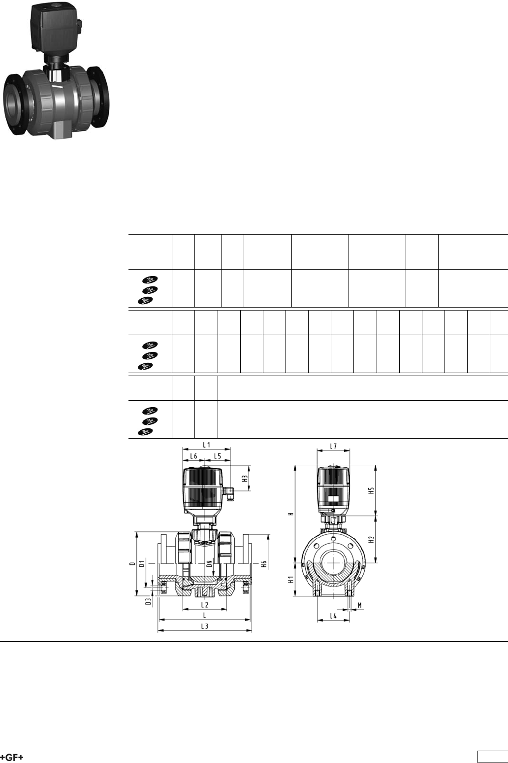
PROGEF Standard
Ball valve type 131 100-230V
With manual emergency override
With backing flanges PP-st ASTM
Model:
ÏMaterial: PP-H
ÏFor easy installation and removal
ÏVoltage 100-230 V, 50-60 Hz
ÏControl range 90°<)
ÏIntegrated stainless steel mounting inserts
ÏAssignment of actuators: EA21 (DN10/15-50), EA31 (DN65-100 if available)
ÏImage and drawing DN65-100 please see ''New product ball valve DN65-100''
ÏControl time: EA21: 5s/90°<), EA31: 15s/90°<)
ÏOverall length according to EN 558
ÏConnecting dimension ANSI/ASME B 16.5 / ASTM D 4024
Option:
ÏIndividual configuration of the valve (see form)
d
[mm]
DN
[mm]
Inch PN kv-value
(”p=1 bar)
[l/min]
EPDM
Code
FPM
Code
kg
75 65 2 1
/210 5000 199 131 529 199 131 539 10.500
90 80 3 10 7000 199 131 530 199 131 540 13.200
110 100 4 10 11000 199 131 531 199 131 541 18.400
d
[mm]
D
[mm]
H
[mm]
H1
[mm]
H2
[mm]
H3
[mm]
H5
[mm]
H6
[mm]
L
[mm]
L1
[mm]
L2
[mm]
L3
[mm]
L4
[mm]
L5
[mm]
L6
[mm]
75 166 346 85 156 94 190 93 280 180 136 290 70 98 83
90 200 358 105 168 94 190 100 296 180 141 310 70 98 83
110 238 365 123 175 94 190 110 336 180 164 350 120 98 83
d
[mm]
L7
[mm]
L8
[mm]
75 122 66
90 122 66
110 122 66
195

PROGEF Standard
Ball valve type 131 100-230V
With manual emergency override
With threaded sockets NPT
Model:
ÏMaterial: PP-H
ÏFor easy installation and removal
ÏVoltage 100-230 V, 50-60 Hz
ÏControl range 90°<)
ÏIntegrated stainless steel mounting inserts
ÏBuilt on with electric actuator EA21
ÏControl time 5 s/90°<)
Option:
ÏIndividual configuration of the valve (see form)
Inch DN
[mm]
PN kv-value
(”p=1 bar)
[l/min]
EPDM
Code
FPM
Code
3
/810 10 70 199 131 402 199 131 412
1
/215 10 185 199 131 403 199 131 413
3
/420 10 350 199 131 404 199 131 414
1 25 10 700 199 131 405 199 131 415
11
/432 10 1000 199 131 406 199 131 416
11
/240 10 1600 199 131 407 199 131 417
2 50 10 3100 199 131 408 199 131 418
Inch D
[mm]
H
[mm]
H1
[mm]
H2
[mm]
H3
[mm]
H5
[mm]
L
[mm]
L1
[mm]
L2
[mm]
L4
[mm]
L5
[mm]
L6
[mm]
L7
[mm]
z
[mm]
3
/850 231 27 64 94 167 96 180 56 25 97 83 122 71
1
/250 231 27 64 94 167 99 180 56 25 97 83 122 64
3
/458 240 30 73 94 167 111 180 65 25 97 83 122 76
1 68 240 36 73 94 167 127 180 71 25 97 83 122 83
11
/484 251 44 84 94 167 146 180 85 45 97 83 122 100
11
/297 251 51 84 94 167 157 180 89 45 97 83 122 111
2 124 273 64 106 94 167 183 180 101 45 97 83 122 134
196

PROGEF Standard
Ball valve type 131 24V
With manual emergency override
With backing flanges PP-st ASTM
Model:
ÏMaterial: PP-H
ÏVoltage 24 V AC/DC
ÏControl range 90°<)
ÏFor easy installation and removal
ÏIntegrated stainless steel mounting inserts
ÏAssignment of actuators: EA21 (DN10/15-50), EA31 (DN65-100 if available)
ÏImage and drawing DN65-100 please see ''New product ball valve DN65-100''
ÏControl time: EA21: 5s/90°<), EA31: 15s/90°<)
ÏOverall length according to EN 558
ÏConnecting dimension ANSI/ASME B 16.5 / ASTM D 4024
Option:
ÏIndividual configuration of the valve (see form)
d
[mm]
DN
[mm]
Inch PN kv-value
(”p=1 bar)
[l/min]
EPDM
Code
FPM
Code
kg
75 65 2 1
/210 5000 199 131 549 199 131 559 10.500
90 80 3 10 7000 199 131 550 199 131 560 13.200
110 100 4 10 11000 199 131 551 199 131 561 18.400
d
[mm]
D
[mm]
H
[mm]
H1
[mm]
H2
[mm]
H3
[mm]
H5
[mm]
H6
[mm]
L
[mm]
L1
[mm]
L2
[mm]
L3
[mm]
L4
[mm]
L5
[mm]
L6
[mm]
75 166 346 85 156 94 190 93 280 180 136 290 70 98 83
90 200 358 105 168 94 190 100 296 180 141 310 70 98 83
110 238 365 123 175 94 190 110 336 180 164 350 120 98 83
d
[mm]
L7
[mm]
L8
[mm]
75 122 66
90 122 66
110 122 66
197
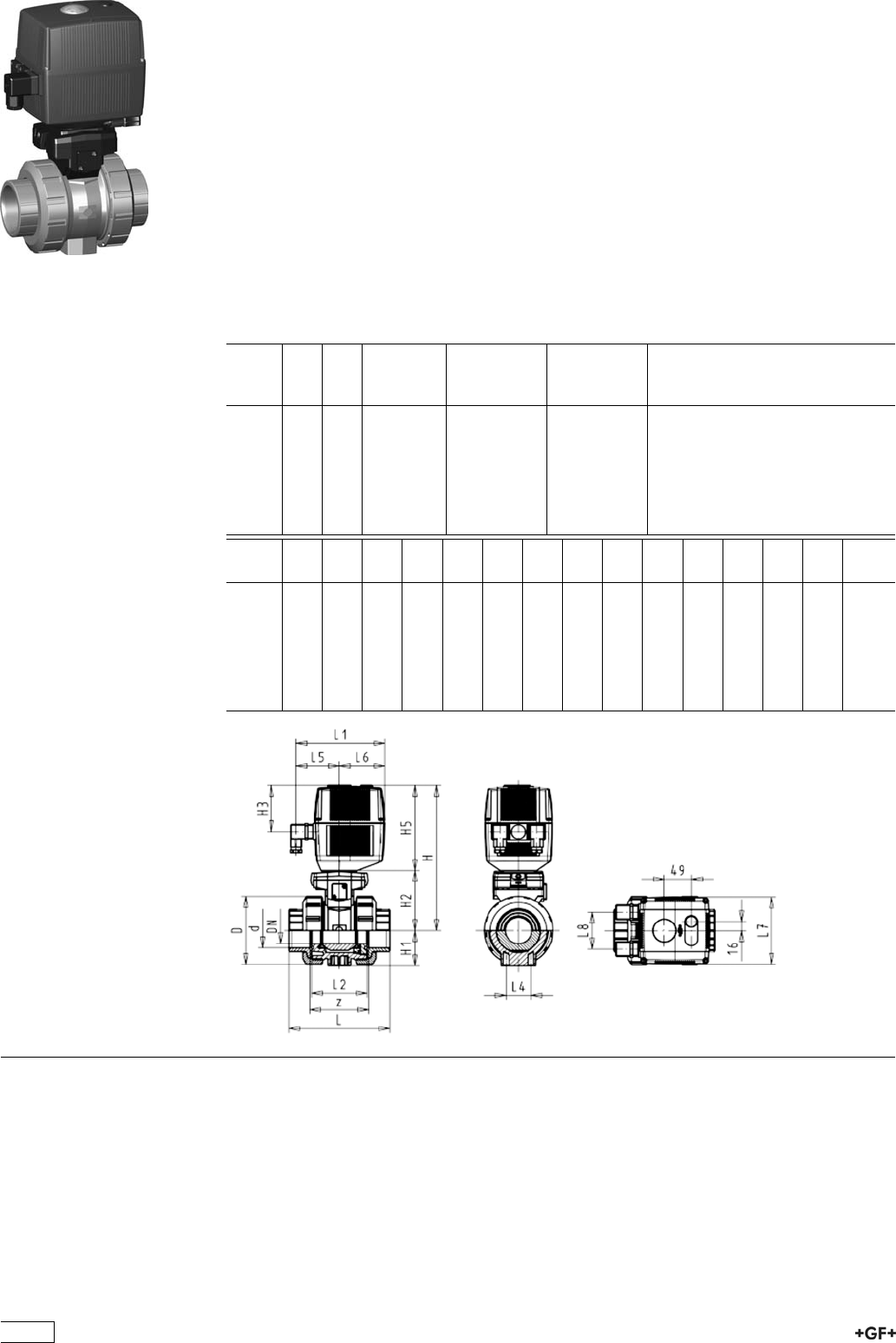
PROGEF Standard
Ball valve type 131 24V
With manual emergency override
With threaded sockets NPT
Model:
ÏMaterial: PP-H
ÏVoltage 24 V AC/DC
ÏControl range 90°<)
ÏFor easy installation and removal
ÏIntegrated stainless steel mounting inserts
ÏBuilt on with electric actuator EA21
ÏControl time 5 s/90°<)
Option:
ÏIndividual configuration of the valve (see form)
Inch DN
[mm]
PN kv-value
(”p=1 bar)
[l/min]
EPDM
Code
FPM
Code
3
/810 10 70 199 131 422 199 131 432
1
/215 10 185 199 131 423 199 131 433
3
/420 10 350 199 131 424 199 131 434
1 25 10 700 199 131 425 199 131 435
11
/432 10 1000 199 131 426 199 131 436
11
/240 10 1600 199 131 427 199 131 437
2 50 10 3100 199 131 428 199 131 438
Inch D
[mm]
H
[mm]
H1
[mm]
H2
[mm]
H3
[mm]
H5
[mm]
L
[mm]
L1
[mm]
L2
[mm]
L4
[mm]
L5
[mm]
L6
[mm]
L7
[mm]
z
[mm]
3
/850 231 27 64 94 167 96 180 56 25 97 83 122 71
1
/250 231 27 64 94 167 99 180 56 25 97 83 122 64
3
/458 240 30 73 94 167 111 180 65 25 97 83 122 76
1 68 240 36 73 94 167 127 180 71 25 97 83 122 83
11
/484 251 44 84 94 167 146 180 85 45 97 83 122 100
11
/297 251 51 84 94 167 157 180 89 45 97 83 122 111
2 124 273 64 106 94 167 183 180 101 45 97 83 122 134
198

PROGEF Standard
3-Way ball valve type 176
Horizontal/L-port 100-230V
With manual emergency override
With fusion sockets metric
Model:
ÏMaterial: PP-H
ÏAssignment of actuators: EA21 (DN10/15-50), EA31 (DN65-100 if available)
ÏVoltage 100-230 V, 50-60 Hz
ÏControl range 90°<)
ÏControl time 5 s/90°<)
ÏFor easy installation and removal
ÏIntegrated stainless steel mounting inserts
d
[mm]
DN
[mm]
PN kv-value
(”p=1 bar)
[l/min]
EPDM
Code
FPM
Code
kg
16 10 10 50 199 176 022 199 176 032 2.051
20 15 10 75 199 176 023 199 176 033 2.051
25 20 10 150 199 176 024 199 176 034 2.174
32 25 10 280 199 176 025 199 176 035 2.297
40 32 10 480 199 176 026 199 176 036 2.522
50 40 10 620 199 176 027 199 176 037 2.886
63 50 10 1230 199 176 028 199 176 038 3.818
d
[mm]
D
[mm]
H
[mm]
H1
[mm]
H2
[mm]
H3
[mm]
H5
[mm]
H6
[mm]
L
[mm]
L1
[mm]
L2
[mm]
L3
[mm]
L4
[mm]
L5
[mm]
L6
[mm]
L7
[mm]
16 46 197 29 31 93 166 8 108 182 70 36 25 99 83 122
20 46 197 29 31 93 166 8 111 182 70 36 25 99 83 122
25 56 205 33 39 93 166 8 131 182 86 43 25 99 83 122
32 67 210 38 44 93 166 8 148 182 96 48 25 99 83 122
40 82 216 44 50 93 166 9 177 182 114 58 45 99 83 122
50 98 229 50 63 93 166 9 205 182 137 69 45 99 83 122
63 121 242 61 76 93 166 9 261 182 179 90 45 99 83 122
d
[mm]
L8
[mm]
M z
[mm]
z1
[mm]
16 33 6 78 39
20 33 6 79 40
25 33 6 95 48
32 33 6 108 54
40 33 8 133 67
50 33 8 155 78
63 33 8 203 102
199

PROGEF Standard
3-Way ball valve type 176
Horizontal/L-port 100-230V
With manual emergency override
With socket fusion spigots
Model:
ÏMaterial: PP-H
ÏAssignment of actuators: EA21 (DN10/15-50), EA31 (DN65-100 if available)
ÏVoltage 100-230 V, 50-60 Hz
ÏControl range 90°<)
ÏControl time 5 s/90°<)
ÏFor easy installation and removal
ÏIntegrated stainless steel mounting inserts
d
[mm]
DN
[mm]
PN kv-value
(”p=1 bar)
[l/min]
EPDM
Code
FPM
Code
kg
16 10 10 75 199 176 002 199 176 012 2.051
20 15 10 75 199 176 003 199 176 013 2.051
25 20 10 150 199 176 004 199 176 014 2.174
32 25 10 280 199 176 005 199 176 015 2.297
40 32 10 480 199 176 006 199 176 016 2.522
50 40 10 620 199 176 007 199 176 017 2.886
63 50 10 1230 199 176 008 199 176 018 3.818
d
[mm]
D
[mm]
H
[mm]
H1
[mm]
H2
[mm]
H3
[mm]
H5
[mm]
H6
[mm]
L
[mm]
L1
[mm]
L2
[mm]
L3
[mm]
L4
[mm]
L5
[mm]
L6
[mm]
L7
[mm]
16 46 197 29 31 93 166 8 119 182 70 36 25 99 83 122
20 46 197 29 31 93 166 8 133 182 70 36 25 99 83 122
25 56 205 33 39 93 166 8 155 182 86 43 25 99 83 122
32 67 210 38 44 93 166 8 170 182 96 48 25 99 83 122
40 82 216 44 50 93 166 9 201 182 114 58 45 99 83 122
50 98 229 50 63 93 166 9 236 182 137 69 45 99 83 122
63 121 242 61 76 93 166 9 286 182 179 90 45 99 83 122
d
[mm]
L8
[mm]
M
16 33 6
20 33 6
25 33 6
32 33 6
40 33 8
50 33 8
63 33 8
200

PROGEF Standard
3-Way ball valve type 176
Horizontal/L-port 100-230V
With manual emergency override
With threaded sockets Rp
Model:
ÏMaterial: PP-H
ÏAssignment of actuators: EA21 (DN10/15-50), EA31 (DN65-100 if available)
ÏVoltage 100-230 V, 50-60 Hz
ÏControl range 90°<)
ÏControl time 5 s/90°<)
ÏFor easy installation and removal
ÏIntegrated stainless steel mounting inserts
Inch DN
[mm]
PN kv-value
(”p=1 bar)
[l/min]
EPDM
Code
FPM
Code
kg
3
/810 10 50 199 176 122 199 176 132 2.051
1
/215 10 75 199 176 123 199 176 133 2.051
3
/420 10 150 199 176 124 199 176 134 2.174
1 25 10 280 199 176 125 199 176 135 2.297
11
/432 10 480 199 176 126 199 176 136 2.522
11
/240 10 620 199 176 127 199 176 137 2.886
2 50 10 1230 199 176 128 199 176 138 3.818
Inch D
[mm]
H
[mm]
H1
[mm]
H2
[mm]
H3
[mm]
H5
[mm]
H6
[mm]
L
[mm]
L1
[mm]
L2
[mm]
L3
[mm]
L4
[mm]
L5
[mm]
L6
[mm]
L7
[mm]
3
/846 197 29 31 93 166 8 108 182 70 36 25 99 83 122
1
/246 197 29 31 93 166 8 111 182 70 36 25 99 83 122
3
/456 205 33 39 93 166 8 131 182 86 43 25 99 83 122
1 67 210 38 44 93 166 8 148 182 96 48 25 99 83 122
11
/482 216 44 50 93 166 9 177 182 114 58 45 99 83 122
11
/298 229 50 63 93 166 9 205 182 137 69 45 99 83 122
2 121 242 61 76 93 166 9 261 182 179 90 45 99 83 122
Inch L8
[mm]
M z
[mm]
z1
[mm]
3
/833 6 78 39
1
/233 6 79 40
3
/433 6 95 48
1 33 6 108 54
11
/433 8 133 67
11
/233 8 155 78
2 33 8 203 102
201
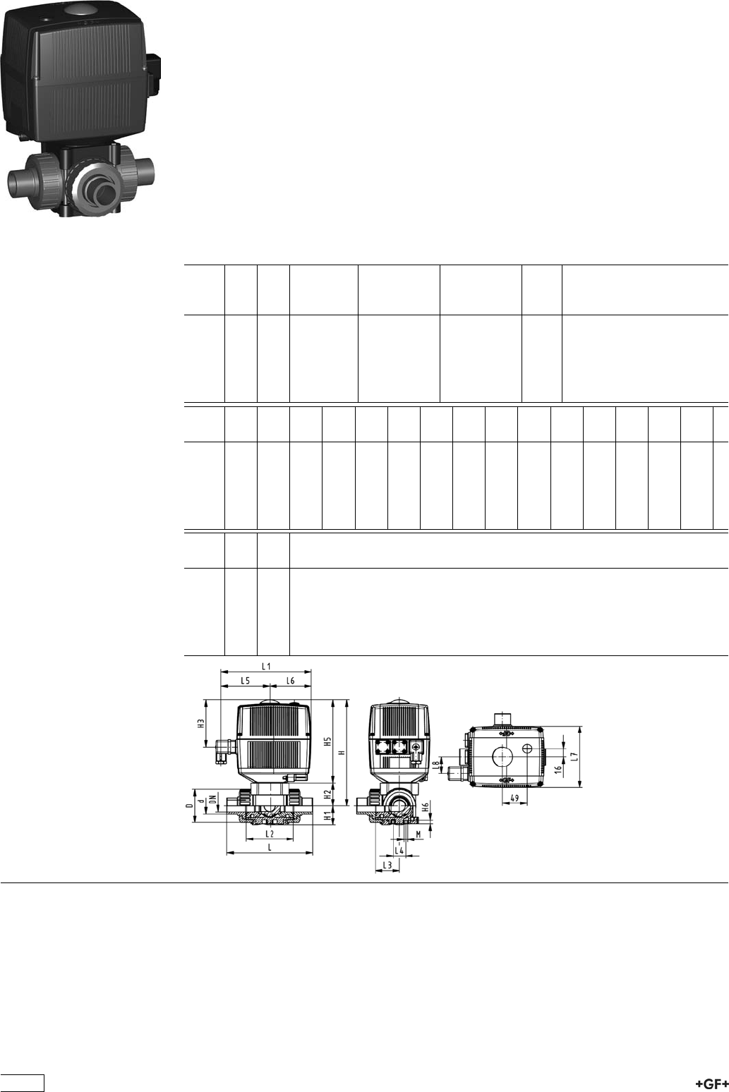
PROGEF Standard
3-Way ball valve type 176
Horizontal/L-port 100-230V
With manual emergency override
With butt fusion spigots metric
Model:
ÏMaterial: PP-H
ÏAssignment of actuators: EA21 (DN10/15-50), EA31 (DN65-100 if available)
ÏVoltage 100-230 V, 50-60 Hz
ÏControl range 90°<)
ÏControl time 5 s/90°<)
ÏFor easy installation and removal
ÏIntegrated stainless steel mounting inserts
d
[mm]
DN
[mm]
PN kv-value
(”p=1 bar)
[l/min]
EPDM
Code
FPM
Code
kg
20 15 10 75 199 176 083 199 176 093 2.051
25 20 10 150 199 176 084 199 176 094 2.174
32 25 10 280 199 176 085 199 176 095 2.297
40 32 10 480 199 176 086 199 176 096 2.522
50 40 10 620 199 176 087 199 176 097 2.886
63 50 10 1230 199 176 088 199 176 098 3.818
d
[mm]
D
[mm]
H
[mm]
H1
[mm]
H2
[mm]
H3
[mm]
H5
[mm]
H6
[mm]
L
[mm]
L1
[mm]
L2
[mm]
L3
[mm]
L4
[mm]
L5
[mm]
L6
[mm]
L7
[mm]
20 46 197 29 31 93 166 8 133 182 70 36 25 99 83 122
25 56 205 33 39 93 166 8 155 182 86 43 25 99 83 122
32 67 210 38 44 93 166 8 170 182 96 48 25 99 83 122
40 82 216 44 50 93 166 9 201 182 114 58 45 99 83 122
50 98 229 50 63 93 166 9 236 182 137 69 45 99 83 122
63 121 242 61 76 93 166 9 286 182 179 90 45 99 83 122
d
[mm]
L8
[mm]
M
20 33 6
25 33 6
32 33 6
40 33 8
50 33 8
63 33 8
202

PROGEF Standard
3-Way ball valve type 176
Horizontal/L-port 24V
With manual emergency override
With fusion sockets metric
Model:
ÏMaterial: PP-H
ÏAssignment of actuators: EA21 (DN10/15-50), EA31 (DN65-100 if available)
ÏVoltage 24 V AC/DC
ÏControl range 90°<)
ÏControl time 5 s/90°<)
ÏFor easy installation and removal
ÏIntegrated stainless steel mounting inserts
d
[mm]
DN
[mm]
PN kv-value
(”p=1 bar)
[l/min]
EPDM
Code
FPM
Code
kg
16 10 10 50 199 176 182 199 176 192 2.051
20 15 10 75 199 176 183 199 176 193 2.051
25 20 10 150 199 176 184 199 176 194 2.174
32 25 10 280 199 176 185 199 176 195 2.297
40 32 10 480 199 176 186 199 176 196 2.522
50 40 10 620 199 176 187 199 176 197 2.886
63 50 10 1230 199 176 188 199 176 198 3.818
d
[mm]
D
[mm]
H
[mm]
H1
[mm]
H2
[mm]
H3
[mm]
H5
[mm]
H6
[mm]
L
[mm]
L1
[mm]
L2
[mm]
L3
[mm]
L4
[mm]
L5
[mm]
L6
[mm]
L7
[mm]
16 46 197 29 31 93 166 8 108 182 70 36 25 99 83 122
20 46 197 29 31 93 166 8 111 182 70 36 25 99 83 122
25 56 205 33 39 93 166 8 131 182 86 43 25 99 83 122
32 67 210 38 44 93 166 8 148 182 96 48 25 99 83 122
40 82 216 44 50 93 166 9 177 182 114 58 45 99 83 122
50 98 229 50 63 93 166 9 205 182 137 69 45 99 83 122
63 121 242 61 76 93 166 9 261 182 179 90 45 99 83 122
d
[mm]
L8
[mm]
M z
[mm]
z1
[mm]
16 33 6 78 39
20 33 6 79 40
25 33 6 95 48
32 33 6 108 54
40 33 8 133 67
50 33 8 155 78
63 33 8 203 102
203

PROGEF Standard
3-Way ball valve type 176
Horizontal/L-port 24V
With manual emergency override
With socket fusion spigots
Model:
ÏMaterial: PP-H
ÏAssignment of actuators: EA21 (DN10/15-50), EA31 (DN65-100 if available)
ÏVoltage 24 V AC/DC
ÏControl range 90°<)
ÏControl time 5 s/90°<)
ÏFor easy installation and removal
ÏIntegrated stainless steel mounting inserts
d
[mm]
DN
[mm]
PN kv-value
(”p=1 bar)
[l/min]
EPDM
Code
FPM
Code
kg
16 10 10 75 199 176 162 199 176 172 2.051
20 15 10 75 199 176 163 199 176 173 2.051
25 20 10 150 199 176 164 199 176 174 2.174
32 25 10 280 199 176 165 199 176 175 2.297
40 32 10 480 199 176 166 199 176 176 2.522
50 40 10 620 199 176 167 199 176 177 2.886
63 50 10 1230 199 176 168 199 176 178 3.818
d
[mm]
D
[mm]
H
[mm]
H1
[mm]
H2
[mm]
H3
[mm]
H5
[mm]
H6
[mm]
L
[mm]
L1
[mm]
L2
[mm]
L3
[mm]
L4
[mm]
L5
[mm]
L6
[mm]
L7
[mm]
16 46 197 29 31 93 166 8 119 182 70 36 25 99 83 122
20 46 197 29 31 93 166 8 133 182 70 36 25 99 83 122
25 56 205 33 39 93 166 8 155 182 86 43 25 99 83 122
32 67 210 38 44 93 166 8 170 182 96 48 25 99 83 122
40 82 216 44 50 93 166 9 201 182 114 58 45 99 83 122
50 98 229 50 63 93 166 9 236 182 137 69 45 99 83 122
63 121 242 61 76 93 166 9 286 182 179 90 45 99 83 122
d
[mm]
L8
[mm]
M
16 33 6
20 33 6
25 33 6
32 33 6
40 33 8
50 33 8
63 33 8
204

PROGEF Standard
3-Way ball valve type 176
Horizontal/L-port 24V
With manual emergency override
With threaded sockets Rp
Model:
ÏMaterial: PP-H
ÏAssignment of actuators: EA21 (DN10/15-50), EA31 (DN65-100 if available)
ÏVoltage 24 V AC/DC
ÏControl range 90°<)
ÏControl time 5 s/90°<)
ÏFor easy installation and removal
ÏIntegrated stainless steel mounting inserts
Inch DN
[mm]
PN kv-value
(”p=1 bar)
[l/min]
EPDM
Code
FPM
Code
kg
3
/810 10 50 199 176 282 199 176 292 2.051
1
/215 10 75 199 176 283 199 176 293 2.051
3
/420 10 150 199 176 284 199 176 294 2.174
1 25 10 280 199 176 285 199 176 295 2.297
11
/432 10 480 199 176 286 199 176 296 2.522
11
/240 10 620 199 176 287 199 176 297 2.886
2 50 10 1230 199 176 288 199 176 298 3.818
Inch D
[mm]
H
[mm]
H1
[mm]
H2
[mm]
H3
[mm]
H5
[mm]
H6
[mm]
L
[mm]
L1
[mm]
L2
[mm]
L3
[mm]
L4
[mm]
L5
[mm]
L6
[mm]
L7
[mm]
3
/846 197 29 31 93 166 8 108 182 70 36 25 99 83 122
1
/246 197 29 31 93 166 8 111 182 70 36 25 99 83 122
3
/456 205 33 39 93 166 8 131 182 86 43 25 99 83 122
1 67 210 38 44 93 166 8 148 182 96 48 25 99 83 122
11
/482 216 44 50 93 166 9 177 182 114 58 45 99 83 122
11
/298 229 50 63 93 166 9 205 182 137 69 45 99 83 122
2 121 242 61 76 93 166 9 261 182 179 90 45 99 83 122
Inch L8
[mm]
M z
[mm]
z1
[mm]
3
/833 6 78 39
1
/233 6 79 40
3
/433 6 95 48
1 33 6 108 54
11
/433 8 133 67
11
/233 8 155 78
2 33 8 203 102
205

PROGEF Standard
3-Way ball valve type 176
Horizontal/L-port 24V
With manual emergency override
With butt fusion spigots metric
Model:
ÏMaterial: PP-H
ÏAssignment of actuators: EA21 (DN10/15-50), EA31 (DN65-100 if available)
ÏVoltage 24 V AC/DC
ÏControl range 90°<)
ÏControl time 5 s/90°<)
ÏFor easy installation and removal
ÏIntegrated stainless steel mounting inserts
d
[mm]
DN
[mm]
PN kv-value
(”p=1 bar)
[l/min]
EPDM
Code
FPM
Code
kg
20 15 10 75 199 176 243 199 176 253 2.051
25 20 10 150 199 176 244 199 176 254 2.174
32 25 10 280 199 176 245 199 176 255 2.297
40 32 10 480 199 176 246 199 176 256 2.522
50 40 10 620 199 176 247 199 176 257 2.886
63 50 10 1230 199 176 248 199 176 258 3.818
d
[mm]
D
[mm]
H
[mm]
H1
[mm]
H2
[mm]
H3
[mm]
H5
[mm]
H6
[mm]
L
[mm]
L1
[mm]
L2
[mm]
L3
[mm]
L4
[mm]
L5
[mm]
L6
[mm]
L7
[mm]
20 46 197 29 31 93 166 8 133 182 70 36 25 99 83 122
25 56 205 33 39 93 166 8 155 182 86 43 25 99 83 122
32 67 210 38 44 93 166 8 170 182 96 48 25 99 83 122
40 82 216 44 50 93 166 9 201 182 114 58 45 99 83 122
50 98 229 50 63 93 166 9 236 182 137 69 45 99 83 122
63 121 242 61 76 93 166 9 286 182 179 90 45 99 83 122
d
[mm]
L8
[mm]
M
20 33 6
25 33 6
32 33 6
40 33 8
50 33 8
63 33 8
206

PROGEF Standard
3-Way ball valve type 176
Horizontal/T-port 100-230V
With manual emergency override
With fusion sockets metric
Model:
ÏMaterial: PP-H
ÏAssignment of actuators: EA21 (DN10/15-50), EA31 (DN65-100 if available)
ÏVoltage 100-230 V, 50-60 Hz
ÏControl range 90°<)
ÏControl time 5 s/90°<)
ÏFor easy installation and removal
ÏIntegrated stainless steel mounting inserts
d
[mm]
DN
[mm]
PN kv-value
(”p=1 bar)
[l/min]
EPDM
Code
FPM
Code
kg
16 10 10 140 199 176 062 199 176 072 2.051
20 15 10 200 199 176 063 199 176 073 2.051
25 20 10 470 199 176 064 199 176 074 2.174
32 25 10 793 199 176 065 199 176 075 2.297
40 32 10 1290 199 176 066 199 176 076 2.522
50 40 10 1910 199 176 067 199 176 077 2.886
63 50 10 3100 199 176 068 199 176 078 3.818
d
[mm]
D
[mm]
H
[mm]
H1
[mm]
H2
[mm]
H3
[mm]
H5
[mm]
H6
[mm]
L
[mm]
L1
[mm]
L2
[mm]
L3
[mm]
L4
[mm]
L5
[mm]
L6
[mm]
L7
[mm]
16 46 197 29 31 93 166 8 108 182 70 36 25 99 83 122
20 46 197 29 31 93 166 8 111 182 70 36 25 99 83 122
25 56 205 33 39 93 166 8 131 182 86 43 25 99 83 122
32 67 210 38 44 93 166 8 148 182 96 48 25 99 83 122
40 82 216 44 50 93 166 9 177 182 114 58 45 99 83 122
50 98 229 50 63 93 166 9 205 182 137 69 45 99 83 122
63 121 242 61 76 93 166 9 261 182 179 90 45 99 83 122
d
[mm]
L8
[mm]
M z
[mm]
z1
[mm]
16 33 6 78 39
20 33 6 79 40
25 33 6 95 48
32 33 6 108 54
40 33 8 133 67
50 33 8 155 78
63 33 8 203 102
207

PROGEF Standard
3-Way ball valve type 176
Horizontal/T-port 100-230V
With manual emergency override
With socket fusion spigots
Model:
ÏMaterial: PP-H
ÏAssignment of actuators: EA21 (DN10/15-50), EA31 (DN65-100 if available)
ÏVoltage 100-230 V, 50-60 Hz
ÏControl range 90°<)
ÏControl time 5 s/90°<)
ÏFor easy installation and removal
ÏIntegrated stainless steel mounting inserts
d
[mm]
DN
[mm]
PN kv-value
(”p=1 bar)
[l/min]
EPDM
Code
FPM
Code
kg
16 10 10 200 199 176 042 199 176 052 2.051
20 15 10 200 199 176 043 199 176 053 2.051
25 20 10 470 199 176 044 199 176 054 2.174
32 25 10 793 199 176 045 199 176 055 2.297
40 32 10 1290 199 176 046 199 176 056 2.522
50 40 10 1910 199 176 047 199 176 057 2.886
63 50 10 3100 199 176 048 199 176 058 3.818
d
[mm]
D
[mm]
H
[mm]
H1
[mm]
H2
[mm]
H3
[mm]
H5
[mm]
H6
[mm]
L
[mm]
L1
[mm]
L2
[mm]
L3
[mm]
L4
[mm]
L5
[mm]
L6
[mm]
L7
[mm]
16 46 197 29 31 93 166 8 119 182 70 36 25 99 83 122
20 46 197 29 31 93 166 8 133 182 70 36 25 99 83 122
25 56 205 33 39 93 166 8 155 182 86 43 25 99 83 122
32 67 210 38 44 93 166 8 170 182 96 48 25 99 83 122
40 82 216 44 50 93 166 9 201 182 114 58 45 99 83 122
50 98 229 50 63 93 166 9 236 182 137 69 45 99 83 122
63 121 242 61 76 93 166 9 286 182 179 90 45 99 83 122
d
[mm]
L8
[mm]
M
16 33 6
20 33 6
25 33 6
32 33 6
40 33 8
50 33 8
63 33 8
208

PROGEF Standard
3-Way ball valve type 176
Horizontal/T-port 100-230V
With manual emergency override
With threaded sockets Rp
Model:
ÏMaterial: PP-H
ÏAssignment of actuators: EA21 (DN10/15-50), EA31 (DN65-100 if available)
ÏVoltage 100-230 V, 50-60 Hz
ÏControl range 90°<)
ÏControl time 5 s/90°<)
ÏFor easy installation and removal
ÏIntegrated stainless steel mounting inserts
Inch DN
[mm]
PN kv-value
(”p=1 bar)
[l/min]
EPDM
Code
FPM
Code
kg
3
/810 10 140 199 176 142 199 176 152 2.051
1
/215 10 200 199 176 143 199 176 153 2.051
3
/420 10 470 199 176 144 199 176 154 2.174
1 25 10 793 199 176 145 199 176 155 2.297
11
/432 10 1290 199 176 146 199 176 156 2.522
11
/240 10 1910 199 176 147 199 176 157 2.886
2 50 10 3100 199 176 148 199 176 158 3.818
Inch D
[mm]
H
[mm]
H1
[mm]
H2
[mm]
H3
[mm]
H5
[mm]
H6
[mm]
L
[mm]
L1
[mm]
L2
[mm]
L3
[mm]
L4
[mm]
L5
[mm]
L6
[mm]
L7
[mm]
3
/846 197 29 31 93 166 8 108 182 70 36 25 99 83 122
1
/246 197 29 31 93 166 8 111 182 70 36 25 99 83 122
3
/456 205 33 39 93 166 8 131 182 86 43 25 99 83 122
1 67 210 38 44 93 166 8 148 182 96 48 25 99 83 122
11
/482 216 44 50 93 166 9 177 182 114 58 45 99 83 122
11
/298 229 50 63 93 166 9 205 182 137 69 45 99 83 122
2 121 242 61 76 93 166 9 261 182 179 90 45 99 83 122
Inch L8
[mm]
M z
[mm]
z1
[mm]
3
/833 6 78 39
1
/233 6 79 40
3
/433 6 95 48
1 33 6 108 54
11
/433 8 133 67
11
/233 8 155 78
2 33 8 203 102
209

PROGEF Standard
3-Way ball valve type 176
Horizontal/T-port 100-230V
With manual emergency override
With butt fusion spigots metric
Model:
ÏMaterial: PP-H
ÏAssignment of actuators: EA21 (DN10/15-50), EA31 (DN65-100 if available)
ÏVoltage 100-230 V, 50-60 Hz
ÏControl range 90°<)
ÏControl time 5 s/90°<)
ÏFor easy installation and removal
ÏIntegrated stainless steel mounting inserts
d
[mm]
DN
[mm]
PN kv-value
(”p=1 bar)
[l/min]
EPDM
Code
FPM
Code
kg
20 15 10 200 199 176 103 199 176 113 2.051
25 20 10 470 199 176 104 199 176 114 2.174
32 25 10 793 199 176 105 199 176 115 2.297
40 32 10 1290 199 176 106 199 176 116 2.522
50 40 10 1910 199 176 107 199 176 117 2.886
63 50 10 3100 199 176 108 199 176 118 3.818
d
[mm]
D
[mm]
H
[mm]
H1
[mm]
H2
[mm]
H3
[mm]
H5
[mm]
H6
[mm]
L
[mm]
L1
[mm]
L2
[mm]
L3
[mm]
L4
[mm]
L5
[mm]
L6
[mm]
L7
[mm]
20 46 197 29 31 93 166 8 133 182 70 36 25 99 83 122
25 56 205 33 39 93 166 8 155 182 86 43 25 99 83 122
32 67 210 38 44 93 166 8 170 182 96 48 25 99 83 122
40 82 216 44 50 93 166 9 201 182 114 58 45 99 83 122
50 98 229 50 63 93 166 9 236 182 137 69 45 99 83 122
63 121 242 61 76 93 166 9 286 182 179 90 45 99 83 122
d
[mm]
L8
[mm]
M
20 33 6
25 33 6
32 33 6
40 33 8
50 33 8
63 33 8
210
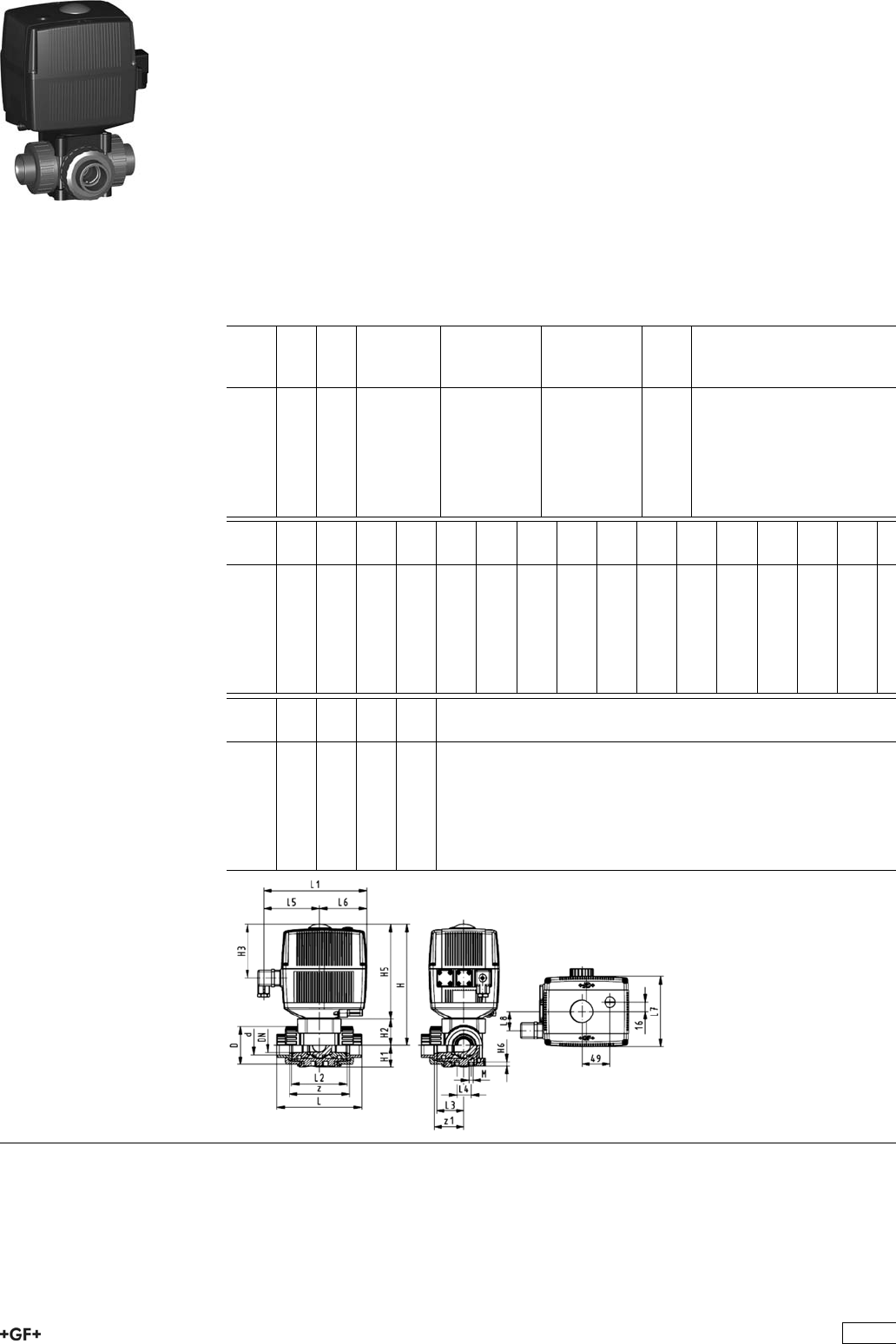
PROGEF Standard
3-Way ball valve type 176
Horizontal/T-port 24V
With manual emergency override
With fusion sockets metric
Model:
ÏMaterial: PP-H
ÏAssignment of actuators: EA21 (DN10/15-50), EA31 (DN65-100 if available)
ÏVoltage 24 V AC/DC
ÏControl range 90°<)
ÏControl time 5 s/90°<)
ÏFor easy installation and removal
ÏIntegrated stainless steel mounting inserts
d
[mm]
DN
[mm]
PN kv-value
(”p=1 bar)
[l/min]
EPDM
Code
FPM
Code
kg
16 10 10 140 199 176 222 199 176 232 2.051
20 15 10 200 199 176 223 199 176 233 2.051
25 20 10 470 199 176 224 199 176 234 2.174
32 25 10 793 199 176 225 199 176 235 2.297
40 32 10 1290 199 176 226 199 176 236 2.522
50 40 10 1910 199 176 227 199 176 237 2.886
63 50 10 3100 199 176 228 199 176 238 3.818
d
[mm]
D
[mm]
H
[mm]
H1
[mm]
H2
[mm]
H3
[mm]
H5
[mm]
H6
[mm]
L
[mm]
L1
[mm]
L2
[mm]
L3
[mm]
L4
[mm]
L5
[mm]
L6
[mm]
L7
[mm]
16 46 197 29 31 93 166 8 108 182 70 36 25 99 83 122
20 46 197 29 31 93 166 8 111 182 70 36 25 99 83 122
25 56 205 33 39 93 166 8 131 182 86 43 25 99 83 122
32 67 210 38 44 93 166 8 148 182 96 48 25 99 83 122
40 82 216 44 50 93 166 9 177 182 114 58 45 99 83 122
50 98 229 50 63 93 166 9 205 182 137 69 45 99 83 122
63 121 242 61 76 93 166 9 261 182 179 90 45 99 83 122
d
[mm]
L8
[mm]
M z
[mm]
z1
[mm]
16 33 6 78 39
20 33 6 79 40
25 33 6 95 48
32 33 6 108 54
40 33 8 133 67
50 33 8 155 78
63 33 8 203 102
211
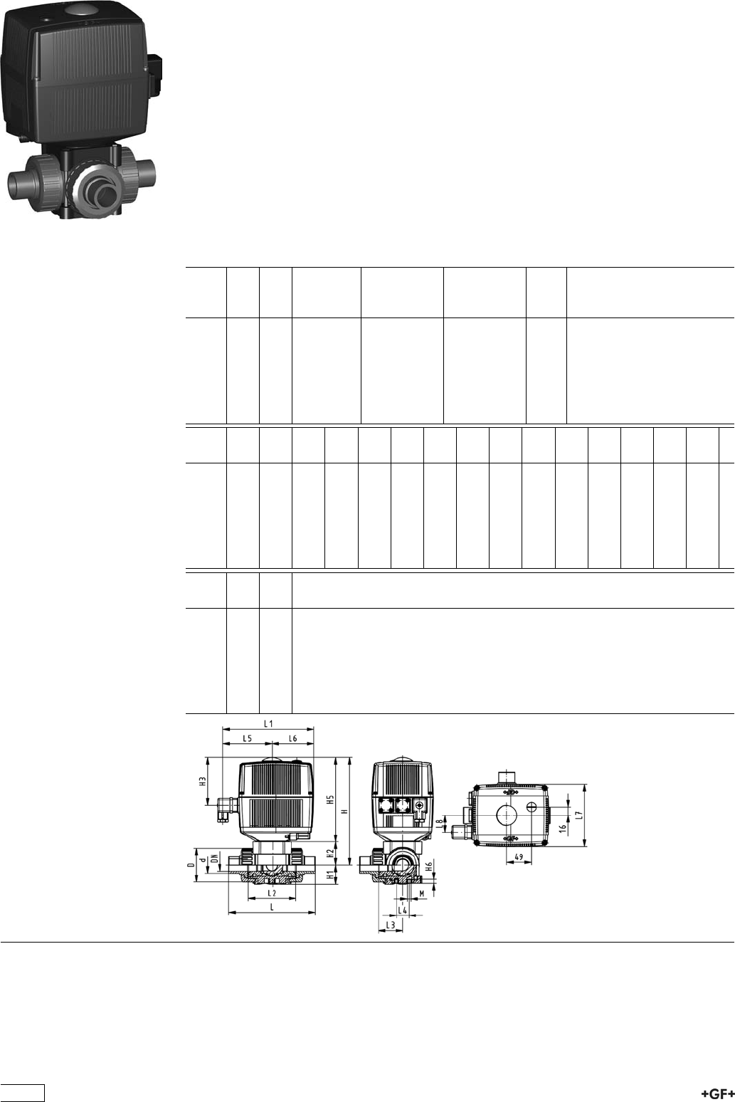
PROGEF Standard
3-Way ball valve type 176
Horizontal/T-port 24V
With manual emergency override
With socket fusion spigots
Model:
ÏMaterial: PP-H
ÏAssignment of actuators: EA21 (DN10/15-50), EA31 (DN65-100 if available)
ÏVoltage 24 V AC/DC
ÏControl range 90°<)
ÏControl time 5 s/90°<)
ÏFor easy installation and removal
ÏIntegrated stainless steel mounting inserts
d
[mm]
DN
[mm]
PN kv-value
(”p=1 bar)
[l/min]
EPDM
Code
FPM
Code
kg
16 10 10 200 199 176 202 199 176 212 2.051
20 15 10 200 199 176 203 199 176 213 2.051
25 20 10 470 199 176 204 199 176 214 2.174
32 25 10 793 199 176 205 199 176 215 2.297
40 32 10 1290 199 176 206 199 176 216 2.522
50 40 10 1910 199 176 207 199 176 217 2.886
63 50 10 3100 199 176 208 199 176 218 3.818
d
[mm]
D
[mm]
H
[mm]
H1
[mm]
H2
[mm]
H3
[mm]
H5
[mm]
H6
[mm]
L
[mm]
L1
[mm]
L2
[mm]
L3
[mm]
L4
[mm]
L5
[mm]
L6
[mm]
L7
[mm]
16 46 197 29 31 93 166 8 119 182 70 36 25 99 83 122
20 46 197 29 31 93 166 8 133 182 70 36 25 99 83 122
25 56 205 33 39 93 166 8 155 182 86 43 25 99 83 122
32 67 210 38 44 93 166 8 170 182 96 48 25 99 83 122
40 82 216 44 50 93 166 9 201 182 114 58 45 99 83 122
50 98 229 50 63 93 166 9 236 182 137 69 45 99 83 122
63 121 242 61 76 93 166 9 286 182 179 90 45 99 83 122
d
[mm]
L8
[mm]
M
16 33 6
20 33 6
25 33 6
32 33 6
40 33 8
50 33 8
63 33 8
212

PROGEF Standard
3-Way ball valve type 176
Horizontal/T-port 24V
With manual emergency override
With threaded sockets Rp
Model:
ÏMaterial: PP-H
ÏAssignment of actuators: EA21 (DN10/15-50), EA31 (DN65-100 if available)
ÏVoltage 24 V AC/DC
ÏControl range 90°<)
ÏControl time 5 s/90°<)
ÏFor easy installation and removal
ÏIntegrated stainless steel mounting inserts
Inch DN
[mm]
PN kv-value
(”p=1 bar)
[l/min]
EPDM
Code
FPM
Code
kg
3
/810 10 140 199 176 302 199 176 312 2.051
1
/215 10 200 199 176 303 199 176 313 2.051
3
/420 10 470 199 176 304 199 176 314 2.174
1 25 10 793 199 176 305 199 176 315 2.297
11
/432 10 1290 199 176 306 199 176 316 2.522
11
/240 10 1910 199 176 307 199 176 317 2.886
2 50 10 3100 199 176 308 199 176 318 3.818
Inch D
[mm]
H
[mm]
H1
[mm]
H2
[mm]
H3
[mm]
H5
[mm]
H6
[mm]
L
[mm]
L1
[mm]
L2
[mm]
L3
[mm]
L4
[mm]
L5
[mm]
L6
[mm]
L7
[mm]
3
/846 197 29 31 93 166 8 108 182 70 36 25 99 83 122
1
/246 197 29 31 93 166 8 111 182 70 36 25 99 83 122
3
/456 205 33 39 93 166 8 131 182 86 43 25 99 83 122
1 67 210 38 44 93 166 8 148 182 96 48 25 99 83 122
11
/482 216 44 50 93 166 9 177 182 114 58 45 99 83 122
11
/298 229 50 63 93 166 9 205 182 137 69 45 99 83 122
2 121 242 61 76 93 166 9 261 182 179 90 45 99 83 122
Inch L8
[mm]
M z
[mm]
z1
[mm]
3
/833 6 78 39
1
/233 6 79 40
3
/433 6 95 48
1 33 6 108 54
11
/433 8 133 67
11
/233 8 155 78
2 33 8 203 102
213

PROGEF Standard
3-Way ball valve type 176
Horizontal/T-port 24V
With manual emergency override
With butt fusion spigots metric
Model:
ÏMaterial: PP-H
ÏAssignment of actuators: EA21 (DN10/15-50), EA31 (DN65-100 if available)
ÏVoltage 24 V AC/DC
ÏControl range 90°<)
ÏControl time 5 s/90°<)
ÏFor easy installation and removal
ÏIntegrated stainless steel mounting inserts
d
[mm]
DN
[mm]
PN kv-value
(”p=1 bar)
[l/min]
EPDM
Code
FPM
Code
kg
20 15 10 200 199 176 263 199 176 273 2.051
25 20 10 470 199 176 264 199 176 274 2.174
32 25 10 793 199 176 265 199 176 275 2.297
40 32 10 1290 199 176 266 199 176 276 2.522
50 40 10 1910 199 176 267 199 176 277 2.886
63 50 10 3100 199 176 268 199 176 278 3.818
d
[mm]
D
[mm]
H
[mm]
H1
[mm]
H2
[mm]
H3
[mm]
H5
[mm]
H6
[mm]
L
[mm]
L1
[mm]
L2
[mm]
L3
[mm]
L4
[mm]
L5
[mm]
L6
[mm]
L7
[mm]
20 46 197 29 31 93 166 8 133 182 70 36 25 99 83 122
25 56 205 33 39 93 166 8 155 182 86 43 25 99 83 122
32 67 210 38 44 93 166 8 170 182 96 48 25 99 83 122
40 82 216 44 50 93 166 9 201 182 114 58 45 99 83 122
50 98 229 50 63 93 166 9 236 182 137 69 45 99 83 122
63 121 242 61 76 93 166 9 286 182 179 90 45 99 83 122
d
[mm]
L8
[mm]
M
20 33 6
25 33 6
32 33 6
40 33 8
50 33 8
63 33 8
214

9ef_WXb[
9edÓ]khWjeh=<XWbblWbl[jof[+*,FHE=;<IjWdZWhZ
7&' 8&+ 9 : ; < = = ? A B
b[\j h_]^j
8WbbLWbl[
6%& 7VaaKVakZ*)+
6%' A^cZVg7VaaKVakZ
CWj[h_Wb
7%* EE"=
:_c[di_ed
8%* Y&+9C&%($-
8%+ Y'%9C&*&$'
8%, Y'*9C'%($)
8%- Y('9C'*&
8%. Y)%9C('&&$)
8&% Y*%9C)%&&$'
8&& Y+(9C*%'
8&'9C+*'&$'
8&(9C-%(
8&)9C&%%)
8&*9C&*%+
L[hi_ed
9%& HiVcYVgY!EI;:WVaahZVa
9%' d^a[gZZ!EI;:WVaahZVadcanl^i]heZX^ÒXXdccZXi^c\eVgih
9%( h^a^Xdc"[gZZ!EI;:WVaahZVadcanl^i]heZX^ÒXXdccZXi^c\eVgih
9%) h^a^Xdc"[gZZ!EK9;WVaahZVa[dgbZig^Xdcanl^i]heZX^ÒXXdccZXi^c\eVgih
I[Wbi
:%& :E9BhZVah
:%' ;EBhZVah
:%( ;;EB$@6AG:OhZVah
J^h[WZ[Z_di[hji
;%& l^i]djii]gZVYZY^chZgih
;%' l^i]i]gZVYZY^chZgih
9edd[Yj_d]fWhji
<(% EE"=;jh^dchdX`ZibZig^X
<(' EE"=HdX`Zi[jh^dche^\dibZig^X
<(( EE"=I]gZVYZYhdX`ZiGegZ^c[dgXZY
<() EE"=I]gZVYZYhdX`ZiCEIgZ^c[dgXZY
<(* EE"=7jii[jh^dche^\diH9G&&bZig^X>G"EAJH
<(+ EE"=7jii[jh^dche^\diH9G&,#+bZig^X
l^i]i]^hkVakZZcYi]ZbVm^bjbcdb^cVaegZhhjgZ
^hgZYjXZYidEC+
<(, EE"=7jii[jh^dche^\diadc\H9G&&bZig^X
<)( E:"&%%7jii[jh^dche^\diadc\H9G&&bZig^X
<)) E:"&%%7jii[jh^dche^\diadc\H9G&,#+bZig^X
<+( ;^mZYÓVc\ZEE"=hZggViZYbZig^X
<,' 7VX`^c\ÓVc\ZEE"hiZZabZig^X
<,( 7VX`^c\ÓVc\ZEE"hiZZa^cX]6CH>
<,, 7VX`^c\ÓVc\ZEE?>Hl^i]XdccZXi^c\eVgih
<,- 7VX`^c\ÓVc\ZEE"<;?>H
<-( EE"=KVakZZcYWaVc`
<)% E:"&%%;jh^dchdX`ZibZig^X
<)& E:"&%%7jii[jh^dche^\diH9G&&bZig^X
<)' E:"&%%7jii[jh^dche^\diH9G&,#+bZig^X
<)( E:"&%%7jii[jh^dche^\diadc\H9G&&bZig^X
<&& EK8"88ZbZcihdX`ZibZig^X
<&( EK8"88ZbZcihdX`Zi^cX]6HIB
<&) EK8"88ZbZcihe^\dibZig^X
<&* EK8"8I]gZVYZYhdX`ZiGe
<&+ EK8"8I]gZVYZYhdX`ZiGegZ^c[dgXZY
<&, EK8"8I]gZVYZYhdX`ZiCEI
Ckbj_#\kdYj_edWbceZkb[
>%& Cdbjai^"[jcXi^dcVabdYjaZ
>%' :beinbdYjaZ
>%( BdYjaZl^i]'ZcYhl^iX]Zh6\!C^
>%) BdYjaZl^i]'ZcYhl^iX]Zh6j
>%* BdYjaZl^i]'^cYjXi^kZhl^iX]ZhCVbjg
>%+ BdYjaZl^i]'^cYjXi^kZhl^iX]ZhECE
>%, BdYjaZl^i]'^cYjXi^kZhl^iX]ZhCEC
B[l[h
@%& HiVcYVgYaZkZggZY
@%' HiVcYVgYaZkZgWaVX`
@&& Bjai^"[jcXi^dcVaaZkZggZY
Cekdj_d]fbWj[
A%& l^i]djibdjci^c\eaViZ
A%' l^i]bdjci^c\eaViZ
Ndjl^aaÒcYVaVg\ZhZaZXi^dcd[Y^[[ZgZcikZg"
h^dch^cdjggVc\Zd[egdYjXih#CZlhnhiZb
ZaZbZcihVahdegdk^YZndjl^i]cZldeedgij"
c^i^Zh[dgjhZ#>cdgYZg[dgjhidhjeeanZmVXian
i]ZWVaakVakZndjcZZY[dgndjVeea^XVi^dc!lZ
]VkZXgZViZYVhZaZXi^dcbZcj[dgndj#
9ZgbVm^bVaoja~hh^\Z7Zig^ZWhYgjX`YZh
@j\Za]V]ch^hiEC&%#
M[ikffbom^Wjoekfkjje][j^[h$
215
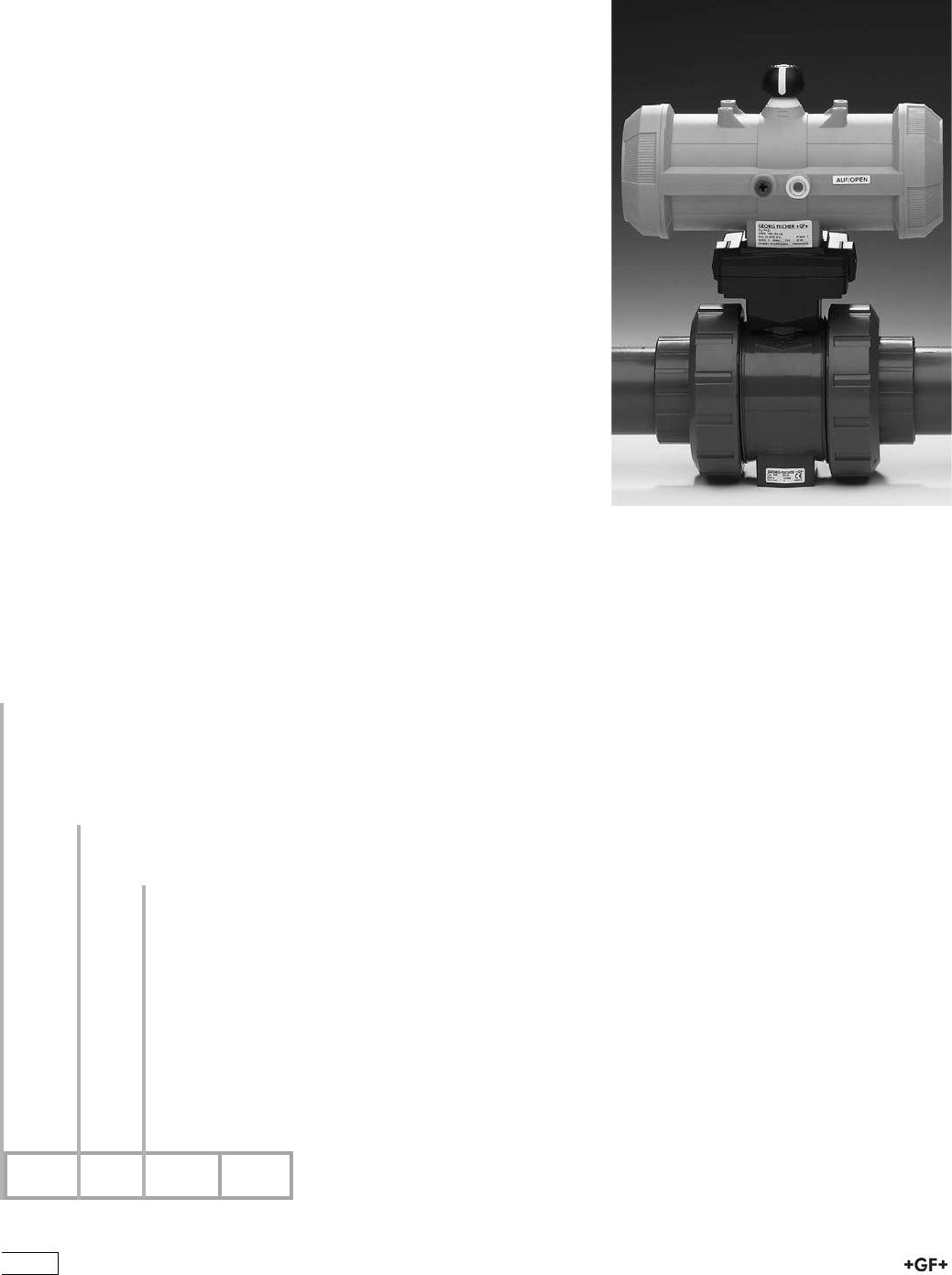
Fd[kcWj_YWYjkWjehiF7''%F7('
E%& ;V^ahV[ZidXadhZE6&&$E6'&
E%' ;V^ahV[ZiddeZcE6&&$'&
E%( 9djWaZVXi^c\E6&&$'&
E(% ;V^ahV[ZidXadhZE6(%$.%
E(& ;V^ahV[ZiddeZcE6(%$.%
E(' 9djWaZVXi^c\E6(%$.%
CWdkWbel[hh_Z[
F%& l^i]djibVcjVadkZgg^YZ
F%' l^i]bVcjVadkZgg^YZ
Ijhea[b_c_j[h
G%& l^i]djihigd`Za^b^iZg
G%' l^i]higd`Za^b^iZg
?jiie[WiojeYed\_]khWj[
j^[jof[+*,0
L^i]i]ZXdcÒ\jgVidg!ndj]VkZVX]d^XZ
d[cZlecZjbVi^XVXijVidghE6&&VcY
E6'&^c'dei^b^oZYh^oZh^cXajY^c\V
aVg\ZgVc\Zd[VXXZhhdg^Zh#
M[ikffbom^Wjoekfkjje][j^[h$
F G H
9ef_WXb[
=<XWbblWbl[jof[+*,m_j^fd[kcWj_YWYjkWjeh
216
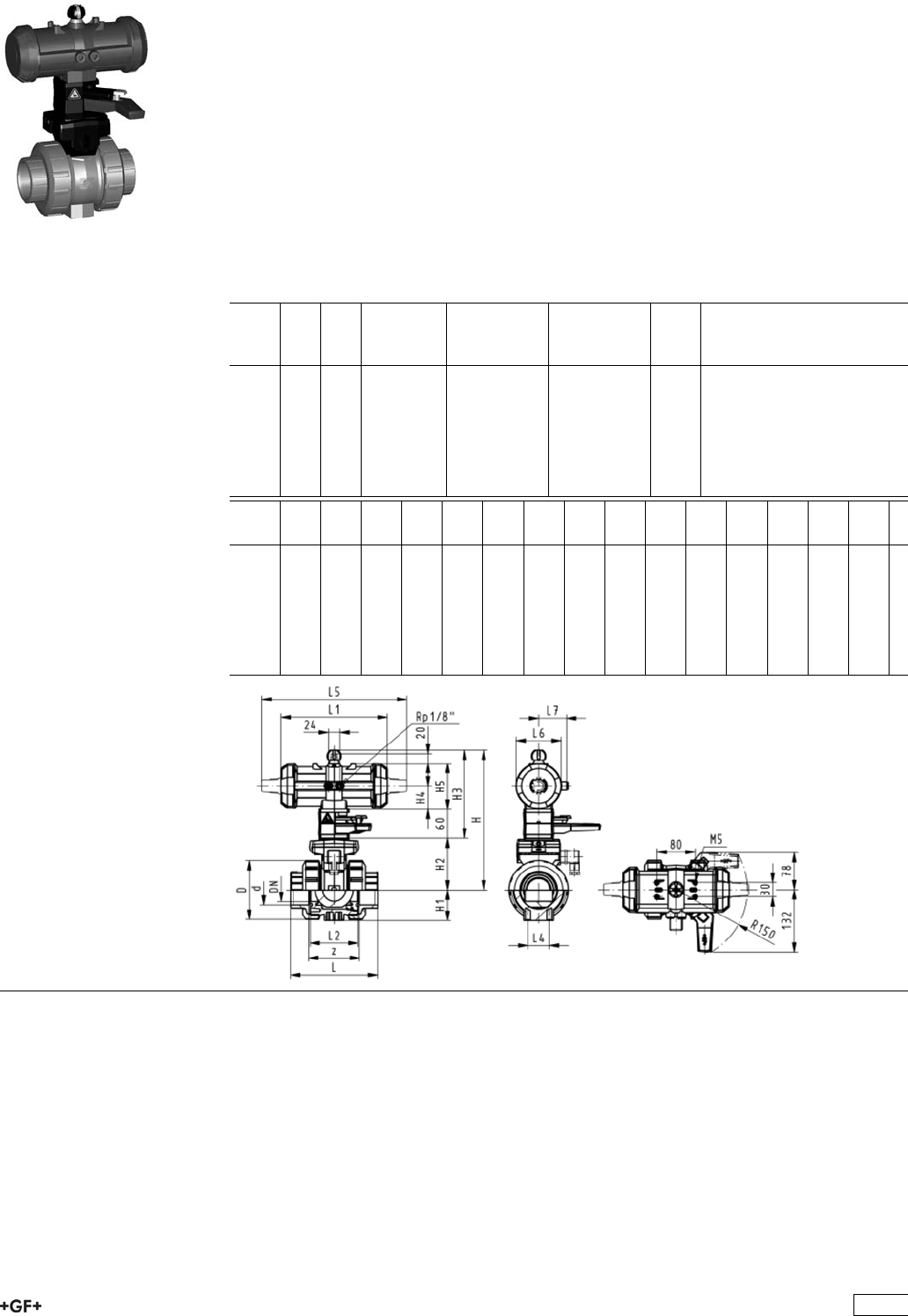
Ball Valves Pneumatic
PROGEF Standard
Ball valve type 231 FC (Fail safe to close)
With manual override
With fusion sockets metric
Model:
ÏMaterial: PP-H
ÏBuilt on with pneumatic actuator PA11 (DN10/15-25), PA21 (DN32-50)
ÏControl time 90°<) 1-2 s
ÏFor easy installation and removal
ÏIntegrated stainless steel mounting inserts
Option:
ÏIndividual configuration of the valve (see form)
d
[mm]
DN
[mm]
PN kv-value
(”p=1 bar)
[l/min]
EPDM
Code
FPM
Code
kg
16 10 10 70 199 231 002 199 231 012 1.500
20 15 10 185 199 231 003 199 231 013 1.500
25 20 10 350 199 231 004 199 231 014 1.600
32 25 10 700 199 231 005 199 231 015 1.700
40 32 10 1000 199 231 006 199 231 016 2.800
50 40 10 1600 199 231 007 199 231 017 3.100
63 50 10 3100 199 231 008 199 231 018 4.000
d
[mm]
D
[mm]
H
[mm]
H1
[mm]
H2
[mm]
H3
[mm]
H4
[mm]
H5
[mm]
L
[mm]
L1
[mm]
L2
[mm]
L4
[mm]
L5
[mm]
L6
[mm]
L7
[mm]
z
[mm]
16 50 230 27 62 168 40 97 93 194 56 25 261 76 48 67
20 50 230 27 62 168 40 97 95 194 56 25 261 76 48 66
25 58 239 30 71 168 40 97 108 194 65 25 261 76 48 77
32 68 239 36 71 168 40 97 118 194 71 25 261 76 48 83
40 84 271 44 84 187 51 115 137 224 85 45 305 95 59 99
50 97 271 51 84 187 51 115 147 224 89 45 305 95 59 105
63 124 293 64 106 187 51 115 168 224 101 45 305 95 59 117
217
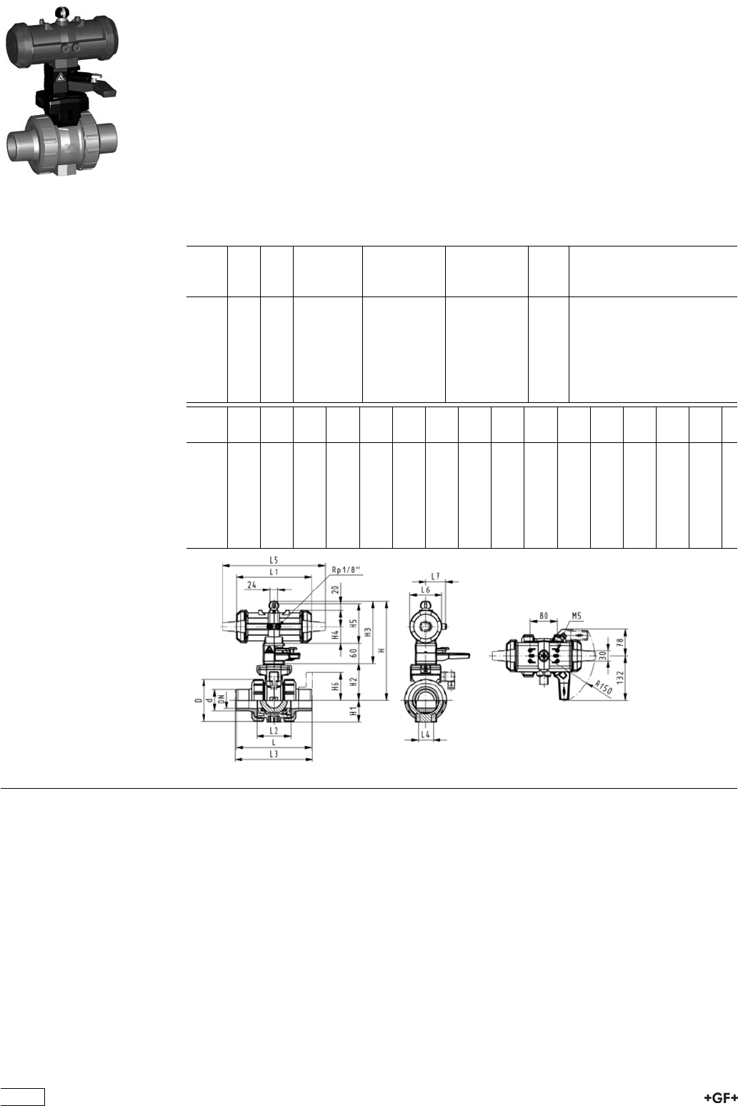
PROGEF Standard
Ball valve type 231 FC (Fail safe to close)
With manual override
With fusion spigots metric
Model:
ÏMaterial: PP-H
ÏBuilt on with pneumatic actuator PA11 (DN10/15-25), PA21 (DN32-50)
ÏControl time 90°<) 1-2 s
ÏFor easy installation and removal
ÏIntegrated stainless steel mounting inserts
Option:
ÏIndividual configuration of the valve (see form)
d
[mm]
DN
[mm]
PN kv-value
(”p=1 bar)
[l/min]
EPDM
Code
FPM
Code
kg
16 10 10 70 199 231 022 199 231 032 1.500
20 15 10 185 199 231 023 199 231 033 1.500
25 20 10 350 199 231 024 199 231 034 1.600
32 25 10 700 199 231 025 199 231 035 1.700
40 32 10 1000 199 231 026 199 231 036 2.800
50 40 10 1600 199 231 027 199 231 037 3.100
63 50 10 3100 199 231 028 199 231 038 4.000
d
[mm]
D
[mm]
H
[mm]
H1
[mm]
H2
[mm]
H3
[mm]
H4
[mm]
H5
[mm]
L
[mm]
L1
[mm]
L2
[mm]
L3
[mm]
L4
[mm]
L5
[mm]
L6
[mm]
L7
[mm]
16 50 230 27 62 168 40 97 110 194 56 25 261 76 48
20 50 230 27 62 168 40 97 120 194 56 130 25 261 76 48
25 58 239 30 71 168 40 97 139 194 65 150 25 261 76 48
32 68 239 36 71 168 40 97 150 194 71 160 25 261 76 48
40 84 271 44 84 187 51 115 170 224 85 180 45 305 95 59
50 97 271 51 84 187 51 115 190 224 89 200 45 305 95 59
63 124 293 64 106 187 51 115 220 224 101 230 45 305 95 59
218

PROGEF Standard
Ball valve type 231 FC (Fail safe to close)
With manual override
With fixed flanges PP-H serrated metric
Model:
ÏMaterial: PP-H
ÏBuilt on with pneumatic actuator PA11 (DN10/15-25), PA21 (DN32-50)
ÏControl time 90°<) 1-2 s
ÏFor easy installation and removal
ÏIntegrated stainless steel mounting inserts
ÏOverall length according to EN 558
ÏConnecting dimensions: ISO 7005 / EN 1092 / DIN 2501 PN10 / BS4504
Option:
ÏIndividual configuration of the valve (see form)
d
[mm]
DN
[mm]
Inch PN kv-value
(”p=1 bar)
[l/min]
EPDM
Code
FPM
Code
kg
20 15 1
/210 185 199 231 243 199 231 253 1.700
25 20 3
/410 350 199 231 244 199 231 254 1.900
32 25 1 10 700 199 231 245 199 231 255 2.100
40 32 1 1
/410 1000 199 231 246 199 231 256 3.400
50 40 1 1
/210 1600 199 231 247 199 231 257 3.900
63 50 2 10 3100 199 231 248 199 231 258 4.900
d
[mm]
D
[mm]
H
[mm]
H1
[mm]
H2
[mm]
H3
[mm]
H4
[mm]
H5
[mm]
H6
[mm]
L
[mm]
L1
[mm]
L2
[mm]
L3
[mm]
L4
[mm]
L5
[mm]
L6
[mm]
20 50 230 27 62 168 40 97 48 120 194 56 130 25 261 76
25 58 239 30 71 168 40 97 53 139 194 65 150 25 261 76
32 68 239 36 71 168 40 97 58 150 194 71 160 25 261 76
40 84 271 44 84 187 51 115 70 170 224 85 180 45 305 95
50 97 271 51 84 187 51 115 75 190 224 89 200 45 305 95
63 124 293 64 106 187 51 115 83 220 224 101 230 45 305 95
d
[mm]
L7
[mm]
20 48
25 48
32 48
40 59
50 59
63 59
219
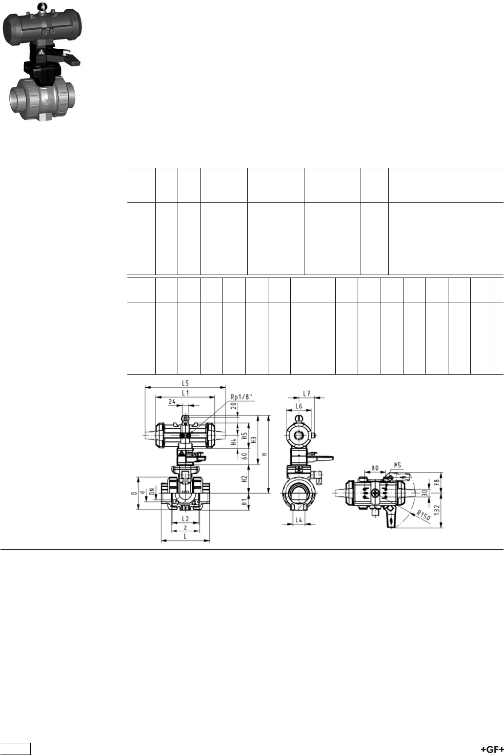
PROGEF Standard
Ball valve type 231 FO (Fail safe to open)
With manual override
With fusion sockets metric
Model:
ÏMaterial: PP-H
ÏBuilt on with pneumatic actuator PA11 (DN10/15-25), PA21 (DN32-50)
ÏControl time 90°<) 1-2 s
ÏFor easy installation and removal
ÏIntegrated stainless steel mounting inserts
Option:
ÏIndividual configuration of the valve (see form)
d
[mm]
DN
[mm]
PN kv-value
(”p=1 bar)
[l/min]
EPDM
Code
FPM
Code
kg
16 10 10 70 199 231 042 199 231 052 1.500
20 15 10 185 199 231 043 199 231 053 1.500
25 20 10 350 199 231 044 199 231 054 1.600
32 25 10 700 199 231 045 199 231 055 1.700
40 32 10 1000 199 231 046 199 231 056 2.800
50 40 10 1600 199 231 047 199 231 057 3.100
63 50 10 3100 199 231 048 199 231 058 4.000
d
[mm]
D
[mm]
H
[mm]
H1
[mm]
H2
[mm]
H3
[mm]
H4
[mm]
H5
[mm]
L
[mm]
L1
[mm]
L2
[mm]
L4
[mm]
L5
[mm]
L6
[mm]
L7
[mm]
z
[mm]
16 50 230 27 62 168 40 97 93 194 56 25 261 76 48 67
20 50 230 27 62 168 40 97 95 194 56 25 261 76 48 66
25 58 239 30 71 168 40 97 108 194 65 25 261 76 48 77
32 68 239 36 71 168 40 97 118 194 71 25 261 76 48 83
40 84 271 44 84 187 51 115 137 224 85 45 305 95 59 99
50 97 271 51 84 187 51 115 147 224 89 45 305 95 59 105
63 124 293 64 106 187 51 115 168 224 101 45 305 95 59 117
220
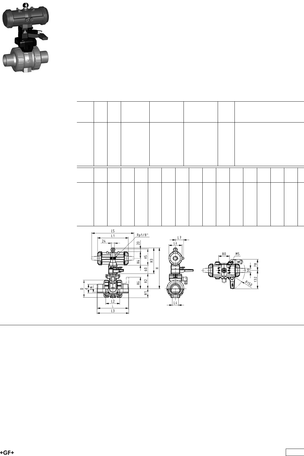
PROGEF Standard
Ball valve type 231 FO (Fail safe to open)
With manual override
With fusion spigots metric
Model:
ÏMaterial: PP-H
ÏBuilt on with pneumatic actuator PA11 (DN10/15-25), PA21 (DN32-50)
ÏControl time 90°<) 1-2 s
ÏFor easy installation and removal
ÏIntegrated stainless steel mounting inserts
Option:
ÏIndividual configuration of the valve (see form)
d
[mm]
DN
[mm]
PN kv-value
(”p=1 bar)
[l/min]
EPDM
Code
FPM
Code
kg
16 10 10 70 199 231 062 199 231 072 1.500
20 15 10 185 199 231 063 199 231 073 1.500
25 20 10 350 199 231 064 199 231 074 1.600
32 25 10 700 199 231 065 199 231 075 1.700
40 32 10 1000 199 231 066 199 231 076 2.800
50 40 10 1600 199 231 067 199 231 077 3.100
63 50 10 3100 199 231 068 199 231 078 4.000
d
[mm]
D
[mm]
H
[mm]
H1
[mm]
H2
[mm]
H3
[mm]
H4
[mm]
H5
[mm]
L
[mm]
L1
[mm]
L2
[mm]
L3
[mm]
L4
[mm]
L5
[mm]
L6
[mm]
L7
[mm]
16 50 230 27 62 168 40 97 110 194 56 130 25 261 76 48
20 50 230 27 62 168 40 97 120 194 56 130 25 261 76 48
25 58 239 30 71 168 40 97 139 194 65 150 25 261 76 48
32 68 239 36 71 168 40 97 150 194 71 160 25 261 76 48
40 84 271 44 84 187 51 115 170 224 85 180 45 305 95 59
50 97 271 51 84 187 51 115 190 224 89 200 45 305 95 59
63 124 293 64 106 187 51 115 220 224 101 230 45 305 95 59
221

PROGEF Standard
Ball valve type 231 FO (Fail safe to open)
With manual override
With fixed flanges PP-H serrated metric
Model:
ÏMaterial: PP-H
ÏBuilt on with pneumatic actuator PA11 (DN10/15-25), PA21 (DN32-50)
ÏControl time 90°<) 1-2 s
ÏFor easy installation and removal
ÏIntegrated stainless steel mounting inserts
ÏOverall length according to EN 558
ÏConnecting dimensions: ISO 7005 / EN 1092 / DIN 2501 PN10 / BS4504
Option:
ÏIndividual configuration of the valve (see form)
d
[mm]
DN
[mm]
Inch PN kv-value
(”p=1 bar)
[l/min]
EPDM
Code
FPM
Code
kg
20 15 1
/210 185 199 231 263 199 231 273 1.700
25 20 3
/410 350 199 231 264 199 231 274 1.900
32 25 1 10 700 199 231 265 199 231 275 2.100
40 32 1 1
/410 1000 199 231 266 199 231 276 3.400
50 40 1 1
/210 1600 199 231 267 199 231 277 3.900
63 50 2 10 3100 199 231 268 199 231 278 4.900
d
[mm]
D
[mm]
H
[mm]
H1
[mm]
H2
[mm]
H3
[mm]
H4
[mm]
H5
[mm]
H6
[mm]
L
[mm]
L1
[mm]
L2
[mm]
L3
[mm]
L4
[mm]
L5
[mm]
L6
[mm]
20 58 230 27 62 168 40 97 48 120 194 56 130 25 261 76
25 58 239 30 71 168 40 97 53 139 194 65 150 25 261 76
32 68 239 36 71 168 40 97 58 150 194 71 160 25 261 76
40 84 271 44 84 187 51 115 70 170 224 85 180 45 305 95
50 97 271 51 84 187 51 115 75 190 224 89 200 45 305 95
63 124 293 64 106 187 51 115 83 220 224 101 230 45 305 95
d
[mm]
L7
[mm]
20 48
25 48
32 48
40 59
50 59
63 59
222

PROGEF Standard
Ball valve type 231 DA (Double acting)
With manual override
With fusion sockets metric
Model:
ÏMaterial: PP-H
ÏBuilt on with pneumatic actuator PA11 (DN10/15-25), PA21 (DN32-50)
ÏControl time 90°<) 1-2 s
ÏFor easy installation and removal
ÏIntegrated stainless steel mounting inserts
Option:
ÏIndividual configuration of the valve (see form)
d
[mm]
DN
[mm]
PN kv-value
(”p=1 bar)
[l/min]
EPDM
Code
FPM
Code
kg
16 10 10 70 199 231 082 199 231 092 1.500
20 15 10 185 199 231 083 199 231 093 1.500
25 20 10 350 199 231 084 199 231 094 1.600
32 25 10 700 199 231 085 199 231 095 1.700
40 32 10 1000 199 231 086 199 231 096 2.800
50 40 10 1600 199 231 087 199 231 097 3.100
63 50 10 3100 199 231 088 199 231 098 4.000
d
[mm]
D
[mm]
H
[mm]
H1
[mm]
H2
[mm]
H3
[mm]
H4
[mm]
H5
[mm]
L
[mm]
L1
[mm]
L2
[mm]
L4
[mm]
L5
[mm]
L6
[mm]
L7
[mm]
z
[mm]
16 50 230 27 62 168 40 97 93 194 56 25 261 76 48 67
20 50 230 27 62 168 40 97 95 194 56 25 261 76 48 66
25 58 239 30 71 168 40 97 108 194 65 25 261 76 48 77
32 68 239 36 71 168 40 97 118 194 71 25 261 76 48 83
40 84 271 44 84 187 51 115 137 224 85 45 305 95 59 99
50 97 271 51 84 187 51 115 147 224 89 45 305 95 59 105
63 124 293 64 106 187 51 115 168 224 101 45 305 95 59 117
223

PROGEF Standard
Ball valve type 231 DA (Double acting)
With manual override
With fusion spigots metric
Model:
ÏMaterial: PP-H
ÏBuilt on with pneumatic actuator PA11 (DN10/15-25), PA21 (DN32-50)
ÏControl time 90°<) 1-2 s
ÏFor easy installation and removal
ÏIntegrated stainless steel mounting inserts
Option:
ÏIndividual configuration of the valve (see form)
d
[mm]
DN
[mm]
PN kv-value
(”p=1 bar)
[l/min]
EPDM
Code
FPM
Code
kg
16 10 10 70 199 231 102 199 231 112 1.500
20 15 10 185 199 231 103 199 231 113 1.500
25 20 10 350 199 231 104 199 231 114 1.600
32 25 10 700 199 231 105 199 231 115 1.700
40 32 10 1000 199 231 106 199 231 116 2.800
50 40 10 1600 199 231 107 199 231 117 3.100
63 50 10 3100 199 231 108 199 231 118 4.000
d
[mm]
D
[mm]
H
[mm]
H1
[mm]
H2
[mm]
H3
[mm]
H4
[mm]
H5
[mm]
L
[mm]
L1
[mm]
L2
[mm]
L3
[mm]
L4
[mm]
L5
[mm]
L6
[mm]
L7
[mm]
16 50 230 27 62 168 40 97 110 194 56 25 261 76 48
20 50 230 27 62 168 40 97 120 194 56 130 25 261 76 48
25 58 239 30 71 168 40 97 139 194 65 150 25 261 76 48
32 68 239 36 71 168 40 97 150 194 71 160 25 261 76 48
40 84 271 44 84 187 51 115 170 224 85 180 45 305 95 59
50 97 271 51 84 187 51 115 190 224 89 200 45 305 95 59
63 124 293 64 106 187 51 115 220 224 101 230 45 305 95 59
224
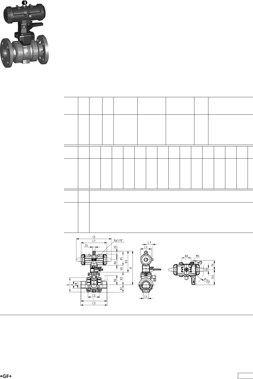
PROGEF Standard
Ball valve type 231 DA (Double acting)
With manual override
With fixed flanges PP-H serrated metric
Model:
ÏMaterial: PP-H
ÏBuilt on with pneumatic actuator PA11 (DN10/15-25), PA21 (DN32-50)
ÏControl time 90°<) 1-2 s
ÏFor easy installation and removal
ÏIntegrated stainless steel mounting inserts
ÏOverall length according to EN 558
ÏConnecting dimensions: ISO 7005 / EN 1092 / DIN 2501 PN10 / BS4504
Option:
ÏIndividual configuration of the valve (see form)
d
[mm]
DN
[mm]
Inch PN kv-value
(”p=1 bar)
[l/min]
EPDM
Code
FPM
Code
kg
20 15 1
/210 185 199 231 283 199 231 293 1.700
25 20 3
/410 350 199 231 284 199 231 294 1.900
32 25 1 10 700 199 231 285 199 231 295 2.100
40 32 1 1
/410 1000 199 231 286 199 231 296 3.400
50 40 1 1
/210 1600 199 231 287 199 231 297 3.900
63 50 2 10 3100 199 231 288 199 231 298 4.900
d
[mm]
D
[mm]
H
[mm]
H1
[mm]
H2
[mm]
H3
[mm]
H4
[mm]
H5
[mm]
H6
[mm]
L
[mm]
L1
[mm]
L2
[mm]
L3
[mm]
L4
[mm]
L5
[mm]
L6
[mm]
20 50 230 27 62 168 40 97 48 120 194 56 130 25 261 76
25 58 239 30 71 168 40 97 53 139 194 65 150 25 261 76
32 68 239 36 71 168 40 97 58 150 194 71 160 25 261 76
40 84 271 44 84 187 51 115 70 170 224 85 180 45 305 95
50 97 271 51 84 187 51 115 75 190 224 89 200 45 305 95
63 124 293 64 106 187 51 115 83 220 224 101 230 45 305 95
d
[mm]
L7
[mm]
20 48
25 48
32 48
40 59
50 59
63 59
225

PROGEF Standard
Ball valve type 231 FC (Fail safe to close)
Without manual override
With fusion sockets metric
Model:
ÏMaterial: PP-H
ÏFor easy installation and removal
ÏIntegrated stainless steel mounting inserts
ÏControl time 90°<) 1-2 s
ÏAssignment of actuators: PA11 (DN10/15-25), PA21 (DN32-50), PA30 (DN65),
PA35 (DN80), PA40 (DN100)
ÏImage and drawing DN65-100 please see ''New product ball valve DN65-100''
Option:
ÏIndividual configuration of the valve (see form)
d
[mm]
DN
[mm]
PN kv-value
(”p=1 bar)
[l/min]
EPDM
Code
FPM
Code
kg
16 10 10 70 199 231 122 199 231 132 1.200
20 15 10 185 199 231 123 199 231 133 1.200
25 20 10 350 199 231 124 199 231 134 1.300
32 25 10 700 199 231 125 199 231 135 1.400
40 32 10 1000 199 231 126 199 231 136 2.500
50 40 10 1600 199 231 127 199 231 137 2.800
63 50 10 3100 199 231 128 199 231 138 3.700
75 65 10 5000 199 231 129 199 231 139 4.000
90 80 10 7000 199 231 130 199 231 140 4.700
110 100 10 11000 199 231 131 199 231 141 6.900
d
[mm]
D
[mm]
H
[mm]
H1
[mm]
H2
[mm]
H4
[mm]
H5
[mm]
L
[mm]
L1
[mm]
L2
[mm]
L4
[mm]
L5
[mm]
L6
[mm]
L7
[mm]
z
[mm]
16 50 167 27 62 40 97 93 194 56 25 261 76 48 67
20 50 167 27 62 40 97 95 194 56 25 261 76 48 66
25 58 176 30 71 40 97 108 194 65 25 261 76 48 77
32 68 176 36 71 40 97 118 194 71 25 261 76 48 83
40 84 210 44 84 51 115 137 224 85 45 305 95 59 99
50 97 210 51 84 51 115 147 224 89 45 305 95 59 105
63 124 232 64 106 51 115 168 224 101 45 305 95 59 117
75 166 262 85 156 70 233 218 136 70 276 65 167
90 200 281 105 168 78 254 259 141 70 341 72 180
110 238 292 123 175 86 301 287 164 120 369 80 215
226
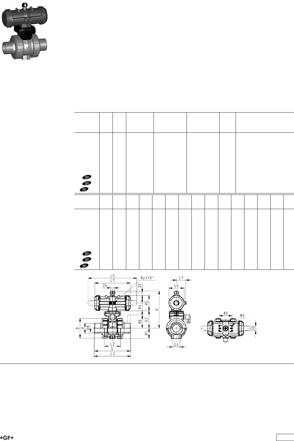
PROGEF Standard
Ball valve type 231 FC (Fail safe to close)
Without manual override
With socket fusion spigots metric
Model:
ÏMaterial: PP-H
ÏFor easy installation and removal
ÏIntegrated stainless steel mounting inserts
ÏControl time 90°<) 1-2 s
ÏAssignment of actuators: PA11 (DN10/15-25), PA21 (DN32-50), PA30 (DN65),
PA35 (DN80), PA40 (DN100)
ÏImage and drawing DN65-100 please see ''New product ball valve DN65-100''
Option:
ÏIndividual configuration of the valve (see form)
d
[mm]
DN
[mm]
PN kv-value
(”p=1 bar)
[l/min]
EPDM
Code
FPM
Code
kg
16 10 10 70 199 231 142 199 231 152 1.200
20 15 10 185 199 231 143 199 231 153 1.200
25 20 10 350 199 231 144 199 231 154 1.300
32 25 10 700 199 231 145 199 231 155 1.400
40 32 10 1000 199 231 146 199 231 156 2.500
50 40 10 1600 199 231 147 199 231 157 2.800
63 50 10 3100 199 231 148 199 231 158 3.700
75 65 10 5000 199 231 149 199 231 159 4.000
90 80 10 7000 199 231 150 199 231 160 4.800
110 100 10 11000 199 231 151 199 231 161 6.900
d
[mm]
D
[mm]
H
[mm]
H1
[mm]
H2
[mm]
H4
[mm]
H5
[mm]
L
[mm]
L1
[mm]
L2
[mm]
L3
[mm]
L4
[mm]
L5
[mm]
L6
[mm]
L7
[mm]
16 50 167 27 62 40 97 110 194 56 130 25 261 76 48
20 50 167 27 62 40 97 120 194 56 130 25 261 76 48
25 58 176 30 71 40 97 139 194 65 150 25 261 76 48
32 68 176 36 71 40 97 150 194 71 160 25 261 76 48
40 84 210 44 84 51 115 170 224 85 180 45 305 95 59
50 97 210 51 84 51 115 190 224 89 200 45 305 95 59
63 124 232 64 106 51 115 220 224 101 230 45 305 95 59
75 166 262 85 156 70 280 218 136 290 70 276 65
90 200 281 105 168 78 296 259 141 310 70 341 72
110 238 292 123 175 86 336 287 164 350 120 369 80
227

PROGEF Standard
Ball valve type 231 FC (Fail safe to close)
Without manual override
With fixed flanges PP-H serrated metric
Model:
ÏMaterial: PP-H
ÏFor easy installation and removal
ÏIntegrated stainless steel mounting inserts
ÏControl time 90°<) 1-2 s
ÏBuilt on with pneumatic actuator PA11 (DN10/15-25), PA21 (DN32-50)
ÏOverall length according to EN 558
ÏConnecting dimensions: ISO 7005 / EN 1092 / DIN 2501 PN10 / BS4504
Option:
ÏIndividual configuration of the valve (see form)
d
[mm]
DN
[mm]
Inch PN kv-value
(”p=1 bar)
[l/min]
EPDM
Code
FPM
Code
kg
20 15 1
/210 185 199 231 423 199 231 433 1.400
25 20 3
/410 350 199 231 424 199 231 434 1.600
32 25 1 10 700 199 231 425 199 231 435 1.800
40 32 1 1
/410 1000 199 231 426 199 231 436 3.100
50 40 1 1
/210 1600 199 231 427 199 231 437 3.600
63 50 2 10 3100 199 231 428 199 231 438 4.700
d
[mm]
D
[mm]
H
[mm]
H1
[mm]
H2
[mm]
H4
[mm]
H5
[mm]
H6
[mm]
L
[mm]
L1
[mm]
L2
[mm]
L3
[mm]
L4
[mm]
L5
[mm]
L6
[mm]
L7
[mm]
20 50 167 27 62 40 97 48 120 194 56 130 25 261 76 48
25 58 176 30 71 40 97 53 140 194 65 150 25 261 76 48
32 68 176 36 71 40 97 58 150 194 71 160 25 261 76 48
40 84 210 44 84 51 115 70 170 224 85 180 45 305 95 59
50 97 210 51 84 51 115 75 190 224 89 200 45 305 95 59
63 124 232 64 106 51 115 83 220 224 101 230 45 305 95 59
228

PROGEF Standard
Ball valve type 231 FC (Fail safe to close)
Without manual override
With backing flanges PP-st metric
Model:
ÏMaterial: PP-H
ÏFor easy installation and removal
ÏIntegrated stainless steel mounting inserts
ÏControl time 90°<) 1-2 s
ÏAssignment of actuators: PA11 (DN10/15-25), PA21 (DN32-50), PA30 (DN65),
PA35 (DN80), PA40 (DN100)
ÏImage and drawing DN65-100 please see ''New product ball valve DN65-100''
ÏOverall length according to EN 558
ÏConnecting dimension: ISO 7005, EN 1092, BS 4504, DIN 2501
Option:
ÏIndividual configuration of the valve (see form)
d
[mm]
DN
[mm]
Inch PN kv-value
(”p=1 bar)
[l/min]
EPDM
Code
FPM
Code
kg
75 65 2 1
/210 5000 199 231 329 199 231 339 8.300
90 80 3 10 7000 199 231 330 199 231 340 10.000
110 100 4 10 11000 199 231 331 199 231 341 14.100
d
[mm]
D
[mm]
H
[mm]
H1
[mm]
H2
[mm]
H5
[mm]
H6
[mm]
L
[mm]
L1
[mm]
L2
[mm]
L3
[mm]
L4
[mm]
L5
[mm]
L6
[mm]
75 166 262 85 156 70 93 280 218 136 290 70 276 65
90 200 281 105 168 78 100 296 259 141 310 70 341 72
110 238 292 123 175 86 110 336 287 164 350 120 369 80
229

PROGEF Standard
Ball valve type 231 FC (Fail safe to close)
Without manual override
With butt fusion spigots IR-Plus SDR11 metric
Model:
ÏMaterial: PP-H
ÏFor easy installation and removal
ÏIntegrated stainless steel mounting inserts
ÏControl time 90°<) 1-2 s
ÏAssignment of actuators: PA11 (DN10/15-25), PA21 (DN32-50), PA30 (DN65),
PA35 (DN80), PA40 (DN100)
ÏImage and drawing DN65-100 please see ''New product ball valve DN65-100''
Option:
ÏIndividual configuration of the valve (see form)
d
[mm]
DN
[mm]
PN kv-value
(”p=1 bar)
[l/min]
EPDM
Code
FPM
Code
kg
75 65 10 5000 199 231 839 199 231 849 4.000
90 80 10 7000 199 231 840 199 231 850 4.800
110 100 10 11000 199 231 841 199 231 851 6.900
d
[mm]
D
[mm]
H
[mm]
H1
[mm]
H2
[mm]
H5
[mm]
L
[mm]
L1
[mm]
L2
[mm]
L3
[mm]
L4
[mm]
L5
[mm]
L6
[mm]
e
[mm]
75 166 262 85 156 70 266 218 136 290 70 276 65 8.2
90 200 281 105 168 78 264 259 141 310 70 341 72 9.9
110 238 292 123 175 86 301 287 164 350 120 369 80 12.0
230
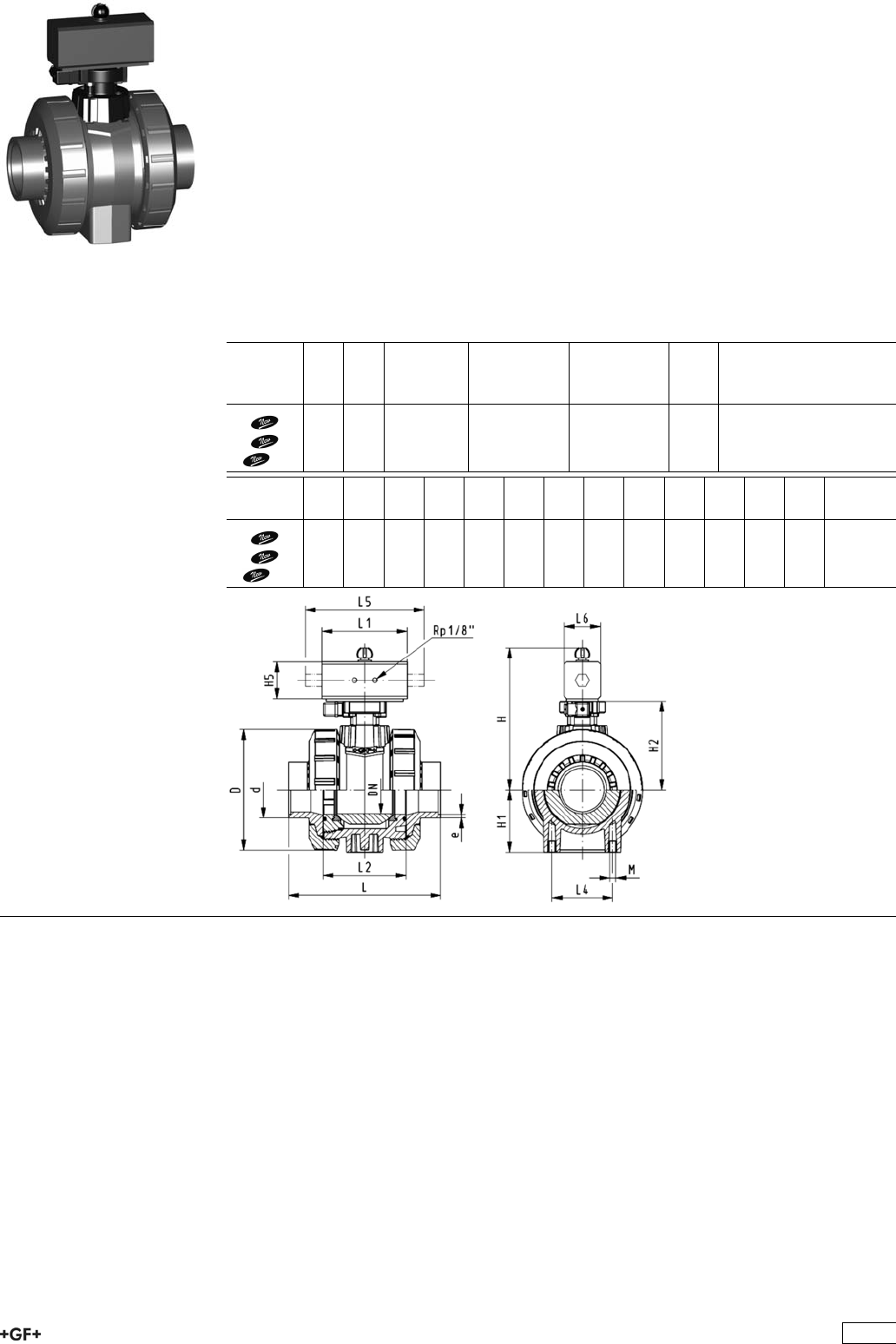
PROGEF Standard
Ball valve type 231 FC (Fail safe to close)
Without manual override
With butt fusion spigots SDR17.6 metric
Model:
ÏMaterial: PP-H
ÏFor easy installation and removal
ÏIntegrated stainless steel mounting inserts
ÏControl time 90°<) 1-2 s
ÏAssignment of actuators: PA11 (DN10/15-25), PA21 (DN32-50), PA30 (DN65),
PA35 (DN80), PA40 (DN100)
ÏImage and drawing DN65-100 please see ''New product ball valve DN65-100''
Option:
ÏIndividual configuration of the valve (see form)
d
[mm]
DN
[mm]
PN kv-value
(”p=1 bar)
[l/min]
EPDM
Code
FPM
Code
kg
75 65 10 5000 199 231 939 199 231 949 4.000
90 80 10 7000 199 231 940 199 231 950 4.800
110 100 10 11000 199 231 941 199 231 951 6.900
d
[mm]
D
[mm]
H
[mm]
H1
[mm]
H2
[mm]
H5
[mm]
L
[mm]
L1
[mm]
L2
[mm]
L3
[mm]
L4
[mm]
L5
[mm]
L6
[mm]
e
[mm]
75 166 262 85 156 70 266 218 136 290 70 276 65 4.6
90 200 281 105 168 78 264 259 141 310 70 341 72 5.5
110 238 292 123 175 86 301 287 164 350 120 369 80 6.7
231

PROGEF Standard
Ball valve type 231 FO (Fail safe to open)
Without manual override
With fusion sockets metric
Model:
ÏMaterial: PP-H
ÏFor easy installation and removal
ÏIntegrated stainless steel mounting inserts
ÏControl time 90°<) 1-2 s
ÏAssignment of actuators: PA11 (DN10/15-25), PA21 (DN32-50), PA30 (DN65),
PA35 (DN80), PA40 (DN100)
ÏImage and drawing DN65-100 please see ''New product ball valve DN65-100''
Option:
ÏIndividual configuration of the valve (see form)
d
[mm]
DN
[mm]
PN kv-value
(”p=1 bar)
[l/min]
EPDM
Code
FPM
Code
kg
16 10 10 70 199 231 162 199 231 172 1.200
20 15 10 185 199 231 163 199 231 173 1.200
25 20 10 350 199 231 164 199 231 174 1.300
32 25 10 700 199 231 165 199 231 175 1.400
40 32 10 1000 199 231 166 199 231 176 2.500
50 40 10 1600 199 231 167 199 231 177 2.800
63 50 10 3100 199 231 168 199 231 178 3.700
75 65 10 5000 199 231 169 199 231 179 4.000
90 80 10 7000 199 231 170 199 231 180 4.700
110 100 10 11000 199 231 171 199 231 181 6.900
d
[mm]
D
[mm]
H
[mm]
H1
[mm]
H2
[mm]
H4
[mm]
H5
[mm]
L
[mm]
L1
[mm]
L2
[mm]
L4
[mm]
L5
[mm]
L6
[mm]
L7
[mm]
z
[mm]
16 50 167 27 62 40 97 93 194 56 25 261 76 48 66
20 50 167 27 62 40 97 95 194 56 25 261 76 48 67
25 58 176 30 71 40 97 108 194 65 25 261 76 48 77
32 68 176 36 71 40 97 118 194 71 25 261 76 48 83
40 84 210 44 84 51 115 137 224 85 45 305 95 59 99
50 97 210 51 84 51 115 147 224 89 45 305 95 59 105
63 124 232 64 106 51 115 168 224 101 45 305 95 59 117
75 166 262 85 156 70 233 218 136 70 276 65 167
90 200 281 105 168 78 254 259 141 70 341 72 180
110 238 292 123 175 86 301 287 164 120 369 80 215
232

PROGEF Standard
Ball valve type 231 FO (Fail safe to open)
Without manual override
With socket fusion spigots metric
Model:
ÏMaterial: PP-H
ÏFor easy installation and removal
ÏIntegrated stainless steel mounting inserts
ÏControl time 90°<) 1-2 s
ÏAssignment of actuators: PA11 (DN10/15-25), PA21 (DN32-50), PA30 (DN65),
PA35 (DN80), PA40 (DN100)
ÏImage and drawing DN65-100 please see ''New product ball valve DN65-100''
Option:
ÏIndividual configuration of the valve (see form)
d
[mm]
DN
[mm]
PN kv-value
(”p=1 bar)
[l/min]
EPDM
Code
FPM
Code
kg
16 10 10 70 199 231 182 199 231 192 1.200
20 15 10 185 199 231 183 199 231 193 1.200
25 20 10 350 199 231 184 199 231 194 1.300
32 25 10 700 199 231 185 199 231 195 1.400
40 32 10 1000 199 231 186 199 231 196 2.500
50 40 10 1600 199 231 187 199 231 197 2.800
63 50 10 3100 199 231 188 199 231 198 3.700
75 65 10 5000 199 231 189 199 231 199 4.000
90 80 10 7000 199 231 190 199 231 200 4.800
110 100 10 11000 199 231 191 199 231 201 6.900
d
[mm]
D
[mm]
H
[mm]
H1
[mm]
H2
[mm]
H4
[mm]
H5
[mm]
L
[mm]
L1
[mm]
L2
[mm]
L3
[mm]
L4
[mm]
L5
[mm]
L6
[mm]
L7
[mm]
16 50 167 27 62 40 97 110 194 56 130 25 261 76 48
20 50 167 27 62 40 97 120 194 56 130 25 261 76 48
25 58 176 30 71 40 97 139 194 65 150 25 261 76 48
32 68 176 36 71 40 97 150 194 71 160 25 261 76 48
40 84 210 44 84 51 115 170 224 85 180 45 305 95 59
50 97 210 51 84 51 115 190 224 89 200 45 305 95 59
63 124 232 64 106 51 115 220 224 101 230 45 305 95 59
75 166 262 85 156 70 280 218 136 290 70 276 65
90 200 281 105 168 78 296 259 141 310 70 341 72
110 238 292 123 175 86 336 287 164 350 120 369 80
233

PROGEF Standard
Ball valve type 231 FO (Fail safe to open)
Without manual override
With fixed flanges PP-H serrated metric
Model:
ÏMaterial: PP-H
ÏFor easy installation and removal
ÏIntegrated stainless steel mounting inserts
ÏControl time 90°<) 1-2 s
ÏBuilt on with pneumatic actuator PA11 (DN10/15-25), PA21 (DN32-50)
ÏOverall length according to EN 558
ÏConnecting dimensions: ISO 7005 / EN 1092 / DIN 2501 PN10 / BS4504
Option:
ÏIndividual configuration of the valve (see form)
d
[mm]
DN
[mm]
Inch PN kv-value
(”p=1 bar)
[l/min]
EPDM
Code
FPM
Code
kg
20 15 1
/210 185 199 231 443 199 231 453 1.400
25 20 3
/410 350 199 231 444 199 231 454 1.600
32 25 1 10 700 199 231 445 199 231 455 1.800
40 32 1 1
/410 1000 199 231 446 199 231 456 3.100
50 40 1 1
/210 1600 199 231 447 199 231 457 3.600
63 50 2 10 3100 199 231 448 199 231 458 4.700
d
[mm]
D
[mm]
H
[mm]
H1
[mm]
H2
[mm]
H4
[mm]
H5
[mm]
H6
[mm]
L
[mm]
L1
[mm]
L2
[mm]
L3
[mm]
L4
[mm]
L5
[mm]
L6
[mm]
L7
[mm]
20 50 167 27 62 40 97 48 120 194 56 130 25 261 76 48
25 58 176 30 71 40 97 53 140 194 65 150 25 261 76 48
32 68 176 36 71 40 97 58 150 194 71 160 25 261 76 48
40 84 210 44 84 51 115 70 170 224 85 180 45 305 95 59
50 97 210 51 84 51 115 75 190 224 89 200 45 305 95 59
63 124 232 64 106 51 115 83 220 224 101 230 45 305 95 59
234
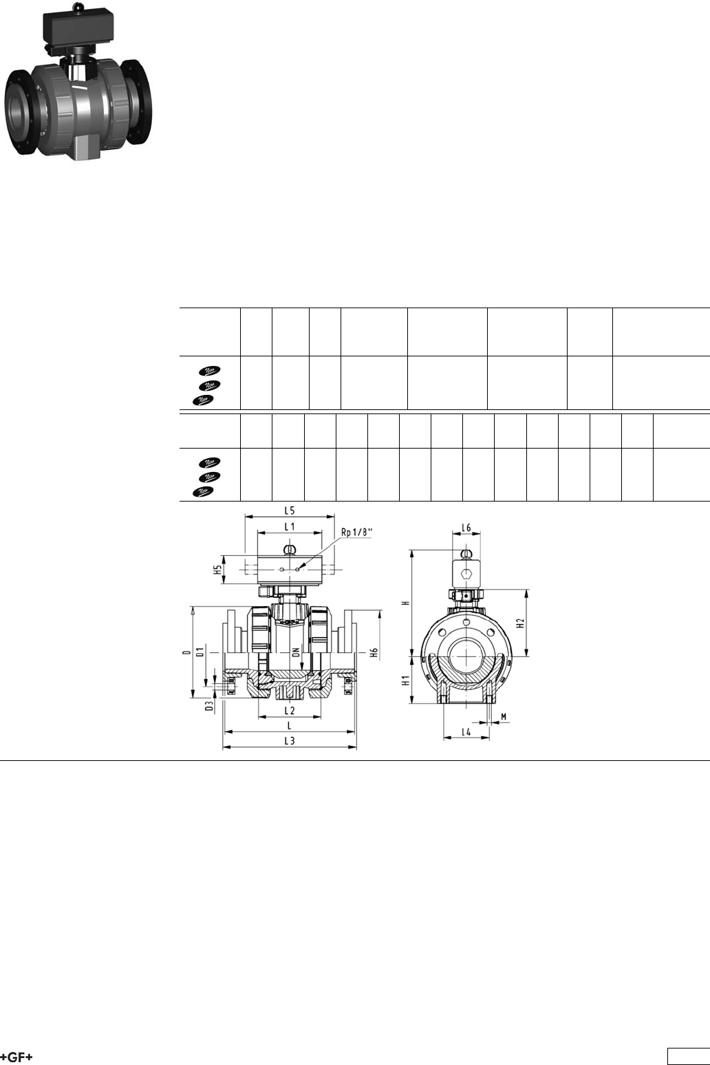
PROGEF Standard
Ball valve type 231 FO (Fail safe to open)
Without manual override
With backing flanges PP-st metric
Model:
ÏMaterial: PP-H
ÏFor easy installation and removal
ÏIntegrated stainless steel mounting inserts
ÏControl time 90°<) 1-2 s
ÏAssignment of actuators: PA11 (DN10/15-25), PA21 (DN32-50), PA30 (DN65),
PA35 (DN80), PA40 (DN100)
ÏImage and drawing DN65-100 please see ''New product ball valve DN65-100''
ÏOverall length according to EN 558
ÏConnecting dimension: ISO 7005, EN 1092, BS 4504, DIN 2501
Option:
ÏIndividual configuration of the valve (see form)
d
[mm]
DN
[mm]
Inch PN kv-value
(”p=1 bar)
[l/min]
EPDM
Code
FPM
Code
kg
75 65 2 1
/210 5000 199 231 349 199 231 359 8.300
90 80 3 10 7000 199 231 350 199 231 360 10.000
110 100 4 10 11000 199 231 351 199 231 361 14.100
d
[mm]
D
[mm]
H
[mm]
H1
[mm]
H2
[mm]
H5
[mm]
H6
[mm]
L
[mm]
L1
[mm]
L2
[mm]
L3
[mm]
L4
[mm]
L5
[mm]
L6
[mm]
75 166 262 85 156 70 93 280 218 136 290 70 276 65
90 200 281 105 168 78 100 296 259 141 310 70 341 72
110 238 292 123 175 86 110 336 287 164 350 120 369 80
235

PROGEF Standard
Ball valve type 231 FO (Fail safe to open)
Without manual override
With butt fusion spigots IR-Plus SDR11 metric
Model:
ÏMaterial: PP-H
ÏFor easy installation and removal
ÏIntegrated stainless steel mounting inserts
ÏControl time 90°<) 1-2 s
ÏAssignment of actuators: PA11 (DN10/15-25), PA21 (DN32-50), PA30 (DN65),
PA35 (DN80), PA40 (DN100)
ÏImage and drawing DN65-100 please see ''New product ball valve DN65-100''
Option:
ÏIndividual configuration of the valve (see form)
d
[mm]
DN
[mm]
PN kv-value
(”p=1 bar)
[l/min]
EPDM
Code
FPM
Code
kg
75 65 10 5000 199 231 859 199 231 869 4.000
90 80 10 7000 199 231 860 199 231 870 4.800
110 100 10 11000 199 231 861 199 231 871 6.900
d
[mm]
D
[mm]
H
[mm]
H1
[mm]
H2
[mm]
H5
[mm]
L
[mm]
L1
[mm]
L2
[mm]
L3
[mm]
L4
[mm]
L5
[mm]
L6
[mm]
e
[mm]
75 166 262 85 156 70 266 218 136 290 70 276 65 8.2
90 200 281 105 168 78 264 259 141 310 70 341 72 9.9
110 238 292 123 175 86 301 287 164 350 120 369 80 12.0
236

PROGEF Standard
Ball valve type 231 FO (Fail safe to open)
Without manual override
With butt fusion spigots SDR17.6 metric
Model:
ÏMaterial: PP-H
ÏFor easy installation and removal
ÏIntegrated stainless steel mounting inserts
ÏControl time 90°<) 1-2 s
ÏAssignment of actuators: PA11 (DN10/15-25), PA21 (DN32-50), PA30 (DN65),
PA35 (DN80), PA40 (DN100)
ÏImage and drawing DN65-100 please see ''New product ball valve DN65-100''
Option:
ÏIndividual configuration of the valve (see form)
d
[mm]
DN
[mm]
PN kv-value
(”p=1 bar)
[l/min]
EPDM
Code
FPM
Code
kg
75 65 10 5000 199 231 959 199 231 969 4.000
90 80 10 7000 199 231 960 199 231 970 4.800
110 100 10 11000 199 231 961 199 231 971 6.900
d
[mm]
D
[mm]
H
[mm]
H1
[mm]
H2
[mm]
H5
[mm]
L
[mm]
L1
[mm]
L2
[mm]
L3
[mm]
L4
[mm]
L5
[mm]
L6
[mm]
e
[mm]
75 166 262 85 156 70 266 218 136 290 70 276 65 4.6
90 200 281 105 168 78 264 259 141 310 70 341 72 5.5
110 238 292 123 175 86 301 287 164 350 120 369 80 6.7
237
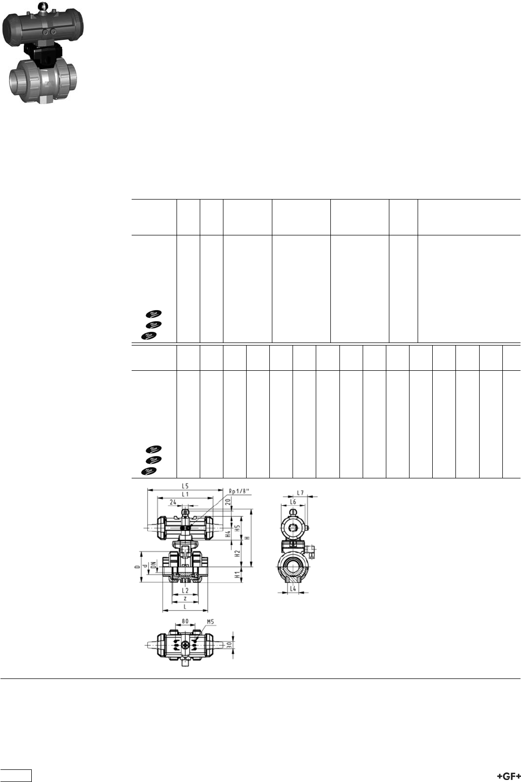
PROGEF Standard
Ball valve type 231 DA (Double acting)
Without manual override
With fusion sockets metric
Model:
ÏMaterial: PP-H
ÏFor easy installation and removal
ÏIntegrated stainless steel mounting inserts
ÏControl time 90°<) 1-2 s
ÏAssignment of actuators: PA11 (DN10/15-25), PA21 (DN32-50), PA35 (DN65),
PA40 (DN80), PA45 (DN100)
ÏImage and drawing DN65-100 please see ''New product ball valve DN65-100''
Option:
ÏIndividual configuration of the valve (see form)
d
[mm]
DN
[mm]
PN kv-value
(”p=1 bar)
[l/min]
EPDM
Code
FPM
Code
kg
16 10 10 70 199 231 202 199 231 212 1.200
20 15 10 185 199 231 203 199 231 213 1.200
25 20 10 350 199 231 204 199 231 214 1.300
32 25 10 700 199 231 205 199 231 215 1.400
40 32 10 1000 199 231 206 199 231 216 2.500
50 40 10 1600 199 231 207 199 231 217 2.800
63 50 10 3100 199 231 208 199 231 218 3.700
75 65 10 5000 199 231 209 199 231 219 2.800
90 80 10 7000 199 231 210 199 231 220 4.000
110 100 10 11000 199 231 211 199 231 221 5.100
d
[mm]
D
[mm]
H
[mm]
H1
[mm]
H2
[mm]
H4
[mm]
H5
[mm]
L
[mm]
L1
[mm]
L2
[mm]
L4
[mm]
L5
[mm]
L6
[mm]
L7
[mm]
z
[mm]
16 50 167 27 62 40 97 93 194 56 25 261 76 48 66
20 50 167 27 62 40 97 95 194 56 25 261 76 48 67
25 58 176 30 71 40 97 108 194 65 25 261 76 48 77
32 68 176 36 71 40 97 118 194 71 25 261 76 48 83
40 84 210 44 84 51 115 137 224 85 45 305 95 59 99
50 97 210 51 84 51 115 147 224 89 45 305 95 59 105
63 124 232 64 106 51 115 168 224 101 45 305 95 59 117
75 166 257 85 156 66 233 144 136 70 190 60 167
90 200 274 105 168 70 254 152 141 70 198 65 180
110 238 273 123 175 78 301 169 164 120 235 72 215
238

PROGEF Standard
Ball valve type 231 DA (Double acting)
Without manual override
With socket fusion spigots metric
Model:
ÏMaterial: PP-H
ÏFor easy installation and removal
ÏIntegrated stainless steel mounting inserts
ÏControl time 90°<) 1-2 s
ÏAssignment of actuators: PA11 (DN10/15-25), PA21 (DN32-50), PA35 (DN65),
PA40 (DN80), PA45 (DN100)
ÏImage and drawing DN65-100 please see ''New product ball valve DN65-100''
Option:
ÏIndividual configuration of the valve (see form)
d
[mm]
DN
[mm]
PN kv-value
(”p=1 bar)
[l/min]
EPDM
Code
FPM
Code
kg
16 10 10 70 199 231 222 199 231 232 1.200
20 15 10 185 199 231 223 199 231 233 1.200
25 20 10 350 199 231 224 199 231 234 1.300
32 25 10 700 199 231 225 199 231 235 1.400
40 32 10 1000 199 231 226 199 231 236 2.500
50 40 10 1600 199 231 227 199 231 237 2.800
63 50 10 3100 199 231 228 199 231 238 3.700
75 65 10 5000 199 231 229 199 231 239 2.900
90 80 10 7000 199 231 230 199 231 240 4.100
110 100 10 11000 199 231 231 199 231 241 5.200
d
[mm]
D
[mm]
H
[mm]
H1
[mm]
H2
[mm]
H4
[mm]
H5
[mm]
L
[mm]
L1
[mm]
L2
[mm]
L3
[mm]
L4
[mm]
L5
[mm]
L6
[mm]
L7
[mm]
16 50 167 27 62 40 97 110 194 56 130 25 261 76 48
20 50 167 27 62 40 97 120 194 56 130 25 261 76 48
25 58 176 30 71 40 97 139 194 65 150 25 261 76 48
32 68 176 36 71 40 97 150 194 71 160 25 261 76 48
40 84 210 44 84 51 115 170 224 85 180 45 305 95 59
50 97 210 51 84 51 115 190 224 89 200 45 305 95 59
63 124 232 64 106 51 115 220 224 101 230 45 305 95 59
75 166 257 85 156 66 280 144 136 290 70 190 60
90 200 274 105 168 70 296 152 141 310 70 198 65
110 238 273 123 175 78 336 169 164 350 120 235 72
239
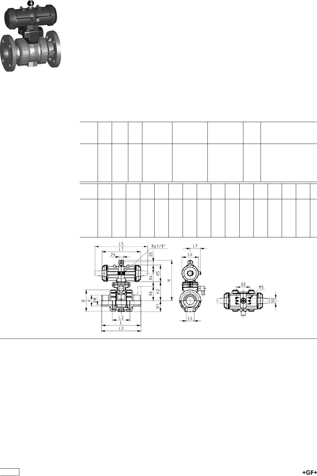
PROGEF Standard
Ball valve type 231 DA (Double acting)
Without manual override
With fixed flanges PP-H serrated metric
Model:
ÏMaterial: PP-H
ÏFor easy installation and removal
ÏIntegrated stainless steel mounting inserts
ÏControl time 90°<) 1-2 s
ÏBuilt on with pneumatic actuator PA11 (DN10/15-25), PA21 (DN32-50)
ÏOverall length according to EN 558
ÏConnecting dimensions: ISO 7005 / EN 1092 / DIN 2501 PN10 / BS4504
Option:
ÏIndividual configuration of the valve (see form)
d
[mm]
DN
[mm]
Inch PN kv-value
(”p=1 bar)
[l/min]
EPDM
Code
FPM
Code
kg
20 15 1
/210 185 199 231 463 199 231 473 1.400
25 20 3
/410 350 199 231 464 199 231 474 1.600
32 25 1 10 700 199 231 465 199 231 475 1.800
40 32 1 1
/410 1000 199 231 466 199 231 476 3.100
50 40 1 1
/210 1600 199 231 467 199 231 477 3.600
63 50 2 10 3100 199 231 468 199 231 478 4.700
d
[mm]
D
[mm]
H
[mm]
H1
[mm]
H2
[mm]
H4
[mm]
H5
[mm]
H6
[mm]
L
[mm]
L1
[mm]
L2
[mm]
L3
[mm]
L4
[mm]
L5
[mm]
L6
[mm]
L7
[mm]
20 50 167 27 62 40 97 48 120 194 56 130 25 261 76 48
25 58 176 30 71 40 97 53 140 194 65 150 25 261 76 48
32 68 176 36 71 40 97 58 150 194 71 160 25 261 76 48
40 84 210 44 84 51 115 70 170 224 85 180 45 305 95 59
50 97 210 51 84 51 115 75 190 224 89 200 45 305 95 59
63 124 232 64 106 51 115 83 220 224 101 230 45 305 95 59
240
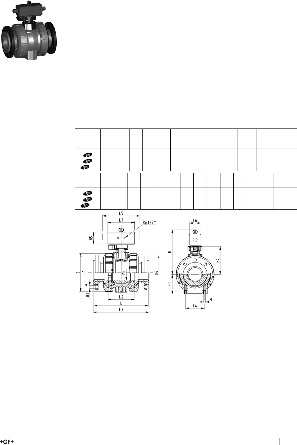
PROGEF Standard
Ball valve type 231 DA (Double acting)
Without manual override
With backing flanges PP-st metric
Model:
ÏMaterial: PP-H
ÏFor easy installation and removal
ÏIntegrated stainless steel mounting inserts
ÏControl time 90°<) 1-2 s
ÏAssignment of actuators: PA11 (DN10/15-25), PA21 (DN32-50), PA35 (DN65),
PA40 (DN80), PA45 (DN100)
ÏImage and drawing DN65-100 please see ''New product ball valve DN65-100''
ÏOverall length according to EN 558
ÏConnecting dimension: ISO 7005, EN 1092, BS 4504, DIN 2501
Option:
ÏIndividual configuration of the valve (see form)
d
[mm]
DN
[mm]
Inch PN kv-value
(”p=1 bar)
[l/min]
EPDM
Code
FPM
Code
kg
75 65 2 1
/210 5000 199 231 369 199 231 379 7.100
90 80 3 10 7000 199 231 370 199 231 380 9.300
110 100 4 10 11000 199 231 371 199 231 381 12.300
d
[mm]
D
[mm]
H
[mm]
H1
[mm]
H2
[mm]
H5
[mm]
H6
[mm]
L
[mm]
L1
[mm]
L2
[mm]
L3
[mm]
L4
[mm]
L5
[mm]
L6
[mm]
75 166 257 85 156 66 93 280 144 136 290 70 190 60
90 200 274 105 168 70 100 296 152 141 310 70 198 65
110 238 273 123 175 78 110 336 169 164 350 120 235 72
241

PROGEF Standard
Ball valve type 231 DA (Double acting)
Without manual override
With butt fusion spigots IR-Plus SDR11 metric
Model:
ÏMaterial: PP-H
ÏFor easy installation and removal
ÏIntegrated stainless steel mounting inserts
ÏControl time 90°<) 1-2 s
ÏAssignment of actuators: PA11 (DN10/15-25), PA21 (DN32-50), PA35 (DN65),
PA40 (DN80), PA45 (DN100)
ÏImage and drawing DN65-100 please see ''New product ball valve DN65-100''
Option:
ÏIndividual configuration of the valve (see form)
d
[mm]
DN
[mm]
PN kv-value
(”p=1 bar)
[l/min]
EPDM
Code
FPM
Code
kg
75 65 10 5000 199 231 879 199 231 889 2.900
90 80 10 7000 199 231 880 199 231 890 4.100
110 100 10 11000 199 231 881 199 231 891 5.200
d
[mm]
D
[mm]
H
[mm]
H1
[mm]
H2
[mm]
H5
[mm]
L
[mm]
L1
[mm]
L2
[mm]
L3
[mm]
L4
[mm]
L5
[mm]
L6
[mm]
e
[mm]
75 166 257 85 156 66 266 144 136 290 70 190 60 8.2
90 200 274 105 168 70 264 152 141 310 70 198 65 9.9
110 238 273 123 175 78 301 169 164 350 120 235 72 12.0
242
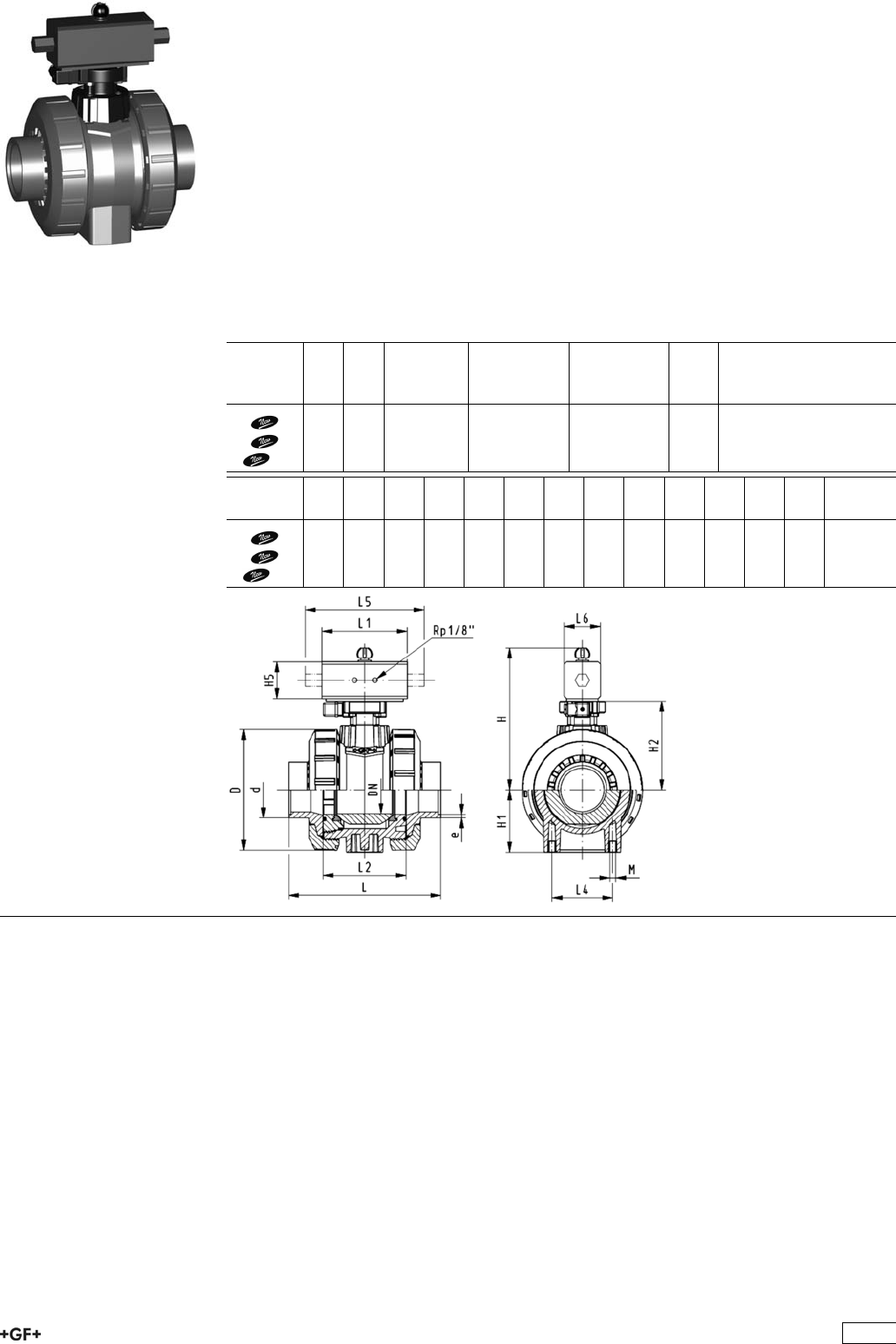
PROGEF Standard
Ball valve type 231 DA (Double acting)
Without manual override
With butt fusion spigots SDR17.6 metric
Model:
ÏMaterial: PP-H
ÏFor easy installation and removal
ÏIntegrated stainless steel mounting inserts
ÏControl time 90°<) 1-2 s
ÏAssignment of actuators: PA11 (DN10/15-25), PA21 (DN32-50), PA35 (DN65),
PA40 (DN80), PA45 (DN100)
ÏImage and drawing DN65-100 please see ''New product ball valve DN65-100''
Option:
ÏIndividual configuration of the valve (see form)
d
[mm]
DN
[mm]
PN kv-value
(”p=1 bar)
[l/min]
EPDM
Code
FPM
Code
kg
75 65 10 5000 199 231 979 199 231 989 2.900
90 80 10 7000 199 231 980 199 231 990 4.100
110 100 10 11000 199 231 981 199 231 991 5.200
d
[mm]
D
[mm]
H
[mm]
H1
[mm]
H2
[mm]
H5
[mm]
L
[mm]
L1
[mm]
L2
[mm]
L3
[mm]
L4
[mm]
L5
[mm]
L6
[mm]
e
[mm]
75 166 257 85 156 66 266 144 136 290 70 190 60 4.6
90 200 274 105 168 70 264 152 141 310 70 198 65 5.5
110 238 273 123 175 78 301 169 164 350 120 235 72 6.7
243

PROGEF Standard
3-Way ball valve type 276
Horizontal/L-port
Without manual override
With fusion sockets metric
Model:
ÏMaterial: PP-H
ÏBuilt on with pneumatic actuator PA11 (DN10/15-25), PA21 (DN32-50)
ÏActuator fails safe to the closed position FC
ÏControl time 90°<) 1-3 s
ÏFor easy installation and removal
ÏIntegrated stainless steel mounting inserts
d
[mm]
DN
[mm]
PN kv-value
(”p=1 bar)
[l/min]
EPDM
Code
FPM
Code
kg
16 10 10 50 199 276 022 199 276 032 1.044
20 15 10 75 199 276 023 199 276 033 1.044
25 20 10 150 199 276 024 199 276 034 1.167
32 25 10 280 199 276 025 199 276 035 1.290
40 32 10 480 199 276 026 199 276 036 2.191
50 40 10 620 199 276 027 199 276 037 2.555
63 50 10 1230 199 276 028 199 276 038 3.487
d
[mm]
D
[mm]
H
[mm]
H1
[mm]
H2
[mm]
H3
[mm]
H4
[mm]
H5
[mm]
H6
[mm]
L
[mm]
L1
[mm]
L2
[mm]
L3
[mm]
L4
[mm]
L5
[mm]
L6
[mm]
16 46 136 29 31 105 40 77 8 108 194 70 36 25 261 73
20 46 136 29 31 105 40 77 8 111 194 70 36 25 261 73
25 56 144 33 39 105 40 77 8 131 194 86 43 25 261 73
32 67 149 38 44 105 40 77 8 148 194 96 48 25 261 73
40 82 177 44 50 127 51 99 9 177 224 114 58 45 305 94
50 98 190 50 63 127 51 99 9 205 224 137 69 45 305 94
63 121 203 61 76 127 51 99 9 261 224 179 90 45 305 94
d
[mm]
L7
[mm]
M z
[mm]
z1
[mm]
16 48 6 78 39
20 48 6 79 40
25 48 6 95 48
32 48 6 108 54
40 59 8 133 67
50 59 8 155 78
63 59 8 203 102
244
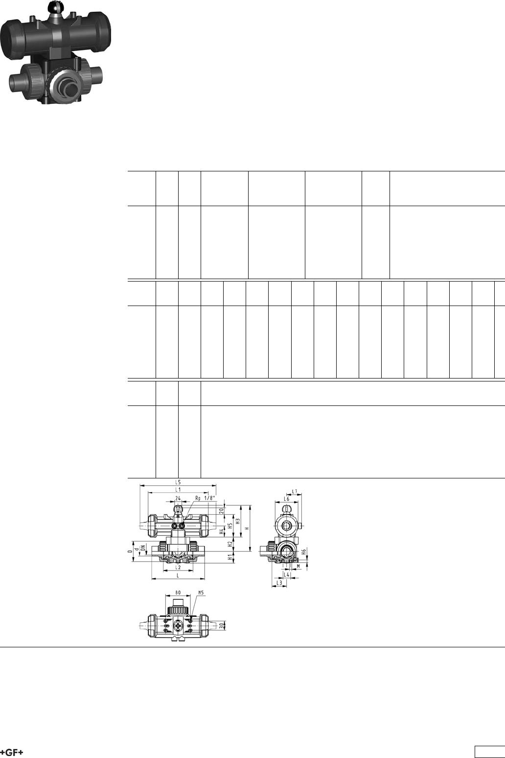
PROGEF Standard
3-Way ball valve type 276
Horizontal/L-port
Without manual override
With socket fusion spigots
Model:
ÏMaterial: PP-H
ÏBuilt on with pneumatic actuator PA11 (DN10/15-25), PA21 (DN32-50)
ÏActuator fails safe to the closed position FC
ÏControl time 90°<) 1-3 s
ÏFor easy installation and removal
ÏIntegrated stainless steel mounting inserts
d
[mm]
DN
[mm]
PN kv-value
(”p=1 bar)
[l/min]
EPDM
Code
FPM
Code
kg
16 10 10 75 199 276 002 199 276 012 1.044
20 15 10 75 199 276 003 199 276 013 0.854
25 20 10 150 199 276 004 199 276 014 1.167
32 25 10 280 199 276 005 199 276 015 1.290
40 32 10 480 199 276 006 199 276 016 2.191
50 40 10 620 199 276 007 199 276 017 2.555
63 50 10 1230 199 276 008 199 276 018 3.487
d
[mm]
D
[mm]
H
[mm]
H1
[mm]
H2
[mm]
H3
[mm]
H4
[mm]
H5
[mm]
H6
[mm]
L
[mm]
L1
[mm]
L2
[mm]
L3
[mm]
L4
[mm]
L5
[mm]
L6
[mm]
16 46 136 29 31 105 40 77 8 108 194 70 36 25 261 73
20 46 136 29 31 105 40 77 8 133 194 70 36 25 261 73
25 56 144 33 39 105 40 77 8 155 194 86 43 25 261 73
32 67 149 38 44 105 40 77 8 170 194 96 48 25 261 73
40 82 177 44 50 127 51 99 9 201 224 114 58 45 305 94
50 98 190 50 63 127 51 99 9 236 224 137 69 45 305 94
63 121 203 61 76 127 51 99 9 286 224 179 90 45 305 94
d
[mm]
L7
[mm]
M
16 48 6
20 48 6
25 48 6
32 48 6
40 59 8
50 59 8
63 59 8
245

PROGEF Standard
3-Way ball valve type 276
Horizontal/L-port
Without manual override
With threaded sockets Rp
Model:
ÏMaterial: PP-H
ÏBuilt on with pneumatic actuator PA11 (DN10/15-25), PA21 (DN32-50)
ÏActuator fails safe to the closed position FC
ÏControl time 90°<) 1-3 s
ÏFor easy installation and removal
ÏIntegrated stainless steel mounting inserts
Inch DN
[mm]
PN kv-value
(”p=1 bar)
[l/min]
EPDM
Code
FPM
Code
kg
3
/810 10 50 199 276 122 199 276 132 1.044
1
/215 10 75 199 276 123 199 276 133 1.044
3
/420 10 150 199 276 124 199 276 134 1.167
1 25 10 280 199 276 125 199 276 135 1.677
11
/432 10 480 199 276 126 199 276 136 2.191
11
/240 10 620 199 276 127 199 276 137 2.555
2 50 10 1230 199 276 128 199 276 138 3.487
Inch D
[mm]
H
[mm]
H1
[mm]
H2
[mm]
H3
[mm]
H4
[mm]
H5
[mm]
H6
[mm]
L
[mm]
L1
[mm]
L2
[mm]
L3
[mm]
L4
[mm]
L5
[mm]
L6
[mm]
3
/846 136 29 31 105 40 77 8 108 194 70 36 25 261 73
1
/246 136 29 31 105 40 77 8 111 194 70 36 25 261 73
3
/456 144 33 39 105 40 77 8 131 194 86 43 25 261 73
1 67 149 38 44 105 40 77 8 148 194 96 48 25 261 73
11
/482 177 44 50 127 51 99 9 177 224 114 58 45 305 94
11
/298 190 50 63 127 51 99 9 205 224 137 69 45 305 94
2 121 203 61 76 127 51 99 9 261 224 179 90 45 305 94
Inch L7
[mm]
M z
[mm]
z1
[mm]
3
/848 6 78 39
1
/248 6 79 40
3
/448 6 95 48
1 48 6 108 54
11
/459 8 133 67
11
/259 8 155 78
2 59 8 203 102
246
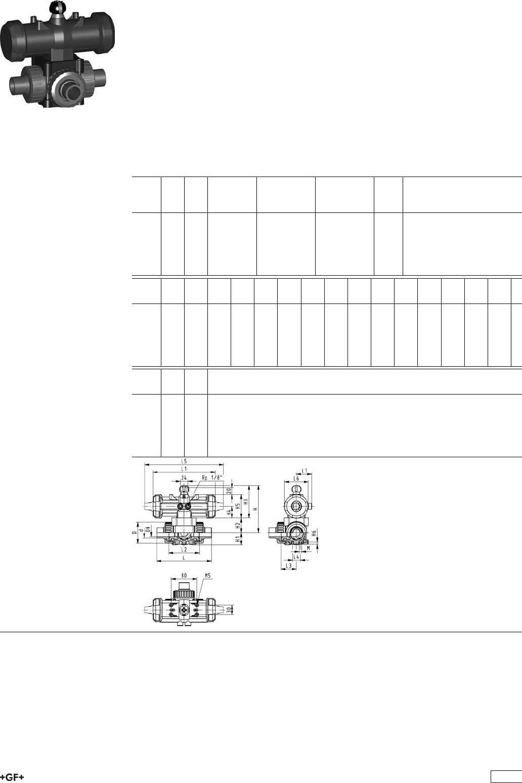
PROGEF Standard
3-Way ball valve type 276
Horizontal/L-port
Without manual override
With butt fusion spigots metric
Model:
ÏMaterial: PP-H
ÏBuilt on with pneumatic actuator PA11 (DN10/15-25), PA21 (DN32-50)
ÏActuator fails safe to the closed position FC
ÏControl time 90°<) 1-3 s
ÏFor easy installation and removal
ÏIntegrated stainless steel mounting inserts
d
[mm]
DN
[mm]
PN kv-value
(”p=1 bar)
[l/min]
EPDM
Code
FPM
Code
kg
20 15 10 75 199 276 083 199 276 093 1.044
25 20 10 150 199 276 084 199 276 094 1.167
32 25 10 280 199 276 085 199 276 095 1.290
40 32 10 480 199 276 086 199 276 096 2.191
50 40 10 620 199 276 087 199 276 097 2.555
63 50 10 1230 199 276 088 199 276 098 3.487
d
[mm]
D
[mm]
H
[mm]
H1
[mm]
H2
[mm]
H3
[mm]
H4
[mm]
H5
[mm]
H6
[mm]
L
[mm]
L1
[mm]
L2
[mm]
L3
[mm]
L4
[mm]
L5
[mm]
L6
[mm]
20 46 136 29 31 105 40 77 8 133 194 70 36 25 261 73
25 56 144 33 39 105 40 77 8 155 194 86 43 25 261 73
32 67 149 38 44 105 40 77 8 170 194 96 48 25 261 73
40 82 177 44 50 127 51 99 9 201 224 114 58 45 305 94
50 98 190 50 63 127 51 99 9 236 224 137 69 45 305 94
63 121 203 61 76 127 51 99 9 286 224 179 90 45 305 94
d
[mm]
L7
[mm]
M
20 48 6
25 48 6
32 48 6
40 59 8
50 59 8
63 59 8
247

PROGEF Standard
3-Way ball valve type 276
Horizontal/L-port DA (Double acting)
Without manual override
With fusion sockets metric
Model:
ÏMaterial: PP-H
ÏBuilt on with pneumatic actuator PA11 (DN10/15-25), PA21 (DN32-50)
ÏControl time 90°<) 1-3 s
ÏFor easy installation and removal
ÏIntegrated stainless steel mounting inserts
d
[mm]
DN
[mm]
PN kv-value
(”p=1 bar)
[l/min]
EPDM
Code
FPM
Code
kg
16 10 10 50 199 276 182 199 276 192 0.854
20 15 10 75 199 276 183 199 276 193 0.854
25 20 10 150 199 276 184 199 276 194 0.977
32 25 10 280 199 276 185 199 276 195 1.100
40 32 10 480 199 276 186 199 276 196 1.767
50 40 10 620 199 276 187 199 276 197 2.131
63 50 10 1230 199 276 188 199 276 198 3.297
d
[mm]
D
[mm]
H
[mm]
H1
[mm]
H2
[mm]
H3
[mm]
H4
[mm]
H5
[mm]
H6
[mm]
L
[mm]
L1
[mm]
L2
[mm]
L3
[mm]
L4
[mm]
L5
[mm]
L6
[mm]
16 46 136 29 31 105 40 77 8 108 194 70 36 25 261 73
20 46 136 29 31 105 40 77 8 111 194 70 36 25 261 73
25 56 144 33 39 105 40 77 8 131 194 86 43 25 261 73
32 67 149 38 44 105 40 77 8 148 194 96 48 25 261 73
40 82 177 44 50 127 51 99 9 177 224 114 58 45 305 94
50 98 190 50 63 127 51 99 9 205 224 137 69 45 305 94
63 121 203 61 76 127 51 99 9 261 224 179 90 45 305 94
d
[mm]
L7
[mm]
M z
[mm]
z1
[mm]
16 48 6 78 39
20 48 6 79 40
25 48 6 95 48
32 48 6 108 54
40 59 8 133 67
50 59 8 155 78
63 59 8 203 102
248

PROGEF Standard
3-Way ball valve type 276
Horizontal/L-port DA (Double acting)
Without manual override
With socket fusion spigots
Model:
ÏMaterial: PP-H
ÏBuilt on with pneumatic actuator PA11 (DN10/15-25), PA21 (DN32-50)
ÏControl time 90°<) 1-3 s
ÏFor easy installation and removal
ÏIntegrated stainless steel mounting inserts
d
[mm]
DN
[mm]
PN kv-value
(”p=1 bar)
[l/min]
EPDM
Code
FPM
Code
kg
16 10 10 75 199 276 162 199 276 172 0.854
20 15 10 75 199 276 163 199 276 173 0.854
25 20 10 150 199 276 164 199 276 174 0.977
32 25 10 280 199 276 165 199 276 175 1.100
40 32 10 480 199 276 166 199 276 176 1.767
50 40 10 620 199 276 167 199 276 177 2.131
63 50 10 1230 199 276 168 199 276 178 3.487
d
[mm]
D
[mm]
H
[mm]
H1
[mm]
H2
[mm]
H3
[mm]
H4
[mm]
H5
[mm]
H6
[mm]
L
[mm]
L1
[mm]
L2
[mm]
L3
[mm]
L4
[mm]
L5
[mm]
L6
[mm]
16 46 136 29 31 105 40 77 8 108 194 70 36 25 261 73
20 46 136 29 31 105 40 77 8 133 194 70 36 25 261 73
25 56 144 33 39 105 40 77 8 155 194 86 43 25 261 73
32 67 149 38 44 105 40 77 8 170 194 96 48 25 261 73
40 82 177 44 50 127 51 99 9 201 224 114 58 45 305 94
50 98 190 50 63 127 51 99 9 236 224 137 69 45 305 94
63 121 203 61 76 127 51 99 9 286 224 179 90 45 305 94
d
[mm]
L7
[mm]
M
16 48 6
20 48 6
25 48 6
32 48 6
40 59 8
50 59 8
63 59 8
249

PROGEF Standard
3-Way ball valve type 276
Horizontal/L-port DA (Double acting)
Without manual override
With threaded sockets Rp
Model:
ÏMaterial: PP-H
ÏBuilt on with pneumatic actuator PA11 (DN10/15-25), PA21 (DN32-50)
ÏControl time 90°<) 1-3 s
ÏFor easy installation and removal
ÏIntegrated stainless steel mounting inserts
Inch DN
[mm]
PN kv-value
(”p=1 bar)
[l/min]
EPDM
Code
FPM
Code
kg
3
/810 10 50 199 276 282 199 276 292 0.854
1
/215 10 75 199 276 283 199 276 293 0.854
3
/420 10 150 199 276 284 199 276 294 0.977
1 25 10 280 199 276 285 199 276 295 1.100
11
/432 10 480 199 276 286 199 276 296 1.767
11
/240 10 620 199 276 287 199 276 297 2.131
2 50 10 1230 199 276 288 199 276 298 3.063
Inch D
[mm]
H
[mm]
H1
[mm]
H2
[mm]
H3
[mm]
H4
[mm]
H5
[mm]
H6
[mm]
L
[mm]
L1
[mm]
L2
[mm]
L3
[mm]
L4
[mm]
L5
[mm]
L6
[mm]
3
/846 136 29 31 105 40 77 8 108 194 70 36 25 261 73
1
/246 136 29 31 105 40 77 8 111 194 70 36 25 261 73
3
/456 144 33 39 105 40 77 8 131 194 86 43 25 261 73
1 67 149 38 44 105 40 77 8 148 194 96 48 25 261 73
11
/482 177 44 50 127 51 99 9 177 224 114 58 45 305 94
11
/298 190 50 63 127 51 99 9 205 224 137 69 45 305 94
2 121 203 61 76 127 51 99 9 261 224 179 90 45 305 94
Inch L7
[mm]
M z
[mm]
z1
[mm]
3
/848 6 78 39
1
/248 6 79 40
3
/448 6 95 48
1 48 6 108 54
11
/459 8 133 67
11
/259 8 155 78
2 59 8 203 102
250

PROGEF Standard
3-Way ball valve type 276
Horizontal/L-port DA (Double acting)
Without manual override
With butt fusion spigots metric
Model:
ÏMaterial: PP-H
ÏBuilt on with pneumatic actuator PA11 (DN10/15-25), PA21 (DN32-50)
ÏControl time 90°<) 1-3 s
ÏFor easy installation and removal
ÏIntegrated stainless steel mounting inserts
d
[mm]
DN
[mm]
PN kv-value
(”p=1 bar)
[l/min]
EPDM
Code
FPM
Code
kg
20 15 10 75 199 276 243 199 276 253 0.854
25 20 10 150 199 276 244 199 276 254 0.977
32 25 10 280 199 276 245 199 276 255 1.100
40 32 10 480 199 276 246 199 276 256 1.767
50 40 10 620 199 276 247 199 276 257 2.131
63 50 10 1230 199 276 248 199 276 258 3.063
d
[mm]
D
[mm]
H
[mm]
H1
[mm]
H2
[mm]
H3
[mm]
H4
[mm]
H5
[mm]
H6
[mm]
L
[mm]
L1
[mm]
L2
[mm]
L3
[mm]
L4
[mm]
L5
[mm]
L6
[mm]
20 46 136 29 31 105 40 77 8 133 194 70 36 25 261 73
25 56 144 33 39 105 40 77 8 155 194 86 43 25 261 73
32 67 149 38 44 105 40 77 8 170 194 96 48 25 261 73
40 82 177 44 50 127 51 99 9 201 224 114 58 45 305 94
50 98 190 50 63 127 51 99 9 236 224 137 69 45 305 94
63 121 203 61 76 127 51 99 9 286 224 179 90 45 305 94
d
[mm]
L7
[mm]
M
20 48 6
25 48 6
32 48 6
40 59 8
50 59 8
63 59 8
251

PROGEF Standard
3-Way ball valve type 276
Horizontal/T-port
Without manual override
With fusion sockets metric
Model:
ÏMaterial: PP-H
ÏBuilt on with pneumatic actuator PA11 (DN10/15-25), PA21 (DN32-50)
ÏActuator fails safe to the closed position FC
ÏControl time 90°<) 1-3 s
ÏFor easy installation and removal
ÏIntegrated stainless steel mounting inserts
d
[mm]
DN
[mm]
PN kv-value
(”p=1 bar)
[l/min]
EPDM
Code
FPM
Code
kg
16 10 10 140 199 276 062 199 276 072 1.044
20 15 10 200 199 276 063 199 276 073 1.044
25 20 10 470 199 276 064 199 276 074 1.167
32 25 10 793 199 276 065 199 276 075 1.290
40 32 10 1290 199 276 066 199 276 076 2.191
50 40 10 1910 199 276 067 199 276 077 2.555
63 50 10 3100 199 276 068 199 276 078 3.487
d
[mm]
D
[mm]
H
[mm]
H1
[mm]
H2
[mm]
H3
[mm]
H4
[mm]
H5
[mm]
H6
[mm]
L
[mm]
L1
[mm]
L2
[mm]
L3
[mm]
L4
[mm]
L5
[mm]
L6
[mm]
16 46 136 29 31 105 40 77 8 108 194 70 36 25 261 73
20 46 136 29 31 105 40 77 8 111 194 70 36 25 261 73
25 56 144 33 39 105 40 77 8 131 194 86 43 25 261 73
32 67 149 38 44 105 40 77 8 148 194 96 48 25 261 73
40 82 177 44 50 127 51 99 9 177 224 114 58 45 305 94
50 98 190 50 63 127 51 99 9 205 224 137 69 45 305 94
63 121 203 61 76 127 51 99 9 261 224 179 90 45 305 94
d
[mm]
L7
[mm]
M z
[mm]
z1
[mm]
16 48 6 78 39
20 48 6 79 40
25 48 6 95 48
32 48 6 108 54
40 59 8 133 67
50 59 8 155 78
63 59 8 203 102
252
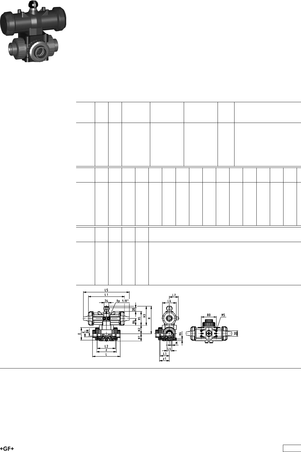
PROGEF Standard
3-Way ball valve type 276
Horizontal/T-port
Without manual override
With threaded sockets Rp
Model:
ÏMaterial: PP-H
ÏBuilt on with pneumatic actuator PA11 (DN10/15-25), PA21 (DN32-50)
ÏActuator fails safe to the closed position FC
ÏControl time 90°<) 1-3 s
ÏFor easy installation and removal
ÏIntegrated stainless steel mounting inserts
Inch DN
[mm]
PN kv-value
(”p=1 bar)
[l/min]
EPDM
Code
FPM
Code
kg
3
/810 10 140 199 276 142 199 276 152 1.044
1
/215 10 200 199 276 143 199 276 153 1.044
3
/420 10 470 199 276 144 199 276 154 1.167
1 25 10 793 199 276 145 199 276 155 1.290
11
/432 10 1290 199 276 146 199 276 156 2.191
11
/240 10 1910 199 276 147 199 276 157 2.555
2 50 10 3100 199 276 148 199 276 158 3.487
Inch D
[mm]
H
[mm]
H1
[mm]
H2
[mm]
H3
[mm]
H4
[mm]
H5
[mm]
H6
[mm]
L
[mm]
L1
[mm]
L2
[mm]
L3
[mm]
L4
[mm]
L5
[mm]
L6
[mm]
3
/846 136 29 31 105 40 77 8 108 194 70 36 25 261 73
1
/246 136 29 31 105 40 77 8 111 194 70 36 25 261 73
3
/456 144 33 39 105 40 77 8 131 194 86 43 25 261 73
1 67 149 38 44 105 40 77 8 148 194 96 48 25 261 73
11
/482 177 44 50 127 51 99 9 177 224 114 58 45 305 94
11
/298 190 50 63 127 51 99 9 205 224 137 69 45 305 94
2 121 203 61 76 127 51 99 9 261 224 179 90 45 305 94
Inch L7
[mm]
M z
[mm]
z1
[mm]
3
/848 6 78 39
1
/248 6 79 40
3
/448 6 95 48
1 48 6 108 54
11
/459 8 133 67
11
/259 8 155 78
2 59 8 203 102
253
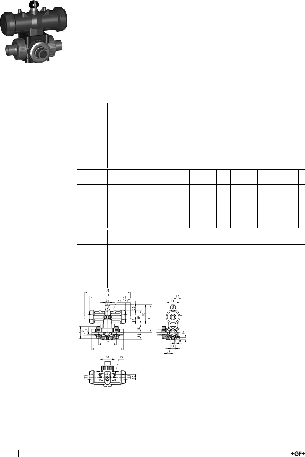
PROGEF Standard
3-Way ball valve type 276
Horizontal/T-port
Without manual override
With socket fusion spigots
Model:
ÏMaterial: PP-H
ÏBuilt on with pneumatic actuator PA11 (DN10/15-25), PA21 (DN32-50)
ÏActuator fails safe to the closed position FC
ÏControl time 90°<) 1-3 s
ÏFor easy installation and removal
ÏIntegrated stainless steel mounting inserts
d
[mm]
DN
[mm]
PN kv-value
(”p=1 bar)
[l/min]
EPDM
Code
FPM
Code
kg
16 10 10 200 199 276 042 199 276 052 1.044
20 15 10 200 199 276 043 199 276 053 1.044
25 20 10 470 199 276 044 199 276 054 1.167
32 25 10 793 199 276 045 199 276 055 1.290
40 32 10 1290 199 276 046 199 276 056 2.191
50 40 10 1910 199 276 047 199 276 057 2.555
63 50 10 3100 199 276 048 199 276 058 3.487
d
[mm]
D
[mm]
H
[mm]
H1
[mm]
H2
[mm]
H3
[mm]
H4
[mm]
H5
[mm]
H6
[mm]
L
[mm]
L1
[mm]
L2
[mm]
L3
[mm]
L4
[mm]
L5
[mm]
L6
[mm]
16 46 136 29 31 105 40 77 8 108 194 70 36 25 261 73
20 46 136 29 31 105 40 77 8 133 194 70 36 25 261 73
25 56 144 33 39 105 40 77 8 155 194 86 43 25 261 73
32 67 149 38 44 105 40 77 8 170 194 96 48 25 261 73
40 82 177 44 50 127 51 99 9 201 224 114 58 45 305 94
50 98 190 50 63 127 51 99 9 236 224 137 69 45 305 94
63 121 203 61 76 127 51 99 9 286 224 179 90 45 305 94
d
[mm]
L7
[mm]
M
16 48 6
20 48 6
25 48 6
32 48 6
40 59 8
50 59 8
63 59 8
254

PROGEF Standard
3-Way ball valve type 276
Horizontal/T-port
Without manual override
With butt fusion spigots metric
Model:
ÏMaterial: PP-H
ÏBuilt on with pneumatic actuator PA11 (DN10/15-25), PA21 (DN32-50)
ÏActuator fails safe to the closed position FC
ÏControl time 90°<) 1-3 s
ÏFor easy installation and removal
ÏIntegrated stainless steel mounting inserts
d
[mm]
DN
[mm]
PN kv-value
(”p=1 bar)
[l/min]
EPDM
Code
FPM
Code
kg
20 15 10 200 199 276 103 199 276 113 1.044
25 20 10 470 199 276 104 199 276 114 1.167
32 25 10 793 199 276 105 199 276 115 1.290
40 32 10 1290 199 276 106 199 276 116 2.191
50 40 10 1910 199 276 107 199 276 117 2.555
63 50 10 3100 199 276 108 199 276 118 3.487
d
[mm]
D
[mm]
H
[mm]
H1
[mm]
H2
[mm]
H3
[mm]
H4
[mm]
H5
[mm]
H6
[mm]
L
[mm]
L1
[mm]
L2
[mm]
L3
[mm]
L4
[mm]
L5
[mm]
L6
[mm]
20 46 136 29 31 105 40 77 8 133 194 70 36 25 261 73
25 56 144 33 39 105 40 77 8 155 194 86 43 25 261 73
32 67 149 38 44 105 40 77 8 170 194 96 48 25 261 73
40 82 177 44 50 127 51 99 9 201 224 114 58 45 305 94
50 98 190 50 63 127 51 99 9 236 224 137 69 45 305 94
63 121 203 61 76 127 51 99 9 286 224 179 90 45 305 94
d
[mm]
L7
[mm]
M
20 48 6
25 48 6
32 48 6
40 59 8
50 59 8
63 59 8
255

PROGEF Standard
3-Way ball valve type 276
Horizontal/T-port DA (Double acting)
Without manual override
With fusion sockets metric
Model:
ÏMaterial: PP-H
ÏBuilt on with pneumatic actuator PA11 (DN10/15-25), PA21 (DN32-50)
ÏControl time 90°<) 1-3 s
ÏFor easy installation and removal
ÏIntegrated stainless steel mounting inserts
d
[mm]
DN
[mm]
PN kv-value
(”p=1 bar)
[l/min]
EPDM
Code
FPM
Code
kg
16 10 10 140 199 276 222 199 276 232 0.854
20 15 10 200 199 276 223 199 276 233 0.854
25 20 10 470 199 276 224 199 276 234 0.977
32 25 10 793 199 276 225 199 276 235 1.100
40 32 10 1290 199 276 226 199 276 236 1.767
50 40 10 1910 199 276 227 199 276 237 2.131
63 50 10 3100 199 276 228 199 276 238 3.297
d
[mm]
D
[mm]
H
[mm]
H1
[mm]
H2
[mm]
H3
[mm]
H4
[mm]
H5
[mm]
H6
[mm]
L
[mm]
L1
[mm]
L2
[mm]
L3
[mm]
L4
[mm]
L5
[mm]
L6
[mm]
16 46 136 29 31 105 40 77 8 108 194 70 36 25 261 73
20 46 136 29 31 105 40 77 8 111 194 70 36 25 261 73
25 56 144 33 39 105 40 77 8 131 194 86 43 25 261 73
32 67 149 38 44 105 40 77 8 148 194 96 48 25 261 73
40 82 177 44 50 127 51 99 9 177 224 114 58 45 305 94
50 98 190 50 63 127 51 99 9 205 224 137 69 45 305 94
63 121 203 61 76 127 51 99 9 261 224 179 90 45 305 94
d
[mm]
L7
[mm]
M z
[mm]
z1
[mm]
16 48 6 78 39
20 48 6 79 40
25 48 6 95 48
32 48 6 108 54
40 59 8 133 67
50 59 8 155 78
63 59 8 203 102
256
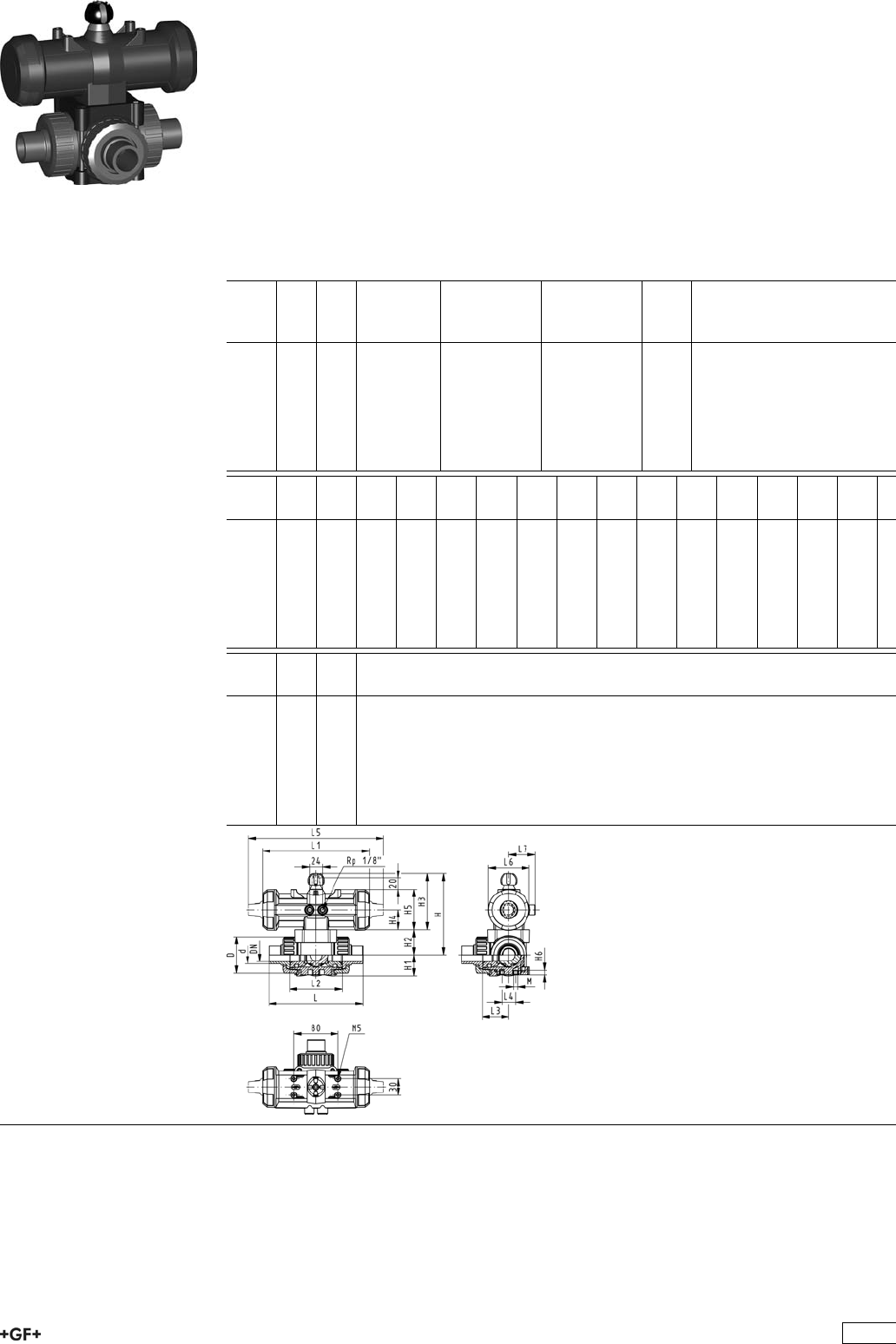
PROGEF Standard
3-Way ball valve type 276
Horizontal/T-port DA (Double acting)
Without manual override
With socket fusion spigots
Model:
ÏMaterial: PP-H
ÏBuilt on with pneumatic actuator PA11 (DN10/15-25), PA21 (DN32-50)
ÏControl time 90°<) 1-3 s
ÏFor easy installation and removal
ÏIntegrated stainless steel mounting inserts
d
[mm]
DN
[mm]
PN kv-value
(”p=1 bar)
[l/min]
EPDM
Code
FPM
Code
kg
16 10 10 200 199 276 202 199 276 212 0.854
20 15 10 200 199 276 203 199 276 213 0.854
25 20 10 470 199 276 204 199 276 214 0.977
32 25 10 793 199 276 205 199 276 215 1.100
40 32 10 1290 199 276 206 199 276 216 1.767
50 40 10 1910 199 276 207 199 276 217 2.131
63 50 10 3100 199 276 208 199 276 218 2.131
d
[mm]
D
[mm]
H
[mm]
H1
[mm]
H2
[mm]
H3
[mm]
H4
[mm]
H5
[mm]
H6
[mm]
L
[mm]
L1
[mm]
L2
[mm]
L3
[mm]
L4
[mm]
L5
[mm]
L6
[mm]
16 46 136 29 31 105 40 77 8 108 194 70 36 25 261 73
20 46 136 29 31 105 40 77 8 133 194 70 36 25 261 73
25 56 144 33 39 105 40 77 8 155 194 86 43 25 261 73
32 67 149 38 44 105 40 77 8 170 194 96 48 25 261 73
40 82 177 44 50 127 51 99 9 201 224 114 58 45 305 94
50 98 190 50 63 127 51 99 9 236 224 137 69 45 305 94
63 121 203 61 76 127 51 99 9 286 224 179 90 45 305 94
d
[mm]
L7
[mm]
M
16 48 6
20 48 6
25 48 6
32 48 6
40 59 8
50 59 8
63 59 8
257

PROGEF Standard
3-Way ball valve type 276
Horizontal/T-port DA (Double acting)
Without manual override
With threaded sockets Rp
Model:
ÏMaterial: PP-H
ÏBuilt on with pneumatic actuator PA11 (DN10/15-25), PA21 (DN32-50)
ÏControl time 90°<) 1-3 s
ÏFor easy installation and removal
ÏIntegrated stainless steel mounting inserts
Inch DN
[mm]
PN kv-value
(”p=1 bar)
[l/min]
EPDM
Code
FPM
Code
kg
3
/810 10 140 199 276 302 199 276 312 0.854
1
/215 10 200 199 276 303 199 276 313 0.854
3
/420 10 470 199 276 304 199 276 314 0.977
1 25 10 793 199 276 305 199 276 315 1.100
11
/432 10 1290 199 276 306 199 276 316 1.767
11
/240 10 1910 199 276 307 199 276 317 2.131
2 50 10 3100 199 276 308 199 276 318 3.063
Inch D
[mm]
H
[mm]
H1
[mm]
H2
[mm]
H3
[mm]
H4
[mm]
H5
[mm]
H6
[mm]
L
[mm]
L1
[mm]
L2
[mm]
L3
[mm]
L4
[mm]
L5
[mm]
L6
[mm]
3
/846 136 29 31 105 40 77 8 108 194 70 36 25 261 73
1
/246 136 29 31 105 40 77 8 111 194 70 36 25 261 73
3
/456 144 33 39 105 40 77 8 131 194 86 43 25 261 73
1 67 149 38 44 105 40 77 8 148 194 96 48 25 261 73
11
/482 177 44 50 127 51 99 9 177 224 114 58 45 305 94
11
/298 190 50 63 127 51 99 9 205 224 137 69 45 305 94
2 121 203 61 76 127 51 99 9 261 224 179 90 45 305 94
Inch L7
[mm]
M z
[mm]
z1
[mm]
3
/848 6 78 39
1
/248 6 79 40
3
/448 6 95 48
1 48 6 108 54
11
/459 8 133 67
11
/259 8 155 78
2 59 8 203 102
258
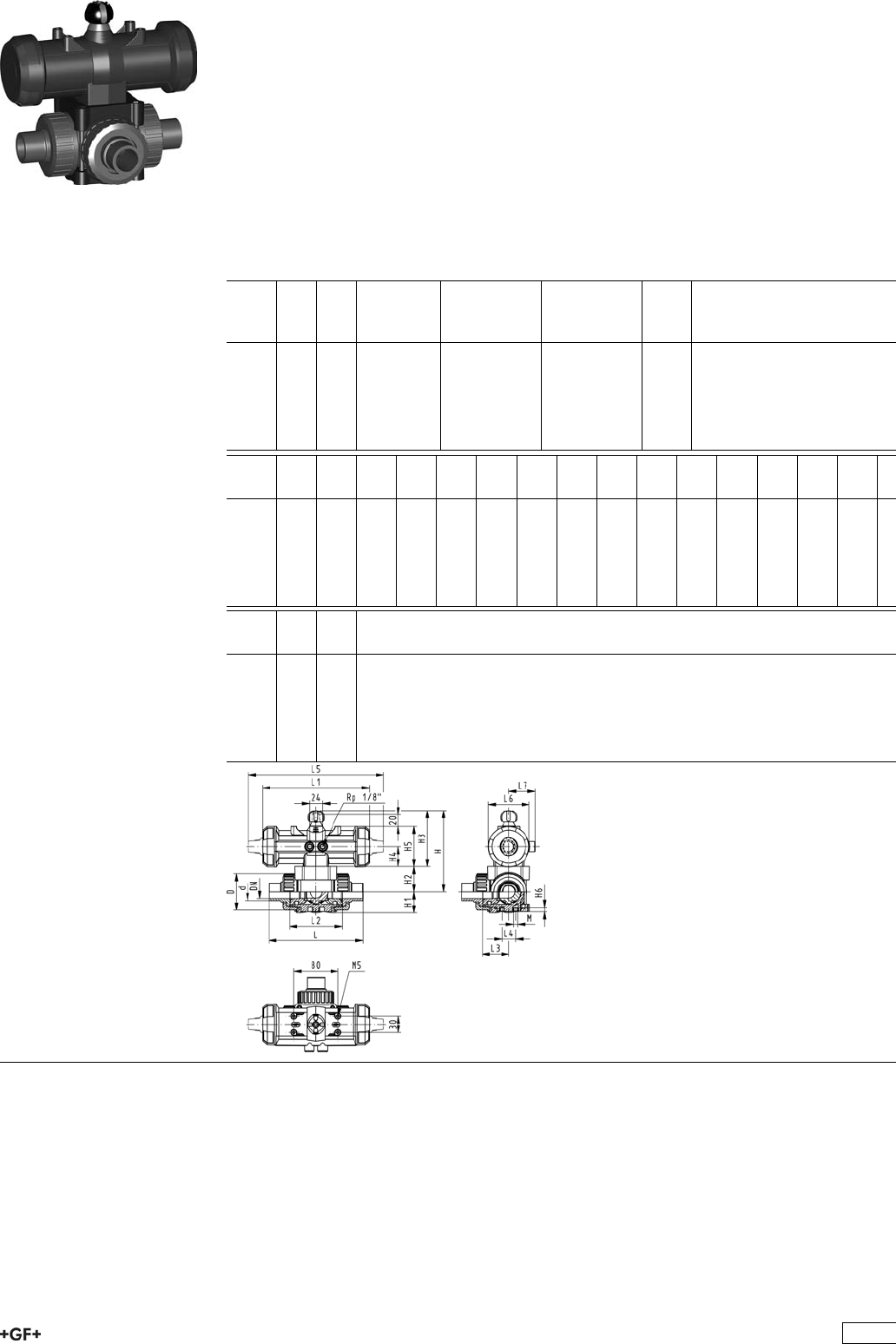
PROGEF Standard
3-Way ball valve type 276
Horizontal/T-port DA (Double acting)
Without manual override
With butt fusion spigots metric
Model:
ÏMaterial: PP-H
ÏBuilt on with pneumatic actuator PA11 (DN10/15-25), PA21 (DN32-50)
ÏControl time 90°<) 1-3 s
ÏFor easy installation and removal
ÏIntegrated stainless steel mounting inserts
d
[mm]
DN
[mm]
PN kv-value
(”p=1 bar)
[l/min]
EPDM
Code
FPM
Code
kg
20 15 10 200 199 276 263 199 276 273 0.854
25 20 10 470 199 276 264 199 276 274 0.977
32 25 10 793 199 276 265 199 276 275 1.100
40 32 10 1290 199 276 266 199 276 276 1.767
50 40 10 1910 199 276 267 199 276 277 2.131
63 50 10 3100 199 276 268 199 276 278 3.297
d
[mm]
D
[mm]
H
[mm]
H1
[mm]
H2
[mm]
H3
[mm]
H4
[mm]
H5
[mm]
H6
[mm]
L
[mm]
L1
[mm]
L2
[mm]
L3
[mm]
L4
[mm]
L5
[mm]
L6
[mm]
20 46 136 29 31 105 40 77 8 133 194 70 36 25 261 73
25 56 144 33 39 105 40 77 8 155 194 86 43 25 261 73
32 67 149 38 44 105 40 77 8 170 194 96 48 25 261 73
40 82 177 44 50 127 51 99 9 201 224 114 58 45 305 94
50 98 190 50 63 127 51 99 9 236 224 137 69 45 305 94
63 121 203 61 76 127 51 99 9 286 224 179 90 45 305 94
d
[mm]
L7
[mm]
M
20 48 6
25 48 6
32 48 6
40 59 8
50 59 8
63 59 8
259
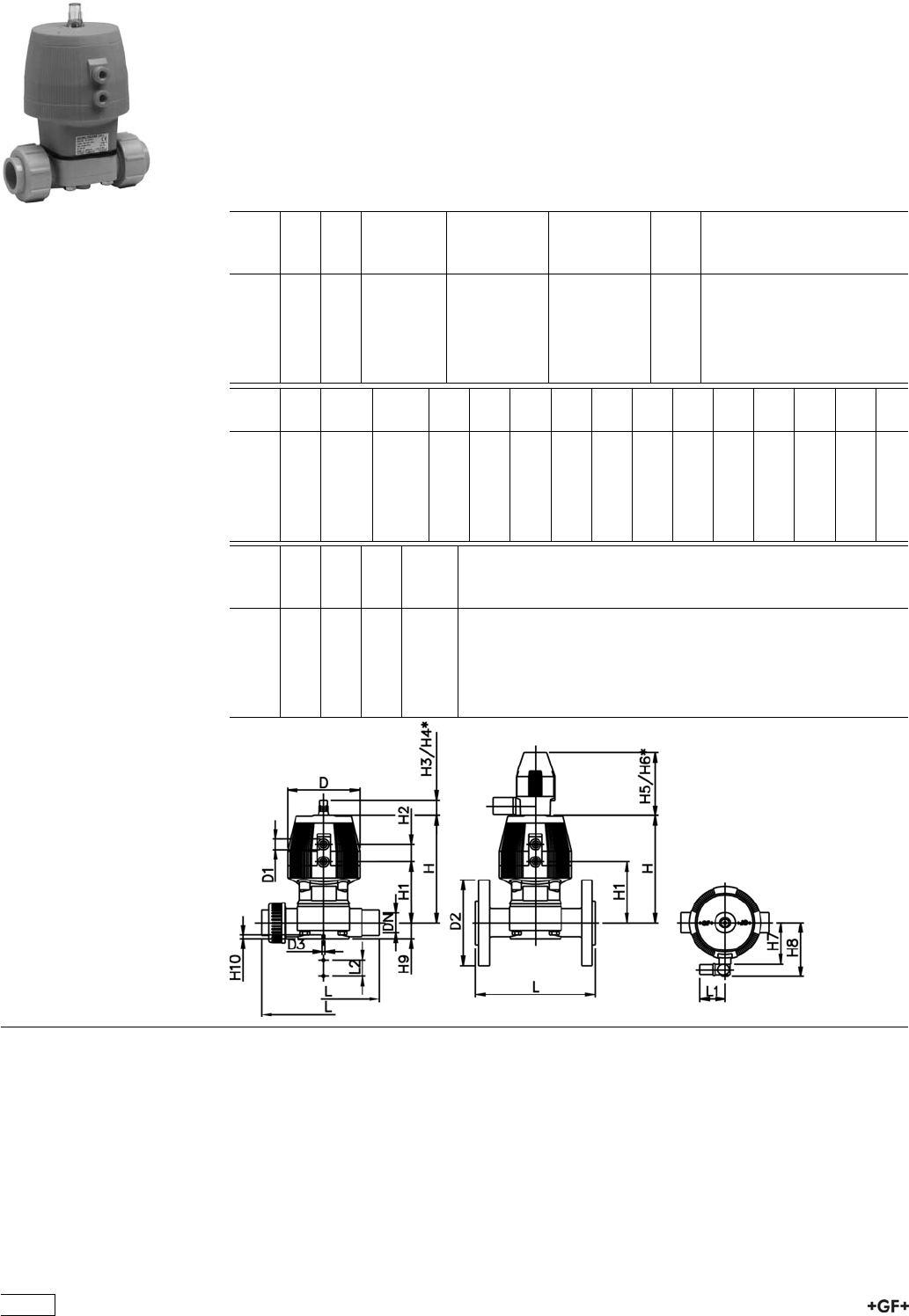
Diaphragm Valves Pneumatic
PROGEF Standard
Diaphragm valve type DIASTAR
Series 025 FC (Fail safe to close)
Unions with fusion sockets metric
Model:
ÏMaterial: PP-H
ÏWith position indicator / Working pressure: both sides
d
[mm]
DN
[mm]
PN kv-value
(”p=1 bar)
[l/min]
EPDM
Code
PTFE/EPDM
Code
kg
20 15 10 72 199 027 201 199 027 231 0.836
25 20 10 120 199 027 202 199 027 232 0.836
32 25 10 238 199 027 203 199 027 233 2.300
40 32 10 341 199 027 204 199 027 234 3.200
50 40 10 460 199 027 205 199 027 235 2.604
63 50 10 685 199 027 206 199 027 236 2.604
d
[mm]
D
[mm]
D1_G
[inch]
D3[M]
[mm]
L
[mm]
L1
[mm]
L2
[mm]
H
[mm]
H1
[mm]
H2
[mm]
H3
[mm]
H4
[mm]
H5
[mm]
H6
[mm]
H7
[mm]
20 96 1
/86 128 60 25 128 69 25 23 44 100 155 56
25 96 1
/86 150 60 25 130 71 25 23 44 100 155 56
32 120 1
/86 162 60 25 166 93 26 36 64 100 155 68
40 150 1
/48 184 60 45 201 106 36 36 64 100 160 85
50 180 1
/48 210 60 45 233 119 37 36 64 100 170 101
63 180 1
/48 248 60 45 247 133 37 36 64 100 170 101
d
[mm]
H8
[mm]
H9
[mm]
H10
[mm]
Lift =
Hx
[mm]
20 86 14 12 8
25 88 18 12 10
32 100 21 12 12
40 117 26 15 14
50 133 33 15 18
63 133 39 15 22
260
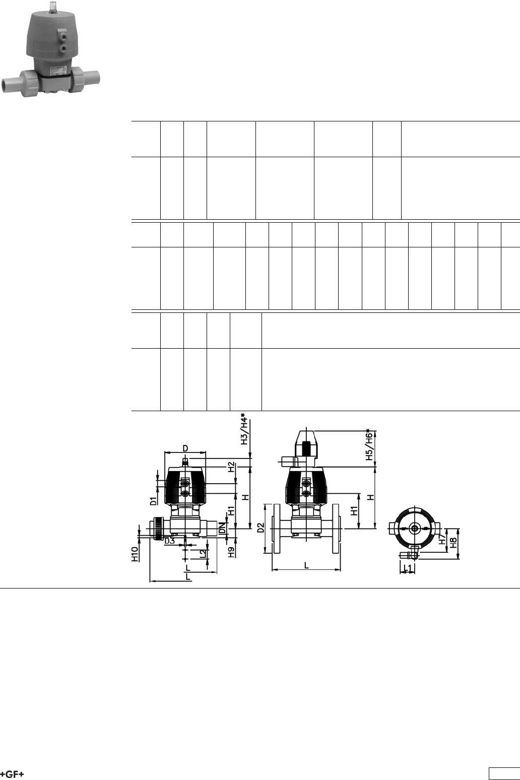
PROGEF Standard
Diaphragm valve type DIASTAR
Series 025 FC (Fail safe to close)
Unions with butt fusion spigots metric
Model:
ÏMaterial: PP-H
ÏWith position indicator / Working pressure: both sides
d
[mm]
DN
[mm]
PN kv-value
(”p=1 bar)
[l/min]
EPDM
Code
PTFE/EPDM
Code
kg
20 15 10 72 199 027 431 199 027 461 0.836
25 20 10 120 199 027 432 199 027 462 0.836
32 25 10 238 199 027 433 199 027 463 2.300
40 32 10 341 199 027 434 199 027 464 2.604
50 40 10 460 199 027 435 199 027 465 2.604
63 50 10 685 199 027 436 199 027 466 6.400
d
[mm]
D
[mm]
D1_G
[inch]
D3[M]
[mm]
L
[mm]
L1
[mm]
L2
[mm]
H
[mm]
H1
[mm]
H2
[mm]
H3
[mm]
H4
[mm]
H5
[mm]
H6
[mm]
H7
[mm]
20 96 1
/86 196 60 25 128 69 25 23 44 100 155 56
25 96 1
/86 221 60 25 130 71 25 23 44 100 155 56
32 120 1
/86 234 60 25 166 93 26 36 64 100 155 68
40 150 1
/48 260 60 45 201 106 36 36 64 100 160 85
50 180 1
/48 284 60 45 233 119 37 36 64 100 170 101
63 180 1
/48 321 60 45 247 133 37 36 64 100 170 101
d
[mm]
H8
[mm]
H9
[mm]
H10
[mm]
Lift =
Hx
[mm]
20 86 14 12 8
25 88 18 12 10
32 100 21 12 12
40 117 26 15 14
50 133 33 15 18
63 133 39 15 22
261

PROGEF Standard
Diaphragm valve type DIASTAR
Series 025 FC (Fail safe to close)
With fusion spigots metric
Model:
ÏMaterial: PP-H
ÏWith position indicator / Working pressure: both sides
d
[mm]
DN
[mm]
PN kv-value
(”p=1 bar)
[l/min]
EPDM
Code
PTFE/EPDM
Code
kg
20 15 10 72 199 025 201 199 025 231 1.200
25 20 10 120 199 025 202 199 025 232 0.916
32 25 10 238 199 025 203 199 025 233 2.200
40 32 10 341 199 025 204 199 025 234 2.604
50 40 10 460 199 025 205 199 025 235 4.165
63 50 10 685 199 025 206 199 025 236 5.900
d
[mm]
D
[mm]
D1_G
[inch]
D3[M]
[mm]
L
[mm]
L1
[mm]
L2
[mm]
H
[mm]
H1
[mm]
H2
[mm]
H3
[mm]
H4
[mm]
H5
[mm]
H6
[mm]
H7
[mm]
20 96 1
/86 124 60 25 128 69 25 23 44 100 155 56
25 96 1
/86 144 60 25 130 71 25 23 44 100 155 56
32 120 1
/86 154 60 25 166 93 26 36 64 100 155 68
40 150 1
/48 174 60 45 201 106 36 36 64 100 160 85
50 180 1
/48 194 60 45 233 119 37 36 64 100 170 101
63 180 1
/48 224 60 45 247 133 37 36 64 100 170 101
d
[mm]
H8
[mm]
H9
[mm]
H10
[mm]
Lift =
Hx
[mm]
20 86 14 12 8
25 88 18 12 10
32 100 21 12 12
40 117 26 15 14
50 133 33 15 18
63 133 39 15 22
262

PROGEF Standard
Diaphragm valve type DIASTAR
Series 025 FC (Fail safe to close)
With butt fusion spigots metric
Model:
ÏMaterial: PP-H
ÏWith position indicator / Working pressure: both sides
d
[mm]
DN
[mm]
PN kv-value
(”p=1 bar)
[l/min]
EPDM
Code
PTFE/EPDM
Code
kg
20 15 10 72 199 025 881 199 025 901 0.739
25 20 10 120 199 025 882 199 025 902 0.836
32 25 10 238 199 025 883 199 025 903 1.505
40 32 10 341 199 025 884 199 025 904 0.238
50 40 10 460 199 025 885 199 025 905 4.165
63 50 10 685 199 025 886 199 025 906 5.600
d
[mm]
D
[mm]
D1_G
[inch]
D3[M]
[mm]
L
[mm]
L1
[mm]
L2
[mm]
H
[mm]
H1
[mm]
H2
[mm]
H3
[mm]
H4
[mm]
H5
[mm]
H6
[mm]
H7
[mm]
20 96 1
/86 124 60 25 125 69 25 23 44 100 155 56
25 96 1
/86 144 60 25 127 71 25 23 44 100 155 56
32 120 1
/86 154 60 25 163 93 26 36 64 100 155 68
40 150 1
/48 174 60 45 196 106 36 36 64 100 160 85
50 180 1
/48 194 60 45 227 119 37 36 64 100 170 101
63 180 1
/48 224 60 45 241 133 37 36 64 100 170 101
d
[mm]
H8
[mm]
H9
[mm]
H10
[mm]
Lift =
Hx
[mm]
20 86 14 12 8
25 88 18 12 10
32 100 21 12 12
40 117 26 15 14
50 133 33 15 18
63 133 39 15 22
263

PROGEF Standard
Diaphragm valve type DIASTAR
Series 025 FC (Fail safe to close)
With backing flanges PP-V metric
Model:
ÏMaterial: PP-H
ÏConnecting dimensions: ISO 7005 / EN 1092 / DIN 2501 PN10 / BS4504
ÏWith position indicator / Working pressure: both sides
d
[mm]
DN
[mm]
Inch PN kv-value
(”p=1 bar)
[l/min]
EPDM
Code
PTFE/EPDM
Code
kg
20 15 1
/210 72 199 025 261 199 025 291 0.739
25 20 3
/410 120 199 025 262 199 025 292 0.836
32 25 1 10 238 199 025 263 199 025 293 1.505
40 32 1 1
/410 341 199 025 264 199 025 294 2.604
50 40 1 1
/210 460 199 025 265 199 025 295 4.165
63 50 2 10 685 199 025 266 199 025 296 6.900
d
[mm]
D
[mm]
D1_G
[inch]
D2
[mm]
D3[M]
[mm]
L
[mm]
L1
[mm]
L2
[mm]
H
[mm]
H1
[mm]
H2
[mm]
H3
[mm]
H4
[mm]
H5
[mm]
H6
[mm]
20 96 1
/895 6 130 60 25 128 69 25 23 44 100 155
25 96 1
/8105 6 150 60 25 130 71 25 23 44 100 155
32 120 1
/8115 6 160 60 25 166 93 26 36 64 100 155
40 150 1
/4140 8 180 60 45 201 106 36 36 64 100 160
50 180 1
/4150 8 200 60 45 233 119 37 36 64 100 170
63 180 1
/4165 8 230 60 45 247 133 37 36 64 100 170
d
[mm]
H7
[mm]
H8
[mm]
H9
[mm]
H10
[mm]
Lift =
Hx
[mm]
20 56 86 14 12 8
25 56 88 18 12 10
32 68 100 21 12 12
40 85 117 26 15 14
50 101 133 33 15 18
63 101 133 39 15 22
264
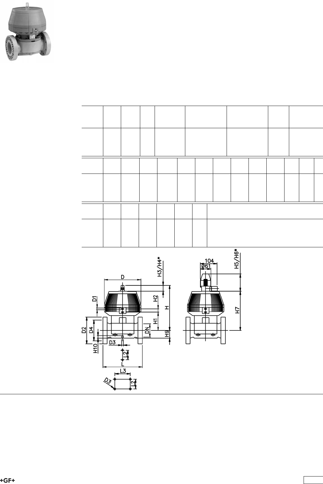
PROGEF Standard
Diaphragm valve type DIASTAR
Series 025 FC (Fail safe to close)
With fixed flanges PP metric
Model:
ÏMaterial: PP-H
ÏConnecting dimensions: ISO 7005 / EN 1092 / DIN 2501 PN10 / BS4504
ÏWith position indicator / Working pressure: one side
* With backing flanges PP-V
** Connecting dimensions DN80 and DN150 metric and Inch ANSI B16.5
d
[mm]
DN
[mm]
Inch PN kv-value
(”p=1 bar)
[l/min]
EPDM
Code
PTFE/EPDM
Code
kg
*75 65 2 1
/210 992 199 025 267 199 025 297 13.600
**90 80 3 10 1700 199 025 268 199 025 298 17.400
110 100 4 8 2700 199 025 269 199 025 299 24.700
**160 150 6 6 6033 199 025 270 - 35.000
d
[mm]
D
[mm]
D1_G
[inch]
D2
[mm]
D3[M]
[mm]
D4
[mm]
L
[mm]
L2
[mm]
L3
[mm]
H
[mm]
H1
[mm]
H2
[mm]
H3
[mm]
*75 280 1
/4185 8 145 290 70 344 148 24 46
**90 280 1
/4200 12 160 310 120 348 150 24 46
110 335 1
/4225 12 180 350 120 395 176 24 46
**160 335 1
/4285 12 240 480 100 200 455 237 24 46
d
[mm]
H4
[mm]
H5
[mm]
H6
[mm]
H7
[mm]
H9
[mm]
H10
[mm]
*75 100 129 195 298 46 15
**90 100 129 195 302 57 15
110 100 129 195 349 69 20
**160 100 129 195 409 108 20
265

PROGEF Standard
Diaphragm valve type DIASTAR
Series 025 FC (Fail safe to close)
ZERO STATIC with butt fusion spigots metric
Model:
ÏMaterial: PP-H
ÏWith position indicator
ÏDN2: for coordination of accessoires
d
[mm]
d1
[mm]
DN
[mm]
DN1
[mm]
DN2
[mm]
PN kv-value
(”p=1 bar)
[l/min]
EPDM
Code
PTFE
Code
kg
20 20 15 15 15 10 47 199 029 461 199 029 301 1.510
25 20 20 15 20 10 69 199 029 462 199 029 302 2.013
25 25 20 20 20 10 91 199 029 463 199 029 303 2.013
32 20 25 15 25 10 86 199 029 464 199 029 304 2.564
32 25 25 20 25 10 126 199 029 465 199 029 305 2.564
32 32 25 25 25 10 156 199 029 466 199 029 306 2.564
40 20 32 15 25 10 84 199 029 467 199 029 307 2.604
50 20 40 15 25 10 82 199 029 471 199 029 311 2.647
50 25 40 20 25 10 124 199 029 472 199 029 312 2.647
50 32 40 25 25 10 159 199 029 473 199 029 313 2.646
63 20 50 15 25 10 81 199 029 476 199 029 316 2.715
63 25 50 20 25 10 115 199 029 477 199 029 317 2.717
63 32 50 25 25 10 156 199 029 478 199 029 318 2.714
90 20 80 15 25 10 88 199 029 485 199 029 325 2.742
90 25 80 20 25 6 133 199 029 486 199 029 326 2.756
90 32 80 25 25 6 162 199 029 487 199 029 327 2.737
90 50 80 40 50 6 504 199 029 488 199 029 328 5.679
90 63 80 50 50 6 530 199 029 489 199 029 329 5.679
110 20 100 15 25 6 89 199 029 490 199 029 330 2.837
110 25 100 20 25 6 123 199 029 491 199 029 331 2.835
110 50 100 25 25 6 159 199 029 492 199 029 332 2.834
110 63 100 40 50 6 503 199 029 493 199 029 333 5.869
110 63 100 50 50 10 543 199 029 494 199 029 334 5.822
d
[mm]
L
[mm]
L1
[mm]
L2
[mm]
L3
[mm]
H
[mm]
H1
[mm]
H2
[mm]
H3
[mm]
H4
[mm]
H5
[mm]
D
[mm]
D1
[inch]
Lift =
Hx
[mm]
20 106 96 30 140 128 69 25 23 44 56 96 1
/88
25 121 108 36 150 130 71 25 23 44 56 96 1
/810
25 121 108 36 150 130 71 25 23 44 56 96 1
/810
32 137 120 43 160 166 93 26 36 64 68 120 1
/812
32 137 120 43 160 166 93 26 36 64 68 120 1
/812
32 137 120 43 160 166 93 26 36 64 68 120 1
/812
40 149 128 51 180 166 93 26 36 64 68 120 1
/812
50 159 134 57 180 166 93 26 36 64 68 120 1
/812
50 159 134 57 180 166 93 26 36 64 68 120 1
/812
50 159 134 57 180 166 93 26 36 64 68 120 1
/812
63 175 144 67 180 166 93 26 36 64 68 120 1
/812
63 175 144 67 180 166 93 26 36 64 68 120 1
/812
63 175 144 67 180 166 93 26 36 64 68 120 1
/812
90 204 159 82 160 166 93 26 36 64 68 120 1
/812
90 204 159 82 160 166 93 26 36 64 68 120 1
/812
90 204 159 82 160 166 93 26 36 64 68 120 1
/812
90 252 207 95 220 247 133 37 36 64 101 180 1
/422
90 252 207 95 220 247 133 37 36 64 101 180 1
/422
110 226 171 94 160 166 93 26 36 64 68 120 1
/812
110 226 171 94 160 166 93 26 36 64 68 120 1
/812
110 226 171 94 160 166 93 26 36 64 68 120 1
/812
110 274 219 107 220 247 133 37 36 64 101 180 1
/422
110 274 219 107 220 247 133 37 36 64 101 180 1
/422
266

PROGEF Standard
Diaphragm valve type DIASTAR
Series 025 FO (Fail safe to open)
Unions with fusion sockets metric
Model:
ÏMaterial: PP-H
ÏWith position indicator / Working pressure: both sides
d
[mm]
DN
[mm]
PN kv-value
(”p=1 bar)
[l/min]
EPDM
Code
PTFE/EPDM
Code
kg
20 15 10 72 199 027 211 199 027 241 0.504
25 20 10 120 199 027 212 199 027 242 0.790
32 25 10 238 199 027 213 199 027 243 1.110
40 32 10 341 199 027 214 199 027 244 1.300
50 40 10 460 199 027 215 199 027 245 2.310
63 50 10 685 199 027 216 199 027 246 2.710
d
[mm]
D
[mm]
D1_G
[inch]
D3[M]
[mm]
L
[mm]
L1
[mm]
L2
[mm]
H
[mm]
H1
[mm]
H2
[mm]
H3
[mm]
H4
[mm]
H5
[mm]
H6
[mm]
H7
[mm]
20 68 1
/86 128 60 25 99 59 24 23 44 100 155 44
25 96 1
/86 150 60 25 130 71 25 23 44 100 155 56
32 96 1
/86 162 60 25 143 85 25 23 44 100 155 56
40 120 1
/88 184 60 45 170 97 26 36 64 100 160 68
50 150 1
/48 210 60 45 203 108 36 36 64 100 170 85
63 150 1
/48 248 60 45 220 126 36 36 64 100 170 85
d
[mm]
H8
[mm]
H9
[mm]
H10
[mm]
Lift =
Hx
[mm]
20 76 14 12 8
25 88 18 12 10
32 88 21 12 12
40 100 26 15 14
50 117 33 15 18
63 117 39 15 22
267
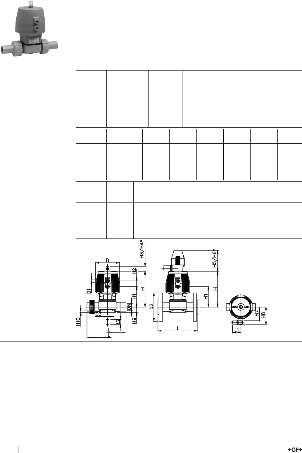
PROGEF Standard
Diaphragm valve type DIASTAR
Series 025 FO (Fail safe to open)
Unions with butt fusion spigots metric
Model:
ÏMaterial: PP-H
ÏWith position indicator / Working pressure: both sides
d
[mm]
DN
[mm]
PN kv-value
(”p=1 bar)
[l/min]
EPDM
Code
PTFE/EPDM
Code
kg
20 15 10 72 199 027 441 199 027 471 0.504
25 20 10 120 199 027 442 199 027 472 0.790
32 25 10 238 199 027 443 199 027 473 1.110
40 32 10 341 199 027 444 199 027 474 1.300
50 40 10 460 199 027 445 199 027 475 2.310
63 50 10 685 199 027 446 199 027 476 2.710
d
[mm]
D
[mm]
D1_G
[inch]
D3[M]
[mm]
L
[mm]
L1
[mm]
L2
[mm]
H
[mm]
H1
[mm]
H2
[mm]
H3
[mm]
H4
[mm]
H5
[mm]
H6
[mm]
H7
[mm]
20 68 1
/86 196 60 25 99 59 24 23 44 100 155 44
25 96 1
/86 221 60 25 130 71 25 23 44 100 155 56
32 96 1
/86 234 60 25 143 85 25 23 44 100 155 56
40 120 1
/88 260 60 45 170 97 26 36 64 100 160 68
50 150 1
/48 284 60 45 203 108 36 36 64 100 170 85
63 150 1
/48 321 60 45 220 126 36 36 64 100 170 85
d
[mm]
H8
[mm]
H9
[mm]
H10
[mm]
Lift =
Hx
[mm]
20 76 14 12 8
25 88 18 12 10
32 88 21 12 12
40 100 26 15 14
50 117 33 15 18
63 117 39 15 22
268

PROGEF Standard
Diaphragm valve type DIASTAR
Series 025 FO (Fail safe to open)
With fusion spigots metric
Model:
ÏMaterial: PP-H
ÏWith position indicator / Working pressure: both sides
d
[mm]
DN
[mm]
PN kv-value
(”p=1 bar)
[l/min]
EPDM
Code
PTFE/EPDM
Code
kg
20 15 10 72 199 025 211 199 025 241 0.374
25 20 10 120 199 025 212 199 025 242 0.660
32 25 10 238 199 025 213 199 025 243 0.910
40 32 10 341 199 025 214 199 025 244 1.150
50 40 10 460 199 025 215 199 025 245 1.410
63 50 10 685 199 025 216 199 025 246 2.660
d
[mm]
D
[mm]
D1_G
[inch]
D3[M]
[mm]
L
[mm]
L1
[mm]
L2
[mm]
H
[mm]
H1
[mm]
H2
[mm]
H3
[mm]
H4
[mm]
H5
[mm]
H6
[mm]
H7
[mm]
20 68 1
/86 124 60 25 99 59 24 23 44 100 155 44
25 96 1
/86 144 60 25 130 71 25 23 44 100 155 56
32 96 1
/86 154 60 25 143 85 25 23 44 100 155 56
40 120 1
/88 174 60 45 170 97 26 36 64 100 160 68
50 150 1
/48 194 60 45 203 108 36 36 64 100 170 85
63 150 1
/48 224 60 45 220 126 36 36 64 100 170 85
d
[mm]
H8
[mm]
H9
[mm]
H10
[mm]
Lift =
Hx
[mm]
20 76 14 12 8
25 88 18 12 10
32 88 21 12 12
40 100 26 15 14
50 117 33 15 18
63 117 39 15 22
269

PROGEF Standard
Diaphragm valve type DIASTAR
Series 025 FO (Fail safe to open)
With butt fusion spigots metric
Model:
ÏMaterial: PP-H
ÏWith position indicator / Working pressure: both sides
d
[mm]
DN
[mm]
PN kv-value
(”p=1 bar)
[l/min]
EPDM
Code
PTFE/EPDM
Code
kg
20 15 10 72 199 025 887 199 025 907 0.374
25 20 10 120 199 025 888 199 025 908 0.660
32 25 10 238 199 025 889 199 025 909 0.910
40 32 10 341 199 025 890 199 025 910 1.150
50 40 10 460 199 025 891 199 025 911 1.410
63 50 10 685 199 025 892 199 025 912 2.660
d
[mm]
D
[mm]
L
[mm]
L1
[mm]
L2
[mm]
H
[mm]
H1
[mm]
H2
[mm]
H3
[mm]
H4
[mm]
H5
[mm]
H6
[mm]
H7
[mm]
H8
[mm]
H9
[mm]
D1_G
[inch]
20 68 124 60 25 99 59 24 23 44 100 155 44 76 14 1
/8
25 96 144 60 25 130 71 25 23 44 100 155 56 88 18 1
/8
32 96 154 60 25 143 85 25 23 44 100 155 56 88 21 1
/8
40 120 174 60 45 170 97 26 36 64 100 160 68 100 26 1
/8
50 150 194 60 45 203 108 36 36 64 100 170 85 117 33 1
/4
63 150 224 60 45 220 126 36 36 64 100 170 85 117 39 1
/4
d
[mm]
H10
[mm]
D3[M]
[mm]
Lift =
Hx
[mm]
20 12 6 8
25 12 6 10
32 12 6 12
40 15 8 14
50 15 8 18
63 15 8 22
270

PROGEF Standard
Diaphragm valve type DIASTAR
Series 025 FO (Fail safe to open)
With backing flanges PP-V metric
Model:
ÏMaterial: PP-H
ÏConnecting dimensions: ISO 7005 / EN 1092 / DIN 2501 PN10 / BS4504
ÏWith position indicator / Working pressure: both sides
d
[mm]
DN
[mm]
Inch PN kv-value
(”p=1 bar)
[l/min]
EPDM
Code
PTFE/EPDM
Code
kg
20 15 1
/210 72 199 025 271 199 025 301 0.654
25 20 3
/410 120 199 025 272 199 025 302 0.890
32 25 1 10 238 199 025 273 199 025 303 1.310
40 32 1 1
/410 341 199 025 274 199 025 304 1.650
50 40 1 1
/210 460 199 025 275 199 025 305 2.310
63 50 2 10 685 199 025 276 199 025 306 3.710
d
[mm]
D
[mm]
D1_G
[inch]
D2
[mm]
D3[M]
[mm]
L
[mm]
L1
[mm]
L2
[mm]
H
[mm]
H1
[mm]
H2
[mm]
H3
[mm]
H4
[mm]
H5
[mm]
H6
[mm]
20 68 1
/895 6 130 60 25 99 59 24 23 44 100 155
25 96 1
/8105 6 150 60 25 130 71 25 23 44 100 155
32 96 1
/8115 6 160 60 25 143 85 25 23 44 100 155
40 120 1
/8140 8 180 60 45 170 97 26 36 64 100 160
50 150 1
/4150 8 200 60 45 203 108 36 36 64 100 170
63 150 1
/4165 8 230 60 45 220 126 36 36 64 100 170
d
[mm]
H7
[mm]
H8
[mm]
H9
[mm]
H10
[mm]
Lift =
Hx
[mm]
20 44 76 14 12 8
25 56 88 18 12 10
32 56 88 21 12 12
40 68 100 26 15 14
50 85 117 33 15 18
63 85 117 39 15 22
271
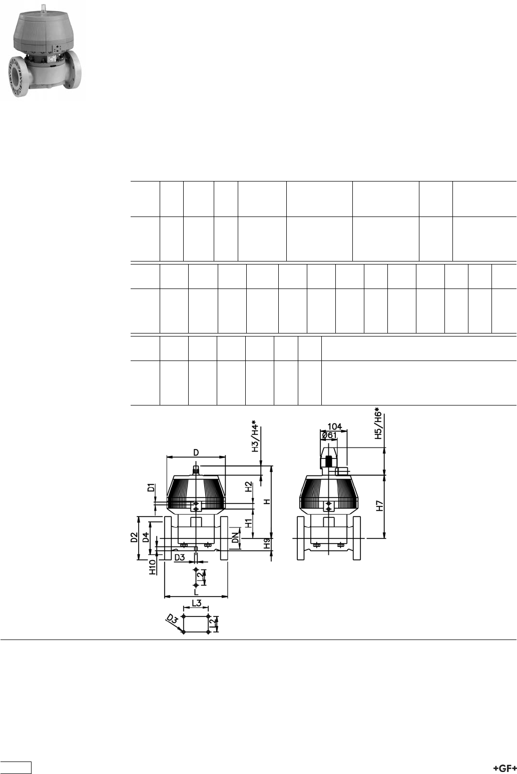
PROGEF Standard
Diaphragm valve type DIASTAR
Series 025 FO (Fail safe to open)
With fixed flanges PP metric
Model:
ÏMaterial: PP-H
ÏConnecting dimensions: ISO 7005 / EN 1092 / DIN 2501 PN10 / BS4504
ÏWith position indicator / Working pressure: one side
** Connecting dimensions DN80 and DN150 metric and Inch ANSI B16.5
* With backing flanges PP-V
** with fixed flanges PP metric and Inch ANSI
d
[mm]
DN
[mm]
Inch PN kv-value
(”p=1 bar)
[l/min]
EPDM
Code
PTFE/EPDM
Code
kg
*75 65 2 1
/210 992 199 025 277 199 025 307 13.600
**90 80 3 10 1700 199 025 278 199 025 308 17.400
110 100 4 8 2700 199 025 279 199 025 309 24.700
160 150 6 6 6033 199 025 280 199 025 310 35.000
d
[mm]
D
[mm]
D1_G
[inch]
D2
[mm]
D3[M]
[mm]
D4
[mm]
L
[mm]
L2
[mm]
L3
[mm]
H
[mm]
H1
[mm]
H2
[mm]
H3
[mm]
*75 280 1
/4185 8 145 290 70 344 148 24 46
**90 280 1
/4200 12 160 310 120 348 150 24 46
110 335 1
/4225 12 180 350 120 395 176 24 46
160 335 1
/4285 12 240 480 100 200 455 237 24 46
d
[mm]
H4
[mm]
H5
[mm]
H6
[mm]
H7
[mm]
H9
[mm]
H10
[mm]
*75 100 129 195 298 46 15
**90 100 129 195 302 57 15
110 100 129 195 349 69 20
160 100 129 195 409 108 20
272

PROGEF Standard
Diaphragm valve type DIASTAR
Series 025 DA (Double acting)
Unions with fusion sockets metric
Model:
ÏMaterial: PP-H
ÏWith position indicator / Working pressure: both sides
d
[mm]
DN
[mm]
PN kv-value
(”p=1 bar)
[l/min]
EPDM
Code
PTFE/EPDM
Code
kg
20 15 10 72 199 027 221 199 027 251 0.504
25 20 10 120 199 027 222 199 027 252 0.790
32 25 10 238 199 027 223 199 027 253 1.110
40 32 10 341 199 027 224 199 027 254 1.300
50 40 10 460 199 027 225 199 027 255 2.310
63 50 10 685 199 027 226 199 027 256 2.710
d
[mm]
D
[mm]
D1_G
[inch]
D3[M]
[mm]
L
[mm]
L1
[mm]
L2
[mm]
H
[mm]
H1
[mm]
H2
[mm]
H3
[mm]
H4
[mm]
H5
[mm]
H6
[mm]
H7
[mm]
20 68 1
/86 128 60 25 98 59 24 23 44 100 155 44
25 96 1
/86 150 60 25 127 71 25 23 44 100 155 56
32 96 1
/86 162 60 25 141 85 25 23 44 100 155 56
40 120 1
/88 184 60 45 167 97 26 36 64 100 160 68
50 150 1
/48 210 60 45 198 108 36 36 64 100 170 85
63 150 1
/48 248 60 45 216 126 36 36 64 100 170 85
d
[mm]
H8
[mm]
H9
[mm]
H10
[mm]
Lift =
Hx
[mm]
20 76 14 12 8
25 88 18 12 10
32 88 21 12 12
40 100 26 15 14
50 117 33 15 18
63 117 39 15 22
273

PROGEF Standard
Diaphragm valve type DIASTAR
Series 025 DA (Double acting)
Unions with butt fusion spigots metric
Model:
ÏMaterial: PP-H
ÏWith position indicator / Working pressure: both sides
d
[mm]
DN
[mm]
PN kv-value
(”p=1 bar)
[l/min]
EPDM
Code
PTFE/EPDM
Code
kg
20 15 10 72 199 027 451 199 027 481 0.504
25 20 10 120 199 027 452 199 027 482 0.790
32 25 10 238 199 027 453 199 027 483 1.110
40 32 10 341 199 027 454 199 027 484 1.300
50 40 10 460 199 027 455 199 027 485 2.310
63 50 10 685 199 027 456 199 027 486 2.710
d
[mm]
D
[mm]
D1_G
[inch]
D3[M]
[mm]
L
[mm]
L1
[mm]
L2
[mm]
H
[mm]
H1
[mm]
H2
[mm]
H3
[mm]
H4
[mm]
H5
[mm]
H6
[mm]
H7
[mm]
20 68 1
/86 196 60 25 99 59 24 23 44 100 155 44
25 96 1
/86 221 60 25 130 71 25 23 44 100 155 56
32 96 1
/86 234 60 25 143 85 25 23 44 100 155 56
40 120 1
/88 260 60 45 170 97 26 36 64 100 160 68
50 150 1
/48 284 60 45 203 108 36 36 64 100 170 85
63 150 1
/48 321 60 45 220 126 36 36 64 100 170 85
d
[mm]
H8
[mm]
H9
[mm]
H10
[mm]
Lift =
Hx
[mm]
20 76 14 12 8
25 88 18 12 10
32 88 21 12 12
40 100 26 15 14
50 117 33 15 18
63 117 39 15 22
274

PROGEF Standard
Diaphragm valve type DIASTAR
Series 025 DA (Double acting)
With fusion spigots metric
Model:
ÏMaterial: PP-H
ÏWith position indicator / Working pressure: both sides
d
[mm]
DN
[mm]
PN kv-value
(”p=1 bar)
[l/min]
EPDM
Code
PTFE/EPDM
Code
kg
20 15 10 72 199 025 221 199 025 251 0.374
25 20 10 120 199 025 222 199 025 252 0.660
32 25 10 238 199 025 223 199 025 253 0.910
40 32 10 341 199 025 224 199 025 254 1.150
50 40 10 460 199 025 225 199 025 255 1.410
63 50 10 685 199 025 226 199 025 256 2.660
d
[mm]
D
[mm]
D1_G
[inch]
D3[M]
[mm]
L
[mm]
L1
[mm]
L2
[mm]
H
[mm]
H1
[mm]
H2
[mm]
H3
[mm]
H4
[mm]
H5
[mm]
H6
[mm]
H7
[mm]
20 68 1
/86 124 60 25 99 59 24 23 44 100 155 44
25 96 1
/86 144 60 25 130 71 25 23 44 100 155 56
32 96 1
/86 154 60 25 143 85 25 23 44 100 155 56
40 120 1
/88 174 60 45 170 97 26 36 64 100 160 68
50 150 1
/48 194 60 45 203 108 36 36 64 100 170 85
63 150 1
/48 224 60 45 220 126 36 36 64 100 170 85
d
[mm]
H8
[mm]
H9
[mm]
H10
[mm]
Lift =
Hx
[mm]
20 76 14 12 8
25 88 18 12 10
32 88 21 12 12
40 100 26 15 14
50 117 33 15 18
63 117 39 15 22
275

PROGEF Standard
Diaphragm valve type DIASTAR
Series 025 DA (Double acting)
With butt fusion spigots metric
Model:
ÏMaterial: PP-H
ÏWith position indicator / Working pressure: both sides
d
[mm]
DN
[mm]
PN kv-value
(”p=1 bar)
[l/min]
EPDM
Code
PTFE/EPDM
Code
kg
20 15 10 72 199 025 893 199 025 913 0.374
25 20 10 120 199 025 894 199 025 914 0.660
32 25 10 238 199 025 895 199 025 915 0.910
40 32 10 341 199 025 896 199 025 916 1.150
50 40 10 460 199 025 897 199 025 917 1.410
63 50 10 685 199 025 898 199 025 918 3.031
d
[mm]
D
[mm]
D1_G
[inch]
D3[M]
[mm]
L
[mm]
L1
[mm]
L2
[mm]
H
[mm]
H1
[mm]
H2
[mm]
H3
[mm]
H4
[mm]
H5
[mm]
H6
[mm]
H7
[mm]
20 68 1
/86 124 60 25 99 59 24 23 44 100 155 44
25 96 1
/86 144 60 25 130 71 25 23 44 100 155 56
32 96 1
/86 154 60 25 143 85 25 23 44 100 155 56
40 120 1
/88 174 60 45 170 97 26 36 64 100 160 68
50 150 1
/48 194 60 45 203 108 36 36 64 100 170 85
63 150 1
/48 224 60 45 220 126 36 36 64 100 170 85
d
[mm]
H8
[mm]
H9
[mm]
H10
[mm]
Lift =
Hx
[mm]
20 76 14 12 8
25 88 18 12 10
32 88 21 12 12
40 100 26 15 14
50 117 33 15 18
63 117 39 15 22
276
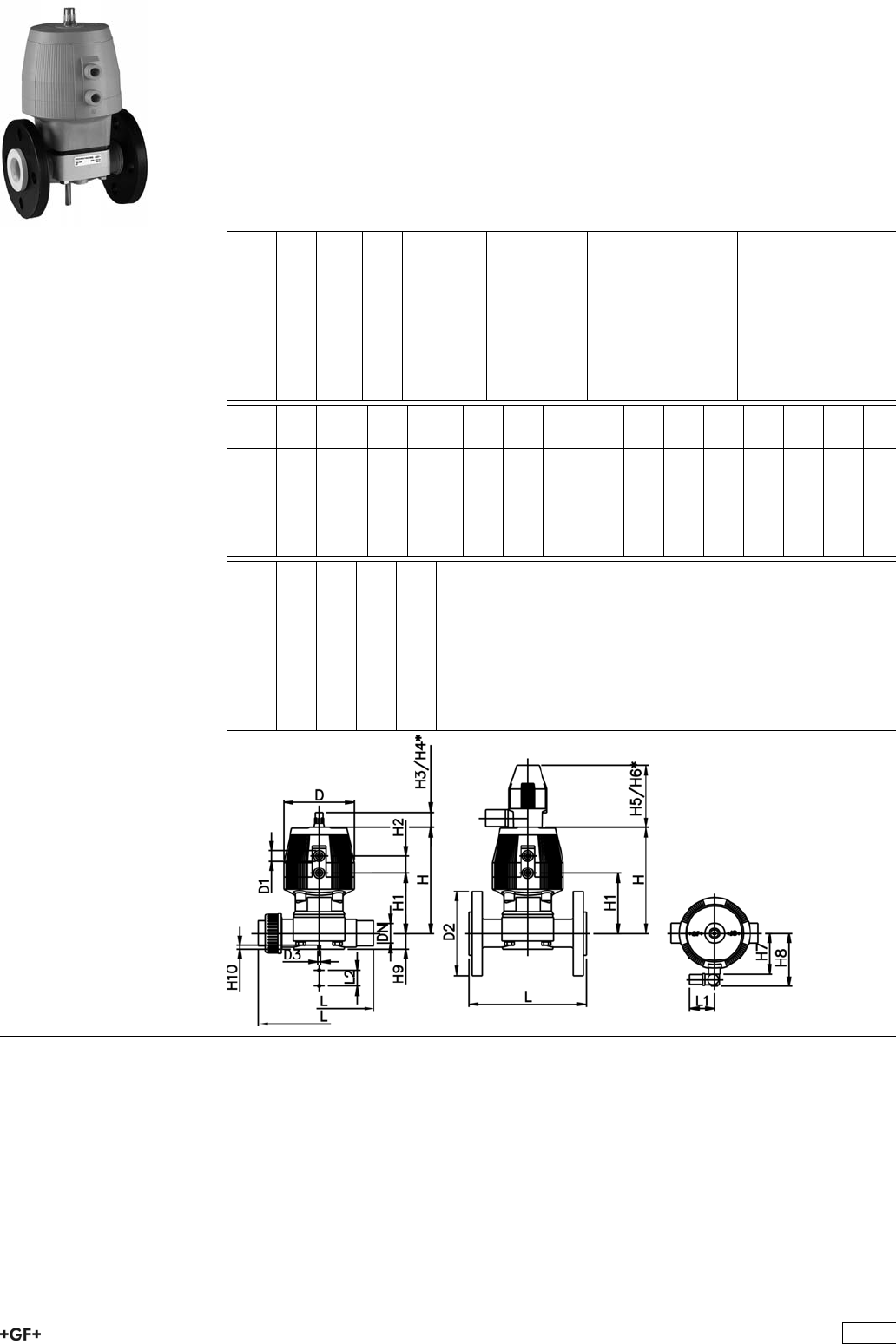
PROGEF Standard
Diaphragm valve type DIASTAR
Series 025 DA (Double acting)
With backing flanges PP-V metric
Model:
ÏMaterial: PP-H
ÏConnecting dimensions: ISO 7005 / EN 1092 / DIN 2501 PN10 / BS4504
ÏWith position indicator / Working pressure: both sides
d
[mm]
DN
[mm]
Inch PN kv-value
(”p=1 bar)
[l/min]
EPDM
Code
PTFE/EPDM
Code
kg
20 15 1
/210 72 199 025 281 199 025 311 0.654
25 20 3
/410 120 199 025 282 199 025 312 0.890
32 25 1 10 238 199 025 283 199 025 313 1.310
40 32 1 1
/410 341 199 025 284 199 025 314 1.650
50 40 1 1
/210 460 199 025 285 199 025 315 2.310
63 50 2 10 685 199 025 286 199 025 316 3.710
d
[mm]
D
[mm]
D1_G
[inch]
D2
[mm]
D3[M]
[mm]
L
[mm]
L1
[mm]
L2
[mm]
H
[mm]
H1
[mm]
H2
[mm]
H3
[mm]
H4
[mm]
H5
[mm]
H6
[mm]
20 68 1
/895 6 130 60 25 99 59 24 23 44 100 155
25 96 1
/8105 6 150 60 25 130 71 25 23 44 100 155
32 96 1
/8115 6 160 60 25 143 85 25 23 44 100 155
40 120 1
/8140 8 180 60 45 170 97 26 36 64 100 160
50 150 1
/4150 8 200 60 45 203 108 36 36 64 100 170
63 150 1
/4165 8 230 60 45 220 126 36 36 64 100 170
d
[mm]
H7
[mm]
H8
[mm]
H9
[mm]
H10
[mm]
Lift =
Hx
[mm]
20 44 76 14 12 8
25 56 88 18 12 10
32 56 88 21 12 12
40 68 100 26 15 14
50 85 117 33 15 18
63 85 117 39 15 22
277

PROGEF Standard
Diaphragm valve type DIASTAR
Series 025 DA (Double acting)
With fixed flanges PP metric
Model:
ÏMaterial: PP-H
ÏConnecting dimensions: ISO 7005 / EN 1092 / DIN 2501 PN10 / BS4504
ÏWith position indicator / Working pressure: one side
** Connecting dimensions DN80 and DN150 metric and Inch ANSI B16.5
* With backing flanges PP-V
** with fixed flanges PP metric and Inch ANSI
d
[mm]
DN
[mm]
Inch PN kv-value
(”p=1 bar)
[l/min]
EPDM
Code
PTFE/EPDM
Code
kg
*75 65 2 1
/210 992 199 025 287 199 025 317 13.600
**90 80 3 10 1700 199 025 288 199 025 318 17.400
110 100 4 8 2700 199 025 289 199 025 319 24.700
160 150 6 6 6033 199 025 290 199 025 320 35.000
d
[mm]
D
[mm]
D1_G
[inch]
D2
[mm]
D3[M]
[mm]
D4
[mm]
L
[mm]
L2
[mm]
L3
[mm]
H
[mm]
H1
[mm]
H2
[mm]
H3
[mm]
*75 280 1
/4185 8 145 290 70 344 148 24 46
**90 280 1
/4200 12 160 310 120 348 150 24 46
110 335 1
/4225 12 180 350 120 395 176 24 46
160 335 1
/4285 12 240 480 100 200 455 237 24 46
d
[mm]
H4
[mm]
H5
[mm]
H6
[mm]
H7
[mm]
H9
[mm]
H10
[mm]
*75 100 129 195 298 46 15
**90 100 129 195 302 57 15
110 100 129 195 349 69 20
160 100 129 195 409 108 20
278

Diaphragm valve type DIASTAR PP-H
Series 028 FC (Fail safe to close)
Unions with butt fusion spigots metric
Model:
ÏMaterial: PP-H
ÏWith position indicator / Working pressure: one side
*PN: EPDM/PTFE
d
[mm]
DN
[mm]
PN
[bar]
kv-value
(”p=1 bar)
[l/min]
EPDM
Code
PTFE/EPDM
Code
kg
20 15 10 / 5 * 72 199 028 431 199 028 461 0.836
25 20 10 / 7 * 120 199 028 432 199 028 462 0.870
32 25 10 / 7 * 238 199 028 433 199 028 463 1.505
40 32 10 / 7 * 341 199 028 434 199 028 464 2.604
50 40 10 / 7 * 460 199 028 435 199 028 465 2.250
63 50 10 / 7 * 685 199 028 436 199 028 466 3.500
d
[mm]
D
[mm]
D1_G
[inch]
D3[M]
[mm]
L
[mm]
L1
[mm]
L2
[mm]
H
[mm]
H1
[mm]
H2
[mm]
H3
[mm]
H4
[mm]
H5
[mm]
H6
[mm]
H7
[mm]
20 68 1
/86 196 60 25 99 59 24 23 44 100 155 44
25 96 1
/86 221 60 25 130 71 25 23 44 100 155 56
32 96 1
/86 234 60 25 143 85 25 23 44 100 155 56
40 120 1
/88 260 60 45 170 97 26 36 64 100 160 68
50 150 1
/48 284 60 45 203 108 36 36 64 100 170 85
63 150 1
/48 321 60 45 220 126 36 36 64 100 170 85
d
[mm]
H8
[mm]
H9
[mm]
H10
[mm]
Lift =
Hx
[mm]
20 76 14 12 8
25 88 18 12 10
32 88 21 12 12
40 100 26 15 14
50 117 33 15 18
63 117 39 15 22
279

Diaphragm valve type DIASTAR PP-H
Series 028 FC (Fail safe to close)
With fusion spigots metric
Model:
ÏMaterial: PP-H
ÏWith position indicator / Working pressure: one side
*PN: EPDM/PTFE
d
[mm]
DN
[mm]
PN
[bar]
kv-value
(”p=1 bar)
[l/min]
EPDM
Code
PTFE/EPDM
Code
kg
20 15 10 / 5 * 72 199 028 201 199 028 231 0.440
25 20 10 / 7 * 120 199 028 202 199 028 232 0.870
32 25 10 / 7 * 238 199 028 203 199 028 233 1.120
40 32 10 / 7 * 341 199 028 204 199 028 234 1.570
50 40 10 / 7 * 460 199 028 205 199 028 235 2.250
63 50 10 / 7 * 685 199 028 206 199 028 236 3.500
d
[mm]
D
[mm]
D1_G
[inch]
D3[M]
[mm]
L
[mm]
L1
[mm]
L2
[mm]
H
[mm]
H1
[mm]
H2
[mm]
H3
[mm]
H4
[mm]
H5
[mm]
H6
[mm]
H7
[mm]
20 68 1
/86 124 60 25 99 59 24 23 44 100 155 44
25 96 1
/86 144 60 25 130 71 25 23 44 100 155 56
32 96 1
/86 154 60 25 143 85 25 23 44 100 155 56
40 120 1
/88 174 60 45 170 97 26 36 64 100 160 68
50 150 1
/48 194 60 45 203 108 36 36 64 100 170 85
63 150 1
/48 224 60 45 220 126 36 36 64 100 170 85
d
[mm]
H8
[mm]
H9
[mm]
H10
[mm]
Lift =
Hx
[mm]
20 76 14 12 8
25 88 18 12 10
32 88 21 12 12
40 100 26 15 14
50 117 33 15 18
63 117 39 15 22
280
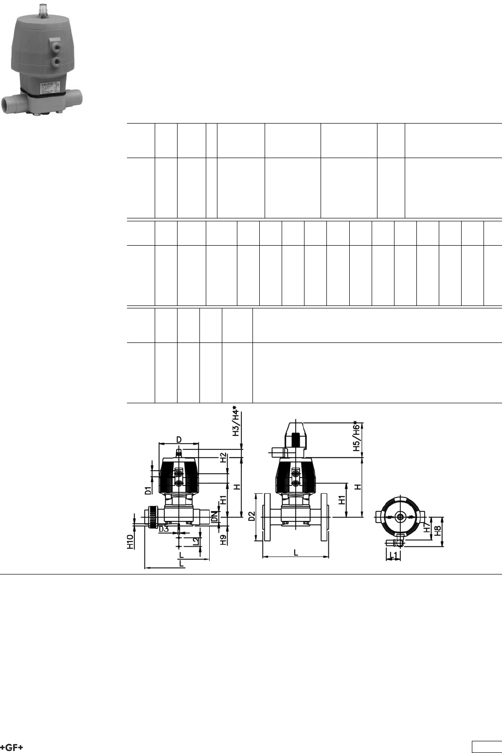
Diaphragm valve type DIASTAR PP-H
Series 028 FC (Fail safe to close)
With butt fusion spigots metric
Model:
ÏMaterial: PP-H
ÏWith position indicator / Working pressure: one side
*PN: EPDM/PTFE
d
[mm]
DN
[mm]
PN
[bar]
kv-value
(”p=1 bar)
[l/min]
EPDM
Code
PTFE/EPDM
Code
kg
20 15 10 / 5 * 72 199 028 881 199 028 901 0.440
25 20 10 / 7 * 120 199 028 882 199 028 902 0.870
32 25 10 / 7 * 238 199 028 883 199 028 903 1.120
40 32 10 / 7 * 341 199 028 884 199 028 904 1.570
50 40 10 / 7 * 460 199 028 885 199 028 905 2.250
63 50 10 / 7 * 685 199 028 886 199 028 906 3.500
d
[mm]
D
[mm]
D1_G
[inch]
D3[M]
[mm]
L
[mm]
L1
[mm]
L2
[mm]
H
[mm]
H1
[mm]
H2
[mm]
H3
[mm]
H4
[mm]
H5
[mm]
H6
[mm]
H7
[mm]
20 68 1
/86 124 60 25 99 59 24 23 44 100 155 44
25 96 1
/86 144 60 25 130 71 25 23 44 100 155 56
32 96 1
/86 154 60 25 143 85 25 23 44 100 155 56
40 120 1
/88 174 60 45 170 97 26 36 64 100 160 68
50 150 1
/48 194 60 45 203 108 36 36 64 100 170 85
63 150 1
/48 224 60 45 220 126 36 36 64 100 170 85
d
[mm]
H8
[mm]
H9
[mm]
H10
[mm]
Lift =
Hx
[mm]
20 76 14 12 8
25 88 18 12 10
32 88 21 12 12
40 100 26 15 14
50 117 33 15 18
63 117 39 15 22
281
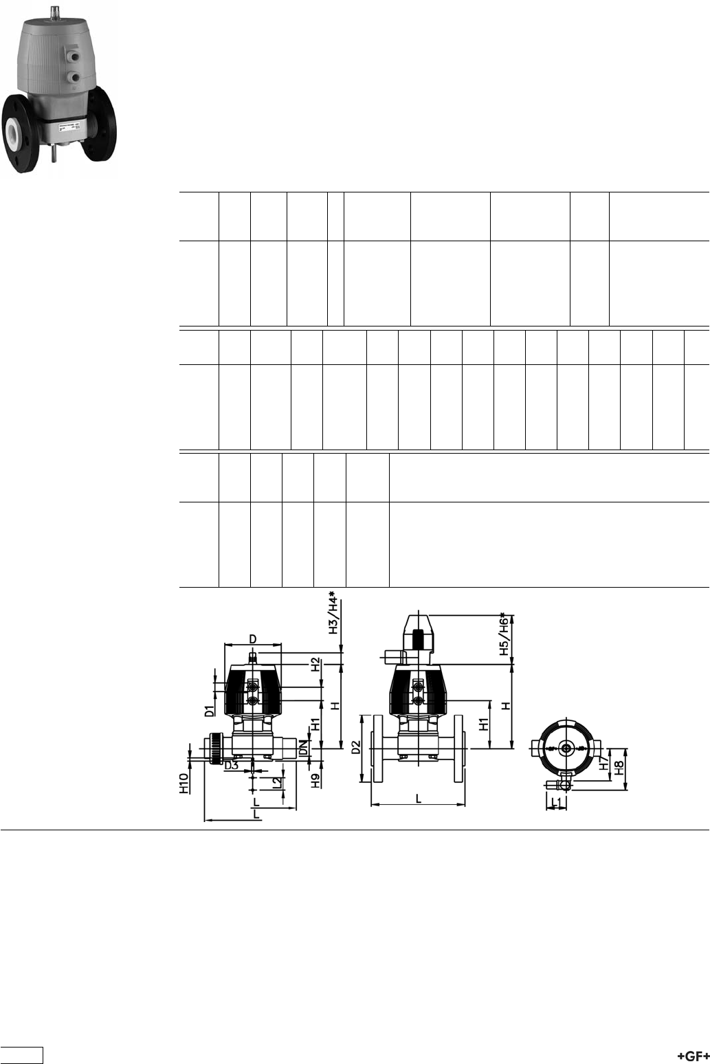
Diaphragm valve type DIASTAR PP-H
Series 028 FC (Fail safe to close)
With backing flanges PP-V metric
Model:
ÏMaterial: PP-H
ÏConnecting dimensions: ISO 7005 / EN 1092 / DIN 2501 PN10 / BS4504
ÏWith position indicator / Working pressure: one side
*PN: EPDM/PTFE
d
[mm]
DN
[mm]
Inch PN
[bar]
kv-value
(”p=1 bar)
[l/min]
EPDM
Code
PTFE/EPDM
Code
kg
20 15 1
/210 / 5 * 72 199 028 261 199 028 291 0.440
25 20 3
/410 / 7 * 120 199 028 262 199 028 292 0.870
32 25 1 10 / 7 * 238 199 028 263 199 028 293 1.120
40 32 1 1
/410 / 7 * 341 199 028 264 199 028 294 1.570
50 40 1 1
/210 / 7 * 460 199 028 265 199 028 295 2.250
63 50 2 10 / 7 * 685 199 028 266 199 028 296 3.500
d
[mm]
D
[mm]
D1_G
[inch]
D2
[mm]
D3[M]
[mm]
L
[mm]
L1
[mm]
L2
[mm]
H
[mm]
H1
[mm]
H2
[mm]
H3
[mm]
H4
[mm]
H5
[mm]
H6
[mm]
20 68 1
/895 6 130 60 25 98 59 24 23 44 100 155
25 96 1
/8105 6 150 60 25 127 71 25 23 44 100 155
32 96 1
/8115 6 160 60 25 141 85 25 23 44 100 155
40 120 1
/8140 6 180 60 45 167 97 26 36 64 100 160
50 150 1
/4150 6 200 60 45 198 108 36 36 64 100 170
63 150 1
/4165 6 230 60 45 216 126 36 36 64 100 170
d
[mm]
H7
[mm]
H8
[mm]
H9
[mm]
H10
[mm]
Lift =
Hx
[mm]
20 44 76 14 12 8
25 56 88 18 12 10
32 56 88 21 12 12
40 68 100 26 15 14
50 85 117 33 15 18
63 85 117 39 15 22
282

Diaphragm valve type DIASTAR PP-H
Series 028 FC (Fail safe to close)
Unions with fusion sockets metric
Model:
ÏMaterial: PP-H
ÏWith position indicator / Working pressure: one side
*PN: EPDM/PTFE
d
[mm]
DN
[mm]
PN
[bar]
kv-value
(”p=1 bar)
[l/min]
EPDM
Code
PTFE/EPDM
Code
kg
20 15 10 / 5 * 72 199 028 181 199 028 187 0.836
25 20 10 / 7 * 120 199 028 182 199 028 188 0.870
32 25 10 / 7 * 238 199 028 183 199 028 189 1.505
40 32 10 / 7 * 341 199 028 184 199 028 190 2.400
50 40 10 / 7 * 460 199 028 185 199 028 191 2.250
63 50 10 / 7 * 685 199 028 186 199 028 192 3.500
d
[mm]
D
[mm]
D1_G
[inch]
D3[M]
[mm]
L
[mm]
L1
[mm]
L2
[mm]
H
[mm]
H1
[mm]
H2
[mm]
H3
[mm]
H4
[mm]
H5
[mm]
H6
[mm]
H7
[mm]
20 68 1
/86 128 60 25 99 59 24 23 44 100 155 44
25 96 1
/86 150 60 25 130 71 25 23 44 100 155 56
32 96 1
/86 162 60 25 143 85 25 23 44 100 155 56
40 120 1
/88 184 60 45 170 97 26 36 64 100 160 68
50 150 1
/48 210 60 45 203 108 36 36 64 100 170 85
63 150 1
/48 248 60 45 220 126 36 36 64 100 170 85
d
[mm]
H8
[mm]
H9
[mm]
H10
[mm]
Lift =
Hx
[mm]
20 76 14 12 8
25 88 18 12 10
32 88 21 12 12
40 100 26 15 14
50 117 33 15 18
63 117 39 15 22
283
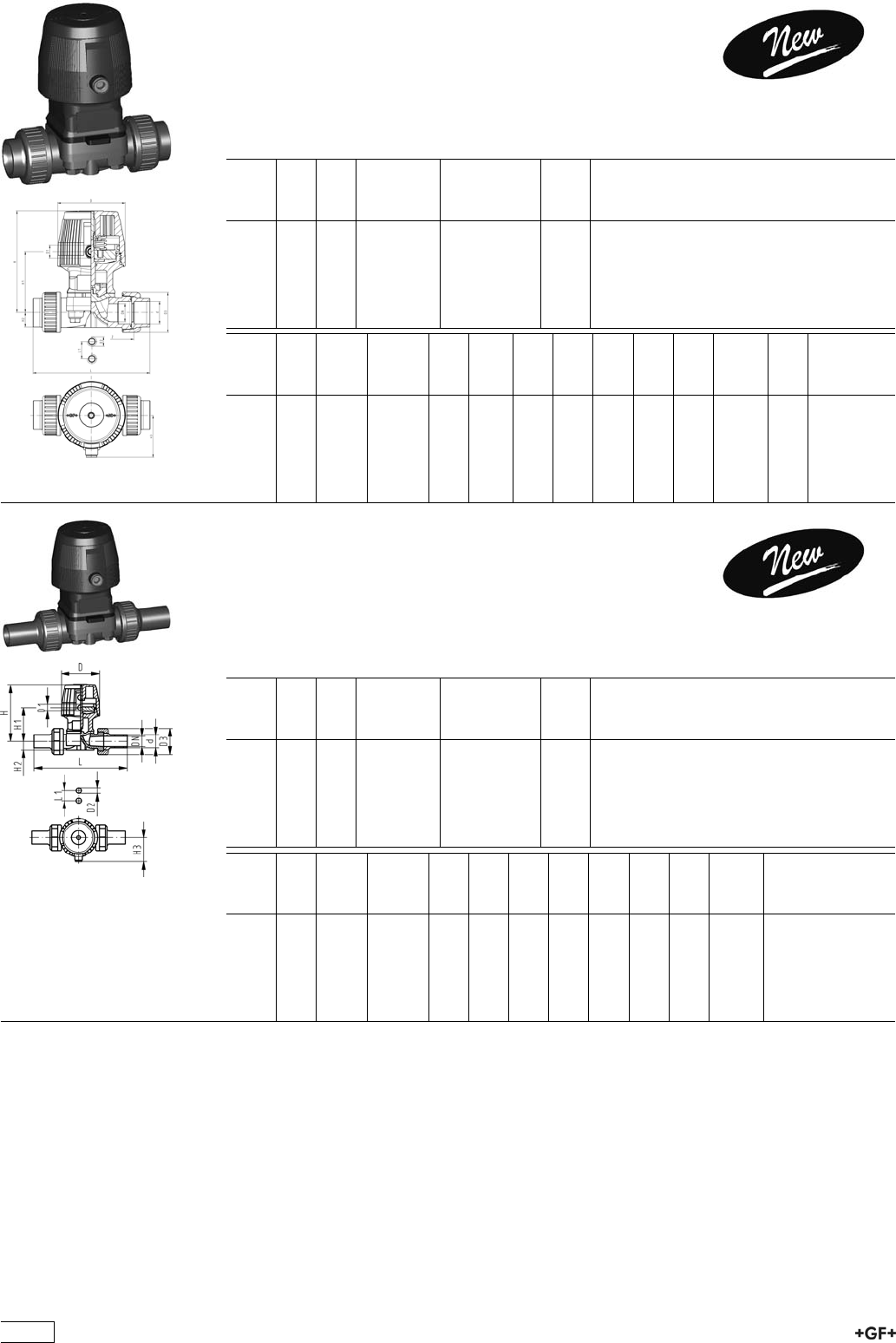
Diaphragm valve type DIASTAR Eco PP-H
FC (Fail safe to close)
Unions with fusion sockets metric
Model:
ÏMaterial: PP-H
ÏWorking pressure 6 bar one side
d
[mm]
DN
[mm]
PN kv-value
(”p=1 bar)
[l/min]
EPDM
Code
kg
20 15 6 72 199 024 311 0.548
25 20 6 120 199 024 312 1.086
32 25 6 238 199 024 313 1.326
40 32 6 341 199 024 314 1.991
50 40 6 460 199 024 315 2.574
63 50 6 685 199 024 316 3.285
d
[mm]
D
[mm]
D1_G
[inch]
D2 (M) D3
[mm]
L
[mm]
L1
[mm]
H
[mm]
H1
[mm]
H2
[mm]
H3
[mm]
Lift =
Hx
[mm]
z
[mm]
20 68 1
/8M6 47 128 25 99 59 14 44 8 100
25 96 1
/8M6 57 150 25 130 71 18 56 10 118
32 96 1
/8M6 64 162 25 143 85 21 56 12 126
40 120 1
/8M8 78 184 45 170 97 26 68 14 144
50 120 1
/8M8 89 2210 45 182 109 33 68 16 164
63 120 1
/8M8 109 248 45 199 126 39 68 16 194
Diaphragm valve type DIASTAR Eco PP-H
FC (Fail safe to close)
Unions with butt fusion spigots metric
Model:
ÏMaterial: PP-H
ÏWorking pressure 6 bar one side
d
[mm]
DN
[mm]
PN kv-value
(”p=1 bar)
[l/min]
EPDM
Code
kg
20 15 6 72 199 024 341 0.556
25 20 6 120 199 024 342 1.098
32 25 6 238 199 024 343 1.346
40 32 6 341 199 024 344 2.023
50 40 6 460 199 024 345 2.634
63 50 6 685 199 024 346 3.385
d
[mm]
D
[mm]
D1_G
[inch]
D2 (M) D3
[mm]
L
[mm]
L1
[mm]
H
[mm]
H1
[mm]
H2
[mm]
H3
[mm]
Lift =
Hx
[mm]
20 68 1
/8M6 47 196 25 99 59 14 44 8
25 96 1
/8M6 57 221 25 130 71 18 56 10
32 96 1
/8M6 64 234 25 143 85 21 56 12
40 120 1
/8M8 78 260 45 170 97 26 68 14
50 120 1
/8M8 89 284 45 182 109 33 68 16
63 120 1
/8M8 109 321 45 199 126 39 68 16
284
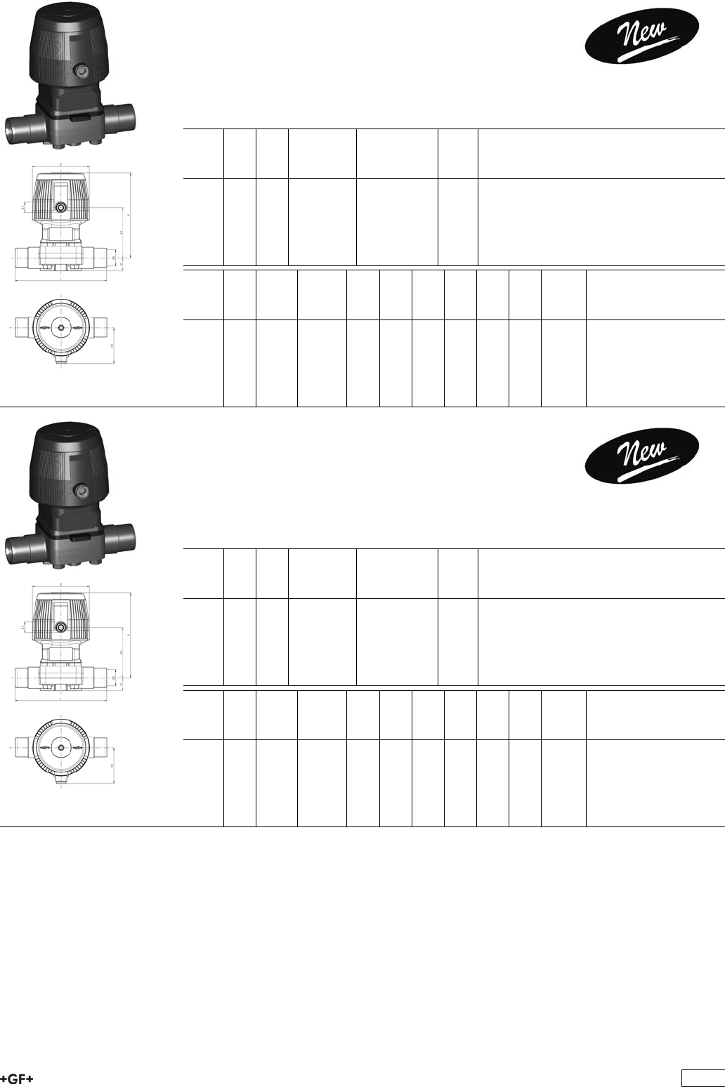
Diaphragm valve type DIASTAR Eco PP-H
FC (Fail safe to close)
With socket fusion spigots metric
Model:
ÏMaterial: PP-H
ÏWorking pressure 6 bar one side
d
[mm]
DN
[mm]
PN kv-value
(”p=1 bar)
[l/min]
EPDM
Code
kg
20 15 6 72 199 024 251 0.486
25 20 6 120 199 024 252 0.988
32 25 6 238 199 024 253 1.202
40 32 6 341 199 024 254 1.781
50 40 6 460 199 024 255 2.296
63 50 6 685 199 024 256 2.826
d
[mm]
D
[mm]
D1_G
[inch]
D2 (M) L
[mm]
L1
[mm]
H
[mm]
H1
[mm]
H2
[mm]
H3
[mm]
Lift =
Hx
[mm]
20 68 1
/8M6 124 25 99 59 14 44 8
25 96 1
/8M6 144 25 130 71 18 56 10
32 96 1
/8M6 154 25 143 85 21 56 12
40 120 1
/8M8 174 45 170 97 26 68 14
50 120 1
/8M8 194 45 182 109 33 68 16
63 120 1
/8M8 224 45 199 126 39 68 16
Diaphragm valve type DIASTAR Eco PP-H
FC (Fail safe to close)
With butt fusion spigots IR metric
Model:
ÏMaterial: PP-H
ÏWorking pressure 6 bar one side
d
[mm]
DN
[mm]
PN kv-value
(”p=1 bar)
[l/min]
EPDM
Code
kg
20 15 6 72 199 024 281 0.481
25 20 6 120 199 024 282 0.981
32 25 6 238 199 024 283 1.195
40 32 6 341 199 024 284 1.773
50 40 6 460 199 024 285 2.272
63 50 6 685 199 024 286 2.790
d
[mm]
D
[mm]
D1_G
[inch]
D2 (M) L
[mm]
L1
[mm]
H
[mm]
H1
[mm]
H2
[mm]
H3
[mm]
Lift =
Hx
[mm]
20 68 1
/8M6 124 25 99 59 14 44 8
25 96 1
/8M6 144 25 130 71 18 56 10
32 96 1
/8M6 154 25 143 85 21 56 12
40 120 1
/8M8 174 45 170 97 26 68 14
50 120 1
/8M8 194 45 182 109 33 68 16
63 120 1
/8M8 224 45 199 126 39 68 16
285
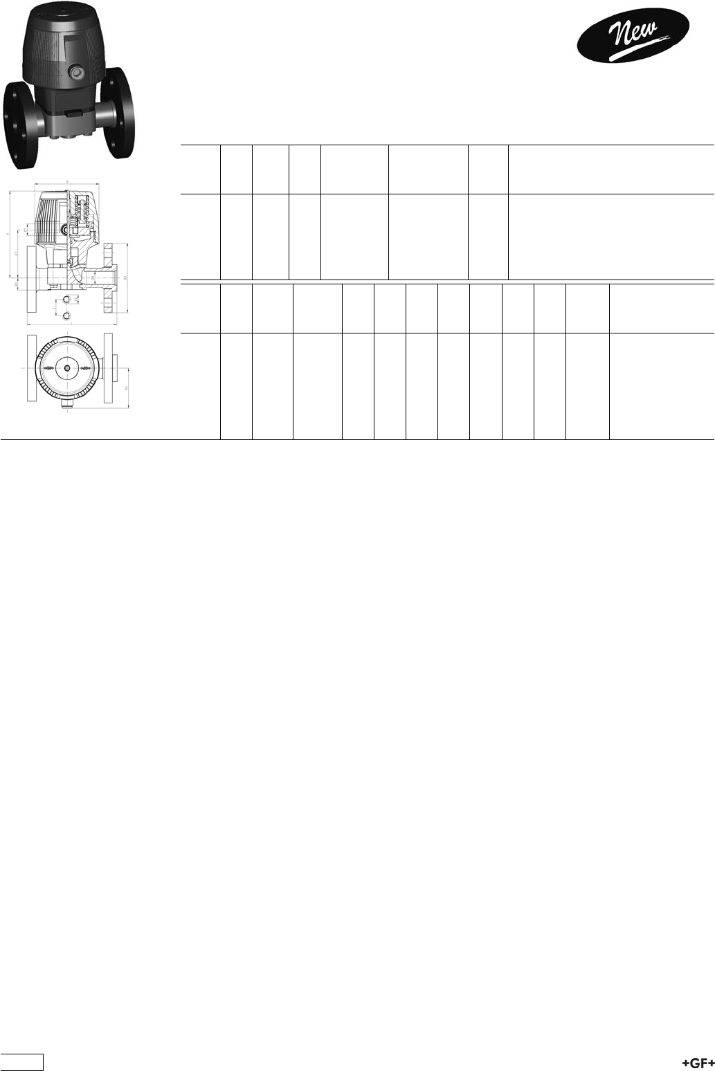
Diaphragm valve type DIASTAR Eco PP-H
FC (Fail safe to close)
With backing flanges PP-V metric
Model:
ÏMaterial: PP-H
ÏWorking pressure 6 bar one side
ÏConnecting dimensions: ISO 7005 / EN 1092 / DIN 2501 PN10 / BS4504
d
[mm]
DN
[mm]
Inch PN kv-value
(”p=1 bar)
[l/min]
EPDM
Code
kg
20 15 1
/26 72 199 024 371 0.633
25 20 3
/46 120 199 024 372 1.150
32 25 1 6 238 199 024 373 1.396
40 32 1 1
/46 341 199 024 374 2.185
50 40 1 1
/26 460 199 024 375 2.983
63 50 2 6 685 199 024 376 3.708
d
[mm]
D
[mm]
D1_G
[inch]
D2 (M) D3
[mm]
L
[mm]
L1
[mm]
H
[mm]
H1
[mm]
H2
[mm]
H3
[mm]
Lift =
Hx
[mm]
20 68 1
/8M6 95 130 25 99 59 14 44 8
25 96 1
/8M6 105 150 25 130 71 18 56 10
32 96 1
/8M6 115 160 25 143 85 21 56 12
40 120 1
/8M8 140 180 45 170 97 26 68 14
50 120 1
/8M8 150 200 45 182 109 33 68 16
63 120 1
/8M8 165 230 45 199 126 39 68 16
286
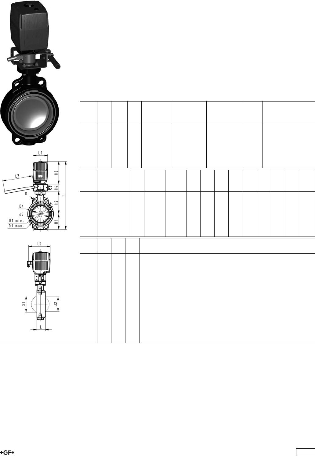
Butterfly Valves Electric
Butterfly valve type 140 PP-H 100-230V
With manual override
Model:
ÏMaterial: PP-H
ÏConnecting dimension: ISO 7005 PN 10, EN 1092 PN 10, DIN 2501 PN 10,
ANSI/ASME B 16.5 Class 150, BS 1560: 1989, BS 4504, JIS B 2220
ÏOverall length according to EN 558, ISO 5752
ÏVoltage 100-230 V, 50-60 Hz
ÏControl time 15 s/90°<) EA31
ÏControl time 25s/90°<) EA42
ÏControl range 90°<)
ÏActuator with integrated emergency manual override standard
d
[mm]
DN
[mm]
Inch PN kv-value
(”p=1 bar)
[l/min]
EPDM
Code
FPM
Code
kg
63 50 2 10 1470 199 140 322 199 140 342 5.607
75 65 2 1
/210 2200 199 140 323 199 140 343 5.699
90 80 3 10 3000 199 140 324 199 140 344 5.829
110 100 4 10 6500 199 140 325 199 140 345 6.341
140 125 5 10 11500 199 140 326 199 140 346 6.789
160 150 6 10 16600 199 140 327 199 140 347 7.579
225 200 8 10 39600 199 140 328 199 140 348 13.299
d
[mm]
Actuator
unit type
D
[mm]
D1
min.
[mm]
D1
max.
[mm]
d2
[mm]
H
[mm]
H1
[mm]
H2
[mm]
H3
[mm]
H4
[mm]
L
[mm]
L1
[mm]
L2
[mm]
63 EA-31 19 120.0 125.0 104 460 77 134 188 60 45 122 180
75 EA-31 19 139.7 145.0 115 473 83 140 188 60 46 122 180
90 EA-31 19 150.0 160.0 131 488 89 146 188 60 49 122 180
110 EA-31 19 175.0 190.5 161 520 104 167 188 60 56 122 180
140 EA-31 23 210.0 215.9 187 547 117 181 188 60 64 122 180
160 EA-31 24 241.3 241.3 215 568 130 189 188 60 72 122 180
225 EA-42 23 290.0 295.0 267 635 158 210 208 60 73 122 180
d
[mm]
L3
[mm]
Q1
[mm]
Q2
[mm]
63 250 40
75 250 54 35
90 250 67 50
110 250 88 74
140 250 113 97
160 250 139 123
225 250 178 169
287

Butterfly valve type 140 PP-H 100-230V
Without manual override
Model:
ÏMaterial: PP-H
ÏConnecting dimension: ISO 7005 PN 10, EN 1092 PN 10, DIN 2501 PN 10,
ANSI/ASME B 16.5 Class 150, BS 1560: 1989, BS 4504, JIS B 2220
ÏOverall length according to EN 558, ISO 5752
ÏVoltage 100-230 V, 50-60 Hz
ÏControl time 15 s/90°<) EA31
ÏControl time 25s/90°<) EA42
ÏControl range 90°<)
ÏActuator with integrated emergency manual override standard
ÏThe dimension DN300 on request
d
[mm]
DN
[mm]
Inch PN kv-value
(”p=1 bar)
[l/min]
EPDM
Code
FPM
Code
kg
63 50 2 10 1470 199 140 362 199 140 382 4.107
75 65 2 1
/210 2200 199 140 363 199 140 383 4.199
90 80 3 10 3000 199 140 364 199 140 384 4.329
110 100 4 10 6500 199 140 365 199 140 385 4.841
140 125 5 10 11500 199 140 366 199 140 386 5.289
160 150 6 10 16600 199 140 367 199 140 387 6.079
225 200 8 10 39600 199 140 368 199 140 388 11.799
d
[mm]
Actuator
unit type
D
[mm]
D1
min.
[mm]
D1
max.
[mm]
d2
[mm]
H
[mm]
H1
[mm]
H2
[mm]
H3
[mm]
L
[mm]
L1
[mm]
L2
[mm]
Q1
[mm]
63 EA-31 19 120.0 125.0 104 400 77 134 188 45 122 180 40
75 EA-31 19 139.7 145.0 115 413 83 140 188 46 122 180 54
90 EA-31 19 150.0 160.0 131 428 89 146 188 49 122 180 67
110 EA-31 19 175.0 190.5 161 460 104 167 188 56 122 180 88
140 EA-31 23 210.0 215.9 187 487 117 181 188 64 122 180 113
160 EA-31 24 241.3 241.3 215 508 130 189 188 72 122 180 139
225 EA-42 23 290.0 295.0 267 575 158 210 208 73 122 180 178
d
[mm]
Q2
[mm]
63
75 35
90 50
110 74
140 97
160 123
225 169
288
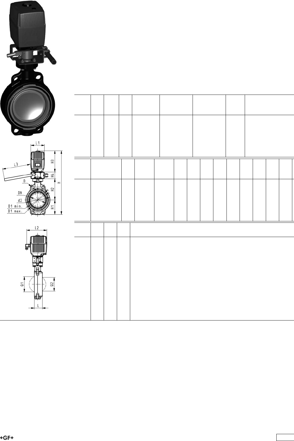
Butterfly valve type 140 PP-H 24V
With manual override
Model:
ÏMaterial: PP-H
ÏConnecting dimension: ISO 7005 PN 10, EN 1092 PN 10, DIN 2501 PN 10,
ANSI/ASME B 16.5 Class 150, BS 1560: 1989, BS 4504, JIS B 2220
ÏOverall length according to EN 558, ISO 5752
ÏVoltage 24 V AC/DC
ÏControl time 15 s/90°<) EA31
ÏControl time 25s/90°<) EA42
ÏControl range 90°<)
ÏActuator with integrated emergency manual override standard
d
[mm]
DN
[mm]
Inch PN kv-value
(”p=1 bar)
[l/min]
EPDM
Code
FPM
Code
kg
63 50 2 10 1470 199 140 402 199 140 422 5.607
75 65 2 1
/210 2200 199 140 403 199 140 423 5.699
90 80 3 10 3000 199 140 404 199 140 424 5.829
110 100 4 10 6500 199 140 405 199 140 425 6.341
140 125 5 10 11500 199 140 406 199 140 426 6.789
160 150 6 10 16600 199 140 407 199 140 427 7.579
225 200 8 10 39600 199 140 408 199 140 428 13.299
d
[mm]
Actuator
unit type
D
[mm]
D1
min.
[mm]
D1
max.
[mm]
d2
[mm]
H
[mm]
H1
[mm]
H2
[mm]
H3
[mm]
H4
[mm]
L
[mm]
L1
[mm]
L2
[mm]
63 EA-31 19 120.0 125.0 104 460 77 134 188 60 45 122 180
75 EA-31 19 139.7 145.0 115 473 83 140 188 60 46 122 180
90 EA-31 19 150.0 160.0 131 488 89 146 188 60 49 122 180
110 EA-31 19 175.0 190.5 161 520 104 167 188 60 56 122 180
140 EA-31 23 210.0 215.9 187 547 117 181 188 60 64 122 180
160 EA-31 24 241.3 241.3 215 568 130 189 188 60 72 122 180
225 EA-42 23 290.0 295.0 267 635 158 210 208 60 73 122 180
d
[mm]
L3
[mm]
Q1
[mm]
Q2
[mm]
63 250 40
75 250 54 35
90 250 67 50
110 250 88 74
140 250 113 97
160 250 139 123
225 250 178 169
289
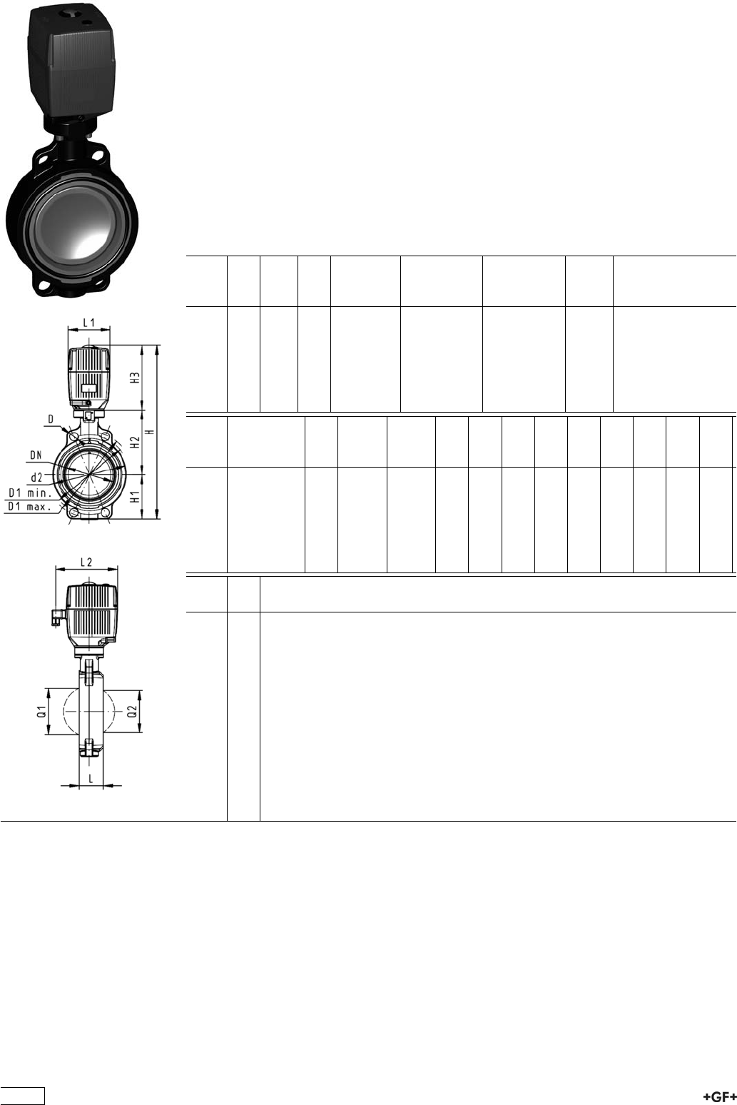
Butterfly valve type 140 PP-H 24V
Without manual override
Model:
ÏMaterial: PP-H
ÏConnecting dimension: ISO 7005 PN 10, EN 1092 PN 10, DIN 2501 PN 10,
ANSI/ASME B 16.5 Class 150, BS 1560: 1989, BS 4504, JIS B 2220
ÏOverall length according to EN 558, ISO 5752
ÏVoltage 24 V AC/DC
ÏControl time 15 s/90°<) EA31
ÏControl time 25s/90°<) EA42
ÏControl range 90°<)
ÏActuator with integrated emergency manual override standard
ÏThe dimension DN300 on request
d
[mm]
DN
[mm]
Inch PN kv-value
(”p=1 bar)
[l/min]
EPDM
Code
FPM
Code
kg
63 50 2 10 1470 199 140 442 199 140 462 4.107
75 65 2 1
/210 2200 199 140 443 199 140 463 4.199
90 80 3 10 3000 199 140 444 199 140 464 4.329
110 100 4 10 6500 199 140 445 199 140 465 4.841
140 125 5 10 11500 199 140 446 199 140 466 5.289
160 150 6 10 16600 199 140 447 199 140 467 6.079
225 200 8 10 39600 199 140 448 199 140 468 11.799
d
[mm]
Actuator
unit type
D
[mm]
D1
min.
[mm]
D1
max.
[mm]
d2
[mm]
H
[mm]
H1
[mm]
H2
[mm]
H3
[mm]
L
[mm]
L1
[mm]
L2
[mm]
Q1
[mm]
63 EA-31 19 120.0 125.0 104 400 77 134 188 45 122 180 40
75 EA-31 19 139.7 145.0 115 413 83 140 188 46 122 180 54
90 EA-31 19 150.0 160.0 131 428 89 146 188 49 122 180 67
110 EA-31 19 175.0 190.5 161 460 104 167 188 56 122 180 88
140 EA-31 23 210.0 215.9 187 487 117 181 188 64 122 180 113
160 EA-31 24 241.3 241.3 215 508 130 189 188 72 122 180 139
225 EA-42 23 290.0 295.0 267 575 158 210 208 73 122 180 178
d
[mm]
Q2
[mm]
63
75 35
90 50
110 74
140 97
160 123
225 169
290
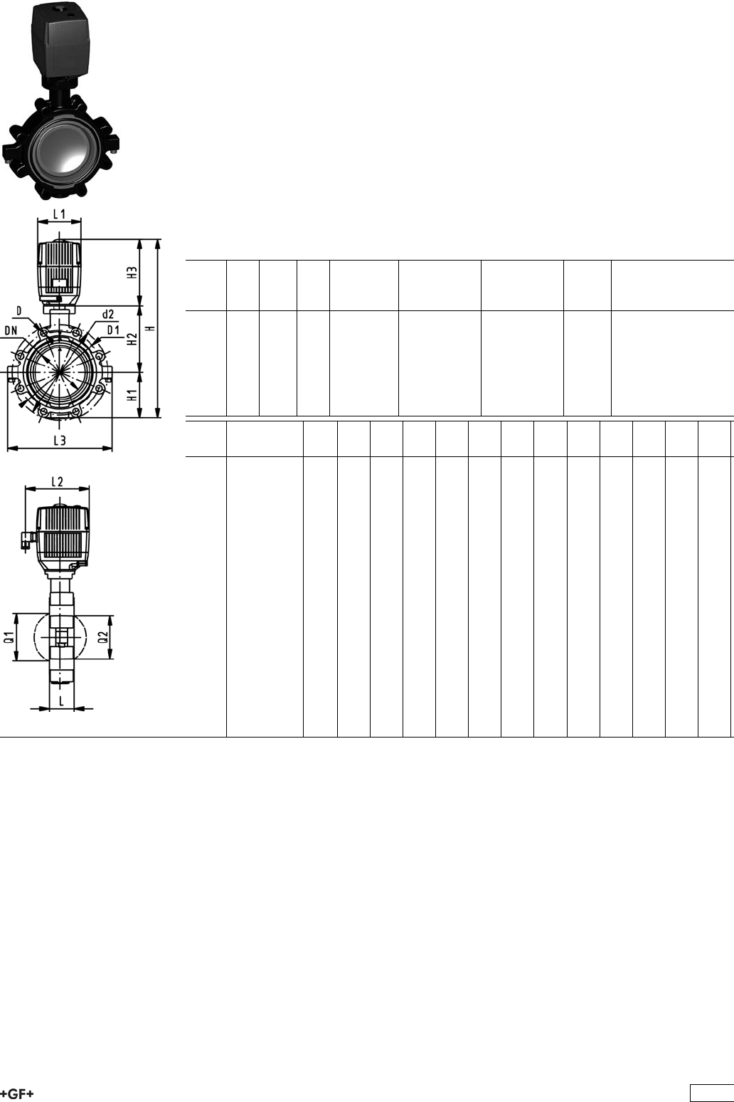
PROGEF Standard
Lugstyle butterfly valve type 141 100-230V
Without manual override
Model:
ÏMaterial: PP-H
ÏOuter body in GGG-40.3 epoxy-coated
ÏConnecting dimension: ISO 7005 PN10, EN 1092 PN10, DIN 2501 PN10
ÏOverall length according to EN 558, ISO 5752
ÏVoltage 100-230 V, 50-60 Hz
ÏControl time 15 s/90°<) EA31
ÏControl time 25s/90°<) EA42
ÏControl range 90°<)
ÏActuator with integrated emergency manual override standard
d
[mm]
DN
[mm]
Inch PN kv-value
(”p=1 bar)
[l/min]
EPDM
Code
FPM
Code
kg
63 50 2 10 1470 199 141 362 199 141 382 6.193
75 65 2 1
/210 2200 199 141 363 199 141 383 6.535
90 80 3 10 3000 199 141 364 199 141 384 7.540
110 100 4 10 6500 199 141 365 199 141 385 8.925
140 125 5 10 11500 199 141 366 199 141 386 10.755
160 150 6 10 16600 199 141 367 199 141 387 12.539
225 200 8 10 39600 199 141 368 199 141 388 21.747
d
[mm]
Actuator
unit type
D D1
[mm]
d2
[mm]
H
[mm]
H1
[mm]
H2
[mm]
H3
[mm]
L
[mm]
L1
[mm]
L2
[mm]
L3
[mm]
Q1
[mm]
Q2
[mm]
63 EA-31 M16 125 150 399 77 134 188 45 122 180 150 40
75 EA-31 M16 145 170 411 83 140 188 46 122 180 160 54 35
90 EA-31 M16 160 184 423 89 146 188 49 122 180 205 67 50
110 EA-31 M16 180 216 459 104 167 188 56 122 180 244 88 74
140 EA-31 M16 210 246 486 117 181 188 64 122 180 272 113 97
160 EA-31 M20 240 273 507 130 189 188 72 122 180 297 139 123
225 EA-42 M20 295 334 576 158 210 208 73 122 180 360 178 169
291
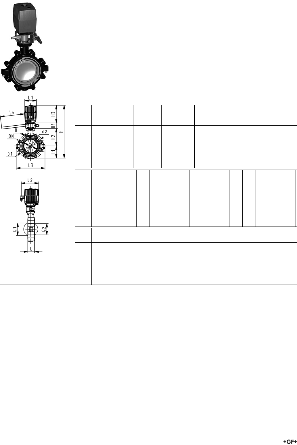
PROGEF Standard
Lugstyle butterfly valve type 141 100-230V
With manual override
Model:
ÏMaterial: PP-H
ÏOuter body in GGG-40.3 epoxy-coated
ÏConnecting dimension: ISO 7005 PN10, EN 1092 PN10, DIN 2501 PN10
ÏOverall length according to EN 558, ISO 5752
ÏVoltage 100-230 V, 50-60 Hz
ÏControl time 15 s/90°<) EA31
ÏControl time 25s/90°<) EA42
ÏControl range 90°<)
ÏActuator with integrated emergency manual override standard
d
[mm]
DN
[mm]
Inch PN kv-value
(”p=1 bar)
[l/min]
EPDM
Code
FPM
Code
kg
63 50 2 10 1470 199 141 322 199 141 342 7.693
75 65 2 1
/210 2200 199 141 323 199 141 343 8.035
90 80 3 10 3000 199 141 324 199 141 344 9.040
110 100 4 10 6500 199 141 325 199 141 345 10.425
140 125 5 10 11500 199 141 326 199 141 346 12.255
160 150 6 10 16600 199 141 327 199 141 347 14.039
225 200 8 10 39600 199 141 328 199 141 348 23.247
d
[mm]
Actuator
unit type
D D1
[mm]
d2
[mm]
H
[mm]
H1
[mm]
H2
[mm]
H3
[mm]
H4
[mm]
L
[mm]
L1
[mm]
L2
[mm]
L3
[mm]
L4
[mm]
63 EA-31 M16 125 150 459 77 134 188 60 45 122 180 150 200
75 EA-31 M16 145 170 471 83 140 188 60 46 122 180 160 200
90 EA-31 M16 160 184 483 89 146 188 60 49 122 180 205 200
110 EA-31 M16 180 216 519 104 167 188 60 56 122 180 244 250
140 EA-31 M16 210 246 546 117 181 188 60 64 122 180 272 250
160 EA-31 M20 240 273 567 130 189 188 60 72 122 180 297 250
225 EA-42 M20 295 334 636 158 210 208 60 73 122 180 360 250
d
[mm]
Q1
[mm]
Q2
[mm]
63 40
75 54 35
90 67 50
110 88 74
140 113 97
160 139 123
225 178 169
292

PROGEF Standard
Lugstyle butterfly valve type 141 24V
Without manual override
Model:
ÏMaterial: PP-H
ÏOuter body in GGG-40.3 epoxy-coated
ÏConnecting dimension: ISO 7005 PN10, EN 1092 PN10, DIN 2501 PN10
ÏOverall length according to EN 558, ISO 5752
ÏVoltage 24 V AC/DC
ÏControl time 15 s/90°<) EA31
ÏControl time 25s/90°<) EA42
ÏControl range 90°<)
ÏActuator with integrated emergency manual override standard
d
[mm]
DN
[mm]
Inch PN kv-value
(”p=1 bar)
[l/min]
EPDM
Code
FPM
Code
kg
63 50 2 10 1470 199 141 442 199 141 462 6.193
75 65 2 1
/210 2200 199 141 443 199 141 463 6.535
90 80 3 10 3000 199 141 444 199 141 464 7.540
110 100 4 10 6500 199 141 445 199 141 465 8.925
140 125 5 10 11500 199 141 446 199 141 466 10.755
160 150 6 10 16600 199 141 447 199 141 467 12.539
225 200 8 10 39600 199 141 448 199 141 468 21.747
d
[mm]
Actuator
unit type
D D1
[mm]
d2
[mm]
H
[mm]
H1
[mm]
H2
[mm]
H3
[mm]
L
[mm]
L1
[mm]
L2
[mm]
L3
[mm]
Q1
[mm]
Q2
[mm]
63 EA-31 M16 125 150 399 77 134 188 45 122 180 150 40
75 EA-31 M16 145 170 411 83 140 188 46 122 180 160 54 35
90 EA-31 M16 160 184 423 89 146 188 49 122 180 205 67 50
110 EA-31 M16 180 216 459 104 167 188 56 122 180 244 88 74
140 EA-31 M16 210 246 486 117 181 188 64 122 180 272 113 97
160 EA-31 M20 240 273 507 130 189 188 72 122 180 297 139 123
225 EA-42 M20 295 334 576 158 210 208 73 122 180 360 178 169
293

PROGEF Standard
Lugstyle butterfly valve type 141 24V
With manual override
Model:
ÏMaterial: PP-H
ÏOuter body in GGG-40.3 epoxy-coated
ÏConnecting dimension: ISO 7005 PN10, EN 1092 PN10, DIN 2501 PN10
ÏOverall length according to EN 558, ISO 5752
ÏVoltage 24 V AC/DC
ÏControl time 15 s/90°<) EA31
ÏControl time 25s/90°<) EA42
ÏControl range 90°<)
ÏActuator with integrated emergency manual override standard
d
[mm]
DN
[mm]
Inch PN kv-value
(”p=1 bar)
[l/min]
EPDM
Code
FPM
Code
kg
63 50 2 10 1470 199 141 402 199 141 422 7.693
75 65 2 1
/210 2200 199 141 403 199 141 423 8.035
90 80 3 10 3000 199 141 404 199 141 424 9.040
110 100 4 10 6500 199 141 405 199 141 425 10.425
140 125 5 10 11500 199 141 406 199 141 426 12.255
160 150 6 10 16600 199 141 407 199 141 427 14.039
225 200 8 10 39600 199 141 408 199 141 428 23.247
d
[mm]
Actuator
unit type
D D1
[mm]
d2
[mm]
H
[mm]
H1
[mm]
H2
[mm]
H3
[mm]
H4
[mm]
L
[mm]
L1
[mm]
L2
[mm]
L3
[mm]
L4
[mm]
63 EA-31 M16 125 150 459 77 134 188 60 45 122 180 150 200
75 EA-31 M16 145 170 471 83 140 188 60 46 122 180 160 200
90 EA-31 M16 160 184 483 89 146 188 60 49 122 180 205 200
110 EA-31 M16 180 216 519 104 167 188 60 56 122 180 244 250
140 EA-31 M16 210 246 546 117 181 188 60 64 122 180 272 250
160 EA-31 M20 240 273 567 130 189 188 60 72 122 180 297 250
225 EA-42 M20 295 334 636 158 210 208 60 73 122 180 360 250
d
[mm]
Q1
[mm]
Q2
[mm]
63 40
75 54 35
90 67 50
110 88 74
140 113 97
160 139 123
225 178 169
294
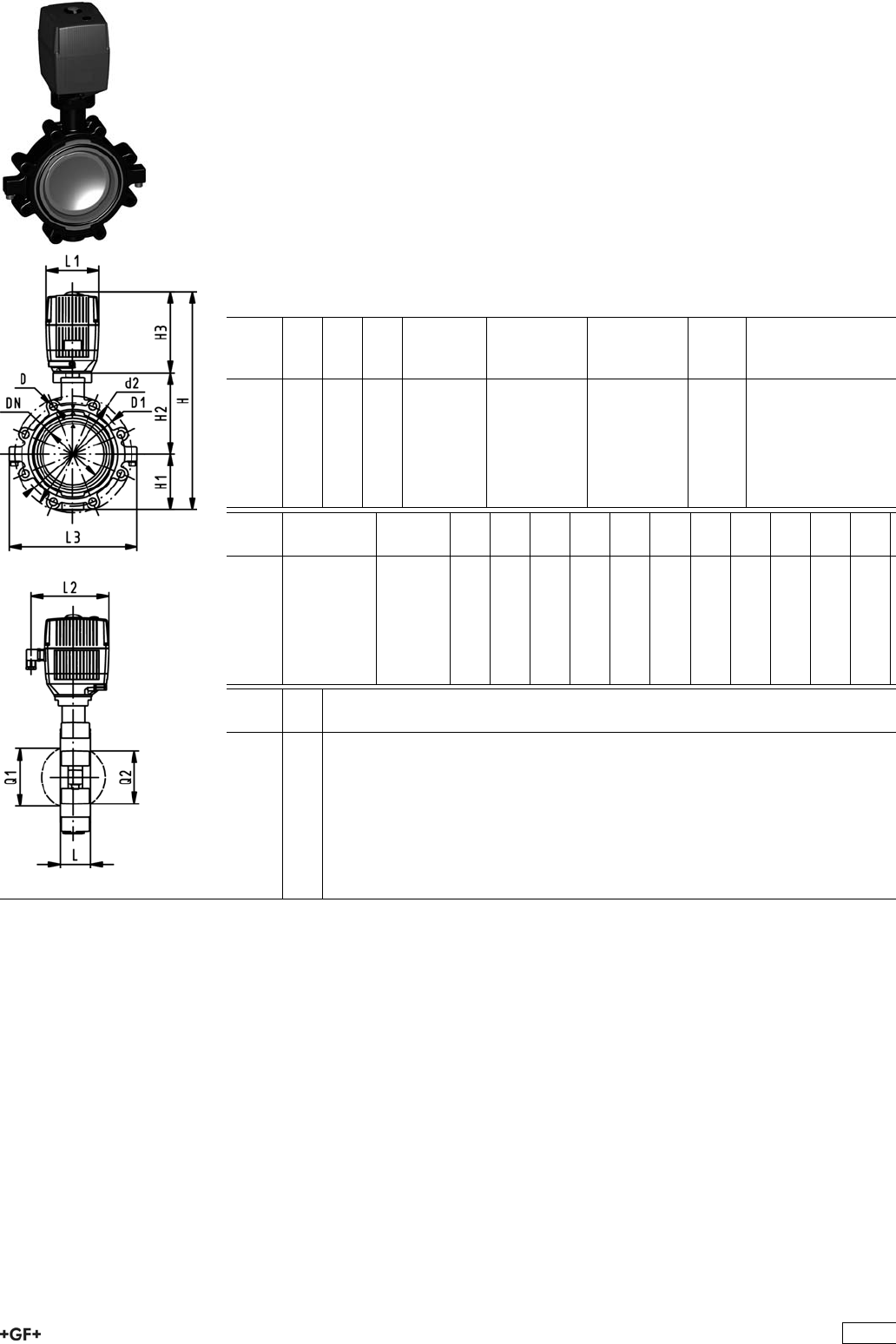
PROGEF Standard
Lugstyle butterfly valve type 142 100-230V
Without manual override
Model:
ÏMaterial: PP-H
ÏOuter body in GGG-40.3 epoxy-coated
ÏConnecting dimension ANSI/ASME B 16.5 Class 150
ÏOverall length according to EN 558, ISO 5752
ÏVoltage 100-230 V, 50-60 Hz
ÏControl time 15 s/90°<) EA31
ÏControl time 25s/90°<) EA42
ÏControl range 90°<)
ÏActuator with integrated emergency manual override standard
Inch DN
[mm]
d
[mm]
PN kv-value
(”p=1 bar)
[l/min]
EPDM
Code
FPM
Code
kg
2 50 63 10 1470 199 142 362 199 142 382 6.193
21
/265 75 10 2200 199 142 363 199 142 383 6.535
3 80 90 10 3000 199 142 364 199 142 384 6.911
4 100 110 10 6500 199 142 365 199 142 385 8.925
5 125 140 10 11500 199 142 366 199 142 386 10.755
6 150 160 10 16600 199 142 367 199 142 387 12.539
8 200 225 10 39600 199 142 368 199 142 388 21.747
Inch Actuator
unit type
D D1
[mm]
d2
[mm]
H
[mm]
H1
[mm]
H2
[mm]
H3
[mm]
L
[mm]
L1
[mm]
L2
[mm]
L3
[mm]
Q1
[mm]
2 EA-31 UNC 5/8 121 150 399 77 134 188 45 122 180 150 40
21
/2EA-31 UNC 5/8 140 170 411 83 140 188 46 122 180 160 54
3 EA-31 UNC 5/8 153 177 423 89 146 188 49 122 180 175 67
4 EA-31 UNC 5/8 191 216 459 104 167 188 56 122 180 244 88
5 EA-31 UNC 3/4 216 246 486 117 181 188 64 122 180 272 113
6 EA-31 UNC 3/4 242 273 507 130 189 188 72 122 180 297 139
8 EA-42 UNC 3/4 299 334 576 158 210 208 73 122 180 360 178
Inch Q2
[mm]
2
21
/235
3 50
4 74
5 97
6 123
8 169
295
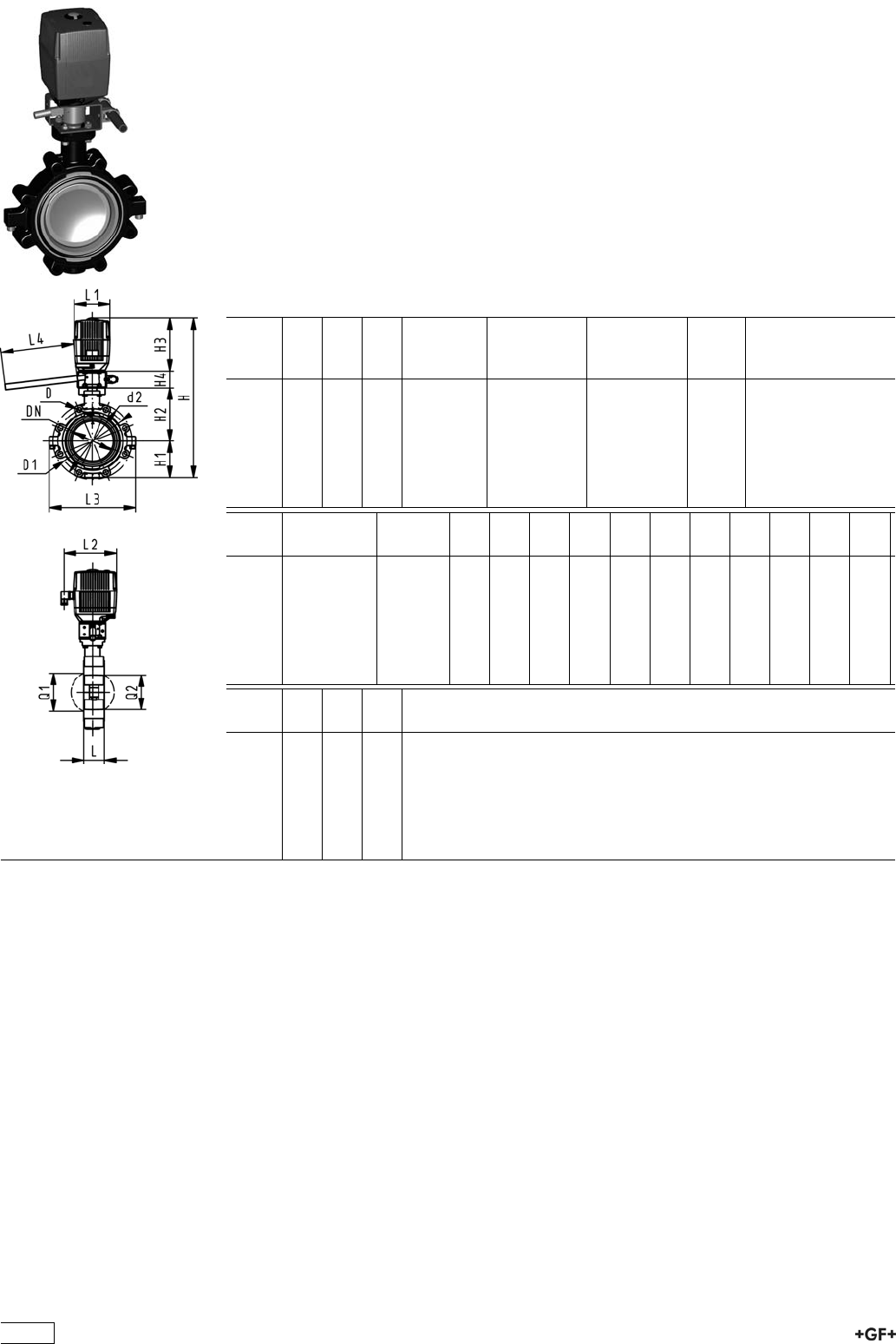
PROGEF Standard
Lugstyle butterfly valve type 142 100-230V
With manual override
Model:
ÏMaterial: PP-H
ÏOuter body in GGG-40.3 epoxy-coated
ÏConnecting dimension ANSI/ASME B 16.5 Class 150
ÏOverall length according to EN 558, ISO 5752
ÏVoltage 100-230 V, 50-60 Hz
ÏControl time 15 s/90°<) EA31
ÏControl time 25s/90°<) EA42
ÏControl range 90°<)
ÏActuator with integrated emergency manual override standard
Inch DN
[mm]
d
[mm]
PN kv-value
(”p=1 bar)
[l/min]
EPDM
Code
FPM
Code
kg
2 50 63 10 1470 199 142 322 199 142 342 6.193
21
/265 75 10 2200 199 142 323 199 142 343 6.535
3 80 90 10 3000 199 142 324 199 142 344 6.911
4 100 110 10 6500 199 142 325 199 142 345 8.925
5 125 140 10 11500 199 142 326 199 142 346 10.755
6 150 160 10 16600 199 142 327 199 142 347 12.539
8 200 225 10 39600 199 142 328 199 142 348 21.747
Inch Actuator
unit type
D D1
[mm]
d2
[mm]
H
[mm]
H1
[mm]
H2
[mm]
H3
[mm]
H4
[mm]
L
[mm]
L1
[mm]
L2
[mm]
L3
[mm]
2 EA-31 UNC 5/8 121 150 459 77 134 188 60 45 122 180 150
21
/2EA-31 UNC 5/8 140 170 471 83 140 188 60 46 122 180 160
3 EA-31 UNC 5/8 153 177 483 89 146 188 60 49 122 180 175
4 EA-31 UNC 5/8 191 216 519 104 167 188 60 56 122 180 244
5 EA-31 UNC 3/4 216 246 546 117 181 188 60 64 122 180 272
6 EA-31 UNC 3/4 242 273 567 130 189 188 60 72 122 180 297
8 EA-42 UNC 3/4 299 334 636 158 210 208 60 73 122 180 360
Inch L4
[mm]
Q1
[mm]
Q2
[mm]
2 200 40
21
/2200 54 35
3 200 67 50
4 250 88 74
5 250 113 97
6 250 139 123
8 250 178 169
296

PROGEF Standard
Lugstyle butterfly valve type 142 24V
Without manual override
Model:
ÏMaterial: PP-H
ÏOuter body in GGG-40.3 epoxy-coated
ÏConnecting dimension ANSI/ASME B 16.5 Class 150
ÏOverall length according to EN 558, ISO 5752
ÏVoltage 24 V AC/DC
ÏControl time 15 s/90°<) EA31
ÏControl time 25s/90°<) EA42
ÏControl range 90°<)
ÏActuator with integrated emergency manual override standard
Inch DN
[mm]
d
[mm]
PN kv-value
(”p=1 bar)
[l/min]
EPDM
Code
FPM
Code
kg
2 50 63 10 1470 199 142 442 199 142 462 6.193
21
/265 75 10 2200 199 142 443 199 142 463 6.535
3 80 90 10 3000 199 142 444 199 142 464 6.911
4 100 110 10 6500 199 142 445 199 142 465 8.925
5 125 140 10 11500 199 142 446 199 142 466 10.755
6 150 160 10 16600 199 142 447 199 142 467 12.539
8 200 225 10 39600 199 142 448 199 142 468 21.747
Inch Actuator
unit type
D D1
[mm]
d2
[mm]
H
[mm]
H1
[mm]
H2
[mm]
H3
[mm]
L
[mm]
L1
[mm]
L2
[mm]
L3
[mm]
Q1
[mm]
2 EA-31 UNC 5/8 121 150 399 77 134 188 45 122 180 150 40
21
/2EA-31 UNC 5/8 140 170 411 83 140 188 46 122 180 160 54
3 EA-31 UNC 5/8 153 177 423 89 146 188 49 122 180 175 67
4 EA-31 UNC 5/8 191 216 459 104 167 188 56 122 180 244 88
5 EA-31 UNC 3/4 216 246 486 117 181 188 64 122 180 272 113
6 EA-31 UNC 3/4 242 273 507 130 189 188 72 122 180 297 139
8 EA-42 UNC 3/4 299 334 576 158 210 208 73 122 180 360 178
Inch Q2
[mm]
2
21
/235
3 50
4 74
5 97
6 123
8 169
297

PROGEF Standard
Lugstyle butterfly valve type 142 24V
With manual override
Model:
ÏMaterial: PP-H
ÏOuter body in GGG-40.3 epoxy-coated
ÏConnecting dimension ANSI/ASME B 16.5 Class 150
ÏOverall length according to EN 558, ISO 5752
ÏVoltage 24 V AC/DC
ÏControl time 15 s/90°<) EA31
ÏControl time 25s/90°<) EA42
ÏControl range 90°<)
ÏActuator with integrated emergency manual override standard
Inch DN
[mm]
d
[mm]
PN kv-value
(”p=1 bar)
[l/min]
EPDM
Code
FPM
Code
kg
2 50 63 10 1470 199 142 402 199 142 422 6.193
21
/265 75 10 2200 199 142 403 199 142 423 6.535
3 80 90 10 3000 199 142 404 199 142 424 6.911
4 100 110 10 6500 199 142 405 199 142 425 8.925
5 125 140 10 11500 199 142 406 199 142 426 10.755
6 150 160 10 16600 199 142 407 199 142 427 12.539
8 200 225 10 39600 199 142 408 199 142 428 21.747
Inch Actuator
unit type
D D1
[mm]
d2
[mm]
H
[mm]
H1
[mm]
H2
[mm]
H3
[mm]
H4
[mm]
L
[mm]
L1
[mm]
L2
[mm]
L3
[mm]
2 EA-31 UNC 5/8 121 150 459 77 134 188 60 45 122 180 150
21
/2EA-31 UNC 5/8 140 170 471 83 140 188 60 46 122 180 160
3 EA-31 UNC 5/8 153 177 483 89 146 188 60 49 122 180 175
4 EA-31 UNC 5/8 191 216 519 104 167 188 60 56 122 180 244
5 EA-31 UNC 3/4 216 246 546 117 181 188 60 64 122 180 272
6 EA-31 UNC 3/4 242 273 567 130 189 188 60 72 122 180 297
8 EA-42 UNC 3/4 299 334 636 158 210 208 60 73 122 180 360
Inch L4
[mm]
Q1
[mm]
Q2
[mm]
2 200 40
21
/2200 54 35
3 200 67 50
4 250 88 74
5 250 113 97
6 250 139 123
8 250 178 169
298
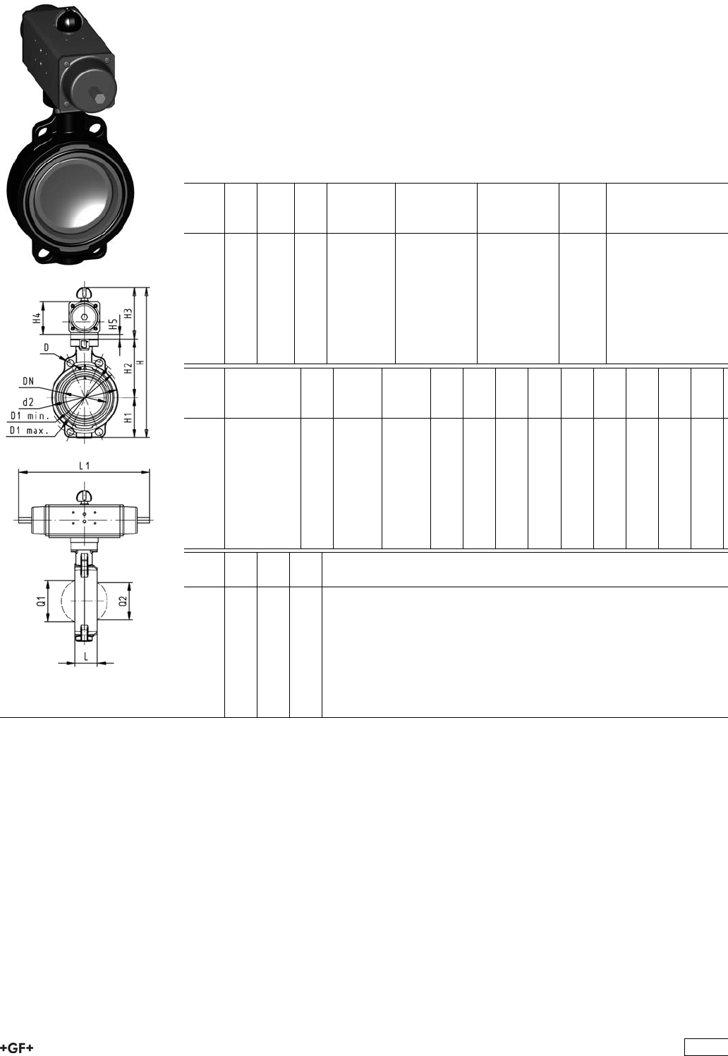
Butterfly Valves Pneumatic
Butterfly valve type 240 PP-H
FC (Fail safe to close)
Without manual override
Model:
ÏMaterial: PP-H
ÏConnecting dimension: ISO 7005 PN 10, EN 1092 PN 10, DIN 2501 PN 10,
ANSI/ASME B 16.5 Class 150, BS 1560: 1989, BS 4504, JIS B 2220
ÏOverall length according to EN 558, ISO 5752
ÏControl range 90°<)
d
[mm]
DN
[mm]
Inch PN kv-value
(”p=1 bar)
[l/min]
EPDM
Code
FPM
Code
kg
63 50 2 10 1470 199 240 282 199 240 302 3.147
75 65 2 1
/210 2200 199 240 283 199 240 303 3.239
90 80 3 10 3000 199 240 284 199 240 304 3.369
110 100 4 10 6500 199 240 285 199 240 305 5.079
140 125 5 10 11500 199 240 286 199 240 306 6.529
160 150 6 10 16600 199 240 287 199 240 307 9.640
225 200 8 10 39600 199 240 288 199 240 308 13.299
280 250 10 8 55200 199 240 289 199 240 309 26.888
315 300 12 8 80000 199 240 290 199 240 310 33.459
d
[mm]
Actuator
unit type
D
[mm]
D1
min.
[mm]
D1
max.
[mm]
d2
[mm]
H
[mm]
H1
[mm]
H2
[mm]
H3
[mm]
H4
[mm]
H5
[mm]
L
[mm]
L1
[mm]
63 PA-30 FC 19 120.0 125.0 104 327 77 134 117 70 15 45 276
75 PA-30 FC 19 139.7 145.0 115 340 83 140 117 70 15 46 276
90 PA-35 FC 19 150.0 160.0 131 361 89 146 126 78 15 49 326
110 PA-40 FC 19 175.0 190.5 161 400 104 167 129 86 56 370
140 PA-45 FC 23 210.0 215.9 187 436 117 181 139 96 64 411
160 PA-50 FC 24 241.3 241.3 215 468 130 189 149 106 72 423
225 PA-55 FC 23 290.0 295.0 267 529 158 210 161 118 73 452
280 PA-65 FC 25 353.0 362.0 329 808 205 264 191 148 113 648
315 PA-70 FC 25 400.0 432.0 379 866 228 285 196 157 113 663
d
[mm]
L2
[mm]
Q1
[mm]
Q2
[mm]
63 65 40
75 65 54 35
90 72 67 50
110 80 88 74
140 90 113 97
160 100 139 123
225 112 178 169
280 137 210 207
315 145 256 253
299
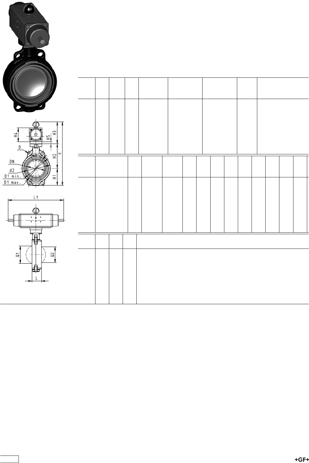
Butterfly valve type 240 PP-H
FO (Fail safe to open)
Without manual override
Model:
ÏMaterial: PP-H
ÏConnecting dimension: ISO 7005 PN 10, EN 1092 PN 10, DIN 2501 PN 10,
ANSI/ASME B 16.5 Class 150, BS 1560: 1989, BS 4504, JIS B 2220
ÏOverall length according to EN 558, ISO 5752
ÏControl range 90°<)
d
[mm]
DN
[mm]
Inch PN kv-value
(”p=1 bar)
[l/min]
EPDM
Code
FPM
Code
kg
63 50 2 10 1470 199 240 322 199 240 342 3.147
75 65 2 1
/210 2200 199 240 323 199 240 343 3.239
90 80 3 10 3000 199 240 324 199 240 344 3.369
110 100 4 10 6500 199 240 325 199 240 345 5.079
140 125 5 10 11500 199 240 326 199 240 346 6.529
160 150 6 10 16600 199 240 327 199 240 347 9.640
225 200 8 10 39600 199 240 328 199 240 348 13.299
280 250 10 8 55200 199 240 329 199 240 349 30.484
315 300 12 8 80000 199 240 330 199 240 350 33.459
d
[mm]
Actuator
unit type
D
[mm]
D1
min.
[mm]
D1
max.
[mm]
d2
[mm]
H
[mm]
H1
[mm]
H2
[mm]
H3
[mm]
H4
[mm]
H5
[mm]
L
[mm]
L1
[mm]
63 PA-30 FO 19 120.0 125.0 104 327 77 134 117 70 15 45 276
75 PA-30 FO 19 139.7 145.0 115 340 83 140 117 70 15 46 276
90 PA-35 FO 19 150.0 160.0 131 361 89 146 126 78 15 49 326
110 PA-40 FO 19 175.0 190.5 161 400 104 167 129 86 56 370
140 PA-45 FO 23 210.0 215.9 187 436 117 181 139 96 64 411
160 PA-50 FO 24 241.3 241.3 215 468 130 189 149 106 72 423
225 PA-55 FO 23 290.0 295.0 267 529 158 210 161 118 73 452
280 PA-65 FO 25 353.0 362.0 329 808 205 264 191 148 113 648
315 PA-70 FO 25 400.0 432.0 379 866 228 285 196 157 113 663
d
[mm]
L2
[mm]
Q1
[mm]
Q2
[mm]
63 65 40
75 65 54 35
90 72 67 50
110 80 88 74
140 90 113 97
160 100 139 123
225 112 178 169
280 137 210 207
315 145 256 253
300
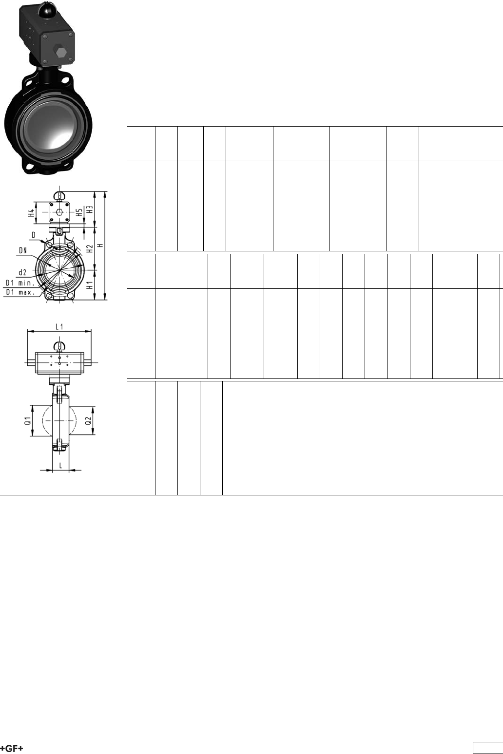
Butterfly valve type 240 PP-H
DA (Double acting)
Without manual override
Model:
ÏMaterial: PP-H
ÏConnecting dimension: ISO 7005 PN 10, EN 1092 PN 10, DIN 2501 PN 10,
ANSI/ASME B 16.5 Class 150, BS 1560: 1989, BS 4504, JIS B 2220
ÏOverall length according to EN 558, ISO 5752
ÏControl range 90°<)
d
[mm]
DN
[mm]
Inch PN kv-value
(”p=1 bar)
[l/min]
EPDM
Code
FPM
Code
kg
63 50 2 10 1470 199 240 362 199 240 382 1.997
75 65 2 1
/210 2200 199 240 363 199 240 383 2.089
90 80 3 10 3000 199 240 364 199 240 384 2.700
110 100 4 10 6500 199 240 365 199 240 385 3.331
140 125 5 10 11500 199 240 366 199 240 386 3.779
160 150 6 10 16600 199 240 367 199 240 387 6.119
225 200 8 10 39600 199 240 368 199 240 388 7.299
280 250 10 8 55200 199 240 369 199 240 389 18.188
315 300 12 8 80000 199 240 370 199 240 390 24.263
d
[mm]
Actuator
unit type
D
[mm]
D1
min.
[mm]
D1
max.
[mm]
d2
[mm]
H
[mm]
H1
[mm]
H2
[mm]
H3
[mm]
H4
[mm]
H5
[mm]
L
[mm]
L1
[mm]
63 PA-35 DA 19 120.0 125.0 104 317 77 134 107 60 15 45 177
75 PA-35 DA 19 139.7 145.0 115 330 83 140 107 60 15 46 177
90 PA-40 DA 19 150.0 160.0 131 348 89 146 113 66 15 49 190
110 PA-45 DA 19 175.0 190.5 161 372 104 167 102 71 56 235
140 PA-45 DA 23 210.0 215.9 187 408 117 181 111 78 64 235
160 PA-55 DA 24 241.3 241.3 215 448 130 189 129 86 72 279
225 PA-55 DA 23 290.0 295.0 267 507 158 210 139 96 73 279
280 PA-65 DA 25 353.0 362.0 329 748 205 264 161 118 113 350
315 PA-70 DA 25 400.0 432.0 379 816 228 285 173 130 113 381
d
[mm]
L2
[mm]
Q1
[mm]
Q2
[mm]
63 55 40
75 55 54 35
90 60 67 50
110 65 88 74
140 72 113 97
160 80 139 123
225 90 178 169
280 112 210 207
315 125 256 253
301

PROGEF Standard
Lugstyle butterfly valve type 241
FC (Fail safe to close)
Without manual override
Model:
ÏMaterial: PP-H
ÏOuter body in GGG-40.3 epoxy-coated
ÏConnecting dimension: ISO 7005 PN10, EN 1092 PN10, DIN 2501 PN10
ÏOverall length according to EN 558, ISO 5752
ÏControl range 90°<)
d
[mm]
DN
[mm]
Inch PN kv-value
(”p=1 bar)
[l/min]
EPDM
Code
FPM
Code
kg
63 50 2 10 1470 199 241 282 199 241 302 5.233
75 65 2 1
/210 2200 199 241 283 199 241 303 5.575
90 80 3 10 3000 199 241 284 199 241 304 6.580
110 100 4 10 6500 199 241 285 199 241 305 9.163
140 125 5 10 11500 199 241 286 199 241 306 11.995
160 150 6 10 16600 199 241 287 199 241 307 16.100
225 200 8 10 39600 199 241 288 199 241 308 23.247
d
[mm]
Actuator
unit type
D D1
[mm]
d2
[mm]
H
[mm]
H1
[mm]
H2
[mm]
H3
[mm]
H4
[mm]
H5
[mm]
L
[mm]
L1
[mm]
L2
[mm]
L3
[mm]
63 PA-30 FC M16 125 150 328 77 134 117 70 15 45 276 65 150
75 PA-30 FC M16 145 170 340 83 140 117 70 15 46 276 65 160
90 PA-35 FC M16 160 184 361 89 146 126 78 15 49 326 72 205
110 PA-40 FC M16 180 216 400 104 167 129 86 56 370 80 244
140 PA-45 FC M16 210 246 437 117 181 139 96 64 411 90 272
160 PA-50 FC M20 240 273 468 130 189 149 106 72 423 100 297
225 PA-55 FC M20 295 334 529 158 210 161 118 73 452 112 360
d
[mm]
Q1
[mm]
Q2
[mm]
63 40
75 54 35
90 67 50
110 88 74
140 113 97
160 139 123
225 178 169
302

PROGEF Standard
Lugstyle butterfly valve type 241
FO (Fail safe to open)
Without manual override
Model:
ÏMaterial: PP-H
ÏOuter body in GGG-40.3 epoxy-coated
ÏConnecting dimension: ISO 7005 PN10, EN 1092 PN10, DIN 2501 PN10
ÏOverall length according to EN 558, ISO 5752
ÏControl range 90°<)
d
[mm]
DN
[mm]
Inch PN kv-value
(”p=1 bar)
[l/min]
EPDM
Code
FPM
Code
kg
63 50 2 10 1470 199 241 322 199 241 342 5.233
75 65 2 1
/210 2200 199 241 323 199 241 343 5.575
90 80 3 10 3000 199 241 324 199 241 344 6.580
110 100 4 10 6500 199 241 325 199 241 345 9.163
140 125 5 10 11500 199 241 326 199 241 346 11.995
160 150 6 10 16600 199 241 327 199 241 347 16.100
225 200 8 10 39600 199 241 328 199 241 348 23.247
d
[mm]
Actuator
unit type
D D1
[mm]
d2
[mm]
H
[mm]
H1
[mm]
H2
[mm]
H3
[mm]
H4
[mm]
H5
[mm]
L
[mm]
L1
[mm]
L2
[mm]
L3
[mm]
63 PA-30 FO M16 125 150 328 77 134 117 70 15 45 276 65 150
75 PA-30 FO M16 145 170 340 83 140 117 70 15 46 276 65 160
90 PA-35 FO M16 160 184 361 89 146 126 78 15 49 326 72 205
110 PA-40 FO M16 180 216 400 104 167 129 86 56 370 80 244
140 PA-45 FO M16 210 246 437 117 181 139 96 64 411 90 272
160 PA-50 FO M20 240 273 468 130 189 149 106 72 423 100 297
225 PA-55 FO M20 295 334 529 158 210 161 118 73 452 112 360
d
[mm]
Q1
[mm]
Q2
[mm]
63 40
75 54 35
90 67 50
110 88 74
140 113 97
160 139 123
225 178 169
303
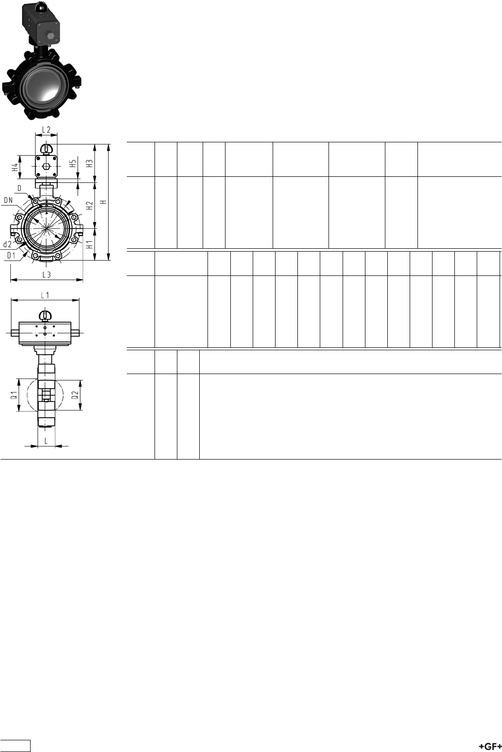
PROGEF Standard
Lugstyle butterfly valve type 241
DA (Double acting)
Without manual override
Model:
ÏMaterial: PP-H
ÏOuter body in GGG-40.3 epoxy-coated
ÏConnecting dimension: ISO 7005 PN10, EN 1092 PN10, DIN 2501 PN10
ÏOverall length according to EN 558, ISO 5752
ÏControl range 90°<)
d
[mm]
DN
[mm]
Inch PN kv-value
(”p=1 bar)
[l/min]
EPDM
Code
FPM
Code
kg
63 50 2 10 1470 199 241 362 199 241 382 4.083
75 65 2 1
/210 2200 199 241 363 199 241 383 4.425
90 80 3 10 3000 199 241 364 199 241 384 5.911
110 100 4 10 6500 199 241 365 199 241 385 7.415
140 125 5 10 11500 199 241 366 199 241 386 9.245
160 150 6 10 16600 199 241 367 199 241 387 12.579
225 200 8 10 39600 199 241 368 199 241 388 17.247
d
[mm]
Actuator
unit type
D D1
[mm]
d2
[mm]
H
[mm]
H1
[mm]
H2
[mm]
H3
[mm]
H4
[mm]
H5
[mm]
L
[mm]
L1
[mm]
L2
[mm]
L3
[mm]
63 PA-35 DA M16 125 150 318 77 134 107 60 15 45 177 55 150
75 PA-35 DA M16 145 170 330 83 140 107 60 15 46 177 55 160
90 PA-40 DA M16 160 184 348 89 146 113 66 15 49 190 60 205
110 PA-45 DA M16 180 216 373 104 167 102 71 56 235 65 244
140 PA-45 DA M16 210 246 409 117 181 111 78 64 235 72 272
160 PA-55 DA M20 240 273 448 130 189 129 86 72 279 80 297
225 PA-55 DA M20 295 334 507 158 210 139 96 73 279 90 360
d
[mm]
Q1
[mm]
Q2
[mm]
63 40
75 54 35
90 67 50
110 88 74
140 113 97
160 139 123
225 178 169
304
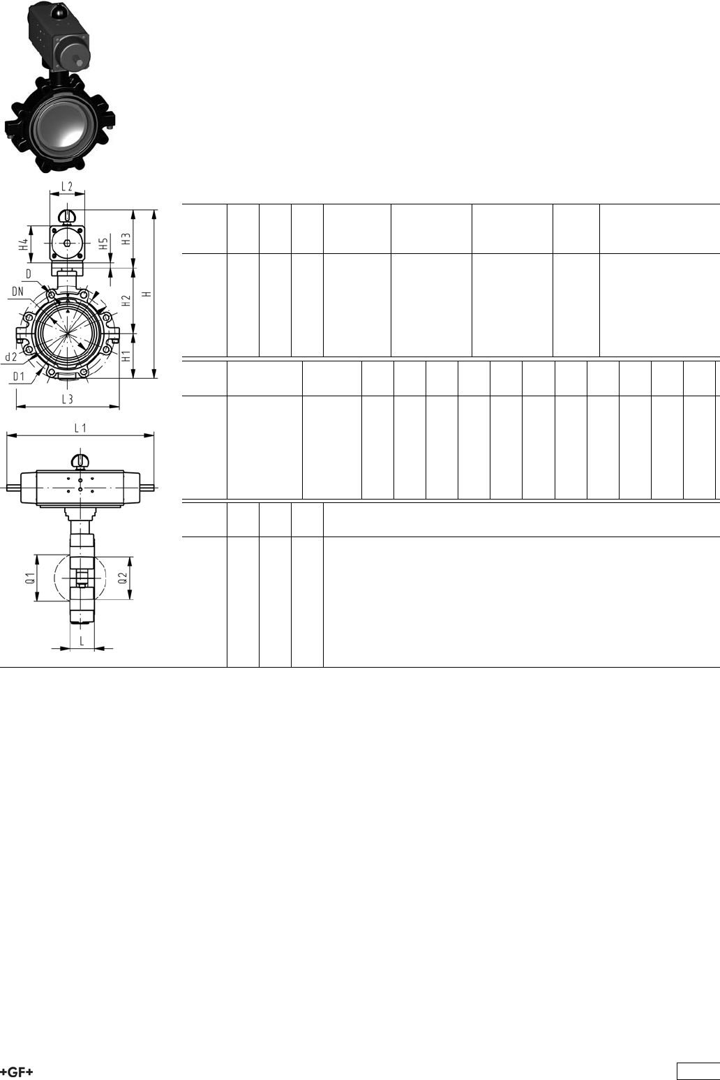
PROGEF Standard
Lugstyle butterfly valve type 242
FC (Fail safe to close)
Without manual override
Model:
ÏMaterial: PP-H
ÏOuter body in GGG-40.3 epoxy-coated
ÏConnecting dimension ANSI/ASME B 16.5 Class 150
ÏOverall length according to EN 558, ISO 5752
ÏControl range 90°<)
Inch DN
[mm]
d
[mm]
PN kv-value
(”p=1 bar)
[l/min]
EPDM
Code
FPM
Code
kg
2 50 63 10 1470 199 242 282 199 242 302 5.233
21
/265 75 10 2200 199 242 283 199 242 303 5.575
3 80 90 10 3000 199 242 284 199 242 304 5.951
4 100 110 10 6500 199 242 285 199 242 305 9.163
5 125 140 10 11500 199 242 286 199 242 306 11.995
6 150 160 10 16600 199 242 287 199 242 307 16.100
8 200 225 10 39600 199 242 288 199 242 308 23.247
Inch Actuator
unit type
D D1
[mm]
d2
[mm]
H
[mm]
H1
[mm]
H2
[mm]
H3
[mm]
H4
[mm]
H5
[mm]
L
[mm]
L1
[mm]
L2
[mm]
2 PA-30 FC UNC 5/8 121 150 328 77 134 117 70 15 45 276 65
21
/2PA-30 FC UNC 5/8 140 170 340 83 140 117 70 15 46 276 65
3 PA-35 FC UNC 5/8 153 177 361 89 146 126 78 15 49 326 72
4 PA-40 FC UNC 5/8 191 216 400 104 167 129 86 56 370 80
5 PA-45 FC UNC 3/4 216 246 437 117 181 139 96 64 411 90
6 PA-50 FC UNC 3/4 242 273 468 130 189 149 106 72 423 100
8 PA-55 FC UNC 3/4 299 334 529 158 210 161 118 73 452 112
Inch L3
[mm]
Q1
[mm]
Q2
[mm]
2 150 40
21
/2160 54 35
3 175 67 50
4 244 88 74
5 272 113 97
6 297 139 123
8 360 178 169
305
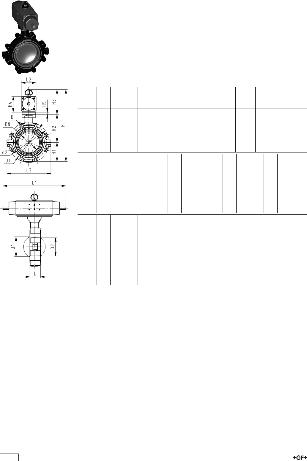
PROGEF Standard
Lugstyle butterfly valve type 242
FO (Fail safe to open)
Without manual override
Model:
ÏMaterial: PP-H
ÏOuter body in GGG-40.3 epoxy-coated
ÏConnecting dimension ANSI/ASME B 16.5 Class 150
ÏOverall length according to EN 558, ISO 5752
ÏControl range 90°<)
Inch DN
[mm]
d
[mm]
PN kv-value
(”p=1 bar)
[l/min]
EPDM
Code
FPM
Code
kg
2 50 63 10 1470 199 242 322 199 242 342 5.233
21
/265 75 10 2200 199 242 323 199 242 343 5.575
3 80 90 10 3000 199 242 324 199 242 344 5.951
4 100 110 10 6500 199 242 325 199 242 345 9.163
5 125 140 10 11500 199 242 326 199 242 346 11.995
6 150 160 10 16600 199 242 327 199 242 347 16.100
8 200 225 10 39600 199 242 328 199 242 348 23.247
Inch Actuator
unit type
D D1
[mm]
d2
[mm]
H
[mm]
H1
[mm]
H2
[mm]
H3
[mm]
H4
[mm]
H5
[mm]
L
[mm]
L1
[mm]
L2
[mm]
2 PA-30 FO UNC 5/8 121 150 328 77 134 117 70 15 45 276 65
21
/2PA-30 FO UNC 5/8 140 170 340 83 140 117 70 15 46 276 65
3 PA-35 FO UNC 5/8 153 177 361 89 146 126 78 15 49 326 72
4 PA-40 FO UNC 5/8 191 216 400 104 167 129 86 56 370 80
5 PA-45 FO UNC 3/4 216 246 437 117 181 139 96 64 411 90
6 PA-50 FO UNC 3/4 242 273 468 130 189 149 106 72 423 100
8 PA-55 FO UNC 3/4 299 334 529 158 210 161 118 73 452 112
Inch L3
[mm]
Q1
[mm]
Q2
[mm]
2 150 40
21
/2160 54 35
3 175 67 50
4 244 88 74
5 272 113 97
6 297 139 123
8 360 178 169
306
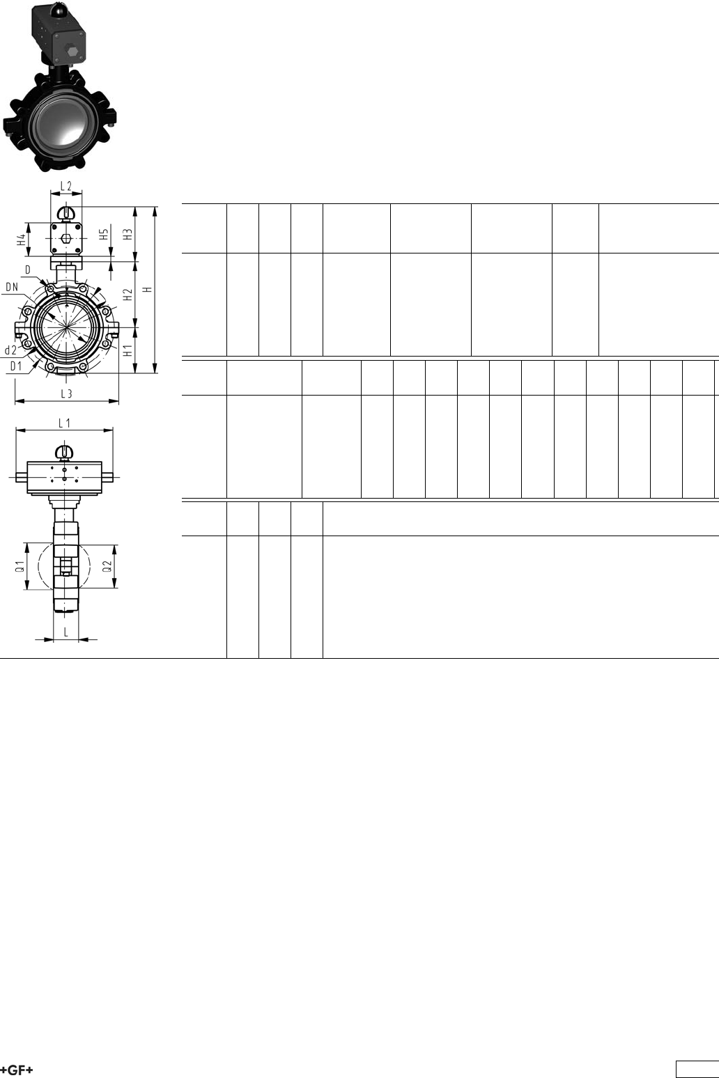
PROGEF Standard
Lugstyle butterfly valve type 242
DA (Double acting)
Without manual override
Model:
ÏMaterial: PP-H
ÏOuter body in GGG-40.3 epoxy-coated
ÏConnecting dimension ANSI/ASME B 16.5 Class 150
ÏOverall length according to EN 558, ISO 5752
ÏControl range 90°<)
Inch DN
[mm]
d
[mm]
PN kv-value
(”p=1 bar)
[l/min]
EPDM
Code
FPM
Code
kg
2 50 63 10 1470 199 242 362 199 242 382 4.083
21
/265 75 10 2200 199 242 363 199 242 383 4.425
3 80 90 10 3000 199 242 364 199 242 384 5.282
4 100 110 10 6500 199 242 365 199 242 385 7.415
5 125 140 10 11500 199 242 366 199 242 386 9.245
6 150 160 10 16600 199 242 367 199 242 387 12.579
8 200 225 10 39600 199 242 368 199 242 388 17.247
Inch Actuator
unit type
D D1
[mm]
d2
[mm]
H
[mm]
H1
[mm]
H2
[mm]
H3
[mm]
H4
[mm]
H5
[mm]
L
[mm]
L1
[mm]
L2
[mm]
2 PA-35 DA UNC 5/8 121 150 318 77 134 107 60 15 45 177 55
21
/2PA-35 DA UNC 5/8 140 170 330 83 140 107 60 15 46 177 55
3 PA-40 DA UNC 5/8 153 177 348 89 146 113 66 15 49 190 60
4 PA-45 DA UNC 5/8 191 216 373 104 167 102 71 56 235 65
5 PA-45 DA UNC 3/4 216 246 409 117 181 111 78 64 235 72
6 PA-55 DA UNC 3/4 242 273 448 130 189 129 86 72 279 80
8 PA-55 DA UNC 3/4 299 334 507 158 210 139 96 73 279 90
Inch L3
[mm]
Q1
[mm]
Q2
[mm]
2 150 40
21
/2160 54 35
3 175 67 50
4 244 88 74
5 272 113 97
6 297 139 123
8 360 178 169
307
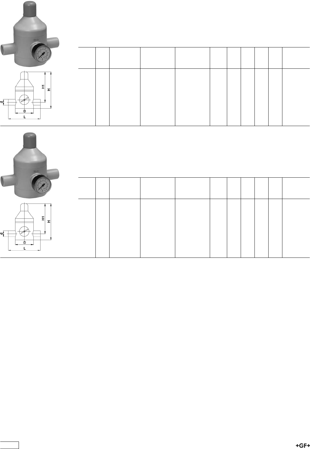
Process Control Valves
PROGEF Standard
Pressure reducing valve type V182
With fusion spigots metric
Model:
ÏMaterial: PP-H
d
[mm]
DN
[mm]
Pressure
range
[bar]
EPDM
Code
FPM
Code
kg D
[mm]
L
[mm]
H
[mm]
H1
[mm]
16 10 0.5 - 10 199 041 621 199 041 631 0.540 70 134 130 100
20 15 0.5 - 10 199 041 622 199 041 632 0.540 70 134 130 100
25 20 0.5 - 10 199 041 623 199 041 633 1.020 100 174 180 134
32 25 0.5 - 10 199 041 624 199 041 634 1.300 100 174 180 134
40 32 0.5 - 10 199 041 625 199 041 635 2.240 130 224 230 175
50 40 0.5 - 10 199 041 626 199 041 636 2.240 130 224 230 175
Pressure reducing valve type V 82 PP-H
With fusion spigots metric
Model:
ÏMaterial: PP-H
d
[mm]
DN
[mm]
Pressure
range
[bar]
EPDM
Code
PTFE
Code
kg D
[mm]
L
[mm]
H
[mm]
H1
[mm]
16 10 0.5 - 10 199 041 032 199 041 042 0.550 70 134 130 100
20 15 0.5 - 10 199 041 033 199 041 043 0.550 70 134 130 100
25 20 0.5 - 10 199 041 034 199 041 044 1.030 100 174 180 134
32 25 0.5 - 10 199 041 035 199 041 045 1.300 100 174 180 134
40 32 0.5 - 10 199 041 036 199 041 046 2.240 130 224 230 175
50 40 0.5 - 10 199 041 037 199 041 047 2.240 130 224 230 175
308
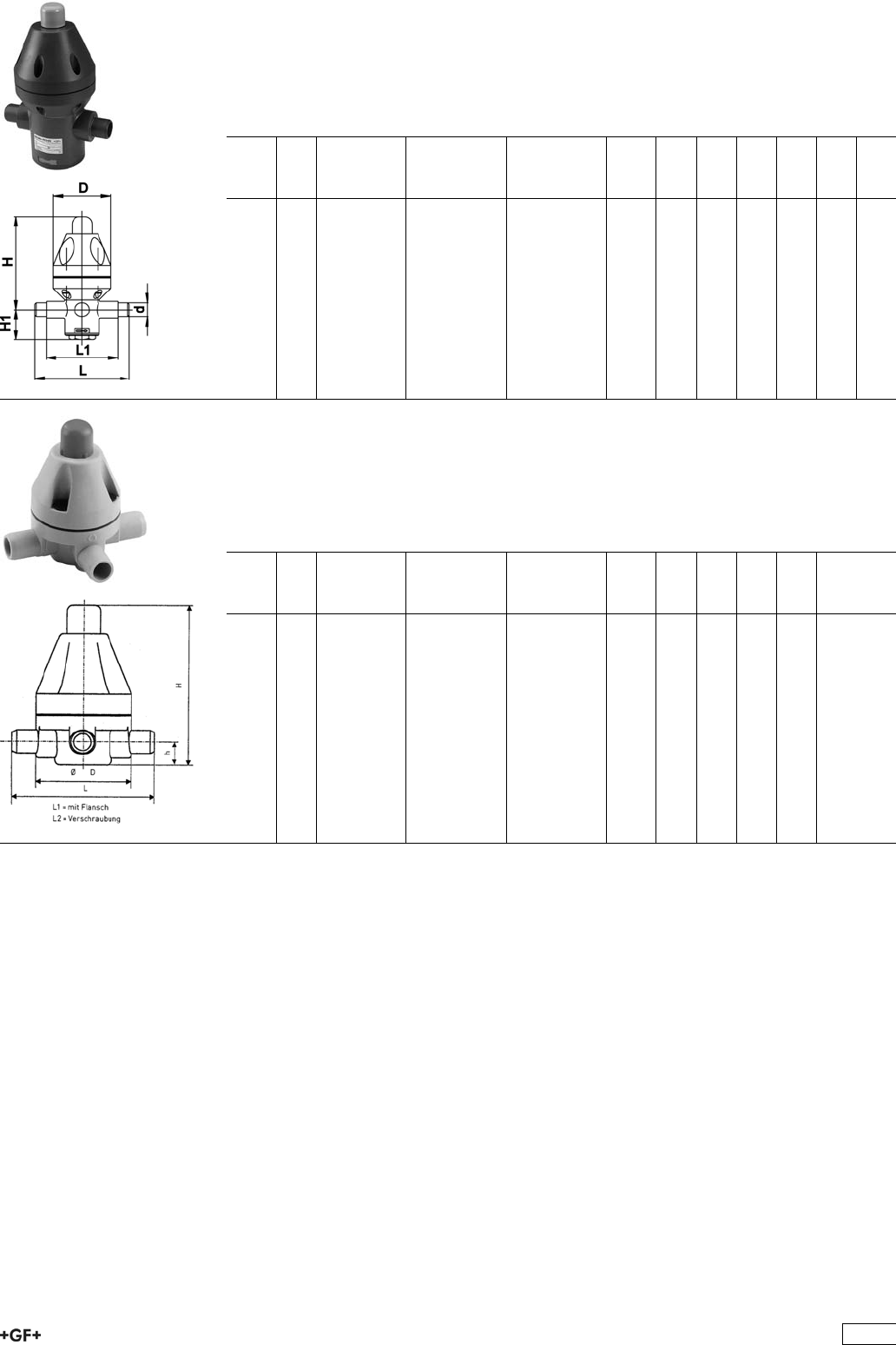
PROGEF Standard
Pressure reducing valve type V782
With fusion spigots metric
Model:
ÏMaterial: PP-H
d
[mm]
DN
[mm]
Pressure
range
[bar]
EPDM
Code
PTFE
Code
kg D
[mm]
L
[mm]
L1
[mm]
H
[mm]
H1
[mm]
16 10 0.5 - 10 199 041 072 199 041 078 0.450 83 134 102 138 48
20 15 0.5 - 10 199 041 073 199 041 079 0.460 83 134 102 138 48
25 20 0.5 - 10 199 041 074 199 041 080 1.240 113 154 110 205 65
32 25 0.5 - 10 199 041 075 199 041 081 1.250 113 154 110 205 65
40 32 0.5 - 10 199 041 076 199 041 082 3.910 165 224 162 248 95
50 40 0.5 - 10 199 041 077 199 041 083 3.930 165 224 162 248 95
PROGEF Standard
Pressure relief valve type V185
With fusion spigots metric
Model:
ÏMaterial: PP-H
d
[mm]
DN
[mm]
Pressure
range
[bar]
EPDM
Code
PTFE
Code
kg D
[mm]
L
[mm]
H
[mm]
H1
[mm]
16 10 0.5 - 10 199 041 367 199 041 337 0.300 83 134 137 20
20 15 0.5 - 10 199 041 368 199 041 338 0.300 83 134 137 20
25 20 0.5 - 10 199 041 369 199 041 339 0.300 83 134 137 20
32 25 0.5 - 10 199 041 370 199 041 340 0.900 112 174 199 27
40 32 0.5 - 10 199 041 371 199 041 341 0.900 112 174 199 43
50 40 0.5 - 10 199 041 372 199 041 342 4.400 165 224 290 43
63 50 0.5 - 10 199 041 373 199 041 343 4.500 165 244 290 43
309
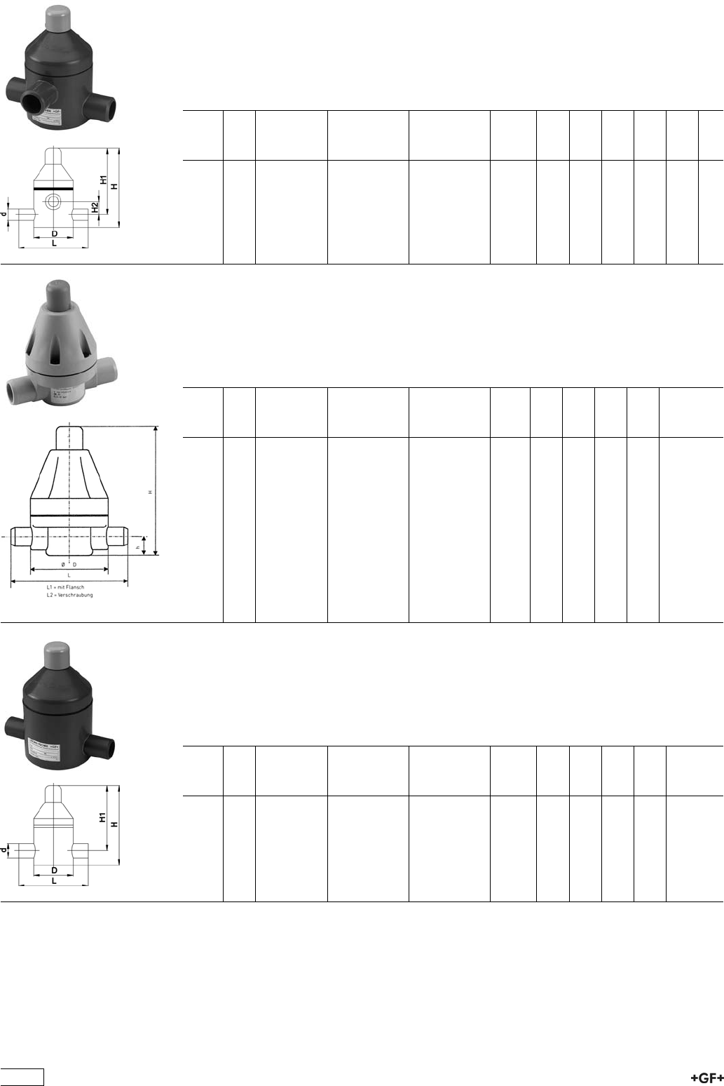
PROGEF Standard
Pressure relief valve type V85
With fusion spigots metric
Model:
ÏMaterial: PP-H
d
[mm]
DN
[mm]
Pressure
range
[bar]
EPDM
Code
PTFE
Code
kg D
[mm]
L
[mm]
H
[mm]
H1
[mm]
H2
[mm]
75 65 1.0 - 6 199 041 926 199 041 895 6.300 180 284 295 250 70
90 80 1.0 - 6 199 041 893 199 041 896 9.500 200 300 400 340 95
110 100 1.0 - 4 199 041 894 199 041 897 19.900 250 380 475 405 110
PROGEF Standard
Pressure retaining valve type V186
With fusion spigots metric
Model:
ÏMaterial: PP-H
d
[mm]
DN
[mm]
Pressure
range
[bar]
EPDM
Code
PTFE
Code
kg D
[mm]
L
[mm]
H
[mm]
H1
[mm]
16 10 0.5 - 10 199 041 386 199 041 316 0.300 83 134 137 20
20 15 0.5 - 10 199 041 387 199 041 317 0.300 83 134 137 20
25 20 0.5 - 10 199 041 388 199 041 318 0.300 83 134 137 20
32 25 0.5 - 10 199 041 389 199 041 319 0.900 112 174 199 27
40 32 0.5 - 10 199 041 390 199 041 320 0.900 112 174 199 43
50 40 0.5 - 10 199 041 391 199 041 321 4.400 165 224 290 43
63 50 0.5 - 10 199 041 392 199 041 322 4.500 165 244 290 43
PROGEF Standard
Pressure retaining valve type V86
With fusion spigots metric
Model:
ÏMaterial: PP-H
d
[mm]
DN
[mm]
Pressure
range
[bar]
EPDM
Code
PTFE
Code
kg D
[mm]
L
[mm]
H
[mm]
H1
[mm]
75 65 0.2 - 4 199 041 882 199 041 887 5.900 180 284 275 230
75 65 1.0 - 6 199 041 883 199 041 888 5.900 180 284 275 230
90 80 0.2 - 4 199 041 884 199 041 889 12.900 250 360 410 320
90 80 1.0 - 6 199 041 885 199 041 890 12.900 250 360 410 320
110 100 1.0 - 4 199 041 886 199 041 891 14.500 250 380 485 415
310
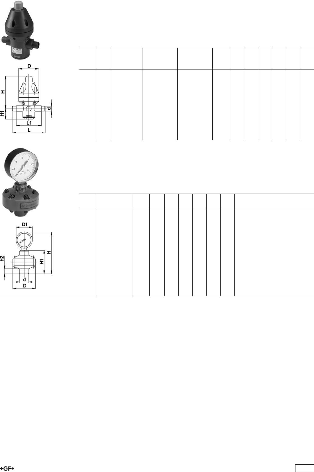
PROGEF Standard
Pressure retaining valve type V786
With fusion spigots metric
Model:
ÏMaterial: PP-H
d
[mm]
DN
[mm]
Pressure
range
[bar]
EPDM
Code
PTFE
Code
kg D
[mm]
L
[mm]
L1
[mm]
H
[mm]
H1
[mm]
16 10 0.5 - 10 199 041 102 199 041 108 0.450 83 134 102 138 38
20 15 0.5 - 10 199 041 103 199 041 109 0.450 83 134 102 138 38
25 20 0.5 - 10 199 041 104 199 041 110 1.280 112 154 110 205 55
32 25 0.5 - 10 199 041 105 199 041 111 1.280 112 154 110 205 55
40 32 0.5 - 4 199 041 106 199 041 112 3.480 165 224 162 248 85
50 40 0.5 - 4 199 041 107 199 041 113 3.480 165 224 162 248 85
PROGEF Standard
Gauge guard type Z700
With manometer 0-10 bar
Model:
ÏMaterial: PP-H
d
[mm]
PTFE
Code
kg G_R D
[mm]
D1
[mm]
H
[mm]
H1
[mm]
H2
[mm]
25 199 041 002 0.250 1
/472 63 129 71 15
32 199 041 003 0.540 1
/2100 100 210 90 22
311
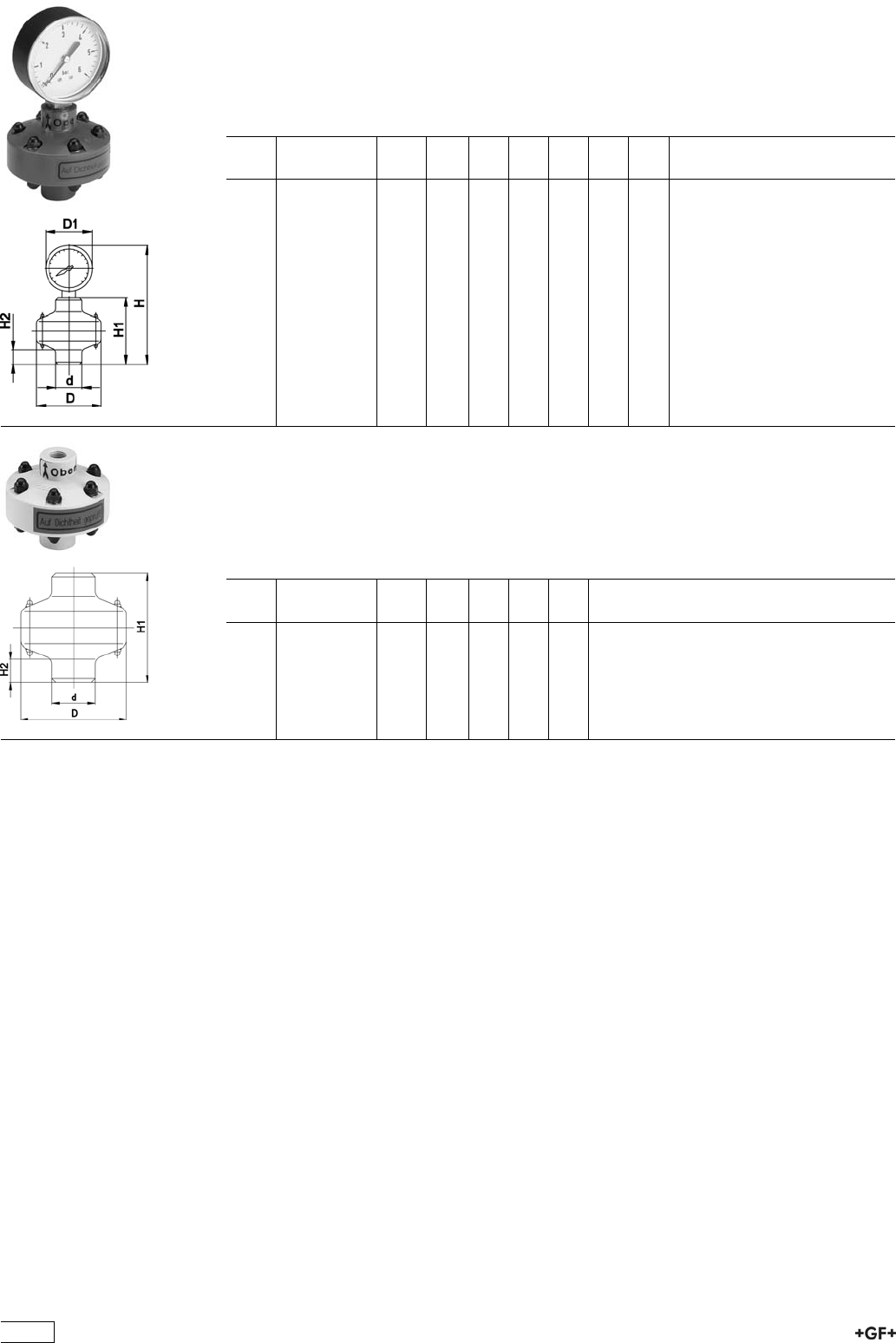
PROGEF Standard
Gauge guard type Z700
With manometer 0-6 bar
Model:
ÏMaterial: PP-H
d
[mm]
PTFE
Code
kg G_R D
[mm]
D1
[mm]
H
[mm]
H1
[mm]
H2
[mm]
25 199 041 294 0.250 1
/472 63 129 71 15
32 199 041 295 0.540 1
/2100 100 210 90 22
PROGEF Standard
Gauge guard type Z701
Without manometer
Model:
ÏMaterial: PP-H
d
[mm]
PTFE
Code
kg G_R D
[mm]
H1
[mm]
H2
[mm]
25 199 041 008 0.100 1
/472 71 15
32 199 041 009 0.170 1
/2100 90 22
312

PROGEF Standard
Ventilating and bleed valve type V91
With fusion spigots metric
Model:
ÏMaterial: PP-H
d
[mm]
DN
[mm]
PN FPM
Code
kg D
[mm]
L
[mm]
L1
[mm]
16 10 10 199 041 247 0.070 35 114 14
20 15 10 199 041 248 0.100 40 124 16
25 20 10 199 041 249 0.140 45 144 19
32 25 10 199 041 250 0.200 55 154 22
40 32 10 199 041 251 0.390 70 174 26
50 40 10 199 041 252 0.500 80 194 31
63 50 10 199 041 253 0.910 95 224 38
75 65 10 199 041 254 1.360 115 284 44
90 80 10 199 041 255 2.300 150 300 51
PROGEF Standard
Ventilating valve type V95
With fusion spigots metric
Model:
ÏMaterial: PP-H
d
[mm]
DN
[mm]
PN FPM
Code
kg D
[mm]
L
[mm]
L1
[mm]
16 10 10 199 041 274 0.070 35 114 14
20 15 10 199 041 275 0.100 40 124 16
25 20 10 199 041 276 0.140 45 144 19
32 25 10 199 041 277 0.200 55 154 22
40 32 10 199 041 278 0.390 70 174 26
50 40 10 199 041 279 0.500 80 194 31
63 50 10 199 041 280 0.910 95 224 38
75 65 10 199 041 281 1.360 115 284 44
90 80 10 199 041 282 2.300 150 300 51
313
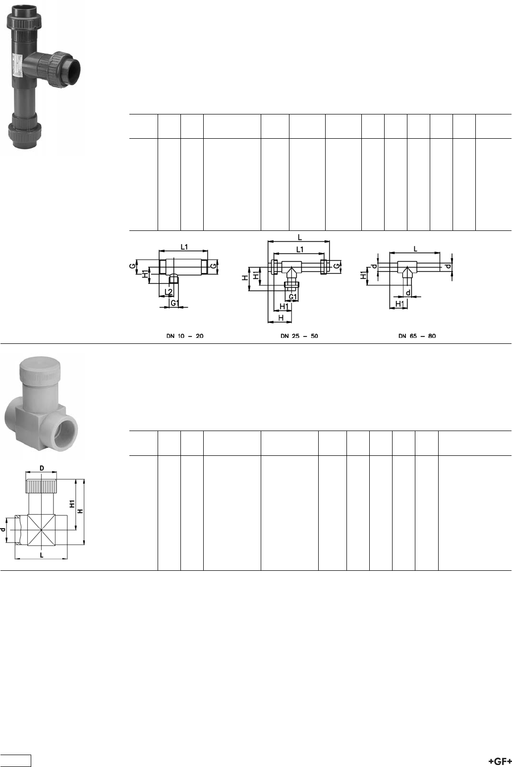
PROGEF Standard
Water jet suction pump type P20
Model:
ÏMaterial: PP-H
ÏDN 10-20: BSP parallel female thread
ÏDN 25-50: Fusion socket metric
ÏDN 65-80: Fusion spigot metric
d
[mm]
DN
[mm]
PN EPDM
Code
kg G
[inch]
G1
[inch]
L
[mm]
L1
[mm]
L2
[mm]
H
[mm]
H1
[mm]
16 10 10 199 041 129 0.100 R 3/4 R 3/4 110 40 35
20 15 10 199 041 130 0.170 R 1 R 3/4 125 40 35
25 20 10 199 041 131 0.270 R 1 1/4 R 3/4 145 45 45
32 25 10 199 041 132 0.400 R 1 1/2 R 1 1/2 245 195 96 71
40 32 10 199 041 133 0.690 R 2 R 2 297 239 116 87
50 40 10 199 041 134 1.090 R 2 1/4 R 2 1/4 369 301 139 105
63 50 10 199 041 135 1.930 R 2 3/4 R 2 3/4 433 351 169 128
75 65 10 199 041 136 1.510 R 1 - 388 115
90 80 10 199 041 137 2.570 R 2 3/4 - 465 149
PROGEF Standard
Throttle valve type V251
With fusion sockets metric
Model:
ÏMaterial: PP-H
d
[mm]
DN
[mm]
PN EPDM
Code
FPM
Code
kg D
[mm]
L
[mm]
H
[mm]
H1
[mm]
16 10 10 199 041 217 199 041 224 0.100 29 47 57 45
20 15 10 199 041 218 199 041 225 0.124 35 55 66 51
25 20 10 199 041 219 199 041 226 0.080 40 66 80 63
32 25 10 199 041 220 199 041 227 0.150 47 80 96 75
40 32 10 199 041 221 199 041 228 0.001 56 100 111 86
50 40 10 199 041 222 199 041 229 0.419 70 120 133 101
63 50 10 199 041 223 199 041 230 0.600 88 146 158 118
314
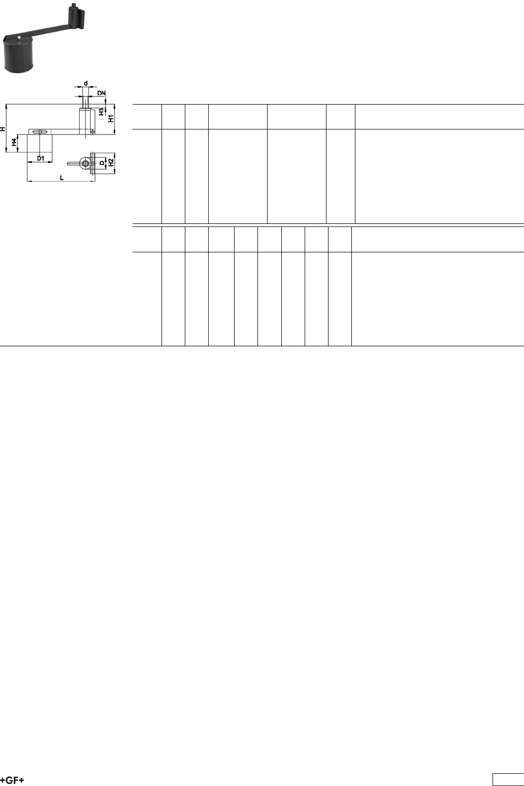
PROGEF Standard
Float valve type V140
With fusion spigots metric
Model:
ÏMaterial: PP-H
ÏLever 1:10
d
[mm]
DN
[mm]
PN EPDM
Code
FPM
Code
kg
16 10 6 199 041 165 199 041 174 0.460
20 15 6 199 041 166 199 041 175 0.500
25 20 6 199 041 167 199 041 176 1.382
32 25 6 199 041 168 199 041 177 2.140
40 32 6 199 041 169 199 041 178 3.250
50 40 6 199 041 170 199 041 179 4.400
63 50 6 199 041 171 199 041 180 5.800
75 65 6 199 041 172 199 041 181 7.400
90 80 6 199 041 173 199 041 182 8.200
d
[mm]
D
[mm]
D1
[mm]
L
[mm]
H
[mm]
H1
[mm]
H2
[mm]
H3
[mm]
H4
[mm]
16 45 125 380 270 120 80 14 130
20 45 125 380 270 120 80 16 130
25 65 160 530 340 160 110 19 170
32 65 160 530 345 165 110 22 170
40 90 225 720 440 210 130 26 210
50 90 225 720 445 215 130 31 210
63 130 315 975 595 255 160 38 290
75 130 315 975 600 260 160 44 290
90 150 355 1140 640 290 180 51 340
315
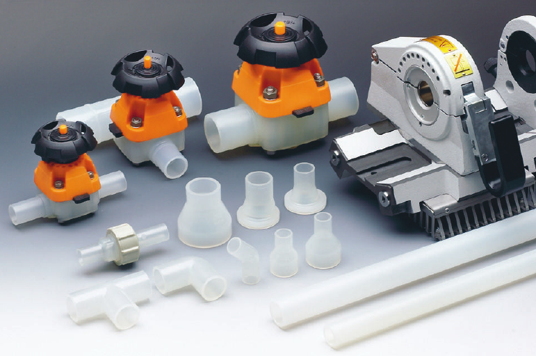
EGD<:;CVijgVa
ÄE^eZh
Ä7jii;jh^dcHnhiZb
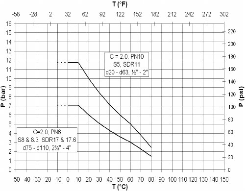
PROGEF® Natural (natural)
P Permissible pressure in bar, psi
T Temperature in °C, °F
Pressure/temperature diagram for PP
PROGEF® Natural
The following pressure/temperature diagram for
PROGEF® Natural pipes and ttings is valid for a
lifetime of 25 years.
The design factor of 2.0 recommended by GF is
incorporated.
It can be used for water or media resembling water, in
other words, media which have no derating factor re-
garding the chemical resistance.
Remark: Please take into account the pressure/
temperature diagrams for valves and special ttings.
Becauseof the construction and/or sealing material
used, differences are possible when compared with
pipes and ttings. This information can be found in the
planning fundamentals of the relevant types of valves,
respectively special ttings.
Remark: Using PROGEF® Natural at higher temperat-
ures can lead to a discoloration of the material.
In case of applications with temperatures in the range
of the dotted lines please contact your GF representa-
tive.

BViZg^Va
8dadjg
9Zch^in
Hjg[VXZiZch^dc
A^cZVgZmeVch^dcXdZ[ÒX^Zci
:"bdYjajh
I]ZgbVaXdcYjXi^k^in
Hjg[VXZgZh^hi^k^in
EdanegdenaZcZGVcYdb8dedanbZg
Jce^\bZciZY!igVchajXZci
s%#.%\$Xb(>HD&&-($6HIB9,.'
(%Ä(*b?$b'
%#&*bb$b@9>C*(,*'
.%%C$bb'>HD*',$6HIB9,.%
%#'(L$b@:C&'++)
Ñ&%&+±>:8+%%.(
9^bZch^dc Y'%ÄY&&%^cVXXdgYVcXZl^i]:C>HD&*).)
EgZhhjgZGVi^c\ E^eZh$;^ii^c\h$9^Ve]gV\bkVakZh/
Y'%ÄY+(H9G&&! EC&%! X 2 '#%H9G&&!EC&%!X2'#%
Y,*ÄY&&%H9G&,#+! EC+! X 2 '#%H9G&,#+!EC+!X2'#%
IZbeZgVijgZGVi^c\ [gdb%8id-%8C+%8[dgkVakZh(';Ä&,+;
EgdYjXi^dc ;^ii^c\h$kVakZh/^c_ZXi^dcbdjaYZY
E^eZh/ZmigjYZY
Hjg[VXZ;^c^h] >ccZghjg[VXZGVD&©b(.©^c
BVg`^c\ ;^ii^c\h!e^eZhVcYkVakZhVgZZbWdhhZYl^i]VeZgbVcZci^YZci^ÒXVi^dcYjg^c\i]ZegdYjXi^dc
egdXZhhidZchjgZ[jaaigVXZVW^a^in/
AdiCd
BViZg^Va
9^bZch^dc
EgZhhjgZGVi^c\
IZhi^c\VcY>cheZXi^dc
:C>HD&*).)
>cXajh^dch
K^hjVa^cheZXi^dc
Hjg[VXZÒc^h]
9^bZch^dcidaZgVcXZ
EgZhhjgZiZhi^c\
;jaaegdYjXigVc\ZeVhhZYi]Z>c^i^VaIneZIZhi>II
6eegdkVah$8dc[dgbVcXZ& ;968;G'&&,,#&*'%
JHE'*XaVhhK>e]nh^dad\^XVacdc"idm^X
LZaY^c\IZX]cdad\n 78;Eajh!WZVYVcYXgZk^XZ[gZZ[jh^dc
>GEajh!^c[gVgZY[jh^dc9KH''%,"+
7jii[jh^dc9KH''%,"&&
9dXjbZciVi^dc' 8Zgi^ÒXViZd[8dc[dgbVcXZl^i];96!JHE
:C&%'%)'#'
:C&%'%)(#&
6HB:7E:
EVX`^c\ E^eZh/8VeeZYh^c\aZWV\\ZY
;^ii^c\h$kVakZh/Bjai^eaZXdbedcZcihh^c\aZWV\\ZY^cheZX^ÒZYWV\
AVWZa^c\ 7gVcYCVbZ
EgdYjXi9ZhXg^ei^dc
8dYZCjbWZg
BViZg^Va
9^bZch^dc
8:"aVWZa^c\(
6eegdkVah
BV^c6eea^XVi^dch JhZh^cXajYZXdhiZ[[ZXi^kZ!ejgZY^hig^Wji^dcd[9>"lViZgVcYXg^i^XVaW^dad\^XVaÓj^Yhl]ZgZ
X]Zb^XVahVc^i^hVi^dc^hcZZYZY#7ZVYVcY8gZk^XZ;gZZ_d^ci^c\VcYb^c^bVabZiVaa^XaZVX]dji
ZchjgZi]Z]^\]ZhiegdYjXifjVa^in#=^\]angZh^hiVciid^beVXi!VWgVh^dcVcYbVcnX]Zb^XVah
bV`Z^i^YZVa[dghajgg^ZhigVchedgiVi^dc^ci]ZhZb^XdcYjXidg^cYjhign#
EGD<:;CVijgVaÄHnhiZbHeZX^ÒXVi^dc
&;dgi]ZgbdeaVhi^XbViZg^Vadcan
'DcgZfjZhi
(;gdb'%%-dc
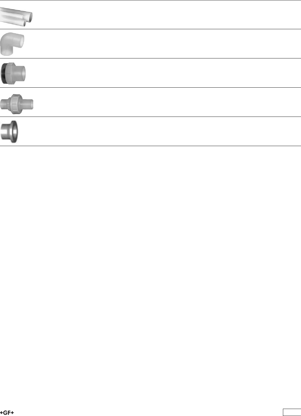
PROGEF Natural Pipes, Fittings, Unions,
Flanges and Flange Adaptors
Page
Pipes 320
Fittings for Butt Fusion 321
Adaptor Fittings for Butt Fusion 324
Unions and Sanitary Adaptors 327
Flange Adaptors, Flanges and Gaskets for Butt Fusion 331
319
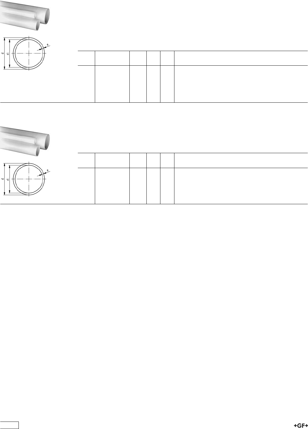
Pipes
68 48 01 PROGEF Natural, S5/SDR11 (PN10)
Model:
ÏMaterial: PP-R unpigmented
ÏColour: natural
ÏLength: Lengths of 5 m
ÏBead and Crevice Free weldable with the new BCF®Plus fusion machine
ÏInfrared-(IR Plus®) compatible. Please choose fusion parameters: PP-n (PP-R)
ÏConventional butt-welding according to DVS 2207 part 11
d
[mm]
Code kg/m e
[mm]
di
[mm]
20 168 480 151 0.107 1,9 16.2
25 168 480 152 0.164 2,3 20.4
32 168 480 153 0.261 2,9 26.2
40 168 480 154 0.412 3,7 32.6
50 168 480 155 0.638 4,6 40.8
63 168 480 156 1.010 5,8 51.4
68 48 02 PROGEF Natural, S8,3/SDR17,6 (PN6)
Model:
ÏMaterial: PP-R unpigmented
ÏColour: natural
ÏLength: Lengths of 5 m
d
[mm]
Code kg/m e
[mm]
di
[mm]
75 168 480 282 0.935 4,3 66.4
90 168 480 283 1.330 5,1 79.8
110 168 480 284 1.990 6,3 97.4
320
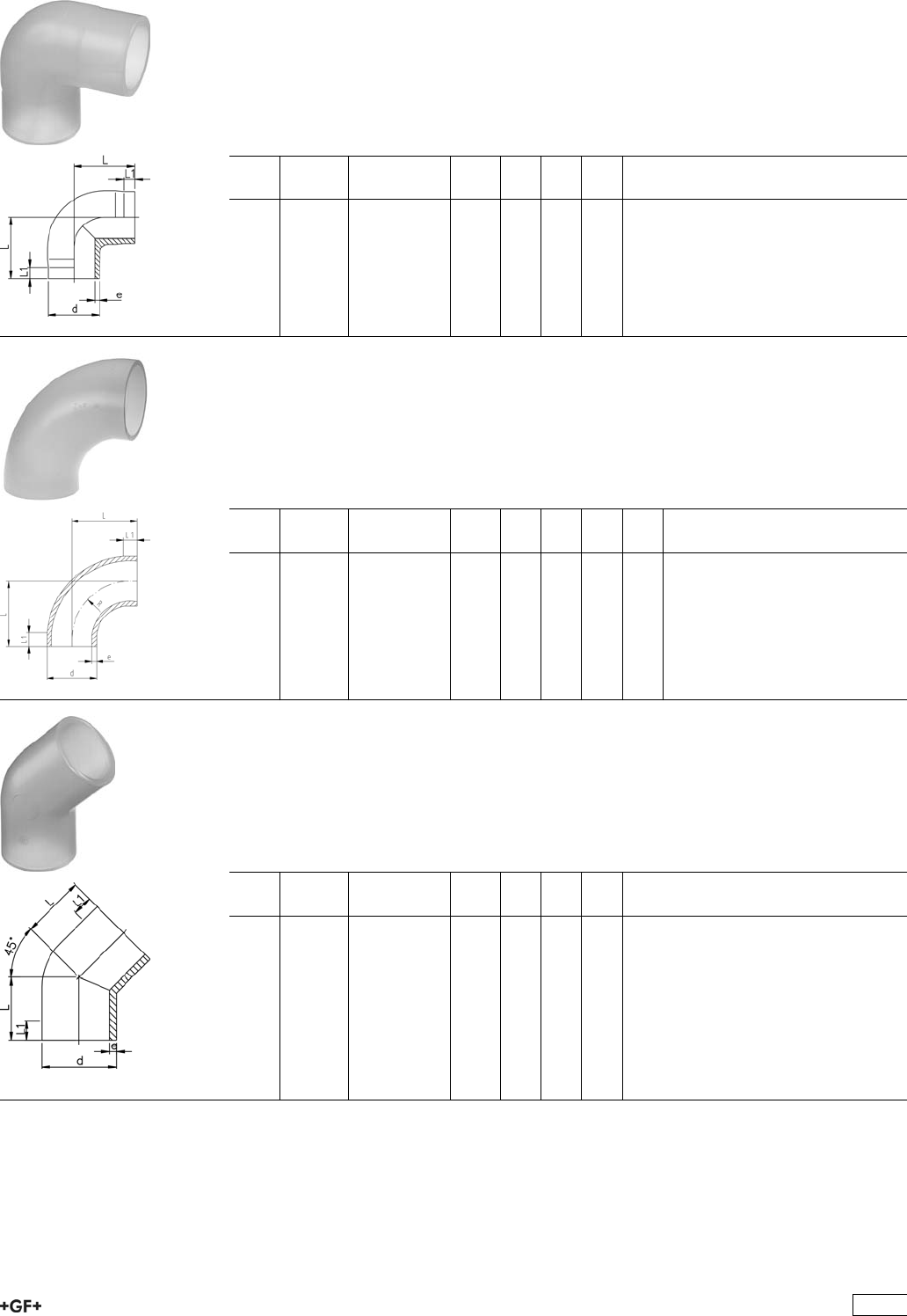
Fittings for Butt Fusion
PROGEF Natural, Elbow 90°, S5/SDR11
Model:
ÏMaterial: PP-R unpigmented
ÏBead and Crevice Free weldable with the new BCF®Plus fusion machine
ÏInfrared-(IR Plus®) compatible. Please choose fusion parameters: PP-n (PP-R)
ÏConventional butt-welding according to DVS 2207 part 11
d
[mm]
FM Code kg L
[mm]
L1
[mm]
e
[mm]
20 BCF, IR 728 108 506 0.008 38 25 1,9
25 BCF, IR 728 108 507 0.013 42 26 2,3
32 BCF, IR 728 108 508 0.022 46 27 2,9
40 BCF, IR 728 108 509 0.044 51 22 3,7
50 BCF, IR 728 108 510 0.077 58 23 4,6
63 BCF, IR 728 108 511 0.138 66 21 5,8
PROGEF Natural, Bend 90°, S8,3/SDR17,6
Model:
ÏMaterial: PP-R unpigmented
ÏBead and Crevice Free weldable with the new BCF®Plus fusion machine
ÏInfrared-(IR Plus®) compatible. Please choose fusion parameters: PP-n (PP-R)
ÏConventional butt-welding according to DVS 2207 part 11
d
[mm]
FM Code kg L
[mm]
L1
[mm]
e
[mm]
R
[mm]
75 BCF, IR 728 018 412 0.156 100 20 4,3 90
90 BCF, IR 728 018 413 0.221 100 20 5,1 90
110 BCF, IR 728 018 414 0.474 141 25 6,3 130
PROGEF Natural, Elbow 45°, S5/SDR11
Model:
ÏMaterial: PP-R unpigmented
ÏBead and Crevice Free weldable with the new BCF®Plus fusion machine
ÏInfrared-(IR Plus®) compatible. Please choose fusion parameters: PP-n (PP-R)
ÏConventional butt-welding according to DVS 2207 part 11
d
[mm]
FM Code kg L
[mm]
L1
[mm]
e
[mm]
20 BCF, IR 728 158 506 0.008 32 24 1,9
25 BCF, IR 728 158 507 0.012 34 25 2,3
32 BCF, IR 728 158 508 0.022 36 25 2,9
40 BCF, IR 728 158 509 0.037 39 25 3,7
50 BCF, IR 728 158 510 0.054 42 26 4,6
63 BCF, IR 728 158 511 0.097 47 29 5,8
321
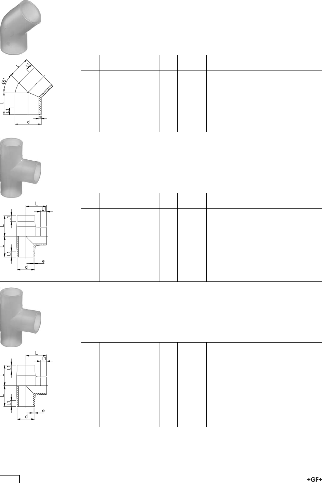
PROGEF Natural, Elbow 45°, S8,3/SDR17,6
Model:
ÏMaterial: PP-R unpigmented
ÏConventional butt-welding according to DVS 2207 part 11
ÏBead and Crevice Free weldable with the new BCF®Plus fusion machine
ÏInfrared-(IR Plus®) compatible. Please choose fusion parameters: PP-n (PP-R)
d
[mm]
FM Code kg L
[mm]
L1
[mm]
e
[mm]
75 BCF, IR 728 158 412 0.099 49 33 4,3
90 BCF, IR 728 158 413 0.164 57 48 5,7
110 BCF, IR 728 158 414 0.296 70 38 6,9
PROGEF Natural, Tee 90° equal, S5/SDR11
Model:
ÏMaterial: PP-R unpigmented
ÏBead and Crevice Free weldable with the new BCF®Plus fusion machine
ÏInfrared-(IR Plus®) compatible. Please choose fusion parameters: PP-n (PP-R)
ÏConventional butt-welding according to DVS 2207 part 11
d
[mm]
FM Code kg L
[mm]
L1
[mm]
e
[mm]
20 BCF, IR 728 208 506 0.011 38 24 1,9
25 BCF, IR 728 208 507 0.019 42 26 2,3
32 BCF, IR 728 208 508 0.032 46 26 2,9
40 BCF, IR 728 208 509 0.059 51 23 3,7
50 BCF, IR 728 208 510 0.103 58 22 4,6
63 BCF, IR 728 208 511 0.184 66 20 5,8
PROGEF Natural, Tee 90° equal, S8,3/SDR17,6
Model:
ÏMaterial: PP-R unpigmented
ÏBead and Crevice Free weldable with the new BCF®Plus fusion machine
ÏInfrared-(IR Plus®) compatible. Please choose fusion parameters: PP-n (PP-R)
ÏConventional butt-welding according to DVS 2207 part 11
d
[mm]
FM Code kg L
[mm]
L1
[mm]
e
[mm]
75 BCF, IR 728 208 412 0.230 75 20 4,3
90 BCF, IR 728 208 413 0.401 90 20 5,7
110 BCF, IR 728 208 414 0.723 110 20 6,9
322
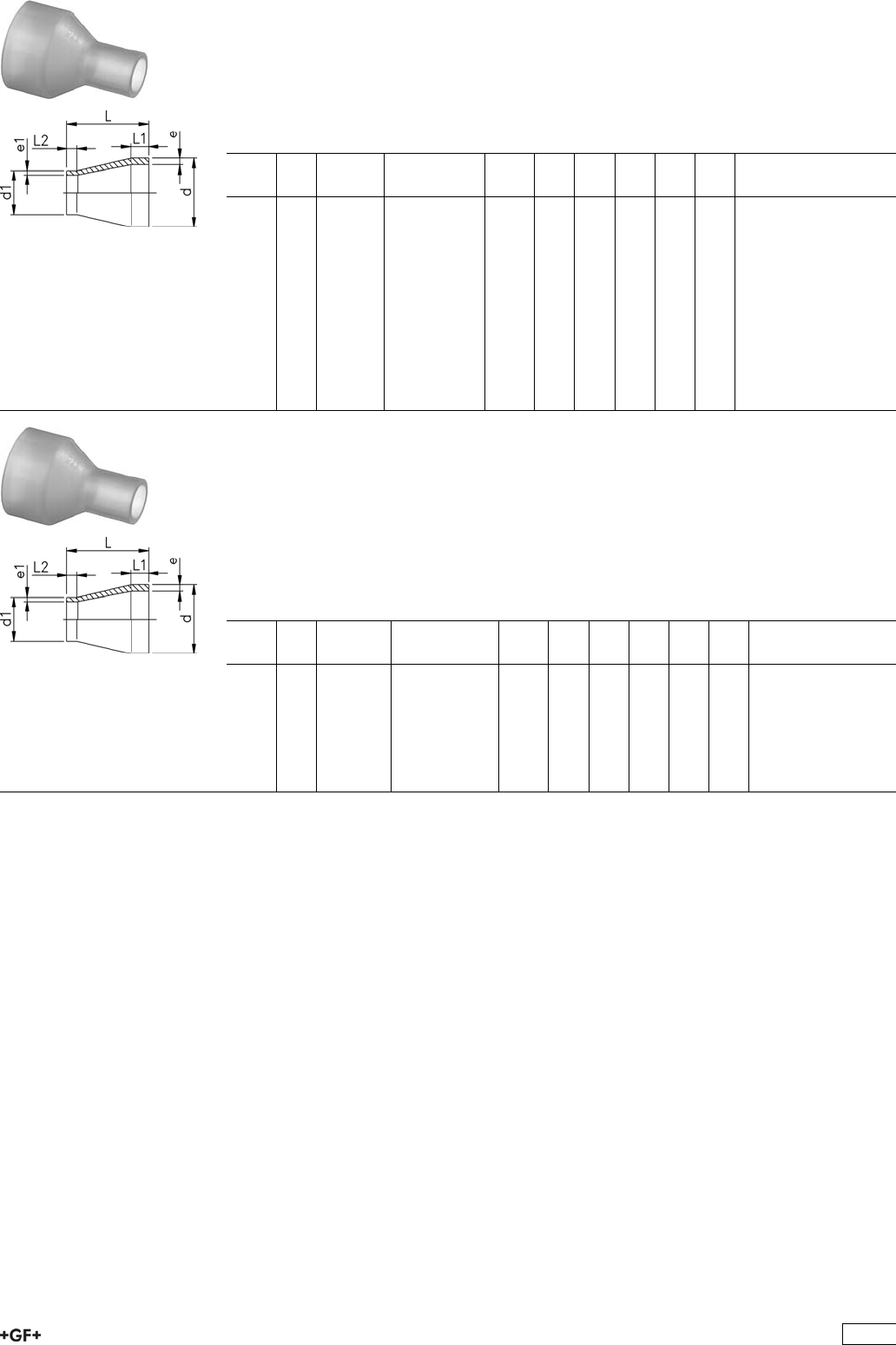
PROGEF Natural, Reducer, S5/SDR11
Model:
ÏMaterial: PP-R unpigmented
ÏBead and Crevice Free weldable with the new BCF®Plus fusion machine
ÏInfrared-(IR Plus®) compatible. Please choose fusion parameters: PP-n (PP-R)
ÏConventional butt-welding according to DVS 2207 part 11
d
[mm]
d1
[mm]
FM Code kg L
[mm]
L1
[mm]
L2
[mm]
e
[mm]
e1
[mm]
25 20 BCF, IR 728 908 537 0.007 50 20 20 2,3 1,9
32 20 BCF, IR 728 908 542 0.010 50 20 20 3,0 1,9
32 25 BCF, IR 728 908 541 0.011 50 20 20 3,0 2,3
40 20 BCF, IR 728 908 548 0.015 58 20 23 3,7 1,9
40 25 BCF, IR 728 908 547 0.016 55 20 20 3,7 2,3
40 32 BCF, IR 728 908 546 0.019 55 20 20 3,7 2,9
50 25 BCF, IR 728 908 554 0.025 60 20 20 4,6 2,3
50 32 BCF, IR 728 908 553 0.027 60 20 20 4,6 2,9
50 40 BCF, IR 728 908 552 0.030 60 20 20 4,6 3,7
63 32 BCF, IR 728 908 560 0.043 65 20 20 5,8 2,9
63 40 BCF, IR 728 908 559 0.047 65 20 20 5,8 3,7
63 50 BCF, IR 728 908 558 0.052 65 20 20 5,8 4,6
PROGEF Natural, Reducer, S8,3/SDR17,6
Model:
ÏMaterial: PP-R unpigmented
ÏBead and Crevice Free weldable with the new BCF®Plus fusion machine
ÏInfrared-(IR Plus®) compatible. Please choose fusion parameters: PP-n (PP-R)
ÏConventional butt-welding according to DVS 2207 part 11
* SDR17,6 - SDR11
d
[mm]
d1
[mm]
FM Code kg L
[mm]
L1
[mm]
L2
[mm]
e
[mm]
e1
[mm]
*75 40 BCF, IR 728 908 466 0.048 68 20 23 4,3 3,7
*75 50 BCF, IR 728 908 465 0.051 65 20 20 4,3 4,6
*75 63 BCF, IR 728 908 464 0.060 65 20 20 4,3 5,8
*90 63 BCF, IR 728 908 471 0.086 75 22 19 5,7 5,8
90 75 BCF, IR 728 908 470 0.086 75 21 19 5,7 4,3
110 75 BCF, IR 728 908 477 0.135 90 26 20 6,9 4,3
110 90 BCF, IR 728 908 476 0.154 90 25 22 6,9 5,7
323
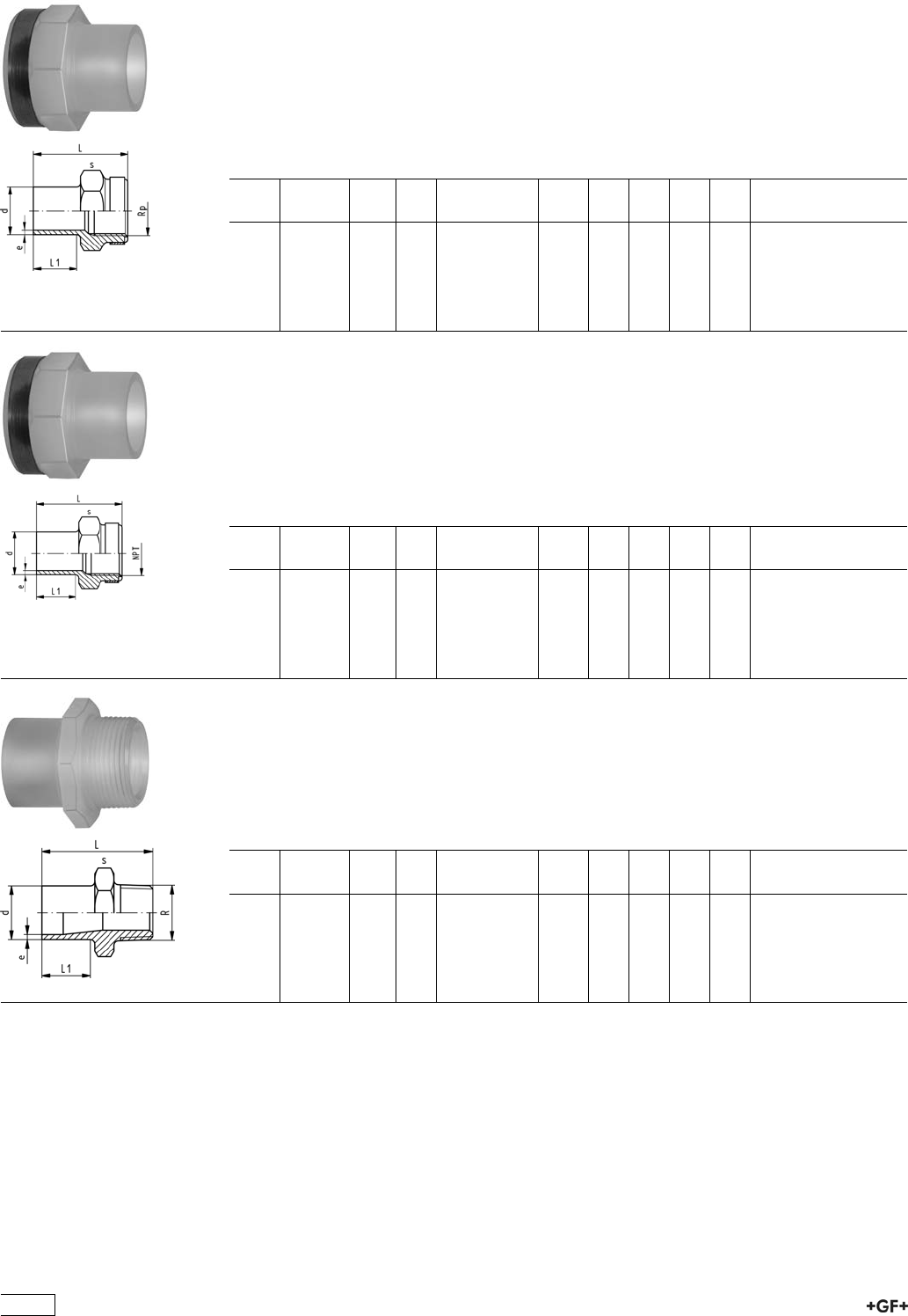
Adaptor Fittings for Butt Fusion
PROGEF Natural, Adaptor Socket, metric - Rp
Model:
ÏMaterial: PP-R unpigmented
ÏWith butt fusion spigot SDR11 and BSP parallel female thread Rp, reinforced
ÏConnection to plastic or metal
ÏReinforcing ring stainless (A2)
ÏDo not use thread sealing pastes that are harmful to PP
d
[mm]
FM Rp
[inch]
PN Code kg L
[mm]
L1
[mm]
s
[mm]
e
[mm]
20 BCF, IR 1
/210 728 918 056 0.017 49 28 32 1,9
25 BCF, IR 3
/410 728 918 057 0.022 51 28 36 2,3
32 BCF, IR 1 10 728 918 058 0.039 54 28 46 2,9
40 BCF, IR 1 1
/410 728 918 059 0.057 56 28 55 3,7
50 BCF, IR 1 1
/210 728 918 060 0.085 60 28 64 4,6
63 BCF, IR 2 10 728 918 061 0.140 62 28 80 5,8
PROGEF Natural, Adaptor Sockets, metric - NPT
Model:
ÏMaterial: PP-R unpigmented
ÏWith butt fusion spigot SDR11 and NPT tapered female thread, reinforced
ÏConnection to plastic or metal
ÏReinforcing ring stainless (A2)
ÏDo not use thread sealing pastes that are harmful to PP
d
[mm]
FM NPT
[inch]
PN Code kg L
[mm]
L1
[mm]
s
[mm]
e
[mm]
20 BCF, IR 1
/210 728 914 056 0.017 49 28 32 1,9
25 BCF, IR 3
/410 728 914 057 0.022 51 28 36 2,3
32 BCF, IR 1 10 728 914 058 0.039 54 28 46 2,9
40 BCF, IR 1 1
/410 728 914 059 0.057 56 28 55 3,7
50 BCF, IR 1 1
/210 728 914 060 0.085 60 28 64 4,6
63 BCF, IR 2 10 728 914 061 0.140 62 28 80 5,8
PROGEF Natural, Adaptor Nipple, metric - R
Model:
ÏMaterial: PP-R unpigmented
ÏWith butt fusion spigot and BSP tapered male thread
ÏConnection to plastic thread only
ÏDo not use thread sealing pastes that are harmful to PP
d
[mm]
FM R
[inch]
PN Code kg L
[mm]
L1
[mm]
s
[mm]
e
[mm]
20 BCF, IR 1
/210 728 918 106 0.013 51 28 32 1,9
25 BCF, IR 3
/410 728 918 107 0.017 52 28 36 2,3
32 BCF, IR 1 10 728 918 108 0.027 55 28 46 2,9
40 BCF, IR 1 1
/410 728 918 109 0.041 58 28 55 3,7
50 BCF, IR 1 1
/210 728 918 110 0.060 60 28 65 4,6
63 BCF, IR 2 10 728 918 111 0.098 67 28 80 5,8
324
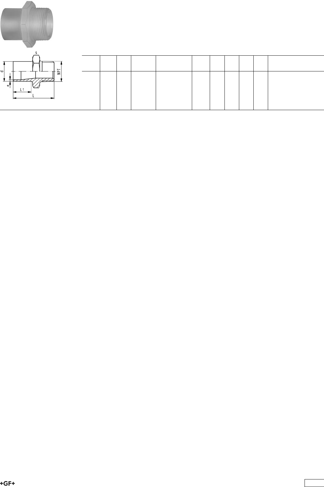
PROGEF Natural, Adaptor Nipple, metric - NPT
Model:
ÏMaterial: PP-R unpigmented
ÏWith butt fusion spigot SDR11 and NPT tapered male thread
ÏConnection to plastic thread only
ÏDo not use thread sealing pastes that are harmful to PP
d
[mm]
NPT
[inch]
PN FM Code kg L
[mm]
L1
[mm]
s
[mm]
e
[mm]
20 1
/210 BCF, IR 728 914 106 0.013 51 28 32 1,9
25 3
/410 BCF, IR 728 914 107 0.017 52 28 36 2,3
32 1 10 BCF, IR 728 914 108 0.027 55 28 46 2,9
40 1 1
/410 BCF, IR 728 914 109 0.041 58 28 55 3,7
50 1 1
/210 BCF, IR 728 914 110 0.060 60 28 65 4,6
63 2 10 BCF, IR 728 914 111 0.098 67 28 80 5,8
325
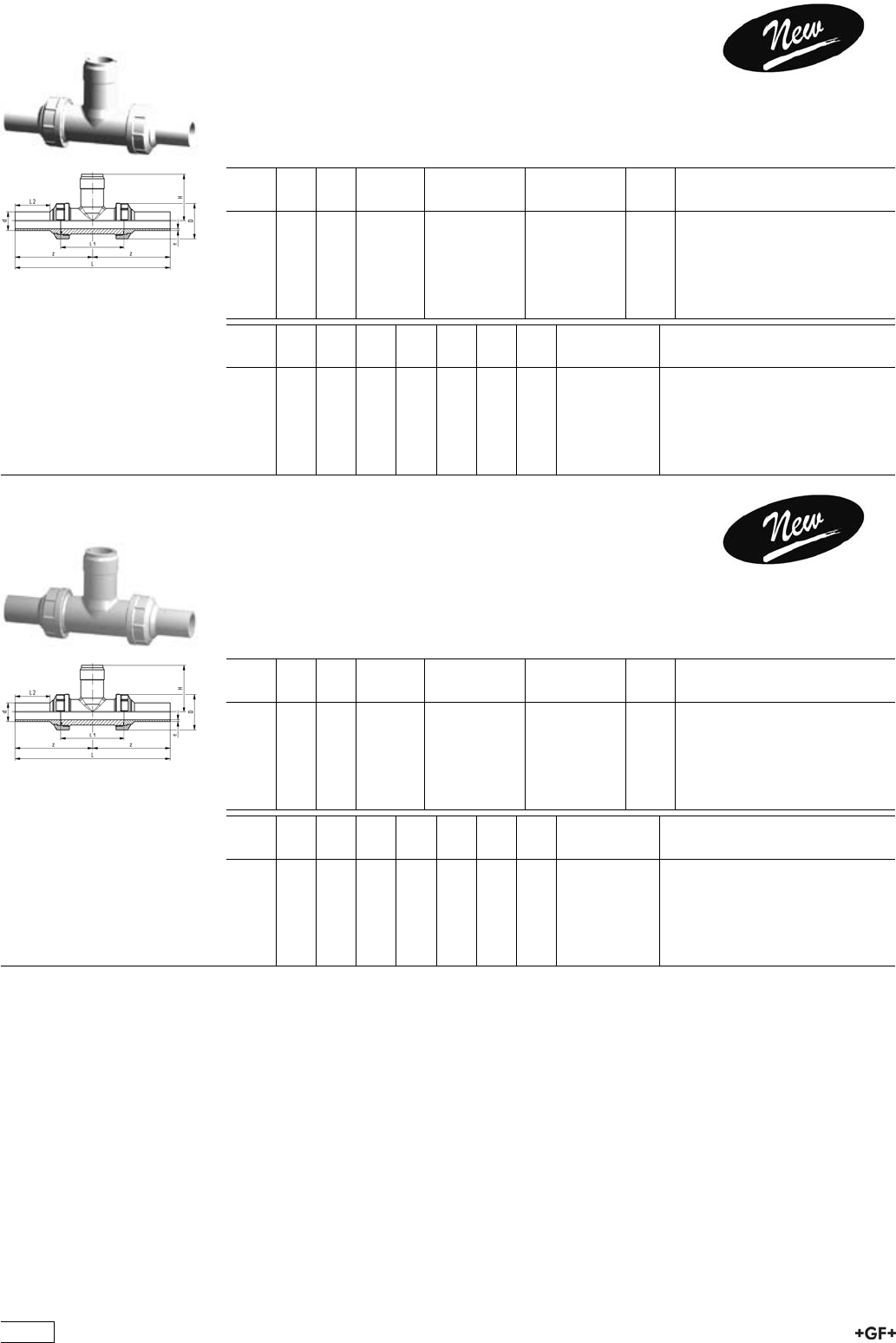
28 31 81 Installation Fitting Type 318, PP-R
for Butt Fusion Systems metric
Model:
ÏFor Signet Paddlewheel Sensors Type -X0 (104 mm)
ÏBody and union nut PP-H
ÏUnion end with butt fusion spigot PP-R
d
[mm]
DN
[mm]
PN FM EPDM
Code
FPM
Code
kg
20 15 10 BCF, IR 728 318 106 728 318 136 0.250
25 20 10 BCF, IR 728 318 107 728 318 137 0.190
32 25 10 BCF, IR 728 318 108 728 318 138 0.250
40 32 10 BCF, IR 728 318 109 728 318 139 0.356
50 40 10 BCF, IR 728 318 110 728 318 140 0.510
63 50 10 BCF, IR 728 318 111 728 318 141 0.800
d
[mm]
D
[mm]
z
[mm]
L
[mm]
L1
[mm]
L2
[mm]
H
[mm]
e
[mm]
Sensor Type
20 45 99 198 90 38 76 1.9 X0
25 55 107 214 100 42 78 2.3 X0
32 62 115 230 110 41 81 2.9 X0
40 75 118 236 110 42 85 3.7 X0
50 84 126 252 120 44 89 4.6 X0
63 101 134 268 130 45 95 5.8 X0
27 31 80 Installation Fitting Type 318, PP-R
for Butt Fusion Systems metric
Model:
ÏFor Signet Paddlewheel Sensors Type -X0 (104 mm)
ÏBody and union nut PVDF
ÏUnion end with butt fusion spigot PP-R
d
[mm]
DN
[mm]
PN FM EPDM
Code
FPM
Code
kg
20 15 10 BCF, IR 728 318 006 728 318 036 0.250
25 20 10 BCF, IR 728 318 007 728 318 037 0.355
32 25 10 BCF, IR 728 318 008 728 318 038 0.427
40 32 10 BCF, IR 728 318 009 728 318 039 0.700
50 40 10 BCF, IR 728 318 010 728 318 040 0.850
63 50 10 BCF, IR 728 318 011 728 318 041 1.182
d
[mm]
D
[mm]
z
[mm]
L
[mm]
L1
[mm]
L2
[mm]
H
[mm]
e
[mm]
Sensor Type
20 45 99 198 90 38 76 1.9 X0
25 55 107 214 100 42 78 2.3 X0
32 62 115 230 110 41 81 2.9 X0
40 75 118 236 110 42 85 3.7 X0
50 84 126 252 120 44 89 4.6 X0
63 101 134 268 130 45 95 5.8 X0
326
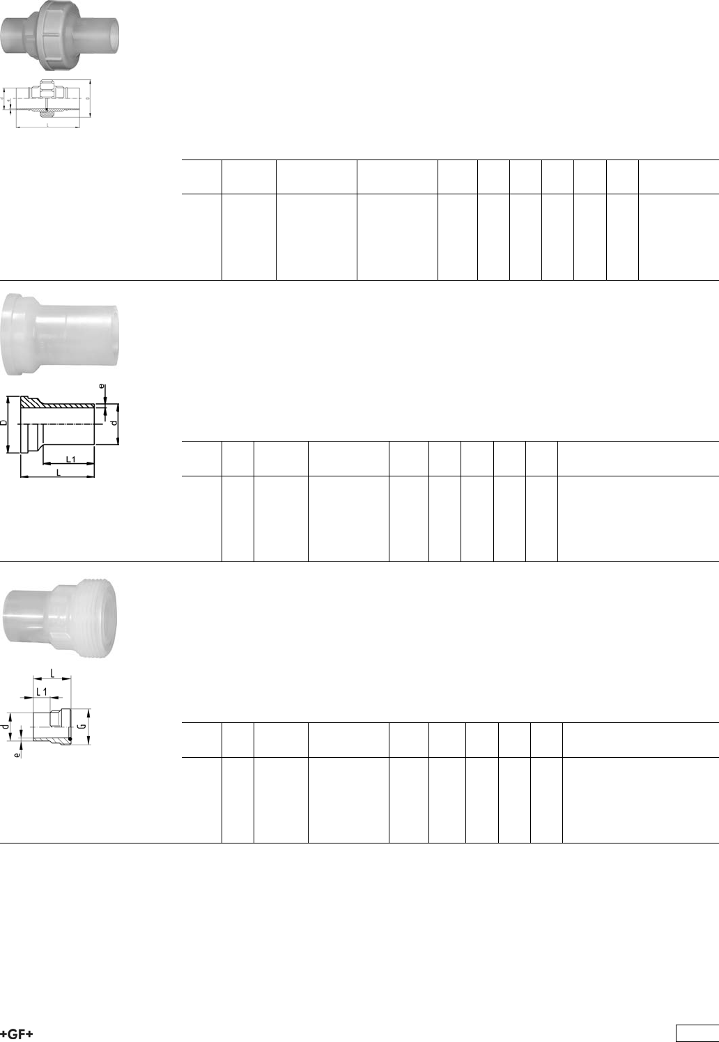
Unions and Sanitary Adaptors
Sanitary Union, SDR11
Model:
ÏMaterial: PP-R unpigmented
ÏBead and Crevice Free weldable with the new BCF®Plus fusion machine
ÏInfrared-(IR Plus®) compatible. Please choose fusion parameters: PP-n (PP-R)
ÏConventional butt-welding according to DVS 2207 part 11
ÏFDA compliant
d
[mm]
FM EPDM
Code
FPM
Code
kg D
[mm]
L
[mm]
L1
[mm]
L2
[mm]
e
[mm]
20 BCF, IR 728 518 526 728 528 526 0.046 48 107 53 25 1,9
25 BCF, IR 728 518 527 728 528 527 0.074 58 113 56 25 2,3
32 BCF, IR 728 518 528 728 528 528 0.102 65 119 59 25 2,9
40 BCF, IR 728 518 529 728 528 529 0.169 79 126 63 25 3,7
50 BCF, IR 728 518 530 728 528 530 0.023 91 131 65 25 4,6
63 BCF, IR 728 518 531 728 528 531 0.382 111 137 68 25 5,8
PROGEF®Natural
Union Ends IR, PP-N
Model:
ÏMaterial: PP-R unpigmented
ÏBead and Crevice Free weldable with the new BCF®Plus fusion machine
ÏInfrared-(IR Plus®) compatible. Please choose fusion parameters: PP-n (PP-R)
ÏConventional butt-welding according to DVS 2207 part 11
d
[mm]
PN FM Code kg D
[mm]
L
[mm]
L1
[mm]
e
[mm]
20 10 BCF, IR 728 608 506 0.009 30 53 35 1,9
25 10 BCF, IR 728 608 507 0.013 39 56 36 2,3
32 10 BCF, IR 728 608 508 0.016 45 59 38 2,9
40 10 BCF, IR 728 608 509 0.035 57 63 39 3,7
50 10 BCF, IR 728 608 510 0.054 63 65 41 4,6
63 10 BCF, IR 728 608 511 0.092 78 69 43 5,8
PROGEF®Natural
Union Bushes IR, PP-N SDR11
Model:
ÏMaterial: PP-R unpigmented
ÏBead and Crevice Free weldable with the new BCF®Plus fusion machine
ÏInfrared-(IR Plus®) compatible. Please choose fusion parameters: PP-n (PP-R)
ÏConventional butt-welding according to DVS 2207 part 11
d
[mm]
PN FM Code kg G
[inch]
L
[mm]
L1
[mm]
e
[mm]
20 10 BCF, IR 728 648 526 0.012 1 54 26 1,9
25 10 BCF, IR 728 648 527 0.020 1 1/4 57 26 2,3
32 10 BCF, IR 728 648 528 0.029 1 1/2 60 25 2,9
40 10 BCF, IR 728 648 529 0.047 2 63 25 3,7
50 10 BCF, IR 728 648 530 0.064 2 1/4 66 25 4,6
63 10 BCF, IR 728 648 531 0.104 2 3/4 69 25 5,8
327
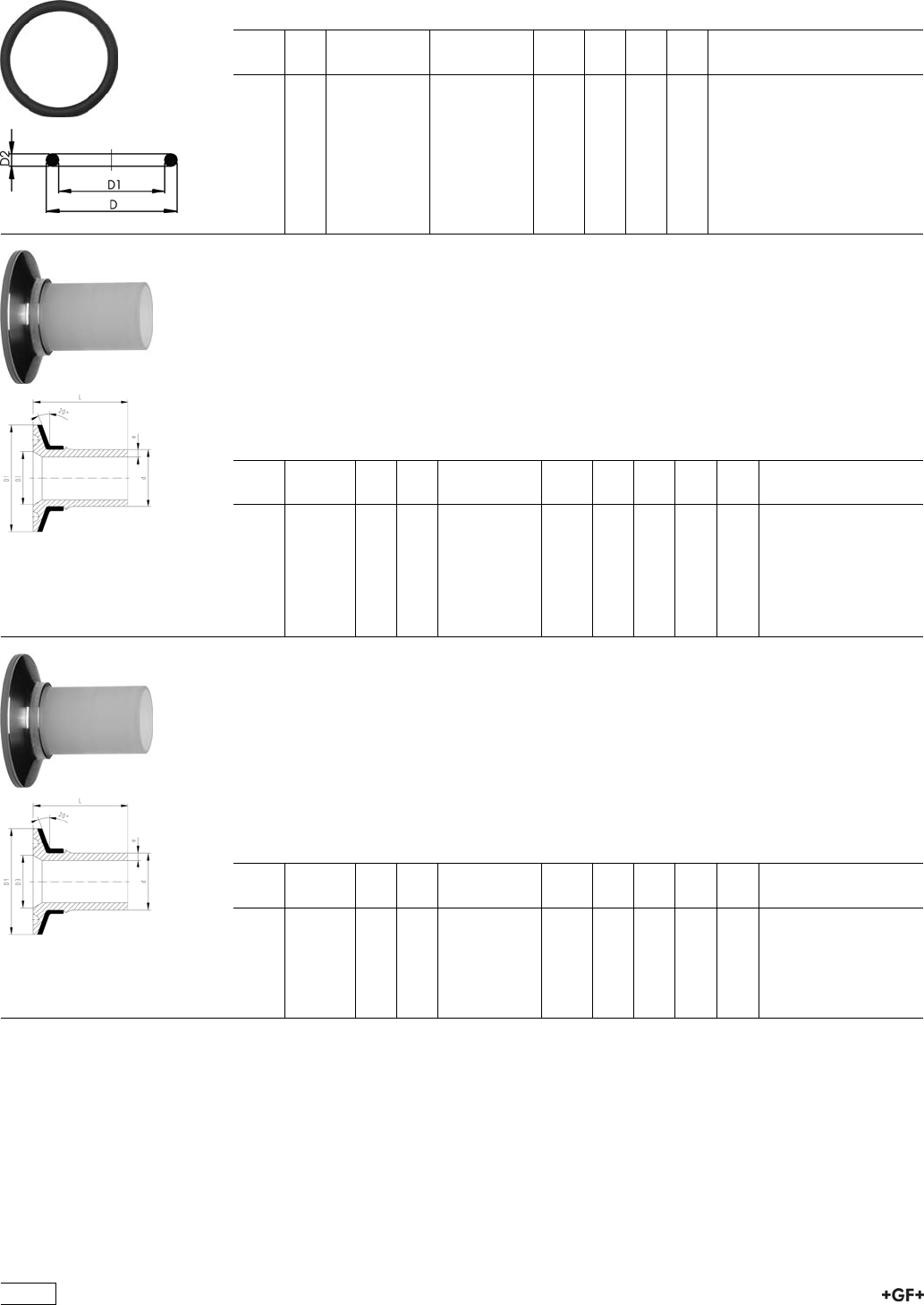
EPDM 48 41 00
FPM 49 41 00
O-Ring Gaskets
Model:
ÏHardness approx. 65° Shore
ÏSuitable for unions 28 51 52, 28 51 53, 28 52 52, 28 52
d
[mm]
DN
[mm]
EPDM
Code
FPM
Code
kg D
[mm]
D1
[mm]
D2
[mm]
20 15 748 410 140 749 410 140 0.003 20 15 3
20 15 748 410 006 749 410 006 0.002 27
32 25 748 410 025 749 410 025 0.002 32 25 4
40 32 748 410 152 749 410 152 0.006 42 31 5
40 32 748 410 009 749 410 009 0.006 51
63 50 748 410 171 749 410 171 0.010 61 50 5
Sanitary Adaptor
Connection to ISO 1127
Model:
ÏMaterial: PP-R unpigmented
ÏConventional butt-welding according to DVS 2207 part 11
ÏInfrared-(IR Plus®) compatible. Please choose fusion parameters: PP-n (PP-R)
ÏBead and Crevice Free weldable with the new BCF®Plus fusion machine
ÏStainless steel reinforcement ring
d
[mm]
FM DN
[mm]
PN Code kg D1
[mm]
D3
[mm]
L
[mm]
e
[mm]
20 BCF, IR 15 10 728 598 006 0.031 50 18 49.0 1,9
25 BCF, IR 20 10 728 598 008 0.032 50 23 49.5 2,3
25 BCF, IR 25 10 728 598 009 0.031 50 29 49.5 2,3
32 BCF, IR 25 10 728 598 010 0.033 50 29 53.0 2,9
40 BCF, IR 32 10 728 598 014 0.054 64 38 54.0 3,7
50 BCF, IR 40 10 728 598 016 0.062 64 44 61.0 4,6
63 BCF, IR 50 10 728 598 018 0.093 77 56 67.0 5,8
Sanitary Adaptor
Connection to DIN 32676
Model:
ÏMaterial: PP-R unpigmented
ÏConventional butt-welding according to DVS 2207 part 11
ÏInfrared-(IR Plus®) compatible. Please choose fusion parameters: PP-n (PP-R)
ÏBead and Crevice Free weldable with the new BCF®Plus fusion machine
ÏStainless steel reinforcement ring
d
[mm]
FM DN
[mm]
PN Code kg D1
[mm]
D3
[mm]
L
[mm]
e
[mm]
20 BCF, IR 15 10 728 598 056 0.014 34 16 49.0 1,9
20 BCF, IR 20 10 728 598 057 0.014 34 20 49.0 1,9
25 BCF, IR 25 10 728 598 059 0.031 50 26 49.5 2,3
32 BCF, IR 32 10 728 598 062 0.031 50 32 53.0 2,9
40 BCF, IR 40 10 728 598 065 0.032 50 38 54.0 3,7
50 BCF, IR 50 10 728 598 067 0.061 64 50 61.0 4,6
328
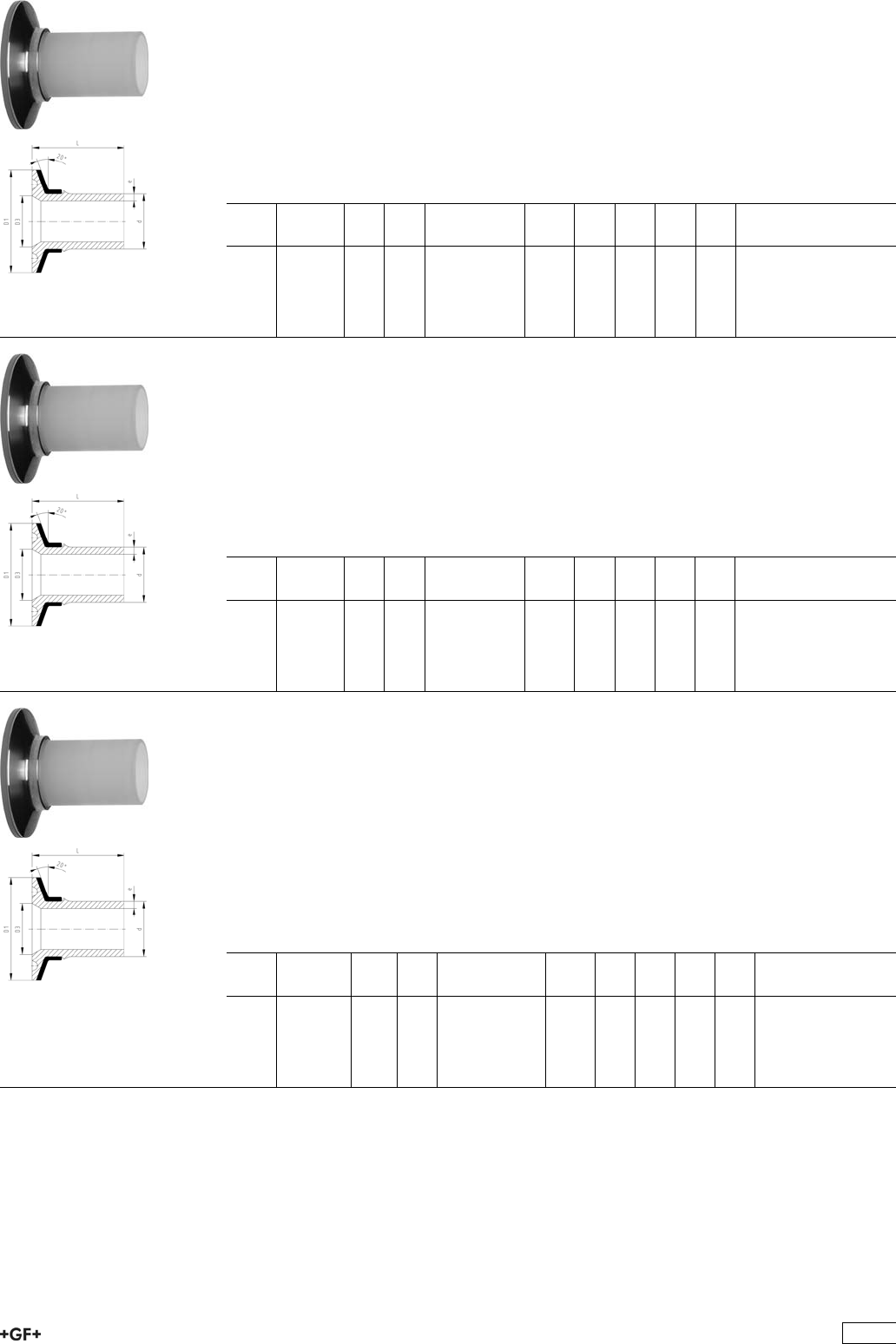
Sanitary Adaptor
Connection to DIN 3017
Model:
ÏMaterial: PP-R unpigmented
ÏConventional butt-welding according to DVS 2207 part 11
ÏInfrared-(IR Plus®) compatible. Please choose fusion parameters: PP-n (PP-R)
ÏBead and Crevice Free weldable with the new BCF®Plus fusion machine
ÏStainless steel reinforcement ring
d
[mm]
FM DN
[mm]
PN Code kg D1
[mm]
D3
[mm]
L
[mm]
e
[mm]
25 BCF, IR 25 10 728 598 259 0.031 50 22 49.5 2,3
32 BCF, IR 32 10 728 598 262 0.031 50 32 53.0 2,9
40 BCF, IR 40 10 728 598 265 0.033 50 35 54.0 3,7
50 BCF, IR 50 10 728 598 267 0.061 64 49 61.0 4,6
63 BCF, IR 65 10 728 598 269 0.093 78 60 67.0 5,8
Sanitary Adaptor
Connection to ISO 2852
Model:
ÏMaterial: PP-R unpigmented
ÏConventional butt-welding according to DVS 2207 part 11
ÏInfrared-(IR Plus®) compatible. Please choose fusion parameters: PP-n (PP-R)
ÏBead and Crevice Free weldable with the new BCF®Plus fusion machine
ÏStainless steel reinforcement ring
d
[mm]
FM DN
[mm]
PN Code kg D1
[mm]
D3
[mm]
L
[mm]
e
[mm]
25 BCF, IR 25 10 728 598 309 0.031 51 22 50 2,3
32 BCF, IR 32 10 728 598 312 0.031 51 32 53 2,9
40 BCF, IR 40 10 728 598 315 0.033 51 35 54 3,7
50 BCF, IR 50 10 728 598 317 0.061 64 49 61 4,6
63 BCF, IR 65 10 728 598 319 0.093 78 60 67 5,8
Sanitary Adaptor
Connection to ASME BPE
Model:
ÏMaterial: PP-R unpigmented
ÏConventional butt-welding according to DVS 2207 part 11
ÏInfrared-(IR Plus®) compatible. Please choose fusion parameters: PP-n (PP-R)
ÏBead and Crevice Free weldable with the new BCF®Plus fusion machine
ÏStainless steel reinforcement ring
* Without stainless steel reinforcement ring
d
[mm]
FM Inch PN Code kg D1
[mm]
D3
[mm]
L
[mm]
e
[mm]
*20 BCF, IR 3/4 10 728 598 357 0.006 25 16 49 1,9
25 BCF, IR 1 10 728 598 359 0.031 51 22 50 2,3
40 BCF, IR 1 1/2 10 728 598 365 0.032 51 35 54 3,7
50 BCF, IR 2 10 728 598 367 0.061 64 48 61 4,6
63 BCF, IR 2 1/2 10 728 598 369 0.093 78 60 67 5,8
329
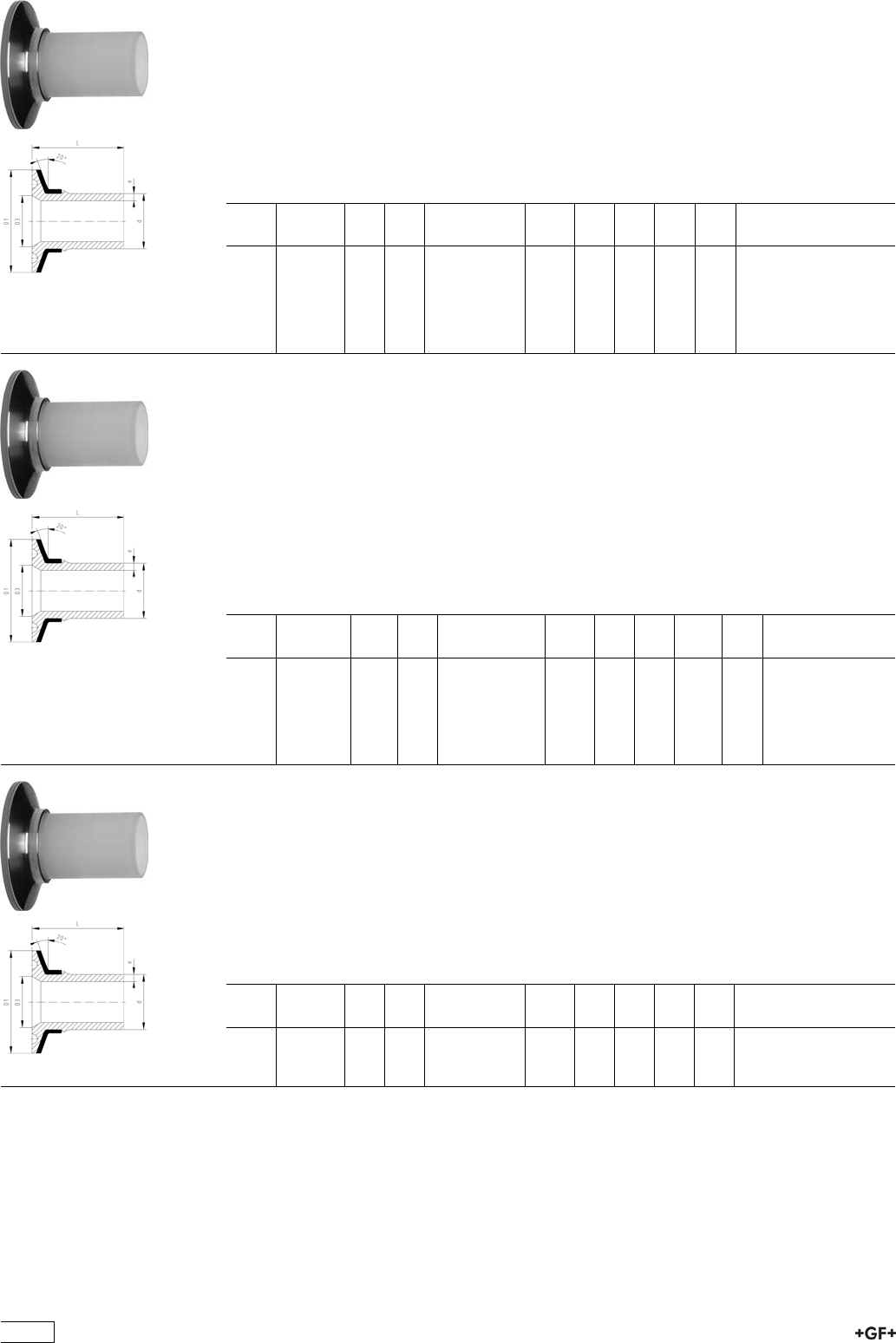
Sanitary Adaptor
Connection to JIS G3447
Model:
ÏMaterial: PP-R unpigmented
ÏConventional butt-welding according to DVS 2207 part 11
ÏInfrared-(IR Plus®) compatible. Please choose fusion parameters: PP-n (PP-R)
ÏBead and Crevice Free weldable with the new BCF®Plus fusion machine
ÏStainless steel reinforcement ring
d
[mm]
FM DN
[mm]
PN Code kg D1
[mm]
D3
[mm]
L
[mm]
e
[mm]
20 BCF, IR 15 10 728 598 406 0.014 34 18 49.0 1,9
25 BCF, IR 20 10 728 598 408 0.032 50 23 49.5 2,3
32 BCF, IR 25 10 728 598 410 0.033 50 30 53.0 2,9
40 BCF, IR 32 10 728 598 414 0.033 50 35 54.0 3,7
50 BCF, IR 40 10 728 598 416 0.061 64 48 61.0 4,6
63 BCF, IR 50 10 728 598 418 0.093 78 60 67.0 5,8
Sanitary Adaptor
Connection to 3A Standard
Model:
ÏMaterial: PP-R unpigmented
ÏConventional butt-welding according to DVS 2207 part 11
ÏInfrared-(IR Plus®) compatible. Please choose fusion parameters: PP-n (PP-R)
ÏBead and Crevice Free weldable with the new BCF®Plus fusion machine
ÏStainless steel reinforcement ring
* Without stainless steel reinforcement ring
d
[mm]
FM Inch PN Code kg D1
[mm]
D3
[mm]
L
[mm]
e
[mm]
*20 BCF, IR 3/4 10 728 598 207 0.006 25 16 49.0 1,9
25 BCF, IR 1 10 728 598 209 0.032 50 22 49.5 2,3
32 BCF, IR 1 1/2 10 728 598 213 0.032 50 35 53.0 2,9
40 BCF, IR 1 1/2 10 728 598 215 0.033 50 35 54.0 3,7
50 BCF, IR 2 10 728 598 217 0.061 64 48 61.0 4,6
63 BCF, IR 2 1/2 10 728 598 219 0.093 78 60 67.0 5,8
Sanitary Adaptor
Connection to Membrane Manometer
Model:
ÏMaterial: PP-R unpigmented
ÏConventional butt-welding according to DVS 2207 part 11
ÏInfrared-(IR Plus®) compatible. Please choose fusion parameters: PP-n (PP-R)
ÏBead and Crevice Free weldable with the new BCF®Plus fusion machine
ÏStainless steel reinforcement ring
d
[mm]
FM DN
[mm]
PN Code kg e
[mm]
D1
[mm]
D3
[mm]
L
[mm]
20 BCF, IR 15 10 728 598 516 0.029 1,9 50 34 49
25 BCF, IR 20 10 728 598 518 0.031 2,3 50 34 50
32 BCF, IR 25 10 728 598 520 0.032 2,9 50 34 53
330
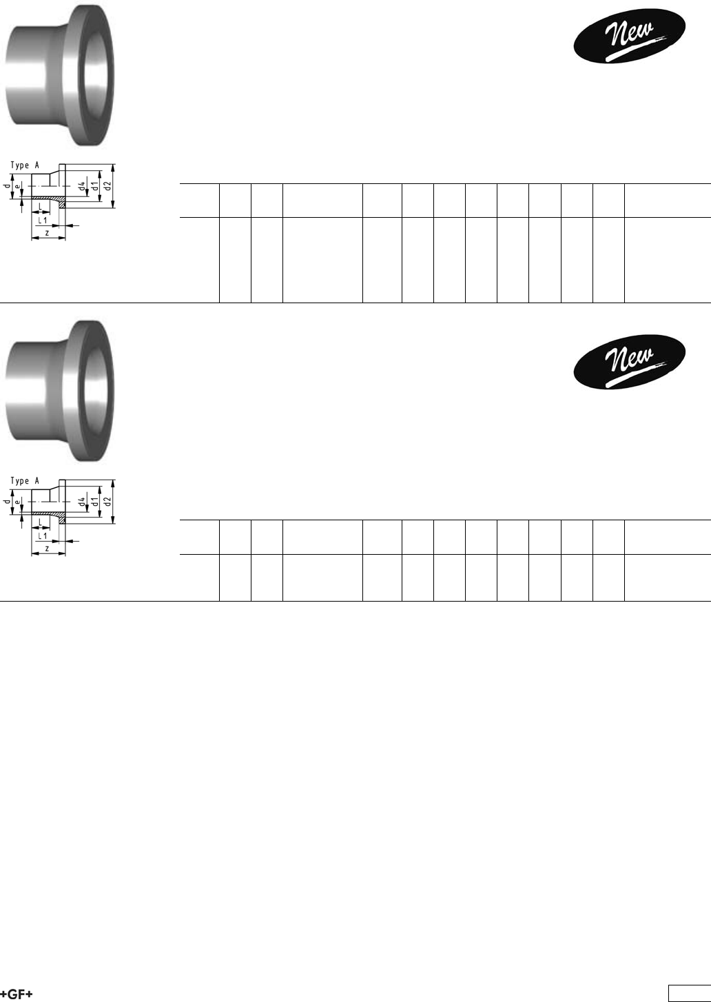
Flange Adaptors, Flanges and Gaskets for
Butt Fusion
PROGEF Natural, Flange Adaptor, S5/SDR11
Combined Jointing Face:
Flat and Serrated
Model:
ÏMaterial: PP-R unpigmented
ÏConventional butt-welding according to DVS 2207 part 11
ÏBead and Crevice Free weldable with the new BCF®Plus fusion machine
ÏInfrared-(IR Plus®) compatible. Please choose fusion parameters: PP-n (PP-R)
ÏGasket: Profile flange gasket EPDM No. 48 44 07, FPM No. 49 44 07
d
[mm]
DN
[mm]
FM Code kg z
[mm]
d1
[mm]
d2
[mm]
d4
[mm]
L
[mm]
L1
[mm]
e
[mm]
20 15 IR 728 798 706 0.015 85 27 45 16 41 7 1.9
25 20 IR 728 798 707 0.028 85 33 58 20 41 9 2.3
32 25 IR 728 798 708 0.042 85 40 68 26 44 10 3.0
40 32 IR 728 798 709 0.064 85 50 78 32 49 11 3.7
50 40 IR 728 798 710 0.091 85 61 88 40 55 12 4.6
63 50 IR 728 798 711 0.146 95 75 102 51 65 14 5.8
PROGEF Natural, Flange Adaptor,
S8.3/SDR17.6
Combined Jointing Face:
Flat and Serrated
Model:
ÏMaterial: PP-R unpigmented
ÏConventional butt-welding according to DVS 2207 part 11
ÏBead and Crevice Free weldable with the new BCF®Plus fusion machine
ÏInfrared-(IR Plus®) compatible. Please choose fusion parameters: PP-n (PP-R)
ÏGasket: Profile flange gasket EPDM No. 48 44 07, FPM No. 49 44 07
d
[mm]
DN
[mm]
FM Code kg z
[mm]
d1
[mm]
d2
[mm]
d4
[mm]
L
[mm]
L1
[mm]
e
[mm]
75 65 IR 728 798 787 0.202 80 89 122 66 70 16 4.5
90 80 IR 728 798 788 0.271 80 105 138 79 79 17 5.4
110 100 IR 728 798 789 0.354 80 125 158 96 82 18 6.6
331
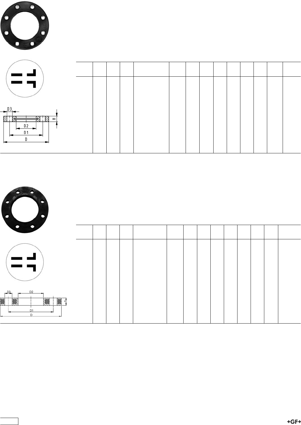
27 70 04
27 70 05
Backing Flanges, PP-V
for Butt Fusion Systems metric
Model:
ÏModern full-plastic flange PP-GF (30 % glass-fibre reinforced)
ÏWith V-groove which applies force evenly on collar
ÏWith integrated bolt retainers as an assembly aid
ÏConnecting dimension: ISO 7005, EN 1092, BS 4504, DIN 2501
ÏBolt circle PN 10
¹) Suitable for socket- and butt fusion systems (no pictograph on flange)
AL: number of holes
d
[mm]
Inch DN
[mm]
PN Code kg D
[mm]
D1
[mm]
D2
[mm]
D3
[mm]
H
[mm]
AL SC
¹20 15 16 727 700 406 0.080 95 65 28 14 16 4 M12
¹25 20 16 727 700 407 0.100 105 75 34 14 17 4 M12
¹32 25 16 727 700 408 0.140 115 85 42 14 18 4 M12
¹40 32 16 727 700 409 0.220 140 100 51 18 20 4 M16
¹50 40 16 727 700 410 0.210 150 110 62 18 22 4 M16
¹63 50 16 727 700 411 0.380 165 125 78 18 24 4 M16
¹75 65 16 727 700 412 0.480 185 145 92 18 26 4 M16
90 80 16 727 700 513 0.520 200 160 108 18 27 8 M16
110 100 16 727 700 514 0.680 220 180 128 18 28 8 M16
27 70 02
27 70 03
Backing Flanges, PP/Steel
for Butt Fusion Systems metric
Model:
ÏMaterial: PP (30 % glass-fibre reinforced) with steel ring
ÏConnecting dimension: ISO 7005, EN 1092, BS 4504, DIN 2501
ÏBolt circle PN 10
AL: number of holes
d
[mm]
d
[inch]
DN
[mm]
PN Code kg D
[mm]
D1
[mm]
D2
[mm]
D3
[mm]
H
[mm]
AL SC
20 15 16 727 700 206 0.220 95 65 28 14 12 4 M12
25 20 16 727 700 207 0.260 105 75 34 14 12 4 M12
32 25 16 727 700 208 0.430 115 85 42 14 16 4 M12
40 32 16 727 700 209 0.650 140 100 51 18 16 4 M16
50 40 16 727 700 210 0.820 150 110 62 18 18 4 M16
63 50 16 727 700 211 0.940 165 125 78 18 18 4 M16
75 65 16 727 700 212 1.300 185 145 92 18 18 4 M16
90 80 16 727 700 313 1.400 200 160 108 18 20 8 M16
110 100 16 727 700 314 1.580 220 180 128 18 20 8 M16
332
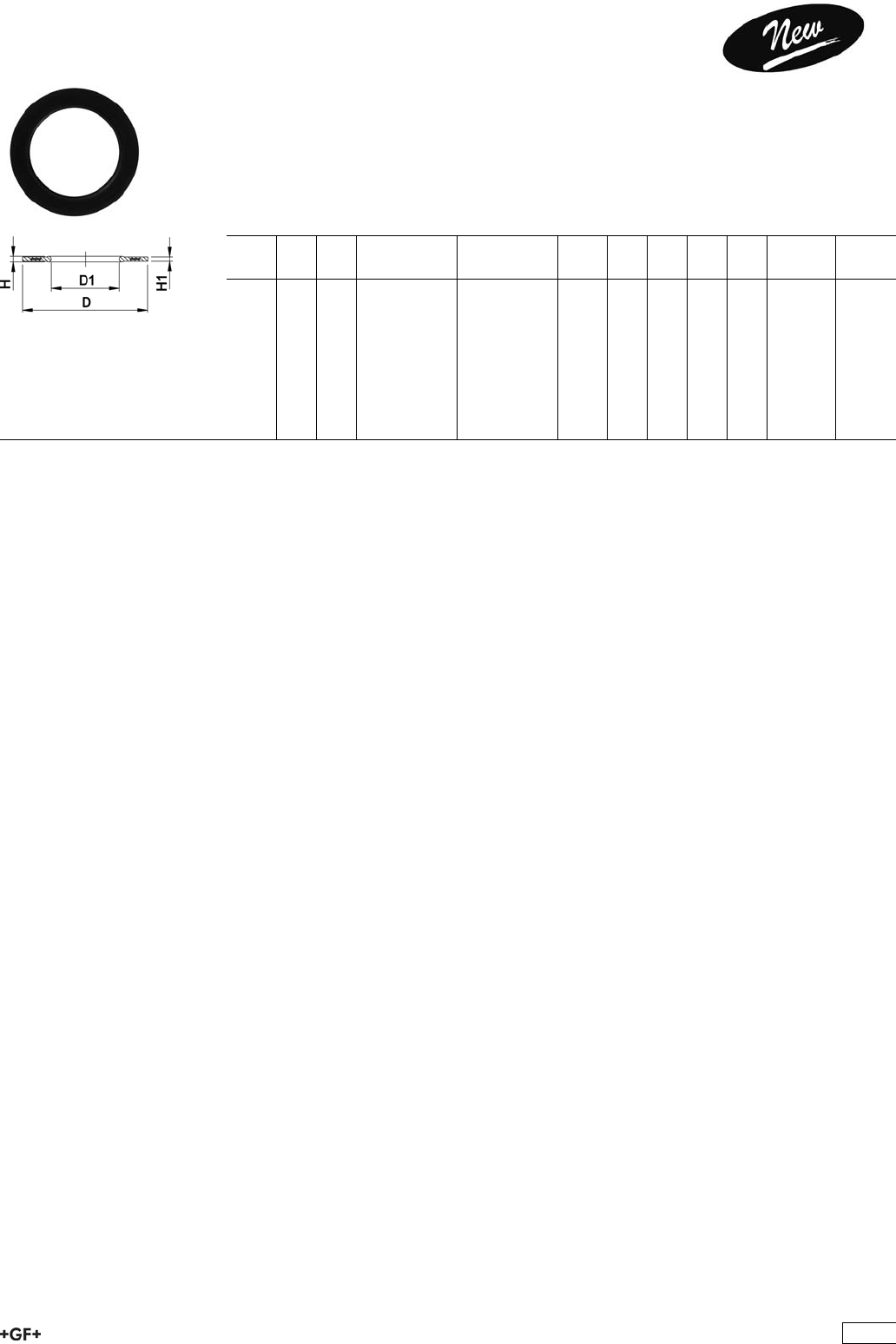
EPDM 48 44 07
FPM 49 44 07 Profile Flange Gaskets metric
EPDM / FPM
Model:
ÏFor all GF Flange Adaptors
ÏProfile Gasket with steel insert (type G-ST-P/K)
ÏHardness: 70° Shore EPDM, 75° Shore FPM
ÏCentering on the inner diameter of the screw crown
di FA are the suitable inner diameters of flange adaptors
d
[mm]
DN
[mm]
PN EPDM
Code
FPM
Code
kg D
[mm]
D1
[mm]
H
[mm]
H1
[mm]
di FA
[mm]
20 15 16 748 440 706 749 440 706 0.008 51 20 4 3 10 - 20
25 20 16 748 440 707 749 440 707 0.011 61 22 4 3 12 - 22
32 25 16 748 440 708 749 440 708 0.014 71 28 4 3 18 - 28
40 32 16 748 440 709 749 440 709 0.021 82 40 4 3 30 - 40
50 40 16 748 440 710 749 440 710 0.022 92 46 4 3 36 - 46
63 50 16 748 440 711 749 440 711 0.041 107 58 5 4 48 - 58
75 65 16 748 440 712 749 440 712 0.055 127 69 5 4 59 - 69
90 80 16 748 440 713 749 440 713 0.062 142 84 5 4 73 - 84
110 100 16 748 440 714 749 440 714 0.085 162 104 6 5 94 - 104
333

334
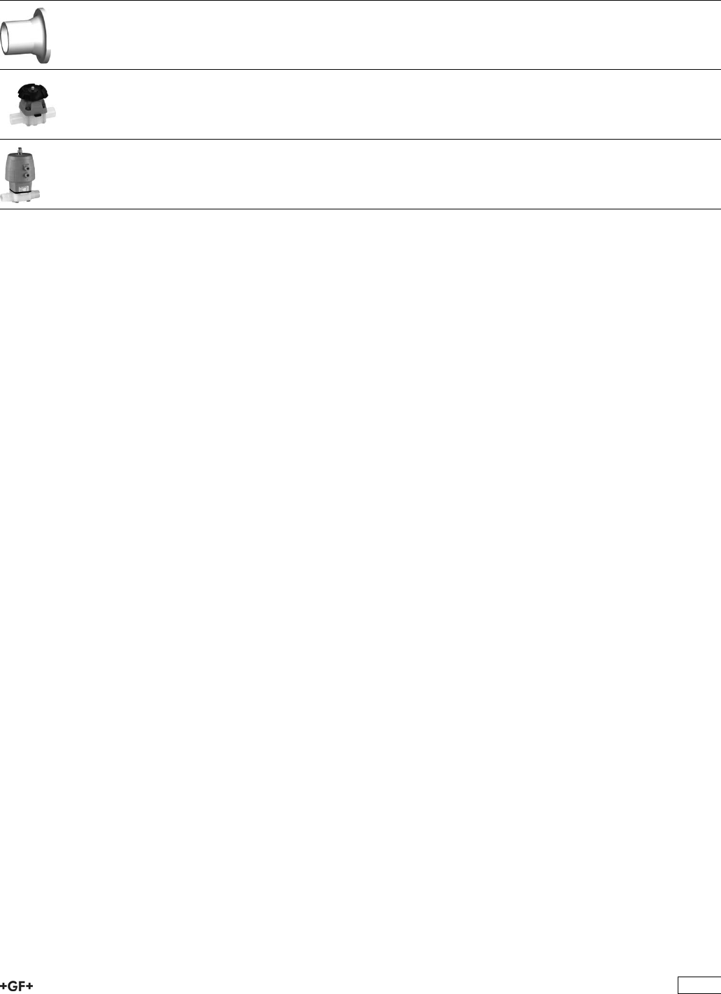
PROGEF Natural Hand-Operated and Actuated
Valves
Page
Valve End 546 336
Diaphragm Valves 337
Diaphragm Valves Pneumatic 342
335
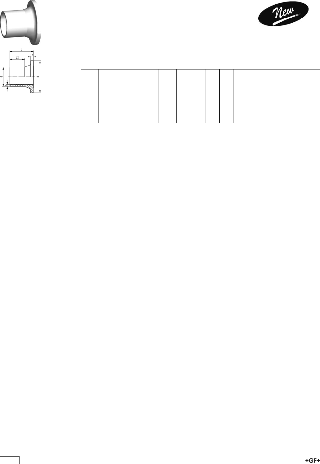
Valve End 546
PROGEF Natural, Valve end 546, SDR11
Model:
ÏMaterial: PP-R unpigmented
ÏBead and Crevice Free weldable with the new BCF®Plus fusion machine
ÏInfrared-(IR Plus®) compatible. Please choose fusion parameters: PP-n (PP-R)
ÏConventional butt-welding according to DVS 2207 part 11
d
[mm]
FM Code kg D
[mm]
L
[mm]
L1
[mm]
L2
[mm]
e
[mm]
20 BCF, IR 168 480 260 0.007 38 37 4 25 1,9
25 BCF, IR 168 480 261 0.011 44 39 5 25 2,3
32 BCF, IR 168 480 262 0.017 53 40 5 25 2,9
40 BCF, IR 168 480 263 0.030 65 43 5 25 3,7
50 BCF, IR 168 480 264 0.053 77 51 6 25 4,6
63 BCF, IR 168 480 265 0.093 99 60 7 28 5,8
336
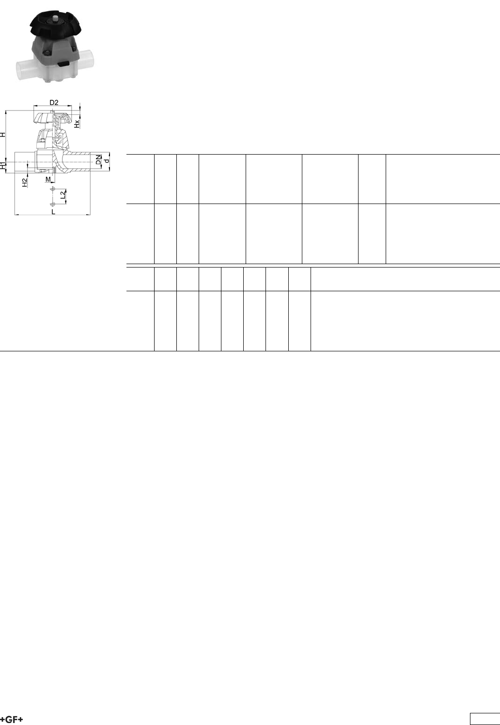
Diaphragm Valves
PROGEF®Natural
Diaphragm valve type 315
With butt fusion spigots
Model:
ÏMaterial: PP-R unpigmented
ÏBead and Crevice Free weldable with the new BCF fusion machine
ÏConventional butt fusion and (IR Plus®) compatible
ÏPTFE with EPDM supporting diaphragm: FDA conform
Ïd20-d63 SDR11, d90-d110 SDR17,6
Option:
ÏHandwheel with built in locking mechanism
d
[mm]
DN
[mm]
PN kv-value
(”p=1 bar)
[l/min]
EPDM
Code
PTFE with
EPDM
supporting
diaphragm
Code
kg
20 15 10 72 168 315 517 168 315 532 0.312
25 20 10 137 168 315 518 168 315 533 0.494
32 25 10 207 168 315 519 168 315 534 0.660
40 32 10 354 168 315 520 168 315 535 0.857
50 40 10 517 168 315 521 168 315 536 1.155
63 50 10 713 168 315 522 168 315 537 2.018
d
[mm]
D2
[mm]
H
[mm]
H1
[mm]
H2
[mm]
L
[mm]
L2
[mm]
M
20 80 90 14 12 124 25 M6
25 80 101 18 12 144 25 M6
32 94 117 22 12 154 25 M6
40 117 127 26 15 174 45 M8
50 117 139 32 15 194 45 M8
63 152 172 39 15 223 45 M8
337
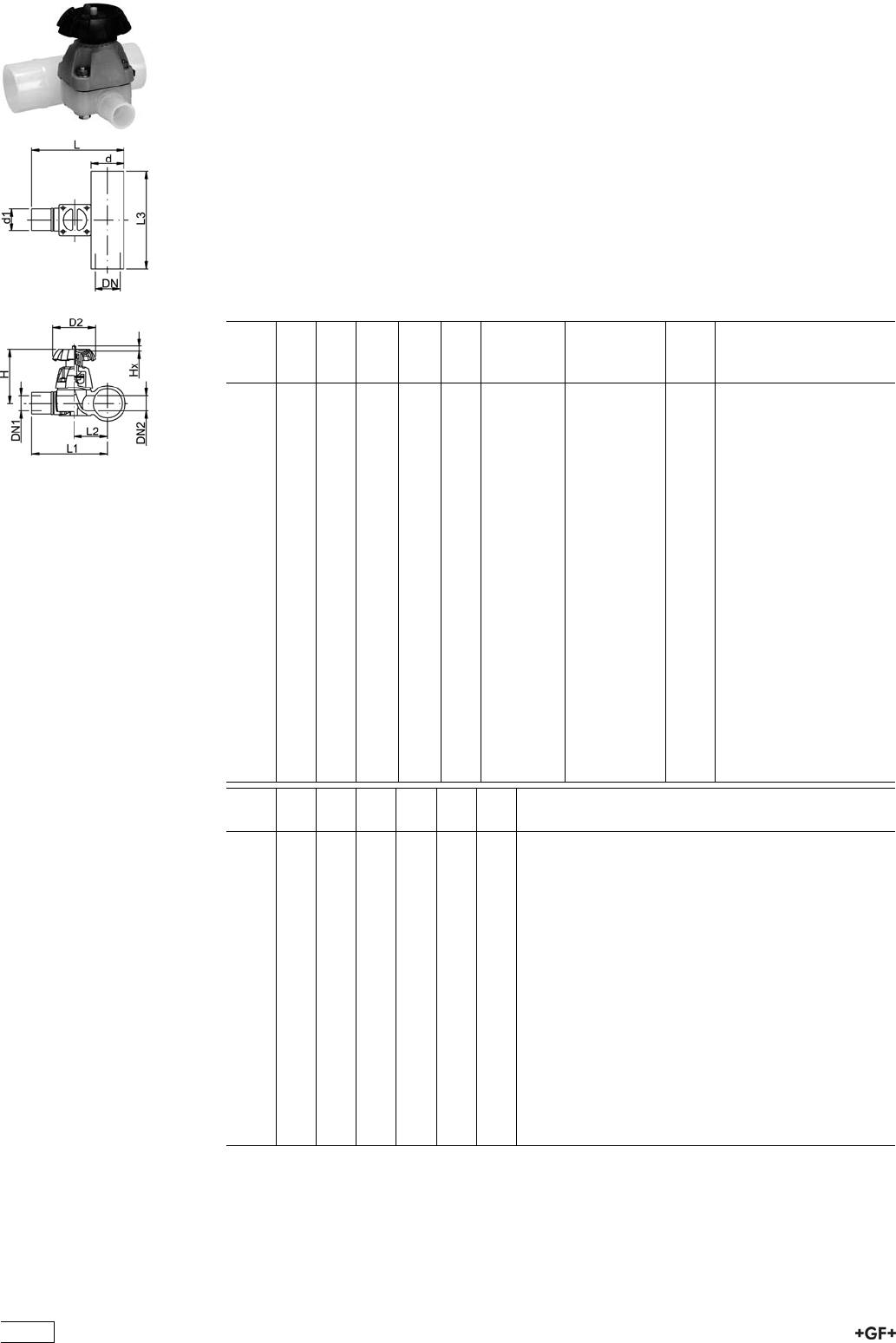
PROGEF®Natural
Diaphragm valve type 319
With butt fusion spigots
Model:
ÏMaterial: PP-R unpigmented
ÏValve body injection molded
ÏMinimized static zone (dead leg)
ÏCompact design
ÏBead and Crevice Free weldable with the new BCF fusion machine
ÏConventional butt fusion and (IR Plus®) compatible
Ïd20-d63 SDR11, d90-d110 SDR17,6
Option:
ÏHandwheel with built in locking mechanism
d
[mm]
d1
[mm]
DN
[mm]
DN1
[mm]
DN2
[mm]
PN kv-value
(”p=1 bar)
[l/min]
EPDM
Code
kg
20 20 15 15 15 10 47 168 319 401 0.274
25 20 20 15 20 10 69 168 319 403 0.361
25 25 20 20 20 10 91 168 319 404 0.361
32 20 25 15 25 10 86 168 319 407 0.602
32 25 25 20 25 10 126 168 319 408 0.601
32 32 25 25 25 10 156 168 319 409 0.596
40 20 32 15 25 10 84 168 319 412 0.634
50 20 40 15 25 10 82 168 319 418 0.677
50 25 40 20 25 10 124 168 319 419 0.676
50 32 40 25 25 10 159 168 319 420 0.676
63 20 50 15 25 10 81 168 319 425 0.750
63 25 50 20 25 10 115 168 319 426 0.749
63 32 50 25 25 10 156 168 319 427 0.746
90 20 80 15 25 6 88 168 319 441 0.871
90 25 80 20 25 6 133 168 319 442 1.062
90 32 80 25 25 6 162 168 319 443 0.907
90 50 80 40 50 6 504 168 319 445 2.285
90 63 80 50 50 6 530 168 319 446 2.285
110 20 100 15 25 6 89 168 319 451 0.888
110 25 100 20 25 6 123 168 319 452 0.887
110 32 100 25 25 6 159 168 319 453 0.886
110 50 100 40 50 6 503 168 319 455 2.400
110 63 100 50 50 6 543 168 319 456 2.426
d
[mm]
D2
[mm]
H
[mm]
L
[mm]
L1
[mm]
L2
[mm]
L3
[mm]
20 80 83 106 96 30 140
25 80 91 121 108 36 150
25 80 91 121 108 36 150
32 94 105 137 120 43 160
32 94 105 137 120 43 160
32 94 105 137 120 43 160
40 94 105 149 128 51 180
50 94 105 159 134 57 180
50 94 105 159 134 57 180
50 94 105 159 134 57 180
63 94 105 175 144 67 180
63 94 105 175 144 67 180
63 94 105 175 144 67 180
90 94 105 204 159 82 160
90 94 105 204 159 82 160
90 94 105 204 159 82 160
90 152 151 252 207 95 220
90 152 151 252 207 95 220
338

d
[mm]
D2
[mm]
H
[mm]
L
[mm]
L1
[mm]
L2
[mm]
L3
[mm]
110 94 105 226 171 94 160
110 94 105 226 171 94 160
110 94 105 226 171 94 160
110 152 151 274 219 107 220
110 152 151 274 219 107 220
339

PROGEF®Natural
Diaphragm valve type 319
With butt fusion spigots
Model:
ÏMaterial: PP-R unpigmented
ÏValve body injection molded
ÏMinimized static zone (dead leg)
ÏCompact design
ÏBead and Crevice Free weldable with the new BCF fusion machine
ÏConventional butt fusion and (IR Plus®) compatible
Ïd20-d63 SDR11, d90-d110 SDR17,6
Option:
ÏHandwheel with built in locking mechanism
d
[mm]
d1
[mm]
DN1
[mm]
DN
[mm]
DN2
[mm]
PN kv-value
(”p=1 bar)
[l/min]
PTFE with
EPDM
supporting
diaphragm
Code
kg
20 20 15 15 15 10 47 168 319 501 0.312
25 20 15 20 20 10 69 168 319 503 0.462
25 25 20 20 20 10 91 168 319 504 0.465
32 20 25 25 25 10 86 168 319 507 0.602
32 25 20 25 25 10 126 168 319 508 0.624
32 32 25 25 25 10 156 168 319 509 0.619
40 20 15 32 25 10 84 168 319 512 0.304
50 20 15 40 25 10 82 168 319 518 0.702
50 25 20 40 25 10 124 168 319 519 0.701
50 32 25 40 25 10 159 168 319 520 0.701
63 20 15 50 25 10 81 168 319 525 0.750
63 25 20 50 25 10 115 168 319 526 0.775
63 32 25 50 25 10 156 168 319 527 0.771
90 20 15 80 25 6 88 168 319 541 0.878
90 25 20 80 25 6 133 168 319 542 1.277
90 32 25 80 25 6 162 168 319 543 0.876
90 50 40 80 50 6 504 168 319 545 2.300
90 63 50 80 50 6 530 168 319 546 2.300
110 20 15 100 25 6 89 168 319 551 0.897
110 25 20 100 25 6 123 168 319 552 0.897
110 32 25 100 25 6 159 168 319 553 0.891
110 50 40 100 50 6 503 168 319 555 2.488
110 63 50 100 50 6 543 168 319 556 2.433
d
[mm]
D2
[mm]
H
[mm]
L
[mm]
L1
[mm]
L2
[mm]
L3
[mm]
20 80 83 106 96 30 140
25 80 91 121 108 36 150
25 80 91 121 108 36 150
32 94 105 137 120 43 160
32 94 105 137 120 43 160
32 94 105 137 120 43 160
40 94 105 149 128 51 180
50 94 105 159 134 57 180
50 94 105 159 134 57 180
50 94 105 159 134 57 180
63 94 105 175 144 67 180
63 94 105 175 144 67 180
63 94 105 175 144 67 180
90 94 105 204 159 82 160
90 94 105 204 159 82 160
90 94 105 204 159 82 160
340
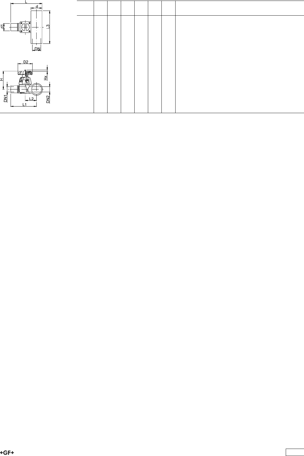
d
[mm]
D2
[mm]
H
[mm]
L
[mm]
L1
[mm]
L2
[mm]
L3
[mm]
90 152 151 252 207 95 220
90 152 151 252 207 95 220
110 94 105 226 171 94 160
110 94 105 226 171 94 160
110 94 105 226 171 94 160
110 152 151 274 219 107 220
110 152 151 274 219 107 220
341
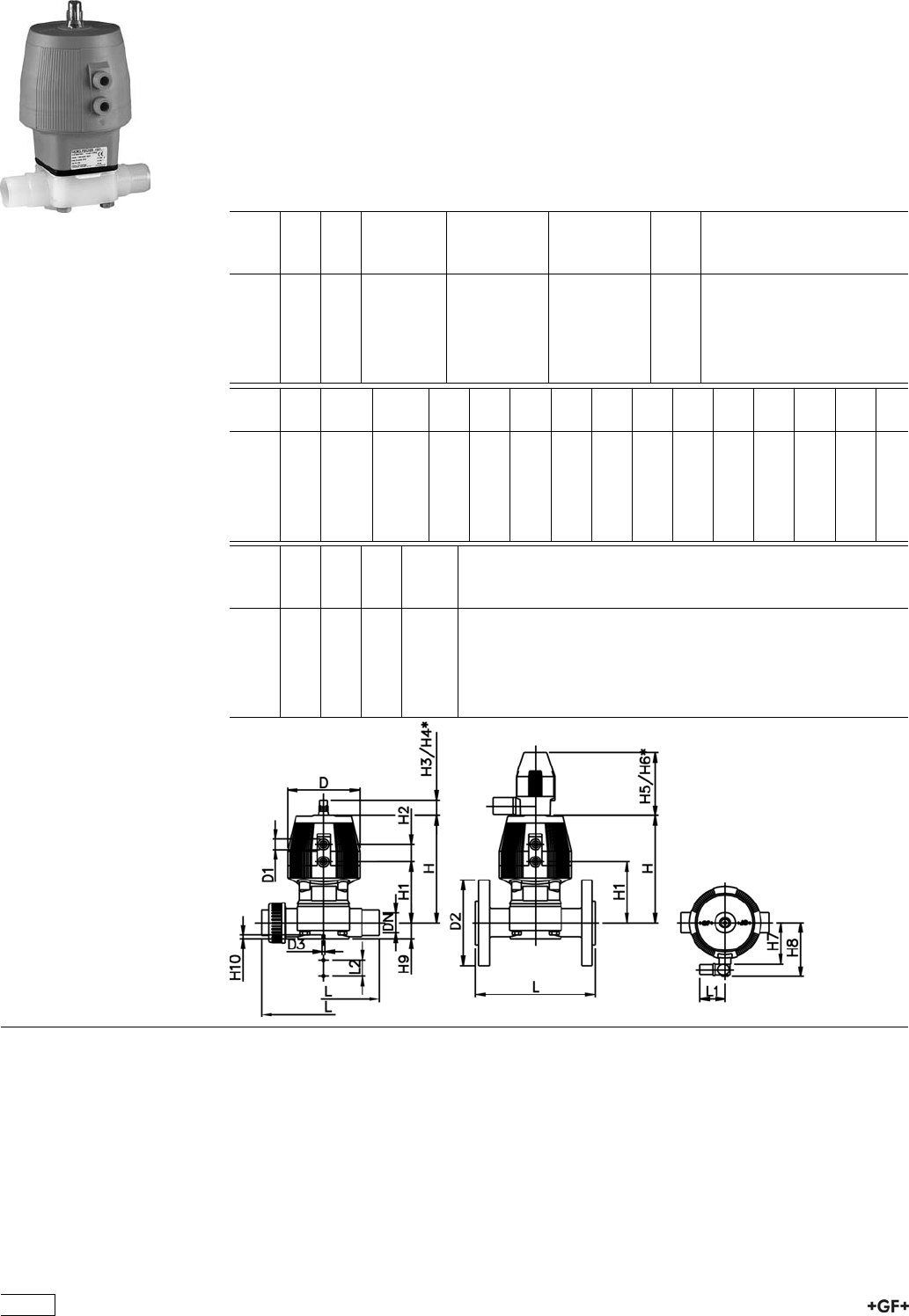
Diaphragm Valves Pneumatic
PROGEF Natural
Diaphragm valve type DIASTAR 025
Function FC (Fail safe to close)
With butt fusion spigots metric
Model:
ÏMaterial: PP-R unpigmented
ÏWith position indicator / Working pressure: both sides
d
[mm]
DN
[mm]
PN kv-value
(”p=1 bar)
[l/min]
EPDM
Code
PTFE/EPDM
Code
kg
20 15 10 72 199 027 521 199 027 551 0.839
25 20 10 120 199 027 522 199 027 552 0.936
32 25 10 238 199 027 523 199 027 553 1.705
40 32 10 341 199 027 524 199 027 554 0.238
50 40 10 460 199 027 525 199 027 555 4.665
63 50 10 685 199 027 526 199 027 556 5.353
d
[mm]
D
[mm]
D1_G
[inch]
D3[M]
[mm]
L
[mm]
L1
[mm]
L2
[mm]
H
[mm]
H1
[mm]
H2
[mm]
H3
[mm]
H4
[mm]
H5
[mm]
H6
[mm]
H7
[mm]
20 96 1
/86 124 60 25 125 69 25 23 44 100 155 56
25 96 1
/86 144 60 25 127 71 25 23 44 100 155 56
32 120 1
/86 154 60 25 163 93 26 36 64 100 155 68
40 150 1
/48 174 60 45 196 106 36 36 64 100 160 85
50 180 1
/48 194 60 45 227 119 37 36 64 100 170 101
63 180 1
/48 224 60 45 241 133 37 36 64 100 170 101
d
[mm]
H8
[mm]
H9
[mm]
H10
[mm]
Lift =
Hx
[mm]
20 86 14 12 8
25 88 18 12 10
32 100 21 12 12
40 117 26 15 14
50 133 33 15 18
63 133 39 15 22
342
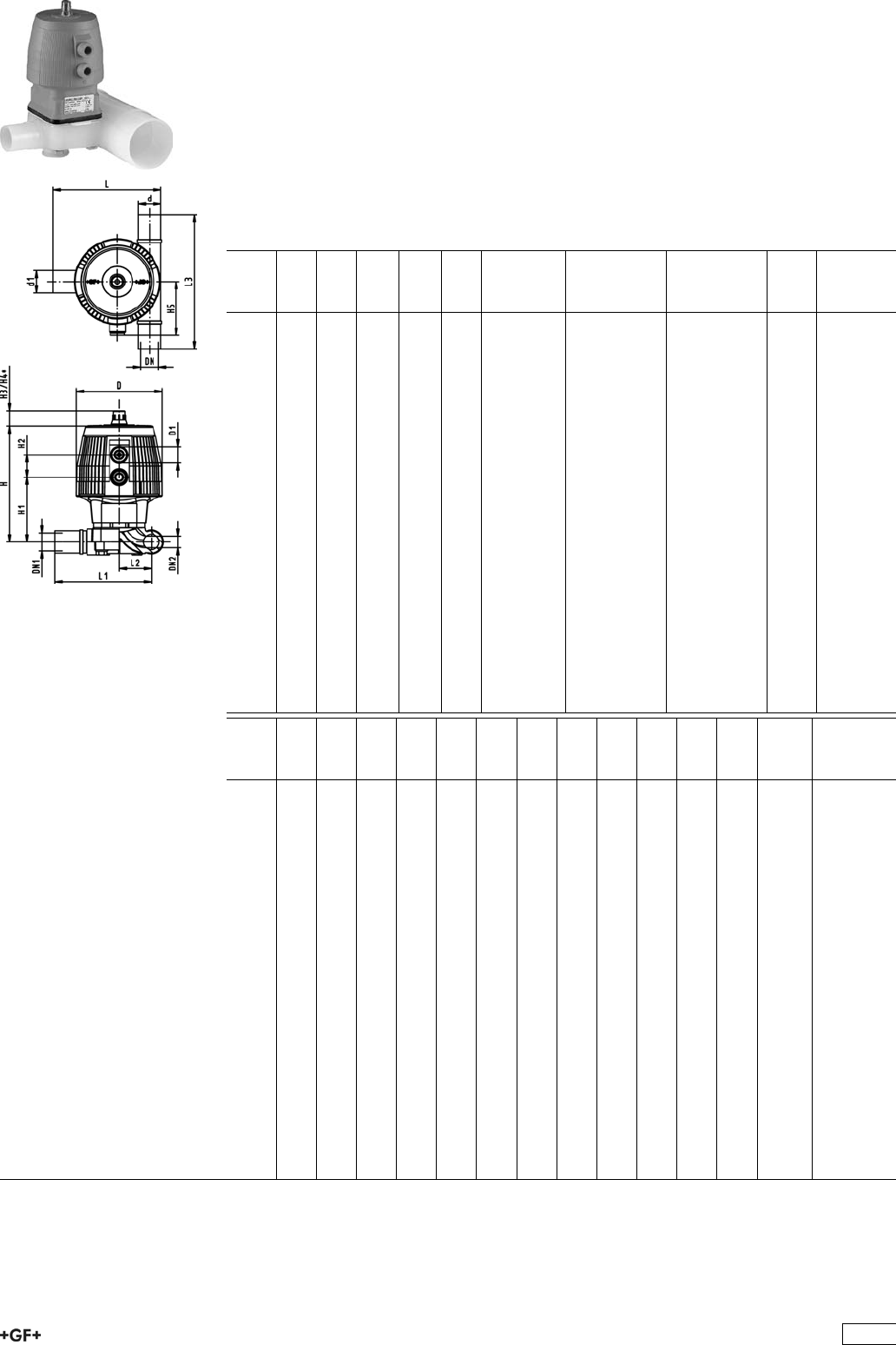
PROGEF Natural
Diaphragm valve type DIASTAR 025
Function FC (Fail safe to close)
ZERO STATIC with butt fusion spigots metric
Model:
ÏMaterial: PP-R unpigmented
Ïd20-d63 SDR11, d90-d110 SDR17,6
ÏWith position indicator
ÏDN2: for coordination of accessoires
d
[mm]
d1
[mm]
DN
[mm]
DN1
[mm]
DN2
[mm]
PN kv-value
(”p=1 bar)
[l/min]
EPDM
Code
PTFE
Code
kg
20 20 15 15 15 10 47 199 029 421 199 029 381 1.510
25 20 20 15 20 10 69 199 029 422 199 029 382 2.013
25 25 20 20 20 10 91 199 029 423 199 029 383 2.013
32 20 25 15 25 10 86 199 029 424 199 029 384 2.567
32 25 25 20 25 10 126 199 029 425 199 029 385 2.566
32 32 25 25 25 10 156 199 029 426 199 029 386 2.561
40 20 32 15 25 10 84 199 029 427 199 029 387 2.599
50 20 40 15 25 10 82 199 029 431 199 029 391 2.642
50 25 40 20 25 10 124 199 029 432 199 029 392 2.641
50 32 40 25 25 10 159 199 029 433 199 029 393 2.641
63 20 50 15 25 10 81 199 029 436 199 029 396 2.715
63 25 50 20 25 10 115 199 029 437 199 029 397 2.714
63 32 50 25 25 10 156 199 029 438 199 029 398 2.711
90 20 80 15 25 6 88 199 029 445 199 029 405 2.742
90 25 80 20 25 6 133 199 029 446 199 029 406 2.756
90 32 80 25 25 6 162 199 029 447 199 029 407 2.737
90 50 80 40 50 6 504 199 029 448 199 029 408 5.679
90 63 80 50 50 6 530 199 029 449 199 029 409 5.679
110 20 100 15 25 6 89 199 029 450 199 029 410 2.837
110 25 100 20 25 6 123 199 029 451 199 029 411 2.835
110 32 100 25 25 6 159 199 029 452 199 029 412 2.834
110 50 100 40 50 6 503 199 029 453 199 029 413 5.869
110 63 100 50 40 6 543 199 029 454 199 029 414 5.822
d
[mm]
L
[mm]
L1
[mm]
L2
[mm]
L3
[mm]
H
[mm]
H1
[mm]
H2
[mm]
H3
[mm]
H4
[mm]
H5
[mm]
D
[mm]
D1
[inch]
Lift =
Hx
[mm]
20 106 96 30 140 128 69 25 23 44 56 96 1
/88
25 121 108 36 150 130 71 25 23 44 56 96 1
/810
25 121 108 36 150 130 71 25 23 44 56 96 1
/810
32 137 120 43 160 166 93 26 36 64 68 120 1
/812
32 137 120 43 160 166 93 26 36 64 68 120 1
/812
32 137 120 43 160 166 93 26 36 64 68 120 1
/812
40 149 128 51 180 166 93 26 36 64 68 120 1
/812
50 159 134 57 180 166 93 26 36 64 68 120 1
/812
50 159 134 57 180 166 93 26 36 64 68 120 1
/812
50 159 134 57 180 166 93 26 36 64 68 120 1
/812
63 175 144 67 180 166 93 26 36 64 68 120 1
/812
63 175 144 67 180 166 93 26 36 64 68 120 1
/812
63 175 144 67 180 166 93 26 36 64 68 120 1
/812
90 204 159 82 160 166 93 26 36 64 68 120 1
/812
90 204 159 82 160 166 93 26 36 64 68 120 1
/812
90 204 159 82 160 166 93 26 36 64 68 120 1
/812
90 252 207 95 220 247 133 37 36 64 101 180 1
/422
90 252 207 95 220 247 133 37 36 64 101 180 1
/422
110 226 171 94 160 166 93 26 36 64 68 120 1
/812
110 226 171 94 160 166 93 26 36 64 68 120 1
/812
110 226 171 94 160 166 93 26 36 64 68 120 1
/812
110 274 219 107 220 247 133 37 36 64 101 180 1
/422
110 274 219 107 220 247 133 37 36 64 101 180 1
/422
343

PROGEF®Natural
Diaphragm valve type DIASTAR 025
Function FO (Fail safe to open)
With butt fusion spigots metric
Model:
ÏMaterial: PP-R unpigmented
ÏWith position indicator / Working pressure: both sides
d
[mm]
DN
[mm]
PN kv-value
(”p=1 bar)
[l/min]
EPDM
Code
PTFE/EPDM
Code
kg
20 15 10 72 199 027 531 199 027 561 0.454
25 20 10 120 199 027 532 199 027 562 0.740
32 25 10 238 199 027 533 199 027 563 1.160
40 32 10 341 199 027 534 199 027 564 1.390
50 40 10 460 199 027 535 199 027 565 2.510
63 50 10 685 199 027 536 199 027 566 5.430
d
[mm]
D
[mm]
D1_G
[inch]
D3[M]
[mm]
L
[mm]
L1
[mm]
L2
[mm]
H
[mm]
H1
[mm]
H2
[mm]
H3
[mm]
H4
[mm]
H5
[mm]
H6
[mm]
H7
[mm]
20 68 1
/86 124 60 25 98 59 24 23 44 100 155 44
25 96 1
/86 144 60 25 127 71 25 23 44 100 155 56
32 96 1
/86 154 60 25 141 85 25 23 44 100 155 56
40 120 1
/88 174 60 45 167 97 26 36 64 100 160 68
50 150 1
/48 194 60 45 198 108 36 36 64 100 170 85
63 150 1
/48 224 60 45 216 126 36 36 64 100 170 85
d
[mm]
H8
[mm]
H9
[mm]
H10
[mm]
Lift =
Hx
[mm]
20 76 14 12 8
25 88 18 12 10
32 88 21 12 12
40 100 26 15 14
50 117 33 15 18
63 117 39 15 22
344

PROGEF Natural
Diaphragm valve type DIASTAR 025
Function DA (Double acting)
With butt fusion spigots metric
Model:
ÏMaterial: PP-R unpigmented
ÏWith position indicator / Working pressure: both sides
d
[mm]
DN
[mm]
PN kv-value
(”p=1 bar)
[l/min]
EPDM
Code
PTFE/EPDM
Code
kg
20 15 10 72 199 027 541 199 027 571 0.454
25 20 10 120 199 027 542 199 027 572 0.740
32 25 10 238 199 027 543 199 027 573 1.160
40 32 10 341 199 027 544 199 027 574 1.390
50 40 10 460 199 027 545 199 027 575 2.510
63 50 10 685 199 027 546 199 027 576 5.430
d
[mm]
D
[mm]
D1_G
[inch]
D3[M]
[mm]
L
[mm]
L1
[mm]
L2
[mm]
H
[mm]
H1
[mm]
H2
[mm]
H3
[mm]
H4
[mm]
H5
[mm]
H6
[mm]
H7
[mm]
20 68 1
/86 124 60 25 98 59 24 23 44 100 155 44
25 96 1
/86 144 60 25 127 71 25 23 44 100 155 56
32 96 1
/86 154 60 25 141 85 25 23 44 100 155 56
40 120 1
/88 174 60 45 167 97 26 36 64 100 160 68
50 150 1
/48 194 60 45 198 108 36 36 64 100 170 85
63 150 1
/48 224 60 45 216 126 36 36 64 100 170 85
d
[mm]
H8
[mm]
H9
[mm]
H10
[mm]
Lift =
Hx
[mm]
20 76 14 12 8
25 88 18 12 10
32 88 21 12 12
40 100 26 15 14
50 117 33 15 18
63 117 39 15 22
345
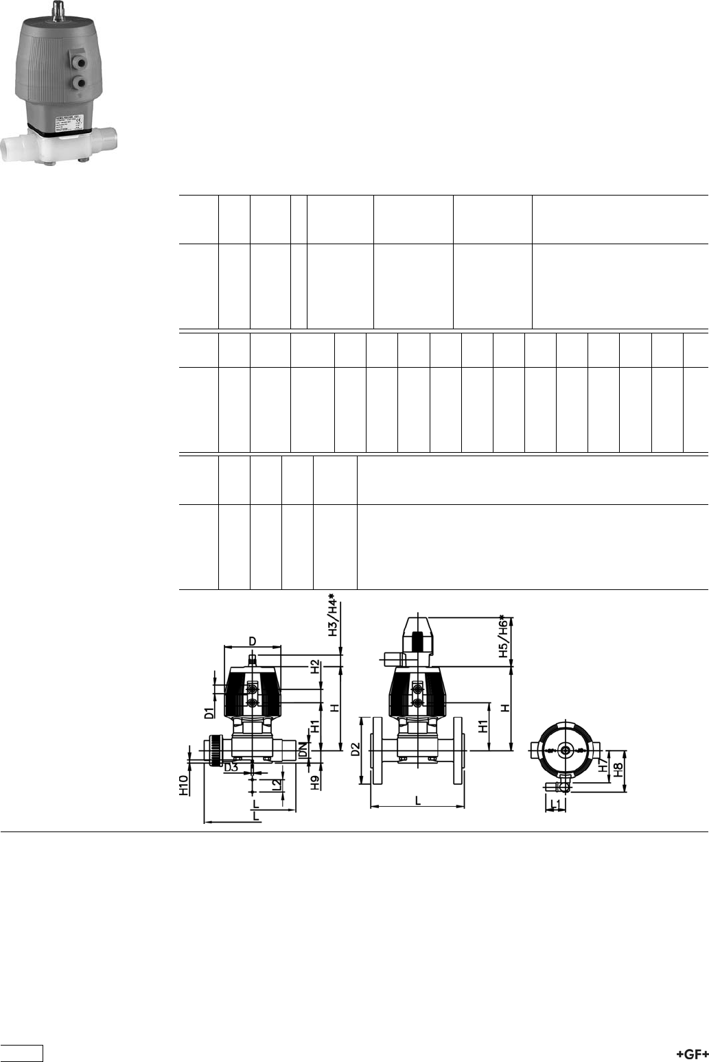
PROGEF Natural
Diaphragm valve type DIASTAR 028
Function FC (Fail safe to close)
With butt fusion spigots metric
Model:
ÏMaterial: PP-R unpigmented
ÏWith position indicator / Working pressure: one side
*PN: EPDM/PTFE
d
[mm]
DN
[mm]
PN
[bar]
kv-value
(”p=1 bar)
[l/min]
EPDM
Code
PTFE/EPDM
Code
20 15 10 / 5 * 72 199 028 521 199 028 551
25 20 10 / 7 * 120 199 028 522 199 028 552
32 25 10 / 7 * 238 199 028 523 199 028 553
40 32 10 / 7 * 341 199 028 524 199 028 554
50 40 10 / 7 * 460 199 028 525 199 028 555
63 50 10 / 7 * 685 199 028 526 199 028 556
d
[mm]
D
[mm]
D1_G
[inch]
D3[M]
[mm]
L
[mm]
L1
[mm]
L2
[mm]
H
[mm]
H1
[mm]
H2
[mm]
H3
[mm]
H4
[mm]
H5
[mm]
H6
[mm]
H7
[mm]
20 68 1
/86 124 60 25 98 59 24 23 44 100 155 44
25 96 1
/86 144 60 25 127 71 25 23 44 100 155 56
32 96 1
/86 154 60 25 141 85 25 23 44 100 155 56
40 120 1
/88 174 60 45 167 97 26 36 64 100 160 68
50 150 1
/48 194 60 45 198 108 36 36 64 100 170 85
63 150 1
/48 224 60 45 216 126 36 36 64 100 170 85
d
[mm]
H8
[mm]
H9
[mm]
H10
[mm]
Lift =
Hx
[mm]
20 76 14 12 8
25 88 18 12 10
32 88 21 12 12
40 100 26 15 14
50 117 33 15 18
63 117 39 15 22
346
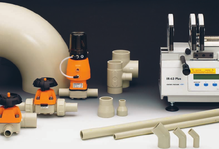
EGD<:;Eajh<ZcZgVa>c[dgbVi^dc
ÄE^eZh
Ä7jii;jh^dcHnhiZb

BViZg^Va
8dadjg
9Zch^in
Hjg[VXZiZch^dc
A^cZVgZmeVch^dcXdZ[ÒX^Zci
:"bdYjajh
I]ZgbVaXdcYjXi^k^in
Hjg[VXZgZh^hi^k^in
7ZiVEE"=&%%
7ZiVEdanegdenaZcZ=dbdedanbZg
Y'%" Y ''*'%"Y''*'%"Y ''*''*''*
G6A,%('eZWWaZ\gZn
s%#.%\$Xb(>HD&&-($ 6HIB 9,.'$6HIB 9,.'$6HIB 9,.'6HIB 9,.'6HIB9,.'
(&b?$b'
%#&+bb$b@9>C*(,*'
&(%%C$bb'>HD*',$6HIB9,.%
%#'(L$b@:C&'++)
Ñ&%&+±>:8+%%.(
HiViZ"d["i]Z"VgiEE
EdanegdenaZcZ
Y'*% " Y (&*'*% " Y (&*'*%"Y(&*(&*(&*
G6A,%('eZWWaZ\gZn
s%#.%\$Xb(>HD&&-($6HIB9,.'
')b?$b'
%#&+"%#&-bb$b@9>C*(,*'
.%%C$bb'>HD*',$6HIB9,.%
%#'(L$b@:C&'++)
Ñ&%&+±>:8+%%.(
9^bZch^dc Y'%ÄY(&*^cVXXdgYVcXZid:C>HD&*).)
EgZhhjgZGVi^c\ E^eZh$;^ii^c\h$9^Ve]gV\bVcYWVaakVakZh/
Y'%ÄY''*H9G&&! EC&%! X2'#%H9G&&!EC&%!X2'#%
Y*%ÄY''*H9G&,#+! EC+! X2'#%H9G&,#+!EC+!X2'#%
7jiiZgÓnkVakZh/
Y+(ÄY''*!EC&%
E^eZh$;^ii^c\h/
Y'*%ÄY(&*H9G&&! EC&%! X2'#%H9G&&!EC&%!X2'#%
Y'*%ÄY(&*H9G&,#+! EC+! X 2 '#%H9G&,#+!EC+!X2'#%
IZbeZgVijgZGVi^c\ ;gdb%8id-%8('; Ä &,+ ;Ä&,+;Ä&,+;&,+;&,+;
EgdYjXi^dc ;^ii^c\h$kVakZh/^c_ZXi^dcbdjaYZY
E^eZh/ZmigjYZY
IgZVibZci/:kZgnXdbedcZci^hheZX^VaanXaZVcZYVXXdgY^c\idVegdXZhhYZÒcZYWn <; #E^eZh
VcYÒii^c\hVgZh^a^Xdc"!d^a"VcYYjhi[gZZ#6YY^i^dcVaheZX^ÒXVi^dch[dgkVakZh#EgdYjXihZheZX^Vaan
hj^iVWaZ[dgi]ZeV^ciVcYb^XgdZaZXigdc^Xh^cYjhign#
Hjg[VXZ;^c^h] >ccZghjg[VXZGVD&#%©b(.©^c[dgXdbedcZcihY'%Ä Y &&%Y'%ÄY&&%
>ccZghjg[VXZGVD&#*©b*.©^c[dgXdbedcZcihY&'* Ä Y (&*Y&'*ÄY(&*
BVg`^c\ 6aaXdbedcZcihVgZZbWdhhZYl^i]VeZgbVcZci^YZci^ÒXVi^dcYjg^c\i]ZegdYjXi^dcegdXZhhid
ZchjgZ[jaaigVXZVW^a^in/
AdiCd
BViZg^Va
9^bZch^dc
EgZhhjgZGVi^c\
IZhi^c\VcY>cheZXi^dc
:C>HD&*).)
K^hjVa^cheZXi^dc
Hjg[VXZÒc^h]
9^bZch^dcidaZgVcXZ
EgZhhjgZiZhi^c\
;jaaegdYjXigVc\ZeVhhZYi]Z>c^i^VaIneZIZhi>II
6eegdkVah$8dc[dgbVcXZ& ;968;G'&&,,#&*'%
JHE'*XaVhhK>e]nh^dad\^XVacdc"idm^X
LZaY^c\IZX]cdad\n >GEajh!^c[gVgZY[jh^dc9KH''%,"+/Y'%ÄY''*
7jii[jh^dc9KH''%,"&&/Y'%ÄY(&*
9dXjbZciVi^dc' :C&%'%)'#'$:C&%'%)(#&
EVX`^c\ E^eZh/8VeeZYVcYYdjWaZWV\\ZY^cheZX^ÒZYWV\
;^ii^c\h$kVakZh/:VX]XdbedcZciYdjWaZWV\\ZY^cheZX^ÒZYWV\
AVWZa^c\ 7gVcYCVbZ
EgdYjXi9ZhXg^ei^dc
8dYZCjbWZg
BViZg^Va
9^bZch^dc
8:"aVWZa^c\(
6eegdkVah
BV^c6eea^XVi^dch 9jZidi]ZheZX^VaigZVibZci!EGD<:;Eajhe^e^c\hnhiZbhVgZhj^iVWaZ[dgZXdcdb^XVaYZa^kZgnd[
jaigVejgZlViZg^chZb^XdcYjXidgVcYI;I$;E9Veea^XVi^dchVcYZchjgZ]^\]fjVa^i^n^ci]ZeV^ci
^cYjhign#=^\]angZh^hiVciid^beVXi!VWgVh^dcVcYbVcnX]Zb^XVah#
EGD<:;EajhÄHnhiZbHeZX^ÒXVi^dc
&;dgi]ZgbdeaVhi^XbViZg^Vadcan'DcgZfjZhi (;gdb'%%-dc
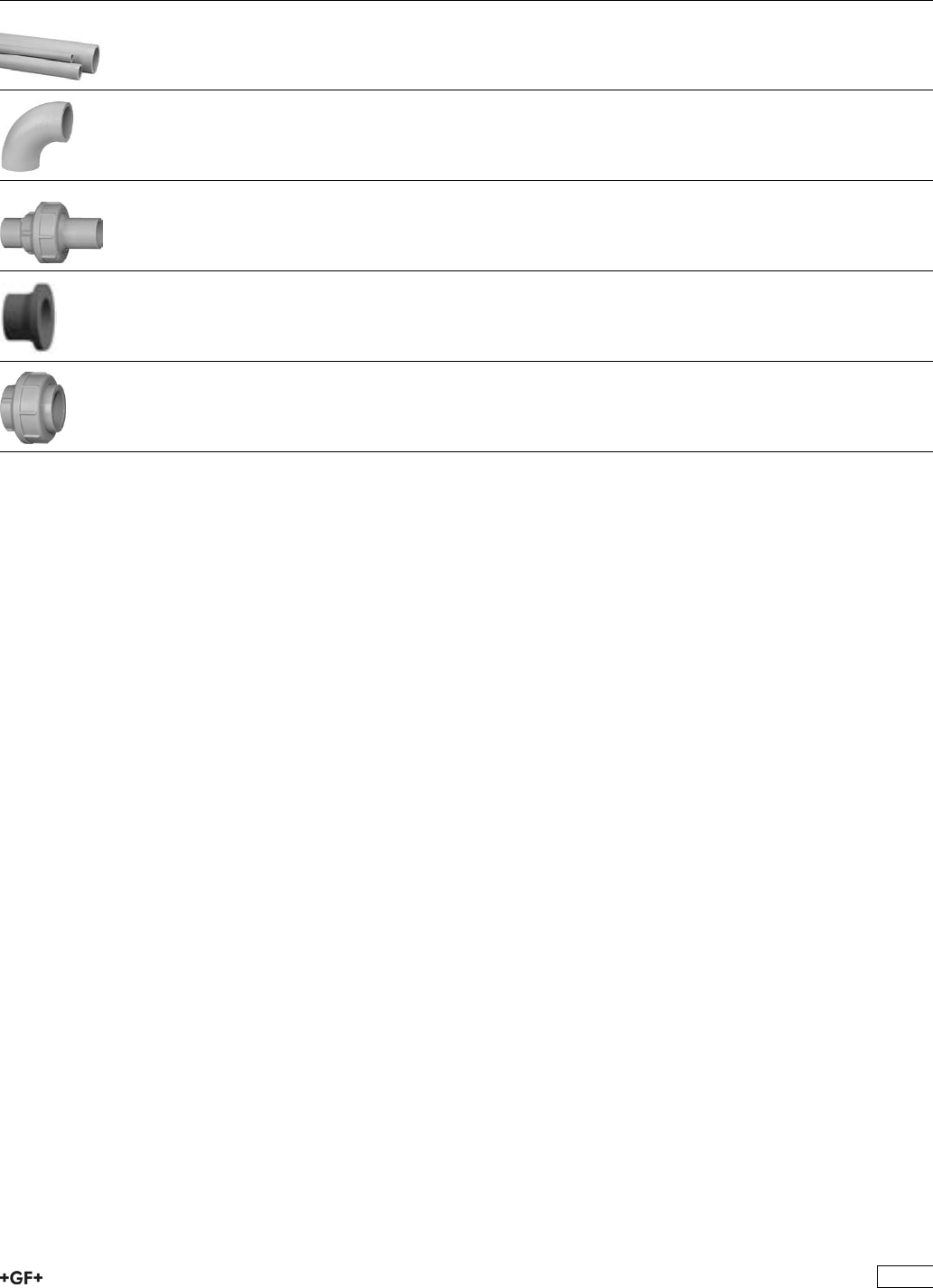
PROGEF Plus Pipes, Fittings, Unions, Flanges
and Flange Adaptors
Page
Pipes 350
Fittings for Butt Fusion 351
Unions for Butt Fusion 356
Flange Adaptors, Flanges and Gaskets for Butt Fusion 357
Unions for Socket Fusion 361
349
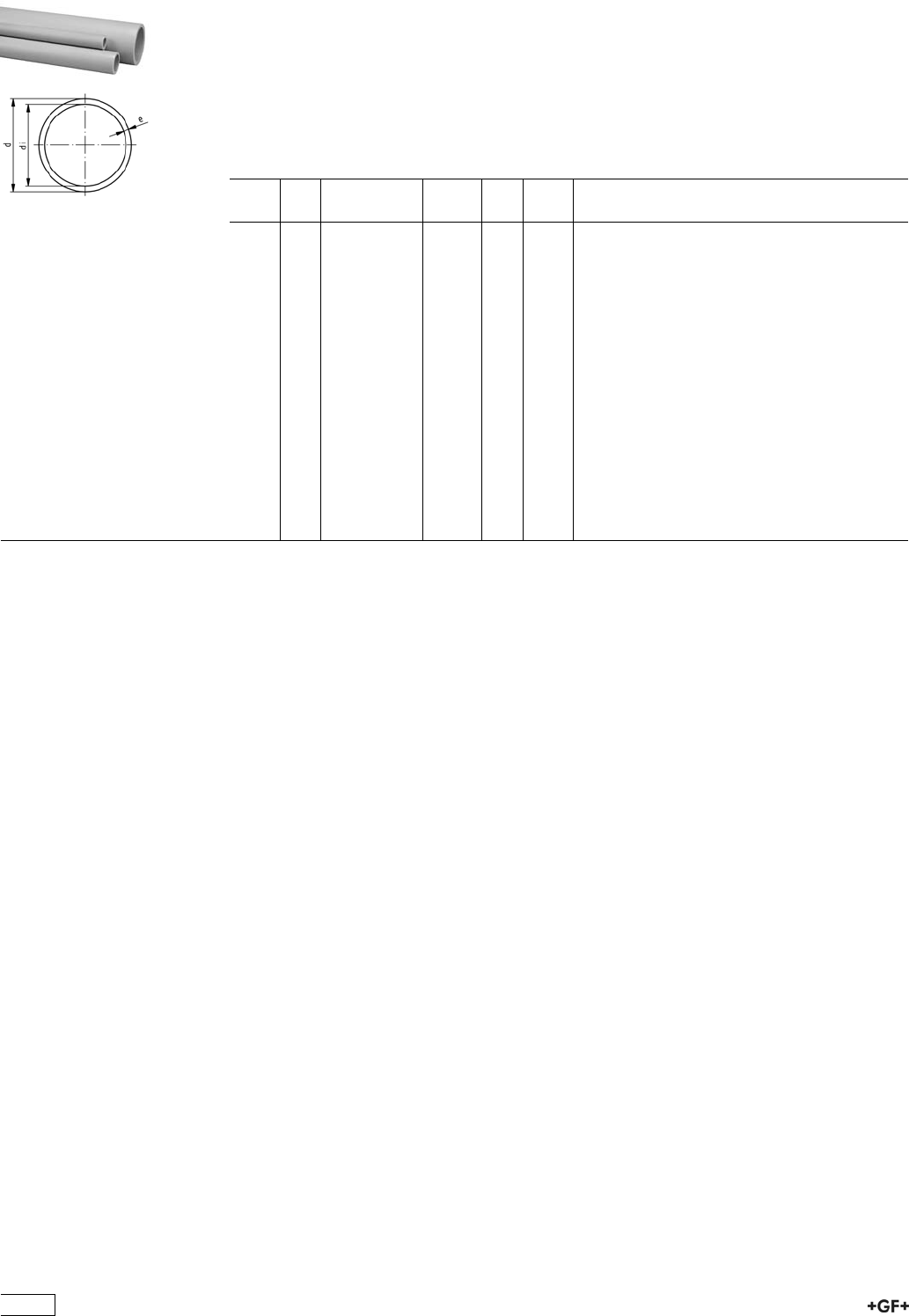
Pipes
PROGEF Plus, S5/SDR11 (PN10)
Model:
ÏMaterial: PP-H
ÏDIN 8077 / 8078 - DIBT Z-40.23-4
ÏClosed with caps and double bagged (LDPE-foil)
ÏColour: RAL 7032 gravel grey
ÏLength: Lengths of 5 m
d
[mm]
PN Code kg/m e
[mm]
di
[mm]
20 10 167 481 711 0.107 1,9 16.2
25 10 167 481 712 0.164 2,3 20.4
32 10 167 481 713 0.261 2,9 24.2
40 10 167 481 714 0.412 3,7 32.6
50 10 167 481 715 0.638 4,6 40.8
63 10 167 481 716 1.010 5,8 51.4
75 10 167 481 717 1.410 6,8 61.4
90 10 167 481 718 2.030 8,2 73.6
110 10 167 481 719 3.010 10,0 90.0
125 10 167 481 720 3.910 11,4 102.2
140 10 167 481 721 4.870 12,7 114.6
160 10 167 481 722 6.380 14,6 130.8
180 10 167 481 723 8.070 16,4 147.2
200 10 167 481 724 9.950 18,2 163.6
225 10 167 481 725 12.600 20,5 184.0
250 10 167 481 726 15.500 22,7 184.6
280 10 167 481 727 19.400 25,4 229.2
315 10 167 481 728 24.600 28,6 257.0
350
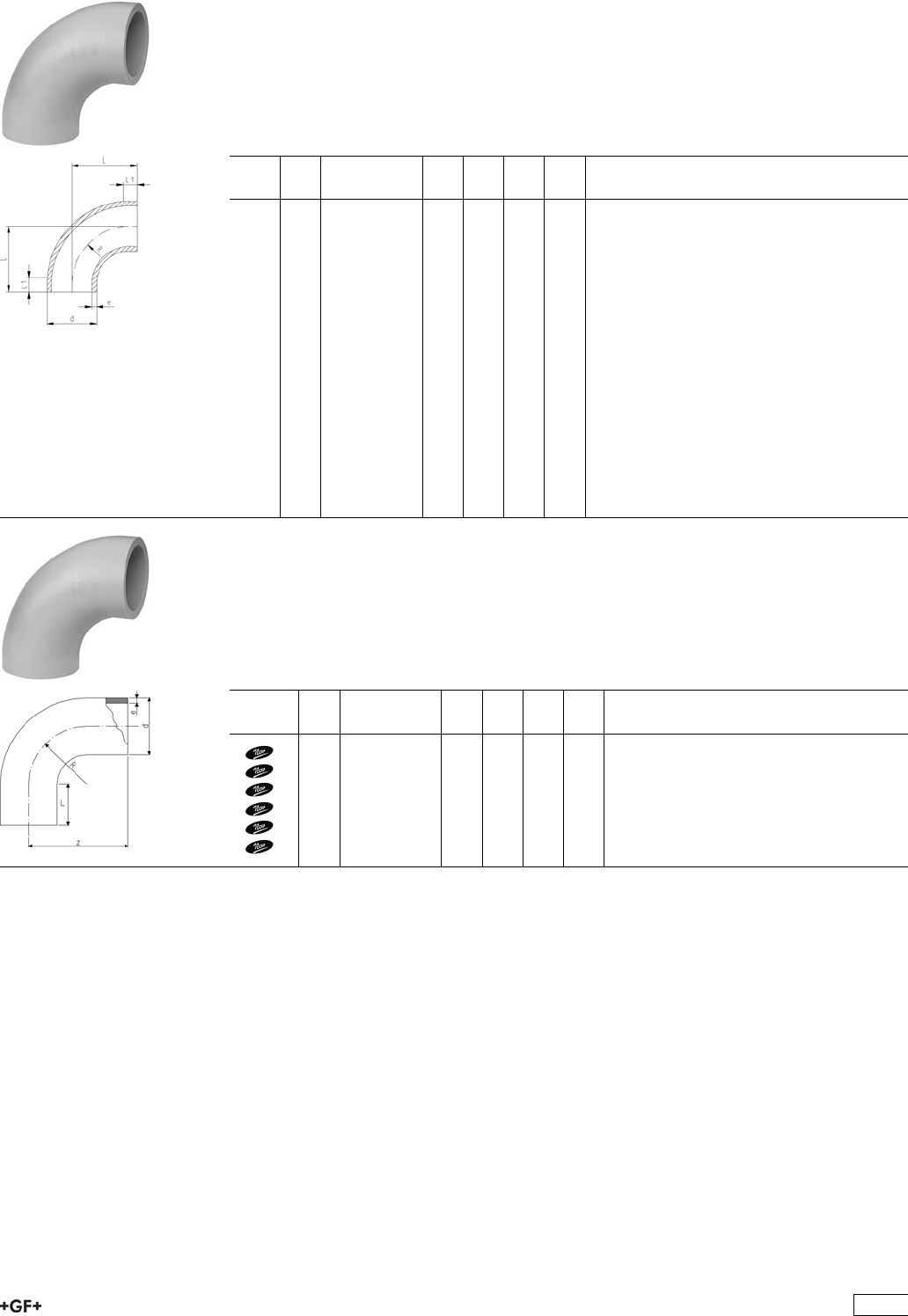
Fittings for Butt Fusion
PROGEF Plus, Bend 90°- Type B, S5/SDR11
Model:
ÏMaterial: PP-H
ÏConventional butt-welding according to DVS 2207 part 11
ÏIR = Infrared-(IR Plus®) compatible. Please choose fusion parameters: PP-H
ÏCleaned and double bagged
d
[mm]
FM Code L
[mm]
L1
[mm]
R
[mm]
e
[mm]
20 IR 727 018 466 27 5 22 1,9
25 IR 727 018 467 32 7 27 2,3
32 IR 727 018 468 40 7 35 2,9
40 IR 727 018 469 51 10 44 3,7
50 IR 727 018 470 62 10 55 4,6
63 IR 727 018 471 77 10 69 5,8
75 IR 727 018 662 100 20 90 6,8
90 IR 727 018 663 100 20 90 8,2
110 IR 727 018 664 141 25 130 10,0
125 IR 727 018 475 140 15 125 11,4
140 IR 727 018 476 155 15 140 12,7
160 IR 727 018 477 175 15 160 14,6
180 IR 727 018 478 195 15 180 16,4
200 IR 727 018 479 215 15 200 18,2
225 IR 727 018 480 245 20 225 20,5
250 -- 727 018 450 256 49 232 22,7
280 -- 727 018 451 286 44 262 25,4
315 -- 727 018 452 321 51 297 28,6
Bends 90°, S5/SDR11 - 0.75d
Model:
ÏMaterial: PP-H
ÏConventional butt-welding according to DVS 2207 part 11
ÏIR = Infrared-(IR Plus®) compatible. Please choose fusion parameters: PP-H
ÏCleaned and double bagged
d
[mm]
FM Code z
[mm]
L
[mm]
R
[mm]
e
[mm]
20 IR 727 018 681 38 23 15 1.9
25 IR 727 018 682 42 23 19 2.3
32 IR 727 018 683 46 22 24 2.9
40 IR 727 018 684 51 21 30 3.7
50 IR 727 018 685 58 21 37 4.6
63 IR 727 018 686 66 21 45 5.8
351
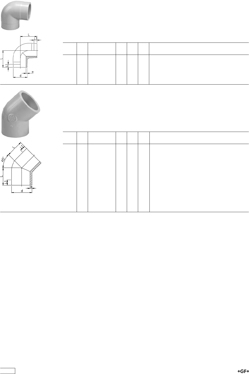
PROGEF Plus, Elbow 90°, S5/SDR11
Model:
ÏMaterial: PP-H
ÏConventional butt-welding according to DVS 2207 part 11
ÏIR = Infrared-(IR Plus®) compatible. Please choose fusion parameters: PP-H
ÏCleaned and double bagged
d
[mm]
FM Code L
[mm]
L1
[mm]
e
[mm]
20 IR 727 108 581 38 25 1,9
25 IR 727 108 582 42 26 2,3
32 IR 727 108 583 46 27 2,9
40 IR 727 108 584 51 22 3,7
50 IR 727 108 585 58 23 4,6
63 IR 727 108 586 66 21 5,8
PROGEF Plus, Elbow 45°, S5/SDR11
Model:
ÏMaterial: PP-H
ÏConventional butt-welding according to DVS 2207 part 11
ÏIR = Infrared-(IR Plus®) compatible. Please choose fusion parameters: PP-H
ÏCleaned and double bagged
d
[mm]
FM Code L
[mm]
L1
[mm]
e
[mm]
20 IR 727 158 581 32 24 1,9
25 IR 727 158 582 34 25 2,3
32 IR 727 158 583 36 25 2,9
40 IR 727 158 584 39 25 3,7
50 IR 727 158 585 42 26 4,6
63 IR 727 158 586 47 29 5,8
75 IR 727 158 587 49 29 6,8
90 IR 727 158 588 57 34 8,2
110 IR 727 158 589 70 43 10,0
125 IR 727 158 590 79 48 11,4
140 IR 727 158 591 88 55 12,7
160 IR 727 158 592 100 60 14,6
200 IR 727 158 594 124 75 18,2
225 IR 727 158 595 140 85 20,5
352
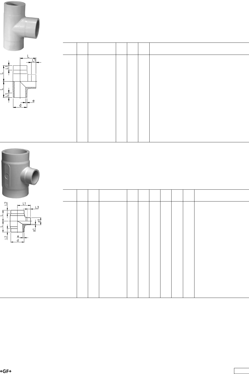
PROGEF Plus, Tee 90° equal, S5/SDR11
Model:
ÏMaterial: PP-H
ÏConventional butt-welding according to DVS 2207 part 11
ÏIR = Infrared-(IR Plus®) compatible. Please choose fusion parameters: PP-H
ÏCleaned and double bagged
d
[mm]
FM Code L
[mm]
L1
[mm]
e
[mm]
20 IR 727 208 581 38 24 1,9
25 IR 727 208 582 42 26 2,3
32 IR 727 208 583 46 26 2,9
40 IR 727 208 584 51 23 3,7
50 IR 727 208 585 58 22 4,6
63 IR 727 208 586 66 20 5,8
75 IR 727 208 587 75 20 6,8
90 IR 727 208 588 90 20 8,2
110 IR 727 208 589 110 20 10,0
125 IR 727 208 590 125 25 11,4
140 IR 727 208 591 140 28 12,7
160 IR 727 208 592 160 28 14,6
180 IR 727 208 593 195 73 16,4
200 IR 727 208 594 200 35 18,2
225 IR 727 208 595 220 35 20,5
250 -- 727 208 596 275 86 22,7
280 -- 727 208 597 310 105 25,4
315 -- 727 208 598 350 111 28,6
Tee 90° reducing, S5/SDR11
Model:
ÏMaterial: PP-H
ÏConventional butt-welding according to DVS 2207 part 11
ÏIR = Infrared-(IR Plus®) compatible. Please choose fusion parameters: PP-H
ÏCleaned and double bagged
d
[mm]
d1
[mm]
FM Code L
[mm]
L1
[mm]
L2
[mm]
L3
[mm]
e
[mm]
e1
[mm]
63 32 IR 727 208 251 65 70 25 25 5,8 2,9
63 50 IR 727 208 252 65 70 25 25 5,8 4,6
75 32 IR 727 208 253 70 75 25 25 6,8 2,9
75 50 IR 727 208 254 70 75 25 25 6,8 4,6
75 63 IR 727 208 255 70 75 25 25 6,8 5,8
90 50 IR 727 208 257 80 85 25 25 8,2 4,6
90 63 IR 727 208 258 80 85 25 25 8,2 5,8
90 75 IR 727 208 259 80 85 25 25 8,2 6,8
110 32 IR 727 208 260 90 95 30 25 10,0 2,9
110 50 IR 727 208 261 90 95 30 25 10,0 4,6
110 63 IR 727 208 262 90 95 30 25 10,0 5,8
110 75 IR 727 208 263 90 95 30 25 10,0 6,8
110 90 IR 727 208 264 90 95 30 25 10,0 8,2
160 63 IR 727 208 271 142 135 50 30 14,6 5,8
160 75 IR 727 208 272 142 135 50 30 14,6 6,8
160 90 IR 727 208 273 142 135 50 30 14,6 8,2
160 110 IR 727 208 274 142 135 50 30 14,6 10,0
225 90 IR 727 208 288 155 165 40 30 20,5 8,2
225 110 IR 727 208 289 155 165 40 30 20,5 10,0
225 160 IR 727 208 291 155 165 40 30 20,5 14,6
353
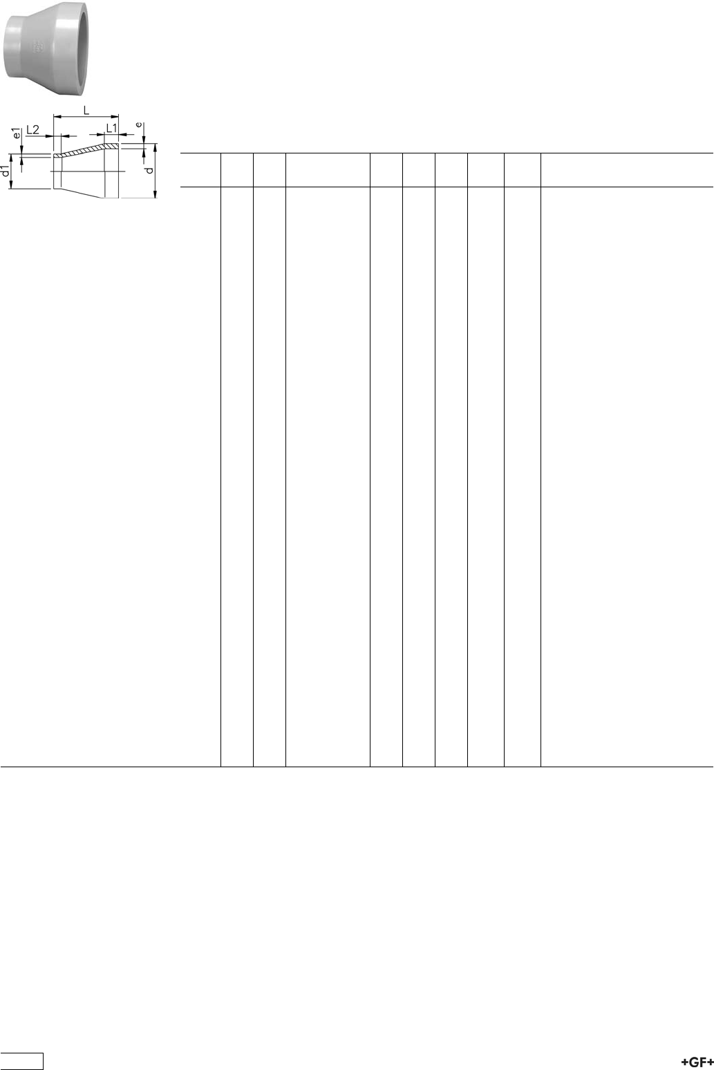
Reducers, S5/SDR11
Model:
ÏMaterial: PP-H
ÏConventional butt-welding according to DVS 2207 part 11
ÏIR = Infrared-(IR Plus®) compatible. Please choose fusion parameters: PP-H
ÏCleaned and double bagged
¹ Material: PP-R
d
[mm]
d1
[mm]
FM Code L
[mm]
L1
[mm]
L2
[mm]
e
[mm]
e1
[mm]
25 20 IR 727 908 637 50 20 20 2,3 1,9
32 20 IR 727 908 642 50 20 20 2,9 1,9
32 25 IR 727 908 641 50 20 20 2,9 2,3
40 20 IR 727 908 648 58 20 23 3,7 1,9
40 25 IR 727 908 647 55 20 20 3,7 2,3
40 32 IR 727 908 646 55 20 20 3,7 2,9
50 25 IR 727 908 654 60 20 20 4,6 2,3
50 32 IR 727 908 653 60 20 20 4,6 2,9
50 40 IR 727 908 652 60 20 20 4,6 3,7
63 32 IR 727 908 660 65 20 20 5,8 2,9
63 40 IR 727 908 659 65 20 20 5,8 3,7
63 50 IR 727 908 658 65 20 20 5,8 4,6
75 40 IR 727 908 666 68 20 20 6,8 3,7
75 50 IR 727 908 665 65 20 20 6,8 4,6
75 63 IR 727 908 664 65 20 20 6,8 5,8
90 63 IR 727 908 671 75 22 19 8,2 5,8
90 75 IR 727 908 670 75 21 19 8,2 6,8
110 75 IR 727 908 677 90 28 18 10,0 6,8
110 90 IR 727 908 676 90 28 20 10,0 8,2
125 110 IR 727 908 680 100 31 30 11,4 10,0
140 110 IR 727 908 685 110 33 29 12,7 10,0
140 125 IR 727 908 684 110 34 30 12,7 11,4
160 110 IR 727 908 690 120 38 27 14,6 10,0
160 140 IR 727 908 688 120 40 35 14,6 12,7
180 90 IR 727 908 691 157 45 22 16,4 8,2
180 110 IR 727 908 955 157 45 28 16,4 10,0
180 125 IR 727 908 698 136 45 32 16,4 11,4
180 140 IR 727 908 699 136 45 35 16,4 12,7
180 160 IR 727 908 952 136 45 40 16,4 14,6
200 160 IR 727 908 692 145 50 40 18,2 14,6
200 180 IR 727 908 693 151 50 45 18,2 16,4
225 110 IR 727 908 695 160 55 35 20,5 10,0
225 160 IR 727 908 696 160 55 40 20,5 14,6
225 180 IR 727 908 694 171 55 45 20,5 16,4
225 200 IR 727 908 697 160 55 50 20,5 18,2
250 160 -- 727 908 700 194 60 40 22,7 14,6
250 225 -- 727 908 701 182 60 55 22,7 20,5
¹280 225 -- 727 908 702 200 85 80 25,4 20,5
¹280 250 -- 727 908 703 200 85 90 25,4 22,7
¹315 225 -- 727 908 704 230 95 88 28,6 20,5
¹315 250 -- 727 908 705 230 95 95 28,6 22,7
¹315 280 -- 727 908 706 230 95 107 28,6 25,4
354
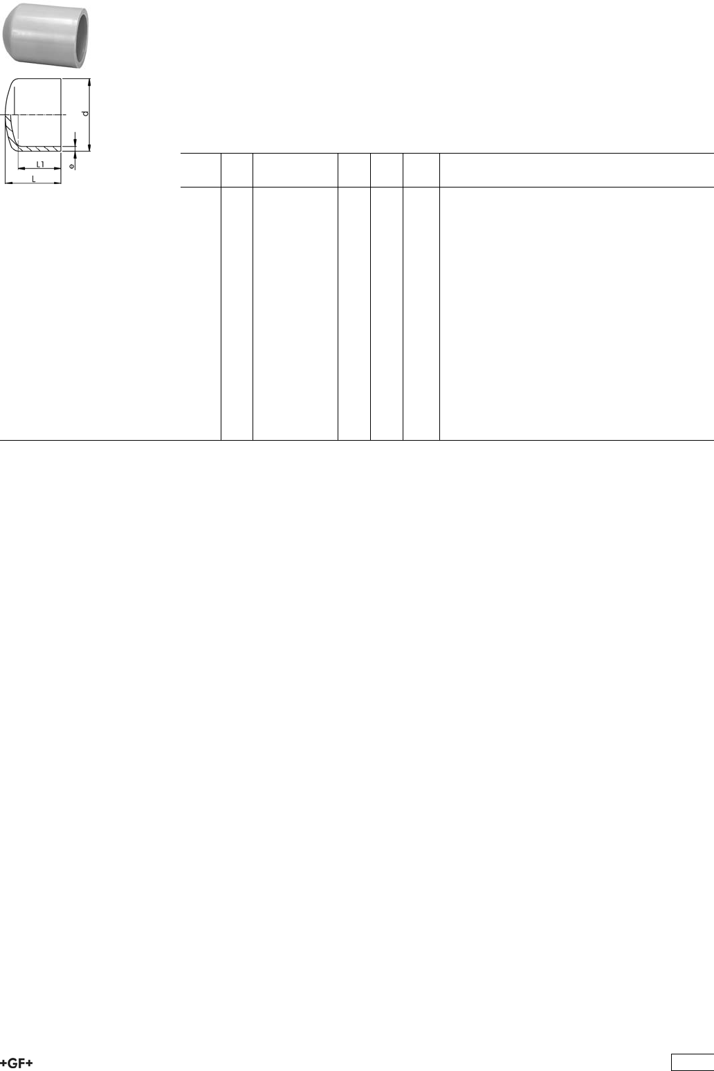
End Caps, S5/SDR11
Model:
ÏMaterial: PP-H
ÏConventional butt-welding according to DVS 2207 part 11
ÏIR = Infrared-(IR Plus®) compatible. Please choose fusion parameters: PP-H
ÏCleaned and double bagged
¹ Material: PP-R
d
[mm]
FM Code L
[mm]
L1
[mm]
e
[mm]
20 IR 727 968 981 45 35 1,9
25 IR 727 968 982 52 40 2,3
32 IR 727 968 983 58 44 2,9
40 IR 727 968 984 67 50 3,7
50 IR 727 968 985 75 55 4,6
63 IR 727 968 986 85 62 5,8
75 IR 727 968 987 95 63 6,8
90 IR 727 968 988 110 79 8,2
110 IR 727 968 989 127 88 10,0
125 IR 727 968 990 138 102 11,4
140 IR 727 968 991 144 106 12,7
160 IR 727 968 992 154 109 14,6
180 IR 727 968 993 191 141 16,4
200 IR 727 968 994 181 127 18,2
225 IR 727 968 995 211 141 20,5
¹250 -- 727 968 996 205 130 22,7
¹280 -- 727 968 997 235 139 25,4
¹315 -- 727 968 998 255 150 28,6
355
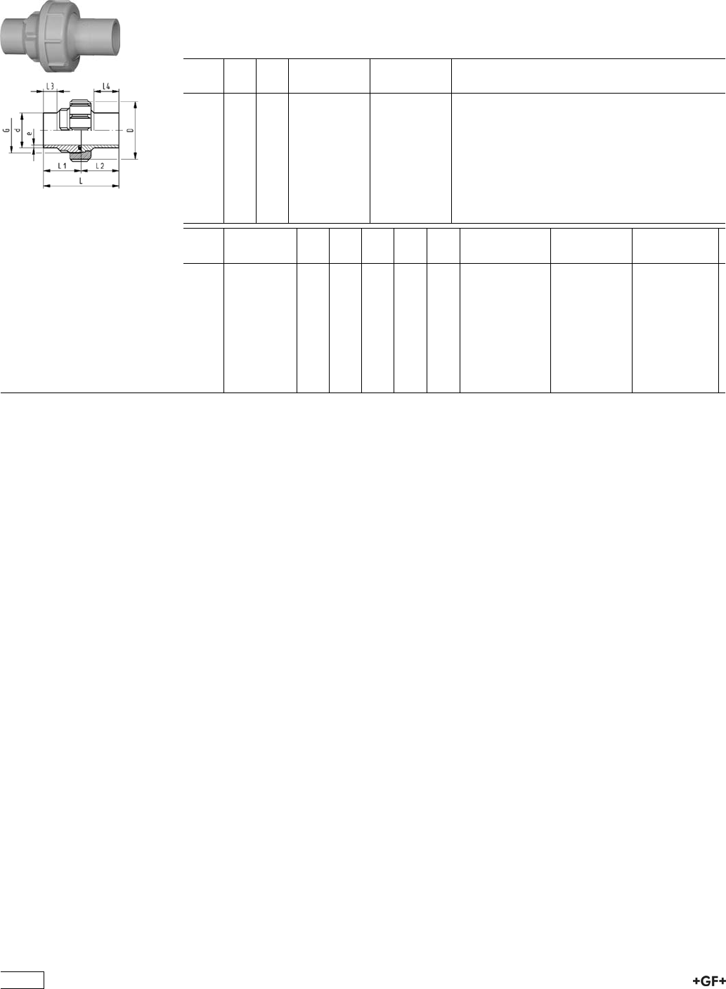
Unions for Butt Fusion
EPDM 27 51 86
FPM 27 52 86
PROGEF Plus, Union, S5/SDR11
Model:
ÏMaterial: PP-H
ÏWith butt fusion ends
ÏIR = Infrared-(IR Plus®) compatible. Please choose fusion parameters: PP-H
ÏCleaned and double bagged
d
[mm]
D
[mm]
FM EPDM
Code
FPM
Code
20 48 IR 727 518 606 727 528 606
25 58 IR 727 518 607 727 528 607
32 65 IR 727 518 608 727 528 608
40 79 IR 727 518 609 727 528 609
50 91 IR 727 518 610 727 528 610
63 111 IR 727 518 611 727 528 611
75 135 IR 727 518 612 727 528 612
90 135 IR 727 518 613 727 528 613
110 158 IR 727 518 614 727 528 614
d
[mm]
G
[inch]
L
[mm]
L1
[mm]
L2
[mm]
L3
[mm]
e
[mm]
O-Ring EPDM O-Ring FPM Size
20 1 107 54 53 26 1,9 748.413.006 749.413.006 20,22 x 3,53
25 1 1/4 113 57 56 26 2,3 748.413.007 749.413.007 28,17 x 3,53
32 1 1/2 119 60 59 26 2,9 748.413.008 749.413.008 32,93 x 3,53
40 2 126 63 63 26 3,7 748.413.009 749.413.009 40,65 x 5,34
50 2 1/4 131 66 66 26 4,6 748.413.010 749.413.010 47,00 x 5,34
63 2 3/4 137 69 68 26 5,8 748.413.011 749.413.011 59,69 x 5,34
75 S107,5x3,6 132 66 66 24 6,8 748.413.013 749.413.013 69,22 x 5,34
90 S107,5x3,6 131 66 66 24 8,2 748.413.014 749.413.014 81,92 x 5,34
110 S127,5x3,6 131 66 66 25 10,0 748.413.015 749.413.015 101,00 x 5,34
356
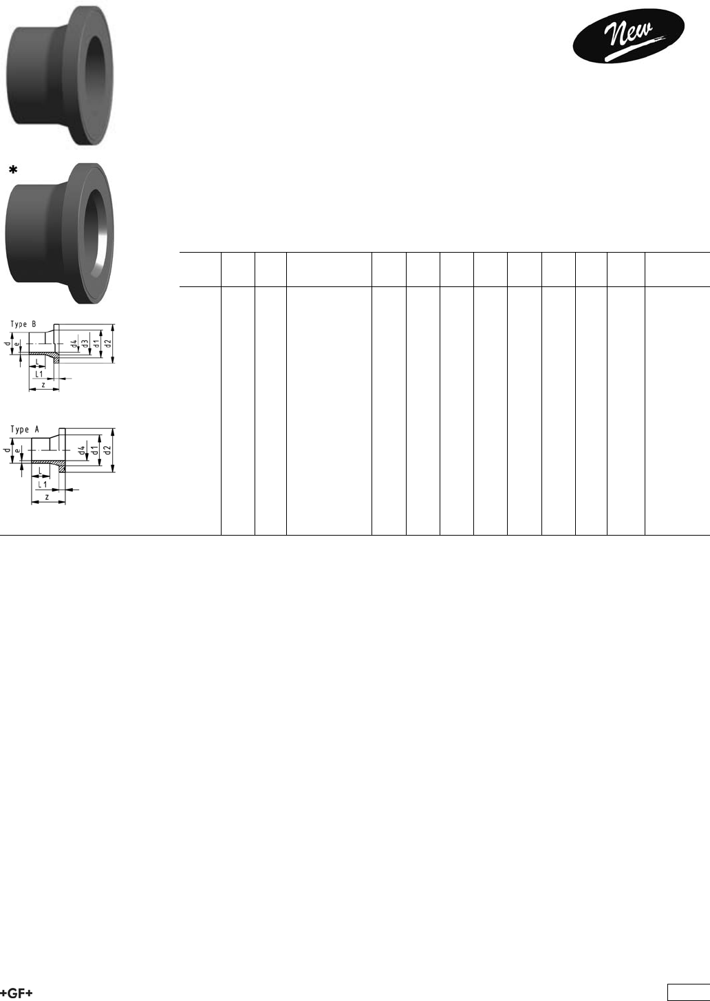
Flange Adaptors, Flanges and Gaskets for
Butt Fusion
PROGEF Plus, Flange Adaptor, S5/SDR11
Combined Jointing Face:
Flat and Serrated
Model:
ÏMaterial: PP-H
ÏConventional butt-welding according to DVS 2207 part 11
ÏIR = Infrared-(IR Plus®) compatible. Please choose fusion parameters: PP-H
ÏSuitable for flange connections to metric (from d110 also to ANSI/ASME B16.5)
ÏSuitable for butterfly valve type 567, 568 and 037
ÏGasket: Profile flange gasket EPDM No. 48 44 17, FPM No. 49 44 17
ÏCleaned and double bagged
* Type B with chamfer
d
[mm]
DN
[mm]
FM Code z
[mm]
d1
[mm]
d2
[mm]
d3
[mm]
d4
[mm]
L
[mm]
L1
[mm]
e
[mm]
20 15 IR 727 798 731 85 27 45 16 41 7 1.9
25 20 IR 727 798 732 85 33 58 20 41 9 2.3
32 25 IR 727 798 733 85 40 68 26 44 10 3.0
40 32 IR 727 798 734 85 50 78 32 49 11 3.7
50 40 IR 727 798 735 85 61 88 40 55 12 4.6
63 50 IR 727 798 736 95 75 102 51 65 14 5.8
*75 65 IR 727 798 737 125 89 122 66 61 75 16 6.8
*90 80 IR 727 798 738 140 105 138 78 73 85 17 8.2
*110 100 IR 727 798 739 160 125 158 100 90 90 18 10.0
*125 100 IR 727 798 740 170 132 158 114 102 95 25 11.4
*140 125 IR 727 798 741 200 155 188 127 114 92 25 12.7
*160 150 IR 727 798 742 200 175 212 158 130 110 25 14.6
*180 150 IR 727 798 743 200 180 212 158 147 115 30 16.4
*200 200 IR 727 798 744 200 232 268 203 163 120 32 18.2
*225 200 IR 727 798 745 200 235 268 210 184 130 32 20.5
*250 250 727 798 746 220 285 320 245 204 130 35 22.7
*280 250 727 798 747 220 291 320 265 229 139 35 25.4
*315 300 727 798 748 230 335 370 300 257 150 35 28.6
357
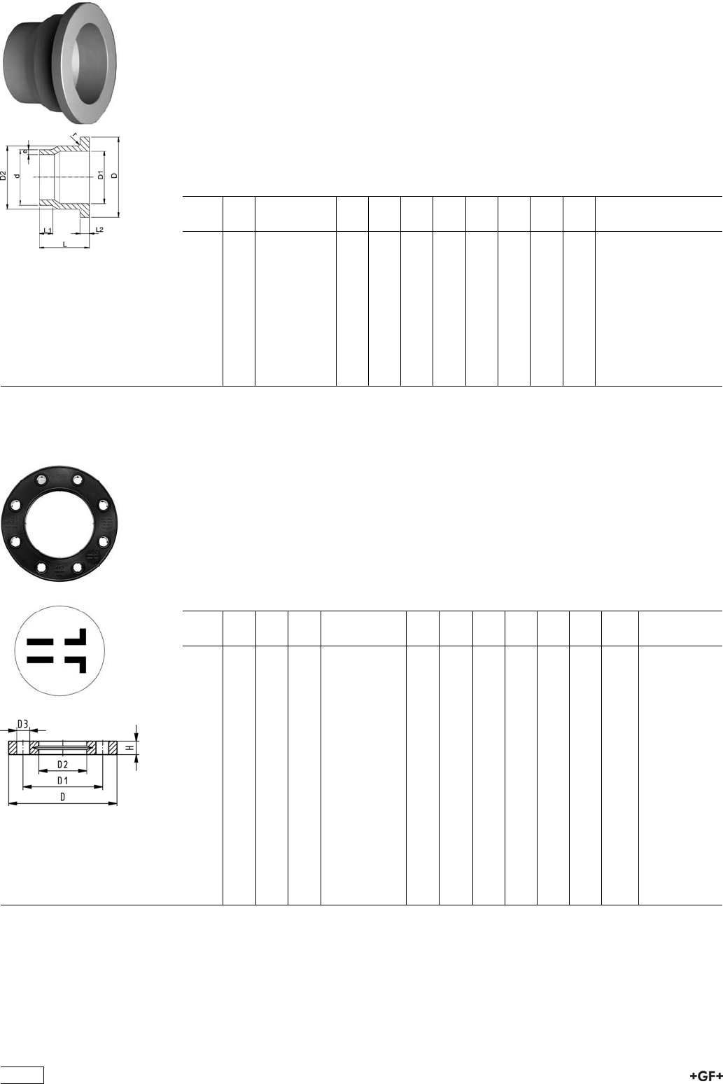
PROGEF Plus, Outlet Flange Adaptor, S5/SDR11
Jointing face, combination serrated / flat
Model:
ÏMaterial: PP-R unpigmented
ÏConventional butt-welding according to DVS 2207 part 11
ÏTo wafer check valves Type 369
ÏCleaned and double bagged
Attention:
ÏIn conjunction with outlet flange adaptors, flange rings for socket systems must
be used.
d
[mm]
DN
[mm]
Code D
[mm]
D1
[mm]
D2
[mm]
L
[mm]
L1
[mm]
L2
[mm]
e
[mm]
r
[mm]
40 32 727 808 134 80 37 50 64 30 11 3,7 3
50 40 727 808 135 90 43 61 67 30 12 4,6 3
63 50 727 808 136 105 54 76 74 30 14 5,8 4
75 65 727 808 137 125 70 90 78 30 16 6,8 4
90 80 727 808 138 140 82 108 87 35 17 8,2 4
110 100 727 808 139 160 105 131 102 41 18 10,0 4
140 125 727 808 141 190 130 165 124 47 25 12,7 4
160 150 727 808 142 215 158 188 149 52 25 14,6 4
225 200 727 808 145 270 206 248 180 55 32 20,5 4
280 250 727 808 147 325 259 308 240 63 35 25,4 4
315 300 727 808 148 375 308 346 272 66 35 28,6 4
27 70 04
27 70 05
Backing Flanges, PP-V
for Butt Fusion Systems metric
Model:
ÏModern full-plastic flange PP-GF (30 % glass-fibre reinforced)
ÏWith V-groove which applies force evenly on collar
ÏWith integrated bolt retainers as an assembly aid
ÏConnecting dimension: ISO 7005, EN 1092, BS 4504, DIN 2501
ÏBolt circle PN 10
¹) Suitable for socket- and butt fusion systems (no pictograph on flange)
AL: number of holes
d
[mm]
Inch DN
[mm]
PN Code D
[mm]
D1
[mm]
D2
[mm]
D3
[mm]
H
[mm]
AL SC
¹20 15 16 727 700 406 95 65 28 14 16 4 M12
¹25 20 16 727 700 407 105 75 34 14 17 4 M12
¹32 25 16 727 700 408 115 85 42 14 18 4 M12
¹40 32 16 727 700 409 140 100 51 18 20 4 M16
¹50 40 16 727 700 410 150 110 62 18 22 4 M16
¹63 50 16 727 700 411 165 125 78 18 24 4 M16
¹75 65 16 727 700 412 185 145 92 18 26 4 M16
90 80 16 727 700 513 200 160 108 18 27 8 M16
110 100 16 727 700 514 220 180 128 18 28 8 M16
125 100 16 727 700 515 220 180 135 18 28 8 M16
140 125 16 727 700 516 250 210 158 18 30 8 M16
160 6 150 16 727 700 517 285 241 178 22 32 8 M20
180 150 16 727 700 518 285 240 188 22 32 8 M20
200 8 200 16 727 700 519 340 295 235 22 34 8 M20
225 9 200 16 727 700 520 340 295 238 22 34 8 M20
250 250 16 727 700 521 395 350 288 22 38 12 M20
280 250 16 727 700 522 395 350 294 22 38 12 M20
315 300 16 727 700 523 445 400 338 22 42 12 M20
358
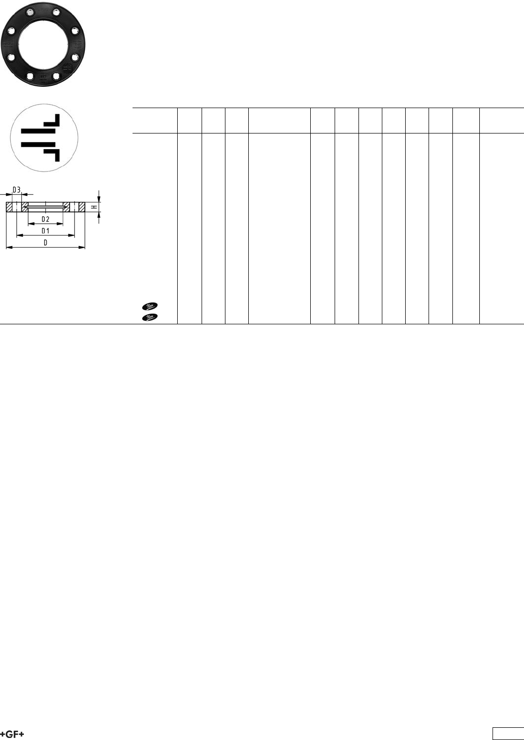
27 70 04
27 70 05
Backing Flanges, PP-V
for Socket Systems metric
Model:
ÏModern full-plastic flange PP-GF (30 % glass-fibre reinforced)
ÏWith V-groove which applies force evenly on collar
ÏWith integrated bolt retainers as an assembly aid
ÏConnecting dimension: ISO 7005, EN 1092, BS 4504, DIN 2501
ÏBolt circle PN 10
¹) Suitable for socket- and butt fusion systems (no pictograph on flange)
AL: number of holes
d
[mm]
Inch DN
[mm]
PN Code D
[mm]
D1
[mm]
D2
[mm]
D3
[mm]
H
[mm]
AL SC
¹20 15 16 727 700 406 95 65 28 14 16 4 M12
¹25 20 16 727 700 407 105 75 34 14 17 4 M12
¹32 25 16 727 700 408 115 85 42 14 18 4 M12
¹40 32 16 727 700 409 140 100 51 18 20 4 M16
¹50 40 16 727 700 410 150 110 62 18 22 4 M16
¹63 50 16 727 700 411 165 125 78 18 24 4 M16
¹75 65 16 727 700 412 185 145 92 18 26 4 M16
90 80 16 727 700 413 200 160 110 18 27 8 M16
110 100 16 727 700 414 220 180 133 18 28 8 M16
140 125 16 727 700 416 250 210 167 18 30 8 M16
160 6 150 16 727 700 417 285 241 190 22 32 8 M20
200 200 16 727 700 419 340 296 226 22 34 8 M20
225 8 200 16 727 700 420 340 295 250 22 34 8 M20
250 250 16 727 700 421 395 350 277 22 38 12 M20
280 250 16 727 700 422 395 350 310 22 38 12 M20
315 300 16 727 700 423 445 400 348 22 42 12 M20
355 350 10 727 700 424 515 460 388 22 46 16 M20
400 400 10 727 700 425 574 515 442 26 50 16 M24
359
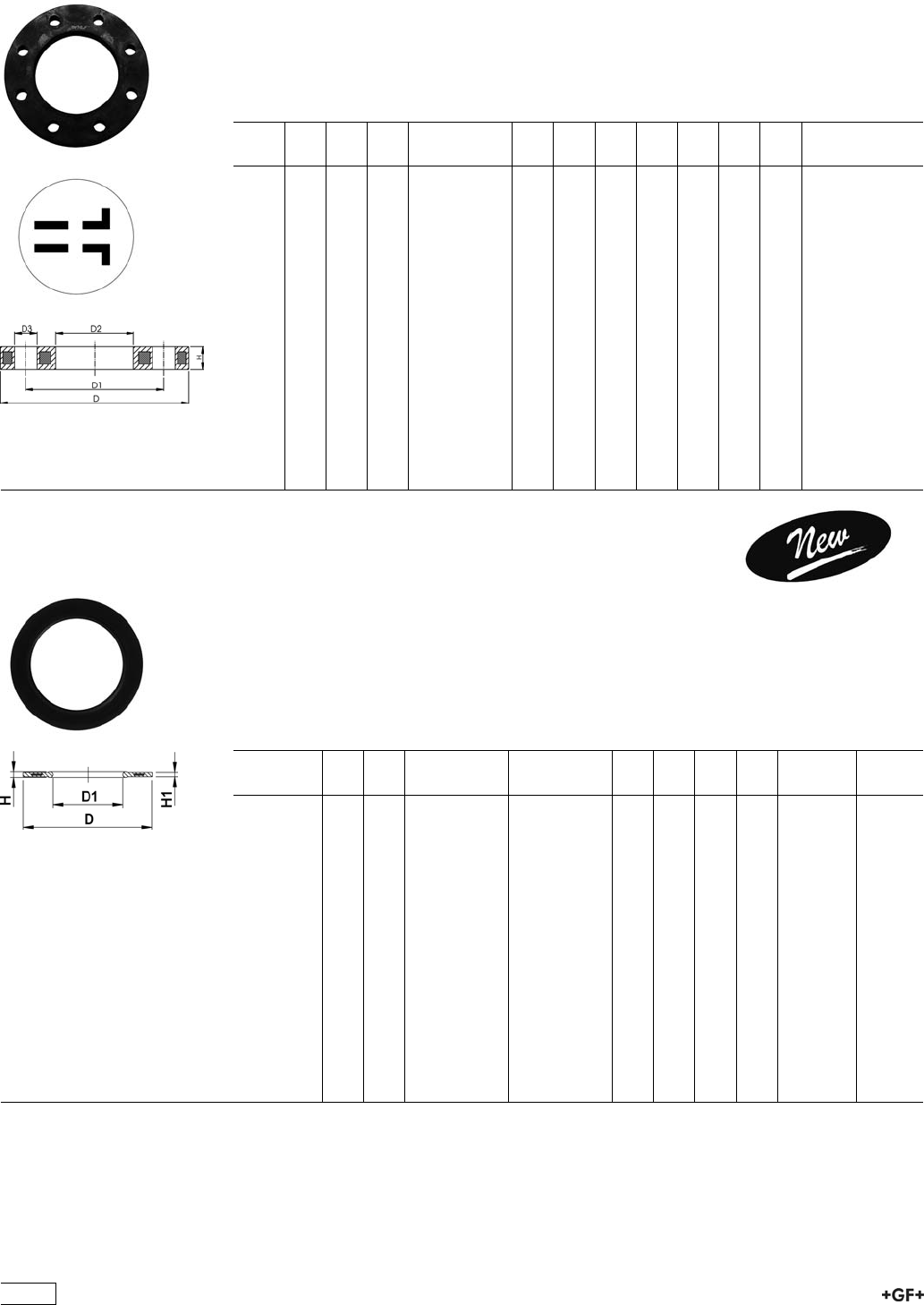
27 70 02
27 70 03
Backing Flanges, PP/Steel
for Butt Fusion Systems metric
Model:
ÏMaterial: PP (30 % glass-fibre reinforced) with steel ring
ÏConnecting dimension: ISO 7005, EN 1092, BS 4504, DIN 2501
ÏBolt circle PN 10
AL: number of holes
d
[mm]
d
[inch]
DN
[mm]
PN Code D
[mm]
D1
[mm]
D2
[mm]
D3
[mm]
H
[mm]
AL SC
20 15 16 727 700 206 95 65 28 14 12 4 M12
25 20 16 727 700 207 105 75 34 14 12 4 M12
32 25 16 727 700 208 115 85 42 14 16 4 M12
40 32 16 727 700 209 140 100 51 18 16 4 M16
50 40 16 727 700 210 150 110 62 18 18 4 M16
63 50 16 727 700 211 165 125 78 18 18 4 M16
75 65 16 727 700 212 185 145 92 18 18 4 M16
90 80 16 727 700 313 200 160 108 18 20 8 M16
110 100 16 727 700 314 220 180 128 18 20 8 M16
125 100 16 727 700 315 220 180 135 18 20 8 M16
140 125 16 727 700 316 250 210 158 18 24 8 M16
160 6 150 16 727 700 317 285 240 178 22 24 8 M20
180 150 16 727 700 318 285 240 188 22 24 8 M20
200 200 16 727 700 319 340 295 235 22 27 8 M20
225 200 16 727 700 320 340 295 238 22 27 8 M20
250 250 16 727 700 321 395 350 288 22 30 12 M20
280 250 16 727 700 322 395 350 294 22 30 12 M20
315 300 16 727 700 323 445 400 338 22 34 12 M20
EPDM 48 44 17
FPM 49 44 17 Flange Gaskets SF
EPDM / FPM
Model:
ÏSilicone free / paint-compatible
ÏFor all GF Flange Adaptors
ÏProfile Gasket with steel insert (type G-ST-P/K)
ÏHardness: 70° Shore EPDM, 75° Shore FPM
di FA are the suitable inner diameters of flange adaptors
d
[mm]
DN
[mm]
PN EPDM
Code
FPM
Code
D
[mm]
D1
[mm]
H
[mm]
H1
[mm]
di FA
[mm]
20 15 16 748 441 706 749 441 706 51 20 4 3 10 - 20
25 20 16 748 441 707 749 441 707 61 22 4 3 12 - 22
32 25 16 748 441 708 749 441 708 71 28 4 3 18 - 28
40 32 16 748 441 709 749 441 709 82 40 4 3 30 - 40
50 40 16 748 441 710 749 441 710 92 46 4 3 36 - 46
63 50 16 748 441 711 749 441 711 107 58 5 4 48 - 58
75 65 16 748 441 712 749 441 712 127 69 5 4 59 - 69
90 80 16 748 441 713 749 441 713 142 84 5 4 73 - 84
110 100 16 748 441 714 749 441 714 162 104 6 5 94 - 104
125 100 16 748 441 715 749 441 715 162 123 6 5 113 - 123
140 125 16 748 441 716 749 441 716 192 137 6 5 127 - 137
160 / 180 150 16 748 441 717 749 441 717 218 160 8 6 150 - 160
200 200 16 748 441 719 749 441 719 273 203 8 6 192 - 203
225 200 16 748 441 720 749 441 720 273 220 8 6 207 - 207
250 250 16 748 441 721 749 441 721 328 252 8 6 238 - 250
280 250 16 748 441 722 749 441 722 328 274 8 6 264 - 274
315 300 16 748 441 723 749 441 723 378 306 8 6 296 - 296
360
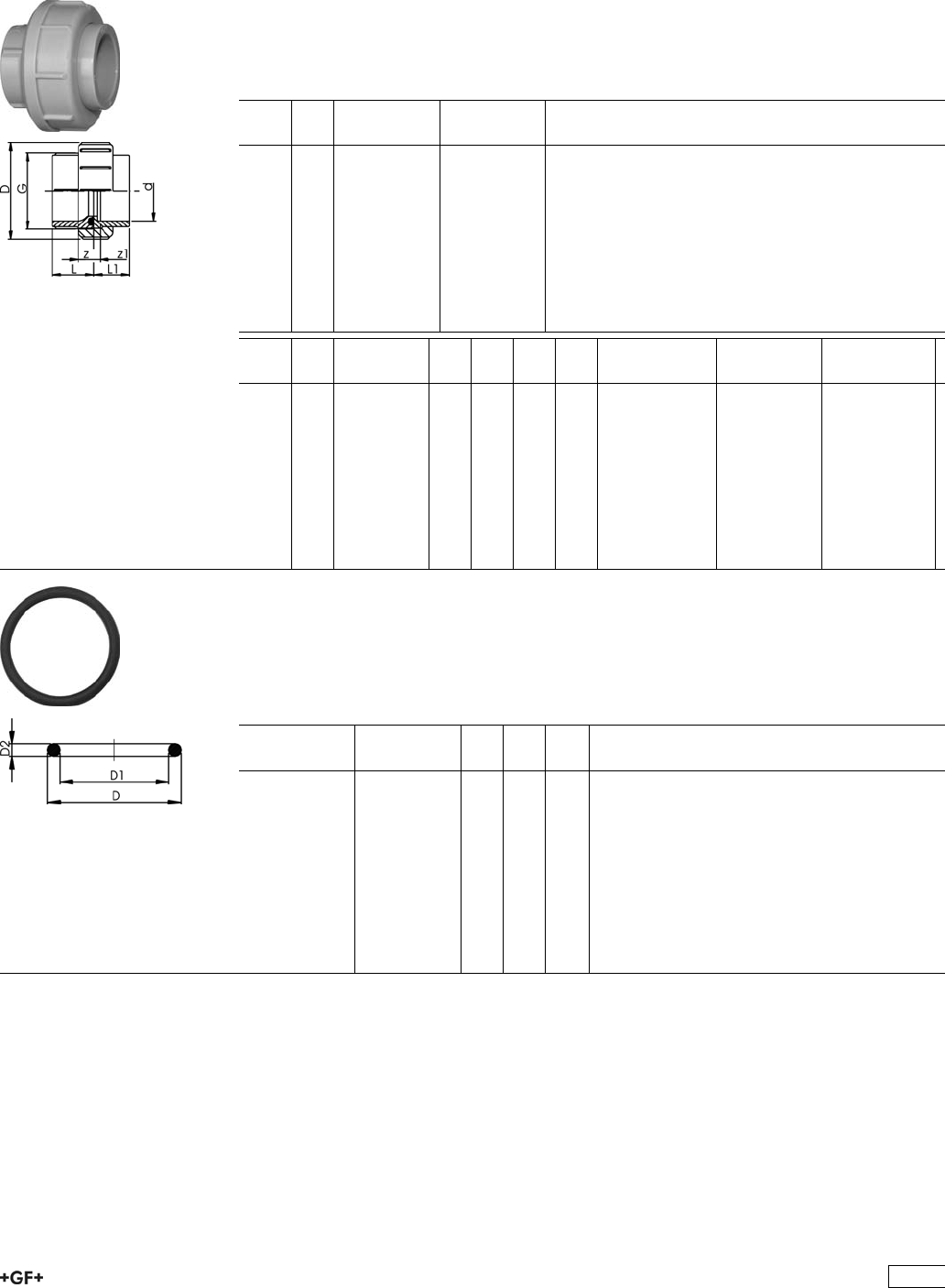
Unions for Socket Fusion
EPDM 27 51 02
FPM 27 52 02
PROGEF Plus, Union
Model:
ÏMaterial: PP-H
ÏWith fusion sockets metric
ÏD75-110 with new thread geometry, now rated PN10 up to d110
ÏJointing face: with O-Ring
ÏCleaned and double bagged
d
[mm]
PN EPDM
Code
FPM
Code
16 10 727 510 255 727 520 255
20 10 727 510 256 727 520 256
25 10 727 510 257 727 520 257
32 10 727 510 258 727 520 258
40 10 727 510 259 727 520 259
50 10 727 510 260 727 520 260
63 10 727 510 261 727 520 261
75 10 727 510 272 727 520 272
90 10 727 510 273 727 520 273
110 10 727 510 274 727 520 274
d
[mm]
D
[mm]
G
[inch]
L
[mm]
L1
[mm]
z
[mm]
z1
[mm]
O-Ring EPDM O-Ring FPM Size
16 35 3/4 24 18 5 11 748.413.005 749.413.005 15,54 x 2,62
20 48 1 26 19 5 12 748.413.006 749.413.006 20,22 x 3,53
25 58 1 1/4 28 21 5 12 748.413.007 749.413.007 28,17 x 3,53
32 65 1 1/2 30 23 5 12 748.413.008 749.413.008 32,93 x 3,53
40 79 2 34 25 5 14 748.413.009 749.413.009 40,65 x 5,54
50 91 2 1/4 39 28 5 16 748.413.010 749.413.010 47,00 x 5,34
63 111 2 3/4 47 32 5 20 748.413.011 749.413.011 59,69 x 5,34
75 135 S107,5x3,6 51 36 5 20 748.413.014 749.413.014 81,92 x 5,34
90 158 S127,5x3,6 55 42 7 20 748.413.015 749.413.015 101,00 x 5,34
110 188 S152,5x3,6 54 49 7 12 748.413.016 748.413.016 120,00 x 6,99
O-Ring
Model:
ÏHardness approx. 65° Shore
ÏSuitable for unions
ÏCleaned and double bagged
EPDM
Code
FPM
Code
D
[mm]
D1
[mm]
D2
[mm]
748 413 005 749 413 005 21 16 2.62
748 413 006 749 413 006 27 20 3.53
748 413 007 749 413 007 35 28 3.53
748 413 008 749 413 008 40 33 3.53
748 413 009 749 413 009 51 41 5.34
748 413 010 749 413 010 58 47 5.34
748 413 011 749 413 011 70 60 5.34
748 413 013 749 413 013 80 69 5.34
748 413 014 749 413 014 93 82 5.34
748 413 015 749 413 015 112 101 5.34
748 413 016 749 413 016 134 120 6.99
361

362
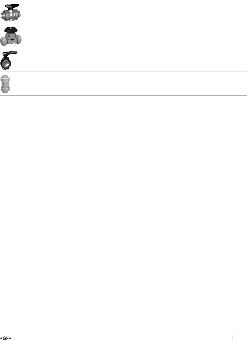
PROGEF Plus Hand-Operated and Actuated
Valves
Page
Ball Valve 364
Diaphragm Valves 369
Butterfly Valves 374
Ball Check Valves 377
363
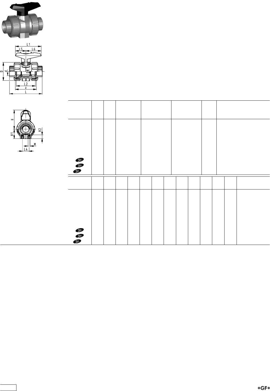
Ball Valve
Ball Valve Type 546, PP-H SF with mounting inserts
With fusion sockets metric
Model:
ÏMaterial: PP-H / silicone free cleaned
ÏImage and drawing DN65-100 please see ''New product ball valve DN65-100''
ÏFor easy installation and removal
Ïz-dimension, valve end and union nut are not compatible with type 346
(DN10/15-50) resp. type 370 (DN65-100)
ÏIntegrated stainless steel mounting inserts
ÏDouble bagged
ÏBall seals PVDF
Option:
ÏIndividual configuration of the valve (see form)
ÏMultifunctional module with integrated limit switches
d
[mm]
DN
[mm]
PN kv-value
(”p=1 bar)
[l/min]
EPDM
Code
FPM
Code
kg
16 10 10 71 167 546 601 167 546 611 0.115
20 15 10 185 167 546 602 167 546 612 0.115
25 20 10 350 167 546 603 167 546 613 0.180
32 25 10 700 167 546 604 167 546 614 0.255
40 32 10 1000 167 546 605 167 546 615 0.440
50 40 10 1600 167 546 606 167 546 616 0.610
63 50 10 3100 167 546 607 167 546 617 1.145
75 65 10 5000 167 546 608 167 546 618 3.700
90 80 10 7000 167 546 609 167 546 619 5.500
110 100 10 11000 167 546 610 167 546 620 8.700
d
[mm]
D
[mm]
H
[mm]
H1
[mm]
H2
[mm]
L
[mm]
L1
[mm]
L2
[mm]
L4
[mm]
L5
[mm]
L6
[mm]
M z
[mm]
16 50 57 27 12 93 77 56 25 32 45 M6 67
20 50 57 27 12 95 77 56 25 32 45 M6 66
25 58 67 30 12 108 97 65 25 39 58 M6 77
32 68 73 36 12 118 97 71 25 39 58 M6 83
40 84 90 44 15 137 128 85 45 54 74 M8 99
50 97 97 51 15 147 128 89 45 54 74 M8 105
63 124 116 64 15 168 152 101 45 66 87 M8 117
75 166 149 85 15 233 270 136 70 64 206 M8 167
90 200 161 105 15 254 270 141 70 64 206 M8 180
110 238 178 123 22 301 320 164 120 64 256 M12 215
364
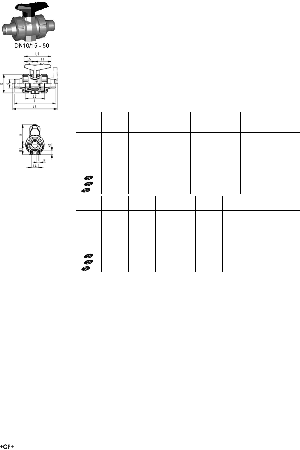
Ball Valve Type 546, PP-H SF with mounting inserts
With socket fusion spigots metric
Model:
ÏMaterial: PP-H / silicone free cleaned
ÏImage and drawing DN65-100 please see ''New product ball valve DN65-100''
ÏFor easy installation and removal
Ïz-dimension, valve end and union nut are not compatible with type 346
(DN10/15-50) resp. type 370 (DN65-100)
ÏIntegrated stainless steel mounting inserts
ÏDouble bagged
ÏBall seals PVDF
Option:
ÏIndividual configuration of the valve (see form)
ÏMultifunctional module with integrated limit switches
d
[mm]
DN
[mm]
PN kv-value
(”p=1 bar)
[l/min]
EPDM
Code
FPM
Code
kg
16 10 10 71 167 546 621 167 546 631 0.120
20 15 10 185 167 546 622 167 546 632 0.120
25 20 10 350 167 546 623 167 546 633 0.180
32 25 10 700 167 546 624 167 546 634 0.260
40 32 10 1000 167 546 625 167 546 635 0.450
50 40 10 1600 167 546 626 167 546 636 0.640
63 50 10 3100 167 546 627 167 546 637 1.210
75 65 10 5000 167 546 628 167 546 638 3.800
90 80 10 7000 167 546 629 167 546 639 5.600
110 100 10 11000 167 546 630 167 546 640 8.800
d
[mm]
D
[mm]
H
[mm]
H1
[mm]
H2
[mm]
L
[mm]
L1
[mm]
L2
[mm]
L3
[mm]
L4
[mm]
L5
[mm]
L6
[mm]
M
16 50 57 27 12 110 77 56 25 32 45 M6
20 50 57 27 12 120 77 56 130 25 32 45 M6
25 58 67 30 12 139 97 65 150 25 39 58 M6
32 68 73 36 12 150 97 71 160 25 39 58 M6
40 84 90 44 15 170 128 85 180 45 54 74 M8
50 97 97 51 15 190 128 89 200 45 54 74 M8
63 124 116 64 15 220 152 101 230 45 66 87 M8
75 166 149 85 15 280 270 136 290 70 64 206 M8
90 200 161 105 15 296 270 141 310 70 64 206 M8
110 238 178 123 22 336 320 164 350 120 64 256 M12
365
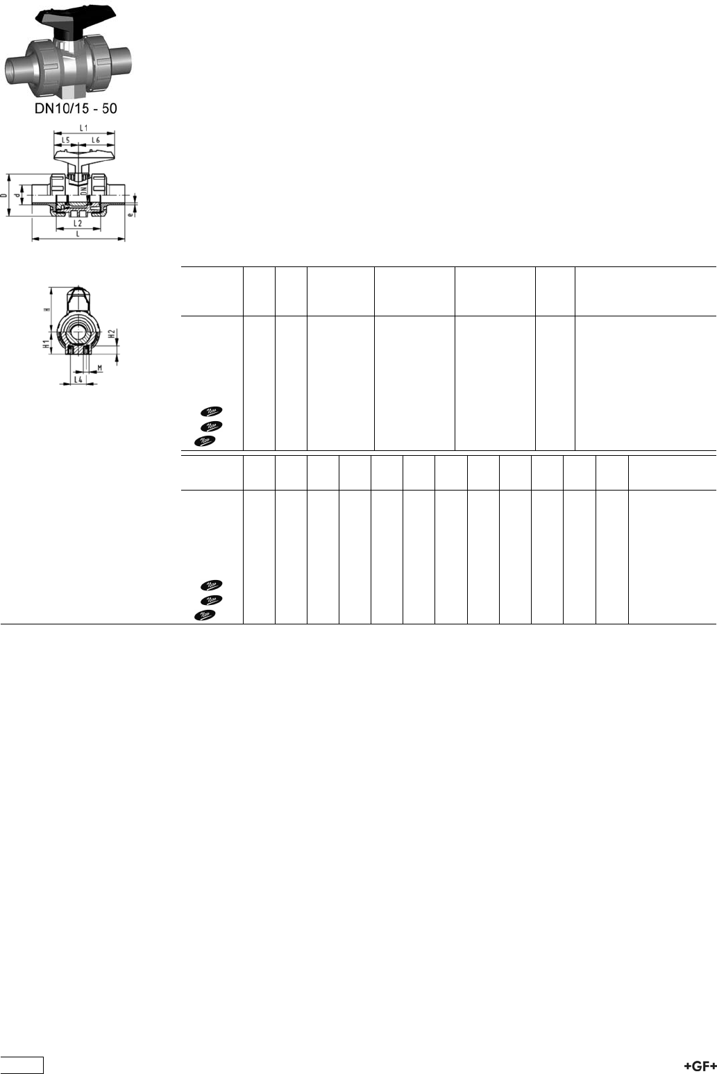
Ball Valve Type 546, PP-H SF with mounting inserts
With butt fusion spigots IR-Plus SDR11 metric
Model:
ÏMaterial: PP-H / silicone free cleaned
ÏImage and drawing DN65-100 please see ''New product ball valve DN65-100''
ÏFor easy installation and removal
Ïz-dimension, valve end and union nut are not compatible with type 346
(DN10/15-50) resp. type 370 (DN65-100)
ÏIntegrated stainless steel mounting inserts
ÏDouble bagged
ÏBall seals PVDF
Option:
ÏIndividual configuration of the valve (see form)
ÏMultifunctional module with integrated limit switches
d
[mm]
DN
[mm]
PN kv-value
(”p=1 bar)
[l/min]
EPDM
Code
FPM
Code
kg
20 15 10 185 167 546 662 167 546 672 0.120
25 20 10 350 167 546 663 167 546 673 0.180
32 25 10 700 167 546 664 167 546 674 0.255
40 32 10 1000 167 546 665 167 546 675 0.440
50 40 10 1600 167 546 666 167 546 676 0.620
63 50 10 3100 167 546 667 167 546 677 1.200
75 65 10 5000 167 546 668 167 546 678 3.800
90 80 10 7000 167 546 669 167 546 679 5.500
110 100 10 11000 167 546 670 167 546 680 8.700
d
[mm]
D
[mm]
H
[mm]
H1
[mm]
H2
[mm]
L
[mm]
L1
[mm]
L2
[mm]
L4
[mm]
L5
[mm]
L6
[mm]
M e
[mm]
20 50 57 27 12 130 77 56 25 32 45 M6 1,9
25 58 67 30 12 143 97 65 25 39 58 M6 2,3
32 68 73 36 12 150 97 71 25 39 58 M6 3
40 84 90 44 15 171 128 85 45 54 74 M8 3,7
50 97 97 51 15 191 128 89 45 54 74 M8 4,6
63 124 116 64 15 220 152 101 45 66 87 M8 5,8
75 166 149 85 15 266 270 136 70 64 206 M8 8.2
90 200 161 105 15 264 270 141 70 64 206 M8 9.9
110 238 178 123 22 301 320 164 120 64 256 M12 12
366
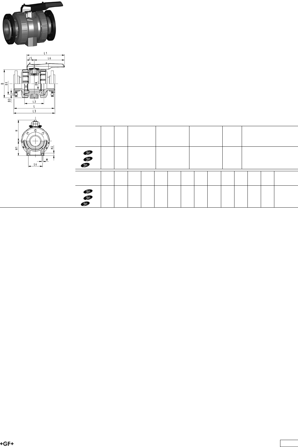
Ball Valve Type 546, PP-H SF with mounting inserts
With backing flanges PP-st metric
Model:
ÏMaterial: PP-H / silicone free cleaned
ÏImage and drawing DN65-100 please see ''New product ball valve DN65-100''
ÏFor easy installation and removal
Ïz-dimension, valve end and union nut are not compatible with type 346
(DN10/15-50) resp. type 370 (DN65-100)
ÏIntegrated stainless steel mounting inserts
ÏDouble bagged
ÏBall seals PVDF
ÏOverall length according to EN 558
ÏConnecting dimension: ISO 7005, EN 1092, BS 4504, DIN 2501
Option:
ÏIndividual configuration of the valve (see form)
ÏMultifunctional module with integrated limit switches
d
[mm]
DN
[mm]
PN kv-value
(”p=1 bar)
[l/min]
EPDM
Code
FPM
Code
kg
75 65 10 5000 167 546 828 167 546 838 4.300
90 80 10 7000 167 546 829 167 546 839 6.400
110 100 10 11000 167 546 830 167 546 840 10.000
d
[mm]
D
[mm]
D1
[mm]
D3
[mm]
L
[mm]
L1
[mm]
L2
[mm]
L3
[mm]
L4
[mm]
L5
[mm]
L6
[mm]
H
[mm]
H1
[mm]
M
75 166 145 18 280 270 136 290 70 64 206 149 85 8
90 200 160 18 296 270 141 310 70 64 206 161 105 8
110 238 180 18 336 320 164 350 120 64 256 178 123 12
367

Ball Valve Type 546, PP-H SF with mounting inserts
With backing flanges PP-st ANSI
Model:
ÏMaterial: PP-H / silicone free cleaned
ÏImage and drawing DN65-100 please see ''New product ball valve DN65-100''
ÏFor easy installation and removal
Ïz-dimension, valve end and union nut are not compatible with type 346
(DN10/15-50) resp. type 370 (DN65-100)
ÏIntegrated stainless steel mounting inserts
ÏDouble bagged
ÏBall seals PTFE
ÏOverall length according to EN 558
ÏConnecting dimension ANSI/ASME B 16.5 / ASTM D 4024
Option:
ÏIndividual configuration of the valve (see form)
ÏMultifunctional module with integrated limit switches
d
[mm]
DN
[mm]
PN kv-value
(”p=1 bar)
[l/min]
EPDM
Code
FPM
Code
kg
75 65 10 5000 167 546 888 167 546 898 4.300
90 80 10 7000 167 546 889 167 546 899 6.400
110 100 10 11000 167 546 890 167 546 900 10.000
d
[mm]
D
[mm]
D1
[mm]
D3
[mm]
L
[mm]
L1
[mm]
L2
[mm]
L3
[mm]
L4
[mm]
L5
[mm]
L6
[mm]
H
[mm]
H1
[mm]
M
75 166 140 19 280 270 136 290 70 64 206 149 85 8
90 200 152 19 296 270 141 310 70 64 206 161 105 8
110 238 191 19 336 320 164 350 120 64 256 178 123 12
368
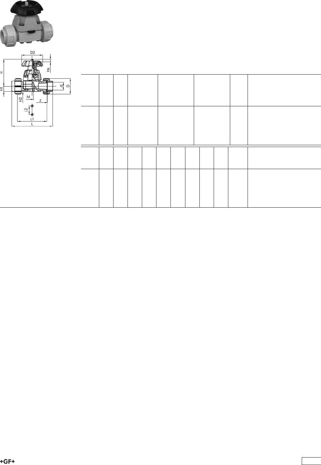
Diaphragm Valves
PROGEF®PLUS silicon free
Diaphragm valve type 314 PP-H SF
With fusion sockets
Model:
ÏMaterial: PP-H / silicone free cleaned
ÏDouble bagged
Option:
ÏHandwheel with built in locking mechanism
d
[mm]
DN
[mm]
PN kv-value
(”p=1 bar)
[l/min]
EPDM
Code
PTFE with
EPDM
Supporting
Diaphragm
Code
kg
20 15 10 72 167 314 477 167 314 492 0.390
25 20 10 137 167 314 478 167 314 493 0.570
32 25 10 207 167 314 479 167 314 494 0.770
40 32 10 354 167 314 480 167 314 495 1.230
50 40 10 517 167 314 481 167 314 496 1.610
63 50 10 713 167 314 482 167 314 497 2.780
d
[mm]
z
[mm]
D
[mm]
D2
[mm]
L
[mm]
L2
[mm]
H
[mm]
H1
[mm]
H2
[mm]
M Lift =
Hx
[mm]
20 100 47 80 128 25 90 14 12 M6 8
25 118 57 80 150 25 101 18 12 M6 11
32 126 64 94 162 25 117 21 12 M6 13
40 144 78 117 184 45 127 26 15 M8 16
50 164 89 117 210 45 139 33 15 M8 21
63 194 109 152 248 45 172 39 15 M8 28
369
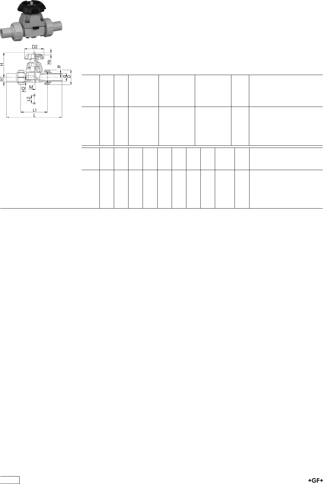
PROGEF®PLUS silicon free
Diaphragm valve type 314 PP-H SF
With butt fusion ends SDR11
Model:
ÏMaterial: PP-H / silicone free cleaned
ÏDouble bagged
Option:
ÏHandwheel with built in locking mechanism
d
[mm]
DN
[mm]
PN kv-value
(”p=1 bar)
[l/min]
EPDM
Code
PTFE with
EPDM
Supporting
Diaphragm
Code
kg
20 15 10 72 167 314 577 167 314 592 0.395
25 20 10 137 167 314 578 167 314 593 0.590
32 25 10 207 167 314 579 167 314 594 0.800
40 32 10 354 167 314 580 167 314 595 1.270
50 40 10 517 167 314 581 167 314 596 1.670
63 50 10 713 167 314 582 167 314 597 2.890
d
[mm]
D
[mm]
D2
[mm]
L
[mm]
L2
[mm]
H
[mm]
H1
[mm]
H2
[mm]
M Lift =
Hx
[mm]
e
[mm]
20 47 80 196 25 90 14 12 M6 8 1,9
25 57 80 221 25 102 18 12 M6 11 2,3
32 64 94 234 25 119 21 12 M6 13 3
40 78 117 260 45 126 26 15 M8 16 3,7
50 89 117 284 45 139 33 15 M8 21 4,6
63 109 152 321 45 172 39 15 M8 28 5,8
370
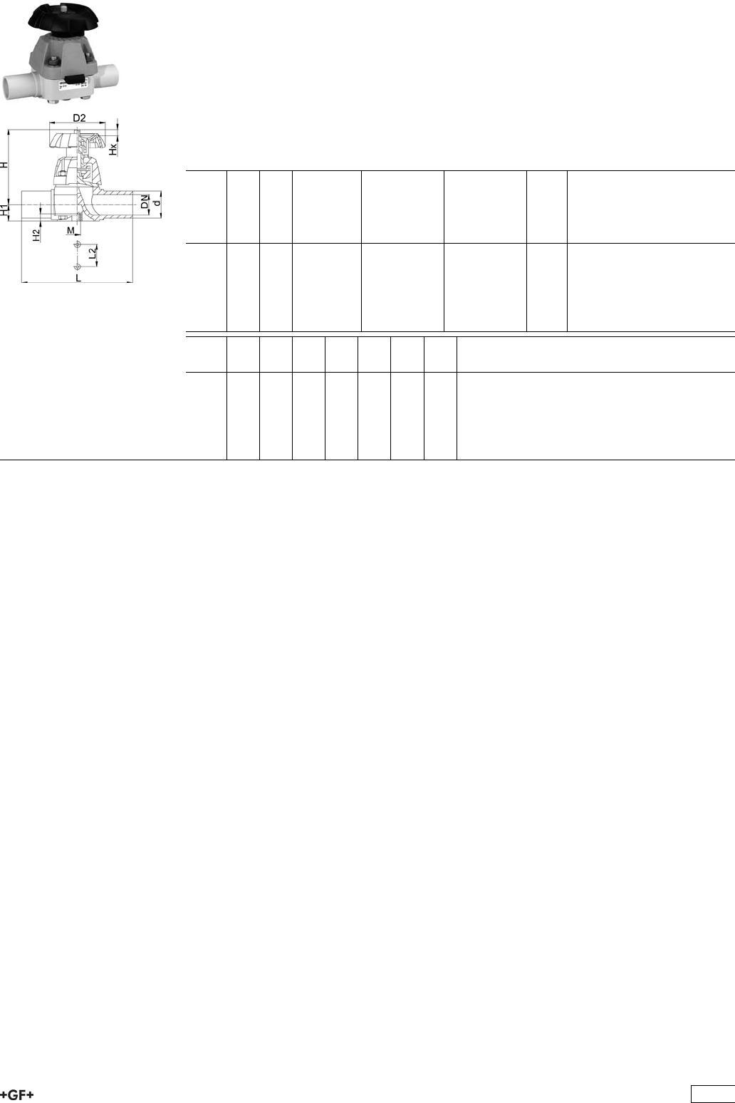
PROGEF®PLUS silicon free
Diaphragm valve type 315 PP-H SF
With butt fusion spigots SDR11
Model:
ÏMaterial: PP-H / silicone free cleaned
ÏDouble bagged
Option:
ÏHandwheel with built in locking mechanism
d
[mm]
DN
[mm]
PN kv-value
(”p=1 bar)
[l/min]
EPDM
Code
PTFE with
EPDM
supporting
diaphragm
Code
kg
20 15 10 72 167 315 577 167 315 562 0.260
25 20 10 137 167 315 578 167 315 563 0.382
32 25 10 207 167 315 579 167 315 564 0.660
40 32 10 354 167 315 580 167 315 565 0.779
50 40 10 517 167 315 581 167 315 566 1.137
63 50 10 713 167 315 582 167 315 567 2.061
d
[mm]
D2
[mm]
H
[mm]
H1
[mm]
H2
[mm]
L
[mm]
L2
[mm]
M
20 80 90 14 12 124 25 M6
25 80 101 18 12 144 25 M6
32 94 117 22 12 154 25 M6
40 117 127 26 15 174 45 M8
50 117 139 32 15 194 45 M8
63 152 172 39 15 223 45 M8
371
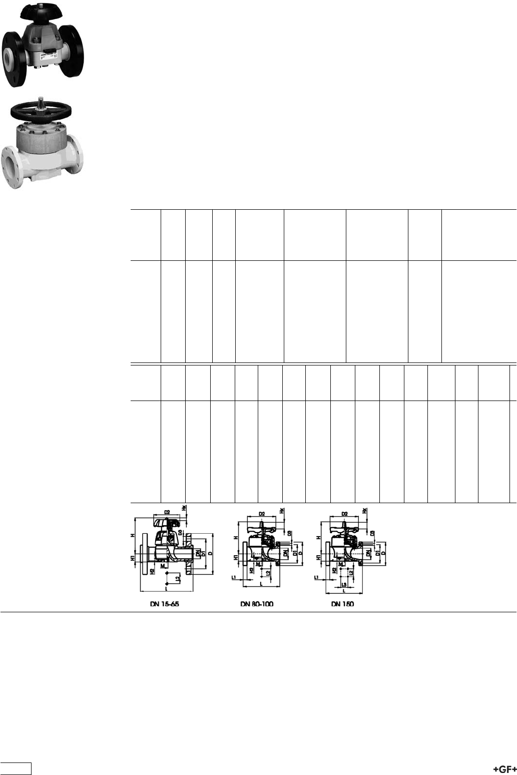
PROGEF®PLUS silicone free
Diaphragm valve type 317 PP-H SF
With flanges
Model:
ÏMaterial: PP-H / silicone free cleaned
ÏDouble bagged
ÏJointing surfaces: serrated or flat
ÏDN 15-65 with backing flange
ÏDN 80-150 with fixed flange
ÏOverall length according to EN 558
ÏConnecting dimensions: ISO 7005 / EN 1092 / DIN 2501 PN10 / BS4504
Option:
ÏHandwheel lockable DN15-65 (basic version not lockable)
* DN80 and DN150 fixed flanges metric and Inch ANSI B16.5
d
[mm]
DN
[mm]
Inch PN kv-value
(”p=1 bar)
[l/min]
EPDM
Code
PTFE with
EPDM
supporting
diaphragm
Code
kg
20 15 1
/210 72 167 317 212 167 317 227 0.532
25 20 3
/410 137 167 317 213 167 317 228 0.844
32 25 1 10 207 167 317 214 167 317 229 1.236
40 32 1 1
/410 354 167 317 215 167 317 230 1.446
50 40 1 1
/210 517 167 317 216 167 317 231 2.456
63 50 2 10 713 167 317 217 167 317 232 3.664
75 65 2 1
/210 992 167 317 218 167 317 233 5.480
*90 80 3 10 1700 167 317 129 167 317 144 8.600
110 100 4 10 2700 167 317 130 167 317 145 11.360
*160 150 6 7 6033 167 317 132 167 317 147 25.000
d
[mm]
D
[mm]
D1
[mm]
D2
[mm]
D3
[mm]
L
[mm]
L1
[mm]
L2
[mm]
L3
[mm]
H
[mm]
H1
[mm]
H2
[mm]
M AL Lift =
Hx
[mm]
20 95 65 80 14 130 25 90 14 12 M6 4 7
25 105 75 80 14 150 25 101 18 12 M6 4 10
32 115 85 94 14 160 25 117 22 12 M6 4 12
40 140 100 117 18 180 45 127 26 15 M8 4 16
50 150 110 117 18 200 45 139 32 15 M8 4 19
63 165 125 152 18 230 45 172 39 15 M8 4 27
75 185 145 152 18 290 70 210 46 15 M8 4 35
*90 200 160 270 18 310 35 120 265 57 23 M12 8 40
110 225 180 270 18 350 38 120 304 69 23 M12 8 50
*160 282 241 400 23 480 29 100 200 437 108 23 M12 8 70
372
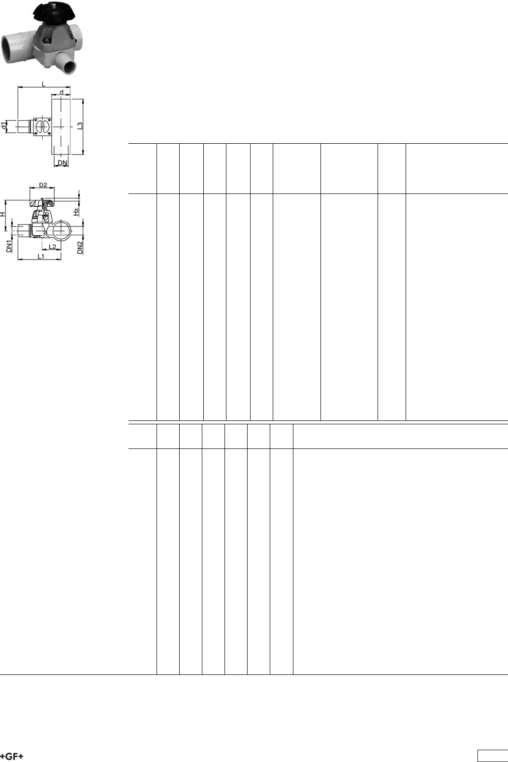
PROGEF®PLUS silicone free
Diaphragm valve type 319 PP-H SF
With butt fusion spigots SDR11
Model:
ÏMaterial: PP-H / silicone free cleaned
ÏDouble bagged
ÏCompact design
ÏMinimized static zone (dead leg)
Option:
ÏHandwheel with built-in locking mechanism (standard version is nonlockable)
d
[mm]
d1
[mm]
DN1
[mm]
DN
[mm]
DN2
[mm]
PN kv-value
(”p=1 bar)
[l/min]
PTFE with
EPDM
supporting
diaphragm
Code
kg
20 20 15 15 15 10 47 167 319 601 0.329
25 20 15 20 20 10 69 167 319 603 0.457
25 25 20 20 20 10 91 167 319 604 0.390
32 20 15 25 25 10 86 167 319 607 0.626
32 25 20 25 25 10 126 167 319 608 0.390
32 32 25 25 25 10 156 167 319 609 0.618
40 20 15 32 25 10 84 167 319 612 0.658
50 20 15 40 25 10 82 167 319 618 0.701
50 25 20 40 25 10 124 167 319 619 0.701
50 32 25 40 25 10 159 167 319 620 0.700
63 20 15 50 25 10 81 167 319 625 0.769
63 25 20 50 25 10 115 167 319 626 0.771
63 32 25 50 25 10 156 167 319 627 0.768
90 20 15 80 20 6 88 167 319 641 0.871
90 25 20 80 25 6 133 167 319 642 1.062
90 32 25 80 25 6 162 167 319 643 0.907
90 50 40 80 50 6 504 167 319 645 2.285
90 63 50 80 50 6 530 167 319 646 2.285
110 20 15 100 25 6 89 167 319 651 0.880
110 25 20 100 25 6 123 167 319 652 0.887
110 32 25 100 25 6 159 167 319 653 0.886
110 50 40 100 50 6 503 167 319 655 2.400
110 63 50 100 50 6 543 167 319 656 2.426
d
[mm]
D2
[mm]
H
[mm]
L
[mm]
L1
[mm]
L2
[mm]
L3
[mm]
20 80 83 106 96 30 140
25 80 91 121 108 36 150
25 80 91 121 108 36 150
32 94 105 137 120 43 160
32 94 105 137 120 43 160
32 94 105 137 120 43 160
40 94 105 149 128 51 180
50 94 105 159 134 57 180
50 94 105 159 134 57 180
50 94 105 159 134 57 180
63 94 105 175 144 67 180
63 94 105 175 144 67 180
63 94 105 175 144 67 180
90 94 105 204 159 82 160
90 94 105 204 159 82 160
90 94 105 204 159 82 160
90 152 151 252 207 95 220
90 152 151 252 207 95 220
110 94 105 226 171 94 160
110 94 105 226 171 94 160
110 94 105 226 171 94 160
110 152 151 274 219 107 220
110 152 151 274 219 107 220
373
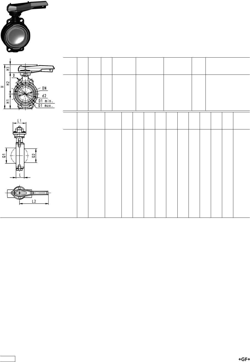
Butterfly Valves
PROGEF®Plus silicone free
Butterfly valve type 567 PP-H SF
Hand lever with ratchet settings
Model:
ÏMaterial: PP-H / silicone free cleaned
ÏConnecting dimension: ISO 7005 PN 10, EN 1092 PN 10, DIN 2501 PN 10,
ANSI/ASME B 16.5 Class 150, BS 1560: 1989, BS 4504, JIS B 2220
ÏOverall length according to EN 558, ISO 5752
d
[mm]
DN
[mm]
Inch PN kv-value
(”p=1 bar)
[l/min]
EPDM
Code
FPM
Code
kg
63 50 2 10 1470 167 567 402 167 567 422 0.969
75 65 2 1
/210 2200 167 567 403 167 567 423 1.061
90 80 3 10 3000 167 567 404 167 567 424 1.191
110 100 4 10 6500 167 567 405 167 567 425 1.751
140 125 5 10 11500 167 567 406 167 567 426 2.199
160 150 6 10 16600 167 567 407 167 567 427 2.989
225 200 8 10 39600 167 567 408 167 567 428 4.706
d
[mm]
D
[mm]
D1
min.
[mm]
D1
max.
[mm]
d2
[mm]
H
[mm]
H1
[mm]
H2
[mm]
H3
[mm]
L
[mm]
L1
[mm]
L2
[mm]
Q1
[mm]
Q2
[mm]
63 19 120.0 125.0 104 264 77 134 54 45 106 205 40
75 19 139.7 145.0 115 277 83 140 54 46 106 205 54 35
90 19 150.0 160.0 131 289 89 146 54 49 106 205 67 50
110 19 175.0 190.5 161 325 104 167 55 56 106 255 88 74
140 23 210.0 215.9 187 352 117 181 55 64 106 255 113 97
160 24 241.3 241.3 215 373 130 189 55 72 106 255 139 123
225 23 290.0 295.0 267 435 158 210 67 73 140 408 178 169
374
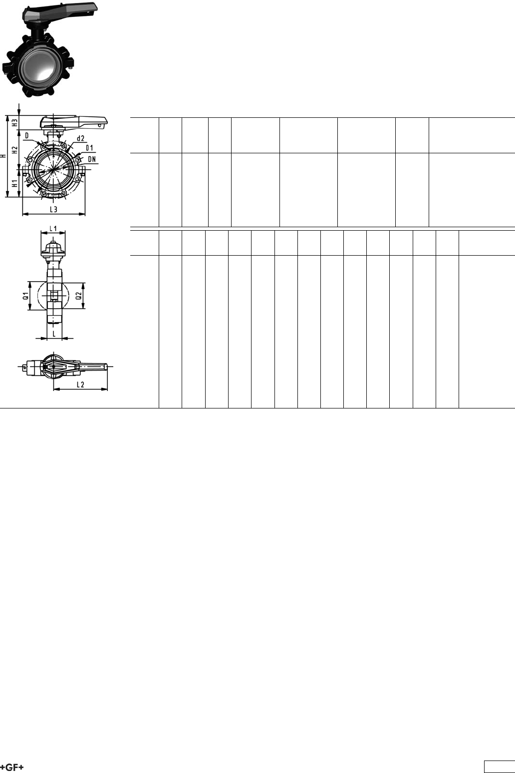
PROGEF Plus silicone free
Lugstyle butterfly valve type 568
Hand lever with ratchet settings
Model:
ÏMaterial: PP-H / silicone free cleaned
ÏOuter body in GGG-40.3 epoxy-coated
ÏConnecting dimension: ISO 7005 PN10, EN 1092 PN10, DIN 2501 PN10
ÏOverall length according to EN 558, ISO 5752
d
[mm]
DN
[mm]
Inch PN kv-value
(”p=1 bar)
[l/min]
EPDM
Code
FPM
Code
kg
63 50 2 10 1470 167 568 402 167 568 422 3.055
75 65 2 1
/210 2200 167 568 403 167 568 423 3.397
90 80 3 10 3000 167 568 404 167 568 424 4.402
110 100 4 10 6500 167 568 405 167 568 425 5.835
140 125 5 10 11500 167 568 406 167 568 426 7.665
160 150 6 10 16600 167 568 407 167 568 427 9.449
225 200 8 10 39600 167 568 408 167 568 428 14.654
d
[mm]
d2
[mm]
D D1
[mm]
H
[mm]
H1
[mm]
H2
[mm]
H3
[mm]
L
[mm]
L1
[mm]
L2
[mm]
L3
[mm]
Q1
[mm]
Q2
[mm]
63 150 M16 125 265 77 134 54 45 106 205 150 40
75 170 M16 145 277 83 140 54 46 106 205 160 54 35
90 184 M16 160 289 89 146 54 49 106 205 205 67 50
110 216 M16 180 326 104 167 55 56 106 255 244 88 74
140 246 M16 210 353 117 181 55 64 106 255 272 113 97
160 273 M20 240 374 130 189 55 72 106 255 297 139 123
225 334 M20 295 435 158 210 67 73 140 408 360 178 169
375

PROGEF®PLUS silicone free
Butterfly valve type 568 PP-H SF ANSI
Hand lever with ratchet settings
Model:
ÏMaterial: PP-H / silicone free cleaned
ÏOuter body in GGG-40.3 epoxy-coated
ÏConnecting dimension ANSI/ASME B 16.5 Class 150
ÏOverall length according to EN 558, ISO 5752
Inch d
[mm]
DN
[mm]
PN kv-value
(”p=1 bar)
[l/min]
EPDM
Code
FPM
Code
kg
2 63 50 10 1470 167 568 502 167 568 522 3.055
21
/275 65 10 2200 167 568 503 167 568 523 3.397
3 90 80 10 3000 167 568 504 167 568 524 3.773
4 110 100 10 6500 167 568 505 167 568 525 5.835
5 140 125 10 11500 167 568 506 167 568 526 7.665
6 160 150 10 16600 167 568 507 167 568 527 9.449
8 225 200 10 39600 167 568 508 167 568 528 14.654
Inch d2
[mm]
D D1
[mm]
H
[mm]
H1
[mm]
H2
[mm]
H3
[mm]
L
[mm]
L1
[mm]
L2
[mm]
L3
[mm]
Q1
[mm]
Q2
[mm]
2 150 UNC 5/8 121 265 77 134 54 45 106 205 150 40
21
/2170 UNC 5/8 138 277 83 140 54 46 106 205 160 54 35
3 177 UNC 5/8 152 289 89 146 54 49 106 205 175 67 50
4 216 UNC 5/8 191 326 104 167 55 56 106 255 244 88 74
5 246 UNC 3/4 216 353 117 181 55 64 106 255 272 113 97
6 273 UNC 3/4 241 374 130 189 55 72 106 255 297 139 123
8 334 UNC 3/4 298 435 158 210 67 73 140 408 360 178 169
376

Ball Check Valves
PROGEF®PLUS silicone free
Ball check valve type 360 PP-H SF
With fusion sockets
Model:
ÏMaterial: PP-H / silicone free cleaned
ÏDouble bagged
ÏFor easy installation and removal
d
[mm]
DN
[mm]
PN kv-value
(”p=1 bar)
[l/min]
EPDM
Code
FPM
Code
kg D
[mm]
L
[mm]
L2
[mm]
z
[mm]
16 10 10 170 167 360 601 167 360 611 0.079 46 98 62 72
20 15 10 150 167 360 602 167 360 612 0.079 46 101 62 73
25 20 10 330 167 360 603 167 360 613 0.134 56 119 74 87
32 25 10 390 167 360 604 167 360 614 0.203 67 130 78 94
40 32 10 710 167 360 605 167 360 615 0.380 82 149 88 109
50 40 10 900 167 360 606 167 360 616 0.612 98 162 94 118
63 50 10 1390 167 360 607 167 360 617 1.116 120 195 113 143
PROGEF®PLUS silicone free
Ball check valve type 360 PP-H SF
With socket fusion spigots
Model:
ÏMaterial: PP-H / silicone free cleaned
ÏDouble bagged
ÏFor easy installation and removal
ÏOverall length EN 558
d
[mm]
DN
[mm]
PN kv-value
(”p=1 bar)
[l/min]
EPDM
Code
FPM
Code
kg D
[mm]
L
[mm]
L2
[mm]
16 10 10 170 167 360 621 167 360 631 0.080 46 109 62
20 15 10 150 167 360 622 167 360 632 0.080 46 119 62
25 20 10 330 167 360 623 167 360 633 0.136 56 140 74
32 25 10 390 167 360 624 167 360 634 0.208 67 150 78
40 32 10 710 167 360 625 167 360 635 0.386 82 171 88
50 40 10 900 167 360 626 167 360 636 0.631 97 191 94
63 50 10 1390 167 360 627 167 360 637 1.149 119 220 113
377
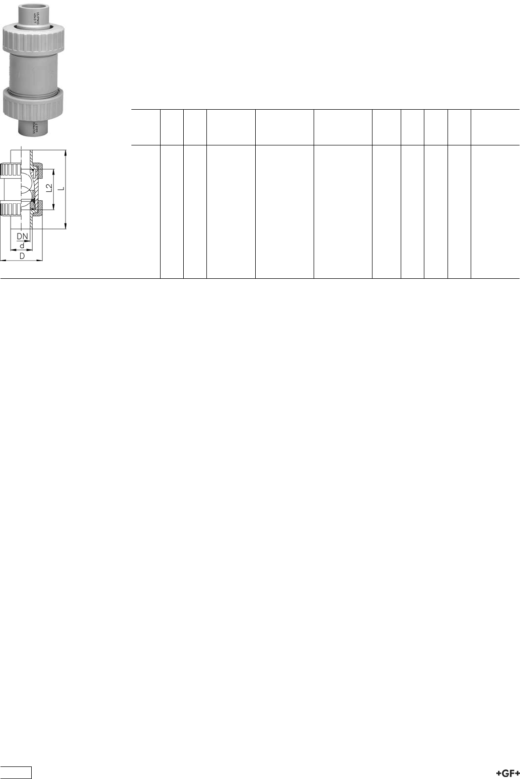
PROGEF®PLUS silicone free
Ball check valve type 360 PP-H SF
With butt fusion ends SDR11
Model:
ÏMaterial: PP-H / silicone free cleaned
ÏDouble bagged
ÏFor easy installation and removal
d
[mm]
DN
[mm]
PN kv-value
(”p=1 bar)
[l/min]
EPDM
Code
FPM
Code
kg D
[mm]
L
[mm]
L2
[mm]
20 15 10 150 167 360 642 167 360 652 0.080 46 119 62
25 20 10 330 167 360 643 167 360 653 0.136 56 140 74
32 25 10 390 167 360 644 167 360 654 0.208 67 150 78
40 32 10 710 167 360 645 167 360 655 0.386 82 171 88
50 40 10 900 167 360 646 167 360 656 0.631 97 191 94
63 50 10 1390 167 360 647 167 360 657 1.149 119 220 113
378
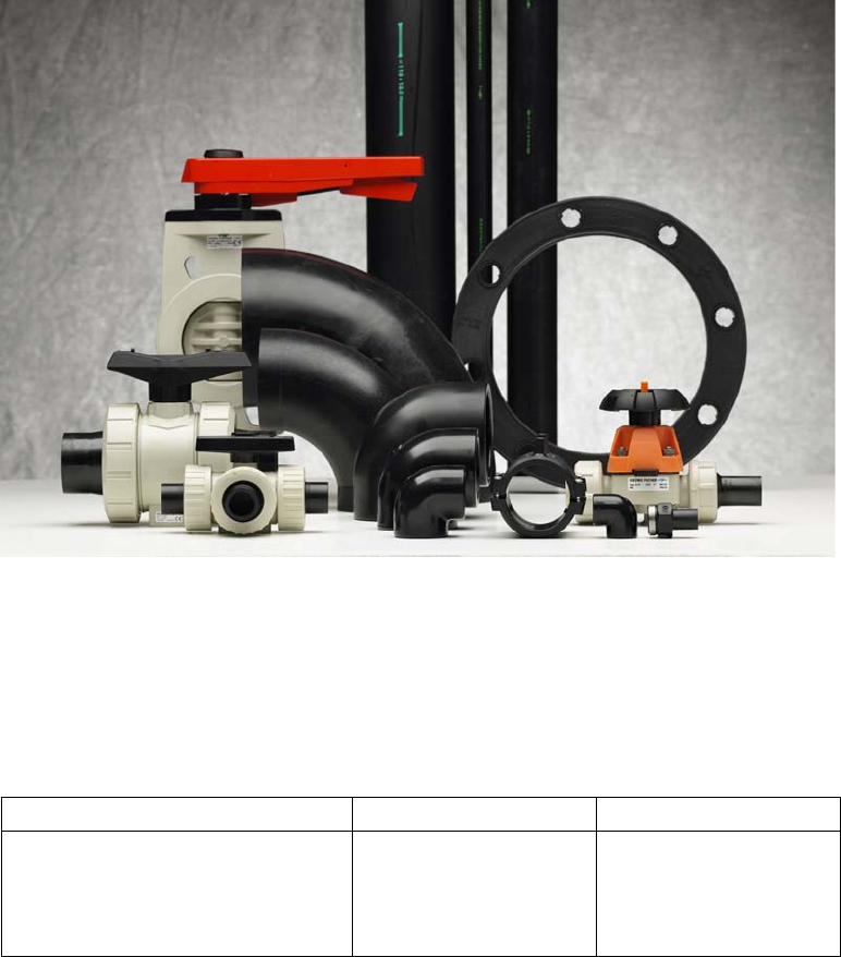
E:&%%
EgZhhjgZGVi^c\h[dgE:";^ii^c\hVcYE:"E^eZh
ÄE^eZh
ÄHdX`Zi;jh^dc;^ii^c\h
Ä7jii;jh^dc;^ii^c\h
Ä:aZXigd[jh^dc;^ii^c\h
H9G&& H9G&,#+
E:-% 82&#'*
E:-% 82&#+
E:&%% 82&#'*
E:&%% 82&#+
EC&'#*
EC&%
EC&+
EC&'#*
EC,#*
EC+
EC&%
EC,#*
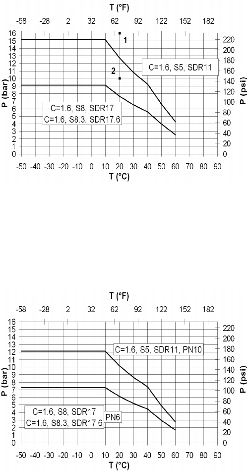
Pressure/temperature diagram for PE
PE 100
The following pressure/temperature diagram for PE100
rkrgu"cpf"Ývvkpiu"ku"xcnkf"hqt"c"nkhgvkog"qh"47"{gctu0
Vjg"fgukip"hcevqt"qh"308"*tgurgevkxg"3047+"tgeqoogp/
fgf"d{"IH"ku"kpeqtrqtcvgf0
It can be used for water or media resembling water,
kpqvjgt"yqtfu."ogfkc"yjkej"jcxg"pq"fgtcvkpi"hcevqt"
tgictfkpi"vjg"ejgokecn"tgukuvcpeg0
Remark: Please take into account the pressure/
vgorgtcvwtg"fkcitcou"hqt"xcnxgu"cpf"urgekcn"Ývvkpiu0"
Because of the construction and/or sealing material
used, differences are possible when compared with
rkrgu"cpf"Ývvkpiu0"Vjku"kphqtocvkqp"ecp"dg"hqwpf"kp"vjg"
rncppkpi"hwpfcogpvcnu"qh"vjg"tgngxcpv"v{rgu"qh"xcnxgu."
tgurgevkxgn{urgekcn"Ývvkpiu0
Kp"ecug"qh"nqpi/vgto"crrnkecvkqpu"cv"eqpvkpwqwu"
rtguuwtg"ykvj"vgorgtcvwtgu"cdqxg"62"̇E."rngcug"
eqpvcev"{qwt"IH"tgrtgugpvcvkxg0
Polyethylene PE 100 – the third Generation of polyethylene
3" Fgukip"Hcevqt"E"?"3047."U7."UFT33"hqt"42"̇E"ycvgt."72"{gctu
4" Fgukip"Hcevqt"E?3047."U:05."UFT3908"cpf"U:."UFT39"hqt"42̇E""
" ycvgt."72"{gctu
P Permissible pressure in bar, psi
V" Vgorgtcvwtg"kp"̇E."̇H
Pressure/temperature diagram for PE
PE 80
Vjg"hqnnqykpi"rtguuwtg1vgorgtcvwtg"fkcitco"hqt"RG:2"
rkrgu"cpf"Ývvkpiu"ku"xcnkf"hqt"c"nkhgvkog"qh"47"{gctu0
Vjg"fgukip"hcevqt"qh"308"tgeqoogpfgf"d{"IH"ku"
kpeqtrqtcvgf0
It can be used for water or media resembling water, in
qvjgt"yqtfu."ogfkc"yjkej"jcxg"pq"fgtcvkpi"hcevqt"tg/
ictfkpi"vjg"ejgokecn"tgukuvcpeg0
Remark: Please take into account the pressure/
vgorgtcvwtg"fkcitcou"hqt"xcnxgu"cpf"urgekcn"Ývvkpiu0"
Becauseof the construction and/or sealing material
used, differences are possible when compared with
rkrgu"cpf"Ývvkpiu0"Vjku"kphqtocvkqp"ecp"dg"hqwpf"kp"vjg"
rncppkpi"hwpfcogpvcnu"qh"vjg"tgngxcpv"v{rgu"qh"xcnxgu."
tgurgevkxgn{"urgekcn"Ývvkpiu0
Kp"ecug"qh"nqpi/vgto"crrnkecvkqpu"cv"eqpvkpwqwu"
rtguuwtg"ykvj"vgorgtcvwtgu"cdqxg"62"̇E"rngcug"
eqpvcev"{qwt"IH"tgrtgugpvcvkxg0
P Permissible pressure in bar, psi
V" Vgorgtcvwtg"kp"̇E."̇H
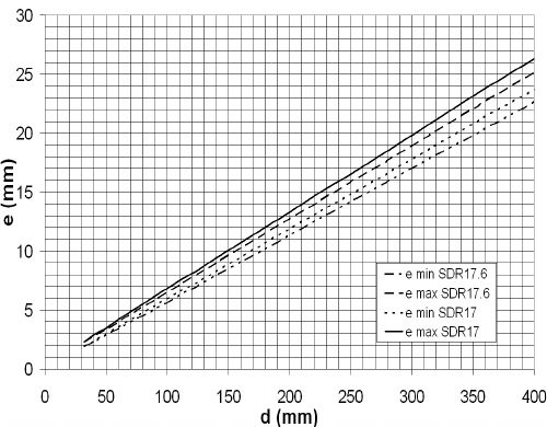
Ascertaining the nominal pressure (PN)
According to the standard, the nominal pressure is a
numeric measure of the size of a pipeline part, which
refers to the mechanical properties of that pipeline part.
Besides the geometric sizes such as SDR, the creep
strength/dimensioning tension and the minimum design
factor are also taken into consideration.
For plastic piping systems intended to carry water, the
nominal pressure value indicates the maximum permit-
ted operating pressure in bar, at a temperature of 20°C,
and 50 years in water, referenced to the minimum value
using the following equation:
PNin bar)
Minimum required strength (MRS):
LCL at 20°C and 50 years in water, roun-
ded down to the next value in the R10 standard series
of numbers.
LCL is understood to mean the equivalent stress
ascertained for a given period and a given temperature
fromthe time-dependent creep diagram. LCL stands
of numbers is a Renard standard series of numbers as
Fgukip"uvtguu"*j"U+<
The permitted stress for a particular application or
as shown in the equation below:
S
The calculated value is rounded down to the next
value in the R10 standard series of numbers.
Vqvcn"qrgtcvkpi"*ecnewncvkqp+"eqghÝekgpv"*E+<
which takes into account both the operating condtions
and also the characteristics of the pipeline component
-
LCL.
nominal pressure for both SDR classes, the result for a
PE 100 pipe is as follows:
C = 1.25 (minimum factor) C = 1.25 (minimum factor)
Eqorctkuqp"qh"pqokpcn"rtguuwtg"hqt"UFT39cpf"UFT3908
e Wall thickness
bar in PN, but in actual practice this does not matter, as
shown below:
-
diagrams we ascertain for ELTEX TUB 121 or CRP 100
LCL for the operating point of
(minimum value of both PE100 materials as per
manufacturer‘s data).
S, and do not round it down, we obtain the
To summarise: Both SDR classes comply with
requirements for industrial applications mentioning
c"RP32"u{uvgo0
Eqorctkuqp"qh"igqogvtke"fkogpukqpu
The two SDR classes differ only slightly in wall thick-
ness, as can be seen from the diagram below. This
shows that there is an area where the wall thickness
complies with both requirements of both SDR classes.
For butt fusion the wall thickness gap may notex-
ceed 10 %. Looking at the differences of the wallthick-
ismuch lower, that means butt fusion of both SDR‘s is
noproblem.

382
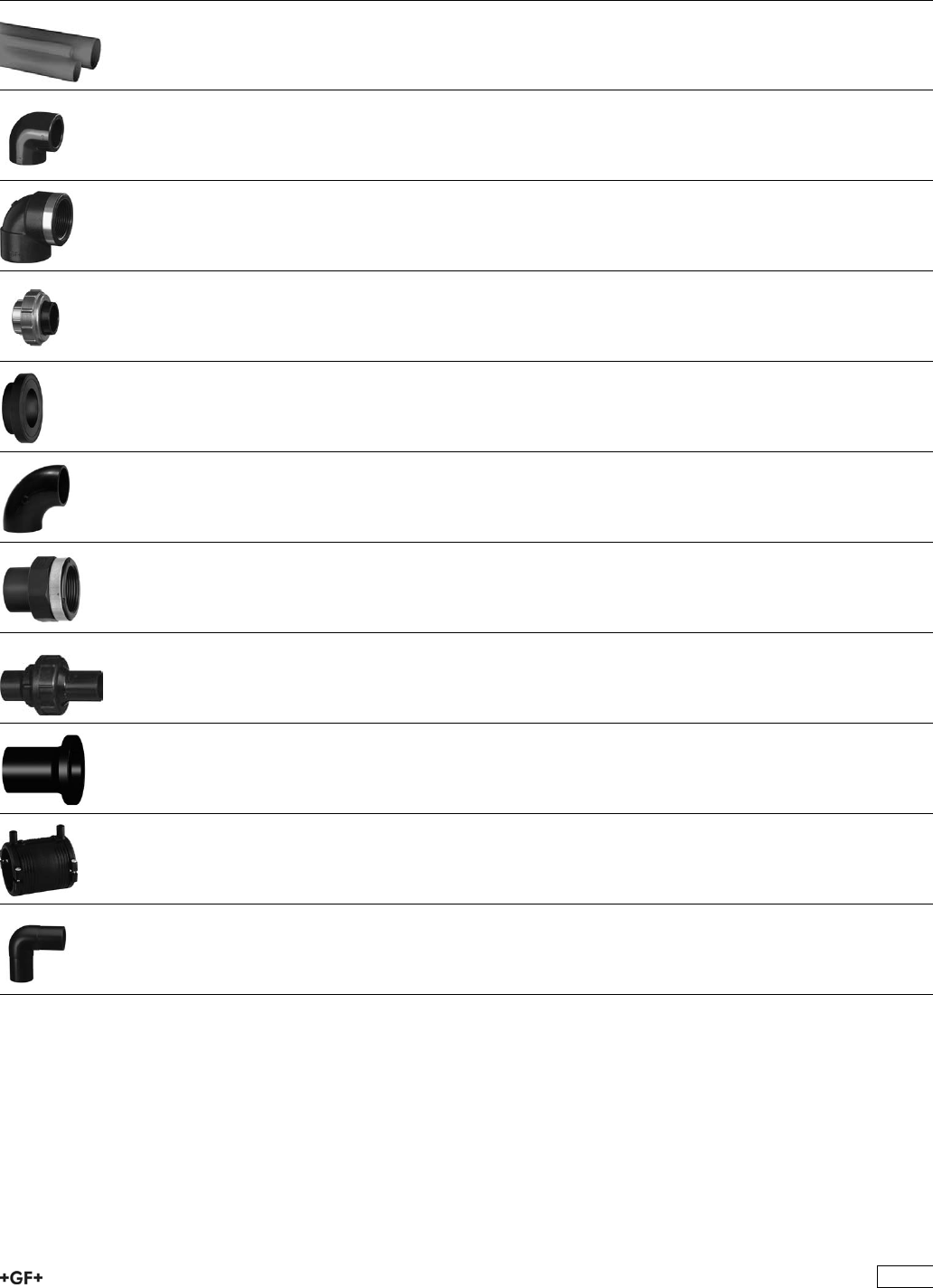
PE Industrial Systems Pipes, Fittings, Unions,
Flanges and Flange Adaptors
Page
PE100 Pipes 384
Fittings for Socket Fusion 386
Adaptor Fittings for Socket Fusion 389
Unions for Socket Fusion 391
Flange Adaptors, Flanges and Gaskets for Socket Fusion 394
Fittings for Butt Fusion 400
Adaptor Fittings for Butt Fusion 409
Unions for Butt Fusion 410
Flange Adaptors, Flanges and Gaskets for Butt Fusion 416
Electrofusion Fittings 426
Spigot Fittings for Electrofusion 446
383
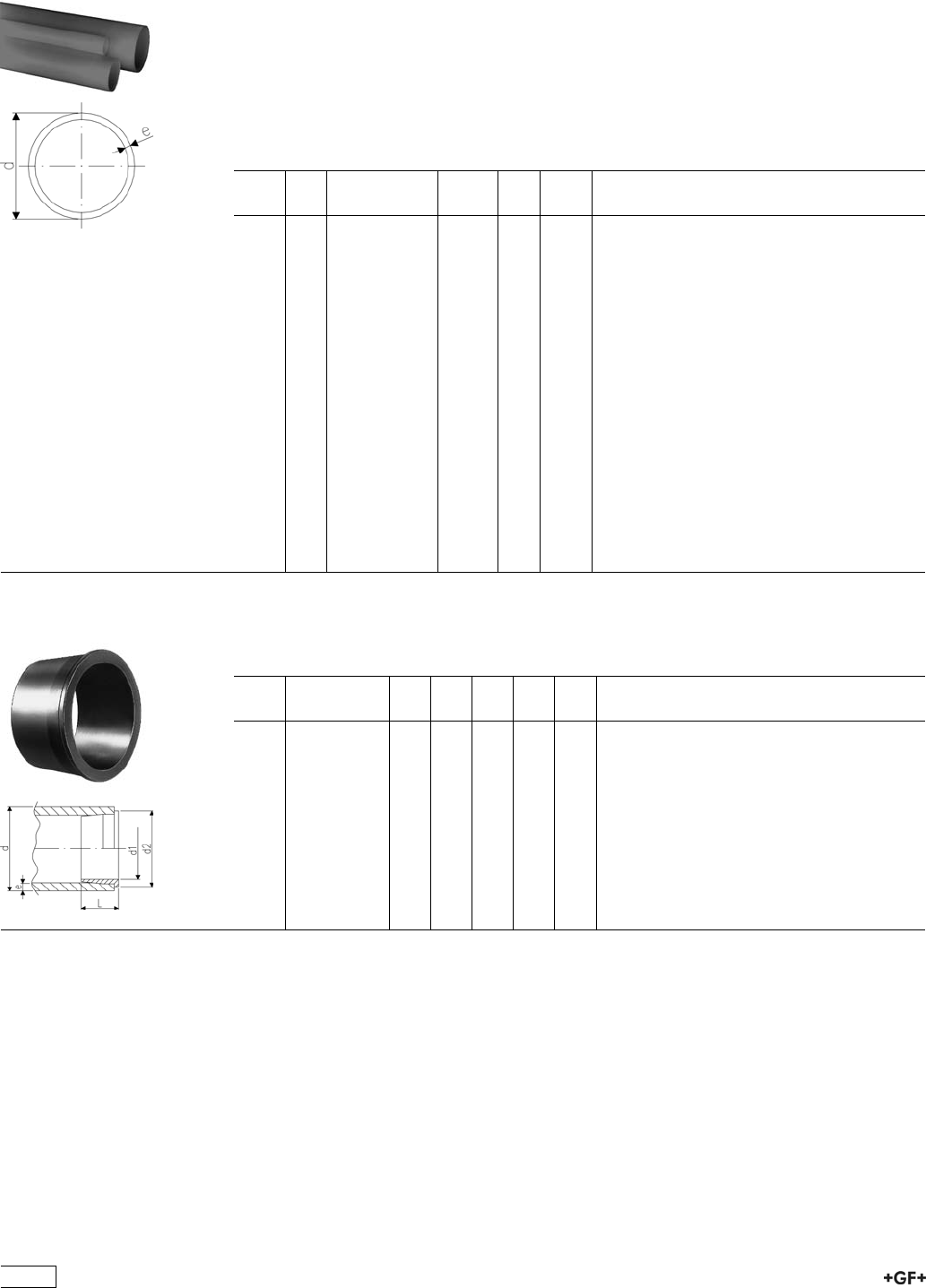
PE100 Pipes
93 01 71 Pipes, PE100 S5/SDR11
Model:
ÏMaterial: PE 100, Polyethylene
ÏColour: RAL 9011 graphite black
ÏDimension: DIN 8074
ÏPipe length: 5m, with plain ends
* In these two sizes, stiffeners Code No. 733 900 006 (20 x 1,9) and 733 900 007 (25 x
2.3) must be used with socket fusion joints.
d
[mm]
PN Code kg/m e
[mm]
di
[mm]
*20 16 193 017 156 0.113 1,9 16.2
*25 16 193 017 157 0.172 2,3 20.4
32 16 193 017 158 0.274 2,9 26.2
40 16 193 017 159 0.434 3,7 32.6
50 16 193 017 160 0.672 4,6 40.8
63 16 193 017 161 1.060 5,8 51.4
75 16 193 017 162 1.480 6,8 61.4
90 16 193 017 163 2.140 8,2 63.6
110 16 193 017 164 3.190 10,0 90.0
125 16 193 017 165 - 11,4 102.8
140 16 193 017 166 5.130 12,7 114.6
160 16 193 017 167 - 14,6 130.8
180 16 193 017 168 8.500 16,4 147.2
200 16 193 017 169 - 18,2 163.6
225 16 193 017 170 - 20,5 184.0
250 16 193 017 171 - 22,7 204.6
280 16 193 017 172 - 25,4 229.2
315 16 193 017 173 - 28,6 257.8
355 16 193 017 174 32.800 32,2 290.6
400 16 193 017 175 41.700 36,3 327.4
33 90 00 Stiffernes, PE100
ÏUsed as support during d20 and d25 socket fusion jointing to prevent the pipe from
collapsing during the heating and jointing process.
d
[mm]
Code d1
[mm]
D2
[mm]
d2
[mm]
L
[mm]
e
[mm]
20 733 900 006 14 18 18 10 1,9
25 733 900 007 18 22 23 11 2,3
384
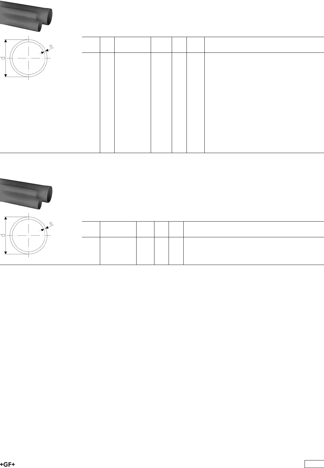
93 01 71 Pipes, PE100 S8,3/SDR17,6
Model:
ÏMaterial: PE 100, Polyethylene
ÏColour: RAL 9011 graphite black
ÏDimension: DIN 8074
ÏPipe length: 5m, with plain ends
d
[mm]
PN Code kg/m e
[mm]
di
[mm]
50 10 193 017 110 - 2,9 44.2
63 10 193 017 111 - 3,6 55.8
75 10 193 017 112 - 4,3 66.4
90 10 193 017 113 - 5,1 79.8
110 10 193 017 114 - 6,3 97.4
125 10 193 017 115 2.690 7,1 110.8
140 10 193 017 116 - 8,0 124.0
160 10 193 017 117 4.390 9,1 141.8
180 10 193 017 118 5.530 10,2 159.6
200 10 193 017 119 - 11,4 177.2
225 10 193 017 120 - 12,8 199.4
250 10 193 017 121 - 14,2 221.6
280 10 193 017 122 - 15,9 248.2
315 10 193 017 123 - 17,9 279.2
355 10 193 017 124 21.400 20,1 290.6
400 10 193 017 125 27.100 22,7 354.6
93 01 72 Pipes, PE100 S3,2/SDR7,4
Model:
ÏDimension: DIN 8074
ÏColour: RAL 9011 graphite black
ÏLength: Lengths of 5 m
Ïfor socket fusion without stiffeners
ÏNot suitable for butt fusion
d
[mm]
Code kg/m e
[mm]
di
[mm]
20 193 017 206 0.156 2,8 14.4
25 193 017 207 0.243 3,5 18.0
385
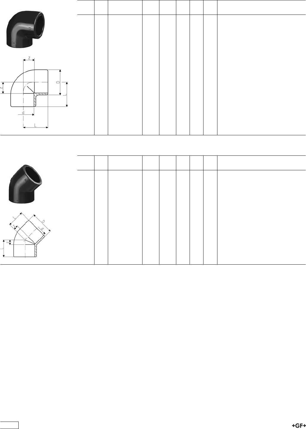
Fittings for Socket Fusion
33 10 01 Elbow 90°, PE80
d
[mm]
PN Code kg kg/m D
[mm]
L
[mm]
z
[mm]
20 10 733 100 106 0.022 0.022 31 28 14
25 10 733 100 107 0.032 0.032 36 32 16
32 10 733 100 108 0.048 0.048 44 38 20
40 10 733 100 109 0.080 0.080 54 44 24
50 10 733 100 110 0.130 0.130 66 51 28
63 10 733 100 111 0.229 0.229 82 62 35
75 10 733 100 112 0.320 0.320 93 76 45
90 10 733 100 113 0.502 0.502 110 88 53
110 10 733 100 114 0.864 0.864 134 106 65
33 15 01 Elbow 45°, PE80
d
[mm]
PN Code kg kg/m D
[mm]
L
[mm]
z
[mm]
20 10 733 150 106 0.018 0.018 31 21 7
25 10 733 150 107 0.026 0.026 36 24 8
32 10 733 150 108 0.038 0.038 44 28 10
40 10 733 150 109 0.061 0.061 53 33 13
50 10 733 150 110 0.088 0.088 64 36 13
63 10 733 150 111 0.184 0.184 82 43 16
75 10 733 150 112 0.232 0.232 93 51 20
90 10 733 150 113 0.415 0.415 114 58 23
110 10 733 150 114 0.658 0.658 134 68 27
386
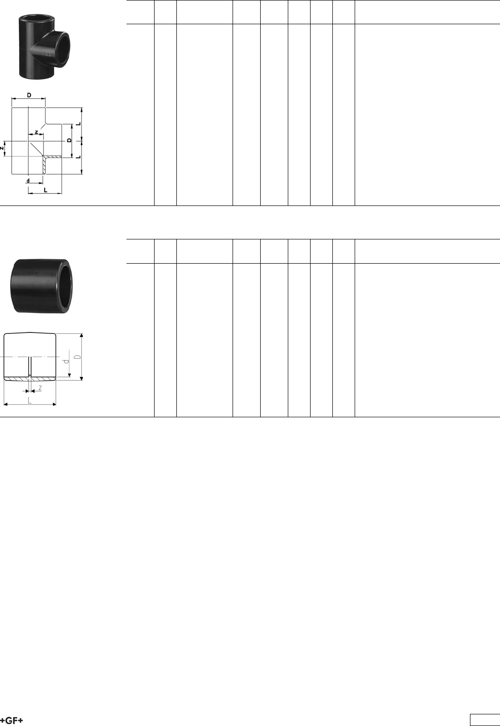
33 20 01 Tee 90° equal, PE80
d
[mm]
PN Code kg kg/m D
[mm]
L
[mm]
z
[mm]
20 10 733 200 106 0.028 0.028 31 28 14
25 10 733 200 107 0.041 0.041 36 32 16
32 10 733 200 108 0.060 0.060 44 38 20
40 10 733 200 109 0.101 0.101 54 44 24
50 10 733 200 110 0.163 0.163 66 51 28
63 10 733 200 111 0.300 0.300 82 62 35
75 10 733 200 112 0.408 0.408 93 76 45
90 10 733 200 113 0.747 0.747 114 88 53
110 10 733 200 114 1.113 1.113 134 106 65
33 91 01 Sockets equal, PE80
d
[mm]
PN Code kg kg/m D
[mm]
L
[mm]
z
[mm]
20 10 733 910 106 0.014 0.014 31 35 7
25 10 733 910 107 0.019 0.019 36 39 7
32 10 733 910 108 0.027 0.027 44 43 7
40 10 733 910 109 0.043 0.043 54 48 8
50 10 733 910 110 0.077 0.077 66 54 8
63 10 733 910 111 0.126 0.126 82 62 8
75 10 733 910 112 0.154 0.154 93 70 8
90 10 733 910 113 0.234 0.234 112 81 11
110 10 733 910 114 0.428 0.428 134 96 14
387
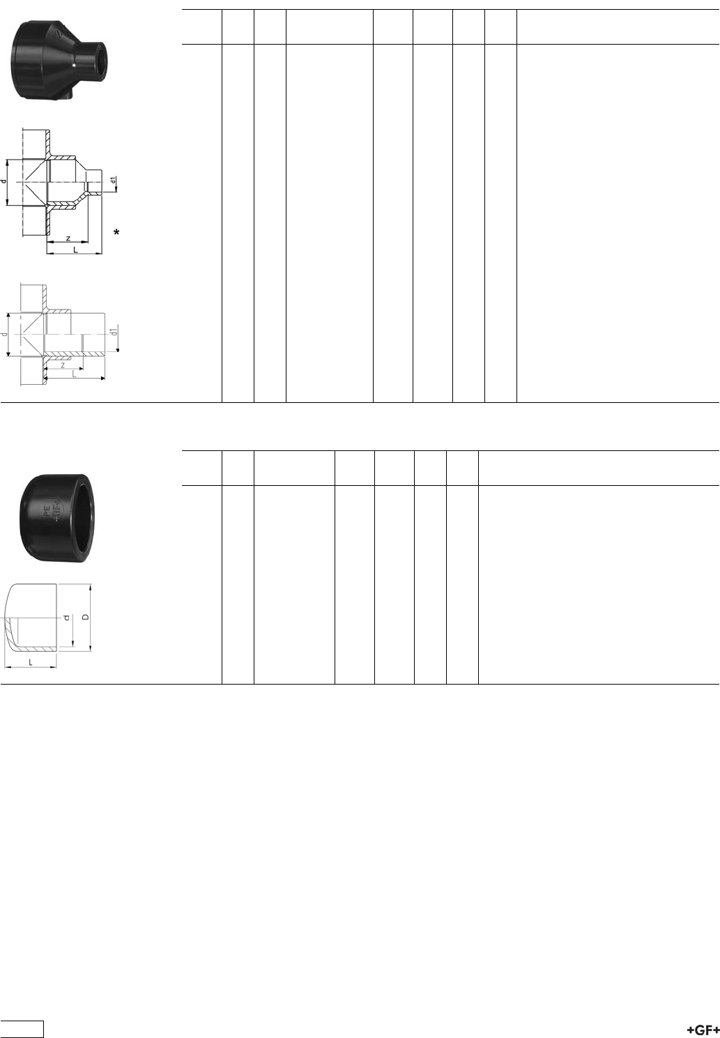
33 91 03 Reducers, PE80
ÏWith socket fusion spigot and fusion socket metric
d
[mm]
d1
[mm]
PN Code kg kg/m L
[mm]
z
[mm]
25 20 10 733 910 337 0.013 0.013 39 23
32 25 10 733 910 341 0.021 0.021 43 27
*40 20 10 733 910 348 0.023 0.023 48 34
*40 25 10 733 910 347 0.027 0.027 48 32
40 32 10 733 910 346 0.032 0.032 48 30
*50 32 10 733 910 353 0.042 0.042 54 36
50 40 10 733 910 352 0.049 0.049 54 34
*63 20 10 733 910 362 0.057 0.057 64 50
*63 25 10 733 910 361 0.060 0.060 64 48
*63 32 10 733 910 360 0.065 0.065 64 46
*63 40 10 733 910 359 0.070 0.070 64 44
63 50 10 733 910 358 0.086 0.086 64 41
75 63 10 733 910 364 0.103 0.103 62 35
*90 63 10 733 910 371 0.192 0.192 88 62
90 75 10 733 910 370 0.146 0.146 70 39
110 90 10 733 910 376 0.253 0.253 81 45
33 96 01 End Caps, PE80
d
[mm]
PN Code kg kg/m D
[mm]
L
[mm]
20 10 733 960 106 0.010 0.010 30 27
25 10 733 960 107 0.016 0.016 36 30
32 10 733 960 108 0.025 0.025 44 34
40 10 733 960 109 0.038 0.038 53 38
50 10 733 960 110 0.061 0.061 65 44
63 10 733 960 111 0.096 0.096 80 51
75 10 733 960 112 0.157 0.157 91 66
90 10 733 960 113 0.272 0.272 111 77
110 10 733 960 114 0.414 0.414 137 93
388
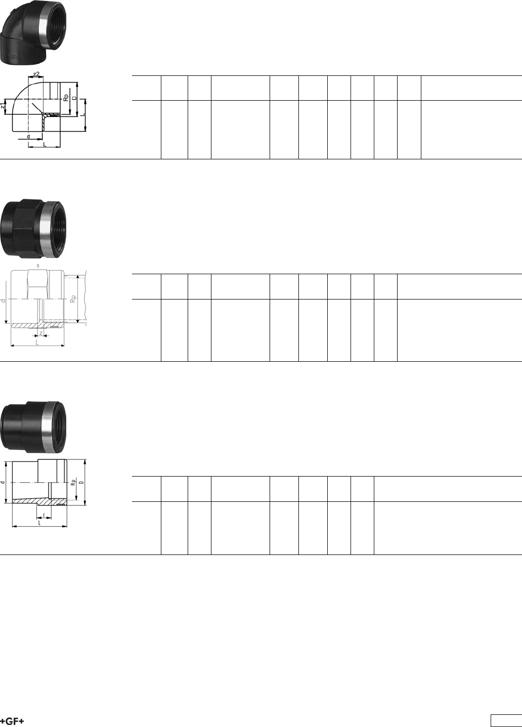
Adaptor Fittings for Socket Fusion
33 10 02 Elbow 90°, PE80
metric - Rp
Model:
ÏWith fusion socket metric and parallel female thread Rp, reinforced
ÏConnection to plastic or metal
ÏReinforcing ring stainless (A2)
ÏDo not use thread sealing pastes that are harmful to PE
d
[mm]
Rp
[inch]
PN Code kg kg/m D
[mm]
L
[mm]
z1
[mm]
z2
[mm]
20 1
/210 733 100 206 0.024 0.024 30 28 14 14
25 3
/410 733 100 207 0.033 0.033 35 32 16 16
32 1 10 733 100 208 0.061 0.061 44 38 20 20
40 1 1
/410 733 100 209 0.094 0.094 54 44 24 24
33 91 02 Adaptor Sockets, PE80
metric - Rp
Model:
ÏWith fusion socket metric and parallel female thread Rp, reinforced
ÏConnection to plastic or metal
ÏReinforcing ring stainless (A2)
ÏDo not use thread sealing pastes that are harmful to PE
d
[mm]
Rp
[inch]
PN Code kg kg/m L
[mm]
s
[mm]
z
[mm]
20 1
/210 733 910 206 0.020 0.020 35 32 7
25 3
/410 733 910 207 0.026 0.026 39 36 7
32 1 10 733 910 208 0.043 0.043 45 46 7
40 1 1
/410 733 910 209 0.070 0.070 53 55 7
50 1 1
/210 733 910 210 0.099 0.099 54 65 9
63 2 10 733 910 211 0.159 0.159 62 80 9
33 91 04 Reducing Bushes, PE80
metric - Rp
Model:
ÏWith fusion socket metric and parallel female thread Rp, reinforced
ÏConnection to plastic or metal
ÏReinforcing ring stainless (A2)
ÏDo not use thread sealing pastes that are harmful to PE
d
[mm]
Rp
[inch]
PN Code kg kg/m L
[mm]
z
[mm]
20 3
/810 733 910 434 0.012 0.012 33 7
25 1
/210 733 910 437 0.017 0.017 37 6
32 3
/410 733 910 441 0.027 0.027 43 8
40 1 10 733 910 446 0.046 0.046 49 9
50 1 1
/410 733 910 452 0.071 0.071 55 10
389
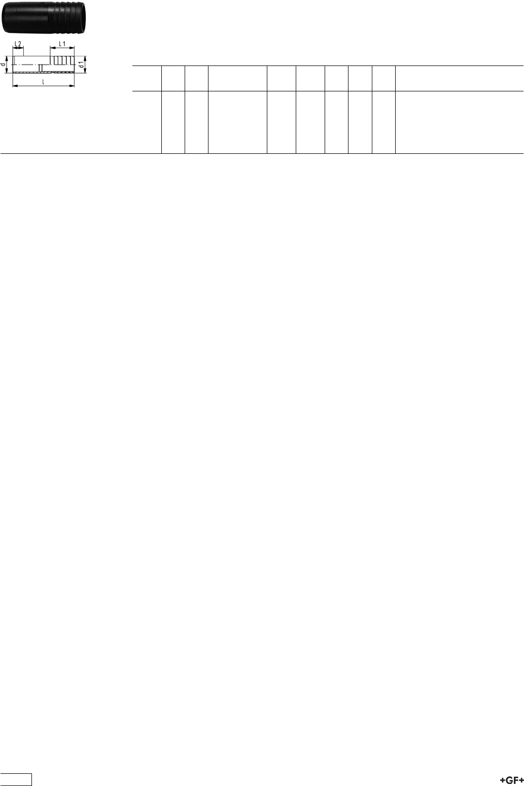
Hose Connectors, PE100
metric
Model:
ÏWith socket fusion spigot metric and parallel hose connection
d
[mm]
d1
[mm]
PN Code kg kg/m L
[mm]
L1
[mm]
L2
[mm]
20 20 10 753 960 406 0.007 0.007 55 27 14
25 25 10 753 960 407 0.015 0.015 68 36 16
32 32 10 753 960 408 0.021 0.021 77 36 18
40 40 10 753 960 409 0.030 0.030 80 42 20
50 50 10 753 960 410 0.064 0.064 90 48 23
63 60 10 753 960 411 0.092 0.092 100 50 27
390
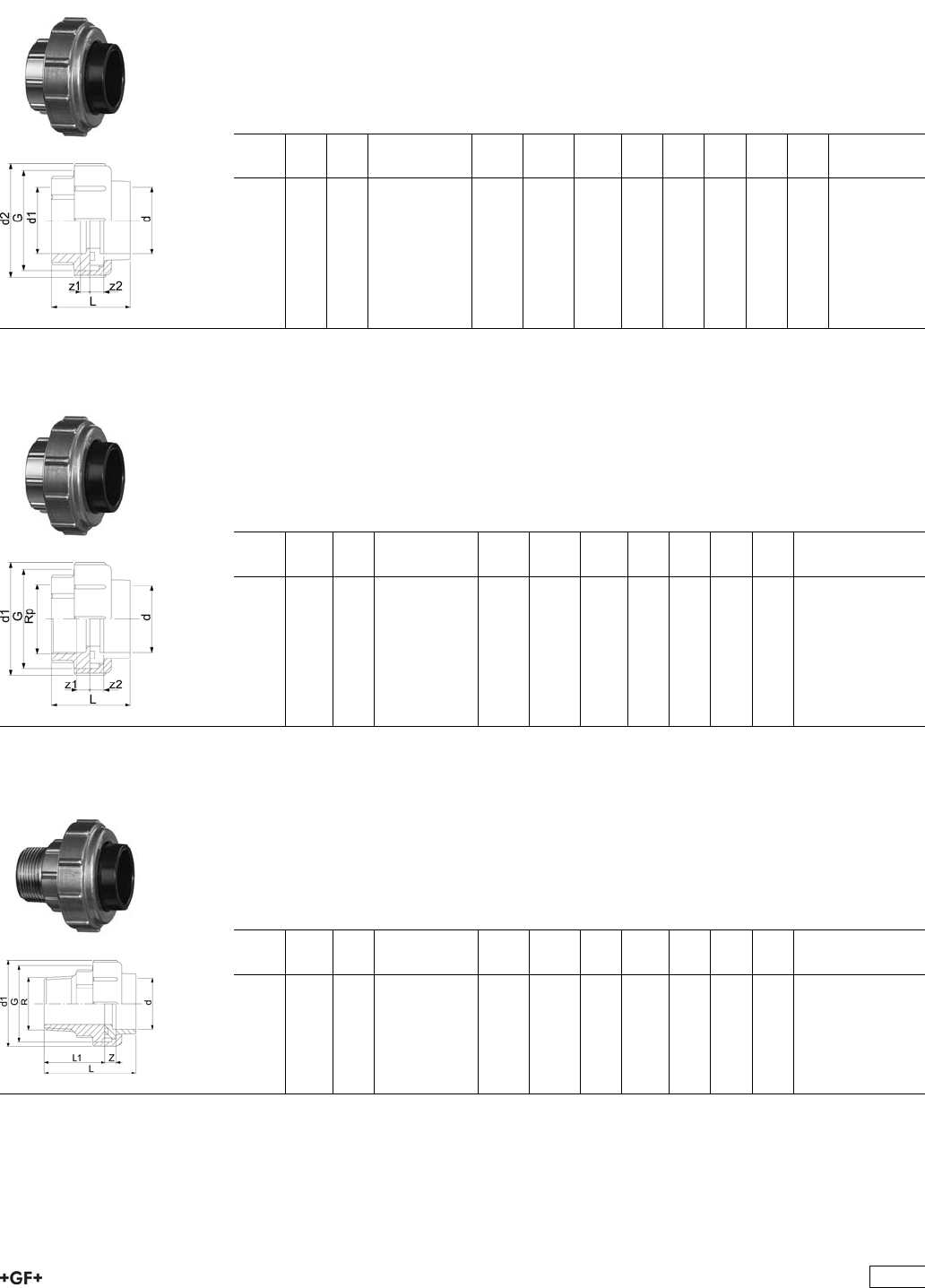
Unions for Socket Fusion
33 58 01 Unions, PE80
metric
Model:
ÏUnion ends: Fusion sockets, PE80 metric
ÏUnion bush: brass
ÏUnion Nut: brass
ÏGasket: O-ring NBR (Nitril-rubber)
d
[mm]
d1
[mm]
PN Code kg kg/m G
[inch]
L
[mm]
z1
[mm]
D2
[mm]
d2
[mm]
z2
[mm]
20 20 10 733 580 106 0.163 0.163 1 1/4 46 6 46 46 3
25 25 10 733 580 107 0.214 0.214 1 1/2 49 6 52 52 3
32 32 10 733 580 108 0.294 0.294 2 51 6 64 64 3
40 40 10 733 580 109 0.473 0.473 2 1/2 56 8 79 79 3
50 50 10 733 580 110 0.491 0.491 2 2/3 61 8 85 85 3
63 63 10 733 580 111 0.730 0.730 3 1/2 69 8 104 104 3
33 58 02 Adaptor unions, PE80 - brass
metrisch - Rp
Model:
ÏUnion ends: Fusion sockets, PE80 metric
ÏUnion bush: nickel-plated, parallel female thread Rp
ÏUnion Nut: brass
ÏGasket: O-ring NBR (Nitril-rubber)
d
[mm]
Rp
[inch]
PN Code kg kg/m G
[inch]
L
[mm]
d1
[mm]
z1
[mm]
z2
[mm]
20 1
/210 733 580 206 0.209 0.209 1 1/4 46 46 6 10
25 3
/410 733 580 207 0.269 0.269 1 1/2 48 52 6 9
32 1 10 733 580 208 0.371 0.371 2 51 64 6 8
40 1 1
/410 733 580 209 0.596 0.596 2 1/2 56 79 8 7
50 1 1
/210 733 580 210 0.666 0.666 2 3/4 59 85 8 7
63 2 10 733 580 211 0.960 0.960 3 1/2 65 104 8 5
33 58 07 Adaptor unions, PE80 - brass
metric - R
Model:
ÏUnion ends: Fusion sockets, PE80 metric
ÏUnion bush: nickel-plated, taper male thread R
ÏUnion Nut: brass
ÏGasket: O-ring NBR (Nitril-rubber)
d
[mm]
R
[inch]
PN Code kg kg/m d1
[mm]
G
[inch]
L
[mm]
L1
[mm]
z
[mm]
20 1
/210 733 580 706 0.260 0.260 46 1 1/4 62 40 6
25 3
/410 733 580 707 0.324 0.324 52 1 1/2 65 41 6
32 1 10 733 580 708 0.470 0.470 64 2 71 45 6
40 1 1
/410 733 580 709 0.754 0.754 79 2 1/2 78 48 8
50 1 1
/210 733 580 710 0.781 0.781 85 2 3/4 81 43 8
63 2 10 733 580 711 1.166 1.166 104 3 1/2 91 54 8
391
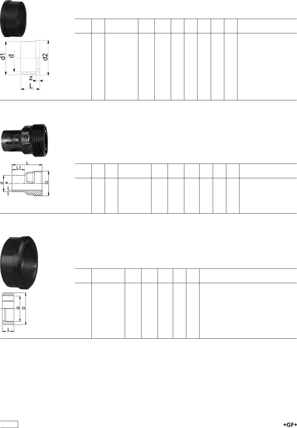
34 60 01 Union Ends, PE80
Model:
ÏWith fusion socket metric
ÏSuitable for unions, tank connectors and diaphragm valves Type 314
d
[mm]
PN Code kg kg/m d1
[mm]
d2
[mm]
L
[mm]
L1
[mm]
z
[mm]
20 10 734 600 106 0.006 0.006 28 30 19 5 5
25 10 734 600 107 0.012 0.012 36 39 21 5 5
32 10 734 600 108 0.015 0.015 42 45 23 6 5
40 10 734 600 109 0.026 0.026 53 57 25 6 5
50 10 734 600 110 0.027 0.027 59 63 28 7 5
63 10 734 600 111 0.045 0.045 74 79 32 8 5
53 64 86 Union Bushes, PE100 SDR11
Model:
ÏConventional butt-welding according to DVS 2207 part 11
ÏIR = Infrared- (IR Plus®) compatible.
ÏGasket: O-Ring EPDM No. 48 41 00, FPM No. 49 41 00
ÏD75-110 with new thread geometry, now rated PN10 up to d110
ÏFor the dimensions d75-110 please see instructions for the installation
d
[mm]
PN FM Code kg kg/m G
[inch]
L
[mm]
L1
[mm]
e
[mm]
20 16 IR 753 648 606 0.016 0.016 1 54 26 1,9
25 16 IR 753 648 607 0.025 0.025 1 1/4 57 26 2,3
32 16 IR 753 648 608 0.035 0.035 1 1/2 60 25 2,9
40 16 IR 753 648 609 0.056 0.056 2 63 25 3,7
50 16 IR 753 648 610 0.078 0.078 2 1/4 66 25 4,6
63 16 IR 753 648 611 0.120 0.120 2 3/4 69 25 5,8
33 69 04 Union Nuts, PE-GF
Model:
ÏPE glass-fibre reinforced
ÏFor the dimensions d75-110 please see instructions for the installation
* PP glass fibre reinforced
d-d
[mm]
Code kg kg/m G
[inch]
D
[mm]
L
[mm]
20 - 733 690 406 0.029 0.029 1 48 24
25 - 733 690 407 0.032 0.032 1 1/4 58 26
32 - 733 690 408 0.042 0.042 1 1/2 65 28
40 - 733 690 409 0.068 0.068 2 79 31
50 - 733 690 410 0.097 0.097 2 1/4 91 35
63 - 733 690 411 0.166 0.166 2 3/4 111 39
392
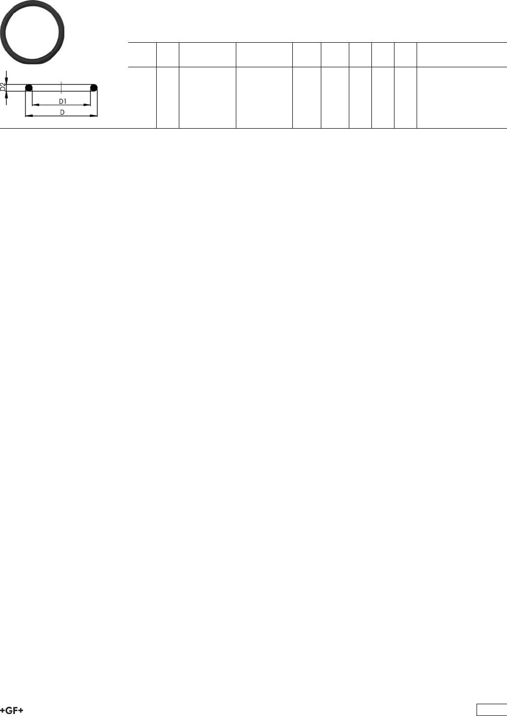
EPDM 48 41 00
FPM 49 41 00
O-Ring Gaskets
Model:
ÏFor unions and adaptor unions
ÏHardness approx. 65° Shore
ÏEPDM minimum temperature -40°C
ÏFPM minimum temperature -15°C
d
[mm]
DN
[mm]
EPDM
Code
FPM
Code
kg kg/m D
[mm]
D1
[mm]
D2
[mm]
20 15 748 410 006 749 410 006 0.002 0.002 27 20 4
25 20 748 410 007 749 410 007 0.002 0.002 35 28
32 25 748 410 008 749 410 008 0.002 0.002 40 33 4
40 32 748 410 009 749 410 009 0.006 0.006 51 41 5
50 40 748 410 010 749 410 010 0.007 0.007 58 47 5
63 50 748 410 011 749 410 011 0.010 0.010 70 60 5
393
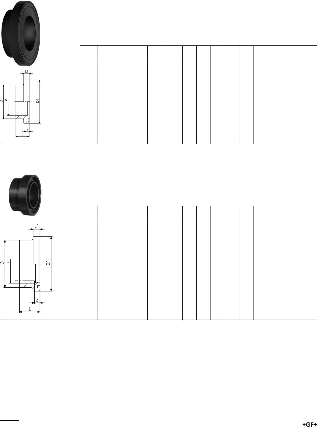
Flange Adaptors, Flanges and Gaskets for
Socket Fusion
53 79 02 Flange Adaptors, PE100
Jointing face flat/serrated
Model:
ÏCounterpart: Flange Adaptor flat/serrated or with O-ring groove
ÏConnection: according to EN ISO 15494-, DIN 16963-11
ÏGasket: Profile flange gasket EPDM No. 48 44 07, FPM No. 49 44 07
ÏFlanges: PP with steel core, No. 27 70 02, PP-V, No 27 70 04
d
[mm]
PN Code kg kg/m D
[mm]
D1
[mm]
L
[mm]
L1
[mm]
z
[mm]
20 10 753 790 206 0.013 0.013 27 45 19 7 5
25 10 753 790 207 0.025 0.025 33 58 21 9 5
32 10 753 790 208 0.037 0.037 41 68 23 10 5
40 10 753 790 209 0.052 0.052 50 78 25 11 5
50 10 753 790 210 0.069 0.069 61 88 28 12 5
63 10 753 790 211 0.102 0.102 76 102 32 14 5
75 10 753 790 212 0.163 0.163 90 122 36 16 5
90 10 753 790 213 0.233 0.233 108 138 42 17 7
110 10 753 790 214 0.319 0.319 131 158 48 18 7
33 81 01 Flange Adaptors, PE80
Jointing Face with O-ring Groove
Model:
ÏCounterpart: Flange adaptor flat/serrated 53 79 02
ÏGasket: O-ring No. 48 41 01 or 49 41 01
ÏFlanges: PP with steel core, No. 27 70 02, PP-V, No 27 70 04
d
[mm]
PN Code kg kg/m D
[mm]
D1
[mm]
L
[mm]
L1
[mm]
z
[mm]
20 10 733 810 106 0.008 0.008 27 34 22 9 8
25 10 733 810 107 0.012 0.012 33 41 24 10 8
32 10 733 810 108 0.019 0.019 41 50 26 10 8
40 10 733 810 109 0.031 0.031 50 61 30 13 10
50 10 733 810 110 0.044 0.044 61 73 33 13 10
63 10 733 810 111 0.072 0.072 76 90 37 14 10
75 10 733 810 112 0.112 0.112 90 106 40 15 10
90 10 733 810 113 0.185 0.185 108 125 47 16 12
110 10 733 810 114 0.283 0.283 131 150 55 18 13
394
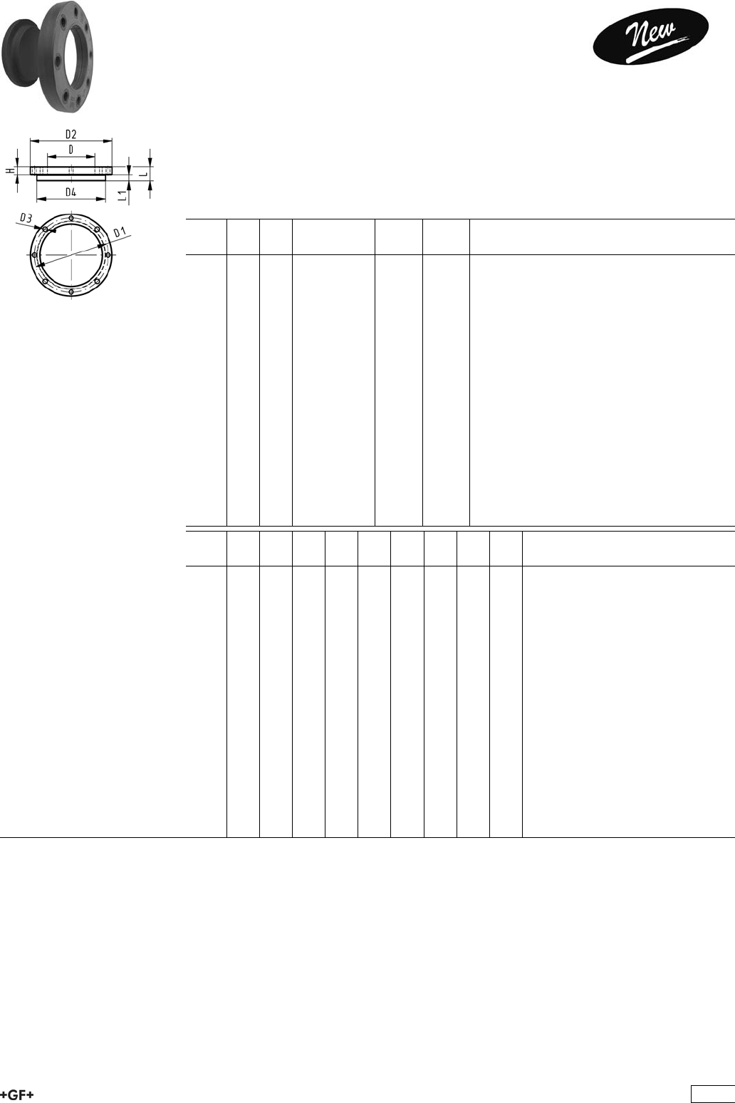
Blanking Flange Set, PE
Combined Jointing face flat and serrated
metric
Model:
Ïd63 - d315: Backing Flange PP-V with End Blank PE
Ïd355 - d630: Backing Flange PP/Steel with End Blank PE
ÏConnecting dimensions: ISO 7005, EN 1092, DIN 2501
ÏBolt circle PN 10
AL: number of holes
L: length of the End Blank
d
[mm]
DN
[mm]
PN Code
Code
kg kg/m
63 50 16 753 700 611 0.674 0.674
75 65 16 753 700 612 0.910 0.910
90 80 16 753 700 613 1.067 1.067
110 100 16 753 700 614 1.216 1.216
125 100 16 753 700 615 1.678 1.678
140 125 16 753 700 616 1.913 1.913
160 150 16 753 700 617 2.352 2.352
180 150 16 753 700 618 2.430 2.430
200 200 16 753 700 619 3.495 3.495
225 200 16 753 700 620 3.744 3.744
250 250 16 753 700 621 5.558 5.558
280 250 16 753 700 622 19.957 19.957
315 300 16 753 700 623 24.569 24.569
355 350 16 753 700 624 23.198 23.198
400 400 16 753 700 625 30.766 30.766
450 500 10 753 700 626 44.271 44.271
500 500 10 753 700 627 47.165 47.165
560 600 10 753 700 628 67.147 67.147
630 600 10 753 700 629 68.574 68.574
d
[mm]
D
[mm]
D1
[mm]
D2
[mm]
D3
[mm]
D4
[mm]
H
[mm]
L
[mm]
L1
[mm]
AL
63 75 125 165 18 102 24 30 14 4
75 89 145 185 18 122 26 30 16 4
90 105 160 200 18 138 27 30 17 8
110 125 180 220 18 158 28 30 18 8
125 132 180 220 18 158 28 35 25 8
140 155 210 250 18 188 30 40 25 8
160 175 240 285 22 212 32 40 25 8
180 180 240 285 22 212 32 45 30 8
200 232 295 340 22 268 34 50 32 8
225 235 295 340 22 268 34 50 32 8
250 285 350 395 22 320 38 55 35 12
280 291 350 395 22 320 38 60 35 12
315 335 400 445 22 370 42 65 35 12
355 373 460 515 22 430 40 70 40 16
400 427 515 574 26 482 40 75 46 16
450 510 620 684 26 585 49 80 60 20
500 530 620 684 26 585 49 90 60 20
560 615 725 796 30 685 58 100 60 20
630 642 725 796 30 685 68 110 60 20
395
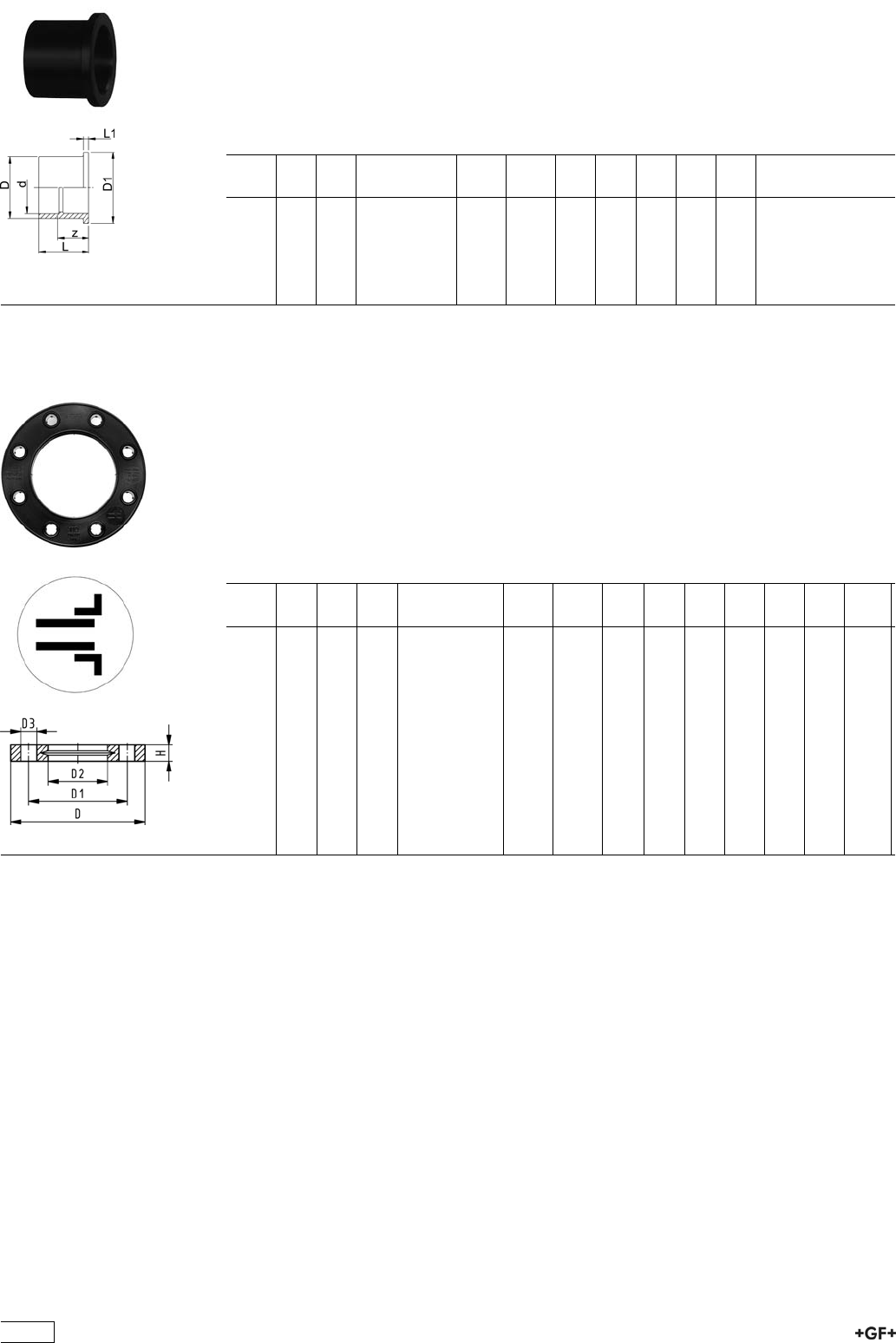
Outlet Flange Adaptor, PE80
Jointing Face flat
Model:
ÏWith fusion socket metric
ÏSuitable for wafer check valves Type 369
ÏTo be installed on the outlet side of the valve
d
[mm]
DN
[mm]
PN Code kg kg/m D
[mm]
D1
[mm]
L
[mm]
L1
[mm]
z
[mm]
40 32 6 733 800 009 0.060 0.060 50 78 55 11 35
50 40 6 733 800 010 0.080 0.080 61 88 61 12 38
63 50 6 733 800 011 0.130 0.130 76 102 69 14 41
75 65 6 733 800 012 0.160 0.160 90 122 79 16 49
90 80 6 733 800 013 0.270 0.270 107 138 100 17 65
110 100 6 733 800 014 0.480 0.480 130 158 105 18 62
27 70 04
27 70 05
Backing Flanges, PP-V
for Socket Systems metric
Model:
ÏModern full-plastic flange PP-GF (30 % glass-fibre reinforced)
ÏWith V-groove which applies force evenly on collar
ÏWith integrated bolt retainers as an assembly aid
ÏConnecting dimension: ISO 7005, EN 1092, BS 4504, DIN 2501
ÏBolt circle PN 10
¹) Suitable for socket- and butt fusion systems (no pictograph on flange)
AL: number of holes
d
[mm]
Inch DN
[mm]
PN Code kg kg/m D
[mm]
D1
[mm]
D2
[mm]
D3
[mm]
H
[mm]
AL SC
¹20 15 16 727 700 406 0.080 0.080 95 65 28 14 16 4 M12
¹25 20 16 727 700 407 0.100 0.100 105 75 34 14 17 4 M12
¹32 25 16 727 700 408 0.140 0.140 115 85 42 14 18 4 M12
¹40 32 16 727 700 409 0.220 0.220 140 100 51 18 20 4 M16
¹50 40 16 727 700 410 0.210 0.210 150 110 62 18 22 4 M16
¹63 50 16 727 700 411 0.380 0.380 165 125 78 18 24 4 M16
¹75 65 16 727 700 412 0.480 0.480 185 145 92 18 26 4 M16
90 80 16 727 700 413 0.520 0.520 200 160 110 18 27 8 M16
110 100 16 727 700 414 0.680 0.680 220 180 133 18 28 8 M16
396
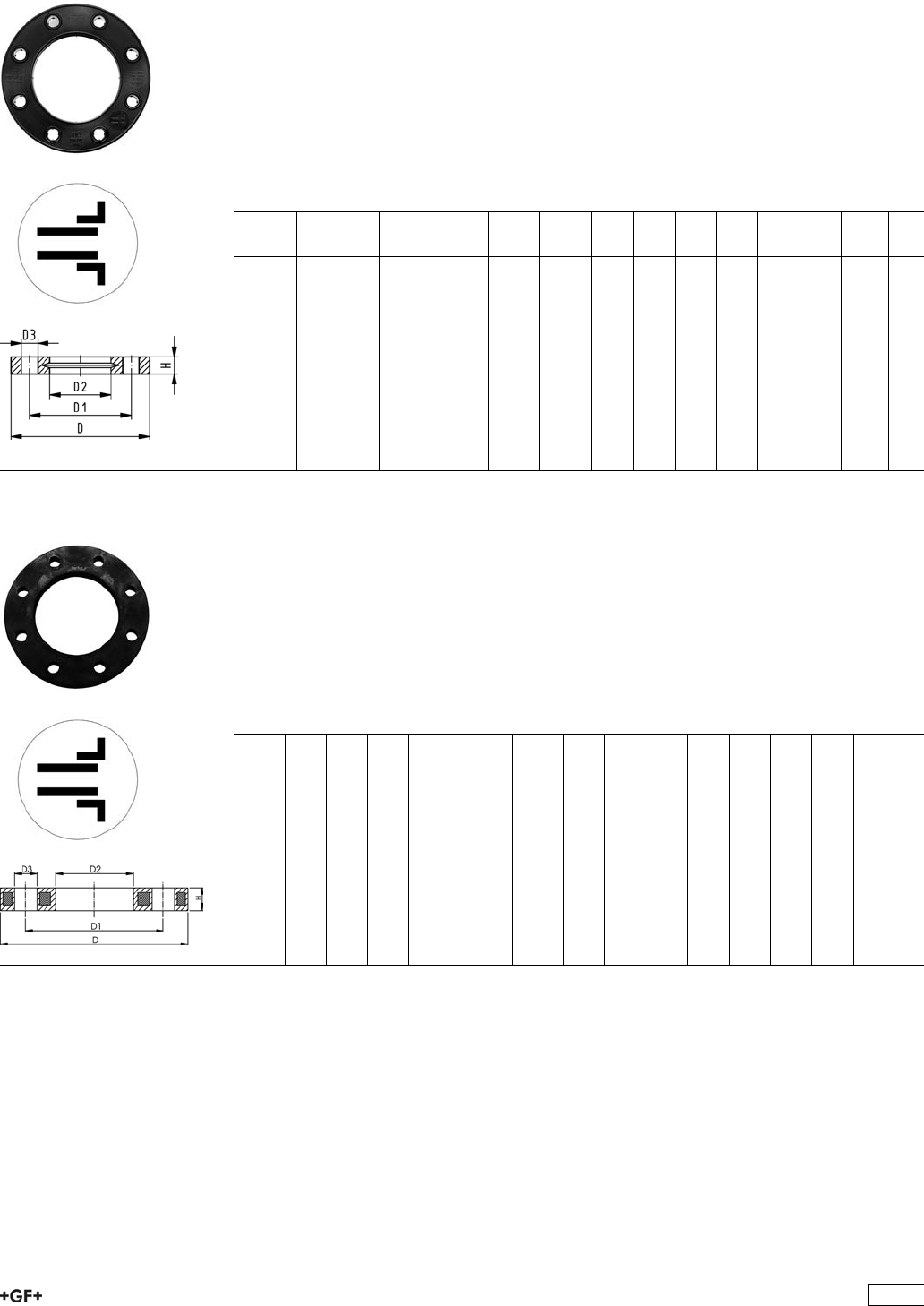
27 70 14
27 70 15
Backing Flanges, PP-V
for Socket Systems Inch/ANSI
Model:
ÏModern full-plastic flange PP-GF (30 % glass-fibre reinforced)
ÏWith V-groove which applies force evenly on collar
ÏWith integrated bolt-fixing as an assembly aid
ÏConnecting dimension: ANSI/ASME B 16.5 class 150, ASTM D 4024, BS 1560, BS
EN 1759
ÏBolt circle class 150
¹) Suitable for socket- and butt fusion systems (no pictograph on flange)
AL: number of holes
Inch DN
[mm]
PN Code kg kg/m D
[mm]
D1
[mm]
D2
[mm]
D3
[mm]
H
[mm]
AL SC
¹1
/215 16 727 701 406 0.080 0.080 95 60 28 16 16 4 M12
¹3
/420 16 727 701 407 0.100 0.100 105 70 34 16 17 4 M12
¹1 25 16 727 701 408 0.140 0.140 115 79 42 16 18 4 M12
¹11
/432 16 727 701 409 0.220 0.220 140 89 51 16 20 4 M16
¹11
/240 16 727 701 410 0.210 0.210 150 98 62 16 22 4 M16
¹2 50 16 727 701 411 0.380 0.380 165 121 78 19 24 4 M16
¹21
/265 16 727 701 412 0.480 0.480 185 140 92 19 26 4 M16
3 80 16 727 701 413 0.520 0.520 200 152 110 19 27 4 M16
4 100 16 727 701 414 0.680 0.680 229 190 133 19 28 8 M16
27 70 02 Backing Flanges, PP/Steel
for Socket Systems metric
Model:
ÏPP-GF (30% glass-fibre reinforced) with steel ring
ÏConnecting dimension: ISO 7005, EN 1092, BS 4504, DIN 2501
ÏBolt circle PN 10
¹ Connecting dimension: ISO 2536 DN125
* Connecting dimension: ISO 2536
AL: number of holes
d
[mm]
d
[inch]
DN
[mm]
PN Code kg D
[mm]
D1
[mm]
D2
[mm]
D3
[mm]
H
[mm]
AL SC
20 15 16 727 700 206 0.220 95 65 28 14 12 4 M12
25 20 16 727 700 207 0.260 105 75 34 14 12 4 M12
32 25 16 727 700 208 0.430 115 85 42 14 16 4 M12
40 32 16 727 700 209 0.650 140 100 51 18 16 4 M16
50 40 16 727 700 210 0.820 150 110 62 18 18 4 M16
63 50 16 727 700 211 0.940 165 125 78 18 18 4 M16
75 65 16 727 700 212 1.300 185 145 92 18 18 4 M16
90 80 16 727 700 213 1.400 200 160 110 18 20 8 M16
110 100 16 727 700 214 1.560 220 180 133 18 20 8 M16
397
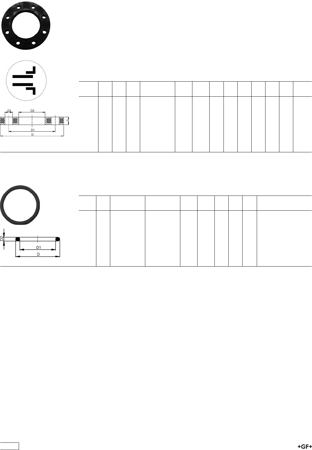
27 70 12 Backing Flanges, PP/Steel
for Socket Systems Inch/ANSI
Model:
ÏFor Flange Adaptors BS/ANSI
ÏMaterial: PP (30 % glass-fibre reinforced) with steel ring
ÏConnecting dimension: ANSI/ASME B 16.5 class 150, ASTM D 4024, BS 1560, BS
EN 1759
ÏBolt circle class 150
ÏDN100 and DN150: only for use with original metric flange adaptors
AL: number of holes
d
[inch]
DN
[mm]
d
[mm]
PN Code kg kg/m D1
[mm]
D2
[mm]
D3
[mm]
D
[mm]
H
[mm]
AL
1
/215 20 16 727 701 206 0.210 0.210 60 28 16 95 12 4
3
/420 25 16 727 701 207 0.250 0.250 70 34 16 105 12 4
1 25 32 16 727 701 208 0.420 0.420 79 42 16 115 16 4
11
/432 40 16 727 701 209 0.670 0.670 89 51 16 140 16 4
11
/240 50 16 727 701 210 0.860 0.860 98 62 16 150 18 4
2 50 63 16 727 701 211 0.930 0.930 121 78 19 165 18 4
21
/265 75 16 727 701 212 1.340 1.340 140 92 19 185 18 4
3 80 90 16 727 701 213 1.550 1.550 152 110 19 200 20 4
4 100 110 16 727 701 214 1.810 1.810 190 133 19 229 20 8
EPDM 48 41 01
FPM 49 41 01
O-Ring Gaskets
Model:
ÏFor Flange Adaptors
ÏHardness approx. 65° Shore
d
[mm]
DN
[mm]
EPDM
Code
FPM
Code
kg kg/m D
[mm]
D1
[mm]
D2
[mm]
20 15 748 410 001 749 410 001 0.002 0.002 31 23 3.53
25 20 748 410 007 749 410 007 0.002 0.002 35 28 3.53
32 25 748 410 002 749 410 002 0.003 0.003 43 36 3.53
40 32 748 410 003 749 410 003 0.007 0.007 55 44 5.34
50 40 748 410 012 749 410 012 0.008 0.008 64 53 5.34
63 50 748 410 013 749 410 013 0.011 0.011 80 69 5.34
75 65 748 410 014 749 410 014 0.012 0.012 93 82 5.34
90 80 748 410 015 749 410 015 0.015 0.015 112 101 5.34
110 100 748 410 016 749 410 016 0.031 0.031 134 120 6.99
398
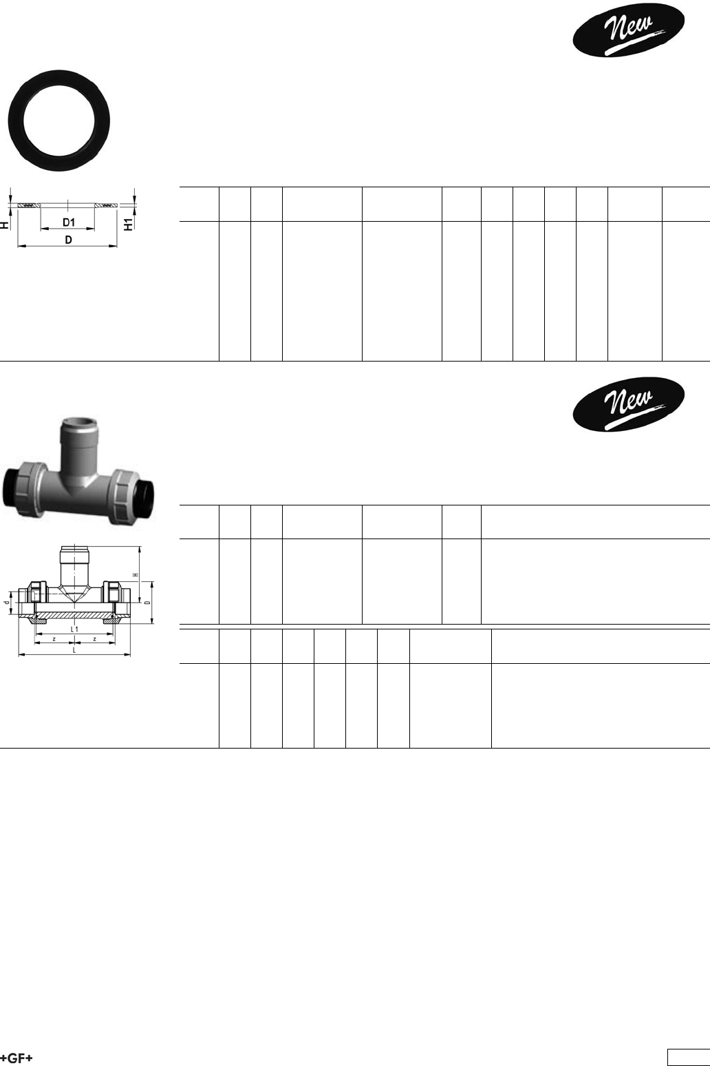
EPDM 48 44 07
FPM 49 44 07 Profile Flange Gaskets metric
EPDM / FPM
Model:
ÏFor all GF Flange Adaptors
ÏProfile Gasket with steel insert (type G-ST-P/K)
ÏHardness: 70° Shore EPDM, 75° Shore FPM
ÏCentering on the inner diameter of the screw crown
di FA are the suitable inner diameters of flange adaptors
d
[mm]
DN
[mm]
PN EPDM
Code
FPM
Code
kg D
[mm]
D1
[mm]
H
[mm]
H1
[mm]
di FA
[mm]
16 10 16 748 440 705 749 440 705 0.007 46 16 4 3 6 - 16
20 15 16 748 440 706 749 440 706 0.008 51 20 4 3 10 - 20
25 20 16 748 440 707 749 440 707 0.011 61 22 4 3 12 - 22
32 25 16 748 440 708 749 440 708 0.014 71 28 4 3 18 - 28
40 32 16 748 440 709 749 440 709 0.021 82 40 4 3 30 - 40
50 40 16 748 440 710 749 440 710 0.022 92 46 4 3 36 - 46
63 50 16 748 440 711 749 440 711 0.041 107 58 5 4 48 - 58
75 65 16 748 440 712 749 440 712 0.055 127 69 5 4 59 - 69
90 80 16 748 440 713 749 440 713 0.062 142 84 5 4 73 - 84
110 100 16 748 440 714 749 440 714 0.085 162 104 6 5 94 - 104
33 31 00 Installation Fitting Type 310, PE80
for Socket Systems metric
Model:
ÏFor Signet Paddlewheel Sensors Type -X0 (104 mm)
ÏBody and union nut PP-H
ÏUnion end with fusion socket PE80
d
[mm]
DN
[mm]
PN EPDM
Code
FPM
Code
kg
20 15 10 733 310 006 733 310 036 0.136
25 20 10 733 310 007 733 310 037 0.190
32 25 10 733 310 008 733 310 038 0.250
40 32 10 733 310 009 733 310 039 0.356
50 40 10 733 310 010 733 310 040 0.510
63 50 10 733 310 011 733 310 041 0.800
d
[mm]
DN
[mm]
D
[mm]
z
[mm]
L
[mm]
L1
[mm]
H
[mm]
Sensor Type
20 15 48 50 128 90 76 X0
25 20 58 55 142 100 78 X0
32 25 65 60 156 110 81 X0
40 32 79 60 160 110 85 X0
50 40 91 65 176 120 89 X0
63 50 105 70 194 130 95 X0
399
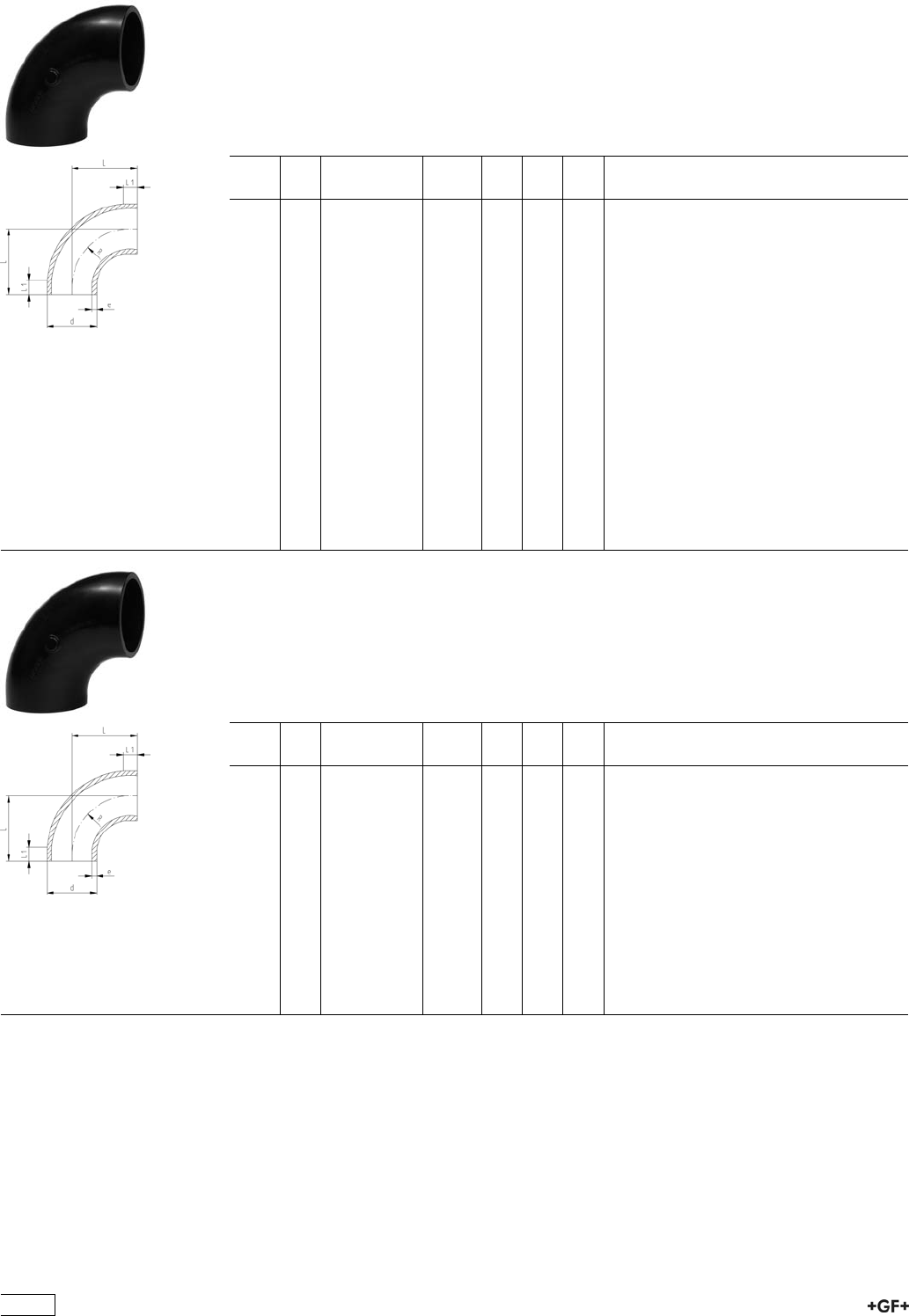
Fittings for Butt Fusion
Bends 90°, PE100 S5/SDR11 - Type B
Model:
ÏConventional butt-welding according to DVS 2207 part 11
ÏIR = Infrared-(IR Plus®) compatible. Please choose fusion parameters: PE100
ÏBends with new geometry
ÏInjection moulding process optimised for PE100
d
[mm]
FM Code kg L
[mm]
L1
[mm]
e
[mm]
20 -- 753 018 681 0.005 28 5 1,9
25 -- 753 018 682 0.010 33 7 2,3
32 -- 753 018 683 0.019 41 7 2,9
40 -- 753 018 684 0.038 52 10 3,7
50 -- 753 018 685 0.069 63 10 4,6
63 -- 753 018 686 0.138 77 10 5,8
75 IR 753 018 712 0.241 100 20 6,8
90 IR 753 018 713 0.358 100 20 8,2
110 IR 753 018 714 0.755 141 25 10,0
125 IR 753 018 690 0.850 140 15 11,4
140 IR 753 018 691 1.180 155 15 12,7
160 IR 753 018 692 1.750 175 15 14,6
180 IR 753 018 693 2.670 195 15 16,4
200 IR 753 018 694 3.440 215 15 18,2
225 IR 753 018 695 4.790 245 20 20,5
250 -- 753 018 621 6.800 256 48 22,7
280 -- 753 018 622 9.900 286 48 25,4
315 -- 753 018 623 13.500 321 48 28,6
355 -- 753 018 674 20.700 380 15 32,2
400 -- 753 018 675 30.500 435 25 36,3
Bends 90°, PE100 S8,3/SDR17,6 - Type B
Model:
ÏConventional butt-welding according to DVS 2207 part 11
ÏIR = Infrared-(IR Plus®) compatible. Please choose fusion parameters: PE100
ÏBends with new geometry
ÏInjection moulding process optimised for PE100
d
[mm]
FM Code kg L
[mm]
L1
[mm]
e
[mm]
75 IR 753 018 737 0.172 100 20 4,3
90 IR 753 018 738 0.243 100 20 5,1
110 IR 753 018 739 0.522 141 20 6,3
125 IR 753 018 590 0.590 140 15 7,1
140 IR 753 018 591 1.180 155 15 8,0
160 IR 753 018 592 1.750 175 15 9,1
180 IR 753 018 593 2.670 195 15 10,2
200 IR 753 018 594 3.440 215 15 11,4
225 IR 753 018 595 4.790 245 15 12,8
250 -- 753 018 521 4.700 256 48 14,2
280 -- 753 018 522 6.500 286 48 15,9
315 -- 753 018 523 9.200 321 48 17,9
355 -- 753 018 549 13.000 380 15 20,1
400 -- 753 018 550 19.700 435 25 22,7
400
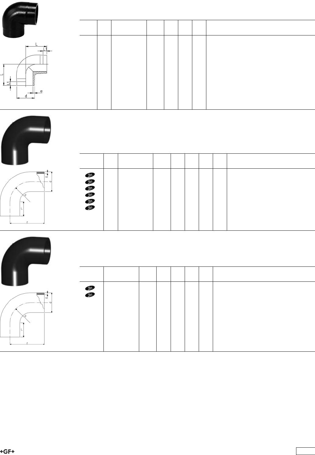
53 10 86 Elbows 90°, PE100 S5/SDR11
Model:
ÏConventional butt-welding according to DVS 2207 part 11
ÏIR = Infrared-(IR Plus®) compatible. Please choose fusion parameters: PE100
d
[mm]
FM Code kg L
[mm]
L1
[mm]
e
[mm]
20 IR 753 108 606 0.009 38 25 1,9
25 IR 753 108 607 0.014 42 26 2,3
32 IR 753 108 608 0.025 46 27 2,9
40 IR 753 108 609 0.049 51 22 3,7
50 IR 753 108 610 0.087 58 23 4,6
63 IR 753 108 611 0.152 66 21 5,8
Bends 90°, PE100 S5/SDR11 - 0.75d
Model:
ÏConventional butt-welding according to DVS 2207 part 11
ÏIR = Infrared-(IR Plus®) compatible. Please choose fusion parameters: PE100
d
[mm]
FM Code kg z
[mm]
L
[mm]
R
[mm]
e
[mm]
20 IR 753 018 706 0.007 38 23 15 1.9
25 IR 753 018 707 0.012 42 23 19 2.3
32 IR 753 018 708 0.022 46 22 24 2.9
40 IR 753 018 709 0.038 51 21 30 3.7
50 IR 753 018 710 0.066 58 21 37 4.6
63 IR 753 018 711 0.118 66 21 45 5.8
Bends 90°, PE100 S8,3/SDR17,6 - 0.75d
Model:
ÏConventional butt-welding according to DVS 2207 part 11
d
[mm]
Code kg z
[mm]
L
[mm]
R
[mm]
e
[mm]
50 753 018 635 0.052 58 21 37 2.9
63 753 018 636 0.084 66 21 45 3.6
401
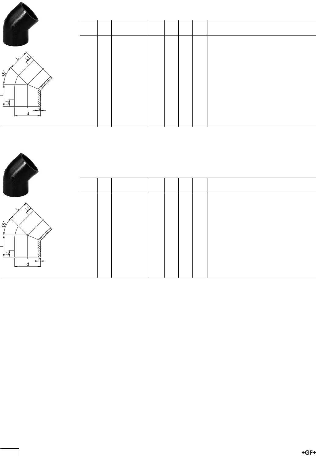
53 15 86 Elbows 45°, PE100 S5/SDR11
Model:
ÏConventional butt-welding according to DVS 2207 part 11
ÏIR = Infrared-(IR Plus®) compatible. Please choose fusion parameters: PE100
d
[mm]
FM Code kg L
[mm]
L1
[mm]
e
[mm]
20 IR 753 158 606 0.008 32 24 1,9
25 IR 753 158 607 0.013 34 25 2,3
32 IR 753 158 608 0.021 36 25 2,9
40 IR 753 158 609 0.037 39 25 3,7
50 IR 753 158 610 0.059 42 26 4,6
63 IR 753 158 611 0.104 47 29 5,8
75 IR 753 158 612 0.147 49 29 6,8
90 IR 753 158 613 0.243 57 34 8,2
110 IR 753 158 614 0.445 70 43 10,0
125 IR 753 158 615 0.653 79 48 11,4
140 IR 753 158 616 0.905 88 55 12,7
160 IR 753 158 617 1.344 100 60 14,6
200 IR 753 158 619 2.625 124 75 18,2
225 IR 753 158 620 3.738 140 85 20,5
53 15 85 Elbows 45°, PE100 S8,3/SDR17,6
Model:
ÏConventional butt-welding according to DVS 2207 part 11
ÏIR = Infrared-(IR Plus®) compatible. Please choose fusion parameters: PE100
ÏMachined from S5/SDR11
d
[mm]
FM Code kg L
[mm]
L1
[mm]
e
[mm]
50 -- 753 158 535 0.045 42 26 2,9
63 -- 753 158 536 0.091 47 29 3,6
75 -- 753 158 537 0.128 49 29 4,3
90 -- 753 158 538 0.208 57 34 5,1
110 IR 753 158 539 0.398 70 43 6,3
125 IR 753 158 540 0.570 79 48 7,1
140 IR 753 158 541 0.825 88 55 8,0
160 IR 753 158 542 1.190 100 60 9,1
200 IR 753 158 544 2.300 124 75 11,4
225 IR 753 158 545 3.200 140 85 12,8
402
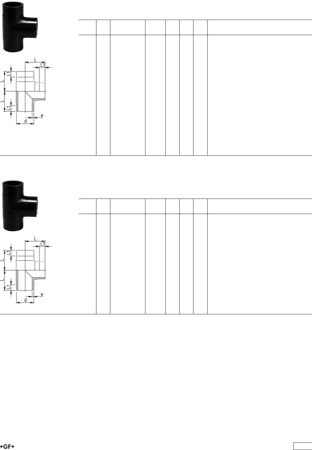
53 20 86 Tees 90° equal, PE100 S5/SDR11
Model:
ÏConventional butt-welding according to DVS 2207 part 11
ÏIR = Infrared-(IR Plus®) compatible. Please choose fusion parameters: PE100
d
[mm]
FM Code kg L
[mm]
L1
[mm]
e
[mm]
20 IR 753 208 606 0.013 38 24 1,9
25 IR 753 208 607 0.021 42 26 2,3
32 IR 753 208 608 0.042 46 26 2,9
40 IR 753 208 609 0.067 51 22 3,7
50 IR 753 208 610 0.114 58 22 4,6
63 IR 753 208 611 0.203 66 21 5,8
75 IR 753 208 612 0.310 75 20 6,8
90 IR 753 208 613 0.564 90 20 8,2
110 IR 753 208 614 1.020 110 20 10,0
125 IR 753 208 615 1.514 125 25 11,4
140 IR 753 208 616 2.111 140 28 12,7
160 IR 753 208 617 3.095 160 28 14,6
180 IR 753 208 668 4.560 190 70 16,4
200 IR 753 208 619 6.037 200 35 18,2
225 IR 753 208 620 8.090 220 35 20,5
250 -- 753 208 671 12.208 272 90 22,7
280 -- 753 208 672 17.831 313 108 25,4
315 -- 753 208 673 25.742 348 114 28,6
355 -- 753 208 674 31.900 345 100 32,2
400 -- 753 208 675 39.200 360 102 36,3
53 20 85 Tees 90° equal, PE100 S8,3/SDR17,6
Model:
ÏConventional butt-welding according to DVS 2207 part 11
ÏIR = Infrared-(IR Plus®) compatible. Please choose fusion parameters: PE100
d
[mm]
FM Code kg L
[mm]
L1
[mm]
e
[mm]
50 -- 753 208 535 0.090 59 26 2,9
63 -- 753 208 536 0.160 71 25 3,6
75 -- 753 208 537 0.263 85 28 4,3
90 -- 753 208 538 0.438 100 23 5,1
110 IR 753 208 539 0.763 120 43 6,3
125 IR 753 208 540 1.066 124 27 7,1
140 IR 753 208 541 1.449 141 33 8,0
160 IR 753 208 542 2.240 160 40 9,1
180 IR 753 208 543 3.176 190 70 10.2
200 IR 753 208 544 4.360 210 70 11,4
225 IR 753 208 545 6.030 238 80 12,8
250 -- 753 208 546 8.610 272 90 14,2
280 -- 753 208 547 11.660 313 108 15,9
315 -- 753 208 548 16.230 348 114 17,9
355 -- 753 208 549 21.900 345 100 20,1
400 -- 753 208 550 27.700 360 102 22,7
403
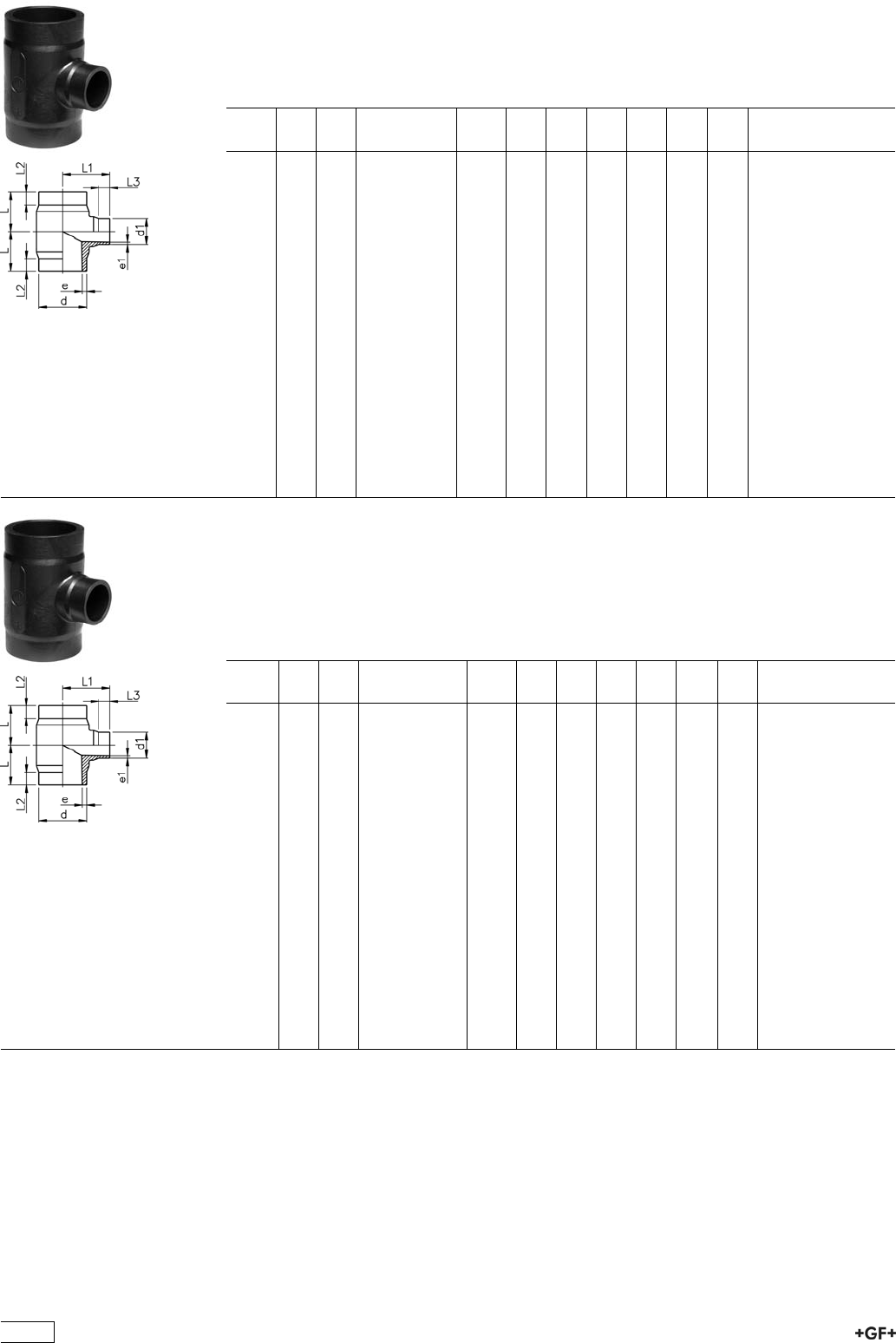
Tees 90°, reduced, PE100 S5/SDR11
Model:
ÏConventional butt-welding according to DVS 2207 part 11
ÏIR = Infrared-(IR Plus®) compatible. Please choose fusion parameters: PE100
d
[mm]
d1
[mm]
FM Code kg L
[mm]
L1
[mm]
L2
[mm]
L3
[mm]
e
[mm]
e1
[mm]
63 32 IR 753 208 351 0.170 65 70 25 25 5,8 2,9
63 50 IR 753 208 352 0.180 65 70 25 25 5,8 4,6
75 32 IR 753 208 353 0.250 70 75 25 25 6,8 2,9
75 50 IR 753 208 354 0.263 70 75 25 25 6,8 4,6
75 63 IR 753 208 355 0.278 70 75 25 25 6,8 5,8
90 50 IR 753 208 357 0.445 80 85 25 25 8,2 4,6
90 63 IR 753 208 358 0.455 80 85 25 25 8,2 5,8
90 75 IR 753 208 359 0.470 80 85 25 25 8,2 6,8
110 32 IR 753 208 360 0.705 90 95 30 25 10,0 2,9
110 50 IR 753 208 361 0.700 90 95 30 25 10,0 4,6
110 63 IR 753 208 362 0.710 90 95 30 25 10,0 5,8
110 75 IR 753 208 363 0.723 90 95 30 25 10,0 6,8
110 90 IR 753 208 364 0.735 90 95 30 25 10,0 8,2
160 63 IR 753 208 371 2.270 142 135 50 30 14,6 5,8
160 75 IR 753 208 372 2.295 142 135 50 30 14,6 6,8
160 90 IR 753 208 373 2.315 142 135 50 30 14,6 8,2
160 110 IR 753 208 374 2.355 142 135 50 30 14,6 10,0
225 90 IR 753 208 388 4.760 155 165 40 30 20,5 8,2
225 110 IR 753 208 389 4.720 155 165 40 30 20,5 10,0
225 160 IR 753 208 391 4.780 155 165 40 30 20,5 14,6
Tees 90°, reduced, PE100 S8,3/SDR17,6
Model:
ÏConventional butt-welding according to DVS 2207 part 11
ÏIR = Infrared-(IR Plus®) compatible. Please choose fusion parameters: PE100
* Branch SDR11
d
[mm]
d1
[mm]
FM Code kg L
[mm]
L1
[mm]
L2
[mm]
L3
[mm]
e
[mm]
e1
[mm]
*63 32 -- 753 208 301 0.157 65 70 25 25 3,6 2,9
63 50 -- 753 208 302 0.158 65 70 25 25 3,6 2,9
*75 32 -- 753 208 303 0.240 70 75 25 25 4,3 2,9
75 50 -- 753 208 304 0.250 70 75 25 25 4,3 2,9
75 63 -- 753 208 305 0.257 70 75 25 25 4,3 3,6
90 50 -- 753 208 307 0.410 80 85 25 25 5,1 2,9
90 63 -- 753 208 308 0.330 80 85 25 25 5,1 3,6
90 75 -- 753 208 309 0.340 80 85 25 25 5,1 4,3
*110 32 IR 753 208 310 0.640 90 95 30 25 6,3 2,9
110 50 IR 753 208 311 0.650 90 95 30 25 6,3 2,9
110 63 IR 753 208 312 0.520 90 95 30 25 6,3 3,6
110 75 IR 753 208 313 0.524 90 95 30 25 6,3 4,3
110 90 IR 753 208 314 0.530 90 95 30 25 6,3 5,1
160 63 IR 753 208 321 2.150 142 135 50 30 9,1 3,6
160 75 IR 753 208 322 2.130 142 135 50 30 9,1 4,3
160 90 IR 753 208 323 1.590 142 135 50 30 9,1 5,1
160 110 IR 753 208 324 1.695 142 135 50 30 9,1 6,3
225 90 IR 753 208 338 3.430 155 165 40 30 12,8 5,1
225 110 IR 753 208 339 3.410 155 165 40 30 12,8 6,3
225 160 IR 753 208 341 3.440 155 165 40 30 12,8 9,1
404
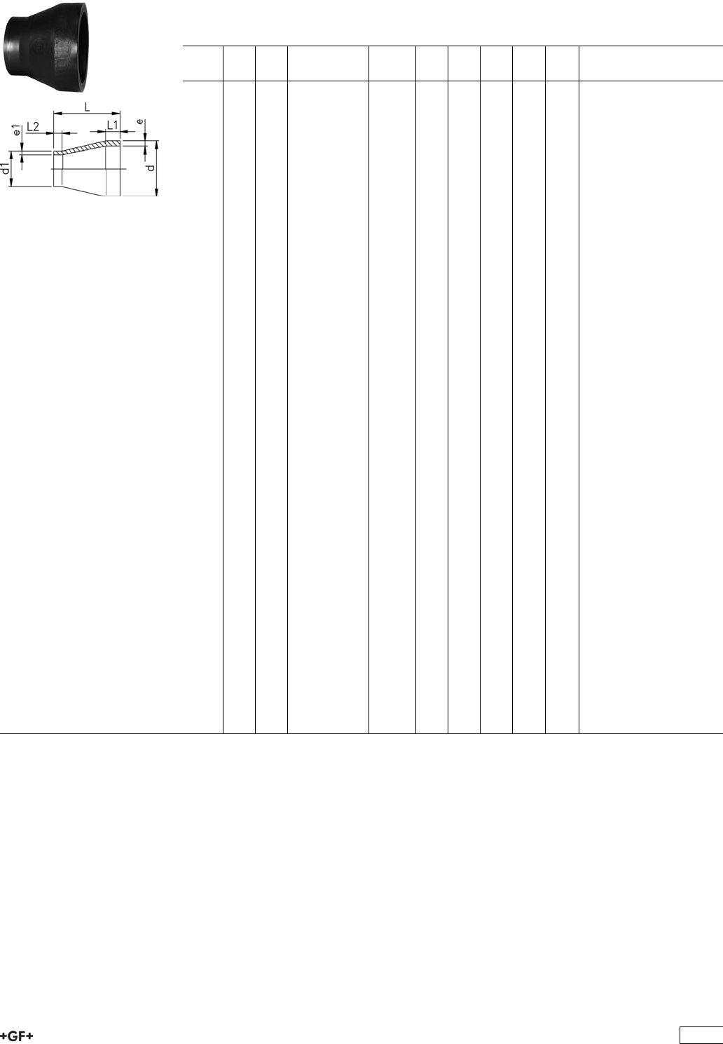
53 90 88 Reducers, PE100 S5/SDR11
Model:
ÏConventional butt-welding according to DVS 2207 part 11
ÏIR = Infrared-(IR Plus®) compatible. Please choose fusion parameters: PE100
d
[mm]
d1
[mm]
FM Code kg L
[mm]
L1
[mm]
L2
[mm]
e
[mm]
e1
[mm]
25 20 IR 753 908 637 0.007 50 20 18 2,3 1,9
32 20 IR 753 908 642 0.010 50 20 18 2,9 1,9
32 25 IR 753 908 641 0.011 50 20 18 2,9 2,3
40 20 IR 753 908 648 0.016 58 20 20 3,7 1,9
40 25 IR 753 908 647 0.017 55 20 18 3,7 2,3
40 32 IR 753 908 646 0.019 55 20 18 3,7 2,9
50 25 IR 753 908 654 0.025 60 20 18 4,6 2,3
50 32 IR 753 908 653 0.028 60 20 18 4,6 2,9
50 40 IR 753 908 652 0.032 60 20 18 4,6 3,7
63 32 IR 753 908 660 0.046 65 20 18 5,8 2,9
63 40 IR 753 908 659 0.051 65 20 18 5,8 3,7
63 50 IR 753 908 658 0.056 65 20 18 5,8 4,6
75 40 IR 753 908 666 0.070 68 20 20 6,8 3,7
75 50 IR 753 908 665 0.074 65 20 18 6,8 4,6
75 63 IR 753 908 664 0.083 65 20 18 6,8 5,8
90 63 IR 753 908 671 0.127 75 21 17 8,2 5,8
90 75 IR 753 908 670 0.132 75 22 17 8,2 6,8
110 75 IR 753 908 677 0.226 90 28 17 10,0 6,8
110 90 IR 753 908 676 0.239 90 28 20 10,0 8,2
125 110 IR 753 908 680 0.345 100 32 26 11,4 10,0
140 110 IR 753 908 685 0.436 110 35 28 12,7 10,0
140 125 IR 753 908 684 0.478 110 35 28 12,7 11,4
160 110 IR 753 908 690 0.608 120 40 25 14,6 10,0
160 140 IR 753 908 688 0.671 120 40 33 14,6 12,7
180 90 IR 753 908 877 0.678 157 45 22 16,4 8,2
180 110 IR 753 908 878 0.556 157 45 28 16,4 10,0
180 125 IR 753 908 879 0.528 136 45 32 16,4 11,4
180 140 IR 753 908 880 0.524 136 45 35 16,4 12,7
180 160 IR 753 908 881 0.537 136 45 40 16,4 14,6
200 160 IR 753 908 692 1.266 150 50 35 18,2 14,6
200 180 IR 753 908 883 0.715 151 50 45 18,2 16,4
225 110 IR 753 908 695 1.447 171 55 45 20,5 10,0
225 160 IR 753 908 696 1.546 160 55 37 20,5 14,6
225 180 IR 753 908 885 1.970 171 55 45 20,5 16,4
225 200 -- 753 908 697 1.737 160 55 48 20,5 18,2
250 160 -- 753 908 890 2.314 194 60 40 22,7 14,6
250 225 -- 753 908 887 2.595 182 60 55 22,7 20,5
280 225 -- 753 908 892 1.908 105 30 20 25,4 20,5
280 250 -- 753 908 891 1.390 70 30 18 25,4 22,7
315 225 -- 753 908 897 2.797 130 30 30 28,6 20,5
315 250 -- 753 908 896 2.370 100 30 20 28,6 22,7
315 280 -- 753 908 895 1.590 63 30 18 28,6 25,4
355 250 -- 753 908 863 4.400 130 54 40 32,3 22,7
355 280 -- 753 908 862 4.100 120 53 40 32,2 25,4
355 315 -- 753 908 861 3.700 110 53 40 32,2 28,6
400 315 -- 753 908 866 5.300 120 50 40 36,3 28,6
400 355 -- 753 908 865 10.000 110 51 40 36,3 32,2
405
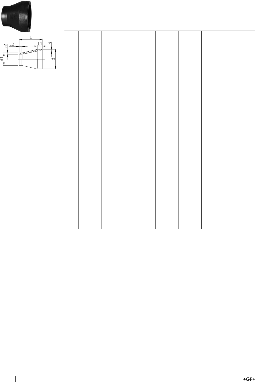
Reducers, PE100 S8,3/SDR17,6
Model:
ÏConventional butt-welding according to DVS 2207 part 11
ÏIR = Infrared-(IR Plus®) compatible. Please choose fusion parameters: PE100
d
[mm]
d1
[mm]
FM Code kg L
[mm]
L1
[mm]
L2
[mm]
e
[mm]
e1
[mm]
50 40 -- 753 908 926 0.010 55 12 12 2,9 2,3
63 40 -- 753 908 927 0.020 65 16 12 3,6 2,3
63 50 -- 753 908 928 0.020 65 16 12 3,6 2,9
75 40 -- 753 908 904 0.041 71 19 12 4,3 2,3
75 50 -- 753 908 903 0.042 71 19 12 4,3 2,9
75 63 -- 753 908 902 0.039 71 19 16 4,3 3,6
90 63 -- 753 908 906 0.074 80 22 16 5,1 3,6
90 75 -- 753 908 905 0.062 80 22 19 5,1 4,3
110 75 -- 753 908 909 0.108 97 28 19 6,3 4,3
110 90 -- 753 908 908 0.097 97 28 22 6,3 5,1
125 110 IR 753 908 912 0.151 108 32 28 7,1 6,3
140 110 IR 753 908 917 0.144 115 35 28 8,0 6,3
140 125 IR 753 908 916 0.150 115 35 32 8,0 7,1
160 110 IR 753 908 922 0.287 124 40 28 9,1 6,3
160 140 IR 753 908 920 0.245 124 40 35 9,1 8,0
180 90 IR 753 908 975 0.445 157 45 22 10,2 5,1
180 110 IR 753 908 976 0.367 157 45 28 10,2 6,3
180 125 IR 753 908 977 0.347 136 45 32 10,2 7,1
180 140 IR 753 908 978 0.344 136 45 35 10,2 8,0
180 160 IR 753 908 979 0.351 136 45 40 10,2 9,1
200 160 IR 753 908 931 0.835 151 50 40 11,4 9,1
200 180 IR 753 908 981 0.467 151 50 45 11,4 10,2
225 110 IR 753 908 938 1.295 160 55 35 12,8 6,3
225 160 IR 753 908 933 0.620 171 55 40 12,8 9,1
225 180 IR 753 908 985 0.601 171 55 45 12,8 10,2
225 200 IR 753 908 932 0.614 171 55 50 12,8 11,4
250 160 -- 753 908 939 0.975 194 60 40 14,2 9,1
250 225 -- 753 908 937 0.681 182 60 55 14,2 12,8
280 225 -- 753 908 944 1.180 105 30 20 15,9 12,8
280 250 -- 753 908 943 0.858 70 30 18 15,9 14,2
315 225 -- 753 908 950 1.715 130 30 20 17,9 12,8
315 250 -- 753 908 949 1.446 100 30 20 17,9 14,2
315 280 -- 753 908 999 1.047 63 30 18 17,9 15,9
355 250 -- 753 908 859 3.000 130 54 40 20,1 14,2
355 280 -- 753 908 858 2.700 120 53 40 20,1 15,9
355 315 -- 753 908 857 2.400 110 53 40 20,1 17,9
400 315 -- 753 908 872 3.600 120 50 40 22,7 17,9
400 355 -- 753 908 871 3.100 110 51 40 22,7 20,1
406
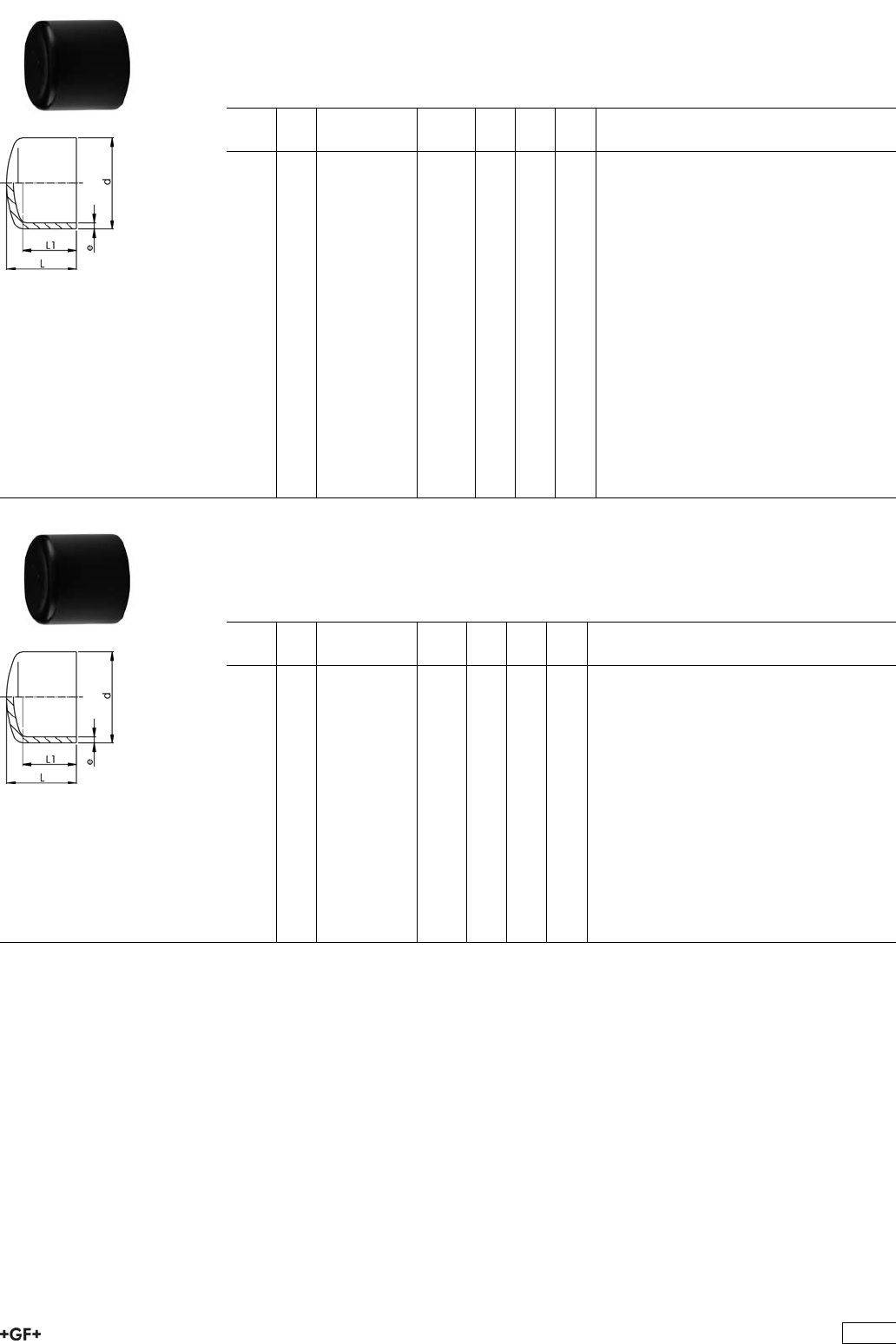
End Caps, PE100 S5/SDR11
Model:
ÏConventional butt-welding according to DVS 2207 part 11
ÏIR = Infrared-(IR Plus®) compatible. Please choose fusion parameters: PE100
d
[mm]
FM Code kg L
[mm]
L1
[mm]
e
[mm]
20 IR 753 968 931 0.004 42 30 1,9
25 IR 753 968 932 0.005 50 35 2,3
32 IR 753 968 933 0.010 55 40 2,9
40 IR 753 968 934 0.018 65 45 3,7
50 IR 753 968 935 0.029 70 50 4,6
63 IR 753 968 936 0.049 80 55 5,8
75 IR 753 968 937 0.065 90 60 6,8
90 IR 753 968 938 0.107 105 70 8,2
110 IR 753 968 939 0.174 120 80 10,0
125 IR 753 968 940 0.210 50 25 11,4
140 IR 753 968 941 0.323 60 30 12,7
160 IR 753 968 942 0.570 76 40 14,6
180 IR 753 968 943 0.730 125 88 16,4
200 IR 753 968 944 1.060 100 50 18,2
225 IR 753 968 945 1.365 103 60 20,5
250 -- 753 968 946 3.600 205 130 22,7
280 -- 753 968 947 5.000 230 139 25,4
315 -- 753 968 948 6.600 255 150 28,6
355 -- 753 968 949 9.800 280 165 32,2
400 -- 753 968 950 13.700 310 180 36,3
End Caps, PE100 S8,3/SDR17,6
Model:
ÏConventional butt-welding according to DVS 2207 part 11
ÏIR = Infrared-(IR Plus®) compatible. Please choose fusion parameters: PE100
d
[mm]
FM Code kg L
[mm]
L1
[mm]
e
[mm]
50 -- 753 968 910 0.040 75 53 2,9
63 -- 753 968 911 0.070 85 58 3,6
75 -- 753 968 912 0.045 90 60 4,3
90 -- 753 968 913 0.073 105 70 5,1
110 IR 753 968 914 0.118 120 80 6,3
125 IR 753 968 915 0.176 50 25 7,1
140 IR 753 968 916 0.194 60 30 8,0
160 IR 753 968 917 0.408 76 40 9,1
180 IR 753 968 918 0.500 125 88 10,2
200 IR 753 968 919 0.730 100 50 11,4
225 IR 753 968 920 0.965 103 60 12,8
250 -- 753 968 921 2.400 205 130 14,2
280 -- 753 968 922 3.400 230 139 15,9
315 -- 753 968 923 4.500 255 150 17,9
355 -- 753 968 924 6.500 280 165 20,1
400 -- 753 968 925 9.300 310 180 22,7
407
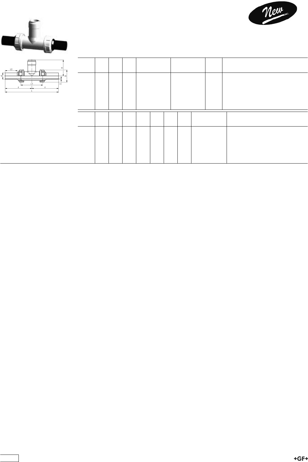
53 31 80 Installation Fitting Type 318, PE100
for Butt Fusion Systems metric
Model:
ÏFor Signet Paddlewheel Sensors Type -X0 (104 mm)
ÏBody and union nut PP-H
ÏUnion end with butt fusion spigot PE100
d
[mm]
DN
[mm]
PN FM EPDM
Code
FPM
Code
kg
20 15 10 IR 753 318 006 753 318 036 0.136
25 20 10 IR 753 318 007 753 318 037 0.190
32 25 10 IR 753 318 008 753 318 038 0.250
40 32 10 IR 753 318 009 753 318 039 0.356
50 40 10 IR 753 318 010 753 318 040 0.510
63 50 10 IR 753 318 011 753 318 041 0.800
d
[mm]
D
[mm]
z
[mm]
L
[mm]
L1
[mm]
L2
[mm]
H
[mm]
e
[mm]
Sensor Type
20 48 112 224 90 52 76 1.9 X0
25 58 121 242 100 53 78 2.3 X0
32 65 128 256 110 55 81 2.9 X0
40 79 136 272 110 60 85 3.7 X0
50 91 147 294 120 66 89 4.6 X0
63 105 158 316 130 70 95 5.8 X0
408
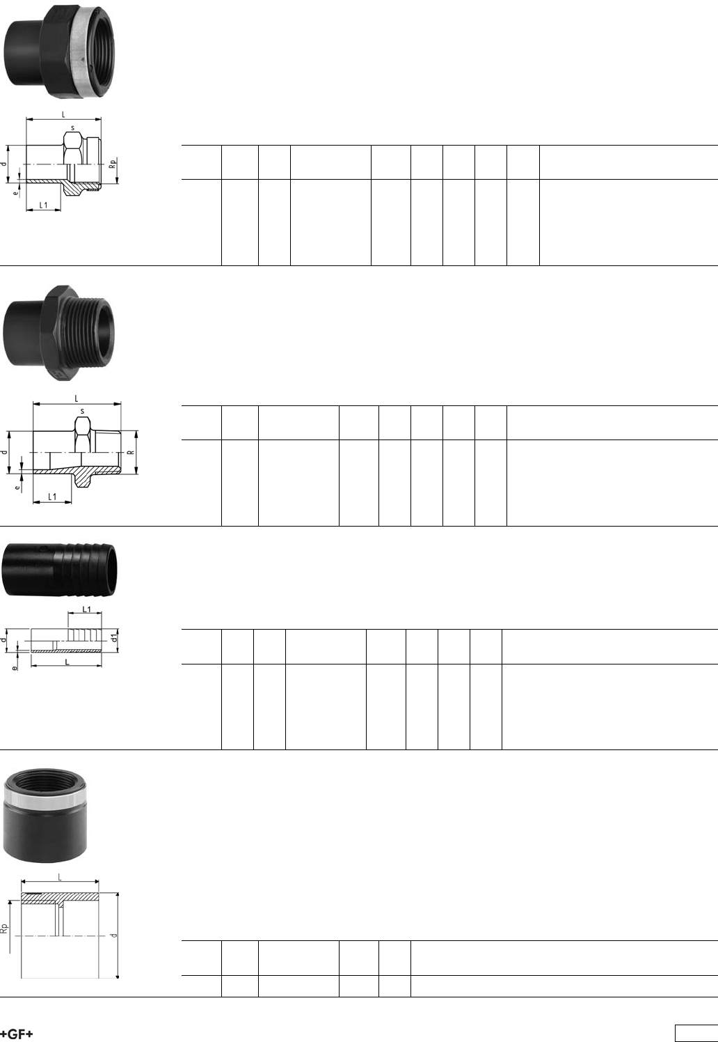
Adaptor Fittings for Butt Fusion
Adaptor Sockets, PE100
metric - Rp
Model:
ÏWith butt fusion spigot SDR11 and BSP parallel female thread Rp, reinforced
ÏConnection to plastic or metal
ÏReinforcing ring stainless (A2)
ÏDo not use thread sealing pastes that are harmful to PE
d
[mm]
Rp
[inch]
FM Code kg L
[mm]
L1
[mm]
s
[mm]
e
[mm]
20 1
/2IR 753 910 266 0.018 48 23 32 1,9
25 3
/4IR 753 910 267 0.022 50 23 36 2,3
32 1 IR 753 910 268 0.039 54 23 46 2,9
40 1 1
/4IR 753 910 269 0.068 56 23 55 3,7
50 1 1
/2IR 753 910 270 0.087 60 23 65 4,6
63 2 IR 753 910 271 0.140 62 23 80 5,8
Adaptor Nipples, PE100
metric - R
Model:
ÏWith butt fusion spigot and BSP tapered male thread
ÏConnection to plastic thread only
ÏDo not use thread sealing pastes that are harmful to PE
d
[mm]
R
[inch]
Code kg L
[mm]
L1
[mm]
s
[mm]
e
[mm]
20 1
/2753 910 556 0.014 51 23 32 1,9
25 3
/4753 910 557 0.026 52 23 36 2,3
32 1 753 910 558 0.029 55 23 46 3,0
40 1 1
/4753 910 559 0.043 58 23 55 3,7
50 1 1
/2753 910 560 0.064 60 23 65 4,6
63 2 753 910 561 0.140 67 26 80 5,8
Hose Connector, PE100
metric
Model:
ÏWith butt fusion spigot SDR11 and parallel hose connection
d
[mm]
d1
[mm]
FM Code kg L
[mm]
L1
[mm]
e
[mm]
20 20 IR 753 968 606 0.008 64 27 1,9
25 25 IR 753 968 607 0.013 75 36 2,3
32 32 IR 753 968 608 0.021 82 36 2,9
40 40 IR 753 968 609 0.034 84 42 3,7
50 50 IR 753 968 610 0.056 90 48 4,6
63 60 IR 753 968 611 0.095 100 50 5,8
PE Adaptor
Female thread
ÏPE 80 SDR 11 (ISO S5)
Ï5 bar Gas / 12,5 bar Water
ÏConnection to plastic or metal
ÏReinforcing ring stainless (A2)
ÏFor ELGEF®Plus Branch Saddle (53 131 000) d 63 - 400 mm, pipe SDR 11, d 75 -
400 mm, pipe SDR 17
ÏParallel female thread
d
[mm]
Rp
[inch]
Code kg L
[mm]
63 1 1
/2173 281 925 0.096 54
409
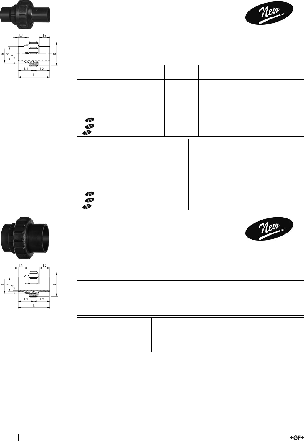
Unions for Butt Fusion
Unions, PE100 S5/SDR11
Model:
ÏConventional butt-welding according to DVS 2207 part 11
ÏIR = Infrared- (IR Plus®) compatible.
ÏGasket: O-Ring EPDM No. 48 41 00, FPM No. 49 41 00
ÏFor the dimensions d75-110 please see instructions for the installation
d
[mm]
PN FM EPDM
Code
FPM
Code
kg
20 16 IR 753 518 606 753 528 606 0.042
25 16 IR 753 518 607 753 528 607 0.052
32 16 IR 753 518 608 753 528 608 0.083
40 16 IR 753 518 609 753 528 609 0.151
50 16 IR 753 518 610 753 528 610 0.196
63 16 IR 753 518 611 753 528 611 0.364
75 10 IR 753 518 612 753 528 612 0.520
90 10 IR 753 518 613 753 528 613 0.540
110 10 IR 753 518 614 753 528 614 0.760
d
[mm]
D
[mm]
G
[inch]
L
[mm]
L1
[mm]
L2
[mm]
L3
[mm]
L4
[mm]
e
[mm]
20 48 1 107 54.0 53.0 26 38 1,9
25 58 1 1/4 113 57.0 56.0 26 42 2,3
32 65 1 1/2 119 60.0 59.0 25 41 3,0
40 79 2 126 63.0 63.0 25 42 3,7
50 91 2 1/4 131 65.5 65.5 25 44 4,6
63 111 2 3/4 137 69.0 68.0 25 45 5,8
75 135 S107,5x3,6 132 66.0 65.5 24 34 6,8
90 135 S107,5x3,6 131 65.5 65.5 24 45 8,2
110 158 S127,5x3,6 131 65.5 65.5 25 40 10,0
Unions, PE100 S8,3/SDR17,6
Model:
ÏConventional butt-welding according to DVS 2207 part 11
ÏIR = Infrared- (IR Plus®) compatible.
ÏGasket: O-Ring EPDM No. 48 41 00, FPM No. 49 41 00
ÏFor the dimensions d75-110 please see instructions for the installation
d
[mm]
PN FM EPDM
Code
FPM
Code
kg
75 10 -- 753 518 412 753 528 412 0.476
90 10 -- 753 518 413 753 528 413 0.483
110 10 IR 753 518 414 753 528 414 0.663
d
[mm]
D
[mm]
G
[inch]
L
[mm]
L1
[mm]
L2
[mm]
e
[mm]
75 135 S107,5x3,6 132 66 24 4,3
90 135 S107,5x3,6 131 66 24 5,1
110 158 S127,5x3,6 131 66 5 6,3
410
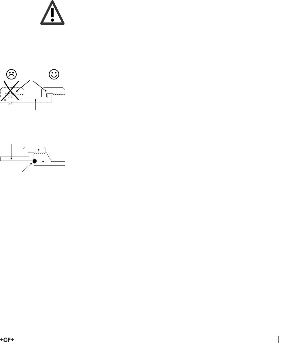
I]ZcZlZhi\ZcZgVi^dcd[eaVhi^Xjc^dch^ci]ZVWdkZbViZg^VahVcYY^bZch^dch]VhWZZcÒiiZY
l^i]VhiViZ"d["i]Z"Vgi!eaVhi^Xh"dg^ZciZYWjiigZhhi]gZVY#Ndji]ZgZ[dgZ]VkZVegdYjXi^cl]^X]
i]Zcdb^cVaegZhhjgZVcYi]ZhV[ZingZhZgkZ]VkZWZZcYgVbVi^XVaan^cXgZVhZY#6ahdcZlVgZi]Z
Wjii[jh^dckZgh^dch#>ci]^hXdccZXi^dc!i]ZgZVgZV[Zled^cihl]^X]ndjbjhiWZVlVgZd[#
8Vji^dc
I]Zi]gZVYhd[i]Zjc^dccjiVcYWjh]]VkZWZZcgZldg`ZY[dgEE!EK9;VcYE:L]Zc
jh^c\^cY^k^YjVaeVgih!eaZVhZX]ZX`eg^dgid^chiVaaVi^dc^[i]Zi]gZVYhd[i]Zjc^dcWjh]VcY
i]Zjc^dccjiXd^cX^YZ#
Jc^dcWjh]l^i]igVeZod^Yi]gZVYdcjc^dccjil^i]igVeZod^Yi]gZVY
dg
Jc^dcWjh]l^i]WjiigZhhi]gZVYdcjc^dccjil^i]WjiigZhhi]gZVY
I^e
IdbV`Z^chiVaaVi^dcd[i]Zjc^dcZVh^Zg!lZii]Zjc^dccji#
;dgi]ZY^bZch^dchY.%VcYY&&%lZVYk^hZ[jh^c\i]ZXdbeaZiZjc^dc!^[edhh^WaZdgha^YZ
i]Zjc^dccjiidi]ZXdaaVgd[i]Zjc^dcZcYWZXVjhZV[iZg[jh^dci]Zjc^dccjiXVccdiWZ
ha^YdkZgi]Z[jh^dcWZVY#;^\#&
S ;dgYZh^\cgZVhdch!^i^hi]ZdgZi^XVaanedhh^WaZidXdbW^cZY^[[ZgZcicdb^cVaY^VbZiZghd[
jc^dcZcYhVcYcjih#IdbV`ZhjgZXdbW^cVi^dchVgZiZX]c^XVaanXdggZXi!ndjXVcÒcYi]Z
XdYZcjbWZghd[i]Zh^c\aZeVgihVcYheVgZeVgih[dgZVX]jc^dc^ci]ZIVWaZh&"(#
8Vji^dc
DcanjhZjc^dcWjh]ZhVcYjc^dcZcYhl^i]i]ZhVbZcdb^cVaY^VbZiZg
6Wjii[jh^dcjc^dcWjh]Y,*bVncdiWZXdbW^cZYl^i]VWjii[jh^dcjc^dcZcYY.%id[dgbV
gZYjXZgWZXVjhZi]^hXVcXVjhZaZV`V\Z!Vh^aajhigViZYidi]ZaZ[i#;^\#'
BVg`^c\hdci]Zjc^dccjih
H;$BH2hdX`Zi[jh^dc!7;$HI2Wjii[jh^dc
H;$BH,* heZX^ÒZY[dghdX`Zi[jh^dcY,*
7;$HI,*Ä.% heZX^ÒZY[dgWjii[jh^dcY,*Ä,*VcYY.%Ä.%
H;$BH.% heZX^ÒZYhdX`Zi[jh^dcY.%
7;$HI&&% heZX^ÒZYWjii[jh^dcY&&%
&&% heZX^ÒZY[dghdX`Zi[jh^dcY&&%
I^e
LZgZXdbbZcYX]Vc\^c\bViZg^Vahdcan[dgi]Zjc^dcZcY[dg^chiVaaVi^dcgZVhdch#
>chigjXi^dch[dgi]Z^chiVaaVi^dcd[jc^dch^cEE!
E:Y,*!Y.%VcYY&&%
butt fusion
union bush d 75
butt fusion
union end d 90
union nut d 75
insufficient
seal
;^\#'
union endpipe
union nut
;^\#&
411
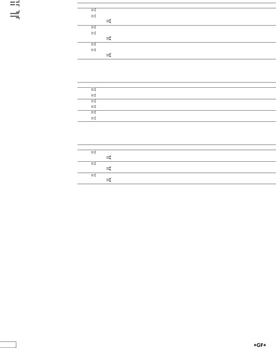
HZaZXi^dciVWaZh[dgh^c\aZeVgihVcYheVgZeVgih
IVWaZ&
H^c\aZeVgih[dgEE"=jc^dchY,*!Y.%VcYY&&%
Y 7;$HI H;$BH H9G EC 8dYZjc^dcZcY 8dYZjc^dcWjh] 8dYZjc^dccji
,* && &% ,',+%-*&' ,',+)-*&' ,',+.%)''
&,#+ + ,',+%-)&' ,',+)-)&' ,',+.%)''
Å &% ,',+%%&&' ,',+)%&,' ,',+.%)''
.% && &% ,',+%-*&( ,',+)-*&( ,',+.%)''
&,#+ + ,',+%-)&( ,',+)-)&( ,',+.%)''
Å &% ,',+%%&&( ,',+)%&,( ,',+.%)'(
&&% && &% ,',+%-*&) ,',+)-*&) ,',+.%)'(
&,#+ + ,',+%-)&) ,',+)-)&) ,',+.%)'(
Å &% ,',+%%&&) ,',+)%&,) ,',+.%)')
IVWaZ'
H^c\aZeVgih[dgE:&%%jc^dchY,*!Y.%VcYY&&%
Y 7;$HI H;$BH H9G EC 8dYZjc^dcZcY 8dYZjc^dcWjh] 8dYZjc^dccji
,* && &% ,*(+%-+&' ,*(+)-+&' ,',+.%))'
&,#+ &% ,*(+%-)&' ,*(+)-)&' ,',+.%))'
.% && &% ,*(+%-+&( ,*(+)-+&( ,',+.%))'
&,#+ &% ,*(+%-)&( ,*(+)-)&( ,',+.%))'
&&% && &% ,*(+%-+&) ,*(+)-+&) ,',+.%))(
&,#+ &% ,*(+%-)&) ,*(+)-)&) ,',+.%))(
IVWaZ(
D"G^c\h[dgEE"=!E:&%%
Y 7;$HI H;$BH H9G EC 8dYZD"G^c\:E9B& 8dYZD"G^c\;EB&
,* &+ ,)-)&%%&( ,).)&%%&(
&+ ,)-)&%%&) ,).)&%%&)
.% &+ ,)-)&%%&) ,).)&%%&)
&+ ,)-)&%%&* ,).)&%%&*
&&% &+ ,)-)&%%&* ,).)&%%&*
&+ ,)-)&%%&+ ,).)&%%&+
Jc^dccjihdkZgaVehZkZgVaY^bZch^dch
& ;aVc\ZVYVeidgD"g^c\h!dcZh^oZhbVaaZg^ccdb^cVaY^bZch^dch!VgZjhZY[dgi]ZY,*Ä&&%Wjii"[jh^dc
jc^dch
7jii[jh^dc
HdX`Zi[jh^dc
412
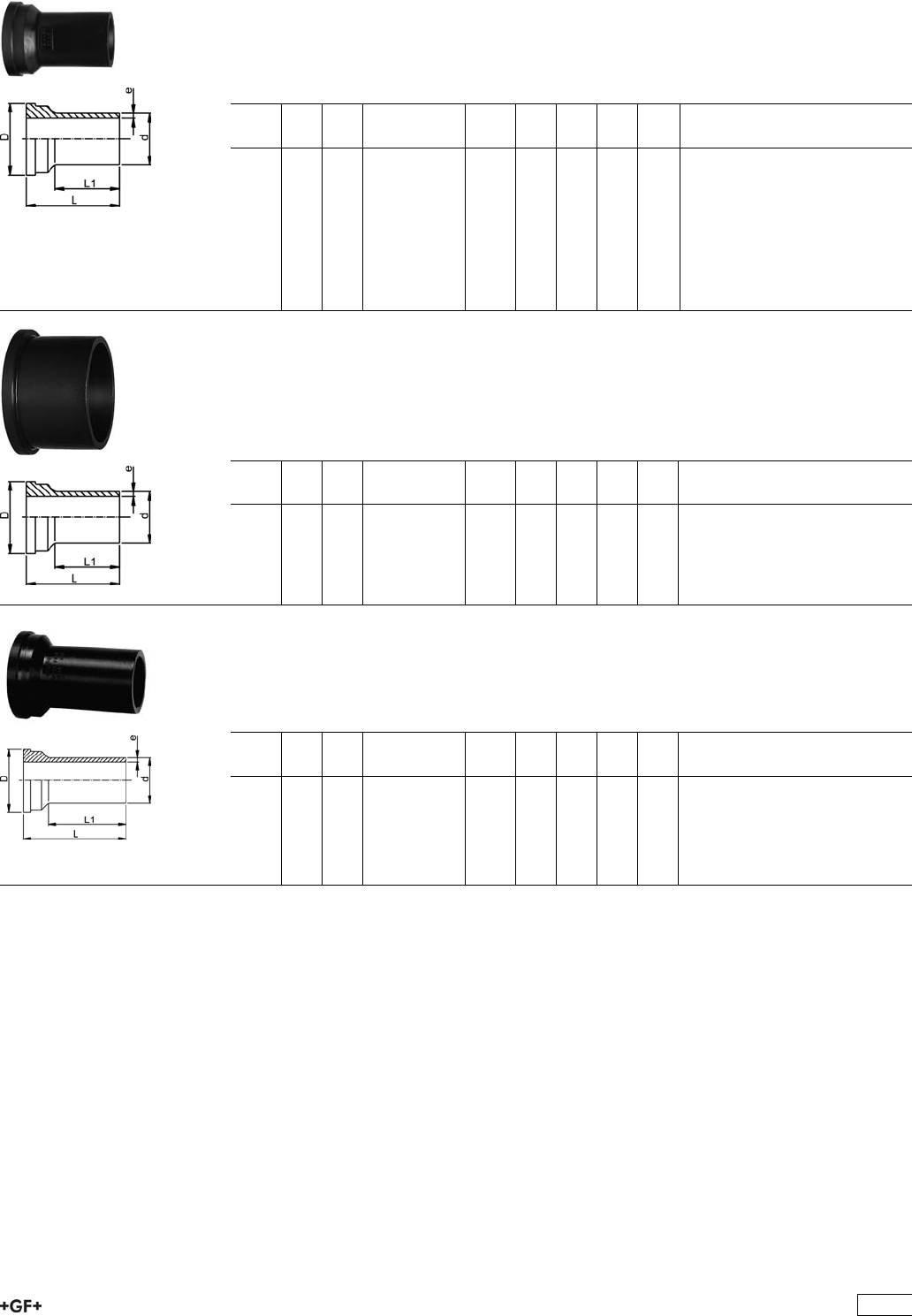
53 60 86 Union Ends, PE100 SDR11
Model:
ÏSuitable for unions, tank connectors and diaphragm valves Type 314
ÏConventional butt-welding according to DVS 2207 part 11
ÏIR = Infrared- (IR Plus®) compatible.
ÏFor the dimensions d75-110 please see instructions for the installation
d
[mm]
PN FM Code kg D
[mm]
L
[mm]
L1
[mm]
e
[mm]
20 16 IR 753 608 606 0.011 30 54 38 1,9
25 16 IR 753 608 607 0.018 39 57 42 2,3
32 16 IR 753 608 608 0.027 45 60 41 2,9
40 16 IR 753 608 609 0.045 57 63 42 3,7
50 16 IR 753 608 610 0.062 63 66 44 4,6
63 16 IR 753 608 611 0.100 78 69 45 5,8
75 10 IR 753 608 612 0.147 101 66 34 6,8
90 10 IR 753 608 613 0.156 101 66 45 8,2
110 10 IR 753 608 614 0.226 121 66 40 10,0
Union Ends, PE100 SDR17,6
Model:
ÏConventional butt-welding according to DVS 2207 part 11
ÏIR = Infrared- (IR Plus®) compatible.
ÏFor the dimensions d75-110 please see instructions for the installation
d
[mm]
PN FM Code kg D
[mm]
L
[mm]
L1
[mm]
e
[mm]
75 10 - 753 608 412 0.125 101 66 34 4,3
90 10 - 753 608 413 0.128 101 66 45 5,1
110 10 IR 753 608 414 0.178 121 66 40 6,3
Union Ends long, PE100
Model:
ÏFor butt-, IR Plus®and electro fusion
ÏSuitable for unions, tank connectors and diaphragm valves Type 314
d
[mm]
PN FM Code kg D
[mm]
L
[mm]
L1
[mm]
e
[mm]
20 16 IR 753 608 616 0.011 30 67 52 1,9
25 16 IR 753 608 617 0.018 39 71 53 2,3
32 16 IR 753 608 618 0.027 45 73 55 2,9
40 16 IR 753 608 619 0.045 57 81 60 3,7
50 16 IR 753 608 620 0.062 63 87 66 4,6
63 16 IR 753 608 621 0.100 78 93 70 5,8
413
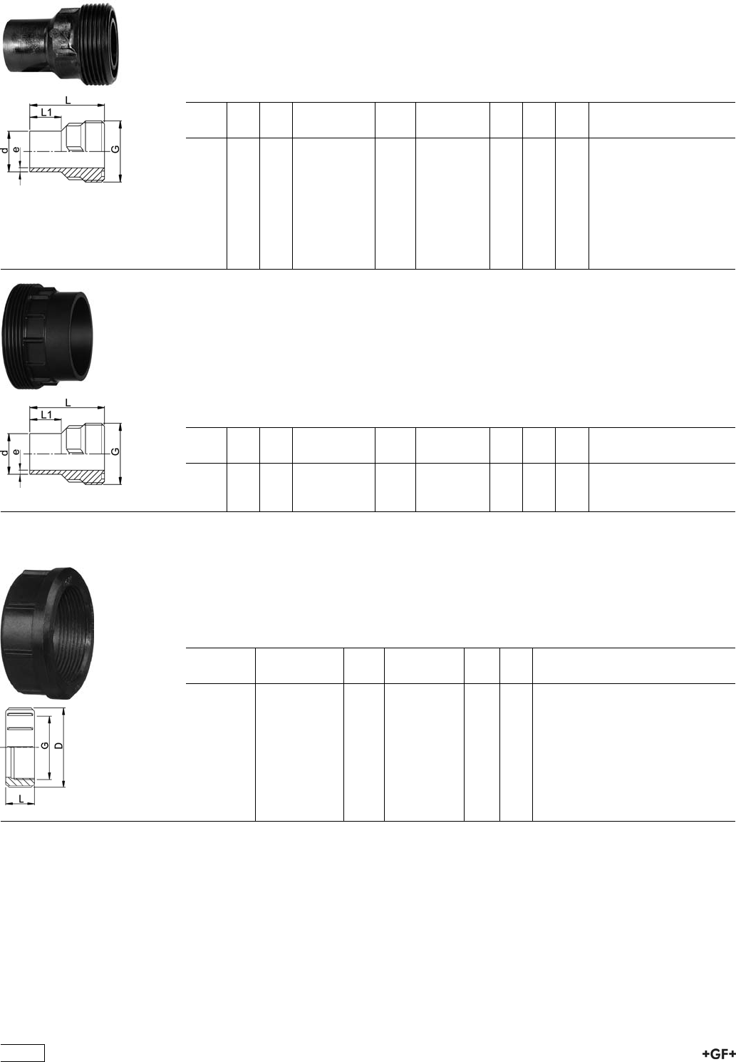
53 64 86 Union Bushes, PE100 SDR11
Model:
ÏConventional butt-welding according to DVS 2207 part 11
ÏIR = Infrared- (IR Plus®) compatible.
ÏGasket: O-Ring EPDM No. 48 41 00, FPM No. 49 41 00
ÏD75-110 with new thread geometry, now rated PN10 up to d110
ÏFor the dimensions d75-110 please see instructions for the installation
d
[mm]
PN FM Code kg G
[inch]
L
[mm]
L1
[mm]
e
[mm]
20 16 IR 753 648 606 0.016 1 54 26 1,9
25 16 IR 753 648 607 0.025 1 1/4 57 26 2,3
32 16 IR 753 648 608 0.035 1 1/2 60 25 2,9
40 16 IR 753 648 609 0.056 2 63 25 3,7
50 16 IR 753 648 610 0.078 2 1/4 66 25 4,6
63 16 IR 753 648 611 0.120 2 3/4 69 25 5,8
75 10 IR 753 648 612 0.183 S107,5x3,6 66 24 6,8
90 10 IR 753 648 613 0.195 S107,5x3,6 66 24 8,2
110 10 IR 753 648 614 0.275 S127,5x3,6 66 25 10
Union Bushes, PE100 SDR17,6
Model:
ÏConventional butt-welding according to DVS 2207 part 11
ÏIR = Infrared- (IR Plus®) compatible.
ÏGasket: O-Ring EPDM No. 48 41 00, FPM No. 49 41 00
ÏD75-110 with new thread geometry, now rated PN10 up to d110
ÏFor the dimensions d75-110 please see instructions for the installation
d
[mm]
PN FM Code kg G
[inch]
L
[mm]
L1
[mm]
e
[mm]
75 10 -- 753 648 412 0.161 S107.5x3.6 66 24 4,3
90 10 -- 753 648 413 0.164 S107.5x3.6 66 24 5,1
110 10 IR 753 648 414 0.221 S127.5x3.6 66 25 6,3
33 69 04 Union Nuts, PE-GF
Model:
ÏPE glass-fibre reinforced
ÏFor the dimensions d75-110 please see instructions for the installation
* PP glass fibre reinforced
d-d
[mm]
Code kg G
[inch]
D
[mm]
L
[mm]
20 - 733 690 406 0.029 1 48 24
25 - 733 690 407 0.032 1 1/4 58 26
32 - 733 690 408 0.042 1 1/2 65 28
40 - 733 690 409 0.068 2 79 31
50 - 733 690 410 0.097 2 1/4 91 35
63 - 733 690 411 0.166 2 3/4 111 39
*75 - 90 727 690 442 0.202 S107,5x3,6 135 40
*90 - 110 727 690 443 0.289 S127,5x3,6 158 43
414
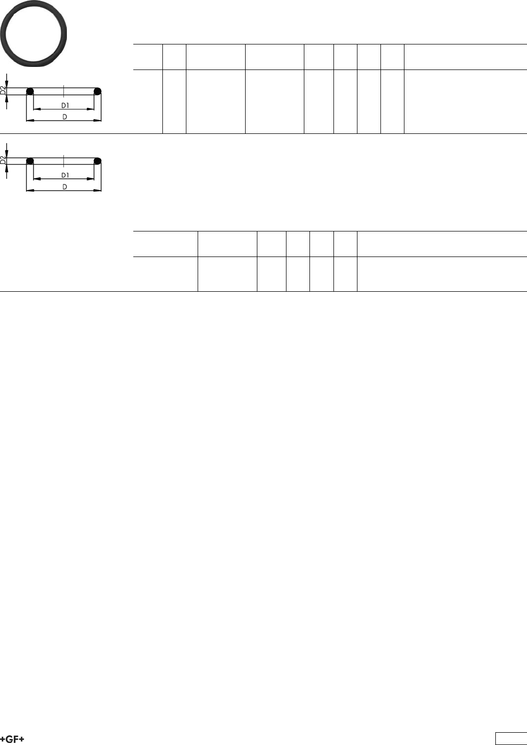
EPDM 48 41 00
FPM 49 41 00
O-Ring Gaskets
Model:
ÏFor unions and adaptor unions
ÏHardness approx. 65° Shore
ÏEPDM minimum temperature -40°C
ÏFPM minimum temperature -15°C
d
[mm]
DN
[mm]
EPDM
Code
FPM
Code
kg D
[mm]
D1
[mm]
D2
[mm]
20 15 748 410 006 749 410 006 0.002 27 20 4
25 20 748 410 007 749 410 007 0.002 35 28
32 25 748 410 008 749 410 008 0.002 40 33 4
40 32 748 410 009 749 410 009 0.006 51 41 5
50 40 748 410 010 749 410 010 0.007 58 47 5
63 50 748 410 011 749 410 011 0.010 70 60 5
O-Ring Gasket, FPM black
Model:
Ïfor unions PP-H, PE100 and PVDF butt fusion
Ïd75 748 410 013 (EPDM), 749 410 013 (FPM)
d90 748 410 014 (EPDM), 749 410 014 (FPM)
d110 748 410 015 (EPDM), 749 410 015 (FPM)
EPDM
Code
FPM
Code
kg D
[mm]
D1
[mm]
D2
[mm]
748 410 013 749 410 013 0.011 80
748 410 014 749 410 014 0.012 93
748 410 015 749 410 015 0.015 112
415
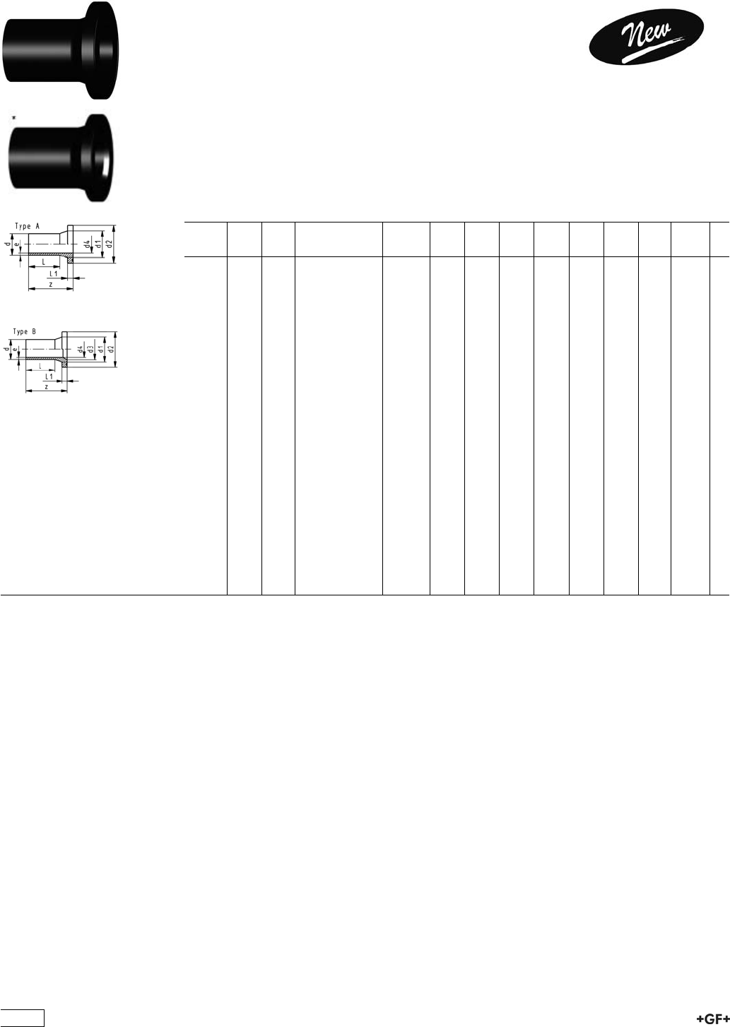
Flange Adaptors, Flanges and Gaskets for
Butt Fusion
Flange Adaptor LS, PE100 SDR11
Combined Jointing Face:
Flat and serrated
Model:
ÏFor butt-, IR Plus®and electro fusion
ÏSuitable for flange connections to metric (from d110 also to ANSI/ASME B16.5)
ÏUp to d315, suitable for butterfly valve type 567, 568 and 037
ÏGasket: Profile flange gasket NBR No. 45 44 07, EPDM No. 48 44 07
Ï10 bar Gas / 16 bar Water
* Type B with chamfer
d
[mm]
DN
[mm]
FM Code kg z
[mm]
d1
[mm]
d2
[mm]
d3
[mm]
d4
[mm]
L
[mm]
L1
[mm]
e
[mm]
20 15 IR 753 800 006 0.022 85 27 45 16 41 7 1.9
25 20 IR 753 800 007 0.034 85 33 58 20 41 9 2.3
32 25 IR 753 800 008 0.051 85 40 68 26 44 10 3.0
40 32 IR 753 800 009 0.076 85 50 78 32 49 11 3.7
50 40 IR 753 800 010 0.107 104 61 88 40 55 12 4.6
63 50 IR 753 800 011 0.174 98 75 102 51 65 14 5.8
*75 65 IR 753 800 012 0.301 125 89 122 66 61 75 16 6.8
*90 80 IR 753 800 013 0.441 140 105 138 78 73 85 17 8.2
*110 100 IR 753 800 014 0.685 160 125 158 100 90 90 18 10.0
*125 100 IR 753 800 015 0.836 170 132 158 114 102 95 25 11.4
*140 125 IR 753 800 016 1.295 200 155 188 127 114 92 25 12.7
*160 150 IR 753 800 017 1.644 200 175 212 151 130 110 25 14.6
*180 150 IR 753 800 018 1.873 200 180 212 158 147 115 30 16.4
*200 200 IR 753 800 019 2.758 200 232 268 203 163 120 32 18.2
*225 200 IR 753 800 020 2.972 200 235 268 210 184 130 32 20.5
*250 250 753 800 021 4.535 220 285 320 245 204 130 35 22.7
*280 250 753 800 022 4.925 220 291 320 265 229 139 35 25.4
*315 300 753 800 023 6.393 230 335 370 300 257 150 35 28.6
*355 350 753 800 024 10.400 250 373 430 340 290 165 40 32.3
*400 400 753 800 025 14.600 280 427 482 385 327 180 46 36.4
*450 500 753 800 026 24.800 333 514 585 400 368 195 60 40.9
*500 500 753 800 027 27.400 350 530 585 440 409 212 60 45.5
*560 600 753 800 028 38.000 365 615 685 490 458 230 60 50.9
*630 600 753 800 029 42.300 385 642 685 545 515 250 60 57.3
416
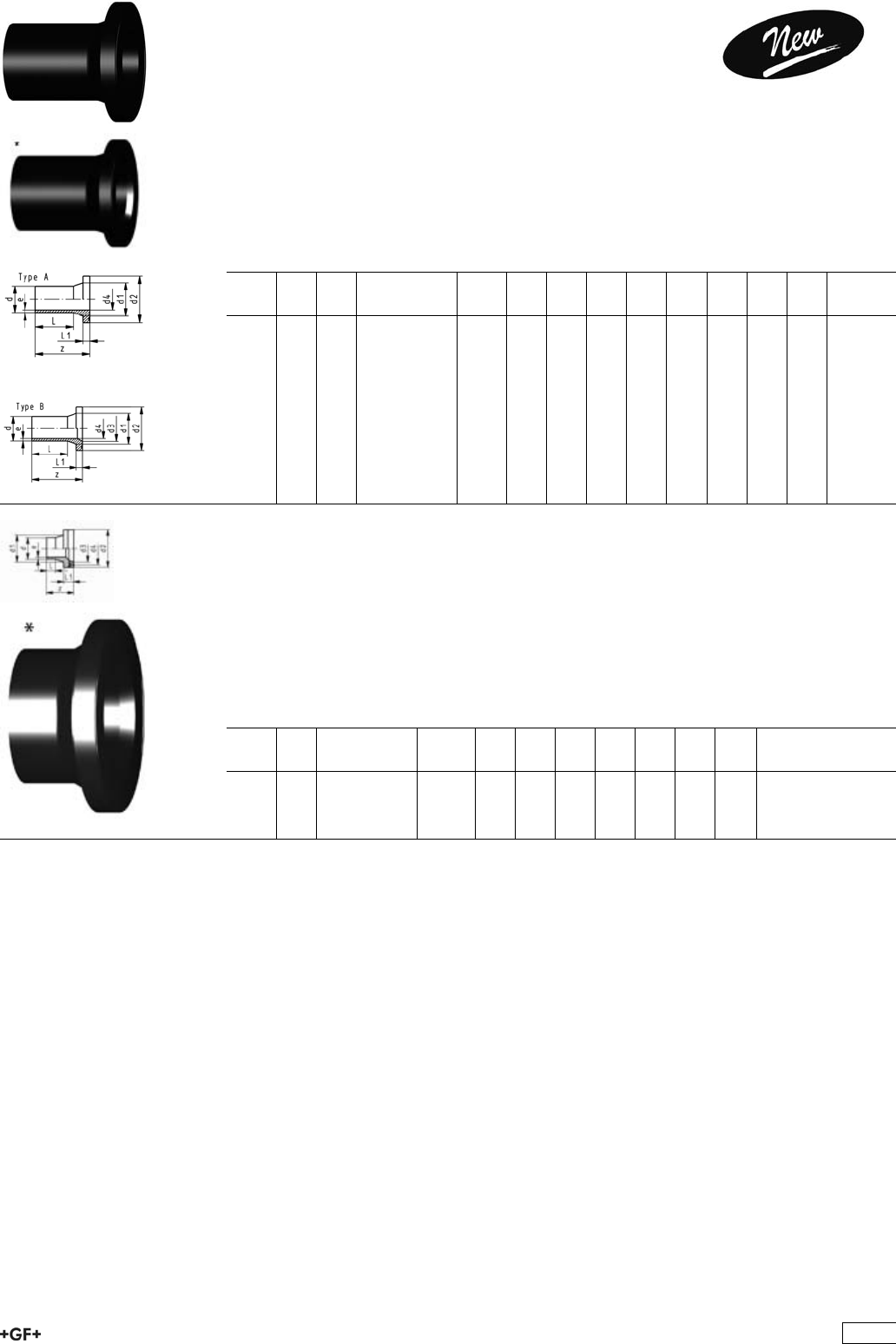
Flange Adaptor LS, PE100 SDR11
Combined Jointing Face:
Flat and serrated
Model:
ÏFor butt-, IR Plus®and electro fusion
ÏSuitable for flange connections to ANSI/ASME B 16.5
ÏSuitable for butterfly valve type 567, 568 and 037
ÏGasket: Profile flange gasket NBR No. 45 44 07, EPDM No. 48 44 07
Ï10 bar Gas / 16 bar Water
* Type B with chamfer
d
[mm]
DN
[mm]
FM Code kg z
[mm]
d1
[mm]
d2
[mm]
d3
[mm]
d4
[mm]
L
[mm]
L1
[mm]
e
[mm]
25 20 IR 753 800 057 0.031 85 33 54 20 41 9 2.3
32 20 IR 753 800 058 0.046 85 40 63 26 44 10 3.0
40 20 IR 753 800 059 0.070 85 50 73 32 49 11 3.7
50 20 IR 753 800 060 0.098 85 61 82 40 55 12 4.6
90 20 IR 753 800 063 0.423 140 105 133 73 85 17 8.2
Flange Adaptors, PE100, S5/SDR11
Jointing Face, combination serrated / flat
metric for Butterfly Valves
Model:
ÏConventional butt-welding according to DVS 2207 part 1
ÏSuitable for most common butterfly valves
ÏChamfered and ready for use
ÏIncluding spacer and O-Ring EPDM
d
[mm]
DN
[mm]
Code kg d1
[mm]
d2
[mm]
d3
[mm]
z
[mm]
L
[mm]
L1
[mm]
e
[mm]
355 350 753 798 824 7.800 373 430 346 156 40 75 32,2
400 400 753 798 825 10.700 427 482 404 176 50 82 36,3
417
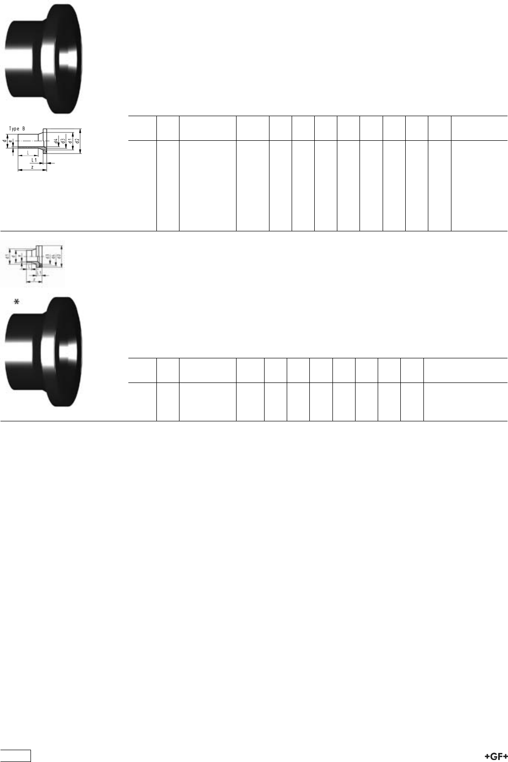
Flange Adaptors, PE100 S5/SDR11
Jointing Face, combination serrated / flat
metric
Model:
ÏConventional butt-welding according to DVS 2207 part 1
ÏUp to d315, suitable for butterfly valve type 567, 568 and 037
ÏGasket: Profile flange gasket NBR No. 45 44 07, EPDM No. 48 44 07
Ï10 bar Gas / 16 bar Water
d
[mm]
DN
[mm]
Code kg z
[mm]
d1
[mm]
d2
[mm]
d3
[mm]
d4
[mm]
L
[mm]
L1
[mm]
e
[mm]
250 250 753 798 826 2.420 120 285 320 245 204 45 35 22,7
280 250 753 798 827 2.800 115 291 320 265 229 70 35 25,4
315 300 753 798 828 3.350 120 335 370 300 257 55 35 28,6
355 350 753 798 829 7.800 118 373 430 340 290 40 40 32,2
400 400 753 798 830 10.700 140 427 482 385 327 55 46 36,3
450 500 753 798 831 12.550 138 514 585 400 368 44 60 40.9
500 500 753 798 832 11.780 138 530 585 440 409 48 60 45.4
560 600 753 798 833 - 135 615 684 490 458 20 60 50,8
630 600 753 798 834 - 135 642 684 545 516 40 60 57,2
Flange Adaptor, PE100, S8.3/SDR17/17.6
Jointing face, combination serrated / flat
metric
Model:
ÏConventional butt-welding according to DVS 2207 part 1
ÏSuitable for most common butterfly valves
ÏChamfered and ready for use
ÏIncluding spacer and O-Ring EPDM
d
[mm]
DN
[mm]
Code kg d1
[mm]
d2
[mm]
d3
[mm]
z
[mm]
L
[mm]
L1
[mm]
e
[mm]
355 350 753 798 849 6.000 373 430 346 120 30 30 20.1
400 400 753 798 850 8.100 427 482 404 120 42 33 22.7
418
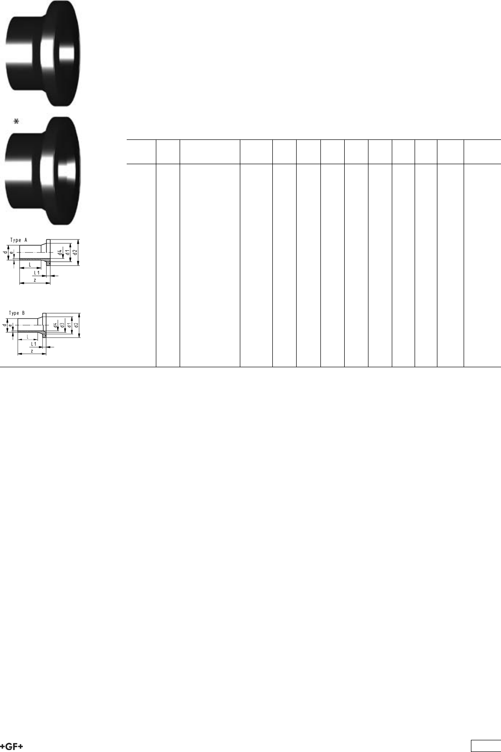
Flange Adaptors, PE100 S8,3/SDR 17/17.6
Jointing Face, combination serrated / flat
metric
Model:
ÏConventional butt-welding according to DVS 2207 part 1
ÏUp to d315, suitable for butterfly valve type 567, 568 and 037
ÏGasket: Profile flange gasket NBR No. 45 44 07, EPDM No. 48 44 07
Ï5 bar Gas / 10 bar Water
* Type B with chamfer
d
[mm]
DN
[mm]
Code kg z
[mm]
d1
[mm]
d2
[mm]
d3
[mm]
d4
[mm]
L
[mm]
L1
[mm]
e
[mm]
*250 250 753 798 851 1.830 120 285 320 245 220 56 25 14,8
*280 250 753 798 852 1.830 120 291 320 265 246 68 25 16,6
*315 300 753 798 853 1.830 120 335 370 300 277 60 25 18,7
*355 350 753 798 854 6.000 120 373 430 340 312 55 30 21,1
*400 400 753 798 855 8.100 140 427 482 385 352 67 33 23,7
450 500 753 798 856 9.070 140 514 585 396 60 46 26,7
500 500 753 798 857 7.870 140 530 585 440 45 46 29,7
560 600 753 798 858 12.310 140 615 685 493 46 50 33,2
630 600 753 798 859 10.520 140 642 685 555 60 50 37,4
419

Flange Adaptor LS, PE100 SDR17/17.6
Combined Jointing Face:
Flat and serrated
Model:
ÏFor butt-, IR Plus®and electro fusion
ÏSuitable for flange connections to metric and ANSI B16.5
ÏUp to d315, suitable for butterfly valve type 567, 568 and 037
ÏGasket: Profile flange gasket NBR No. 45 44 07, EPDM No. 48 44 07
Ï5 bar Gas / 10 bar Water
* Type B with chamfer
d
[mm]
DN
[mm]
FM Code kg z
[mm]
d1
[mm]
d2
[mm]
d3
[mm]
d4
[mm]
L
[mm]
L1
[mm]
e
[mm]
50 40 IR 753 800 085 0.110 104 61 88 44 55 12 3.0
63 50 IR 753 800 086 0.143 120 75 102 55 65 14 3.8
75 65 IR 753 800 087 0.246 130 89 122 66 75 16 4.5
90 80 IR 753 800 088 0.351 140 105 138 79 85 17 5.4
110 100 IR 753 800 089 0.531 160 125 158 96 90 18 6.6
*125 100 IR 753 800 090 0.629 170 132 158 114 110 95 25 7.4
*140 125 IR 753 800 091 0.973 200 155 188 127 123 92 25 8.3
*160 150 IR 753 800 092 1.257 200 175 212 158 141 110 25 9.5
180 150 IR 753 800 093 1.364 200 180 212 158 115 30 10.7
*200 200 IR 753 800 094 2.212 200 232 268 203 176 120 32 11.9
*225 200 IR 753 800 095 2.233 200 235 268 210 198 130 32 13.4
*250 250 753 800 096 3.595 220 285 320 245 220 130 35 14.8
*280 250 753 800 097 3.355 220 291 320 265 246 139 35 16.6
*315 300 753 800 098 5.320 230 335 370 308 277 150 35 18.7
*355 350 753 800 099 7.300 250 373 430 340 312 165 40 21.1
*400 400 753 800 100 10.300 280 427 482 385 352 180 46 23.7
450 500 753 800 101 15.800 333 514 585 396 195 60 26.7
500 500 753 800 102 19.100 350 530 585 440 212 60 29.7
560 600 753 800 103 27.500 365 615 685 493 230 60 33.2
630 600 753 800 104 30.000 385 642 685 555 250 60 37.4
Outlet Flange Adaptors, PE80 S5/SDR11
Model:
ÏConventional butt-welding according to DVS 2207 part 11
ÏSuitable for wafer check valves Type 369
Attention:
ÏIn conjunction with outlet flange adaptors, flange rings for socket systems must
be used.
d
[mm]
DN
[mm]
Code kg D
[mm]
D1
[mm]
D2
[mm]
L
[mm]
L1
[mm]
L2
[mm]
e
[mm]
r
[mm]
40 32 733 808 034 0.064 80 37 50 64 30 11 3,7 3
50 40 733 808 035 0.088 90 43 61 67 30 12 4,6 3
63 50 733 808 036 0.126 105 54 76 74 30 14 5,8 4
75 65 733 808 037 0.187 125 70 90 78 30 16 6,8 4
90 80 733 808 038 0.346 140 82 108 87 35 17 8,2 4
110 100 733 808 039 0.500 160 105 131 102 41 18 10,0 4
140 125 733 808 041 0.710 190 130 165 124 47 25 12,7 4
160 150 733 808 042 0.910 215 158 188 149 52 25 14,6 4
225 200 733 808 045 1.830 270 206 248 180 55 32 20,5 4
280 250 733 808 047 3.550 325 259 308 240 63 35 25,4 4
315 300 733 808 048 4.960 375 308 346 272 66 35 28,6 4
420
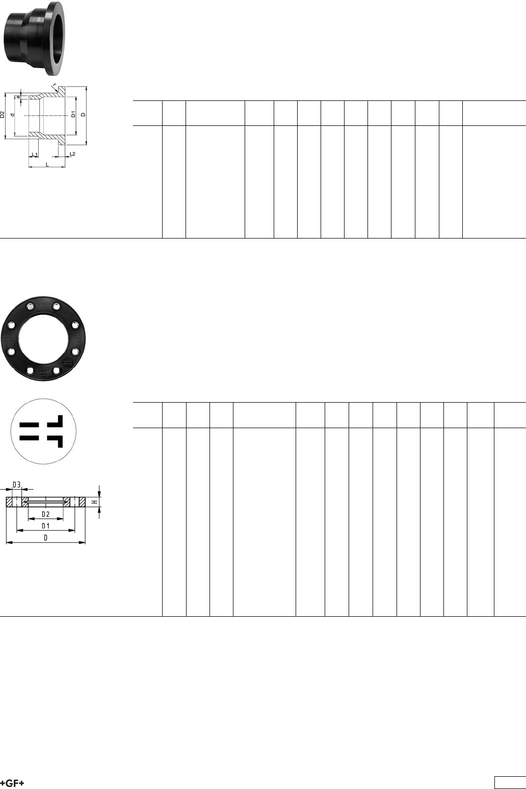
Outlet Flange Adaptors, PE80 S8,3/SDR17,6
Model:
ÏConventional butt-welding according to DVS 2207 part 11
ÏSuitable for wafer check valves Type 369
Attention:
ÏIn conjunction with outlet flange adaptors, flange rings for socket systems must
be used.
d
[mm]
DN
[mm]
Code kg D
[mm]
D1
[mm]
D2
[mm]
L
[mm]
L1
[mm]
L2
[mm]
e
[mm]
r
[mm]
40 32 733 808 009 0.060 80 37 50 64 30 11 2,3 3
50 40 733 808 010 0.067 90 43 61 67 30 12 2,9 3
63 50 733 808 011 0.096 105 54 76 74 30 14 3,6 4
75 65 733 808 012 0.170 125 70 90 78 30 16 4,3 4
90 80 733 808 013 0.260 140 82 108 87 35 17 5,1 4
110 100 733 808 014 0.355 160 105 131 102 41 18 6,3 4
140 125 733 808 016 0.500 190 130 165 124 47 18 8,0 4
160 150 733 808 017 0.630 215 158 188 149 52 18 9,1 4
225 200 733 808 020 1.225 270 206 248 180 55 24 12,8 4
280 250 733 808 022 2.230 325 259 308 240 63 25 15,9 4
315 300 733 808 023 2.450 375 308 346 272 66 25 17,9 4
27 70 04
27 70 05
Backing Flanges, PP-V
for Butt Fusion Systems metric
Model:
ÏModern full-plastic flange PP-GF (30 % glass-fibre reinforced)
ÏWith V-groove which applies force evenly on collar
ÏWith integrated bolt retainers as an assembly aid
ÏConnecting dimension: ISO 7005, EN 1092, BS 4504, DIN 2501
ÏBolt circle PN 10
¹) Suitable for socket- and butt fusion systems (no pictograph on flange)
AL: number of holes
d
[mm]
Inch DN
[mm]
PN Code kg D
[mm]
D1
[mm]
D2
[mm]
D3
[mm]
H
[mm]
AL SC
¹20 15 16 727 700 406 0.080 95 65 28 14 16 4 M12
¹25 20 16 727 700 407 0.100 105 75 34 14 17 4 M12
¹32 25 16 727 700 408 0.140 115 85 42 14 18 4 M12
¹40 32 16 727 700 409 0.220 140 100 51 18 20 4 M16
¹50 40 16 727 700 410 0.210 150 110 62 18 22 4 M16
¹63 50 16 727 700 411 0.380 165 125 78 18 24 4 M16
¹75 65 16 727 700 412 0.480 185 145 92 18 26 4 M16
90 80 16 727 700 513 0.520 200 160 108 18 27 8 M16
110 100 16 727 700 514 0.680 220 180 128 18 28 8 M16
125 100 16 727 700 515 0.760 220 180 135 18 28 8 M16
140 125 16 727 700 516 0.800 250 210 158 18 30 8 M16
160 6 150 16 727 700 517 1.200 285 241 178 22 32 8 M20
180 150 16 727 700 518 1.200 285 240 188 22 32 8 M20
200 8 200 16 727 700 519 1.400 340 295 235 22 34 8 M20
225 9 200 16 727 700 520 1.400 340 295 238 22 34 8 M20
250 250 16 727 700 521 1.700 395 350 288 22 38 12 M20
280 250 16 727 700 522 1.700 395 350 294 22 38 12 M20
315 300 16 727 700 523 2.400 445 400 338 22 42 12 M20
421
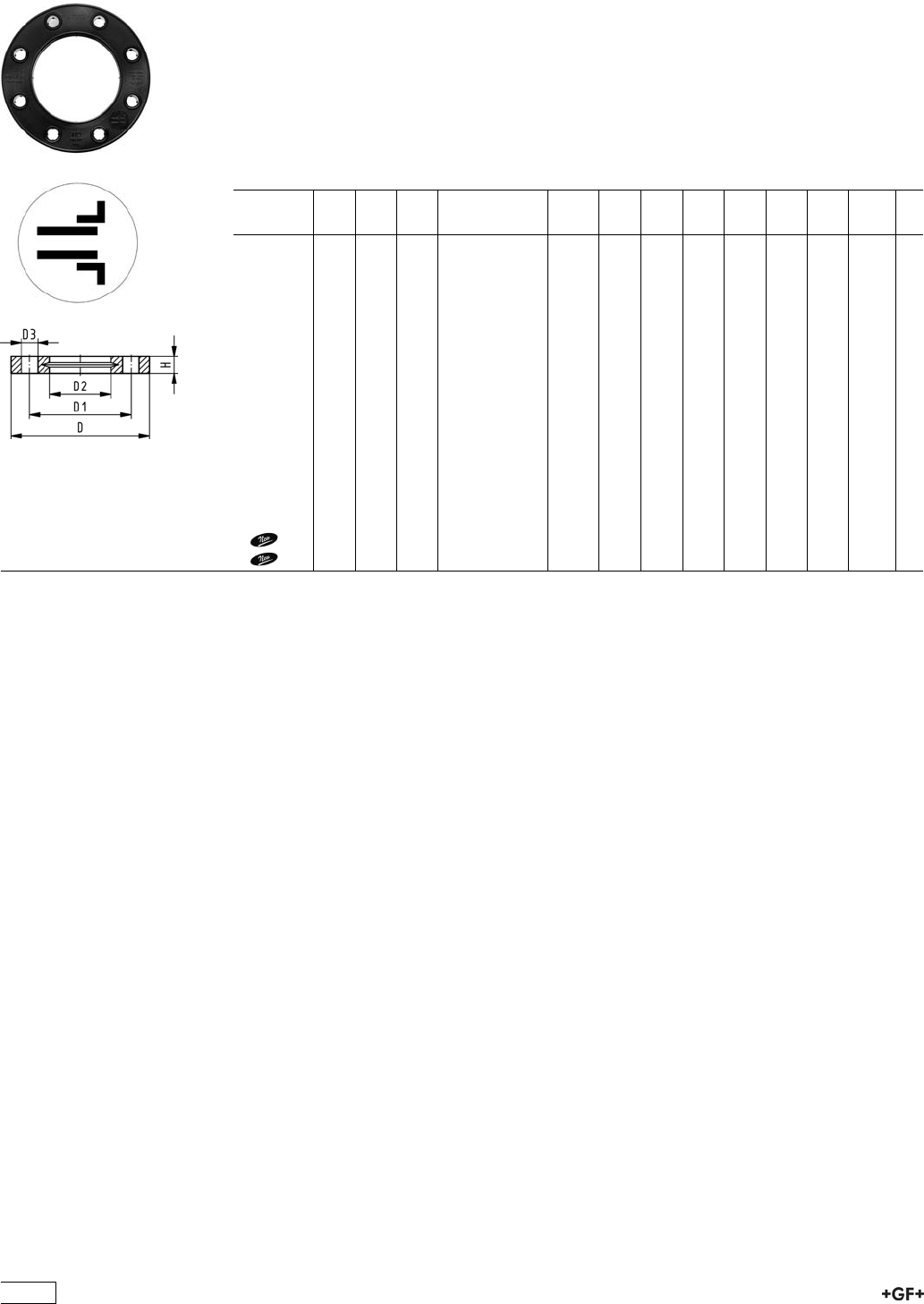
27 70 04
27 70 05
Backing Flanges, PP-V
for Socket Systems metric
Model:
ÏModern full-plastic flange PP-GF (30 % glass-fibre reinforced)
ÏWith V-groove which applies force evenly on collar
ÏWith integrated bolt retainers as an assembly aid
ÏConnecting dimension: ISO 7005, EN 1092, BS 4504, DIN 2501
ÏBolt circle PN 10
¹) Suitable for socket- and butt fusion systems (no pictograph on flange)
AL: number of holes
d
[mm]
Inch DN
[mm]
PN Code kg D
[mm]
D1
[mm]
D2
[mm]
D3
[mm]
H
[mm]
AL SC
¹20 15 16 727 700 406 0.080 95 65 28 14 16 4 M12
¹25 20 16 727 700 407 0.100 105 75 34 14 17 4 M12
¹32 25 16 727 700 408 0.140 115 85 42 14 18 4 M12
¹40 32 16 727 700 409 0.220 140 100 51 18 20 4 M16
¹50 40 16 727 700 410 0.210 150 110 62 18 22 4 M16
¹63 50 16 727 700 411 0.380 165 125 78 18 24 4 M16
¹75 65 16 727 700 412 0.480 185 145 92 18 26 4 M16
90 80 16 727 700 413 0.520 200 160 110 18 27 8 M16
110 100 16 727 700 414 0.680 220 180 133 18 28 8 M16
140 125 16 727 700 416 0.800 250 210 167 18 30 8 M16
160 6 150 16 727 700 417 1.200 285 241 190 22 32 8 M20
200 200 16 727 700 419 1.500 340 296 226 22 34 8 M20
225 8 200 16 727 700 420 1.400 340 295 250 22 34 8 M20
250 250 16 727 700 421 1.700 395 350 277 22 38 12 M20
280 250 16 727 700 422 1.700 395 350 310 22 38 12 M20
315 300 16 727 700 423 2.400 445 400 348 22 42 12 M20
355 350 10 727 700 424 3.000 515 460 388 22 46 16 M20
400 400 10 727 700 425 3.500 574 515 442 26 50 16 M24
422
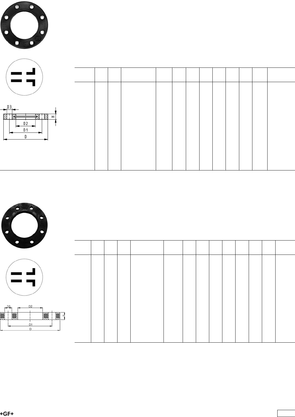
27 70 14
27 70 15
Backing Flanges, PP-V
for Butt Fusion Systems Inch/ANSI
Model:
ÏModern full-plastic flange PP-GF (30 % glass-fibre reinforced)
ÏWith V-groove which applies force evenly on collar
ÏWith integrated bolt-fixing as an assembly aid
ÏConnecting dimension: ANSI/ASME B 16.5 class 150, ASTM D 4024, BS 1560, BS
EN 1759
ÏBolt circle class 150
¹) Suitable for socket- and butt fusion systems (no pictograph on flange)
AL: number of holes
Inch DN
[mm]
PN Code kg D
[mm]
D1
[mm]
D2
[mm]
D3
[mm]
H
[mm]
AL SC
¹1
/215 16 727 701 406 0.080 95 60 28 16 16 4 M12
¹3
/420 16 727 701 407 0.100 105 70 34 16 17 4 M12
¹1 25 16 727 701 408 0.140 115 79 42 16 18 4 M12
¹11
/432 16 727 701 409 0.220 140 89 51 16 20 4 M16
¹11
/240 16 727 701 410 0.210 150 98 62 16 22 4 M16
¹2 50 16 727 701 411 0.380 165 121 78 19 24 4 M16
¹21
/265 16 727 701 412 0.480 185 140 92 19 26 4 M16
3 80 16 727 701 513 0.520 200 152 108 19 27 4 M16
4 100 16 727 701 514 0.680 229 190 128 19 28 8 M16
6 150 16 727 700 517 1.200 285 241 178 22 32 8 M20
8 200 16 727 700 519 1.400 340 295 235 22 34 8 M20
9 200 16 727 700 520 1.400 340 295 238 22 34 8 M20
10 250 16 727 701 521 1.800 406 362 288 26 38 12 M20
10 250 16 727 701 522 1.700 406 362 294 26 38 12 M20
12 300 16 727 701 523 2.400 483 432 338 26 42 12 M20
27 70 02
27 70 03
Backing Flanges, PP/Steel
for Butt Fusion Systems metric
Model:
ÏMaterial: PP (30 % glass-fibre reinforced) with steel ring
ÏConnecting dimension: ISO 7005, EN 1092, BS 4504, DIN 2501
ÏBolt circle PN 10
AL: number of holes
d
[mm]
d
[inch]
DN
[mm]
PN Code kg D
[mm]
D1
[mm]
D2
[mm]
D3
[mm]
H
[mm]
AL SC
20 15 16 727 700 206 0.220 95 65 28 14 12 4 M12
25 20 16 727 700 207 0.260 105 75 34 14 12 4 M12
32 25 16 727 700 208 0.430 115 85 42 14 16 4 M12
40 32 16 727 700 209 0.650 140 100 51 18 16 4 M16
50 40 16 727 700 210 0.820 150 110 62 18 18 4 M16
63 50 16 727 700 211 0.940 165 125 78 18 18 4 M16
75 65 16 727 700 212 1.300 185 145 92 18 18 4 M16
90 80 16 727 700 313 1.400 200 160 108 18 20 8 M16
110 100 16 727 700 314 1.580 220 180 128 18 20 8 M16
125 100 16 727 700 315 1.550 220 180 135 18 20 8 M16
140 125 16 727 700 316 2.360 250 210 158 18 24 8 M16
160 6 150 16 727 700 317 3.890 285 240 178 22 24 8 M20
180 150 16 727 700 318 3.410 285 240 188 22 24 8 M20
200 200 16 727 700 319 5.180 340 295 235 22 27 8 M20
225 200 16 727 700 320 5.150 340 295 238 22 27 8 M20
423
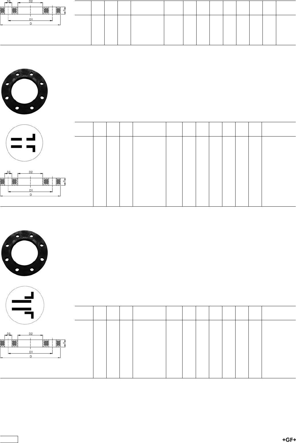
d
[mm]
d
[inch]
DN
[mm]
PN Code kg D
[mm]
D1
[mm]
D2
[mm]
D3
[mm]
H
[mm]
AL SC
250 250 16 727 700 321 6.680 395 350 288 22 30 12 M20
280 250 16 727 700 322 6.580 395 350 294 22 30 12 M20
315 300 16 727 700 323 8.420 445 400 338 22 34 12 M20
355 350 16 727 700 324 15.790 515 460 376 22 40 16 M20
400 400 16 727 700 325 19.320 574 515 430 26 40 16 M24
27 70 12 Backing Flanges, PP/Steel
for Butt Fusion Systems Inch/ANSI
Model:
ÏMaterial: PP (30 % glass-fibre reinforced) with steel ring
ÏConnecting dimension: ANSI/ASME B 16.5 class 150, ASTM D 4024, BS 1560, BS
EN 1759
ÏBolt circle class 150
AL: number of holes
d
[inch]
DN
[mm]
d
[mm]
PN Code kg D1
[mm]
D2
[mm]
D3
[mm]
D
[mm]
H
[mm]
AL
1
/215 20 16 727 701 206 0.210 60 28 16 95 12 4
3
/420 25 16 727 701 207 0.250 70 34 16 105 12 4
1 25 32 16 727 701 208 0.420 79 42 16 115 16 4
11
/432 40 16 727 701 209 0.670 89 51 16 140 16 4
11
/240 50 16 727 701 210 0.860 98 62 16 150 18 4
2 50 63 16 727 701 211 0.930 121 78 19 165 18 4
21
/265 75 16 727 701 212 1.340 140 92 19 185 18 4
3 80 90 16 727 701 313 1.550 152 108 19 200 20 4
4 100 110 16 727 701 314 1.840 190 128 19 229 20 8
6 150 160 16 727 700 317 3.890 240 178 22 285 24 8
8 200 200 16 727 701 319 5.180 298 235 22 340 27 8
8 200 225 16 727 701 320 5.150 298 238 22 340 27 8
27 70 12 Backing Flanges, PP/Steel
for Socket Systems Inch/ANSI
Model:
ÏFor Flange Adaptors BS/ANSI
ÏMaterial: PP (30 % glass-fibre reinforced) with steel ring
ÏConnecting dimension: ANSI/ASME B 16.5 class 150, ASTM D 4024, BS 1560, BS
EN 1759
ÏBolt circle class 150
ÏDN100 and DN150: only for use with original metric flange adaptors
AL: number of holes
d
[inch]
DN
[mm]
d
[mm]
PN Code kg D1
[mm]
D2
[mm]
D3
[mm]
D
[mm]
H
[mm]
AL
1
/215 20 16 727 701 206 0.210 60 28 16 95 12 4
3
/420 25 16 727 701 207 0.250 70 34 16 105 12 4
1 25 32 16 727 701 208 0.420 79 42 16 115 16 4
11
/432 40 16 727 701 209 0.670 89 51 16 140 16 4
11
/240 50 16 727 701 210 0.860 98 62 16 150 18 4
2 50 63 16 727 701 211 0.930 121 78 19 165 18 4
21
/265 75 16 727 701 212 1.340 140 92 19 185 18 4
3 80 90 16 727 701 213 1.550 152 110 19 200 20 4
4 100 110 16 727 701 214 1.810 190 133 19 229 20 8
6 150 160 16 727 700 217 3.390 240 190 22 285 24 8
424
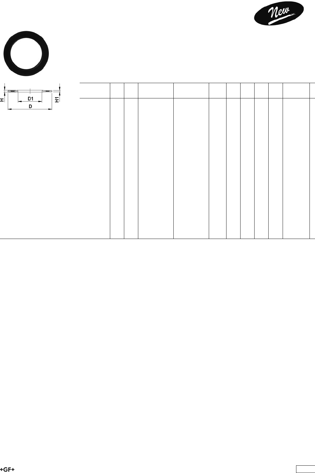
EPDM 48 44 07
FPM 49 44 07 Profile Flange Gaskets metric
EPDM / FPM
Model:
ÏFor all GF Flange Adaptors
ÏProfile Gasket with steel insert (type G-ST-P/K)
ÏHardness: 70° Shore EPDM, 75° Shore FPM
ÏCentering on the inner diameter of the screw crown
di FA are the suitable inner diameters of flange adaptors
d
[mm]
DN
[mm]
PN EPDM
Code
FPM
Code
kg D
[mm]
D1
[mm]
H
[mm]
H1
[mm]
di FA
[mm]
20 15 16 748 440 706 749 440 706 0.008 51 20 4 3 10 - 20
25 20 16 748 440 707 749 440 707 0.011 61 22 4 3 12 - 22
32 25 16 748 440 708 749 440 708 0.014 71 28 4 3 18 - 28
40 32 16 748 440 709 749 440 709 0.021 82 40 4 3 30 - 40
50 40 16 748 440 710 749 440 710 0.022 92 46 4 3 36 - 46
63 50 16 748 440 711 749 440 711 0.041 107 58 5 4 48 - 58
75 65 16 748 440 712 749 440 712 0.055 127 69 5 4 59 - 69
90 80 16 748 440 713 749 440 713 0.062 142 84 5 4 73 - 84
110 100 16 748 440 714 749 440 714 0.085 162 104 6 5 94 - 104
125 100 16 748 440 715 749 440 715 0.158 162 123 6 5 113 - 123
140 125 16 748 440 716 749 440 716 0.118 192 137 6 5 127 - 137
160 / 180 150 16 748 440 717 749 440 717 0.153 218 160 8 6 150 - 160
200 200 16 748 440 719 749 440 719 0.263 273 203 8 6 192 - 203
225 200 16 748 440 720 749 440 720 0.181 273 220 8 6 207 - 220
250 250 16 748 440 721 749 440 721 0.410 328 252 8 6 238 - 252
280 250 16 748 440 722 749 440 722 0.226 328 274 8 6 264 - 274
315 300 16 748 440 723 749 440 723 0.334 378 306 8 6 296 - 306
355 350 16 748 440 724 749 440 724 0.410 438 355 10 7 340 - 355
400 400 16 748 440 725 749 440 725 0.513 489 400 10 7 385 - 400
450 500 16 748 440 726 749 440 726 0.718 594 403 10 7 393 - 403
500 500 16 748 440 727 749 440 727 0.718 594 447 10 7 437 - 447
560 600 16 748 440 728 749 440 728 0.923 695 494 10 7 484 - 494
630 600 16 748 440 729 749 440 729 0.923 695 555 10 7 545 - 555
425
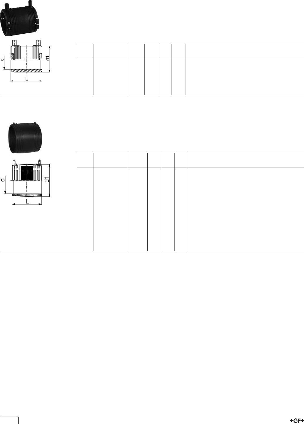
Electrofusion Fittings
53 91 16 Coupler
with integral clamp
ÏPE 100 SDR 11 (ISO S5)
Ï10 bar Gas / 16 bar Water
Ï4 mm pin connectors
ÏLimited path fusion indicators
ÏRemovable centre stop
d
[mm]
Code kg d1
[mm]
L
[mm]
z
[mm]
20 753 911 606 0.054 31 68 2
25 753 911 607 0.060 36 68 2
32 753 911 608 0.072 44 72 2
40 753 911 609 0.100 54 80 2
50 753 911 610 0.136 66 88 2
63 753 911 611 0.194 81 96 2
53 91 16 Coupler
ÏPE 100 SDR 11 (ISO S5)
Ï10 bar Gas / 16 bar Water
Ï4 mm pin connectors
ÏLimited path fusion indicators
ÏRemovable centre stop up to d160
d
[mm]
Code kg d1
[mm]
L
[mm]
z
[mm]
75 753 911 612 0.287 96 110 2
90 753 911 613 0.421 113 125 2
110 753 911 614 0.697 138 145 2
125 753 911 615 0.738 154 158 3
140 753 911 616 0.968 172 168 3
160 753 911 617 1.390 196 180 3
180 753 911 618 1.750 219 194
200 753 911 619 2.350 244 208
225 753 911 620 3.193 273 224
250 753 911 621 4.210 304 244
280 753 911 622 5.675 340 252
315 753 911 623 8.000 382 268
355 753 911 624 12.110 432 246
400 753 911 625 15.993 487 246
426
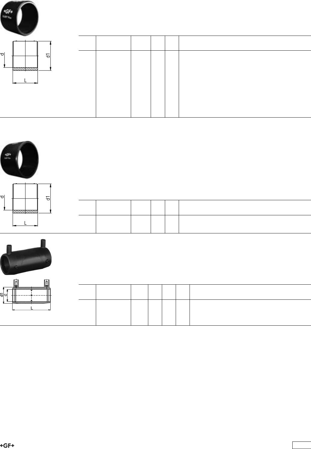
53 91 18 Coupler
ÏPE 100 SDR 17 (ISO S8)
Ï5 bar Gas / 10 bar Water
Ï4 mm pin connectors
ÏLimited path fusion indicators
Ïd160 with removable centre stop
d
[mm]
Code kg d1
[mm]
L
[mm]
160 753 911 817 1.050 186 180
180 753 911 818 1.450 213 194
200 753 911 819 1.800 233 208
225 753 911 820 2.385 261 224
250 753 911 821 4.345 304 244
280 753 911 822 5.675 340 252
315 753 911 823 8.000 382 268
355 753 911 824 8.200 414 246
400 753 911 825 15.993 487 246
450 753 911 826 15.500 522 290
500 753 911 827 19.000 579 290
53 91 18 Coupler
ÏPE 100 SDR 17 (ISO S8)
Ï5 bar Gas / 10 bar Water
Ï4 mm pin connectors
ÏLimited path fusion indicators
Ï2 separate welding zones
ÏInstallation only with pressure pad kit (799 301 561)
ÏStandard welding units required with steady output power of 2500 W
ÏFor generator use: output power of min. 5 kW recommended
d
[mm]
Code kg d1
[mm]
L
[mm]
560 753 911 828 25.500 638 392
630 753 911 829 35.000 716 442
Coupler long
ÏPE 100 SDR 11 (ISO S5)
Ï10 bar Gas / 16 bar Water
Ï4 mm pin connectors
ÏRemovable centre stop
d
[mm]
Code kg d1
[mm]
L
[mm]
z
[mm]
32 753 911 208 0.084 44 104 2
40 753 911 209 0.135 56 121 2
50 753 911 210 0.215 68 139 2
63 753 911 211 0.318 82 166 2
427
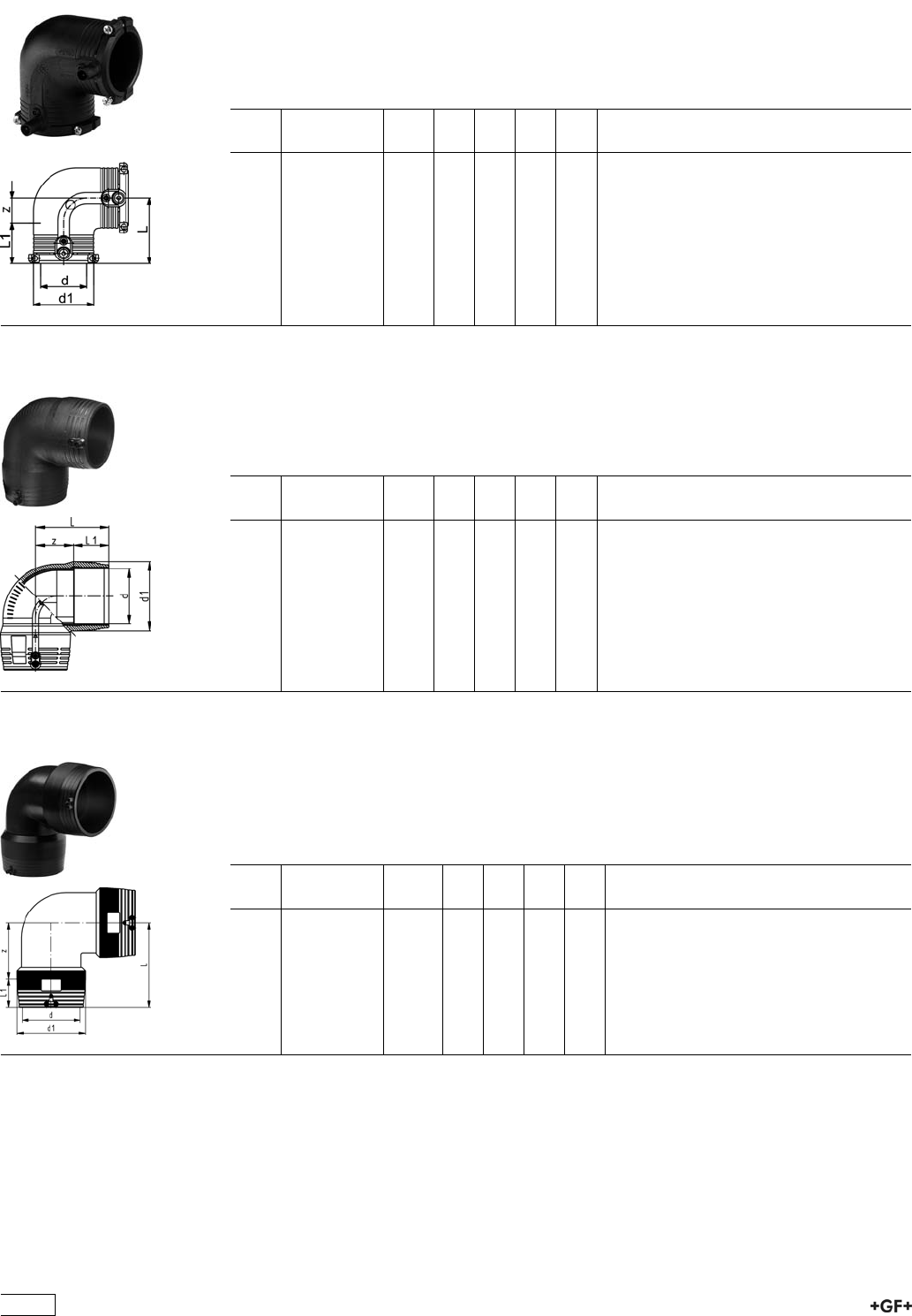
53 10 16 Elbow 90°
with integral pipe fixation
ÏPE 100 SDR 11 (ISO S5)
Ï10 bar Gas / 16 bar Water
Ï4 mm pin connectors
ÏLimited path fusion indicators
d
[mm]
Code kg d1
[mm]
L
[mm]
L1
[mm]
z
[mm]
20 753 101 606 0.093 35 54 34 20
25 753 101 607 0.078 35 54 34 20
32 753 101 608 0.098 44 53 36 17
40 753 101 609 0.142 54 62 39 23
50 753 101 610 0.215 66 71 43 28
63 753 101 611 0.280 81 81 48 32
53 10 18 Elbow 90°
ÏPE 100 SDR 11 (ISO S5)
Ï10 bar Gas / 16 bar Water
Ï4 mm pin connectors
ÏLimited path fusion indicators
d
[mm]
Code kg d1
[mm]
L
[mm]
L1
[mm]
z
[mm]
75 753 101 812 0.530 97 101 61 40
90 753 101 813 0.676 115 122 62 60
110 753 101 814 1.190 140 147 72 76
125 753 101 815 1.740 151 142 74 68
160 753 101 817 3.433 196 178 92 86
180 753 101 818 4.286 219 195 95 100
53 10 18 Elbow 90°
ÏPE 100 SDR 11 (ISO S5)
Ï10 bar Gas / 16 bar Water
Ï4 mm pin connectors
ÏLimited path fusion indicators
ÏTwo separate fusion zones
d
[mm]
Code kg d1
[mm]
L
[mm]
L1
[mm]
z
[mm]
200 753 101 819 8.173 245 265 104 161
225 753 101 820 12.440 274 305 112 193
250 753 101 821 15.800 305 335 123 212
428
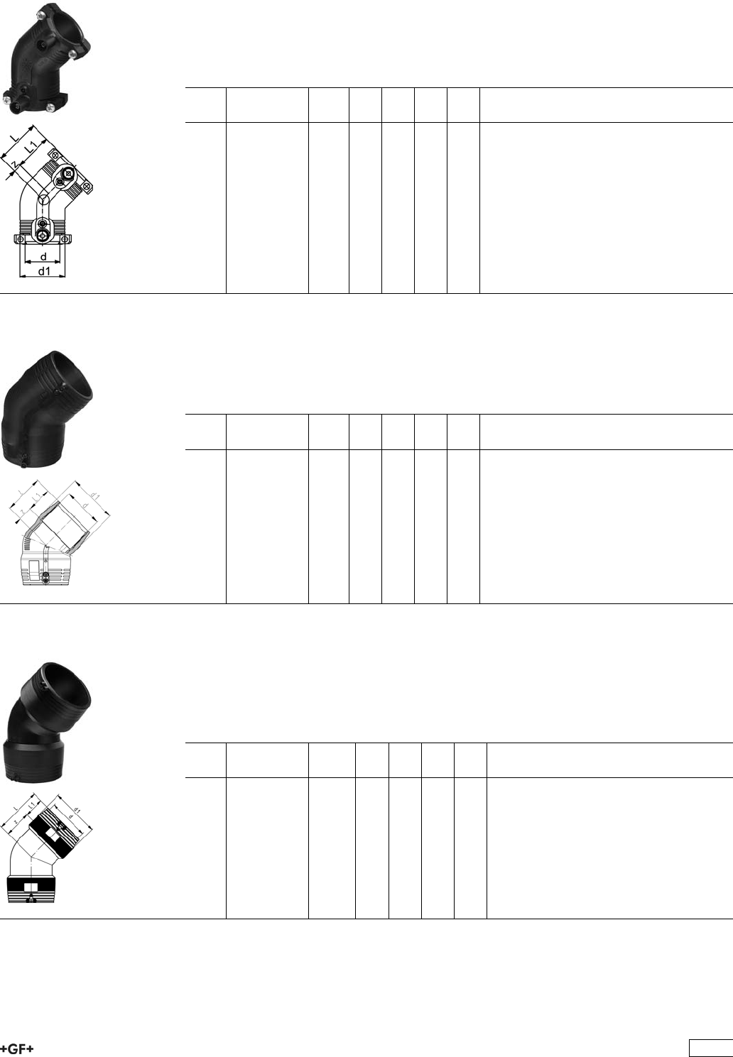
53 15 16 Elbow 45°
with integral pipe fixation
ÏPE 100 SDR 11 (ISO S5)
Ï10 bar Gas / 16 bar Water
Ï4 mm pin connectors
ÏLimited path fusion indicators
d
[mm]
Code kg d1
[mm]
L
[mm]
L1
[mm]
z
[mm]
32 753 151 608 0.087 44 44 36 8
40 753 151 609 0.121 54 50 39 11
50 753 151 610 0.140 66 56 43 13
63 753 151 611 0.274 81 63 48 15
53 15 18 Elbow 45°
ÏPE 100 SDR 11 (ISO S5)
Ï10 bar Gas / 16 bar Water
Ï4 mm pin connectors
ÏLimited path fusion indicators
d
[mm]
Code kg d1
[mm]
L
[mm]
L1
[mm]
z
[mm]
75 753 151 812 0.437 97 79 62 17
90 753 151 813 0.537 115 91 62 29
110 753 151 814 0.974 140 112 72 40
125 753 151 815 1.420 160 127 78 49
160 753 151 817 1.800 196 134 92 42
180 753 151 818 3.200 217 142 95 47
53 15 18 Elbow 45°
ÏPE 100 SDR 11 (ISO S5)
Ï10 bar Gas / 16 bar Water
Ï4 mm pin connectors
ÏLimited path fusion indicators
ÏTwo separate fusion zones
d
[mm]
Code kg d1
[mm]
L
[mm]
L1
[mm]
z
[mm]
200 753 151 819 6.810 245 215 104 111
225 753 151 820 10.590 274 235 112 123
250 753 151 821 12.740 305 263 123 140
429
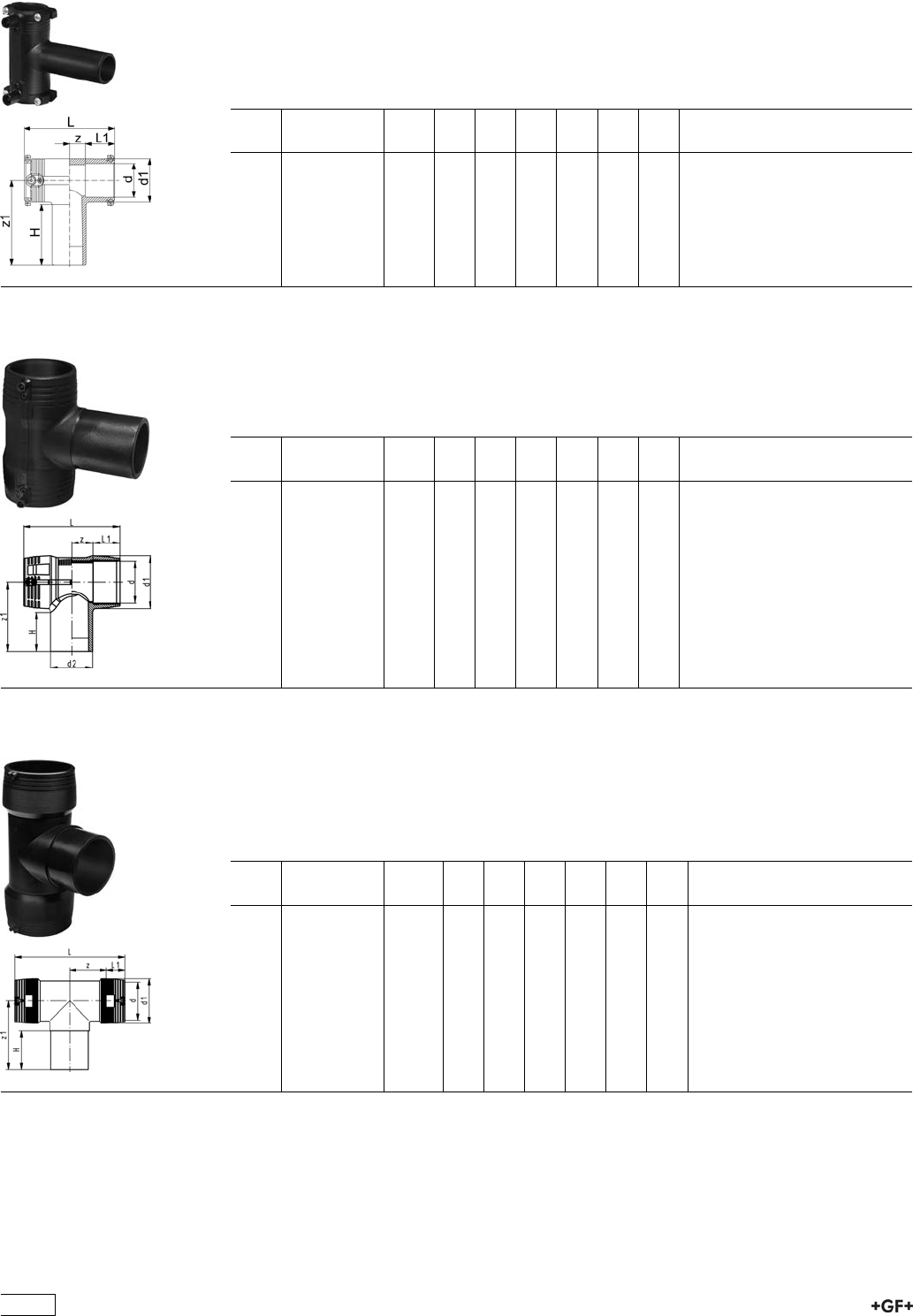
53 21 16 Tee 90°, equal
with Integral Clamp
ÏPE 100 SDR 11 (ISO S5)
Ï10 bar Gas / 16 bar Water
Ï4 mm pin connectors
ÏLimited path fusion indicators
d
[mm]
Code kg d1
[mm]
L
[mm]
L1
[mm]
z
[mm]
z1
[mm]
H
[mm]
20 753 211 606 0.100 35 90 34 11 92 67
25 753 211 607 0.088 35 90 34 11 92 70
32 753 211 608 0.115 44 102 36 15 100 74
40 753 211 609 0.176 54 120 39 21 114 82
50 753 211 610 0.268 66 135 43 24 126 90
63 753 211 611 0.429 81 152 48 28 150 102
53 20 18 Tee 90° equal
ÏPE 100 SDR 11 (ISO S5)
Ï10 bar Gas / 16 bar Water
Ï4 mm pin connectors
ÏLimited path fusion indicators
d
[mm]
Code kg d1
[mm]
L
[mm]
L1
[mm]
z
[mm]
z1
[mm]
H
[mm]
75 753 201 812 0.597 97 187 61 33 126 78
90 753 201 813 0.910 115 205 62 41 161 94
110 753 201 814 1.420 140 255 72 56 184 104
125 753 201 815 1.980 151 256 75 53 174 92
160 753 201 817 4.893 196 325 92 71 206 103
180 753 201 818 6.770 225 344 90 82 250 110
53 20 18 Tee 90°, equal
ÏPE 100 SDR 11 (ISO S5)
Ï10 bar Gas / 16 bar Water
Ï4 mm pin connectors
ÏLimited path fusion indicators
ÏTwo separate fusion zones
d
[mm]
Code kg d1
[mm]
L
[mm]
L1
[mm]
z
[mm]
z1
[mm]
H
[mm]
200 753 201 819 10.100 245 560 104 176 250 117
225 753 201 820 15.145 274 610 112 193 270 122
250 753 201 821 18.100 305 667 123 211 288 127
430

Tee 90°, reduced (Kit)
ÏPE 100 SDR 11 (ISO S5)
Ï10 bar Gas / 16 bar Water
ÏIntegral pipe fixation (up to d63)
Ï4 mm pin connectors
ÏLimited path fusion indicators
ÏSupplied as kit including ELGEF®Plus Coupler and Spigot Reducer
d
[mm]
d2
[mm]
Code kg d1
[mm]
L
[mm]
L1
[mm]
z
[mm]
z1
[mm]
H
[mm]
40 20 193 281 004 0.314 54 120 39 21 244 212
40 25 193 281 005 0.319 54 120 39 21 244 212
75 40 193 280 998 1.060 97 187 61 33 296 248
90 50 193 280 999 1.620 112 202 61 41 336 274
110 63 193 280 961 2.670 136 242 65 56 366 293
125 63 193 280 963 3.690 151 256 75 53 361 279
125 110 193 280 965 3.920 151 256 75 53 389 307
160 125 193 280 969 8.250 196 325 92 71 451 348
180 90 193 281 032 10.056 225 344 90 82 487 347
180 110 193 281 033 10.246 225 344 90 82 495 355
53 21 10 Tee 90°, reduced
ÏPE 100 SDR 11 (ISO S5)
Ï10 bar Gas / 16 bar Water
Ï4 mm pin connectors
ÏLimited path fusion indicators
ÏTwo separate fusion zones
Ï*Two connected fusion zones
d
[mm]
d2
[mm]
Code kg d1
[mm]
L
[mm]
L1
[mm]
z
[mm]
z1
[mm]
H
[mm]
160 63 753 211 037 4.940 196 405 90 113 176 65
160 90 753 211 039 5.040 196 405 90 113 188 79
160 110 753 211 040 5.160 196 405 90 113 195 85
200 90 753 211 059 11.260 245 557 104 175 215 81
200 110 753 211 060 11.260 245 557 104 175 218 84
200 160 753 211 063 11.260 245 557 104 175 236 101
225 90 753 211 069 12.700 274 615 112 196 226 80
225 110 753 211 070 12.750 274 615 112 196 235 85
225 160 753 211 073 13.200 274 615 112 196 255 105
250 110 753 211 080 11.260 305 668 123 211 245 85
250 160 753 211 083 11.260 305 668 123 211 264 101
431
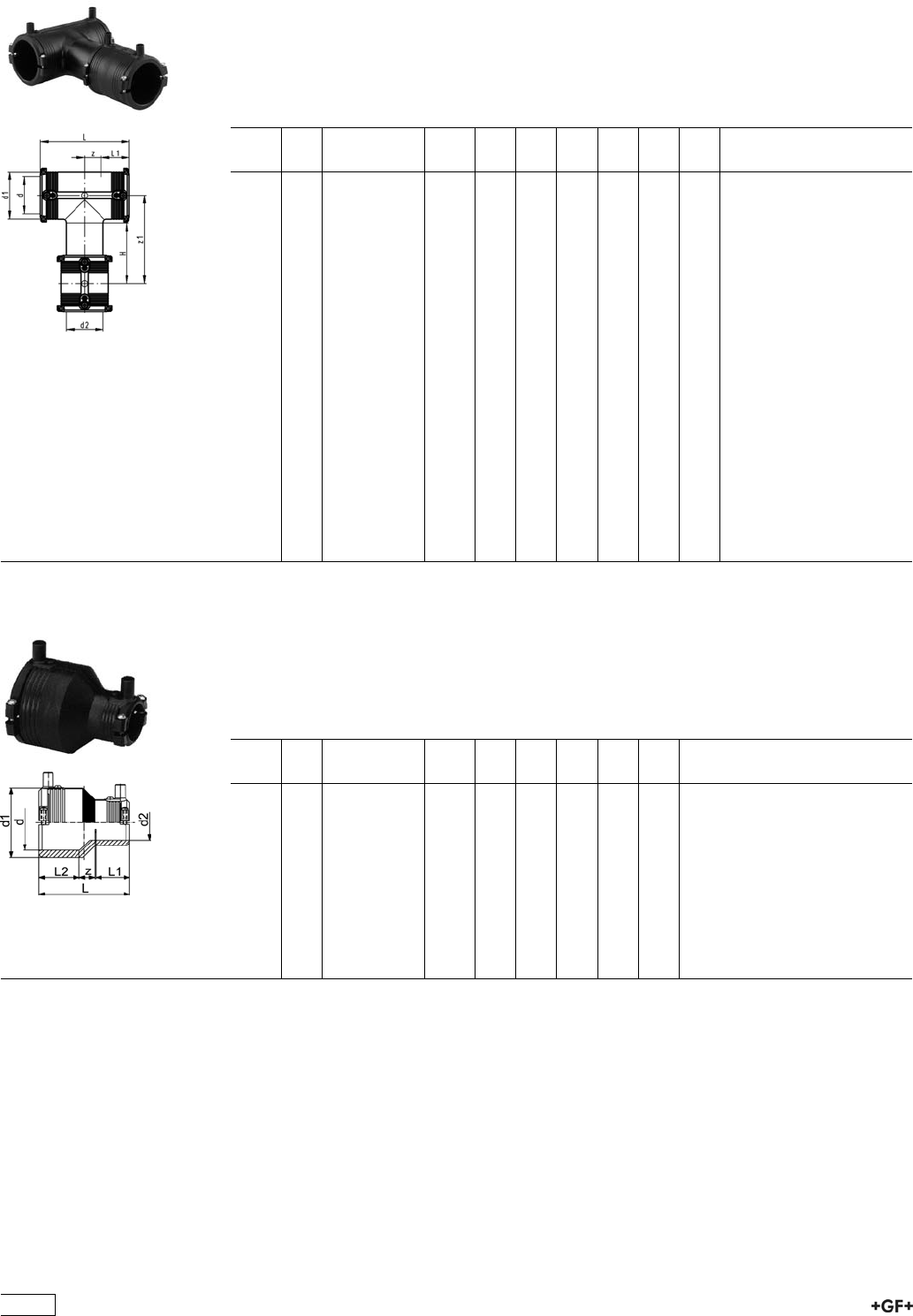
53 20 16 Tee 90° with weldable outlet (Kit)
ÏPE 100 SDR 11 (ISO S5)
Ï10 bar Gas / 16 bar Water
ÏIntegral pipe fixation (up to d63)
Ï4 mm pin connectors
ÏLimited path fusion indicators
ÏSupplied as kit including ELGEF®Plus Coupler or ELGEF®Plus Reducer
d
[mm]
d2
[mm]
Code kg d1
[mm]
L
[mm]
L1
[mm]
z
[mm]
z1
[mm]
H
[mm]
20 20 753 201 606 0.170 35 90 34 11 92 67
25 25 753 201 607 0.170 35 90 34 11 92 70
32 32 753 201 608 0.213 44 102 36 15 100 74
40 32 193 281 006 0.248 54 120 39 21 127 95
40 40 753 201 609 0.295 54 120 39 21 114 82
50 32 193 281 007 0.364 66 135 43 24 144 108
50 40 193 281 008 0.404 66 135 43 24 140 104
50 50 753 201 610 0.419 66 135 43 24 126 90
63 32 193 280 997 0.550 81 152 48 28 173 125
63 40 193 281 009 0.605 81 152 48 28 169 121
63 50 193 281 010 0.618 81 152 48 28 165 117
63 63 753 201 611 0.641 81 152 48 28 150 102
90 63 193 281 011 1.300 112 202 61 41 182 120
90 90 753 201 613 1.450 112 202 61 41 146 84
110 90 193 281 012 2.294 136 242 65 56 200 127
110 110 753 201 614 2.400 136 242 65 56 161 88
125 90 193 281 013 2.850 151 256 75 53 214 132
125 125 753 201 615 2.930 151 256 75 53 174 92
160 110 193 281 030 6.093 196 325 92 71 271 168
160 160 753 201 617 6.664 196 325 92 71 206 103
180 125 193 281 031 8.770 225 344 90 82 330 190
180 180 753 201 618 9.600 225 344 90 82 250 110
53 90 16 Reducer
with Integral Clamp
ÏPE 100 SDR 11 (ISO S5)
Ï10 bar Gas / 16 bar Water
Ï4 mm pin connectors
ÏLimited path fusion indicators
d
[mm]
d2
[mm]
Code kg d1
[mm]
L
[mm]
L1
[mm]
L2
[mm]
z
[mm]
25 20 753 901 639 0.059 35 74 34 34 6
32 20 753 901 640 0.071 44 79 33 36 10
32 25 753 901 641 0.060 44 79 33 36 10
40 20 753 901 644 0.069 54 88 33 39 15
40 25 753 901 645 0.071 54 88 33 39 15
40 32 753 901 646 0.072 54 88 33 39 13
50 32 753 901 651 0.096 66 96 35 43 18
50 40 753 901 652 0.136 66 96 39 43 14
63 32 753 901 656 0.171 81 106 35 48 23
63 40 753 901 657 0.176 81 106 39 48 19
63 50 753 901 658 0.189 81 106 43 48 15
432
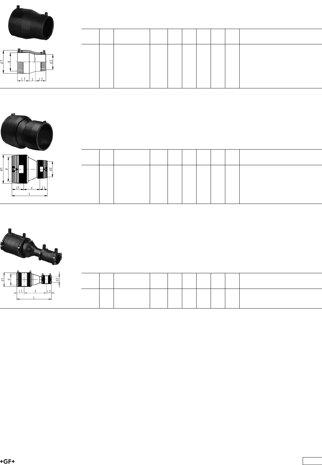
53 90 18 Reducer
ÏPE 100 SDR 11 (ISO S5)
Ï10 bar Gas / 16 bar Water
Ï4 mm pin connectors
ÏLimited path fusion indicators
d
[mm]
d2
[mm]
Code kg d1
[mm]
L
[mm]
L1
[mm]
L2
[mm]
z
[mm]
90 63 753 901 831 0.360 113 146 63 47 36
110 90 753 901 833 0.657 138 173 73 63 38
125 90 753 901 836 0.870 152 180 79 61 40
160 110 753 901 834 1.200 196 226 91 70 65
180 125 753 901 835 2.000 220 247 97 70 80
53 90 18 Reducer
ÏPE 100 SDR 11 (ISO S5)
Ï10 bar Gas / 16 bar Water
Ï4 mm pin connectors
ÏLimited path fusion indicators
ÏTwo separate fusion zones
d
[mm]
d2
[mm]
Code kg d1
[mm]
L
[mm]
L1
[mm]
L2
[mm]
z
[mm]
200 160 753 901 837 4.150 245 311 104 90 117
225 160 753 901 838 5.240 274 331 112 90 129
250 160 753 901 840 7.100 305 362 123 90 149
250 200 753 901 841 7.680 305 380 123 104 153
93 28 09 Reducer (Kit)
ÏPE 100 SDR 11 (ISO S5)
Ï10 bar Gas / 16 bar Water
ÏIntegral pipe fixation (up to d63)
Ï4 mm pin connectors
ÏLimited path fusion indicators
ÏSupplied as kit including ELGEF®Plus Coupler and Spigot Reducer
d
[mm]
d2
[mm]
Code kg d1
[mm]
L
[mm]
L1
[mm]
L2
[mm]
z
[mm]
75 40 193 280 992 0.567 96 265 55 40 170
433
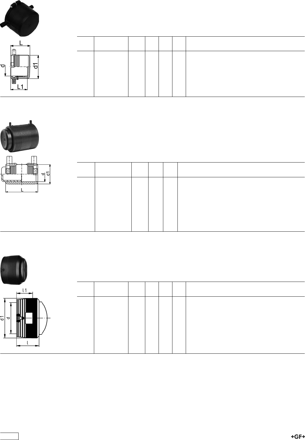
53 96 16 End Cap
with integral pipe fixation
ÏPE 100 SDR 11 (ISO S5)
Ï10 bar Gas / 16 bar Water
Ï4 mm pin connectors
ÏLimited path fusion indicators
d
[mm]
Code kg d1
[mm]
L
[mm]
L1
[mm]
20 753 961 606 0.038 35 52 44
25 753 961 607 0.030 35 52 44
32 753 961 608 0.080 44 52 44
40 753 961 609 0.074 54 56 47
50 753 961 610 0.086 66 60 49
63 753 961 611 0.154 81 66 54
53 96 17 End cap (Kit)
ÏPE 100 SDR 11 (ISO S5)
Ï10 bar Gas / 16 bar Water
Ï4 mm pin connectors
ÏLimited path fusion indicators
ÏSupplied as kit including ELGEF®Plus Coupler
Ï* Article to be discontinued, replaced by 53 96 16
d
[mm]
Code kg d1
[mm]
L
[mm]
75 753 961 712 0.446 96 110
90 753 961 713 0.680 113 125
110 753 961 714 1.126 133 145
125 753 961 715 1.594 155 158
140 753 961 716 2.250 175 170
*160 753 961 717 2.712 197 180
180 753 961 718 4.136 220 194
*200 753 961 719 4.906 245 208
*225 753 961 720 6.500 296 224
53 96 16 End Cap
ÏPE 100 SDR 11 (ISO S5)
Ï10 bar Gas / 16 bar Water
Ï4 mm pin connectors
ÏLimited path fusion indicators
d
[mm]
Code kg d1
[mm]
L
[mm]
L1
[mm]
160 753 961 617 1.840 196 129 90
200 753 961 619 3.040 245 147 104
225 753 961 620 4.140 274 157 112
250 753 961 621 5.860 305 173 123
434
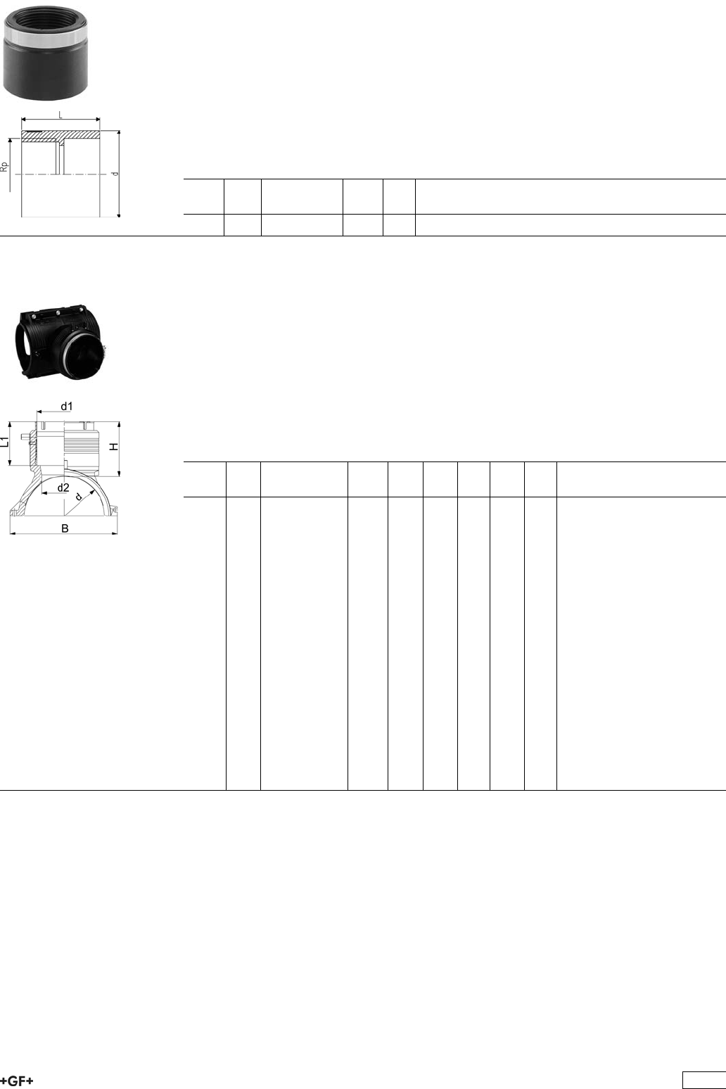
PE Adaptor
Female thread
ÏPE 80 SDR 11 (ISO S5)
Ï5 bar Gas / 12,5 bar Water
ÏConnection to plastic or metal
ÏReinforcing ring stainless (A2)
ÏFor ELGEF®Plus Branch Saddle (53 131 000) d 63 - 400 mm, pipe SDR 11, d 75 -
400 mm, pipe SDR 17
ÏParallel female thread
d
[mm]
Rp
[inch]
Code kg L
[mm]
63 1 1
/2173 281 925 0.096 54
51 336 001 Branch Fitting
ÏPE 100 SDR 11 (ISO S5)
Ï10 bar Gas / 16 bar Water
ÏBranch Fitting complete, incl. lower part and 3 screws
ÏAdditional fixing with snatch hinge
ÏElectrofusion outlet with integrated pipe fixation
ÏProtected wire without medium contact
Ï4 mm pin connectors
ÏLimited path fusion indicators
Ï* Delivered without lower part. Pipe fixation with multiple use assembly tool no. 193
281 027
d
[mm]
d1
[mm]
Code kg H
[mm]
L
[mm]
L1
[mm]
B
[mm]
d2
[mm]
110 90 193 135 009 1.074 101 220 82 164 65
110 110 193 135 010 1.152 107 220 88 164 65
125 90 193 135 019 1.134 101 220 82 179 65
125 110 193 135 020 1.258 107 220 88 179 65
*140 90 193 135 029 1.134 101 220 81 195 65
*140 110 193 135 030 1.258 107 220 87 195 65
160 90 193 135 039 1.444 102 240 82 215 65
160 110 193 135 040 1.523 108 240 88 215 86
160 125 193 135 041 1.738 129 240 99 215 86
180 90 193 135 049 1.714 102 260 82 237 65
180 110 193 135 050 1.782 108 260 88 237 86
180 125 193 135 051 1.972 129 260 99 237 86
200 90 193 135 059 1.811 102 260 82 253 65
200 110 193 135 060 1.879 108 260 88 253 86
200 125 193 135 061 2.069 129 260 99 253 86
225 90 193 135 069 1.959 102 260 82 287 65
225 110 193 135 070 2.027 108 260 88 287 86
225 125 193 135 071 2.217 129 260 99 287 86
250 90 193 135 079 2.116 102 260 82 312 65
250 110 193 135 080 2.184 108 260 88 312 86
250 125 193 135 081 2.374 129 260 99 312 86
435
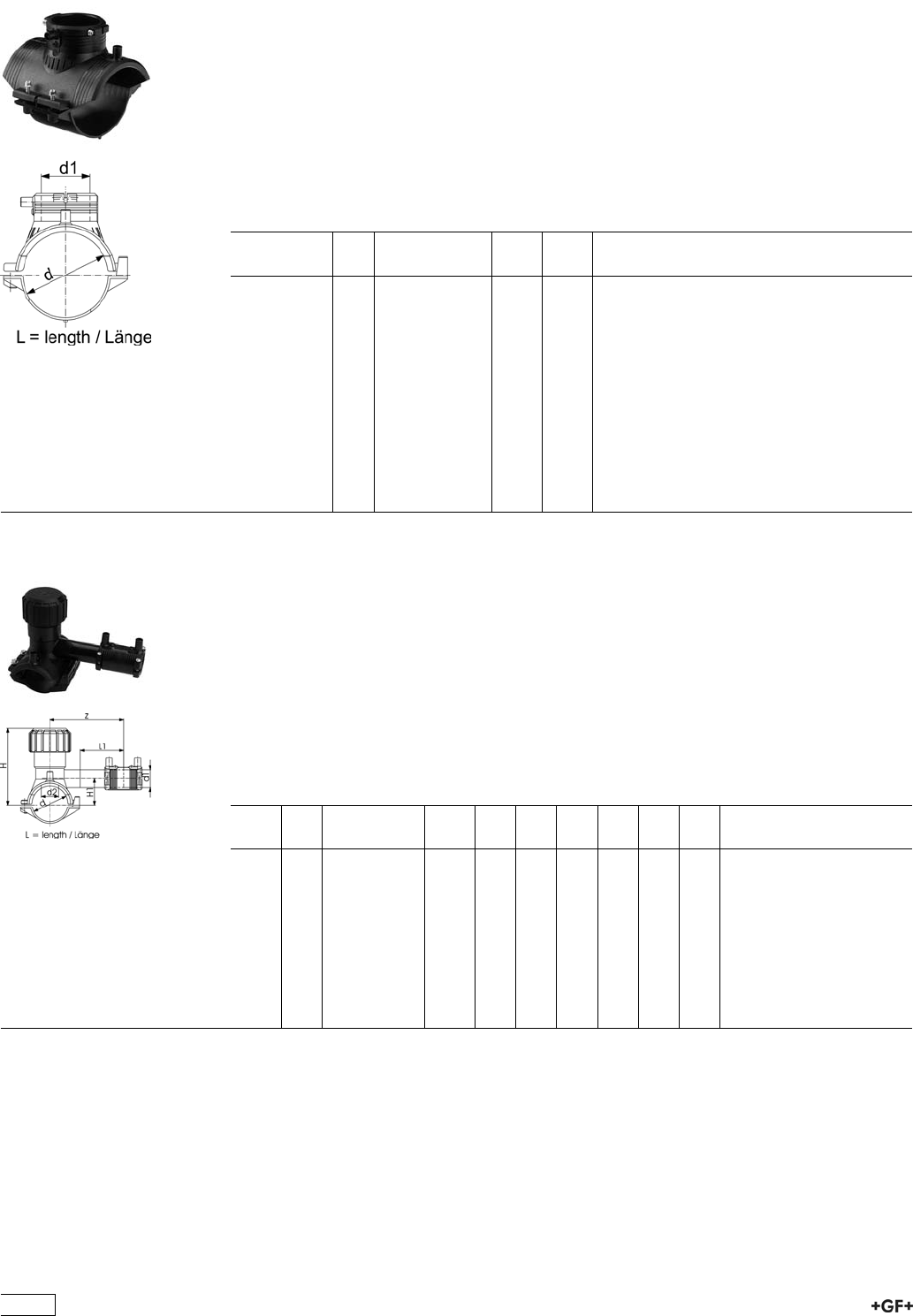
53 131 000 Electrofusion Saddle
ÏPE 100 SDR 11 (ISO S5)
Ï10 bar Gas / 16 bar Water
ÏComplete with lower part
Ï4 mm pin connectors
ÏLimited path fusion indicators
* = not suitable for all tapping-tee, tapping-valve and spigot with cutter of the modular
systems
** = not suitable for all tapping-tee, tapping-valve and spigot with cutter of the modular
systems / delivery without lower part for assembling as Top load with tool 799.350.475
d
[mm]
d1
[mm]
Code kg L
[mm]
63 63 193 131 037 0.335 165
75 63 193 131 047 0.465 165
90 63 193 131 057 0.425 165
110 63 193 131 067 0.493 165
125 63 193 131 077 0.523 165
140 63 193 131 087 0.523 165
160 63 193 131 097 0.526 165
180 63 193 131 107 0.632 165
200 63 193 131 117 0.651 165
225 63 193 131 127 0.653 165
*250 63 193 131 137 0.665 165
**280 63 193 131 147 0.370 165
**315 - 400 63 193 131 157 0.370 165
53 132 400 Tapping Saddle (Kit)
Monobloc version
ÏPE 100 SDR 11 (ISO S5)
Ï10 bar Gas / 16 bar Water
ÏWith integrated cutter to tap live mains under pressure
ÏComplete with lower part
Ï4 mm pin connectors
ÏLimited path fusion indicators
ÏLong fusion outlet
ÏO-ring sealed screw-cap
ÏSupplied as Kit with enclosed service line fitting (ELGEF®Plus Coupler or Reducer)
d
[mm]
d1
[mm]
Code kg d2
[mm]
H
[mm]
H1
[mm]
L
[mm]
L1
[mm]
z
[mm]
40 20 193 132 412 0.324 16 99 33 103 70 102
40 25 193 132 413 0.331 16 99 33 103 70 102
40 32 193 132 414 0.353 16 99 33 103 70 120
50 20 193 132 422 0.325 16 105 38 103 70 102
50 25 193 132 423 0.323 16 105 38 103 70 102
50 32 193 132 424 0.342 16 105 38 103 70 120
63 20 193 132 432 0.486 25 134 44 126 70 115
63 25 193 132 433 0.492 25 134 44 126 70 115
63 32 193 132 434 0.507 25 134 44 126 70 130
63 40 193 132 435 0.534 25 134 44 126 70 130
436
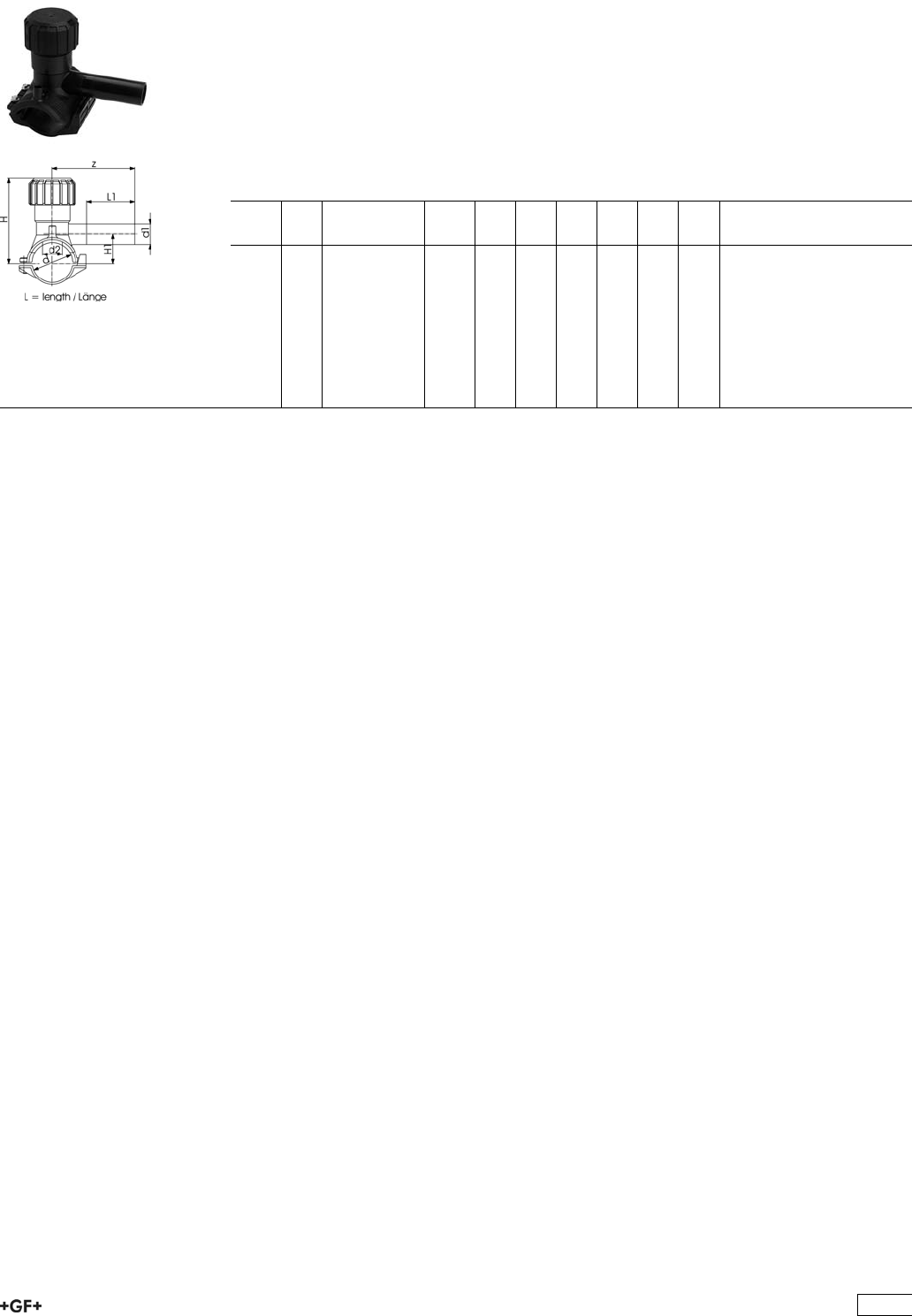
53 131 400 Tapping Saddle
Monobloc version
ÏPE 100 SDR 11 (ISO S5)
Ï10 bar Gas / 16 bar Water
ÏWith integrated cutter to tap live mains under pressure
ÏComplete with lower part
Ï4 mm pin connectors
ÏLimited path fusion indicators
ÏLong fusion outlet
ÏO-ring sealed screw-cap
d
[mm]
d1
[mm]
Code kg d2
[mm]
H
[mm]
H1
[mm]
L
[mm]
L1
[mm]
z
[mm]
40 20 193 131 412 0.270 16 99 33 103 70 102
40 25 193 131 413 0.272 16 99 33 103 70 102
40 32 193 131 414 0.277 16 99 33 103 70 120
50 20 193 131 422 0.260 16 104 38 103 70 102
50 25 193 131 423 0.262 16 104 38 103 70 102
50 32 193 131 424 0.270 16 104 38 103 70 120
63 20 193 131 432 0.428 25 134 44 126 70 115
63 25 193 131 433 0.431 25 134 44 126 70 115
63 32 193 131 434 0.433 25 134 44 126 70 130
437
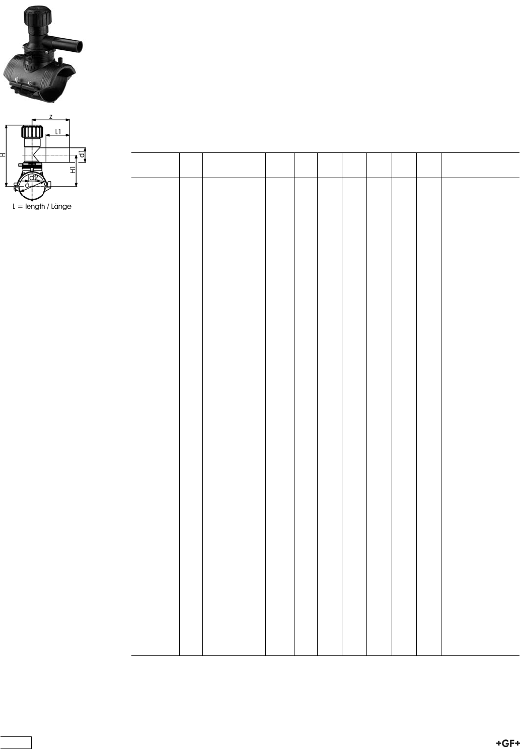
53 131 400 Tapping Saddle
with 360° rotatable outlet
ÏPE 100 SDR 11 (ISO S5)
Ï10 bar Gas / 16 bar Water
ÏWith integrated cutter to tap live mains under pressure
ÏComplete with lower part
Ï4 mm pin connectors
ÏLimited path fusion indicators
ÏLong fusion outlet
ÏO-ring sealed screw-cap
ÏD 315 - 400 mm: application is limited on pipes d 355 and d 400 mm. Not suitable for
pipes with an SDR value higher than 17.
Ï*Delivery without lower part for assembling as Top Load with tool no. 799.350.475
d
[mm]
d1
[mm]
Code kg d2
[mm]
H
[mm]
H1
[mm]
L
[mm]
L1
[mm]
z
[mm]
63 20 193 131 402 0.695 32 186 108 165 71 130
63 25 193 131 403 0.713 32 186 108 165 71 130
63 32 193 131 404 0.715 32 186 108 165 76 130
63 40 193 131 405 0.731 32 186 108 165 81 137
63 63 193 131 437 1.455 32 134 112 165 100 160
75 20 193 131 442 0.825 32 191 113 165 71 130
75 25 193 131 443 0.839 32 191 113 165 71 130
75 32 193 131 444 0.841 32 191 113 165 76 130
75 40 193 131 445 0.858 32 191 113 165 81 137
75 63 193 131 447 1.579 32 240 118 165 100 160
90 20 193 131 452 0.791 32 199 121 165 71 130
90 25 193 131 453 0.802 32 199 121 165 71 130
90 32 193 131 454 0.801 32 199 121 165 76 130
90 40 193 131 455 0.819 32 199 121 165 81 137
90 63 193 131 457 1.541 32 248 126 165 100 160
110 20 193 131 462 0.853 32 209 131 165 71 130
110 25 193 131 463 0.860 32 209 131 165 71 130
110 32 193 131 464 0.860 32 209 131 165 76 130
110 40 193 131 465 0.877 32 209 131 165 81 137
110 63 193 131 467 1.590 35 258 136 165 100 160
125 20 193 131 472 0.879 32 216 138 165 71 130
125 25 193 131 473 0.883 32 216 138 165 71 130
125 32 193 131 474 0.889 32 216 138 165 76 130
125 40 193 131 475 0.906 32 216 138 165 81 137
125 63 193 131 477 1.623 35 265 143 165 100 160
140 20 193 131 482 0.887 32 233 146 165 71 130
140 25 193 131 483 0.884 32 233 146 165 71 130
140 32 193 131 484 0.900 32 233 146 165 76 130
140 40 193 131 485 0.920 32 233 146 165 81 137
140 63 193 131 487 1.639 35 273 151 165 100 160
160 20 193 131 492 0.886 32 243 156 165 71 130
160 25 193 131 493 0.896 32 243 156 165 71 130
160 32 193 131 494 0.896 32 243 156 165 76 130
160 40 193 131 495 0.920 32 243 156 165 81 137
160 63 193 131 497 1.636 35 283 161 165 100 160
180 20 193 131 502 1.002 32 244 166 165 71 130
180 25 193 131 503 1.002 32 244 166 165 71 130
180 32 193 131 504 1.002 32 244 166 165 76 130
180 40 193 131 505 1.022 32 244 166 165 81 137
180 63 193 131 507 1.742 35 293 171 165 100 160
200 20 193 131 512 1.011 32 254 176 165 71 137
200 25 193 131 513 1.011 32 254 176 165 71 130
200 32 193 131 514 1.021 32 254 176 165 76 130
200 40 193 131 515 1.041 32 254 176 165 81 137
200 63 193 131 517 1.761 35 303 181 165 100 160
225 20 193 131 522 1.014 32 266 188 165 71 130
225 25 193 131 523 1.014 32 266 188 165 71 130
225 32 193 131 524 1.014 32 266 188 165 76 130
438
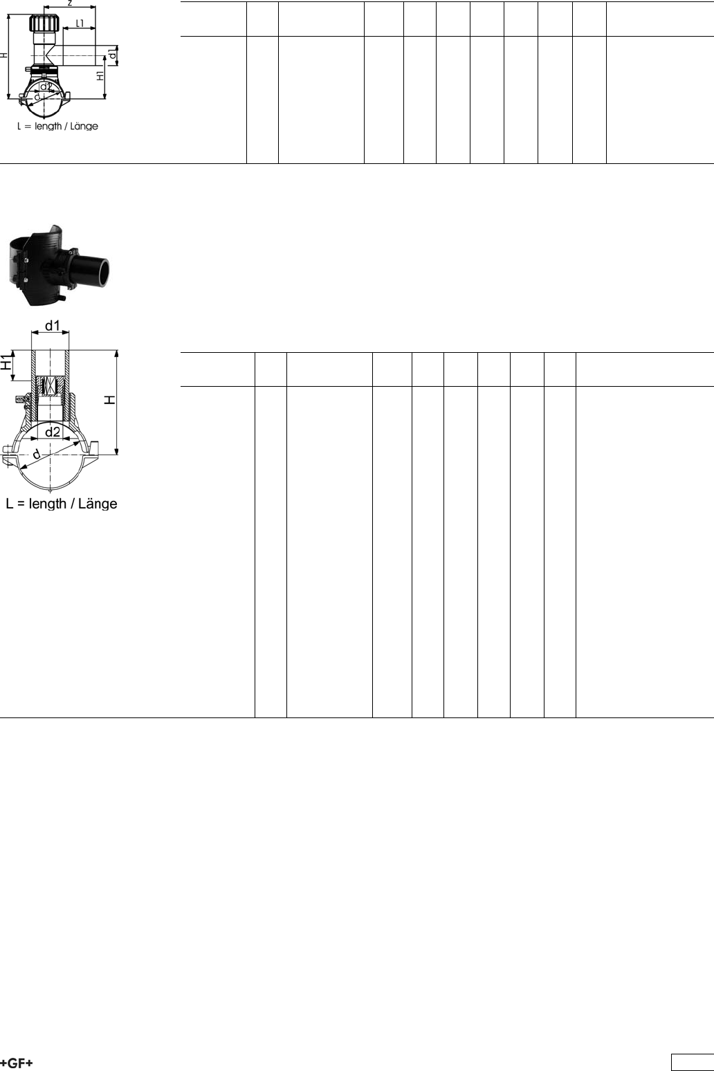
d
[mm]
d1
[mm]
Code kg d2
[mm]
H
[mm]
H1
[mm]
L
[mm]
L1
[mm]
z
[mm]
225 40 193 131 525 1.043 32 266 188 165 81 137
225 63 193 131 527 1.763 35 315 193 165 100 160
250 20 193 131 532 1.025 32 279 201 165 76 130
250 25 193 131 533 1.035 32 279 201 165 76 130
250 32 193 131 534 1.035 32 279 201 165 76 130
250 40 193 131 535 1.055 32 279 201 165 81 137
250 63 193 131 537 1.775 35 328 206 165 100 160
*280 63 193 131 547 1.240 35 328 206 165 100 160
*315-400 63 193 131 557 1.513 35 328 206 165 100 160
53 131 200 Spigot Saddle with Cutter
ÏPE 100 SDR 11 (ISO S5)
Ï10 bar Gas / 16 bar Water
ÏComplete with lower part
Ï4 mm pin connectors
ÏLimited path fusion indicators
ÏD 315 - 400 mm: application is limited on pipes d 355 and d 400 mm. Not suitable for
pipes with an SDR value higher than 17.
Ï*Delivery without lower part for assembling as Top Load with tool no. 799.350.475
d
[mm]
d1
[mm]
Code kg d2
[mm]
H
[mm]
H1
[mm]
L
[mm]
SW
[mm]
63 32 193 131 234 0.538 19 145 50 165 13
63 63 193 131 237 1.036 32 152 50 165 17
75 32 193 131 244 0.668 19 151 50 165 13
75 63 193 131 247 1.166 32 158 50 165 17
90 32 193 131 254 0.628 19 158 50 165 13
90 63 193 131 257 1.126 32 165 50 165 17
110 32 193 131 264 0.696 19 168 50 165 13
110 63 193 131 267 1.194 32 175 50 165 17
125 32 193 131 274 0.726 19 176 50 165 13
125 63 193 131 277 1.224 32 183 50 165 17
140 32 193 131 284 0.726 19 183 50 165 13
140 63 193 131 287 1.224 32 190 50 165 17
160 32 193 131 294 0.729 19 193 50 165 13
160 63 193 131 297 1.227 32 200 50 165 17
180 32 193 131 304 0.835 19 203 50 165 13
180 63 193 131 307 1.333 32 210 50 165 17
200 32 193 131 314 0.854 19 213 50 165 13
200 63 193 131 317 1.352 32 220 50 165 17
225 32 193 131 324 0.856 19 226 50 165 13
225 63 193 131 327 1.354 32 233 50 165 17
250 32 193 131 334 0.868 19 238 50 165 13
250 63 193 131 337 1.366 32 245 50 165 17
*280 63 193 131 347 0.830 35 245 50 165 17
*315 - 400 63 193 131 357 0.830 35 245 50 165 17
439
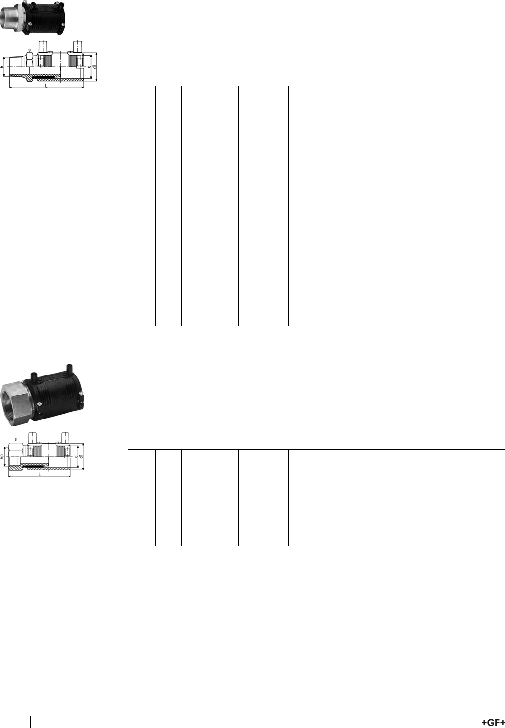
20 92 07 Transition Coupler PE/brass (Ms 58)
Male Thread
ÏPE 100 SDR 11 (ISO S5)
Ï10 bar Gas / 16 bar Water
ÏWith integral pipe fixation
Ï4 mm pin connectors
ÏLimited path fusion indicators
ÏSupplied as kit
d
[mm]
R
[inch]
Code kg d1
[mm]
L
[mm]
s
[mm]
20 1
/2720 920 756 0.217 31 110 30
20 1 720 920 754 0.344 44 124 40
25 3
/4720 920 757 0.280 36 111 35
25 1 720 920 763 0.364 44 124 40
32 1
/2720 920 764 0.235 44 121 30
32 3
/4720 920 765 0.287 44 122 35
32 1 720 920 758 0.355 44 117 40
32 1 1
/4720 920 766 0.543 54 135 50
32 1 1
/2720 920 767 0.685 60 143 60
32 2 720 920 768 1.000 81 157 70
40 1 720 920 771 0.387 54 133 40
40 1 1
/4720 920 759 0.541 54 127 50
40 1 1
/2720 920 772 0.694 66 143 60
40 2 720 920 773 0.992 81 157 70
50 1 720 920 776 0.416 66 141 40
50 1 1
/4720 920 777 0.578 66 143 50
50 1 1
/2720 920 760 0.670 66 135 60
50 2 720 920 778 0.994 81 157 70
63 1 720 920 781 0.460 81 151 40
63 1 1
/4720 920 782 0.626 81 153 40
63 1 1
/2720 920 783 0.741 81 153 60
63 2 720 920 761 1.005 81 147 70
20 92 02 Transition Coupler PE/brass (Ms 58)
Female Thread
ÏPE 100 SDR 11 (ISO S5)
Ï10 bar Gas / 16 bar Water
ÏWith integral pipe fixation
Ï4 mm pin connectors
ÏLimited path fusion indicators
ÏSupplied as kit
d
[mm]
Rp
[inch]
Code kg d1
[mm]
L
[mm]
s
[mm]
32 1 720 920 258 0.338 44 108 40
40 1 1
/4720 920 259 0.511 54 118 50
50 1 1
/2720 920 260 0.744 66 126 60
63 1 720 920 281 1.280 81 138 70
63 1 1
/4720 920 282 1.230 81 138 70
63 1 1
/2720 920 283 1.115 81 138 70
63 2 720 920 261 1.016 81 138 70
440
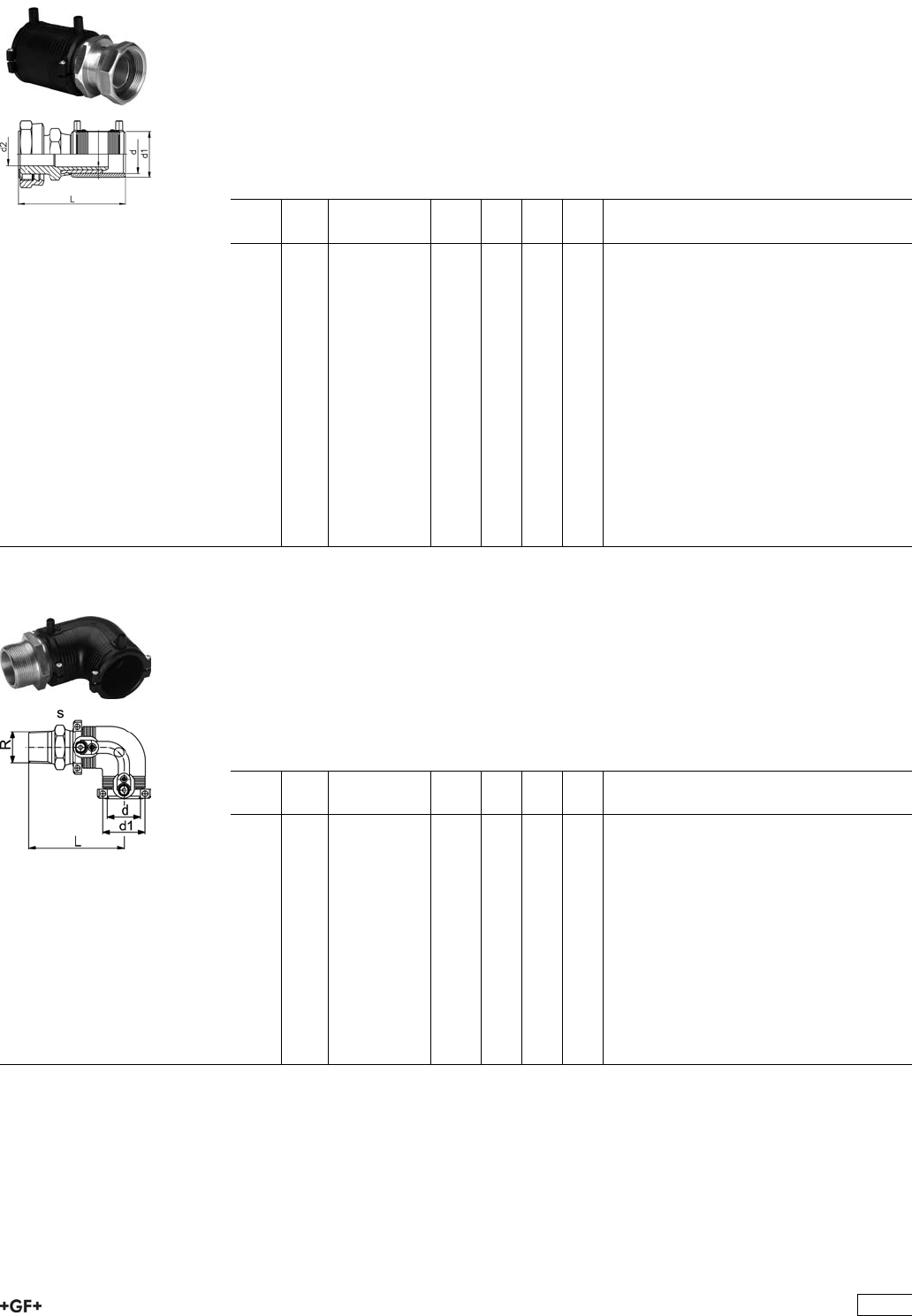
20 91 00 Transition Coupler PE/brass (Ms 58)
with loose Nut
ÏPE 100 SDR 11 (ISO S5)
ÏGas on request / 16 bar Water
ÏWith integral pipe fixation
Ï4 mm pin connectors
ÏLimited path fusion indicators
ÏDelivered as a kit. Further combinations modular system with threaded adapter and
reductions
ÏIncl. flat gasket for water applications (KTW / WRC approved)
d
[mm]
Rp
[inch]
Code kg d1
[mm]
d2
[mm]
L
[mm]
25 3
/4720 910 007 0.240 36 15 104
25 1 720 910 017 0.315 36 16 106
32 1 720 910 008 0.342 44 20 110
32 1 1
/4720 910 018 0.460 44 22 114
32 1 1
/2720 910 028 0.480 44 22 114
40 1 720 910 009 0.465 54 21 119
40 1 1
/4720 910 019 0.520 54 25 123
40 1 1
/2720 910 029 0.595 54 28 123
50 1 720 910 020 0.685 66 20 128
50 1 1
/4720 910 030 0.730 66 25 133
50 1 1
/2720 910 010 0.774 66 29 133
50 2 720 910 040 0.980 66 36 137
63 1 720 910 021 1.025 81 20 137
63 1 1
/4720 910 031 1.060 81 25 141
63 1 1
/2720 910 041 1.070 81 29 141
63 2 720 910 011 1.235 81 36 145
63 2 1
/2720 910 051 1.495 81 46 148
20 10 07 Transition Elbow 90° PE/brass (Ms 58)
Male Thread
ÏPE 100 SDR 11 (ISO S5)
Ï10 bar Gas / 16 bar Water
ÏWith integral pipe fixation
Ï4 mm pin connectors
ÏLimited path fusion indicators
ÏSupplied as kit
d
[mm]
R
[inch]
Code kg d1
[mm]
L
[mm]
s
[mm]
20 1
/2720 100 756 0.240 31 96 30
25 3
/4720 100 757 0.260 36 97 35
32 1 720 100 758 0.383 44 98 40
32 1 1
/4720 100 766 0.500 44 100 50
32 1 1
/2720 100 767 0.562 44 100 60
40 1 720 100 771 0.528 54 107 50
40 1 1
/4720 100 759 0.584 54 109 50
40 1 1
/2720 100 772 0.642 54 109 60
50 1 720 100 776 0.710 66 116 60
50 1 1
/4720 100 777 0.771 66 118 60
50 1 1
/2720 100 760 0.757 66 118 60
63 1 1
/4720 100 782 1.040 81 128 70
63 1 1
/2720 100 783 1.045 81 128 70
63 2 720 100 761 1.115 81 132 70
441
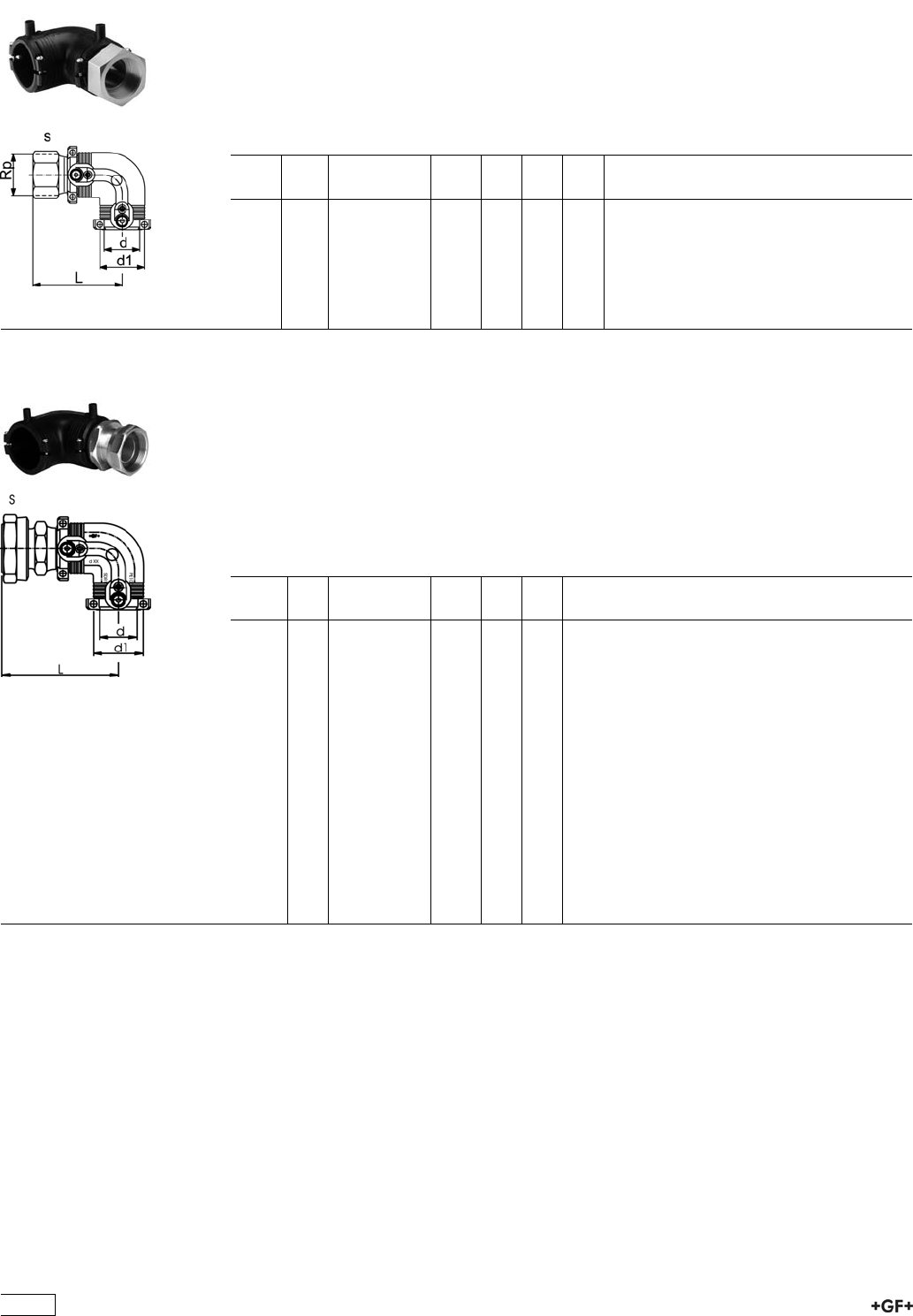
20 10 02 Transition Elbow 90° PE/brass (Ms 58)
Female Thread
ÏPE 100 SDR 11 (ISO S5)
Ï10 bar Gas / 16 bar Water
ÏWith integral pipe fixation
Ï4 mm pin connectors
ÏLimited path fusion indicators
ÏSupplied as kit
d
[mm]
Rp
[inch]
Code kg d1
[mm]
L
[mm]
s
[mm]
32 1 720 100 258 0.365 44 89 40
40 1 1
/4720 100 259 0.556 54 100 50
50 1 1
/2720 100 260 0.819 66 109 60
63 1 720 100 281 1.420 81 123 70
63 1 1
/4720 100 282 1.380 81 123 70
63 1 1
/2720 100 283 1.305 81 123 70
63 2 720 100 261 1.165 81 123 70
20 10 00 Transition Elbow 90° PE/brass (Ms 58)
with loose Nut
ÏPE 100 SDR 11 (ISO S5)
ÏGas on request / 16 bar Water
ÏWith integral pipe fixation
Ï4 mm pin connectors
ÏLimited path fusion indicators
ÏSupplied as kit
ÏIncl. flat gasket for water applications (KTW / WRC approved)
Rp
[inch]
d
[mm]
Code kg d1
[mm]
L
[mm]
3
/425 720 100 007 0.260 36 90
1 25 720 100 017 0.335 36 92
1 32 720 100 008 0.370 44 91
11
/432 720 100 018 0.490 44 95
11
/232 720 100 028 0.505 44 95
1 40 720 100 009 0.505 54 101
11
/440 720 100 019 0.565 54 105
11
/240 720 100 029 0.635 54 105
1 50 720 100 020 0.760 66 111
11
/450 720 100 030 0.805 66 116
11
/250 720 100 010 0.850 66 116
2 50 720 100 040 1.060 66 120
1 63 720 100 021 1.171 81 121
11
/463 720 100 031 1.200 81 125
11
/263 720 100 041 1.210 81 125
2 63 720 100 011 1.375 81 129
21
/263 720 100 051 1.635 81 132
442
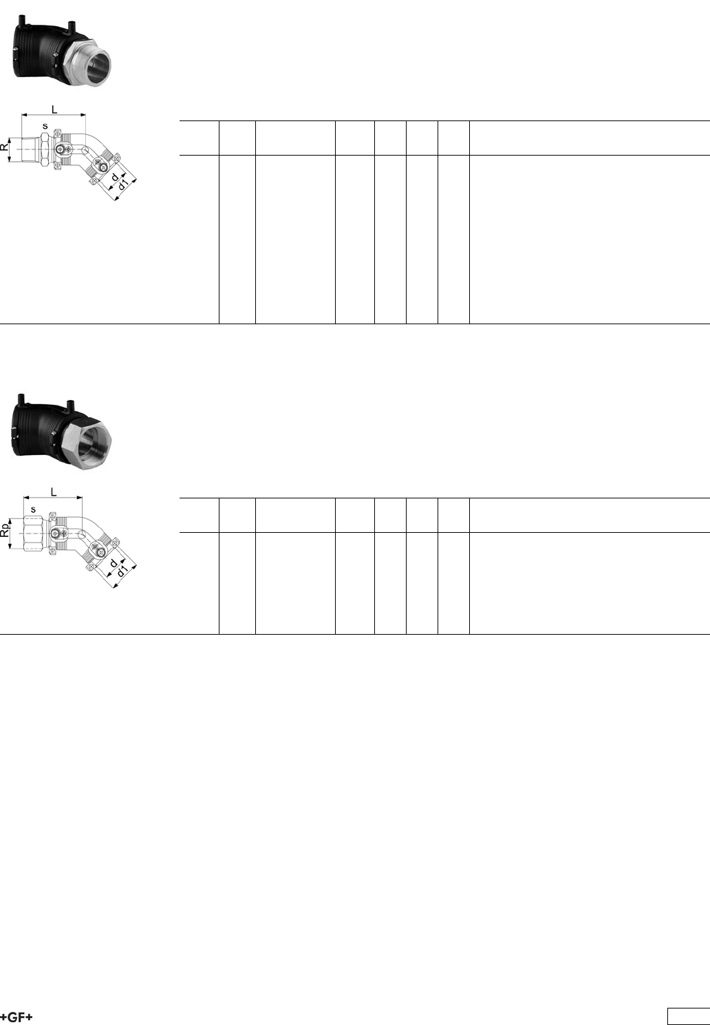
20 15 07 Transition Elbow 45° PE/brass (Ms 58)
Male Thread
ÏPE 100 SDR 11 (ISO S5)
Ï10 bar Gas / 16 bar Water
ÏWith integral pipe fixation
Ï4 mm pin connectors
ÏLimited path fusion indicators
ÏSupplied as kit
d
[mm]
R
[inch]
Code kg d1
[mm]
L
[mm]
s
[mm]
32 1 720 150 758 0.374 44 89 40
32 1 1
/4720 150 766 0.380 44 91 50
32 1 1
/2720 150 767 0.560 44 91 60
40 1 720 150 771 0.510 54 95 50
40 1 1
/4720 150 759 0.560 54 97 50
40 1 1
/2720 150 772 0.630 54 97 60
50 1 720 150 776 0.670 66 101 60
50 1 1
/4720 150 777 0.740 66 103 60
50 1 1
/2720 150 760 0.720 66 103 60
63 1 1
/4720 150 782 0.990 81 110 70
63 1 1
/2720 150 783 0.990 81 110 70
63 2 720 150 761 1.069 81 114 70
20 15 02 Transition Elbow 45° PE/brass (Ms 58)
Female Thread
ÏPE 100 SDR 11 (ISO S5)
Ï10 bar Gas / 16 bar Water
ÏWith integral pipe fixation
Ï4 mm pin connectors
ÏLimited path fusion indicators
ÏSupplied as kit
d
[mm]
Rp
[inch]
Code kg d1
[mm]
L
[mm]
s
[mm]
32 1 720 150 258 0.354 44 80 40
40 1 1
/4720 150 259 0.530 54 88 50
50 1 1
/2720 150 260 0.780 66 94 60
63 1 720 150 281 1.360 81 105 70
63 1 1
/4720 150 282 1.320 81 105 70
63 1 1
/2720 150 283 1.240 81 105 70
63 2 720 150 261 1.090 81 105 70
443
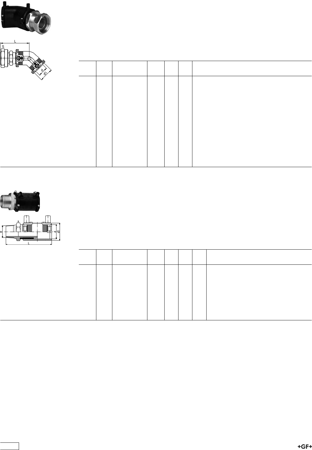
20 15 00 Transition Elbow 45° PE/brass (Ms 58)
with loose Nut
ÏPE 100 SDR 11 (ISO S5)
ÏGas on request / 16 bar Water
ÏWith integral pipe fixation
Ï4 mm pin connectors
ÏLimited path fusion indicators
ÏSupplied as kit
ÏIncl. flat gasket for water applications (KTW / WRC approved)
d
[mm]
Rp
[inch]
Code kg d1
[mm]
L
[mm]
32 1 720 150 008 0.355 44 82
32 1 1
/4720 150 018 0.475 44 86
32 1 1
/2720 150 028 0.495 44 86
40 1 720 150 009 0.485 54 89
40 1 1
/4720 150 019 0.540 54 93
40 1 1
/2720 150 029 0.615 54 93
50 1 720 150 020 0.725 66 96
50 1 1
/4720 150 030 0.770 66 101
50 1 1
/2720 150 010 0.815 66 101
50 2 720 150 040 1.024 66 105
63 1 720 150 021 1.105 81 104
63 1 1
/4720 150 031 1.140 81 108
63 1 1
/2720 150 041 1.150 81 108
63 2 720 150 011 1.315 81 112
63 2 1
/2720 150 051 1.575 81 115
24 92 07 Transition Coupler PE/steel (stainless 1.4305)
Male Thread
ÏPE 100 SDR 11 (ISO S5)
Ï10 bar Gas / 16 bar Water
ÏWith integral pipe fixation
Ï4 mm pin connectors
ÏLimited path fusion indicators
ÏDelivered as a kit. Further combinations modular system with threaded adapter and
reductions
d
[mm]
R
[inch]
Code kg d1
[mm]
L
[mm]
s
[mm]
20 1
/2724 920 756 0.210 31 110 30
25 3
/4724 920 757 0.260 36 111 35
32 1 724 920 758 0.347 44 117 40
32 1 1
/2724 920 767 0.330 44 125 60
40 1 1
/4724 920 759 0.519 54 127 50
40 1 1
/2724 920 772 0.690 66 143 60
50 1 1
/2724 920 760 0.657 66 135 60
63 1 1
/2724 920 771 0.904 81 147 70
63 2 724 920 761 0.963 81 147 70
444
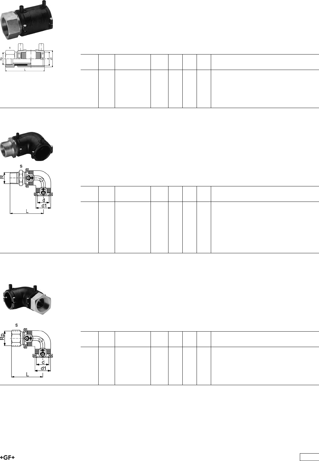
24 92 02 Transition Coupler PE/steel (stainless 1.4305)
Female Thread
ÏPE 100 SDR 11 (ISO S5)
Ï10 bar Gas / 16 bar Water
ÏWith integral pipe fixation
Ï4 mm pin connectors
ÏLimited path fusion indicators
ÏSupplied as kit
d
[mm]
Rp
[inch]
Code kg d1
[mm]
L
[mm]
s
[mm]
20 1
/2724 920 256 0.197 31 100 30
25 3
/4724 920 257 0.253 36 101 35
32 1 724 920 258 0.340 44 108 40
40 1 1
/4724 920 259 0.505 54 118 50
50 1 1
/2724 920 260 0.725 66 126 60
63 2 724 920 261 0.995 81 138 70
24 10 07 Transition Elbow 90° PE/steel (stainless 1.4305)
Male Thread
ÏPE 100 SDR 11 (ISO S5)
Ï10 bar Gas / 16 bar Water
ÏWith integral pipe fixation
Ï4 mm pin connectors
ÏLimited path fusion indicators
ÏSupplied as kit
d
[mm]
R
[inch]
Code kg d1
[mm]
L
[mm]
s
[mm]
20 1
/2724 100 756 0.211 31 96 30
25 3
/4724 100 757 0.230 36 97 35
32 1 724 100 758 0.370 44 98 40
40 1 1
/4724 100 759 0.560 54 109 50
40 1 1
/2724 100 772 0.730 54 109 60
50 1 1
/2724 100 760 0.730 66 118 60
63 1 1
/2724 100 771 1.040 81 132 70
63 2 724 100 761 1.105 81 132 70
24 10 02 Transition Elbow 90° PE/steel (stainless 1.4305)
Female Thread
ÏPE 100 SDR 11 (ISO S5)
Ï10 bar Gas / 16 bar Water
ÏWith integral pipe fixation
Ï4 mm pin connectors
ÏLimited path fusion indicators
ÏSupplied as kit
d
[mm]
Rp
[inch]
Code kg d1
[mm]
L
[mm]
s
[mm]
20 1
/2724 100 256 0.211 31 86 30
25 3
/4724 100 257 0.237 36 87 35
32 1 724 100 258 0.360 44 89 40
40 1 1
/4724 100 259 0.545 54 100 50
50 1 1
/2724 100 260 0.805 66 109 60
63 2 724 100 261 1.135 81 123 70
445
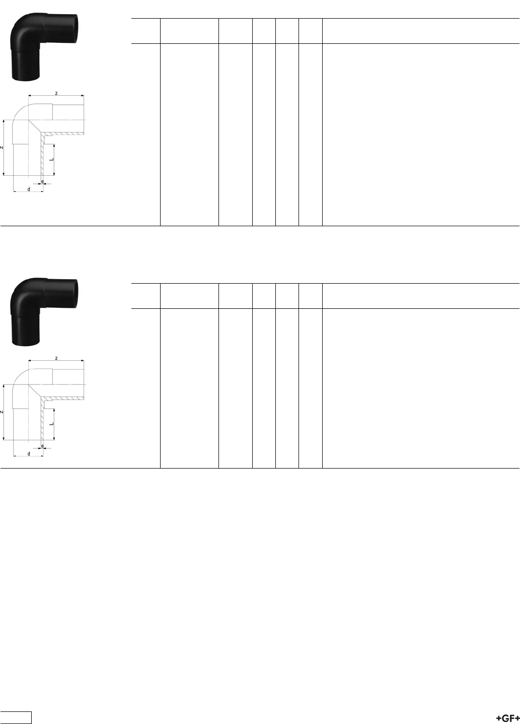
Spigot Fittings for Electrofusion
53 10 10 Elbow 90° Type L
ÏPE 100 SDR 11 (ISO S5)
Ï10 bar Gas / 16 bar Water
d
[mm]
Code kg z
[mm]
L
[mm]
e
[mm]
20 753 101 006 0.027 75 52 3.0
25 753 101 007 0.037 80 52 3.0
32 753 101 008 0.053 85 54 3.0
40 753 101 009 0.093 95 57 3.7
50 753 101 010 0.159 105 63 4.6
63 753 101 011 0.275 115 65 5.8
75 753 101 012 0.413 130 72 6.8
90 753 101 013 0.704 150 81 8.2
110 753 101 014 1.145 165 86 10.0
125 753 101 015 1.609 180 93 11.4
140 753 101 016 1.920 202 92 12.7
160 753 101 017 3.100 210 103 14.6
180 753 101 018 4.319 232 107 16.4
200 753 101 019 5.733 253 117 18.2
225 753 101 020 7.780 270 122 20.5
250 753 101 001 11.091 292 130 22.7
280 753 100 922 15.286 320 140 25.4
315 753 100 923 21.960 370 150 28.6
53 10 08 Elbow 90° Type L
ÏPE 100 SDR 17 / 17,6 (ISO S8 / S8,3)
Ï5 bar Gas / 10 bar Water
d
[mm]
Code kg z
[mm]
L
[mm]
e
[mm]
90 753 100 813 0.544 150 81 5,4
110 753 100 814 0.625 165 86 6,6
125 753 100 815 0.927 180 93 7,4
140 753 100 816 1.430 202 92 8,3
160 753 100 817 3.040 210 102 9,5
180 753 100 818 3.750 232 107 10,7
200 753 100 819 4.980 253 115 11,9
225 753 100 820 6.850 270 120 13,4
250 753 100 821 8.274 292 130 14,8
280 753 100 822 11.423 320 140 16,6
315 753 100 823 16.050 370 150 18,7
446
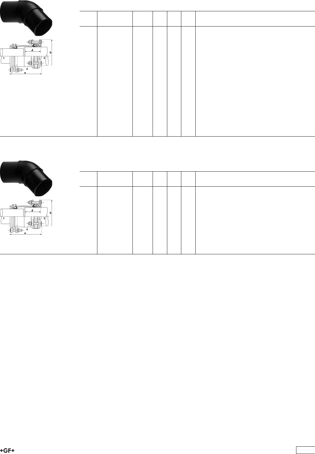
53 15 10 Elbow 45° Type L
ÏPE 100 SDR 11 (ISO S5)
Ï10 bar Gas / 16 bar Water
d
[mm]
Code kg z
[mm]
L
[mm]
e
[mm]
20 753 151 006 0.026 70 52 3,0
25 753 151 007 0.035 75 52 3,0
32 753 151 008 0.051 80 54 3,0
40 753 151 009 0.082 85 57 3,7
50 753 151 010 0.137 90 63 4,6
63 753 151 011 0.300 95 65 5,8
75 753 151 012 0.346 105 72 6,8
90 753 151 013 0.578 120 81 8,2
110 753 151 014 0.931 130 86 10,0
125 753 151 015 1.286 140 92 11,4
140 753 151 016 1.600 164 120 12,7
160 753 151 017 2.461 162 102 14,6
180 753 151 018 3.283 170 107 16,4
200 753 151 019 4.371 186 116 18,2
225 753 151 020 6.013 200 123 20,5
250 753 151 021 8.541 220 130 22,7
280 753 150 922 10.924 230 140 25,4
315 753 150 923 14.818 250 150 28,6
53 15 08 Elbow 45° Type L
ÏPE 100 SDR 17 / 17,6 (ISO S8 / S8,3)
Ï5 bar Gas / 10 bar Water
d
[mm]
Code kg z
[mm]
L
[mm]
e
[mm]
90 753 150 813 0.450 120 81 5,4
110 753 150 814 0.900 130 86 6,6
125 753 150 815 1.250 140 92 7,4
140 753 150 816 1.100 164 120 8,3
160 753 150 817 2.390 162 102 9,5
180 753 150 818 3.060 170 107 10,7
200 753 150 819 4.100 186 116 11,9
225 753 150 820 5.610 205 123 13,4
250 753 150 821 6.227 220 130 14,8
280 753 150 822 7.819 230 140 16,6
315 753 150 823 10.596 250 150 18,7
447
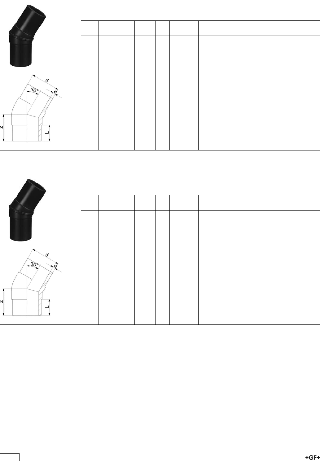
53 12 09 Elbow 30° Type L
ÏPE 100 SDR 11 (ISO S5)
Ï10 bar Gas / 16 bar Water
ÏWelded design
d
[mm]
Code kg z
[mm]
L
[mm]
e
[mm]
32 753 120 908 0.050 70 54 3,0
40 753 120 909 0.530 80 57 3,7
50 753 120 910 0.530 80 63 4,6
63 753 120 911 0.207 80 65 5,8
75 753 120 912 0.530 90 72 6,8
90 753 120 913 0.540 100 81 8,2
110 753 120 914 0.840 105 86 10,0
125 753 120 915 1.240 115 92 11,4
140 753 120 916 1.760 135 92 12,7
160 753 120 917 2.050 130 102 14,6
180 753 120 918 2.907 140 107 16,4
200 753 120 919 8.600 150 116 18,2
225 753 120 920 5.360 165 123 20,5
250 753 120 921 7.300 190 130 22,7
280 753 120 922 10.600 200 139 25,4
315 753 120 923 10.100 200 150 28,6
53 12 08 Elbow 30° Type L
ÏPE 100 SDR 17 / 17,6 (ISO S8 / S8,3)
Ï5 bar Gas / 10 bar Water
ÏWelded design
d
[mm]
Code kg z
[mm]
L
[mm]
e
[mm]
90 753 120 813 0.430 110 81 5,4
110 753 120 814 0.620 115 86 6,6
125 753 120 815 1.070 125 92 7,4
140 753 120 816 1.490 150 92 8,3
160 753 120 817 1.600 140 102 9,5
180 753 120 818 2.040 150 107 10,7
200 753 120 819 2.780 160 116 11,9
225 753 120 820 3.880 180 123 13,4
250 753 120 821 5.830 200 130 14,8
280 753 120 822 8.100 200 139 16,6
315 753 120 823 11.200 220 150 18,7
448
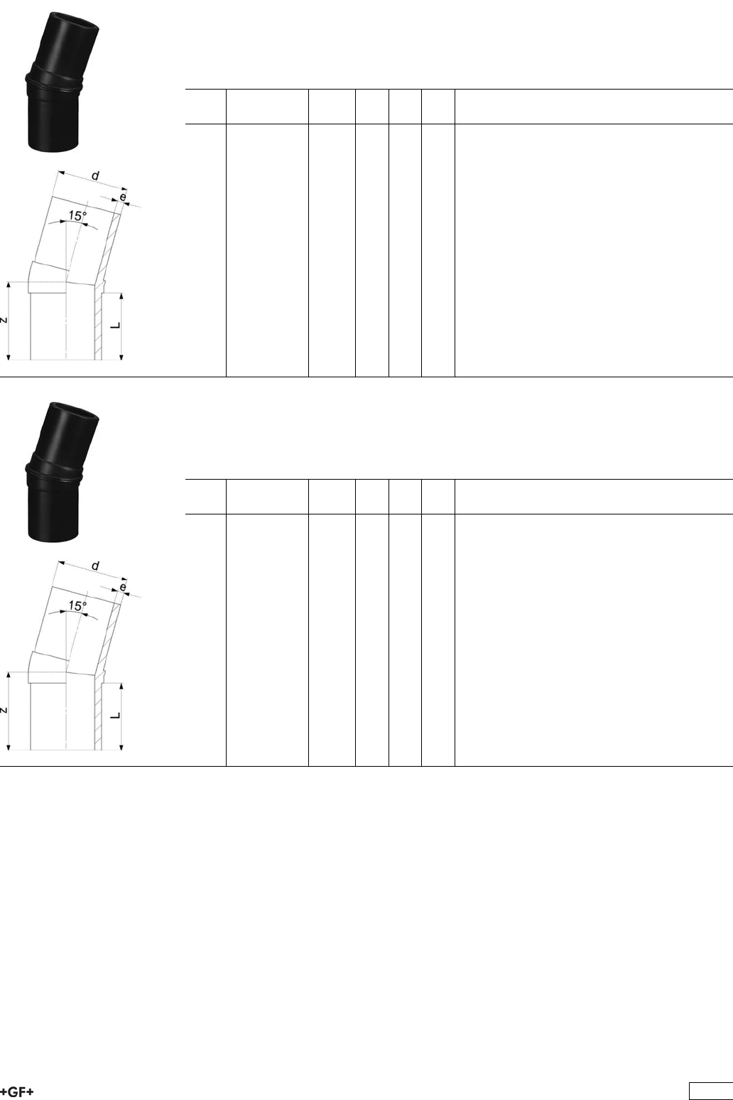
Elbow 15° Type L
ÏPE 100 SDR 11 (ISO S5)
Ï10 bar Gas / 16 bar Water
ÏWelded design
d
[mm]
Code kg z
[mm]
L
[mm]
e
[mm]
32 753 141 008 0.051 70 54 3.0
40 753 141 009 0.082 80 57 3.7
50 753 141 010 0.137 80 63 4.6
63 753 141 011 0.200 80 65 5.8
75 753 141 012 0.250 90 72 6.8
90 753 141 013 0.487 100 81 8.2
110 753 141 014 0.785 105 86 10.0
125 753 141 015 1.070 115 92 11.4
140 753 141 016 1.600 135 92 12.7
160 753 141 017 2.050 130 102 14.6
180 753 141 018 2.669 140 107 16.4
200 753 141 019 3.440 150 116 18.2
225 753 141 020 4.900 165 123 20.5
250 753 141 021 8.300 190 130 22.7
280 753 141 022 9.500 200 139 25.4
315 753 141 023 13.100 200 150 28.6
Elbow 15° Type L
ÏPE 100 SDR 17 / 17,6 (ISO S8 / S8,3)
Ï5 bar Gas / 10 bar Water
ÏWelded design
d
[mm]
Code kg z
[mm]
L
[mm]
e
[mm]
90 753 140 813 0.370 100 81 5.4
110 753 140 814 0.620 105 86 6.6
125 753 140 815 0.990 115 92 7.4
140 753 140 816 0.370 135 92 8.3
160 753 140 817 1.600 130 102 9.5
180 753 140 818 2.040 140 107 10.7
200 753 140 819 2.780 150 116 11.9
225 753 140 820 4.820 165 123 13.4
250 753 140 821 5.830 190 130 14.8
280 753 140 822 8.100 195 139 16.6
315 753 140 823 11.200 200 150 18.7
449
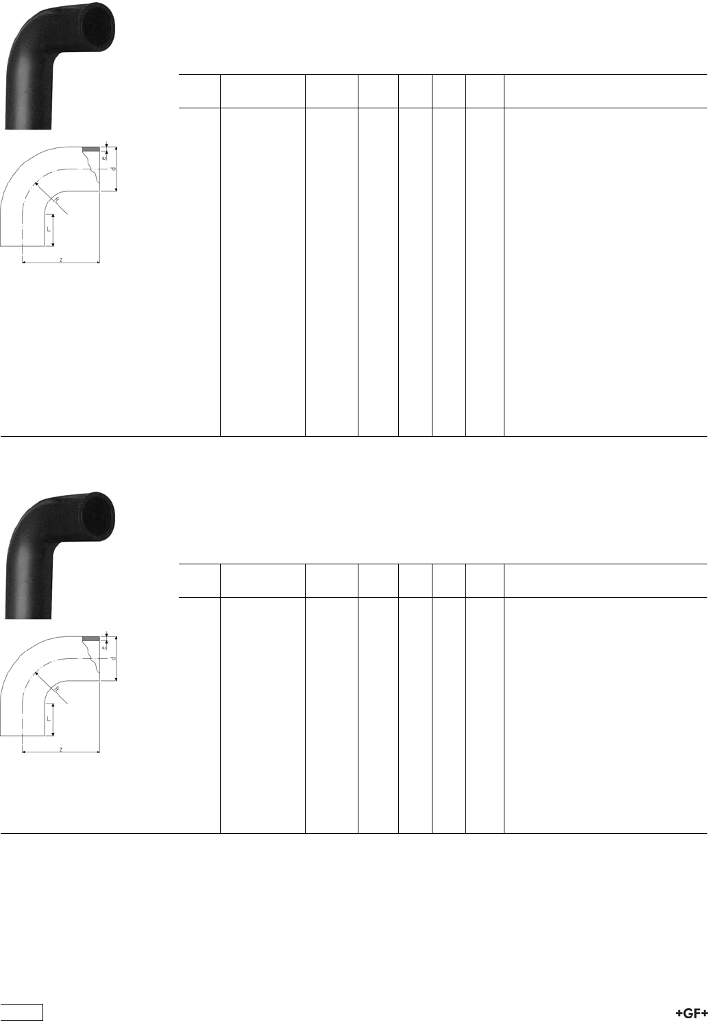
53 00 09 Bend 90° Type L
ÏPE 100 SDR 11 (ISO S5)
Ï10 bar Gas / 16 bar Water
* made out of seamless pipe
d
[mm]
Code kg z
[mm]
L
[mm]
R
[mm]
e
[mm]
20 753 001 006 0.020 63 41 20 1,9
25 753 001 007 0.030 68 41 25 2,3
32 753 001 008 0.050 78 46 32 2,9
40 753 001 009 0.090 91 49 40 3,7
50 753 001 010 0.160 107 55 50 4,6
63 753 001 011 0.290 130 63 63 5,8
75 753 001 012 0.300 152 70 75 6,8
90 753 001 013 0.530 168 79 90 8,2
110 753 001 014 0.890 193 82 110 10,0
125 753 001 015 1.290 216 87 125 11,4
140 753 001 016 2.230 232 92 140 12,7
160 753 001 017 2.460 258 98 160 14,6
180 753 001 018 5.000 290 105 180 16,4
200 753 001 019 4.480 317 112 200 18,2
225 753 001 020 9.770 350 120 225 20,5
250 753 001 021 9.230 375 130 250 22,7
280 753 001 022 17.410 430 150 280 25,4
315 753 001 023 23.950 470 150 315 28,6
*355 753 001 024 53.300 900 250 533 32,3
*400 753 001 025 71.900 980 250 600 36,4
*450 753 001 026 97.300 1070 250 675 40,9
*500 753 001 027 134.000 1200 280 750 45,5
*560 753 001 028 179.300 1290 280 840 50,9
*630 753 001 029 243.200 1400 280 945 57,3
53 00 08 Bend 90° Type L
ÏPE 100 SDR 17 / 17,6 (ISO S8 / S8,3)
Ï5 bar Gas / 10 bar Water
* made out of seamless pipe
d
[mm]
Code kg z
[mm]
L
[mm]
R
[mm]
e
[mm]
90 753 000 813 0.600 168 79 90 5,4
110 753 000 814 1.000 193 82 110 6,6
125 753 000 815 1.300 216 87 125 7,4
140 753 000 816 2.500 232 92 140 8,3
160 753 000 817 2.500 258 98 160 9,5
180 753 000 818 4.000 290 105 180 10,7
200 753 000 819 6.500 317 112 200 11,9
225 753 000 820 8.500 350 120 225 13,4
250 753 000 821 8.500 375 130 250 14,8
280 753 000 822 15.000 430 150 280 16,6
315 753 000 823 24.000 470 150 315 18,7
*355 753 000 824 36.700 900 250 533 21,1
*400 753 000 825 49.700 980 250 600 23,7
*450 753 000 826 66.600 1070 250 675 26,7
*500 753 000 827 87.400 1200 280 750 29,7
*560 753 000 828 116.000 1290 280 840 33,2
*630 753 000 829 159.600 1400 280 945 37,4
450
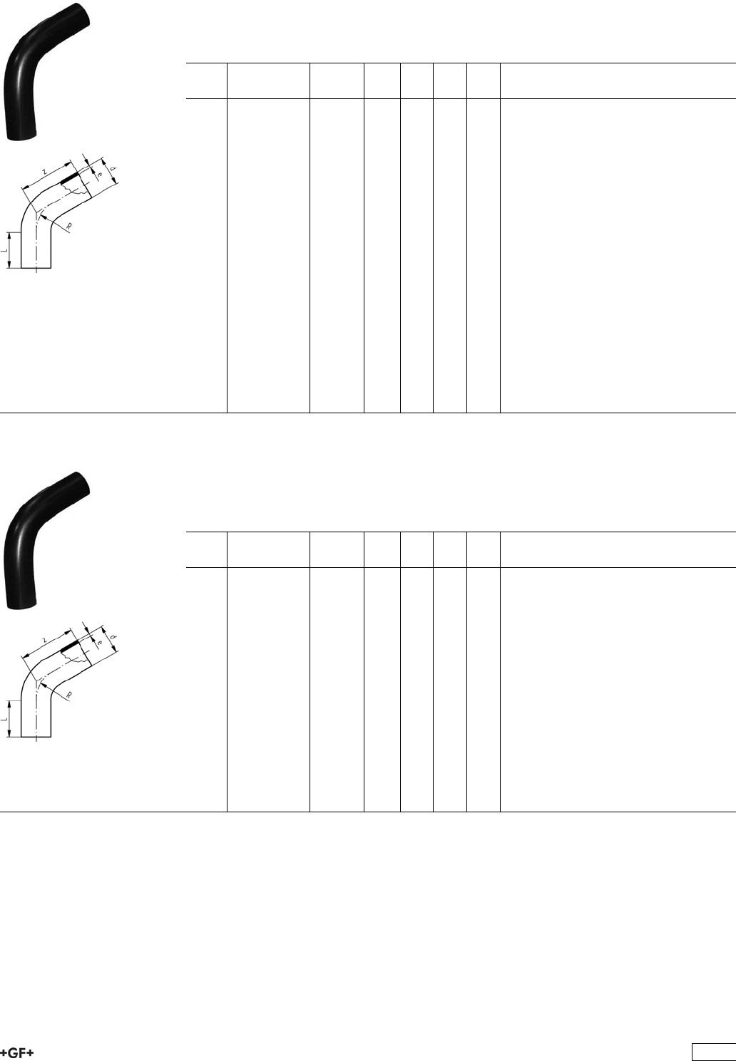
53 07 10 Bend 60° Type L
ÏPE 100 SDR 11 (ISO S5)
Ï10 bar Gas / 16 bar Water
Ïmade out of seamless pipe
d
[mm]
Code kg z
[mm]
L
[mm]
R
[mm]
e
[mm]
32 753 071 008 0.070 128 80 48 2,9
40 753 071 009 0.120 135 80 60 3,7
50 753 071 010 0.240 158 100 75 4,6
63 753 071 011 0.420 173 100 95 5,8
75 753 071 012 0.600 182 100 113 6,8
90 753 071 013 0.900 193 100 135 8,2
110 753 071 014 1.780 270 150 165 10,0
125 753 071 015 2.500 283 150 188 11,4
140 753 071 016 2.700 296 150 210 12,7
160 753 071 017 4.500 313 150 240 14,6
180 753 071 018 4.900 330 150 270 16,4
200 753 071 019 6.400 348 150 300 18,2
225 753 071 020 8.600 370 150 338 20,5
250 753 071 021 14.500 500 250 375 22,7
280 753 071 022 19.100 530 250 420 25,4
315 753 071 023 25.600 612 250 473 28,6
355 753 071 024 41.700 690 300 533 32,3
400 753 071 025 55.800 730 300 600 36,4
450 753 071 026 76.000 780 300 675 40,9
500 753 071 027 104.600 880 350 750 45,5
560 753 071 028 139.500 930 350 840 50,9
630 753 071 029 188.500 1000 350 945 57,3
53 07 08 Bend 60° Type L
ÏPE 100 SDR 17 / 17,6 (ISO S8 / S8,3)
Ï5 bar Gas / 10 bar Water
Ïmade out of seamless pipe
d
[mm]
Code kg z
[mm]
L
[mm]
R
[mm]
e
[mm]
90 753 070 813 0.600 193 100 135 5,4
110 753 070 814 1.280 270 150 165 6,6
125 753 070 815 1.300 283 150 187 7,4
140 753 070 816 1.800 296 150 210 8,3
160 753 070 817 3.160 313 150 240 9,5
180 753 070 818 3.190 330 150 270 10,7
200 753 070 819 4.200 348 150 300 11,9
225 753 070 820 5.600 370 150 337 13,4
250 753 070 821 9.250 500 250 375 14,8
280 753 070 822 15.000 530 250 420 16,6
315 753 070 823 19.500 612 250 472 18,7
355 753 070 824 30.100 690 300 532 21,1
400 753 070 825 38.200 730 300 600 23,7
450 753 070 826 53.700 780 300 675 26,7
500 753 070 827 73.900 880 350 750 29,7
560 753 070 828 98.200 930 350 840 33,2
630 753 070 829 132.300 1000 350 945 37,4
451

53 05 10 Bend 45° Type L
ÏPE 100 SDR 11 (ISO S5)
Ï10 bar Gas / 16 bar Water
Ïmade out of seamless pipe
d
[mm]
Code kg z
[mm]
L
[mm]
R
[mm]
e
[mm]
32 753 051 008 0.077 120 80 48 2,9
40 753 051 009 0.120 120 80 60 3,7
50 753 051 010 0.240 149 100 75 4,6
63 753 051 011 0.360 161 100 95 5,8
75 753 051 012 0.560 168 100 113 6,8
90 753 051 013 0.760 177 100 135 8,2
110 753 051 014 1.700 243 150 165 10,0
125 753 051 015 2.300 253 150 188 11,4
140 753 051 016 2.800 262 150 210 12,7
160 753 051 017 3.800 274 160 240 14,6
180 753 051 018 5.140 287 150 270 16,4
200 753 051 019 5.600 299 150 300 18,2
225 753 051 020 7.400 315 150 338 20,5
250 753 051 021 13.000 440 250 375 22,7
280 753 051 022 15.000 460 250 420 25,4
315 753 051 023 24.930 535 250 473 28,6
355 753 051 024 39.500 620 300 533 32,3
400 753 051 025 48.500 650 300 600 36,4
450 753 051 026 69.800 680 300 675 40,9
500 753 051 027 96.300 760 350 750 45,5
560 753 051 028 129.800 800 350 840 50,9
630 753 051 029 174.000 870 350 945 57,3
53 05 08 Bend 45° Type L
ÏPE 100 SDR 17 / 17,6 (ISO S8 / S8,3)
Ï5 bar Gas / 10 bar Water
Ïmade out of seamless pipe
d
[mm]
Code kg z
[mm]
L
[mm]
R
[mm]
e
[mm]
90 753 050 813 0.600 177 100 135 5,4
110 753 050 814 1.100 243 150 165 6,6
125 753 050 815 1.200 253 150 188 7,4
140 753 050 816 1.720 262 150 210 8,3
160 753 050 817 2.200 274 150 240 9,5
180 753 050 818 3.000 287 150 270 10,7
200 753 050 819 3.700 299 150 300 11,9
225 753 050 820 5.000 315 150 338 13,4
250 753 050 821 10.000 440 250 375 14,8
280 753 050 822 15.000 460 250 420 16,6
315 753 050 823 17.800 535 250 473 18,7
355 753 050 824 25.600 620 300 533 21,1
400 753 050 825 36.600 650 300 600 23,7
450 753 050 826 45.300 680 300 675 26,7
500 753 050 827 62.400 760 350 750 29,7
560 753 050 828 81.900 800 350 840 33,2
630 753 050 829 62.400 870 350 945 37,4
452
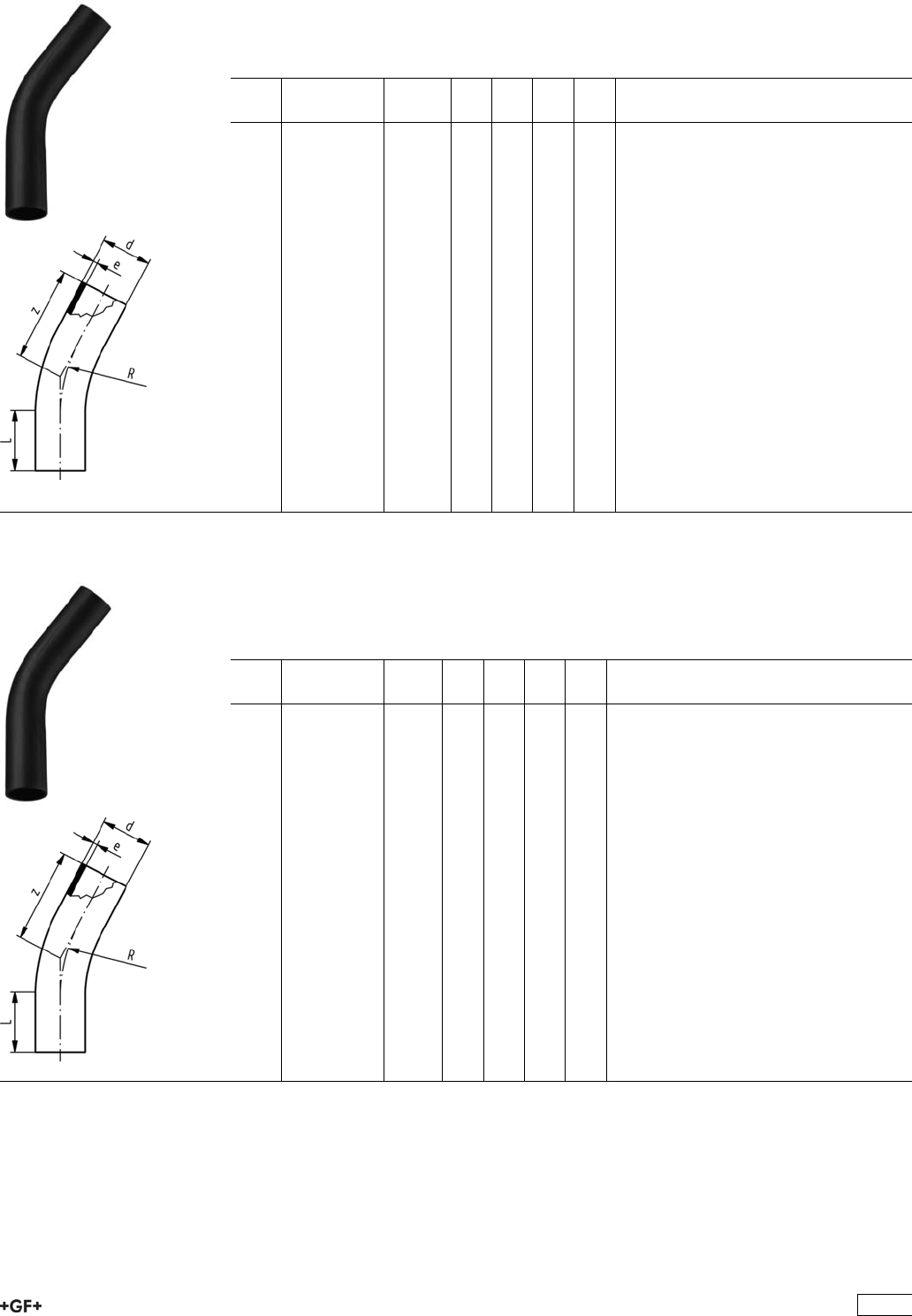
53 06 10 Bend 30° LS
ÏPE 100 SDR 11 (ISO S5)
Ï10 bar Gas / 16 bar Water
Ïmade out of seamless pipe
d
[mm]
Code kg z
[mm]
L
[mm]
R
[mm]
e
[mm]
32 753 061 008 0.077 113 80 48 2,9
40 753 061 009 0.120 116 80 60 3,7
50 753 061 010 0.200 140 100 75 4,6
63 753 061 011 0.400 150 100 95 5,8
75 753 061 012 0.520 155 100 113 6,8
90 753 061 013 0.760 160 100 135 8,2
110 753 061 014 1.500 219 150 165 10,0
125 753 061 015 2.000 225 150 188 11,4
140 753 061 016 2.200 231 150 210 12,7
160 753 061 017 3.300 239 150 240 14,6
180 753 061 018 3.700 247 150 270 16,4
200 753 061 019 4.750 255 150 300 18,2
225 753 061 020 6.300 266 150 338 20,5
250 753 061 021 13.100 385 250 375 22,7
280 753 061 022 16.300 400 250 420 25,4
315 753 061 023 21.850 460 250 473 28,6
355 753 061 024 34.900 540 300 533 32,3
400 753 061 025 45.900 560 300 600 36,4
450 753 061 026 60.200 580 300 675 40,9
500 753 061 027 83.300 630 350 750 45,5
560 753 061 028 108.600 680 350 840 50,9
630 753 061 029 148.300 730 350 945 57,3
53 06 08 Bend 30° LS
ÏPE 100 SDR 17 (ISO S8)
Ï5 bar Gas / 10 bar Water
Ïmade out of seamless pipe
d
[mm]
Code kg z
[mm]
L
[mm]
R
[mm]
e
[mm]
90 753 060 813 0.500 160 100 135 5,4
110 753 060 814 1.060 219 150 165 6,6
125 753 060 815 1.100 225 150 188 7,4
140 753 060 816 1.720 231 150 210 8,3
160 753 060 817 1.900 239 150 240 9,5
180 753 060 818 2.500 247 150 270 10,7
200 753 060 819 3.200 255 150 300 11,9
225 753 060 820 7.540 266 150 338 13,4
250 753 060 821 11.600 385 250 375 14,8
280 753 060 822 12.800 400 250 420 16,6
315 753 060 823 25.000 460 250 473 18,7
355 753 060 824 22.700 540 300 533 21,1
400 753 060 825 29.800 560 300 600 23,7
450 753 060 826 39.100 580 300 675 26,7
500 753 060 827 54.000 650 350 750 29,7
560 753 060 828 70.300 680 350 840 33,2
630 753 060 829 95.800 730 350 945 37,4
453
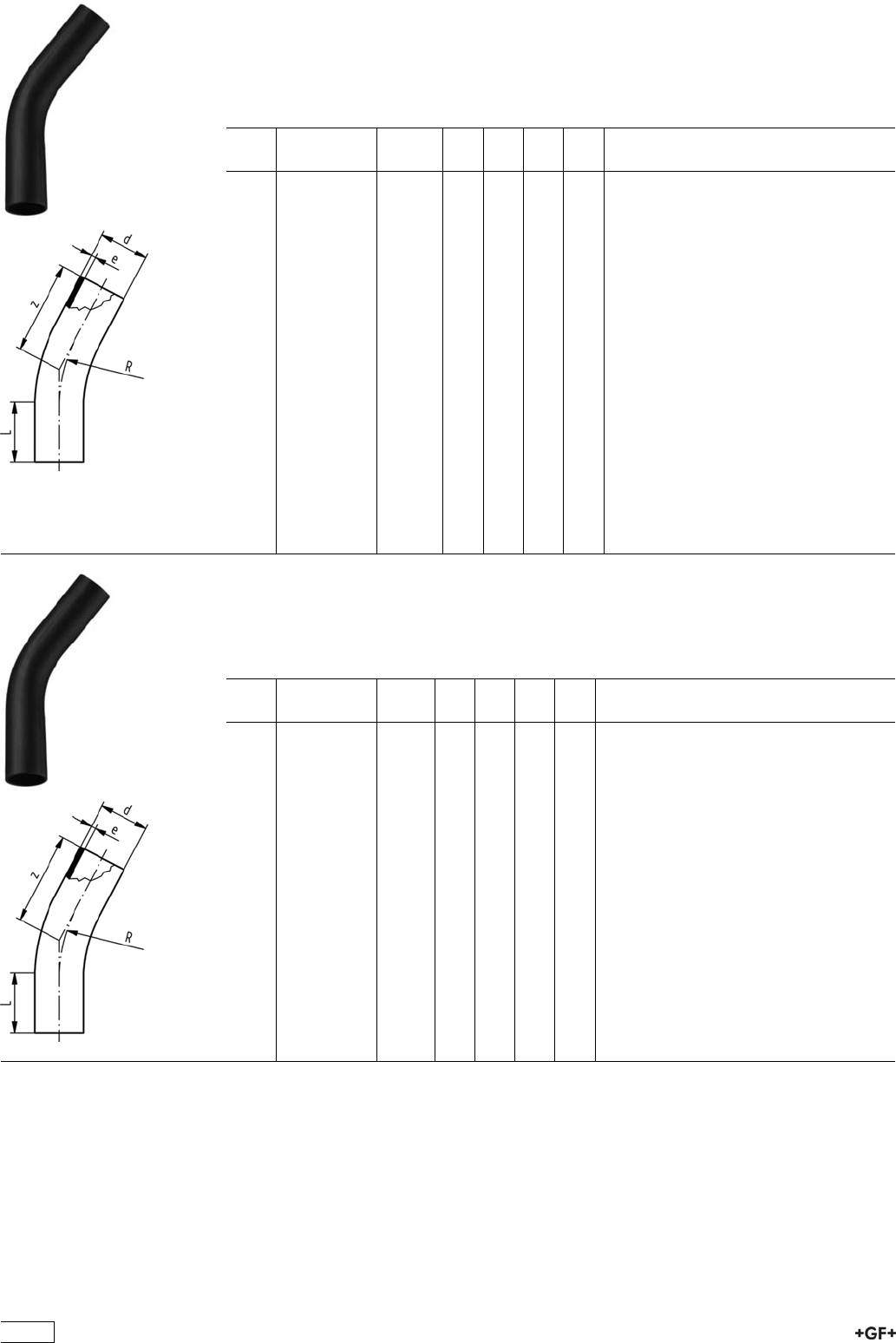
Bend 22° LS
ÏPE 100 SDR 11 (ISO S5)
Ï10 bar Gas / 16 bar Water
Ïmade out of seamless pipe
d
[mm]
Code kg z
[mm]
L
[mm]
R
[mm]
e
[mm]
32 753 081 008 0.077 113 80 48 2,9
40 753 081 009 0.120 116 80 60 3,7
50 753 081 010 0.200 140 100 75 4,6
63 753 081 011 0.400 150 100 95 5,8
75 753 081 012 0.520 155 100 113 6,8
90 753 081 013 0.760 160 100 135 8,2
110 753 081 014 1.500 219 150 165 10,0
125 753 081 015 2.000 225 150 188 11,4
140 753 081 016 2.200 231 150 210 12,7
160 753 081 017 3.300 239 150 240 14,6
180 753 081 018 3.700 247 150 270 16,4
200 753 081 019 4.750 255 150 300 18,2
225 753 081 020 6.300 266 150 338 20,5
250 753 081 021 13.100 385 250 375 22,7
280 753 081 022 16.300 400 250 420 25,4
315 753 081 023 21.845 460 250 473 28,6
355 753 081 024 34.900 540 300 533 32,3
400 753 081 025 45.900 560 300 600 36,4
450 753 081 026 60.200 580 300 675 40,9
500 753 081 027 83.300 650 350 750 45,5
560 753 081 028 108.600 680 350 840 50,9
630 753 081 029 148.300 730 350 945 57,3
Bend 22° LS
ÏPE 100 SDR 17 / 17,6 (ISO S8 / S8,3)
Ï5 bar Gas / 10 bar Water
Ïmade out of seamless pipe
d
[mm]
Code kg z
[mm]
L
[mm]
R
[mm]
e
[mm]
90 753 080 813 0.500 160 100 135 5.4
110 753 080 814 1.060 219 150 165 6.6
125 753 080 815 1.100 225 150 188 7.4
140 753 080 816 1.720 231 150 210 8.3
160 753 080 817 1.900 239 150 240 9.5
180 753 080 818 2.500 247 150 270 10.7
200 753 080 819 3.200 255 150 300 11.9
225 753 080 820 7.540 266 150 338 13.4
250 753 080 821 11.600 385 250 375 14.8
280 753 080 822 12.800 400 250 420 16.6
315 753 080 823 25.000 460 250 473 18.7
355 753 080 824 22.700 540 300 533 21.1
400 753 080 825 29.800 560 300 600 23.7
450 753 080 826 39.100 580 300 675 26.7
500 753 080 827 54.000 650 350 750 29.7
560 753 080 828 70.300 680 350 840 33.2
630 753 080 829 95.800 730 350 945 37.4
454

Bend 11° LS
ÏPE 100 SDR 11 (ISO S5)
Ï10 bar Gas / 16 bar Water
Ïmade out of seamless pipe
d
[mm]
Code kg z
[mm]
L
[mm]
R
[mm]
e
[mm]
32 753 091 008 0.077 113 80 48 2.9
40 753 091 009 0.120 116 80 60 3.7
50 753 091 010 0.200 140 100 75 4.6
63 753 091 011 0.400 150 100 95 5.8
75 753 091 012 0.520 155 100 113 6.8
90 753 091 013 0.760 160 100 135 8.2
110 753 091 014 1.500 219 150 165 10.0
125 753 091 015 2.000 225 150 188 11.4
140 753 091 016 2.200 231 150 210 12.7
160 753 091 017 3.300 239 150 240 14.6
180 753 091 018 3.700 247 150 270 16.4
200 753 091 019 4.750 255 150 300 18.2
225 753 091 020 6.300 266 150 338 20.5
250 753 091 021 13.100 385 250 375 22.7
280 753 091 022 16.300 400 250 420 25.4
315 753 091 023 21.845 460 250 473 28.6
355 753 091 024 34.900 540 300 533 32.3
400 753 091 025 45.900 560 300 600 36.4
450 753 091 026 60.200 580 300 675 40.9
500 753 091 027 83.300 650 350 750 45.5
560 753 091 028 108.600 680 350 840 50.9
630 753 091 029 148.300 730 350 945 57.3
Bend 11° LS
ÏPE 100 SDR 17 / 17,6 (ISO S8 / S8,3)
Ï5 bar Gas / 10 bar Water
Ïmade out of seamless pipe
d
[mm]
Code kg z
[mm]
L
[mm]
R
[mm]
e
[mm]
90 753 090 813 0.500 160 100 135 5.4
110 753 090 814 1.060 219 150 165 6.6
125 753 090 815 1.100 225 150 188 7.4
140 753 090 816 1.720 231 150 210 8.3
160 753 090 817 1.900 239 150 240 9.5
180 753 090 818 2.500 247 150 270 10.7
200 753 090 819 3.200 255 150 300 11.9
225 753 090 820 7.540 266 150 338 13.4
250 753 090 821 11.600 385 250 375 14.8
280 753 090 822 12.800 400 250 420 16.6
315 753 090 823 25.000 460 250 473 18.7
355 753 090 824 22.700 540 300 533 21.1
400 753 090 825 29.800 560 300 600 23.7
450 753 090 826 39.100 580 300 675 26.7
500 753 090 827 54.000 650 350 750 29.7
560 753 090 828 70.300 680 350 840 33.2
630 753 090 829 95.800 730 350 945 37.4
455
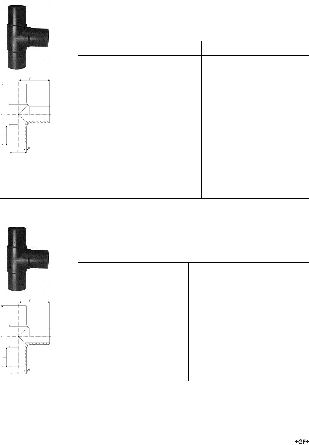
53 20 10 Tee 90°, equal Type L
ÏPE 100 SDR 11 (ISO S5)
Ï10 bar Gas / 16 bar Water
* With welded pipes
* Segment welded and reinforced
* No pressure reduction factor
d
[mm]
Code kg z
[mm]
z1
[mm]
L
[mm]
e
[mm]
20 753 201 006 0.038 150 75 52 3,0
25 753 201 007 0.054 160 80 52 3,0
32 753 201 008 0.074 170 85 54 3,0
40 753 201 009 0.127 190 95 57 3,7
50 753 201 010 0.217 210 105 63 4,6
63 753 201 011 0.375 230 115 65 5,8
75 753 201 012 0.616 264 132 72 6,8
90 753 201 013 1.031 300 150 81 8,2
110 753 201 014 1.660 330 165 86 10,0
125 753 201 015 2.215 366 183 92 11,4
140 753 201 016 3.200 396 196 92 12,7
160 753 201 017 4.320 420 210 102 14,6
180 753 201 018 5.980 460 230 107 16,4
200 753 201 019 7.760 500 250 117 18,2
225 753 201 020 10.485 540 270 122 20,5
250 753 201 001 14.708 575 288 130 22,7
280 753 200 902 18.670 615 308 139 25,4
315 753 200 903 26.150 695 346 150 28,6
355 753 200 904 39.800 818 410 165 32,3
400 753 200 905 42.495 910 455 180 36,4
450 753 200 906 77.300 970 485 195 40,9
500 753 200 907 101.000 1060 530 215 45,5
*560 753 200 908 153.300 1510 50,9
*630 753 200 909 205.500 57,3
53 20 08 Tee 90°, equal Type L
ÏPE 100 SDR 17 / 17,6 (ISO S8 / S8,3)
Ï5 bar Gas / 10 bar Water
* Segment welded and reinforced
* With welded pipes
* No pressure reduction factor
d
[mm]
Code kg z
[mm]
z1
[mm]
L
[mm]
e
[mm]
90 753 200 813 0.780 300 150 80 5,4
110 753 200 814 1.440 330 165 86 6,6
125 753 200 815 1.646 366 183 92 7,4
140 753 200 816 2.120 396 196 92 8,3
160 753 200 817 3.970 428 214 104 9,5
180 753 200 818 5.450 460 230 105 10,7
200 753 200 819 5.910 500 250 115 11,9
225 753 200 820 8.240 540 270 122 13,4
250 753 200 821 10.793 575 288 130 14,8
280 753 200 802 13.810 615 308 139 16,6
315 753 200 803 18.155 695 346 150 18,7
355 753 200 804 25.850 818 410 165 21,1
400 753 200 805 35.015 910 455 180 23,7
450 753 200 806 56.000 970 485 195 26,7
500 753 200 807 71.000 1060 530 215 29,7
*560 753 200 808 99.200 1510 755 230 33,2
*630 753 200 809 132.700 1630 815 250 37,4
456

Tee 90°, reduced LS moulded
ÏPE 100 SDR 11 (ISO S5)
Ï10 bar Gas / 16 bar Water
d
[mm]
d1
[mm]
Code kg z
[mm]
z1
[mm]
L
[mm]
L1
[mm]
e
[mm]
e1
[mm]
63 50 753 201 044 0.300 215 103 63 56 5.8 4.6
75 32 753 201 045 0.490 256 108 70 46 6.8 2.9
75 50 753 201 046 0.530 253 113 70 56 6.8 4.6
75 63 753 201 047 0.560 255 117 70 63 6.8 5.8
90 50 753 201 027 0.820 280 117 79 55 8.2 4.6
90 63 753 201 029 0.775 280 123 79 63 8.2 5.8
90 75 753 201 030 0.793 272 138 73 68 8.2 6.8
110 63 753 201 028 1.267 320 147 87 63 10.0 5.8
110 75 753 201 031 1.244 309 151 82 70 10.0 6.8
110 90 753 201 032 1.275 320 158 86 79 10.0 8.2
125 90 753 201 048 2.389 340 170 112 92 11.4 8.2
125 110 753 201 033 1.860 341 170 90 83 11.4 10.0
160 63 753 201 034 2.680 343 176 98 65 14.6 5.8
160 75 753 201 035 2.726 343 180 98 74 14.6 6.8
160 90 753 201 036 2.775 412 188 101 79 14.6 8.2
160 110 753 201 037 3.300 412 195 101 82 14.6 10.0
180 90 753 201 049 4.100 418 200 136 97 16.4 8.2
180 110 753 201 050 4.379 430 206 130 101 16.4 10.0
180 160 753 201 038 4.379 411 205 105 94 16.4 14.6
200 63 753 201 073 7.300 500 190 122 63 18.2 5.8
200 90 753 201 074 9.730 500 207 122 79 18.2 8.2
200 110 753 201 075 9.730 500 215 122 82 18.2 10.0
200 160 753 201 076 9.730 500 234 122 98 18.2 14.6
225 75 753 201 039 6.500 555 215 120 70 20.5 6.8
225 90 753 201 040 6.633 558 226 120 80 20.5 8.2
225 110 753 201 041 6.600 558 235 120 82 20.5 10.0
225 160 753 201 042 8.095 560 253 120 98 20.5 14.6
225 180 753 201 043 9.375 560 280 120 105 20.5 16.4
250 110 753 201 078 9.730 575 242 130 82 22.7 10.0
250 160 753 201 079 9.730 575 261 127 98 22.7 14.6
315 110 753 201 051 15.300 695 277 150 82 28.6 10.0
315 160 753 201 052 16.600 695 296 150 102 28.6 14.6
315 225 753 201 053 20.500 650 335 170 145 28.6 20.5
315 250 753 201 054 22.000 695 325 150 130 28.6 22.7
457
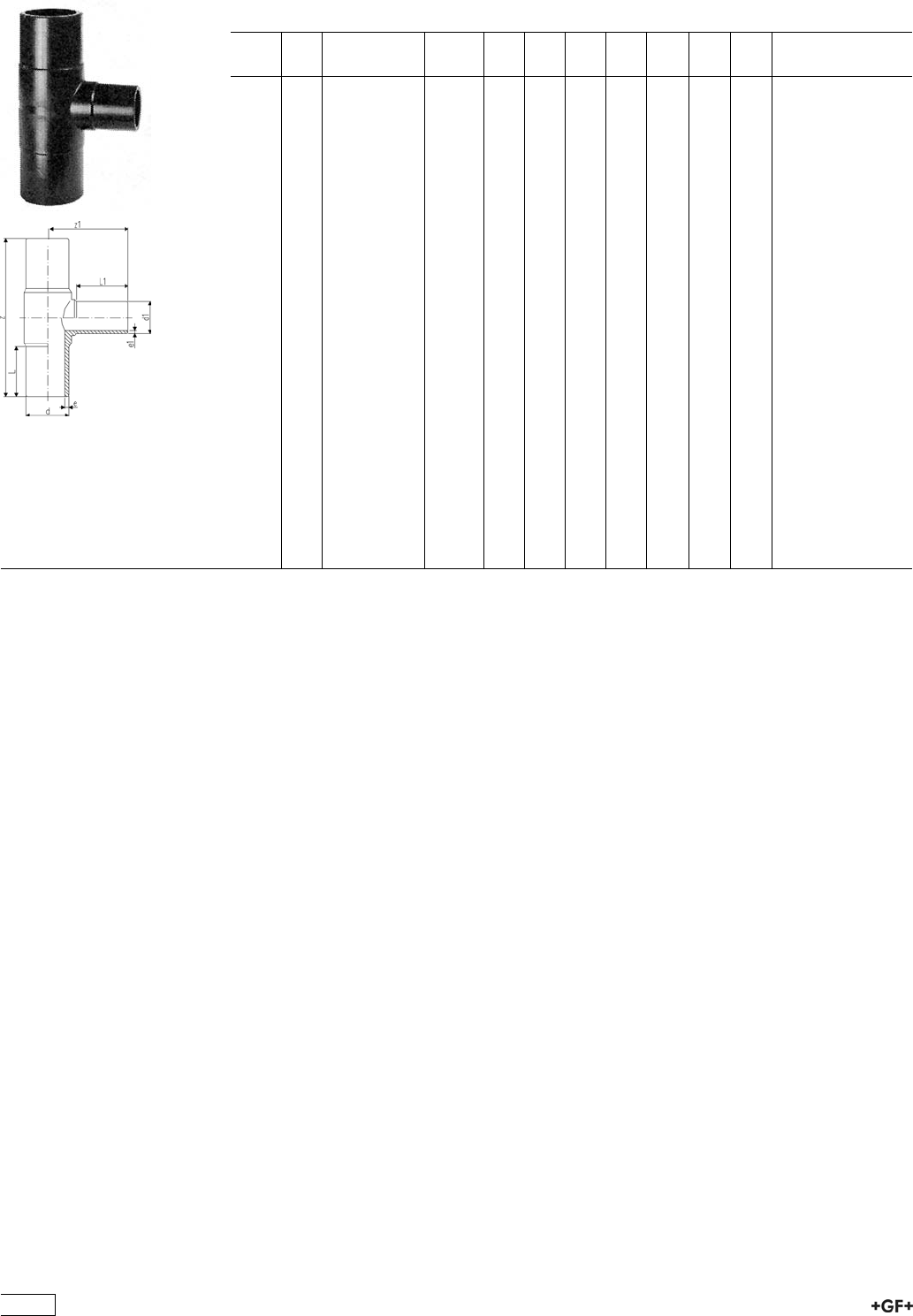
53 20 08 Tee 90°, reduced LS moulded
ÏPE 100 SDR 17 / 17,6 (ISO S8 / S8,3)
Ï5 bar Gas / 10 bar Water
d
[mm]
d1
[mm]
Code kg z
[mm]
z1
[mm]
L
[mm]
L1
[mm]
e
[mm]
e1
[mm]
e1
[mm]
90 50 753 201 827 0.630 275 117 79 55 5.4 3,0 3.0
90 63 753 200 829 0.560 275 123 79 63 5.4 3,8 3.8
90 75 753 200 830 0.593 272 139 74 71 5.4 4,5 4.5
110 63 753 200 828 0.900 318 147 82 63 6.6 3,8 3.8
110 75 753 200 831 0.882 315 152 84 70 6.6 4,5 4.5
110 90 753 200 832 0.941 318 158 82 79 6.6 5,4 5.4
125 110 753 200 833 1.282 334 168 84 83 7.4 6,6 6.6
160 63 753 200 834 1.950 330 130 86 63 9.5 3,8 3.8
160 75 753 200 835 1.960 343 180 98 74 9.5 4,5 4.5
160 90 753 200 836 1.972 410 188 98 79 9.5 5,4 5.4
160 110 753 200 837 2.414 410 195 98 82 9.5 6,6 6.6
180 90 753 200 844 3.218 422 204 134 97 10.7 5,4 5.4
180 160 753 200 838 5.890 411 205 105 94 10.7 9,5 9.5
200 63 753 201 873 6.800 500 190 122 63 11.9 3,8 3.8
200 90 753 201 874 6.900 500 207 122 79 11.9 5,4 5.4
200 110 753 201 875 7.200 500 215 122 82 11.9 6,6 6.6
200 160 753 201 876 7.400 500 234 122 98 11.9 9,5 9.5
225 75 753 200 839 4.600 555 277 120 70 13.4 4,5 4.5
225 90 753 200 840 4.732 555 226 127 80 13.4 5,4 5.4
225 110 753 200 841 4.700 555 235 127 82 13.4 6,6 6.6
225 160 753 200 842 5.922 555 253 127 98 13.4 9,5 9.5
225 180 753 200 843 7.211 550 280 120 105 13.4 10,7 10.7
250 110 753 201 878 9.400 575 242 130 82 14.8 6,6 6.6
250 160 753 201 879 9.800 575 261 130 98 14.8 9,5 9.5
315 110 753 200 851 10.800 695 277 150 82 18.7 6,6 6.6
315 160 753 200 852 12.200 695 296 150 102 18.7 9,5 9.5
315 225 753 200 853 14.500 650 335 170 145 18.7 13,4 13.4
315 250 753 200 854 15.500 695 325 150 130 18.7 14,8 14.8
458
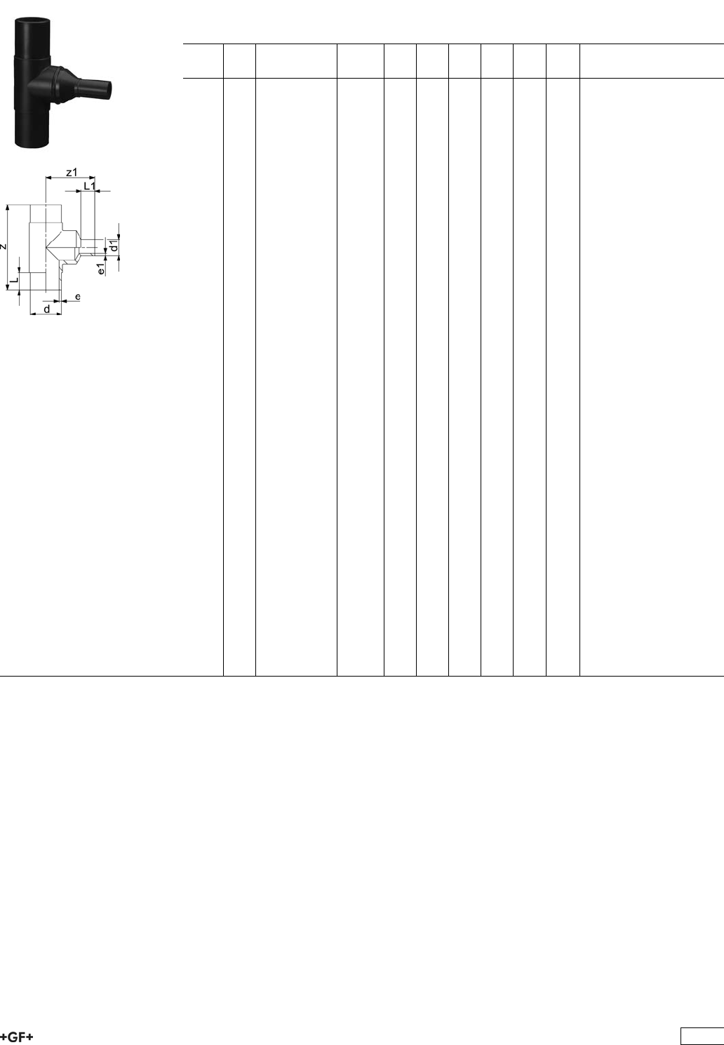
53 20 10 Tee 90°, reduced Type L with welded reducer
ÏPE 100 SDR 11 (ISO S5)
Ï10 bar Gas / 16 bar Water
ÏWith welded reducer
d
[mm]
d1
[mm]
Code kg z
[mm]
z1
[mm]
L
[mm]
L1
[mm]
e
[mm]
e1
[mm]
25 20 753 201 002 0.053 160 52 52 3,0 3,0
32 20 753 201 003 0.094 170 105 54 52 3,0 3,0
32 25 753 201 004 0.098 170 110 54 52 3,0 3,0
40 20 753 201 005 0.155 190 120 57 52 3,7 3,0
40 25 753 201 069 0.160 190 120 57 52 3,7 3,0
40 32 753 201 070 0.160 190 120 57 52 3,7 3,0
50 20 753 201 072 0.252 210 140 63 52 4,6 3,0
50 25 753 201 077 0.260 210 130 63 52 4,6 3,0
50 32 753 201 080 0.267 210 130 63 53 4,6 3,0
50 40 753 201 081 0.276 210 130 63 57 4,6 3,7
63 32 753 201 082 0.460 230 140 65 53 5,8 3,0
63 40 753 201 116 0.480 230 145 65 57 5,8 3,7
75 40 753 201 084 0.755 264 180 72 57 6,8 3,7
125 63 753 201 085 2.850 366 225 92 61 11,4 5,8
125 75 753 201 086 2.880 366 235 92 72 11,4 6,8
140 75 753 201 087 4.050 396 230 92 70 12,7 6,8
140 90 753 201 089 4.095 396 235 92 79 12,7 8,2
140 110 753 201 090 3.600 396 240 92 82 12,7 10,0
140 125 753 201 091 4.170 396 240 92 90 12,7 11,4
160 125 753 201 092 5.715 420 265 102 92 14,6 11,4
160 140 753 201 093 5.895 420 270 102 96 14,6 12,7
180 125 753 201 094 8.930 460 285 107 92 16,4 11,4
180 140 753 201 095 9.070 460 295 107 110 16,4 12,7
200 125 753 201 096 10.460 500 295 117 92 18,2 11,4
200 140 753 201 097 10.570 500 310 117 110 18,2 12,7
200 180 753 201 098 9.500 500 310 117 110 18,2 16,4
225 125 753 201 099 14.470 540 320 122 92 20,5 11,4
225 140 753 201 100 14.574 540 335 122 110 20,5 12,7
225 200 753 201 101 14.925 540 340 122 117 20,5 18,2
250 180 753 201 102 18.890 576 350 130 105 22,7 16,4
250 200 753 201 103 19.220 576 360 130 112 22,7 18,2
250 225 753 201 104 19.690 576 390 130 120 22,7 20,5
280 200 753 201 105 24.520 616 410 139 112 25,4 18,2
280 225 753 201 106 24.755 616 420 139 120 25,4 20,5
280 250 753 201 107 25.210 616 420 139 130 25,4 22,7
315 200 753 201 108 33.950 690 470 150 134 28,6 18,2
315 280 753 201 109 34.950 690 480 150 139 28,6 25,4
355 250 753 201 110 48.900 818 530 165 130 32,3 22,7
355 280 753 201 111 49.300 818 480 165 139 32,3 25,4
355 315 753 201 112 49.690 818 480 165 150 32,3 28,6
400 280 753 201 113 52.915 910 530 180 139 36,4 25,4
400 315 753 201 114 53.625 910 580 180 150 36,4 28,6
400 355 753 201 115 54.075 910 675 180 165 36,4 32,3
459

Tee 90°, reduced LS with welded reducer
ÏPE 100 SDR 17 / 17,6 (ISO S8 / S8,3)
Ï5 bar Gas / 10 bar Water
d
[mm]
d1
[mm]
Code kg z
[mm]
z1
[mm]
L
[mm]
L1
[mm]
e
[mm]
e1
[mm]
125 63 753 200 801 2.115 366 215 92 61 7.4 3.8
125 75 753 200 810 2.140 366 235 92 72 7.4 4.5
125 90 753 200 811 2.180 366 235 92 80 7.4 5.4
140 75 753 200 812 2.820 396 240 92 70 8.3 4.5
140 90 753 200 822 2.855 396 240 92 78 8.3 5.4
140 110 753 200 823 2.910 396 235 92 82 8.3 6.6
140 125 753 200 824 2.955 396 240 92 87 8.3 7.4
160 125 753 200 825 3.970 428 265 104 90 9.5 5.4
160 140 753 200 826 4.070 428 280 104 96 9.5 8.3
180 110 753 200 827 5.250 460 285 105 92 10.7 6.6
180 125 753 200 845 5.070 460 285 105 90 10.7 7.4
180 140 753 200 846 5.290 460 305 105 110 10.7 8.3
200 125 753 200 847 7.100 500 310 115 92 11.9 7.4
200 140 753 200 848 7.200 500 315 115 110 11.9 8.3
200 180 753 200 849 6.900 500 315 115 110 11.9 10.7
225 125 753 200 850 8.620 540 320 122 92 13.4 7.4
225 140 753 200 855 8.780 540 345 122 110 13.4 8.3
225 200 753 200 856 9.300 540 335 122 115 13.4 11.9
250 180 753 200 857 15.000 576 340 130 105 14.8 10.7
250 200 753 200 858 15.440 576 350 130 112 14.8 11.9
250 225 753 200 859 15.620 576 370 130 120 14.8 13.4
280 200 753 200 860 19.200 616 400 139 112 16.6 11.9
280 225 753 200 861 19.500 616 400 139 120 16.6 13.4
280 250 753 200 862 20.120 616 400 139 130 16.6 14.8
315 200 753 200 863 18.700 690 480 150 134 18.7 11.9
315 280 753 200 864 26.940 690 480 150 139 18.7 16.6
355 250 753 200 865 35.770 818 480 165 130 21.1 14.8
355 280 753 200 866 36.330 818 480 165 139 21.1 16.6
355 315 753 200 867 37.740 818 490 165 150 21.1 18.7
400 280 753 200 868 48.330 910 540 180 139 23.7 16.6
400 315 753 200 869 48.880 910 580 180 150 23.7 18.7
400 355 753 200 870 50.020 910 675 180 165 23.7 21.1
460
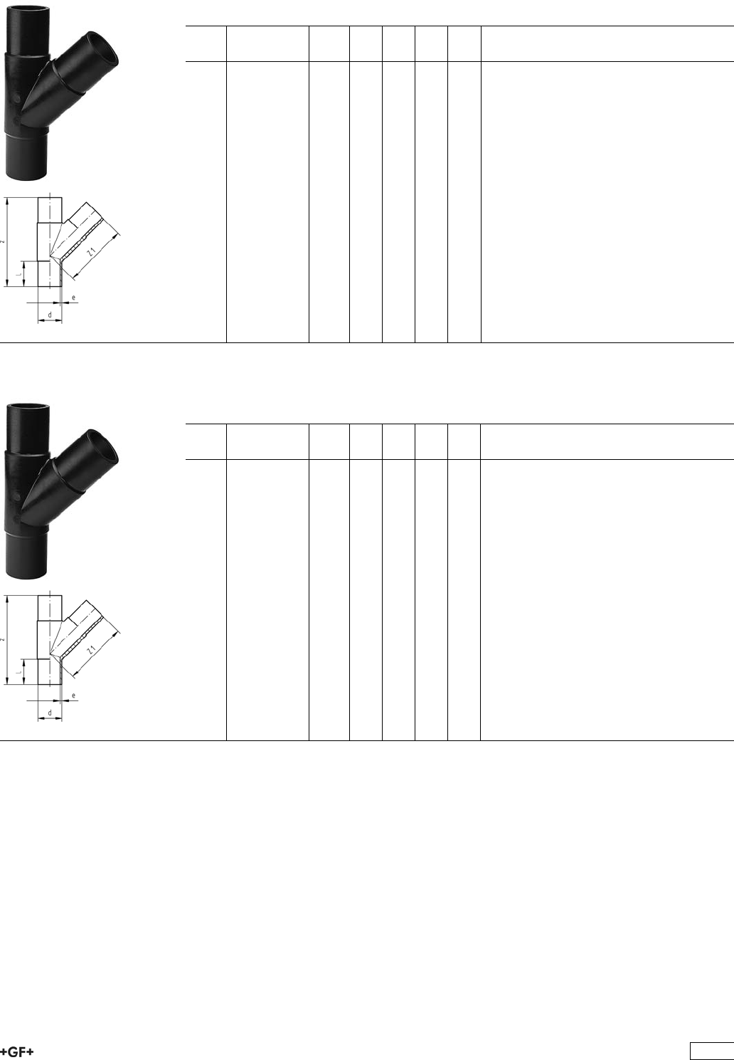
53 25 10 Tee 45°, equal Type L
ÏPE 100 SDR 11 (ISO S5)
Ï10 bar Gas / 16 bar Water
d
[mm]
Code kg z
[mm]
z1
[mm]
L
[mm]
e
[mm]
63 753 251 011 0.500 255 158 63 5,8
75 753 251 012 0.800 301 190 70 6,8
90 753 251 013 1.300 368 234 79 8,2
110 753 251 014 1.800 395 260 82 10,0
53 25 10 Tee 45°, equal Type L
ÏPE 100 SDR 17 / 17,6 (ISO S8 / S8,3)
Ï5 bar Gas / 10 bar Water
d
[mm]
Code kg z
[mm]
z1
[mm]
L
[mm]
e
[mm]
90 753 251 063 0.800 368 234 79 5,4
110 753 251 064 1.400 395 260 82 6,6
461
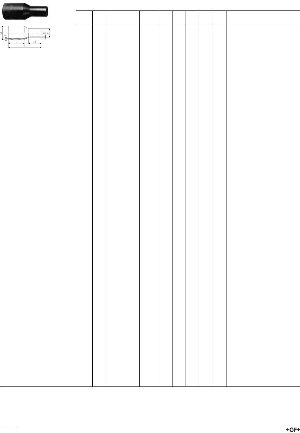
53 90 10 Reducer LS
ÏPE 100 SDR 11 (ISO S5)
Ï10 bar Gas / 16 bar Water
d
[mm]
d1
[mm]
Code kg z
[mm]
L
[mm]
L1
[mm]
e
[mm]
e1
[mm]
25 20 753 901 038 0.022 115 52 52 3,0 3,0
32 20 753 901 042 0.028 120 54 52 3,0 3,0
32 25 753 901 041 0.031 120 54 52 3,0 3,0
40 20 753 901 048 0.040 130 57 52 3,7 3,0
40 25 753 901 047 0.043 130 57 52 3,7 3,0
40 32 753 901 046 0.047 130 57 53 3,7 3,0
50 20 753 901 055 0.064 150 63 52 4,6 3,0
50 25 753 901 054 0.066 140 63 52 4,6 3,0
50 32 753 901 053 0.067 140 63 53 4,6 3,0
50 40 753 901 052 0.079 140 63 57 4,6 3,7
63 32 753 901 060 0.109 150 65 53 5,8 3,0
63 40 753 901 059 0.119 150 65 57 5,8 3,7
63 50 753 901 058 0.130 150 65 63 5,8 4,6
75 40 753 901 063 0.178 170 72 57 6,8 3,7
75 50 753 901 064 0.191 170 72 63 6,8 4,6
75 63 753 901 065 0.216 170 72 65 6,8 5,8
90 50 753 901 072 0.291 190 81 63 8,2 4,6
90 63 753 901 071 0.317 190 81 65 8,2 5,8
90 75 753 901 070 0.361 190 81 70 8,2 6,8
110 63 753 901 078 0.469 205 86 65 10,0 5,8
110 75 753 901 077 0.497 205 86 70 10,0 6,8
110 90 753 901 076 0.557 205 86 81 10,0 8,2
125 63 753 901 083 0.579 214 87 63 11,4 5,8
125 75 753 901 082 0.660 210 92 72 11,4 6,8
125 90 753 901 081 0.735 212 92 81 11,4 8,2
125 110 753 901 080 0.819 212 92 86 11,4 10,0
140 75 753 901 086 0.560 230 110 70 12,7 6,8
140 90 753 901 087 0.690 230 110 79 12,7 8,2
140 110 753 901 084 0.820 230 110 88 12,7 10,0
140 125 753 901 085 0.988 235 110 90 12,7 11,4
160 90 753 901 088 1.060 244 120 79 14,6 8,2
160 110 753 901 090 1.240 244 102 86 14,6 10,0
160 125 753 901 089 1.403 245 102 92 14,6 11,4
160 140 753 901 032 1.350 260 120 110 14,6 12,7
180 90 753 901 073 1.530 245 105 79 16,4 8,2
180 110 753 901 074 1.720 270 105 82 16,4 10,0
180 125 753 901 091 1.753 258 107 92 16,4 11,4
180 140 753 901 075 1.980 270 120 110 16,4 12,7
180 160 753 901 033 2.044 255 107 102 16,4 14,6
200 140 753 901 066 2.310 275 120 110 18,2 12,7
200 160 753 901 092 2.472 265 117 102 18,2 14,6
200 180 753 901 034 2.580 265 117 107 18,2 16,4
225 140 753 901 067 2.900 295 130 110 20,5 12,7
225 160 753 901 096 3.118 279 122 102 20,5 14,6
225 180 753 901 095 3.277 280 122 107 20,5 16,4
225 200 753 901 094 3.538 280 122 117 20,5 18,2
250 160 753 901 000 2.385 300 130 100 22,7 14,6
250 180 753 901 068 4.050 295 130 105 22,7 16,4
250 200 753 901 001 2.385 315 130 112 22,7 18,2
250 225 753 901 002 2.385 332 130 120 22,7 20,5
280 200 753 901 098 6.850 333 140 112 25,4 18,2
280 225 753 901 099 6.090 335 140 120 25,4 20,5
280 250 753 901 003 2.385 340 140 130 25,4 22,7
315 200 753 901 004 2.385 380 180 134 28,6 18,2
315 225 753 901 097 7.790 365 150 120 28,6 20,5
315 250 753 901 005 2.385 365 150 130 28,6 22,7
315 280 753 901 012 8.800 365 150 139 28,6 25,4
355 250 753 901 013 9.100 390 165 130 32,3 22,7
355 280 753 901 014 9.500 390 165 139 32,3 25,4
355 315 753 901 015 9.900 390 165 150 32,3 28,6
400 280 753 901 016 10.420 415 180 139 36,4 25,4
400 315 753 901 017 11.130 415 180 150 36,4 28,6
400 355 753 901 018 11.600 420 180 165 36,4 32,3
462
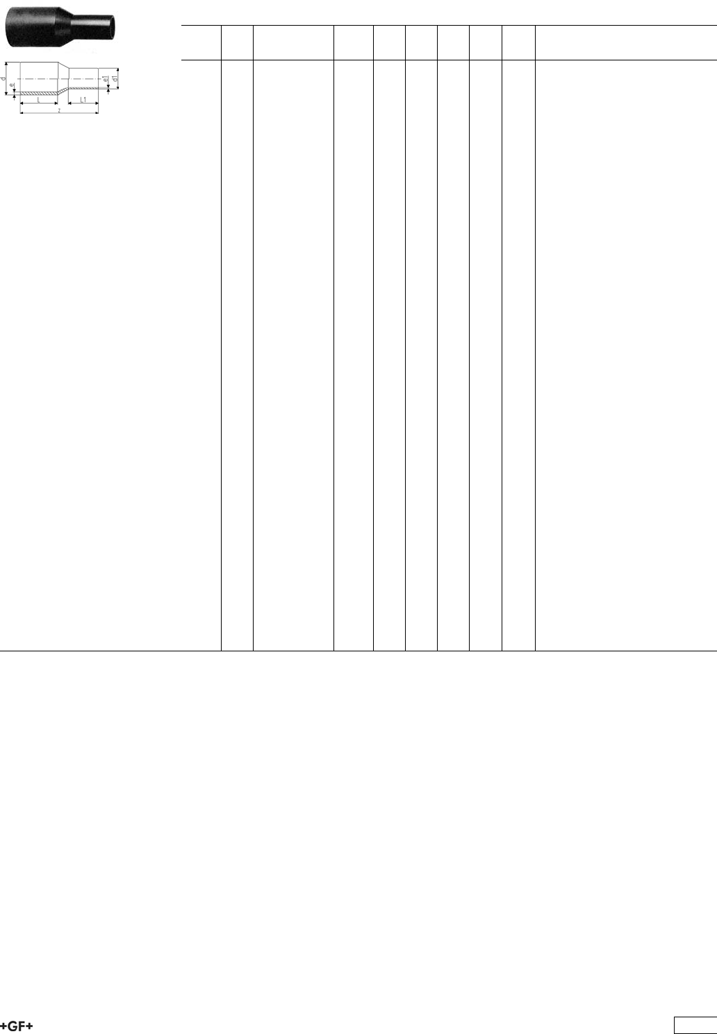
53 90 08 Reducer LS
ÏPE 100 SDR 17 / 17,6 (ISO S8 / S8,3)
Ï5 bar Gas / 10 bar Water
d
[mm]
d1
[mm]
Code kg z
[mm]
L
[mm]
L1
[mm]
e
[mm]
e1
[mm]
90 63 753 900 872 0.216 182 79 70 5,4 3,8
90 75 753 900 870 0.202 185 79 70 5,4 4,5
110 63 753 900 877 0.326 185 82 63 6,6 3,8
110 90 753 900 876 0.650 205 85 80 6,6 5,4
125 90 753 900 881 0.700 215 90 80 7,4 5,4
125 110 753 900 880 0.810 215 90 85 7,4 6,6
140 75 753 900 886 0.560 230 112 70 8,3 4,5
140 90 753 900 887 0.610 230 112 79 8,3 5,4
140 110 753 900 884 0.660 230 112 82 8,3 6,6
140 125 753 900 885 0.712 235 115 87 8,3 7,4
160 90 753 900 888 0.752 248 120 85 9,5 5,4
160 110 753 900 890 9.970 245 100 85 9,5 6,6
160 125 753 900 889 1.380 245 100 90 9,5 7,4
160 140 753 900 831 1.380 260 120 110 9,5 8,3
180 90 753 900 873 1.010 237 105 79 10,7 5,4
180 110 753 900 874 1.600 270 120 92 10,7 6,6
180 125 753 900 891 1.710 255 105 90 10,7 7,4
180 140 753 900 875 1.720 270 120 110 10,7 8,3
180 160 753 900 832 2.100 255 105 100 10,7 9,5
200 140 753 900 866 1.800 275 120 110 11,9 8,3
200 160 753 900 892 2.370 265 115 100 11,9 9,5
200 180 753 900 893 2.580 265 115 105 11,9 10,7
225 140 753 900 867 1.450 280 120 100 13,4 8,3
225 160 753 900 896 2.980 280 120 100 13,4 9,5
225 180 753 900 895 3.160 280 120 105 13,4 10,7
225 200 753 900 894 3.750 280 120 115 13,4 11,9
250 160 753 900 800 2.850 290 130 100 14,8 9,5
250 180 753 900 868 3.100 295 130 105 14,8 10,7
250 200 753 900 801 3.210 302 130 112 14,8 11,9
250 225 753 900 802 2.385 332 162 120 14,8 13,4
280 200 753 900 898 3.800 333 140 112 16,6 11,9
280 225 753 900 899 4.100 335 140 120 16,6 13,4
280 250 753 900 803 2.385 340 140 130 16,6 14,8
315 200 753 900 804 6.200 380 180 134 18,7 11,9
315 225 753 900 807 6.200 365 150 120 18,7 13,4
315 250 753 900 805 6.420 365 150 130 18,7 14,8
315 280 753 900 806 5.940 365 150 140 18,7 16,6
355 250 753 900 808 5.270 390 165 130 21,1 14,8
355 280 753 900 809 5.830 390 165 140 21,1 16,6
355 315 753 900 810 7.240 390 165 150 21,1 18,7
400 280 753 900 811 7.930 415 180 140 23,7 16,6
400 315 753 900 812 8.480 415 180 150 23,7 18,7
400 355 753 900 813 9.620 420 180 165 23,7 21,1
463
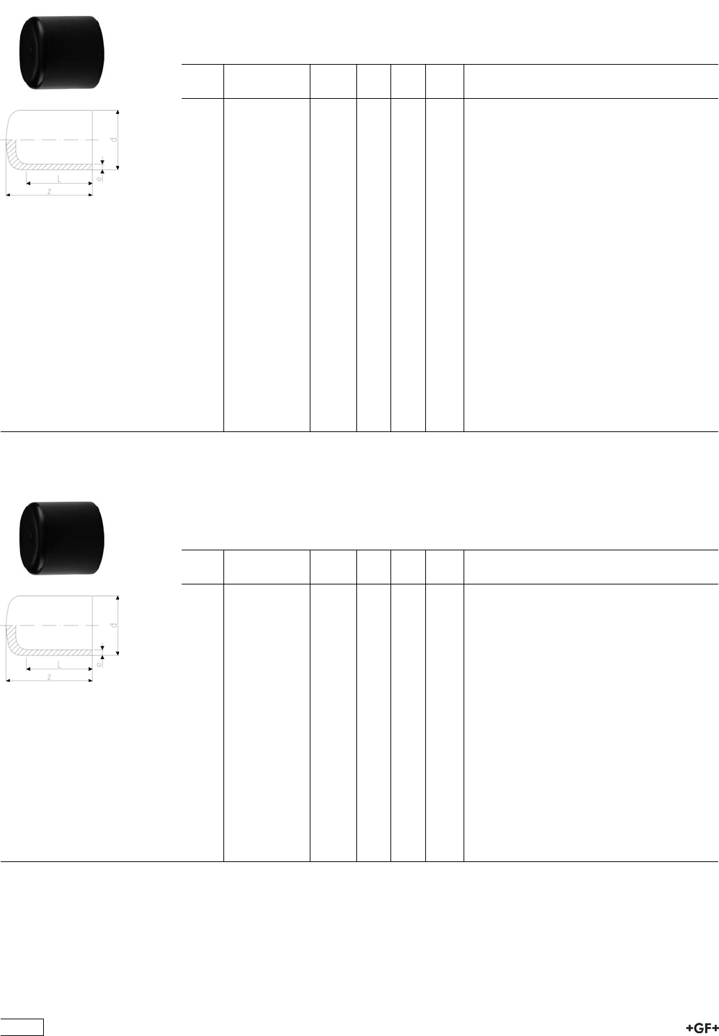
53 96 10 Cap Type L
ÏPE 100 SDR 11 (ISO S5)
Ï10 bar Gas / 16 bar Water
Note:
Ï* Fabricated part using pipe
d
[mm]
Code kg z
[mm]
L
[mm]
e
[mm]
20 753 961 006 0.009 52 52 3,0
25 753 961 007 0.013 52 52 3,0
32 753 961 008 0.017 54 54 3,0
40 753 961 009 0.031 57 57 3,7
50 753 961 010 0.050 63 63 4,6
63 753 961 011 0.085 65 65 5,8
75 753 961 012 0.145 80 72 6,8
90 753 961 013 0.240 90 81 8,2
110 753 961 014 0.387 98 86 10,0
125 753 961 015 0.546 105 92 11,4
140 753 961 016 0.835 136 92 12,7
160 753 961 017 1.026 120 102 14,6
180 753 961 018 1.369 128 107 16,4
200 753 961 019 1.839 138 115 18,2
225 753 961 020 2.500 148 122 20,5
250 753 961 021 3.927 205 130 22,7
280 753 960 922 5.344 235 139 25,4
315 753 960 923 7.176 255 150 28,6
355 753 960 924 9.780 280 165 32,3
400 753 960 925 13.370 310 180 36,4
*450 753 960 926 20.800 275 195 40,9
*500 753 960 927 28.400 297 212 45,5
*560 753 960 928 39.100 325 230 50,9
*630 753 960 929 59.700 355 250 57,3
53 96 08 Cap Type L
ÏPE 100 SDR 17 / 17,6 (ISO S8 / S8,3)
Ï5 bar Gas / 10 bar Water
Note:
Ï* Fabricated part using pipe
d
[mm]
Code kg z
[mm]
L
[mm]
e
[mm]
50 753 960 810 0.036 70 55 3,0
63 753 960 811 0.066 82 63 3,8
75 753 960 812 0.105 92 70 4,5
90 753 960 813 0.220 90 81 5,4
110 753 960 814 0.350 98 86 6,6
125 753 960 815 0.520 105 92 7,4
140 753 960 816 0.522 136 92 8,3
160 753 960 817 0.990 120 102 9,5
180 753 960 818 1.360 128 107 10,7
200 753 960 819 1.880 138 115 11,9
225 753 960 820 2.420 148 122 13,4
250 753 960 821 2.547 205 130 14,8
280 753 960 822 3.523 235 139 16,6
315 753 960 823 4.758 255 150 18,7
355 753 960 824 6.510 280 165 21,1
400 753 960 825 9.330 310 180 23,7
*450 753 960 826 15.800 265 195 26,7
*500 753 960 827 21.400 287 212 29,7
*560 753 960 828 29.400 310 230 33,2
*630 753 960 829 41.400 340 250 37,4
464
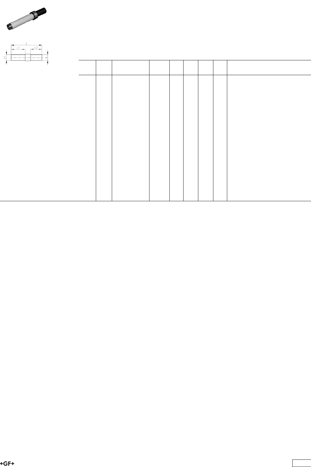
Transition Fittings PE / steel
ÏPE 100 SDR 11 (ISO S5)
Ï6 bar Gas / 16 bar Water
ÏElectrofusion weldable
ÏSteel pipe acc. to EN 10208-1, PE coated for corrosion resistance
* Steel pipe without plastic shroud
d
[mm]
d1
[inch]
Code kg d1
[mm]
z
[mm]
L1
[mm]
L2
[mm]
*20 1
/2775 641 502 0.500 21 450 310 85
25 3
/4775 641 507 0.640 27 460 310 100
32 1 775 641 510 0.940 34 460 310 100
40 1 1
/4775 641 514 1.200 42 460 310 100
50 1 1
/2775 641 518 1.440 48 460 310 100
63 2 775 641 524 1.930 60 460 310 100
75 2 1
/2775 641 632 2.800 76 510 310 100
90 3 775 641 636 3.700 89 520 310 100
110 3 775 641 640 3.800 89 520 310 100
110 4 775 641 641 6.600 114 520 310 100
125 4 775 641 645 6.700 114 520 310 100
160 6 775 641 655 11.300 168 580 310 120
180 6 775 641 659 11.800 168 580 310 130
200 8 775 642 664 19.100 219 600 310 130
225 8 775 642 669 19.500 219 600 310 130
250 8 775 642 665 20.500 219 620 310 160
250 10 775 642 666 30.000 273 620 310 160
280 10 775 642 673 31.000 273 620 310 160
315 12 775 642 672 47.000 324 630 310 220
355 12 775 642 675 49.000 324 630 310 220
400 16 775 642 678 94.000 406 640 310 220
465
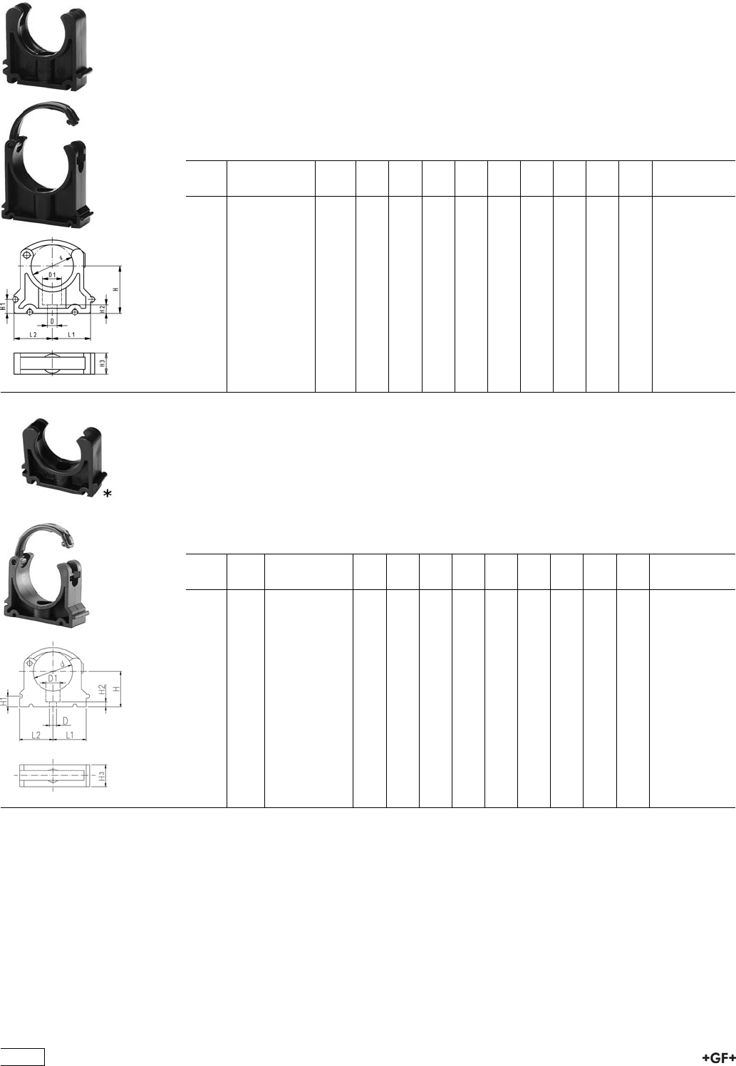
Pipe Clips
KLIP-IT Pipe Clips Type 061H, PP metric
Model:
ÏFor mm-pipes d16-d63
ÏMaterial: PP black, UV resistant
ÏMinimum order quantity: standard packagings SP
Ïd16 - d63: height designed for Ball Valve Type 546
Ï* d16 to d32 without bracket
d
[mm]
Code kg D
[mm]
D1
[mm]
L1
[mm]
L2
[mm]
H
[mm]
H1
[mm]
H2
[mm]
H3
[mm]
SC
*16 167 061 035 0.006 6 11 14 17 27 10 6 16 M5
*20 167 061 036 0.008 6 11 17 19 27 10 6 16 M5
*25 167 061 037 0.009 6 11 19 22 30 10 6 16 M5
*32 167 061 038 0.012 6 11 24 27 36 10 6 16 M5
40 167 061 039 0.027 7 14 34 34 44 10 7 22 M6
50 167 061 040 0.031 7 14 37 37 51 10 7 22 M6
63 167 061 041 0.054 9 17 45 45 64 10 10 25 M8
KLIP-IT Pipe Clips Type 061, PP
metric
Model:
ÏFor mm pipes
ÏMaterial: Clip and safety clip PP black, UV resistant
Ïd16 - d63: Height designed for Ball Valve Type 546
ÏMinimum order quantity: standard packagings SP
d
[mm]
d
[inch]
Code D
[mm]
D1
[mm]
L1
[mm]
L2
[mm]
H
[mm]
H1
[mm]
H2
[mm]
H3
[mm]
SC
*10 167 061 003 5 8 11 14 20 10 6 12 M4
*12 167 061 004 5 8 11 14 21 10 6 12 M5
*16 167 061 035 6 11 14 17 27 10 6 16 M5
*20 167 061 036 6 11 17 19 27 10 6 16 M5
*25 167 061 037 6 11 19 22 30 10 6 16 M5
*32 167 061 038 6 11 24 27 36 10 6 16 M5
40 167 061 039 7 14 34 34 44 10 7 22 M6
50 167 061 040 7 14 37 37 51 10 7 22 M6
63 167 061 041 9 17 45 45 64 10 10 25 M8
75 2 1
/2167 061 012 9 17 52 52 58 10 10 25 M8
90 3 167 061 013 9 17 65 65 65 10 10 28 M8
110 4 167 061 014 9 17 79 79 75 10 10 28 M8
125 167 061 015 9 17 88 88 90 10 10 32 M8
140 5 167 061 016 9 17 98 98 110 10 10 32 M8
160 167 061 017 9 17 109 109 108 10 10 32 M8
466
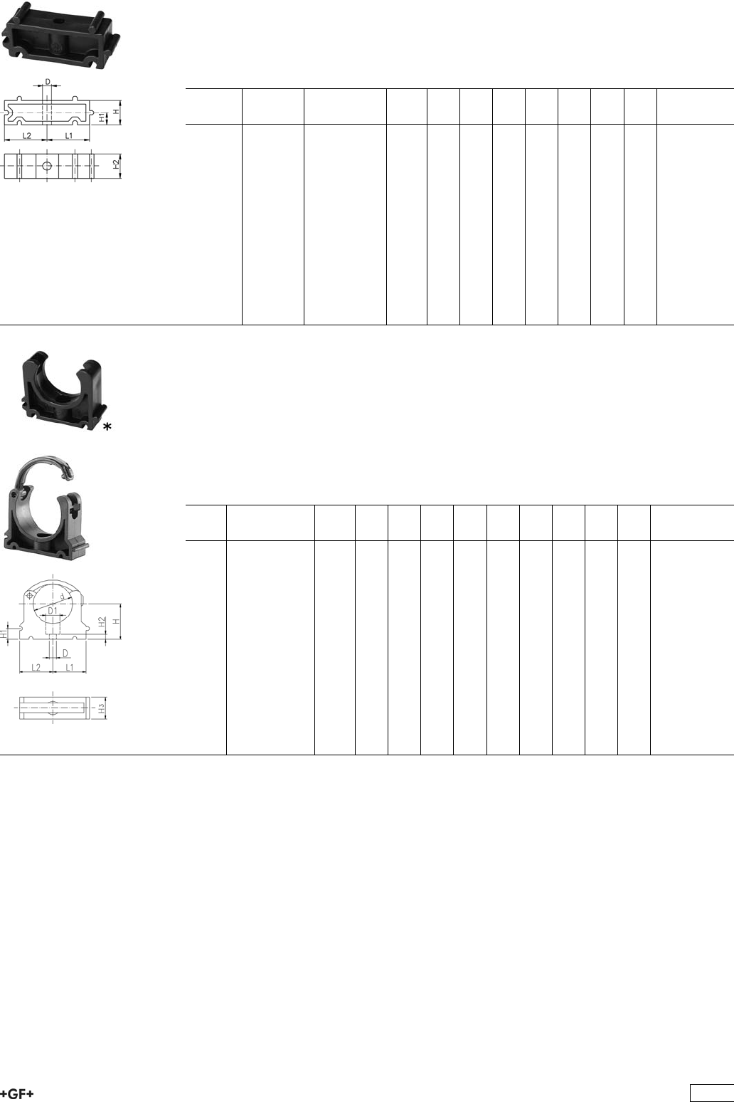
KLIP-IT Spacer Type 061, PP
Model:
ÏFor pipe clips Type 061/061H, PP black, UV resistant
ÏMinimum order quantity: standard packaging SP
d
[mm]
Inch
[inch]
Code kg D
[mm]
L1
[mm]
L2
[mm]
H
[mm]
H1
[mm]
H2
[mm]
SC
10 - 12 1
/8-1
/4167 061 153 0.003 5 11 14 20 10 12 M4
16 3
/8167 061 155 0.006 6 14 17 20 10 16 M5
20 1
/2167 061 156 0.006 6 17 19 20 10 16 M5
25 3
/4167 061 157 0.007 6 19 22 20 10 16 M5
32 1 167 061 158 0.008 6 24 27 20 10 16 M5
40 1 1
/4167 061 159 0.016 7 34 34 20 10 22 M6
50 1 1
/2167 061 160 0.017 7 37 37 20 10 22 M6
63 2 167 061 161 0.024 9 45 45 20 10 25 M8
75 2 1
/2167 061 162 0.027 9 52 52 20 10 25 M8
90 3 167 061 163 0.040 9 65 65 20 10 28 M8
110 4 167 061 164 0.048 9 79 79 20 10 28 M8
125 4 1
/2167 061 165 0.059 9 88 88 20 10 32 M8
140 5 167 061 166 0.065 9 98 98 20 10 32 M8
160 6 167 061 167 0.074 9 109 109 20 10 32 M8
KLIP-IT Pipe Clips Type 061, PE
metric
Model:
ÏFor mm pipes
ÏMaterial: Clip PE and safety clip PP black
ÏMinimum order quantity: standard packaging SP
ÏHeight not designed for ball valve 546. Please use spacer 73 06 11.
d
[mm]
Code kg D
[mm]
D1
[mm]
L1
[mm]
L2
[mm]
H
[mm]
H1
[mm]
H2
[mm]
H3
[mm]
SC
*10 173 061 003 0.003 5 8 11 14 20 10 6 12 M4
*12 173 061 004 0.006 5 8 11 14 21 10 6 12 M5
*16 173 061 005 0.007 6 11 14 17 23 10 6 16 M5
*20 173 061 006 0.008 6 11 17 19 25 10 6 16 M5
*25 173 061 007 0.009 6 11 19 22 28 10 6 16 M5
*32 173 061 008 0.012 6 11 24 27 31 10 6 16 M5
40 173 061 009 0.022 7 14 34 34 35 10 7 22 M6
50 173 061 010 0.030 7 14 37 37 40 10 7 22 M6
63 173 061 011 0.044 9 17 45 45 52 10 10 25 M8
75 173 061 012 0.062 9 17 52 52 58 10 10 25 M8
90 173 061 013 0.090 9 17 65 65 65 10 10 28 M8
110 173 061 014 0.114 9 17 79 79 75 10 10 28 M8
125 173 061 015 0.174 9 17 88 88 90 10 10 32 M8
140 173 061 016 0.217 9 17 98 98 110 10 10 32 M8
160 173 061 017 0.237 9 17 109 109 108 10 10 32 M8
467
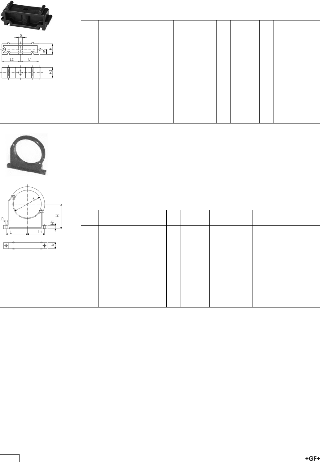
73 06 11 KLIP-IT Spacer Type 061, PE
Model:
ÏFor pipe clips Type 061, PE black, UV resistant
ÏMinimum order quantity: standard packaging SP
d
[mm]
Inch Code kg D
[mm]
L1
[mm]
L2
[mm]
H
[mm]
H1
[mm]
H2
[mm]
SC
1/8-1/4 173 061 153 0.003 5 11 14 20 10 12 M4
16 3/8 173 061 155 0.005 6 14 17 20 10 16 M5
20 1/2 173 061 156 0.006 6 17 19 20 10 16 M5
25 3/4 173 061 157 0.007 6 19 22 20 10 16 M5
32 1 173 061 158 0.008 6 24 27 20 10 16 M5
40 11/4 173 061 159 0.016 7 34 34 20 10 22 M6
50 11/2 173 061 160 0.017 7 37 37 20 10 22 M6
63 2 173 061 161 0.025 9 45 45 20 10 25 M8
75 21/2 173 061 162 0.027 9 52 52 20 10 25 M8
90 3 173 061 163 0.040 9 65 65 20 10 28 M8
110 4 173 061 164 0.048 9 79 79 20 10 28 M8
125 41/2 173 061 165 0.059 9 88 88 20 10 32 M8
140 5 173 061 166 0.065 9 98 98 20 10 32 M8
160 6 173 061 167 0.074 9 109 109 20 10 32 M8
Pipe Clips Type 060, PP
metric
Model:
ÏFor mm pipes d90-400
ÏMaterial: Clip and safety clip PP black, UV resistant
ÏAccidental opening of the safety clip is not possible
ÏMinimum order quantity: standard packaging SP or gross packaging GP
ÏClip and safety clip are not assembled in the packaging.
ÏPipes with flanges can be installed directly
d
[mm]
d
[inch]
Code kg D
[mm]
L
[mm]
L1
[mm]
H
[mm]
H1
[mm]
H2
[mm]
SC
90 3 167 060 038 0.163 9 89 71 105 15 33 M 8
110 167 060 039 0.179 9 94 80 115 15 33 M 8
125 167 060 040 0.300 11 116 91 130 20 35 M10
140 5 167 060 041 0.309 11 121 98 130 20 35 M10
160 167 060 042 0.348 11 131 107 148 20 35 M10
180 167 060 043 0.378 11 143 115 163 20 35 M10
200 167 060 019 0.582 13 152 120 175 25 39 M12
225 167 060 020 0.612 13 165 132 175 25 39 M12
250 167 060 021 0.698 13 183 143 200 25 39 M12
280 167 060 022 0.722 13 198 156 200 25 39 M12
315 167 060 023 0.842 13 219 172 225 25 39 M12
355 167 060 024 1.250 17 275 209 258 30 50 M16
400 167 060 025 1.450 17 300 228 288 30 50 M16
468
Fusion Jointing Machines
Page
Manual Butt and Socket Fusion Tools 470
SG 110 Socket Fusion Machine 473
SG 160 Combined Butt and Socket Fusion Machine 474
MC 110 Butt Fusion Machine 478
PSO 701 Butt Fusion Machine 479
SG 315 Butt Fusion Machine 480
IR-63 Plus®and IR-225 Plus®Fusion Jointing Machines 485
BCF®Plus Plastic Fusion Jointing Machine 487
Electrofusion Units and Accessories 489
469
Manual Butt and Socket Fusion Tools
SSE Butt fusion tool
ÏAll devices are equiped with on/off switch, mains control and control lamp for heating
intervals
ÏChoice of electronic or thermostatic temperature control
ÏHeating element diameter 120 mm, 200 mm and 300 mm
ÏPick up for floor stand or table clamp
ÏHigh-quality, non-stick PTFE-coating with long service life
ÏMonitoring and setting of heating element temperature
ÏHigh temperature accuracy over the entire heating surface
ÏT = thermostatic temperature control
ÏE = electronic temperature control
d
[mm]
Type Performance Code kg
110 SSE 120 115 V/400 W T 790 105 136 2.300
110 SSE 120 115 V/400 W E 790 105 141 2.400
180 SSE 200 230 V/800 W T 790 105 052 3.000
180 SSE 200 230 V/800 W E 790 105 059 3.000
180 SSE 200 115 V/800 W T 790 105 137 3.000
180 SSE 200 115 V/800 W E 790 105 142 3.000
280 SSE 300 230 V/1500 W T 790 105 053 5.540
280 SSE 300 230 V/1500 W E 790 105 060 5.640
280 SSE 300 115 V/1500 W T 790 105 138 5.540
280 SSE 300 115 V/1500 W E 790 105 143 5.640
SSE 200 -Set- Butt fusion tool
ÏAll devices are equiped with on/off switch, mains control and control lamp for heating
intervals
ÏChoice of electronic or thermostatic temperature control
ÏPick up for floor stand or table clamp
ÏHigh-quality, non-stick PTFE-coating with long service life
ÏMonitoring and setting of heating element temperature
ÏHigh temperature accuracy over the entire heating surface
ÏAvailable as a complete set in a practical metal case
ÏHeating element-diameter 200 mm
ÏTable clamp
ÏT = thermostatic temperature control
ÏE = electronic temperature control
d
[mm]
Performance Code kg
180 230 V/800 W T 790 105 054 7.815
180 230 V/800 W E 790 105 061 8.800
180 115 V/800 W T 790 105 139 7.400
180 115 V/800 W E 790 105 144 7.400
470
SSE 300 -Set- Butt fusion tool
ÏAll devices are equiped with on/off switch, mains control and control lamp for heating
intervals
ÏChoice of electronic or thermostatic temperature control
ÏPick up for floor stand or table clamp
ÏHigh-quality, non-stick PTFE-coating with long service life
ÏMonitoring and setting of heating element temperature
ÏHigh temperature accuracy over the entire heating surface
ÏAvailable as a complete set in a practical metal case
ÏHeating element-diameter 300 mm
ÏTable clamp
ÏT = thermostatic temperature control
ÏE = electronic temperature control
d
[mm]
Performance Code kg
280 230 V/1500 W T 790 105 055 11.725
280 230 V/1500 W E 790 105 062 11.000
280 115 V/1500 W T 790 105 140 11.000
280 115 V/1500 W E 790 105 145 11.000
MSE 63/MSE 110 Socket fusion tools
ÏFor fusion jointing of PP, PE and PVDF pipes and fittings
ÏSize range d 16-110 mm
ÏChoice of electronic or thermostatic temperature control
ÏSupport for heating bushes and spigots of d 16 to 63 mm (110 mm)
ÏPick up for floor stand or table clamp
ÏHigh-quality, non-stick PTFE-coating with long service life
ÏMonitoring and setting of heating element temperature
ÏHigh temperature accuracy over the entire heating surface
ÏT = thermostatic temperature control
ÏE = electronic temperature control
d-d
[mm]
Type Performance Code kg
16 - 63 MSE 63 230 V/800 W T 790 105 081 1.760
16 - 63 MSE 63 230 V/800 W E 790 105 082 2.000
16 - 63 MSE 63 115 V/800 W T 790 105 096 2.075
16 - 63 MSE 63 115 V/800 W E 790 105 097 2.145
16 - 110 MSE 110 230 V/1500 W T 790 105 083 3.550
16 - 110 MSE 110 230 V/1500 W E 790 105 084 3.200
16 - 110 MSE 110 115 V/1500 W T 790 105 126 3.200
16 - 110 MSE 110 115 V/1500 W E 790 105 127 3.200
471
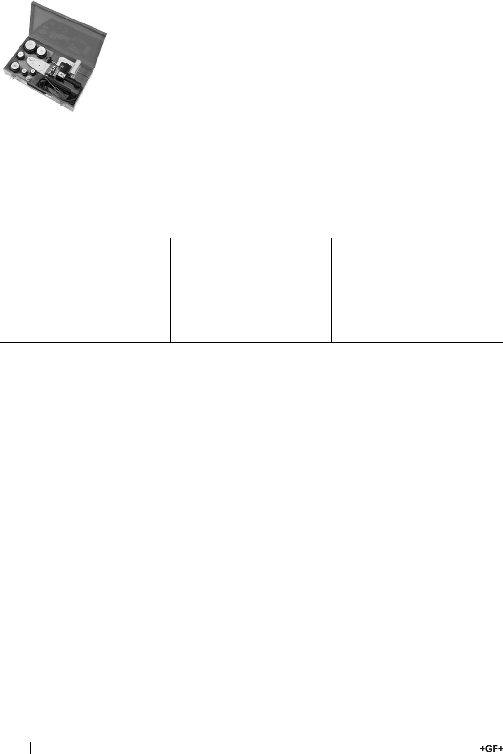
MSE 63/MSE 110 - Set - Socket fusion tools
ÏFor fusion jointing of PP, PE and PVDF pipes and fittings
ÏSize range d 16-110 mm
ÏAll devices are equiped with on/off switch, mains control and control lamp for heating
intervals
ÏChoice of electronic or thermostatic temperature control
ÏSupport for heating bushes and spigots of d 16 to 63 mm (110 mm)
ÏPick up for floor stand or table clamp
ÏHigh-quality, non-stick PTFE-coating with long service life
ÏMonitoring and setting of heating element temperature
ÏHigh temperature accuracy over the entire heating surface
ÏHeating bushes and spigots
ÏAvailable as a complete set in a practical metal case
ÏTable clamp
ÏFloor stand for MSE 63
ÏAlen screws and key
ÏT = thermostatic temperature control
ÏE = electronic temperature control
d-d
[mm]
Type Performance Code kg
16 - 63 MSE 63 230 V/800 T 790 105 085 8.600
16 - 63 MSE 63 230 V/800 E 790 105 086 10.180
16 - 63 MSE 63 115 V/800 T 790 105 098 8.600
16 - 63 MSE 63 115 V/800 E 790 105 099 8.600
16 - 110 MSE 110 230 V/1500 T 790 105 087 17.700
16 - 110 MSE 110 230 V/1500 E 790 105 088 17.680
16 - 110 MSE 110 115 V/1500 T 790 105 128 14.880
16 - 110 MSE 110 115 V/1500 E 790 105 129 15.600
472
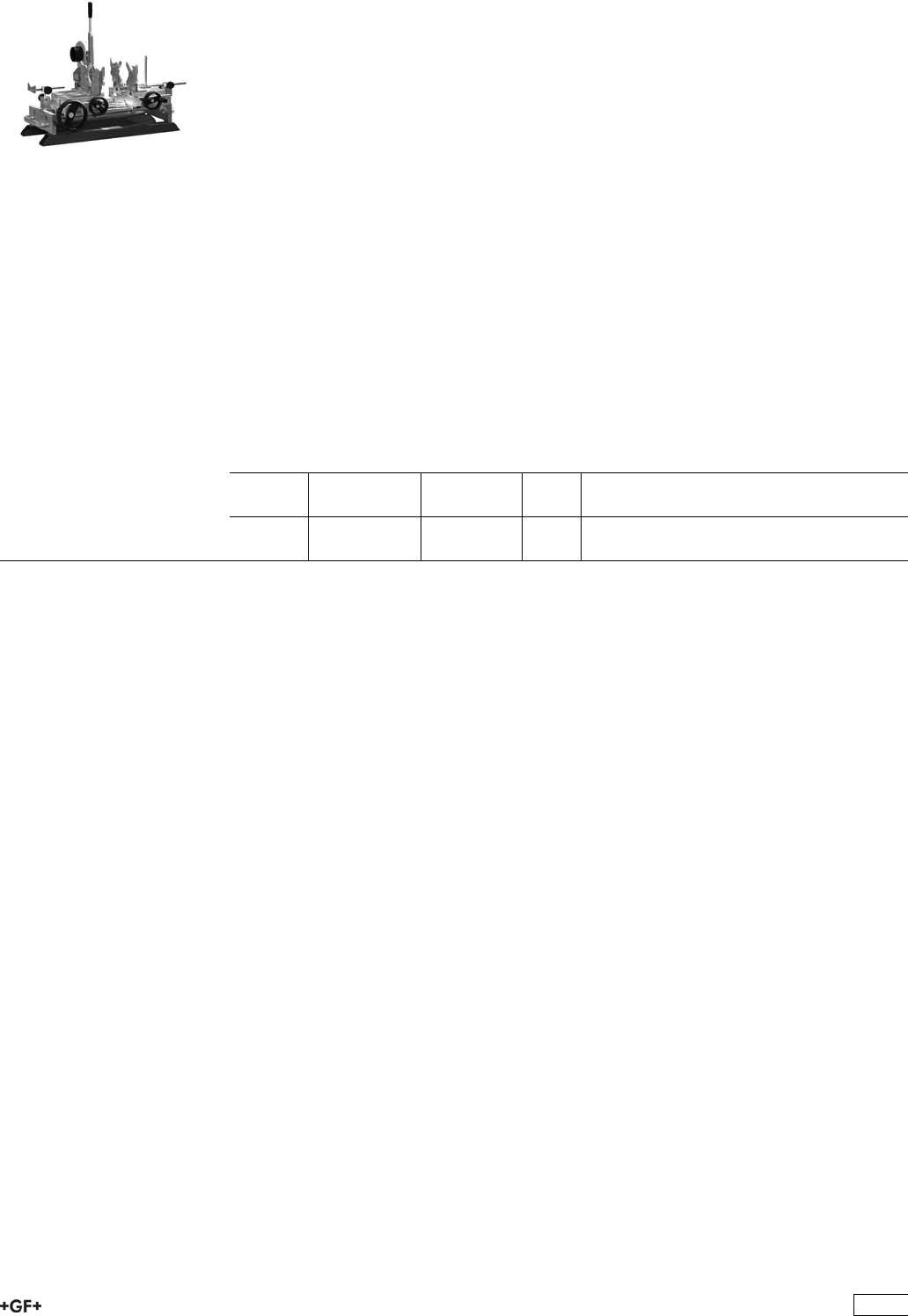
SG 110 Socket Fusion Machine
For fusion jointing of PP, PE, PB and PVDF pipes and
fittings
ÏPortable heating element - socket fusion machine for use in the workshop and on job
sites.
ÏDimension d 20 - 110 mm
ÏBase machine
ÏCompact, sturdy design, distortion-free machine bed
ÏHandwheel with torque locking mechanism for the slide movement
ÏHeater
ÏWith electronic temeperature control
ÏHigh temperature accuracy over the entire heating surface
ÏAdditional standard equipment on the basic model
ÏUniversal, left and right prismatic clamping devices, complete, for clamping pipe and
fittings. Additional set of prismatic clamping devices for outer clamping of pipes
available as an option.
ÏDepth stop
ÏV-shaped pipe support d 20 - 110 mm
ÏBack stop
ÏMachine specific tool set
ÏTimer to clock fusion times
d-d
[mm]
Performance Code kg
20 - 110 230 V/1200 W 790 310 001 65.000
20 - 110 115 V/1200 W 790 310 003 64.000
473
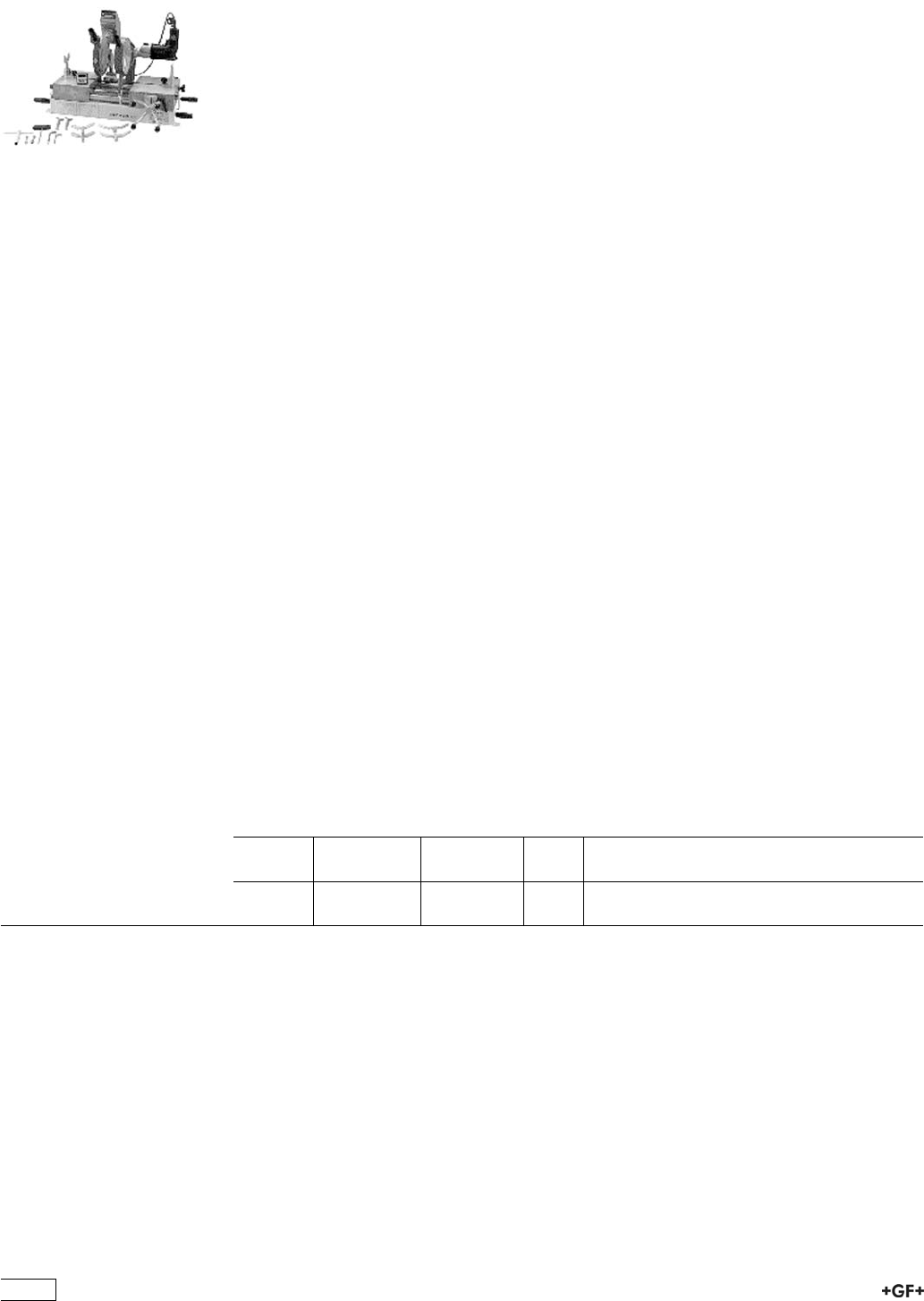
SG 160 Combined Butt and Socket Fusion
Machine
for fusion jointing PP, PE and PVDF pipes and
fittingssize range for butt fusion d 32 - 160
Mobile, very compact and universal plastic fusion machine for use
in the workshop and on job sites.
Butt fusion d 32 - 160 mm, all pressure ratings up to PE/PP SDR 11; PVDF SDR 21.
Socket fusion d 16 - 110 mm
Basic machine
Ïhigh precision, distortion-free and robust machine base
Ïhandwheel for easy moving of machine carriage
Ïexact pressure adjustment via direct load transfer
Ïhardened, hard-chrome plated guide shafts for extreme loads
Ïhandle for safe transport of machine
ÏAll clamping possibilities for base clamping plates, pipe supports, back stop and
prismatic clamping devices.
Planer
Ïplaning device made of light cast aluminium
Ïoptimised cutting geometry for even and chatter-free planing
Ïpowerful parallel planer, swivels in and out for single or double-sided facing of pipe
ends 620 W
Ïintegrated pick up for easy mounting of calibration tools for machining of pipe ends in
socket fusion
Heater
Ïhigh-performance and precision heater with electronic temperature control 1500 W
Ïhigh accuracy of +/- 4°C over the entire heating surface
Ïheater temperature can be set exactly with digital LCD
Ïhigh quality, non-stick, easy to change PTFE fabric (Teflon)
Additional standard equipment on the basic model
ÏV-shaped pipe supports d 16 - 160 mm for fittings
Ïtimer to clock fusion times
Ïtool set specified to machine
d-d
[mm]
Performance Code kg
16 - 160 230 V 790 103 031 44.900
16 - 160 115 V 790 103 033 45.000
474
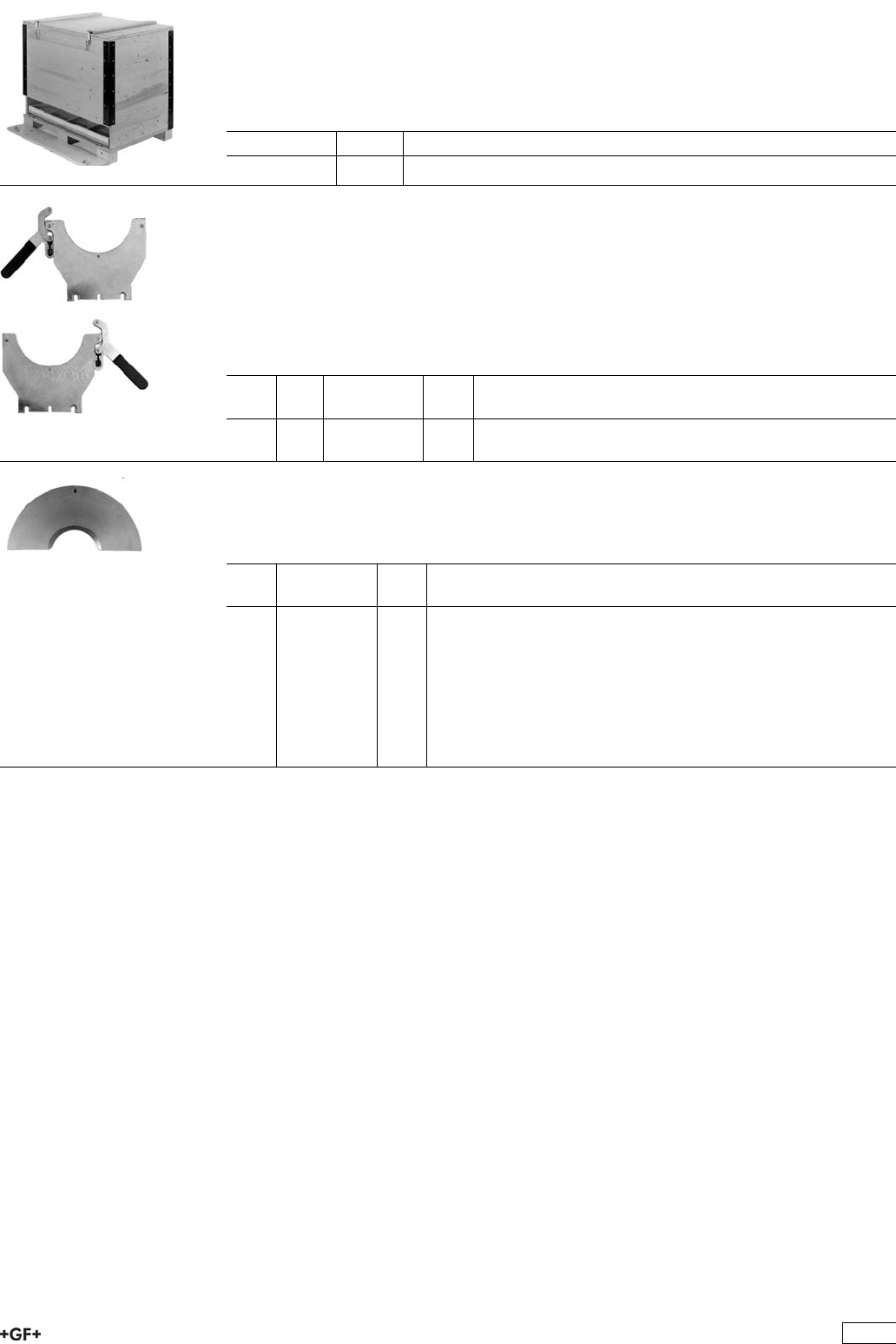
Special transport crate
ÏCompact and sturdy for proper transportation and safe storage
ÏMultifunctional, can be used as a workbench for ergonomic working position
ÏTwo integrated drawers to store all accessories
ÏDimensions 1 m height x 1,2 m length x 0.8 m width
Code kg
790 103 099 108.000
Base clamping plates
ÏIn order to improve the quality of the fusion joint, and for reliable clamping of long
pipes, we recommend using the maximum number of clamping devices.
ÏFor welding of long pipes we recommend to use the outer left and outer right base
clamping plates as well.
ÏL = left
ÏR = right
d
[mm]
Type Code kg
160 L 790 103 010 2.503
160 R 790 103 011 2.510
Inserts, left/right
ÏFor base clamping plate
ÏLeft or right
d
[mm]
Code kg
32 790 103 019 0.315
40 790 103 020 0.310
50 790 103 021 0.302
63 790 103 022 0.277
75 790 103 023 0.250
90 790 103 024 0.224
110 790 103 025 0.178
125 790 103 026 0.132
140 790 103 027 0.079
475
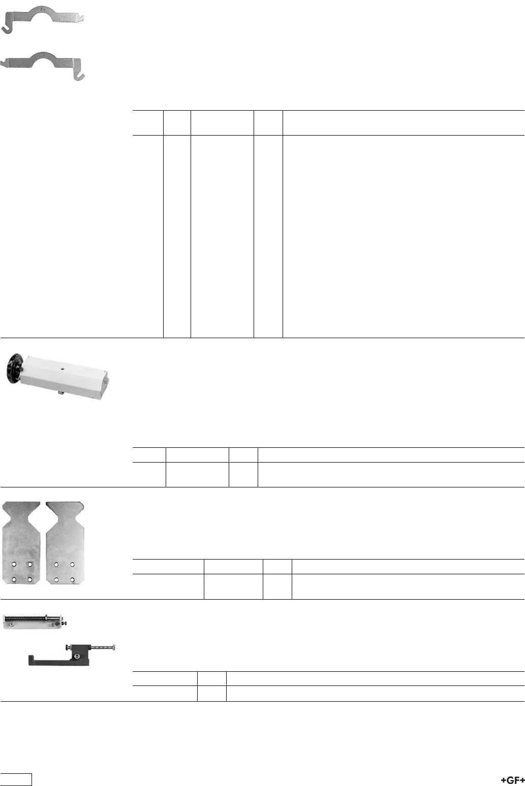
Clamping bracket, left/right
ÏFor base clamping plate
ÏL = left
ÏR = right
* Threaded clamping bracket, for mounting inserts d 32 - 140 mm. An additional insert
must be used instead of clamping brackets d 32 - 140 mm, i.e. twice the number of
inserts listed must be ordered.
d
[mm]
Type Code kg
32 L 790 103 039 0.530
40 L 790 103 040 0.530
50 L 790 103 041 0.530
63 L 790 103 042 0.530
75 L 790 103 043 0.530
90 L 790 103 044 0.580
110 L 790 103 045 0.580
125 L 790 103 046 0.606
140 L 790 103 047 0.650
*160 L 790 103 048 0.669
32 R 790 103 059 0.530
40 R 790 103 060 0.530
50 R 790 103 061 0.530
63 R 790 103 062 0.530
75 R 790 103 063 0.530
90 R 790 103 064 0.580
110 R 790 103 065 0.590
125 R 790 103 066 0.605
140 R 790 103 067 0.530
*160 R 790 103 068 0.650
Prismatic clamping device
ÏPrismatic clamping device for pick up of clamping jaws for exact alignment of fusion
components
ÏL = left
ÏR = right
*Horizontal adjustable
Type Code kg
L790 103 080 6.112
*R 790 103 081 6.118
Clamping jaws
ÏFor prismatic base units, left/right
ÏEach code number defines 1 piece prismatic clamping device. For socket fusion 4
pieces are needed.
** Code kg
16-32 / 90-110 790 103 085 0.310
30-50 / 50-90 790 103 086 0.330
Depth stop, complete
ÏWarrants the correct insertion depth of the pipe in the fittings socket
ÏBuilt-in spring for easier removal of fusion components from the heater. Damage to
the plastified fusion surfaces is prevented.
Code kg
790 103 090 0.610
476
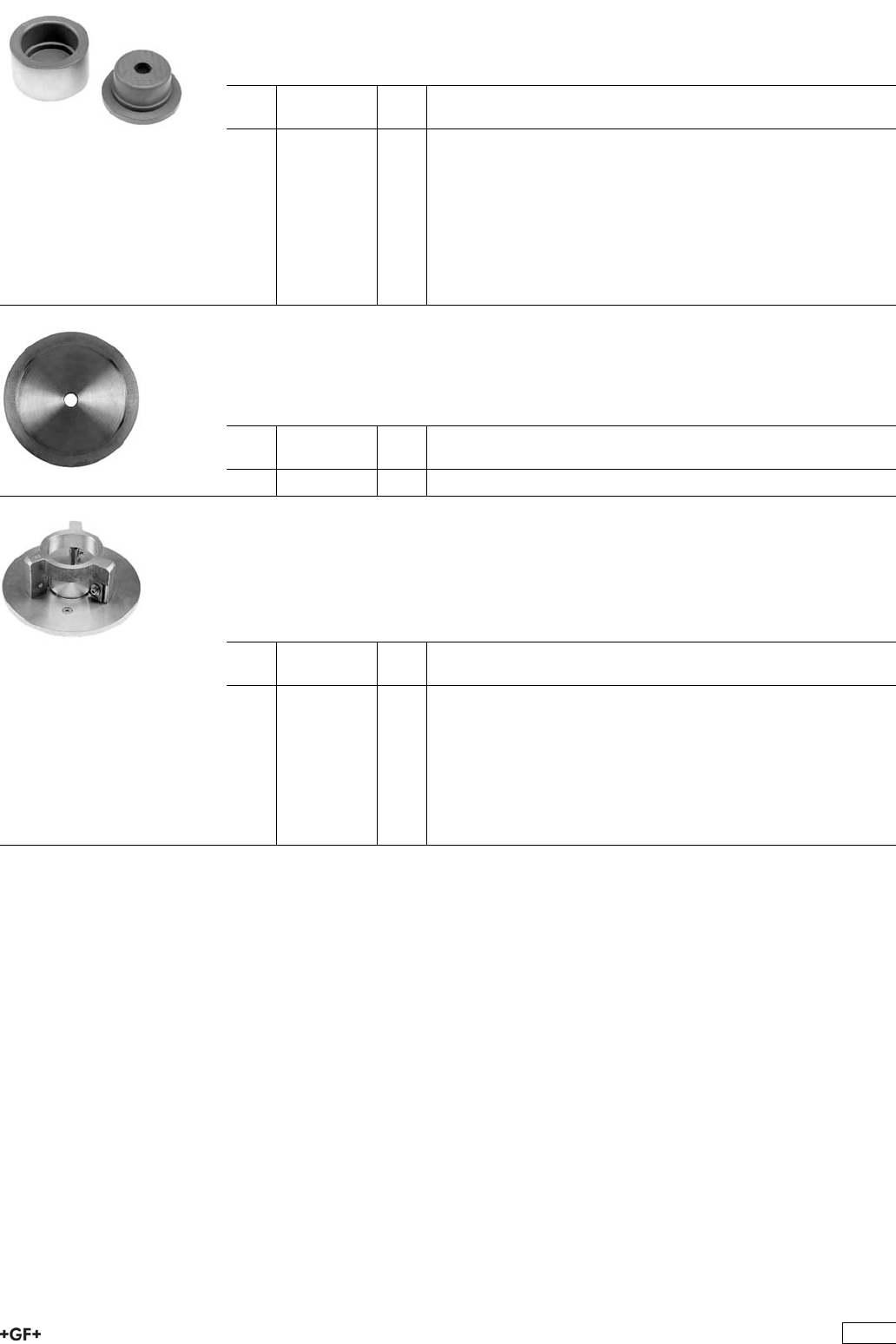
Heating spigots and bushes
ÏAluminium, PTFE coated
Ï1 pair is always delivered
d
[mm]
Code kg
16 790 101 086 0.310
20 790 101 087 0.315
25 790 101 088 0.313
32 790 101 089 0.316
40 790 101 090 0.329
50 790 101 091 0.475
63 790 101 092 0.858
75 790 101 093 1.157
90 790 101 094 1.697
110 790 101 095 2.090
Stiffener plate
ÏFor heating bush d 110 mm
ÏWarrants consistent heat transfer from heater plate to heating bush 110 mm
ÏIs recommended for socket fusion in the dimension 110 mm
d
[mm]
Code kg
110 790 101 098 0.264
Calibration tool
ÏFor mechanical, standardised calibration of pipe ends in PE, PP and PVDF (to be
used with planer)
Ïeasy and time-saving removal of oxide film
ÏConsistent peeling quality over the entire pipe circumference
d
[mm]
Code kg
20 790 103 160 0.950
25 790 103 161 0.950
32 790 103 162 0.950
40 790 103 163 0.930
50 790 103 164 0.950
63 790 103 165 1.000
75 790 103 166 1.150
90 790 103 167 1.250
110 790 103 168 1.344
477
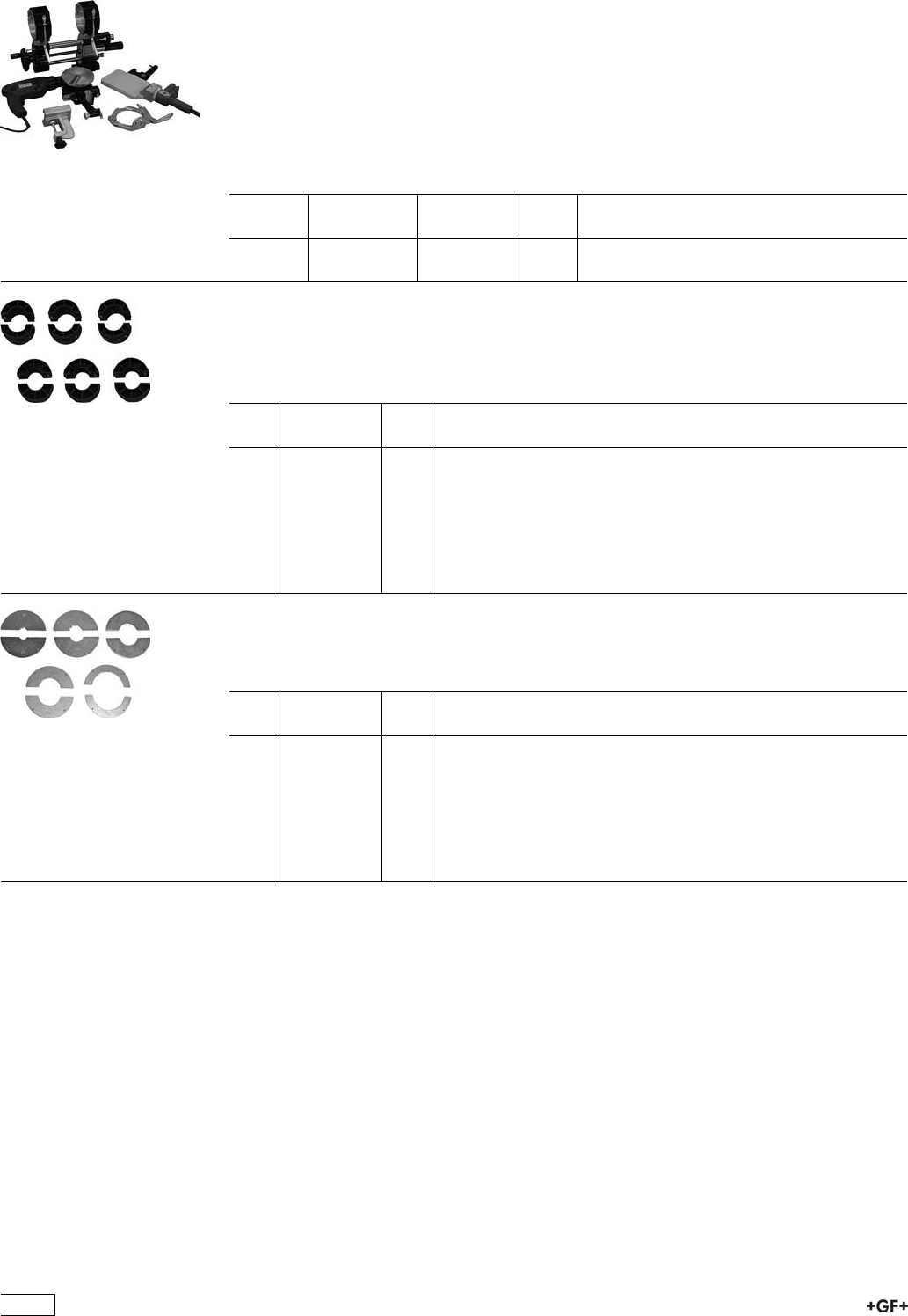
MC 110 Butt Fusion Machine
Machine MC 110, complete with electric planer
ÏPortable butt fusion machine for use in the workshop and on job sites. For fusion
jointing of PP and PE pipes and fittings as well as prefabrication of segments in the
size range d 20 - 110 mm and up to PN 10.
ÏMachine MC 110 complete includes: machine mounting, basic machine, 2 base
clamping plates (wide), base clamping plate (left narrow), planer, heater
thermostatic controlled, table clamp and transport crate.
ÏIncluding transport packaging, without accessories
d-d
[mm]
Performance Code kg
20 - 110 230 V/ 800 W 790 109 303 31.000
20 - 110 115 V/ 800 W 790 109 321 31.000
Reduction clamping inserts, wide
Ï20 - 90 mm
ÏEach code number defines 1 half shell. Per wide base clamping plate 2 reduction
half -shells are needed.
d
[mm]
Code kg
25 790 109 327 0.150
32 790 109 328 0.150
40 790 109 329 0.145
50 790 109 330 0.129
56 790 109 342 0.150
63 790 109 331 0.125
75 790 109 332 0.113
90 790 109 333 0.105
Reduction clamping inserts, narrow
ÏEach code number defines 1 half shell. Per wide base clamping plate 2 reduction
half -shells are needed.
d
[mm]
Code kg
25 790 109 335 0.075
32 790 109 336 0.070
40 790 109 337 0.125
50 790 109 338 0.124
56 790 109 343 0.114
63 790 109 339 0.110
75 790 109 340 0.100
90 790 109 341 0.100
478
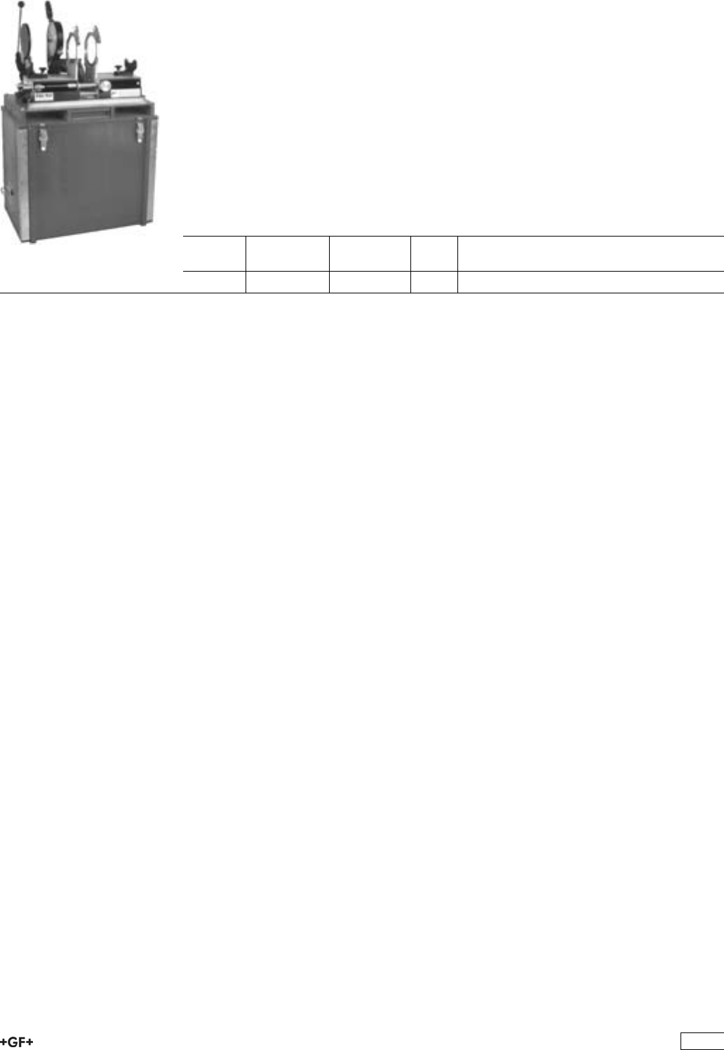
PSO 701 Butt Fusion Machine
For fusion jointing of PP and PE pipes and fittings, size
range d 40 - 160mm
ÏProfessional butt fusion machine capable to weld pipes d 160mm up to PN10. The
wooden box is usable as working bench as well as for transportation.
ÏPressure adjustment via direct load transfer (max. force 100kp)
ÏPlaner and heating element could be swivelled in and out
ÏHigh performance heating element thermostatic controlled (PTFE coated)
ÏThe heating element can be used as manual fusion tool
ÏV-shaped pipe support d 40 - 140 mm
ÏReduction clamping inserts d 40 - 140 mm
ÏBase clamping plates right and left, d 160 mm
ÏMachine specific tool set
d-d
[mm]
Performance Code kg
40 - 160 230 V/800 W 790 301 000 90.000
479
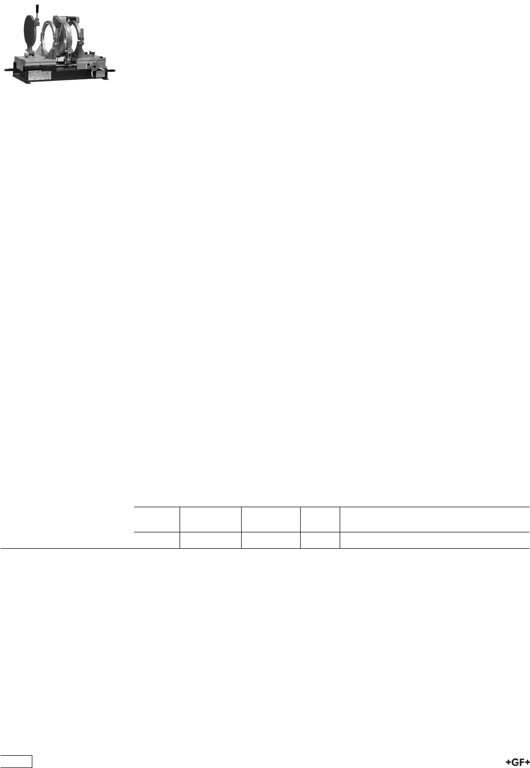
SG 315 Butt Fusion Machine
SG 315 for butt fusion jointing of PP, PE and PVDF
pipes and fittings
The industrial butt fusion machine for pressure piping systems. Extremely sturdy design
use in the workshop and on job sites.
Sizes d 90-315 mm, all pressure ratings up to max. PE d 280 SDR 11;
PP d 280 SDR 7.25 and PVDF d 315 SDR 21.
Basic machine
Ïhigh precision, distortion-free and robust machine base
Ïhandwheel for easy moving of machine carriage
Ïfusion pressure is maintained with a user friendly torque limiter
Ïexact pressure adjustment via direct load transfer
Ïhardened, hard-chrome plated guide shafts for extreme loads
Ïhandle for safe transport of machine
Ïoptional outer, horizontally removeable clamping devices available
Planer
Ïoptimised cutting geometry for even and chatter-free planing
Ïpowerful parallel planer, swivels in and out for single or double-sided facing of pipe
ends, 1100 W
Ïfor your personal safety, a safety switch has been integrated to prevent unintentional
start-up in the working position
Heater
Ïhigh-performance and precision heater with electronic temperature control 1700 W
Ïhigh accuracy of +/- 4°C over the entire heating surface
Ïheater temperature can be set exactly with digital LCD
Ïhigh quality, non-stick, easy to change PTFE coating
Ïwith digital temperature indicator
Additional standard equipment included in the base model
Ïinner left and right clamping plates, d 315 mm, for pick up of reduction clamping
inserts d 90 - 280 mm
Ïpipe supports d 315 mm for support of fittings
Ïtimer to clock fusion times
Ïtool set specified to machine
d-d
[mm]
Performance Code kg
90 - 315 115 V 790 130 002 128.000
480
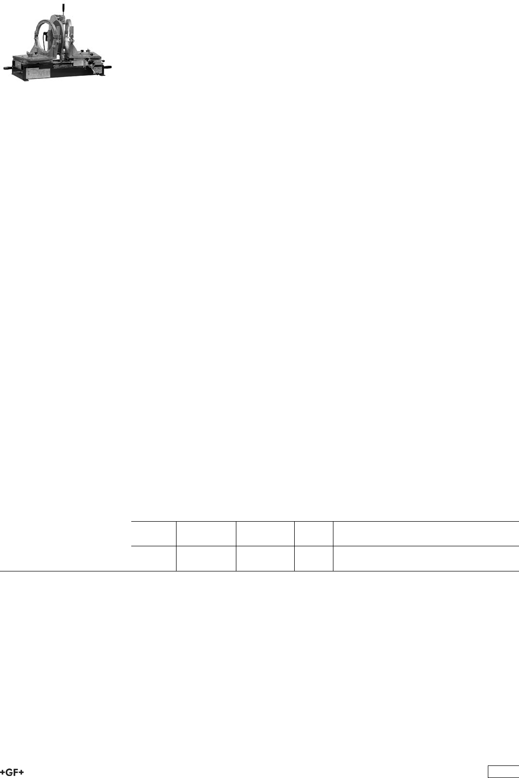
SG 315 for butt fusion jointing of PP, PE and PVDF
pipes and fiitings
The industrial butt fusion machine for pressure piping systems.
The S-version (S = segment) additionally allows prefabrication of segments.
Sizes d 90-315 mm, all pressure ratings up to max. PE d 280 SDR 11;
PP d 280 SDR 7.25 and PVDF d 315 SDR 21.
Basic machine
Ïintegrated swivel tables for equalization of wall offset transverse to axial direction, for
segment fusion up to 30°
Ïoptional outer, horizontally removeable clamping devices available
Ïhigh precision, distortion-free and robust machine base
Ïhandwheel for easy moving of machine carriage
Ïfusion pressure is maintained with a user friendly torque limiter
Ïexact pressure adjustment via direct load transfer
Ïhardened, hard-chrome plated guide shafts for extreme loads
Ïhandle for safe transport of machine
Planer
Ïoptimised cutting geometry for even and chatter-free planing
Ïpowerful parallel planer, swivels in and out for single or double-sided facing of pipe
ends, 1100 W
Ïfor your personal safety, a safety switch has been integrated to prevent unintentional
start-up in the working position
Heater
Ïhigh-performance and precision heater with electronic temperature control
1700 W
Ïhigh accuracy of +/- 4°C over the entire heating surface
Ïheater temperature can be set exactly with digital LCD
Ïhigh quality, non-stick, easy to change PTFE coating
Ïwith digital temperature indicator
Additional standard equipment included in the base model
Ïinner left and right clamping plates, d 315 mm, for pick up of reduction clamping
inserts d 90 - 280 mm
Ïpipe supports d 315 mm for support of fittings
Ïtimer to clock fusion times
Ïtool set specified to machine
d-d
[mm]
Performance Code kg
90 - 315 230 V 790 130 003 150.000
90 - 315 115 V 790 130 004 143.000
481

SG 315 for butt fusion jointing of PP, PE and PVDF
pipes and fittings
The industrial butt fusion machine for pressure piping systems. Extremely sturdy design
use in the workshop and on job sites.
Equipped with a load cell and a digital display of the fusion force.
Sizes d 90-315 mm, all pressure ratings up to max. PE d 280 SDR 11;
PP d 280 SDR 7.25 and PVDF d 315 SDR 21.
Basic machine
Ïhigh precision, distortion-free and robust machine base
Ïhandwheel for easy moving of machine carriage
Ïfusion pressure is maintained with a user friendly torque limiter
Ïexact pressure adjustment via direct load transfer
Ïhardened, hard-chrome plated guide shafts for extreme loads
Ïhandle for safe transport of machine
Ïdigital display
Ïoptional outer, horizontally removeable clamping devices available
Planer
Ïoptimised cutting geometry for even and chatter-free planing
Ïpowerful parallel planer, swivels in and out for single or double-sided facing of pipe
ends, 1100 W
Ïfor your personal safety, a safety switch has been integrated to prevent unintentional
start-up in the working position
Heater
Ïhigh-performance and precision heater with electronic temperature control
1700 W
Ïhigh accuracy of +/- 4°C over the entire heating surface
Ïheater temperature can be set exactly with digital LCD
Ïhigh quality, non-stick, easy to change PTFE coating
Ïwith digital temperature indicator
Additional standard equipment included in the base model
Ïinner left and right clamping plates, d 315 mm, for pick up of reduction clamping
inserts d 90 - 280 mm
Ïpipe supports d 315 mm for support of fittings
Ïtimer to clock fusion times
Ïtool set specified to machine
d-d
[mm]
Performance Code kg
90 - 315 230 V 790 130 031 150.000
90 - 315 115 V 790 130 032 128.000
482
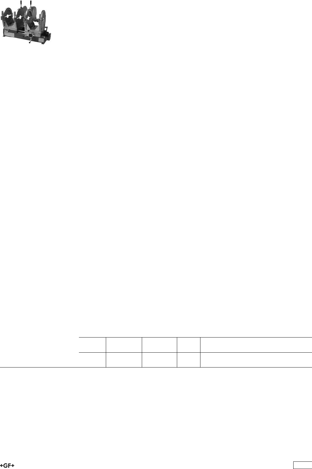
SG 315 for butt fusion jointing of PP, PE and PVDF
pipes and fittings
The industrial butt fusion machine for pressure piping systems.
The S-version (S = segment) additionally allows prefabrication of segments.
Sizes d 90-315 mm, all pressure ratings up to max. PE d 280 SDR 11;
PP d 280 SDR 7.25 and PVDF d 315 SDR 21.
Basic machine
Ïintegrated swivel tables for equalization of wall offset transverse to axial direction, for
segment fusion up to 30°
Ïoptional outer, horizontally removeable clamping devices available
Ïhigh precision, distortion-free and robust machine base
Ïhandwheel for easy moving of machine carriage
Ïfusion pressure is maintained with a user friendly torque limiter
Ïexact pressure adjustment via direct load transfer
Ïhardened, hard-chrome plated guide shafts for extreme loads
Ïhandle for safe transport of machine
Ïload cell
Ïdigital display
Planer
Ïoptimised cutting geometry for even and chatter-free planing
Ïpowerful parallel planer, swivels in and out for single or double-sided facing of pipe
ends, 1100 W
Ïfor your personal safety, a safety switch has been integrated to prevent unintentional
start-up in the working position
Heater
Ïhigh-performance and precision heater with electronic temperature control
1700 W
Ïhigh accuracy of +/- 4°C over the entire heating surface
Ïheater temperature can be set exactly with digital LCD
Ïhigh quality, non-stick, easy to change PTFE coating
Ïwith digital temperature indicator
Additional standard equipment included in the base model
Ïinner left and right clamping plates, d 315 mm, for pick up of reduction clamping
inserts d 90 - 280 mm
Ïpipe supports d 315 mm for support of fittings
Ïtimer to clock fusion times
Ïtool set specified to machine
d-d
[mm]
Performance Code kg
90 - 315 230 V 790 130 033 143.000
90 - 315 115 V 790 130 034 145.000
483
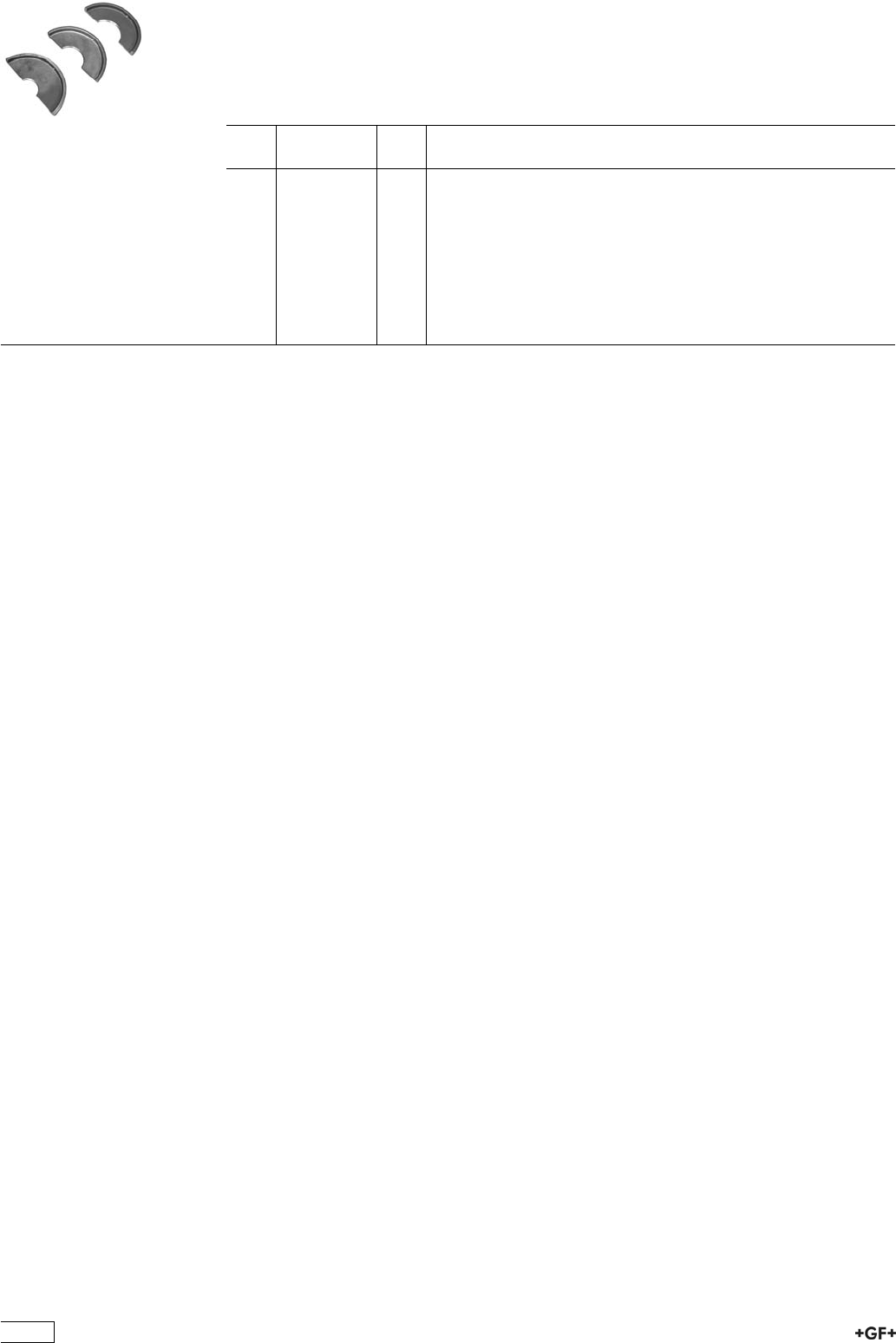
Reduction clamping inserts, narrow
Ïd 90 - 280 mm
ÏEach code number defines 1 piece of reduction clamping insert. Per machine and
dimension maximum 8 narrow or wide reduction clamping inserts are needed.
ÏWe recommend 4 wide and 4 narrow half shells.
d
[mm]
Code kg
90 790 112 098 0.995
110 790 112 099 1.285
125 790 112 100 1.245
140 790 112 101 1.205
160 790 112 102 1.135
180 790 112 103 1.010
200 790 112 104 0.950
225 790 112 105 0.865
250 790 112 106 0.770
280 790 112 107 0.560
484

IR-63 Plus®and IR-225 Plus®Fusion Jointing
Machines
IR-63 Plus®Fully-Equipped Machine
Fully-equipped fusion jointing machine for welding SYGEF®Standard, SYGEF®Plus,
PROGEF®Standard, PROGEF®Natural, PROGEF®Plus, PE 100 in dimensions
d 20-63 mm with integrated remote welding unit, 2 USB interfaces, monochrome display
with icons and 12 languages.
Supply:
1-phase AC (50/60 Hz) 230 V L/N/PE
Delivery includes:
ÏMachine housing complete (1 pcs.)
ÏHeater assembly (1 pcs.)
ÏRemote weld device (1 pcs.)
ÏFacing tool (1 pcs.)
ÏTransport box (1 pcs.)
ÏPipe stop (1 pcs.)
ÏClamping inserts d 20-63 mm (8 pcs. per dimension)
ÏEnd caps PE d 20-63 mm (4 pcs. per dimension)
ÏPower supply cable 230 V (1 pcs.)
ÏExtension cable for remote weld device (1 pcs.)
ÏExtension cable for heater (1 pcs.)
ÏExtension cable for facing tool (1 pcs.)
ÏCleaning brush No. 8 (1 pcs.)
ÏHexagon key 3 mm (1 pcs.)
ÏHexagon key 4 mm (1 pcs.)
ÏHeater protection shield (1 pcs.)
ÏClamping unit extension (8 pcs.)
ÏSocket wrench (facing blades) (1 pcs.)
ÏScrew driver, Size 0 (1 pcs.)
ÏHP-Accessory Tray (1 pcs.)
ÏManual (1 pcs.)
d-d
[mm]
Code kg
20 - 63 790 131 005 52.000
485

IR-225 Plus®Fully-Equipped Machine with HP Working
Table (HP = High Purity)
Fully-equipped fusion jointing machine for welding SYGEF®Standard, SYGEF®Plus,
PROGEF®Standard, PROGEF®Natural, PROGEF®Plus, PE 100 in dimensions
d 63-225 mm, 2 USB interfaces, monochrome display with icons and 12 languages.
Supply:
1-phase AC (50/60 Hz) 230 V L/N/PE or 3-phase AC (50/60 Hz) 400 V/230 V
L1/L2/L3/N/PE
Delivery includes:
ÏMachine base (1 pcs.)
ÏHeater assembly (1 pcs.)
ÏFacing tool (1 pcs.)
ÏWorking table, HP (1 pcs.)
ÏMovable clamping units (1 pcs.)
ÏClamping inserts d 63-225 mm (8 pcs. per dimension)
ÏEnd caps PE d 63-225 mm (4 pcs. per dimension)
ÏTransportation lock (1 pcs.)
ÏPipe stop (1 pcs.)
ÏHexagon key 5 mm (1 pcs.)
ÏHexagon key 6 mm (1 pcs.)
ÏCombination ring /open-jaw wrench 13 mm (1 pcs.)
ÏCleaning brush (1 pcs.)
ÏConnecting cable 400 V - 230 V (1 pcs.)
ÏBall for lever (1 pcs.)
ÏManual (1 pcs.)
d-d
[mm]
Code kg
63 - 225 790 133 009 453.000
486
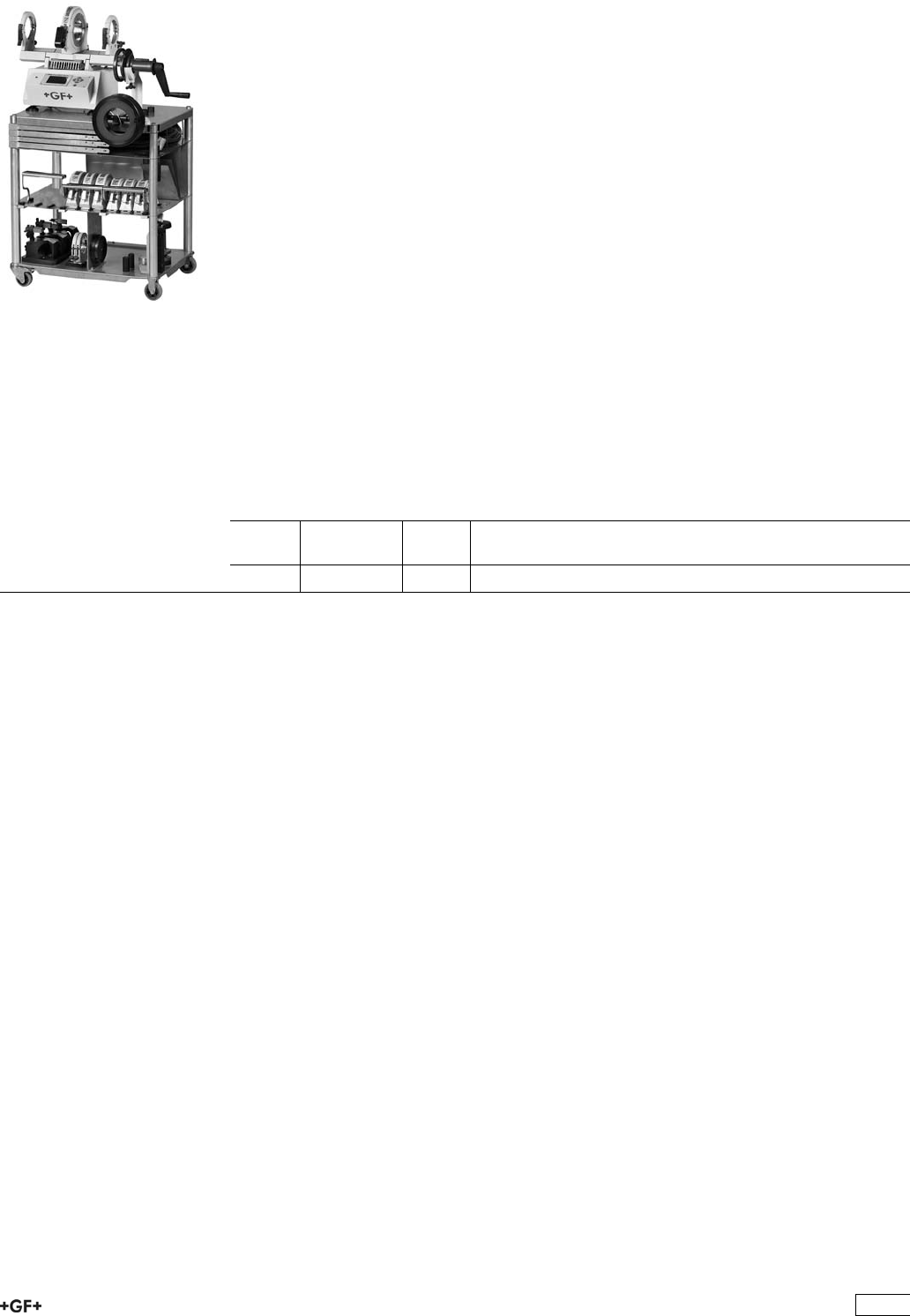
BCF®Plus Plastic Fusion Jointing Machine
BCF®Plus fully equipped machine d 20 - 63 mm
Fully-equipped machine for bead and crevice free jointing of SYGEF®Standard,
SYGEF®Plus, PROGEF®Natural of the dimensions
d 20-63 mm with integrated remote welding unit, 2 USB interfaces, monochrome display
with icons and 12 languages.
Supply:
1-phase AC (50/60 Hz) 115 / 230 V L/N/PE
Delivery includes:
ÏMachine housing (1 pcs.) incl. remote welding unit (1 pcs.)
ÏTransport box (1 pcs.)
ÏHP working table (1 pcs.)
ÏHeating stations d 20-63 mm (6 pcs.)
ÏClamping units small (2 pcs.) with clamping inserts d 20-63 mm (24 pcs.)
ÏFacing tool small (1 pcs.) with facing inserts d 20-63 mm (6 pcs.)
ÏFacing tool support (1 pcs.)
ÏHose box (1 pcs.) incl. air hose (1 pcs.)
ÏSupporting tools small d 20-63 mm (2 pcs.)
ÏBReT (1 pcs.)
ÏHose cutter (1 pcs.)
ÏAir hose reducer (6-4 mm) (1 pcs.), air hose socket (4-4 mm) (1 pcs.)
ÏExtension cable (1 pcs.)
ÏManual (1 pcs.)
d-d
[mm]
Code kg
20 - 63 790 121 002 153.000
487
BCF®Plus Bladder
ÏOnly suitable for welding PROGEF®Natural). Blue bladder head (except d 75
-110mm)!
d
[mm]
Code kg Pieces
20 790 122 091 0.038 1
25 790 122 092 0.044 1
32 790 122 093 0.062 1
40 790 122 094 0.082 1
50 790 122 095 0.131 1
63 790 122 096 0.168 1
488
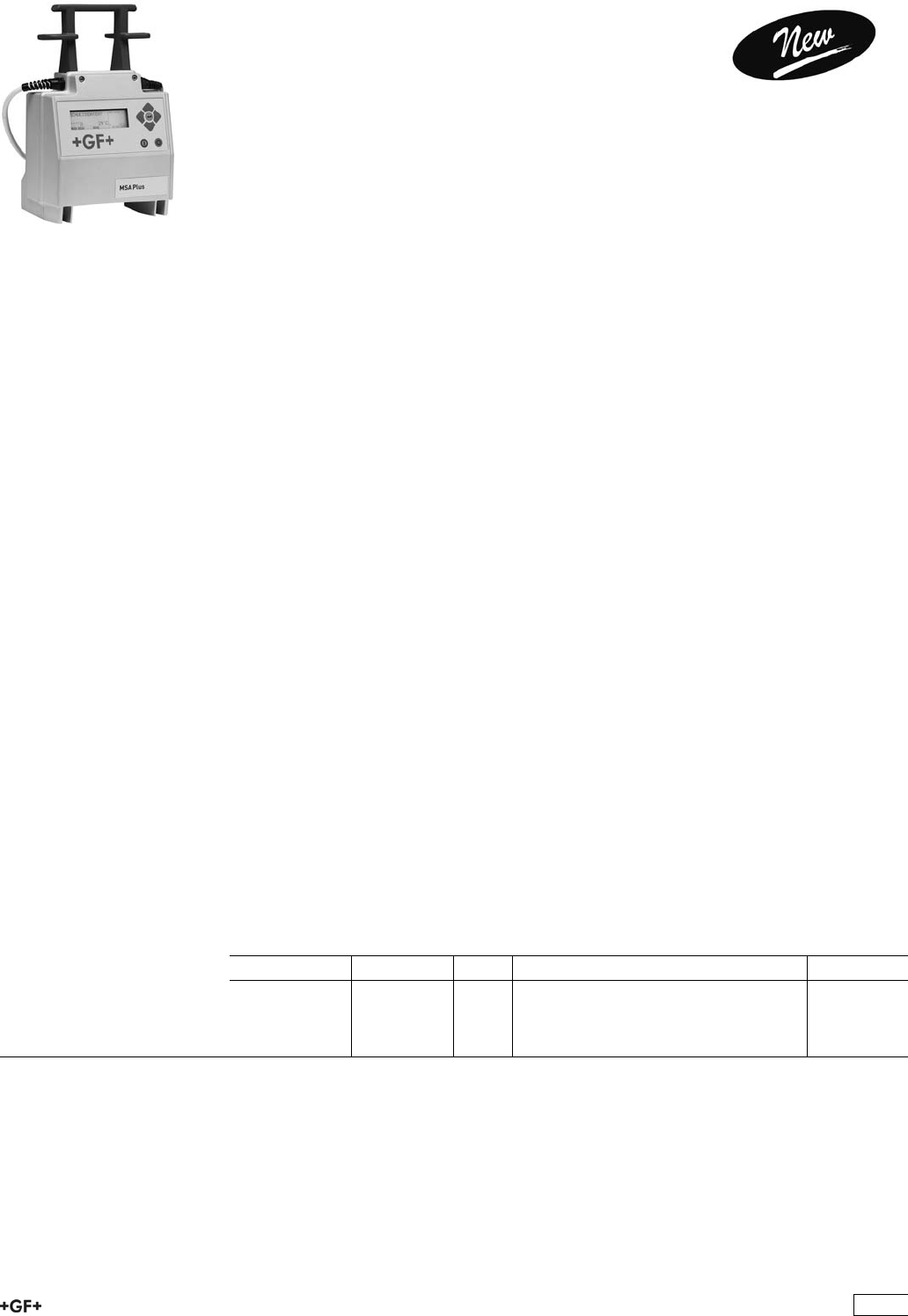
Electrofusion Units and Accessories
MSA Plus 400
Traceability Electrofusion Unit with
USB interfaces
NEW, environmental friendly manufactured electrofusion unit according EU
directive 2002/95/EU (RoHS).
Professional electrofusion unit for traceability of piping system components from raw
material to completed electrofusion joint (to ISO 12176). The MSA units with the unique
inverter technology and the active cooling system for trouble-free operation from
generator or mains supply. Suitable for jointing in series. The unit is equipped with
compact flash memory card (exchangeable data carrier), barcode reader pen or
optional barcode scanner. The unit is robust, light and easy to use. The menue has up
to 27 different languages. Inclusive 1 transport case, 1 USB memory stick, 1 pair of
angle adapter clips 4.0 mm, operating instructions, configuration card and Software
MSA WIN-WELD.
For printer or PC communication the USB cable (799350619) is required.
Technical Data
Ambient temperature -10 °C - +45 °C
Mains voltage 180 V - 264 V AC
Mains frequency 45Hz - 65 Hz
Fusion voltage 8 - 42 (48) V AC
Fusion current max. 80 A
Power max. 3500 W
Protection 1 / IP 65
Interfaces USB (type A) for printer communication and to load software
updates
USB (type B) for PC communication
Mains cable 3 m
Fusion cable 3 m
Dimensions (WxHxD) 284 x 440 x 195 mm
Weight incl. cables ca. 11,5 kg, light-weight aluminium housing
Display LCD graphic, background light, contrast adjustment
Size display (WxH) 132 x 39 mm
Type size 8 mm
Languages Brasilian, Bulgarian, Chinese, Croatian, Czech, Danish, Dutch,
English, Estonian, Finnish, French, German, Hungarian, Italian,
Latvian, Lithuanian, Malaysian, Norwegian, Polish, Portuguese,
Rumanian, Russian, Slovakian, Slovenian, Spanish, Swedish,
Turkish
Warranty 24 months
Type Code kg Description
MSA Plus 400 799 350 580 16.800 barcode reader pen, transport case
MSA Plus 400 799 350 581 16.800 barcode scanner, transport case
MSA Plus 400 799 350 585 16.800 CH power plug with barcode reader pen,
transport case
489
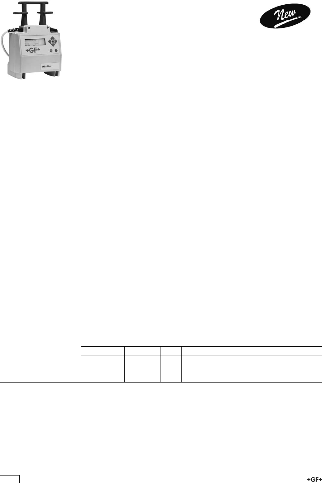
MSA Plus 350
Record Electrofusion Unit
with USB interfaces
NEW, environmental friendly manufactured electrofusion unit according EU
directive 2002/95/EU (RoHS).
Professional electrofusion unit for recording jointing data of electrofusion components
as a basis for electronic joint recording. The MSA units with the unique inverter
technology and the active cooling system for trouble-free operation from generator or
mains supply. Suitable for jointing in series. The unit is equipped with barcode reader
pen, optional with barcode scanner. The unit is robust, light and easy to use. The menu
has up to 27 different languages. Inclusive transport box, 1 USB memory stick, 1 pair of
angle adapter clips 4.0 mm, operating instructions, configuration card and Software
MSA WIN-WELD.
To read out the fusion protocols the USB cable (799 350 619) or the USB memory stick
(799 350 622) required.
Technical Data
Ambient temperature -10 °C - +45 °C
Mains voltage 180 V - 264 V AC
Mains frequency 45Hz - 65 Hz
Fusion voltage 8 - 42 (48) V AC
Fusion current max. 80 A
Power max. 3500 W
Protection 1 / IP 65
Interface USB (type A) for printer communication and to load software
updates
USB (type B) for PC communication
Mains cable 3 m
Fusion cable 3 m
Dimensions (WxHxD) 284 x 440 x 195 mm
Weight incl. cables ca. 11,5 kg, light-weight aluminium housing
Display LCD graphic, background light, contrast adjustment
Size display (WxH) 132 x 39 mm
Type size 8 mm
Languages Brasilian, Bulgarian, Chinese, Croatian, Czech, Danish, Dutch,
English, Estonian, Finnish, French, German, Hungarian, Italian,
Latvian, Lithuanian, Malaysian, Norwegian, Polish, Portuguese,
Rumanian, Russian, Slovakian, Slovenian, Spanish, Swedish,
Turkish
Warranty 24 months
Type Code kg Description
MSA Plus 350 799 350 570 16.800 barcode reader pen, transport case
MSA Plus 350 799 350 571 16.800 barcode scanner, transport case
MSA Plus 350 799 350 575 16.800 CH Power plug, with barcode reader,
transport case
490
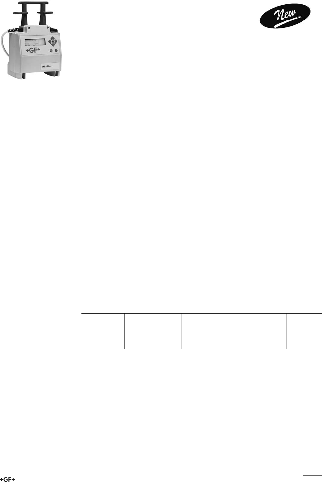
MSA Plus 300
Automatic Electrofusion Unit
with USB interfaces
NEW, environmental friendly manufactured electrofusion unit according EU
directive 2002/95/EU (RoHS).
Automatic electrofusion unit with barcode reader pen, optional with barcode scanner.
The MSA units with the unique inverter technology and the active cooling system for
trouble-free operation from generator or mains supply. Suitable for jointing in series.
The unit is robust, light and easy to use. The menu has up to 27 different languages.
Inclusive transport box, 1 pair of angle adapter clips 4.0 mm, operating instructions and
configuration card.
To load software updates the USB memory stick (799 350 622) is required.
Technical Data
Ambient temperature -10 °C - +45 °C
Mains voltage 180 V - 264 V AC
Mains frequency 45Hz - 65 Hz
Fusion voltage 8 - 42 (48) V AC
Fusion current max. 80 A
Power max. 3500 W
Protection 1 / IP 65
Interfaces USB (type A) to load software updates
USB (type B) for PC communication
Mains cable 3 m
Fusion cable 3 m
Dimensions (WxHxD) 284 x 440 x 195 mm
Weight incl. cables ca. 11,5 kg, light-weight aluminium housing
Display LCD graphic, background light, contrast adjustment
Size display (WxH) 132 x 39 mm
Type size 8 mm
Languages Brasilian, Bulgarian, Chinese, Croatian, Czech, Danish, Dutch,
English, Estonian, Finnish, French, German, Hungarian, Italian,
Latvian, Lithuanian, Malaysian, Norwegian, Polish, Portuguese,
Rumanian, Russian, Slovakian, Slovenian, Spanish, Swedish,
Turkish
Warranty 24 months
Type Code kg Description
MSA Plus 300 799 350 560 16.800 barcode reader pen, transport case
MSA Plus 300 799 350 561 16.800 barcode scanner, transport case
MSA Plus 300 799 350 565 16.800 CH Power plug, with barcode reader pen,
transport case
491
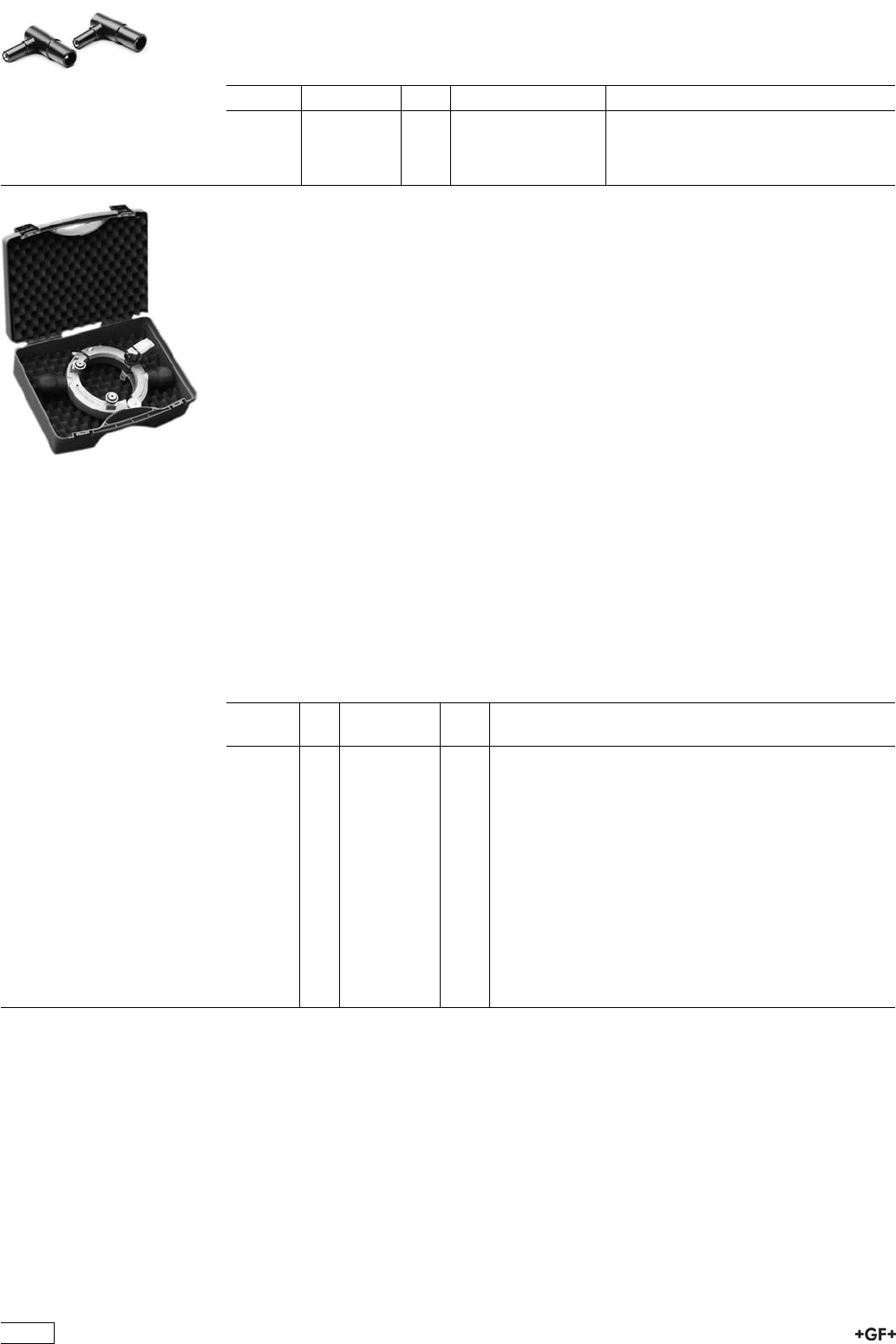
Adapter
ÏAdapters for electrofusion units with 4 mm connectors.
ÏCompatible with electrofusion units MSA 210, MSA 250-400 and MSA Plus 250-400.
Type Code kg Description
4,0 mm 799 350 340 0.055 Angle adapter, black
4,7 mm 799 350 341 0.055 Angle adapter, grey
4,0 mm 799 350 461 0.055 Adapter, black
4,7 mm 799 350 462 0.055 Adapter, white
Rotary Peeler RS
This innovative Rotary Peeler RS is designed to use for universal peeling at the pipe
endfor electrofusion couplings, tees and elbows and as well as for electrofusion saddles.
Suitable for peeling of pipes made out of PE80, PE100, PEX, PP.
Feature and your advantage:
Spring loaded peeling blade:Independent peeling quality of pipe ovality or tolerances
Pivoted mounted peeling blade:To compensate the shape of coiled pipe
Optimized cutting geometry:Defined chip thickness with cutting width overlap
One tool per dimension:Minimized swivel radius for peeling in narrow locations
Divisible tool:Peeling for saddles with the same tool
Peeling length:No limitation of peeling length
Guidance rolls:3 point support for dimensional optimized cutting feed, time saving
Time saving:Tool is always ready to use, it
can be used for the next peeling without setting the peeling blade back in its origin position
Your advantage:Time saving and highest repeatable peeling quality at smallest
rotation radius. No operator errors possible for change of dimension
Included:1 x Rotary Peeler RS, Transport case, Operating manual, Spare parts list
Article d
[mm]
Code kg
RS 40 40 790 136 001 2.096
RS 50 50 790 136 002 1.250
RS 63 63 790 136 003 2.038
RS 75 75 790 136 004 1.450
RS 90 90 790 136 005 1.450
RS 110 110 790 136 006 1.450
RS 125 125 790 136 007 1.650
RS 140 140 790 136 008 1.650
RS 160 160 790 136 009 1.650
RS 180 180 790 136 010 1.850
RS 200 200 790 136 011 1.850
RS 225 225 790 136 012 1.850
RS 250 250 790 136 013 2.150
RS 280 280 790 136 014 2.150
RS 315 315 790 136 015 2.150
492
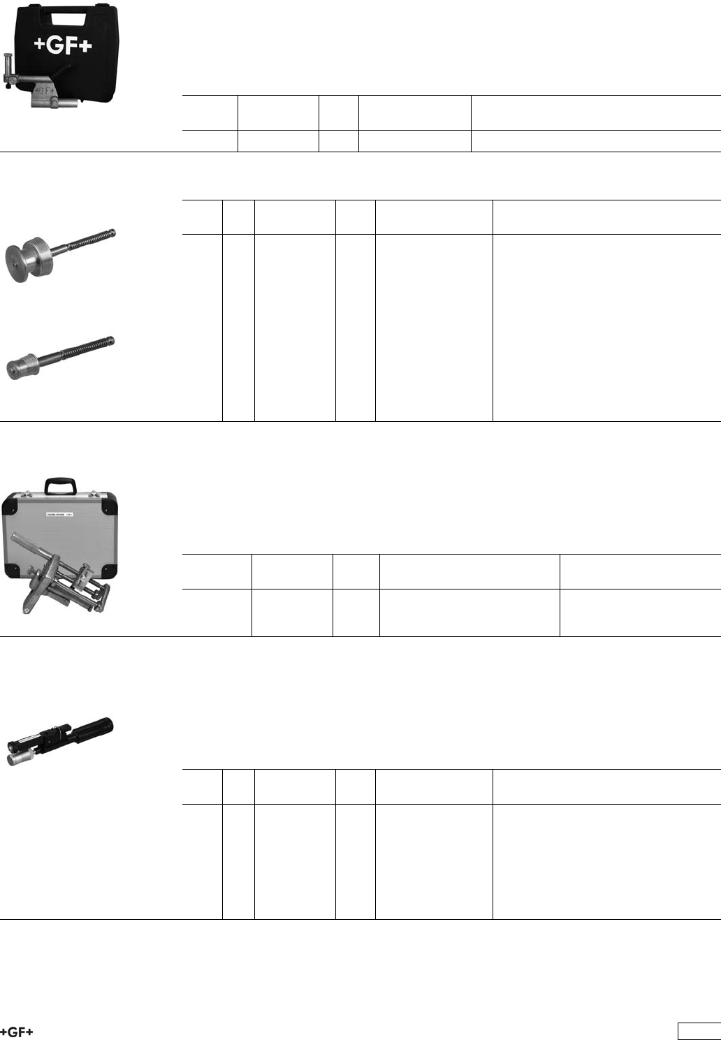
9 300 725 Peeling Tool PT 1 E
ÏThe rotating Peeling Tool PT 1 E is suitable for preparing pipe ends with diameters d
20 - 90 mm (when installing electrofusion couplers and fittings). The tool ensures a
constant peeling quality on the complete peeling surface and is suitable for PE80,
PE100 and PEX.
ÏScope of delivery: 1 basic tool in a plastic carrying case, without pipe inserts. The
case has sufficient space for approximately 6 pipe inserts.
d-d
[mm]
Code kg Description
20 - 90 799 150 382 3.400 Basic Tool PT 1 E
9 300 725 Pipe Inserts for Peeling Tool PT 1 E
d
[mm]
e
[mm]
Code kg Description
20 1.9 799 300 739 0.220 Pipe Insert SDR 11
20 3.0 799 300 741 0.220 Pipe Insert SDR 7
25 2.3 799 300 740 0.230 Pipe Insert SDR 11
25 3.0 799 300 742 0.230 Pipe Insert SDR 9
32 3.0 799 300 743 0.230 Pipe Insert SDR 11
40 3.7 799 300 744 0.230 Pipe Insert SDR 11
50 4.6 799 300 745 0.350 Pipe Insert SDR 11
63 3.8 799 300 725 0.475 Pipe Insert SDR 17
63 5.8 799 300 746 0.475 Pipe Insert SDR 11
75 4.5 799 300 727 0.601 Pipe Insert SDR 17
75 6.9 799 300 747 0.601 Pipe Insert SDR 11
90 5.4 799 300 748 0.834 Pipe Insert SDR 17
90 8.2 799 300 749 0.220 Pipe Insert SDR 11
9 300 750 Peeling Tool PT 2
ÏThe rotating Peeling Tools PT 2 are suitable for preparing pipe ends (when installing
electrofusion couplers and fittings). The tool ensures a constant peeling quality on
the complete peeling surface and is suitable for PE80, PE100 and PEX pipes.
ÏScope of delivery: 1 tool (size 1, 2 or 3) in a case (size 1 in aluminium, size 2 and 3
in plastic).
d-d
[mm]
Code kg Description
90 - 250 799 300 753 5.100 Size 1, peeling length 140 mm
110 - 400 799 300 755 7.320 Size 2, peeling length 150 mm
110 - 500 799 300 756 11.000 Size 3, peeling length 175 mm
9 300 700 Peeling Tool PT 4
ÏThe easy-to-use peeling tools PT 4 are suitable for preparing pipe ends (when
installing electrofusion couplers and fittings). The tools ensure a constant peeling
quality on the whole peeled area and are suitable for PE80 and PE100 pipes. There
is no tool service ararngement for the PT 4.
ÏScope of delivery: 1 tool with exchangeable blade (4 cutting surfaces).
e
[mm]
d
[mm]
Code kg Description
1.9 20 799 300 704 0.271 Pipe Insert SDR 11
3.0 20 799 300 705 0.255 Pipe Insert SDR 7
2.3 25 799 300 706 0.308 Pipe Insert SDR 11
3.0 25 799 300 707 0.290 Pipe Insert SDR 9
3.0 32 799 300 708 0.340 Pipe Insert SDR 11
3.7 40 799 300 709 0.380 Pipe Insert SDR 11
4.6 50 799 300 710 0.436 Pipe Insert SDR 11
5.8 63 799 300 711 0.540 Pipe Insert SDR 11
493
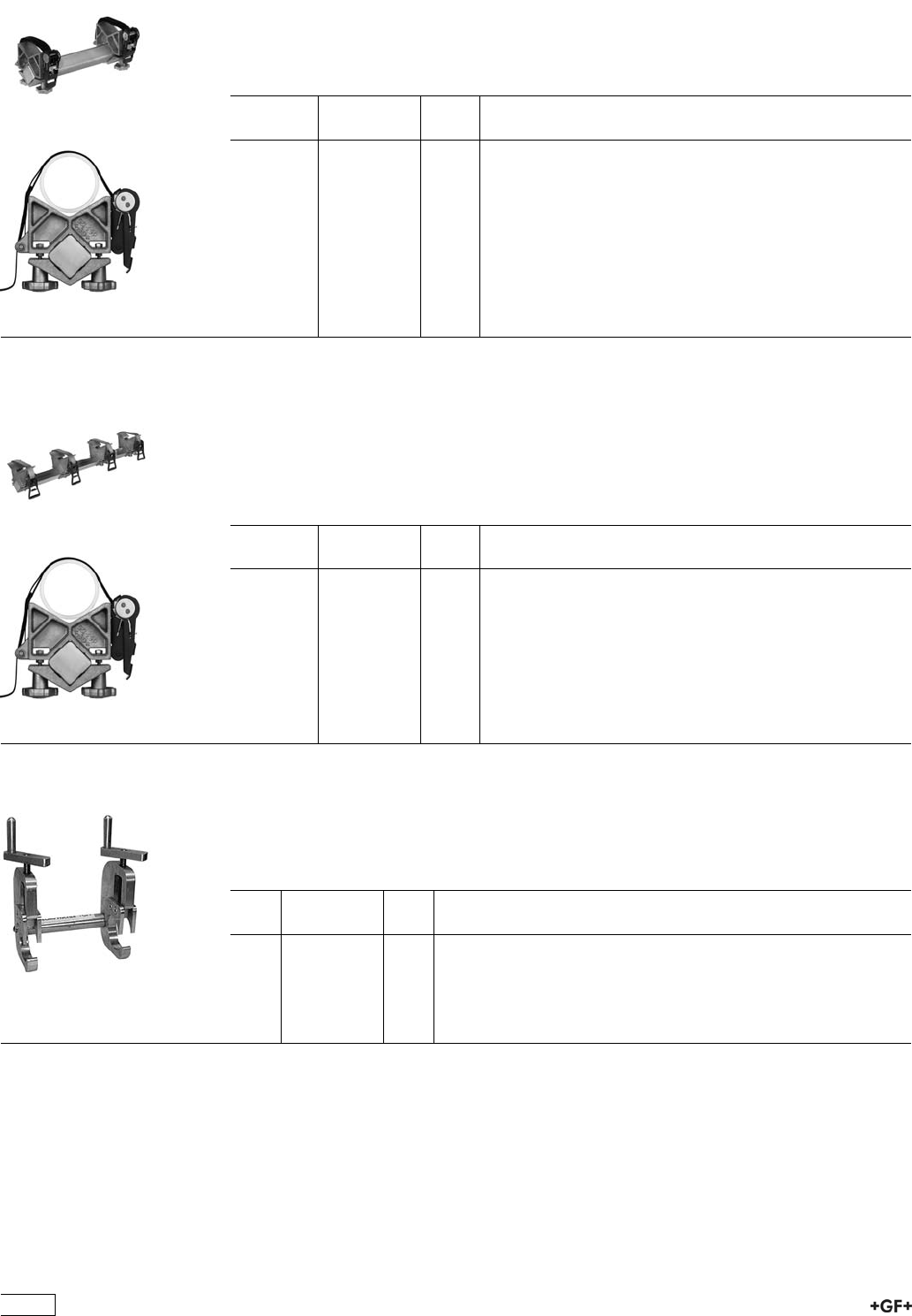
9 301 475 Double Clamp
ÏThe user-friendly Double Clamps are suitable for coupler connections. They are
quickly and easily put into position and prevent pullout and pipe movements during
the fusion time and cooling time.
ÏScope of delivery: 1 tool consisting of 1 beam (compact), 2 vee-clamps complete
with ratchet and belt.
d-d
[mm]
Code kg
63 - 125 799 301 484 2.795
110 - 225 799 301 486 10.000
225 - 500 799 301 488 15.000
9 301 450 Quadruple Clamp
ÏThe professional Quadruple Clamps are suitable for coupler connections. They are
quickly and easily put into position and ensure a stress-free fusion. They prevent
pullout and pipe movements during the fusion and cooling times.
ÏRecommended for difficult site conditions with large installation-induced stresses.
ÏScope of delivery: 1 tool consisting of 1 beam (long), 4 vee-clamps complete with
ratchet and belt.
d-d
[mm]
Code kg
63 - 125 799 301 459 6.900
110 - 225 799 301 461 19.000
225 - 500 799 301 463 28.500
9 301 525 Twin Clamp
ÏThe easy-to-use Twin Clamp is suitable for coupler connections on straight or coiled
pipe. The clamps prevent pullout and pipe movements during the fusion and cooling
time.
ÏScope of delivery: 1 complete tool.
d
[mm]
Code kg
20 799 301 536 0.498
25 799 301 537 0.471
32 799 301 538 0.756
40 799 301 539 0.876
50 799 301 540 1.167
63 799 301 541 1.438
494
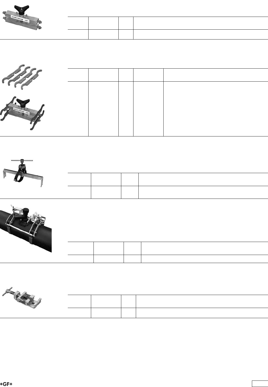
9 301 575 Multi Clamp
ÏThis tool is quick and easy to use and is suitable for straight forward connections to
straight lengths of pipe or saddle branch outlets with electrofusion couplers.
ÏScope of delivery: 1 tool without accessories.
d-d
[mm]
Code kg
20 - 63 799 301 575 1.409
9 301 575 Inserts for Multi Clamp
ÏThe inserts are easily and quickly exchanged. A set consists of 4 inserts, each insert
with 2 different dimensions.
d-d
[mm]
Code kg Description
25 - 20 799 150 385 0.806 Inserts, Sets
32 - 20 799 150 386 0.520 Inserts, Sets
32 - 25 799 150 387 0.520 Inserts, Sets
40 - 32 799 150 388 0.520 Inserts, Sets
50 - 40 799 150 389 0.520 Inserts, Sets
63 - 32 799 150 390 0.520 Inserts, Sets
63 - 40 799 150 391 0.520 Inserts, Sets
63 - 50 799 150 392 0.520 Inserts, Sets
9 370 000 Clamp for coiled pipe
ÏThese clamps are easily mounted on coiled pipes. They hold the pipes in position
during the fusion time and cooling phase.
ÏScope of delivery: 1 tool with clamp and belt.
d-d
[mm]
Code kg
25 - 63 799 370 007 4.000
63 - 125 799 370 011 10.000
Clamping device Topload 315
ÏThis clamp and mounting tool is used to top-load Saddles onto pipes of dimensions
d 280 - 400 mm.
ÏScope of delivery: 1 basis mounting clamp, 1 bracket, 2 clamping screws, 2 ratchet
scraps, 1 transport-box
d-d
[mm]
Code kg
280 - 400 799 350 475 25.000
9 150 090 Spring Clamp for ELGEF®24 V Reinforcing Saddles
ÏThe Spring Clamp is used to install ELGEF®24 V reinforcing saddles d 40 - 225
mm. The tool ensures a constant jointing pressure during the entire fusion cycle.
d-d
[mm]
Code kg
40 - 225 799 150 090 1.289
495
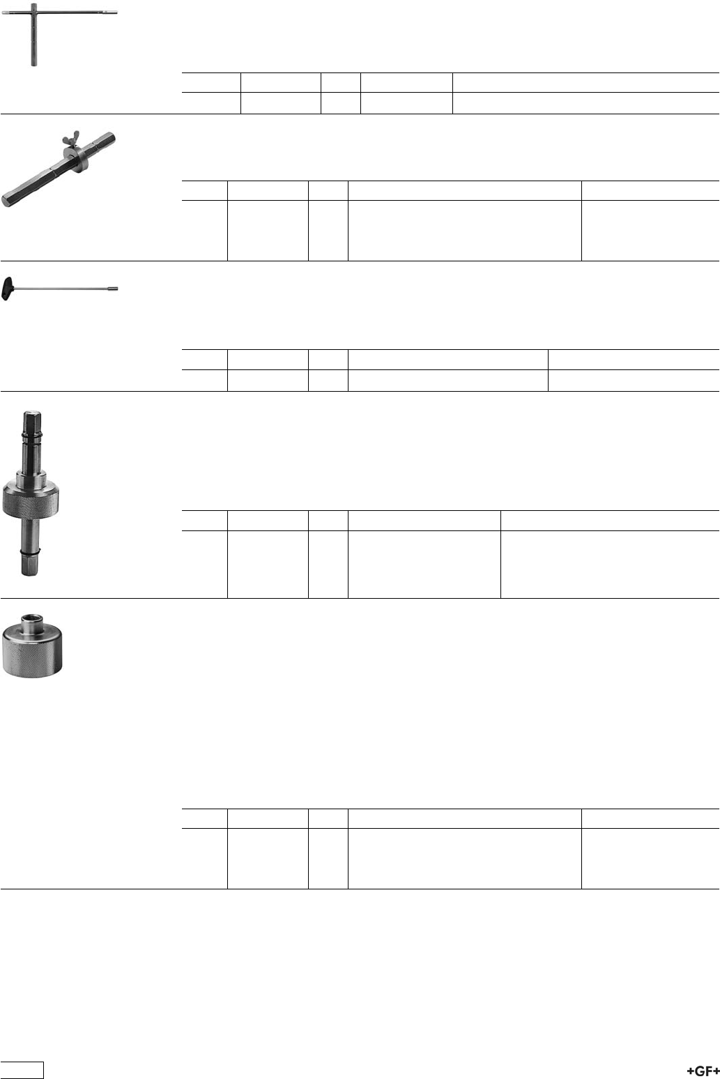
Assembly and Tapping Key
for ELGEF®Plus Saddles
ÏCombination tool for tapping and tightening of fixation screws.
Type Code kg Description
8/10/17 799 198 047 0.803 For all saddles
Tapping Key for ELGEF®Plus Saddles
ÏWith adjustable tapping depth.
Type Code kg Description
10 799 198 080 0.120 for Monobloc d 40 mm and d 50 mm
17 799 198 079 0.555 for Monobloc d 63 mm and all Duobloc
saddles
12.7 799 198 091 0.600 for socket with cutter
Hexagon Key for ELGEF®Plus Saddles
and Branch Fittings
ÏFor tightening fixation screws.
Type Code kg Description
SW8 799 150 378 0.152 For all saddles and branch fittings
Tapping Adapter
for ELGEF®Plus Saddles
ÏThe Adapter is used for gas-free tapping under pressure. Type S 54 for tapping
saddles with rotatable outlet d 20 - 40 mm (Tapping Tee d 32 mm). Type S 67 for
tapping saddles with rotatable outlet d 50 - 63 mm (Tapping Tee d 63 mm).
Type Code kg Description
S 54 799 100 061 0.813 for Tapping Tee d 32 mm
S 67 799 100 062 1.011 for Tapping Tee d 63 mm
Pressure Test Cap for ELGEF®Plus
Tapping Saddles
Ï''The cap has a Rp 3/8'''' connection thread and is made from galvanised steel.''
ÏOverview of Tapping Adapter types and Pressure Test Cap
ÏTyp Bezeichnung description
ÏM For Monoblock d 40 and 50 mm (outlets d 20 - 32 mm)
ÏS 54 For Monoblock d 63 (outlets d 20 - 32 mm) and all saddles with rotatable outlet
(outlets d 20 - 40 mm) i.e. Tapping Tee d 32 mm.
ÏS 67 For all Saddles with rotatable outlet (outlets d 50 and 63 mm) i.e. Tapping Tee
d 63 mm.
Type Code kg Description
M799 199 282 0.119 for Monoblock d 40 mm and d 50 mm
S 54 799 199 283 0.283 for Monoblock d 63 mm and Tapping Tee d
32 mm
S 67 799 199 286 0.461 for Tapping Tee d 63 mm
496
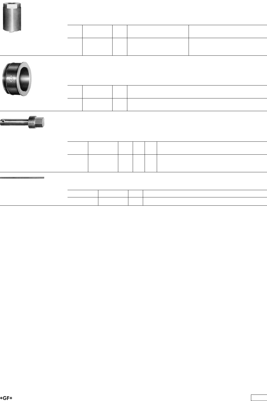
Cutter for PE Pipes
ÏThis cutter is suitable for PE pipes and can be used on pipes of up to d 225 mm with
a wall thickness of up to 21 mm.
d
[mm]
Code kg Description
30 799 198 013 0.131 accessories Basic Tool Box
39 799 198 012 0.215 accessories Basic Tool Box
50 799 198 057 0.278 accessories Basic Tool Box
PE Repair Plug
ÏPE Repair Plugs are suitable for use with ELGEF®24 V PE Reinforcement Saddles
53 127 000.
d
[mm]
Code kg
30 799 199 088 0.012
39 799 199 089 0.019
Hexagon Key for PVC Saddles
ÏThe Hexagon Key is suitable for tapping water and gas mains under pressure.
ÏScope of delivery: 1 hexagon key, protective cover, without rotating pin.
d-d
[mm]
Code kg s
[mm]
G
[inch]
16 - 25 799 150 007 0.345 19 30
32 - 40 799 150 008 0.496 27 38
50 - 63 799 150 009 0.690 27 47
Rotating pin for Hexagon Key
description Code kg
10x350 mm 799 150 011 0.220
497
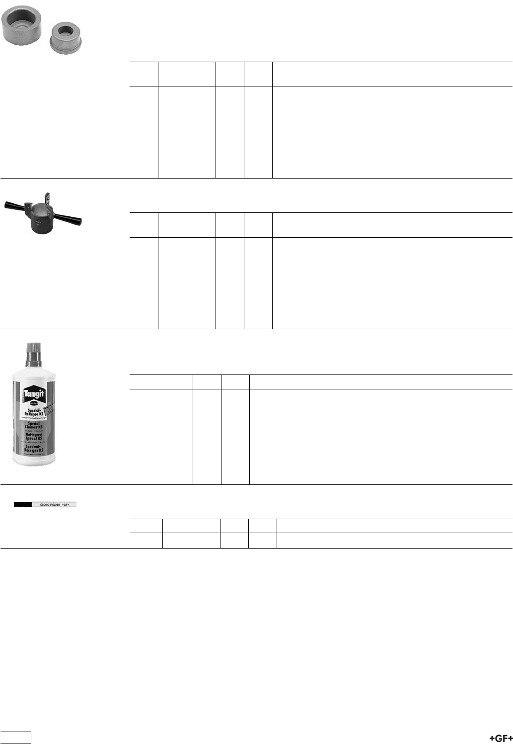
Accessories and Tools for Welding Machines
Heating Spigots and Bushes
ÏAluminium, PTFE coated
ÏType B
ÏAlways delivered in pairs (also usable for SG 110, not for SG 160)
d
[mm]
Code kg kg/m
16 799 300 155 0.070 0.070
25 799 300 157 0.110 0.110
32 799 300 158 0.140 0.140
40 799 300 159 0.230 0.230
50 799 300 160 0.335 0.335
63 799 300 161 0.565 0.565
75 799 300 162 0.965 0.965
90 799 300 163 1.440 1.440
110 799 300 164 2.210 2.210
Manual Pipe Peeling Tool for Socket Fusion
d
[mm]
Code kg kg/m
20 799 300 260 0.067 0.067
25 799 300 270 0.081 0.081
32 799 300 280 0.102 0.102
40 799 300 290 0.244 0.244
50 799 300 300 0.294 0.294
63 799 300 310 0.505 0.505
75 799 300 320 0.780 0.780
90 799 300 330 0.987 0.987
110 799 300 340 1.360 1.360
KS Tangit Cleaner
ÏSpecial cleaning agent for plastic fusion connections with PP, PE, PVDF and PB.
Code kg kg/m
799 298 023 0.890 0.890
Marker
Type Code kg kg/m
silver 799 350 364 0.012 0.012
498
General Condition of Supply of Georg Fischer Piping Systems Limited, Schaffhausen
1 General
1.1 TheseGeneralConditionsshallapplytoallProductssuppliedbyGeorgFischertothePurchaser
Theyshallalsoapplytoallfuturebusinessevenwhennoexpressreferenceismadetothem
1.2 AnydeviatingorsupplementaryconditionsespeciallyPurchaser’sgeneralconditionsofpurchase
andverbalagreementsshallonlybeapplicableifacceptedinwritingbyGeorgFischer.
1.3 Thewrittenformshallbedeemedtobefullledbyallformsoftransmission,evidencedintheform
oftext,suchastelefax,e-mail,etc.
2 Tenders
Tendersshallonlybebindingiftheycontainaspecicallystatedperiodforacceptance.
3 Scope of Delivery
3.1 GeorgFischer’sproductrangeissubjecttochange.
3.2 Theconrmationofordershallgovernthescopeandexecutionofthecontract.
4 Data and Documents
4.1 Technicaldocumentssuchasdrawings,descriptions,illustrationsanddataondimensions,
performanceandweightaswellasthereferencetostandardsareforinformationpurposesonly.
Theyarenotwarrantedcharacteristicsandaresubjecttochange.
4.2 AlltechnicaldocumentsshallremaintheexclusivepropertyofGeorgFischerandmayonlybe
usedfortheagreedpurposesorasGeorgFischermayconsent.
5 Condentiality, Protection of Personal Data
5.1 Eachpartyshallkeepinstrictcondenceallcommercialortechnicalinformationrelatingto
thebusinessoftheotherparty,ofwhichithasgainedknowledgeinthecourseofitsdealingwith
theotherparty.Suchinformationshallneitherbedisclosedtothirdpartiesnorusedforother
purposesthanthoseforwhichtheinformationhasbeensupplied.
5.2 InthecontextofthecontractualrelationwiththePurchaserpersonaldatamaybeprocessed.The
Purchaseragreestothedisclosureofsaiddatatothirdpartiessuchasforeignsubcontractorsand
suppliersetc.
6 Local Laws and Regulations, Export Controls
6.1 ThePurchasershallbringtotheattentionofGeorgFischeralllocallawsandregulationsatthe
placeofdestinationwhichbearconnectionwiththeexecutionofthecontractandtheadherenceto
relevantsafetyregulationsandapprovalprocedures.
6.2 Incaseofre-exports,Purchasershallberesponsibleforcompliancewithpertinentexportcontrol
regulations.
7 Price
7.1 Unlessagreedotherwise,thepricesshallbedeemedquotednetexworks(accordingtoIncoterms
oftheICC,latestversion)includingstandardpacking.Allsupplementarycostssuchasthecost
ofcarriage,insurance,export-,transit-andimportlicencesetc.shallbebornebythePurchaser.
ThePurchasershallalsobearthecostsofalltaxes,fees,dutiesetc.connectedwiththecontract.
7.2 Ifthecostsofpacking,carriage,insurance,feesandothersupplementarycostsareincludedin
thetenderpriceorcontractpriceorarereferredtospecicallyinthetenderorconrmationof
order,GeorgFischerreservetherighttorevisetheirpricesaccordinglyshouldanychangeoccur
intherelevanttariffs.
8 Terms of Payment
8.1 ThePurchasershallmakepaymentinthemanneragreedbythepartieswithoutanydeductions
suchasdiscounts,costs,taxesordues.
8.2 ThePurchasermayonlywithholdoroff-setpaymentsdueagainstcounterclaimswhichareeither
expresslyacknowledgedbyGeorgFischerornallyawardedtothePurchaser.
Inparticular,paymentshallstillbemadewhenunessentialitemsarestillout-standingprovided
thattheProductsalreadydeliveredarenotrenderedunusableasaresult.
9 Retention of Title
9.1 TheProductsshallremainthepropertyofGeorgFischeruntilthePurchasershallhavesettled
allclaims,presentandfuture,whichGeorgFischermayhaveagainsthim.
9.2 ShouldthePurchaserresellProductstowhichtitleisreserved,intheordinarycourseofbusi-
ness,heshallherebybedeemedtohavetacitlyassignedtoGeorgFischertheproceedsderiving
fromtheirsaletogetherwithallcollateralrights,securitiesandreservationsoftitleuntil
allclaimsheldbyGeorgFischershallhavebeensettled.UntilrevokedbyGeorgFischer,this
assignmentshallnotprecludePurchaser’srighttocollecttheassignedreceivables.
9.3 TotheextentthevalueoftheProductstowhichtitleisreservedtogetherwithcollateralsecurities
exceedsGeorgFischer’sclaimsagainstthePurchaserbymorethan20%,GeorgFischershall
re-assigntheaboveproceedstoPurchaserathisrequest.
10 Delivery
10.1 Thetermofdeliveryshallcommenceassoonasthecontracthasbeenenteredinto,allofcial
formalitiessuchasimportandpaymentpermitshavebeenobtainedandallessentialtechnical
issueshavebeensettled.Thetermofdeliveryshallbedeemeddulyobservedwhen,uponits
expiry,theProductsarereadyfordespatch.
10.2 Deliveryissubjecttothefollowingconditions,i.e.thetermofdeliveryshallbereasonably
extended:
a) ifGeorgFischerarenotsuppliedintimewiththeinformationnecessaryfortheexecutionofthe
contractorifsubsequentchangescausingdelaysaremadebythePurchaser.
b) ifGeorgFischerarepreventedfromperformingthecontractbyforcemajeure.Forcemajeure
shallequallybedeemedtobeanyunforeseeableeventbeyondGeorgFischer’scontrolwhich
rendersGeorgFischer’sperformancecommerciallyunpracticalorimpossible,suchasdelayed
ordefectivesuppliesfromsubcontractorslabourdisputes,governmentalordersorregulations,
shortagesinmaterialsorenergy,seriousdisturbancesinGeorgFischer’sworks,suchasthe
totalorpartialdestructionofplantandequipmentorthebreakdownofessentialfacilities,serious
disruptionsintransportfacilities,e.g.impassableroads.
Shouldtheeffectofforcemajeureexceedaperiodofsixmonths,eitherpartymaycancelthe
contractforthwith.
GeorgFischershallnotbeliableforanydamageorlossofanykindwhatsoeverresultingthere-
from,anysuspensionorcancellationbeingwithoutprejudicetoGeorgFischer’srighttorecover
allsumsdueinrespectofconsignmentsdeliveredandcostsincurredtodate.
c) ifthePurchaserisindelaywiththefullmentofhisobligationsunderthecontract,inparticular,
ifhedoesnotadheretotheagreedconditionsofpaymentorifhehasfailedtotimelyprovidethe
agreedsecurities.
10.3 IfforreasonsattributabletoGeorgFischertheagreedtermofdeliveryorareasonableextension
thereofisexceeded,GeorgFischershallnotbedeemedindefaultuntilthePurchaserhas
grantedtoGeorgFischerinwritingareasonableextensionthereofofnotlessthanonemonth
whichequallyisnotmet.
ThePurchasershallthenbeentitledtotheremediesprovidedatlaw,itbeinghoweverunderstood
that,subjecttolimitationsofArt.16,damageclaimsshallbelimitedtomax.10%ofthepriceof
thedelayeddelivery.
10.4 PartshipmentsshallbeallowedandGeorgFischershallbeentitledtoinvoiceforsuchpartial
deliveries.
10.5 IfthePurchaserfailstotakedeliverywithinareasonabletimeofProductsnotiedasreadyfor
despatch,GeorgFischershallbeentitledtostoretheProductsatthePurchaser’sexpenseand
riskandtoinvoicethemasdelivered.IfPurchaserfailstoeffectpayment,GeorgFischershall
beentitledtodisposeoftheProducts.
10.6 ShouldPurchasercancelanorderwithoutjusticationandshouldGeorgFischernotinsiston
theperformanceofthecontract,GeorgFischershallbeentitledtoliquidateddamagesinthe
amountof10%ofthecontractprice,GeorgFischer›srighttoproveandclaimhigherdamages
remainingreserved.Purchasershallbeentitledtoprove,thatGeorgFischerhassufferedno
oraconsiderablylowerdamage.
11 Packing
IftheProductsareprovidedwithadditionalpackingoverandabovethestandardpacking,such
packingshallbechargedadditionally.
12 Passing of Risk
12.1 TheriskintheProductsshallpasstothePurchaserassoonastheyhaveleftGeorgFischer’s
works(EXWORKS,IncotermsICC,latestversion),evenifdeliveryismadecarriage-paid,under
similarclausesorincludinginstallationorwhencarriageisorganizedandmanagedby
GeorgFischer.
12.2 IfdeliveryisdelayedforreasonsbeyondGeorgFischer’scontrol,theriskshallpasstothe
PurchaserwhenheisnotiedthattheProductsarereadyfordespatch.
13 Carriage and Insurance
13.1 Unlessagreedotherwise,thePurchasershallbearthecostofcarriage.
13.2 ThePurchasershallberesponsiblefortransportinsuranceagainstdamageofwhateverkind.
EvenwhensuchinsuranceisarrangedbyGeorgFischeritshallbedeemedtakenoutbytheorder
ofandfortheaccountofthePurchaserandathisrisk.
13.3 SpecialrequestsregardingcarriageandinsuranceshallbecommunicatedtoGeorgFischerin
duetime.OtherwisecarriageshallbearrangedbyGeorgFischerattheirdiscretion,butwithout
responsibility,bythequickestandcheapestmethodpossible.
Incaseofcarriage-paiddeliverytransportarrangementsshallbemadebyGeorgFischer.If
thePurchaserspeciesparticularrequirements,anyextracostsinvolvedshallbebornebyhim.
13.4 IntheeventofdamageorlossoftheProductsduringcarriagethePurchasershallmarkthe
deliverydocumentsaccordinglyandimmediatelyhavethedamageascertainedbythecarrier.Not
readilyascertainabledamagessustainedduringcarriageshallbenotiedtothecarrierwithinsix
daysafterreceiptoftheProducts.
14 Inspection, Notication of Defects and Damages
14.1 TheProductswillbesubjecttonormalinspectionbyGeorgFischerduringmanufacture.
AdditionaltestsrequiredbythePurchasershallbeagreeduponinwritingandshallbecharged
tothePurchaser.
14.2 ItshallbeaconditionofGeorgFischer’sobligationunderthewarrantiesstatedhereinafter
thatGeorgFischerbenotiedinwritingbythePurchaserofanypurporteddefectimmediately
upondiscovery.Noticeconcerningweight,numbersorapparentdefectsistobegivenlatest
within30daysfromreceiptoftheProducts,noticeofotherdefectsimmediatelylatestwithin
7workingdaysafterdiscovery,inanyeventwithintheagreedwarrantyperiod.
14.3 PurchasershallnotdisposeofallegedlydefectiveProductsuntilallwarrantyand/ordamage
claimsarenallysettled.Atitsrequest,defectiveProductsaretobeplacedatGeorgFischer’s
disposal.
14.4 Atitsrequest,GeorgFischershallbegiventheopportunitytoinspectthedefectand/ordamage,
priortocommencementofremedialwork,eitheritselforbythirdpartyexperts.
15 Warranty
15.1 AtthewrittenrequestofthePurchaser,GeorgFischerundertaketorepairorreplaceattheir
discretion,asquicklyaspossibleandfreeofchargeallProductssuppliedwhichdemonstrably
sufferfromfaultydesign,materialsorworkman-shiporfromfaultyoperatingorinstallation
instructions.
Inordertoprotectemployeesfromtoxicorradioactivesubstanceswhichmayhavebeen
transportedthroughdefectivepartsreturnedtoGeorgFischer’ssalesorganisation,saidparts
mustbeaccompaniedbyaMaterialSafetyDisclosureForm.Theformmaybeobtainedfrom
GeorgFischer’slocalsalescompanyorviawww.piping.georgscher.com.
ReplacedpartsshallbecomepropertyofGeorgFischer.
15.2 ForProductswhicharemanufacturedtospecications,drawingsorpatternssuppliedbythe
Purchaser,GeorgFischer’swarrantyshallberestrictedtopropermaterialsandworkmanship.
15.3 ThePurchasershallbeentitledtocancelthecontractortodemandareductioninthecontract
priceifalsoasecondattempttorepairorreplacetheProductshasfailed.
15.4 ForProductsoressentialcomponentsmanufacturedbyathirdpartyandsuppliedbyGeorg
Fischerunderthiscontract,GeorgFischer’swarrantyislimitedtothewarrantyprovidedbysaid
thirdparty.
15.5 Thiswarrantyshallnotapplytodamageresultingfromnormalwearandtear,improperstorage
andmaintenance,failuretoobservetheoperatinginstructions,overstressingoroverloading,
unsuitableoperatingmedia,unsuitableconstructionworkorunsuitablebuildingground,improper
repairsoralterationsbythePurchaserorthirdparties,theuseofotherthanoriginalspareparts
andotherreasonsbeyondGeorgFischer’scontrol.
15.6 NoactionorclaimmaybebroughtbythePurchaseronaccountofanyallegedbreachofwarranty
oranyotherobligationofGeorgFischeraftertheexpirationoftwelve(12)monthsfromreceipt
oftheProductsbytheenduseroratthelatestwithineighteen(18)monthsoftheProductsbeing
despatchedbyGeorgFischer.
15.7 IncaseofProductsforuseindomesticinstallationsorinutilities
– GeorgFischerwillassumethecostsofdismantlingthedefectiveProductandrestoringthe
damagedobjectaswellas,incaseofnegligence,allotherdirectdamagescausedbythe
defectiveProduct(damagetopropertyandinjurytoordeathofpersons)uptoCHF1000000per
occurrence.
– thestatuteoflimitationsforwarrantyordamageclaims–contrarytoSection15.6–willbe5
yearsfromthedateofinstallation.
16 Limitation of Liability
Allcasesofbreachofcontractandtherelevantconsequencesaswellasallrightsandclaimson
thepartofthecustomer,irrespectiveonwhatgroundtheyarebased,areexhaustivelycovered
bythesegeneralconditionsofsupply.Inparticular,anyclaimsnotexpresslymentionedfordam-
ages,reductionofprice,terminationoforwithdrawalfromthecontractareexcluded.Innocase
whatsoevershallthecustomerbeentitledtoclaimdamagesotherthancompensationforcosts
ofremedyingdefectsinthesupplies.Thisinparticularrefers,butshallnotbelimited,toloss
ofproduction,lossofuse,lossoforders,lossofprotandotherdirectorindirectorconsequential
damage.Thisexclusionofliability,however,doesnotapplytounlawfulintentorgrossnegligence
onthepartofGeorgFischerandincaseofstrictliabilityunderapplicableproductliabilitystat-
utes,butdoesapplytounlawfulintentorgrossnegligenceofpersonsemployedorappointedby
GeorgFischertoperformanyofitsobligations.
17 Severability
ShouldanytermorclauseoftheseGeneralConditionsinwholeorinpartbefoundtobeunen-
forceableorvoid,allotherprovisionsshallremaininfullforceandeffectandtheunenforceableor
voidprovisionshallbereplacedbyavalidprovision,whichcomesclosesttotheoriginalintention
oftheunenforceableorinvalidprovision.
18 Place of Performance and Jurisdiction
18.1 PlaceofperformancefortheProductsshallbetheGeorgFischerworksfromwhichtheProducts
aredespatched.
18.2 Anycivilactionbaseduponanyallegedbreachofthiscontractshallbeledandprosecutedexclu-
sivelyinthecourtsofSchaffhausen,Switzerland.
GeorgFischerhoweverreservestherighttoleactionsinanycourthavingjurisdictionover
controversiesarisingoutoforinconnectionwiththepresentcontract.
18.3 ThecontractshallbegovernedbySwisslawwithoutregardtoconictoflawprovisionsthatwould
requiretheapplicationofanotherlaw.
7/2005

GMST 8273/4a (6.08)
© Georg Fischer Piping Systems Ltd
CH-8201 Schaffhausen/Switzerland, 2008
Printed in Germany
GF Piping Systems > worldwide at home
Our sales companies and representatives
ensure local customer support in over 100 countries. www.piping.georgscher.com
Adding Quality to People’s Lives
The technical data is not binding. They neither
constitute expressly warranted characteristics nor
guaranteed properties nor a guaranteed durability.
They are subject to modication. Our General Terms
of Sale apply.
Australia
George Fischer Pty Ltd
Riverwood NSW 2210 Australia
Phone +61(0)2 9502 8000
australia.ps@georgscher.com
www.georgescher.com.au
Austria
Georg Fischer
Rohrleitungssysteme GmbH
3130 Herzogenburg
Phone +43(0)2782 856 43-0
austria.ps@georgscher.com
www.georgscher.at
Belgium / Luxembourg
Georg Fischer NV/SA
1070 Bruxelles/Brüssel
Phone +32(0)2 556 40 20
be.ps@georgscher.com
www.georgscher.be
Brazil
George Fischer Ltda
04795-100 São Paulo
Phone +55(0)11 5687 1311
br.ps@georgscher.com
China
Georg Fischer
Piping Systems Ltd Shanghai
Pudong, Shanghai 201319
Phone +86(0)21 58 13 33 33
china.ps@georgscher.com
www.cn.piping.georgscher.com
Denmark / Iceland
Georg Fischer A/S
2630 Taastrup
Phone +45 (0)70 22 19 75
info.dk.ps@georgscher.com
www.georgscher.dk
France
Georg Fischer SAS
95932 Roissy Charles de Gaulle Cedex
Phone +33(0)1 41 84 68 84
fr.ps@georgscher.com
www.georgescher.fr
Germany
Georg Fischer GmbH
73095 Albershausen
Phone +49(0)7161 302-0
info.de.ps@georgscher.com
www.georgscher.de
India
Georg Fischer Piping Systems Ltd
400 076 Mumbai
Phone +91 224007 2001
in.ps@georgscher.com
www.georgscher.in
Italy
Georg Fischer S.p.A.
20063 Cernusco S/N (MI)
Phone +3902 921 861
it.ps@georgscher.com
www.georgscher.it
Japan
Georg Fischer Ltd
556-0011 Osaka,
Phone +81(0)6 6635 2691
jp.ps@georgscher.com
www.georgscher.jp
Korea
Georg Fischer Piping Systems
Guro-3 dong, Guro-gu, Seoul, Korea
Phone +82(0)2 2081 1450
Fax +82(0)2 2081 1453
kor.ps@georgscher.com
Malaysia
Georg Fischer (M) Sdn. Bhd.
40460 Shah Alam, Selangor
Phone +60 (0)3 5122 5585
conne.kong@georgscher.com
Mexico
Georg Fischer S.A. de C.V.
Apodaca, Nuevo Leon
CP66636 Mexico
Phone +52 (81)1340 8586
Fax +52 (81)1522 8906
Middle East
George Fischer Piping Systems
Dubai, United Arab Emirates
Phone +971 4 289 49 60
info.export@georgscher.com
www.export.georgscher.com
Netherlands
Georg Fischer N.V.
8161 PA Epe
Phone +31(0)578 678 222
nl.ps@georgscher.com
www.georgscher.nl
Norway
Georg Fischer AS
1351 Rud
Phone +47(0)67 18 29 00
no.ps@georgscher.com
www.georgscher.no
Poland
Georg Fischer Sp. z o.o.
02-226 Warszawa
Phone +48(0)22 313 10 50
poland.ps@georgscher.com
www.georgscher.pl
Romania
Georg Fischer
Piping Systems Ltd
020257 Bucharest - Sector 2
Phone +40(0)21 230 53 80
ro.ps@georgscher.com
www.export.georgscher.com
Russia
Georg Fischer Piping Systems
Moscow 125047
Tel. +7 495 258 60 80
ru.ps@georgscher.com
www.georgscher.ru
Singapore
George Fischer Pte Ltd
528 872 Singapore
Phone +65(0)67 47 06 11
sgp.ps@georgscher.com
www.georgescher.com.sg
Spain / Portugal
Georg Fischer S.A.
28046 Madrid
Phone +34(0)91 781 98 90
es.ps@georgscher.com
www.georgscher.es
Sweden / Finland
Georg Fischer AB
12523 Älvsjö-Stockholm
Phone +46(0)8 506 775 00
info.se.ps@georgscher.com
www.georgscher.se
Switzerland
Georg Fischer
Rohrleitungssysteme (Schweiz) AG
8201 Schaffhausen
Phone +41(0)52 631 30 26
ch.ps@georgscher.com
www.piping.georgscher.ch
Taiwan
Georg Fischer Piping Systems
San Chung City, Taipei Hsien
Phone +886 2 8512 2822
Fax +886 2 8512 2823
United Kingdom / Ireland
George Fischer Sales Limited
Coventry, CV2 2ST
Phone +44(0)2476 535 535
uk.ps@georgscher.com
www.georgescher.co.uk
USA / Canada / Latin America / Caribbean
Georg Fischer LLC
Tustin, CA 92780-7258
Phone +1(714) 731 88 00
Toll Free 800 854 40 90
us.ps@georgscher.com
www.us.piping.georgescher.com
International
Georg Fischer
Piping Systems (Switzerland) Ltd.
8201 Schaffhausen
Phone +41(0)52 631 30 03
Fax +41(0)52 631 28 93
info.export@georgscher.com
www.export.georgscher.com
