E18377 1 06 13_eds3400_frontbuendig 34Z6 PRO0000000000000000000018377010011
User Manual: 34Z6
Open the PDF directly: View PDF ![]() .
.
Page Count: 4
E 18.377.1/11.13
89
4
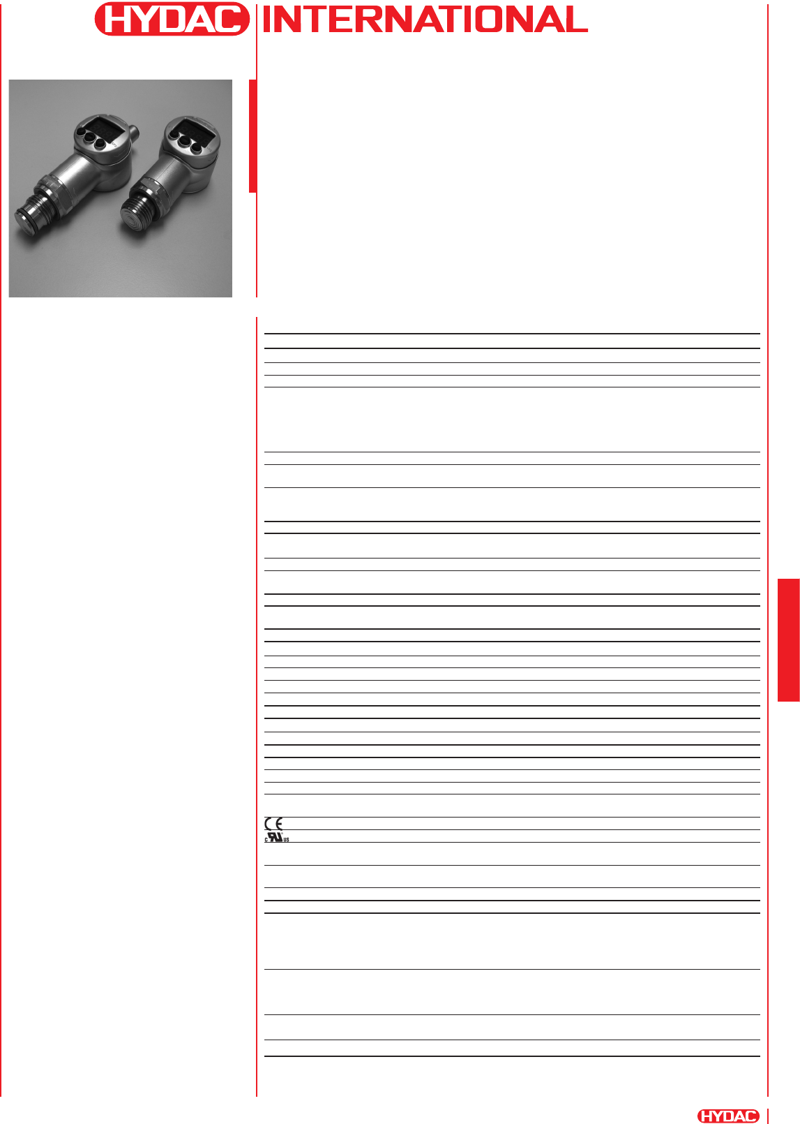
Electronic
Pressure Switch
EDS 3400
with Flush Membrane
Description:
The electronic pressure switch
EDS 3400 with a ush membrane was
designed specically for applications in
which a standard pressure connection
could become blocked, clogged or
frozen by the particular medium used.
Further applications include processes
where the medium changes frequently
and any residues could cause mixing or
contamination of the media.
Like the standard model, the EDS 3400
with ush membrane has a stainless
steel measurement cell with a thin
lm strain gauge for relative pressure
measurement in the high pressure
range.
The pressure connection is achieved
with a fully-sealed stainless steel
front membrane lled internally with
a pressure transfer uid. The process
pressure is transmitted hydrostatically
to the measurement cell via the
pressure transfer uid.
Depending on the type, the instrument
can have up to 2 switching outputs and
a switchable analogue output
(4 .. 20 mA or 0 .. 10 V).
Special features:
- Pressure connection has a ush
membrane
- 1 or 2 PNP transistor switching
outputs, up to 1.2 A load per output
- Accuracy ≤ 1 % FS
- Optional analogue output selectable
(4 .. 20 mA / 0 .. 10 V)
- 4-digit digital display
- Rotation in two planes (axes)
for optimum alignment
- Measured value can be displayed in
bar, psi or MPa
- Simple operation with key
programming
- Switching points and switch-back
hystereses can be adjusted
independently
- Many useful additional functions
- Option of Desina®-compliant
pin conguration with diagnostic
function
Technical data:
Input data
Measuring ranges 40; 100; 250; 400; 600 bar
Overload pressures 80; 200; 500; 800; 900 bar
Burst pressures1) 200; 500; 1000; 2000; 2000 bar
Mechanical connection G1/2 A DIN 3852
G1/2 with additional front O-ring seal
G1/4 with additional front O-ring seal
G1/4 A DIN 3852
G1/2 with add. front O-ring seal
and cooling section
Pressure transfer uid Silicone-free oil
Torque value 45 Nm for G1/2, G1/2 A
20 Nm for G1/4
Parts in contact with medium2) Mech. conn.: Stainless steel
Seal: FPM
O-ring: FPM
Output data
Accuracy to DIN 16086, ≤ ± 0.5 % FS typ.
Max. setting (display, analogue output) ≤ ± 1 % FS max.
Repeatability ≤ ± 0.25 % FS max.
Temperature drift ≤ ± 0.025 % FS / °C max. zero point
≤ ± 0.025 % FS / °C max. range
Analogue output (optional)
Output signal (selectable) 4 .. 20 mA load resistance max. 500 Ω
0 .. 10 V load resistance min. 1 kΩ
Switch outputs
Type PNP transistor output
Switching current max. 1.2 A per output
Switching cycles > 100 million
Reaction time < 10 ms
Long-term drift ≤ ± 0.3 % FS typ. / year
DESINA® diagnostic signal (Pin 2)
Function OK: HIGH level / not OK: LOW level
Level HIGH: approx. +UB / LOW: < +0.3 V
Environmental conditions
Compensated temperature range -10 .. +70 °C, -10 .. +60 °C for UL spec.
Operating temperature range -25 .. +80 °C, -25 .. +60 °C for UL spec.
Storage temperature range -40 .. +80 °C
Fluid temperature range3) -40 .. +80 °C / -25 .. +80 °C
-40 .. +150 °C / -25 .. +150 °C
for G1/2
with cooling section
mark EN 61000-6-1 / 2 / 3 / 4
mark4) Certicate No. E318391
Vibration resistance to ≤ 10 g
DIN EN 60068-2-6 at 10 .. 500 Hz
Shock resistance to ≤ 50 g
DIN EN 60068-2-29 (11 ms)
Protection class to IEC 60529 IP 67
Other data
Supply voltage 9 .. 35 V DC without analogue output
18 .. 35 V DC with analogue output
for use acc. to UL spec. - limited energy - according to
9.3 UL 61010; Class 2;
UL 1310/1585; LPS UL 60950
Current consumption max. 2.455 A total
max. 35 mA with inactive switching output
max. 55 mA with inactive switching output
and analogue output
Display 4-digit, LED, 7 segment, red,
height of digits 7 mm
Weight ~ 120 g
Note: Reverse polarity protection of the supply voltage, excess voltage, override and short circuit protection are provided.
FS
(
F
ull
S
cale) = relative to the full measuring range
1) G1/2 with additional front O-ring seal max. 1500 bar
2) Other seal materials on request
3) -25 °C with FPM seal, -40 °C on request
4) Environmental conditions according to 1.4.2 UL 61010-1; C22.2 No. 61010-1
E 18.377.1/11.13
90
4
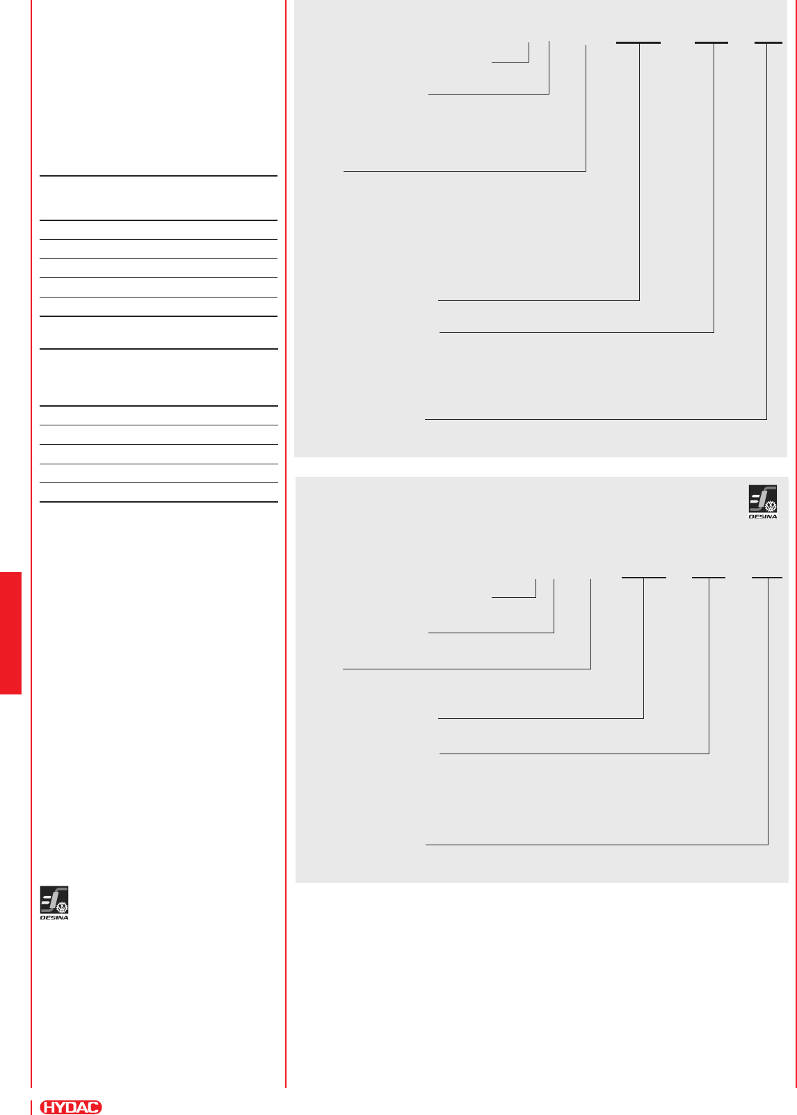
Model code:
EDS 3 4 Z X – X – XXXX – XXX – 000
Mechanical process connection
Z = Flush membrane
Electrical connection
6 = Male M12x1, 4 pole
only possible on output models "1", "2" and "3"
8 = Male M12x1, 5 pole
only possible on output model "5"
Output
1 = 1 switching output
only in conjunction with electrical connection type "6"
2 = 2 switching outputs
only in conjunction with electrical connection type "6"
3 = 1 switching output and 1 analogue output
only in conjunction with electrical connection type "6"
5 = 2 switching outputs and 1 analogue output
only in conjunction with electrical connection type "8"
Pressure ranges in bar
0040; 0100; 0250; 0400; 0600
Mechanical connection
G01 = G1/2 A DIN 3852
G02 = G1/2 with additional front O-ring seal
G04 = G1/4 with additional front O-ring seal
G05 = G1/4 A DIN 3852
G12 = G1/2 with add. front O-ring seal and cooling section
Modication number
000 = Standard
Setting options:
All settings offered by the EDS 3400 are
grouped in 2 easy-to-navigate menus.
In order to prevent unauthorised
adjustment of the device, a programming
lock can be set.
Setting ranges for the switch
outputs:
Switching point function
Meas.
range
in bar
Switch
point
in bar
Hysteresis
in bar
Incre-
ment*
in bar
0 .. 40 0.6 .. 40 0.2 .. 39.6 0.1
0 .. 100 1.6 .. 100 0.6 .. 99.0 0.2
0 .. 250 4.0 .. 250 1.5 .. 247.5 0.5
0 .. 400 6.0 .. 400 2.0 .. 396 1
0 .. 600 9.0 .. 600 3.0 .. 594 1
Window function
Meas.
range
in bar
Lower
switch
value
in bar
Upper
switch
value
in bar
Incre-
ment*
in bar
0 .. 40 0.6 .. 39.2 0.9 .. 39.6 0.1
0 .. 100 1.6 .. 98.2 2.4 .. 99 0.2
0 .. 250 4.0 .. 245.5 6.0 .. 247.5 0.5
0 .. 400 6.0 .. 392 9.0 .. 396 1
0 .. 600 9.0 .. 589 14 .. 594 1
* All ranges given in the table
are adjustable by the increments
shown.
Additional functions:
- Switching mode of the switching outputs
adjustable (switching point function or
window function)
- Switching direction of the switching
outputs adjustable (N/C or N/O function)
- Switch-on and switch-off delay
adjustable from 0.00 .. 99.99 seconds
- Choice of display (current pressure,
peak value, switch point 1,
switch point 2, display off)
- Display lter for smoothing the display
value during pressure pulsations
- Analogue output signal selectable
4 .. 20 mA or 0 .. 10 V
- Pressure can be displayed in
the measurement units bar, psi, MPa.
The scaling can also be adapted to
indicate force, weight, etc.
EDS 3400 for self diagnostics:
The DESINA®-compliant pressure
switch has been specially developed
for customers in the machine tool and
mechanical engineering sectors and
complies with the DESINA® specication.
A diagnostic signal enables errors to be
detected and an "ERROR" message also
appears in the display. The electrical
connection is a round 5-pole M12x1
to IP 67 in accordance with DESINA®
requirements.
Model code:
DESINA®-compliant or
can be connected to DESINA®:
EDS 3 4 Z 8 – X – XXXX – XXX – D00
Mechanical process connection
Z = ush membrane
Electrical connection
8 = M12x1, 5 pole, male
Output
1 = 1 switching output
3 = 1 switching output and 1 analogue output
Pressure ranges in bar
0040; 0100; 0250; 0400; 0600
Mechanical connection
G01 = G1/2 A DIN 3852
G02 = G1/2 with additional front O-ring seal
G04 = G1/4 with additional front O-ring seal
G05 = G1/4 A DIN 3852
G12 = G1/2 with additional front O-ring seal and cooling section
Modication number
D00 = DESINA®-compliant pin conguration for self-diagnostics
Note:
Special models on request.
For instruments with a different modication number, please read the label or
the technical amendment details supplied with the instrument.
Accessories:
Appropriate accessories, such as electrical connectors, mechanical adapters,
splash guards, clamps for wall-mounting etc can be found in the Accessories brochure.
E 18.377.1/11.13
91
4
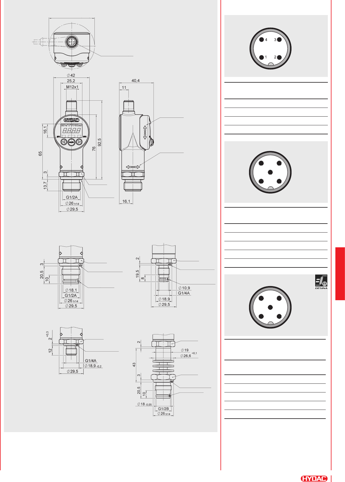
Pin connections:
Dimensions:
Note:
The information in this brochure relates to the operating conditions and
applications described. For applications and operating conditions not described, please
contact the relevant technical department.
Subject to technical modications.
M12x1, 4 pole
HYDAC ELECTRONIC GMBH
Hauptstraße 27, D-66128 Saarbrücken
Telephone +49 (0)6897 509-01
Fax +49 (0)6897 509-1726
E-mail: electronic@hydac.com
Internet: www.hydac.com
Pin EDS
34Z6-1
EDS
34Z6-2
EDS
34Z6-3
1 +UB+UB+UB
2 n.c. SP 2 Analogue
30 V 0 V 0 V
4SP 1 SP 1 SP 1
Pin EDS
34Z8-5
1 +UB
2 Analogue
30 V
4SP 1
5 SP 2
M12x1, 5 pole
M12x1, 5 pole
hex-SW27
DESINA®-
compliant
Can be
connected to
DESINA®
Pin EDS
34Z8-1
EDS
34Z8-3
1 +UB+UB
2Diagnostics Diagnostics
30 V 0 V
4SP 1 SP 1
5 n.c. Analogue
1 2
34
5
1 2
34
5
installation dimension Ø 53.5
O-ring 15 x 2
[G01]
[G02]
[G05]
[G04]
[G12]
hex-SW27
O-ring 7.65 x 1.78
hex-SW27
hex-SW27
hex-SW27
O-ring 15 x 2
seal ring DIN3869
18.5 x 23.9 x 1.5
seal ring DIN3869
18.5 x 23.9 x 1.5
male, electr. conn. M12x1
4 pole/5 pole
display
turns thru
270°
housing
turns thru
340°
elastomer
prole gasket
DIN 3869
seal ring DIN3869
18.5 x 23.9 x 1.5
hex-SW27
seal ring DIN3869
11.6 x 16.5 x 1.5

E 18.377.1/11.13
92
4
