Prosec T Series T1 16S Manual Do Software TPDS Em Ingles
User Manual: Prosec T-Series
Open the PDF directly: View PDF ![]() .
.
Page Count: 108 [warning: Documents this large are best viewed by clicking the View PDF Link!]

UM-TS03∗∗∗-E045
PROGRAMMABLE CONTROLLER
PROSEC T-SERIES
PROGRAM DEVELOPMENT SYSTEM
T-PDS32 for Windows
Version 2.2
BASIC OPERATION MANUAL
TOSHIBA CORPORATION
Important Information
Misuse of this equipment can result in property damage or human injury.
Because controlled system applications vary widely, you should satisfy yourself
as to the acceptability of this equipment for your intended purpose.
In no event will Toshiba Corporation be responsible or liable for either indirect
or consequential damage or injury that may result from the use of this equipment.
No patent liability is assumed by Toshiba Corporation with respect to use of information,
illustrations, circuits, equipment or examples of application in this publication.
Toshiba Corporation reserves the right to make changes and improvements to this
publication and/or related products at any time without notice. No obligation shall be
incurred other than as noted in this publication.
This publication is copyrighted and contains proprietary material. No part of this book
may be reproduced, stored in a retrieval system, or transmitted, in any form or by any
means − electrical, mechanical, photocopying, recording, or otherwise − without
obtaining prior written permission from Toshiba Corporation.
© TOSHIBA Corporation 1997-2002. All rights reserved.
Publication number: UM-TS03***-E045
3rd edition October 2002
Microsoft, Windows, WindowsNT are registered trademarks of Microsoft Corporation.
IBM is a registered trademark of International Business Machines Corporation.
Ethernet is a registered trademark of Xerox Corporation.

Basic Operation 1
Contents
Preface ............................................................................................................... 3
Preparations and Checks ......................................................................................... 5
Operating Environment ....................................................................................... 5
T- PDS32 Installation ......................................................................................... 6
Before Operation ................................................................................................ 9
Screen Configuration ........................................................................................... 9
Selecting Functions ............................................................................................. 10
Menu Configuration ............................................................................................. 11
Toolbar Configuration .......................................................................................... 17
Key Operation ..................................................................................................... 18
Key Assignment to the Instruction bar ................................................................. 21
Basic Operation .......................................................................................................... 22
1. Procedure ............................................................................................. 22
1.1 Sample Program .................................................................................... 22
1.2 Procedure ............................................................................................... 23
2. Starting Up the T-PDS32 .................................................................... 24
2.1 System Startup ...................................................................................... 24
2.2 Changing the PLC Operation Mode ........................................................ 25
2.3 Switching Between Online and Offline Mode .......................................... 27
2.4 Opening a New Project .......................................................................... 29
2.5 Opening an Existing Project .................................................................. 30
3. Programming ....................................................................................... 31
3.1 Clear Memory ........................................................................................ 31
3.2 Registering System Parameters ............................................................ 32
3.3 Registering I/O Cards ............................................................................. 36
3.3.1 When I/O Cards are Installed .......................................................... 38
3.3.2 When No I/O Card is Installed .......................................................... 38
3.3.3 Checking Register Numbers ............................................................ 40

2 T-PDS32 for Windows V2.2
Contents
3.4 Programming ......................................................................................... 41
3.4.1 Programming screen ........................................................................... 41
3.4.2 Creating Circuit 1 ................................................................................. 42
3.4.3 Creating Circuit 2 ................................................................................. 45
3.4.4 Finishing the Program ......................................................................... 47
3.4.5 Writing the Program ............................................................................. 48
3.4.6 Correcting the Instruction .................................................................... 49
4. Program Execution ............................................................................. 51
4.1 Executing the Program ........................................................................... 51
4.2 Checking Operation .............................................................................. 52
5. Advanced Editing ................................................................................ 53
5.1 Inserting Circuits .................................................................................. 53
5.2 Setting Data .......................................................................................... 57
5.3 Deleting Circuits .................................................................................... 60
5.4 Complex Circuits ................................................................................... 62
6. Saving Programs ................................................................................ 63
6.1 Save to Disk .......................................................................................... 63
6.2 Loading Programs from Disk ................................................................. 65
7. Beyond the Basics .............................................................................. 66
7.1 Register/Device Comment ..................................................................... 66
7.1.1 Select Comment File ........................................................................... 66
7.1.2 Registering Names ............................................................................. 68
7.1.3 Displaying Names ............................................................................... 70
7.2 Sampling Trace ....................................................................................... 71
7.2.1 Setting the Sampling Buffer ................................................................ 71
7.2.2 Setting the Sampling Condition ........................................................... 72
7.2.3 Viewing Sampling Trace Data ............................................................. 75
7.2.4 Timing Chart Display ............................................................................ 76
7.3 Printing the Program ............................................................................. 78
Index ............................................................................................................................. 81
Error Message ........................................................................................................... 83
List of Instructions ................................................................................................... 106
Basic Operation 3
Preface
Preface
About the T-PDS32 for Windows
The T-PDS32 for Windows (hereafter called T-PDS32) is the programming support
software for PROSEC T-series programmable controllers (PLCs). The T-PDS32 is used to
create program, load the program into PLC, monitor the execution status, debug the
program, and for documentation. It is also useful for the PLC maintenance.
T-PDS32 for Windows runs on the Microsoft Windows 95/98/Me/NT4.0/2000/XP platform. It
allows all programming operations to be done using the mouse, including program creation;
copy, move, delete and other editing operations; and setting/changing of monitoring data
(program operation status, current data values, etc.). The T-PDS32 provides an efficient
program development.
T-PDS32 Versions
This manual is prepared for T-PDS32 Version 2.2x.
The table below shows the version history of the T-PDS32.
Version Release date Major revisions
2.0 Aug. 1999 Initial release of 32-bit version (T-PDS32) for Windows 95, 98
and NT4.0
2.1 Dec. 1999 •Error handling improvements
(Jump to the error position, jump to offset address, etc.)
•Jump to next/prev block support for T1-series PLC
2.11 Mar. 2000 •Block/rung comment improvements
•Documentation improvements
2.12 Jan. 2001 •For Windows 95, 98, Me, NT4.0, 2000
•Connection retry for T1-series non parity setting
•Force setting color indication
•Improvement of Timer/Counter search in offline
2.13 Oct. 2001 •S2T support
•Coil cross-reference print with ladder program
2.14 Mar.2002 •For Windows 95, 98, Me, NT4.0, 2000 and XP
•Improvement of communication time-out processing
•Event history file output function
•Online monitor window size expansion
•Improvement of usage map with ATOH instruction
2.20 Oct. 2002 •CD-R version
•Toolbar improvement
•S2T - C2 data exchange setting function
•Improvement of block merge
About This Manual
This manual explains basic information of T-PDS32, hot to install and the basic operations
using the T-PDS32. For details of each functions and operations, refer to the T-PDS32
online Help.

4 T-PDS32 for Windows V2.2
Preface
Related Manuals
The following related manuals are available T-series PLC. Read the manuals for your PLC
model for your better understanding.
T-series common:
T-series Instruction Set UM-TS03***-E004
T-PDS32 for Windows Operation manual (Ver. 2.2) UM-TS03***-E045 (This manual)
T-series Computer Link Operation Manual UM-TS03***-E008
Handy Programmer (HP911) Operation Manual UM-TS03***-E025
DDE Server Software (T-PSV) UM-TS03***-E044
T1/T1S:
T1-16S User's Manuals - Basic Hardware and Function UM-TS01***-E031
T1-16S User's Manuals - I/O Modules UM-TS01***-E034
T1-16S User's Manuals - Communication Function UM-TS01***-E033
T1/T1S User's Manuals - Basic Hardware and Function UM-TS01***-E001
T1/T1S User's Manuals - Expansion I/O UM-TS01***-E002
T1/T1S User's Manuals - Communication Function UM-TS01***-E003
T2E/T2N:
T2E User's Manual UM-TS02E**-E001
T2N User’s Manual UM-TS02N**-E001
T2E/T2N Enhanced Communication Function UM-TS02E**-E003
T2 Analog I/O Module (AD268/DA264/TC218) UM-TS02***-E026
T2 2-Channel Pulse Input Module (PI232/272) UM-TS02***-E021
T2 2-Axis Motion Control Module (MC212) UM-TS02***-E018
T2 Communication Interface Module (CF211) UM-TS02***-E013
T3/T3H:
T3 User's Manual - Hardware UM-TS03***-E002
T3 User's Manual - Function UM-TS03***-E003
T3H User’s Manual UM-TS03***-E032
T3 Analog Input Module (AD368/AD318/AD328/AD338) UM-TS03***-E016
T3 Analog Output Module (DA364/DA374) UM-TS03***-E017
T3 Pulse Input Module (PI312) UM-TS03***-E018
T3 ASCII Module (AS311) UM-TS03***-E020
T3 Change Detect DC Input Module (CD332) UM-TS03***-E024
S2T:
S2T User's Manual - Hardware 6F8C0926
S2T User's Manual - Function 6F8C0928
Network:
T2N Ethernet function 6F3B0362
Ethernet Module (EN311) for T3H 6F3B0361
TOSLINE-S20 - T2/T3 Station 6F3B0354
TOSLINE-S20 - SIF Station 6F3B0352
TOSLINE-S20 - Active Star Coupler ASC22 6F3B0358
TOSLINE-S20 - Active Star Coupler ASC25 6F3B0360
TOSLINE-S20LP - T2N/T3H Station 6F3B0356
TOSLINE-S20/S20LP - S2T Station 6F8C0890
TOSLINE-S20/S20LP - Loader software S-LS for Windows 6F3B0357
DeviceNet Scanner Module for T2 (DN211A) 6F3B0364
DeviceNet Scanner Module for T3 (DN311A) 6F3B0363
DeviceNet Scanner Module for S2T (DN611A) 6F8C1043
DeviceNet Wizard for Toshiba -
TOSLINE-F10 User's Manual - T2/T3 System UM-TLF10**-E001
Basic Operation 5
Preparation and Checks
Preparations and Checks
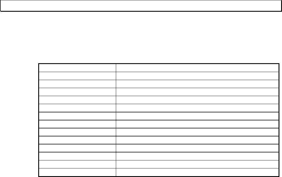
Operating Environment
The T-PDS32 for Windows program runs on a PC/AT compatible computer with the
specifications shown in the table below.
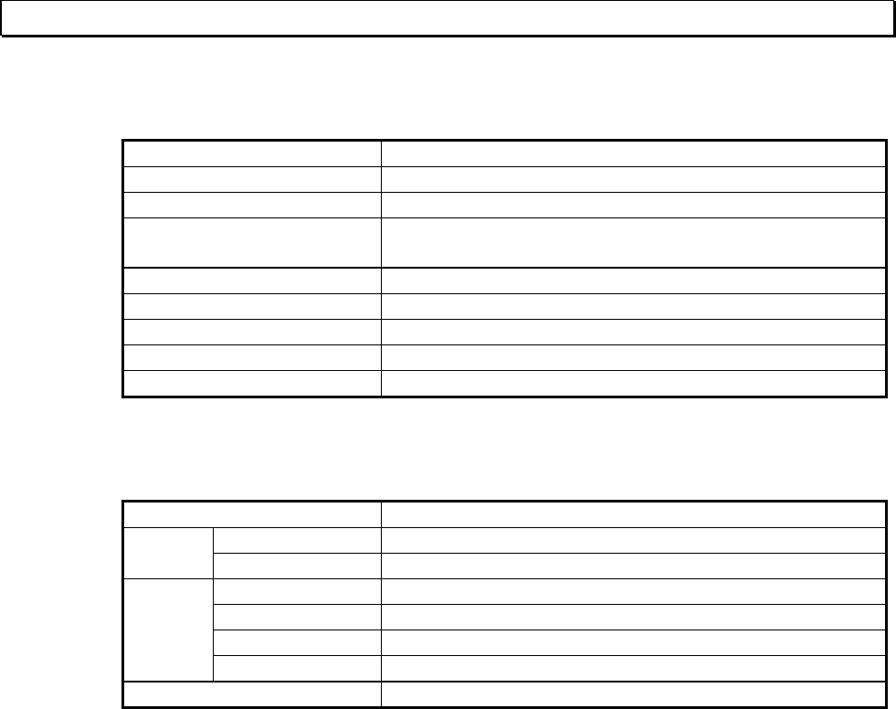
Category Specification
OS Operating System Windows 95
Windows 98 SE
Windows Me
WindowsNT4.0 SP3
Windows 2000
Windows XP
CPU Main Processor Min. Pentium 150 MHz
(MMX Pentium 200MHz or faster)
Memory RAM Min. 32MB
(64MB or more)
Display Display unit
Graphics monitor
Color/gray scale monitor 16 colors or more
Min. 640 x 480 pixels VGA/SVGA
(800 x 600 pixels or more)
Input device Keyboard
Mouse
101 keys/84 keys
PS2 or serial
Disk drive Hard disk drive
CD-ROM drive
Min. 80MB
For setup only
Interface RS-232C *1
Printer
LAN
9600bps
Mono or Color Printer
Ethernet
( ): Recommended
*1: USB/Serial adapter is not guaranteed. It may cause unstable communication between
T-PDS and PLC. If your computer has no serial port, it is recommended to use an RS-232C
PCMCIA card.
6 T-PDS32 for Windows V2.2
T- PDS32 Installation
T- PDS32 Installation
The T-PDS32 installation files are provided by a CD-ROM.
Use the following procedure to install the T-PDS32 for Windows program.
The following steps describe the procedure used to install the T-PDS32 into the hard disk
drive C.
On machines with a different drive configuration, change the drive names as needed.
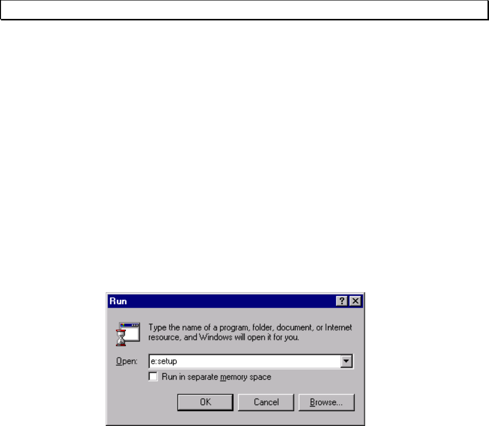
(1) Startup the Windows operating system.
(2) Insert the T-PDS32 CD-ROM. (Drive E in this example)
(3) Point to the Start Bar and then click Run....
(4) In the command line box, enter e:\setup.exe and click OK. Then the T-PDS32
installer program will be started.
Basic Operation 7
T- PDS32 Installation
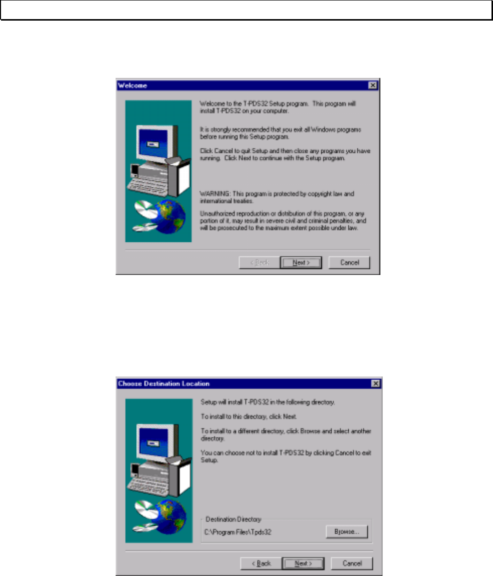
(5) When the installation environment is complete, the following dialog box will appear.
Click Next.
(6) The Destination Location dialog box will appear. The default option for the
destination is "C:\Program Files\Tpds32". To change the destination directory, you
must enter a new directory. Click Browse. A dialog box for selecting the drive and
directory will appear. Select the directory from the list.
Then click Next.
8 T-PDS32 for Windows V2.2
T-PDS32 Installation
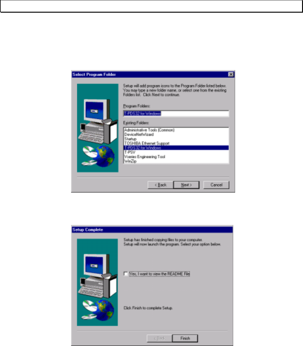
(7) The Program Folder dialog box will appear. The default option for the folder name is
"T-PDS32 for Windows". To change the folder name, you must enter a new folder
name.
When preparations for installation are complete, click Next. To cancel the
installation process, click Cancel.
(8) When installation of T-PDS32 for Windows is completed properly, the execution files
and other files will be registered in the T-PDS32 for Windows folder.
Basic Operation 9
Before Operation
Before Operation
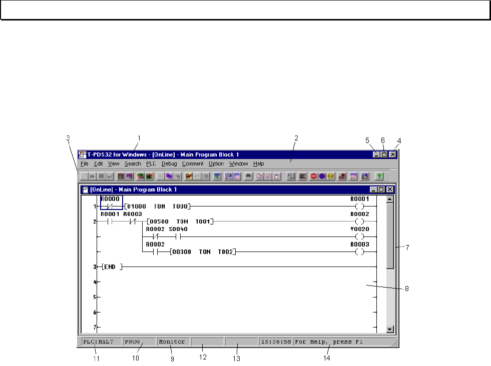
Screen Configuration of T-PDS32 for Windows
The configuration for the main window screen is described below.
1 - Title bar: Shows the name of the window.
2 - Menu bar: Shows the names of the main menus.
3 - Toolbar: Displays icons for tools that can be used. You can hide the toolbar by changing the
Toolbar setting on the View menu.
4 - Control-menu box: Clicking this button closes the window.
5 - Reduce button: Clicking this button shrinks the window so it is displayed as an icon.
6 - Restore button: This button appears when the window fills the entire screen. Clicking the button
restores the window to its original size.
7 - Client area: This area shows the data for the selected function.
8 - Work window: The work area for the selected function.
9 - Current command: Shows the currently selected command.
10 - Status: Shows programming enable or protected status of the controller.
11 - Operational status: When the T-PDS32 is online mode, "PLC" appears in the status bar, followed by
the operational mode of the controller.
"OFFLINE" appears when the T-PDS32 is offline mode.
12 - Insert/Overwrite: In Edit mode, this shows whether insert or overwrite mode. It can be controlled by
[Ins] key.
13 - SFC line number: Shows the SFC line number of the cursor position (at SFC programming).
14 - Help message: Shows help messages pertaining to the toolbox.

10 T-PDS32 for Windows V2.2
Before Operation
Selecting Functions
In the T-PDS32 for Windows program, you can select operational modes using the
main menus on the menu bar.
[File] Used to open, save and print projects and to quit the program.
Program load/save between the PLC is under this menu.
[Edit] Used to write a program, modify the program, and online write into the
PLC.
[View] Used to display the data monitor window, change the data display
format, zoom in/out the program display, etc.
[Search] Used to perform the search function for designated operand and/or
instruction, and jump to the designated location in the program.
[PLC] Used to monitor/set the PLC system parameter, monitor the
maintenance information, control the PLC mode, etc. The T-PDS32
online/offline mode selection is under this menu.
[Debug] Used for program debugging functions such as force, data set/reset,
sampling trace, etc.
[Comment] Used to edit/display the comment. Comment conversion to/from CSV file
is also available.
[Option] Used to display cross-reference, usage-map and force list.
The T-PDS32 connection method selection and some customize
function are under this menu.
[Window] Used to open or change the display status of windows.
[Help] Used to access the help function and display the version data.
Menu items may be selected either by using the mouse or by pressing keys on the
keyboard.
Using the mouse: Move the mouse pointer on the item in the menu bar and click the
left mouse button.
Using the keyboard: Press the Alt key and select the menu, then use the cursor keys
to select the desired menu item and press Enter key.
Basic Operation 11
Before Operation
Menu Configuration
[File] Used to open, save and print projects and to quit the program.
Program load/save between the PLC is under this menu.
New Project Opens a new project
Open Project Opens an existing project
Save Project Saves changes to the project
Save Project As Saves the project under a different name
Close Project Closes the project
Compare Project Compares the PLC program with another project
Multiple Projects Opens another project
Print Prints the project
Print Preview Shows a preview of printing
Print Setup Used to choose the printer settings
Transfer Program Transfers the project between PLC and disk file
Program Block Read Appends the program blocks to the editing program
Recent File List Shows a list of recently accessed files
Exit Quits the program
12 T-PDS32 for Windows V2.2
Before Operation
[Edit] Used to write a program, modify the program, and online write into the
PLC.
Edit Mode Changes the mode to Edit mode
Undo Recovers the last edit operation
Cut Cuts the circuit (Ladder)
Copy Copies the circuit (Ladder)
Paste Pastes the circuit (Ladder)
Line Inserts a line (ladder)
Rung Inserts a rung (ladder)Insert
Column Inserts a column (SFC)
Line Deletes a line (ladder)
Rung Deletes a rung (ladder)Delete
Column Deletes a column (SFC)
Direct Used to edit the transition/action directly (SFC)
Edge Used to set/release Edge execution setting
Digit Used to set/release Digit designation
Edge/Digit/
Index Index Used to set/release Index modification
Change Language Selects the language either Ladder or SFC
Edit Block Edits the program in block units (Block copy/move)
Merge Block Merges the block with anotherBlock
Divide Block Divides the block
Change
Device Changes register or device
Function Replace
Address Search and replace the designated registers or devices
Check Program Checks the program
Write Writes the edited program into PLC (online) or into internal
memory (offline)
Basic Operation 13
Before Operation
[View] Used to display the data monitor window, change the data display format,
zoom in/out the program display, etc.
Tool Bar Displays/hides the toolbar
Status Bar Displays/hides the status bar
Data Box Displays the data box to set data
Auxiliary Monitor Displays auxiliary data monitor window. (simultaneous
monitor with program execution)
Data Monitor Displays the data monitor window (32 words data)
Data Format Changes the data display format
Trace Format Changes the trace display format
Zoom In/Out Enlarges/reduces the display size
Fit To Window Fit the display to the window size
[Search] Used to perform the search function for designated operand and/or
instruction, and jump to the designated location in the program.
Find Searches for designated register/device in the program
Start of Block Moves to the first rung in the block
Rung End of Block Moves to the last rung in the block
Start of Program Moves to the first block of the program type
End of Program Moves to the last block of the program type
Next Block Moves to the next block
Block
Previous Block Moves to the previous block
Goto Used to display the designated program type and block
14 T-PDS32 for Windows V2.2
Before Operation
[PLC] Used to monitor/set the PLC system parameter, monitor the maintenance
information, control the PLC mode, etc. The T-PDS32 online/offline mode
selection is under this menu.
System Parameters Monitors/edits the system parameters
I/O Allocation I/O module allocation data
Interrupt
Assignment Interrupt assignment data
I/O Allocation
Network
Assignment Link data allocation for network module
Event History Reads and displays the PLC's event history
Scan Time Reads and displays the scan time
Power Interruption Used to set the power interruption function
C2 Access Setting Used to set the register allocation for data exchanging
between S2T and C2
Clear Event Clears the event history
Clear Memory Clears entire PLC memory
Clear IC Card Clears the IC card memory
Read EEPROM/
IC Card
Loads program from EEPROM or IC card and stores it
in PLC's memory
Memory
Management
Write EEPROM/
IC Card
Writes PLC memory program into the built-in EEPROM
or IC card
Change Protect
Level Changes the level accessible with the password
Password
Set Password Sets a password
Halt Stops the program execution
Run Starts the program execution
Force Run Starts the program execution without checking I/O
mounting status
Error Reset Resets the PLC error status
Hold Stops the program execution with keeping I/O update
Hold Cancel Cancels hold mode and returns to Run
PLC Control
Float Box Displays/hides the PLC control box
Online/Offline Toggles the mode between Online and Offline
Basic Operation 15
Before Operation
[Debug] Used for program debugging functions such as force, data set/reset,
sampling trace, etc.
Force Used to set force input or force coil
Set On/Off Used to set data into the register/device
Change Value Used to write data into the register or change the constant
operand value
Sample Trace Used to execute the sampling trace function
Status Latch Used to execute the status latch function
Data Validity Check Used to execute the bit-pattern check function
[Comment] Used to edit/display the comment. Comment conversion to/from CSV file
is also available.
View Displays/hides the comment on the program
Block Comment Edits block comments
Rung Comment Edits rung comments
Edit
Reg/Dev
Comment
Edits register/device comments
Program
Comment
Appends the block/rung comment from the existing comment
file
Append
Reg/Dev
Comment
Appends the register/device comment from the existing
comment file
Convert Converts the comment file to/from CSV file
Select Comment File Selects the reference comment file in online mode
[Option] Used to display cross-reference, usage-map and force list.
The T-PDS32 connection method selection and some customize function
are under this menu.
Cross Reference Shows the cross reference list
Usage Map Shows the register/device usage map
Forced List Shows the list of forced inputs/coils
Instruction Box Sets the instruction bar option
Communication Sets communication method between PLC
Comment Font Customizes the comment font
Color Set Customizes the color
Customize
User Instruction Customizes the user Instruction group
16 T-PDS32 for Windows V2.2
Before Operation
[Window] Used to close or change the display status of windows.
New Window Opens a new program window
Cascade Displays windows overlapped in cascading fashion
Tile Displays windows side by side in tiled fashion
Arrange Icons Changes window into icon
Close All Closes all open windows
List of Open Windows Displays/hides a list of open windows
[Help] Used to access the help function and display the version number.
Contents Displays help categories
Search on Help Searches help by key word
About T-PDS for Windows Displays the version data
Basic Operation 17
Before Operation
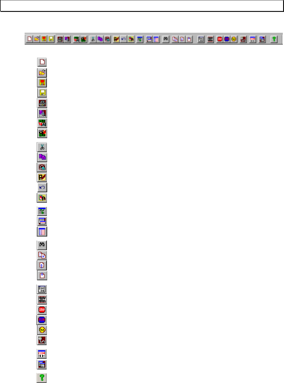
Toolbar Configuration
The toolbar contains the most frequently used functions.
[File] [New Project] Opens a new project
[File] [Open] Opens an existing project
[File] [Save] Saves changes to a project
[File] [Save Project As] Saves the project under a different name
[File] [Print] Prints the program
[File] [Print Preview] Displays the print preview
[File] [Program Transfer] [PLC→File] Uploads the program from PLC to file
[File] [Program Transfer] [File→PLC] Downloads the program from file to PLC
[Edit] [Cut] Cuts the rungs
[Edit] [Copy] Copies the rungs
[Edit] [Paste] Pastes the rungs
[Edit] [Edit Mode] Selects/deselects program edit mode
[Edit] [Undo] Recovers the last edit operation
[Edit] [Write] Writes the program into PLC or offline memory
[View] [Data Box] Displays the data box
[View] [Auxiliary Monitor] Displays the auxiliary monitor window
[View] [Data Window] Displays the data monitor window
[Search] [Find] Searches operand and/or instruction
[Search] [Go to] Moves to the designated location
[Search] [Block] [Previous Block] Moves to the previous block
[Search] [Block] [Next Block] Moves to the next block
[PLC] [Event History] Displays the event history
[PLC] [Memory Management] [Write EEPROM] Executes EEPROM write command
[PLC] [PLC Control] [Halt] Executes HALT command
[PLC] [PLC Control] [Run] Executes RUN command
[PLC] [PLC Control] [Error Reset] Executes Error Reset command
[PLC] [Online/Offline] Switches T-PDS32 mode online/offline
[Comment] [Comment Format] Displays comments on the program
[Window] [New Window] Opens program window
[Help] Calls online help

18 T-PDS32 for Windows V2.2
Before Operation
Key Operation
Described below are the key functions of the T-PDS32.
<<File>>
- Ctrl + N Opens a new project.
- Ctrl + O Opens an existing project.
- Ctrl + S Saves on the same file name.
- Ctrl + A Saves as a new file.
- Ctrl + P Prints out
- Alt + F4 Ends the T-PDS32
<<Common to program view and edit (Ladder/SFC’s Action and Transition)>>
- [→] Moves the cursor to right.
- Shift + [→] Moves the cursor to the extreme right.
- [←] Moves the cursor to left.
- Shift + [←] Moves the cursor to the extreme left.
- [↑] Moves up the cursor to the line above.
- [↓] Moves down the cursor to the line below.
- Shift + [↓] Selects a range from the cursor rung. (up to 11 lines)
- Shift + [↑] Cancels the selected range.
- Home Moves the cursor to the first rung of the block.
- End Moves the cursor to the last rung of the block. (for ladder only)
- PageUp Scrolls up the circuit. (for ladder only)
- PageDown Scrolls down the circuit. (for ladder only)
- Shift + PageUp Moves to the previous block.
- Shift + PageDown Moves to the next block.
- Ctrl + E Edit mode/Edit quit
- Ctrl + C Copies a range of the program.
<<Commn to program view and edit (SFC)>>
- [→] Moves the cursor right.
- [←] Moves the cursor left.
- [↑] Moves up the cursor to the line above.
- [↓] Moves down the cursor to the line below.
- Home Moves the cursor to the home position.
- End Moves the cursor to the last symbol position.
- PageUp Moves up the cursor to the 12 lines above.
- PageDown Moves down the cursor to the 12 lines below.
- Ctrl + E Edit mode/Edit quit

Basic Operation 19
Before Operation
<<Program edit (Ladder/SFC’s Action and Transition)>>
- Shift + 0 to 8 Specifies the digit designation. (Q0 to Q8)
- Shift + Ctrl + 0 to 8 Cancels the digit designation. (Q0 to Q8)
- Shift + I, J, K Specifies the index modification. (I, J, or K)
- Shift + Ctrl + I, J, K Cancels the index modification. (I, J, or K)
- Shift + P Specifies/cancels the edge execution modifier.
- Ctrl + H Changes constant operand input format. (Decimal/hexadecimal)
- Insert Changes overwrite/insert mode.
- Delete Deletes instructions.
- Space Clears operand.
- Enter Enters the instruction. If blank, inserts a line blow cursor.
- Shift + Enter Inserts a line below the cursor position. (for ladder only)
- Ctrl + Z Undoes the recent edit operation. (for ladder only)
- Ctrl + X Cuts a range of the program. (for ladder only)
- Ctrl + C Copies a range of the program. (for ladder only)
- Ctrl + V Pastes a cut or copied program. (for ladder only)
- Ctrl + W Writes the edited program. (for ladder only)
- Shift + C Erases circuits. (for ladder only)
- Shift + X Deletes lines. (for ladder only)
- Esc Cancels the edit process.
<<Program edit (SFC)>>
- Insert Changes overwrite/insert mode. (toggle)
- Delete Deletes symbols.
- Space Clears operand.
- Enter Enters the operand and confirms it.
- Shift + [↓] Selects lines from the symbol on the cursor position.
Shift + [↑] Cancels the selected line.
- Ctrl + W Writes programs
- Esc Cancels the edit process.
<<Data Monitor>>
- [→] Moves forwards between blocks.
- [←] Moves backwards between blocks.
- [↑] Scrolls up the block.
- [↓] Scrolls down the block.
- PageUp Scrolls by the block size in the decrement direction.
- PageDown Scrolls by the block size in the increment direction.
- Home Moves the cursor to the first address of the block.
- End Moves the cursor to the last address of the block.
- Enter Edits the data value at the cursor position. (in data box)

20 T-PDS32 for Windows V2.2
Before Operation
<<Auxiliary monitor>>
- [→] Moves forwards between blocks.
- [←] Moves backwards between blocks.
- [↑] Scrolls up the block.
- [↓] Scrolls down the block.
- PageUp Scrolls by the block size in the decrement direction.
- PageDown Scrolls by the block size in the increment direction.
- Home Moves the cursor to the first address of the block.
- End Moves the cursor to the last address of the block.
- Enter Registers the data address to the cursor position and edit the
data value. (in data box)
- Delete Deletes the registration.
<<Comment window>>
- [↑] Scrolls up the screen.
- [↓] Scrolls down the screen.
- PageUp Scrolls up by 32 addresses..
- PageDown Scrolls down by 32 addresses.
- Home Moves the cursor to the first address.
- End Moves the cursor to the last address.
- Enter Edits the tag/comment at the cursor position. (in data box)
<<Debug>>
- Ctrl + 1 Sets the device ON.
- Ctrl + 2 Resets the device OFF.
- Ctrl + 3 Sets force the device.
- Ctrl + 4 Resets force the device.
Basic Operation 21
Before Operation
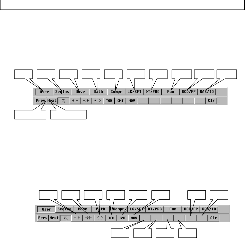
Key Assignment to the Instruction bar
The instruction type and instruction toolbar buttons have a shortcut key allocated.
The instruction type can be selected by pressing one of the following shortcut keys.
The instruction will be pasted to the cursor position by pressing the following shortcut
keys.
ALT+F1 ALT+F2 ALT+F3 ALT+F4 ALT+F5 ALT+F8 ALT+F9 ALT+F10 ALT+F11 ALT+F12
ALT+PageUp ALT+PageDown
ALT+1 ALT+2 ALT+3 ALT+4 ALT+5 ALT+6 ALT+ - ALT+ =
ALT+7 ALT+8 ALT+9 ALT+0
22 T-PDS32 for Windows V2.2
1. Procedure
Basic Operation
1. Procedure
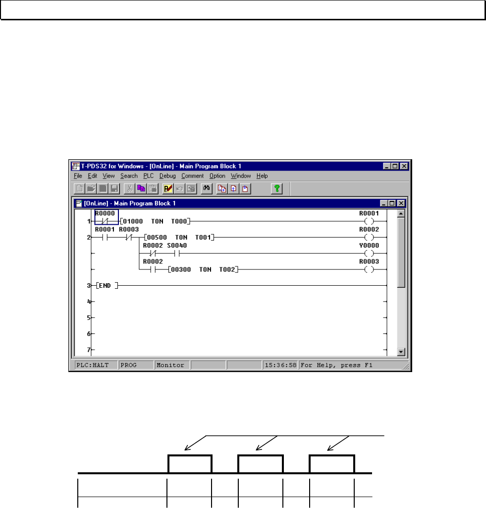
1.1 Sample Program
In this manual, the operation of the T-PDS32 is explained through the process of
creating a control program for the flicker circuit shown below.
• Flicker Circuit Operation
10 seconds after startup, the flicker circuit blinks for 5 seconds at 3-second intervals.
Contact S0040 is a special relay (timing relay) that goes on and off every 0.1 second.
During its 5-second operation it turns the device (output coil) on and off every 0.1
second.
When there is an I/O card (D0334 and R0364 [T3], D031 and D032/R061 [T2] or other
output module), it should be installed in slot 0.
Program execution can be checked on the module operation LEDs. Program creation
and execution is possible even if the I/O card is not installed.
Blinks ever
y
0.1 second for 5 seconds
10 sec 5 sec 3 sec 5 sec 3 sec 5 sec

Basic Operation 23
1. Procedure
1.2 Procedure
This manual describes how to create the program for the flicker circuit using the
following procedure.
Check system configuration - Check the program for the flicker circuit.
Connect controller - Connect the controller to the programmer.
Starting up T-PDS32 - Launch the programmer.
Register system control data - Register the control parameters for the flicker
circuit.
Register I/O card - Register the I/O card to be used with the flicker
circuit.
Programming 1 - Place symbols and write operands to create a
sample program.
Write program - Write the program to the controller.
Execute program - Execute the program and check the operation on
the Program screen and the Register All screen.
Check operation 1
Check operation 2
Insert circuit - Insert a circuit and change some of the sample
program functions.
Set data - Execute the corrected program and then change
some of the data being executed and check
operation.
Delete circuit - Delete a portion of the circuit and finish the revised
program.
Save program - Save the program on a floppy disk. This section also
discusses how to load programs from the floppy disk.
Helpful function - This section describes how to name the registers for
the program, sample the operational status and
check it on a time chart, debug programs and print
out programs.
24 T-PDS32 for Windows V2.2
2. Starting Up the T-PDS32
2. Starting Up the T-PDS32
2.1 System Startup
You need to connect the programmer to the controller before starting up the system.
The cable can be connected to the controller while it is running or power on.
Connect the male connector of the
dedicated cable to the [PROG]
connector on the CPU module of the T-
series controller.
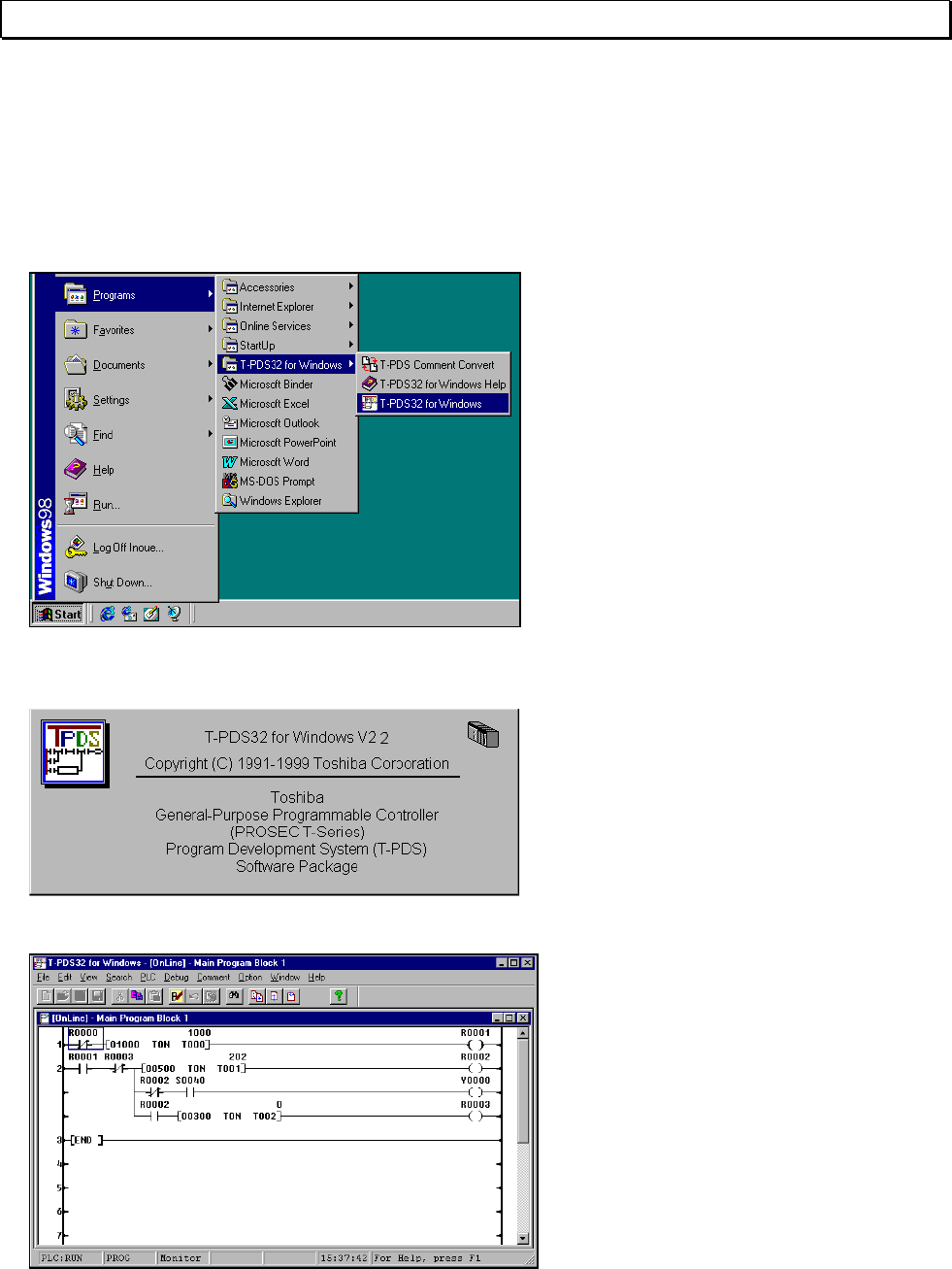
To launch the T-PDS32 for Windows
program, double-click the T-PDS32 icon
in the T-PDS32 group. Only one project
is opened when the program is
launched.
When the system starts up, the title
screen will appear, followed by the default
screen.
After a while, the base system programs
of the controller appear.
If the programmer is not connected
properly to the controller through the
dedicated cable, a screen in offline
mode appear.
Basic Operation 25
2. Starting Up the T-PDS32
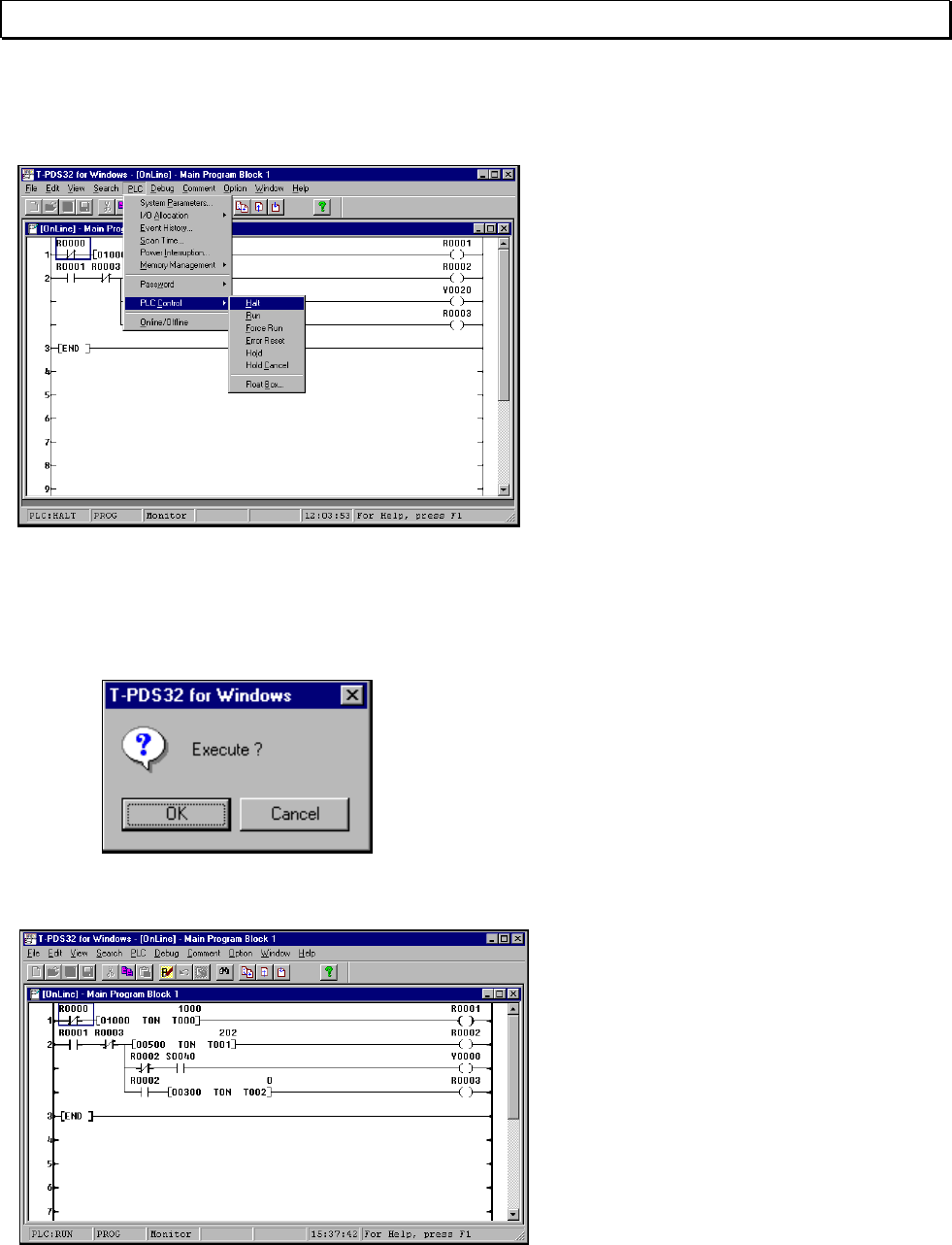
2.2 Changing the PLC Operation Mode
The operational status of the controller
can be changed from the programmer
as well as by using the operation
selector switch on the CPU module.
To change the operation mode using the
programmer, point to PLC Control in the
PLC menu. Another submenu will
appear containing a list of controller
operation modes.
There are six controller operation modes
- Halt
- Run
- Force Run
- Error Reset
- Hold
- Hold Cancel
Click the desired mode.
A dialog box will appear, asking you to
confirm that you want to change the
controller operation mode.
Click OK.
The controller will change to the
designated mode. Check the mode
displayed at the bottom of the screen.
26 T-PDS32 for Windows V2.2
2. Starting Up the T-PDS32
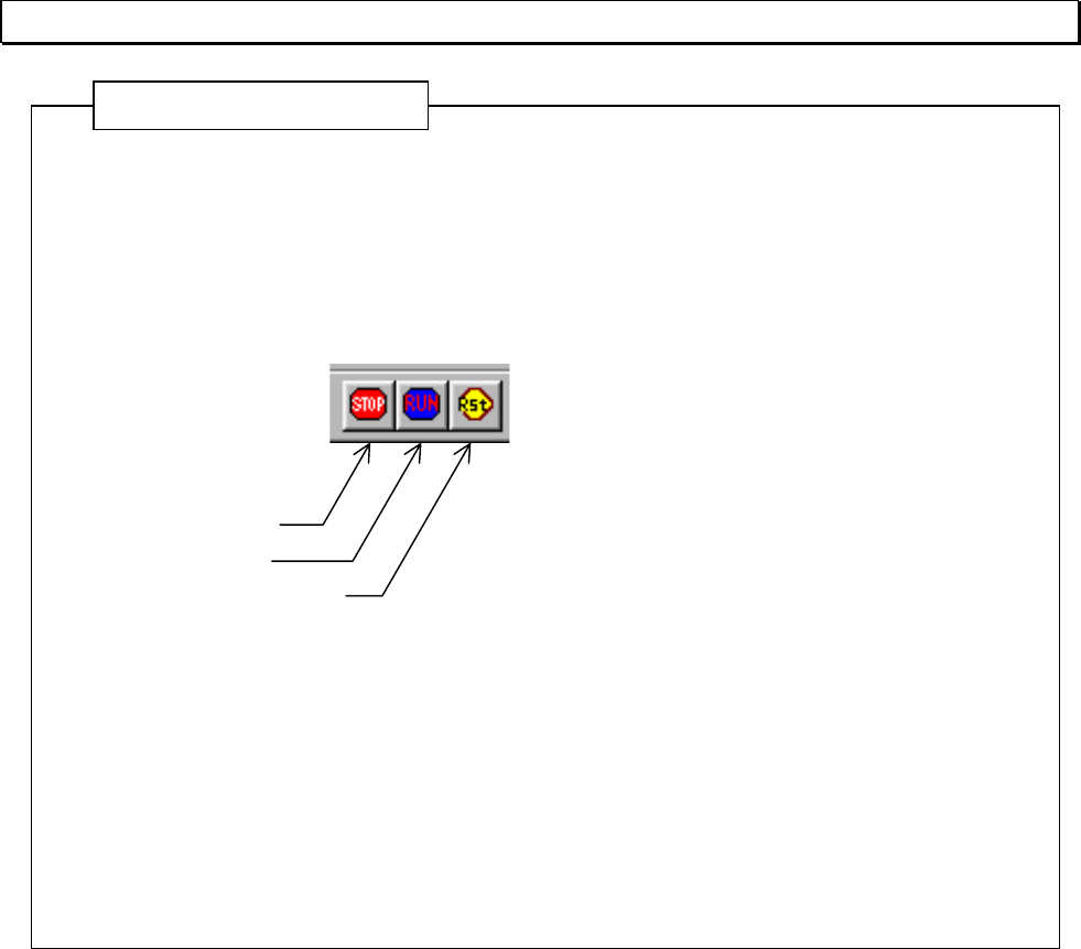
Using the toolbar to control the PLC operation mode
The PLC operation mode can be changed at any time when the PLC Control
toolbar is displayed.
When you click one of the buttons in the toolbar, a dialog box will appear, asking
you to confirm the mode change.
Click OK to change the mode. Click Cancel to cancel the operation.
The operation mode can be changed from the T-PDS32 only when the operation
switch on the controller is set to RUN or P-RUN. If an attempt is made to change
the mode from the T-PDS32 when the operation switch is set to HALT, a "Mode
Unmatch" message will appear. Set the operation switch to RUN or P-RUN and
then repeat the mode changing procedure. If the controller cannot be operated
properly (in other words, if the mode cannot be changed to RUN), a message
explaining the cause will appear.
Additional Information
HALT
RUN
Error Reset
Basic Operation 27
2. Starting Up the T-PDS32
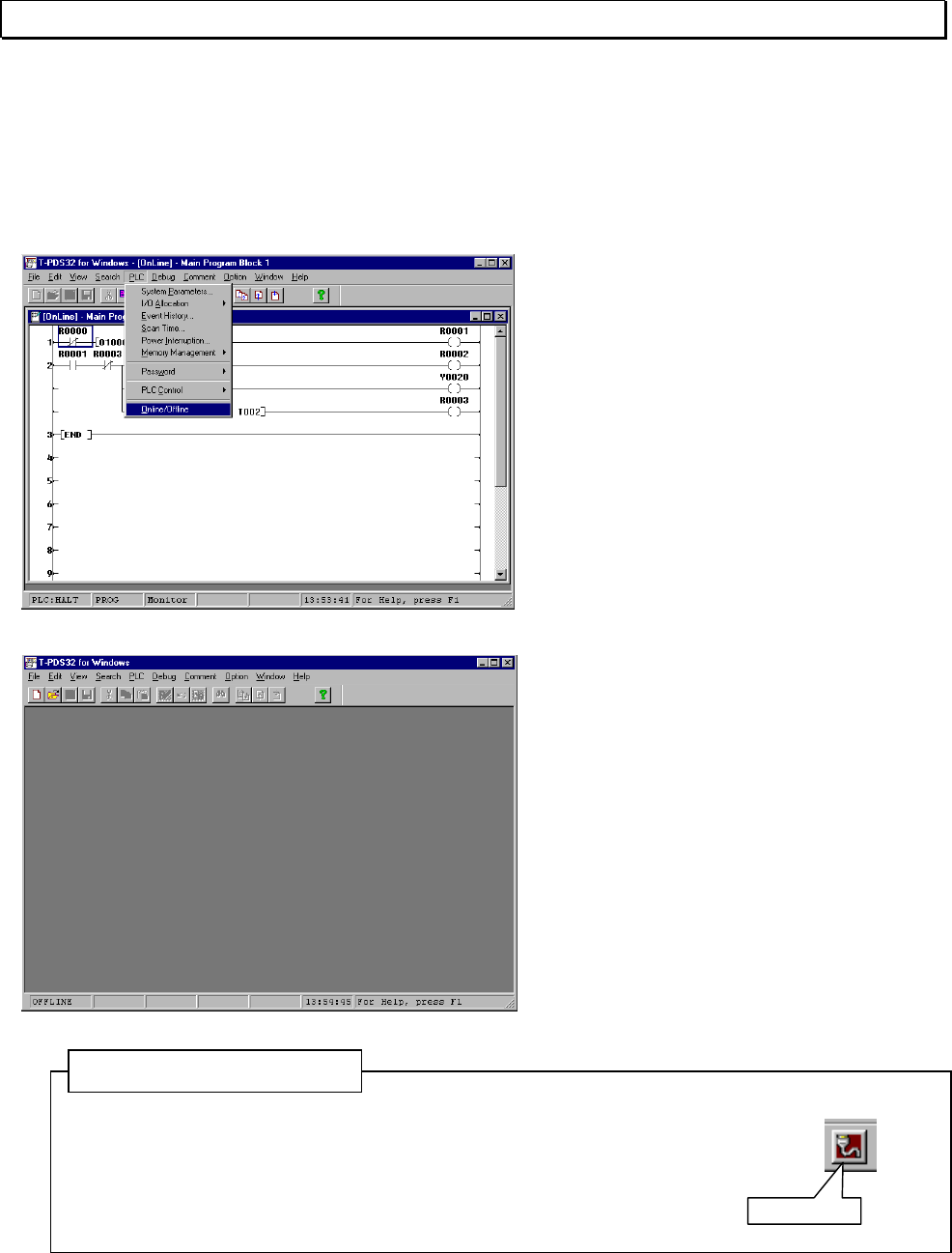
2.3 Switching Between Online and Offline Mode
In addition to creating programs and setting data in online status, with the programmer
and controller connected, the T-PDS32 for Windows program can also be used to
create and edit programs in offline mode with the programmer alone.
To change the online/offline mode, use
Online/Offline on the PLC menu.
Clicking Online/Offline toggles the status
to the opposite of the current status.
When the status is changed from Offline
to Online, a project for that controller
opens and the program for the first block
is displayed.
No project is displayed when the status
is changed from Online to Offline.
You have to create a new project or
open an existing project for editing in
offline mode.
Using the toolbar to change Online/Offline
You can change the T-PDS32 operation mode between
online and offline by clicking the tool button. (Toggle)
Additional Information
Online/Offline
28 T-PDS32 for Windows V2.2
2. Starting Up the T-PDS32
1. The difference in operation between online and offline are as follows:
Online: The T-PDS32 reads/writes program and data with the connected PLC
memory.
The T-PDS32 reads/writes comments either in the specified comment
file or in the PLC memory (T3/T3H/S2T only).
Offline: The T-PDS32 reads/writes program and data with the offline work
memory on the PC.
The T-PDS32 reads/writes comments in the offline work memory
(temporary comment file).
It is necessary to save them into a file before exit.
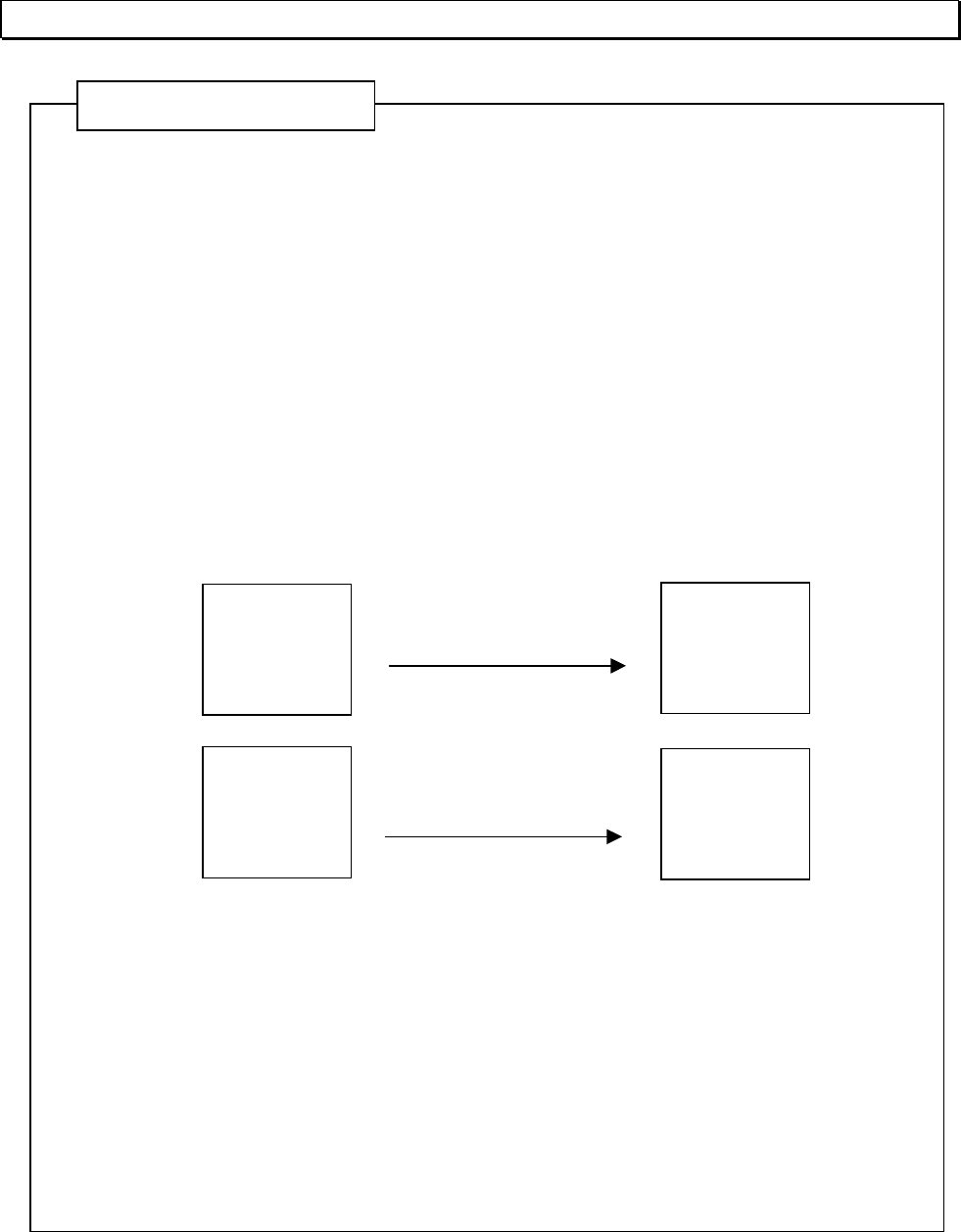
2. Relation between work memory and comment file
When a project is opened, the T-PDS32 reads the program and data from the file
and load them in the work memory as follows.
In the default setting, the comment file is also transferred to the work memory
(temporary comment file) when [Open Project] is executed.
If you do not want to transfer the comments, uncheck comment in the transfer
items. (See Section 2.5 on Page 30)
The temporary comment file is initialized when creating a New Project.
When you load comments into the temporary comment file from another
comment file, use [Append] function under [Comment] menu.
Additional Information
Program Program
Comment
(the same
name as the
program)
Temporary
Comment
File
Saved file Offline work memory
[Open Project]
When open a project,
the comment file is
also transferred.
(Default setting)
Basic Operation 29
2. Starting Up the T-PDS32
2.4 Opening a New Project
To create a new program in Offline status, first you must open a new project.
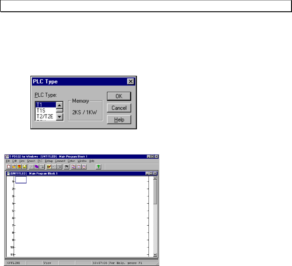
Click New Project on the File menu. (Toolbar is also available)
The PLC Type list box will appear asking
you to select the PLC.
In the PLC Type list box, select the
controller PLC type (T1, T1S, T2/T2E,
T2N, T3, T3H-32K, T3H-64K, S2T-32K
or S2T-64K).
The memory size and data register size
for the selected type will appear.
Click OK to create a new project for the
selected controller type; the Program
screen will appear. Click Cancel to
cancel the creation process.
30 T-PDS32 for Windows V2.2
2. Starting Up the T-PDS32
2.5 Opening an Existing Project
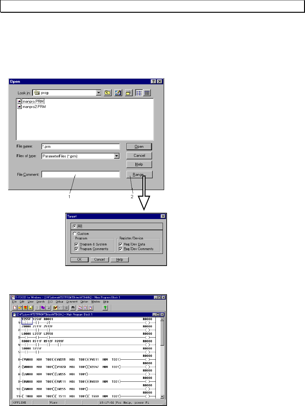
To use an existing project, click Open Project on the File menu.
(Toolbar is also available)
A dialog box will appear, asking you to
select the project.
(1) File Comment
Shows the title of the project at the
location of the cursor in the File Name
list box.
(2) Range
Displays dialog box used to select the
type of files to be loaded.
To designate an existing project, select
the file from the ones in the File Name
list box, or enter the name of the file in
the File Name text box.
Clicking Range shows the Target dialog
that allows you to select either program
files only or both program and data files .
Click OK in the Select Project box to
open the designed project.
Click Cancel to cancel the open project
process.
Basic Operation 31
3. Programming
3. Programming
The first step in the programming process is to register the I/O card and the system
parameters needed by the control system.
In this manual, programming steps are explained using online mode. Basically
programming in offline mode is almost same as online mode.
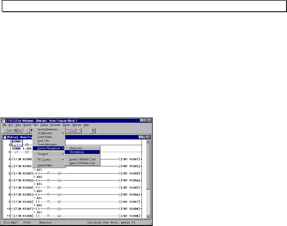
3.1 Clear Memory
When you program initially, you should clear the controller memory using the Clear
Memory command.
On the PLC menu, point to Memory
Management and click Clear Memory.
A dialog box will appear, asking you to
confirm that you want to clear the memory.
Click OK.
This will initialize system parameters, clear I/O registration, all program and register
data. This command cannot be undone, so be sure you want to clear the memory
before initiating the procedure. Back up necessary data to a disk.
32 T-PDS32 for Windows V2.2
3. Programming
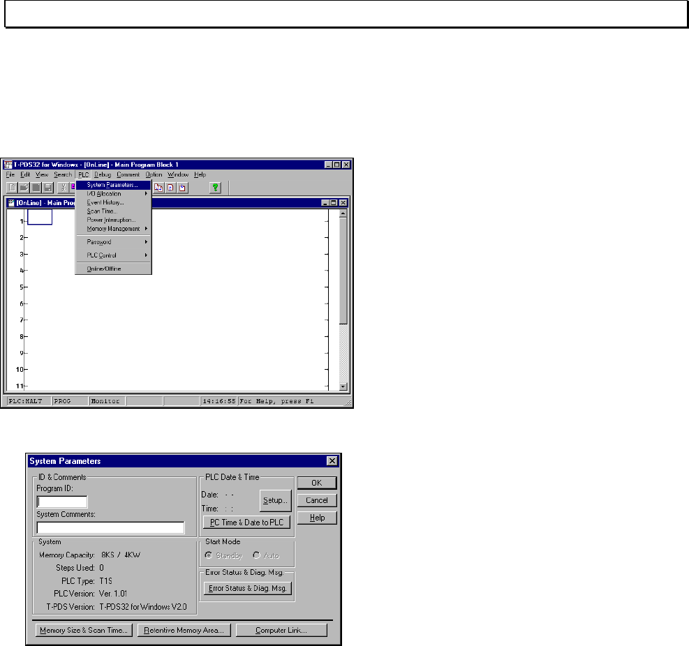
3.2 Registering System Parameters
This section describes how to register the system parameters needed to control the
flicker circuit.
Click System Parameters on the PLC
menu. The System Parameters box will
appear.
The System Parameters window will
appear. On this window, connected PLC
information, loaded program information
and control parameters are displayed.
Basic Operation 33
3. Programming
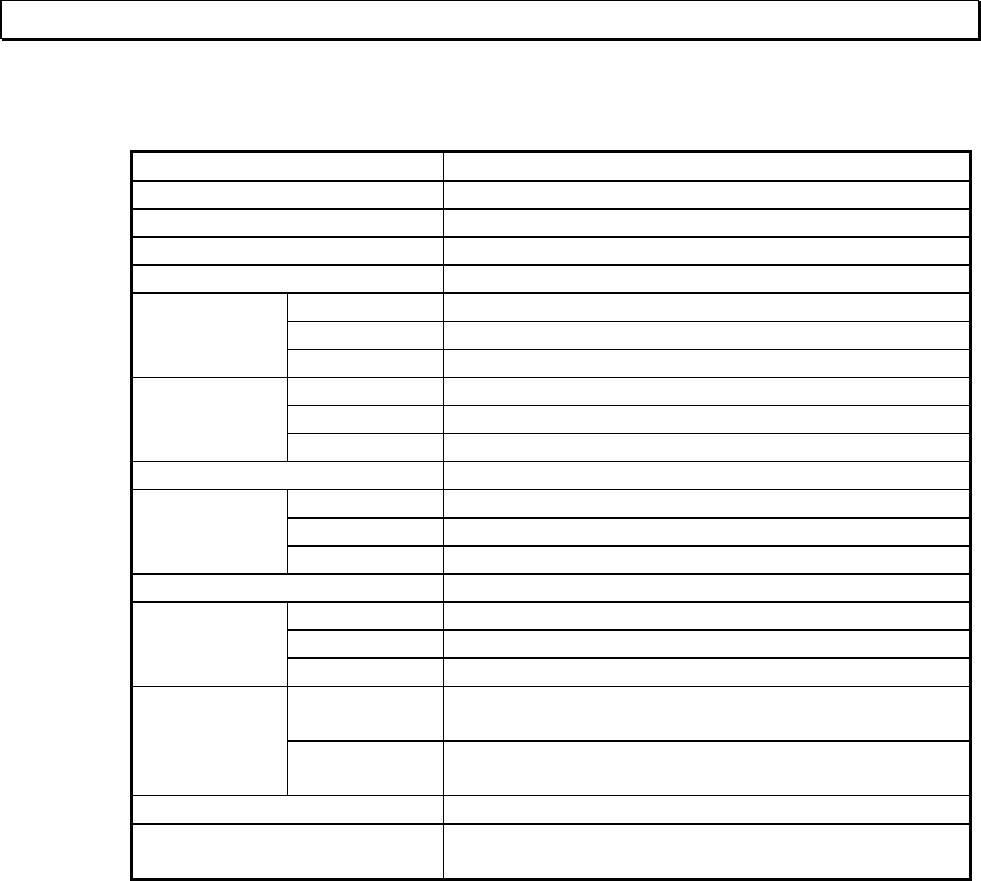
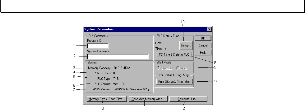
<System Parameters box>
1 - Program ID: The name used to identify the user program (Up to 10 characters)
2 - System Comments: Comments added for the user program (Up to 30 characters)
3 - Memory Capacity: Shows the PLC's memory capacity (Program in K steps / Data registers
in K words)
4 - Steps Used: Shows the number of steps used in the user program.
5 - PLC Type: Shows the PLC type. (online only)
6 - PLC Version: Shows the PLC version. (online only)
7 - T-PDS Version: Shows the version number of the T-PDS32.
8 - PLC Date & Time: Shows the date and time that is managed in the PLC. (online only)
- PC Time & Date to PLC: Used to set the PC's date and time to the PLC. (online only)
9 - Start Mode: Selects the PLC's initial operation mode immediately after the power is
turned on. (for T3H, S2T only)
Standby: Starts up in HALT mode regardless of the position of the
operation mode switch on the CPU
Auto: Goes into RUN mode when the operation mode switch on the
CPU is RUN or P-RUN
10 - Memory Size&Scan Time: Displays a dialog box used to set the program size, sampling buffer,
scan time, subprogram execution time, timer interrupt interval and 10ms
timer allocation.
11 - Retentive Memory Area: Displays a dialog box used to set the retentive register area.
12 - Computer Link: Displays a dialog box used to set the computer link transmission
parameters.
13 - Setup (online only): Used to set the PLC's date and time.
14 - Error status/diagnostics: Displays a dialog box showing the error status and diagnostics.
(online only)
34 T-PDS32 for Windows V2.2
3. Programming
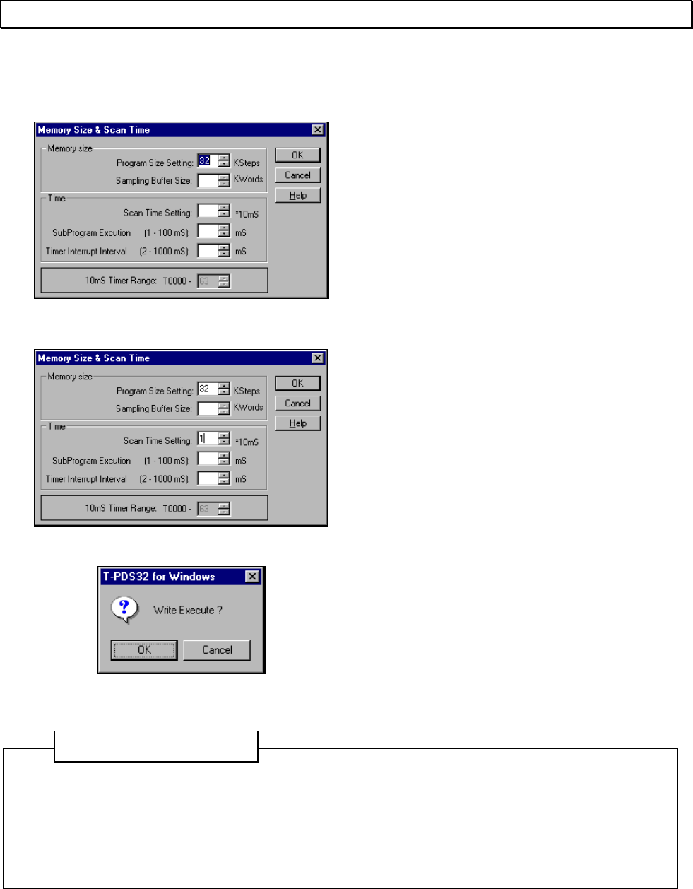
In this example, you will set the scan time for the flicker circuit control program.
Click the Memory Size & Scan Time button
to display the Memory Size & Scan Time
box.
Move the cursor to the Scan Time Setting
box. Enter a scan interval and click OK,
which saves the value temporary.
Then, return to the System Parameter box.
Click the OK button in this dialog box to
register and confirm the entered value as a
system parameter.
You will see a dialog box, asking you to
confirm that you want to register the new
data.
To register the data for the controller, click
OK. To cancel the registration process,
click Cancel.
In the Event of a Registration Error (Mode Unmatch)
System data can only be registered when the controller is in HALT mode. If a registration
error occurs, change the controller operation mode to HALT mode, either by using the
operation mode switch on the controller or by using Control command of T-PDS32.
Additional Informtion
Basic Operation 35
3. Programming
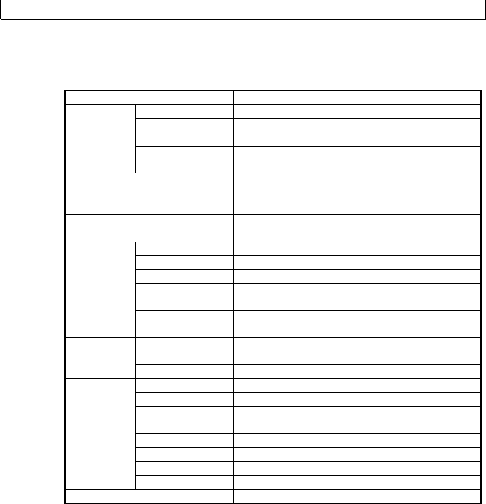
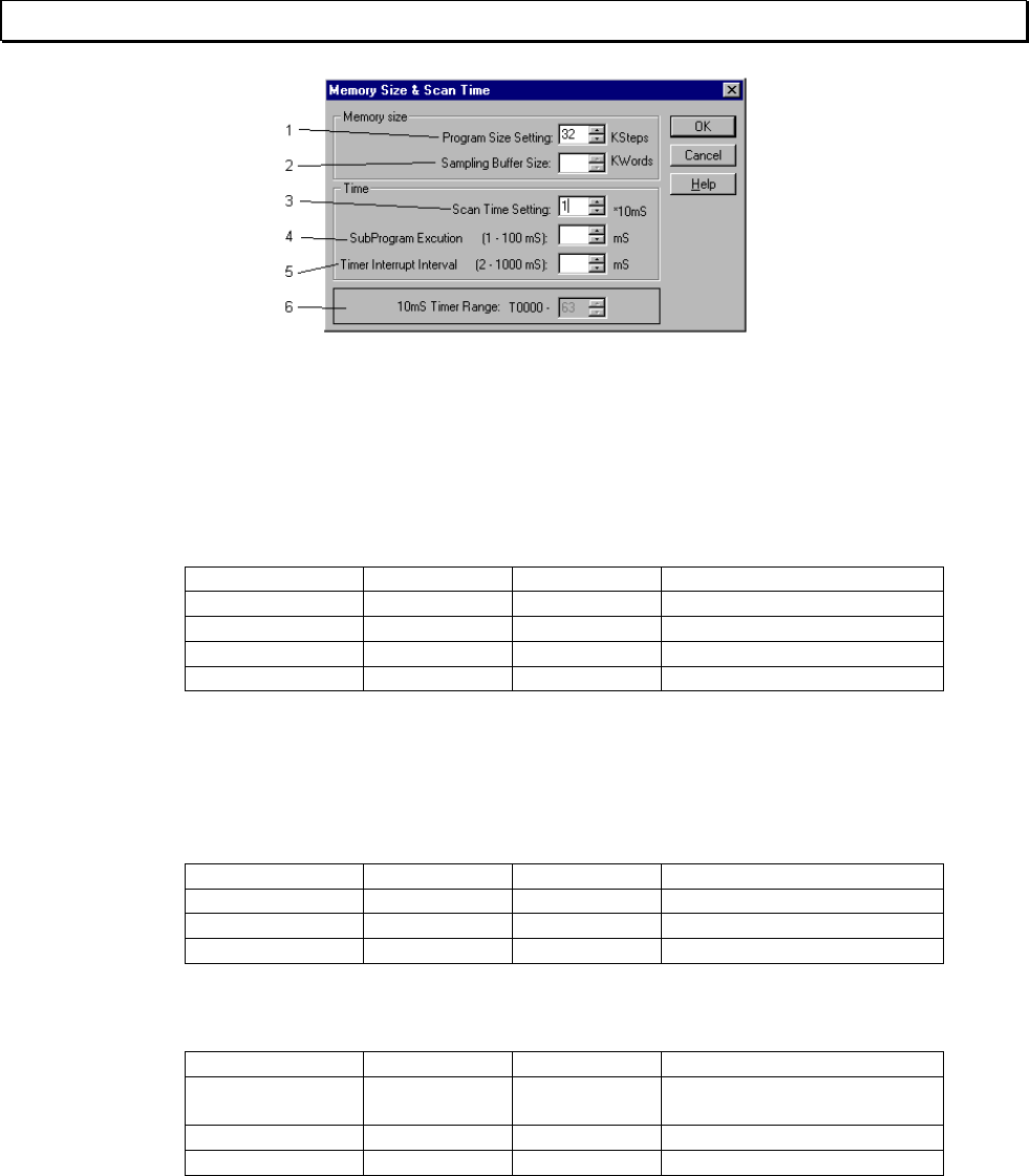
<Memory Size & Scan Time box>
1 - Program Size Setting: Sets the size of memory reserved for the program.
This item is available for T1S to select memory mode 4K or 8K, and for
T3/T3H/S2T to reserve comment memory in the PLC.
2 - Sampling Buffer Size: Sets the buffer memory size for the sampling trace function.
The setting range is shown below.
PLC type Minimum Maximum Note
T1,T1S 1KW 1KW Fixed at 1KW
T2/T2E,T2N 8KW 8KW Fixed at 8KW
T3, T3H 0KW 8KW
S2T 8KW 8KW Fixed at 8KW
3 - Scan Time Setting: Sets the constant scan interval for main program. The setting range is
10 to 200ms. The value is set in 10ms increments, so enter a value from
1 to 20.
4 - Sub Program Execution: Sets the execution time limit for sub-program. The range for this setting
is shown below.
PLC type Minimum Maximum Note
T1,T1S 0ms 0ms Not supported
T2/T2E,T2N 0ms 0ms Not supported
T3, T3H, S2T 1ms 100ms
5 - Timer Interrupt Interval: Sets the interrupt interval for the timer interrupt program. The setting
range is shown below:
PLC type Minimum Maximum Note
T1, T1S,
T2/T2E,T2N 5ms 1000ms 5ms increments
T3 2ms 1000ms 1ms increments
T3H, S2T 1ms 1000ms 1ms increments
6 - 10ms Timer Range: Sets the 10ms timer allocation range. The default setting is T000 to
T063. Other than this range of timers works as 100ms timer.
(T3H, S2T only)
36 T-PDS32 for Windows V2.2
3. Programming
3.3 Registering I/O Cards
This section describes how to register the system parameters needed to control the
flicker circuit.
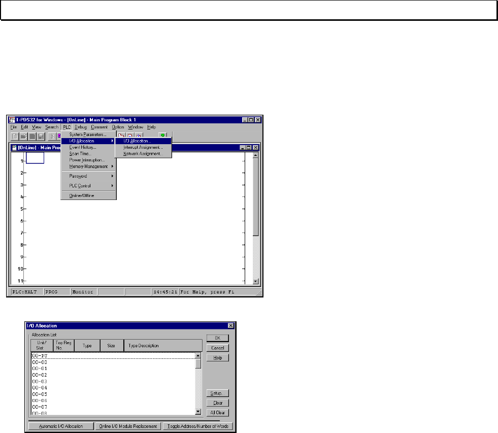
On the PLC menu, point to I/O Allocation
and click I/O Allocation on the submenu.
The I/O allocation box will appear.
Basic Operation 37
3. Programming
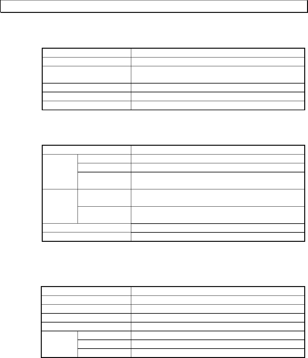
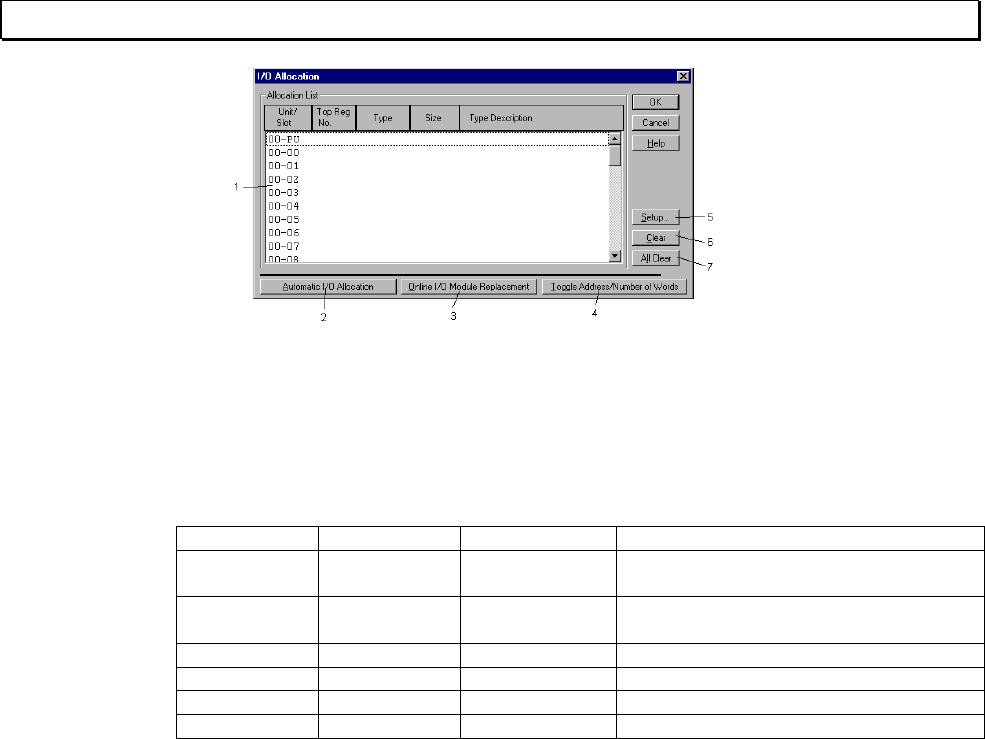
<I/O Allocation box>
1 - Allocation List:
Shows the I/O allocation status.
- Unit/Slot:
Shows the unit and slot numbers separated by a hyphen (unit - slot). Unit 0 means the main
unit, Unit 1 means the expansion unit 1, and so on. The available setting ranges of the unit -
slot and the maximum number of I/O modules are shown below.
PLC type Unit - slot I/O modules Note
T1,T1-40S 0 - 0 to 0 - 7 2 option card
+ 4 I/O module Main unit is allocated on unit 0 - slot 0
T1-16S 0 - 0 and
1 - 0 to 1-7 8 Main unit is allocated on unit 0 - slot 0
I/O modules are allocated on the unit 1
T2/T2E,T2N 0-3 32
S2T 0-3 32
T3 0-3 43
T3H 0-6 76
- Top register no:
When the unit base address setting function is used, the setting address is displayed.
- Type: The I/O type is displayed.
- Size: The shared I/O register size is displayed.
- Type Description:
Shows the I/O module name. (available at setting)
2 - Automatic I/O Allocation:
Used to automatically register the I/O card when the I/O card is installed. (online only)
3 - Online I/O Module Replacement:
Used to disconnect a designated I/O card in software to enable online I/O replacement.
To use this function, locate the cursor on the slot to be disconnected, then click the Online
I/O Module Replacement button. When disconnected, ampersand (&) mark will appear on
the slot. During this status, the I/O module can be replaced.
To recover to normal operation, point the slot and click again the Online I/O Module
Replacement button.
4 - Toggle Address/Number:
Used to check the leading register address assigned to the I/O card.
5 - Setup: Used to set the I/O allocation. Point the slot, then click the Setup button.
6 - Clear: Clears the I/O allocation data for the slot where the cursor is positioned.
7 - All Clear: Clears all I/O allocation data.
38 T-PDS32 for Windows V2.2
3. Programming
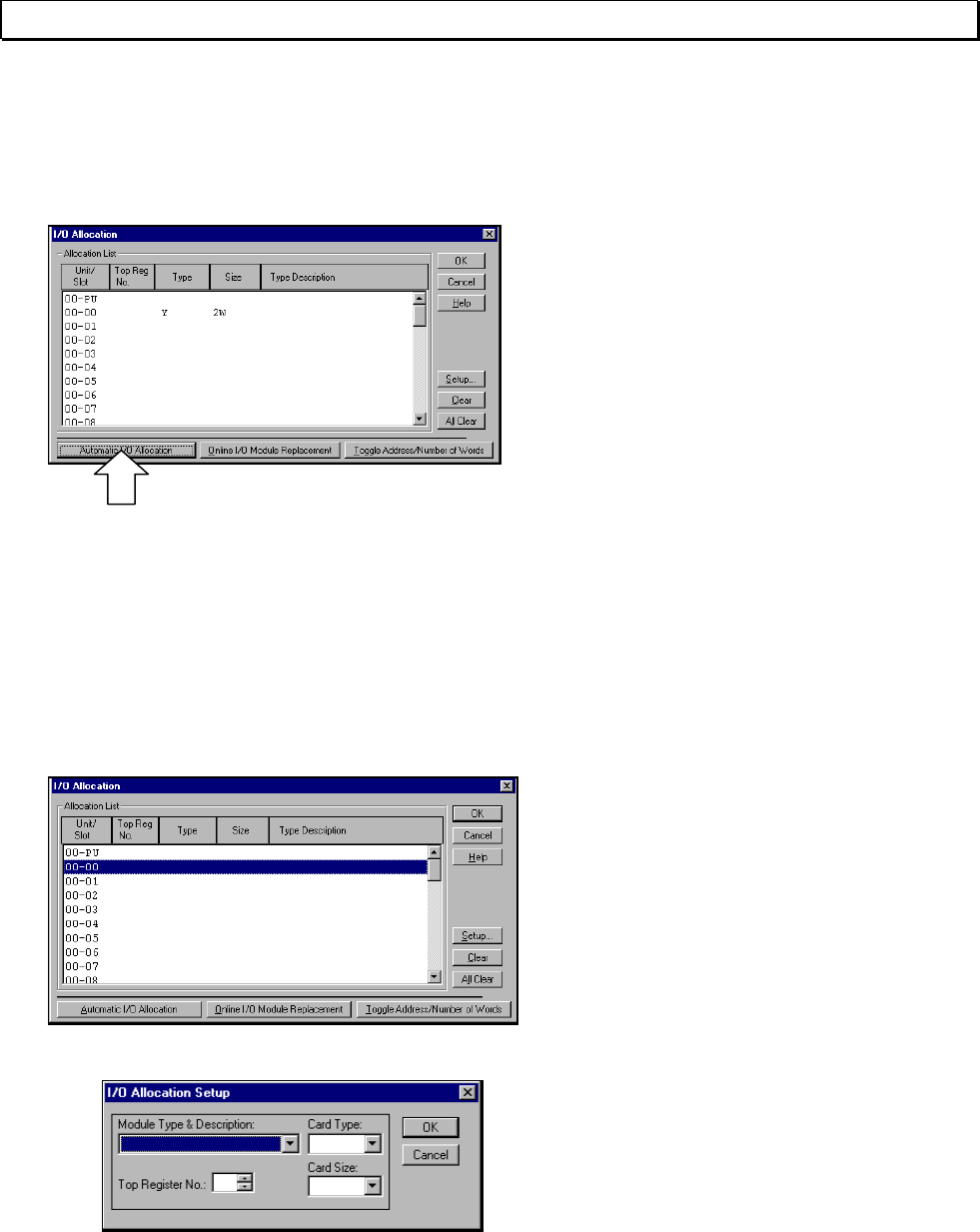
3.3.1 When I/O Cards are Installed
When an I/O card is installed in the controller slot, the Automatic I/O Allocation
function can be used to have the installed I/O card automatically registered.
Click the Automatic I/O Allocation button.
The programmer will check the type of
card installed in the slot and display it on
the screen. Check to make sure that "Y
2W" is displayed for slot 0.
The card type "Y" indicates an output
card, used for flicker circuit lamp output.
The card size "2W" indicates that the
card handles 32 output points.
3.3.2 When No I/O Card is Installed
When no I/O card is installed, the I/O card data must be set manually. The
following example describes how to set data by registering a 32 output points
module in slot 0 of the base unit.
Designate the slot position and click Setup.
The I/O Allocation Setup box will appear.
Basic Operation 39
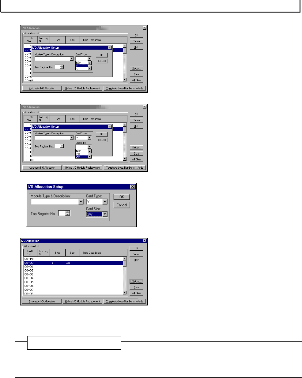
3. Programming
Move the cursor to the Card Type area.
Select the card type from those displayed
in the list box.
For this example, select "Y."
Next, move the cursor to the Card Size
area. Select the card size from those
displayed in the list box.
For this example, select "2W."
Click OK. The I/O Allocation box will
become the active window again. When
this happens, the data will be displayed
at the location of the corresponding slot.
To write the setting, click OK.
To cancel the setting process, click
Cancel.
To set the I/O allocation for a different
slot, repeat the same procedure for each
slot in the I/O Allocation box.
Even if you click OK in the I/O Allocation Setup box, the settings are not registered until you
click OK in the I/O Allocation box.
Additional Information
40 T-PDS32 for Windows V2.2
3. Programming
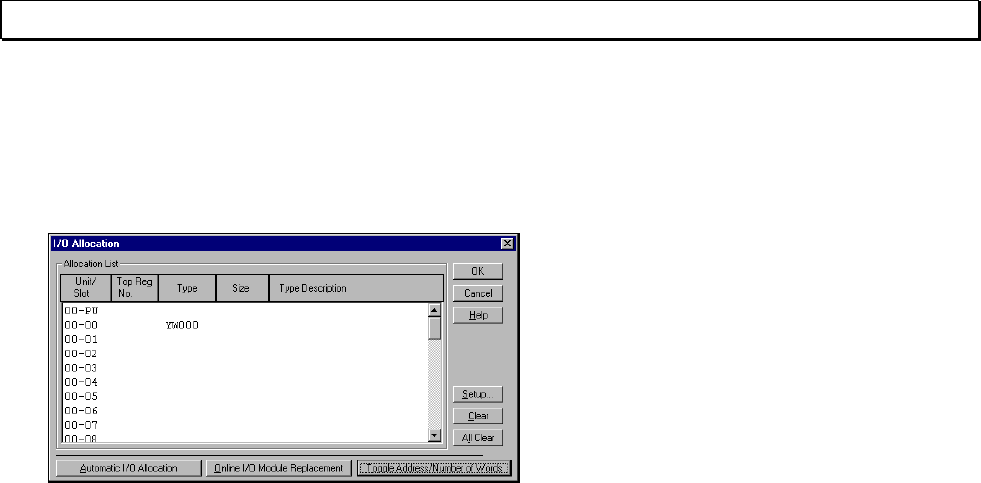
3.3.3 Checking Register Numbers
When I/O card registration is complete, you should check the register address for the
card.
Click Toggle Addresses/Number of
Words. The data for slot 2 will change
from card type/size "Y 2W" to "YW000".
Clicking the button again causes the card
type/size data to reappear.
This shows that the card registered in this
example has been allocated to two word
of the YW000 output register.
Designating device number Y000 - Y01F
for the flicker circuit lamp output in the
program causes the data to be output to
this card.
Basic Operation 41
3. Programming
3.4 Programming
Now you can create the program for the flicker circuit. Programming is done in Edit
mode.
3.4.1 Programming screen
Open the Programming screen. This prepares a blank screen for creating the program.
When the operation status is changed to
Online, a Programming screen with a bus
for the ladder program will appear.
If a program already exists in the
controller, the program is displayed.
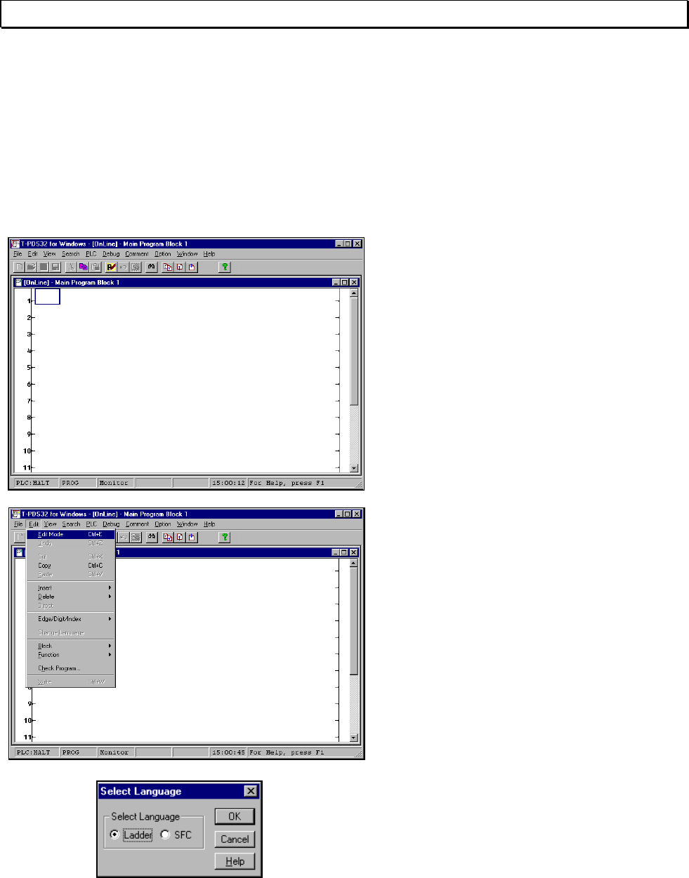
Programming is done in Edit mode.
On the Edit menu, click Edit Mode.
(Toolbar is also available)
A dialog box will appear, allowing you to
select the programming language.
Select Ladder and then click OK.
42 T-PDS32 for Windows V2.2
3. Programming
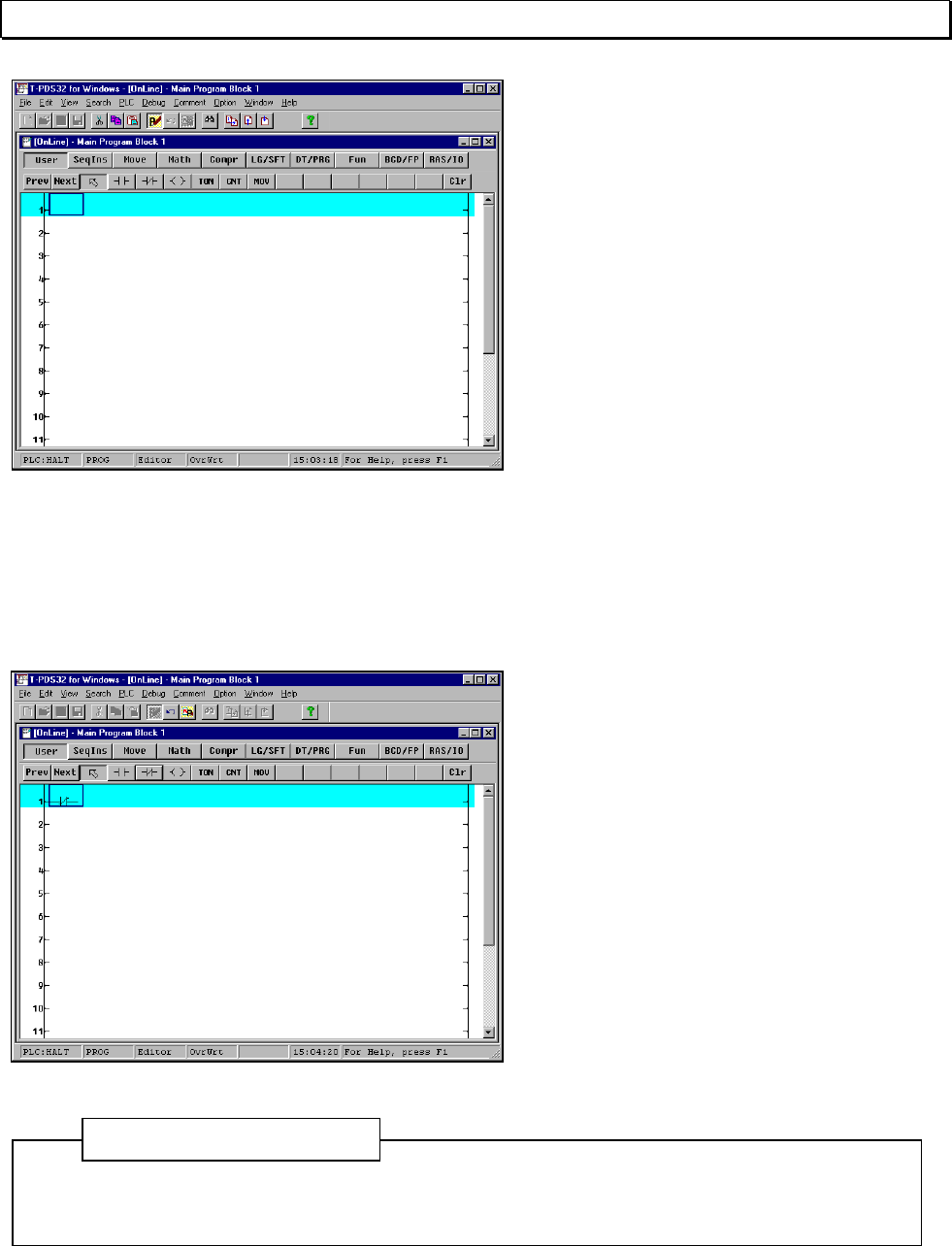
The programming window will change to
editable status and the circuit at the
position of the box cursor will be shaded.
A toolbar containing instruction will also
appear.
Editing can be done for the circuit at the
current location of the cursor. You may
also use the Shift + ↓ keys to designate
the range for editing. Up to 11 lines may
be designated in this manner.
Editing may be done in only one
programming window per project.
Online traces cannot be displayed in the
programming window being edited.
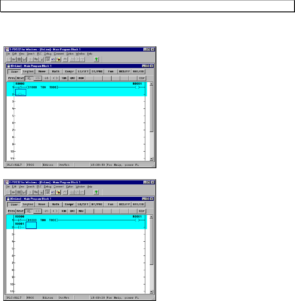
3.4.2 Creating Circuit 1
Now you are ready to create the first circuit for the flicker circuit.
To make a circuit, pick-up an instruction
by mouse click, place it on the position in
the edit area by mouse click, then enter
the operand (register, device, or constant
value).
In this example you will first place a NC
contact of R000.
In the Ladder Instruction toolbar, pick-up
NC contact and place it on the left end of
circuit 1. This will place a NC contact at
that location.
To continuously place the same instruction, select an instruction and click the left mouse
button while pressing the Shift key.
Additional Information
Basic Operation 43
3. Programming
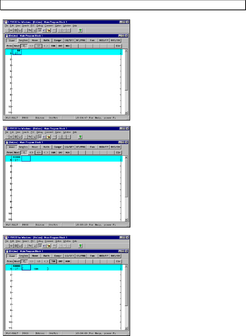
Operands may be entered when the box
cursor is at the location of the symbol.
Enter "R0" on the keyboard. When "R0"
appears above the NC contact, press the
Enter key.
When you enter operands, you may omit
the zeroes after the register number and
device number codes.
For example, to enter "R0001F," you can
enter "R1F".
Also, even if you enter small letters such
as "r" in operands, these will be
converted to capital letters when Enter
key is pressed.
Next you will place an ON delay timer
connected to the NC contact.
Select "TON" instruction and then move
the mouse pointer to the right of the NC
contact and click the button. The symbol
for the ON-delay timer will appear.
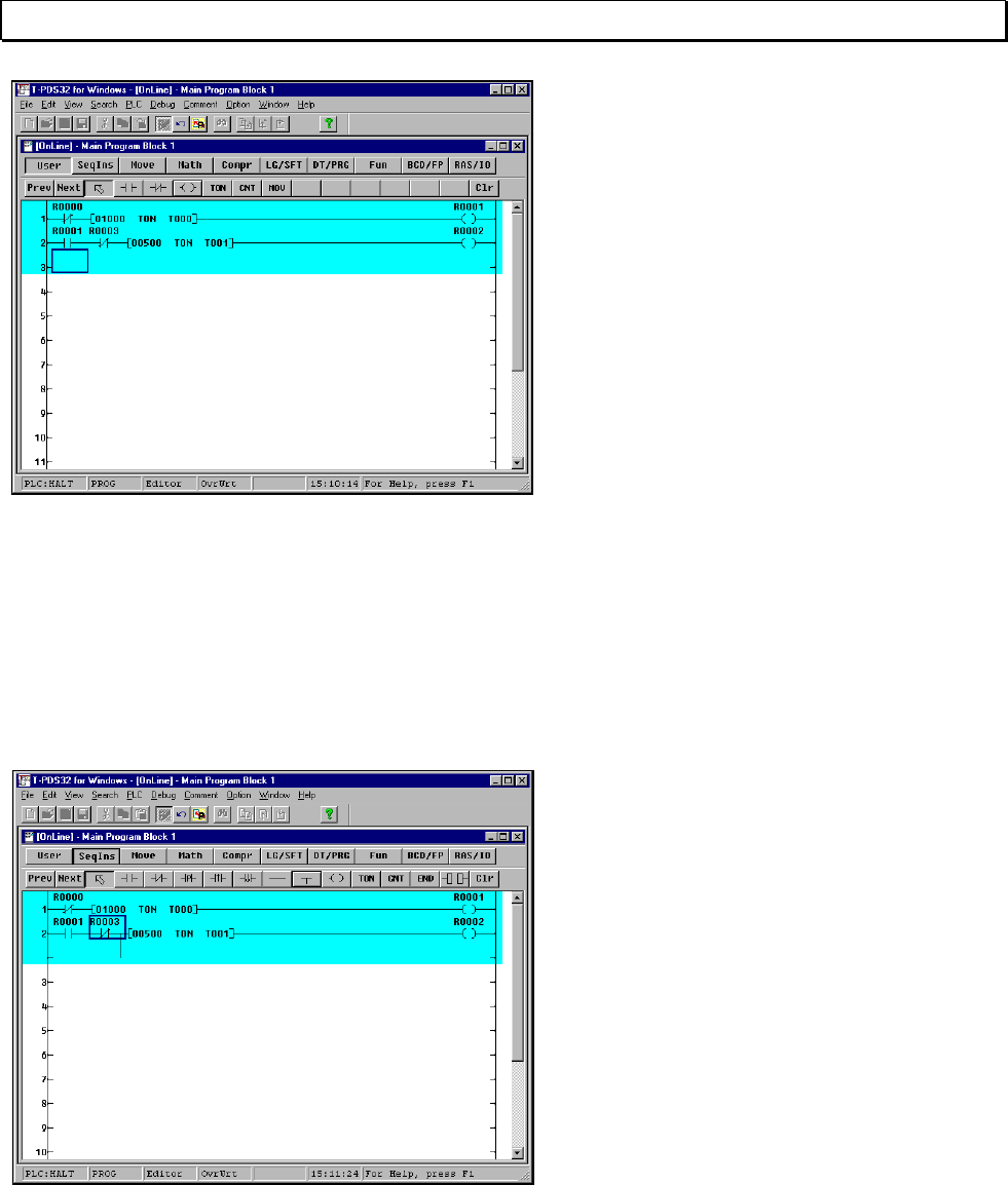
44 T-PDS32 for Windows V2.2
3. Programming
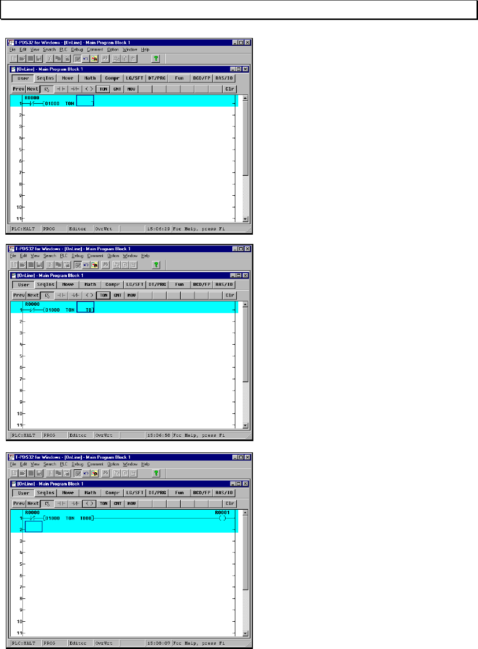
Two operands are needed for the ON-
delay timer: the preset time and the timer
number. Check that the box cursor is at
the preset time position then enter the
preset time setting by the keyboard.
Preset time is entered in 10ms
increments for T0 to T63 and in 100ms
increments for T64 and after.
The startup time setting for this flicker
circuit is 10 seconds. Enter "1000."
When the Enter key is pressed, the
cursor will move to the timer number
position. Then enter the timer number.
In this sample, timer 0 is used. So enter
"T0".
When the Enter key is pressed, "T000"
will appear and the cursor will move to the
right of the ON-delay timer symbol.
Select the symbol for output coil, then
point the right of the ON-delay timer and
click the mouse.
The output coil will be placed at the right
end of circuit 1. The connection line is
automatically drawn between the ON-
delay timer and the coil.
Check that the cursor is at the output coil
position and enter "R1" by the keyboard.
When the Enter key is pressed, "R0001"
will appear above the coil.
Basic Operation 45
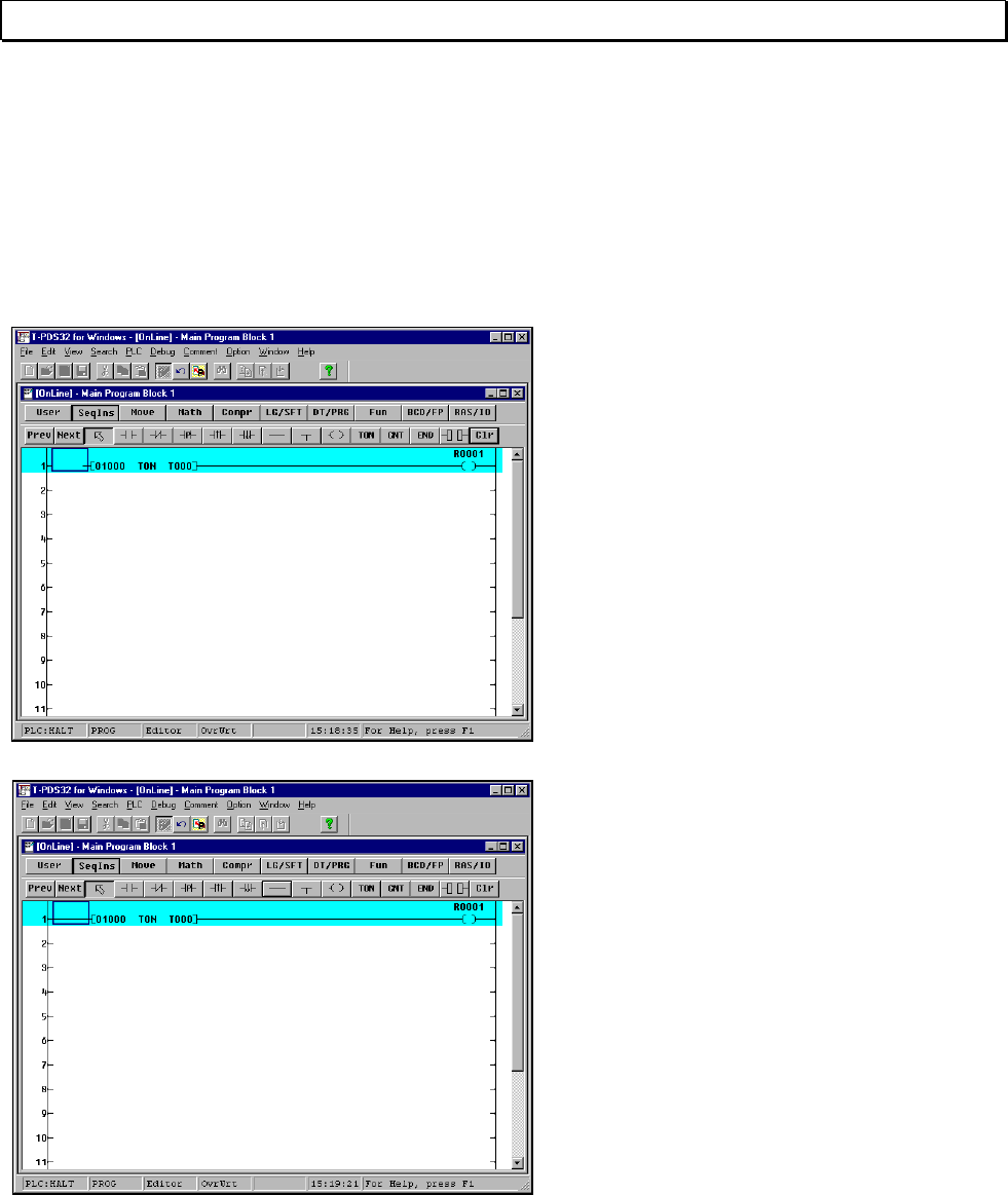
3. Programming
3.4.3 Creating Circuit 2
Place an NO contact of R0001.
In the Ladder Instruction toolbar, select
NO contact and move the mouse pointer
to the left end of circuit 2 and click the left
mouse button.
This will place an NO contact at that
location.
After you placed the NO contact, enter
the operand.
Enter "R1" on the keyboard. When "R1"
appears above the NO contact, press the
Enter key.
46 T-PDS32 for Windows V2.2
3. Programming
As same manner, place an NC contact of
R0003, an ON delay timer (preset time 5
sec, timer 1) and an output coil of R0002.
<Summary>
Select NO contact Click left button Enter R1 Press [Enter]
Select B contact Click left button Enter R3 Press [Enter]
Select TON Click left button Enter 500 Press [Enter]
Enter T1 Press [Enter]
Select coil Click left button Enter R2 Press [Enter]
Next, a vertical connection must be
placed on the output side of the NC
contact of R0003 for branching.
The vertical line is in the SeqIns
(sequence instruction) group. Select the
SeqIns and click the vertical line. Then
place it on the NC contact of R0003. The
vertical line is drawn from right hand to
downward.
In this manner, a vertical circuit will be
created to the right below the position of
the cursor.
To clear the vertical line, select the
vertical line and place on the position to
be cleared. Then the vertical line will be
cleared.
Basic Operation 47
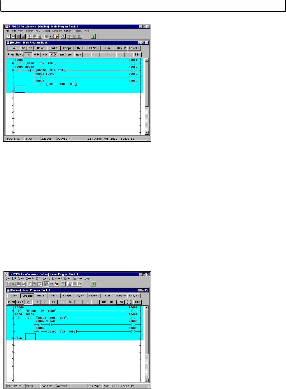
3. Programming
Now you will create the second and third
lines of the circuit.
Move the cursor to the second line of the
circuit and move it to the right of the
vertical connection and place a symbol
there. Then click the operand item.
To place a vertical connection on the third
line of the circuit, move the cursor to the
vertical connection on the second line,
then select the vertical connection item
and click the left button. A one-line
vertical connection will be placed there.
<Summary>
Move cursor to third line of Circuit 2 (to right of vertical connection)
Select NC contact Click left button Enter R2 Press [Enter]
Select NO contact Click left button Enter S40 Press [Enter]
Select coil Click left button Enter Y0 Press [Enter]
Move cursor to vertical connection on second line of Circuit 2
Select NO contact Click left button Enter R2 Press [Enter]
Select TON Click left button Enter 300 Press [Enter]
Enter T2 Press [Enter]
Select coil Click left button Enter R3 Press [Enter]
3.4.4 Finishing the Program
An END instruction is always required at the end of the program.
Move the box cursor to the top of Circuit
3, then select END on the toolbar and
click the left button. The END instruction
symbol will appear in Circuit 3.
At this point, the END instruction symbol
is not connected to the right bus.
However, when the program is written,
the END instruction will be automatically
connected to the right bus, so there is no
need to do this manually.
48 T-PDS32 for Windows V2.2
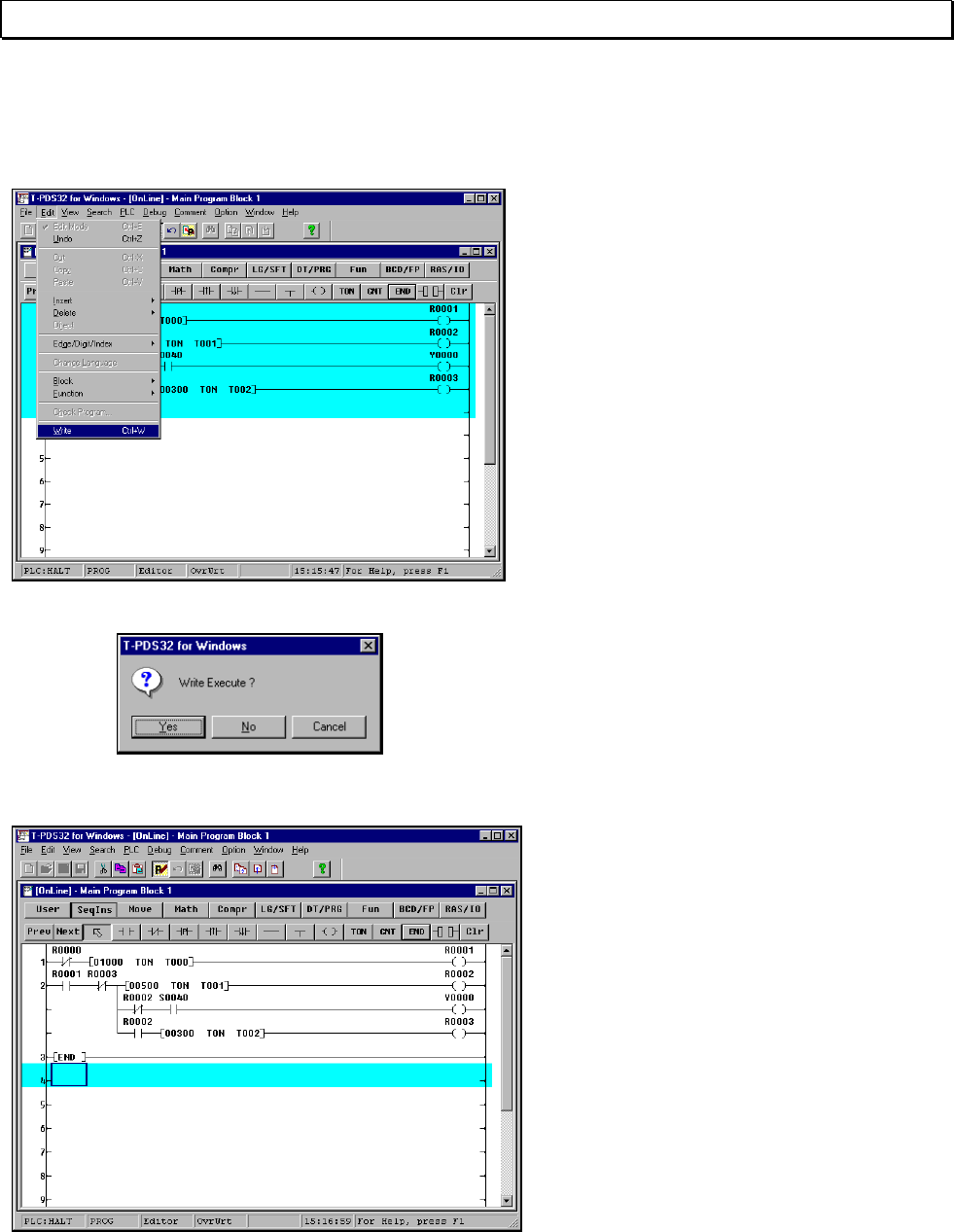
3. Programming
3.4.5 Writing the Program
Now you will write the program that you have created to the controller.
On the Edit menu, click Write.
(Toolbar is also available)
A message will appear, asking you to
confirm that you want to execute the write
command. Click Yes. The program will be
written to the controller.
When the write process is complete, click
Edit Mode on the Edit menu.
The T-PDS32 will quit edit mode and the
Program screen will reappear.
Pressing the Ctrl + E keys can also quit
edit mode.
Basic Operation 49
3. Programming
3.4.6 Correcting the Instruction
Clear the Instruction Symbol
If you have made a mistake in the symbol placement process, click Clr in the Ladder
Instruction toolbar to delete the mistake. For this example you will delete the first
symbol that you placed, the NC contact of R000.
Click Clr in the Ladder Instruction toolbar
and then move the mouse pointer to the
NC contact and click the mouse button.
The symbol and operand will be deleted.
[Del] (Delete) key on the keyboard can
also be used to clear the instruction.
You may also use the space key on the
keyboard to delete an operand that has
been entered by mistake.
When a symbol has been cleared, a
blank space will remain at the cleared
location. Leaving this as it is will result in
an incomplete connection, so you should
connect the circuit through this area.
In the toolbar, select the symbol for
horizontal short and then move the
mouse pointer to the blank area and click
the mouse button.
To delete the ON-delay timer, click Clr
and move the mouse pointer to the TON
position at the ON-delay timer and click
the mouse.
You may also use the space key on the
keyboard to delete an operand that has
been entered by mistake.
Move the cursor to the operand position
and press the space key. Only the
operand will be deleted, so enter the
operand again.
50 T-PDS32 for Windows V2.2
3. Programming
Overwrite/Insert
Two modes are available for placing symbols in the circuit: Overwrite mode and Insert
mode. Pressing the Ins key on the keyboard toggles the mode to Overwrite (and the
indicator in the status bar at the bottom of the screen changes to "OvrWrt").
In Overwrite mode, entering a symbol
replaces the data at the position of the
mouse pointer.
In Insert mode, the symbol is inserted at
the position of the mouse pointer.
In this example, you will use this function
to place the B contact symbol again (the
one that you cleared in the previous
example).
Change the mode to Insert, then select B
contact in the Ladder Instruction toolbar.
Place the mouse pointer to the left end of
circuit 1 and click the mouse button.
One B contact will be inserted at the
position of the cursor. After inserting the
B contact, enter the operand again.
Basic Operation 51
4. Program Execution
4. Program Execution
In this procedure, you will execute a program and check its operation. The execution
status can be checked in the program as well as using the Data Monitor command on
the View menu.
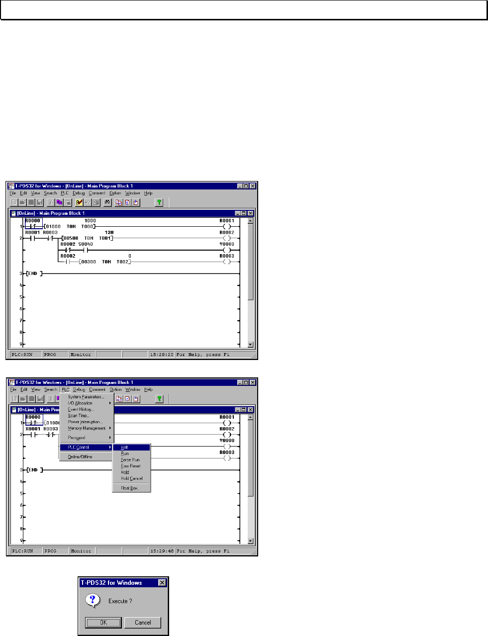
4.1 Executing the Program
First you will execute the program.
Programs can be executed using the
operation mode switch on the controller.
Execution can also be started and
stopped with the programmer.
Setting the operation mode switch on the
controller to RUN will execute the
program.
Check to make sure that "PLC:RUN" is
displayed for the operation status in the
lower left-hand corner of the window.
If an I/O card is installed, the bit 0 in the
operation status LED will blink. Check to
make sure it blinks in line with the
program.
With the I/O card setting for the program
created in this example, an error will
result if the program is executed with no
I/O card installed. If no I/O card is
installed, use the procedure described in
"Registering I/O Cards" earlier in this
manual to change the setting to "no I/O
card registered."
You can also operate the controller from
the programmer. On the PLC menu, point
to PLC Control. A submenu listing the
operation modes will appear; select Halt
and then click the mouse button or press
the Enter key. (Toolbar is also available)
A message will appear, asking you to
confirm that you want to execute that
command. Click OK. The operation
status in the screen will change to
"PLC:Halt" and the controller will stop
operating.
52 T-PDS32 for Windows V2.2
4. Program Execution
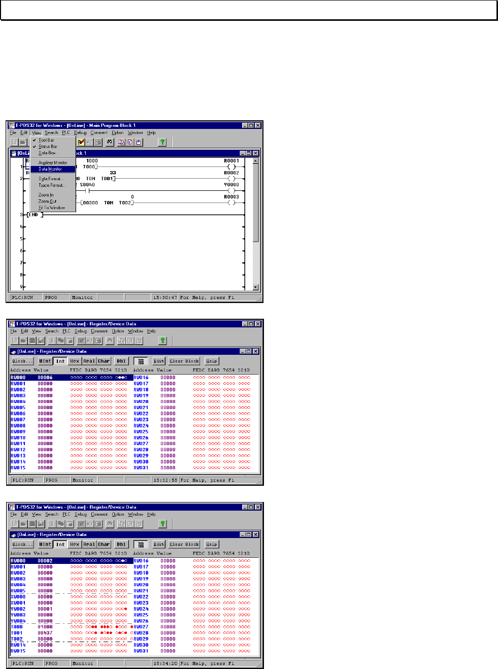
4.2 Checking Operation
Program operation can also be checked using the Data Monitor command on the
View menu.
On the View menu, click Data Monitor.
(Toolbar is also available)
A list will appear showing the current
register values and the on/off status of
each register bit.
The column on the left marked "Address"
shows the registers (such as RW000)
registered to the controller. The circles to
the right correspond to the bits (0 - F) for
these registers. A black circle indicates
that the bit is on; a white circle indicates
that the bit is off.
In addition to the displayed internal
auxiliary registers, the Data Monitor
command can also be used to display
and check I/O registers and timer data.
Current values can also be set and
changed.
This figure shows the I/O registers and
timer registers displayed in a single
screen.
For more information on the data and
register settings shown, see the Online
HELP.
Check to make sure that the bit 0 in the
YW000 register blinks in line with the
progress of the program.
Basic Operation 53
5. Advanced Editing
5. Advanced Editing
5.1 Inserting Circuits
In this section, you make a few edits and corrections to the circuit to add some
features. You will begin by inserting a circuit.
In this example, first assume a flicker
circuit for which the lighting interval has
been set to 3 seconds by writing an ON
delay timer directly. Then you will change
this circuit to such a configuration that
the data for the lighting interval for the
circuit is set to the data register in
advance and the ON delay timer
references the value in this data register.
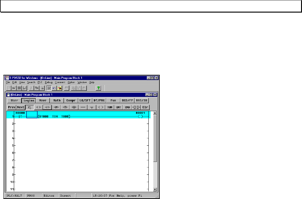
First, add a circuit in front of Circuit 2.
To add a circuit, use the Line insertion
function.
On the Edit menu, click Edit Mode.
In Edit mode, move the box cursor to the
insertion point. Then, on the Edit menu,
point to Insert and then click Line on the
submenu.
54 T-PDS32 for Windows V2.2
5. Advanced Editing
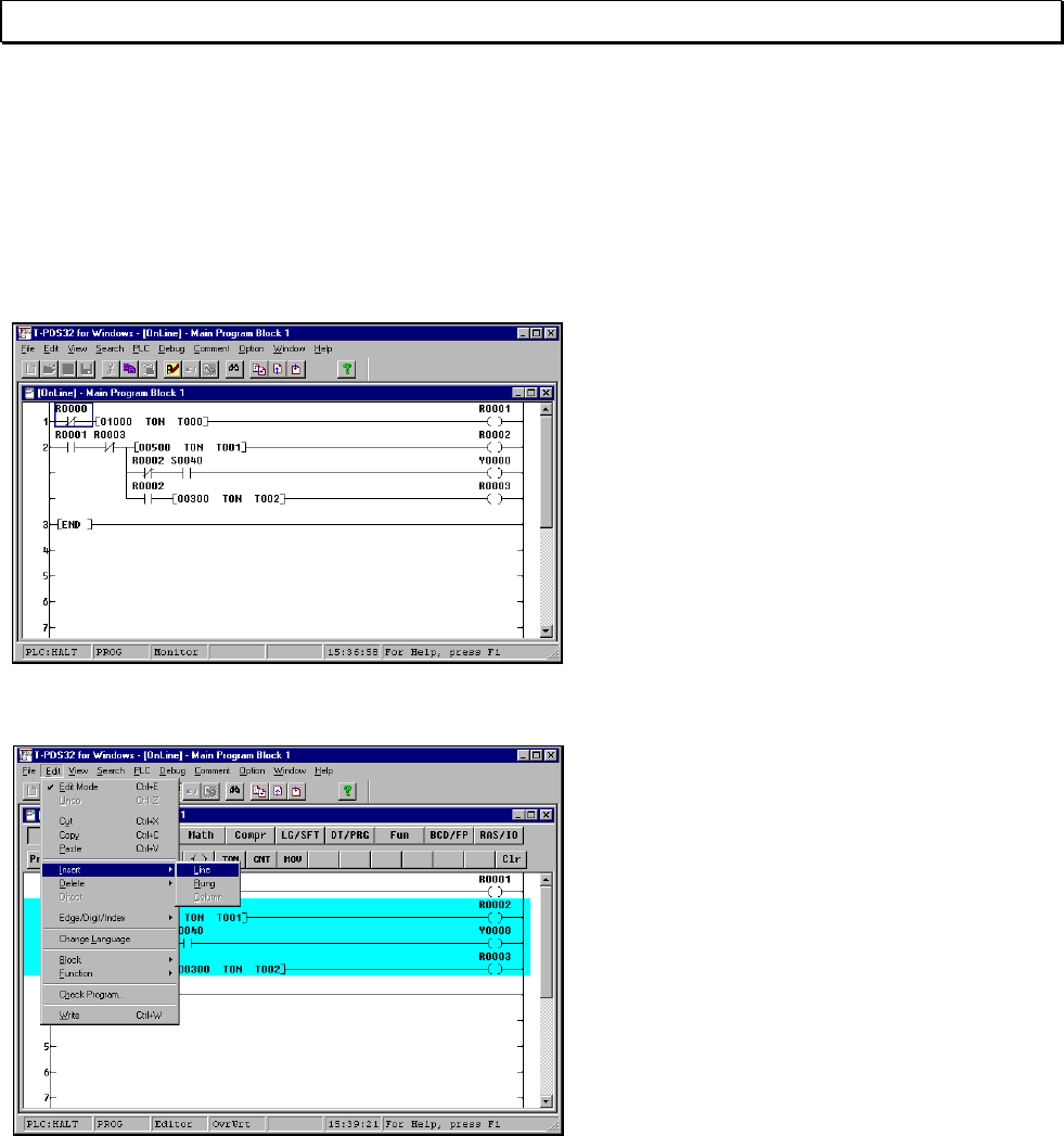
A blank line will be inserted. The existing
circuits will move down from the next line
on, as shown in the figure.
You will create a circuit on this line to set
the lighting interval.
Check to make sure that the box cursor is
at the beginning of Circuit 2, then start by
placing a NC contact of R0000.
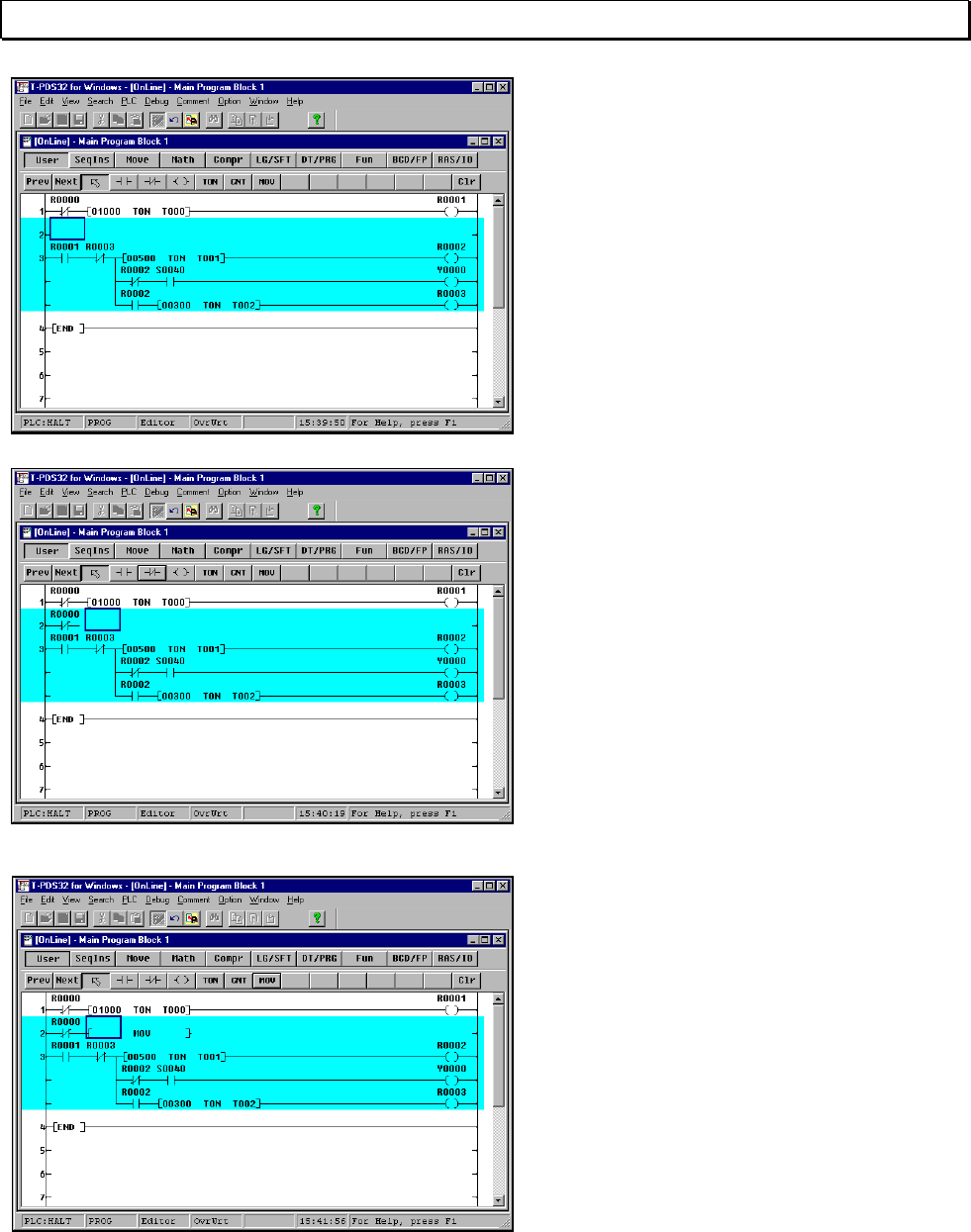
When you have placed the NC contact,
place the symbol for setting data to the
data register.
Select the "Mov" item and then click to
the right of the B contact. The Mov
instruction symbol will be placed there.
Basic Operation 55
5. Advanced Editing
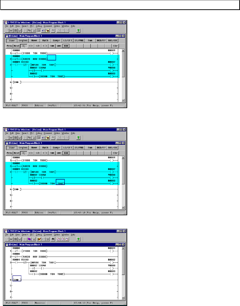
Two operands are entered for the Mov
instruction symbol, a transfer source
register or a constant and a transfer
destination register.
In this example, we will assume that the
data for the flicker circuit lighting interval
is determined in another program (for
example, to match the level of error
occurrence) and stored in RW020, and
we will transfer this data to data register
D0000.
Enter the two operands on the keyboard.
The line from the Mov instruction symbol
to the right bus is unconnected, but it will
be automatically connected when the
program is written like the END
instruction issued.
Now you will do a little editing on circuit 3.
In this example, you will change the
setting for the ON delay timer from a
constant to the data register number.
Move the box cursor to the first operand
in the ON delay timer instruction in the
third line of Circuit 3, then enter "D0" and
press the Enter key.
This will cause the ON delay timer setting
to be replaced with the value in data
register D0000.
When the operand has been properly
entered, select Write to write the data to
the controller.
Check to make sure that the new circuit
has been added to Circuit 2 and the
subsequent circuits have moved down
accordingly. Then quit Edit mode and
return to Monitor mode.
56 T-PDS32 for Windows V2.2
5. Advanced Editing
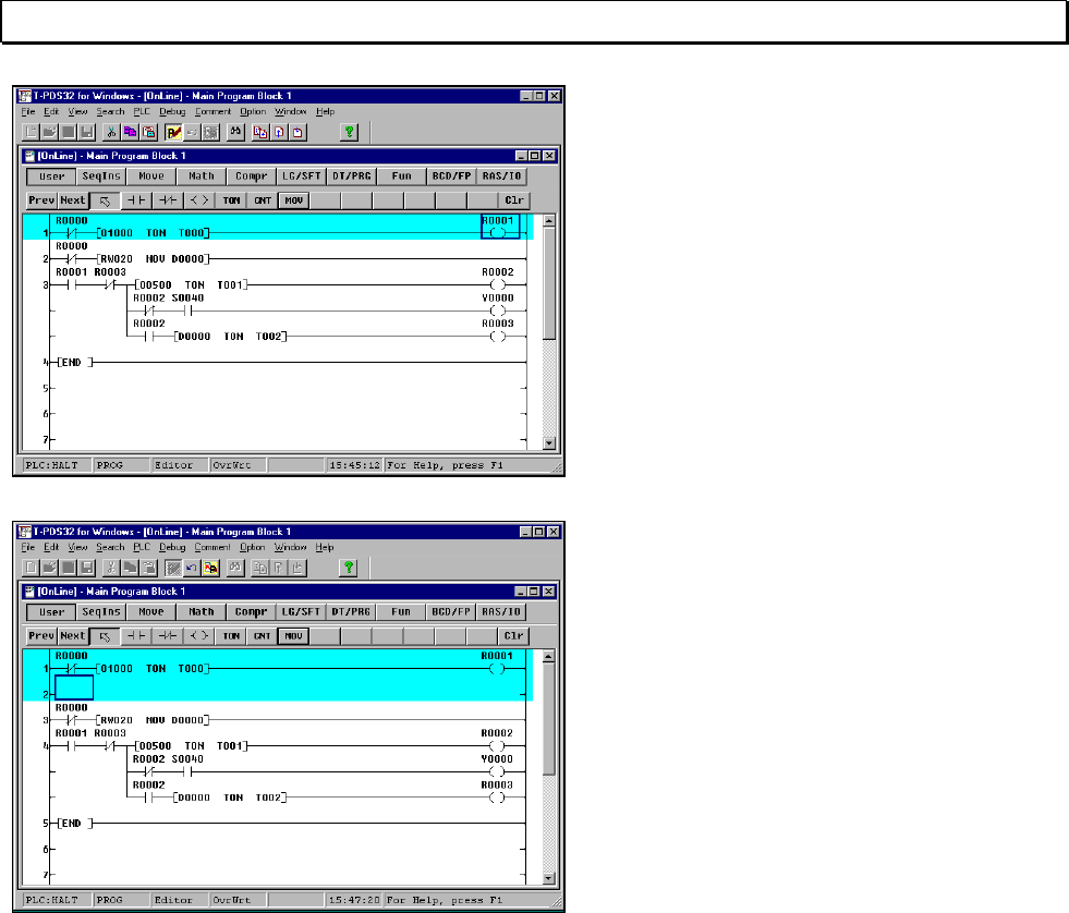
Circuits may be inserted by using the
Insert function. This may also be done by
pressing the Enter key with the box
cursor at the extreme right margin to
insert a new line.
Change to Edit mode and move the box
cursor to the last position in the first line.
Press the Enter key. A new line will be
inserted and the editing area will also be
enlarged by one line.
To edit including Circuit 3, use Shift + ↓ to
enlarge the editing area to Circuit 3
before a new line inserted.
Basic Operation 57
5. Advanced Editing
5.2 Setting Data
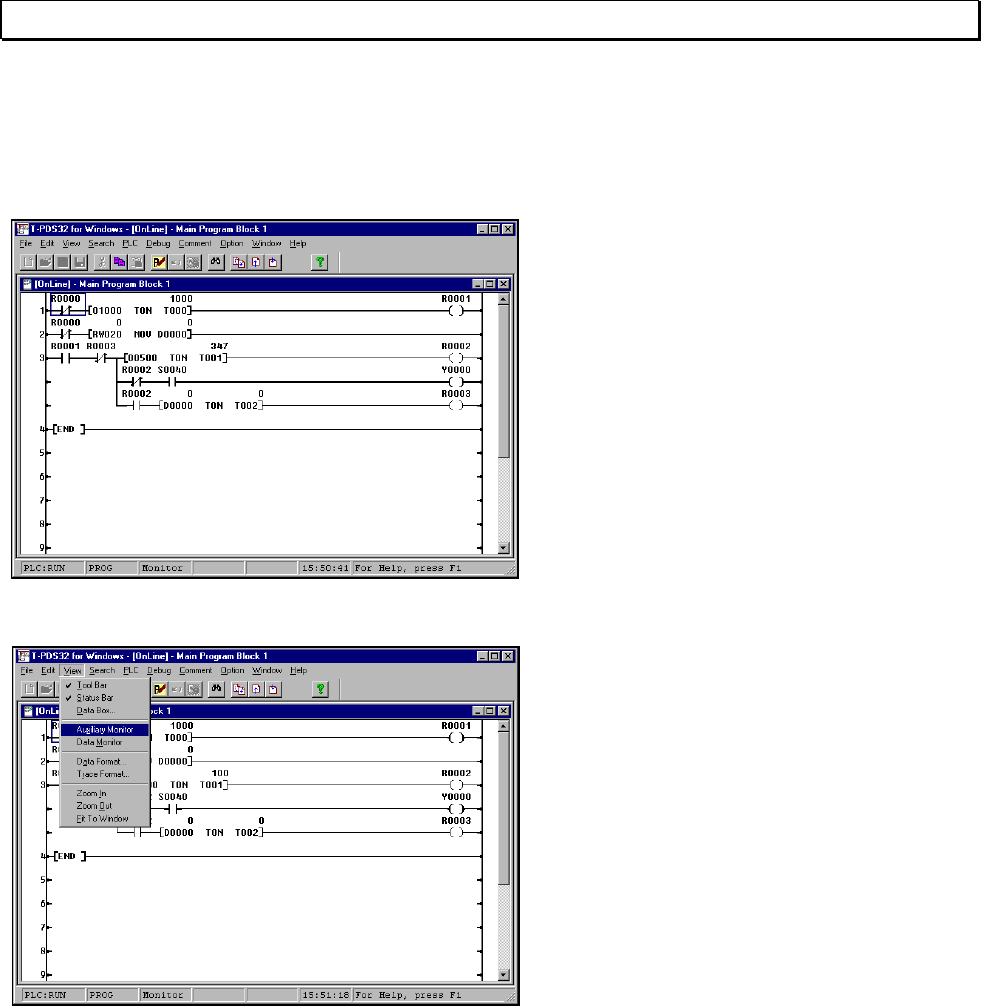
Register data may be set in the Program screen. Let's use this function to set the data
for register RW020. Execute the program.
Check to make sure that the live wires
and current values for the circuit being
executed are displayed on the screen.
In this program, the data for RW020 is 0,
so it should blink continuously.
On the View menu, click Auxiliary
Monitor.
(Toolbar is also available)
58 T-PDS32 for Windows V2.2
5. Advanced Editing
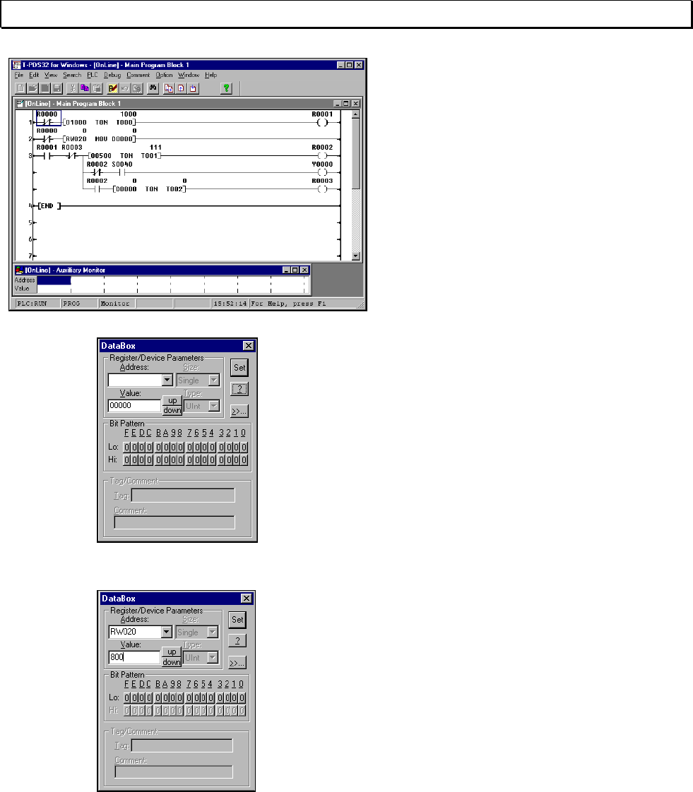
The Auxiliary Monitor window will open in
the programming window. This window
allows current values to be set for any
register and device.
Clicking the mouse at the position of the
cursor in the Auxiliary Monitor window will
display the DataBox.
Enter the register number and data value
that you wish to set in the Auxiliary
Monitor window.
For "Addresses," you will designate
register RW020.
Enter "R20". "0" will be displayed for the
current value in the "Value" area.
Enter the desired setting on the keyboard
and press Enter.
Register RW020 will be registered in the
Auxiliary Monitor window and the current
value will be replaced with the data you
have just entered.
To close the DataBox, click the Close
button in the upper right-hand corner.
Basic Operation 59
5. Advanced Editing
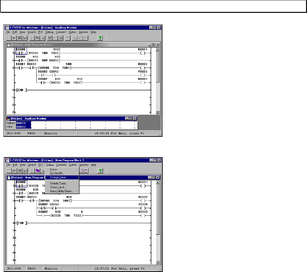
The flicker circuit will operate at the
designated interval.
If an I/O card is installed, check the
operation on the operation lamp.
At the same time, check to make sure
that data is sent to the data registers in
the program and that the current values
are displayed.
You can set data directly in the registers
in the circuit program.
On the Debug menu, click Change Value.
The DataBox will appear.
When a register is designated with the
box cursor in the programming window,
the current value for that register will be
displayed and that value can be changed.
60 T-PDS32 for Windows V2.2
5. Advanced Editing
5.3 Deleting Circuits
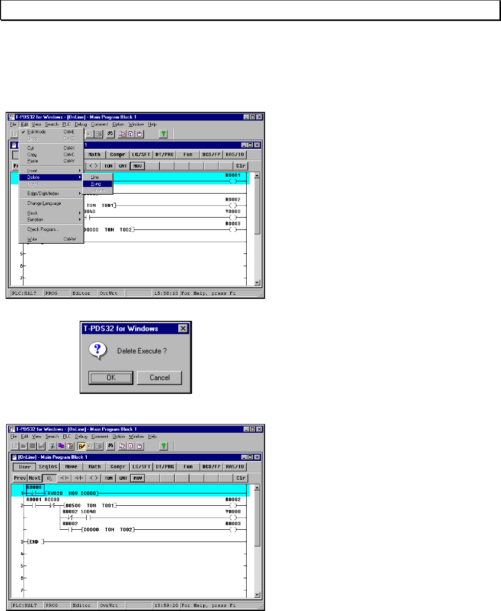
This section covers how to delete unnecessary circuits. In this example, you will
delete the circuit that waits for ten seconds after startup in Circuit 1.
Move the box cursor onto the circuit that
you want to delete.
On the Edit menu, point to Delete and
click Rung on the submenu.
A message will appear asking you to
confirm that you really want to delete the
circuit. Click Yes.
The designated circuit will be deleted and
the subsequent circuits will move up.
Basic Operation 61
5. Advanced Editing
When you have deleted Circuit 1, change
the NO contact of R0001 at the
beginning of circuit 2 to the NC contact of
R0000.
62 T-PDS32 for Windows V2.2
5. Advanced Editing
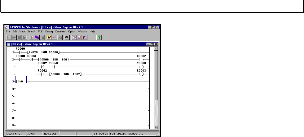
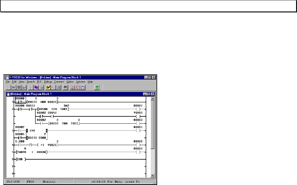
5.4 Complex Circuits
This screen shows a counter function added to the flicker circuit. Try creating this
program circuit as a final exercise.
- The number of R0002 turning ON is
counted in Circuit 3.
The counter is reset every 10 counts.
- The value for output register YW020 is
increased by 1 every 10 counts in
Circuit 4.
- And in Circuit 5, when the value for
output register YW020 exceeds 30,
R0000 is turned on and flickering stops.
When an I/O card corresponding to
YW020 is installed, the LEDs on the I/O
card indicates the counting operation.
When the I/O card is not installed, you
can confirm the operation on the program
monitor screen or data monitor screen.
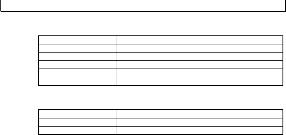
<Summary>
Insert one line in Circuit 3.
- Circuit 3
Select NO contact Click left button Enter R2 Press [Enter]
Press [Enter]
Select NC contact Click left button Enter R5 Press [Enter]
Move the box cursor to the right of the NO contact.
In the Ladder Instruction toolbar, display the CNT instruction
Select CNT Click left button
Move cursor to lower left of CNT instruction
Enter 10 Press [Enter]
Enter C0 Press [Enter]
Select coil Click left button Enter R5 Press [→] [→] [→] and [Enter]
- Circuit 4
Select NO contact Click left button Enter C.0 Press [Enter]
Select Pulse (rising) Click left button
Select the arithmetic instruction group
Select Math Click left button
Select +1 (increment) Click left button Enter YW20 Press [Enter]
Select coil Click left button Enter R6 Press [Enter]
- Circuit 5
Select the comparison instruction group
Select Compr Click left button
Select > (greater than) Click left button Enter YW20 Press [Enter]
Enter 30 Press [Enter]
Select coil Click left button Enter R0 Press [→]
Basic Operation 63
6. Saving Program
6. Saving Program
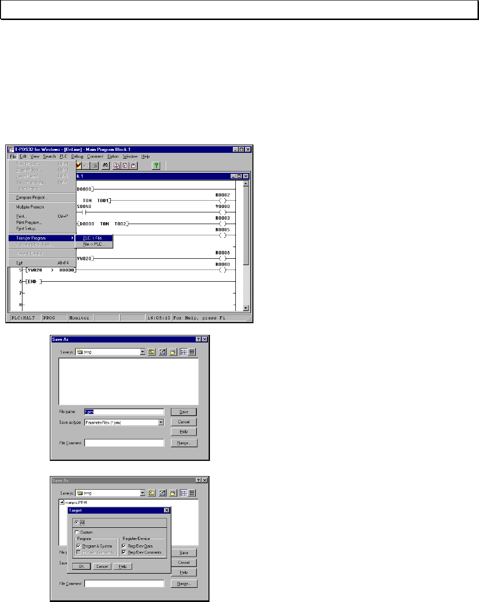
6.1 Save to Disk
The Transfer Program command is used to save the programs that have been
created to disk or to load them from disk.
On the File menu, point to Transfer
Program and click PLC -> File on the
submenu.
(Toolbar is also available)
A dialog box will appear on the screen.
This box is used to save data from the
controller to disk.
It shows data in the folder currently
available. To change the folder, click on
the folder list box and select the desired
folder.
When the folder has been selected, a list
of files in that folder will appear in the File
Name list box.
Select “Range” and specify the items to
be transferred.
When a comment has been registered in
the controller, the comment will be saved
under the Comment File as the same file
name.
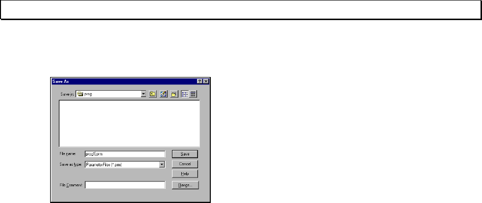
64 T-PDS32 for Windows V2.2
6.Saving Program
Enter the name of the file in the File
Name text box.
In this example, enter "prog1".
After entering the file name, click OK.
The program will be stored in that file.
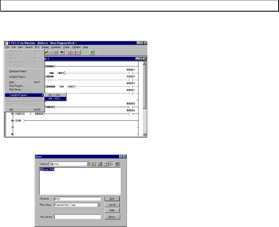
Basic Operation 65
6.Saving Program
6.2 Loading Programs from Disk
To load programs from disk, point to
Transfer Program on the File menu and
click File -> PLC on the submenu.
(Toolbar is also available)
A dialog box will appear.
This dialog box is used to enter the name
of the file to be loaded from the disk.
Designate the name of the file to be
loaded from the disk.
You may change the folder in the same
manner as when saving programs to
disk.
To specify the name of the file for loading
from the disk, either enter the name on
the keyboard in the File Name text box or
select the name from the File Name list
box.
After entering the file name, click OK.
The program will be loaded from that file.
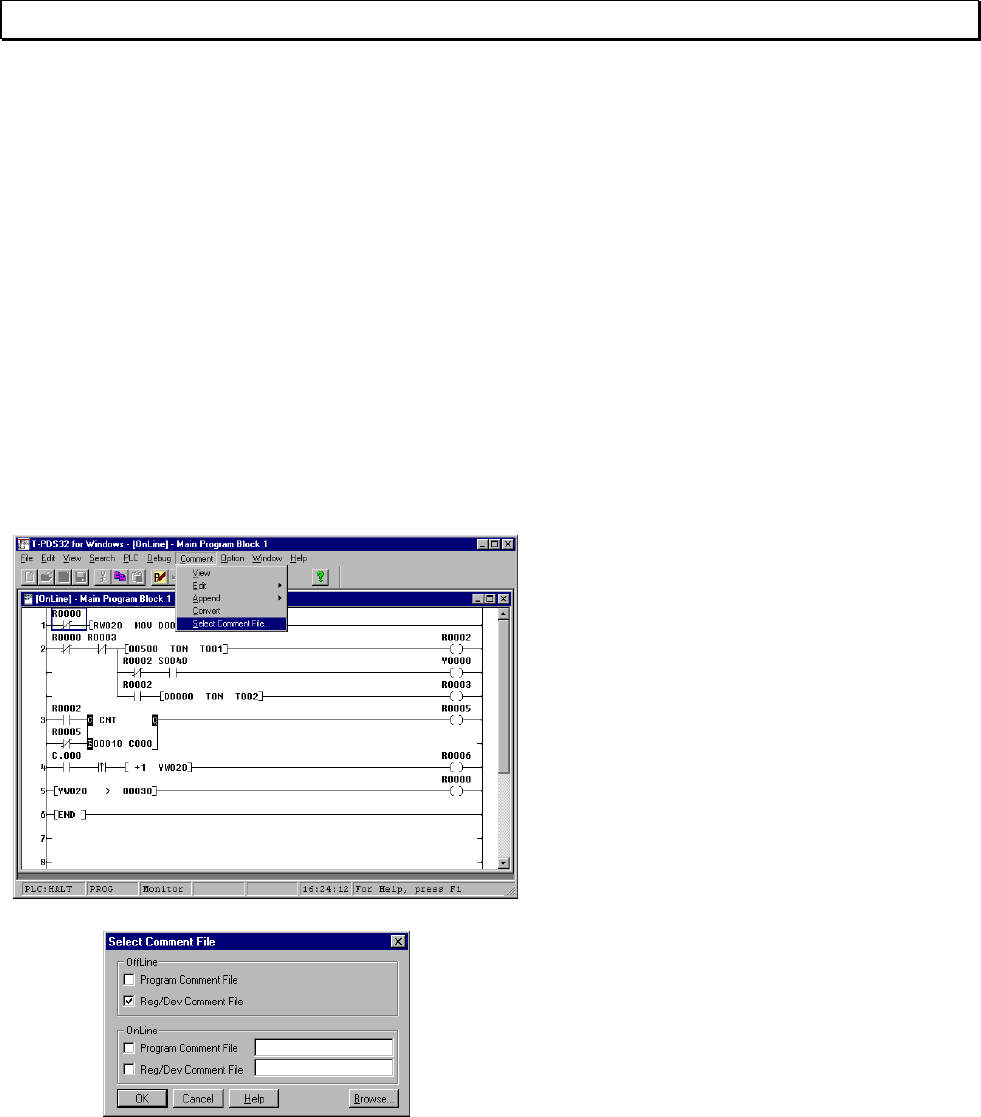
66 T-PDS32 for Windows V2.2
7. Beyond the Basic
7. Beyond the Basic
7.1 Register/Device Comment
You can assign comments to the program blocks, circuits, relays and registers. This
allows you to have the relays and devices displayed with comments in the program, and
the program blocks and circuits with complementary comments.
Display the flicker circuit created in Chapter 5 on the screen.
In this example, you will assign the tag name "DATA1" to the D000 data register used in
this program.
7.1.1 Select Comment File
Note that assigning comments to relays and registers and saving these names will
require files.
On the Comment menu, click Select
Comment File. A dialog box allowing you
to select the comment file will appear.
When you use register/device comment
in offline mode, click the Reg/Dev
Comment File check box in OffLine area.
Click OK.
Then the temporary comment file is
created, and you can use the
register/device comment.
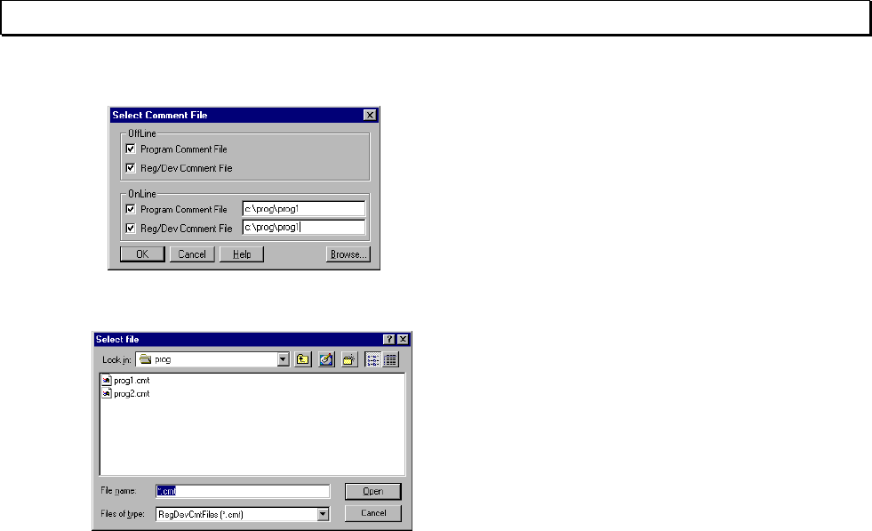
Basic Operation 67
7. Beyond the Basic
When you want to display the
register/device comment in online mode,
click the Reg/Dev Comment File check
box in OnLine area.
Clicking Browse displays a dialog box for
selecting the file for referring.
Select the comment file name and click
OK.
If you are designating a new file, enter the
file name in the Data Comment File text
box. The extender ".CMT" is used for
data comment files, but you do not need
to enter this.
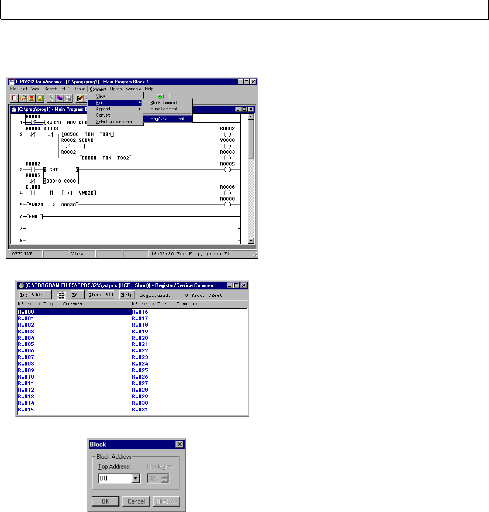
68 T-PDS32 for Windows V2.2
7. Beyond the Basic
7.1.2 Registering Names
On the Comment menu, point to Edit and
click Reg/Dev Comment on the
submenu.
The Register/Device Comment window
will appear.
The number of currently registered items
is shown in the upper right-hand corner,
as well as the number of free items.
To register a name for D0000, you must
change the display area. Click Top Addr
on the toolbar.
A dialog box allowing you to designate
the starting address will appear.
Enter "D0" in the Top Address text box.
The Block Size item is fixed at 32.
Then click OK.
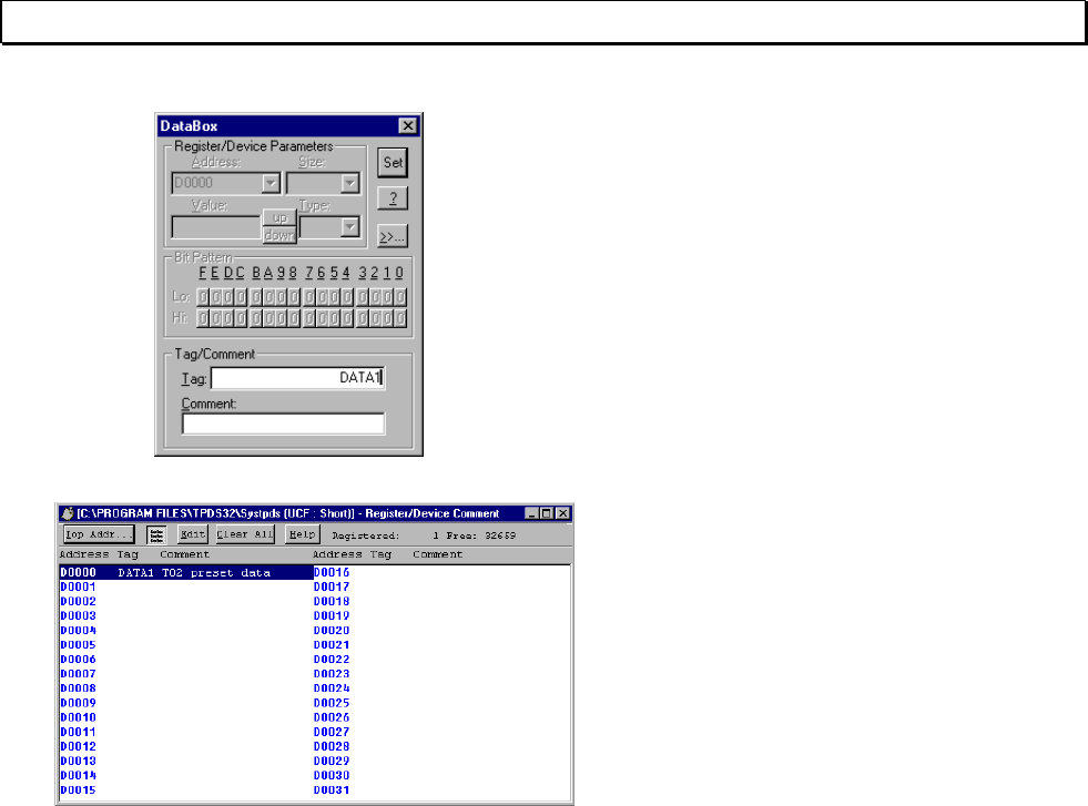
Basic Operation 69
7. Beyond the Basic
When D0000 - D0031 appears on the
screen, click Edit on the toolbar to open
the DataBox data editing dialog box.
Comments as well as relay and register
names may be registered with the
Comment function.
Check to make sure that the cursor is in
the Tag text box, then enter "Data 1" and
click OK. Close the DataBox dialog box
by clicking the Close button in the upper
left-hand corner.
The tag name will appear under Tag in
the Register/Device Comment window.
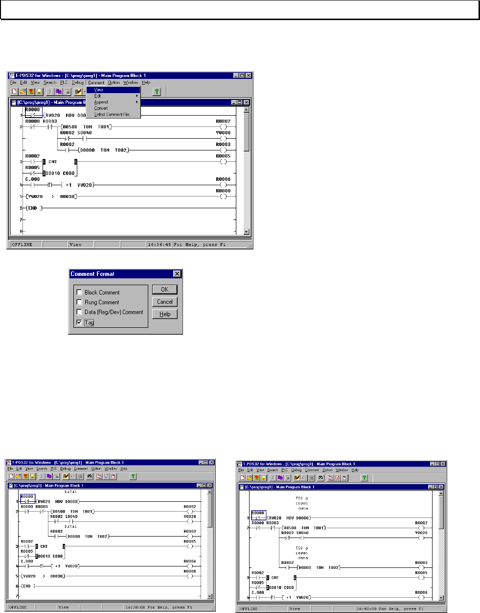
70 T-PDS32 for Windows V2.2
7. Beyond the Basic
7.1.3 Displaying Names
When the names and comments have
been registered, click View on the
Comment menu.
(Toolbar is also available)
A dialog box allowing you to specify the
display format for comments will appear.
Click in the Tag check box so the box is
checked.
The tag name is displayed above the
register and device numbers.
Check this in the program. The “DATA1” above the ON delay timer and MOV symbol
operand D0000. When the Data (Reg/Dev) Comment is specified for display, comment
will appear.
- Tag Display - Comment Display
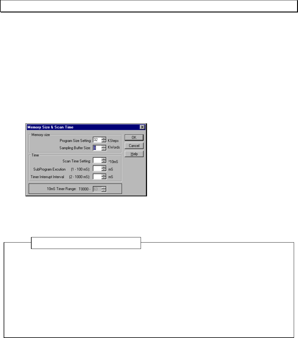
Basic Operation 71
7. Beyond the Basic
7.2 Sampling Trace
The controller has a function that enables you to sample and display changes in
device status and register values during program execution. In this example, you will
use this function to check on device and register trends in the flicker circuit.
7.2.1 Setting the Sampling Buffer
In order to sample data, it is necessary to secure a buffer, i.e. the memory area in which
the sampling data will be stored. This is set in the system data.
On the PLC menu, click System
Parameters. The System Parameters
screen will appear. Click Memory Size &
Scan Time.
Then set the Sampling Buffer Size in the
Memory Size area. For the T3, the
sampling buffer may be set up to a
maximum of 8KW.
- On the T3/T3H the F register or an IC memory card is used for the sampling buffer.
Note that setting a sampling buffer will decrease the amount of memory used by the
program by the amount of the buffer setting.
- On the T2, IC cards are used to store sampling data.
- When performing a sample trace on the T2, be sure to insert an IC memory card and
assign the memory card using the "I/O Card Allocation" procedure. The sampling buffer
size is fixed at 8KW.
- For the T2E/T2N, the sampling buffer size is fixed at 8kW and uses internal memory.
- For the T1/T1S, the sampling buffer size is fixed at 1kW and uses internal memory.
- For the S2T, the sampling buffer size is fixed at 8kW and uses internal memory.
Additional Information
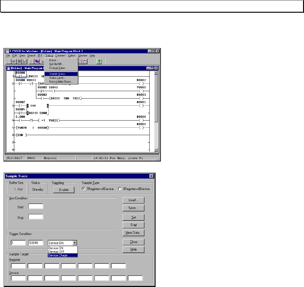
72 T-PDS32 for Windows V2.2
7. Beyond the Basic
7.2.2 Setting the Sampling Condition
On the Debug menu, click Sample Trace.
The Sample Trace dialog box will appear.
The Sample Trace dialog box is used to set
the registers for data sampling, the
sampling trigger condition and other data.
First check to make sure that the
sampling buffer size set as system data is
displayed in the upper left-hand corner.
In this example, you will set the trigger
condition.
The trigger condition sets the timing for
data sampling during program execution
(during scanning). The trigger condition
is specified as a device and a register
condition, such as when the device status
has changed or when the register has
reached a certain constant value.
In this example, you will set the trigger to
be activated when the timing relay
(S0040) goes ON or OFF.
Move the mouse to the Trigger Condition text box and enter "1".
This designates how many times sampling is performed when the sampling conditions
are fulfilled. Setting the value to "1" causes sampling to be performed for each scan that
fulfills the trigger conditions.
Move the mouse pointer to the right and enter "S0040" for the sampling device. Then
select the operation condition to one of the choices in the list box (Device ON, Device
OFF or Device Change). In this example, you will set it to Device Change.
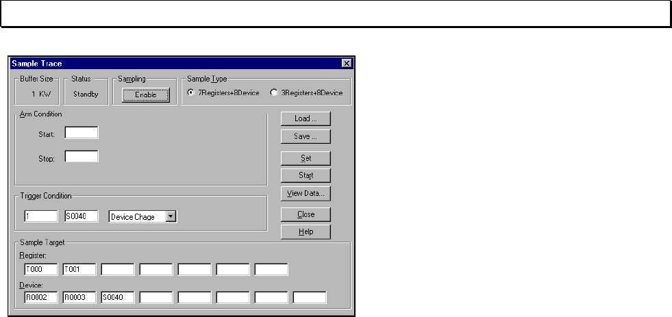
Basic Operation 73
7. Beyond the Basic
When the trigger conditions have been
set, move the mouse pointer to the
Sample Target area.
This area is used to designate the
devices and registers for sampling. Enter
the device and register numbers.
In this example, enter T000 and T001 for
the registers and R0002, R0003 and
S0040 for the devices.
When the settings are complete, click Set
to save them.
As a result of these settings, when the
S0040 relay changes from ON to OFF or
vice versa, the current values for timer 0
and timer 1 and the ON/OFF status of
R0002, R0003 and S0040 will be
sampled.
The sampling conditions have now been set. Click Enable at the top of the dialog box.
This completes the preparations for sampling.
Execute the program using the key-switch on the T3 or PLC Control. When the
program is ready for execution, click Start. Sampling will begin. When sampling has
been performed for 10 seconds or more (and flickering has begun), click Stop.
Sampling will stop and the program operation status will be stored in the sampling
buffer.
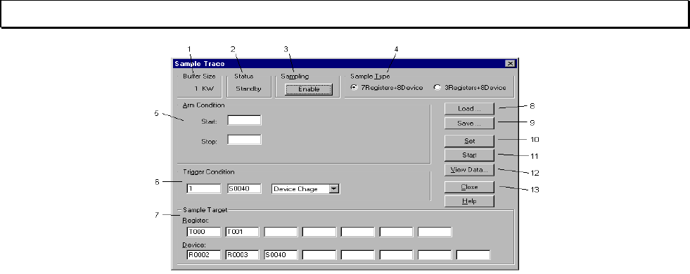
74 T-PDS32 for Windows V2.2
7. Beyond the Basic
<Sample Trace dialog box>
1 - Buffer Size: Shows the sampling buffer size (0 - 8kw).
2 - Status: Shows the status of sampling execution.
Executing: Sampling in progress
Standby: Sampling stopped
3 - Sampling: This button shows whether sampling is enabled or disabled. The status can be
toggled by clicking the button.
Enable: Sampling is enabled. Clicking the button changes this to Disable
and sampling is stopped.
Disable: Sampling is disabled. Clicking the button changes this to Enable.
4 - Sample Type: This area is used to select the number of registers and devices sampled. You may
choose either of two options:
7 registers + 8 devices
3 registers + 8 devices
5 - Arm Condition: This area is used to set the arm conditions. Setting these values causes sampling
to begin and end automatically in line with the arm conditions.
Start: The start condition for sampling. Enter a register or device, a
timing value or (in the case of numerical change) a numerical
value in the box.
Stop: The stop condition for sampling.
After: Sets how many sampling scans are performed after the Stop
conditions are met.
6 - Trigger Condition: Sets the timing for the sampling operation. The trigger condition is set in the same
manner as Arm Condition above. The setting for number of trigger operations
determines the number of times sampling is performed each time trigger
conditions are fulfilled. If this value is set to 1 or left blank, sampling is performed
each time the conditions are fulfilled. Similarly, if the register and device boxes are
left blank, sampling is performed for each scan.
7 - Sample Target: Sets the registers and devices for which sampling is performed.
8 - Load: This button is used to load files containing sampling conditions and reflect these
conditions on the screen.
9 - Save: This button is used to save the sampling conditions set on the screen to a file.
10 - Set: This button sets the sampling conditions currently displayed on the screen.
11 - Start: Clicking this button starts the sampling procedure in sampling ready status. The
button changes to "Stop" when sampling begins. Clicking the Stop button stops
the sampling process.
12 - View Data: This button loads the results of the sampling procedure from the PLC and displays
them in the Sample Trace Data View window.
13 – Close: Clicking this button closes the sample trace dialog box.
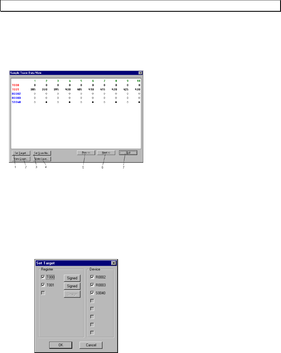
Basic Operation 75
7. Beyond the Basic
7.2.3 Viewing Sampling Trace Data
In this example, you will view the sampled data. Click the View Data button to display
all of the sampled data.
The top part of the data shows the timer
register values. The bottom part shows
the device on/off status. White circles
indicate ON status and black circles
indicate OFF status.
The numbers at the very top are scan
numbers. You may use the Set Scan No.
button to display the data from any scan
number. Click Prev to display the data for
the previous ten scan items. Click Next to
display the data for the next ten scan
items.
<Sample Trace Data View dialog box>
1 - Set Target: Clicking this button displays the Set Target dialog box, enabling you to set the
devices and registers to be displayed.
2 - View Graph: Clicking this button displays a dialog box with a graph of the sample data.
3 - Set Scan No: Clicking this button displays a dialog box used to set the first scan number for the
sample data.
4 - Data Save: Save the sample data to the file in CSV format.
5 - Prev: Shows the previous page of data.
6 - Next: Shows the next page of data.
7 - Quit: Returns to the Sample Trace dialog box.
- Set Target screen
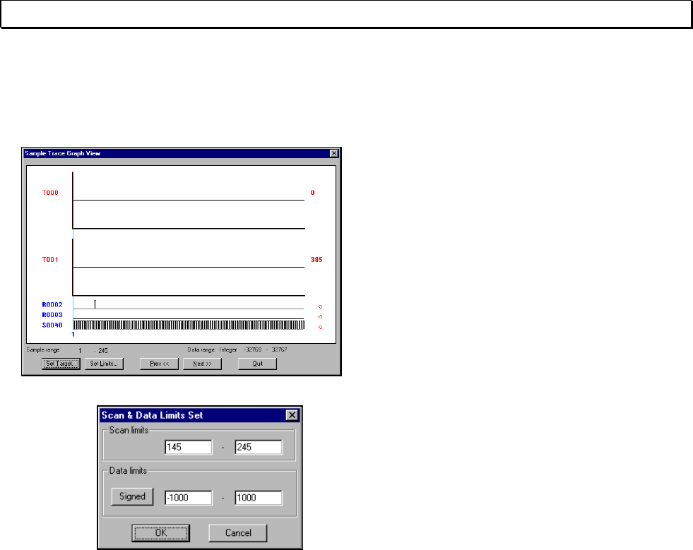
76 T-PDS32 for Windows V2.2
7. Beyond the Basic
7.2.4 Timing Chart Disply
In this example you will view the time chart for this data.
Click the View Graph button. The
sampled data will be displayed in the form
of a time chart.
The time chart shows the scans from
number 1 to number 256.
In this format, the data is a bit difficult to
view, so you should change the scan
range (the scale of the time axis in the
chart).
Click the Set Limits button. A dialog box will
appear, enabling you to set the display
range for the data.
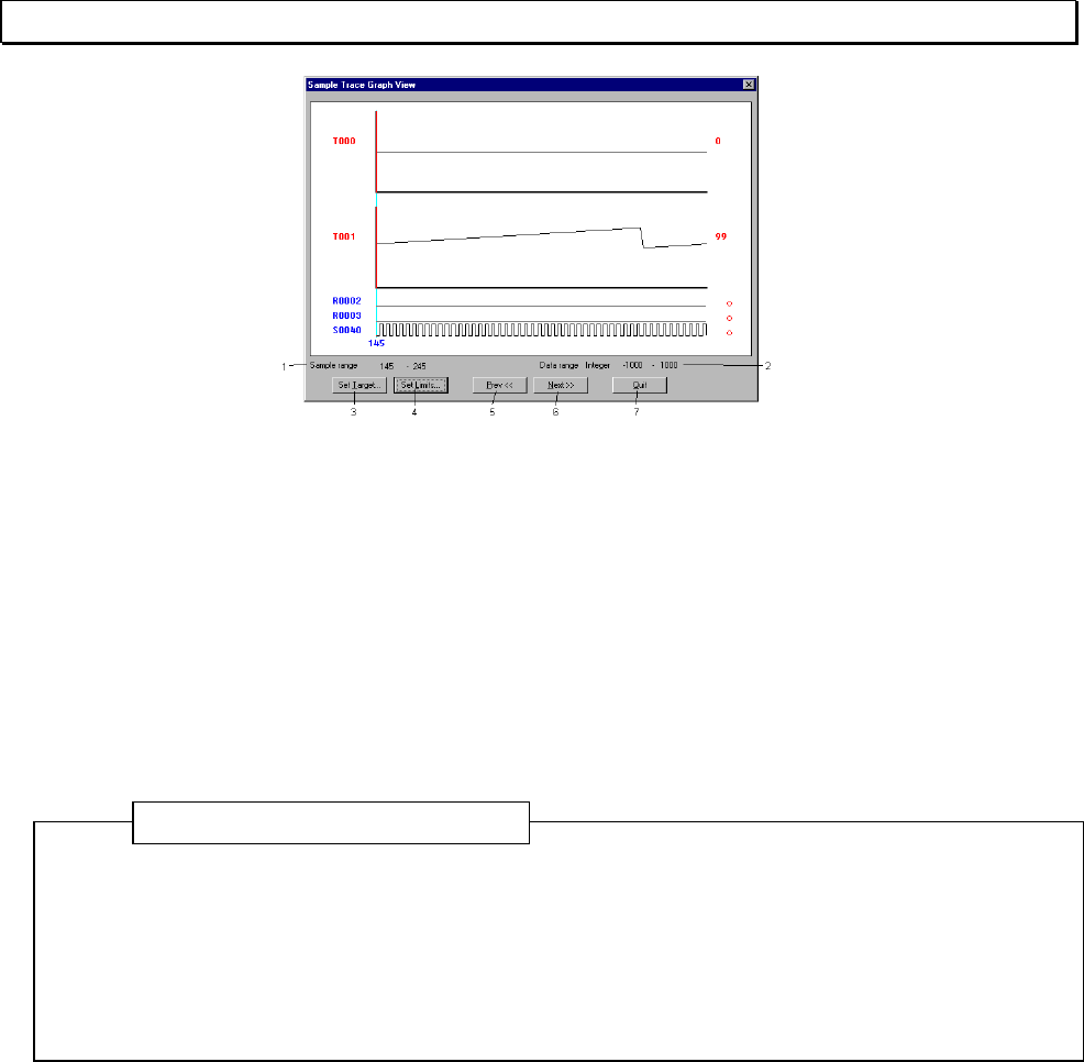
Basic Operation 77
7. Beyond the Basic
<Sample Trace Graph View>
1 - Sample Range: Shows the lower and upper limits for the currently displayed scan range.
2 - Data Range: Shows the lower and upper limits for the display data.
3 - Set Target: Clicking this button displays the Device/Register Data dialog box.
4 - Set Limits: Clicking this button displays the Display Data Range dialog box.
5 - Prev: Shows the previous page of data.
6 - Next: Shows the next page of data.
7 - Quit: Returns to the Sample Trace Data View screen.
The following keyboard shortcuts can also be used:
Left/right arrow keys Moves the sample cursor.
T Displays the Device/Register Data dialog box.
L Displays the Display Data Range dialog box.
P Shows the previous page of data.
N Shows the next page of data.
Additional Information
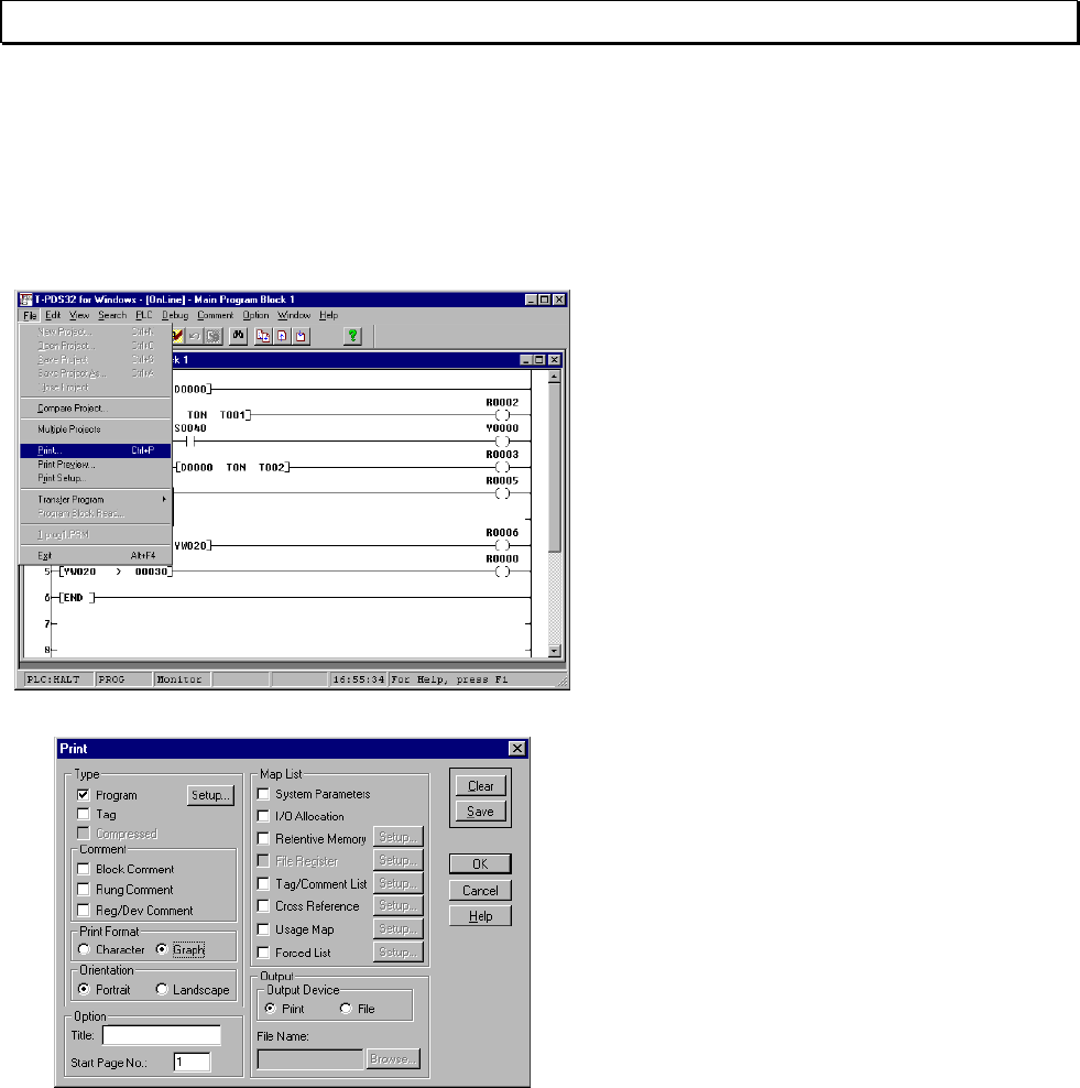
78 T-PDS32 for Windows V2.2
7. Beyond the Basic
7.3 Printing the Program
The Print command on the File menu allows you to print out the program, system
information, device/register data, cross-reference, etc.
In this example, you will use this command to print out the program.
On the File menu, click Print.
(Toolbar is also available)
The Print dialog box will appear.
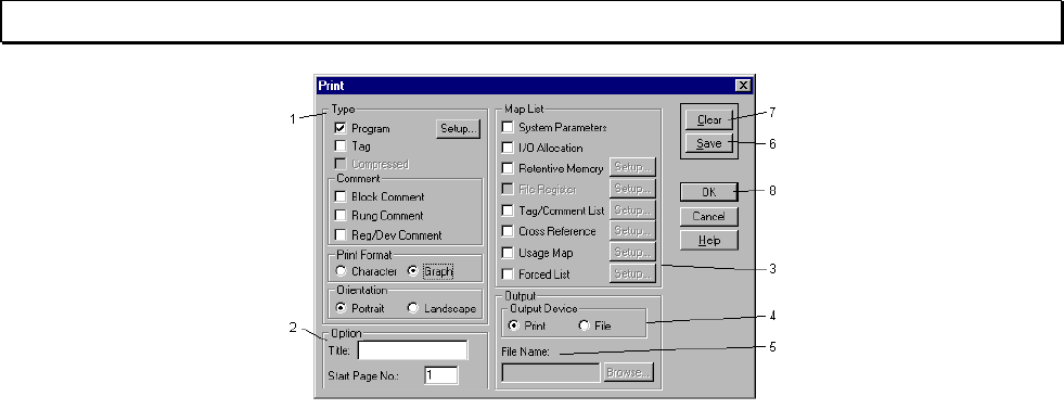
Basic Operation 79
7. Beyond the Basic
<Print dialog box>
1 - Type: This item is used to specify the program print-out format.
Program: Check here to print out the program. The program range to be printed can
be specified.
Tag: Check here to print out the program with the tags.
Comment: Used to add the comments on the program. The following types of
comments are available.
- Block Comment
- Rung Comment
- Register/Device Comment
Print Format: Select the print out mode either character mode or graphics mode.
2 - Option: This item is used to specify the print-out header title and the starting page
number.
3 - Map List: This item is used to select the optional maps to be printed.
System Parameters: Check here to print the system parameters.
I/O Allocation: Check here to print the I/O allocation information.
Retentive Memory: Check here to print the data of the retentive registers.
File Registers: Check here to print the data of the file registers (F registers).
Tag/Comment List: Check here to print the list of the register/device comments.
Cross Reference: Check here to print the cross-reference list.
Usage Map: Check here to print the register/device usage map.
Forced List: Check here to print the list of forced devices/coils.
4 - Output: This item is used to select the output device.
5 - Output Device: Select the output device either printer or file.
File Name: When file is selected as the output device, enter the file name here.
6 - [Save] button: Saves the print settings into the system file.
7 - [Clear] button: Clears the setting.
8 - [OK] button: Starts the printing.
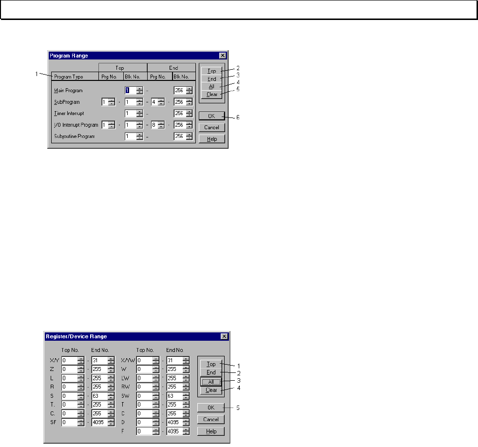
80 T-PDS32 for Windows V2.2
7. Beyond the Basic
On the Print dialog, when you check the
Program and click the [Setup] button, the
Program Range dialog box will appear.
Set the block range for each program
type to be printed on this dialog box.
<Program Range dialog box>
1 - Program Type: Sets the program ranges to be printed.
2 - Top: Sets the starting program number (if any) and the block number to be printed on
the cursor position.
3 - End: Sets the last program number (if any) and the block number to be printed on the
cursor position.
4 - All: Sets all the program range.
5 - Clear: Clears the settings.
6 - OK: Registers the settings and returns to the Print dialog box.
When you want to print the system parameter, I/O allocation, cross-reference, etc., check the
desired items on the Map List.
When you check the Retentive Memory,
File Register, Tag/Comment List, Cross
Reference, Usage Map, or Forced List,
click the [Setup] button to set the register
range to be printed. The Register/Device
Range dialog box will appear.
<Register/Device Range dialog box>
1 - Top: Sets the starting register address to be printed on the cursor position.
2 - End: Sets the last register address to be printed on the cursor position.
3 - All: Sets all the register range.
4 - Clear: Clears the settings.
5 - OK: Registers the settings and returns to the Print dialog box.
When you have finished the necessary setting, click the [OK] button on the Print dialog
box. The print-out will be started.
If you want to save the setting, click the [Save] button on the Print dialog box. The
current setting is saved in the system file, and it will be displayed when the next time
you open the Print dialog box.

Basic Operation 81
Index
Index
A - E
Automatic I/O Allocation 38
Auxiliary Monitor 58
Changing the Operation Mode 25
Checking Operation 52
Checking Register Numbers 40
Clear Memory 31
Clear the Instruction 49
Comment 15
Comment file 28
Comment Format 70
Correcting the Instruction 49
Data Monitor 52
Databox 58
Debug 15
Deleting Circuits 60
Device Name 66
Displaying Names 70
Edit 12
Edit mode 41
Executing the Program 51
F - J
File 11
Finishing the Program 47
Halt 25
Help 16
Insert 50
Inserting Circuits 53
Installation 6
Instruction toolbar 42
I/O Allocation Setup 38
K -O
Key Assignment to the Instruction bar 21
Key Operation 18
Ladder 41
Loading Programs from Disk 65
Map List 79
Memory Management 31
Memory Size 33
Menu Configuration 11
New Project 29
Offline 28
Online 28
Online I/O Module Replacement 37
Open Project 30
Opening a New Project 29
Opening an Existing Project 30
Operating Environment 5
Option 15
Overwrite 50

82 T-PDS32 for Windows V2.2
Index
P - T
PLC 14
PLC Control 25
PLC Control Box 26
Print 78
Printing the Program 78
Programming 41
Programming screen 41
Register/Device Comment 68
Registering I/O Cards 36
Registering Names 68
Registering System Parameters 32
Run 51
Sample Program 22
Sample Trace 71
Save to Disk 63
Scan Time 33
Screen Configuration 9
Search 13
Select Comment File 66
Setting Data 57
Selecting Functions 10
Setting the Sampling Buffer 71
Setting the Sampling Condition 72
SFC 41
Switching Between Online and Offline Status 27
System Disks 6
System Parameter 32
System Startup 24
Time Chart 76
Timer Interrupt Interval 33
Toggle Address/Number of Words 40
Toolbar Configuration 17
U - Z
Vertical Connection 46
View 13
Viewing Sample Trace Data 75
Window 16
When an I/O Card is Installed 38
When No I/O Card is Installed 38
Writing the Program 48
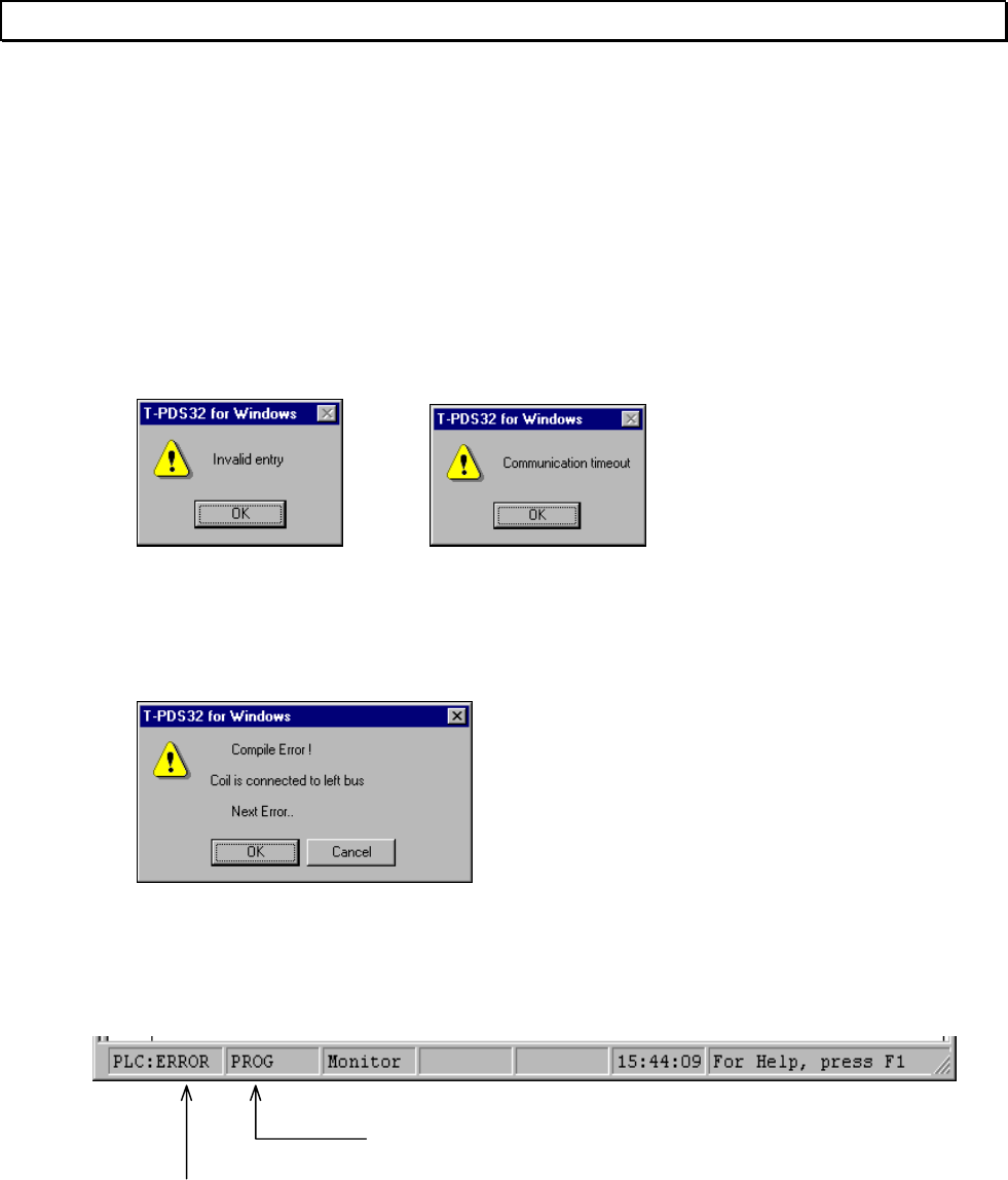
Basic Operation 83
Error Message
Error Message
Error Message Overview
There are 4 types of error messages as follows.
A. Operation Error
These error messages are displayed for the T-PDS operation which you attempt to do.
Communication error between T-PDS and PLC is also included in this type.
It is displayed in the message box.
B. Compile Error
These errors are detected in the T-PDS when edited program is compiled.
It is displayed in the message box.
C. PLC Status Line
When the T-PDS is on-line mode, the PLC's operation mode (RUN, HALT, or ERROR)
and alarm status are displayed in the status line.
PLC mode
RUN
HALT
ERROR
Alarm status
PROG: Programming enabled.
PROT: Program is write-protected.
LOAD: Under program down-loading.
DIAG: User diagnostic instruction was executed.
SCAN: Time-over for the constant scan setting.
TL-F: TOSLINE-F10 error.
TL-S: TOSLINE-S20 error.
BATT: Battery alarm.
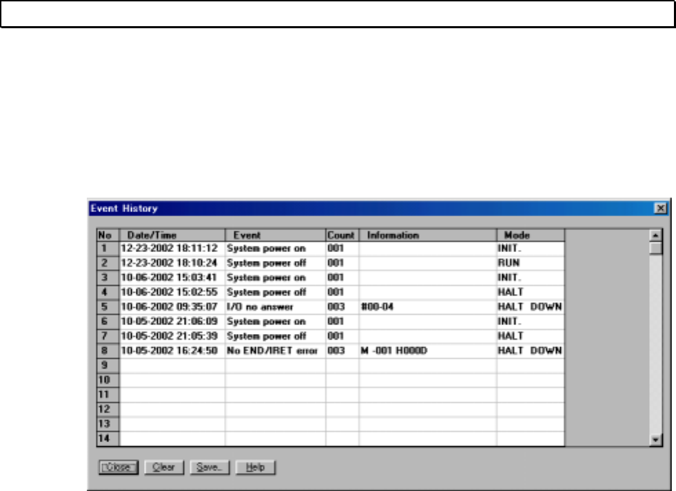
84 T-PDS32 for Windows V2.2
Error Message
D. Event History Table
When the PLC detects some abnormality in its diagnostic checks, it is recorded in the
PLC memory called Event history table. In the Event history table, the last 30 event
messages (15 in case of T1/T1S) are stored in this table. The contents of the Event
history table can be monitored on the T-PDS screen by [PLC] [Event History] menu.
<Event History Table>
Date The date the error occurred (requires RTC/calendar).
Time The time the error was detected (requires RTC/calendar).
Event Description of what occurred.
Count Number of retries to correct the event.
Information Additional information about the event.
Mode The operation mode when the event occurred.
DOWN The event caused the controller to enter the Error Mode.
[Save] button is used to save the Event history table contents into the disk file.
Usually a PLC goes into the error mode when one of its diagnostic checks determines
that something has occurred which interferes with normal operation. When a controller
is in the error mode, all outputs turn OFF and operation stops. Nothing else is possible
until Error Reset is executed. The basic recovery procedure is:
(1) Execute Error Reset (reset the error and put the PLC in the Halt Mode).
(2) Study the Event History Table.
(3) Make the necessary corrections.
(4) Return to the Run Mode.
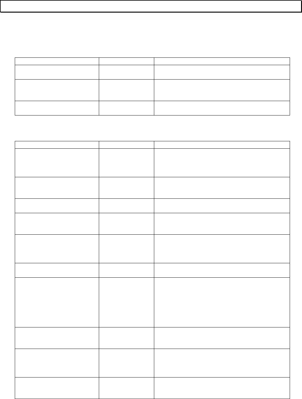
Basic Operation 85
Error Message
Error Message List
A...
Message Type of Error Description
Address limit over Operation error The register address is not valid.
Address over
Limit the size? Operation error The block specified will exceed the address
range. Limit the block size automatically?
Address setting error Operation error The address specified is not correct.
B...
Message Type of Error Description
Batt voltage drop Event history Battery voltage drop or back-up data error was
detected.
Replace the battery if it is used.
Block separation impossible
(max 16 blocks) Operation error Number of divided blocks in the data monitor is
16 blocks maximum.
Block size error Operation error Specified block size is illegal.
Block size error Operation error The block number specified is out of the
allowable range.
Block/rung comment file is
not specified Operation error Block/rung comment file has not been
specified.
BLOCKEDI.EXE running Operation error The edit block function has already activated.
Boundary error Event history The index modified operand exceeds the
allowable address/data range.
Info 1: Program type - block No.
Info 2: Offset address in the block
Info 3: Function No.
Check the program for the index registers data.
Branch connection below
MCS/JCS Compile error MCS and JCS must be the last instruction in a
rung.
Branch connection error Operation error The program cannot be displayed because it
contains illegal branch connection. (Program
abnormal)
Branch connection error Compile error In the SFC program, combination of divergence
and convergence is not correct.
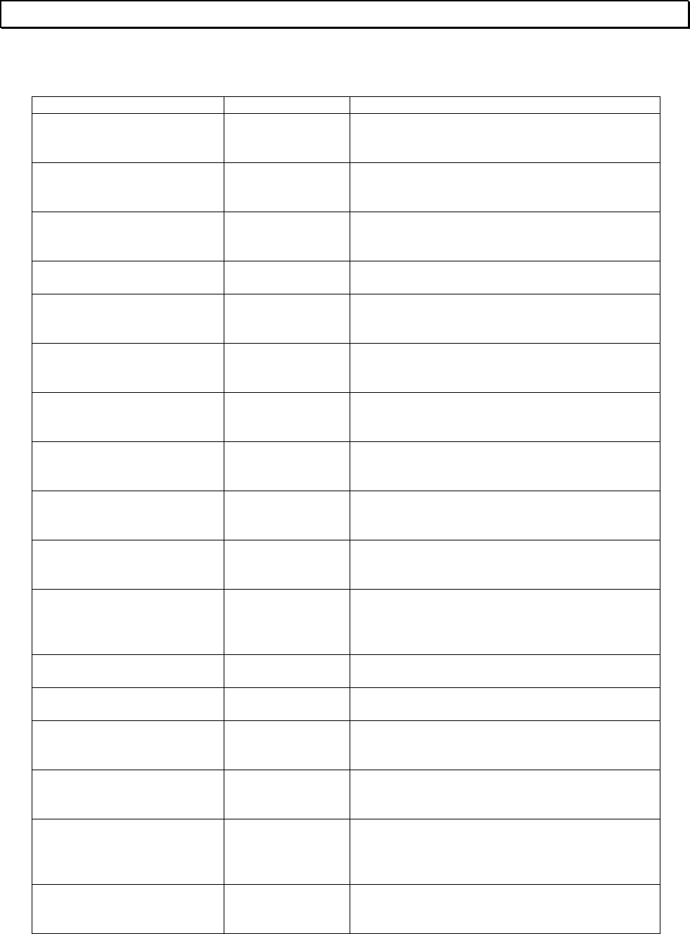
86 T-PDS32 for Windows V2.2
Error Message
C...
Message Type of Error Description
Can't check register/device
comment file type Operation error The format type, long or short, of the comment
file could not be confirmed.
Cannot connect with other
instruction Compile error This instruction cannot be connected with other
instructions.
Cannot copy because of
memory capacity over Operation error The block copy operation specified will cause
memory capacity over.
Cannot delete Operation error The delete range specified is illegal.
Cannot delete line Operation error The current cursor position is illegal to execute
the line delete operation.
Cannot execute because of
memory allocation error Operation error Block edit cannot be started because of
insufficient memory.
Cannot execute because of
TPDS.EXE not loaded Operation error The block edit cannot be started because T-
PDS has not been executed.
Cannot insert Operation error The current cursor position is illegal to execute
the insert operation.
Cannot insert line Operation error The current cursor position is illegal to execute
the line insert operation.
Cannot Load Spin.VBX
Place the file on the path Operation error The Spin.vbx file was not found in the folder of
Tpds.exe file.
Cannot move because of
insufficient empty blocks Operation error The block move operation specified is not
possible because empty blocks are not
sufficient.
Cannot Open File Operation error The file specified could not be opened.
Cannot Save This File Operation error Saving into the file was failed.
Changing item not found Operation error The target was not found for the search &
replace function.
Channel Size Error Operation error Channel number specified for F10 assignment
is out of allowable range.
Clock-calendar err Event history An error was detected in the calendar LSI. (no
error down)
Reset the clock-calendar data.
Coil is connected to left bus Compile error Coil cannot be connected to the left bus
directly.
Basic Operation 87
Error Message
Message Type of Error Description
Column over Operation error The program cannot be displayed because it
contains excess columns. (Program abnormal)
Combination error Operation error The combination of I/O type and size is invalid.
Comm format error Operation error Communication format error has occurred.
Command line not found Operation error Command line could not be found.
Comment character size
error Operation error Data comment character size exceeds the limit.
Comment file insert error Operation error An error occurred during writing to the comment
file.
Comment file open error Operation error The comment file could not be opened.
Comment file write error Operation error An error occurred during writing to the comment
file.
Comment space full Operation error The comment memory is full.
Comment space full Operation error The comment memory is full.
CommonData Lock Error Operation error Common data could not be obtained.
Communication busy Operation error When the programmer port and the computer
link port are used simultaneously, the PLC CPU
cannot respond due to busy status for other
communication support.
Communication err Operation error Communication error has occurred.
Communication error Operation error Communication error between T-PDS and PLC
has occurred.
Communication timeout Operation error Communication time-out error occurred.
Connection error Compile error In the SFC program, there are illegal
connections.
Connection error for edge
detect instruction Compile error No instruction cannot be connected to the
output of the edge detect modified instruction.
Connection error for multi-
input instruction Compile error Vertical connection point cannot be connected
directly with the input of a multi-input
instruction.
(except for the enable input)
Contact is connected to right
bus Compile error Contact instruction cannot be connected to the
right bus.
88 T-PDS32 for Windows V2.2
Error Message
Message Type of Error Description
Control inst incl. Operation error In the on-line program changes, the following
instructions cannot be deleted or added.
FOR, NEXT, MCS, MCR, JCS, JCR, END,
JUMP, LBL, CALL, SUBR, RET, IRET
CRect over Operation error The printing space is not sufficient.
D...
Message Type of Error Description
Data type mismatch Operation error The data format specified is not allowed for the
operand.
Device context error Operation error The device context could not be obtained.
Direct Instruction or
Operand Operation error Specify the instruction or operand to be
searched.
Disk full Operation error The disk is full.
Duplicate coil Operation error Duplicate coil was detected in the program
check function.
Duplicate entry No. Event history LBL or SUBR instruction is duplicated
Info 1: Program type - block No.
Info 2: Offset address in the block
Info 3: Entry No.
Check the program.
Duplicate I/O reg Event history Duplication of XW/YW registers is detected.
Info 1: Unit No. - slot No.
Info 2: Register address
Check the I/O allocation information (unit base
address setting).
Duplicate mark information Operation error The mark ID specified has already been
registered.
Duplicate Registers Operation error X/Y registers are duplicated due to incorrect
unit base address setting.
Duplicate SFC No. Event history The SFC program No. is duplicated.
Info 1: Program type - block No.
Info 2: SFC program No.
Check the program.
Duplicate step No. Compile error SFC step number is duplicated.
Basic Operation 89
Error Message
E...
Message Type of Error Description
Edit line over Operation error Editing range exceeds 11 lines.
Edit size over Compile error Number of steps in the rung exceeds 132
steps.
EEPROM BCC error Event history BCC error was detected in the user program
memory (built-in EEPROM). Initial load was not
executed.
Info 1: Illegal BCC data
Check the program. Then write into the
EEPROM again.
EEPROM warning Event history The number of times of EEPROM write has
exceeded the life (100,000 times).
Info 1: Excess times of EPROM write
EEPROM write error Operation error Error occurred during writing into built-in
EEPROM.
Empty block has been
specified Operation error An empty block was specified as copy source.
END exists in subroutine Compile error END instruction cannot be programmed in the
subroutine.
Entered tag(s) has already
been registered Operation error Entered tag is duplicated.
Entry block has been
specified Operation error Programmed block cannot be specified as copy
destination.
Ethernet not support Operation error Ethernet is not supported in the computer.
Exceeds 132 steps Operation error A rung contains more than 132 steps.
Expansion unit err Event history 5 Vdc power f the expansion unit is not normal.
ExtDeviceMode function not
support Operation error The printer driver does not support Landscape
mode printing.
90 T-PDS32 for Windows V2.2
Error Message
F...
Message Type of Error Description
File access error Operation error An error occurred during accessing the file.
File access error Operation error File access error occurred during accessing
comment file.
File append impossible Operation error File append is not possible.
File name not exist Operation error The specified file was not found.
File open error Operation error The file specified could not be opened.
File read error Operation error The file read error has occurred.
File Save Error Operation error An error occurred in writing to the file.
File write error Operation error The file write error has occurred.
File write error Operation error File writing error occurred during accessing
comment file.
FileName is Illegal Operation error The file name specified is illegal.
I...
Message Type of Error Description
I/O bus error Event history I/O bus check error occurred.
Info 1: Unit No.
Info 2: Illegal data
Check the expansion cable connection, I/O
module mounting condition.
I/O mismatch Operation error The specified device/register does not match
with the I/O allocation status.
I/O mismatch Operation error The operand specified does not match the I/O
allocation status.
I/O mismatch Event history The I/O allocation information and actual I/O
mounting status are not matched.
Info 1: Unit No. - slot No.
Info 2: Register address
Check the I/O allocation information and the I/O
module mounting position.
Basic Operation 91
Error Message
Message Type of Error Description
I/O no answer Event history No answer was acknowledged from the I/O
module.
Info 1: Unit No. - slot No.
Info 2: Register address
Check the I/O allocation information and the I/O
module mounting position.
I/O parity error Event history I/O bus parity error occurred during accessing
the I/O module.
Info 1: Unit No. - slot No.
Info 2: Register address
Check the I/O module mounting condition.
IC card BCC error Event history BCC error was detected in the user program
memory (IC card). Initial load was not executed.
Info 1: Illegal BCC data
IC card type error Event history The program stored in the IC card is bigger
than the PLC memory. Check the IC card.
Illegal file name Operation error Illegal file name was specified.
Illegal Filename Operation error The file name specified is illegal.
Illegal I/O reg Event history XW/YW register address exceeded the limit in
allocating I/O modules.
Info 1: Unit No. - slot No.
Info 2: Register address
Check the I/O allocation information.
Illegal inst Event history An illegal instruction was detected in the
program.
Info 1: Program type - block No.
Info 2: Offset address in the block
Clear memory and reload the program.
Illegal instruction Operation error The program cannot be displayed because it
contains illegal instruction. (Program abnormal)
Illegal mode Operation error The function attempted is not allowed in the
current operation mode.
Illegal Parameters Operation error Sampling parameters specified are illegal.
Illegal register/device
comment file type Operation error The format type of the register/device comment
file is illegal.
Illegal sys intrpt Event history Illegal system interrupt was detected.
Info 1: Interrupt address 1
Info 2: Interrupt address 2
Check external noise environment.
92 T-PDS32 for Windows V2.2
Error Message
Message Type of Error Description
Immediate data only in
Offline mode Operation error Register data setting on the program window is
not allowed in off-line mode.
Impossible in the specified
block Operation error The block divide operation specified will cause
memory capacity over.
In and Out of the instruction
are shorted Compile error The input and output of an instruction are
shorted.
In/Out Method Error Operation error Global setting is not allowed for F10
assignment.
Incorrect connection Compile error The combination of the line connectors is not
correct.
Incorrect cursor position Operation error The current cursor position is illegal to execute
the operation specified.
Incorrect End position Compile error In the SFC program, position of the SFC End is
not correct.
Incorrect Macro End
position Compile error The position of the SFC Macro End is not
correct.
Incorrect range specification Operation error The range specified is not correct.
Incorrect register/device
specification Operation error The register/device specified is not correct.
Incorrect search target
specification Operation error The search target specified is not correct.
Incorrect target Operation error The register address range specified is not
correct.
Incorrect target specification Operation error The range specified is not correct.
Index/digit option is added
to the operand Operation error Data setting was attempted to an operand with
index modification/digit designation.
Initial and End steps
combination error Compile error In the SFC program, combination of Initial step
and End step is not correct.
Input error Operation error The instruction cannot be placed on the
specified position.
Insufficient comment area Operation error The comment memory is full.
Insufficient comment area in
workfile Operation error The comment memory allocated in the PLC is
full.
Basic Operation 93
Error Message
Message Type of Error Description
Insufficient disk capacity Operation error The disk capacity is not sufficient.
Insufficient disk capacity Operation error Disk full is detected during accessing comment
file.
Insufficient Memory Operation error Memory allocated is not sufficient to execute.
Insufficient memory capacity Operation error Memory allocated is not sufficient to execute.
Invalid block No. Operation error The required block number is out of the
allowable range.
Invalid combination Operation error The combination of I/O type and size is invalid.
Invalid cursor position Operation error The current cursor position is illegal to execute
the operation specified.
Invalid data Operation error The data specified is not valid.
Invalid data range Operation error The data value range specified is not correct.
Invalid digit specification Operation error The digit specification exceeds the allowable
data size for the instruction.
Invalid entry Operation error The value set is invalid.
Invalid for SFC block Operation error The function required is not allowed in the SFC
block.
Invalid format specification Operation error The data format specified is not allowed for the
operand.
Invalid Fun inst Event history Unavailable function instruction for the PLC is
programmed.
Info 1: Program type - block No.
Info 2: Offset address in the block
Info 3: Function No.
Check the program.
Invalid function in online
mode Operation error The function required is invalid in on-line mode.
Invalid function No. Operation error The function number specified is not valid.
Invalid I/O intrpt Event history Unused I/O interrupt signal was detected.
Info 1: Unit No. - slot No.
Allocate the interrupt module correctly. Check
external noise environment.
Invalid in constant scan
mode Operation error The Subprogram execution time assignment is
invalid if Constant scan mode is selected.
94 T-PDS32 for Windows V2.2
Error Message
Message Type of Error Description
Invalid in offline mode Operation error The function is not available in off-line mode.
Invalid instruction in detail
part Compile error In the SFC transition condition or action part,
unavailable instruction is programmed.
Invalid location Operation error The current cursor position is not allowed for
the I/O type specified.
Invalid operand Operation error The operand specified is not valid.
Invalid operand Operation error
Compile error The operand specified for the instruction is not
valid.
Invalid operation Operation error The cursor position is not correct for the
operation specified.
Invalid output range
specification Operation error The output range specified is invalid.
Invalid program Event history Program management information is not
normal.
SUBR instruction is not programmed before
RET instruction.
END instruction is programmed in the interrupt
program.
IRET instruction is programmed in other than
the interrupt program.
SFC is programmed in other than the main or
subprogram.
Unavailable instruction for the PLC is used.
Info 1: Program type - block No.
Check the program.
Invalid register/device in
offline mode Operation error The register/device specified is invalid in off-
line mode.
Invalid Rung No. Operation error The required rung number is out of the
allowable range.
Invalid sampling range Operation error The sampling range specified is not correct.
Invalid SFC Prog Event history The correspondence between initial step and
end step, or the macro entry and macro end is
not correct.
Info 1: Program type - block No.
Check the program.
iomodule.sys file format
error Operation error The format of the I/O module type file
(iomodule.sys) is not correct.
IP Address no entry Operation error The IP address for Ethernet is not entered.
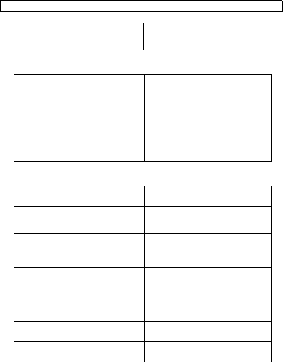
Basic Operation 95
Error Message
Message Type of Error Description
IP Address or Port No no
entry Operation error IP address or Port number for Ethernet
connection was not entered.
J...
Message Type of Error Description
Joint connection error Operation error The program cannot be displayed because it
contains illegal joint connection. (Program
abnormal)
Jump target error Event history LBL instruction corresponding to the JUMP
instruction is not programmed, or it is on the
incorrect location.
Info 1: Program type - block No.
Info 2: Offset address in the block
Info 3: Jump label No.
Check the program.
L...
Message Type of Error Description
Last block cannot divided Operation error The last block (block 256) cannot be divided.
Last block cannot specified Operation error The last block (block 256) cannot be divided.
Latch Condition Data Error Operation error The data for latch condition is illegal.
Latch target No. x is Illegal Operation error The latch target specified on No. x is illegal.
LBL/SUBR is not connected
to left bus Compile error No other instruction is allowed in the rung of
LBL or SUBR instruction.
Limit over Operation error The value set is out of the range specified.
Line Clear Error Operation error The current cursor position is illegal to execute
the line clear operation.
Line Delete Error Operation error The current cursor position is illegal to execute
the line delete operation.
Line Insert Error Operation error The current cursor position is illegal to execute
the line insert operation.
Line over Operation error The program cannot be displayed because it
contains excess lines. (Program abnormal)
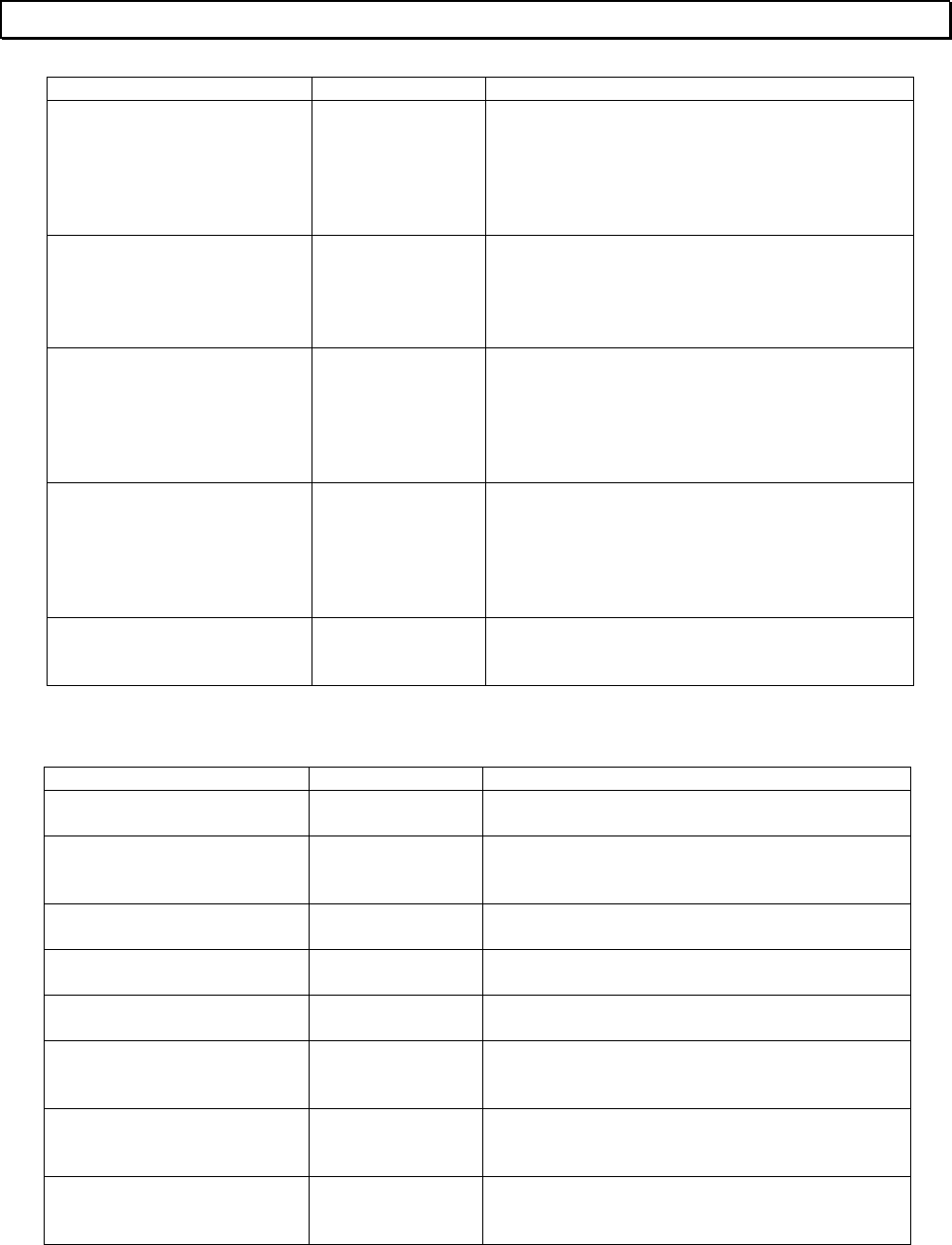
96 T-PDS32 for Windows V2.2
Error Message
Message Type of Error Description
Loop nesting error Event history The nesting level of FOR-NEXT loops exceeds
the limit specified.
Info 1: Program type - block No.
Info 2: Offset address in the block
Check the program.
LP exec timeout Event history The execution of the language processor (LP)
did not finish within the time specified, or scan
time exceeded the time specified.
Reduce the scan time or use WDT instruction.
LP function error Event history An error was detected during the language
processor (LP) function check.
Info 1: Error code
Info 2: Error data
Turn off power and on again.
LP reg R/W error Event history An error was detected in the initial read/write
check for the language processor (LP).
Info 1: Error code
Info 2: Error data
Turn off power and on again.
LP start chk error Event history The language processor (LP) could not be
started normally.
M...
Message Type of Error Description
Meaningless specification Operation error The erase range specified has no meaning.
Memory capacity not
compatible Operation error The memory capacity is not matched.
Memory full Operation error The program memory is full.
Memory protect Operation error The writing operation is prohibited by P-RUN.
Merging block mismatch Operation error Ladder and SFC blocks cannot be merged.
Mode mismatch Operation error The current PLC operation mode does not
allow to execute the required function.
Mode mismatch Operation error Sampling parameters can be set into the PLC
when the PLC is HALT or sampling is disabled.
Move destination is invalid Operation error Same block is specified for move source and
destination.
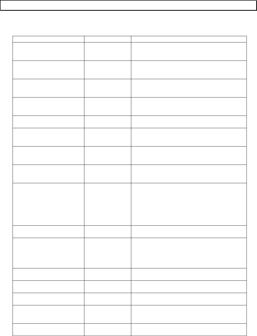
Basic Operation 97
Error Message
N...
Message Type of Error Description
Next block exists Operation error Block divide operation is not allowed because
the next block exists.
No address specified Operation error The register address range specified is not
correct.
No buffering comment data Operation error Rung comment paste operation is not possible
because the buffer is empty.
No comment registered Operation error No comment is registered.
No Data Latched Operation error No data has been latched.
No device setting Operation error In the bit pattern check function, the device
setting is not correct.
No EEPROM Operation error EEPROM write was not executed because no
EEPROM is mounted.
No empty block Operation error Copy or move is not possible because there is
no empty block.
No END/IRET error Event history END instruction is missing in the main or
subprogram, or IRET instruction is missing in
the interrupt program.
Info 1: Program type - block No.
Info 2: Offset address in the block
Check the program.
No entry Operation error A required entry item was not made.
No entry block Operation error Block operation is not possible because there is
no programmed block in the program type.
There is no programmed block in the erase
range specified.
No entry range Operation error The range has not been specified.
No mark information Operation error The mark ID specified has not been registered.
No merging block Operation error The next block to be merged does not exist.
No operand Operation error
Compile error Necessary operand has not been entered.
No parameter file Operation error The parameter file was not found.
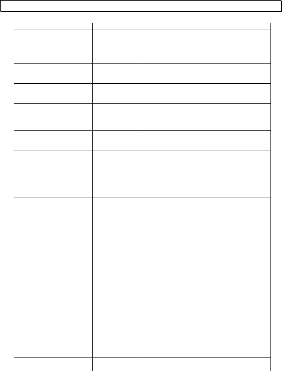
98 T-PDS32 for Windows V2.2
Error Message
Message Type of Error Description
No pattern setting Operation error In the bit pattern check function, the on/off
pattern setting is not correct.
No print out item Operation error The print item has not been specified.
No program in any specified
blocks Operation error There is no program in the blocks specified.
No program in the compile
range Compile error Empty rung cannot be compiled. Use rung
delete function.
No program monitored Operation error Program is not monitored.
No range specified Operation error The range has not been specified.
No register setting Operation error In the data validity check function, the register
setting is not correct.
No RET error Event history RET instruction is not programmed in the
subroutine.
Info 1: Program type - block No.
Info 2: Offset address in the block
Info 3: Subroutine No.
Check the program.
No Sampling Buffer Operation error No sampling buffer is allocated.
No sampling data Operation error There is no sampling data in the buffer to be
displayed.
No SFC jump label Event history SFC label corresponding to the SFC jump is not
programmed.
Info 1: Program type - block No.
Info 2: SFC label No.
Check the program.
No SFC macro entry Event history Macro program corresponding to the macro
step is not programmed.
Info 1: Program type - block No.
Info 2: Macro No.
Check the program.
No sub-r entry Event history SUBR instruction corresponding to the CALL
instruction is not programmed.
Info 1: Program type - block No.
Info 2: Offset address in the block
Info 3: Subroutine No.
Check the program.
No support device Operation error The device specified is not supported.
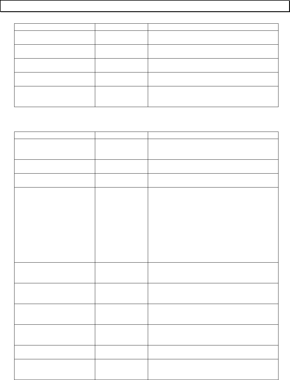
Basic Operation 99
Error Message
Message Type of Error Description
Not a WinSock error Operation error The specified target could not be confirmed.
Not Support Operation error The function specified is not supported.
Not support device Operation error The device specified is not supported.
Not support yet Operation error The function required is not supported.
Number of SFC steps
exceeds the limit Compile error In the SFC block, the number of SFC steps
exceeds the limit (128).
O...
Message Type of Error Description
One device at a time for T.
and C. Operation error For timer device (T.) or counter device (C.), only
one device can be specified at a time.
Open circuit Compile error A line is not complete between the instructions.
Operand error Operation error The device/register specified is illegal.
Operand error Event history Input device/register is used for output.
Unavailable device/register for the PLC is used.
Timer or counter is duplicated.
Unavailable subroutine number for the PLC is
used.
Unavailable operand modification for the PLC is
used.
Info 1: Program type - block No.
Info 2: Offset address in the block
Check the program.
Operand range mismatch Operation error The replace address exceeds the limit in the
search & replace function.
Operand range over Operation error
Compile error The operand specified is out of the allowable
data range or register/device address range.
Operand type error Operation error The operand types are not matched in the
search & replace function.
Out of address range Operation error The register address is out of the range
specified.
Out of input range Operation error The value set is out of the range specified.
Out of Position Operation error The current cursor position is illegal to execute
the operation specified.
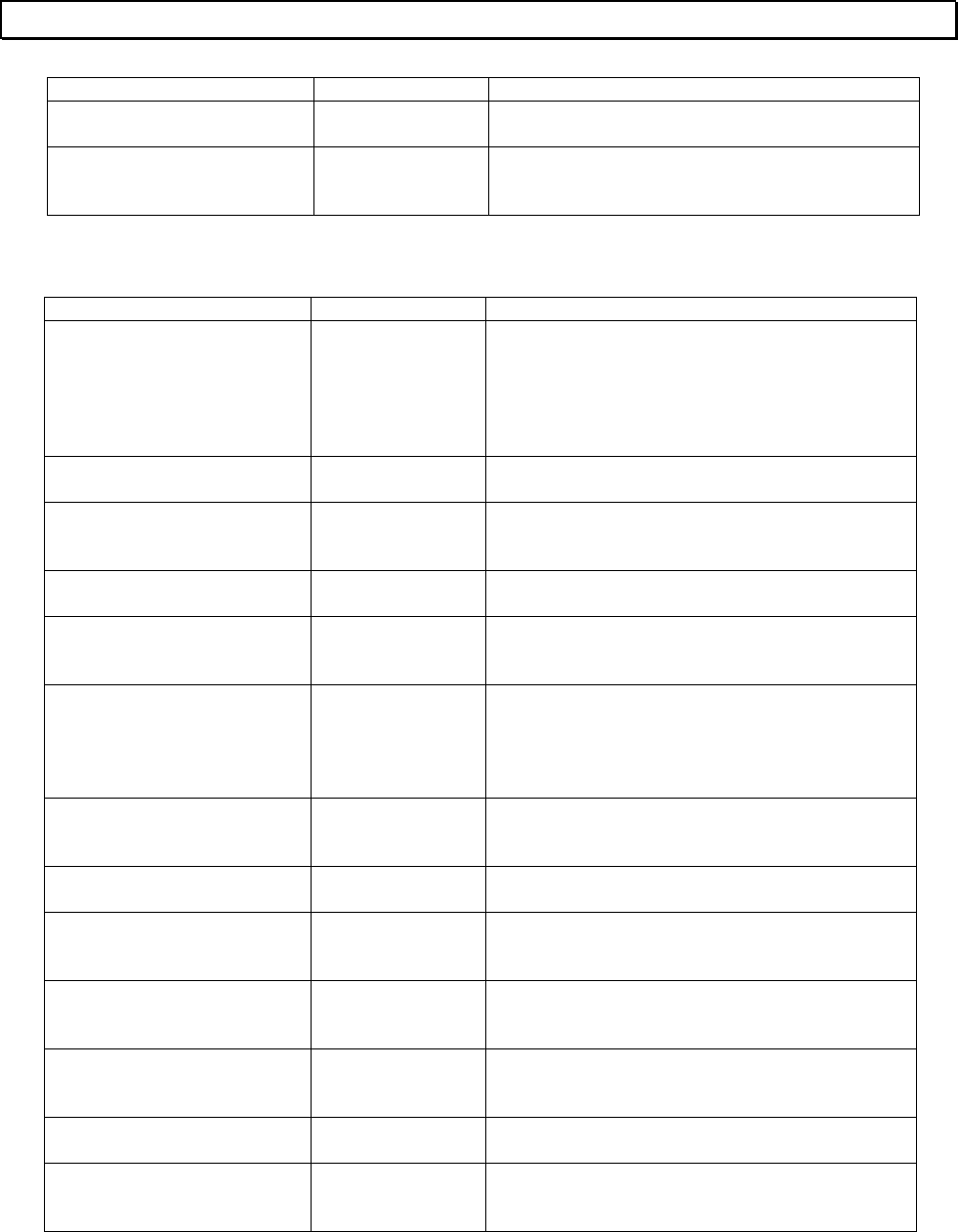
100 T-PDS32 for Windows V2.2
Error Message
Message Type of Error Description
Out of range Operation error The value set is out of the range specified.
Out of value range Operation error The value set is out of the allowable data
range.
P...
Message Type of Error Description
Pair inst error Event history Program error was detected for MCS/MCR or
JCS/JCR combination.
Info 1: Program type - block No.
Info 2: Offset address in the block
Check the program.
Parameter error Operation error Comment file parameter error is detected.
Parameter file error Operation error The contents of the parameter file are not
correct.
Password mismatch Operation error The password entered is not matched.
Password protect Operation error The operation was rejected by the PLC due to
password protection.
Peripheral LSI err Event history An error was detected in peripheral LSI
checking.
Info 1: Error code
Turn off power and on again.
PLC communication error Operation error Communication error between T-PDS and PLC
has occurred.
Port No no entry Operation error The Port number for Ethernet is not entered.
Position error Operation error The current cursor position is illegal to execute
the operation specified.
Position of LBL/SUBR is not
correct Compile error No other instruction is allowed in the rung of
LBL or SUBR instruction.
Position of RET/IRET is not
correct Compile error Position of RET or IRET instruction is not
correct.
Power interrupt Event history Power interruption is detected. (T3/T3H only)
Power intr resumed Event history Power interruption has been recovered.
(T3/T3H only)
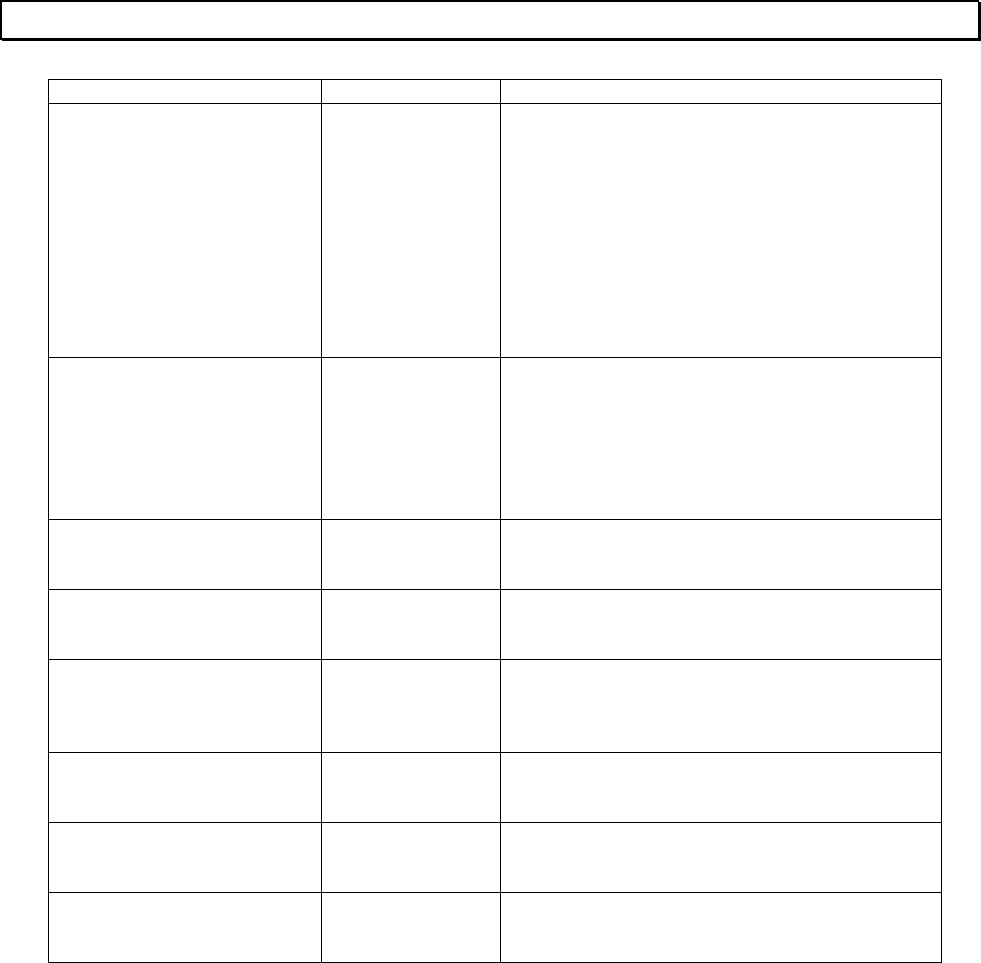
Basic Operation 101
Error Message
Message Type of Error Description
Program abnormal Operation error Program management information is not
normal.
SUBR instruction is not programmed before
RET instruction.
END instruction is programmed in the interrupt
program.
IRET instruction is programmed in other than
the interrupt program.
SFC is programmed in other than the main or
subprogram.
Program BCC error Event history BCC error was detected in the user program
memory (RAM).
Info 1: Illegal BCC data
Check the program. If it looks normal, save it
into a disk file, and remake BCC by Block edit
function.
Program error detected
(stopped) Operation error An error is detected in the program. Therefore
the operation is stopped.
Program is empty Operation error The function specified cannot be executed
because the program is empty.
Program loaded Operation error The initial load (from EEPROM/IC card to RAM)
was executed, or program was loaded through
other communication port.
Program type of merging
block mismatch Operation error Ladder and SFC blocks cannot be merged.
ProgramComment
character size error Operation error Length of System Comment is up to 30
characters.
ProgramID character size
error Operation error Length of Program ID is up to 10 characters.
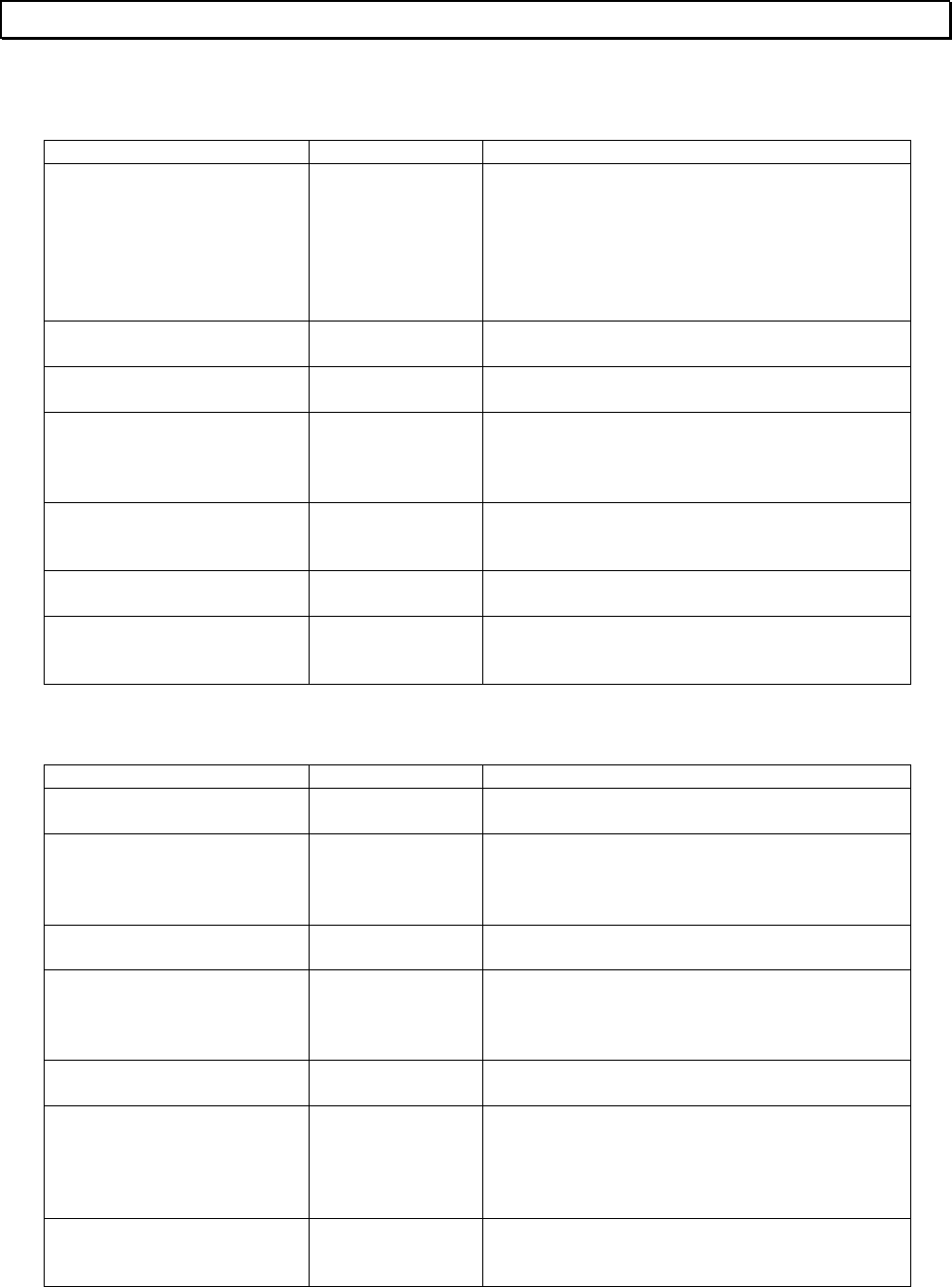
102 T-PDS32 for Windows V2.2
Error Message
R...
Message Type of Error Description
RAM check error Event history Read/write error was detected in the user data
memory (RAM).
Info 1: Error address
Info 2: Error data
Info 3: Test data
Turn off power and on again.
Range error Operation error The range specified is not correct.
Range over Operation error The value set is out of the range specified.
Reg No./size error Operation error The required register is out of the allowable
range.
Register type - bit position, register address
Register/Device No. is
Illegal Operation error The register/device specified for latch condition
is illegal.
Reverse signal flow Compile error Power flow from right to left is not allowed.
RUN mode - cannot execute Operation error The operation cannot be executed because the
PLC is RUN.
S...
Message Type of Error Description
Same target name entry Operation error The target name is duplicated.
Sampling buffer Allocation
error Operation error Sampling buffer could not be allocated
correctly.
Sampling status is Disable Operation error Sampling trace is disabled.
Scan time over Event history Scan time exceeded the time specified.
Info 1: Scan time
Reduce the scan time or use WDT instruction.
Set Data is Illegal Operation error The data set for latch condition is illegal.
SFC jump label err Event history The SFC label is duplicated.
Info 1: Program type - block No.
Info 2: SFC label No.
Check the program.
SFC Jump/Label connection
error Compile error In the SFC program, combination of SFC Jump
and Label is not correct.
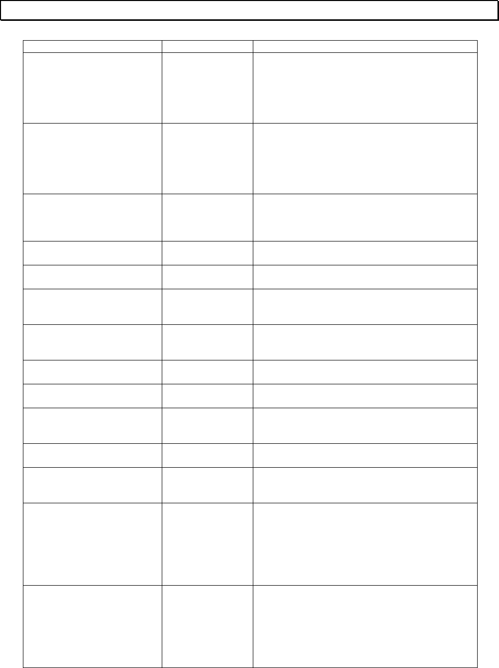
Basic Operation 103
Error Message
Message Type of Error Description
SFC macro No. err Event history Macro No. is duplicated, or the same macro No.
is called from two or more locations.
Info 1: Program type - block No.
Info 2: Macro No.
Check the program.
SFC step No. err Event history Step No. is duplicated, or step No. is not
matched between Initial and End steps.
Info 1: Program type - block No.
Info 2: Step No.
Check the program.
Short circuit Compile error In the SFC program, no step or transition is
programmed between divergence and
convergence.
Size error Operation error The value set is out of the range specified.
SLATCH.EXE running Operation error The status latch function has already activated.
SMPTRACE.EXE running Operation error The sampling trace function has already
activated.
Specified file has already be
used as user comment file Operation error The file specified is currently used as comment
file.
Specified name not
registered Operation error The name (tag) is not registered.
Specified tag not registered Operation error The tag specified has not been registered.
Step connection error Compile error In the SFC program, step connection is not
correct.
Step no. error Operation error The step number is not correct.
Steps connected Compile error In the SFC program, no transition is
programmed between steps.
Sub-r nesting err Event history The nesting level of subroutines exceeds the
limit specified.
Info 1: Program type - block No.
Info 2: Offset address in the block
Info 3: Subroutine No.
Check the program.
Sys RAM check err Event history Read/write error was detected in the system
memory (RAM).
Info 1: Error address
Info 2: Error data
Info 3: Test data
Turn off power and on again.
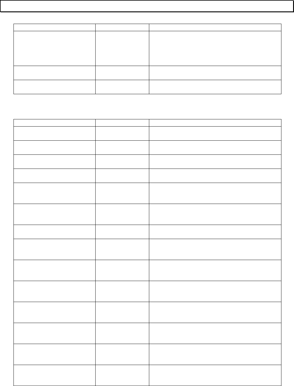
104 T-PDS32 for Windows V2.2
Error Message
Message Type of Error Description
Sys ROM BCC error Event history BCC error was detected in the system memory
(ROM).
Info 1: Illegal BCC data
Turn off power and on again.
System power off Event history PLC power is turned off. (no error)
System power on Event history PLC power is turned on. (no error)
T...
Message Type of Error Description
Tag character size error Operation error Tag character size exceeds the limit.
Tag not registered Operation error The tag specified has not been registered.
Target name no entry Operation error The target name for Ethernet is not entered.
Target not found Operation error The search target was not found.
The rung that contains more
than 132 steps detected Operation error The rung contains excess program steps. The
maximum size of a rung is 132 steps.
This file is not T-PDS project
file Operation error The file specified is not a T-PDS project file.
Timeout offset no entry Operation error The time-out offset for Ethernet is not entered.
Top Register Limit over Operation error The unit base address specified is out of the
allowable range.
Top register/device is out of
range Operation error The register/device address specified is out of
the allowable range.
Top rung of block cannot
divide Operation error The top rung of the block cannot be specified
for the block divide operation.
Top rung of block cannot
specified Operation error The top rung of the block cannot be specified
for the block divide operation.
Total program steps of this
block exceeds the limit Compile error Number of steps in the SFC block exceeds
1021 steps.
Transition connection error Compile error In the SFC program, transition connection is not
correct.
Transitions connected Compile error In the SFC program, no step is programmed
between transitions.
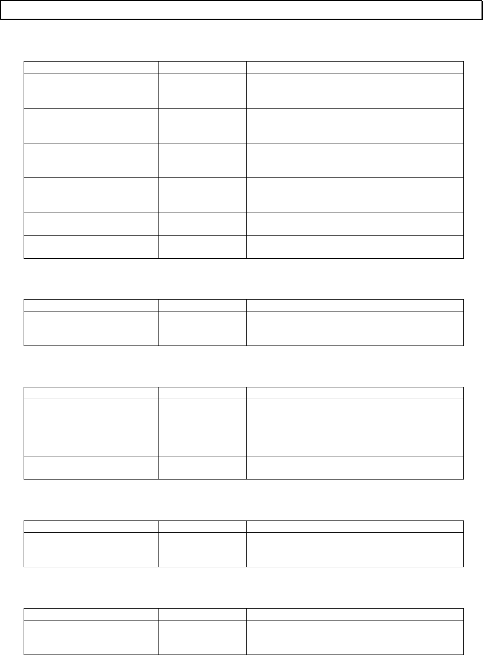
Basic Operation 105
Error Message
U...
Message Type of Error Description
Unable to allocate ∗∗∗
memory Operation error ∗∗∗ could not be allocated to the memory.
Unable to Execute for
BLOCKEDI.EXE Operation error The edit block function could not be started.
Unable to execute for
SLATCH.EXE Operation error The status latch function could not be started.
Unable to execute for
SMPTRACE.EXE Operation error The sampling trace function could not be
started.
Unable to get file
information Operation error The file information could not be read.
Unavailable in this block Compile error The instruction is not allowed in this block.
V...
Message Type of Error Description
Vertical connection
impossible Operation error Vertical connection cannot be entered on the
specified position.
W...
Message Type of Error Description
WD timer error Event history Watchdog timer error occurred.
Info 1: Address 1
Info 2: Address 2
Check external noise environment.
Write protect error Operation error The drive specified is write protect state.
X...
Message Type of Error Description
XY Register Size Limit error Operation error The registers allocated to I/O types X, Y and
X+Y exceed the address limit.
Z...
Message Type of Error Description
Z Register Size Limit error Operation error The registers allocated to I/O type Z exceed the
address limit.

TOSHIBA CORPORATION
Industrial Equipment Department
1-1, Shibaura 1-chome, Minato-ku
Tokyo 105-8001, JAPAN
Tel: 03-3457-4900 Fax: 03-5444-9268
