VCMA 10 PT150 540S(2008 2009)
User Manual: VCMA-10
Open the PDF directly: View PDF ![]() .
.
Page Count: 13
Superdrive Pump
Model PT150-540S
Form OM0033
Rev. Date 11/09
PBZ LLC | 50 Wood Corner Rd | Lititz PA 17543
www.CropCareEquipment.com | (717) 738-7365
A Paul B Zimmerman Inc. Company
Owner's Manual
3
Table Of Contents
Specications ��������������������������������������������������������������������������������� 3
Before You Begin ������������������������������������������������������������������������� 4
Safety Precautions ����������������������������������������������������������������������� 4
General Guidelines ����������������������������������������������������������������� 4
Before Operation ������������������������������������������������������������������� 4
Pump Safety Precautions ������������������������������������������������������� 4
Operating Instructions �������������������������������������������������������������� 5
Mounting Procedure �������������������������������������������������������������� 5
Before/During Operation ����������������������������������������������������� 5
Maintenance Instructions ��������������������������������������������������������� 6
Pump Drive Maintenance ������������������������������������������������������ 6
CropCare® would like to thank you for choosing to purchase one of our Superdrive pumps� We appreciate your business and want
to fill all of your sprayer and equipment needs� We also desire to provide you with the technical support and needed parts that will
allow you to continue operating without disruption� For parts and service please contact your local CropCare® dealer�
Pump Maintenance ����������������������������������������������������������������� 6
Winterizing your Pump ��������������������������������������������������������� 7
Troubleshooting ��������������������������������������������������������������������������� 7
Pump Repair Instructions �������������������������������������������������������� 8
Breakdowns & Parts Lists �������������������������������������������������������� 9
Hypro 9203C Pump Breakdown & Parts List ������������������ 9
PT150-540S Breakdown ������������������������������������������������������10
PT150-540S Parts List ����������������������������������������������������������11
CropCare® Limited Warranty ��������������������������������������������12
Contact Us ������������������������������������������������������������������������������������13
Ordering Parts �����������������������������������������������������������������������13
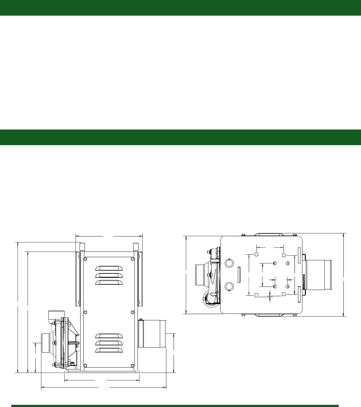
Specications
Dry weight ����������������������������������������������������������������������������������99 lbs
Max input speed ������������������������������������������������������������������600 RPM
Max pressure �������������������������������������������������������������������������� 125 PSI
Input shaft ������������������������������������������������������������������������1” diameter
Seal ����������������������������������������������������������������Viton / Silicon Carbide
Superdrive Pump
Model #: PT150-540S
17.00
17.50
9.35
4.19
5.50
10.00
18.34
10.00
3.00
1.625 10.72
3.50
5.25
5.00
.125

4
Safety Precautions
Before Operation
• Carefully study and understand this owner’s manual�
• Give the Superdrive pump a visual inspection for any
worn parts, loose bolts, or other visible problems, and
make any needed repairs� See the maintenance section
(page 6)�
Pump Safety Precautions
• Never pump ammable or explosive uids such as
gasoline, fuel oil, kerosene, etc�
• Useonlypipe,hose,andttingsratedforthemaximum
psi rating of the pump�
• Never pump faster than, or above, the maximum
recommended speed and pressure�
• Never pump liquids at temperatures higher than the
recommended maximum temperature (140° F / 60° C)
Do not exceed this temperature�
• Before servicing your pump, disconnect the power,
release all pressure, and drain all liquids�
• Do not run pump dry for any amount of time�
• Be sure all exposed moving parts, such as the PTO
shafts and adapters, are properly shielded or guarded
and that all coupling devices are securely attached
before applying power�
Every year many unnecessary accidents occur due to improper equipment handling and a disregard for safety precautions� You, the
operator, can avoid accidents by observing the precautions in this section�
• The operator should be a responsible adult� Do not
allow persons to operate this pump until they have
displayed a thorough understanding of the safety
precautions and operational use!
• Never attempt to operate this pump while under the
inuenceofalcoholordrugs.
General Guidelines
• The best defense against accidents is a careful and
responsible operator�
• If there is any portion of this manual that you do not fully
understand, please contact an authorized CropCare®
dealer�
• Be aware of all safety guidelines, warnings, and cautions.
• Familiarize yourself and other operators with the picking assistant’s components and how all parts are operated.
Before You Begin
Please read and understand this manual and its instructions and warnings completely before operating
the picking assistant.
5
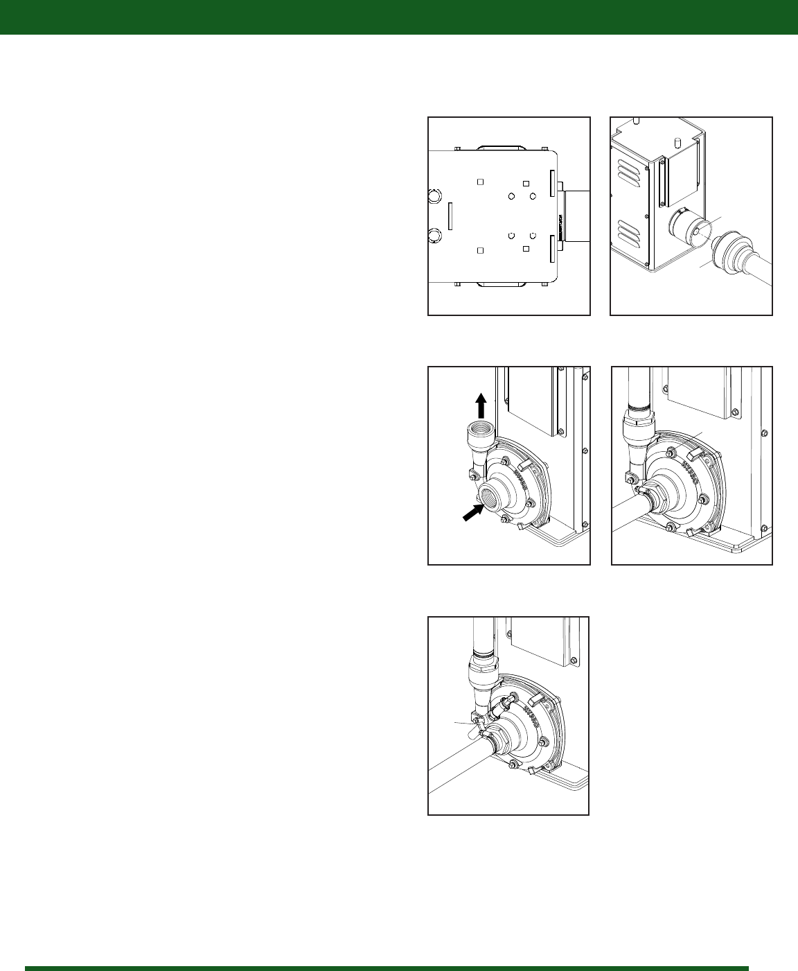
Operating Instructions
Mounting Procedure
a
Figure 2: Attaching the PTO
1� Mount the Superdrive pump on the sprayer using 3/8”
bolts and lock washers through either the four square
holes, or the four round holes on the bottom of the pump
drive housing (Figure 1)�
2� Attach the PTO shaft (a) to the pump drive shaft (b) as
shown (Figure 2)�
3� Connect the inlet and outlet plumbing as shown (Figure 3)�
b
Figure 1: Mounting holes
Inlet
Outlet
Figure 3: Pump plumbing
1� If the sprayer was completely empty before use, there
willbeairtrappedinthelineswhenthetankislled.The
pump will need to be primed to release this trapped air�
2� If your pump is not equipped with a bleeder valve, remove
the topmost plug (a) (Figure 4) from the face of the pump
with the tractor off�
3� With the plug removed, open the inlet suction valve until
there is a steady ow of liquid out of the bleeder plug
hole, indicating that there is no more air in the system�
4� Replace the bleeder plug before engaging pump�
5� If your pump is equipped with a bleeder valve (a), open
thevalvewiththetractoroffuntilthereisasteadyow
of liquid out of the hose, indicating that there is no more
air in the system (Figure 5)�
6� If liquid does not come out with the tractor off, start the
tractor, open all valves, and engage the PTO� This will
force the rest of the air out�
7� Important: Engage the PTO clutch slowly and smoothly�
Avoid sudden starts and fast clutching that can damage
the drive section of the pump�
Figure 4: Pump priming with plug
a
Before/During Operation
a
Figure 5: Pump priming with bleeder valve
6
1� Flush the pump out with fresh water after every use� It
is also very important to winterize your pump to prevent
freezing and corrosion� Please see the Winterizing your
Pump section for winterizing instructions�
2� Refer to the Pump Repair section (page 8) for service
recommendations, or contact your local CropCare®
dealer�
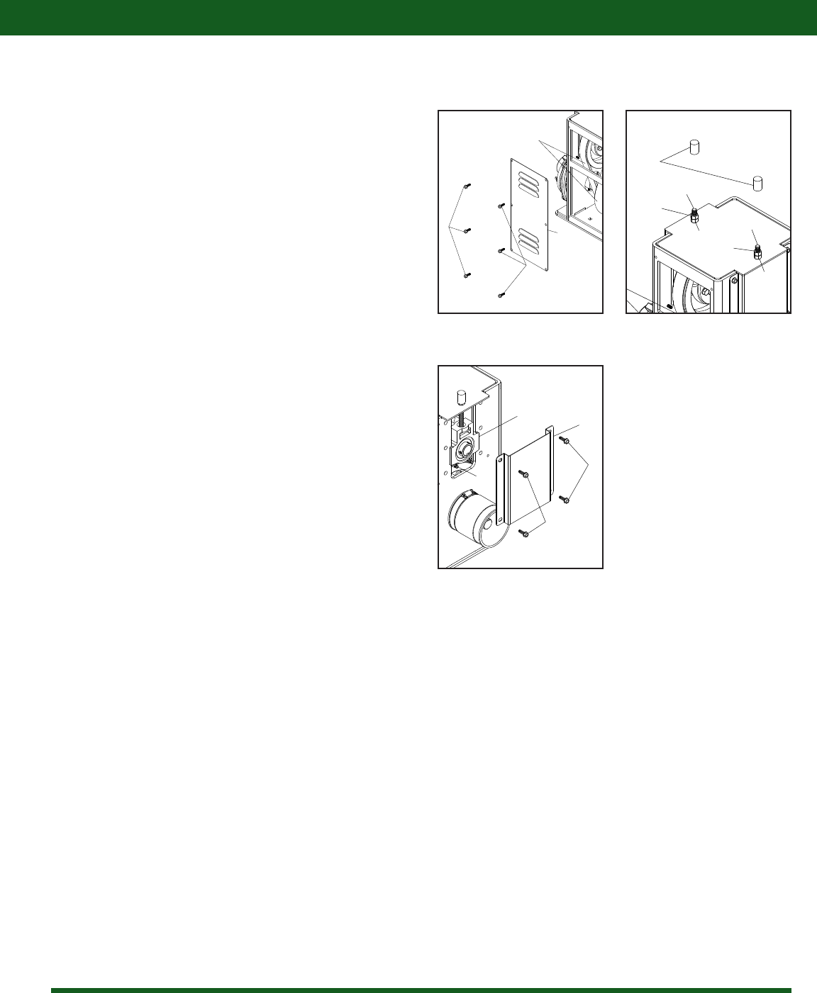
Pump Maintenance
Maintenance Instructions
Pump Drive Maintenance
1� Follow all pump safety precautions and warnings (page 4)�
Following these guidelines will help to ensure many years
of smooth and trouble-free service�
2� Be sure that the belts (a) are properly tensioned before
use� Remove the side cover (b) by loosening the six 1/4”
x 3/4” screws (c) that attach it to the main frame, and
check the belt tension (Figure 6)�
3� Thepropertensionshouldbe:.120”ofdeectionwith
13�6 lbs of applied force (4 groove belt), and �120” of
deectionwith10.2lbsofappliedforce(3groovebelt).
4� To adjust the tension, remove the nylon bolt caps (d) that
cover the adjustment bolts (e)� Loosen the top nut (f)
rst,thenadjustthetensionbyturningthebottomnut
(g)� Re-tighten the top nut when the belts are properly
tensioned and replace the nylon bolt caps� Replace the
sidecoverwhennished(Figure7).
5� Note: It is extremely important to keep the top shaft
parallel with the pump input shaft� Misalignment will
greatly reduce belt life�
6� There are 2 take-up bearings (a) on the Superdrive pump
thatmustbegreased.Togreasethebearings,rstremove
the take-up bearing cover (b) by removing the four 1/4” x
3/4” screws (c) that attach it to the main frame� Grease
the bearings using the grease tting (d) on the bottom
ofthebearing.Replacethebearingcoverwhennished
(Figure 8)�
7� The recommended greasing interval for the take up
bearings is every 50 hours of operation, or once a year�
Figure 6: Checking belt tension
c
c
a
b
Figure 8: Greasing the Bearings
c
a
d
b
g
f
d
g
f
e
e
Figure 7: Tensioning the belts
c

7
Winterizing your Pump
It is essential that you winterize your Superdrive Pump to avoid damage and to allow for optimal performance� The winterization
process should be undertaken before freezing conditions and/or after each season of use� Failure to winterize your pump will
void the manufacturer’s warranty.
1� Verify that the sprayer tank is empty and rinsed out� Pour some RV nontoxic antifreeze into the tank� It is not recommended to
use engine antifreeze� Engine antifreeze can be harmful to humans, animals, crops, and the environment�
2� Engage the pump and make sure that the antifreeze has been pumped through the entire system�
3� Store the sprayer and pump in a safe, dry location away from the elements and human and animal activity�
4� Beforeuseinthespring,itisrecommendedtoushthepumpwithfreshwatertocleanseitoftheantifreezeandanyother
buildup� Also do a thorough inspection of the pump before use�
Maintenance Instructions
Troubleshooting
If you are having problems with you Superdrive Pump, please attempt to use this troubleshooting section to solve the problem� If you
are unable to fix the problem please contact an authorized CropCare® dealer for service�
Problems/Symptoms Possible Causes Solutions
Low Pressure
or
Low discharge
Pump not primed Remove topmost vent plug from face of pump and run pump to
expel trapped air� Recommend vent line or bleeder valve be used
Air leaks in suction line Check and reseal the suction hoses and fittings
Blocked or clogged line strainer or impeller Inspect strainer and impeller to clear any debris or obstruction
Undersized suction line or collapsed hose Suction line must be the same or larger diameter as pump inlet port
Broken Impeller Inspect for cracks and replace if damaged or broken
Pump not operating at 540 RPM Run tractor at PTO speed (540 RPM)
Belts not properly tensioned Tension belts (see page 6)
Liquid leaking out weep port Worn seal Replace seal
Rubber smell / Hot belts Belts not properly tensioned Tension belts (see page 6)

8
Pump Repair Instructions
1� Remove the four casing cap screws with 9/16" box end
wrench� Tap pump casing on discharge port with rubber
hammer, if necessary, to break loose from mounting
ange. Check inside of pump casing including suction
port� If badly eroded (or damaged), pump casing should
be replaced� Remove o-ring and discard� O-ring should
always be replaced�
2� Toremovetheimpellernut,clamptheangeinaviseand
insertalargescrewdriverorle(atleast10"long)into
impeller vanes to prevent impeller from turning when
loosening nut� Use a 5/8” socket wrench to remove the
impeller nut by turning it counterclockwise�
3� Once the nut is removed, place a screwdriver on each
side behind the impeller and pry away from the mounting
ange.Removeo-ringfromthemountingange.
Pump Housing Disassembly
In most cases, seal replacement requires disassembly of only
the pump half of the unit�
Pump Seal Removal
1� Lightly lubricate shaft for easier removal of seal� Using
two screwdrivers positioned opposite each other, pry the
rotary portion of the seal from the shaft�
2� Remove stationary seat and boot by prying out with two
small screwdrivers in manner similar to impeller removal�
(Caution: The seal will be damaged by removal in this
manner� A new seal and rubber gasket MUST be used
when pump is reassembled�)
Pump Shaft and Bearing Assembly Removal
and Replacement
1� While the pump is disassembled (see the Pump Housing
Disassembly section), the driven pulley on the pump shaft
must be removed� Remove the large retainer ring in pump
bearing bore on the pulley side of housing� Press out the
shaft and bearing assembly from the pump side using an
arbor press�
2� Bearings must be pressed off each end of shaft and
replaced in the same manner� NOTE: Shaft diameter
between bearings is larger�
3� For reassembly, reverse the order of instructions�
Seal Replacement & Pump Housing Reassembly
NOTE: Reassemble if drive end is not to be repaired�
Be extremely careful with the new seal� Take special care not
to scratch the lapped sealing faces of the rotary washer and
stationary seat�
1� LubricatesealcavityinmountingangewithWD-40,LPS
or equivalent�
2� Install the stationary portion of the mechanical seal by
sliding over the shaft with the ceramic side out�
IMPORTANT: Make sure the seal cavity is clean and
lubricated� Never run the sealing faces dry�
3� To seat the seal in the seal cavity, use a piece of 3/4” PVC
pipe4”to6”inlength.Pressitinrmlyandsquarely.
4� To install the rotary portion of the mechanical seal, place
it over the shaft with the carbon side facing in, and press
until it bottoms out against the stationary portion�
5� Insert key into shaft key slot� Place impeller on shaft� Put
[washer, jam nut and gasket] impeller nut on shaft end,
andusingalargescrewdriverorleintheimpellervanes
for support, tighten impeller nut securely�
6� Installo-ringonmountingange.Replaceo-ringifworn
or damaged�
7� Placepumpcasingonmountingange,insertandtighten
bolts evenly�
Cleanup Of Pump Housing
1� Using the circular bottle-type wire brush with air or hand
drill, clean the discharge port, suction port and the sealing
areas of the O-ring on the pump casing and mounting
ange.
2� After wire brush cleaning, it is recommended that the
pumpcasingandmountingangebefurthercleanedina
solvent tank to remove rust and corrosion particles�
9
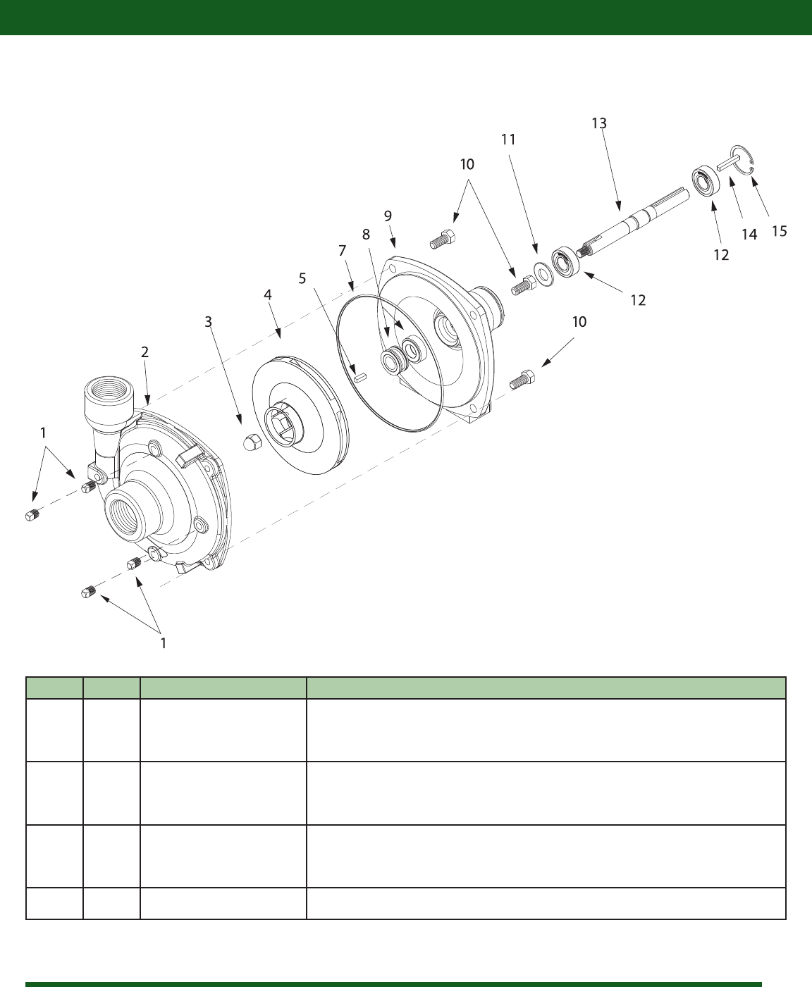
Ref # Qty. Part Number Description
1 4 2406-0007 Drain plug (cast series)
2 1 0150-9000C Pump casing (cast series)
3 1 2253-0002 Impeller nut (cast series)
4 1 0401-9100P Impeller (model 9203C) (nylon)
5 1 1610-0015 Key (cast series)
7 1 1720-0083 O-ring
8 1 3430-0589 Mechanical seal kit (silicon carbide)
9 1 0750-9200C3 Mounting flange (cast series)
10 4 2210-0020 Bolt (cast series)
11 1 1410-0056 Slinger ring
12 2 2000-0010 Ball bearing
13 1 0505-9200 Pump shaft
14 1 1610-0004 Key
15 1 1820-0013 Bearing retainer
Breakdowns & Parts Lists
Hypro 9203C Pump Breakdown & Parts List
Seal repair kit: 3430-0589 - consists of: (1) ref # 7 O-ring, (1) ref # 8 Mechanical seal
10
Breakdowns & Parts Lists
28
20
20 28
20
20
25
30 33
24
39
11
34
37
5
19
12
2
16 32
18
36
14
6
33
11
39
24
29
27
38
26
38
10
10
8
17
31
31
4
13
18
32
36
9
22
35
3
15
23
3
35
1
21
26
38
19
12
7
34
37
38
27
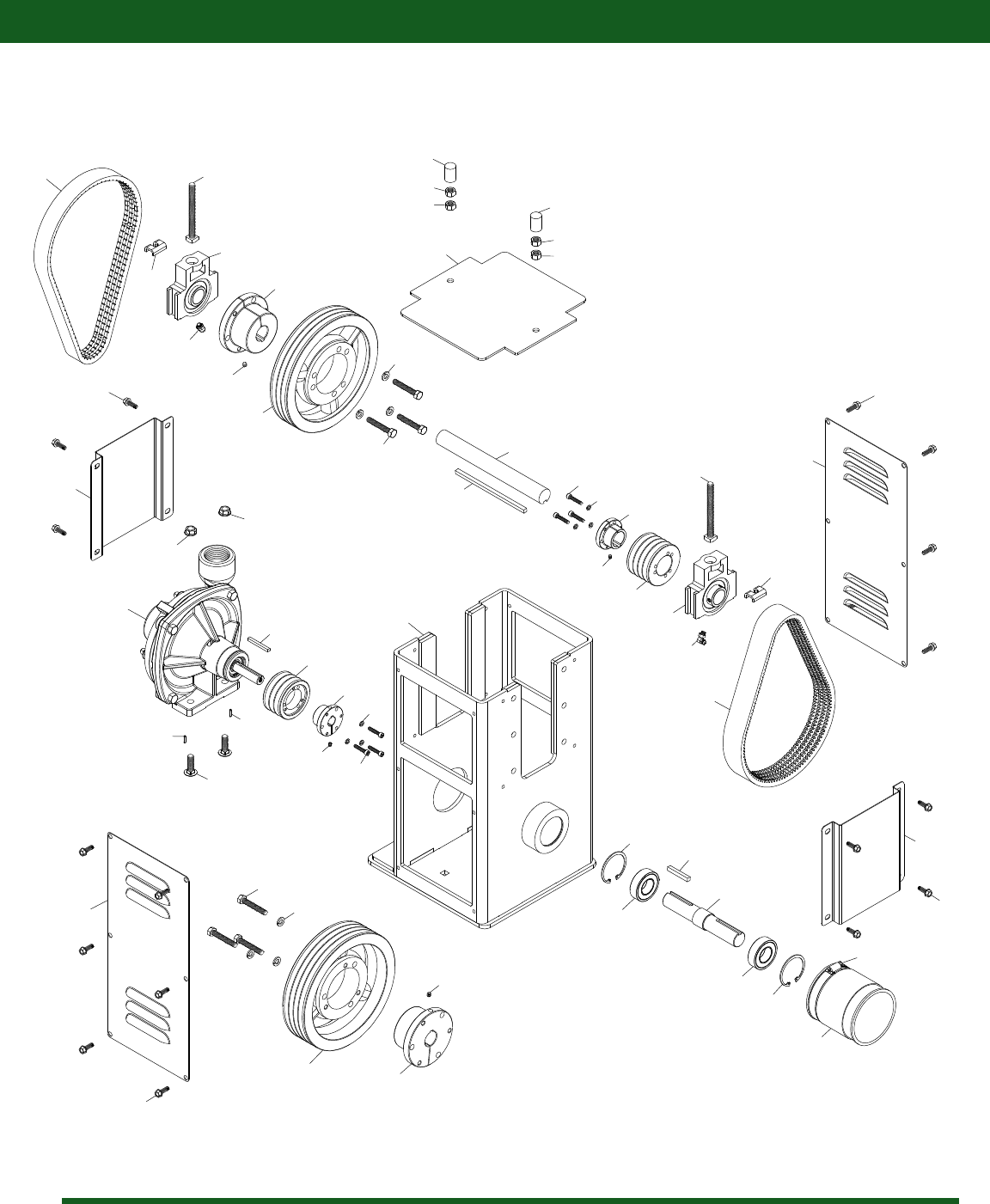
PT150-540S Breakdown

11
Breakdowns & Parts Lists
Ref # Qty. Part Number Description
1 1 6864 Stainless hose clamp, 2 1/2" - 4 1/2"
2 1 1441600 1" shaft, keyed 1/4", 9" lg�
3 2 16412RS Bearing, 1" ID, 2" OD, 9/16" wide
4 1 3-3V265JA 2�65" 3 groove sheave - JA bushing
5 1 3-3V800SK 8" 3 groove sheave - SK bushing
6 1 4-3V280JA 2�8" 4 groove sheave - JA bushing
7 1 4-3V800SK 8" 4 groove sheave - SK bushing
8 1 9203C Hypro pump (See page 9 for pump breakdown)
9 2 CB38*114G5 Carriage bolt, 3/8-16 x 1 1/4" grade 5
10 2 FN38 Flange nut, 3/8-16
11 2 GF103 Grease fitting, 1/4-28 90 degree
12 6 H5C516*2 Hex head bolt, 5/16-18 x 2" grade 5
13 1 JA10 JA bushing 5/8"
14 1 JA16 JA bushing 1"
15 1 KEY14X134 1/4" key stock 1 3/4" lg�
16 1 KEY14X6 1/4" key stock 6" lg�
17 1 KEY316X134 3/16" key stock 1 3/4" lg�
18 6 LW10 Lock washer, #10
19 6 LW516 Lock washer, 5/16"
20 4 NC38 Hex nut, 3/8-16
21 1 P105633 Flex coupling 3"
22 1 PT1500 Main Frame
23 1 PT1501 Input shaft
24 2 PT1503 Bolt clip
25 1 PT1504 Top cover
26 2 PT1505 Take-up bearing cover
27 2 PT1506 Side cover
28 2 PT1507 Vinyl bolt cap
29 1 R3VX315-4 Belt 31�5" 4 groove
30 1 R3VX335-3 Belt 33�5" 3 groove
31 2 RP18*12 Roll pin, 1/8" x 1/2"
32 6 SCC1024*1 Socket head cap screw, 10-24 x 1"
33 2 SHB38*4 Square head bolt, 3/8-16 x 4"
34 2 SK16 SK bushing 1"
35 2 SRI2 Internal snap ring, 2"
36 2 SSC1024*14 Allen set screw, 10-24 x 1/4"
37 2 SSC14*14 Allen set screw, 1/4-20 x 1/4"
38 20 TF14*34 Hex head self tapping screw, 1/4-20 x 3/4"
39 2 UCT205-16 Take-up bearing 1"
PT150-540S Parts List

12
CropCare® Limited Warranty
Warranty Coverage
Warranty Is Void if:
Getting Service
Superdrive Pump: Model PT150-540S
1� The pump has been subjected to, in the opinion of CropCare®, negligent handling, misuse, an accident or if the instructions in the
owner's manual were not completely followed�
2� The pump's components have been altered in any manner or repairs have taken place with unapproved parts�
3� The pump and its components were subject to freezing or freezing conditions� The pump must have been winterized as per the
maintenance instructions to retain the warranty�
4� A non-compatible chemical was used and/or if the pump operator failed to rinse all chemical residue out of the pump after use�
5� Apetroleum-based,oil-based,orammableproductwasusedandcauseddamagetothepump.
All Superdrive Pump warranty claims must be made through an authorized CropCare® dealer� All warranty claims must be submitted
with an invoice or a proof of purchase that denotes the purchase date and place of purchase� If you have any questions or comments
concerning this warranty, please contact an authorized CropCare® dealer�
CropCare® hereby provides a Limited One (1) Year Warranty on Superdrive Pumps, manufactured by CropCare®� Superdrive pumps
manufactured by CropCare®are warrantied against any manufacturer’s defects in any of the pump’s components in the 12 months
following the original date of purchase�
Defective components will be repaired or replaced at the discretion of the manufacturer� It is the responsibility of the purchaser to
return warranted components to the manufacturer� This warranty is limited to the repair or replacement of pump components only�
CropCare® is not to be held liable for incidental or consequential damages of any kind� This warranty covers the purchaser of this
pump and any other owners who own it during the one year warranty period�
To retain the warranty, the pump must be operated and maintained as ascribed by its owner’s manual� For warranty service, please
have a copy of the purchase invoice available�

13
Contact Us
We desire to give you continuing service in the best manner possible� This includes listening to your comments, suggestions, and
problems� We will do our best to answer all questions thoroughly and in a timely manner� Please feel free to contact our customer
service department�
Ordering Parts
A brand of PBZ LLC
A Brand of Paul B Zimmerman Inc� Company
50 Woodcorner Road
Lititz PA 17543
(717) 738-7365
Fax (717) 738-7369
www�CropCareEquipment�com
Please contact your authorized CropCare® dealer to order replacement�parts for your product�
