PTX_PRM_PCL_II_P8_257400A PTX PRM PCL II P8 257400A
PTX_PRM_PCL_II_P8_257400A PTX_PRM_PCL_II_P8_257400A
PTX_PRM_PCL_II_P8_257400A PTX_PRM_PCL_II_P8_257400A
PTX_PRM_PCL_II_P8_257400A PTX_PRM_PCL_II_P8_257400A
User Manual: PTX_PRM_PCL_II_P8_257400A
Open the PDF directly: View PDF ![]() .
.
Page Count: 304 [warning: Documents this large are best viewed by clicking the View PDF Link!]
- Trademark Acknowledgements
- A Standard ASCII Character Set 213
- B P-Series Emulation Character Sets 215
- C Proprinter Emulation Character Sets 267
- D Epson Emulation Character Sets 273
- E Contact Information 293
- 1 Introduction
- About this Guide
- Software Features
- 2 HP PCL-II
- Introduction
- Configuring the PCL-II Emulation with Control Codes
- Printer Feature Set Compatibility
- General Information
- Escape Sequences
- Bar Codes
- US Postnet Barcodes
- Character Density Selection
- Character Font Selection
- Character Overstrike
- Character Style Selection
- Cursor Positioning
- Display Functions Mode
- Horizontal Margin Selection
- Line Spacing
- Logical Page Length Selection
- Perforation Skip Mode
- Print Mode Selection
- Print Pitch Selection
- Printing in the Hex 80 through Hex FF Region
- PTX Linefeed
- Programmable Reset
- Programmable VFC
- Raster Graphics
- Self-test
- Standard (Computed) VFC
- Stroke Weight (Bold)
- Switching Character Fonts
- Text Length (Vertical Margin) Selection
- Transparent Print Data
- Underline Mode
- Vertical Forms Control (VFC)
- HP e3000 Information
- HP 1000 Information
- 3 P-Series Printer Emulation
- Overview
- Configuring the P-Series Emulation with Control Codes
- Format for Control Code Descriptions
- Switching Between the Emulations
- Special Function Control Code (SFCC) Header
- SFCC Command Line
- Attribute Set and Reset Codes
- NUL Code
- Print Modes Supported for Character Sets
- The Control Codes
- Backspace
- Bell
- Bold Print
- Bold Print Reset
- Carriage Return
- Character Set Select
- Character Set Select: ECMA Latin 1 Extended
- Character Set Select: International Languages
- Characters 80-9F (Control Codes)
- Characters 80-9F (Printable Symbols)
- Elongated (Double High) Print, One Line Only
- Elongated (Double High) Print, Set/Reset
- Emphasized Print
- Emphasized Print Reset
- Emulation Reset
- Expanded Print (Double Wide), One Line Only
- Expanded Print (Double Wide), Set/Reset
- Extended Character Set
- Extended Character Set Cancel (Primary Set Select)
- Form Feed
- Forms Length Set (Inches)
- Forms Length Set (Lines)
- Line Feed
- Line Spacing 1/6 Inch (6 lpi)
- Line Spacing 1/8 Inch (8 lpi)
- Line Spacing 8 or 10.3 lpi (1 Line Only)
- Line Spacing 7/72 Inch
- Line Spacing n/72 Inch
- Line Spacing n/216 Inch
- Overscoring
- Plot, Even Dot (P-Series High Density Graphics)
- Plot, Odd Dot (P-Series Normal Density Graphics)
- Print Mode/Pitch Selection
- Reverse
- Superscript/Subscript Printing
- Superscript/Subscript Printing Reset
- Underline
- VFU Commands
- Vertical Tab
- 4 IBM Proprinter III XL Emulation
- Overview
- Configuring the Proprinter III XL Emulation with Control Codes
- Format for Control Code Descriptions
- Escape Control Codes Overview
- Graphics Control Codes Overview
- Switching Between the Emulations
- The Control Codes
- Backspace
- Bell
- Bit Image Mode, Single Density (Normal Speed)
- Bit Image Mode, Double Density (Half Speed)
- Bit Image Mode, Double Density (Normal Speed)
- Bit Image Mode, Quadruple Density (Half Speed)
- Bold Printing
- Bold Printing, Cancel
- Cancel
- Carriage Return
- Carriage Return Set
- Character Pitch 12 cpi
- Character Set Select: Set 1 (A)
- Character Set Select: Set 2 (B)
- Condensed Print
- Condensed Print, Cancel
- Deselect Printer
- Double Wide Print
- Double Wide Print (One Line Only)
- Double Wide Print (One Line Only) Cancel
- Emphasized Print
- Emphasized Print, Cancel
- Form Feed
- Forms Length Set in Inches
- Forms Length Set in Lines
- Initialize Parameters
- Line Feed
- Line Feed n/216 Inch (One Line Only)
- Line Spacing 1/8 Inch (8 lpi)
- Line Spacing 7/72 Inch (10.3 lpi)
- Line Spacing n/72 Inch (Executes)
- Line Spacing n/72 Inch (Storage)
- Line Spacing n/216 Inch
- Margin, Bottom
- Margin Cancel, Bottom
- Margins, Horizontal
- Overscoring
- Print All Characters
- Print Next Character
- Print Mode
- Print Quality
- Proportional Spacing
- Select Attributes
- Set Top-of-Form
- Superscript/Subscript Printing
- Superscript/Subscript Printing, Cancel
- Tab, Horizontal
- Tab Set/Clear, Horizontal
- Tab, Vertical
- Tab Set/Clear, Vertical
- Tabs, Clear All (Return to default)
- Underline
- Unidirectional Printing
- 5 Epson FX-1050 Emulation
- Overview
- Configuring the Epson FX-1050 Emulation with Control Codes
- Format for Control Code Descriptions
- Escape Sequences
- Attribute Set and Reset Codes
- NUL Code
- Switching Between the Emulations
- The Control Codes
- Backspace
- Bell
- Cancel Line
- Carriage Return
- Character Pitch 10 CPI
- Character Pitch 12 CPI
- Character Pitch 15 CPI
- Character Set Select: International Languages
- Clear Bit 7 of Incoming Data Bytes to 0
- Condensed Print
- Condensed Print Reset
- Cut-Sheet / Paper Feed Control
- Define a Download Character
- Delete Character
- Double High Print, Set/Reset
- Double Strike
- Double Strike, Cancel
- Double Wide Print
- Double Wide Print (One Line)
- Double Wide Print (One Line), Cancel
- Emphasized Print
- Emphasized Print, Cancel
- Enable Printing Hex Codes 00-1F and 80-9F
- Form Feed
- Graphics, Standard Density
- Graphics, Double Density
- Graphics, Double Density Double Speed
- Graphics, Quadruple Density
- Half Speed Mode, On/Off
- Horizontal Tab Execute
- Horizontal Tab Set/Release
- Initialize Printer
- Italic Printing
- Italic Printing, Cancel
- Line Feed
- Line Feed n/216 Inch
- Line Spacing 1/6 Inch (6 lpi)
- Line Spacing 1/8 Inch (8 lpi)
- Line Spacing 7/72 Inch
- Line Spacing n/216 Inch
- Line Spacing n/72 Inch
- Make Hex 80-9F Control Codes
- Make Hex 80-9F Printable
- Master Print Select
- Paper Out Detection, Enable
- Paper Out Detection, Disable
- Pass Bit 7 from Host
- Printer Select
- Printer Deselect
- Reassign Graphics Mode
- Remove Downloaded Characters
- Select Graphics Mode
- Select Italic Character Set
- Select 9-Pin Graphics Mode
- Select Print Quality
- Select/Deselect Proportional Spacing
- Select Serif or Sans Serif Font
- Select User-Defined Font
- Select Vertical Tab Channel
- Set Absolute Horizontal Print Position in 1/60 Inch
- Set Bit 7 of Incoming Data Bytes to 1
- Set Form Length in Inches
- Set Form Length in Lines
- Set Intercharacter Spacing in 1/120 Inch
- Set Margin, Left
- Set Margin, Right
- Set Relative Horizontal Print Position in 1/120 Inch
- Set Vertical Tabs in Channels
- Skip Over Perforation
- Skip Over Perforation, Cancel
- Superscript and Subscript Printing
- Superscript and Subscript Printing, Cancel
- Underline
- Unidirectional Printing, 1 Line
- Unidirectional Printing, Set/Reset
- Vertical Tab, Execute
- Vertical Tab, Set/Clear
- 6 Graphics
- Overview
- Bit Image Graphics
- Plot Mode
- Combining Graphics and Text
- 7 Vertical Page Formatting
- Overview
- Planning a Vertical Page Format
- Proprinter and Epson Vertical Tab Table
- P-Series EVFU (Electronic Vertical Format Unit)
- A Standard ASCII Character Set
- B P-Series Emulation Character Sets
- Introduction
- IBM PC, Primary Subset: ASCII (USA)
- IBM PC, Primary Subset: French
- IBM PC, Primary Subset: German
- IBM PC, Primary Subset: English (UK)
- IBM PC, Primary Subset: Danish
- IBM PC, Primary Subset: Swedish
- IBM PC, Primary Subset: Italian
- IBM PC, Primary Subset: Spanish
- IBM PC, Primary Subset: Japanese
- IBM PC, Primary Subset: French Canadian
- IBM PC, Primary Subset: Latin American
- IBM PC, Primary Subset: Danish II
- IBM PC, Primary Subset: Spanish II
- IBM PC, Primary Subset: Latin American II
- IBM PC, Extended Subset: 0437 PC Character Set
- IBM PC, Extended Subset: 0850 PC Multilingual
- Multinational, ASCII (USA)
- Multinational, EBCDIC
- ECMA Latin 1, Primary Subset: ASCII (USA)
- ECMA Latin 1, Primary Subset: German
- ECMA Latin 1, Primary Subset: Swedish
- ECMA Latin 1, Primary Subset: Danish
- ECMA Latin 1, Primary Subset: Norwegian
- ECMA Latin 1, Primary Subset: Finnish
- ECMA Latin 1, Primary Subset: English (UK)
- ECMA Latin 1, Primary Subset: Dutch
- ECMA Latin 1, Primary Subset: French
- ECMA Latin 1, Primary Subset: Spanish
- ECMA Latin 1, Primary Subset: Italian
- ECMA Latin 1, Primary Subset: Turkish
- ECMA Latin 1, Primary Subset: Japanese
- ECMA Latin 1, Extended Subset: Multinational
- ECMA Latin 1, Extended Subset: Barcode 10 cpi
- ECMA Latin 1, Extended Subset: Greek
- ECMA Latin 1, Extended Subset: Graphic
- ECMA Latin 1, Extended Subset: Scientific 10 cpi
- DEC Multinational, ASCII (USA)
- DEC Multinational, French
- DEC Multinational, German
- DEC Multinational, English (UK)
- DEC Multinational, Norwegian/Danish
- DEC Multinational, Swedish
- DEC Multinational, Italian
- DEC Multinational, Spanish
- DEC Multinational, Japanese
- DEC Multinational, French Canadian
- DEC Multinational, Dutch
- DEC Multinational, Finnish
- DEC Multinational, Swiss
- OCR A
- OCR B
- C Proprinter Emulation Character Sets
- Introduction
- 0437 PC Character Set
- 0850 PC Multilingual
- OCR A
- OCR B
- D Epson Emulation Character Sets
- Introduction
- 0437 PC Character Set
- 0850 PC Multilingual
- Epson Set, ASCII (USA)
- Epson Set, French
- Epson Set, German
- Epson Set, English (UK)
- Epson Set, Danish I
- Epson Set, Swedish
- Epson Set, Italian
- Epson Set, Spanish I
- Epson Set, Japanese
- Epson Set, Norwegian
- Epson Set, Danish II
- Epson Set, Spanish II
- Epson Set, Latin American I
- Epson Set, French Canadian
- Epson Set, Latin American II
- OCR A
- OCR B
- E Contact Information
- Printronix Customer Support Center
- Printronix Supplies Department
- Corporate Offices

Line Matrix Printers
PCL
®
-II/LinePrinter Plus
®
Programmer’s Reference Manual

Line Matrix Printers
PCL
®
-II/LinePrinter Plus
®
Programmer’s Reference Manual
Printronix, Inc. makes no representations or warranties of any kind regarding
this material, including, but not limited to, implied warranties of
merchantability and fitness for a particular purpose. Printronix, Inc. shall not
be held responsible for errors contained herein or any omissions from this
material or for any damages, whether direct, indirect, incidental or
consequential, in connection with the furnishing, distribution, performance or
use of this material. The information in this manual is subject to change
without notice.
This document contains proprietary information protected by copyright. No
part of this document may be reproduced, copied, translated or incorporated
in any other material in any form or by any means, whether manual, graphic,
electronic, mechanical or otherwise, without the prior written consent of
Printronix, Inc.
COPYRIGHT 2001, 2012, PRINTRONIX, INC.
All rights reserved.

Trademark Acknowledgements
IBM and Proprinter are registered trademarks, and PC-DOS is a trademark of
International Business Machines Corporation.
Centronics is a registered trademark of Genicom Corporation.
ENERGY STAR is a registered trademark of the United States
Environmental Protection Agency. As an ENERGY STAR® Partner,
Printronix has determined that this product meets the ENERGY STAR®
guidelines for energy efficiency.
Epson is a registered trademark of Seiko Epson Corporation.
Hewlett-Packard, HP and PCL are registered trademarks, and LineJet is a
trademark of Hewlett-Packard Company.
IGP, PGL, LinePrinter Plus, and Printronix are registered trademarks of
Printronix, Inc.
Magnum and QMS are registered trademarks, and Code V is a trademark of
Quality Micro Systems, Inc.
Microsoft, MS, Windows and MS-DOS are registered trademarks of Microsoft
Corporation.
PKUNZIP is a registered trademark of PKWARE, Inc.
Postnet is a registered trademark of the United States Postal Service.
This product uses Intellifont Scalable typefaces and Intellifont technology.
Intellifont is a registered trademark of Agfa Division, Miles Incorporated
(Agfa).
CG, Garth Graphic, Intellifont, and Type Director are registered trademarks,
and Shannon and CG Triumvirate are trademarks of Agfa Division, Miles
Incorporated (Agfa). CG Bodoni, CG Century Schoolbook, CG Goudy Old
Style, CG Melliza, Microstyle, CG Omega, and CG Palacio are products of
Agfa Corporation. CG Times, based on Times New Roman under license
from The Monotype Corporation Plc is a product of Agfa.
Univers is a registered trademark of Linotype AG and/or its subsidiaries.
Letraset is a registered trademark, and Aachen, Revue and University Roman
are trademarks of Esselte Pendaflex Corporation.
Futura is a registered trademark of Fundición Tipográfica Neufville, S.A.
ITC Avant Garde Gothic, ITC Benguiat, ITC Bookman, ITC Century, ITC
Cheltenham, ITC Clearface, ITC Galliard, ITC Korinna, ITC Lubalin Graph,
ITC Souvenir, ITC Tiepolo, ITC Zapf Chancery, and ITC Zapf Dingbats are
registered trademarks of International Typeface Corporation.
Albertus, Gill Sans, and Times New Roman are registered trademarks, and
Monotype Baskerville is a trademark of The Monotype Corporation Plc,
registered in the U.S. Pat. and TM office and elsewhere.
Hiroshige and Marigold are trademarks of AlphaOmega Typography, Inc.

Table of Contents
1 Introduction......................................................... 17
About this Guide .................................................................................. 17
Warnings and Special Information ................................................ 17
Related Product Information ......................................................... 18
Software Features ............................................................................... 19
PCL-II ............................................................................................ 19
P-Series ........................................................................................ 19
Proprinter III XL ............................................................................. 20
Epson FX-1050 ............................................................................. 20
2 HP PCL-II ........................................................... 21
Introduction.......................................................................................... 21
HP PCL-II Emulation Default Settings........................................... 22
Switching between the Emulations................................................ 23
Configuring the PCL-II Emulation with Control Codes......................... 23
Printer Feature Set Compatibility .................................................. 23
General Information ...................................................................... 24
Escape Sequences ....................................................................... 25
Bar Codes ..................................................................................... 28
US Postnet Barcodes.................................................................... 38
Character Density Selection.......................................................... 42
Character Font Selection .............................................................. 45
Character Overstrike ..................................................................... 47
Character Style Selection.............................................................. 47
Cursor Positioning......................................................................... 49
Display Functions Mode................................................................ 49
Horizontal Margin Selection .......................................................... 50
Line Spacing ................................................................................. 50
Logical Page Length Selection...................................................... 51
Perforation Skip Mode................................................................... 52
Print Mode Selection ..................................................................... 52
Print Pitch Selection ...................................................................... 53
Printing in the Hex 80 through Hex FF Region.............................. 53
PTX Linefeed ................................................................................ 53
Programmable Reset .................................................................... 54
Programmable VFC....................................................................... 55

Table of Contents
Raster Graphics ............................................................................ 63
Self-test ......................................................................................... 65
Standard (Computed) VFC ........................................................... 65
Stroke Weight (Bold) ..................................................................... 65
Switching Character Fonts ............................................................ 65
Text Length (Vertical Margin) Selection ........................................ 66
Transparent Print Data.................................................................. 66
Underline Mode............................................................................. 66
Vertical Forms Control (VFC)........................................................ 67
HP e3000 Information.......................................................................... 68
Feature Access and Transparent Modes ...................................... 68
VFC Download with a Serial Interface .......................................... 68
Carriage-Control Directives........................................................... 69
Graphics........................................................................................ 69
Printing in the Perforation Skip Region ......................................... 69
HP 1000 Information............................................................................ 70
Downloading VFC ......................................................................... 70
Perforation Skip Mode................................................................... 70
3 P-Series Printer Emulation ................................. 71
Overview.............................................................................................. 71
P-Series Default Values and States.............................................. 72
Configuring the P-Series Emulation with Control Codes ..................... 74
Format for Control Code Descriptions........................................... 74
Switching Between the Emulations ............................................... 74
Special Function Control Code (SFCC) Header ........................... 75
SFCC Command Line ................................................................... 75
Attribute Set and Reset Codes...................................................... 76
NUL Code ..................................................................................... 76
Print Modes Supported for Character Sets ................................... 76
The Control Codes ........................................................................ 77
Backspace..................................................................................... 79
Bell ................................................................................................ 79
Bold Print....................................................................................... 80
Bold Print Reset ............................................................................ 80
Carriage Return............................................................................. 81
Character Set Select ..................................................................... 82
Character Set Select: ECMA Latin 1 Extended............................. 84
Character Set Select: International Languages ............................ 85
Characters 80-9F (Control Codes)................................................ 86
Characters 80-9F (Printable Symbols).......................................... 86
Elongated (Double High) Print, One Line Only ............................. 87

Table of Contents
Elongated (Double High) Print, Set/Reset..................................... 88
Emphasized Print .......................................................................... 88
Emphasized Print Reset................................................................ 89
Emulation Reset............................................................................ 89
Expanded Print (Double Wide), One Line Only............................. 90
Expanded Print (Double Wide), Set/Reset.................................... 90
Extended Character Set................................................................ 91
Extended Character Set Cancel (Primary Set Select)................... 91
Form Feed..................................................................................... 92
Forms Length Set (Inches)............................................................ 92
Forms Length Set (Lines).............................................................. 93
Line Feed ...................................................................................... 93
Line Spacing 1/6 Inch (6 lpi).......................................................... 94
Line Spacing 1/8 Inch (8 lpi).......................................................... 94
Line Spacing 8 or 10.3 lpi (1 Line Only) ........................................ 95
Line Spacing 7/72 Inch.................................................................. 95
Line Spacing n/72 Inch.................................................................. 96
Line Spacing n/216 Inch................................................................ 97
Overscoring................................................................................... 97
Plot, Even Dot (P-Series High Density Graphics) ......................... 98
Plot, Odd Dot (P-Series Normal Density Graphics)....................... 98
Print Mode/Pitch Selection ............................................................ 99
Reverse....................................................................................... 102
Superscript/Subscript Printing..................................................... 103
Superscript/Subscript Printing Reset........................................... 103
Underline..................................................................................... 104
VFU Commands.......................................................................... 104
Vertical Tab ................................................................................. 104
4 IBM Proprinter III XL Emulation ........................ 105
Overview............................................................................................ 105
Proprinter III XL Emulation Default Settings................................ 106
Configuring the Proprinter III XL Emulation with Control Codes........ 108
Format for Control Code Descriptions......................................... 108
Escape Control Codes Overview ................................................ 108
Graphics Control Codes Overview.............................................. 109
Switching Between the Emulations ............................................. 111
The Control Codes ...................................................................... 112
Backspace................................................................................... 114
Bell .............................................................................................. 114
Bit Image Mode, Single Density (Normal Speed)........................ 115
Bit Image Mode, Double Density (Half Speed)............................ 116

Table of Contents
Bit Image Mode, Double Density (Normal Speed) ...................... 117
Bit Image Mode, Quadruple Density (Half Speed) ...................... 118
Bold Printing................................................................................ 119
Bold Printing, Cancel................................................................... 119
Cancel ......................................................................................... 120
Carriage Return........................................................................... 120
Carriage Return Set .................................................................... 121
Character Pitch 12 cpi................................................................. 121
Character Set Select: Set 1 (A)................................................... 121
Character Set Select: Set 2 (B)................................................... 121
Condensed Print ......................................................................... 122
Condensed Print, Cancel ............................................................ 122
Deselect Printer........................................................................... 123
Double Wide Print ....................................................................... 123
Double Wide Print (One Line Only)............................................. 124
Double Wide Print (One Line Only) Cancel................................. 124
Emphasized Print ........................................................................ 125
Emphasized Print, Cancel........................................................... 125
Form Feed................................................................................... 126
Forms Length Set in Inches ........................................................ 126
Forms Length Set in Lines .......................................................... 127
Initialize Parameters.................................................................... 128
Line Feed .................................................................................... 130
Line Feed n/216 Inch (One Line Only) ........................................ 131
Line Spacing 1/8 Inch (8 lpi)........................................................ 132
Line Spacing 7/72 Inch (10.3 lpi)................................................. 132
Line Spacing n/72 Inch (Executes) ............................................. 133
Line Spacing n/72 Inch (Storage)................................................ 134
Line Spacing n/216 Inch.............................................................. 135
Margin, Bottom............................................................................ 136
Margin Cancel, Bottom................................................................ 136
Margins, Horizontal ..................................................................... 136
Overscoring................................................................................. 137
Print All Characters ..................................................................... 137
Print Next Character.................................................................... 138
Print Mode................................................................................... 138
Print Quality................................................................................. 139
Proportional Spacing................................................................... 139
Select Attributes .......................................................................... 140
Set Top-of-Form.......................................................................... 141
Superscript/Subscript Printing..................................................... 141
Superscript/Subscript Printing, Cancel........................................ 142

Table of Contents
Tab, Horizontal............................................................................ 142
Tab Set/Clear, Horizontal............................................................ 142
Tab, Vertical ................................................................................ 143
Tab Set/Clear, Vertical ................................................................ 144
Tabs, Clear All (Return to default)............................................... 144
Underline..................................................................................... 145
Unidirectional Printing ................................................................. 145
5 Epson FX-1050 Emulation................................ 147
Overview............................................................................................ 147
Epson FX-1050 Default Values and States................................. 148
Epson Emulation Exceptions and Differences ............................ 150
Epson Character Sets ................................................................. 151
Configuring the Epson FX-1050 Emulation with Control Codes ........ 152
Format for Control Code Descriptions......................................... 152
Escape Sequences .................................................................... 152
Attribute Set and Reset Codes.................................................... 153
NUL Code ................................................................................... 153
Switching Between the Emulations ............................................. 153
The Control Codes ...................................................................... 154
Backspace................................................................................... 157
Bell .............................................................................................. 157
Cancel Line ................................................................................. 157
Carriage Return........................................................................... 158
Character Pitch 10 CPI ............................................................... 158
Character Pitch 12 CPI ............................................................... 158
Character Pitch 15 CPI ............................................................... 158
Character Set Select: International Languages .......................... 159
Clear Bit 7 of Incoming Data Bytes to 0 ...................................... 160
Condensed Print ......................................................................... 160
Condensed Print Reset ............................................................... 161
Cut-Sheet / Paper Feed Control.................................................. 161
Define a Download Character ..................................................... 161
Delete Character ......................................................................... 161
Double High Print, Set/Reset ...................................................... 162
Double Strike............................................................................... 162
Double Strike, Cancel ................................................................. 163
Double Wide Print ....................................................................... 163
Double Wide Print (One Line) ..................................................... 164
Double Wide Print (One Line), Cancel ........................................ 164
Emphasized Print ........................................................................ 165
Emphasized Print, Cancel........................................................... 165

Table of Contents
Enable Printing Hex Codes 00-1F and 80-9F ............................. 165
Form Feed................................................................................... 167
Graphics, Standard Density ........................................................ 167
Graphics, Double Density ........................................................... 168
Graphics, Double Density Double Speed.................................... 169
Graphics, Quadruple Density ...................................................... 170
Half Speed Mode, On/Off............................................................ 170
Horizontal Tab Execute............................................................... 171
Horizontal Tab Set/Release ........................................................ 171
Initialize Printer............................................................................ 172
Italic Printing................................................................................ 172
Italic Printing, Cancel .................................................................. 172
Line Feed .................................................................................... 173
Line Feed n/216 Inch .................................................................. 173
Line Spacing 1/6 Inch (6 lpi)........................................................ 174
Line Spacing 1/8 Inch (8 lpi)........................................................ 174
Line Spacing 7/72 Inch................................................................ 175
Line Spacing n/216 Inch.............................................................. 175
Line Spacing n/72 Inch................................................................ 176
Make Hex 80-9F Control Codes.................................................. 176
Make Hex 80-9F Printable .......................................................... 176
Master Print Select...................................................................... 178
Paper Out Detection, Enable ...................................................... 178
Paper Out Detection, Disable...................................................... 179
Pass Bit 7 from Host ................................................................... 179
Printer Select............................................................................... 179
Printer Deselect........................................................................... 179
Reassign Graphics Mode............................................................ 180
Remove Downloaded Characters ............................................... 180
Select Graphics Mode................................................................. 181
Select Italic Character Set........................................................... 182
Select 9-Pin Graphics Mode ....................................................... 182
Select Print Quality...................................................................... 183
Select/Deselect Proportional Spacing......................................... 183
Select Serif or Sans Serif Font.................................................... 184
Select User-Defined Font............................................................ 184
Select Vertical Tab Channel........................................................ 184
Set Absolute Horizontal Print Position in 1/60 Inch..................... 185
Set Bit 7 of Incoming Data Bytes to 1 ......................................... 185
Set Form Length in Inches .......................................................... 185
Set Form Length in Lines ............................................................ 186
Set Intercharacter Spacing in 1/120 Inch .................................... 186

Table of Contents
Set Margin, Left........................................................................... 186
Set Margin, Right ........................................................................ 187
Set Relative Horizontal Print Position in 1/120 Inch.................... 187
Set Vertical Tabs in Channels..................................................... 188
Skip Over Perforation.................................................................. 188
Skip Over Perforation, Cancel..................................................... 189
Superscript and Subscript Printing.............................................. 189
Superscript and Subscript Printing, Cancel................................. 190
Underline..................................................................................... 190
Unidirectional Printing, 1 Line...................................................... 190
Unidirectional Printing, Set/Reset................................................ 191
Vertical Tab, Execute .................................................................. 191
Vertical Tab, Set/Clear ................................................................ 192
6 Graphics ........................................................... 193
Overview............................................................................................ 193
Bit Image Graphics ............................................................................ 193
Designing a Bit Image Pattern .................................................... 195
Bit Image Density ........................................................................ 195
Bit Image Programming Format .................................................. 196
Bit Image Sample Program ......................................................... 197
Plot Mode........................................................................................... 198
Plot Density ................................................................................. 198
Plot Data Byte Format................................................................. 199
Plot Data Line Format ................................................................. 200
Plotting the Data.......................................................................... 202
Exiting from P-Series Plot Mode ................................................. 203
Combining Graphics and Text ........................................................... 204
Plot Data Byte Dot Patterns ........................................................ 205
7 Vertical Page Formatting .................................. 207
Overview............................................................................................ 207
Planning a Vertical Page Format ....................................................... 207
VFU Characteristics .................................................................... 208
Proprinter and Epson Vertical Tab Table........................................... 208
Executing Vertical Tabs .............................................................. 208
Vertical Tab Positions ................................................................. 209
P-Series EVFU (Electronic Vertical Format Unit) .............................. 210
Start Load Code - Hex 1E ........................................................... 210
Channel Assignment ................................................................... 210
End Load - Hex 1F ...................................................................... 210
Using the EVFU .......................................................................... 211
Clearing the EVFU Memory ........................................................ 212

Table of Contents
A Standard ASCII Character Set ......................... 213
B P-Series Emulation Character Sets.................. 215
Introduction........................................................................................ 215
IBM PC, Primary Subset: ASCII (USA).............................................. 216
IBM PC, Primary Subset: French....................................................... 217
IBM PC, Primary Subset: German..................................................... 218
IBM PC, Primary Subset: English (UK).............................................. 219
IBM PC, Primary Subset: Danish....................................................... 220
IBM PC, Primary Subset: Swedish .................................................... 221
IBM PC, Primary Subset: Italian ........................................................ 222
IBM PC, Primary Subset: Spanish..................................................... 223
IBM PC, Primary Subset: Japanese .................................................. 224
IBM PC, Primary Subset: French Canadian ...................................... 225
IBM PC, Primary Subset: Latin American.......................................... 226
IBM PC, Primary Subset: Danish II.................................................... 227
IBM PC, Primary Subset: Spanish II.................................................. 228
IBM PC, Primary Subset: Latin American II....................................... 229
IBM PC, Extended Subset: 0437 PC Character Set.......................... 230
IBM PC, Extended Subset: 0850 PC Multilingual .............................. 231
Multinational, ASCII (USA) ................................................................ 232
Multinational, EBCDIC....................................................................... 233
ECMA Latin 1, Primary Subset: ASCII (USA).................................... 234
ECMA Latin 1, Primary Subset: German........................................... 235
ECMA Latin 1, Primary Subset: Swedish .......................................... 236
ECMA Latin 1, Primary Subset: Danish............................................. 237
ECMA Latin 1, Primary Subset: Norwegian....................................... 238
ECMA Latin 1, Primary Subset: Finnish ............................................ 239
ECMA Latin 1, Primary Subset: English (UK).................................... 240
ECMA Latin 1, Primary Subset: Dutch............................................... 241
ECMA Latin 1, Primary Subset: French............................................. 242
ECMA Latin 1, Primary Subset: Spanish........................................... 243
ECMA Latin 1, Primary Subset: Italian .............................................. 244
ECMA Latin 1, Primary Subset: Turkish ............................................ 245
ECMA Latin 1, Primary Subset: Japanese ........................................ 246
ECMA Latin 1, Extended Subset: Multinational................................. 247
ECMA Latin 1, Extended Subset: Barcode 10 cpi ............................. 248
ECMA Latin 1, Extended Subset: Greek ........................................... 249
ECMA Latin 1, Extended Subset: Graphic......................................... 250
ECMA Latin 1, Extended Subset: Scientific 10 cpi ............................ 251
DEC Multinational, ASCII (USA)........................................................ 252
DEC Multinational, French................................................................. 253

Table of Contents
DEC Multinational, German ............................................................... 254
DEC Multinational, English (UK)........................................................ 255
DEC Multinational, Norwegian/Danish............................................... 256
DEC Multinational, Swedish .............................................................. 257
DEC Multinational, Italian .................................................................. 258
DEC Multinational, Spanish............................................................... 259
DEC Multinational, Japanese ............................................................ 260
DEC Multinational, French Canadian ................................................ 261
DEC Multinational, Dutch................................................................... 262
DEC Multinational, Finnish ................................................................ 263
DEC Multinational, Swiss................................................................... 264
OCR A ............................................................................................... 265
OCR B ............................................................................................... 266
C Proprinter Emulation Character Sets ............... 267
Introduction........................................................................................ 267
0437 PC Character Set...................................................................... 268
0850 PC Multilingual.......................................................................... 269
OCR A ............................................................................................... 270
OCR B ............................................................................................... 271
D Epson Emulation Character Sets..................... 273
Introduction........................................................................................ 273
0437 PC Character Set...................................................................... 274
0850 PC Multilingual.......................................................................... 275
Epson Set, ASCII (USA) .................................................................... 276
Epson Set, French............................................................................. 277
Epson Set, German ........................................................................... 278
Epson Set, English (UK) .................................................................... 279
Epson Set, Danish I ........................................................................... 280
Epson Set, Swedish........................................................................... 281
Epson Set, Italian............................................................................... 282
Epson Set, Spanish I ......................................................................... 283
Epson Set, Japanese......................................................................... 284
Epson Set, Norwegian ....................................................................... 285
Epson Set, Danish II .......................................................................... 286
Epson Set, Spanish II ........................................................................ 287
Epson Set, Latin American I .............................................................. 288
Epson Set, French Canadian............................................................. 289
Epson Set, Latin American II ............................................................. 290
OCR A ............................................................................................... 291
OCR B ............................................................................................... 292

Table of Contents
E Contact Information .......................................... 293
Printronix Customer Support Center.................................................. 293
Printronix Supplies Department ......................................................... 293
Corporate Offices............................................................................... 294
17
1
Introduction
About this Guide
This manual explains how to work with the standard emulations provided with
your printer so that it works properly and efficiently.
The Technical Reference Manual is designed so that you can quickly find the
information you need to use and configure your Printronix® P8000 Series
printer.
Warnings and Special Information
Read and comply with all information highlighted under special headings:
Warning Warning messages call attention to situations that could hurt you or
damage the equipment.
Caution Conditions that could damage the printer or related equipment.
Note A note gives you helpful hints about printer operation and maintenance.

18
Chapter 1
About this Guide
Related Product Information
Refer to the following books for printer operation:
•
P8000 User's Manual
Provides configuration instructions and descriptions and troubleshooting
guidelines.
•
P8000 Quick Setup Guide
Describes the keys on the control panel and provides quick reference
information on daily printer operations such as loading paper and
replacing ribbons. Italian, French, German, and Spanish are included.
•
P8000 Maintenance Manual
This manual is not shipped with the printer, but can be ordered. It explains
how to maintain and repair the LineJet printer at the field service level of
maintenance. This manual covers alignments and adjustments,
preventive and corrective maintenance, troubleshooting, and basic
principles of operation.
PCL-II
19
Software Features
This section outlines many of the features available with the software
described in this manual.
PCL-II
The PCL®-II emulation software provides the following features:
•
Graphics and a selection of print densities. You can enable graphics
mode and specify a density mode (dots per inch).
•
Print Attributes. Characters can be bold, italic, double high, double wide,
etc.
•
Page Formatting. PCL-II commands allow you to set line spacing, page
length, and vertical forms control.
•
Font Typefaces. Also referred to as print modes. The five typefaces
include Near Letter Quality (NLQ), Data Processing (DP), High Speed
(HS), OCR A, and OCR B.
•
Character Sets. Forty-seven character sets are available. You can print
the character sets in the different print modes. (OCR A and B character
sets must be printed in OCR A and OCR B print modes.)
•
Bar codes. Several bar codes are available, including Code 3 of 9,
Industrial 2 of 5, Interleaved 2 of 5, UPC A, EAN 8, EAN 13, UCC/EAN-
128, UPCE, Royal Mail (including KIX format), Postnet® 11.3 cpi, and
Postnet 4 cpi.
P-Series
The P-Series emulation software provides the following features:
•
Graphics and a selection of print densities. You can enable graphics
mode and specify a density mode (dots per inch).
•
Print Attributes. Characters can be bold, double high, double wide, etc.
•
Page Formatting. Commands allow you to set line spacing, page length,
and vertical tabbing.
•
Font Typefaces. Also referred to as print modes. The five typefaces
include: Near Letter Quality (NLQ) with or without serifs, Data Processing
(DP), High Speed (HS), OCR A, and OCR B.
•
Different character sets are available. You can print the character sets in
the different print modes. (OCR A and B character sets must be printed in
OCR A and OCR B print modes.)
Note For software installation instructions, refer to the User’s Manual.

20
Chapter 1
Software Features
Proprinter III XL
The Proprinter® emulation software provides the following features:
•
Graphics and print densities. You can specify different graphics modes
which use different dpi's (dots per inch).
•
Print Attributes. Characters can be bold, italic, double high, double wide,
etc.
•
Page Formatting. Commands allow you to set line spacing, page length,
and vertical tabbing.
•
Font Typefaces. Also referred to as print modes. The five typefaces
include: Near Letter Quality (NLQ) with or without serifs, Data Processing
(DP), High Speed (HS), OCR A, and OCR B.
•
Numerous character sets are available. You can print the character sets
in the different print modes. (OCR A and B character sets must be printed
in OCR A and OCR B print modes.)
Epson FX-1050
The Epson® emulation software provides the following features:
•
Graphics and print densities. You can enable graphics mode and specify
a density mode (dots per inch).
•
Print Attributes. Characters can be bold, italic, double high, double wide,
etc.
•
Page Formatting. Epson commands allow you to set line spacing, page
length, and vertical tabbing.
•
Font Typefaces. Also referred to as print modes. The five typefaces
include: Near Letter Quality (NLQ) with or without serifs, Data Processing
(DP), High Speed (HS), OCR A, and OCR B.
•
Character Sets. Thirty character sets are available. You can print the
character sets in the different print modes. (OCR A and B character sets
must be printed in OCR A and OCR B print modes.)

21
2
HP PCL-II
Introduction
This chapter describes the HP® PCL-II emulation host control codes that are
supported for your P8000 printer. Emulation refers to the ability of a printer to
execute the commands of a particular printer control language. A printer
control language is the coding system used to convey, manipulate, and print
data. It contains character codes and command sequences that configure the
emulation. In this manual, the terms emulation, printer protocol, and printer
control language are synonymous.
In the HP PCL-II emulation mode, your printer can print files coded for the HP
PCL-II printer control language. To select the PCL-II emulation mode as the
active printer emulation, select PCL-II in the ACTIVE EMULATION menu and
then the PCL-II menu will appear under the EMULATION menu, as described
in the User's Manual.
The PCL-II emulation provides many configurable parameters. The default
parameter values for this emulation are shown in Table 1. You can modify the
emulation parameter values in two ways:
•
The PCL-II host control codes. An extensive set of PCL-II control code
commands can be sent to the printer from an attached host computer via
the host data stream. Most of this chapter is devoted to describing the
PCL-II control code commands.
•
The printer configuration menus. You can modify a subset of the PCL-II
emulation parameters using the printer configuration menus and control
panel keys as described in the User's Manual.
A parameter value set by a host control code overrides a value set from the
printer's control panel.
Note Configuration values selected from the menus or via host control codes
can be saved to memory so that they will not be lost when you power off
the printer. The menu selection for saving a configuration to memory is
described in the User's Manual.
22
Chapter 2
Introduction
HP PCL-II Emulation Default Settings
The factory settings for the PCL-II emulation menu options are shown in
Table 1. Host control codes can override the settings for these menu options.
*The Reset Command can also be set to Disable, Current Config, or Factory
Config. See the User's Manual for more information.
Table 1. PCL-II Menu Option Factory Settings
Parameter Default Setting
Primary/Secondary Character Set
ID 0
Symbol Set Roman-8(8U)
Pitch 10.0 cpi
Density Data Processing
Page Length Representation Inches/Page
Face, CPI Delay Enable
Graphics Density 60 dpi
Max. Line Width 13.2 inches
Perforation Skip Disable
Display Functions Disable
LF after CR Disable
CR after LF Disable
CR after FF Disable
CR after VT Enable
PTX Linefeed Disable
LPI Adjust 6 LPI
Page L. /Lines 66 lines
Page L. /Inches 11 Inches
*Reset Cmd CFG Ld Power-Up Config.
Switching between the Emulations
23
Switching between the Emulations
The printer supports four emulations: PCL-II (the default), LinePrinter Plus®,
Code V™ and IGP/PGL. The LinePrinter Plus has three protocols from which
to choose: P-Series, Proprinter III XL, and Epson FX-1050.
You can switch between PCL-II and any of the LinePrinter Plus protocols by
sending one of the following commands:
ESC%-00000X Switches from PCL-II to P-Series
ESC%-00001X Switches from PCL-II to Proprinter III XL
ESC%-00002X Switches from PCL-II to Epson FX-1050
SFCC|};K0 Switches from any of the LinePrinter Plus emulations
to PCL-II
Configuring the PCL-II Emulation with Control Codes
The remainder of this chapter describes the PCL-II printer control language
codes that may be sent from a host computer attached to the printer.
The escape (ESC) control code is used to select most of the programmable
features.
Commands and control codes sent from a host system override settings in the
configuration menus. However, any configuration settings from host control
codes will be gone once the printer is powered off (or reset to the default
values). Host control codes are never reflected in the PCL-II configuration
menu. In order to save a configuration, it is necessary to select the desired
options from the front panel and save the options to one of the printers eight
user-selectable configurations. The User's Manual describes the menu option
for saving changes to the printer memory.
Printer Feature Set Compatibility
The printer uses the “Printer Control Language” which standardizes printer
features and user access of these features, providing compatibility between
HP printers. “Printer Control Language” structure consists of five feature
levels:
•
Level I Print and Space
•
Level II EDP
•
Level III Word Processing
•
Level IV Page Formatting
•
Level V Enhanced Page Formatting
Note The SFCC is the Special Function Control Code. From the P-Series
protocol, this code is selectable from the front panel. The default value is
hex 01. For the Proprinter and Epson emulations, the SFCC is always the
ESC (hex 1B) character.

24
Chapter 2
Configuring the PCL-II Emulation with Control Codes
Each PCL level supersedes features of the levels below it. The P8000 printers
are Level II printers, meaning that all applications for Level I and II printers will
operate correctly on your printer with no modifications. In addition to
supporting Level I and Level II features, the printer supports a limited set of
additional features that may not be supported by other HP products.
Applications written using these additional features may not operate as
intended on other Hewlett-Packard printers which do not have these
capabilities.
General Information
Programmatic Printer Control
Control codes, multi-character escape sequences, and parameterized escape
sequences are all used to control the printers.
The printers execute parameters sequentially, in the order they are received.
Therefore, the order of the parameters is significant. Unrecognized escape
sequences are ignored in their entirety and may cause erroneous printing
since the printer may be unable to perform the requested operation.
Logical and Physical Pages
The limits of the logical page determine the area in which printing can take
place. Logical page length is set programmatically (in lines per page).
Physical page length is set via the control panel and indicates the actual size
of a single page. The physical page length cannot be changed
programmatically. Refer to the Quick Reference Guide for more information.
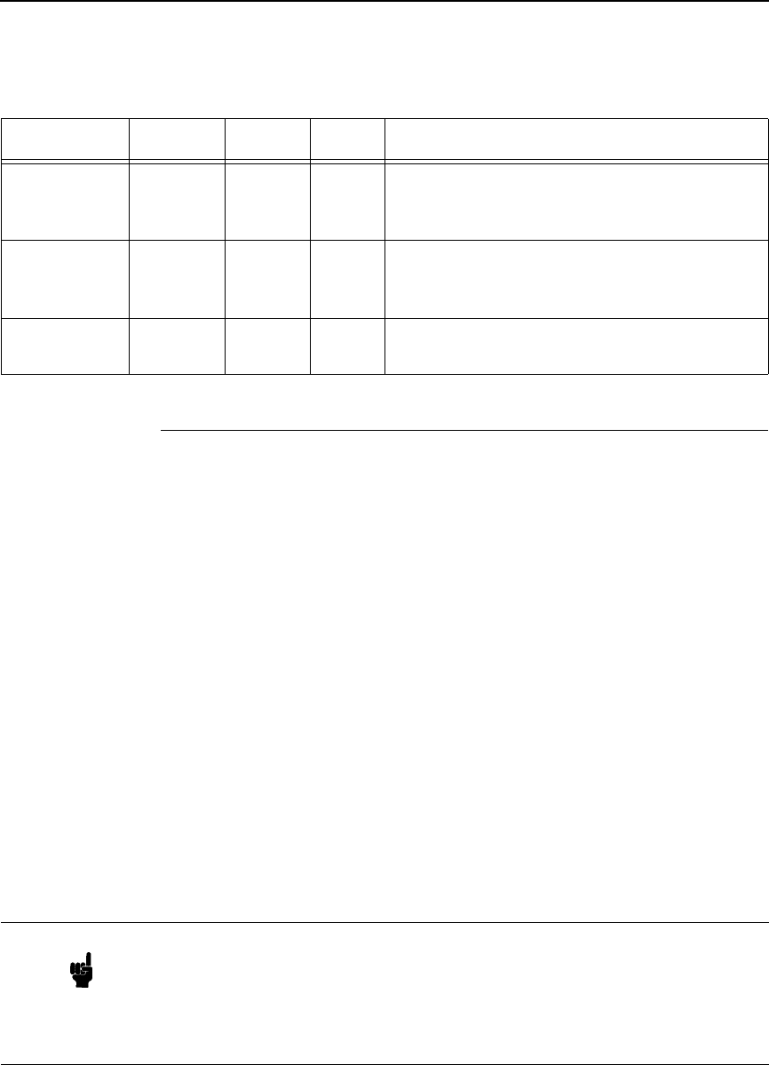
Table 2. Control Codes
Function Symbol Binary Level Description
Backspace BS 1000 II Move one column left.
Horizontal
Tab
HT
1001 V Move the current active position to the next
tab stop on the current line. The tab stops are
at the left margin and every 8th column
between the left and right margins. If new
position crosses the right margin, the new
position is set to the right margin.
Line Feed LF
1010 I Move to next print line while maintaining
current column position
Form Feed FF
1100 I Move to first line at top of the next page while
maintaining current column position
Carriage
Return
CR 1101 IMove to the left margin on current print line
Escape Sequences
25
Escape Sequences
An escape sequence consists of the ESC control code followed by one or
more characters in succession. Both two-character and parameterized
escape sequences control the printer. Two-character escape sequences take
the form ESCX, where X is a character from the ASCII table (0 through ~).
Parameterized escape sequences are structured in the following form:
ESCXy[parameter]Z
This sequence is explained below:
ESCXy Prefix. This part of the escape sequence indicates that the
escape sequence is parameterized and also specifies which type
of control is being performed. “X” is referred to as the
parameterized character; “y” is referred to as the group character.
Parameter This string of ASCII characters specifies a value (either numeric
or alphanumeric).
ZTerminator. This ASCII character indicates the function to which
the previous parameter value applies. If this character is lower
case (a,b,c, etc.), it indicates a combined escape sequence,
meaning that more parameterized information will follow. If the
character is upper case (A,B,C, etc.), it terminates the escape
sequence string.
Shift Out SO 1110 I Select following characters from the current
secondary character font until receipt of a
Shift In
Shift In SI 1111 I Select following characters from the current
primary character font until receipt of a Shift
Out
Escape ESC
11011 I The following characters are a special control
sequence
Table 2. Control Codes
Function Symbol Binary Level Description
Note Brackets [ ] are shown in many of the escape sequences for clarification
purposes, but are not actually part of the escape sequence. For example,
the brackets in the escape sequence for selecting page length (ESC&l[1-
128]P) specify a range of values (1 through 128) for page length. To
specify a page length of 35 lines, the escape sequence ESC&l35P would
be sent to the printer.

26
Chapter 2
Configuring the PCL-II Emulation with Control Codes
Combining Escape Sequences
Parameterized escape sequences can be combined to save keystrokes.
Combining sequences involves adding the parameter value and terminator of
one or more sequences to another escape sequence. Parameterized
sequences can be combined only if their prefixes are identical. When a
parameter/terminator of one sequence is added to another sequence, all of
the terminators except the last should be lower case. For example, to set the
left and right margins using two separate escape sequences, the following
two sequences would be sent:
Set left margin at position 10 ESC&a10L
Set right margin at position 99 ESC&a99M
Using one combined escape sequence, the following would be sent to the
printer:
ESC&a10l99M
The list below shows the escape sequences you can use with the printer.
Note that the brackets [ ] used in these escape sequences are for clarification
purposes only (the brackets are not actually part of the commands).
FUNCTION ASCII CODE PAGE
PCL LEVEL I
Display Functions Mode on ESCY 49
Display Functions Mode off ESCZ 49
Perforation Skip Mode on ESC&l1L 52
Perforation Skip Mode off ESC&l0L 52
Print Mode Selection (10 & 16.67 cpi) ESC&k[0,2]S 52
Programmable reset ESCE 54
Raster Graphics start ESC*rA 63
Raster Graphics data ESC*b[#]W[data]63
Raster Graphics end ESC*rB 63
Self-test ESCz 65
Stroke Weight (Bold) ESC[(,)]s[#]B 65
Underline Mode on ESC&d[DEFGLMNOTUVW\}^] 66
Underline Mode off ESC&d[@CHIJKPQRSWXZ[] 66
PCL LEVEL II
Character Font Selection ESC[(,)]ID 45
Cursor Control (absolute row) ESC&a[#]R 47
Cursor Control (absolute column) ESC&a[#]C 47
Cursor Control (relative row) ESC&a[+#]R 47
Cursor Control (relative column) ESC&a[+/-#]C 47
Horizontal Margin Selection (Left) ESC&a[print position]L 50
Horizontal Margin Selection (Right) ESC&a[print position]M 50
Horizontal Margin Selection (Reset) ESC9 50
Line Spacing ESC&l[6,8]D 50
Logical Page Length Selection ESC&l[1-128]P 51
Print Pitch Selection ESC[(,)]s[Cpi]H 53
Text Length (Vertical Margin) Selection ESC&l[1-128]F 66
Transparent Print Data ESC&p[# of bytes]X 66

Escape Sequences
27
FUNCTION ASCII CODE PAGE
PCL LEVEL III
Character Density Selection ESC[(,)]s[0,1,-1]Q 42
Character Style Selection ESC[(,)]s[0,1]S 47
Cursor Positioning (horizontal) ESC&a[#]H 49
Cursor Positioning (vertical) ESC&a[#]V 49
Print Mode Selection (12 cpi) ESC&k4S 52
Raster Graphics start ESC*r[#]A 63
Additional Commands
Bar Code Data ESC*z[<bar code data>]Z 28
Bar Code Height ESC*z[#]H 28
Bar Code Header Control ESC*z[#]Q 28
Bar Code Label Placement ESC*z[#]C 28
Bar Code Selection ESC*z[#]V 28
Emulation Switching ESC%-[0000,0001,0002]X 23
Print Mode Selection (double size) ESC&k8S 52
PTX Linefeed ESC*t[0,1]L 53
Programmable VFC ESC&l[#bytes]W[data]55
Raster Graphics: Move # raster lines ESC*b[#]Y 63
Raster Graphics: Resolution ESC*t[70,140]R 63
Raster Graphics: Horizontal ResolutionESC*r[60,70,120,140]L 63
Raster Graphics: Vertical Resolution ESC*r[72,144]V 63
Standard (Computed) VFC ESC&l[0-16]V 67
28
Chapter 2
Configuring the PCL-II Emulation with Control Codes
Bar Codes
To print bar codes, escape sequences are sent to the printer specifying the
type of code, bar code height, bar code header information, placement
information, and bar code data. The following five escape sequences are
used for bar code printing:
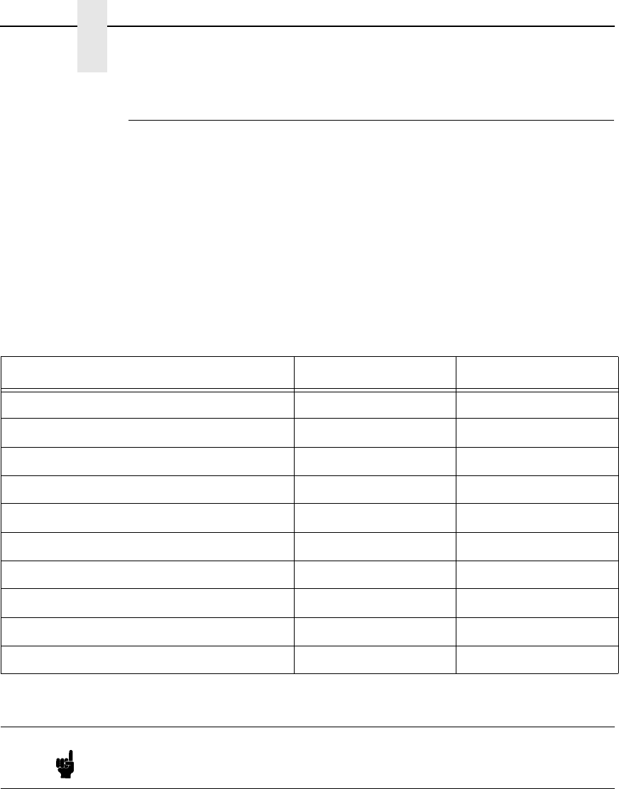
ESC*z#V Bar Code Selection
This sequence selects the type of bar code to be used in subsequent printing
of bar code data. If a number other than those available is selected, the
previously selected bar code type will be used. The following table lists the
bar code types available and their corresponding value field numbers.
ESC*z#H Bar Code Height
This escape sequence defines the height of the bar code label in tenths of an
inch as specified in the value field (#). To specify a bar code height of .8
inches, the ESC*z8H escape sequence would be sent to the printer. A zero in
the value field specifies that bar code height is determined by the current line
spacing (1/6 or 1/8 inch for 6/8 LPI respectively, or 1/3 or 1/4 inch for double-
high/double-wide). The default bar code height is 0.6 inches.
Table 3. Bar Code Types
Bar Code Type Character Length Value Field No.
Code 3 of 9 (default) Variable 0
Industrial 2 of 5 Variable 1
Interleaved 2 of 5 Variable 4
UPC A Fixed 8
UPC E Fixed 9
EAN 8 Fixed 10
EAN 13 Fixed 11
UCC/EAN 128 Fixed 12
Postnet Fixed 13, 14
Royal Mail (including KIX format) Variable 15, 16
Note The Postnet Barcodes type 13 & 14 print 24 bars per inch. See the section
on 256x Postal Barcodes for information on the 20 bars per inch and 22.5
bars per inch Postal Barcodes.
Bar Codes
29
ESC*z#C Bar Code Label Placement
This escape sequence specifies the horizontal starting location of a bar code
by specifying the column number based on the currently active print pitch.
The value field (#) indicates the absolute column position the bar code will
begin printing. A plus or minus sign in the value field is ignored. A value field
whose position is less than the current active printing position is illegal and
causes the cursor to move to the next column position to the right of the
current active printing position. When printing bar codes, always allow at least
1/4 inch margin in all directions from each bar code. This will limit the
interference from other characters and help readability. If you need to print
text and bar codes on the same line, see the “Printing Bar Codes With Text”
discussion later in this chapter.
ESC*z#Q Bar Code Header Control
This sequence specifies the placement of the bar code header. A number 1 in
the value field specifies that a header will be printed above the bar code label
and a 2 specifies that it will be placed below the bar code. A zero in the value
field specifies that no header will be printed. The printer default places the
header above the bar code.
ESC*z<Bar Code Data>Z Bar Code Label Data
This sequence sends the bar code label data in the form of an alphanumeric
string enclosed in angled brackets. The header (if enabled) will print in the
location specified by the bar code header control sequence.
The printer automatically formats the bar code, inserts start and stop bits, and
calculates and inserts the checksum (if applicable-not for Code 3 of 9,
Industrial 2 of 5, or Interleaved 2 of 5 ).
For UPC E bar codes, a zero (0) must be in the first position of the bar code
data.
Note Upon termination of the bar code label data escape sequence, the printer
will print all buffered bar code data and generate a carriage return.

30
Chapter 2
Configuring the PCL-II Emulation with Control Codes
Printing Bar Codes
Generally, sending bar code information to the printer is performed in two
steps:
Step 1: Selecting the bar code printing specifications; bar code type, height,
and header control information.
Step 2: Moving the cursor to the desired label location and sending the bar
code data.
Step 1
Before positioning and printing the bar code data, the type of code, height of
the label, and header placement may be specified. Once this is done, the
succeeding labels will be printed using these specifications until a new type,
height, or header control is specified. In other words, the bar code print
specifications can be sent once and need not be sent again unless the printer
is reset or new print specifications are desired. The following example
specifies the print specifications for bar codes that are 0.5 inches in height,
have a header above the label, and are printed in the UPC A code.
ESC*z8v5h1Q
ESC*z8v Select UPC A code
5h Label is to be .5 inches high
1Q Places header above bar code
Notice that the last letter in the escape sequence (Q) is upper-case while the
other letters in the sequence (v and h) are lower-case. (See “Escape
Sequences” on page 25 for more information concerning combining two or
more sequences.)
Step 2
To print a bar code label, the cursor must be placed in the desired position
and the bar code data must be sent. The following escape sequence moves
the cursor to column 25, sends the data “1234567” to the printer, and initiates
printing.
ESC*z25c<1234567>Z
ESC*z25c Places start of label at column 25
< Indicates start of bar code data
1234567 Bar code data
> Signals end of bar code data
Z Upper case Z initiates printing *
*Note that an upper-case “Z” terminator results in the bar code being printed
and an automatic carriage return (CR) being executed.

Bar Codes
31
Printing Multiple Labels on the Same Line
Printing more than one label on the same line involves no more than
positioning the cursor and sending the data for each label to be printed. Since
the termination of the bar code data sequence (signalled by an upper-case Z)
causes the bar code to be printed and a carriage return to be executed, all of
the label information must be sent in the same escape sequence. The
following example shows an escape sequence used to print three labels on a
single line:
ESC*z5c<label1>z20c<label2>z35c<label3>Z
ESC*z5c Moves cursor to column 5
<label1> Bar code data
z20c Moves cursor to column 20
<label2> Bar code data
z35c Moves cursor to column 35
<label3> Bar code data
Z Initiates printing
Printing Bar Codes with Text
When printing bar codes with text, since the printer automatically generates a
carriage return and line feed at the end of the terminating character (upper
case Z), potential problems exist. As a general rule, for each line of bar code
mixed with text, send the text information first, followed by a carriage return
without a line feed (ASCII 13), and then overlay the bar code. (The carriage
return is required so that the bar code cursor position will be correct.) The
following example illustrates how to print text and bar codes on the same line.
This example involves a three-line bar code (and three escape sequences) as
shown below:
ESC*z0v25c1q<12345>Z
ESC*z0v Selects Code 3 of 9
25c Moves cursor to column 25
1q Specifies header placement above label
<12345> Bar code data
Z Enables printing this portion of the bar code
ESC*z75CThis is textCRESC*z0q25c<12345>Z
ESC*z75C Moves cursor to column 75
This is text Text for right of bar code
CR Carriage return without a line feed
ESC*z0q Disables header for this portion
25c Moves cursor to column 25
<12345> Bar code data
Z Initiates printing this portion
ESC*z25c0q<12345>Z
ESC*z25c Moves cursor to column 25
0q Disables header for lower portion
<12345> Bar code data
Z Initiates printing for lower portion of label
32
Chapter 2
Configuring the PCL-II Emulation with Control Codes
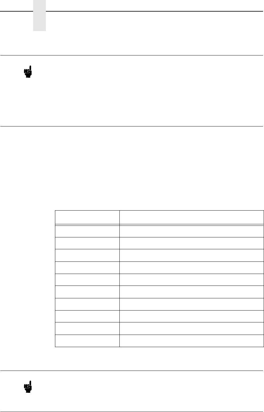
Bar Code Width Information
The following paragraphs contain information concerning the size of the
printed bar codes. If you are designing a form that contains bar codes, this
information may prove useful in judging how much space the bar code will
occupy.
The following table lists the number of characters sent by the user for each
type of bar code:
Note When a header is enabled, sending one line of information causes the
printer to print two lines; one line containing the header along with any text
you may have sent in that line, and one line containing the bar code label.
When a header is enabled, no information can be printed on the same line
as the bar code label. However, if the header is disabled, text can be
placed next to the bar code label. For example, if you want a label and also
wish to enclose the bar code with a box, you may not use automatic
headers. Instead, you may set the height of the bar code to the text height
and manually print the header.
Table 4. Bar Code Character
Bar Code Number of Characters Sent
Code 3 of 9 Variable
Industrial 2 of 5 Variable
Interleaved 2 of 5 Variable
UPC A 11
UPC E 11
EAN 8 7
EAN 13 12
UCC/EAN 128 19
Postnet 5 (6), 9(10), or 11(12)
Royal Mail (incl. KIX) Variable
Note For Postnet Barcodes printed using the P8000 style, if 5, 9, or 11 digits are
sent, your printer will automatically calculate and print the check digit.
If 6, 10, or 12 digits are sent, the printer will verify the check digit. Should
the check digit be inaccurate, or an invalid bar code length is sent, your
P8000 printer will not attempt to print the invalid data.

Bar Codes
33
CODE 3 of 9
A variable-length data string of up to 32 ASCII characters may be printed
using the Code 3 of 9 bar code. The string may be an odd or even length and
may use any of the standard characters (specified in MIL-STD-1189). If a
non-valid character is used in the string, a blank non-readable bar code will be
printed; non-valid characters are not substituted or deleted. Optional
checksums are not inserted in the bar code. The width of the printed bar code
can be approximated by the following equation:
Width in inches = (number of characters)/3.14 + 0.50
INDUSTRIAL 2 of 5
A variable-length data string of up to 32 ASCII characters may be printed
using the Industrial 2 of 5 bar code. The string may be an odd or even length
and may use any character from 0 through 9. If a non-valid character is used
in the string, a blank non-readable bar code will be printed; non-valid
characters are not substituted or deleted. Optional checksums are not
inserted in the bar code. The width of the printed bar code can be
approximated by the following equation:
Width in inches = (number of characters)/3.7 + 0.38
INTERLEAVED 2 of 5
A variable-length data string of up to 32 ASCII characters may be printed
using the Interleaved 2 of 5 bar code. The string may be an odd or even
length. However, if the string is an odd length, a leading zero will be inserted
to make a string of an even length. Valid data characters are 0 through 9. If a
non-valid character is used in the string, a blank non-readable bar code will be
printed; non-valid characters are not substituted or deleted. Optional
checksums are not inserted in the bar code. The width of the printed bar code
can be approximated by the following equations:
Width in inches = (even number of characters)/6.25 + 0.15
UPC A
A fixed-length data string of 11 ASCII characters may be printed using the
UPC A bar code. The string must have a length of 11 and may use any of the
standard characters 0 through 9. If a non-valid character or string length is
used, a blank non-readable bar code will be printed; non-valid characters are
not substituted or deleted. The width of the printed bar code does not vary
and is 1.56 inches.

34
Chapter 2
Configuring the PCL-II Emulation with Control Codes
UPC E
A fixed-length data string of 11 ASCII characters may be printed using the
UPC E bar code. The string length must be 11 and may use any of the
standard characters 0 through 9 (however, the data pattern must meet the
format of UPC E bar codes; UPC E is a shortened version of very specific
patterns printable with UPC A). If a non-valid character or string length is
used, a blank non-readable bar code will be printed; non-valid characters are
not substituted or deleted. For UPC E, a zero (0) is required in the first
position of the bar code data (the number system character). The width of the
printed bar code is not variable and is 0.81 inches.
EAN 8
A fixed-length data string of 7 ASCII characters may be printed using the
EAN 8 bar code. The string length must be 7 and may use any of the standard
characters 0 through 9. If a non-valid character or string length is used, a
blank non-readable bar code will be printed; non-valid characters are not
substituted or deleted. The width of the printed bar code is not variable and is
1.25 inches.
EAN 13
A fixed-length data string of 12 ASCII characters may be printed using the
EAN 13 bar code. The string length must be 12 and may use any of the
standard characters 0 through 9. If a non-valid character or string length is
used, a blank non-readable bar code will be printed; non-valid characters are
not substituted or deleted. The width of the printed bar code is not variable
and is 1.56 inches.
Royal Mail
A variable length data string may be printed using the “Royal Mail 4 State
Customer Code”. The string may use any character from 0 through 9 and
alpha characters A through Z. A complete bar code consists of a set of distinct
bars and spaces for each character followed by a checksum character and
enclosed by a unique start bar, stop bar and quiet zone. A second version of
the Royal Mail barcode prints with no stop bar, start bar or checksum
character.
The KIX format for Royal Mail does not include the start/stop code or the
check digit, but will allow lowercase alpha characters a through z.
UCC/EAN 128
The UCC/EAN 128 bar code contains special characters which use unique
codes to identify the leading and trailing end of the bar code. EAN/UCC 128
supports a full ASCII character set and provides standard alphanumeric
keyboard characters and control and special characters.
The EAN/UCC 128 data structure requires an Application Identifier (AI) at the
beginning of barcode data. Each AI determines the format and length of the
data which follows. Refer to Table 5 for more detail.
Bar Codes
35
Table 5. UCC/EAN 128 Application Identifiers
Application
Identifier (AI) Content Format
00 Serial Shipping Container Code n2+n18
02 Item Num. of Goods Within Another Unit n2+n14
10 Batch or Lot Number n2+an..20
11 (*) Production Date (YYMMDD) n2+n6
13 (*) Packaging Date (YYMMDD) n2+n6
15 (*) Sell By Date (Quality) (YYMMDD) n2+n6
17 (*) Expiration Date (Safety) (YYMMDD) n2+n6
20 Product Variant n2+n2
21 Serial Number n2+an..20
22 HIBCC = Quantity, Date, Batch and Link n2+an..29
23 (**) Lot Number (Transitional Use) n3+n..19
240 Additional Product ID Assigned By Manufacturer n3+an..30
250 Secondary Serial Number n3+an..30
30 Quantity n2+n..8
310 (***) Net Weight, Kilograms n4+n6
311 (***) Length or 1st Dimension, Meters n4+n6
312 (***) Width, Diameter or 2nd Dimension, Meters n4+n6
313 (***) Depth, Thickness, Height or 3rd Dimension, Meters n4+n6
314 (***) Area, Square Meters n4+n6
315 (***) Volume, Liters n4+n6
316 (***) Volume, Cubic Meters n4+n6
320 (***) Net Weight, Pounds n4+n6
321 (***) Length or 1st Dimension, Inches n4+n6
322 (***) Length or 1st Dimension, Feet n4+n6
323 (***) Length or 1st Dimension, Yards n4+n6
324 (***) Width, Diameter, or 2nd Dimension, Inches n4+n6
325 (***) Width, Diameter, or 2nd Dimension, Feet n4+n6
326 (***) Width, Diameter, or 2nd Dimension, Yards n4+n6
327 (***) Depth, Thickness, Height, or 3rd Dimension, Inches n4+n6
328 (***) Depth, Thickness, Height, or 3rd Dimension, Feet n4+n6
329 (***) Depth, Thickness, Height, or 3rd Dimension, Yards n4+n6
330 (***) Gross Weight-Kilograms n4+n6
331 (***) Length or 1st Dimension, Logistics n4+n6
332(***) Width, Diameter, or 2nd Dimension, Meters, Logistics n4+6
333 (***) Depth, Thickness, Height or 3rd Dimension, Meters, Logistics n4+n6
36
Chapter 2
Configuring the PCL-II Emulation with Control Codes
334 (***) Area, Square Meters, Logistics n4+n6
335 (***) Gross Volume, Liters n4+n6
336 (***) Gross Volume, Cubic Meters n4+n6
337 (***) Kilograms Per Square Meter n4+n6
340 (***) Gross Weight, Pounds n4+n6
341 (***) Length or 1st Dimension, Inches, Logistics n4+n6
342 (***) Length or 1st Dimension, Feet, Logistics n4+n6
343 (***) Length or 1st Dimension, Yards, Logistics n4+n6
344 (***) Width, Diameter, or 2nd Dimension, Inches, Logistics n4+n6
345 (***) Width, Diameter, or 2nd Dimension, Feet, Logistics n4+n6
346 (***) Width, Diameter, or 2nd Dimension, Yards, Logistics n4+n6
347 (***) Depth, Thickness, Height or 3rd Dimension, Inches, Logistics n4+n6
348 (***) Depth, Thickness, Height or 3rd Dimension, Feet, Logistics n4+n6
349 (***) Depth, Thickness, Height or 3rd Dimension, Yards, Logistics n4+n6
350 (***) Area, Square Inches n4+n6
351 (***) Area, Square Feet n4+n6
352 (***) Area, Square Yards n4+n6
353 (***) Area, Square Inches, Logistics n4+n6
354 (***) Area, Square Feet, Logistics n4+n6
355 (***) Area, Square Yards, Logistics n4+n6
356 (***) Net Weight, Troy Ounce n4+n6
357 (***) Net Volume, Ounces n4+n6
360 (***) Volume, Quarts n4+n6
361 (***) Volume, Gallons n4+n6
362 (***) Gross Volume, Quarts n4+n6
363 (***) Gross Volume, Gallons n4+n6
364 (***) Volume, Cubic Inches n4+n6
365 (***) Volume, Cubic Feet n4+n6
366 (***) Volume, Cubic Yards n4+n6
367 (***) Gross Volume, Cubic Inches n4+n6
368 (***) Gross Volume, Cubic Inches n4+n6
369 (***) Gross Volume, Cubic Inches n4+n6
37 Quantity of Units Contained (For Use With AI 02 Only) n2+n..8
400 Customer's Purchase Order Number n3+an..30
401 Consignment Number n3+an..30
410 Ship To (Deliver To) Location Code Using EAN 13 n3+n13
Table 5. UCC/EAN 128 Application Identifiers (continued)
Application
Identifier (AI) Content Format

Bar Codes
37
(*)To indicate only year and month, DD must be filled with “00”
(**) Plus one digit for length indication
(***) Plus one digit for decimal point indication
Data Value Representation:
a - alphabetic characters n - numeric characters
an - alpha-numeric characters n3 - 3 numeric characters, fixed length
an..3 - up to 3 alpha-numeric characters n..3 - up to 3 numeric characters
411 Bill To (Invoice To) Location Code Using EAN 13 n3+n13
412 Purchase From (Location Code of Party From Whom Goods Are
Purchased)
n3+n13
413 Ship For UCC/EAN Location Code n3+n13
414 EAN Location Code For Physical Identification n3+n13
420 Ship To (Deliver To) Postal Code Within a Single Postal Authority n3+an..20
421 Ship To (Deliver To) Postal Code With 3-Digit ISO Country Code Prefix n3+n3+an..9
8001 Roll Products-Width, Length, Core Diameter, Direction and Splices n4+n14
8003 UPC/EAN Number and Serial Number or Returnable Asset n4+n14+an..16
8004 UCC/EAN Serial Identification n4+an..30
8005 Identifies the Price Per Unit of Measure n4+n6
8006 Component of an Article n4+n14+n2+n2
8018 Service Relation Number n4+n18
8100 Coupon Extended Code-Number System Character and Offer n4+n1+n5
8101 Coupon Extended Code-Number System Character, Offer and End of Offer n4+n1+n5+n4
8102 Coupon Extended Code-Number System Character Preceded by Zero n4+n1+n1
90 Mutually Agreed, Between Trading Partners n2+an..30
91 Intra-Company (Internal) n2+an..30
92 Intra-Company (Internal) n2+an..30
93 Intra-Company (Internal) n2+an..30
94 Intra-Company (Internal) n2+an..30
95 Internal-Carriers n2+an..30
96 Internal-Carriers n2+an..30
97 Intra-Company (Internal) n2+an..30
98 Intra-Company (Internal) n2+an..30
99 Internal n2+an..30
Table 5. UCC/EAN 128 Application Identifiers (continued)
Application
Identifier (AI) Content Format

38
Chapter 2
Configuring the PCL-II Emulation with Control Codes
US Postnet Barcodes
The P8000 printer can print barcodes in three different formats. The default,
24 bars per inch, uses the same syntax as the other barcodes. It is suggested
to use the ESC*Z0Q command to disable placement of a header on postal
barcodes. The P8000 printer will also print barcodes using the 256X format
for 20 and 22.5 bars per inch postal barcodes. See the section on 256X - US
Barcodes for more details. P8000 style Postnet barcodes will automatically
generate the check digit if it is not present. The 256X-compatibility barcodes
require the host to generate the check digit. If a non-valid character or string
length is used, a blank non-readable bar code will be printed; non-valid
characters are not substituted or deleted. The width of the printed bar code is
not variable and is 1.33 (5 digit), 2.17 (9 digit), or 2.59 (11 digit) inches.
256X US POSTNET BAR CODE
The US POSTNET Bar Code is an HP character set which meets the US
Postal Office specifications for Postnet bar coding, including the latest
Delivery Point Bar Code, or DPBC.
US POSTNET Bar Codes print at 4.0 cpi (20 bars per inch) and 11.3 cpi (22.5
bars per inch). Both bar codes are printed by replacing normal printable
characters with vertical bars. Both options use different characters to
represent the desired bar codes, as a result the methods by which they are
produced are incompatible.
11.3 CPI (22.5 bars per inch) US POSTNET BAR CODE
Font Selection
You may select either of the US POSTNET character sets from either the
front panel or through escape sequences. (Refer to the User's Manual for
details on front panel menus.)
The following escape sequence will configure the 11.3 cpi POSTNET BAR
CODE as a secondary font:
ESC)1KESC)s11.3H
The sequence above sets the secondary font symbol set to 11.3 cpi
POSTNET BAR CODE, and sets the pitch to 11.3 cpi. Once the Secondary
character set is configured for 11.3 cpi Postnet Bar Codes, the Shift Out
command can be used to activate the bar codes:
Shift Out: hex 0E
After the bar code is printed, the normal print mode is activated by using the
Shift In command:
Shift In: hex 0F
Note It is recommended setting the US POSTNET Bar Code character set as
the secondary set, with the normal operation mode as the primary font.
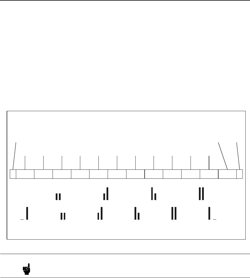
US Postnet Barcodes
39
Printing 11.3 CPI US POSTNET Bar Code Information
The US POSTNET BAR CODES represent digits 0 - 9 with five vertical bars.
Each digit consists of two long bars (1's) and three short bars (0's). The
Delivery Point Bar Code font is designed to be printed only at 11.3 cpi or 22.5
bars per inch. A Delivery Point Bar Code is an eleven digit postal code. (For
five or nine postal bar codes, use the 4.0 cpi US POSTNET Bar Code.) The
eleven numeric characters are: ZIP + 4 + 2
To make the bar code scannable, you must add frame bars and a check digit.
The check digit is calculated by adding all of the digits and subtracting the
sum from the next highest multiple of ten. Consequently, the sum of the
eleven digits, and the check digit, will be an even multiple of ten.
The printer does not calculate the check digit or automatically generate frame
bars. They must be generated by the computer resident software and sent to
the printer. To do this, it is necessary to design a program that will convert a
pair of digits into ten vertical bars.
Note Each digit is five bars, with each printable character being two bars. Thus,
2 1/2 characters are needed to print one digit.
Frame
Bar
01234567891
Correction
Digit
Frame
Bar
= \ (5C/h) = ~ (7E/h) = } (7D/h) = { (7B/h) = ‘ (60/h) = ^ (5E/h)
00 = 01 = 10 = 11 =
1 111000 00011 00101 00110 01001 01010 01100 10001 10010 10100 00011 00101
}{
~
‘
→→→→
40
Chapter 2
Configuring the PCL-II Emulation with Control Codes
Follow the example below to convert a ZIP Code into a bar code:
1. Calculate the check digit for the ZIP Code 45834-8844-70:
a. Add the digits of the ZIP code:
4+5+8+3+4+8+8+4+4+7+0 = 51
b. Subtract from the next highest multiple of ten:
60-51 = 9
The check digit is 9, so the number for conversion is 45834-8844-709.
2. Separate the ZIP Code + digit into digit pairs:
45834-8844-709 = 45 83 48 84 47 09
3. Convert the digit pairs into binary code:
Example:
45 = 01001 01010
4. Convert the binary code into pairs:
01001 01010 = 01 00 10 10 10
5. Convert each pair into its text equivalent:
01 00 10 10 10 = }~{{{
6. Add the frame bars. This can be done in one of two ways: Method 1
(Table 6) uses the frame bars as separate characters, and Method 2
(Table 7) “links” the frame bars to the first and last characters:
Table 6: Method 1
ZIP Code + digit Frame Bar
+
Digit Pairs
Binary
Code
Conversion
Text
Equivalent Converted ZIP Code
(Text To Printer)
45 83 48 84 47 09
Frame Bar 1 \
45 01 00 10 10 10 }~{{{
83 10 01 00 01 10 {}~}{
48 01 00 11 00 10 }~`~{ SO\}~{{{{}~}{}~`~{{}~{}}~}~}`~}}~^SI
84 10 01 00 10 01 {}~{}
47 01 00 11 00 01 }~}~}
09 11 00 01 01 00 `~}}~
Frame Bar 1 ^
Note: SO = Shift Out (hex 0E), and SI = Shift In (hex 0F)
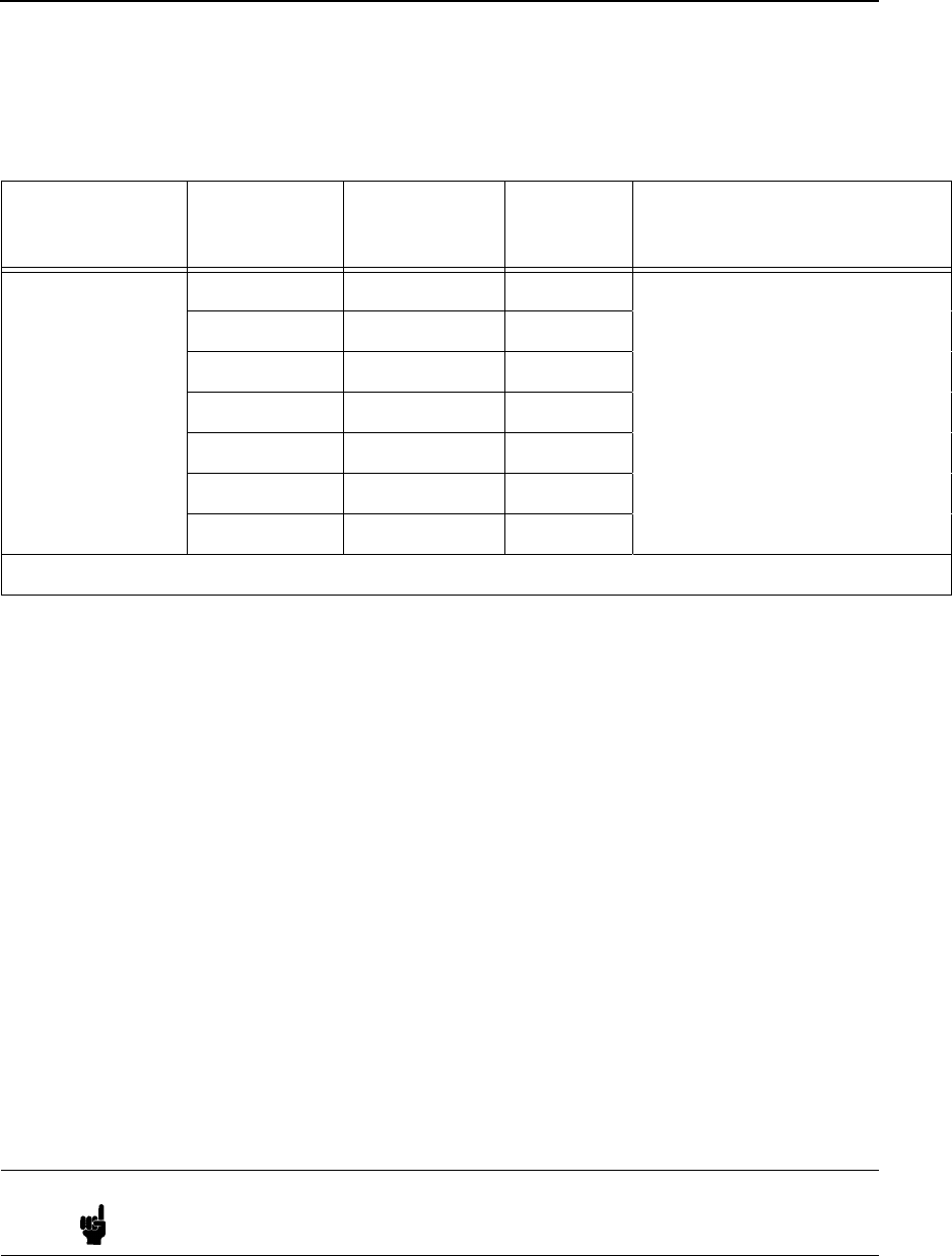
US Postnet Barcodes
41
4.0 CPI (20 bars per inch) US POSTNET Bar Code
Font Selection
You may select either of the US POSTNET character sets from the front
panel, or through escape sequences. (Refer to your User's Manual for details
on front panel menus.)
The following escape sequence will configure the 4.0 cpi POSTNET BAR
CODE as a secondary font:
ESC)0K (Compatible with 256XC series printers.)
ESC)0KESC)s4.0H (Compatible with C235XA series printers.)
The sequence above sets the secondary font symbol set to 4.0 cpi POSTNET
BAR CODE, and sets the pitch to 4.0 cpi. Once the Secondary character set
is configured for 4.0 CPI Postnet Bar Codes, the Shift Out command can be
used to activate the bar codes:
Shift Out: hex 0E
After the bar code is printed, the normal print mode is activated by using the
Shift In command:
Shift In: hex 0F
Table 7: Method 2
ZIP Code + digit Frame Bar
+
Digit Pairs
Binary
Code
Conversion
Symbol
Equivalent Converted ZIP Code
(Text To Printer)
45 83 48 84 47 09
Frame Bar + 4 10 10 01 {{}
58 01 01 01 00 10 }}}~{
34 00 11 00 10 01 ~`~{}
88 10 01 01 00 10 {}}~{ SO{{}}}}~{~`~{}{}}~{}~{{}{~`{~{{}SI
44 01 00 10 10 01 }~{{}
79 10 00 11 10 00 {~`{~
9 + Frame Bar 10 10 01 {{}
Note: SO = Shift Out (hex 0E), and SI = Shift In (hex 0F)
Note It is recommended setting the US POSTNET Bar Code character set as
the secondary set, with the normal operation mode as the primary font.

42
Chapter 2
Configuring the PCL-II Emulation with Control Codes
Perform the following steps to determine the check digit for 45834-8844-70:
1. Calculate the check digit:
Add the digits of the postal code: 4+5+8+3+4+8+8+4+4+7+0 = 51
2. Subtract from the next highest multiple of ten:
60 - 51 = 9
The check digit is 9.
3. Text sent to Printer:
SONUL458348844709.SI
SO = Shift Out (hex 0E)
NUL = Nul (hex 00)
SI = Shift In (hex 0F)
Character Density Selection
(PCL Level III)
Standard-density print, high-density print, and high-speed draft printing can
be specified using the following escape sequences:
Primary Selection
ESC(s0Q Select Standard-Density (12 x 9 dot matrix, 120 x 72 dpi) for the
primary font
ESC(s1Q Select High-Density (18 x 12 dot matrix, 180 x 96 dpi) for the
primary font
ESC(s-1Q Select High-speed Draft Printing (12 x 6 dot matrix, 120 x 48 dpi)
for the primary font
Secondary Selection
ESC)s0Q Select Standard-Density (12 x 9 dot matrix, 120 x 72 dpi) for the
secondary font
ESC)s1Q Select High-Density (18 x 12 dot matrix, 180 x 96 dpi) for the
secondary font
ESC)s-1Q Select High-speed Draft Printing (12 x 6 dot matrix, 120 x 48 dpi)
for the secondary font
The default density is that of the default font specified from the control panel.
If the symbol set selected is not available in the requested density, the printer
will print blank space. However, OCR-A, OCR-B, and Postal Barcodes force
density changes to ensure scanability.
When draft printing is selected, the printer prints less dots vertically (5 dots).
This reduction in dots results in an increase in print speed of up to 30%.
ESC(0UESC(s10h0s-1Q
To cue high-speed draft with Roman Extension:
ESC(0EESC(s10h0s-1Q
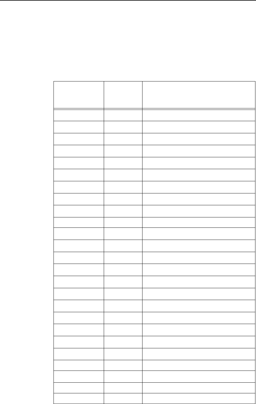
Character Density Selection
43
The following table lists all the Symbol Sets available to the PCL II Emulation.
Each Symbol Set is followed by its selection Code, and the Characters Per
Inch (CPI) available in it. With the exception of OCR-A and OCR-B, selecting
a symbol set in a CPI combination not listed in the chart below will result in
spaces being printed in place of the desired character.
Table 8. Available Symbol Sets
Name Code CPI in High Speed (HS),
Data Processing (DP) and
Near Letter Quality (NLQ)
Roman-8 8U 5 - 20 cpi
1
in HS, DP and NLQ
Turkish-8 8T 5 - 20 cpi
1
in HS, DP and NLQ
Arab-8 8V 5 - 20 cpi
1
in DP and NLQ; 10 cpi in HS only
Cyrillic 8R 5 - 20 cpi
1
in HS, DP and NLQ
PC858 MtLi 13U 5 - 20 cpi
1
in HS, DP and NLQ
MC Text 12J 5 - 20 cpi
1
in HS, DP and NLQ
Roman-9 4U 5 - 20 cpi
1
in HS, DP and NLQ
Latin-9 9N 5 - 20 cpi
1
in HS, DP and NLQ
Win 3.0Lat-1 9U 5 - 20 cpi
1
in HS, DP and NLQ
Japan Postnet 15Y 4 cpi in NLQ only
Katakana Post n/a
2
11.25 cpi in NLQ only
ASCII 0U 5 - 20 cpi
1
in HS, DP and NLQ
Math Sym 0A/0M 5 - 20 cpi
1
in HS, DP and NLQ
LineDraw 0B/0L 5 - 20 cpi
1
in DP only
ISO Den/Nor 0D 5 - 20 cpi
1
in HS, DP and NLQ
Roman Ext. 0E 5 - 20 cpi
1
in HS, DP and NLQ
ISO UK 1E 5 - 20 cpi
1
in HS, DP and NLQ
ISO France 0F 5 - 20 cpi
1
in HS, DP and NLQ
ISO German 0G 5 - 20 cpi
1
in HS, DP and NLQ
Hebrew 0H 5 - 20 cpi
1
in HS, DP and NLQ
Japan ASCII 0K 5 - 20 cpi
1
in HS, DP and NLQ
Katakana 1K 10 cpi in DP and NLQ only
Block Char 1L 5 - 20 cpi
1
in DP only
OCR-A 0O 10 cpi in OCR typeface only
OCR-B 1O 10 cpi in OCR typeface only
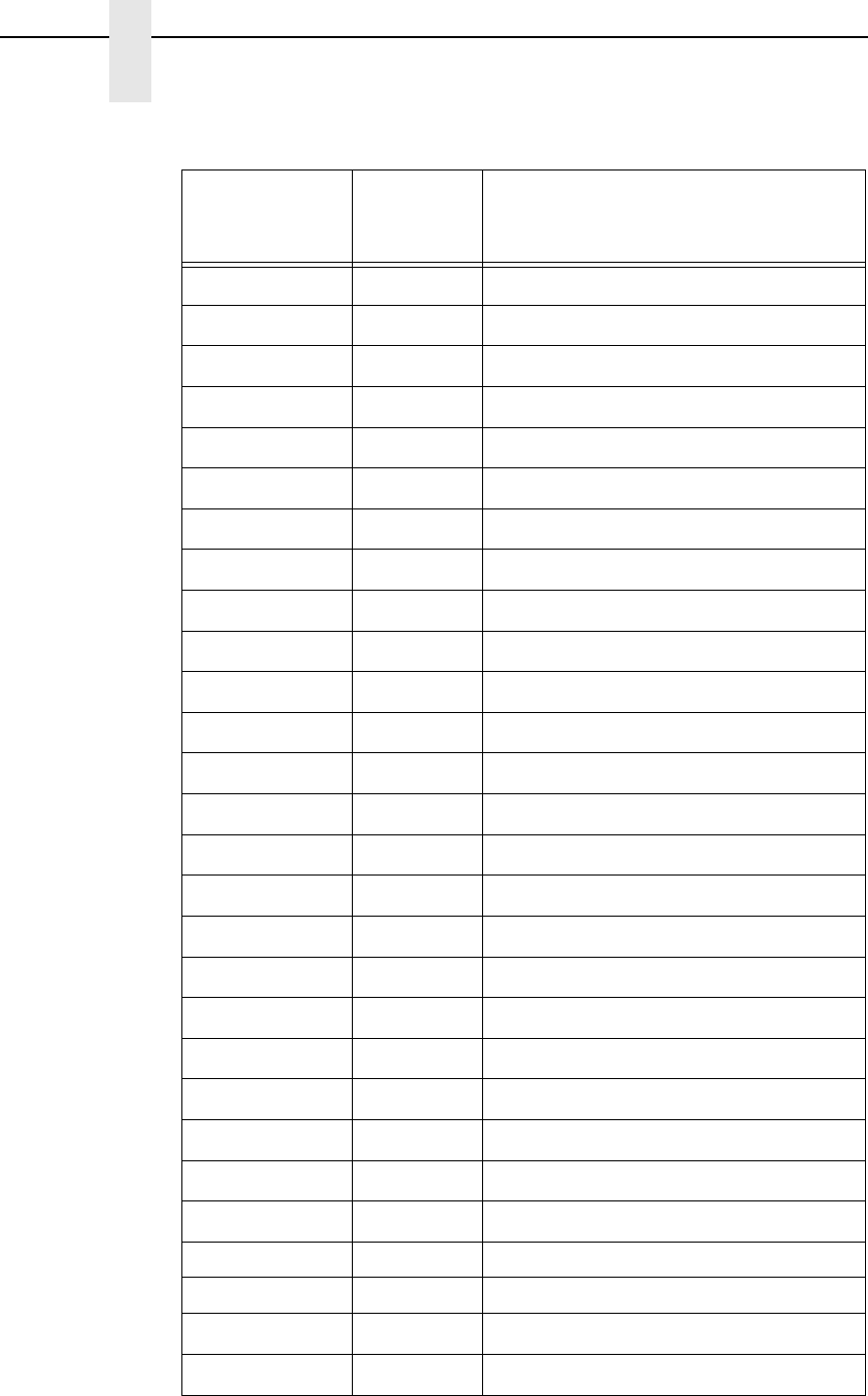
44
Chapter 2
Configuring the PCL-II Emulation with Control Codes
ISO Swe/Fin 0S 5 - 20 cpi
1
in HS, DP and NLQ
ISO Spain 1S 5 - 20 cpi
1
in HS, DP and NLQ
ISO Italian 0I 5 - 20 cpi
1
in HS, DP and NLQ
ISO Portugu 4S 5 - 20 cpi
1
in HS, DP and NLQ
Latin-1 0N 5 - 20 cpi
1
in HS, DP and NLQ
Latin-2 2N 5 - 20 cpi
1
in HS, DP and NLQ
Latin-5 5N 5 - 20 cpi
1
in HS, DP and NLQ
Latin-6 6N 5 - 20 cpi
1
in HS, DP and NLQ
Baltic 19L 5 - 20 cpi
1
in HS, DP and NLQ
PC8 DanNor 11U 5 - 20 cpi
1
in HS, DP and NLQ
PC8 Cd437 10U 5 - 20 cpi
1
in HS, DP and NLQ
PC850 MtLi 12U 5 - 20 cpi
1
in HS, DP and NLQ
PC851 LtGk 12G 5 - 20 cpi
1
in HS, DP and NLQ
PC852 Lat2 17U 5 - 20 cpi
1
in HS, DP and NLQ
PC Turkish 9T 5 - 20 cpi
1
in HS, DP and NLQ
PC Hebrew 15H 5 - 20 cpi
1
in HS, DP and NLQ
PC Lat/Ara 10V 5 - 20 cpi
1
in DP and NLQ; 10 cpi
in HS only
PC Cyrillic 3R 5 - 20 cpi
1
in HS, DP and NLQ
Win3.1Lat1 19U 5 - 20 cpi
1
in HS, DP and NLQ
Win3.1Lat-2 9E 5 - 20 cpi
1
in HS, DP and NLQ
Win3.1Lat-5 5T 5 - 20 cpi
1
in HS, DP and NLQ
Math-8 8M 5 - 20 cpi
1
in DP and NLQ only
PS Math 5M 5 - 20 cpi
1
in DP and NLQ only
Greek 7 12N 5 - 20 cpi
1
in HS, DP and NLQ
Postnet4 15Y 4 cpi in NLQ only
Postnet11.25 1K 11.25 cpi in NLQ only
Greek-8 8G 5 - 20 cpi
1
in HS, DP and NLQ
Hebrew-8 8H 5 - 20 cpi
1
in HS, DP and NLQ
Table 8. Available Symbol Sets (continued)
Name Code CPI in High Speed (HS),
Data Processing (DP) and
Near Letter Quality (NLQ)
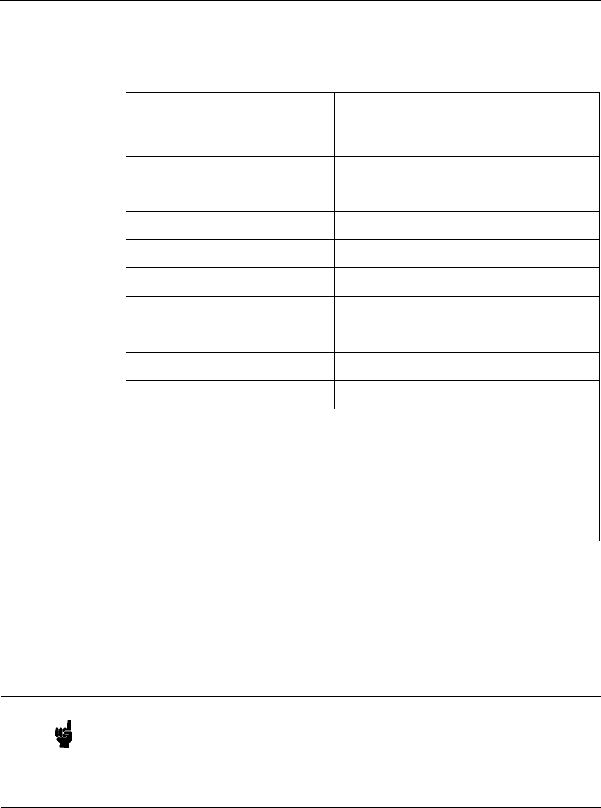
Character Font Selection
45
Character Font Selection
The printer can print several different character sets (fonts). By performing a
printer self-test, you can see which fonts are installed in your printer. You may
specify any of these fonts from an application. On the self-test printout, each
available character font is printed along with a parameter number to the left of
the printed font.
Katakana-8 8K 10 cpi in DP and NLQ only
DEC 256 Greek n/a
2
5 - 20 cpi
1
in HS, DP and NLQ
ELOT 928 Greek n/a
2
5 - 20 cpi
1
in HS, DP and NLQ
Greek 3 n/a
2
5 - 20 cpi
1
in HS, DP and NLQ
ABY Greek n/a
2
5 - 20 cpi
1
in HS, DP and NLQ
ABG Greek n/a
2
5 - 20 cpi
1
in HS, DP and NLQ
ELOT 927 Greek n/a
2
5 - 20 cpi
1
in HS, DP and NLQ
Greek 437 n/a
2
5 - 20 cpi
1
in HS, DP and NLQ
Greek 8859-7 n/a
2
5 - 20 cpi
1
in HS, DP and NLQ
NOTES
5 - 20 cpi
1
= 5, 10, 12, 13.3, 15, 16.67, 20 cpi
n/a
2
= not applicable. There is no designated code for this font; you can
select it only from the control panel.
Table 8. Available Symbol Sets (continued)
Name Code CPI in High Speed (HS),
Data Processing (DP) and
Near Letter Quality (NLQ)
Note Many earlier models of HP printers could not select certain combinations of
character sets. Your P8000 printer does not have this limitation. The
P8000 printer produces different characters than the previous models, and
your application may be requesting the old character set. You will need to
modify your application's settings to prevent it from selecting the old
character set.

46
Chapter 2
Configuring the PCL-II Emulation with Control Codes
There are two ways to select a font from those available:
•
By entering the parameter number via the control panel (function 1 =
primary character set; function 2 = secondary character set)
•
By specifying the attributes of the desired fonts using escape sequences.
The list below contains the font attributes, listed in order of descending
priority:
•
Symbol Set (ASCII, Roman-8, Line Draw, etc.)
•
Pitch (10,12,13.3,15,16.67, 20)
•
Style (Upright/Italic)
•
Density (High-Speed, Near Letter Quality)
The attributes are specified for both primary and secondary fonts so that you
may switch between the primary and secondary fonts using the Shift Out (SO)
and Shift In (SI) control codes. Notice that the only difference between the
primary and secondary font escape sequences is the direction of the
parentheses. The left parenthesis “(“ is used for primary fonts and the right
parenthesis “)” for secondary. Upon receiving these font attribute commands,
the printer selects the best fitting font from those available.
It is not necessary to specify all four font attributes when selecting a font. If
any of the attributes are not specified, the printer defaults to those attributes
last specified (or, if none have been specified, from the control panel default
font). For example, if you wish to select a font without selecting a print pitch,
the print pitch last specified will be in effect. If you had not previously specified
a print pitch, the printer will use the print pitch of the default font that was last
specified from the control panel (provided that the particular symbol set
selected is available in the current pitch).
The escape sequences used for specifying the character font attributes are
explained in the following paragraphs.
Symbol Set Selection
The printer allows you to select a symbol set. A symbol set is a set of
characters that are mapped to certain locations in the printer's memory.
Symbol sets differ from one another in the characters contained in the set and
in their locations within memory. The default symbol set is that of the default
font specified from the control panel.
The following escape sequences are used to specify the primary and
secondary symbol sets:
ESC(ID Select symbol set for primary character font
ESC)ID Select symbol set for secondary character font
Table 8 lists the codes needed to select each symbol set. For example, to
select the Roman-8 symbol set for the primary font, you would send the
ESC(8U escape sequence. To select OCR-B for the secondary font, you
would send ESC)1O to the printer.
Character Overstrike
47
An ASCII symbol set table is provided in Appendix A.
Character Overstrike
To create special symbols and underline selected portions of your output, one
character (maximum) may be printed over another on a character-by-
character or line-by-line basis.
A character overstrike is accomplished using either the backspace control
code or a carriage return with no line feed. The overstrike print line will be held
in the print buffer and will be merged with the next line to form a single printed
line with superimposed characters.
Attempting to print more than two characters in any one print location will
result in a loss of data integrity. (Only the last two characters received will be
retained.)
When the automatic underlining enhancement is used (ESC&dD), the
underlined character is not considered an overstrike character. Therefore, if
the underlining enhancement was used to underline a character, another
character could still be printed over it without risking data loss.
Character Style Selection
The printer has two types of character styles: upright and italic. The following
escape sequences select either the upright or the italic print style for the
primary and secondary character fonts:
ESC(s0S Selects the upright style for the primary font
ESC(s1S Selects the italic style for the primary font
ESC)s0S Selects the upright style for the secondary font
ESC)s1S Selects the italic style for the secondary font
Italics cannot be selected or saved from the control panel. The printer will
default to the upright style when the printer is first powered on. Changing
emulations, loading a configuration, or sending the ESCE command to the
printer will cancel the italic style for the primary and secondary fonts.
Cursor Control
Absolute and relative cursor control are provided for the printer. Cursor moves
are made in the current active pitch and current active vertical spacing. The
following escape sequences perform these functions:
Absolute Vertical Cursor Position in Rows
ESC&a#R
Move cursor to absolute vertical cursor position in rows
(where # is an unsigned integer)
Relative Vertical Cursor Position in Rows
ESC&a[+#]R
Note Any number of fonts may be printed on each line, but to do this, each font
must be the same pitch and typeface. That is, only one print pitch, or
typeface is allowed per line.

48
Chapter 2
Configuring the PCL-II Emulation with Control Codes
Move cursor vertically in rows relative to the current
position (where # is a signed [+ only] integer)
Absolute Vertical Cursor Position in Decipoints
ESC&a#V
Move cursor to absolute vertical cursor position in
decipoints (where # = x/720 inch increments). Fractional
decipoint values are not allowed.
Relative Vertical Cursor Position in Decipoints
ESC&a[+/-#]V
Move cursor vertically in decipoints relative to the
current position (where # is a signed [+/-] integer at
x/720 inch increments)
.
Fractional decipoint values are
not allowed.
Absolute Horizontal Cursor Position in Columns
ESC&a#C
Move cursor to absolute horizontal cursor position in
columns (where # is an unsigned integer)
Relative Horizontal Cursor Position in Columns
ESC&a[+/-#]C
Move cursor horizontally in columns relative to the
current position (where # is a signed [+/-] integer)
Absolute Horizontal Cursor Position in Decipoints
ESC&a#H
Move cursor to absolute horizontal cursor position in
decipoints (where # = x/720 inch increments). Fractional
decipoint values are not allowed.
Relative Horizontal Cursor Position in Decipoints
ESC&a[+/-#]H
Move cursor horizontally in decipoints relative to the
current position (where # is a signed [+/-] integer at
x/720 inch increments). Fractional decipoint values are
not allowed.
The vertical cursor positioning commands move the current active position to
the same column on a new line; the vertical movement is based on the active
vertical line spacing or x/720 inch line spacing.
The horizontal cursor positioning commands move the current active position
to a new column on the same line; the horizontal movement is based on the
active horizontal print pitch or x/720 inch horizontal spacing.
Note A plus (+) or minus (-) sign in front of the value indicates that the new
position is relative to the current active position. A (+) sign means the new
position is to the right (horizontal) or that paper motion is forward (vertical).
A (-) sign means that the new cursor position is to the left (horizontal) or
backwards (vertical). The paper cannot be moved backwards past the top-
of-form.
Cursor Positioning
49
The first column/row within a line/page is column/row zero. Therefore, the
upper left-most position is position (0,0). This escape sequence ignores
margins and can therefore be used to set the current active position to any
location within the printer's physical limits. If a request is made for a location
outside the printer's physical limits, the current active position is moved to the
appropriate limit.
Cursor Positioning
The Cursor Positioning commands are used to move the cursor horizontally
or vertically in 1/720 inch increments. Absolute and relative positions are
supported, but not fractional decimals. Do not use Cursor Positioning
commands to go beyond page boundaries.
Horizontal ESC&a[#]H
Vertical ESC&a[#]V
Reverse paper motion may occur if vertical positioning is set to a
value higher than the current position.
Display Functions Mode
(PCL Level I)
The display functions mode can be entered using the ESCY sequence. In the
display functions mode, the printer prints representative character symbols for
the control code characters instead of actually executing the control
characters. In this mode, the carriage return (CR) control character will cause
a CR symbol to be printed and an actual carriage return and line feed to be
performed. The display functions mode can be exited by sending an ESCZ
sequence. The ESCZ will be printed before the mode is terminated. Display
Functions Mode “off” is the printer default state.
When the printer is printing in high-speed draft mode, display function
characters will not be printed.
Note After a Cursor Positioning command, the backspace commands do not
function.
Note The system driver may only allow the printer to print one line in the display
functions mode.

50
Chapter 2
Configuring the PCL-II Emulation with Control Codes
Horizontal Margin Selection
Absolute left and right margin selection is accomplished using the following
escape sequences:
ESC&a[print position]L Set left margin
ESC&a[print position]M Set right margin
The print position specified indicates a decimal number in the range 0 through
131 @ 10cpi (0 - 65 for Double-size, 5 cpi, 0-219 for compressed, 16.67 cpi).
The print position represents the column using the print pitch active when the
margin is set. For example, if the character pitch is 10 characters/inch and the
left margin is set to column 20, the left margin will be two inches from the left
physical limit of the printer. If the pitch is then changed to 5 characters/inch,
the left margin would still be in the same logical position, but column 20 would
be four inches from the left physical limit of the printer instead of 2 inches.
Margins can be set at any column, regardless of the present printing position.
If the new margin selected is to the right of the current print position, then the
new setting takes effect immediately. If the new margin setting is to the left of
the current print position, then the new setting does not take effect until the
cursor is reset to zero.
The first column within a line is designated column 0. If a print position greater
(or less) than the printer's physical limit is specified, the right (or left) margin
will be set to the limits of the printer. Power-on and set the margins to the
maximum limits.
Commands are ignored if the result would place the left margin to the right of
the right margin. The only way to move the current active position outside the
margins is by using the escape sequences for horizontal cursor control.
To release the right margin use one of the following escape sequences:
ESC&a132M for 10 cpi
ESC&a158M for 12 cpi
ESC&a175M for 13.3 cpi
ESC&a198M for 15 cpi
ESC&a220M for 16.7 cpi
The ESC9 command resets the left and right margins. The left margin is set to
the left edge of the logical page (column 0) and the right margin is set to the
right edge of the logical page.
Line Spacing
Vertical line spacing of 6 or 8 LPI (lines per inch) can be selected either from
the control panel or remotely using the ESC&l[6 or 8]D sequence. When the
printer is reset, the vertical line spacing is as set from the control panel. If a
parameter other than 6 or 8 is entered, the command is ignored and no line
spacing change is made.
Note Changing the line spacing causes the standard VFC table to be
recalculated.

Logical Page Length Selection
51
Logical Page Length Selection
(PCL Level II)
Two page length definitions exist for the printer; physical page length and
logical page length. The physical page length is the length of the paper in
inches. The printer also allows you to set page length in lines per page.
The logical page length is that which is received via an escape sequence and
is calculated in lines per page. Therefore, one physical page can contain
more than one logical page.
The default logical page length is the physical page length. In most cases,
formatting problems can be solved by changing the physical page length and
using the default logical page length.
The logical page length is set using the ESC&l[1-128]P sequence, where the
value field (1-128) is the desired number of lines per page. This command
also defaults the text length to be one inch less than the logical page length,
unless the logical page length is one inch or less, in which case the text length
is set equal to the page length. Requests for a page length of zero cause the
logical page length to equal the physical page length. Requests for a page
length greater than 128 are ignored.
Although the logical page is specified in number of lines, this number
represents the space occupied by that many lines (using the line spacing that
was effective at the time the logical page length was specified). Therefore, if a
logical page length of 66 lines is specified and the line spacing is currently at 6
LPI, the logical page length is 11 inches. If the line spacing is changed (to 8
LPI) in the middle of the page, the actual length of the page would still be 11
inches but the number of print lines would be 88 (8 LPI x 11 inches).
Before changing the page length, it is recommended that a VFC select of
channel 0 be performed. This will bring the printer to the top of the next
physical page (unless the printer is already at the top of the physical page).
Changing the logical page length changes the standard VFC table.
Note When loading a different size of form in the printer, it is usually best to have
the operator set the physical page (from the control panel) to the actual
size of the paper rather than programmatically setting the logical page to
match the length of the new form (and leaving the physical page length at
its previous value). This practice avoids problems if a paper-out occurs.
52
Chapter 2
Configuring the PCL-II Emulation with Control Codes
Perforation Skip Mode
(PCL Level I)
When perforation skip is enabled, the printer skips to the next Top of Form if
the bottom margin is entered following a line feed. The following escape
sequences enable and disable the perforation skip mode:
ESC&l1L Enable perforation skip mode
ESC&l0L Disable perforation skip mode
If a programmable VFC is enabled, the end of text is determined by the first
occurrence of channel 2. If channel 2 is completely clear, the end of text is the
end of the page (that is, there is no perforation region). The text length
defaults to one inch less than the logical page length unless the text length
has been specified with the ESC&l[1-128]F sequence.
Perforation skip mode defaults as configured from the control panel.
When the perforation skip mode is disabled, the printer will print in the margin
space below the desired bottom of text. This can be avoided if a VFC select to
the next Top of Form is performed immediately following the last desired line
of text on the page.
Print Mode Selection
The standard, compressed, and double-high/double-wide print modes are
selected using the ESC&k[0,2,4,8]S sequence as shown in the following
table. This escape sequence affects both the primary and secondary
character fonts. The default print mode is that of the default font specified
from the control panel. Only one print mode is allowed per line.
* Dependent on current line spacing.
** Double high/double wide character set selection.
Note Many systems perform an automatic page eject which overrides the
printer's perforation skip mode. If the user desires to print in the perforation
skip region, the system's automatic page eject must be disabled.
Table 9. Print Mode Selection
Mode Horizontal Pitch
(in characters/inch) Vertical Pitch
(in lines/inch)*
010.0 6 or 8
216.67 6 or 8
412.0 6 or 8
8** 5.0 3 or 4
Print Pitch Selection
53
Print Pitch Selection
Print pitch is specified using the following escape sequences:
ESC(s[5,10,12,13.3,15,16.7,20.0]H
Select print pitch for primary character font
ESC)s[5,10,12,13.3,15,16.7,20.0]H
Select print pitch for secondary character font
When specifying a pitch, if no font with the exact size specified is available,
the next larger pitch will be designated. If a larger pitch does not exist, the
pitch will be set to 16.67. Only one pitch per line may be selected. The default
print pitch is that of the primary font specified from the control panel.
Printing in the Hex 80 through Hex FF Region
The P8000 printer exhibits different behaviors as it processes characters in
the hex 80 through FF range. Behavior is based upon the symbol set of the
active font. If the symbol set of the active font is 7-bit, characters in the hex 80
through FF range will be ignored. If the symbol set is 8-bit, the printer will
attempt to process the characters.
There are two different types of 8-bit sets. Some have characters that are
printable in the hex 80 through 9F region, while others do not. If the active
symbol set does not have printables in the hex 80 through 9F range, the
characters are ignored.
To determine symbol set properties, perform a symbol set print from the PCL
menu. 7-bit sets print only one line of characters, while 8-bit sets print two. 8-
bit sets, with printables in the hex 80 through 9F range, print characters in the
space below the control code on the first line. Those without printables in that
range leave the area under the control codes blank.
PTX Linefeed
Determines the vertical text alignment when a Linefeed command is sent.
ESC*t1L Enabled
ESC*t0L Disabled
When PTX Linefeed is enabled, the Linefeed moves to the next line as
calculated from the Top of Form position, thereby retaining vertical text
alignment. When printing graphics or bar codes, you may want to set the PTX
Linefeed parameter to Enable to maintain text alignment.
When PTX Linefeed is disabled, the Linefeed is to be performed as calculated
from the bottom of the graphics or barcode, thereby disrupting the vertical text
alignment.
See Figure 1 for an example of this parameter enabled and disabled.
Note Refer to the User's Manual to see which pitches are available for different
symbol set and typeface combinations.
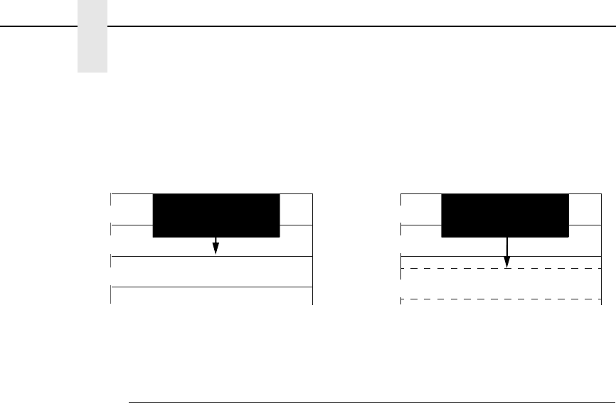
54
Chapter 2
Configuring the PCL-II Emulation with Control Codes
Figure 1. PTX Linefeed
Programmable Reset
The programmable reset escape sequence (ESCE*) causes the printer to
eject paper to the top-of-form (position 0,0) if not already at top-of-form. This
command resets all current printer configuration values to the following
states. The printer remains on-line after a programmable reset. When the
printer is reset, it is set to a known state as follows:
•
Primary and secondary character sets (fonts) as configured from the
control panel.
•
Vertical line spacing (6/8 LPI) as configured from the control panel.
•
Paper moves to the next Top of Form position (if not currently at Top of
Form).
•
Data buffer is printed and then the buffer is cleared.
•
Standard VFC channel assignments selected as defined by physical page
length.
•
Margins set at maximum limits and/or Left margin set at first column (0).
•
Physical page length remains as configured from the control panel.
•
Logical page length = physical page length
•
Text length = logical page length minus one inch
•
All character font attributes (symbol set, pitch, style, and density) default
to the character font configured from the control panel.
•
Display functions off and Underline enhance disabled.
•
Perforation skip mode as configured from the control panel.
•
Enable/Disable Label Card as configured from control panel.
•
Printronix linefeed emulation as configured from control panel.
•
Raster graphics horizontal resolution as configured from the control
panel. Vertical resolution set to 72 dots per inch.
*The Reset Command can also be set to Disable, Current Config, or Factory
Config. See the User's Manual for more information.
LINE 1
LINE 3
LINE 2
LINE 1
LINE 3
LINE 2
PTX Linefeed Enabled PTX Linefeed Disabled
Linefeed
Linefeed
Programmable VFC
55
Programmable VFC
Programmable VFC allows the user to specify paper movement information
other than the standard VFC definitions shown in Table 12. VFC information
is stored in the memory (RAM) table just as the standard VFC is, only the
bytes of information are loaded into RAM using the following escape
sequence:
ESC&l[byte count]W[VFC data]
The byte count parameter specifies the number (in decimal 0 - 255) of VFC
data bytes to expect immediately following the termination of the escape
sequence.
VFC data is the binary data which is loaded into the VFC table in RAM. These
8-bit bytes are sent in the following order following the ESC sequence
terminator: the most significant byte of the first word followed by the least
significant byte of the first word, followed by the most significant byte of the
second word, etc. The most significant bit of each word is channel 16 and the
least significant bit of each word is channel 1.
VFC Data = (MS byte) (LS byte) (MS byte) (LS byte) . . .
(word 1 = line 1) (word 2 = line 2) . . .
Once the VFC has been loaded into the RAM table, the VFC channels are
selected using the ESC&l[0 through 16]V sequence in the same manner as
the standard VFC. The standard and programmable VFC both use the same
table in RAM. Resetting the printer causes the standard VFC to be
recalculated using the current page and text (form) length and a new table to
be overwritten in RAM. The VFC table is also recalculated when the line
spacing, text length, or page length changes.
Special VFC Considerations
Before loading a VFC table, it is recommended that a VFC select of channel 0
be performed. This will bring the printer to the top of the physical page.
When a programmed VFC is loaded into RAM, the logical page length is
automatically calculated using the following formula:
Logical Page Length (in number of lines) = byte count /2
The example on page 61 shows a VFC table which uses “standard” VFC
definitions and also illustrates a programmable VFC.
Example: Defining a 3.5 inch form at six lines per inch.
1 inch = 6 lines x 3.5 inches = 21 lines
Note An even byte count must be indicated. If an odd byte count is indicated, the
VFC table in RAM will not be overwritten and the data bytes following the
ESC sequence are read and discarded.
Note If the I/O is configured for 7 bit data, channels 8 and 16 cannot be
downloaded with confidence since the eighth bit is used for the
communication protocol. Selecting channels 8 or 16 for 7 bit data is not
recommended.
56
Chapter 2
Configuring the PCL-II Emulation with Control Codes
Programmable VFC Using PCL
Programmable VFC's using PCL seem to cause a lot of problems and
misunderstandings. Most of the misunderstanding concerns the use of the
escape sequence used to set the VFC file. This escape sequence is used to
override the default VFC of the printer. This escape sequence can be hard-
coded into a program or ASCII file.
VFC's are best understood by reviewing an actual example of how to
implement them. For this discussion, the example consists of a 3.5 inch form
at six lines per inch with several different channels defined for use on the form
to be printed.
1 inch = 6 lines per inch x 3.5 inches = 21 lines; therefore this would be a 21
line form.
First, establish the VFC length: with a 3.5” form and 6 LPI print, we have 21
potential lines of print (3.5 x 6 = 21). Refer to the following figure for an
example of the desired finished output.
There are many methods to accomplish this task. The simplest way is to
provide a “1” in CH3 (Channel 3) for all possible print lines and simply call
CH3 for each line (including blank lines). This is called “line counting” and
leaves the burden of positioning with the programmer (adding or deleting a
line causes an adjustment elsewhere to be made).
EXAMPLE FORM
Line 1 Company name
Line 2 Street address
Line 3
Line 4
Line 5
Line 6
Line 7 Opening line
Line 8
Line 9
Line 10 Body
Line 11 Body
Line 12 Body
Line 13
Line 14
Line 15
Line 16
Line 17 Closing line
Line 18
Line 19
Line 20 P.S. line
Line 21
Note The TEXT LENGTH command could be used in conjunction with the
standard VFC and accomplish the above requirements. The assumption is
there are reasons to use a customized VFC; this example has been
simplified for clarification purposes.

Programmable VFC
57
A second method involves only providing a “1” in CH3 where print will occur.
The programmer then simply calls CH3 and the blank lines are skipped.
There still is no flexibility for adding or deleting lines without VFC modification,
but line counting is minimized.
A third method involves assigning VFC channels to each section of the letter
and performing a call to CH3 within each section. To do this, the manufacturer
highly recommends following these guidelines:
•
CH1 should always define TOF and must be present for a valid load.
•
CH2 should always define BOF allowing for vertical margin (if any) and
must be present for valid paper out conditions.
•
CH3 should be present for any potential print line except in the vertical
margin area (if any).
For this example, CH1 will occur at line 1 and is aligned with the Company
Name. We will arbitrarily assign CH4 to occur at line 7 (Opening Line), CH5 to
occur at line 10 (Body), CH6 to occur on line 17 (Closing Line) and CH7 to
occur on line 20 (P.S. Line).
With the above channel assignments in mind, the programmer would call CH1
to begin the letter. After printing the name and address (using calls to CH3 to
“move” to each line) the programmer would call CH4 to skip to line 7 and print
the opening line. Next, a call is made to CH5 to skip to line 10 and print the
body, CH6 to print the closing and CH7 to print the P.S. line. This gives each
section flexibility by allowing variable sizes, limited by the physical room
available before interfering with the next section and avoiding the drudgery of
line count.
The above VFC would look like:
Channel 12345678910111213141516
Line 1 1 1
Line 2 1
Line 3 1
Line 4 1
Line 5 1
Line 6 1
Line 7 1 1
Line 8 1
Line 9 1
Line 10 1 1
Line 11 1
Line 12 1
Line 13 1
Line 14 1
Line 15 1
Line 16 1
Line 17 1 1
Line 18 1
Line 19 1
Line 20 1 1
Line 21 1 1
58
Chapter 2
Configuring the PCL-II Emulation with Control Codes
Notice that for each line channel 3 is selected, this would select a single
space advance. A 1 could be placed in any or all other channels and the VFC
would still be valid since the printer will only look at the channel selected and
advance to the next line that contained a 1 in that channel. For example, if the
printer was on line 2 and channel 7 was selected, the printer would advance
or slew down to line 20 which is the first line where there is a “1” in channel 7.
The next step would be to convert the above VFC definition into the escape
sequence format. The VFC data portion of the escape sequence reverses the
order of the channels. Once reversed, the 16 bits are then divided into two, 8-
bit bytes, with channel 16 being the Most Significant Bit (MSB) of the word
and channel 1 the Least Significant Bit (LSB) of the word. Refer to Table 10.
Since the escape sequence requires the VFC data to be in ASCII format this
binary data must be converted to ASCII. As in our example, many characters
may convert to “unprintable” ASCII characters (below ASCII OCTAL 037).
Refer to the ASCII Symbol Set chart in Appendix A. Entering unprintable data
can be done in several ways:
The easiest and preferred method involves using “dummy” VFC channels to
cause the converted character to become a printable one. For example,
always have bit 7 and bit 15 a “1”, thus adding %100 to the unprintable
character, and eliminating the confusion of entering unprintable data. Do not
“call” the corresponding channel bit 7 or 15 or else improper spacing will
occur.
If the VFC channels that bits 7 and 15 represent must be used, these
unprintable characters must be manipulated for data entry. In most cases, this
can be dealt with by using the DISPLAY FUNCTIONS mode of your terminal.
Type in the “ESC&l[byte count]W” followed by the ASCII characters using the
CONTROL key with the corresponding letter. (Since the CONTROL key
subtracts %100 (100 OCTAL) simply add %100 to the “unprintable” character.
For example, 00000101 converts to %5, adding %100 gives you a %105
which is an E, therefore, pressing a CONTROL E gives the desired result.)
If your terminal doesn't have a DISPLAY FUNCTIONS mode, some EDITOR
programs allow entering the OCTAL equivalents. Some editors do not allow
the user to directly enter OCTAL numbers. In this case, a “dummy” character
would be entered as the VFC data. Next, the EDITOR “CHANGE” command
would be used to change the dummy character to the desired ASCII
character. For example, place an “x” as a dummy character in the VFC data
and use the CHANGE command to replace the “x” with an ASCII 01 (SOH
character) by typing “CHANGEQ “x” to ‘01”. This would replace the “x” with
the unprintable ASCII 01; your escape sequence would appear one character
shorter without DISPLAY FUNCTIONS mode turned on.
This could also be accomplished by changing the specific column to the
ASCII character required. It is important to specify the starting and stopping
column or the CHANGE command will act as a column INSERT. For
Note A “1” corresponds to a hole punched in a physical paper tape.
Programmable VFC
59
example, if column 10 on line 2 is to be changed to an ASCII 04 you would
type “CHANGEQ 10/10 TO '04 IN 2”.
The HP e3000 Workstation Configurator allows entering the VFC data in an
initialization string. This is only applicable when using a printer with a serial
interface and has some limitations. The most significant limitation is that the
initialization string can contain only 120 formatted (compiled) characters. This
limits use to VFCs of 57 lines or less (6 escape sequence characters + 114
VFC data characters = 120). Any other commands in the initialization string
reduces this further. Space available in the initialization string data entry field
(three lines) is NOT an accurate indicator of the number of formatted
characters; careful counting is necessary. Using VFC channels 8 and 16 is
also not allowed due to a limitation of entering data with an octal value above
177.
There are several methods to enter data in the Workstation Configurator:
•
Entering data as a decimal number, i.e. 13 for a carriage return.
•
As an OCTAL number (one byte at a time) by preceding the number with
the % sign.
•
As a two or three character mnemonic such as BS or DC1 (see Appendix
B of the Workstation Configuration manual).
•
By entering the control characters with the up-arrow or circumflex
character preceding the character, i.e. a backspace would be an ^H.
•
By entering the actual ASCII character within single quotes, i.e. 'A' would
equate to an OCTAL %101.
Each character entered, with the exception of multiple ASCII characters within
the single quote, MUST BE separated by commas. An example would be
“ESC, '&16W', %101, 'ABC', BS, 13”.
Note The “ ' ” is the single quote and not the prime character.
Note Only one byte may be specified at a time in OCTAL, thus allowing a
maximum of OCTAL 377 which would place a 1 in columns 1-8.

60
Chapter 2
Configuring the PCL-II Emulation with Control Codes
* DO NOT depress the Control Key on these BOLDFACE characters since
they are printable characters.
This VFC data can now be entered into the escape sequence in an ASCII file
or programmatically and be either embedded into the application or merged
with the spool file.
Table 10. Converting VFC Format to VFC Data
Most Significant Byte Least Significant Byte
16 15 14 13 12 11 10 987654321Octal ASCII CTL
MSB/LSB MSB/LSB MSB/LSB
Line 1 0 000000000000101%000%005 NulEnq @E
Line 2 0000000000000101%000%004 NulEot @D
Line 3 0000000000000101%000%004 NulEot @D
Line 4 0 000000000000100%000%004 NulEot @D
Line 5 0 000000000000100%000%004 NulEot @D
Line 6 0 000000000000100%000%004 NulEot @D
Line 7 0 000000000001100%000%014 NulFF @L
Line 8 0 000000000000100%000%004 NulEot @D
Line 9 0 000000000000100%000%004 NulEot @D
Line 10 0 000000000010100%000%024 NulDc4 @T
Line 11 0 000000000000100%000%004 NulEot @D
Line 12 0 000000000000100%000%004 NulEot @D
Line 13 0 000000000000100%000%004 NulEot @D
Line 14 0 000000000000100%000%004 NulEot @D
Line 15 0 000000000000100%000%004 NulEot @D
Line 16 0 000000000000100%000%004 NulEot @D
Line 17 0 000000000100100%000%044 Nul$ @$*
Line 18 0 000000000000100%000%004 NulEot @D
Line 19 0 000000000000100%000%004 NulEot @D
Line 20 0 000000001000100%000%104 NulD @D*
Line 21 0 000000000000110%000%006 NulAck @F

Programmable VFC
61
Example VFC Data Entry Methods
The example escape sequence may be created while the DISPLAY
FUNCTIONS key has been enabled as shown below.*
Top of Form
Bottom of Form
Single Spacing
Double Spacing**
Triple Spacing**
Half Form
Quarter Form
Tenth Line
Bottom of Form
Bottom of Form - 1
Top of Form - 1
Top of Form
Seventh Line
Sixth Line
Fifth Line
Fourth Line
Channels 12345678910111213141516
Line 1 1 111111 11111
Line 2 1
Line 3 1 1
Line 4 1 1
Line 5 1 1 1 1
Line 6 1 1
Line 7 1 1 1 1
Line 8 1 1
Line 9 1 1 1 1 1
Line 10 1 1
Line 11 1 1 1 1
Line 12 1
Line 13 1 1 1 1 1 1
Line 14 1 1
Line 15 1 1 1 1 1
Line 16
Line 17
Line 18
Line 19
Line 20
Line 21 1
*This sample shows a 21-line VFC table at 6 LPI. The text ends at line 14,
leaving 6 blank lines (one inch) at the bottom of the page.
**These channels cause a move to the next double/triple space line.
Press the CONTROL key before each letter of the VFC data except for the
two BOLDFACE characters.
ESC&142W@E@D@D@D@D@D@L@D@D@T@D@D@D@D@D@
$@D@D@D@F
VFC data
This would display the corresponding ASCII character, i.e., the Nul for CTL
@.

62
Chapter 2
Configuring the PCL-II Emulation with Control Codes
Another method using a text editor would be to do a CHANGE command
replacement to convert the characters to ASCII characters. This is shown as:
\ADD 1
1 ESC&142WabcdefghijklmnopqrstuvwxyzABCDEFGHIJ
2 //
\CHANGEQ 7/7 TO '00
\CHANGEQ 8/8 TO '05
\CHANGEQ 9/9 TO '00
.
.
.
\CHANGEQ 48/48 TO '06
This could also be input by not entering the letters, but simply changing the
specific column to the desired ASCII character. In the above example the
“abc... HIJ” would not be entered and the CHANGE command would be used
as follows:
\CHANGEQ 7 TO '00 \CHANGEQ 8 TO '05
.
.
.
An example for the Workstation Configurator might be input in several
formats. An example showing the various formats is shown below:
ESC, '&142W' ,NUL,ENQ, '@, 'D, 00, 04, %0, %4, ....%0, %6
As you can see, the escape sequence for the Programmable VFC can be
quite complicated. This should only be used after attempting to satisfy VFC
requirements using the standard (computed) VFC and the TEXT and PAGE
LENGTH escape sequences.
The most common errors in successfully implementing the Programmable
VFC escape sequence usually involve improper VFC byte counting or
attempting to manipulate “unprintable” characters and getting confused.
Converting these “unprintable” characters to printable ones is the easiest way
to avoid data entry confusion.
Summary of Recommended Steps to Implement Programmable VFC
1. Layout the required VFC in a standard channel 1-16 format.
2. Reverse the resulting bit image so that channel 1 is now where channel
16 was and channel 16 is now where channel 1 was.
3. Divide this 16 bit image into two 8-bit bytes.
4. Decode these 8-bit bytes into ASCII characters using the chart in
Appendix A. If the corresponding decoded character is not a printable
character (below %37), it is highly suggested to convert to one by using a
“dummy” channel (7 and/or 15).
5. Enter these characters into the Programmable VFC escape sequence as
the VFC data. This data MUST be an even byte count and is CASE
SENSITIVE (upper/lower). As in all escape sequences, do not include the
brackets ([ ]); they are for clarification only.
Raster Graphics
63
6. This escape sequence must be sent to the printer before the data by
embedding in the application or as part of an initialization string. A
programmable or hardware RESET will clear the VFC RAM causing the
printer to return to the default VFC.
Raster Graphics
Graphics are sent to the printer using the following escape sequences:
ESC*t[70, 140]RRaster graphics resolution
ESC*r#L Horizontal raster graphics resolution
ESC*r#V Vertical raster graphics resolution
The ESC*r#L and ESC*r#V escape sequences allow you to set the horizontal
and vertical raster graphics resolutions independently. Valid raster graphics
resolutions are 70 DPI by 72 DPI, 140 DPI by 72 DPI, 70 DPI by 144 DPI, and
140 DPI by 144 DPI. The following table lists the graphics resolution and the
corresponding escape sequence used to select that graphics resolution.
There are many different valid ways to select a given graphics resolution. The
following table lists only one of the many valid ways.
The ESC*t#R escape sequence allows you to select a graphics resolution of
either 70 x 72 dots per inch (default) or 140 x 144 dots per inch (high
resolution). For example, to specify high-resolution, you would send the
ESC*t140R escape sequence to the printer. Using the standard resolution,
the maximum amount of graphics data that can be printed is 115.5 bytes
versus 231 bytes for high-resolution.
Note If either the RS-232E or the RS-422B interface is installed in the printer,
the interface can be configured to have such things as STRIP NULLS AND
DELETES. The Null and/or Delete character could be used as valid
characters, so the user must either combine other channels on the same
line to generate another character, or not configure the printer to strip
these characters. Another factor may be the use of 8-bit data. If the user
desires to use channels 8 and 16, then 8-bit data must be configured. For
more detail please refer to the User's Manual.
Table 11. Graphics Resolution
Horizontal DPI Vertical DPI Escape Sequence
70 72 ESC*r70l72V
140 72 ESC*r140l72V
70 144 ESC*r70l144V
140 144 ESC*r140l144V

64
Chapter 2
Configuring the PCL-II Emulation with Control Codes
ESC*rA or ESC*r#A Prepare for raster graphics
(PCL Level III)
ESC*b[# of bytes] W[binary data] Raster data transfer (PCL Level I)
ESC*b[# of raster lines]Y Move paper # number of raster lines
ESC*rB Raster graphics complete (PCL Level I)
The ESC*rA or ESC*r#A sequence informs the printer that a raster graphics
dump is to follow the sequence. If value of # is 0 and the printer has received
a partial line of ASCII data before this sequence is received, then the ASCII
data prints with a carriage return and line feed following. If the value of # is 1,
then the graphics will start at the current horizontal position. If no value is
entered for #, then 0 is assumed.
The ESC*b#W[binary data] sequence actually sends the raster data to the
printer. This escape sequence must be sent for each raster line to be printed.
The # of bytes parameter is the decimal number of bytes of binary graphics
data to be sent to the printer. The binary data consists of a 1 for every dot to
be printed and a 0 for every blank space.
The ESC*b#Y escape sequence allows you to skip multiple adjacent blank
lines. The # of raster lines parameter is the decimal number of blank raster
lines to skip. The size of the blank raster line to be skipped is equivalent to the
currently set vertical raster graphics resolution. The advantage of using this
escape sequence over sending multiple raster data transfer escape
sequences containing blank raster lines is the escape sequence is processed
faster and the paper is moved faster.
The ESC*rB sequence informs the printer that all the raster data has been
transferred.
The following example illustrates how to send three lines of raster graphics to
the printer.
ESC*rAESC*b2WDc
ESC*rA Prepares printer for raster graphics
ESC*b2W Indicates two bytes of data to follow
D First byte of graphics data
c Second byte of graphics data
ESC*b2WL@
ESC*b2W Indicates two bytes of data to follow
L First byte of graphics data
@ Second byte of graphics data
ESC*b2W$+ESC*rB
ESC*b2W Indicates two bytes of data to follow
$ First byte of graphics data
+ Second byte of graphics data
ESC*rB Raster graphics complete
Many systems perform an automatic line feed after each line of data. The
system's automatic line feed must be suppressed or else the raster lines will
not be adjacent to each other. A file equation which specifies the line length
(for example, RESC=-219) may be used to suppress the automatic line feed
along with carriage control directives, such as “+”.

Self-test
65
Graphics files must be raster graphics files in the format described here in
order to print on the printer. To print vector graphics files, such as graphics
files created for plotters, a vector-to-raster conversion must be performed on
the data. (Vector-to-raster conversion is NOT a standard feature of the
printer.) Text and graphics cannot mix on the same line due to grid conflicts.
Raster graphics use 8-bit data.
Self-test
(PCL Level I)
ESCz prints the PCL-II configuration report, which shows available character
sets, symbol sets, bar codes, etc.
Standard (Computed) VFC
The printer VFC uses the logical page and form length (text length) to
calculate the distance to be skipped for each VFC channel. This information is
then loaded into the printer's VFC “table.” The “table” is 16 channels wide and
n lines long, where n is the logical page length in number of lines. A VFC
channel contains a 1 in this table on every line it can access. If the VFC
channel cannot access the line, a 0 is placed on that line for that channel. For
example, to specify a skip to the next half form, a program would specify VFC
channel 6. Notice in the sample on page 61 that 1's are placed in the table at
the half form position (lines 1 and 9). Then, for example, if the printer has
finished printing line 2 and channel 6 is selected, the paper will be advanced
to line 9.
To use the standard VFC, perform the ESC&l[0-16]V sequence using the
appropriate parameter number listed in Table 12.
Stroke Weight (Bold)
The Stroke Weight command designates the thickness of the strokes that
compose the characters of a font.
ESC(s#B Primary stroke weight
ESC)s#B Secondary stroke weight
The value field (#) must be 0 for standard stroke weight, or 3 for bold stroke
weight.
Switching Character Fonts
Character fonts can be accessed using the Shift In/Shift Out (SI/SO) control
codes.
The SO (CTRL N) control code is sent to the printer to access the secondary
font; the SI (CTRL O) control code is sent to select the primary font.

66
Chapter 2
Configuring the PCL-II Emulation with Control Codes
Text Length (Vertical Margin) Selection
(PCL Level II)
The length of a form within a logical page is set using the ESC&l[1-128]F
sequence, where the number of lines desired (1-128) is specified. The first
line of text is printed at the Top of Form position. The physical page length
minus the text length defines the total vertical margin (top plus bottom margin)
for the page.
If a text length of zero is received, the text length defaults to one inch less
than the logical page length. The default text length, which is invoked any time
the logical page length is changed, is one inch less than the logical page
length. If the logical page length is one inch or less, the text length is set equal
to the logical page length.
Transparent Print Data
This feature allows the printing of binary data which is required in certain
applications. The escape sequence ESC&p[# of bytes]X enables the printer to
print data as in the display functions mode, except that no control codes or
escape sequences (including CR and ESCZ) are executed. The number
specified in the value field is the exact number of bytes that will be interpreted
as binary.
Underline Mode
The ESC&dD sequence enables the automatic underlining mode. In this
mode, each printed character and space is underlined until the printer
receives an ESC&d@ sequence. The underline enhancement is disabled in
the default state. Underlining only affects forward horizontal movement such
as SP (space), DATA, or forward horizontal cursor moves; reverse
movements such as BS (backspace), CR (carriage return) and negative
horizontal cursor moves are not affected.
Vertical Forms Control (VFC)
67
Vertical Forms Control (VFC)
Vertical forms control (VFC) is a feature which allows increased throughput by
enabling the printer to skip to predetermined print locations. Key page
locations, such as top of form, half form, double space, and triple space, are
referred to as channels (0 through 16) and are stored in a VFC “table.”
The printer has both a standard (computed) VFC and a programmable VFC.
*All escape sequences except ESC&l0V refer to the logical page rather than
the physical page. This escape sequence causes a skip to the top of the next
physical page (unless already at top of page).
**These channels cause a move to the next double/triple space line, and
therefore may not actually perform a double/triple space.
Note In most situations, the printer's standard (computed) VFC page length
setting, as determined from the front panel, meets the application
requirements. Refer to the User's Manual for information on setting the
page length from the front panel.
Table 12. VFC Default Channel Definitions
Prefix Parameter Terminator Explanation
ESC&l 0v/V *Conditional Top of Physical Page
1Top of Form (first line of text)
2Bottom of Form (last line of text)
3Single spacing
4**Double spacing
5**Triple spacing
6Half form
7Quarter form
8Tenth line
9Bottom of Form
10 Bottom of Form - 1
11 Top of Form - 1
12 Top of Form
13 Seventh line
14 Sixth line
15 Fifth line
16 Fourth line

68
Chapter 2
HP e3000 Information
HP e3000 Information
This section contains information which is specific to HP e3000 users. It
explains the use of the feature access and transparent modes, environment
files, downloading VFC files, carriage control, perforation skip mode, and
discusses recoverability.
Feature Access and Transparent Modes
During system device configuration, the P8000 printer is configured to default
to either the transparent or feature access mode. In the transparent mode, the
printer prints (but does not execute) all data including control codes and
escape sequences. In the feature access mode, the supported control codes
and escape sequences are executed. The user can access the non-default
mode using either the FDEVICECONTROL intrinsic (for programs) or an
environment file.
VFC Download with a Serial Interface
Typically, VFC download was only possible for 256X and HP 2300 Series
printers with an HPIB interface using the CIPER driver. MPE V/E T-MIT and
above support a software product called Workstation Configurator that allows
serial printers to “download” VFC by placing the VFC escape sequence in an
initialization string instead of embedding them within the application.
The process of downloading VFC using Workstation Configurator is different
than when using an HPIB printer. Workstation Configurator has a utility that
allows modification to two different files that allow for, among other things,
setting initialization strings, flow control, and VFC. Workstation Configurator
has a terminal type file that is used for certain functions and a VFC file that is
used for setting the initialization strings and the VFC. These files are not in the
same format as the HPIB VFC file and must be created using Workstation
Configurator.
When using the VFC file created using Workstation Configurator, the user
must specify the terminal type file in the HP e3000 I/O Configuration, or by
referencing it with the ENV parameter of the FILE statement. The
DOWNLOAD command will NOT operate in this configuration.
If the ENV parameter of the FILE statement is used, the associated terminal
type file that has been configured with the printer will still be sent to the printer
first and the terminal type file that has been specified with the ENV parameter
will be sent NEXT. This does not create any problems, it just should be noted
when using a datascope or analyzing a spool file.

Carriage-Control Directives
69
Carriage-Control Directives
The HP e3000 software drivers allow users to embed the following carriage-
control directives in files:
ASCII SYMBOL CARRIAGE ACTION
“ ” Single space (with or without automatic page eject).
“+” No space, return (next printing at column 1).
“-” Triple space (without automatic page eject).
“0” Double space (without automatic page eject).
“1” Page eject (form feed). Selects VFC channel 1.
“C” Sets single-space option, without automatic page
eject (66 lines-per-page).
The carriage-control directive is placed in column 1 of the file and is executed
(but not printed) when the file is printed. When using this feature, all other
characters placed in column 1 will be ignored (not printed).
When using the carriage-control directives, the application must use carriage
control and [;CCTL] must be included in the file equation as shown in the
following example:
:file [filename];dev=[device number];cctl
Graphics
When using graphics, the line feed generated by the driver must be
suppressed or there will be 1/6” or 1/8” spacing between raster lines. One way
to do this is to add a “+” to the front of the file as carriage control (the file
equation must have “;CCTL.”)
Printing in the Perforation Skip Region
When using the HP e3000, an automatic page eject occurs when the
perforation skip region is entered. There are three ways to avoid a page eject
and allow printing in the perforation skip region:
•
Set the text length = logical page length = physical page length on the
front panel.
•
Use carriage control with a “C” in column 1 (the application must use
carriage control).
•
Set the carriage control to null (no CR-LF at end of line) and
programmatically add a CR-LF to the end of each record.

70
Chapter 2
HP 1000 Information
HP 1000 Information
The P8000 printer may be commanded in either transparent or feature access
mode. In the transparent mode, the printer prints (but does not execute) all
data including control codes and escape sequences. In the feature access
mode, the control codes and escape sequences are executed.
All configuration information is located in the DVC12 Graphics Printer Driver
Reference Manual (P/N 92068-90022). For HP 1000 A-Series information,
refer to the Driver Reference Manual (P/N 92077-90011) and the RTE-A
System Design Manual (P/N 92077-90013). To set transparent mode with the
DVC12 driver, the following command can be used where LU is the logical
unit address of the printer: --CN,LU,30B,20B
Downloading VFC
All information concerning downloading VFC files is contained in the DVC12
Graphics Printer Driver Reference Manual (P/N 92068-90022).
B-4 Carriage-Control Directives
The HP 1000 software drivers allow users to embed the following carriage-
control directives in files:
ASCII SYMBOL CARRIAGE ACTION
“ ” Single space (with or without automatic page eject).
“+” or “*” No space, return (next printing at column 1).
“-” Triple space (without automatic page eject).
“0” Double space (without automatic page eject).
“1” Page eject (form feed). Selects VFC channel 1.
The carriage-control directive is placed in column 1 of the file and is executed
(but not printed) when the file is printed. When using this feature, all other
characters placed in column 1 are ignored (not printed).
Perforation Skip Mode
To override the HP 1000 driver's automatic page eject, see the Control
Requests section of the DVC12 Graphics Printer Driver Reference Manual
(P/N 92068-90022).

71
3
P-Series Printer Emulation
Overview
This chapter describes the P-Series emulation host control codes.
“Emulation” refers to the ability of a printer to execute the commands of a
particular printer control language. A printer control language is the coding
system used to convey, manipulate, and print data. It contains character
codes and command sequences that configure the emulation. In this manual,
the terms emulation, printer protocol, and printer control language are
synonymous.
In the P-Series emulation mode, your printer can print files coded for the P-
Series printer control language. To select the P-Series emulation mode as the
active printer emulation, select LinePrinter+ from the EMULATION menu and
P-Series from the Printer Protocol menu, as described in the User's Manual.
The P-Series emulation provides many configurable parameters. The default
parameter values for this emulation are shown in Table 13. You can modify
the emulation parameter values in two ways:
•
The P-Series host control codes. An extensive set of P-Series control
code commands can be sent to the printer from an attached host
computer via the host data stream. Most of this chapter is devoted to
describing the P-Series control code commands.
•
The printer configuration menus. You can modify a subset of the P-
Series emulation parameters using the printer configuration menus,
control panel keys and LCD, as described in the User's Manual.
A parameter value set by a host control code generally overrides a value set
from the printer's control panel.
Note Configuration values selected from the menus or via host control codes
can be saved to the printer's NVRAM memory so that they will not be lost
when you power off the printer or reset it to the factory defaults. The menu
selection for saving a configuration to memory is described in the User's
Manual.
72
Chapter 3
Overview
P-Series Default Values and States
The factory settings for the P-Series emulation menu options are shown in
Table 13. Table 14 lists additional factory settings for parameters provided by
the LinePrinter+ formatting menus. (The EMULATION menu options are
described in the User's Manual). Host control codes can override many of the
settings for these menu options.
Table 13. P-Series Default Settings
Characteristic Default Setting
Control Code 06 8.0 LPI
Control Code 08 Elongated
Define CR Code CR = CR
Auto LF Disable
Overstrike Enable
Define LF Code LF = CR + LF
Select SFCC 1
EVFU Selected Enable
Alternate Set 80-9F Control Code
Character Set IBM PC
Primary Subset ASCII (USA)
Extended Subset Code Page 437
SFCC d Command Even Dot Plot
P-Series Default Values and States
73
Table 14. LinePrinter+ Menu Option Factory Settings
Characteristic Default Setting
CPI 10.0
LPI 6.0
Typeface Data Processing
Proportional Spacing Disable
Bold Print Disable
Italic Print Disable
Slashed Zero Disable
Left Margin 0 columns
Right Margin 0 columns
Bottom Margin 0 lines
Perforation Skip Disable
Form Length 11.0 inches
279.4 millimeters
66 lines
Form Width 13.6 inches
345.4 millimeters
136 characters
Reset Cmd CFG Ld Disable
74
Chapter 3
Configuring the P-Series Emulation with Control Codes
Configuring the P-Series Emulation with Control Codes
The remainder of this chapter describes the P-Series printer control language
codes that may be sent from a host computer attached to the printer, in order
to invoke and configure numerous P-Series emulation functions.
Format for Control Code Descriptions
The following information is listed for each code function (where applicable):
Name The title or function of the command.
ASCII Code The ASCII mnemonic for the command is shown. Command
sequences are in 7-bit (ASCII) form.
Hex Code The code or command sequence in hexadecimal numbers.
Dec Code The code or command sequence in decimal numbers.
Purpose The function(s) of the control code.
Discussion A discussion of the uses of the code or command sequence,
including exceptions or limitations to its use.
Example A sample is provided for some control codes when it is possible
to illustrate the effect of a control code, or if a specific syntax is
required to complete the program statement (i.e. Horizontal Tab
set, Vertical Tab set/clear).
Switching Between the Emulations
The printer supports several different emulations. PCL-II is the default. P-
Series, Proprinter III XL, and Epson FX-1050 are all a part of the LinePrinter
Plus emulation.
The following command switches from PCL-II to P-Series:
ESC%-00000X
To switch from P-Series to PCL-II, send the following command to the printer:
ESC|};KD
Note If you specify any parameters for a control code other than the ones that
are defined in the control code description, unpredictable results may
occur.
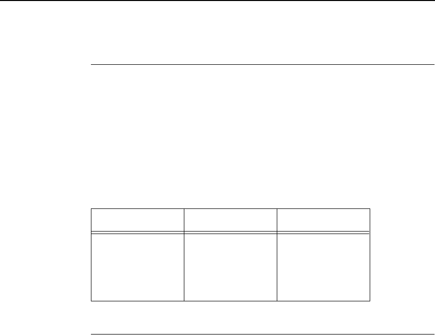
Special Function Control Code (SFCC) Header
75
Special Function Control Code (SFCC) Header
A Special Function Control Code (SFCC) is used to extend the control code
protocol. The SFCC is the control code introducer (or header); it is the first
input in the sequence of parameters. The general control code sequence is:
(SFCC)(parameter 1)(parameter 2)...(parameter n)
P-Series codes can be configured to use any value from 1 through 127 (hex
01 through hex 7F) as control code introducers. For example, bold print could
be configured to be enabled in the P-Series protocol using any of the control
code introducers listed in Table 15.
SFCC Command Line
Print format, print mode, or international language selection can be controlled
by a longer sequence known as a command line. Command lines are string
type commands placed between complete lines of text and affect the text
which follows. The protocol has six command lines: PMODE, OSET, PSET,
LPI, LINES, and INCHES. Each of these command lines is discussed in this
chapter under the appropriate Control Code function.
For example, the forms length (in inches) can be set using the following
command line:
SFCC INCHES; n.f
where: n is the whole number of inches, and f is the fractional increment
in 0.5 inch increments.
When using the SFCC in a command line, the SFCC must be the first non-
blank symbol in the line (space, hex 20, is a blank symbol). In addition,
characters following spaces (other than a valid line terminator) in a command
line are ignored so that user comments can be included on the command line.
The valid line terminators are Form Feed (FF), Line Feed (LF), and Carriage
Return (CR); however, when used in the command line, these line terminators
do not cause any paper motion. If a command line contains an error, the
command will not be executed.
Table 15. SFCC Example (Bold Print)
ASCII Hex Decimal
SOH G
ETX G
ESC G
^ G
~ G
01 47
03 47
1B 47
5E 47
7E 47
01 71
03 71
27 71
94 71
126 71
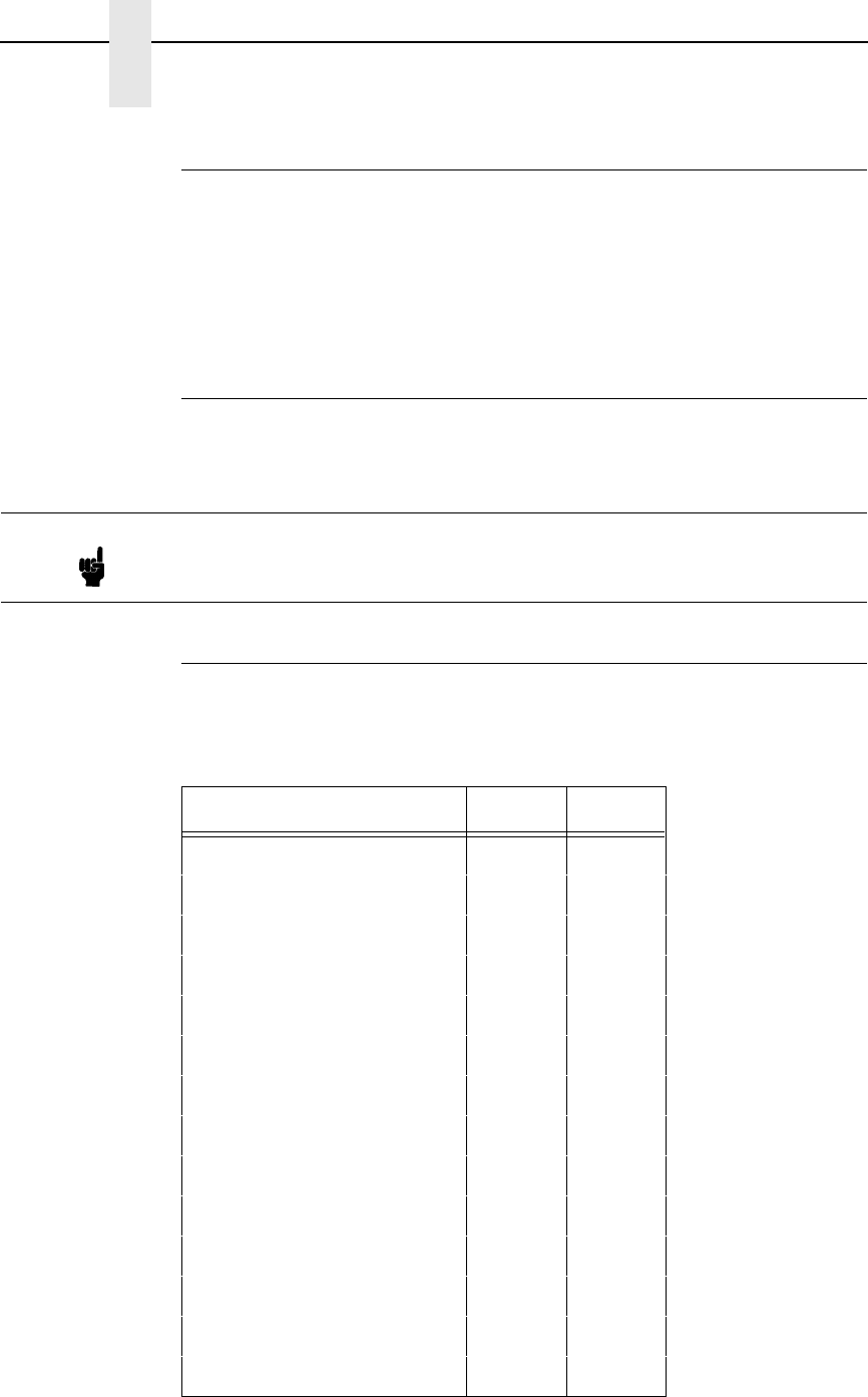
76
Chapter 3
Configuring the P-Series Emulation with Control Codes
Attribute Set and Reset Codes
Certain print attributes are set and reset (turned on or off) by using the
appropriate SFCC code sequence and the numbers 1 or 0. These may be
either the hexadecimal code 01 and 00, or the ASCII code for the printable
symbols of decimal 1 and 0 (hexadecimal code 31 and 30, respectively).
Expanded Print, Super/Subscript Print, and Underline are attributes that are
set/reset this way.
NUL Code
NUL (hex 00) is ignored by the printer and can be used as a fill character;
however, it can not be used to add blank spaces since it is not a space
character.
Print Modes Supported for Character Sets
All print modes are supported for all character sets; however, for the character
sets listed in Table 16, only the print modes listed are supported.
Note Hex 80 in the 0437 PC Character Set and hex 7F in the 0850 PC Character
Set are treated as a NUL; however, these two controls can not be used as
parameter terminators.
Table 16. Print Modes Supported
Character Set Mode Pitch
Barcode 10 cpi DP 10
Multinational DP 10 cpi DP 10
Multinational DP 12 cpi DP 12
Multinational NLQ 10 cpi NLQ 10
Greek DP 10 cpi DP 10
Greek DP 12 cpi DP 12
Greek NLQ 10 cpi NLQ 10
Graphic DP 10 cpi DP 10
Graphic NLQ 10 cpi NLQ 10
Scientific DP 10 cpi DP 10
Scientific DP 12 cpi DP 12
Scientific NLQ 10 cpi NLQ 10
OCR-A OCR-A 10
OCR-B OCR-B 10
The Control Codes
77
The Control Codes
This index lists each printer command by function, ASCII mnemonic, and the
page where the command is explained in detail. “N/A” means not applicable.
The rest of this chapter defines the control code functions for P-Series
Emulation mode. The commands are listed in alphabetical order.
FUNCTION ASCII CODE PAGE
Paper Motion
Form Feed FF 92
Line Feed LF 93
Reverse SFCC } ; n102
Vertical Tab VT 104
Page Format
Backspace BS 79
Carriage Return CR 81
Forms Length Set (Inches) SFCC INCHES; n.f 92
Forms Length Set (Lines) SFCC LINES; n93
Line Spacing 1/6 Inch (6 lpi) SFCC 2 94
SFCC LPI
Line Spacing 1/8 Inch (8 lpi) SFCC 0 94
SFCC LPI
Line Spacing 8 or 10.3 LPI ACK 95
(1 line only) SFCC f
Line Spacing 7/72 Inch SFCC 1 95
Line Spacing n/72 Inch SFCC A 96
Line Spacing n/216 Inch SFCC 3 97
VFU Commands N/A 104
Print Attributes
Bold Print SFCC G 80
Bold Print (1 line only) SFCC j 80
Bold Print Reset SFCC H 80
Elongated (Double High) Print,
One Line Only SFCC h 87
Elongated (Double High) Print,
Set/Reset SFCC w n88
Emphasized Print SFCC E 88
Emphasized Print Reset SFCC F 89
Expanded Print (Double Wide)
One Line Only SFCC k 90
Expanded Print (Double Wide) SFCC W n 90
Overscoring SFCC _ n97
Print Mode/Pitch Selection SFCC X m n 99
SFCC PMODE; n
SFCC [ n q
Note Some control code functions can be accomplished using another control
code sequence or via control panel selection.

78
Chapter 3
Configuring the P-Series Emulation with Control Codes
FUNCTION ASCII CODE PAGE
Print Attributes (continued)
Superscript/Subscript Printing SFCC S n103
Superscript/Subscript Printing
Reset SFCC T 103
Underline SFCC - n104
Graphics
Plot, Even Dot (High Density) EOT 98
SFCC d
Plot, Odd Dot (Normal Density) ENQ 98
SFCC e
Other Functions
Bell BEL 79
Character Set Select SFCC l xyz 82
Character Set Select:
ECMA Latin 1 Extended SFCC OSET; n 84
Character Set Select:
International Languages SFCC R n85
SFCC PSET; n
Characters 80-9F
(Control Codes) SFCC 7 86
Characters 80-9F
(Printable Symbols) SFCC 6 86
Emulation Reset SFCC @ 89
Extended Character Set SO 91
SFCC SO
SFCC n
SFCC 4
Extended Character Set Cancel SI 91
(Primary Set Select) SFCC SI
SFCC o
SFCC 5

Backspace
79
Backspace
ASCII Code BS
Hex Code 08
Dec Code 08
Purpose Moves the logical print head to the left one character space
toward the first character column.
Discussion When configured from the control panel for backspace, BS
moves the character position indicator (the logical print head
position) one character space to the left at the current character
pitch setting. The code is ignored if the logical print head is
positioned at the first character column.
Example If you were to print five “T” characters, then two BS commands,
then two “=” characters, the output would look like the sample
below:
Bell
ASCII Code BEL
Hex Code 07
Dec Code 07
Purpose Sounds the printer's buzzer/beeper.
Discussion The BEL function will sound the buzzer/beeper for 0.2 seconds
upon receipt of this command.
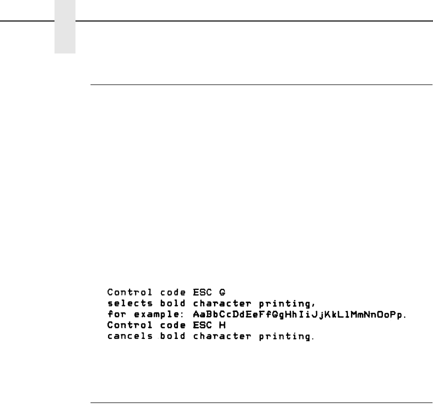
80
Chapter 3
Configuring the P-Series Emulation with Control Codes
Bold Print
ASCII Code SFCC G SFCC j
Hex Code SFCC 47 SFCC 6A
Dec Code SFCC 71 SFCC 106
Purpose Selects bold character printing.
Discussion When the bold character printing control code is received, all
characters are printed in bold until reset by the bold print reset
control code or printer reset. Bold Print is the same as
emphasized printing.
When SFCC j is used, bold printing is selected for one line only
and reset by the bold print reset control code, emulation reset, or
a paper motion command.
Example The following sample illustrates bold character printing.
Bold Print Reset
ASCII Code SFCC H
Hex Code SFCC 48
Dec Code SFCC 72
Purpose Resets bold character printing.
Discussion This control code resets the bold print character attribute. Other
print attributes such as double wide printing are not affected.
Example Refer to the Bold Print control code for a sample of bold
character print set and reset.
Carriage Return
81
Carriage Return
ASCII Code CR
Hex Code 0D
Dec Code 13
Purpose Returns the logical print head to the first character column
(resets the pointer to the first character position).
Discussion The CR code may or may not cause printing or paper motion,
depending on the Define CR Code value defined in the
configuration menus. If the Define CR Code submenu displays:
The characters following the CR are printed over the previous
characters on the line. If identical characters are placed in the
same position on the line, those characters will be printed in
emphasized print when the Overstrike mode is enabled from the
control panel.
The CR=CR configuration causes subsequent printable data to
overprint previous data at half speed if Overstrike is enabled
from the control panel (and prints somewhat faster if Overstrike
is disabled), unless an intervening paper motion command is
received.
If the Define CR Code submenu displays:
Control code CR is converted to perform a carriage return and
line feed function.
Define CR Code
CR = CR*
Define CR Code
CR = CR+LF*
82
Chapter 3
Configuring the P-Series Emulation with Control Codes
Character Set Select
ASCII Code SFCC l xyz (lowercase “L”)
Hex Code SFCC 6C xyz
Dec Code SFCC 108 xyz
Purpose Selects the character set, extended character set, and the
international language for a specific character set.
where x is the character set (Table 17);
y is the international language for the selected character set
(Table 18);
z is the extended character set for the selected character set
(Table 19);
Discussion An asterisk (*) (hex 2A) may be submitted for x, y, or z. If the
asterisk (*) is the value selected for x, the character set will not
change. If * is the value selected for y or z, the previously
selected international language and/or extended character set
for the selected character set will be used.
The character set, international language and extended
character set can also be selected from the printer control panel,
via the Character Set and Print Language options; however, the
control code setting will override the control panel selection.
Except for the asterisk value discussed above, values other than
those shown in the tables will result in the control sequence
being terminated.
Table 16 on page 76 provides detailed notes on print mode
support for each character set.
Table 17. Character Set Select (x)
xCharacter Set
0 (hex 30) IBM PC
1 (hex 31) Multinational
2 (hex 32) ECMA Latin 1
3 (hex 33) DEC Multinational
Character Set Select
83
Table 18. International Language Select (y)
yx = 0 (hex 30) x = 1 (hex 31) x = 2 (hex 32) x = 3 (hex 33)
IBM PC Multinational ECMA Latin 1 DEC Multinational
0 (hex 30) ASCII (USA) ASCII (USA) ASCII (USA) ASCII (USA)
1 (hex 31) French EBCDIC German French
2 (hex 32) German Swedish German
3 (hex 33) English (UK) Danish English (UK)
4 (hex 34) Danish Norwegian Norwegian/Danish
5 (hex 35) Swedish Finnish Swedish
6 (hex 36) Italian English (UK) Italian
7 (hex 37) Spanish Dutch Spanish
8 (hex 38) Japanese French Japanese
9 (hex 39) French Canadian Spanish French Canadian
10 (hex 3A) Latin American Italian Dutch
11 (hex 3B) Norwegian Turkish Finnish
12 (hex 3C) Danish-II Japanese Swiss
13 (hex 3D) Spanish-II
14 (hex 3E) Latin American-II
Table 19. International Language Select (z)
zx = 0 (hex 30) x = 1 (hex 31) x = 2 (hex 32) x = 3 (hex 33)
IBM PC Multinational ECMA Latin 1 DEC Multinational
0 (hex 30) IBM PC (0437) Mult. Extended Set Barcode 10 cpi DEC Mult. Ext. Set
1 (hex 31) IBM PC (0850) Mult. DP 10 cpi
2 (hex 32) Mult. DP 12 cpi
3 (hex 33) Mult. NLQ 10 cpi
4 (hex 34) Greek DP 10 cpi
5 (hex 35) Greek DP 12 cpi
6 (hex 36) Greek NLQ 10 cpi
7 (hex 37) Graphics DP 10 cpi
8 (hex 38) Graphics NLQ 10 cpi
9 (hex 39) Scientific DP 10 cpi
10 (hex 3A) Scientific DP 12 cpi
11 (hex 3B) Scientific NLQ 10 cpi
12 (hex 3C) Multinational (at Primary set mode and pitch)
84
Chapter 3
Configuring the P-Series Emulation with Control Codes
Character Set Select: ECMA Latin 1 Extended
ASCII Code SFCC OSET; n
Purpose Selects the print mode and pitch at which the extended
characters will print.
OSET is valid only when the ECMA Latin 1 character set has
been selected from the control panel. OSET will be ignored if the
IBM PC, Multinational, or DEC Multinational Character Sets are
active.
Discussion n ranges from 0 through 12 (hex 00 through 0B) to select the
print mode/pitch combinations available from Table 20. All other
values will result in an error message.
Extended characters will print at the print mode and pitch
selected by the OSET command, even if that mode and pitch
differs from the currently selected print mode and pitch. If the
print mode differs between the extended and primary characters,
the first character in the data stream selects the print mode at
which that line will print. Different pitches can be printed on the
same line.
Table 20. Print Modes/Pitches Available Using P-Series OSET (ECMA
Latin 1, Extended Character Set Only)
nPrint Mode/Pitch Select
0Barcode DP 10 cpi
1Multinational DP 10 cpi
2Multinational DP 12 cpi
3Multinational NLQ 10 cpi
4Greek DP 10 cpi
5Greek DP 12 cpi
6Greek NLQ 10 cpi
7Graphics DP 10 cpi
8Graphics NLQ 10 cpi
9Scientific DP 10 cpi
10 Scientific DP 12 cpi
11 Scientific NLQ 10 cpi
12 Multinational at Primary Character Set Mode and Pitch
Character Set Select: International Languages
85
Character Set Select: International Languages
ASCII Code SFCC PSET;nSFCC R n
Hex Code SFCC 52 n
Dec Code SFCC 82 n
Purpose Specifies the international language set identified by n in the
basic character set selected from the control panel (ECMA Latin
1, IBM PC, Multinational, and DEC Multinational).
where n specifies a language, as shown in Table 21.
Table 21. International Character Sets
nCharacter Set Selected
SFCC R
(hex) PSET ECMA Latin 1 IBM PC (0437 or
0850) Multinational DEC
Multinational
0 (30) 0ASCII (USA) ASCII (USA) ASCII (USA) ASCII (USA)
1 (31) 1German French EBCDIC French
2 (32) 2Swedish German German
3 (33) 3Danish English (UK) English (UK)
4 (34) 4Norwegian Danish Norw./Danish
5 (35) 5Finnish Swedish Swedish
6 (36) 6English (UK) Italian Italian
7 (37) 7Dutch Spanish Spanish
8 (38) 8French Japanese Japanese
9 (39) 9Spanish French Canadian French Canadian
0A (3A) 10 Italian Latin American Dutch
0B (3B) 11 Turkish Danish-II Finnish
0C (3C) 12 Japanese Spanish-II Swiss
0D (3D) 13 Latin American-II
0E (3E) 14
(currently undefined)
0F (3F) 15
10 (40) 16
11 (41) 17
12 (42) 18
13 (43) 19
14 (44) 20
15 (45) 21
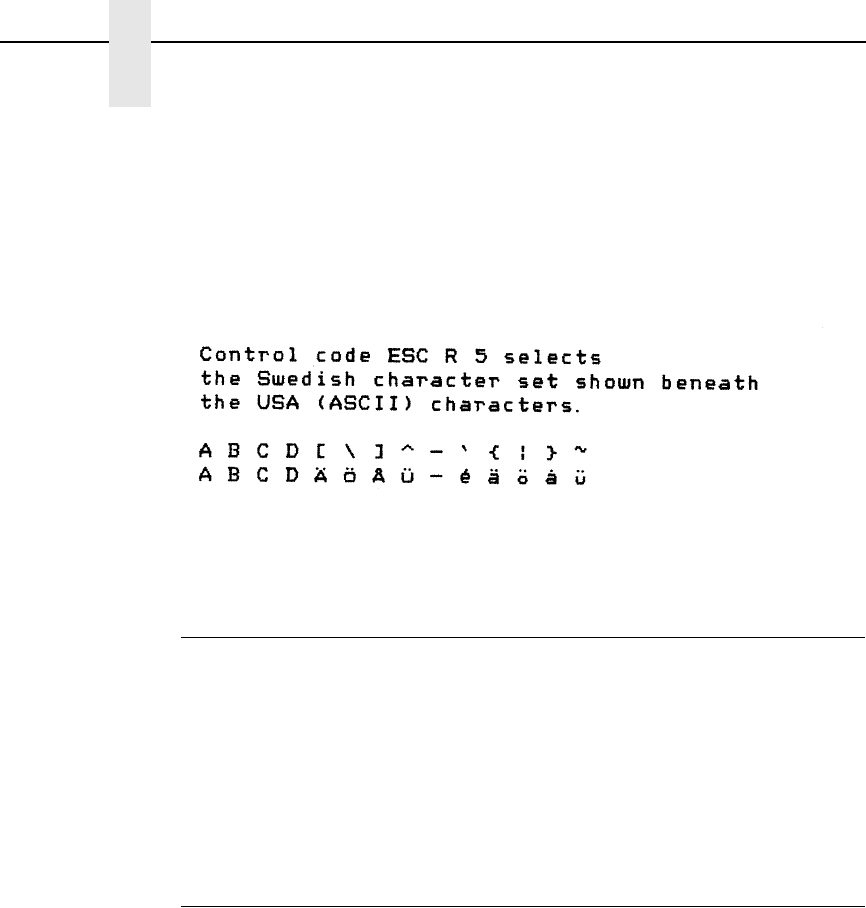
86
Chapter 3
Configuring the P-Series Emulation with Control Codes
Discussion The international character set can also be selected from the
control panel via the Print Language option; however, the control
code setting will override the control panel character set
selection. Values other than those selectable from Table 21 will
be ignored.
Example The following example illustrates international character
selection using the IBM PC character set.
Characters 80-9F (Control Codes)
ASCII Code SFCC 7
Hex Code SFCC 37
Dec Code SFCC 55
Purpose Selects hex codes 80 through 9F in the character sets as control
codes. Cancels the command SFCC 6.
Discussion This control code overrides the control panel setting.
Characters 80-9F (Printable Symbols)
ASCII Code SFCC 6
Hex Code SFCC 36
Dec Code SFCC 54
Purpose Selects hex codes 80 through 9F in the character sets as
printable symbols. Cancels the command SFCC 7.
Discussion This control code overrides the control panel setting.
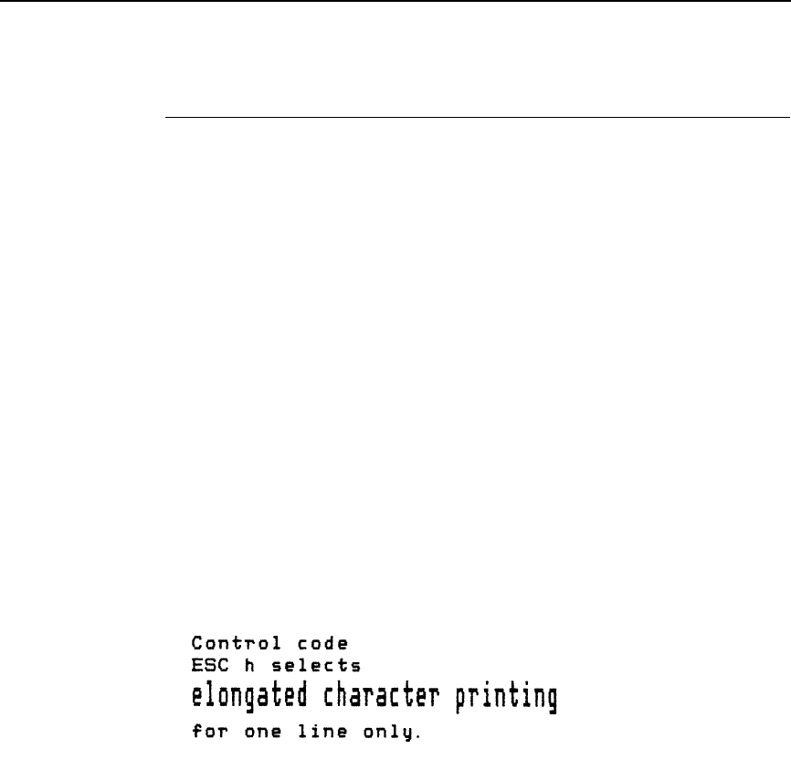
Elongated (Double High) Print, One Line Only
87
Elongated (Double High) Print, One Line Only
ASCII Code SFCC h BS
Hex Code SFCC 68 08
Dec Code SFCC 104 08
Purpose Selects elongated (double high) character printing for one line
only. Elongated characters are approximately double height but
standard width.
Discussion The elongated character control code is a line-by-line print
attribute; when the control code is received, one entire line of
elongated characters is printed and then automatically reset.
When configured for double high print, the P-Series control code
BS (Hex 08) also selects elongated character printing for a
single line.
When using this feature with relative line slewing, the paper will
be moved n + 1 lines rather than n lines. Refer to “Vertical Page
Formatting” on page 207 for more information on relative line
slewing. When using small line spacing and the lines overlap, an
unexpected print format may result.
Example The following sample illustrates elongated character printing.
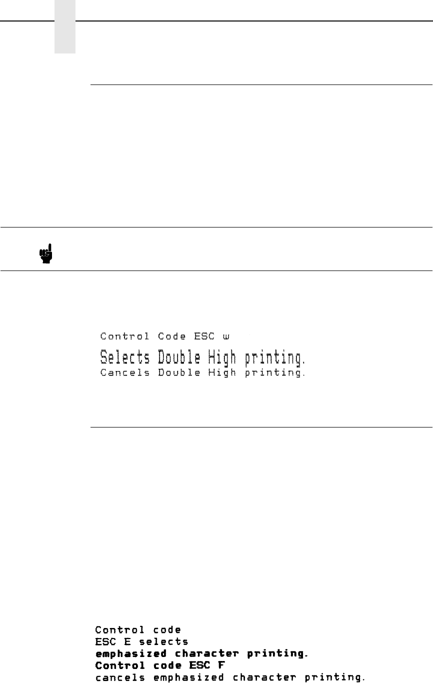
88
Chapter 3
Configuring the P-Series Emulation with Control Codes
Elongated (Double High) Print, Set/Reset
ASCII Code SFCC w n
Hex Code SFCC 77 n
Dec Code SFCC 119 n
Purpose Turns double-high character printing on and off. Double-high
characters are standard width but twice as high.
where n = 1 or 49 (hex 01 or hex 31) turns double high printing on
n = 0 or 48 (hex 00 or hex 30) turns double high printing off
Discussion The OCR A and OCR B fonts cannot be printed in double high.
If Superscript/Subscript (SFCC S) is combined with Double High
printing, only Double High printing will occur.
Example The following illustrates double-high character printing.
Emphasized Print
ASCII Code SFCC E
Hex Code SFCC 45
Dec Code SFCC 69
Purpose Selects emphasized character print format.
Discussion When the emphasized print control code is received, all
characters will be printed in emphasized print until reset by the
emphasized print reset control code or printer reset. The
emphasized print attribute is implemented by horizontal
“shadow” printing.
Emphasized print is ignored during superscript or subscript
printing, and when 15-20 cpi characters have been selected.
Example The following sample illustrates emphasized character printing.
Note It is recommended to use double Line Feeds and Carriage Returns when
double-high character printing is on (after an SFCC w control code has
been sent), or else the printer will overstrike text that has already printed.

Emphasized Print Reset
89
Emphasized Print Reset
ASCII Code SFCC F
Hex Code SFCC 46
Dec Code SFCC 70
Purpose Resets emphasized character printing.
Discussion The emphasized print reset control code only resets the
emphasized print character attribute.
Example See the Emphasized Print control code example for an example
of Emphasized Print Reset.
Emulation Reset
ASCII Code SFCC @
Hex Code SFCC 40
Dec Code SFCC 64
Purpose Initializes all print mode related parameters to their factory
default or power-up configuration values.
Discussion Print mode, line spacing, international language selection,
margins, form length, skip-over perforation, and character pitch
are reset to their selected power-up configuration values.
Character-by-character and line-by-line attributes are canceled.
The vertical format unit is cleared. The current line is set to the
top-of-form position. Interface parameters and printer protocol
selection are not affected.
If the menu option “Reset Cmd CFG Ld” is disabled, the factory
default configuration is loaded. If it is enabled, the power-up
configuration is used. The default is the factory default.
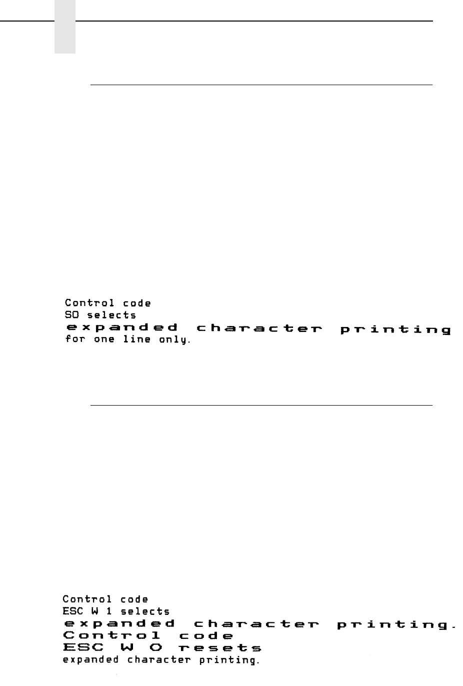
90
Chapter 3
Configuring the P-Series Emulation with Control Codes
Expanded Print (Double Wide), One Line Only
ASCII Code SFCC k
Hex Code SFCC 6B
Dec Code SFCC 107
Purpose Selects expanded (double wide) print for one line only.
Discussion This expanded print control code is a line-by-line print attribute;
when the SFCC k control code is received, the current line is
printed double wide and then automatically reset.
This control code can be reset by a paper motion control code
(LF, VT, CR, etc.), SFCC @ (printer reset), CAN or SFCC W
(double wide print).
Example The following sample illustrates Expanded Print for one line only.
Another example of expanded printing is shown for Expanded
(Double Wide) Print, SFCC W on page 90.
Expanded Print (Double Wide), Set/Reset
ASCII Code SFCC W n
Hex Code SFCC 57 n
Dec Code SFCC 87 n
Purpose Selects or resets expanded (double wide) print.
where n = SOH (hex 01) or 1 (hex 31) selects expanded print.
n = NUL (hex 00) or 0 (hex 30) resets expanded print.
Discussion When expanded print using SFCC W is received, all characters
will be printed double wide until reset by the expanded print reset
control code or a printer reset.
Example The following sample illustrates expanded character printing and
expanded character printing reset.
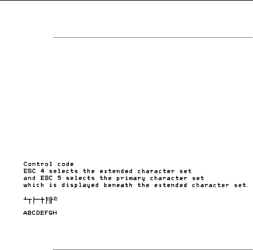
Extended Character Set
91
Extended Character Set
ASCII Code SO SFCC SO SFCC n SFCC 4
Hex Code 0E SFCC 0E SFCC 6E SFCC 34
Dec Code 14 SFCC 14 SFCC 110 SFCC 52
Purpose Accesses the extended character set in the range hex A0
through FF using codes 32 through 127 (hex 20 through 7F).
Discussion Used in 7-bit systems as if data bit 8 was set to 1. For example,
sending code hex 20 accesses the symbol at code point hex A0.
If a printable symbol is not available at the code point, a space is
printed.
SFCC 4 is not cancelled by the next paper motion command;
SO, SFCC SO, and SFCC n are cancelled by paper motion.
Example The following sample illustrates the Extended Character Set and
Extended Character Set Cancel (see page 91) control codes.
Extended Character Set Cancel (Primary Set Select)
ASCII Code SI SFCC SI SFCC o SFCC 5
Hex Code 0F SFCC 0F SFCC 6F SFCC 35
Dec Code 15 SFCC 15 SFCC 111 SFCC 53
Purpose Cancels Extended Character Set as selected by SO, SFCC SO,
SFCC n, and SFCC 4, and selects the Primary Character Set.
Discussion Used in 7-bit systems. If data bit 8 is disabled, this control code
selects the range as if data bit 8 is set to 0, and data is printed as
characters from 32 through 127 (hex 20 through 7F).
Example Refer to the Extended Character Set example on page 91.

92
Chapter 3
Configuring the P-Series Emulation with Control Codes
Form Feed
ASCII Code FF
Hex Code 0C
Dec Code 12
Purpose Prints the data in the buffer, advances the paper position to the
next top-of-form and moves the character position to the first
character column.
Discussion The default forms length is determined by the printer
configuration. Forms length is set by using the control panel or
forms length control codes. Code FF cancels all single-line only
print attributes.
The default form length is 11 inches. The Form Feed command
will react differently when the VFU is active. Refer to Chapter 7.
Forms Length Set (Inches)
ASCII Code SFCC INCHES; n.f
Purpose Sets the length of forms (paper) in inches.
where n = 1 through 24 (hex 01 through 18) specify the number of
inches on a page.
f = fractional number in .5-inch increments (minimum forms
length is .5 inches).
Discussion Upon receipt of this code, the current line becomes the first line
of the form, and the form length set becomes the current forms
length. Vertical tab positions set below the bottom of the form
are cleared.
Forms length is defined in inches; therefore, subsequent line
spacing changes do not affect the result of this command.
Increments of .5-inch can be specified; for example, sending the
following command will result in a form length setting of 7
½
inches: SFCC INCHES; 7.5
The maximum forms length is 24 inches. All other values are
ignored. In INCHES mode, incorrect values will produce an error
message.
Forms length can be set by the control panel. The control code
forms length setting from the host computer will override the
control panel setting. If the VFU is enabled and loaded, this
command is ignored.

Forms Length Set (Lines)
93
Forms Length Set (Lines)
ASCII Code SFCC LINES; n
Purpose Sets the length of a form (paper) in lines.
where n = 1 through 192 (hex 01 through C0) specify the number of
lines per page at the current line spacing.
Discussion The forms length is set to the number of lines defined by the
quotient of n and the current line spacing so that the units are in
inches. In LINES mode, the maximum form length is 24 inches,
and n values in excess of 24 inches will cause an error
message.
If the calculated forms length in lines is not an exact multiple of
the target machine dot size, the forms length value will be
adjusted down to the next possible multiple.
If the VFU is enabled and loaded, this command is ignored.
Line Feed
ASCII Code LF
Hex Code 0A
Dec Code 10
Purpose Prints the data in the buffer (if any) and advances the vertical
character position one line at the current line space setting.
Discussion If configured for LF equals new line (LF=CR+LF), the logical
print head is positioned at character column 1 of the new line.
Otherwise, the logical print head does not move when
configured for LF function only (LF=LF ONLY). The LF function
cancels all single line print attributes such as double high
(elongated) and double wide (expanded) characters.
This code is always configured for LF=CR+LF in the P-Series
protocol.
In the P-Series Even Dot Plot mode (high density graphics), the
LF code does not cause paper position motion; the data in the
buffer is plotted and the logical print head is positioned at
character column 1 in anticipation of the Odd Dot Plot control
code to complete high density graphic plotting.
In the P-Series Odd Dot Plot mode (normal density graphics),
the LF code plots the data in the buffer, advances the paper
position a single dot row at the current vertical dot density, and
positions the logical print head at character column 1.
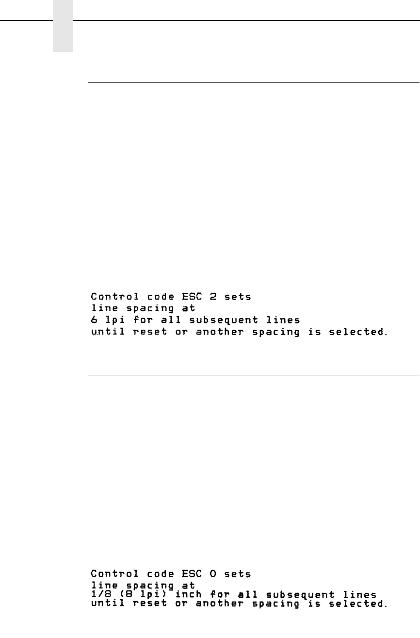
94
Chapter 3
Configuring the P-Series Emulation with Control Codes
Line Spacing 1/6 Inch (6 lpi)
ASCII Code SFCC 2 SFCC LPI; n
Hex Code SFCC 32
Dec Code SFCC 50
Purpose Sets line spacing to 6 lpi or as set by SFCC A (page 96).
Discussion For SFCC LPI; n, the value of n can be 6 or 8 only. If n = 6, this
command sets line spacing to 1/6 inch. Values of n other than 6
or 8 will cause an error message.
SFCC 2 asserts n/72-inch line spacing as set by SFCC A (page
96). If no distance has been set by SFCC A, the distance is 1/6”
The control code line spacing selection will override the control
panel line spacing setting.
Example The following example illustrates 1/6-inch line spacing and
assumes that a distance has not been set by ESC A.
Line Spacing 1/8 Inch (8 lpi)
ASCII Code SFCC 0 SFCC LPI; n
Hex Code SFCC 30
Dec Code SFCC 48
Purpose Specifies continuous line spacing at 1/8-inch increments (8 lpi).
Discussion When the 1/8-inch line spacing control code is received, all lines
will be printed at 8 lpi until a new line spacing is selected or the
printer is reset. The control code line spacing selection will
override the control panel line spacing setting.
For SFCC LPI; n, the value of n can be 6 or 8 only. If n = 8, this
command sets line spacing to 1/8 inch. Values of n other than 6
or 8 will cause an error message.
Example The following example illustrates 1/8-inch line spacing.
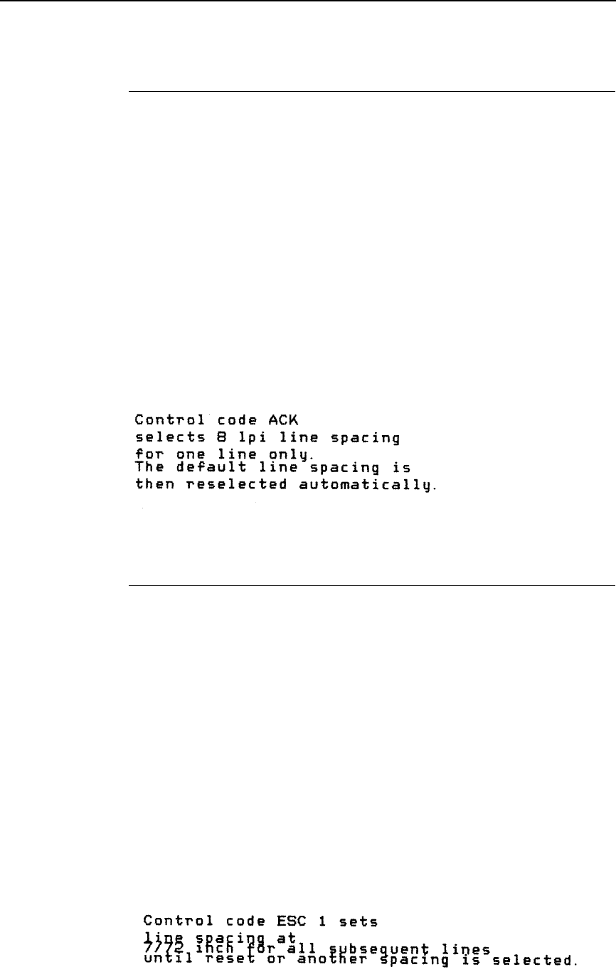
Line Spacing 8 or 10.3 lpi (1 Line Only)
95
Line Spacing 8 or 10.3 lpi (1 Line Only)
ASCII Code ACK SFCC f
Hex Code 06 SFCC 66
Dec Code 06 SFCC 102
Purpose Selects line spacing of 8 or 10.3 lpi for the current line only.
Discussion The default line spacing is reselected automatically after one
line. Line spacing may be selected either through the control
panel or by line spacing control codes. The control code setting
will override the control panel line spacing setting.
If the alternate line spacing selected from the control panel is 8
lpi, the ACK control code will set the line spacing to 8 lpi. If 10.3
lpi was selected from the control panel, the ACK control code will
set the line spacing to 10.3 lpi (7/72”).
Example The following example illustrates printing a single line of text at 8
lpi.
Line Spacing 7/72 Inch
ASCII Code SFCC 1
Hex Code SFCC 31
Dec Code SFCC 49
Purpose Specifies the line spacing at 7/72-inch (10.3 lpi) increments.
Discussion When the 7/72-inch line spacing control code is received, all
lines will be printed at the 7/72-inch line spacing until a new line
spacing is selected or the printer is reset. The control code line
spacing selection will override the control panel line spacing
setting, and the message display will reflect the line spacing as
10.3 lines per inch.
Caution should be used when combining this control code with
other print attributes such as Elongated (Double High),
Superscript, or Subscript; overlapping lines may occur. Printing
at different horizontal and vertical densities will not overlap.
Example The following example illustrates 7/72-inch line spacing.
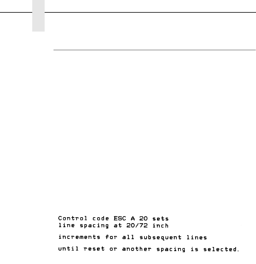
96
Chapter 3
Configuring the P-Series Emulation with Control Codes
Line Spacing n/72 Inch
ASCII Code SFCC A n
Hex Code SFCC 41 n
Dec Code SFCC 65 n
Purpose Stores a line spacing of n/72-inch increments.
where n = 1 through 85 (hex 01 through 55). All others are ignored.
Discussion When the SFCC A control sequence is received, all line feed
commands following an SFCC 2 sequence* will be at n/72-inch
line spacing until a new line spacing is selected or the printer is
reset. The control code line spacing selection will override the
control panel line spacing setting.
*The SFCC 2 sequence (page 94) asserts the line spacing which
was stored by the preceding SFCC A sequence.
Small values of n may result in overlapping lines. Overlapping
lines may also occur if print attributes such as Elongated
(Double High), Superscript, or Subscript characters are used on
the same line. Printing at different horizontal and vertical
densities will not overlap.
Example The following example illustrates 20/72-inch line spacing.
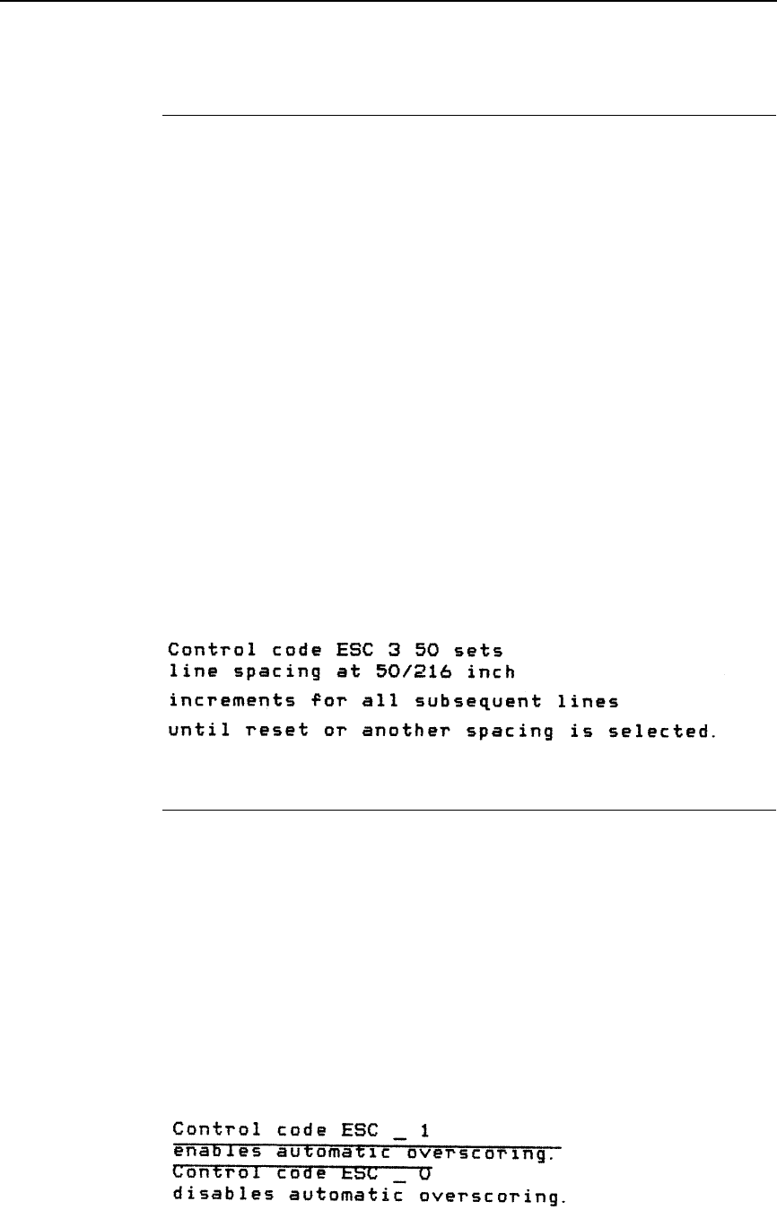
Line Spacing n/216 Inch
97
Line Spacing n/216 Inch
ASCII Code SFCC 3 n
Hex Code SFCC 33 n
Dec Code SFCC 51 n
Purpose Specifies the line spacing at n/216-inch increments.
where n = 1 through 255 (hex 01 through FF).
Discussion When the n/216-inch line spacing control code is received, all
line feeds following will be at n/216-inch line spacing until a new
line spacing is selected or the printer is reset. The control code
line spacing selection will override the control panel line spacing
setting.
The vertical character position moves only in multiples of the
current dot row spacing. If the distance to move is other than a
multiple of the current dot row spacing, the remainder is added
to the next paper motion command.
Caution should be used when combining this control code with
other print attributes such as Elongated (Double High),
Superscript, or Subscript; overlapping lines may occur. Printing
at different horizontal and vertical densities will not overlap.
Example The following example illustrates n/216-inch line spacing.
Overscoring
ASCII Code SFCC _ n
Hex Code SFCC 5F n
Dec Code SFCC 95 n
Purpose Enables or disables automatic overscoring of all characters.
where n = SOH (hex 01) or 1 (hex 31) selects overscore print.
n = NUL (hex 00) or 0 (hex 30) resets overscore print.
Discussion When automatic overscore is enabled, all characters, including
spaces, will be overscored until disabled.
Example The following sample illustrates automatic overscoring and
overscoring reset.
98
Chapter 3
Configuring the P-Series Emulation with Control Codes
Plot, Even Dot (P-Series High Density Graphics)
ASCII Code EOT SFCC d
Hex Code 04 SFCC 64
Dec Code 04 SFCC 100
Purpose Prints dots at the even numbered dot columns.
Discussion The even dot plot code is used for programming high density
graphics and must be used in conjunction with the Odd Dot Plot
code (hex 05). Refer to the Plot Mode section in Chapter 6 for
detailed plot mode information.
Example Print two high density plot boxes using odd and even dot plot for
high density graphics. Compare the example below to the
normal density odd dot plot example.
Plot, Odd Dot (P-Series Normal Density Graphics)
ASCII Code ENQ SFCC e
Hex Code 05 SFCC 65
Dec Code 05 SFCC 101
Purpose Prints dots at the odd numbered dot columns.
Discussion This is the P-Series programming normal density graphics
control code. The ENQ code should occur before any printable
data in the data stream. For high density graphics, the Even Dot
Plot code (04 hex) must be used in conjunction with (and
precede) the Odd Dot Plot code. Refer to the P-Series
Compatible Plot mode section in Chapter 6 for detailed plot
mode information.
Example Print two normal density plot boxes using odd dot plot. Compare
the odd dot plot example below to the high density Even Dot Plot
example.

Print Mode/Pitch Selection
99
Print Mode/Pitch Selection
ASCII Code SFCC PMODE; nSFCC X mn SFCC [ n q
Hex Code SFCC 58 mn SFCC 5B n 71
Dec Code SFCC 88 mn SFCC 91 n 113
Purpose Selects the print mode and character pitch in characters per inch
(cpi).
where In SFCC PMODE; n
n = 0 through 11 to select the print mode/pitch combinations
available from Table 22. All other values will result in an error
message.
where In SFCC [ n q
n = Print Mode/Pitch code (values other than those shown in
Table 23 are ignored.)
q = Command sequence terminator
where In SFCC X mn
m = Print Mode code
n = Pitch (cpi)
An asterisk (*) (hex 2A) may be substituted for m or n. Whenever
the asterisk replaces m or n, its current value will not change.
Values other than those shown in Table 24 and Table 25 are
ignored.
Discussion P-Series PMODE switches to the Primary Character Set and
selects print mode and pitch.
Print mode and pitch can also be selected from the control
panel. The print mode/pitch select control code from the host
computer will override the control panel print mode setting and
the print mode and pitch selection will be reflected on the
message display.
If PMODE 7 through 11 are selected to enable upside down
characters, the printing is still left to right. Even though
characters are upside down, you must reverse the order to read
left to right.
A complete set of tables identifying print mode, pitch, and dot
densities for all print modes follows.
Note The print mode must be changed before the first printable symbol or space
of a print line or the command sequence is deferred until the next line.
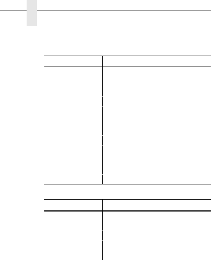
100
Chapter 3
Configuring the P-Series Emulation with Control Codes
Table 22. Print Mode and Pitch (SFCC PMODE;n)
nPrint Mode and Pitch
0DP 10 cpi
1DP 12 cpi
2DP 15 cpi
3NLQ 10 cpi
4HS 10 cpi
5OCR-A 10 cpi
6OCR-B 10 cpi
7DP 10 cpi upside down
8DP 12 cpi upside down
9DP 13 cpi upside down
10 DP 15 cpi upside down
11 DP 17 cpi upside down
Table 23. Print Mode and Pitch (SFCC [nq)
nPrint Mode and Pitch
1 (hex 31) NLQ 10 cpi
2 (hex 32) DP 10 cpi
3 (hex 33) HS 12 cpi
4 (hex 34) DP 12 cpi
5 (hex 35) DP 13 cpi
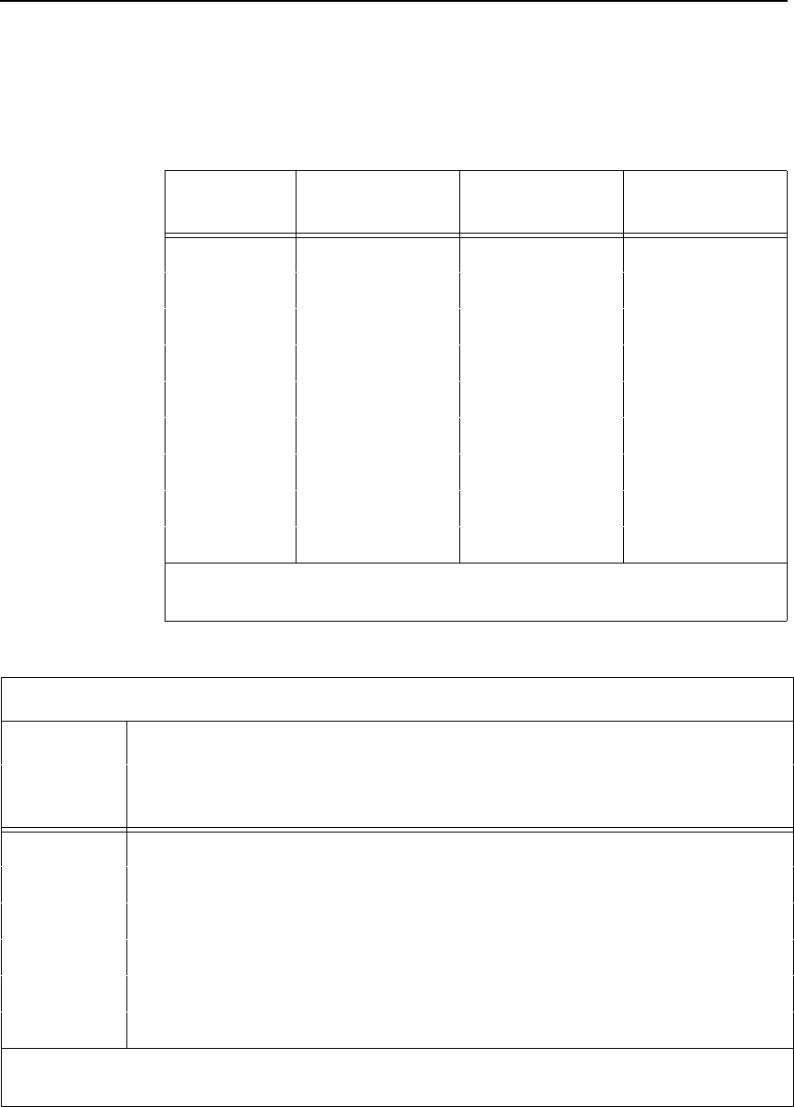
Print Mode/Pitch Selection
101
Table 24. Horizontal and Vertical Dot Density (SFCC X)
m (Hex*) Horiz. Density
Resolution Vertical Density Print Mode
0 (30) 120 dpi 72 dpi DP
1 (31) 180 dpi 96 dpi NLQ
2 (32) 120 dpi 48 dpi HS
3 (33) 120 dpi 48 dpi HS
4 (34) 120 dpi 48 dpi HS
5 (35) 120 dpi 144 dpi OCR-A
6 (36) 120 dpi 144 dpi OCR-B
7 (37) 180 dpi 96 dpi NLQ2
8 (38) 180 dpi 96 dpi NLQ2
*The hex values shown (i.e., 0 and 30) are equal. Either value can be used
in your program expression.
Table 25. Print Mode and Character Pitches (SFCC X)
Characters Per Inch
value of n:value of m:
Print Mode* DP
0 (30) NLQ
1 (31) HS
2 (32) HS
3 (33) HS
4 (34) OCR-A
5 (35) OCR-B
6 (36) NLQ2
7 (37) NLQ2
8 (38)
0 (30) 10 10 10 10 10 10 10 10 10
1 (31) 12 12 12 12 12 – – 12 12
2 (32) 13 13 13 13 13 – – 13 13
3 (33) 15 15 15 15 15 – – 15 15
4 (34) 17 17 17 17 17 – – 17 17
5 (35) 20 17 20 20 20 – – 17 17
*The hex values shown (i.e., 0 and 30) are equal. Either value can be used in your program
expression. The value of m is represented by the font choice line.
102
Chapter 3
Configuring the P-Series Emulation with Control Codes
Example Any of the BASIC expressions listed below will select the DP
print mode at 17 cpi.
where m (print mode) = SOH (hex 00) or 0 (hex 30)
n (pitch) = EOT (hex 04) or 4 (hex 34)
CHR$(1);“X”;CHR$(0);CHR$(4);
CHR$(1);“X”;CHR$(30);CHR$(34);
CHR$(1);“X04”;
Reverse
ASCII Code SFCC } ; n
Hex Code SFCC 7D 3B n
Dec Code SFCC 125 59 n
Purpose Moves the logical print head up.
Discussion If n is “L,” the print head moves up one line. (Reverse line feed.)
If n is “P,” the print head moves up to the previous top of form.
(Reverse form feed.)
Note The character set used when OCR-A or OCR-B is selected depends on
the Standard character set currently selected. The character set can be
changed by using SFCC l or by using the front panel.
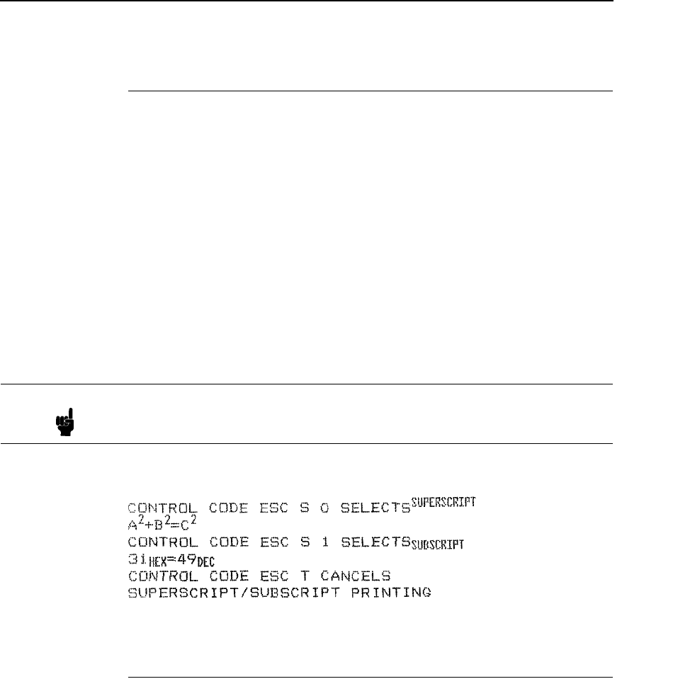
Superscript/Subscript Printing
103
Superscript/Subscript Printing
ASCII Code SFCC S n
Hex Code SFCC 53 n
Dec Code SFCC 83 n
Purpose Selects superscript or subscript printing.
Discussion An SFCC S code can be set for superscript or subscript printing,
as follows:
where n = SOH (hex 01) or 1 (hex 31) enables subscript printing.
n = NUL (hex 00) or 0 (hex 30) enables superscript printing.
When this control code is received, all characters will be
superscript or subscript until reset by the super/subscript printing
reset control code (SFCC T) or printer reset. Use caution when
combining this command with other print attributes; arbitrary
combinations might yield unexpected results.
Example The following sample illustrates superscript/subscript printing.
Superscript/Subscript Printing Reset
ASCII Code SFCC T
Hex Code SFCC 54
Dec Code SFCC 84
Purpose Resets superscript and subscript printing.
Example See the Superscript/Subscript Printing command example.
Note Superscript and subscript characters print at the same size as the current
font. They are shifted up or down one half of a line.
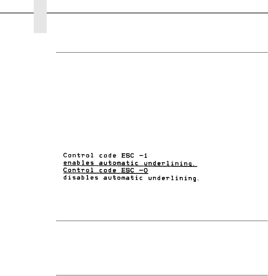
104
Chapter 3
Configuring the P-Series Emulation with Control Codes
Underline
ASCII Code SFCC - n
Hex Code SFCC 2D n
Dec Code SFCC 45 n
Purpose Enables or disables automatic underlining of all characters.
where n = SOH (hex 01) or 1 (hex 31) enables automatic underlining.
n = NUL (hex 00) or 0 (hex 30) disables automatic underlining.
Discussion When automatic underline is enabled, all characters, including
spaces, will be underlined until disabled.
Example The following sample illustrates automatic underlining.
VFU Commands
ASCII Code Refer to the P-Series VFU section in Chapter 7.
Purpose Load and execute the VFU.
Discussion Refer to Chapter 7 for detailed information.
Vertical Tab
ASCII Code VT
Hex Code 0B
Dec Code 11
Purpose Prints the data in the buffer and advances the paper to the next
vertical tab position.
Discussion If a vertical tab format is defined in the EVFU (channel 12) and
the VFU is enabled, the paper is moved to the next vertical tab
position.
If a vertical tab format is not defined, the paper is advanced to
the next line at the current line spacing. More information on
Vertical Tabs is provided in the EVFU section of Chapter 7.

105
4
IBM Proprinter III XL
Emulation
Overview
This chapter describes the Proprinter III XL emulation host control codes.
“Emulation” refers to the ability of a printer to execute the commands of a
particular printer control language. A printer control language is the coding
system used to convey, manipulate, and print data. It contains character
codes and command sequences that configure the emulation. In this manual,
the terms “emulation”, “printer protocol”, and “printer control language” are
synonymous.
In the Proprinter III XL emulation mode, your printer can print files coded for
the Proprinter III XL printer control language. To select the Proprinter
emulation as the active printer emulation, select LinePrinter+ from the
EMULATION menu and Proprinter III XL from the Printer Protocol menu, as
described in the User's Manual.
The Proprinter III XL emulation provides many configurable parameters. The
default parameter values for this emulation are shown in Table 26. You can
modify these parameter values in two ways:
•
The Proprinter III XL host control codes. An extensive set of Proprinter
III XL control code commands can be sent to the printer from an attached
host computer via the host data stream. Most of this chapter is devoted to
describing the Proprinter III XL control code commands.
•
The printer configuration menus. You can modify a subset of the
Proprinter III XL emulation parameters using the printer configuration
menus, control panel keys, and LCD, as described in the User's Manual.
Control codes sent from a host system generally override previous settings
that result from the configuration menus.
Note Configuration values selected from the menus or via host control codes
can be saved to the printer's NVRAM memory so that they will not be lost
when you power off the printer or reset it to the factory default
configuration. The menu selection for saving a configuration to memory is
described in the User's Manual.
106
Chapter 4
Overview
Proprinter III XL Emulation Default Settings
The factory settings for the Proprinter III XL emulation menu options are
shown in Table 26. Table 27 lists additional factory settings for parameters
provided by the LinePrinter+ formatting menus. (The EMULATION menu
options are described in the User's Manual.) Host control codes can override
many of the settings for these menu options.
Table 26. Proprinter III XL Menu Option Factory Settings
Characteristic Default Setting
Define CR Code CR = CR
Auto LF Enable
Define LF Code LF = LF
FF Valid at TOF Enable
Character Set Code Page 437
Alt. Char Set Set 1
20 CPI Condensed Enable

Proprinter III XL Emulation Default Settings
107
Table 27. LinePrinter+ Menu Option Factory Settings
Characteristic Default Setting
CPI 10.0
LPI 6.0
Typeface Data Processing
Proportional Spacing Disable
Bold Print Disable
Italic Print Disable
Slashed Zero Disable
Left Margin 0 columns
Right Margin 0 columns
Bottom Margin 0 lines
Perforation Skip Disable
Form Length 11.0 inches
279.4 millimeters
66 lines
Form Width 13.6 inches
345.4 millimeters
136 characters
Reset Cmd CFG Ld Disable
108
Chapter 4
Configuring the Proprinter III XL Emulation with Control Codes
Configuring the Proprinter III XL Emulation with
Control Codes
The remainder of this chapter describes the Proprinter printer control
language codes that may be sent from a host computer attached to the
printer, in order to configure numerous Proprinter emulation parameters.
Format for Control Code Descriptions
In this chapter, the following information is listed for each control code (where
applicable):
Name The title or function of the command.
ASCII Code The ASCII mnemonic for the command is shown. Command
sequences are in 7-bit (ASCII) form.
Hex Code The code or command sequence in hexadecimal numbers.
Dec Code The code or command sequence in decimal numbers.
Purpose The function(s) of the control code.
Discussion A discussion of the uses of the code or command sequence,
including exceptions or limitations to its use.
Example A sample is provided when it is possible to illustrate the effect of
a control code or if a specific syntax is required.
Escape Control Codes Overview
Printer capability is greatly increased by the use of escape control code
sequences. Escape sequences always begin with the ASCII escape
sequence introducer, ESC (hex 1B). Many of the ASCII control codes
described in this chapter are escape sequences.
An ESC sequence introducer in the data stream signals the printer to wait for
special instructions, even if it is ready and printing. The character codes
following the ESC character tell the printer what to do.
Note If you specify any parameters for a control code other than the ones that
are defined in the control code description, unpredictable results may
occur. The PI line is never recognized in Proprinter III XL Emulation mode.
Note An Escape code can occur anywhere in the datastream and is acted upon
immediately if it precedes a valid command.
Note For readability, code sequences appear in this manual with spaces
inserted between command elements. Do not insert spaces between code
characters when you are programming unless the ASCII space character
(SP) is part of a code sequence. For example, a code sequence printed in
this manual as ESC [ 1 is programmed as ESC[1.

Graphics Control Codes Overview
109
An escape sequence uses two or more bytes to define a specific printer
control function. The format for an escape sequence is:
After the ESC character are one or more characters which indicate the action
of the control code. One or more numerical parameters may in turn follow
these characters. For example, the sequence ESC S n tells the printer to
begin the superscript print attribute if n is an even number, or to begin the
subscript attribute if n is an odd number.
If the characters following the ESC code are not within the defined ranges, or
if they are within the defined ranges but not recognized as a function of this
printer, the entire sequence is ignored.
Graphics Control Codes Overview
The individual control codes that set graphics print quality are described
starting on page 115. Some additional background information about graphics
printing for the Proprinter III XL emulation is provided here.
The Proprinter III XL emulation provides one data protocol for printing
graphics information; the Bit Image graphics protocol allows an image block to
be printed. When using the Bit Image protocol, you can mix text and graphics
on the same line.
Setting Bit Image Modes via Control Codes
Control codes select bit image modes. The following bit image modes can be
mixed on the same line as text characters:
Parameters n1 and n2 together represent a 16-bit (hexadecimal) unsigned
number of the quantity (n1 + 256n2), which equals the number of bit image
characters (i.e. data bytes) to follow. If n1 and n2 are programmed so that
data extends past the last character position, the data is truncated at the last
character position. If n1 and n2 are both zero, the ESC sequence is ignored.
See Chapter 6 for details on bit image graphics.
ASCII ESC X n
Hex 1B 00-7F 0-FF
Escape Sequence
Introducer
Character(s) Numerical
parameter(s)
Table 28. Bit Image Modes
Control Code Bit Image Mode
ESC K n1 n2 data Normal Density
ESC L n1 n2 data Double Density
ESC Y n1 n2 data Double Density, Double Speed
ESC Z n1 n2 data Quadruple Density

110
Chapter 4
Configuring the Proprinter III XL Emulation with Control Codes
Dot Density Versus Printing Speed
When you select ESC K (normal density), the dot columns are printed at 60
dots per inch (dpi) horizontally and 72 dpi vertically. This does not decrease
printing speed.
If ESC L (double density) is selected, the dot columns are printed at 120 dpi
horizontally and 72 dpi vertically. Double density reduces printing speed by
one half.
With ESC Y (double density, double speed), dot columns are printed at 120
dpi horizontally and 72 dpi vertically, but adjacent dots are not printed. Double
density, double speed does not decrease printing speed.
When ESC Z (quadruple density) is selected, the dot columns are printed at
240 dpi horizontally and 72 dpi vertically. Quadruple density reduces printing
speed by one half.
All line-by-line character print attributes are ignored in Bit Image graphics. The
most significant bit for each data character is the uppermost dot position in the
vertical dot image pattern. A bit value of 1 indicates a dot; a value of 0
indicates a blank. In 7-bit RS-232E serial interface protocol, the most
significant bit (bit 8) is cleared to 0.
Code Page and Character Set Control Codes
A code page is a set of symbols consisting of letters, numbers, and graphic
elements. For the Proprinter III XL emulation, your printer supports characters
from IBM's Code Page 0437 and Code Page 0850, among an extensive array
of different print quality and print language sets. The print language sets are
selected using the Print Language configuration menu option, which is
described in detail in your User's Manual.
Two columns of characters, hex 80 through 9F, may be configured as either
control codes or printable symbols. Control code ESC 7 selects Character Set
1 (hex 80-9F configured as control codes). Control code ESC 6 selects
Character Set 2 (hex 80-9F configured as printable symbols).
Ignored Codes
The control codes recognized by the Proprinter III XL emulation software are
described in this chapter. Control codes not described in this chapter are
undefined and ignored. In addition, codes that represent printable characters
(hex 10, 11, 15, 21-7E, and 80-FF) are not available as Proprinter III XL
control codes.
The ASCII control code ETX (hex code 03 or 1B 03) is ignored as a Proprinter
III XL control code, but is valid for the Serial Interface Protocol.
Note Entering control codes that are not defined in this chapter may produce
unpredictable results.

Switching Between the Emulations
111
Reserved Codes
The Download Characters control code (ASCII code ESC =, hex code 1B 3D)
is a reserved code. It is not implemented at this time. When implemented, this
code is usually followed by large blocks of data. The Proprinter III XL
emulation will currently ignore this control code and any data applicable to it.
Switching Between the Emulations
The printer supports several different emulations. PCL-II is the default. P-
Series, Proprinter III XL, and Epson FX-1050 are all a part of the LinePrinter
Plus emulation.
The following command switches from PCL-II to Proprinter:
ESC%-00001X
To switch from Proprinter to PCL-II, send the following command to the
printer:
ESC|};KD

112
Chapter 4
Configuring the Proprinter III XL Emulation with Control Codes
The Control Codes
This index lists each printer command by function, ASCII mnemonic, and the
page where the command is explained in detail. The rest of this chapter
defines the control code functions for Proprinter III XL emulation mode. The
commands are listed in alphabetical order.
FUNCTION ASCII CODE PAGE
Paper Motion
Form Feed FF 126
Line Feed LF 130
Line Feed n/216 Inch
(One Line Only) ESC J n131
Tab, Vertical VT 143
Tab Set/Clear, Vertical ESC B n1 n2 ... nk NUL 144
Tabs, Clear All ESC R 144
Format
Backspace BS 114
Cancel CAN 120
Carriage Return CR 120
Carriage Return Set ESC 5 n121
Forms Length Set in Inches ESC C NUL n126
Forms Length Set in Lines ESC C n 127
Margin, Bottom ESC N n 136
Margin Cancel, Bottom ESC O 136
Margins, Horizontal ESC X n m 136
Set Top-of-Form ESC 4 141
Tab, Horizontal HT 142
Tab Set/Clear, Horizontal ESC D n1 n2...nk NUL 142
Tabs, Clear All ESC R 144
Line Spacing
Line Spacing 1/8” (8 lpi) ESC 0 132
Line Spacing 7/72” (10.3 lpi) ESC 1 132
Line Spacing n/72 Inch
(Executes) ESC 2 133
Line Spacing n/72 Inch
(Storage) ESC A n134
Line Spacing n/216 Inch ESC 3 n135
Selection of Alternate Character Set 80-9F
Character Set Select: Set 1 (A) ESC 7 121
Character Set Select: Set 2 (B) ESC 6 121

The Control Codes
113
FUNCTION ASCII CODE PAGE
Print Quality
Bold Printing ESC G 119
Bold Printing, Cancel ESC H 119
Character Pitch 12 cpi ESC : 121
Condensed Print SI 122
Condensed Print, Cancel DC2 122
Double Wide Print ESC W n123
Double Wide Print (1 Line Only) SO 124
Double Wide Print (1 Line Only),
Cancel DC4 124
Emphasized Print ESC E 125
Emphasized Print, Cancel ESC F 125
Overscoring ESC _ n137
Print Mode ESC I n138
Print Quality ESC x n 139
Proportional Spacing ESC P n139
Select Attributes ESC [ @ n1 NUL NUL NUL n2 n3 140
Superscript/Subscript Printing ESC S n141
Superscript/Subscript Printing,
Cancel ESC T 142
Underline ESC - n145
Bit Image
Bit Image Mode, Single Density
(Normal Speed) ESC K n1 n2 115
Bit Image Mode, Double Density
(Half Speed) ESC L n1 n2 116
Bit Image Mode, Double Density
(Normal Speed) ESC Y n1 n2 117
Bit Image Mode, Quadruple Density
(Half Speed) ESC Z n1 n2 118
Other Functions
Bell BEL 114
Deselect Printer ESC Q 22 123
Escape Sequence ESC 108
Initialize Parameters ESC [ K n1 NUL n2 n3 n4 n5 128
Print All Characters ESC \ n1 n2 137
Print Next Character ESC ^ n138
Unidirectional Printing ESC U n145
114
Chapter 4
Configuring the Proprinter III XL Emulation with Control Codes
Backspace
ASCII Code BS
Hex Code 08
Dec Code 08
Purpose Moves the logical print head left one character space toward the
first character column.
Discussion BS moves the character position indicator one character space
to the left at the current character pitch setting. This code is
ignored if the logical print head is positioned at the first character
column.
When the backspace code is received, printing speed will be
reduced. If the printer is in double width mode, the backspace
code moves the print head left two normal character spaces.
Example If you were to print five “T” characters, then two BS commands,
then two “=” characters, the output would look like the sample
below:
Bell
ASCII Code BEL
Hex Code 07
Dec Code 07
Purpose Sounds a buzzer/beeper.
Discussion The BEL function will sound one beep upon receipt of this
command.

Bit Image Mode, Single Density (Normal Speed)
115
Bit Image Mode, Single Density (Normal Speed)
ASCII Code ESC K n1 n2
Hex Code 1B 4B n1 n2
Dec Code 27 75 n1 n2
Purpose Selects single (normal) density bit image graphics.
where n1 + 256n2 defines the number of data bytes to follow.
DATA = ASCII characters for the dot pattern bytes.
n1 = (Number of DATA bytes) - 256(n2)
(remainder of division of number of DATA bytes by 256,
sometimes referred to as MOD 256)
n2 = (Number of DATA bytes) / 256
(quotient of division)
Discussion This code prints specified data as bit image graphics at normal
density, 60 dots per inch horizontally and 72 dots per inch
vertically. For more information, see “Bit Image Graphics” on
page 193.
Example The following example produces a pattern of Single Density Bit
Image graphics. The 9-byte bit pattern is repeated 27 times.
Compare this example to the double density and quadruple
density examples.
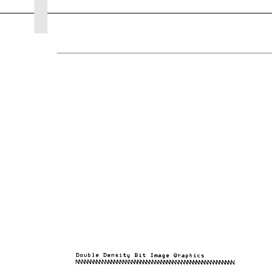
116
Chapter 4
Configuring the Proprinter III XL Emulation with Control Codes
Bit Image Mode, Double Density (Half Speed)
ASCII Code ESC L n1 n2
Hex Code 1B 4C n1 n2
Dec Code 27 76 n1 n2
Purpose Selects double density bit image graphics.
where n1 + 256n2 defines the number of data bytes to follow.
DATA = ASCII characters for the dot pattern bytes.
n1 = (Number of DATA bytes) - 256(n2)
(remainder of division of number of DATA bytes by 256,
sometimes referred to as MOD 256)
n2 = (Number of DATA bytes) / 256
(quotient of division)
Discussion This code prints specified data as bit image graphics at double
horizontal density, 120 dots per inch horizontally and 72 dots per
inch vertically. This code causes print speed to be reduced by
half from normal density speed. For more information, see “Bit
Image Graphics” on page 193.
Example The following example produces Double Density Bit Image
graphics of the pattern used in the Single Density Bit Image
Mode example. Note that the amount of data must be doubled in
order to produce this pattern for double density (the data is used
54 times rather than 27).
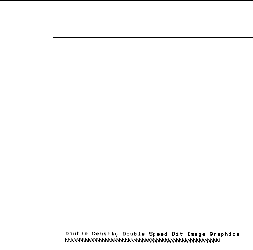
Bit Image Mode, Double Density (Normal Speed)
117
Bit Image Mode, Double Density (Normal Speed)
ASCII Code ESC Y n1 n2
Hex Code 1B 59 n1 n2
Dec Code 27 89 n1 n2
Purpose Selects double density bit image graphics at single density
speed.
where n1 + 256n2 defines the number of data bytes to follow.
DATA = ASCII characters for the dot pattern bytes.
n1 = (Number of DATA bytes) - 256(n2)
(remainder of division of number of DATA bytes by 256,
sometimes referred to as MOD 256)
n2 = (Number of DATA bytes) / 256
(quotient of division)
Discussion This code prints specified data as bit image graphics at double
horizontal density, 120 dots per inch horizontally and 72 dots per
inch vertically. By ignoring adjacent dots, the print speed is not
reduced from the normal density speed. For more information,
see “Bit Image Graphics” on page 193.
Example The following example produces a Double Density Normal
Speed Bit Image graphics for the same pattern as in the Normal
(Single) Density example. Note that the amount of data must be
doubled for double density (the data is used 54 times rather than
27).
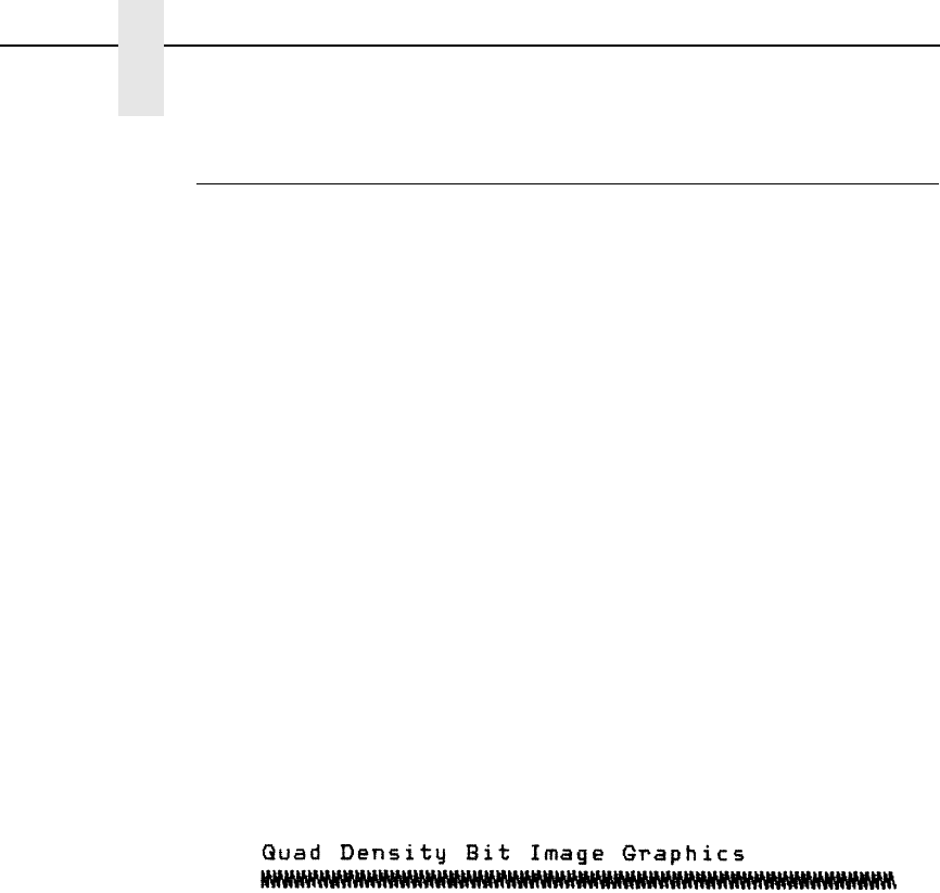
118
Chapter 4
Configuring the Proprinter III XL Emulation with Control Codes
Bit Image Mode, Quadruple Density (Half Speed)
ASCII Code ESC Z n1 n2
Hex Code 1B 5A n1 n2
Dec Code 27 90 n1 n2
Purpose Selects quadruple density bit image graphics.
where n1 + 256n2 defines the number of data bytes to follow.
DATA = ASCII characters for the dot pattern bytes.
n1 = (Number of DATA bytes) - 256(n2)
(remainder of division of number of DATA bytes by 256,
sometimes referred to as MOD 256)
n2 = (Number of DATA bytes) / 256
(quotient of division)
Discussion This code prints specified data as bit image graphics at
quadruple density, 240 dots per inch horizontally and 72 dots per
inch vertically. This code causes print speed to be reduced by
half. For more information, see “Bit Image Graphics” on page
193.
Example The following example produces quadruple density graphics of
the pattern used in the Single Density Bit Image Mode example.
Note that the amount of data must be quadrupled for quadruple
density (the data is used 108 times rather than 27).
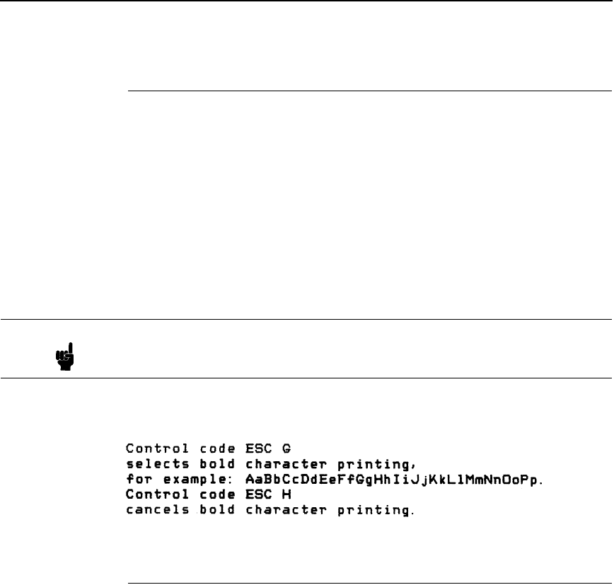
Bold Printing
119
Bold Printing
ASCII Code ESC G
Hex Code 1B 47
Dec Code 27 71
Purpose Selects bold character printing.
Discussion When this command is received, all characters are printed in
bold until reset by the Bold Print Reset control code or printer
reset. The bold print attribute is implemented by increasing the
dot density for the bold text (with a result similar to emphasized
printing). Bold printing reduces the current print speed by one
half.
Example The following sample illustrates bold character printing.
Bold Printing, Cancel
ASCII Code ESC H
Hex Code 1B 48
Dec Code 27 72
Purpose Cancels bold printing.
Discussion No other print attributes are changed.
Note The ESC E (page 125) and ESC G commands are equivalent; they
produce the same print effect.

120
Chapter 4
Configuring the Proprinter III XL Emulation with Control Codes
Cancel
ASCII Code CAN
Hex Code 18
Dec Code 24
Purpose Clears the print buffer of all symbols since the last paper motion
command was received.
Discussion The CAN command cancels all characters sent to the printer
after the last paper motion command.
This command will cancel the double wide attribute if set by SO.
No other print attributes are affected.
Carriage Return
ASCII Code CR
Hex Code 0D
Dec Code 13
Purpose Returns the logical print head to the first character column
(resets the pointer to the first character position). May be
configured to include a line feed.
Discussion The CR code is configured via the ESC 5 code or via the control
panel menus (described in the User's Manual). The CR = CR
configuration causes the character position indicator to be
positioned at character column one; subsequent printable data
preceding a paper motion command overstrikes previously
printed data. The CR = CR + LF configuration causes the CR
code to perform a carriage return plus a line feed.
The CR code also cancels expanded (double wide) print when
set by code SO (single line printing attribute).

Carriage Return Set
121
Carriage Return Set
ASCII Code ESC 5 n
Hex Code 1B 35 n
Dec Code 27 53 n
Purpose Defines the result from the Carriage Return (CR) code.
where n may range from 0 through 255 (hex 00 through hex FF).
If n = 0, 2, 4 ... (any even value), then CR = CR (the default).
If n = 1, 3, 5 ... (any odd value), then CR = CR + LF.
Discussion This command overrides the configuration menu setting.
•
CR = CR (default) configuration causes the character position indicator to
be positioned at character column one. Subsequent printable data
preceding a paper motion command overstrikes previous printable data.
•
CR = CR + LF configuration causes the CR code to perform a carriage
return plus a line feed.
Character Pitch 12 cpi
ASCII Code ESC :
Hex Code 1B 3A
Dec Code 27 58
Purpose Sets character pitch to 12 cpi.
Discussion An ESC : code overrides any control panel setting.
Character Set Select: Set 1 (A)
ASCII Code ESC 7
Hex Code 1B 37
Dec Code 27 55
Purpose Selects hex codes 80 through 9F in the character sets as control
codes. Cancels the command ESC 6.
Discussion This code overrides the control panel setting Alt. Char Set.
Character Set Select: Set 2 (B)
ASCII Code ESC 6
Hex Code 1B 36
Dec Code 27 54
Purpose Selects hex codes 80 through 9F in the character sets as
printable symbols. Cancels the command ESC 7.
Discussion This control code overrides the control panel setting Alt. Char
Set. Appendix C shows the printable symbols for hex codes 80
through 9F.
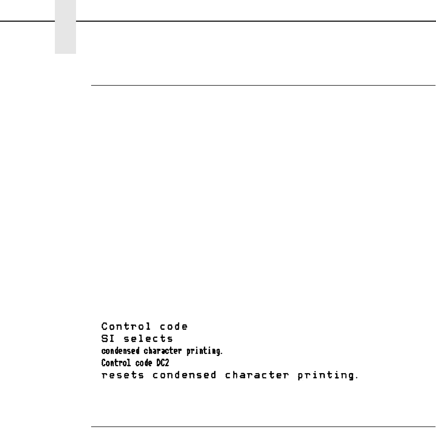
122
Chapter 4
Configuring the Proprinter III XL Emulation with Control Codes
Condensed Print
ASCII Code SI ESC SI
Hex Code 0F 1B 0F
Dec Code 15 27 15
Purpose Sets condensed print.
Discussion If the emulation is set at 5 cpi, it is changed to 8.55 cpi.
If the emulation is set at 10 cpi, it is changed to 17.1 cpi.
If the emulation is set at 12 cpi, it is changed to 20 cpi.
If the emulation is set at NLQ 12 cpi, it is changed to 17.1 cpi.
You may enable/disable condensed print using the control
panel; the default is Enable. Once you enable condensed print
using the control panel, this control code sets condensed print to
enabled until it is canceled by control code DC2, a printer reset,
or a new print mode (ESC I) control code.
Example The following sample shows condensed character printing and
reset.
Condensed Print, Cancel
ASCII Code DC2 ESC DC2
Hex Code 12 1B 12
Dec Code 18 27 18
Purpose Cancels condensed character printing and sets pitch to 10 cpi.
Discussion The Condensed Print Cancel command sets the character pitch
to 10 cpi, or 5 cpi if printing is set for double wide.
Example See the SI control code above for an example of Condensed
Print Cancel.
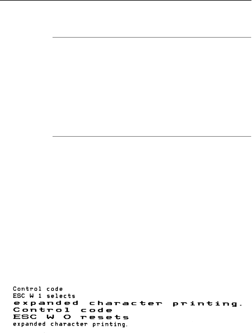
Deselect Printer
123
Deselect Printer
ASCII Code ESC Q 22
Hex Code 1B 51 16
Dec Code 27 81 22
Purpose Stops the printer from processing data received from the host
computer.
Discussion This code is for diagnostic use; it instructs the printer to stop
processing data received from the host system. In order to
resume processing data, the printer must be reset from the host
system.
Double Wide Print
ASCII Code ESC W n
Hex Code 1B 57 n
Dec Code 27 87 n
Purpose Selects or cancels double wide (expanded) print.
where n may range from 0 through 255 (hex 00 through hex FF).
If n = 1, 3, 5 ... (any odd value), double wide print is selected.
If n = 0, 2, 4 ... (any even value), double wide print is cancelled.
Discussion An ESC W code sets or cancels double wide print, as follows:
When expanded print using ESC W is received, all characters
print double wide until cancelled by an even parameter hex
code.
Double wide print can also be set via the command SO and ESC
SO, double wide print for one line only. An ESC W code
overrides these settings.
Example The following sample illustrates expanded character printing and
expanded character printing reset.
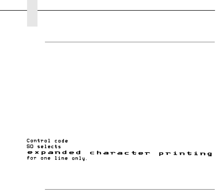
124
Chapter 4
Configuring the Proprinter III XL Emulation with Control Codes
Double Wide Print (One Line Only)
ASCII Code SO ESC SO
Hex Code 0E 1B 0E
Dec Code 14 27 14
Purpose Selects double wide print for one line only.
Discussion This expanded print command is a line-by-line print attribute;
when the SO or ESC SO command is received, the current line
will be printed double wide and automatically reset. This
command can be reset by a paper motion command (FF, LF,
VT, CR), by the DC4 (double wide cancel) code, CAN or ESC W
(double wide print).
Example The following sample illustrates Expanded Print for one line only.
Double Wide Print (One Line Only) Cancel
ASCII Code DC4 ESC DC4
Hex Code 14 1B 14
Dec Code 20 27 20
Purpose Cancels double wide print, if it was set by command SO.
Discussion The DC4 code cancels Double Wide Print command SO. If
Double Wide Print is not enabled, the DC4 code is ignored. A
DC4 code can occur at any place in the datastream and is acted
upon immediately.
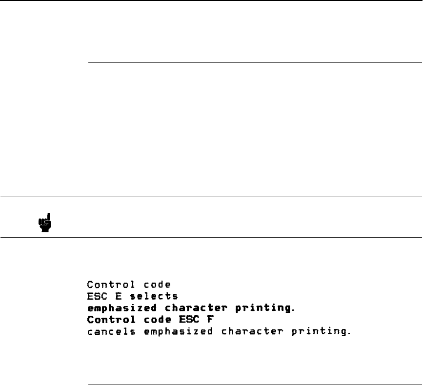
Emphasized Print
125
Emphasized Print
ASCII Code ESC E
Hex Code 1B 45
Dec Code 27 69
Purpose Selects emphasized character print format.
Discussion When the emphasized print command is received, all characters
will be printed in emphasized (bold) print until reset by the
Emphasized Print Reset command or printer reset. Emphasized
print reduces the current print speed.
Example The following sample illustrates emphasized character printing.
Emphasized Print, Cancel
ASCII Code ESC F
Hex Code 1B 46
Dec Code 27 70
Purpose Cancels emphasized character printing.
Discussion The emphasized print reset command only resets the
emphasized print character attribute. See Example for using
ESC E combined with ESC F.
Note The ESC G (page 119) and ESC E commands are equivalent; they
produce the same print effect.

126
Chapter 4
Configuring the Proprinter III XL Emulation with Control Codes
Form Feed
ASCII Code FF
Hex Code 0C
Dec Code 12
Purpose Prints the data in the buffer, advances the paper to the next top-
of-form, and moves the logical printhead to the first character
column.
Discussion Forms length is set by using the control panel or forms length
control codes. This code cancels double wide (expanded)
characters if set by the SO command. The Form Feed command
will react differently when the VFU is active. Refer to Chapter 7
in this manual for further information. The Form Feed command
will react differently when the control panel selection “FF Valid at
TOF” is disabled. Refer to the User's Manual for further
information.
Forms Length Set in Inches
ASCII Code ESC C NUL n
Hex Code 1B 43 00 n
Dec Code 27 67 0 n
Purpose Sets the length of forms (paper) in inches.
where n = whole numbers from 1 through 21 (hex 01 through hex 15) to
specify the number of inches on a page. (All larger values are
ignored.)
Discussion Upon receipt of this code, the current line becomes the first line
of the form, and the forms length set becomes the current forms
length. Vertical tab positions set below the bottom of the form
are ignored; in addition, once a new forms length is set the
bottom margin is set to zero.
Line spacing changes do not affect the result of this command. If
the forms length is set smaller than the line spacing, a form feed
advances the paper position to the next top-of-form position.
Forms length in inches can also be set at the control panel via
the LinePrinter+ Form Length menu option (refer to the User's
Manual). However, this host control code overrides the control
panel setting.

Forms Length Set in Lines
127
Forms Length Set in Lines
ASCII Code ESC C n
Hex Code 1B 43 n
Dec Code 27 67 n
Purpose Sets the length of a form (paper) in lines.
where n = 1 through 168 (hex 01 through hex A8) to specify the number
of lines per page at the current line spacing.
Discussion The forms length is defined in inches as the quotient of n divided
by the current lines per inch (lpi) setting. Once the forms length
has been set, subsequent line spacing changes do not affect the
result of this command.
If the forms length is set smaller than the line spacing, a form
feed advances the paper position to the next top-of-form
position.
If the forms length derived from the quotient of n lines divided by
lines per inch is not an exact multiple of the printer dot
resolution, the value is adjusted down until the forms length and
dot resolution distance match.
Forms length can also be set at the control panel via the
LinePrinter+ Form Length menu option (refer to the User's
Manual). However, this host control code overrides the control
panel setting.
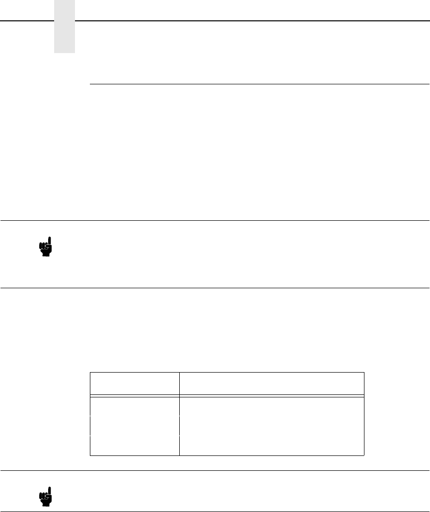
128
Chapter 4
Configuring the Proprinter III XL Emulation with Control Codes
Initialize Parameters
ASCII Code ESC [ K n1 NUL n2 n3 n4 n5
Hex Code 1B 5B 4B n1 00 n2 n3 n4 n5
Dec Code 27 91 75 n1 0 n2 n3 n4 n5
Purpose Sets the printer's initial condition.
Discussion This command causes the printer to reset and defines the
configuration that will be loaded to the printer during the reset.
Several variables must be specified to define the load
configuration, as described below.
n1
The value of n1 defines which of the following n bytes will be included in the
command line, as shown in Table 29.
n2
The 2-digit hexadecimal value for n2 defines the load configuration for the
printer. The Proprinter III XL supports six values for this parameter: 00, 01, 04,
05, 254, and 255 (hex 00, 01, 04, 05, FE, and FF). Any other value will be
ignored.
If any of the six supported values is entered for the n2 parameter, then the
printer will reset to the factory default configuration. Configuration parameters
defined by command bytes n4 and n5, if present, will override conflicting
factory default values.
Note An ESC[K code can occur at any place in the datastream and is acted
upon immediately. All numerical parameters are in the hex 00 through FF
range unless stated otherwise. Only specified parameters are supported.
Other values may be ignored or cause unpredictable results, and should
be avoided.
Table 29. n1 Values
n1 Hex Value Function
1One byte follows (n2)
3Three bytes follow (n2, n3 and n4)
4Four bytes follow (n2, n3, n4 and n5)
Note Specifying any value for n1 other than 1, 3, or 4 may cause unpredictable
results, and should be avoided.
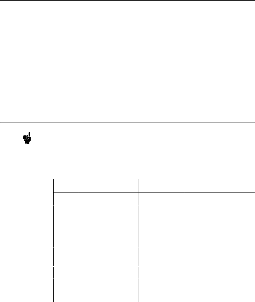
Initialize Parameters
129
n3
Parameter n3 is provided for compatibility with the Proprinter III XL printer
control language standard. You may define any value for this parameter. (For
Proprinters, this bit must define the attached printer as either Proprinter, value
03, or Proprinter III XL, value 22 [hex 16].)
n4 and n5
Parameter bytes n4 and n5 allow you to define several configuration
parameters that will override conflicting factory default and memory-based
configuration values when the printer is reinitialized. Possible values for n4
and n5 are listed in Table 30 and Table 31, respectively.
Note In addition to the formatting from bytes n4 and n5, this command sets the
current line as top-of-form. It also clears vertical tabs and sets the
horizontal tabs at every eight columns, starting at column 9.
Table 30. n4 Values
n4 Bit Function OFF (0) ON (1)
7Process this byte Process Ignore
6Reserved Reserved Reserved
5n/a n/a n/a
4Line Feed = LF LF + CR
(add CR with each LF)
3Carriage Return = CR CR + LF
(add LF with each CR)
2Set forms length 11 inches 12 inches
1Slashed Zero Disable Enable
0Character set 1 (A) 2 (B)
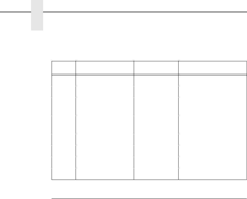
130
Chapter 4
Configuring the Proprinter III XL Emulation with Control Codes
Line Feed
ASCII Code LF
Hex Code 0A
Dec Code 10
Purpose Prints the data in the buffer (if any) and advances the paper one
line at the current line space setting.
Discussion If configured for LF equals new line (LF = CR + LF), the logical
print head is positioned at character column 1 of the new line.
Otherwise, the logical print head does not move when
configured for LF function only (LF = LF only). The LF function
cancels double wide (expanded) characters if set by the SO
command.
Line feed can occur at any place in the datastream and is acted
upon immediately.
Table 31. n5 Values
n5 Bit Function OFF (0) ON (1)
7Process this byte Process Ignore
6Code page 437 850
5Unidirectional
Printing
Bidirectional Unidirectional
412 cpi compressed
to 20
20 12
3n/a n/a n/a
2Form feed at TOF Enable Ignore
1Print Width 13.2 inches 8 inches
0Sheet feeder n/a n/a
Line Feed n/216 Inch (One Line Only)
131
Line Feed n/216 Inch (One Line Only)
ASCII Code ESC J n
Hex Code 1B 4A n
Dec Code 27 74 n
Purpose Advances the vertical character position n/216 inch for one line
only.
where n = 1 through 255 (hex 01 through hex FF).
Discussion The n/216-inch line feed control code is effective for one line
only. All single-line-only print attributes are canceled.
If the emulation is configured for LF equals newline
(LF=CR+LF), the paper advances one line at the n line spacing
setting and the logical print head is positioned at character
column 1.
The paper position moves only in multiples of the current dot row
spacing. If the distance to move is other than a multiple of the
current dot row spacing, the remainder is added to the next
paper motion command.
Small values of n may result in overlapping lines. Overlapping
lines may also occur if print attributes such as Elongated
(Double High), Superscript, or Subscript characters are used on
the same line. Printing at different horizontal and vertical
densities will not overlap.
Example The following example illustrates n/216-inch line spacing.
132
Chapter 4
Configuring the Proprinter III XL Emulation with Control Codes
Line Spacing 1/8 Inch (8 lpi)
ASCII Code ESC 0
Hex Code 1B 30
Dec Code 27 48
Purpose Specifies continuous line spacing at 1/8-inch increments (8 lpi).
Discussion When the 1/8-inch line spacing control code is received, all lines
will be printed at 8 lpi until a new line spacing is selected or the
printer is reset.
Example The following example illustrates 1/8-inch line spacing.
Line Spacing 7/72 Inch (10.3 lpi)
ASCII Code ESC 1
Hex Code 1B 31
Dec Code 27 49
Purpose Specifies the line spacing at 7/72-inch (10.3 lpi) increments.
Discussion When the 7/72-inch line spacing control code is received, all
lines will be printed at the 7/72-inch line spacing until a new line
spacing is selected or the printer is reset. The control code line
spacing selection will override the control panel line spacing
setting, and the message display will reflect the line spacing as
10.3 lines per inch.
Caution should be used when combining this control code with
other print attributes such as Elongated (Double High),
Superscript, or Subscript; overlapping lines may occur.
Example The following example illustrates 7/72-inch line spacing.
Line Spacing n/72 Inch (Executes)
133
Line Spacing n/72 Inch (Executes)
ASCII Code ESC 2
Hex Code 1B 32
Dec Code 27 50
Purpose ESC 2 sets line spacing to 6 lpi or as set by ESC A.
Discussion ESC 2 asserts n/72-inch line spacing as set by ESC A (page
134). If no distance has been set by ESC A, the distance is 1/6
inch.
The control code line spacing selection will override the control
panel line spacing setting.
Example The following example illustrates 1/6-inch line spacing and
assumes that a distance has not been set by ESC A.
134
Chapter 4
Configuring the Proprinter III XL Emulation with Control Codes
Line Spacing n/72 Inch (Storage)
ASCII Code ESC A n
Hex Code 1B 41 n
Dec Code 27 65 n
Purpose Stores a line spacing of n/72-inch increments.
where n = 1 through 255 (hex 01 through hex FF).
All others values are ignored.
Discussion This control code stores a value for line spacing of n/72 inch.
The ESC 2 control code (described on page 133) executes the
line spacing stored by the preceding ESC A, until a new line
spacing is selected or the printer is reset. A control code line
spacing overrides a control panel line spacing setting. (The
control panel display shows line spacing in lines per inch.)
Small values of n may result in overlapping lines. Overlapping
lines may also occur if print attributes such as Elongated
(Double High), Superscript, or Subscript characters are used on
the same line. Common values of n are listed in Table 32.
Example The following example illustrates 20/72-inch line spacing.
Table 32. Line Spacing values
nLine Spacing
24 3 lpi
18 4 lpi
12 6 lpi
98 lpi
89 lpi
612 lpi
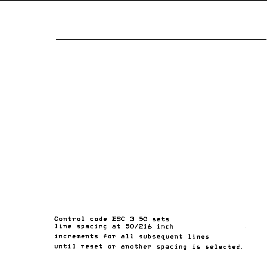
Line Spacing n/216 Inch
135
Line Spacing n/216 Inch
ASCII Code ESC 3 n
Hex Code 1B 33 n
Dec Code 27 51 n
Purpose Specifies the line spacing at n/216-inch increments.
where n = 1 through 255 (hex 01 through hex FF).
Discussion When the n/216-inch line spacing control code is received, all
line feeds following will be at n/216-inch line spacing until a new
line spacing is selected or the printer is reset. The control code
line spacing selection will override the control panel line spacing
setting.
The vertical character position moves only in multiples of the
current dot row spacing. If the distance to move is other than a
multiple of the current dot row spacing, the remainder is added
to the next paper motion command.
Caution should be used when combining this control code with
other print attributes such as Elongated (Double High),
Superscript, or Subscript; overlapping lines may occur.
Example The following example illustrates n/216-inch line spacing.

136
Chapter 4
Configuring the Proprinter III XL Emulation with Control Codes
Margin, Bottom
ASCII Code ESC N n
Hex Code 1B 4E n
Dec Code 27 78 n
Purpose Sets the bottom margin.
Discussion n defines the number of lines above the bottom of the form to set
as the bottom margin. n has a range from 1 through 255 (hex 01
through hex FF). The actual margin in inches is the quotient of n
divided by the current lines per inch (lpi).
If a line feed command causes the active position to advance
below the bottom margin, the paper advances to the top of the
next form. If the bottom margin set is equal to or greater than the
form length, printing is only allowed on the top line of each page.
If the forms length is changed by the ESC C code (Forms Length
sequence), the bottom margin is set to zero.
The bottom margin setting can also be selected from the control
panel; however, the host control code will override the control
panel setting. Any vertical tabs set within the bottom margin
zone will be ignored.
Margin Cancel, Bottom
ASCII Code ESC O
Hex Code 1B 4F
Dec Code 27 79
Purpose Resets the bottom margin to zero.
Margins, Horizontal
ASCII Code ESC X n m
Hex Code 1B 58 n m
Dec Code 27 88 n m
Purpose Sets left and right margins in character positions.
where n = left margin position
m = right margin position
Discussion The values of n and m must be in the range from 0 through 255
(hex 00 through hex FF). The margins are measured in
character positions at the current characters per inch (cpi).
n is the column number from the left edge of the paper. For
example, n = 5 means that the line starts at column number 5.
Therefore it has a left margin of 4.
m is the column number from the right edge of the paper. For
example, m = 56 means that the line ends on column 80 if the
form width is 136.
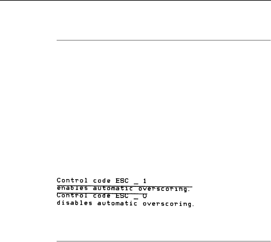
Overscoring
137
Overscoring
ASCII Code ESC _ n
Hex Code 1B 5F n
Dec Code 27 95 n
Purpose Enables or disables automatic overscoring of all characters.
where n may range from 0 through 255 (hex 00 through hex FF).
n = 0, 2, 4... disables automatic overscoring (any even value
from hex 00 through hex FE)
n = 1, 3, 5... enables automatic overscoring (any odd value
from hex 01 through hex FF)
Discussion When automatic overscore is enabled, all characters, including
spaces, are overscored. Full-height graphics characters are not
overscored.
Example The following sample illustrates automatic overscoring and
overscoring reset.
Print All Characters
ASCII Code ESC \ n1 n2
Hex Code 1B 5C n1 n2
Dec Code 27 92 n1 n2
Purpose Prints the characters assigned to code points as characters,
rather than interpreting the code values as commands.
where n1 + 256n2 defines the number of data bytes to follow
n1 = (Number of DATA bytes) - 256(n2)
(remainder of division of number of DATA bytes by 256,
sometimes referred to as MOD 256)
n2 = (Number of DATA bytes) / 256
(quotient of division)
Discussion The number of data bytes specified by n1 + 256n2 will print as
text. Valid numerical parameters are in the range 0 through 255
(hex 00 through hex FF). Data values that do not correspond to
standard ASCII codes will print as spaces.
138
Chapter 4
Configuring the Proprinter III XL Emulation with Control Codes
Print Next Character
ASCII Code ESC ^ n
Hex Code 1B 5E n
Dec Code 27 94 n
Purpose Prints the graphic character assigned to n, rather than
interpreting the code value as a command.
Discussion This command may appear anywhere in the data stream, and
will be acted upon immediately. Valid numerical parameters are
in the range 0 through 255 (hex 00 through hex FF).
Print Mode
ASCII Code ESC I n (uppercase “i”)
Hex Code 1B 49 n
Dec Code 27 73 n
Purpose Selects a print mode.
Discussion This control code selects a print mode from among the choices
listed in Table 33.
There are several duplicate function values that select the same
print quality. These are provided for compatibility with the
Proprinter III XL standard.
Table 33. Print Mode Values
n Hex Function
00 DP 10 cpi
01 HS 12 cpi
02 NLQ Sans Serif 10 cpi
03 NLQ 10 cpi
04 DP 10 cpi
05 HS 12 cpi
06 NLQ Sans Serif 10 cpi
07 NLQ 10 cpi
0B NLQ Italic Proportional
0F NLQ Italic 10 cpi
Note If you specify any value other than the ones shown in Table 33,
unpredictable results may occur.

Print Quality
139
Print Quality
ASCII Code ESC x n
Hex Code 1B 78 n
Dec Code 27 120 n
Purpose This code selects a print quality.
where n = 0 or 48 (hex 00 or hex 30) selects DP print quality
n = 1 or 49 (hex 01 or hex 31) selects NLQ print quality
n = 2 or 50 (hex 02 or hex 32) selects HS print quality
n = 3 or 51 (hex 03 or hex 33) selects OCR A print quality
n = 4 or 52 (hex 04 or hex 34) selects OCR B print quality
Comment When you select NLQ, the font is serif. Print qualities selected
with this command override control panel selections. Selecting
an OCR print quality overrides any character attributes already
set, such as condensed, double-wide, etc. These attributes will
not return when another print quality is set. Character attributes
set when OCR is selected will be ignored.
Proportional Spacing
ASCII Code ESC P n
Hex Code 1B 50 n
Dec Code 27 80 n
Purpose Enables/disables proportional spacing of characters.
where n may range from 0 through 255 (hex 00 through hex FF).
n = 1, 3, 5...(any odd value) enables proportional spacing
n = 0, 2, 4...(any even value) disables proportional spacing
Comment This command is ignored when a non-proportional font is used.
140
Chapter 4
Configuring the Proprinter III XL Emulation with Control Codes
Select Attributes
ASCII Code ESC [ @ n1 NUL NUL NUL n2 n3
Hex Code 1B 5B 40 n1 00 00 00 n2 n3
Dec Code 27 91 64 n1 0 0 0 n2 n3
Purpose Selects double high and double wide attributes, and single or
double high line spacing.
Discussion Parameter n1 selects the attributes from n2 and n3, as follows:
Parameter n2 defines the height attributes, as follows:
Table 34. Select Attributes n1 Values
n1 (Hex) Function
03 Set character height and line feed settings according to
the value of n2. (If n1 = 03, there is no n3).
04 Set character height, line feed, and character settings
according to the values of n2 and n3.
Table 35. Select Attributes n2 Values
n2 (Hex) Function
00 No change
01 Set single height characters
02 Set double height characters
10 Set single line spacing
11 Set single height characters and single line spacing
12 Set double high characters and single line spacing
20 Set double line spacing
21 Set single height characters and double line spacing
22 Set double high characters and double line spacing
Set Top-of-Form
141
Parameter n3 defines the width attributes, as follows:
An ESC [ @ code can occur at any place in the datastream and
is acted upon immediately.
All numerical parameters are in the hex 00 through FF range
unless stated otherwise.
Set Top-of-Form
ASCII Code ESC 4
Hex Code 1B 34
Dec Code 27 52
Purpose Sets the current paper position as the top-of-form.
Superscript/Subscript Printing
ASCII Code ESC S n
Hex Code 1B 53 n
Dec Code 27 83 n
Purpose Selects superscript or subscript printing.
where n may range from 0 through 255 (hex 00 through hex FF).
n = 1, 3, 5 (any odd value), selects subscript printing.
n = 0, 2, 4 (any even value), selects superscript printing.
Discussion When the super/subscript command is received, all characters
will be superscript or subscript until reset by the super/subscript
reset command or printer reset. Super/subscript print modes are
not available for the double high attribute.
You can print both superscript and subscript characters in the
same character column by using the Backspace (BS) control
code, but these characters will not print when double high
printing is in effect.
Table 36. Select Attributes n3 Values
n3 (Hex) Function
00 No change
01 Set single wide characters
02 Set double wide characters
Note Superscript and subscript characters print at the same size as the current
font, shifted up or down relative to the print line.
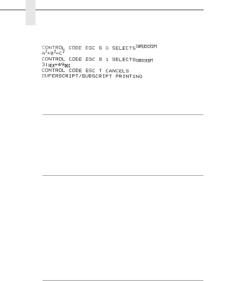
142
Chapter 4
Configuring the Proprinter III XL Emulation with Control Codes
Example The following sample illustrates superscript/subscript printing.
Superscript/Subscript Printing, Cancel
ASCII Code ESC T
Hex Code 1B 54
Dec Code 27 84
Purpose Cancels superscript and subscript printing (as set by ESC S).
This code can occur at any place in the datastream and is acted
upon immediately.
Tab, Horizontal
ASCII Code HT
Hex Code 09
Dec Code 09
Purpose Moves the logical printhead right to the next horizontal tab stop.
Discussion Power-on default horizontal tabs are set at every eighth
character starting at position 9 (9, 17, 25). If there are no
horizontal tabs set or the logical printhead is located at the last
character column, the code is ignored and no movement occurs.
If double-wide, double-high attributes are enabled, single-wide
character spacing is used. Horizontal tabs are stored as a
relative position; therefore, character pitch changes will change
horizontal tab positions. Refer to the ESC D control code
description (page 142) to set new tab positions.
Tab Set/Clear, Horizontal
ASCII Code ESC D n1 n2...nk NUL
Hex Code 1B 44 n1 n2...nk 00
Dec Code 27 68 n1 n2...nk 0
Purpose Sets up to 28 horizontal tab positions.
Discussion n1, n2, up to nk denote character column positions for tab stops
(at the current character pitch), where n1 and n2 represent the
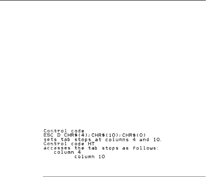
Tab, Vertical
143
first two tab stops and nk is the final tab stop. You may specify
from 1 up to 28 tab stops (all parameters after 28 are ignored).
The leftmost character column position is 1. The value for each
tab stop can range from 1 through 255 (hex 01 through hex FF),
inclusive, and all tabs must be specified in ascending order. Any
out-of-order symbols are ignored, though the remainder of the
sequence is processed.
If you are defining a sequence of tabs, terminate the string with a
00H (not an ESC D 00H). If you want every column to be set with
a horizontal tab, use ESC D 00H. If only one tab position is set
and it is beyond the right margin, then every column is also set
as a horizontal tab. Any change in character pitch within a line
changes the tab positions for the entire line. All control codes
that define horizontal distance expressed in units of characters
are stored internally in character columns.
Example The following example illustrates horizontal tab setting and
accessing.
Tab, Vertical
ASCII Code VT
Hex Code 0B
Dec Code 11
Purpose Prints the data in the buffer and advances the paper to the next
vertical tab position.
Discussion In the Proprinter III XL emulation, vertical tab positions are set by
control code ESC B and executed by control code VT. In this
mode, if vertical tabs are loaded, the paper position moves to the
next vertical tab position.
If a vertical tab format is not defined, the paper position is
advanced to the next line at the current line spacing. If a vertical
tab format is defined but no vertical tab positions are set
between the current print position and the end of the form, the
paper position is advanced to the top of the next form. The VT
code resets all single line print attributes. More information on
vertical tabs is provided in the Chapter 7.
If configured for LF = CR + LF (LF equals new line), the
character position indicator is positioned at character column 1
of the new line. Otherwise, the character position indicator does
not move.
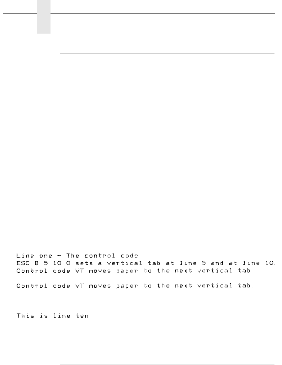
144
Chapter 4
Configuring the Proprinter III XL Emulation with Control Codes
Tab Set/Clear, Vertical
ASCII Code ESC B n1 n2 ... nk NUL
Hex Code 1B 42 n1 n2 ... nk 00
Dec Code 27 66 n1 n2 ... nk 0
Purpose Sets or clears vertical tab positions.
Discussion The physical position on the paper is defined by n and the
current line spacing.
where n = vertical tab setting (in lines), and
k = number of tabs possible.
The value of n can be defined in the range of 1 through 255 (hex
01 through hex FF), inclusive, while k is defined in the range of 1
through 64 (hex 01 through 40). Any value for k over 64 is
ignored. Subsequent line spacing changes affect the tab
position. If the value of n exceeds the forms length, that tab
position is ignored.
Vertical tab positions are set by the command ESC B and
executed by the command VT. The tab positions must be in
ascending order, or the emulation ignores the out-of-order
symbols. If the ESC B command is followed immediately by hex
00, the vertical tab positions are cleared.
Example The following sample illustrates Vertical Tab Setting. To run the
sample, set your printer at top-of-form.
Tabs, Clear All (Return to default)
ASCII Code ESC R
Hex Code 1B 52
Dec Code 27 82
Purpose Clears all horizontal and vertical tab stops.
Discussion When ESC R is invoked, horizontal tab stops reinitialize to every
eight columns, starting at column 9 (9, 17, 25). In addition, the
vertical tabs are cleared.
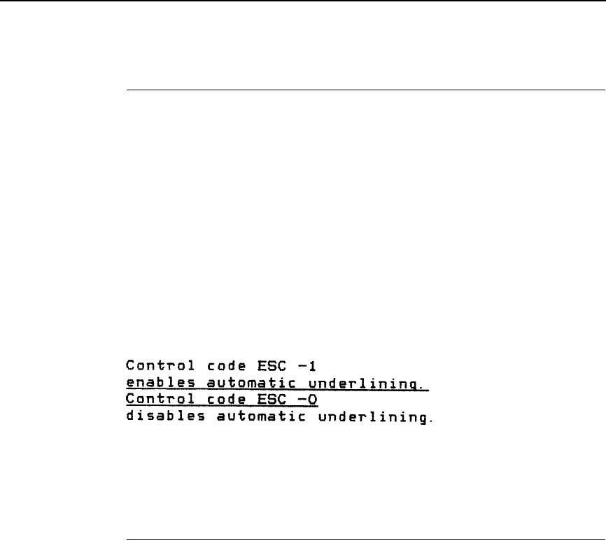
Underline
145
Underline
ASCII Code ESC - n
Hex Code 1B 2D n
Dec Code 27 45 n
Purpose Enables or disables automatic underlining of all characters.
Discussion When automatic underline is enabled, all characters, including
spaces, are underlined until disabled.
where n may range from 0 through 255 (hex 01 through hex FF).
n = 1, 3, 5 (any odd value) selects underlining.
n = 0, 2, 4 (any even value) cancels underlining.
Example The following sample illustrates automatic underlining and
underlining reset.
Unidirectional Printing
ASCII Code ESC U n
Hex Code 1B 55 n
Dec Code 27 85 n
Purpose Sets or cancels unidirectional printing. While this feature reduces
print speed by 1/2, the increased print quality will improve the
readability of barcodes and graphics.
Discussion This code sets or cancels unidirectional printing, as follows:
where n may range from 0 through 255 (hex 00 through hex FF).
n = 1, 3, 5 (any odd value) selects unidirectional text printing.
n = 0, 2, 4 (any even value) cancels unidirectional text printing.

146
Chapter 4
Configuring the Proprinter III XL Emulation with Control Codes

147
5
Epson FX-1050 Emulation
Overview
This chapter describes the Epson FX emulation host control codes.
“Emulation” refers to the ability of a printer to execute the commands of a
particular printer control language. A printer control language is the coding
system used to convey, manipulate, and print data. It contains character
codes and command sequences that configure the emulation. In this manual,
the terms emulation, printer protocol, and printer control language are
synonymous.
In Epson FX emulation mode, your printer can print files coded for the Epson
FX printer control language. To select the Epson FX emulation as the active
printer emulation, select LinePrinter Plus from the EMULATION menu and
Epson FX from the Printer Protocol menu, as described in the User's Manual.
The Epson FX emulation provides many configurable parameters. The default
parameter values for this emulation are shown in Table 37. You can modify
these parameter values in two ways:
•
The Epson FX host control codes. An extensive set of Epson FX
control code commands can be sent to the printer from an attached host
computer via the host data stream. Most of this chapter is devoted to
describing the Epson FX control code commands.
•
The printer configuration menus. You can modify a subset of the
Epson FX emulation parameters using the control panel switches and
LCD display, as described in the User's Manual.
A parameter value set by a host control code generally overrides a value set
from the printer's control panel.
Note Configuration values selected from the menus or via host control codes
can be saved to the printer's NVRAM memory so that they will not be lost
when you power off the printer or reset it to the factory defaults. The menu
selection for saving a configuration to memory is described in the User's
Manual.

148
Chapter 5
Overview
Epson FX-1050 Default Values and States
The factory settings for the Epson FX-1050 emulation menu options are
shown in Table 37. Table 38 lists additional factory settings for parameters
provided by the LinePrinter+ formatting menus. (The EMULATION menu
options are described in the User's Manual). Host control codes can override
many of the settings for these menu options.
Table 37. Epson Emulation Menu Option Factory Settings
Characteristic Default Setting
Define CR Code CR = CR
Auto LF Enable
Define LF Code LF = LF
Printer Select Disable
Character Set Epson Set
20 CPI Condensed Enable
Alt. Set 80-9F Control Code

Epson FX-1050 Default Values and States
149
Table 38. LinePrinter+ Menu Option Factory Settings
Characteristic Default Setting
CPI 10.0
LPI 6.0
Typeface Data Processing
Proportional Spacing Disable
Bold Print Disable
Italic Print Disable
Slashed Zero Disable
Left Margin 0 columns
Right Margin 0 columns
Bottom Margin 0 lines
Perforation Skip Disable
Form Length 11.0 inches
279.4 millimeters
66 lines
Form Width 13.6 inches
345.4 millimeters
136 characters
Reset Cmd CFG Ld Disable

150
Chapter 5
Overview
Epson Emulation Exceptions and Differences
Because of mechanical differences between your line matrix printer and
Epson printers (moving printhead serial matrix printers), some Epson features
are approximated or not supported.
•
Epson codes that produce different behavior in your printer are indicated
by a “dagger” (†) in the Control Code Index.
•
The Epson emulation supports the following fonts: DP, NLQ Serif and
Sans Serif, Draft with 10 cpi, 12 cpi and 15 cpi in either condensed or
normal widths, and OCR A and OCR B in 10 cpi. Condensed printing at
10 cpi in DP quality maps to 17.1 cpi. Character pitches other than 10 DP
cpi map to 20 cpi in DP and 17.1 cpi in NLQ.
•
Epson bit-image graphics are supported, including all plotter and CRT
densities.
•
Many character sets are available, including IBM-PC Graphics (IBM Code
Page 0437) and Epson. You can configure the zero character to contain a
slash or no slash.
•
The Double Wide print control codes (ESC W, SO) double character
width, but not inter-character spacing, unlike the Epson FX-1050. The
formulas for total character spacing are as follows:
Epson FX-1050 2 (char + 1 dot + space)
Epson Emulation 2 (char + 1 dot) + space
•
The Condensed Print (SI) control code condenses character width but not
inter-character spacing, unlike the Epson FX-1050 which condenses both
character width and spacing.
•
If one or more Backspace control codes follow directly after a Bit Image
Graphics command (ESC K, ESC L, ESC Y, or ESC Z), the printer will
backspace into the graphic pattern, the number of dots depending on the
current cpi setting. For an Epson FX-1050 printer, one Backspace will
send the logical printhead directly to the beginning of the graphics
pattern.
•
When backspacing over proportionally spaced characters, Epson printers
move back the width of each proportional character; this emulation moves
back based on the current cpi setting, as if proportional spacing is
disabled.

Epson Character Sets
151
Epson Character Sets
Epson printers use five character sets. The IBM PC code page, OCR A, OCR
B, and an extensive array of print language sets may be selected from the
configuration menus. In addition, there is a unique Epson character set. The
Epson character set (shown in Table 39) is the ASCII character set with the
upper, non-ASCII set defined as italics, and the usually unprintable codes
designated as international characters.
The international characters in hex 00-1F and hex 80-9F can be printed when
you invoke control code ESC I 1 (see page 165). You may use the Epson
configuration menus described in the User's Manual (or the ESC R control
code) to select an international character set.
Normally, these characters are either blank or control codes. The
implementation is that the control codes hide the non-italic international
characters, even in hex 00 through 1F, and DEL. DEL conceals the non-italic
slashed zero.
Table 39. Epson Character Set
Hex 0 1 2 3 4 5 6 7 8 9 A B C D E F
0à§SP 0 @ P ‘ p à § SP 0 @ P ‘ p
1 è ß ! 1 A Q a q è ß ! 1 A Q a q
2 ù DC2 " 2 B R b r ù Æ " 2 B R b r
3 ò DC3 # 3 C S c s ò æ # 3 C S c s
4 ì DC4 $ 4 D T d t ì ø $ 4 D T d t
5 ° ø % 5 E U e u ° ø % 5 E U e u
6 £ ¨ & 6 F V f v £ ¨ & 6 F V f v
7BEL Ä ‘ 7 G W g w i Ä ’ 7 G W g w
8BS CAN ( 8 H X h x ¿ Ö ( 8 H X h x
9HT Ü ) 9 I Y i y Ñ Ü ) 9 I Y i y
ALF ä * : J Z j z ñ ä * : J Z j z
BVT ESC + ; K [ k { ¤ ö + ; K [ k {
CFF ü ’ < L \ l | P
t
ü , < L \ l |
DCR É – = M ] m } Å É – = M ] m }
ESO é . > N ^ n ~ å é . > N ^ n ~
FSI ¥ / ? O _ o DEL Ç ¥ / ? O _ o ø

152
Chapter 5
Configuring the Epson FX-1050 Emulation with Control Codes
Configuring the Epson FX-1050 Emulation with
Control Codes
The remainder of this chapter describes the Epson printer control language
codes that may be sent from a host computer attached to the printer, in order
to invoke and configure numerous Epson emulation functions.
Format for Control Code Descriptions
The following information is listed for each control code (where applicable):
Name The title or function of the command.
ASCII Code The ASCII mnemonic for the command is shown. Command
sequences are in 7-bit (ASCII) form.
Hex Code The code or command sequence in hexadecimal numbers.
Dec Code The code or command sequence in decimal numbers.
Purpose The function(s) of the control code.
Discussion A discussion of the uses of the code or command sequence,
including a description of exceptions or limitations to normal use.
Example A sample is provided when it is possible to illustrate the effect of
a control code or if a specific syntax is required.
† (“dagger”) This symbol means the code produces non-Epson behavior in
your printer.
Escape Sequences
An Epson control code consisting of more than one character is called an
escape sequence because the first character in the sequence is always the
ASCII ESCape character. ESC alerts the printer that a special function
command (not printable characters) follows.
The format for an Epson escape sequence is:
(ESC)(parameter 1)(parameter 2)...(parameter n)
For example, to select emphasized (offset) print, send the ESC character
immediately followed by the E character (do not add a space character):
ASCII: ESC E Hex: 1B 45
Note If you specify any parameters for a control code other than the ones that
are defined in the control code description, unpredictable results may
occur.
Attribute Set and Reset Codes
153
Attribute Set and Reset Codes
Set and reset are another way of saying turn on and turn off, select and
deselect, or enable and disable.
Some printer features are set and reset with an escape sequence and the
numbers 1 or 0. In such cases you can represent 1 and 0 as hexadecimal
codes 01 and 00, or as the ASCII codes for the numerals 1 and 0
(hexadecimal 31 and 30).
NUL Code
NUL (Hex 00) is ignored by the printer and can be used as a fill character;
however, it can not be used to add blank spaces since it is not a space
character. NUL can also be used as a parameter terminator for the Set
Horizontal Tabs (page 171) or Set Vertical Tabs multibyte control code (page
192).
Switching Between the Emulations
The printer supports several different emulations. PCL-II is the default. P-
Series, Proprinter III XL, and Epson FX-1050 are all a part of the LinePrinter
Plus emulation.
The following command switches from PCL-II to Epson:
ESC%-00002X
To switch from Epson to PCL-II, send the following command to the printer:
ESC|};KD
Note Hex 80 in the 0437 PC Character Set and hex 7F in the 0850 PC
Character Set are treated as a NUL; however, these two controls can not
be used as parameter terminators.

154
Chapter 5
Configuring the Epson FX-1050 Emulation with Control Codes
The Control Codes
The following index lists the control codes by function, ASCII mnemonic, and
page number. Some control code functions can also be selected at the control
panel.
† = Produces non-Epson behavior in your printer.
FUNCTION ASCII CODE PAGE
Vertical Motion and Print Execution
Carriage Return CR 158
Form Feed FF 167
Line Feed LF 173
Line Feed n/216 Inch ESC J n173
Line Spacing 1/6 Inch (6 lpi) ESC 2 174
Line Spacing 1/8 Inch (8 lpi) ESC 0 174
Line Spacing 7/72 Inch ESC 1 175
Line Spacing n/216 Inch ESC 3 n175
Line Spacing n/72 Inch ESC A n 176
†Paper Out Detection, Enable ESC 9 178
†Paper Out Detection, Disable ESC 8 179
Select Vertical Tab Channel ESC / c184
Set Form Length in Inches ESC C NUL n185
Set Form Length in Lines ESC C n186
Set Vertical Tabs in Channels ESC b c n1 n2 n3 ... n16 NUL 188
Skip Over Perforation ESC N n188
Skip Over Perforation, Cancel ESC O 189
Vertical Tab, Execute VT 191
Vertical Tab Set/Clear ESC B n1 n2 ... nk NUL 192
Horizontal Motion
†Backspace BS 157
Carriage Return CR 158
Character Pitch 10 cpi ESC P 158
Character Pitch 12 cpi ESC M 158
Horizontal Tab Execute HT 171
Horizontal Tab Set/Release ESC D n1 ... nk NUL 171
Select/Deselect Proportional
Spacing ESC p n183
Set Absolute Horizontal Print
Position in 1/60 Inch ESC $ n1 n2 185
Set Intercharacter Spacing
in 1/120 Inch ESC SP n186
Set Margin, Left ESC l n186
Set Margin, Right ESC Q n187
Set Relative Horizontal Print
Position in 1/120 Inch ESC \ n1 n2 187

The Control Codes
155
Emphasis
†Condensed Print SI (or ESC SI) 160
Condensed Print Reset DC2 161
Double High Print, Set/Reset ESC w n162
Double Strike ESC G 162
Double Strike, Cancel ESC H 163
†Double Wide Print ESC W n163
†Double Wide Print (One Line) SO (or ESC SO) 164
Double Wide Print (One Line),
Cancel DC4 164
Emphasized Print ESC E 165
Emphasized Print, Cancel ESC F 165
Italic Printing ESC 4 172
Italic Printing, Cancel ESC 5 172
†Superscript and Subscript
Printing ESC S n189
Superscript and Subscript
Printing, Cancel ESC T 190
Underline ESC - n190
Print Quality Control
†Character Pitch 15 cpi ESC g 158
†Define a Download Character ESC & 161
†Master Print Select ESC ! n178
†Remove Downloaded CharactersESC : NUL n NUL 180
†Select Print Quality ESC x n183
†Select Serif or Sans Serif Font ESC k n184
†Select User-Defined Font ESC % n184
Character Set Manipulation
Character Set Select:
International Languages ESC R n159
Enable Printing Hex Codes
00-1F and 80-9F ESC I n165
Make Hex 80-9F Control Codes ESC 7 176
Make Hex 80-9F Printable ESC 6 176
Select Italic Character Set ESC t n 182
Data Manipulation
Cancel Line CAN 157
†Clear Bit 7 of Incoming Data
Bytes to 0 ESC = 160
Delete Character DEL 161
Pass Bit 7 from Host ESC # 179
Set Bit 7 of Incoming Data
Bytes to 1 ESC > 185

156
Chapter 5
Configuring the Epson FX-1050 Emulation with Control Codes
Graphics
Graphics, Standard Density ESC K n1 n2 167
Graphics, Double Density ESC L n1 n2 168
Graphics, Double Density
Double Speed ESC Y n1 n2 169
Graphics, Quadruple Density ESC Z n1 n2 170
Reassign Graphics Mode ESC ? s m 180
Select Graphics Mode ESC * m n1 n2 181
Select 9-Pin Graphics Mode ESC ^ m n1 n2 d1 ... dk 182
Miscellaneous Printer Control
Bell BEL 157
†Cut-Sheet/Paper Feed Control ESC EM n161
†Half-Speed Mode, On/Off ESC s n170
Initialize Printer ESC @ 172
Printer Select DC1 179
Printer Deselect DC3 179
Unidirectional Printing, 1 Line ESC < 190
Unidirectional Printing, Set/ResetESC U n191

Backspace
157
Backspace
ASCII Code BS
Hex Code 08
Dec Code 08
Purpose Moves the logical print head to the left one character space
toward the first character column.
Discussion Assures that the previous printable characters will be printed,
then moves the logical print head one character space to the left
at the current pitch setting (which includes double wide and ESC
SP). If the logical print head bumps into the left margin, it stops.
†When backspacing over proportionally spaced characters,
Epson printers move back the width of each proportional
character; this emulation moves back based on the current cpi
setting, as if proportional spacing is disabled.
†If one or more Backspace control codes follow directly after a Bit
Image Graphics command (ESC K, ESC L, ESC Y, or ESC Z),
your printer will backspace into the graphic pattern, the number
of dots depending on the current cpi setting. For an Epson FX-
1050 printer, one Backspace will send the logical printhead
directly to the beginning of the graphics pattern.
Example If you were to print five “T” characters, then two BS commands,
then two “=” characters, the output would look like the sample
below:
Bell
ASCII Code BEL
Hex Code 07
Dec Code 07
Purpose Sounds the printer's buzzer/beeper.
Discussion The BEL function will sound the buzzer/beeper for 0.2 seconds
upon receipt of this command.
Cancel Line
ASCII Code CAN
Hex Code 18
Dec Code 24
Purpose Clears all unprinted data from a line, but does not affect control
codes.
Discussion You can use this control code to delete a line, but do so with
caution to avoid possible misprinting. This control code cancels
the double wide attribute set by SO. No other print attributes are

158
Chapter 5
Configuring the Epson FX-1050 Emulation with Control Codes
affected. The logical print head goes to the print position it had
after the last CR or paper motion command.
Carriage Return
ASCII Code CR
Hex Code 0D
Dec Code 13
Purpose Prints the data in the buffer, then returns the logical print head to
the left margin.
Discussion Subsequent data are shifted 1/2 dot position to the right. A line
feed will be appended if the printer is configured from the control
panel for CR = CR + LF. When CR = CR + LF, this code cancels
all one-line-only emphasis and font controls: double-wide from
SO and ESC SO, and unidirectional printing from ESC <.
Character Pitch 10 CPI
ASCII Code ESC P
Hex Code 1B 50
Dec Code 27 80
Purpose Sets character pitch to 10 characters per inch (cpi).
Discussion This command is normally used to cancel 12 cpi.
Character Pitch 12 CPI
ASCII Code ESC M
Hex Code 1B 4D
Dec Code 27 77
Purpose Sets character pitch to 12 characters per inch (cpi).
Discussion This command is available in all print modes except OCR A and
OCR B.
Character Pitch 15 CPI
ASCII Code ESC g
Hex Code 1B 67
Dec Code 27 103
Purpose Sets character pitch to 15 characters per inch (cpi).
†Discussion This command is not defined in Epson FX printers. It is included
in this emulation for compatibility with the Okidata KX-P1180
printer. This command is available in all print modes except OCR
A and OCR B.
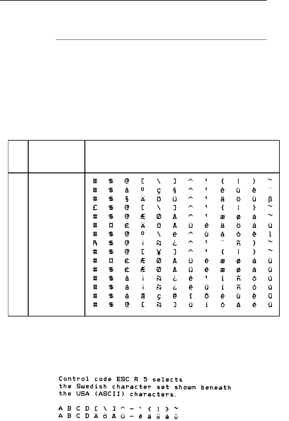
Character Set Select: International Languages
159
Character Set Select: International Languages
ASCII Code ESC R n
Hex Code 1B 52 n
Dec Code 27 82 n
Purpose Specifies a language overlay that prints the characters shown in
Table 40 when the specified code is invoked.
where n = 0 through 15 (hex 00 through 0E) to determine the language
overlay shown in Table 40 below. Epson only defines character
sets through hex 0C.
Discussion This control code setting overrides a character set selection
made at the control panel.
Example The following example illustrates international character
selection using the IBM PC character set.
Table 40. Epson International Character Sets
23 24 40 5B 5C 5D 5E 60 7B 7C 7D 7E
0
1
2
3
4
5
6
7
8
9
A
B
C
n= International
Character Set Is:
If
(Hex) Hex Codes
USA
French
German
English (UK)
Danish I
Swedish
Italian
Spanish I
Japanese
Norwegian
Danish II
Spanish II
Latin American I
French Canadian
Latin American II
D
E
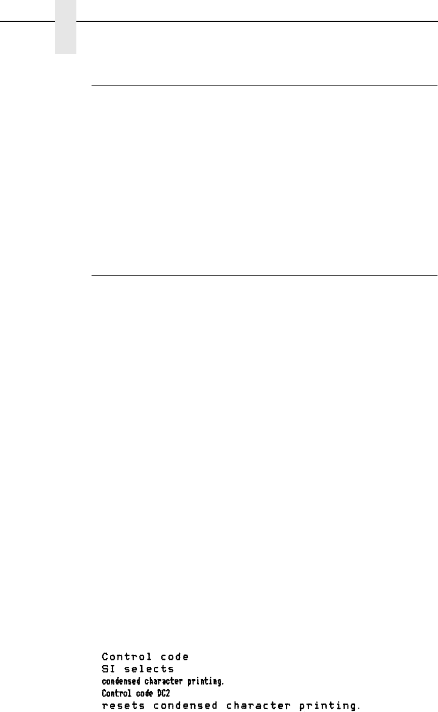
160
Chapter 5
Configuring the Epson FX-1050 Emulation with Control Codes
Clear Bit 7 of Incoming Data Bytes to 0
ASCII Code ESC =
Hex Code 1B 3D
Dec Code 27 61
Purpose Sets the most significant bit (MSB) of all incoming data to 0.
†Discussion The MSB is bit number 7. This command only affects text and
control code data. Graphics data passes through unchanged.
Some applications always set the MSB of print data to one (1),
which results in italic or graphics printing in Epson printers. This
command overcomes the problem.
This command does not suppress hex FF from printing.
Condensed Print
ASCII Code SI ESC SI
Hex Code 0F 1B 0F
Dec Code 15 27 15
Purpose Condenses print pitch as close to 60% of the former character
width as possible (up to 20 characters per inch).
Discussion The condensed print command affects all subsequent
characters. After the printer receives code SI, all characters are
printed condensed (approximately 60 per cent of the width of
normal characters) until the printer is reset by ESC M, ESC P,
DC2, a printer reset, or a new print mode control code. SI code
(hex 0F) is equivalent to the ESC SI code. If condensed print is
not allowed in the current font, this code is ignored.
Proportionally spaced text cannot be condensed. Proportional
spacing overrides condensed printing.
When condensed print is selected, the following character
pitches go into effect:
•
DP 10 cpi condenses to DP 17.1 cpi. NLQ 10, 12, and 15 cpi condense to
NLQ 17.1 cpi. Draft 10 cpi condenses to Draft 17.1 cpi.
•
DP 12 and 15 cpi condense to DP 20. Draft 12 and 15 cpi condense to
Draft 20.
† This control code condenses character width but not inter-
character spacing. An actual Epson FX-1050 printer condenses
both character width and spacing. If Condensed Print is
combined with Double High (ESC w) printing, only Double High
printing will occur.
Example This sample shows condensed character printing and reset.

Condensed Print Reset
161
Condensed Print Reset
ASCII Code DC2
Hex Code 12
Dec Code 18
Purpose Cancels the condensed print mode set by SI, ESC SI, or the
control panel.
Discussion This returns the printer to the font that was active before
condensed print occurred. Other print attributes are not affected.
Example See the Condensed Print control code (page 160) for an
example of Condensed Print Reset.
Cut-Sheet / Paper Feed Control
ASCII Code ESC EM n
Hex Code 1B 19 n
Dec Code 27 25 n
Purpose This code controls the paper feed mechanism on Epson printers.
†Discussion The printer ignores this command.
Define a Download Character
ASCII Code ESC &
Hex Code 1B 26
Dec Code 27 38
Purpose Defines a download character.
†Discussion The printer ignores this command and removes all downloaded
font data from the data stream.
Delete Character
ASCII Code DEL
Hex Code 7F
Dec Code 127
Purpose Deletes the previous character on a line.
Discussion This command is ignored if it occurs immediately after a CR or a
paper motion command. Characters truncated due to line length
restrictions are not affected by this code.
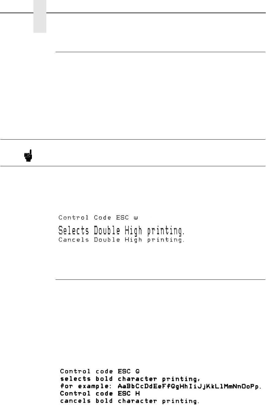
162
Chapter 5
Configuring the Epson FX-1050 Emulation with Control Codes
Double High Print, Set/Reset
ASCII Code ESC w n
Hex Code 1B 77 n
Dec Code 27 119 n
Purpose Turns double-high character printing on and off. Double-high
characters are standard width but twice as high.
where n = 1 or 49 (hex 01 or hex 31) turns double high printing on
n = 0 or 48 (hex 00 or hex 30) turns double high printing off
Discussion The OCR A and OCR B fonts cannot be printed in double high.
If Superscript/Subscript (ESC S) or Condensed Print (SI) is
combined with Double High printing, only Double High printing
will occur.
Example The following sample illustrates double-high character printing.
Double Strike
ASCII Code ESC G
Hex Code 1B 47
Dec Code 27 71
Purpose Makes text bolder by double printing each dot twice.
Discussion This command makes text bolder by printing each dot twice, the
second dot offset to the right of the first by a distance equal to
1/2 the width of a dot, the same as with ESC E.
Example The following sample illustrates double strike character printing.
Note It is recommended to use double Line Feeds and Carriage Returns when
double-high character printing is on (after an ESC w control code has been
sent), or else the printer will overstrike text that has already printed.
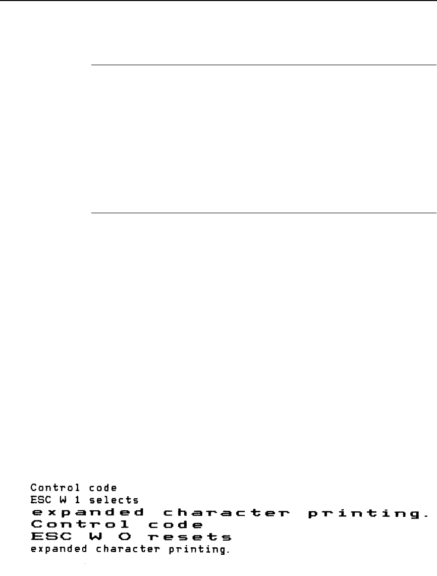
Double Strike, Cancel
163
Double Strike, Cancel
ASCII Code ESC H
Hex Code 1B 48
Dec Code 27 72
Purpose Turns off the double strike printing set by ESC G or ESC !.
Discussion This control code resets only the double strike print attribute.
Other print attributes, such as double wide printing, are not
affected.
Double Wide Print
ASCII Code ESC W n
Hex Code 1B 57 n
Dec Code 27 87 n
Purpose Turns double wide print on and off.
where n = 1 or 49 (hex 01 or hex 31) turns double wide print on
n = 0 or 48 (hex 00 or hex 30) turns double wide print off
Discussion When ESC W is received, all characters are printed twice as
wide until reset. This command overrides SO, ESC SO, and
DC4. The OCR A and OCR B fonts cannot be printed in double
wide.
†This control code doubles character width, but does not double
inter-character spacing, unlike the Epson FX-1050. The formulas
for total character spacing are as follows:
Epson FX-1050 2(char + 1 dot + space)
Epson Emulation 2(char + 1 dot) + space
Example The following sample illustrates double wide character printing.
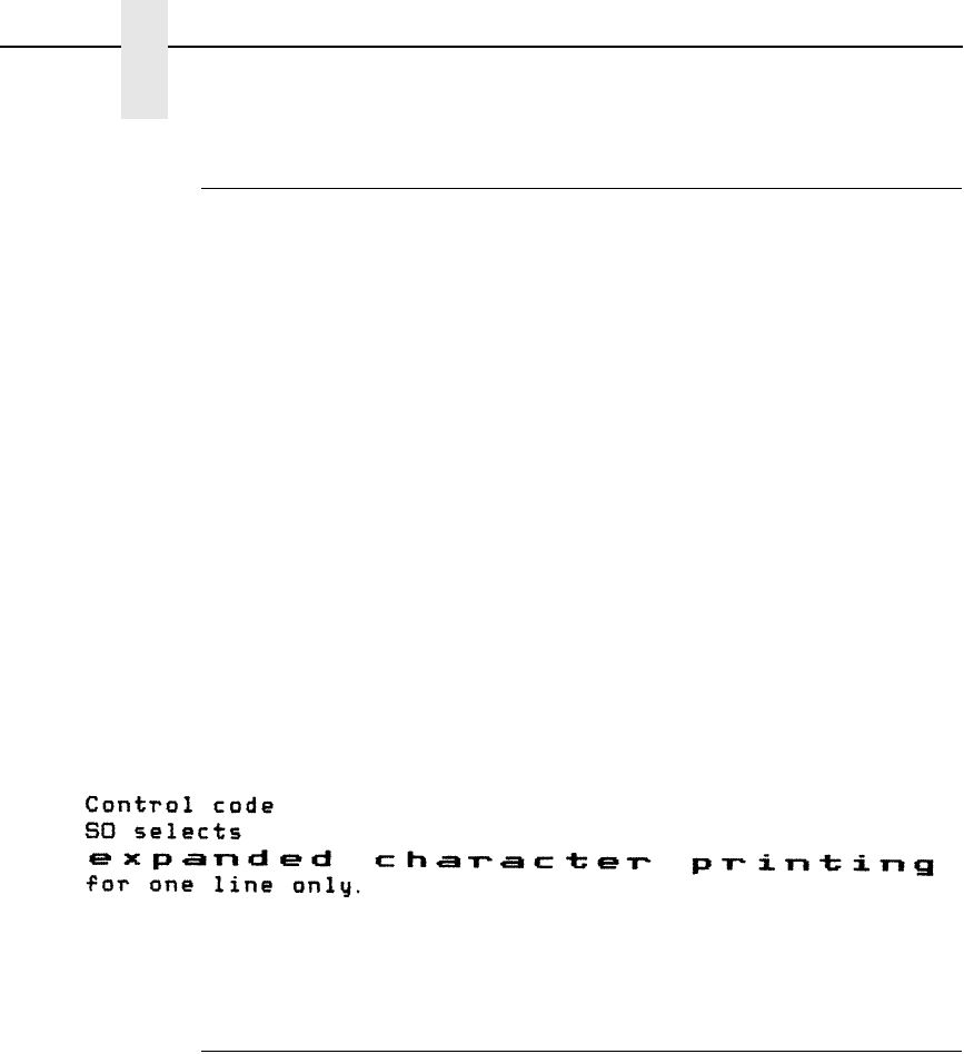
164
Chapter 5
Configuring the Epson FX-1050 Emulation with Control Codes
Double Wide Print (One Line)
ASCII Code SO ESC SO
Hex Code 0E 1B 0E
Dec Code 14 27 14
Purpose Selects double wide print for one line only.
Discussion This control code is a line-by-line print attribute; when SO or
ESC SO is received, the characters on the current line print
twice as wide, then automatically reset.
This control code is cancelled by the DC4 code or by a CR code,
as in the Epson FX-1050. It is also cancelled by a paper motion
control code (LF, VT, etc.), as in the IBM Proprinter III XL.
†This control code doubles character width, but does not double
inter-character spacing, unlike the Epson FX-1050. The formulas
for total character spacing are as follows:
Epson FX-1050 2(char + 1 dot + space)
Epson Emulation 2(char + 1 dot) + space
Example The following sample illustrates double wide print for one line
only.
Double Wide Print (One Line), Cancel
ASCII Code DC4
Hex Code 14
Dec Code 20
Purpose Cancels the double wide print for one line only selected by SO or
ESC SO.
Discussion This command cancels the double wide print selected by SO or
ESC SO, but does not cancel double wide printing selected by
ESC W or ESC !.
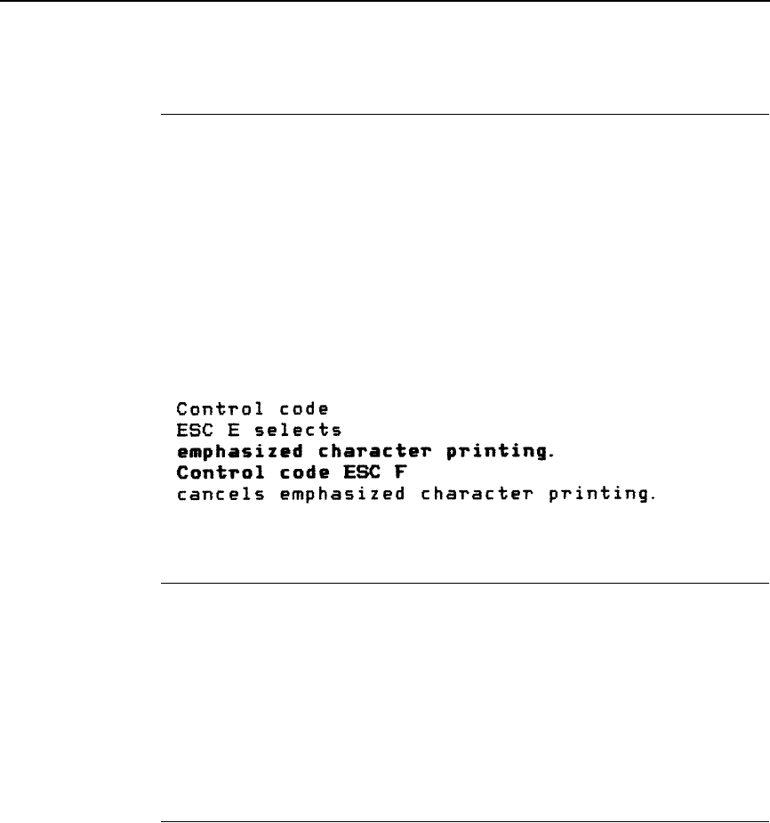
Emphasized Print
165
Emphasized Print
ASCII Code ESC E
Hex Code 1B 45
Dec Code 27 69
Purpose Selects emphasized character print format.
Discussion Emphasized print makes text bolder by printing each dot twice,
the second dot offset to the right of the first by a distance equal
to 1/2 the width of a dot. This command is available in both DP
and NLQ modes.
Example The following sample illustrates emphasized character printing.
Emphasized Print, Cancel
ASCII Code ESC F
Hex Code 1B 46
Dec Code 27 70
Purpose Cancels emphasized character printing selected by ESC E or
ESC !
Discussion This command is available in both DP and NLQ modes.
Enable Printing Hex Codes 00-1F and 80-9F
ASCII Code ESC I n (uppercase “i”)
Hex Code 1B 49 n
Dec Code 27 73 n
Purpose Permits you to print hex codes 00-1F and 80-9F.
where n = 1 allows hex codes 00-1F and 80-9F to be printable and to
be used for user-defined characters.
n = 0 returns hex 00-1F and 80-9F to control codes.
Discussion The printable characters that are included in hex codes 00
through 1F and 80 through 9F are usually not printable in the
default state on Epson printers. Sending ESC I 1 enables you to
print characters in this range. Sending ESC I 0 returns the codes
to non-printable status.
Figure 2 shows the types of characters and their addresses; it is
not a sample of printer output.
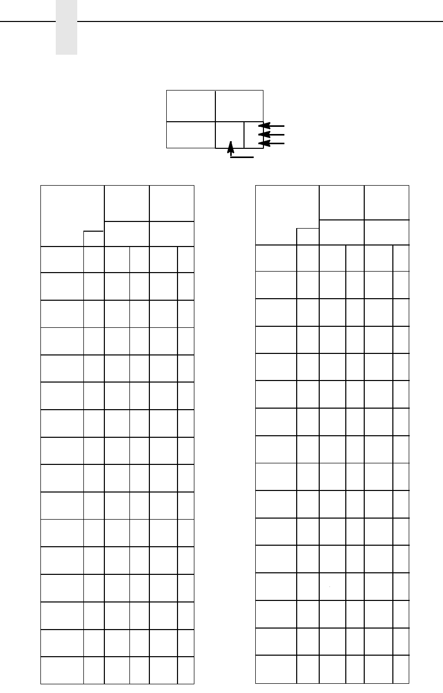
166
Chapter 5
Configuring the Epson FX-1050 Emulation with Control Codes
Figure 2. Epson Printable Codes (Hex 00-1F and 80-9F)
B7 0 0
B6 0
B5 0 01
COLUMN
01
BITS
ROW
B4 B2B3 B1
0
1
2
3
4
5
6
7
8
9
10
11
12
13
14
15
0000
00 10
001 0
001 1
010 0
010 1
011 0
011 1
1000
100 1
101 0
101 1
110 0
110 1
111 0
111 1
0
0
0
1
1
1
2
2
2
3
3
3
4
4
4
5
5
5
6
6
6
7
7
7
10
8
8
11
9
9
12
10
A0
13
11
B0
14
12
C0
15
13
D0
16
14
E0
17
15
F0
20
16
10
21
17
11
22
18
12
23
19
13
24
20
14
25
21
15
26
22
16
27
23
17
30
18
24
31
25
19
32
26
1A
33
27
1B
34
28
1C
35
29
1D
36
30
1E
37
31
1F
BEL
BS
HT
LF
VT
FF
CR
SO
SI
DC2
DC3
DC4
CAN
ESC
B8 0 0
KEY
CHARACTER
ESC
33
27
1B
OCTAL
DECIMAL
HEX
10 1 1
B4 B2B3 B1
B7 B6 B5
001
BITS
à
è
ù
ò
ì
£
§
ß
ø
¨
Ä
Ü
ä
ü
É
é
¥
00
0001
COLUMN
89
200
128
80
201
129
81
202
130
82
203
131
83
204
132
84
205
133
85
206
134
86
207
135
87
210
136
88
211
137
89
212
138
213
139
214
140
215
141
216
142
217
143
220
144
90
221
145
91
222
146
92
223
147
93
224
148
94
225
149
95
226
150
96
227
151
97
230
98
152
231
153
99
232
154
9A
233
155
9B
234
156
9C
235
157
9D
236
158
9E
237
159
9F
8A
8B
8C
8D
8E
8F
11
B7 B6 B5
BITS
ROW
B4 B2B3 B1
0
1
2
3
4
5
6
7
8
9
10
11
12
13
14
15
0000
00 10
001 0
001 1
010 0
010 1
011 0
011 1
1000
100 1
101 0
101 1
110 0
110 1
111 0
111 1
B8
à
è
ù
ò
ì
£
¡
¿
Ñ
ñ
¤
Å
å
ç
§
ß
Æ
æ
Ø
ø
¨
Ä
Ö
ö
ä
Ü
ü
É
é
¥
oo
P
t
à

Form Feed
167
Form Feed
ASCII Code FF
Hex Code 0C
Dec Code 12
Purpose Prints the data in the buffer, if any, then moves the paper to the
top of the next form.
Discussion The logical print head moves to the left margin. This code
cancels all one-line-only emphasis and font controls: double-
wide from SO and ESC SO, and unidirectional printing from ESC
<.
Graphics, Standard Density
ASCII Code ESC K n1 n2
Hex Code 1B 4B n1 n2
Dec Code 27 75 n1 n2
Purpose Selects normal density bit image graphics of 60 dots per inch
horizontally and 72 dots per inch vertically.
where (n1 + 256n2) defines the number of data bytes to follow.
DATA = ASCII characters for the dot pattern bytes.
n1 = (Number of DATA bytes) - 256(n2)
(remainder of division of number of DATA bytes by 256,
sometimes referred to as MOD 256)
n2 = (Number of DATA bytes) / 256 (quotient of division)
Discussion You can change graphics density with the ESC ? command.
Example The following example produces a pattern of standard density bit
image graphics. The 9 data-bit pattern is repeated 27 times.
Compare this example to the double density and quadruple
density examples.
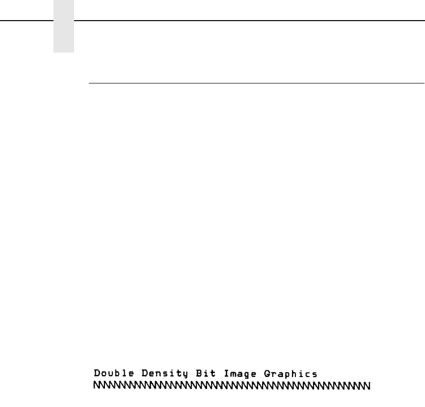
168
Chapter 5
Configuring the Epson FX-1050 Emulation with Control Codes
Graphics, Double Density
ASCII Code ESC L n1 n2
Hex Code 1B 4C n1 n2
Dec Code 27 76 n1 n2
Purpose Selects double density bit image graphics of 120 dots per inch
horizontally and 72 dots per inch vertically.
where (n1 + 256n2) defines the number of data bytes to follow.
DATA = ASCII characters for the dot pattern bytes.
n1 = (Number of DATA bytes) - 256(n2)
(remainder of division of number of DATA bytes by 256,
sometimes referred to as MOD 256)
n2 = (Number of DATA bytes) / 256 (quotient of division)
Discussion Double density printing reduces print speed to half that of normal
density printing. You can change graphics density with the ESC
? command. This feature is widely used to move the print head
precisely, by printing blank dot columns.
Example The following example produces double density bit-image
graphics of the pattern used in the standard density bit-image
mode example. The amount of data must be doubled for double
density (the data are used 54 times rather than 27).
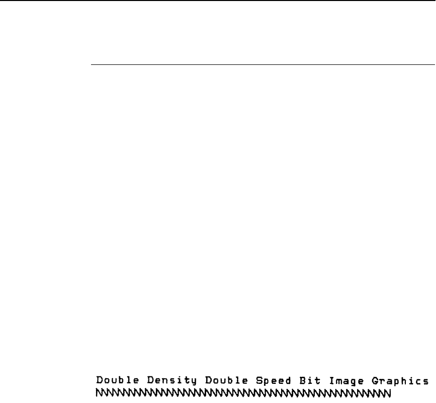
Graphics, Double Density Double Speed
169
Graphics, Double Density Double Speed
ASCII Code ESC Y n1 n2
Hex Code 1B 59 n1 n2
Dec Code 27 89 n1 n2
Purpose Selects double density, double speed bit-image graphics of 120
dpi horizontally and 72 dpi vertically.
where (n1 + 256n2) defines the number of data bytes to follow.
DATA = ASCII characters for the dot pattern bytes.
n1 = (Number of DATA bytes) - 256(n2)
(remainder of division of number of DATA bytes by 256,
sometimes referred to as MOD 256)
n2 = (Number of DATA bytes) / 256 (quotient of division)
Discussion This mode prints double density with no adjacent dots. It is
similar to ESC L, except that if the graphics data contain
horizontally adjacent dots, the data may print incorrectly. This
feature is widely used to move the print head precisely, by
printing blank dot columns.
Example The following example produces a double density, double speed
graphic image of the pattern used in the standard density
example. The amount of data must be doubled for double
density (the data are used 54 times rather than 27).
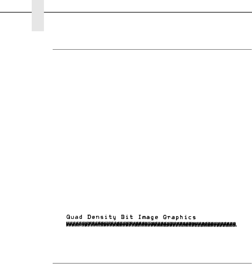
170
Chapter 5
Configuring the Epson FX-1050 Emulation with Control Codes
Graphics, Quadruple Density
ASCII Code ESC Z n1 n2
Hex Code 1B 5A n1 n2
Dec Code 27 90 n1 n2
Purpose Selects Quadruple Density Bit Image graphics of 240 dpi
horizontally and 72 dpi vertically.
where (n1 + 256n2) defines the number of data bytes to follow.
DATA = ASCII characters for the dot pattern bytes.
n1 = (Number of DATA bytes) - 256(n2)
(remainder of division of number of DATA bytes by 256,
sometimes referred to as MOD 256)
n2 = (Number of DATA bytes) / 256 (quotient of division)
Discussion This mode is similar to ESC L, except that four dot columns are
printed in the space normally taken by two columns. You can
change graphics density with the ESC ? command.
Example The following example produces quadruple density graphics of
the pattern used in the standard density example. The amount of
data must be quadrupled for quadruple density (the data are
used 108 times rather than 27).
Half Speed Mode, On/Off
ASCII Code ESC s n
Hex Code 1B 73 n
Dec Code 27 115 n
Purpose Reduces printer speed 50%
where n = 1 or 49 (hex 00 or 30) turns half speed mode off
n = 0 or 48 (hex 01 or 31) turns half speed mode on
†Discussion This is simulated in your printer by unidirectional printing.
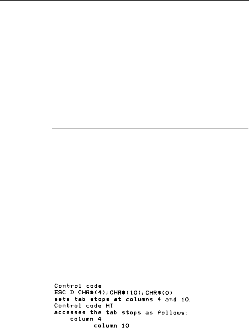
Horizontal Tab Execute
171
Horizontal Tab Execute
ASCII Code HT
Hex Code 09
Dec Code 09
Purpose Moves the logical print head to the next horizontal tab stop.
Discussion Power-on default horizontal tabs are set at every eighth
character at the current character spacing. Tab positions are not
affected by a change of font or character width. Blank spaces
between HT stops are underlined in underline mode.
Horizontal Tab Set/Release
ASCII Code ESC D n1 ... nk NUL
Hex Code 1B 44 n1 ... nk 00
Dec Code 27 68 n1 ... nk 0
Purpose Sets up to 32 horizontal tab positions.
where n1 through n32 specify the character column of the tab positions.
NUL (hex 00) is the sequence terminator. ESC D 0 clears all
tabs.
Discussion The values of n must be listed in ascending order or they are
ignored. Tabs greater than 32 or those positioned beyond the
right margin are ignored. The physical tab position is the product
of n and the current cell width (1/pitch), excluding double wide.
After the tabs are set, HT moves the logical print head to the
next tab stop. Sending ESC @ initializes the printer and resets
the tabs to every eighth character column (which is the default).
In proportional mode, the size of 10 CPI characters determines
tab positions.
Example The following example illustrates how to set horizontal tabs.

172
Chapter 5
Configuring the Epson FX-1050 Emulation with Control Codes
Initialize Printer
ASCII Code ESC @
Hex Code 1B 40
Dec Code 27 64
Purpose Resets all print-related parameters to the power-up
configuration.
Discussion Restores the power-up values and clears the print buffer of
printable data on the line preceding the command. Current
position is set as top-of-form.
Font, international language selection, forms length, skip-over
perforation, and character pitch are reset to their power-up
values.
Character-by-character and line-by-line attributes are canceled.
All channels of the vertical format unit are cleared.
This command resets the horizontal tabs to every eighth
character column. Interface parameters and printer protocol
selection are not affected.
Italic Printing
ASCII Code ESC 4
Hex Code 1B 34
Dec Code 27 52
Purpose Turns on italic character printing.
Discussion Character graphics (IBM graphic set hex B0 through DF and F0
through FE) cannot be italicized. Italic printing will reduce
throughput.
Italic Printing, Cancel
ASCII Code ESC 5
Hex Code 1B 35
Dec Code 27 53
Purpose Turns off italic character printing.
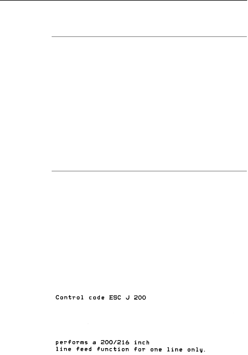
Line Feed
173
Line Feed
ASCII Code LF
Hex Code 0A
Dec Code 10
Purpose Prints the data in the buffer (if any) and advances the vertical
character position a distance of one line at the current line
spacing.
Discussion The logical print head keeps the same distance from the margin.
The current line is printed and the logical printhead moves down
a distance equal to the current line spacing. If there are no dots,
paper moves and no printing occurs. When possible, successive
line feeds are accumulated and moved at once.
This code cancels all one-line-only emphasis and font
selections: double-wide from SO and ESC SO, and
unidirectional printing from ESC <.
Line Feed n/216 Inch
ASCII Code ESC J n
Hex Code 1B 4A n
Dec Code 27 74 n
Purpose Immediately advances the paper n/216 inch.
where n = 0 through 255 (hex 00 through hex FF).
Discussion n = 0 is ignored. Paper movement occurs in multiples of 3/216
inch. This command produces an immediate line feed but does
not affect line spacing or produce a carriage return. Any one-
line-only print attributes in effect are canceled.
Small values of n may result in overlapping lines. Overlapping
lines may also occur if print attributes such as double high,
superscript, or subscript characters are used on the same line.
Example The following example illustrates n/216-inch line spacing.
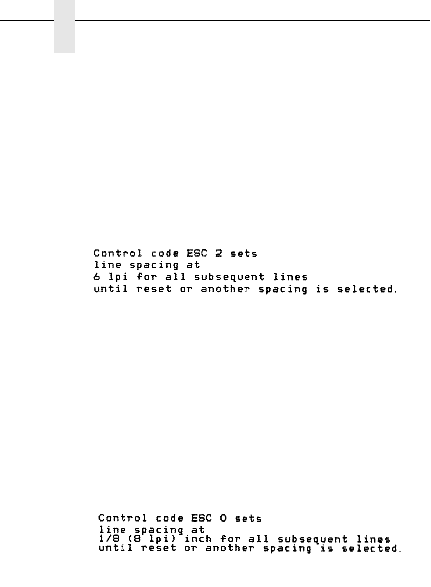
174
Chapter 5
Configuring the Epson FX-1050 Emulation with Control Codes
Line Spacing 1/6 Inch (6 lpi)
ASCII Code ESC 2
Hex Code 1B 32
Dec Code 27 50
Purpose Sets the line spacing to 1/6 inch (6 lpi) for subsequent line feeds.
Discussion The 2 is ASCII character 2, not hex 02.
When ESC 2 is received, all lines are printed at 6 lpi until a new
line spacing is selected or the printer is reset.
This control code overrides line spacing set at the control panel.
Example The following example illustrates 1/6-inch line spacing.
Line Spacing 1/8 Inch (8 lpi)
ASCII Code ESC 0
Hex Code 1B 30
Dec Code 27 48
Purpose Sets the line spacing to 1/8 inch (8 lpi) for subsequent line feeds.
Discussion The 0 is ASCII character 0 (zero), not hex 00. When ESC 0 is
received, all lines are printed at 8 lpi until a new line spacing is
selected or the printer is reset. This control code overrides line
spacing set at the control panel.
Example The following example illustrates 1/8-inch line spacing.
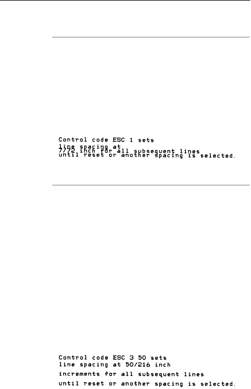
Line Spacing 7/72 Inch
175
Line Spacing 7/72 Inch
ASCII Code ESC 1
Hex Code 1B 31
Dec Code 27 49
Purpose Sets the line spacing to 7/72 inch (10.3 lpi) for subsequent line
feeds.
Discussion All lines are printed at the 7/72-inch line spacing until a new line
spacing is selected or the printer is reset. This control code
overrides line spacing set at the control panel.
Printing speed is reduced if printed lines overlap.
Example The following example illustrates 7/72-inch line spacing.
Line Spacing n/216 Inch
ASCII Code ESC 3 n
Hex Code 1B 33 n
Dec Code 27 51 n
Purpose Specifies the line spacing at n/216-inch increments.
where n = 1 through 255 (hex 01 through hex FF).
Discussion All line feeds following receipt of this code are at n/216 inch line
spacing until a new line spacing is selected or the printer is
reset. Line spacing set by this control code overrides line
spacing setting set at the control panel.
The vertical character position moves only in multiples of the
current dot row spacing. If the distance to move is other than a
multiple of the current dot row spacing, the remainder is added
to the next paper motion command.
Paper movement occurs in multiples of 3/216 only.
Use caution when combining this control code with other print
attributes such as Elongated (Double High), Superscript, or
Subscript; overlapping lines may occur. Print speed is reduced if
lines overlap.
Example The following example illustrates n/216-inch line spacing.
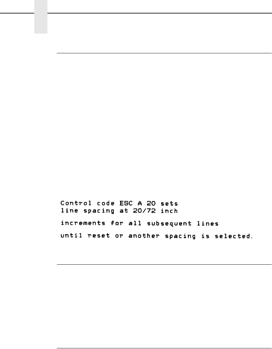
176
Chapter 5
Configuring the Epson FX-1050 Emulation with Control Codes
Line Spacing n/72 Inch
ASCII Code ESC A n
Hex Code 1B 41 n
Dec Code 27 65 n
Purpose Sets a line spacing of n/72 inch for subsequent line feeds.
where n = 1 through 255 (hex 01 through hex FF).
Discussion When this control sequence is received, all subsequent line
feeds are n/72-inch until a new line spacing is selected or the
printer is reset. This setting overrides line spacing set at the
control panel.
Small values of n may result in overlapping lines. Overlapping
lines may also occur if print attributes such as Elongated
(Double High), Superscript, or Subscript characters are used on
the same line. If lines overlap, printing speed is reduced. Any
values set by ESC 3 (line spacing n/216 inch) are replaced.
Example The following example illustrates 20/72-inch line spacing.
Make Hex 80-9F Control Codes
ASCII Code ESC 7
Hex Code 1B 37
Dec Code 27 55
Purpose Selects codes hex 80-9F in the character sets as control codes.
Discussion This is the default when the Epson character set is selected as
the default set at the control panel.
Make Hex 80-9F Printable
ASCII Code ESC 6
Hex Code 1B 36
Dec Code 27 54
Purpose Selects codes hex 80-9F in the character sets as printable
characters.
Discussion This is the default when the IBM PC character set (code page
0437) is selected as the default set at the control panel.
Figure 3 shows the hex 80-9F printable characters for the Epson
character set and for the IBM PC graphic character set.
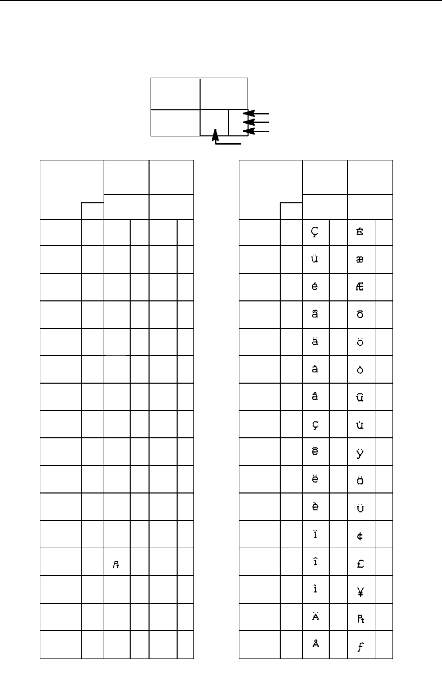
Make Hex 80-9F Printable
177
Figure 3. Epson Printable Codes (Hex 80-9F)
KEY
CHARACTER
ESC
33
27
1B
OCTAL
DECIMAL
HEX
10 1 1
B4 B2B3 B1
B7 B6 B5
001
BITS
00
0001
COLUMN
89
200
128
80
201
129
81
202
130
82
203
131
83
204
132
84
205
133
85
206
134
86
207
135
87
210
136
88
211
137
89
212
138
213
139
214
140
215
141
216
142
217
143
220
144
90
221
145
91
222
146
92
223
147
93
224
148
94
225
149
95
226
150
96
227
151
97
230
98
152
231
153
99
232
154
9A
233
155
9B
234
156
9C
235
157
9D
236
158
9E
237
159
9F
8A
8B
8C
8D
8E
8F
11
B7 B6 B5
BITS
ROW
B4 B2B3 B1
0
1
2
3
4
5
6
7
8
9
10
11
12
13
14
15
0000
00 10
00 1 0
00 1 1
01 0 0
01 0 1
01 1 0
01 1 1
1000
10 0 1
10 1 0
10 1 1
11 0 0
11 0 1
11 1 0
11 1 1
B8
è
ù
ò
ì
£
¡
¿
Ñ
ñ
¤
Å
å
ç
§
ß
Æ
æ
Ø
ø
¨
Ä
Ö
ö
ä
Ü
ü
É
é
¥
00
0001
COLUMN
89
200
128
80
201
129
81
202
130
82
203
131
83
204
132
84
205
133
85
206
134
86
207
135
87
210
136
88
211
137
89
212
138
213
139
214
140
215
141
216
142
217
143
220
144
90
221
145
91
222
146
92
223
147
93
224
148
94
225
149
95
226
150
96
227
151
97
230
98
152
231
153
99
232
154
9A
233
155
9B
234
156
9C
235
157
9D
236
158
9E
237
159
9F
8A
8B
8C
8D
8E
8F
11
B7 B6 B5
BITS
ROW
B4 B2B3 B1
0
1
2
3
4
5
6
7
8
9
10
11
12
13
14
15
0000
00 10
00 1 0
00 1 1
01 0 0
01 0 1
01 1 0
01 1 1
1000
10 0 1
10 1 0
10 1 1
11 0 0
11 0 1
11 1 0
11 1 1
B8
Epson USA Character Set IBM 437 Code Page
à
o
à
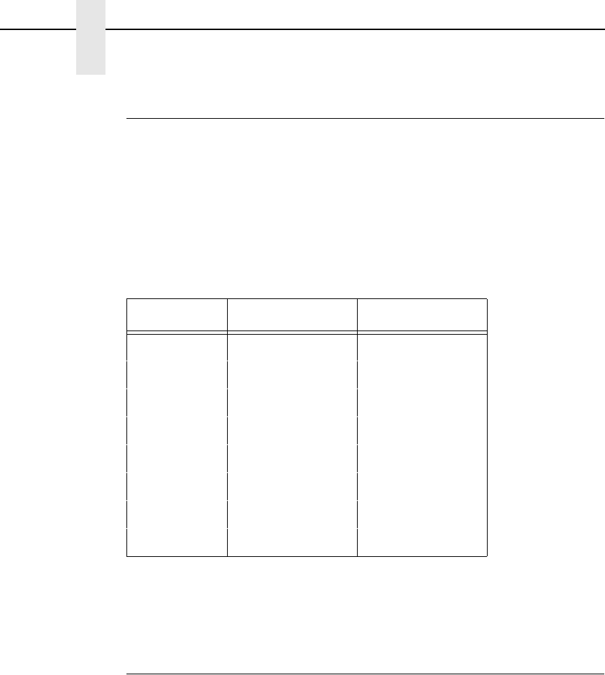
178
Chapter 5
Configuring the Epson FX-1050 Emulation with Control Codes
Master Print Select
ASCII Code ESC !
n
Hex Code 1B 21
n
Dec Code 27 33
n
Purpose Selects or changes print attributes in a single command.
where
n
= an 8-bit number with the bits set to specify print attributes, as
shown in Table 41.
Discussion Emphasized is substituted for double strike. Graphics and grey
scale characters are not underlined. Proportional spacing
overrides condensed or 12 cpi printing if both are selected.
Paper Out Detection, Enable
ASCII Code ESC 9
Hex Code 1B 39
Dec Code 27 57
Purpose Asserts a paper out condition immediately when the end of the
paper supply is sensed.
†
Discussion The printer decodes and ignores this command.
Table 41. Master Print Select Bit Values
Bit No. Bit = 0 Bit = 1
010 cpi
†
12 cpi
1Monospaced
†
Proportional
2Normal Condensed
3Normal Emphasized
4Normal
†
Double Strike
5Normal Double Wide
6Normal Italic
7Normal Underlined

Paper Out Detection, Disable
179
Paper Out Detection, Disable
ASCII Code ESC 8
Hex Code 1B 38
Dec Code 27 56
Purpose Enable printing to the end of the paper supply when a paper out
condition is sensed.
†
Discussion The printer decodes and ignores this command.
Pass Bit 7 from Host
ASCII Code ESC #
Hex Code 1B 23
Dec Code 27 35
Purpose Passes bit 7 (the eighth and most significant bit) whether it is 1
or 0, thereby cancelling ESC > and ESC =.
Discussion This command affects only text and control code data; bit 8 of
graphics data is always passed through.
Printer Select
ASCII Code DC1
Hex Code 11
Dec Code 17
Purpose Places printer in the selected state.
Discussion The configuration parameter Printer Select must be set to
Enable. Refer to the
User's Manual
for information about this
menu option.
This control code allows the printer to receive and print data from
the host if it was deselected by DC3. If the printer was not
deselected by DC3, this code is ignored.
Printer Deselect
ASCII Code DC3
Hex Code 13
Dec Code 19
Purpose Places printer in the deselected state.
Discussion The configuration parameter Printer Select must be set to
Enable. Refer to the
User's Manual
for information about this
menu option.
When the printer receives this command it ignores data until a
DC1 (Printer Select) command is received.

180
Chapter 5
Configuring the Epson FX-1050 Emulation with Control Codes
Reassign Graphics Mode
ASCII Code ESC ?
s m
Hex Code 1B 3F
s m
Dec Code 27 63
s m
Purpose Changes one graphics mode to another.
Discussion
s
is character K, L, Y, or Z, which is changed to mode
m
(0-7)
from Table 42 (page 181). Thereafter, sending data to the bit
image command makes the data print according to the graphics
mode you select with
m.
Remove Downloaded Characters
ASCII Code ESC : NUL
n
NUL
Hex Code 1B 3A 00
n
00
Dec Code 27 58 0
n
0
Purpose Erases all downloaded characters.
†
Discussion The printer ignores this command but removes all data sent.
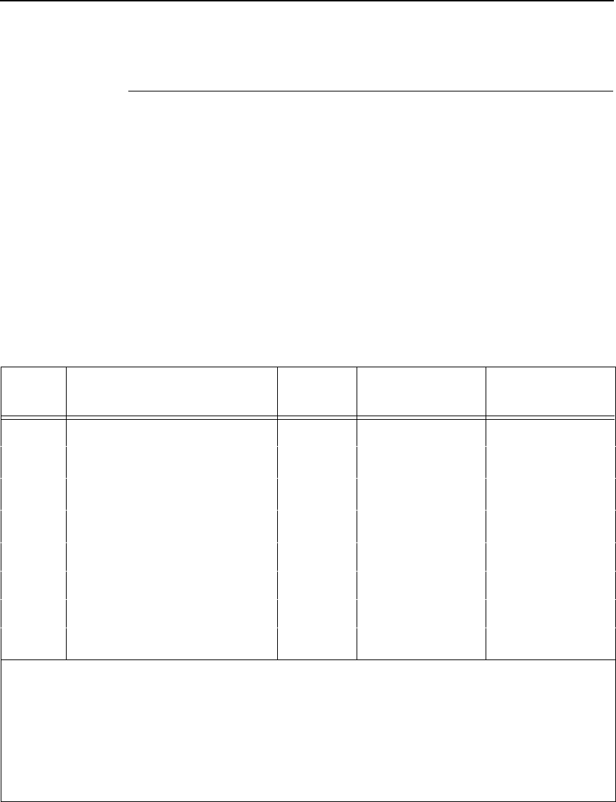
Select Graphics Mode
181
Select Graphics Mode
ASCII Code ESC *
m n1 n2
Hex Code 1B 2A
m n1 n2
Dec Code 27 42
m n1 n2
Purpose Turns on 8-pin bit image graphics mode
m
. Table 42 charts the
graphics modes available.
Discussion The total number of columns =
n1
+
256
n2.
n1
= (Number of DATA bytes) - 256(
n2
)
(remainder of division of number of DATA bytes by 256,
sometimes referred to as MOD 256)
n2
= (Number of DATA bytes) / 256 (quotient of division)
This command does not suppress hexadecimal FF from printing.
Table 42. Epson Graphics Modes
m
Option Alternate
Code Density*
(dots per inch) Resolution**
(dots per inch)
0Single density ESC K 60 120
1Double density ESC L 120 120
1
2High-speed double density ESC Y 60 120
2
3Quadruple density ESC Z 120 240
1,2,3
4CRT I none 80 160
5Plotter (1:1) none 72 144
6CRT II none 90 180
7Double density plotter none 144 144
1
1
Prints at half speed.
2
Data can be sent incorrectly. In these modes, no dots can be closer horizontally than the
current font dot density. Sending incorrect data does not damage the printer.
3
240 dpi is simulated by combining the dots from two adjacent columns into one 120 dpi
dot column.
* Number of horizontal dots per inch the printer can make.
** Number of dot columns available.

182
Chapter 5
Configuring the Epson FX-1050 Emulation with Control Codes
Select Italic Character Set
ASCII Code ESC t
n
Hex Code 1B 74
n
Dec Code 27 116
n
Purpose Selects the italics characters from hex 80 through hex FF, or
selects the graphics characters from hex 80 through hex FF.
where
n
= hex 01 selects the graphics character set
n
= hex 00 selects the italics character set
Discussion The graphics character set is the IBM Graphics Code Page 437.
Select 9-Pin Graphics Mode
ASCII Code ESC ^
m n1 n2 d1 ... dk
Hex Code 1B 5E
m n1 n2 d1 ... dk
Dec Code 27 94
m n1 n2 d1 ... dk
Purpose Turns on 9-pin bit image graphics mode.
Discussion
m
defines the plot density as shown in Table 42 on page 181.
n1
+ 256
n2
= The total number of columns.
n1
= (Number of DATA bytes) - 256(
n2
)
(remainder of division of number of DATA bytes by 256,
sometimes referred to as MOD 256)
n2
= (Number of DATA bytes) / 256 (quotient of division)
This mode requires two bytes of graphic data for every column of
print. Each column is sent as a pair:
d1, d3, ... d
(
k
-1) set the top
8 bits of a normal dot column, just like ESC K;
d2, d4, ... dk
set
the ninth dot in the column (the most significant bit) just below
the bottom-most dot of columns
d1, d3, ... d
(
k
-1).
Select Print Quality
183
Select Print Quality
ASCII Code ESC x
n
Hex Code 1B 78
n
Dec Code 27 120
n
Purpose Selects print quality.
where
n
may be in the range from 0 through 4. Values in the range
5-255 are invalid.
n
= 0 or 48 (hex 00 or hex 30) selects DP print quality
n
= 1 or 49 (hex 01 or hex 31) selects Near Letter Quality (NLQ)
n
= 2 or 50 (hex 02 or hex 32) selects HS print quality
n
= 3 or 51 (hex 03 or hex 33) selects OCR A print quality
n
= 4 or 52 (hex 04 or hex 34) selects OCR B print quality
Discussion This command overrides control panel print quality selections.
Selecting an OCR print quality overrides any character attributes
set, such as condensed, double-wide, etc. Setting character
attributes when OCR is set may cause unexpected results.
†
Draft, OCR A, and OCR B print qualities (
n
= 2, 3, or 4) are not
defined in Epson-FX printers.
Select/Deselect Proportional Spacing
ASCII Code ESC p
n
Hex Code 1B 70
n
Dec Code 27 112
n
where
n
= 0 = Off
n
= 1 = On
Purpose Turns proportional mode on and off.
Note Some print attributes (such as condensed, double-wide, etc.) may not
return to their previous setting when changing from OCR-A or OCR-B back
to another Print Quality. For guaranteed results, all print attributes should
be set after the Print Quality is selected.

184
Chapter 5
Configuring the Epson FX-1050 Emulation with Control Codes
Select Serif or Sans Serif Font
ASCII Code ESC k
n
Hex Code 1B 6B
n
Dec Code 27 107
n
†
Purpose Selects an NLQ font.
where
n
may range from 0 through 255 (hex 00 through hex FF).
n
= 0, 2, 4 .. (any even value), the font selected is a serif NLQ
font (Courier, instead of standard Epson Roman).
n
= 1, 3, 5 .. (any odd value), the font selected is a sans serif
NLQ font.
Select User-Defined Font
ASCII Code ESC %
n
Hex Code 1B 25
n
Dec Code 27 37
n
Purpose Selects a user-defined font.
†
Discussion The printer ignores this command and removes all font data
sent from the data stream.
Select Vertical Tab Channel
ASCII Code ESC /
c
Hex Code 1B 2F
c
Dec Code 27 47
c
Purpose Selects a vertical tab channel set by ESC b.
where
c
= 0 through 7.
Discussion Subsequent VT (Hex 0B) commands use tab table specified by
c
. If no tab table is selected, channel 0 is used.

Set Absolute Horizontal Print Position in 1/60 Inch
185
Set Absolute Horizontal Print Position in 1/60 Inch
ASCII Code ESC $
n1 n2
Hex Code 1B 24
n1 n2
Dec Code 27 36
n1 n2
Purpose Moves the logical print head to an absolute horizontal print
position, using 1/60 inch increments.
where (
n1
+ [256
n2
]) / 60 = the unsigned distance in inches from the
left margin.
n1
= (Number of DATA bytes) - 256(
n2
)
(remainder of division of number of DATA bytes by 256,
sometimes referred to as MOD 256)
n2
= Number of DATA bytes) / 256 (quotient of division)
Discussion If the distance goes beyond right margin, the sequence is
ignored.
Set Bit 7 of Incoming Data Bytes to 1
ASCII Code ESC >
Hex Code 1B 3E
Dec Code 27 62
Purpose Sets the most significant bit (MSB) of all incoming data to 1.
Discussion The MSB is bit number 7. This command only affects text and
control code data. Graphics data pass through unchanged.
Set Form Length in Inches
ASCII Code ESC C NUL
n
Hex Code 1B 43 00
n
Dec Code 27 67 0
n
Purpose Sets form length to
n
inches.
where
n
= whole numbers from 1 through 24 to specify the number of
inches on a form.
Discussion Upon receipt of this code, the current line becomes the first line
of the form, and the form length set becomes the current forms
length. Vertical tab positions set below the bottom of the form
are ignored. Forms length is defined in inches; therefore,
subsequent line spacing changes do not affect the result of this
command.
Values of
n
greater than 24 are ignored.
When forms length is set by an ESC C sequence, the skip-over
perforation set by ESC N is cancelled.
This control code overrides forms length set at the control panel.

186
Chapter 5
Configuring the Epson FX-1050 Emulation with Control Codes
Set Form Length in Lines
ASCII Code ESC C
n
Hex Code 1B 43
n
Dec Code 27 67
n
Purpose Sets the form length by lines.
where
n
= 1 through 192 (hex 01 through C0) to specify the number of
lines per form at the current line spacing.
Discussion The forms length is set to the number of lines defined by the
quotient of
n
divided by the current lines per inch so that the
units are in inches.
The current line becomes the first line of the form. The forms
length is always defined in inches; therefore, changing the lpi
after this control code has been issued does not change the
forms length.
If the calculated forms length in lines is not an exact multiple of
the target machine dot size, the forms length value will be
adjusted down to the next possible multiple.
When forms length is set by an ESC C sequence, the skip-over
perforation set by ESC N is cancelled.
Set Intercharacter Spacing in 1/120 Inch
ASCII Code ESC SP
n
Hex Code 1B 20
n
Dec Code 27 32
n
Purpose Permits character spacing adjustments in 1/120 inch increments.
where
n
= 0 through 127 (hex 00 through 7F).
Set Margin, Left
ASCII Code ESC l
n
(lowercase “L”)
Hex Code 1B 6C
n
Dec Code 27 108
n
where
n
= number of columns from the left edge of the physical page to
the beginning of the print line;
n
= 1 through 232 (hex 00 through hex E8)
Purpose Sets the left margin to
n
columns in the current font.
Discussion Be sure to use the alphabetic lowercase “L” (as in left) rather
than the numeral “1” (one) for this command. The number of
inches of margin does not vary if the font, character width, or
horizontal dot density changes. This command automatically
clears and resets horizontal tabs to every eight characters. The
smallest possible space between the left and right margins is the

Set Margin, Right
187
width of one double-wide, 10 cpi character. If a margin control
code violates this minimum distance, it is ignored. Settings in
proportional mode are treated as 10 CPI.
Set Margin, Right
ASCII Code ESC Q
n
Hex Code 1B 51
n
Dec Code 27 81
n
where
n
= number of columns from the left edge of the physical page to
the end of the print line;
n
= 1 through 232 (hex 00 through hex E8)
Purpose Sets the right margin to
n
columns at the current character width.
Discussion The number of inches of margin does not vary if the font,
character width, or horizontal dot density changes. This
command automatically clears and resets horizontal tabs to
every eight characters. The smallest possible space between
the left and right margins is the width of one-double wide, 10 cpi
character. If a margin control code violates this minimum
distance, it is ignored. Settings in proportional mode are treated
as 10 CPI.
Set Relative Horizontal Print Position in 1/120 Inch
ASCII Code ESC \
n1 n2
Hex Code 1B 5C
n1 n2
Dec Code 27 92
n1 n2
Purpose Moves the logical print head to a relative horizontal print
position, using 1/120 inch increments.
Discussion Adds (
n1
+ 256
n2
) / 120 inches to the horizontal position of the
logical print head. The number sent is two's complement, with
negative numbers moving to the left. The command is ignored if
it would move the logical print head beyond the page margins.

188
Chapter 5
Configuring the Epson FX-1050 Emulation with Control Codes
Set Vertical Tabs in Channels
ASCII Code ESC b
c n1 n2 n3 ... n16
NUL
Hex Code 1B 62
c n1 n2 n3 ... n16
00
Dec Code 27 98
c n1 n2 n3 ... n16
0
Purpose Assigns vertical tabs to channels selected by ESC /.
where
c
= 0 through 7
n
= 0 through 255 (hex 00 through FF).
n1
through
nk
specify the line number for the vertical tab(s), up
to a maximum of 16 tab positions. NUL must end the sequence.
Discussion Channels are selected by ESC /. The distance of each tab stop
from TOF is the current line spacing times the number of lines
given in
n.
If paper movement is commanded to a value of
n
greater than
the page length, the paper movement command is ignored. The
values of
n
must be in ascending order. If they are not, the
sequence up to and including the out of sequence number is
ignored. The rest of the load is processed. Skip over perforation
is ignored.
You can clear any channel by sending ESC b
c
NUL, where
c
is
the channel number.
Skip Over Perforation
ASCII Code ESC N
n
Hex Code 1B 4E
n
Dec Code 27 78
n
Purpose Selects the number of lines (at the current line spacing) for the
paper to skip at the bottom of the page.
where
n
= 1 through 127 (hex 01 through 7F)
Discussion
n
is the number of lines skipped between the last line printed on
one page and the first line on the next page. The actual distance
set is the product of
n
and the current line spacing. If the value of
n
exceeds the current form length, the skip is set to one line
smaller than the form length or to 0, whichever is greater.
Skip over perforation set by this command overrides control
panel settings. This feature is canceled by ESC O, ESC C, ESC
C 0.
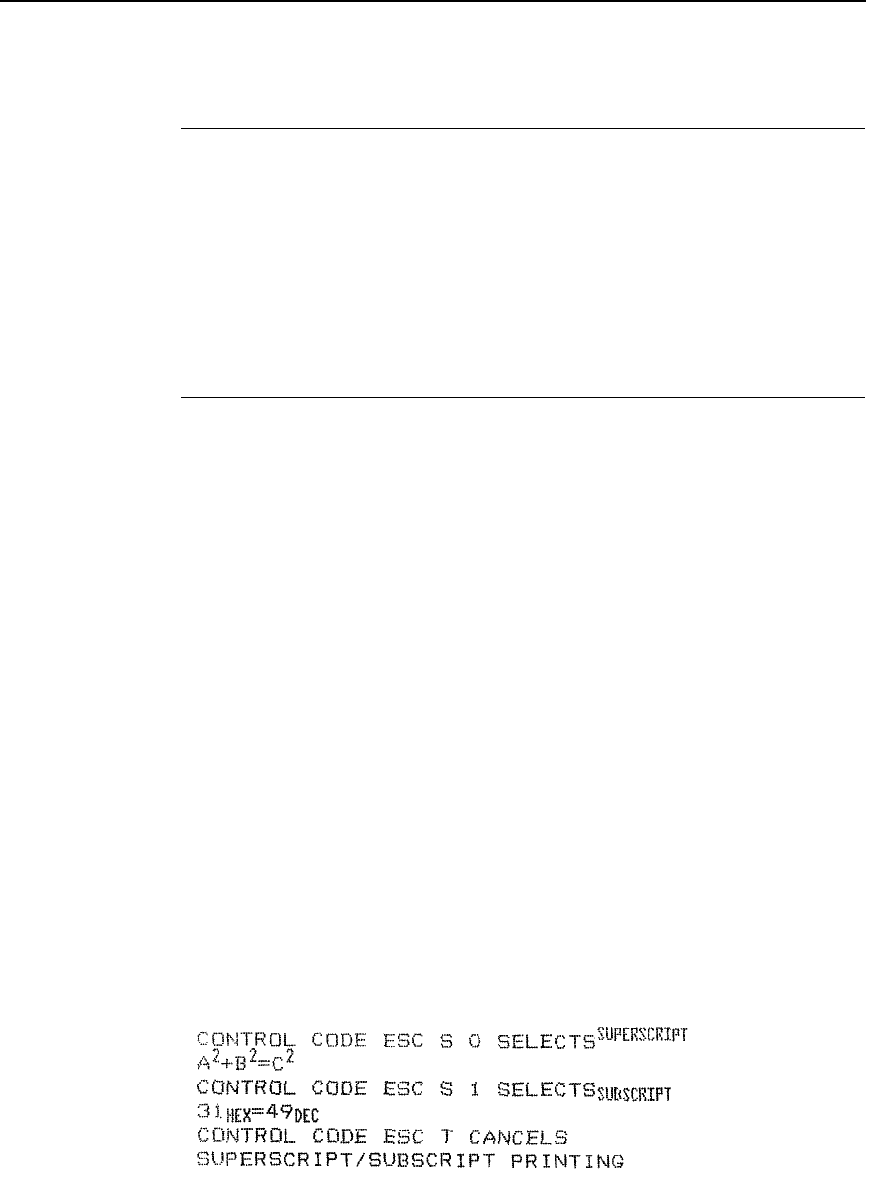
Skip Over Perforation, Cancel
189
Skip Over Perforation, Cancel
ASCII Code ESC O
Hex Code 1B 4F
Dec Code 27 79
Purpose Cancels the skip over perforation set by ESC N and resets the
bottom margin to zero.
Discussion O is ASCII uppercase o, not zero (0).
Superscript and Subscript Printing
ASCII Code ESC S
n
Hex Code 1B 53
n
Dec Code 27 83
n
Purpose Selects superscript or subscript printing.
where
n
= NUL (hex 00) or 0 (hex 30) to enable superscript printing
n
= SOH (hex 01) or 1 (hex 31) to enable subscript printing
†
Discussion Superscript prints full-sized characters with a baseline higher
than the normal characters. Subscript prints full-sized characters
with a baseline lower than the normal characters. When the
control code is received, all characters are superscript or
subscript until reset by ESC T or printer reset. (This differs from
the Epson standard, which utilizes half-size characters for
superscript and subscript printing.)
You can print both superscript and subscript characters in the
same character column by using the Backspace (BS) control
code, but these characters will not print when double high
printing is in effect.
If Superscript/Subscript is combined with Double High (ESC w)
printing,
only
Double High printing will occur.
Example The following sample illustrates superscript and subscript
printing.
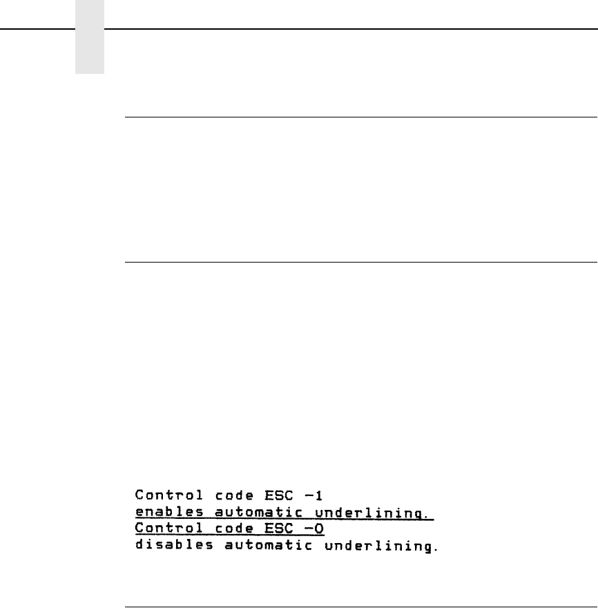
190
Chapter 5
Configuring the Epson FX-1050 Emulation with Control Codes
Superscript and Subscript Printing, Cancel
ASCII Code ESC T
Hex Code 1B 54
Dec Code 27 84
Purpose Cancels superscript and/or subscript printing as set by ESC S
n.
Underline
ASCII Code ESC -
n
Hex Code 1B 2D
n
Dec Code 27 45
n
Purpose Turns automatic underlining on and off.
where
n
= NUL (hex 00) or 0 (hex 30) to turn off underlining
n
= SOH (hex 01) or 1 (hex 31) to turn on underlining
Discussion Spaces are underlined, but graphics and grey scale characters
are not.
Example The following sample illustrates underlining.
Unidirectional Printing, 1 Line
ASCII Code ESC <
Hex Code 1B 3C
Dec Code 27 60
Purpose Causes printing to occur from left to right for one line only.
Discussion Printing normally occurs in both directions of shuttle movement.
This command causes the printer to print from left to right for one
line. The command is cancelled by a CR.

Unidirectional Printing, Set/Reset
191
Unidirectional Printing, Set/Reset
ASCII Code ESC U
n
Hex Code 1B 55
n
Dec Code 27 85
n
Purpose Causes printing to occur in only one direction of shuttle
movement (left to right).
where
n
= NUL (hex 00) or 0 (hex 30) to turn off unidirectional printing
n
= SOH (hex 01) or 1 (hex 31) to turn on unidirectional printing
Discussion Printing normally occurs in both directions of shuttle movement.
Unidirectional printing slows the printer down approximately
50%, but is sometimes used when very accurate dot placement
is desired in graphics.
Vertical Tab, Execute
ASCII Code VT
Hex Code 0B
Dec Code 11
Purpose Advances the logical print head to the next vertical tab position
selected by ESC /.
Discussion If no vertical channel was selected, channel 0 is used. If no
vertical tabs were set, the paper advances one line.
The logical print head moves to the left margin. If a tab position
is on the current line, the paper is moved to the next tab position.
If there are no tab positions between the current line and the end
of the form, the paper is moved to the top of the next form.
This code cancels all one-line-only emphasis and font controls:
double-wide from SO and ESC SO, and unidirectional printing
from ESC <.

192
Chapter 5
Configuring the Epson FX-1050 Emulation with Control Codes
Vertical Tab, Set/Clear
ASCII Code ESC B
n1 n2 n3...nk
NUL
Hex Code 1B 42
n1 n2 n3...nk
00
Dec Code 27 66
n1 n2 n3...nk
0
Purpose Sets up to 16 vertical tab positions.
where
n
= 1 through 255 (hex 01 through FF).
k
= 1 through 16 (hex 01 through 10).
n1
through
nk
specify the line numbers for the vertical tab(s), up
to a maximum of 16 tab positions. NUL must end the sequence
To clear the tab settings, send ESC B NUL (1B 42 00).
Discussion The values of
n
range from 1 through 255 (hex 01 through FF)
and must be in ascending order. The distance of each tab stop
from TOF is the current line spacing times the number of lines
given in
n
. If the value of
n
exceeds the form length, commands
to move to that tab position are ignored.
If values of
n
are not in ascending order, the sequence up to and
including the out-of-sequence number is ignored, and the rest of
the load is processed. Skip over perforation is ignored.
This command always sets channel 0. You can clear channel 0
by sending ESC B NUL. (See also the channel selection
command, ESC
/, and the channel loading command, ESC b.)

193
6
Graphics
Overview
This chapter explains how the printer produces graphic images.
The quickest way to produce graphic images is to use one of the many
graphics software applications available. Any graphics program that is
compatible with the Epson FX, Proprinter XL, or P-Series emulation should
provide excellent results.
You can also use the Intelligent Graphics Processor (IGP) Printronix
emulation or the Code V Printronix emulation. Both allow you to create and
store forms, generate logos, bar codes, expanded characters, and other
graphics.
Printing text and characters is the default mode of operation. However, your
printer can print graphics.
•
When the emulation is in the Proprinter XL or Epson FX protocol mode,
Bit Image graphics is used for graphics printing.
•
When the emulation is in the P-Series protocol mode, Odd/Even dot
plotting is used for graphics printing.
Each line of graphics data must include a graphics control code to enable the
emulation for the desired graphics mode of operation.
Bit Image Graphics
When the printer uses the IBM Proprinter XL or Epson FX emulation, it
creates graphics by accepting bit image graphics data.
Bit image graphics are created by vertically printing the bit pattern of a series
of data bytes. For example, the bit pattern of the ASCII character A (hex 41,
decimal 65) is shown in Figure 4. If we rotate this data byte 90 degrees
clockwise, we have a vertical data byte with the most significant bit (MSB) at
the top. If we then print each 1 (true) bit as a dot, the result is a “bit image” plot
of the ASCII character A.
Note Text and graphics can be mixed on the same line when the printer plots bit
images in the Epson or Proprinter XL emulation.
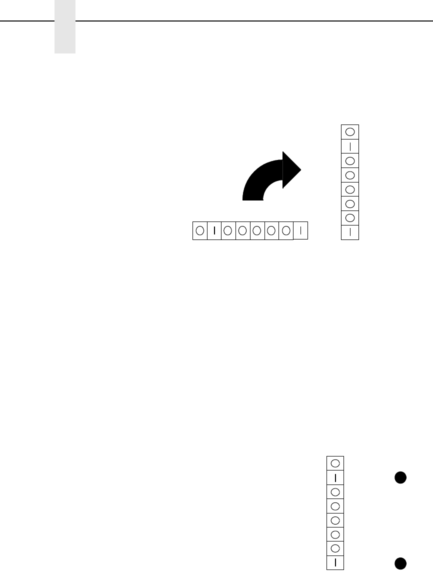
194
Chapter 6
Bit Image Graphics
Figure 4. Vertical Data Byte Pattern
The relationship between the ASCII character, its decimal value, and its bit
image plot is shown in Figure 5. All 8 bits of the data byte are used in all fonts,
but some fonts have taller and shorter characters. (You may have to adjust
the line spacing in order to print without horizontal gaps.) Data bytes are
identified by their binary, octal, hexadecimal, or decimal equivalents. These
numeric equivalents are combined in data streams to form graphic patterns
such as the one illustrated in Figure 6.
Figure 5. Bit Image Pattern from an ASCII Character
Bit Image plotting is not limited to printable ASCII characters. You can print Bit
Image patterns for any 8-bit data byte with decimal values ranging from 0
through 255. (The ASCII character set is charted in Appendix A.)
MSB
MSB
87654321
8
7
6
5
4
3
2
1
MSB : Most Significant Bit
ASCII character A = Hex 41 = Binary 01000001
=A65=
MSB
=
ASCII
Character Decimal
Value
Binary
Code
Equivalent to Vertically
Rotated Data
Byte Bit Image
128
64
32
16
8
4
2
1
Printed
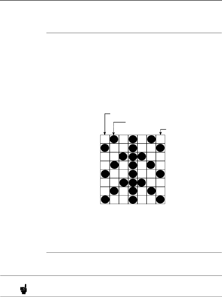
Designing a Bit Image Pattern
195
Designing a Bit Image Pattern
A Bit Image pattern is produced in four steps:
1. On a quadrille pad or graph paper, lay out the graphic pattern you want to
print. (See Figure 6.)
2. Determine the decimal equivalent of each vertical data byte in your
pattern. (The sum of the decimal equivalent of each true bit in the vertical
data byte is the decimal equivalent of the data byte.)
3. Write a program to generate the pattern.
4. Enter and run the program on the host computer.
Figure 6. Bit Image Pattern Plan
Bit Image Density
You can print bit image graphics in different dot densities. Select dot densities
by sending a control code in the data stream.
Single Density Mode: ESC K
Single density bit image graphics in a Data Processing (DP) print quality are
printed at 60 dots per inch (dpi) horizontally and 72 dpi vertically. For NLQ
print quality, the horizontal dot density is 90 dpi and vertical dot density is 96
dpi. For High Speed (HS) draft print quality, horizontal dot density is 60 dpi
and vertical dot density is 48 dpi.
73 146 36 255 36 146 73 Decimal
Equivalents
128
64
32
16
8
4
2
1
Decimal
Weights 7th Bit Image Date Byte
2nd Bit Image Data Byte
1st Bit Image Data Byte
LSB
MSB
Note Every line of graphics data must include the necessary plot mode
command so the printer can perform the chosen graphics functions.

196
Chapter 6
Bit Image Graphics
Double Density Mode: ESC L
Double density mode prints up to twice the number of dots per inch
horizontally in the same space used for single density. The vertical dot density
remains the same as in single density mode. Double horizontal density
requires twice the number of input data bytes to print the same length line as
single density. Printing double density reduces the printing speed by half.
Double Speed - Double Density Mode: ESC Y
When the double density - double speed control code is received, data bytes
print at double the current horizontal dot density, but adjacent dots are not
printed. Since double density graphics are printed at half speed, double speed
- double density graphics are printed at the same speed as single density
graphics. This mode is often used to position a simulated print head precisely
by sending blank dot columns.
Quadruple Density Mode: ESC Z
When printing quadruple density graphics, the printer combines adjacent
quadruple density bit image bytes. The compounded data are then printed in
double density mode.
Bit Image Programming Format
The bit image command format is:
ESC
CC n1 n2 DATA
where:
ESC the serial matrix SFCC
CC
K, L, Y or Z to select dot density
(K = single, L = double, Y = double density -
double speed, Z=quadruple density)
n1
(Number of DATA bytes) - 256(
n2
)
(remainder of division of number of DATA bytes by
256, sometimes referred to as MOD 256)
n2
(Number of DATA bytes) / 256 (quotient of division)
DATA the dot pattern bytes
The syntax of the bit image expression must be correct.
The number of data bytes and the
n1, n2
definition must be equal.
Any characters following
n1
and
n2
are interpreted and plotted as data until
the
n1, n2
definition is satisfied.
If
n1 = n2 =
0, then control codes K, L, Y, or Z are ignored.
The maximum number of data bytes that can be included in the DATA portion
of the program statement (when using 132 column paper) varies according to
the dot density:
At 60 dpi, single density = 792 bytes
double density = 1584 bytes
quadruple density = 3168 bytes
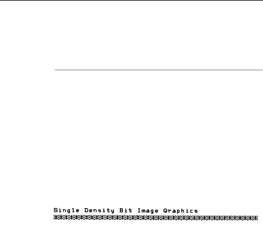
Bit Image Sample Program
197
Data that go past the right margin are discarded if automatic line feed is
disabled. If automatic line feed is enabled, data that go past the right margin
trigger an automatic line feed (LF) and are printed on the next line.
Bit Image Sample Program
The program below, written in BASIC, produces the single density bit image
pattern shown in Figure 7. The 7-byte pattern is repeated 40 times.
Depending on the host computer system, it may be necessary to add a width
statement to the BASIC program.
10 WIDTH “LPT1:”, 255
20 LPRINT “Single Density Bit Image Graphics”
30 LPRINT CHR$(27);“K”;CHR$(24);CHR$(1);
40 FOR N=1 TO 40
50 RESTORE
60 FOR I=1 TO 7
70 READ R
80 LPRINT CHR$(R);
90 NEXT I
100 NEXT N
110 DATA 73, 146, 36, 255, 36, 146, 73
120 LPRINT
Figure 7. Sample Single-Density Bit Image Graphics

198
Chapter 6
Plot Mode
Plot Mode
Plot mode is available for the P-Series protocol only.
This subsection describes the P-Series compatible odd/even dot Plot mode of
operation. The P-Series plot has a rigid format wherein each line of data
contains a plot command code, the plot data, and an LF code (hex 0A).
The P-Series codes (hex 04 and 05, respectively) can be placed anywhere on
the command line.
When P-Series Plot mode is enabled by an EOT (hex 04) or ENQ (hex 05)
code, all control codes except LF, CR, and FF, are ignored. Any control
sequence parameter prior to a plot code is acted upon immediately.
If any combination of EOT (hex 04) or ENQ (hex 05) code is received in a
single line, the priority of action is:
•
EOT (hex 04) takes priority over ENQ (hex 05)
•
ENQ has the same priority level and is acted upon in the order received
A printable symbol is defined as any character or command that might cause
the head of a serial printer to move away from character column one.
Plot Density
Plot density refers to the number of dots per inch (dpi) printed in a single dot
row. Two types of plot density are available with P-Series Plot mode graphics:
normal density and high density. The densities can be mixed within the
printed page on a dot row-by-row basis, but the two densities cannot be mixed
on the same dot row.
Normal density plotting is selected with the odd dot plot control code ENQ
(hex 05). The odd numbered dot columns are addressed to produce a vertical
density that varies based on the font selected: 72 dpi vertical for Letter Gothic
(DP), and 144 dpi vertical for Courier (NLQ). Figure 8 illustrates normal
density dot plot.
Figure 8. Normal Density Plot
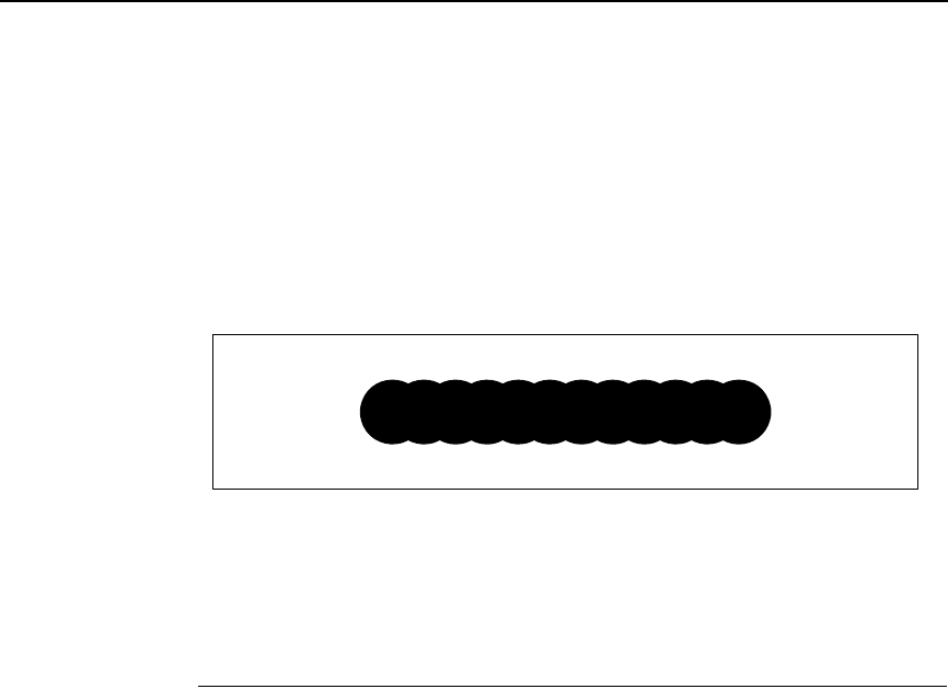
Plot Data Byte Format
199
High density plotting is selected with the even dot plot control code EOT (hex
04) in conjunction with the odd dot plot control code ENQ (hex 05). The odd
and even numbered dot columns are addressed to double the horizontal
density. The vertical density remains the same in normal and high density
plotting, though vertical density is based on the current print mode. Figure 9
illustrates high density plotting.
Figure 9. High Density Plot
Plot Data Byte Format
In P-Series Plot Mode, the format is as follows:
1. Each data byte specifies six out of twelve plot dot columns.
2. Using odd dot plot mode, bits 1 to 6 of the data byte address the odd-
numbered dot columns; using even dot plot mode, bits 1 to 6 of the data
byte address the even-numbered dot columns.
3. Bit 6 and/or bit 7 of the data byte must be a “1” (or true) bit in the Plot
mode.
4. Bit 8 of the data byte is not used in the Plot mode and may be 1 or 0.
5. The binary equivalent of the plot data bytes must be known to accurately
address specific dot positions.
As shown in Figure 10, a dot is printed at the location addressed by each of
bits 1 to 6 in the data byte that is set (1 or true).
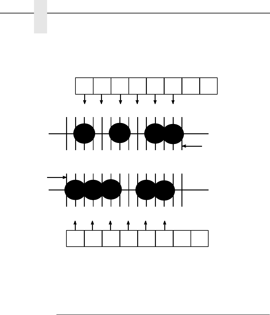
200
Chapter 6
Plot Mode
Figure 10. P-Series Plot Data Byte Format
Plot Data Line Format
A plot data line may contain the following plot data bytes: When using 132
column paper, the maximum bytes are 132 for a horizontal dot density of 60
dpi or 198 bytes for a horizontal dot density of 90 dpi. If Auto Line Feed is
disabled, any bytes over the maximum are lost. If the maximum is exceeded
and Auto Line Feed is enabled, a Line Feed (LF) is forced and the remaining
plot data is printed as text on the next line.
The plot mode control code may occur anywhere in the line prior to the line
terminator, but plot speed may decrease if it is not at the beginning of the line.
111 1110
BIT 1 BIT 2 BIT 3 BIT 4 BIT 5 BIT 6 BIT 7 BIT 8
ODD DOT PLOT DATA BYTE
LSB MSB
1357911
NOT
USED
NOT
USED
00 01111
2 4 6 8 10 12
EVEN DOT PLOT DATA BYTE
BIT 1 BIT 2 BIT 3 BIT 4 BIT 5 BIT 6 BIT 7 BIT 8
LSB MSB
DOT COLUMN #1 OF
NEXT CHARACTER
COLUMN
~~~~~~~~~~~~~~
DOT COLUMN
#12 OF PREVIOUS
CHARACTER
COLUMN
NOTE: IN ACTUAL
PRINTING, THESE
TWO ROWS MERGE
TO PRINT ON THE
SAME ROW.
NOTE: BIT 6
AND/OR BIT 7
MUST BE 1"
FOR PLOT MODE
~~~~~~~~~~~~~~
DOT COLUMN
#12 OF PREVIOUS
CHARACTER
COLUMN
NOTE: BIT 6
AND/OR BIT 7
MUST BE "1"
FOR PLOT MODE.
DOT COLUMN #1 OF
NEXT CHARACTER
COLUMN
NOTE: IN ACTUAL
PRINTING, THESE
TWO ROWS MERGE
TO PRINT ON THE
SAME ROW.

Plot Data Line Format
201
Normal Density Plot
For normal density plot, the plot line contains: Control Code hex 05, plot data
bytes, and a Line Terminator (hex 0A or hex 0C). The control sequence for
sending the P-Series Normal Density Plot is as follows:
1. Send the plot command code ENQ (hex 05).
2. Send the plot data bytes (refer to page 205).
3. Send a line terminator, either a Line Feed (LF, hex 0A) or a Form Feed
(FF, hex 0C). A Carriage Return (CR) may also be used instead of the LF
code, provided the Carriage Return has been configured for Carriage
Return = Carriage Return + Line Feed (CR = CR + LF).
a. A line feed (hex 0A) used as the line terminator plots the contents of
the buffer and advances the paper position a single dot row, based on
the vertical density of the current mode.
b. A form feed (hex 0C) used as the line terminator plots the contents of
the buffer and advances the paper to the next TOF.
4. Regardless of which line terminator code is sent, the emulation will
default to the previously selected print mode unless further plot control
codes are provided with the data.
Double Density Plot
For double density plot, the plot line contains: Control Code hex 04, plot data
bytes, a Line Terminator (hex 0A or hex 0C), Control Code hex 05, plot data
bytes, and a Line Terminator. The control sequence for sending P-Series
Double Density Plot is as follows:
1. Send the even dot plot control code EOT (hex 04), followed by plot data
bytes (refer to page 205).
2. Send a line terminator, which causes the emulation to plot the data bytes;
the paper position is not advanced in Double Density Plot; the emulation
now waits for the second plot command and plot data bytes.
3. Send the odd dot plot control code ENQ (hex 05) and a second line of
data, followed by a line terminator.
a. A line feed (hex 0A) used as the line terminator plots the contents of
the buffer and advances the paper position a single dot row, based on
the vertical density of the current mode. A CR (if CR = CR + LF is
configured) may also be used with the same result.
b. A form feed (hex 0C) used as the line terminator plots the data bytes
and advances the paper position to the next TOF.
4. Regardless of which line terminator code is sent, the emulation will
default to the previously selected print mode unless further plot control
codes are provided with the data.
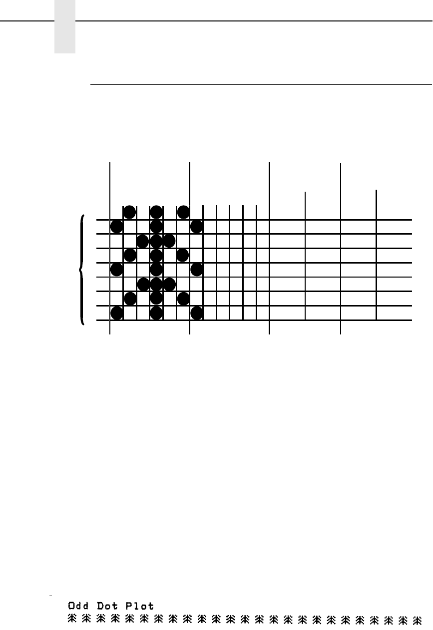
202
Chapter 6
Plot Mode
Plotting the Data
P-Series Plot Mode plots the image from the horizontal bit pattern. Figure 11
duplicates the pattern shown in Figure 6 but is modified for Odd Dot Plot.
Eight dot rows are required, two characters per row, six columns per
character.
Figure 11. Odd Dot Plot Pattern Plan
The following program uses the Odd Dot Plot control code to produce the
image. The image is printed 25 times as shown in Figure 12. An entire dot row
is plotted in one printing pass. Consequently, the first row of all 25 images is
printed in one pass, followed by the second row, etc., until all rows have been
printed.
10 LPRINT “Odd Dot Plot”
20 FOR I=1 TO 8
30 READ R1
40 READ R2
50 LPRINT CHR$(5);
60 FOR N=1 TO 25
70 LPRINT CHR$(R1);CHR$(R2);
80 NEXT N
90 LPRINT
100 NEXT I
110 DATA 42, 64, 73, 65, 92, 64, 42, 64, 73, 65, 92, 64, 42, 64, 73, 65
120 LPRINT
Figure 12. Sample Odd Dot Plot
1
2
3
4
5
6
7
8
13 11579 13 11579
1st
CHARACTER
ODD COLUMNS
2nd
CHARACTER
ODD COLUMNS
1st
CHARACTER
ASCII DECIMAL
2nd
CHARACTER
ASCII DECIMAL
42
73
92
42
73
92
42
73
*
|
\
*
|
\
*
|
64
65
64
64
65
64
64
65
@
A
@
@
A
@
@
A
DOT
ROW
Exiting from P-Series Plot Mode
203
Exiting from P-Series Plot Mode
When returning to the print mode from the P-Series Plot Mode, an extra line
feed should be included in the data stream to maintain proper print line
registration relative to the last line of plot graphics. If the extra line feed is not
included, the first character line after the graphics data may be truncated, as
shown in Figure 13.
Figure 13. Truncated Character Line
@ABCDEFGHIJKLMNOPQR
plot data plot data
A text line follows plot data,
preceded by a single line
terminator code. (Text characters
may extend into the range of the
previously printed plot line and
appear truncated.)
A text line follows plot data, but is
preceded by an additional line
terminator or LF code. (Characters
are printed at full-height.)
@ABCDEFGHIJKLMNOPQR
Note Adding the additional line terminator will cause the text lines for the
remainder of the document to be shifted down from the text lines above the
plot dot rows plotted into the last character row.

204
Chapter 6
Combining Graphics and Text
Combining Graphics and Text
The LinePrinter Plus Emulation is capable of combining graphics and
characters (text) on the same page in two ways:
•
Use Bit Image graphics or P-Series Plot mode to produce characters as
well as graphics
•
A combination of text (not plot) and graphics can be mixed on the same
page within all protocols.
Text and graphics can be mixed on the same line, however, only by using the
Bit Image graphics in the Epson FX or Proprinter XL protocols.
Any character or symbol can be created in the Plot mode or with Bit Image
graphics simply by addressing and plotting the appropriate dot positions.
Either Bit Image or Plot mode graphics can be mixed with text within the page
on a line by line basis. Each line of graphics data must include a graphics
control code or the emulation will automatically default to the print mode.
Using Bit Image graphics, it is possible to use the print mode to produce text
on one print pass followed by a print pass to produce graphics on the same
line; however, text characters can be affected by the Bit Image data when
combined on the same line.
The plot data byte dot patterns shown on page 205 are referenced in the
description of P-Series plot mode on page 200.
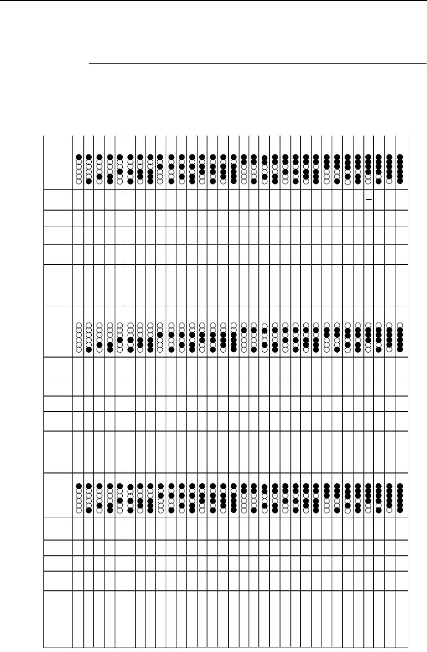
Plot Data Byte Dot Patterns
205
Plot Data Byte Dot Patterns
0100000
Space
0100001
0100010
0100011
0100100
0100101
0100110
0100111
0101000
0101001
0101010
0101011
0101100
0101101
0101110
0101111
0110000
0110001
0110010
0110011
0110100
0110101
0110110
0110111
0111000
0111001
0111010
0111011
0111100
0111101
0111110
0111111
BINARY OCT HEXDEC ASCII 2 4 6 8 1012
BINARY OCT HEXDEC ASCII 1 3 5 7 9 11
2 4 6 8 1012 BINARY OCT HEXDEC ASCII 2 4 6 8 1012
!
"
#
$
%
&
'
(
)
*
+
,
-
.
/
0
1
2
3
4
5
6
7
8
9
:
;
<
=
>
?
1000000
1000001
1000010
1000011
1000100
1000101
1000110
1000111
1001000
1001001
1001010
1001011
1001100
1001101
1001110
1001111
1010000
1010001
1010010
1010011
1010100
1010101
1010110
1010111
1011000
1011001
1011010
1011011
1011100
1011101
1011110
1011111
@
A
B
C
D
E
F
G
H
I
J
K
L
M
N
O
P
Q
R
S
T
U
V
W
X
Y
Z
[
\
]
^
__
1100000
1100001
1100010
1100011
1100100
1100101
1100110
1100111
1101000
1101001
1101010
1101011
1101100
1101101
1101110
1101111
1110000
1110001
1110010
1110011
1110100
1110101
1110110
1110111
1111000
1111001
1111010
1111011
1111100
1111101
1111110
1111111
60
61
62
63
64
65
66
67
68
69
6A
6B
6C
6D
6E
6F
70
71
72
73
74
75
76
77
78
79
7A
7B
7C
7D
7E
7F
96
97
98
99
100
101
102
103
104
105
106
107
108
109
110
111
112
113
114
115
116
117
118
119
120
121
122
123
124
125
126
127
`
a
b
c
d
e
f
g
h
i
j
k
l
m
n
o
p
q
r
s
t
u
v
w
x
y
z
{
}
~
Delete
2032040
21
22
23
24
25
26
27
28
29
2A
2B
2C
2D
2E
2F
30
31
32
33
34
35
36
37
38
39
3A
3B
3C
3D
3E
3F
33
34
35
36
37
38
39
40
41
42
43
44
45
46
47
48
49
50
51
52
53
54
55
56
57
58
59
60
61
62
63
041
042
043
044
045
046
047
050
051
052
053
054
055
056
057
060
061
062
063
064
065
066
067
070
071
072
073
074
075
076
077
40
41
42
43
44
45
46
47
48
49
4A
4B
4C
4D
4E
4F
50
51
52
53
54
55
56
57
58
59
5A
5B
5C
5D
5E
5F
64
65
66
67
68
69
70
71
72
73
74
75
76
77
78
79
80
81
82
83
84
85
86
87
88
89
90
91
92
93
94
95
100
101
102
103
104
105
106
107
110
111
112
113
114
115
116
117
120
121
122
123
124
125
126
127
130
131
132
133
134
135
136
137
140
141
142
143
144
145
146
147
150
151
152
153
154
155
156
157
160
161
162
163
164
165
166
167
170
171
172
173
174
175
176
177
1 3 5 7 9 11 1 3 5 7 9 11

206
Chapter 6
Combining Graphics and Text

207
7
Vertical Page Formatting
Overview
Rapid vertical paper movement is called slewing. A vertical format unit (VFU)
is a program you load into the printer that enables it to slew paper to preset
locations on a page.
On your printer, LF commands and other commands that produce blank lines
are accumulated and moved in one efficient paper motion. The VFUs are
maintained for compatibility with earlier applications.
Following an introductory overview of how to plan a vertical page format, the
following two methods of vertical formatting are described in this chapter:
•
Vertical tab table: The IBM Proprinter XL and the Epson FX emulations
each contain a vertical tab table. It is a set of programmed vertical tabs.
•
Electronic Vertical Format Unit (EVFU): Only the P-Series emulation
provides the EVFU capability.
Planning a Vertical Page Format
Vertical page formatting with a VFU consists of four steps:
1. Select the type of vertical format you want to use. This is covered in the
next section.
2. Design the form, determining the spacing and channel assignments for
every line. Channel assignments are discussed in the VFU sections.
3. Determine the programming sequence. The format of the sequence
depends on the type of VFU you select and is discussed in each VFU
section of this chapter.
4. Send the programming sequence to the printer in the host data stream.
This loads the VFU program.

208
Chapter 7
Proprinter and Epson Vertical Tab Table
VFU Characteristics
Keep in mind the following information when programming and using a VFU:
Elongated Characters. You can use elongated (double high) characters in
VFU programs. The VFU automatically counts one line of elongated
characters as two character lines.
VFU Not Loaded. If the VFU is not loaded, the printer performs a single line
feed in response to VFU commands.
Paper Runaway Protection. If the VFU memory is loaded and a channel
code is sent that was not previously loaded, the printer moves the paper a
single line feed.
Line Spacing. The printer can use either 6 or 8 lines per inch (lpi) spacing.
These VFUs calculate the forms length by line density selected. The 6 and 8
lpi spacing may be mixed on the same form, but should be done carefully.
Form Feed. A form feed sent from the control panel or a command from the
host moves the paper to the first channel 1, which is the top of form.
Vertical Tab. A VT command moves the paper to the next channel 12. If a
channel 12 is not loaded, a line feed will occur.
Proprinter and Epson Vertical Tab Table
The IBM Proprinter XL and the Epson FX emulations each contain a vertical
tab table. It is a set of programmed vertical tabs. Various lines of the form are
assigned vertical tabs, which are then accessed by control code for rapid
paper advancement to the tab position.
Two control codes are used for vertical tabbing: ESC B sets single channel
vertical tabs, and VT executes a vertical tab. These codes are described in
Chapters 4 and 5, which cover the Proprinter and Epson emulations,
respectively. The Epson emulation also has ESC / to select one of eight tab
channels and ESC b to set the tabs in a particular channel.
Executing Vertical Tabs
The vertical tab execute code is VT (hex 0B). It prints the contents of the print
buffer (if data are in the buffer) and causes paper movement to the next
predefined vertical tab position. If a tab position is not defined, the paper is
moved to the next line at the current line spacing. If a tab position is at the
current line, the paper is moved to the next tab position. If no tab positions are
defined between the current line and the end of the form, the paper moves to
the next TOF.
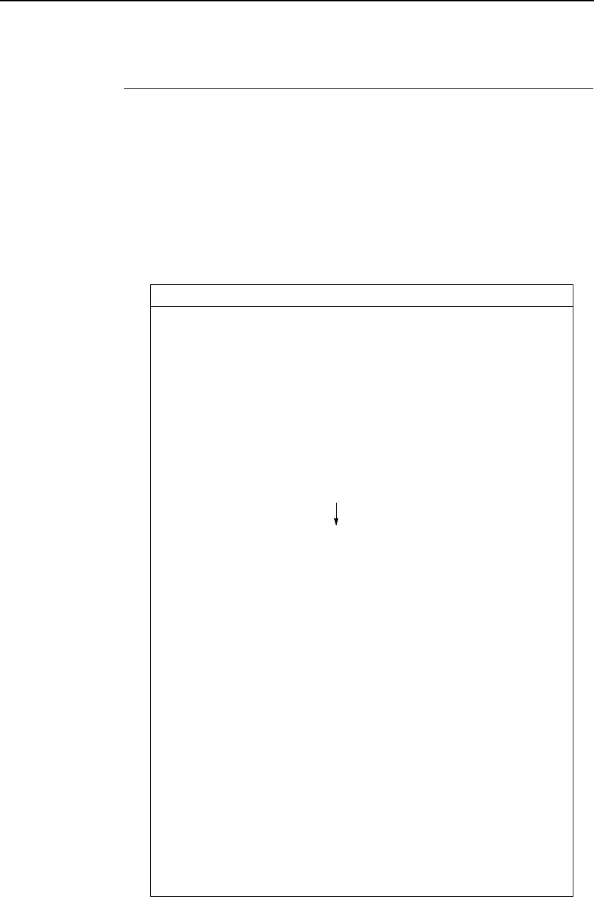
Vertical Tab Positions
209
Vertical Tab Positions
Vertical tab positions are set by line number. A maximum of 16 vertical tab
positions can be set on the form. A sample format is shown in Figure 14.
The first vertical tab is set at line 6 for part number data, a second tab is set at
line 8 for part name data, and a third tab is set at line 14 for quantity data. The
ESC B code assigns the vertical tabs to the lines of the form. Once the tab
positions are set, sending the vertical tab execute code (VT) causes the paper
(currently at the top-of-form position) to advance to the first tab position for
PART NUMBER data. Sending another VT moves the paper to the second
tab position for PART NAME, followed by a third VT to access the third tab
position for QUANTITY data.
Figure 14. Example of Vertical Tab Positions
PART NUMBER
PART NAME
QUANTITY
Vertical Tabs
Tab 1
Form Data
Tab 2
Form Line Number
Tab 3
1
2
3
4
5
6
7
8
9
10
11
12
13
14
15
Top of Form
20

210
Chapter 7
P-Series EVFU (Electronic Vertical Format Unit)
P-Series EVFU (Electronic Vertical Format Unit)
The EVFU may be selected in P-Series protocol. The EVFU provides 14
channels to identify up to 192 lines depending on the paper instruction. The
programming sequence is 1) start load code; 2) line identification code; and 3)
end load code.
Start Load Code - Hex 1E
The start load code clears and initializes the EVFU memory for the memory
load program. The start load code is hex 1E.
Channel Assignment
The EVFU memory has the capacity for 192-line forms. The first line
identification code (channel code) in the memory load program defines the
first line on the form; the second line identification code defines the second
line on the form, etc. Each line must have a line identification code. Filler
channel codes are used for lines that will not be accessed by the print
program. Any channel code can be used as a filler except channel code 1,
which is reserved for the top-of-form, and channel code 12, which is reserved
as the vertical tab channel. The same filler channel code can be repeated as
necessary for any number of lines.
Channel 1. The top-of-form code, reserved as the first line on the form or the
first line printed (top-of-form position). The operating program sends the
channel 1 code to advance to the top of the next form. After the memory is
loaded, a Form Feed code (FF, hex 0C) will move the paper to the next
channel 1 (top-of-form).
Channels 2 through 11, 13 and 14. Used as general channel codes (line
identification codes) or filler channels. Each line on the form must be identified
by a channel code. When the operating program sends the channel code, the
paper advances to the line identified by the channel code. Lines not used by
the operating program must be identified by filler channels (unused channel
codes).
Channel 12. Reserved as the Vertical Tab channel. The Vertical Tab code
(VT, hex 0B) prints any data in the print buffer and rapidly slews the paper to
the next line identified by the channel 12 code. If channel 12 is not loaded in
the EVFU memory, a single line feed will be executed when a VT code is sent.
Channel 15 and 16. The codes for Channels 15 and 16 function as the Start
Load and End Load codes.
End Load - Hex 1F
The end load code terminates the memory load program. The end load code
is hex 1F. Channel codes in excess of 192 channels received prior to the end
load code are discarded.
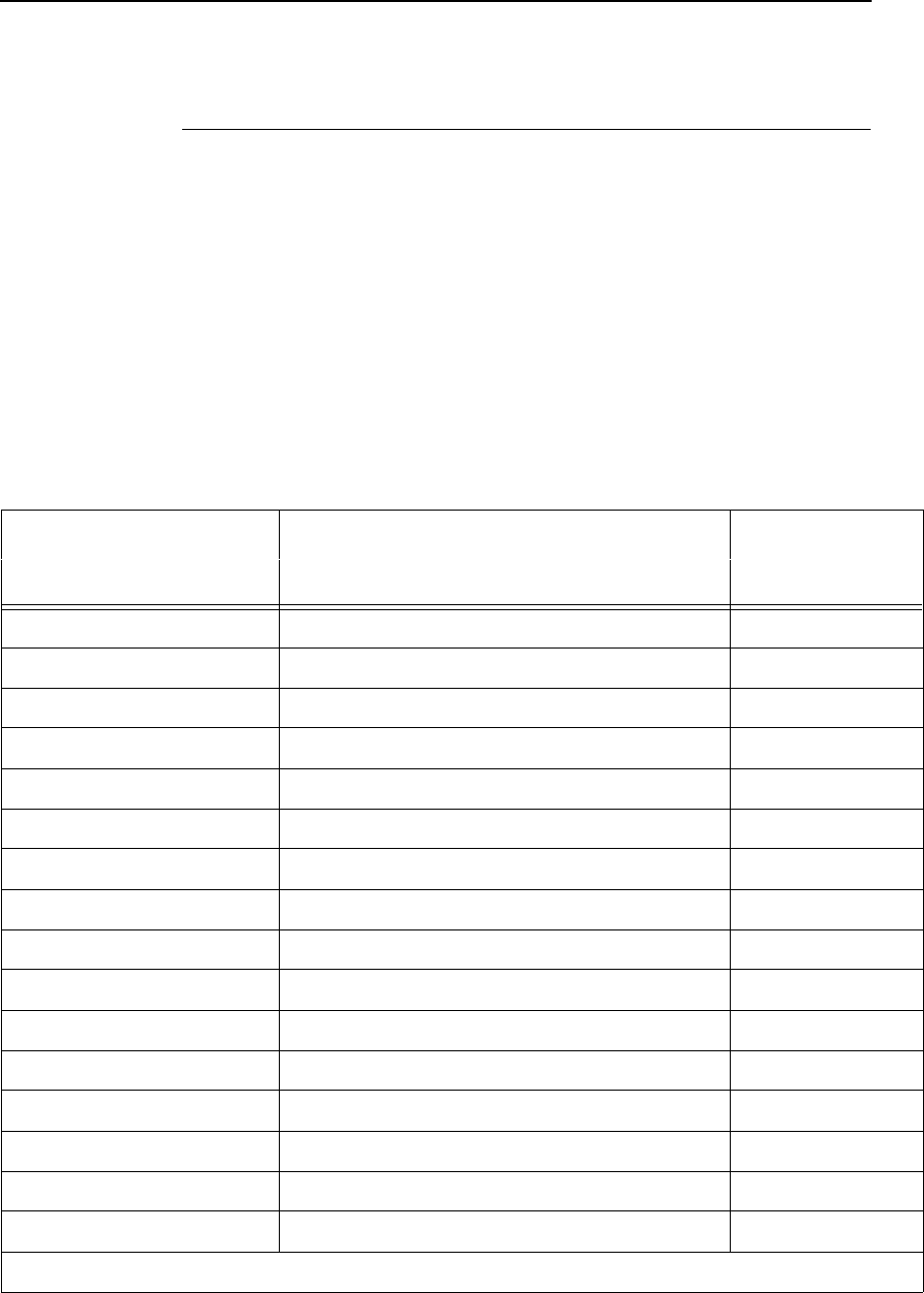
Using the EVFU
211
Using the EVFU
Once the EVFU program has been enabled and loaded, sending the
appropriate channel code to the printer will cause any data in the buffer to
print and will position the paper to the next line on the form having the
specified channel number assigned in EVFU memory.
For a data byte to be recognized as an EVFU instruction, the following criteria
must be met:
•
Data bit 5 must be 1 (set)
•
Data bits 6-8 must be 0 (not set)
Given these conditions, the lower four bits of a byte will specify the EVFU
channel number. Table 43 lists the EVFU channels and their equivalent data
bytes.
Table 43. P-Series EVFU Codes
ASCII Data Bits Channel
Hex Dec. Code 8 7 6 5 4 3 2 1
10 16 DLE 0 0 0 1 0 0 0 0 1 (TOF)
11 17 DC1 0 0 0 1 0 0 0 1 2
12 18 DC2 0 0 0 1 0 0 1 0 3
13 19 DC3 0 0 0 1 0 0 1 1 4
14 20 DC4 0 0 0 1 0 1 0 0 5
15 21 NAK 0 0 0 1 0 1 0 1 6
16 22 SYN 0 0 0 1 0 1 1 0 7
17 23 ETB 0 0 0 1 0 1 1 1 8
18 24 CAN 0 0 0 1 1 0 0 0 9
19 25 EM 0 0 0 1 1 0 0 1 10
1A 26 SUB 0 0 0 1 1 0 1 0 11
1B 27 ESC 0 0 0 1 1 0 1 1 12 (VT)
1C 28 FS 0 0 0 1 1 1 0 0 13
1D 29 GS 0 0 0 1 1 1 0 1 14
1E 30 RS 0 0 0 1 1 1 1 0 Start Load
1F 31 US 0 0 0 1 1 1 1 1 End Load
(X = Undefined, 0, or 1) (1 = High) (0 = Low)
212
Chapter 7
P-Series EVFU (Electronic Vertical Format Unit)
Clearing the EVFU Memory
The following actions will reset (clear) the EVFU memory:
1. Sending only the start load code.
2. Sending a start load code followed immediately by an end load code.
3. A second start load code is received, resulting in reinitialization of the
EVFU. (This allows the host data to be restarted.)
When the EVFU memory is cleared, the forms length returns to the previously
set value and the current print position becomes the top-of-form (TOF).
Note The ESC code cannot be used simultaneously as the EVFU VT code and
the Special Function Control Code (SFCC). Refer to the appropriate
protocol chapter for more information on the SFCC.
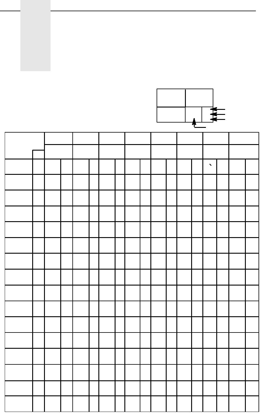
213
A
Standard ASCII Character
Set
KEY
ASCII CHARACTER
ESC
33
27
1B
OCTAL
DECIMAL
HEX
B7 00 0011 1 1
B6 0
B5 0 01101100011011
COLUMN
01234567
BITS
ROW
B4 B2B3 B1
0
1
2
3
4
5
6
7
8
9
10
11
12
13
14
15
0000
00 10
00 1 0
00 1 1
01 0 0
01 0 1
01 1 0
01 1 1
1000
10 0 1
10 1 0
10 1 1
11 0 0
11 0 1
11 1 0
11 1 1
NUL
SOH
STX
ETX
EOT
ENQ
ACK
BEL
BS
HT
LF
VT
FF
CR
SO
SI
0
0
0
1
1
1
2
2
2
3
3
3
4
4
4
5
5
5
6
6
6
7
7
7
10
8
8
11
9
9
12
10
A
13
11
B
14
12
C
15
13
D
16
14
E
17
15
F
DLE
DC1
DC2
DC3
DC4
NAK
SYN
ETB
CAN
EM
SUB
ESC
FS
GS
RS
US
(XON)
(XOFF)
20
16
10
21
17
11
22
18
12
23
19
13
24
20
14
25
21
15
26
22
16
27
23
17
30
18
24
31
25
19
32
26
1A
33
27
1B
34
28
1C
35
29
1D
36
30
1E
37
31
1F
SP
!
"
#
$
%
&
'
(
)
+
,
-
.
/
40
32
20
41
33
21
42
34
22
43
35
23
44
36
24
45
37
25
46
38
26
47
39
27
50
40
28
51
41
29
52
42
2A
53
43
2B
54
44
2C
55
45
2D
56
46
2E
57
47
2F
0
1
2
3
4
5
6
7
8
9
:
;
<
=
>
?
60
48
30
61
49
31
62
50
32
63
51
33
64
52
34
65
53
35
66
54
36
67
55
37
70
56
38
71
57
39
72
58
3A
73
59
3B
74
60
3C
75
61
3D
76
62
3E
77
63
3F
@
A
B
C
D
E
F
G
H
I
J
K
L
M
N
O
100
64
40
101
65
41
102
66
42
103
67
43
104
68
44
105
69
45
106
70
46
107
71
47
110
72
48
111
73
49
112
74
4A
113
75
4B
114
76
4C
115
77
4D
116
78
4E
117
79
4F
P
Q
R
S
T
U
V
W
X
Y
Z
[
\
]
_
120
80
50
121
81
51
122
82
52
123
83
53
124
84
54
125
85
55
126
86
56
127
87
57
130
88
58
131
89
59
132
90
5A
133
91
5B
134
92
5C
135
93
5D
136
94
5E
137
95
5F
a
b
c
d
e
f
g
h
i
j
k
l
m
n
o
140
96
60
141
97
61
142
98
62
143
99
63
144
100
64
145
101
65
146
102
66
147
103
67
150
104
68
151
105
69
152
106
6A
153
107
6B
154
108
6C
155
109
6D
156
110
6E
157
111
6F
p
q
r
s
t
u
v
w
x
y
z
{
|
}
~
DEL
160
112
70
161
113
71
162
114
72
163
115
73
164
116
74
165
117
75
166
118
76
167
119
77
170
120
78
171
121
79
172
122
7A
173
123
7B
174
124
7C
175
125
7D
176
126
7E
177
127
7F
10 1 1
B4 B2B3 B1
B7 B6 B5
001
BITS
0
0
0
0
0
0
^
*

214
Appendix A

215
B
P-Series Emulation
Character Sets
Introduction
This appendix shows the character set charts (also referred to as code pages)
for the P-Series emulation. The character sets are shown in Near Letter
Quality (NLQ). They may be selected using the configuration menus,
described in detail in your
User’s Manual
. There are also several control
codes that allow you to select different character sets, described in Chapter 3
of this book. These include “SFCC l”, “SFCC OSET”, “SFCC R” and “SFCC
PSET”.
The maximum set of printable symbols is shown for columns hex 80-9F
(selected via the ESC 6 control code).
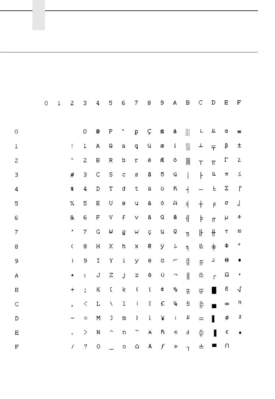
216
Appendix B
P-Series Emulation Character Sets
IBM PC, Primary Subset: ASCII (USA)
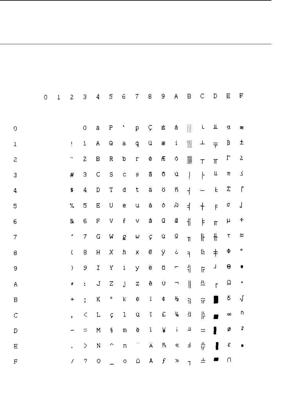
217
IBM PC, Primary Subset: French
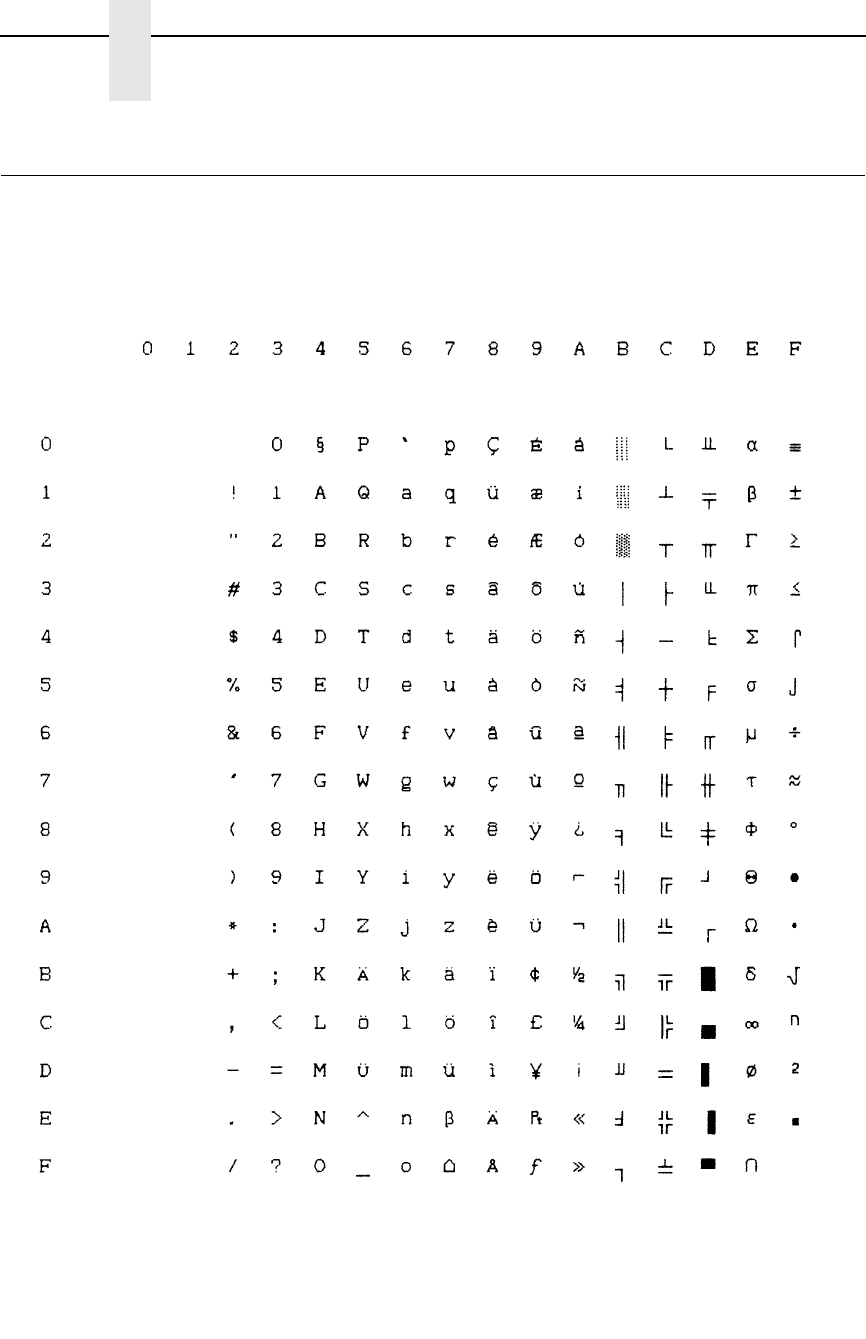
218
Appendix B
P-Series Emulation Character Sets
IBM PC, Primary Subset: German
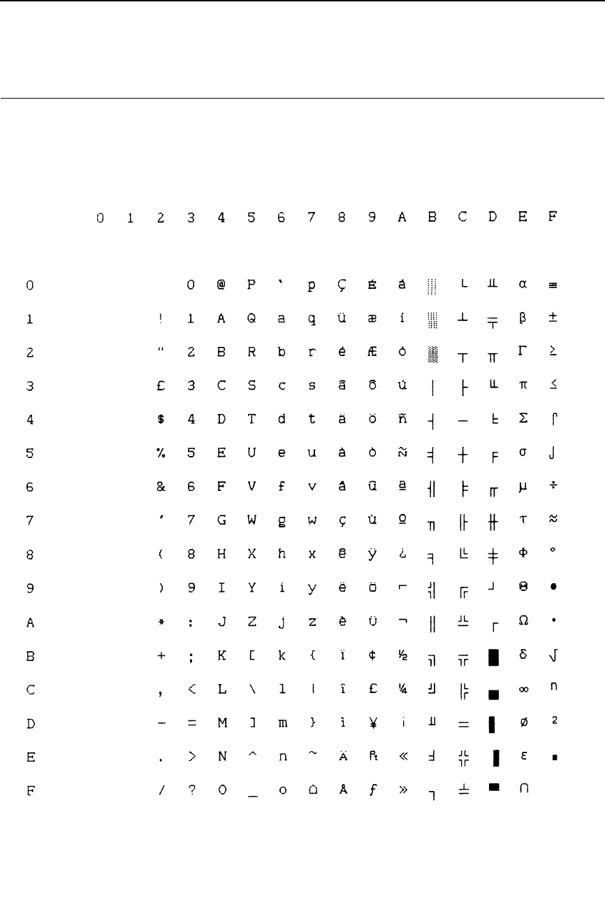
219
IBM PC, Primary Subset: English (UK)
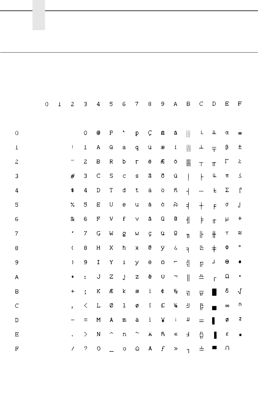
220
Appendix B
P-Series Emulation Character Sets
IBM PC, Primary Subset: Danish
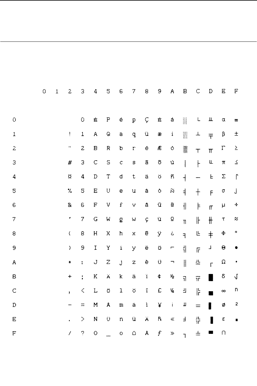
221
IBM PC, Primary Subset: Swedish
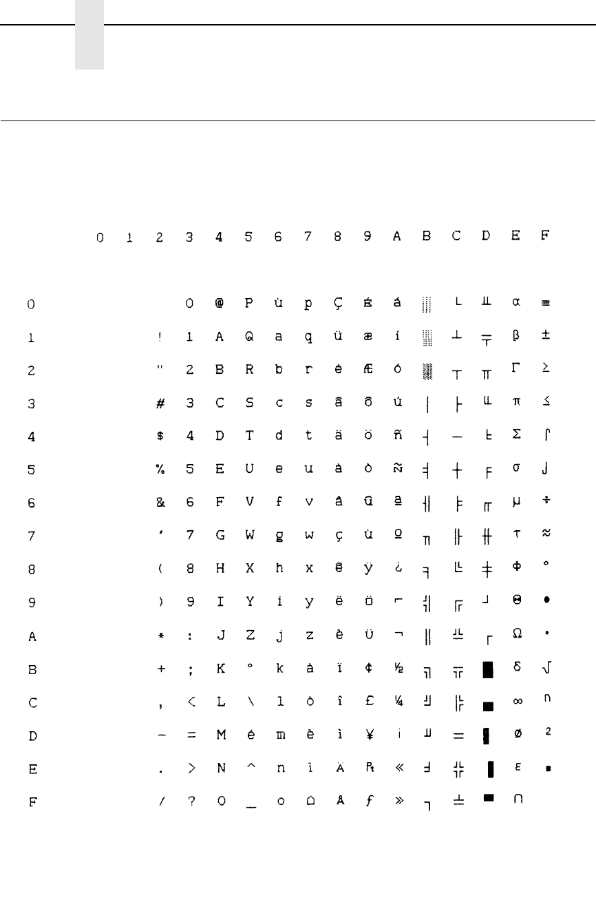
222
Appendix B
P-Series Emulation Character Sets
IBM PC, Primary Subset: Italian

223
IBM PC, Primary Subset: Spanish
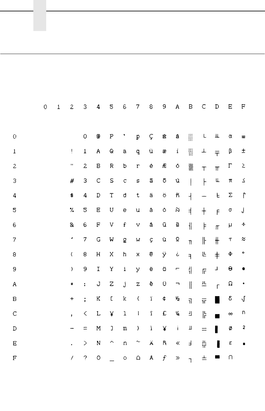
224
Appendix B
P-Series Emulation Character Sets
IBM PC, Primary Subset: Japanese
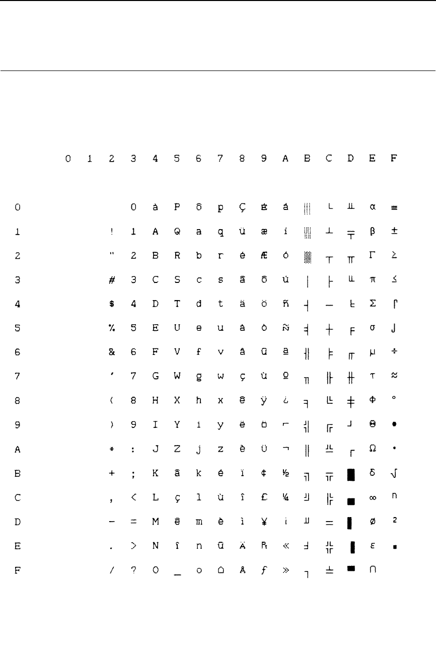
225
IBM PC, Primary Subset: French Canadian

226
Appendix B
P-Series Emulation Character Sets
IBM PC, Primary Subset: Latin American
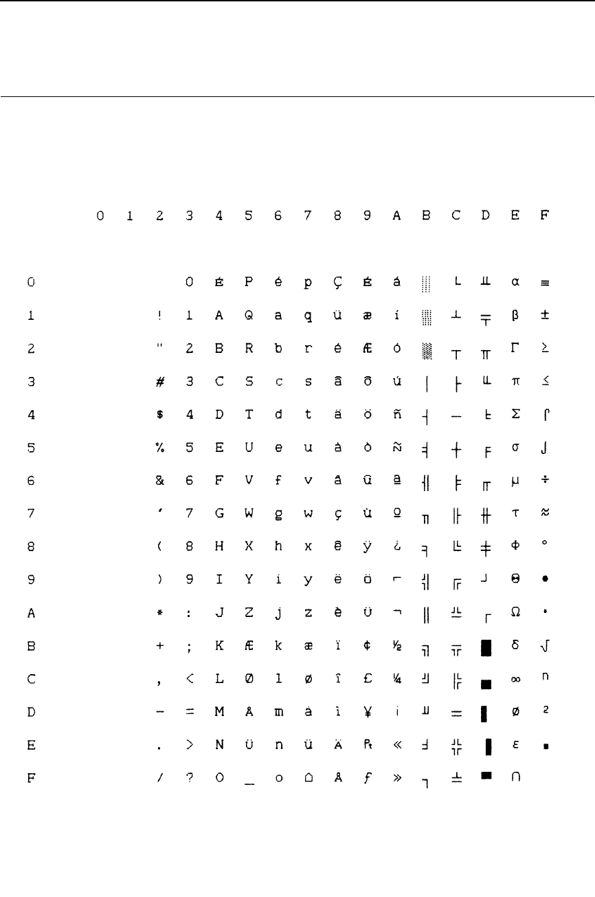
227
IBM PC, Primary Subset: Danish II
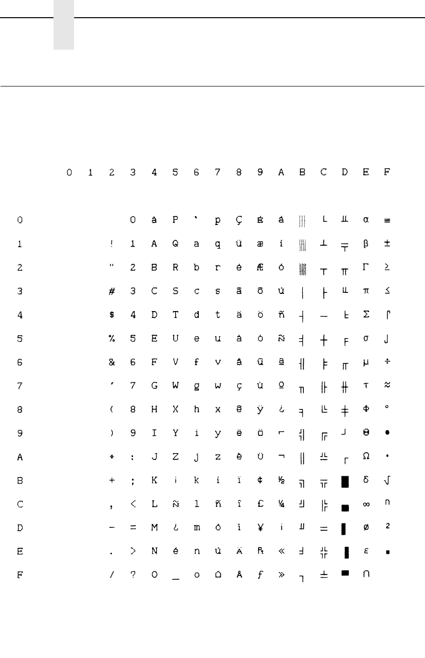
228
Appendix B
P-Series Emulation Character Sets
IBM PC, Primary Subset: Spanish II
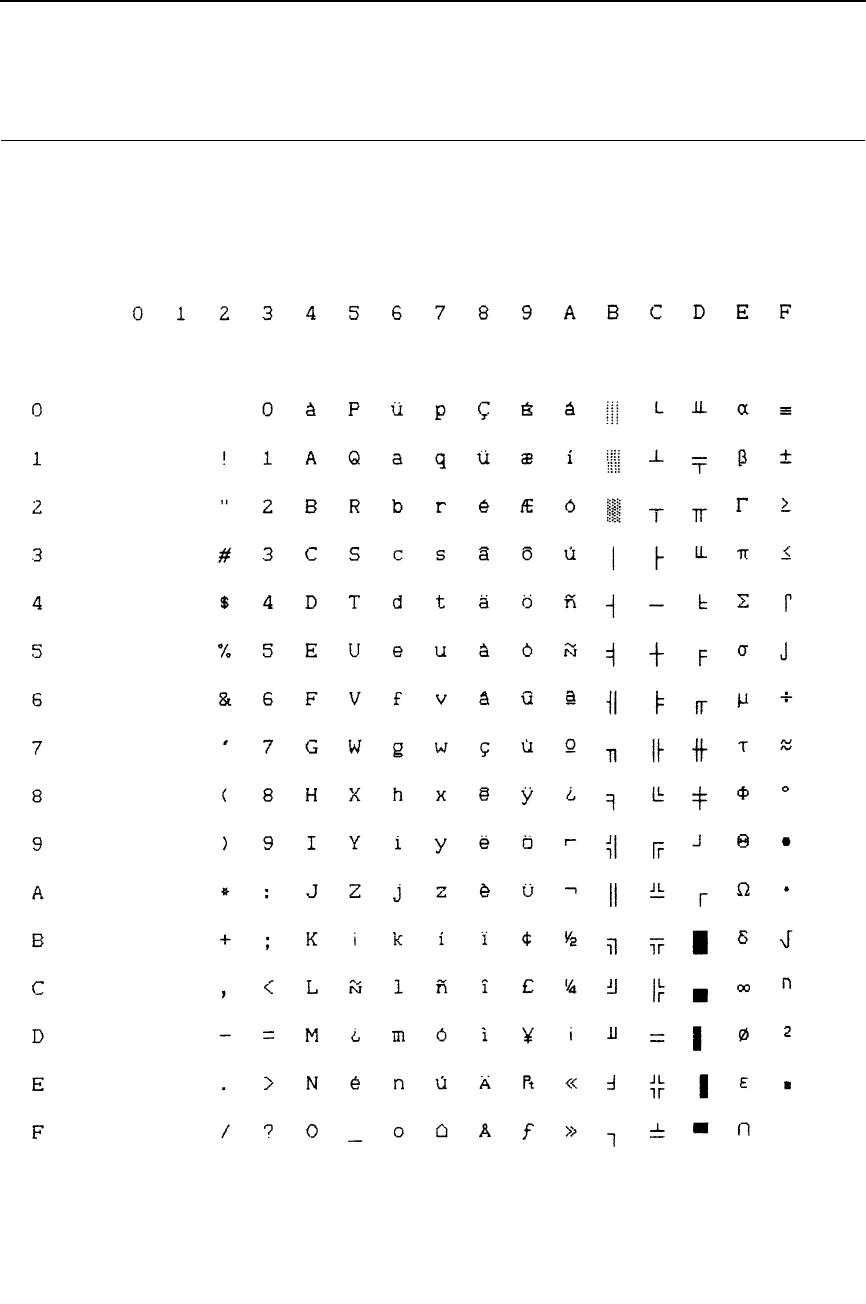
229
IBM PC, Primary Subset: Latin American II
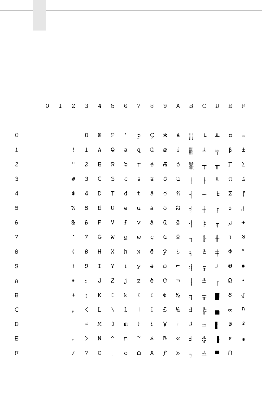
230
Appendix B
P-Series Emulation Character Sets
IBM PC, Extended Subset: 0437 PC Character Set
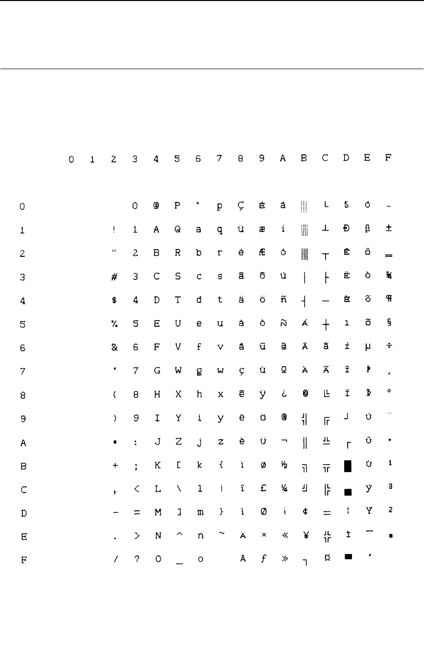
231
IBM PC, Extended Subset: 0850 PC Multilingual
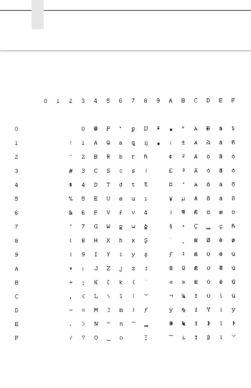
232
Appendix B
P-Series Emulation Character Sets
Multinational, ASCII (USA)
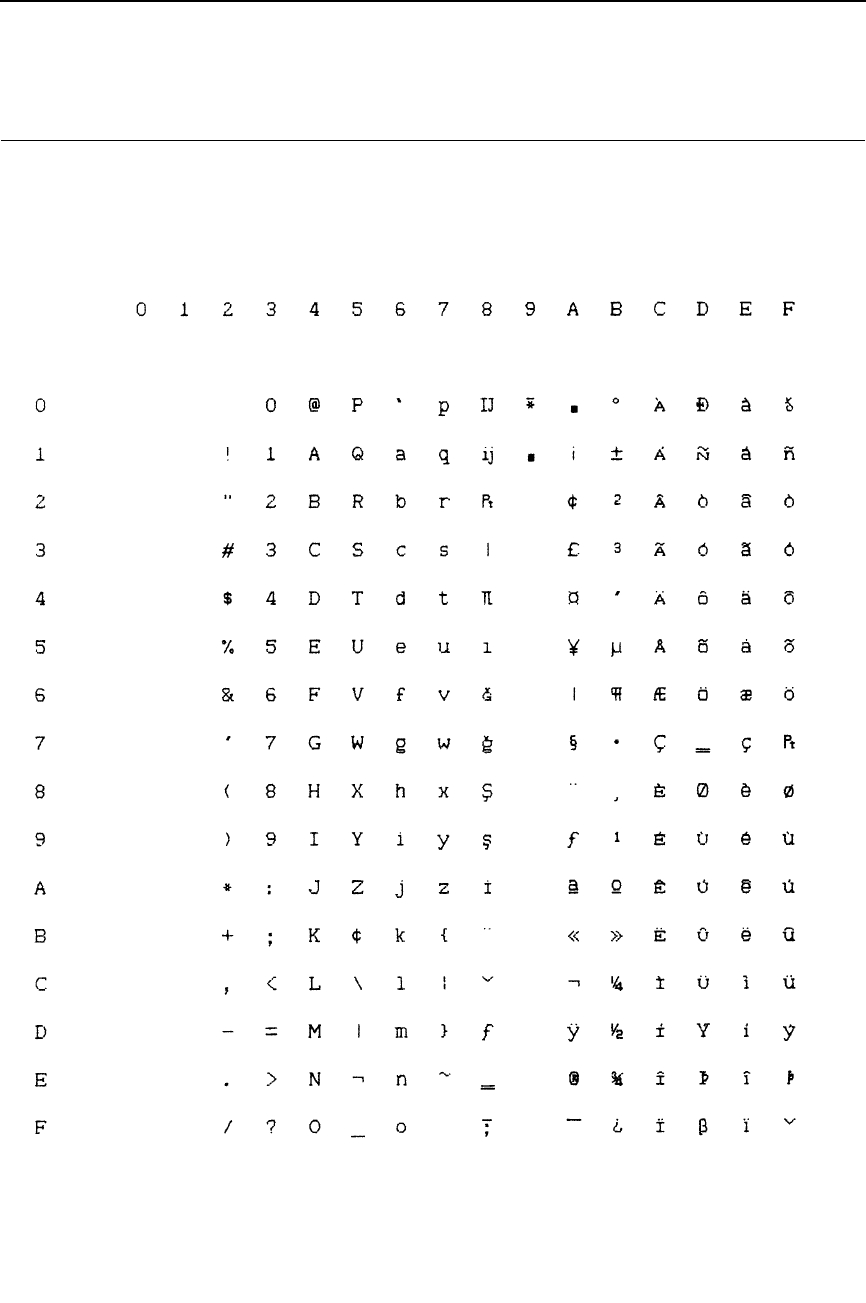
233
Multinational, EBCDIC
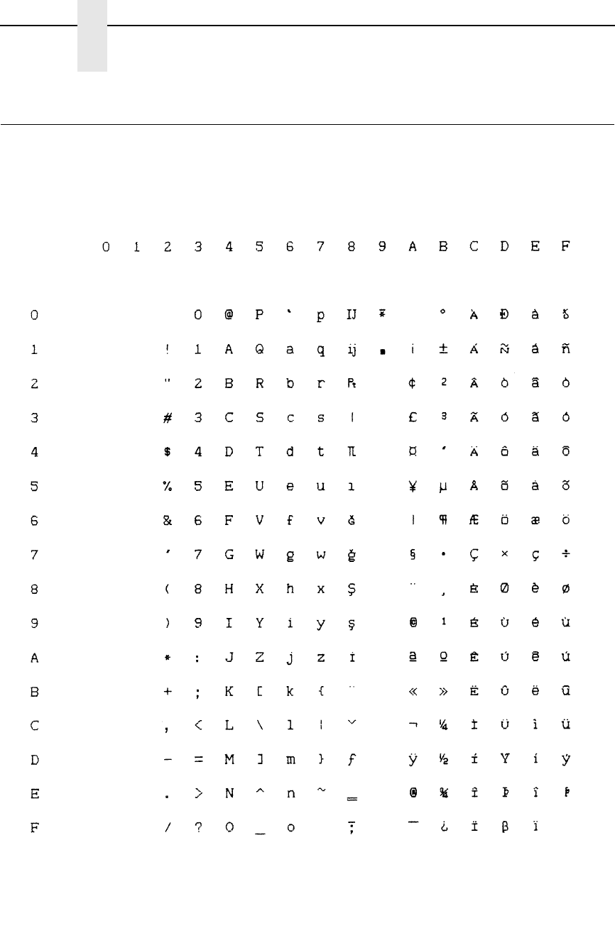
234
Appendix B
P-Series Emulation Character Sets
ECMA Latin 1, Primary Subset: ASCII (USA)
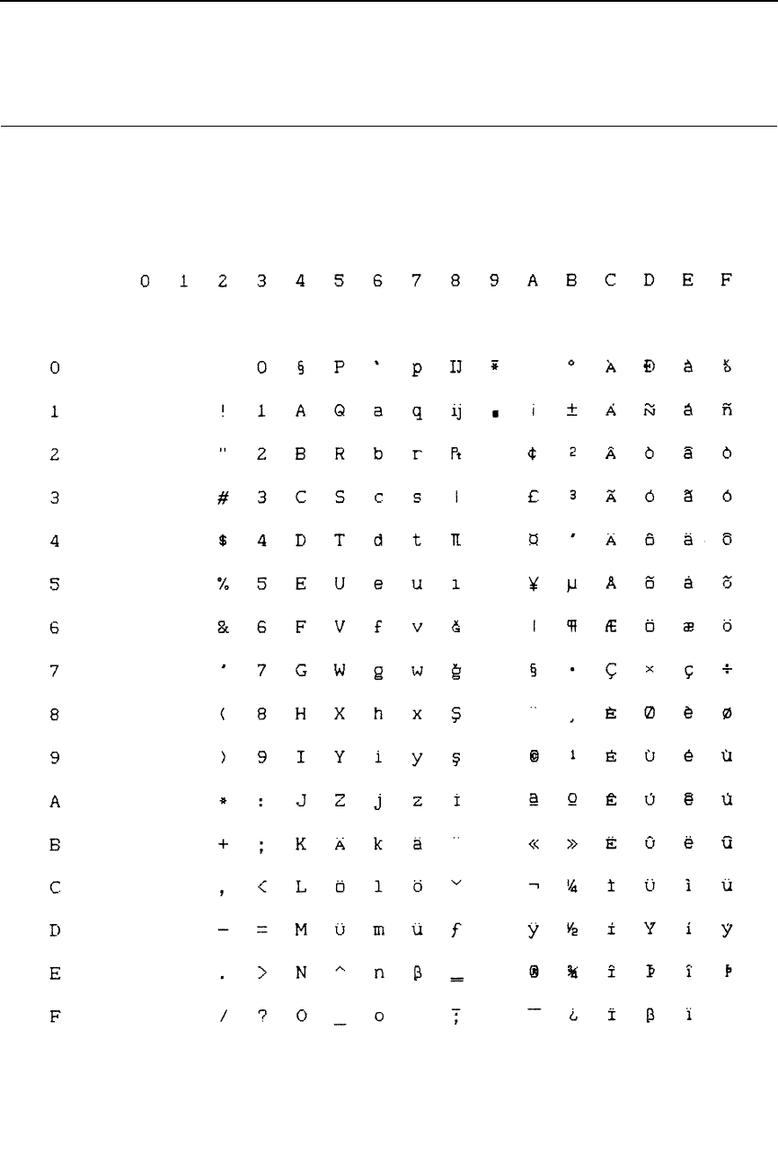
235
ECMA Latin 1, Primary Subset: German
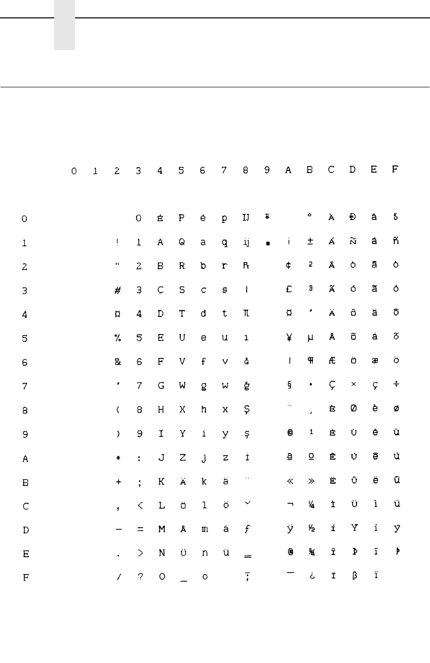
236
Appendix B
P-Series Emulation Character Sets
ECMA Latin 1, Primary Subset: Swedish
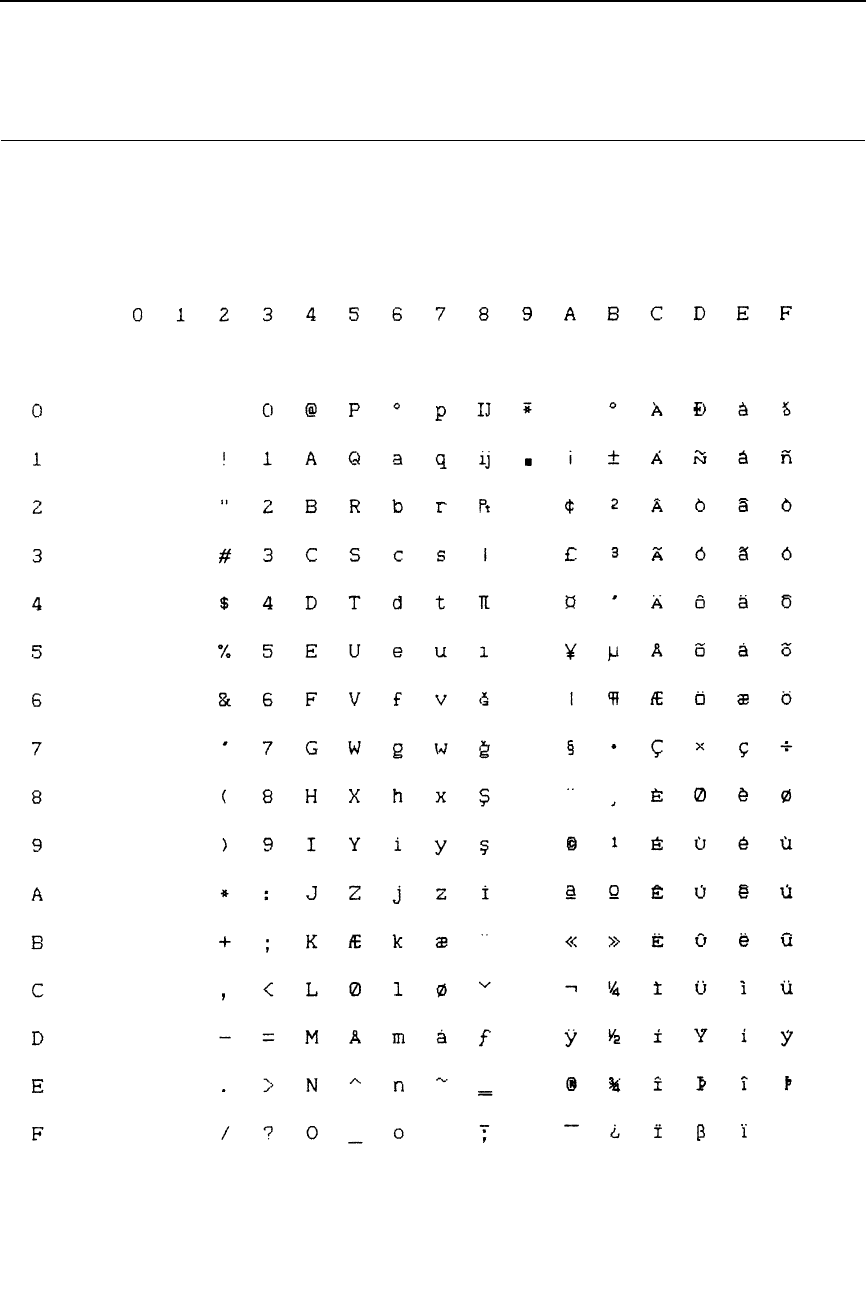
237
ECMA Latin 1, Primary Subset: Danish
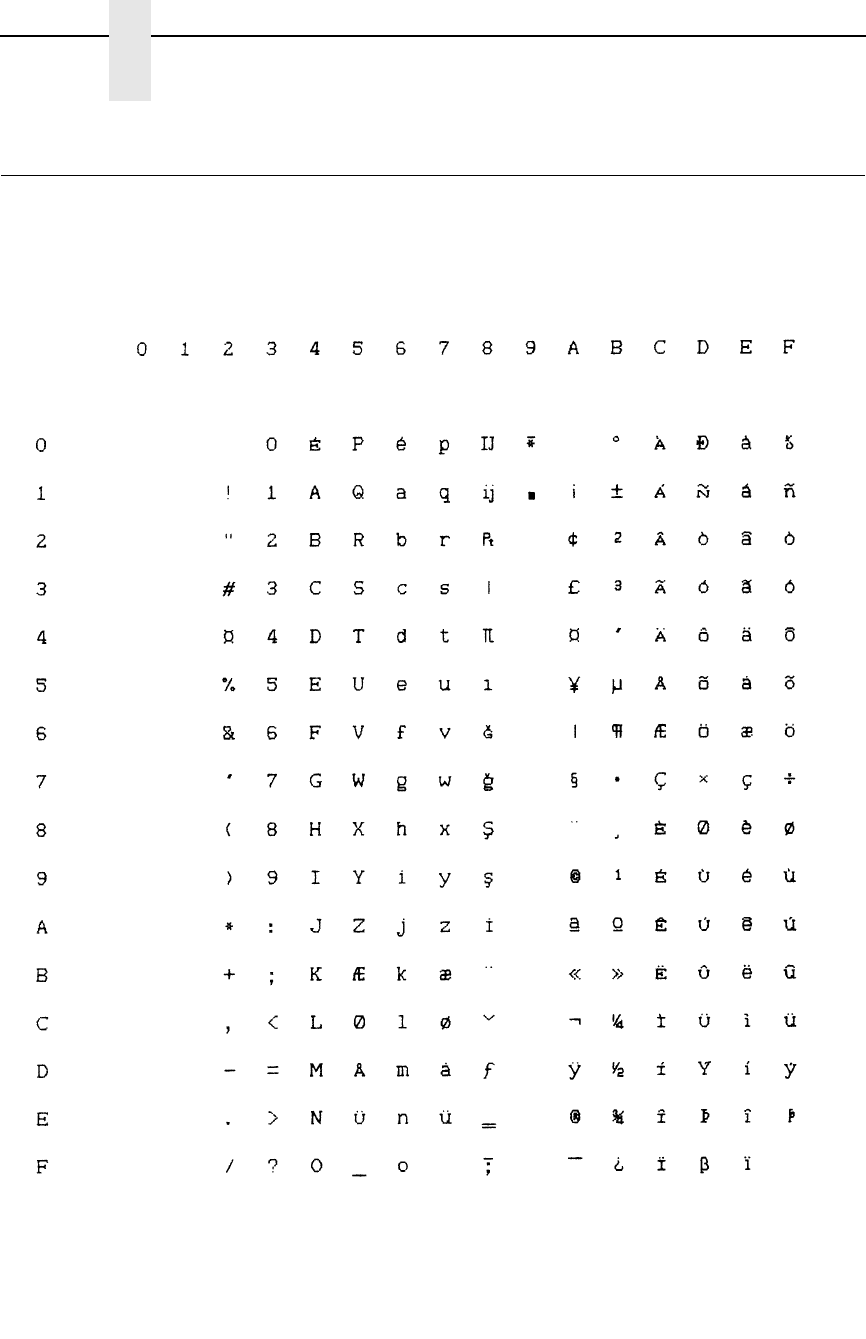
238
Appendix B
P-Series Emulation Character Sets
ECMA Latin 1, Primary Subset: Norwegian
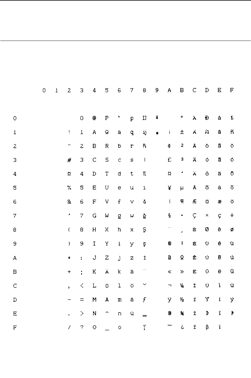
239
ECMA Latin 1, Primary Subset: Finnish
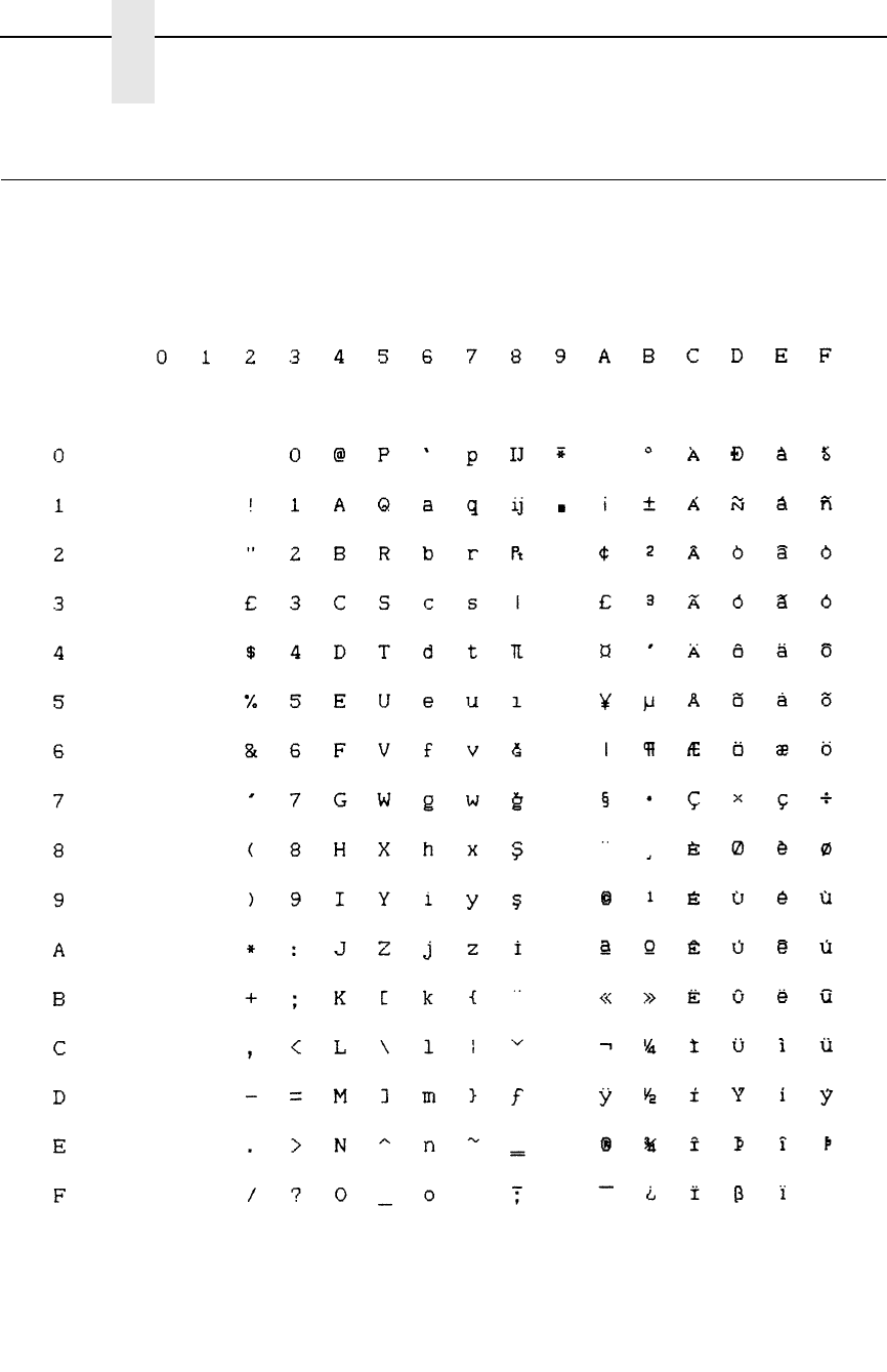
240
Appendix B
P-Series Emulation Character Sets
ECMA Latin 1, Primary Subset: English (UK)
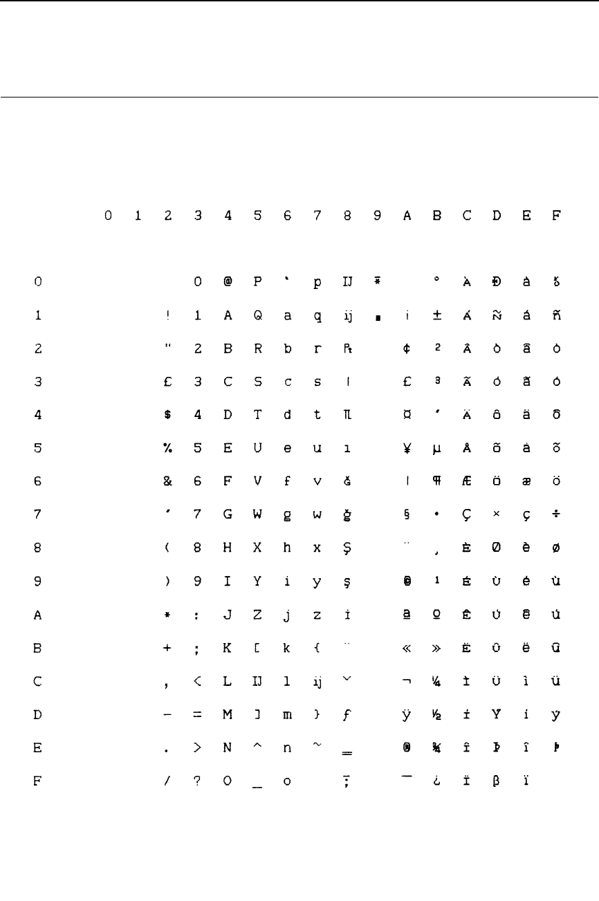
241
ECMA Latin 1, Primary Subset: Dutch
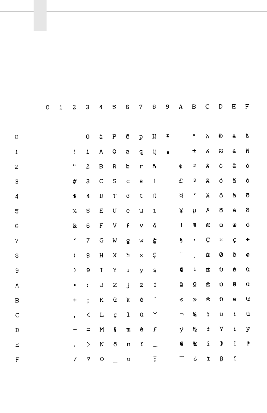
242
Appendix B
P-Series Emulation Character Sets
ECMA Latin 1, Primary Subset: French
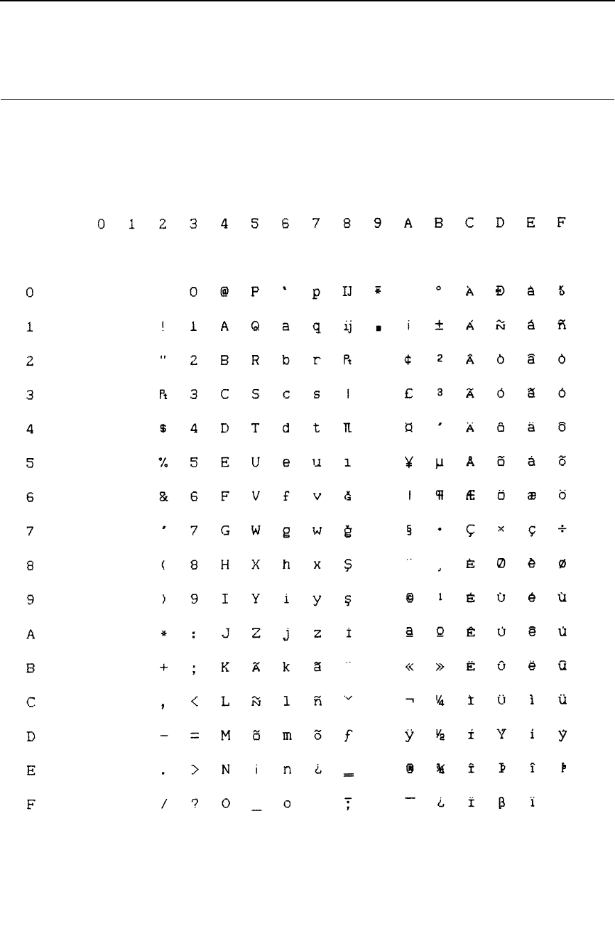
243
ECMA Latin 1, Primary Subset: Spanish
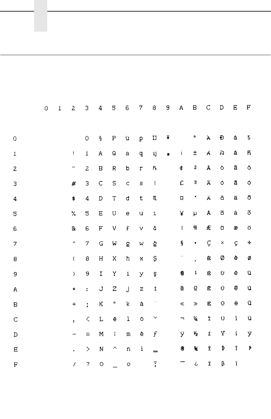
244
Appendix B
P-Series Emulation Character Sets
ECMA Latin 1, Primary Subset: Italian
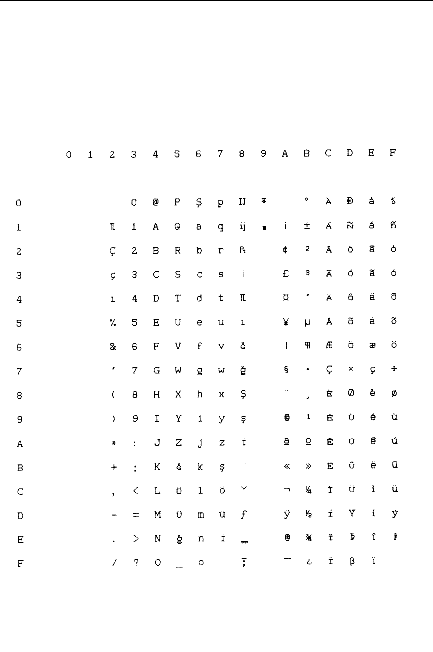
245
ECMA Latin 1, Primary Subset: Turkish
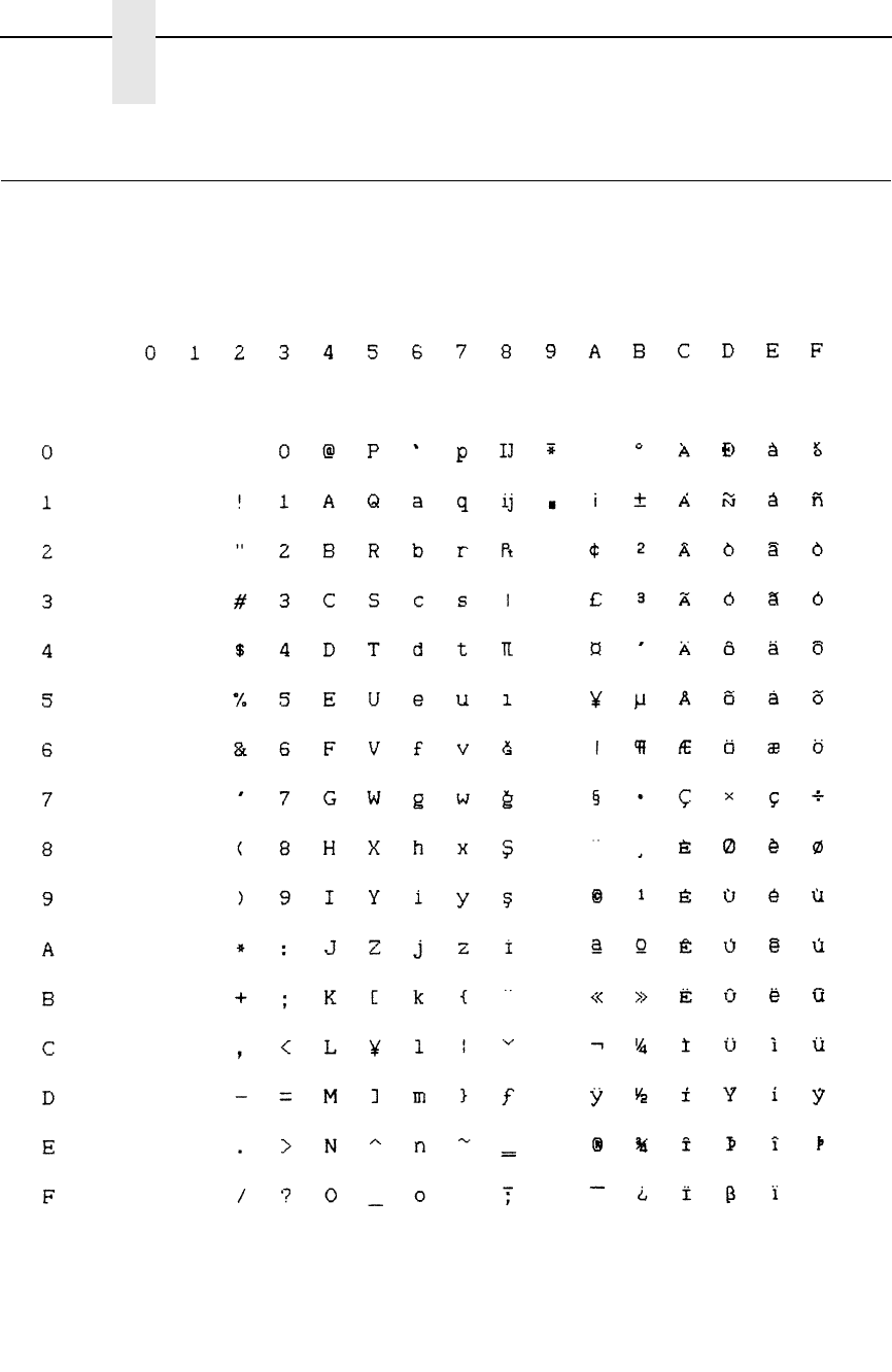
246
Appendix B
P-Series Emulation Character Sets
ECMA Latin 1, Primary Subset: Japanese
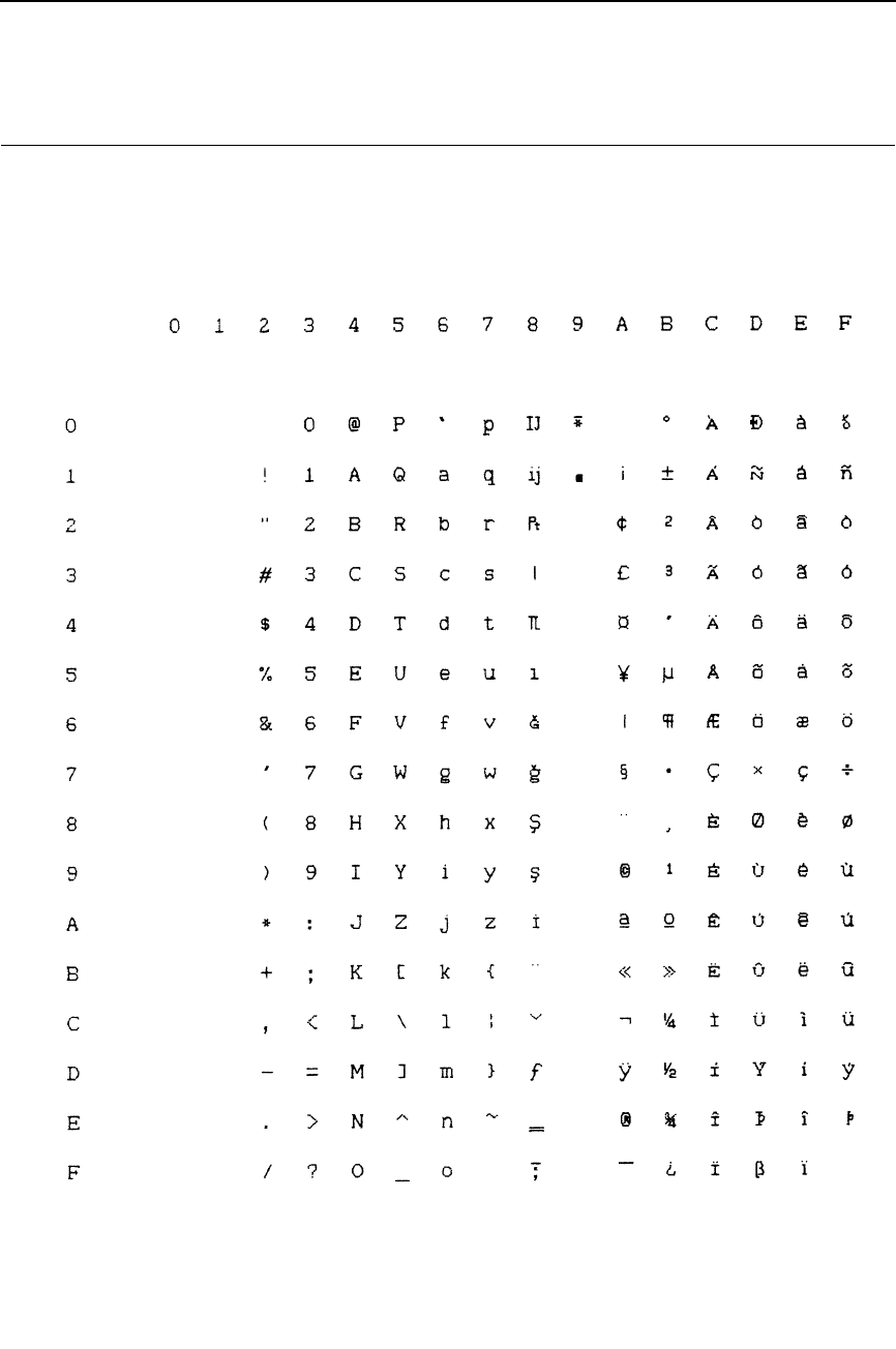
247
ECMA Latin 1, Extended Subset: Multinational
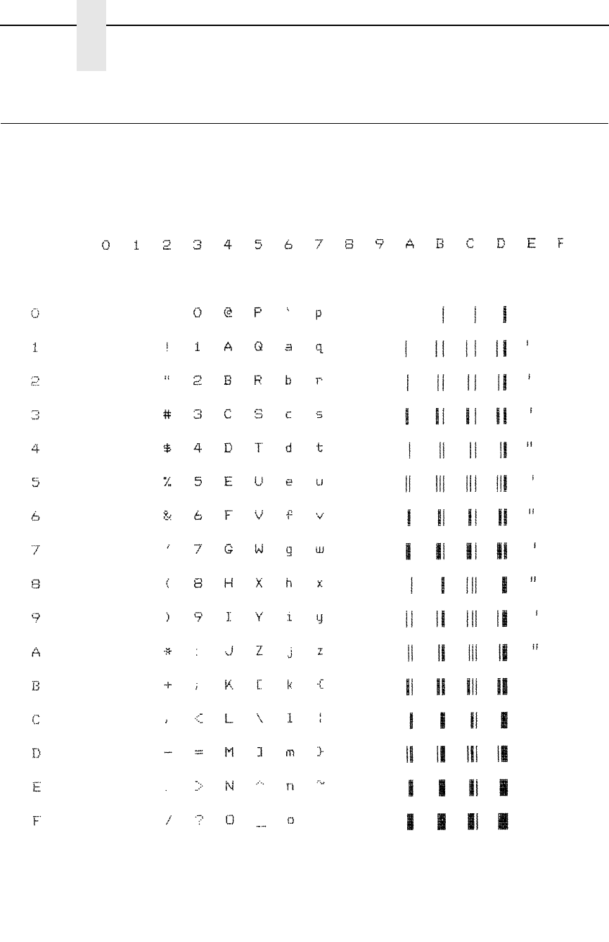
248
Appendix B
P-Series Emulation Character Sets
ECMA Latin 1, Extended Subset: Barcode 10 cpi
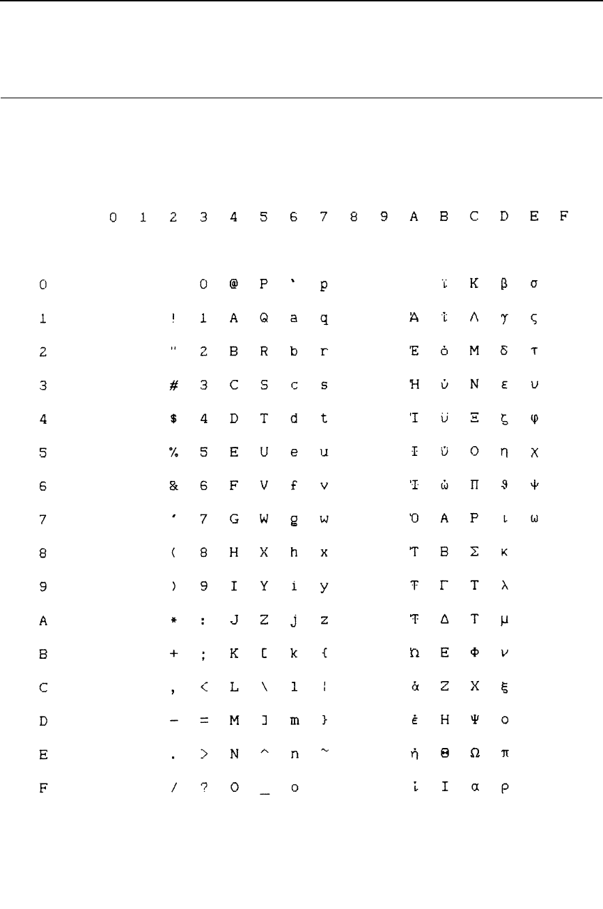
249
ECMA Latin 1, Extended Subset: Greek
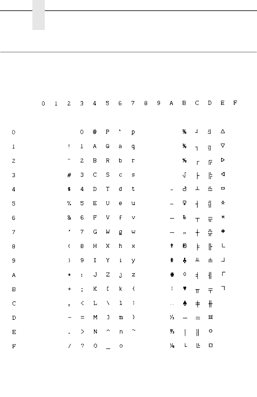
250
Appendix B
P-Series Emulation Character Sets
ECMA Latin 1, Extended Subset: Graphic
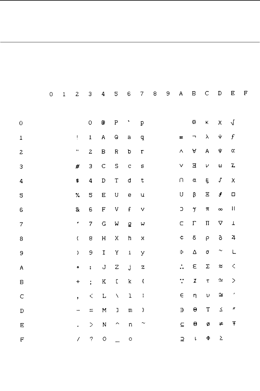
251
ECMA Latin 1, Extended Subset: Scientific 10 cpi
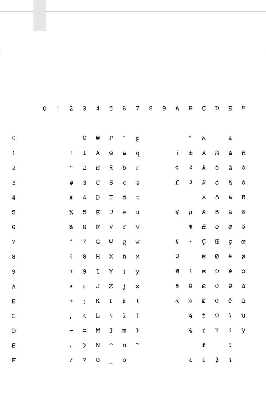
252
Appendix B
P-Series Emulation Character Sets
DEC Multinational, ASCII (USA)
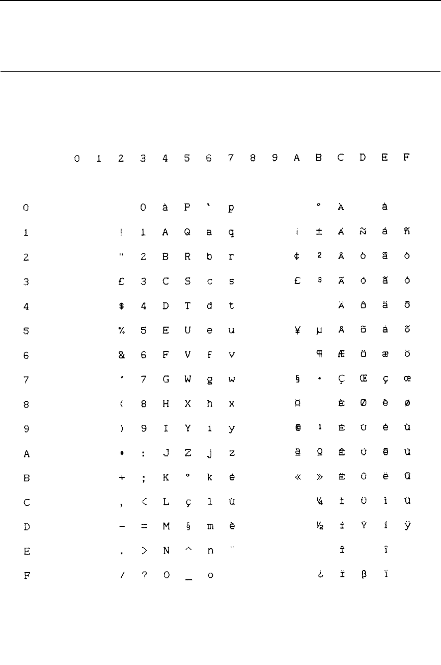
253
DEC Multinational, French
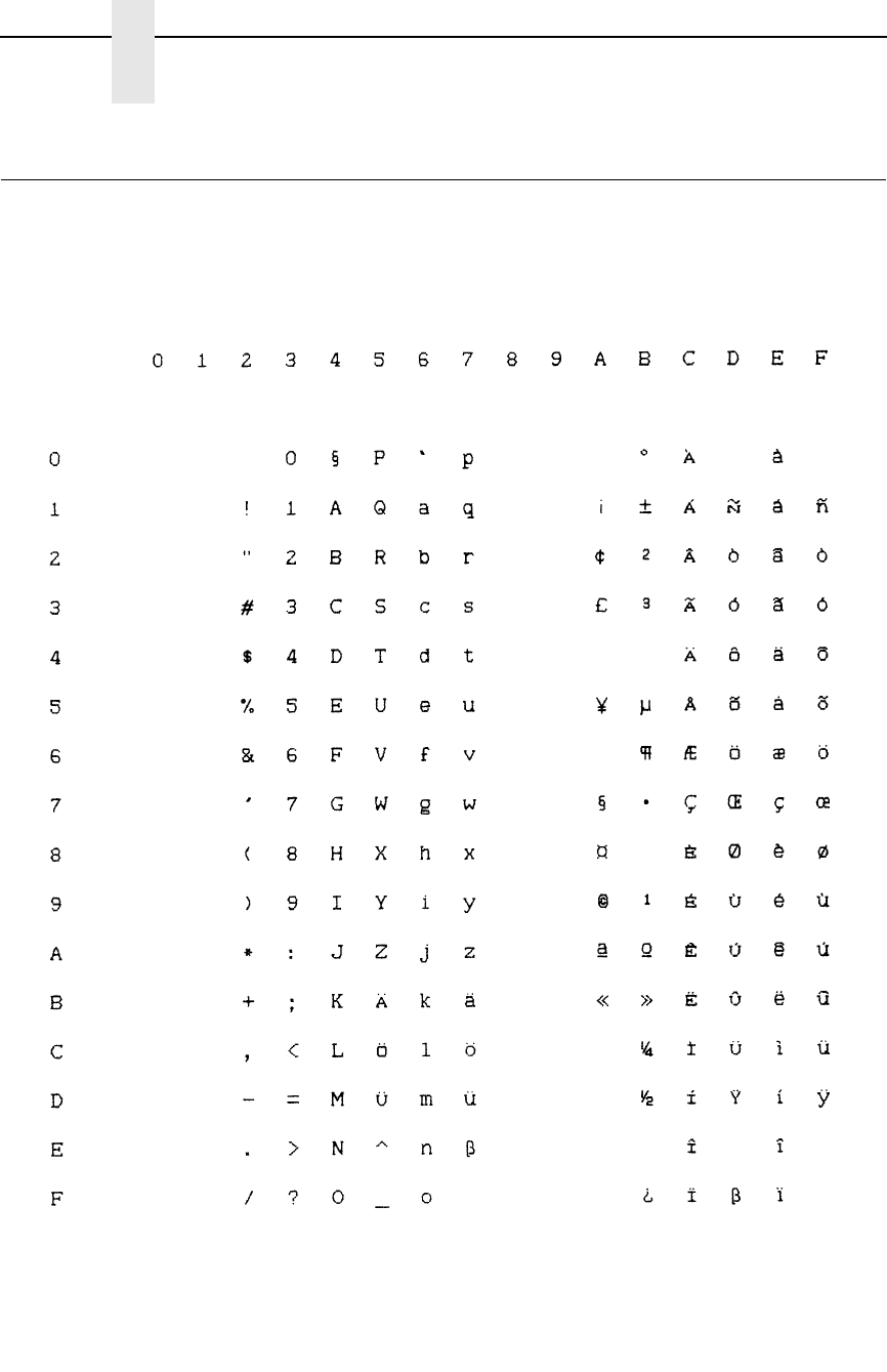
254
Appendix B
P-Series Emulation Character Sets
DEC Multinational, German
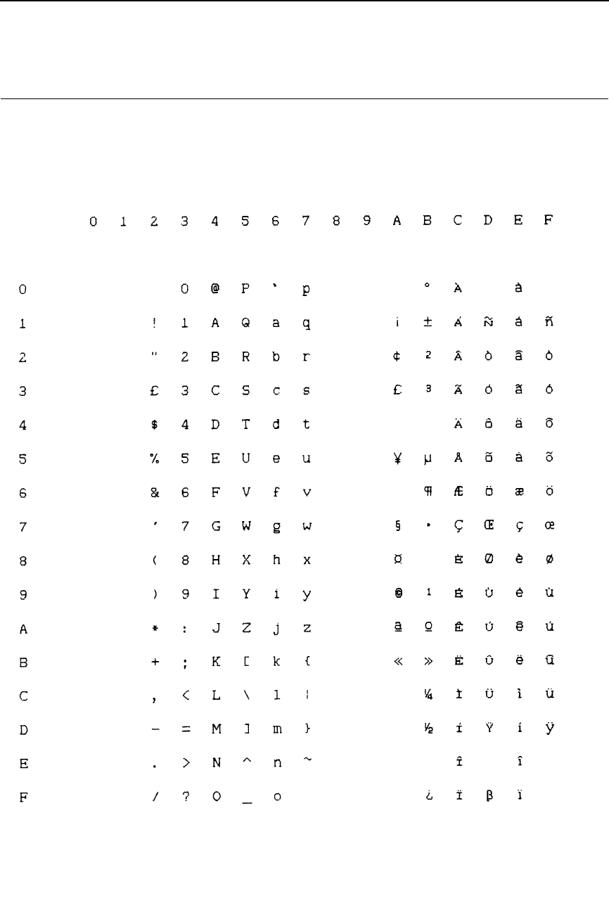
255
DEC Multinational, English (UK)
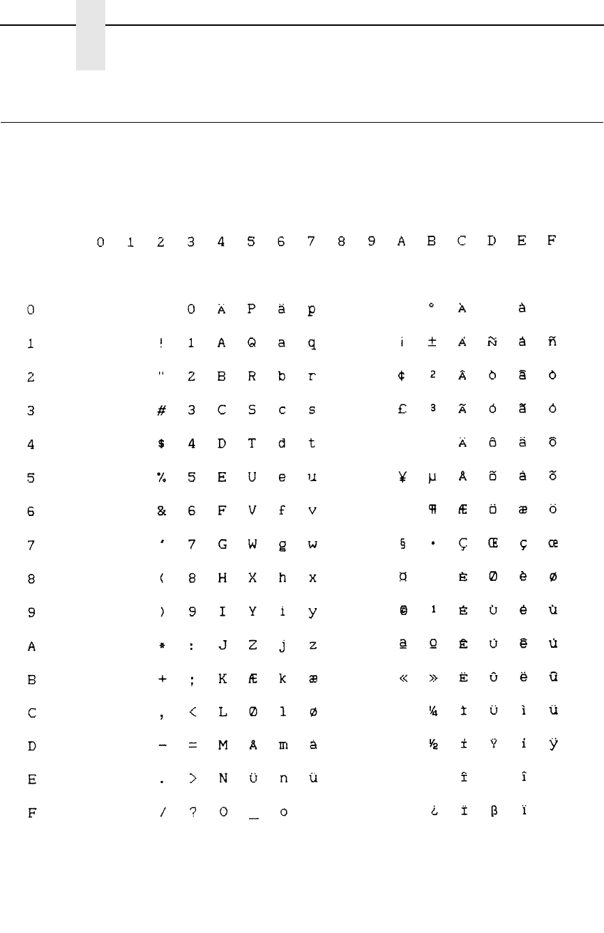
256
Appendix B
P-Series Emulation Character Sets
DEC Multinational, Norwegian/Danish
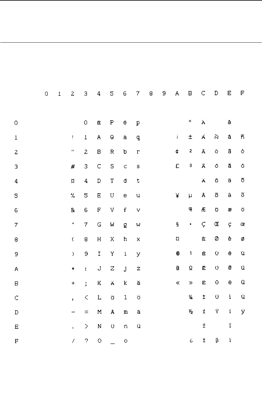
257
DEC Multinational, Swedish
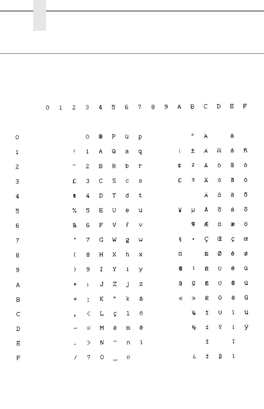
258
Appendix B
P-Series Emulation Character Sets
DEC Multinational, Italian
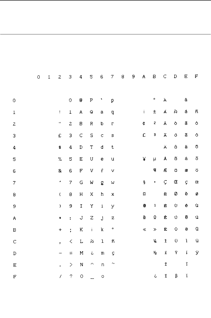
259
DEC Multinational, Spanish
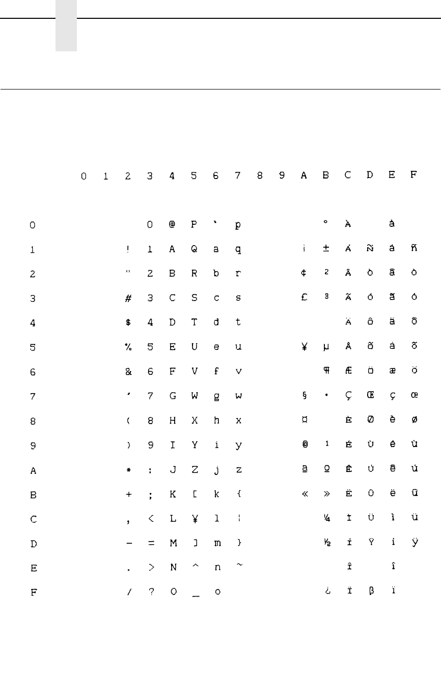
260
Appendix B
P-Series Emulation Character Sets
DEC Multinational, Japanese
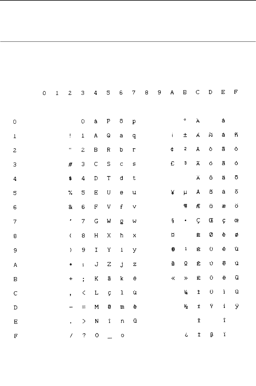
261
DEC Multinational, French Canadian
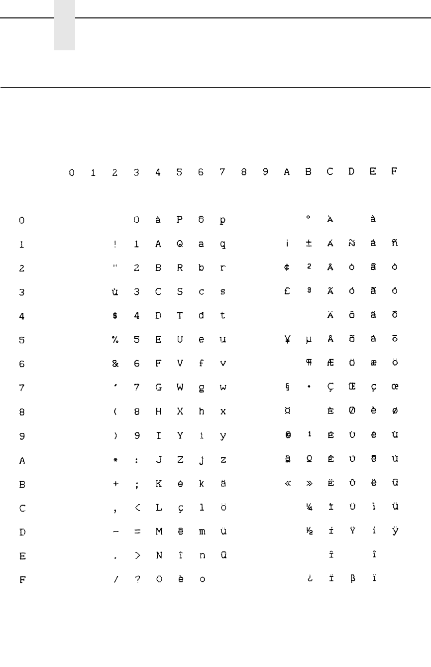
262
Appendix B
P-Series Emulation Character Sets
DEC Multinational, Dutch
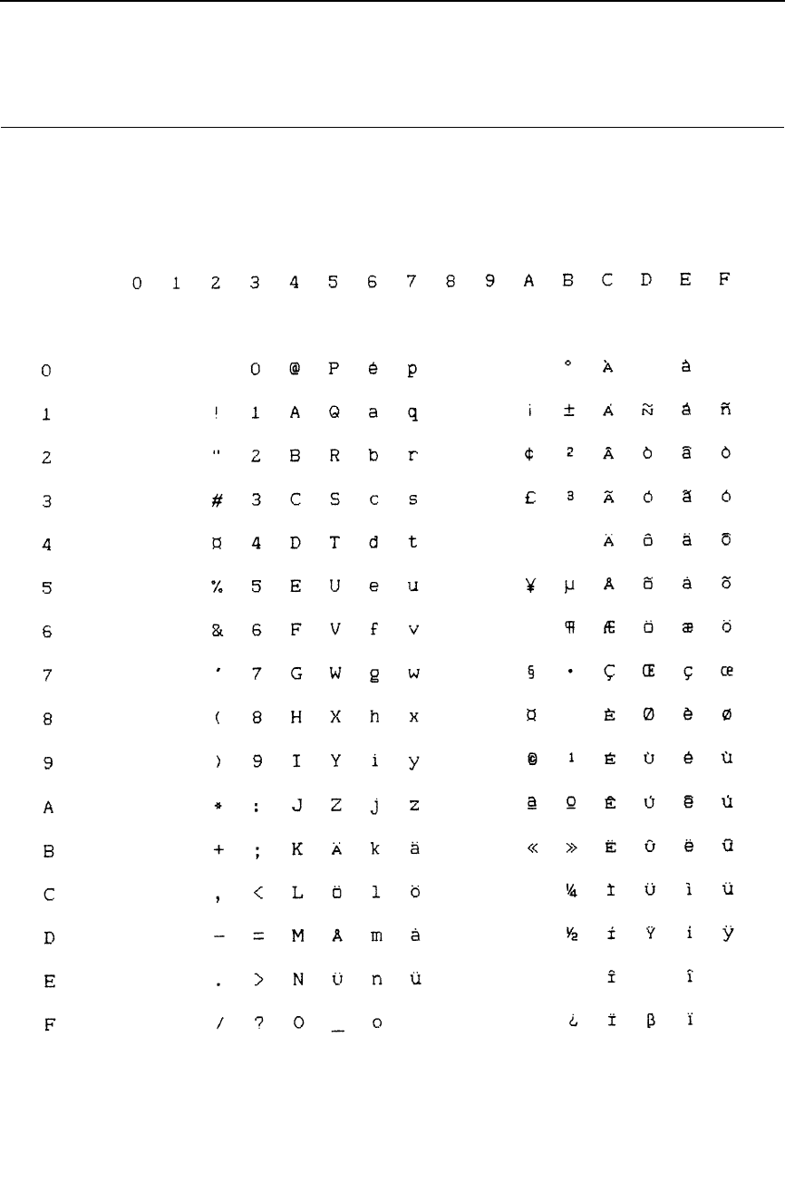
263
DEC Multinational, Finnish
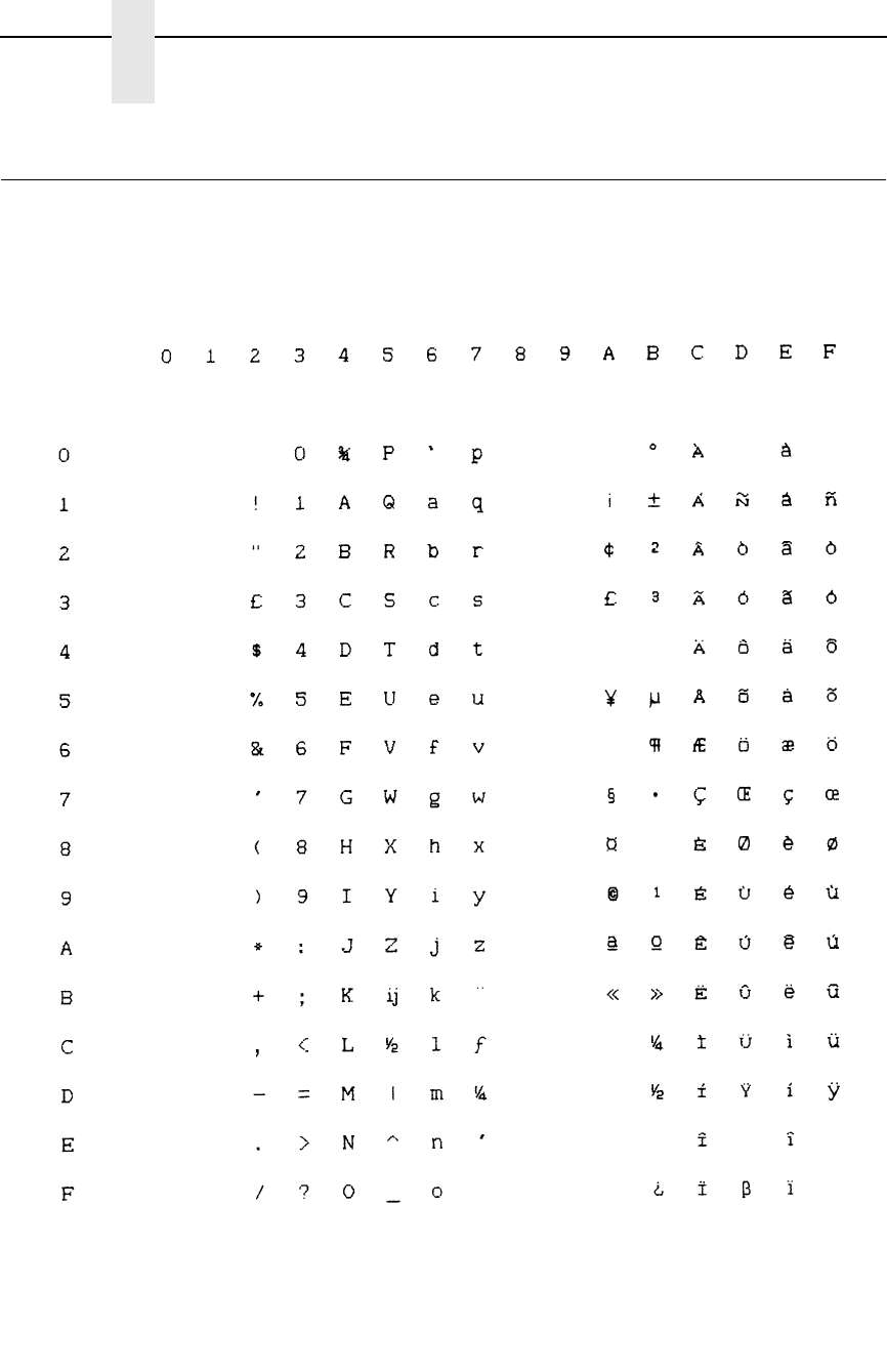
264
Appendix B
P-Series Emulation Character Sets
DEC Multinational, Swiss
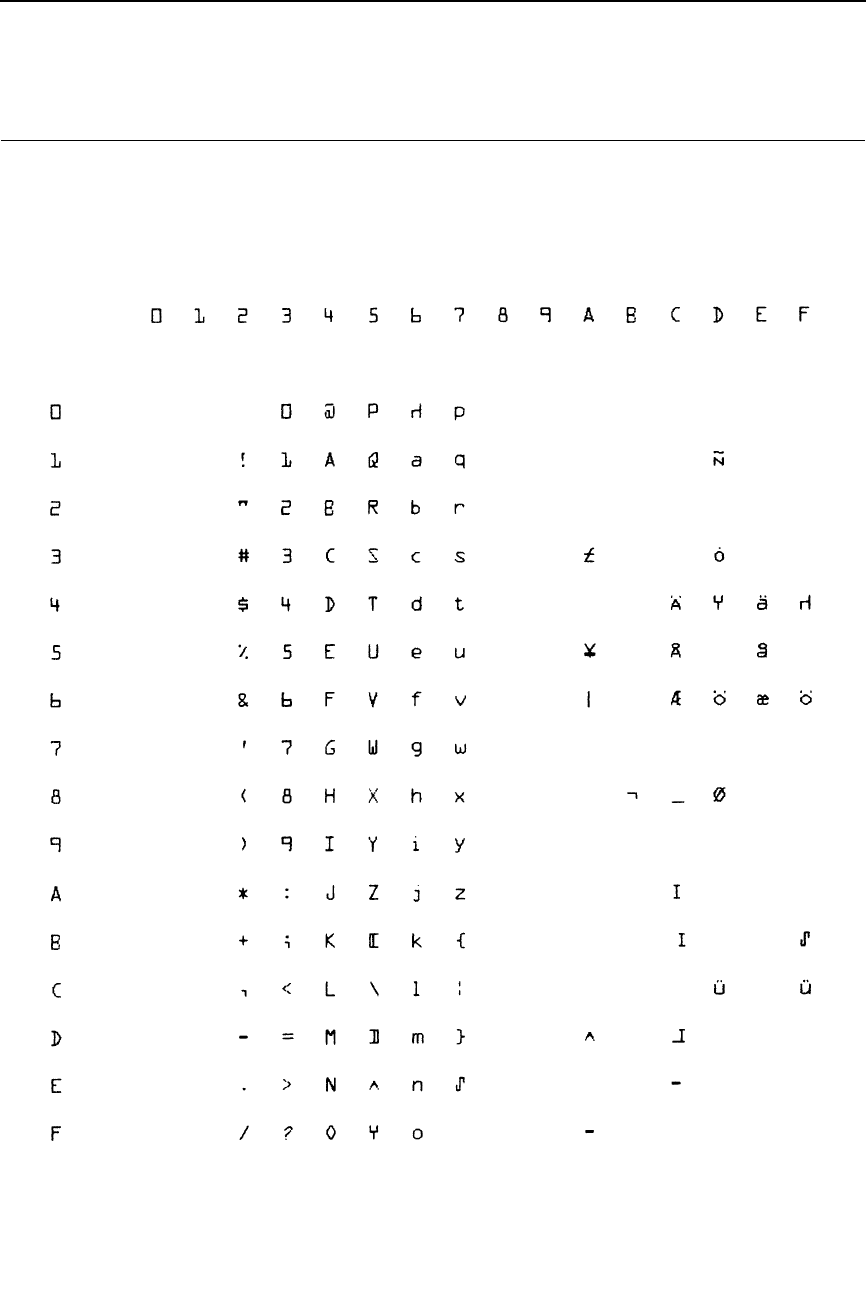
265
OCR A
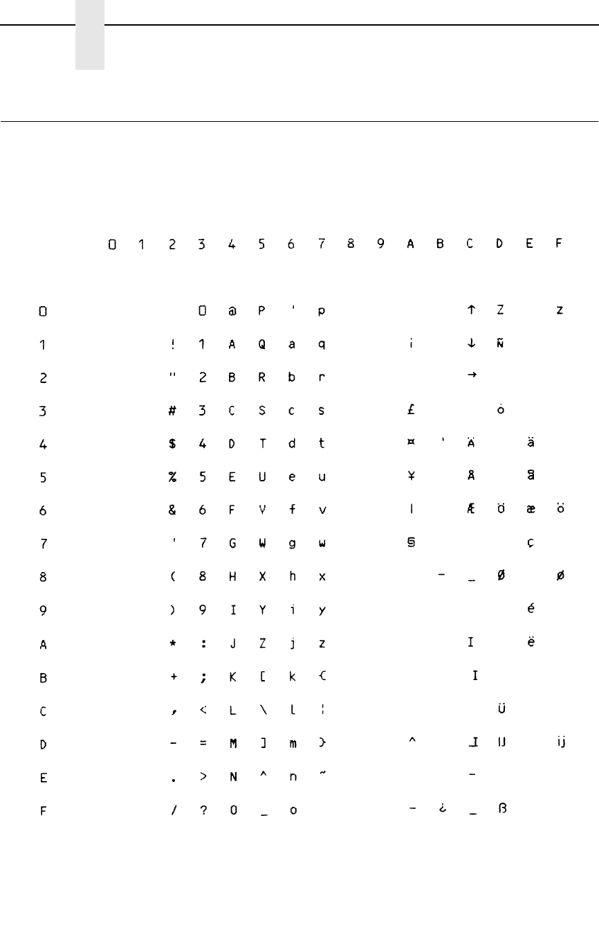
266
Appendix B
P-Series Emulation Character Sets
OCR B

267
C
Proprinter Emulation
Character Sets
Introduction
This appendix shows the character set charts (also referred to as code pages)
for the Proprinter emulation. The character sets are shown in Near Letter
Quality (NLQ). They may be selected using the configuration menus,
described in detail in your
User’s Manual
.
The maximum set of printable symbols is shown for columns hex 80-9F
(selected via the ESC 6 control code).

268
Appendix C
0437 PC Character Set
0437 PC Character Set

269
0850 PC Multilingual
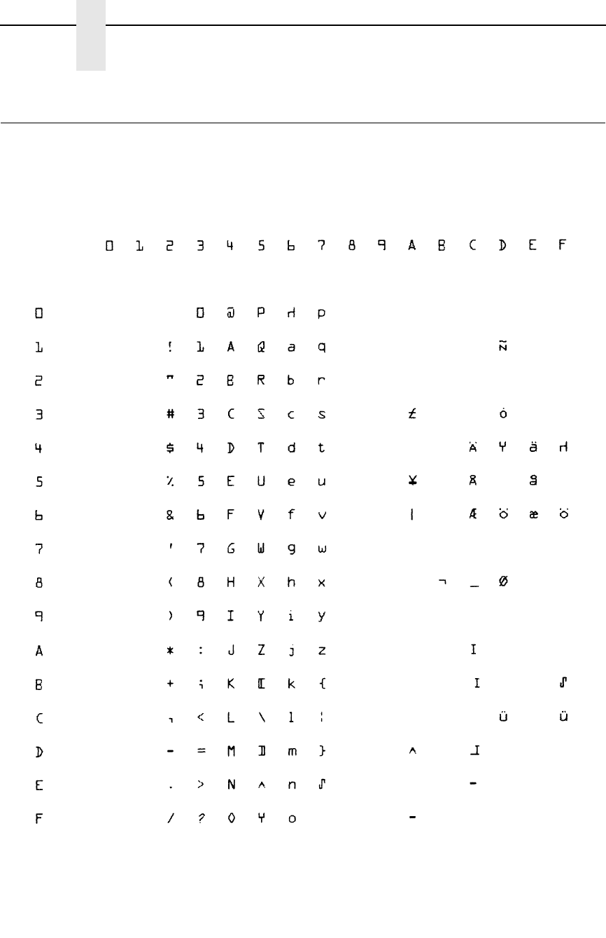
270
Appendix C
OCR A
OCR A
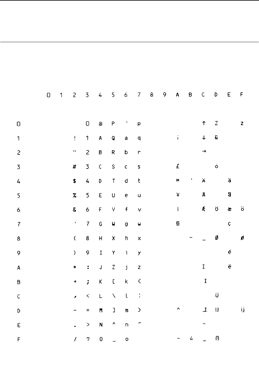
271
OCR B

272
Appendix C
OCR B

273
D
Epson Emulation
Character Sets
Introduction
This appendix shows the character set charts (also referred to as code pages)
for the Epson emulation. The character sets are shown in Near Letter Quality
(NLQ). They may be selected using the configuration menus, described in
detail in your
User’s Manual
. The international character sets may be selected
using the ESC R
n
control code (see page 159).
The maximum set of printable symbols is shown for columns hex 80-9F
(selected via the ESC I or ESC 6 control code).
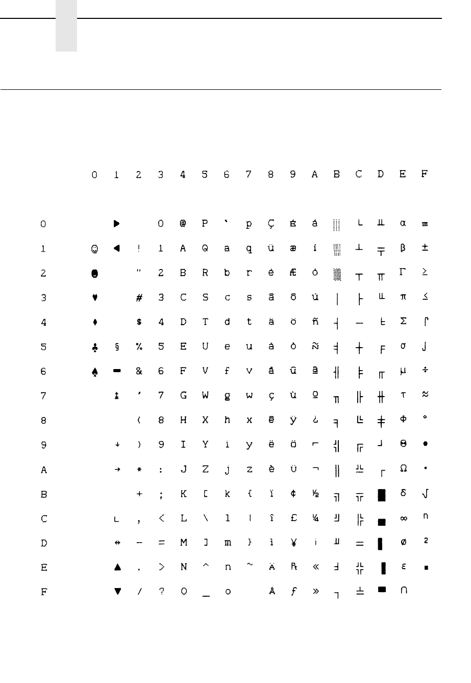
274
Appendix D
0437 PC Character Set
0437 PC Character Set
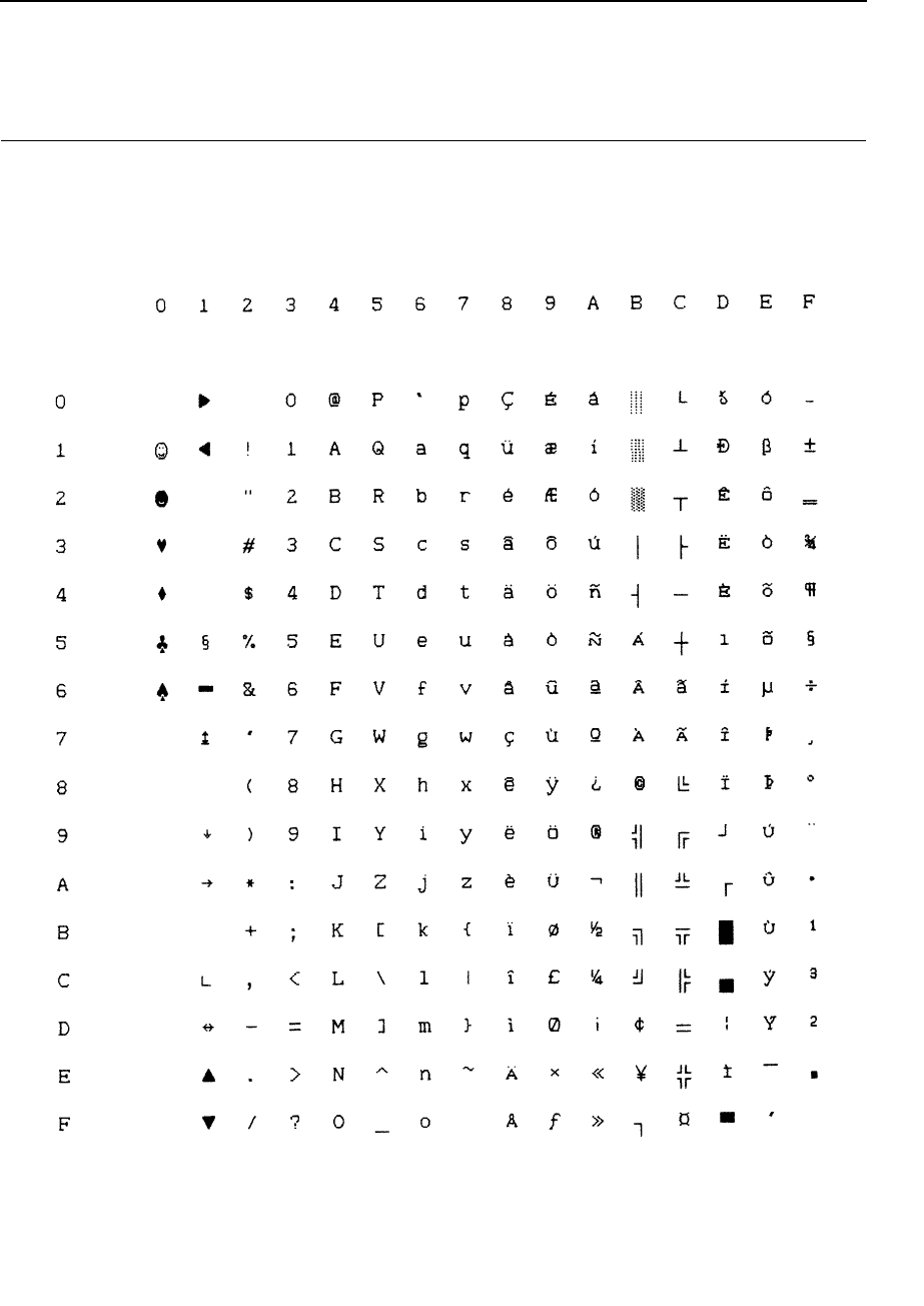
275
0850 PC Multilingual

276
Appendix D
Epson Set, ASCII (USA)
Epson Set, ASCII (USA)

277
Epson Set, French

278
Appendix D
Epson Set, German
Epson Set, German
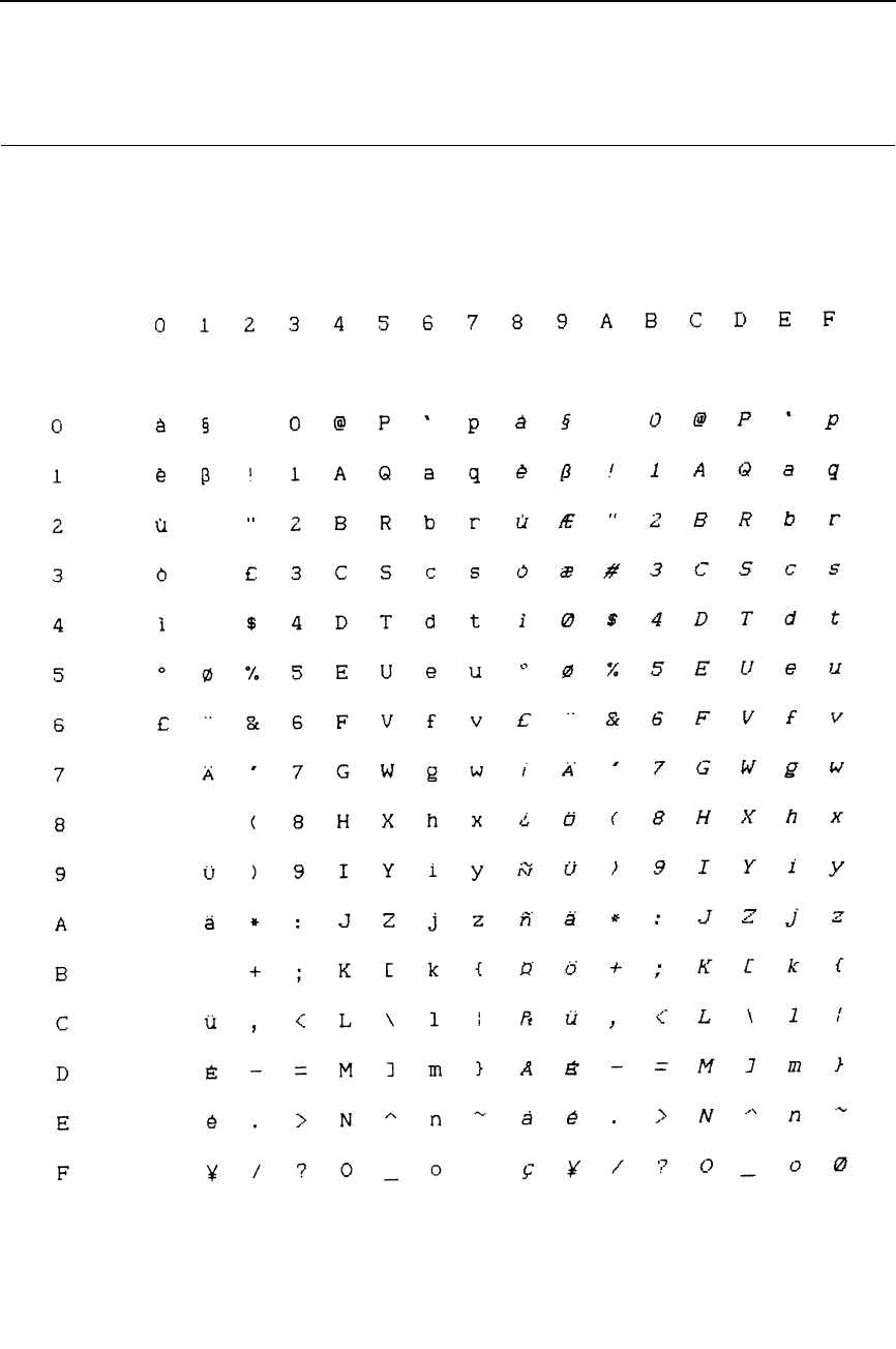
279
Epson Set, English (UK)
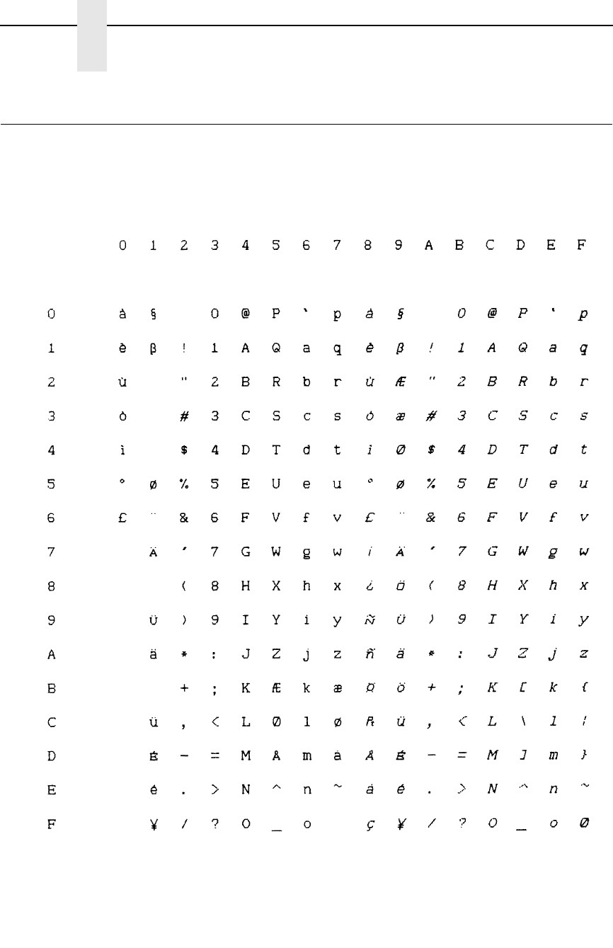
280
Appendix D
Epson Set, Danish I
Epson Set, Danish I
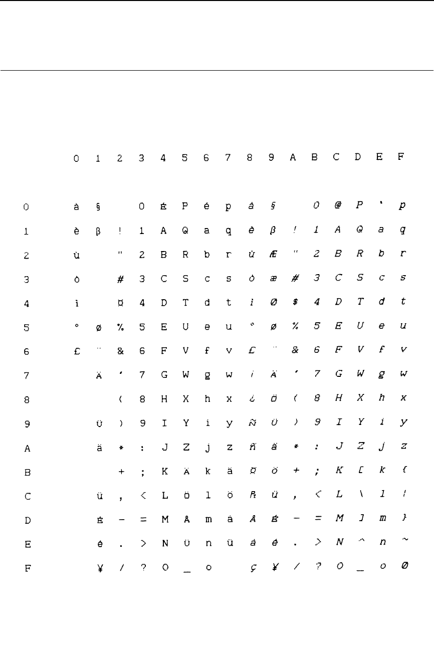
281
Epson Set, Swedish
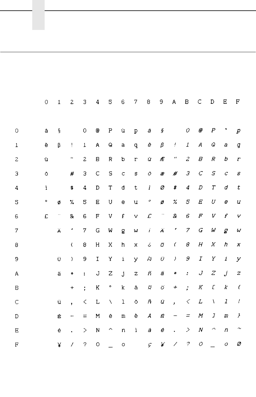
282
Appendix D
Epson Set, Italian
Epson Set, Italian
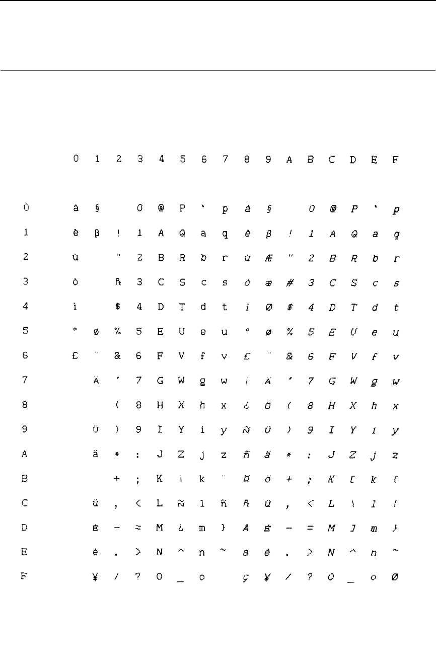
283
Epson Set, Spanish I
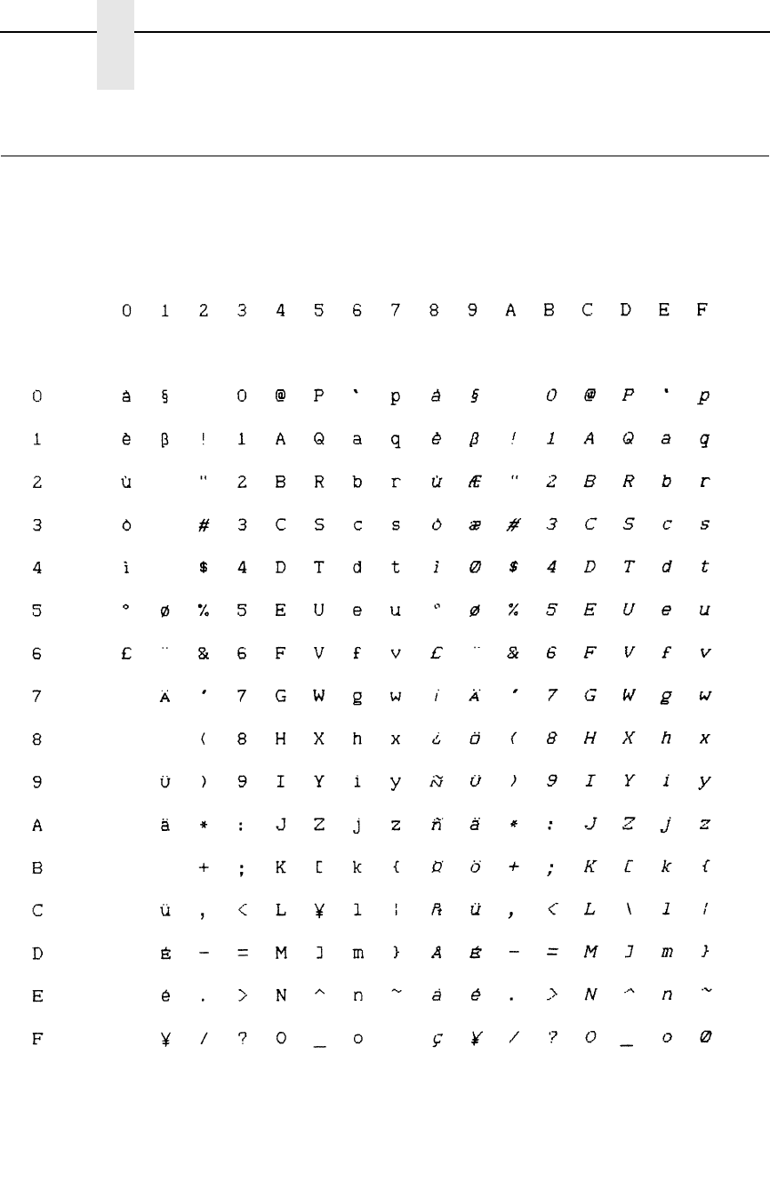
284
Appendix D
Epson Set, Japanese
Epson Set, Japanese
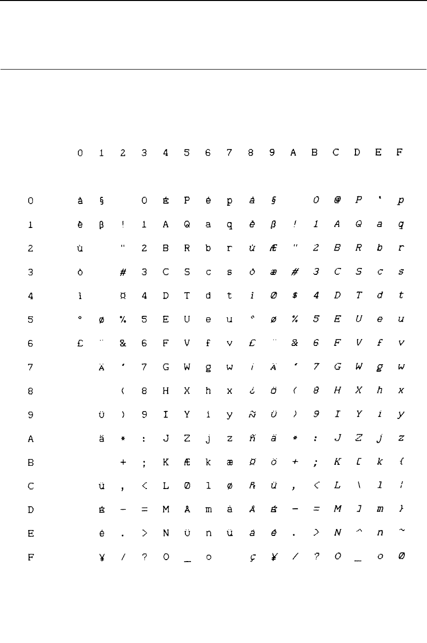
285
Epson Set, Norwegian
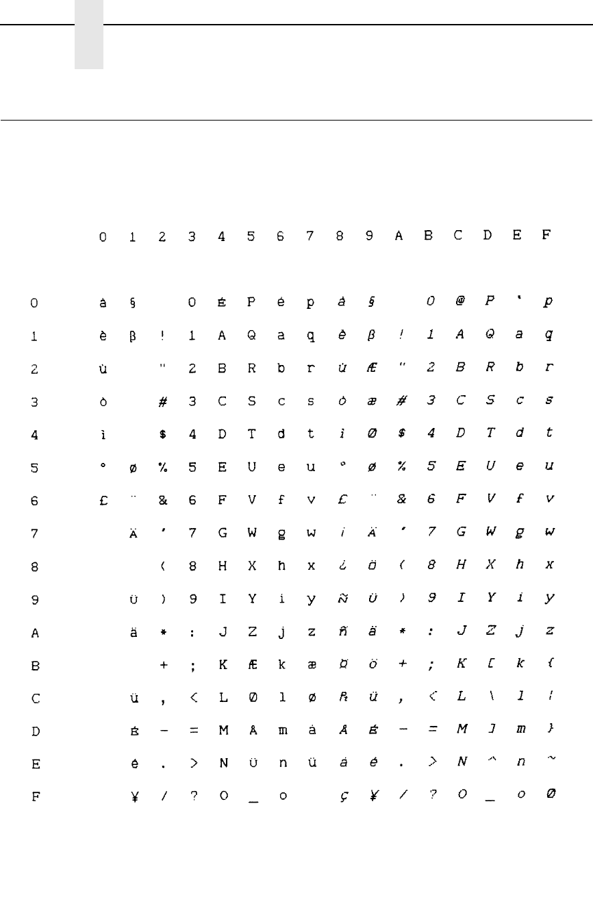
286
Appendix D
Epson Set, Danish II
Epson Set, Danish II
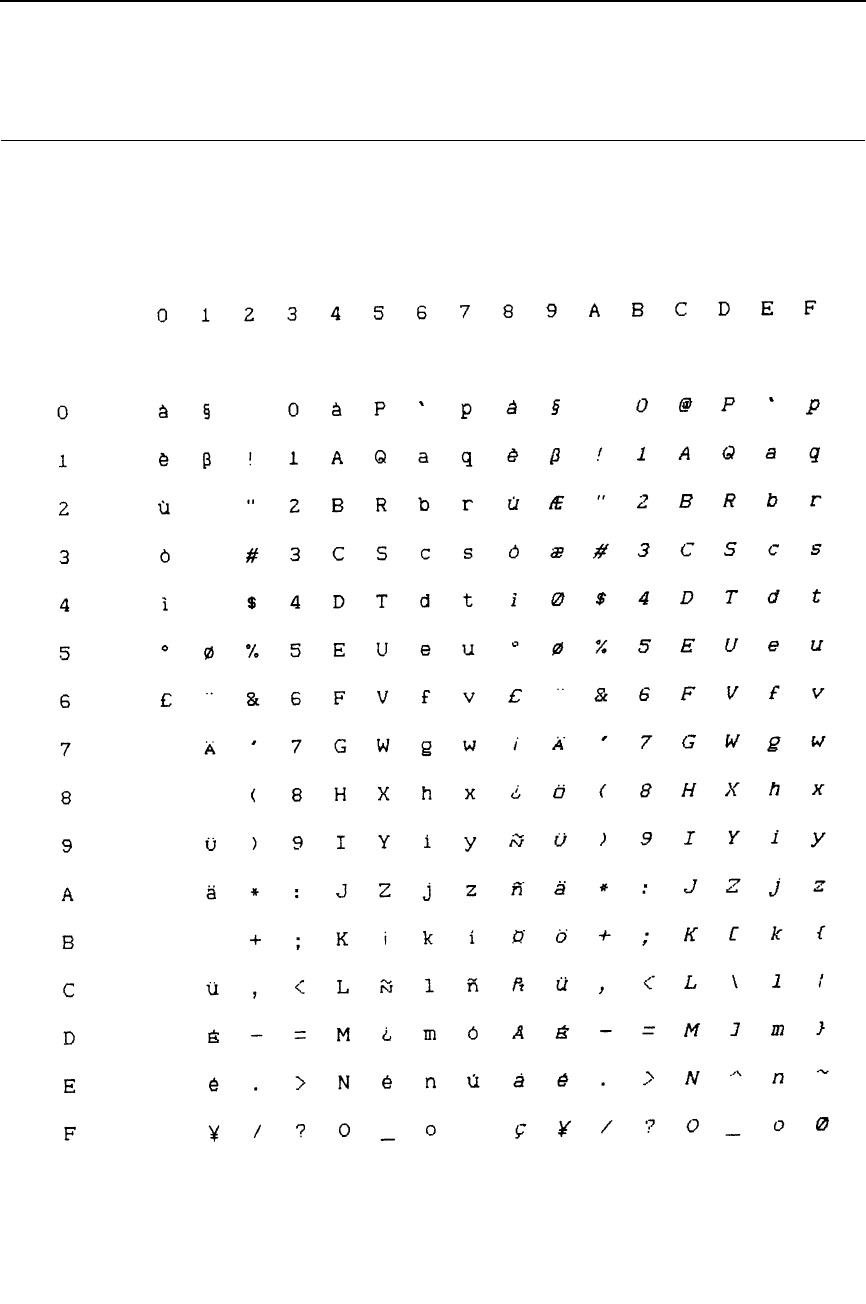
287
Epson Set, Spanish II

288
Appendix D
Epson Set, Latin American I
Epson Set, Latin American I
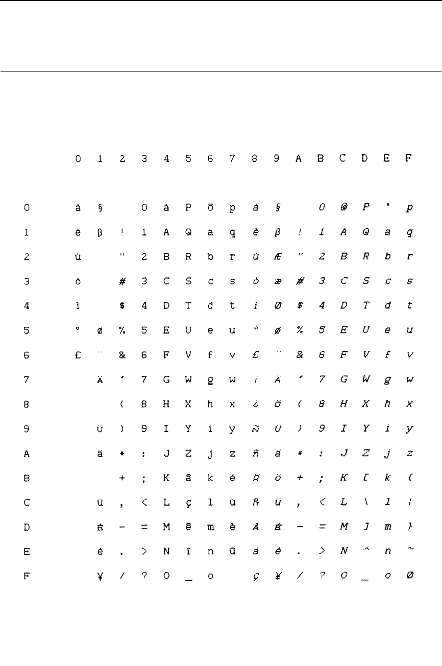
289
Epson Set, French Canadian
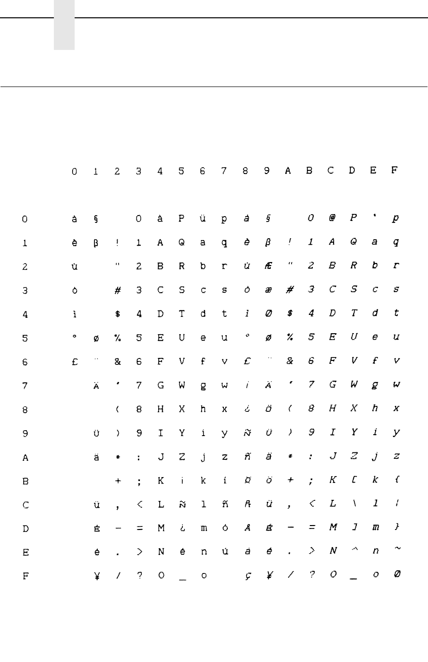
290
Appendix D
Epson Set, Latin American II
Epson Set, Latin American II

291
OCR A

292
Appendix D
OCR B
OCR B

293
E
Contact Information
Printronix Customer Support Center
IMPORTANT
Please have the following information available prior to calling the
Printronix Customer Support Center:
•
Model number
•
Serial number (located on the back of the printer)
•
Installed options (i.e., interface and host type if applicable to the problem)
•
Configuration printout:
Thermal Printer
See “Printing A Configuration” in the
Quick Setup Guide
.
Line Matrix Printer
Press PRT CONFIG on the control panel, then press Enter.
•
Is the problem with a new install or an existing printer?
•
Description of the problem (be specific)
•
Good and bad samples that clearly show the problem (faxing of these
samples may be required)
Americas (714) 368-2686
Europe, Middle East, and Africa (31) 24 6489 311
Asia Pacific (65) 6548 4114
China (86) 800-999-6836
http://www.printronix.com/support.aspx
Printronix Supplies Department
Contact the Printronix Supplies Department for genuine Printronix supplies.
Americas (800) 733-1900
Europe, Middle East, and Africa 33 (0) 1 46 25 19 07
Asia Pacific (65) 6548 4116
or (65) 6548 4182
China (86) 400-886-5598
India (800) 102-7869
http://www.printronix.com/supplies-parts.aspx

294
Appendix E
Corporate Offices
Corporate Offices
Printronix, Inc.
15345 Barranca Parkway
Irvine, CA 92618
U.S.A.
Phone: (714) 368-2300
Fax: (714) 368-2600
Printronix Inc.
c/o Printronix Nederland BV
Bijsterhuizen 11-38
6546 AS Nijmegen
The Netherlands
Phone: (31) 24 6489489
Fax: (31) 24 6489499
Printronix Schweiz GmbH
42 Changi South Street 1
Changi South Industrial Estate
Singapore 486763
Phone: (65) 6542 0110
Fax: (65) 6546 1588
Printronix Commercial (Shanghai) Co. Ltd
22F, Eton Building East
No.555, Pudong Av.
Shanghai City, 200120, P R China
Phone: (86) 400 886 5598
Fax: (86-21) 5138 0564
Visit the Printronix web site at www.printronix.com

295
Index
Numerics
11.3 CPI US Postnet Bar Code, 38
A
ASCII Character Set, 213
Attribute set and reset codes
P-Series, 76
Available symbol sets table, 43
B
Bar Code, US POSTNET, 256X
US POSTNET Bar Code, 38
Bar codes
PCL-II, 28
printing, 30
types table, 28
BEL (Bell)
Proprinter control code, 114
Binary data printing
PCL-II, 66
Bit image density selection, 195
Bit image graphics
bit pattern from ASCII character, 194
for Proprinter and Epson emulations, 193
sample program, 197
Bit image pattern
procedure for designing, 195
Bit image programming format, 196
Bold
PCL-II, 65
BS (Backspace)
Proprinter control code, 114
C
CAN (Cancel)
Proprinter control code, 120
Carriage control
directives, 69
Carriage Return
Epson FX-1050, 158
Proprinter emulation, 120
Character density selection
PCL-II, 42
Character font selection
PCL-II, 45
Character overstrike
PCL-II, 47
Character sets
ASCII, 213
Epson FX-1050
international overlays, 159
Proprinter III XL control codes, 110
P-Series international overlays, 85
Character style selection
PCL-II, 47
Clearing horizontal margins, PCL-II, 50
Code selection
Bar Code table, 28
Configuration report printing
PCL-II, 65
Configuring
PCL-II, 23
Contact information, 293
Control code description format
Epson FX-1050, 152
Proprinter III XL, 108

296
Control codes
P-Series emulation description format, 74
P-Series emulation index, 77
P-Series header, 75
table, 24
Control codes index
Epson FX-1050, 154
Proprinter emulation, 112
Cursor control
PCL-II, 47
Customer Support Center, 293
D
Dagger symbol
non-standard Epson code, 150
DC2, ESC DC2 (Condensed Print Cancel)
Proprinter control code, 122
DC4, ESC DC4 (Double Wide Print Cancel)
Proprinter control code, 124
Default values
Epson FX-1050 emulation, 148
PCL-II, 22
Proprinter III XL emulation, 106
P-Series emulation, 72
Density selection for bit images, 195
Diskette storage of emulation configuration, 23
Display functions mode
PCL-II, 49
E
EAN 13
Bar Code, width, 34
EAN 8
Bar Code, width, 34
Emulation switching, 23
Epson FX
vertical tabs, 208
Epson FX-1050 emulation, 147
character sets, 151
configuring with control codes, 152
control code description format, 152
control codes index, 154
ESC (Escape) sequences, 152
exceptions, 150
factory settings, 148
Set and Reset codes, 153
Epson FX-1050 emulation control codes
Backspace (BS), 157
Bell (BEL), 157
Cancel Line (CAN), 157
Carriage Return (CR), 158
Character Pitch 10 CPI (ESC P), 158
Character Pitch 12 CPI (ESC M), 158
Character Pitch 15 CPI (ESC g), 158
Character Set Select, International Languages
(ESC R), 159
Clear Bit 7 of Incoming Data Bytes to
0 (ESC =), 160
Condensed Print (SI, ESC SI), 160
Condensed Print Reset (DC2), 161
Cut-Sheet/Paper Feed Control (ESC EM), 161
Define a Download Character (ESC &), 161
Delete Character (DEL), 161
Double High Print. Set/Reset (ESC w), 162
Double Strike (ESC G), 162
Double Strike, Cancel (ESC H), 163
Double Wide Print (1 Line), Cancel (DC4), 164
Double Wide Print (ESC W), 163
Double Wide Print, 1 Line (SO), 164
Emphasized Print (ESC E), 165
Emphasized Print, Cancel (ESC F), 165
Enable Printing Hex 00-1F and 80-9F
(ESC I), 165
Form Feed (FF), 167
Graphics, double density (ESC L), 168
Graphics, double density double speed
(ESC Y), 169
Graphics, quadruple density (ESC Z), 170
Graphics, standard density (ESC K), 167
Half Speed Mode, On/Off (ESC s), 170
Horizontal Tab Execute (HT), 171
Horizontal Tab Set/Release (ESC D), 171
Initialize Printer (ESC @), 172
Italic Printing (ESC 4), 172
Italic Printing Cancel (ESC 5), 172
Line Feed (LF), 173
Line Feed n/216 Inch (ESC J), 173

297
Line Spacing 1/6 Inch (6 lpi) (ESC 2), 174
Line Spacing 1/8 Inch (8 lpi) (ESC 0), 174
Line Spacing 7/72 Inch (ESC 1), 175
Line Spacing n/216 Inch (ESC 3), 175
Line Spacing n/72 Inch (ESC A), 176
Make 80-9F Hex Control Codes (ESC 7), 176
Make 80-9F Hex Printable (ESC 6), 176
Master Print Select (ESC !), 178
Paper Out Detection Disable (ESC 8), 179
Paper Out Detection Enable (ESC 9), 178
Pass Bit 7 from Host (ESC #), 179
Printer Deselect (DC3), 179
Printer Select (DC1), 179
Proportional Spacing, Select/Deselect
(ESC p), 183
Reassign Graphics Mode (ESC ?), 180
Remove Downloaded Characters, 180
Select 9-Pin Graphics Mode (ESC ^), 182
Select Graphics Mode (ESC *), 181
Select Italic Character Set (ESC t), 182
Select Print Quality (ESC x), 183
Select Serif or Sans Serif Font (ESC k), 184
Select User-Defined Font (ESC %), 184
Select Vertical Tab Channel (ESC /), 184
Set Absolute Print Position in 1/60 Inch
(ESC $), 185
Set Bit 7 of Incoming Data Bytes to 1
(ESC >), 185
Set Forms Length by Lines (ESC C), 186
Set Forms Length in Inches (ESC C 0), 185
Set Intercharacter Spacing in 1/120 Inch
(ESC SP), 186
Set Margin, Left (ESC l), 186
Set Margin, Right (ESC Q), 187
Set Relative Horizontal Print Position in 1/120
Inch (ESC ›, 187
Set Vertical Tabs in Channels (ESC b), 188
Skip Over Perforation (ESC N), 188
Skip Over Perforation, Cancel (ESC O), 189
Superscript and Subscript Printing
(ESC S), 189
Superscript and Subscript Printing, Cancel
(ESC T), 190
Underline (ESC -), 190
Unidirectional Printing, 1 Line (ESC, 190
Unidirectional Printing, Set/Reset (ESC U), 191
Vertical Tab, Execute (VT), 191
Vertical Tab, Set/Clear (ESC B), 192
Epson FX-1050 features, 20
ESC
(Character Pitch 12 cpi)
Proprinter control code, 121
ESC - (Underline)
Proprinter control code, 145
ESC (Print All Characters)
Proprinter control code, 137
ESC ^ (Print Next Character)
Proprinter control code, 138
ESC _ (Overscoring)
Proprinter control code, 137
ESC 0 (Line Spacing 1/8 Inch, 8 lpi)
Proprinter control code, 132
ESC 1 (Line Spacing 7/72 Inch, 10.3 lpi)
Proprinter control code, 132
ESC 2 (Line Spacing n/72 Inch, Executes)
Proprinter control code, 133
ESC 3 (Line Spacing n/216 inch)
Proprinter control code, 135
ESC 4 (Set Top-of-Form)
Proprinter control code, 141
ESC 5 (Carriage Return Set)
Proprinter control code, 121
ESC 6 (Character Set Select Set 2(B))
Proprinter control code, 121
ESC 7 (Character Set Select Set 1(A))
Proprinter control code, 121
ESC A (Line Spacing n/72 Inch, Storage)
Proprinter control code, 134
ESC B (Tab Set/Clear, Vertical)
Proprinter control code, 144
ESC C (Forms Length Set in Lines)
Proprinter control code, 127
ESC C 0 (Forms Length Set in Inches)
Proprinter control code, 126
ESC D (Tab Set/Clear, Horizontal)
Proprinter control code, 142

298
ESC E (Emphasized Print)
Proprinter control code, 125
ESC F (Emphasized Print Cancel)
Proprinter control code, 125
ESC G (Bold Printing)
Proprinter control code, 119
ESC H (Bold Printing Cancel)
Proprinter control code, 119
ESC I (Print Mode)
Proprinter control code, 138
ESC J (Line Feed n/216 Inch, One Line Only)
Proprinter control code, 131
ESC K (Bit Image Mode, Single Density)
Proprinter control code, 115
ESC K control code
single density bit image graphics, 195
ESC L (Bit Image Mode, Double Density,
Half Speed)
Proprinter control code, 116
ESC L control code
double density bit image graphics, 196
ESC N (Margin, Bottom)
Proprinter control code, 136
ESC O (Margin Cancel, Bottom)
Proprinter control code, 136
ESC P (Proportional Spacing)
Proprinter control code, 139
ESC Q (Deselect Printer)
Proprinter control code, 123
ESC R (Tabs, Clear All)
Proprinter control code, 144
ESC S (Superscript/Subscript Printing)
Proprinter control code, 141
ESC T (Superscript/Subscript Printing, Cancel)
Proprinter control code, 142
ESC U (Unidirectional Printing)
Proprinter control code, 145
ESC W (Double Wide Print)
Proprinter control code, 123
ESC x (Print Quality)
Proprinter control code, 139
ESC Y (Bit Image Mode, Double Density, Normal
Speed) Proprinter control code, 117
ESC Y control code
double density bit image graphics, 196
ESC Z (Bit Image Mode, Quadruple Density)
Proprinter control code, 118
ESC Z control code
quadruple density bit image graphics, 196
Escape (ESC) control codes overview
IBM Proprinter III XL, 108
Escape (ESC) sequences
Epson FX-1050, 152
Escape sequences
PCL-II, 25
EVFU (Electronic Vertical Format Unit), 210
EVFU (Electronic Vertical Formatting Unit)
channel assignment, 210
clearing the memory, 212
end load code, 210
P-Series, 210
start load code, 210
using the EVFU, 211
F
Factory settings
Epson FX-1050 emulation, 148
PCL-II, 22
Proprinter III XL emulation, 106
P-Series emulation, 72
Feature access
transparent mode, 68
FF (Form Feed)
Proprinter control code, 126
Font selection
11.3 cpi, US Postnet, 38
G
General information
PCL-II, 24
Graphics, 69
Graphics and text, combining, 204
Graphics control codes overview
IBM Proprinter III XL, 109

299
Graphics Mode
8-Pin, 181
Graphics printing
overview, 193
Proprinter and Epson bit image graphics, 193
Graphics resolution table, 63
H
Horizontal margin selection
PCL-II, 50
HP 1000 information
PCL-II, 70
HP 3000 information
PCL-II, 68
HT (Tab, Horizontal)
Proprinter control code, 142
I
Ignored and reserved control codes
Proprinter III XL emulation, 110
Image printing
overview, 193
Industrial 2 of 5
Bar Code, width, 33
Interleaved 2 of 5
Bar Code, width, 33
International character sets
Epson FX-1050, 159
Italic character selection
PCL-II, 47
K
Proprinter control codes
Initialize Parameters (ESC, 128
L
Labels, multiple
printing, 31
Levels, compatible, 23
LF (Line Feed)
Proprinter control code, 130
Line spacing
PCL-II, 50
M
Manuals, related, 18
Margins, Horizontal (ESC X)
Proprinter control code, 136
Moving paper, VFC
PCL-II, 55
O
Odd Dot plot pattern plan, 202
Odd Dot plot sample, 202
P
Paper slewing, 207
Parameter, escape sequence
PCL-II, 25
PCL-II, 21
default settings, 22
levels of compatibility, 23
Perforation skip mode, 69
PCL-II, 52
PI Line
not used by Proprinter emulation, 108
Plot density
P-Series emulation, 198
Plot mode
data byte format sample, 200
data line format, 200
double density plot, 201
high density plot sample, 199
how to exit, 203
normal density plot, 201
normal density plot sample, 198
Odd Dot pattern plan, 202
Odd Dot sample, 202
plot data byte format, 199
Truncated Character Line, 203
Plot mode graphics
P-Series emulation, 198
Prefix, escape sequence
PCL-II, 25
Primary symbol set
PCL-II, 46

300
Print mode selection
PCL-II, 52
Print pitch selection
PCL-II, 53
Printing bar codes, 30
Printing hex values, 53
Programmable reset
PCL-II, 54
Programmable VFC
PCL-II, 55
Proprinter control codes
Backspace (BS), 114
Bell (BEL), 114
Bit Image Mode, Double Density (Half Speed),
ESC L, 116
Bit Image Mode, Double Density, Normal
Speed (ESC Y), 117
Bit Image Mode, Quadruple Density
(ESC Z), 118
Bit Image Mode, Single Density (ESC K), 115
Bold Printing (ESC G), 119
Bold Printing Cancel (ESC H), 119
Cancel (CAN), 120
Carriage Return (CR), 120
Carriage Return Set (ESC 5), 121
Character Pitch 12 cpi (ESC), 121
Character Set Select
Set 1(A) (ESC 7), 121
Set 2(B) (ESC 6), 121
Condensed Print (SI, ESC SI), 122
Condensed Print Cancel (DC2, ESC DC2), 122
Deselect Printer (ESC Q), 123
Double Wide Print (ESC W), 123
Double Wide Print (One Line Only) Cancel
(DC4, ESC DC4), 124
Double Wide Print, One Line Only (SO), 124
Emphasized Print (ESC E), 125
Emphasized Print Cancel (ESC F), 125
Form Feed (FF), 126
Forms Length Set in Inches (ESC C 0), 126
Forms Length Set in Lines (ESC C), 127
grouped by function, 112
Line Feed (LF), 130
Line Feed n/216 Inch, One Line Only
(ESC J), 131
Line Spacing 1/8 Inch, 8 lpi (ESC 0), 132
Line Spacing 7/72 Inch, 10.3 lpi (ESC 1), 132
Line Spacing n/216 Inch (ESC 3), 135
Line Spacing n/72 Inch, Executes (ESC 2), 133
Line Spacing n/72 Inch, Storage (ESC A), 134
Margin Cancel, Bottom (ESC O), 136
Margin, Bottom (ESC N), 136
Margins, Horizontal (ESC X), 136
Overscoring (ESC_), 137
Print All Characters (ESC ), 137
Print Mode (ESC I), 138
Print Next Character (ESC ^), 138
Print Quality (ESC x), 139
Proportional Spacing (ESC P), 139
Set Top-of-Form (ESC 4), 141
Superscript/Subscript Printing (ESC S), 141
Superscript/Subscript Printing Cancel
(ESC T), 142
Tab Set/Clear, Horizontal (ESC D), 142
Tab Set/Clear, Vertical (ESC B), 144
Tab, Horizontal (HT), 142
Tab, Vertical (VT), 143
Tabs, Clear All (ESC R), 144
Underline (ESC -), 145
Proprinter III XL emulation
character set control codes, 110
configuring via control codes and menus, 105
control code description format, 108
ESC (Escape) control codes overview, 108
factory settings, 106,
148
graphics control codes overview, 109
ignored and reserved control codes, 110
overview, 105
vertical tabs, 208
Proprinter III XL features, 20
P-Series emulation, 71
configuring via control codes and
menus, 21,
71
control code description format, 74
control codes, 77
factory settings, 22,
72

301
high density plot sample, 199
normal density plot sample, 198
plot data byte format, 199
plot density, 198
plot mode, 202
plot mode graphics, 198
P-Series emulation control codes
Backspace (BS), 79
Bell (BEL), 79
Bold Print (SFCC G), 80
Bold Print Reset (SFCC H), 80
Carriage Return (CR), 81
Character Set Select (SFCC 1), 82
Character Set Select, ECMA Latin 1 Extended
(SFCC OSET), 84
Character Set Select, International Languages
(SFCC PSET, SFCC R), 85
Characters 80-9F, Control Codes (SFCC 7), 86
Characters 80-9F, Printable Symbols
(SFCC 6), 86
Elongated (Double High) Print, 1 Line Only
(SFCC h, BS), 87
Elongated (Double High) Print, Set/Reset
(SFCC w), 88
Emphasized Print (SFCC E), 88
Emphasized Print Reset (SFCC F), 89
Emulation Reset (SFCC @), 89
Expanded Print, Double Wide (SFCC W), 90
Expanded Print, Double Wide 1 LIne Only
(SFCC k), 90
Extended Character Set (S0, SFCC SO), 91
Extended Character Set Cancel
(SI, SFCC SI), 91
Form Feed (FF), 92
Forms Length Set in Inches
(SFCC INCHES), 92
Forms Length Set in Lines (SFCC LINES), 93
Line Feed (LF), 93
Line Spacing 1/6 Inch (SFCC A), 94
Line Spacing 1/8 Inch, 8 lpi (SFCC LPI), 94
Line Spacing 7/72 Inch (SFCC 1), 95
Line Spacing 8 or 10.3 lpi, 1 line only (ACK), 95
Line Spacing n/216 Inch (SFCC 3), 97
Line Spacing n/72 Inch (SFCC A), 96
Overscoring (SFCC_), 97
Plot, Even Dot, P-Series High Density Graphics
(EOT), 98
Plot, Odd Dot, P-Series Normal Density
Graphics (ENQ), 98
Print Mode/Pitch Selection (SFCC PMODE), 99
Superscript/Subscript Printing (SFCC S), 103
Superscript/Subscript Printing Reset
(SFCC T), 103
Underline (SFCC), 104
Vertical Tab (VT), 104
VFU Commands, 104
P-Series emulation extended and multinational
character sets, 82
P-Series EVFU, 210,
211
channel assignment, 210
clearing the memory, 212
end load code, 210
start load code, 210
P-Series features, 19
PTX Linefeed, 53
R
Raster graphics
PCL-II, 63
Resetting, PCL-II, 54
Royal Mail barcode, 34
S
Save Custom Sets menu option, 23
Selecting fonts, attributes, 45
Self-test
PCL-II, 65
Serial Interface, 68
Set and reset codes
Epson FX-1050 emulation, 153
SFCC
P-Series, 75
SFCC 1 (Character Set Select)
P-Series control code, 82
SI, ESC SI (Condensed Print)
Proprinter control code, 122

302
SO (Double Wide Print, One Line Only)
Proprinter control code, 124
Standard
PCL-II, 65
Storage of emulation configuration on diskette, 23
Stroke Weight
PCL-II, 65
Supplies Department, 293
Switching character font
PCL-II, 65
Switching emulations, 23
Symbol set selection
PCL-II, 46
T
Tabs, vertical
Epson FX, 208
Proprinter III XL emulation, 208
Terminator, escape sequence
PCL-II, 25
Text length selection
PCL-II, 51,
66
Throughput increased, VFC
PCL-II, 67
Transparent print data
PCL-II, 66
Truncated Character Line, 203
U
UCC/EAN 128
Bar Code, 34
Underline, 190
Underlining
PCL-II, 66
Unidirectional Printing (ESC U)
Proprinter control code, 145
UPC A
Bar Code, width, 33
UPC E
Bar Code, width, 34
Upright character selection
PCL-II, 47
US Postnet bar code
4.0 cpi, 41
US Postnet barcode, 38
check digits, 38
V
Vertical Format Unit (VFU), 207
characteristics, 208
general programming information, 207
Vertical formatting
P-Series EVFU, 210
Vertical forms control
PCL-II, 67
Vertical page format planning, 207
Vertical tabbing
example, 209
Vertical tabs
Epson FX, 208
Proprinter III XL emulation, 208
VFC Channel Definitions table, 67
VT (Tab, Vertical)
Proprinter control code, 143

257400-001A
*257400-001*
