260071 001A_PM_S828NEW PTX_PRM_S828_260071 001 PTX PRM S828
PTX_PRM_S828_260071-001 PTX_PRM_S828_260071-001
PTX_PRM_S828_260071-001 PTX_PRM_S828_260071-001
PTX_PRM_S828_260071-001 PTX_PRM_S828_260071-001
User Manual: PTX_PRM_S828_260071-001
Open the PDF directly: View PDF ![]() .
.
Page Count: 424 [warning: Documents this large are best viewed by clicking the View PDF Link!]
- Printronix S828 Programmer's Manual
- Introduction
- Contents
- Index: Command Summary in Alphabetical Order
- Preface
- Chapter 1 EPSON/IBM Commands
- Chapter 2 Native Emulation Commands
- Chapter 3 ANSI Emulation Commands
- Chapter 4 IPDS Emulation Commands
- Chapter 5 IPDS Programming Information
- Chapter 6 IPDS Exception Reporting Codes
- Chapter 7 IPDS Print Samples and IPDS Coding Example
- Appendix A Code Pages
- Appendix B Interfaces
- Appendix C Network Interface Technical Reference
- Appendix D LAN Interface MIB Support
- Appendix E The Remote Printer Management Utility
- Appendix F Print Driver Support
- Appendix G Application Paper Source Selection IPDS
- Appendix H Bar Code and OCR Printing Options
- Appendix I Configuration Menu Lockout
- Appendix J Addendum (Bar Codes)
- Notices
- Customer Support
P
ro
g
M
g
r
a
Ma
a
m
a
n
u
m
e
u
al
e
r’
s
s

ProgrammerManual PTX‐S828
Contents1260071‐001A
Introduction
This publication provides information about the commands supported by your printer. The commands are
organized by function groups. Each command has both a brief and a detailed description.
Each command has the following structure:
Name and function description. Information about protocol (IBM® Proprinter XLIII, IBM Personal 2381+,
EPSON FX Series, ANSI 3.64, IPDS® ).
The hexadecimal and decimal codes for the command: n represents variable parameters of the command.
The functions of these parameters are explained in its corresponding command description.
Index of Contents
Chapters Page
Contents 1
Introduction 1
Index of Contents 1
Index of Command Summary in Alphabetical Order 9
Common commands for the Printronix S828 model printers. 9
Commands for the Printronix S828 model printer with the IPDS feature present 13
Preface 15
Chapter 1. EPSON/IBM Mode Commands 17
Print and Line Feed Execution 17
Format Control 18
Print Mode 29
Character Set 42
Download Character 44
Bit Image 48
Data Input Control 49
Miscellaneous 51
Chapter 2. Native Emulation Commands 57
Format Control 57
Native Character Set 58
Bar Codes 60
Miscellaneous 66
Chapter 3. ANSI Emulation Commands 71
Character Set Control 71
Character Pitch and Print Modes 74
Horizontal Movements 76
Vertical Movements 78
Interface Control 82
Operating System Control 83
Paper Path Selection 85
Barcode Functions 86
Basic Program Sample 88
Basic Program Printed Output 89

ProgrammerManual PTX‐S828
Contents2260071‐001A
Chapters Page
Chapter 4. IPDS Commands 91
Overview 91
Physical Medium 91
IPDS Coordinate Systems 92
Processing IPDS Commands 95
IPDS Command Format 96
Acknowledge Requests and Replies 97
IPDS Data 100
Mixing Rules 101
IPDS Operating States 102
Summary of IPDS States and Commands 104
A typical IPDS Command Sequence 107
Error Handling 113
Chapter 5. IPDSProgrammingInformation115
IPDS Initialization Defaults 115
Command Format 116
Supported IPDS Command Codes 117
Command Function Sets 118
Device Control Function Set Commands 118
Text Function Set Commands 149
Image Function Set Commands 158
Graphics Function Set Commands 160
Related Drawing Orders 193
Bar Code Function Set Commands 196
Code 128 Character Set (EBCDIC) 208
Overlay Function Set Commands 209
Page Segment Function Set Commands 211
Loaded Font Function Set Commands 212
Chapter6.IPDSExceptionReportingCodes215
Command Reject - X'80' 215
Intervention Required - X'40' 215
Equipment Check - X'10' 216
Data Check - X'08' 216
Specification Check-Bar Code - X'04' 216
Specification Check-Graphics - X'03' 218
Specification Check-General - X'02' 220
Conditions Requiring Host Notification - X'01' 229
Chapter7.PrintSamplesandIPDSCodingExample231
Text Print Samples 231
Bar Codes 231
Graphics Patterns 232
Graphics Example 233
IPDS Coding Example 238

ProgrammerManual PTX‐S828
Contents3260071‐001A
Chapters Page
Appendix A. Code Pages 247
EBCDIC Code Pages (IPDS) 247
ASCII Code Pages 293
Character Sets 355
Hexadecimal to Decimal Table 357
Epson FX-series Code Pages 358
ANSI National Variations 361
AppendixB‐Interfaces363
The Parallel Interface 363
The Serial Interface 369
LAN Interface Port 370
USB Interface Port 370
AppendixC–NetworkInterfaceReference371
Network Configuration Parameters 371
Managing a Single Printer Configuration Using the Internal Webpage 373
Managing Multiple Printers Using the Remote Printer 373
Network Interface Summary 373
AppendixD–LanInterfaceMIBSupport377
Appendix E- The Remote Printer Management Utility 383
Operating System Compatibility 383
Software Installation and Documentation 383
AppendixF–PrinterDriverSupport385
AppendixG‐ApplicationPaperSourceinIPDS387
Appendix H- Bar Code and OCR Printing Options 389
AppendixIConfigurationMenuLockout393
AppendixJAddendum(BarCodes)395
Notices 415
Customer Support 419

ProgrammerManual PTX‐S828
Contents4260071‐001A
Figures Page
Figure 1.Page Presentation 16
Figure 2.The Physical Medium 92
Figure 3. The Xm,Ym Medium Coordinate System 93
Figure 4. The Physical-Logical Page Relationship 93
Figure 5. The X and Y Coordinate System and the Logical Page 94
Figure 6. The I and B Coordinate System on the Logical Page 95
Figure 7. An Example of the IPDS Data Stream 96
Figure 8. A Sample Page Constructed on an IPDS Printer 101
Figure 9. The Relationship between Home State, Page State, and Block States 103
Figure 10. The Relationship between Home State, Overlay State, and Block State 104
Figure 11. The Complete IPDS State Diagram 107
Figure 12. Using the Load Page Descriptor Command to Specify the Logical Page 129
Figure 13. Using the Logical Page Position Command to Position 129
Figure 14. Using the Set Media Size Command to Specify the Physical Medium 132
Figure 15. Exception Handling Control (Part 1 of 3) 146
Figure 15. Exception Handling Control (Part 2 of 3) 147
Figure 15. Exception Handling Control (Part 3 of 3) 148
Figure 16. The Graphics X and Y Coordinate System 161
Figure 17. The Graphic Medium Presentation Space and Its Limits 162
Figure 18. The Graphic Window within the Graphic Medium Presentation Space 162
Figure 19. The Graphic Block Area on the Physical Medium 163
Figure 20. Graphic Block Area Position Control and the Graphic Block Area 165
Figure 21. Graphic Output Control and the Graphic Block Area 167
Figure 22. Graphic Data Descriptor and the Graphic Medium Presentation Space 169
Figure 23. Scale-to-Fit Mapping 170
Figure 24. Center-and-Trim Mapping 172
Figure 25. Position-and-Trim Mapping 173
Figure 26. Specifying the Bar Code Block Using the Bar Code Area Position Field 199
Figure 27. Specifying the Bar Code Block Size Using the Bar Code Output Control 201
Figure 28. Specifying the Bar Code Medium Presentation Space Size
Using the Bar Code Data Descriptor 205
Figure 29 Shows an overlay nesting. 210
Figure 30. Bar Code Example in IPDS 232
Figure 31. Graphic Patterns Example in IPDS 233
Figure 32. Graphic Example in IPDS 234
Figure 33. Print Sample from an IPDS Application Program 239
Figure 34. CP00037 USA/Canada/Canadian Bilingual 249
Figure 35. CP00260 Canadian French 250
Figure 36. CP00273 Austrian/German 251
Figure 37. CP00274 Belgian Old 252
Figure 38. CP00275 Brazilian 253
Figure 39. CP00277 Danish/Norwegian 254
Figure 40. CP00278 Finnish/Swedish 255
Figure 41. CP00280 Italian 256
Figure 42. CP00281 Japanese English 257
Figure 43. CP00282 Portuguese 258
Figure 44. CP00284 Spanish/Spanish Speaking 259
Figure 45. CP00285 English (UK)/Ireland 260
Figure 46. CP00290 Japanese Katakana 261
Figure 47. CP00297 French/French Azerty 262

ProgrammerManual PTX‐S828
Contents5260071‐001A
Figures Page
Figure 48. CP00420 Arabic 263
Figure 49. CP00423 Greek (Old) 264
Figure 50. CP00424 Hebrew Bulletin 265
Figure 51. CP00500 International 5/Swiss/Belgian 266
Figure 52. CP00813 Greek/Latin (ISO 8859-7) + euro 267
Figure 53. CP00833 Korean 268
Figure 54. CP00838 Thai 269
Figure 55. CP00870 Latin 2/ROECE 270
Figure 56. CP00871 Icelandic 271
Figure 57. CP00875 Greek New + euro 272
Figure 58. CP00880 Cyrillic 273
Figure 59. CP00890 Yugoslav (Old) 274
Figure 60. CP00892 OCR-A 275
Figure 61. CP00893 OCR-B 276
Figure 62. CP00924 Latin 9 (ISO 8859) + euro 277
Figure 63. CP01025 Cyrillic Multilingual 278
Figure 64. CP01026 Latin-5 Turkey 279
Figure 65. CP01097 Farsi 280
Figure 66. CP01112 Baltic Multilingual 281
Figure 67. CP01122 Estonian 282
Figure 68. CP01140 USA/Canada + euro 283
Figure 69. CP01141 Austrian/German + euro 284
Figure 70. CP01142 Danish/Norwegian + euro 285
Figure 71. CP01143 Finnish/Swedish + euro 286
Figure 72. CP01144 Italian + euro 287
Figure 73. CP01145 Spanish/Spanish Speaking + euro 288
Figure 74. CP01146 English/UK + euro 289
Figure 75. CP01147 French + euro 290
Figure 76. CP01148 International 5/Belgian New + euro 291
Figure 77. CP01149 Icelandic + euro 292
Figure 78. USA(CP437) 295
Figure 79. Greek(CP437-G) 296
Figure 80. Croatian(CP437-SLAVIC) 297
Figure 81. Greek/Latin (ISO 8859-7) 298
Figure 82 .ISO8859/1(Latin1) 299
Figure 83.Multilingual(CP850) 300
Figure 84.Old Greek(CP851) 301
Figure 85.EasternEurope(CP852) 302
Figure 86.Turkish(CP853) 303
Figure 87.Cyrillic(CP855) 304
Figure 88.Turkish(CP857) 305
Figure 89.EuroPCMultilingual(CP858) 306
Figure 90.Portugal(CP860) 307
Figure 91.Hebrew(CP862) 308
Figure 92.Canada/France(CP863) 309
Figure 93.Arabic(CP864) 310
Figure 94.CP864E(Arabic) 311
Figure 95.Denmark/Norway(CP865) 312
Figure 96Russian(CP866) 313
Figure 97.Turkish2(CP867) 314

ProgrammerManual PTX‐S828
Contents6260071‐001A
Figures Page
Figure 98.OCR-A(CP876) 315
Figure 99.OCR-B(CP877) 316
Figure 100.ISO8859/2(Latin2) 317
Figure 101.ISO8859/3(Latin3) 318
Figure 102.ISO8859/4(Latin4) 319
Figure 103.ISO8859/5(Latin/Cyrillic) 320
Figure 104.ISO8859/8 (Latin 8) 321
Figure 105.ISO8859/9(Latin5) 322
Figure 106.BalticWindows(CP921) 323
Figure 107.Estonian (CP922) 324
Figure 108.ISO8859/15(Latin9) 325
Figure 109.Urdu (CP01006) 326
Figure 110.Arabic Extended (CP1046) 327
Figure 111.ISO8859/6(Latin/Arabic) 328
Figure 112.Farsi(CP1098) 329
Figure 113.Estonian (CP1116) 330
Figure 114.Latvian (Personal Computer) (CP1117) 331
Figure 115.Lthuanian (Personal Computer) (CP1118) 332
Figure 116.CentralEurope(CP1250) 333
Figure 117.Cyrillic(CP1251) 334
Figure 118.Latin1AnsiWindows(CP1252) 335
Figure 119.GreekWindows(CP1253) 336
Figure 120.TurkishWindows(CP1254) 337
Figure 121.HebrewWindows(CP1255) 338
Figure 122.ArabicWindows(CP1256) 339
Figure 123.Batlic Windows (CP1257) 340
Figure 124.MAZOWIA(Polish) 341
Figure 125.GOST(Russian) 342
Figure 126.TASS(Cyrillic) 343
Figure 127.UKRANIAN(oldversion) 344
Figure 128.KOI8-U(newversion) 345
Figure 129. Farsi 1 346
Figure 130. Farsi 2 347
Figure 131.Kamenicky 348
Figure 132.CWI 349
Figure 133.Roman-8 350
Figure 134.IN2 351
Figure 135.Turkish 352
Figure 136. Bulgarian 353
Figure 137.96GREEK 354
Figure 138.CharacterSet1 355
Figure 139.CharacterSet2 356
Figure 140.Hexadecimal to Decimal Table 357
Figure 141. Epson Extended Graphics Character 358
Figure 142. Epson Italic Character 359
Figure 143. Epson Extended Character Variables 360
Figure 144. ANSI National Variations 361
Figure 145. Mode Centronics 368
Figure 146. Mode IEEE 1284 369
Figure 147. Hex Dump of Intelligent Mail Bar Code in IPDS Commands Example 399
Figure 148. Intelligent Mail Bar Code in Native Commands Example (Bar Code Mode Native) 400

ProgrammerManual PTX‐S828
Contents7260071‐001A
Figure 149. Intelligent Mail Bar Code in Epson/IBM Commands Example (Bar Code Mode Alt. 1) 400
Figure 150. Intelligent Mail Bar Code in ANSI Commands Example 401
Figure 151. Intelligent Mail Bar Code in MTPL Commands Example (Bar Code Mode Alt. 1) 401
Figure 152. Bar Code Examples with NATIVE Commands Example (Bar Code Mode Native) 402
Figure 153. Hex Dump of example on figure 151 403
Figure 154. Bar Code Examples with NATIVE Commands Example (Bar Code Mode Native) 404
Figure 155. Bar Code Examples with NATIVE Commands Example (Bar Code Mode Native) 405
Figure 156. Bar Code Examples with NATIVE Commands Example (Bar Code Mode Native) 406
Figure 157. Hex Dump of example on figures 154, 155, 156 407
Figure 158. Bar Code Examples with MTPL Commands (Bar Code Mode Alt. 1) 409
Figure 159. Bar Code Examples with MTPL Commands (Bar Code Mode Alt. 1) 410
Figure 160. Hex Dump of example on figures 158, 159 411
Figure 161. Bar Code Examples with SEIKOSHA Commands (Bar Code Mode Alt. 1) 413
Figure 162. Hex Dump of example on figure 161 414

ProgrammerManual PTX‐S828
Contents8260071‐001A
Tables Page
Table 1. 7-bit Substitution 72
Table 2. 8-bit Substitution 73
Table 3. Valid IPDS Command Codes for the Printronix S828 IPDS Printer 97
Table 4. IPDS Command Code Summary for the 828 IPDS Printer 105
Table 5. An Example of an IPDS Command Sequence 108
Table 6. IPDS Initialization Defaults 115
Table 7. Front and Rear with no linking 131
Table 8. Related Drawing Order 193
Table 9. Code 128 Character Set (EBCDIC) 208
Table 10. Exception Reporting Group Codes 215
Table 11. IPDS Coding Example 239
Table 12. Network Interface Summary 373
Table 13 List of the MIB of the printer 377
Table 14. Bar Code Printing Options for Non-UPC Family Bar Codes 389
Table 15. Bar Code Printing Options for UPC Family Bar Codes 391
Table 16. OCR Symbol Subsets 392

ProgrammerManual PTX‐S828
Contents9260071‐001A
Index of Command Summary in Alphabetical Order
This section contains a summary of commands used on the Printronix S828 model printer. It is divided into 2
separate sections. “Common commands for the Printronix S828 model printers” lists all the commands
common to all models, the standard ASCII and the one with Intelligent Print Data Stream (IPDS) option
installed.
“Commands for the Printronix S828 model printer with the IPDS feature present commands that can only be
used when the IPDS option installed.
Common commands for the Printronix S828 model printers
Command Description Page
BEL Buzzer (IBM/EPSON). 51
BEL Bell (ANSI). 83
BS Print and space back one position (IBM/EPSON). 51
BS Back space (ANSI). 76
CAN Cancels line. (EPSON) 49
CAN Cancels data. (IBM) 49
CR Prints all received data and the column counter is set to the left margin
IBM/EPSON) 17
CR Carriage return (ANSI). 76
DC1 Selects printer. (IBM) 49
DC1 Selects printer. (EPSON) 50
DC1 Selects printer (Data Control 1) (ANSI) 82
DC2 Sets 10 cpi printing. (IBM) 29
DC2 Cancels compressed printing. (EPSON) 29
DC3 Deselects printer. (EPSON) 50
DC3 Deselects printer (Data Control 3) (ANSI) 82
DC4 Cancels double width printing (IBM/EPSON) 29
DC4 DC4 ESC ! Bar Code Selection 60
DC4 DC4 ESC (GS Prints bar code symbols. 66
DC4 DC4 ESC @ Re-initializes the printer. 66
DC4 DC4 ESC 1 Sets vertical spacing n/180 inch. 57
DC4 DC4 ESC 3 1 Sets vertical spacing 12 lines/30 mm. 57
DC4 DC4 ESC 3 3 Sets vertical spacing to 3 lines/30 mm. 57
DC4 DC4 ESC 3 4 Sets vertical spacing 4 lines/30 mm. 57
DC4 DC4 ESC 3 6 Sets vertical spacing 6 lines/30 mm. 58
DC4 DC4 ESC 3 8 Sets vertical spacing 8 lines/30 mm. 58
DC4 DC4 ESC A Sets the horizontal spacing to 15, 17.1, 20 CPI. 58
DC4 DC4 ESC D Sends the operator panel messages to the serial I/F. 68
DC4 DC4 ESC g Selects LQ fonts. 58
DC4 DC4 ESC J Sets amplification factor. 66
DC4 DC4 ESC N Selects/loads or parks the fanfold from the Front 2 path. 67
DC4 DC4 ESC p Sets quality printing. 59
DC4 DC4 ESC R String rotation. 67
DC4 DC4 ESC r Digit rotation. 67
DC4 DC4 ESC S Selects character set ISO Character Sets or Code Pages. 59
DC4 DC4 ESC T Selects/loads or parks the fanfold from the Front1 path. 67
DC4 DC4 ESC u Selects the user macros. 68

ProgrammerManual PTX‐S828
Contents10260071‐001A
Command Description Page
DC4 DC4 ESC Y Selects emulation. 68
DC4 DC4 ESC Z Makes AGA in column. 68
DEL Deletes the last character. (EPSON) 50
DEL Delete (ANSI). 83
ENQ Enquiry (ANSI). 82
ESC Escape (ANSI). 83
ESC - Sets or cancels underlined printing (IBM/EPSON). 29
ESC [ p1 a Horizontal position relative (HPR) (ANSI). 77
ESC [ p1; pn h Sets mode (SM) (ANSI). 87
ESC [ p1 d Vertical position absolute (VPA) (ANSI). 79
ESC [ p1 q Select graphics mode/density (GRM) (ANSI). 86
ESC p1; pn l Resets mode (RM) (ANSI) 84
ESC [ p1; pn v Sets vertical tab stops at specified positions
(Multiple Vertical Tab Set -VTS) (ANSI) 81
ESC ! Sets printing style. (EPSON) 30
ESC # Cancels MSB control. (EPSON) 50
ESC $ Sets the absolute printing position. (EPSON) 18
ESC % Selects user-defined character set. (EPSON) 44
ESC & Defines the user-defined download characters. (EPSON) 44
ESC ( - Sets score line. (EPSON) 30
ESC * Sets dot graphics printing. (IBM , EPSON) 47
ESC / Selects the Vertical Format Unit (VFU) channel. (EPSON) 19
ESC : Sets 12 CPI. (IBM) 22
ESC : Copies characters from ROM to RAM. (EPSON) 45
ESC ? Reassigns dot graphics mode. (EPSON) 47
ESC @ Initializes the printer. (EPSON) 51
ESC [ - Selects the score line. (IBM 2381 + only) 31
ESC [ I Sets font and pitch of a character. (IBM 2381 + only) 34
ESC [ p1 ' Horizontal position absolute (HPA) (ANSI). 77
ESC [ p1 k Vertical position backward (VPB) (ANSI). 80
ESC [ p1 x Selects national character set (Select National Characters -SNC) (ANSI). 72
ESC [ p1; p2 f Horizontal and vertical position absolute (HVP) (ANSI). 80
ESC [ p1; p2 SP~ Selects emulation (EMU) (ANSI). 85
ESC [ p1; pn { Unidirectional printing (UDP) (ANSI). 76
ESC [ p1; pn } Sets bar code parameters (BC) (ANSI). 86
ESC [ p1; pn u Sets horizontal tab stops at specified positions multiple horizontal
tab set (HTS) (ANSI) 78
ESC [ @ Selects the printing type style. (IBM 2381 + only) 32
ESC [ @ Sets double high printing and double line feed. (IBM) 32
ESC [ \ Sets vertical units. (IBM) 19
ESC [ d Set the print quality. (IBM 2381 + only) 33
ESC [ g Selects 8 or 24 needle dot graphics mode. (IBM) 43
ESC [ K Sets initial conditions. (IBM 2381 + only) 52
ESC [ p1 e Vertical position relative (VPR) (ANSI). 79
ESC [ p1 j Horizontal position backward (HPB) (ANSI). 77
ESC [ p1 t Special print mode (Oversize/Expanded/Bar code Mode -SPM) (ANSI). 75
ESC [ p1; p2 <SP> G Sets the line/character spacing (ANSI). 82
ESC [ p1; p2 s Left/right margin set (SLR) (ANSI). 77
ESC [ p1; p2 SP B Graphic size modification (GSM) (ANSI). 75
ESC [ p1; p2; p3 r Form definition (FD) (ANSI). 81

ProgrammerManual PTX‐S828
Contents11260071‐001A
Command Description Page
ESC [ p1; pn g Tab clear (TBC) (ANSI). 80
ESC [ p1; pn m Select graphics rendition (SGR) (ANSI). 74
ESC [ T Selects a Code page (IBM). 42
ESC [ u n Bar Codes selection. (IBM -Epson) 54
ESC [ v nm Sets Barcode parameters. (IBM -Epson) 54
ESC \ Sets the relative dot position. (EPSON) 19
ESC \ Prints characters from all characters table. (IBM) 42
ESC \ or ST String terminator (ANSI). 83
ESC ] Sets a reverse line feed. (IBM) 17
ESC ^ Prints a single character from the all characters table. (IBM) 43
ESC _ Sets or cancels overscore printing. (IBM) 35
ESC + Sets n/360-inch line spacing. (IBM) 11
ESC < Prints characters for one line from left to right. (EPSON) 31
ESC = Defines downloaded characters. (IBM) 45
ESC = Sets MSB to 0. (EPSON) 50
ESC > Sets MSB to 1. (EPSON) 51
ESC 0 Sets vertical spacing to 1/8 inch (IBM/EPSON). 20
ESC 1 Sets vertical spacing to 7/72 inch. (IBM) 20
ESC 2 Sets the vertical spacing to 1/6 inch. (EPSON) 20
ESC 2 Enables the vertical spacing set by ESC A. (IBM) 20
ESC 3 Sets vertical spacing to n/180 inch. (IBM , EPSON) 21
ESC 3 Sets vertical spacing to n/216 inch. (IBM XLIII, 2381 +) 21
ESC 4 Sets the current position as top of form (first printable line). (IBM) 21
ESC 4 Sets italics printing mode. (EPSON) 35
ESC 5 Sets an automatic line feed after a carriage return. (IBM) 17
ESC 5 Cancels italics printing. (EPSON) 35
ESC 6 Selects the Character Set 2 (IBM). 43
ESC 7 Selects the Character Set 1 (IBM). 43
ESC 7 Cancel Printable Code Area Expansion (EPSON) 34
ESC A Sets variable vertical spacing to n/60 inch. (IBM , EPSON) 21
ESC A Sets variable vertical spacing to n/72 inch. (IBM XLIII, 2381 +) 21
ESC a Sets Letter Quality justification printing. (EPSON) 35
ESC B Sets vertical tab stops (IBM/EPSON). 22
ESC b Sets vertical tab stops in one of the 8 Vertical Format Unit channels
Available (EPSON) 22
ESC B NUL Resets vertical tab stops (IBM/EPSON). 22
ESC b NUL Resets vertical tab stops in one of the 8 Vertical Format Unit channels
Available (EPSON) 23
ESC c Resets to initial state (RIS) (ANSI). 84
ESC C 0 n Sets form length to n inches (IBM/EPSON). 23
ESC C n Sets form length to n lines (IBM/EPSON). 23
ESC D Sets horizontal tab stops (IBM/EPSON). 23
ESC d Spaces forwards relative dot position. (IBM) 24
ESC D or IND Index (ANSI). 78
ESC e Spaces backward relative dot position. (IBM) 24
ESC E Sets emphasized printing (IBM/EPSON). 35
ESC E or NEL Next line (ANSI). 78
ESC F Cancels emphasized printing (IBM/EPSON). 36
ESC G Sets double strike printing (IBM/EPSON). 36
ESC g Sets 15 CPI. (EPSON) 28

ProgrammerManual PTX‐S828
Contents12260071‐001A
Command Description Page
ESC H Cancels double strike printing (IBM/EPSON). 36
ESC H or HTS Horizontal tab setting (ANSI). 78
ESC I Selects printing type for resident and DLL characters. (IBM) 37
ESC J Advances paper n/216 inch (IBMXLIII and 2381) 18
ESC j Feed paper n/216 in reverse direction (EPSON) 18
ESC J or VTS Vertical tab setting (ANSI). 81
ESC k Selects the LQ fonts. (EPSON) 43
ESC K Normal density dot graphics printing (60 dpi) (IBM/EPSON). 47
ESC k Prints test character (PTC) (ANSI). 84
ESC K or PLD Partial line down (ANSI). 79
ESC I Sets left margin. (EPSON) 24
ESC L Double density dot graphics printing (120 dpi) (IBM/EPSON). 48
ESC L or PLU Partial line up (ANSI). 79
ESC M Selects 10.5 point. 12 CPI. (EPSON) 37
ESC M or RI Reverse index (ANSI). 79
ESC N Sets the skip over perforation to n lines (IBM/EPSON). 25
ESC O Disables the skip over perforation (IBM/EPSON). 26
ESC P Selects 10.5 point, 10 cpi (EPSON) 37
ESC P Sets or cancels proportional printing. (IBM) 38
ESC p Sets or cancels proportional printing. (EPSON) 38
ESC Q Sets the right margin. (EPSON) 26
ESC Q Deselects Printer. (IBM) 51
ESC Q or PU1 Executes Self test (ANSI). 83
ESC R Sets horizontal and vertical tab stops to default values. (IBM) 26
ESC R Selects Nation character set. (EPSON) 43
ESC S Sets subscript or superscript printing (IBM/EPSON). 38
ESC s Sets and resets Quiet printing. (EPSON) 39
ESC SP Sets inter character space. (EPSON) 27
ESC T Cancels subscript or superscript printing (IBM/EPSON). 39
ESC t Selects characters table. (EPSON) 44
ESC U Sets printing direction (IBM/Epson). 53
ESC W Sets or cancels double width printing (IBM/EPSON). 40
ESC w Sets or cancels double height printing. (EPSON) 40
ESC X Sets left and right margins. (IBM) 27
ESC x Selects Letter Quality or Draft. (EPSON) 40
ESC Y Double density dot graphics printing at double-speed graphics
(120 virtual dpi) (IBM/EPSON) 48
ESC Z Quadruple density dot graphics printing (240 virtual dpi) (IBM/EPSON) 49
FF Advances paper to the top of the next page (IBM/EPSON). 28
FF Form feed (ANSI). 81
HT Logically moves the print carriage to the next horizontal tab stop
(IBM/EPSON). 28
HT Horizontal tab (ANSI). 77
LF Line Feed (IBM/EPSON). 18
LF Line feed (ANSI). 78
NUL Ignored (ANSI). 82
SI Sets compressed printing. (EPSON) 41
SI Shift in (ANSI). 74
SI or ESC SI Sets compressed printing (IBM/EPSON). 38

ProgrammerManual PTX‐S828
Contents13260071‐001A
Command Description Page
SO Sets double width printing (one line) (IBM/EPSON). 41
SO Shift out (ANSI). 75
SO or ESC SO Sets double width printing (one line) (IBM/EPSON). 39
SP Space (ANSI). 76
VT Advances paper to the next vertical tab stop of the selected
VFU channel (IBM/EPSON). 28
VT Vertical tab (ANSI) 80
Commands for the Printronix S828 model printer with the IPDS feature present
Command EBCD Description Page
ACK D6FF Acknowledge Reply 98
BP D6AF Begin Page
BPS D65F Begin Page Segment 211
BO D6DF Begin Overlay 210
DF D64F Deactivate Font 130
DO D6EF Deactivate Overlay 210
DPS D66F Deactivate Page Segment 212
END D65D End 130
EP D6BF End Page 130
IO D67D Include Overlay 210
IPS D67F Include Page Segment 211
LE D61D Load Equivalence 149
LFE D63F Load Font Equivalence 123
LSS D61E Load Symbol Set 212
LCC D69F Load Copy Control 126
LPD D6CF Logical Page Descriptor 127
LPP D66D Logical Page Position 129
NOP D603 No Operation 119
SHS D697 Set Home State 122
STM D6E4 Sense Type and Model 119
WBCC D680 Write Bar Code Control 197
WBC D681 Write Bar Code 206
WGC D684 Write Graphics Control 164
WG D685 Write Graphics 175
WIC D63D Write Image Control 158
WI D64D Write Image 160
WT D62D Write Text 150
XOH D68F Execute Order Home State 130
XOA D633 Execute Order Any State 140

ProgrammerManual PTX‐S828
Contents14260071‐001A
This page is intentionally left blank

ProgrammerManual PTX‐S828
Preface15260071‐001A
Preface
Print Job Processing
There are no EPSON/IBM controls that explicity define print job boundaries. A print job for the Printronix
S828 is established by the host system and consists of any set of related print objects. A print job could be
as short as one character or could be many pages long.
As an aid to the printer operator, the printer provides a DATA indicator on the operator panel. When the
DATA indicator is flashing, it indicates that data is currently being received, processed, or printing, or that
data is buffered in the printer but cannot be immediately printed. If the DATA indicator is not lit, then all print
jobs have been completed.
Configuration parameter values can be changed at any time; however, to obtain predictable results,
changes to operator panel configuration parameter values should be made before the print job is sent to
the printer and after the previous print job has completed printing. Changing configuration parameter
values while a print job is in progress may cause unpredictable results.
Printronix Company recommends the following to ensure that your print jobs run correctly:
● Establish a known print environment, and end any previous print job. Start each print job with a Set
Initial Conditions control or an Initialize Printer control. This control resets the printer environment to the
default settings. You can then set additional controls depending on your print job environment.
● End each print job with a FORM FEED control. This control causes all data to be printed, and the
current position is set to the top-of-form position.
● If a print job is abnormally terminated, the job should be canceled. See “Cancel Print” in “Chapter 2.
Understanding the Operator Panel” in the Administrators Manual for your printer.
Page Printing Concept
The Printronix Printronix S828 processes print jobs in terms of pages, as well as in lines and columns. A
page is a logical entity
whose boundaries are defined by the width and the page length. These boundaries are established during
printer initialization using the printer defaults, and can be changed using the Configuration Menu or by
issuing the appropriate data stream controls.
As a job prints, the printer controller maintains both the logical position and the physical position on the
page. If a print job does not end with a proper job terminator (for example, FORM FEED), then:
● All data for the current page may not print
● The next print job may be misaligned on the form
● Residual data from a previous job could print with the new job.
Page Presentation
Many EPSON/IBM commands (tabs, margins, line spacing, for example) are described in terms of the
presentation surface. A presentation surface is a two-dimensional surface upon which the printer positions
symbols according to controls embedded in the incoming data stream. The presentation surface is defined
in absolute terms by the width and depth parameters of the page size control commands (Set Page
Length, Set Horizontal Margins, for example). The physical print position does not move outside the range
of these two parameters. The left margin (LM) and right margin (RM) are variable parameters within the
presentation surface. The logical print position does not move outside the range of the vertical margins nor
outside the horizontal margins + 1. The following figure shows the presentation surface and the
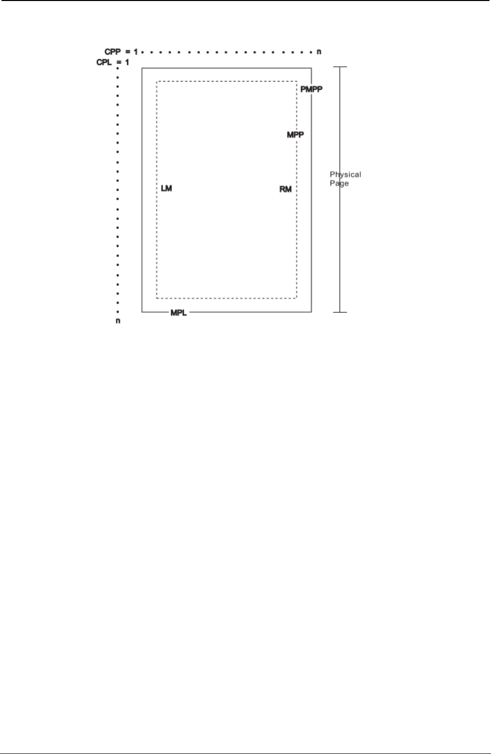
ProgrammerManual PTX‐S828
Preface16260071‐001A
relationships of some of these parameters.
Figure 1 Page Presentation
CPP Current Print Position (LM = CPP = RM).
CPL Current Print Line
MPP Maximum Print Position (in characters at current CPI)
PMPP Physical Maximum Print Position. The largest number of characters that can be placed on one line
of the surface (the largest value that MPP can assume).
LM Left Margin
RM Right Margin
MPL Maximum Page Length (in lines at current LPI)
Notes:
1. The host should set the limits of the presentation surface if the default or previous values are not
acceptable.
2. The operator should align the physical paper so that it matches the logical presentation surface.
Also created with this surface is a pair of numbers (CPL and CPP) which specify the line number and
column number where the next graphic will be printed. These internal values are the logical position on the
presentation surface.
The variable parameters have default values which are established when the printer is initialized. The
standard power-on defaults are:
MPP (width) Operator panel setting
MPL (depth) Operator panel setting
CPI Operator panel setting
LPI Operator panel setting
LM 0 inches (Column 1)
RM Equal to MPP
HT Horizontal tabs are set at each 8th column, starting with column 9 (9, 17, 25, 33, and so on.)
VT Vertical tabs are all cleared

ProgrammerManual PTX‐S828
Chapter1EPSON/IBMCommands17260071‐001A
Chapter 1. EPSON/IBM Commands
The following printer commands are supported by this printer according to the IBM Proprinter XLIII-XLIII
AGM, IBM 2381+ and EPSON FX Series.
Print and Line Feed Execution
CR
Prints all received data and the column counter is set to the left margin (IBM/EPSON).
ASCII Code CR
Hexadecimal Value X'0D'
Decimal Value 13
This code is a terminator code; when received, it causes any data in the buffer to be printed out. The print
head then moves logically to the left margin position. The column counter is set to the left margin value
and a line feed is inserted automatically after the carriage return (see the automatic carriage return
function in the printer setup). The code cancels the double width printing set by the SO or ESC SO
command.
ESC ]
Sets a reverse line feed. (IBM)
ASCII Code ESC ]
Hexadecimal Value X'1B' X'5D'
Decimal Value 27 93
This is a terminator code; it therefore causes the current contents of the print buffer to be printed before
advancing the paper by one line at the current vertical spacing. If no data precedes the LF code, or if the
preceding data consists of spaces, the code only causes a line feed.
When the line counter reaches the last line of the form (defined by the software or the function menu), the
LF code causes a skip to the first line of the next form. This code cancels the double width printing set by
the SO code. In IBM mode, the column counter is set to the first column if the automatic carriage return is
selected. In EPSON mode, the column is always set to the first column.
ESC 5
Sets an automatic line feed after a carriage return. (IBM)
ASCII Code ESC 5 n
Hexadecimal Value X'1B' X'35' n
Decimal Value 27 53 n
If n is equal to 1, this command sets an automatic line feed on receiving of a CR code. If n is equal to 0,
this command cancels the automatic line feed.
n Automatic line feed
0 Disabled
1 Enabled

ProgrammerManual PTX‐S828
Chapter1EPSON/IBMCommands18260071‐001A
ESC J
Advances paper n/216 inch. (EPSON)
ASCII Code ESC J n
Hexadecimal Value X'1B' X'4A' n
Decimal Value 27 74 n
Range 1 = n = 255
This is a terminator code; it causes the current contents of the print buffer to be printed before performing
a single line feed of n/216 of an inch. This command is cancelled after the line feed has been
performed. The printing restarts after a line feed from the column at which the command was sent.
ESC j
Feed paper n/216 in reverse direction (EPSON)
ASCII Code ESC J n
Hexadecimal Value X'1B' X'6A' n
Decimal Value 27 106 n
Range 1 = n = 255
This is a terminator code; it causes the current contents of the print buffer to be printed. Then the paper is
moved backward of n/216 of an inch. The printing restarts from the column at which the command was sent.
LF
Line Feed (IBM/EPSON).
ASCII Code LF
Hexadecimal Value X'0A'
Decimal Value 10
This is a terminator code; it causes the current contents of the print buffer to be printed before advancing
the paper by one line at the current vertical spacing. If no data precedes the LF code, or if the preceding
data consists of spaces, the code only causes a line feed.
When the line counter reaches the last line of the form (defined by software or function menu), the LF
code causes a skip to the first line of the next form. This code cancels the double width printing set by the
SO code. In IBM mode, the column counter is set to the first column if the automatic carriage return is
selected. In EPSON mode, the column is always set to the first column.
Format Control
ESC $
Sets the absolute printing position. (EPSON)
ASCII Code ESC & n1 n2
Hexadecimal Value X'1B' X'24' n1 n2
Decimal Value 27 36 n1 n2
Range 0 = n1 n2 = 255

ProgrammerManual PTX‐S828
Chapter1EPSON/IBMCommands19260071‐001A
This command specifies the distance from the left margin to where you want to print subsequent
characters. The distance is in number of dots and must be calculated using the following formula:
Margin distance = n1 +(n2 x 256) where n2 is the integer result of the number of dots divided by 256 and
n1 is the remainder. 1 dot = 1/60 inch. If the selected position is outside the current right margin, the
sequence is ignored.
ESC[ \
Sets vertical units. (IBM)
ASCII Code ESC [ \ m1 m2 t1 ... t4
Hexadecimal Value X'1B' X'5B' X'5C' m1 m2 t1 ... t4
Decimal Value 27 91 92 m1 m2 t1 ... t4
Range m1 =4
m2 =0
0 = t1 = 255
0 = t2 = 255
t3 =0
t4 = 180 or 216
This command changes the base units for the graphics line spacing commands (ESC J, ESC 3). The
default is 1/216 or 1/180 inch.
ESC /
Selects the Vertical Format Unit (VFU) channel. (EPSON)
ASCII Code ESC / m
Hexadecimal Value X'1B' X'2F' m
Decimal Value 27 47 m
Range 0 = m = 7
This sequence selects the VFU channel that you want to use. Eight different channels are available. The
m parameter represents the channel you want to select.
ESC \
Sets the relative dot position. (EPSON)
ASCII Code ESC \ n1 n2
Hexadecimal Value X'1B' X'5C' n1 n2
Decimal Value 27 92 n1 n2
Range 0 = n1, n2 = 255
This command specifies the distance between the current print head position and the position where you
want to print subsequent characters (relative position). The distance is a number of dots and must be
calculated using the following formula:
Current position distance = n1 +(n2 x 256)
where n2 is the integer result of the number of dots divided by 256 and the n1 is the remainder. The unit of
dots is 1/120 inch for Draft or 1/180 inch for Letter Quality printing. If the distance is negative (Most
Significant Bit of m2 equal to 1), the print head is moved to the left of the current position by the number of
dots equal to the complement on two of n1 +(n2 x 256).

ProgrammerManual PTX‐S828
Chapter1EPSON/IBMCommands20260071‐001A
ESC 0
Sets vertical spacing to 1/8 inch (IBM/EPSON).
ASCII Code ESC 0
Hexadecimal Value X'1B' X'30'
Decimal Value 27 48
This code causes vertical spacing to be set to 1/8 inch.
ESC 1
Sets vertical spacing to 7/72 inch. (IBM)
ASCII Code ESC 1
Hexadecimal Value X'1B' X'31'
Decimal Value 27 49
This command causes vertical spacing to be set to 7/72 inch.
ESC +
Sets n/360-inch line spacing. (IBM)
ASCII Code ESC + n
Hexadecimal Value X'1B' X'2B' n
Decimal Value 27 43 n
Range 0 = n = 255
This command sets the line spacing to n/360 inch. If the line spacing is changed, it does not affect
previous settings for vertical tabs or page length.
ESC 2
Sets the vertical spacing to 1/6 inch. (EPSON)
ASCII Code ESC 2
Hexadecimal Value X'1B' X'32'
Decimal Value 27 50
This command causes the vertical spacing to be set to 1/6 inch.
ESC 2
Enables the vertical spacing set by ESC A. (IBM)
ASCII Code ESC 2
Hexadecimal Value X'1B' X'32'
Decimal Value 27 50
This command enables the vertical spacing sets by ESC A.

ProgrammerManual PTX‐S828
Chapter1EPSON/IBMCommands21260071‐001A
ESC 3
Sets vertical spacing to n/180 inch. (IBM , EPSON)
ASCII Code ESC 3 n
Hexadecimal Value X'1B' X'33' n
Decimal Value 27 51 n
Range 1 = n = 255
This sequence sets the vertical spacing to n/180 inch. It is ignored if n is equal to 0.
ESC 3
Sets vertical spacing to n/216 inch. (IBM/EPSON)
ASCII Code ESC 3 n
Hexadecimal Value 1B 33 n
Decimal Value X'27' X'51' n
Range 0 = n = 255
This sequence sets the vertical spacing to n/216 inch.
ESC 4
Sets the current position as top of form (first printable line). (IBM)
ASCII Code ESC 4
Hexadecimal Value X'1B' X'34'
Decimal Value 27 52
This sequence sets the first line of the fanfold paper as the current paper position of the form.
ESC A
Sets variable vertical spacing to n/72 inch. (EPSON)
ASCII Code ESC A n
Hexadecimal Value X'1B' X'41' n
Decimal Value 27 65 n
This command changes the default vertical spacing to n/72 inch. The new vertical spacing value is
immediately activated.
ESC A
Sets variable vertical spacing to n/72 inch. (IBM)
ASCII Code ESC A n
Hexadecimal Value X'1B' X'41' n
Decimal Value 27 65 n
This command changes the default vertical spacing to n/72 inch. The vertical spacing value is stored and
activated only after the ESC 2 code is received.

ProgrammerManual PTX‐S828
Chapter1EPSON/IBMCommands22260071‐001A
ESC B
Sets vertical tab stops (IBM/EPSON).
ASCII Code ESC B n1 ... nx 0
Hexadecimal Value X'1B' X'42' n1 ... nx 0
Decimal Value 27 66 n1 ... nx 0
Range 1 = n = 255
In EPSON mode, it sets the vertical tab stops in the 0 Vertical Format Unit (VFU) channel. This code sets
up to 16 vertical tab stops at the line specified by n1, n2 and so on in the 0 VFU channel. The tab stops
are memorized as physical positions. In IBM mode, this code sets up to 64 vertical tab stops at the line
number specified by n1, n2 and so on in the 0 VFU channel. The tab stops are retained as logical
positions.
ESC B NUL
Resets vertical tab stops (IBM/EPSON).
ASCII Code ESC B NUL
Hexadecimal Value X'1B' X'42' 00
Decimal Value 27 66 00
This command resets the vertical tab stops in the 0 Vertical Format Unit (VFU) channel.
ESC b
Sets vertical tab stops in one of the 8 Vertical Format Unit channels available. (EPSON)
ASCII Code ESC b mn1 ... nx 0
Hexadecimal Value X'1B' X'62' mn1 ... nx 00
Decimal Value 27 98 mn1 ... nx 0
Range 0 = m = 7
1 = n1 ... nx = 255
This sequence sets vertical tabulations in the VFU channel specified by the parameter m.
The VFU channel can be imagined as a blank page where you can set up to 16 vertical tabulations in
order to format your page as you like. 8 channels are available and in each of them you can create a
sample page that you can recall later. n1 to n16 specify the lines at which vertical tabulations must be set.
The values of n must be in ascending order. If you change the vertical spacing, the vertical tabulations set
are not cancelled and they maintain their physical position on the page.
The vertical tabulations set in the channel specified by the m parameter are executed by the VT code
when the specific channel is selected by the ESC / command, this code is executed as a line feed.

ProgrammerManual PTX‐S828
Chapter1EPSON/IBMCommands23260071‐001A
ESC b NUL
Resets vertical tab stops in one of the 8 Vertical Format Unit channels available. (EPSON)
ASCII Code ESC b NUL
Hexadecimal Value X'1B' X'62' X'00'
Decimal Value 27 98 0
This command resets the vertical tab stops in one of the 8 Vertical Format Unit channels available.
ESC C 0 n
Sets form length to n inches (IBM/EPSON).
ASCII Code ESC C 0 n
Hexadecimal Value X'1B' X'43' X'00' n
Decimal Value 27 67 0 n
Range 1 = n = 24
This command sets the form length to the number of inches specified by n. The current position of the
paper is assumed as the top-of-form.
ESC C n
Sets form length to n lines (IBM/EPSON).
ASCII Code ESC C n
Hexadecimal Value X'1B' X'43' n
Decimal Value 27 67 n
Range 1 = n = 255
This command sets the form length to the number of lines specified by n at the current vertical spacing.
The current position of the paper is assumed as top-of-form.
ESC D
Sets horizontal tab stops (IBM/EPSON).
ASCII Code ESC D n1 n2 ... nx 0
Hexadecimal Value X'1B' X'44' n1 n2 ... nx 00
Decimal Value 27 68 n1 n2 ... nx 0
Range 1 = n = 255
This sequence sets up to 28 (IBM mode) or 32 (EPSON mode) horizontal tab stops after canceling the
current setting. The n1 to nx parameters specify the number of columns at which horizontal tab stops are
required and must be entered in the sequence in ascending numerical order. Any value outside this range
is ignored. In IBM mode, the tab stop position is retained as a logical position in the page so that it is
affected by changing the horizontal spacing. The columns are numbered 1 through 136. In EPSON mode,
the tab stop position set by ESC D is retained as the physical position on the page and therefore it is not
affected by changing the horizontal spacing. The physical position of the tab stop depends on the
horizontal spacing in operation when ESC D is used. The ESC D 0 cancels all active tab stops.

ProgrammerManual PTX‐S828
Chapter1EPSON/IBMCommands24260071‐001A
ESC d
Spaces forwards relative dot position. (IBM)
ASCII Code ESC d n1 n2
Hexadecimal Value X'1B' X'64' n1 n2
Decimal Value 27 100 n1 n2
Range 0 = n1 n2 = 255
This command moves the print carriage (n1 +(n2*256))/120 of an inch displacement on the right of its
current dot position. If the selected position is outside the current right margin, it is forced to the last
column.
ESC e
Spaces backward relative dot position. (IBM)
ASCII Code ESC e n1 n2
Hexadecimal Value X'1B' X'65' n1 n2
Decimal Value 27 101 n1 n2
Range 0 = n1 n2 = 255
This command moves the print carriage (n1 +(n2*256))/120 of an inch displacement on the left of its
current dot position. If the selected position is outside the current left margin, it is forced to the first
column.
ESC I
Sets left margin. (EPSON)
ASCII Code ESC I n
Hexadecimal Value X'1B' X'6C' n
Decimal Value 27 108 n
Range 0 = n = 255
This code sets the left margin at the current horizontal spacing. It must be sent at the beginning of the
line. The n parameter specifies the number of columns. For each type of horizontal spacing there is a
different range of possible values, as shown in the following table:
Character Width Horizontal Spacing Range of columns
Double Width 5 cpi 0 = n = 67
6 cpi 0 = n = 80
7.5 cpi 0 = n = 100
8.5 cpi 0 = n = 114
10 cpi 0 = n = 134

ProgrammerManual PTX‐S828
Chapter1EPSON/IBMCommands25260071‐001A
Character Width Horizontal Spacing Range of columns
Normal 10 cpi 0 = n = 134
12 cpi 0 = n = 160
15 cpi 0 = n = 201
17 cpi 0 = n = 229
20 cpi 0 = n = 255
Any value outside the accepted range is ignored and the previous setting remains in effect. The left margin
must be smaller than the right margin. The physical position set for the left margin does not change if the
horizontal spacing is modified. This command overrides the menu setting.
ESC N
Sets the skipover perforation to n lines (IBM/EPSON).
ASCII Code ESC N n
Hexadecimal Value X'1B' X'4E' n
Decimal Value 27 78 n
Range 1 = n = 127 (EPSON mode)
1 = n = 255 (IBM mode)
The skipover perforation is the sum of the top and bottom margin values at the selected vertical spacing.
The n parameter must be less than the current form length. The skipover is retained as the physical
position on the page. It is cancelled by ESC O or changing the form length.
The skipover value, when accepted, sets the top and bottom margins according to the operator panel
setting (see the Administrators Manual):
If the top margin set using the operator panel is greater than the skipover value, the following value of the
margins is set:
Top margin = skipover value
Bottom margin = 0
If the top margin set using the operator panel is less than or equal to the skipover value, then the following
value of the margins is set:
Top margin = operator panel value
Bottom margin = the difference between skipover value and top margin value
If the sum of the top and bottom margins values set using the operator panel is less than the skipover
value, the following values for the margins is set:
Top margin = operator panel value
Bottom margin = the difference between skipover value and top margin value
Changing the vertical spacing does not affect the skipover distance. This can be changed by another ESC
N command or can be reset by the ESC O command, which resets the skipover value to 0. The skipover
perforation is performed when the end of the page is reached with a LF, VT or FF code and not with the
ESC J or ESC C command. The skipover perforation is cancelled and must be reset.

ProgrammerManual PTX‐S828
Chapter1EPSON/IBMCommands26260071‐001A
ESC O
Disables the skipover perforation (IBM/EPSON).
ASCII Code ESC O
Hexadecimal Value X'1B' X'4F'
Decimal Value 27 79
This sequence sets the number of lines of the skipover perforation to the value 0. Any skip perforation set
by ESC N is cancelled.
ESC Q
Sets the right margin. (EPSON)
ASCII Code ESC Q n
Hexadecimal Value X'1B' X'51' n
Decimal Value 27 81 n
Range 1 = n = 225
This code sets the line length at the current horizontal spacing. It must be sent at the beginning of the line.
The n parameter specifies the number of columns and for each type of horizontal spacing there is a range
of values, as shown in the following table:
Character Width Horizontal Spacing Range of columns
Double Width 5 cpi 1 <= n <= 67
6 cpi 1 <= n <= 81
7.5 cpi 1 <= n <= 101
8.5 cpi 1 <= n <= 111
10 cpi 1 <= n <= 135
Normal 10 cpi 1 <= n <= 135
12 cpi 1 <= n <= 162
15 cpi 1 <= n <= 203
17 cpi 1 <= n <= 232
20 cpi 1 <= n <= 255
Any value outside the accepted range is ignored and the previous setting remains in effect. The right
margin must be greater than the left margin. The physical position set for the right margin does not change
if the horizontal spacing is modified.
ESC R
Sets horizontal and vertical tab stops to default values. (IBM)
ASCII Code ESC R
Hexadecimal Value X'1B' X'52'
Decimal Value 27 82
This command sets horizontal tab stops every eight columns starting from column 9 and cancels all
vertical tab stops.

ProgrammerManual PTX‐S828
Chapter1EPSON/IBMCommands27260071‐001A
ESC SP
Sets intercharacter space. (EPSON)
ASCII Code ESC SP™ n
Hexadecimal Value X'1B' X'20' n
Decimal Value 27 32 n
Range 0 = n = 225
This command sets the intercharacter space to n/120 inch in Draft printing and n/180 inch in Quality
printing.
ESC X
Sets left and right margins. (IBM)
ASCII Code ESC X n1 n2
Hexadecimal Value X'1B' X'58' n1 n2
Decimal Value 27 88 n1 n2
Range 0 = n = 134 (left margin)
2 = n = 136 (right margin)
This command sets the left and right margins at the same time. The n1 and n2 parameters indicate
respectively the number of columns for the left and right margins at the current spacing. These margins
are retained in terms of absolute displacement from the physical left edge of the page. Use a CR
immediately after ESC X n to establish the print head position relative to the new margin setting.
If n1 is equal to 0, the current left margin of the page is used. If n2 is equal to 1, the current right margin of
the page is used. The left margin value must be less than the right margin value. The right margin value
must not exceed the physical right edge of the paper; otherwise the maximum acceptable value for the
right margin will be set.

ProgrammerManual PTX‐S828
Chapter1EPSON/IBMCommands28260071‐001A
FF
Advances paper to the top of the next page (IBM/EPSON).
ASCII Code FF
Hexadecimal Value X'0C'
Decimal Value 12
This code is a terminator code, when received, causes all data in the print buffer to be printed out. Then it
advances the paper to the first printable line of the next form. The line counter is set to the first line value
and the column counter is set to the left margin value. This code cancels the double width printing set by
SO code.
HT
Logically moves the print carriage to the next horizontal tab stop (IBM/EPSON).
ASCII Code HT
Hexadecimal Value X'09'
Decimal Value 9
This code logically moves the print carriage to the next horizontal tab stop as defined by ESC D. Up to 28
(IBM mode) or 32 (EPSON mode) horizontal tab stops can be set. The HT code is ignored if no tab stop is
set, the current print carriage position is moved past the last tab position, or the tab stop is on or beyond
the right margin. When the printer is powered on, the tab stops are set every eight columns (default).
In EPSON mode, the default tab stops are retained as logical positions in the page that are affected by
changing the horizontal spacing. The tab stop positions set by ESC D are retained as physical positions
on the page and are not affected by changing the horizontal spacing. When double width printing is
selected, the tab stop setting must take into account that each character occupies two columns. In IBM
mode, the tab stops, both the default and those set by ESC, are retained as logical positions in the page
that are affected by changing the horizontal spacing. The horizontal tab stops can be changed by the ESC
D command.
VT
Advances paper to the next vertical tab stop of the selected VFU channel (IBM/EPSON).
ASCII Code VT
Hexadecimal Value X'0B'
Decimal Value 11
This is a terminator code and when received causes the contents of the print buffer to be printed before
advancing the paper to the next vertical tab stop set by the ESC B or the ESC b commands.
This code is run normally if vertical tab stops follow the current print position. It runs like an FF code
(EPSON mode) or like a LF code (IBM mode), if the vertical tab stops follow the bottom of form position (
corresponding to the form length if the bottom of the form has not been set), or if the current position is
beyond the last vertical tab stop. It runs like an LF code if no vertical tab stops have been set by the ESC
B or ESC b commands.
In EPSON mode, the vertical tabulations are referred to the VHF channel selected by the ESC / m.Ifno
VFU channels have been selected, the printer assumes the default channel 0.
This command cancels the double width printing set by SO or ESC SO command.

ProgrammerManual PTX‐S828
Chapter1EPSON/IBMCommands29260071‐001A
Print Mode
DC2
Sets 10 cpi printing. (IBM)
ASCII Code DC2
Hexadecimal Value X'12'
Decimal Value 18
This is a terminator code. It causes all data present in the print buffer to be printed. This command is
accepted at any position within the line. The character that follows this command is printed at 10 cpi.
DC2
Cancels compressed printing. (EPSON)
ASCII Code DC2
Hexadecimal Value X'12'
Decimal Value 18
This is a terminator code. It causes all data present in the print buffer to be printed. This command is
accepted at any position within the line. The character that follows this command is printed as follows:
17 CPI . 10 CPI
20 CPI . 12 CPI
DC4
Cancels double width printing (IBM/EPSON).
ASCII Code DC4
Hexadecimal Value X'14'
Decimal Value 20
This code cancels the double width printing set by SO or ESC SO code. It has no effect if the ESC W or
ESC ! command is set to double width.
ESC -
Sets or cancels underlined printing (IBM/EPSON).
ASCII Code ESC - n
Hexadecimal Value X'1B' X'2D' n
Decimal Value 27 45 n
Enables or disables underlined printing. See the following table:
n Underlined Printing
1 enabled
0 disabled

ProgrammerManual PTX‐S828
Chapter1EPSON/IBMCommands30260071‐001A
ESC !
Sets printing style. (EPSON)
ASCII Code ESC ! n
Hexadecimal Value X'1B' X'21' n
Decimal Value 27 33 n
This command is used to select any valid combination of printing attributes. Each printing attribute is
selected by the nparameter, as specified in the following page:
n Attribute
0 10 cpi
1 12 cpi
2 Proportional
4 Compressed
8 Emphasized
16 Double Strike
32 Double Width
64 Italics
128 Underline
To print the desired combination of printing attributes, calculate the nparameter by adding up the values of
each attribute.
ESC(-
Sets score line. (EPSON)
ASCII Code ESC ( - n1 n2 md1 d2
Hexadecimal Value X'1B' X'28' X'2D' n1 n2 md1 d2
Decimal Value 27 40 45 n1 n2 md1 d2
Range n1 =3
n2 =0
m=1
1 = d1 = 3
d2 =0,1,2,5,6
This command enables or disables scoring of all characters and spaces following the command according
to the following parameters:
d1 Line
1 Underline
2 Strikethrough
3 Overscore

ProgrammerManual PTX‐S828
Chapter1EPSON/IBMCommands31260071‐001A
d2 Line
0 Cancel score line
1 Single continuous line
2 Double continuous line
5 Single broken line
6 Single broken line
Any combination of scoring may be used at the same time and are independent of each other. Graphics
characters are not scored.
ESC[-
Selects the score line. (IBM 2381 + only)
ASCII Code ESC [ - n1 n2 loc type
Hexadecimal Value X'1B' X'5B' X'2D' n1 n2 loc type
Decimal Value 27 91 45 n1 n2 loc type
Range n1 =2
n2 =0
This command selects several forms of overscore, underscore, and strikethrough.
To select loc: To select type:
loc Selection type Selection
1 Underscore 0 Cancles Line
2 Strikethrough 1 Single Line
3 Overscore 2 Double Line
255 Cancels all score selections
ESC :
Sets 12 CPI. (IBM)
ASCII Code ESC :
Hexadecimal Value X'1B' X'3A'
Decimal Value 27 58
This is a terminator code. It causes all data present in the print buffer to be printed. Subsequent data is
printed at 12 cpi. This command is accepted at any position within the line. The setting of another
horizontal spacing resets this command.
ESC <
Prints characters for one line from left to right. (IBM XLIII, EPSON)
ASCII Code ESC <
Hexadecimal Value X'1B' X'3C'
Decimal Value 27 60
This command causes the printing of one line from left to right.

ProgrammerManual PTX‐S828
Chapter1EPSON/IBMCommands32260071‐001A
ESC[@
Selects the printing type style. (IBM 2381 + only)
ASCII Code ESC [ @ 40m1 0m3 m4
Hexadecimal Value X'1B' X'5B' X'40' 04*00*m1 00*m3 m4
Decimal Value 27 91 64 40m1 0m3 m4
(*) These values are constants.
This command is used to modify the type style of the character and the number of line spacing. Use this
command for:
1. Italic printing
2. Single-high character
3. Double-high character
4. Single-wide character
5. Double-wide character
6. Single Line Feed
7. Double Line Feed
These selections may be combined, for example, italic print with double height or doublewide character
and double line feed.
See the following tables for m1, m3 and m4 selections:
m1 Selection m3 Selection m4 Selection
0 No Change 0 No Change 0 No Change
1 Start Italic Printing 1 Single-High Character 1 Single-Wide Character
2 Stop Italic Printing 2 Double-High Character 2 Double-Wide Character
4 Start Outline 4 Single Line Feed 4 Single Line Feed
8 Stop Outline 8 Double Line Feed 8 Double Line Feed
16 Start Shadow 16
32 Stop Shadow 32
ESC[@
Sets double high printing and double line feed. (IBM)
ASCII Code ESC [ @ lhm1 m2 m3 m4
Hexadecimal Value X'1B' X'5B' X'40' lhm1 m2 m3 m4
Decimal Value 27 91 64 lhm1 m2 m3 m4
l= normally 4, h= normally 0, m1 =0, m2 =0
This command sets height, width, and vertical spacing.
The land hparameters specify the number of mode bytes mx contained in the sequence.
The m3 and m4 parameters specify the printing characteristics.

ProgrammerManual PTX‐S828
Chapter1EPSON/IBMCommands33260071‐001A
The m3 parameter controls both line spacing and character height. It has two parts: a high-order half-byte
of m3 controls the line spacing and the low-order half-byte controls the character height.
m3 Character Height Line Spacing
0 No Change No Change
1 Standard character height Line feeds unchanged
2 Double character height Line feeds unchanged
16 Character height unchanged Normal line feeds
17 Standard character height Normal line feeds
18 Double character height Normal line feeds
32 Character height unchanged Double line feeds
33 Standard character height Double line feeds
34 Double character height Double line feeds
The m4 parameter specifies the character width. Only the low-order half-byte is significant in this mode
byte. The high-order half-byte is ignored.
m4 Character Width Line Spacing
0 No change Standard width character
1 Double width character No change
2 No change No change
ESC[d
Set the print quality. (IBM 2381 + only)
ASCII Code ESC [ d 10n
Hexadecimal Value X'1B' X'5B' X'64' 0100n
Decimal Value 27 91 100 10n
This command sets the print quality to draft or LQ print.
n Types
0 No Change
From 64 to 127 Draft
From 128 to 254 Letter Quality
255 Initialization on NVRAM values

ProgrammerManual PTX‐S828
Chapter1EPSON/IBMCommands34260071‐001A
ESC[I
Sets font and pitch of a character. (IBM 2381 + only)
ASCII Code ESC [ I 2 0 m n
Hexadecimal Value X'1B' X'5B' X'49' 02 00 m n
Decimal Value 27 91 73 2 0 m n
This command allows you to modify the character's font and style of pitch type.
The values 2 and 0 are constants. If font and pitch locks are active, this command is ignored. To select the
values for the variables m and n, which identify the pitch and the font type style to use, refer to the table
below.
1. Identify the type style (pitch and font) to use in the left column (pitch).
2. For the hexadecimal values of m and n, look across the row to the second column (Hex mn)
3. For the decimal values for m and n, look across the row to the third column (Decimal mn).
4. Substitute these values for m and n in the printer command syntax.
Pitch Hexadecimal Decimal Dec. Value
m n m n (m x 256 + n)
Courier
10 X'00' X'00B' 0 11 11
12 X'01' X'EB' 1 235 491
15 X'01' X'EC' 1 236 492
17 X'01' X'ED' 1 237 493
20 X'01' X'EE' 1 238 494
Pitch Hexadecimal Decimal Dec. Value
m n m n (m x 256 + n)
Gothic
10 X'00' X'24' 0 36 36
12 X'01' X'8F' 1 143 399
15 X'01' X'8E' 1 236 398
17 X'01' X'8D' 1 237 397
20 X'01' X'8C' 1 238 396

ProgrammerManual PTX‐S828
Chapter1EPSON/IBMCommands35260071‐001A
ESC _
Sets or cancels overscore printing. (IBM)
ASCII Code ESC _ n
Hexadecimal Value X'1B' X'5F' n
Decimal Value 27 95 n
Enables or disables overscore printing. See the following table:
n Overscore Printing
1 Enabled (all spaces and characters that follow are overscored)
0 Disabled
ESC 4
Sets italics printing mode. (EPSON)
ASCII Code ESC 4
Hexadecimal Value X'1B' X'34'
Decimal Value 27 52
Sets the style attribute of the font to italic. This command selects italic printing even if the italic character
table is not selected.
ESC 5
Cancels italics printing. (EPSON)
ASCII Code ESC 5
Hexadecimal Value X'1B' X'35'
Decimal Value 27 53
Sets the style attribute of the font to normal (cancels the italic style attribute previously selected with the
ESC 4 command).
ESC a
Sets Letter Quality justification printing. (EPSON)
ASCII Code ESC a n
Hexadecimal Value X'1B' X'61' n
Decimal Value 27 97 n
Range 0 = n = 3
Selects from four types of justification, as follows:
n Justification
0 Left
1 Centered
2 Right
3 Allows an uniform printing between the margins when the buffer is full.

ProgrammerManual PTX‐S828
Chapter1EPSON/IBMCommands36260071‐001A
ESC E
Sets emphasized printing (IBM/EPSON).
ASCII Code ESC E
Hexadecimal Value X'1B' X'45'
Decimal Value 27 69
This command starts emphasized printing. The print head strikes each dot twice to produce a darker,
bolder character. The second strike is offset horizontally.
ESC F
Cancels emphasized printing (IBM/EPSON).
ASCII Code SC F
Hexadecimal Value X'1B' X'46'
Decimal Value 27 70
This command ends emphasized printing. This escape sequence cancels emphasized printing that was
started by ESC E.
ESC G
Sets double strike printing (IBM/EPSON).
ASCII Code ESC G
Hexadecimal Value X'1B' X'47'
Decimal Value 27 71
This command starts double-strike printing. ESC G may be canceled by ESC H.
ESC g
Sets 15 CPI. (EPSON)
ASCII Code ESC g
Hexadecimal Value X'1B' X'67'
Decimal Value 27 103
Subsequent data is printed at 15 cpi. This command is accepted at any position within the line. If you
change the pitch during proportional mode (selected with the ESC p command), the change takes effect
when the printer exits proportional mode.
ESC H
Cancels double strike printing (IBM/EPSON).
ASCII Code ESC H
Hexadecimal Value X'1B' X'48'
Decimal Value 27 72
This command cancels double-strike printing set with the ESC G command.

ProgrammerManual PTX‐S828
Chapter1EPSON/IBMCommands37260071‐001A
ESC I
Selects printing type for resident and DLL characters. (IBM)
ASCII Code ESC I n
Hexadecimal Value X'1B' X'49' n
Decimal Value 27 73 n
This command selects the resident or the download font in Draft or LQ printing mode. It is ignored if you
select a font that has not been downloaded or has been overwritten. See the following table:
n Resident font n Download font
0 Draft 10 cpi 4 Draft 10 cpi
2 LQ10cpi 6 LQ10cpi
3 Proportional 7 Proportional
8 Draft 12 cpi 12 Draft 12 cpi
10 LQ 12 cpi 14 LQ 12 cpi
16 Draft 17 cpi 20 Draft 17 cpi
18 LQ 17 cpi 22 LQ 17 cpi
ESC M
Selects 10.5 point, 12 CPI. (EPSON)
ASCII Code ESC M
Hexadecimal Value X'1B' X'4D'
Decimal Value 27 77
This is a terminator code. It causes all data present in the print buffer to be printed. Subsequent data is
printed at 12 cpi, if you previously set the compressed spacing by sending the SI or ESC SI command. If
you select proportional printing, this command is stored.
ESC P
Selects 10.5 point, 10 cpi. (EPSON)
ASCII Code ESC P n
Hexadecimal Value X'1B' X'50' n
Decimal Value 27 80 n
This command selects 10.5 point, 10 cpi character printing. If you change the pitch during proportional
mode (selected with the ESC p command) the change takes effect when the printer exits proportional
mode.

ProgrammerManual PTX‐S828
Chapter1EPSON/IBMCommands38260071‐001A
ESC P
Sets or cancels proportional printing. (IBM)
ASCII Code ESC P n
Hexadecimal Value X'1B' X'50' n
Decimal Value 27 80 n
Range 1 = n = 255
This code is a terminator code. It causes all data in the print buffer to be printed. Then if the n parameter
is equal to 1, the subsequent data is printed in proportional mode. If the n parameter is equal to 0,
proportional mode is reset. If the any horizontal spacing command is sent to the printer when the
proportional printing is set, the command is stored and activated as soon as the proportional printing is
reset.
ESC p
Sets or cancels proportional printing. (EPSON)
ASCII Code ESC p n
Hexadecimal Value X'1B' X'70' n
Decimal Value 27 112 n
Range 1 = n = 255
This command selects the proportional or fixed spacing according to the following values:
n Proportional Printing
0 Returns to current fixed character pitch
1 Selects proportional character spacing
ESC S
Sets subscript or superscript printing (IBM/EPSON).
ASCII Code ESC S n
Hexadecimal Value X'1B' X'53' n
Decimal Value 27 83 n
Selects subscript or superscript printing. See the following table:
n Selection
0 Subscript Print enabled
1 Superscript Print enabled
Proportional printing of subscript or superscript characters is performed at 2/3 of the proportional character
width. Use the ESC T command to cancel subscript or superscript printing.
ESC SI
Sets 17/20 cpi (IBM).
ASCII Code SI or ESC SI
Hexadecimal Value X'0F' or X'1B' X'0F'
Decimal Value 15 or 27 15

ProgrammerManual PTX‐S828
Chapter1EPSON/IBMCommands39260071‐001A
This command sets horizontal spacing to 17 or 20 cpi. DC2 code cancels this mode and returns spacing to
10 characters per inch.
ESC SI
Sets compressed printing (EPSON).
ASCII Code SI or ESC SI
Hexadecimal Value X'0F' or X'1B' X'0F'
Decimal Value 15 or 27 15
This command is accepted at any position within the line. The setting of this command depends on the
horizontal spacing previously set:
10 CPI . 17 CPI
12 CPI . 20 CPI
The DC2 code cancels the compressed printing.
ESC SO
Sets double width printing (one line) (IBM/EPSON).
ASCII Code SO or ESC S0
Hexadecimal Value X'0E' or X'1B' X'0E'
Decimal Value 14 or 27 14
This code causes subsequent data in the same line to be printed as double width characters. It is
canceled by the CR, LF, VT, FF and DC4 codes or when the buffer is full.
ESC s
Sets and resets Quiet printing. (EPSON)
ASCII Code ESC s n
Hexadecimal Value X'1B' X'73' n
Decimal Value 27 115 n
This command controls print speed as follows:
n Selection
0 Normal speed printing
1 Quiet speed printing
ESC T
Cancels subscript or superscript printing (IBM/EPSON).
ASCII Code ESC T
Hexadecimal Value X'1B' X'54'
Decimal Value 27 84
This command cancels subscript or superscript printing started with the ESC S command.

ProgrammerManual PTX‐S828
Chapter1EPSON/IBMCommands40260071‐001A
ESC W
Sets or cancels double width printing (IBM/EPSON).
ASCII Code ESC W n
Hexadecimal Value X'1B' X'57' n
Decimal Value 27 87 n
Range 0 = n = 1
Enables or disables double width printing. See the following table:
n Selection
0 Double Width Printing disabled
1 Double Width Printing enabled
ESC w
Sets or cancels double height printing. (EPSON)
ASCII Code ESC w n
Hexadecimal Value X'1B' X'77' n
Decimal Value 27 119 n
Range 0 = n = 255
Enables or disables double-height printing of all characters. The first line of a page is not doubled if the
ESC w command is sent on the first line; all following lines are printed at double-height. Double-height
printing overrides superscript, subscript, and condensed. Superscript, subscript, and condensed print
resumes when double-height printing is canceled. See the following table:
n Selection
0 Double Height Printing disabled
1 Double Height Printing enabled
ESC x
Selects Letter Quality or Draft. (EPSON)
ASCII Code ESC x n
Hexadecimal Value X'1B' X'78' n
Decimal Value 27 120 n
This command selects either LQ or Draft printing according to the following values:
n Selection
0 Draft printing
1 Letter Quality printing
If you select proportional spacing with the ESC p command during Draft printing, the printer prints an LQ
font instead. When you cancel proportional spacing with the ESC p command, the printer returns to Draft
printing.

ProgrammerManual PTX‐S828
Chapter1EPSON/IBMCommands41260071‐001A
SI
Sets compressed printing. (IBM)
ASCII Code SI
Hexadecimal Value X'0F'
Decimal Value 15
This command sets horizontal spacing to 17 or 20 cpi. DC2 code cancels this mode and returns spacing to
10 characters per inch.
SI
Sets compressed printing. (EPSON)
ASCII Code SI
Hexadecimal Value X'0F'
Decimal Value 15
This command is accepted at any position within the line. DC2 code cancels compressed printing. The
setting of this command depends on the horizontal spacing previously set
10 CPI . 17 CPI
12 CPI . 20 CPI
DC2 code cancels compressed printing.
SO
Sets double width printing (one line) (IBM/EPSON).
ASCII Code SO
Hexadecimal Value X'0E'
Decimal Value 14
This code causes subsequent data in the same line to be printed as double width characters. It is
cancelled by the CR, LF, VT, FF and DC4 codes or when the buffer is full.

ProgrammerManual PTX‐S828
Chapter1EPSON/IBMCommands42260071‐001A
Character Set
ESC [ T
Selects a Code page (IBM).
ASCII Code ESC [ T 4000HcLc
Hexadecimal Value X'1B' X'5B' X'54' 04000000HcLc
Decimal Value 7 91 84 4000HcLc
This sequence allows you to change the current code page. If an unavailable code page is specified, this
command is ignored. The digits 04000000(hexadecimal) and 4000(decimal) are constant. To
calculate Hc Lc for a code page that is not shown: If your code page has an alphabetic character, such as
437G, add 10,000 to the code page number, then divide by 256.
The whole number result is the Hc value
The remainder is the Lc value.
Hc Lc Hc Lc Hc Lc Hc Lc
1 181 CP437 3 96 CP864 33 143 8859/1 4 229 CP1253
3 122 CP437G 3 97 CP865 33 144 8859/2 4 230 CP1254
33 129 CP437 Slavic 3 98 CP866 33 145 8859/3 4 231 CP1255
33 82 CP850 3 99 CP867 33 146 8859/4 4 232 CP1256
3 83 CP851 3 108 CP876 33 147 8859/5 4 233 CP1257
3 84 CP852 3 109 CP877 33 148 8859/6 33 130 FARSI 1
3 85 CP853 4 74 CP1098 33 149 8859/7 33 131 FARSI 2
3 87 CP855 33 123 96 GREEK 33 150 8859/8
3 89 CP857 33 124 GOST 33 151 8859/9
3 90 CP858 33 125 TASS 3 155 8859/15
3 92 CP860 33 126 MAZOWIA 4 226 CP1250
3 94 CP862 33 128 UKRANIAN 4 227 CP1251
3 95 CP863 33 138 KOI8-U 4 228 CP1252
ESC \
Prints characters from all characters table. (IBM)
ASCII Code ESC \ n1 n2
Hexadecimal Value X'1B' X'5C' n1 n2
Decimal Value 27 92 n1 n2
Range 0 = n1 = 255
0 = n2 = 255
This command prints the next n1 + n2 x 256 characters from the table of all printable characters.
The total number of characters that will be printed from the table of all printable characters is equal to n1 +
(n2 x 256). For example, to print 300 characters from the table of all printable characters: n1 = 44, n2 =1.
The control codes are not recognized as long as this sequence is active. The space character is printed as
an unassigned character.

ProgrammerManual PTX‐S828
Chapter1EPSON/IBMCommands43260071‐001A
ESC ^
Prints a single character from the all characters table. (IBM)
ASCII Code ESC ^ n
Hexadecimal Value X'1B' X'5E' n
Decimal Value 27 94 n
Range 0 = n = 255
This command prints the next character from the all characters table. This sequence prints only one
character from the all character table.
ESC 6
Selects the Character Set 2 (EPSON, IBM).
ASCII Code ESC 6
Hexadecimal Value X'1B' X'36'
Decimal Value 27 54
This command selects the character set 2.
ESC 7
Selects the Character Set 1 (IBM).
ASCII Code ESC 7
Hexadecimal Value X'1B' X'37'
Decimal Value 27 55
This command selects the character set 1.
ESC k
Selects the NLQ fonts. (EPSON)
ASCII Code ESC k n
Hexadecimal Value X'1B' X'6B' n
Decimal Value 27 107 n
Selects one of the available fonts in Letter Quality. If Draft mode is selected when this command is sent,
the new LQ font is selected when the printer returns to LQ printing.
n Types
0 Courier
2 Gothic
ESC R
Selects Nation character set. (EPSON)
ASCII Code ESC R n
Hexadecimal Value X'1B' X'52' n
Decimal Value 27 82 n
Range 0 = n = 13

ProgrammerManual PTX‐S828
Chapter1EPSON/IBMCommands44260071‐001A
This code causes the national character set to be selected according to the parameter n. See the following
table:
n National Character Sets n National Character Sets n National Character Sets
0 USA 5 Sweden 10 Denmark-II
1 France 6 Italy 11 Spain-II
2 Germany 7 Spain-I 12 Latin America
3 United Kingdom 8 Japan
4 Denmark-I 9 Norway
ESC t
Selects characters table. (EPSON)
ASCII Code ESC t n
Hexadecimal Value X'1B' X'74' n
Decimal Value 27 116 n
Range 0 = n = 3
Selects the upper half (from 128 to 255) from the character table.
n Character Tables
0 Standard Italic Character Set
1 ASCII Character Set
2 Remaps DLL Character Set from position 0-127 to 128-255
Download Character
ESC %
Selects user-defined character set. (EPSON)
ASCII Code ESC & n
Hexadecimal Value X'1B' X'25' n
Decimal Value 27 37 n
This command switches between normal (resident) and user-defined (downloaded) characters:
n Selection
1 Selects the use of downloaded character set in RAM
0 Selects the use of resident character set in ROM
ESC &
Defines user-defined characters. (EPSON)
ASCII Code ESC & NUL n m [ a d1 ... d11 ]
Hexadecimal Value X'1B' X'26' 00 n m [a d1 ... d11 ]
Decimal Value 27 38 00 nm a [ d1 ... d11 ]
Range 0 <= n <= 255
0 <= m <= 255
n<= m
0 <=a <= 255
0 <=d <= 255
ProgrammerManual PTX‐S828
Chapter1EPSON/IBMCommands45260071‐001A
The data within brackets above is repeated for each character you define.
The parameters in the command have the following meaning:
n and m The n and m parameters are two decimal numbers that define the first and the last
characters to be replaced in the character set in use.
a It sets parameters for characters to be user-defined.
d1 ...d11 They are the character data that is printed.
The format of the attribute byte “a” is the following:
You can define characters 11-dots wide by 8-dots high. You must specify whether to define the upper or
lower 8 dots of the 9 dots available.
You can also specify the columns not printed on the left and right of the characters during proportional
spacing. Set both these parameters with the a parameter, as described in the following table:
Attribute byte table
Beginning Column Ending Column Upper/Lower 8 pins
Column
Number
Value Column
Number
Value Pin group Value
0 0 0 0 Upper 8 pins 128
1 16 1 1 Lower 8 pins 0
2 32 2 2
3 48 3 3
4 64 4 4
5 80 5 5
6 96 6 6
7 128 7 7
8 8
9 9
10 10
11 11
Add up the values for all three setting; the total will be the a value.
ESC :
Copies characters from ROM to RAM. (EPSON)
ASCII Code ESC : NULn0
Hexadecimal Value X'1B' X'3A' 00n00
Decimal Value 27 58 n0
This code copies the draft character generator in ROM into RAM area dedicated to the user-defined
characters. Also Courier or Gothic character generator font from ROM is copied to RAM memory according
to the following values of n parameter:
n Selection
0 Courier
1 Gothic
ESC =
Defines downloaded characters. (IBM)
ASCII Code ESC = n m id p [a1 a2 d1 … d 11 ]
Hexadecimal Value 1B 3D n m id p [a1 a2 d1 … d 11 ]
Decimal Value 27 61 n m id p [a1 a2 d1 … d 11 ]

ProgrammerManual PTX‐S828
Chapter1EPSON/IBMCommands46260071‐001A
This sequence allows to design and then down-line load special characters not present in the character set
in use. Whenever you would like to start the DLL setting procedure, it should be better to copy the character
generator in ROM into RAM by sending the ESC = {0} {0} sequence that causes the DLL to be reset. Up to
256 characters can be defined using the DLL function.
The parameters in the command line have the following meaning:
n and m Indicate how many characters you should down-line load. n and m are calculated as follows:
{number of characters x 13}+2 = {total}
If {total} is less than {256}
{n} = {t}
{m} = {0}
If {total} is greater than {256}
{n} = {remainder of {t} divided by 256}
{m} = {integer result of {t} divided by 256}
id Indicates the printer model. In this case it is fixed to {20}.
Each DLL character is described using the following parameters:
p This is the decimal code of the first character of the character set in use that should be
replaced by the DLL character.
a1 This is the first attribute byte and it has the following meaning:
Bit 7: {0} indicates that the character is not a true descender.
{1} indicates that the character is a true descender.
This bit is ignored if bit 0 or bit 1 is set to 1.
Bit 6 to 2 Ignored
Bit 1, 0 Character description:
{00} no 12-high expansion. The bit 7 is valid.
{01} line drawing character. The dots in row 8 are extended
downward to rows 9, 10, 11 and 12. The bit 7 is ignored. It is
advisable to use this mode to create characters that should
replace 179 to 223 code characters.
{11} shading characters. The dots in row 1, 2, 3 and 4 are
repeated as rows 9, 10, 11 and 12. The Quality printing is
ignored. It is advisable to use this mode to create characters
that should replace 176 to 178 code characters.
a2 This is the second attribute byte. It specifies the proportional printing information. If
you do not wish to define a proportional character, set the bit 6 – 0 to {0}. When you
use the proportional printing for a DLL character with bit 6 – 0 set to {0}, the databytes
of the character will be printed.
Bit 7: Ignored
Bit 6, 5, 4 Interpreted as binary number. These bits specify the number
of leading bytes that should be ignored. This number is the
offset. Up to 7 bytes can be ignored. The counts begins with
byte 1.
Bit 3 to 0 Interpreted as binary number. These bits specify the number
of dots-columns that should be printed. Each character must
be followed by a blank byte that is not included in the count
of the character width. Character widths greater than 11 are
treated as 11.

ProgrammerManual PTX‐S828
Chapter1EPSON/IBMCommands47260071‐001A
Bit-Image
ESC *
Sets dot graphics printing. (EPSON)
ASCII Code ESC * m n1 n2 p1 p2 ... px
Hexadecimal Value X'1B' X'2A' m n1 n2 p1 p2 ... px
Decimal Value 27 42 m n1 n2 p1 p2 ... px
Range m = 0,1,2,3,4,5,6,7;
0 < n1 < 255;
0 < n2 < 31
This command prints dot-graphics in 8-dot columns, depending on the following parameters: number of dot
columns = (n1 + (n2 x 256))
m Specifies the dot density.
n1, n2 specify the total number of columns of graphics data according to the formula:
The following table shows the 8-dot graphics mode:
m OPTION Horizontal Density (dpi) Alternate Code
0 Normal density 60 ESC K
1 Dual density 120 ESC L
2 Double speed, Double density 120 (virtual) ESC Y
3 Quadruple-density 240 (virtual) ESC Z
4 CTR Graphics I 80
5 Plotter Graphics 72
6 CTR Graphics II 90
7 Double Density Plotter Graphics 144
ESC ?
Reassigns dot graphics mode. (EPSON)
ASCII Code ESC ? nm
Hexadecimal Value X'1B' X'3F' nm
Decimal Value 27 63 nm
Reassigns one of the dot graphics mode (described in the command ESC *) to one of the following
commands: ESC K, ESC L, ESC Y and ESC Z. The nparameter specifies a character (K, L, Y, or Z)
which is reassigned to specific mode m= 0,1,2,3.
m n m n
0 (K): ESC K graphic command 2 (Y): ESC Y graphic command
1 (L): ESC L graphic command 3 (Z): ESC Z graphic command
ESC K
Normal density dot graphics printing (60 dpi) (IBM/EPSON).
ASCII Code ESC K n1 n2 p1 p2 ... px
Hexadecimal Value X'1B' X'4B' n1 n2 p1 p2 ... px
Decimal Value 27 75 n1 n2 p1 p2 ... px
Range 0 = n1 = 255

ProgrammerManual PTX‐S828
Chapter1EPSON/IBMCommands48260071‐001A
0 = n2 = 31
0 = p= 255
Terminator code. This command prints dot graphics at 60 horizontal dots per inch (dpi) by 180 vertical dpi.
The parameter values are calculated as follows:
n1 Remainder of the number of columns divided by 256.
n2 Integer result of the previous division.
p1 Sum of the values corresponding to the dots that should be printed in the first column of the
graphics pattern.
p2 Sum of the values corresponding to the dots that should be printed in the second column of the
graphics pattern.
px Sum of the values corresponding to the dots that should be printed in the last column of the
graphics pattern.
ESC L
Double density dot graphics printing (120 dpi) (IBM/EPSON).
ASCII Code ESC L n1 n2 p1 p2 ... px
Hexadecimal Value X'1B' X'4C' n1 n2 p1 p2 ... px
Decimal Value 27 76 n1 n2 p1 p2 ... px
Range 0 = n1 = 255
0 = n2 = 31
0 = p = 255
Terminator code. This command prints dot graphics at 120 horizontal dpi by 180 vertical dpi.
The parameter values should be calculated as follows:
n1 Remainder of the number of columns divided by 256.
n2 Integer result of the previous division.
p1 Sum of the values corresponding to the dots that should be printed in the first column of the
graphics pattern.
p2 Sum of the values corresponding to the dots that should be printed in the second column of the
graphics pattern.
px Sum of the values corresponding to the dots that should be printed in the last column of the
graphics pattern.
ESC Y
Double density dot graphics printing at double-speed graphics (120 virtual dpi) (IBM/EPSON).
ASCII Code ESC Y n1 n2 p1 p2 ... px
Hexadecimal Value X'1B' X'59' n1 n2 p1 p2 ... px
Decimal Value 27 89 n1 n2 p1 p2 ... px
Range 0 = n1 = 255
0 = n2 = 31
0 = p = 255
Terminator code. This command prints dot graphics at 120 horizontal dpi by 180 vertical dpi.
The parameter values should be calculated as follows:
n1 Remainder of the number of columns divided by 256.
n2 Integer result of the previous division.
p1 Sum of the values corresponding to the dots that should be printed in the first column of the

ProgrammerManual PTX‐S828
Chapter1EPSON/IBMCommands49260071‐001A
graphics pattern.
p2 Sum of the values corresponding to the dots that should be printed in the second column of the
graphics pattern.
px Sum of the values corresponding to the dots that should be printed in the last column of the
graphics pattern.
ESC Z
Quadruple density dot graphics printing (240 virtual dpi) (IBM/EPSON).
ASCII Code ESC Z n1 n2 p1 p2 ... px
Hexadecimal Value X'1B' X'5A' n1 n2 p1 p2 ... px
Decimal Value 27 90 n1 n2 p1 p2 ... px
Range 0 = n1 = 255
0 = n2 = 31
0 = p = 255
Terminator code. This command prints dot graphics at 240 horizontal dot per inch by 180 vertical dpi.
The parameter values should be calculated as follows:
n1 Remainder of the number of columns divided by 256.
n2 Integer result of the previous division.
p1 Sum of the values corresponding to the dots that should be printed in the first column of the
graphics pattern.
p2 Sum of the values corresponding to the dots that should be printed in the second column of the
graphics pattern.
Data Input Control
CAN
Cancels line. (EPSON)
ASCII Code CAN
Hexadecimal Value X'18'
Decimal Value 24
This code clears all printable characters and bit-image graphics on the current line. This code moves the
print position to the left-margin position.
CAN
Cancels data. (IBM)
ASCII Code CAN
Hexadecimal Value X'18'
Decimal Value 24
This code clears all data stored in the preceding print buffer but does not change the current print position.
DC1
Selects printer. (IBM)
ASCII Code DC1
Hexadecimal Value X'11'
Decimal Value 17
This command causes the printer to be enabled after it has been disabled by the ESC Q command.

ProgrammerManual PTX‐S828
Chapter1EPSON/IBMCommands50260071‐001A
DC1
Selects printer. (EPSON)
ASCII Code DC1
Hexadecimal Value X'11'
Decimal Value 17
This command causes the printer to be enabled after it has been disabled by the DC3 command.
DC3
Deselects printer. (EPSON)
ASCII Code DC3
Hexadecimal Value X'13'
Decimal Value 19
This code deselects the printer. The printer remains deselected until it receives a DC1 command or power
is turned off then on again. The printer ignores the ESC @ command (initialize printer) when it is
deselected.
DEL
Deletes the last character. (EPSON)
ASCII Code DEL
Hexadecimal Value X'7F'
Decimal Value 127
This command causes the printer to delete the last printable character sent to the printer. Printer control
codes are not affected. The printer ignores this command if it follows a command that moves the
horizontal print position (ESC $, ESC \, or HT).
ESC #
Cancels MSB control. (EPSON)
ASCII Code ESC #
Hexadecimal Value X'1B' X'23'
Decimal Value 27 35
This command cancels any controls on the Most Significant Bit (MSB) (bit number 7) set by ESC = or
ESC > commands. The printer then accepts all MSB data as is.
ESC =
Sets MSB to 0. (EPSON)
ASCII Code ESC =
Hexadecimal Value X'1B' X'3D'
Decimal Value 27 61
This command sets the MSB (bit number 7) of all incoming data to 0. All data is affected, including
graphics data.

ProgrammerManual PTX‐S828
Chapter1EPSON/IBMCommands51260071‐001A
ESC >
Sets MSB to 1. (EPSON)
ASCII Code ESC >
Hexadecimal Value X'1B' X'3E'
Decimal Value 27 62
This command sets the MSB (bit number 7) of all incoming data to 1. All data is affected, including
graphics data.
ESC Q
Deselects Printer. (IBM)
ASCII Code ESC Q n
Hexadecimal Value X'1B' X'51' n
Decimal Value 27 81 n
This sequence tells the printer not to accept data from the host. The host must reset the printer or select
the printer by using DC1 (Select Printer) to accept data. To deselect the printer, use ESC Q35.
Miscellaneous
BEL
Buzzer (IBM/EPSON).
ASCII Code BEL
Hexadecimal Value X'07'
Decimal Value 7
This code sounds the printer buzzer.
BS
Print and space back one position (IBM/EPSON).
ASCII Code BS
Hexadecimal Value X'08'
Decimal Value 8
This code causes printing to be continued from one column to the left of the current carriage position. The
printer ignores this command if it would move the print position to the left of the left margin.
ESC @
Initializes the printer. (EPSON)
ASCII Code ESC @
Hexadecimal Value X'1B' X'40'
Decimal Value 27 64
This sequence causes the printer:

ProgrammerManual PTX‐S828
Chapter1EPSON/IBMCommands52260071‐001A
To go back to the current printer setup settings
To cancel any selected print attributes
To reset the column counter
To set the horizontal tabulations every 8 columns
To clear all vertical tabulations
Only the selection of the Draft or Quality printing DLL, and the selected character generator are
maintained.
ESC[ K
Sets initial conditions. (IBM 2381 + only)
ASCII Code
ESC [ K n1 n2 init id
Hexadecimal Value X'1B' X'5B' X'4B' n1 n2 init id
Decimal Value
27 91 75 n1 n2 init id
This command causes the printer to reset to its initial status:
n1, n2 The n1 and n2 parameters specify the number of bytes in the escape sequence normally,
n1 = 2 and n2 = always 0.
init The init parameter specifies which condition the printer should be initialized: normally init =
0,1,4,5,254,255.
init Description
0 Initializes the printer to user-default settings. The download font remains unchanged.
If parameters are specified, they overwrite the default settings. If the emulation mode
is changed, the download font is initialized. This command only copies data from the
selected macro, adds parameter changes, if any, and stores it in working RAM. The
data stored in the macro's nonvolatile RAM is not affected.
1 Initializes the printer to user-default settings. The download font is initialized. If
parameters are specified, they overwrite the default settings. This command only
copies data from the selected macro, adds parameter changes, if any, and stores it
in working RAM. The data stored in the macro's nonvolatile RAM is not affected.
4 Initializes the printer to factory settings. The download font remains unchanged. If
parameters are specified, they overwrite the default settings. If the emulation mode
is changed, the download font is initialized. This command only copies the default
settings from ROM, adds parameter changes, if any, and stores it in working RAM.
The data stored in the macro's nonvolatile RAM is not affected.
5 Initializes the printer to factory settings. The download font is initialized. If
parameters are specified, they overwrite the default settings. This command only
copies the default settings from ROM, adds parameter changes, if any, and stores it
in working RAM. The data stored in the macro's nonvolatile RAM is not affected.
254 Initializes the printer to user-default settings. The download font is initialized. If
parameters are specified, they overwrite the default settings.
This command changes the data stored in the selected macro. It copies data from
the selected macro, adds parameter changes, if any, and stores it in working RAM
and in the selected macro. It also changes the default macro to the value of parm 3.

ProgrammerManual PTX‐S828
Chapter1EPSON/IBMCommands53260071‐001A
255 Initializes the printer to default settings. The download font is initialized. If
parameters are specified, they overwrite the default settings. This command
changes the data stored in the macro's nonvolatile RAM. It copies default settings
from ROM, adds parameter changes, if any, and stores it in working RAM and all
macros. It also sets the default macro to
disable.
id The id parameter specifies the printer for which the following parameter bytes are
intended. If the ID does not address your printer, the mode bytes that follow are ignored.
The ID values are Hex = X'B6', Dec = 182.
parm1 Specifies the following functions:
Bit Not set Set
7 Discard byte Process this byte Ignore this byte
6 Reserved
5 Alarm Alarm enabled Alarm disabled
4 Automatic CR No CR on vertical movement CR on vertical movement
3 Automatic LF No LF after CR LF after CR
2 Page length 11 inches 12 inches
1 Slashed zero Zero without slash Zero with slash
0 Character set CS1 CS2
parm2 Specifies the following functions:
Bit Not set Set
7 Discard byte Process this byte Ignore this byte
6 Pass over from CP437 CP850
CP437-CP850
5 Reserved
4 Reserved
3 Reserved
2 Reserved
1 Line length 13.6 inch 8 inch
0 Reserved
Only the selection of the Draft or Quality printing DLL, and the selected character generator are maintained.
ESC U
Sets printing direction (IBM/Epson).
ASCII Code ESC U n
Hexadecimal Value X'1B' X'55' n
Decimal Value 27 85 n
Selects bidirectional or unidirectional printing according to the parameters below:
n Direction
0 Bidirectional printing
1 Unidirectional (left to right) printing
Unidirectional printing provides better alignment of vertical lines while bidirectional printing is faster.

ProgrammerManual PTX‐S828
Chapter1EPSON/IBMCommands54260071‐001A
ESC[ u n
Bar Codes selection. (IBM -Epson)
ASCII Code ESC [ u n
Hexadecimal Value X'1B' X'5B' X'75' n
Decimal Value 27 91 117 n
This command is recognized only if the Bar Code menu option is set to “Alternate” mode.
n
0 Exit Bar Code mode
1 Enter Bar Code mode. Subsequent data are barcode data strings as set by ESC [ v n
ESC [ v n m
Sets Barcode parameters. (IBM -Epson)
ASCII Code ESC [ vnm
Hexadecimal Value X'1B' X'5B' X'76' nm
Decimal Value 27 91 118 nm
Set barcode parameters according to the table below. Parameter values that are not supported result in
the command being ignored.
n Parameter Description m values m default
0 Barcode style see below table 4
1 Barcode height 1-120 (1/12" increments) 12
2 Human readable line 0=disable 1=enable 1
3 Narrow bar width 2-225 3
4 Wide bar width 2-225 7
5 Narrow space width 2-225 3
6 Wide space width 2-225 7
7 Intercharacter space width 2-225 3
8 Rotation and HRC font 0.1=no rotation and current font for HRC 0
2=90 3=180 4=270 and special HRC font
9 Horizontal print density 1=120 2=144 3=180 dpi 1
10 Check digit 0=disable 1=enable 0
11 HRC font for rotate barcode 3=OCRA 4=OCRB 3
12 Barcode height 0-240 (1/24" increments) 24
Supported Bar Code Styles
m Style
0 Interleaved 2 of 5
1 Bidirectional 2 of 5
2 Matrix 2 of 5
3 Industrial 2 of 5

ProgrammerManual PTX‐S828
Chapter1EPSON/IBMCommands55260071‐001A
Supported Bar Code Styles
m Style
4 Code 3 of 9 (default)
5 EAN-8
6 EAN-13
7 Code 11
9 Codabar (default start/stop = a/t)
10 Codabar (default start/stop = b/n)
11 Codabar (default start/stop = c/*)
12 Codabar (default start/stop = d/e)
13 UPC-A
14 UPS-E
15 Code 93
16 Code 128 (subset A, B, and C)
17 Code 128 (subset A, B, and C)
18 Code 128 (subset A, B, and C)
19 MSI
20 UPC 2 Supplemental
21 UPC 5 Supplemental
22 EAN 2 Supplemental
23 EAN 5 Supplemental
50 Postnet

ProgrammerManual PTX‐S828
Chapter1EPSON/IBMCommands56260071‐001A
This page is intentionally left blank

ProgrammerManual PTX‐S828
Chapter2NativeEmulationCommands57260071‐001A
Chapter 2. Native Emulation Commands
The printer in the Native Mode supports the following printer commands.
Format Control
DC4 DC4 ESC 1
Sets vertical spacing n/180 inch.
ASCII Code DC4 DC4 ESC 1 n
Hexadecimal Value X'14' X'14' X'1B' X'31' n
Decimal Value 20 20 27 49 n
Range 0 = n = 255
This command sets vertical spacing to n/180 inch for subsequent line feeds.
DC4 DC4 ESC 3 1
Sets vertical spacing 12 lines/30 mm.
ASCII Code DC4 DC4 ESC 3 1
Hexadecimal Value X'14' X'14' X'1B' X'33' X'31'
Decimal Value 20 20 27 51 49
This command sets vertical spacing to 12 lines per 30 mm.
DC4 DC4 ESC 3 3
Sets vertical spacing to 3 lines/30 mm.
ASCII Code DC4 DC4 ESC 3 3
Hexadecimal Value X'14' X'14' X'1B' X'33' X'33'
Decimal Value 20 20 27 51 51
This command sets vertical spacing to 3 lines per 30 mm.
DC4 DC4 ESC 3 4
Sets vertical spacing 4 lines/30 mm.
ASCII Code DC4 DC4 ESC 3 4
Hexadecimal Value X'14' X'14' X'1B' X'33' X'34'
Decimal Value 20 20 27 51 52
This command sets vertical spacing to 4 lines per 30 mm.

ProgrammerManual PTX‐S828
Chapter2NativeEmulationCommands58260071‐001A
DC4 DC4 ESC 3 6
Sets vertical spacing 6 lines/30 mm.
ASCII Code DC4 DC4 ESC 3 6
Hexadecimal Value X'14' X'14' X'1B' X'33' X'36'
Decimal Value 20 20 27 51 54
This command sets vertical spacing to 6 lines per 30 mm.
DC4 DC4 ESC 3 8
Sets vertical spacing 8 lines/30 mm.
ASCII Code DC4 DC4 ESC 3 8
Hexadecimal Value X'14' X'14' X'1B' X'33' X'38'
Decimal Value 20 20 27 51 56
This command sets vertical spacing to 8 lines per 30 mm.
DC4 DC4 ESC A
Sets the horizontal spacing to 15, 17.1, 20 CPI.
ASCII Code DC4 DC4 ESC A n
Hexadecimal Value X'14' X'14' X'1B' X'41' n
Decimal Value 20 20 27 65 n
This is terminator code and causes the current contents of the print buffer to be printed. The subsequent
characters are printed at the horizontal spacing specified by the n parameter.
n Spacing
4 15 cpi
5 17 cpi
6 20 cpi
Native Character Set
DC4 DC4 ESC g
Selects LQ fonts.
ASCII Code DC4 DC4 ESC g n
Hexadecimal Value X'14' X'14' X'1B' X'67' n
Decimal Value 20 20 27 103 n
Range 0 = n = 255
If down-line loading is selected, the command is stored and activated as soon as the down-line loading is
canceled.
Boldface is available if the ESC p1 (proportional) is sent.

ProgrammerManual PTX‐S828
Chapter2NativeEmulationCommands59260071‐001A
n Types
0 Courier
1 Gothic
182 DLL
The OCR-A and OCR-B print styles are selected by the DC4 DC4 ESC S command.
DC4 DC4 ESC S
Selects character set ISO Character Sets or Code Pages.
ASCII Code DC4 DC4 ESC S n
Hexadecimal Value X'14' X'14' X'1B' X'53' n
Decimal Value 20 20 27 83 n
n Types n Types
1 ISO 8859/1 Latin 1 137 CP 852 Eastern Europe
2 ISO 8859/2 Latin 2 138 CP 876 OCR-A
3 ISO 8859/3 Latin 3 139 CP 877 OCR-B
4 ISO 8859/4 Latin 4 140 CP 855 Cyrillic
5 ISO 8859/5 Latin/Cyrillic 141 CP 866 Russian
6 ISO 8859/6 Latin/Arabic 142 GOST Cyrillic
7 ISO 8859/7 Latin/Greek 145 CP 437G Greek
8 ISO 8859/8 Latin/Hebrew 146 CP 853 Turkish
9 ISO 8859/9 Latin 5 147 CP 857 Turkish
15 ISO 8859/15 Latin 9 148 CP 867 Turkish
128 CP 437 USA 149 CP 858 Euro PC Multilingual
129 CP 850 Multilingual 199 96 Greek
130 CP 860 Portugal 200 CP 1250
131 CP 863 Canada/France 201 MAZOWIA
132 CP 865 Denmark/Norway 202 CP 1251
133 CP 851 Greek 203 CP 1252
134 CP 862 Hebrew
135 CP 864 Arab
136 TASS Cyrillic
DC4 DC4 ESC p
Selects printing style type.
ASCII Code DC4 DC4 ESC p n
Hexadecimal Value X'14' X'14' X'1B' X'70' n
Decimal Value 20 20 27 112 n
n Setting
0 HS Draft
1 Normal Draft
2 DP Text

ProgrammerManual PTX‐S828
Chapter2NativeEmulationCommands60260071‐001A
Bar Codes
DC4 DC4 ESC !
Bar Code Selection.
ASCII Code DC4 DC4 ESC ! htfFroqbsBSiEM
Hexadecimal Value X'14' X'14' X'1B' X'21' ! htfFroqbsBSiEM
Decimal Value 20 20 27 33 ! htfFroqbsBSiEM
This command is recognized only if the menu option “BAR CODE” is set to “NATIVE” mode.
h = Bar Code Height at n/6”, 1 < h < 30
t = Standard Bar Code to use
t Name
1 8-digits European Article Numbering EAN-8
2 13-digits European Article Numbering EAN-13
3 Universal Product Code Type A UPC-A
4 Universal Product Code Type E UPC-E
5 UPC/EAN 2 Digit Supplement UPC-EAN 2
6 UPC/EAN 5 Digit Supplement UPC-EAN 5
7, 8, 9 8-digits European Article Numbering EAN-8
10 General Purpose Bar Code Code-GP
11 Code 2 of 5 3-BAR (Data Logic) C25-3BAR
12 Binary Coded Decimal CODE BCD
13 MSI-Plessey MSI
14 AIM-USD-8 / Code-11 Code 11
15 AIM-USD-7 / Code-93 Code 93
16 Code 2 of 5 Bidirectional C25-BID
17 Code 2 of 5 Interleaved C25-INT
18 Code 2 of 5 Industrial C25-IND
19 Code 2 of 5 Matrix C25-MTX
20 Code 3 of 9 Code-39
21 8-digits European Article Numbering EAN-8
22 Codabar (all types) CODABAR
23 Code 128 CODE-128
24 USPS-PostNet POSTNET
f = Readable character printing
f = 1 printing enabled
f = 0 printing disabled
F = Font selection for the printable characters
F Selection
0 Selected font by r value
1 Default font for text
1 Special font for OCR-A o OCR-B bar codes according to the t value
3 Special font for OCR-A bar codes
4 Special font for OCR-B bar codes
r = Bar code rotation
r Selection
0 No rotation

ProgrammerManual PTX‐S828
Chapter2NativeEmulationCommands61260071‐001A
1 Rotation at 0°
2 Rotation at 90°
3 Rotation at 180°
4 Rotation at 270°
o = A check digit is inserted as the last character of the received string according to the bar code
q = The horizontal graphic density of the bar code
q Selection
0 1/120"
1 1/180"
b = Narrow bar width in n/180", 3 < b <18
s = Narrow space width in n/180", 3 < s <18
B = Wide bar width in n/180", 6 < B <72
S = Wide space width in n/180", 6 < S <72
i = Spacing between characters in n/180", 3 < i <72
EM = Check sequence terminator
Bar Code Description
EAN-8 DC4 DC4 ESC ! n1pEM
The EAN-8 bar code data field must only contain numeric data and must be eight bytes long
including the check digit. The EAN-8 character repertoire provides 0 to 9 ASCII numeric
figures. n indicates the bar code height in units of 1/6 inch and must be in the range 1 to 12.
pmust be NUL (hex. X'00') if no Human Readable Characters are to be printed, and 1 (hex.
X'01') if they are to be printed. The range of values for the nand pparameters can be
increased of 32 dec.
EAN-13 DC4 DC4 ESC ! n2pEM
The EAN-13 bar code data field must only contain numeric data and must be 13 bytes long
including the check digit. The EAN-13 character repertoire provides 0 to 9 ASCII numeric
figures. n indicates the bar code height in units of 1/6 inch and must be in the range 1 to 12.
If you want to print the Human Readable Characters, pmust have the value 1 (hex. X'01');
otherwise this value must be NUL (hex. X'00'). The range of values for the nand pparameters
can be increased of 32 dec.
UPC-A DC4 DC4 ESC ! n3pEM
The UPC-A bar code data field allows 10 numeric characters plus one system number digit
and one check digit at the leftmost and rightmost positions, respectively. The UPC-A
character repertoire provides 0 to 9 ASCII numeric figures. nindicates the bar code height in
units of 1/6 inch and must be in the range 1 to 12. pmust be NUL (hex. X'00') if no Human
Readable Characters are to be printed, and 1 (hex. X'01') if they are to be printed. The range
of values for the nand pparameters can be increased of 32 dec.
UPC-E DC4 DC4 ESC ! n4pEM
If 11-digit strings are received and the ocheck digit field is missing or takes values 0 or 2,
question marks are printed in place of the HRC string, when possible. If the ofield takes a
value of 1, the 12th digit is inserted by the printer as a result of the internally available
algorithm applied to the received string.

ProgrammerManual PTX‐S828
Chapter2NativeEmulationCommands62260071‐001A
If 10-digit strings are received and the ocheck-digit is missing or takes NULL value, question
marks are printed in place of HRC string, if possible. If the ofield takes a value of 1, a default
0 System-Digit is automatically inserted by the printer and the 12th digit is also inserted as
result of he internally available algorithm applied to the final string.
If the final UPC-A string cannot be compressed to an 8-digits string, or the received System-
Digit is different than 0 or 1, question marks are printed in place of the HRC string, if
possible.
The LEFT and RIGHT delimiters, System-Digit, and the Check-Digit are printed as
descending bars to make a field to host a 6-digits HRC string. The System-Digit HRC to the
left of the LEFT delimiter (at about the middle of the symbol) when the ffield is missing or set
to 1. In this case, the Check-Digit shows in HRC to the right of the RIGHT delimiter (at about
the middle of the symbol), when ofield takes values 2 or 3. Otherwise it never shows on the
HRC string.
UPC-EAN 2 DC4 DC4 ESC ! n5pEM
The ADD ON-2 bar code data fields contain numeric data only. Otherwise question marks
are printed in place of the HRC string, if possible.
If 3-digit strings are received within a DC4 DC4 ESC (... EM control sequence and the o
check-digit option field is missing or takes NULL value, the symbol encodes the first 2 digits
and the 3rd received digit is used as the check digit, even though this may affect its
readability. If the o field takes a value of 1, the 3rd digit is matched as opposed to the
internally generated check-digit. Question marks are printed in place of HRC string when
mismatched, if possible.
If 2-digit strings are received and ocheck digit field is missing or takes NULL value, question
marks are printed in place of the HRC string, when possible. If the ofield takes a value of 1,
the check digit are computed applying the internally available algorithm to the received string
in order to properly encode the symbol.
If the ffield is missing or takes a value of 1, the 2-digit HRC string is printed above the
Bar/Spaces symbol and its height is part of the overall symbol's height. The check-digit never
shows on the HRC string. If the ffield takes a value of 0, the symbol's encoding prints at full
height.
UPC-EAN 5 DC4 DC4 ESC ! n6pEM
The ADD ON-5 bar code data field contains numeric data only. Otherwise question marks
are printed in place of the HRC string, if possible.
If 6-digit strings are received within a DC4 DC4 ESC (... EM control sequence and ocheck-
digit option field is missing or takes NULL value, the symbol encodes the first 5 digits and the
6th received digit is used as a check digit, even though this may affect its readability. If the
ocheck digit option takes a value of 1, the 6th digit is matched as opposed to the internally
generated check digit. Question marks are printed in place of the HRC string when
mismatching, if possible.
If 5-digit strings are received and the ocheck digit field is missing or takes a NULL value,
question marks are printed in place of the HRC string, if possible. If the ofield takes a value
of 1, the check digit is computed applying the internally available algorithm to the received
string in order to properly encode the symbol If the ffield is missing or takes a value of 1, the
5-digit HRC string is printed above the Bar/Spaces symbol and its height is part of the overall
symbol's height; the check-digit never shows on the HRC string. If the ffield takes a value of
0, the symbol’s encoding prints at full height.
CODE GP DC4 DC4 ESC ! n10pEM
The CODE-GP bar code allows bar codes to be constructed from the two basic elements
(BAR and SPACE) by sending 0,1 digits: digit 0 produces a BAR and digit 1 produces a
SPACE.
ProgrammerManual PTX‐S828
Chapter2NativeEmulationCommands63260071‐001A
These two elements may be combined in any sequence, giving the possibility of producing
bars and spaces of any width that is a multiple of the basic element width. The default
bar/spaces width is 1/60" (q= 0,1) but these values may be set by the user according to its
specific needs. Data fields do not have a defined format length and contain 0,1 data only.
Otherwise question marks are printed in place of HRC string, if possible.
No Human Readable Interpretation is possible No TEXT STRING below or above the
bar/space symbol can be printed. The fand ofields are ignored.
C25-3BAR DC4 DC4 ESC ! n11pEM
The C25-3BAR bar code data fields do not have a defined format length and contain numeric
data only. Otherwise, question marks are printed in place of the HRC string, if possible. If the
ocheck digit option field takes a value of 1, an internally generated check digit complying with
general 2/5 family algorithm is added to the encoded string. However, it will not show on the
required HRC string.
Code BCD DC4 DC4 ESC ! n12pEM
The CODE-BCD bar code data fields do not have a defined format length and contain
numeric data only. Otherwise question marks will be printed in place of the HRC string, if
possible. No internal check digit algorithm is available for this standard. The ofield is
meaningless.
MSI Plessey DC4 DC4 ESC ! n13pEM
The MSI bar code data fields do not have a defined format length and must contain numeric
data only. Otherwise question marks are printed in place of the HRC string, if possible. To
releave the host from calculating the MSI check digits, internal algorithms are provided that
are accessible by the host application program, giving the proper supported value to the
ocheck-digit option field, according to the following options:
0 Print the bar code symbol with no
printer-generated check digits
1 Print the bar code symbol with IBM
Modulus-10 check digit -generated
by the printer and put at the end of
the numeric string. This is the 2nd
check digit. The 1st check digit is
IBM Modulus-10 also.
2 Print the bar code symbol with both
check digits generated by the printer and
put at the end of the data. The 2nd check
digit is IBM Modulus-10. The 1st check
digit is also IBM Modulus-10.
3 Print the bar code symbol with both
check digits generated by the printer
and put it at the end of the data. The
2nd check digit is IBM Modulus-10.
The 1st check digit is NCR Modulus-
11. If the modulus is 10, it is an error
and question marks are printed in
place of the HRC string, if possible.
4 Print the bar code symbol with both
check digits generated by the printer and
put it at the end of the data. The 2nd
check digit is IBM Modulus-10. The 1st
check digit is IBM Modulus-11. If the
modulus is 10, it is an error and question
marks are printed in place of the HRC
string, if possible.
5 Print the bar code symbol with both
check digits generated by the printer
and put it at the end of the data. The
2nd check digit is IBM Modulus-10.
The 1st check digit is the
complement to 11 of NCR Modulus-
11 algorithm applied to the received
string, If the modulus is 0 or 1, the
check digit is 0.
6 Print the bar code symbol with both
check digits generated by the printer and
put it at the end of the data. The 2nd
check digit is IBM Modulus-10. The 1st
check digit is the complement to 11 of
IBM Modulus-11 algorithm applied to the
received string. If the modulus is 0 or 1,
the check digit is 0.

ProgrammerManual PTX‐S828
Chapter2NativeEmulationCommands64260071‐001A
7 Print the bar code symbol with both
check digits generated by the printer
and put at the end of the data. The
2nd check digit is IBM Modulus-10.
The 1st check digit is the
complement to 11 of NCR Modulus-
11 algorithm applied to the received
string. If the modulus is 0 or 1, it is
an error and question marks are
printed in place of the HRC string, if
possible.
8 Print the bar code symbol with both
check digits generated by the printer and
put at the end of the data. The 2nd check
digit is IBM Modulus-10. The 1st check
digit is the complement to 11 of IBM
Modulus-11 algorithm applied to the
received string. If the modulus is 0 or 1,
it is an error and question marks are
printed in place of the HRC string, if
possible.
The printer-generated second check digit does not show on the required HRC string.
Code 11 DC4 DC4 ESC ! n14pEM
The CODE-11 bar code fields do not have a defined format length and contain data
belonging to the character set listed below:
0123456789
Otherwise question marks are printed in place of the HRC string, if possible.
This barcode type defines a variable WIDE/NARROW ratio. The bar code is printed at 1/180"
horizontal and vertical graphical printing resolution to ensure high readability rate. Each digit
encoding is separated from the next by a 1/90"—1/60" wide default Intercharacter Gap.
CODE-11 has unique a START/STOP character. The printer generates the couple related to
each symbol. It is visually interpreted by an OPEN TRIANGLE and will always appear on the
HRC string because its size is usually varied to signify the number of check digits being used
in the particular symbol:
SMALL open triangle means ONE check-digit
LARGE open triangle means TWO check-digit
The ffield is meaningless and always defaults to the HRC string print.
Code 93 DC4 DC4 ESC ! n15pEM
The CODE-93 bar code fields do not have a defined format length and contain data
belonging to the standard ASCII character set, including control codes.
Since the GS and EM control codes are used, the DC4 DC4 ESC (... EM “Print bar-code”
control sequence is part of the supported character set. The host application must SET THE
HIGHER-ORDER BIT of the above control codes to allow the printer to distinguish between
encodable data and string terminators.
The complete ASCII standard character set is encoded using 47 combinations of 9
bar/space narrow elements arranged into 3 variable width bars with their adjacent variable
width spaces. Each of the bars in the supported combinations can be 1, 2, or 3 modules
wide. The START/STOP character has a 4-module wide bar. CODE-93 directly implements
the basic subset as shown below:
0123456789 A BCDEFGHIJKL MNOP QRS T UVWX Y Z-.SPACES$/+%
($) (%) (/) (+) (as special control characters)
# (as unique START/STOP character)
The other STANDARD-ASCII codes not presented above are represented by means of a
combination of one control character in the above set followed by a symbol in the
alphabetical set. The HRC string is printed BELOW the symbol when ffield is set to 1 without

ProgrammerManual PTX‐S828
Chapter2NativeEmulationCommands65260071‐001A
check digits. Non-printable ASCII characters are represented in the “control code” format (for
example, CR is ^M, where “control” is represented as DARK-SQUARE symbol).
2of5 DC4 DC4 ESC ! n16pEM
Bidirectional The BID-25 bar code data fields do not have a defined format length and
contain numeric data only. Otherwise, question marks are printed in place of the HRC string,
if possible. If the ocheck digit option field takes a value of 1, an internally generated check
digit is added to the encoded string that will not show on the required HRC string.
2of5 DC4 DC4 ESC ! n17pEM
Interleaved The 2/5-INTERLEAVED bar code does not have a defined format length.
However, the total sum of the characters must be even. nindicates the bar code height and
must be in the range 1 to 12. p must be NUL (hex. X'00') if no Human Readable Characters
are to be printed, and 1 (hex. X'01') if they are to be printed.
2of5 DC4 DC4 ESC ! n18pEM
Industrial The 2/5 INDUSTRIAL bar code. Data format length is variable and the supported
character set only provides ASCII numeric figures 0 to 9. nindicates the bar code height in
units of 1/6 inch and must be in the range 1 to 12. pmust be NUL (hex. X'00') if no Human
Readable Characters are to be printed, and 1 (hex. X'01') if they are to be printed.
2of5 DC4 DC4 ESC ! n19pEM
The 2/5 MATRIX bar code. Data format length is variable and the supported character set
only provides ASCII numeric figures 0 to 9. nindicates the bar code height in units of 1/6 inch
and must be in the range 1 to 12. pmust be NUL (hex. X'00') if no Human Readable
Characters are to be printed, and 1 (hex. X'01') if they are to be printed.
Code 39 DC4 DC4 ESC ! n20pEM
The CODE 39 bar code. Data format length is variable and must always start and end with
an asterisk. It can contain the alphanumeric character listed below:
0123456789
ABCDEFGHIJKL MNOP QRS T UVWX Y Z -. SPACE$/+%*(as start / stop character)
The parameter indicates the bar code height in units of 1/6 inch and must be in the range 1
to 12. The pparameter must be NUL (hex. X'00') if no Human Readable Characters are to be
printed, and 1 (hex. X'01') if they are to be printed.
CODABAR DC4 DC4 ESC ! n22pEM
The Codabar bar code data fields do not have a defined format length and contain data
belonging to the character set listed hereafter:
0123456789-$:/.+
ABCDEN T *abcdent (only as START/STOP characters)
The printer allows any combination of START/STOP characters. If the first and last
characters of the received string do not belong to the START/STOP characters subset,
question marks are printed in place of the HRC string, if possible
CODE 128 DC4 DC4 ESC ! n23pEM
The CODE-128 bar code data fields do not have a defined format length and contain data
belonging to the standard ASCII character set, including control codes. Since the GS and
EM control codes used within the DC4 DC4 ESC (...EM “Print Bar Code” control sequence
are part of the supported character set, the host application must SET THE HIGHER-

ProgrammerManual PTX‐S828
Chapter2NativeEmulationCommands66260071‐001A
ORDER BIT of the above control codes to allow the printer to distinguish between encodable
data and string terminators.
POSTNET DC4 DC4 ESC ! n24pEM
The POSTNET bar code data fields contain only numeric data and do not have a defined
format length. POSTNET bar codes have no printed HRC string. The LOW/TALL bars that
encode the symbol comply with the U.S.P.S standard regardless of the p field value.
DC4 DC4 ESC (GS
Prints bar code symbols.
ASCII Code DC4 DC4 ESC (GS n1 data GS n2 data ... EM
Hexadecimal Value X'14' X'14' X'1B' X'28' X'1D' n1 data ... 19
Decimal Value 20 20 27 40 29 n1 data ... 25
Range 1 = n = 12
0 = p = 1
This sequence prints the bar code symbol according to the previous selection. If you want to print more
than one bar code symbol of the same type and height, GS n defines the distance from the beginning of
the line or between two bar code symbols in multiples of 1/60 or 1/90 of an inch, depending upon the
selected barcode density (120 or 180 dpi). At the end of the line EM must close this command.
Miscellaneous
DC4 DC4 ESC @
Re-initializes the printer.
ASCII Code DC4 DC4 ESC @
Hexadecimal Value X'14' X'14' X'1B' X'40'
Decimal Value 20 20 27 64
This command resets the printer mode and clears the buffer of printable data.
DC4 DC4 ESC J
Sets amplification factor.
ASCII Code DC4 DC4 ESC J hv
Hexadecimal Value X'14' X'14' X'1B' X'4A' hv
Decimal Value 20 20 27 74 hv
This command sets the required amplification factor to be applied to the current font.
h It is the horizontal amplification factor; the value range is 1 to 4. It is applied to the basic symbols.
It is the vertical amplification factor; the value range is 1 to 4.
0 values for either the hand vparameters keep the related current amplification factor unchanged.
The internally available symbol's amplification algorithms support the following character attributes that
may be selected by means of the available control sequences within the currently active emulation: double
width, double-height, emphasized, double strike, subscript, superscript, italics, proportional, and
compressed.
Doublewide and double-high attributes must be lower than 2.

ProgrammerManual PTX‐S828
Chapter2NativeEmulationCommands67260071‐001A
DC4 DC4 ESC N
Selects/loads or parks the fanfold from the Front 2 path.
ASCII Code DC4 DC4 ESC N n
Hexadecimal Value X'14' X'14' X'1B' X'4E' n
Decimal Value 20 20 27 78 n
Range 0 = n= 1
n Selection
0 Selects and loads the fanfold from the Front2 path. If the paper is present, the printer automatically
parks the fanfold that is not requested before loading the new one (after having pressed the PARK
key in response to the TEAR IF NECESS/PARK PAPER message).
1 Parks the fanfold loaded from the Front2 path to allow the tear off function (after having pressed the
PARK key in response to the TEAR IF NECESS/PARK PAPER message).
DC4 DC4 ESC R
String rotation.
ASCII Code DC4 DC4 ESC R n string EM
Hexadecimal Value X'14' X'14' X'1B' X'52' n string EM
Decimal Value 20 20 27 82 n string EM
n Selection
0 No rotation.
1 Rotation at 0°
2 Rotation at 90°
3 Rotation at 180°
4 Rotation at 270°
DC4 DC4 ESC r
Digit rotation.
ASCII Code DC4 DC4 ESC r
Hexadecimal Value X'14' X'14' X'1B' X'72'
Decimal Value 20 20 27 144
This command is used to set the required character rotation to be applied to the selected font.
n Selection
0 No rotation.
1 Rotation at 0°
2 Rotation at 90°
3 Rotation at 180°
4 Rotation at 270°
DC4 DC4 ESC T
Selects/loads or parks the fanfold from the Front1 path.
ASCII Code DC4 DC4 ESC T n
Hexadecimal Value X'14' X'14' X'1B' X'54' n
Decimal Value 20 20 27 84 n
Range 0 = n = 1

ProgrammerManual PTX‐S828
Chapter2NativeEmulationCommands68260071‐001A
n Selection
0 Selects and loads the fanfold from the Front1 path. If the paper is present (cut sheet/fanfold), the
printer automatically parks this fanfold that is not requested before loading the new one (after having
pressed the PARK key in response to the TEAR IF NECESS/PARK PAPER message).
1 Parks the fanfold loaded from the Front1 path to allow the tear off function (after having pressed the
PARK key in response to the TEAR IF NECESS/PARK PAPER message).
DC4 DC4 ESC Y
Selects emulation.
ASCII Code DC4 DC4 ESC Y n
Hexadecimal Value X'14' X'14' X'1B' X'59' n
Decimal Value 20 20 27 89 n
Selects the printer emulation type according to the n parameter value:
n Emulation
0 Default printer emulation
1 EPSON FX Series
2 IBM Proprinter XL III
5 IBM 2381+
DC4 DC4 ESC Z
Makes AGA in column.
ASCII Code DC4 DC4 ESC Z n
Hexadecimal Value X'14' X'14' X'1B' X'5A' n
Decimal Value 20 20 27 90 n
The n parameter is the column number at 10 cpi where the AGA (Automatic Gap Adjustment) is made.
DC4 DC4 ESC u
Selects the user macros.
ASCII Code DC4 DC4 ESC u n
Hexadecimal Value X'14' X'14' X'1B' X'75' n
Decimal Value 20 20 27 117 n
Range 0 = n = 4
n Selection
1 Selects User Macro 1
2 Selects User Macro 2
4 Selects User Macro 3
5 Selects User Macro 4
DC4 DC4 ESC D
Sends the operator panel messages to the serial I/F.
ASCII Code DC4 DC4 ESC D n
Hexadecimal Value X'14' X'14' X'1B' X'44' n
Decimal Value 20 20 27 68 n

ProgrammerManual PTX‐S828
Chapter2NativeEmulationCommands69260071‐001A
This command enables or disables sending operator panel messages to the serial I/F. The string to send
is the following: STX “message (16 ASCII byte-characters)”EXT.
n Selection
0 enabled
1 disabled

ProgrammerManual PTX‐S828
Chapter2NativeEmulationCommands70260071‐001A
This page is intentionally left blank

ProgrammerManual PTX‐S828
Chapter3ANSIEmulationCommands71260071‐001A
Chapter 3. ANSI Emulation Commands
The following printer commands are supported by this printer according to the ANSI X3.64 emulation.
Most dimensional parameters in ANSI protocol are expressed in “decipoints”. For example:
1 decipoint = 1/720 inch
72 decipoints = 1/10 inch
120 decipoints = 1/6 inch
720 decipoints = 1 inch
2880 decipoints = 4 inches
All parameter values must be expressed as ASCII numeric rather than binary values.
Parameters, within commands with multiple parameters, must be separated by a semicolon “;”.
See “Basic Program Sample” at the end of this chapter and result printed by the printer.

ProgrammerManual PTX‐S828
Chapter3ANSIEmulationCommands72260071‐001A
Character Set Control
ESC [ p1 x
Selects national character set (Select National Characters -SNC).
ASCII Code ESC [ p1 x
Hexadecimal Value X'1B' X'5B' p1 X'78'
Decimal Value 27 91 p1 120
This command selects the national character set table according to the p1 parameter value. See the
following tables:
Table 1. 7-bit Substitution
p1 NATION p1 NATION
0 USA 13 Swedish/Finnish A
1 Germany 14 Swedish/Finnish B
2 French A 15 Swedish/Finnish C
3 French B 16 Swedish/Finnish D
4 French Canadian 17 Switzerland
5 Netherlands 18 USA (ISO)
6 Italian 19 Yugoslavia
7 United Kingdom 20 United Kingdom A
8 Spanish 21 Turkey
9 Danish/Norwegian A 22 Greece
10 Danish/Norwegian B 25 Cyrillic
11 Danish/Norwegian C
12 Danish/Norwegian D
See the tables in “ANSI National Variations”.

ProgrammerManual PTX‐S828
Chapter3ANSIEmulationCommands73260071‐001A
Table 2. 8-bit Substitution
p1 CHARACTER SETS p1 CHARACTER SETS
437 Code Page 437 8579 Kamenicky
850 Code Page 850 8580 CWI
851 Code Page 851 8581 Roman-8
852 Code Page 852 8582 IN2
853 Code Page 853 8583 Code Page 864E
855 Code Page 855 8584 Reserved
858 Code Page 858 8585 Bulgarian
(Euro symbol included) 8586 to 8590 Reserved
860 Code Page 860 8591 ISO 8859-1 Western Europe
863 Code Page 863 8592 SO 8859-2 Eastern Europe
864 Code Page 864 8593 ISO 8859-3 Southern Europe
865 Code Page 865 8594 ISO 8859-4 Northern Europe
866 Code Page 866 8595 ISO 8859-5 Cyrillic
867 Code Page 867 8596 ISO 8859-6 Arabic
1250 Code Page 1250 8597 ISO 8859-7 Greek
5915 ISO 8859-15 8598 ISO 8859-8 Hebrew
(Euro symbol included) 8599 ISO 8859-9 Southern Europe 2
8570 to 8575 Reserved 8600 to 8700 Reserved for other ISO Tables
8576 Mazowia
8577 Turkish
8578 Greek
See the tables in “Character Sets”.

ProgrammerManual PTX‐S828
Chapter3ANSIEmulationCommands74260071‐001A
Character Pitch and Print Modes
ESC [ p1; ... pn m
Select graphics rendition (SGR).
ASCII Code ESC [ p1; ... pn m
Hexadecimal Value X'1B' X'5B' p1 X'3B' ... pn X'6D'
Decimal Value 27 91 p1 59 ... pn 109
This command selects fonts, pitch, print modes, and character styles according to the parameter settings:
p DEFINITION
p DEFINITION
0 Normal Print Mode
1 Bold Print Mode
2 Subscript Mode
3 Superscript Mode
4 Underline Mode
5 Expanded Mode
6 Proportional
7 Italic Mode
8, 9 Reserved
10 Draft Font
11 Draft Font
12 LQ Gothic
13 Draft Font
14 LQ Courier
15 Draft Italic
16 LQ Gothic Italic
17 Draft Italic
18 LQ Courier Italic
19 Draft
20 Reserved
21 Double Underline Mode
22 Cancel Bold Mode
23 Reserved
24 Cancel Underline Mode (Single & Double)
25 Cancel Expanded Mode
26 Cancel Proportional Mode
Subscript and Superscript modes are enabled through the System Menu (ANSI OPTIONS-S/SCRIPT YES).
Refer to the Administrators Manual.

ProgrammerManual PTX‐S828
Chapter3ANSIEmulationCommands75260071‐001A
ESC [ p1; p2 SP B
Graphic size modification (GSM).
ASCII Code ESC [ p1; p2 SP B
Hexadecimal Value X'1B' X'5B' p1 X'3B' p2 X'20' X'42'
Decimal Value 27 91 p1 59 p2 32 66
This command sets the height and/or width of expanded and oversized characters.
The p1 and p2 parameters are the percentages by which the height and width will be multiplied,
respectively. The default values of p1 and p2 are 100%.
The maximum expansion factor is18700 for oversize mode and 800 for expanded mode, respectively.
ESC [ p1 t
Special print mode (Oversize/Expanded/Bar code Mode -SPM).
ASCII Code ESC [ p1 t
Hexadecimal Value X'1B' X'5B' p1 X'74'
Decimal Value 27 91 p1 116
This sequence selects or deselects oversize expanded or bar code mode according to the p1 parameter
value. See the following table:
p1 FUNCTION
0 Cancel special mode
1 Select oversize mode
2 Select expanded mode
3 Select bar code mode
It can select just one special print mode at a time.
SO
Shift out.
ASCII Code SO
Hexadecimal Value X'0E'
Decimal Value 14
This code enables Expanded/Oversize mode as determined by the last received ESC [ p1 t command.
SI
Shift in.
ASCII Code SI
Hexadecimal Value X'0F'
Decimal Value 15
This code disables Expanded/Oversize mode as determined by the last received ESC [ p1 t command.

ProgrammerManual PTX‐S828
Chapter3ANSIEmulationCommands76260071‐001A
ESC [ p1; pn {
Unidirectional printing (UDP).
ASCII Code ESC [ p1; pn {
Hexadecimal Value X'1B' X'5B' p1 X'3B' pn X'7B'
Decimal Value 27 91 p1 59 pn 123
This command selects the unidirectional or bidirectional printing according to the p parameter values. See
the following table:
p FUNCTION
0 Cancel unidirectional printing
1 Print unidirectional LQ and DP
2 Print unidirectional Dot Graphics
Horizontal Movements
BS
Back space.
ASCII Code BS
Hexadecimal Value X'08'
Decimal Value 8
The BS code moves the print head one character to the left at the current cpi.
CR
Carriage return.
ASCII Code CR
Hexadecimal Value X'0D'
Decimal Value 13
This code causes the print head to be moved to the left margin on the current line.
SP
Space.
ASCII Code SP
Hexadecimal Value X'20'
Decimal Value 32
This code positions one character space to the right of the print position.

ProgrammerManual PTX‐S828
Chapter3ANSIEmulationCommands77260071‐001A
ESC [ p1 '
Horizontal position absolute (HPA).
ASCII Code ESC [ p1 '
Hexadecimal Value X'1B' X'5B' p1 X'60'
Decimal Value 27 91 p1 96
This command causes the print position to be moved to the decipoint location specified by p1. This
sequence can be used to print within the left, top, and bottom margins.
ESC [ p1 a
Horizontal position relative (HPR).
ASCII Code ESC [ p1 a
Hexadecimal Value X'1B' X'5B' p1 X'61'
Decimal Value 27 91 p1 97
This command moves the print position to the right, relative to the current position. The p1 parameter
specifies the number of decipoints. This command cannot be used to move beyond the right margin.
ESC [ p1; p2 s
Left/right margin set (SLR).
ASCII Code ESC [ p1; p2 s
Hexadecimal Value X'1B' X'5B' p1 X'3B' p2 X'73'
Decimal Value 27 91 p1 59 p2 115
This command sets the left and right margin values. The p1 parameter specifies the decipoint value of the
left margin. The p2 parameter specifies the decipoint value of the right margin value. The default value for
the left margin is 0. The value for the right margin is the maximum width supported by the printer
configuration (that is 13.6*720=9792).
ESC [ p1 j
Horizontal position backward (HPB).
ASCII Code ESC [ p1 j
Hexadecimal Value X'1B' X'5B' p1 X'6A'
Decimal Value 27 91 p1 106
This command causes the current horizontal position to be moved backwards as specified by the p1
parameter (decipoints).
HT
Horizontal tab.
ASCII Code HT
Hexadecimal Value X'09'
Decimal Value 9
This code causes the print head to be moved to the next tab stop.

ProgrammerManual PTX‐S828
Chapter3ANSIEmulationCommands78260071‐001A
ESC H or HTS
Horizontal tab setting.
ASCII Code ESC H or HTS
Hexadecimal Value X'1B' X'48' (7-bit) or X'88' (8-bit)
Decimal Value 27 72 (7-bit) or 136 (8-bit)
This command causes a horizontal tab stop to be set to the decipoint value of the current print position.
ESC [ p1; pn u
Sets horizontal tab stops at specified positions multiple horizontal tab set (HTS).
ASCII Code ESC [ p1; pn u
Hexadecimal Value X'1B' X'5B' p1 X'3B' pn X'75'
Decimal Value 27 91 p1 59 pn 117
This command sets up to 22 horizontal tab stops at each decipoint position specified by p parameters.
When specifying more than one position, enter the parameters in ascending order.
Vertical Movements
LF
Line feed.
ASCII Code LF
Hexadecimal Value X'0A'
Decimal Value 10
This code positions the paper one line space as indicated by the current line spacing value.
ESC D or IND
Index.
ASCII Code ESC D or IND
Hexadecimal Value X'1B' X'44' (7-bit) or X'84' (8-bit)
Decimal Value 27 68 (7-bit) or 132 (8-bit)
This command causes the paper to be positioned down one line space as indicated by the current line
spacing value.
ESC E or NEL
Next line.
ASCII Code ESC E or NEL
Hexadecimal Value X'1B' X'45' (7-bit) or X'85' (8-bit)
Decimal Value 27 69 (7-bit) or 133 (8-bit)
This command causes the paper to be positioned down one line space as indicated by the current line
spacing value. The column counter is reset to the left margin value.

ProgrammerManual PTX‐S828
Chapter3ANSIEmulationCommands79260071‐001A
ESC K or PLD
Partial line down.
ASCII Code ESC K or PLD
Hexadecimal Value X'1B' X'4B' (7-bit) or X'8B' (8-bit)
Decimal Value 27 75 (7-bit) or 139 (8-bit)
This command causes the paper to be positioned down one half line space at the current line spacing
value. This can create an appearance of subscripting. This sequence is also used after an ESC L (partial
line up sequence) to recover the original active vertical position.
ESC L or PLU
Partial line up.
ASCII Code ESC L or PLU
Hexadecimal Value X'1B' X'4C' (7-bit) or X'8C' (8-bit)
Decimal Value 27 76 (7-bit) or 140 (8-bit)
This command causes the paper to be positioned up one half line space at the current line spacing value.
This can create an appearance of superscripting. This sequence is also used after an ESC K (partial line
down sequence) to recover the original active vertical position.
ESC M or RI
Reverse index.
ASCII Code ESC M or RI
Hexadecimal Value X'1B' X'4D' (7-bit) or X'8D' (8-bit)
Decimal Value 27 77 (7-bit) or 141 (8-bit)
This command causes the paper to be positioned up one line space at the current line spacing value.
ESC [ p1 d
Vertical position absolute (VPA).
ASCII Code ESC [ p1 d
Hexadecimal Value X'1B' X'5B' p1 X'64'
Decimal Value 27 91 p1 100
This command causes the current vertical position to be set to the decipoint value specified by the p1
parameter relative to the top most line of the current form length. This sequence can be used to print
within the top and the bottom margins.
ESC [ p1 e
Vertical position relative (VPR).
ASCII Code ESC [ p1 e
Hexadecimal Value X'1B' X'5B' p1 X'65'
Decimal Value 27 91 p1 101
This command causes the current vertical position to be advanced to the position specified by the p1
parameter (in decipoints) relative to the current print line position.

ProgrammerManual PTX‐S828
Chapter3ANSIEmulationCommands80260071‐001A
ESC [ p1; p2 f
Horizontal and vertical position absolute (HVP).
ASCII Code ESC [ p1; p2 f
Hexadecimal Value X'1B' X'5B' p1 X'3B' p2 X'66'
Decimal Value 27 91 p1 59 p2 102
This command causes the current print position to be moved to the vertical (p1) and horizontal (p2)
decipoint locations specified relative to the top left corner of the page.
This sequence can be used to print within the right, left, top and bottom margins.
ESC [ p1 k
Vertical position backward (VPB).
ASCII Code ESC [ p1 k
Hexadecimal Value X'1B' X'5B' p1 X'6B'
Decimal Value 27 91 p1 107
This command causes the current vertical position to be moved backwards as specified by the p1
parameter (decipoints) relative to the current print line position.
ESC [ p1; pn g
Tab clear (TBC).
ASCII Code ESC [ p1; pn g
Hexadecimal Value X'1B' X'5B' p1 X'3B' pn X'67'
Decimal Value 27 91 p1 59 pn 103
This command clears horizontal and vertical tab stops. If no parameter is present, the horizontal tab stop
at the current position is cleared (default).
p DESCRIPTION
0 (default) Clear horizontal tab at current position
1 Clear vertical tab at current position
2 Clear all horizontal tab stops
3 Clear all vertical tab stops
VT
Vertical tab.
ASCII Code VT
Hexadecimal Value X'0B'
Decimal Value 11
This code causes printing to be moved to the left margin at the next vertical tab stop.

ProgrammerManual PTX‐S828
Chapter3ANSIEmulationCommands81260071‐001A
ESC J or VTS
Vertical tab setting.
ASCII Code ESC J or VTS
Hexadecimal Value X'1B' X'4A' (7-bit) or X'8A' (8-bit)
Decimal Value 27 74 (7-bit) or 138 (8-bit)
This command causes a vertical tab stop to be set to the decipoint value of the current vertical position.
ESC [ p1; pn v
Sets vertical tab stops at specified positions (Multiple Vertical Tab Set -VTS).
ASCII Code ESC [ p1; pn v
Hexadecimal Value X'1B' X'5B' p1 X'3B' pn X'76'
Decimal Value 27 91 p1 59 pn 118
This command sets up to 12 vertical tab stops at each decipoint position specified by p parameters. The
tab stops are measured from the top of the page. When specifying more than one position, enter the
parameters in ascending order.
FF
Form feed.
ASCII Code FF
Hexadecimal Value X'0C'
Decimal Value 12
This code causes the data in the print buffer to be printed out and then advances the paper to the top of
the next form.
ESC [ p1; p2; p3 r
Form definition (FD).
ASCII Code ESC [ p1; p2; p3 r
Hexadecimal Value X'1B' X'5B' p1 X'3B' p2 X'3B' p3 X'72'
Decimal Value 27 91 p1 59 p2 59 p3 114
This command sets the page length, top and bottom margins.
The p1, p2 and p3 parameters specify the decipoint values.
pn FUNCTION
p1 Page Length
p2 Top Margin Position From the Beginning of the Page
p3 Bottom Margin Position From the End of the Page
The maximum page length value is 15840 decipoints (22 inches).

ProgrammerManual PTX‐S828
Chapter3ANSIEmulationCommands82260071‐001A
ESC [ p1; p2 <SP> G
Sets the line/character spacing.
ASCII Code ESC [ p1; p2 <SP> G
Hexadecimal Value X'1B' X'5B' p1 X'3B' p2 X'20' X'47'
Decimal Value 27 91 p1 59 p2 32 71
This command sets the spacing between lines (p1 parameter) and the horizontal character pitch (p2
parameter) in decipoints.
If the vertical spacing value exceeds the current form length, this setting is ignored.
Interface Control
NUL
Ignored.
ASCII Code NUL
Hexadecimal Value X’00’ or NUL
Decimal Value 00
This code is ignored.
ENQ
Enquiry.
ASCII Code ENQ
Hexadecimal Value X'05'
Decimal Value 5
This code is used to request the message string defined by the OSC command when parameter p1=8 is
transmitted to the host.
DC1
Selects printer (Data Control 1).
ASCII Code DC1
Hexadecimal Value X'11'
Decimal Value 17
In parallel interface, this code reselects the printer after the printer has been deselected by a DC3 code.
In serial interface, this code is sent from the printer to the host to indicate that the printer is ready to
receive data.
DC3
Deselects printer (Data Control 3).
ASCII Code DC3
Hexadecimal Value X'13'
Decimal Value 19

ProgrammerManual PTX‐S828
Chapter3ANSIEmulationCommands83260071‐001A
In parallel interface, this code causes the printer to enter the standby condition until a DC1 code is
received.
In serial interface, this code is sent from the printer to the host to indicate that it is not ready to receive
data.
Operating System Control
BEL
Bell.
ASCII Code BEL
Hexadecimal Value X'07'
Decimal Value 7
This code causes the buzzer to sound for about 0.5 second.
DEL
Delete.
ASCII Code DEL
Hexadecimal Value X'7F'
Decimal Value 127
In parallel interface, this code causes the last received character to be deleted.
ESC
Escape.
ASCII Code ESC
Hexadecimal Value X'1B'
Decimal Value 27
This code is used as an escape sequence introducer.
ESC\ or ST
String terminator.
ASCII Code ESC \ or ST
Hexadecimal Value X'1B' X'5C' (7-bit) or X'9C' (8-bit)
Decimal Value 27 92 (7-bit) or 156 (8-bit)
This command closes the other escape sequences including the operating system and dot graphics
commands.
ESC Q or PU1
Executes Selftest.
ASCII Code ESC Q or PU1
Hexadecimal Value X'1B' X'51' (7-bit) or X'91' (8-bit)
Decimal Value 27 81 (7-bit) or 145 (8-bit)
In serial interface, upon receipt of this command the printer transmits 1B 50 30 1B 5C.

ProgrammerManual PTX‐S828
Chapter3ANSIEmulationCommands84260071‐001A
ESC c
Resets to initial state (RIS).
ASCII Code ESC c
Hexadecimal Value X'1B' X'63'
Decimal Value 27 99
This command writes the printer parameters from the stored format assigned to the current path into the
current format.
ESC k
Prints test character (PTC).
ASCII Code ESC k
Hexadecimal Value X'1B' X'6B'
Decimal Value 27 107
This sequence causes one line of the print head test character to be printed.
ESC [ p1; ... pn h
Sets mode (SM).
ASCII Code ESC [ p1; ... pn h
Hexadecimal Value X'1B' X'5B' p1 X'3B' ... pn X'68'
Decimal Value 27 91 p1 59 ... pn 104
This command sets a specific print mode according to the parameter value. If the first parameter (p1)is
preceded by a “>” symbol then all parameters are interpreted as proprietary defined parameters. If the “>”
character is not specified, all parameters are interpreted as ANSI defined parameters.
The proprietary defined parameter values are:
p MNEMONIC MODE FUNCTION
1 PRM0 Proportional Print Mode
2 CSI Single Character CSI Mode
3 BLD Bold Mode
4 CS2 Character Set 2 Mode
The ANSI defined parameter values are:
p MNEMONIC MODE FUNCTION
0 Ignored
20 LNM Auto CR on LF
ESC p1; pn l
Resets mode (RM).
ASCII Code ESC p1; pn l
Hexadecimal Value X'1B' X'5B' p1 X'3B' pn X'6C'
Decimal Value 27 91 p1 59 pn 108
This sequence resets the print mode(s) indicated by the p1/pn parameter(s).

ProgrammerManual PTX‐S828
Chapter3ANSIEmulationCommands85260071‐001A
ESC [ p1; p2 SP~
Selects emulation (EMU).
ASCII Code ESC [ p1; p2 SP~
Hexadecimal Value X'1B' X'5B' p1 X'3B' p2 X'20' X'7E'
Decimal Value 27 91 p1 59 p2 32 126
This sequence selects the emulation according to p values. The p1 parameter is an emulation identifier
value while p2 is a reset control value.
The proprietary defined parameter values are:
p1 p2 FUNCTION
0 ANSI
1 -20 Reserved
21 IBM Proprinter XL 24/24E
22 EPSON LQ 1050
0 Hold values (default). The current settings remain valid after changing the printer
emulation.
1 Full reset. The status of such parameters reverts to defaults dependent on the
selected emulation.
To select ANSI mode from the Proprinter XL 24 mode and maintain the parameters, the sequence would
be: <ESC>[0; 0<SP>~ Leading zeros and defaulting parameters are not guaranteed to be parsed and
therefore should not be used by the application. Parameter p1 & p2 will be expressed as ASCII, not binary,
values. In the example above, “0” is “30H”, not “00H”.
Paper Path Selection
ESC [ p1; pn p
Assign source for forms.
ASCII Code ESC [ p1; p2 p
Hexadecimal Value X'1B' X'5B' p1 X'3B' pn X'70'
Decimal Value 27 91 p1 59 pn 32 112
This command controls the modes of paths for parking, loading paper. The p parameter is an ASCII value.
See the following table:
P PAPER PATH CONTROL
0-7 Reserved
8 Park paper in the current path. Fanfold can be moved backwards for two form lengths. This creates a
“Paper Out” fault condition that exists until paper is loaded from the control panel.
9 Load Paper from the selected paper path.
10 Select and load paper from the Front2 (is the optional Front 2 push tractor assembly is installed).
The current paper will be parked or ejected.
11 Select and load paper from the Front 1. The current paper will be parked.
13 Select and load paper from the Front 2. (is the optional Front 2 push tractor assembly is installed).
The current paper will be parked or ejected.
14 Reserved

ProgrammerManual PTX‐S828
Chapter3ANSIEmulationCommands86260071‐001A
Barcode Functions
ESC [ p1; pn }
Sets bar code parameters (BC).
ASCII Code ESC [ p1; pn }
Hexadecimal Value X'1B' X'5B' p1 X'3B' pn X'7D'
Decimal Value 27 91 p1 59 pn 125
This command allows selection of the bar code characteristics such as style height, symbol rotation and so
on. The command ESC [3 t enables the bar code mode while ESC [0 t disables the mode.
p1: Bar code style
p1 FUNCTION
0 Interleaved 2 of 5
1 Bidirectional 2 of 5
2 Matrix 2 of 5
3 Industrial 2 of 5
4 Code 3 of 9 (default)
5 EAN-8
6 EAN-13
7 Code 11
9 Codabar (default start/stop = a/t)
10 Codabar (default start/stop = b/n)
11 Codabar (default start/stop = c/*)
12 Codabar (default start/stop = d/e)
13 UPC-A
14 UPC-E
15 Code 93
16 Code 128 (subset A, B and C)
17 Code 128 (subset A, B and C)
18 Code 128 (subset A, B and C)
19 MSI
20 UPC 2 Supplemental
21 UPC 5 Supplemental
22 EAN 2 Supplemental
23 EAN 5 Supplemental
50 Postnet
p2: Barcode Height
p2 FUNCTION
1 Minimum bar code height (1/12 inch)
120 Maximum bar code height (10 inches)
12 Default bar code height (1 inch)
p3: Human Readable Input (HRI)
p3 FUNCTION
0 Disables printing of the HRI
1 Enables printing of the HRI (default)
p4: Narrow Bar
Default width value: 2 (120, 144 and 180 dpi)
p5: Wide Bar Width
Default width value: 3 (120, 144 dpi), 4 (180 dpi)
p6: Narrow Space Width
Default width value: 6 (120, 144 and 180 dpi)

ProgrammerManual PTX‐S828
Chapter3ANSIEmulationCommands87260071‐001A
p7: Wide Space Width
Default width value: 7 (120, 144 dpi), 8 (180 dpi)
p8: Intercharacter Space Width
Default width value: 3 (120, 144 dpi), 4 (180 dpi)
p9: Rotation
p9 FUNCTION
0 0 degrees using current font
1 0 degrees using special HRI font
2 90 degrees using special HRI font
3 180 degrees using special HRI font
4 270 degrees using special HRI font
p10: Horizontal Print Density for Bar Codes Printed
p10 FUNCTION
1 120 dpi horizontal density
2 144 dpi horizontal density (Reserved)
3 180 dpi horizontal density
p11: Check Digit
p11 FUNCTION
0 No check digit requested (default)
1 Check digit requested
p12: Human Readable Font -Reserved
p13: Bar Code Height (in 1/24th-inch increments) -Reserved

ProgrammerManual PTX‐S828
Chapter3ANSIEmulationCommands88260071‐001A
Basic Program Sample
100 DEFSTR
110 WIDTH
120 LPRINT
121 LPRINT
130 LPRINT
140 LPRINT
150 LPRINT
160 LPRINT
170 LPRINT
180 LPRINT
190 LPRINT
200 LPRINT
210 LPRINT
220 LPRINT
230 LPRINT
240 LPRINT
250 LPRINT
260 LPRINT
270 LPRINT
280 LPRINT
290 LPRINT
300 LPRINT
310 LPRINT
320 LPRINT
340 LPRINT
350 LPRINT
260 LPRINT
370 LPRINT
371 LPRINT
380 LPRINT
381 LPRINT
390 LPRINT
400 LPRINT
410 REM
420 LPRINT
430 REM
440 LPRINT
441 LPRINT
450 LPRINT
460 REM
470 LPRINT
471 LPRINT
480 LPRINT
490 LPRINT
500 LPRINT
510 LPRINT
520 FOR
530 LPRINT
540 NEXT
550 LPRINT
560 LPRINT
570 FOR
580 LPRINT
590 NEXT
600 LPRINT
610 LPRINT
620 END
DEFSTR
WIDTH
LPRINT
LPRINT
LPRINT
LPRINT
LPRINT
LPRINT
LPRINT
LPRINT
LPRINT
LPRINT
LPRINT
LPRINT
LPRINT
LPRINT
LPRINT
LPRINT
LPRINT
LPRINT
LPRINT
LPRINT
LPRINT
LPRINT
LPRINT
LPRINT
LPRINT
LPRINT
LPRINT
LPRINT
LPRINT
LPRINT
LPRINT
REM
LPRINT
REM
LPRINT
LPRINT
LPRINT
E:ESC=CHRS(27) ’Define Escape character
.LPT1:*,255
.FOLLOWING ARE SOME OF THIS PRINTER’S .;
.FEATURES USING THE ANSI EMULATION.
ESC;.[;72 C.;.10 CPI (PICA).
ESC;.[;60 G.;.12 CPI (ELITE).
ESC;.[;48 G.;.15 CPI.
ESC;.[;72 C.;.10 CPI.
ESC;.[6m.;.PROPOERTIONAL MODE.
ESC;.[0m.;.BACK TDO NORMAL.
ESC;.5m.;.DOUBLE-WIDE MODE.
LPRINT ESC;.0m’:.BACK TO NORMAL.
LPRINT ESC;.[1m.;.BOLD PRINTING.
LPRINT ESC;.[0m.;.BACK TO NORMAL.
LPRINT ESC;.[1m.;.BOLD PRINTING.
LPRINT ESC;.[0m.;.BACK TO NORMAL.
ESC;.L.;.PARTIAL LINE UP .;
ESC;.K.;./ .;
ESC;.L.;.BACK TO NORMAL.
ESC;.[4m.;.UNDERLINE MODE.
ESC;.[0m.;.BACK TO NORMAL.
.
123.;
’456.
.1234567890123456789012345678901234567890.;
.12345678901234567890.
ESC;.[10m.;.DRAFT PRINT MODE.
ESC;.[720;2880s.
.LEFT MARGIN NOW BEGINS AT 1 INCH AND .;
.RIGHT MARGIN NOW ENDS AT 4 INCHES.
ESC;.[0;9792S.
.LEFT MARGIN NOW BEGINS AT 0 INCH AND .;
.RIGHT MARGIN NOW ENDS AT 13.6 INCHES.
ESC;.[62m.;.LQ PRINT MODE .
ESC;.[120; G.;
[=1 TO 3
.1/6 INCH LINE FEED.
I
ESC;.[90; G.;
J=1 TO 3
.1/8 INCH LINE FEED.
J
ESC;.[120; G.;.NOW 1/6 INCH LINE FEED.
.A FORMFEED <FF> FOLLOWS THIS LINE.;CHR$(12)
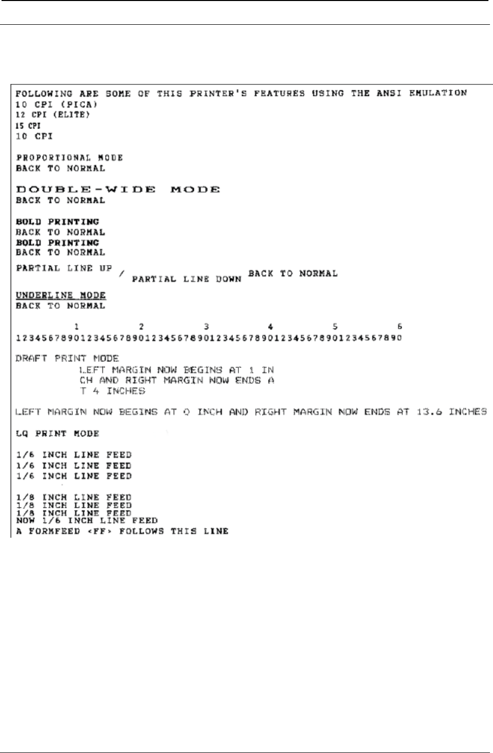
ProgrammerManual PTX‐S828
Chapter3ANSIEmulationCommands89260071‐001A
Basic Program Printed Output

ProgrammerManual PTX‐S828
Chapter3ANSIEmulationCommands90260071‐001A
This page is intentionally left blank

ProgrammerManual PTX‐S828
Chapter4IPDSCommands91260071‐001A
Chapter 4. Intelligent Printer Commands
This chapter explains the concepts of the Intelligent Printer Data Stream (IPDS). IPDS is an orderable
feature for your printer. The intent of this chapter is to provide a basic overview of how IPDS works. The
Intelligent Printer Data Stream Reference provides detailed information about IPDS programming in general
while Chapter 5, “IPDS Programming Information,” provides a detailed description of the IPDS commands
that the Printronix Model S828 printer uses. If the programming information in the Intelligent Printer Data
Stream Reference is different from the programming information in this manual, use this manual to program
the Printronix Model S828 printer.
Overview
The Intelligent Printer Data Stream (IPDS) is a structured-field data stream for managing and controlling
printer processes. IPDS uses all points addressability that allows users to position text, images, graphic
pictures, bar codes, and overlays at any defined point on a printed page. Later pages in this chapter
explain each of these data types and their uses.
IPDS offers the flexibility of creating data and commands independent of the type of attachment protocol
used by the printer or its system. Using the same data stream, printers can attach to control units or any
type of network link that does not restrict the transmission of data to the printer.
IPDS commands within the data stream enable the host processor to control and manage the downloading
of symbol sets and stored objects, such as overlays and page segments. The printer can later use these
stored objects to construct a printed page.
The IPDS command structure also provides the means for returning error information to the host, for
returning query information, and for performing error recovery actions.
Physical Medium
The S828 IPDS defines the physical medium as an area with boundaries of width and depth that define
the limits of this page. The maximum print position (MPP) defines the width of the current page in
characters.
MPP x 1/CPI = width in inches (CPI is the number of characters per inch).
The maximum page length (MPL) defines the depth of the current page in lines.
MPL x 1/LPI = depth in inches (LPI is the number of lines per inch).
The top margin on this page is the top-of-form position, as selected by pressing SET TOP OF FORM on
the operator panel. Figure 2 shows the physical medium layout.
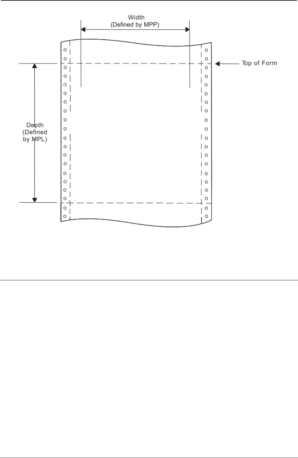
ProgrammerManual PTX‐S828
Chapter4IPDSCommands92260071‐001A
Figure 2. The Physical Medium
The physical medium defined above is assumed to coincide with the actual physical medium (form) as that
terminology is used in the following discussion.
IPDS Coordinate Systems
IPDS uses coordinate systems to define any point on a page. All IPDS commands containing location
parameters use these coordinate systems to define distance measurements. The coordinate systems
specify these distances in logical units called units.
Many IPDS commands contain parameters that specify values for position or size in units. For example,
one unit may equal approximately 0.018 mm (0.007 in. [1/144 in.]). Before using these values, the S828
Printer truncates the specified values to multiples of 0.18 mm (0.0007 in. [1/1440 in.]) for all unit parameters
except those associated with DP, and DP Text baseline positioning. The S828 Printer truncates DP, and
DP Text baseline positioning parameters to multiples of 0.36 mm (0.014 in. [1/72 in.]). The unit parameters
are identified in Chapter 5, “IPDS Programming Information,”.
X and Y Medium Coordinate System
The Xm and Ym coordinates, known as the medium coordinate system, relate directly to the physical
medium. The Xm, Ym coordinate system is fixed for each medium or form size. IPDS commands cannot
change the origin and the orientation of these coordinates. The origin (Xm=0, Ym=0) is always at the top
left hand corner of the physical medium. Positive Xm values begin at the origin and increase along the top
of the sheet, from left to right. Positive Ym values begin at the origin and increase along the left side of the
sheet moving downward toward the bottom of the sheet. Figure 3 shows the Xm, Ym coordinate system:
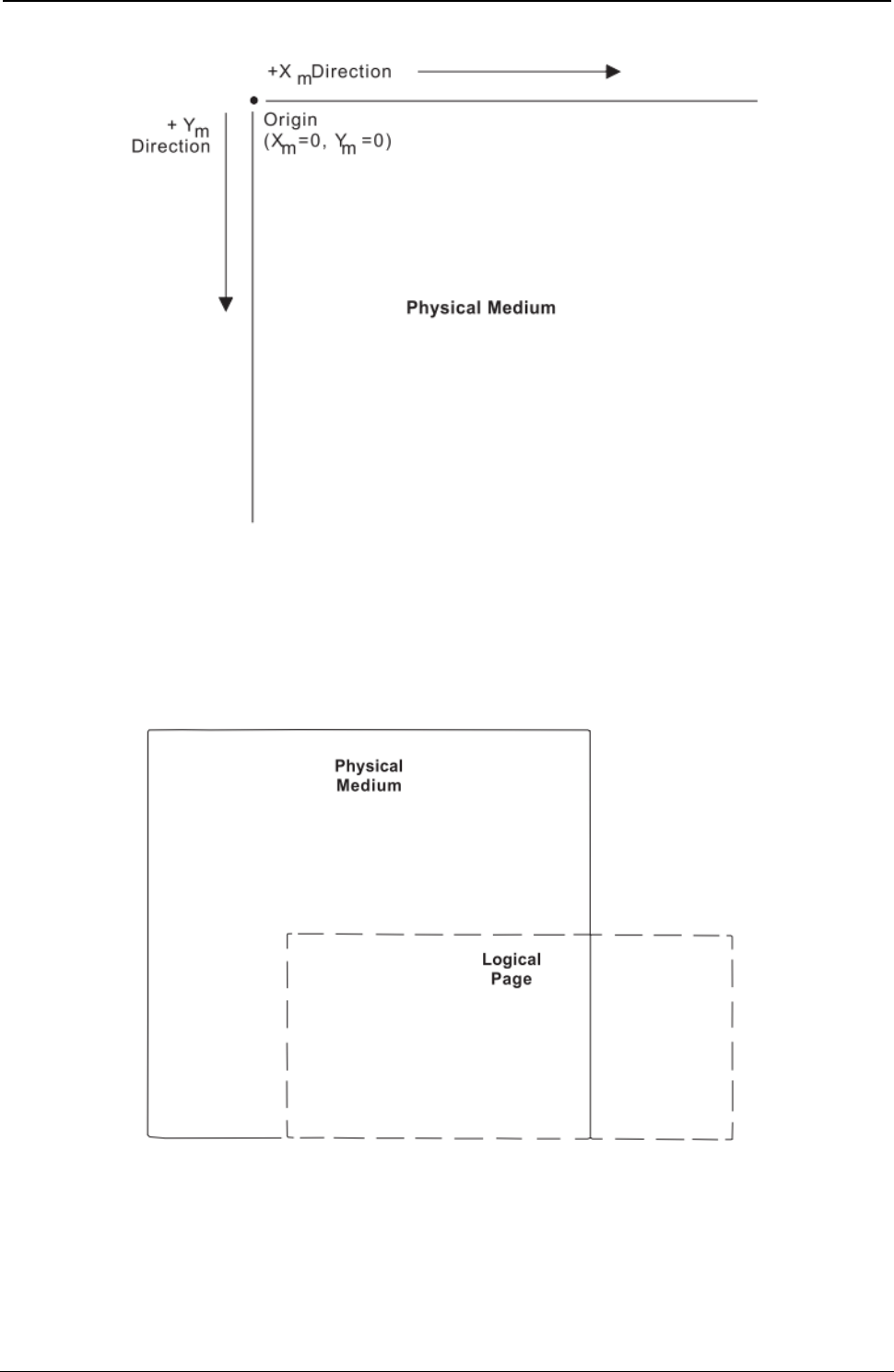
ProgrammerManual PTX‐S828
Chapter4IPDSCommands93260071‐001A
Figure 3. The Xm,Ym Medium Coordinate System
Logical Page Layout
IPDS describes the printed output in terms of logical pages. The logical page does not have to be
contained completely on the physical medium. However, printing can only occur where the two areas
overlap. Figure 4 shows the physical-logical page relationship.
Figure 4. The Physical-Logical Page Relationship
The logical page reference corner is the corner of the logical page that is at the smallest Xp, Yp position.
This corner does not necessarily have to coincide with the physical medium origin (Xm=0, Ym=0). The
logical page size in the X dimension is the 'X-Extent', and the logical page size in the Y dimension is the
'Y-Extent'. IPDS commands specify the logical page size and location. Figure 5 shows the relationship
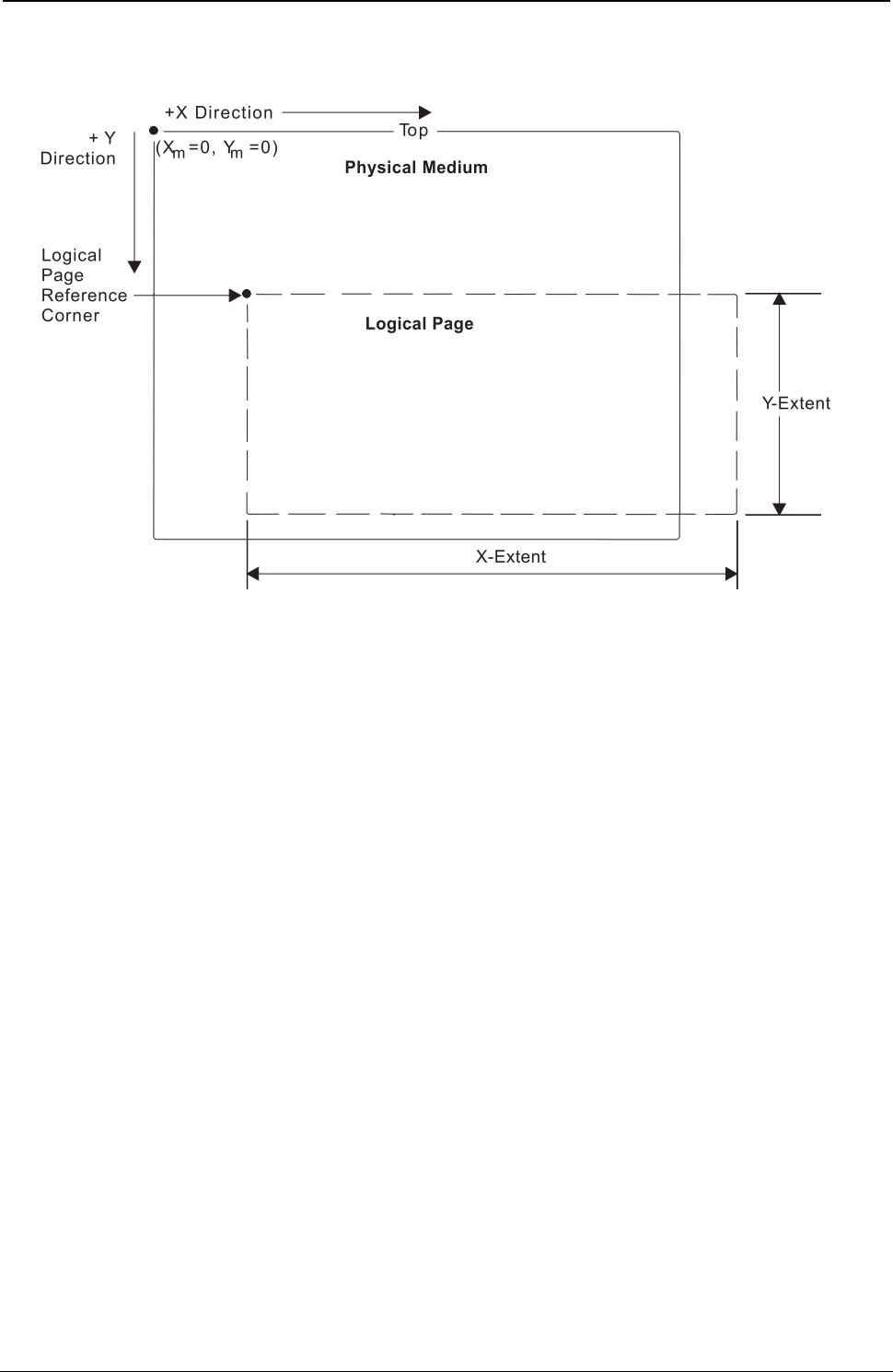
ProgrammerManual PTX‐S828
Chapter4IPDSCommands94260071‐001A
between the X and Y coordinates and the logical and physical medium.
Figure 5. The X and Y Coordinate System and the Logical Page
I and B Coordinate System
In addition to the X,Y coordinate system, IPDS uses another coordinate system, the I-B coordinate system.
These coordinates describe the placement and orientation of text or images on the logical page. The
printer places characters along the I-axis for a line of text. The B-axis is the direction in which the printer
places lines of text on the logical page. IPDS commands can change both the origin and the orientation of
the I and B axes (see Figure 5).
Direction: As the printer places text characters on the page, the inline coordinate increases. The direction
of this increase is the positive inline direction or +I. The baseline coordinate also increases as the printer
places text lines on the page. The direction of this increase is the positive baseline direction or +B.
Location parameters within the IPDS commands specify the I and B directions. Chapter 5, “IPDS
Programming Information,” contains specific information about these commands.
Distance: The inline coordinate increases a predetermined distance as the printer places the text
characters on the page. This distance is the character increment. The baseline coordinate also increases a
predetermined distance as the printer places lines of text on the page. This distance is the baseline
increment. Location parameters within the IPDS commands specify the I and B distances. Chapter 5,
“IPDS Programming Information,” contains specific information about these commands.
Initial coordinates: The coordinates of the first print position on the logical page are the initial
coordinates. The initial inline print coordinate is Ii. The initial baseline print coordinate is Bi.
Current coordinates: The coordinates of the current print position on the logical page are the current
coordinates. The current inline print coordinate is Ic. The current baseline print coordinate is Bc. Figure 6
shows the various I and B coordinates on the logical page:
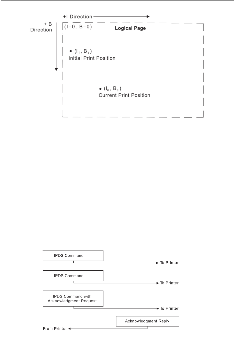
ProgrammerManual PTX‐S828
Chapter4IPDSCommands95260071‐001A
Figure 6. The I and B Coordinate System on the Logical Page
Notes:
1. The S828 IPDS Printer text character box is 180 units high by 144 units wide at 10 CPI when the XpYp
units equal 1,440 per inch. The left edge of the character box is at the specified inline position and the
bottom edge of the character box is 20 units below the specified baseline position.
2. If the bottom edge of the character box falls below the printable area on the physical medium, the
character will not print. In this situation, a baseline move (Relative Move Baseline or Absolute Move
Baseline) text command can place the character box totally within the printable area.
Processing IPDS Commands
The structured field format of IPDS allows one or more commands to be sent to the printer in a continuous
stream. Each command is self-describing; the command length, type, optional parameters, and data are all
part of each specific command. The printer processes each command in the order it is received. Every
IPDS command contains a flag byte. Setting the Acknowledgment Required bit on in this flag byte
indicates to the printer the end of a command stream sequence. The printer then sends an Acknowledge
Reply to the host. Figure 7 shows an example of an IPDS data stream:
Figure 7. An Example of the IPDS Data Stream
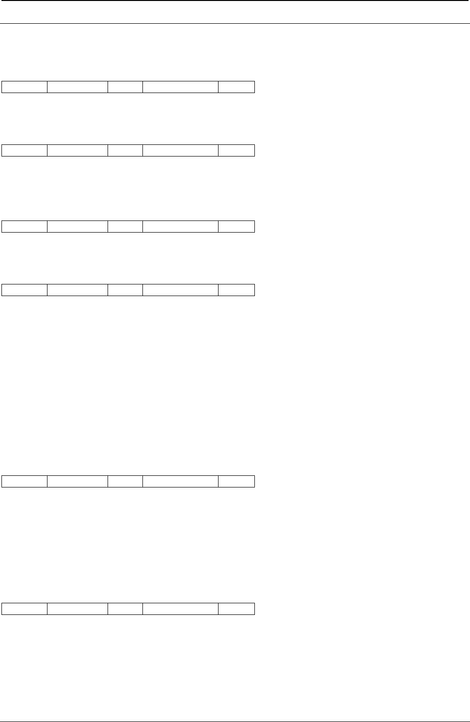
ProgrammerManual PTX‐S828
Chapter4IPDSCommands96260071‐001A
IPDS Command Format
All of the printer commands use the following format:
Length Command Flag Correlation ID Data
Note: Bit numbering follows the EBCDIC convention with bit zero being the most significant bit. A
description of each field follows.
Length
Length is a two-byte field that specifies the length of this command. This count includes the two-byte
length field, the command field, the flag byte, and the optional fields (Correlation ID and Data Fields). The
Length field can be any value from 5 to 32,767 (X'7FFF').
Command
Command is a two-byte field that specifies the IPDS command code. See next table for a list of valid
command codes.
Flag
Flag is a one-byte field that contains the IPDS command stream flags.
Bit 0 of this byte is the Acknowledgment Required (ARQ) flag. If this bit is on, the host requests the printer
to send an Acknowledge Reply.
Bit 1 of this byte is the Correlation ID flag. If this bit is B’1’, a two-byte correlation number follows this flag
byte. If this bit is B'0', the optional correlation number is not present and the following byte or bytes contain
the data field.
Bit 2 of this byte is the acknowledgement continuation flag. If this bit is B'1', the host is requesting
continuation of the current Acknowledge Reply. If this bit is B'0', the host is not requesting continuation.
Bits 3-7 of the flag byte are reserved and must be zero.
Correlation ID
Correlation ID is a two-byte value that specifies an identifier for this command. The Correlation ID is an
optional field and is only present if bit 1 of the flag byte is B'1'. The printer can use any value between
0000 and FFFF for this ID. If an error occurs on a command prior to acceptance for processing, the printer
sends a negative acknowledgement (NACK) to the host. If the printer recognizes the command that
caused the error, the Correlation ID field in the NACK will contain the ID of the command responsible for
the NACK. Correlation ID is also returned in response to commands that request information and
commands that request an acknowledgement.
Data

ProgrammerManual PTX‐S828
Chapter4IPDSCommands97260071‐001A
Data is an optional field and is not present for all commands. This field contains specific subcommands,
parameters, and data appropriate for the given command. The length of the data field can range from 0 to
32760 (X'7FF8') if the correlation ID is present. If the correlation ID is not present, the length of the data
field can range from 0 to 32762 (X'7FFA').
Table 3. Valid IPDS Command Codes for the Printronix S828 IPDS Printer
Command Hex Code Description
SHS D697 Set Home State
STM D6E4 Sense Type and Model
NOP D603 No Operation
LSS D61E Load Symbol Set
XOH D68F Execute Order Home State
XOA D633 Execute Order Any State
BP D6AF Begin Page
EP D6BF End Page
LCC D69F Load Copy Control
LPD D6CF Logical Page Descriptor
LPP D66D Logical Page Position
WBCC D680 Write Bar Code Control
WBC D681 Write Bar Code
WGC D684 Write Graphics Control
WG D685 Write Graphics
WIC D63D Write Image Control
WI D64D Write Image
WT D62D Write Text
BO D6DF Begin Overlay
DO D6EF Deactivate Overlay
IO D67D Include Overlay
BPS D65F Begin Page Segment
DPS D66F Deactivate Page Segment
IPS D67F Include Page Segment
LE D61D Load Equivalence
LFE D63F Load Font Equivalence
DF D64F Deactivate Font
END D65D End
Acknowledge Requests and Replies
The following sections explain:
● Acknowledge Reply (ACK)
● Host Acknowledgment Requests
● Printer Acknowledgement Replies
ProgrammerManual PTX‐S828
Chapter4IPDSCommands98260071‐001A
Acknowledge Reply (ACK)
The printer uses the Acknowledge Reply to return device status, sense information, and any additionally
requested information to the host application program.
The application program uses the Acknowledge data to maintain control of the printing application and to
initiate error recovery actions when necessary.
The format for the Acknowledge Reply is:
Length D6FF Flag Correlation ID Data
or
Length D6FF Flag Correlation ID Data
The printer sends an acknowledgment:
● Whenever the acknowledgment required bit in the flag byte is on
● Whenever the printer detects a command stream error or device error and a negative response must be
sent.
A negative reply (NACK), if required, has priority over a positive reply (ACK).
Length
Length is the total length of the ACK reply, including this field. The maximum length of this command is
255 bytes. If there is a five-byte command header (no correlation ID present), the data field can be up to
250 bytes long. If a correlation ID is present in the header, the maximum data field length is 248 bytes.
D6FF
D6FF in the command ID field indicates this is an Acknowledge Reply from the printer to the host.
Flag
Flag is a one-byte field that specifies the flags for this command. Bits 1, 2, and 7 are the only bits used in
this byte. All other bits are reserved and must be zeros. If bit 1 is BX'1', a Correlation ID is present in this
command. If bit 1 is BX'0', no Correlation ID is present. If bit 2 is B'1', the response can be continued in a
later Acknowledge Reply. If bit 2 is B'0', the response is complete in this Acknowledge Reply.
Correlation ID
Correlation ID is a two-byte field that contains the identifier from a previously received command, such as
Sense Type and Model. If the printer receives a command that requires an Acknowledgment Reply, and if
that command contains a correlation ID, the printer also includes the same correlation ID in its
corresponding field. Also, if an error occurs and the printer can recognize the command that caused the
error, the printer includes the correlation ID of that command in the NACK.
Data
Acknowledgement Type Page/Copy Counters Special Data (SD)

ProgrammerManual PTX‐S828
Chapter4IPDSCommands99260071‐001A
DATA is the field that follows the correlation ID field or the flag byte if no correlation ID is present. The
length of this field can be 0-250 (X'00'-X'FA') if no correlation ID is present, and 0-248 (X'00'-X'F8') if the
correlation ID is present.
The first byte of the data field is the acknowledgment type. Values of 00, 01, 04, and 06 for this byte
indicate a positive acknowledgment (ACK). A value of X'80' for this byte indicates a negative
acknowledgment (NACK). Any other values for this byte are invalid.
The next 4 bytes of the data field are the page/copy counters. The first two page/copy counter bytes
(most significant bytes) are a stacked page counter. This counter identifies how many pages have
successfully stacked and printed. The last two page/copy counter bytes (least significant bytes) are
reserved and must be zero.
Following the page/copy counter bytes is the Special Data (SD) area. Depending on the acknowledgment
type, this field can be omitted, can contain requested printer information, or can contain sense information.
The following chart summarizes the acknowledgments and the special data areas:
Type Meaning Special Data Area Contents
X'00' ACK None
X'01' ACK Type and Model
X'04' ACK Resource List
X'06' ACK Printer Information
X'80' NACK Sense Bytes
For a detailed explanation of the Special Data (SD) area contents, see Chapter 5, “IPDS Programming
Information”.
Host Acknowledgment Requests
The host requests an acknowledgment from the printer by setting the Acknowledgment Required (ARQ)
flag bit on in the IPDS command (see “IPDS Command Format”). This request occurs in two
instances:
1. In any command of a command sequence when the host wants a positive acknowledgment (ACK) that
the printer has received and accepted the command sequence for processing.
2. In commands sent by the host to request the return of printer information.
If the printer receives a command that is normally used to request the return of printer data but the ARQ
flag is not on, the printer ignores this command.
A positive acknowledgment (ACK) at the end of a command stream is equivalent to an ACK on each and
every command preceding the command that has the ACK. An ACK is an indication from the printer that
all commands since the last acknowledgment are accepted for processing.
Printer Acknowledgment Replies
The printer sends an Acknowledge Reply to the host to:
● Indicate that a received command or command sequence requesting acknowledgment has been
accepted for processing
● Return requested printer information
● Report errors

ProgrammerManual PTX‐S828
Chapter4IPDSCommands100260071‐001A
The printer sends a Negative Acknowledge Reply (NACK) to the host to indicate that an error has
occurred.
The printer can send an ACK or a NACK in response to an ARQ. If an error occurs, the printer can send a
NACK without receiving an ARQ.
The following general rules apply to the printer replies:
● If the printer receives a command requesting acknowledgment and this command also requests specific
printer information, then:
1. The printer sends a positive acknowledgment to the host, and
2. The printer sends the requested information in the data field portion of the Acknowledge Reply.
● If the printer receives a command requesting acknowledgment and this command does not request
specific printer information, then:
1. The printer sends a positive acknowledgment to the host, and
2. The printer does not include any information in the data field portion of the Acknowledge Reply.
● If the printer generates the Acknowledge Reply as a result of detecting an error, then the printer sends a
Negative Acknowledgment (NACK) to the host. Under this condition, the printer also sends to the host
information concerning the error. This error information is in the data field portion of the Acknowledge
Reply.
● The Exception Handling Control command instructs the printer on error processing. For more
information about the Exception Handling Control, see Chapter 5, “IPDS Programming Information,”.
● The printer can only return one error per NACK.
● If the printer receives a command requesting an acknowledgment, the printer expects the host to wait
for the acknowledgment before sending further commands. If the printer receives additional commands
from the host within the same transmission after the acknowledgment, the commands are ignored.
IPDS Data
There are various forms of data that the printer uses for creating the output page. These include text,
graphics, bar codes, and images. The printed page can include any combination of this data.
Text data contains lines of character information which the printer places in sequence on the page.
Graphics data contains lines, arcs, markers, and other elements which present a printed picture.
Bar code data is a data type that supports applications requiring precision printing of encoded information
in a form that is recognizable by scanning devices.
Image data contains rectangular arrays of information. The array consists of a sequence of scan lines.
Each scan line consists of picture elements (pels). The image data contains one (dot position) bit per pel.
The text, graphics, bar code, and image data types each have their own unique commands. Chapter 5,
“IPDS Programming Information,” contains a detailed description of these commands.
Blocks of graphics, image, or bar code data are presented as a single unit to the printer. The printer
enters the appropriate Block State (graphics block, image block, or bar code block) to create the entire
data group for that block of data.
Page segments and overlays are any combinations of text, graphics, bar codes, and images. The printer
can store these segments and overlays for later use as the page is created. For information about segments,
see “Include Page Segment (IPS)”. For information about overlays, see “Begin Overlay (BO)”. Figure 8
shows various data types on a page.
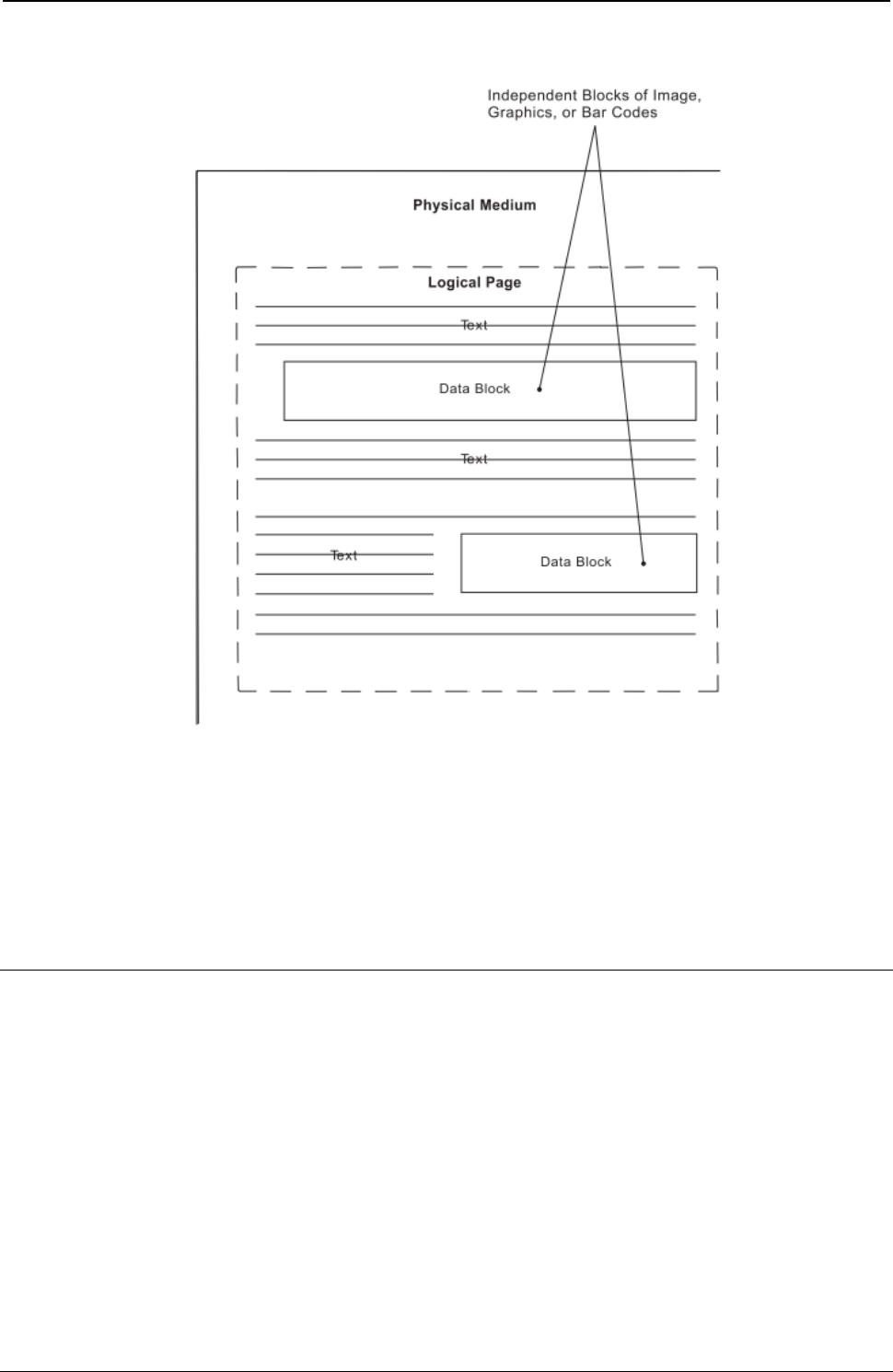
ProgrammerManual PTX‐S828
Chapter4IPDSCommands101260071‐001A
Figure 8. A Sample Page Constructed on an IPDS Printer
Notes:
1. Overlays and page segments can be merged on this page.
2. Text and data blocks can be positioned at different places on this page.
3. A logical page can be positioned anywhere with respect to the physical medium.
Mixing Rules
IPDS allows the same physical pel to be overwritten an unlimited number of times. Overwriting can occur
both within a block and across blocks. For example, within text blocks, overwriting can be caused by using
the Overstrike control. Within a graphics block, overwriting occurs whenever one graphics area or figure
overlays another. Across block overwriting can occur whenever one IPDS block physically overlays any
portion of another IPDS block.
Within each block, the S828 IPDS Printer further defines background pels and foreground pels. Foreground
pels are:
● The pels of a character

ProgrammerManual PTX‐S828
Chapter4IPDSCommands102260071‐001A
● The pels of a rule
● The pels of an image
● The pels of a graphic line or arc
● The pels of a filled area
● The pels of a bar code.
Background pels are all other pels.
Text data, because it prints at a different physical resolution than the data in the other blocks, does not
logically mix with any other data type. The only mixing that takes place between text data and any other
data type is the (possible) physical mixing of ink on forms.
For the S828 IPDS Printer, the mixing rule for overwritten data within a given block of image, graphics, or bar
code data is quite simple: background pels are transparent; foreground pels are opaque. Thus,
background pels always show through what is underneath (what was received earlier), while foreground
pels cover it up. In other words, a pel prints in the color of its last overwriting.
Note: Color of medium is a valid color for image, graphics, and bar code data. Thus, foreground pels in
this color cover up pels of any other color that are underneath.
For the S828 IPDS Printer, the mixing rule for overwritten data across blocks is the same as it is within
blocks except for text. Thus, across image and graphics, or bar code blocks, background pels are
transparent, while foreground pels are opaque.
IPDS Operating States
There are various operating states using the IPDS commands. The following states define the operating
environment for this printer:
● Home state
● Page state
● Overlay state
● Page segment state
● Block state.
While in the page, overlay, or page segment state, the printer can enter a block state. The block state
causes the printer to process a block of data. There are image blocks, graphics blocks, and bar code
blocks. Thus, the printer can enter any of the data block states from any of the operating states.
Home State
Home state is the initial IPDS operating state. The printer returns to home state at the end of each page,
page segment, or overlay. In addition, the printer can enter the home state by receiving a Set Home State
command. The S828 IPDS Printer also goes to home state when a NACK is returned.
While in the home state, the printer receives control and initialization commands to prepare for a print
operation. In this state, the printer can also receive commands that request the return of printer information
to the host application program.
Page State
Page state is the operating state for printing a logical page. The printer enters the page state from the
home state as a result of receiving a Begin Page command.
In the page state, the printer can receive commands that merge previously defined and loaded overlay and
page segments with the current page information. The printer can also receive Write Text commands that
position text on the logical page. The presence of Write Image (block) Control, Write Graphics (block)
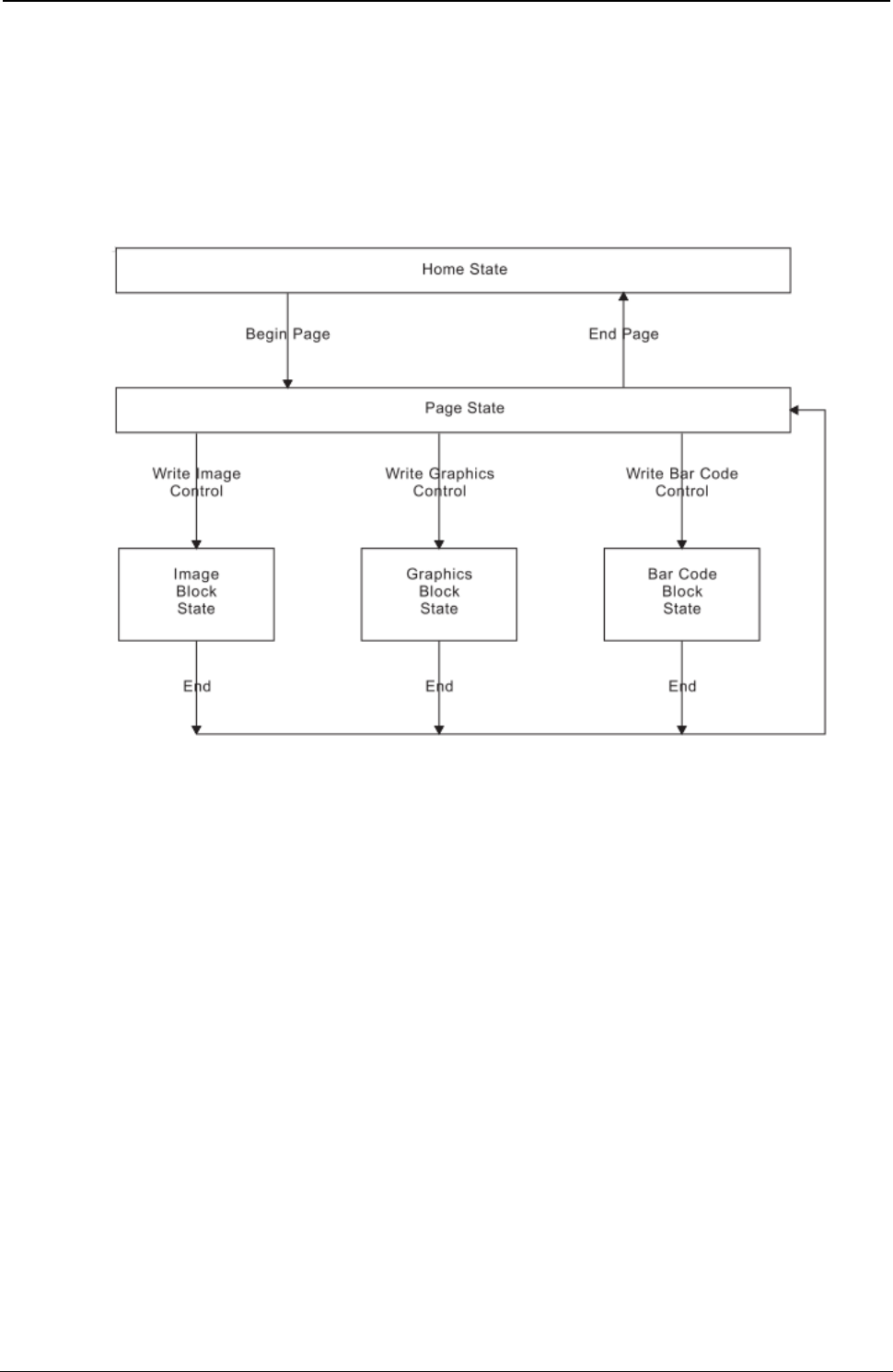
ProgrammerManual PTX‐S828
Chapter4IPDSCommands103260071‐001A
Control, or Write Bar Code (block) Control commands in the data stream indicates that the printed page
contains individual blocks of image, graphics, or bar code data for positioning on the page. These
commands cause a state transition to occur to an appropriate page block state. In the block state, the
printer establishes the initial conditions and processes the block of data onto the page. Receiving an End
command in a page block state terminates that state and returns processing back to the page state.
Figure 9 shows the relationship between the home state, page state, and block states.
Figure 9. The Relationship between Home State, Page State, and Block States
Overlay State
Overlay state is the operating state that stores data in the printer. The printer enters the overlay state from
the home state as a result of receiving a Begin Overlay command.
A parameter in the Begin Overlay command provides an identifier for later references to this overlay. The
printer saves the currently active Logical Page Descriptor value, the Load Font Equivalence value, and the
Load Equivalence value as part of the stored overlay definition.
The same commands that the printer uses in the page state are also valid while in the overlay state.
Figure 10 shows the relationship between the home state, overlay state, and block states.
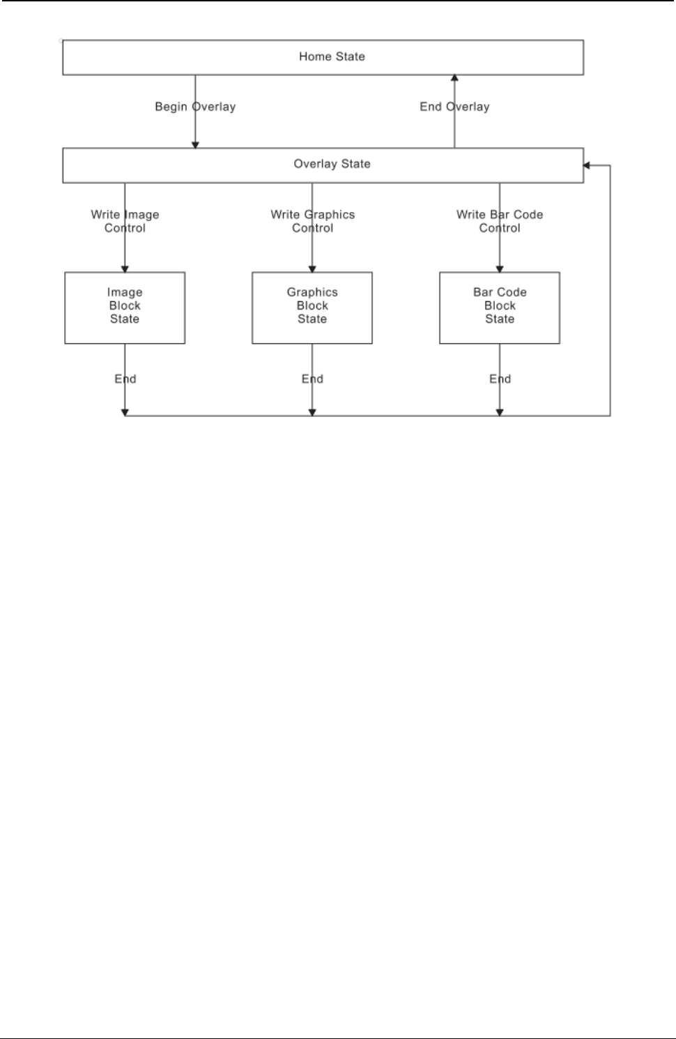
ProgrammerManual PTX‐S828
Chapter4IPDSCommands104260071‐001A
Figure 10. The Relationship between Home State, Overlay State, and Block State
Page Segment State
The printer enters the page segment state from the home state as a result of receiving a Begin Page
Segment command. A parameter in the Begin Page Segment command provides an identifier for later
references to this segment.
Page segments assume the environment (Logical Page Descriptor, Load Font Equivalence, and Load
Equivalence) that is active at the time the segment is presented.
While in a page segment state, the printer can only receive commands to write text, image, bar code, and
graphics blocks.
Figure 11 shows the relationship between the home state, page segment state, and block
states.
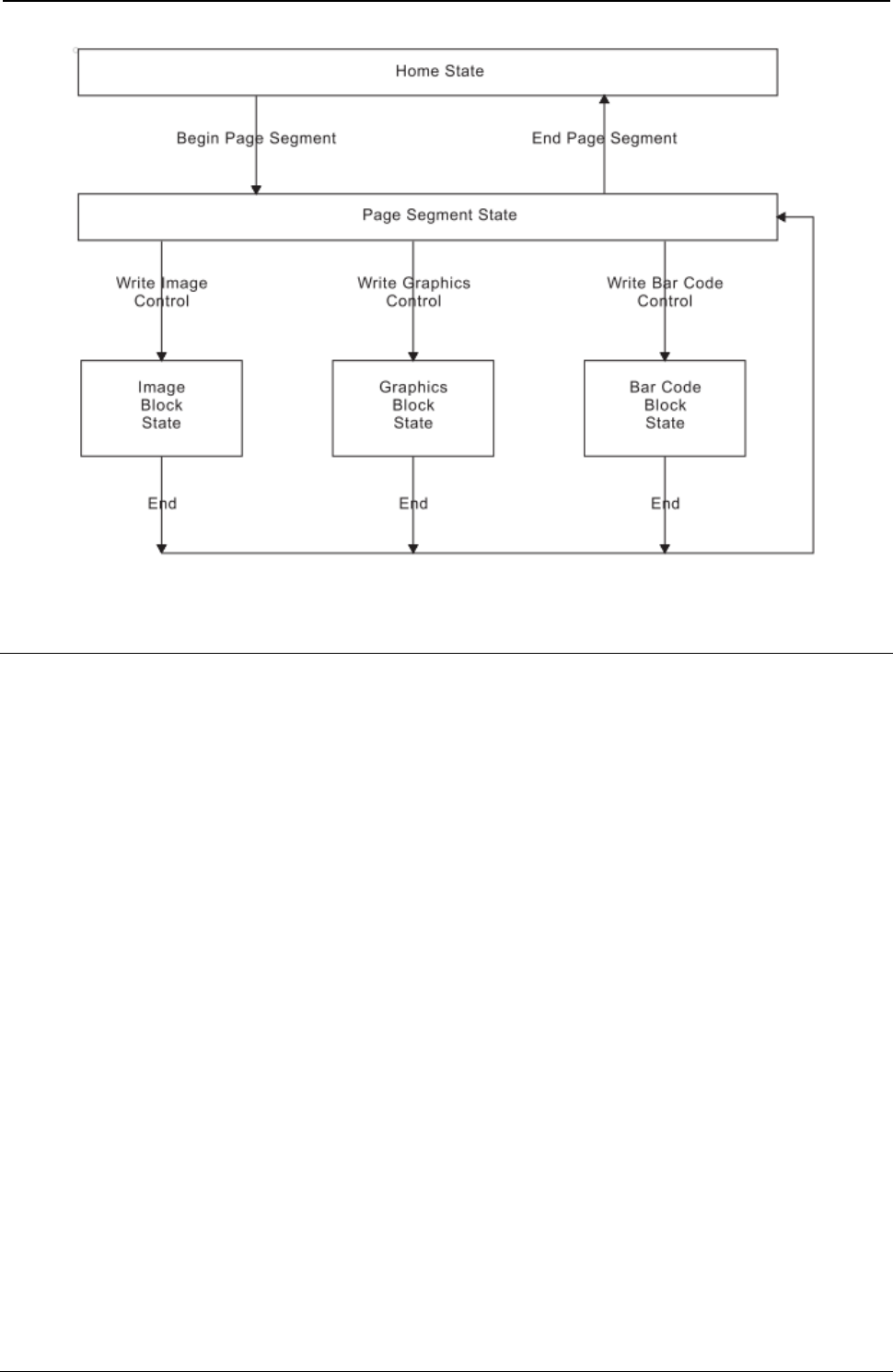
ProgrammerManual PTX‐S828
Chapter4IPDSCommands105260071‐001A
Figure 11. The Relationship between Home State, Page Segment State, and Block States
Summary of the IPDS States and Commands
Next table shows all the valid IPDS commands for the S828 IPDS Printer and the initial and ending states for
each command. The printer must be in the initial state shown for each command for that command to be
valid. The ending state is the resulting state the printer enters after a valid command processes.
Table 4. IPDS Command Code Summary for the S828 IPDS Printer
Cmd Hex Code Description Initial State Ending State
SHS D697 Set Home State Any Home
STM D6E4 Sense Type and Model Any No Change
NOP D603 No Operation Any No Change
LSS D61E Load Symbol Set Home Home
XOH D68F Execute Order Home State Home Home
XOA D633 Execute Order Any State Any No Change (See Note 1)
BP D6AF Begin Page Home Page
EP D6BF End Page Page, Page Segment, Home
or Overlay
LCC D69F Load Copy Control Home Home
LPD D6CF Logical Page Descriptor Home Home
LPP D66D Logical Page Position Home Home

ProgrammerManual PTX‐S828
Chapter4IPDSCommands106260071‐001A
Table 4. IPDS Command Code Summary for 828 IPDS Printer (continued)
Cmd Hex Code Description Initial State Ending State
WBCC D680 Write Bar Code Control Page, Page Segment, Page Bar Code Block, Page
or Overlay Segment Bar Code Block, or
Overlay Bar Code Block
WBC D681 Write Bar Code Page Page Bar Code Block, No Change
Page Segment Bar Code
Block, or Overlay Bar
Code Block
WGC D684 Write Graphics Control Page, Page Segment, Page Graphics Block, Page
or Overlay Segment Graphics Block,
or Overlay Graphics Block
WG D685 Write Graphics Page Graphics Block, No Change
Page Segment Graphics
Block, or Overlay
Graphics Block
WIC D63D Write Image Control Page, Page Segment, Page Image Block, Page
or Overlay Segment Image Block,
or Overlay Image Block
WI D64D Write Image Page Image Block, Page No Change
Segment Image Block,
or Overlay Image Block
WT D62D Write Text Page, Page Segment, No Change
or Overlay
BO D6DF Begin Overlay Home Overlay
DO D6EF Deactivate Overlay Home Home
IO D67D Include Overlay Page or Overlay No Change
BPS D65F Begin Page Segment Home Page Segment
DPS D66F Deactivate Page Segment Home Home
IPS D67F Include Page Segment Page or Overlay No Change
LE D61D Load Equivalence Home Home
LFE D63F Load Font Equivalence Home, Page, Page No Change
Segment, or Overlay
DF D64F Deactivate Font Home Home
END D65D End See Note 2 See Note 2
Notes:
1. The Discard Buffered Data subcommand in the Execute Order Any State command causes the printer to
enter the home state.
2. The End command is valid in any page block, overlay block, or page segment block state and causes the
printer to return to the corresponding page, overlay, or page segment state.
Figure 11 shows all of the IPDS states and their commands. Notice that some commands can only occur in a
specific state, some commands can occur in more than one state, and some commands can occur in any
state. Also note that the printer can only enter the page state, the page segment state, and the overlay state
from the home state.
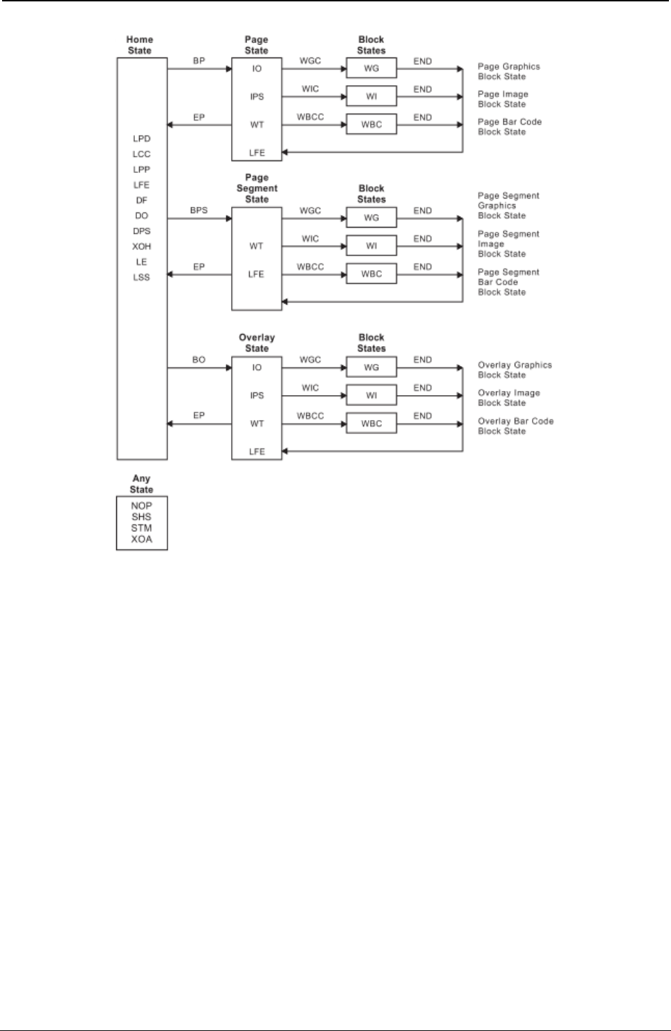
ProgrammerManual PTX‐S828
Chapter4IPDSCommands107260071‐001A
Figure 11. The Complete IPDS State Diagram
A Typical IPDS Command Sequence
The following chart shows an example of a typical IPDS command sequence. This sequence contains five
basic categories:
1. Initialization
2. Preparation
3. Page Segment
4. Overlay
5. Page
ProgrammerManual PTX‐S828
Chapter4IPDSCommands108260071‐001A
Each category starts with a command from the host to the printer and ends with an acknowledgment from
the printer to the host. An analysis of each category follows this example.
Note: . indicates a command from the host to the printer. . indicates a reply from the printer to the host.
Table 5. An Example of an IPDS Command Sequence
Printer Command CMD Command Name Description
State Direction
Initialization STM Sense Type and Model Request Device Information
Sequence
ACK Acknowledgement Response Return Type/Model Information
Preparatory SHS Set Home State Set Printer Home State
Sequence LPD Logical Page Descriptor Define Logical Page
LPP Logical Page Position Locate Logical Page
LCC Load Copy Control Load Page Copy Information
LFE Load Font Equivalence Load Font Mapping
ACK Acknowledgement Response Acknowledge Successful Operation
Page BPS Begin Page Segment Set Printer to Page Segment State
Segment WT Write Text Store Text Data in Page Segment
Sequence WT Write Text Store Text Data in Page Segment
WT Write Text Store Text Data in Page Segment
Block WIC Write Image Control Start Page Segment Image Block
State State
WI Write Image Store Image Data in Page Segment
WI Write Image Store Image Data in Page Segment
End Block END End End Image Block State
State WT Write Text Store Text Data in Page Segment
WT Write Text Store Text Data in Page Segment
EP End Page Return to Home State
ACK Acknowledgement Response Acknowledge Successful Operation
Overlay BO Begin Overlay Enter Overlay State
Sequence WT Write Text Store Text Data in Overlay
WT Write Text Store Text Data in Overlay
WT Write Text Store Text Data in Overlay
IO Include Overlay Include Another Overlay
Block WGC Write Graphics Control Enter Overlay Graphics Block State
State WG Write Graphics Store Graphics Data in Overlay
WG Write Graphics Store Graphics Data in Overlay
End Block END End End Overlay Graphics Block State
State WT Write Text Store Text in Overlay
WT Write Text Store Text in Overlay
IO Include Overlay Include Another Overlay
IPS Include Page Segment Include Page Segment in Overlay
EP End Page Return to Home State
ACK Acknowledgement Response Acknowledge Successful Operation

ProgrammerManual PTX‐S828
Chapter4IPDSCommands109260071‐001A
Table 3. An Example of an IPDS Command Sequence (continued)
Printer Command CMD Command Name Description
State Direction
Page BP Begin Page Enter Page State
Sequence WT Write Text Send Text Data to Printer
IO Include Overlay Print Overlay
IPS Include Page Segment Print Page Segment
Block WIC Write Image Content Start Page Segment Image Block
State State
WI Write Image Send Image Data to Printer
WI Write Image Send Image Data to Printer
End Block END End End Image Block State
State WT Write Text Send Text Data to Printer
WT Write Text Send Text Data to Printer
IO Include Overlay Print Overlay
IPS Include Pate Segment Print Page Segment
EP End Page Complete All Printing and Return to
Home State
ACK Acknowledgement Response Acknowledge Successful Operation
Printer Initialization and Preparation Sequence
Before any printing begins, it is necessary to specify certain parameters and conditions for the printer. The
following sample command sequence accomplishes this task:
● STM (Sense Type and Model)
● ACK (Acknowledgment Reply)
● SHS (Set Home State)
● LPD (Logical Page Descriptor)
● LPP (Logical Page Position)
● LCC (Load Copy Control)
● LFE (Load Font Equivalence)
● ACK (Acknowledgment Reply).
Note: This sequence is only a typical example. It is not mandatory for the host to send all of these
commands.
STM (Sense Type and Model): The host sends the STM command to sense the printer characteristics.
ACK (Acknowledgment Reply): If the previous command had the ARQ bit on, the printer responds with
type and model information to the host. This information includes printer number (S828), model, and the
various function set vector information.
SHS (Set Home State): The host sends the SHS command to make sure the printer is in the home state
before the start of a print job.
LPD (Logical Page Descriptor): The LPD command sets print characteristics for the logical page. These
parameters include:
● Page size
● Initial coordinates
● Initial left margin
● Intercharacter increment
● Baseline increment
● Font ID

ProgrammerManual PTX‐S828
Chapter4IPDSCommands110260071‐001A
● Text color.
LPP (Logical Page Position): The LPP command positions the upper-left corner of the logical page (as
defined by the LPD command) with respect to the top-of-form setting. This command locates the logical
page on the physical medium.
LCC (Load Copy Control): The LCC command specifies which overlays to include on each subsequent
page and which suppressions to activate for each page. Suppression allows selective suppression of data
while printing.
LFE (Load Font Equivalence): The LFE command maps a local font identifier (from within the text,
graphics, or bar code data) to a global ID used for resource management. This command also specifies
for each font attributes, such as bold, double-strike, double-wide, and italics.
ACK (Acknowledgment Reply): If the previous command had the ARQ bit on, the printer responds with
the ACK reply to inform the host of successful execution of all the previous commands. This command
indicates to the host that the printer is now ready to accept data for print operations. This is the end of the
initialization and preparation sequence.
Page Segment Sequence
The page segment sequence creates one or more page segments for later printing. The following
command sequence illustrates the loading of a sample page segment:
● BPS (Begin Page Segment)
● WT (Write Text)
● WIC (Write Image Control)
● WI (Write Image)
● END (End)
● WT (Write Text)
● EP (End Page)
● ACK (Acknowledgment Reply).
Note: This sequence is only an example. A page segment can contain any combination of text, image,
graphics, or bar code data.
BPS (Begin Page Segment): The host sends the BPS command to the printer, causing the printer to
leave the home state and enter the page segment state. The page segment state creates a segment of
page data to save within the printer for later printing. The BPS command contains an identifier (ID) for
later use in selecting this segment. This segment can contain combinations of text, images, bar codes, and
graphics.
WT (Write Text): The WT command sends text data to the printer. Because the printer is currently in a
page segment state, this text information does not print at this time. Instead, the data becomes part of the
page segment. The host can send multiple WT commands to the printer while in the page segment state.
WIC (Write Image Control): The WIC command causes the printer to enter the image block state.
Parameters in this command define the image size, scale, initial coordinates, and color of the image.
WI (Write Image): The WI command sends a block of image data to the printer. One or more of these
commands create the actual image for later printing.
END (End): The END command terminates the image block state. The printer remains in the page
segment state with the image stored for later use.

ProgrammerManual PTX‐S828
Chapter4IPDSCommands111260071‐001A
WT (Write Text): This command is repeated at this point in the sequence to illustrate that additional text
data can be added to the page segment. In addition to zero or more of the WT commands, this segment
could also include additional graphics data, image data, or bar code data.
EP (End Page): The EP command causes the printer to leave the page segment state and return to the
home state Printronix recommends that this command contain an acknowledgment request to let you know
of successful execution of the page segment.
ACK (Acknowledgment Reply): If the previous command had the ARQ bit on, the printer responds with
the ACK command to inform the host of successful execution of all the previous commands. This
command indicates to the host that the printer has accepted all the segment data and stored this
information for later printing.
Overlay Sequence
The overlay sequence creates one or more overlays for later printing. The following command sequence
illustrates the loading of a typical overlay:
● BO (Begin Overlay)
● WT (Write Text)
● IO (Include Overlay)
● WGC (Write Graphics Control)
● WG (Write Graphics)
● END (End)
● WT (Write Text)
● IO (Include Overlay)
● IPS (Include Page Segment)
● EP (End Page)
● ACK (Acknowledgment Reply).
Note: This sequence is only an example. An overlay can contain any combination of text, image blocks,
graphics blocks, bar code blocks, page segments, or overlays.
BO (Begin Overlay): The host sends the BO command to the printer causing the printer to leave the
home state and enter the overlay state. The overlay state creates an overlay of data to save within the
printer for later printing. The BO command contains an identifier (ID) for later use in selecting this overlay.
WT (Write Text): The WT command sends text data to the printer. Because the printer is currently in an
overlay state, this information does not print at this time. Instead, the data becomes part of the overlay.
The host can send multiple WT commands to the printer while in the overlay state.
IO (Include Overlay): The IO command causes a previously stored overlay to merge onto the current
overlay. This command contains an ID field that selects the desired overlay.
WGC (Write Graphics Control): The WGC command causes the printer to enter the graphics block state.
Parameters in this command specify the placement, size, and orientation of the graphics block.
WG (Write Graphics): The WG command sends graphics data to the printer. The graphics data
(contained in drawing orders) specifies the various elements of the graphic. These include color, size, line
type, line width, and other parameters. One or more WG commands present the graphics picture.
END (End): The END command terminates the graphics block state. The printer remains in the overlay
state with the graphics block as part of the overlay.
WT (Write Text): This command is repeated at this point in the sequence to illustrate that additional text
data can be added to the overlay. In addition to zero or more of the WT commands, image data, bar code
data, or additional graphics data could also be included in the overlay.

ProgrammerManual PTX‐S828
Chapter4IPDSCommands112260071‐001A
IO (Include Overlay): The IO command causes a previously stored overlay to merge onto the current
overlay.
IPS (Include Page Segment): The IPS command causes a previously stored page segment to merge
onto the current overlay. An ID in this command specifies the selected page segment.
EP (End Page): The EP command causes the printer to leave the overlay state and return to the home
state. Printronix recommends that this command contain an acknowledgment request to verify successful
transmission of the overlay.
ACK (Acknowledgment Reply): If the previous command had the ARQ bit on, the printer responds with
the ACK reply, to inform the host of successful execution of all the previous commands. This reply
indicates to the host that the printer has accepted all the overlay data and stored this information for later
printing.
Page Sequence
The page sequence causes data to print on the current page. This data can include previously stored
overlays or page segments, as well as text data. The following commands illustrate a typical page
sequence:
● BP (Begin Page)
● WT (Write Text)
● IO (Include Overlay)
● IPS (Include Page Segment)
● WIC (Write Image Control)
● WI (Write Image)
● END (End)
● WT (Write Text)
● IO (Include Overlay)
● IPS (Include Page Segment)
● EP (End Page)
● ACK (Acknowledgment Reply).
Note: This sequence is only an example. A page can contain any combination of text, image blocks,
graphics blocks, bar code blocks, page segments, or overlays.
BP (Begin Page): The host sends the BP command to the printer, causing the printer to leave the home
state and enter the page state.
WT (Write Text): The WT command sends text data to the printer. Because the printer is currently in a
page state, this text information prints at this time. The host can send multiple WT commands to the
printer while in the page state.
IO (Include Overlay): The IO command causes a previously stored overlay to merge onto the current
page. This command contains an ID field, which selects the desired overlay.
IPS (Include Page Segment): The IPS command causes a previously stored page segment to merge
onto the current page. An ID in this command specifies the selected page segment. The selected page
segment now prints on the current page.
WIC (Write Image Control): The WIC command causes the printer to enter the image block state.
Parameters in this command define the image size, scale, initial coordinates, and color of the image.
WI (Write Image): The WI command sends a block of bit image data to the printer. One or more of these
commands create the actual image for printing. Because the printer is now in the page state, the image
prints as it is received by the printer.

ProgrammerManual PTX‐S828
Chapter4IPDSCommands113260071‐001A
END (End): The END command terminates the image block state. The printer remains in the page state.
WT (Write Text): This command is repeated at this point in the sequence to illustrate that additional text
data can be added to the page. In addition to zero or more of the WT commands, graphics data, bar code
data, or additional image data could also be included on the page.
IO (Include Overlay): The IO command causes a previously stored overlay to merge onto the current
page. This overlay now prints on the current page.
IPS (Include Page Segment): The IPS command causes a previously stored page segment to merge
onto the current page. An ID in this command specifies the selected page segment. The selected page
segment now prints on the current page.
EP (End Page): The EP command causes the printer to leave the page state and return to the home
state. Printronix that this command contain an acknowledgment request to verify successful execution of the
page data.
ACK (Acknowledgment Reply): If the previous command had the ARQ bit on, the printer responds with
the ACK reply to inform the host of successful execution of all the previous commands. This reply
indicates to the host that the printer has accepted all the page data, and all selected segments, images, or
overlays have successfully printed.
Chapter 5, “IPDS Programming Information,” contains a more detailed description of all the IPDS commands.
Error Handling
An exception (error) occurs when the printer detects an invalid or unsupported command, control, or
parameter value in the data stream received from the host. The IPDS error handling structure assigns a
unique exception code to each type of error. The printer sends these codes to the host, as sense bytes, in
the NACK (negative acknowledgment reply). See Chapter 6, “IPDS Exception Reporting Codes,” for a
description of the exception codes.
The host can control how the printer responds to the exceptions. The Exception Handling Control
(see“Exception Handling Control (EHC)”) order permits independent control over three exception
handling functions:
● The exceptions to report with a NACK reply
● The implementation of Alternate Exception Actions (AEA) when a valid parameter value is received but
not supported by the printer
● The termination or continuation procedure to follow if the alternate error action is not taken or if there is
no alternate error action associated with this error.
The host application program can use the Exception Handling Control order to accomplish many specific
control capabilities necessary in data printing environments. For example, through the proper selection of
settings, it is possible to:
● Enforce control over printing of page information
● Enable automatic skipping of data types not supported by the printer
● Suppress the return of meaningless or redundant exception reports when alternate actions are
acceptable to the user.
The host can issue the Exception Handling Control order in any printer state. This allows the host to
manage exception processing at any level desired by the host application.

ProgrammerManual PTX‐S828
Chapter4IPDSCommands114260071‐001A
This page is intentionally left blank

ProgrammerManual PTX‐S828
Chapter5IPDSProgrammingInformation115260071‐001A
Chapter 5. IPDS Programming Information
This chapter contains programming information for the Intelligent Printer Data Stream (IPDS) commands.
The information is for the experienced programmer. A knowledge of data stream requirements, hexadecimal
numbering systems, and data processing terminology and concepts is assumed.
In addition to the information in this chapter, Chapter 4, “Intelligent Printer Commands,” contains introductory
information about the IPDS.
IPDS Initialization Defaults
When the printer power switch is initially turned On (|), various IPDS data stream parameters are set to
their initialization default values. These values remain in effect until overridden by specific data stream
commands from the host application program.
Table 6 contains the initialization defaults for this printer:
Table 6. IPDS Initialization Defaults
Default Description Hex Value
Units Base Value 00 (10 in.)
Input Media Source Determined by Operator Panel Paper Source setting
Width of the Physical Medium MPP Value, Operator Panel Selection
Length of the Physical Medium MPL Value, Operator Panel Selection
Width of the Logical Page in Units (X-Extent) 4A40 (Decimal 13.2 in. Width, 1440 Units Per In.)
Length of the Logical Page in Units (Y-Extent) 3DE0 (Decimal 11 in. Length, 1440 Units Per In.)
Ordered Data Flags 00 (Unordered Page, Block, and Text Flags)
X-Axis Orientation 0000 (0 Degrees)
Y-Axis Orientation 2D00 (90 Degrees)
Current I Text Position 0000
Current B Text Position 00A0 The Default Font Type Baseline (see Note 1)
X-Displacement 0000 Logical Page X-Displacement from Physical Medium Origin
Y-Displacement 0000 Logical Page Y-Displacement from Physical Medium Origin
Initial Inline Margin in Units 0000
Intercharacter Adjustment 0000
Baseline Increment LPI value, Operator Panel Selection
Local Font ID FF (see Note 3)
Text Color Black
Code Page ID Language value, Operator Panel selection
Font Quality Print Quality value, Operator Panel selection
Font Type Determined by Print Quality and CPI value Operator Panel
selection (see Note 2)
Exception Handling Control Report Undefined Characters, Position Checks, and All
Other Exceptions. Do Not Take Alternate Exception Action.
Terminate, Print Page, and Go to Home State.
Notes:
1. Text printing on the first line requires an initial Y-displacement value of 00A0.
2. The printer default font is Gothic for DP and fast draft print quality and Courier for DP Text and NLQ
print quality. To determine the current values for CPI, language and quality, refer to the Administrators
Manual for your printer.
3. When Local Font ID equals FF is used, the latest inline sequence established in “Logical Page
Descriptor (LPD)” determines whether to print in a left-to-right or right-to-left sequence. The default
when the printer is powered on is the left-to-right sequence.
ProgrammerManual PTX‐S828
Chapter5IPDSProgrammingInformation116260071‐001A
Parameter Values
The Printronix S828 Printer allows flexibility in selecting various options to perform a wide range of functions.
Parameter values are initially set at the factory. The printer uses these values to format the page and to
control forms movement. The parameter values also allow the operator to select the printer address,
language, and print mode and compatibility options, and to turn the alarm on or off.
The printer can use the initial factory set values, or the operator can change these values. Any new value
selection made at the operator panel becomes the new parameter value immediately upon selection. If this
configuration is saved by the operator into the power-on custom set, this value remains as the new
parameter value, even after the printer power switch is turned Off (O).
The operator can select the following parameter values at the operator panel and change them:
● Characters per inch (CPI)
● Lines per inch (LPI)
● Maximum print position (MPP)
● Maximum page length (MPL) (See Note)
● Language
● Print quality
● Alarm (Enabled/Disabled)
● Graphics and Bar Code mode
● Left margin
● Emulation mode
Note: An MPL setting that results in a page length less than 762 mm (3 in.) causes a throughput
reduction. A maximum reduction of about 50 percent occurs at an MPL setting of one line per page.
The application program can override any of the parameter values, except for turning the alarm on or off
changing the address selection, changing the emulation determines what parameter value the printer uses:
1. The printer uses the program specified value.
2. If no program command has specified the value, the printer uses the current parameter value.
Command Format
All the printer commands use the following format:
Length Command Flag Correlation ID (Optional) Data
The following chart shows the purpose of each field:
Byte Field Description
0-1 Length Total Command Length, Including the Length Bytes
2-3 Command Command Type

ProgrammerManual PTX‐S828
Chapter5IPDSProgrammingInformation117260071‐001A
Byte Field Description
4 Flag Bit 0
0 = Acknowledge Response Not Required
1 = Acknowledge Response Required
Bit 1
0 = Correlation ID Not Included
1 = Correlation ID Included
Bit 2
0 = Acknowledge Reply Response is Complete
1 = Second Buffer of XOH - OPC Reply Required
Bit 3 - 6
Reserved (Always Zero)
Bit 7
0 = Persistent NACK is inactive
1 = Persistent NACK
5-6 Correlation ID Identifier Name (Valid Only if Byte 4, Bit 1 Is On)
7-n Data Specific Subcommands, Operands, Parameters, and Data Fields as Appropriate for
the Given Command
Notes:
1. Bit numbering follows the EBCDIC convention with bit zero being the most significant bit.
2. If the Correlation ID field is not present (byte 4, bit 1 is zero), the data field starts at byte 5 instead of
byte 7.
3. Both positive or negative values fitting in the data fields are allowable. Negative values are in
twos-complement form.
4. Some bits or bytes in the data fields are Reserved. The printer does not always check the contents of
these fields. However, Printronix recommends that such fields equal the specified value (if one exists) or
zero.
5. The printer will not detect a condition where the specified command length (bytes 0 through 1)
exceeds the actual number of bytes received. If this occurs, the printer will not process the command
until the printer receives the specified number of bytes.
6. If the host wants to request the second buffer, the request must be the next command following the
request for the first buffer of an acknowledgment. However, it is not required that the host request the
second buffer of an acknowledgment.
Supported IPDS Command Codes
Command Hex Code Description
SHS D697 Set Home State
STM D6E4 Sense Type and Model
NOP D603 No Operation
LSS D61E Load Symbol Set
XOH D68F Execute Order Home State
XOA D633 Execute Order Any State
BP D6AF Begin Page
EP D6BF End Page
LCC D69F Load Copy Control
LPD D6CF Logical Page Descriptor

ProgrammerManual PTX‐S828
Chapter5IPDSProgrammingInformation118260071‐001A
Command Hex Code Description
LPP D66D Logical Page Position
WBCC D680 Write Bar Code Control
WBC D681 Write Bar Code
WGC D684 Write Graphics Control
WG D685 Write Graphics
WIC D63D Write Image Control
WI D64D Write Image
WT D62D Write Text
BO D6DF Begin Overlay
DO D6EF Deactivate Overlay
IO D67D Include Overlay
BPS D65F Begin Page Segment
DPS D66F Deactivate Page Segment
IPS D67F Include Page Segment
LE D61D Load Equivalence
LFE D63F Load Font Equivalence
DF D64F Deactivate Font
END D65D End
Command Function Sets
Function sets divide the printer commands into various categories. Each function set provides all the
necessary controls for its functional area. These function sets are:
● Device Control function set
● Text function set
● Image function set
● Graphics function set
● Bar Code function set
● Overlay function set
● Page Segment function set
● Loaded Font function set.
Device Control Function Set Commands
The Device Control function set contains the commands the printer uses to set up the page, communicate
device controls, and manage the Acknowledge protocol. The following commands are the device control
function set:
Command Hex Code Description
NOP D603 No Operation
STM D6E4 Sense Type and Model
SHS D697 Set Home State
ACK D6FF Acknowledge Reply
LFE D63F Load Font Equivalence
LCC D69F Load Copy Control
ProgrammerManual PTX‐S828
Chapter5IPDSProgrammingInformation119260071‐001A
Command Hex Code Description
LPP D66D Logical Page Position
LPD D6CF Logical Page Descriptor
BP D6AF Begin Page
DF D64F Deactivate Font
EP D6BF End Page
END D65D End
XOH D68F Execute Order Home State
XOA D633 Execute Order Any State
The following pages describe the device control function set commands in detail.
No Operation (NOP)
Length D603 Flag Correlation ID (Optional) Data
An NOP command is valid in any printer state. The printer does not perform any operation as a result of
receiving this command. The printer ignores any data in this command.
Sense Type and Model (STM)
Length D6E4 Flag Correlation ID (Optional)
This command is valid in any state. The Sense Type and Model command requests the printer to respond
with device dependent information, which identifies the printer and the function it supports. The printer
returns this information to the host application program in the Special Data (SD) portion of the
Acknowledge Reply to the STM command.
Acknowledge Reply for Sense Type and Model
Length D6FF Flag Correlation ID (Optional) Data
The format of the data field returned with the Acknowledge Reply is: acknowledgment type, page/copy
counters, and 6 bytes of general information, followed by a sequence of function set vectors identifying the
functions supported by this printer. The following chart shows the Data field:
Decimal Hex Description
0 0 01 (Acknowledgment Type)
1-4 1-4 Page/Copy Counters
5 5 FF (System/370™ Convention)
6-7 6-7 Printer Product Number 4247 (or 4230 or 4224 if printer is in emulation mode)
8 8 Printer Model Number (see note)
9-10 9-A 0000 (Reserved)
11-40 B-28 Device Control Function Set Vector
41-54 29-36 Text Function Set Vector
55-66 37-42 Image Function Set Vector

ProgrammerManual PTX‐S828
Chapter5IPDSProgrammingInformation120260071‐001A
Decimal Hex Description
67-78 43-4E Graphics Function Set Vector
79-84 4F-54 Page Segment Function Set Vector
85-92 55-5C Overlay Function Set Vector
93-98 5D-62 Loaded Font Function Set Vector
99-110 63-6E Bar Code Function Set Vector
Note: The format for byte 8, the printer model number, is “03 - Ethernet Host Interface”
The function set vectors contain information relating to each specific command function set. The format of
each function set vector group follows:
Device Control Function Set Vector
Decimal Hex Value Description
11-12 B-C 001E
13-14 D-E C4C3 Device Control Function Set Identifier
15-16 F-10 FF10 DC/1 Level Identifier
17-18 11-12 8010 XOA, Activate Printer Alarm
19-20 13-14 80F2 XOA, Discard Buffered Data
21-22 15-16 80F4 XOA, Request Resource List
23-24 17-18 80F6 XOA, Exception Handling
25-26 19-1A 80F8 XOA, Print Quality Control
27-28 1B-1C 9005 XOH, Erase Print Data
29-30 1D-1E 9007 XOH, Erase Font Data
31-32 1F-20 900D XOH, Stack Received Pages
33-34 21-22 9015 XOH, Select Input Media Source
35-36 23-24 9017 XOH, Set Media Size
37-38 25-26 F001 XOH, DSC Mode Persistent NACK Handling Supported
39-40 27-28 FF02 Three Byte Sense Data Supported
Text Function Set Vector
Decimal Hex Value Description
41-42 29-2A 000E Vector Length
43-44 2B-2C D7E3 Composed Text Function Set Identifier
45-46 2D-2E FF20 PT/2 Level Identifier
47-48 2F-30 1001 Unordered Text Supported
49-50 31-32 4020 Limited Simulated Color Supported (see note 3)
(see note 1)
4000
(see note 2)
51-52 33-34 5041 Text Orientation (2 for NLS)
53-54 35-36 1000 Optimum Performance if Text Data in Ordered Page

ProgrammerManual PTX‐S828
Chapter5IPDSProgrammingInformation121260071‐001A
Notes:
1. 4247 native mode.
2. 4224 and 4230 emulation mode.
3. For Limited Simulated Color support, all valid but unsupported color values for text data are accepted
and result in simulation of the specified colors without generation of unsupported color exceptions. In
the S828 Printer, simulation of Color of Medium is done by printing in Color of Medium, except where
not possible because of different resolutions when text overlays graphics, image, or bar code. For
actual colors, all valid colors not listed in the above table are simulated in the S828 Printer by printing
in black.
Image Function Set Vector
Decimal Hex Value Description
55-56 37-38 000C Vector Length
57-58 39-3A C9D4 Image Function Set Identifier
59-60 3B-3C FF10 IM/1 Level Identifier
61-62 3D-3E 1001 Unordered Image Blocks Supported
63-64 3F-40 4022 Limited Simulated Color and Color of Medium Supported
65-66 41-42 1000 Optimum Performance if Image Blocks in Ordered Page
Graphics Function Set Vector
Decimal Hex Value Description
67-68 43-44 000C Vector Length
69-70 45-46 E5C7 Graphics Function Set Identifier
71-72 47-48 FF20 GR/2 Level Identifier
73-74 49-4A 1001 Unordered Graphics Blocks Supported
75-76 4B-4C 4022 Limited Simulated Color and Color of Medium Supported
77-78 4D-4E A080 Zero Degree (°) Orientation Supported
Page Segment Function Set Vector
Decimal Hex Value Description
79-80 4F-50 0006 Vector Length
81-82 51-52 D7E2 Page Segment Function Set Identifier
83-84 53-54 FF10 Page Segment Function Set Level Identifier
Overlay Function Set Vector
Decimal Hex Value Description
85-86 55-56 0008 Vector Length
87-88 57-58 D6D3 Overlay Function Set Identifier
89-90 59-5A FF10 OL/1 Level Identifier
91-92 5B-5C 1505 5 Levels of Nested Overlays in Overlay State
ProgrammerManual PTX‐S828
Chapter5IPDSProgrammingInformation122260071‐001A
Loaded Font Function Set Vector
Decimal Hex Value Description
93-94 5D-5E 0006 Vector Length
95-96 5F-60 C3C6 Loaded Font Function Set Identifier
97-98 61-62 FF20 Symbol Sets
Bar Code Function Set Vector
Decimal Hex Value Description
99-100 63-64 000C Vector Length
101-102 65-66 C2C3 Bar Code Function Set Identifier
103-104 67-68 FF10 BC/1 Level Identifier
105-106 69-6A 1001 Unordered Bar Code Blocks Supported
107-108 6B-6C 4022 Limited Simulated Color and Color of Medium Supported (see
(see note 1) note 3)
4002
(see note 2)
109-110 6D-6E A0C0 0°, 90° Orientation Supported
Notes:
1. 4247 native mode.
2. 4224 and 4230 emulation mode.
3. For Limited Simulated Color support, all valid but unsupported color values for text data are accepted
and result in simulation of the specified colors without generation of unsupported color exceptions. In
the S828 Printer, simulation of Color of Medium is done by printing in Color of Medium, except where
not possible because of different resolutions when text overlays graphics, image, or bar code. For
actual colors, all valid colors not listed in the above table are simulated in the S828 Printer by printing
in black.
Set Home State (SHS)
Length D697 Flag Correlation ID (Optional)
This command is valid in any state. When the printer receives the Set Home State command, the current
page ends, all buffered data prints, and the printer returns to the home state. If the printer receives this
command while already in the home state, the printer treats this command as a No Operation command.
Acknowledge Reply (ACK)
Length D6FF 00 Data
or
Length D6FF 40 Correlation ID (Optional) Data
The printer uses the Acknowledge Reply to return device status, sense information, and any additionally
requested information back to the host application program. The application program uses the
Acknowledge data to maintain control of the printing application and to begin error recovery actions when
necessary. The printer sends an acknowledgment:

ProgrammerManual PTX‐S828
Chapter5IPDSProgrammingInformation123260071‐001A
● Whenever the acknowledgment required bit in the flag byte is on
● Whenever the printer detects a command stream error or device error and a negative response
must be sent.
A negative response has priority over a positive response.
If the printer can identify the command and the command has a correlation ID, the Acknowledge Reply
contains a correlation ID that matches the command.
The maximum length of this command is 255 bytes. If there is a five-byte command header (no correlation
ID present), the data field can be up to 250 bytes long. If a correlation ID is present in the header, the
maximum data field length is 248 bytes. The Acknowledge Reply data field contains the acknowledgment
type, page/copy counters, and a Special Data (SD) area. The printer loads the Special Data area with the
appropriate data when one of the following occurs:
1. The printer receives one of the following information request commands:
● Sense Type and Model
● Obtain Printer Characteristics
● Request Resource List.
2. An error occurs. Under this condition, the printer loads the special data area with the sense bytes and
sends a negative acknowledgment (NACK) to the host.
The format of the Acknowledge Reply data field follows:
Decimal Hex Value Description
0 0 Acknowledgement Type
00 Positive - No Special Data (SD)
01 Positive - Sense Type/Model (STM) Data in SD
04 Positive - Request Resource List (RRL) in SD
06 Positive - Obtain Printer Characteristics (OPC) in SD
80 Negative - Sense Bytes in SD
1-4 1-4 XX...XX
5-n 5-n XX...XX
Load Font Equivalence (LFE)
Length D63F Flag Correlation ID (Optional) Data
The Load Font Equivalence command maps font identifiers. The fonts do not have to exist in the printer
when the printer receives this command.
In the home state, this command creates a new font equivalence record that completely replaces the
current LFE record. In the page state:
● The font equivalence entries in this command add to the current LFE entries, or
● If identical local font identifiers (byte 1) exist, this command overlays the current LFE entries.
In the page segment or overlay state, a received LFE is stored as part of the page segment or overlay,
and it does not process until the Include Page Segment or Include Overlay command is received.
The font equivalences for a given page are those that are in effect when the Begin Page command
processes plus those added in the page state. There is a maximum of 20 different loaded font ID/print

ProgrammerManual PTX‐S828
Chapter5IPDSProgrammingInformation124260071‐001A
quality combinations defined in home or page state. Page segments use the font equivalence tables active
at the time the Include Page Segment command processes. In addition, the LFEs that were stored as part
of the page segment add to the font equivalence tables during the include page segment process up to a
maximum of 20 loaded font ID/print quality combinations.
Each Begin Overlay command starts the overlay with the loaded font IDs currently defined and will add its
LFE entries during the overlay’s definition up to a maximum of 20 loaded font ID/print quality combinations
total. On a logical page, the sum of each included overlay’s number of loaded font ID/print quality
combinations (whether included through Include Overlay or through Load Copy Control commands) added
to the number of loaded font ID/print quality combinations on the logical page cannot exceed 58.
Each font equivalence entry is 16 bytes, in the following format:
Decimal Hex Value Description
0 0 00-FE Local Font ID
FF Reserved (4248 mode) (See Note 4)
1-2 1-2 0001 - 7EFF Font Host Assigned ID (See Note 3)
3-4 3-4 Font Inline Sequence (Ignored)
5-6 5-6 0000 Reserved
7-8 7-8 XXXX Code Page ID (See Code Page ID Chart)
FFFF Use the Printer Defined Default Code Page ID
9-10 9-A XXXX Font (Style) ID (See Font ID Chart)
FFFF Use the Printer Defined Default Font
11-12 B-C 0000 Reserved
13 D 00 Reserved
14 E Font Attributes
Bit 0 Font Is Present in Printer (See Notes 1 and 2)
Bit 1-2 Reserved
Bit 3 Double High (See Notes 5 and 6)
Bit 4 Italicized Print (See Note 6)
Bit 5 Double Strike
Bit 6 Bold
Bit 7 Double Wide
15 F 00 Reserved (See Note 2)
Notes:
1. If the Font Present in Printer bit is on, this indicates to the printer that the font has previously been
downloaded or is permanently resident. If this bit is off, this indicates to the printer that the font is not
present in the printer and will, presumably, be downloaded (by an LSS command) prior to selection for
printing.
2. Additional font equivalence entries, each 16 bytes long, can follow this entry, using the same format.
No more than 20 different loaded font ID/print quality combinations can be active at a given time.
3. Use the same Loaded Font ID when using the same Font ID and Code Page ID for several Local IDs.
This saves storage space and font allocation time in the printer.
4. Local ID byte 0 may use any value 1 to FE. A value of FF is supported if the printer is in 4224
Emulation Mode for compatibility, but is not recommended. See “Set Character Set” , “Logical Page
Descriptor (LPD)”, and “Printer Initialization and Preparation Sequence” for more information regarding Local
IDs equal to FF.

ProgrammerManual PTX‐S828
Chapter5IPDSProgrammingInformation125260071‐001A
5. A double high font can be printed only on a page that is unordered. See “Logical Page Descriptor (LPD)”
for more information.
6. A font cannot be both double high and italicized.
Code Page ID Values
Hex Value Code Page Hex Value Code Page
0025 USA/Canada 01A4 Arabic
0100 International Set 1 01A7 Greek
0104 Canadian French 01A8 Hebrew
0111 Austria/Germany 01B5 PC Character Sets 1 and 2
0112 Belgium 01F4 International Set 1
0113 Brazil 0323 Hebrew (old)
0115 Denmark/Norway 033F Portugal (Alternate)
0116 Finland/Sweden 0341 Korean
0118 Italy 0346 Thai
0119 Japan (English) 0366 Latin 2/ROECE
011A Portugal 0367 Icelandic
011C Spain/Latin America 036B Greek (Old)
011D United Kingdom 0373 Cyrillic (Old)
011E Austria/Germany (Alternate) 037A Yugoslav
011F Denmark/Norway (Alternate) 037C OCR-A (NLQ Only)
0120 Finland/Sweden (Alternate) 037D OCR-B NLQ Only)
0121 Spain (Alternate) 03EA DCF Compatibility
0122 Japan/Katakana 0401 Cyrillic Multilingual
0125 APL (4224 Compatibility) 0402 Turkish
0129 France 0449 Farsi
0136 APL 0458 Baltic Multilingual
0462 Estonian 0154 OCR (4224 Compatibility) NLQ only
1149 euro 924
Font ID Values
Hex Value Font ID Hex Value Font ID
001A 10 CPI, Gothic (Fast Draft and DP Quality) 00A0 Proportional spacing, Gothic
(DP Text and NLQ)
000B 10 CPI, Courier (DP Text and NLQ) 00DE 15 CPI, Gothic (Fast Draft
and DP Quality)
0013 10 CPI, OCR-A (NLQ) 00DF 15 CPI Courier (DP Text
and NLQ)
0003 10 CPI, OCR-B (NLQ) 0190 16.7 CPI Gothic (Fast Draft
and DP Quality)
0055 12 CPI, Courier (DP Text and NLQ) 0057 12 CPI, Gothic (Fast Draft
and DP Quality)
Notes:
1. The Graphic Character Set Global (GCSGID) portion of the Global Font ID is ignored by the printer.
2. All combinations of CPGID and FGID are valid with the following exceptions:
● OCR-A Code Page and FGID 0013 are only valid in combination together.
ProgrammerManual PTX‐S828
Chapter5IPDSProgrammingInformation126260071‐001A
● OCR-B Code Page and FGID 0003 are only valid in combination together.
● The following Code Pages are not available with FGID X'00A0' (PSM)
– Code Page 290 Katakana
– Code Page 293 APL (4224)
– Code Page 310 APL
– Code Page 420 Arabic
– Code Page 833 Korean
– Code Page 838 Thai
– Code Page 880 Cyrillic (Old)
– Code Page 1002 DCF Compatibility
– Code Page 1025 Cyrillic Multilingual
– Code Page 1097 Farsi
Load Copy Control (LCC)
Length D69F Flag Correlation ID (Optional) Data
The Load Copy Control command controls the production of output from subsequently received input
logical pages. The LCC command is only valid while the printer is in the home state. This command
remains in effect until the printer receives the next LCC.
The format of the data field (DATA) for this command is:
Decimal Hex Value Description
0 0 02-24 Copy Subgroup Count (See Note 1)
1 1 01 Number of Copies
2-n 2-n XXXX Copy Modification (See Description)
C100 = Simplex
D101 - D1FF = Suppression ID
E101 - E1FE = Overlay ID
Notes:
1. Group Count is the number of bytes in this group definition entry. Valid ranges are from 2 to 36 (X'02'
to X'24') in units of 2.
2. Subsequent LCC commands nullify previous Overlay IDs or Suppression IDs from previous LCC
commands.
Copy Modification is an optional modification keyword list made up of two byte controls:
● The first byte is the keyword.
● The second byte is the associated parameter for this keyword.
Valid values for copy modification are:
● C100 - Simplex Printing
● D101 to D1FF - Suppression ID
● E101 to E1FE - Overlay ID.
Simplex Printing is printing on only one side of the document. This is the only type of printing the S828
Printer can perform.
Suppression ID allows the later suppression of text data. The first byte of the keyword, D1, specifies this
keyword as suppression. The second byte of the keyword specifies a suppression identifier. Valid
suppression ID values are 01 to FF. Print suppression occurs as follows:
ProgrammerManual PTX‐S828
Chapter5IPDSProgrammingInformation127260071‐001A
1. The LCC command specifies one or more suppression ID values. (Each ID must begin with the
keyword - D1.)
2. The printer receives a Begin Suppression control (inside a Write Text command) with a suppression ID
that matches a value in the LCC command.
3. All subsequent text data does not print (text suppression), until the printer receives an End
Suppression control (inside a Write Text command) with the same ID.
4. All text data received after the End Suppression control prints normally.
Overlay ID allows later processing of specified overlays. The first byte of the keyword, E1, specifies this
keyword as overlay. The second byte of the keyword specifies an overlay identifier. Valid overlay ID values
are 01 to FE. An overlay processes as follows:
1. The LCC command specifies one or more overlay ID values. (Each ID must begin with the keyword -
E1.)
2. The previously stored overlay with this specified identifier merges onto the following page at its
reference corner.
Logical Page Descriptor (LPD)
Length D6CF Flag Correlation ID (Optional) Data
This command establishes the print characteristics for the logical page. The Logical Page Descriptor
command is only valid in the home state. See “Set Media Size (SMS)” for physical medium size information.
The format of the data field (DATA) for this command is:
Decimal Hex Value Description
0 0 00 Units Base Value Equals 10 in.
1 1 00 Reserved
2-3 2-3 05AD-7FFF X Units Per Unit Base Value
4-5 4-5 05A0-7FFF Y Units Per Unit Base Value
6 6 00 Reserved
7-9 7-9 000001 – Width of Page in Units
007FFF
(See Note 1)
10 A 00 Reserved
11-13 B-D 000001 - Length of Page in Units
007FFF
(See Note 1)
14 E 00 Reserved
15 F Ordered Page Flag (See Note 2)
Bit 0 Bit 0 0 Unordered Page
1 Ordered Page
Bits 1-7 Bits 1-7 Reserved
16-17 10-11 0000 Reserved
18-21 12-15 00000000 Reserved
22-23 16-17 0000 Reserved

ProgrammerManual PTX‐S828
Chapter5IPDSProgrammingInformation128260071‐001A
Decimal Hex Value Description
24-25 18-19 0000 I-Axis Orientation of 0 Degrees
5A00 I-Axis Orientation of 180 Degrees (See Note 5)
FFFF Printer Default (0 Degrees) (See Note 3)
26-27 1A-1B 2D00 B-Axis Orientation of 90 Degrees
FFFF Printer Default (90 Degrees)
29-29 1C-1D 0000-FFFF Initial I Displacement in Units (See Note 4)
30-31 1E-1F 0000-FFFF Initial B Displacement in Units
32-33 20-21 0000-FFFF Initial Inline Margin in Units
FFFF Printer Default (Use Initialization Value) (See Note 4)
34-35 22-23 0000 Intercharacter Increment
0000-7FFF Printer Default (Use Initialization Value)
36-37 24-25 0000 Reserved
38-39 26-27 0000-7FFF Baseline Increment
FFFF Printer Default (Use Initialization Value)
40 28 00-FE Local Font ID
FF Printer Default (Use Initialization Value)
41-42 29-2A 0000 Printer Default (Black)
0008 Black
FF00 Printer Default (Black)
FF07 Printer Default (Black)
FFFF Printer Default (Black)
Notes:
1. The LPD command accepts logical page values from 0001 to 7FFF for this parameter. However,
attempts to print outside the intersection of the physical medium (as defined by the Set Media Size
command) and the logical page result in an error.
2. If the Ordered Page Flag is on, this indicates to the printer that subsequent data is in order and can
print as it is received. If page data is unordered, printing is deferred (buffered), because the printer
must place the received data in the proper sequence.
3. The high-order 9 bits of the two byte fields 18-19 and 1A-1B are interpreted as a 9-bit binary value that
describes the orientation of the X and Y axes.
4. If bytes 1C-1D and bytes 20-21 are all 0, each line begins at the leftmost print position for 0, 90
orientation and rightmost print position for 180, 90 orientation.
5. The S828 Printer can print right-to-left by selecting a 180, 90 degree orientation within the Load Page
Descriptor command or within the Set Text Orientation control sequence. The S828 Printer forces an
inline sequence of 180 degrees for the default font to maintain upright printing when right-to-left
printing is selected.
Figure 12 shows how the Logical Page Descriptor command defines the logical page.
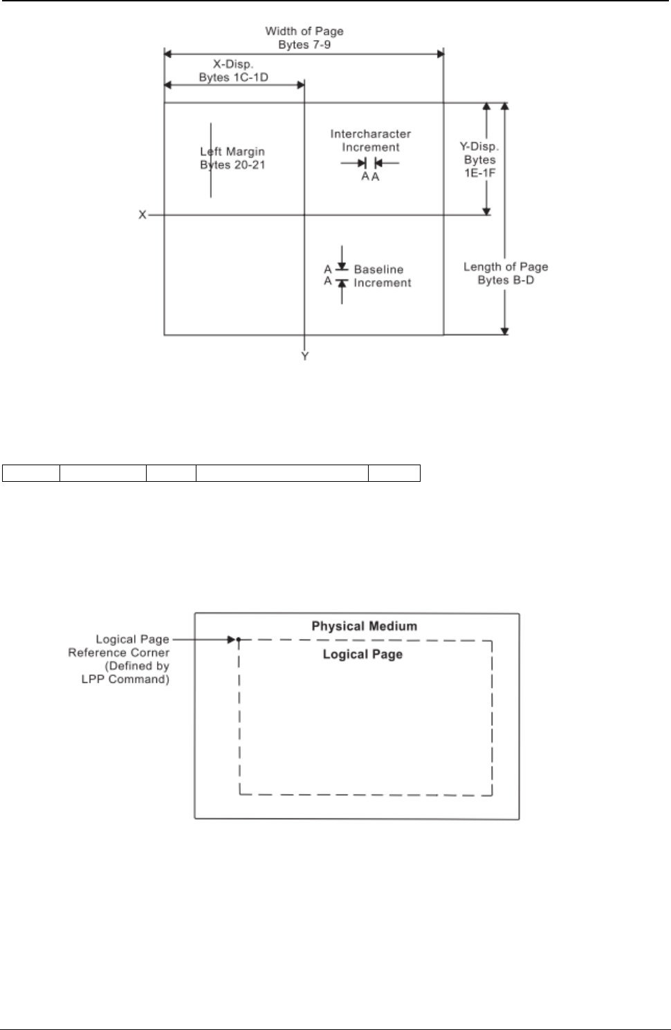
ProgrammerManual PTX‐S828
Chapter5IPDSProgrammingInformation129260071‐001A
Figure 12. Using the Load Page Descriptor Command to Specify the Logical Page
Logical Page Position (LPP)
Length D66D Flag Correlation ID (Optional) Data
This command positions the upper left corner of the logical page (defined by the Logical Page Descriptor
control) with respect to the physical medium. The Logical Page Position command is only valid in the
home state.
Figure 13 shows the LPP command positioning the logical page on the physical medium.
Figure 13. Using the Logical Page Position Command to Position
The physical medium dimensions do not change. The X and Y coordinates of the LPP command specify
the location of the Logical Page Reference Corner relative to the corresponding corner of the physical
medium. These coordinates are expressed in terms of the units in effect at the time the LPP command is
received.
ProgrammerManual PTX‐S828
Chapter5IPDSProgrammingInformation130260071‐001A
Only positive values are valid for the data field. The format of the data field (DATA) for this command is:
Decimal Hex Value Description
0 0 00 Reserved
1-3 1-3 000000-007FFF X Displacement
4 4 00 Reserved
5-7 5-7 000000-007FFF Y Displacement
8-9 8-9 0000 Reserved
Deactivate Font (DF)
Length D64F Flag Correlation ID (Optional) Data
The Deactivate Font command provides a means for the control unit to delete one or more fonts from the
printer.
End Page (EP)
Length D6BF Flag Correlation ID (Optional) Data
This command causes the printer to return to the home state from the page, page segment, or overlay
state. If the printer is in the page state, the printer completes any deferred printing for the current page
and advances the forms to the top of the next page. Zero or more bytes of data may be transmitted with
this command but are ignored.
End (END)
Length D65D Flag Correlation ID (Optional) Data
The End command is the ending control for a graphics block, image block, or bar code block state. This
command completes a series of write image, write graphics, or write bar code commands. This command
does not transmit any data. At the completion of this command, the printer leaves the block state and
returns to the page, overlay, or page segment state.
Execute Order Home State (XOH)
Length D68D Flag Correlation ID (Optional) Data
Subcommand Subcommand Data
The Execute Order Home State command identifies a set of subcommands (orders) for formatting physical
mediums of data, printing groups of physical mediums, and managing the fonts, page segments, and
overlays. This command is only valid while the printer is in the home state.
The data field contains a two byte order, called the subcommand, and a subcommand data field. There is
only one subcommand for a single XOH command. The subcommand data field contains parameters for
that order.

ProgrammerManual PTX‐S828
Chapter5IPDSProgrammingInformation131260071‐001A
The valid orders for the XOH command for the S828 Printer are:
Order Description
0100 Print Buffered Data (PBD)
0500 Erase Residual Print Data (ERPD)
0700 Erase Residual Font Data (ERFD)
0D00 Stack Received Pages (SRP)
1500 Select Input Media Source (SIMS)
1700 Set Media Size (SMS)
F300 Obtain Printer Characteristics (OPC)
Print Buffered Data (PBD)
This subcommand causes the printer to print all buffered data pages prior to sending the Acknowledgment
Reply, if requested. The print buffer clears at the completion of this command.
Erase Residual Print Data (ERPD)
This is a data security and privacy order. This order causes the printer to first complete a Print Buffered
Data order, then delete all page segments, overlays, and buffered page data (text, image, graphics, and
bar codes) from the printer storage.
Erase Residual Font Data (ERFD)
This is a data security and privacy order. This order causes the printer to first complete a Print Buffered
Data order, then delete all font information from the printer storage.
Stack Received Pages (SRP)
This command is a synchronizing command. It is accepted by the S828 Printer, but it is functionally a
no-op because of the simple paper path.
Select Input Media Source (SIMS)
The Select Input Media Source (SIMS) subcommand selects an input media source ID and indirectly
selects the input for subsequent sheets. This subcommand applies to the sheet that the next received
page is printed on.
The size of the input media can be specified explicitly by the Set Media Size command or implicitly by the
assumptions the printer makes about the size of the media in the input media source selected by this
subcommand.
The set of valid Media Source ID values depend on what paper sources are currently installed. The
following tables give the valid values for the configurations described in each table.
If the printer is in 4247 mode or an emulation mode with one or two tractors installed, valid values are:
Table 7. Front and Rear with no linking
Bytes 0-1 X'1500' Select Input Media Source Order Code
Byte 2 X'00' Front Paper Source
X'01' Rear Paper Source (if configured)
X'FF' Printer Default Bin
Set Media Size (SMS)
The Set Media Size subcommand specifies the size of the physical medium.
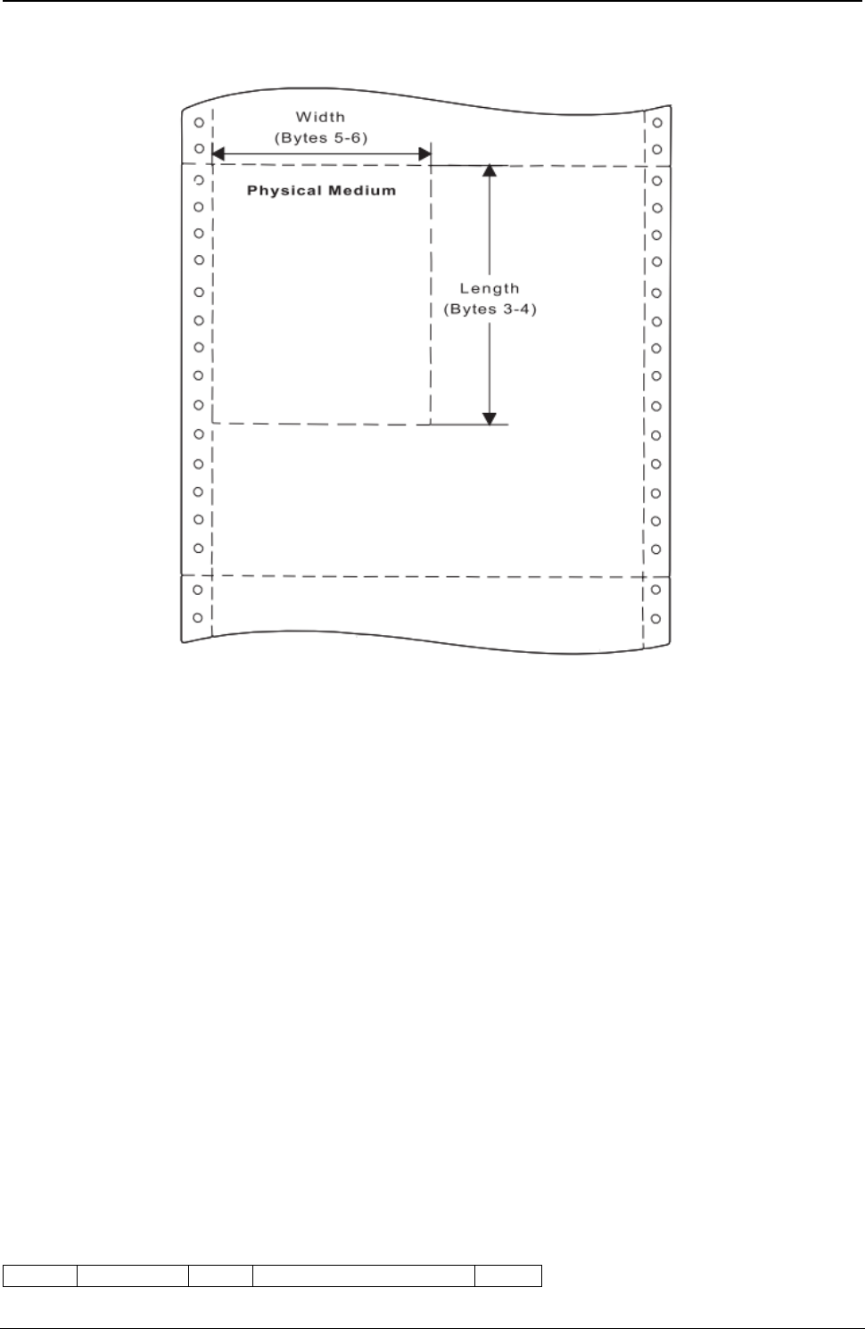
ProgrammerManual PTX‐S828
Chapter5IPDSProgrammingInformation132260071‐001A
Refer to your printer's Administrators Manual for information on setting operator media size input.
Figure 14. Using the Set Media Size Command to Specify the Physical Medium
The data field for the Set Media Size subcommand has the following format:
Decimal Hex Value Description
0 0 00 Unit Base (10 in.)
01 Unit Base (10 cm.)
1-2 1-2 5A0-7FFF Units per Base Value (per 10 in.)
1626-7FFF Units per Base Value (per 10 cm)
3-4 3-4 000A-4A40 X-Extent of the Physical Medium in Units
FFF Use Current MPP
5-6 5-6 000A-7FFF Y-Extent of the Physical Medium in Units
FFFF Use Current MPL
Obtain Printer Characteristics (OPC)
This subcommand is a host request for information about the current printer environment characteristics.
The printer responds by placing the requested information in the Special Data (SD)area of a subsequent
Acknowledge Reply. The printer reply is a series of self-defining fields describing the printer
characteristics. The OPC data is returned in more than one response buffer. The self-defining fields
contain specific information about the printer characteristics. If the ARQ flag was not set on for the XOH
command containing this order, then this order is equivalent to a No Operation.
Acknowledge Reply for Obtain Printer Characteristics:
Length D6FF Flag Correlation ID (Optional) Data

ProgrammerManual PTX‐S828
Chapter5IPDSProgrammingInformation133260071‐001A
The following charts describe the self-defining data fields.
Acknowledge Type and Counters:
Decimal Hex Value Description
0 0 06 Acknowledgement Type (4 byte)
1-4 1-4 XXXXXXXX Page/Copy Counters
Printable Area Self-Defining Field: The page extents are set at initialization time to reflect
the operator panel settings. The Set Media Size command can change the page extents. For 4247 mode
and all emulation modes with one or two tractors installed:
Decimal Hex Value Description
0-1 0-1 0018 Length of this Field
2-3 2-3 0001 Printable Area ID
4 4 Media Source ID (See notes)
00 Front Continuous Forms
01 Rear Continuous Form
5 5 00 Reserved
6 6 00 00 Unit Base (10 in.)
7 7 00 Reserved
8-9 8-9 3840 Units per Base Value (Decimal 14400 per 10 in.)
10-11 A-B XXXX Current Forms X-Extent
12-13 C-D XXXX Current Forms Y-Extent
14-15 E-F 0000 Printable Area X-Offset
16-17 10-11 0000 Printable Area Y-Offset
18-19 12-13 XXXX Printable Area X-Extent (from Page Extent)
20-21 14-15 XXXX Printable Area Y-Extent from Page Extent
22-23 16-17 XX00 Input Media Source Characteristics
Bit 0 0 =No Duplex
Bit 1,2 01=Continuous Forms
Bit 3 1 =Media Source Available
Bit 4 0 =Reserved (Always 0)
Bit 5 0 =Reserved (Always 0)
Bit 6 0 =Reserved (Always 0)
Bit 7 0 =Reserved (Always 0)
Note: The Printable Area Self-Defining Field is returned once for each installed media source; that is, front
and rear tractor.
Symbol-Set Support Self-Defining Field:
Decimal Hex Value Description
0-1 0-1 0046 Length of this field
2-3 2-3 0002 Symbol Set Support ID

ProgrammerManual PTX‐S828
Chapter5IPDSProgrammingInformation134260071‐001A
Decimal Hex Value Description
4 4 10 Length of Self-Defining Parameter
5 5 01 Fixed Box Size Support (Fixed Pitch NLQ)
6 6 14 X-Box Size in Pels (20)
7 7 12 Y-Box Size in Pels (18)
8 8 00 Reserved
9 9 02 Repeating Group Length
10-11 A-B 000B 10 CPI Courier (NLQ)
12-13 C-D 0055 12 CPI Courier (NLQ)
14-15 E-F 00DF 15 CPI Courier (NLQ)
16-17 10-11 0013 10 CPI OCR-A (NLQ)
18-19 12-13 0003 10 CPI OCR-B (NLQ)
20 14 0C Length of Self Defining Parameter
21 15 01 Fixed Box Size Support (Fixed Pitch DP Text)
22 16 14 X-Box Size in Pels (20)
23 17 09 Y-Box Size in Pels (9)
24 18 00 Reserved
25 19 02 Repeating Group Length
26-27 1A-1B 000B 10 CPI Courier (DP Text)
28-29 1C-1D 0055 12 CPI Courier (DP Text)
30-31 1E-1F 00DF 15 CPI Courier (DP Text)
32 20 0E Length of Self Defining Parameter
33 21 01 Fixed Box Size Support (Fixed Pitch DP Text)
34 22 A0 X-Box Size in Pels (20)
35 23 09 Y-Box Size in Pels (9)
36 24 00 Reserved
37 25 02 Repeating Group Length
38-39 26-27 001A 10 CPI Gothic (DP)
40-41 28-29 0057 12 CPI Gothic (DP)
42-43 2A-2B 00DE 15 CPI Gothic (DP)
44-45 2C-2D 0190 16.7 CPI Gothic (DP)
46 2E 0C Length of Self Defining Parameter
47 2F 02 Variable Box Size Support (PSM NLQ)
48 30 00 Unit Base (10 in.)
49 31 00 Reserved
50-51 32-33 0960 Units per Unit Base (2400)
52 34 FF Maximum X-Box Size in Pels (255)
53 35 12 Y-Box Size in Pels (18)
54 36 00 Reserved
55 37 02 Repeating Group Length
56-57 38-39 00A0 PSM Essay (NLQ)
58 3A 0C Length of Self-Defining Parameter

ProgrammerManual PTX‐S828
Chapter5IPDSProgrammingInformation135260071‐001A
Decimal Hex Value Description
59 3B 02 Variable Box Size Support (PSM DP Text)
60 3C 00 Unit Base (10 in.)
61 3D 00 Reserved
62-63 3E-3F 0960 Units per Unit Base (2400)
64 40 FF Maximum X-Box Size in Pels (255)
65 41 09 Y-Box Size in Pels (9)
66 42 00 Reserved
67 43 02 Repeating Group Length
67-68 44-45 00A0 PSM Essay (DP Text)
Image/Coded-Font Self-Defining Field:
Decimal Hex Value Description
0-1 0-1 000A Length of this field
2-3 2-3 0003 Image/Coded-Font Resolution ID
4 4 00 Unit Base (10 in.)
5 5 00 Reserved
6-7 6-7 05A0 X Pels per Base Value (Decimal 1440 per 10 in.)
8-9 8-9 05A0 Y Pels per Base Value (Decimal 1440 per 10 in.)
Storage Pools Self-Defining Field:
Decimal Hex Value Description
0-1 0-1 000F Length of this field
2-3 2-3 0004 Storage Pools ID
4 4 0B Length of Self-Defining Parameter
5 5 01 Triplet ID
6 6 00 Storage Pool ID
7-10 7-A 0006D000 Size of Storage Pool when empty
11-14 B-E 00000000 Reserved
Foreground Color Support Self-Defining Field:
Decimal Hex Value Description
0-1 0-1 0006 Length of this field
2-3 2-3 0005 Foreground Color
4-5 4-5 0008 Black Ribbon
Installed Features Self-Defining Field:
Decimal Hex alue Description
0-1 0-1 0006 Length of this field
2-3 2-3 0006 Installed Features ID
4-5 4-5 0B00 Continuous Forms Output

ProgrammerManual PTX‐S828
Chapter5IPDSProgrammingInformation136260071‐001A
Available Features Self-Defining Field:
Decimal Hex Value Description
0-1 0-1 0006 Length of this field
2-3 2-3 0007 Available Features
4-5 4-5 0B00 Continuous Forms Output
Resident-Symbol Set Support Self-Defining Field: For Ethernet interfaces:
Decimal Hex Value Description
0-1 0-1 00B6 Length of this field
2-3 2-3 0008 Resident Symbol Set Support
4 4 6A Length of this field
5 5 01 Code Page Support
6 6 56 Length of Code Page List
7 7 02 Length of CP Repeating Group Entry
8-9 8-9 01A7 CP423 Greek (Old)
10-11 A-B 01A8 CP424 Hebrew (New)
12-13 C-D 01B5 CP437 PC Extended
14-15 E-F 0323 CP089 Hebrew (Old)
16-17 10-11 0366 CP870 Latin 2/ROECE
18-19 12-13 0367 CP871 Icelandic
20-21 14-15 036B CP875 Greek (New)
22-23 16-17 0402 CP1026 Turkish
24-25 18-19 0100 CP256 International #1
26-27 1A-1B 01F4 CP500 International #2
28-29 1C-1D 0025 CP037 USA/Canada
30-31 1E-1F 0104 CP260 Canadian French
32-33 20-21 0111 CP273 Austrian/German
34-35 22-23 0112 CP274 Belgian
36-37 24-25 0113 CP275 Brazilian
38-39 26-27 0115 CP277 Danish/Norwegian
40-41 28-29 0116 CP278 Finnish/Swedish
42-43 2A-2B 0118 CP280 Italian
44-45 2C-2D 0119 CP281 Japanese English
46-47 2E-2F 011A CP282 Portuguese
48-49 30-31 011C CP284 Spanish and Spanish-Speaking
50-51 32-33 011D CP285 English (UK)
52-53 34-35 0129 CP297 French (Alternate)
54-55 36-37 011E CP286 Austrian/German (Alternate)

ProgrammerManual PTX‐S828
Chapter5IPDSProgrammingInformation137260071‐001A
Decimal Hex Value Description
56-57 38-39 0121 CP289 Spanish (Alternate)
58-59 3A-3B 0120 CP288 Finnish/Swedish (Alternate)
60-61 3C-3D 011F CP287 Danish/Norwegian (Alternate)
62-63 3E-3F 033F CP831 Portuguese (Alternate)
64-65 40-41 037A CP890 Yugoslav
66-67 42-43 0458 CP1112 Baltic Multilingual
68-69 44-45 0462 CP1122 Estonian
70-71 46-47 0474 CP1140 USA/Canada + euro
72-73 48-49 0475 CP1141 Austrian/German + euro
74-75 4A-4B 0476 CP1142 Danish/Norwegian +euro
76-77 4C-4D 0477 CP1143 Finnish/Swedish + euro
78-79 4E-4F 0478 CP1144 Italian + euro
80-81 50-51 0479 CP1145 Spanish/Spanish Speaking + euro
82-83 52-53 047A CP1146 English UK + euro
84-85 54-55 047B CP1147 French + euro
86-87 56-57 047C CP1148 International 5 / Beligian New + euro
88-89 58-59 047D CP1149 Icelandic + euro
90-91 5A-5B 039C CP924 Latin 9 ISO 8859 +euro
92 5C 12 Length of Font ID List
93 5D 02 Length of Font ID Repeating Group Entry
94-95 5E-5F 000B 10 CPI Courier (DP Text and NLQ)
96-97 60-61 0055 12 CPI Courier (DP Text and NLQ)
98-99 62-63 00DF 15 CPI Courier (DP Text and NLQ)
100-101 64-65 001A 10 CPI Gothic (Fast Draft and DP)
102-103 66-67 0057 12 CPI Gothic (Fast Draft and DP)
104-105 68-69 00DE 15 CPI Gothic (Fast Draft and DP)
106-107 6A-6B 0190 16.7 CPI Gothic (Fast Draft and DP)
108-109 6C-6D 00A0 PSM ESSAY (DP Text and NLQ)
110 6E 28 Total Length of CP List
111 6F 01 CP Support
112 70 16 Length of CP List
113 71 02 Length of CP Repeating Group Entry
114-115 72-73 0122 CP290 Japanese Katakana
116-117 74-75 01A4 CP420 Arabic
118-119 76-77 0346 CP838 Thai
120-121 78-79 0370 CP880 Cyrillic (Old)
122-123 7A-7B 0401 CP1025 Cyrillic Multinational
124-125 7C-7D 03EA CP1002 DCF Compatibility (Release 2)
126-127 7E-7F 0125 CP293 APL (4224 Compatibility)
128-129 80-81 0136 CP310 APL
130-131 82-83 0341 CP833 Korean

ProgrammerManual PTX‐S828
Chapter5IPDSProgrammingInformation138260071‐001A
Decimal Hex Value Description
132-133 84-85 0449 CP1097 Farsi
134 86 10 Length of Font ID List
135 87 02 Length of Font ID Repeating Group Entry
136-137 88-89 000B 10 CPI Courier (DP Text and NLQ)
138-139 8A-8B 0055 12 CPI Courier (DP Text and NLQ)
140-141 8C-8D 00DF 15 CPI Courier (DP Text and NLQ)
142-143 8E-8F 001A 10 CPI Gothic (Fast Draft and DP)
144-145 90-91 0057 12 CPI Gothic (Fast Draft and DP)
146-147 92-93 00DE 15 CPI Gothic (Fast Draft and DP)
148-149 94-95 0190 16.7 CPI Gothic (Fast Draft and DP)
150 96 0C Total Length of CP List
151 97 01 CP Support
152 98 04 Length of CP List
153 99 02 Length of CP Repeating Group Entry
154-155 9A-9B 0154 CP 340,OCR (4224 compatibility)
156 9C 06 Length of Font ID List
157 9D 02 Length of Font ID Repeating Group Entry
158-159 9E-9F 0013 OCR-B Quality
160-161 A0-A1 0003 OCR-A Quality
162 A2 0A Total Length of CP List
163 A3 01 CP Support
164 A4 04 Length of CP List
165 A5 02 Length of CP Repeating Group Entry
166-167 A6-A7 037C CP 892,OCR-A
168 A8 04 Length of Font ID List
169 A9 01 Length of Font ID Repeating Group Entry
170-171 AA-AB 0013 OCR-A Quality
172 AC 0A Total Length of CP List
173 AD 01 CP Support
174 AE 04 Length of CP List
175 AF 02 Length of CP Repeating Group Entry
176-177 B0-B1 037D CP 893,OCR-B
178 B2 04 Length of Font ID List
179 B3 02 Length of Font ID Repeating Group Entry
180-181 B4-B5 0003 OCR-B Quality
Print Quality Support Self-Defining Field: These values apply if Host Fast Draft is
disabled in the printer configuration menu:

ProgrammerManual PTX‐S828
Chapter5IPDSProgrammingInformation139260071‐001A
Decimal Hex Value Description
0-1 0-1 0007 Length of this field
2-3 2-3 0009 Print Quality ID
4 4 01 DP Quality
5 5 56 DP Text Quality
6 6 AB NLQ
These values apply if Host Fast Draft is enabled in the printer configuration menu:
Decimal Hex Value Description
0-1 0-1 0008 Length of this field
2-3 2-3 0009 Print Quality ID
4 4 01 Fast Draft Quality
5 5 2B DP Quality
6 6 56 DP Text Quality
7 7 AB NLQ
XOA RRL RT & RIDF Support Self-Defining Field:
Decimal Hex Value Description
0-1 0-1 0006 Length
2-3 2-3 000A RRL Resource Type Self Defining Field
4-5 4-5 FF00 All Resources as Host Assigned Resource ID
Common Bar Code Type Self-Defining Field:
Decimal Hex Value Description
0-1 0-1 0007 Length of this field
2-3 2-3 000E RRL Resource Type Self Defining Field
4 4 0D Codabar Modifier Byte Options X'01' and X'02'
5 5 11 Code 128 Modifier Byte Options X'02'
6 6 1 8 POSTNET Modifier Byte Options X'00' - X'03'
Product Identifier Self-Defining Field: If the printer is in 4247 native or 4230 Emulation
Mode:
Decimal Hex Value Description
0-1 0-1 003C Length
2-3 2-3 0013 Product Identifier
4 4 38 Length of this ID
5-6 5-6 0001 4247 with Page Counter Fix ID
7-12 7-C F0F0F4F2F4F7 Device Type
13-15 D-F E5F0F3 Model Number
16-18 10-12 C9C2D4 Manufacturer
ProgrammerManual PTX‐S828
Chapter5IPDSProgrammingInformation140260071‐001A
Decimal Hex Value Description
19-20 13-14 F0F1 Plant of Manufacture
21-32 15-20 XX...XX Sequence Number
33-34 21-22 0000 Tag
35-43 23-2B XX...XX EC Level
44-59 2C-3B XX...XX Device Specific
If the printer is in 4224 emulation mode:
Decimal Hex Value Description
0-1 0-1 003F Length
2-3 2-3 0013 Product Identifier
4 4 03 Length of this Field
5-6 5-6 0000 4224 with Page Counter Fix ID
7 7 38 Length of this Field
8-9 8-9 0001 4224 Product Identifier Parameter ID
10-15 A-F F0F0F4F2F4F7 Device Type
16-18 10-12 E5F0F3 Model Number
19-21 13-15 C9C2D4 Manufacturer
22-23 16-17 F0F1 Plant of Manufacture
24-35 18-23 XX...XX Sequence Number
36-37 24-25 0000 Tag
38-46 26-2E XX...XX EC Level
47-62 2F-3E XX...XX Device Specific
Execute Order Any State (XOA)
Length D633 Flag Correlation ID (Optional) Data
Subcommand Subcommand Data
The Execute Order Any State command identifies a set of subcommands (orders) that take effect
immediately, regardless of the current printer command state. This command is valid in any state.
Each data field contains a two byte order (subcommand), followed by a zero or more bytes of parameters
for that order. There is only one subcommand for a single XOA command.
The valid orders for the XOA command are:
Order Description
1000 Activate Printer Alarm (APA)
F200 Discard Buffered Data (DBD)
F400 Request Resource List (RRL)
F600 Exception Handling Control (EHC)

ProgrammerManual PTX‐S828
Chapter5IPDSProgrammingInformation141260071‐001A
Order Description
F800 Print Quality Control (PQC)
Activate Printer Alarm (APA)
The XOA Activate Printer Alarm (APA) subcommand signals the printer to activate the alarm mechanism.
As long as the printers alarm function is enabled, the alarm will be turned on in response to this command.
It will remain on until Stop is pressed.
After processing this command, the printer continues to process the incoming IPDS data stream. If
synchronization of actions is desired, the application must ensure if the appropriate commands are sent to
the printer.
Discard Buffered Data (DBD)
The XOA Discard Buffered Data (DBD) subcommand deletes all buffered data from the printer storage and
returns the printer to home state. Any data currently being received is deleted. If this order is syntactically
correct, no exceptions can result from its execution. The DBD order does not affect completely received
resources, such as fonts, page segments, and overlays; however, if the printer is in any resource state, the
printer deletes the partial resource before returning to home state. If the printer is in Ordered Page Mode,
the subcommand prints all buffered data to the point of the command, does a page eject, and returns to
Home State.
The DBD order is a synchronizing command. Any command following a synchronizing command is not
processed until all preceding commands have been completely processed. Also, the ACK of the DBD order
is not returned until DBD processing is complete.
Request Resource List (RRL)
This subcommand is a request from the host application program for the printer to identify resources
currently allocated in the printer. The printer responds by placing the requested information in the Special
Data (SD) area of a subsequent Acknowledge Reply.
The subcommand and subcommand data field has the following format:
Decimal Hex Value Description
0-1 0-1 F400 RRL Order Code
2 2 FF Device Defined Ordering
3-4 3-4 XXXX Entry Continuation Indicator (See Note 1)
5 5 03 - FF Entry Length
6 6 Resource Type Requested (See Note 2)
01 Single Byte Fonts
04 Page Segments
05 Overlays
FF All Resources
7 7 00 Resource ID Format
Host-Assigned Resource ID
8-9 8-9 XXXX Resource ID (See Note 2)

ProgrammerManual PTX‐S828
Chapter5IPDSProgrammingInformation142260071‐001A
Notes:
1. If the entire resource list does not fit in the Special Data Area of the Acknowledge Reply, continuation is
necessary which the S828 Printer will indicate using the Acknowledgement Continuation bit in the flag byte of
the Acknowledge Reply. If the host requests Acknowledgement Continuation by sending a command with
ARQ bit and the Continuation bit set, the printer will complete the RRL reply using Acknowledgement
Continuation. If the host requests RRL continuation (by sending an RRL command with nonzero values in
bytes 3 and 4), the printer will use continuation, the printer will default to RRL continuation.
2. For overlays, segments, and symbol sets, this is their two byte ID. This field is omitted when the resource
type equals All.
Acknowledge Reply for Request Resource List
Length D6FF Flag Correlation ID (Optional) Data
The format of the resource list returned with the Acknowledge Reply is as follows:
Decimal Hex Value Description
0 0 FF Unordered List
1 1 01 End of List
06 Length of this Entry
2 2 Resource Type
00 Resource Size equals 0. The queried Resource Type, ID
Format, or ID is unknown, unsupported, or inconsistent.
01 Deletable Single Byte Coded Font
04 Deletable Overlays
05 Resource Size equals 0
FF The List Query requested is not supported.
3 3 01 Resource ID Format (RIDF)
Host-Assigned Resource ID
4 4 Resource Size Indicator
00 Resource Not Present
01 Resource Present
5-6 5-6 XXXX Resource ID
Note: Bytes 2 - 6 repeat for each resource type.
Exception Handling Control (EHC)
An exception (error) exists when the printer detects an invalid or unsupported command, control, or
parameter value in the data stream received from the host. The IPDS structure provides Alternate
Exception Action (AEA) when the printer receives a valid parameter value, but the printer does not support
this value. The Exception Handling Control subcommand allows the host control of exception handling by
the printer. This subcommand specifies the action the printer is to take with respect to the reporting and
processing of exception (error) conditions. The format of the EHC subcommand is:
Decimal Hex Value Description
0-1 0-1 F600 EHC Order Code

ProgrammerManual PTX‐S828
Chapter5IPDSProgrammingInformation143260071‐001A
Decimal Hex Value Description
2 2 Exception Reporting
Bit 0 Bit 0 Undefined Character Check
0 Do Not Report Exceptions
1 Report Exceptions
Bit 1 Bit 1 Page Position Check
0 Do Not Report Exceptions
1 Report Exceptions
Bit 2-6 Bit 2-6 Reserved
Bit 7 Bit 7 All other Errors
0 Do Not Report Exceptions
1 Report Exceptions
3 3 Alternate Exception Action
Bit 0-6 Bit 0-6 Reserved
Bit 7 Bit 7 0 Take Alternate Exception Action and Continue
1 Do Not Take Alternate Exception Action, Proceed per Byte 4
4 4 Exception Presentation Processing
Bit 0-5 Bit 0-5 Reserved
Bit 6 Bit 6 0 No Page Continuation
1 Page Continuation (Skip and Continue Action)
Bit 7 Bit 7 0 Discard Page
1 Print to point of exception
Exception Reporting: Byte 2 of the EHC subcommand handles exception reporting. Bits 0, 1, and 7 of
this byte may be set to report or not report exceptions as defined below. If the exception has no Alternate
Exception Action or the printer is told not to take the Alternate Exception Action, the exception is always
reported.
● Bit 0: Report Undefined Character Check
When this bit is set to 1, an undefined data character in a Write Text, Write Graphics, or Write Bar Code
command causes the printer to report an error to the host program. When this bit is set to 0, the printer
does not report Undefined Character Check errors.
● Bit 1: Report Page Position Check
Printing occurs only where the physical medium and the logical page overlap. When bit 1 is set to 1, an
attempt to print outside the overlap of the logical page and the physical medium causes the printer to
report an error. If bit 1 is set to 0, the printer does not report Position Check errors.
● Bits 2-6: Reserved
● Bit 7: Report all other exceptions

ProgrammerManual PTX‐S828
Chapter5IPDSProgrammingInformation144260071‐001A
If this bit is set to 1, the printer reports all exceptions other than those defined by bits 0-1. If this bit is
set to 0, the printer does not report errors other than those specified above.
If the printer is in home state or the application requests an Acknowledge Reply in an IPDS command, the
printer reports exceptions with a Negative Acknowledge Reply (NACK). If an exception occurs within a
page, overlay, or page segment, the printer reports the NACK instead of sending a positive
acknowledgment of the page, overlay, or page segment.
The first asynchronous NACK is the only one reported, even though other synchronous NACKs may be
detected before the first NACK is reported. If the printer has a pending exception (the exception has
occurred but has not yet been reported), the printer reports the exception when exception handling control
directs.
Alternate Exception Action: Byte 3 of the EHC subcommand controls Alternate Exception Actions.
● Bits 0-6: Reserved
● Bit 7: Alternate Exception Action (AEA) control
This bit defines how printer processing continues when a data stream error occurs.
If the bit is set to 0, the printer continues processing with the Alternate Exception Action. If the error has
no Alternate Exception Action defined, the printer continues as though this bit contained a 1.
If this bit is set to 1 or no AEA is defined, the printer reports the error regardless of the value in the
Exception Reporting byte above. The printer continues processing as defined by the contents of the
Exception Presentation Processing byte below.
Exception Presentation Processing: Byte 4 of the EHC subcommand defines what the printer does
when exceptions occur in any state except home state.
● Bits 0-5: Reserved
● Bit 6: Page Continuation
If bit 6 is 0, the printer does the following:
– Terminates processing of the page, overlay, or page segment data
– Prints as much of the previously processed data as possible
– Enters home state.
If bit 6 is set to 1, the printer ignores bit 7 (Error Page Print) after taking a skip and continue action.
The printer remains in the current state and treats subsequent commands as No Operation (NOP) until
it encounters either the next valid command or a terminating condition.
1. Skip and Continue Action
Skip and Continue Actions are attempts by the printer to skip the remainder of the IPDS block
containing the exception and to print subsequent blocks or text on the page (if any).
The printer treats all subsequent commands other than Any State commands (NOP, SHS, STM, and
XOA) as No Operation (NOP) commands until it encounters either the next valid command or a
terminating condition. The printer remains in page, page segment, or overlay state. If the printer is in
a block state, the End command is the next valid command that returns the printer to page, page
segment, or overlay state. When the next valid command is encountered, the printer begins normal
processing again. The exception that caused the skip and continue action is reported when the end
of the page is reached, when an XOA command sets home state, or when a command with an ARQ
is received. The following conditions determine the next valid command:
– If the exception occurs in a Write Text command, a Load Font Equivalence command, or an
Include Page Segment command, the next valid command is End Page, Set Home State, or
XOA Discard Buffered Data.
– If the exception occurs in a block state, the next valid command is End.
– If the exception occurs in an Any-state command, the next valid command is the command that
follows.

ProgrammerManual PTX‐S828
Chapter5IPDSProgrammingInformation145260071‐001A
– If the exception occurs in any other command, the next valid command is one of the following (if
supported):
- Write Text
- Include Overlay
- Include Page Segment
- Write Text Control
- Write Image Control
- Write Image Control 2
- Write Bar Code Control
- Write Graphics Control
- End Page
- Set Home State
- XOA Discard Buffered Data
- Load Font Equivalence.
If the following terminating conditions occur, the printer returns to home state and reports the
indicated exception:
– An asynchronous exception occurs such that the printer cannot recover without host intervention.
The asynchronous exception is reported and the exception that caused the skip and continue
action is discarded.
– A command is received with the ARQ flag set on. The exception that caused the skip and
continue action is reported.
– A command is received with a length outside the valid IPDS range. The exception that caused
the skip and continue action is reported.
– A command is received that violates the IPDS state diagram. The exception that caused the skip
and continue action is reported.
During skip and continue actions, Any-state commands are treated as follows:
– SHS and XOA-DBD are next valid commands in all cases. They are processed, the skip and
continue action processing is terminated, the exception is reported, and normal command
processing resumes.
– Any-state commands with the ARQ bit set on are terminating conditions. They are not processed;
they terminate skip and continue processing, the exception is reported, and the printer returns to
home state.
– All other Any-state commands are processed as normal. However, subsequent non-Any-state,
non-next valid commands are skipped.
Exceptions detected in included overlays or page segments are treated as though the commands
were received as part of the page.
● Bit 7: Error Page Print
If both bits 6 and 7 are set to 1, bit 7 is ignored. If bit 6 is 0 and bit 7 is 1, the printer prints as much of
the page as possible and returns to home state.
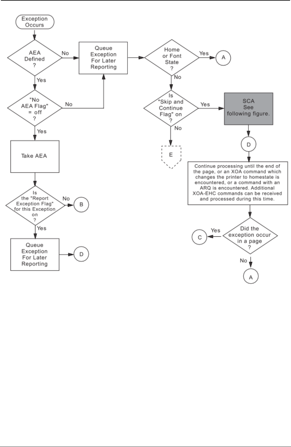
ProgrammerManual PTX‐S828
Chapter5IPDSProgrammingInformation146260071‐001A
Figure 15. Exception Handling Control (Part 1 of 3)
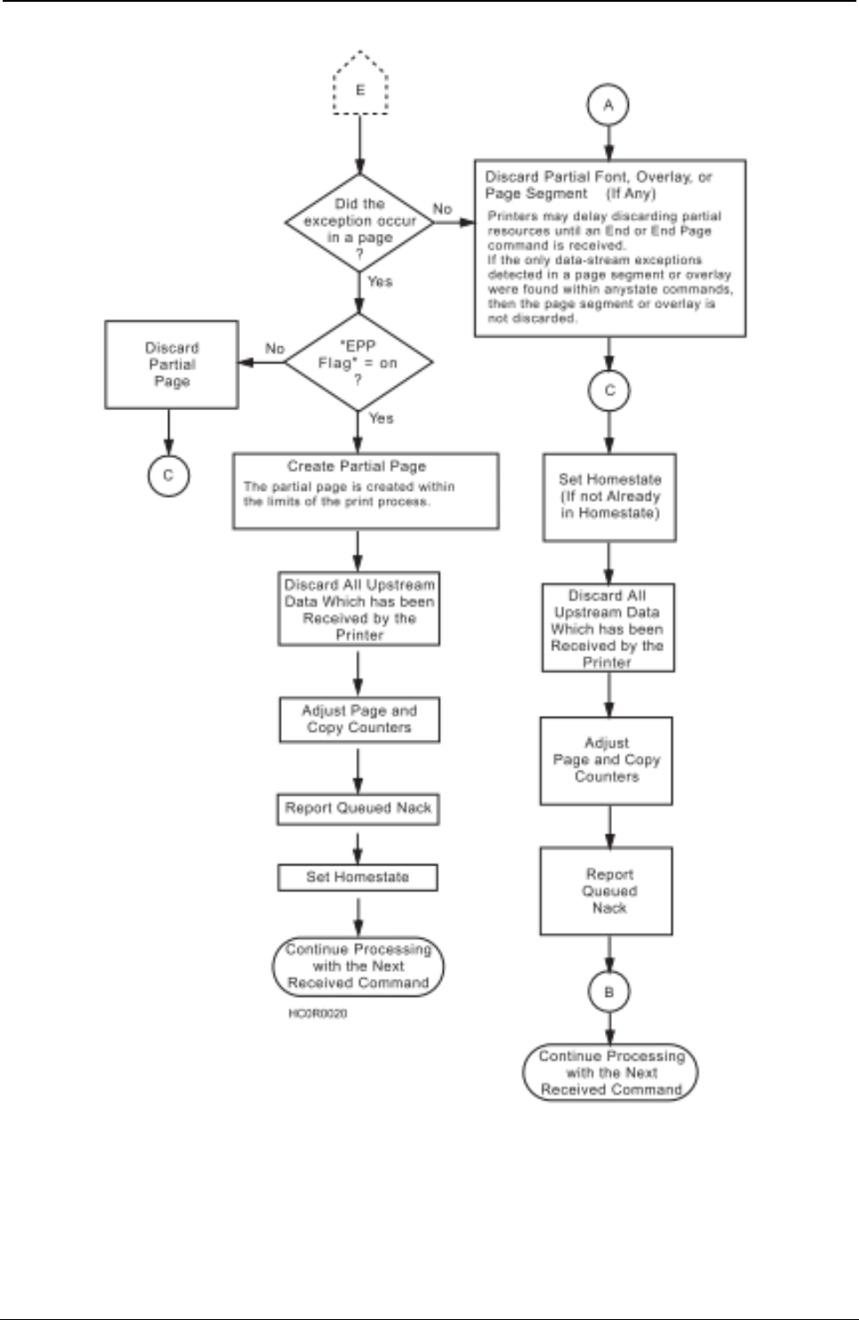
ProgrammerManual PTX‐S828
Chapter5IPDSProgrammingInformation147260071‐001A
Figure 15. Exception Handling Control (Part 2 of 3)
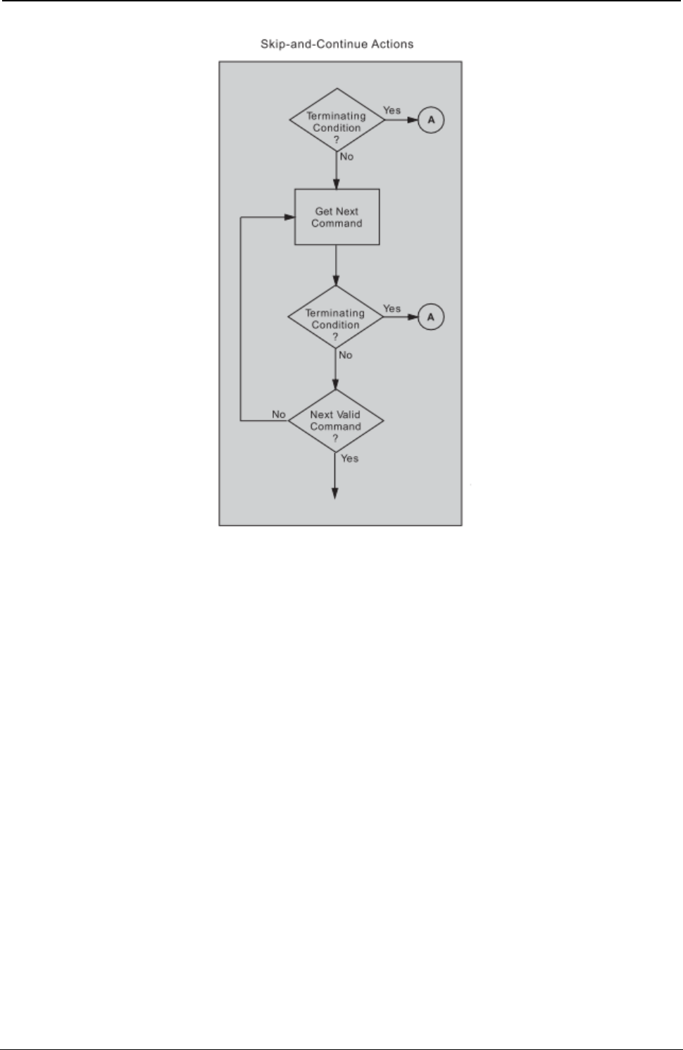
ProgrammerManual PTX‐S828
Chapter5IPDSProgrammingInformation148260071‐001A
Figure 15. Exception Handling Control (Part 3 of 3)
Print Quality Control (PQC)
The Print Quality Control subcommand allows the host to specify the desired print quality without changing
fonts (see notes). The quality selection (from the PQC subcommand) specifies the quality for printing text
associated with fonts selected by the Set Coded Font Local (SCFL) command and defined by the Load
Font Equivalence (LFE) command. A PQC specifying a print quality compatible with the desired font
should precede the SCFL command. The PQC has no effect when the default font (defined by the offline
operator panel selection) is in use.
The following bytes contain the print quality selection, as shown:
Byte Value Description
Bit 0-1 F800 PQC Order Code
Bit 2 00 Reserved
01 - 55 DP
56 - AA DP Text
AB - FE NLQ
FF Depends on Operator Panel setting
Note: Host Fast Draft disabled.

ProgrammerManual PTX‐S828
Chapter5IPDSProgrammingInformation149260071‐001A
The following bytes contain the print quality selection, as shown:
Byte Value Description
Bit 0-1 F800 PQC Order Code
Bit 2 01 - 2A Fast Draft Quality
2B - 55 DP
56 - AA DP Text
AB - FE NLQ
FF Depends on Operator Panel setting
Note: S828 only with Host Fast Draft enabled.
For printing multiple-density selections of graphics and bar codes, the following values are valid if bar
code/graphics density is set to computer selected:
Byte Value Description
Bit 0-1 F800 PQC Order Code
Bit 2 01 - 55 Low-Density Graphics/Bar Codes
56 - FE High-Density Graphics/High-Contrast Bar Codes
FF Depends on Operator Panel setting
Notes:
1. A PQC command can result in a font change in order to provide the desired quality level.
2. The printer changes fonts to satisfy quality selections for all supported code pages except OCR (340),
OCR-A (892), or OCR-B (893). It will not change the selected code page to provide a requested quality.
Text Function Set Commands
The text function set contains the commands and data controls for presenting text information on a logical
page, page segment, or overlay area on the physical medium. The following commands are the text
function set:
The following pages describe the text function set commands.
Load Equivalence (LE)
Length D61D Flag Correlation ID (Optional) Data
This command permits Begin and End suppression controls imbedded in data stored within the printer to
reference different external values. For example, internal suppression values of 06, 07, and 09 (from a
Begin Suppression control) can map to an external value of 02 from a Load Copy Control command, if the
printer previously has received an appropriate Load Equivalence command. Thus, the printer can use a
single Load Copy Control suppression pair for more than one suppression value (see “Begin Suppression
(BSU)”).
ProgrammerManual PTX‐S828
Chapter5IPDSProgrammingInformation150260071‐001A
If a Load Copy Control command refers to a suppression identifier that has not been specified as an
external value in an LE command, the identifier (external value) will map to itself. This is the only case
where the identifier will map to itself unless specified.
This mapping remains in effect until the printer receives another Load Equivalence command, at which
time its values will totally replace this mapping.
This command consists of a two-byte parameter followed by a list of 0 to 127 four-byte entries in the
following format:
Decimal Hex Description
0-1 0-1 Mapping Type - X'0100' Is the Only Valid Value, Indicating Suppression
Equivalence Mapping.
2-3 2-3 Internal Value - Value of the Stored Parameter that the Begin Suppression and
End Suppression Controls use. Valid Values are from 1 to 255 (X'1' to X'FF').
4-5 4-5 External Value - Value that the Load Copy Control Command uses. This Is the
Value for Referencing the Internal Value. Valid Values are from 1 to 127 (X'1' to
X'7F').
Notes:
1. Additional entries, each four bytes long, can follow this entry, using the same format as bytes 2
through 5.
2. The mapping of one internal ID to more than one external ID is an error.
Write Text (WT)
Length D62D Flag Correlation ID (Optional) Data
One or More Text Controls and Text Characters.
The Write Text command writes text presentation data to the printer. This command is only valid if the
printer is in the overlay, page, or page segment state.
The DATA field in this command can contain one or more text controls and text characters. A text control
begins with the text control escape sequence introducer, 2BD3. The format for this control is:
2BD3 Length Control Parameters
The length field of each text control is a one-byte value that gives the number of bytes in the text control.
This length value includes the length field itself but excludes the 2BD3 introducer. Multiple text controls
without intervening character data can chain together. Bit 7 (the least significant, or rightmost bit) of the
control field is the chain bit. If this bit is on, the following text control is chained to the previous control.
That is, chaining allows one escape sequence introducer for multiple text controls. With chaining, the first
text control contains the X'2BD3' introducer, and each subsequent text control starts with its own length
field, followed by its control field and any parameters for that control. The last text control in the chain
must have the chain bit off.
A Write Text command can span to another Write Text command. That is, if a Write Text command ends
after the control sequence has begun (the 2B has been received), and before all of the control sequence
parameters have been received, this Write Text command spans to the next Write Text command.
Spanning also occurs if a Write Text command ends between chained controls. Between the spanned
Write Text commands, only STM, XOA, and NOP commands are valid. All other commands received at
this time result in an error. The printer uses the following controls with the Write Text command:
ProgrammerManual PTX‐S828
Chapter5IPDSProgrammingInformation151260071‐001A
Control Description Control Description
CO (C1) Set Inline Margin (SIM) F4 (F5) End Suppression (ESU)
C2 (C3) Set Intercharacter Adjustment (SIA) E4 (E5) Draw I-Axis Rule (DIR)
D0 (D1) Set Baseline Increment (SBI) E6 (E7) Draw B-Axis Rule (DBR)
C6 (C7) Absolute Move Inline (AMI) EE (EF) Repeat String (RPS)
D2 (D3) Absolute Move Baseline (AMB) DA (DB) Transparent Data (TRN)
C8 (C9) Relative Move Inline (RMI) F8 (F9) No Operation (NOP)
D4 (D5) Relative Move Baseline (RMB) C4 (C5) Set Variable Space Increment (SVI)
D8 (D9) Begin Line (BLN) 74 (75) Set Text Color (STC)
F0 (F1) Set Coded Font Local (SCFL) 72 (73) Overstrike (OVS)
F6 (F7) Set Text Orientation (STO) 76 (77) Underscore (USC)
F2 (F3) Begin Suppression (BSU) 78 (79) Temporary Baseline Move (TBM)
Note: The controls shown in parenthesis are the text controls with their corresponding chain bit on.
Set Inline Margin (SIM)
2BD3 04 C0(C1) P1P2
Description: This control specifies the position of the inline margin in the (I) direction, when the printer
performs a Begin Line command. Receipt of this control does not change the current print position.
Parameters P1P2 form a two-byte value that specifies the margin in units. All values between 0 and
X'7FFF' are valid. A value of X'FFFF' causes the printer to use the value in the LPD command.
Note: Values as large as X'7FFF' are valid but might be off the page.
Set Intercharacter Adjustment (SIA)
2BD3 04 C2(C3) P1P2
or
2BD3 05 C2(C3) P1P2
Description: This control specifies additional inline adjustment between graphic characters.
Parameters P1P2 form a two byte value that specifies an additional increment or decrement in the inline
direction between text characters in units. All values between 0 and X'7FFF' are valid. A value of X'FFFF'
causes the printer to use the value in the LPD command.
Parameter P3 is a direction parameter and is optional. This parameter identifies whether the adjustment is
an increment or a decrement. If P3 has a value of 0 or X'FF', the adjustment is an increment. If P3 has a
value of 1, the adjustment is a decrement. If this parameter is missing, the default is an increment.
Set Baseline Increment (SBI)
2BD3 04 D0 (D1) P1P2
ProgrammerManual PTX‐S828
Chapter5IPDSProgrammingInformation152260071‐001A
Description: This control specifies a distance, which the printer adds to the current baseline coordinate
when the printer performs a Begin Line control.
Parameters P1P2 form a two byte value that specifies the baseline increment in units. All values between
X'8000' and X'7FFF' are valid. A value of X'FFFF' causes the printer to use the value in the LPD
command.
Absolute Move Inline (AMI)
2BD3 04 04 C6 (C7) P1P2
Description: This control moves the inline coordinate in the I direction. The move is to an absolute
position on the inline (I) axis.
Parameters P1P2 form a two byte value that specifies the new inline coordinate in units. All values
between 0 and X'7FFF' are valid.
Notes:
1. Values as large as X'7FFF' are valid but might be off the page.
2. Several Absolute Move Inline controls used in a single line reduce throughput. If possible, replace
Absolute Move Inline controls with spaces, or combine multiple Absolute Move Inline controls into a
single Absolute Move Inline control.
Absolute Move Baseline (AMB)
2BD3 04 D2 (D3) P1P2
Description: This control moves the baseline coordinate in the B direction. The move is to an absolute
position on the baseline (B) axis.
Parameters P1P2 form a two byte value that specifies the new baseline coordinate in units. All values
between 0 and X'7FFF' are valid.
Note: Baseline coordinate values that require a negative baseline displacement in order to print results in
an error if the LPD command specifies ordered printing.
Relative Move Inline (RMI)
2BD3 04 C8 (C9) P1P2
Description: This control moves the inline coordinate relative to the current line coordinate position.
Parameters P1P2 form a two byte value that specifies the displacement value in units. All values between
X'8000' and X'FFFF' are valid. Negative values are in twos-complement form.
Notes:
1. Values as large as X'FFFF' are valid but might be off the page.
2. Several Relative Move Inline controls used in a single line reduce throughput. If possible, replace
Relative Move Inline controls with spaces, or combine multiple Relative Move Inline controls into a
single Relative Move Inline control.
Relative Move Baseline (RMB)
2BD3 04 D4 (D5) P1P2
ProgrammerManual PTX‐S828
Chapter5IPDSProgrammingInformation153260071‐001A
Description: This control moves the baseline coordinate relative to the current baseline coordinate
position.
Parameters P1P2 form a two byte value that specifies the displacement value in units. All values between
X'8000' and X'FFFF' are valid.
Note: Baseline displacement values that require a negative baseline displacement in order to print results
in an error if the LPD command specifies ordered printing.
Begin Line (BLN)
2BD3 02 D8 (D9)
Description: This control moves the inline and baseline coordinates to the first position on the next line.
The inline margin sets the inline coordinate. The baseline coordinate increases by the value in the Set
Baseline Increment control.
Set Coded Font Local (SCFL)
2BD3 03 F0 (F1) P1
Description: This control selects a previously assigned font, pitch, and code page. Load Font Equivalence
commands assign a local font identifier (LFID) to a specified font, pitch, and character set. The SCFL
control then specifies the LFID (in parameter P1) to use for printing. A Print Quality Control subcommand
specifying a print quality that is compatible with the LFID (defined by a previous Load Font Equivalence
command) must precede the SCFL control to provide the desired font and quality selections. Parameter
P1 is the LFID selection. Valid values for this parameter are 01 to X'FF'. A value of X'FF' specifies the LPD
value.
Set Text Orientation (STO)
2BD3 06 F6 (F7) P1-P4
Description: This control can be set to print right-to-left by selecting 180, 90 (X'5A00', X'2D00') degree
orientation. The S828 Printer forces an inline sequence of 180 degrees for the default font to maintain
upright printing when right-to-left printing is selected. The only valid values are 0 and 180 degrees for the
inline direction and 90 degrees for the baseline direction. The Logical Page Descriptor command can also
be used to select right-to-left printing.
Parameters P1P2 specify the inline direction and must be a value of X'0000', X'5A00', or X'FFFF'.
Note: If the inline direction is set to 180 degrees, only fonts with 180 degree character rotation can be
used or else error 023F02 is flagged.
X'5A00' is an orientation of 180 degrees used to print in a right-to-left direction. X'FFFF' specifies to use
the inline direction from the LPD command. Parameters P3P4 specify the baseline direction and must be a
value of X'2D00' or X'FFFF'. X'FFFF' specifies to use the baseline direction value from the LPD command.
Refer to the description of the LFE command for supported combinations of LFE character rotation and
STO.
Begin Suppression (BSU)
2BD3 03 F2 (F3) P1
ProgrammerManual PTX‐S828
Chapter5IPDSProgrammingInformation154260071‐001A
Description: This control marks the beginning of a string of text that the printer can suppress from the
printed output.
Parameter P1 is a one byte suppression identifier. Valid values are from 1 to X'FF'. An End Suppression
control, with the same suppression identifier, must follow the Begin Suppression control. An error results
when BSU-ESU text controls are not paired properly or have different suppression IDs.
Suppression of the text output occurs only when activated by a Load Copy Control with a matching
suppression ID.
For additional information about suppression, see Suppression ID in the “Load Copy Control (LCC)” on
page 126.
End Suppression (ESU)
2BD3 03 F4(F5) P1
Description: This control marks the end of a string of text that the printer can suppress from the printed
output.
Parameter P1 is a one byte suppression identifier. Valid values are from 1 to X'FF'. A string of suppressed
text starts with a Begin Suppression control and ends with an End Suppression control having the same
suppression identifier.
Draw I-Axis Rule (DIR)
2BD3 04 or 07 E4(E5) P1-P5
Description: This control specifies the dimensions of a horizontal rule (line) extending from the current
print position. The current position does not change as a result of this control. The rule is not drawn until
the current position advances vertically (as a result of other controls).
Parameters P1P2 specify the length of the rule in the inline direction in units. Valid values are from X'8000'
to X'7FFF'. Negative values are in twos-complement form.
Parameters P3, P4, and P5 are optional, as a group. That is, either all three parameters are omitted or all
three must be included together. Parameters P3P4 specify the width of the rule in the baseline direction in
units. Valid values are from X'8000' to X'7FFF'. Also valid is X'FFFF'’ which selects the printer default of 5
pels wide.
Parameter P5 is ignored by the S828 Printer.
Draw B-Axis Rule (DBR)
2BD3 04 or 07 E6(E7) P1-P5
Description: This control specifies the dimensions of a vertical rule (line) extending from the current print
position. The current position does not change as a result of this control. The rule is not drawn until the
current position advances vertically (as a result of other controls).
Parameters P1P2 specify the length of the rule in the baseline direction in units. Valid values are from
X'8000' to X'7FFF'. Parameters P3, P4, and P5 are optional, as a group. That is, either all three
parameters are omitted or all three must be included together.
ProgrammerManual PTX‐S828
Chapter5IPDSProgrammingInformation155260071‐001A
Parameters P3P4 specify the width of the rule in the inline direction in units. Valid values are from X'8000'
to X'7FFF'. Negative values are in twos-complement form. Also valid is X'FFFF'. This selects the printer
default of 5 pels wide.
Parameter P5 is ignored by the S828 Printer.
Repeat String (RPS)
2BD3 04-FF EE (EF) P1-Pn
Description: This control contains a string of coded graphic characters that repeats on the current line.
Parameters P1P2 specify the repeat length. This is the total length of the generated string.
Parameters P3 through Pn are the repeat data. The data specified in bytes P3 through Pn repeats until
the output equals the repeat length specified in parameters P1P2. The data field can be a maximum of
253 bytes. The printer does not check the data for the control sequence introducer (X'2B'). If the repeat
length is zero, this control is a no-op. If the count equals 04, but the repeat length is greater than zero, an
error occurs.
Transparent Data (TRN)
2BD3 02-FF DA (DB) P1-Pn
Description: This control marks the beginning of a string of coded characters, which the printer does not
check for an embedded X'2B' escape sequence. The inline position increments for each position in the
string.
Parameters P1 through Pn are the graphic characters. The data field can be a maximum of 253 bytes.
No Operation (NOP)
2BD3 02-FF F8 (F9) P1-Pn
Description: This control specifies a string of bytes that the printer ignores. The printer ignores all
parameter data. The data field can be a maximum of 253 bytes.
Set Variable Space Increment (SVI)
2BD3 04 C4 (C5) P1-P2
Description: The Variable Space Increment is a two byte positive value that defines the width of the
variable space character in units. Parameters P1P2 are the width value. Valid values are 0 to X'7FFF'.
X'FFFF' equals the printer default. The variable space character is X'40' for EBCDIC code pages and X'20'
for ASCII code pages.
Set Text Color (STC)
2BD3 04 or 05 74 (75) P1-P3
Description: This control specifies the color attributes for text.
ProgrammerManual PTX‐S828
Chapter5IPDSProgrammingInformation156260071‐001A
Parameters P1P2 are the color attributes, as shown:
Hex Color Hex Color
0000 Black (Default) 0008 Black
FF00 Black FFFF Use Current Default
FF07 Black (Default)
Note: For Limited Simulated Color Support, all valid but unsupported color values for text data are
accepted and result in simulation of the specified colors without generation of unsupported color
exceptions. In the S828 Printer, simulation of Color of Medium is done by printing in Color of
Medium except where not possible because of different resolutions when text overlays graphics,
image, or barcode. For actual colors, all valid colors not listed in the above table are simulated in
the S828 Printer by printing in black.
Parameter P3 is the precision parameter. This parameter is optional and has the following meaning:
00 If the color is not supported or cannot be printed as requested, the printer reports an exception.
Printing is in the default color if alternate exception action is invoked.
01 If the color is not supported or cannot be printed as requested, the printer does not report an
exception, regardless of the EHC, and printing is in the default color.
FF If the color is not supported or cannot be printed as requested, the printer reports an exception.
Printing is in the default color if alternate exception action is invoked.
Overstrike (OVS)
2BD3 05 72 (73) P1-P3
Description: This control identifies text that the printer overstrikes with a specified character. The
overstrike character prints using the font and character set that is active when the printer receives the
Overstrike command.
Parameter P1 is the bypass identifier. This parameter controls white space to be overstruck, depending on
its value, as shown:
Bits 0-3 Reserved
Bit 4 0 Overstrike white space from Relative Move Inline
1 Bypass white space from Relative Move Inline
Bit 5 0 Overstrike white space from Absolute Move Inline
1 Bypass white space from Absolute Move Inline
Bit 6 0 Overstrike white space from Space or Variable Space Character
1 Bypass white space from Space or Variable Space Character
Bit 7 0 Bypass Treat Bits 0-6 according to their set values
1 No Bypass Treat Bits 0-6 as if their values were set to 0.
Note: If bit 7 is on, the printer treats all other bits in byte P1 as zeros, regardless of their values.
The printer ignores parameter P2 for this control. Parameter P3 is the overstrike character.
ProgrammerManual PTX‐S828
Chapter5IPDSProgrammingInformation157260071‐001A
An OVS command with a bypass value of 00 ends overstrike mode.
Underscore (USC)
2BD3 05 76 (77) P1-P3
Description: This control identifies text the printer underscores at the baseline of the current line. The
underscore prints using the same print quality as the text.
Parameter P1 is the bypass identifier. This parameter controls underscoring of white space, depending on
its value, as shown:
Bits 0-3 Reserved
Bit 4 0 Underscore white space from Relative Move Inline
1 Bypass white space from Relative Move Inline
Bit 5 0 Underscore white space from Absolute Move Inline
1 Bypass white space from Absolute Move Inline
Bit 6 0 Underscore white space from Space or Variable Space Character
1 Bypass white space from Space or Variable Space Character
Bit 7 0 Bypass Treat Bits 0-6 according to their set values
1 No Bypass Treat Bits 0-6 as if their values were set to 0.
X'FF' No bypass in effect.
Note: If bit 7 is on, the printer treats all other bits in byte P1 as zeros, regardless of their values.
A USC command with a bypass value of 00 ends underscore mode.
Temporary Baseline Move (TBM)
2BD3 03 or 06 78 (79) P1-P4
Description: This control changes the position of the sequential baseline without change to the
established baseline. This control also stops and starts both subscript and superscript printing.
Parameter P1 is the direction parameter. Its values are:
00 Do not change baseline
01 Return to established baseline
02 Shift baseline away from the I axis (subscript) one additional temporary baseline
increment, per parameters P3 and P4
03 Shift baseline towards the I axis (superscript) one additional temporary baseline
increment, per parameters P3 and P4.
Parameter P2 is the precision parameter. Its values are:
00 Baseline shift is not simulated and the active font is used.
ProgrammerManual PTX‐S828
Chapter5IPDSProgrammingInformation158260071‐001A
01 A substitute font with characteristics identical to the current font may be used to simulate
baseline shift (superscript/subscript).
FF Same as 00.
Note: When subscript or superscript is active, double high printing will not occur.
Parameters P3 and P4 are the temporary baseline increments. Its values are:
0000 - 7FFF Temporary Baseline Increment
FFFF Half the current baseline increment.
Image Function Set Commands
The image function set contains the commands and data controls for presenting image data on a logical
page, page segment, or overlay area on the physical medium. The following commands are the image
function set:
Command Code Description
WIC D63D Write Image Content
WI D64D Write Image
END D65D End
Write Image Control (WIC)
Length D63D Flag Correlation ID (Optional) DATA
The Write Image Control command causes the printer to enter the image block state. The command
sequence that follows directs an image presentation block area on the current page, overlay, or page
segment that is being constructed.
The parameters of this command define the input and output size of the image array and the necessary
information for interpreting the input data.
In the page state, the printer checks all the Write Image Control command parameter values for validity. If
the parameters are not within the valid ranges, an exception condition exists.
An image cannot print outside the page without an error. If any part of the image extends beyond the
physical or logical page, no image prints and an exception occurs.
The DATA field bytes have the following meaning for this command:
Decimal Hex Value Description
0-1 0-1 1 - 7FFF Output - Pels per Scan Line
2-3 2-3 1 - 7FFF Output - Number of Scan Lines
4-5 4-5 1 - 7FFF Input - Pels per Scan Line
6-7 6-7 1 - 7FFF Input - Number of Scan Lines
8 8 00 No Compression Algorithm
9 9 00 Pel Data Format - One Bit per Pel
10-11 A-B 0101 No Magnification
0202 Scale by 2, Both X and Y

ProgrammerManual PTX‐S828
Chapter5IPDSProgrammingInformation159260071‐001A
Decimal Hex Value Description
12-13 C-D 0000 Zero Degrees Scan Line Direction
14-15 E-F 2D00 90 Degrees Scan Line Sequence Direction
16 10 Coordinate Type (See note 1)
00 Absolute I, Absolute B
20 Absolute I, Relative B
40 Relative I, Absolute B
60 Relative I, Relative B
AD Absolute X, Absolute Y
17-19 11-13 FF8000 - 7FFF First Pel X or I Coordinate
20 14 00 Reserved
21-23 15-17 FF8000 - 7FFF First Pel Y or B Coordinate
24-25 18-19 0000, 0008, Color - Same as Text and Graphics Color Values (See note 2)
FF00, FF07,
FF08
Notes:
1. Only A0 can be used if the text is set to 180/90 degrees.
2. The S828 Printer provides Limited Simulated Color Support. All architecturally defined color values for
image data are accepted and result in simulation of the specified colors without generation of
unsupported color exceptions. All valid colors not listed in the above table (X'0001' through X'0007',
X'0009' through X'0010', and X'FF01' through X'FF06') are simulated by printing in black.
Coordinate Type: Can be either an absolute or a relative value. Absolute values specify a location on the
logical page relative to the reference coordinates. Relative values specify a location on the logical page
relative to the current coordinates.
If byte 10 equals X'00', the S828 Printer uses the absolute values of I and B, as specified in bytes 11
through 13 and bytes 15 through 17 of this command. These values are the text inline and text baseline
coordinates, respectively.
If byte 10 equals’X'20', the S828 Printer uses the absolute value of I and the relative value of B. The
absolute I value is the text inline coordinate (bytes 11 through 13 of this command); the relative B value is
the sum of the current text baseline coordinate and the value specified in bytes 15 through 17 of this
command.
If byte 10 equals X'40', the S828 Printer uses the relative value of I and the absolute value of B. The
relative I value is the sum of the current text inline coordinate and bytes 11 through 13 of this command;
the absolute B value is the text baseline coordinate, specified in bytes 15 through 17 of this command.
If byte 10 equals X'60', the S828 Printer uses the relative value of I and the relative value of B. The
relative I value is the sum of the current text inline coordinate and bytes 11 through 13 of this command;
the relative B value is the sum of the current text baseline coordinate and bytes 15 through 17 of this
command.
If byte 10 equals X'A0', the current logical page X and Y coordinates determine the origin. When the block
is within a page, WIC bytes 11 through 13 and 15 through 17 specify the offset from the X-coordinate and
Y-coordinate origin specified in a previously received LPP command (or from the printer default
coordinates if no LPP command is received). When the block is within an overlay that is invoked using an
LCC command, WIC bytes 11 through 13 and 15 through 17 specify the offset from the Xm-coordinate and
ProgrammerManual PTX‐S828
Chapter5IPDSProgrammingInformation160260071‐001A
Ym-coordinate origin. When the block is within an overlay that is invoked using an IO command, WIC bytes
11 through 13 and 15 through 17 specify the offset from the X-coordinate and Y-coordinate origin specified
in the IO command.
Bytes C through D must equal 0 degrees scan line direction and bytes E through F must equal 90 degrees
scan line sequence direction. The Coordinate Type byte 10 is not used to modify the image direction.
Write Image (WI)
Length D63D Flag Correlation ID (Optional) DATA
This command transmits a block of image data to the printer. A sequence of one or more Write Image
commands follows the Write Image Control command and terminates with an End command.
The total number of bits of image is equal to the product of the number of source scan lines and the
number of bits on each scan line. Thus, the number of bytes sent is:
(Bytes 4 through 5 x bytes 6 through 7 of the WIC command) divided by 8
Note: If this calculation yields a fractional remainder, round the result to the next whole number. The
DATA parameter bytes contain the image bit string.
End (END)
For a description of the End control, see “End (END)”.
Graphics Function Set Commands
The graphics function set contains the commands and data controls for presenting graphic pictures on a
logical page, page segment, or overlay area on the physical medium. The following commands are the
graphics function set:
Command Code Description
WGC D684 Write Graphics Content
WG D685 Write Graphics
END D65D End
Graphics is a data type the printer uses to present line art picture drawings in a graphics block area on a
page. A sequence of drawing orders produce arcs, lines, fillets, character strings, markers, and other
elements that define the drawing. These orders, grouped into one or more segments, present the picture.
The control unit sends a Write Graphics Control command to the printer to establish the control
parameters and initial drawing conditions for presenting the picture data. The picture segments themselves
are sent to the printer as data in one or more Write Graphics commands.
Knowing how the graphics picture is developed allows an understanding of the relationship between the
Write Graphics command and the Write Graphics Control command. The following pages explain the
drawing order coordinates, the graphic medium presentation space, and the graphic block area.
Drawing Order Coordinate System
The drawing orders specify graphics in an abstract space rather than directly on the page. This allows
repositioning graphics on a page without changing the drawing orders. Coordinates (Graphics X and Y)
specify the position of the graphic.
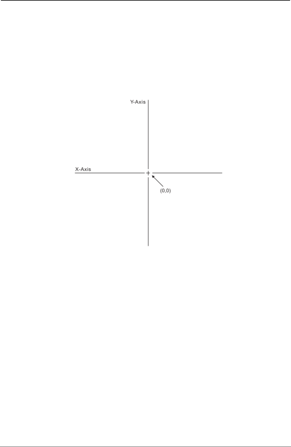
ProgrammerManual PTX‐S828
Chapter5IPDSProgrammingInformation161260071‐001A
Note: The Graphics X and Y coordinates are not the same as the media X and Y coordinates. The
horizontal axis is Graphics X; the vertical axis is Graphics Y. The intersection of the Graphics X and
Y axes is coordinate (0,0). The horizontal axis is positive to the right of center and negative to the
left of center. The vertical axis is positive to the top of center and negative to the bottom of center.
Therefore, both positive and negative values are valid. Negative values are specified in
twos-complement form.
All coordinates are in coordinate units, called drawing units that are the same as units in the Graphics
Data Descriptor (GDD) structured fields. Figure 16 shows the Graphics X and Y coordinate system.
Figure 16. The Graphics X and Y Coordinate System
Graphic Medium Presentation Space
The graphic medium presentation space is an abstract coordinate space where graphics are composed. It
is a conceptual structure defined by the limits of the coordinate space as shown in Figure 17.
Units are defined in “Graphic Data Descriptor (GDD)”.
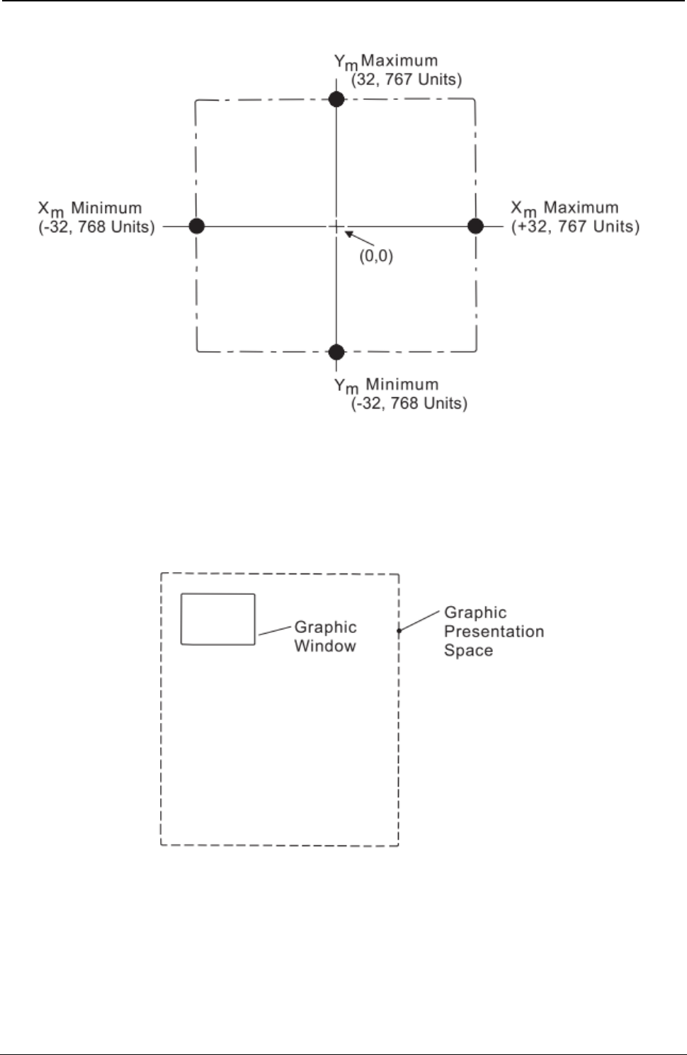
ProgrammerManual PTX‐S828
Chapter5IPDSProgrammingInformation162260071‐001A
Figure 17. The Graphic Medium Presentation Space and Its Limits
Graphic Window
The graphic window is a user-defined, rectangular area within the graphic medium presentation space.
This area is the source from where information is selected for printing. Figure 18 illustrates the relationship
of the graphic window to the graphic medium presentation space.
Figure 18. The Graphic Window within the Graphic Medium Presentation Space
Graphic Block Area
The graphic block area is the part of the current physical medium in which the graphics is printed.
The graphic block area can overlap other output (such as text or images) specified earlier for the same
page. Likewise, subsequent output specified by other commands for the same page can overlap the
graphic block area. Figure 19 shows the graphic block area and its relationship to the
physical medium.
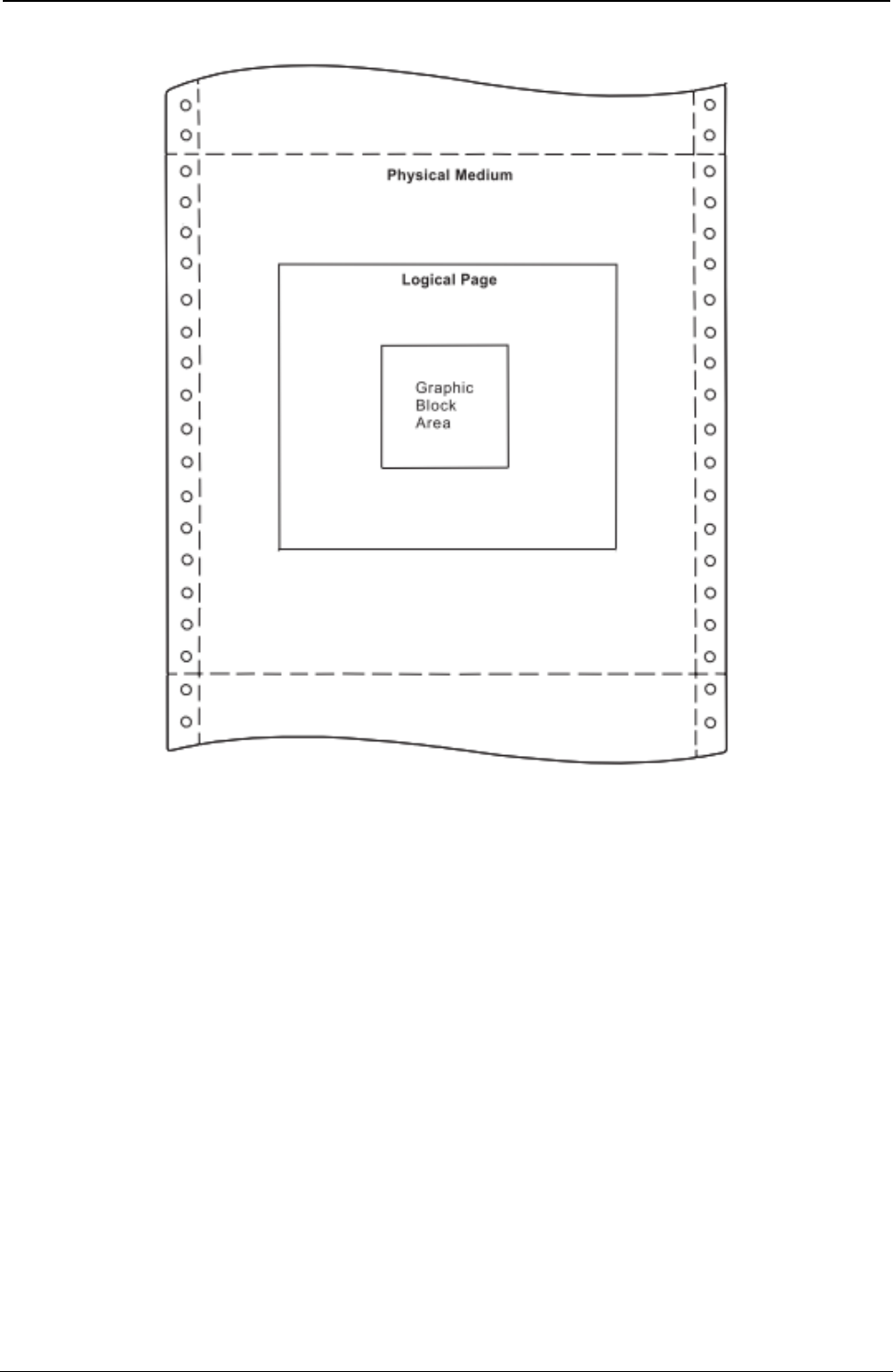
ProgrammerManual PTX‐S828
Chapter5IPDSProgrammingInformation163260071‐001A
Figure 19. The Graphic Block Area on the Physical Medium
Positioning the Graphic Window in the Graphic Block Area
As mentioned previously, the graphic window can be any size within the graphic presentation space limits.
The graphic block area size can be the entire physical Medium or a portion of the physical medium.
The Write Graphics Control command, described in detail in “Write Graphics Control (WGC)”,
specifies the mapping of the graphic window to the graphic block area.
The term mapping refers to the transformation of an abstract space into its size and position on the
physical medium. There are three ways to map the abstract space. They are scale-to-fit, center-and-trim,
and position-and-trim mapping. These mapping methods are described in detail in “Area Mapping Control
Options”.
ProgrammerManual PTX‐S828
Chapter5IPDSProgrammingInformation164260071‐001A
Write Graphics Control (WGC)
Length D684 Flag Correlation ID (Optional) DATA
GAP GOC GDD
The Write Graphics Control command causes the printer to enter the graphics block state. The parameters
of this command define the size, placement, and orientation of the graphic block area and establish the
initial conditions for interpreting the graphic data. Receiving the End command in the graphic block state
terminates the processing of the graphic data.
The Write Graphics Control data consists of three consecutive structured fields:
● The Graphic Area Position control defines the position of the graphics picture on the page.
● The Graphic Output Control (GOC) defines the size of this picture on the page.
● The Graphic Data Descriptor (GDD) defines the size of the graphics window and the default
characteristics of the graphics picture.
Each structured field contains a two byte length field, then a two byte structured field ID, and finally a data
field.
Note: The quality of the graphics output is affected by the graphics mode and direction parameter values
selected at the operator panel (see the Administrators Manual for your model printer), and by the Print
Quality Control command (see “Print Quality Control (PQC)”).
Graphic Area Position Control (GAP)
GAP GOC GDD
Length ID DATA
The Graphic Area Position Control structured field is the first structured field in the DATA portion of the
Write Graphics Control command. This field defines the position and orientation of the graphic block area.
The top left corner of the graphic block area is defined relative to the reference coordinate system.
The format of the GAP field is:
Decimal Hex Value Description
0-1 0-1 000B - (n + 1) Length of this Field
2-3 2-3 AC6B Structured Field ID
4-5 4-5 8000 - 7FFF X Coordinate Position or Inline Coordinate Position of the
Graphic Block Area in Units (Position of the Top Left Corner)
6-7 6-7 8000 - 7FFF Y Coordinate Position or Baseline Coordinate Position of the
Graphic Block Area in Units (Position of the Top Left Corner)
8-9 8-9 0000 When you use the X,Y coordinate system or the I,B coordinate
system with the inline orientation system equal to 0 degrees,
you must use the 0 degree orientation for graphics.
5A00 When you use the I,B reference system and the inline
orientation is 180 degrees, you must use the 180 degree
orientation for graphics.
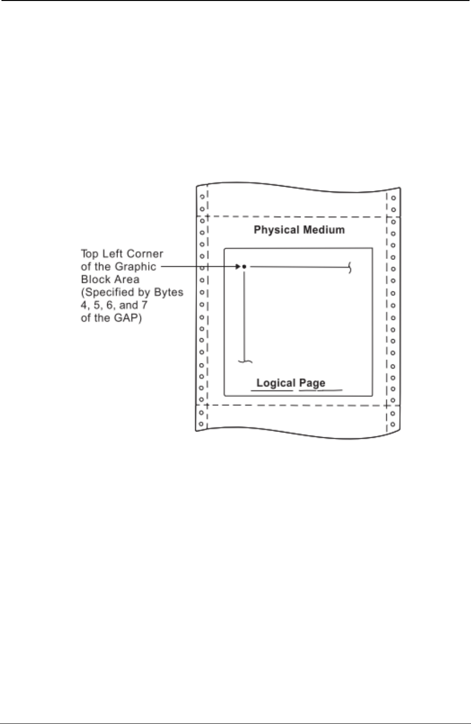
ProgrammerManual PTX‐S828
Chapter5IPDSProgrammingInformation165260071‐001A
Decimal Hex Value Description
10 A Reference Coordinate System:
00 Absolute I, Absolute B
20 Absolute I, Relative B
40 Relative I, Absolute B
60 Relative I, Relative B
A0 Absolute X, Absolute Y
11-n B-n Reserved
Figure 20 shows the Graphic Block Area Position control specifying the top left reference point for the
graphic block area.
Figure 20. Graphic Block Area Position Control and the Graphic Block Area
Byte A of the GAP specifies the reference coordinate system. The reference coordinate system used for
determining the top left corner of the graphic block area can be either the media X,Y or the I,B coordinate
system.
If byte A equals X'00', the absolute I and B coordinates determine the top left corner. GAP bytes 4 and 5
specify the text inline coordinate. GAP bytes 6 and 7 specify the text baseline coordinate.
If byte A equals X'20', the absolute I and relative B coordinates determine the top left corner. GAP bytes 4
and 5 specify the text inline coordinate. GAP bytes 6 and 7 add to the last text baseline coordinate
position used prior to graphics.
If byte A equals X'40', the relative I and absolute B coordinates determine the top left corner. GAP bytes 4
and 5 add to the last text inline coordinate position used prior to graphics. GAP bytes 6 and 7 specify the
text baseline coordinate.
If byte A equals X'60', the relative I and B coordinates determine the top left corner. GAP bytes 4 and 5
add to the last text inline coordinate position used prior to graphics. GAP bytes 6 and 7 add to the last text
baseline coordinate position used prior to graphics.
ProgrammerManual PTX‐S828
Chapter5IPDSProgrammingInformation166260071‐001A
If byte 10A equals X'A0', the current logical page X and Y coordinates determine the origin. When the
block is within a page, GAP bytes 4 through 7 specify the offset from the X-coordinate and Y-coordinate
origin specified in a previously received LPP command (or from the printer default coordinates if no LPP
command was received). When the block is within an overlay that is invoked using an LCC command,
GAP bytes 4 through 7 specify the offset from the Xm-coordinate and Ym-coordinate origin. When the block
is within an overlay that is invoked using an IO command, GAP bytes 4 through 7 specify the offset from
the X-coordinate and Y-coordinate origin specified in the IO command.
When you use the X,Y coordinate system or the I,B coordinate system with the inline orientation equal to 0
degrees, you must use the 0 degree orientation for graphics.
When you use the I,B reference system and the inline orientation is 180 degrees, you must use the 180
degree orientation for graphics.
Graphic Output Control (GOC)
GAP GOC GDD
Length ID DATA
The Graphic Output Control structured field is the second structured field in the DATA portion of the Write
Graphics Control command. This field specifies the size of the graphic block area and a mapping option
for placing the graphic window into the graphic block area. This field is optional and does not need to be in
the Write Graphics Control command. If the GOC field is not present, the printer uses:
● The mapping option X'30' (where offset equals zero)
● X offset and Y offset equals zero
● Graphics block size equals the graphics medium presentation space window size defined in the GDD
self-defining field.
The format of the GOC field is:
Decimal Hex Value Description
0-1 0-1 0010 - (n + 1) Length of this Structured Field
2-3 2-3 A66B Structured Field ID
4 4 00 Unit Base (10 in.)
01 Unit Base (10 cm)
5-6 5-6 05A0 - 7FFF Units per Unit Base (10 in.) (See Note 1)
1626 - 7FFF Units per Unit Base (10 cm) (See Note 1)
7-8 7-8 1 - 7FFF Width of Graphic Block Area in Units
FFFF Use Value From LPD Command
9-10 9-A 1 - 7FFF Height of Graphic Block Area in Units
FFFF Use Value From LPD Command
11 B Area Mapping Control Option (See Note 2)
10 Scale-to-Fit
20 Center-and-Trim
30 Position-and-Trim
12-13 C-D 8000 - 7FFF X Offset in Units (See Note 3)
14-15 E-F 8000 - 7FFF Y Offset in Units (See Note 3)
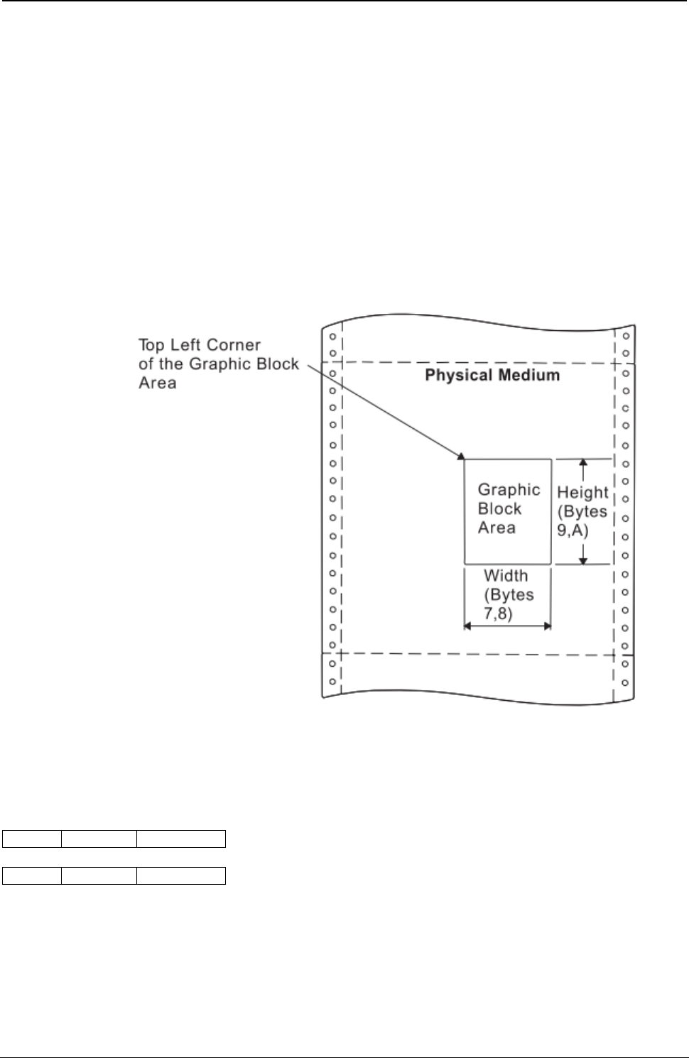
ProgrammerManual PTX‐S828
Chapter5IPDSProgrammingInformation167260071‐001A
Decimal Hex Value Description
16-17 10-n Reserved
Notes:
1. For bytes 5 through 6 (units per base value), 14400/10 in. is supported precisely. Multiples of 14400/10 in.
are also supported. If byte 4 specifies units in centimeters and byte B specifies 20 (center-and-trim) or 30
(position-and-trim), then bytes 5 through 6 must be equivalent to a supported value such as X'1626' or
X'2C4C'.
2. See “Area Mapping Control Options”.
3. The printer ignores the X and Y offset fields unless byte B equals X'30'. These values are the offset of the
top left corner of the graphic window relative to the top left corner of the graphic block area.
Figure 21 shows the Graphic Output Control parameters specifying the size of the graphic block area.
Figure 21. Graphic Output Control and the Graphic Block Area
Graphic Data Descriptor (GDD)
GAP GOC GDD
Length ID DATA
The Graphic Data Descriptor is the last structured field in the DATA portion of the Write Graphics Control
command. This field specifies the parameters for the graphic window in the graphic medium presentation
space (GPS) and sets the drawing default conditions. The graphic window limits define the range of
drawing order coordinate values that map to the graphic block area.
Without causing an error, the drawing orders can specify GPS coordinates in the X'8000' to X'7FFF' range.
The specified GDD graphic window limits select the part of the drawing order’s picture to consider for
mapping to the output area.

ProgrammerManual PTX‐S828
Chapter5IPDSProgrammingInformation168260071‐001A
The format of the GDD field is:
Decimal Hex Value Description
0-1 0-1 001C - (n + 1) Length of this Structured Field
2-3 2-3 A6BB Structured Field ID
4 4 00 Unit Base (10 in.)
01 Unit Base (10 cm)
5 5 00 Reserved
6-7 6-7 05A0 - 7FFF Units per Unit Base (10 in.) (See Note)
1626 - 7FFF Units per Unit Base (10 cm) (See Note)
8-9 8-9 05A0 - 7FFF Units per Unit Base (10 in.) (See Note)
1626 - 7FFF Units per Unit Base (10 cm) (See Note)
10-13 A-D 00000000 Reserved
14-15 E-F 8000 - 7FFF X Left Limit of the Graphic Window in GPS coordinate units
16-17 10-11 8000 - 7FFF X Right Limit of the Graphic Window in GPS coordinate units
18-19 12-13 8000 - 7FFF Y Top Limit of the Graphic Window in GPS coordinate units
20-21 14-15 8000 - 7FFF Y Bottom Limit of the Graphic Window in GPS coordinate units
22-25 16-19 00000000 Reserved
26-27 1A-1B 0000 Graphics Flags - Ignored
28-n 1C-n Initial Graphic Default Conditions - Self-Describing Instructions
that Set the Drawing Defaults for the Picture (See Note)
(Optional field)
Note: See “Self-Describing Instructions”. Figure 22 shows the Graphic Data Descriptor control parameters
specifying the size of the graphic window.
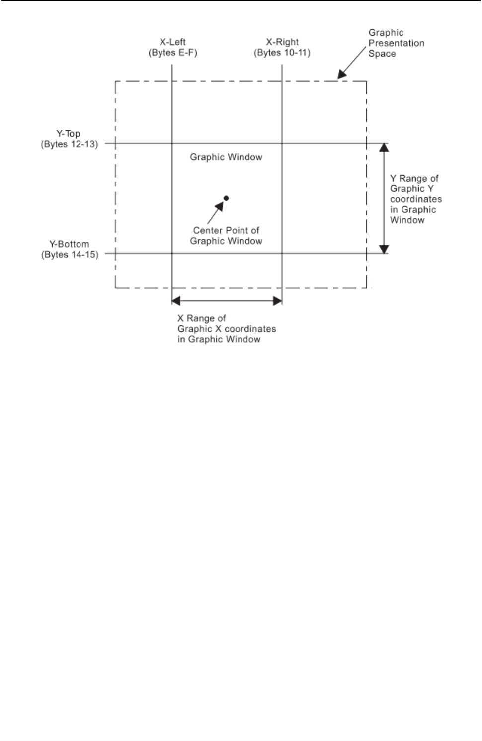
ProgrammerManual PTX‐S828
Chapter5IPDSProgrammingInformation169260071‐001A
Figure 22. Graphic Data Descriptor and the Graphic Medium Presentation Space
Area Mapping Control Options
Byte B in the GOC data field is the area mapping control option byte. The option values are:
● 10 - Scale to fit
● 20 - Center and trim
● 30 - Position and trim.
Scale to Fit Mapping: The center of the graphic window is mapped to the center of the graphic block
area and the graphic data is scaled by the printer (to a printer-supported unit per unit base) so that the
picture within the graphic window fits entirely within the output area at the closest maximum scale.
Figure 23 shows the result of scale-to-fit mapping. For this example, the graphic window is shown larger than
the graphic block area. The parameters in the Graphic Data Descriptor specify the size of the graphic
window (in GPS coordinate units). The parameters in the Graphic Area Position and the Graphic Output
Control specify the size and location of the graphic block area on the physical medium.
If the graphic block area is smaller than the graphic window, as shown in this example, the graphic window
is proportionally reduced to fit in the graphic block area. That is, the entire graphic drawing contained
within the graphic window appears in the graphic block area, reduced in size to fit in the graphic block
area.
This size reduction is done to scale, keeping the same proportions as the original graphic drawing.
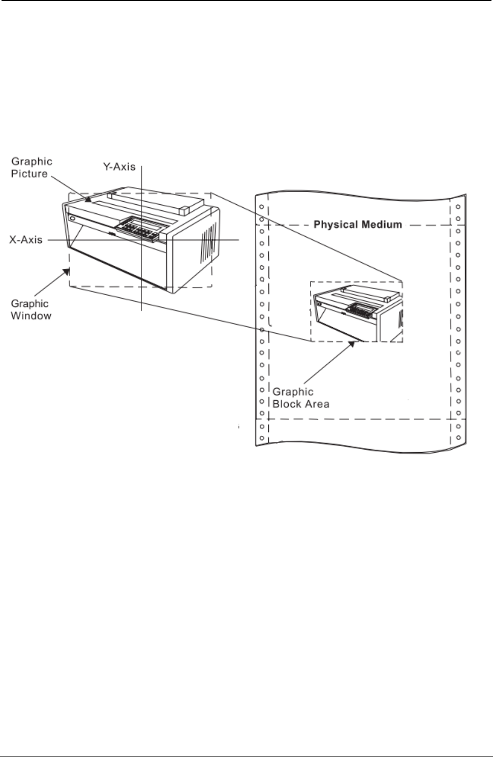
ProgrammerManual PTX‐S828
Chapter5IPDSProgrammingInformation170260071‐001A
Notes:
1. The printer will not rescale graphics image data. If the image data does not fit within the output area,
clipping of the image data occurs.
2. Graphics markers are not scaled; they are always 3 mm (0.12 in. [17/144-in.]) square. If markers are
drawn close to the boundary of a page and the page is then scaled down, the center points of the
markers are scaled closer to the boundary of the page but the marker size is still the same. The
markers may be clipped from the page if the scaling factor scales the centers of the markers too close
to the edge.
Figure 23. Scale-to-Fit Mapping
Center and Trim Mapping: The center of the graphic window is mapped to the center of the graphic
block area and the graphic data is presented at the specified scale. Any portion of the picture that goes
outside the graphic block area is clipped to the graphic block area boundary. Figure 24 shows the result of
center-and-trim mapping. For this example, the graphic window is shown smaller than a previously defined
graphic picture. This picture is to be placed on the physical medium. The parameters in the Graphic Data
Descriptor specify the size of the graphic window (in graphic medium presentation space (GPS) units). The
parameters in the Graphic Area Position and the Graphic Output Control specify the size and location of the
graphic block area on the physical medium.
If the graphic block area is smaller than the graphic window, as shown in this example, a portion of the
graphic picture is eliminated. The centers of the graphic window and the graphic block area coincide, and
the boundaries of the graphic block area determine the limits of the graphic picture. Any portion of the
graphic picture extending beyond the graphic block area will not be drawn on the page.
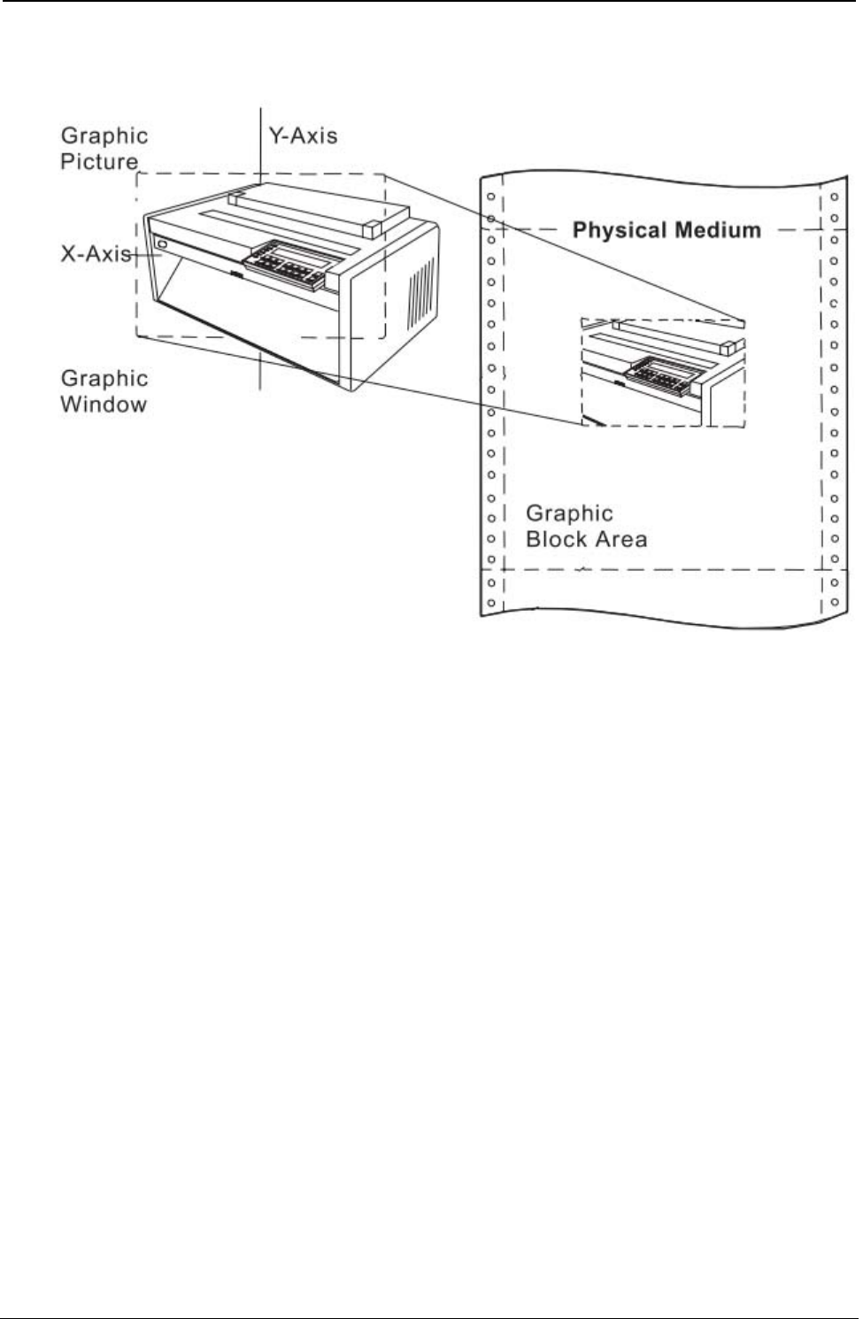
ProgrammerManual PTX‐S828
Chapter5IPDSProgrammingInformation171260071‐001A
Figure 24. Center-and-Trim Mapping
Position and Trim Mapping: The upper left-hand corner of the graphic window is mapped to the graphic
block area using the specified offset and presented at the specified scale. Any portion of the picture that
goes outside the graphic block area is clipped to the area boundary. Figure 25 shows the result of position-
and-trim mapping. For this example, the graphic window is shown smaller than a previously defined graphic
picture. This picture is to be placed on the physical medium. The parameters in the Graphic Data Descriptor
specify the size of the graphic window. The parameters in the Graphic Area Position and the Graphic Output
Control specify the size and location of the graphic block area on the physical medium.
If the graphic block area is smaller than the graphic window, a portion of the graphic picture is eliminated.
The top-left corner of the graphic window is either coincident with the top left corner of the graphic block
area, or it is offset from the top left corner of the graphic block area by a distance specified in the Graphic
Output Control. Only the portion of the picture contained within the overlapping areas of the graphic
window and the graphic block area will be drawn. The printer trims (eliminates) the portion of the graphic
picture outside this area.
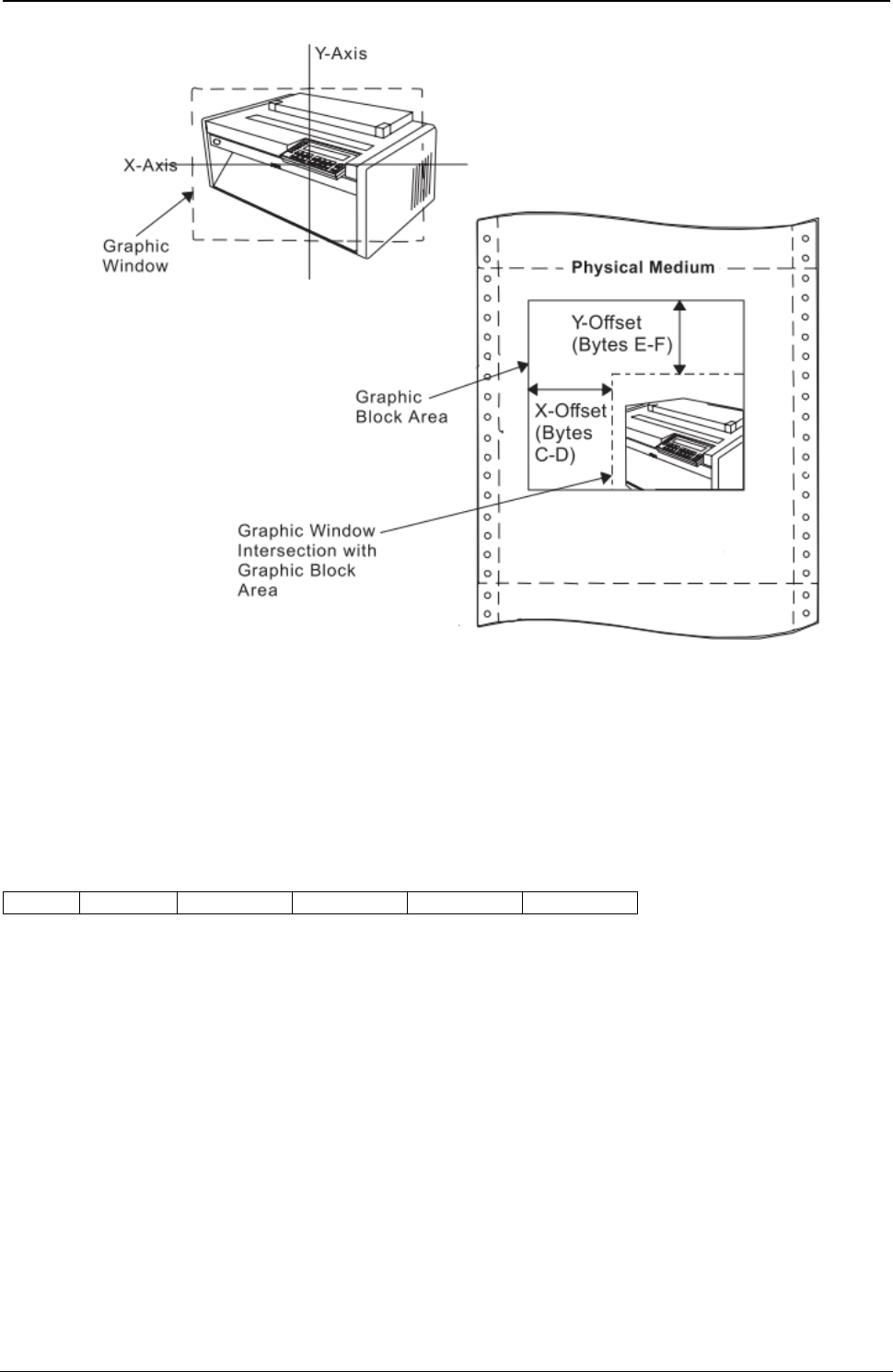
ProgrammerManual PTX‐S828
Chapter5IPDSProgrammingInformation172260071‐001A
Figure 25. Position-and-Trim Mapping
Self-Describing Instructions
This portion of the Graphic Data Descriptor structured field contains zero or more self-describing
instructions that set the drawing defaults for the graphics picture. The general format of a self-describing
instruction is:
21 Length Set Mask Default Data
The first byte, 21, indicates that the following parameter is a Set Current Defaults instruction.
The Length byte is the length of the following data. If this value equals 4, the printer uses the standard
default values.
The Set byte indicates the type of attribute or parameter this instruction is specifying.
The bits 0 through 15 in the Mask bytes correspond to attribute items within the indicated set. The
individual set descriptions explain the meanings of these bits. When a mask bit equals one, the value of
the default byte selects one of two options. See the default byte description for details. When a mask bit
equals zero, the default does not change and the data does not include the value for the corresponding
attribute.
The Default byte has a value of either 0F or 8F. A value of 0F sets all indicated items to their standard
default values. A value of 8F and a mask bit equal to one requires the appropriate data for a new default
to be defined in the data field for the corresponding attribute. Unreferenced data bytes not addressed by
the mask field are ignored.

ProgrammerManual PTX‐S828
Chapter5IPDSProgrammingInformation173260071‐001A
The Data bytes contain immediate data that specifies values for the attributes in this instruction. If the
Default byte is 0F, these Data bytes are not present.
The Set byte specifies one of the following attributes or parameters:
Set Value Description
00 Drawing Attributes
01 Line Attributes
02 Character Attributes
03 Marker Attributes
04 Pattern Attributes
0B Arc Parameters
The following charts explain the meaning of the mask bits for each of the Set instructions. Refer to the
drawing order descriptions for supported attribute values.
Drawing Attributes Set (Set = 00):
Mask Bit Item Name Length (Bytes)
0 Color 2
1-15 Reserved (Mask Bits = 0) -
Line Attributes Set (Set = 01):
Mask Bit Item Name Length (Bytes)
0 Line Type 1
1 Line Width 1
2-15 Reserved (Mask Bits = 0) –
Character Attributes Set (Set = 02):
Mask Bit Item Name Length (Bytes)
0 Angle X, Y 4
1 Cell size CW, CH 4
2 Direction 1
3 Precision 1
4 Symbol Set 1
5 Shear X, Y 4
6-15 Reserved (Mask Bits = 0) –

ProgrammerManual PTX‐S828
Chapter5IPDSProgrammingInformation174260071‐001A
Marker Attributes Set (Set = 03):
Mask Bit Item Name Length (Bytes)
0-1 Reserved (Mask Bits = 0) –
2 Reserved (Mask Bits = 0) –
3 Precision 1
4 Symbol Set 1
5-6 Reserved (Mask Bits = 0) –
7 Marker Symbol 1
8-15 Reserved (Mask Bits = 0) –
Pattern Attributes Set (Set = 04):
Mask Bit Item Name Length (Bytes)
0-4 Reserved (Mask Bits = 0) –
5-6 Reserved (Mask Bits = 0) –
7 Pattern Symbol 1
8-15 Reserved (Mask Bits = 0) –
Arc Parameters Set (Set = 0B):
Mask Bit Item Name Length (Bytes)
0 P Value 2
1 Q Value 2
2 R Value 2
3 S Value 2
4-15 Reserved (Mask Bits = 0) –
If the self-describing instructions do not specify a current default, the printer uses the standard graphic
default for that parameter. The standard default values for the graphic segments are:
Description Value
Color Black
Line Type Solid
Line Width Normal
Character Angle No Rotation
Character Cell Standard Size (19 Dots High by 21 Dots Wide in 1/144 in. Units)
Character Direction Left to Right
Character Set Current Set (through the operator panel)
Character Font NLQ Courier
Marker Symbol Cross
Pattern Symbol Solid Shading
ProgrammerManual PTX‐S828
Chapter5IPDSProgrammingInformation175260071‐001A
Description Value
Current Position X, Y = 0, 0
Arc Parameters P = Q = 1, R = S = 0
Foreground Mix Overpaint
Background Mix Leave Alone
Character Precision Character Precision
Marker Precision Character Precision
Marker Symbol Set Resident Set in Printer
Note: Standard NLQ text character images (18 1/144 in. high by 20 1/200 in. wide) map to the standard
size graphics character so that their upper left corners are coincident.
Write Graphics (WG)
Length D685 Flag Correlation ID (Optional) DATA
BSI One or More Drawing Orders
The Write Graphics command transmits graphic data to the printer. The data in this command consists of
picture segments that contain the drawing orders that define the picture in the graphic medium
presentation space. Any number of Write Graphics commands may follow the Write Graphics Control
command.
The Write Graphics command has a data length restriction of 32K. Within this data-length limit, the Write
Graphics command can transmit partial segments, full segments, multiple segments, or any combination of
these. Segments and drawing orders must be transmitted in the order in which they are to take effect.
When the printer encounters a partial segment, the printer expects the next graphics data to be the
remainder of the segment. This condition is called graphics spanning. For a spanned segment, the
segment length is the length of the entire segment before spanning. The Write Graphics command length
is the actual number of bytes being transmitted in the current command.
The valid sequence for graphics spanning is as follows:
● Write Graphics command with zero or more segments, followed by the start of a partial segment
● Zero or more XOA, NOP, or STM commands
● A new Write Graphics command with a continuation of the partial segment, followed by zero or more
segments.
All segments are run in deferred mode; drawing orders are included in the picture as they are received.
The printer does not retain or store the segments. Receipt of the first segment starts the drawing process.
Begin Segment Introducer (BSI)
BSI One or More Drawing Orders
The Begin Segment Introducer precedes all of the drawing orders that are together in the graphic
segment. The following chart shows the format of the BSI:
ProgrammerManual PTX‐S828
Chapter5IPDSProgrammingInformation176260071‐001A
Decimal Hex Content Description
0 0 70 Begin Segment Command
1 1 0C Length of the Following Parameters in BSI
2-5 2-5 NAME Name of Segment (Printer ignores this field)
6 6 00 Reserved
7 7 Bit 0-2 Reserved (Must be Zeros)
Bit 3 Prologue Flag
0 - No Prologue
1 - Prologue
Bit 4 Reserved
Bit 5-6 Segment Flags
00 - New Segment (Reinitialize Current Drawing Attributes)
11 - Append This Segment to the Previous Segment (Do Not
Reinitialize Current Drawing Attributes)
Bit 7 Reserved
8-9 8-9 LEN Length of Created Segment
10-13 A-D NAME Predecessor/Successor Name (The Printer Ignores This Field)
14-n E-n ORDER Drawing Order or Orders (The Number of Bytes in This Field
Must Equal the Length Field, Bytes 8-9)
If bit 3 of byte 7 is on, a prologue is the first sequence of drawing orders in a new segment. The prologue,
if present, is always at the beginning of a new segment's data and ends by an End Prologue order within
the same segment.
If bits 5 and 6 of byte 7 are zero, the drawing attributes are re-initialized to the current default values. If
bits 5 and 6 of byte 7 are equal to 11, this segment appends to the previous segment and the current
drawing attributes do not reinitialize.
Drawing Orders: One or more drawing orders follow each Begin Segment Introducer. The format of a
drawing order is:
Order Code
Order Code Parameter(s)
Order Code Length Parameter(s)
The order code specifies the type of graphics to print or the assigned drawing attribute.
The Length field, if present, is a one byte value that specifies the length of the drawing order following this
byte. See the specific drawing orders for information about the length field.
ProgrammerManual PTX‐S828
Chapter5IPDSProgrammingInformation177260071‐001A
The parameter bytes contain the specific characteristics for the drawing order. For information about the
parameters, see the specific drawing orders, following this description.
Code Drawing Code Drawing
00 No Operation 33 Set Character Cell Size
01 Comment 34 Set Character Angle
04 Reserved (Treated as a No-op) 38 Set Character Set
08 Set Pattern Set 39 Set Character Precision
0A Set Color (Graphics) 3A Set Character Direction
0C Set Mix 3B Set Marker Precision
0D Set Background Mix 3C Set Marker Set
11 Set Fractional Line Width 3E End Prologue
18 Set Line Type 43 Reserved (Treated as a No-op)
19 Set Line Width 60 End Area
21 Set Current Position 68 Begin Area
22 Set Arc Parameters 71 End Segment (Treated as a No-op)
26 Set Extended Color 81 Line at Current Position
28 Set Pattern Symbol 82 Marker at Current Position
29 Set Marker Symbol 83 Character String at Current Position
85 Fillet at Current Position C1 Line
87 Full Arc at Current Position C2 Marker
91 Image at Current Position C3 Character String
92 Image Data C5 Fillet
93 End Image C7 Full Arc
A1 Relative at Current Position D1 Begin Image
E1 Relative Line
The following sections describe the drawing orders.
No Operation
00
Description: This order is a no-operation; it has no effect on the graphic medium presentation space or
any attribute or any current parameter.
Comment
01 L1 P1..Pn
Description: This order is a no-operation; it has no effect on the graphic medium presentation space or
any attribute or any current parameter. This order can appear anywhere within the segment.
L1 is the length byte. This byte is a value between 1 and 255 and specifies the number of data bytes that
follow. Parameters P1 to Pn are the data bytes. The printer ignores the data within the order. However,
there must be at least one data byte within this order.
ProgrammerManual PTX‐S828
Chapter5IPDSProgrammingInformation178260071‐001A
Segment Characteristics
04 L1 P1..Pn
Description: This order is for compatibility with existing products and is a No Operation order.
Set Pattern Set
08 P1
Description: This order sets the value of the current pattern set attribute. Parameter byte P1 has the
following value:
00 Pattern default
Set Color
0A P1
Description: This order sets the value of the current graphic color attribute. The color for non-graphics (for
example, text) does not change with this order. The color attribute applies to all following graphic drawing
orders until another Set Color order or Set Extended Color order occurs or until a new graphic segment
initializes the graphic attributes. This order does not change any other graphic drawing attributes.
Parameter P1 specifies the color, as follows:
Hex Color (See note)
00 Current Default
07 Black
08 Color of Medium
Note: The S828 Printer provides Limited Simulated Color Support. All architecturally defined color values
for graphics data are accepted and result in simulation of the specified colors without generation of
unsupported color exceptions. All valid colors not listed in the above table (X'01' through X'06') are
simulated by printing in black.
If the color requested is not available, the printer uses black. If this occurs, the Exception Handling
Control determines whether to report this condition. The EHC also determines whether to continue
with the Write Graphics command.
For all color selections except the color of the medium, graphics prints in black. These selections
overpaints previous graphics (if of a different color) by changing the color of the dots to print. For a
color of medium selection, following graphics overpaints previous graphics by deleting (erasing) the
dots to print.
Set Mix
0C P1
Description: This order sets the value of the current mix attribute. The mix controls the way that the
printer combines the color of the foreground with the color of the medium presentation space. Parameter
byte P1 contains the value of the current mix attribute. The only valid values for this byte are:
ProgrammerManual PTX‐S828
Chapter5IPDSProgrammingInformation179260071‐001A
00 Use the default (overpaint)
02 Overpaint - The color attribute value of the foreground replaces the color attribute value of the
graphics medium presentation space.
Set Background Mix
0D P1
Description: This order sets the value of the background mix. The background mix controls the way the
printer combines the color of the background with the color of the graphics medium presentation space.
Parameter byte P1 contains the value of the current mix attribute. The only valid values for this byte are:
00 Use the default (leave alone)
05 Leave Alone - The color attribute value of the medium presentation space does not change.
Set Fractional Line Width
11 P1 P2
Description: The Set Fractional Line Width order sets the line width attribute. This order changes only the
line width attribute. The printer uses the last line width received, no matter which order, Fractional Line
Width Order or Set Line Width, sets the line width. Parameters P1 and P2 form a two byte sequence that
specifies the line width, as follows:
Hex Value Line Width
0000 Current Default
0001 - 017FF Normal Line (One Dot Wide)
0180 - FFFF Thick Line (Two Dots Wide)
This order aids graphics interchange capability. See also “Set Line Width” .
Set Line Type
18 P1
Description: The Set Line Type order sets the value of the current line type attribute. This order does not
change any other graphic drawing order attributes.
Parameter P1 specifies the type of line for the graphic output. The following values are valid for P1:
Hex Line Type
00 Current Default
01 Dotted Line
02 Short Dashed Line
03 Dash-Dot Line
04 Double Dotted Line
05 Long Dashed Line
06 Dash-Double Dot Line
07 Solid Line
08 Invisible Line
ProgrammerManual PTX‐S828
Chapter5IPDSProgrammingInformation180260071‐001A
Set Line Width
19 P1
Description: The Set Line Width order specifies the line width for subsequent graphics. This order
changes the fractional line width attribute only. The printer uses the last line width received, no matter
which order, Set Fractional Line Width Order or Set Line Width, sets the line width. Parameter P1 specifies
the width of the line for the graphic output. The following values are valid for P1:
Hex Line Type
00 Current Default
01 Normal Line (One Dot Wide)
02-FF Thick Line (Two Dots Wide)
Set Current Position
21 04 P1-P4
Description: This order sets the current graphics position for a subsequent drawing order. The position for
non-graphics (for example, text) does not change.
Parameters P1 and P2 form a two byte value that specifies the X coordinate in drawing units. Parameters
P3 and P4 form a two byte value that specifies the Y coordinate in drawing units. The printer resolves the
coordinates to the nearest increment of 0.18 mm (0.007 in. [1/144 in.]).
Set Arc Parameters
Description: This order specifies the parameters for a full arc (circle or ellipse), which the Full Arc orders
use.
The center of this circle or ellipse is the origin (coordinate 0,0). The circle or ellipse is drawn in a
counterclockwise direction. Parameters P1 to P8 form four two byte values that specify the coordinates of
the major and minor axis ends, as follows:
P1P2 - The X coordinate of the major axis end
P3P4 - The Y coordinate of the minor axis end
P5P6 - The X coordinate of the minor axis end
P7P8 - The Y coordinate of the major axis end.
For an ellipse:
(P1P2) x (P5P6) + (P3P4) x (P7P8) = 0
For a circle of radius r, the parameters are:
P1P2 = P3P4 = r, P5P6 = P7P8 = 0
For an ellipse with major axis a and minor axis b, the parameters are:
P1P2 = a, P3P4 = b, P5P6 = P7P8 = 0
For the above ellipse, tilted at an angle A to the X axis, the parameters are:
P1P2 = a cos(A)
P3P4 = b cos(A)
P5P6 = -b sin(A)
P7P8 = a sin(A)
ProgrammerManual PTX‐S828
Chapter5IPDSProgrammingInformation181260071‐001A
This order does not change any other graphic drawing attributes.
Set Extended Color
21 04 P1-P4
Description: This order functions the same as the Set Color order except that it specifies a length field
and the color parameter contains two bytes. The color for non-graphics (for example, text) does not
change with this order.This order does not change any other graphic drawing attributes.
This order aids graphics interchange compatibility.
Parameters P1 and P2 form a two byte value that specifies the color, as follows:
Hex Line Type
0000 Current Default
0008 Black
FF00 Black
FF07 Black
FF08 Color of Medium
Note: The S828 Printer provides Limited Simulated Color Support. All architecturally defined color values
for graphics data are accepted and result in simulation of the specified colors without generation of
unsupported color exceptions. All valid colors not listed in the above table (X'0001' through X'0007',
X'0009' through X'0010', and X'FF01' through X'FF06') are simulated by printing in black.
For all color selections except the color of the medium, graphics prints in the selected color. These
selections overpaint previous graphics (if of a different color) by changing the color of the dots to be
printed. For a color of medium selection, following graphics overpaints previous graphics by deleting
(erasing) the dots to print.
Set Pattern Symbol
28 P1
Description: This order sets the value of the current shading pattern attribute for subsequent area
shading. For additional information, see “Begin Area” and “End Area”.
Parameter P1 specifies the pattern attribute value. This value determines which particular pattern from the
pattern symbol set the printer uses to shade (fill) the interior of subsequent areas. The pattern attribute
values are:
Hex Line Type
00 Current Default
01 - 08 Density 1 to Density 8 (Decreasing)
09 Vertical Lines
0A Horizontal Lines
0B Diagonal Lines 1 (Bottom Left to Top Right)
ProgrammerManual PTX‐S828
Chapter5IPDSProgrammingInformation182260071‐001A
Hex Line Type
0C Diagonal Lines 2 (Bottom Left to Top Right)
0D Diagonal Lines 1 (Top Left to Bottom Right)
0E Diagonal Lines 2 (Top Left to Bottom Right)
0F No Shading
10 Solid Shading
40 Blank
Set Marker Symbol
29 04
Description: This order sets the value of the current marker symbol attribute for subsequent markers. See
“Marker” and “Marker at Current Position” orders.
Parameter P1 specifies the marker symbol attribute value. This value determines which marker from the
marker symbol set the printer uses for subsequent orders. The following are the marker symbol values:
Hex Line Type
00 Current Default
01 Cross
02 Plus
03 Diamond
04 Square
05 Six Point Star
06 Eight Point Star
07 Filled Diamond
08 Filled Square
09 Dot
0A Small Circle
40 Blank
Set Character Cell Size
33 04 P1-P4
or
21 08 P1-P4
Description: This order specifies the size of the character cell for output characters with subsequent
Character String orders. The character cell size for non-graphics (for example, text) does not change with
this order. The Set Character Cell order does not change any other graphic drawing attributes.
There are two types of formats with this order. The first format has a length of 4 and has four parameter
bytes. The second format has a length of 8 and has eight parameter bytes.
ProgrammerManual PTX‐S828
Chapter5IPDSProgrammingInformation183260071‐001A
For both formats, parameters P1P2 form a two byte value that specifies the width of the character in
drawing units. Parameters P3P4 form a two byte value that specifies the height of the character in drawing
units.
For the second format, the width and height of the character cell contain both integer and fractional values.
Parameters P5P6 form a two byte value that specifies the fractional portion of the width of the character in
drawing units. Parameters P7P8 form a two byte value that specifies the fractional portion of the height of
the character in drawing units. There is an implied decimal point between P1P2 and P5P6, and between
P3P4 and P7P8.
The printer pads the standard graphics character cell with spaces to achieve the desired spacing. The
printer also adjusts the character size within the specified cell in integer multiples of the standard size
graphics character. The minimum character image (resulting from graphics mapping) is the standard size
graphics character, even though the scaled character cell may be smaller. In this case, overlapping of
characters may occur.
Note: The printer clips the expanded graphics representation of the last vertical column of a downloaded
NLQ character (see Load Symbol Sets).
Set Character Angle
34 04 P1-P4
Description: This order specifies the angle of the baseline of graphic character strings that print using
subsequent character string orders. The non-graphics (for example, text) character angle does not change
with this order. Angles of 0, 90, 180, and 270 degrees are valid. This order does not change any other
graphic drawing order attributes.
Parameters P1 and P2 form a two byte value that specifies the X coordinate. Parameters P3 and P4 form
a two byte value that specifies the Y coordinate. To meet the requirement that the angle be 0, 90, 180, or
270 degrees, either the X or the Y coordinate must equal zero, as follows:
If X > 0 and Y = 0, then the angle is zero degrees (default).
If X = 0 and Y > 0, then the angle is 90 degrees.
If X < 0 and Y = 0, then the angle is 180 degrees.
If X = 0 and Y < 0, then the angle is 270 degrees.
If X = 0 and Y = 0, then the angle is zero degrees.
If neither the X nor the Y coordinate is zero, the printer uses the current default for this drawing order.
Set Character Set
38 P1
Description: This order sets the value of the current character set attribute. The character set specified by
this command must use an NLQ font if printing high-density graphics or a DP font if printing low-density
graphics. Downloaded DP characters are not supported in graphics.
Parameter P1 specifies the local character set identifier. A value of 0 or X'FF' selects the current drawing
default. A value of X'01' to X'FE' selects a local ID for the character set. This local ID is mapped to a
global font ID by the Load Font Equivalence command. See “Load Font Equivalence (LFE)”.
Set Character Precision
39 P1
ProgrammerManual PTX‐S828
Chapter5IPDSProgrammingInformation184260071‐001A
Description: This order sets the value of the current character precision attribute. Parameter P1 specifies
the type of precision. Precision 2 (character precision) is the only valid type of precision for this printer. P1
must equal 01 or 02. P1 set to X'00' is the current default.
Set Character Direction
3A P1
Description: This order sets the value of the character direction attribute. Subsequent strings that print
using the Character String order will print in the direction specified relative to the character baseline angle.
See “Set Character Angle”. The character direction for non-graphics (text) does not change with this order.
This order does not change any other graphic drawing attributes.
Parameter P1 specifies the direction, as shown:
Hex Line Type
00 Current Default
01 Left to Right
02 Top to Bottom
03 Right to Left
04 Bottom to Top
Set Marker Precision
3B P1
Description: This order sets the value of the current marker precision attribute. Parameter P1 specifies
the type of precision. Precision 2 (character precision) is the only valid type of precision for this printer. P1
must equal 01 or 02.
Set Marker Set
3C P1
Description: This order sets the value of the current marker symbol set attribute. Parameter P1 specifies
the local character set identifier. This printer only uses the default marker set. Thus, P1 must equal 00.
End Prologue
3E P1
Description: This order ends the prologue section of a segment. It is only valid if the prologue flag bit is
on in the Begin Segment Introducer (BSI). When the BSI prologue flag bit is on, only the following orders
are valid before the End Prologue order:
● Comment
● No Operation
● Segment Characteristics
● All Set Attribute type orders.
ProgrammerManual PTX‐S828
Chapter5IPDSProgrammingInformation185260071‐001A
End Area
80 L1 P1-Pn
Description: This order indicates the end of the boundary of an area specified with a Begin Area order.
This order does not change any other graphic drawing attributes. However, orders between a Begin
Area/End Area pair can update the current position.
L1 is the length of the data, P1 to Pn. If no data is present, the length is zero.
Parameters P1 to Pn are optional data bytes, and if present, must be zeros.
Within the area boundaries, one or more closed figures can exist. A figure ends either by an End Area
order or by a order specifying a coordinate that implies the start of a new closed figure. These orders
include a Line, Relative Line, Arc, Full Arc, Fillet, or Set Current Position order.
Each closed figure should close properly; its start and end points should be identical. If not, the figure
closes arbitrarily with a straight line connecting the start and end points.
Begin Area
68 L1
Description: This order indicates the beginning of the boundary of an area that the printer shades. The
area definition must terminate with an End Area order.
The area boundaries consist of one or more closed figures. Each closed figure is made up of a continuous
set of straight lines, full arcs, and fillets defined using the Line at Current Position, Fillet at Current
Position, and Full Arc at Current Position orders. The pattern symbol and the shading color for the area
are the attribute values that are current prior to the Begin Area order. Only the following orders are valid
between a Begin Area and an End Area order:
● Comment
● Line or Relative Line
● Line at Current Position
● Relative Line at Current Position
● Set Arc Parameters
● Full Arc at Current Position
● Full Arc or Fillet
● Fillet at Current Position
● Set Color or Set Extended Color (see note)
● Set Line Type, Set Line Width, or Set Fractional Line Width (see note)
● Set Current Position.
Note: When used between Begin Area and End Area drawing orders, the orders Set Color, Set Extended
Color, Set Line Type, Set Line Width, and Set Fractional Line Width update the values of their
respective current attributes only for the Area boundary, if drawn. These orders do not update their
respective current values for the area fill pattern after an area has begun.
Use of the Line, Relative Line, Full Arc, and Fillet in the non At Current Position form can cause the printer
to arbitrarily close the area figure. The recommended orders to use within an area definition are those in
the At Current Position form.
The printer cannot nest Area orders. The Begin Area order does not change any other graphic drawing
attributes. However, orders between a Begin Area/End Area pair can update the current position.
ProgrammerManual PTX‐S828
Chapter5IPDSProgrammingInformation186260071‐001A
Parameter P1 is a flag byte that specifies whether boundary lines are to be drawn, as shown:
Bit 0 Reserved
Bit 1 0 = Do Not Draw Boundary Lines
1 = Draw Boundary Lines
Bits 2-7 Reserved
The printer uses the current values of color, mix, background mix, pattern, and pattern set when shading
the area. If boundary lines are drawn, the printer uses the current values of graphics color, line type, and
line width. The printer shades any commented region with an odd number of line crossings from infinity.
This shading uses the current values of pattern symbol, color, mix, and background mix from the Begin
Area order. The printer will not shade regions with an even number of line crossings from infinity. The
printer counts all coincident boundary lines when counting line crossings.
The current position is the last coordinate value of the preceding drawing order. The Set Current Position
order can move the current position to any drawing order coordinate within the limits of the GDD defined
medium presentation space window.
Note: When filled areas are drawn such that some boundaries coincide, it is recommended that they be
drawn with the same value for Parameter P1 so that the area boundary is drawn properly.
Line at Current Position
81 L1 P1-Pn
Description: This order specifies one or more connected lines. The printer draws a line from the current
graphics position to the points specified by the first set of X and Y coordinates in the parameters. The
printer then draws additional lines from the previous end point to the next coordinate pair, if additional
coordinates are present.
The printer uses the current attributes for color, mix, line type, and line width in drawing the lines.
L1, the length, specifies the number of bytes following this byte. The value of L1 must be a multiple of
four. If L1 is zero, no line is drawn.
Parameters P1 to Pn, if present, form two byte values that specify the X and Y coordinates of the end
points for a series of connected lines. This order updates the current graphics position to the last line end
point. If the order does not specify any points, the current graphics position does not change. P1 and P2
form a two byte sequence that specifies the X coordinate of the second end point. P3 and P4 form a two
byte sequence that specifies the Y coordinate of the second end point. Additional X and Y coordinates, if
present, are specified in the remaining parameters, following the same format.
Marker at Current Position
82 L1 P1-Pn
Description: This order specifies one or more marker symbols, which the printer places at the points
specified by a pair of X and Y coordinates, beginning with the current graphics position. The Set Marker
Symbol order determines the marker that prints.
L1, the length, specifies the number of bytes following this byte. The value of L1 must be a multiple of
four. A value of zero for L1 is valid and results in only one marker symbol being drawn at the current
graphics position.
ProgrammerManual PTX‐S828
Chapter5IPDSProgrammingInformation187260071‐001A
Parameters P1 to Pn, if present, form two byte values that specify the X and Y coordinates for each
additional marker symbol. The printer draws the first marker symbol at the current graphics position. P1
and P2 form a two byte value that specifies the second X coordinate. P3 and P4 form a two byte value
that specifies the second Y coordinate. Any remaining parameters specify additional coordinate values for
additional markers, using the same format.
The printer uses the current values of color, mix, background mix, marker, precision marker set, and
marker symbol for drawing the marker.
This order updates the current graphics position to the value of the last point coordinates. If this order
does not specify any points, the current graphics position will not change.
Note: The marker cell size is constant 3 mm (0.12 in. [17/144 in.]). The scaling factor used in defining a
graphics area does not affect the size of the marker. If markers are used near the edge of a defined
graphics area, scaling the graphics may result in the markers being clipped from the printable
graphics area.
Character String at Current Position
83 L1 P1-Pn
Description: This order draws a character string, starting at the current graphics position. A previous Set
Character Set order specifies the font to use for drawing the character string. If no previous Set Character
Set order has been processed, the printer uses the drawing default character set.
The printer uses the current values of color, mix, background mix, and character precision when drawing
the string. The Set Character Cell, Set Character Angle, and Set Character Direction orders determine the
character size, character angle, and character direction, respectively.
L1 is a one-byte value that specifies the length of the character string. If L1 is zero, no character string is
drawn.
Parameters P1 to Pn, the character string, are one-byte values that specify the code points (characters) of
the character string to be drawn, using the currently active character set.
Fillet at Current Position
85 L1 P1-Pn
Description: This order specifies a curved line that the printer draws tangential to a specified set of
connected, imaginary, straight lines. The printer uses the current graphics position for the first point and
the parameter (or parameters) specifies additional points to use.
The printer joins the points specified by imaginary straight lines. The printer then fits a curve to the lines,
as follows:
● The curve is tangent to the first line at the start point and to the last line at its end point.
● If there are intermediate lines, the curve is tangent to these lines at their center points.
L1 specifies the length of the parameter (or parameters) in this order. The value of L1 must be a multiple
of four. A value of zero for L1 is invalid.
The first end point for the imaginary line specifying the fillet is the graphics current position. Parameters P1
to Pn form two byte values that specify additional X and Y coordinates. These coordinates are additional,
ProgrammerManual PTX‐S828
Chapter5IPDSProgrammingInformation188260071‐001A
sequential end points of the imaginary lines specifying the fillet.
The printer uses the current values of color, mix, line type, and line width when drawing the fillet.
This order updates the current graphics position to the coordinates of the last point.
Full Arc at Current Position
87 L1 P1-P2
Description: This order specifies a full arc (circle or ellipse) with the center at the current graphics
position. A previous Set Arc Parameters order determines the shape and orientation of the arc. If no Set
Arc Parameters order has been received, then the printer draws an arc using the default values of the arc
parameters.
Parameters P1 and P2 form a two byte value that specifies the scale. P1 specifies the integer portion of
the scale; P2 specifies the fractional portion of the scale (P2 divided by 256). For example, if P2 equals
X'40', the decimal value of P2 is 64. This value (64) divided by 256 equals the fraction one-fourth.
The scale value acts as a multiplier for the arc parameters. For a circle, the radius is P1P2 x r. A previous
Set Arc Parameters order specifies the value of r.
For an ellipse: The major axis is P1P2 x a, the minor axis is P1P2 x b, and a previous Set Arc Parameters
order specifies the values for a and b.
The printer uses the current values of color, mix, line type, and line width when drawing the arc.
This order does not update the current graphics position.
Begin Image at Current Position
91 06 P1-P6
Description: This order defines an image, with the top left corner of the image at the current graphics
position. An image consists of a rectangular region with a resolution of one pel, defined in increments of
0.18 mm (0.007 in. [1/144 in.]). Each pel, therefore, represents one dot in the printed image. One or more
Image Data orders follow the Begin Image at Current Position order. The Image Data orders contain the
image data itself. The Begin Image at Current Position order introduces a graphics image. Only Image
Data, Comment, or No-op orders are valid between Begin Image and End Image orders.
Parameters P1 and P2 are always zero for this order. Parameters P3 and P4 form a two byte value that
specifies the width of the image in increments of 0.18 mm (0.007 in. [1/144 in.]). Parameters P5 and P6
form a two byte value that specifies the height of the image in increments of 0.18 mm (0.007 in. [1/144
in.]).
The printer uses the current values of color and mix when drawing the image.
Note: The Begin Image at Current Position order always specifies the width and height of the image in
increments of 0.18 mm (0.007 in. [1/144 in.]), not in drawing units.
Image Data
92 L1 P1-Pn
Description: This order specifies the image data for all or part of an image introduced by a Begin Image
order. A Begin Image order must precede an Image Data order.
ProgrammerManual PTX‐S828
Chapter5IPDSProgrammingInformation189260071‐001A
L1 is a one-byte value that specifies the length (in bytes) of the image data that follows. Valid values for
L1 are X'00' through X'FF'.
Parameters P1 to Pn are values that specify the image dot data, a zero indicating the absence of a dot, a
one indicating the presence of a dot. The dots are 0.18 mm (0.007 in. [1/144 in.]) apart horizontally and
vertically.
The image data is in the form of horizontal scan lines (rows), left to right. Each Image Data order specifies
only one scan line (row) of the image. Therefore, the number of Image Data orders following a Begin
Image order must be equal to the value specified in parameters P5 and P6 (the image height) of the Begin
Image order.
Each of the parameters, P1 to Pn, of the Image Data order specifies eight dots. Therefore, parameter L1
of the Image Data order must equal the image width divided by eight. Parameters P3 and P4 of the Begin
Image order specify the image width. If the image width is not a multiple of eight, the printer ignores any
extra dots specified by bits in the last parameter, Pn.
Note: The image data specified in the Image Data Orders between a Begin Image and End Image pair
must exactly fill the area specified by the width and height of the Begin Image order.
This order does not update the current graphics position.
End Image
93 L1 P1-Pn
Description: This order defines the end of an image. A Begin Image order and zero or more Image Data
orders must precede the End Image order.
L1, the length, is a one-byte value that specifies the number of parameter bytes that follow. If no
parameter bytes follow, L1 is zero.
Parameters P1 to Pn are optional. The printer does not use these parameters; if they are present, the
printer discards them.
This order does not update the current graphics position.
Relative Line at Current Position
A1 L1 P1-Pn
Description: This order specifies one or more connected straight lines, like the Line at Current Position
order. With this order, the end point of each line is an offset from the previous end point, rather than an
absolute coordinate pair.
L1 is a one-byte value that specifies the length of the parameter field. L1 must be a multiple of two. The
printer will not draw a line if L1 is zero.
Parameters P1 to Pn are signed, twos-complement, one-byte values that specify the offset, in drawing
units. The first line end point is the graphics current position. P1 specifies the X coordinate for the second
point as an offset from the first point. P2 specifies the Y coordinate for the second point as an offset from
the first point. The remaining parameters, if present, specify additional X and Y coordinate values, as
offsets from each previous end point, following the same format.
ProgrammerManual PTX‐S828
Chapter5IPDSProgrammingInformation190260071‐001A
The printer uses the current values of color, mix, line type, and line width when drawing the line.
This order updates the current graphics position to the coordinates of the last end point. If there are no
offsets in this order, the current graphics position does not change.
Line
C1 L1 P1-Pn
Description: This order specifies one or more connected lines.
L1 is a one-byte value that specifies the length of the parameter field that follows. The value of L1 must be
a multiple of four and cannot be zero. If L1 equals four, no line is drawn, but the printer updates the
graphics current position to the points specified by parameters P1 to P4.
Parameters P1 and P2 form a two byte value that specifies the first X coordinate point. Parameters P3
and P4 form a two byte value that specifies the first Y coordinate point. Parameters P5 to P8, if present,
specify the second X and Y coordinate points. The printer draws a line from the point specified by the first
pair of coordinates to the point specified by the second pair of coordinates. If additional coordinate pairs
are present, the printer draws additional lines from the previous end point to the next coordinate pair.
This order uses the current values of color, mix, line type, and line width.
Following this order, the printer updates the graphics current position to the last end point specified in the
order.
Marker
C2 L1 P1-Pn
Description: This order specifies one or more marker symbols to place at the points specified by pairs of
coordinates. The specified location is the center of the marker.
A previously specified Set Marker Symbol order determines the marker symbol the printer uses. If no
previous Set Marker Symbol order was processed, the printer uses the current graphics default marker
symbol. The printer uses the current values of color, mix, background mix, marker precision, marker set,
and marker symbol when drawing the markers.
L1 is a one-byte value that specifies the length of the parameter field that follows. The value of L1 must be
a multiple of four. If L1 equals zero, the printer does not draw a marker.
Parameters P1 and P2 form a two byte value that specifies the X coordinate point for the first marker.
Parameters P3 and P4 form a two byte value that specifies the Y coordinate point for the first marker.
Parameters P5 to Pn, if present, specify the X and Y coordinate points for additional markers.
This order updates the current graphics position to the coordinates of the last end point.
Note: The marker cell size is constant 3 mm (0.12 in. [17/144 in.]). The scaling factor used in defining a
graphics area does not affect the size of the marker. If markers are used near the edge of a defined
graphics area, scaling the graphics may result in the markers being clipped from the printable
graphics area.
Character String
C3 L1 P1-Pn
ProgrammerManual PTX‐S828
Chapter5IPDSProgrammingInformation191260071‐001A
Description: This order draws a character string starting at the specified location. A previous Set
Character Set order specifies the font to use for drawing the character string. If no previous Set Character
Set order was processed, the printer uses the drawing default character set.
The printer places the character cell of the first character in the string at the specified graphics position.
The Set Character Cell, Set Character Angle, and Set Character Direction orders determine the character
size, character angle, and character direction, respectively. The printer uses the current values of color,
mix, background mix, and character precision when drawing the string.
L1 is a one-byte value that specifies the length of the parameter field that follows. L1 must be greater than
or equal to four. If L1 equals four, the printer does not draw the character string, but the printer updates
the graphics current position to the point specified by parameters P1 to P4.
Parameters P1 and P2 form a two byte value that specifies the X coordinate of the starting location.
Parameters P3 and P4 form a two byte value that specifies the Y coordinate of the starting location.
Parameters P5 to Pn, if present, are one-byte values that specify the code points of the character string,
using the currently active character set.
This order updates the current graphics position to the coordinates of the last point.
Fillet
C5 L1 P1-Pn
Description: This order specifies a curved line, which the printer draws tangential to a specified set of
connected, imaginary, straight lines.
The printer joins the points specified in the order by imaginary straight lines. The printer then fits a curve
to the lines. The curve is tangent to the first line at the start point and is tangent to the last line at its end
point. If there are intermediate lines, the curve is tangent to these lines at their center points.
L1 is a one-byte value that specifies the length of the following parameters. L1 must be a multiple of four
and cannot equal zero. If L1 equals four, the printer does not draw the fillet, but the printer updates the
graphics current position to the point specified by parameters P1 to P4.
Parameters P1 and P2 form a two byte value that specifies the X coordinate of the first point. Parameters
P3 and P4 form a two byte value that specifies the Y coordinate of the first point. Parameters P5 to Pn, if
present, form two byte values that specify the corresponding coordinate values for additional points. If only
two points are specified, the printer draws a straight line.
The printer uses the current values of color, mix, line type, and line width when drawing the fillet.
This order updates the current graphics position to the coordinates of the last point.
Full Arc
C7 L1 P1-Pn
Description: This order specifies a full arc (circle or ellipse) with the center at the specified point. A
previous Set Arc Parameters order determines the shape and orientation of the arc. If no previous Set Arc
Parameters order was processed, the printer draws the arc using the graphics default arc parameters.
Parameters P1 and P2 form a two byte value that specifies the X coordinate for the center of the arc.
Parameters P3 and P4 form a two byte value that specifies the Y coordinate for the center of the arc.
ProgrammerManual PTX‐S828
Chapter5IPDSProgrammingInformation192260071‐001A
Parameters P5 and P6 form a two byte, unsigned, floating point value that specifies the scale. P5 specifies
the integer portion of the scale; P6 specifies the fractional portion of the scale. There is an implied decimal
point between P5 and P6. Byte P6 represents the fraction given by the value of P6 divided by 256 (see
“Full Arc at Current Position”).
The scale value acts as a multiplier for the arc parameters, as follows:
For a circle: The radius is P5P6 x r. A previous Set Arc Parameters order specifies the value of r. For an
ellipse: The major axis is P5P6 x a and the minor axis is P5P6 x b.
A previous Set Arc Parameters order specifies the values for a and b. The printer uses the current values
of color, mix, line type, and line width when drawing the arc.
This order does not update the current graphics position.
Begin Image
D1 0A P1-P10
Description: This order defines an image at the graphics position specified by parameters P1 to P4. An
image consists of a rectangular region defined in increments of 1/144 in. One or more Image Data orders
follow the Begin Image order. The Image Data orders contain the image data itself. The Begin Image order
introduces a graphics image. Only Image Data, Comment, or No-op orders are valid between Begin Image
and End Image orders.
Parameters P1 and P2 form a two byte value that specifies the X coordinate for the start of the image.
Parameters P3 and P4 form a two byte value that specifies the Y coordinate for the start of the image.
Parameters P1 to P4 define the location of the top left corner of the image. Parameters P5 and P6 are
always zero for this order. Parameters P7 and P8 form a two byte value that specifies the width of the
image in increments of 1/144 in. Parameters P9 and P10 form a two byte value that specifies the height of
the image in increments of 1/144 in.
The printer draws the image in the current values of color and mix.
This order updates the current graphics position to the coordinates of the image (parameters P1 to P4).
Notes:
1. The Begin Image at Current Position order always specifies the width and height of the image in
increments of 1/144 in., not in drawing units.
2. By sending the image ordered (immediate) instead of unordered (deferred), the printer uses less
storage.
Relative Line
E1 L1 P1-Pn
Description: This order specifies one or more connected straight lines, like the Line order, except that the
end point of each line is an offset from the previous end point.
L1 is a one-byte value that specifies the length of the parameter field that follows. A value of zero for L1 is
invalid; L1 must be a multiple of 2. If the value of L1 is two, the printer does not draw the line. However,
the printer does update the graphics current position to the point specified by P1 and P2.
Parameters P1 to Pn are signed, twos-complement, one-byte values that specify the offset in drawing
units. Parameters P1 and P2 form a two byte value that specifies the X coordinate of the first end point of
the line. Parameters P3 and P4 form a two byte value that specifies the Y coordinate of the first end point

ProgrammerManual PTX‐S828
Chapter5IPDSProgrammingInformation193260071‐001A
of the line. Parameter P5 is a signed, twos-complement, one-byte value that specifies the X coordinate of
the second end point as an offset from the first end point. Parameter P6 is a signed, twos-complement,
one-byte value that specifies the Y coordinate of the second end point as an offset from the first end point.
The remaining parameters, if present, specify additional X and Y coordinate values as offsets from the
previous point, following the same format.
The printer draws the line in the current values of color, mix, line type, and line width.
This order updates the current graphics position to the coordinates of the last offset point. If there are no
offset points with this order, the current graphics position does not change.
End (END)
For a description of the End control, see “End (END)”.
Related Drawing Orders
The following list contains drawing orders that relate to a selected order. That is, when defining parameters
for a specific order, the additional orders in the list are also affected or should be considered.
Table 8. Related Drawing Order
Set Color Set Extended Color
Line, Line at Current Position
Fillet, Fillet at Current Position
Begin Area, End Area
Full Arc, Full Arc at Current Position
Begin Image
Begin Image at Current Position
Image Data, End Image
Marker, Marker at Current Position
Character String
Character String at Current Position
Relative Line
Relative Line at Current Position
Set Fractional Line Width Set Line Width
Line, Line at Current Position
Fillet, Fillet at Current Position
Full Arc, Full Arc at Current Position
Begin Area, End Area
Relative Line
Relative Line at Current Position
Set Line Type Line, Line at Current Position
Fillet, Fillet at Current Position
Full Arc, Full Arc at Current Position
Begin Area, End Area
Relative Line
Relative Line at Current Position
Set Line Width Set Fractional Line Width
Line, Line at Current Position
Fillet, Fillet at Current Position
Full Arc, Full Arc at Current Position
Begin Area, End Area
Relative Line
Relative Line at Current Position

ProgrammerManual PTX‐S828
Chapter5IPDSProgrammingInformation194260071‐001A
Table 8. Related Drawing Order (continued)
Set Current Position Line at Current Position
Fillet at Current Position
Full Arc at Current Position
Begin Image at Current Position
Marker at Current Position
Character String at Current Position
Relative Line at Current Position
Set Arc Parameters Full Arc, Full Arc at Current Position
Set Extended Color Set Color
Line, Line at Current Position
Fillet, Fillet at Current Position
Begin Area, End Area
Full Arc, Full Arc at Current Position
Begin Image
Begin Image at Current Position
Image Data, End Image
Marker, Marker at Current Position
Character String
Character String at Current Position
Relative Line
Relative Line at Current Position
Set Pattern Symbol Begin Area, End Area
Set Marker Symbol Marker
Marker at Current Position
Set Character Cell Size Set Character Angle (Related to Cell Size, Not affected by It)
Set Character Direction (Related to Cell Size, Not affected by It)
Character String
Character String at Current Position
Set Character Angle Set Character Cell Size (Related to Character Angle, Not affected by It)
Set Character Direction (Related to Character Angle, Not affected by It)
Character String
Character String at Current Position
Set Character Direction Set Character Angle (Related to Character Direction, Not affected by It)
Set Character Cell Size (Related to Character Direction, Not affected by It)
Character String
Character String at Current Position
End Area Set Color, Set Extended Color
Set Pattern Symbol
Begin Area
Set Line Type
Set Line Width
Set Fractional Line Width
Begin Area Set Color, Set Extended Color
Set Pattern Symbol
Set Line Type
Set Line Width
Set Fractional Line Width
End Area

ProgrammerManual PTX‐S828
Chapter5IPDSProgrammingInformation195260071‐001A
Table 8. Related Drawing Order (continued)
Line at Current Position Line, Relative Line
Relative Line at Current Position
Set Line Type
Set Line Width
Set Fractional Line Width
Set Color
Set Extended Color
Set Current Position
Marker at Current Position Marker
Set Marker Symbol
Set Color, Set Extended Color
Set Current Position
Character String at Current Position Character String
Set Character Direction
Set Character Angle
Set Character Cell Size
Set Color, Set Extended Color
Set Current Position
Fillet at Current Position Fillet
Set Color, Set Extended Color
Set Line Type
Set Line Width
Set Fractional Line Width
Set Current Position
Full Arc at Current Position Full Arc
Set Arc Parameters
Set Color, Set Extended Color
Set Line Type
Set Line Width
Set Fractional Line Width
Set Current Position
Begin Image at Current Position Begin Image
Set Color, Set Extended Color
Image Data
End Image
Set Current Position
Image Data Begin Image
Begin Image at Current Position
Set Color, Set Extended Color
End Image
End Image Begin Image
Begin Image at Current Position
Image Data
Set Color, Set Extended Color
Relative Line at Current Position Line, Relative Line
Line at Current Position
Set Line Type
Set Line Width
Set Fractional Line Width
Set Current Position
Set Color, Set Extended Color

ProgrammerManual PTX‐S828
Chapter5IPDSProgrammingInformation196260071‐001A
Table 8. Related Drawing Order (continued)
Line Line at Current Position
Relative Line
Relative Line at Current Position
Set Line Type
Set Line Width
Set Fractional Line Width
Set Color
Set Extended Color
Marker Marker at Current Position
Set Marker Symbol
Set Color, Set Extended Color
Character String Character String at Current Position
Set Character Direction
Set Character Angle
Set Character Cell Size
Set Color, Set Extended Color
Fillet Fillet at Current Position
Set Color, Set Extended Color
Set Line Type
Set Line Width
Set Fractional Line Width
Full Arc Full Arc at Current Position
Set Arc Parameters
Set Color, Set Extended Color
Set Line Type
Set Line Width
Set Fractional Line Width
Begin Image Begin Image at Current Position
Set Color, Set Extended Color
Image Data
End Image
Set Current Position
Relative Line Line
Relative Line at Current Position
Line at Current Position
Set Line Type
Set Line Width
Set Fractional Line Width
Set Current Position
Set Color, Set Extended Color
Bar Code Function Set Commands
The bar code function set contains the commands and controls for presenting bar code information on a
logical page, a page segment, or an overlay area on the physical medium. The following commands are
the bar code function set:
Command Code Description
WBCC D680 Write Bar Code Control
WBC D681 Write Bar Code
END D65D End
The following pages describe the bar code function set commands.
ProgrammerManual PTX‐S828
Chapter5IPDSProgrammingInformation197260071‐001A
Write Bar Code Control (WBCC)
Length D680 Flag Correlation ID (Optional) DATA
BCAP BCOC BCDD
The Write Bar Code Control command causes the printer to enter the bar code block state in the current
page, overlay, or page segment state. The parameters of this command define the size, placement, and
orientation of the bar code block. Parameters in this command also establish the initial conditions for
interpreting the bar code data.
Note: The quality of the bar code output is affected by the bar code mode and direction parameter values
selected at the operator panel (see the Administrators Manual for your model printer), and by the Print
Quality Control command (see “Print Quality Control (PQC)”).
A bar code block contains one or more bar code symbols with or without human readable interpretation of
the bar encoded information. Because an important application of bar code printing is printing bar code
symbols on labels, means are provided in the function set to repeat symbols. The repeated symbols must
be of the same type, but the length and content of the variable data can be different. General parameters
applying to all the repeated symbols are in a single Write Bar Code Control command. Parameters that
always change or can change from symbol to symbol are in the Write Bar Code command. A separate
Write Bar Code command must be used with the variable bar code data for each symbol.
Upon receiving the Write Bar Code Control command, the printer enters the appropriate bar code block
state. The printer then initializes control for processing bar code symbols in subsequent Write Bar Code
commands. Receiving the End Code in the bar code block state terminates the processing of bar code
data.
The Write Bar Code Control command data contains three consecutive structured fields:
● Bar Code Area Position (BCAP)
● Bar Code Output Control (BCOC)
● Bar Code Data Descriptor (BCDD).
Each structured field contains a two byte length field, then a two byte structured field ID, and finally a data
field.
Note: For more detailed information on bar codes, see Appendix C, “S828 Bar Code and OCR Printing
Options,”.
Bar Code Area Position (BCAP)
BCAP BCOC BCDD
Length ID Data
The Bar Code Area Position Control structured field is the first structured field in the DATA portion of the
Write Bar Code Control command. This field defines the origin and orientation of the bar code block
relative to the reference coordinate system. The format of the BCAP field is:
Decimal Hex Content Description
0-1 0-1 000B - XXXX Length of This Field
2-3 2-3 AC6B Structured Field ID
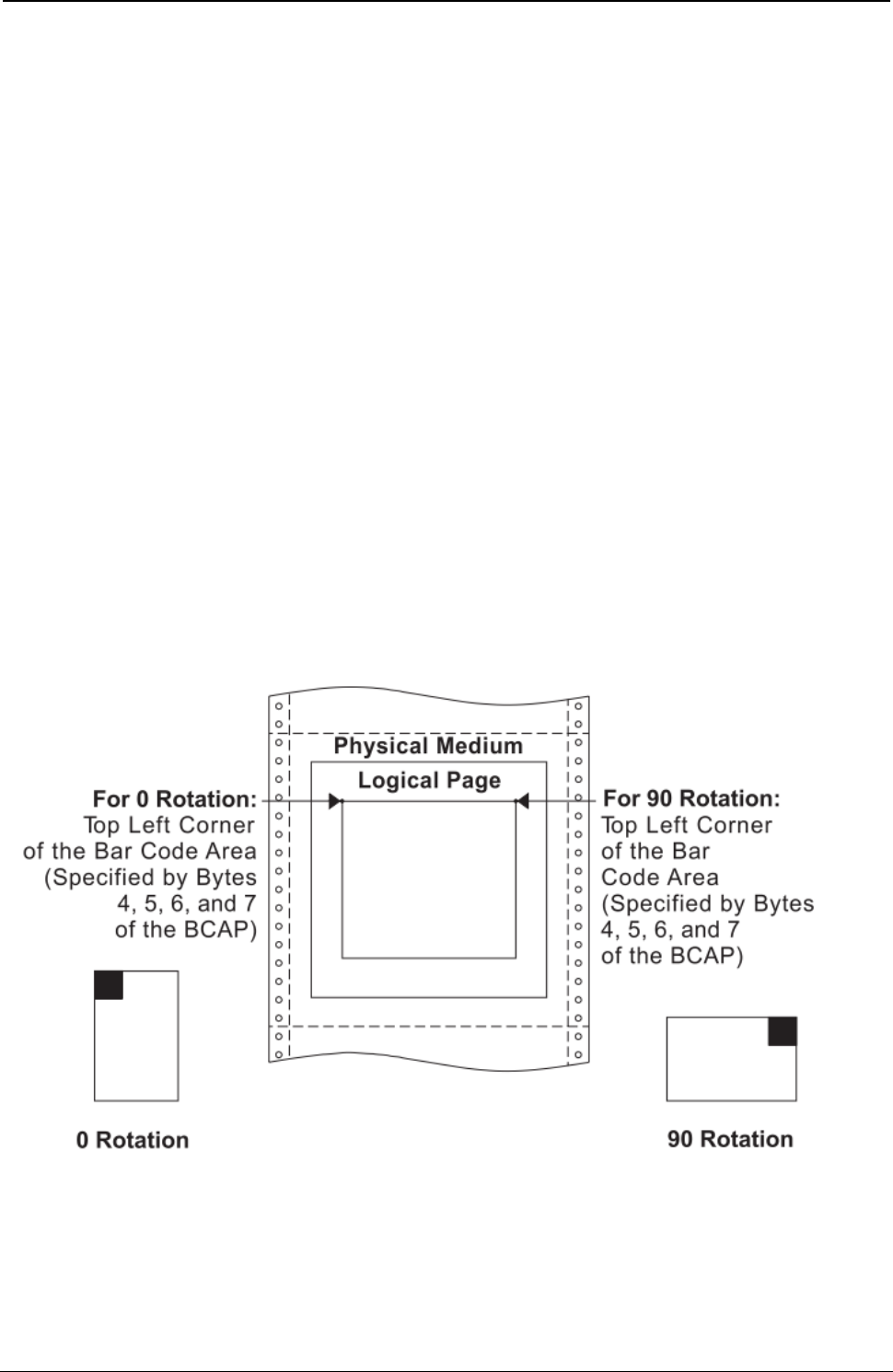
ProgrammerManual PTX‐S828
Chapter5IPDSProgrammingInformation198260071‐001A
Decimal Hex Content Description
4-5 4-5 8000 - 7FFF X Coordinate of Origin of Bar Code Block
6-7 6-7 8000 - 7FFF Y Coordinate of Origin of Bar Code Block
8-9 8-9 0000 When you use the X,Y coordinate system or the I,B
2D00 coordinate system with the inline orientation equal to 0
Note (2) degrees, you must use the 0 or 90 degree orientation for bar
codes.
5A00 When you use the I,B reference system and the inline
8700 orientation is 180 degrees, you must use the 180 or 270
degree orientation for bar codes.
10 A 00 Absolute I, Absolute B
20 Absolute I, Relative B
40 Relative I, Absolute B
60 Relative I, Relative B
A0 Absolute X, Absolute Y
11-x B-x Reserved
Notes:
1. Any positive or negative value fitting in the two byte field is allowable. Negative values are in
twos-complement form. Figure 26 shows the BCAP field specifying the top left reference point, or
origin, for the bar code block, relative to the logical page.
2. Bar codes with a unit/module width of 0.533 mm (0.021 in.) cannot be printed in high speed mode. Bar
codes with a unit/module width of 0.356 mm (0.014 in.) and a wide-to-narrow ratio of 2.5:1 cannot be
printed in high speed mode.
Figure 26. Specifying the Bar Code Block Using the Bar Code Area Position Field
Byte A of the BCAP specifies the reference coordinate system. The reference coordinate system for
determining the top left corner of the bar code area can be either the X,Y or the I,B coordinate system.
If byte A equals X'00', the absolute I and B coordinates determine the top left corner. BCAP bytes 4 and 5
specify the text inline coordinate. BCAP bytes 6 and 7 specify the text baseline coordinate.
ProgrammerManual PTX‐S828
Chapter5IPDSProgrammingInformation199260071‐001A
If byte A equals X'20', the absolute I and relative B coordinates determine the top left corner. BCAP bytes
4 and 5 specify the text inline coordinate. BCAP bytes 6 and 7 add to the last text baseline coordinate
position prior to bar codes.
If byte A equals X'40', the relative I and absolute B coordinates determine the top left corner. BCAP bytes
4 and 5 add to the last text inline coordinate position prior to bar codes. BCAP bytes 6 and 7 specify the
text baseline coordinate.
If byte A equals X'60', the relative I and B coordinates determine the top left corner. BCAP bytes 4 and 5
add to the last text inline coordinate position prior to bar codes. BCAP bytes 6 and 7 add to the last text
baseline coordinate position prior to bar codes.
If byte A equals X'A0', the current logical page X and Y coordinates determine the origin. When the block
is within a page, BCAP bytes 4-7 specify the offset from the X-coordinate and Y-coordinate origin specified
in a previously received LPP command (or from the printer default coordinates if no LPP command
received). When the block is within an overlay that is invoked using an LCC command, BCAP bytes 4-7
specify the offset from the Xm-coordinate and Ym-coordinate origin. When the block is within an overlay
that is invoked using an IO command, BCAP bytes 4-7 specify the offset from the X-coordinate and
Y-coordinate origin specified in the IO command.
When you use the X,Y coordinate system or the I,B coordinate system with the inline orientation equal to 0
degrees, you must use the 0 or 90 degree orientation for bar codes.
When you use the I,B reference system and the inline orientation is 180 degrees, you must use the 180 or
270 degree orientation for bar codes.
Bar Code Output Control (BCOC)
BCAP BCOC BCDD
Length ID Data
The Bar Code Output Control structured field is the second structured field in the DATA portion of the Write
Bar Code Control command. This field specifies the mapping option for the bar code block. This field is
optional and may not be present in the Write Bar Code Control command.
If the BCOC field is not present, the bar code block is equal to the bar code medium presentation space.
The format of the BCOC field is:
Decimal Hex Content Description
0-1 0-1 0010 – XXXX Length of This Structured Field
2-3 2-3 A66B Structured Field ID
4 4 00 Unit Base (10 in.)
01 Unit Base (10 cm)
5-6 5-6 05A0 - 7FFF Units per Unit Base (10 in.)
1626 - 7FFF Units per Unit Base (10 cm)
7-8 7-8 1 - 7FFF Block Width (X-Extent of Block)
FFFF Use LPD Value
9-10 9-A 1 - 7FFF Block Height (Y-Extent of Block)
FFFF Use LPD Value
11 B 30 Area Mapping Option - Position
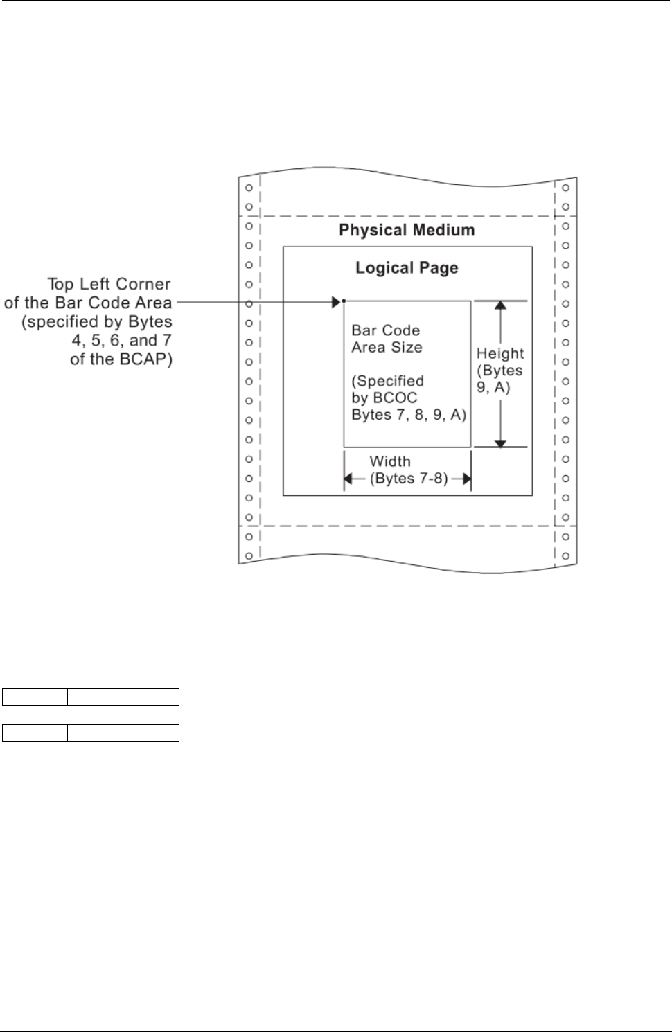
ProgrammerManual PTX‐S828
Chapter5IPDSProgrammingInformation200260071‐001A
Decimal Hex Content Description
12-13 C-D 8000 - 7FFF X Offset of Medium Presentation Space Origin in Units
14-15 E-F 8000 - 7FFF Y Offset of Medium Presentation Space Origin in Units
16-x 10-x Reserved
Figure 27 shows the BCOC field specifying the size of the bar code block on the logical page.
Figure 27. Specifying the Bar Code Block Size Using the Bar Code Output Control
Bar Code Data Descriptor (BCDD)
BCAP BCOC BCDD
Length ID Data
The Bar Code Data Descriptor structured field is the last structured field in the DATA portion of the Write
Bar Code Control command. This field specifies the parameters that define the bar code symbols that
print. The format of the BCDD field is:
Decimal Hex Content Description
0-1 0-1 001B – XXXX Length of This Structured Field
2-3 2-3 A6EB Structured Field ID
4 4 00 Unit Base (10 in.)
01 Unit Base (10 cm)
5 5 Reserved
6-7 6-7 05A0 - 7FFF Units per Unit Base (10 in.)
1626 - 7FFF Units per Unit Base (10 cm)
8-9 8-9 05A0 - 7FFF Units per Unit Base (10 in.)
1626 - 7FFF Units per Unit Base (10 cm)

ProgrammerManual PTX‐S828
Chapter5IPDSProgrammingInformation201260071‐001A
Decimal Hex Content Description
10-11 A-B 1 - 7FFF X-Extent of Medium Presentation Space (Width)
FFFF Use BCOC bytes 7-8 if BCOC is present. Otherwise, use
LPD value.
12-13 C-D 1 - 7FFF Y-Extent of Medium Presentation Space (Height)
FFFF Use BCOC bytes 9-A if BCOC is present. Otherwise, use
LPD value.
14-15 E-F Reserved
16 10 Bar Code Type
00 Reserved
01 3 of 9 Code
02 MSI
03 UPC - Version A
04 Reserved
05 UPC - Version E
06 UPC - Two Digit Add-On (Magazine)
07 UPC - Five Digit Add-On (Paperback)
08 EAN-8
09 EAN-13
0A 2 of 5 Industrial
0B 2 of 5 Matrix
0C 2 of 5 Interleaved
0D Codabar
0E-10 Reserved
11 Code 128
12-15 Reserved
16 EAN Two Digit Add On (Magazine)
17 EAN Five Digit Add On (Paperback)
18 POSTNET (See Note 6)
17 11 Modifier (See Note 1)
18 12 01-FE Local Font ID (See Note 4)
FF Printer Default
19-20 13-14 Color support (See note 7)
0000 Printer Default (Black)
0008 Black
FF00 Printer Default (Black)
FF07 Color of Medium
FF08 Printer Default (Black)
FFFF Use Current Default

ProgrammerManual PTX‐S828
Chapter5IPDSProgrammingInformation202260071‐001A
Decimal Hex Content Description
21 15 Unit/Module Width (See Note 2)
0E 0.36 mm (0.014 in.) Width
11 0.43 mm (0.017 in.) Width (Must have 0 in bytes 8-9 of
BCAP)
15 0.53 mm (0.021 in.) Width
1C 0.71 mm (0.028 in.) Width
FF Printer Default
22-23 16-17 1 - 7FFF Element Height (See Note 3)
FFFF Printer Default
24 18 1 - FF Height Multiplier (See Note 3)
25-26 19-1A Wide-to-Narrow Ratio (See Note 5)
2, 14 2:1
19, 0FA 2.5:1
3, 1E 3:1
FFFF Printer Default
27-x 1B-x Reserved
Notes:
1. The meaning of byte 11 (modifier byte) is dependent upon the bar code type. For the meaning of this
byte, see “Modifier Byte”
2. Any bar code can print with a unit/module width of 0.36 mm (0.014 in.). The only bar codes that can
print with a unit/module width of 0.53 and 0.71 mm (0.021 and 0.028 in.) are: Code 128, Codabar,
Code 3 of 9, MSI, 2 of 5 Industrial, 2 of 5 Matrix, and 2 of 5 Interleaved. If an unsupported unit/module
width is specified, the closest smaller supported unit/module width is used. For 0.43 mm (0.017 in.),
bar code block must equal 0 in BCAP bytes 8 - 9.
3. For all bar code types except UPC and EAN, the specified height equals the height of the bar/space
patterns. For UPC and EAN bar codes, the specified height includes the bar/space patterns and the
HRI. If a UPC or EAN bar code specifies a height less than or equal to 190 units at 1440 units per in.,
the height of the bar/space patterns equals the specified height and the total height is the specified
height plus the HRI height (180 units at 1440 units per in.).
If UPC supplemental or EAN add-on bar codes specify a zero degree rotation and a height less than
or equal to 460 units at 1440 units per in., the top of the bar/space patterns begins at the symbol
reference point. The height of the bar/space patterns equals the specified height, and the total height
equals the specified height plus the HRI height (450 units at 1440 units per in.). Otherwise, the top of
the HRI begins at the symbol reference point and the specified height includes the bar/space patterns
and the HRI.
If UPC supplemental or EAN add-on bar codes specify a 90 degree rotation and a height less than or
equal to 420 units at 1440 units per in., the top of the bar/space patterns begins at the symbol
reference point. The height of the bar/space patterns equals the specified height, and the total height
equals the specified height plus the HRI height (410 units at 1440 units per in.). Otherwise, the top of
the HRI begins at the symbol reference point and the specified height includes the bar/space patterns
and the HRI.
4. Byte 12 selects a Local Font ID, either OCR-A or OCR-B, for use when printing the Human Readable
Information (HRI) beneath the bar code. The list below shows the bar code types that use OCR-A and
those that use OCR-B:
OCR-A OCR-B
Code 128 UPC - Version A
Code 3 of 9 UPC - Version E

ProgrammerManual PTX‐S828
Chapter5IPDSProgrammingInformation203260071‐001A
OCR-A OCR-B
MSI UPC - Two Digit Add-On (Magazine)
2 of 5 Industrial UPC - Five Digit Add-On (Paperback)
2 of 5 Matrix EAN-8
2 of 5 Interleaved EAN-13
Codabar EAN Two Digit Add-On
EAN Five Digit Add-On
5. Wide-to-Narrow ratio is only valid for the following bar code types:
● Code 3 of 9 (X'01')
● MSI (X'02')
● 2 of 5 Industrial (X'0A')
● 2 of 5 Matrix (X'0B')
● Interleaved 2 of 5 (X'0C')
● Codabar (X'0D')
The default ratio for Codabar, Code 3 of 9, and the 2 of 5 types is 2.5:1 for unit/module width of 0.36
and 0.43 mm (0.014 and 0.017 in.), 3:1 for 0.53 mm (0.021 in.), and 2.5:1 for 0.71 mm (0.028 in.) The
default for MSI is always 2:1.
6. BCDD bytes 12 and 15-1A and WBC command byte 0 are not applicable to POSTNET; these bytes
are ignored by the printer as the POSTNET Specification defines values for these parameters.
7. The S828 Printer provides Limited Simulated Color Support. All architecturally defined color values for
graphics data are accepted and result in simulation of the specified colors without generation of
unsupported color exceptions. All valid colors not listed in the above table (X'0001' through X'0007',
X'0009' through X'0010', and X'FF01' through X'FF06') are simulated by printing in black.
8. If the color requested is not available, the printer uses black.
Figure 28 shows the BCDD field specifying the size of the bar code medium presentation space within the
bar code block on the logical page. The bar code medium presentation space must fit within the bar code
block.
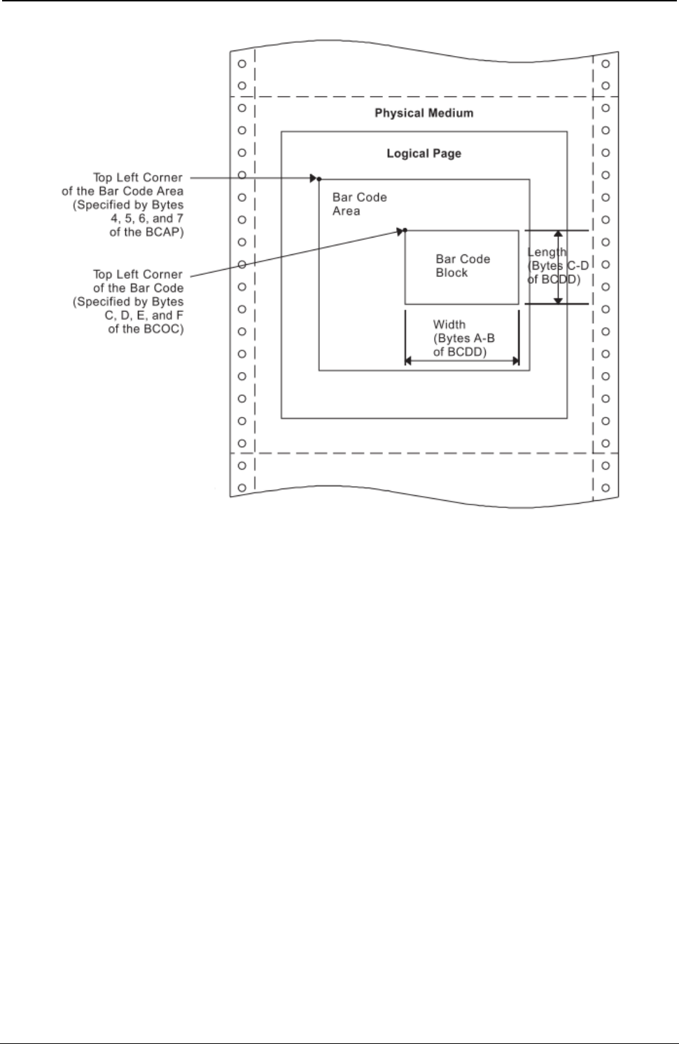
ProgrammerManual PTX‐S828
Chapter5IPDSProgrammingInformation204260071‐001A
Figure 28. Specifying the Bar Code Medium Presentation Space Size. Using the Bar Code Data Descriptor
Modifier Byte: 3 of 9 Code:
01 Print bar code with no printer generated check character.
02 Generate check character and print with bar code.
MSI Code:
01 Print bar code with no printer generated check character.
02 Print bar code with IBM Modulus 10 check digit generated by the printer and put at the end of the
data. This check digit will be the second check digit.
03 Print bar code with both check digits generated by the printer and put at the end of the data. The
second check digit will be IBM Modulus 10. The first check digit will also be IBM Modulus 10.
04 Print bar code with both check digits generated by the printer and put at the end of the data. The
second check digit will be IBM Modulus 10. The first check digit will be NCR Modulus 11. Check
digit equals remainder; check digit of 10 equals error.
05 Print bar code with both check digits generated by the printer and put at the end of the data. The
second check digit will be IBM Modulus 10. The first check digit will be IBM Modulus 11. Check
digit equals remainder; check digit of 10 equals error.
06 Print bar code with both check digits generated by the printer and put at the end of the data. The
second check digit will be IBM Modulus 10. The first check digit will be NCR Modulus 11. Check
digit equals 11 minus remainder; check digit of 10 equals zero.

ProgrammerManual PTX‐S828
Chapter5IPDSProgrammingInformation205260071‐001A
07 Print bar code with both check digits generated by the printer and put at the end of the data. The
second check digit will be IBM Modulus 10. The first check digit will be IBM Modulus 11. Check
digit equals 11 minus remainder; check digit of 10 equals zero.
08 Print bar code with both check digits generated by the printer and put at the end of the data. The
second check digit will be IBM Modulus 10. The first check digit will be NCR Modulus 11. Check
digit equals 11 minus remainder; check digit of 10 equals error.
09 Print bar code with both check digits generated by the printer and put at the end of the data. The
second check digit will be IBM Modulus 10. The first check digit will be IBM Modulus 11. Check
digit equals 11 minus remainder; check digit of 10 equals error.
UPC Version A:
00 Generate check digit and print standard symbol. Variable data field of Write Bar Code command
contains 11 bytes, first the number system digit, then the 10 article number digits.
UPC Version E:
00 Print bar code; six digits are bar encoded. Ten variable data characters are input. From the ten
input digits, the printer generates both the check digit and the six bar code characters. The printer
does not bar code the check digit. The check digit only assigns odd or even parity to the six bar
encoded digits.
UPC Two Digit Add-On:
00 Print the two supplemental digits (bar/space pattern and HRI). The Write Bar Code command
variable data consists only of the two supplemental digits. The preceding Version A or E symbol
prints under control of separate Write Bar Code Control and Write Bar Code commands.
UPC Five Digit Add-On:
00 Print the five supplemental digits (bar/space pattern and HRI). The Write Bar Code command
variable data consists only of the supplemental digits. The preceding Version A or E symbol prints
under control of separate Write Bar Code Control and Write Bar Code commands.
EAN-8:
00 Print the bar code symbol. The input variable data is seven digits: two flag digits and five article
identification digits. The seven digits are all bar coded along with a check digit generated by the
printer. The check digit follows the last article identification digit.
EAN-13:
00 Print the bar code symbol. The input variable data is twelve digits — two flag digits and ten article
identification digits, in that order. The first flag digit is not bar encoded. The second flag digit, the
article identification digits, and a check digit generated by the printer are bar encoded. The first
flag digit prints in human readable form at the bottom of the left quiet zone. The first flag digit
governs the A/B number set pattern of the bar/space encoding of the six digits to the left of the
center pattern.
Two of Five Industrial, Two of Five Matrix, Two of Five Interleaved:
01 Print the bar code with no printer generated check digit.
02 Generate the check digit and print it with the bar code.
EAN Two Digit Add-On:
00 Print the two add-on digits (bar/space pattern and HRI). The Write Bar Code command variable

ProgrammerManual PTX‐S828
Chapter5IPDSProgrammingInformation206260071‐001A
data consists of only the add-on digits. The preceding EAN-13 symbol prints under control of
separate Write Bar Code Control and Write Bar Code commands.
EAN Five Digit Add-On:
00 Print the five add-on digits (bar/space pattern and HRI). The Write Bar Code command variable
data consists of only the add-on digits. The preceding EAN-13 symbol prints under control of
separate Write Bar Code Control and Write Bar Code commands.
Codabar:
01 Print the bar code with no printer generated check digit.
02 Generate the check digit and print it with the bar code.
Code 128:
01 Print the bar code with no printer generated check digit (4230 and 4224 emulation only)
02 Generate the check digit and print it with the bar code.
Note: Code 128 is normally printed with a check digit.
POSTNET:
00 Print a U.S. Postal Service POSTNET ZIP Code (5 digit) bar code symbol. The ZIP Code to be
bar encoded is defined as a 5-digit, numeric (0-9), input data variable to the Write Bar Code
(WBC) command. The POSTNET ZIP Code bar code is printed with a leading frame bar, the bar
encoded ZIP Code data, a correction digit, and a trailing frame bar.
01 Print a U.S. Postal Service POSTNET ZIP+4 (9 digit) bar code symbol. The ZIP+4 code to be bar
encoded is defined as a 9-digit, numeric (0-9), input data variable to the Write Bar Code (WBC)
command. The POSTNET ZIP+4 bar code is printed with a leading frame bar, the bar encoded
ZIP+4 Code data, a correction digit, and a trailing frame bar.
02 Print a U.S. Postal Service POSTNET Advanced Bar Code (ABC, 11 digit) bar code symbol. The
ABC code to be bar encoded is defined as an 11-digit, numeric (0-9), input data variable to the
Write Bar Code (WBC) command. The POSTNET ABC bar code is printed with a leading frame
bar, the bar encoded ABC data, a correction digit, and a trailing frame bar.
03 Print a variable length POSTNET bar code symbol. The code to be bar encoded is defined as a
n-digit, numeric (0-9), input data variable to the Write Bar Code (WBC) command. The printer
produces a bar code symbol without length checking; the symbol is not guaranteed to be
scannable or interpretable. The POSTNET variable-length bar code is printed with a leading frame
bar, the bar encoded data, a correction digit, and a trailing frame bar.
Write Bar Code (WBC)
Length D681 Flag Correlation ID (Optional) DATA
The Write Bar Code command transmits data (code points) to output as a bar code symbol. This
command contains parameters that locate the symbol reference point within the bar code medium
presentation space. The WBC command also contains the variable bar code data for printing as bar/space
patterns and information about printing the code in human readable form.
A flag byte contains information as to whether a human readable interpretation (HRI) is to print, whether
the HRI is to be above or below the bar/space patterns, and for the 3 of 9 code, whether the HRI of the
start/stop character (a star or asterisk) is to print or not.

ProgrammerManual PTX‐S828
Chapter5IPDSProgrammingInformation207260071‐001A
The HRI code prints in the OCR-A or the OCR-B font, depending on the bar code type. The following bar
codes print the HRI in OCR-A:
● Code 128
● Code 3 of 9
● MSI
● 2 of 5 Industrial
● 2 of 5 Matrix
● 2 of 5 Interleaved
● Codabar.
The following bar codes print the HRI in OCR-B:
● UPC-A
● UPC-E
● UPC Two Digit Add-On
● UPC Five Digit Add-On
● EAN-8
● EAN-13
● EAN Two Digit Add-On
● EAN Five Digit Add-On.
POSTNET bar codes have no HRI.
The DATA field for the WBC command has the following format:
Decimal Hex Content Description
0 0 Flags
Bit 0 0 - Print Human Readable Code (HRI)
1 - Do Not Print HRI
Bit 1-2 00 - Printer Option
01 - Print HRI Below Symbol - Valid for Code 128,
Codabar, 3of 9, MSI, UPC-A, UPC-E, EAN-8, EAN-13,
and All 2 of 5 Bar Codes.
10 - Print HRI Above Symbol - Not valid for UPC and EAN
without 2-Digit Supplemental and UPC and EAN 5-Digit
Supplemental.
11 -Invalid Combination
Bit 3 0 - Do Not Print Asterisk (*) with Bar Code 3 of 9
1 - Print Asterisk (*) with Bar Code 3 of 9
Bit 4-7 Reserved
1-2 1-2 1 - 7FFF X Coordinate of Symbol Reference Point
3-4 3-4 1 - 7FFF Y Coordinate of Symbol Reference Point
5-n 5-n Bar Code Data (See Note 3)
ProgrammerManual PTX‐S828
Chapter5IPDSProgrammingInformation208260071‐001A
Notes: If bar codes with human readable interpretation (HRI) are placed too close to the page edges, the
human readable characters may fall outside the physical medium boundaries. If the HRI falls outside the
physical medium boundaries, the characters may not print and a Position Check error, X'041100', may occur.
To ensure that the human-readable characters print, choose X and Y parameter values that allow sufficient
space for the characters to print. Some guidelines are:
1. For bar code types UPC-A, UPC-E, EAN-8, and EAN-13, choose X and Y coordinates that place the bar
code at least 3.88 mm (0.15 in.) from both the top and left edges of the page.
2. For bar code types UPC Two Digit Add-On and UPC Five Digit Add-On, choose a Y coordinate that places
the bar code at least 6.35 mm (0.25 in.) from the top edge of the page.
3. For Codabar bar codes, the data must include the START and STOP characters. For Code 128 bar codes,
the table on the following page should be used to determine the hex value of the desired character.
The symbol reference point must be inside the bar code medium presentation space and must lie within the
logical page.
Code 128 Character Set (EBCDIC)
Table 9. Code 128 Character Set (EBCDIC)
CharacterHexCharacterHexCharacter HexCharacter Hex
NUL00.4Bi89IC9
SOH01<4CFNC18F}D0
STX02(4Dj91JD1
ETX03+4Ek92KD2
HT 05|4Fl93LD3
VT 0B&50m94MD4
FF 0C!5An95ND5
CR 0D$5Bo96OD6
SO 0E*5Cp97PD7
SI 0F)5Dq98QD8
DLE10;5Er91RD9
DC111_60~A1\E0
DC212/61sA2SE2
DC313,6BtA3TE3
BS 16%6CuA4UE4
CAN18‐6DvA5VE5
EM 19>6EwA6WE6
GS 1D?6FxA7XE7
RS 1E‘79yA8YE8
US 1F:7AzA9ZE9
FS 22#7B^BOFNC2EA
LF 25@7C[BA0F0
ETB26’7D]BB1F1
ESC27=7EFNC4BE2F2
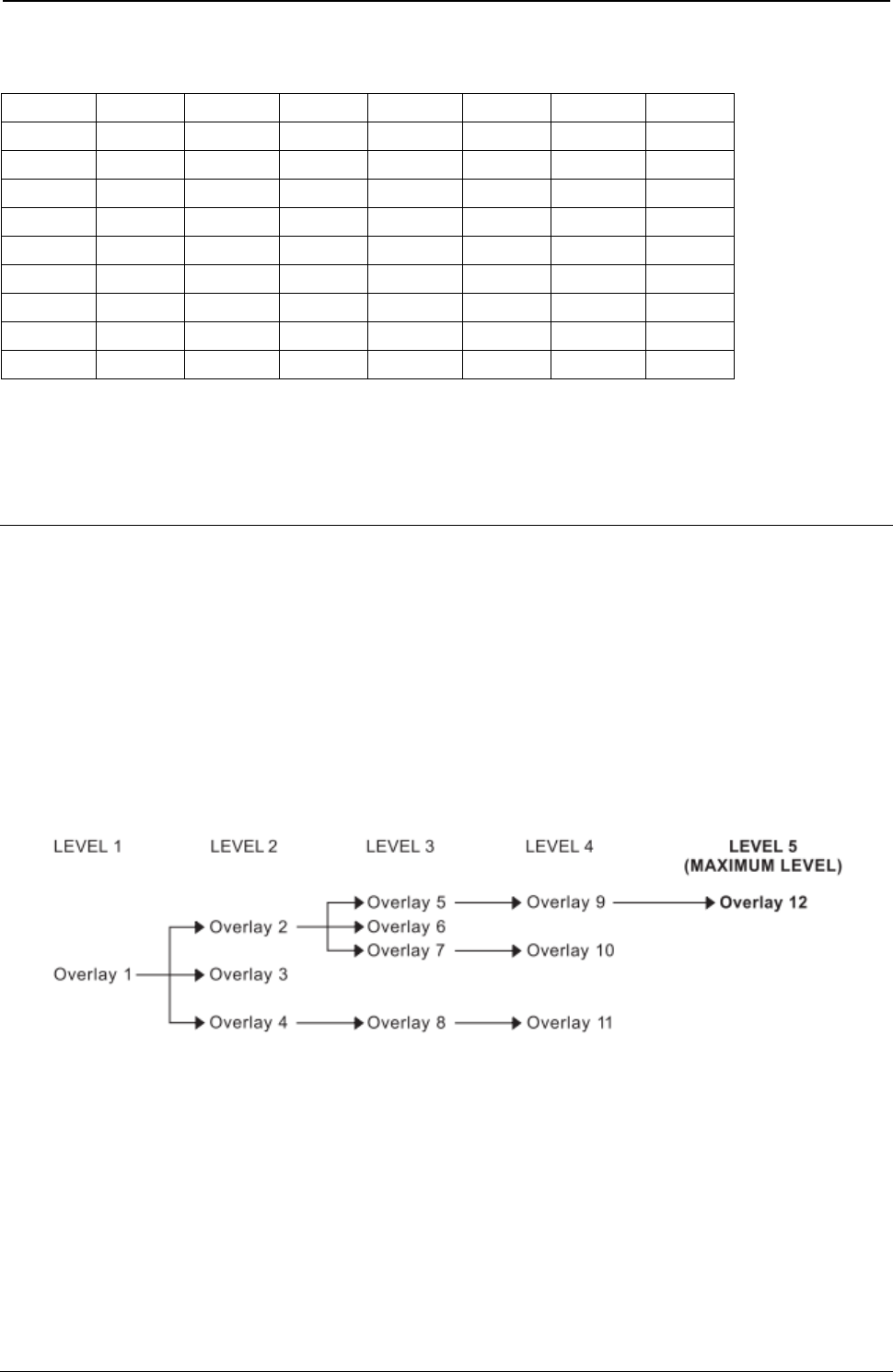
ProgrammerManual PTX‐S828
Chapter5IPDSProgrammingInformation209260071‐001A
Table 7. Code 128 Character Set (EBCDIC) (continued)
CharacterHexCharacterHexCharacter HexCharacter Hex
ENQ2D"7F{C03F3
ACK2Ea81AC14F4
BEL2Fb82BC25F5
SYN32c83CC36F6
EOT37d84DC47F7
DC43Ce85EC58F8
NAK3Df86FC69F9
SUB3Fg87GC7FNC3FA
SP 40h88HC8DELFF
Note: All START, STOP, SHIFT, and CODE characters are generated by the printer in order to produce
the shortest bar code possible from the given data.
Overlay Function Set Commands
The overlay function set contains the commands the printer uses to store, delete, and present information
in the overlay memory of the printer. These commands are independent of any specific data types used in
defining the overlay.
The overlay is contained between the Begin Overlay (BO) command and the End Page (EP) command
and cannot contain itself. Overlays can be nested; that is, overlays can contain other overlays. The depth
of the overlay nesting cannot exceed five levels.
Figure 29 shows an overlay nesting.
Figure 29. An Example of Overlay Nesting
The following commands are the overlay function set:
Command Code Description
BO D6DF Begin Overlay
DO D6EF Delete Overlay
IO D67D Include Overlay
The following pages describe the overlay function set commands.
ProgrammerManual PTX‐S828
Chapter5IPDSProgrammingInformation210260071‐001A
Begin Overlay (BO)
Length D6DF Flag Correlation ID (Optional) DATA
The Begin Overlay command causes the printer to leave the home state and enter the overlay state. This
command defines data that the printer saves for later use within an overlay. The printer later merges the
stored overlay with ordinary printed pages by using the Include Overlay command or the Load Copy
Control command. The current Load Page Description, Load Font Equivalence, and Load Equivalence
records, if any, become part of the definition of the overlay. The definition of the overlay terminates by an
End Page command. The overlay itself is between the Begin Overlay and the End Page commands.
The DATA field is one byte and it specifies the overlay ID. Valid values for this byte are decimal 1 through
254 (X'1' through X'FE'’). If this value specifies an overlay identifier already loaded in the printer, an
exception occurs.
Note: Because overlays use more than the normal amount of printer storage, use overlays only when
data needs to be kept.
Delete Overlay (DO)
Length D6EF Flag Correlation ID (Optional) DATA
The Delete Overlay command deletes (clears) either a single overlay or all overlays from the printer
memory.
The DATA field is one byte in length and can be any value between 0 and 254 (X'00' to X'FE'). This value
is the overlay identifier, and it specifies the overlay to be deleted. If this value is zero, all overlays are
deleted.
Include Overlay (IO)
Length D67D Flag Correlation ID (Optional) DATA
The Include Overlay command causes a previously stored overlay to merge onto the current page at the
specified presentation position. Following the inclusion and processing of an overlay, the current print
position remains where it was prior to the overlay processing. The printer restores all page description
values, font and suppression equivalences, and text control values to the values that existed for each at
the time the overlay was processed.
The DATA field is 10 bytes in length, and contains the following:
Decimal Hex Content Description
0-1 0-1 0001 - 00FE Overlay ID
2 00 Reserved
3-5 3-5 X Coordinate
000000 - Positive Offset Value Relative to the Logical Page
007FFF
FF8000 - Negative Offset Value Relative to the Logical Page
FFFFFE
FFFFFF Use the Current Inline Text Position
6 6 00 Reserved
ProgrammerManual PTX‐S828
Chapter5IPDSProgrammingInformation211260071‐001A
Decimal Hex Content Description
7-9 7-9 Y Coordinate
000000 - Positive Offset Value Relative to the Logical Page
007FFF
FF8000 - Negative Offset Value Relative to the Logical Page
FFFFFE
FFFFFF Use the Current Baseline Text Position
Note: Negative values must be specified in twos-complement form.
Page Segment Function Set Commands
The page segment function set contains the commands the printer uses to store, delete, and present
information in the page segment memory of the printer. These commands are independent of any specific
data types defining the page segment. The following commands are the page segment function set:
Command Code Description
BPS D65F Begin Page Segment
DPS D66F Deactivate Page Segment
IPS D67F Include Page Segment
The following pages describe the page segment function set commands.
Begin Page Segment (BPS)
Length D65F Flag Correlation ID (Optional) DATA
The Begin Page Segment command causes the printer to enter the page segment state. This command is
only valid in the home state. Receipt of an End Page command while in the page segment state causes
the printer to return to the home state.
The Page Segment command defines a segment of page data to save within the printer for later printing.
This printer later includes this segment when it receives the Include Page Segment command.
The DATA field is two bytes in length and can be any value between X'01' and X'7F'. This value is the
page segment identifier. If this value specifies a page segment identifier already loaded in the printer, an
exception occurs.
Note: Because page segments use more than the normal amount of printer storage, use page segments
only when data needs to be kept.
Include Page Segment (IPS)
Length D67F Flag Correlation ID (Optional) DATA
The Include Page Segment command causes a previously stored set of commands to process in the input
data stream as though they were just received from the host. The printer places the segment at the
current presentation position and updates the presentation position as a result of this command.
ProgrammerManual PTX‐S828
Chapter5IPDSProgrammingInformation212260071‐001A
The DATA field is two bytes in length and can be any value between X'01' and X'7F'. This value is the
page segment identifier, and it specifies the page segment to include. A value specifying a page segment
identifier that is not defined in the printer causes an exception to occur.
Deactivate Page Segment (DPS)
Length D66F Flag Correlation ID (Optional) DATA
The Deactivate Page Segment command deletes (clears) either a single page segment or all page
segments from the printer memory.
The DATA field is two bytes in length and can be any value between X'00' and X'7F'. This value is the
page segment identifier, and it specifies the page segment to delete. A value of zero deletes all segments.
Loaded Font Function Set Commands
The loaded font function set contains the commands the printer uses to download and delete font
information from the font storage of the printer. The following commands are the loaded font function set:
Command Code Description
LSS D61E Load Symbol Set
The following pages describe the loaded font function set commands.
Load Symbol Set (LSS)
Length D61E Flag Correlation ID (Optional) DATA
The Load Symbol Set command provides control and pattern information for code points of a font. This
command is only valid in the home state and does not result in a state transition. The DATA field contains
the following information:
Decimal Hex Content Description
0 0 90 FLAGS (Vertical Format Download - See Note 1)
1 1 00 Reserved
2 2 01-0F Starting Code Point
3 3 00 Reserved
4 4 D-FF Additional Parameter Byte Length (This Value Is One More
Than the Number of Bytes Remaining)
5 5 60 No Self-Defining Fields Present
61 Self-Defining Fields Present
6 6 XX Uniform Character Box Size X Dimension (See Note 2)
7 7 Uniform Character Box Size Y Dimension
DP and DP Text Quality
09 NLQ
12
8 8 00 Reserved
9 9 00 Reserved

ProgrammerManual PTX‐S828
Chapter5IPDSProgrammingInformation213260071‐001A
Decimal Hex Content Description
10 A 00 Reserved
11 B 01-FF Ending Code Point
12 C 00 Reserved
13 D 00 Reserved
14 E 00 Reserved
15-16 F-10 0001 - 7EFF Loaded Font Identifier (See Note 3)
17-x 11-x 00...00 Reserved (See Note 4)
(x+1) - xx (x+1) - xx 02FF...XX Self-Defining Fields
o-p o-p XX...XX Character Raster Data
Notes:
1. Vertical format download refers to the method used to send the character patterns to the printer. The
bits are organized as a sequence of vertical cell slices. Each slice contains a number of bits equal to
the uniform box Y size (byte 7). Slices are contiguous (run together) in the raster pattern data. The last
slice of each character is padded with the minimum number of bits needed to reach a byte boundary.
Padded bits are always zeros. The number of vertical slices per character is equal to the uniform box
X size (byte 6).
The first vertical slice received by the printer is the left reference edge of the character box. The last
slice received is the right reference edge of the character box. The first received pel of each slice
makes up the top reference edge of each character box. The last received non-padding pel of each
slice makes up the bottom reference edge of each character box.
2. The meaning of this byte depends upon the font selected, as explained below.
3. An LFE entry must exist for this LFID prior to receiving the LSS command; otherwise an error occurs.
4. The value of byte 4 determines the number of bytes in this field.
5. Load symbol set into Fast Draft fonts is not allowed.
Character Box Size X Dimension (Byte 6): The meaning of byte 6 is as follows:
● Resident Fonts, except PSM
– 0A - DP Quality
– 14 - DP Text and NLQ Quality
● Resident PSM Fonts
– 01-FF - DP Text Quality
– 01-FF - NLQ Quality
● Non-Resident Fonts
– 01-FF - With Y Dimension (byte 7) equal to 09
– 01-FF - With Y Dimension (byte 7) equal to 12.
The print quality must be set appropriately (with the PQC command) before the LSS command is issued if
the font is present in the printer (specified by the LFE command).
Self-Defining Fields: If byte 5, bit 7, equals one, then the DATA field includes one or more self-defining
fields. The format of each field is:
L T Data
L and T are single byte values that specify the length and type of self-defining field. The only valid
self-defining field is the terminator field X'02FF', without any data. The character raster patterns
immediately follow this field. The printer ignores any other self-defining fields.

ProgrammerManual PTX‐S828
Chapter5IPDSProgrammingInformation214260071‐001A
Character Raster Patterns: Data in this field contains the actual code points (bit patterns) for the font
specified in bytes 0F and 10. If the font identifier matches an existing font ID, and one or more of the code
points specified in bytes 2 and 0B overlap previously specified code points, then the printer replaces the
character patterns of the previously specified code points, regardless of how they were originally loaded.
Note: Printronix recommends that image data bits for the last vertical column of NLQ
character patterns be all zeros. The printer clips the graphics representation of the last vertical
column if NLQ characters are expanded for graphics printing (see “Set Character Cell Size” on
page 182). Resident NLQ text character patterns do not contain image data (dots) in the last
column of the character box.

ProgrammerManual PTX‐S828
Chapter6IPDSExceptionReportingCodes215260071‐001A
Chapter 6. IPDS Exception Reporting Codes
The following tables contain the exception reporting codes, which the printer sends to the host in the
NACK reply. These codes are in a three-byte format. The first byte, byte 0, is the error group. The
remaining two bytes, bytes 1 and 2, are the individual error identifiers. Table 8 shows the error group
meanings:
Table 10. Exception Reporting Group Codes
Byte 0 Error Type
80 “Command Reject - X'80'”
40 “Intervention Required - X'40'”
10 “Equipment Check - X'10'”
08 “Data Check - X'08'”
04 “Specification Check-Bar Code - X'04'”
03 “Specification Check-Graphics - X'03'”
02 “Specification Check-General - X'02'”
01 “Conditions Requiring Host Notification - X'01'”
Command Reject: Indicates that the printer cannot recognize a received command.
Intervention Required: Indicates that the printer requires operator intervention.
Equipment Check: Indicates that a hardware error has occurred. Data Check: Indicates that the printer
detects a data error when receiving a logical unit from the application program or that the printer detects a
data error while printing the page.
Specification Check: Indicates that the data parameters or values in a received command are invalid.
Condition Requiring Host Notification: Indicates that the printer has detected an error or condition that
should be reported to the host computer.
Command Reject - X'80'
The following exception codes are the valid codes for a command reject condition:
X'800100' Invalid IPDS Command Code
Explanation:
1. The command code is not recognized. An error
length on a previous command may have caused the
current data to be processed as a command.
2. The command is not supported.
Alternate Exception Action: None
X'800200' Invalid IPDS Command Sequence
Explanation: The printer state is invalid for the
received command.
Alternate Exception Action: None
Intervention Required - X'40'
The following exception codes are the valid codes for an intervention required condition:
X'400000' Printer Not Ready
Explanation: The printer needs operator intervention
to tear off a continuous forms paper source so paper
source switching can be done when in 4224
emulation mode.
Alternate Exception Action: None
X'400100' Printer Out of Forms
Alternate Exception Action: None

ProgrammerManual PTX‐S828
Chapter6IPDSExceptionReportingCodes216260071‐001A
X'402000' Incorrect Forms Module Selection
Alternate Exception Action: None.
X'401300' Tear-Off Required
Explanation: The printer needs operator
intervention to tear off a continuous forms paper
source so paper source switching can be done.
Alternate Exception Action: None
X'40E000' Forms Jam
Alternate Exception Action: None.
X'40E400' Cancel Print Key Pressed
Explanation: The Cancel Print key was
pressed while the printer was receiving IPDS
data.
Alternate Exception Action: None.
Equipment Check - X'10'
The following exception codes are the valid codes for an equipment check condition:
X'10F100' Permanent Erro
r
Explanation:
1. There was a permanent hardware error.
2. The microcode detected an irrecoverable logic error.
3. The microcode detected a condition that should not
have occurred.
Alternate Exception Action: None.
Data Check - X'08'
The following exception codes are the valid codes for a data check condition:
X'082100' Undefined Character
Explanation:
1. An undefined character code has been detected in
Write Text data.
2. An undefined overstrike character code has been
detected.
3. A character has been detected in Write Text
Command data which is undefined at the quality
level specified by the XOA-PQC command.
4. An undefined character code has been detected in
Write Bar Code data.
Alternate Exception Action: For reasons 1-3, print
the default character. For reason 4, there is no
alternate exception action.
X'08C100' Position Check
Explanation: An attempt was made to print
outside the valid printable area.
Alternate Exception Action: All physical
printing
outside the valid printable area is suppressed.
All data and controls continue processing. The
printer continues to print within the valid
printable area to the greatest possible extent.
For text, this may mean truncating text lines at
the character boundary closest to the edge of
the intersection. For graphics, this may mean
truncating graphics pictures at the pel closest
to the boundary. For image, this may mean
truncating scan lines at the pel closest to the
boundary, or alternatively, not printing any of
the image if any part of the image falls outside
the valid printable area.
Specification Check-Bar Code - X'04'
The following exception codes are the valid codes for a bar code specification check condition:
X'040300' Bar Code Type Requested Is Not
Supported
Explanation: The bar code type requested in the
Write Bar Code Data Descriptor field is not
supported.
X'040400' LCID Requested Is Not Supported
Explanation: The type style/font requested in
the
Write Bar Code Data Descriptor field is not
supported.

ProgrammerManual PTX‐S828
Chapter6IPDSExceptionReportingCodes217260071‐001A
Alternate Exception Action: None.
Alternate Exception Action: Use printer
default.
X'040500' Bar Code Color Requested Is Not
Supported
Explanation: The color requested in the Write Bar
Code Data Descriptor field is not supported.
Alternate Exception Action: Use printer default
color.
X'040600' Bar Code Color Requested Is Not
Supported
Explanation: The unit/module width specified in the
Write Bar Code Data Descriptor field is not
supported.
Alternate Exception Action: Use closest smaller
width supported or the device default for those
devices with only one fixed default value.
X'040700' Element Height Specified Is Not
Supported
Explanation: The element height specified in
the Write Bar Code Data Descriptor field is not
supported.
Alternate Exception Action: Use closest
height supported
X'040800' Height Multiplier Specified Is Not
Supported
Explanation: The height multiplier specified in the
Write Bar Code Data Descriptor field is not
supported.
Alternate Exception Action: Use closest multiplier
supported.
X'040900' Wide/Narrow Ratio Is Not
Supported
Explanation: The wide/narrow ratio specified
in the Write Bar Code Data Descriptor field is
not supported.
Alternate Exception Action: Use the printer
default wide element width. The default wide
element width and the specified or default
unit/module width should be such that a
wide/narrow ratio of 2.50 or 3.00 results.
X'040A00' Invalid Symbol Reference Point
Explanation: The symbol reference point given in
the Write Bar Code command is not a valid or
supported value.
Alternate Exception Action: None.
X'040B00' Invalid Bar Code Modifier
Explanation: The bar code modifier, byte 17
of the Bar Code Data Descriptor structured
field, is not a valid or supported value for the
bar code type specified by byte 16 of the same
structured field.
Alternate Exception Action: None.
X'040C00' Invalid Bar Code Data Length
Explanation: The length of the variable data (as
given in bytes 5-n of the Write Bar Code command)
to be bar-encoded/printed, plus any printer-generated
check digits to be coded/printed, is not a valid or
supported value.
Alternate Exception Action: None.
X'040E00' Check Digit Calculation Error
Explanation: A first check digit calculation
resulting in a value of 10 is defined as an error
in various modifier options (byte 17 of the Bar
Code Data Descriptor structured field) for the
MSI bar code.
Alternate Exception Action: None.
X'041000' HRI Location Not Supported
Explanation: HRI location specified in the FLAGS
byte of the WBC command is not a supported
location.
Alternate Exception Action: None.
X'041100' Attempt to Print Portion of
Symbol Outside Block or VPA
Explanation:
1. A portion of the bar code presentation
space, as mapped into the block, extends
outside the bar code block boundaries, or a
portion of the bar code block extends outside
of the logical page (or current overlay).
2. An attempt is made to print a bar code
symbol or HRI outside the physical page.
3. The symbol reference point lies outside the
bar code block, presentation space, or logical
page (or current overlay).
Alternate Exception Action: None.

ProgrammerManual PTX‐S828
Chapter6IPDSExceptionReportingCodes218260071‐001A
Specification Check-Graphics - X'03'
The following exception codes are the valid codes for a graphics specification check condition:
X'030001' Unallocated Graphic Order or
Command Code
Explanation:
1. An attempt was made to execute an unallocated
order code that is reserved for future use.
2. An attempt was made to execute an unallocated
command code that is reserved for future use.
Alternate Exception Action: None.
X'030002' Reserved Byte Error or Invalid
Default
Explanation:
1. A reserved byte in the graphic order is not set
to zero.
2. The Set Current Defaults instruction attempts,
in byte 2, to set an invalid or unsupported
attribute.
3. An invalid default byte value was received in
the GDD.
Alternate Exception Action: None.
X'030003' Incorrect Drawing Order Length
Explanation: A drawing order length is invalid.
Alternate Exception Action: None.
X'030004' Invalid Attribute Value
Explanation: An attribute value for a graphic
order or for a WGC Set Current Default
instruction is invalid.
Alternate Exception Action: Use the standard
default value for that attribute.
X'030008' Truncated Order Error
Explanation: An order has been requested that is
not a complete order. This order is one of the
following:
1. A fixed 2-byte order and the second byte is not in
the segment.
2. A long order and the length byte is not in the
segment.
3. A long order and the number of bytes following
the byte containing the length count to the end of
the segment is less than the value of the length
count.
Alternate Exception Action: None.
X'03000C' Segment Prologue Error
Explanation: A supported order that is not valid
within a prologue was found in a prologue.
The end of a segment was reached without an
End Prologue order.
Alternate Exception Action: None.
X'03000E' Unsupported Attribute Value
Explanation: An attribute value for a graphic order
or for a WGC Set Current Default instruction is not
supported.
Alternate Exception Action: Use the standard
default value for that attribute.
X'0300021' Invalid Default
Explanation: The Set Current Defaults
instruction sets an invalid or unsupported
default for an attribute.
Alternate Exception Action: None.
X'033400' Character Angle Value Not Supported
Explanation: The specific character angle
requested is not supported.
Alternate Exception Action: Use the closest angle
supported by the printer.
X'033E00' Invalid End Prologue
Explanation: An End Prologue was found
outside the prologue section of a segment.
Alternate Exception Action: None.
X'036000' Area Bracket Error
Explanation: An End Area order has been
executed without a Begin Area order having
previously been executed.
Alternate Exception Action: None.
X'038000' Begin Area Received Incorrectly
Explanation: Begin Area order received while
Begin Area is already in progress.
Alternate Exception Action: None.

ProgrammerManual PTX‐S828
Chapter6IPDSExceptionReportingCodes219260071‐001A
X'036801' Area Truncation Error
Explanation: A Begin Area order has been
executed in a segment, and the end of the segment
is reached without an End Area order being
executed. Area fill implementation results are printer
dependent.
Alternate Exception Action: None.
X'036802' Supported Order Invalid in Area
Explanation: A supported order is detected
that is not valid within an area.
Alternate Exception Action: None.
.
X'036803' Pattern Symbol Set Not Available
Explanation: The symbol set identified by the
current Pattern Set is not available.
Alternate Exception Action: Use the standard
default pattern symbol set.
X'036804' Undefined Pattern Symbol
Explanation: The current pattern symbol is
undefined in the pattern symbol set.
Alternate Exception Action: Use the standard
default pattern symbol.
X'037001' Invalid Repeat/Append Bit
Explanation: The Begin Segment Repeat/Append
bit has a value of B'10' in chained immediate mode.
Alternate Exception Action: None.
X'037082' Invalid Repeat/Append Bit
Explanation: The Begin Segment
Repeat/Append bit has a value of B'01'.
Alternate Exception Action: None.
X'0370C1' Invalid Begin Segment length
Explanation: The Begin Segment parameter length
is invalid.
Alternate Exception Action: None.
X'039200' Graphic Image Order Sequence
Error
Explanation: A Begin Image order was not
executed before the Image Data order in this
segment.
Alternate Exception Action: None.
X'039201' Image Data Discrepancy
Explanation: There are insufficient or too many
bytes of data in the Image Data order.
Alternate Exception Action: None.
X'039300' Graphic Image Bracket Error
Explanation: An End Image order is executed
without a Begin Image order having been
previously executed.
Alternate Exception Action: None.
X'039301' Incorrect Number of Image Data
Orders
Explanation: The number of Image Data orders
between the Begin Image and End Image orders is
not equal to the number of rows in the image (as
given by the value of height in the Begin Image
order).
Alternate Exception Action: None.
X'03C200' Marker Symbol Set Not Available
Explanation: The symbol set identified by the
current Marker Set attribute is not available.
Alternate Exception Action: Use the standard
default marker symbol set.
X'03C201' Undefined Marker Code
Explanation: A marker code point is undefined in
the current marker symbol set.
Alternate Exception Action: Use the standard
default marker symbol.
X'03C300' Character Symbol Set Not
Available
Explanation:
1. The symbol set identified by the current
Character Set is not available.
2. The current character set specified in the Set
Character Set order does not have the proper
attributes to be printed in graphics mode.
Alternate Exception Action: Use the standard
default character symbol set.
X'03C301' Undefined Graphics Character Code
Explanation: A code in a character string is
undefined in the current character symbol set.
Alternate Exception Action: Use the standard
default character symbol.
X'03D100' Truncated Graphic Image Error
Explanation: A Begin Image order has been
executed in a segment, and the end of the
segment is reached without an End Image order
having been executed.
Alternate Exception Action: None.

ProgrammerManual PTX‐S828
Chapter6IPDSExceptionReportingCodes220260071‐001A
X'03D101' Invalid Order in Graphic Image
Explanation: A Begin Image order has been
executed in a segment, and an order other than a
Comment, Image Data, or End Image order is
executed.
Alternate Exception Action: None.
X'03D102' Graphic Image Format Not
Supported
Explanation: The value specified for the
graphic image format parameter is not
supported.
Alternate Exception Action: None.
X'03D103' Image Width Greater Than Maximum
Supported
Explanation: The Width value specified in the
Begin
Image order exceeds the maximum image width
supported by the product.
Alternate Exception Action: The image width is
truncated at the maximum width supported.
X'03D104' Image Height Greater Than
Maximum Supported
Explanation: The Height value specified in the
Begin Image order exceeds the maximum
image height supported by the product.
Alternate Exception Action: The image height
is truncated at the maximum height supported.
X'03E100' Relative Line Outside Coordinate
Space
Explanation: The relative line starts inside the
drawing order coordinate space but goes outside.
Alternate Exception Action: None.
Specification Check-General - X'02'
The following exception codes are the valid codes for a general specification check condition:
X'020001' Embedded Text Control Code Error
Explanation: Undefined text control code.
Alternate Exception Action: Ignore the control
sequence.
X'020201' End Suppression Text Control
Error
Explanation: The active Begin Suppression ID
within the current page, overlay, or page
segment is not the same as that specified in the
ES control.
There is no active suppression ID.
X'020202' Invalid IPDS Command Length
Explanation: The length for a command is not
within the allowed range.
The length of a Request Resource List entry is not a
valid or supported value.
The length specified for a Request Resource List
entry does not match the number of bytes received.
Alternate Exception Action: None.
X'020205' Invalid Data Structured Field
Length
Explanation: A data structured field has been
received in a WGC or WBCC command that is
less than the minimum allowable length.
Alternate Exception Action: None.
X'020302' IPDS Command Header Length too
Small
Explanation: The length value of a command is
less than 5 (or less than 7 if a correlation ID is
included).
Alternate Exception Action: None.
X'020305' Area Position Orientation is Not
Supported
Explanation: The orientation specified in the
Area Position structured field of the WGC or
WBCC command is not a valid or supported
value.
Alternate Exception Action: None.
X'020401' End Page Encountered During Active
Suppression
Explanation: The End Page control was
encountered before a text suppression ended.
Alternate Exception Action: Process the object as
if the corresponding End Suppression control
sequence appeared at the end of the object. That is,
all of the data following the Begin Suppression
control sequence in the object is processed and
suppressed.
X'020402' Acknowledge Reply Response
Continuation Request is Invalid
Explanation: The printer received a command
whose response continuation bit is on but there
is no response to continue.
Alternate Exception Action: None.

ProgrammerManual PTX‐S828
Chapter6IPDSExceptionReportingCodes221260071‐001A
X'020405' Area Position Reference System is
Not Supported
Explanation: The reference system specified in the
Area Position structured field of the WGC or WBCC
command is not a valid or supported value.
Alternate Exception Action: None.
X'020501' Invalid Spanning Sequence
Explanation: A Write Text or Write Graphics
command is required to complete a partial
order, control, or double-byte character code
and another command was received other than
an XOA command.
Alternate Exception Action: None.
X'020502' Unsupported Baseline Move
Explanation: Unsupported advancement of the
baseline coordinate toward the I-axis.
Alternate Exception Action: None.
X'020505' Structured Field Unit-Base Invalid
Explanation: The unit-base (measurement
units) specified in the Output Control or the Data
Descriptor structured field of the WGC or WBCC
command is not a valid or supported value.
Alternate Exception Action: None.
X'020601' Begin Suppression Error
Explanation: Begin Suppression encountered in
the same unit (page, segment or overlay) before
previous suppression in that unit ended.
Alternate Exception Action: None.
X'020605' Structured Field Units Invalid
Explanation:
1. The units specified in the Output Control or
the Data Descriptor structured field of the WGC
or WBCC command is not a valid or supported
value.
2. The result of the calculation cannot be
represented in the printer. This may result from
the WGC GDD window limits being very close
together.
3. Coordinate overflow while scaling graphics.
Possible if scaling coordinates require
multiplication by a value greater than 1.
Alternate Exception Action: None.
X'020705' Structured Field Extents Not
Supported
Explanation: The extents specified in the Output
Control or Data Descriptor structured field of the
WGC or WBCC command are not a valid or
supported value. The window values of the WGC
GDD structured field are not consistent; therefore,
the value of XL is larger than the value of XR or the
value of YB is larger than the value of YT.
Alternate Exception Action: None.
X'020805' Invalid Mapping Option
Explanation: A mapping option specified in the
Output Control structured field of the WGC or
WBCC command is not a valid or supported
value.
Alternate Exception Action: None.
X'020905' Invalid Axis Offsets
Explanation: The axis offsets specified in the
Output Control structured field of the WGC or
WBCC command are not valid or supported values.
Alternate Exception Action: None.
X'020B05' Invalid Structured Field Identifier
Explanation: A two-byte structured field
identifier in a WGC or WBCC command is
invalid or out of sequence.
Alternate Exception Action: None.
X'020F01' Invalid Text Orientation
Explanation: Baseline or Inline orientation specified
in Set Text Orientation is not a valid or supported
value.
Alternate Exception Action: Use an inline
orientation of 0 degrees and a baseline orientation
of 90 degrees.
X'021001' Invalid Margin
Explanation: The margin position is not a valid
or supported value.
Alternate Exception Action: None.

ProgrammerManual PTX‐S828
Chapter6IPDSExceptionReportingCodes222260071‐001A
X'021101' Invalid Baseline Increment
Explanation: The value of the baseline increment is
not a valid or supported value.
Alternate Exception Action: None.
X'021201' Invalid Intercharacter Adjustment
Explanation:
1. The value of the intercharacter adjustment is
not a valid or supported value.
2. The intercharacter adjustment direction is not
a valid or supported value.
Alternate Exception Action:
1. Ignore the control sequence and continue
presentation with the parameter values
according to the hierarchy (the hierarchy is the
last valid value received or if none received then
use the LPD value).
2. Use direction = zero.
Note: In an LPD command, no Alternate
Exception Action occurs.
X'021202' Font Storage is Full
Explanation: There is insufficient pattern storage to
store the font transmitted with the Load Symbol Set
command. There is insufficient storage to load the
data transmitted with the Load Font Equivalence
command.
Alternate Exception Action: None.
X'021301' Invalid Absolute Move Baseline
Value
Explanation: The Absolute Move Baseline
parameter value is not a valid or supported
value.
Alternate Exception Action: None.
X'021401' Invalid Absolute Move Inline Value
Explanation: The Absolute Move Inline parameter
value is not a valid or supported value.
Alternate Exception Action: None.
X'021402' Font to be Deleted Not Found
Explanation: The single byte font specified by
the Deactivate Font command is not in the
machine.
Alternate Exception Action: None.
X'021403'
Explanation: Unsupported Baseline Move
Alternate Exception Action: None.
X'021502' Invalid DF Font
Explanation: The Loaded Font Identifier field is
required in the Deactivate Font command;
however, it is not present or its value is not a
valid or supported value.
Alternate Exception Action: None.
X'021802' Invalid Font ID
Explanation:
1. The two-byte Font Identifier on a Load Symbol
Set or Load Font Equivalence command is not a
valid or supported value.
2. The one-byte Font Identifier value on the Load
Font Equivalence command is not a valid or
supported value.
3. A font is referenced on a Set Font control, a
Logical Page Description, a Load Symbol Set, a
Write Graphics, or Write Bar Code command, but
the font has not been previously identified by the
Load Font Equivalence command.
4. The font or symbol set referenced in a Logical
Page Description, Write Text, or Write Graphics
command is defined within the current Load Font
Equivalence but is not loaded in the printer.
Alternate Exception Action:
1. None.
2. None.
3. Substitute the active font for the specified local
font and continue processing.
4. Substitute the active coded font for the specified
local font and continue processing.
X'021701' Invalid Variable Space Increment
Explanation: The value of the variable space
increment as specified in a text control is not a
valid or supported value.
Alternate Exception Action: None.

ProgrammerManual PTX‐S828
Chapter6IPDSExceptionReportingCodes223260071‐001A
X'021702' Invalid DF Deletion Type
Explanation: The Deletion Type on a Deactivate
Font command is not a valid or supported value.
Alternate Exception Action: None.
X'021901' Repeat String Length Error
Explanation: The Repeat String target string
length is not a valid or supported value.
Alternate Exception Action: None.
X'021902' Multiple Occurrences of the Same LFE
Local ID
Explanation: Explanation: The one-byte Local
Identifier value in the Load Font Equivalence
command has been used more than once, making
the Two-Byte Font Identifier reference ambiguous.
Alternate Exception Action: None.
X'021C01' Invalid Embedded Text Control
Sequence
Explanation: A text control sequence contains
a code other than X'D3' following X'2B'.
Alternate Exception Action: None.
X'021D02' Invalid LFE Identifier
Explanation: One or more of the following font
parameters listed in the LFE or their combination is
not valid or supported: Character Set ID, Code Page
ID, Uniform Character Increment, and Proportional
Increment Coefficient Table.
Alternate Exception Action: None.
X'021E01' Invalid Text Control Length
Explanation: The length of a text control is not
valid.
Alternate Exception Action: None.
X'021E02' Mismatch Between Font and XOA
Print Quality Control
Explanation:
1. The combination of parameters specified in LFE
are not supported together with the quality indicated
by XOA Print Quality Control.
2. The Font (Style) ID specified in the LFE is invalid
or unsupported or is not valid with the other font
parameters.
Alternate Exception Action: Choose “Best Fit”
font. Note: This error will be flagged when an
attempt to present the font is processed.
X'021F01' Repeat String Length Error
Explanation: Repeat String control on a Write
Text command has nonzero fill count but zero
string length.
Alternate Exception Action: None.
X'021F02' Mismatch of LFE Two-Byte Loaded
Font ID Parameters
Explanation: Two fonts have been assigned the
same two-byte Loaded Font ID by the LFE
command, but one or more of the following
attributes differ: Character Set ID, Code Page ID,
Font (Style) ID, Uniform Character Increment,
Proportional Increment Coefficient Table.
Alternate Exception Action: None.
X'022602' Invalid LSS X Box Size
Explanation: The Box X size, specified in Byte
6 of the Load Symbol Set command, is not a
valid or supported value or is incompatible with
the specified font.
Alternate Exception Action: None.
X'022702' Invalid LSS Y Box Size
Explanation: The Box Y size, specified in Byte 7 of
the Load Symbol Set command, is not a valid or
supported value or is incompatible with the specified
font.
Alternate Exception Action: None.
X'022802' LSS Pattern Download Format
Reserved or Not Supported
Explanation: The specified pattern download
format in LSS is either a reserved value or not
supported.
Alternate Exception Action: None.
X'022902' Invalid LSS Additional Parameter Byte
Length
Explanation: The additional parameter byte length
specified in the LSS command is outside the range
X'0D' through X'FF' or is not a supported value.
Alternate Exception Action: None.
X'023101' Invalid LCC Number of Copies
Explanation: The Number of Copies value
specified on the Load Copy Control command is
not a valid or supported value.
Alternate Exception Action: Proceed as
though the number of copies field stated 1.
X'023201' Invalid LCC Number of Copies X'023401' Invalid LCC Copy Group Byte

ProgrammerManual PTX‐S828
Chapter6IPDSExceptionReportingCodes224260071‐001A
Explanation: There is an invalid or unsupported
Load Copy Control keyword in the group entry.
Alternate Exception Action: None.
Count
Explanation:
1. The number of bytes in Load Copy Control
group is not a multiple of two byte pairs.
2. The number of bytes in Load Copy Control
group is not a valid or supported value.
Alternate Exception Action: None.
X'023601' Invalid or Unsupported Load Copy
Control Simplex/Duplex Parameter
Explanation: The LCC command simplex/duplex
parameter is invalid or unsupported.
Alternate Exception Action: If invalid, none. If
unsupported, the printer prints simplex.
X'023A02' Maximum Number of Fonts
Allowed by the Printer Exceeded
Explanation: An attempt was made to
download more fonts than the printer can
support.
Alternate Exception Action: None.
X'023F02' Font Index Not Loaded
Explanation:
1. The font inline sequence in Load Font
Equivalence command is not supported or not
supported with the current Text Orientation.
2. The Font Index specified in a Load Font
Equivalence command called out by a Set Coded
Font Local text control is not loaded.
Alternate Exception Action: None.
X'024201' WIC Pel Count < Minimum
Required
Explanation: The Target or Source Pel Count
value on the Write Image Control command is
less than 1.
Alternate Exception Action: None.
X'024301' WIC Pel Count > Maximum Allowed
Explanation: The Target or Source Pel Count value
on the Write Image Control command is greater
than the valid or supported maximum.
Alternate Exception Action: None.
X'024401' WIC Scan Count < Minimum
Required
Explanation: The Target or Source Scan Count
value on the Write Image Control command is
less than 1.
Alternate Exception Action: None.
X'024501' WIC Scan Count > Maximum Allowed
Explanation: The Target or Source Scan Count
value on the Write Image Control command is
greater than the valid or supported maximum.
Alternate Exception Action: None.
X'024601' Invalid WIC Source Image Format
Explanation:
1. The Compression Algorithm value (Byte 8) is
not a valid or supported value.
2. The (Pel) Data Format value (Byte 9) in the
Write Image Control command is not X'00'.
Alternate Exception Action: None.
X'024701' Invalid WIC Scale Factor Value
Explanation:
1. The Pel Count Scale Factor value on the Write
Image Control command is not a valid or supported
value.
2. The Scan Count Scale Factor value on the Write
Image Control command does not equal the Pel
Count Scale Factor.
Alternate Exception Action: None.
X'024702' Invalid LFE Font Inline Sequence
Explanation: The Font Inline Sequence
parameter in a Load Font Equivalence
command is not a valid or supported value.
Alternate Exception Action: None
X'024801' Invalid WIC Scan Line Direction
Explanation: The Scan Line Direction parameter
value on the Write Image Control command is not a
valid or supported value.
Alternate Exception Action: None.
X'024802' Invalid Font Section Number in
LSS command
Explanation: The section number specified in
the LSS command is not a valid or supported
value.
Alternate Exception Action: None.

ProgrammerManual PTX‐S828
Chapter6IPDSExceptionReportingCodes225260071‐001A
X'024901' Invalid WIC Scan Sequence Direction
Explanation: The Scan Line Sequence Direction
value specified on the Write Image Control
command is not plus ninety degrees from the Scan
Line Direction value.
Alternate Exception Action: None.
Note: Plus ninety from 270, (X'8700') must be
X'0000'.
X'024902' Invalid Starting Code Point in LSS
command
Explanation: The Starting Code Point in the
LSS command is not a valid or supported value.
Alternate Exception Action: None.
X'024A01' Invalid WIC Coordinate Specification
Explanation:
1. The Coordinate Definition value on the Write
Image Control command is not a valid or supported
value.
2. The First Pel Location (X or I Direction) value on
the Write Image Control command is not a valid or
supported value.
3. The First Pel Location (Y or B Direction) value on
the Write Image Control command is not a valid or
supported value.
Alternate Exception Action: None.
X'024A02' Invalid WIC Coordinate
Specification
Explanation: The Ending Code Point specified
in the LSS command is not a valid or supported
value.
Alternate Exception Action: None.
X'024B02' Invalid Bit Values in Flag Bytes of LSS
Command
Explanation: One or more of the bits in the two
Flags bytes of the LSS command Extended Form,
Clear/Overstrike, Skip, APA/CB/OB, Use S. E. T. is
not a valid or supported value.
Alternate Exception Action: None.
X'024C02' Invalid LSS Data Length
Explanation:
1. The LSS additional parameter byte length
does not correlate with the LSS data length.
2. An LSS self-identifying field length is not a
valid or supported value or does not correlate
with the LSS data length.
3. The amount of bit image data in the LSS
command does not correspond with the number
of code points, box size, and pattern download
format.
Alternate Exception Action: None.
X'025301' Invalid WIC Color Value
Explanation: The Color value of the WIC command
is not a valid or supported value.
Alternate Exception Action: Use printer default
value.
X'025503' Unsupported Color or Color Attribute
Explanation:
1. The text color is not a valid or supported
value.
2. The text color precision is not a valid or
supported value.
Alternate Exception Action: If the attribute
value is not valid, ignore the control and
continue presentation with the value that was in
effect prior to this control sequence. If the
attribute value is valid but unsupported for this
printer, use the printer default color.
X'026002' Invalid LPD X Units/Unit-Base
Explanation: On the Logical Page Description
command, the X units per unit-base value is not a
valid or supported value.
Alternate Exception Action: None.
X'026102' Invalid LPD Y Units/Unit-Base
Explanation:
1. On the Logical Page Description command,
the Y units per unit-base value is not a valid or
supported value.
2. On the Set Media Size command, the units
per unit-base value is not a valid or supported
value.
Alternate Exception Action: None.

ProgrammerManual PTX‐S828
Chapter6IPDSExceptionReportingCodes226260071‐001A
X'026202' Invalid LPD X-Extent
Explanation: On the Logical Page Description
command, the X-Extent is not a valid or supported
value.
Alternate Exception Action: None.
X'026302' Invalid LPD Y-Extent
Explanation: On the Logical Page Description
command, the Y-Extent is not a valid or
supported value.
Alternate Exception Action: None.
X'026401' Insufficient Control Storage for Image
Explanation: There is insufficient control storage to
print the image data transmitted with the Write
Image command.
Alternate Exception Action: None.
X'026402' Invalid LPD Unit-Base
Explanation: On the Logical Page Description
command, the unit-base is not a valid or
supported value.
Alternate Exception Action: None.
X'026802' Invalid LPD Inline Direction
Explanation: On a Logical Page Description
command the Inline Sequence Direction value is not
a valid or supported value.
Alternate Exception Action: Use an inline
sequence direction of 0 degrees and a baseline
sequence direction of 90 degrees.
X'026902' Invalid LPD Baseline Direction
Explanation: On a Logical Page Description
command the Baseline Sequence Direction
value is not a valid or supported value.
Alternate Exception Action: Use an inline
sequence direction of 0 degrees and a baseline
sequence direction of 90 degrees.
X'026A01' Insufficient Source Image Data
Explanation: The number of source image bytes
received < the number implied in the Write Image
Control command.
Alternate Exception Action: None.
X'026A02' Invalid LPD Initial Inline
Coordinate
Explanation: On a Logical Page Description
command, the initial inline coordinate value is
not a valid or supported value.
Alternate Exception Action: None.
X'026B01' Excess Source Image Data
Explanation: The number of source image bytes
received > the number implied in the Write Image
Control command.
Alternate Exception Action: None.
X'026B02' Invalid LPD Initial Baseline
Coordinate
Explanation: On a Logical Page Description
command, the initial baseline coordinate value
is not a valid or supported value.
Alternate Exception Action: None.
X'027002' Invalid Units Value in an XOH SMS
Command
Explanation: The units value in an XOH SMS
command is invalid or unsupported.
Alternate Exception Action: None.
X'027202' Invalid SMS X-Extent
Explanation: On the Set Media Size command,
the X-extent is not a valid or supported value.
Alternate Exception Action: None.
X'027302' Invalid SMS Y-Extent
Explanation: On the Set Media Size command, the
Y-extent is not a valid or supported value.
Alternate Exception Action: None.
X'027402' Invalid SMS Unit Base
Explanation: On the Set Media Size command,
the unit-base is not a valid or supported value.
Alternate Exception Action: None.
X'028101' Insufficient Storage for Overlay or
Page Segment
Explanation: There is insufficient storage to
process an overlay or page segment.
Alternate Exception Action: None.
X'028501' Invalid DO Parameter Value
Explanation: The Overlay Identifier on the
Deactivate Overlay command is not a valid or
supported value.
Alternate Exception Action: None.
X'028A01' Invalid DPS Parameter Value
Explanation: The Page Segment Identifier on the
Deactivate Page Segment command is not a valid
or supported value.
Alternate Exception Action: None.
X'029001' Overlay Number Outside Valid
Range
Explanation:
1. The Overlay Identifier on the Begin Overlay
command is not a valid or supported value.
2. The Overlay Identifier on the Include Overlay
command is not a valid or supported value.
3. The Overlay Identifier on a Load Copy
Control command is not a valid or supported
value. Alternate Exception Action: None.

ProgrammerManual PTX‐S828
Chapter6IPDSExceptionReportingCodes227260071‐001A
X'029101' BO Overlay Number Already Loaded
Explanation: The host attempted to download an
overlay from the Begin Overlay command that
already exists in the printer.
Alternate Exception Action: None.
X'029102' Invalid Request Resource List
Parameter
Explanation:
1. The Requested Ordering parameter of a
Request Resource List order is not a valid or
supported value.
2. The Entry Index parameter of a Request
Resource List order is not a valid or supported
value.
3. The Resource Qualifier parameter of a
Request Resource List order is not a valid or
supported value.
4. The Resource Type parameter on the
Request Resource List order is not a valid or
supported value.
Alternate Exception Action: None.
X'029201' Overlay Number Not Loaded
Explanation: The overlay identified by the Overlay
Identifier on the Include Overlay, Deactivate Overlay
or LCC command was not loaded or was already
deleted prior to its attempted use.
Alternate Exception Action: None.
X'029202' Invalid Print Quality Control
Parameter:
Explanation: The Print Quality Control
parameter is X'00', which is a reserved value.
Alternate Exception Action: None.
X'029301' Recursive Overlay Invocation:
Explanation: An infinite nesting loop has occurred
with the Include Overlay command (for example, an
overlay has included itself).
Alternate Exception Action: None.
X'029401' Recursive Overlay Invocation:
Explanation:
1. The Page Segment Identifier on the Include
Page Segment command is not a valid or
supported value.
2. The Page Segment Identifier on the Begin
Page Segment command is not a valid or
supported value.
Alternate Exception Action: None.
X'029501' Page Segment Number Already
Loaded
Explanation: The host attempted to download a
page segment that already exists in the printer.
Alternate Exception Action: None.
X'029601' Page Segment Number Not
Loaded
Explanation: The page segment identified by
the Page Segment Identifier on the Include
Page Segment or Deactivate Page Segment
command was not loaded or was already
deleted prior to its attempted use.
Alternate Exception Action: None.
X'029701' Overlay Nesting Limit Exceeded
Explanation: Depth of overlay nesting is greater
than the maximum depth.
Alternate Exception Action: None.
X'029801' Suppression Number Outside
Valid Range
Explanation:
1. On a Write Text command, the Begin
Suppression number value is not a valid or
supported value.
2. In a LCC command, the suppression number
value is not a valid or supported value.
Alternate Exception Action:
1. Ignore the control sequence.
2. None.

ProgrammerManual PTX‐S828
Chapter6IPDSExceptionReportingCodes228260071‐001A
X'029803' Temporary Baseline Move Error
Explanation:
1. The temporary baseline increment is not a valid
or supported value.
2. The temporary baseline move direction is not a
valid or supported value.
3. The temporary baseline move precision is not a
valid or supported value.
4. Unsupported multiple offset temporary baseline
move.
5. Unable to support temporary baseline move by
printing full size characters.
Alternate Exception Action:
1. None for reasons 1 through 4.
2. For reason 5, present according to the
substitution method.
X'02A401' Logical-page boundary in the
X-direction cannot be represented
Explanation: In either the page or page
overlay, the sum of the logical page origin and
the logical page size in the X direction exceeds
the maximum supported.
Alternate Exception Action: None.
X'02A501' Logical-page boundary in the
Y-direction cannot be represented
Explanation: In either the page or page overlay, the
sum of the logical page origin and the logical page
size in the Y direction exceeds the maximum
supported.
Alternate Exception Action: None.
X'02AC01' Insufficient Storage to Print the
Sheet
Explanation: Page is too large for main
storage.
Alternate Exception Action: None.
X'02AD01' Invalid Logical Page Position
Parameter
Explanation: The X Coordinate value on the
Logical Page Position command is not a valid or
supported value. The Y Coordinate value on the
Logical Page Position command is not a valid or
supported value.
Alternate Exception Action: None.
X'02AE01' Invalid Include Overlay Position
Parameter
Explanation:
1. The X-Coordinate value on the Include
Overlay command is not a valid or supported
value.
2. The Y-Coordinate value on the Include
Overlay command is not a valid or supported
value.
Alternate Exception Action: None.
X'02C101' Maximum Number of Simplex
Keywords in an LCC Command
Explanation: More than one simplex operation
keyword has been specified in an LCC command
copy group.
Alternate Exception Action: None.
X'02C102' Load Equivalence Internal Value
Not Unique
Explanation: The first two bytes of two or more
list entries on the Load Equivalence command
are not unique. Setting both external values to
the same value will not prevent the error.
Alternate Exception Action: None.
X'02C602' Invalid Load Equivalence Mapping
Type
Explanation: The Mapping Type on the Load
Equivalence command is not X'0100'.
Alternate Exception Action: None.
X'02C801' An unsupported Input Media
Source ID was Specified
Explanation: An unsupported Input Media
Source ID was specified in an XOH-SIMS
command.
Alternate Exception Action: None.
X'02C802' Invalid Internal/External Value on LE
Explanation: The Internal or External value on a
Load Equivalence command is not a valid or
supported value.
Alternate Exception Action: None.

ProgrammerManual PTX‐S828
Chapter6IPDSExceptionReportingCodes229260071‐001A
Conditions Requiring Host Notification - X'01'
X'010100' Media Size or Input Media Source ID
Changed
Explanation:
1. The size of the media in one or more of the
installed input media sources was changed.
2. The input media source ID of one or more of the
installed input media sources was changed.
Alternate Exception Action: None.
Note: Not reported in 4224 Emulation Mode.

ProgrammerManual PTX‐S828
Chapter6IPDSExceptionReportingCodes230260071‐001A
This page is intentionally left blank

ProgrammerManual PTX‐S828
Chapter7.PrintSamplesandIPDSCodingExample231260071‐001A
Chapter 7. Print Samples and IPDS Coding Example
The following pages contain examples of the printing capabilities of the S828 Printer and one IPDS coding
example.
Text Print Samples
Various print styles are available with this Printronix printer. The data stream sent by the host computer
determines the print style, characters per inch, and character set.
There are four print qualities available:
This is Fast Draft Mode
This is DP mode, printed in the Gothic font,
This is DP Text mode, printed in the Courier font.
This is NLQ mode, printed in the Courier font.
Pitches include:
10 characters per inch,
12 characters per inch,
15 characters per inch
16.7 characters per inch in DP quality
Printer can also be Underscored to emphasize important points.
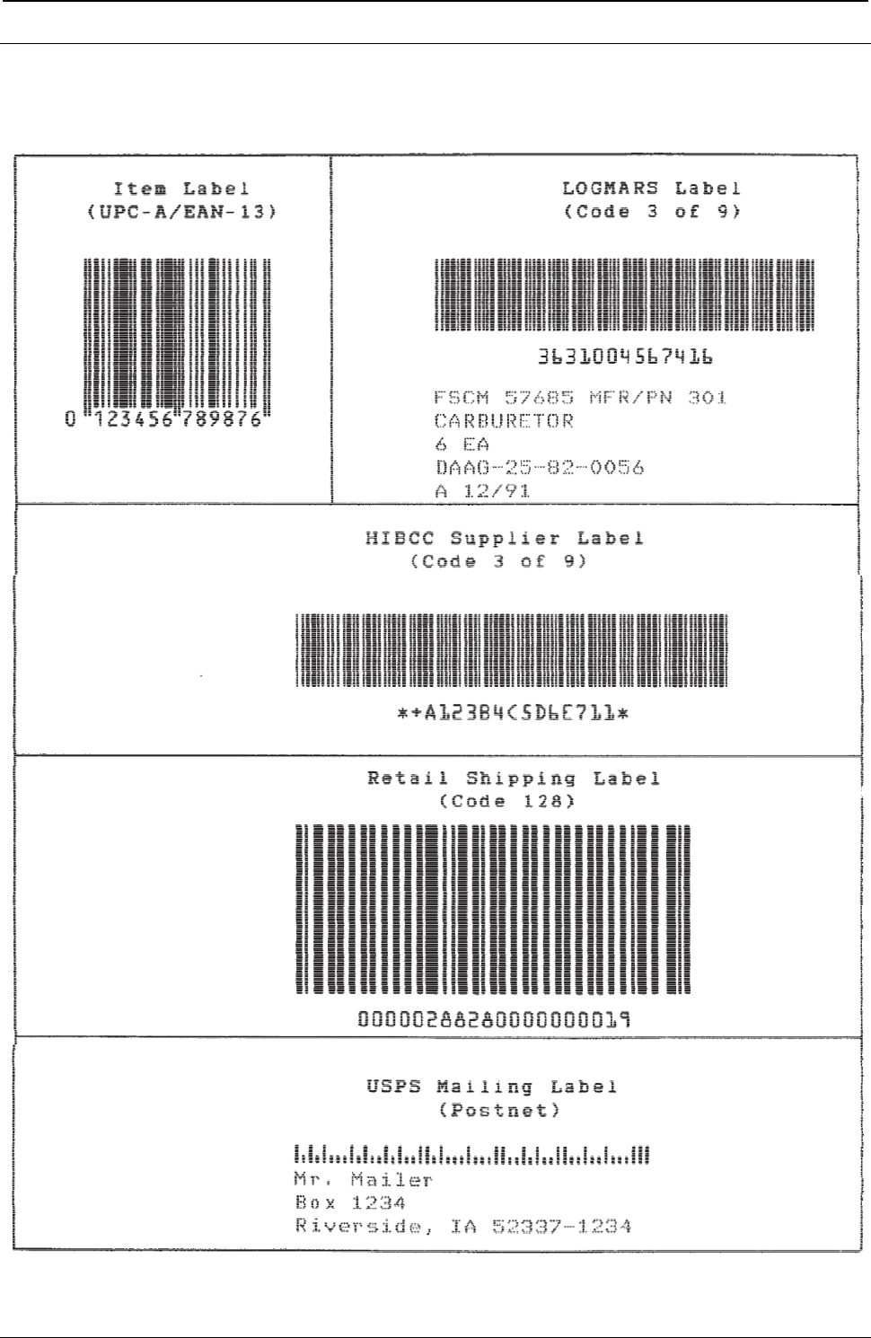
ProgrammerManual PTX‐S828
Chapter7.PrintSamplesandIPDSCodingExample232260071‐001A
Bar Codes
The following are sample bar code labels printed with the S828 Printer:
Figure 30. Bar Code Example in IPDS
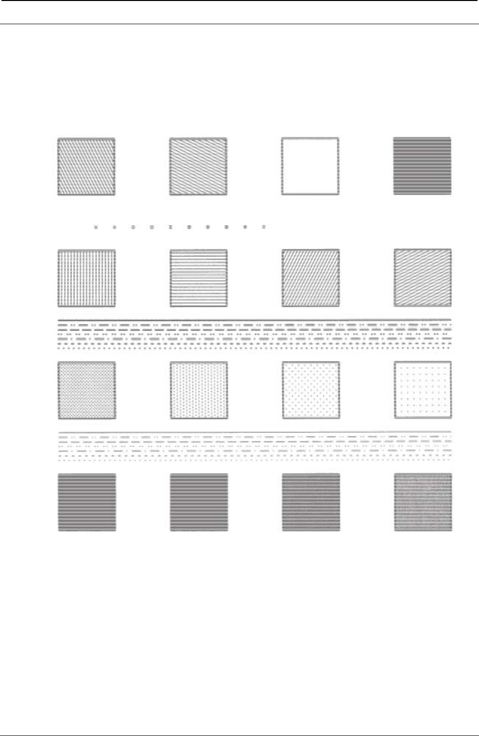
ProgrammerManual PTX‐S828
Chapter7.PrintSamplesandIPDSCodingExample233260071‐001A
Graphics Patterns
The following example shows the area fill patterns, line widths, line types, and marker symbols available
with this printer.
Figure 31. Graphic Patterns Example in IPDS
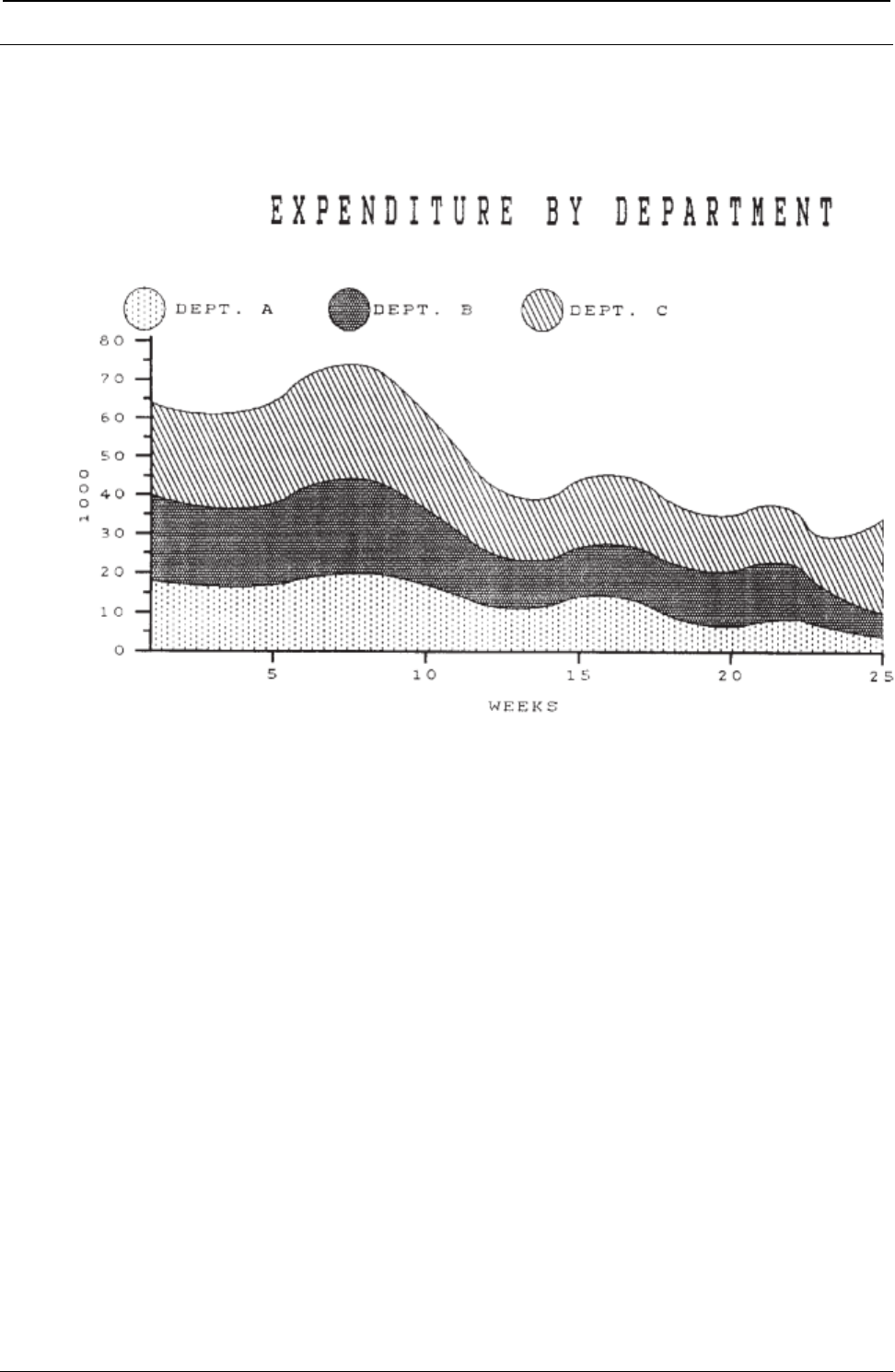
ProgrammerManual PTX‐S828
Chapter7.PrintSamplesandIPDSCodingExample234260071‐001A
Graphics Example
The following drawing is an example of the graphics capabilities of the S828 Printer. The actual IPDS
graphics data stream commands necessary to draw this graphic follow the example.
Figure 32. Graphic Example in IPDS
Data Stream for Graphics Example
********* BEGIN PAGE
0009D6AF0000000000
********* Write Graphics Control
003CD68400000BAC6B000000000000A0
0010A66B0038403DE030001000000000
001CA6BB00003840384000000000DB0010001000F000
000000000000
********* Write Graphics Command Header
037FD68500
********* Begin Segment
700C000000000000036C00000000
********* Set Character Cell Size
3304010E021C
********* Character String
C31DF32B0E10
********* String Data - EXPENITURE BY DEPARTMENT
C5E7D7C5D5C4C9E3E4D9C540C2E840C4C5D7C1D9E3D4C5D5E3
********* Character String
C313F8710BF4
********* String Data - FIRST HALF 1979
C6C9D9E2E340C8C1D3C640F1F9F7F9
********* Key Circles, Set Line Type979
1800
********* Color
0A00
********* Set Pattern Symbol
2806

ProgrammerManual PTX‐S828
Chapter7.PrintSamplesandIPDSCodingExample235260071‐001A
********* Begin Area
6840
********* Full Arc
C706ED680A8CF000
********* End Area
6000
********* Color
0A00
********* Set Pattern Symbol
2803
********* Begin Area
6840
********* Full Arc
C706F6DC0A8CF000
********* End Area
6000
********* Color
0A00
********* Set Pattern Symbol
280D
********* Begin Area
6840
********* Full Arc
C706FFB00A8CF000
********* End Area
6000
********* Color
0A00
********* Set Pattern Symbol
280D
********* Set Line Type
1800
********* Begin Area
6840
********* Fillet
C528EDB80654F1F00492F6280924
FA6000654FE98008702D00438070800FA
OB4002760CA8FF1F0F78010E
********* Set Line Type
1803
********* Line At Current Position
810C0F78FB14EDBBFB14EDB80654
********* End Area
6000
********* Color
0A08
********* Set Pattern Symbol
2800
********* Set Line Type
1800
********* Begin Area
6840
********* Fillet
C528EDB8021CF1F00087F628
0384FA6001C2FE98FE3E02D0
00B40708FE110B40FFA60CA8
FD8A0F78FCD6
********* Set Line Type
1808
********* Line At Current Position
810C0F78FB14EDB8FB14EDB8021C
********* End Area
6000
********* Color
0A00
********* Set Pattern Symbol
2803

ProgrammerManual PTX‐S828
Chapter7.PrintSamplesandIPDSCodingExample236260071‐001A
Set Line Type
1800
********* Begin Area
6840
********* Fillet
C528EDB8021CF1F00087F628
0384FA6001C2FE98FE3E02D0
00B40708FE110B40FFA60CA8FD8A0F78FCD6
********* Set Line Type
1808
********* Line
810C0F78FB14EDB8FB14EDB8021C
********* End Area
6000
********* Color
0A08
********* Set Pattern Symbol
2800
********* Set Line Type
1800
********* Begin Area
6840
********* Fillet
C528EDB8FE3EF1F0FD8AF628
FEC5FA60FE3EFE98FC7C02D
FE3E0708FBC80B40FCD6
0CA8FC220F78FBC8
********* Set Line Type
1808
********* Line At Current Position
810C0F78FB14EDB8FB14EDB801C2
********* End Area
6000
********* Color
0A00
********* Set Pattern Symbol
2806
********* Set Line Type
1800
********* Begine Area
6840
********* Fillet
C528EDB8FE3EF1F0FD8AF628
FEC5FA60FE3EFE98FC7C02D0FE3E0708FBC80B40FCD6
0CA8FC220F78FBC8
********* Set Line Type
1808
********* Line At Current Position
810C0F78FB14EDB8FB14EDB801C2
********* End Area
6000
********* Axes and Tic Marks, Set Line Type
1800
********* Set Line Width
1902
********* Color
0A00
********* Line
C108EDB8FB14EDB80951
********* Line
C108EDB8FB140F78FB14
********* Line
C108EDB8FB14ED04FB14
********* Line
C108EDB8FCD6ED04FCD6
********* Line
C108EDB8FE98ED04FE98

ProgrammerManual PTX‐S828
Chapter7.PrintSamplesandIPDSCodingExample237260071‐001A
********* Line
C108EDB8005AED04005A
********* Line
C108EDB8021CED04021C
********* Line
C108EDB803DEED0403DE
********* Line
C108EDB805A0ED0405A0
********* Line
C108EDB80762ED040762
********* Line
C108EDB80924ED040924
********* Line
C108EDB8FBF5ED5EFBF5
********* Line
C108EDB8FDB7ED5EFDB7
********* Line
C108EDB8FF79ED5EFF79
********* Line
C108EDB8013BED5E013B
********* Line
C108EDB802FDED5E02FD
********* Line
C108EDB804BFED5E04BF
********* Line
C108EDB80681ED5E0681
********* Line
C108EDB80843ED5E0843
********* Line
C108F358FB14F358FA8D
********* Line
C108FA60FB14FA60FA8D
********* Line
C1080168FB140168FA8D
********* Line
C1080870FB140870FA8D
********* Line
C1080F78FB140F78FA8D
********* Letters and Numbers, Set Character Cell
330400000000
********* Character String, DEPT. A
C30BEEC60A32
C4C5D7E34B40C1
********* Character String, DEPT. B
C30BF7EA0A32
C4C5D7E34B40C2
********* Character String, DEPT. C
C30B00E10A32
C4C5D7E34B40C3
********* Character String, 5
C305F2FEF9AC
F5
********* Character String, 10
C306F9ACF9AC
F1F0
********* Character String, 15
C30600BAF9AC
F1F5
********* Character String, 20
C30607BCF9AC
F2F0
********* Character String, 25
C3060EC4F9AC
F2F5
********* Character String, WEEKS
C309FD30F844
E6C5C5D2E2

ProgrammerManual PTX‐S828
Chapter7.PrintSamplesandIPDSCodingExample238260071‐001A
********* Character String, 80
C306EB4208ca
F8F0
********* Character String, 70
C306EB420708
F7F0
********* Character String, 60
C306EB420546
F6F0
********* Character String, 50
C306EB420384
F5F0
********* Character String, 40
C306EB4201C2
F4F0
********* Character String, 30
C306EB420000
F3F
********* Character String, 20
C306EB42FE3E
F2F0
********* Character String, 10
C306EB42FC7C
F1F0
********* Character String, 0
C305EBF6FABA
F0
********* Character Angle
3404000005A0
********* Character String, 1000
C308EAE800B4
F1F0F0F0
********* END
0005D65D00
********* END PAGE
0005D6BF00
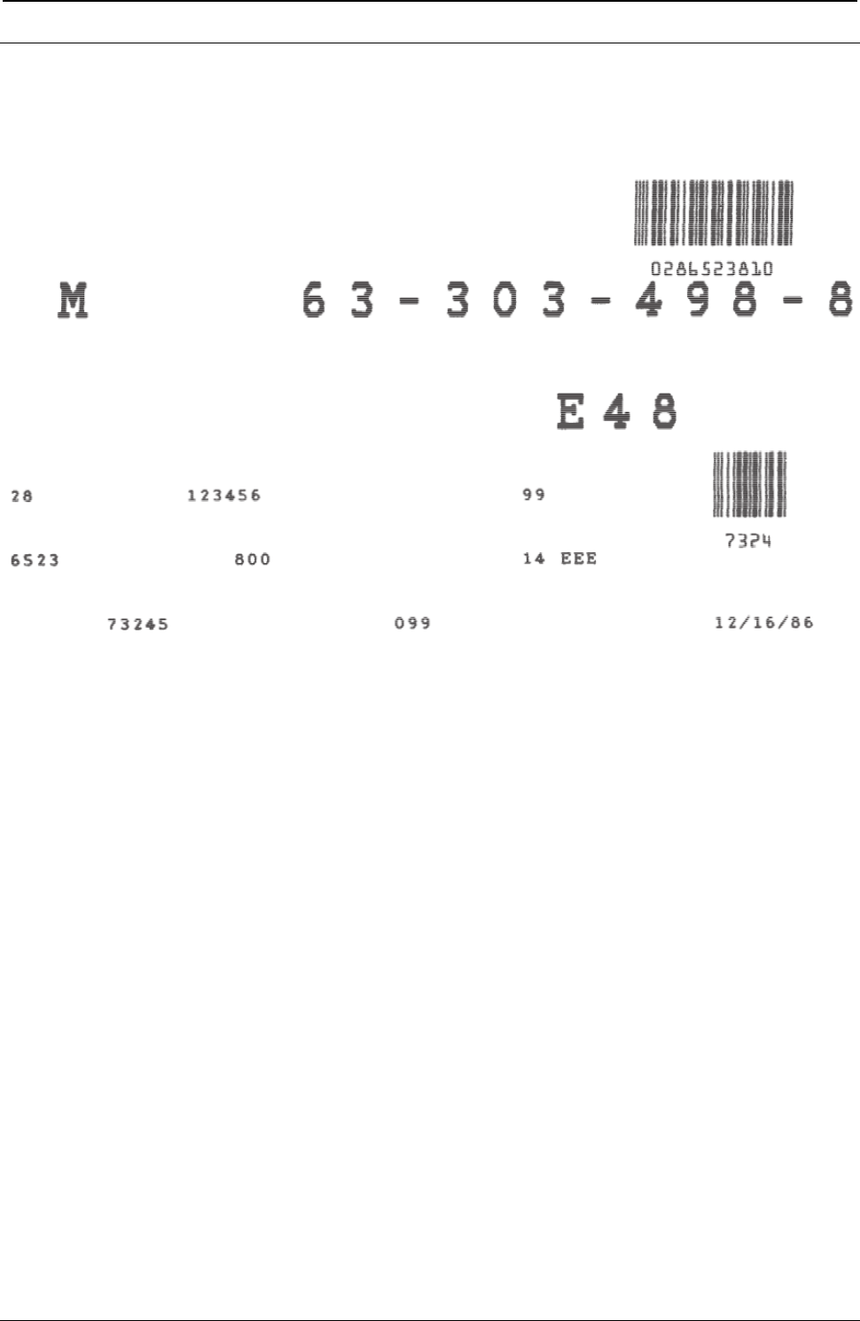
ProgrammerManual PTX‐S828
Chapter7.PrintSamplesandIPDSCodingExample239260071‐001A
IPDS Coding Example
The S828 Printer produced this example of text, bar codes, and block graphic characters printing on the
front continuous forms paper source. The code used to print the example appears in Table 11.
Figure 33. Print Sample from an IPDS Application Program
The following chart is an example of an IPDS application program that prints the block graphic characters,
two bar codes, and text information shown in Table 9, printing on the front continuous forms paper source.
The first column (IPDS Commands) contains abbreviations of the IPDS instructions that are coded in
column 2. Column 2 (Hexadecimal Code) contains the hexadecimal code that produces the characters, bar
codes, and text pictured in Table 9. Column 3 (Code Explanation) explains each command element.
When the application is actually coded, the hexadecimal code of each command may be entered in one
stream. The IPDS command abbreviations in the first column and the explanation of each part of the
command in the last column, are comments.
Table 11. IPDS Coding Example
IPDS Command Hexadecimal Code Code Explanation
******** Printer Initialization
SHS 0005 Control Length
— D697 Set Home State
— 00 Flag Byte
X0A(EHC) 000A Control Length
— D633 Execute Order Any State
— 00 Flag Byte
— F600 Exception Handling Order
— C1 Report All Exceptions
— 01 Do Not Take Alternate Action

ProgrammerManual PTX‐S828
Chapter7.PrintSamplesandIPDSCodingExample240260071‐001A
Table 11. IPDS Coding Example (continued)
IPDS Command Hexadecimal Code Code Explanation
— 01 Print All Data and Exit
XOA(DBD) 0007 Control Length
— D633 Execute Order Any Style
— 00 Flag Byte
— F200 Discard Buffer Data
LPD 0030 Control Length
— D6CF Load Page Descriptor
— 00 Flag Byte
— 00 Units Base Value equals (10 in.)
— 00 Reserved
— 3840 X Units per Base Value
— 3840 Y Units per Base Value
— 00 Reserved
— 00 3570 Width of Page (Units)
— 00 Reserved
— 00 1EF0 Length of Page (Units)
— 00 Reserved
— 00 No Ordered Page
— 0000 Reserved
— 00000000 Reserved
— 0000 Reserved
— 0000 X-Axis Orientation (0 degrees)
— 2D00 Y-Axis Orientation (90 degrees)
— 0000 Initial X Displacement
— 0000 Initial Y Displacement
— 0000 Initial Left Margin
— 0000 Intercharacter Increment
— 0000 Reserved
— FFFF Baseline Increment (Use Default)
— FF Local Font ID (Use Default)
— FFFF Text Color (Use Default)
LPP 000F Control Length
— D66D Load Page Position
— 00 Flag Byte
— 00 Reserved
— 000000 X Displacement
— 00 Reserved
— 000000 Y Displacement
— 0000 Reserved
XOH(SMS) 000E Control Length

ProgrammerManual PTX‐S828
Chapter7.PrintSamplesandIPDSCodingExample241260071‐001A
Table 9. IPDS Coding Example (continued)
IPDS Command Hexadecimal Code Code Explanation
— D68F Execute Order Home State
— 00 Flag Byte
— 1700 Set Media Size (SMS)
— 00 Units Base Value equals (10 in.)
— 3840 Units per Base Value
— 3570 X-Extent of Physical Medium
— 1EF0 Y-Extent of Physical Medium
LFE 0015 Control Length
— D63F Load Font Equivalence
— 00 Flag Byte
— 07 Local ID
— 0007 Loaded Font ID
— 0000 Character Rotation (0 degrees)
— 0000 Reserved
— 0025 Code Page ID (USA)
— 000B Font Style ID (10 CPI, Courier)
— 0000 Reserved
— 00 Reserved
— 80 Font Attribute (In printer)
— 00 Reserved
XOA(PQC) 0008 Control Length
— D633 Execute Order Any State
— 00 Flag Byte
— F800 Print Quality Control
— AB Select NLQ
XOH(SIMS) 0008 Control Length
— D68F Execute Order Home State
— 00 Flag Byte
— 1500 Select Input Media Source
— 00 Front Paper Source
******** Begin Page
BP 0009 Control Length
— D6AF Begin Page
— 00 Flag Byte
— 00000000 Data ** Ignored
******** Write Text Data

ProgrammerManual PTX‐S828
Chapter7.PrintSamplesandIPDSCodingExample242260071‐001A
Table 9. IPDS Coding Example (continued)
IPDS Command Hexadecimal Code Code Explanation
WT 0014 Control Length
— 262D Write Text
— 00 Flag Byte
— 2BD3 Escape Sequence
— 03F107 Set Coded Font Local
— 04C709D8 Absolute Move Inline
— 04D20F78 Absolute Move Baseline
— F2F8 Data '28'
WT 0011 Control Length
— D62D Write Text
— 00 Flag Byte
— 2BD3 Escape Sequence
— 04C61194 Absolute Move Inline
— F1F2F3F4F5F6F Data '123456'
WT 000D Control Length
— D62D Write Text
— 00 Flag Byte
— 2BD3 Escape Sequence
— 04C62058 Absolute Move Inline
— F9F9 Data '99'
WT 0013 Control Length
— D62D Write Text
— 00 Flag Byte
— 2BD3 Escape Sequence
— 04C709D8 Absolute Move Inline
— 04D21248 Absolute Move Baseline
— F6F5F2F3 Data '6523'
WT 000E Control Length
— D62D Write Text
— 00 Flag Byte
— 2BD3 Escape Sequence
— 04C613B0 Absolute Move Inline
— F8F0F0 Data '800'
WT 0011 Control Length
— D62D Write Text
— 00 Flag Byte
— 2BD3 Escape Sequence
— 04C62058 Absolute Move Inline
— F1F4FFC5C5C5 Data '14 EEE'
WT 0014 Control Length

ProgrammerManual PTX‐S828
Chapter7.PrintSamplesandIPDSCodingExample243260071‐001A
Table 9. IPDS Coding Example (continued)
IPDS Command Hexadecimal Code Code Explanation
— D62D Write Text
— 00 Flag Byte
— 2BD3 Escape Sequence
— 04C70E10 Absolute Move Inline
— 04D21518 Absolute Move Baseline
— F7F3F2F4F5 Data '73245'
WT 000E Control Length
— D62D Write Text
— 00 Flag Byte
— 2BD3 Escape Sequence
— 04C61AB8 Absolute Move Inline
— F0F9F9 Data '099'
WT 0013 Control Length
— D62D Write Text
— 00 Flag Byte
— 2BD3 Escape Sequence
— 04C628C8 Absolute Move Inline
— F1F262F1F661F8F6 Data '12/16/86'
******** Write Graphics Control
WGC 002C Control Length
— D684 Write Graphics Control
— 00 Flag Byte
(GAP) 000B Field Length
— AC6B Graphics Area Position Control
— 0000 Inline (X) Coordinate Position
— 0000 Baseline (Y) Coordinate Position
— 0000 Orientation (0 degrees)
— A0 Absolute X, Absolute Y
(GDD) 001C Field Length
— A6BB Graphics Data Descriptor
— 00 Unit Base (10 in.)
— 00 Reserved
— 3840 X Units/Unit Base
— 3840 Y Units/Unit Base
— 00000000 Reserved
— 0000 X Left Limit of Window
— 3570 X Right Limit of Window
— 1EF0 Y Top Limit of Window

ProgrammerManual PTX‐S828
Chapter7.PrintSamplesandIPDSCodingExample244260071‐001A
Table 9. IPDS Coding Example (continued)
IPDS Command Hexadecimal Code Code Explanation
— 0000 Y Bottom Limit of Window
— 00000000 Reserved
— 0000 Graphics Flags ** Ignored
******** Write Graphics
WG 003D Control Length
— D685 Write Graphics
— 00 Flag Byte
(BSI) 70 Begin Segment Introducer
— 0C Length of Following Parameter
— 00000000 Reserved
— 00 Flags
— 06 Append Segment
— 002A Length of Segment
— 00000000 Reserved
(SCCS) 33 Set Character Cell Size
— 04 Length of Data
— 021C Width of Cell
— 02D0 Height of Cell
(SCS) 38 Set Character String
— 07 Local Character Set ID
(CS) 05 Character String
— C3 Field String
— 0BF4 X Coordinate (Units)
— 1734 Y Coordinate (Units)
— D4 Data 'M'
(CS) C3 Character String
— 10 Field Length
— 1680 X Coordinate (Units)
— 1734 Y Coordinate (Units)
— F6F3CAF3F0F3CA Data '63-303-498-8'
— F4F9F8CAF8
(CS) C3 Character String
— 07 Field Length
— 21C0 X Coordinate (Units)
— 1248 Y Coordinate (Units)
— C5F4F8 Data 'E48'
END 0005 Control Length
— D65D End (Graphics)

ProgrammerManual PTX‐S828
Chapter7.PrintSamplesandIPDSCodingExample245260071‐001A
Table 9. IPDS Coding Example (continued)
IPDS Command Hexadecimal Code Code Explanation
— 00 Flag Byte
******** Write Bar Code Control
WBCC 002B Control Length
— D680 Write Bar Code Control (BC)
— 00 Flag Byte
(BCAP) 000B Field Length
— AC6B BC Area Position Control
— 0000 X Coordinate of BC Area
— 0000 Y Coordinate of BC Area
— 0000 Orientation of Bar Code (0 Degrees)
— A0 Absolute X, Absolute Y
(BCDD) 001B Field Length
— A6EB Bar Code Data Descriptor
— 00 Unit Base (10 in.)
— 00 Reserved
— 3840 X Units/Unit Base
— 3840 Y Units/Unit Base
— 3840 X Extent of Block (Width)
— 2FD0 Y Extent of Block (Height)
— 0000 Reserved
— 0C Bar Code Type (2 of 5 Interleaved)
— 01 No Check Digit
— FF User Printer Default LFID
— 0000 Select Color (Black)
— 0E Unit Module Width (.014 in.)
— 02D0 Element Height (720 Units)
— 01 Height Multiplier
— 0019 Wide/Narrow Ratio
******** Write Bar Codes
WBC 0013 Control Length
— D681 Write Bar Code
— 00 Flag Byte
— 20 Bar Code Flag
— 2544 X Coordinate
— 0168 Y Coordinate
— F2F8F6F5F1F3F8F1F0 Data '286523810'

ProgrammerManual PTX‐S828
Chapter7.PrintSamplesandIPDSCodingExample246260071‐001A
Table 9. IPDS Coding Example (continued)
IPDS Command Hexadecimal Code Code Explanation
WBC 00E Control Length
— D681 Write Bar Code
— 00 Flag Byte
— 20 Bar Code Flag
— 28C8 X Coordinate
— 0D5C Y Coordinate
— F7F3F2F4 Data '7324'
END 0005 Control Length
— D65D End (Bar Code)
— 00 Flag Byte
******** End of Page
EP 0005 Control Length
— D6BF End Page
— 00 Flag Byte

ProgrammerManual PTX‐S828
AppendixA.CodePages247260071‐001A
Appendix A. Code Pages
The EBCDIC code charts contains information about the code pages that the Printronix S828 Model
Printers use on the Ethernet IPDS attachments.
See the “ASCII Code Pages” for information about the code pages for Ethernet ASCII attachments.
You can use the following charts to determine the actual character printed for any code page and font
combination.
EBCDIC Code Pages (IPDS)
The table below lists the EBCDIC code pages used by the S828 Printer, and also provides page
references so you can determine what code page contains the characters you want to use.
Code
Page Character Set Name
37 USA/Canada/Canadian Bilingual
260 Canadian French
273 Austrian/German
274 Belgian Old
275 Brazilian
277 Danish/Norwegian
278 Finnish/Swedish
280 Italian
281 Japanese English
282 Portuguese
284 Spanish/Spanish Speaking
285 English (UK)/Ireland
290 Japanese Katakana
297 French/French Azerty
420 Arabic
423 Greek (Old)
424 Hebrew Bulletin
500 International 5/Swiss/Belgian
813 Greek/Latin (ISO 8859-7) + euro
833 Korean
838 Thai
870 Latin 2/ROECE
871 Icelandic
875 Greek New + euro
880 Cyrillic
890 Yugoslav (Old)
892 OCR-A
893 OCR-B
924 Latin 9 (ISO 8859) + euro
1025 Cyrillic Multilingual

ProgrammerManual PTX‐S828
AppendixA.CodePages248260071‐001A
Code
Page Character Set Name
1026 Latin-5 Turkey
1097 Farsi
1112 Baltic Multilingual
1122 Estonian
1140 USA/Canada + euro
1141 Austrian/German + euro
1142 Danish/Norwegian + euro
1143 Finnish/Swedish + euro
1144 Italian + euro
1145 Spanish/Spanish Speaking + euro
1146 English/UK + euro
1147 French + euro
1148 International 5/Belgian New + euro
1149 Icelandic + euro

ProgrammerManual PTX‐S828
AppendixA.CodePages249260071‐001A
USA/Canada/Canadian Bilingual
Code Page 00037
Figure 34. CP00037 USA/Canada/Canadian Bilingual
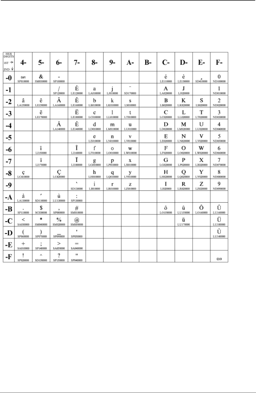
ProgrammerManual PTX‐S828
AppendixA.CodePages250260071‐001A
Canadian French
Code Page 00260
Figure 35. CP00260 Canadian French

ProgrammerManual PTX‐S828
AppendixA.CodePages251260071‐001A
Austrian/German
Code Pages 273
Figure 36. CP00273 Austrian/German

ProgrammerManual PTX‐S828
AppendixA.CodePages252260071‐001A
Belgian Old
Code Pages 274
Figure 37. CP00274 Belgian Old
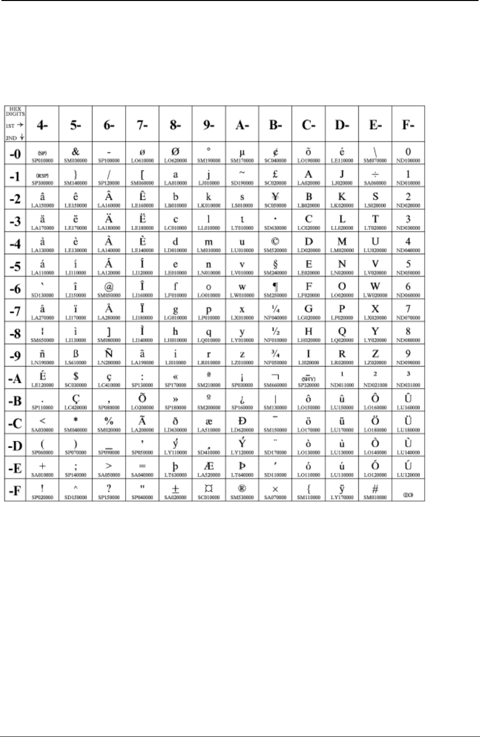
ProgrammerManual PTX‐S828
AppendixA.CodePages253260071‐001A
Brazilian
Code Pages 275
Figure 38. CP00275 Brazilian

ProgrammerManual PTX‐S828
AppendixA.CodePages254260071‐001A
Danish/Norwegian
Code Page 00277
Figure 39. CP00277 Danish/Norwegian

ProgrammerManual PTX‐S828
AppendixA.CodePages255260071‐001A
Finnish/Swedish
Code Pages 278
Figure 40. CP00278 Finnish/Swedish
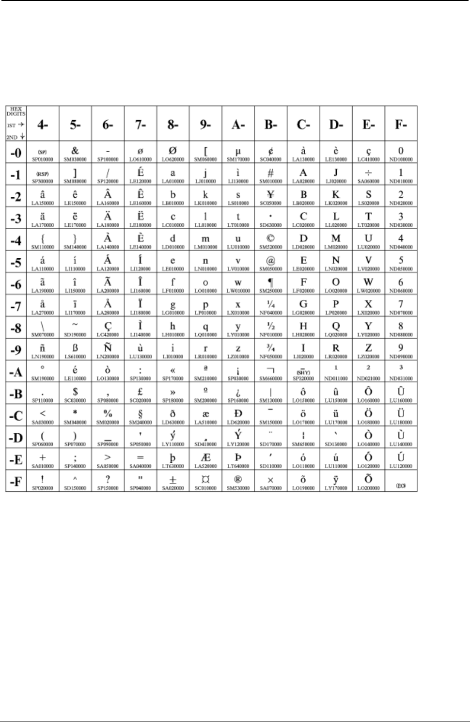
ProgrammerManual PTX‐S828
AppendixA.CodePages256260071‐001A
Italian
Code Page 00280
Figure 41. CP00280 Italian

ProgrammerManual PTX‐S828
AppendixA.CodePages257260071‐001A
Japanese English
Code Pages 00281
Figure 42. CP00281 Japanese English

ProgrammerManual PTX‐S828
AppendixA.CodePages258260071‐001A
Portuguese
Code Page 00282
Figure 43. CP00282 Portuguese
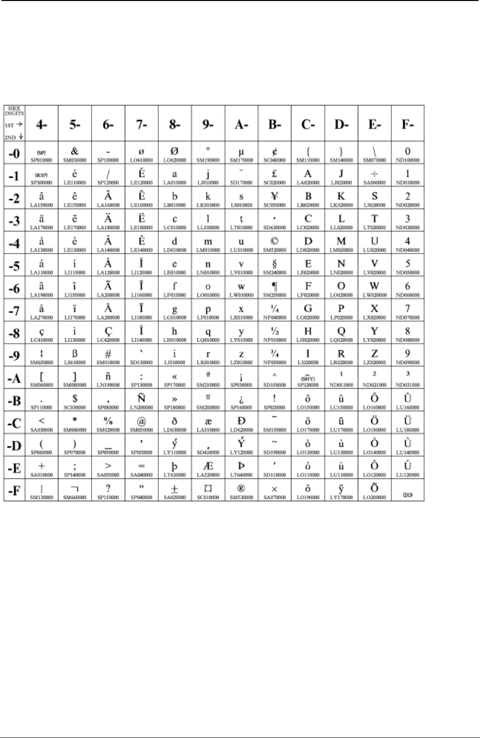
ProgrammerManual PTX‐S828
AppendixA.CodePages259260071‐001A
Spanish/Spanish Speaking
Code Pages 00284
Figure 44. CP00284 Spanish/Spanish Speaking

ProgrammerManual PTX‐S828
AppendixA.CodePages260260071‐001A
English (UK)/Ireland
Code Page 00285
Figure 45. CP00285 English (UK)/Ireland
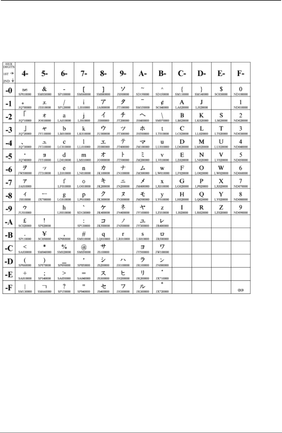
ProgrammerManual PTX‐S828
AppendixA.CodePages261260071‐001A
Japanese Katakana
Code Page 00290
Figure 46. CP00290 Japanese Katakana
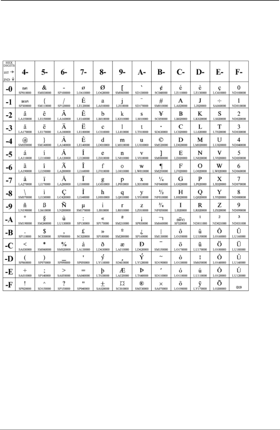
ProgrammerManual PTX‐S828
AppendixA.CodePages262260071‐001A
French/French Azerty
Code Page 00297
Figure 47. CP00297 French/French Azerty
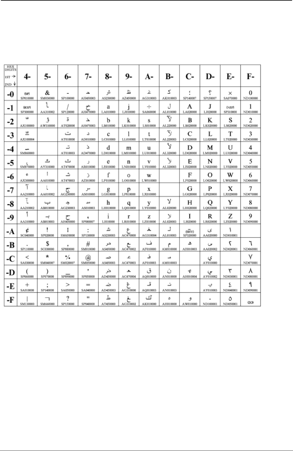
ProgrammerManual PTX‐S828
AppendixA.CodePages263260071‐001A
Arabic
Code Page 00420
Figure 48. CP00420 Arabic
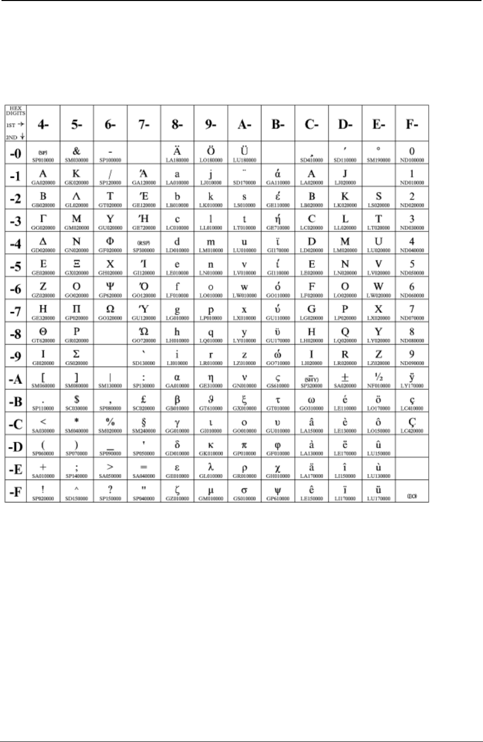
ProgrammerManual PTX‐S828
AppendixA.CodePages264260071‐001A
Greek (Old)
Code Page 00423
Figure 49. CP00423 Greek (Old)
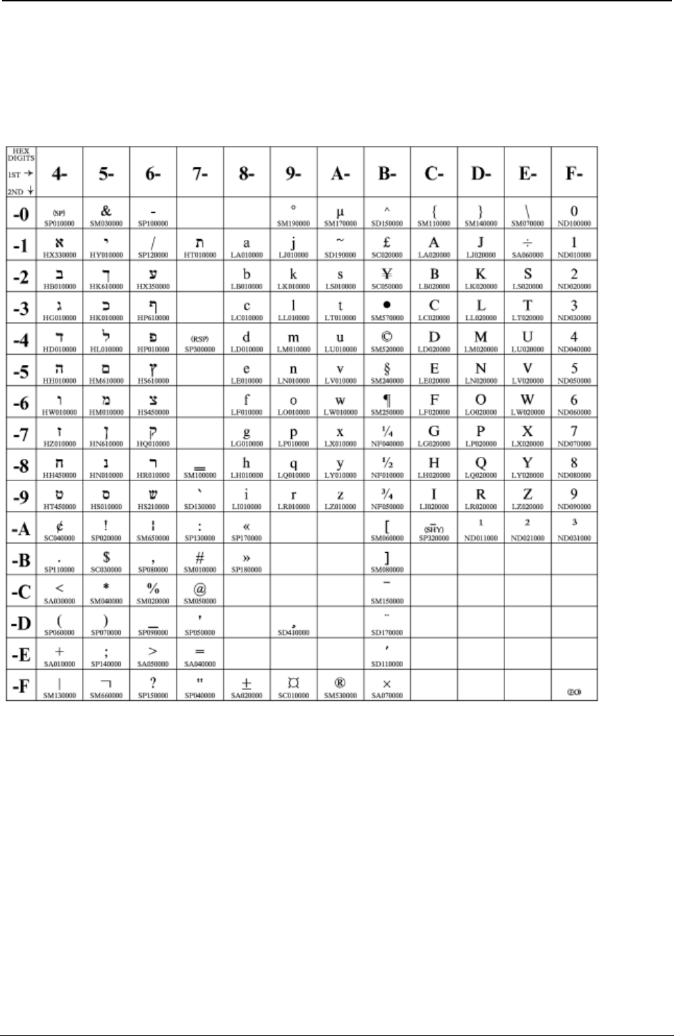
ProgrammerManual PTX‐S828
AppendixA.CodePages265260071‐001A
Hebrew Bulletin
Code 00424
Figure 50. CP00424 Hebrew Bulletin

ProgrammerManual PTX‐S828
AppendixA.CodePages266260071‐001A
International 5/Swiss/Belgian
Code Page 00500
Figure 51. CP00500 International 5/Swiss/Belgian
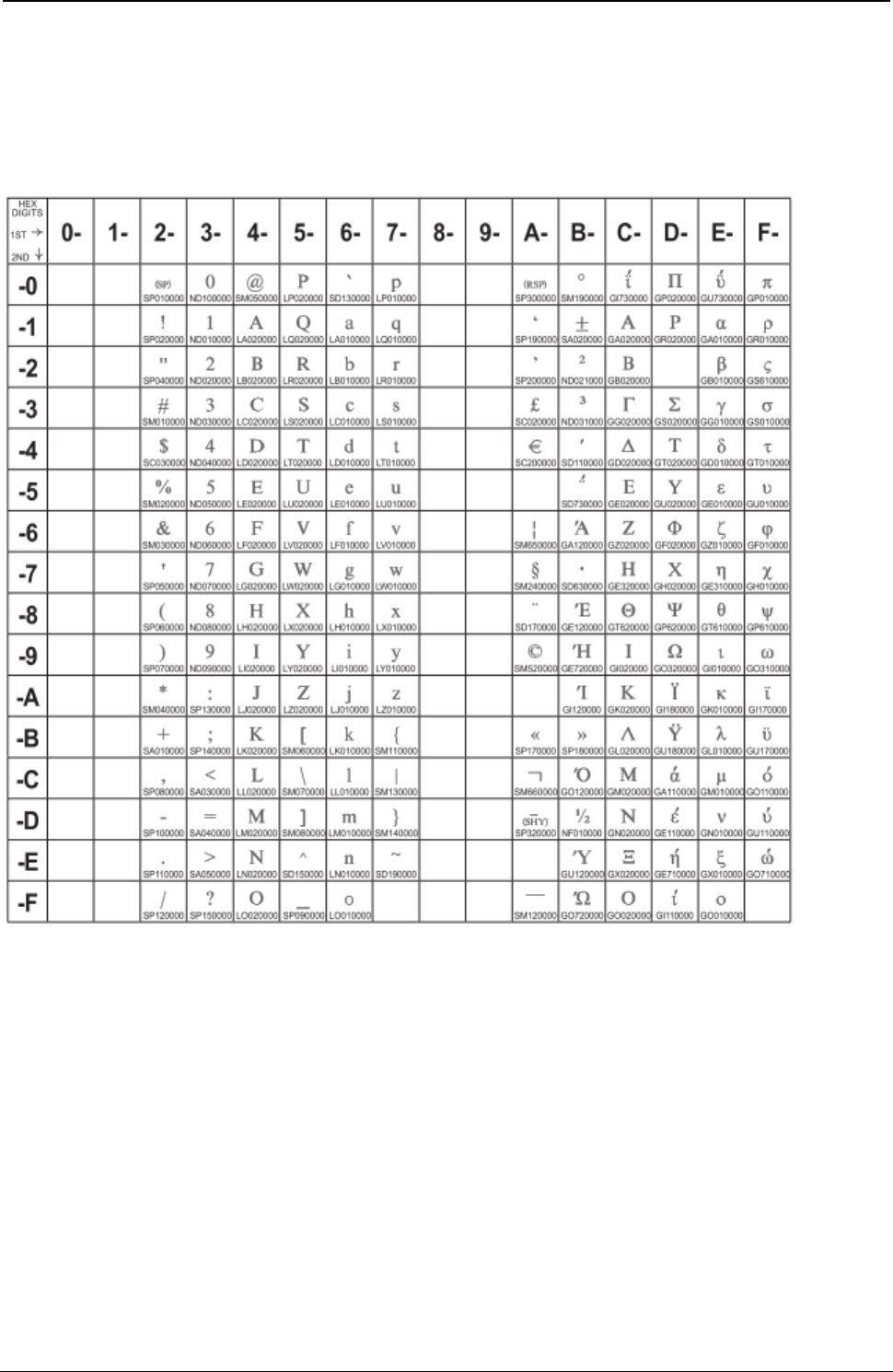
ProgrammerManual PTX‐S828
AppendixA.CodePages267260071‐001A
Greek/Latin (ISO 8859-7) + euro
Code Page 00813
Figure 52. CP00813 Greek/Latin (ISO 8859-7) + euro
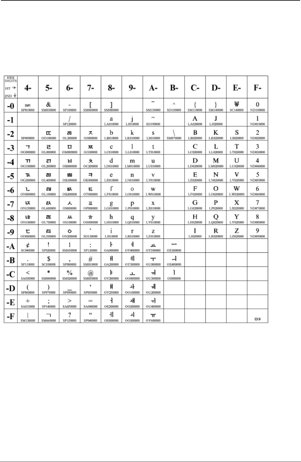
ProgrammerManual PTX‐S828
AppendixA.CodePages268260071‐001A
Korean
Code Page 00833
Figure 53. CP00833 Korean
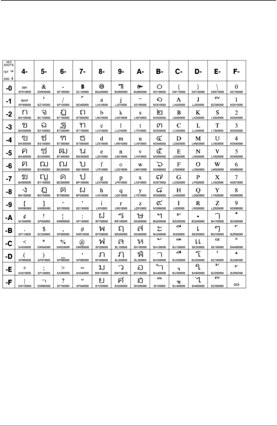
ProgrammerManual PTX‐S828
AppendixA.CodePages269260071‐001A
Thai
Code Page 00838
Figure 54. CP00838 Thai
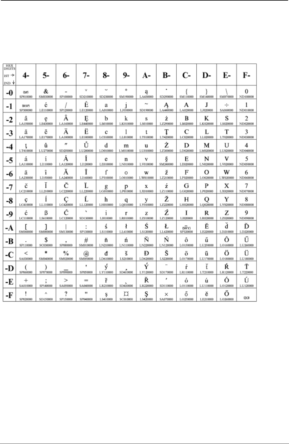
ProgrammerManual PTX‐S828
AppendixA.CodePages270260071‐001A
Latin 2/ROECE
Code Page 00870
Figure 55. CP00870 Latin 2/ROECE

ProgrammerManual PTX‐S828
AppendixA.CodePages271260071‐001A
Icelandic
Code Page 00871
Figure 56. CP00871 Icelandic
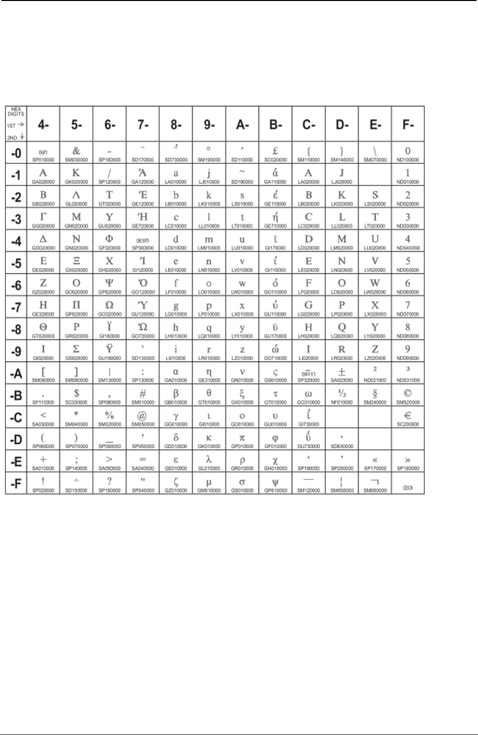
ProgrammerManual PTX‐S828
AppendixA.CodePages272260071‐001A
Greek New + euro
Code Page 00875
Figure 57. CP00875 Greek New + euro
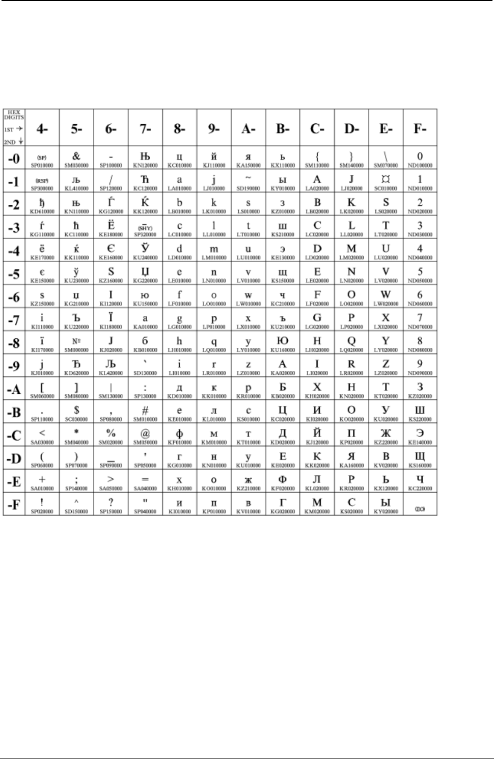
ProgrammerManual PTX‐S828
AppendixA.CodePages273260071‐001A
Cyrillic
Code Page 00880
Figure 58. CP00880 Cyrillic
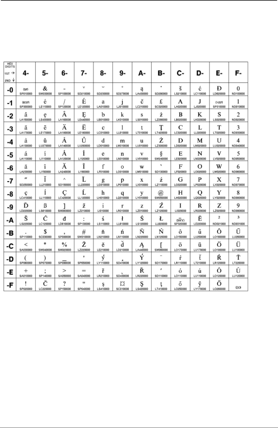
ProgrammerManual PTX‐S828
AppendixA.CodePages274260071‐001A
Yugoslav (Old)
Code Page 00890
Figure 59. CP00890 Yugoslav (Old)
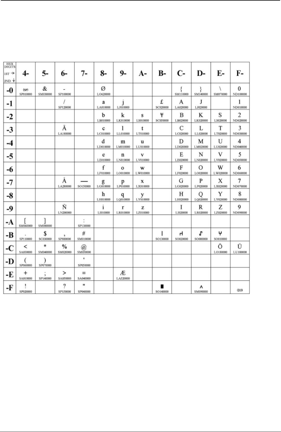
ProgrammerManual PTX‐S828
AppendixA.CodePages275260071‐001A
OCR-A
Code Page 00892
Figure 60. CP00892 OCR-A
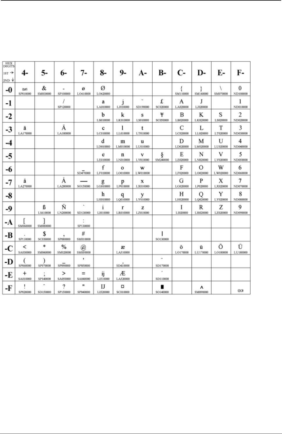
ProgrammerManual PTX‐S828
AppendixA.CodePages276260071‐001A
OCR-B
Code Page 00893
Figure 61. CP00893 OCR-B

ProgrammerManual PTX‐S828
AppendixA.CodePages277260071‐001A
Latin 9 (ISO 8859) + euro
Code Page 00924
Figure 62. CP00924 Latin 9 (ISO 8859) + euro

ProgrammerManual PTX‐S828
AppendixA.CodePages278260071‐001A
Cyrillic Multilingual
Code Page 01025
Figure 63. CP01025 Cyrillic Multilingual

ProgrammerManual PTX‐S828
AppendixA.CodePages279260071‐001A
Latin-5 Turkey
Code Page 01026
Figure 64. CP01026 Latin-5 Turkey
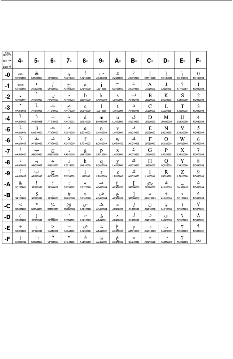
ProgrammerManual PTX‐S828
AppendixA.CodePages280260071‐001A
Farsi
Code Page 01097
Figure 65. CP01097 Farsi

ProgrammerManual PTX‐S828
AppendixA.CodePages281260071‐001A
Baltic Multilingual
Code Page 01112
Figure 66. CP01112 Baltic Multilingual
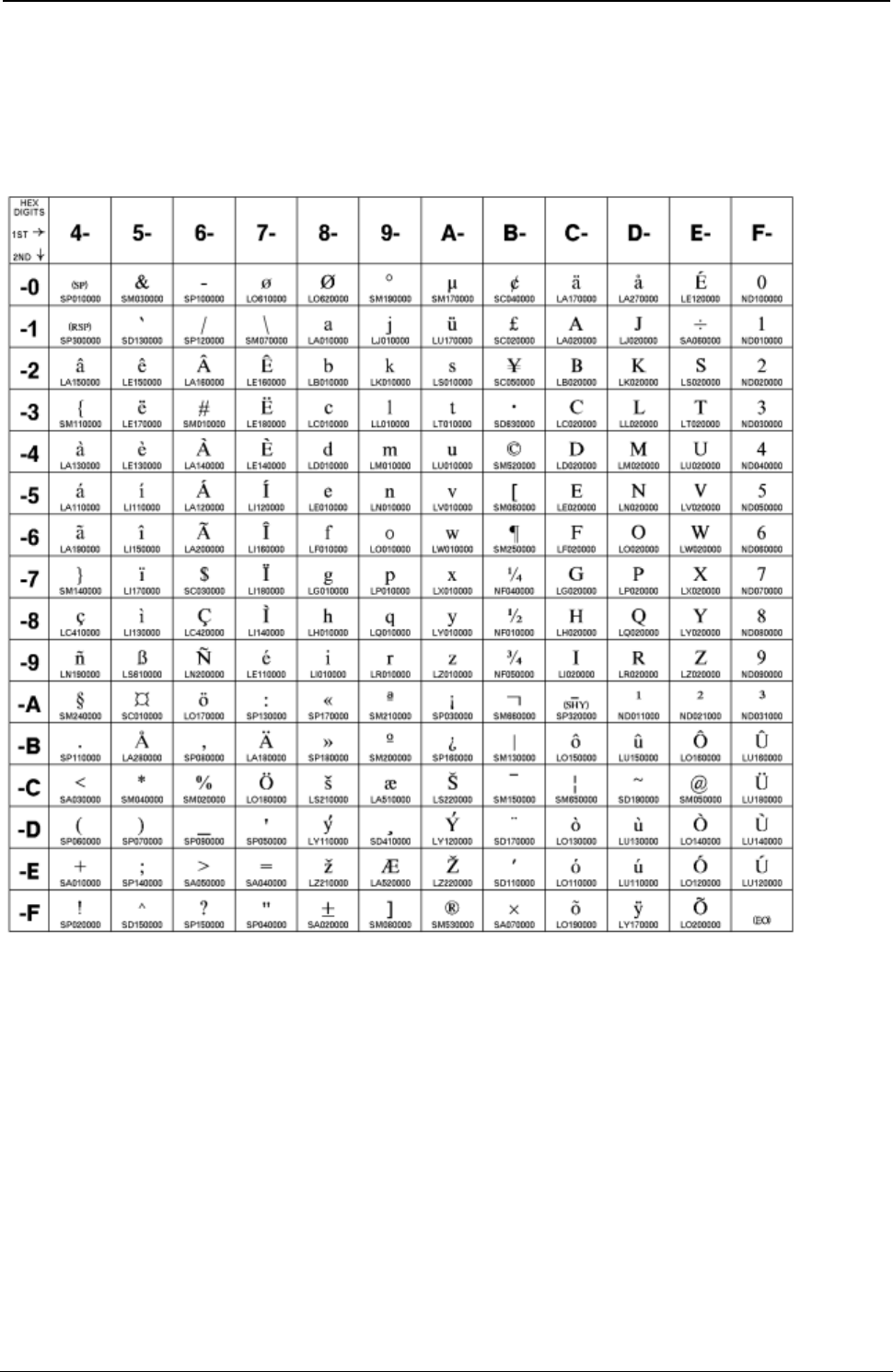
ProgrammerManual PTX‐S828
AppendixA.CodePages282260071‐001A
Estonian
Code Page 01122
Figure 67. CP01122 Estonian

ProgrammerManual PTX‐S828
AppendixA.CodePages283260071‐001A
USA/Canada + euro
Code Page 01140
Figure 68. CP01140 USA/Canada + euro

ProgrammerManual PTX‐S828
AppendixA.CodePages284260071‐001A
Austrian/German + euro
Code Page 01141
Figure 69. CP01141 Austrian/German + euro

ProgrammerManual PTX‐S828
AppendixA.CodePages285260071‐001A
Danish/Norwegian + euro
Code Page 01142
Figure 70. CP01142 Danish/Norwegian + euro

ProgrammerManual PTX‐S828
AppendixA.CodePages286260071‐001A
Finnish/Swedish + euro
Code Page 001143
Figure 71. CP01143 Finnish/Swedish + euro
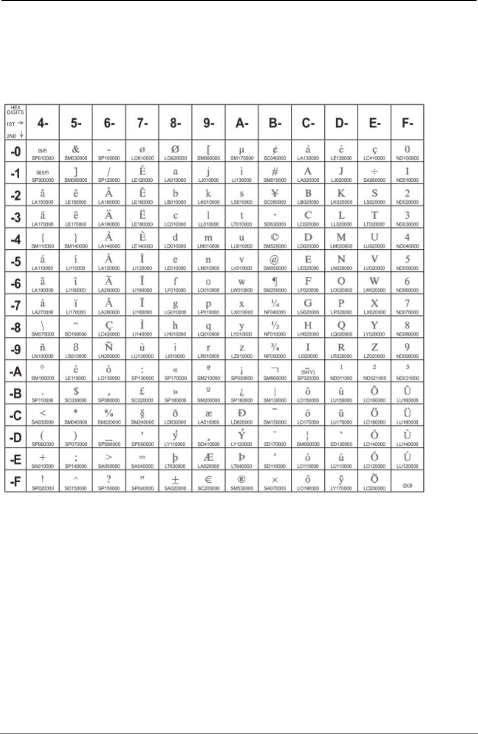
ProgrammerManual PTX‐S828
AppendixA.CodePages287260071‐001A
Italian + euro
Code Page 00144
Figure 72. CP01144 Italian + euro

ProgrammerManual PTX‐S828
AppendixA.CodePages288260071‐001A
Spanish/Spanish Speaking + euro
Code Page 01145
Figure 73. CP01145 Spanish/Spanish Speaking + euro

ProgrammerManual PTX‐S828
AppendixA.CodePages289260071‐001A
English/UK + euro
Code Page 01146
Figure 74. CP01146 English/UK + euro

ProgrammerManual PTX‐S828
AppendixA.CodePages290260071‐001A
French + euro
Code Page 01147
Figure 75. CP01147 French + euro

ProgrammerManual PTX‐S828
AppendixA.CodePages291260071‐001A
International 5/Belgian New + euro
Code Page 01148
Figure 76. CP01148 International 5/Belgian New + euro
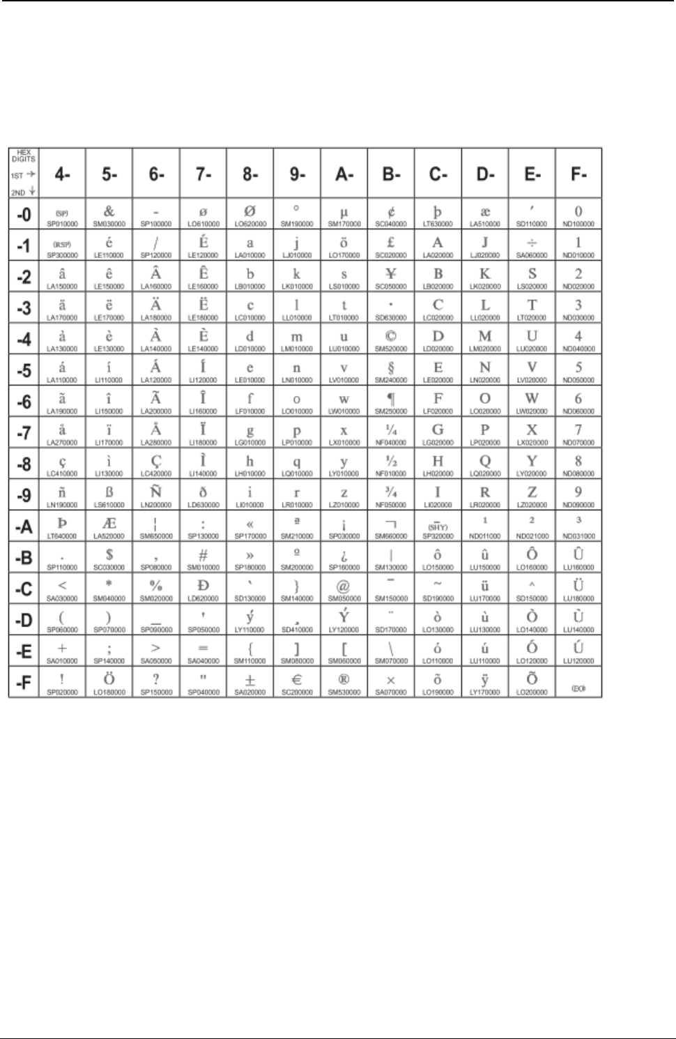
ProgrammerManual PTX‐S828
AppendixA.CodePages292260071‐001A
Icelandic + euro
Code Page 01149
Figure 77. CP01149 Icelandic + euro

ProgrammerManual PTX‐S828
AppendixA.CodePages293260071‐001A
ASCII Code Pages
The table below lists the ASCII code pages used by the S828 Printer, and also provides page references
so you can determine what code page contains the characters you want to use.
These Code Pages can be found in the EPSON/IBM/ANSI emulations.
Code
Page Character Set Name
437 USA (Personal Computer) A-54
437-G Greek
437-SL Croatian
850 PC Multilingual
851 Old Greek
852 Latin 2/ROECE
853 Latin 3 (PC)
855 Cyrillic (PC)
857 Latin 5-Turkey + euro
858 PC Multilingual + euro
860 Portuguese
862 Hebrew
863 Canadian French
864E Arabic
865 Danish/Norwegian
866 PC Data, Cyrillic, Russian
867 Turkish 2
876 OCR-A
877 OCR-B
1098 Farsi (Personal Computer)
1250 Central Europe Latin 2
1251 Cyrillic
1252 Latin 1 Ansi Windows
1253 Greek Windows
1254 Turkish Windows
1255 Hebrew Windows
1256 Arabic Windows
1257 Baltic Windows
MAZOWIA Polish
GOST Russian
TASS Cyrillic
UKRANIAN old version
KOI8-U new version
FARSI 1
FARSI 2
Kamenicky
CWI
Roman-8
IN2
Turkish
Bulgarian

ProgrammerManual PTX‐S828
AppendixA.CodePages294260071‐001A
Code
Page Character Set Name Page
ISO 8859-1 Latin 1
ISO 8859/2 Latin 2
ISO 8859/3 Latin 3
ISO 8859/4 Latin 4
ISO 8859-5 Latin/Cyrillic 281
ISO 8859-6 Latin/Arabic 300
ISO 8859-7 Latin/Greek 301
ISO 8859-8 Latin/Hebrew 302
ISO 8859-9 Latin 5 305
ISO 8859-15 Latin 9 308
96 GREEK
Extended Graphics Character Table 318
Italic Character Table 319
Epson Extended Character Variables 320
ANSI National VAriations

ProgrammerManual PTX‐S828
AppendixA.CodePages295260071‐001A
USA (Personal Computer) A-54
Code Page 00437
Figure 78. USA(CP437)
ProgrammerManual PTX‐S828
AppendixA.CodePages296260071‐001A
Greek
Code Page 00437-G
00 10 20 30 40 50 60 70 80 90 A0 B0 C0 D0 E0 F0
00 Ø 0 @ P ’ p
░ └ ╨ o
01 ! 1 A Q a q
▒ ┴ ╤ ±
02 “ 2 B R b r - ▓ ┬ ╥ ≥
03 !! # 3 C S c s │ ├ ╙ ≤
04 ¶ $ 4 D T d t ┤ ─ ╘ ⌠
05 § % 5 E U e u ╡ ┼ ╒ ⌡
06 – & 6 F V f v ╢ ╞ ╓ ÷
07 ‘ 7 G W g w ╖ ╟ ╫ ≈
08 ( 8 H X h x ╕ ╚ ╪ °
09 ° ) 9 I Y i y
╣ ╔ ┘ £
0A ■ * : J Z j z
║ ╩ ┌ ¥
0B + ; K [ k { ╗ ╦ █ √
0C └ , < L \ l |
╝ ╠ ▄ ⁿ
0D - = M ] m } ╜ ═ ▌ ²
0E . > N ^ n ~ ╛ ╬ ▐ ■
0F / ? O _ o ┐ ╧ ▀
Figure 79.Greek(CP437-G)
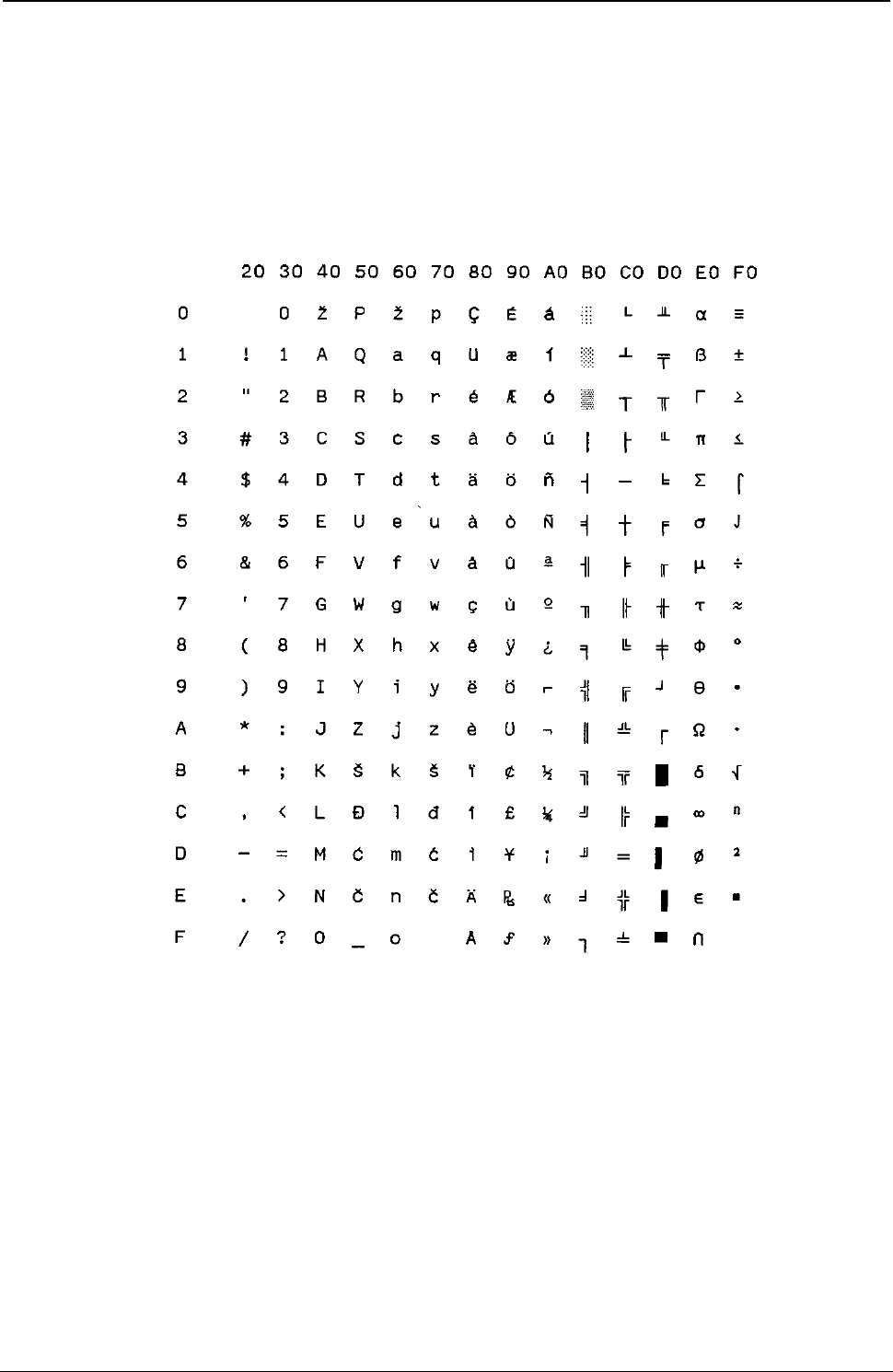
ProgrammerManual PTX‐S828
AppendixA.CodePages297260071‐001A
Croatian
Code Page 00437-SL
Figure 80.Croatian(CP437-SLAVIC)
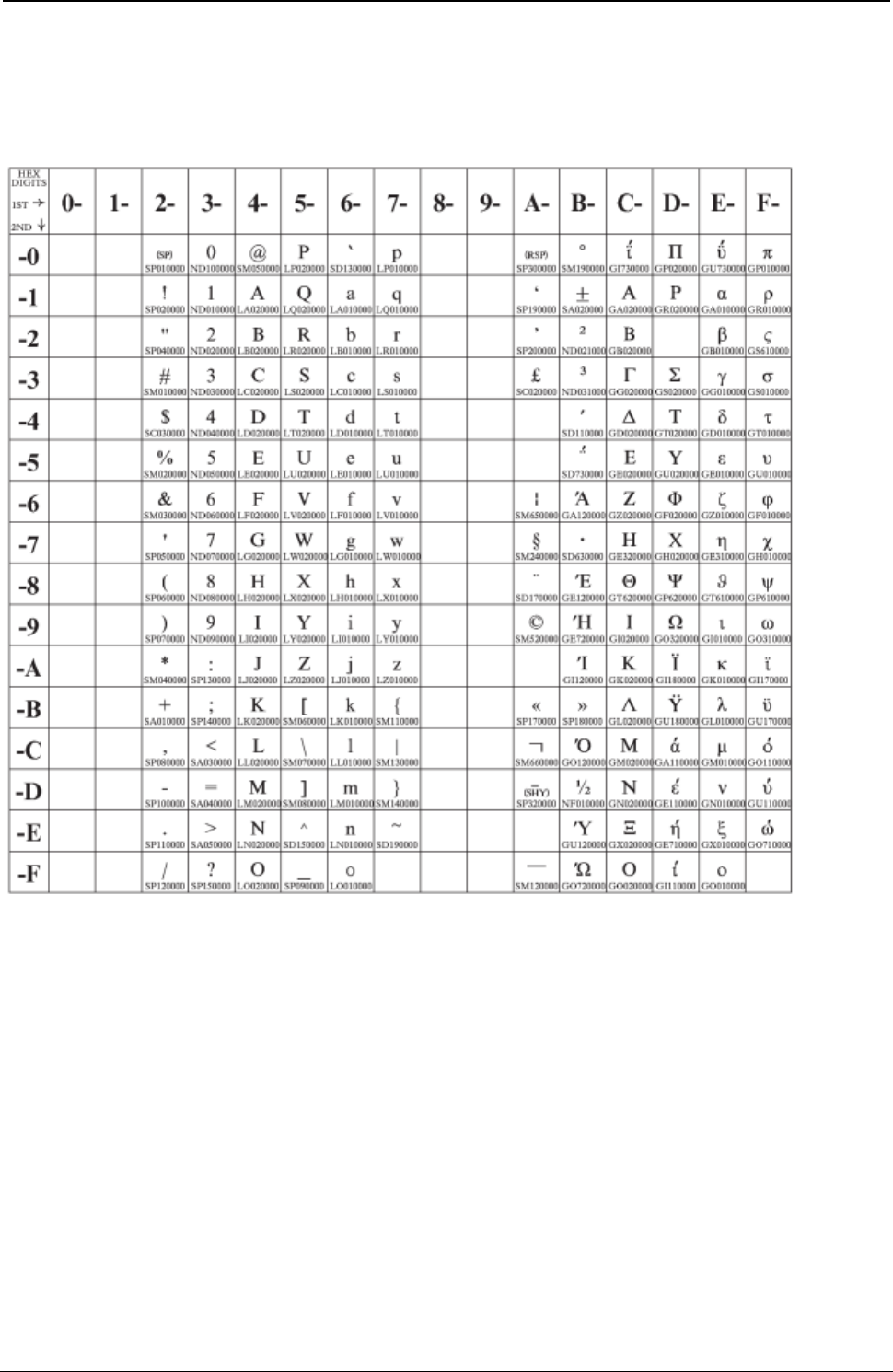
ProgrammerManual PTX‐S828
AppendixA.CodePages298260071‐001A
Greek/Latin (ISO 8859-7)
Code Page 00813
Figure 81. Greek/Latin (ISO 8859-7)
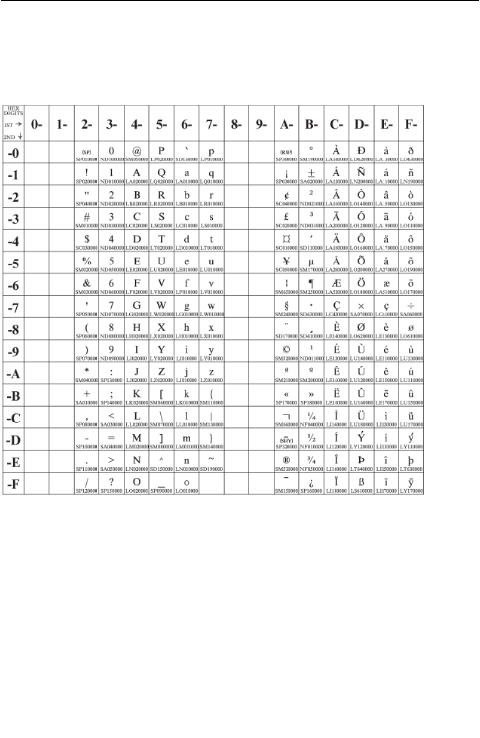
ProgrammerManual PTX‐S828
AppendixA.CodePages299260071‐001A
Latin 1 (ISO 8859-1)
Code Page 00819
Figure 82 .ISO8859/1(Latin1)

ProgrammerManual PTX‐S828
AppendixA.CodePages300260071‐001A
PC Multilingual
Code Page 00850
Figure 83.Multilingual(CP850)
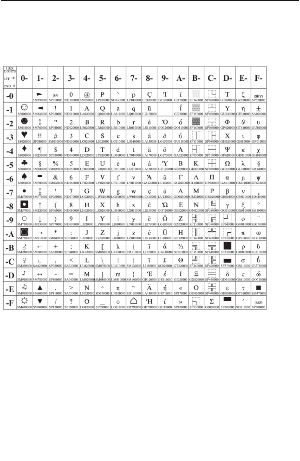
ProgrammerManual PTX‐S828
AppendixA.CodePages301260071‐001A
Old Greek
Code Page 00851
Figure 84.Old Greek(CP851)
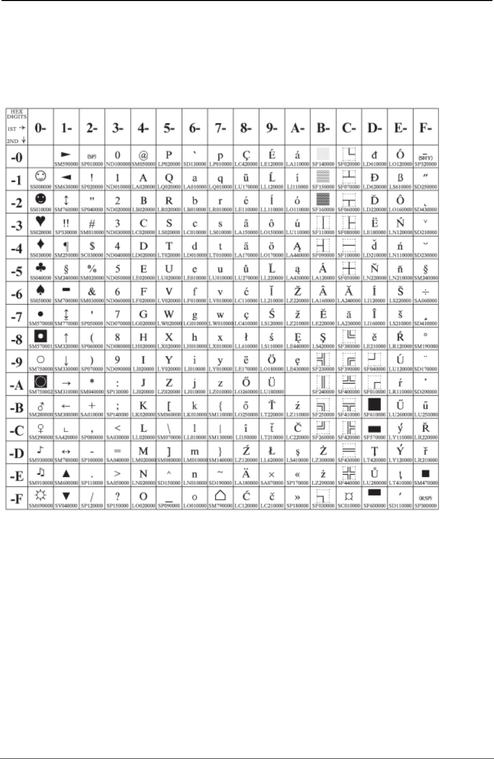
ProgrammerManual PTX‐S828
AppendixA.CodePages302260071‐001A
Latin 2/ROECE
Code Page 00852
Figure 85.EasternEurope(CP852)
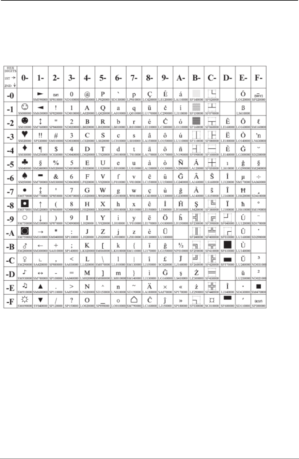
ProgrammerManual PTX‐S828
AppendixA.CodePages303260071‐001A
Latin 3 (PC)
Code Page 00853
Figure 86.Turkish(CP853)
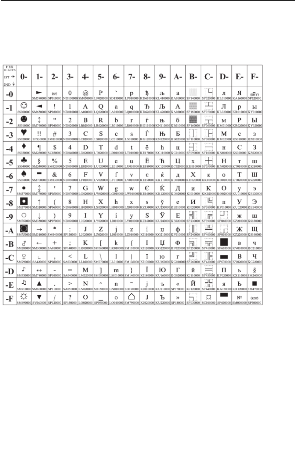
ProgrammerManual PTX‐S828
AppendixA.CodePages304260071‐001A
Cyrillic (PC)
Code Page 00855
Figure 87.Cyrillic(CP855)
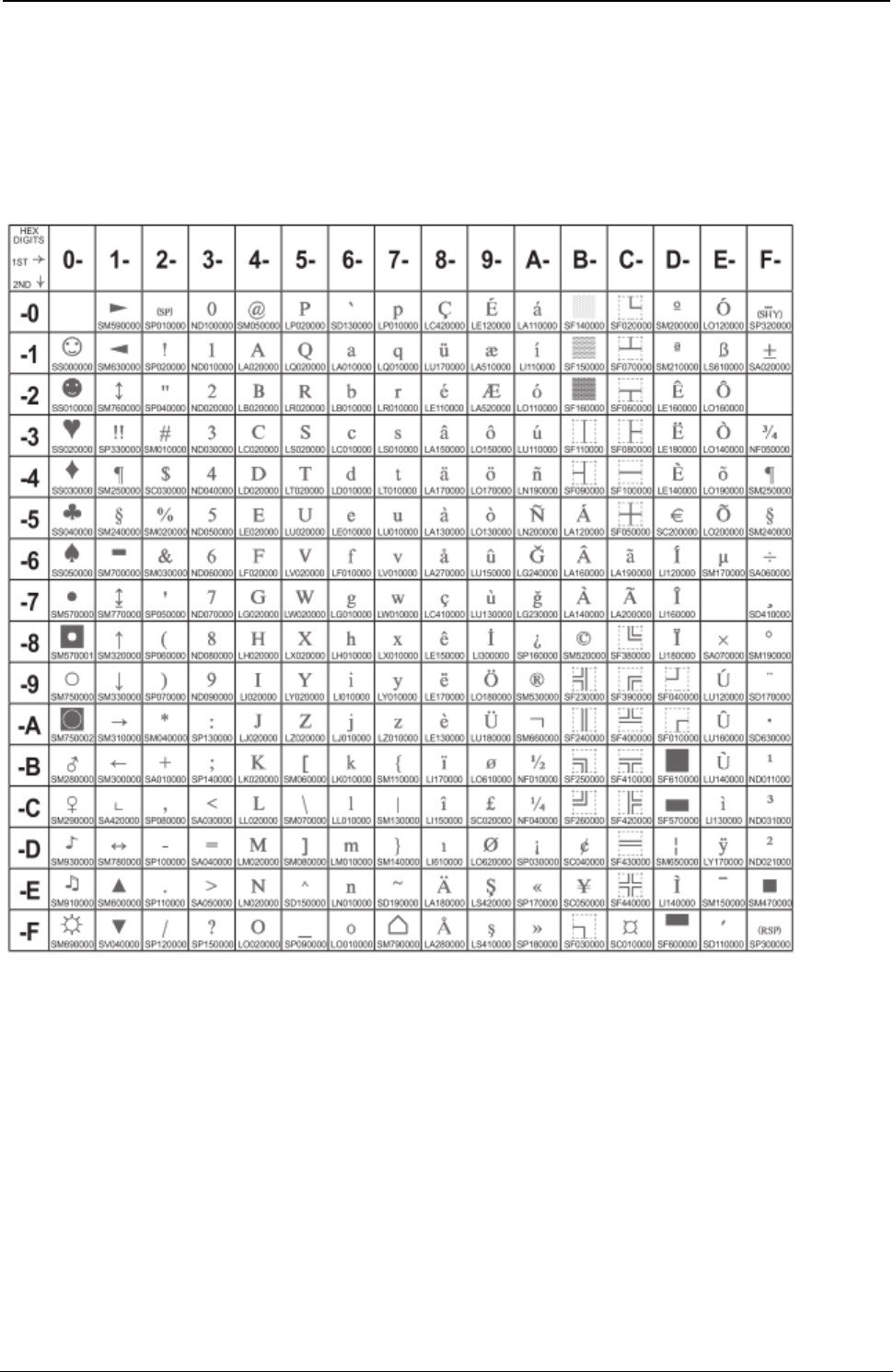
ProgrammerManual PTX‐S828
AppendixA.CodePages305260071‐001A
Latin 5-Turkey + euro
Code Page 00857
Figure 88.Turkish(CP857)
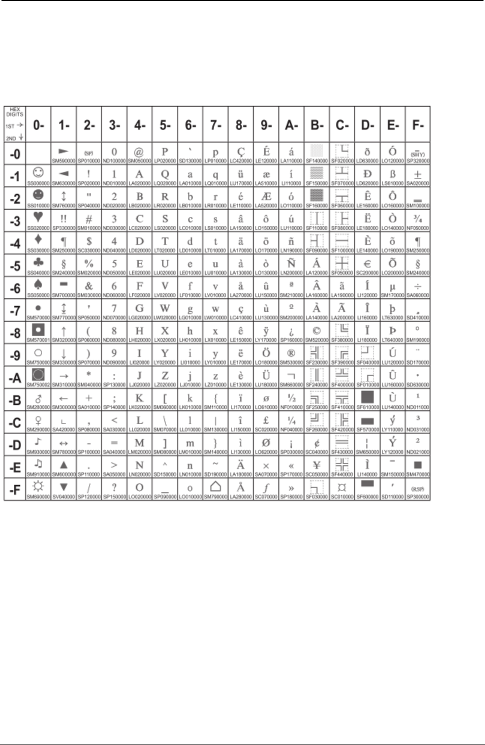
ProgrammerManual PTX‐S828
AppendixA.CodePages306260071‐001A
PC Multilingual + euro
Code Page 00858
Figure 89.EuroPCMultilingual(CP858).

ProgrammerManual PTX‐S828
AppendixA.CodePages307260071‐001A
Portuguese
Code Page 00860
Figure 90.Portugal(CP860)
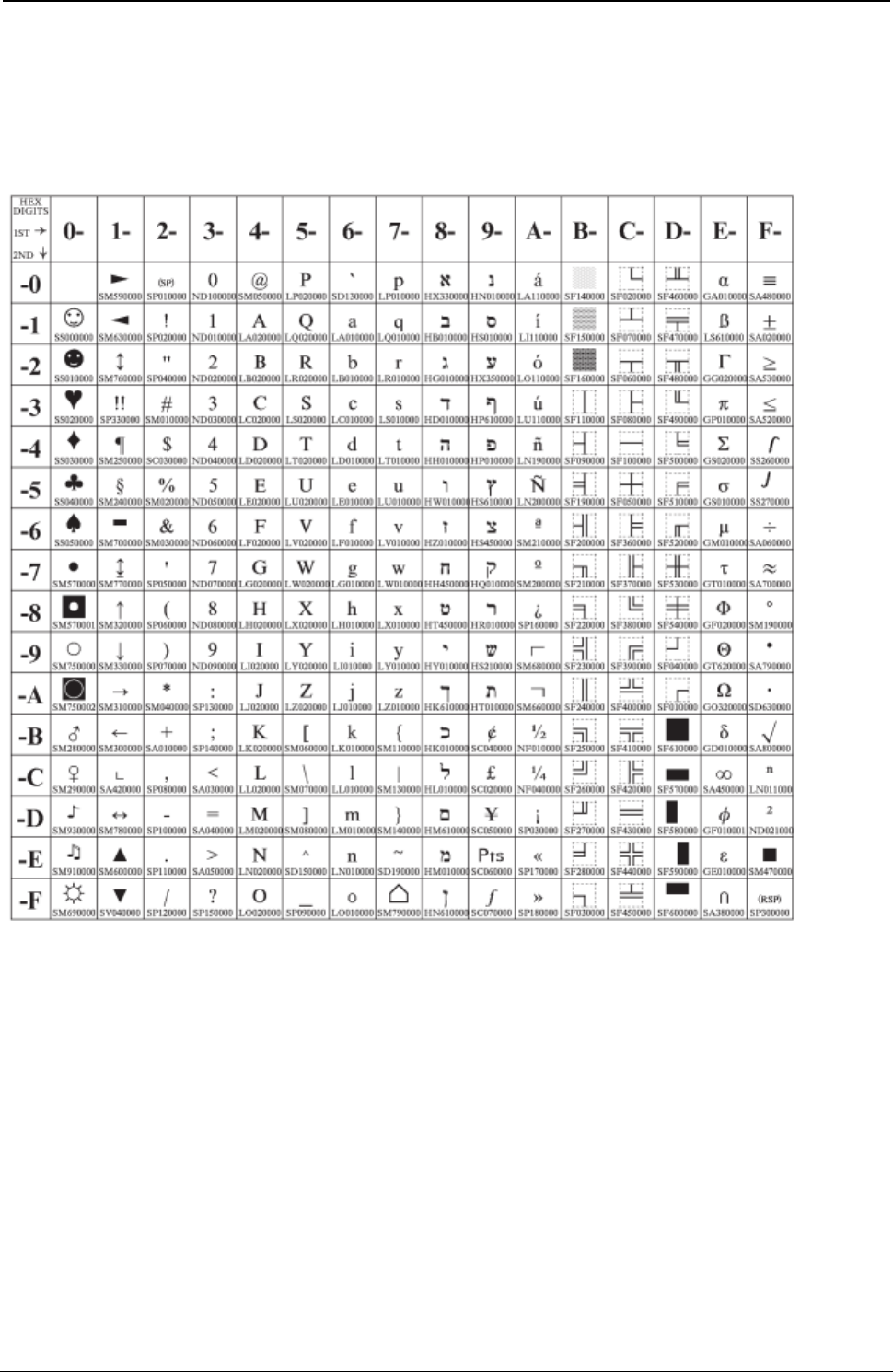
ProgrammerManual PTX‐S828
AppendixA.CodePages308260071‐001A
Hebrew
Code Page 00862
Figure 91.Hebrew(CP862)
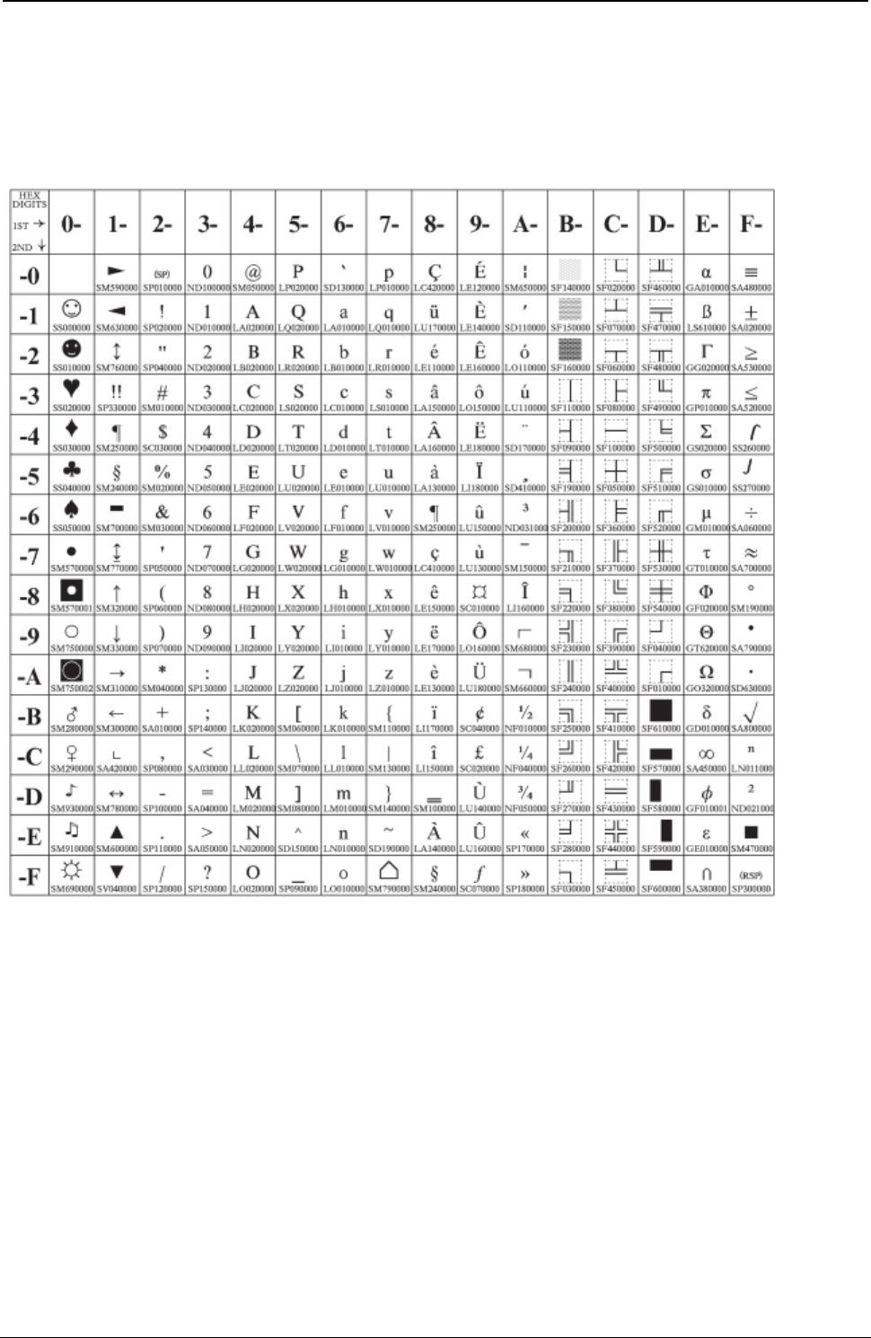
ProgrammerManual PTX‐S828
AppendixA.CodePages309260071‐001A
Canadian French
Code Page 00863
Figure 92.Canada/France(CP863)
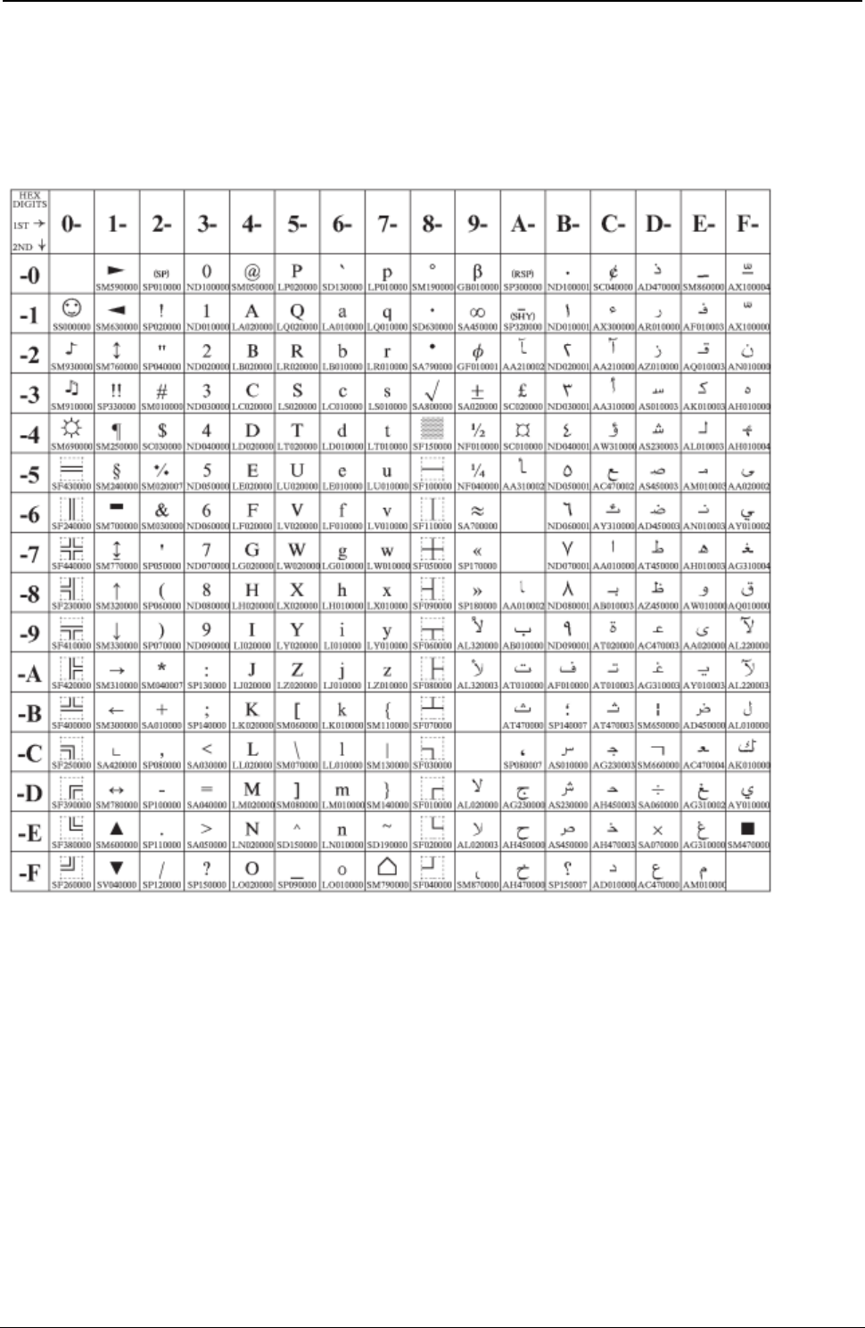
ProgrammerManual PTX‐S828
AppendixA.CodePages310260071‐001A
Arabic
Code Page 00864
Figure 93.Arabic(CP864)
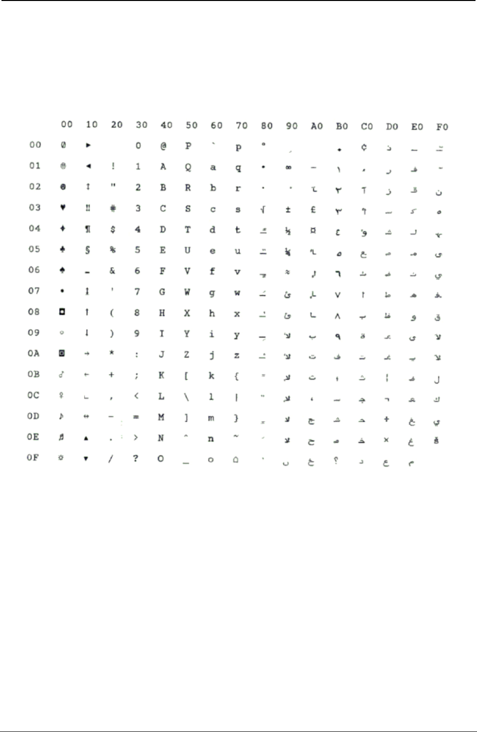
ProgrammerManual PTX‐S828
AppendixA.CodePages311260071‐001A
Arabic
Code Page 00864E
Figure 94.CP864E(Arabic)

ProgrammerManual PTX‐S828
AppendixA.CodePages312260071‐001A
Danish/Norwegian
Code Page 00865
Figure 95.Denmark/Norway(CP865)
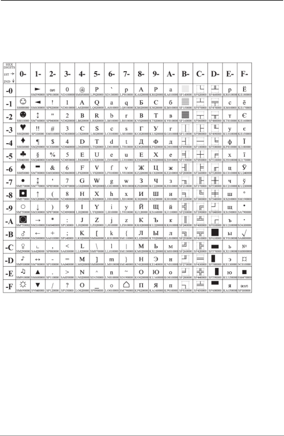
ProgrammerManual PTX‐S828
AppendixA.CodePages313260071‐001A
PC Data, Cyrillic, Russian
Code Page 00866
Figure 96. Russian(CP866)
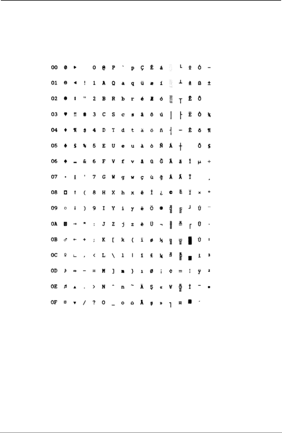
ProgrammerManual PTX‐S828
AppendixA.CodePages314260071‐001A
Turkish 2
Code Page 00867
Figure 97.Turkish2(CP867)
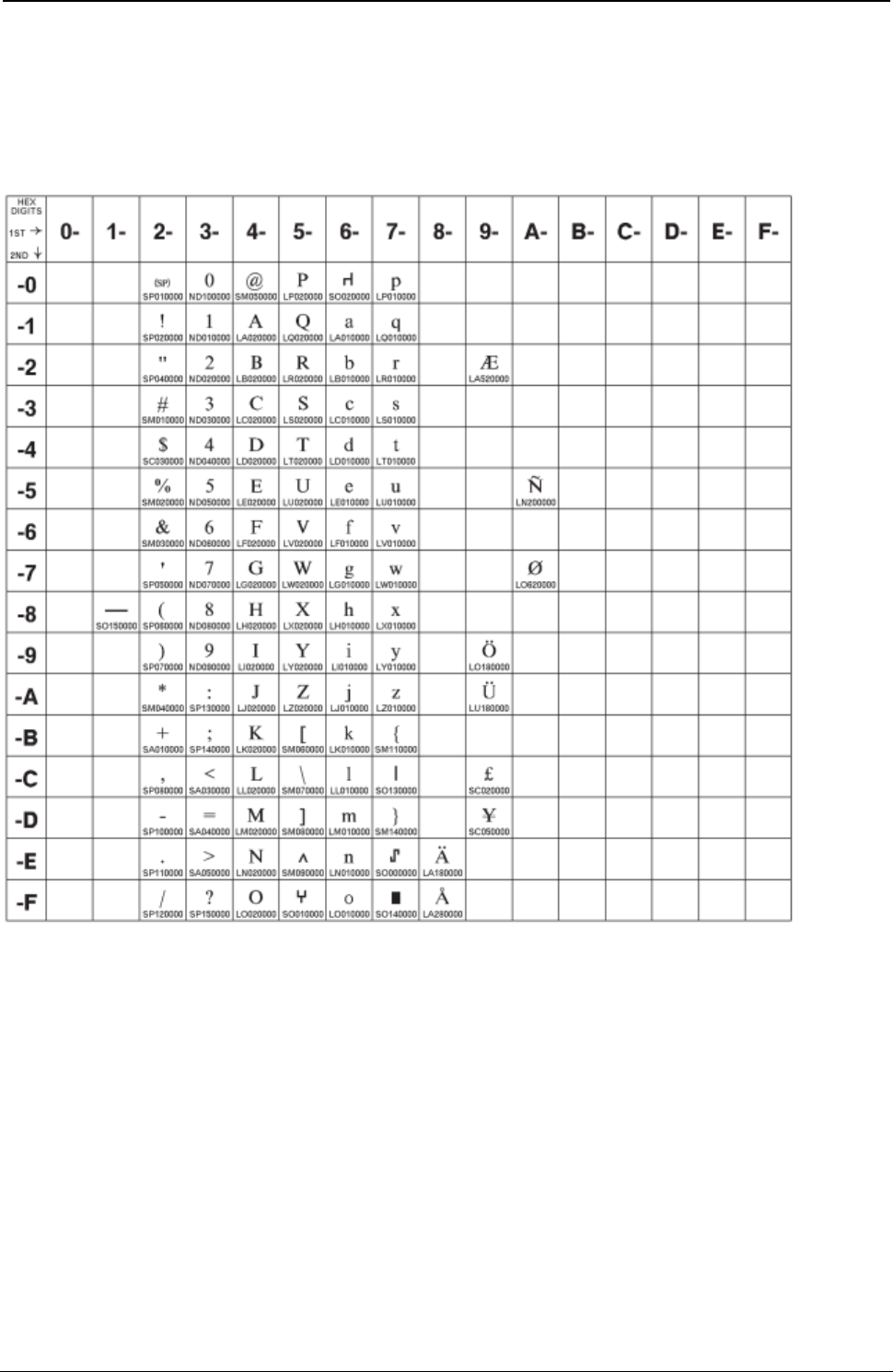
ProgrammerManual PTX‐S828
AppendixA.CodePages315260071‐001A
OCR-A
Code Page 00876
Figure 98.OCR-A(CP876)
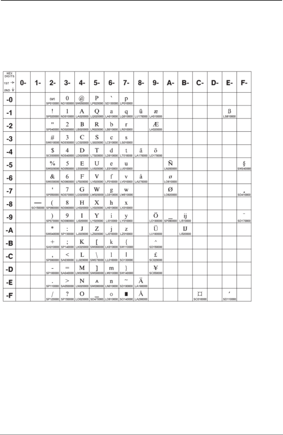
ProgrammerManual PTX‐S828
AppendixA.CodePages316260071‐001A
OCR-B
Code Page 00877
Figure 99.OCR-B(CP877)
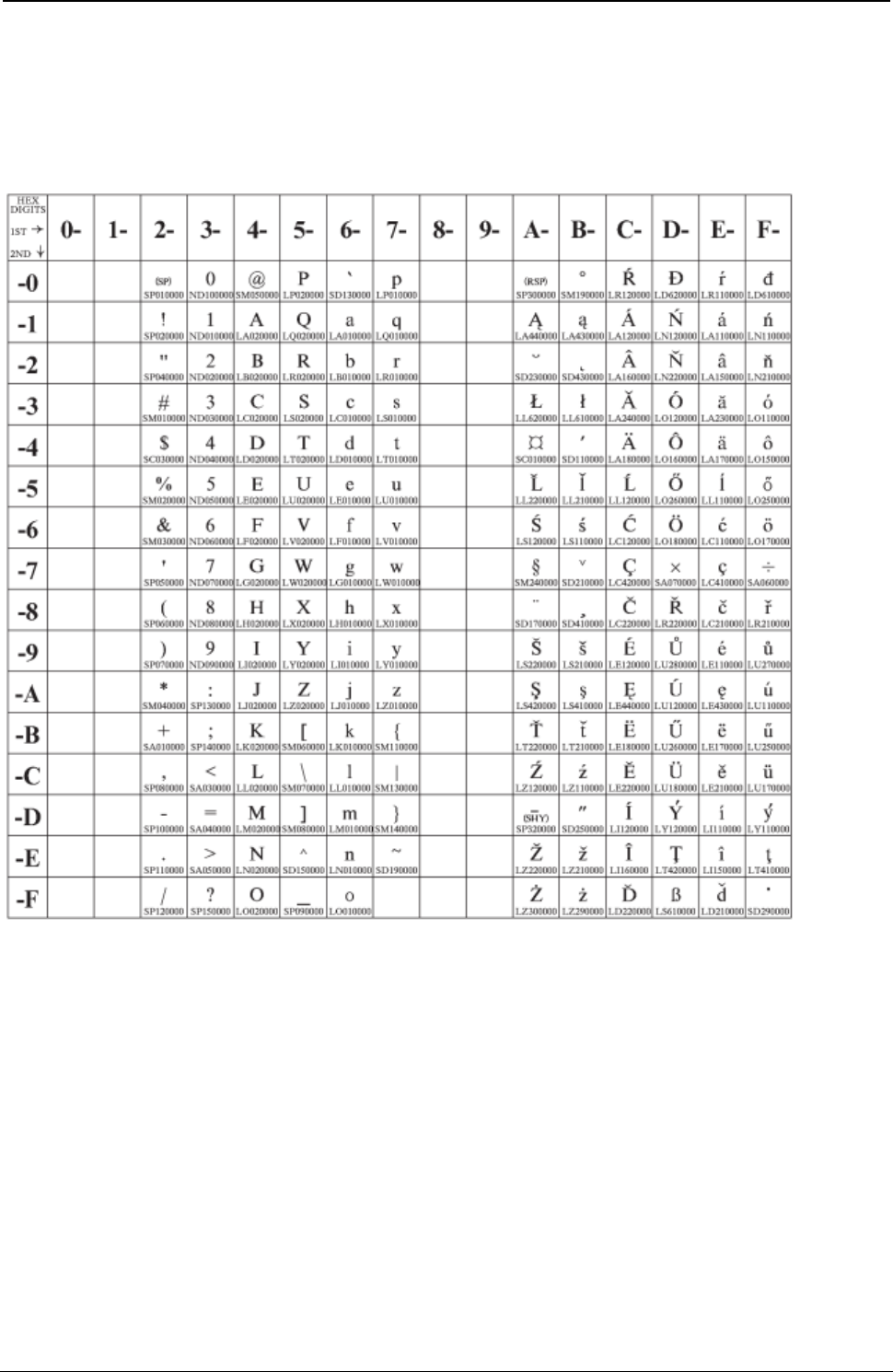
ProgrammerManual PTX‐S828
AppendixA.CodePages317260071‐001A
Latin 2 (ISO 8859-2)
Code Page 00912
Figure 100.ISO8859/2(Latin2)
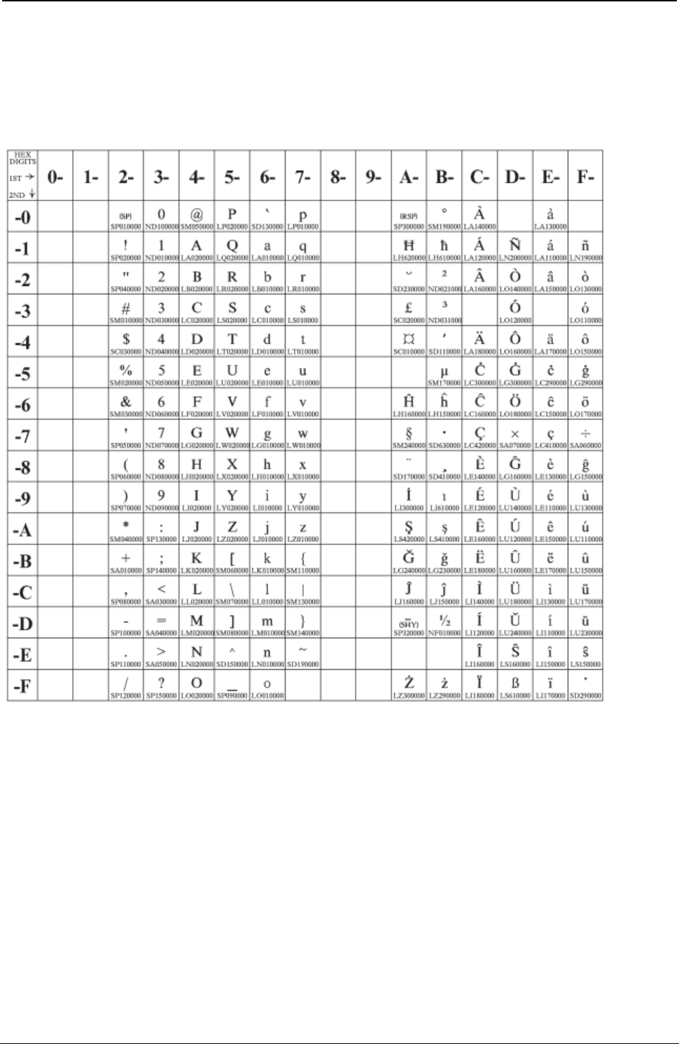
ProgrammerManual PTX‐S828
AppendixA.CodePages318260071‐001A
Latin 3 (ISO 8859-3)
Code Page 00913
Figure 101.ISO8859/3(Latin3)
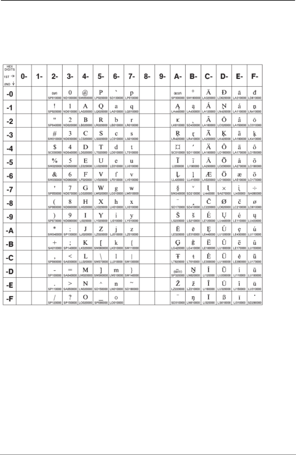
ProgrammerManual PTX‐S828
AppendixA.CodePages319260071‐001A
Latin 4 (ISO 8859-4)
Code Page 00914
Figure 102.ISO8859/4(Latin4)
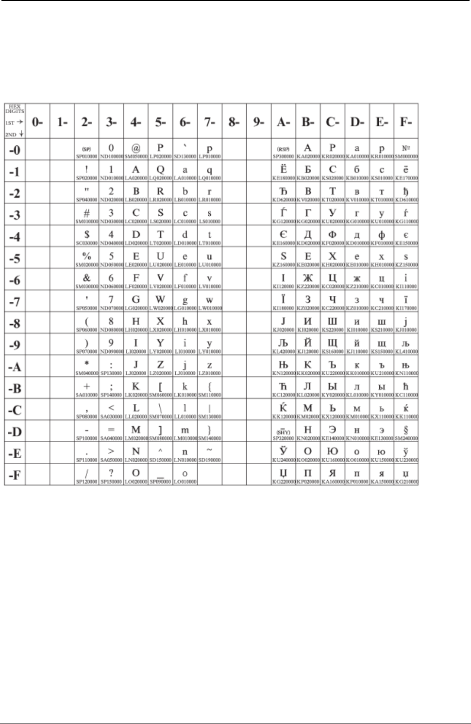
ProgrammerManual PTX‐S828
AppendixA.CodePages320260071‐001A
Cyrillic (ISO 8859-5)
Code Page 00915
Figure 103.ISO8859/5(Latin/Cyrillic)
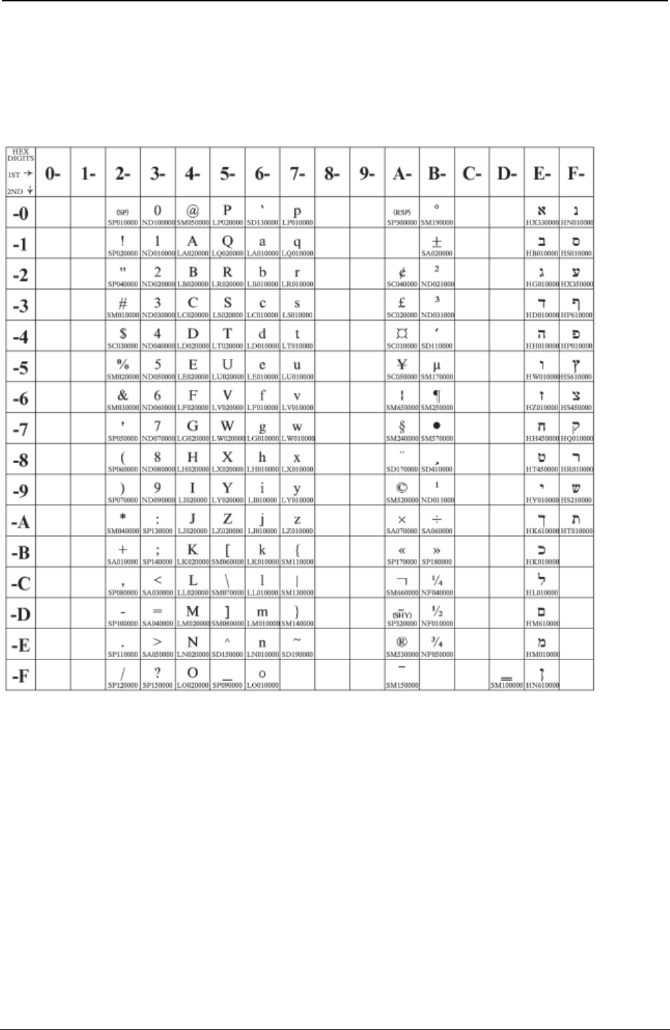
ProgrammerManual PTX‐S828
AppendixA.CodePages321260071‐001A
Latin 8 (ISO 8859-8)
Code Page 00916
Figure 104.ISO8859/8

ProgrammerManual PTX‐S828
AppendixA.CodePages322260071‐001A
Latin 5 (ISO 8859-9)
Code Page 00920
Figure 105.ISO8859/9(Latin5)
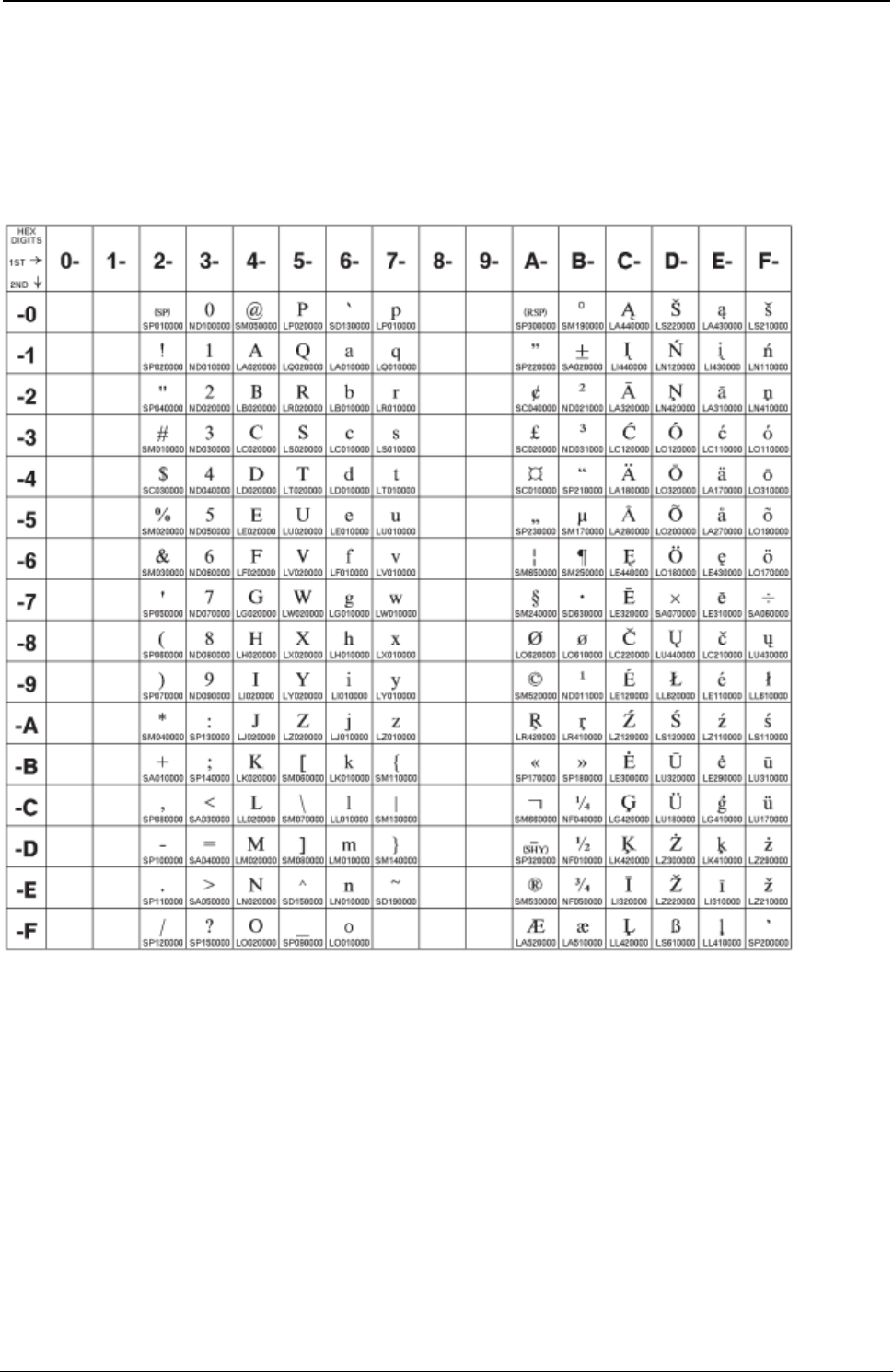
ProgrammerManual PTX‐S828
AppendixA.CodePages323260071‐001A
Baltic Multilingual
Code Page 00921
Figure 106.BalticWindows(CP921)
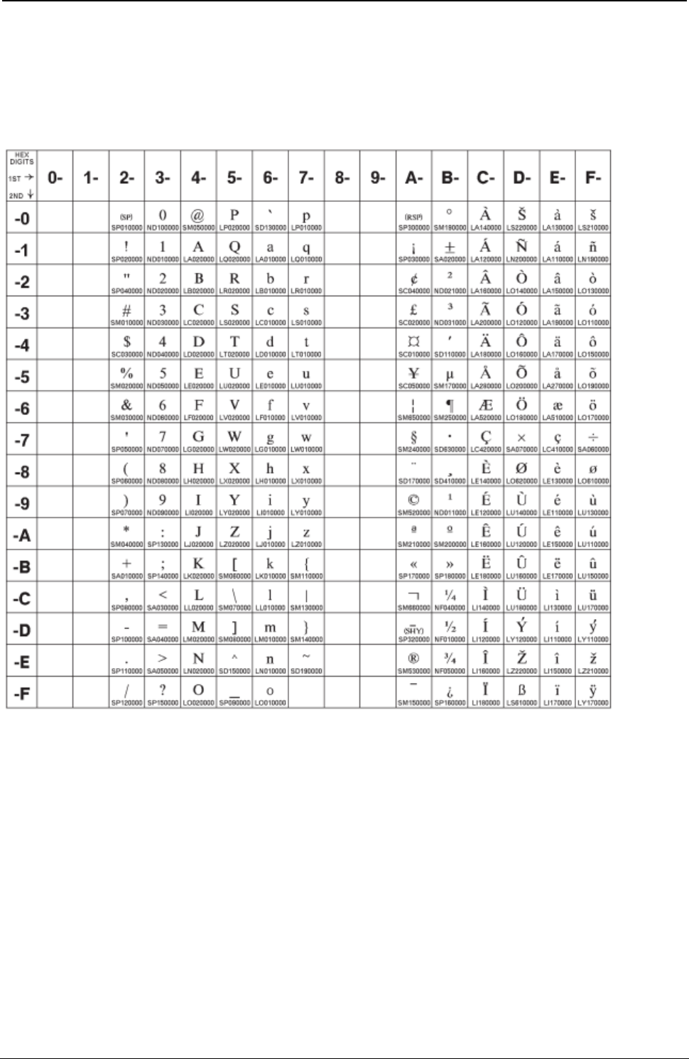
ProgrammerManual PTX‐S828
AppendixA.CodePages324260071‐001A
Estonian
Code Page 00922
Figure 107.Estonian (CP922)

ProgrammerManual PTX‐S828
AppendixA.CodePages325260071‐001A
Latin 9 (ISO 8859-15) + euro
Code Page 00923
Figure 108.ISO8859/15(Latin9) .151
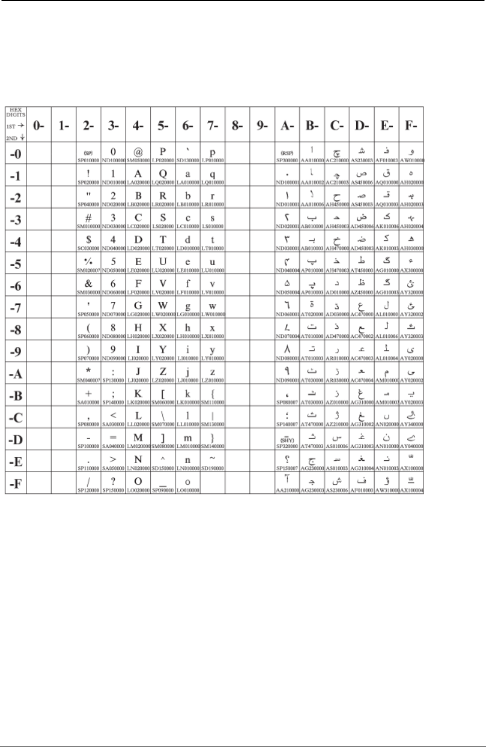
ProgrammerManual PTX‐S828
AppendixA.CodePages326260071‐001A
Urdu
Code Page 01006
Figure 109.Urdu (CP01006)
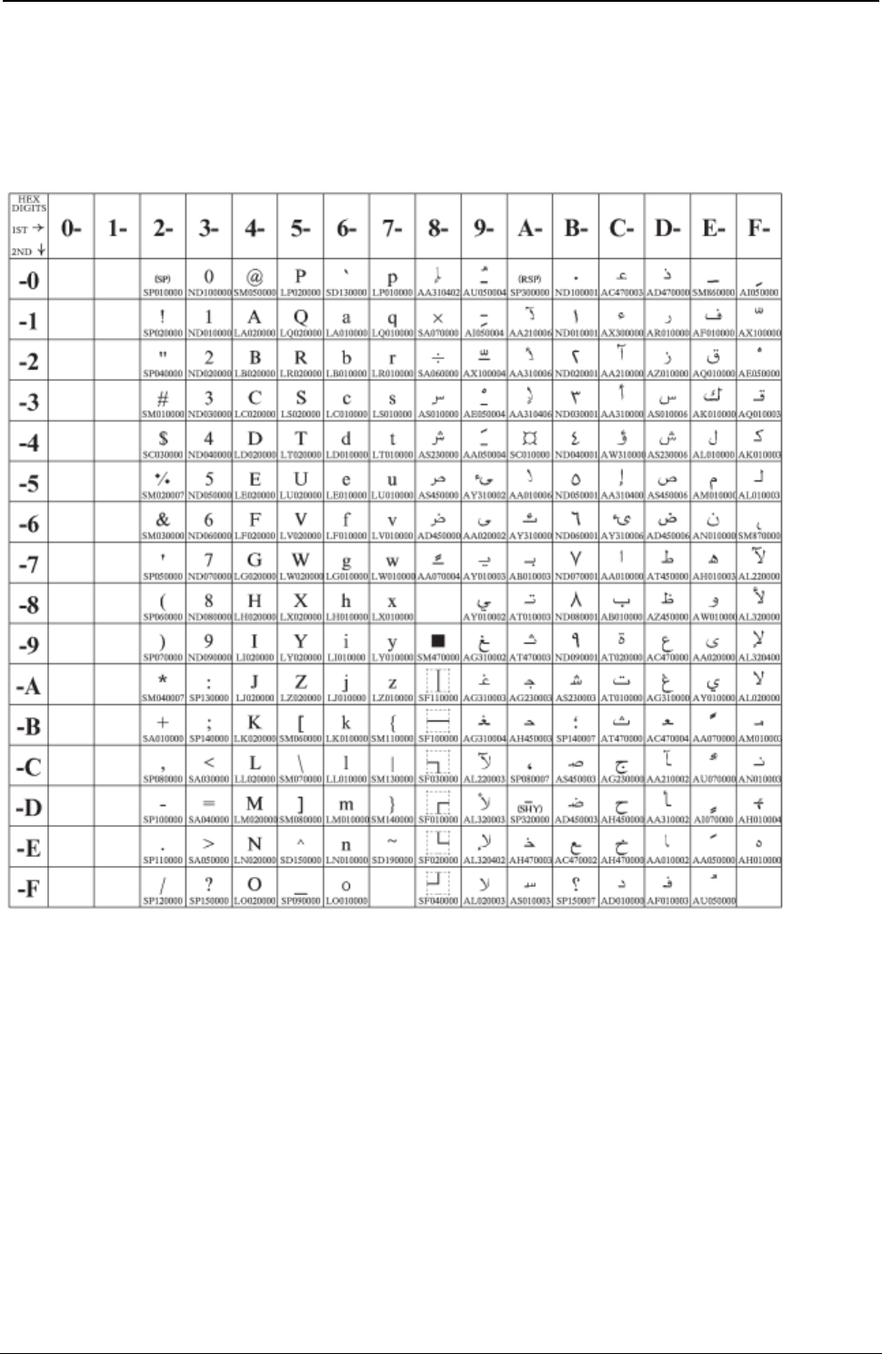
ProgrammerManual PTX‐S828
AppendixA.CodePages327260071‐001A
Arabic Extended
Code Page 01046
Figure 110.Arabic Extended (CP1046)
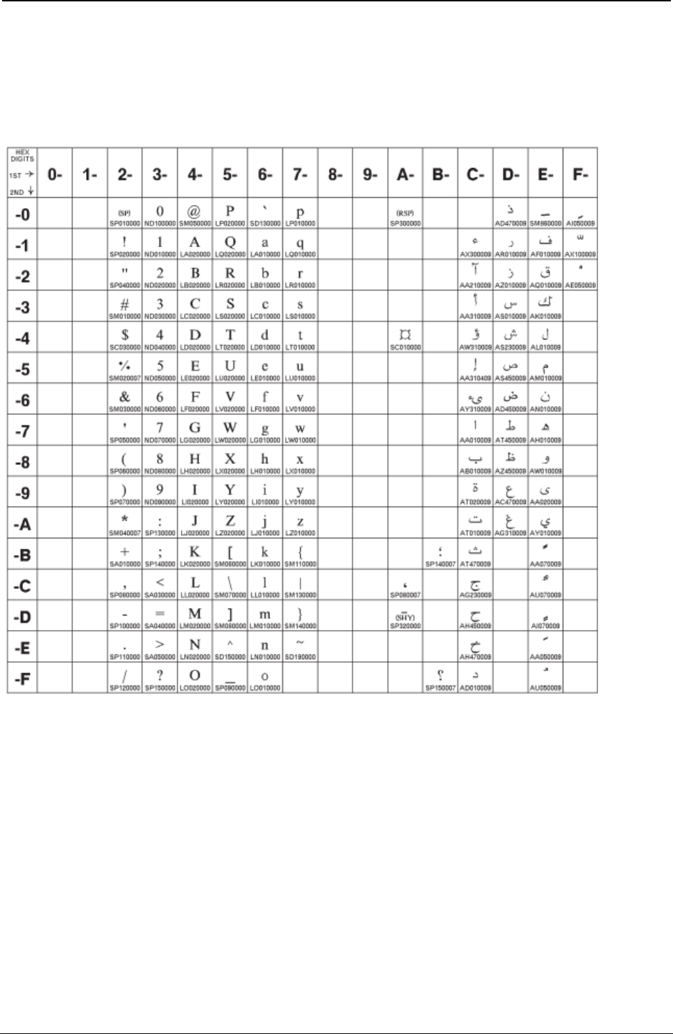
ProgrammerManual PTX‐S828
AppendixA.CodePages328260071‐001A
Latin 6 (ISO 8859-6)
Code Page 01089
Figure 111.ISO8859/6(Latin/Arabic)
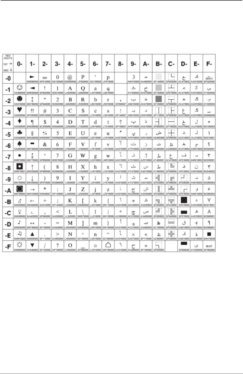
ProgrammerManual PTX‐S828
AppendixA.CodePages329260071‐001A
Farsi (Personal Computer)
Code Page 01098
Figure 112.Farsi(CP1098)
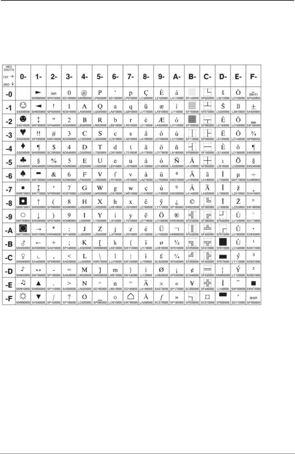
ProgrammerManual PTX‐S828
AppendixA.CodePages330260071‐001A
Estonian (Personal Computer)
Code Page 01116
Figure 113.Estonian (CP1116)
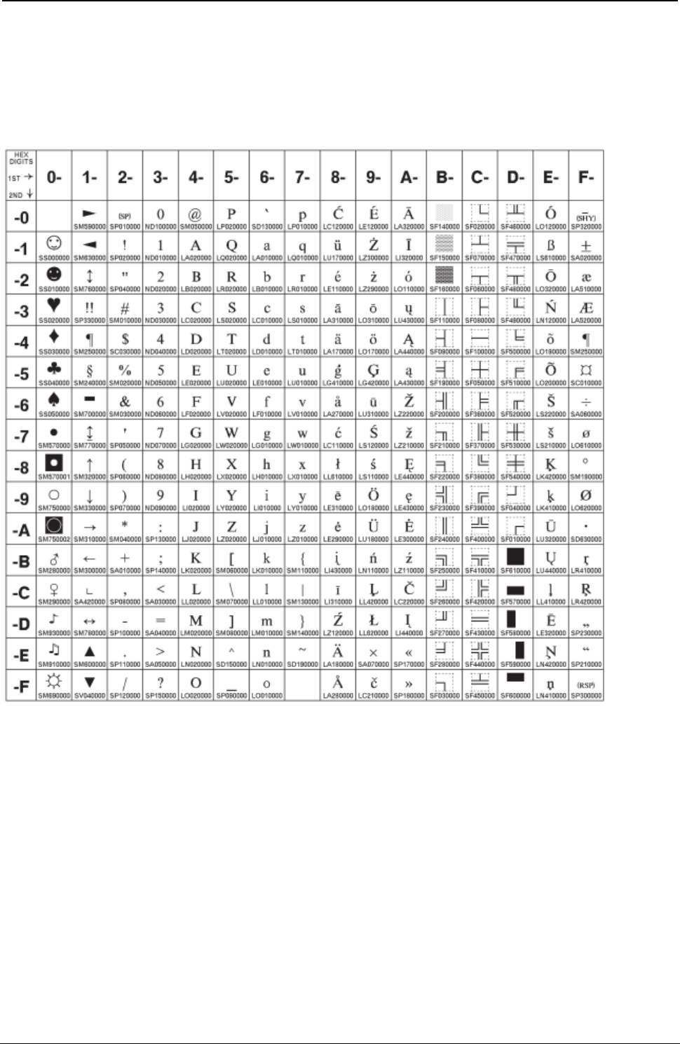
ProgrammerManual PTX‐S828
AppendixA.CodePages331260071‐001A
Latvian (Personal Computer)
Code Page 01117
Figure 114.Latvian (Personal Computer) (CP1117)
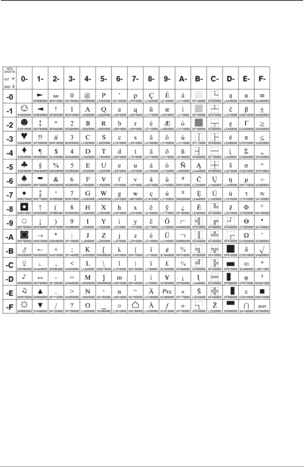
ProgrammerManual PTX‐S828
AppendixA.CodePages332260071‐001A
Lithuanian (Personal Computer)
Code Page 01118
Figure 115.Lthuanian (Personal Computer) (CP1118)
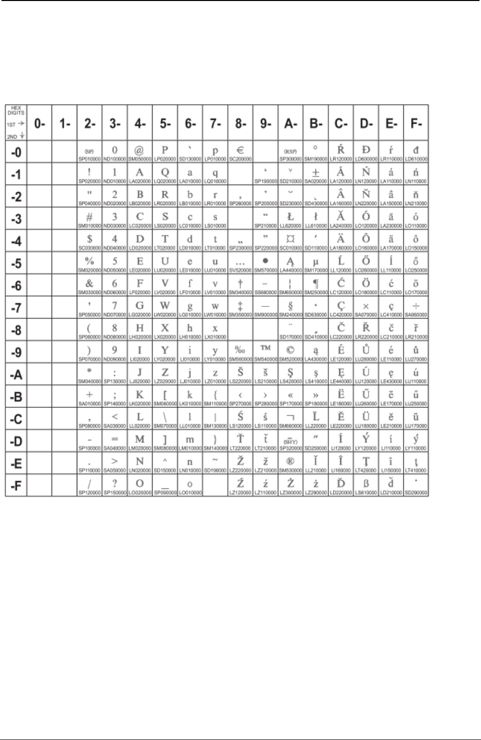
ProgrammerManual PTX‐S828
AppendixA.CodePages333260071‐001A
Central Europe Latin 2
Code Page 01250
Figure 116.CentralEurope(CP1250)
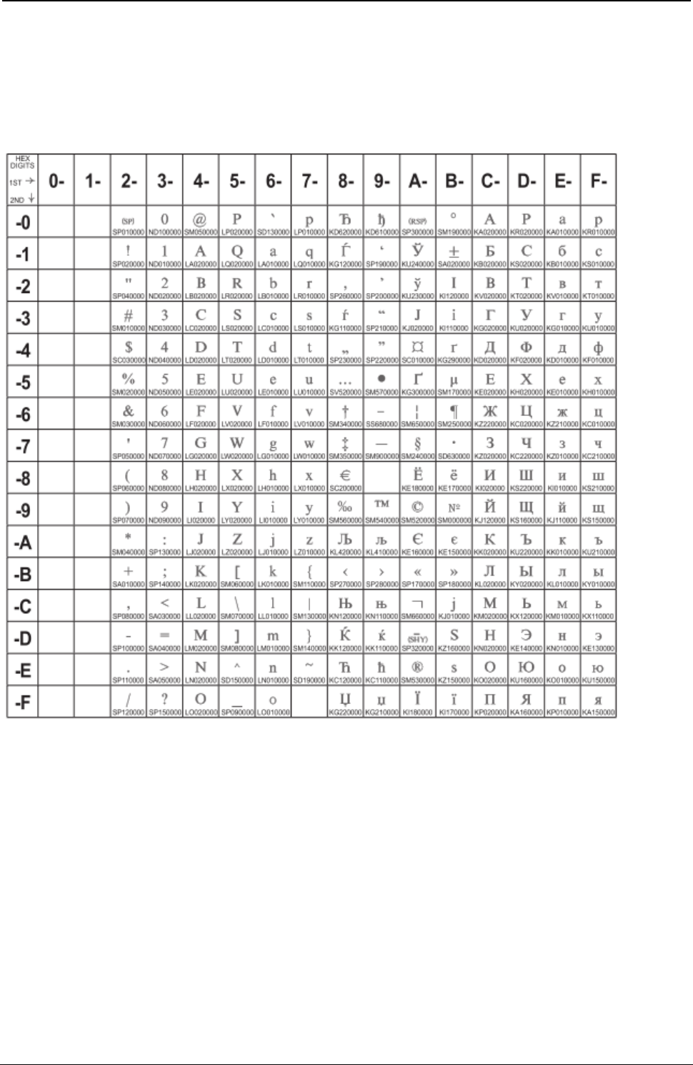
ProgrammerManual PTX‐S828
AppendixA.CodePages334260071‐001A
Cyrillic Windows + euro
Code Page 01251
Figure 117.Cyrillic(CP1251)
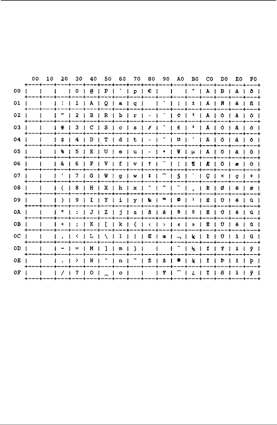
ProgrammerManual PTX‐S828
AppendixA.CodePages335260071‐001A
Latin1 Ansi Windows
Code Page 01252
Figure 118.Latin1AnsiWindows(CP1252)
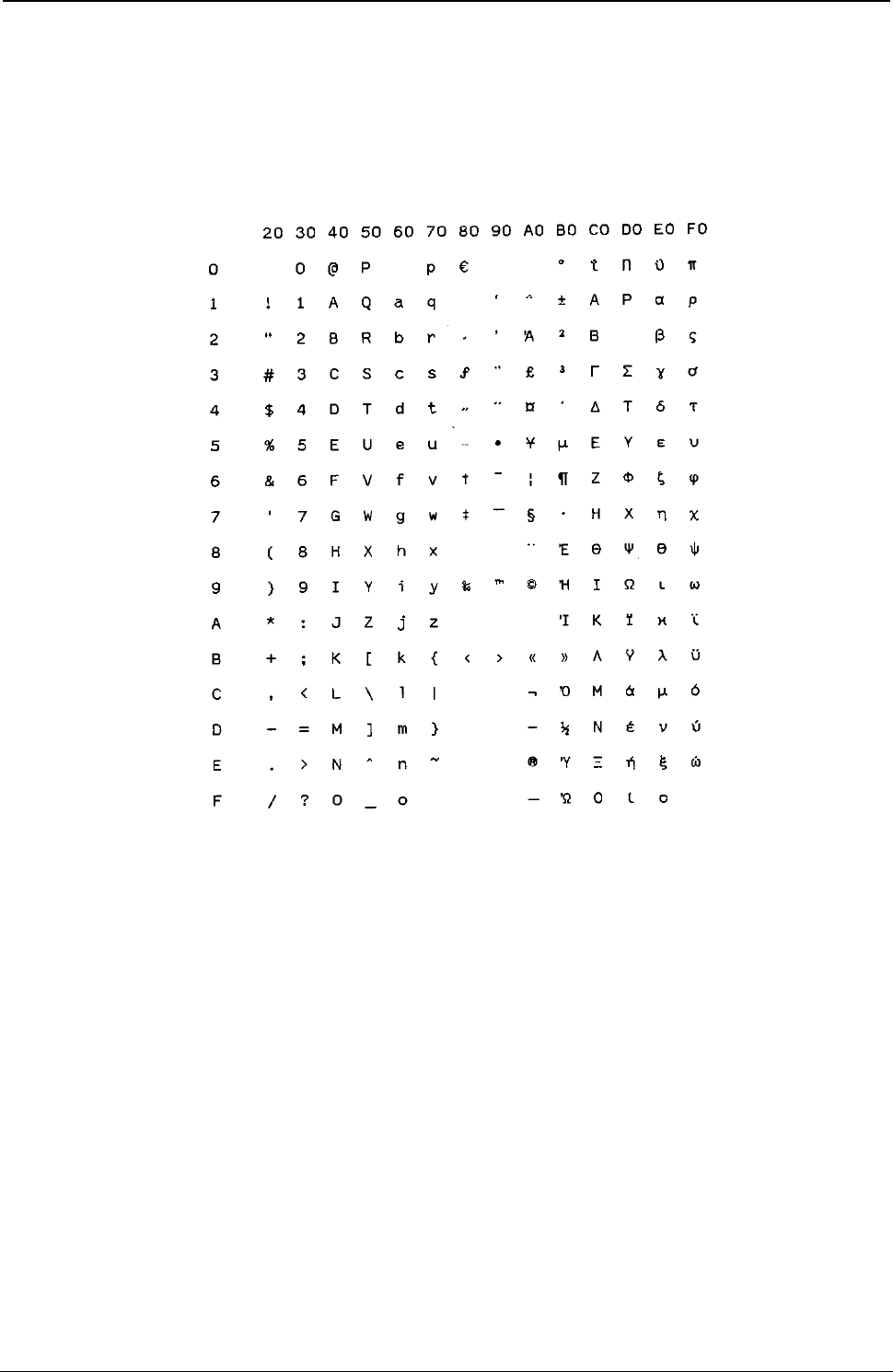
ProgrammerManual PTX‐S828
AppendixA.CodePages336260071‐001A
Greek Windows
Code Page 01253
Figure 119.GreekWindows(CP1253)
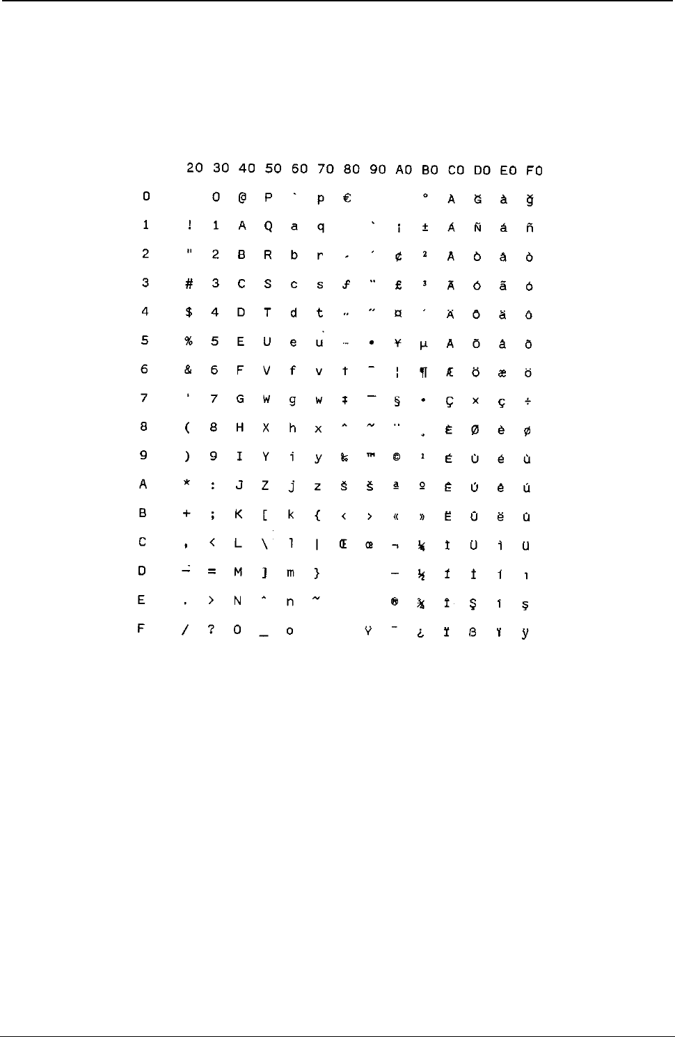
ProgrammerManual PTX‐S828
AppendixA.CodePages337260071‐001A
Turkish Windows
Code Page 01254
Figure 120.TurkishWindows(CP1254)
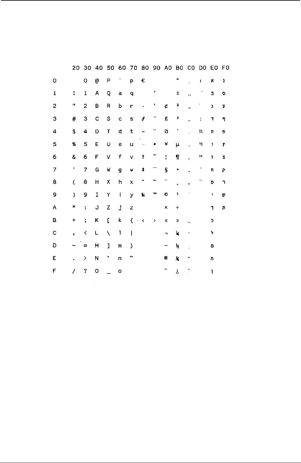
ProgrammerManual PTX‐S828
AppendixA.CodePages338260071‐001A
Hebrew Windows
Code Page 01255
Figure 121. HebrewWindows(CP1255)
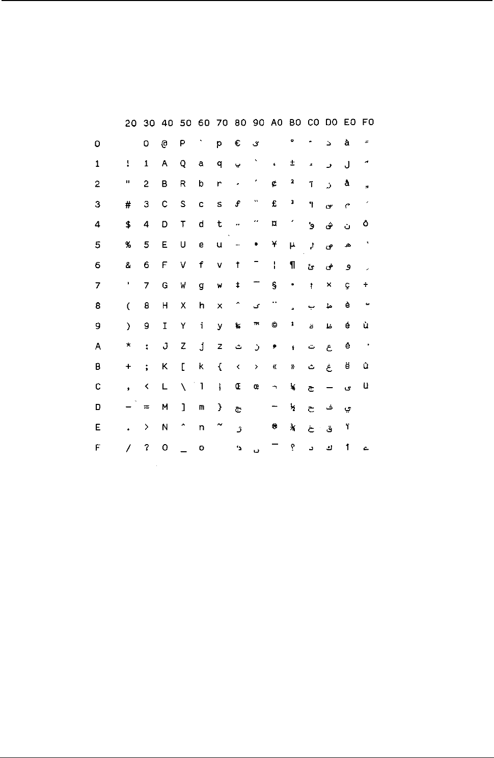
ProgrammerManual PTX‐S828
AppendixA.CodePages339260071‐001A
Arabic Windows
Code Page 01256
Figure 122.ArabicWindows(CP1256)
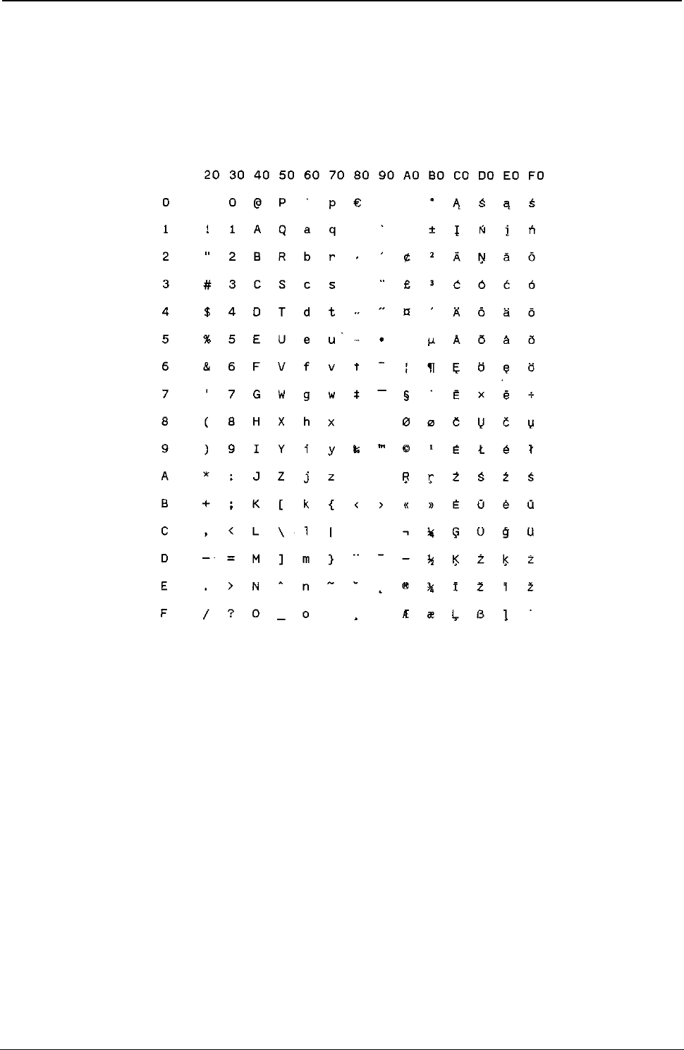
ProgrammerManual PTX‐S828
AppendixA.CodePages340260071‐001A
Baltic Windows
Code Page 01257
Figure 123.Batlic Windows (CP1257)
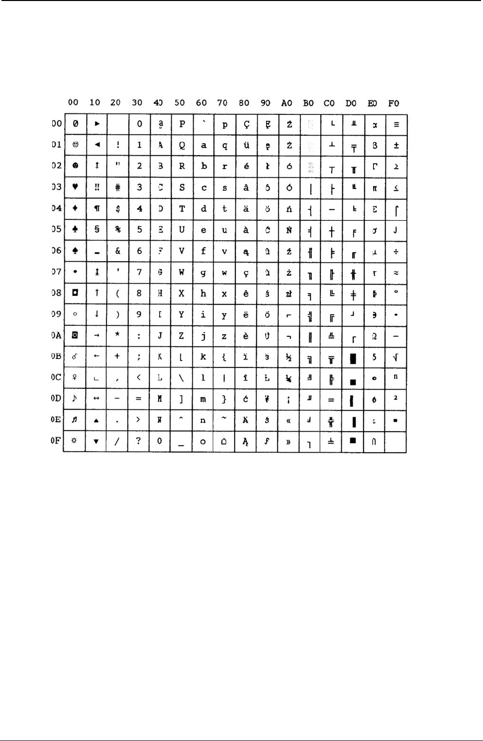
Programm
e
AppendixA
MAZO
W
Figure 124.
e
rManual
A
.CodePage
s
W
IA (Poli
s
MAZOWIA(
P
s
s
h)
P
olish)
341
2
PTX‐S82
8
60071‐001
A
8
A
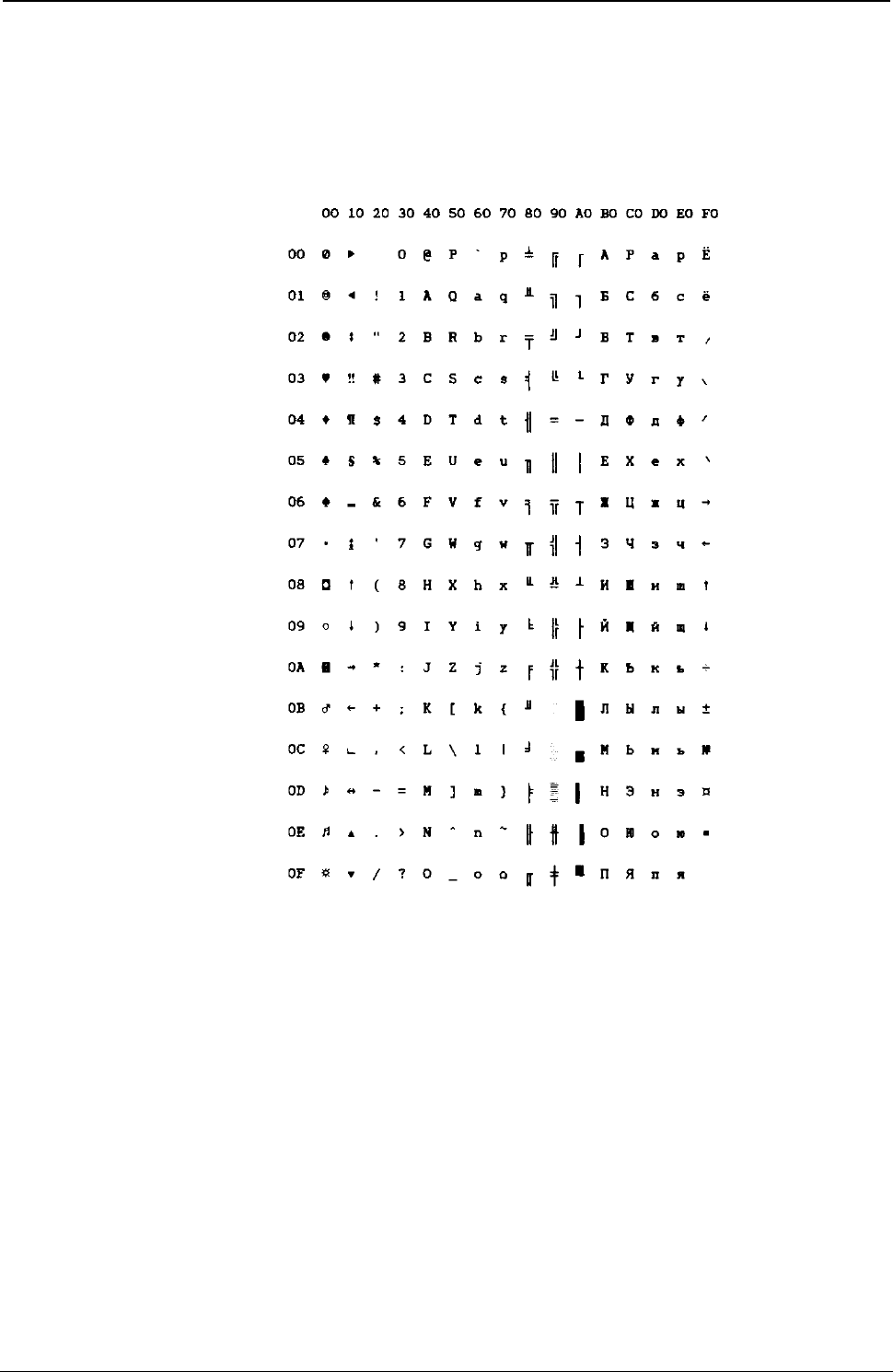
ProgrammerManual PTX‐S828
AppendixA.CodePages342260071‐001A
GOST (Russian)
Figure 125.GOST(Russian)
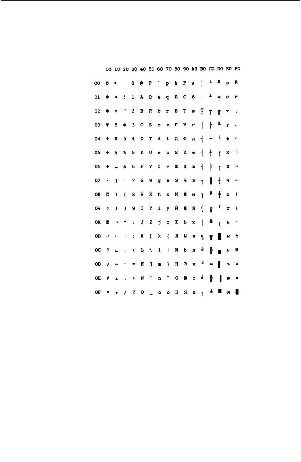
ProgrammerManual PTX‐S828
AppendixA.CodePages343260071‐001A
TASS (Cyrillic)
Figure 126.TASS(Cyrillic)
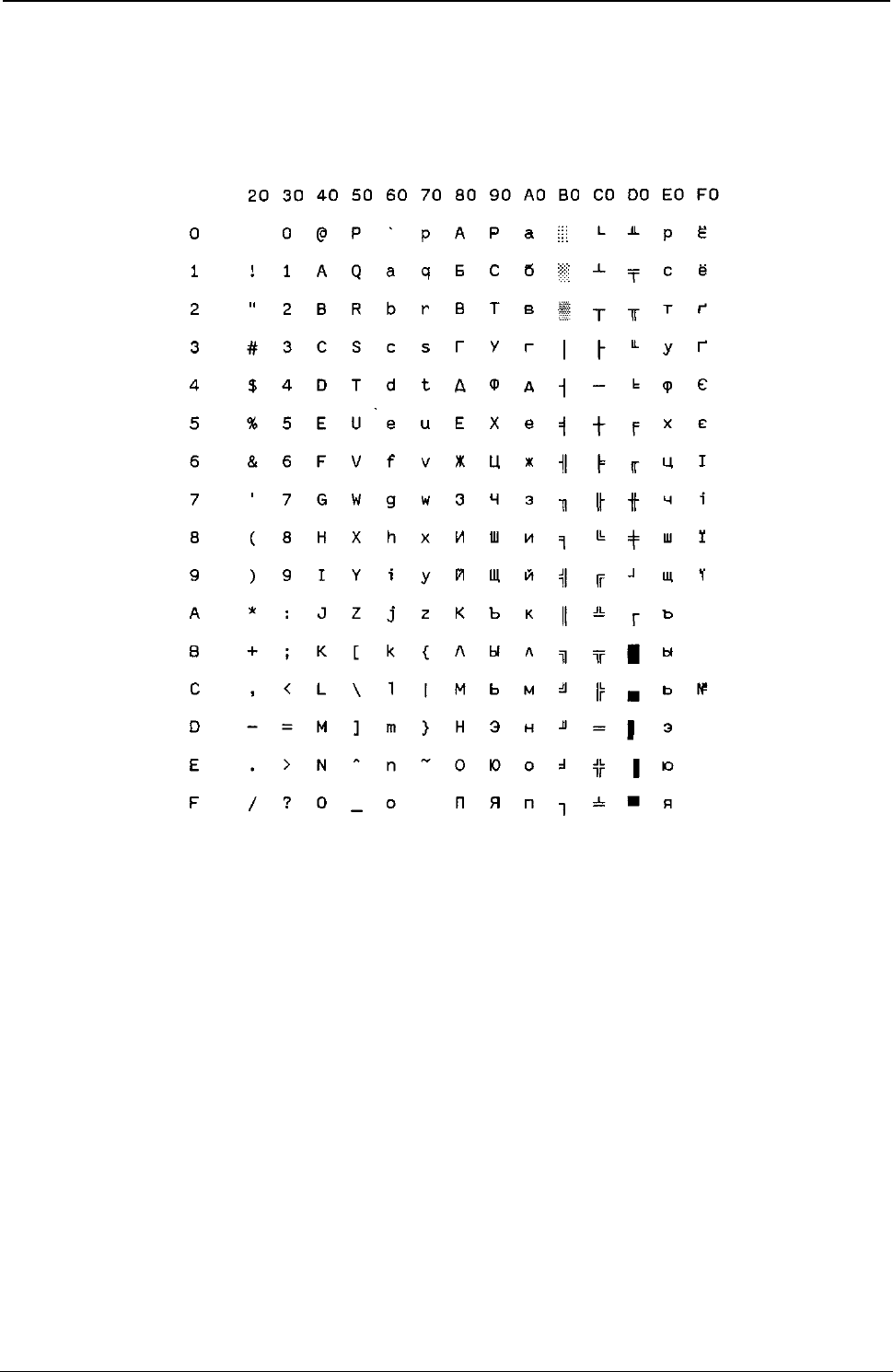
ProgrammerManual PTX‐S828
AppendixA.CodePages344260071‐001A
UKRANIAN (old version)
Figure 127.UKRANIAN(oldversion)
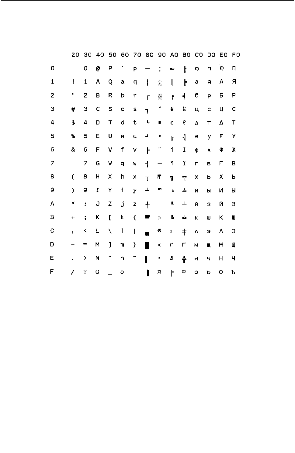
ProgrammerManual PTX‐S828
AppendixA.CodePages345260071‐001A
KOI8-U (new version)
Figure 128.KOI8-U(newversion)
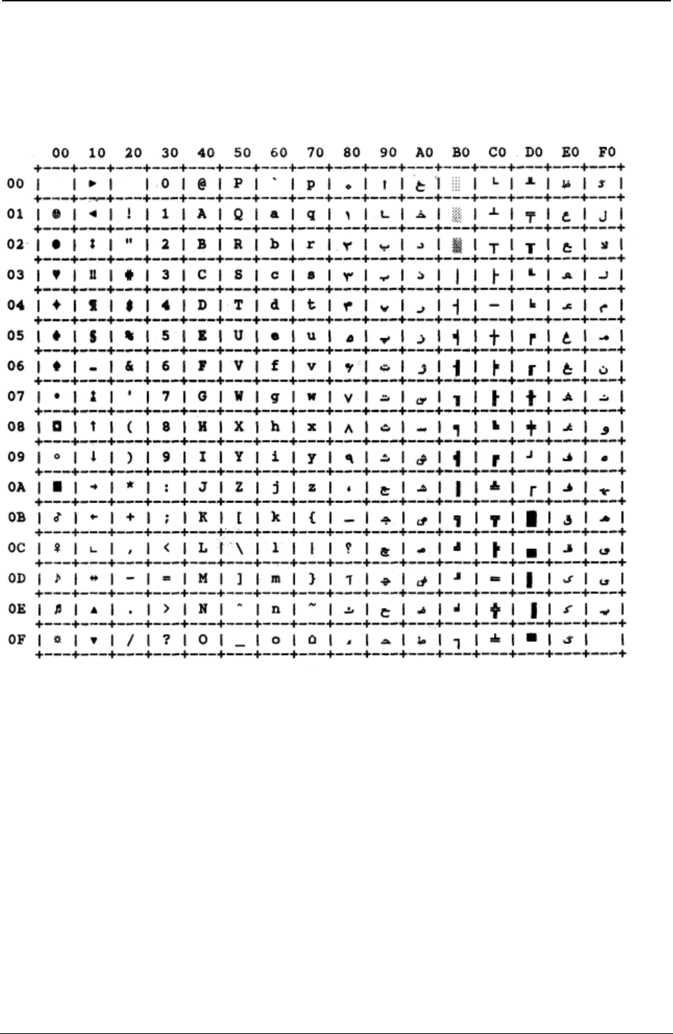
ProgrammerManual PTX‐S828
AppendixA.CodePages346260071‐001A
FARSI 1
Figure 129. Farsi 1
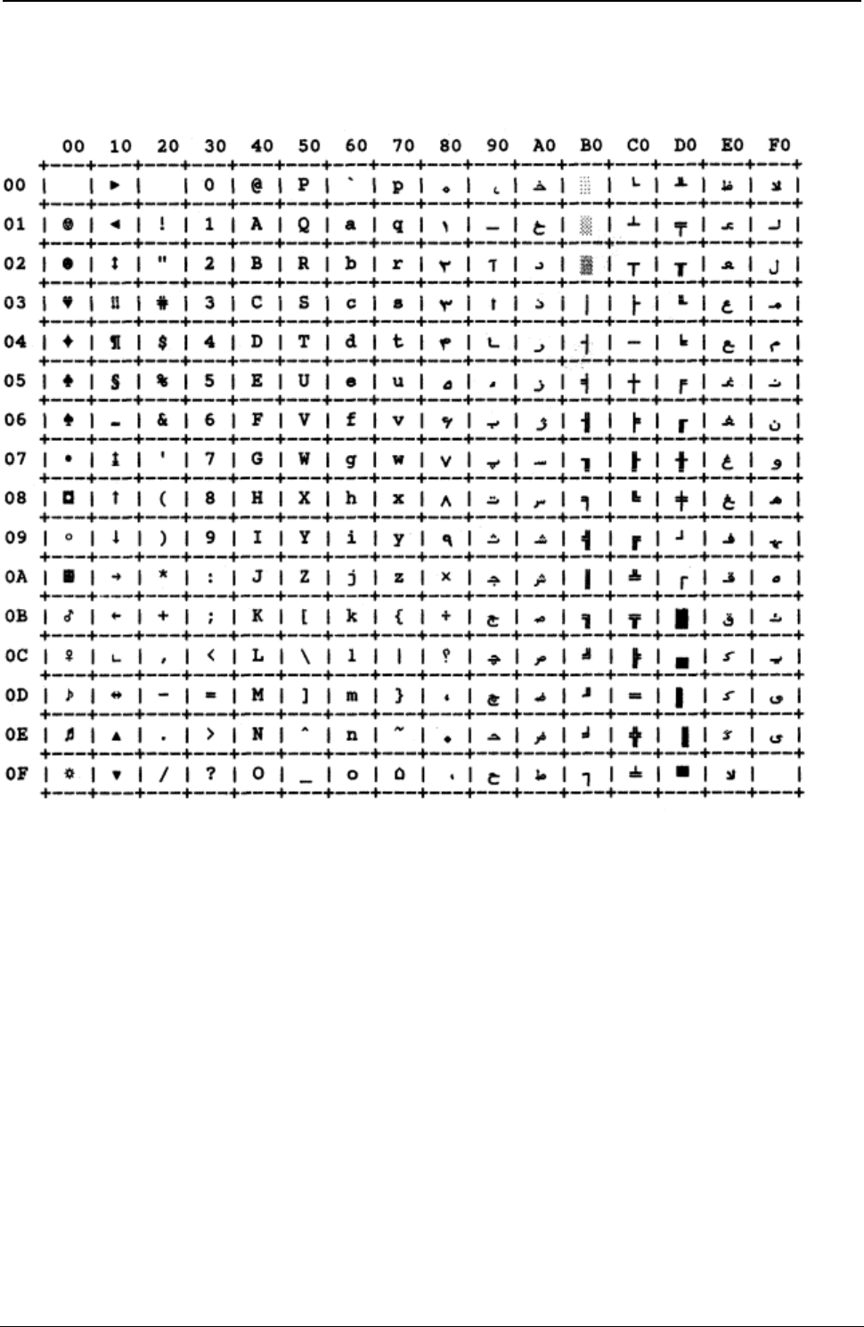
ProgrammerManual PTX‐S828
AppendixA.CodePages347260071‐001A
FARSI 2
Figure 130. Farsi 2
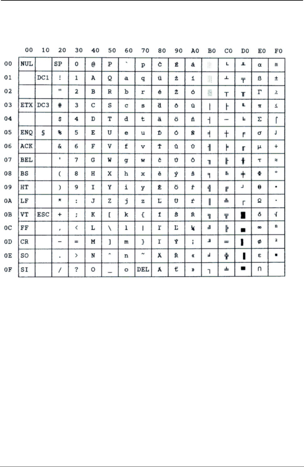
ProgrammerManual PTX‐S828
AppendixA.CodePages348260071‐001A
Kamenicky
Figure 131.Kamenicky
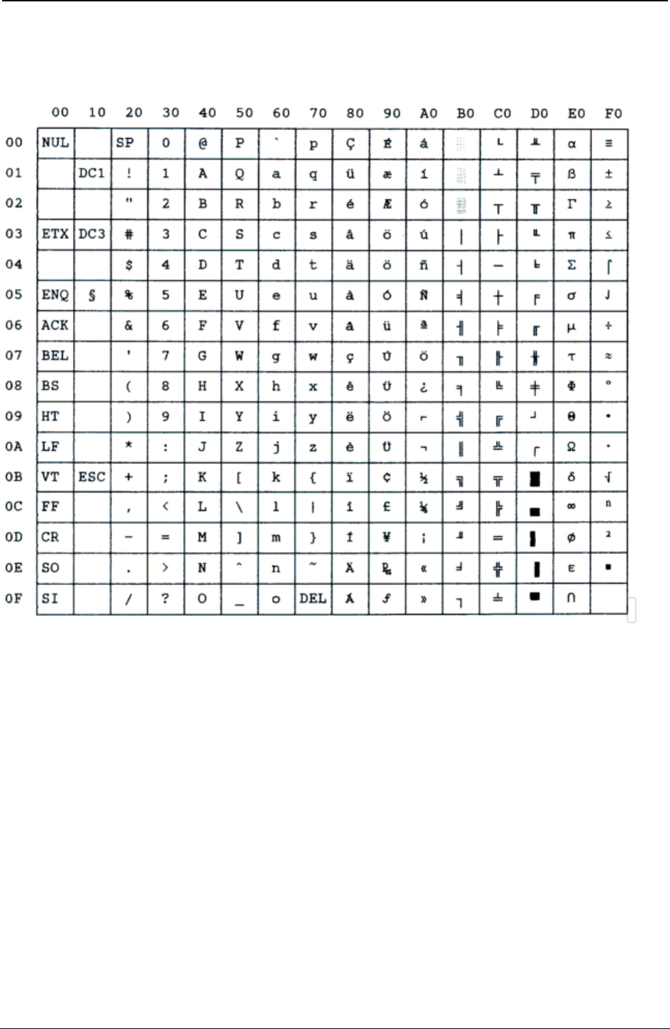
ProgrammerManual PTX‐S828
AppendixA.CodePages349260071‐001A
CWI
Figure 132.CWI
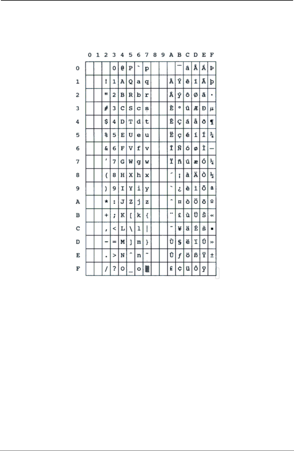
ProgrammerManual PTX‐S828
AppendixA.CodePages350260071‐001A
Roman-8
Figure 133.Roman-8
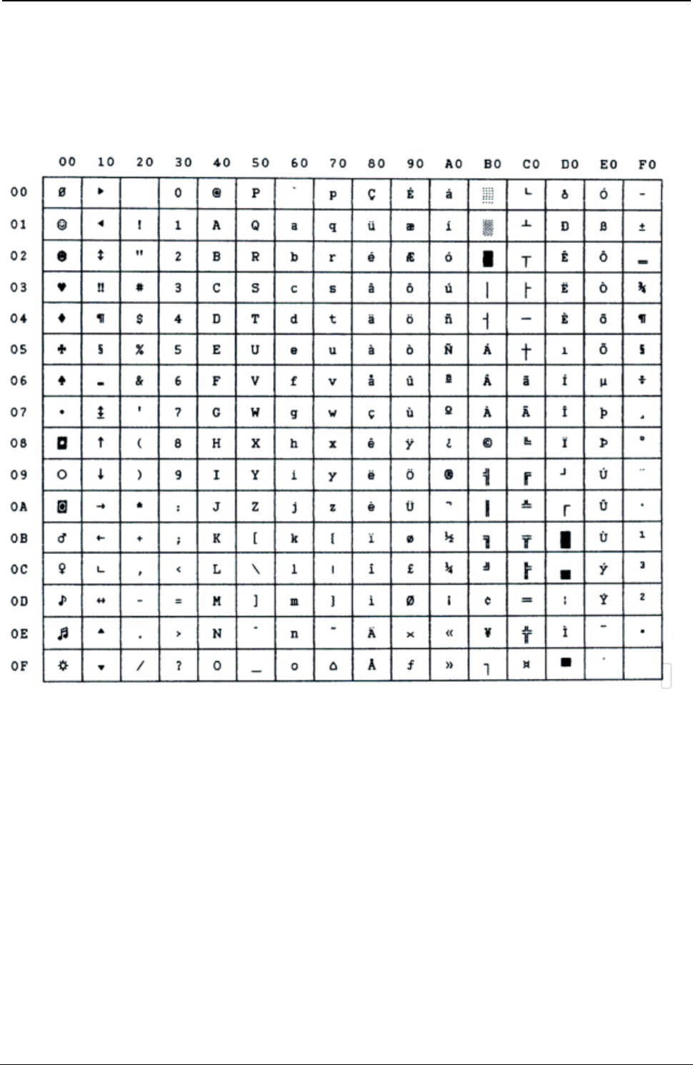
ProgrammerManual PTX‐S828
AppendixA.CodePages351260071‐001A
IN2
Figure 134.IN2
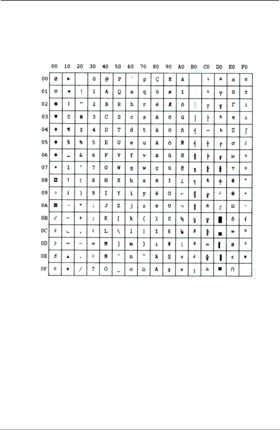
ProgrammerManual PTX‐S828
AppendixA.CodePages352260071‐001A
Turkish
Figure 135.Turkish
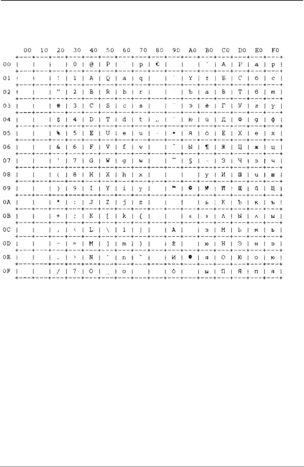
ProgrammerManual PTX‐S828
AppendixA.CodePages353260071‐001A
Bulgarian
Figure 136. Bulgarian
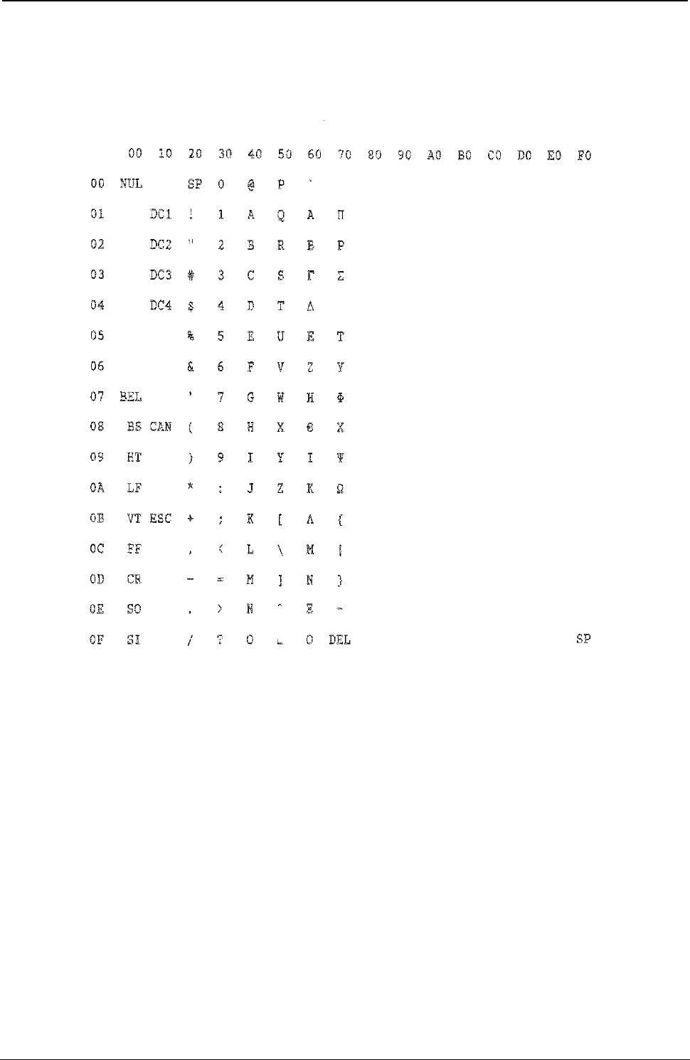
ProgrammerManual PTX‐S828
AppendixA.CodePages354260071‐001A
96 GREEK
Figure 137.96GREEK
ProgrammerManual PTX‐S828
AppendixA.CodePages355260071‐001A
Character Sets
Character Set 1
00 10 20 30 40 50 60 70 80 90 A0 B0 C0 D0 E0 F0
00 NUL
SP 0 @ P ’ p NUL
á
░ └ ╨ α ≡
01 DC1 ! 1 A Q a q DC1
í ▒ ┴ ╤ ß ±
02 DC2 “ 2 B R b r DC2
ó ▓ ┬ ╥ Γ ≥
03 DC3 # 3 C S c s DC3
ú │ ├ ╙ π ≤
04 DC4 $ 4 D T d t DC4
ñ ┤ ─ ╘ Σ ⌠
05 % 5 E U e u Ñ
╡ ┼ ╒ σ ⌡
06 & 6 F V f v ª
╢ ╞ ╓ µ ÷
07 BEL
‘ 7 G W g w BEL
º ╖ ╟ ╫ τ ≈
08 BS CAN ( 8 H X h x BS CAN
¿ ╕ ╚ ╪ Φ °
09 HT ) 9 I Y i y HT ⌐ ╣ ╔ ┘ Θ ·
0A LF * : J Z j z LF ¬ ║ ╩ ┌ Ω ·
0B VT ESC + ; K [ k { VT ESC
½ ╗ ╦ █ δ √
0C FF , < L \ l | FF ¼ ╝ ╠ ▄ ∞ ⁿ
0D CR - = M ] m } CR ¡ ╜ ═ ▌ φ ²
0E SO . > N ^ n ~ SO « ╛ ╬ ▐ ε ■
0F SI / ? O _ o DEL
SI » ┐ ╧ ▀ ∩ SP
Figure 138.CharacterSet1
ProgrammerManual PTX‐S828
AppendixA.CodePages356260071‐001A
Character Set 2
00 10 20 30 40 50 60 70 80 90 A0 B0 C0 D0 E0 F0
00 NUL
SP 0 @ P ’ p Ç É á ░ └ ╨ α ≡
01 DC1 ! 1 A Q a q ü æ í ▒ ┴ ╤ ß ±
02 ` DC2 “ 2 B R b r é Æ ó ▓ ┬ ╥ Γ ≥
03 DC3 # 3 C S c s â ô ú │ ├ ╙ π ≤
04 DC4 $ 4 D T d t ä ö ñ ┤ ─ ╘ Σ ⌠
05 § % 5 E U e u à ò Ñ ╡ ┼ ╒ σ ⌡
06 & 6 F V f v å û ª ╢ ╞ ╓ µ ÷
07 BEL
‘ 7 G W g w ç ù
º ╖ ╟ ╫ τ ≈
08 BS CAN ( 8 H X h x ê ÿ ¿ ╕ ╚ ╪ Φ °
09 HT ) 9 I Y i y ë ö ⌐ ╣ ╔ ┘ Θ ·
0A LF * : J Z j z è Ü
¬ ║ ╩ ┌ Ω ·
0B VT ESC + ; K [ k { ï ¢ ½ ╗ ╦ █ δ √
0C FF , < L \ l | î £ ¼ ╝ ╠ ▄ ∞ ⁿ
0D CR - = M ] m } ì ¥ ¡ ╜ ═ ▌ φ ²
0E SO . > N ^ n ~ Ä ₧ « ╛ ╬ ▐ ε ■
0F SI / ? O _ o DEL
Å ƒ » ┐ ╧ ▀ ∩ SP
Figure 139.CharacterSet2
ProgrammerManual PTX‐S828
AppendixA.CodePages357260071‐001A
Hexadecimal to Decimal Table
00 10 20 30 40 50 60 70 80 90 A0 B0 C0 D0 E0 F0
00 0 16 32 48 64 80 96 112 128 144 160 176 192 208 224 240
01 1 17 33 49 65 81 97 113 129 145 161 177 193 209 225 241
02 2 18 34 50 66 82 98 114 130 146 162 178 194 210 226 242
03 3 19 35 51 67 83 99 115 131 147 163 179 195 211 227 243
04 4 20 36 52 68 84 100 116 132 148 164 180 196 212 228 244
05 5 21 37 53 69 85 101 117 133 149 165 181 197 213 229 245
06 6 22 38 54 70 86 102 118 134 150 166 182 198 214 230 246
07 7 23 39 55 71 87 103 119 135 151 167 183 199 215 231 247
08 8 24 40 56 72 88 104 120 136 152 168 184 200 216 232 248
09 9 25 41 57 73 89 105 121 137 153 169 185 201 217 233 249
0A 10 26 42 58 74 90 106 122 138 154 170 186 202 218 234 250
0B 11 27 43 59 75 91 107 123 139 155 171 187 203 219 235 251
0C 12 28 44 60 76 92 108 124 140 156 172 188 204 220 236 252
0D 13 29 45 61 77 93 109 125 141 157 173 189 205 221 237 253
0E 14 30 46 62 78 94 110 126 142 158 174 190 206 222 238 254
0F 15 31 47 63 79 95 111 127 143 159 175 191 207 223 239 255
Figure 140.Hexadecimal to Decimal Table
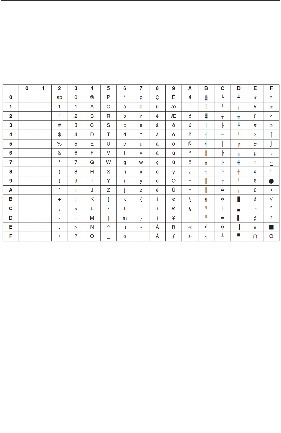
ProgrammerManual PTX‐S828
AppendixA.CodePages358260071‐001A
Epson FX-series Code Pages
The following Epson code charts provide information on the character tables available for Epson FX-series
emulation mode.
Extended Graphics Character
Figure 141. Epson Extended Graphics Character
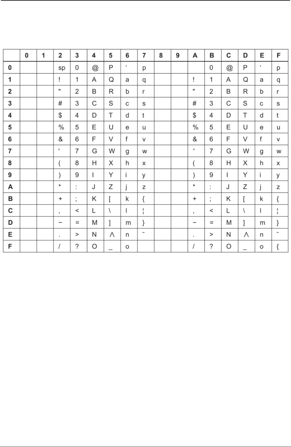
ProgrammerManual PTX‐S828
AppendixA.CodePages359260071‐001A
Italic Character Table
Figure 142. Epson Italic Character
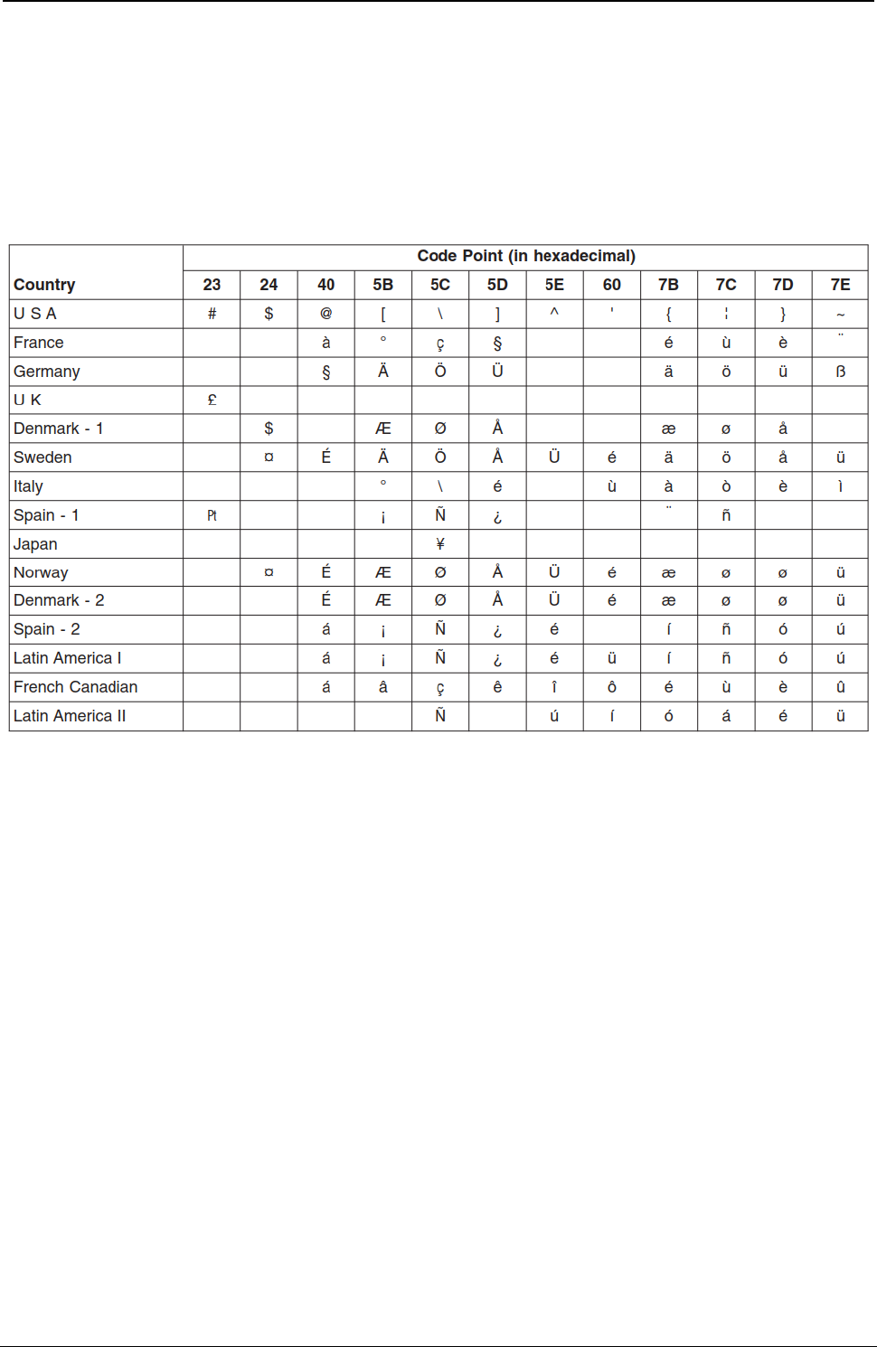
ProgrammerManual PTX‐S828
AppendixA.CodePages360260071‐001A
Epson Extended Character Variables
The following table shows characters that vary, by language, from the Epson Extended Character Graphics
set.
The code points shown are the only ones that vary. For example, in the United Kingdom, only code point
X'23' is different from the basic Epson table, shown on previous pages.
Figure 143. Epson Extended Character Variables
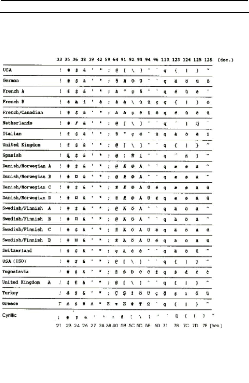
ProgrammerManual PTX‐S828
AppendixA.CodePages361260071‐001A
ANSI National Variations
The following table shows characters that vary, by language, from the ANSI Extended Character Graphics
set.
Figure 144. ANSI National Variations

ProgrammerManual PTX‐S828
AppendixA.CodePages362260071‐001A
This page is intentionally left blank

ProgrammerManual PTX‐S828
AppendixB‐Interfaces363260071‐001A
Appendix B. Interfaces
This section provides technical information for the parallel and serial interfaces.
The Parallel Interface
The parallel interface of this printer fully supports the Centronics protocol plus the specific features
requested by the EPSON and IBM printer connection in monodirectional mode and the Compatibility and
Nibbles modes in bidirectional mode, plus the negotiation phases and the device identifier (as IEEE
P1284).
The parallel interface is available on a specific 36 contact connector type AMPHENOL 57-40360- 12-D56
or equivalent connector for 1284 Type B.
● Drive Capability
Up to 15 feet (5 m) on AWG26 min. wire size of twisted conductors on TTL receiver. The max.
reachable distance is conditioned by the host drive capability and by the noise level along the interface
cable path.
● Printer Connector Type
36 pins, 1284 Type B
● Cable Connector
25 pin, 1284 A Type
Signals Description
According to the IEEE - P1284 Standard, the pins assume different meanings and are identified by
different names depending on the actual handshaking mode as follows:
● Compatibility mode (Centronics)
This is the lower level mode provides an asynchronous, byte-wide forward (host-to-peripheral) channel
with data and status lines used according to their original definitions. The interfaces power up in the
compatibility Mode Idle phase.
● Nibble Mode
This mode provides an asynchronous, reverse (peripheral-to-host) channel, under control of the host. In
this mode, peripheral device to host data bytes are sent as two sequential, four-bit nibbles using the
four peripheral-to-host status lines. These two modes cannot be active simultaneously.
● Byte Mode
This mode provides an asynchronous, byte-wide reverse (peripheral-to host) channel based on eight
data lines of the interface for data and the control/status lines for handshaking. Byte mode is under host
control and it cannot be simultaneously active with compatibility mode.
Operating Phases
The link protocol is mainly based on the following three phases:
● Negotiation Phase
This phase is activated always by the host, only when in compatibility mode, and defines:
– whether a bidirectional link protocol can be established.
– the handshaking mode as well as the communications mode to be used.
– the device identification, if supported.
● Communication Phase
This phase is based on well defined handshaking rules which depend upon the selected link mode.
● Termination Phase

ProgrammerManual PTX‐S828
AppendixB‐Interfaces364260071‐001A
This phase is initiated by the host and returns the interface to the compatibility mode.
Parallel Interface Signals
Description of the signals in monodirectional link:
Signal Name Pin N° Source Description
STROBE 1 HOST Clock signal which controls data transmission with its falling edge.
ACK 10 PRINTER Negative pulsed signal indicating that the printer has received data
and is ready to accept the next set of data. Also sent when the
printer is switched from off-line to on-line and at the end of the
initialization time. The BUSY line is always active.
DATA BIT 1 2 PRINTER / Data 8 is the most significant bit. These are the data lines used by
HOST host or printer to transfer control code or ASCII codes.
DATA BIT 2 3
DATA BIT 3 4
DATA BIT 4 5
DATA BIT 5 6
DATA BIT 6 7
DATA BIT 7 8
DATA BIT 8 9
BUSY 11 PRINTER When high, this signal indicates that the printer cannot accept data
or control codes. This signal goes high during data processing, in
test and program modes, during initialization, when the buffer is full,
and when a paper jam, paper end or paper size error occurs, in case
of a power-on reset, the reception of a STROBE signal, while the
register was not yet read, or when the INIT line is still active.
PE 12 PRINTER When high, this signal indicates that the automatic input bin is out of
paper and paper cannot be loaded from an other bin.
SELECT 13 PRINTER When high, this signal indicates that the printer is on-line. It is put to
low state in case of initialization or test and program mode. In IBM
Proprinter emulation in low condition this signal signals a off-line
request from the operator panel, paper jam, paper end or paper size
errors.
AUTOFEEDXT 14 HOST Active low level signal. Indicates whether a LF is performed after a
CR or not.
GND 16 – Logical ground level (0V).
CHASSIS GND 17 – Frame ground.
+5 VDC 18 PRINTER Is the DC voltage supplied by a component that limits the driven
capability up to 100 mA.
SIGNAL GND 19-30 – Signal ground.
INIT 31 HOST Active low level signal. Indicates, that the printer is initializing. The
BUSY signal is forced high.
ERROR 32 PRINTER When low, this signal indicates that the printer is offline, there is an
offline request from the operator panel, or the printer is in an error
state because of: paper jam, paper end or paper size error, engine
error, output bin full or cover open condition.
+5V 35 PRINTER Pulled up to signal.
SELECTIN 36 HOST Active low level signal. Enables the printer.

ProgrammerManual PTX‐S828
AppendixB‐Interfaces365260071‐001A
The pins 1 to 14 of the printer are connected to the pins with the same number of the parallel port of the
host.
The pins 19 to 30 of the printer are connected to the pins 18 to 25 of the parallel port of the host.
The pins 31, 32 and 36 of the printer are connected respectively to the pins 16, 15 and 17 of the parallel port
of the host.
1284 Mode signal names are shown with their Compatibility mode (Centronics) names in parenthesis ( ) for
the bidirectional link.
Signal Name Pin N° for Pin N° for
Signal Wire Return Wire Source
HostClk (nStrobe) 1 19 HOST
AD1 (Data 1) 2 20 HOST in Compatibility mode and negotiation
phase.
AD2 (Data 2) 3 21
AD3 (Data 3) 4 22 NOT USED in Nibble mode.
AD4 (Data 4) 5 23
AD5 (Data 5) 6 24 BIDIRECTIONAL in Byte mode.
AD6 (Data 6) 7 25
AD7 (Data 7) 8 26
AD8 (Data 8) 9 27
PrtClk (nAck) 10 28 PRINTER
PrtBusy (Busy) 11 29 PRINTER
AckDataReq (PError) 13 28 PRINTER
Xflag (Select) 14 28 PRINTER
HostBusy (nAutofd) 15 30 HOST
Peripheral Logic High 18 PRINTER
(+5 V)
n.a. (nInit) 31 30 HOST
nDataAvail (NFault) 32 29 PRINTER
1284 Active (NSelectIn) 36 30
Common Logic Ground 16 and Return Wires
Chassis Ground 17
Parallel Interface Signals Behaviour
HostClk /nWrite (nStrobe)
Compatibility Mode: Set Active low to transfer data into printer input latch. Data is valid while nStrobe is
low.
Negotiation Phase: Set active low to transfer extendibility request value into printer input latch. Data is
valid on the falling edge of HostClk.
Reverse Data Transfer Set high during Nibble Mode transfer to avoid latching data into printer. Pulsed
Phase: low during Byte Mode transfers to acknowledge transfer of data from the printer.
The printer shall ensure that this pulse does not transfer a new data into the printer
input latch.
AD1 ... AD8 (Data 1 ... Data 8)
Compatibility Mode: Forward channel data.
Negotiation Phase: Extendibility request value.
Reverse Data Transfer Nibble Mode: NOT USED.
Phase: Byte Mode: Reverse channel data.

ProgrammerManual PTX‐S828
AppendixB‐Interfaces366260071‐001A
PrtClk (nAck)
Compatibility Mode: Pulsed low by the printer to acknowledge the transfer of a data from the host.
Negotiation Phase: Set low to acknowledge 1284 support, then set high to indicate that the Xflag
(Select) and data available flags may be read.
Reverse Data Transfer Used in both Nibble and Byte Modes to qualify data being sent to the host.
Phase:
PrtBusy (Busy)
Compatibility Mode: Driven high to indicate that the printer is not ready to receive data.
Negotiation Phase: Reflects the present state of the printer’s forward channel.
Reverse Data Transfer Nibble Mode: Data bits 3 then 7, then forward channel busy status
Phase: Byte Mode: Forward channel busy status.
Reverse Idle phase: Forward channel busy status.
AckDataReq (PError)
Compatibility Mode: Driven high to indicate that the printer has encountered an error in the paper path.
The printer shall set nFault low whenever it sets PError high.
Negotiation Phase: Set high to indicate 1284 support, then follows nDataAvail (nFault).
Reverse Data Transfer Nibble Mode: Data bits then 6.
Phase: Byte Mode: same as nDataAvail (nFault)
Reverse Idle phase: Set high until host requests data transfer, then follows nDataAvail (nFault).
Xflag (Select)
Compatibility Mode: Set high to indicate that the printer in on-line.
Negotiation Phase: The Xflag refers to extendibility flag. Used by the printer to reply to the requested
extendibility byte sent by the host during the negotiation phase. The signal level is
low for Nibble Mode, high for Byte Mode.
Reverse Data Transfer Nibble Mode: Data bits 1 then 5.
Phase: Byte Mode: Same as negotiation phase.
Reverse Idle phase: Same as negotiation phase.
Xflag (Select)
Compatibility Mode: Set low by host to put the printer into auto-line feed mode.
Negotiation Phase: Set low in conjunction with 1284 Active (NSelectIn) being set high to request a
1284 mode.
Then set high after printer sets PtrClk (nAck) low.
Xflag (Select)
Reverse Data Transfer Nibble Mode: Set low to indicate that host can receive printer-to-host data then set
Phase: high to acknowledge receipts of that nibble.
Byte Mode: Same as Nibble Mode to request and acknowledge bytes. Following a
reverse channel transfer the interface transitions to idle phase when
HostBusy (nAutoFd) is set low and printer‘s no data available.
Reverse Idle phase: Set high in response to PtrClk (nAck) low pulse to re-enter reverse data transfer
phase.
Is set high with 1284 Active (nSelectIn) being set low, the 1284 idle phase is being
aborted and the interface returns to Compatibility Mode.
Peripheral Logic High (+ 5V)
Set high to indicate that all other signals sourced by the printer are in valid state. Set low to indicate the
printer is off.

ProgrammerManual PTX‐S828
AppendixB‐Interfaces367260071‐001A
n.a. (nInit)
Compatibility Mode: Pulsed low in conjunction with 1284 Active low to reset the interface and force to
return to Compatibility Mode idle phase.
Negotiation Phase: Set HIGH.
Reverse Data Transfer Set HIGH.
Phase:
nDataAvail (NFault)
Compatibility Mode: Set low to indicate that an internal printer error has occurred.
Negotiation Phase: Set high to acknowledge 1284 compatibility. In Nibble or Byte Mode it is then set low
to indicate printer-to-host data is available following host setting HostBusy (nAutoFd)
high.
Reverse Data Transfer Nibble Mode: Set low to indicate that printer is ready to send to host. Then used to
Phase: send data bits 0 then 4.
Byte Mode: Used to indicate that data is available.
Reverse Idle phase: Used to indicate that data is available.
1284 Active (NSelectIn)
Compatibility Mode: Set low by host to select printer.
Negotiation Phase: Set high in conjunction with Host Busy being set low to request a 1284 mode.
Reverse Data Transfer Set high to indicate that bus direction is printer to host. Set low to terminate 1284
Phase: mode and set bus direction host to printer.
Reverse Idle Phase: Same as Reverse Data Transfer phase.
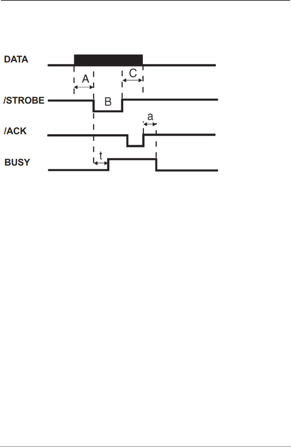
ProgrammerManual PTX‐S828
AppendixB‐Interfaces368260071‐001A
Interface Timing
Timing and Handshaking depend upon the connection mode.
Figure 145. Mode Centronics
Our Centronics mode supports the BUSY-WHILE-STROBE busy signal timing and ACK-INBUSY as
BUSY-ACK relationship.
Legend Time interval Min. Max.
A Data Setup Time 1.0
B Strobe pulse width 1.0 500
C Data hold time 1.0 all times in µs
t Busy while Strobe 0.25 1.0
a Ack in Busy 0 2.5
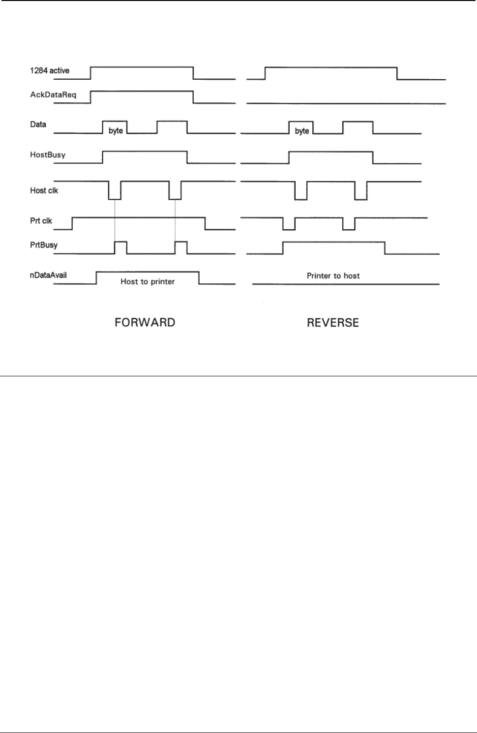
ProgrammerManual PTX‐S828
AppendixB‐Interfaces369260071‐001A
Mode IEEE 1284
Figure 146. Mode IEEE 1284
The Serial Interface
This printer provides the RS-232/C serial interfaces. The interface mode is selected via menu.
● Transmission Type
Data is sent and received in start/stop (asynchronous) transmission.
● Character Format
Each character is transmitted in the following format:
1 START BIT + 8 DATA BITS + 1 PARITY BIT + 1 STOP BIT
The least significant bit of the data bits is sent first after the start bit. The number of data bits is selected
via menu. The parity bit, when present, follows the data bits. The start bit is a logical “0” and the stop bit
is a logical “1”. The start and stop bits are used as character framing bits.
● Printer Connector
Male DB9 or equivalent connector.
● Drive Capability
Max. 50 feet (15 m) for all supported data rates. The RS-422/A interface is effective up to 1200 m.

ProgrammerManual PTX‐S828
AppendixB‐Interfaces370260071‐001A
Serial Interface Signals
The following table lists the RS-232/C serial interface signals:
Local Remote
Connect. Connect.
Signal Name Pin Number Source Source Description
SIGNAL 5 – – Always connected to the 0 Volts of the
GROUND Power Supply
TXD 3 Printer Printer Transmitted Data Signal (an output from
printer). A MARK condition is held during
IDLE communication state. An indeterminate
state is present when printer is powered off.
RXD 2 Host Data Set Received data signal (an input to printer).
RTS 7 Printer Printer Request to Send Signal (an output from
printer). Active HIGH level signal. It is HIGH
until the printer is powered off, then an
indeterminate state is present .
CTS 8 Data Set Active HIGH level signal indicates that the
host or data set is ready to receive data from
the printer.
DSR 6 Data Set Active HIGH level signal. Indicates that the
host or data set is ready to be connected to
the printer and is ready for data transfer.
DCD 1 Data Set Active HIGH level signal. Indicates that the
host is transmitting or the data set is r
receiving the Data Carrier signal.
2nd RTS 9 Printer Functionally equivalent to the DTR signal.
DTR 4 Printer Printer Data Terminal Ready. Normally HIGH (ON).
Indicates that the printer is ready to initiate a
connection.
LAN Interface Port
LAN Interface Port
1. Ethernet 10/100BaseT Connector
2. Green 10/100Mbit/sec. Transmission Speed LED
3. Yellow Traffic LED
LED Indicators
The LED indicator modes are described in the following table:
LED Status Description
Yellow LED Unlit Transmission speed at 10Mbit/sec.
Lit Transmission speed at 100Mbit/sec.
Green LED Blinks Transmitting or receiving packets from the network.
USB Interface Port
USB 2.0 full speed 12/Mbit/sec. interface.

ProgrammerManual PTX‐S828
AppendixC–NetworkInterfaceReference371260071‐001A
Appendix C. Network Interface Technical Reference
Network Configuration Parameters
IP Address Assignment
Fixed: Assigns the static or fixed IP address.
DHCP: Assigns the dynamic IP address (DHCP protocol).
Default value is DHCP.
Fixed and DHCP assignments of IP addresses are supported. On most networks, you will want to assign a
permanent IP address and disable DHCP.
IP Address
These values set the IP Address. The address is represented by a decimal notation where the decimal
values are divided by points in four fields.
Each field ranges between 0 and 255.
Default is 127.000.000.000.
Subnet Mask
These values set the Subnet Mask number. This number is represented by a decimal notation where the
decimal values are divided by points in four fields. Each field ranges between 0 and 255.
Default is 255.255.254.000.
Default Gateway
These values set the Default Gateway address. This address is represented by a decimal notation where the
decimal values are divided by points in four fields. Each field ranges between 0 and 255.
Default is 000.000.000.000.
The gateway address tells the printer which router or gateway to use to access other subnets or hosts.
Simply add your router’s IP address as the default gateway. All packets destined for other subnets will be
forwarded to the default gateway for delivery to the destination host.
Host Name
The host is identified by a name in the NetBIOS protocol over TCP/IP. This function allows creating the name
of the host using a 14-character string.
Default is PTX_xxxxxx where xxxxxx are the last 6-digits of the MAC address...
Workgroup Name
The workgroup is identified by a name in the NetBIOS protocol over TCP/IP in Windows. This function allows
creating the name of the workgroup using a 14-character string.
Default is Workgroup.

ProgrammerManual PTX‐S828
AppendixC–NetworkInterfaceReference372260071‐001A
SMTP Service
SMTP (Simple Mail Transfer Protocol) allows a mail server address to be entered into the printer
configuration to send automated e-mail notifications with printer alert conditions.
Disabled: Disables the SMTP (Simple Mail Transfer Protocol) service, that is disables the
reception/transfer/error service of the e-mail.
Enabled: Enables the SMTP service, that is it enables the reception/transfer/error service of the e-
mail.
Default is Disabled.
Mail Server Address
These values set the mail server address. This number is represented by a decimal notation where the
decimal values are divided by points in four fields. Each field ranges between 0 and 255.
Default is 000.000.000.000.
Note: Item selection on the printer menu allowed only if the “SMTP Service” function choice is Enabled.
E-mail Address (Receiver)
This function allows writing the e-mail address where you can notify the failures using a 48-character
string. Default is an empty string.
Note: Item selection on the printer menu allowed only if the “SMTP Service” function choice is Enabled.
E-mail Address (Sender)
This function allows to write the sender e-mail address using a 48-character string.
Default is an empty string.
Note: Item selection on the printer menu allowed only if the “SMTP Service” function choice is Enabled.
Location
You can enter the physical location of the printer into this field.
Contact
You can enter a network support contact’s name and phone number into this field.

ProgrammerManual PTX‐S828
AppendixC–NetworkInterfaceReference373260071‐001A
Managing a Single Printer Configuration Using the Internal Webpage
Configuration Password
The Printronix S828's configuration settings can be protected by a password to keep unauthorized users
from making changes. When you try to submit any Printronix S828 configuration change, you will be asked
for your user name and password. At the prompt, enter the default user name = root and default
password = root, unless you have setup another user name and password with root privileges.
Storing and Saving Settings
When settings are configured on the Printronix S828 and the SUBMIT button on the related page has been
pressed, you will be reminded to Reboot the printer to ensure the latest settings are in use. To reset the
Printronix S828, go to the Home page, enter the Power On Reset page, and Click on the REBOOT
PRINTER button.
Managing Multiple Printers Using the Remote Printer
Management Utility
The Remote Printer Management Utility (RPMU) is a software tool for network administrators that allows
the configuration and control of Printronix S828 printers remotely over a LAN. With this tool the installed
printers can be controlled, configured and organized easily. The main features are:
Device Discovery - Searches for the devices within a range of IP addresses.
Printer Organization - Printers connected to the network can be organized into logical groups in a
hierarchically structured tree.
Printer Status Report - Checks the printer's status and reports alarms.
Printer Configuration - Printers may be configured as needed from the administrators workstation.
Change the configuration of single printers, or simultaneously change the configuration of multiple
printers in your enterprise, anywhere, and anytime.
Firmware Updating - Provides a firmware download function to upgrade the printer's firmware.
Remote Operator Panel Management - Provides a virtual operator panel for the remotely connected
printer at the administrators workstation that allows performing all functions normally achieved pressing
the operator panel keys. The RPMU also provides the basic status management for third-party printers
compliant to the standard MIB objects. Visit our website to download this free software utility program.
Network Interface Summary
Table 12. Network Interface Summary
INSTALLATION INTEGRATION
Network speed / connection 10/100 BASET
Auto-detection 10/100 network speed Yes
Manual network speed selection No
Parallel interface free Yes
Network configuration through printer operator panel Yes
Web page network setting configuration Yes
Web page login password protection Yes
Web page default user-id and default password Root, Root
Windows Port Monitor and Drivers Yes, download from www.Printronix.com
NIC configuration printout Yes

ProgrammerManual PTX‐S828
AppendixC–NetworkInterfaceReference374260071‐001A
Table 12. Network Interface Summary (cont.)
DHCP Yes
WINS Yes
DDNS Yes
SYSTEM / OS
IBM System i OS 400 Yes
IBM pSeries® AIX Yes
Sun Solaris Yes
Unix Yes
Linux® Yes
Windows 95,98,2000,NT,XP, 2003 Server Yes
Windows VISTA, Win7, Win8, Win10 Yes
NETBIOS over TCP Yes
NETBEUI No
Novell Netware No
OS2 No
MacIntosh / Apple EtherTalk No
PRINTING METHODS
Raw Port 9100 Yes
LPD/LPR Port 515 Yes
LPR print queue name Any name (PR1, d1PRN, etc.) can be used.
IPDS Port 5100 Yes (with IPDS option on some models)
Interleaved multi-protocol communications Yes
Hot Interface switching Yes between Parallel and LAN interfaces
Hot Port switching Yes between Raw 9100, LPR/LPD 515,
and IPDS 5100 (with IPDS option on some models)
Multiple internal print server queues No
String substitutions No
String before/after job No
DATASTREAMS
S828 ASCII native Yes
ASCII text and single byte escapes Yes
IBM Proprinter III emulation Yes (on some models)
IBM Personal Printer 2391 emulation Yes (on some models)
IBM Proprinter III emulation Yes (on some models)
IBM Personal Printer 2381 emulation Yes (on some models)
Epson FX series emulation Yes (on some models)
Epson - FX emulation Yes (on some models)
IPDS Yes (with IPDS option on some models. See
“Intelligent Printer Data Stream,” for
application program compatibility considerations)
PRINTER SERVER FACILITIES SUPPORT
PSF AIX Yes
PSF OS400 Yes

ProgrammerManual PTX‐S828
AppendixC–NetworkInterfaceReference375260071‐001A
Table 12. Network Interface Summary (cont.)
PSF MVS™ Yes
PSF VSE Yes
PSF VM Yes
NETWORK MANAGEMENT
S828 Remote Printer Management Utility Yes, download from www.Printronix.com
IBM NPM Yes (generic printer)
HP JetAdmin Yes (generic printer)
E-mail SMTP Yes
Internal Web page Yes
PRINTER STATUS AND ERROR REPORTING
Ready Yes
Not ready Yes
Paper out Yes
Paper jam Yes
Cover open Yes
Machine check (carriage fault, ribbon blocked...) Yes
NETWORK CONFIGURATION PARAMETERS (see above)
LINK LAYER
Ethernet II Yes
802.2 Yes
802.3 Yes
2/SNAP Yes
Link disconnect (no data timeout) 15 second fixed setting
PROTOCOLS
IP Yes
TCP Yes
UDP Yes
ARP Yes
RARP Yes
SMP Yes
Telnet Yes
DHCP Yes
DDNS Yes
WINS Yes
BOOTP Yes
FTP Yes
TFTP Yes
ICMP Yes
LPR/LPD Yes
DHCP Yes
SNMP Yes
SMTP Yes

ProgrammerManual PTX‐S828
AppendixC–NetworkInterfaceReference376260071‐001A
Table 12. Network Interface Summary (cont.)
Direct Socket Printing Yes
HTTP Yes
PING Yes
SNMP Yes
MIB II (RFC 1514) Yes (see note)
Host Resource MIB (RFC 1514) Yes
Printer MIB (RFC1759) Yes
S828 Private MIB Yes
Reverse Telnet No
PROS No
IPP No
SLPv2 No
HARDWARE
RISC processor Yes
Flash memory 4MB
RAM 16MB
Attachment connector type RJ-45
Network traffic led Yes (green)
Network speed led Yes (yellow)
FIRMWARE UPGRADE
Firmware upgrade over network Yes
Firmware upgrade through parallel interface Yes
Note: All relevant parts of MIB-II (RFC1231) required to support HP JetAdmin are implemented.
● The following IP table group OIDs are not implemented: ipForwarding, ipDefaultTTL , ipInReceives
,ipInHdrErrors,ipInAddrErrors, ipForwDatagrams, ipInUnknownProtos, ipInDiscards, ipInDelivers,
ipOutRequests, ipOutDiscards, ipOutNoRoutes, ipReasmTimeout ,ipReasmReqds,
ipReasmOKs,ipReasmFails,ipFragOKs, ipFragFails, ipFragCreates
● The ipRouteTable OIDs are not implemented.
● The ipNetToMediaTable OIDs are not implemented.
● The icmp group OIDs are not implemented.
● The tcp group OIDs are not implemented.
● The udp group OIDs are not implemented.
● The snmp group OIDs are not implemented.

ProgrammerManual PTX‐S828
AppendixD–LanInterfaceMIBSupport377260071‐001A
Appendix D. LAN Interface MIB Support
Table 13 List of the MIB of the printer.
Description MIB
prtButton 1, 3, 6, 1, 4, 1, 6345, 1, 2, 1, 1
prtBaseCodeVersion 1, 3, 6, 1, 4, 1, 6345, 1, 2, 1, 2
prtHtmlContact 1, 3, 6, 1, 4, 1, 6345, 1, 2, 1, 3
prtRebootPrinter 1, 3, 6, 1, 4, 1, 6345, 1, 2, 1, 4
prtRestoreToMfg 1, 3, 6, 1, 4, 1, 6345, 1, 2, 1, 5
prtGetPrinterStatus 1, 3, 6, 1, 4, 1, 6345, 1, 2, 1, 6
prtMenuLocked 1, 3, 6, 1, 4, 1, 6345, 1, 2, 1, 7
prtPowerOnCycles 1, 3, 6, 1, 4, 1, 6345, 1, 2, 1, 8
prtPowerOnMinutes 1, 3, 6, 1, 4, 1, 6345, 1, 2, 1, 9
prtBarCodes 1, 3, 6, 1, 4, 1, 6345, 1, 2, 1, 10
prtPageWithGraphics 1, 3, 6, 1, 4, 1, 6345, 1, 2, 1, 11
prtHSDraftCharacters 1, 3, 6, 1, 4, 1, 6345, 1, 2, 1, 12
prtDPCharacters 1, 3, 6, 1, 4, 1, 6345, 1, 2, 1, 13
prtDPTextCharacters 1, 3, 6, 1, 4, 1, 6345, 1, 2, 1, 14
prtNLQCharacters 1, 3, 6, 1, 4, 1, 6345, 1, 2, 1, 15
prtBESTDraftCharacters 1, 3, 6, 1, 4, 1, 6345, 1, 2, 1, 16
prtLQCharacters 1, 3, 6, 1, 4, 1, 6345, 1, 2, 1, 17
prtPrintedPageNumber 1, 3, 6, 1, 4, 1, 6345, 1, 2, 1, 18
prtLPD_Timeout 1, 3, 6, 1, 4, 1, 6345, 1, 2, 1, 19
LPD_Reboot 1, 3, 6, 1, 4, 1, 6345, 1, 2, 1, 20
prtMenuUserMacro 1, 3, 6, 1, 4, 1, 6345, 1, 2, 3, 2
prtMenuUserMacroTable 1, 3, 6, 1, 4, 1, 6345, 1, 2, 3, 2, 1
prtUserMacroEntry 1, 3, 6, 1, 4, 1, 6345, 1, 2, 3, 2, 1, 1
prtUserMacroIndex 1, 3, 6, 1, 4, 1, 6345, 1, 2, 3, 2, 1, 1, 1
prtUserMacroLineSpace 1, 3, 6, 1, 4, 1, 6345, 1, 2, 3, 2, 1, 1, 2
prtUserMacroLineSpaceLock 1, 3, 6, 1, 4, 1, 6345, 1, 2, 3, 2, 1, 1, 3
prtUserMacroLength 1, 3, 6, 1, 4, 1, 6345, 1, 2, 3, 2, 1, 1, 4
prtUserMacroTopOfForm 1, 3, 6, 1, 4, 1, 6345, 1, 2, 3, 2, 1, 1, 5
prtUserMacroSkiPover 1, 3, 6, 1, 4, 1, 6345, 1, 2, 3, 2, 1, 1, 6
prtUserMacroDraftMode 1, 3, 6, 1, 4, 1, 6345, 1, 2, 3, 2, 1, 1, 7
prtUserMacroFont 1, 3, 6, 1, 4, 1, 6345, 1, 2, 3, 2, 1, 1, 8
prtUserMacroPitch 1, 3, 6, 1, 4, 1, 6345, 1, 2, 3, 2, 1, 1, 9
prtUserMacroPitchLock 1, 3, 6, 1, 4, 1, 6345, 1, 2, 3, 2, 1, 1, 10
prtUserMacroLeftMargin 1, 3, 6, 1, 4, 1, 6345, 1, 2, 3, 2, 1, 1, 11
prtUserMacroRightMargin 1, 3, 6, 1, 4, 1, 6345, 1, 2, 3, 2, 1, 1, 12
prtUserMacroSlashZero 1, 3, 6, 1, 4, 1, 6345, 1, 2, 3, 2, 1, 1, 13
prtUserMacroPath 1, 3, 6, 1, 4, 1, 6345, 1, 2, 3, 2, 1, 1, 14
prtUserMacroTear 1, 3, 6, 1, 4, 1, 6345, 1, 2, 3, 2, 1, 1, 15
prtUserMacroImpact 1, 3, 6, 1, 4, 1, 6345, 1, 2, 3, 2, 1, 1, 16
prtUserMacroPerforSave 1, 3, 6, 1, 4, 1, 6345, 1, 2, 3, 2, 1, 1, 17
prtUserMacroGap 1, 3, 6, 1, 4, 1, 6345, 1, 2, 3, 2, 1, 1, 18
prtUserMacroTuningHor 1, 3, 6, 1, 4, 1, 6345, 1, 2, 3, 2, 1, 1, 19
prtUserMacroTuningVer 1, 3, 6, 1, 4, 1, 6345, 1, 2, 3, 2, 1, 1, 20
prtUserMacroIgnoreFF 1, 3, 6, 1, 4, 1, 6345, 1, 2, 3, 2, 1, 1, 21
prtUserMacroQuality 1, 3, 6, 1, 4, 1, 6345, 1, 2, 3, 2, 1, 1, 22
prtUserMacro1524Cpi 1, 3, 6, 1, 4, 1, 6345, 1, 2, 3, 2, 1, 1, 23

ProgrammerManual PTX‐S828
AppendixD–LanInterfaceMIBSupport378260071‐001A
Table 13 List of the MIB of the printer (cont.)
Description MIB
prtUserMacroTearDelay 1, 3, 6, 1, 4, 1, 6345, 1, 2, 3, 2, 1, 1, 24
prtUserMacroQuiet 1, 3, 6, 1, 4, 1, 6345, 1, 2, 3, 2, 1, 1, 25
prtUserMacroDBCS 1, 3, 6, 1, 4, 1, 6345, 1, 2, 3, 2, 1, 1, 26
prtUserMacroDBCS_Cpi 1, 3, 6, 1, 4, 1, 6345, 1, 2, 3, 2, 1, 1, 27
prtUserMacroDBCS_Lpi 1, 3, 6, 1, 4, 1, 6345, 1, 2, 3, 2, 1, 1, 28
prtUserMacroTH_Space 1, 3, 6, 1, 4, 1, 6345, 1, 2, 3, 2, 1, 1, 29
/* IPDS SETTINGS START */
prtUserMacroI_Pitch 1, 3, 6, 1, 4, 1, 6345, 1, 2, 3, 2, 1, 1, 30
prtUserMacroI_LineSpace 1, 3, 6, 1, 4, 1, 6345, 1, 2, 3, 2, 1, 1, 31
prtUserMacroI_RightMargin 1, 3, 6, 1, 4, 1, 6345, 1, 2, 3, 2, 1, 1, 32
prtUserMacroI_FormLength 1, 3, 6, 1, 4, 1, 6345, 1, 2, 3, 2, 1, 1, 33
prtUserMacroI_Font 1, 3, 6, 1, 4, 1, 6345, 1, 2, 3, 2, 1, 1, 34
prtUserMacroI_NLQ_Font 1, 3, 6, 1, 4, 1, 6345, 1, 2, 3, 2, 1, 1, 35
prtUserMacroI_HostFastDraft 1, 3, 6, 1, 4, 1, 6345, 1, 2, 3, 2, 1, 1, 36
prtUserMacroI_Nation 1, 3, 6, 1, 4, 1, 6345, 1, 2, 3, 2, 1, 1, 37
prtUserMacroI_Emulation 1, 3, 6, 1, 4, 1, 6345, 1, 2, 3, 2, 1, 1, 38
prtUserMacroI_MediaSizePriority 1, 3, 6, 1, 4, 1, 6345, 1, 2, 3, 2, 1, 1, 39
prtUserMacroI_BcMode 1, 3, 6, 1, 4, 1, 6345, 1, 2, 3, 2, 1, 1, 40
prtUserMacroI_GraMode 1, 3, 6, 1, 4, 1, 6345, 1, 2, 3, 2, 1, 1, 41
prtUserMacroFontLock 1, 3, 6, 1, 4, 1, 6345, 1, 2, 3, 2, 1, 1, 42
/* IPDS SETTINGS END */
prtMenuConfig 1, 3, 6, 1, 4, 1, 6345, 1, 2, 3, 3
prtMenuConfigTable 1, 3, 6, 1, 4, 1, 6345, 1, 2, 3, 3, 1
prtMenuConfigEntry 1, 3, 6, 1, 4, 1, 6345, 1, 2, 3, 3, 1, 1
prtMenuConfigMacroWork 1, 3, 6, 1, 4, 1, 6345, 1, 2, 3, 3, 1, 1, 1
prtMenuConfigIfType 1, 3, 6, 1, 4, 1, 6345, 1, 2, 3, 3, 1, 1, 2
prtMenuConfigEmulation 1, 3, 6, 1, 4, 1, 6345, 1, 2, 3, 3, 1, 1, 3
prtMenuConfigCharset 1, 3, 6, 1, 4, 1, 6345, 1, 2, 3, 3, 1, 1, 4
prtMenuConfigNation 1, 3, 6, 1, 4, 1, 6345, 1, 2, 3, 3, 1, 1, 5
prtMenuConfigAutoCR 1, 3, 6, 1, 4, 1, 6345, 1, 2, 3, 3, 1, 1, 6
prtMenuConfigAutoLF 1, 3, 6, 1, 4, 1, 6345, 1, 2, 3, 3, 1, 1, 7
prtMenuConfigIBM20CPI 1, 3, 6, 1, 4, 1, 6345, 1, 2, 3, 3, 1, 1, 8
prtMenuConfigBarcode 1, 3, 6, 1, 4, 1, 6345, 1, 2, 3, 3, 1, 1, 9
/* ANSI SETTINGS START */
prtMenuConfigA_CharSet 1, 3, 6, 1, 4, 1, 6345, 1, 2, 3, 3, 1, 1, 10
prtMenuConfigA_CharTable 1, 3, 6, 1, 4, 1, 6345, 1, 2, 3, 3, 1, 1, 11
prtMenuConfigA_Nation 1, 3, 6, 1, 4, 1, 6345, 1, 2, 3, 3, 1, 1, 12
prtMenuConfigA_RIS_Enable 1, 3, 6, 1, 4, 1, 6345, 1, 2, 3, 3, 1, 1, 13
prtMenuConfigA_SI_SO_Control 1, 3, 6, 1, 4, 1, 6345, 1, 2, 3, 3, 1, 1, 14
prtMenuConfigA_AutoCR 1, 3, 6, 1, 4, 1, 6345, 1, 2, 3, 3, 1, 1, 15
prtMenuConfigA_PrimeOnDEL 1, 3, 6, 1, 4, 1, 6345, 1, 2, 3, 3, 1, 1, 16
prtMenuConfigA_ControlInDg 1, 3, 6, 1, 4, 1, 6345, 1, 2, 3, 3, 1, 1, 17
prtMenuConfigA_ExpandUp 1, 3, 6, 1, 4, 1, 6345, 1, 2, 3, 3, 1, 1, 18
prtMenuConfigA_AltGraph 1, 3, 6, 1, 4, 1, 6345, 1, 2, 3, 3, 1, 1, 19
prtMenuConfigA_8BitControl 1, 3, 6, 1, 4, 1, 6345, 1, 2, 3, 3, 1, 1, 20
prtMenuConfigA_ENQ_Code 1, 3, 6, 1, 4, 1, 6345, 1, 2, 3, 3, 1, 1, 21
prtMenuConfigA_SubSuperScript 1, 3, 6, 1, 4, 1, 6345, 1, 2, 3, 3, 1, 1, 22
prtMenuConfigA_ControlInESC 1, 3, 6, 1, 4, 1, 6345, 1, 2, 3, 3, 1, 1, 23
prtMenuConfigA_VT_NotSet 1, 3, 6, 1, 4, 1, 6345, 1, 2, 3, 3, 1, 1, 24

ProgrammerManual PTX‐S828
AppendixD–LanInterfaceMIBSupport379260071‐001A
Table 13 List of the MIB of the printer (cont.)
Description MIB
prtMenuConfigA_DoubleLF 1, 3, 6, 1, 4, 1, 6345, 1, 2, 3, 3, 1, 1, 25
prtMenuConfigA_AutoWrap 1, 3, 6, 1, 4, 1, 6345, 1, 2, 3, 3, 1, 1, 26
prtMenuConfigA_ClearMargin 1, 3, 6, 1, 4, 1, 6345, 1, 2, 3, 3, 1, 1, 27
prtMenuConfigA_Backup 1, 3, 6, 1, 4, 1, 6345, 1, 2, 3, 3, 1, 1, 28
prtMenuConfigA_GuardBar 1, 3, 6, 1, 4, 1, 6345, 1, 2, 3, 3, 1, 1, 29
/* ANSI SETTINGS END */
prtMenuConfigParType 1, 3, 6, 1, 4, 1, 6345, 1, 2, 3, 3, 1, 1, 30
prtMenuConfigParSelectIn 1, 3, 6, 1, 4, 1, 6345, 1, 2, 3, 3, 1, 1, 31
prtMenuConfigParDataBits 1, 3, 6, 1, 4, 1, 6345, 1, 2, 3, 3, 1, 1, 32
prtMenuConfigParDedicBuffer 1, 3, 6, 1, 4, 1, 6345, 1, 2, 3, 3, 1, 1, 33
prtMenuConfigSerType 1, 3, 6, 1, 4, 1, 6345, 1, 2, 3, 3, 1, 1, 34
prtMenuConfigSerBaudRate 1, 3, 6, 1, 4, 1, 6345, 1, 2, 3, 3, 1, 1, 35
prtMenuConfigSerDataBits 1, 3, 6, 1, 4, 1, 6345, 1, 2, 3, 3, 1, 1, 36
prtMenuConfigSerParity 1, 3, 6, 1, 4, 1, 6345, 1, 2, 3, 3, 1, 1, 37
prtMenuConfigSerProtocol 1, 3, 6, 1, 4, 1, 6345, 1, 2, 3, 3, 1, 1, 38
prtMenuConfigSerLocRem 1, 3, 6, 1, 4, 1, 6345, 1, 2, 3, 3, 1, 1, 39
prtMenuConfigSerDedicBuffer 1, 3, 6, 1, 4, 1, 6345, 1, 2, 3, 3, 1, 1, 40
prtMenuConfigBuzzer 1, 3, 6, 1, 4, 1, 6345, 1, 2, 3, 3, 1, 1, 45
prtMenuConfigSequence 1, 3, 6, 1, 4, 1, 6345, 1, 2, 3, 3, 1, 1, 46
prtMenuConfigRibbon 1, 3, 6, 1, 4, 1, 6345, 1, 2, 3, 3, 1, 1, 47
prtMenuConfigBarCodeDpi 1, 3, 6, 1, 4, 1, 6345, 1, 2, 3, 3, 1, 1, 48
prtMenuConfigTextDirect 1, 3, 6, 1, 4, 1, 6345, 1, 2, 3, 3, 1, 1, 49
prtMenuConfigGraphDirect 1, 3, 6, 1, 4, 1, 6345, 1, 2, 3, 3, 1, 1, 50
prtMenuConfigBarCodeDirect 1, 3, 6, 1, 4, 1, 6345, 1, 2, 3, 3, 1, 1, 51
prtMenuConfigGraphHighSpeed 1, 3, 6, 1, 4, 1, 6345, 1, 2, 3, 3, 1, 1, 52
prtMenuConfigPowerOnPath 1, 3, 6, 1, 4, 1, 6345, 1, 2, 3, 3, 1, 1, 53
prtMenuConfigMenuLanguage 1, 3, 6, 1, 4, 1, 6345, 1, 2, 3, 3, 1, 1, 54
prtMenuConfigLowerJamSensor 1, 3, 6, 1, 4, 1, 6345, 1, 2, 3, 3, 1, 1, 55
prtMenuConfigUpperJamSensor 1, 3, 6, 1, 4, 1, 6345, 1, 2, 3, 3, 1, 1, 56
prtMenuConfigTearAdjust 1, 3, 6, 1, 4, 1, 6345, 1, 2, 3, 3, 1, 1, 57
prtMenuConfigQuick 1, 3, 6, 1, 4, 1, 6345, 1, 2, 3, 3, 1, 1, 58
prtMenuConfigOverlay 1, 3, 6, 1, 4, 1, 6345, 1, 2, 3, 3, 1, 1, 59
prtMenuConfigA_AutoLF 1, 3, 6, 1, 4, 1, 6345, 1, 2, 3, 3, 1, 1, 60
prtMenuConfigD_G0_CharSet 1, 3, 6, 1, 4, 1, 6345, 1, 2, 3, 3, 1, 1, 61
prtMenuConfigD_UP_CharSet 1, 3, 6, 1, 4, 1, 6345, 1, 2, 3, 3, 1, 1, 62
prtMenuConfigD_AutoCR 1, 3, 6, 1, 4, 1, 6345, 1, 2, 3, 3, 1, 1, 63
prtMenuConfigD_AutoLF 1, 3, 6, 1, 4, 1, 6345, 1, 2, 3, 3, 1, 1, 64
prtMenuConfigD_AutoWrap 1, 3, 6, 1, 4, 1, 6345, 1, 2, 3, 3, 1, 1, 65
prtMenuConfigCondensed 1, 3, 6, 1, 4, 1, 6345, 1, 2, 3, 3, 1, 1, 66
printserver 1, 3, 6, 1, 4, 1, 6345, 1, 1
csystem 1, 3, 6, 1, 4, 1, 6345, 1, 1, 1
csystemVersion 1, 3, 6, 1, 4, 1, 6345, 1, 1, 1, 1
cinetd 1, 3, 6, 1, 4, 1, 6345, 1, 1, 2
cinetdnum 1, 3, 6, 1, 4, 1, 6345, 1, 1, 2, 1
cinetdNumber 1, 3, 6, 1, 4, 1, 6345, 1, 1, 2, 1, 1
cinetdlpd 1, 3, 6, 1, 4, 1, 6345, 1, 1, 2, 2
cinetdDescr1 1, 3, 6, 1, 4, 1, 6345, 1, 1, 2, 2, 1
cinetdType1 1, 3, 6, 1, 4, 1, 6345, 1, 1, 2, 2, 2

ProgrammerManual PTX‐S828
AppendixD–LanInterfaceMIBSupport380260071‐001A
Table 13 List of the MIB of the printer (cont.)
Description MIB
cinetdUdp1 1, 3, 6, 1, 4, 1, 6345, 1, 1, 2, 2, 3
cinetdWait1 1, 3, 6, 1, 4, 1, 6345, 1, 1, 2, 2, 4
cinetdInstance1 1, 3, 6, 1, 4, 1, 6345, 1, 1, 2, 2, 5
cinetdUserID1 1, 3, 6, 1, 4, 1, 6345, 1, 1, 2, 2, 6
cinetdProgram1 1, 3, 6, 1, 4, 1, 6345, 1, 1, 2, 2, 7
cinetdProgram11 1, 3, 6, 1, 4, 1, 6345, 1, 1, 2, 2, 8
cinetdftp 1, 3, 6, 1, 4, 1, 6345, 1, 1, 2, 3
cinetdDescr2 1, 3, 6, 1, 4, 1, 6345, 1, 1, 2, 3, 1
cinetdType2 1, 3, 6, 1, 4, 1, 6345, 1, 1, 2, 3, 2
cinetdUdp2 1, 3, 6, 1, 4, 1, 6345, 1, 1, 2, 3, 3
cinetdWait2 1, 3, 6, 1, 4, 1, 6345, 1, 1, 2, 3, 4
cinetdInstance2 1, 3, 6, 1, 4, 1, 6345, 1, 1, 2, 3, 5
cinetdUserID2 1, 3, 6, 1, 4, 1, 6345, 1, 1, 2, 3, 6
cinetdProgram2 1, 3, 6, 1, 4, 1, 6345, 1, 1, 2, 3, 7
cinetdProgram12 1, 3, 6, 1, 4, 1, 6345, 1, 1, 2, 3, 8
cinetdtelnet 1, 3, 6, 1, 4, 1, 6345, 1, 1, 2, 4
cinetdDescr3 1, 3, 6, 1, 4, 1, 6345, 1, 1, 2, 4, 1
cinetdType3 1, 3, 6, 1, 4, 1, 6345, 1, 1, 2, 4, 2
cinetdUdp3 1, 3, 6, 1, 4, 1, 6345, 1, 1, 2, 4, 3
cinetdWait3 1, 3, 6, 1, 4, 1, 6345, 1, 1, 2, 4, 4
cinetdInstance3 1, 3, 6, 1, 4, 1, 6345, 1, 1, 2, 4, 5
cinetdUserID3 1, 3, 6, 1, 4, 1, 6345, 1, 1, 2, 4, 6
cinetdProgram3 1, 3, 6, 1, 4, 1, 6345, 1, 1, 2, 4, 7
cinetdProgram13 1, 3, 6, 1, 4, 1, 6345, 1, 1, 2, 4, 8
cinetddipd 1, 3, 6, 1, 4, 1, 6345, 1, 1, 2, 5
cinetdDescr4 1, 3, 6, 1, 4, 1, 6345, 1, 1, 2, 5, 1
cinetdType4 1, 3, 6, 1, 4, 1, 6345, 1, 1, 2, 5, 2
cinetdUdp4 1, 3, 6, 1, 4, 1, 6345, 1, 1, 2, 5, 3
cinetdWait4 1, 3, 6, 1, 4, 1, 6345, 1, 1, 2, 5, 4
cinetdInstance4 1, 3, 6, 1, 4, 1, 6345, 1, 1, 2, 5, 5
cinetdUserID4 1, 3, 6, 1, 4, 1, 6345, 1, 1, 2, 5, 6
cinetdProgram4 1, 3, 6, 1, 4, 1, 6345, 1, 1, 2, 5, 7
cinetdProgram14 1, 3, 6, 1, 4, 1, 6345, 1, 1, 2, 5, 8
cservices 1, 3, 6, 1, 4, 1, 6345, 1, 1, 3
cservnum 1, 3, 6, 1, 4, 1, 6345, 1, 1, 3, 1
cservNumber 1, 3, 6, 1, 4, 1, 6345, 1, 1, 3, 1, 1
cservftp 1, 3, 6, 1, 4, 1, 6345, 1, 1, 3, 2
cservDescr1 1, 3, 6, 1, 4, 1, 6345, 1, 1, 3, 2, 1
cservPort1 1, 3, 6, 1, 4, 1, 6345, 1, 1, 3, 2, 2
cservType1 1, 3, 6, 1, 4, 1, 6345, 1, 1, 3, 2, 3
cservtelnet 1, 3, 6, 1, 4, 1, 6345, 1, 1, 3, 3
cservDescr2 1, 3, 6, 1, 4, 1, 6345, 1, 1, 3, 3, 1
cservPort2 1, 3, 6, 1, 4, 1, 6345, 1, 1, 3, 3, 2
cservType2 1, 3, 6, 1, 4, 1, 6345, 1, 1, 3, 3, 3
cservlpd 1, 3, 6, 1, 4, 1, 6345, 1, 1, 3, 4
cservDescr3 1, 3, 6, 1, 4, 1, 6345, 1, 1, 3, 4, 1
cservPort3 1, 3, 6, 1, 4, 1, 6345, 1, 1, 3, 4, 2
cservType3 1, 3, 6, 1, 4, 1, 6345, 1, 1, 3, 4, 3

ProgrammerManual PTX‐S828
AppendixD–LanInterfaceMIBSupport381260071‐001A
Table 13 List of the MIB of the printer (cont.)
Description MIB
cservdipd 1, 3, 6, 1, 4, 1, 6345, 1, 1, 3, 5
cservDescr4 1, 3, 6, 1, 4, 1, 6345, 1, 1, 3, 5, 1
cservPort4 1, 3, 6, 1, 4, 1, 6345, 1, 1, 3, 5, 2
cservType4 1, 3, 6, 1, 4, 1, 6345, 1, 1, 3, 5, 3
cqueue 1, 3, 6, 1, 4, 1, 6345, 1, 1, 4
cinit 1, 3, 6, 1, 4, 1, 6345, 1, 1, 5
cintAddr 1, 3, 6, 1, 4, 1, 6345, 1, 1, 5, 1
cdefRout 1, 3, 6, 1, 4, 1, 6345, 1, 1, 5, 3
cnetMask 1, 3, 6, 1, 4, 1, 6345, 1, 1, 5, 2
cinitHost 1, 3, 6, 1, 4, 1, 6345, 1, 1, 5, 4
cinitWorkg 1, 3, 6, 1, 4, 1, 6345, 1, 1, 5, 5
cinitDescr 1, 3, 6, 1, 4, 1, 6345, 1, 1, 5, 6
cinitBoot 1, 3, 6, 1, 4, 1, 6345, 1, 1, 5, 7
cprinter 1, 3, 6, 1, 4, 1, 6345, 1, 1, 6
cconfig 1, 3, 6, 1, 4, 1, 6345, 1, 1, 7
csnmpd 1, 3, 6, 1, 4, 1, 6345, 1, 1, 7, 1
csnmpdEnb 1, 3, 6, 1, 4, 1, 6345, 1, 1, 7, 1, 1
csnmpdReadCommunity 1, 3, 6, 1, 4, 1, 6345, 1, 1, 7, 1, 2
csnmpdSetCommunity 1, 3, 6, 1, 4, 1, 6345, 1, 1, 7, 1, 3
csnmpdSetCommunityCrypt 1, 3, 6, 1, 4, 1, 6345, 1, 1, 7, 1, 4
chttpd 1, 3, 6, 1, 4, 1, 6345, 1, 1, 7, 2
chttpdEnb 1, 3, 6, 1, 4, 1, 6345, 1, 1, 7, 2, 1
csamba 1, 3, 6, 1, 4, 1, 6345, 1, 1, 7, 3
csambaEnb 1, 3, 6, 1, 4, 1, 6345, 1, 1, 7, 3, 1
cnovell 1, 3, 6, 1, 4, 1, 6345, 1, 1, 7, 4
cnovellEnb 1, 3, 6, 1, 4, 1, 6345, 1, 1, 7, 4, 1
cnovellFrmType 1, 3, 6, 1, 4, 1, 6345, 1, 1, 7, 4, 2
cnovellNwServer 1, 3, 6, 1, 4, 1, 6345, 1, 1, 7, 4, 3
cnovellPrtName 1, 3, 6, 1, 4, 1, 6345, 1, 1, 7, 4, 4
cnovellQueueName 1, 3, 6, 1, 4, 1, 6345, 1, 1, 7, 4, 5
csmtp 1, 3, 6, 1, 4, 1, 6345, 1, 1, 7, 5
csmtpEnb 1, 3, 6, 1, 4, 1, 6345, 1, 1, 7, 5, 1
csmtpEmailAddr 1, 3, 6, 1, 4, 1, 6345, 1, 1, 7, 5, 2
csmtpSMTPAddr 1, 3, 6, 1, 4, 1, 6345, 1, 1, 7, 5, 3
csmtpTrap 1, 3, 6, 1, 4, 1, 6345, 1, 1, 7, 5, 4
csmtpEmailMittAddr 1, 3, 6, 1, 4, 1, 6345, 1, 1, 7, 5, 6
csecurity 1, 3, 6, 1, 4, 1, 6345, 1, 1, 7, 6
csecUser 1, 3, 6, 1, 4, 1, 6345, 1, 1, 7, 6, 1
csecPwd 1, 3, 6, 1, 4, 1, 6345, 1, 1, 7, 6, 2
csecPwdCrypt 1, 3, 6, 1, 4, 1, 6345, 1, 1, 7, 6, 3
cipds 1, 3, 6, 1, 4, 1, 6345, 1, 1, 7, 7
cipdsEnb 1, 3, 6, 1, 4, 1, 6345, 1, 1, 7, 7, 1
cipdsPort 1, 3, 6, 1, 4, 1, 6345, 1, 1, 7, 7, 2

ProgrammerManual PTX‐S828
AppendixD–LanInterfaceMIBSupport382260071‐001A

ProgrammerManual PTX‐S828
AppendixE–TheRPMU383260071‐001A
Appendix E. The Remote Printer Management Utility
The Remote Printer Management Utility (RPMU) is a software tool for network administrators that allows the
configuration and control of Printronix Company printers remotely connected to the Ethernet LAN.
With this tool the installed printers may be controlled, configured and organized easily.
The main features are:
Device Discovery Searches for the devices within a range of IP addresses.
Printer Organization The printers connected to the network can be organized into logical
groups in a hierarchically structured tree.
Printer Status Report Checks the printer's status and reports alarms.
Printer Configuration The remotely connected printers may be configured as needed from
the administrators workstation.
Firmware Updating Provides a firmware downloading function to upgrade both the base
and the LAN card firmware.
Remote Operator Panel Provides a virtual operator panel for the remotely connected
Management printer at the administrators workstation that allows to perform all
functions normally achieved pressing the operator panel keys.
The Remote Printer Management Utility also provides the basic status management for third-party printers
compliant to the standard MIB objects.
Operating System Compatibility
The Remote Printer Management Utility is a Java™ based application and can be run on any platform
supporting the Java Run Time Environment version 1.6 or newer.
Software Installation and Documentation
The Remote Printer Management Utility software and Administrators Manual can be downloaded from our
website at : www.printronix.com

ProgrammerManual PTX‐S828
AppendixE–TheRPMU384260071‐001A
This page is intentionally left blank

ProgrammerManual PTX‐S828
AppendixF–PrinterDriverSupport385260071‐001A
Appendix F. Print Driver Support
Microsoft Windows drivers, IBM pSeries AIX color files, and IBM System i workstation customization objects
can be downloaded from our website: www.Printronix.com

ProgrammerManual PTX‐S828
AppendixF–PrinterDriverSupport386260071‐001A

ProgrammerManual PTX‐S828
AppendixG‐ApplicationPaperSourceinIPDS387260071‐001A
Appendix G. Application Paper Source Selection
Application-controlled paper-source selection
This section describes the identifiers to use in selecting the various available paper sources on the S828
printer for key IPDS applications. These selections will cause the appropriate forms path selection
commands to be sent to the printer from the host applications.
PSF usage - z/OS and System i
In the z/OS® PSF's (PSF/MVS, PSF/VSE, and PSF/VM), the desired paper source is identified in the
FORMDEF, using the appropriate Media ID number as defined in the following sections. The FORMDEF
can also be used in System i™ PSF and uses these same Media ID numbers.
Paper source identification (media IDs)
Continuous forms or combination forms feeding: “Continuous Forms Feeding” uses either the front
forms path or the rear forms path. The front path uses the forms that are fed into the front of the printer,
and utilize the forms tractor installed in the standard (default) Front Push configuration when the optional
second tractor is not installed. The standard (default) tractor becomes the rear tractor only when the
optional second tractor is installed. In this condition the optional second tractor becomes the front tractor.
“Combination Forms Feeding” applies to the dual continuous forms (both front push and rear push path in
use) printer configuration.
This is the common usage mode for the S828. These identifiers should be used in all configurations.
In this configuration, the S828 paper sources are identified by the host application as follows:
Front Media ID = 1
Rear Media ID = 2
The S828 may be run in native (S828) mode or in an emulation mode (something other than S828).
Creating form definitions (FORMDEFs)
In z/OS and AIX: Page Printer Formatting Aid (PPFA) can be used to create Form Definitions in the z/OS
and AIX® environments.
In System i: System i supports user specification of a Form Definition with the PRTAFPDTA command
and DEVTYPE=*AFPDS. Support for user named Form Definitions in the Printer File is included in System
i V3R2 and V3R7 or later releases.
System i media selection (other than FORMDEF)
In System i, selecting the input media source requires a combination of two Printer File parameters, Form
Feed (FORMFEED) and Source Drawer (DRAWER). The following selection parameters should be used
whether the printer is configured in S828 or emulation (4230/42x4) mode:
Front CF: FORMFEED (*CONT) See notes 1 & 2)
Rear CF: FORMFEED (2) (See notes 1 & 2)
Note: The combination of settings with Automatic Eject = Enabled and Automatic Restore = Disabled is not
recommended.
Notes:
1. In OS/400® Version 3 Release 2 and Version 3 Release 7, the FORMFEED parameter has been
enhanced to support explicit selection of the rear continuous form input source as follows:

ProgrammerManual PTX‐S828
AppendixG‐ApplicationPaperSourceinIPDS388260071‐001A
Rear CF: FORMFEED (*CONT2)
In this case, the AS/400® is aware that the Rear Continuous Forms is in fact a continuous form feed.
Therefore a drawer parameter is not required and the Forms Alignment message can be issued.
2. When you are switching from one continuous forms path to the other, printed output must be manually
torn off and removed from the printer before the first forms path can be parked. For this reason, you
may want to use the FORM keyword in the AS/400 Printer File to alert the operator to remove any
printer output before a job using a different forms path is sent.
Use of 'FORMS' parameters - z/OS and System i
For continuous forms printers with only a single continuous forms paper source, forms were specified
using FORMS parameters in JCL or, for the AS/400, the FORMTYPE parameter. This method can still be
used to have the operator change to the correct forms for the job. But it cannot be used to cause the
printer to switch between the Front and Rear continuous forms sources.
Using S828 with System i Host Print Transform
AS/400 Host Print Transform (HPT) provides two objects that allow you to use the multiple paper sources
available on the S828 printer.
The first is *IBM4247DUAL. This object provides support for the two tractor feeds, with DRAWER (1)
meaning the front tractor feed and DRAWER (2) meaning the rear tractor feed.
Front Continuous Forms: DRAWER (2)
Rear Continuous Forms: DRAWER (4)
Support that includes this enhancement to the HPT objects can also be added to V4R1 or V4R2 by
applying a PTF. For information, see the Euro I Info APAR, number II1523.
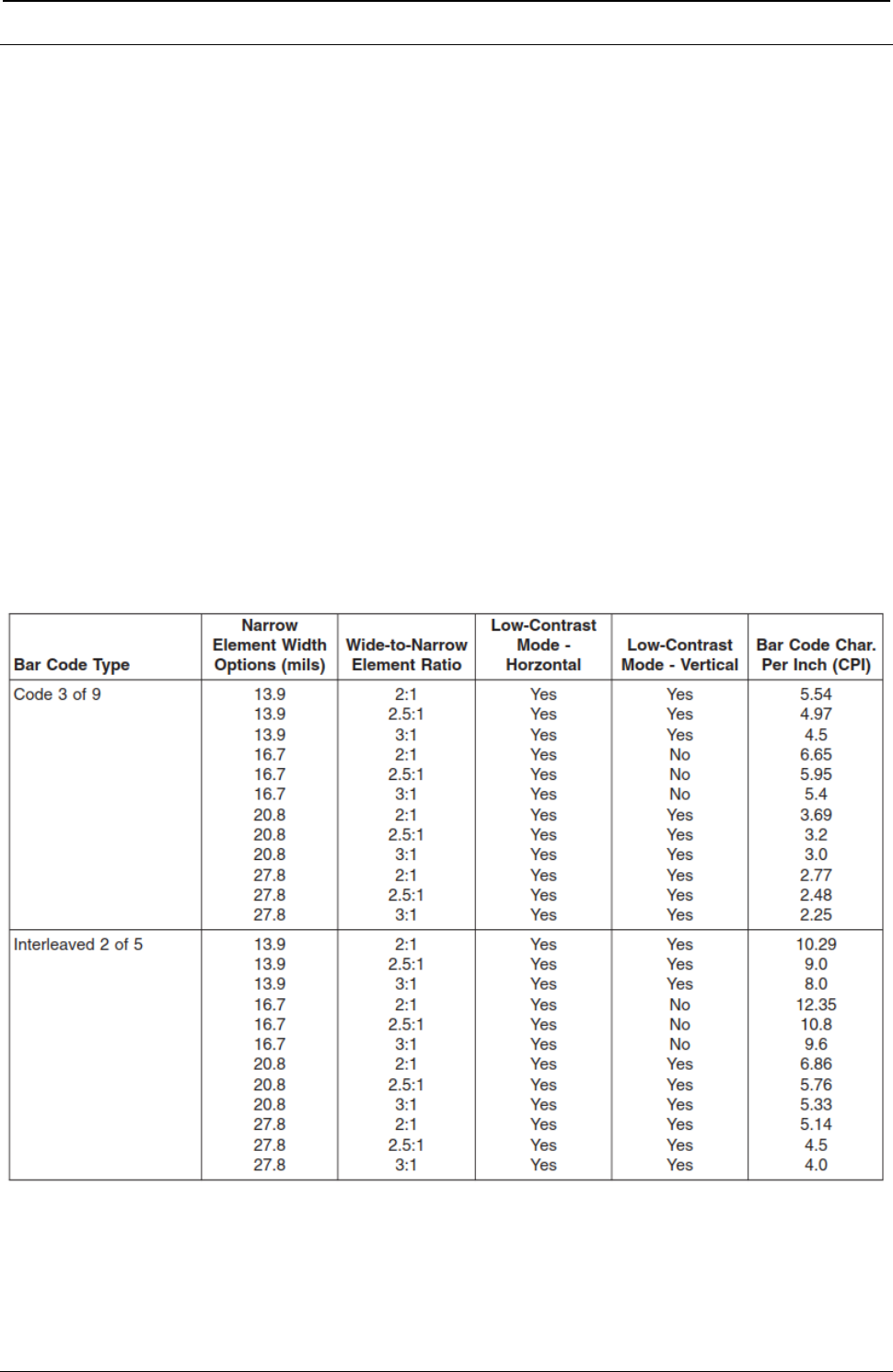
ProgrammerManual PTX‐S828
AppendixH389260071‐001A
Appendix H. S828 Bar Code and OCR Printing Options
This appendix contains information about the options that are available for printing bar codes and Optical
Character Recognition (OCR) characters. The bar code charts detail the element (bar/space) width
options, the wide-to-narrow element ratios, the magnification percentages, and the characters printed per
inch plus whether the bar codes can be printed in low-contrast or high-contrast modes. Low-contrast mode
provides the best throughput, while high-contrast mode results in the best bar code printing quality.
The OCR section contains the Optical Character Recognition symbol subsets that can be printed.
Bar Code Printing Options Charts
Keep the following statements in mind when printing bar codes.
● All bar codes printed by the S828 Printer can print in high-contrast mode. Not all of them, however, can
print in low-contrast mode. If you specify low-contrast mode for a bar code that is not supported in that
mode, the printer will not return an error but will default to high-contrast mode instead.
● Vertically-rotated bar codes may not consistently meet bar/space width specifications. Users should test
for application suitability.
● Bar codes printed in low-contrast mode may not consistently meet specifications. Users should test for
application suitability.
Table 14. Bar Code Printing Options for Non-UPC Family Bar Codes
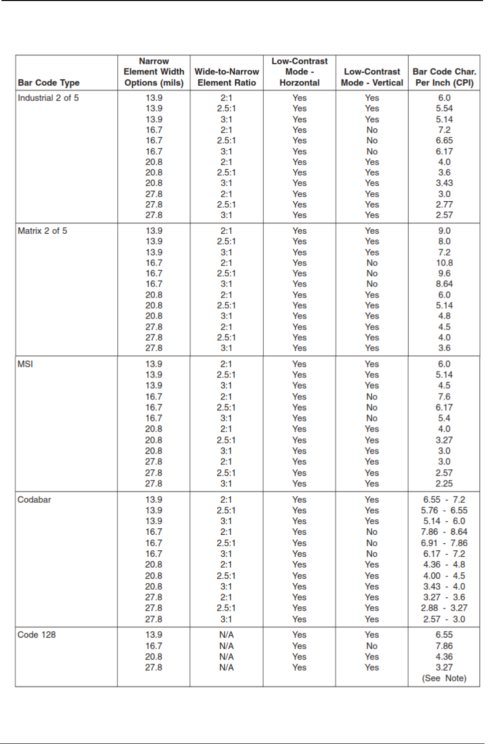
ProgrammerManual PTX‐S828
AppendixH390260071‐001A
Table 14. Bar Code Printing Options for Non-UPC Family Bar Codes (continued)
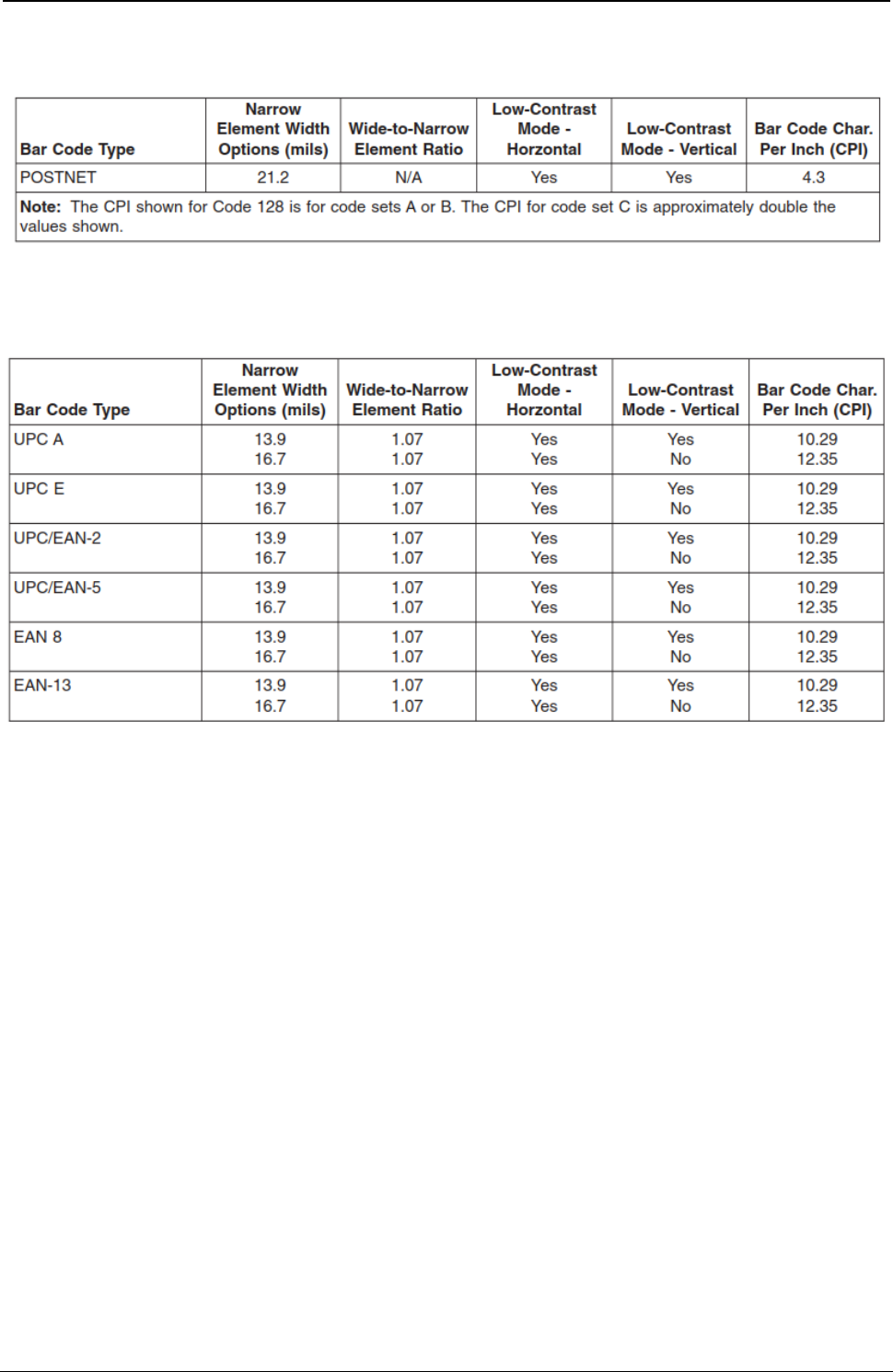
ProgrammerManual PTX‐S828
AppendixH391260071‐001A
Table 14. Bar Code Printing Options for Non-UPC Family Bar Codes (continued)
Table 15. Bar Code Printing Options for UPC Family Bar Codes
Optical Character Recognition (OCR) Printing
OCR Symbols
The S828 prints a comprehensive set of OCR-A and OCR-B characters derived from standards developed
by the International Standards Organization (ISO) and the American National Standards Institute (ANSI).
All OCR character shapes produced by the S828 Printer are not identical with the shapes defined in these
standards. Users should test OCR printing with their scanning equipment to verify satisfactory
performance.
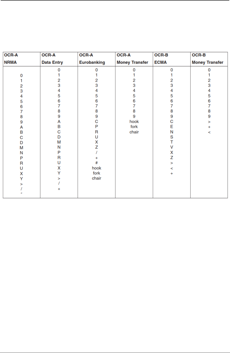
ProgrammerManual PTX‐S828
AppendixH392260071‐001A
OCR Scanning
Printronix Company has tested the following OCR symbol subsets for readability:
Table 16. OCR Symbol Subsets

ProgrammerManual PTX‐S828
AppendixIConfigurationMenuLockout393260071‐001A
Appendix I. Configuration Menu Lockout
Configuration Menu Lockout should be used by the application programmer or printer operator to lock the
Configuration Menu when you want to prevent a casual operator from changing parameter values that
have been set for print jobs.
To set Configuration Menu Lockout:
1. Press ON LINES if the READY indicator is on. The printer goes to the NOT READY state.
2. In the NOT READY state, press and hold ALTERNATE + MACRO + ONLINE keys in the same time.
The printer displays MENU LOCKED.
3. To unlock the Configuration Menu repeat the step 1 and 2. The printer display MENU UNLOCKED.

ProgrammerManual PTX‐S828
AppendixIConfigurationMenuLockout394260071‐001A

ProgrammerManual PTX‐S828
AppendixIConfigurationMenuLockout395260071‐001A
Appendix J. Addendum (Bar Codes)
The following chapter integrates the Bar Code information already present in this manual adding the
Intelligent Mail Barcode explanation with examples in different emulations.
Furthermore it describes some features in specific Emulation Commands present in the firmware but not
described in the previous chapters.
Bar Code Mode
The S828 printer has three different Bar Code Modes selectable in the Power-on Configuration Setup.
1) Native selection enables bar code printing using :
● The Native commands as indicated in chapter 2 and also in this chapter as examples
● MTPL commands as indicated later on in this chapter.
2) Alt.1 selection enables bar code printing using :
● EPSON or IBM commands as indicated in chapter 1.
3) Alt.2 selection enables bar code printing using:
● SEIKOSHA commands as indicated later on in this chapter.
The S828 can print Bar Code using also :
● ANSI commands as indicated in chapter 3 (see example in this chapter)
● IPDS (see example in this chapter)
USPS Intelligent Mail Bar Code 4-state
The S828 can print the USPS Intelligent Mail Bar Code 4-state in different emulations.
The 4-statebarcode data must contains only ASCII numeric (from 0 to 9) and must be converted into only 0,
1, 2 or 3. Each number represents one of the four possible bars.
The Intelligent Mail barcode is a 65-bar Postal Service™ barcode used to sort and track letters and flats. It
allows mailers to use a single barcode to participate in multiple Postal Service programs simultaneously,
expands mailers’ ability to track individual mail pieces, and provides greater mail stream visibility.
The Intelligent Mail barcode consists of a 20-digit tracking code (Barcode Identifier, Service Type Identifier,
Mailer Identifier, and Serial Number) and a Routing Code (ZIP Code™) field of up to 11 digits.
An encoder converts the digits into a 65-character string representing the bars of the IMb® tracking code,
EXAMPLE:
Service Type ID of 270 (First-Class Mail®, Intelligent Mail Full-Service option, with IMb Tracing® service,
no address correction), Mailer ID 123456, uniquely identified by Serial Number 200800001, going to ZIP
Code 98765-4321(01), is encoded like this:
Digit String:
0027012345620080000198765432101
Intelligent Mail barcode encoder > Encoded string (T=Tracker, F=Full Bar, A=Ascender, D=Descender):
TTFAFDADTFFFADTAFAFTTDATDFAAFTDAFDFDFDATFDFTDDDDFADFFDADDTDDTTDAT
More information on website: https://postalpro.usps.com/mailing/intelligent-mail-barcode

ProgrammerManual PTX‐S828
AppendixIConfigurationMenuLockout396260071‐001A
Intelligent Mail Bar Code 4-state with Native Commands Mode
(Native Bar Code Mode)
DC4 DC4 ESC ! h “ f EM
UPPS Bar Code Selection.
ASCII Code DC4 DC4 ESC ! h “ f F r EM
Hexadecimal Value X'14' X'14' X'1B' X'21' h X’22’ f F r X’19’
Decimal Value 20 20 27 33 h 34 f F r 25
h = Bar Code Height at n/6”, 1 < h < 30
f = Readable character printing
f = 0 printing disabled
f = 1 printing enabled, characters below barcode, justified position
f = 21 printing enabled, characters above barcode, justified position
f = 81 printing enabled, characters below barcode, middle position
f = A1 printing enabled, characters above barcode, middle position
F = Font selection for the printable characters
0 Selected font by r value
1 Default font for text
1 Special font for OCR-A o OCR-B bar codes according to the t value
3 Special font for OCR-A bar codes
4 Special font for OCR-B bar codes
r = Bar code rotation
r Selection
0 No rotation
1 Rotation at 0°
2 Rotation at 90°
3 Rotation at 180°
4 Rotation at 270°
EM = Check sequence terminator

ProgrammerManual PTX‐S828
AppendixIConfigurationMenuLockout397260071‐001A
Intelligent Mail Bar Code 4-state with Epson/IBM Emulations Commands
(Alt. 1 Bar Code Mode)
See chapter 1, pages 54, 55 for details of these commands.
Remark: these commands are not handled in DEC emulations.
ESC [ v n m
Sets Barcode parameters. (IBM -Epson)
ASCII Code ESC [ vnm
Hexadecimal Value X'1B' X'5B' X'76' nm
Decimal Value 27 91 118 nm
Set barcode parameters according to the table below. Parameter values that are not supported result in
the command being ignored.
n Parameter Description m values
0 Barcode style IMB 4-state X ‘22’, 34 dec
2 Human readable line 0=disable
1, 21 =enable below barcode
81, A1 =enable above barcode
8 Rotation and HRC font 0.1=no rotation and current font for HRC
2=90 3=180 4=270 and special HRC font
11 HRC font for rotate barcode 3=OCRA 4=OCRB
Intelligent Mail Bar Code 4-state with MTPL Commands
(Native Bar Code Mode)
ESC [ 9 SP k CR
Sets bar code parameters (BC).
ASCII Code ESC [ 9 SP k CR
Hexadecimal Value X'1B' X'5B' X’39’ X'20' X’6B’ X’0D’
Decimal Value 27 91 57 32 109 13
In next pages a specific sub-chapter describes the MTPL (Mannesmann-Tally Printer Language) commands
which can be handled by S828 printer.

ProgrammerManual PTX‐S828
AppendixIConfigurationMenuLockout398260071‐001A
Intelligent Mail Bar Code 4-state with ANSI Emulation Commands
See chapter 3, pages 86 and 87 for details of these commands.
ESC [ p1; ; ; pn }
Sets bar code parameters (BC).
ASCII Code ESC [ p1; pn }
Hexadecimal Value X'1B' X'5B' p1 X'3B' pn X'7D'
Decimal Value 27 91 p1 59 pn 125
This command allows selection of the bar code characteristics such as style height, symbol rotation and so
on. The command ESC [3 t enables the bar code mode while ESC [0 t disables the mode.
p1: Bar code style
p1 FUNCTION
X ’33 34’, dec 48 49 IMB 4-state
p3: Human Readable Input (HRI)
p3 FUNCTION
0 Disables printing of the HRI
1 Enables printing of the HRI
p9: Rotation
p9 FUNCTION
0 0 degrees using current font
1 0 degrees using special HRI font
2 90 degrees using special HRI font
3 180 degrees using special HRI font
4 270 degrees using special HRI font
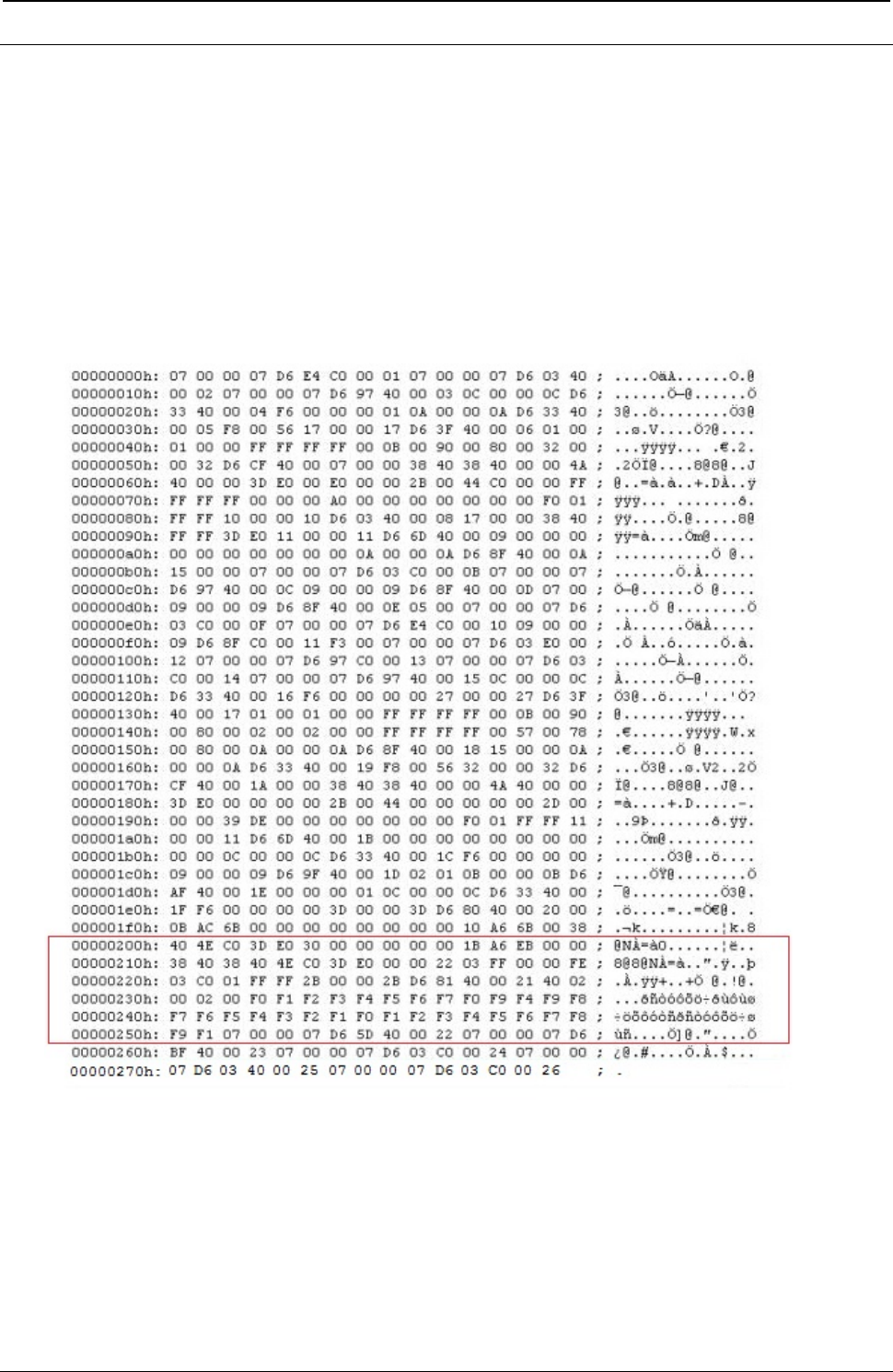
ProgrammerManual PTX‐S828
AppendixIConfigurationMenuLockout399260071‐001A
Intelligent Mail Bar Code 4-state with IPDS Emulation Commands
See chapter 5, pages 196 to 208 for details of these commands.
The BCDD (Bar Code Data Descriptor) has only one byte changed:
Decimal Hex Content Description
16 10 Bar Code Type
22 USPS Four.State Bar Code
Figure 147. Hex Dump of Intelligent Mail Bar Code in IPDS Commands Example
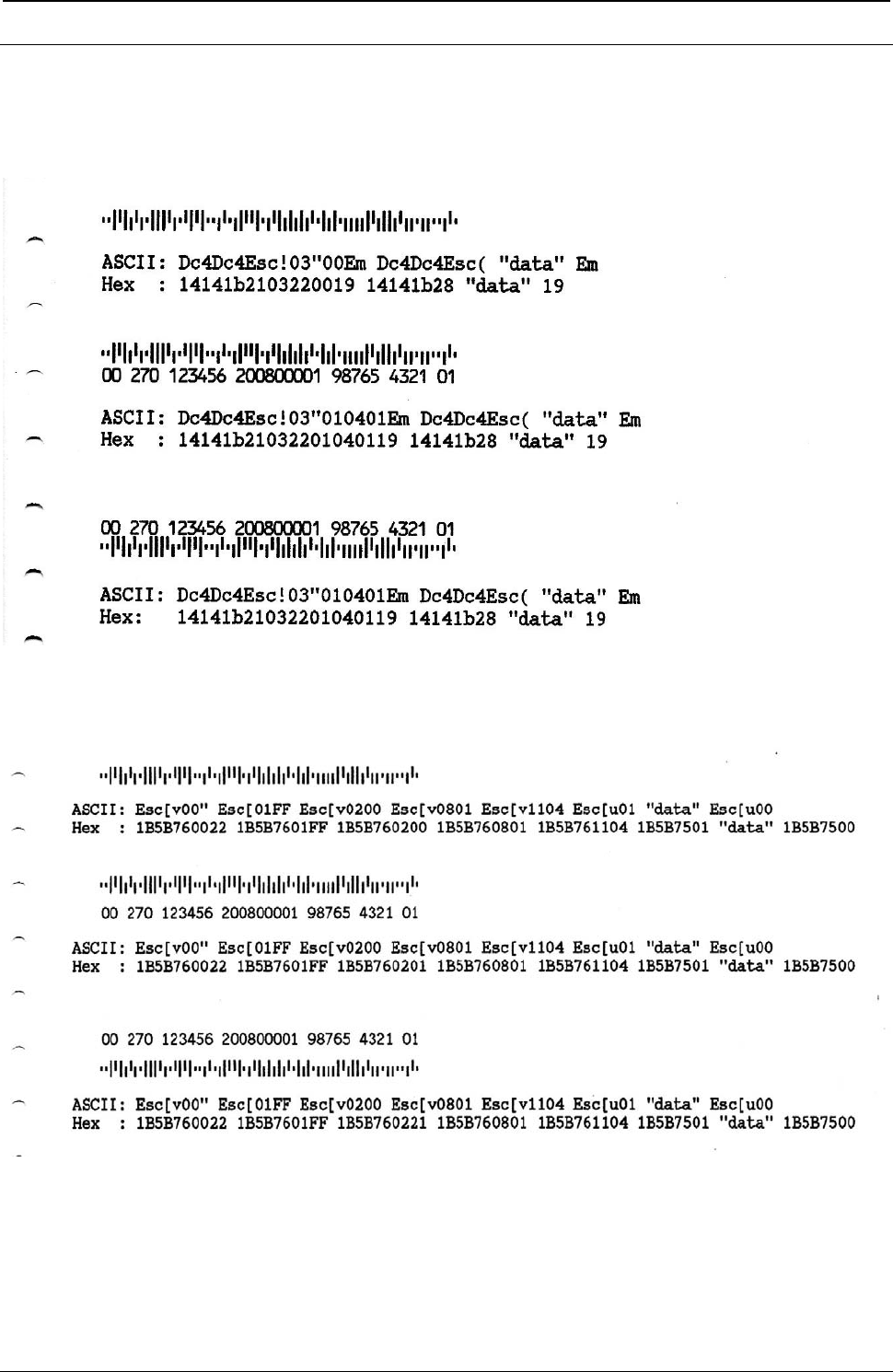
ProgrammerManual PTX‐S828
AppendixIConfigurationMenuLockout400260071‐001A
USPS Intelligent Mail Bar Code 4-state Examples
The following are samples for USPS Intelligent Mail Bar Code 4-state printed with the S828 Printer with
related hex commands:
Figure 148. Intelligent Mail Bar Code in Native Commands Example (Bar Code Mode Native)
Figure 149. Intelligent Mail Bar Code in Epson/IBM Commands Example (Bar Code Mode Alt. 1)
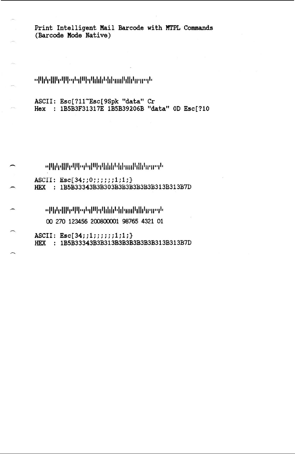
ProgrammerManual PTX‐S828
AppendixIConfigurationMenuLockout401260071‐001A
Figure 150. Intelligent Mail Bar Code in ANSI Commands Example
Figure 151. Intelligent Mail Bar Code in MTPL Commands Example (Bar Code Mode Alt. 1)
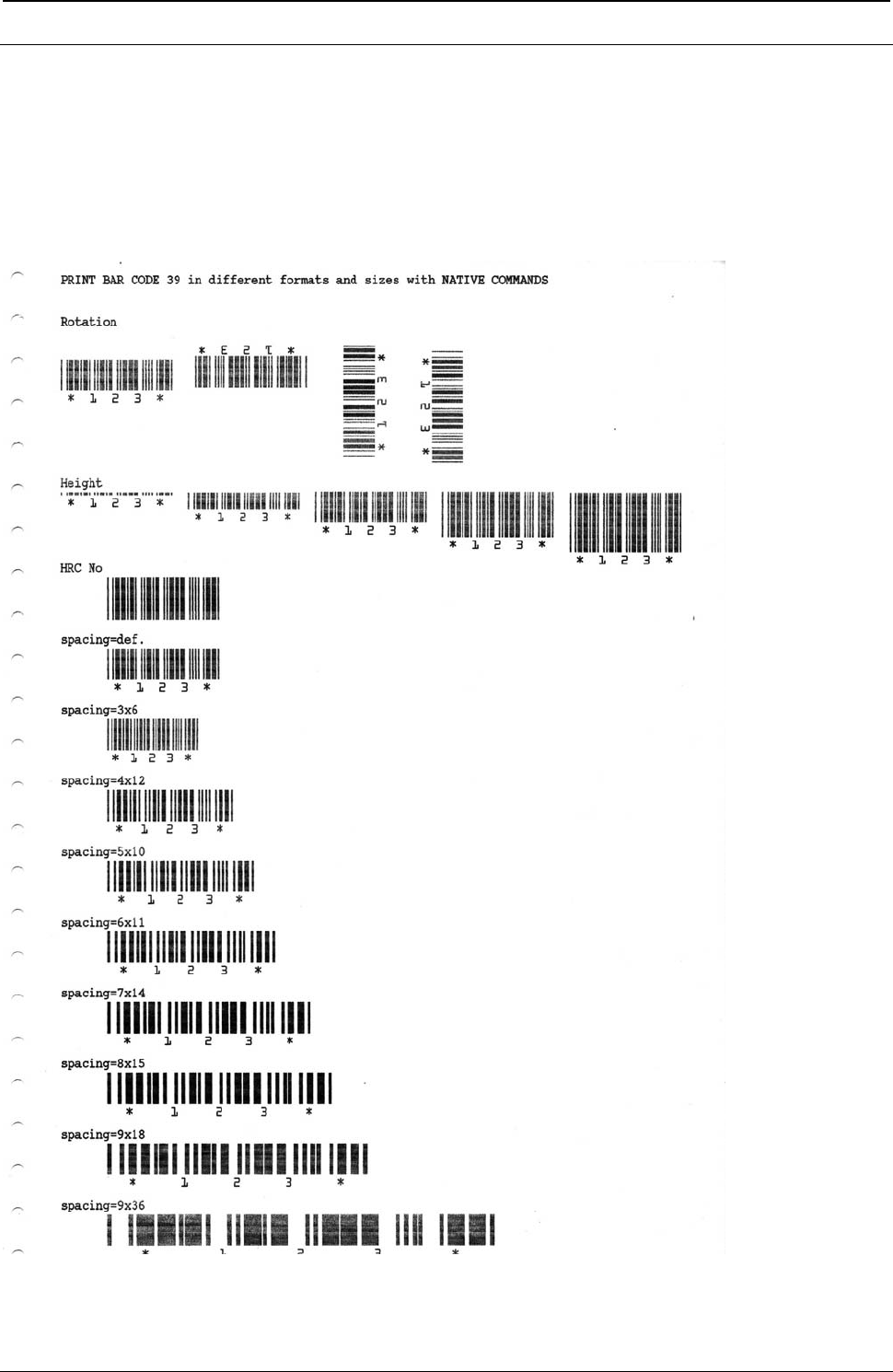
ProgrammerManual PTX‐S828
AppendixIConfigurationMenuLockout402260071‐001A
Bar Codes handled in NATIVE Commands
(Native Bar Code Mode)
The S828 integrates in the firmware the handling of the Bar Codes with the NATIVE commands.
The complete and detailed information for these commands can be found on chapter 2 of this Programmer
Manual. Here are reported some examples how these commands work.
Figure 152. Bar Code Examples with NATIVE Commands Example (Bar Code Mode Native)
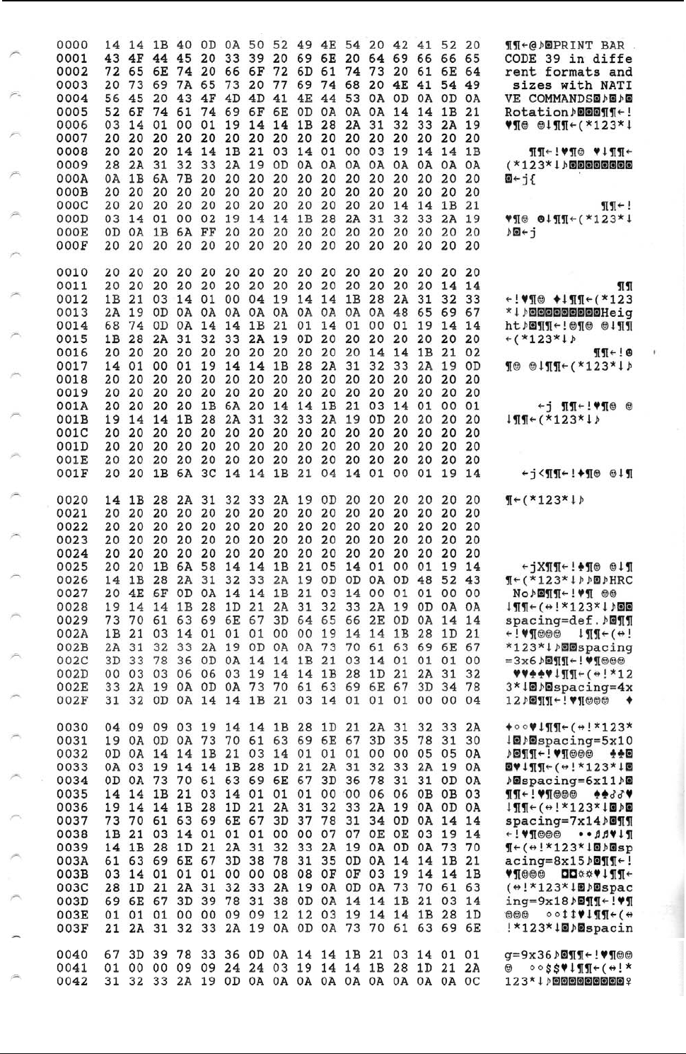
ProgrammerManual PTX‐S828
AppendixIConfigurationMenuLockout403260071‐001A
Figure 153. Hex Dump of example on figure 151
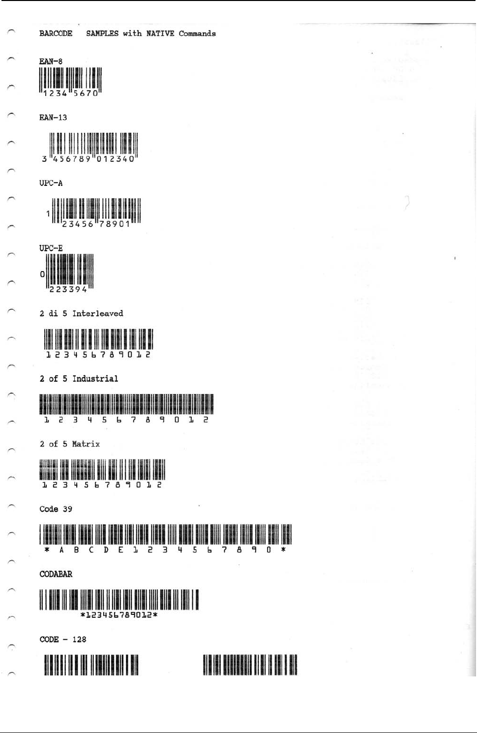
ProgrammerManual PTX‐S828
AppendixIConfigurationMenuLockout404260071‐001A
Figure 154. Bar Code Examples with NATIVE Commands Example (Bar Code Mode Native)
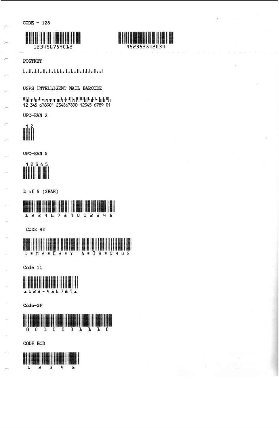
ProgrammerManual PTX‐S828
AppendixIConfigurationMenuLockout405260071‐001A
Figure 155. Bar Code Examples with NATIVE Commands Example (Bar Code Mode Native)
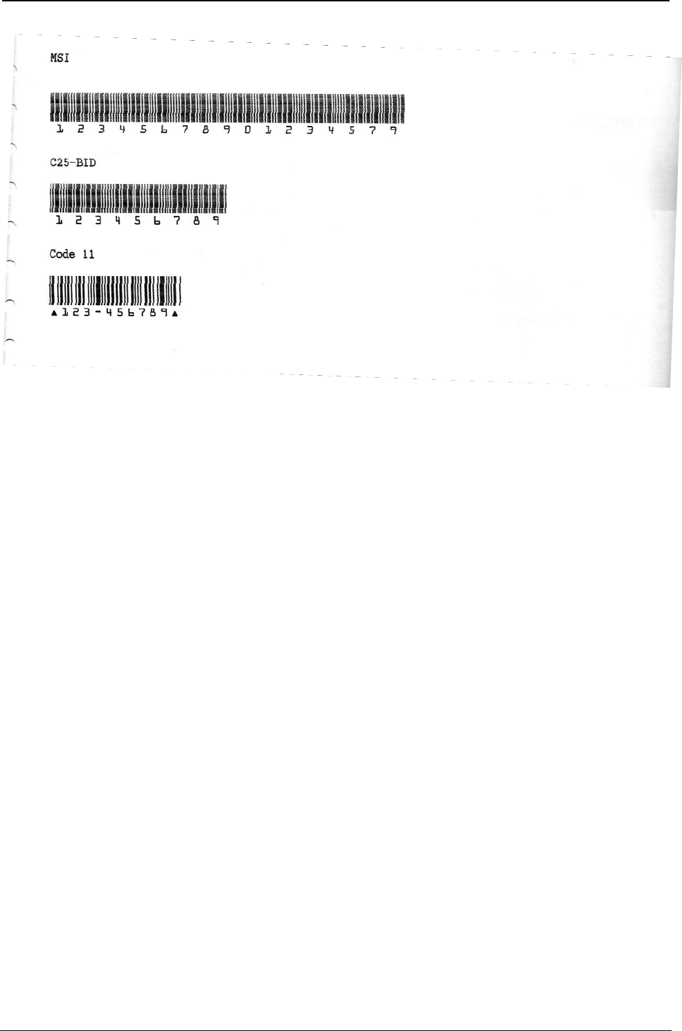
ProgrammerManual PTX‐S828
AppendixIConfigurationMenuLockout406260071‐001A
Figure 156. Bar Code Examples with NATIVE Commands Example (Bar Code Mode Native)
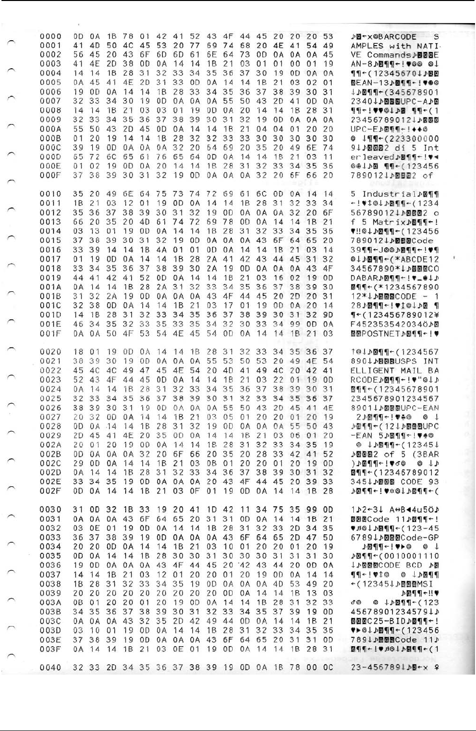
ProgrammerManual PTX‐S828
AppendixIConfigurationMenuLockout407260071‐001A
Figure 157. Hex Dump of example on figures 154, 155, 156

ProgrammerManual PTX‐S828
AppendixIConfigurationMenuLockout408260071‐001A
Bar Codes handled in MTPL Commands
(Native Bar Code Mode)
The S828 integrates in the firmware a sub-set handling of the MTPL emulation Bar Codes commands.
The complete and detailed information for these commands can be found on specific MTPL Programmer
Manual available on web.
Bar Code Description
Before the data, which contain the Barcode information, are transmitted to the printer, the Barcode header
must be sent. Otherwise the standard parameter values are used (see section "Header Format"). In the
header, the printing parameters, the Barcode size and the Barcode Type are de-fined. This header only
needs to be transferred once, unless settings are to be changed or the printer has been turned off.
Header Format Format: SUB [F] a [n] [;xyz] [;p] EM
[ ] Specification is optional
x, y unregarded at EAN/UPC-Barcode!
For Code 128 and EAN 128 (Type S+T) only the X parameter is valid. This is automatically used for the Y
parameter. The Z parameter is not evaluated.
Meaning of the characters:
SUB (hex.1A, dec.26) Start header
F Print feature
SP (hex. 20, dec. 32): HRI OFF, Normal Print, Double Pass, Unidirectional (def.)
! (hex. 22, dec. 34): HRI ON, Normal Print, Double Pass, Unidirectional
a ASCII a = "A"..."S" Barcode Types (def. “A”, see later on)
n ASCII n = "0"..."90" Barcode height in n/6 inch. At n="0" the Barcode height equals to 1/12 inch. (def. 1)
; ASCII Separation character
x ASCII x = "0"..."3" Width of the narrow bar (def.0 )
y ASCII y = "0"..."3" Width of the narrow space (def.0 )
z ASCII z = "0"..."3" Ratio of wide to narrow (def.0 )
p ASCII p = "0"…"9" Barcode orientation (def. 0, horizontal)
EM (hex.19, dec.25) End of header
Barcode Types
A = 2/5 matrix (default) B = 2/5 industrial C = 2/5 interleaved
D = Code 11 E = Code BCD matrix F = Code 39
G = Codabar H = EAN 8 with HRI I = EAN 8 without HRI
J = 2/5 matrix (default) K = EAN 13 with HRI L = EAN 13 without HRI
M = MSI/modified Plessey N = UPC A with HRI O = UPC A without HRI
P = UPC E with HRI Q = UPC E without HRI S = Code 128
T = EAN 128/GSI-128
Post Office Barcode Types
US Postnet Barcode = ESC [ 1 SP p
Planet Barcode = ESC [ 2 SP p <data> EM
KIX Barcode = ESC [ 2 SP k
Royal Mail Customer Barcode = ESC [ 1 SP k
USPS Intelligent Mail Barcode (IMB) = ESC [ 9 SP k
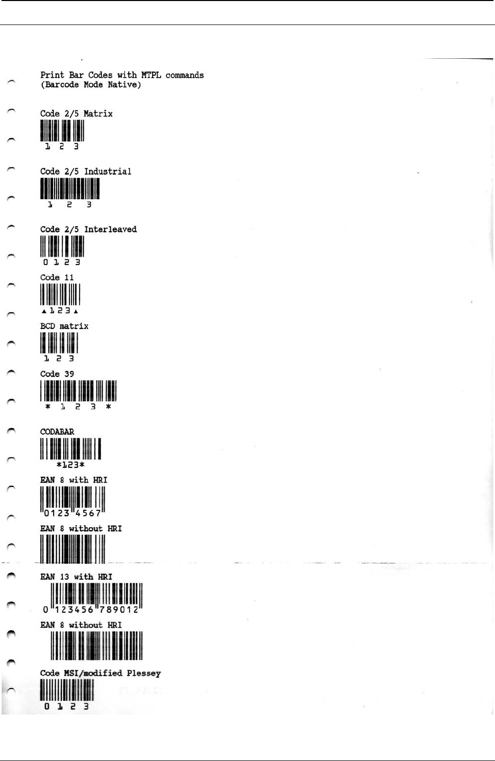
ProgrammerManual PTX‐S828
AppendixIConfigurationMenuLockout409260071‐001A
MTPL Bar Codes Commands Examples
Figure 158. Bar Code Examples with MTPL Commands (Bar Code Mode Alt. 1)
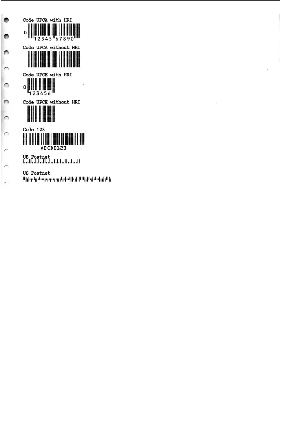
ProgrammerManual PTX‐S828
AppendixIConfigurationMenuLockout410260071‐001A
Figure 159. Bar Code Examples with MTPL Commands (Bar Code Mode Alt. 1)
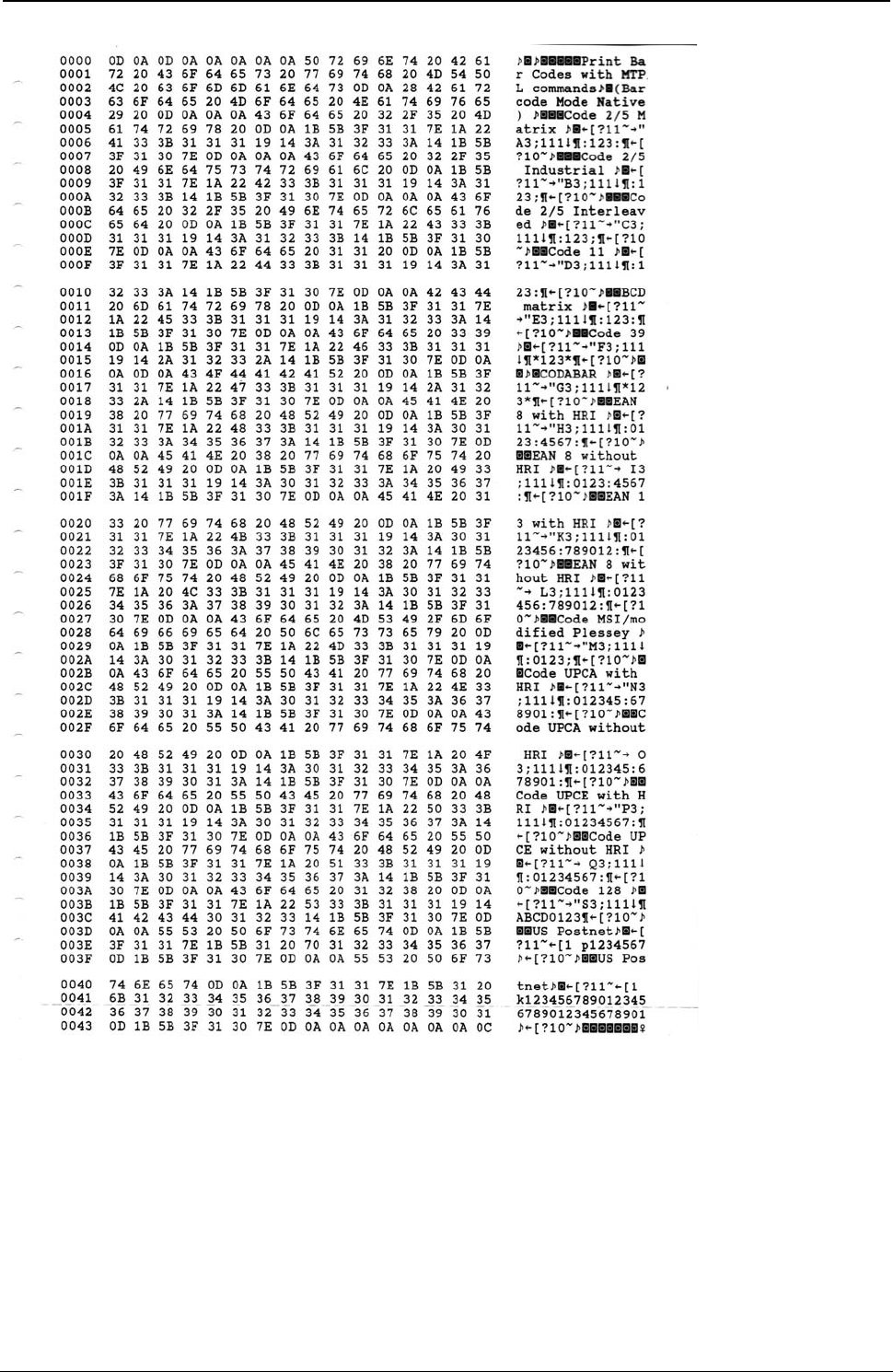
ProgrammerManual PTX‐S828
AppendixIConfigurationMenuLockout411260071‐001A
Figure 160. Hex Dump of example on figures 158, 159

ProgrammerManual PTX‐S828
AppendixIConfigurationMenuLockout412260071‐001A
Bar Codes handled in SEIKOSHA Commands
(Alt. 2 Bar Code Mode)
The S828 partially integrates in the firmware a sub-set handling of the SEIKOSHA BP-9000 Bar Codes
specific commands.
The complete and detailed information for these can be found in specific SEIKOSHA BP-9000 programmer
manual available on web.
# Function Bar Code Commands
1. Bar code type DC4 DC4 T n
2. Element width DC4 DC4 E n1 n2
3. Bar code height DC4 DC4 H n
4. Setting HRI on and off DC4 DC4 I n
5. HRI font DC4 DC4 F n
6. Check character DC4 DC4 C n
7. Starting the bar code data sequence ESC SI
8. Ending the bar code data seqence ESC SO
9. Bar code data sequence DC4 DC4 B n d1 d2 ... dk
10. Printing density DC4 DC4 D n
11. Guard bar expansion DC4 DC4 G n
12. Start and stop characters DC4 DC4 N n1 n2
13. Bar code rotational angle DC4 DC4 R n
14. Disabling HRI of the start and stop characters DC4 DC4 S n
15. Value input mode DC4 DC4 V n
16. Initializing the bar code mode DC4 DC4 @
Bar Code Type (n)
0 Industrial 2 of 5 5 Code39 10 UPC-A
1 Interleaved 2 of 5 6 Code93 11 UPC-E
2 Matrix 2 of 5 7 Code128 12 Postnet
3 Codabar 8 EAN-8
4 Code11 9 EAN-13
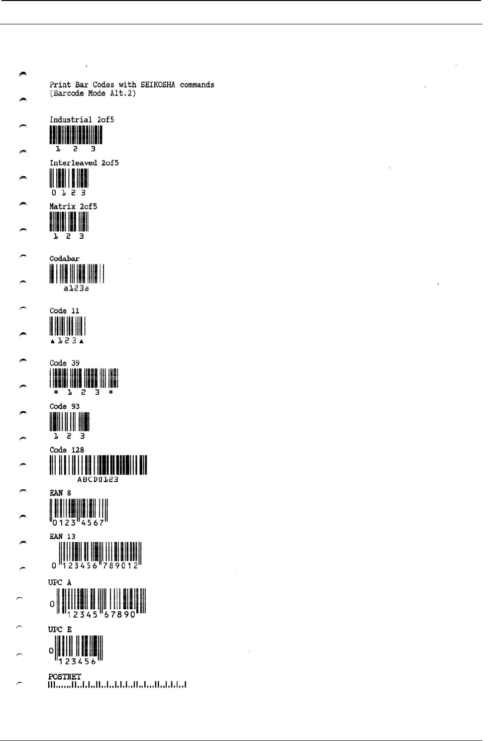
ProgrammerManual PTX‐S828
AppendixIConfigurationMenuLockout413260071‐001A
SEIKOSHA Commands Bar Codes Examples
Figure 161. Bar Code Examples with SEIKOSHA Commands (Bar Code Mode Alt. 1)
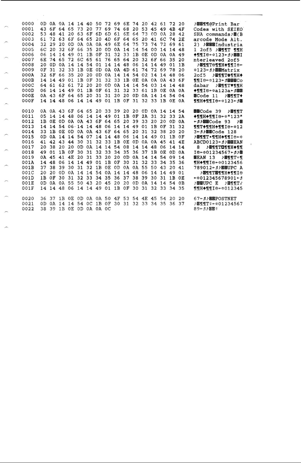
ProgrammerManual PTX‐S828
AppendixIConfigurationMenuLockout414260071‐001A
Figure 162. Hex Dump of example on figure 161

ProgrammerManual PTX‐S828
Notices415260071‐001A
Notices
These terms are trademarks or registered trademarks of Ricoh Co., Ltd., in the United States, other
countries, or both:
● IBM
● Infoprint Solutions
● Ricoh
● Advanced Function Printing
● AFP
● Intelligent Printer Data Stream
● IPDS
These terms are trademarks or registered trademarks of International Business Machines Corporation in
the United States, other countries, or both:
● AIX
● AS400
● i5/OS
● IBM
● iSeries
● MVS
● OS/400
● Print Services Facility
● PSF
● System i
● z/OS
● zSeries
Adobe, the Adobe logo, PostScript, and the PostScript logo are either registered trademarks or trademarks
of Adobe Systems Incorporated in the United States and/or other countries.
Intel, Intel Inside (logos), MMX, and Pentium are trademarks of Intel Corporation in the United States,
other countries, or both.
Java and all Java-based trademarks and logos are trademarks or registered trademarks of Sun
Microsystems, Inc. in the U.S. and other countries.
Linux is a registered trademark of Linus Torvalds in the United States, other countries, or both.
Microsoft, Windows, Windows NT, and the Windows logo are trademarks of Microsoft Corporation in the
United States, other countries, or both.
UNIX is a registered trademark of The Open Group in the United States and other countries.
Other company, product, or service names may be trademarks or service marks of others.

ProgrammerManual PTX‐S828
Notices416260071‐001A
This page is intentionally left blank.

ProgrammerManual PTX‐S828
Notices417260071‐001A
This page is intentionally left blank.

ProgrammerManual PTX‐S828
Notices418260071‐001A
This page is intentionally left blank.
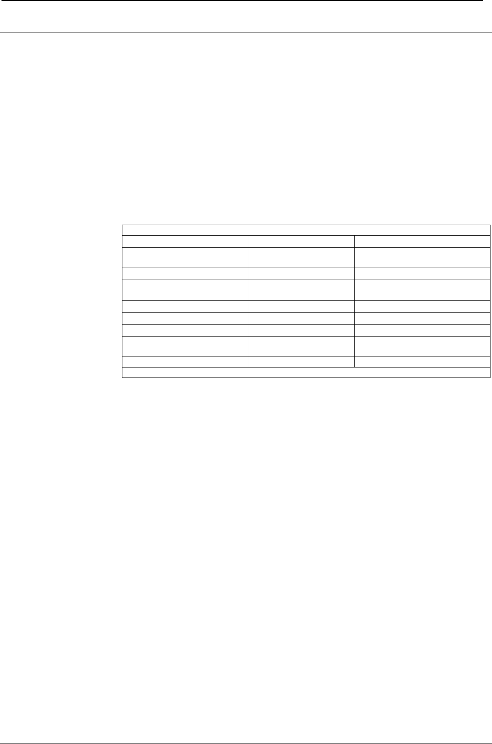
ProgrammerManual PTX‐S828
CustomerSupport419260071‐001A
Customer Support
Printronix Customer Support Center
IMPORTANT Please have the following information available prior to calling the Printronix
Customer Support Center:
• Model number
• Serial number (located on the back of the printer)
• Installed options (i.e., interface and host type if applicable to the problem)
• Configuration printout:
Press the ON LINE ke
y
to take the
p
rinter OFF LINE
Press the PROGRAM ke
y
PRINT OUT? NO Is displayed
Press the → ke
y
PRINT OUT? YES The PROGRAM SETUP
PRINTOUT is printed
Press the ↓ key until PRINT STATS? NO Is displayed
Press the → ke
y
PRINT OUT? YES The USAGE STATISTICS
DATA PRINTOUT is printed
Press the ↓ key until CONFIG MENU NO Is displayed
Press the → key to displa
y
CONFIG MENU YES
Press the ↓ ke
y
PRINT OUT? NO Is displayed
Press the → ke
y
PRINT OUT? YES The CONFIGURATION
SETUP PRINTOUT is
p
rinted
Press the PROGRAM ke
y
Press the TEAR ke
y
and tear off the
p
rintout at the
p
erforation
• Is the problem with a new install or an existing printer?
• Description of the problem (be specific)
• Good and bad samples that clearly show the problem (faxing or emailing these samples
may be required)
Americas (714) 368-2686
Europe, Middle East, and Africa (31) 24 6489 311
Asia Pacific (65) 6548 4114
China (86) 800-999-6836
http://www.printronix.com/support.aspx
Printronix Supplies Department
Contact the Printronix Supplies Department for genuine Printronix supplies.
Americas (800) 733-1900
Europe, Middle East, and Africa (33) 1 46 25 19 07
Asia Pacific (65) 6548 4100
China (86) 400-886-5598
http://www.printronix.com/supplies-parts.aspx

ProgrammerManual PTX‐S828
CustomerSupport420260071‐001A
Corporate Offices
Printronix, LLC.
6440 Oak Canyon Rd, Suite 200
Irvine, CA 92618
U.S.A.
Phone: (714) 368-2300
Fax: (714) 368-2600
Printronix Inc.
c/o Printronix Nederland BV
Bijsterhuizen 11-38
6546 AS Nijmegen
The Netherlands
Phone: (31) 24 6489489
Fax: (31) 24 6489499
Printronix Schweiz GmbH
3Changi Business Park Vista
#04-05 AkzoNobelHouse
Singapore 486051
Phone: (65) 6548 4100
Fax: (65) 6548 4111
Printronix Commercial (Shanghai) Co. Ltd
Room 903, 9thFloor
No. 199, North Xizang Road
200070 Shanghai P.R. China
Phone: (86) 400 886 5598
Fax: (8621) 61171256
Printronix India PvtLtd
B-808/809, BSEL Tech Park 8thFloor, Sector 30A
VashaiNaviMumbai 400705 India
Toll Free No.: 1800 102 7896 Fax: (9211) 4158 5555
Visit the Printronix web site at www.printronix.com
SPECIFICATIONS ARE SUBJECT TO CHANGE WITHOUT NOTICE.
This manual refers to various company and products by their trade names.
In most of the cases, these designations are claimed as trademarks or
registered tramarkers by their respective companies.
Copyright 2017 PRINTRONIX s.r.l. - Printed in Italy
260071-001A
