PTX_PRM_VGL_T5r_254079B PTX PRM VGL T5r 254079B
PTX_PRM_VGL_T5r_254079B PTX_PRM_VGL_T5r_254079B
PTX_PRM_VGL_T5r_254079B PTX_PRM_VGL_T5r_254079B
PTX_PRM_VGL_T5r_254079B PTX_PRM_VGL_T5r_254079B
User Manual: PTX_PRM_VGL_T5r_254079B
Open the PDF directly: View PDF ![]() .
.
Page Count: 418 [warning: Documents this large are best viewed by clicking the View PDF Link!]
- 1 Overview
- 2 Commands
- Modes of Operation
- VGL Command Standards
- Normal Mode
- Graphics Mode
- Command Codes
- Graphics Mode Enable Commands
- Standard Graphics Commands
- Extended Graphics Commands
- Extended Graphics/High Resolution Commands
- Alphanumerics
- Boxes
- Carriage Return
- Character Height
- Character Width
- Character Type
- Compressed Print
- Dark Print
- Descending Characters
- Direct Printer Commands
- Dot Slew
- Duplication, Horizontal
- Duplication, Horizontal (Version II)
- Duplication, Vertical
- Duplication, Vertical (Version II)
- Dynamic Form Commands
- Electronic Vertical Format Unit (EVFU)
- Emphasized Print
- Emulation Switch
- Font Load
- Font, Selecting Default (Version II)
- Fonts, Rotatable
- Fonts, Compressed Print Density
- Form Feed
- Form Length
- Forms Construction
- Forms, Creating Dynamic (Version II)
- Forms, Deleting Dynamic (Version II)
- Forms, Executing Dynamic (Version II)
- Forms, Listing Dynamic (Version II)
- Forms, Predefined (Version II)
- Forms, Resetting Dynamic (Version II)
- Free Format (Enable/Disable)
- Free Format Enable, Non-Graphics
- Free Format Disable, Non-Graphics
- Graphics Mode Enable
- Graphics Mode Disable
- Hex Dump
- Ignore Data
- Interrupt
- Justification, Vertical
- Line Feed
- Line Slew
- Line Spacing
- Lines, Dashed
- Lines, Solid
- Logo Generation (Version II)
- Logo, PCX
- Logo, TIFF
- Page, Controlling Paper Options (Version II)
- Passing Hex Values
- Pixel Expansion (Version II)
- Plotting Bitmap Images
- Plotting Graphics (Columns)
- Plotting Graphics (Rows)
- Reset
- Reverse Print
- Scaling
- Shading
- Shading Mask
- Special Function Control Code Change
- Symbols, Creating Standard User Defined
- Symbols, Creating Expanded User Defined
- Symbols, Printing
- Tab, Horizontal
- Tab, Vertical
- Underlined Print
- Wait For Online
- 3 Barcodes
- 4 Exercises And Examples
- 5 Multinational And International Character Sets
- 6 Error Codes
- A Standard ASCII Character Set
- B Shading Masks
- C Grid Samples
- D Page Boundaries
- E PTX_SETUP Option
- F VGL Command Support on L7032 Printers
- G Glossary
- H Contact Information

IGP
®
/VGL Emulation for Thermal Printers
Code V
TM
Graphics Language
Programmer’s Reference Manual

IGP®/VGL Emulation for Thermal Printers
Code V™ Graphics Language
Programmer’s Reference Manual
Printronix, Inc. makes no representations or warranties of any kind regarding
this material, including, but not limited to, implied warranties of
merchantability and fitness for a particular purpose. Printronix, Inc. shall not
be held responsible for errors contained herein or any omissions from this
material or for any damages, whether direct, indirect, incidental or
consequential, in connection with the furnishing, distribution, performance or
use of this material. The information in this manual is subject to change
without notice.
This document contains proprietary information protected by copyright. No
part of this document may be reproduced, copied, translated or incorporated
in any other material in any form or by any means, whether manual, graphic,
electronic, mechanical or otherwise, without the prior written consent of
Printronix, Inc.
COPYRIGHT © 2000, 2012, PRINTRONIX, INC.
All rights reserved.

Trademark Acknowledgements
IBM and IBM PC are registered trademarks of the International Business
Machines Corp.
HP and PCL are registered trademarks of Hewlett-Packard Company.
IGP, LinePrinter Plus, and Printronix are registered trademarks and LaserLine
and PSA are trademarks of Printronix, Inc.
QMS is a registered trademark and Code V is a trademark of Quality Micro
Systems, Inc.
CSA is a registered certification mark of the Canadian Standards Association.
TUV is a registered certification mark of TUV Rheinland of North America, Inc.
UL is a registered certification mark of Underwriters Laboratories, Inc.
This product uses Intellifont Scalable typefaces and Intellifont technology.
Intellifont is a registered trademark of Agfa Division, Miles Incorporated
(Agfa).
CG Triumvirate are trademarks of Agfa Division, Miles Incorporated (Agfa).
CG Times, based on Times New Roman under license from The Monotype
Corporation Plc is a product of Agfa.
Table of Contents
1 Overview............................................................... 13
About this Manual ...................................................................................13
Warnings and Special Information ...................................................13
Features..................................................................................................14
Online Form and Label Generation..................................................14
Variable Barcodes............................................................................14
Expanded and Compressed Print ....................................................14
Rotated Alphanumerics....................................................................14
Logos ...............................................................................................15
Reversed and Shaded Print .............................................................15
Automatic Increment/Decrement Capability.....................................15
Multinational and International Character Sets ................................15
New or Different Features for the VGL ...................................................15
Modes of Operation ................................................................................16
Normal Mode....................................................................................16
Graphics Mode.................................................................................16
Extended Graphics Mode.................................................................16
Extended Graphics/High Resolution Mode ......................................17
Configuring VGL with the Control Panel.................................................17
2 Commands............................................................ 19
Modes of Operation ................................................................................19
VGL Command Standards......................................................................20
Special Function Control Code (SFCC) ...........................................21
Command Sequence .......................................................................21
Command Parameters .....................................................................21
Brackets ...........................................................................................21
Spaces .............................................................................................22
Comma.............................................................................................22
Terminator........................................................................................22
Character Height, Width, and Intercharacter Spacing......................23
Normal Mode ..........................................................................................23
Graphics Mode .......................................................................................24
Data Positioning ...............................................................................24

Table of Contents
Command Codes....................................................................................26
Graphics Mode Enable Commands .................................................26
Standard Graphics Commands........................................................27
Extended Graphics Commands .......................................................29
Extended Graphics/High Resolution Commands.............................31
Alphanumerics .................................................................................32
Boxes ...............................................................................................39
Carriage Return................................................................................41
Character Height ..............................................................................42
Character Width ...............................................................................44
Character Type ................................................................................46
Compressed Print ............................................................................47
Dark Print .........................................................................................49
Descending Characters....................................................................51
Direct Printer Commands.................................................................53
Dot Slew...........................................................................................54
Duplication, Horizontal .....................................................................54
Duplication, Horizontal (Version II)...................................................56
Duplication, Vertical .........................................................................57
Duplication, Vertical (Version II).......................................................63
Dynamic Form Commands ..............................................................65
Electronic Vertical Format Unit (EVFU)............................................73
Emphasized Print .............................................................................76
Emulation Switch..............................................................................77
Font Load .........................................................................................77
Font, Selecting Default (Version II) ..................................................78
Fonts, Rotatable...............................................................................82
Fonts, Compressed Print Density ....................................................85
Form Feed........................................................................................88
Form Length.....................................................................................89
Forms Construction..........................................................................90
Forms, Creating Dynamic (Version II)..............................................93
Forms, Deleting Dynamic (Version II) ..............................................94
Forms, Executing Dynamic (Version II)............................................94
Forms, Listing Dynamic (Version II) .................................................95
Forms, Predefined (Version II) .........................................................95
Forms, Resetting Dynamic (Version II) ............................................99
Free Format (Enable/Disable)..........................................................99
Free Format Enable, Non-Graphics ...............................................101
Free Format Disable, Non-Graphics ..............................................102
Graphics Mode Enable...................................................................103
Graphics Mode Disable..................................................................104

Table of Contents
Hex Dump ......................................................................................104
Ignore Data ....................................................................................105
Interrupt..........................................................................................106
Justification, Vertical ......................................................................108
Line Feed .......................................................................................110
Line Slew........................................................................................111
Line Spacing ..................................................................................111
Lines, Dashed ................................................................................113
Lines, Solid.....................................................................................116
Logo Generation (Version II)..........................................................118
Logo, PCX......................................................................................120
Logo, TIFF......................................................................................121
Page, Controlling Paper Options (Version II) .................................122
Passing Hex Values .......................................................................124
Pixel Expansion (Version II) ...........................................................125
Plotting Bitmap Images ..................................................................127
Plotting Graphics (Columns) ..........................................................129
Plotting Graphics (Rows)................................................................132
Reset..............................................................................................135
Reverse Print .................................................................................136
Scaling ...........................................................................................138
Shading ..........................................................................................140
Shading Mask ................................................................................142
Special Function Control Code Change.........................................144
Symbols, Creating Standard User Defined ....................................145
Symbols, Creating Expanded User Defined...................................148
Symbols, Printing ...........................................................................150
Tab, Horizontal...............................................................................151
Tab, Vertical ...................................................................................155
Underlined Print .............................................................................156
Wait For Online ..............................................................................157
3 Barcodes............................................................. 159
Overview...............................................................................................159
Examples .......................................................................................160
Barcode Size/Height Requirements ...............................................160
Barcode Command Format ..................................................................162
Standard Barcode Command Format ............................................163
IBARC, (Version II) Barcode Command Format ............................164

Table of Contents
Barcodes...............................................................................................167
Australian 4-State...........................................................................169
BC412 Barcode..............................................................................174
Codabar .........................................................................................178
Code 39..........................................................................................184
Code 93..........................................................................................191
Code 128........................................................................................195
EAN 8.............................................................................................204
EAN 13...........................................................................................209
German Interleaved 2/5 .................................................................214
GS1-128.........................................................................................219
GS-1 Data Matrix ...........................................................................230
Identicon.........................................................................................239
Intelligent Mail 4-State Barcode .....................................................242
Interleaved 2/5 ...............................................................................244
Maxicode........................................................................................249
MSI.................................................................................................254
PDF417 ..........................................................................................260
Planet .............................................................................................264
POSTNET ......................................................................................269
Royal Mail ......................................................................................273
Telepen ..........................................................................................275
UPC-A ............................................................................................280
UPC-E ............................................................................................285
UPCSHIP .......................................................................................293
UPS 11...........................................................................................297
4 Exercises And Examples .................................... 301
Practice Using VGL ..............................................................................301
Practice Graphic Exercise - Normal Resolution .............................302
Practice Graphic Exercise - High Resolution .................................306
Form Example ......................................................................................311
Page Layout Considerations ..........................................................311
Planning the Form Layout ..............................................................311
Label Example......................................................................................328
Solving Program Errors ........................................................................336

Table of Contents
5 Multinational And International Character
Sets..................................................................... 337
Multinational Character Sets.................................................................337
Character Addresses .....................................................................338
Making Character Substitutions .....................................................338
Accessing Characters and Character Sets...........................................341
Data Bit 8 .......................................................................................341
Power-Up Character Set Selection ................................................341
Building a Character Translation Table..........................................341
Resetting the Character Set...........................................................342
User-Defined Set Command ..........................................................343
Character Set Selection Command................................................345
Selecting an ISO Character Set .....................................................348
Multinational Character Set Charts ................................................349
International Character Sets.................................................................353
6 Error Codes......................................................... 355
The Purpose of Error Codes.................................................................355
Error Codes ..........................................................................................355
A Standard ASCII Character Set............................ 361
B Shading Masks ................................................... 363
Selecting Masks....................................................................................363
C Grid Samples ...................................................... 375
D Page Boundaries ................................................ 379
Paper Selection and Maximum Values.................................................379
Setting Top/Bottom Margins...........................................................380
Setting Left Margins .......................................................................381
E PTX_SETUP Option ........................................... 383
Overview...............................................................................................383
The PTX_SETUP Commands ..............................................................383
Commands.....................................................................................384
F VGL Command Support on L7032 Printers ........ 391
G Glossary.............................................................. 393

Table of Contents
H Contact Information............................................. 403
Printronix Customer Support Center.....................................................403
Printronix Supplies Department ............................................................404
Corporate Offices..................................................................................404

13
1
Overview
About this Manual
This manual is divided into chapters that contain all the information required
to use the IGP
®
/VGL
®
Emulation. Use this manual in conjunction with your
printer User’s Manual for complete printer-VGL compatibility.
Warnings and Special Information
Information requiring special attention is highlighted under special headings.
Always read and comply with this information. The heading reveals the nature
of the information:
WARNING
Conditions that could cause you physical harm as well as damage the
equipment.
CAUTION
Conditions that indicate the possiblity of damage to a program, device,
system, or data.
IMPORTANT
Information vital to proper operation of the printer.
NOTE: Provides helpful tips about printer operation and maintenance.

14
Chapter 1
Features
Features
The Code V Graphics Language (VGL) is the QMS compatible Intelligent
Graphics Printing software designed for Printronix thermal, line matrix and
L7032 printers. VGL emulates the QMS Code V Version II programming
language to produce on-line forms, barcodes, and alphanumeric text
generation in both normal and high resolution. The VGL graphics processing
features are detailed below.
Online Form and Label Generation
On-Line Form and Label Generation makes it easy to create forms or labels
with the “preprinted” look for each application. VGL programs control all
graphics functions, dramatically reducing host computer programming and
processing time. Graphics capabilities include boxes, vertical, horizontal, solid
and dashed lines in normal or high resolution with a variety of thickness,
logos, and special alphanumeric print features. Forms and graphic designs
can be duplicated horizontally and vertically.
Variable Barcodes
Variable Barcodes allow the barcode for your application to print easily with
standard or user-defined ratios in vertical or horizontal orientations, in normal
or high resolution. Available barcodes are: Australian 4-State; Codabar; Code
39; Code 128 with Subsets A, B, and C; Code 93; Data Matrix; EAN 8;
EAN 13; German Interleaved 2 of 5; Identicon; Intelligent Mail 4-State;
Interleaved 2 of 5; Maxicode; MSI; Planet; POSTNET; Royal Mail; Telepen;
UCC/EAN-128; UPC-A; UPC-E; UPS 11 and UPC Shipping.
. POSTNET is available only in horizontal direction. Impact printers include a
dark print mode for darker, high-contrast barcodes. The IBARC barcode
command prints barcodes in four orientations: horizontal, rotated 90, rotated
180 or rotated 270 degrees.
See Table 21 on page 167 for a complete list of barcodes.
Expanded and Compressed Print
Expanded and Compressed Print draws attention where needed.
Alphanumeric height and width are controlled independently for a tremendous
range of character sizes up to 9.9 inches wide and tall. Six compressed print
sizes are available: 12, 13.33, 15, 17.65, 20, and 24 cpi (characters per inch),
permitting up to 204 columns in an 8.5-inch printed area (24 cpi). In high
resolution mode, characters can be sized and positioned to hundredth of an
inch specification.
Rotated Alphanumerics
Rotated Alphanumerics permit new concepts in form design. Normal,
expanded, and compressed character strings can be rotated 90 degrees
clockwise, counterclockwise, or printed upside down.

Logos
15
Logos
Logos are easily created using alphanumeric commands and a variety of print
and shading features, providing a “customized” appearance for forms,
reports, and labels. The registered trademark, copyright, TUV
®
, GS-Mark,
UL
®
, and CSA
®
symbols are provided as standard designs on the VGL, and
you can also define custom symbols.
Reversed and Shaded Print
Reverse and Shaded Print permit highlighting and contrasting by printing
white characters on a dark background or white characters on a gray, shaded
background. Various levels or patterns of gray shading and reverse printing
can be combined with the many other print features to create distinctive
designs.
Automatic Increment/Decrement Capability
Automatic Increment/Decrement Capability allows batch form processing.
Individual numeric and barcode data fields can be identified and automatically
incremented or decremented by any amount, beginning from any specified
number.
Multinational and International Character Sets
Multinational and International Character Sets provide you with access to
predefined international character sets, each 96 characters in length. The
Multinational Character Set also allows you to create your own character sets
using characters defined and stored in memory.
New or Different Features for the VGL
VGL introduces the QMS-compatible Intelligent Graphics Printing software to
the Printronix thermal printer environment. Certain variations due to the line
matrix versus thermal printing technology change the way the VGL operates
in several ways.
• The “dots” parameter in a command is based on a 60 dots-per-inch (dpi)
horizontal by 72 dpi vertical grid. In normal resolution mode, this grid is
converted to the equivalent number of dots on a high-density, thermal
print engine. For example, 1 horizontal dot on a line matrix printer equals
5 dots on a 300 X 300 dpi thermal printer. In high resolution mode,
however, size and position parameters are specified in inches.
• Thermal and laser printers cannot produce half-dots. Therefore, for same-
cpi fonts on a thermal or laser printer, full dot fonts in draft print and half-
dot fonts in correspondence print would produce the same number of
dots.
16
Chapter 1
Modes of Operation
• Dark print, used to produce darker looking graphic elements
(e.g., barcodes, shading masks, reverse print, etc.) is a function of line
matrix printers only. The darker looking print is produced by overstriking.
Thermal and laser printers ignore dark print commands.
Modes of Operation
Normal Mode
VGL has two basic modes of operation: Normal and Graphics. In Normal
Mode, all characters and commands are passed directly through VGL to the
Line Printer Plus
®
Emulation without processing, except to check for the VGL
Special Function Control Code (SFCC) and Graphics Mode command.
All the standard Line Printer Plus Emulation features (such as EVFU,
elongated characters, compressed print, plot mode, etc.) are still available
when VGL is in Normal Mode. However, when VGL receives a Graphics
Mode command, the VGL changes to the Graphics Mode and assumes
control of the printer.
Graphics Mode
In Graphics Mode, all VGL functions are available. The standard graphics
commands provide features such as underline print, horizontal and vertical
duplication, dynamic forms, graphics plotting, and vertical formatting. A
complete listing of all standard graphics commands is provided in the
“Commands” chapter.
Extended Graphics Mode
In addition to the standard graphics commands, the VGL Graphics Mode has
an extended graphics command set, providing more specific graphic features
for forms and labels. Alphanumeric commands, boxes, lines, logos, shading,
special fonts, and all barcodes are part of the extended graphics command
set. Again, complete extended graphics command information is provided in
the “Commands” chapter.
VGL also supports the QMS Version II commands (ILOGO, IPEXP, IISO,
IBARC, IREPH, IREPV, IFONT,S, IHEX, IPLOT, IFORM,C, IFORM,D,
IFORM,E, IFORM,L, and IFORM,R) as well as the original commands
performing the same or similar functions to those in Version II. For example,
the Horizontal Duplication command (S) is still available, while an enhanced
Horizontal Duplication command (IREPH,) is now available with Version II.
Extended Graphics/High Resolution Mode
17
Extended Graphics/High Resolution Mode
Within Graphics Mode, there is an additional high resolution mode called
Extended Graphics/High Resolution Mode. In this mode, you can access the
extended graphics commands as well as new commands designed to achieve
enhanced resolution for thermal printing.
Extended Graphics/High Resolution Mode allows you to specify graphic
elements and characters in expanded size and position parameters. Graphic
elements (lines, boxes, and forms) can now be defined in increments of one
thousandth of an inch. Characters can now be specified in increments of one
hundredth of an inch. As a result of these enhancements, you can print forms
and labels that include high resolution text, graphics and barcodes.
The actual positioning and size, however, can be only as “fine” as your printer
resolution (dpi). For example, a graphic position change of 0.001, 0.002, or
0.003 would result in one printer dot at 300 dpi (1 - .0033 inches). Also,
because the actual height of characters changes in increments of seven
printer dots (0.0233 inches at 300 dpi), a size specification of 0.01 inch or
0.02 inch would result in a character of the same size.
Configuring VGL with the Control Panel
Matching certain printer operational settings to those of the host computer is
known as printer configuration. The settings, or configuration parameters,
such as selecting the host interface, parallel/serial data input and file
management, are adjusted according to the printer function switch
descriptions in your printer's User's Manual. Configure VGL in the same way
you would configure the printer for other features.
You can select VGL default parameters directly from the control panel as
explained in your User's Manual, or by control codes as explained in the
“Commands” chapter. Your User's Manual also contains detailed
configuration menus and diagrams, as well as descriptions of each
configuration parameter available with your printer.

18
Chapter 1
Configuring VGL with the Control Panel

19
2
Commands
Modes of Operation
VGL has two basic modes of operation: Normal mode and Graphics mode. In
Normal mode, the data stream passes unchanged to the printer until the
Special Function Control Code (SFCC) and Graphics Mode Enable command
are detected, indicating that special Graphics mode functions follow. All of the
printer standard features operate in Normal mode (such as the EVFU, plot,
hex dump) and the printer responds to command and control codes as
described in the printer User’s Manual.
In Graphics mode, you can generate alphanumeric characters, graphic
components and barcodes. Once the Graphics mode is enabled, specific
command sequences are used to generate a variety of graphics. The
command parameters define height, width, location, and type of graphic
(boxes, lines, alphanumeric characters).
Three types of command sets are used in the Graphics mode:
• standard graphics
• extended graphics
• extended graphics/high resolution.
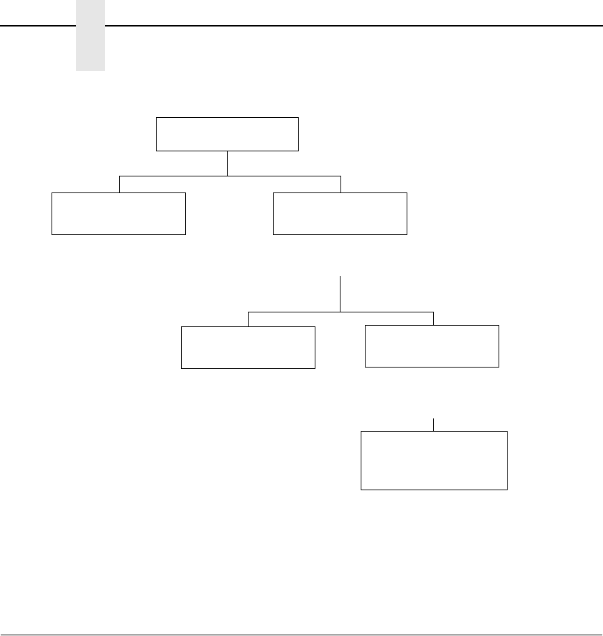
Figure 1 illustrates the relationship between the Normal and Graphics modes
of operation as described above. In addition, at the beginning of each
command in this chapter, the graphics mode(s) in which that command
operates are listed.
20
Chapter 2
VGL Command Standards
Figure 1. Modes of Operation
VGL Command Standards
Many of the commands described in this chapter include an example to
illustrate the application. Commas are used in the example commands to
easily identify the various command parameters.
Many of the example commands shown also require the Free Format
command. Using the Free Format command in the examples more clearly
identifies the data and command parameters.
The commands used to operate VGL have various selectable options and a
specific format that you must follow to obtain the desired results. These
command standards are described in the following sections. Become familiar
with their meaning and use before operating VGL.
VGL
Modes of Operation
Normal Mode Graphics Mode
(Table 1)
Standard Graphics
(Table 2)
Passes data directly
through to printer.
Enabled with PY Command
(see page 103).
An alphanumeric command from
Table 1 must be entered before using
an Extended Graphics command.
Extended Graphics
(Table 3)
Extended Graphics/High Resolution
Mode must be enabled
(^IPARAM,EXTENDED^G^-) before
using a high resolution command.
Extended Graphics/
High Resolution
(Table 3)

Special Function Control Code (SFCC)
21
Special Function Control Code (SFCC)
The SFCC identifies a command directed to VGL to enable a specific VGL
function. Based on the host computer interface or application requirements,
you can set the SFCC to any decimal character from 17 through 255 (hex 11
through hex FF).
When VGL is shipped, the caret symbol (hex 5E), “^”, is configured as the
SFCC. You can change the SFCC as described in your user's manual, or as
described in “Special Function Control Code Change” on page 144.
Throughout the practical examples in this manual, the SFCC is shown as a ^
(caret, hex 5E, dec 94); always use the actual SFCC required by your system
configuration wherever the ^ is shown.
In the general command formats, the SFCC is represented by (cc). Always
substitute the actual SFCC required by your system configuration in the
general command format where (cc) is shown. Do not enter parentheses with
your SFCC.
NOTE: Refer to your User's Manual for a description of SFCC selections.
Perform a configuration printout and examine the configuration option
listing to determine which SFCC is currently selected.
Command Sequence
Individual commands are made up of various command parameters (such as
character height or width parameters). Each command generally begins with
the SFCC. You can string many commands together to form a command
sequence, or command line. After the Graphics Mode is enabled by the
Graphics Mode Enable command, you can input a command sequence. The
command sequence includes all commands and data from the initial SFCC of
the first command to the sequence terminator.
The VGL buffer holds and can process approximately 64K characters in a
single graphics command sequence. However, if a single command
sequence exceeds the buffer capacity, you can use the Interrupt command
(page 106). The Interrupt command breaks the command sequence and
specifies where the sequence begins printing again.
Command Parameters
Most commands have a number of variable parameters for which input is
required. Throughout this manual, actual commands required for input are
shown exactly as they must be entered, while all the variable parameters
associated with that command are shown in italics.
Brackets
Paired brackets [ ] indicate an optional command parameter. You can choose
to use or not use such a command parameter, but do not enter the brackets in
the command sequence.
22
Chapter 2
VGL Command Standards
Spaces
Spaces are used in the general command formats to visually separate
individual command parameters. You must supply the information for the
command parameter, but do not enter the spaces in the command sequence;
they are shown simply as a visual aid to illustrate where one command
parameter ends and another begins.
Comma
VGL accepts commas as parameter diameters. Commas are often helpful in
distinguishing the various numeric parameters within the command
sequence. Commas are not allowed immediately after the SFCC or before the
first data character. Commas within the command sequence are optional
unless they are a part of the command format (i.e., IBARC, IFONT,S, etc.). If
used, commas occupy character spaces in the buffer and require processing
time. In the practical examples throughout this manual, commas are used in
the command sequences.
Terminator
Each command line, or command sequence, must be followed by a valid
terminator. Valid terminators are as follows: carriage return (CR, hex 0D), line
feed (LF, hex 0A), form feed (FF, hex 0C), vertical tab (VT, hex 0B), EVFU
commands (hex 10-1F), hex 01 and hex 06, and PI line commands. A
complete command sequence is the very first character (including the SFCC)
to and including the terminator.
Certain terminators have different functional effects based on their use with
standard graphics commands or within extended graphics command
sequences. For example, CR, FF, and LF function as sequence terminators
within an extended graphics command sequence.
If the Free Format command is used, host generated terminators are ignored
and only the standard graphics command terminators are recognized. See
Table 2 on page 27 for a list of the Standard Graphics Commands and
appropriate page references where additional information is provided.
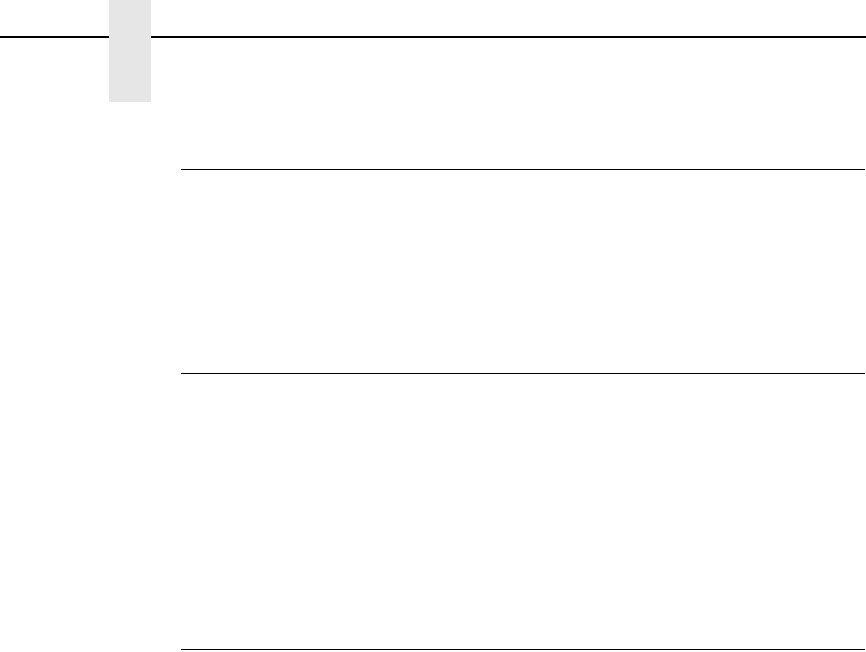
Character Height, Width, and Intercharacter Spacing
23
Character Height, Width, and Intercharacter Spacing
Alphanumeric height and width parameters include the intercharacter spacing
as shown in Figure 2. The intercharacter spacing is the space between
characters. (Scalable fonts, however, change the size of the intercharacter
gap used depending on the characters used.) Intercharacter spacing is
measured to the right of standard or upside-down characters and to the
bottom of sideways characters.
For example, specifying a character width of .5-inch in normal resolution
results in a five-dot column intercharacter spacing to the right or bottom of that
character based on orientation. Generally, intercharacter spacing is not
accounted for to the left, above, or below characters except when printing
reverse images or descending characters.
Figure 2. Character Height, Width, and Intercharacter Spacing
Normal Mode
In Normal Mode, data passes directly through VGL to the printer without
processing except to check for the SFCC and the Graphics Mode Enable or
the Enable Non-Graphics Free Format command. This normal, or pass-
through, data assumes the standard 10 cpi print mode, and all other standard
printer features function normally according to the configuration and
programming of the printer.
NOTE: Printers must be configured at the control panel for Data Processing
10 cpi (DP 10) print mode at 6 lpi for VGL to operate properly. To set
a line spacing when VGL is active, use the Line Spacing (@L)
command described on page 110.
WIDTH DETERMINED
BY wd PARAMETER
WIDTH DETERMINED
BY wd PARAMETER
HEIGHT
DETERMINED
BY Ht
PARAMETER
HEIGHT
DETERMINED
BY Ht
PARAMETER
INTERCHARACTER SPACING
1 DOT COLUMN PER 0.1" OF WIDTH
INTERCHARACTER SPACING
1 DOT COLUMN PER 0.1" OF HEIGHT
24
Chapter 2
Graphics Mode
Graphics Mode
Some graphics commands have different functions depending on whether the
command is used within an extended or a standard graphics command
sequence. For example, the W command identifies a standard graphics
command line slew; when used within an extended graphics command
sequence, W identifies a Character Width Change command. Therefore, be
certain of appropriate command usage to obtain the desired results.
Also, graphic commands have different parameters and different functionality
depending on whether the command is used in normal or high resolution
graphics mode.
Each command in this chapter is presented in alphabetical order. The tables
on the following pages list VGL commands according to the graphics mode in
which it operates. Information specific to the Extended Graphics/High
Resolution Mode, such as expanded parameter definition, is supplied on the
command description page for each command available in the mode.
Data Positioning
In Graphics Mode, you must understand certain positioning rules to obtain the
desired results. Horizontal and vertical starting positions of a command are
determined either by implied relative position to the prior graphics command
or explicit position from a positioning command.
Implied Relative Positioning
For any graphics command sequence (a string of one or more extended
graphics commands), the initial "relative" print position is the current dot row
and column 1 or the Graphics margin, if set.
NOTE: Because previous command sequences may have been used to
define prior printing on the page, the actual physical position of the
print mechanism may be on a different row, but it will be always in
column 1 or the Graphics margin, if set.
Without an immediately preceding positioning command, the starting position
of any command within the sequence is dot row 1 and the first dot column
past the right edge of the previous command "print envelope." This implied
position may be modified horizontally or vertically by specific positioning
commands.
Without explicit horizontal positioning commands, the horizontal print position
constantly increases within the command sequence. Each command starts at
the right edge of the previous command. Without explicit vertical positioning
commands, the vertical print position for each command within a sequence is
always at relative dot row 1 (the current physical position of the print
mechanism resulting from printing the last sequence).

Data Positioning
25
Explicit Positioning Commands
Use the Horizontal Tab command to change the horizontal print position. With
the Horizontal Tab command, any horizontal print position on the current print
line can be specified as the print position.
NOTE: The control panel form feed key will operate differently depending on
the source of form feed control at the time the key is pressed. Form
feed is controlled by the LP+ and VGL emulation at different times.
The vertical print position can be changed using the Justification command or
justification parameter within one of the alphanumeric commands. The
Justification command or parameter specifies a vertical position down the
form from the current print position. Additionally, you can use standard
graphics commands for line slew, dot slew, line feed, form feed, or EVFU
commands to specify a vertical print position.
These positioning commands and their use are described within this chapter.
It is important to remember that the end of a command sequence always
resets the "origin" for all subsequent positioning to row 1, column 1 or the left
Graphics margin.
Vertical Dot Density
A vertical tenth-inch in normal resolution mode equals 7 dots based on 72 dpi
vertical dot density. A true vertical tenth-inch at 72 dpi would be 7.2 dots.
Since .2 dots is not printable, seven dots are used and the vertical
measurement of a line, box, or similar graphic element is not exact.
A vertical inch in high resolution mode equals 292/300 times the printer
vertical dot density. A vertical inch at 300 dpi would be 292 dots. Therefore,
when specifying the size of your graphic elements, be aware that the vertical
dimensions of your graphic design print slightly smaller than the value
specified in your command.
You can enable the "True vert 1/10" option which allows the vertical size/
position parameter to be in true inches. With this option enabled in normal
resolution, vertical dimensions are as close to true as possible based on a 72
dpi dot density (e.g., 1.0 inch is exact at 72 dots. While 1.2 inch is close at 86
dots, exact would be 86.4 dots.) In high resolution, with true vert 1/10, vertical
dimensions are exact or nearly exact due to the higher dot density.
26
Chapter 2
Command Codes
Command Codes
The tables on the following pages list each VGL command according to the
Graphics Mode in which it operates. Following these tables, each command in
this chapter is presented in alphabetical order.
Graphics Mode Enable Commands
To enable the Graphics Mode, you must use the Graphics Mode Enable
command. Table 1 summarizes the Graphics Mode Enable and Disable
commands and the four alphanumeric commands, which are fully described
on the referenced pages. After enabling the Graphics Mode, alphanumeric
commands, standard graphics commands, or extended graphics commands
are available.
Table 1. Graphics Mode Commands
Command Description Page #
IPARAM Graphics Resolution 29
PF Free-Format Enable, Non-Graphics 101
PO Free Format Disable, Non-Graphics 102
FFree Format (graphics) Enable 99
OFree Format (graphics) Disable 99
PY Graphics Mode Enable 103
PN Graphics Mode Disable 104
MAlphanumerics, Standard 32
VAlphanumerics, Rotated Clockwise (Top Down) 32
EAlphanumerics, Rotated Counterclockwise (Bottom Up) 32
EAlphanumerics, Rotated Counterclockwise-Reverse String 32
UAlphanumerics, Inverted 32
UAlphanumerics, Inverted-Reverse String 32
in Character Set Selection (Multinational Character Set) 337
IInterrupt 106
un User Set Selection (Multinational Character Set) 343
IPAGE Page, Controlling Paper Options 122
Standard Graphics Commands
27
NOTE: Some systems pad the data stream with characters and spaces. If the
VGL file on your system contains padded characters or spaces
before the SFCC, this padded data must be ignored before VGL can
operate. The Ignore Data command (X), discussed on page 105, is
provided for this purpose.
Similarly, sometimes you may need VGL to ignore host-generated
paper movement commands (carriage return, line feed, form feed,
etc.) in lengthy data streams. The Free Format command (F),
discussed on page 99, is designed for this purpose.
Standard Graphics Commands
Standard graphics commands can be used any time VGL is in the Graphics
Mode. They set internal control values or are sent directly to the printer for
processing. Standard graphics commands are summarized in Table 2 and
fully described on the referenced pages.
NOTE: The Graphics Mode (Table 1) must be enabled before issuing a
Standard Graphics command.
Table 2. Standard Graphics Commands
Command Description Page #
-Carriage Return 41
@C Character Type 46
#x Compressed Print 47
!Direct Printer Command, Hex 01 53
"Direct Printer Command, Hex 02 53
#Direct Printer Command, Hex 03 53
$Direct Printer Command, Hex 04 53
%Direct Printer Command, Hex 05 53
&Direct Printer Command, Hex 06 53
'Direct Printer Command, Hex 07 53
(Direct Printer Command, Hex 08 53
.Direct Printer Command, Hex 0E 53
/Direct Printer Command, Hex 0F 53
DDot Slew 54
SDuplication, Horizontal 54
IREPH, Duplication, Horizontal (Version II) 56
RDuplication, Vertical 57
YAuto-Increment/Decrement Vertical Duplication 59
28
Chapter 2
Command Codes
IREPV, Duplication, Vertical (Version II) 63
BDynamic Form 65
[ or { Dynamic Form, Field Length 67
CDynamic Form, Copy Fields 69
RDynamic Form, Repeat Form 71
>EVFU, Start Load 73
?EVFU End Load 73
0-9 EVFU Channels 1 through 10 73
:EVFU Channel 11 73
;EVFU Channel 12 73
<EVFU Channel 13 73
=EVFU Channel 14 73
@E Emphasized Print 76
IEMUL, Emulation Switch 77
,Form Feed 88
LForm Length (with PI Line Enabled) 89
HForm Length 89
ILOAD, Font Load 77
IFONT, Font, Selecting Default (Version II) 78
FFree Format (graphics) Enable 99
OFree Format (graphics) Disable 99
@H Hex Dump 104
XIgnore Data 105
*Line Feed 110
KLine Slew 111
WLine Slew 111
@L Line Spacing 111
QPlotting Graphics (Rows), (Odd Dot Plot) 132
CPlotting Graphics (Rows), (Even Dot Plot) 132
@R Reset 135
Table 2. Standard Graphics Commands (continued)
Command Description Page #
Extended Graphics Commands
29
Extended Graphics Commands
Specific graphics functions (lines, boxes, alphanumerics, forms, barcodes,
reverse printing, etc.) are available through commands sent as part of an
extended graphics command sequence. Table 3 summarizes the extended
graphics commands, which are fully described on the referenced pages.
Extended commands must be used as part of an alphanumeric command
sequence (after VGL is in the Graphics Mode). In some cases, the actual
command may have a different meaning and perform a different function
when used within an extended graphics command sequence compared to its
use as a standard graphics command.
NOTE: An alphanumeric command from Table 1 must be used before issuing
an Extended Graphics Command.
NSpecial Function Control Code Change 144
TTab, Horizontal (Set Graphics Margin) 151
+Tab, Vertical 155
@U Underlined Print 156
Table 2. Standard Graphics Commands (continued)
Command Description Page #
Table 3. Extended Graphics Commands
Command Description Page #
IBARC, Barcode (Version II) 164
BBarcode, Horizontal 160
CBarcode, Vertical 160
LB Boxes 39
HCharacter Height 42
WCharacter Width 44
in Character Set Selection 345
KF Dark Print 49
DDescending Characters 51
IREPH, Duplication, Horizontal (Version II) 56
IREPV, Duplication, Vertical (Version II) 63
fFill (for Standard and Expanded User-Defined Symbols) 148
IFONT,S, Font, Selecting Default (Version II) 78
Font Fonts, Rotatable 82
30
Chapter 2
Command Codes
SFonts, Compressed Print Density 85
LF Forms Construction 90
IFORM,C Forms, Creating Dynamic (Version II) 93
IFORM,D Forms, Deleting Dynamic (Version II) 94
IFORM,E Forms, Executing Dynamic (Version II) 94
IFORM,L Forms, Listing Dynamic (Version II) 95
IFORM,R Forms, Resetting Dynamic (Version II) 99
JJustification, Vertical 108
LD Lines, Dashed 113
LS Lines, Solid 116
QPlotting Graphics (Columns) 129
IHEX, Passing Hex Value to the Printer 124
ILOGO, Logo Generation (Version II) 118
IPCX, Logo, PCX 120
ITIFF, Logo, TIFF 121
IPEXP, Pixel Expansion (Version II) 125
IPLOT, Plotting Bitmap Images 127
RReverse Print 136
KH Shading 140
KL Shading Mask 142
ZSymbols, Printing 150
zx Symbol, Creating Expanded User-Defined 148
zx Symbol, Creating Standard User-Defined 145
TTab, Horizontal 151
Table 3. Extended Graphics Commands (continued)
Command Description Page #

Extended Graphics/High Resolution Commands
31
Extended Graphics/High Resolution Commands
In Extended Graphics/High Resolution Mode, you can access the extended
graphics commands as well as new commands designed to achieve
enhanced resolution for thermal printing. This mode allows you to specify
graphic elements and characters in expanded size and position parameters.
Graphic elements (lines, boxes, and forms) can now be defined in increments
of one thousandth of an inch. Characters can now be specified in increments
of one hundredth of an inch. As a result of these enhancements, you can print
forms and labels that include high resolution text, graphics and barcodes.
The actual positioning and size, however, can be only as "fine" as your printer
resolution (dpi). For example, a graphic position change of 0.001, 0.002, or
0.003 would result in one printer dot at 300 dpi (1 - .0033 inches). Also,
because the actual height of characters change in increments of seven printer
dots (0.0233 inches at 300 dpi), a size specification of 0.01 inch or 0.02 inch
would result in a character of the same size.
To enable Extended Graphics/High Resolution Mode, you must have already
enabled Graphics Mode through use of the ^PY command. You cannot
enable the Extended Graphics/High Resolution Mode, however, from within a
graphics pass (an alphanumeric command, ^M, ^E, ^U, or ^V).
Once in Graphics Mode, type the following command to enable Extended
Graphics/High Resolution Mode:
^IPARAM,EXTENDED^G^-
Once in Extended Graphics/High Resolution Mode, type the following
command to return to normal resolution Graphics Mode:
^IPARAM,NORMAL^G^-
VGL initially operates in normal resolution mode. To switch between normal
and high resolution, send the appropriate command shown above, or use the
"Cmd Resolution" option on the front panel menu.
You can switch between normal and high resolution between graphics passes
on the same page. VGL maintains the current resolution setting after a ^PN
("Exit Graphics Mode") command has been sent.
Example:
^PY^-
^IPARAM,EXTENDED^G^-
^M02002001000 text in high resolution^-
^IPARAM,NORMAL^G^-
^M0202100 text in normal resolution^-
^PN^-
32
Chapter 2
Command Codes
Alphanumerics
Purpose Produces alphanumeric text (i.e., numbers and alphabet letters)
in standard, rotated or inverted orientations. A reverse string
order option is also available in the rotated and inverted
orientations.
Mode Graphics
Format (cc) x ht wd jus data [(cc)G] (cc)-
(cc) Represents the Special Function Control Code
(SFCC). Enter the specific SFCC for your VGL
configuration.
xRepresents an Alphanumeric command. Replace x
with one of the following alphanumeric orientations:
M for Standard Alphanumerics
V for Rotated Clockwise
E for Rotated Counterclockwise
U for Inverted
ht Normal Resolution:
Defines the character height in tenth (.10) inches.
Enter a two-digit height value ranging from 01
through 99 to define a character height of 0.1
through 9.9 inches. VGL automatically understands
the decimal point between the first and second
digits. Height values of 00 and 01 have special
meanings for rotatable/high-speed fonts as
described in “Fonts, Rotatable” on page 82.
High Resolution:
Defines the character height in hundredth (.01)
inches. Enter a three-digit height value ranging
from 001 through 999 to define a character height
of 0.01 inch through 9.99 inches. VGL
automatically understands the decimal point
between the first and second digits.
The actual height of the printed character increases
in increments of seven printer dots. Changing the ht
field by one printer dot, therefore, may not produce
a change in the actual printed character. You must
increase the field by at least seven printer dots in
order to produce an actual change in character
height.
wd Normal Resolution:
Defines the character width in tenth (.10) inches.
Enter a two-digit width value ranging from 01
through 99 to define a character width of 0.1
through 9.9 inches. VGL automatically understands
the decimal point between the first and second
digits. Width values of 00 and 01 have special
meanings for rotatable/high-speed fonts as
described in “Fonts, Rotatable” on page 82.

Alphanumerics
33
High Resolution:
Defines the character width in hundredth (.01)
inches. Enter a three-digit width value ranging from
001 through 999 to define a character width of 0.01
inch through 9.99 inches. VGL automatically
understands the decimal point between the first
and second digits.
The actual width of the printed character increases
in increments of six printer dots (characters per
inch). Changing the wd field by one printer dot,
therefore, may not produce a change in the actual
printed character. You must increase the field by at
least six printer dots in order to produce an actual
change in character width.
NOTE: High Resolution mode does not allow a character height or width
parameter of 0. If 0 is used, a 1 is substituted. Fonts, Rotatable (see
page 82) cannot be accessed in High Resolution.
NOTE: In vertical alphanumeric commands, height refers to the physical
height of the character and intercharacter spacing top to bottom on
the page (from the left to right edge of the printed character). Width
refers to the physical width of the character from left to right on the
page (from the bottom to the top of the printed character).
jus Normal Resolution:
Defines vertical justification (position) for character
printing in tenth inches and dot rows. Enter a three-
digit value ranging from 000 through 999 to define
the printing location down from the starting position
of the command sequence. The first two digits
specify 0.1 through 9.9 inches downward
justification; the third digit specifies an additional 0
through 9 dot rows of downward justification. VGL
automatically understands the decimal point
between the first two digits and the third digit is
automatically interpreted as dot rows.
High Resolution:
Defines vertical justification (position) for character
printing in thousandth inches. Enter a five-digit
value ranging from 00000 through 99999 to define
the printing location down from the starting position
of the command sequence from 0.0 inch through
99.999 inches. VGL automatically understands the
decimal point between the second and third digits
as thousandths.

34
Chapter 2
Command Codes
If the data character immediately following the jus
field is not a digit (zero through nine), then you can
omit trailing zeros. For example, the command
^M10010001ABC, results in a 1.000 inch
justification because the three empty spaces in the
jus field (before the characters “ABC”) are
completed with three implied trailing zero digits.
(See “Justification, Vertical” on page 108.)
NOTE: If your data to be printed begin with a number (not a character), then
you must complete the field; otherwise, VGL assumes the number is
a digit in the field value.
As in normal resolution mode, the ht field of either an alphanumeric
command or a height/width command also specifies the height of any
succeeding barcode in the graphics pass. The field value is not
specified in increments of six or seven printer dots, however. In
normal resolution mode, you can select character sizes 10 characters
per inch (cpi), 12 cpi, 15 cpi and size 0 by height and width
parameters in 0 and 1 digit combinations. You cannot perform this
type of character size selection, however, in Extended Graphics/High
Resolution Mode.
data The data characters to print or a specific graphics
command (such as one of the barcode commands,
a horizontal tab command, etc.).
(cc)G (Optional) Reverses the character data from the
actual input order. This parameter is available only
with the Rotated Counterclockwise command (E) or
the Inverted Rotated Alphanumeric command (U).
Enter the SFCC for your VGL configuration
immediately followed by G.
(cc)- Graphics Mode CR used as a sequence terminator.
Enter the SFCC for your VGL configuration
immediately followed by - to end the command
sequence.
Comments
The Graphics Mode (PY) must be enabled before sending an
alphanumeric command. Alphanumeric commands must be a
part of the command sequence before using specific graphics
commands. Alphanumeric commands must be used to initiate
any extended graphic command sequence. Other data or graphic
commands can be used with alphanumeric commands.
Examples Normal resolution examples for each of the four alphanumeric
orientations follow. Rotated Clockwise alphanumerics print
characters with a clockwise vertical rotation; the characters are
read top to bottom. Rotated Counterclockwise alphanumerics
print characters with a counterclockwise vertical rotation; the
characters are read bottom to top. Inverted alphanumerics print
characters upside down; the characters are read right to left.
Rotated Counterclockwise and Inverted Rotated alphanumerics
have an optional reverse string parameter option.
Alphanumerics
35
NOTE: When the alphanumeric command is used simply to introduce one of
the extended graphics commands (such as Horizontal Tabs,
Justification, Dark Print, etc.), the alphanumeric command
parameters are optional and can be entered only as needed.
However, the alphanumeric command parameters are required for
Barcode commands.
Alphanumerics Examples
The following sample commands in this section illustrate some applications
for standard, rotated and inverted alphanumeric features in normal resolution
mode. (Note that the Free Format enable and disable commands, ^F and ^O,
are used.)
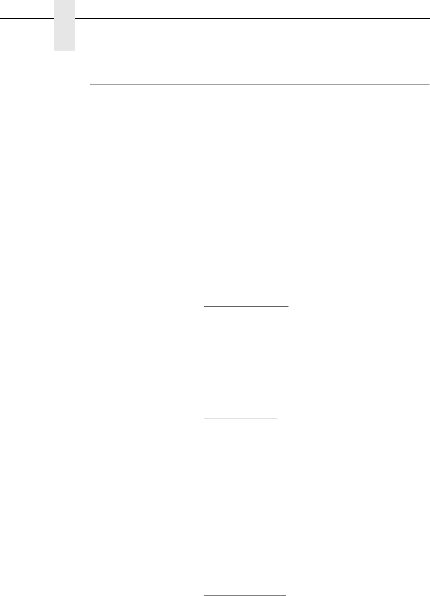
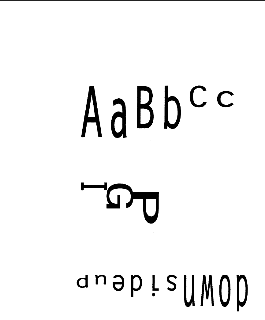
Standard Alphanumerics:
^PY^-^F^-
^M06,04,000AaBb^M04,06,000AaBb^-
^O^-^PN^-
^PY^-^F^-
^M03,03,000I^M03,03,030G^M03,03,060P
^M03,03,060I^M03,03,030G^M03,03,000P^-
^O^-^PN^-
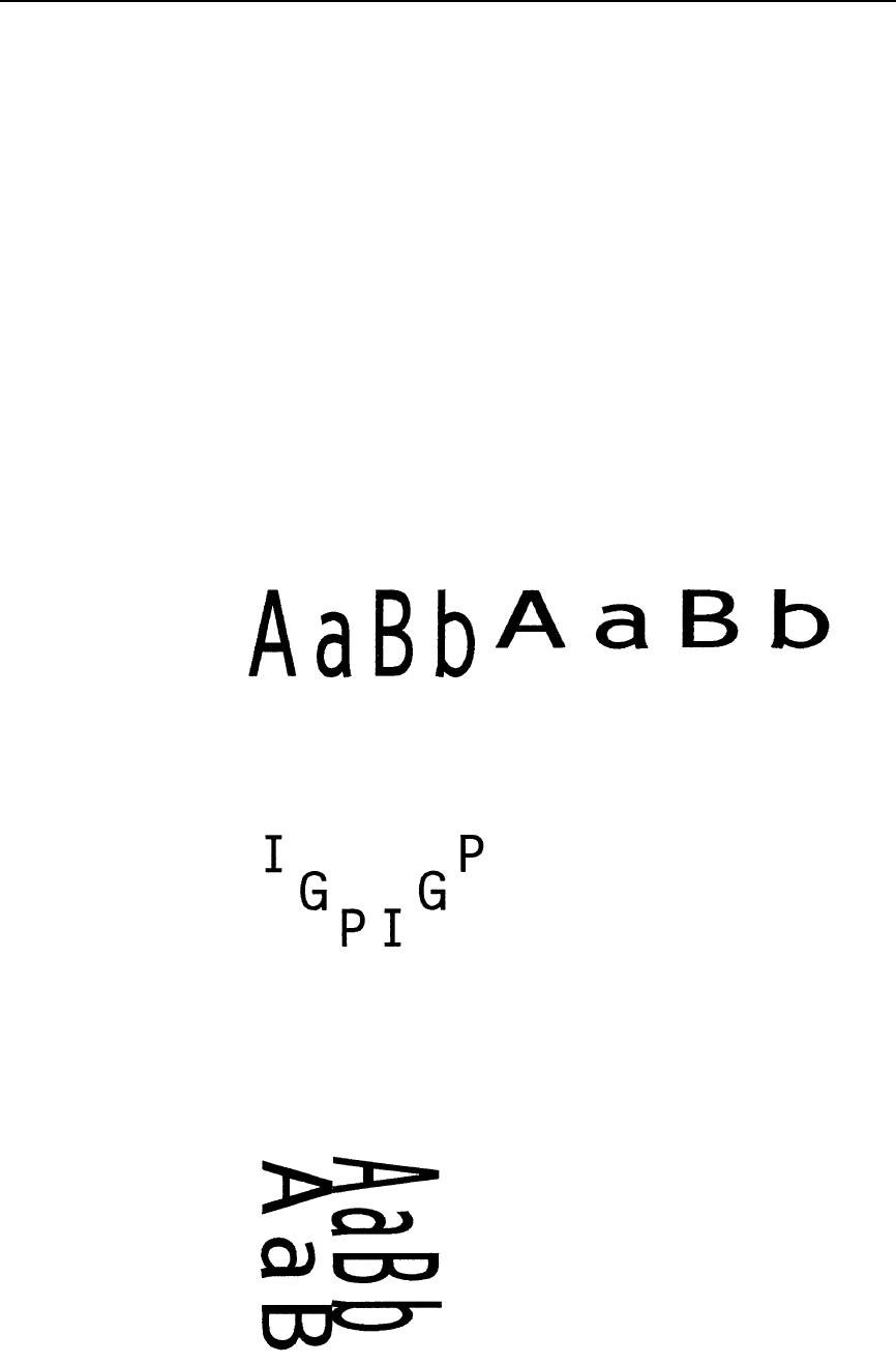
Rotated Clockwise Alphanumerics:
^PY^-^F^-
^V06,04,000AaBb^V04,06,000AaBb^-
^O^-^PN^-
alph
36
Chapter 2
Command Codes
^PY^-^F^-
^V03,03,000I^V03,03,030G^V03,03,060P
^V03,03,060I^V03,03,030G^V03,03,000P^-
^O^-^PN^-
Rotated Counterclockwise Alphanumerics:
^PY^-^F^-
^E06,04,000AaBb^E04,06,000AaBb^-
^O^-^PN^-
^PY^-^F^-
^E03,03,000I^E03,03,030G^E03,03,060P
^E03,03,060I^E03,03,030G^E03,03,000P^-
^O^-^PN^-
alpha.ex4
alpha.ex5
alpha.ex6
Alphanumerics
37
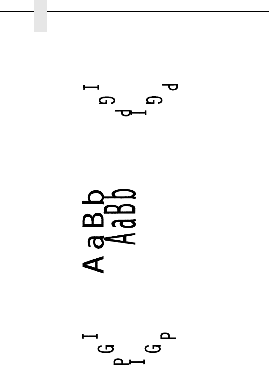
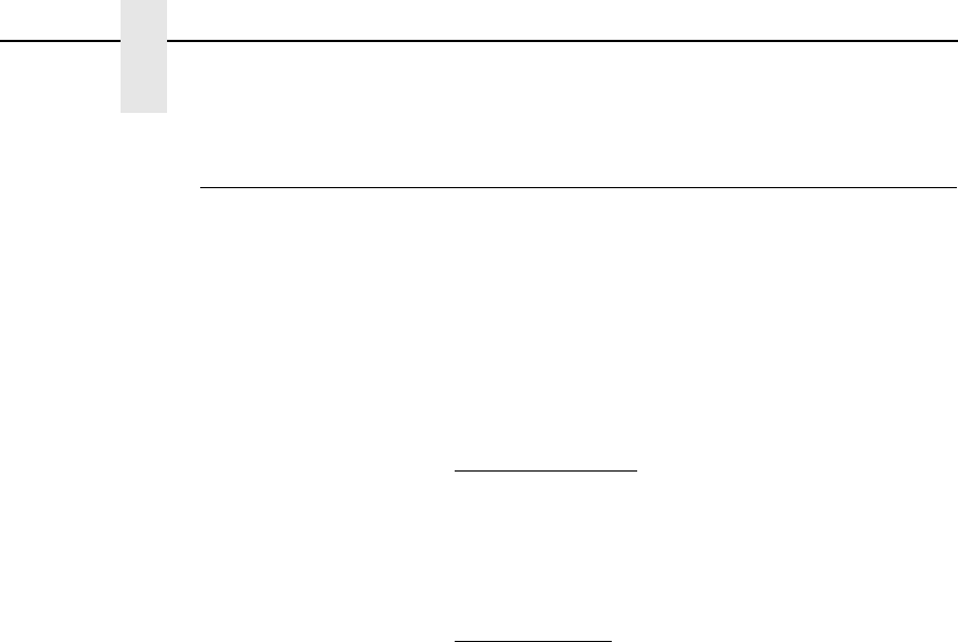
Inverted Alphanumerics:
^PY^-^F^-
^U06,04,000AaBb^U04,06,000AaBb^-
^O^-^PN^-
^PY^-^F^-
^U03,03,000I^U03,03,030G^U03,03,060P
^U03,03,060I^U03,03,030G^U03,03,000P^-
^O^-^PN^-
^PY^-^F^-
^U03,03,000IGP^U03,03,060PGI^-
^O^-^PN^-
alpha.e
alpha.ex8
alpha.ex
38
Chapter 2
Command Codes
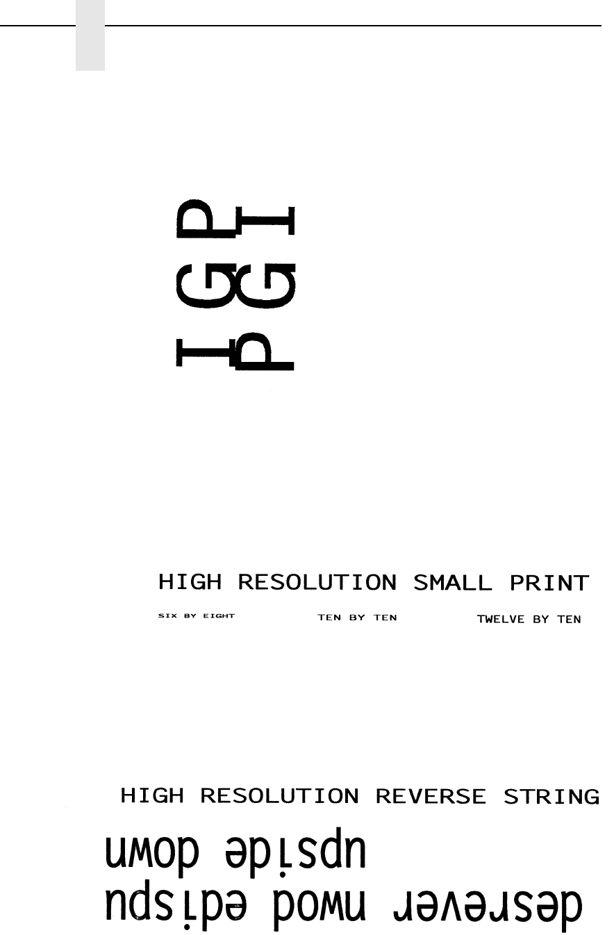
Alphanumerics Reverse String:
^PY^-^F^-
^E08,05,000IGP^E08,05,000IGP^G^-
^O^-^PN^-
^PY^-^F^-
^M020,020,01000^T01.500HIGH RESOLUTION SMALL PRINT
^I01.500^-
^M006.008.00000^T01.500SIX BY EIGHT
^M010.010.00000^T03.500TEN BY TEN
^M012.010.00000^T05.500TWELVE BY TEN
^-
^O^-^PN^-
^PY^-^F^-
^M020.020.00000^T01.200HIGH RESOLUTION REVERSE STRING
^I00.500^-
^U055.030.00000^T01.000^D upside down^D^-
^U055.030.00000^T01.000^Dupside down reversed^G^D^-
^O^-^PN^-
A
Boxes
39
Boxes
Purpose Produces a rectangular box.
Mode Graphics with an Extended Graphics Command selected
Format (cc) LB horz vert h v (cc)-
(cc) Represents the Special Function Control Code
(SFCC). Enter the specific SFCC for your VGL
configuration.
LB The Box command. Enter LB.
horz Normal Resolution:
Defines the horizontal length of the box in tenth
inches and dot columns. Enter a three-digit
horizontal length value ranging from 000 through
999 to define a horizontal length of 00.0 through
99.9 inches and a fourth digit ranging from 0
through 9 to specify 0 through 9 additional dot
columns of length. VGL automatically understands
the decimal between the second and third digits for
tenth inches and automatically interprets the fourth
digit as dot columns. For example, entering 0126
specifies a 1.2-inch plus 6-dot column horizontal
length; entering 1016 specifies a 10.1-inch plus 6-
dot column horizontal length.
High Resolution:
Defines the horizontal length of the box in
thousandth inches. Enter a five-digit horizontal
value ranging from 00000 through 99999 to define
a horizontal length of 0.000 inch through 99.999
inches. VGL automatically understands the decimal
between the second and third digits. The horz field
must be at least twice the value of the thickness of
the vertical sides (v).
vert Normal Resolution:
Defines the vertical length of the box in tenth inches
and dot rows. Enter a three-digit vertical length
value ranging from 000 through 999 to define a
vertical length of 00.0 through 99.9 inches and a
fourth digit ranging from 0 through 9 to specify 0
through 9 additional dot rows of length. VGL
automatically understands the decimal between the
second and third digits for tenth inches and
automatically interprets the fourth digit as dot rows.
For example, entering 0204 specifies a 2.0-inch
plus 4-dot row vertical length; entering 0242
specifies a 2.4-inch and 2-dot row vertical length.
40
Chapter 2
Command Codes
High Resolution:
Defines the vertical length of the box in thousandth
inches. Enter a five-digit vertical value ranging from
00000 through 99999 to define a vertical length of
0.001 through 99.999 inches. VGL automatically
understands the decimal between the second and
third digits. The vert field must be at least twice the
value of the thickness of the horizontal sides (h).
hNormal Resolution:
Defines the horizontal border thickness in dot
columns. Enter a number ranging from 1 through 9
to specify a horizontal border thickness from 1
through 9 dots.
High Resolution:
Defines the horizontal border thickness in
thousandth inches. Enter a three-digit value
ranging from 000 through 999 to define a horizontal
border thickness from 0.000 through 0.999 inches.
vNormal Resolution:
Defines the vertical border thickness in dot rows.
Enter a number ranging from 1 through 9 to specify
a vertical border thickness from 1 through 9 dots.
High Resolution:
Defines the vertical border thickness in thousandth
inches. Enter a three-digit value ranging from 000
through 999 to define a horizontal border thickness
from 0.000 through 0.999 inches.
(cc)- Graphics Mode CR used as a sequence terminator.
Enter the SFCC for your VGL configuration
immediately followed by - to end the command
sequence.
Comments
Box drawing uses horizontal and vertical length parameters.
Boxes are positioned on the page using an alphanumerics
command sequence (such as horizontal tabs, the justification
parameter, etc.). Consequently, an alphanumeric command must
precede a Box command. The horizontal and vertical border
thickness can also be specified in varying line thicknesses.
Carriage Return
41
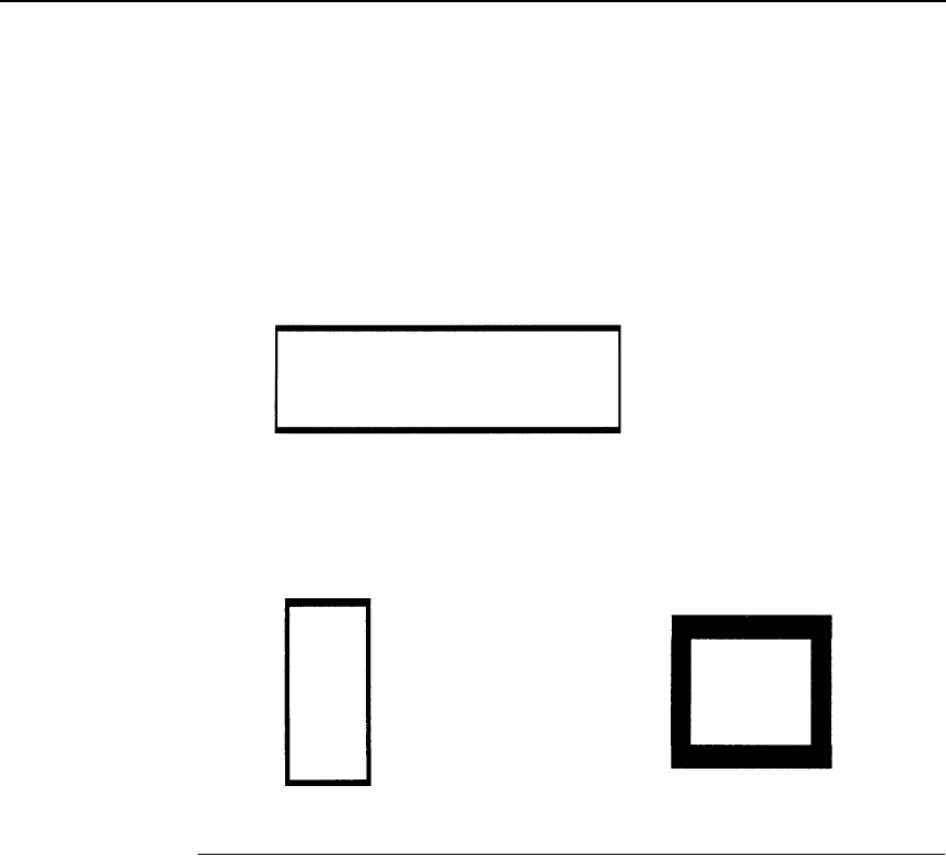
Examples The following commands illustrate boxes in normal resolution. As
shown in the examples, changing the horizontal and vertical
length and border thickness parameter values construct a variety
of boxes. (The Graphics Mode Enable command and an
alphanumerics command were previously sent.)
^LB0425,0150,5,2^-
^LB0052,0123,3,2^- ^LB0100,0100,9,9^-
Carriage Return
Purpose Terminates a command.
Mode Graphics with a Standard Graphic Command selected
Format (cc)-
(cc) Represents the Special Function Control Code
(SFCC). Enter the specific SFCC for your VGL
configuration.
- The graphics CR mnemonic. Enter -.
Comments
The VGL Graphics Mode carriage return (CR) performs the same
function as a standard carriage return (hex 0D) when used to
terminate a standard graphics command. When used to
terminate a graphics sequence in an extended graphics
command when Free Format is enabled, this command functions
as a sequence terminator.
b

42
Chapter 2
Command Codes
Character Height
Purpose Specifies a new alphanumeric height.
Mode Graphics with an Extended Graphics Command selected
Format (cc) H ht data (cc)-
(cc) Represents the Special Function Control Code
(SFCC). Enter the specific SFCC for your VGL
configuration.
H The Character Height command. Enter H.
ht Normal Resolution:
Defines the new character height in tenth inches.
Enter a two-digit height value ranging from 01
through 99 to define a character height of 0.1
through 9.9 inches. The decimal point between the
digits is automatically understood by VGL.
High Resolution:
Defines the new character height in hundredth
inches. Enter a three-digit height value ranging
from 001 through 999 to define a character height
of 0.01 inch through 9.99 inches. VGL
automatically understands the decimal point
between the first and second digits. The actual
height of the printed character increases in
increments of seven printer dots. Changing the ht
field by one printer dot, therefore, may not produce
a change in the actual printed character. You must
increase the field by at least seven printer dots in
order to produce an actual change in character
height.
The printable data for the new height is input
following the new height parameter.
data Identifies the characters to print at the new height.
(cc)- Graphics Mode CR used as a sequence terminator.
Enter the SFCC for your VGL configuration
immediately followed by - to end the command
sequence.
Comments The H command specifies a new alphanumerics height
parameter without sending the complete alphanumerics
command sequence again. Only the character height is affected
by this command; character width, justification, rotation, or any
other parameter specifications remain unchanged. The Character
Height command is input as part of the data in one of the
alphanumeric commands.
Character Height
43
Examples The following sample commands illustrate character height
changes in normal resolution. (The Graphics Mode Enable
command was previously sent to enable Graphics Mode but is
not shown in the examples.)
^M12,06,000Aa^H10Bb^H05Cc^-
^V05,05,000I^H10G^H15P^-
^U03,04,000up^H05side^H10down^-
charht.
charht.2
44
Chapter 2
Command Codes
Character Width
Purpose Specifies a new alphanumeric width.
Mode Graphics with an Extended Graphics Command selected
Format (cc) W wd data (cc)-
(cc) Represents the Special Function Control Code
(SFCC). Enter the specific SFCC for your VGL
configuration.
W The Character Width command. Enter W.
wd Normal Resolution:
Defines the new character width in tenth inches.
Enter a two-digit width value ranging from 01
through 99 to define a character width of 0.1
through 9.9 inches. VGL automatically understands
the decimal point between the digits.
High Resolution:
Defines the new character width in hundredth
inches. Enter a three-digit width value ranging from
001 through 999 to define a character width of 0.01
inch to 9.99 inches. VGL automatically understands
the decimal point between the first and second
digits.
The actual width of the printed character increases
in increments of six printer dots (characters per
inch). Changing the wd field by one printer dot,
therefore, may not produce a change in the actual
printed character. You must increase the field by at
least six printer dots in order to produce an actual
change in character width.
The printable data for the new width is input
following the new width parameter.
data Identifies the characters to print at the new width.
(cc)- Graphics Mode CR used as a sequence terminator.
Enter the SFCC for your VGL configuration
immediately followed by - to end the command
sequence.
Comments
The W command specifies a new alphanumerics width parameter
without sending the complete alphanumerics command
sequence again. Only the character width is affected by this
command; character height, justification, rotation, or any other
parameter specifications remain unchanged. The W command is
input as part of the data in one of the alphanumeric commands.
Character Width
45
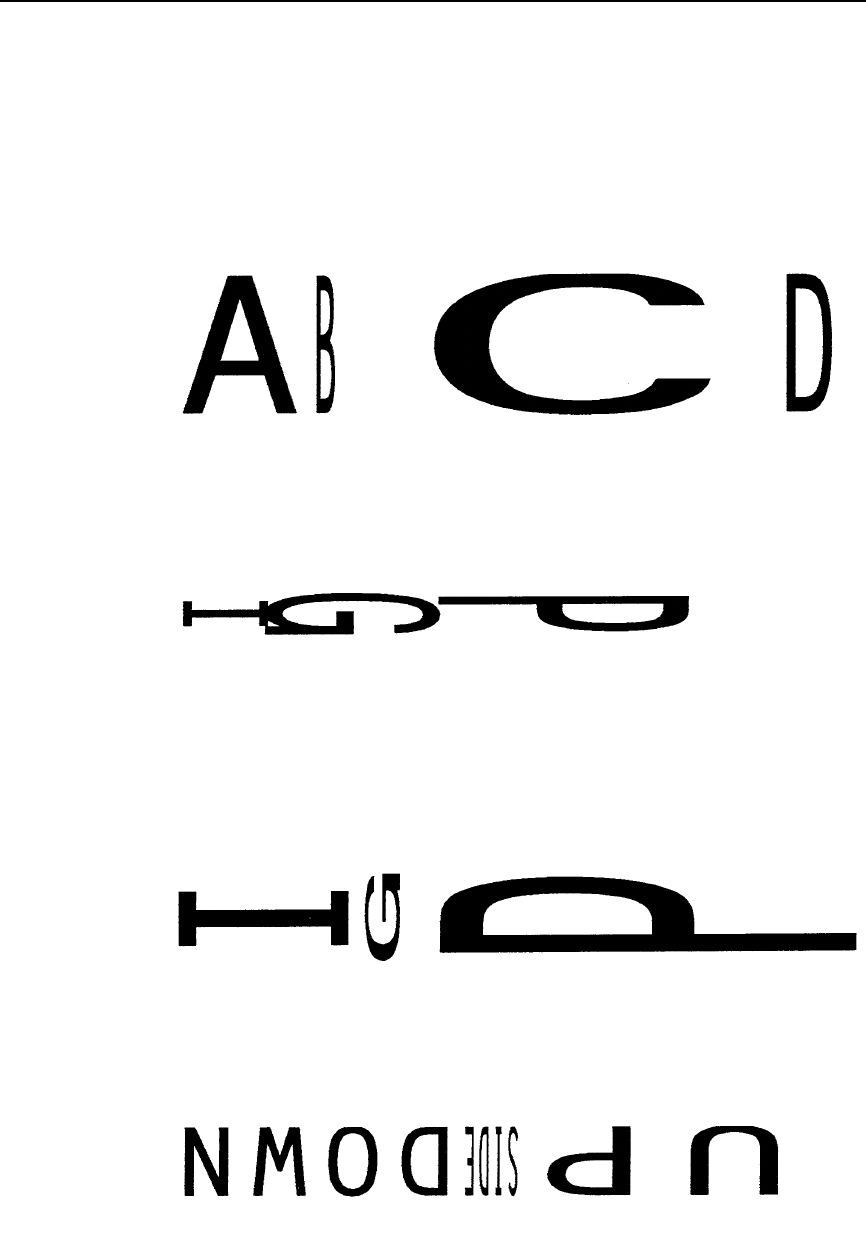
Examples The following sample commands illustrate character width
changes in normal resolution.
^PY^-
^M10,10,000A^W02B^W30C^W05D^-
^PN^-
^PY^-
^V05,05,000I^W10G^W15P^-
^PN^-
NOTE: The command sequence below also uses the Horizontal Tab (T012,5
and T017,5) command for character spacing.
^PY^-
^E10,10,000I^T012,5^W02G^T017,5^W25P^-
^PN^-
^PY^-
^U05,05,000DOWN^W01SIDE^W10UP^-
^PN^-
c
c
harwd
.ex
cha
46
Chapter 2
Command Codes
Character Type
Purpose Selects a character type or character per inch (cpi) density.
Mode Graphics with a Standard Graphic Command selected
Format (cc) @ C type (cc)* data (cc)*
(cc) Represents the Special Function Control Code
(SFCC). Enter the specific SFCC for your VGL
configuration.
@ Specifies one of the @ commands. Enter @ to
begin an @ command function.
C Specifies the Character Type command. Enter C.
type (cc)* Represents the type parameter. Enter one of the 2-
digit codes shown in Table 4 to select a character
type, followed by the SFCC. For example, enter
^@C17^* to select 17.65 cpi. This cpi remains
effective until a new @C command is sent.
data The data to be printed in a selected font.
(cc)* Graphics Mode LF. Enter the SFCC for your VGL
configuration immediately followed by * to end the
command sequence.
Comments
The @C command can be used anytime VGL is in the Graphics
Mode. Once a new character type is selected, all standard
Graphics mode text lines are printed in the selected type until
another type is selected or VGL returns to the Normal Mode. If
another type is selected, it must be introduced on a separate line
from the currently selected character type.
Table 4. Character Type Codes
Character Type Code Character Type Selected
05 Double High (.2”)
0A OCR-A
0B OCR-B
10 Standard 10 cpi
12 12 cpi
13 13.33
15 15 cpi
17 17.65
20 20.0 cpi
24 24.0 cpi
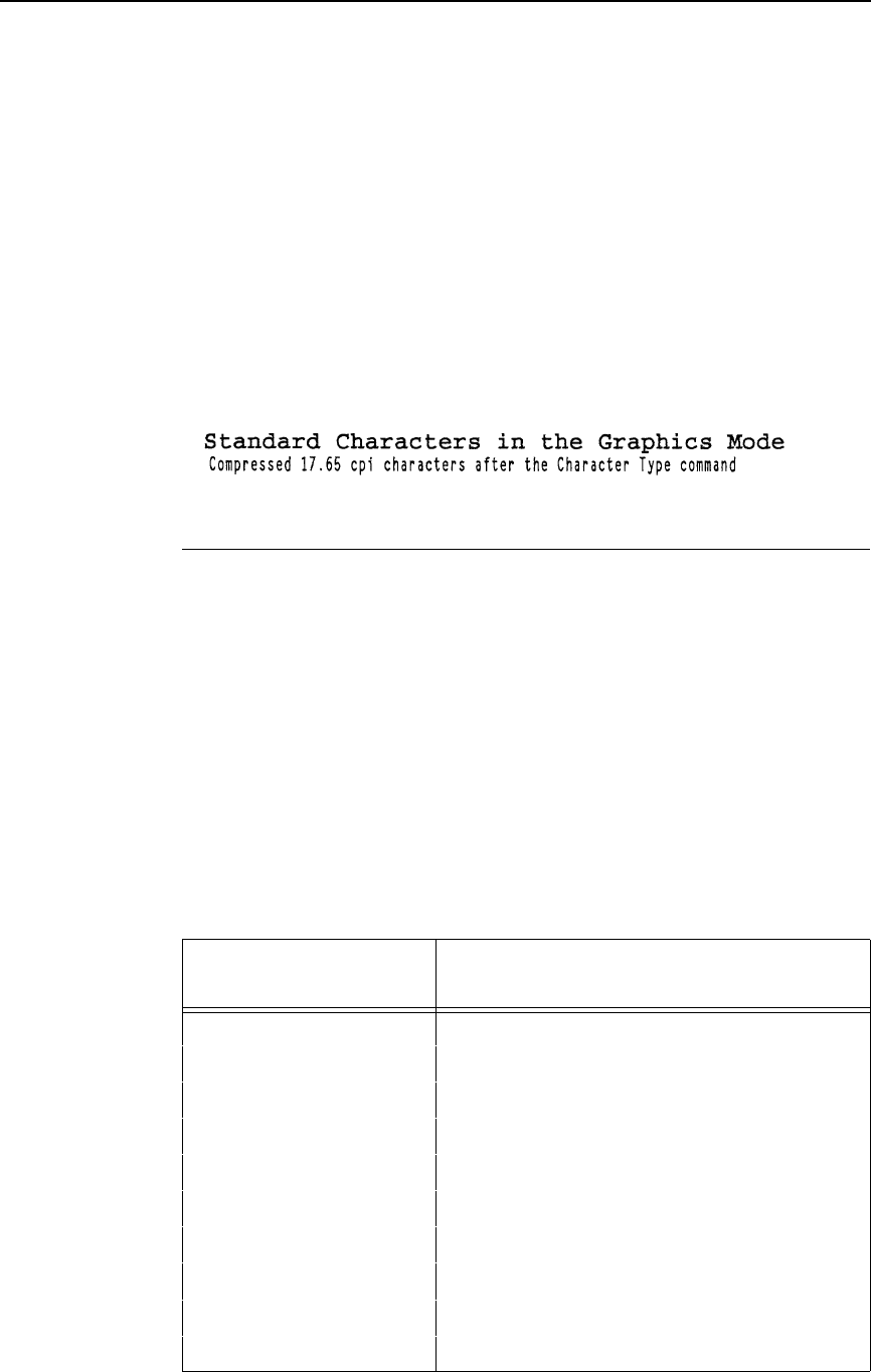
Compressed Print
47
NOTE: Due to different printing technologies and dot sizes, some printers
may not be capable of printing small characters clearly.
Example The following example illustrates changing character type from
the standard characters to 17.65 cpi characters.
^PY^-
Standard Characters in the Graphics Mode
^@C17^*Compressed 17.65 cpi characters after the Character Type
command^*
^@C10^-
^PN^-
NOTE: The second character type is sent to return VGL to standard 10 cpi
print.
Compressed Print
Purpose Selects a compressed print font.
Mode Graphics with a Standard Graphic Command selected
Format (cc) #x (cc)- data (cc)*
(cc) #0 (cc)-
(cc) Represents the Special Function Control Code
(SFCC). Enter the specific SFCC for your VGL
configuration.
#xSpecifies the compressed print font to use. The
values for x and the corresponding compression
are shown in Table 5.
Table 5. Compressed Print Fonts
Selection
Code (x)Compressed Print Font
Characters per Inch (cpi)
0Terminate compressed print
110 cpi
212 cpi
313.33 cpi
415 cpi
517.65 cpi
6OCR-A
7OCR-B
812 cpi
915 cpi
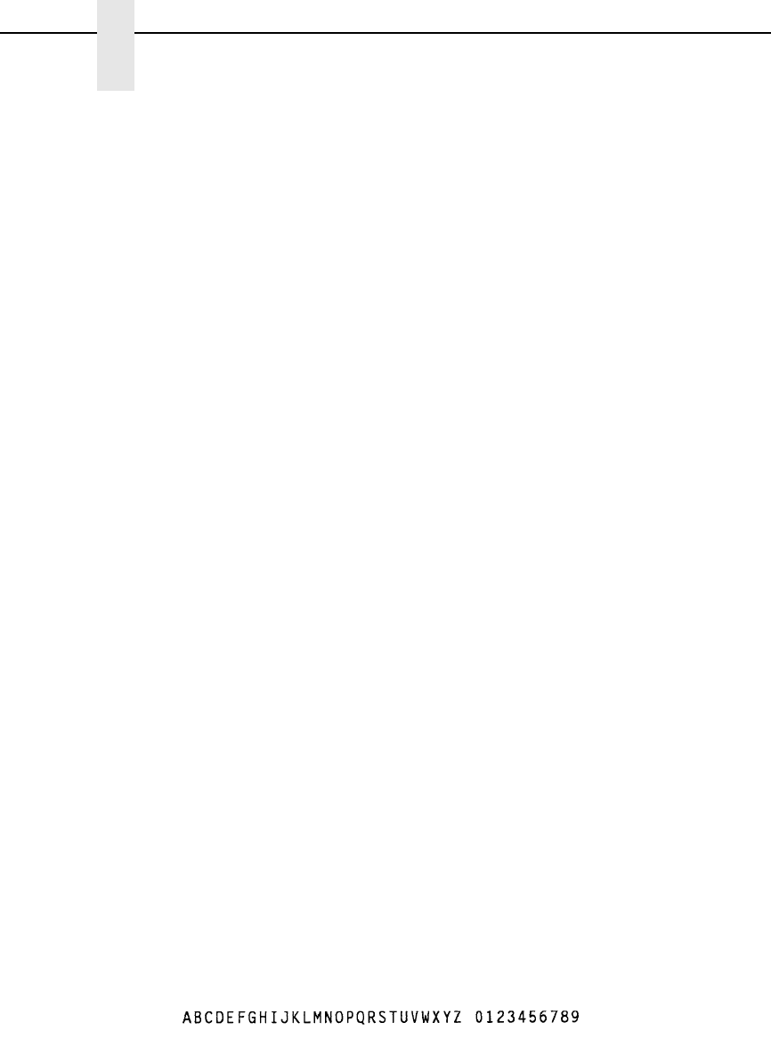
48
Chapter 2
Command Codes
(cc)- Graphics Mode CR used as a sequence terminator
representing an end to the initial command
sequence. Enter the SFCC for your VGL
configuration immediately followed by - to end the
initial sequence.
data The data for compressed print. All characters are
printed in the specified compressed print font until
the compressed print command is terminated (0).
(cc)* Graphics Mode LF used as a sequence terminator
representing an end to the data sequence. Enter
the SFCC for your VGL configuration immediately
followed by * to end the data sequence.
(cc)#0 The command to terminate compressed printing.
On a separate line, enter the SFCC for your VGL
configuration immediately followed by #0 to
terminate use of the compressed print font.
(cc)- Graphics Mode CR. Enter the SFCC for your VGL
configuration immediately followed by - to end the
command sequence.
Comments
The Compressed Print command can be used anytime VGL is in
the Graphics Mode to select one of the compressed print fonts.
The Compressed Print Off command must be on a separate line
from a Compressed Print On command.
Do not place compressed print and alphanumeric commands
from the Extended Graphics command set on the same print line.
All pass-through text data input after the Compressed Print On
command and before the Compressed Print Off command prints
in the selected compressed print font.
Examples #1: 12 cpi Compressed Print Font. The following command
generates the uppercase alphabet with numbers 0-9 in the 12 cpi
compressed print font.
^PY^-
^#2^-BCDEFGHIJKLMNOPQRSTUVWXYZ 0123456789^*
^#0^-
^PN^-
#2: 13.33 cpi Compressed Print Font. The following command
generates the uppercase alphabet with numbers 0-9 in the 13.33
cpi compressed print font.
^PY^-
^#3^-ABCDEFGHIJKLMNOPQRSTUVWXYZ 0123456789^*
^#0^-
^PN^-
compress
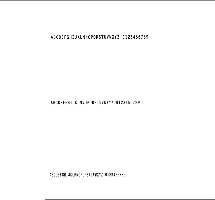
Dark Print
49
#3: 15 cpi Compressed Print Font. The following command
generates the uppercase alphabet with numbers 0-9 in the 15 cpi
compressed print font.
^PY^-
^#4^-ABCDEFGHIJKLMNOPQRSTUVWXYZ 0123456789^*
^#0^-
^PN^-
#4: 17.65 cpi Compressed Print Font. The following command
generates the uppercase alphabet with numbers 0-9 in the 17.65
cpi compressed print font.
^PY^-
^#5^-ABCDEFGHIJKLMNOPQRSTUVWXYZ 0123456789^*
^#0^-
^PN^-
Dark Print
Purpose Activates the dark printing feature on line matrix printers to
produce darker images.
Mode Graphics with an Extended Graphics Command selected
Format (cc) KF data (cc) KF (cc)-
(cc) Represents the Special Function Control Code
(SFCC). Enter the specific SFCC for your VGL
configuration.
KF The Dark Print command. Enter KF to turn on the
dark printing feature.
data Represents the data characters for dark printing.
(cc) KF Following the data, enter the Special Function
Control Code (SFCC) for your VGL configuration
and KF to turn off the dark printing feature.
(cc)- Graphics Mode CR used as a sequence terminator.
Enter the SFCC for your VGL configuration
immediately followed by - to end the command
sequence.
compress
compress.ex5
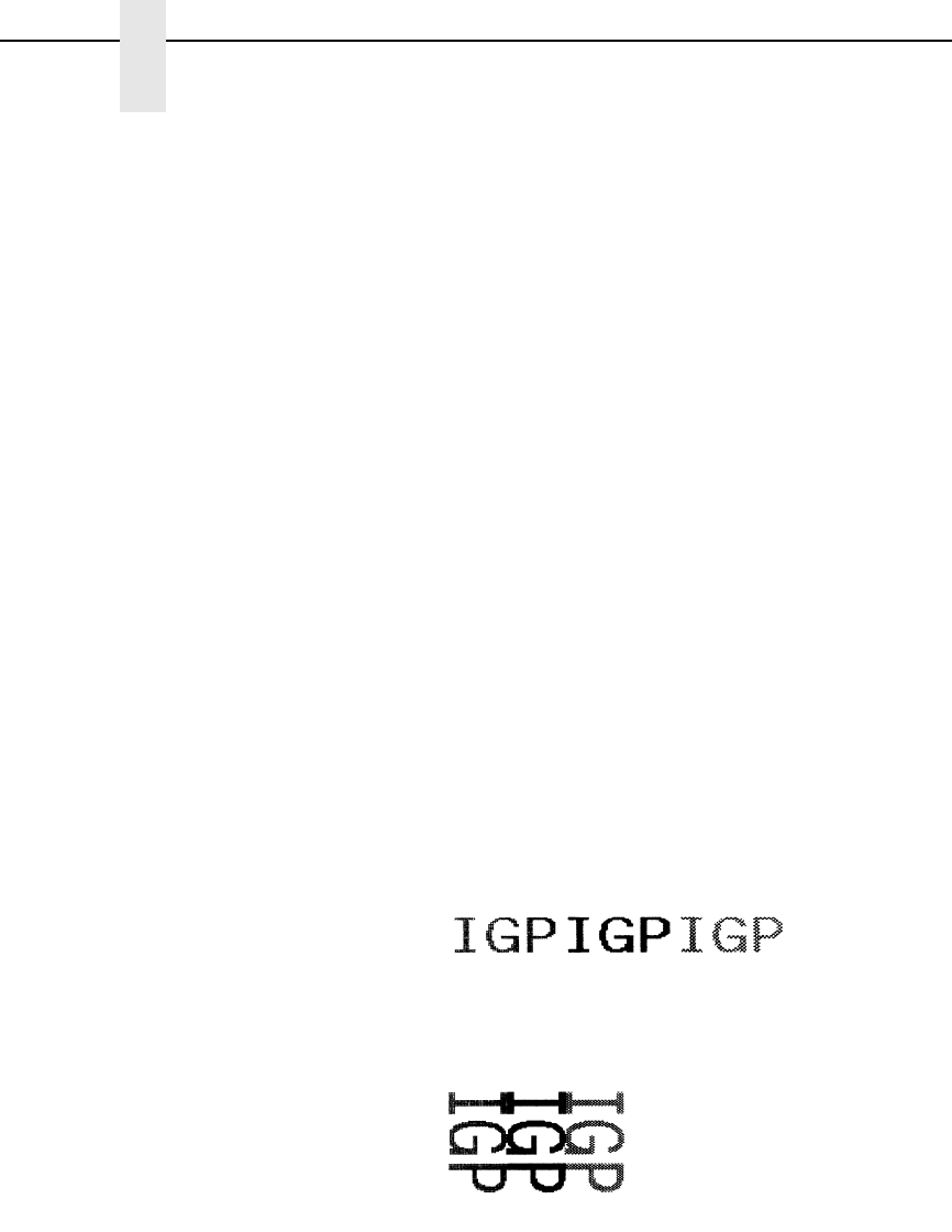
50
Chapter 2
Command Codes
Comments
NOTE: Dark printing has no effect on thermal and laser L7032 printers and is
included for compatibility with line matrix printers.
Dark Print command prints all dot positions at half-dot resolution
to produce images with a darker intensity. The KF command
provides special attention when used with barcodes to provide
darker barcodes, yet not change the critical bar-width
dimensions. Human readable data, however, will print in non-dark
mode. Dark print is discussed further in the Chapter 3, on
page 159.
The KF command operates as a toggle. The first KF command
enables dark printing, the second KF disables dark printing, the
third KF enables dark printing, and so on.
All data following the first KF command will print dark until the
second KF command is encountered.
The KF command is a part of the data contained in an
alphanumeric command. When the alphanumeric command
sequence is terminated, dark printing is also disabled.
Reverse printing and shading or mask shading can be combined
with dark printing to produce a variety of different shades.
Example The following sample commands illustrate dark printing.
Combining shading and dark print is also shown.
^PY^-
^M03,03,000IGP^KFIGP^KHIGP^KH^KF^-
^PN^-
^PY^-
^V05,05,000IGP^KFIGP^KHIGP^KF^KH^-
^PN^-

Descending Characters
51
Descending Characters
Purpose Prints descending lowercase characters one of two ways: 1) by
extending below the print baseline, or 2) by raising the characters
slightly to completely contain the descending characters above
the print baseline.
Mode Graphics with an Extended Graphics Command selected
Format (cc) D data (cc)D (cc)-
(cc) Represents the Special Function Control Code
(SFCC). Enter the specific SFCC for your VGL
configuration.
D The Descending Character command. Enter D.
data The data characters for descending character
printing. Only lowercase descending characters are
printed extending below the print baseline.
(cc)D Following the data, enter the Special Function
Control Code (SFCC) for your VGL configuration
and D to turn off descending character printing.
(cc)- Graphics Mode CR used as a sequence terminator.
Enter the SFCC for your VGL configuration
immediately followed by - to end the command
sequence.
Comments
Descending characters are the lowercase characters g, j, p, q,
and y and are the only characters affected by this command.
Normal descending characters extend below the baseline of
normal print. Unless specified, VGL begins each alphanumerics
command sequence with descending character print turned off,
which means the characters are printed completely above the
print baseline.
The D command operates as a toggle. The first D command
enables descending characters to print below the baseline, the
second D command disables this feature, the third D command
enables, and so on. All lowercase descending character data
following the first D command prints below the print baseline until
the next D command is encountered.
The D command is input as part of the data in one of the
alphanumeric commands. When the alphanumerics command
sequence is terminated, descending character printing is also
terminated.
When the D command is turned on, VGL automatically allows
space for the descending characters whether or not descending
characters are part of the data. The amount of space allowed is
two dot rows per tenth inch of character height. This space
produces a gap under the standard print baseline of
non-descending characters. This space also produces a larger
reverse print character image background area.
52
Chapter 2
Command Codes
NOTE: The default setting for the D command is OFF.
The default setting for the IFONT command, however, is ON.
If the D command is used after an IFONT command and before the
command terminator, the D command will always be ON. The IFONT
command always overrides a D command.
Example The following sample commands illustrate descending character
printing. In the first example, notice that the alphanumerics
command sequence terminator was also used to end descending
character printing. In the second example, notice that when using
the rotate clockwise (^V) command with descending characters,
and dots are positioned in the first dot column, a .10-inch tab was
required to prevent out-of-bounds descending characters.
^PY^-
^M02,02,000IGP or igp^D and IGP or igp^-
^PN^-
^PY^-
^V03,03,000^T0010igp^Digp^D^-
^PN^-
descend.ex2
Direct Printer Commands
53
Direct Printer Commands
Purpose Sends control characters for special purposes directly to the Line
Printer Plus emulation.
Mode Graphics with a Standard Graphic Command selected
Format See Table 6.
NOTE: The commands in Table 6 are not supported on L7032 printers.
NOTE: Do not use the ^# direct printer command to send hex 03 to the
printer at the start of a line. This is to avoid confusion with the
Compressed Print command described on page 47.
Comments
A detailed understanding of Line Printer Plus function and
response to the control characters is recommended. Refer to the
Line Printer Plus Programmer’s Reference Manual for information
regarding the hex codes for various printer commands.
The Graphics Mode must be entered before sending the direct
printer commands. However, do not use these commands within
an extended graphics command sequence.
Example The following example command sequence sends hex 05 to the
printer, initiating the printer plot command to plot the data.
^PY^-
^% data ^-
Table 6. Direct Printer Commands
Direct Command Hex Code Sent to the Printer
^ ! 01
^ ” 02
^ # 03 (see note below)
^ $ 04
^ % 05
^ & 06
^ ’ 07
^ ( 08
^ . 0E
^ / 0F
54
Chapter 2
Command Codes
Dot Slew
Purpose Changes the vertical print position by specifying a number of dot
rows to advance the paper from the current print position.
Mode Graphics with a Standard Graphic Command selected
Format (cc) D n (cc)-
(cc) Represents the Special Function Control Code
(SFCC). Enter the specific SFCC for your VGL
configuration.
D The Dot Slew command. Enter D.
nSpecifies the number of dot rows to advance (slew)
the paper from the current print position. Enter a
two-digit number of dot rows ranging from 01
through 99. For example, enter 05 to slew 5 dot
rows, 21 to slew 21 dot rows.
(cc)- Graphics Mode CR. Enter the SFCC for your VGL
configuration immediately followed by - to end the
command sequence.
Comments
The (cc)Dn Dot Slew command dot values are interpreted as 60
dpi P-Series dots.
Duplication, Horizontal
Purpose Activates horizontal duplication.
Mode Graphics with a Standard Graphics Command selected
Format (cc) S # spacing (cc)- data (cc)S (cc)-
(cc) Represents the Special Function Control Code
(SFCC). Enter the specific SFCC for your VGL
configuration.
S The Horizontal Duplication command. Enter S to
turn on the horizontal duplication feature.
# Specifies the number of horizontal duplications to
print. Enter a two-digit number ranging from 00
through 99 to specify the number of copies.
spacing Represents the amount of spacing, in tenth inches,
between each duplication. The spacing amount
should include a sufficient space to contain the
complete printed result of the duplicated command
sequence plus space for a margin between copies.
The right edge of the last duplication must not
exceed selected page width. Enter a two-digit
number ranging from 00 through 99 to specify a 0.0
through 9.9 inch spacing for the copies.
Duplication, Horizontal
55
(cc)- Graphics Mode CR used as a sequence terminator
representing an end to the data. Enter the SFCC
for your VGL configuration immediately followed by
- to end the command sequence.
data Represents the data to be repeated. Enter any valid
VGL Graphics Mode command. Specific command
sequences are input as part of the Horizontal
Duplication data. These commands are then
repeated as specified in the Horizontal Duplication
command.
(cc)S (cc)- Mandatory Horizontal Duplication command
sequence terminator. Enter the SFCC for your VGL
configuration immediately followed by S, another
SFCC, and - to end terminate the Horizontal
Duplication command sequence.
Comments
The S command operates as a toggle. The first S command
enables horizontal duplication, the second S command disables
horizontal duplication, the third S command enables duplication,
and so on.
All data following the first S command repeats the number of
times specified until the second S command is encountered.
Copies are produced across the page as many times as
requested or until the page width is reached. Any duplications
that would print beyond column 132 are lost and cause an
Element Off Page error (Error 48).
Example The following sample command illustrates horizontal duplication.
This extended graphics command sequence consists of a
Standard Alphanumeric command using the letters "IGP" printed
at a height of 0.2". "IGP" is being duplicated 5 times with a gap of
0.8" between each duplication (0.6" space plus a 0.2" margin
between each duplication).
^PY^-
^S05,08^-^M02,02,000IGP^-^S^-
^PN^-
ho

56
Chapter 2
Command Codes
Duplication, Horizontal (Version II)
This command performs the same function as (cc)S described on page 54.
The IREPH command can also operate within an Extended Graphics
command. You must enable the Free Format command for this command to
work properly.
Purpose Defines both the number of times data is horizontally duplicated
(repeated), and the horizontal spacing between each duplication.
Mode Graphics with a Standard Graphics Command selected or
Graphics with an Extended Graphics Command selected
Format (cc) IREPH, n, spacing (cc)G data (cc)IREPE
(cc) Represents the Special Function Control Code
(SFCC). Enter the specific SFCC for your VGL
configuration.
IREPH, The horizontal duplication command. Enter
IREPH,.
n, Represents the number of times to duplicate the
data horizontally. Enter a value which allows the
characters to print within the horizontal page
boundaries. Enter a value ranging from 1 through
99.
spacing Represents the amount of horizontal spacing
between the start of each set of repeated data.
Enter up to three numbers.
The first and second digits represent horizontal
tenths, and the third digit represents horizontal
dots. If less than three digits are entered, zeros are
automatically inserted from left to right.
Example:
001
012
123
(cc)G The universal terminator. Enter the SFCC for your
VGL configuration immediately followed by G to
terminate the IREPH command.
data Represents the data to be repeated. Enter any valid
VGL Graphics Mode command. Specific command
sequences are input as part of the Horizontal
Duplication data. These commands are then
repeated as specified in the Horizontal Duplication
command.
One Horizontal Duplication command can be
contained within a Horizontal Duplication
command. The total number of characters within
the command sequence (including all repetitions)
must be 256 characters less than the maximum
size of the input buffer.
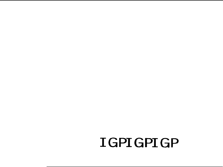
Duplication, Vertical
57
(cc)IREPE The horizontal duplication end command. Enter the
SFCC for your VGL configuration immediately
followed by IREPE to end the horizontal duplication
command.
Comments
Multiple IREPH/IREPE duplication loops can be used in a form
and can also be nested. Vertical duplication loops (IREPV/
IREPE) can also be used in conjunction with IREPH. Each
IREPH must have a corresponding IREPE.
Example The following command repeats "IGP" 3 times horizontally using
the IREPH, command, separating each set of "IGP" with 5 tenths
plus 2 dots of horizontal spacing.
^PY^-^F^-
^IREPH,3,52^G^M02,02,000IGP^-^IREPE
^O^-^PN^-
Duplication, Vertical
Purpose Prints multiple copies of data vertically down the page.
Mode Graphics with a Standard Graphics Command selected
Format (cc) R # (cc)- data (cc)Z(cc)-
(cc) Represents the Special Function Control Code
(SFCC). Enter the specific SFCC for your VGL
configuration.
R Specifies the Vertical Duplication command. Enter
R to activate vertical repetition.
#Specifies the number of times to repeat the data,
that is, specifies the number of copies to print.
Enter a four digit number ranging from 0000
through 9999 to specify the number of copies.
(cc)- Mandatory Graphics Mode CR terminator. Enter
the SFCC for your VGL configuration immediately
followed by - to end terminate the initial Vertical
Duplication command sequence.
data Represents the data to be repeated. Enter any valid
VGL Graphics Mode command. Specific command
sequences are input as part of the Vertical
Duplication data. These commands are then
repeated as specified in the Vertical Duplication
command.
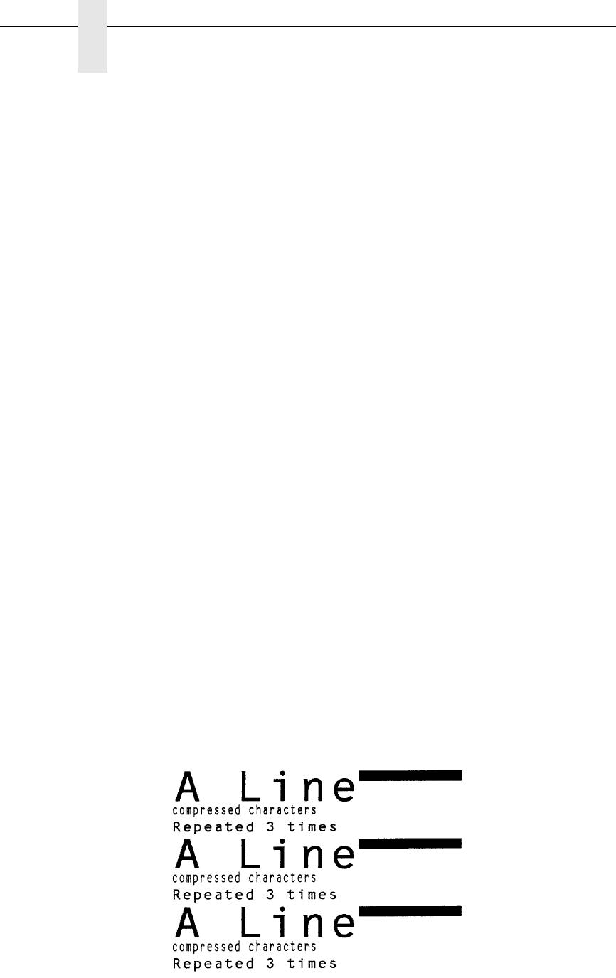
58
Chapter 2
Command Codes
One Vertical Duplication command can be
contained within a Vertical Duplication command.
The total number of characters within the command
sequence (including all repetitions) must be 256
characters less than the maximum size of the input
buffer.
(cc)Z(cc)- Mandatory Vertical Duplication command
sequence terminator. Enter the SFCC for your VGL
configuration immediately followed by Z, another
SFCC, and - to end terminate the Vertical
Duplication command sequence. If a Vertical
Duplication command is nested within a Vertical
Duplication command, this single terminator
sequence terminates both Vertical Duplication
commands.
If Auto Increment/Decrement command parameters
are used with this command (page 59), this
terminator causes all the numeric fields to increase/
decrease (as specified by the Auto Increment/
Decrement command) at the end of the repeat
pass. If the (cc)ZO(cc)- (alpha O) terminator is
used, all numeric fields are updated sequentially
within the repeat pass. See “Auto Increment/
Decrement Vertical Duplication” on page 59 for
more information.
Example The following example illustrates the Vertical Duplication
command. Alphanumeric commands, line elements, and
standard graphics commands are repeated 3 times down the
page. (The ^*^* causes the two line feeds on which the data is
repeated. See the Free Format commands discussed on pages
99 and 102.)
^PY^-^F^-
^R0003^-^M03,03,000A Line^LS0100,0010^-
^M^D^S4compressed characters^-
^M^D^S1Repeated 3 times^*^*^Z^-
^O^-^PN^-
v
er
tdu

Duplication, Vertical
59
Auto Increment/Decrement Vertical Duplication
Purpose Updates increment and decrement data within a Vertical
Duplication command sequence (page 57).
Format (cc) Y start# +/- amount (cc)G
(cc) Represents the Special Function Control Code
(SFCC). Enter the specific SFCC for your VGL
configuration.
Y Specifies the Auto Increment/Decrement
command. Enter Y to activate automatic update of
repeated numeric data fields.
start# Represents the starting numeric data to automati-
cally update. Enter the starting number of the
numeric data field ranging from 1 through 12 digits.
This number is the first numeric data printed and
subsequently updated according to the +/- and
amount parameters. Spaces are converted to zeros
when necessary.
+/- Specifies increment or decrement updates to the
numeric data. Enter + to increment the data or
enter - to decrement the data.
amount Represents the numeric amount to update the data
field. Enter the update amount ranging from 1
through 12 digits. Spaces are converted to zeros
when necessary.
(cc)G The universal terminator. Enter the SFCC for your
VGL configuration immediately followed by G to ter-
minate the auto increment/decrement command.
The terminator used in the Vertical Duplication command
determines when each inner auto increment field of a nested
repeat sequence is updated (incremented/decremented). If the
(cc)Z(cc)- Vertical Duplication command terminator is used, each
inner field is updated at the end of the repeat pass. For example,
four fields within a repeat pass would all be updated together at
the end of each repeat pass. If, however, the (cc)ZO(cc)- Vertical
Duplication command terminator is used in the same example,
each of the four inner fields is updated sequentially within the
overall repeat pass.
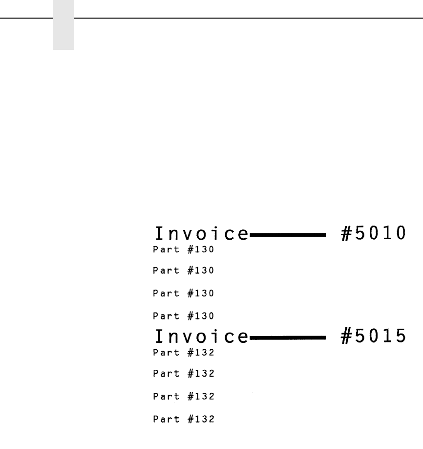
60
Chapter 2
Command Codes
Example 1 The following example illustrates the Vertical Duplication
command with Auto Increment/Decrement of numeric fields
updated at the end of the repeat pass. (The ^* on the fourth line
causes a line feed on which the second set of Invoice data is
printed. See the Free Format commands discussed on pages 99
and 102.)
^PY^-^F^-
^R0002^-^M02,02,000Invoice
^J010^LS0106,0004^J000 #^Y5010+5^G^-
^R0004^-^M01,01,010Part #^Y130+2^G^-^*^Z^-
^O^-^PN^-
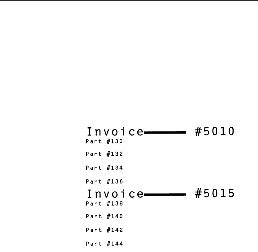
Duplication, Vertical
61
Example 2 The following example illustrates the same Vertical Duplication
command but uses the different terminator for Auto Increment/
Decrement of numeric fields updated sequentially within the
repeat pass. (The ^* on the fourth line causes a line feed on
which the second set of Invoice data is printed. Refer to the Free
Format commands discussed on pages 99 and 102.)
^PY^-^F^-
^R0002^-^M02,02,000Invoice
^J010^LS0100,0004^J000 #^Y5010+5^G^-
^R0004^-^M01,01,010Part #^Y130+2^G^-^*^ZO^-
^O^-^PN^-
(cc)Y can be used in conjunction with IREPV and IREPH to
achieve auto increment/decrement on both vertical duplication
and horizontal duplication for the data, including numeric,
alphabetical and barcode data. (cc)Y can also work with (cc)R
vertical duplication command (page 57), but NOT with (cc)S
horizontal duplication command (page 54). If the data is non-
alphanumeric (except for space characters) and you are using
the (cc)Y command with the (cc)R Vertical Duplication command,
an error occurs. If the data exceeds 12 digits in length, an error
also occurs.
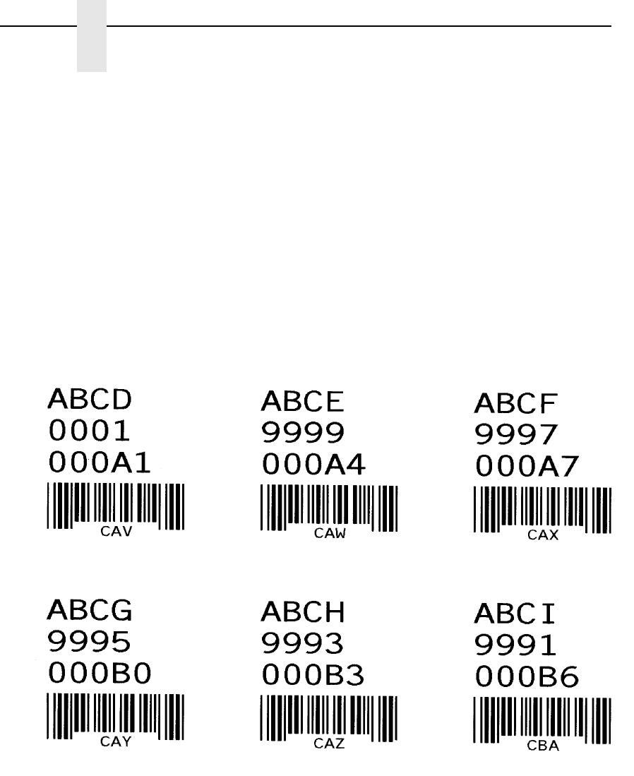
62
Chapter 2
Command Codes
Example The following example illustrates the vertical/horizontal
duplication commands using IREPV/IREPH.
^PY^-^F^-
^IREPV,2,0050^G
^IREPH,3,200^G
^M0202010^YABCD+1^G^-
^M0202010^Y0001-2^G^-
^M0202010^Y000A1+3^G^-
^M0505010^IBARC,C39,E,^YCAV+1^G^-
^IREPE^-
^IREPE^-
^O^-^PN^-

Duplication, Vertical (Version II)
63
Duplication, Vertical (Version II)
This command performs an enhanced function of the (cc)R command
described on page 57. The IREPV command can also operate within an
Extended Graphics command, and vertical spacing between each duplication
can be specified. You must enable the Free Format command for this
command to work properly.
Purpose Defines both the number of times data is vertically duplicated
(repeated), and the vertical spacing between each duplication.
Mode Graphics with an Extended Graphics Command selected
Format (cc) IREPV, n, spacing (cc)G data (cc)IREPE
(cc) Represents the Special Function Control Code
(SFCC). Enter the specific SFCC for your VGL con-
figuration.
IREPV, The vertical duplication command. Enter IREPV,.
n, Represents the number of times to duplicate the
data vertically. Enter a value ranging from 1
through 9999.
spacing Represents the amount of vertical spacing to
separate each set of repeated data. Enter up to
four numbers.
The first, second and third digits represent vertical
tenths, and the fourth digit represents vertical dots.
If less than four digits are entered, zeros are
automatically inserted from left to right.
Example:
0001
0012
0123
1234
(cc)G The universal terminator. Enter the SFCC for your
VGL configuration immediately followed by G to
terminate the IREPV command.
data Represents the data to be repeated. Enter any valid
VGL Graphics Mode command. Specific command
sequences are input as part of the Vertical
Duplication data. These commands are then
repeated as specified in the Vertical Duplication
command.
One Vertical Duplication command can be
contained within a Vertical Duplication command.
The total number of characters within the command
sequence (including all repetitions) must be 256
characters less than the maximum size of the input
buffer.
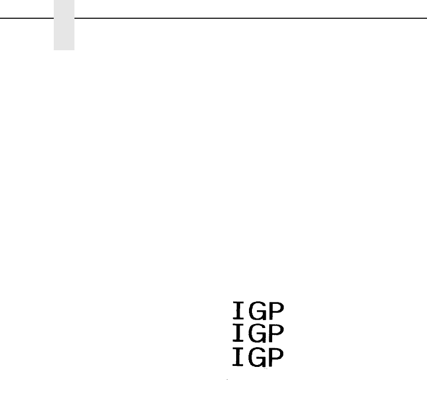
64
Chapter 2
Command Codes
(cc)IREPE The vertical duplication end command. Enter the
SFCC for your VGL configuration immediately
followed by IREPE to end the vertical duplication
command.
Comments
Multiple IREPV/IREPH duplication loops can be used in a form
and can also be nested. Horizontal duplication loops (IREPH/
IREPE) can also be used in conjunction with IREPV. Each IREPV
must have a corresponding IREPE.
Example The following command repeats "IGP" 3 times vertically using the
IREPV, command, separating each line with 3 tenths plus 4 dots
of vertical spacing.
^PY^-^F^-
^IREPV,3,4^G^M02,02,000IGP^-^IREPE
^O^-^PN^-

Dynamic Form Commands
65
Dynamic Form Commands
Purpose Permits an entire form or label to be sent to VGL with variable
data entered into specific locations on each form.
Mode Graphics with a Standard Graphic Command selected
Format (cc) B (cc)- data (cc)t
(cc) Represents the Special Function Control Code
(SFCC). Enter the specific SFCC for your VGL con-
figuration.
B Specifies the Dynamic Form command. Enter B to
begin dynamic forms.
(cc)- The Graphics Mode CR. Enter the SFCC for your
VGL configuration immediately followed by - to ter-
minate the initial Dynamic Form command
sequence.
data Represents the dynamic form data. Any text,
graphics command sequences, or Dynamic Form
Field Length, Copy or Repeat commands are
entered as part of the data. (See Comments.)
This is not the dynamic data for the variable fields;
this data represents all information required for the
boilerplate form.
(cc)tTerminates the complete Dynamic Form command
sequence. Enter the SFCC for your VGL
configuration immediately followed by ] or } to
terminate the Dynamic Form processing. The
dynamic data for the variable fields can be sent
following termination of the completed Dynamic
Form command.
Comments
Dynamic form commands allow a boilerplate form to be
transmitted once. The data that changes with each form is
provided in the variable data fields after the Dynamic Form
command is terminated. Variable fields can include barcode data
fields.
The Dynamic Form commands consist of the primary Dynamic
Form command referenced above, which enables dynamic form
generation, and three additional commands listed below. These
additional commands are added to the primary command
according to your particular dynamic form requirements:
•Dynamic Form Field Length (defined on page 67) specifies the
number of data bytes expected to fill a variable data field.
•Dynamic Form Copy Fields (defined on page 69) copies fields
within the form.
•Dynamic Form Repeat Form (defined on page 71) repeats the
complete form.

66
Chapter 2
Command Codes
Dynamic Form Special Command Definitions
The graphics carriage return, line feed, form feed, vertical tab, and universal
terminator commands are interpreted differently when used within the
Dynamic Form commands. These interpretations are described below.
(CR) Carriage Return (^-) - Fills the remainder of the current dynamic field
with spaces. If this is the only input, the entire field is filled with spaces.
(LF) Line Feed (^*) - Fills (pads) the remainder of the current dynamic field
and all remaining dynamic fields in the form with spaces. If this is the only
input, the entire field is filled with spaces. If used within a dynamic copy
command, all fields to the end of the current copy are filled with spaces. If
used with a dynamic repeat command, all remaining fields of all copies are
filled with spaces.
(FF) Form Feed (^,) - Performs the same function as LF, except for use
within a dynamic copy command. If used within a dynamic copy command, all
fields to the end of copy are filled with spaces, and all fields continue to fill
with spaces until the copy count is complete.
(VT) Vertical Tab (^+) - Causes the remainder of the current dynamic field to
be ignored. No data is printed in the current dynamic field if this is the only
input in the field.
(G) Universal Terminator (^G) - Terminates the dynamic Form function and
completes the current graphics command sequence.
Example Examples using the Dynamic Data command features are
provided following the discussion of each command.

Dynamic Form Commands
67
Dynamic Form: Field Length
Purpose Assigns a field length to each variable field in a boilerplate
dynamic form.
Format (cc) t length (cc)-
(cc) Represents the Special Function Control Code
(SFCC). Enter the specific SFCC for your VGL
configuration.
tSpecifies the Dynamic Form Field Length
command. Enter [ or { to designate a field length
follows.
length Represents the field length. Enter a three-digit
number to inform VGL how many data bytes are
expected to fill a certain variable data field. Each
variable data field on the form must have an associ-
ated field length.
(cc)- Graphics Mode CR used as a sequence terminator.
Enter the SFCC for your VGL configuration
immediately followed by - to end the command
sequence.
Comments
This Dynamic Form: Field Length command is supplied as part of
the data within the Dynamic Form command. The length is
assigned to a variable field at the current position based on all
other commands and data within the Dynamic Form command.
For example, if alphanumeric commands are input followed by a
tab followed by this length command, the length is assigned
beginning at the position after the alphanumeric command and
tab are executed.
Each variable field in a boilerplate dynamic form must have a field
length assigned. The field length specifies how many data bytes
are required to fill the field. For example, a form might have a
variable field called "quantity" which could be specified as three
data bytes. VGL would then expect three data bytes supplied
dynamically to fill that field.
Following the completed Dynamic Form command, the data is
sent and the forms are processed. The data is sent in the order of
the variable fields. The first data sent fills the first variable field;
the second data sent fills the second variable field, etc. The data
must be the same length as the field or special dynamic form
commands (CR, LF, FF explained on page 66) must be used to
fill the field.
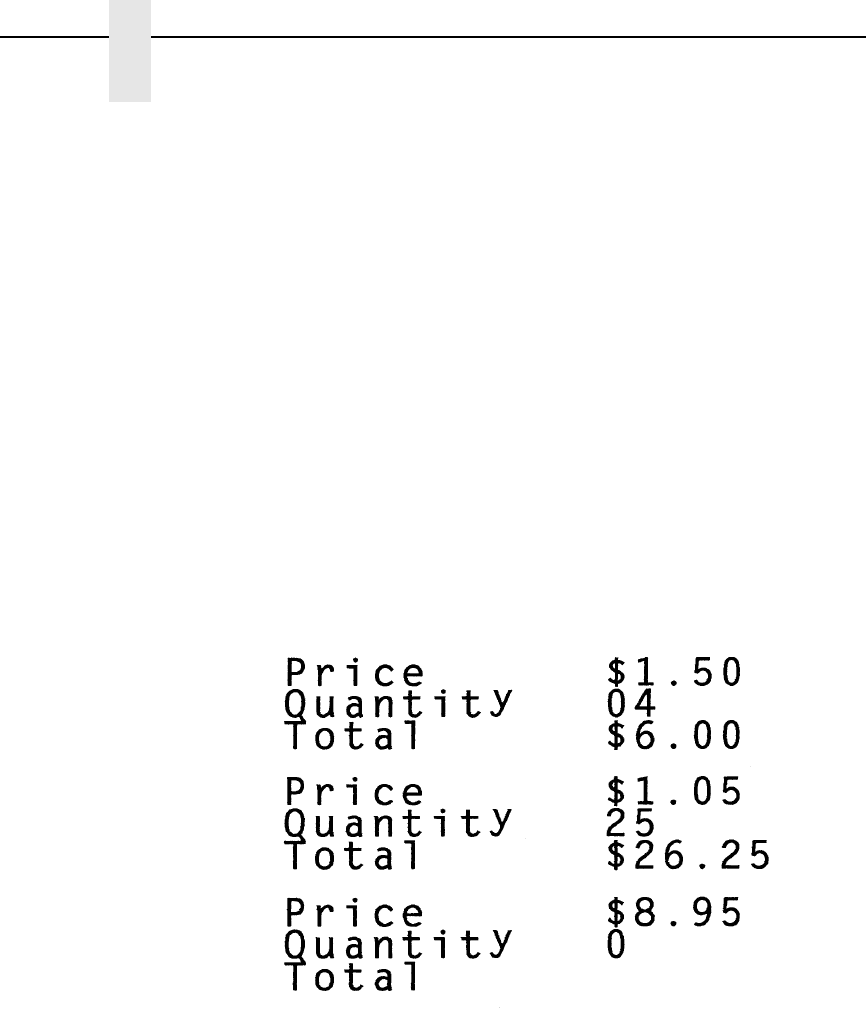
68
Chapter 2
Command Codes
Example This example illustrates the Dynamic Form command. Three
variable fields are used: one each for Price, Quantity, and Total.
Following the command sequence, the dynamic data is sent to fill
the variable fields. The special use of the CR command for
dynamic forms is shown in the example with the dynamic data.
^PY^-^F^-
^B^-^M02,02,000Price^T0220^[005^-
^M02,02,002Quantity^T0220^[002^-
^M02,02,002Total^T0220^[006^-^*^*^]
$1.5004$6.00^-
$1.0525$26.25
$8.950^-
^G
^O^-^PN^-
Three sets of dynamic data in this example are defined as follows:
1. $1.50 Price, 04 Quantity, $6.00 Total, CR to fill with spaces
2. $1.05 Price, 25 Quantity, $26.25 total
3. $8.95 Price, 0 Quantity, CR to fill with spaces
4. End of data (^G)

Dynamic Form Commands
69
Dynamic Form: Copy Fields
Purpose Duplicates specific fields or data within a boilerplate dynamic
form.
Format (cc) C # copydata (cc)Z(cc)-
(cc) Represents the Special Function Control Code
(SFCC). Enter the specific SFCC for your VGL
configuration.
C Specifies the Dynamic Form Copy Fields
command. Enter C to copy fields within the form.
# Specifies the number of copies. Enter a two-digit
number to inform VGL how many copies of the
copy data to make within the form.
copydata Represents the copy data. Any text or graphics
command sequences (including Dynamic Form
Field Length) are entered as part of the data.
This is not the dynamic data for the variable fields;
this data represents all information to copy within
the boilerplate form.
(cc)Z(cc)- Terminates the copy sequence. Enter the SFCC for
your VGL configuration immediately followed by Z,
another SFCC, and - or another valid graphics
command mnemonic to terminate the Dynamic
Form Copy Fields sequence.
Comments
The dynamic copy command is supplied as part of the data within
the Dynamic Form command. Do not use this command with the
Dynamic Form: Repeat command (page 71).
The LF and FF commands (as previously described on page 66)
have an additional meaning when used with Dynamic Form:
Copy Fields commands.
Example The following example illustrates the Dynamic Form: Copy Fields
command. As in the previous example (page 68), the same three
variable fields are used for Price, Quantity, and Total, except that
the Price and Quantity fields are copied. Following the Dynamic
Form command sequence, the dynamic data is sent to fill the
variable fields. The special use of the LF command for dynamic
form copy fields is shown in the example with the dynamic data.
^PY^-^F^-
^B^-^M02,02,000Price^T0160^[005^*^*
^C02^M01,01Quantity^T0100^[002
^M01,01^T0170Total^T0250^[006^-
^*^Z^-^*^*^]
$1.5004$06.00
10$15.00
$1.0525$26.25
50$52.50
$8.9502$17.90
^*
$8.95^,
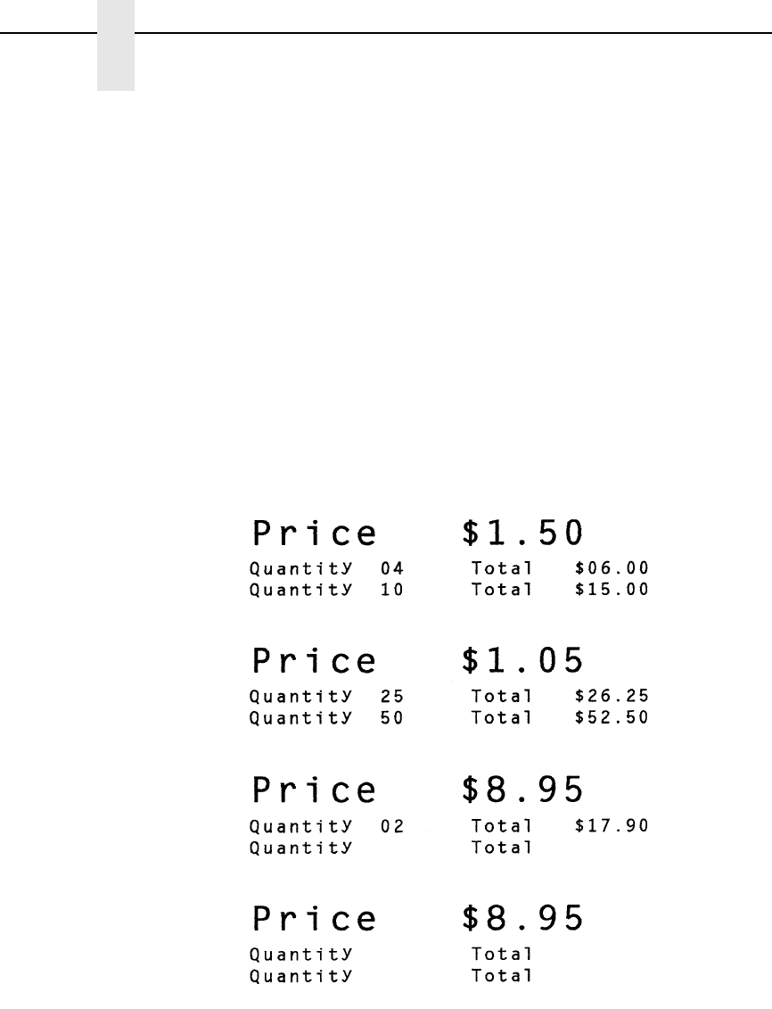
70
Chapter 2
Command Codes
^G
^O^-^PN^-
The dynamic data in the above example is defined below.
1. $1.50 Price, 04 Quantity, $06.00 Total
2. 10 Quantity, $15.00 Total
3. $1.05 Price, 25 Quantity, $26.25 Total
4. 50 Quantity, $52.50 Total
5. $8.95 Price, 02 Quantity, $17.90 Total
6. End of data in these fields (^*)
7. $8.95 Price, 0 Quantity, and FF to fill all fields with spaces until copy
count is complete.
8. End of data (^G)
dyn.

Dynamic Form Commands
71
Dynamic Form: Repeat
Purpose Repeats (duplicates) an entire form within a boilerplate dynamic
form.
Format (cc) R formdata (cc)Z(cc)-
(cc) Represents the Special Function Control Code
(SFCC). Enter the specific SFCC for your VGL
configuration.
R Specifies the Dynamic Form: Repeat command.
Enter R to repeat the boilerplate form.
formdata Represents the dynamic form data. Any text,
graphics command sequences, or dynamic form
field length, are entered as part of the data.
This is not the dynamic data for the variable fields;
this data represents all information required for the
boilerplate form to be repeated. The number of
copies of the form is specified as part of the
dynamic data sequence after the dynamic form is
processed.
(cc)Z(cc)- Terminates the repeat sequence. Enter the SFCC
for your VGL configuration immediately followed by
Z, another SFCC, and - or another valid graphics
command mnemonic to terminate the Dynamic
Form Copy Fields sequence.
Comments
The Dynamic Form: Repeat command is supplied as the first
input of the data parameter within the Dynamic Form command.
Do not use this command with the Dynamic Form: Copy Fields
command (page 69).
The LF and FF commands (as previously described on page 66)
have an additional meaning when used with Dynamic Form:
Repeat commands.
When the data is supplied, the first parameter becomes a four-
digit repeat number field. For example, 0003 before the first
dynamic data byte specifies three repeated forms with the data.
The repeat number field must be supplied with each set of data
when the Dynamic Form: Repeat command is used. If only one
copy of the form is required, enter 0001 as the repeat number.
72
Chapter 2
Command Codes
Example This example illustrates the Dynamic Form: Repeat command.
The Price field repeats with a five-digit field length. Following the
Dynamic Form command sequence, the dynamic data with the
repeat quantities is sent. The special use of the CR command for
dynamic forms is shown in the example with the dynamic data.
^PY^-^F^-
^B^-^R^-^M00,00,000^T0160Price^[005^-
^*^*^Z^-^]
0003$1.50
0002$1.0^-
0001$8.95
0000^G
^O^-^PN^-
The dynamic data in this example is defined as:
1. 3 copies with $1.50 Price
2. 2 copies with $1.0 Price, CR to fill with spaces
3. 1 copy with $8.95 Price
4. No data (^G)
dyn.e
Electronic Vertical Format Unit (EVFU)
73
Electronic Vertical Format Unit (EVFU)
Purpose To use the software-controlled vertical formatter which allows you
to program frequently used lines on forms and documents for
efficient printing processes when merging operations (such as
invoicing or payrolling).
Mode Graphics with a Standard Graphics Command selected
Format See Table 7.
NOTE: The codes in Table 7 are not supported on L7032 printers.
Table 7. EVFU Command Codes
EVFU Code Command
Start Load ^ >
Channel: 1 (TOF) ^ 0
Channel 2 ^ 1
Channel 3 ^ 2
Channel 4 ^ 3
Channel 5 ^ 4
Channel 6 ^ 5
Channel 7 ^ 6
Channel 8 ^ 7
Channel 9 ^ 8
Channel 10 ^ 9
Channel 11 ^ :
Channel 12 ^ ;
Channel 13 ^ <
Channel 14 ^ =
End Load ^ ?
74
Chapter 2
Command Codes
Comments
By flagging each line to be printed, the EVFU automatically
moves the printhead to the identified lines. The EVFU provides
14 channels (line identification codes) to identify up to 132 lines
on a form. For complete EVFU information, refer to your Line
Printer Plus Programmer's Reference Manual.
The EVFU is loaded with a program of line identification codes,
one code for each line of the form. The program includes a Start
Load code to initiate the load routine, a series of line identification
codes, and an End Load code. After the memory is loaded, a line
identification code occurring in the data stream causes the EVFU
to slew to the identified line. To clear the EVFU memory, send a
Start Load code with no channel codes or End Load code.
The Start Load, End Load, and Channel Code commands are
listed in Table 7. A sample EVFU form is shown in Table 8.
Table 8. Sample EVFU Form
Form Data Form Line # EVFU Load
Program
EVFU
Command
Code
Start Load ^>
1Ch 2 ^1
2Ch 2 ^1
Company: Timmy’s Toys 3Ch 1 ^0
4Ch 2 ^1
5Ch 2 ^1
6Ch 2 ^1
7Ch 2 ^1
Item: Tricycle 8Ch 3 ^2
9Ch 2 ^1
Color: Red 10 Ch 4 ^3
11 Ch 2 ^1
12 Ch 2 ^1
Quantity: 45 13 Ch 5 ^4
14 Ch 2 ^1
15 Ch 2 ^1
P/O Number: TT-1203 16 Ch 6 ^5
17 Ch 2 ^1
Electronic Vertical Format Unit (EVFU)
75
The format for the form definition program sent from the host computer is as
follows:
1. The EVFU Start Load code (^>) is sent first. VGL must be in the Graphics
Mode to load and use the EVFU in the Graphics Mode.
2. The Channel 2 code (^1) is sent twice to assign the first two lines of the
form as fillers. Filler lines are not called by the print program. The same
channel code can be used to assign all filler lines of the form.
3. The Channel 1 code (^0), the top-of-form (TOF) code, is sent to assign
form line number 3. This is the first line of the form with print data. In the
sample form, this line is used for company name information. (Alternately,
the TOF code could be assigned to the first line of the form and a unique
channel code assigned to line 3.)
4. The Channel 2 code is again sent four times to assign line numbers 4
through 7 as fillers.
5. The Channel 3 code (^2) is sent to assign line number 8. In the sample
form, this line is used for item information.
6. The Channel 2 code is sent to assign line number 9 as a filler.
7. The Channel 4 code (^3) is sent to assign line number 10. In the sample
form, this line is used for color information.
8. The Channel 2 code is sent twice to assign line numbers 11 and 12 as a
fillers.
9. The Channel 5 code (^4) is sent to assign line number 13. In the sample
form, this line is used for quantity information.
10. The Channel 2 code is sent twice to assign line numbers 14 and 15 as a
fillers.
11. The Channel 6 code (^5) is sent to assign line number 16. In the sample
form, this line is used for purchase order number information.
12. The Channel 2 code is sent twice to assign line numbers 17 and 18 as a
fillers.
13. The Channel 7 code (^6) is sent to assign line number 19. In the sample
form, this line is used for date information.
14. The Channel 2 code is sent to assign line number 20 as a filler.
15. The EVFU End Load code (^?) is sent last to terminate the memory load
routine.
18 Ch 2 ^1
Date: 12/24/86 19 Ch 7 ^6
20 Ch 2 ^1
End Load ^?
Table 8. Sample EVFU Form
Form Data Form Line # EVFU Load
Program
EVFU
Command
Code
76
Chapter 2
Command Codes
After the EVFU is loaded, sending one of the EVFU codes in the data stream
(or as a line terminator) causes the printer to slew the paper to the line
assigned to the EVFU code sent.
Emphasized Print
Purpose Selects emphasized (bold) character printing.
Mode Graphics with a Standard Graphics Command selected
Format (cc) @ E (cc)-
(cc) Represents the Special Function Control Code
(SFCC). Enter the specific SFCC for your VGL
configuration.
@ Specifies one of the @ commands. Enter @ to
begin an @ command function.
E Specifies the Emphasized Print command. Enter E
and all characters on the line are emphasized.
Emphasized print is automatically reset upon
receipt of the line terminator.
(cc)- Graphics Mode CR. Enter the SFCC for your VGL
configuration immediately followed by - to end the
command sequence.
Comments
Emphasized print is available when VGL is in the Graphics Mode.
Emphasized print is a line-by-line print attribute; it is selected
once and all characters in the line are emphasized. The @E
command must be used prior to any printable data in the line, and
it is automatically reset when a line terminator is received. When
printing text, this command produces the same output as the
Dark Print command.
Example The following example illustrates changing character type from
the standard characters to emphasized characters.
^PY^-
Standard Characters in the Graphics Mode^*
^@E^-Emphasized characters: ABCDEFGHIJKLMNOP^*^*
^PN^-
Emulation Switch
77
Emulation Switch
NOTE: The Emulation Switch command is not supported on L7032 printers.
Purpose Switches to a different emulation.
Mode Graphics with a Standard Graphics Command selected
Format (cc) IEMUL, des (cc)-
(cc) Represents the Special Function Control Code
(SFCC). Enter the specific SFCC for your VGL
configuration.
IEMUL, The emulation switch command. Enter IEMUL,.
des Enter PGL to switch to PGL emulation. Enter PPI1
to switch to ZGL emulation.
(cc)- Graphics Mode CR. Enter the SFCC for your VGL
configuration immediately followed by - to end the
command sequence.
Comments Once the system is switched to a new emulation, VGL will be
reset as the default. There is no need to exit the graphic mode
separately.
Font Load
Purpose Load binary TrueType font (.ttf) or Intellifont (.sf) into RAMDISK
or flash memory.
Mode Standard Graphics mode
Format (cc)ILOAD, name, size [,DISK] (cc)G data (cc)G(cc)-
(cc) Represents the Special Function Control Code
(SFCC). Enter the specific SFCC for your VGL
configuration.
ILOAD, The font load command. Enter ILOAD,.
name Specify associated binary TrueType font or
Intellifont data by name. Enter the name of the font,
including its extension. The maximum length of the
name is 8 characters and the maximum length of
the extension is 3 characters. For example,
93952.sf specifies Courier Bold (Intellifont) and
arial.ttf would represent Arial (TrueType). The
name is used by (cc) IFONT,N command.
size Enter the size, in bytes, of the binary TrueType font
or Intellifont data.
DISK Optional parameter to store the binary data in flash
memory. Enter DISK. By default, the binary data is
stored in RAMDISK when DISK is not specified.
(cc)G The universal terminator. Enter the SFCC for your
VGL configuration immediately followed by G to
terminate the ILOAD, command.

78
Chapter 2
Command Codes
data The binary TrueType font or Intellifont data to be
stored in memory.
(cc)G The universal terminator. Enter the SFCC for your
VGL configuration immediately followed by G to
terminate the binary font data parameter.
(cc)- Graphics Mode CR. Enter the SFCC for your VGL
configuration immediately followed by - to end the
command sequence.
Comment When loading fonts to RAMDISK, the printer files will not be
saved to RAMDISK when the printer is powered off. When
loading fonts to flash memory, the printer files will be saved when
the printer is powered off. Both RAMDISK and flash memory
support file operations such as saving, reading, and deleting files.
Font, Selecting Default (Version II)
Purpose Selects a default font.
Mode Standard Graphics or Graphics with an Extended Graphics
Command selected. When this command is executed as an
Extended Graphics command, descender mode automatically
turns on.
Format (cc) IFONT,S, n (cc)G
or
(cc) IFONT,N, name (cc)G
(cc) Represents the Special Function Control Code
(SFCC). Enter the specific SFCC for your VGL
configuration.
IFONT, Specifies the IFONT command. Enter IFONT,.
S,nRepresents the selected font value. Enter S,.
Replace n with a value ranging from 1 through 13,
or 100 or 101, according to the IFONT values
shown in Table 9 or as shown in the Font Values
section below.
N,name Represents the selected TrueType font or Intellifont
(AGFA) by name. Enter N, and the name of the font
with its extension. The maximum length of the
name is 8 characters and the maximum length of
the extension is 3 characters. For example,
93952.sf specifies Courier Bold (AGFA) and
arial.ttf represents Arial (TrueType). If this
parameter is used, then IFONT S, should not be
used.
(cc)G The universal terminator. Enter the SFCC for your
VGL configuration immediately followed by G to ter-
minate the IFONT,S, command.
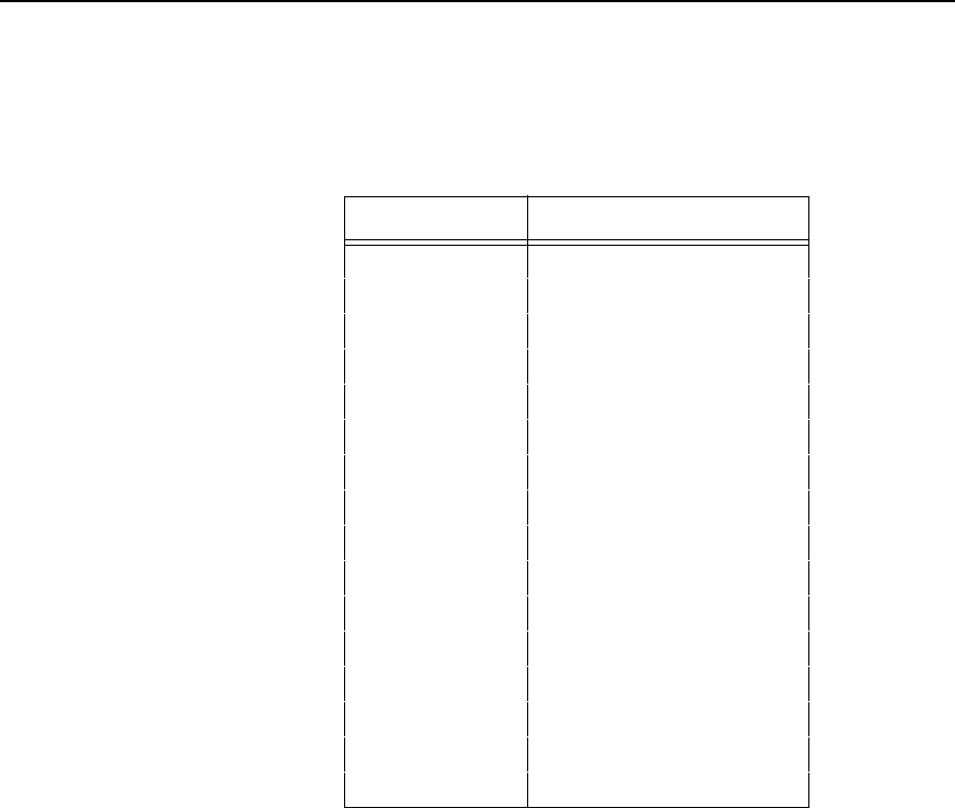
Font, Selecting Default (Version II)
79
NOTE: For thermal printers a Letter Gothic font at the higher quality NLQ is
always used.
Comments
When this command is used within an Extended Graphics
command, the default font is selected for Extended Graphics
printing and the four orientations of the Alphanumerics command
(page 32) are available. When this command is used in a
Standard Graphics command, the default font is selected for
standard printing only.
Table 9. IFONT, Values
Font # (n)Font Description
1Draft 10 cpi
2Draft 12 cpi
3Draft 15 cpi
4Draft 7.5 cpi
5NLQ 10 cpi
6NLQ 12 cpi
7NLQ 13.33 cpi
8NLQ 15 cpi
9NLQ 17.65 cpi
10 OCR-A Size 1 10 cpi
11 OCR-B Size 1 10 cpi
12 Draft 10 cpi
13 Draft 10 cpi
100 20 cpi
101 24 cpi
xxxxx AGFA font or Bitmap font

80
Chapter 2
Command Codes
Font Values
The ^IFONT,S command is used to select proportional fonts. The following list
indicates each of the font values and how they are used:
0 - 199 These values are already defined. When the
^IFONT command is received with one of
these values, it selects the standard font
(Letter Gothic) and selects the CPI (as
shown in Table 9).
89001 - 89003 These values select an Printronix bitmap font
on the flash memory. The least significant
digit indicates which font is selected (for
example 89001 selects bitmap font 1).
See “Bitmap Fonts” below.
90000 - 99999 These values select a Printronix proportional
font, as described below.
Font Selection
Fonts are selected using the ^IFONT command, as follows:
^IFONT,S,XXXXX^G
The parameter XXXXX indicates the font selected. The rest of the command
is parsed and acted upon based upon the font number selected.
^IFONT,N,name^G
Represents the selected TrueType font or Intellifont (AGFA) by name. Enter
N, and the name of the font with its extension. The maximum length of the
name is 8 characters and the maximum length of the extension is 3
characters.
Bitmap Fonts
Font values of 89001 - 89003 select a bitmap font. The size of the font is
determined by the font. The font on the flash memory is in the HP
®
PCL
®
Bitmap format. The file names for the fonts are CUSTOMx.FNT (where x is
the font number from 1 through 3).

Font, Selecting Default (Version II)
81
Printronix/AGFA Fonts
Font values of 90000 - 99999 select an AGFA font. When using an AGFA or
TrueType font, additional optional parameters are available to modify the font.
The syntax for selecting an AGFA font is:
^IFONT,S,XXXXX [,BOLD] [,RSLANT / ,LSLANT] [POINT [,WIDTH]]^G
The syntax for selecting an AGFA or TrueType font by name is:
^IFONT,N,name [,BOLD] [,RSLANT / ,LSLANT] [POINT [,WIDTH]]^G
The parameter XXXXX indicates the font to be selected, by number. If the font
number is an AGFA font (value 90000 - 99999), then it selects the desired
AGFA font, and also interprets the optional parameters. If a bitmap font is
selected (value 89001 - 89003), then the font is selected, but no optional
parameters are allowed. The name parameter indicates the font to be
selected, by name (e.g. “arial.ttf”)
If the ,BOLD parameter is specified, the font is printed in bold. If the ,RSLANT
or ,LSLANT parameter is specified, the font is printed slanted to the left or
right (pseudo-italics).
If the POINT parameter is specified, it selects the height (point size) of the
text. This is a numeric value in 1/4 points (1/288"). In addition if the POINT
parameter is specified a WIDTH parameter may also be specified. If given, it
is in 1/4 points (or 1/288"). If it is 0 or is not given, the standard aspect ratio is
used.
The file name on the flash memory for the AGFA fonts is XXXXX.SF, where
XXXXX is the font number.
Pass-through Mode
If the font is selected in standard graphics mode, it applies to all text in
standard graphics mode. In addition, this font applies to text printed when
outside graphics mode (i.e. after VGL is terminated with the ^PN^- command).
If the UNIFORM FONTS menu selection is ENABLED, the typeface also
applies to text within extended graphics mode. If it is DISABLED, the standard
font is used within extended graphics mode, and returns to the selected font
when the graphic pass is terminated.
Extended Graphic Mode
If the font is selected when in extended graphics mode, the font selected is
the selected font for this graphics pass. If the UNIFORM FONTS selection is
ENABLED, it also affects the typeface used for standard graphics mode text
and future graphic passes. If the UNIFORM FONTS selection is DISABLED, it
does not affect the font for standard graphics mode text or future graphic
passes.

82
Chapter 2
Command Codes
Examples
The following examples illustrate how to select a font using the IFONT,S, and
IFONT,N, formats.
Example 1. To print “This is Courier font” in Courier font face:
^PY^-^M0202000^IFONT,S,93952^GThis is Courier font^-^PN^-
Example 2. To print “This is TrueType font” in Arial font face:
^PY^-^M0202000^IFONT,N,arial.ttf^GThis is TrueType font^-^PN^-
Fonts, Rotatable
Purpose Using special parameter values within any of the four
alphanumerics commands described on page 32, you can specify
four different fonts.
Mode Normal resolution Graphics with an Extended Graphics
Command selected.
Format (cc) expand font jus data (cc)-
(cc) Represents the Special Function Control Code
(SFCC). Enter the specific SFCC for your VGL con-
figuration.
expand Represents one of the alphanumeric command
mnemonics: Enter M for horizontal, V for clockwise,
E for counterclockwise, or U for inverted.
font Represents the four-digit font parameter value
which selects the font. Font parameter values are
shown in Table 10.
jus Normal Resolution:
Defines vertical justification (position) for character
printing in tenth inches and dot rows. Enter a three-
digit value ranging from 000 through 999 to define
the printing location down from the starting position
of the command sequence. The first two digits
specify 0.1 through 9.9 inches downward justifica-
tion; the third digit specifies an additional 0 through
9 dot rows of downward justification. The decimal
point between the first two digits is automatically
understood by VGL and the third digit is automati-
cally interpreted as dot rows.
High Resolution:
Defines the horizontal length of the form in
thousandth inches. Enter a five-digit horizontal
value ranging from 00000 through 99999 to define
a horizontal length of 0.000 inch to 99.999 inches.
VGL automatically understands the decimal
between the second and third digits.
NOTE: If your data to be printed begin with a number (not a character), then
you must complete the field; otherwise, VGL assumes the number is
a digit in the field value.
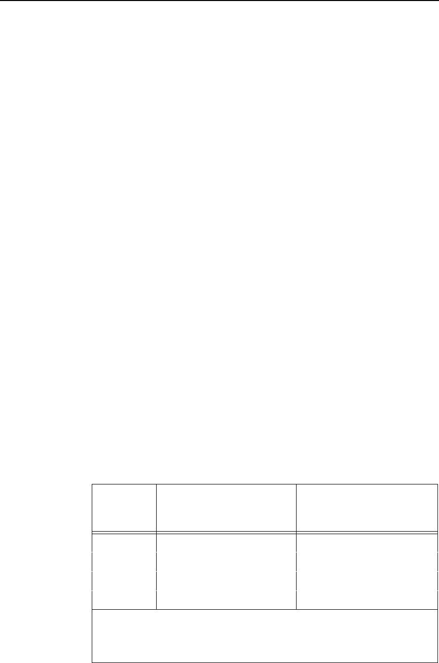
Fonts, Rotatable
83
data The data characters for printing in the rotatable
font.
(cc)- Graphics Mode CR. Enter the SFCC for your VGL
configuration immediately followed by - to end the
command sequence.
Comments
Compressed Print Density Fonts provide six other fonts with
higher density print characteristics. See “Fonts, Compressed
Print Density” on page 85.
Each of the three pitches, 10 cpi, 12 cpi, and 15 cpi (measured in
characters per inch, cpi) produce non-expandable characters 0.1-
inch high and 3, 4, or 5 dot columns wide with a one-dot column
intercharacter spacing.
The 7 cpi font produces non-expandable characters 0.2-inch high
and 0.15-inch wide with a 2-dot column intercharacter spacing at
approximately 7 cpi.
You can select any specific font from any of the four
alphanumerics commands using the Font Parameter (special
combinations of the alphanumeric command height and width
parameters) as described in Table 10.
The Rot. Char Size option setting (from the front panel menu)
determines if rotated (clockwise / counter-clockwise), expanded
characters have a different size than an unrotated character with
the same size parameters ("Adjusted") or the same size ("Not
Adjusted"). The previous VGL version always operated in the
Adjusted mode.
The Adjusted mode reflects rotating a fixed 5x7 cell character on
a 60x72 dpi, non-symmetrical printer. The Not Adjusted mode
reflects rotating on a symmetrical dpi printer.
Table 10. Rotatable Fonts
Font Size Impact Printer
Character Dimensions*
(Vert X Horiz)
Alphanumeric Command
Font Parameter Value
7 cpi 14 dots (V) X 8 dots 00,00
10 cpi 7 dots (V) X 5 dots 01,01
12 cpi 7 dots (V) X 4 dots 00,01
15 cpi 7 dots (V) X 3 dots 01,00
* 10, 12, and 15 cpi use an intercharacter spacing of one dot position. The
elongated font uses an intercharacter spacing of two dot positions. Vertical
by horizontal dimensions above are based on the 60 X 72 dpi dots produced
on line matrix printers.
84
Chapter 2
Command Codes
Examples The following examples illustrate the available fonts. For each
example, the Graphics Mode command (^PY^-) was previously
sent but not shown.
10 cpi Font - The following command generates the uppercase alphabet with
numbers 0-9 in 10 cpi:
^M01,01,000ABCDEFGHIJKLMNOPQRSTUVWXYZ 0123456789^-
12 cpi Font - The following command generates the uppercase alphabet with
numbers 0-9 in 12 cpi:
^M00,01,000ABCDEFGHIJKLMNOPQRSTUVWXYZ 0123456789^-
15 cpi Font - The following command generates the uppercase alphabet with
numbers 0-9 in 15 cpi:
^M01,00,000ABCDEFGHIJKLMNOPQRSTUVWXYZ 0123456789^-
7 cpi Font - The following command generates the uppercase alphabet with
numbers 0-9 in 7 cpi:
^M00,00,000ABCDEFGHIJKLMNOPQRSTUVWXYZ 0123456789^-
Rotatable Font - The following commands combine rotated fonts with
alphanumeric commands.
^M05,05,000IGP^M01,01,000IGP^-
font.ex1
font.ex2
font.ex3
f
ont.
ex5
Fonts, Compressed Print Density
85
^V03,03,0003 X 3^V01,00,000IGP^-
Fonts, Compressed Print Density
Purpose Defines the horizontal print density in characters per inch (cpi).
Mode Graphics with an Extended Graphics Command selected
Format (cc) S f data (cc)-
(cc) Represents the Special Function Control Code
(SFCC). Enter the specific SFCC for your VGL
configuration.
S The Compressed Print Density command. Enter S.
fRepresents the Compressed Print Density font.
Replace f with a value ranging from 1 through 9 to
select the compressed print density font as
described in Table 11. Standard print density is 10
cpi. Each character font is .1-inch high. The font
sizes are illustrated in the examples beginning on
page 87.
data The data characters for printing in the Compressed
Print Density font.
(cc)- Graphics Mode CR used as a sequence terminator.
Enter the SFCC for your configuration immediately
followed by - to end the command sequence.
font.ex6
86
Chapter 2
Command Codes
Comments
Use Compressed Print Density commands as part of the
Alphanumerics command. Reverse print and rotated commands
are not available with the Compressed Print feature. Characters
selected with this command print only in the standard horizontal
orientation. A Reverse Print or rotated alphanumeric command
specified in the command sequence is ignored.
Table 11. Compressed Print Density Font Selection
fFont Selected
110 cpi
212 cpi
313.33 cpi
415 cpi
517.65 cpi
6OCR-A font at 10 cpi
7OCR-B font at 10 cpi
812 cpi
915 cpi
Fonts, Compressed Print Density
87
Compressed Print Density Font Examples
The following examples illustrate the commands and print samples which
generate the uppercase alphabet with numbers 0-9 in the available
compressed print density fonts. Notice the height and width parameters of the
alphanumerics command does not apply to the data specified for compressed
print.
f = 1 (10 cpi)
^PY^-
^M03,02,000^S1ABCDEFGHIJKLMNOPQRSTUVWXYZ 0123456789^-
^PN^-
f = 2 (12 cpi)
^PY^-
^M03,02,000^S2ABCDEFGHIJKLMNOPQRSTUVWXYZ 0123456789^-
^PN^-
f = 3 (13.33 cpi)
^PY^-
^M03,02,000^S3ABCDEFGHIJKLMNOPQRSTUVWXYZ 0123456789^-
^PN^-
f = 4 (15 cpi)
^PY^-
^M03,02,000^S4ABCDEFGHIJKLMNOPQRSTUVWXYZ 0123456789^-
^PN^-
densi
density
density.ex
88
Chapter 2
Command Codes
f = 5 (17.65 cpi)
^PY^-
^M03,02,000^S5ABCDEFGHIJKLMNOPQRSTUVWXYZ 0123456789^-
^PN^-
f = 6 (OCR-A 10 cpi)
^PY^-
^M03,02,000^S6ABCDEFGHIJKLMNOPQRSTUVWXYZ 0123456789^-
^PN^-
f = 7 (OCR-B 10 cpi)
^PY^-
^M03,02,000^S7ABCDEFGHIJKLMNOPQRSTUVWXYZ 0123456789^-
^PN^-
Form Feed
Purpose Performs a form feed (hex 0C) function to advance the paper to
the next top of form, or may be used to terminate a graphics
command.
Mode Graphics with a Standard Graphics Command selected
Format (cc),
(cc) Represents the Special Function Control Code
(SFCC). Enter the specific SFCC for your VGL
configuration.
, The graphics FF mnemonic. Enter ,.
Comments
The form feed command functions as a terminator only when
used to terminate a graphics sequence in a graphics command
when Free Format is enabled.
The control panel form feed key will operate differently dependent
on the source of form feed control at the time the key is pressed.
Form feed is controlled by the LP+ and VGL emulation at different
times.
density.e

Form Length
89
Form Length
Purpose Defines the length of the form in total number of lines.
Mode Graphics with a Standard Graphics Command selected
Format (cc) L length (cc)-
or
(cc) H length (cc)-
(cc) Represents the Special Function Control Code
(SFCC). Enter the specific SFCC for your VGL
configuration.
L or H The Form Length command. If your VGL is
configured with the PI line enabled, enter L. If your
VGL is configured with the PI line disabled, enter H.
length Represents the form length in total number of lines.
Enter a two-digit number of total lines on the form
ranging from 01 through 99. For example, enter 05
for a 5-line form length, 21 for a 21-line form length.
(cc)- Graphics Mode CR. Enter the SFCC for your VGL
configuration immediately followed by - to end the
command sequence.
Comments
The L command is available any time VGL is in the Graphics
Mode. The physical length of the paper for the form is a product
of the total lines per form and the current lines per inch (lpi)
setting for the printer. For example, a typical 66-line form at 6 lpi
is 11 inches long. A 48-line form at 6 lpi is 8 inches long; the
same 48-line form at 8 lpi is 6 inches long.
Form feeds following this command advance the form from the
current print position to the top of the next form.
With the Host Form Length configuration option enabled, the form
length defined by this command sets the physical page length on
the printer.
90
Chapter 2
Command Codes
Forms Construction
Purpose Produces vertical lines inside a box to construct forms.
Mode Graphics with an Extended Graphics Command selected
Format (cc) LF horz vert h v line1 t line2 t (cc)G(cc)-
(cc) Represents the Special Function Control Code
(SFCC). Enter the specific SFCC for your VGL
configuration.
LF The Forms Construction command. Enter LF.
horz Normal Resolution:
Defines the horizontal length of the form in tenth
inches and dot columns. Enter a three-digit
horizontal length value ranging from 000 through
999 to define a horizontal length of 00.0 through
99.9 inches and a fourth digit ranging from 0
through 9 to specify 0 through 9 additional dot
columns of length. VGL automatically understands
the decimal between the second and third digits for
tenth inches and automatically interprets the fourth
digit as dot columns. For example, entering 0126
specifies a 1.2-inch plus 6-dot column horizontal
length; entering 1016 specifies a 10.1-inch plus 6-
dot column horizontal length.
High Resolution:
Defines the horizontal length of the form in
thousandth inches. Enter a five-digit horizontal
value ranging from 00000 through 99999 to define
a horizontal length of 0.000 inch through 99.999
inches. VGL automatically understands the decimal
between the second and third digits. The horz field
must be at least twice the value of the thickness of
the vertical sides (v).
vert Normal Resolution:
Defines the vertical length of the form in tenth
inches and dot rows. Enter a three-digit vertical
length value ranging from 000 through 999 to
define a vertical length of 00.0 through 99.9 inches
and a fourth digit ranging from 0 through 9 to spec-
ify 0 through 9 additional dot rows of length. VGL
automatically understands the decimal between the
second and third digits for tenth inches and auto-
matically interprets the fourth digit as dot rows. For
example, entering 0204 specifies a 2.0-inch plus 4-
dot row vertical length; entering 0242 specifies a
2.4-inch plus 2-dot row vertical length.
Forms Construction
91
vert High Resolution:
Defines the vertical length of the form in thousandth
inches. Enter a five-digit vertical value ranging from
00000 through 99999 to define a vertical length of
0.000 inch through 99.999 inches. VGL
automatically understands the decimal between the
second and third digits. The vert field must be at
least twice the value of the thickness of the
horizontal sides (h).
hNormal Resolution:
Defines the horizontal border thickness in dot col-
umns. Enter a number ranging from 1 through 9 to
specify a horizontal border thickness from 1
through 9 dots.
High Resolution:
Defines the horizontal border thickness in
thousandth inches. Enter a number ranging from
000 through 999 to specify a border thickness from
0.000 through 0.999 inch. VGL automatically
understands the decimal before the first digit.
vNormal Resolution:
Defines the vertical border thickness in dot rows.
Enter a number ranging from 1 through 9 to specify
a vertical border thickness from 1 through 9 dots.
High Resolution:
Defines the vertical border thickness in thousandth
inches. Enter a number ranging from 000 through
999 to specify a border thickness from 0.000
through 0.999 inch. VGL automatically understands
the decimal before the first digit.
line1 Normal Resolution:
Defines the vertical line position in tenth inches and
dot columns from the form left edge or prior vertical
line right edge. Therefore, the line value for all but
the first vertical line is actually the gap between the
right edge of the previous line and the left edge of
the current line. Enter a three-digit position value
ranging from 000 through 999 to define a position
of 00.0 through 99.9 inches and a fourth digit rang-
ing from 0 through 9 to specify 0 through 9 addi-
tional dot columns. VGL automatically understands
the decimal between the second and third digits for
tenth inches and automatically interprets the fourth
digit as dot columns. For example, entering 0126
specifies a 1.2-inch plus 6-dot column position from
the left edge or last vertical line position; entering
1016 specifies a 10.1-inch plus 6-dot column posi-
tion.
92
Chapter 2
Command Codes
line1 High Resolution:
Defines the vertical line position in thousandth
inches from the form left edge or prior vertical line
right edge. The line value for all but the first vertical
line, therefore, is actually the gap between the right
edge of the previous line and the left edge of the
current line. Enter a five-digit position value ranging
from 00000 through 99999 to define a position of
00.000 inch through 99.999 inches. VGL
automatically understands the decimal between the
second and third digits.
tNormal Resolution:
Defines the vertical line thickness in dot columns.
Enter a number ranging from 1 through 9 to specify
a line thickness from 1 through 9 dots.
High Resolution:
Defines the vertical line thickness in thousandth
inches. Enter a number ranging from 000 through
999 to specify a line thickness from .000 inch
through .999 inch.
line2 The line position parameter is entered repeatedly
as needed for the number of lines required in the
form.
tThe line thickness parameter is entered for each
vertical line position parameter.
(cc)G Terminator. Enter the SFCC for your VGL
configuration immediately followed by G, the
universal terminator, or another valid Graphics
Mode command to end the input of vertical line and
form data.
(cc)- Graphics Mode CR used as a sequence terminator.
Enter the SFCC for your configuration immediately
followed by - to end the command sequence.
NOTE: You must supply leading and trailing zeros for all fields.
Comments
The LF command produces vertical lines inside a box using a
single command sequence. Forms are positioned by the
parameters or commands of an alphanumerics command
sequence (such as horizontal tabs, the justification parameter,
etc.). Therefore, one of the alphanumerics commands must
precede an LF command.
Using appropriate values for the horizontal and vertical length
parameters constructs a variety of form shapes. The horizontal
and vertical border thickness can also be specified in varying line
thicknesses. Any number of vertical lines can be drawn inside the
form. The position of the vertical line is based on the left edge of
the form or the last vertical line drawn.
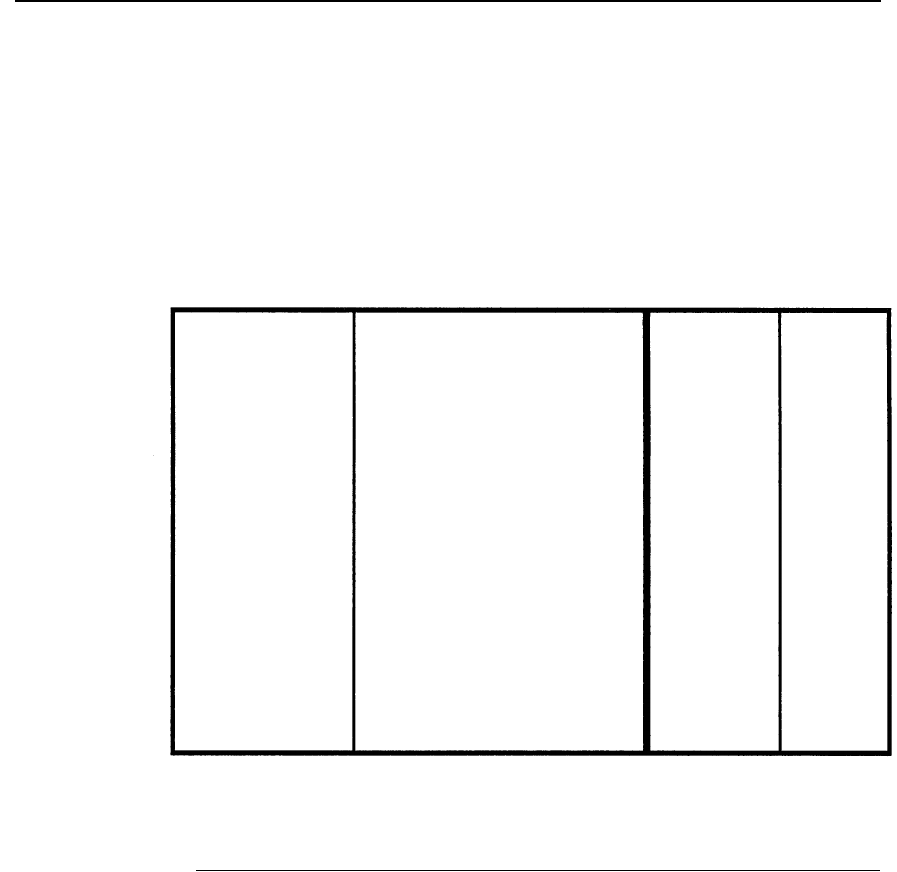
Forms, Creating Dynamic (Version II)
93
Example The following sample command illustrates forms construction in
normal resolution. In addition to enabling the Free Format, an
alphanumerics command was sent for form positioning.
^PY^-^F^-
^M01,01,000
^LF0500,0320,2,2,0123,1,0200,3,0090,1^G^-
^O^-^PN^-
Forms, Creating Dynamic (Version II)
NOTE: This command operates similar to the Dynamic Form Commands
described beginning on page 65.
Purpose Creates a new dynamic form and stores it in memory under a
specified name.
Mode Graphics with an Extended Graphics Command selected
Format (cc) IFORM,C name [,DISK] (cc)G data (cc)]
(cc) Represents the Special Function Control Code
(SFCC). Enter the specific SFCC for your VGL
configuration.
IFORM,C The command to create buffered forms. Enter
IFORM,C.
name Represents the form name. Enter a name up to 15
characters long. Another form in memory by the
same name is overwritten with the new form.
DISK Optional parameter to store the form in the printer’s
flash memory. Enter DISK.

94
Chapter 2
Command Codes
(cc)G Terminator. Enter the SFCC for your VGL
configuration immediately followed by G, the
universal terminator, or another valid Graphics
Mode command to end the input of the form name.
data The form data. Enter any number of valid Graphics
or Extended Graphics command sequences.
(cc)] Ends the form and all contents. Enter the specific
SFCC for your VGL configuration followed by the
right bracket ( ] ) to end the form.
Forms, Deleting Dynamic (Version II)
Purpose Deletes an existing dynamic form stored in memory under a
specified name.
Mode Graphics with an Extended Graphics Command selected
Format (cc) IFORM,D name (cc)G
(cc) Represents the Special Function Control Code
(SFCC). Enter the specific SFCC for your VGL
configuration.
IFORM,D The command to delete the form. Enter IFORM,D.
name Represents the form name. Enter the form name
exactly as created in the IFORM,C command (page
93).
(cc)G Terminator. Enter the SFCC for your VGL
configuration immediately followed by G, the
universal terminator, or another valid Graphics
Mode command terminator to end the data.
Forms, Executing Dynamic (Version II)
NOTE: This command operates similar to the Dynamic Form Commands
described beginning on page 65.
Purpose Executes an existing dynamic form stored in memory under a
specified name.
Mode Graphics with an Extended Graphics Command selected
Format (cc) IFORM,E name [,DISK] (cc)G
(cc) Represents the Special Function Control Code
(SFCC). Enter the specific SFCC for your VGL
configuration.
IFORM,E The command to execute the form. Enter
IFORM,E.
name Represents the form name. Enter the form name
exactly as created in the IFORM,C command
(page 93).

Forms, Listing Dynamic (Version II)
95
DISK Optional parameter to print the form stored in the
printer’s flash memory.
(cc)G Terminator. Enter the SFCC for your VGL
configuration immediately followed by G, the
universal terminator, or another valid Graphics
Mode command terminator to end the data.
Forms, Listing Dynamic (Version II)
Purpose Lists all previously created forms including the form size, in bytes,
used by each form name.
Mode Graphics with an Extended Graphics Command selected
Format (cc) IFORM,L (cc)G
(cc) Represents the Special Function Control Code
(SFCC). Enter the specific SFCC for your VGL
configuration.
IFORM,L The command to list the forms in memory. Enter
IFORM,L.
(cc)G Terminator. Enter the SFCC for your VGL
configuration immediately followed by G, the
universal terminator, or another valid Graphics
Mode command terminator to end the data.
Forms, Predefined (Version II)
Purpose Loads one of three predefined forms from memory (AIAG,
Primary Metals, and Odette). These forms are selected and
completed using the commands and legends described.
Mode Graphics with standard Graphics Command selected
Format (cc) IFORM,Eformname.QMS (cc)G
(cc) Represents the Special Function Control Code
(SFCC). Enter the specific SFCC for your VGL
configuration.
IFORM,Eformname.QMS
The command to retrieve the specified predefined
form. Enter IFORM,Eformname.QMS, where
formname ia AIAG, METALS, or ODETTE.
(cc)G Terminator. Enter the SFCC for your VGL
configuration immediately followed by G, the
universal terminator, or another valid Graphics
Mode command terminator to end the data.
Comments The IFORM,E command not only loads the desired predefined
form, but provides the means to fill out the form. The following
three examples show the method of specifying the data to be
placed on the forms.
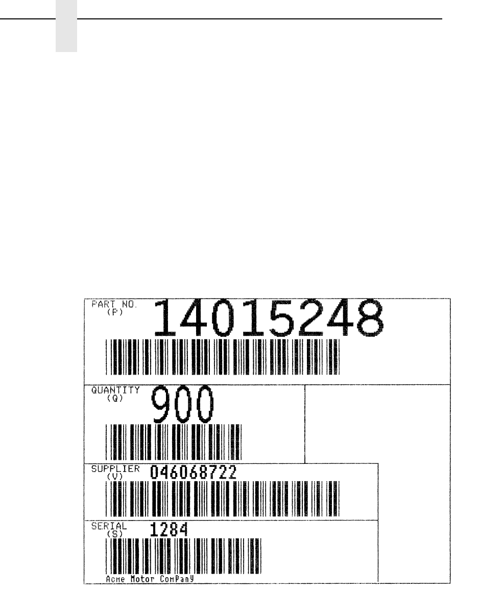
96
Chapter 2
Command Codes
Example 1 The following sample command illustrates forms construction
after loading the AIAG form from memory.
^PY^-^F^-
^IFORM,EAIAG.QMS^G
14015248^+
14015248^+
900^+900^+
046068722
046068722
1284^+1284^+
Acme Motor Company^+
^G
^O^-^PN^-
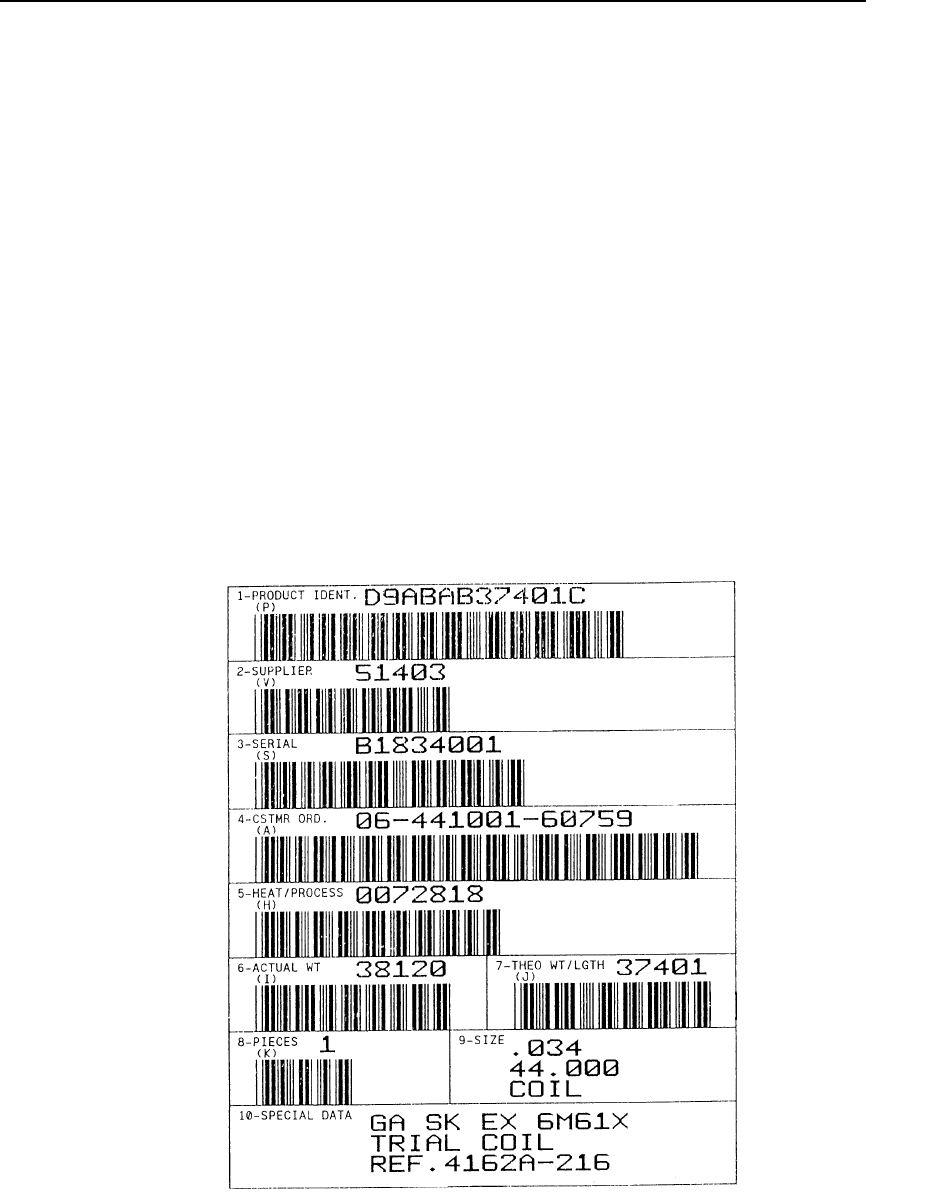
Forms, Predefined (Version II)
97
Example 2 The following sample command illustrates forms construction
after loading the Primary Metals form from memory.
^IFORM,EMETALS.QMS^G
D9ABAB37401C^+D9ABAB37401C^+
51403^+51403^+
B1834001^+B1834001^+
06-441001-6075906-441001-60759^+
0072818^+0072818^+
3812038120
3740137401
1^+1^+
.034^+
44.000^+
COIL^+
GA SJ EX 6M61X^
TRIAL COIL^+
REF.4162A-216^+
^G
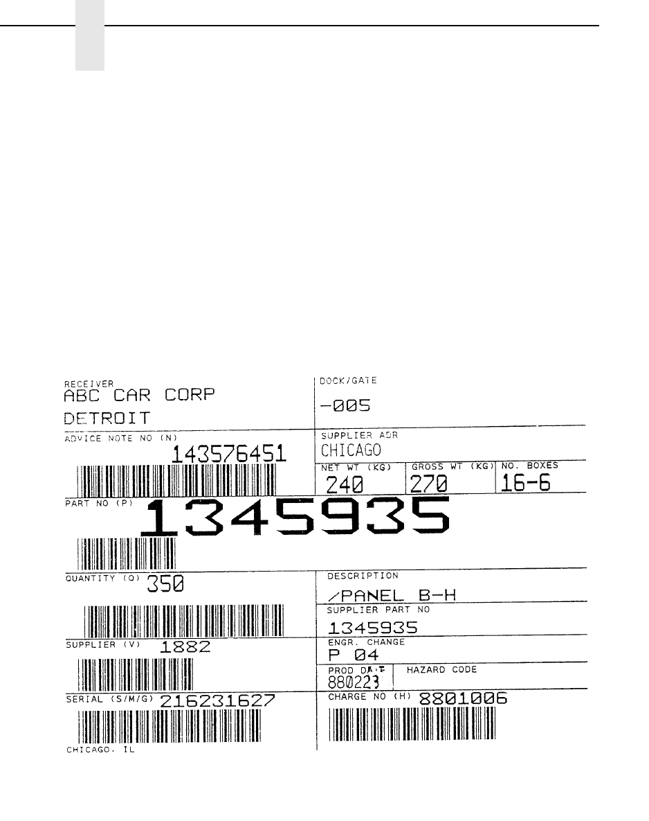
98
Chapter 2
Command Codes
Example 3 The following sample command illustrates forms construction
after loading the Odette form from memory.
^IFORM,EODETTE.QMS^G
ABC CAR CORP^+
DETROIT^+
-005^+
143576451143576451
CHICAGO^
240^+270^+
16-6^+1345935^+
1882^+1882^+
P04^+^+880223
216231627S216231627
8801006^+8801006^+
CHICAGO, IL^+^G

Forms, Resetting Dynamic (Version II)
99
Forms, Resetting Dynamic (Version II)
Purpose Resets dynamic form memory by deleting all forms stored in
memory.
Mode Graphics with an Extended Graphics Command selected
Format (cc) IFORM,R (cc)G
(cc) Represents the Special Function Control Code
(SFCC). Enter the specific SFCC for your VGL
configuration.
IFORM,R The command to reset forms memory. Enter
IFORM,R.
(cc)G Terminator. Enter the SFCC for your VGL
configuration immediately followed by G, the
universal terminator, or another valid Graphics
Mode command terminator to end the data.
Comments
Standard predefined forms are not deleted from forms memory
with this command. If predefined forms were previously deleted,
they are reinstalled in the forms memory after execution of this
command.
Free Format (Enable/Disable)
Purpose Enables VGL to ignore all host generated paper motion
commands ranging from hex 00 through 1F.
Mode Graphics with a Standard Graphics Command selected
Format (cc) F (cc)-
data
(cc) O (cc)-
(cc) Represents the Special Function Control Code
(SFCC). Enter the specific SFCC for your VGL
configuration.
F Specifies the Free Format command. Enter F.
(cc)- Graphics Mode CR. Enter the SFCC for your VGL
configuration immediately followed by - to end the
command sequence.
data Represents the data, commands, and all other
codes for processing in Free Format. All VGL
features are available with Free Format enabled.
(cc)O Turns off the Free Format mode. Following the data
for processing in the Free Format, enter the SFCC
for your VGL configuration immediately followed by
O (alpha O) to end the Free Format.
(cc)- Graphics Mode CR. Enter the SFCC for your VGL
configuration immediately followed by - to end the
command sequence.
100
Chapter 2
Command Codes
Comments
Some host systems automatically generate forms control codes
such as CR or LF after a specific number of characters. These
host generated forms control codes could prematurely terminate
the graphics command sequence. The Free Format command
allows VGL to accept incoming data as one continuous stream
even though the data stream may include host generated forms
control codes.
Free Format is available when VGL is in the Graphics Mode.
When enabled, VGL recognizes only the Free Format terminator
commands (Table 12) for forms control until the Free Format is
disabled. If the Graphics Mode is disabled, Free Format
command is automatically disabled.
NOTE: Free Format commands may be used in the normal Graphics Mode
even though Free Format is not enabled. However, when the Free
Format command is enabled, the only valid terminators are the Free
Format commands; others are ignored.
Example The following command enables and disables Free Format in the
Graphics Mode.
^PN^-^F^-
data
^O^-PN^-
Table 12. Free Format Terminator Commands
Command Meaning
^ * Line Feed (LF)
^ , Form Feed (FF)
^ - Carriage Return (CR)
^ + Vertical Tab (VT)
^ > EVFU Start Load
^ ? EVFU End Load
^ 0-9 EVFU Chs 1 - 10
^ : EVFU Ch 11
^ ; EVFU Ch 12
^ < EVFU Ch 13
^ = EVFU Ch 14

Free Format Enable, Non-Graphics
101
Free Format Enable, Non-Graphics
Purpose Permits VGL to override host-generated paper motion commands
when not in Graphics Mode.
Mode Normal
Format (cc) PF (cc)-
(cc) Represents the Special Function Control Code
(SFCC). Enter the specific SFCC for your VGL
configuration.
PF Specifies the Enable Non-Graphics Free Format
command; enter PF.
(cc)- Terminator. Enter the SFCC for your VGL
configuration immediately followed by - (Graphics
Mode CR) or other valid terminator.
Comments
Use the PF command with host systems that send blocks of data
padded with NULs or other control characters that may interfere
with a graphics sequence (such as unformatted LU 3 mode,
coaxial environments). When the Graphics Mode Disable
command (^PN^-) is used to exit the Graphics Mode, it also
automatically terminates the Free Format command and disables
the Ignore Data commands. This can result in unwanted paper
motion if Graphics Mode is exited between forms or labels, since
host-generated line feeds, form feeds, etc., are no longer ignored
by the firmware. (Refer to the Free Format and Ignore Data
commands on pages 99 and 105 for more information on these
functions.)
The PF command must be issued before the Graphics Mode
Enable command (PY). Host-generated line terminators are then
ignored by VGL and only the following standard graphics format
control commands are recognized:
(cc) *Line Feed (hex 0A)
(cc), Form Feed (hex 0C)
(cc)- Carriage Return (hex 0D)
NOTE: When VGL is in the Graphics Mode, the Enable Non-Graphics Free
Format command has no effect on the host data stream. In the
Graphics Mode, use the Free Format and Ignore Data commands
(pages 99 and 105, respectively) to ignore unwanted data.
102
Chapter 2
Command Codes
Example The example below illustrates the use of the Enable Non-
Graphics Free Format command:
^PF^-(LF)(LF)(LF)(LF)^PY^-F^-^M02,02,100 data for form one
^*^X extraneous, unwanted host data^A^M01,01,000 more form one
data ^-(LF)(LF)(LF)(FF)^PN^-^*^*(LF)(LF)
^PY^-^F^-^M02,02,000 data for form two, etc.^-
In this example, all of the host-generated line and form feed
commands, represented by (LF) and (FF), are ignored and paper
motion is controlled by VGL standard graphics format control
commands (^-), (^*), and (^,), even though Graphics Mode is
exited and reentered between the forms. Between the forms two
standard graphics line feed commands (^*) are used to move the
paper instead of the host-generated (LF) commands. Notice that
after the Graphics Mode is enabled, the Free Format and Ignore
Data commands (^F^-), (^X), and (^A) are used to ignore the
unwanted host data. When all of the labels or forms are
completed, sending Free Format Non-Graphics Disable
command (PO, page 102) returns VGL to the fully-transparent
Normal Mode.
Free Format Disable, Non-Graphics
Purpose Disables the Non-Graphics Free Format command (PF), which
allows host-generated paper motion when VGL Graphics Free
Format command is disabled.
Mode Normal
Format (cc) PO (cc)-
(cc) Represents the Special Function Control Code
(SFCC). Enter the specific SFCC for your VGL
configuration.
PO Specifies the End Non-Graphics Free Format
command; enter PO.
(cc)- Terminator. Enter the SFCC for your VGL
configuration immediately followed by - (Graphics
Mode CR) or other valid terminator.
Comments
Send the PO command anytime after the Graphics Mode Disable
command (PN).
Example The following command disables Free Format in Non-Graphics
Mode.
^PO^-

Graphics Mode Enable
103
Graphics Mode Enable
Purpose Enables use of Graphics Mode commands.
Mode Normal
Format (cc) PY (cc)-
(cc) Represents the Special Function Control Code
(SFCC). Enter the specific SFCC for your VGL
configuration.
PY Specifies the Graphics Mode Enable command;
enter PY.
(cc)- Terminator. Enter the SFCC for your VGL
configuration immediately followed by - (the
Graphics Mode CR) or other valid terminator.
Comments
Following the PY command, the Graphics Mode commands
(page 26) are available. Once in Graphics mode, you can enter
Extended Graphics/High Resolution Mode. (See page 31 for
more information.)
For the Graphics Mode Enable command to be recognized and
accepted by VGL, the following rules must be followed:
1. If Midline PY is enabled on the printer’s control panel menu,
the Graphics Mode Enable command can be placed
anywhere on a line. If Midline PY is disabled, the Graphics
Mode Enable command must be the first characters of a new
line. See your User’s Manual for more information.
2. The command line must also terminate with a line terminator
(CR, LF, FF, etc.).
3. VGL absorbs all characters between the command and the
line terminator.
Example The following command enables the Graphics Mode:
^PY^-
104
Chapter 2
Command Codes
Graphics Mode Disable
Purpose Exits VGL from Graphics Mode and returns to the Normal Mode.
Mode Graphics
Format (cc) PN (cc)-
(cc) Represents the Special Function Control Code
(SFCC). Enter the specific SFCC for your VGL
configuration.
PN Specifies the Graphics Mode Disable command;
enter PN.
(cc)- Terminator. Enter the SFCC for your VGL
configuration immediately followed by - (Graphics
Mode CR) or other valid terminator.
Example The following command disables the Graphics Mode:
^PN^-
Hex Dump
Purpose Prints all data in hexadecimal code equivalent.
Mode Graphics with a Standard Graphics Command selected
Format (cc) @ H 0 (cc)-
(cc) Represents the Special Function Control Code
(SFCC). Enter the specific SFCC for your VGL
configuration.
@ Specifies one of the @ commands. Enter @ to
begin an @ command function.
H Specifies the Hex Dump command. Enter H.
0 Specifies the Hex Dump parameter. Enter 0 (zero).
(cc)- Graphics Mode CR. Enter the SFCC for your VGL
configuration immediately followed by - to end the
command sequence.
Comments
The @H command is available when VGL is in the Graphics
Mode. To disable the hex dump, place the printer offline and
change the hex dump parameter from Enable to Disable. Refer to
your User's Manual for instructions.

Ignore Data
105
Ignore Data
Purpose Instructs VGL to ignore data until a (cc)A command is received.
(See Comments below.)
Mode Graphics with a Standard Graphics Command selected
Format (cc) X data (cc)A
(cc) Represents the Special Function Control Code
(SFCC). Enter the specific SFCC for your VGL
configuration.
X Specifies the Ignore Data command. Enter X to
ignore all subsequent characters until the Ignore
Data command is disabled.
data Represents the data. Any text and characters sent
following the Ignore Data command are not
processed.
(cc)A Disables Ignore Data. Enter the SFCC for your VGL
configuration immediately followed by A to disable
the Ignore Data feature in order to process
characters.
NOTE: No function occurs if a (cc)A command is used independent of the
(cc)X command.
Comments
Some host systems use fixed record lengths which causes the
end of a line of data in the data stream to be filled (padded) with
characters and spaces. If VGL file on your system contains
padded characters or spaces before the SFCC, this padded data
must be ignored before VGL can operate. When the X command
is sent to ignore data, all data following the command is ignored
until the (cc)A command to ignore data is disabled.
106
Chapter 2
Command Codes
Interrupt
Purpose In cases where a single command sequence exceeds the buffer
capacity, an interrupt can be used to break the command
sequence and specify the position where the sequence begins
printing again.
Mode Graphics with or without an Extended Graphics Command
selected
Format (cc) I dis (cc)-
(cc) Represents the Special Function Control Code
(SFCC). Enter the specific SFCC for your VGL
configuration.
I Specifies the Interrupt command. Enter I.
dis Normal Resolution:
Defines the interrupt position in tenth inches and
dot columns. Enter a two-digit interrupt position
value ranging from 00 through 99 to define a
position of 0.0 through 9.9 inches and a third digit
ranging from 0 through 9 to specify 0 through 9
additional dot columns. VGL automatically
understands the decimal between the first and
second digits for tenth inches and automatically
interprets the third digit as dot columns. For
example, entering 126 specifies a 1.2-inch plus 6-
dot column interrupt position. Setting the interrupt
position parameter to all zeros processes all data in
the VGL buffer before the next sequence is
initiated.
High Resolution:
Defines the interrupt position in thousandth inches.
Enter a five-digit vertical value ranging from 00000
through 99999 to define a vertical justification of
0.000 inch through 99.999 inches. VGL
automatically understands the decimal between the
second and third digits.
(cc)- Graphics Mode CR used as a command terminator.
Enter the SFCC for your VGL configuration immedi-
ately followed by - to end the command sequence.
NOTE: Only required outside of an Extended
Graphics sequence.
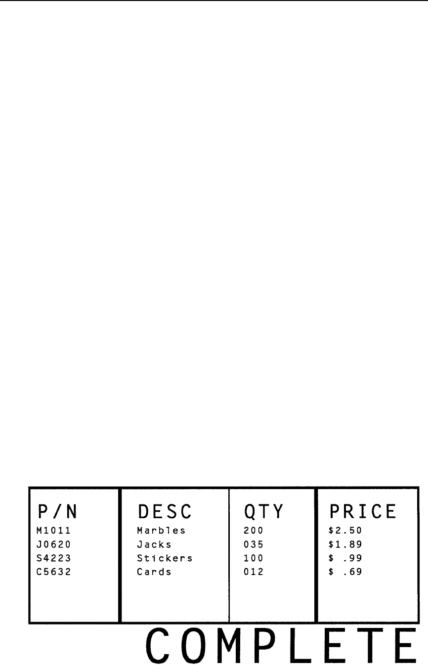
Interrupt
107
Comments
The VGL buffer holds and can process approximately 64K
characters in a single graphics command sequence, which is
sufficient for most applications. However, infrequent situations
may arise where the command sequence is too large for the VGL
buffer to hold for processing as a single command sequence. In
such cases, use the I command to break the printing command
sequence at a specified position and specify where the sequence
resumes printing. Interrupted command sequences are
processed as if a single command sequence occurred.
The I command can also be used for vertical positioning. Use the
I command to skip to a new vertical position and print the data.
Interrupt commands also can be included in a Vertical Duplication
command sequence.
Like the Alphanumeric commands, the Interrupt command also
enables extended graphics functions, if not already in an
Extended Graphics sequence.
To complete the printing of all interrupted command sequences,
use ^I000^- or no ^I command in the last command sequence.
The last technique is used in the following example.
Example The following commands illustrate the interrupt function
combined with form construction using tabs and various
character parameters in normal resolution. The Free Format
Enable command is also used.
^PY^-^F^-
^M01,01,000^LF0550,0200,2,2,0123,3,0150,1,0120,3^I020^-
^M02,02,005^T0010P/N^T0150DESC^T0300QTY^T0420PRICE^I020^-
^M01,01,020^T0010M1011^T0150Marbles^T0300200^T0420$2.50^I020^-
^M01,01,020^T0010J0620^T0150Jacks^T0300035^T0420$1.89^I020^-
^M01,01,020^T0010S4223^T0150Stickers^T0300100^T0420$ .99^I020^-
^M01,01,020^T0010C5632^T0150Cards^T0300012^T0420$ .69^I020^-
^M05,05,084^T0149COMPLETE^-
^O^-^PN^-
108
Chapter 2
Command Codes
Justification, Vertical
Purpose Specifies a lower vertical print position relative to the print
position of the alphanumerics command. This feature is useful for
positioning data within boxes or columns on a form.
Mode Graphics with an Extended Graphics Command selected
Format (cc) J jus (cc)-
(cc) Represents the Special Function Control Code
(SFCC). Enter the specific SFCC for your VGL
configuration.
J The Vertical Justification command. Enter J.
jus Normal Resolution:
Defines the new vertical justification (position) for
character printing in tenth inches and dot rows.
Enter a three-digit value ranging from 000 through
999 to define the new print location down from the
starting position of the command sequence. The
first two digits specify 0.1 through 9.9 inches
downward justification; the third digit specifies an
additional 0 through 9 dot rows of downward
justification. The decimal point between the first two
digits is automatically understood by VGL and the
third digit is automatically interpreted as dot rows.
High Resolution:
Defines vertical justification (position) for character
printing in thousandth inches. Enter a five-digit
value ranging from 00000 through 99999 to define
the printing location down from the starting position
of the command sequence from 0.0 inch through
99.999 inches. VGL automatically understands the
decimal point between the second and third digits
as thousandths.
If the data character immediately following the jus
field is not a digit (zero through nine), then you can
omit trailing zeros. For example, the command
^M10010000000^J01ABC, results in a 1.000 inch
justification because the three empty spaces in the
jus field (before the characters "ABC") are
completed with three implied trailing zero digits.
NOTE: If your data to be printed begin with a number (not a character), then
you must complete the field; otherwise, VGL assumes the number is
a digit in the field value.
The data to print at the new print position is input
following the Character Justification Change
command.
(cc)- Graphics Mode CR. Enter the SFCC for your VGL
configuration immediately followed by - to end the
command sequence.
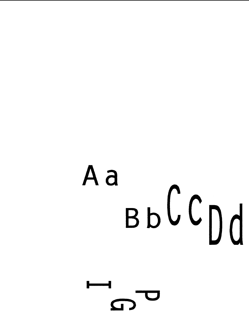
Justification, Vertical
109
NOTE: This command causes extra vertical blank spaces at the bottom of a
form if its value is greater than the bottom edge of any previously
drawn graphical element in the current command sequence.
Comments
The J command is input as part of the data in one of the
alphanumeric commands and only affects the justification; other
parameters (such as height and width) are not changed.
A justification of 2 inches specifies a print position 2 inches down
from the position of the alphanumerics command; a subsequent
justification of 1 specifies the print position at 1 inch down from
the position of the alphanumerics command.
Example The following sample commands illustrate character justification
changes in normal resolution. (The Graphics Mode Enable
command was previously sent to enable Graphics Mode but is
not shown in the examples.)
^M05,05,000Aa^J105Bb^M10,05,050Cc^J100Dd^-
^V05,05,000I^J050G^J025P^-
^E05,05,000IGP^J050IGP^J100IGP^-
v
e
rtj
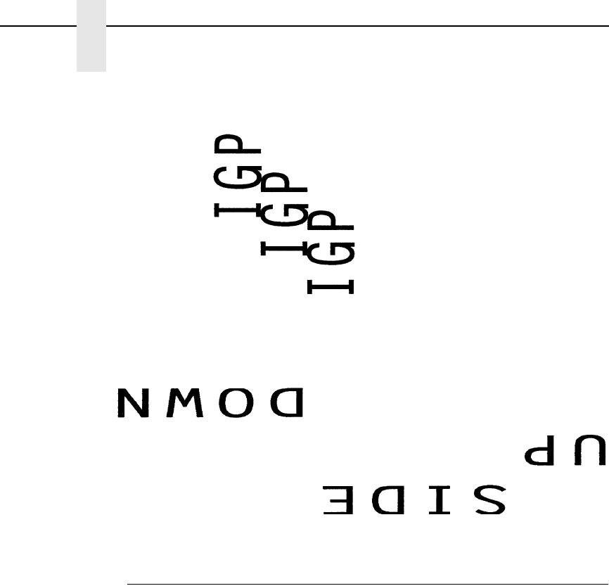
110
Chapter 2
Command Codes
^U03,05,000DOWN^J100SIDE^J050UP^-
Line Feed
Purpose Performs a line feed (hex 0A) and a carriage return function when
used to terminate a standard graphics command.
Mode Graphics with a Standard Graphics Command selected
Format (cc)*
(cc) Represents the Special Function Control Code
(SFCC). Enter the specific SFCC for your VGL
configuration.
* The graphics LF mnemonic. Enter *.
Comments
The line feed command functions as a carriage return only when
it is used to terminate a graphics sequence in an extended
graphics command when Free Format is enabled.
ve

Line Slew
111
Line Slew
Purpose Changes the vertical print position by specifying a number of lines
to advance the paper from the current print position.
Mode Graphics with a Standard Graphics Command selected
Format (cc) slew n (cc)-
(cc) Represents the Special Function Control Code
(SFCC). Enter the specific SFCC for your VGL
configuration.
slew Represents a Line Slew command. Enter K or W.
(Both K and W perform the same line slew
command.)
nSpecifies the number of lines to advance (slew) at
the current lines per inch (lpi) setting. Enter a two-
digit number of lines ranging from 01 through 99.
For example, enter 05 to slew 5 lines, 21 to slew 21
lines.
(cc)- Graphics Mode CR. Enter the SFCC for your VGL
configuration immediately followed by - to end the
command sequence.
Line Spacing
Purpose Selects a new line spacing in lines per inch (lpi).
Mode Graphics with a Standard Graphics Command selected
Format (cc) @ L newlpi (cc)-
(cc) Represents the Special Function Control Code
(SFCC). Enter the specific SFCC for your VGL
configuration.
@ Specifies one of the @ commands. Enter @ to
begin an @ command function.
L Specifies the Line Spacing command. Enter L to
change the line spacing.
newlpi Represents the line spacing parameter. Enter one
of the two-digit codes shown in Table 13 to select a
new line spacing. For example, enter 10 to select
10 lpi.
Not all values are available on all printer models.
Check with your printer User's Manual for the line
spacing options available.
Once the new line spacing is selected, all lines are
printed at the new lpi setting until another line
spacing is selected or VGL returns to the Normal
Mode.
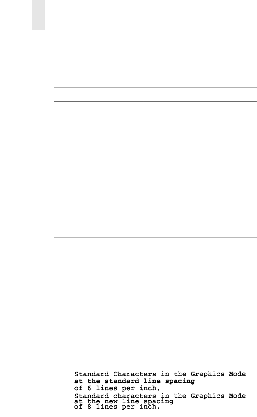
112
Chapter 2
Command Codes
(cc)- Graphics Mode CR. Enter the SFCC for your VGL
configuration immediately followed by - to end the
command sequence.
Values above 20 (except 72) default to 18. Values
selected but not shown on the table are rounded to
the nearest value. For example, selecting a line
spacing code of 05, would be rounded up to 06.
Example The following example illustrates different line spacings.
^PY^-^F^-
Standard Characters in the Graphics Mode^*
at the standard line spacing^*
of 6 lines per inch.^*
^@L08^-Standard characters in the Graphics Mode^*
at the new line spacing^*
of 8 lines per inch.^*
^@L06^-
^O^-^PN^-
Table 13. Line Spacing Codes
Line Spacing Code Line Spacing (lpi) Selected
01 1
02 2
03 3
04 4
06 6
07 6
08 8
09 9
10 10
12 12
18 18
72 72

Lines, Dashed
113
Lines, Dashed
Purpose Produces dashed lines.
Mode Graphics with an Extended Graphics Command selected
Format (cc) LD horz vert (cc)-
(cc) Represents the Special Function Control Code
(SFCC). Enter the specific SFCC for your VGL
configuration.
LD The Dashed Line command. Enter LD.
horz Normal Resolution:
Defines the horizontal length of the line in tenth
inches and dot columns. Enter a three-digit
horizontal length value ranging from 000 through
999 to define a horizontal length of 00.0 through
99.9 inches and a fourth digit ranging from 0
through 9 to specify 0 through 9 additional dot
columns of length. VGL automatically understands
the decimal between the second and third digits for
tenth inches and automatically interprets the fourth
digit as dot columns. The additional dots are only
printed if the length is an even number. If the length
is an odd number, the space for the additional dots
is provided but the dots are not printed. For
example, entering 0126 specifies a 1.2-inch plus 6-
dot column horizontal line length; entering 1016
specifies a 10.1-inch plus 6-dot column horizontal
line length, but the additional 6 dots are not printed.
The LD command is ignored if either length
parameter is zero plus zero dots.
High Resolution:
Defines the horizontal length of a line in thousandth
inches. Enter a five-digit horizontal value ranging
from 00000 through 99999 to define a horizontal
length of 0.000 inch through 99.999 inches. VGL
automatically understands the decimal between the
second and third digits.
vert Normal Resolution:
Defines the vertical length of the line in tenth inches
and dot rows. Enter a three-digit vertical length
value ranging from 000 through 999 to define a
vertical length of 00.0 through 99.9 inches and a
fourth digit ranging from 0 through 9 to specify 0
through 9 additional dot rows of length. VGL
automatically understands the decimal between the
second and third digits for tenth inches and
automatically interprets the fourth digit as dot rows.
The additional dots are only printed if the length is
an even number.
114
Chapter 2
Command Codes
If the length is an odd number, the space for the
additional dots is provided but the dots are not
printed. For example, entering 0004 specifies a 0.0-
inch plus 4-dot row vertical line length; entering
0242 specifies a 2.4-inch plus 2-dot row vertical line
length, but the additional 2 dots are not printed. The
LD command is ignored if either length parameter
is zero plus zero dots.
High Resolution:
Defines the vertical length of a line in thousandth
inches. Enter a five-digit vertical value ranging from
00000 through 99999 to define a vertical length of
0.000 inch through 99.999 inches. VGL
automatically understands the decimal between the
second and third digits.
NOTE: Even in High Resolution Mode, dashed lines are still "dashed" in
tenths-of-an-inch increments.
(cc)- Graphics Mode CR. Enter the SFCC for your VGL
configuration immediately followed by - to end the
command sequence.
Comments
Line drawing commands are positioned by the parameters or
commands of an alphanumerics command sequence (such as
horizontal tabs, the justification parameter, etc.). Consequently,
an alphanumeric command must precede a line drawing
command.
Using appropriate values for the horizontal and vertical line length
parameters constructs a variety of vertical and horizontal lines in
varying line thicknesses. The dashed line is produced by printing
the odd tenth inches of length only; the even tenth inches of
length are blanked. If the length ends in an even number (2.4" for
example), the last even tenth inch is blank, making the line
appear one-tenth inch too short. A 2.4" dashed line appears to be
the same length as a 2.3" dashed line due to the blanking of the
last even tenth inch.
The vertical or horizontal orientation of the dashed line is
determined by the horizontal and vertical length parameters. If
the horizontal length parameter is the longest, a dashed
horizontal line is printed; conversely, if the vertical length
parameter is the longest, a dashed vertical line is printed. If the
horizontal and vertical line length parameters are equal, VGL
prints a horizontal dashed line.
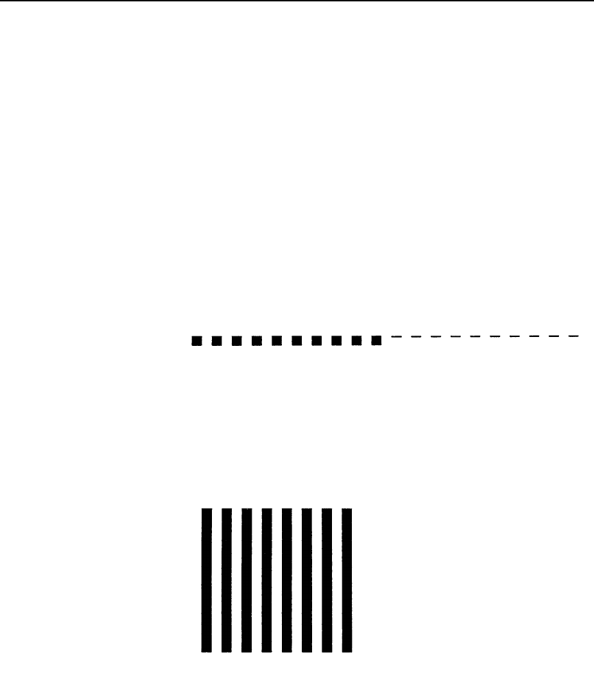
Lines, Dashed
115
Examples The following examples illustrate dashed lines in normal
resolution mode. Note that changing the horizontal and vertical
line length parameter values constructs a variety of dashed
vertical and horizontal lines in varying line thicknesses. With
horizontal lines, the horizontal length parameter actually specifies
line length and the vertical length parameter determines line
thickness. Similarly with vertical lines, the vertical length
parameter specifies line length and the horizontal length
parameter determines line thickness. Notice that an
alphanumerics command is required for line positioning.
^PY^-
^M01,01,000^LD0200,0010^LD0200,0001^-
^PN^-
^PY^-
^M01,01,000^LD0150,0150^-
^PN^-
l
ines
.ex
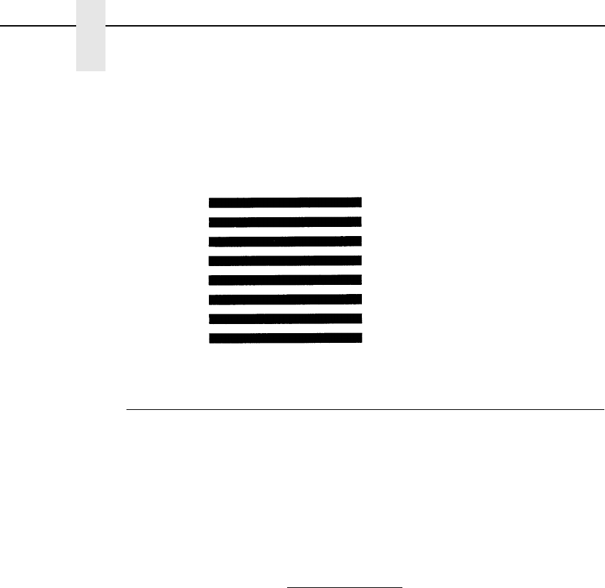
116
Chapter 2
Command Codes
^PY^-
^M01,01,000^LD0150,0154^-
^PN^-
Lines, Solid
Purpose Produces solid lines.
Mode Graphics with an Extended Graphics Command selected
Format (cc) LS horz vert (cc)-
(cc) Represents the Special Function Control Code
(SFCC). Enter the specific SFCC for your VGL
configuration.
LS The Solid Line command. Enter LS.
horz Normal Resolution:
Defines the horizontal line length in tenth inches
and dot columns. Enter a three-digit horizontal
length value ranging from 000 through 999 to
define a horizontal length of 00.0 through 99.9
inches and a fourth digit ranging from 0 through 9 to
specify 0 through 9 additional dot columns of
length.
VGL automatically understands the decimal
between the second and third digits for tenth inches
and automatically interprets the fourth digit as dot
columns.
For example, entering 0120 specifies a 1.2-inch
plus no-dot column horizontal line length; entering
1016 specifies a 10.1-inch plus 6-dot column
horizontal line length. This command is ignored if
either length parameter is zero plus zero dots.
l
ines.e
x3
Lines, Solid
117
High Resolution:
Defines the horizontal length of a line in thousandth
inches. Enter a five-digit horizontal value ranging
from 00000 through 99999 to define a horizontal
length of 0.000 inch through 99.999 inches. VGL
automatically understands the decimal between the
second and third digits.
vert Normal Resolution:
Defines the vertical length of the line in tenth inches
and dot rows. Enter a three-digit vertical length
value ranging from 000 through 999 to define a
vertical length of 00.0 through 99.9 inches and a
fourth digit ranging from 0 through 9 to specify 0
through 9 additional dot rows of length.
VGL automatically understands the decimal
between the second and third digits for tenth inches
and automatically interprets the fourth digit as dot
rows.
For example, entering 0004 specifies a 0.0-inch
plus 4-dot row vertical line length; entering 0240
specifies a 2.4-inch plus no-dot row vertical line
length. This command is ignored if either length
parameter is zero plus zero dots.
High Resolution:
Defines the vertical length of a line in thousandth
inches. Enter a five-digit vertical value ranging from
00000 through 99999 to define a vertical length of
0.000 inch through 99.999 inches. VGL
automatically understands the decimal between the
second and third digits.
(cc)- Graphics Mode CR. Enter the SFCC for your VGL
configuration immediately followed by - to end the
command sequence.
Comments
Line drawing commands are positioned by the parameters or
commands of an alphanumerics command sequence (such as
horizontal tabs, the justification parameter, etc.). Consequently,
an alphanumerics command must precede a line drawing
command.
Using appropriate values for the horizontal and vertical line length
parameters constructs a variety of vertical and horizontal lines in
varying line thicknesses. The horizontal or vertical orientation of
the line is determined by the longest length parameter.
118
Chapter 2
Command Codes
Example The following commands illustrate solid lines in normal resolution.
As shown in the examples, changing the horizontal and vertical
line length parameter values constructs a variety of vertical and
horizontal lines in varying line thicknesses.
With horizontal lines, the horizontal length parameter actually
specifies line length and the vertical length parameter determines
line thickness.
Similarly with vertical lines, the vertical length parameter specifies
line length and the horizontal length parameter determines line
thickness. (The Graphics Mode Enable command was previously
sent to enable Graphics Mode but is not shown in the examples.
Additionally, an alphanumerics command must be sent for line
positioning but is not shown in the examples.)
^LS0425,0010^-
^LS0100,0100^- ^LS0001,0150^-
Logo Generation (Version II)
Purpose Provides eight pre-designed logos and symbols in different sizes
and rotations totaling 14 new options. Logo Generation is used in
conjunction with the Pixel Expansion command described on
page 125
Mode Graphics with an Extended Graphics Command selected
Format (cc) ILOGO, value (cc)G
(cc) Represents the Special Function Control Code
(SFCC). Enter the specific SFCC for your VGL con-
figuration.
ILOGO, The Logo Generation command. Enter ILOGO, (the
comma following the command is required).
value Represents the variable which selects the pre-
defined logo or symbol. Enter a 2-digit value from
Table 14 representing the symbol or logo desired.
(cc)G The required terminator for the ILOGO, command.
Enter the SFCC for your VGL configuration fol-
lowed by a G to end the ILOGO, command
sequence.
Logo Generation (Version II)
119
Comments
The Pixel Expansion (IPEXP) command, described on page 125,
may be used with all logos printed using the ILOGO, command.
Logos and symbols created using the Z command (described on
page 150) are still available and do not conflict with the ILOGO,
command. Do not use any alphanumeric-rotation commands with
ILOGO, symbols and logos.
Example The following program and print sample illustrate how the
copyright symbol (value 41 from Table 14) is called using the
ILOGO, command. Note that the alphanumerics command ^M is
simply “introducing” an Extended Graphics command; therefore,
the alphanumeric command parameters (01,01,000) are optional.
^PY^-
^M^IPEXP,06,06^G^ILOGO,41^G^-
^PN^-
Table 14. Logo Generation Values
Value Description
41 Copyright symbol
42 Copyright symbol at 90 degrees
43 Registered trademark symbol
44 Registered trademark symbol at 90 degrees
45 UL symbol, large
46 UL symbol, large, at 90 degrees
47 Trademark symbol
48 Trademark symbol at 90 degrees
49 CSA symbol
4A CSA symbol at 90 degrees
4B UL symbol, medium
4C UL symbol, small
61 TUV Rheinland symbol
62 GS-Mark symbol
ilogo.ex

120
Chapter 2
Command Codes
Logo, PCX
Purpose Downloads and prints PCX format logos.
Mode Standard Graphics format except for option E (see below).
Format
Format 1 (cc) IPCX, option name [,size] [,DISK] (cc)G
PCX logo data
(cc) IPCX, END(cc)G
Format 2 (cc) IPCX, option name [,DISK] (cc)G
Format 3 (cc) IPCX, option (cc)G
(cc) Represents the Special Function Control Code
(SFCC). Enter the specific SFCC for your VGL
configuration.
IPCX, The Logo Generation command. Enter IPCX, (the
comma following the command is required).
option C = Creates/Loads logo into printer memory.
The logo can be printed later.
E = Executes/Prints logo.
D = Deletes logo from printer memory.
R = Resets/Clears logo from printer memory.
L = Lists all the PCX logos that are stored in
printer memory.
name Name of logo. Required for options C, E, and D.
size Size (in bytes) of the logo.
DISK Optional parameter to download a logo to flash
memory or execute (print) a logo stored in flash
memory. Enter DISK. Currently, the DISK
parameter only applies to option C and option E.
(cc)G The required terminator for the IPCX, command.
Enter the SFCC for your VGL configuration
followed by a G to end the IPCX, command
sequence.
PCX logo data
Logo data in PCX format. Must be in either
uncompressed or packbits format.
END Ends PCX logo to be downloaded.
NOTE: Format 1 is used for creating/downloading a logo (option C).
Format 2 is used for executing (printing) a logo (option E), or deleting
a logo from memory (option D).
Format 3 is used for listing (option L) or clearing (option R) all logos
from memory.
NOTE: Option E (executing/printing a logo) should be used in Graphics mode
with Extended Graphics Command selected. All other options should
be used in Standard Graphics mode.

Logo, TIFF
121
Example To download a PCX logo:
^IPCX,Cfilename[,size]^G
PCX logo data
^IPCX,END^G
Your host may interpret the PCX data as control codes, which
affects the way the host sends data to the printer. Consult your
host's user manual for sending binary data.
To print a PCX logo in Extended Graphics mode:
^IPCX,Efilename^G
Logo, TIFF
Purpose Downloads and prints TIFF format logos.
Mode Standard Graphics format except for option E (see below).
Format
Format 1 (cc) ITIFF, option name [,size] [,DISK] (cc)G
TIFF logo data
(cc) ITIFF, END(cc)G
Format 2 (cc) ITIFF, option name [,DISK] (cc)G
Format 3 (cc) ITIFF, option (cc)G
(cc) Represents the Special Function Control Code
(SFCC). Enter the specific SFCC for your VGL
configuration.
ITIFF, The Logo Generation command. Enter ITIFF, (the
comma following the command is required).
option C = Creates/Loads logo into printer memory.
The logo can be printed later.
E = Executes/Prints logo.
D = Deletes logo from printer memory.
R = Resets/Clears logo from printer memory.
L = Lists all the TIFF logos that are stored in
printer memory.
name Name of logo. Required for options C, E, and D.
size Size (in bytes) of the logo.
DISK Optional parameter to download a logo to flash
memory or execute (print) a logo stored in flash
memory. Enter DISK. Currently, the DISK
parameter only applies to option C and option E.
(cc)G The required terminator for the ITIFF, command.
Enter the SFCC for your VGL configuration
followed by a G to end the ITIFF, command
sequence.
TIFF logo data
Logo data in TIFF format. Must be in either
uncompressed or packbits format.

122
Chapter 2
Command Codes
END Ends Tiff logo to be downloaded.
NOTE: Format 1 is used for creating/downloading a logo (option C).
Format 2 is used for executing (printing) a logo (option E), or deleting
a logo from memory (option D).
Format 3 is used for listing (option L) or clearing (option R) all logos
from memory.
NOTE: Option E (executing/printing a logo) should be used in Graphics mode
with Extended Graphics Command selected. All other options should
be used in Standard Graphics mode.
Example To download a TIFF logo:
^ITIFF,Cfilename[,size]^G
TIFF logo data
^ITIFF,END^G
Your host may interpret the TIFF data as control codes, which
affects the way the host sends data to the printer. Consult your
host's user manual for sending binary data.
To print a TIFF logo in Extended Graphics mode:
^ITIFF,Efilename^G
Page, Controlling Paper Options (Version II)
NOTE: This command is partially supported on L7032 printers. The L7032
printer supports only EJECT, COPY, ORIENTATION, and MARGINS.
Purpose Controls the paper options for printing.
NOTE: Not all options may be available with your printer. Consult your printer
User's Manual to determine which options are available. If an option
is not available, the emulation ignores the corresponding command.
Mode Graphics with a Standard Graphics Command selected
Format (cc) IPAGE, option [,value] (cc)G (cc)-
(cc) Represents the Special Function Control Code
(SFCC). Enter the specific SFCC for your VGL
configuration.
IPAGE, The command to control paper options. Enter
IPAGE, (the comma following the command is
required).
option [,value] Represents the option to be set. See Table 15.
Enter the option and comma, then the value.
(cc)G Terminator. Enter the SFCC for your VGL
configuration immediately followed by G, the
universal terminator.
(cc)- Graphics Mode CR. Enter the SFCC for your VGL
configuration immediately followed by - to end the
command sequence.
Page, Controlling Paper Options (Version II)
123
Table 15. Page, Controlling Paper Options
Option Value and Meaning
SPEED,
(Thermal only)
Specifies the print speed in lines per minute at 6 lpi. Enter SPEED and a number in
the range of 0 through 9999.
INTENSITY,
(Thermal only)
Specifies the darkness of the dots. Enter INTENSITY and a number in the range of
-15 through +15.
TEAR,
(Thermal only)
Sets the printer to pause (for the user to tear-off a page) after a specified number of
pages. Enter TEAR and a number in the range of 0 through 256 (0 implies no pause).
CUT, Sets the printer to cut a page after a specified number of pages. Enter CUT and a
number in the range of 0 through 256 (0 implies no cutting). Note: This does not
perform a job separation. Use the EJECT command for job separations.
LABELS,
(Thermal)
Specifies the label sensor. Enter LABELS and a number in the range from 0 through
7 (0 is disable).
0 = No sensor
1 = Reflective gap sensor,
2 = Transmissive gap sensor.
EJECT, Tells the printer to eject a partially-complete page from the printer, regardless of the
current graphical print position. Enter EJECT. (No values follow the command.) On
continuous form printers, EJECT moves enough paper so that all completed or
partially completed pages are fused and moved completely out of the engine.
COPY, Sets the printer to print multiple copies of each "physical page" - that is, one cut sheet
or the distance between perforations on continuous forms, which may contain
multiple forms or labels. (If the page contains incremented fields for a repeated form,
the image is the same.) Enter COPY followed by the number of copies from 001
through 999. (If a partial page has not been printed and an EJECT is performed, then
the selected number of copies of the partial page is produced.)
ORIENTATION, Sets printing orientation. After the IPAGE command, enter either PORT for portrait,
LAND or RLAND for landscape, INV for inverted portrait, or LLAND for inverted
landscape. If any data has been drawn on a page when this command is received
with a new orientation, the current physical page is printed and the next page is in the
new orientation. (Existing margin settings apply to the new orientation.)
MARGINS, Sets the page margins and printable text length. Enter MARGIN followed by four
digits specifying the top margin in hundredths of an inch (0000/0.00 - 9999/99.99),
three digits specifying the text length in character lines at the current line spacing
(001-999), and four digits specifying the left margin in hundredths of an inch (0000/
0.00 - 9999/99.99). (See Appendix D for an explanation of page margins.)
124
Chapter 2
Command Codes
Passing Hex Values
Purpose Sends specified hex values to the printer. This command can be
used in Standard or Extended Graphics mode.
Mode Standard or Extended Graphics mode, with or without an
Extended Graphic Command selected
Format (cc) IHEX, value
(cc) Represents the Special Function Control Code
(SFCC). Enter the specific SFCC for your VGL con-
figuration.
IHEX, The Pass Hex Values command. Enter IHEX,. (The
comma following the command is required).
value The hex value to be sent to the printer. Valid values
are hex 00 through FF.
Comments
The IHEX command can be used to send graphic and non-
graphic hex data. The difference between the use of the
command is shown in example 1, Standard Graphic mode, and
Example 2, Extended Graphic mode.
Example 1
The following example of the command used in the Standard
Graphic mode, prints A through F with C underlined. The hex 08
is the control code for a backspace.
NOTE: The "Control Code 08" setting for the Line Printer Plus Emulation
must be set to "Backspace" in order for VGL to recognize the hex
code. Refer to your User's Manual for details.
^PY^-
ABC^IHEX,08_DEF
^PN^-

Pixel Expansion (Version II)
125
Example 2 The following example of the command used in the Extended
Graphic mode, prints Schön with the proper accent marks.
^PY^-^F^
^M0202000Sch^IHEX,F6n^-
^O^-^PN^-
Pixel Expansion (Version II)
Purpose Expands those graphics which were plotted using the ILOGO,
command (page 118), the Plotting Graphics (cc)Q command
(page 129), and the Symbols command (page 145).
Mode Graphics with an Extended Graphic Command selected
Format cc) IPEXP, horz, vert (cc)G
(cc) Represents the Special Function Control Code
(SFCC). Enter the specific SFCC for your VGL con-
figuration.
IPEXP, The Pixel Expansion command. Enter IPEXP, (the
comma following the command is required).
horz The horizontal expansion of the logo or symbol.
Enter a value ranging from 1 through 255. Leading
zeros for values less than three digits are not
required.
vert The vertical expansion of the logo or symbol. Enter
a value ranging from 1 through 255. Leading zeros
for values less than three digits are not required.
(cc)G The required terminator for the IPEXP, command.
Enter the SFCC for your VGL configuration fol-
lowed by a G to end the IPEXP, command
sequence.
Comments
Only use the IPEXP, command in conjunction with graphics
plotting and symbols which were created using the ILOGO,
command, the Plotting Graphics Q command, and the Symbols
command. The IPEXP, command expands these pre-designed
graphics and symbols similar to the way normal characters are
expanded using the Character Height and Character Width
commands.
The IPEXP, command does not affect any other elements, such
as fonts. Unless this command is turned off, once an expansion
factor is selected, that value remains selected until a new IPEXP,
command is received. Turn this command off by entering 1,1 for
the horizontal and vertical expansion values.

126
Chapter 2
Command Codes
Example The following program and print sample illustrate how the TUV
Rheinland symbol (value 61 from Table 14) is called using the
ILOGO, command and expanded 4X by 4X using the IPEXP,
command. Note that the alphanumerics command ^M is simply
“introducing” an Extended Graphics command; therefore, the
alphanumeric command parameters (such as 01,01,000) are
optional.
^PY^-^F^-
^M^IPEXP,04,04^G^ILOGO,61^G^-
^PN^-

Plotting Bitmap Images
127
Plotting Bitmap Images
Purpose Creates and prints bitmap images
Mode Graphics with an Extended Graphics Command selected
Format To create a bitmap image:
(cc) IPLOT, type, id, width, data (cc)G
(cc) Represents the Special Function Control Code
(SFCC). Enter the specific SFCC for your VGL con-
figuration.
IPLOT, The bitmap image command. Enter IPLOT, (the
comma is required).
type The data type that is used to specify the bitmap.
Enter 4 for 4 bit data, or 8 for 8 bit data. For 4 bit
data, two bytes determine 8 bits of the image. For 8
bit data, one byte determines 8 bits of the image.
id The bitmap identification number. Enter a one digit
number between 0 and 9.
width The width of the bitmap, in bytes. Enter a value
between 1 and 999. Leading zeros for values with
less than 3 digits are not required.
data The bitmap image data. The data may either be
specified in its entirety, or represented in a com-
pressed format using the (cc)B, (cc)W, and (cc)D
commands in any sequence and quantity.
(cc)B pattern, count
Byte repeat specifier. Allows you to repeat a
desired byte pattern. Enter the SFCC, followed by
B. Then enter a 2 character byte pattern, followed
by a comma, followed by a value between 1 and
999 for the number of times (count) to repeat the
pattern. Leading zeros for values with less than 3
digits are not required.
(cc)W count "White" byte (all bits "off") repetition. Enter the
SFCC, followed by W, followed by a value between
1 and 999 for the number of times (count) to repeat
the pattern. Leading zeros for values with less than
3 digits are not required.
(cc)D count "Dark" byte (all bits "on") repetition. Enter the
SFCC, followed by D followed by a value between
1 and 999 for the number of times (count) to repeat
the pattern. Leading zeros for values with less than
3 digits are not required.
(cc)G IPLOT command terminator. Enter the SFCC for
your VGL configuration followed by G to end the
IPLOT command sequence.

128
Chapter 2
Command Codes
To print a previously created bitmap image:
(cc) IPLOT,E, id (cc)G
(cc) Represents the Special Function Control Code
(SFCC). Enter the specific SFCC for your VGL
configuration.
IPLOT,E, The bitmap image execute (print) command. Enter
IPLOT,E, (both commas are required).
id The bitmap identification number. Enter a one digit
number between 0 and 9. The number must
correspond to the identification number used for a
previously created bitmap, or an error is reported.
(cc)G IPLOT command terminator. Enter the SFCC for
your VGL configuration followed by G to end the
IPLOT command sequence.
Comments
Bitmap images are stored in memory only as long as the printer
power is applied, or until being replaced by another bitmap with
the same identification number. The maximum size and number
of bitmaps that may be created is dependent on the amount of
available printer memory. Therefore, it may not be possible to
store up to the maximum number of 10 bitmap images if each is
relatively large.
Bitmap images may be created using the IPLOT, command as a
standard graphics command once graphics mode has been
enabled. However, the IPLOT,E, command must be used as an
extended graphics command within a graphics (^M, ^V, ^E, ^U,
^T, ^J) command sequence to position and rotate the bitmap as
desired.
Example The bit pattern 11000011 is represented by the hex characters
C3. To specify 10 consecutive C3 patterns, you can enter either
C3C3C3C3C3C3C3C3C3C3 or, using the byte repeat format,
(cc)BC3,10. Also, for clarity, commas may be embedded within
the data stream, such as C3,C3,C3,C3,C3,C3,C3,C3,C3,C3 or
C3C3,C3C3,C3C3,C3C3,C3C3.
A stream of 6 consecutive 00 bytes may be written
00,00,00,00,00,00 or, using the "white" byte repetition format,
(cc)W6.
A stream of 9 consecutive FF bytes may be written
FFFFFFFFFFFFFFFFFF or, using the "dark" byte repetition
format, (cc)D9.
The following illustrates how to create and print a simple bitmap
image. The bitmap is created using 4 bit data, is identified as
bitmap number 0, and is 120 bytes wide. On a 300 dpi printer,
this creates an image that is 3 inches wide (120 bytes*8 bits per
byte = 900 bits, or 900 dots, or 3 inches wide).
Plotting Graphics (Columns)
129
^PY^-
^F^-
^IPLOT,4,0,120,
^D40,^W40,^D40,^D40,^W40,^D40,
^D40,^W40,^D40,^D40,^W40,^D40,
^D40,^W40,^D40,^D40,^W40,^D40,
^D40,^W40,^D40,^D40,^W40,^D40,
^D40,^W40,^D40,^D40,^W40,^D40,
^D40,^W40,^D40,^D40,^W40,^D40,
^G^-
^O^-
^PN^-
The following prints the bitmap:
^PY^-
^M0101000^IPLOT,E,0^G^-
^,
^PN^-
The resulting image:
Plotting Graphics (Columns)
Purpose Creates logos or other graphic patterns by plotting in dot-
addressable columns.
NOTE: Do not confuse this graphics plot command, (cc)Q, with the odd dot
plot command, (cc)Q, discussed on page 132. The graphics plot
command discussed in this section plots in vertical data bytes
(columns) and is effective when an Extended Graphics Command is
selected. Odd dot plot plots in horizontal data bytes (rows) and is
effective when a Standard Graphics Command is selected.
Mode Graphics with an Extended Graphics Command selected
Format (cc) Q data (cc) G (cc)-
(cc) Represents the Special Function Control Code
(SFCC). Enter the specific SFCC for your VGL
configuration.
Q The Logo command. Enter Q.
data The hexadecimal logo data. Each hexadecimal
value defines one 7-dot vertical data byte (column)
for each 0.1-inch row.
(cc)G Terminator. Enter the SFCC for your VGL
configuration immediately followed by G, the
universal terminator, to end the input of logo data.

130
Chapter 2
Command Codes
(cc)- Graphics Mode CR used as a sequence terminator.
Enter the SFCC for your configuration immediately
followed by - to end the command sequence.
Comments
Logos are positioned by the parameters or commands of an
alphanumerics command sequence (such as horizontal tabs, the
justification parameter, etc.) and can be created only from within
an alphanumerics command sequence. Consequently, an
alphanumerics command must precede a Logo command.
Any logo that can be designed using the rows of the 0.1-inch x
0.1-inch matrix grid can be produced with the Q command. The
form example in the “Exercises And Examples” chapter on page
301, illustrates how the hand logo was produced. An arrow
pattern is illustrated in the following example.
Graphics designed using this command cannot be stored in VGL
memory for future use. Once your graphic pattern prints, it is
automatically purged from VGL working memory.
Example 1
The bottom-most bit of the data byte corresponds to the least
significant bit (LSB) of the data byte, which corresponds to the
bottom row (row #1); the data byte works up through the other
bits to the top-most significant bit of the data byte, which
corresponds to the top bit row (row #7).
Summing the values determines the data for each column of the
logo. Table 16 shows the decimal value sums for each data byte
(column) for the arrow pattern illustrated. Each byte was
calculated first in decimal and then converted to the equivalent
hexadecimal value (using the ASCII chart in Appendix A). These
hexadecimal values are then entered in the data parameter for
the Q command.
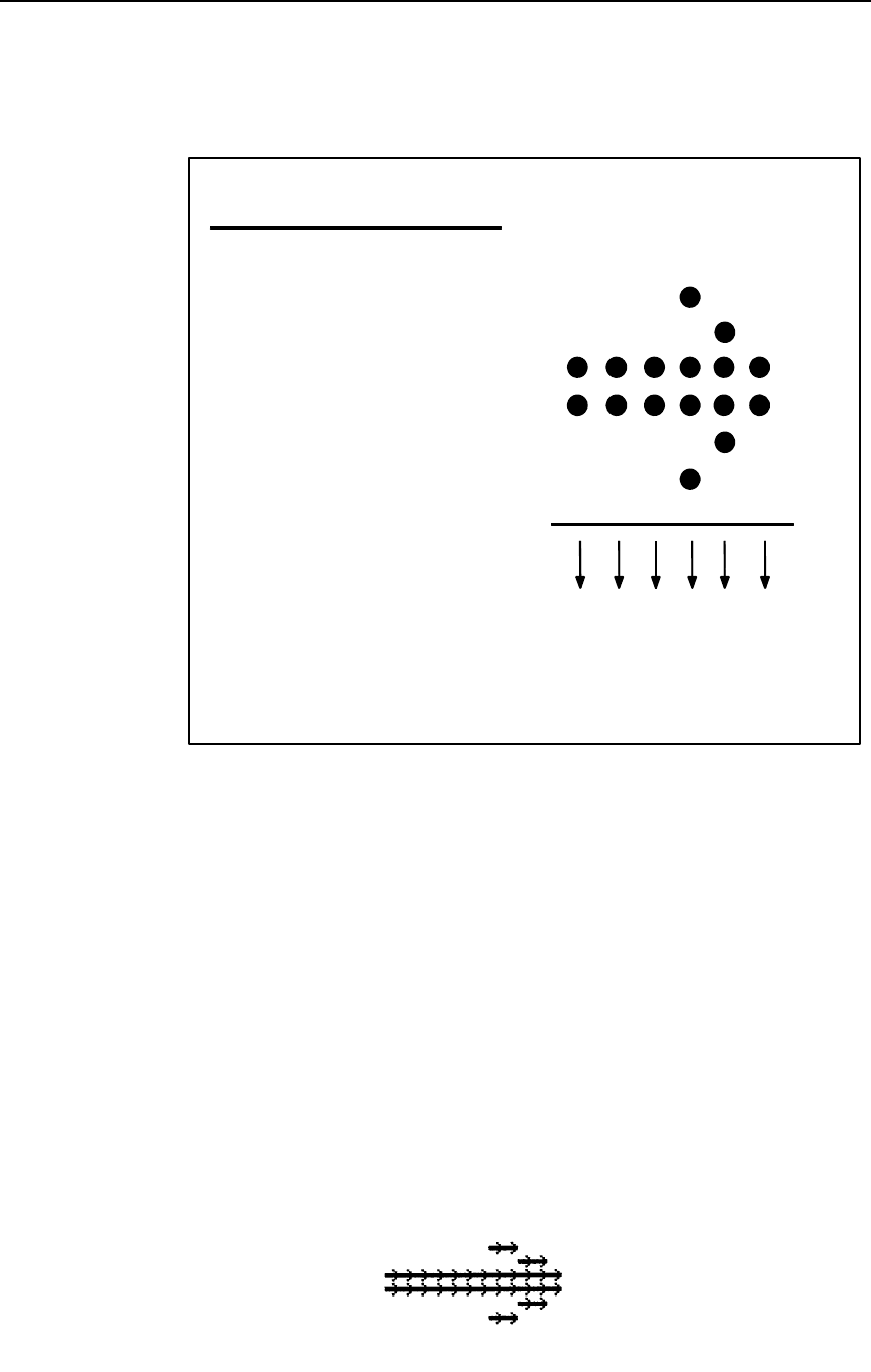
Plotting Graphics (Columns)
131
Table 16. Graphics Logo Plot Data Format
Example 2 The sample command below illustrates the logo function drawing
the arrow shown in Table 16. The six hex data values for each
0.1" x 0.1" matrix are repeated and horizontal tabs and
justification commands are used to produce the arrow in an arrow
pattern. Notice that an alphanumerics command was required for
logo positioning.
^PY^-^F^-
^M01,01,000^T0070^Q0C,0C,0C,2D,1E,0C,0C,0C,0C,2D,1E,0C^G^-
^M01,01,000^T0090^Q0C,0C,0C,2D,1E,0C,0C,0C,0C,2D,1E,0C^G^-
^M01,01,000^Q0C,0C,0C,2D,1E,0C,0C,0C,0C,2D,1E,0C,0C,0C,0C,2D,
1E,0C,0C,0C,0C,2D,1E,0C,0C,0C,0C,2D,1E,0C,0C,0C,0C,2D,1E,0C,0C,
0C,0C,2D,1E,0C,0C,0C,0C,2D,1E,0C,0C,0C,0C,2D,1E,0C,0C,0C,0C,2D,
1E,0C,0C,0C,0C,2D,1E,0C,0C,0C,0C,2D,1E,0C^G^-
^M01,01,000^Q0C,0C,0C,2D,1E,0C,0C,0C,0C,2D,1E,0C,0C,0C,0C,2D,
1E,0C,0C,0C,0C,2D,1E,0C,0C,0C,0C,2D,1E,0C,0C,0C,0C,2D,1E,0C,0C,
0C,0C,2D,1E,0C,0C,0C,0C,2D,1E,0C,0C,0C,0C,2D,1E,0C,0C,0C,0C,2D,
1E,0C,0C,0C,0C,2D,1E,0C,0C,0C,0C,2D,1E,0C^G^-
^M01,01,000^T0090^Q0C,0C,0C,2D,1E,0C,0C,0C,0C,2D,1E,0C^G^-
^M01,01,000^T0070^Q0C,0C,0C,2D,1E,0C,0C,0C,0C,2D,1E,0C^G^-
^O^-^PN^-
Bit#
7
6
5
4
3
2
1
Decimal
Value
64
32
16
8
4
2
1
Top
Bottom LSB
Data Bytes (Columns)
123456
Decimal Value:
Hex Value:
12 12 12 45 30 12
0C 0C 0C 0C2D 1E
l
ogoar
ro.

132
Chapter 2
Command Codes
Plotting Graphics (Rows)
NOTE: The Plotting Graphics command is not supported on L7032 printers.
Purpose Allows you to address and print any individual dot position using
Printronix odd and even dot plot commands. Odd and even dot
plot addresses each dot position using a row method (as
opposed to the column method created in Extended Graphics as
described on page 129.)
NOTE: Do not confuse this odd dot plot command, (cc)Q, with the graphics
plot command, (cc)Q, discussed on page 129. The odd dot plot
discussed in this section plots in horizontal data bytes (rows) and is
effective when a Standard Graphics Command is selected. Graphics
plot plots in vertical data bytes (columns) and is effective when an
Extended Graphics Command is selected.
Mode Graphics with a Standard Graphics Command selected
Format (cc) plot data (cc)G
(cc) Represents the Special Function Control Code
(SFCC). Enter the specific SFCC for your VGL con-
figuration.
plot Represents a Printronix plot command. Enter Q for
normal density odd dot plot, or enter C for high den-
sity even dot plot.
data The plot data. Enter the hex data required to pro-
duce the desired graphics pattern. (See Comments
below.)
(cc)G Following the data, enter the (SFCC) for your VGL
configuration immediately followed by any valid
command character or G, the universal sequence
terminator.
Comments
Graphics designed using this command cannot be stored in VGL
memory for future use. Once your graphic pattern prints, it is
automatically purged from VGL working memory.
In typical Printronix plotting, the binary pattern ASCII characters
supplied as data are used to address the character columns with
the Least Significant Bit (LSB) corresponding to the left-most dot
column. VGL, however, addresses the binary pattern of hex data
bytes in a "mirror image" of Printronix plotting, with the LSB
addressing the right-most dot position.
Two plot types are available and defined below: odd dot plot for
normal density and even dot plot for high density applications.
You must define each byte of each data line in plot format, which
is explained in the "Plot Data Byte Format" section on the next
page.
Odd dot plot (normal density plotting) is selected with the Odd
Dot Plot command, (cc)Q data (cc)G. Odd dot plot addresses the
Plotting Graphics (Rows)
133
odd numbered dot columns to produce a horizontal and vertical
density that varies based on the printer and mode of operation.
Even dot plot (high density plotting) is selected with the Even
Dot Plot command, (cc)C data (cc)G. Even dot plot works in
conjunction with the Odd Dot Plot command. The odd and even
numbered dot columns are addressed to double the horizontal
density.
Plot Data Format
You must define each byte for a complete line of data in plot format. Plot Data
Byte Format explains how to define each byte along a data line. Plot Data
Line Format explains how to take each defined byte and create a complete
line of data.
Plot Data Byte Format
Each data byte specifies six of the twelve dot columns that compose one
character column. Using odd dot plot, bits 1 through 6 of the data byte
address the odd numbered dot columns; using even dot plot, bits 1 through 6
of the data byte address the even numbered dot columns.
A dot is printed for each bit that is set ("1") in the data byte. When using plot
commands, bits 7 and 8 of the data byte must always be set "1". The sum of
each bit in the data byte, in hexadecimal value, becomes the plot data used in
the plot command.
For example, refer to Table 17. A hex data value of C4 prints a dot at the
column corresponding to the 04 bit. A hex data byte value of FF produces
dots in all columns; a value of C0 leaves the column blank. The bit pattern
addresses the odd columns of the character space for odd dot plot or the
even columns of the character space for even dot plot. Both odd and even
columns are used for high density plot. These hex data bytes to produce the
graphics pattern are entered in the data parameter of the plot command.
Table 17 illustrates the plotting hex data required to produce the same arrow
graphics as shown in Table 16 on page 131 for the Logo Mode.
1 2 . . . 132Byte #
Data
11
Dot Pattern
3
1000001111111111100001
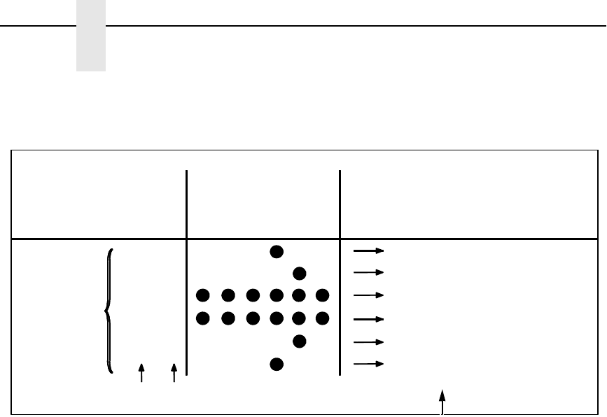
134
Chapter 2
Command Codes
Table 17. Odd Dot Plot Data Example
Plot Data Line Format
Each plotted line of data may include up to 132 data bytes. The first data byte
in the line addresses the dot positions to print in the first character column; the
second data byte addresses the dot positions to print in the second character
column, etc. After the last byte of data, enter the terminator command (cc)G,
and repeat this sequence for the number of plot lines involved.
In odd dot plot, the (cc)G terminator causes the contents of the buffer to plot
and advances the paper (or moves the logical print position in thermal
printers) a single dot row based on the vertical density of the current print
mode. In even dot plot, the paper/logical print position is not advanced.
For high density plot, the Even Dot Plot and Odd Dot Plot commands are
used in conjunction with two data lines. The Even Dot command is sent with
the first data line along with the (cc)G terminator. The terminator causes the
contents of the buffer to plot in the even dot columns but does not advance
the paper/logical print position. The printer waits for the second line of data
using the Odd Dot Plot command and a terminator. Data in the buffer is
plotted in odd dot columns of the same row where even dot column data was
just plotted and the paper/logical print position is advanced one dot row at the
vertical density of the current print mode.
Dot Row
1
2
3
4
5
6
Decimal
Byte/Character Column #1
1357911
Binary
11000100
11000010
11111111
11111111
11000010
11000100
Odd Dot Columns:
Decimal Value: 32 16 08 04 02 01 Value for
the Row
196
194
255
255
194
196
Bit #: 654321 Hex Data
Byte for
the Row
C4
C2
FF
FF
C2
C4
Pattern
128 64
87
--
Bit 7 and 8 may be “0” or “1” in Plot Mode. LSB
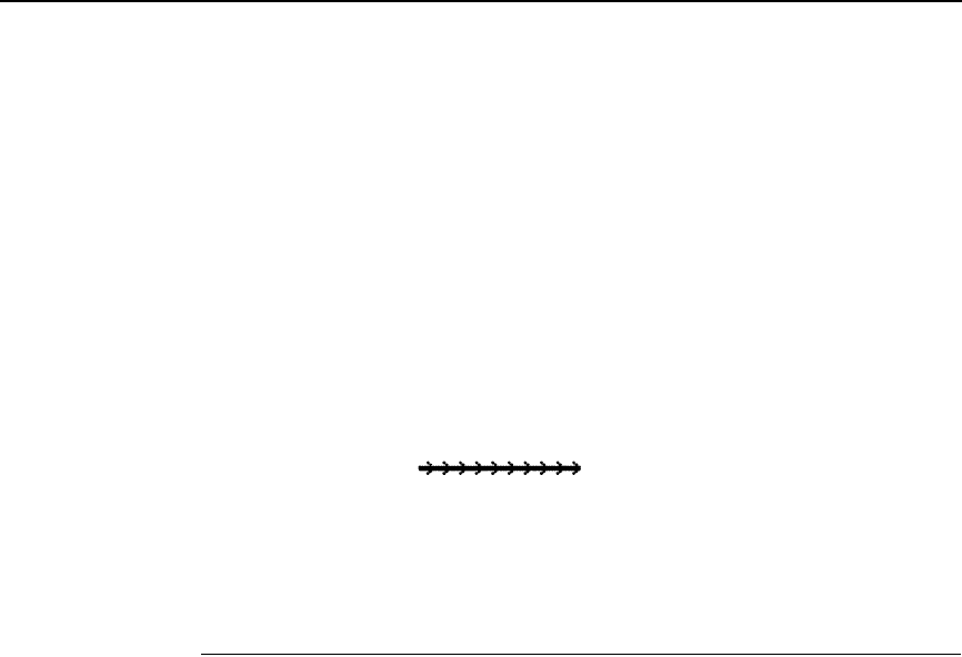
Reset
135
Example The following sample command illustrates Printronix plotting,
plotting a line of arrows using the data shown in Table 17.
^PY^-^F^-
^QC4,C4,C4,C4,C4,C4,C4,C4,C4,C4^*
^QC2,C2,C2,C2,C2,C2,C2,C2,C2,C2^*
^QFF,FF,FF,FF,FF,FF,FF,FF,FF,FF^*
^QFF,FF,FF,FF,FF,FF,FF,FF,FF,FF^*
^QC2,C2,C2,C2,C2,C2,C2,C2,C2,C2^*
^QC4,C4,C4,C4,C4,C4,C4,C4,C4,C4^*
^O^-^PN^-
Reset
NOTE: The Reset command is not supported on L7032 printers.
Purpose Resets VGL to the current user defined configuration.
Mode Graphics with a Standard Graphics Command selected
Format (cc) @ R (cc)-
(cc) Represents the Special Function Control Code
(SFCC). Enter the specific SFCC for your VGL con-
figuration.
@ Specifies one of the @ commands. Enter @ to
begin an @ command function.
R Specifies the Reset command. Enter R to reset the
printer to the current user defined configuration.
(cc)- Graphics Mode CR. Enter the SFCC for your VGL
configuration immediately followed by - to end the
command sequence.
Comments
The Reset command prints any pending page then resets VGL to
the current user defined configuration (last loaded configuration
plus any front panel changes). This may not be the same
configuration used to power-up the printer if the front panel
changes were made and not saved to flash memory. VGL then
restarts as if just powered up (no dynamic forms in form library,
character substitution sets reset, starts printing in upper left
corner, etc.).
NOTE: Any EVFU setting in the Line Printer Plus Emulation (by direct codes
or the VGL (cc)L command) is not reset (see page 89).
p
l
ot.
136
Chapter 2
Command Codes
Reverse Print
Purpose Produces white characters on either a black printed background
or any of the shaded or patterned backgrounds available with the
shading and shading mask features.
Mode Graphics with an Extended Graphics Command selected
Format (cc) R data (cc)R (cc)-
(cc) Represents the Special Function Control Code
(SFCC). Enter the specific SFCC for your VGL
configuration.
R The Reverse Print command. Enter R.
data The data characters for reverse printing.
(cc)R Following the data, enter the SFCC for your VGL
configuration and the Reverse Print command (R)
to turn off the reverse printing feature.
(cc)- Graphics Mode CR used as a sequence terminator.
Enter the SFCC for your configuration immediately
followed by - to end the command sequence.
Comments
The R command is input as part of the data in one of the
alphanumeric commands. The R command must be turned on
and off by command. Any character data entered between the
reverse print on and off commands is printed in reverse print.
However, when the alphanumerics command sequence is
terminated, reverse printing is also terminated.
Shading (page 140) or shading mask (page 142) backgrounds
are also available with the R command. Do not use Compressed
Print Fonts (discussed on page 47) with this feature.
The reverse printed character is actually created by not printing
within the black or shaded background. A dark box border is
automatically produced around the reverse printed characters
character. The black background border combined with the size
of the character increases the total area of the character field. If
the descending character printing feature is used with reverse
print, the black background border area is increased to allow for
the descending character space.
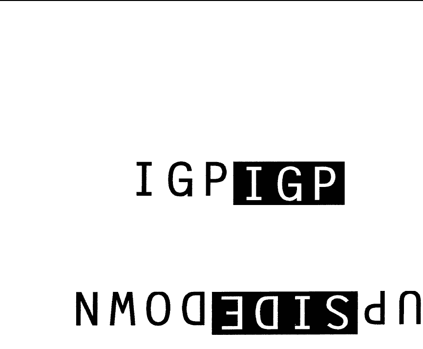
Reverse Print
137
Example The following examples illustrate reverse printing command
sequences. In the first example, notice that the alphanumerics
command sequence terminator was also used to end reverse
printing.
^PY^-
^M05,05,000IGP^RIGP^-
^PN^-
^PY^-
^U05,05,000DOWN^RSIDE^RUP^-
^PN^-
reve
138
Chapter 2
Command Codes
IMPACT
Scaling
Purpose Selects a new line spacing and different horizontal by vertical (H
x V) dot density from the standard 120 x 72 base density. (See
Comments below.)
Mode Graphics with a Standard Graphics Command selected
Format (cc) @ M scale 00 (cc)-
(cc) Represents the Special Function Control Code
(SFCC). Enter the SFCC for your configuration.
@ Specifies one of the @ commands. Enter @ to
begin an @ command function.
M Specifies the Scaling command. Enter M to change
the horizontal and vertical scaling.
scale Represents the scaling parameter. Enter one of the
two-digit codes shown in Table 18 to select a new
scaling. For example, with an MVP printer, enter 02
to select mode 2, 120 x 72 (H x V) dpi scale.
Once the new scaling is selected, all printing
reflects the new scale in horizontal by vertical dots
per inch (dpi) until scaling is disabled or VGL
returns to the Normal Mode.
00 Toggles scaling on and off. When 00 is first
entered, the scaling value as selected in the scale
parameter is enabled if a printer is selected through
the “Prt to Emulate” option. When 00 is entered
again, scaling is disabled and VGL returns to the
default scaling configuration.
(cc)- Graphics Mode CR. Enter the SFCC for your
configuration followed by - to end the command
sequence.
NOTE: If the VGL Options “Prt to Emulate” is selected, scaling is enabled.
Comments Dot density varies by printer mode; selecting a different printer
mode selects a different horizontal and vertical dot density. This
varying density can affect graphic elements created in one
particular mode but printed in a different mode. Scaling permits
graphic elements, such as corners or boxes, to retain their
physical shapes and sizes when printed in a horizontal and
vertical density other than the base density of 120 x 72 dpi.
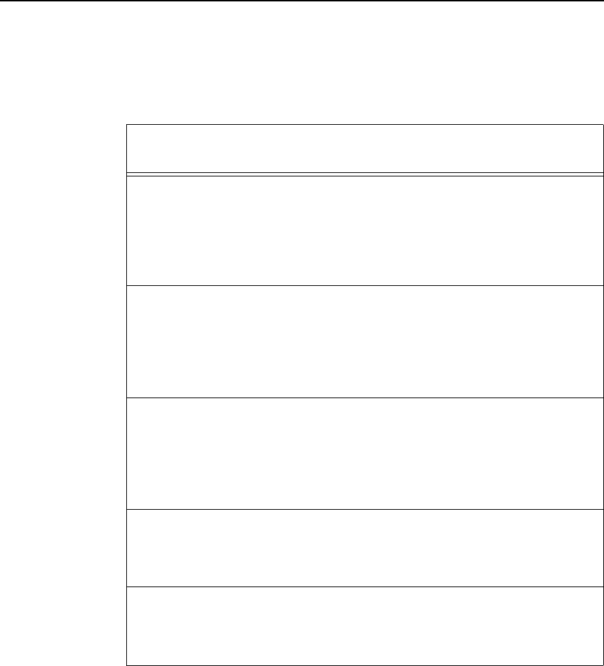
Scaling
139
NOTE: MVP and MVP 150B printers must be in Scale Mode 02 and Printer
Mode 2 to produce readable barcodes. L150 printers must be in
Scale Mode 04 and Printer Mode 4 to produce readable barcodes,
except for UPC-A, EAN 8 and EAN 13, which require Mode 5 to
produce readable barcodes.
Table 18. Scaling Codes
Printer Type Scale
Code Printer Mode Dot Density
(H x V) dpi
MVP and MVP 150B 00
01
02
03
04
05
Toggles Scaling On/Off
1
2
3
4
5
200 x 96
120 x 72
125 x 64
100 x 48
200 x 72
L150 00
01
02
03
04
05
Toggles Scaling On/Off
1
2
3
4
5
200 x 96
120 x 72
125 x 64
145 x 72
160 x 72
P3040 00
01
02
03
04
05
Toggles Scaling On/Off
1
2
3
4
5
180 x 96
120 x 72
120 x 48
145 x 72
160 x 72
P6000 00
01
02
03
Toggles Scaling On/Off
1
2
3
120 x 144
120 x 72
120 x 48
P9000 00
01
02
03
Toggles Scaling On/Off
1
2
3
180 x 96
120 x 72
120 x 48
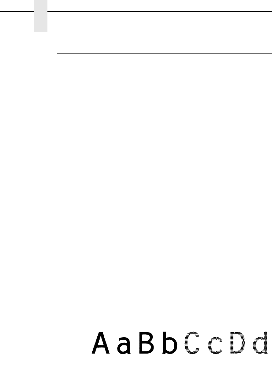
140
Chapter 2
Command Codes
Shading
Purpose Produces alphanumeric characters using a black-shaded
impression.
Mode Graphics with an Extended Graphics Command selected
Format (cc) KH data (cc)KH (cc)-
(cc) Represents the Special Function Control Code
(SFCC). Enter the specific SFCC for your VGL con-
figuration.
KH The Shading command. Enter KH to turn on the
shading feature.
data The data characters to print in shaded graphics.
(cc)KH Following the data, enter the Special Function Con-
trol Code (SFCC) for your VGL configuration and
KH to turn off the shading feature.
(cc)- Graphics Mode CR. Enter the SFCC for your VGL
configuration immediately followed by - to end the
command sequence.
Comments
The KH feature must be turned on and off by command. Any
character data entered between the KH on and off commands is
shaded when printed. Shading commands are input as part of the
data in one of the alphanumeric commands. Reverse printing
(discussed on page 136) can be combined with shading.
When the shading feature is used, only certain dot positions are
printed (versus every dot position in the normal graphics) which
produces the shaded images. The shading value can be changed
using the Shading Mask command discussed on page 142.
Examples The following sample commands illustrate shading.
^PY^-
^M05,05,000AaBb^KHCcDd^KH^-
^PN^
-

Shading
141
^PY^-
^M05,03,000IGP SH^KHAD^KHING^-
^PN^-
^PY^-
^E05,05,000IGP^KHIGP^KH^-
^PN^-
^PY^-
^E05,05,000I^KHG^KHP^-
^PN^-
^PY^-
^U03,03,000SHADING^KHDOWN^KHUPSIDE^-
^PN^-
shad
s
h
ad
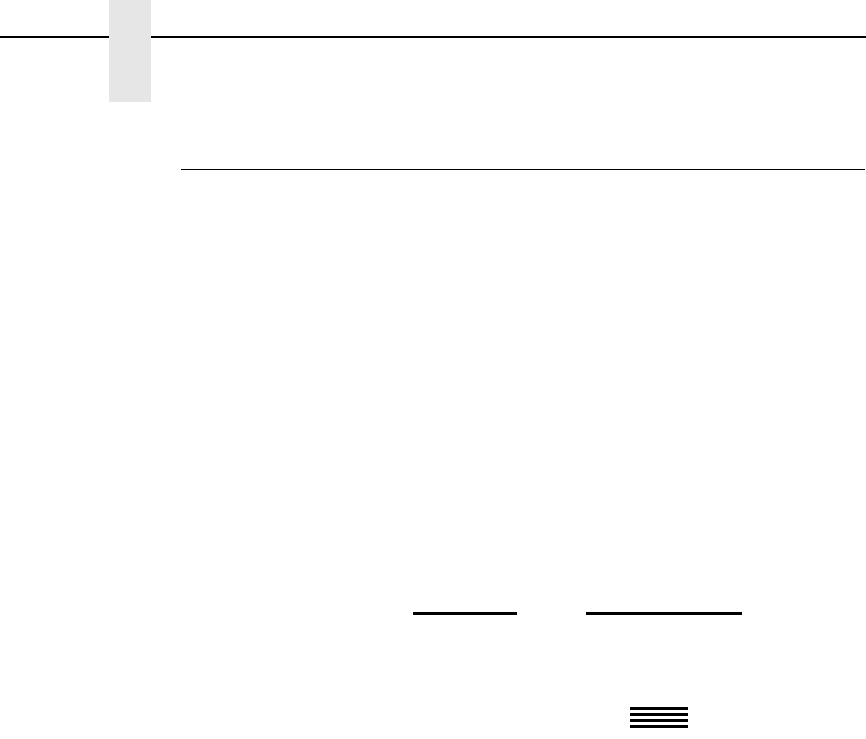
142
Chapter 2
Command Codes
Shading Mask
Purpose Activates the shading feature with a specific shading mask.
Mode Graphics with an Extended Graphics Command selected
Format (cc) KL mask data (cc)KH (cc)-
(cc) Represents the Special Function Control Code
(SFCC). Enter the specific SFCC for your VGL con-
figuration.
KL The Shading Mask command. Enter KL to turn on
the shading mask feature.
mask Represents the shading mask factor. Enter a two-
digit hex value ranging from 00 through FF to spec-
ify the shading mask factor. Four default shading
mask patterns are available and shown below. See
Appendix B for print samples of all masking values.
The shading mask selected remains selected until
another mask value is selected or the Shading
Mask command is turned off.
data The data characters to print in mask shaded
graphics.
(cc)KH Following the data, enter the Special Function
Control Code (SFCC) for your VGL configuration
and KH to turn off the shading mask feature.
(cc)- Graphics Mode CR. Enter the SFCC for your VGL
configuration immediately followed by - to end the
command sequence.
Mask Value
(Hex) Default Shading
Mask Produced
00
01
04
FF
|||||||
///////
\\\\\

Shading Mask
143
Comments
The KL command is used as part of the data contained in one of
the alphanumeric commands.
Shading Mask commands must be turned on and off by
command. Any character data entered between the KL on and off
commands is shaded with the selected mask. Shading must be
turned off before any commands are used to change character
height, width, justification, or horizontal print position. Reverse
printing can be combined with shading.
Examples The following sample commands illustrate shading. Four default
mask shading factors are available to produce vertical stripes
(KL00), horizontal stripes (KLFF), slanted stripes upper right to
lower left (KL01), and slanted stripes upper left to lower right
(KL04).
^PY^-
^M03,03,000IGP^KL00IGP^KLFFIGP^KL01IGP^KL04IGP^-
^PN^-
^PY^-
^M03,03,000IGP^KL00MASK^KL8DSHAD^KL02ING^-
^PN^-
^PY^-
^V05,05,000I^KLC2G^KHP^-
^PN^-
mask.ex3
144
Chapter 2
Command Codes
^PY^-
^E05,05,000IGP^KL9BIGP^KLFFIGP^KLF1IGP^KH^-
^PN^-
^PY^-
^U03,03,000ING^KL01SHAD^KL04DOWN-^KL8CSIDE^KL02UP^KH^-
^PN^-
Special Function Control Code Change
Purpose Changes the current Special Function Control Code (SFCC).
Mode Graphics with a Standard Graphics Command selected
Format (cc) N x (cc)-
(cc) Represents the current Special Function Control
Code (SFCC). Enter the specific SFCC for your
VGL configuration.
N Specifies the SFCC Change command. Enter N.
xRepresents the new SFCC. Enter the ASCII
character for the new SFCC. You can set the SFCC
to any character from 17 through 255.
(cc)- A Graphics Mode CR using the new SFCC. Enter
the new SFCC, immediately followed by - to end
the command sequence.
Comments
You can also change the SFCC through configuration as
described in your User's Manual.
When the SFCC is changed by the N command, the change is
effective immediately, and the old SFCC is no longer recognized.
When printer power is turned off and on, the SFCC returns to the
configuration default.
mask.
m
a
sk

Symbols, Creating Standard User Defined
145
Example The following command changes the SFCC from the caret (^) to
the tilde (~).
^N~~-
Symbols, Creating Standard User Defined
Purpose To create specialized standard size symbols.
Mode Graphics with an Extended Graphics Command selected
Format (cc) z x data (cc)G
(cc) Represents the Special Function Control Code
(SFCC). Enter the specific SFCC for your VGL
configuration.
z The Create Symbol command. Enter lowercase z.
xRepresents the symbol being defined. See the
Comments below and Table 19. Enter a lowercase
character from a through g to specify where your
symbol is stored. (Make a note of the
corresponding “Print” Value; you need this number
in your Print Symbols command when you print the
symbol as discussed on page 150.)
data The data required to define the symbol. Each dot
row of a standard size symbol contains three
character cells comprised of four dot rows each,
which equals a total of 12 dots per row. Since the
standard size symbol can only be 12 dot rows by 12
dot columns, the maximum number of character
cells used to define a standard size symbol is 36
(12 dot rows X 3 character cells per row). ASCII
characters from hex 0 through F are used to
describe the dot pattern for each cell of the symbol.
Enter hex values from 0 through F from Table 20 to
describe the dot pattern.
If more than 36 character cells are input, the extra
data is ignored until a valid terminator, such as
(cc)G, (cc)-, or (cc)* is found.
(cc)G Terminator. Enter the SFCC for your VGL
configuration immediately followed by G, the
universal terminator, or another valid Graphics
Mode command.
146
Chapter 2
Command Codes
Comments
The zx command creates a special standard sized symbol. When
you are ready to print that symbol, use the Z command as
described on page 150.
The zx command must be within a valid graphics sequence. The
symbol can measure up to 12 dot rows wide by 12 dot columns
high, based on 60 x 72 dots per inch resolution. You can create
and store up to seven standard size symbols in printer memory.
The created symbols remain in memory until they are redefined,
the printer is reset, or the printer power is turned off.
Table 19. Standard Size Symbol Values
“Create” Value “Print” Value
(Registered Trademark Symbol) 1
(Copyright Symbol) 2
a 3
b 4
c 5
d 6
e 7
f 8
g 9
Symbols, Creating Standard User Defined
147
Example The following example illustrates the creation of the standard size
Registered Trademark symbol defined for "a". The symbol is 12
dot columns wide by 12 rows high.
^PY^-^F^-
^M0101^za0C0,
330,408,5C8,
924,924,9C4,
944,528,408,
330,0C0^G
^M01,01,000^T0020^Z3^-
^O^-^PN^-
Table 20. Hex Codes and Dot Patterns
ASCII Hex Value Binary Code Dot Pattern
00000
))))
10001
)))#
20010
))#)
30011
))##
40100
)#))
50101
)#)#
60110
)##)
70111
)###
81000
#)))
91001
#))#
A1010
#)#)
B1011
#)##
C1100
##))
D1101
##)#
E1110
###)
F1111
####
stdsym.ex

148
Chapter 2
Command Codes
Symbols, Creating Expanded User Defined
Purpose To create specialized expanded symbols. An optional fill
command can define large expanded symbols.
Mode Graphics with an Extended Graphics Command selected
Format (cc) z x ht wd data [f n pattern] (cc)G
(cc) Represents the Special Function Control Code
(SFCC). Enter the specific SFCC for your VGL con-
figuration.
z The Create Symbol command. Enter lowercase z.
xRepresents the symbol being defined. Enter an
uppercase character from A through F to specify
where your symbol is stored. (Make a note of this
character; you need it in your Print Symbols
command when you print the symbol as discussed
on page 150.)
ht Specifies the height of the symbol in dot rows from
001 through 108. If a value of 000 or greater than
108 is entered, it defaults to the maximum value of
108. You must include the leading zeros when
entering this data.
wd Specifies the width of the symbol in character cells
from 001 through 022. If a value of 000 or greater
than 022 is entered, it defaults to the maximum
value of 022. You must include the leading zeros
when entering this data.
data The data required to define the symbol. Enter a hex
value of 0 through F to define the dot pattern for
each character cell. (Each character cell is
comprised of 4 dots each.) See Table 20 to select
dot patterns. Since one character cell represents 4
dot columns, the smallest symbol you can create is
4 dot columns wide by 1 dot row high. You can
define up to 2,376 character cells (108 dot rows X
22 character cells per row).
If more than the total of 2,376 character cells are
defined, the extra data is ignored until a valid
terminator, such as (cc)G, (cc)-, or (cc)* is found.
f (Optional) Fills a specified number of character
cells with a repeated dot pattern. Enter lowercase f.
nSpecifies the number of character cells to fill. Enter
a decimal value from 0001 through 9999. A value of
0000 fills all remaining cells with a specified dot
pattern.
pattern Specifies the fill dot pattern. Enter a value from 0
through F from Table 20 to describe the dot pattern.

Symbols, Creating Expanded User Defined
149
(cc)G Terminator. Enter the SFCC for your VGL
configuration immediately followed by G, the
universal terminator, or another valid Graphics
Mode command.
NOTE: If a syntax error occurs, or invalid data is entered in the command, the
remaining data in the command sequence is ignored until a sequence
terminator or SFCC is found. If the printer power is turned off or the
printer is reset, all expanded symbol data is deleted.
Comments
The zx command creates an expanded-size symbol. When you
are ready to print the symbol, use the Z command as described
on page 150.
Expanded User Defined Symbols command must be within a
valid graphics sequence. They can measure up to 1-1/2 inches
wide by 1-1/2 inches high, which equals 88 dot columns wide by
108 dot rows high. You can store a maximum of six expanded
symbols in printer memory until the printer is reset or the printer
power is turned off.
Example The following sample palm tree symbol illustrates the Expanded
User Defined Symbol and the optional fill commands. The symbol
measures 96 dot rows high by 64 dot columns, or 16 character
cells wide, which equals a total of 1,536 character cells.
^PY^-
^F^-
^M01,01,020
^zA,096,016
f0112,F,f0004,F,C01,f0009,F,f0004,F,C01,f0009,F,f0003,F,8,f0003,0,1
f0004,F,03f0002,F,f0003,F,8,f0003,0,lf0004,F,03f0002,F
f0002,F,Cf0005,0,3F8,f0003,0,3F,f0002,F,Cf0005,0,3F8,f0003,0,3F
f0004,F,Cf0004,0,8,f0005,0,F,f0004,F,Cf0004,0,8,f0005,0,F
f0005,F,Cf0009,0,F,f0005,F,Cf0009,0,F,f0006,F,8f0006,0,f0003,F
f0006,F,8f0006,0,f0003,F,f0005,F,f0007,0,f0004,F,f0005,F,f0007,0,f000F
f0003,F,Cf0009,0,3f0002,F,f0003,F,Cf0009,0,3f0002,F,f0003,F,f0011,0,f0002,F
f0003,F,f0011,0,f0002,F,f0002,F,Cf0011,0,3F,f0002,F,Cf0011,0,3F
f0002,F,f0013,0,F,f0002,F,f0013,0,F,FCf0013,0,F,FCf0013,0,F
FC0,0Ff0010,0,F,FC0,0Ff0010,0,F,F03,FCf0006,0,FF01F,F03,FCf0006,0,FF01F
E3FF,f0007,0,1FF3F,E3FF,f0007,0,1FF3F,CFFC,f0008,0,3F7F,CFFC,f0008,0,3F7F
f0003,F,Cf0009,0,f0003,F,f0003,F,Cf0009,0,f0003,F,f0003,F,800,FCf0005,0,7FF
f0003,F,800,FCF0005,0,7FF,f0003,F,003FE,007C,03FF,f0003,F,003FE,007C,03FF
FFE,00,7FF,003,F80,FF,FFE,00,7FF,003,F80,FF,FFC,00,f0003,F,003,FE0FF
FFC,00,f0003,F,003,FE0FF,FF803,f0003,F,001,FF0FF,FF803,f0003,F,001,FF0FF
FF00,f0004,F,800,FFCFF,FF00,f0004,F,800,FFCFF,FF03,f0004,F800,FFDFF
FF03,f0004,F800,FFDFF,FF8,f0005,F,800,f0005,F,FF8,f0005,F,800,f0005,F
FFB,f0005,F,C00,f0005,F,FFB,f0005,F,C00,f0005,F,f0008,F,C007,f0004,F
f0008,F,8003,f0004,F,f0008,F,8003,f0004,F,f0008,F,8003,f0004,F
f0008,F,8003,f0004,F,f0008,F,8003,f0004,F,f0008,F,8003,f0004,F
f0008,F,0001,f0004,F,f0008,F,0001,f0004,F,f0008,F,0001,f0004,F
f0008,F,0001,f0004,F,f0008,F,0001,f0004,F,f0008,F,0001,f0004,F
f0007,F,E0000,f0004,F,f0007,F,E0000,f0004,F,f0007,F,Ef0004,0,f0004,F
f0007,F,Ef0004,0,f0004,F,f0007,F,Cf0004,0,f0004,F,f0007,F,Cf0004,0,f0004,F
f0007,F,Cf0004,0,f0004,F,f0007,F,Cf0004,0,f0004,F,f0007,F,f0005,0,f0004,F
f0007,F,f0005,0,f0004,F,f0000,F^G
^M01,01^ZA^-^*^*^*
^PN^-
150
Chapter 2
Command Codes
Symbols, Printing
Purpose Prints specialized Standard or Expanded sized symbols
previously created using the zx commands described on
pages 145 and 148, respectively.
Mode Graphics with an Extended Graphics Command selected
Format (cc) Z n (cc)-
(cc) Represents the Special Function Control Code
(SFCC). Enter the specific SFCC for your VGL con-
figuration.
Z The Print Symbol command. Enter uppercase Z.
nRepresents the symbol to print. See Table 19 on
page 146. Enter the number 1 to print the regis-
tered trademark symbol; enter the number 2 to print
the copyright symbol; enter the User Defined num-
ber from 3 through 9 which corresponds to the
alphabetical value (“a” through “g”) you specified
where the standard sized symbol is stored; or,
enter an upper case character from A through F to
select the corresponding Expanded User Defined
Symbol.
For example, in the program example shown on
page 147, the symbol was created and stored at “a”
(^za); when the symbol was printed, it was
specified as 3 (^Z3).
(cc)- Graphics Mode CR. Enter the SFCC for your VGL
configuration immediately followed by - to end the
command sequence.
Comments
The standard alphanumerics command must be input prior to the
Z command. The alphanumeric height and width parameters do
not affect the symbol. Horizontal tabs and justification commands
and parameters affect symbol position.
Tab, Horizontal
151
Specialized standard and expanded symbols are printable only in
the horizontal orientation and are printed according to the size
specification when the symbol was created. However, you can
rotate the standard Registered Trademark symbol and Copyright
Symbol when the Append Rotated configuration parameter is
enabled. Refer to the VGL configuration parameters tables in
your User's Manual.
Blank spacing occurs between plotted elements if an undefined
number or character is assigned to a symbol in the Z command.
Specialized symbols created with the zx command remain in
memory until the printer is reset or the printer power is turned off.
Printing a specialized symbol after the data is lost causes VGL to
react as if the symbol was created with null data, and blank
spaces print in the place of the symbol.
Example The following sample commands illustrate the standard symbols.
Notice that the standard alphanumerics command was sent for
symbol positioning.
^PY^-
^M02,02,000^DCopyright ^Z2 1986^-
^M03,03,000ACME MOTOR ^Z1 Inc.^-
^PN^-
Tab, Horizontal
Purpose Specifies a new horizontal print position relative to the left page
margin.
Mode Graphics with a Standard or an Extended Graphics Command
selected
Format (cc) T dis [(cc)-]
(cc) Represents the Special Function Control Code
(SFCC). Enter the specific SFCC for your VGL
configuration.
T The Horizontal Tab command. Enter T.
^T as a Standard Graphics command sets a
"permanent" left Graphics margin for the start of all
Extended Graphics command sequences.
A ^T as an Extended Graphics command adds to
this "permanent" margin.
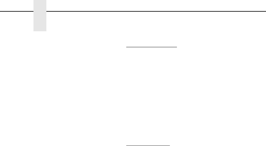
152
Chapter 2
Command Codes
dis Normal Resolution:
Defines the horizontal tab in tenths of an inch plus
dot columns from the left margin. Enter a three-digit
value ranging from 000 through 999 to define a tab
from 00.0 through 99.9 inches from the left margin
and a fourth digit ranging from 0 through 9 to
specify 0 through 9 additional dot columns. VGL
automatically understands the decimal between the
second and third digits for tenth inches and
automatically interprets the fourth digit as dot
columns. For example, 0120 (or 012,0) specifies a
1.2-inch plus no-dot column tab; 1016 (or 101,6)
specifies a 10.1-inch plus 6-dot column tab.
High Resolution:
Defines the horizontal tab in thousandth inches.
Enter a five-digit horizontal value ranging from
00000 through 99999 to define a horizontal tab of
0.000 inch through 99.999 inches. VGL
automatically understands the decimal between the
second and third digits.
The data to print at the new print position is input
following the Horizontal Tab command.
(cc)- Graphics Mode CR used as a sequence terminator.
Enter the SFCC for your VGL configuration
immediately followed by - to end the command
sequence.
NOTE: The (cc)- sequence terminator is used only when ^T is a Standard
Graphics command.
Comments
The T command may be input as part of the data in one of the
alphanumeric commands and also may be used in standard
graphics mode.
A 2-inch tab specifies a position 2 inches from the left margin; a
6-inch tab specifies a position 6 inches from the left margin, etc.
Since the tab specifies a print position relative to the left print
margin, you can use tabs to specify a print position to the left or
right of the current position (unlike a typewriter, which can only
tab to the right of the current position). For example, if the current
print position is 4 inches from the left margin and a 1-inch tab is
specified, the next print position is 1 inch from the left margin.
This left/right capability is useful for positioning data within boxes
of a form or similar applications.
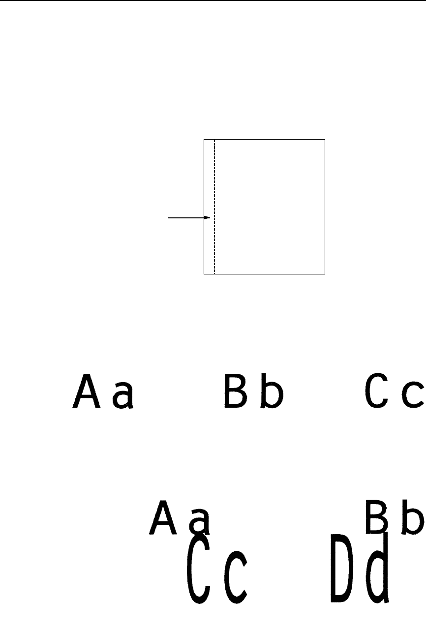
Tab, Horizontal
153
Examples The following sample shows an Extended Graphics command
placed before and after the ^T command. Notice that the left
margin changes:
^M1010ABC^-
^T0100^-
^M1010ABC^-
The following sample commands illustrate horizontal tabs in
normal resolution.
^PY^-
^M05,05,000Aa^T020,5Bb^T040,5Cc^-
-PN^-
^PY^-^F^-
^M05,05,000Aa^T030,0Bb
^M10,05,050^T005,0Cc^T025,0Dd^-
^O^-^PN^-
^PY^-
^V05,05,000I^V10,30,050^T010,0G^V05,05,075^T030,5P^-
^PN^-
ABC
ABC
Permanent
Left Margin

154
Chapter 2
Command Codes
^PY^-
^E05,05,000IGP^T025,5IGP^-
^PN^-
NOTE: Due to space constraints, the ^U commands below are separated into
three lines. During actual VGL input, do not separate your command
parameters.
^PY^-^F^-
^U06,05,000UP
^U03,03,070^T010,0SIDE
^U05,05,000^T022,0DOWN^-
^O^-^PN^-

Tab, Vertical
155
Tab, Vertical
NOTE: The Vertical Tab command is not supported on L7032 printers.
Purpose Performs a vertical tab (VT, hex 0B) function to advance the
paper to the next vertical tab position when used to terminate a
standard graphics command.
Mode Graphics with a Standard Graphics Command selected
Format (cc)+
(cc) Represents the Special Function Control Code
(SFCC). Enter the specific SFCC for your VGL
configuration.
+ The graphics vertical tab mnemonic. Enter +.
Comments
The vertical tab functions as a carriage return only when it is used
to terminate a graphics sequence in an extended graphics
command when Free Format is enabled.
The vertical tab functions as a line feed:
•when the vertical tab is not used as a graphics command
or graphics function terminator; and
•when the EVFU is not loaded through the use of form
length or host commands.
If the EVFU is loaded but channel 12 is not loaded, then the
vertical tab functions as a line feed. If channel 12 of the EVFU is
loaded, the vertical tab skips to channel 12.
See “Electronic Vertical Format Unit (EVFU)” on page 73 for
more information on EVFU and channel 12.
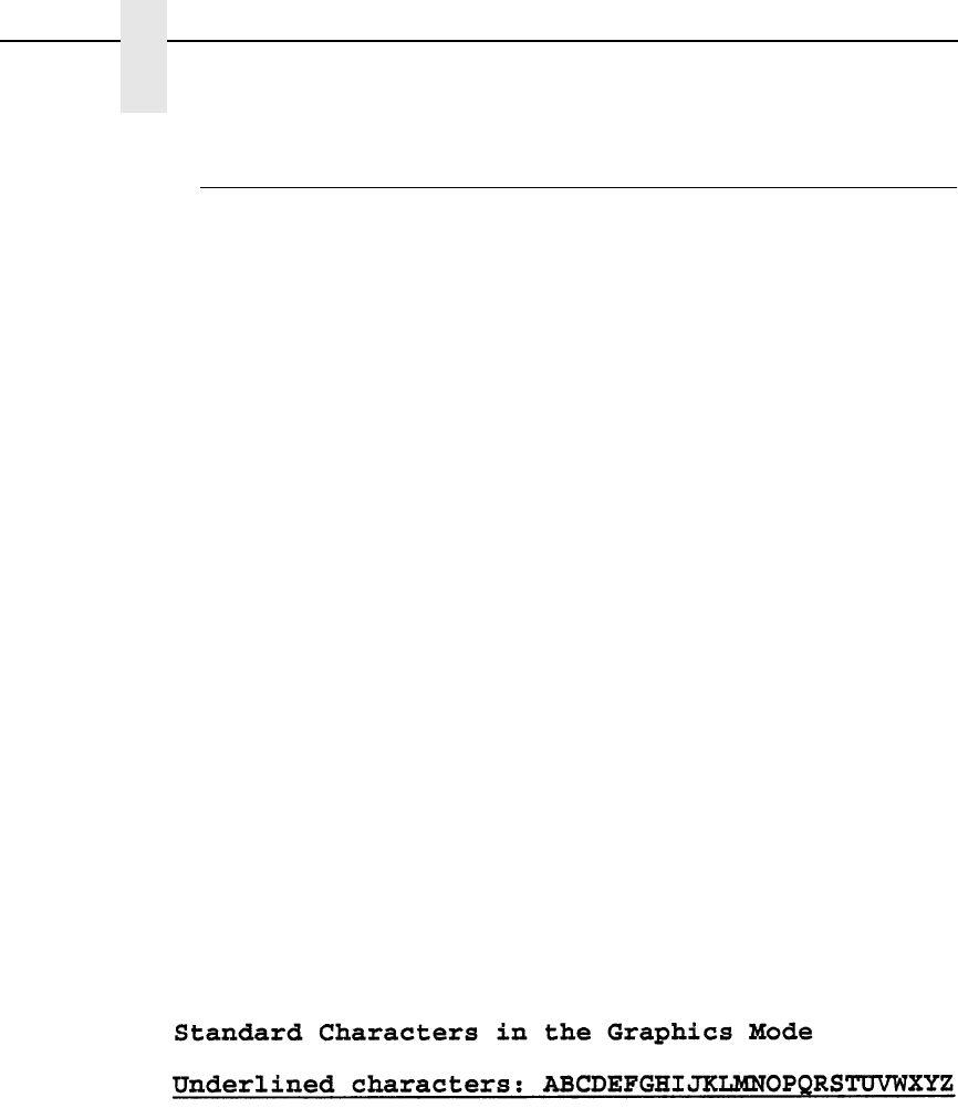
156
Chapter 2
Command Codes
Underlined Print
Purpose Selects underlined printing.
Mode Graphics with a Standard Graphics Command selected
Format (cc) @ U (cc)-
(cc) Represents the Special Function Control Code
(SFCC). Enter the specific SFCC for your VGL
configuration.
@ Specifies one of the @ commands. Enter @ to
begin an @ command function.
U Specifies the Underlined Print command. Enter U
and all characters on the line are underlined.
Underlined print is automatically reset upon receipt
of the line terminator.
(cc)- Graphics Mode CR. Enter the SFCC for your VGL
configuration immediately followed by - to end the
command sequence.
Comments
Underlined print is a line-by-line print attribute; it is selected once
and all characters in the line are underlined. The U command
must precede any printable data in the line, and it is automatically
reset when a line terminator is received.
Example The following example illustrates underlined print.
^PY^-
Standard Characters in the Graphics Mode^*
^@U^-Underlined characters: ABCDEFGHIJKLMNOPQRSTUVWXYZ^*
^PN^-

Wait For Online
157
Wait For Online
NOTE: The Wait For Online command is not supported on L7032 printers.
Purpose Causes VGL to discontinue processing data until you put the
printer offline and then back online.
Mode Graphics with a Standard Graphics Command selected
Format (cc) @ W (cc)-
(cc) Represents the Special Function Control Code
(SFCC). Enter the specific SFCC for your VGL
configuration.
@ Specifies one of the @ commands. Enter @ to
begin an @ command function.
W Specifies the Wait For Online command. Enter W
and the front panel displays "Waiting on User" until
you place the printer offline.
(cc)- Graphics Mode CR. Enter the SFCC for your VGL
configuration immediately followed by - to end the
command sequence.
NOTE: Wait For Online must be given while VGL is in graphics mode (^PY),
but not inside of a graphics pass (^M.....^-).

158
Chapter 2
Command Codes

159
3
Barcodes
Overview
A barcode is a graphic representation of alphanumeric characters. Barcodes
are produced by entering a barcode command to VGL in the Graphics mode
using an Extended Graphics command.
You can print the barcodes horizontally, vertically, with or without a human
readable data field, with default bar/space ratios, or with variable ratios. The
human readable data field may be printed using any of the Extended
Graphics command fonts available with the (cc)S or (cc)IFONT, commands.
Barcode symbols are configured in a series of varying width bars and spaces
representing a specific barcode character set. These characteristics are in
accordance with established industry-wide practices.
Several integrity checks are performed against the barcode data, and error
messages are printed if any illegal data is discovered.
Each type of barcode has a different set of characters that can be barcoded,
and VGL ensures that the data falls within the allowable set. Some barcodes
permit a variable number of data characters, while other barcodes require a
fixed number of data characters. VGL ensures that the data adheres to these
constraints.
NOTE: Be sure you have set the proper printer mode as described in
Chapter 2.
The single most important consideration when printing a barcode is to ensure
the barcode will be scanned properly. Incorporating a barcode quality
procedure in the printing process is the best way to ensure that barcodes are
being printed correctly. A properly implemented validation procedure will
increase overall barcode quality, reduce waste from misprinted barcodes, and
Printronix achieve high first-time read rates, which is an increasingly
important factor in newer, more efficient systems where manually entered
data is not acceptable as a backup function. Validation also minimizes the
costs of returned products due to poor reading or unaccountable barcodes.
For more information on barcode validation, contact your Printronix
representative, or visit our web site at www.printronix.com.
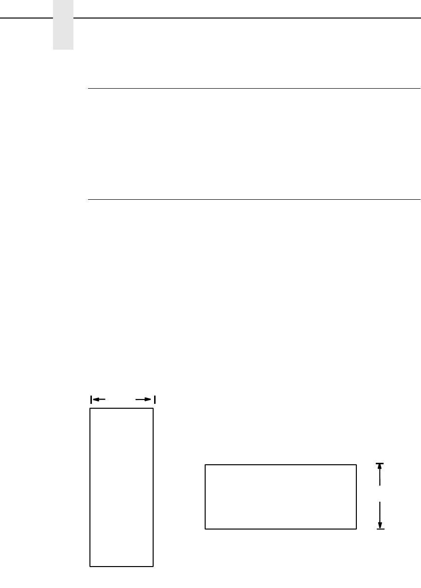
160
Chapter 3
Overview
Examples
Using different printers may affect the printed appearance of your print
samples compared to those shown in this manual due to the printer's scaling
factor and varying print mode/densities. Print position also depends on your
paper top-of-form position and the initial print position. Therefore, the location
of the barcode print samples in this chapter are for reference only and do not
reflect the actual barcode print position.
Barcode Size/Height Requirements
The length of any barcode is based on several factors:
(1) the type of barcode
(2) the number of data characters encoded
(3) the bar/space ratios
The starting position of a barcode is determined by any justifications specified
in the previous alphanumeric command.
The alphanumeric command provides the proper length (height) of the bars in
barcodes.
For horizontal barcodes, the graphics height command specifies barcode
height; for vertical barcodes, graphics width specifies barcode height.
Barcode height/width parameters are specified in the two-digit extended
graphics command. A decimal point is automatically interpreted between the
first and second character digits.
Figure 3. Barcode Size/Height Requirements
DATA FIELD
HEIGHT
DATA FIELD
HEIGHT
(No Readable Data Field)
(No readable
data field)
Barcode
Barcode
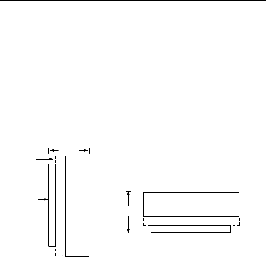
Barcode Size/Height Requirements
161
VGL allows you to add a human readable data field to the barcode. Also, you
can specify a 1 or 3 dot gap between the human readable field and the
barcode.
When you insert a human readable field, the height of the barcode
automatically shortens. For example, you print a barcode that is 1" high.
Later, you add a human readable data field. The barcode height is 1" minus
the 1 or 3 dot gap and the text, which is 1/10" or 1/5".
If the barcode height is less than the height of the human readable text, the
barcode height adjusts to the height of one dot. The gap and the human
readable text remain the same.
Horizontal barcode data is printed below the barcode; vertical barcode data is
printed to the left of the barcode. Figure 4 illustrates the readable data
adjustment feature.
Figure 4. Barcode Height Adjustment
DATA FIELD
1-3 DOT GAP
OPTIONAL READABLE DATA FIELD
HEIGHT
DATA
HEIGHT
OPTIONAL
READABLE
DATA FIELD
GAP
FIELD
1-3 DOT
(Bar Code)
(Bar
Code)

162
Chapter 3
Barcode Command Format
Barcode Command Format
Barcode commands are Extended Graphics commands which must occur
within the Graphics Mode and must be introduced by an SFCC and one of the
four alphanumeric commands (^M, ^V, ^E, and ^U). Data provided in the
alphanumeric command sequence identifies specific height, width, and
justification information used to define barcode length (height) and position.
Complete alphanumeric command information is explained in Chapter 2.
NOTE: Throughout this manual, the caret (^) is used to represent the Special
Function Control Code introducer and terminator for graphics and
barcode commands. Be sure to use the appropriate control character
for your VGL configuration.
VGL offers a choice between two types of barcode command formats which
are described on the following pages: Standard (^B and ^C) barcode format,
and IBARC, (a QMS Version II command). Two advantages of IBARC are a 4-
way rotation, not 2-way, and dot or printer dot resolution for variable ratio
barcodes. Neither the Standard nor IBARC format offers significantly more or
less features; both formats accomplish the same task. The format you select
is a matter of personal choice. In each barcode section throughout this
chapter, each of the command parameters is fully described and examples
provided using the standard barcode format (^B and ^C).
You can also print high resolution barcodes. With the control panel menu
option, “Var Ratio Barcd” set to “High Resolution”, barcode variable ratio data
can be specified in printer dots. You can use this option in either high or
normal resolution with the IBARC command. (This option is ignored for ^B
and ^C which always use low resolution.)
If “Var Ratio Barcd” is set to “Low Resolution” (the default), the barcode
variable ratio data is interpreted as line matrix printer dots (60x72 dpi).
NOTE: When using variable ratio barcode commands, you must ensure the
“scanability” of your barcodes, including toner spread compensation.
Make sure the variable ratio conforms to the specification.
The barcode command and associated parameters for standard barcodes are
described on page 163. IBARC, barcodes, associated parameters and
examples are described on page 164.
NOTE: Each barcode parameter is visually separated by spaces, and
optional parameters are marked by paired brackets [ ]; do not enter
these spaces or brackets in your command sequence; they are
provided throughout the manual for clarity in distinguishing
parameters. Italicized text represents a variable parameter for which
a value must be inserted. Command parameters not italicized must
be input exactly as shown.

Standard Barcode Command Format
163
Standard Barcode Command Format
Default Ratio: (cc) dir p type data (cc)G
Variable Ratio: (cc) dir p [9] [:] type [ratio] data (cc)G
(cc) Represents the Special Function Control Code
(SFCC). Enter the specific SFCC for your VGL
configuration.
dir Represents the direction of the barcode. Enter B for
horizontal barcodes; enter C for vertical barcodes.
pPrints the optional readable data field by selecting
one of five codes representing the font and gap
size for the readable data field. The readable data
field is printed below a horizontally configured
barcode (picket fence orientation) and on the left-
hand side of a vertically configured barcode (ladder
orientation). The barcode size is automatically
adjusted to allow for the height of the data field font
and the spacing between the data and barcode.
NOTE: Vertical barcodes print only in standard 10 cpi font because OCR
fonts cannot be rotated. If an OCR-type font is selected with a vertical
barcode command, the standard 10 cpi font is substituted
automatically.
9 or : Selects the variable ratio length barcode feature,
which permits unique bar and space width ratios
adjusted for specific applications. Enter the number
9 to select variable ratio barcodes represented in
line matrix printer dots (60 x 72 dpi).
Enter : to select variable ratio barcodes
represented in actual printer dots (203 x 203 dpi or
300 x 300 dpi, depending on the printer head being
used).
type Represents the barcode type from Table 21 on
page 167. Invalid codes are treated as errors.
ratio Represents unique ratio data for variable ratio
barcodes. The default ratios shown in Table 21 are
overridden by this feature. Four- and eight-digit
ratios are used, depending upon the barcode
selected.
data Represents the data to be barcoded.
(cc)G Terminates the barcode command. Enter the SFCC
for your VGL configuration immediately followed by
any valid command character or G, the universal
sequence terminator.

164
Chapter 3
Barcode Command Format
IBARC, (Version II) Barcode Command Format
Default Ratio: (cc) IBARC, type, loc, data (cc)G
Variable Ratio: (cc) IBARC, type, [R [D] ratio,] loc, data (cc)G
When using the IBARC, barcode command format, the type code changes
from a single alphanumeric value to a mnemonic as shown in Table 21. Using
the appropriate alphanumeric command (^M, ^V, ^E, and ^U), IBARC,
barcodes allow you to print barcodes in four orientations: horizontal, or rotated
90, 180 or 270 degrees. In addition, a loc parameter allows you to select one
of three ways in which the printable data field appears below the barcode.
The barcode command parameters applicable to IBARC, barcodes are
defined below. At the end of this section, several IBARC, examples are
provided illustrating applications for these parameters.
(cc) Represents the Special Function Control Code
(SFCC). Enter the specific SFCC for your VGL
configuration.
IBARC, The Barcode command. Enter IBARC, (the comma
is required).
type, Represents the IBARC, barcode type from Table
21. Invalid codes are treated as errors.
[R [D] ratio,] Optional parameter representing the ratios for
variable ratio barcodes. The default ratios shown in
Table 21 are overridden by the variable ratio
feature. Four- and eight-digit ratios can be used,
depending upon the barcode selected. Ratio data
must be decimal values from 0 through 99. Enter R,
followed by the actual barcode ratio. A colon must
separate each element of the ratio.
Like standard barcode ratios, IBARC, ratios are
also interpreted from left to right, measuring the
size of each bar or space, in dot width, in the
following pattern: narrow bar : narrow space : wide
bar : wide space.
If Variable Ratio Barcode is set to High Resolution
or if the D parameter is specified, the ratios are
represented in actual printer dots instead of line
matrix printer dots (60 x 72 dpi).
NOTE: VGL does not verify that ratio data creates acceptable wide/narrow
element relationships for barcode readability. When designing unique
ratio data, carefully plot wide and narrow ratios to conform to
readable barcodes.
loc Represents the location of the printable data field.
Enter N for no printable data field, E to have the
data field embedded in the barcode, or B to print
the data field below the barcode. If this parameter
is selected, the printable data field prints in the
current font as selected by the (cc)S or (cc)IFONT
commands or the default font selected.
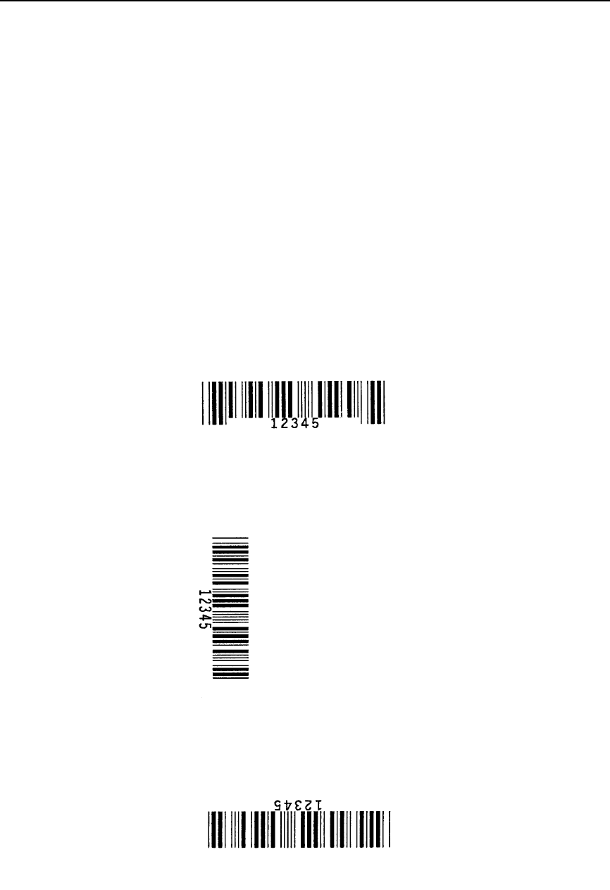
IBARC, (Version II) Barcode Command Format
165
data Represents the data to be barcoded. The maximum
amount of data depends on which barcode has
been selected from Table 21.
(cc)G Terminates the barcode command. Enter the SFCC
for your VGL configuration immediately followed by
any valid command character or G, the universal
sequence terminator.
IBARC, Examples
The following examples illustrate use of the IBARC, command format using
Code 39. In the command sequence, graphics mode data is italicized and
barcode data is boldface. Refer to Chapter 2 for a detailed description of
alphanumeric commands.
Example 1 Code 39 horizontal barcode with embedded printable data field:
^PY^-^M05,05,000^IBARC,C39,E,12345^G^-^PN^-
Example 2 Code 39 barcode rotated 90° with printable data field printed
below the barcode.
^PY^-^V05,05,000^IBARC,C39,B,12345^G^-^PN^-
Example 3 Code 39 barcode rotated 180° with printable data field printed
below the barcode.
^PY^-^U05,05,000^IBARC,C39,B,12345^G^-^PN^-
i
ba
rc.
i
barc.
ex2
ibarc.ex
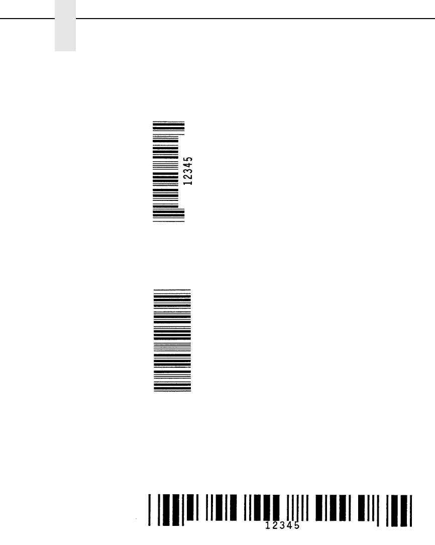
166
Chapter 3
Barcode Command Format
Example 4 Code 39 barcode rotated 270° with embedded printable data
field.
^PY^-^E05,05,000^IBARC,C39,E,12345^G^-^PN^-
Example 5 Code 39 barcode rotated 90° with no printable data field.
^PY^-^V05,05,000^IBARC,C39,N,12345^G^-^PN^-
Example 6 Code 39 horizontal barcode, embedded printable data field, and
double the default ratio:
^PY^-^M05,05,000^IBARC,C39,R2:2:6:6,E,12345^G^-^PN^-
ibarc.ex4
i
barc.e
x5
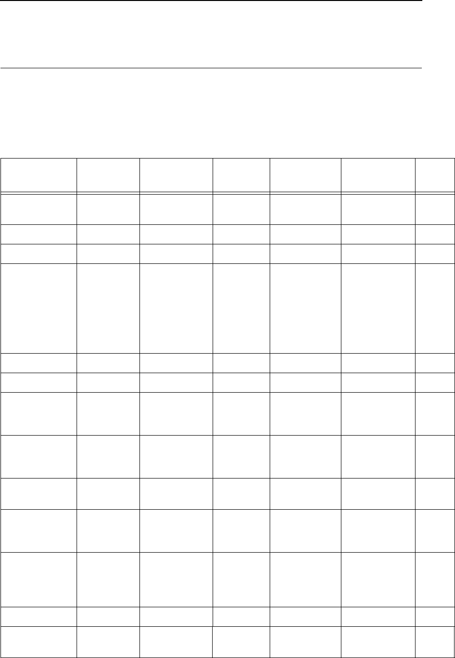
IBARC, (Version II) Barcode Command Format
167
Barcodes
NOTE: When using standard barcode types (either (cc) B or (cc) C) select
the appropriate type code from the Standard Type Code column in
Table 21. When using the IBARC, barcode, select the appropriate
type code from the IBARC, Type Code column in Table 21.
Table 21. VGL Barcode Types
Barcode
Description Standard
Type Code IBARC,
Type Code # of Data Check Digits Default Bar/
Space Ratios Page
#
Australian
4-State
sAUSTPOST Varied None n/a 169
BC 412 +BC412 Varied Mod 35 1:1 174
Codabar DCBAR 1-40 None 1:2:3:4:1:1:1:1 178
Code 39 A
B
C
C39
LOGMAR
AIAG
EMBARC
C39A
C39M43
HIBCC
1-40
1-40
1-40
1-40
1-40
1-40
1-40
None
None
None
None
None
Mod 43
Mod 43
1:1:3:3
1:1:3:3
1:1:3:3
1:1:3:3
1:2:4:5
1:1:3:3
1:1:3:3
184
Code 93 iC93 1-40 Mod 47 1:1:2:2:3:3:4:4 191
Code 128 ZC128 1-40 Mod 103 1:1:2:2:3:3:4:4 195
EAN 8
EAN 8+2
EAN 8+5
U
o
p
EAN8
EAN8+2
EAN8+5
7
9
12
Mod 10 1:1:2:2:3:3:4:4 204
EAN 13
EAN 13+2
EAN 13+5
T
m
n
EAN13
EAN13+2
EAN13+5
12
14
17
Mod 10 1:1:2:2:3:3:4:4 209
German
Interleaved 2/5
V
W
POSTAGI
POSTAGL
11
13
Mod 10 4:6:14:16 214
GS1-128,
formerly
UCC/EAN-128
qUCC128 see Note
below
Mod 103/10 1:1:2:2:3:3:4:4 219
GS-1
Datamatrix,
formerly
Datamatrix
MDATAMATRIX Varied n/a n/a 230
Identicon EIDENTICON 1-40 None 1:1:3 239
Intelligent Mail
4-state
jINTMAIL 20-31 Automatic n/a 242
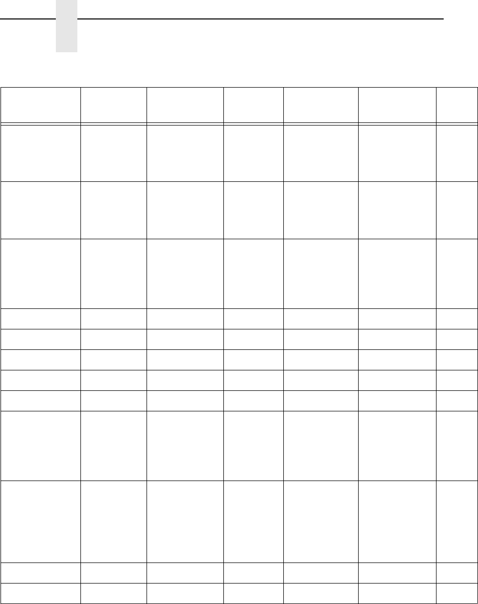
168
Chapter 3
Barcodes
NOTE: Data requirements for UCC/EAN-128 is determined by the application
identifier preceding the barcode data. There is a wide range of
selections.
Barcode
Description Standard
Type Code IBARC,
Type Code # of Data Check Digits Default Bar/
Space Ratios Page
#
Interleaved 2/5 K
k
L
l
INT2/5
INT2/5CD
INT2/5A
INT2/5CDA
1-40
1-40
1-40
1-40
None
Mod 10
None
Mod 10
1:1:3:3
1:1:3:3
1:2:4:5
1:2:4:5
244
Maxicode %MAXICODE depends
on mode
used
None N/A 249
MSI F
G
H
I
X
MSI
MSI10
MSI1010
MSI1110
MSI11
1-13
1-13
1-13
1-13
1-13
None
Mod 10
Mod 10/10
Mod 11/10
Mod 11
1:1:2:2 254
PDF417 &PDF417 Variable None n/a 260
Planet rPLANET 11 Mod 10 n/a 264
POSTNET *POSTNET 5, 9, or 11 Mod 10 n/a 269
Royal Mail YROYALBAR Varied Mod 6 3:6 273
Telepen JTELEPEN 1-40 Mod 127 1:1:3:3 275
UPC-A
UPC-A+2
UPC-A+5
UPC-A 80%
UPC-A100%
P
a
b
0
1
UPCA
UPCA+2
UPCA+5
UPCA80
UPCA100
11
13
16
11
11
Mod 10
Mod 10
Mod 10
1:1:2:2:3:3:4:4
1:1:2:2:3:3:4:4
1:1:2:2:3:3:4:4
280
UPC-E
UPC-E0
UPC-E+2
UPC-E+5
UPC-E0+2
UPC-E0+5
Q
R
c
d
e
f
UPCE
UPCE0
UPCE+2
UPCE+5
UPCE0+2
UPCE0+5
10
6
12
15
8
11
Mod 10 1:1:2:2:3:3:4:4 285
UPCSHIP $UPCSHIP 13 Mod 10 1:1:3:3 293
UPS 11 uUPS11 10 Mod 103 1:1:2:2:3:3:4:4 297
Table 21. VGL Barcode Types (continued)
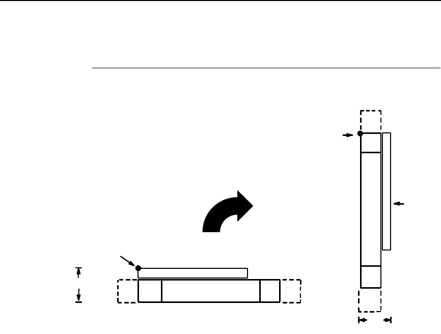
Australian 4-State
169
Australian 4-State
The Australian 4-State structure is shown in Figure 5 and described on the
following pages.
Figure 5. Australian 4-State Structure
The Australian 4-State barcode supports the Australian Postal Service.
Australian 4-State barcodes are similar to POSTNET in terms of bar space
and width, but have four different types of bars (Full Height, Ascender,
Descender, and Tracker), whereas POSTNET only has two bar types (Tall
and Short).
The Australian 4-State symbology converts alphanumeric characters into
patterns of four bars, using combinations of Full Height, Ascender,
Descender, and Trackers. It also adds start and stop barcodes as well as
Reed-Solomon parity information.
Quiet Zone
Quiet zones extend on both ends of the barcode to permit the scan to begin
and end in a blank area. The quiet zones should be at least 0.25 inches wide
and completely blank to ensure accurate reading of the start/stop codes and
to prevent adjacent barcodes from overlapping. You are responsible for
providing sufficient space on the form for the quiet zones.
Start/Stop Code
The start and stop bars identify the orientation of the barcode. The start bar
consists of an ascender bar, and is positioned at the leftmost end of the
barcode. The stop bar consists of a full height bar, and is positioned at the
rightmost end of the barcode adjacent to the check digit.
DATA FIELD QUIETQUIET START STOP
OPTIONAL READABLE DATA FIELD
CODE CODEZONE ZONE
HEIGHT
STARTING
POSITION
DATA
FIELD
QUIET
ZONE
QUIET
ZONE
STOP
CODE
START
CODE
OPTIONAL
READABLE
DATA
FIELD
HEIGHT
STARTING
POSITION

170
Chapter 3
Barcodes
Data Field
Australian 4-State barcodes use four types of bars to encode its data: Full
Height, Ascender, Descender, and Tracker. Each Full Height bar is 0.198 inch
±
0.030 inch. The Ascender and Descender bars are about 62.5% of the Full
Height bar in length, while the Tracker bar is about 25% of the Full Height bar.
Each bar width is equal, and must be .020-inch ± .005-inch. Horizontal
spacing between bars (pitch) must be 22 bars ±
2 bars per inch over any
0.50-inch portion of the barcode.
The Australian 4-State barcode data field consists of four different sections:
the FCC, Sorting Number, Customer Data, and Reed-Solomon parity
information. The FCC is a two-digit code specifying the format of the barcode
(see Table 23). The Sorting Number is an 8-digit code used to sort the mail
item. Customer Data is optional and is only allowed on certain formats (as
indicated by the FCC selected). VGL emulation automatically generates the
Reed-Solomon parity information and includes it in the barcode.
Check Digit
No check digit is calculated for the Australian 4-State barcode. The Reed-
Solomon parity information is automatically included.
Australian 4-State Command Format
NOTE: See page 164 for the IBARC, command format and definitions. (This
barcode will not print vertically using the IBARC, command format.)
Default Ratio: (cc) dir p s [Fn] [In] data (cc)G
(cc) Represents the Special Function Control Code
(SFCC). Enter the specific SFCC for your VGL
configuration.
dir Represents the direction of the barcode. Enter B for
horizontal barcodes; enter C for vertical barcodes.
pPrints the optional readable data field. The
readable data field is printed left-aligned above a
horizontal barcode or top-aligned to the right of a
vertical barcode.
Replace p in the barcode command with one of the
codes listed in Table 22 to print the readable data
field in the corresponding font with the specified
guard band gap.
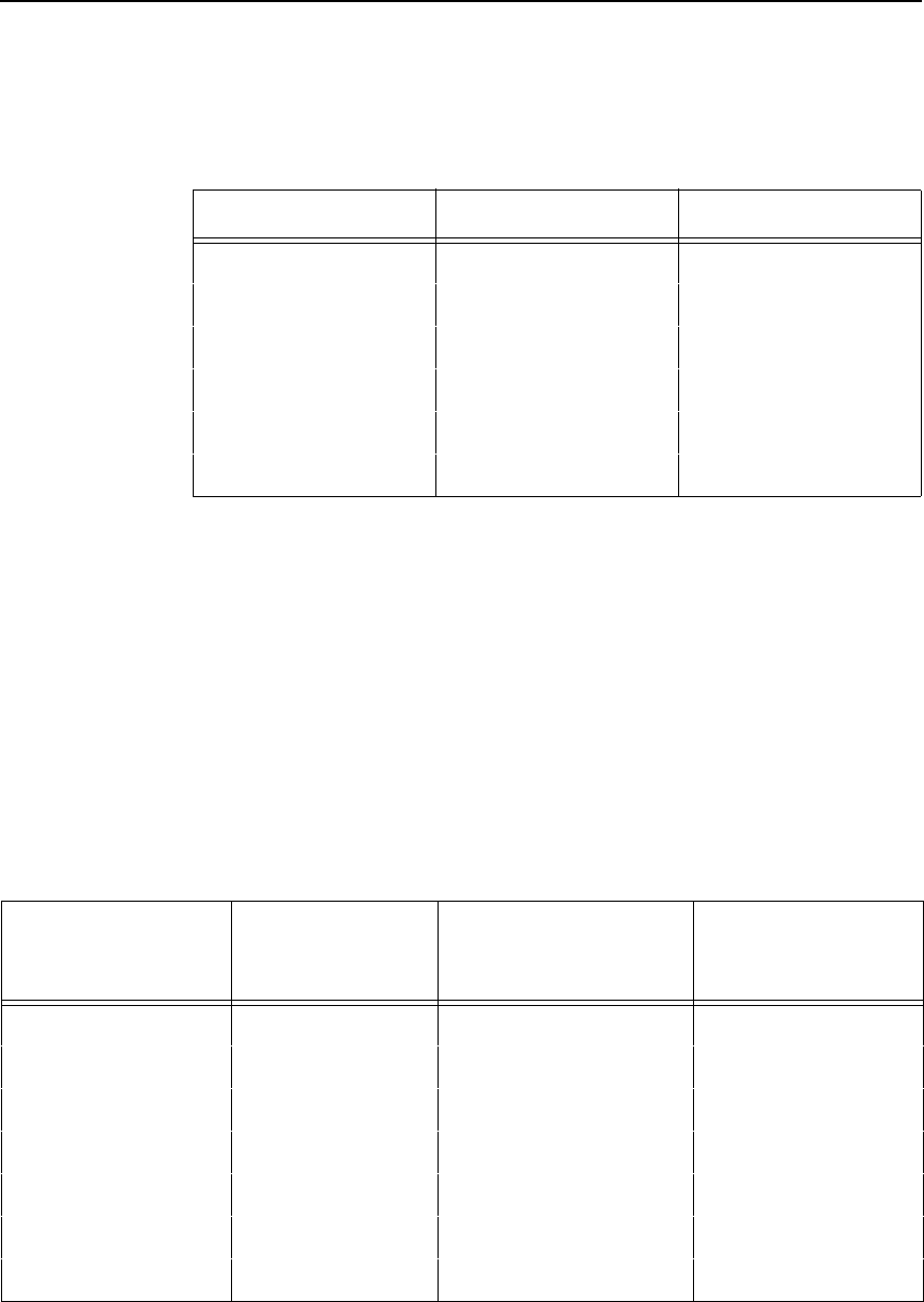
Australian 4-State
171
s The Australian 4-State type code. Enter s.
FnSpecifies the FCC code, which defines the format
of the barcode and its size. If no value is specified,
the FCC defaults to a value of 11. Enter F, then one
of the values shown in Table 23.
InSpecifies the format of the customer information
field. If no value is specified, the information field
defaults to a value of 1. Enter I, then one of the
values shown in Table 23.
Table 22. Printable Data Field Fonts
Font Gap p code
Standard 10 cpi 3 dots Y
OCR-A 3 dots O
OCR-A .1-inch S
OCR-B 3 dots B
OCR-B .1-inch T
None N
Table 23. FCC Codes, Customer Information Fields
and Maximum Barcode Lengths
FCC (Fn)Customer
Information (In)Valid Data Maximum Length
(Sorting Number +
Customer Data)
11, 87, 45, or 92 n/a Any 8 + 0
59 1A-Z, a-z, 0-9, space, # 8 + 5
59 20-9 8 + 7
59 30-3 8 + 15
44, 62 1A-Z, a-z, 0-9, space, # 8 + 10
44, 62 20-9 8 + 15
44, 62 30-3 8 + 30
172
Chapter 3
Barcodes
data The barcode data. See “Data Field” on page 170
for a description of the Australian 4-State barcode
data field.
NOTE: For a In value of 3, the digits 0 through 3 represent the following bars:
0 = Full Height; 1 = Ascender; 2 = Descender; 3 = Tracker. Since this
is a proprietary encoding, the Customer Data is not included in the
optional readable data field.
(cc)G Terminates the barcode command. Enter the SFCC
for your VGL configuration immediately followed by
any valid command character or G, the universal
sequence terminator.
Australian 4-State Examples
The following command generates the horizontal Australian 4-State barcode
below. In the command sequence, Graphics Mode data is italicized and
barcode data is boldface. See Chapter 2 for a detailed description of
alphanumeric commands.
^PY^-^M10,10,100^KF^BYsF62I100141544adc0grell7^G^KF^-^PN^-
^PY^- enabled the graphics command sequence.
^M introduced the standard alphanumeric command.
The character height selected was 1.0 inches and character width selected
was at 1.0 inches.
A 1.0 justification value plus 0 additional dots was selected for the data
placement.
^KF activated Dark Print.
^B introduced the barcode command.
Y selected the standard 10 cpi font to print the optional readable data field.
Letter s selected Australian 4-State barcode type.
F62 selected an FCC Code value of 62.
I1 selected a customer information field value of 1.
00141544adc0grell7 is the barcode data. 00141544 is the sorting data, and
adc0grell7 is the customer data.
^G terminated the barcode command sequence.
^KF^- at the end of the barcode turned off Dark Print.
^PN^- terminated the graphics mode.
Australian 4-State
173
The following command generated the vertical Australian 4-State barcode
below using standard 10 cpi font, FCC Code value of 59, customer
information field value of 1, and data of 0123456789076 (01234567 is the
sorting data, and 89076 is the customer data):
^PY^-^M10,10,050^KF^CYsF59I10123456789076^G^KF^-^PN^-
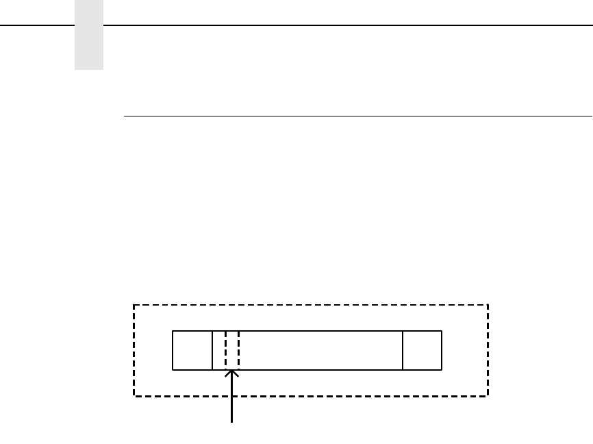
174
Chapter 3
Barcodes
BC412 Barcode
The BC412 barcode was invented by IBM in 1988 to meet the needs of the
the semiconductor wafer identification application. The word BC stands for
binary code (presence or absence of a bar) and 412 means 4 bar modules in
a total of 12 module positions in every character. It is a one dimensional
barcode that meets the requirements of small space, easy scribing and robust
decoding even if the barcode symbols are under poor light contrast. It can
achieve a density of 23 characters in less than an inch with a 3.3 mil bar
width.
Data Field
Data BC412 can accommodate 35 characters, 0 - 9 and A - Z. The number 0
is used in place of the letter O. Table 24 lists the character with it’s
corresponding module sequence and character value.
Quiet/Clear Zone
The barcode structure requires a completely blank clear zone which extends
4.75 inches from the right edges of the mail piece. In addition, a minimum
clear zone of 0.040 inch above and below the barcode data must also be
provided.
Start/Stop Code
The start and stop pattern identify the orientation of the barcode. The start
code is bar,space,space” in all cases. The stop code is bar, space, bar for all
cases.
I = Bar
- = Space
Bar Code Data Field
Clear Zone
Clear Zone Clear
Zone
Clear
Zone Start
Code Stop
Code
Check Character

BC412 Barcode
175
Table 24. BC412 Character, Module Sequence, and Character Value
Character Module
Sequence Character
Value
0I-I-I-I----- 00
1I-I-I--I---- 15
2I-I-I---I--- 17
3I-I-I----I-- 29
4I-I-I-----I- 11
5I-I--I-I---- 33
6I-I--I--I--- 19
7I-I--I---I-- 21
8I-I--I----I- 08
9I-I---I-I--- 02
AI-I---I--I-- 07
BI-I---I---I- 25
CI-I----I-I-- 20
DI-I----I--I- 22
EI-I-----I-I- 09
FI--I-I-I---- 30
GI--I-I--I--- 03
HI--I-I---I-- 06
II--I-I----I- 27
JI--I--I-I--- 16
KI--I--I--I-- 24
LI--I--I---I- 04
MI--I---I-I-- 34
NI--I---I--I- 12
PI--I----I-I- 32
QI---I-I-I--- 18
RI---I-I--I-- 01
SI---I-I---I- 14
176
Chapter 3
Barcodes
Check Code
The BC412 has a mod 35 check character. The check character is placed in
the second position behind the first data character. The check code is
automatically included in the bar structure; however, it is not included in the
PDF. The check digit computation is shown below.
Let D = D1D2....Dn be a string of n data characters and C = C1C2....Cn+1 be
a string value of n+1 encoded characters.
V1 = Character value of C1. Refer to Table 24.
Fo = (Sum of Odd V1) Mod 35
Fe = (Sum of Even V1) Mod 35
F = (Fo + 2Fe) Mod 35
Since the second character is the check character, designate the second
character of C1C2.... as the check character of D.
Set C2 = 0
therefore C1C3C4.... Cn+1 = D1D2D3....Dn.
Calculate Fo, Fe, and F
C2 = the character that has the check character value 17F Mod 35.
TI---I--I-I-- 13
UI---I--I--I- 26
VI---I---I-I- 05
WI----I-I-I-- 31
XI----I-I--I- 28
YI----I--I-I- 23
ZI-----I-I-I- 10
Start I--
Stop I-I
Table 24. BC412 Character, Module Sequence, and Character Value
Character Module
Sequence Character
Value

BC412 Barcode
177
Example
Assume that the data character string is AQ1557
Form the character string C = A0Q1557
Fo = (7 + 18 + 33 + 21) Mod 35
= 79 Mod 35
= 9
Fe = (0 + 11 + 19) Mod 35
= 34 Mod 35
= 34
F = (9 + 2*34) Mod 35
= 77 Mod 35
= 7
Character value of the check character is = 17*7 Mod 35
= 119 Mod 35
= 14
As referenced in Table 24, 14 is the character value of character “S.”
Therefore, the check character is “S.”
Barcode Ratio
Default ratio is: 1:1.
Note: The BC412 barcode is not yet available for impact printers.
BC412 Standard Command Format
Default Ratio: (cc) dir N Y data (cc)G
(cc) Represents the Special Function Control Code
(SFCC). Enter the specific SFCC for your VGL
configuration.
dir Represents the direction of the barcode. Enter B for
horizontal barcodes; enter C for vertical barcodes.
N Turns off the readable data field. Enter N.
Y The type code for BC412. Enter +.
data The barcode data. A check digit is automatically
added by VGL.
(cc)G Terminates the barcode command. Enter the SFCC
for your VGL configuration immediately followed by
any valid command character or G, the universal
sequence terminator.
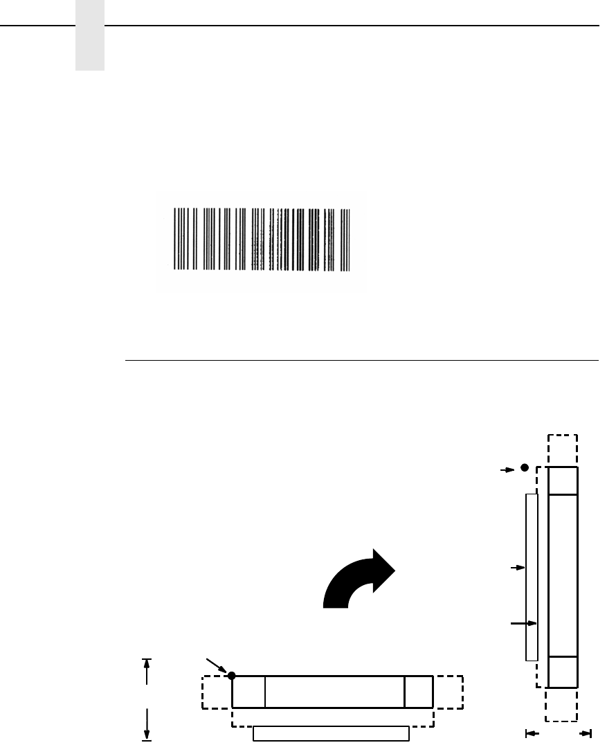
178
Chapter 3
Barcodes
BC412 Example
The following command generates the horizontal BC412 barcode below:
^PY^-^M05.05.100^T0100^BN+12345ABCDE^G^-^PN^-
Codabar
The Codabar structure is shown in Figure 6 and described on the following
pages.
Figure 6. Codabar Structure
Quiet Zone
Quiet zones extend on both ends of the barcode to permit the scan to begin
and end in a blank area. The quiet zones should be at least 0.25 inches wide
and completely blank to ensure accurate reading of the start/stop codes and
to prevent adjacent barcodes from overlapping. You are responsible for
providing sufficient space on the form for the quiet zones.
DATA FIELD QUIETQUIET START STOP
LOWER GUARD BAND
CODE CODEZONE ZONE
OPTIONAL READABLE DATA FIELD
HEIGHT
STARTING
POSITION
DATA
FIELD
QUIET
ZONE
QUIET
ZONE
STOP
CODE
START
CODE
OPTIONAL
READABLE
DATA
FIELD
HEIGHT
STARTING
POSITION
GUARD
LOWER
BAND

Codabar
179
Start/Stop Codes
The start/stop codes identify the leading and trailing end of the barcode. Four
start/stop code characters (A, B, C, and D) are available in any combination
as start/stop codes. The start/stop code character must be included in the
data field to be produced with the barcode.
Data Field
The barcode symbol uses a series of wide and narrow bars and spaces to
represent numeric characters and six control characters. Each character is
represented by seven elements consisting of four bars and three spaces,
either wide or narrow.
Readable Data
The optional readable data field provides a readable interpretation of the
barcode data. Barcode data is printed below the horizontal barcode symbol
and to the left of a vertical barcode symbol. The lower guard band is provided
when the readable data field is selected.
Codabar Command Format
NOTE: See page 164 for the IBARC, command format and definitions.
Default Ratio: (cc) dir p D data (cc)G
Variable Ratio: (cc) dir p [9] [:] D [ratio] data (cc)G
(cc) Represents the Special Function Control Code
(SFCC). Enter the specific SFCC for your VGL
configuration.
dir Represents the direction of the barcode. Enter B for
horizontal barcodes; enter C for vertical barcodes.
pPrints the optional readable data field. The
readable data field is printed below a horizontal
barcode or on the left-hand side of a vertical
barcode.
Replace p in the barcode command with one of the
codes listed in Table 25 to print the readable data
field in the corresponding font with the specified
guard band gap.

180
Chapter 3
Barcodes
9 or : Selects the variable ratio length barcode feature,
which permits unique bar and space width ratios
adjusted for specific applications.
Enter the number 9 to select variable ratio
barcodes represented in line matrix printer dots (60
x 72 dpi).
Enter : to select variable ratio barcodes
represented in actual printer dots (203 x 203 dpi or
300 x 300 dpi, depending on the printer head being
used).
D The Codabar type code. Enter D.
ratio Optional parameter (used in conjunction with 9 or :
above) representing the ratios for variable ratio
barcodes. The default ratios are overridden by the
variable ratio feature. The ratio data must be
hexadecimal numbers from 0 through 9 or A
through F; VGL automatically checks the input for
validity. If an invalid character is found in the ratio,
an error message is generated.
NOTE: VGL automatically checks ratio data for validity only within the
allowable hexadecimal range. VGL does not verify that ratio data
creates acceptable wide/narrow element relationships for barcode
readability. For example, VGL accepts wide/narrow ratio values of 2
and 5, respectively; however, a narrow element larger than the wide
element produces an unreadable barcode. When designing unique
ratio data, carefully plot wide/narrow ratios to conform to readable
barcodes.
Table 25. Printable Data Field Fonts
Font Gap p code
Standard 10 cpi 3 dots Y
OCR-A 3 dots O
OCR-A .1-inch S
OCR-B 3 dots B
OCR-B .1-inch T
None N
Codabar
181
Codabar barcodes require an eight-digit ratio. The
ratios are interpreted from left to right, measuring
the size of each bar or space in dot width. The first
four digits are interpreted as follows: narrow bar :
narrow space : wide bar : wide space. The sixth
digit specifies the number of dots for the
intercharacter spacing. The fifth, seventh and
eighth digits are not used; any data in these
positions is ignored. For example, if the Codabar
ratio data was 24681211, it would be translated as
follows:
2-dot-wide narrow bar
4-dot-wide narrow space
6-dot-wide wide bar
8-dot-wide wide space
ignore data
2-dot-wide intercharacter spacing
ignore data
ignore data
data The barcode data. Codabar encodes from 1
through 40 characters from the Codabar Character
Set shown in Table 26. Characters A, B, C, and D
are strictly start/stop codes.
(cc)G Terminates the barcode command. Enter the SFCC
for your VGL configuration immediately followed by
any valid command character or G, the universal
sequence terminator.
*A, B, C and D are start/stop codes only.
Table 26. Codabar Character Set
Character Hex Character Hex
030 +2B
131 -2D
232 .2E
333 /2F
434 $24
535 :3A
636 A* 41
737 B* 42
838 C* 43
939 D* 44
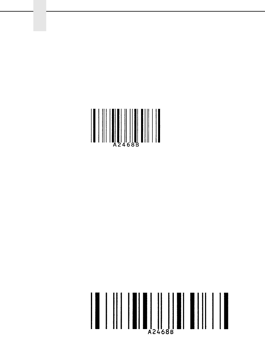
182
Chapter 3
Barcodes
Codabar Examples
The following command generates the horizontal variable ratio Codabar
barcode below. In the command sequence, Graphics Mode data is italicized
and barcode data is boldface. See Chapter 2 for a detailed description of
alphanumeric commands.
^PY^-^M10,10,000^KF^BYDA2468B^G^KF^-^PN^-
^PY^- enabled the graphics command sequence.
^M introduced the standard alphanumeric command.
The character height selected was 1.0 inches and character width selected
was at 1.0 inches.
A 0.0 justification value plus 0 additional dots was selected for the data
placement.
^KF activated Dark Print.
^B introduced the barcode command.
Y selected the standard 10 cpi font to print the optional readable data field.
Letter D selected Codabar barcode type.
A2468B is the barcode data.
^G terminated the barcode command sequence.
^KF^- at the end of the barcode turned off Dark Print.
^PN^- terminated the graphics mode.
The following command generated the horizontal Codabar barcode below
using OCR-B font, double the default ratio, and data of A2468B:
^PY^-^M10,10,000^KF^BB9D24681211A2468B^G^KF^-^PN^-
c
odabar.e
x1

Codabar
183
The following commands generated the vertical Codabar barcodes below
using standard 10 cpi font with the standard default ratio and data of A2468B:
^PY^-^M10,10,000^KF^CYDA2468B^G^KF^-^PN^-
The following command generates the same vertical Codabar barcode
described above, except that double the default ratio is used:
^PY^-^M10,10,000^KF^CY9D24681211A2468B^G^KF^-^PN^-
codab
c
odaba
r.e
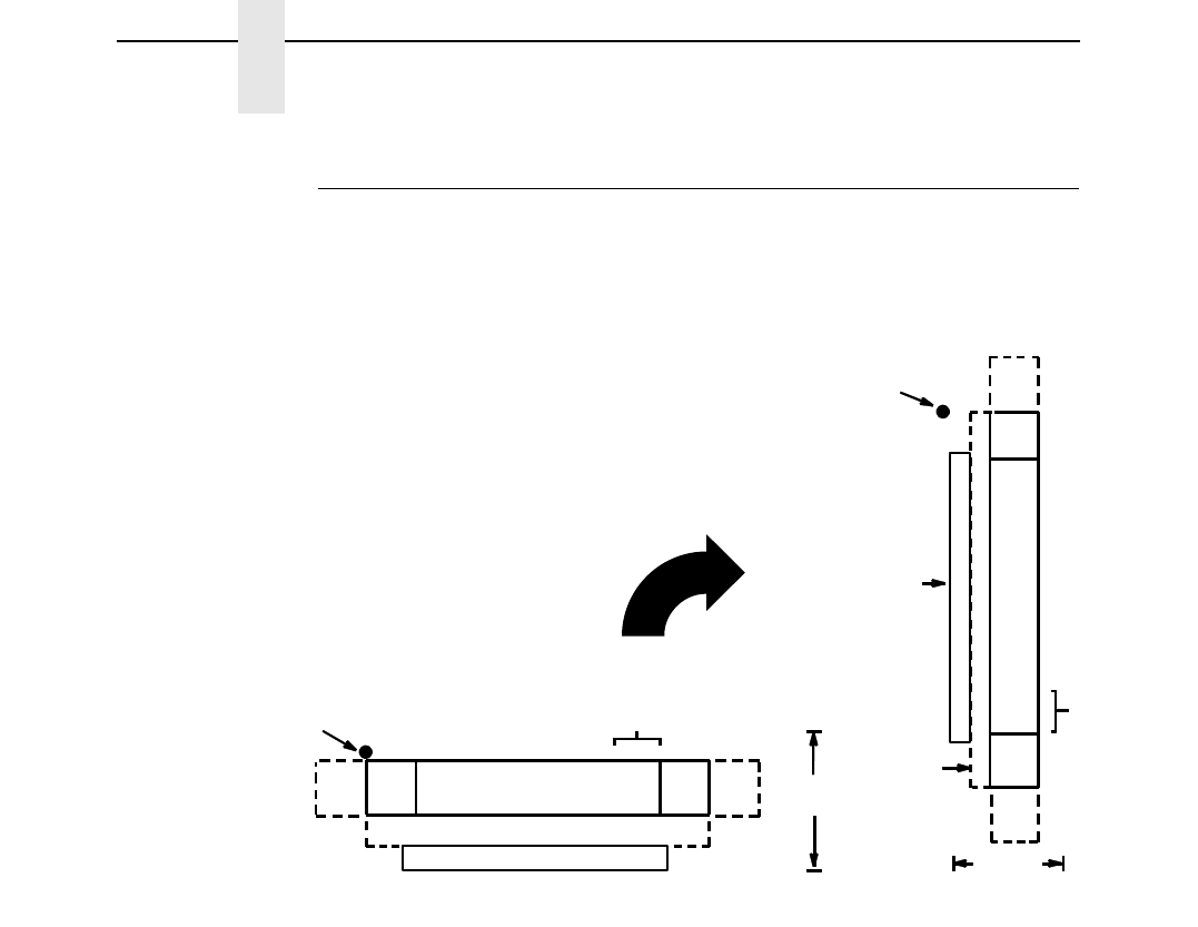
184
Chapter 3
Barcodes
Code 39
The Code 39 structure is shown in Figure 7 and described on the following
pages.
Figure 7. Code 39 Structure
Quiet Zone
Both ends of the barcode structure require blank quiet zones. The quiet zones
should be at least 0.25 inches wide and completely blank to ensure accurate
reading of the start/stop codes and to prevent adjacent barcodes from
overlapping. You are responsible for providing sufficient space on the form for
the quiet zones.
Start/Stop Codes
The start/stop code is a unique character identifying the leading and trailing
end of the barcode. The start/stop code is automatically produced with each
barcode. The start/stop code structure permits bidirectional barcode
scanning.
Data Field
The barcode symbol uses a series of wide and narrow bars and spaces to
represent standard alphanumeric characters. Each wide or narrow bar or
space is 1 element; each character in the data field has 9 elements. The
structure is 3 wide elements (bars or spaces) out of the 9 total elements that
compose one character.
DATA FIELD QUIETQUIET START STOP
LOWER GUARD BAND
CODE CODEZONE ZONE
OPTIONAL READABLE DATA FIELD
CHECK DIGIT
OPTIONAL
HEIGHT
STARTING
POSITION
DATA
FIELD
QUIET
ZONE
QUIET
ZONE
START
CODE
STOP
CODE
OPTIONAL
READABLE
DATA
FIELD
CHECK
OPTIONAL
HEIGHT
STARTING
POSITION
DIGIT
GUARD
BAND
LOWER

Code 39
185
Readable Data
The optional readable data field provides a readable interpretation of the
barcode data. Barcode data is printed below the horizontal barcode symbol
and to the left of a vertical barcode symbol. The lower guard band is provided
when the readable data field is selected.
Check Digit
Code 39 Type C inserts the modulo-43 check digit into the barcode. This
feature provides a means of verifying accurate scanning.
Code 39 Command Format
NOTE: Refer to page 164 for the IBARC, command format and definitions.
Default Ratio: (cc) dir p type data (cc)G
Variable Ratio: (cc) dir p [9] [:] type [ratio] data (cc)G
(cc) Represents the Special Function Control Code
(SFCC). Enter the specific SFCC for your VGL
configuration.
dir Represents the direction of the barcode. Enter B for
horizontal barcodes; enter C for vertical barcodes.
pPrints the optional readable data field. The
readable data field is printed below a horizontal
barcode or on the left-hand side of a vertical
barcode.
Replace p in the barcode command with one of the
codes in Table 27 to print the readable data field in
the corresponding font with the specified guard
band gap.
Table 27. Printable Data Field Fonts
Font Gap p code
Standard 10 cpi 3 dots Y
OCR-A 3 dots O
OCR-A .1-inch S
OCR-B 3 dots B
OCR-B .1-inch T
None N
186
Chapter 3
Barcodes
9 or : Selects the variable ratio length barcode feature,
which permits unique bar and space width ratios
adjusted for specific applications.
Enter the number 9 to select variable ratio
barcodes represented in line matrix printer dots (60
x 72 dpi).
Enter : to select variable ratio barcodes
represented in actual printer dots (203 x 203 dpi or
300 x 300 dpi, depending on the printer head being
used).
type Selects the barcode type. Code 39 types available
are shown in Table 28. Enter the Type Code
corresponding to the Code 39 type desired.
ratio Optional parameter (used in conjunction with
parameter 9 or : ) representing the ratios for
variable ratio barcodes. The default ratios are
overridden by the variable ratio feature. The ratio
data must be hexadecimal numbers from 0 through
9 or A through F. VGL automatically checks the
input for validity. If an invalid character is found in
the ratio, an error message is generated.
Code 39 barcodes use four-digit ratios. The ratios
are interpreted from left to right, measuring the size
of each bar or space, in dot width according to the
following pattern: narrow bar : narrow space : wide
bar : wide space. For example, enter 2266 in the
ratio parameter for:
Table 28. Code 39 Barcodes
Standard
Type Code IBARC,
Type Code # of Data
Characters Check
Digits Default Bar/
Space Ratios* Ratio
AC39 1-40 None 1:1:3:3 1:3
BC39A 1-40 None 1:2:4:5 1:3
CC39M43 1-40 Mod 43 1:1:3:3 1:3
LOGMAR 1-40 None 1:1:3:3
HIBCC 1-40 Mod 43 1:1:3:3
AIAG 1-40 None 1:1:3:3
EMBARC 1-40 None 1:1:3:3
* Ratios represent dot width of the bar/space elements as follows:
Narrow Bar : Narrow Space : Wide Bar : Wide Space.

Code 39
187
2 dot-wide narrow bar
2 dot-wide narrow space
6 dot-wide wide bar
6 dot-wide wide space.
NOTE: VGL automatically checks ratio data for validity only within the
allowable hexadecimal range. VGL does not verify that ratio data
creates acceptable wide/narrow element relationships for barcode
readability. For example, VGL accepts wide/narrow ratio values of 2
and 5, respectively; however a narrow element larger than the wide
element produces an unreadable barcode. When designing unique
ratio data, carefully plot wide and narrow ratios to conform to
readable barcodes.
data The barcode data. Code 39 encodes 1 through 40
characters from the Code 39 full ASCII Character
Set shown in Table 29.
(cc)G Terminates the barcode command. Enter the SFCC
for your VGL configuration immediately followed by
any valid command character or G, the universal
sequence terminator.
188
Chapter 3
Barcodes
NOTE: Character pairs /M, /N, and /P through /Y are reserved for future
control character pairs.
Table 29. Code 39 Character Set
ASCII CODE 39 ASCII CODE 39 ASCII CODE 39 ASCII CODE 39
NUL
SOH
STX
ETX
EOT
ENQ
ACK
BEL
BS
HT
LF
VT
FF
CR
SO
SI
DLE
DC1
DC2
DC3
DC4
NAK
SYN
ETB
CAN
EM
SUB
ESC
FS
GS
RS
US
%U
$A
$B
$C
$D
$E
$F
$G
$H
$I
$J
$K
$L
$M
$N
$O
$P
$Q
$R
$S
$T
$U
$V
$W
$X
$Y
$Z
%A
%B
%C
%D
%E
SP
!
"
#
$
%
&
'
(
)
*
+
,
—
.
/
0
1
2
3
4
5
6
7
8
9
:
;
<
=
>
?
Space
/A
/B
/C
/D
/E
/F
/G
/H
/I
/J
/K
/L
—
.
/O
0
1
2
3
4
5
6
7
8
9
/Z
%F
%G
%H
%I
%J
@
A
B
C
D
E
F
G
H
I
J
K
L
M
N
O
P
Q
R
S
T
U
V
W
X
Y
Z
[
\
]
^
__
%V
A
B
C
D
E
F
G
H
I
J
K
L
M
N
O
P
Q
R
S
T
U
V
W
X
Y
Z
%K
%L
%M
%N
%O
`
a
b
c
d
e
f
g
h
i
j
k
l
m
n
o
p
q
r
s
t
u
v
w
x
y
z
{
|
}
^
DEL
%W
+A
+B
+C
+D
+E
+F
+G
+H
+I
+J
+K
+L
+M
+N
+O
+P
+Q
+R
+S
+T
+U
+V
+W
+X
+Y
+Z
%P
%Q
%R
%S
%T %X
%Y %Z
Code 39
189
Code 39 Examples
The following command generates the horizontal default ratio Code 39
barcode shown below. In the command sequence, graphics mode data is
italicized and barcode data is boldface. See Chapter 2 for a detailed
description of alphanumeric commands.
^PY^-^M10,10,000^KF^BYA$25NW20%^G^KF^-^PN^-
^PY^- enabled the graphics command sequence.
^M introduced the standard alphanumeric command.
The character height selected was 1.0 inches and character width was
selected at 1.0 inches.
A 0.0 justification value plus 0 additional dots was selected for the data
placement.
^KF activated Dark Print.
^B introduced the barcode command.
Y selected the standard 10 cpi font to print the optional readable data field.
Letter A selected Code 39 Type A.
$25NW20% is the barcode data, and ^G terminated the barcode command
sequence.
^KF^- at the end of the barcode sequence turned off Dark Print, and ^PN^-
terminated the graphics mode.
The following command generated the horizontal Code 39 barcode below
using OCR-A font, double the default ratio, and data of $25NW20%:
^PY^-^M10,10,000^KF^BO9A2266$25NW20%^G^KF^-^PN^-
code39.
code39.ex
190
Chapter 3
Barcodes
The following commands generated the vertical Code 39 barcodes below
using standard 10 cpi font, the standard default ratio, and data of $25:
^PY^-^M10,10,000^KF^CYB$25^G^KF^-^PN^-
The following command generates the same vertical Code 39 barcode
described above, except that double the default ratio is used:
^PY^-^M10,10,000^KF^CY9B248A$25^G^KF^-^PN^-
c
od
e3
code39.ex4
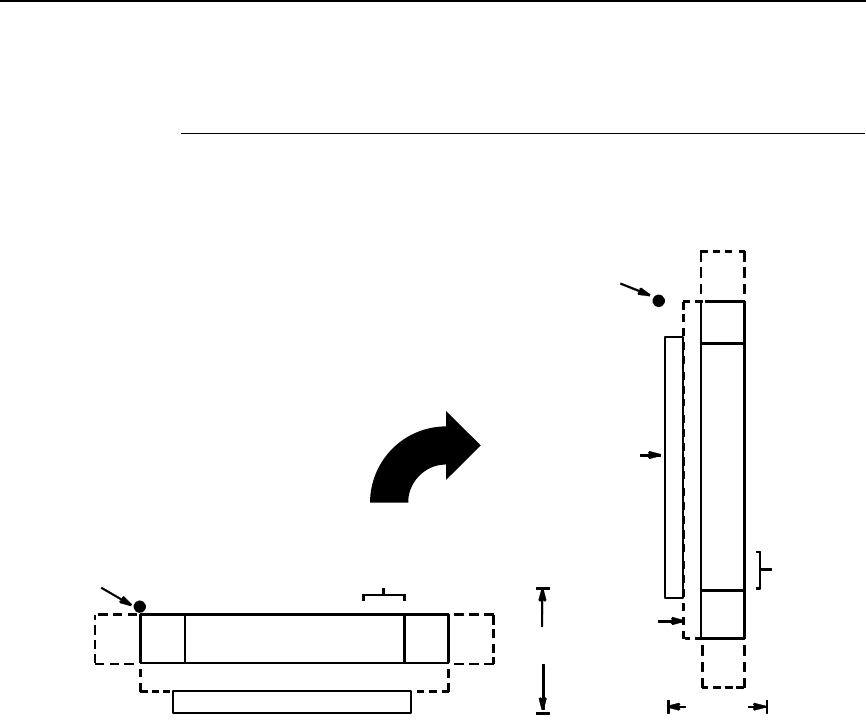
Code 93
191
Code 93
The Code 93 structure is shown in Figure 8 and described on the following
pages.
Figure 8. Code 93 Structure
Quiet Zone
Both ends of the barcode structure require blank quiet zones. The quiet zones
should be at least 0.25 inches wide and completely blank to ensure accurate
reading of the start/stop codes and to prevent adjacent barcodes from
overlapping. You are responsible for providing sufficient space on the form for
the quiet zones.
Start/Stop Codes
The start/stop code is a unique character identifying the leading and trailing
end of the barcode. The start/stop code is automatically produced with each
barcode. The start/stop code structure permits bidirectional barcode
scanning.
Data Fields
The barcode symbol uses a series of varying width bars and spaces to
represent the full ASCII character set. Bars and spaces vary in width from 1
through 4 modules. Each character consists of 2 bars and two spaces that
total 7 modules. The symbol coding of the left data field is different from the
right data field to permit read direction sensing.
DATA FIELD QUIETQUIET START STOP
LOWER GUARD BAND
CODE CODEZONE ZONE
OPTIONAL READABLE DATA FIELD
CHECK DIGIT
OPTIONAL
HEIGHT
STARTING
POSITION
DATA
FIELD
QUIET
ZONE
QUIET
ZONE
START
CODE
STOP
CODE
OPTIONAL
READABLE
DATA
FIELD
CHECK
OPTIONAL
HEIGHT
STARTING
POSITION
DIGIT
GUARD
BAND
LOWER
192
Chapter 3
Barcodes
Readable Data
The optional readable data field provides a readable interpretation of the
barcode data. Barcode data is printed below the horizontal barcode symbol
and to the left of a vertical barcode symbol. The lower guard band is provided
when the readable data field is selected.
Check Digit
Code 93 inserts the modulo-47 check digit into the barcode. This feature
provides a means of verifying accurate scanning.
Code 93 Command Format
NOTE: See page 164 for the IBARC, command format and definitions.
Default Ratio: (cc) dir p i data (cc)G
Variable Ratio: (cc) dir p [9] [:] i [ratio] data (cc)G
(cc) Represents the Special Function Control Code
(SFCC). Enter the specific SFCC for your VGL
configuration.
dir Represents the direction of the barcode. Enter B for
horizontal barcodes; enter C for vertical barcodes.
pPrints the optional readable data field. The
readable data field is printed below a horizontal
barcode or on the left-hand side of a vertical
barcode.
Replace p in the barcode command with one of the
following codes to print the readable data field in
the corresponding font with the specified guard
band gap.
Table 30. Printable Data Field Fonts
Font Gap p code
Standard 10 cpi 3 dots Y
OCR-A 3 dots O
OCR-A .1-inch S
OCR-B 3 dots B
OCR-B .1-inch T
None N

Code 93
193
9 or : Selects the variable ratio length barcode feature,
which permits unique bar and space width ratios
adjusted for specific applications.
Enter the number 9 to select variable ratio
barcodes represented in line matrix printer dots (60
x 72 dpi).
Enter : to select variable ratio barcodes
represented in actual printer dots (203 x 203 dpi or
300 x 300 dpi, depending on the printer head being
used).
i The type code for Code 93. Enter i.
ratio Optional parameter (used in conjunction with
parameter 9 or :) representing the ratios for
variable ratio barcodes. The default ratios are
overridden by the variable ratio feature. The ratio
data must be hexadecimal numbers from 0 through
9 or A through F. VGL automatically checks the
input for validity. If an invalid character is found in
the ratio, an error message is generated.
Code 93 barcodes use eight-digit ratios. The ratios
are interpreted from left to right, measuring the size
of each bar or space in dot width, in the following
pattern: 1 module wide bar : 1 module wide space :
2 module wide bar : 2 module wide space : 3
module wide bar : 3 module wide space : 4 module
wide bar : 4 module wide space. For example,
enter 22446688 in the ratio data field for:
2 module wide bar
2 module wide space
4 module wide bar
4 module wide space
6 module wide bar
6 module wide space
8 module wide bar
8 module wide space
NOTE: VGL automatically checks ratio data for validity only within the
allowable hexadecimal range. VGL does not verify that ratio data
creates acceptable bar/space element relationships for barcode
readability. When designing unique ratio data, carefully plot bar/
space ratios to conform to readable barcodes.
data The barcode data. Code 93 encodes from 1
through 40 characters. They can be any ASCII
characters 0-127.
(cc)G Terminates the barcode command. Enter the SFCC
for your VGL configuration immediately followed by
any valid command character or G, the universal
sequence terminator.

194
Chapter 3
Barcodes
Code 93 Example
The following command generates the horizontal default ratio Code 93
barcode shown below. In the command sequence, graphics mode data is
italicized and barcode data is boldface. See Chapter 2 for a detailed
description of alphanumeric commands.
^PY^-^F^-
^M1010100^IBARC,C93,B,1234ABCD^G^-
^PN^-
^PY^- enabled the graphics command sequence.
^F^- enabled Free Format.
^M introduced the standard alphanumeric command.
The character height selected was 1.0 inches and character width was
selected at 1.0 inches.
A 1.0 justification value plus 0 additional dots was selected for the data
placement.
^IBARC, introduced the barcode command.
C93, selected Code 93.
B, prints the readable data field below the barcode.
1234ABCD is the barcode data, and ^G^- terminated the barcode command
sequence.
^PN^- terminated the graphics mode.

Code 128
195
Code 128
Code 128 includes three subsets: A, B, and C. All contain the same bar
patterns, except for the unique start character instructing the barcode reader
which subset is being used. Special characters are available for switching
between the subsets in order to generate the shortest possible barcode. The
Code 128 structure is shown in Figure 9 and described on the following
pages.
Figure 9. Code 128 Structure
Quiet Zone
Both ends of the barcode structure require blank quiet zones. The quiet zones
should be at least 0.25 inches wide and completely blank to ensure accurate
reading of the start/stop codes and to prevent adjacent barcodes from
overlapping. You are responsible for providing sufficient space on the form for
the quiet zones.
Start/Stop Codes
Code 128 contains special characters which use unique start/stop codes to
identify the leading and trailing end of the barcode. In the automatic mode,
start and stop codes are generated automatically. In the manual mode, you
must supply the start code, but the stop code is generated automatically.
DATA FIELD QUIETQUIET START STOP
LOWER GUARD BAND
CODE CODEZONE ZONE
OPTIONAL READABLE DATA FIELD
HEIGHT
STARTING
POSITION
CHECK DIGIT
FIELD
DATA
FIELD
QUIET
ZONE
QUIET
ZONE
STOP
CODE
START
CODE
OPTIONAL
READABLE
DATA
FIELD
HEIGHT
STARTING
POSITION
GUARD
BAND
LOWER
CHECK
DIGIT
FIELD

196
Chapter 3
Barcodes
Data Field
Code 128 barcodes support a full ASCII character set: Subset A provides
standard alphanumeric keyboard characters, control and special characters;
subset B includes all standard alphanumeric keyboard characters, lowercase
alphabetical characters, and special characters; subset C provides 100 digit
pairs, from 00 through 99 inclusive, plus special characters. Table 32 lists the
full Code 128 character set.
Control characters, identified by a “greater than” (>) symbol, introduce Special
Function Control Codes so that you can manually supply control codes to shift
between subsets as described in the “Mode Selection” section, below. The
bars and spaces vary in width from 1 through 4 modules. Each character
consists of 3 bars and 3 spaces that total 11 modules.
Readable Data
The optional readable data field provides a readable interpretation of the
barcode data. Barcode data is printed below the horizontal barcode symbol,
and to the left of a vertical barcode symbol. The lower guard band is provided
when the readable data field is selected. The readable data field is available
only in the automatic mode.
Check Digit
For Code 128, the modulo-103 check digit is automatically calculated and
inserted in the barcode symbol. The check digit verifies accurate scanning.
The start code is included in the check digit algorithm.
Mode Selection
VGL generates Code 128 barcodes in one of two modes: automatic or
manual.
Automatic Mode
VGL creates the shortest possible barcode by automatically sending the
subset switch characters (characters preceded by >) to switch from subset B
into subset C whenever strings of four or more consecutive numeric
characters are provided. As long as the data includes ordinary keyboard
characters and no subset switch, VGL switches in and out of subsets B and C
automatically before and after numeric character strings. Start codes, stop
codes, and check digits are generated automatically.
NOTE: The code >0 is not a special character; VGL recognizes >0 as the
“greater than” character (>) on a standard ASCII chart.

Code 128
197
Manual Mode
The manual mode is selected by inputting a subset switch character
(characters preceded by >) anywhere in the barcode data. In the manual
mode, you must insert the special codes into the barcode command to switch
to another subset. Once a special code is found in the data, all automatic
switching features are suspended, the readable data field option is cancelled,
and VGL expects you to provide all special code switching commands. In this
mode, you must supply the start code; if no start code is provided, VGL
inserts a subset B start code. Stop codes and check digits are generated
automatically in the manual mode. More information about Manual Mode is
provided in the following section.
Manual Mode Operation
NOTE: In the manual mode, you are responsible for correct implementation
of Code 128 in accordance with the Code 128 Standards Manual.
The Code 128 character set is shown in Table 32. The Alternate column
identifies the special subset switch characters that switch VGL to the manual
mode. These > characters are also horizontally aligned with functions also
performed in an automatic mode. For example, >/ represents SI in subset A, o
in subset B, and value 79 in subset C. Thus, the following commands
generate the same barcode using Alternate characters, or subsets B or C:
Subset Switch Characters: ^BNZ>7>,>->.>/^G
Subset C: ^BNZ>576777879^G
Subset B: ^BNZ>6lmno^G
Non-ASCII characters are specified by using the subset switch characters
(from >1 through >8 in the Alternate column on Table 32) which corresponds
to your application. The Value column is used when manually translating
subset B and C barcodes into their briefest form.
NOTE: The subset switch start codes, >5, >6, and >7 have two functions. At
the beginning of a line, they start manual mode data in subset C, B, or
A, respectively. When these codes are used anywhere in the data
other than at the start of a line, they are interpreted as the non-ASCII
characters in Table 32.
Subset B and C Switching
In the automatic mode, VGL creates the briefest, most compact barcode by
automatically switching from subset B to subset C. For example, the data
LT436682 could be entered directly into a typed barcode command as
^BNZLT436682^G. VGL automatically selects the appropriate start code, and
switches to subset C to compact the continuous numeric data characters
(436682).
In the manual mode, however, you must specify the start code and all special
function codes to switch subsets. For example, to create the same barcode as
generated automatically in the previous paragraph (data of LT436682), the
subset B start code is entered, followed by the alpha data (LT), and the
subset switch character to switch to subset C is entered followed by the
continuous numeric characters. A typical barcode command, in the manual
mode, for the data is: ^BNZ>6LT>5Kbr^G. The pairs of continuous numeric

198
Chapter 3
Barcodes
data were manually translated to subset B, data Kbr, corresponding to the
subset C values of 436682, respectively, as shown in Table 32. If the data
(LT436682) had been entered directly into the barcode command as
^BNZ>6LT>5436682, the barcode generated would have been: Start Code B:
LT, subset C: 20 19 22 22 24 18, as determined by the value of the individual
data characters in Table 32.
NOTE: If a start code is not entered in the manual mode, VGL provides a
subset B start code.
Subset A
Subset A operates in the manual mode only. Subset A data characters
include mostly normal printable ASCII characters which require no subset
switching and can be entered directly. For example, the data ABC123 in
subset A is input in the barcode command as: ^BNZ>7ABC123^. Switching to
another subset does not generate a shorter barcode.
Non-printable control characters in subset A can be generated by either: 1)
using the subset B lowercase character equivalent from Table 32 (` through o)
or 2) using the subset switch characters (>1 through >8, or >SP through >/)
from the Alternate column of Table 32.
Code 128 Command Format
NOTE: See page 164 for the IBARC, command format and definitions.
Default Ratio: (cc) dir p Z data (cc)G
Variable Ratio: (cc) dir p [9] [:] Z [ratio] data (cc)G
(cc) Represents the Special Function Control Code
(SFCC). Enter the specific SFCC for your VGL
configuration.
dir Represents the direction of the barcode. Enter B for
horizontal barcodes; enter C for vertical barcodes.
pPrints the optional readable data field. The
readable data field is printed below a horizontal
barcode or on the left-hand side of a vertical
barcode.
Replace p in the barcode command with one of the
codes listed in Table 31 to print the readable data
field in the corresponding font with the specified
guard band gap.
Code 128
199
9 or : Selects the variable ratio length barcode feature,
which permits unique bar and space width ratios
adjusted for specific applications.
Enter the number 9 to select variable ratio
barcodes represented in line matrix printer dots (60
x 72 dpi).
Enter: to select variable ratio barcodes represented
in actual printer dots (203 x 203 dpi or 300 x 300
dpi, depending on the printer head being used).
Z The Code 128 type code. Enter Z.
ratio Optional parameter (used in conjunction with 9 or :
above) representing the ratios for variable ratio
barcodes. Default ratios are overridden by the
variable ratio feature. The ratio data must be
hexadecimal numbers from 0 through 9 or A
through F; VGL automatically checks the input for
validity. If an invalid character is found in the ratio,
an error message is generated.
Code 128 barcodes use eight-digit ratios. The
ratios are interpreted from left to right, measuring
the size of each bar or space in dot width, in the
following pattern: 1 module wide bar : 1 module
wide space : 2 module wide bar : 2 module wide
space : 3 module wide bar : 3 module wide space :
4 module wide bar : 4 module wide space. For
example, enter 22446688 in the ratio data field for:
2 module wide bar
2 module wide space
4 module wide bar
4 module wide space
6 module wide bar
6 module wide space
8 module wide bar
8 module wide space
Table 31. Printable Data Field Fonts
Font Gap p code
Standard 10 cpi 3 dots Y
OCR-A 3 dots O
OCR-A .1-inch S
OCR-B 3 dots B
OCR-B .1-inch T
None N

200
Chapter 3
Barcodes
NOTE: VGL automatically checks ratio data for validity only within the
allowable hexadecimal range. VGL does not verify that ratio data
creates acceptable bar/space element relationships for barcode
readability. When designing unique ratio data, carefully plot bar/
space ratios to conform to readable barcodes.
data The barcode data. In the automatic mode,
whenever a string of 4 or more contiguous numeric
digits are detected, VGL inserts a subset C
command at the start of the numeric string. When
the string of numeric digits is broken, VGL inserts a
subset B command. Code 128 encodes from 1
through 40 characters from the character set of the
subset code selected. Use the appropriate subset
code from the Code 128 Character Set in Table 32.
When data is provided in the manual mode, the
readable data field is not printed.
(cc)G Terminates the barcode command. Enter the SFCC
for your VGL configuration immediately followed by
any valid command character or G, the universal
sequence terminator.

Code 128
201
Table 32. Code 128 Character Set
Value B C Value A B C
0
1
2
3
4
5
6
7
8
9
10
11
12
13
14
15
16
17
18
19
20
21
22
23
24
25
26
27
28
29
30
31
32
33
34
35
36
37
38
39
40
41
42
43
44
45
46
47
48
49
50
51
52
53
A
Subset Alternate
SP
!
"
#
$
%
&
(
)
*
+
'
-
.
/
0
1
2
3
4
5
6
7
8
9
:
;
<
=
>
?
@
A
B
C
D
E
F
G
H
I
J
K
L
M
N
O
P
Q
R
S
T
U
54
55
56
57
58
59
60
61
62
63
64
65
66
67
68
69
70
71
72
73
74
75
76
77
78
79
80
81
82
83
84
85
86
87
88
89
90
91
92
93
94
95
96
97
98
99
100
101
102
103
104
105
V
W
X
Y
Z
[
\
]
^
__
NUL
SOH
STX
ETX
EOT
ENQ
ACK
BEL
BS
HT
LF
VT
FF
CR
SO
SI
DLE
DC1
DC2
DC3
DC4
NAK
SYN
ETB
CAN
EM
SUB
ESC
FS
GS
RS
US
FNC3
FNC2
SHIFT
CODE C
CODE B
FNC4
FNC1
START CODE A*
START CODE B*
START CODE C*
SP
!
"
#
$
%
&
(
)
*
+
'
-
.
/
0
1
2
3
4
5
6
7
8
9
:
;
<
=
>
?
@
A
B
C
D
E
F
G
H
I
J
K
L
M
N
O
P
Q
R
S
T
U
V
W
X
Y
Z
[
\
]
^
__
a
b
c
d
e
f
g
h
i
j
k
l
m
n
o
p
q
r
s
t
u
v
w
x
y
z
{
:
}
~
DEL
FNC3
FNC2
SHIFT
CODE C
FNC4
CODE A
FNC1
00
01
02
03
04
05
06
07
08
09
10
11
12
13
14
15
16
17
18
19
20
21
22
23
24
25
26
27
28
29
30
31
32
33
34
35
36
37
38
39
40
41
42
43
44
45
46
47
48
49
50
51
52
53
54
55
56
57
58
59
60
61
62
63
64
65
66
67
68
69
70
71
72
73
74
75
76
77
78
79
80
81
82
83
84
85
86
87
88
89
90
91
92
93
94
95
96
97
98
99
CODE B
CODE A
FNC1
>SP
>!
>"
>#
>$
>%
>&
>'
''
>(
>)
>*
>+
>,
>-
>.
>/
>1
>2
>3
>4
>5
>6
>7
>8
>7
>6
>5
*Used at the beginning of manual mode commands.
Subset Subset Subset Subset Subset
202
Chapter 3
Barcodes
Code 128 Examples
The following command generates the horizontal default ratio Code 128
barcode below in the automatic mode. In the command sequence, graphics
mode data is italicized and barcode data is boldface. See Chapter 2 for a
detailed description of alphanumeric commands.
^PY^-^M10,10,000^KF^BNZABC123456^G^KF^-^PN^-
^PY^- enabled the graphics command sequence.
^M introduced the standard alphanumeric command.
The character height selected was 1.0 inches and character width was
selected at 1.0 inches.
A 0.0 justification value plus 0 additional dots was selected for data
placement.
^KF activated Dark Print.
^B introduced the barcode command.
N deselected printing the optional readable data field.
Letter Z selected Code 128.
ABC123456 is the barcode data.
^G terminated the barcode command sequence.
^KF^- at the end of the barcode sequence turned off Dark Print.
^PN^- terminated the graphics mode.
The following command generated the Code 128 barcode below in the
automatic mode using standard 10 cpi font, double the default ratio, and data
of ABC123456. The barcode data begins in subset B and automatically
switches to subset C for the numeric data.
^PY^-^M10,10,000^KF^BY9Z22446688ABC123456^G^KF^-^PN^-
code128.ex1
Code 128
203
The command below generates the following vertical Code 128 barcode with
data of 123@25% in manual mode, subset A.
^PY^-^M10,10,000^KF^CNZ>7123@25%^G^KF^-^PN^-
The command below generates the same vertical Code 128 barcode in the
automatic mode, subset B. Because less than 4 consecutive numeric digits
were provided in the data, no subset switching occurred, and the barcode
remained in subset B.
^PY^-^M10,10,000^KF^CNZ123@25%^G^KF^-^PN^-
c
ode128
.ex
code128.ex

204
Chapter 3
Barcodes
EAN 8
The EAN 8 barcode is related to the Universal Product Code (UPC) group.
EAN 8 can be printed with or without a 2- or 5-digit add-on data field, which is
placed at the end of the barcode. The EAN 8 (European Article Number)
barcode structure is shown in Figure 10 and described on the following
pages.
Figure 10. EAN 8 Structure
QUIET
ZONE
START CODE CENTER CODE
CHECK DIGIT FIELD
STOP CODE
LEFT DATA
FIELD RIGHT DATA
FIELD HEIGHT
QUIET
ZONE
OPTIONAL READABLE
STARTING
POSITION
DATA FIELD
2- or 5-
DIGIT
ADD-ON
CODE
QUIET
CHECK
CODE
LEFT
CENTER
RIGHT
QUIET
ZONE
STOP
HEIGHT
STARTING
POSITION
START
OPTIONAL
READABLE
DATA
FIELD
2- or 5-
DIGIT
ADD-ON
CODE
CODE
ZONE
DIGIT
FIELD
DATA
FIELD
CODE
DATA
FIELD

EAN 8
205
Quiet Zone
Both ends of the barcode structure have blank quiet zones. The quiet zones
should be at least 0.25 inches wide and completely blank to ensure accurate
reading of the start/stop codes and to prevent adjacent barcodes from
overlapping. You are responsible for providing sufficient space on the form for
the quiet zones. A trailing quiet zone is provided automatically if an add-on
code has been specified in the barcode command.
Start/Center/Stop Codes
The Start/Center/Stop codes are special character codes marking those
portions of the barcode. These codes are automatically produced with each
barcode.
Data Field
The barcode symbol uses a series of varying width bars and spaces to
represent a limited numeric character set (numbers 0-9 and Special
Characters Start, Center, and Stop). The bars and spaces vary in width from 1
through 4 modules. Each character consists of 2 bars and 2 spaces that total
7 modules. The symbol coding of the left data field is different from the right
data field to permit read direction sensing.
Readable Data
The human readable data field provides a readable interpretation of the
barcode data. Barcode data is printed below the horizontal barcode symbol,
and to the left of a vertical barcode symbol.
Check Digit
The modulo-10 check digit is automatically calculated and inserted in the
barcode symbol. The check digit provides the means to verify accurate
scanning.
EAN 8 Command Format
NOTE: See page 164 for the IBARC, command format and definitions.
Default Ratio: (cc) dir p type data (cc)G
Variable Ratio: (cc) dir p [9] [:] type [ratio] data (cc)G
(cc) Represents the Special Function Control Code
(SFCC). Enter the specific SFCC for your VGL
configuration.
dir Represents the direction of the barcode. Enter B for
horizontal barcodes; enter C for vertical barcodes.
206
Chapter 3
Barcodes
pPrints the optional readable data field. The
readable data field is printed below a horizontal
barcode or on the left-hand side of a vertical
barcode.
Replace p in the barcode command with one of the
codes listed in Table 33 to print the readable data
field in the corresponding font with the specified
guard band gap.
9 or : Selects the variable ratio length barcode feature,
which permits unique bar and space width ratios
adjusted for specific applications.
Enter the number 9 to select variable ratio
barcodes represented in line matrix printer dots (60
x 72 dpi).
Enter : to select variable ratio barcodes
represented in actual printer dots (203 x 203 dpi or
300 x 300 dpi, depending on the printer head being
used).
type Represents the barcode type. Enter U for standard
EAN 8; enter o (alpha o) for EAN 8 plus a 2-digit
add-on data field; enter p for EAN 8 plus a 5-digit
add-on data field.
Table 33. Printable Data Field Fonts
Font Gap p code
Standard 10 cpi 3 dots Y
OCR-A 3 dots O
OCR-A .1-inch S
OCR-B 3 dots B
OCR-B .1-inch T
None N

EAN 8
207
ratio Optional parameter (used in conjunction with 9 or :
above) representing the ratios for variable ratio
barcodes. Default ratios are overridden by the
variable ratio feature. However, unique variable
ratios for EAN 8 barcodes easily generate large,
out-of-spec barcodes. Ratio data must be
hexadecimal numbers from 0 through 9 or A
through F; VGL automatically checks the input for
validity. If an invalid character is found in the ratio,
an error message is generated.
EAN 8 barcodes use eight-digit ratios. The ratios
are interpreted from left to right, measuring the size
of each bar or space, in dot width, in the following
pattern: 1 module wide bar : 1 module wide space :
2 module wide bar : 2 module wide space : 3
module wide bar : 3 module wide space : 4 module
wide bar : 4 module wide space.
NOTE: VGL automatically checks ratio data for validity only within the
allowable hexadecimal range. VGL does not verify that ratio data
creates acceptable bar/space element relationships for barcode
readability. When designing unique ratio data, carefully plot bar/
space ratios to conform to readable barcodes.
data The barcode data. Standard EAN 8 barcodes
encode exactly 7 digits. The first four data
characters are in the left half of the data field, and
the last 3 characters are in the right half of the data
field. (A check digit is automatically computed and
printed at the end of the right data field). If the 2- or
5-digit add-on data field is used, include this data at
the end of the data field.
The characters available for the data field are 0
through 9 (hex 30 through 39, respectively).
(cc)G Terminates the barcode command. Enter the SFCC
for your VGL configuration followed by any valid
command character or G, the universal sequence
terminator.
208
Chapter 3
Barcodes
EAN 8 Examples
The following command generated the horizontal default ratio EAN 8 barcode
below. In the command sequence, graphics mode data is italicized and
barcode data is boldface. See Chapter 2 for a detailed description of
alphanumeric commands.
^PY^-^M10,10,000^KF^BYU2244595^G^KF^-^PN^-
^PY^- turned on the graphics command sequence.
^M introduced the standard alphanumeric command.
The character height selected was 1.0 inches and character width was
selected at 1.0 inches.
A 0.0 justification value plus 0 additional dots was selected for data
placement.
^KF activated Dark Print.
^B introduced the barcode command.
Y selected the standard 10 cpi font to print the optional readable data field.
Letter U selected the EAN 8 barcode type.
2244595 is the 7-digit barcode data.
^G terminated the barcode command sequence.
^KF^- at the end of the barcode sequence turned off Dark Print.
^PN^- terminated the graphics mode.
The following command generated the vertical EAN 8 barcode below using
standard 10 cpi font with the standard default ratio and data of 2244595:
^PY^-^M10,10,000^CYU2244595^G^PN^-
ean8.ex1
e
an8.e
x2

EAN 13
209
EAN 13
The EAN 13 barcode is related to the Universal Product Code (UPC) group.
EAN 13 can be printed with or without a 2- or 5-digit add-on data field, which
is placed at the end of the barcode. The EAN 13 (European Article Number)
barcode structure is shown in Figure 11 and described on the following
pages.
Figure 11. EAN 13 Structure
Quiet Zone
Quiet zones extend on both ends of the barcode to permit the code to begin
and end in a blank area. You are responsible for providing sufficient space on
the form for the quiet zones. A trailing quiet zone is provided automatically if
an add-on code has been specified in the barcode command.
Start/Center/Stop Codes
The Start/Center/Stop codes are special character codes marking those
portions of the barcode. These codes are automatically produced with each
barcode.
QUIET
ZONE
START CODE CENTER CODE
CHECK DIGIT FIELD
STOP CODE
LEFT DATA
FIELD RIGHT DATA
FIELD HEIGHT
QUIET
ZONE
OPTIONAL READABLE
STARTING
POSITION
N
NUMBER
SYSTEM
CHARACTER
DATA FIELD
2- or 5-
DIGIT
ADD-ON
CODE
QUIET
ZONE
CHECK
LEFT
CENTER
RIGHT
QUIET
STOP
STARTING
START
OPTIONAL
READABLE
DATA
FIELD
NUMBER N
2- or 5-
DIGIT
ADD-ON
CODE
HEIGHT
CODE
CODE
ZONE
SYSTEM
CHARACTER
DATA
FIELD
CODE
DATA
FIELD
POSITION
DIGIT
FIELD

210
Chapter 3
Barcodes
Number System Character
The number system character field allows you to apply a code to a class or
type of item. The first character in the data field is used as the number system
character; it is printed in the left quiet zone.
Data Field
The barcode symbol uses a series of varying width bars and spaces to
represent a limited character set (numbers 0-9 and Special Characters Start,
Center, and Stop). The bars and spaces vary in width from 1 through 4
modules. Each character consists of 2 bars and two spaces that total 7
modules. The symbol coding of the left data field is different from the right
data field to permit read direction sensing.
Readable Data
The human readable data field provides a readable interpretation of the
barcode data. Barcode data is printed below the horizontal barcode symbol
and to the left of a vertical barcode symbol.
Check Digit
The modulo-10 check digit is automatically calculated and inserted in the
barcode symbol. The check digit provides the means to verify accurate
scanning. The number system character is included in the check digit
algorithm.
EAN 13 Command Format
NOTE: See page 164 for the IBARC, command format and definitions.
Default Ratio: (cc) dir p type data (cc)G
Variable Ratio: (cc) dir p [9] [:] type [ratio] data (cc)G
(cc) Represents the Special Function Control Code
(SFCC). Enter the specific SFCC for your VGL
configuration.
dir Represents the direction of the barcode. Enter B for
horizontal barcodes; enter C for vertical barcodes.
pPrints the optional readable data field. The
readable data field is printed below a horizontal
barcode or on the left-hand side of a vertical
barcode.
Replace p in the barcode command with one of the
codes listed in Table 34 to print the readable data
field in the corresponding font with the specified
guard band gap.

EAN 13
211
9 or : Selects the variable ratio length barcode feature,
which permits unique bar and space width ratios
adjusted for specific applications.
Enter the number 9 to select variable ratio
barcodes represented in line matrix printer dots (60
x 72 dpi).
Enter : to select variable ratio barcodes
represented in actual printer dots (203 x 203 dpi or
300 x 300 dpi, depending on the printer head being
used).
type Represents the barcode type. Enter T for standard
EAN 13; enter m for EAN 13 plus a 2-digit add-on
data field; enter n for EAN 13 plus a 5-digit add-on
data field.
ratio Optional parameter (used in conjunction with 9 or :
above) representing the ratios for variable ratio
barcodes. Default ratios are overridden by the
variable ratio feature. However, unique variable
ratios for EAN 13 barcodes easily generate large,
out-of-spec barcodes. Ratio data must be
hexadecimal numbers from 0 through 9 or A
through F; VGL automatically checks the input for
validity. If an invalid character is found in the ratio,
an error message is generated.
EAN 13 barcodes use eight-digit ratios. The ratios
are interpreted from left to right, measuring the size
of each bar or space, in dot width, in the following
pattern: 1 module wide bar : 1 module wide space :
2 module wide bar : 2 module wide space : 3
module wide bar : 3 module wide space : 4 module
wide bar : 4 module wide space.
Table 34. Printable Data Field Fonts
Font Gap p code
Standard 10 cpi 3 dots Y
OCR-A 3 dots O
OCR-A .1-inch S
OCR-B 3 dots B
OCR-B .1-inch T
None N

212
Chapter 3
Barcodes
NOTE: VGL automatically checks ratio data for validity only within the
allowable hexadecimal range. VGL does not verify that ratio data
creates acceptable bar/space element relationships for barcode
readability. When designing unique ratio data, carefully plot bar/
space ratios to conform to readable barcodes.
data The barcode data. EAN 13 barcodes encode
exactly 12 digits. The first character input is
interpreted as the number system character. (A
barcode character is not produced for the number
system character.) The next six characters are the
left side (the upper side on vertically oriented
symbols). The final five characters are the right side
(or the lower side on vertically oriented symbols). A
thirteenth character is an automatic check digit
which is computed and printed in the last character
position in the right data field. If the 2- or 5-digit
add-on data field is used, include this data at the
end of the data field. The characters available for
the data field are 0 through 9 (hex 30 through 39).
(cc)G Terminates the barcode command. Enter the SFCC
for your VGL configuration immediately followed by
any valid command character or G, the universal
sequence terminator.
EAN 13 Examples
The following command generated the horizontal default ratio EAN 13
barcode below. In the command sequence, graphics mode data is italicized,
and barcode data is boldface. See Chapter 2 for a detailed description of
alphanumeric commands.
^PY^-^M10,10,000^KF^BYT123456123456^G^KF^-^PN^-
^PY^- enabled the graphics command sequence.
^M introduced the standard alphanumeric command.
The character height selected was 1.0 inches and character width was
selected at 1.0 inches.
A 0.0 justification value plus 0 additional dots was selected for data
placement.
^KF activated Dark Print.
^B introduced the barcode command.
Y selected the standard 10 cpi font to print the optional readable data field.
Letter T selected the EAN 13 barcode type.
123456123456 is the 12-digit barcode data.

EAN 13
213
^G terminated the barcode command sequence.
^KF^- at the end of the barcode sequence turned off Dark Print.
^PN^- terminated the graphics mode.
The following command generated the vertical EAN 13 barcode below using
standard 10 cpi font with the standard default ratio and data of
123456123456:
^PY^-^M10,10,000^KF^CYT123456123456^G^KF^-^PN^-
ean13.ex2

214
Chapter 3
Barcodes
German Interleaved 2/5
The German Interleaved 2/5 barcode structure is shown in Figure 12 and
described on the following pages.
Figure 12. German Interleaved 2/5 Structure
Quiet Zone
Both ends of the barcode structure have blank quiet zones. The quiet zones
should be at least 0.25 inches wide and completely blank to ensure accurate
reading of the start/stop codes and to prevent adjacent barcodes from
overlapping. You are responsible for providing sufficient space on the form for
the quiet zones.
Start/Stop Codes
Unique start and stop codes permit bidirectional scanning. Both start and stop
codes contain bars and spaces. They are automatically produced.
Data Field
The barcode symbol uses a series of wide and narrow bars and spaces to
represent numeric characters. The structure is 2 wide elements (bars or
spaces) and 3 narrow elements. In the barcode, two characters are
interleaved (paired); bars are used to represent data characters occupying
the odd-numbered positions, and spaces are used to represent data
characters occupying the even-numbered positions.
DATA FIELD
QUIETQUIET START STOP
LOWER GUARD BAND
CODE CODEZONE ZONE
OPTIONAL READABLE DATA FIELD
HEIGHT
STARTING
DATA
FIELD
QUIET
ZONE
STOP
CODE
START
CODE
OPTIONAL
READABLE
DATA
FIELD
HEIGHT
STARTING
GUARD
BAND
LOWER
CHECK
OPTIONAL
DIGIT
POSITION
POSITION
CHECK DIGIT
OPTIONAL
QUIET
ZONE

German Interleaved 2/5
215
Readable Data
The optional readable data field provides a readable interpretation of the
barcode data. Bbarcodearcode data is printed below the horizontal barcode
symbol and to the left of a vertical barcode symbol. The lower guard band is
provided when the readable data field is selected.
Check Digit
The modulo-10 check digit is automatically calculated and inserted in the
barcode symbol. The check digit provides the means to verify accurate
scanning.
German Interleaved 2/5 Command Format
NOTE: See page 164 for the IBARC, command format and definitions.
Default Ratio: (cc) dir p type data (cc)G
Variable Ratio: (cc) dir p [9] [:] type [ratio] data (cc)G
(cc) Represents the Special Function Control Code
(SFCC). Enter the specific SFCC for your VGL
configuration.
dir Represents the direction of the barcode. Enter B for
horizontal barcodes; enter C for vertical barcodes.
pPrints the optional readable data field. The
readable data field is printed below a horizontal
barcode or on the left-hand side of a vertical
barcode.
Replace p in the barcode command with one of the
codes listed in Table 35 to print the readable data
field in the corresponding font with the specified
guard band gap.
Table 35. Printable Data Field Fonts
Font Gap p code
Standard 10 cpi 3 dots Y
OCR-A 3 dots O
OCR-A .1-inch S
OCR-B 3 dots B
OCR-B .1-inch T
None N
216
Chapter 3
Barcodes
9 or : Selects the variable ratio length barcode feature,
which permits unique bar and space width ratios
adjusted for specific applications.
Enter the number 9 to select variable ratio
barcodes represented in line matrix printer dots (60
x 72 dpi).
Enter : to select variable ratio barcodes
represented in actual printer dots (203 x 203 dpi or
300 x 300 dpi, depending on the printer head being
used).
type Represents the barcode type. Select one of the
German Interleaved 2/5 barcode type codes shown
in Table 36.
ratio Optional parameter (used in conjunction with 9 or :
above) representing the ratios for variable ratio
barcodes. Default ratios are overridden by the
variable ratio feature. The ratio data must be
hexadecimal numbers from 0 through 9 or A
through F. VGL automatically checks the input for
validity. If an invalid character is found in the ratio,
an error message is generated.
German Interleaved 2/5 barcodes use four-digit
ratios. The ratios are interpreted from left to right,
measuring the size of each bar or space, in dot
width, in the following pattern: narrow bar : narrow
space : wide bar : wide space. For example, enter
2266 in the ratio parameter for:
2 dot-wide narrow bar
2 dot-wide narrow space
6 dot-wide wide bar
6 dot-wide wide space
Table 36. German Interleaved 2/5 Barcodes
Standard
Type Code IBARC,
Type Code # of Data
Characters Check
Digits
Default Bar/
Space
Ratios*
VPOSTAGI** 11 Mod 10 4:6:14:16
WPOSTAGL 13 Mod 10 4:6:14:16
*Ratios represent dot width of the bar/space elements as follows:
Narrow Bar : Narrow Space : Wide Bar : Wide Space.
**The last character of this type command is the uppercase “i” character
(hex 49), not to be confused with a lowercase “L” character (hex 6C).

German Interleaved 2/5
217
NOTE: VGL automatically checks ratio data for validity only within the
allowable hexadecimal range. VGL does not verify that ratio data
creates acceptable wide/narrow element relationships for barcode
readability. For example, VGL accepts wide/narrow ratio values of 2
and 5, respectively; however a narrow element larger than the wide
element produces an unreadable barcode. When designing unique
ratio data, carefully plot wide and narrow ratios to conform to
readable barcodes.
data The barcode data. German Interleaved 2/5
encodes either 11 or 13 characters. The characters
available for the data field are 0 through 9 (hex 30
through 39).
(cc)G Terminates the barcode command. Enter the SFCC
for your VGL configuration immediately followed by
any valid command character or G, the universal
sequence terminator.
German Interleaved 2/5 Examples
The following command generates the horizontal default ratio German
Interleaved 2/5 barcode shown below. In the command sequence, graphics
mode data is italicized and barcode data is boldface. See Chapter 2 for a
detailed description of alphanumeric commands.
^PY^-^M10,10,000^KF^BTV01853624568^G^KF^-^PN^-
^PY^- enabled the graphics command sequence.
^M introduced the standard alphanumeric command.
The character height selected was 1.0 inches and character width was
selected at 1.0 inches.
A 0.0 justification value plus 0 additional dots was selected for data
placement.
^KF activated Dark Print.
^B introduced the barcode command.
T selected the .1-inch OCR-B font to print the optional readable data field.
Letter V selected the 11-digit German Interleaved 2/5 with the default
4:6:14:16 ratio.
01853624568 is the barcode data.
^G terminated the barcode command sequence.
218
Chapter 3
Barcodes
^KF^- at the end of the barcode sequence turned off Dark Print.
^PN^- terminated the graphics mode.
The following command generated the 11-digit horizontal German Interleaved
2/5 barcode below using standard font, the default ratio, and data of
10518475232:
^PY^-^M05,05,000^KF^IBARC,POSTAGI,B,10518475232^G^KF^-^PN^-
The following command generated the 13-digit vertical German Interleaved
2/5 barcode below using the .1-inch OCR-B font, the default ratio, and data of
2846586755694:
^PY^-^M10,10,000^KF^CTW2846586755694^G^KF^-^PN^-
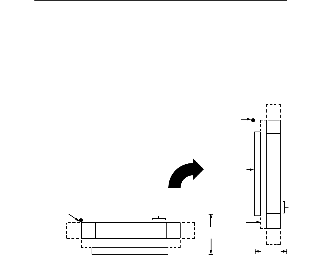
GS1-128
219
GS1-128
NOTE: GS1-128 is formerly known as UCC/EAN-128.
The UCC/EAN-128 structure is shown in Figure 13 and described on the
following pages.
Figure 13. UCC/EAN-128 Structure
UCC/EAN-128 uses the same barcode and character set as Code 128.
However, in UCC/EAN-128, the Function 1 character FNC1 immediately
follows the start code. The FNC1 character has been reserved exclusively for
UCC/EAN-128.
The UCC/EAN-128 data structure requires an Application Identifier (AI) at the
beginning of barcode data. Each AI determines the format and length of the
data which follows. See Table 37 for more detail.
DATA FIELD QUIETQUIET START STOP
LOWER GUARD BAND
CODE CODEZONE ZONE
OPTIONAL READABLE DATA FIELD
HEIGHT
STARTING
POSITION CHECK DIGIT
FIELD
DATA
FIELD
QUIET
ZONE
QUIET
ZONE
STOP
CODE
START
CODE
OPTIONAL
READABLE
DATA
FIELD
HEIGHT
STARTING
POSITION
GUARD
BAND
LOWER
CHECK
DIGIT
FIELD

220
Chapter 3
Barcodes
Table 37. UCC/EAN-128 Application Identifiers
Application
Identifier (AI) Content Format
00 Serial Shipping Container Code n2+n18
02 Item Num. of Goods Within Another Unit n2+n14
10 Batch or Lot Number n2+an..20
11 (*) Production Date (YYMMDD) n2+n6
13 (*) Packaging Date (YYMMDD) n2+n6
15 (*) Sell By Date (Quality) (YYMMDD) n2+n6
17 (*) Expiration Date (Safety) (YYMMDD) n2+n6
20 Product Variant n2+n2
21 Serial Number n2+an..20
22 HIBCC = Quantity, Date, Batch and Link n2+an..29
23 (**) Lot Number (Transitional Use) n3+n..19
240 Additional Product ID Assigned By Manufacturer n3+an..30
250 Secondary Serial Number n3+an..30
30 Quantity n2+n..8
310 (***) Net Weight, Kilograms n4+n6
311 (***) Length or 1st Dimension, Meters n4+n6
312 (***) Width, Diameter or 2nd Dimension, Meters n4+n6
313 (***) Depth, Thickness, Height or 3rd Dimension, Meters n4+n6
314 (***) Area, Square Meters n4+n6
315 (***) Volume, Liters n4+n6
316 (***) Volume, Cubic Meters n4+n6
320 (***) Net Weight, Pounds n4+n6
321 (***) Length Or 1st Dimension, Inches n4+n6
322 (***) Length Or 1st Dimension, Feet n4+n6
323 (***) Length Or 1st Dimension, Yards n4+n6
324 (***) Width, Diameter, or 2nd Dimension, Inches n4+n6
325 (***) Width, Diameter, or 2nd Dimension, Feet n4+n6
326 (***) Width, Diameter, or 2nd Dimension, Yards n4+n6
327 (***) Depth, Thickness, Height, or 3rd Dimension, Inches n4+n6
328 (***) Depth, Thickness, Height, or 3rd Dimension, Feet n4+n6
329 (***) Depth, Thickness, Height, or 3rd Dimension, Yards n4+n6
330 (***) Gross Weight-Kilograms n4+n6
331 (***) Length or 1st Dimension, Logistics n4+n6
332(***) Width, Diameter, or 2nd Dimension, Meters, Logistics n4+n6
333 (***) Depth, Thickness, Height or 3rd Dimension, Meters, Logistics n4+n6
GS1-128
221
334 (***) Area, Square Meters, Logistics n4+n6
335 (***) Gross Volume, Liters n4+n6
336 (***) Gross Volume, Cubic Meters n4+n6
337 (***) Kilograms Per Square Meter n4+n6
340 (***) Gross Weight, Pounds n4+n6
341 (***) Length Or 1st Dimension, Inches, Logistics n4+n6
342 (***) Length Or 1st Dimension, Feet, Logistics n4+n6
343 (***) Length Or 1st Dimension, Yards, Logistics n4+n6
344 (***) Width, Diameter, or 2nd Dimension, Inches, Logistics n4+n6
345 (***) Width, Diameter, or 2nd Dimension, Feet, Logistics n4+n6
346 (***) Width, Diameter, or 2nd Dimension, Yards, Logistics n4+n6
347 (***) Depth, Thickness, Height or 3rd Dimension, Inches, Logistics n4+n6
348 (***) Depth, Thickness, Height or 3rd Dimension, Feet, Logistics n4+n6
349 (***) Depth, Thickness, Height or 3rd Dimension, Yards, Logistics n4+n6
350 (***) Area, Square Inches n4+n6
351 (***) Area, Square Feet n4+n6
352 (***) Area, Square Yards n4+n6
353 (***) Area, Square Inches, Logistics n4+n6
354 (***) Area, Square Feet, Logistics n4+n6
355 (***) Area, Square Yards, Logistics n4+n6
356 (***) Net Weight, Troy Ounce n4+n6
357 (***) Net Volume, Ounces n4+n6
360 (***) Volume, Quarts n4+n6
361 (***) Volume, Gallons n4+n6
362 (***) Gross Volume, Quarts n4+n6
363 (***) Gross Volume, Gallons n4+n6
364 (***) Volume, Cubic Inches n4+n6
365 (***) Volume, Cubic Feet n4+n6
366 (***) Volume, Cubic Yards n4+n6
367 (***) Gross Volume, Cubic Inches n4+n6
368 (***) Gross Volume, Cubic Inches n4+n6
369 (***) Gross Volume, Cubic Inches n4+n6
37 Quantity of Units Contained (For Use With AI 02 Only) n2+n..8
400 Customer's Purchase Order Number n3+an..30
401 Consignment Number n3+an..30
410 Ship To (Deliver To) Location Code Using EAN-13 n3+n13
Table 37. UCC/EAN-128 Application Identifiers (continued)
Application
Identifier (AI) Content Format
222
Chapter 3
Barcodes
(*)To indicate only year and month, DD must be filled with “00”
(**) Plus one digit for length indication
(***) Plus one digit for decimal point indication
Data Value Representation:
a - alphabetic characters n - numeric characters
an - alpha-numeric characters n3 - 3 numeric characters, fixed length
an..3 - up to 3 alpha-numeric characters n..3 - up to 3 numeric characters
411 Bill To (Invoice To) Location Code Using EAN-13 n3+n13
412 Purchase From (Location Code of Party From Whom Goods Are
Purchased)
n3+n13
413 Ship For UCC/EAN Location Code n3+n13
414 EAN Location Code For Physical Identification n3+n13
420 Ship To (Deliver To) Postal Code Within a Single Postal Authority n3+an..20
421 Ship To (Deliver To) Postal Code With 3-Digit ISO Country Code Prefix n3+n3+an..9
8001 Roll Products-Width, Length, Core Diameter, Direction and Splices n4+n14
8003 UPC/EAN Number and Serial Number Or Returnable Asset n4+n14+an..16
8004 UCC/EAN Serial Identification n4+an..30
8005 Identifies the Price Per Unit of Measure n4+n6
8006 Component of an Article n4+n14+n2+n2
8018 Service Relation Number n4+n18
8100 Coupon Extended Code-Number System Character and Offer n4+n1+n5
8101 Coupon Extended Code-Number System Character, Offer and End of Offer n4+n1+n5+n4
8102 Coupon Extended Code-Number System Character Preceded by Zero n4+n1+n1
90 Mutually Agreed, Between Trading Partners n2+an..30
91 Intra-Company (Internal) n2+an..30
92 Intra-Company (Internal) n2+an..30
93 Intra-Company (Internal) n2+an..30
94 Intra-Company (Internal) n2+an..30
95 Internal-Carriers n2+an..30
96 Internal-Carriers n2+an..30
97 Intra-Company (Internal) n2+an..30
98 Intra-Company (Internal) n2+an..30
99 Internal n2+an..30
Table 37. UCC/EAN-128 Application Identifiers (continued)
Application
Identifier (AI) Content Format

GS1-128
223
Quiet Zone
Both ends of the barcode structure require blank quiet zones. The quiet zones
must be at least 0.25 inches wide and completely blank to ensure accurate
reading of the start/stop codes and to prevent adjacent barcodes from
overlapping. You must provide sufficient space on the form for the quiet
zones.
Start/Stop Codes
The start and stop codes identify the leading and trailing ends of the barcode.
UCC/EAN-128 uses unique start codes for character subsets B and C, and a
stop code common to both. An automatic mode switching feature is used to
generate the correct start code based on the first four data field characters.
Data Field
UCC/EAN-128 barcodes require a special character called “Function 1”
(FNC1) to immediately follow the start code. VGL automatically supplies this
character, so it must not be included in the data field by the user.
A character is made up of three bars and three spaces, each varying in width
from 1 through 4 modules, for a total of eleven modules. The number of
modules making up the bars is even. The stop code has four bars and is 13
modules wide.
The character set for UCC/EAN-128 is the same as the character set for Code
128. Refer to the Code 128 Character Set (Table 32). Every character is
interpreted according to the currently active character subset. UCC/EAN-128
uses subset B and subset C only. Subset B, shown in Table 32, includes all
standard alphanumeric keyboard characters, lowercase alphabetical
characters, and special characters. Subset C interprets the characters as
pairs of numbers 00 through 99, along with some special characters, as
shown in Table 32. The start code or subset switch code determines whether
a particular barcode character is decoded as one character or as a pair of
numbers.
Readable Data
The optional printed data field (PDF) provides a human-readable
interpretation of the barcode data. When the printed data field is enabled by
use of the “PDF” parameter, the overall height of the bars is reduced to make
room for a guard band and the human-readable characters. The printed data
field is formatted with spaces or parentheses denoting particular data fields
such as the application identifier. Special characters such as start, stop,
subset switch, modulo-103 check digit, and FNC1 do not appear in the
human-readable data.
Refer to Figure 13. Using Level I syntax ^B (horizontal) or ^C (vertical
clockwise rotation), the readable data appears below the barcode, reading in
the direction of start code towards stop code. Using Level II syntax (^IBARC),
the barcode may be oriented with any of the graphics commands ^M, ^V, ^U,
or ^E; and the human-readable data may be positioned above or below the
bars, still reading in the direction of start code towards stop code.

224
Chapter 3
Barcodes
Modulo-103 Check Digit
A modulo-103 check digit is automatically calculated and inserted in the
barcode symbol immediately in front of the stop code, in the same manner as
the Code 128 barcode. The check digit verifies accurate scanning. The start
code is included in the check digit algorithm. The modulo-103 check digit is
not displayed in the readable data field.
Modulo-10 Data Field Check Digit for SSCC-18 and SCC-14
AI 00 (called the Serial Shipping Container Code, or SSCC-18) takes
eighteen additional numerical data bytes. The last data byte is a modulo-10
check digit on the preceding seventeen data bytes. Counting the two zeros of
the application identifier, the modulo-10 check digit is the twentieth byte in the
data field.
AI 01 (called the Shipping Container Code, or SCC-14) takes fourteen
additional numerical data bytes. The last data byte is a modulo-10 check digit
on the preceding thirteen data bytes. Counting the zero and the one of the
application identifier, the modulo-10 check digit is the sixteenth byte in the
data field.
The modulo-10 data field check digit for both SSCC-18 and SCC-14 is printed
in the barcode as the second half of the last number pair using subset C. It is
displayed in the human-readable data field as the twentieth byte for SSCC-18
or the sixteenth byte for SCC-14.
VGL automatically calculates the modulo-10 check digit for SSCC-18 if only
17 data digits are provided following the application identifier of 00.
UCC/EAN-128 Command Format
NOTE: See page 164 for the IBARC, command format and definitions.
Default Ratio: (cc) dir p q data (cc)G
Variable Ratio: (cc) dir p [9] [:] q [ratio] data (cc)G
(cc) Represents the Special Function Control Code
(SFCC). Enter the specific SFCC for your VGL
configuration.
dir Represents the direction of the barcode. Enter B for
horizontal barcodes; enter C for vertical barcodes.
pPrints the optional readable data field. The
readable data field is printed below a horizontal
barcode or on the left-hand side of a vertical
barcode.
Replace p in the barcode command with one of the
codes listed in Table 38 to print the readable data
field in the corresponding font with the specified
guard band gap.
GS1-128
225
9 or : Selects the variable ratio length barcode feature,
which permits unique bar and space width ratios
adjusted for specific applications.
Enter the number 9 to select variable ratio
barcodes represented in line matrix printer dots (60
x 72 dpi).
Enter : to select variable ratio barcodes
represented in actual printer dots (203 x 203 dpi or
300 x 300 dpi, depending on the printer head being
used).
q The type code for UCC/EAN-128. Enter q.
ratio Optional parameter (used in conjunction with 9 or :
above) representing the ratios for variable ratio
barcodes. Default ratios are overridden by the
variable ratio feature. The ratio data must be
hexadecimal numbers from 0 through 9 or A
through F; VGL automatically checks the input for
validity. If an invalid character is found in the ratio,
an error message is generated.
UCC/EAN-128 barcodes use eight-digit ratios. The
ratios are interpreted from left to right, measuring
the size of each bar or space in dot width, in the
following pattern: 1 module wide bar : 1 module
wide space : 2 module wide bar : 2 module wide
space : 3 module wide bar : 3 module wide space :
4 module wide bar : 4 module wide space. For
example, enter 22446688 in the ratio data field for:
2 module wide bar
2 module wide space
4 module wide bar
4 module wide space
6 module wide bar
6 module wide space
8 module wide bar
8 module wide space
Table 38. Printable Data Field Fonts
Font Gap p code
Standard 10 cpi 3 dots Y
OCR-A 3 dots O
OCR-A .1-inch S
OCR-B 3 dots B
OCR-B .1-inch T
None N

226
Chapter 3
Barcodes
NOTE: VGL automatically checks ratio data for validity only within the
allowable hexadecimal range. VGL does not verify that ratio data
creates acceptable bar/space element relationships for barcode
readability. When designing unique ratio data, carefully plot bar/
space ratios to conform to readable barcodes.
data The barcode data. In the automatic mode,
whenever a string of 4 or more contiguous numeric
digits are detected, VGL inserts a subset C
command at the start of the numeric string. When
the string of numeric digits is broken, VGL inserts a
subset B command. Code 128 encodes from 1
through 40 characters from the character set of the
subset code selected. UCC/EAN-128 must have
exactly 19 digits. Use the appropriate subset code
from the Code 128 Character Set in Table 32.
When data is provided in the manual mode,
readable data field is not printed.
(cc)G Terminates the barcode command. Enter the SFCC
for your VGL configuration immediately followed by
any valid command character or G, the universal
sequence terminator.
UCC/EAN-128 Examples
The following command generates the horizontal default ratio UCC/EAN-128
barcode below. In the command sequence, graphics mode data is italicized
and barcode data is boldface. See Chapter 2 for a detailed description of
alphanumeric commands.
^PY^- ^M10,10,000^BYq0034567890123456789^G^-^PN^-
^PY^- enabled the graphics command sequence.
^M introduced the standard alphanumeric command.
The character height selected was 1.0 inches and character width was
selected at 1.0 inches.
A 0.0 justification value plus 0 additional dots was selected for data
placement.
^B introduced the barcode command.
Y selected printing the optional readable data field.
Letter q selected UCC/EAN-128.
The barcode data is 0034567890123456789.
^G terminated the barcode command sequence.
^PN^- terminated the graphics mode.

GS1-128
227
The following command generated the UCC/EAN-128 barcode below using
variable target dot ratio and data of 0034567890123456789.
^PY^-^M10,10,000^IBARC,UCC128,RD2:4:5:7:8:10:11:13,N,
0034567890123456789^G^-^PN^-
The command below generates the following vertical UCC/EAN-128 barcode
with data of 0034567890123456789.
^PY^-^V05,05,300^IBARC,UCC128,B,0034567890123456789^G-^PN^-
The command below generates the same vertical UCC/EAN-128 barcode
using target dot variable ratios with the Version I syntax.
^PY^-^M10,10,300^CN:q24578ABD0034567890123456789^G-^PN^-

228
Chapter 3
Barcodes
The program below illustrates the use of dynamic forms to generate part of a
shipping form with three UCC/EAN-128 barcodes. An internal code (AI = 91)
is used as a store number, a ship-to-postal (AI = 420) gives the customer ZIP
Code as dynamic data, and a serial shipping container code (AI = 00) is also
given as dynamic data. In this example, since the application identifiers are
known, they are given as static data, and only the data field for each variable
AI is made dynamic. The ship-to-postal takes a five digit ZIP Code; the SSCC-
18 takes seventeen digits with VGL creating the modulo-10 data field check
digit automatically.
^PY^-^F^-
^B^-
^M0101000
^X titles using compressed print ^A
^T0010^J000^S4SHIP TO POSTAL CODE
^T0010^J170^S4STORE
^T0010^J340^S4SSCC-18
^X EAN/UCC 128 barcodes ^A
^M0808^T0030^J020^KF^BYq420^[005^G^KF
^M0808^T0030^J190^KF^BYq911528^G^KF
^M1208^T0030^J360^KF^BYq00^[017^G^KF
^-
^,^-
^]
92614
34567890123456789
^G^-
^,^-
^O^-^PN^-
UCC 128.ex4
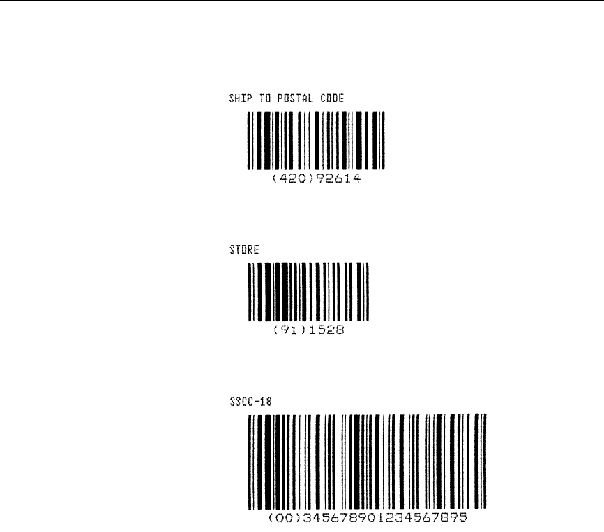
GS1-128
229

230
Chapter 3
Barcodes
GS-1 Data Matrix
NOTE: GS-1 Datamatrix is formerly known as Datamatrix.
Data Matrix is a two-dimensional barcode containing small dark and light
square data modules. It has a finder pattern of two solid lines and two
alternating dark and light lines on its perimeter. This barcode is capable of
storing up to 3116 numeric digits or 2335 alphanumeric characters in a
symbol 144 modules square. It is also capable of encoding in a number of
different schemes.
Two main subsets for Data Matrix exist, which differ in terms of error
correction. The first subset uses ECC-000 through ECC-140 and uses
convolution coding for error correction. The second subset is ECC-200, which
uses Reed-Solomon error correction techniques. ECC-200 format is
recommended.
Quiet Zone
The minimum quiet zone is one module width on all four sides.
Readable Data
There is no printable data field allowed for the Data Matrix barcode.
Data Field
The data allowed within the data field depends on the error correction subset
you are using. See the data description on page 231 for details.
Data Matrix Command Format
Default Ratio: (cc) dir N M [X[D]n] [Cn] [Rn] [En] [In], data (cc)G
(cc) Represents the Special Function Control Code
(SFCC). Enter the specific SFCC for your VGL
configuration.
dir Represents the direction of the barcode. Enter B for
horizontal barcodes; enter C for vertical barcodes.
NEnter N to turn off the readable data field.
M The Data Matrix type code. Enter M.
X[D]nOptional parameter which designates the x-
dimension width of a single square data module in
dots (60 x 72 dpi), or printer dots if the D parameter
is used. For n, enter a value from 1 through 255 to
represent the dot number.
CnOptional parameter that sets the number of
columns in the symbol. A value of 0 (the default)
automates this process. See Table 42 through
Table 48 for the combination of columns and rows
allowed and the maximum amount of data that can
be encoded.

GS-1 Data Matrix
231
RnOptional parameter that specifies the number of
rows in the symbol. A value of 0 (the default)
automates this process. See Table 42 through
Table 48 for the combination of columns and rows
allowed and the maximum amount of data that can
be encoded.
EnOptional parameter that specifies the error
correction level. Enter E, then one of the following
values: 0, 50, 80, 100, 140, or 200. Levels 0
through 140 use increasing levels of convolutional
error coding. Level 200 (the default) uses Reed-
Solomon block error correction and is the
recommended level of error correction.
InOptional parameter that specifies the format ID.
This field only has meaning for ECC-000 through
ECC-140 and is ignored for ECC-200. This
specifies the type of data that is encoded in the
symbol. Enter I, then a value from 1 through 6. The
default value is 3. Table 39 shows the type of data
encoded for the various format IDs.
, Enter a comma (,) to separate the data field from
the previous field. The comma is required.
data For ECC-000 through ECC-140, the data allowed
within the data field depends on the format ID
parameter. The allowed data for these ECC types
are given in Table 39. For Format ID #5 which
accepts control characters and Format ID #6 which
accepts codes greater than 127, you can enter
these values using a SO character followed by an
identifier. When encoding special characters, you
must enter a SO character followed by at least one
other identifier and its field (i.e., ASCII 254 =
^d254). This is only considered to be one
character, even though the data field holds 5
characters (^d254). If you intend to code the SO
character by itself (no special encoding), then the
SO character should be followed by another SO
character. Table 40 illustrates how to use these
special characters.
232
Chapter 3
Barcodes
For ECC-200, format ID has no meaning and is
ignored. Instead, you can enter data of any type
(ASCII 0-255) and it will be automatically optimized
into the proper encoding scheme. See the “Special
Characters Using SO” section for examples of
methods to enter special characters such as FNC1
into the data stream.
The maximum number of data depend on three
factors: (1) size of the matrix, (2) ECC level, and (3)
type of data. The size of the matrix is automatically
chosen by VGL unless the parameters of row and/
or column are supplied (see Cn and Rn
parameters). The maximum number of data can
then be found by finding the proper table based on
ECC type. For each different valid matrix
combination, the maximum number of data are
given for numeric, alphanumeric, and full 8-byte
data. You do not have to enter the maximum; a pad
character is automatically inserted into the barcode
when necessary.
(cc)G Terminates the barcode command. Enter the SFCC
for your VGL configuration followed by any valid
command character or G, the universal sequence
terminator.
Table 39. Data Field for ECC-000 through ECC-140
Format ID # Data
1Numeric 0-9, Space
2Uppercase A-Z, Space
3Uppercase A-Z, Numeric 0-9, Space
4Uppercase A-Z, Numeric 0-9, Space, Period, Comma,
Minus, Forward Slash
5Full 128 ASCII set (0-127)
6User defined (0-255)
GS-1 Data Matrix
233
Special Characters Using SO
Table 40 and Table 41 illustrate the methods of encoding special characters,
and shows the special characters supported. These special characters are
identified by using SO. The default value for the SO character is hex 0E, but
this value can be changed using the printer's front panel (see User's Manual
for details). Examples are given with the SO character represented by “^” for
clarity.
Table 40. Special Character Encoding (All ECC Levels)
Special Characters Method Example
Control Characters 0-31 <SO> + @ ... <SO> + _NUL = ^@, BEL = ^G
Any ASCII value 0 - 255 <SO> + d + 3 digit ASCII 10 = ^d010
ASCII value SO <SO> + <SO> ^^
Table 41. Special Character Encoding (ECC-200 Only)
Special Characters Method Example
FNC1 <SO> + 1. If FNC1 is 2nd
codeword, previous data must be
A-Z, a-z, or 01-99
01^1<Data>
Structured Append <SO> + 2 + 3 digit number
representing symbol sequence
and file identifier
^2042<File ID>
Reader Programming <SO> + 3
Must be first in the data field
^3<Data>
MH10.8.3 Abbreviated
Format 05 Header
<SO> + 5
Must be first in the data field
^5<Data>
MH10.8.3 Abbreviated
Format 06 Header
<SO> + 6
Must be first in the data field
^6<Data>
Extended Channel
Interpretation
<SO> + 7 + 6 digit EC
(000000-999999)
^7112233<Data>
234
Chapter 3
Barcodes
Symbol Characteristics
The following tables illustrate the maximum data capacities for the Data
Matrix barcode as a function of symbol size (column x row) and data type.
Note that all ECC-000 through ECC-140 symbols are square and always have
an odd number of rows and columns. ECC-200 symbols have square or
rectangular sizes and have an even number of rows and columns.
Table 42. ECC-000 Characteristics
(Row x Column) Maximum
Numeric Maximum
Alphanumeric Maximum 8-Byte
Data
9 X 9 3 characters 2 characters 1 character
11 X 11 12 characters 8 characters 5 characters
13 X 13 24 characters 16 characters 10 characters
15 X 15 37 characters 25 characters 16 characters
17 X 17 53 characters 35 characters 23 characters
19 X 19 72 characters 48 characters 31 characters
21 X 21 92 characters 61 characters 40 characters
23 X 23 115 characters 76 characters 50 characters
25 X 25 140 characters 93 characters 61 characters
27 X 27 168 characters 112 characters 73 characters
29 X 29 197 characters 131 characters 86 characters
31 X 31 229 characters 153 characters 100 characters
33 X 33 264 characters 176 characters 115 characters
35 X 35 300 characters 200 characters 131 characters
37 X 37 339 characters 226 characters 148 characters
39 X 39 380 characters 253 characters 166 characters
41 X 41 424 characters 282 characters 185 characters
43 X 43 469 characters 313 characters 205 characters
45 X 45 500 characters 345 characters 226 characters
47 X 47 560 characters 378 characters 248 characters
49 X 49 596 characters 413 characters 271 characters
GS-1 Data Matrix
235
Table 43. ECC-050 Characteristics
(Row x Column) Maximum
Numeric Maximum
Alphanumeric Maximum 8-Byte
Data
11 X 11 1 character 1 character not supported
13 X 13 10 characters 6 characters 4 characters
15 X 15 20 characters 13 characters 9 characters
17 X 17 32 characters 21 characters 14 characters
19 X 19 46 characters 30 characters 20 characters
21 X 21 61 characters 41 characters 27 characters
23 X 23 78 characters 52 characters 34 characters
25 X 25 97 characters 65 characters 42 characters
27 X 27 118 characters 78 characters 51 characters
29 X 29 140 characters 93 characters 61 characters
31 X 31 164 characters 109 characters 72 characters
33 X 33 190 characters 126 characters 83 characters
35 X 35 217 characters 145 characters 95 characters
37 X 37 246 characters 164 characters 108 characters
39 X 39 277 characters 185 characters 121 characters
41 X 41 310 characters 206 characters 135 characters
43 X 43 344 characters 229 characters 150 characters
45 X 45 380 characters 253 characters 166 characters
47 X 47 418 characters 278 characters 183 characters
49 X 49 457 characters 305 characters 200 characters
Table 44. ECC-080 Characteristics
(Row x Column) Maximum
Numeric Maximum
Alphanumeric Maximum 8-Byte
Data
13 X 13 4 characters 3 characters 2 characters
15 X 15 13 characters 9 characters 6 characters
17 X 17 24 characters 16 characters 10 characters
19 X 19 36 characters 24 characters 16 characters
21 X 21 50 characters 33 characters 22 characters
23 X 23 65 characters 43 characters 28 characters
25 X 25 82 characters 54 characters 36 characters
27 X 27 100 characters 67 characters 44 characters
29 X 29 120 characters 80 characters 52 characters
31 X 31 141 characters 94 characters 62 characters
33 X 33 164 characters 109 characters 72 characters
35 X 35 188 characters 125 characters 82 characters
37 X 37 214 characters 143 characters 94 characters
39 X 39 242 characters 161 characters 106 characters
41 X 41 270 characters 180 characters 118 characters
43 X 43 301 characters 201 characters 132 characters
45 X 45 333 characters 222 characters 146 characters
47 X 47 366 characters 244 characters 160 characters
49 X 49 402 characters 268 characters 176 characters

236
Chapter 3
Barcodes
Table 45. ECC-100 Characteristics
(Row x Column) Maximum
Numeric Maximum
Alphanumeric Maximum 8-Byte
Data
13 X 13 1 character 1 character not supported
15 X 15 8 characters 5 characters 3 characters
17 X 17 16 characters 11 characters 7 characters
19 X 19 25 characters 17 characters 11 characters
21 X 21 36 characters 24 characters 15 characters
23 X 23 47 characters 31 characters 20 characters
25 X 25 60 characters 40 characters 26 characters
27 X 27 73 characters 49 characters 32 characters
29 X 29 88 characters 59 characters 38 characters
31 X 31 104 characters 69 characters 62 characters
33 X 33 121 characters 81 characters 53 characters
35 X 35 140 characters 93 characters 61 characters
37 X 37 159 characters 106 characters 69 characters
39 X 39 180 characters 120 characters 78 characters
41 X 41 201 characters 134 characters 88 characters
43 X 43 224 characters 149 characters 98 characters
45 X 45 248 characters 165 characters 108 characters
47 X 47 273 characters 182 characters 119 characters
49 X 49 300 characters 200 characters 131 characters
Table 46. ECC-140 Characteristics
(Row x Column) Maximum
Numeric Maximum
Alphanumeric Maximum 8-Byte
Data
17 X 17 2 characters 1 character 1 character
19 X 19 6 characters 4 characters 3 characters
21 X 21 12 characters 8 characters 5 characters
23 X 23 17 characters 11 characters 7 characters
25 X 25 24 characters 16 characters 10 characters
27 X 27 30 characters 20 characters 13 characters
29 X 29 38 characters 25 characters 16 characters
31 X 31 46 characters 30 characters 20 characters
33 X 33 54 characters 36 characters 24 characters
35 X 35 64 characters 42 characters 28 characters
37 X 37 73 characters 49 characters 32 characters
39 X 39 84 characters 56 characters 36 characters
41 X 41 94 characters 63 characters 41 characters
43 X 43 106 characters 70 characters 46 characters
45 X 45 118 characters 78 characters 51 characters
47 X 47 130 characters 87 characters 57 characters
49 X 49 144 characters 96 characters 63 characters
GS-1 Data Matrix
237
Table 47. ECC-200 Square Characteristics
(Row x Column) Maximum
Numeric Maximum
Alphanumeric Maximum 8-Byte
Data
10 X 10 6 characters 3 characters 1 character
12 X 12 10 characters 6 characters 3 characters
14 X 14 16 characters 10 characters 6 characters
16 X 16 24 characters 16 characters 10 characters
18 X 18 36 characters 25 characters 16 characters
20 X 20 44 characters 31 characters 20 characters
22 X 22 60 characters 43 characters 28 characters
24 X 24 72 characters 52 characters 34 characters
26 X 26 88 characters 64 characters 42 characters
32 X 32 124 characters 91 characters 60 characters
36 X 36 172 characters 127 characters 84 characters
40 X 40 228 characters 169 characters 112 characters
44 X 44 288 characters 214 characters 142 characters
48 X 48 348 characters 259 characters 172 characters
52 X 52 408 characters 304 characters 202 characters
64 X 64 560 characters 418 characters 278 characters
72 X 72 736 characters 550 characters 366 characters
80 X 80 912 characters 682 characters 454 characters
88 X 88 1152 characters 862 characters 574 characters
96 X 96 1392 characters 1042 characters 694 characters
104 X 104 1632 characters 1222 characters 814 characters
120 X 120 2100 characters 1573 characters 1048 characters
132 X 132 2608 characters 1954 characters 1302 characters
144 X 144 3116 characters 2335 characters 1556 characters
Table 48. ECC-200 Rectangular Characteristics
(Row x Column) Maximum
Numeric Maximum
Alphanumeric Maximum 8-Byte
Data
8 X 18 10 characters 6 characters 3 characters
8 X 32 20 characters 13 characters 8 characters
12 X 26 32 characters 22 characters 14 characters
12 X 36 44 characters 31 characters 20 characters
16 X 36 64 characters 46 characters 30 characters
16 X 48 98 characters 72 characters 47 characters

238
Chapter 3
Barcodes
Data Matrix Example
The following commands generated the Data Matrix barcodes shown below.
In the command sequence, graphics mode data is italicized, and barcode
data is boldface. See Chapter 2 for a detailed description of alphanumeric
commands.
^PY^-^M01,01,010^KF^BNMXD8C36R12E200I5,0123456789^G^KF^-^PN^-
^PY^- enabled the graphics command sequence.
^M introduced the standard alphanumeric command.
The character height selected was 0.1 inches and character width was
selected at 0.1 inches.
A 0.1 justification value plus 0 additional dots was selected for data
placement.
^KF activated Dark Print.
^B introduced the barcode command.
N deselected printing the readable data field.
Letter M selected the Data Matrix barcode.
XD8 designates the x-dimension width of a single square module as 8 printer
dots.
C36 sets the number of columns in the symbol at 36.
R12 sets the number of rows in the symbol at 12.
E200 sets the error correction level at ECC-200.
I5 set the format ID. This value is ignored with the ECC-200 error correction
level set.
, (comma) separates the previous information from the data field.
0123456789 is the barcode data.
^G terminated the barcode command sequence.
^KF^- at the end of the barcode sequence turned off Dark Print.
^PN^- terminated the graphics mode.
^PY^-^M01,01,010^KF^BNM,0123456789^G^KF^-^PN^-
^M0101010^KF^IBARC,DATAMATRIX,XD8,C36,R12,E140,I5,N,A1B2C3D4E5F
6G7H8I9J0K12^G^KF^-
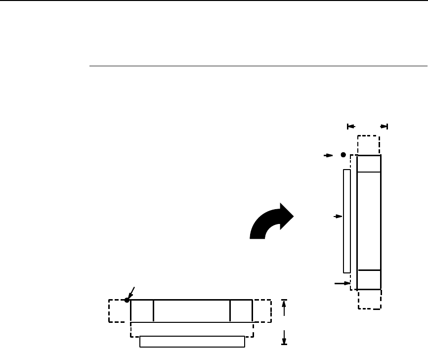
Identicon
239
Identicon
The Identicon barcode structure is shown in Figure 14 and described on
following pages.
Figure 14. Identicon Structure
Quiet Zone
Quiet zones extend on both ends of the barcode to permit the scan to begin
and end in a blank area. The quiet zone should be at least 0.25 inch wide and
completely blank.
Start/Stop Codes
The Start/Stop codes identify the leading and trailing end of the barcode. The
Start/Stop code is automatically produced with each barcode.
Data Field
The barcode symbol uses a series of wide and narrow bars to represent the
10 numeric characters (0 - 9) and Start/Stop codes. All the information is
contained in the width of the bars, the spaces serving only to separate the
individual bars. The wide bars are conventionally three times the widths of the
narrow bars. The spaces may be any reasonable width but are typically equal
to the narrow bars. The barcode can encode up to 40 numbers. Each data
character is represented by 5 bars separated by spaces. There must be two
wide bars among the 5 bars. See Table 49 for symbol coding.
DATA FIELD QUIETQUIET START STOP
LOWER GUARD BAND
CODE CODEZONE ZONE
OPTIONAL READABLE DATA FIELD
HEIGHT
STARTING
DATA
FIELD
QUIET
ZONE
STOP
CODE
START
CODE
OPTIONAL
READABLE
DATA
FIELD
HEIGHT
STARTING
GUARD
BAND
LOWER
POSITION
POSITION
QUIET
ZONE
240
Chapter 3
Barcodes
Readable Data
barcode data is printed below the horizontal barcode and to the left of the
vertical barcodes. The lower guard band is provided when the readable data
filed is selected.
Identicon Command Format
NOTE: See page 164 for the IBARC, command format and definitions.
Default Ratio: (cc) dir p E data (cc)G
Variable Ratio: (cc) dir p [9] [:] E [ratio] data (cc)G
(cc) Represents the Special Function Control Code
(SFCC). Enter the specific SFCC for your VGL
configuration.
dir Represents the direction of the barcode. Enter B for
horizontal barcodes; enter C for vertical barcodes.
pPrints the optional readable data field. The
readable data field is printed below a horizontal
barcode or on the left-hand side of a vertical
barcode.
Replace p in the barcode command with one of the
codes listed in Table 50 to print the readable data
field in the corresponding font with the specified
guard band gap.
Table 49. Identicon Symbol Coding
Character Code
000110
110001
201001
311000
400101
510100
601100
700011
810010
901010
Start 110
Stop 101

Identicon
241
9 or : Selects the variable ratio length barcode feature,
which permits unique bar and space width ratios
adjusted for specific applications.
Enter the number 9 to select variable ratio
barcodes represented in line matrix printer dots (60
x 72 dpi).
Enter : to select variable ratio barcodes
represented in actual printer dots (203 x 203 dpi or
300 x 300 dpi, depending on the printer head being
used).
E The type code for IDENTICON. Enter E.
ratio Optional parameter (used in conjunction with 9 or :
above) representing the ratios for variable ratio
barcodes. Default ratios are overridden by the
variable ratio feature. The ratio data must be
hexadecimal numbers from 0 through 9 or A
through F. VGL automatically checks the input for
validity. If an invalid character is found in the ratio,
an error message is generated.
NOTE: VGL automatically checks ratio data for validity only within the
allowable hexadecimal range. VGL does not verify that ratio data
creates acceptable wide/narrow element relationships for barcode
readability. For example, VGL accepts wide/narrow ratio values of 2
and 5, respectively; however a narrow element larger than the wide
element produces an unreadable barcode. When designing unique
ratio data, carefully plot wide and narrow ratios to conform to
readable barcodes.
data The barcode data. IDENTICON encodes from 1
through 40 characters. The characters available for
the data field are 0 through 9 (hex 30 through 39).
(cc)G Terminates the barcode command. Enter the SFCC
for your VGL configuration immediately followed by
any valid command character or G, the universal
sequence terminator.
Table 50. Printable Data Field Fonts
Font Gap p code
Standard 10 cpi 3 dots Y
OCR-A 3 dots O
OCR-A .1-inch S
OCR-B 3 dots B
OCR-B .1-inch T
None N

242
Chapter 3
Barcodes
Intelligent Mail 4-State Barcode
Intelligent Mail 4-state is a barcode symbology, introduced by USPS to
support the US Mail 4-state customer barcode. It is also known as the USPS
OneCode Solution or USPS 4-State Customer Barcode. This barcode is
identified by four different types of bars:
•
Full Height - fixed height
•
Tracker - a small center section
•
Ascender - extends from the top of the Full Height limit to the bottom of
the Tracker limit.
•
Descender - extends from the top of the Tracker Limit to the bottom of
the Full Height limit.
Figure 15. Intelligent Mail Barcode Bar Types
Customer Data must be in numeric format only. PDF is not allowed for
Intelligent Mail Barcode.
Additional information regarding use of this barcode can be obtained from the
USPS publication Intelligent Mail Barcode Technical Resource Guide.
Intelligent Mail Command Format
Default Ratio: (cc) dir N j data (cc)G
(cc) Represents the Special Function Control Code
(SFCC). Enter the specific SFCC for your VGL
configuration.
Dir Represents the direction of the barcode. Enter B for
horizontal barcodes. Enter C for vertical barcodes.
N Turns off the readable data field. Enter N.
j The type code for Intelligent Mail. Enter j.
Ascending
Region
Tracking
Region
Descending
Region
Full Bar Ascender Tracker Descender
Intelligent Mail 4-State Barcode
243
data The barcode data. The table later in this section
shows the valid parameters for the all the fields.
The Tracking Code is 20 digits in length. The
Routing Code is optional, but if it is included, it must
be 5, 9 or 11 digits in length. The minimum total
input data is 20 and the maximum total input data is
31 numeric digits. VGL encodes any length of input
data within this range into a 4-state customer
barcode string consisting of 65 bars. A check digit
is automatically added by VGL.
(cc)G Terminates the barcode command. Enter the SFCC
for your VGL configuration immediately followed by
any valid command character or G, the universal
sequence terminator.
Intelligent Mail 4-State Barcode Example
The following command generates the horizontal Intelligent Mail barcode
shown below. In the command sequence, graphics mode data is italicized and
barcode data is boldface. See Chapter 2 for a detailed description of
alphanumeric commands.
^PY^-^M10,10,000^KF^BNj01234567094987654321012345678^G^KF^-
^PN^-
Table 51. Data Field Parameters
Type Field Digits
Tracking
Code
Barcode Identifier 2
Second digit must be 0 - 4.
Service Type Identifier 3
Mailer Identifier 6 or 9
Serial Number 9 when Mailer ID is 6 digits
6 when Mailer ID is 9 digits
Routing Code Delivery Point Zip Code 0, 5, 9, 11
Total 20 minimum, 31 maximum

244
Chapter 3
Barcodes
Interleaved 2/5
The Interleaved 2/5 barcode structure is shown in Figure 16 and described on
following pages.
Figure 16. Interleaved 2/5 Structure
Quiet Zone
Both ends of the barcode structure have blank quiet zones. The quiet zones
should be at least 0.25 inches wide and completely blank to ensure accurate
reading of the start/stop codes and to prevent adjacent barcodes from
overlapping. You are responsible for providing sufficient space on the form for
the quiet zones.
Start/Stop Codes
Unique start and stop codes permit bidirectional scanning. Both start and stop
codes contain bars and spaces. They are automatically produced.
Data Field
The barcode symbol uses a series of wide and narrow bars and spaces to
represent numeric characters. The structure is 2 wide elements (bars or
spaces) and 3 narrow elements. In the barcode, two characters are
interleaved (paired); bars are used to represent data characters occupying
the odd-numbered positions, and spaces are used to represent data
characters occupying the even-numbered positions. The interleaving process
requires an even number of characters; if an odd number of characters are
encoded, a leading zero is automatically inserted to change the number of
characters to an even number.
DATA FIELD
QUIETQUIET START STOP
LOWER GUARD BAND
CODE CODEZONE ZONE
OPTIONAL READABLE DATA FIELD
HEIGHT
STARTING
DATA
FIELD
QUIET
ZONE
STOP
CODE
START
CODE
OPTIONAL
READABLE
DATA
FIELD
HEIGHT
STARTING
GUARD
BAND
LOWER
CHECK
OPTIONAL
DIGIT
POSITION
POSITION
CHECK DIGIT
OPTIONAL
QUIET
ZONE
Interleaved 2/5
245
Readable Data
The optional readable data field provides a readable interpretation of the
barcode data. barcode data is printed below the horizontal barcode symbol
and to the left of a vertical barcode symbol. The lower guard band is provided
when the readable data field is selected.
Check Digit
An optional check digit is inserted for type k and l barcodes. The optional
check digit is automatically calculated and inserted in the barcode symbol.
The check digit provides the means to verify accurate scanning.
Interleaved 2/5 Command Format
NOTE: See page 164 for the IBARC, command format and definitions.
Default Ratio: (cc) dir p type data (cc)G
Variable Ratio: (cc) dir p [9] [:] type [ratio] data (cc)G
(cc) Represents the Special Function Control Code
(SFCC). Enter the specific SFCC for your VGL
configuration.
dir Represents the direction of the barcode. Enter B for
horizontal barcodes; enter C for vertical barcodes.
pPrints the optional readable data field. The
readable data field is printed below a horizontal
barcode or on the left-hand side of a vertical
barcode.
Replace p in the barcode command with one of the
codes listed in Table 52 to print the readable data
field in the corresponding font with the specified
guard band gap.
Table 52. Printable Data Field Fonts
Font Gap p code
Standard 10 cpi 3 dots Y
OCR-A 3 dots O
OCR-A .1-inch S
OCR-B 3 dots B
OCR-B .1-inch T
None N

246
Chapter 3
Barcodes
9 or : Selects the variable ratio length barcode feature,
which permits unique bar and space width ratios
adjusted for specific applications.
Enter the number 9 to select variable ratio
barcodes represented in line matrix printer dots (60
x 72 dpi).
Enter : to select variable ratio barcodes
represented in actual printer dots (203 x 203 dpi or
300 x 300 dpi, depending on the printer head being
used).
type Represents the barcode type. Select one of the
I-2/5 barcode type codes shown in Table 53.
ratio Optional parameter (used in conjunction with 9 or :
above) representing the ratios for variable ratio
barcodes. Default ratios are overridden by the
variable ratio feature. The ratio data must be
hexadecimal numbers from 0 through 9 or A
through F. VGL automatically checks the input for
validity. If an invalid character is found in the ratio,
an error message is generated.
Interleaved 2/5 barcodes use four-digit ratios. The
ratios are interpreted from left to right, measuring
the size of each bar or space, in dot width, in the
following pattern: narrow bar : narrow space : wide
bar : wide space. For example, enter 2266 in the
ratio parameter for:
2 dot-wide narrow bar
2 dot-wide narrow space
6 dot-wide wide bar
6 dot-wide wide space
Table 53. Interleaved 2/5 Barcodes
Standard
Type Code IBARC,
Type Code # of Data
Characters Check
Digits
Default Bar/
Space
Ratios*
KINT2/5 1-40 None 1:1:3:3
kINT2/5CD 1-40 Mod 10 1:1:3:3
LINT2/5A 1-40 None 1:2:4:5
lINT2/5CDA 1-40 Mod 10 1:2:4:5
*Ratios represent dot width of the bar/space elements as follows:
Narrow Bar : Narrow Space : Wide Bar : Wide Space.

Interleaved 2/5
247
NOTE: VGL automatically checks ratio data for validity only within the
allowable hexadecimal range. VGL does not verify that ratio data
creates acceptable wide/narrow element relationships for barcode
readability. For example, VGL accepts wide/narrow ratio values of 2
and 5, respectively; however a narrow element larger than the wide
element produces an unreadable barcode. When designing unique
ratio data, carefully plot wide and narrow ratios to conform to
readable barcodes.
data The barcode data. Interleaved 2/5 encodes from 1
through 40 characters. The characters available for
the data field are 0 through 9 (hex 30 through 39). If
an odd number of characters are encoded, a
leading zero is automatically inserted in the data
field to change the number of characters to an even
number.
(cc)G Terminates the barcode command. Enter the SFCC
for your VGL configuration immediately followed by
any valid command character or G, the universal
sequence terminator.
Interleaved 2/5 Examples
The following command generates the horizontal default ratio Interleaved 2/5
barcode shown below. In the command sequence, graphics mode data is
italicized and barcode data is boldface. See Chapter 2 for a detailed
description of alphanumeric commands.
^PY^-^M10,10,000^KF^BYK2244595^G^KF^-^PN^-
^PY^- enabled the graphics command sequence.
^M introduced the standard alphanumeric command.
The character height selected was 1.0 inches and character width was
selected at 1.0 inches.
A 0.0 justification value plus 0 additional dots was selected for data
placement.
^KF activated Dark Print. ^B introduced the barcode command.
Y selected the standard 10 cpi font to print the optional readable data field.
Letter K selected Interleaved 2/5 with the default 1:1:3:3 ratio.
2244595 is the barcode data.
^G terminated the barcode command sequence.
^KF^- at the end of the barcode sequence turned off Dark Print.
^PN^- terminated the graphics mode.
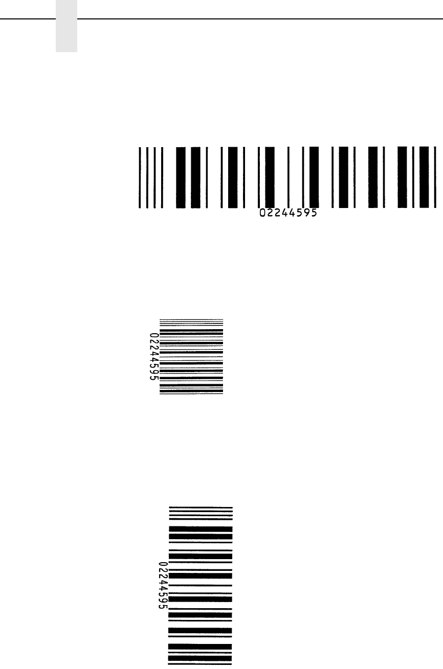
248
Chapter 3
Barcodes
The following command generated the Interleaved 2/5 barcode below using
OCR-B font, double the default ratio, and data of 2244595:
^PY^-^M10,10,000^KF^BB9L248A2244595^G^KF^-^PN^-
The following command generates the vertical Interleaved 2/5 barcode below
using standard 10 cpi font with the standard default ratio and data of 2244595:
^PY^-^M10,10,000^KF^CYK2244595^G^KF^PN^-
The following command generates the same vertical Interleaved 2/5 barcode
above, except that double the default ratio is used:
^PY^-^M10,10,000^KF^CY9K22662244595^G^KF^-^PN^-
i
25.
ex3

Maxicode
249
Maxicode
The Maxicode barcode is a fixed size matrix symbology made up of an offset
of rows of hexagonal elements arranged around a unique finder pattern.
Maxicode is suitable for high speed scanning applications, and is capable of
encoding all of the 256 ASCII characters.
Readable Data
The Maxicode barcode does not support a human readable form.
Data Field
The data field of a Maxicode barcode is divided into a primary message and a
secondary message. The primary message has a fixed structure, while the
secondary message has a free format. The maximum number of characters
encoded in the message depends on the error correction mechanism used.
When the Standard Error Correction (SEC) method is in use (see the mode
definition, below) a maximum of 84 symbol characters can be encoded. Each
segment in the secondary message is 21 characters long.
Maxicode Command Format
Default Ratio: (cc) dir N % [Z] mode data (cc)G
(cc) Represents the Special Function Control Code
(SFCC). Enter the specific SFCC for your VGL
configuration.
dir Represents the direction of the barcode. Enter B for
horizontal barcodes, C for vertical barcodes.
NEnter N to turn off the readable data field.
% Represents the Maxicode barcode type. Enter %.
Z Optional parameter to print the zipper. Enter Z to
exercise this option.
mode Represents the desired Maxicode mode. The legal
modes are 2, 3, 4, and 6. If mode 0 is entered, it is
converted to mode 2 or 3 depending on the postal
code. If mode 1 is entered, it is converted to mode
4. All other modes cause an error to be reported.
Table 54 defines the modes supported.
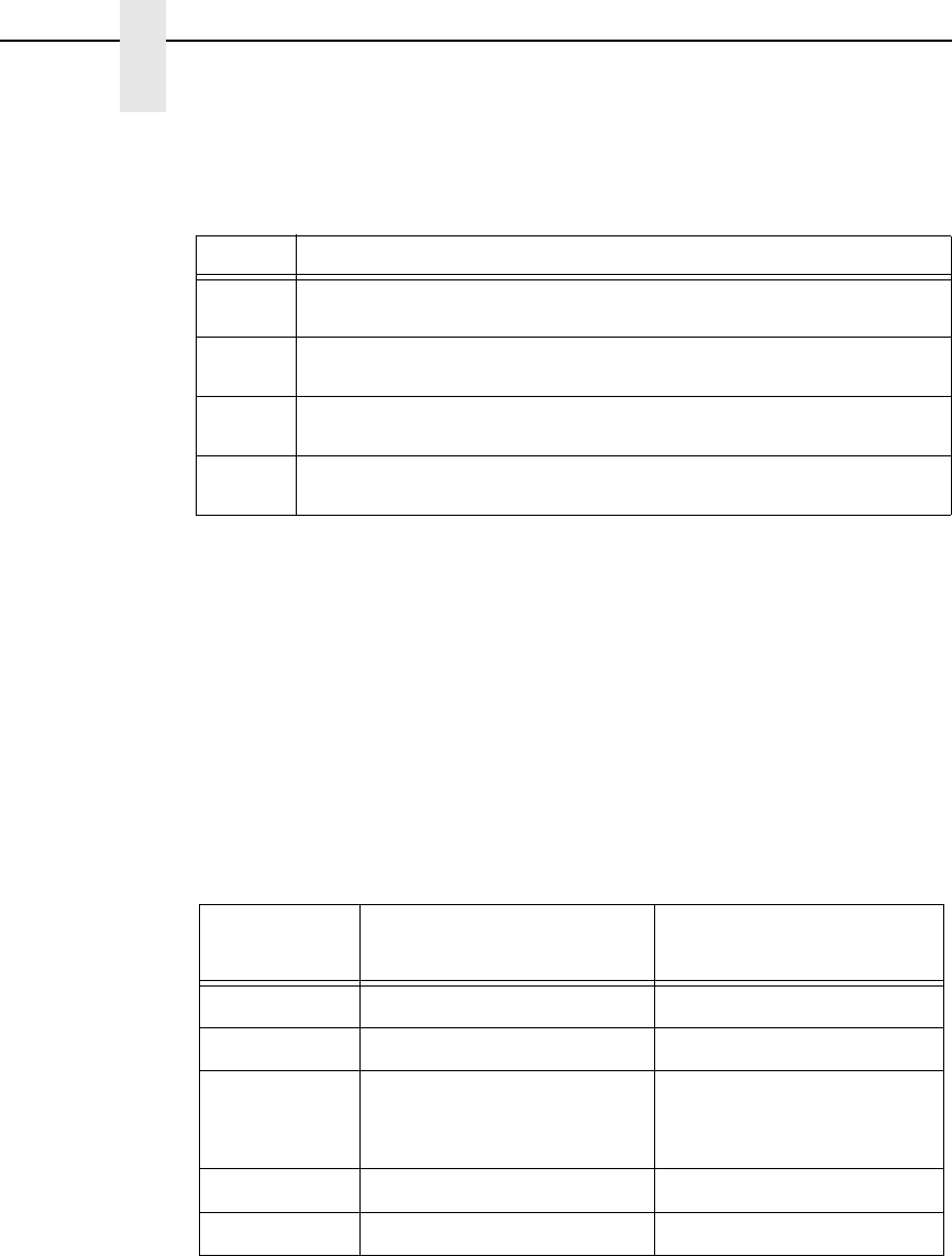
250
Chapter 3
Barcodes
data Represents the data to be barcoded. There are two
different ways the Maxicode data field can be
formatted: Standard Data Field and UPS Shipping
Data Field.
Standard Data Field
Modes 2 and 3 have their primary message structured as shown in Table 55.
The data following the primary message is the secondary message and has a
free format.
Table 54. Maxicode Barcode Mode
Mode Definition
2Primary and secondary messages employ SEC. Primary message
is a structured carrier message with a numeric postal code.
3Primary and secondary messages employ SEC. Primary message
is a structured carrier message with an alphanumeric postal code.
4Primary and secondary messages together encode up to 93
characters.
6Primary and secondary messages together encode up to 93
characters. For reader configuration purposes only.
Table 55. Standard Data Fields
Character
Positions Title Data
0 - 2 Class of Service Numeric
3 - 5 Country Code Numeric
6 - 14 Postal Code 9 Digit Numeric for US or
6 Digit Alphanumeric for
Canada
15, 16 Separator '>A'
17 - ... Secondary Message Free Format
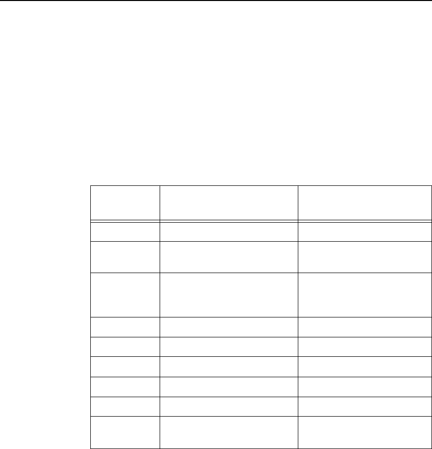
Maxicode
251
UPS Shipping Data Field
This syntax begins with seven encoded data characters followed by a date
(yy). The first four characters are the Message Header and the next five are
the Transportation Data Format Header. The format of the Message Header
is “[)>Rs”. The Transportation Data Format Header is “01Gsyy” where yy is
the year, and “G's” and “R's” are control characters. The structure is shown in
Table 56.
(cc)G Terminates the barcode command. Enter the SFCC
for your VGL configuration followed by any valid
command character or G, the universal sequence
terminator.
Table 56. UPS Shipping Data Fields
Character
Positions Title Data
0 - 3 Message Header [)>Rs
4 - 8 Transportation Data Format
Header
01Gsyy
9 - 17 Postal Code 9 Digit Numeric for US or
6 Digit Alphanumeric for
Canada
18 Separator Gs
19 - 21 Country Code Numeric
22 Separator Gs
23 - 25 Class of Service Numeric
26 Separator Gs
27 - ... Secondary Message As per the UPS Guide To
Barcoding
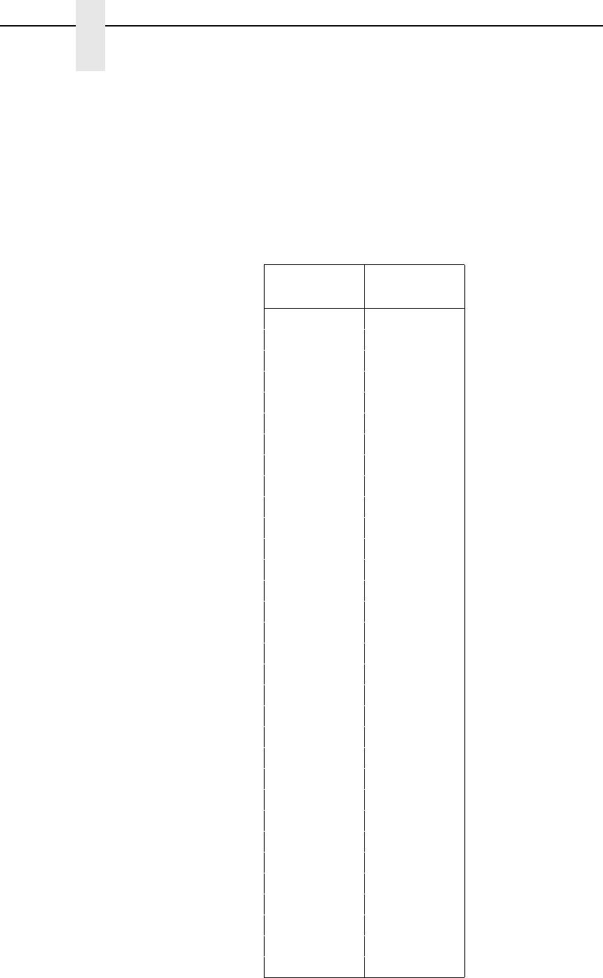
252
Chapter 3
Barcodes
Maxicode Control Characters
The non-printable control characters can be generated by using the switch
characters defined in Table 57.
NOTE: If a “>” has to be part of the data stream, enter the character twice.
NOTE: <pp> = Shift Out Character
Table 57. Maxicode Control Characters
Control
Characters Alternate
Characters
NUL <pp>SP
SOH <pp>!
STX <pp>"
ETX <pp>#
EOT <pp>$
ENQ <pp>%
ACK <pp>&
BEL <pp>'
BS <pp>(
HT <pp>)
LF <pp>*
VT <pp>+
FF <pp>,
CR <pp>-
SO <pp>.
SI <pp>/
DLE <pp>`
DC1 <pp>a
DC2 <pp>b
DC3 <pp>c
DC4 <pp>d
NAK <pp>e
SYN <pp>f
ETB <pp>g
CAN <pp>h
EM <pp>i
SUM <pp>j
ESC <pp>k
FS <pp>l
GS <pp>m
RS <pp>n
US <pp>o
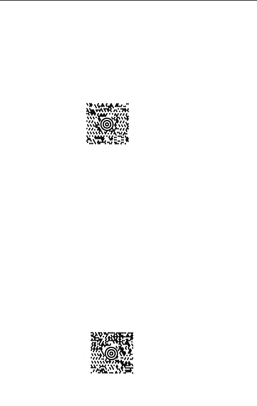
Maxicode
253
Maxicode Examples
The following command generates the Maxicode barcode shown below. In
the command sequence, graphics mode data is italicized and barcode data is
boldface. See Chapter 2 for a detailed description of alphanumeric
commands.
^PY^-^M10,10,050^BN%2999840068107317>AThis is a secondary
message.^G^-^PN^-
^PY^- enabled the graphics command sequence.
^M introduced the standard alphanumeric command.
The character height selected was 1.0 inches and character width was
selected at 1.0 inches.
A 0.5 justification value plus 0 additional dots was selected for the data
placement.
^B introduced the barcode command.
N selects no readable data field.
% selected Maxicode barcode.
2 selects Maxicode mode 2.
999840068107317 is the primary barcode data.
>A separates the primary barcode data from the secondary barcode data
(“This is a secondary message”).
^G^- terminated the barcode command sequence.
^PN^- terminated the graphics mode.
The following example generates the MAXICODE barcode shown below:
NOTE: “|” in the barcode represents the Shift Out Character.
^PY^-^M10,10,050^IBARC,MAXICODE,N,2[)>|n01|m96841706672|m840|
m001|m1Z12345675|mUPSN|m12345E|m089|m|m1/1|m10.1|mY|m|m|mUT|n|
$^G^-^PN^-
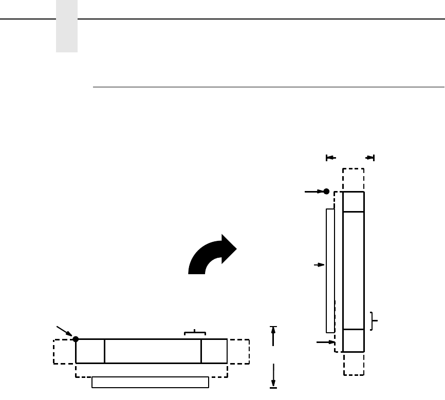
254
Chapter 3
Barcodes
MSI
The MSI structure is shown in Figure 23 and described on the following
pages.
Figure 17. MSI Barcode Structure
Quiet Zone
Both ends of the barcode structure require blank quiet zones. The quiet zones
should be at least 0.25 inches wide and completely blank to ensure accurate
reading of the start/stop codes and to prevent adjacent barcodes from
overlapping. You are responsible for providing sufficient space on the form for
the quiet zones.
Start/Stop Codes
The start/stop code is a unique character identifying the leading and trailing
end of the barcode. The start/stop code is automatically produced with each
barcode, and permits bidirectional barcode scanning.
Data Field
The MSI barcode symbol uses a series of wide and narrow bars and spaces
to represent numeric characters. The structure is 1-module-wide narrow
elements and 2-module-wide wide elements; elements can be a bar or a
space. Each character is composed of 4 data bits, with each bit made up of a
bar and a space totalling 3 modules.
DATA FIELD QUIETQUIET START STOP
LOWER GUARD BAND
CODE CODEZONE ZONE
OPTIONAL READABLE DATA FIELD
HEIGHT
STARTING
POSITION
CHECK DIGIT
FIELD
DATA
FIELD
QUIET
ZONE
QUIET
ZONE
STOP
CODE
START
CODE
OPTIONAL
READABLE
DATA
FIELD
HEIGHT
STARTING
GUARD
BAND
LOWER
CHECK
OPTIONAL
DIGIT
POSITION
MSI
255
Readable Data
The optional readable data field provides a readable interpretation of the
barcode data. barcode data is printed below the horizontal barcode symbol,
and to the left of a vertical barcode symbol. The lower guard band is provided
when the readable data field is selected.
Check Digit
The check digit provides the means of verifying accurate scanning. For MSI
Types G, H, I, and X, a specific check digit, Modulo-10 or Modulo-11 (or both),
is automatically calculated and appended in the barcode symbol. MSI Type F
does not use a check digit.
MSI Command Format
NOTE: See page 164 for the IBARC, command format and definitions.
Default Ratio: (cc) dir p type data (cc)G
Variable Ratio: (cc) dir p [9] [:] type [ratio] data (cc)G
(cc) Represents the Special Function Control Code
(SFCC). Enter the specific SFCC for your VGL
configuration.
dir Represents the direction of the barcode. Enter B for
horizontal barcodes; enter C for vertical barcodes.
pPrints the optional readable data field. The
readable data field is printed below a horizontal
barcode or on the left-hand side of a vertical
barcode.
Replace p in the barcode command with one of the
codes listed below to print the readable data field in
the corresponding font with the specified guard
band gap.
Table 58. Printable Data Field Fonts
Font Gap p code
Standard 10 cpi 3 dots Y
OCR-A 3 dots O
OCR-A .1-inch S
OCR-B 3 dots B
OCR-B .1-inch T
None N
256
Chapter 3
Barcodes
9 or : Selects the variable ratio length barcode feature,
which permits unique bar and space width ratios
adjusted for specific applications.
Enter the number 9 to select variable ratio
barcodes represented in line matrix printer dots (60
x 72 dpi).
Enter : to select variable ratio barcodes
represented in actual printer dots (203 x 203 dpi or
300 x 300 dpi, depending on the printer head being
used).
type Represents the barcode type. As shown in Table
59, MSI Types F, G, H, I, and X are available. Enter
the type code corresponding to the MSI barcode
type desired.
ratio Optional parameter (used in conjunction with 9 or :
above) representing the ratios for variable ratio
barcodes. Default ratios are overridden by the
variable ratio feature. The ratio data must be
hexadecimal numbers from 0 through 9 or A
through F. VGL automatically checks the input for
validity. If an invalid character is found in the ratio,
an error message is generated.
Table 59. MSI Barcodes
Standard
Type Code IBARC,
Type Code # of Data
Characters Check Digits Default Bar/
Space
Ratios*
FMSI 1-13 None 1:1:2:2
GMSI10 1-13 Mod 10 1:1:2:2
HMSI1010 1-13 Mod 10, Mod 10 1:1:2:2
IMSI1110 1-13 Mod 11, Mod 10 1:1:2:2
XMSI11 1-13 Mod 11 1:1:2:2
*Ratios represent dot width of the bar/space elements as follows:
Narrow Bar : Narrow Space : Wide Bar : Wide Space.

MSI
257
MSI barcodes use four-digit ratios. The ratios are
interpreted from left to right, measuring the size of
each bar or space, in dot width, in the following
pattern: narrow bar : narrow space : wide bar : wide
space. For example, enter 2244 in the ratio
parameter for:
2 dot-wide narrow bar
2 dot-wide narrow space
4 dot-wide wide bar
4 dot-wide wide space
NOTE: VGL automatically checks ratio data for validity only within the
allowable hexadecimal range. VGL does not verify that ratio data
creates acceptable wide/narrow element relationships for barcode
readability. For example, VGL accepts wide/narrow ratio values of 2
and 5, respectively; however, a narrow element larger than the wide
element produces an unreadable barcode. When designing unique
ratio data, carefully plot wide and narrow ratios to conform to
readable barcodes.
data The barcode data. MSI encodes from 1 through 13
characters. The available characters for the data
field are 0 through 9 (hex 30 through 39).
(cc)G Terminates the barcode command. Enter the SFCC
for your VGL configuration immediately followed by
any valid command character or G, the universal
sequence terminator.
MSI Barcode Examples
The following command generates the horizontal default ratio MSI barcode
shown below. In the command sequence, graphics mode data is italicized and
barcode data is boldface. See Chapter 2 for a detailed description of
alphanumeric commands.
^PY^-^M10,10,000^KF^BYH87654321^G^KF^-^PN^-
msi.ex1
258
Chapter 3
Barcodes
^PY^- enabled the graphics command sequence.
^M introduced the standard alphanumeric command.
The character height selected was 1.0 inches and character width was
selected at 1.0 inches.
A 0.0 justification value plus 0 additional dots was selected for the data
placement.
^KF activated Dark Print.
^B introduced the barcode command.
Y selected the standard 10 cpi font to print the optional readable data field.
Letter H selected MSI barcode Type H, which automatically appends two Mod
10 check digits to the barcode data.
87654321 is the barcode data.
^G terminated the barcode command sequence.
^KF^- at the end of the barcode sequence turned off Dark Print.
^PN^- terminated the graphics mode.
The following command generated the horizontal MSI barcode below using
OCR-B font and double the default ratio:
^PY^-^M10,10,000^KF^BB9X224487654321^G^KF^-^PN^-
The following command generates the vertical MSI barcode below using
standard 10 cpi font, the standard default ratio, and data of 87654321:
^PY^-^M10,10,000^KF^CYF87654321^G^KF^-^PN^-
msi.e
m
si.
ex3
MSI
259
The following command generates the same vertical MSI barcode above,
except that double the default ratio is used:
^PY^-^M10,10,000^KF^CY9I224487654321^G^KF^-^PN^-
msi.ex4
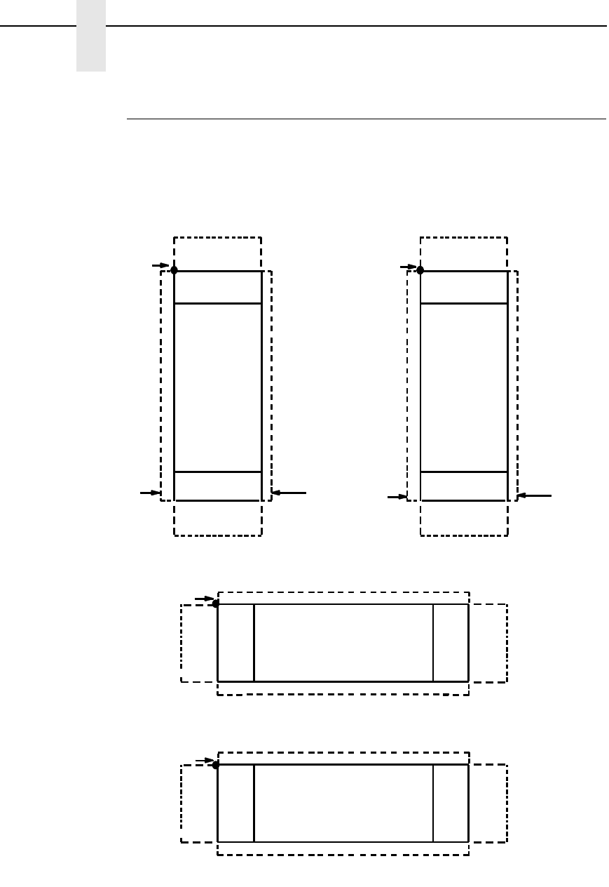
260
Chapter 3
Barcodes
PDF417
The PDF417 structure is shown in Figure 18 and described on the following
pages.
Figure 18. PDF417 Structure
SR, SC
POSITION
QUIET
ZONE
START
CODE
STOP
CODE
QUIET
ZONE
UPPER GUARD BAND
LOWER GUARD BAND
DATA FIELD QUIET
ZONE
QUIET START
CODEZONE
STOP
CODE
LOWER GUARD BAND
UPPER GUARD BAND
SR, SC
POSITION
DATA
FIELD
QUIET
ZONE
QUIET
ZONE
STOP
CODE
CODE
START
GUARD
BAND
UPPER
SR, SC
POSITION
GUARD
BAND
LOWER STOP
CODE
CODE
START
DATA
FIELD
QUIET
ZONE
QUIET
ZONE
GUARD
BAND
LOWER
GUARD
BAND
UPPER
SR, SC
POSITION
CCW CW
Normal
INV

PDF417
261
Quiet Zone
Both ends of the barcode structure require blank quiet zones. The quiet zones
must be at least 0.25 inches wide and completely blank to ensure accurate
reading of the start/stop codes and to prevent adjacent barcodes from
overlapping. Be sure to provide sufficient space on the form for the quiet
zones.
Start/Stop Codes
The start/stop codes identify the leading and trailing end of the barcode.
Data Field
PDF417 provides twelve modes to encode data. The first three are pre-
established (the remaining nine are user modes, which can be defined by
users or industry associations according to specific applications):
1. Extended Alphanumeric Compaction mode (EXC). Comprised of four
sub-modes, this mode offers encodation of all printable ASCII characters.
This is the default mode; the IGP uses shift or latch characters to enable
other modes.
2. Binary/ASCII Plus mode. This offers encodation for all ASCII characters,
printable or not, and binary values.
3. Numeric Compaction mode. This offers encodation for numeric values to
a density of almost 3 digits per code word.
4. The IGP will automatically switch between modes to provide the smallest
encodation for the data.
Security Level
PDF417 can detect and correct errors. Each label has 2 code words of error
detection. You can select the error correction capacity based on application
needs. Specify a security level in the range of 0 - 8, at the time of printing.
PDF417 can also recover from omissions and misdecodes of code words.
Since it requires two code words to recover from a misdecode, one to detect
the error and one to correct for it, a given security level can support half the
number of misdecodes that it can of undecoded words.
PDF
Print Data Field is not offered due to the large amount of data that can be
encoded.

262
Chapter 3
Barcodes
PDF417 Command Format
Default Ratio: (cc) dir p type [X[D]n] [Y[D]n] [(Hn)] (Wn)] [Ah:w]
[Rn] [Cn] [Sn], DATA^G
(cc) Represents the Special Function Control Code
(SFCC). Enter the specific SFCC for your VGL
configuration.
dir Represents the direction of the barcode. Enter B for
horizontal or C for vertical barcodes.
pAn optional readable data field. Enter N so no
readable data prints in this field.
type Enter & for PDF417.
X[D]nOptional parameter to designate the width of the
narrow element in either the default 60 X 72 dots
per inch or, if the D is given, in target dots. The
default size is 1/60th of an inch.
Y[D]nOptional parameter to designate the height of the
barcode in either the default 60 X 72 dots per inch
or, if the D is given, in target dots. The default size
is 2/72nd of an inch.
HnOptional parameter to adjust the overall height of
the barcode symbol (including human readable
data). Height adjustments are made in 0.1-inch
increments; enter H and a value from 4 through 99
to select height adjustments from 0.4 through 9.9
inches. Parameters Wn, Rn, Cn or A cannot be
entered if this parameter is used.
WnOptional parameter to adjust the maximum width of
the symbol based on the narrow element width.
Enter Wn; where n is the overall width in tenths of
an inch. Parameters Hn, Rn, Cn or A cannot be
entered if this parameter is used.
Ah:w Optional parameter for specifying the symbol
height-to-width ratio where h is the height and w is
the width, both expressed as integers. The default
is 1:2. Parameters Hn, Wn, Rn, or Cn cannot be
entered if this parameter is used.
RnOptional parameter that specifies the number of
rows the symbol will have. Enter R followed by the
number of rows in the range of 3 through 90 in
multiples of 3. Parameters Hn, Wn, Cn or A cannot
be entered if this parameter is used.
CnOptional parameter that specifies the number of
columns the symbol will have. Enter C followed by
the number of columns in the range of 1 through
90. Parameters Hn, Wn, Rn or A cannot be entered
if this parameter is used.
PDF417
263
SnOptional parameter that specifies the security level.
Enter S followed by the security level in the range
of 0 through 8. The default is 2.
data Enter the data for the barcode. A null data field (no
characters) is not permitted. The data field can
contain any character including carriage returns
and line feeds. The length of the data field is
variable; however, the maximum length is usually
limited to 1024 bytes to minimize potential reading
errors.
(cc)G Terminates the barcode command. Enter the SFCC
for your VGL configuration immediately followed by
any valid command character or G, the universal
sequence terminator.
PDF417 Example
Figure 19 illustrates a horizontal PDF417 barcode generated by the following
program:
^PY^-
^M10,10,000^KF^BN&X1Y2,ABCDEFGHIJKLMNOPQRSTUVWXYZabcdefghijklmn
opqrstuvwxyz‘1234567890-
=\[];’,./!@#$%^&()_+|{}:”<>?^G^KF^-^PN^-
Figure 19. Sample PDF417 Barcode
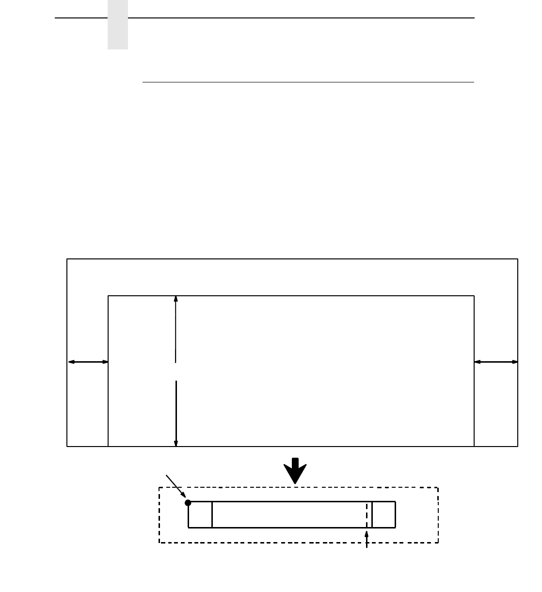
264
Chapter 3
Barcodes
Planet
The Planet barcode was introduced by the U.S. Postal Service under the
product name “Confirm.” Planet is a 12-digit barcode used to track mail
electronically, both inbound and outbound. Under the “Confirm” process, the
first two digits of the Planet data field defines the service expected. The next
nine digits are customer information, and the last digit is the check digit.
The Planet barcode structure is illustrated in Figure 20 and Figure 21 and
described on the following pages. The Planet code can be a part of the
address block and appear anywhere within a vertical 4-inch area across the
width of the mail piece.
The Planet barcode cannot use variable ratios and does not have a readable
data field.
Figure 20. Planet Structure
NOTE: Additional information regarding Planet barcode requirements can be
obtained from the U.S. Postal Service's Publication 25: A Guide to
Business Mail Preparation.
Return Address Area Postage Area
1/2"1/2"
BAR CODE DATA FIELD
START STOP
QUIET ZONE
CODE CODE
STARTING
POSITION
QUIET ZONE
CHECK DIGIT
NOTE: Illustration is not to scale
QUIET
ZONE
QUIET
ZONE
ADDRESS BLOCK BAR CODE READ AREA
4"
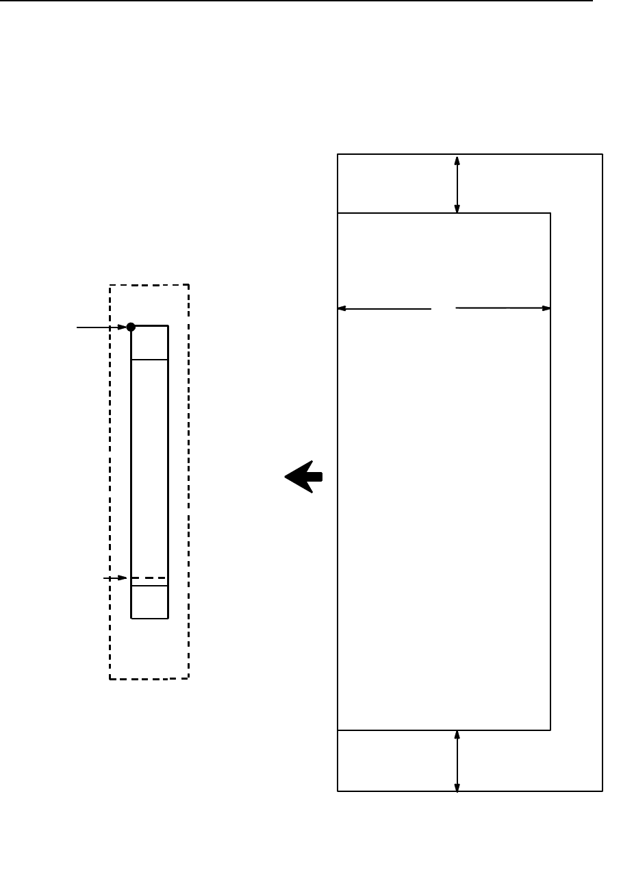
Planet
265
Figure 21. Planet Structure (Vertical Bar)
Return Address Area Postage Area
1/2"
1/2"
CODE
CODE
START
STOP
STARTING
POSITION
CHECK DIGIT
ZONE
QUIET
QUIET
ADDRESS BLOCK BAR CODE READ AREA
4"
BAR
CODE
DATA
FIELD
ZONE
NOTE: Illustration is not to scale.

266
Chapter 3
Barcodes
Quiet Zone
The barcode structure requires a completely blank quiet zone which extends
4.75 inches from the right edge of the mail piece. In addition, a minimum quiet
zone of 0.040-inch above and below the barcode data must also be provided.
You must provide sufficient space for this zone.
Start/Stop Code
The start and stop codes are referred to as “framing bars” in Planet. The start
and stop codes are each one tall bar, one identifying the leading and trailing
end of the barcode. The start/stop code is automatically produced with each
barcode. The start/stop code structure permits barcode scanning in a left-to
right direction only.
Data Field
The barcode data produces a single field of 60 bars for an 11-digit data field.
The bars are grouped in sets of five. Each set of five bars (comprised of three
tall bars and two short bars) represents one of the five digits of the zip code,
plus the four-digit zip code extension. If the Delivery Point Barcode is used, an
additional two-digit code is also added to make an 11-digit data field.
Exact barcode dimensions depend on the type of printer used, but fall within
the following specifications:
Each bar width is equal and is .020-inch ± .005-inch. Each bar height is either
a tall (full) or short (half) bar, representing a 1 or 0, respectively. Each tall bar
is .125-inch ± .010-inch; each short bar is .050-inch ± .010-inch. Horizontal
spacing between bars (pitch) is 22 bars ±
2 bars per inch over any 0.50-inch
portion of the barcode. Horizontal spacing at 24 and 20 bars per inch is
0.0416-inch and .050-inch, respectively, with a clear vertical space ranging
from 0.012-inch to 0.040-inch between bars.
Check Digit
The twelfth digit represents the automatic check digit character. The Mod 10
check digit is added automatically to verify accurate scanning.

Planet
267
Planet Command Format
Default Ratio: (cc) dir N r data (cc)G
(cc) Represents the Special Function Control Code
(SFCC). Enter the specific SFCC for your VGL
configuration.
dir Represents the direction of the barcode. Enter B for
horizontal barcodes; enter C for vertical barcodes.
N Turns off the readable data field. Enter N.
r The type code for Planet. Enter r.
data The barcode data. Planet barcodes encode exactly
11 numeric digits. A check digit is automatically
added by VGL.
(cc)G Terminates the barcode command. Enter the SFCC
for your VGL configuration immediately followed by
any valid command character or G, the universal
sequence terminator.
NOTE: The Planet barcode symbol height is fixed at 0.125 inches.
268
Chapter 3
Barcodes
Planet Examples
The following command generates the horizontal Planet barcode shown
below. In the command sequence, graphics mode data is italicized and
barcode data is boldface. See Chapter 2 for a detailed description of
alphanumeric commands.
^PY^-^M^KF^BNr01234567890^G^KF^-^PN^-
^PY^- enabled the graphics command sequence.
^M introduced the standard alphanumeric command.
^KF activated Dark Print.
^B introduced the barcode command.
N selected no readable data field.
r selected Planet barcode.
01234567890 is the barcode data.
^G terminated the barcode command sequence.
^KF^- at the end of the barcode sequence turned off Dark Print.
^PN^- terminated the graphics mode.
The following command generated the vertical Planet barcode below with
data of 01234567890:
^PY^-^M^KF^CNr01234567890^G^KF^-^PN^-

POSTNET
269
POSTNET
The POSTNET barcode structure is illustrated in Figure 22 and Figure 23 and
described on the following pages. The POSTNET code can be a part of the
address block and appear anywhere within a vertical 4-inch area across the
width of the mail piece.
The POSTNET barcode cannot use variable ratios and does not have a
readable data field.
Figure 22. POSTNET Structure
NOTE: Additional information regarding POSTNET barcode requirements
can be obtained from the U.S. Postal Service's Publication 25: A
Guide to Business Mail Preparation.
Return Address Area Postage Area
1/2"1/2"
BAR CODE DATA FIELD
START STOP
QUIET ZONE
CODE CODE
STARTING
POSITION
QUIET ZONE
CHECK DIGIT
NOTE: Illustration is not to scale
QUIET
ZONE
QUIET
ZONE
ADDRESS BLOCK BAR CODE READ AREA
4"
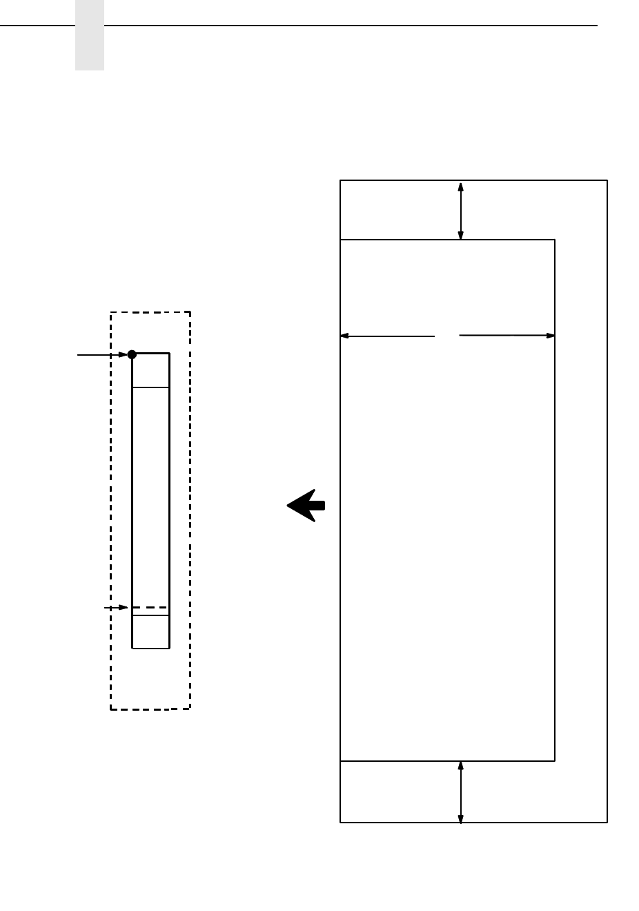
270
Chapter 3
Barcodes
Figure 23. POSTNET Structure (Vertical Bar)
Return Address Area Postage Area
1/2"
1/2"
CODE
CODE
START
STOP
STARTING
POSITION
CHECK DIGIT
ZONE
QUIET
QUIET
ADDRESS BLOCK BAR CODE READ AREA
4"
BAR
CODE
DATA
FIELD
ZONE
NOTE: Illustration is not to scale.

POSTNET
271
Quiet Zone
The barcode structure requires a completely blank quiet zone which extends
4.75 inches from the right edge of the mail piece. In addition, a minimum quiet
zone of 0.040-inch above and below the barcode data must also be provided.
You must provide sufficient space for this zone.
Start/Stop Code
The start and stop codes are referred to as “framing bars” in POSTNET. The
start and stop codes are each one tall bar, one identifying the leading and
trailing end of the barcode. The start/stop code is automatically produced with
each barcode. The start/stop code structure permits barcode scanning in a
left-to right direction only.
Data Field
The barcode data produces a single field of 30 bars for a 5-digit field, 50 bars
for a 9-digit data field, or 60 bars for an 11-digit data field. The bars are
grouped in sets of five. Each set of five bars (comprised of two tall bars and
three short bars) represents one of the five digits of the zip code, plus the
four-digit zip code extension. If the Delivery Point Barcode is used, an
additional two-digit code is also added to make an 11-digit data field.
Exact barcode dimensions depend on the type of printer used, but fall within
the following specifications:
Each bar width is equal and is .020-inch ± .005-inch. Each bar height is either
a tall (full) or short (half) bar, representing a 1 or 0, respectively. Each tall bar
is .125-inch ± .010-inch; each short bar is .050-inch ± .010-inch. Horizontal
spacing between bars (pitch) is 22 bars ±
2 bars per inch over any 0.50-inch
portion of the barcode. Horizontal spacing at 24 and 20 bars per inch is
0.0416-inch and .050-inch, respectively, with a clear vertical space ranging
from 0.012-inch to 0.040-inch between bars.
Check Digit
The sixth, tenth, or twelfth digit represents the automatic check digit character
for the 5, 9, or 11-digit data field, respectively. The Mod 10 check digit is
added automatically to verify accurate scanning.
272
Chapter 3
Barcodes
POSTNET Command Format
Default Ratio: (cc) dir N * data (cc)G
(cc) Represents the Special Function Control Code
(SFCC). Enter the specific SFCC for your VGL
configuration.
dir Represents the direction of the barcode. Enter B for
horizontal barcodes; enter C for vertical barcodes.
N Turns off the readable data field. Enter N.
* The type code for POSTNET. Enter *.
data The barcode data. POSTNET barcodes encode
exactly 5, 9, or 11 numeric digits. A check digit is
automatically added by VGL.
(cc)G Terminates the barcode command. Enter the SFCC
for your VGL configuration immediately followed by
any valid command character or G, the universal
sequence terminator.
NOTE: The POSTNET barcode symbol height is fixed at 0.125 inches.
POSTNET Example
The following command generates the horizontal POSTNET barcode shown
below. In the command sequence, graphics mode data is italicized and
barcode data is boldface. See Chapter 2 for a detailed description of
alphanumeric commands.
^PY^-^M^KF^BN*927047563^G^KF^-^PN^-
^PY^- enabled the graphics command sequence.
^M introduced the standard alphanumeric command.
^KF activated Dark Print.
^B introduced the barcode command.
N selected no readable data field.
Asterisk (*) selected POSTNET barcode.
927047563 is the barcode data.
^G terminated the barcode command sequence.
^KF^- at the end of the barcode sequence turned off Dark Print.
^PN^- terminated the graphics mode.

Royal Mail
273
Royal Mail
The Royal Mail barcode, like POSTNET, is used for mailing applications.
However, the barcode can encode full addresses on labels. Royal Mail
barcodes are similar to POSTNET in terms of bar space and width, but have
four different types of bars (Full Height, Ascender, Descender, and Tracker),
whereas POSTNET only has two bar types (Tall and Short).
The Royal Mail symbology converts alphanumeric characters into patterns of
four bars, using combinations of Full Height, Ascender, Descender, and
Trackers. It also adds start and stop barcodes as well as a check digit.
Quiet Zone
The barcode structure requires a completely blank quiet zone which is a 2mm
border on each side of the barcode.
Start/Stop Code
The start and stop bars identify the orientation of the barcode. The start bar
consists of an ascender bar, and is positioned at the leftmost end of the
barcode. The stop bar consists of a full height bar, and is positioned at the
rightmost end of the barcode adjacent to the check digit.
Data Field
Royal Mail barcodes use four types of bars to encode its data: Full Height,
Ascender, Descender, and Tracker. Each Full Height bar is 0.198 inch ±
0.030 inch. The Ascender and Descender bars are about 62.5% of the Full
Height bar in length, while the Tracker bar is about 25% of the Full Height bar.
Each bar width is equal, and must be .020-inch ± .005-inch. Horizontal
spacing between bars (pitch) must be 22 bars ±
2 bars per inch over any
0.50-inch portion of the barcode.
Royal Mail barcodes have a variable length of data field, which consists of
valid characters “0” through “9” and “A” through “Z”. Each character is
encoded with four bars of varied types.
Check Digit
A modulo-6 check digit is added automatically to the end of the barcode to
verify accurate scanning.
274
Chapter 3
Barcodes
Royal Mail Command Format
Default Ratio: (cc) dir N Y data (cc)G
(cc) Represents the Special Function Control Code
(SFCC). Enter the specific SFCC for your VGL
configuration.
dir Represents the direction of the barcode. Enter B for
horizontal barcodes. Enter C for vertical barcodes.
N Turns off the readable data field. Enter N.
Y The type code for Royal Mail. Enter Y.
data The barcode data. A check digit is automatically
added by VGL.
(cc)G Terminates the barcode command. Enter the SFCC
for your VGL configuration immediately followed by
any valid command character or G, the universal
sequence terminator.
Royal Mail Example
The following command generates the horizontal Royal Mail barcode shown
below. In the command sequence, graphics mode data is italicized and
barcode data is boldface. See Chapter 2 for a detailed description of
alphanumeric commands.
^PY^-^M10,10,000^KF^BNY050LU178XE2B^G^KF^-^PN^-
^PY^- enabled the graphics command sequence.
^M introduced the standard alphanumeric command.
The character height selected was 1.0 inches and character width was
selected at 1.0 inches.
A 0.0 justification value plus 0 additional dots was selected for the data
placement.
^KF activated Dark Print.
^B introduced the barcode command.
N selected no readable data field.
Y selected Royal Mail barcode.
050LU178XE2B is the barcode data.
^G terminated the barcode command sequence.
^KF^- at the end of the barcode sequence turned off Dark Print.
^PN^- terminated the graphics mode.
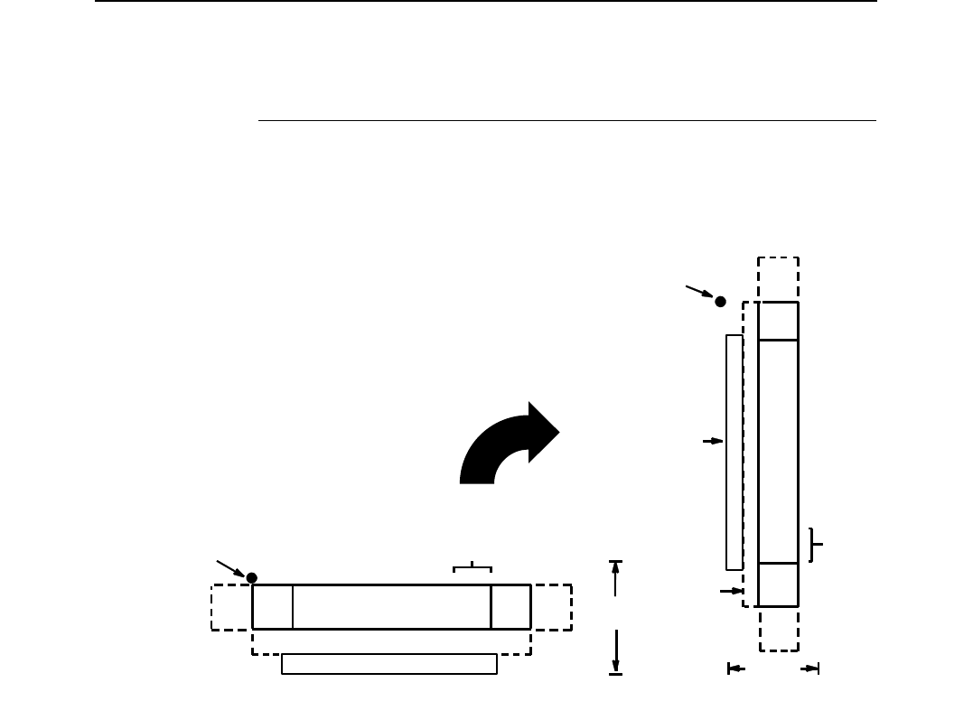
Telepen
275
Telepen
The Telepen structure is shown in Figure 24 and described on the following
pages.
Figure 24. Telepen Structure
Quiet Zone
Both ends of the barcode structure require blank quiet zones. The quiet zones
should be at least 0.25 inches wide and completely blank to ensure accurate
reading of the start/stop codes and to prevent adjacent barcodes from
overlapping. You are responsible for providing sufficient space on the form for
the quiet zones.
Start/Stop Codes
The start/stop code is a unique character identifying the leading and trailing
end of the barcode. The start/stop code is automatically produced with each
barcode. The start/stop code structure permits bidirectional barcode
scanning.
Data Field
The barcode symbol uses a series of wide and narrow bars and spaces to
represent standard alphanumeric characters. Each character is represented
by a different series of bars and spaces, both wide and narrow, but is always
16 units in width (for a wide to narrow ratio of 3). Each character starts with a
bar and ends with a space.
DATA FIELD QUIETQUIET START STOP
LOWER GUARD BAND
CODE CODEZONE ZONE
OPTIONAL READABLE DATA FIELD
CHECK DIGIT
OPTIONAL
HEIGHT
STARTING
POSITION
DATA
FIELD
QUIET
ZONE
QUIET
ZONE
START
CODE
STOP
CODE
OPTIONAL
READABLE
DATA
FIELD
CHECK
OPTIONAL
HEIGHT
STARTING
POSITION
DIGIT
GUARD
BAND
LOWER

276
Chapter 3
Barcodes
Readable Data
The optional readable data field provides a readable interpretation of the
barcode data. barcode data is printed below the horizontal barcode symbol
and to the left of a vertical barcode symbol. The lower guard band is provided
when the readable data field is selected.
Check Digit
A mandatory modulo-127 check digit is inserted into the barcode. This feature
provides a means of verifying accurate scanning.
Telepen Command Format
NOTE: Refer to page 164 for the IBARC, command format and definitions.
Default Ratio: (cc) dir p J data (cc)G
Variable Ratio: (cc) dir p [9] [:] J [ratio] data (cc)G
(cc) Represents the Special Function Control Code
(SFCC). Enter the specific SFCC for your VGL
configuration.
dir Represents the direction of the barcode. Enter B for
horizontal barcodes; enter C for vertical barcodes.
pPrints the optional readable data field. The
readable data field is printed below a horizontal
barcode or on the left-hand side of a vertical
barcode.
Replace p in the barcode command with one of the
codes in Table 27 to print the readable data field in
the corresponding font with the specified guard
band gap.
Table 60. Printable Data Field Fonts
Font Gap p code
Standard 10 cpi 3 dots Y
OCR-A 3 dots O
OCR-A .1-inch S
OCR-B 3 dots B
OCR-B .1-inch T
None N

Telepen
277
9 or : Selects the variable ratio length barcode feature,
which permits unique bar and space width ratios
adjusted for specific applications.
Enter the number 9 to select variable ratio
barcodes represented in line matrix printer dots (60
x 72 dpi).
Enter : to select variable ratio barcodes
represented in actual printer dots (203 x 203 dpi or
300 x 300 dpi, depending on the printer head being
used).
J The type code for Telepen. Enter J.
ratio Optional parameter (used in conjunction with
parameter 9 or :) representing the ratios for
variable ratio barcodes. The default ratios are
overridden by the variable ratio feature. The ratio
data must be hexadecimal numbers from 0 through
9 or A through F. VGL automatically checks the
input for validity. If an invalid character is found in
the ratio, an error message is generated.
Telepen barcodes use four-digit ratios. The ratios
are interpreted from left to right, measuring the size
of each bar or space, in dot width according to the
following pattern: narrow bar : narrow space : wide
bar : wide space. For example, enter 2266 in the
ratio parameter for:
2 dot-wide narrow bar
2 dot-wide narrow space
6 dot-wide wide bar
6 dot-wide wide space.
NOTE: VGL automatically checks ratio data for validity only within the
allowable hexadecimal range. VGL does not verify that ratio data
creates acceptable wide/narrow element relationships for barcode
readability. For example, VGL accepts wide/narrow ratio values of 2
and 5, respectively; however a narrow element larger than the wide
element produces an unreadable barcode. When designing unique
ratio data, carefully plot wide and narrow ratios to conform to
readable barcodes.
data The barcode data. Telepen encodes 1 through 40
characters from the Telepen full ASCII Character
Set shown in Table 29.
(cc)G Terminates the barcode command. Enter the SFCC
for your VGL configuration immediately followed by
any valid command character or G, the universal
sequence terminator.

278
Chapter 3
Barcodes
NOTE: Character pairs /M, /N, and /P through /Y are reserved for future
control character pairs.
Table 61. Telepen Character Set
ASCII Telepen ASCII Telepen ASCII Telepen ASCII Telepen
NUL
SOH
STX
ETX
EOT
ENQ
ACK
BEL
BS
HT
LF
VT
FF
CR
SO
SI
DLE
DC1
DC2
DC3
DC4
NAK
SYN
ETB
CAN
EM
SUB
ESC
FS
GS
RS
US
%U
$A
$B
$C
$D
$E
$F
$G
$H
$I
$J
$K
$L
$M
$N
$O
$P
$Q
$R
$S
$T
$U
$V
$W
$X
$Y
$Z
%A
%B
%C
%D
%E
SP
!
"
#
$
%
&
'
(
)
*
+
,
—
.
/
0
1
2
3
4
5
6
7
8
9
:
;
<
=
>
?
Space
/A
/B
/C
/D
/E
/F
/G
/H
/I
/J
/K
/L
—
.
/O
0
1
2
3
4
5
6
7
8
9
/Z
%F
%G
%H
%I
%J
@
A
B
C
D
E
F
G
H
I
J
K
L
M
N
O
P
Q
R
S
T
U
V
W
X
Y
Z
[
\
]
^
__
%V
A
B
C
D
E
F
G
H
I
J
K
L
M
N
O
P
Q
R
S
T
U
V
W
X
Y
Z
%K
%L
%M
%N
%O
`
a
b
c
d
e
f
g
h
i
j
k
l
m
n
o
p
q
r
s
t
u
v
w
x
y
z
{
|
}
^
DEL
%W
+A
+B
+C
+D
+E
+F
+G
+H
+I
+J
+K
+L
+M
+N
+O
+P
+Q
+R
+S
+T
+U
+V
+W
+X
+Y
+Z
%P
%Q
%R
%S
%T %X
%Y %Z
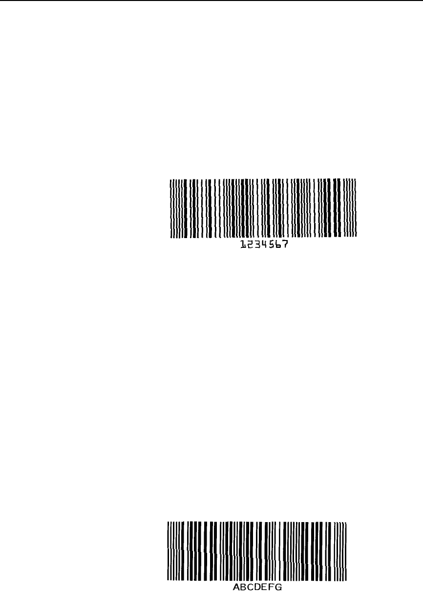
Telepen
279
Telepen Examples
The following command generates the horizontal default ratio Telepen
barcode shown below. In the command sequence, graphics mode data is
italicized and barcode data is boldface. See Chapter 2 for a detailed
description of alphanumeric commands.
^PY^-^M10,10,010^BOJ1234567^G^-^PN^-
^PY^- enabled the graphics command sequence.
^M introduced the standard alphanumeric command.
The character height selected was 1.0 inches and character width was
selected at 1.0 inches.
A 0.1 justification value plus 0 additional dots was selected for the data
placement.
^B introduced the barcode command.
O selected the 3-dot OCR-A font to print the optional readable data field.
J selected the Telepen barcode
1234567 is the barcode data, and ^G terminated the barcode command
sequence.
^PN^- terminated the graphics mode.
The following command generated the horizontal Telepen barcode below
using Standard 10 cpi font, and data of ABCDEFG:
^PY^-^M10,10,010^BYJABCDEFG^G^-^PN^-
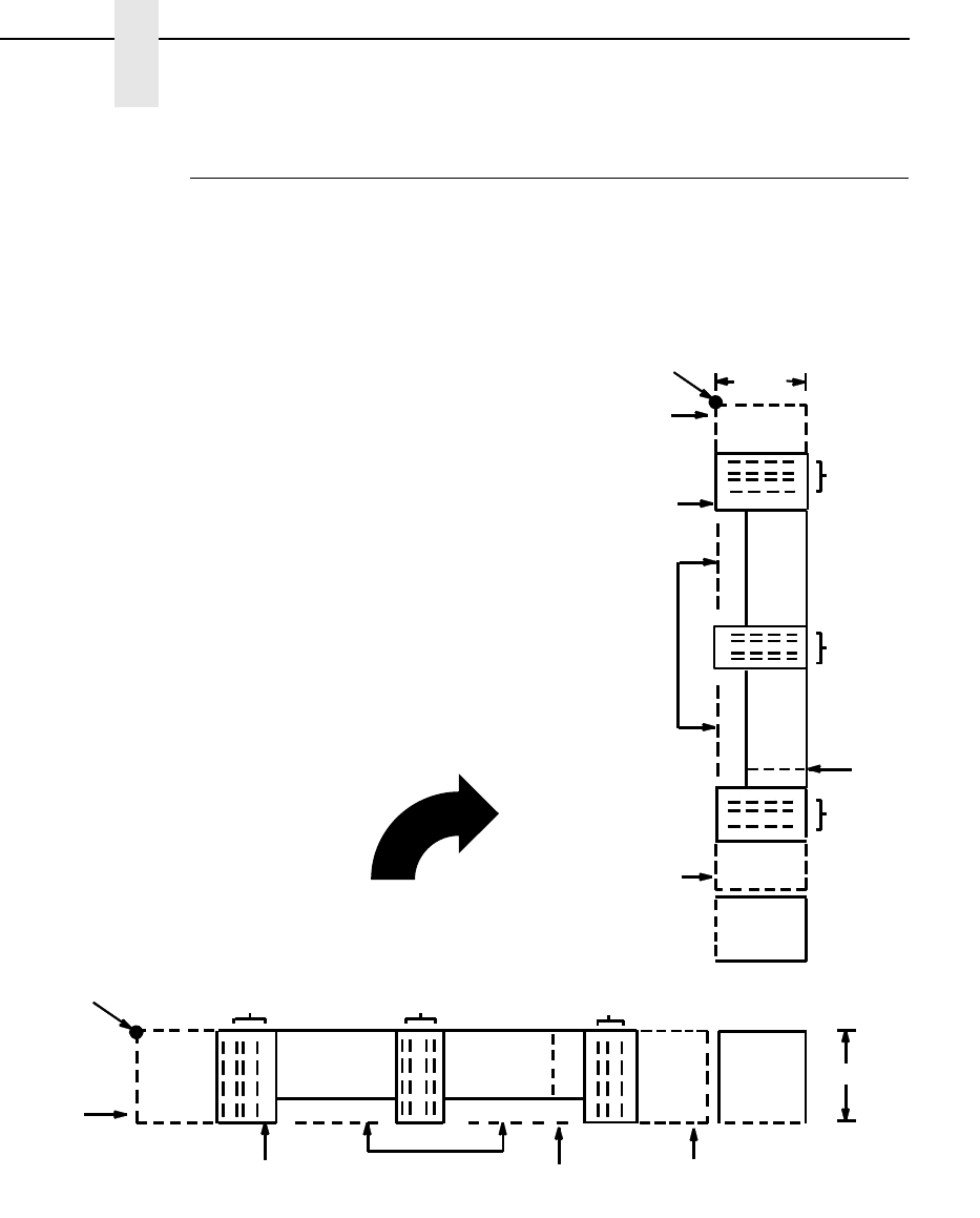
280
Chapter 3
Barcodes
UPC-A
The UPC-A barcode can be printed with or without a 2- or 5-digit add-on data
field, which is placed at the end of the barcode. The UPC-A barcode structure
is shown in Figure 25 and described on the following pages.
Figure 25. UPC-A Structure
Quiet Zone
Quiet zones extend on both ends of the barcode to permit the scan to begin
and end in a blank area. You are responsible for providing sufficient space on
the form (minimum of 7 modules) for the right quiet zone. (A trailing quiet zone
is provided automatically if an add-on code has been specified in the barcode
command.) The number system character is printed automatically in the left
quiet zone; the check digit is printed automatically in the right quiet zone.
QUIET
ZONE
START CODE CENTER CODE
CHECK DIGIT FIELD
STOP CODE
LEFT DATA
FIELD RIGHT DATA
FIELD HEIGHT
QUIET
ZONE
OPTIONAL READABLE
STARTING
POSITION
N
NUMBER
SYSTEM
CHARACTER
C
CHECK DIGIT
CHARACTER
NUMBER SYSTEM
CHARACTER FIELD DATA FIELD
2- or 5-
DIGIT
ADD-ON
CODE
QUIET
ZONE
CHECK
DIGIT
LEFT
DATA
FIELD
CENTER CODE
RIGHT
DATA
FIELD
QUIET
ZONE
STOP CODE
HEIGHT
STARTING
FIELD
START CODE
NUMBER
SYSTEM
CHARACTER N
NUMBER SYSTEM
CHARACTER FIELD
C
CHECK
DIGIT
CHARACTER
POSITION
OPTIONAL
READABLE
DATA
FIELD
2- OR 5-
DIGIT ADD-
ON CODE

UPC-A
281
Start/Center/Stop Codes
The Start/Center/Stop codes are special character codes which extend into
the printed data field area, marking the start, center, and stop portions of the
barcode. These codes are automatically provided.
Number System Character
The number system character field allows you to apply a code to a class or
type of item and is printed in the left quiet zone. The first character in the data
field is used as the number system character.
Data Field
The barcode symbol uses a series of varying width bars and spaces to
represent a limited character set (numbers 0-9 and Special Characters Start,
Center, and Stop). The bars and spaces vary in width from 1 through 4
modules. Each character consists of 2 bars and two spaces that total 7
modules. The symbol coding of the left data field is different from the right
data field to permit read direction sensing.
Readable Data
The human readable data field provides a readable interpretation of the
barcode data.
Check Digit
The modulo-10 check digit is automatically calculated and inserted in the
barcode symbol and printed in the right quiet zone, if specified. The check
digit provides the means to verify accurate scanning. The number system
character is included in the check digit algorithm.
282
Chapter 3
Barcodes
UPC-A Command Format
NOTE: See page 164 for the IBARC, command format and definitions.
Default Ratio: (cc) dir p type data (cc)G
Variable Ratio: (cc) dir p [9] [:] type [ratio] data (cc)G
(cc) Represents the Special Function Control Code
(SFCC). Enter the specific SFCC for your VGL
configuration.
dir Represents the direction of the barcode. Enter B for
horizontal barcodes; enter C for vertical barcodes.
pPrints the optional readable data field. The
readable data field is printed below a horizontal
barcode or on the left-hand side of a vertical
barcode.
Replace p in the barcode command with one of the
codes listed in Table 62 to print the readable data
field in the corresponding font with the specified
guard band gap.
NOTE: For UPC 100% PDF is printed in 12 cpi Letter Gothic. For UPC 80% it
is printed in 15 cpi Letter Gothic.
9 or : Selects the variable ratio length barcode feature,
which permits unique bar and space width ratios
adjusted for specific applications.
Enter the number 9 to select variable ratio
barcodes represented in line matrix printer dots (60
x 72 dpi).
Enter : to select variable ratio barcodes
represented in actual printer dots (203 x 203 dpi or
300 x 300 dpi, depending on the printer head being
used).
Table 62. Printable Data Field Fonts
Font Gap p code
Standard 10 cpi 3 dots Y
OCR-A 3 dots O
OCR-A .1-inch S
OCR-B 3 dots B
OCR-B .1-inch T
None N

UPC-A
283
type Represents the barcode type. Enter P for standard
UPC-A; enter a for UPC-A plus a 2-digit add-on
data field; enter b for UPC-A plus a 5-digit add-on
data field; enter 0 for UPC-A 80%; enter 1 for UPC-
A 100%.
ratio Optional parameter (used in conjunction with 9 or :
above) representing the ratios for variable ratio
barcodes. Default ratios are overridden by the
variable ratio feature. However, unique variable
ratios for UPC-A barcodes easily generate large,
out-of-spec barcodes. Ratio data must be
hexadecimal numbers from 0 through 9 or A
through F; VGL automatically checks the input for
validity. If an invalid character is found in the ratio,
an error message is generated.
UPC-A barcodes use eight-digit ratios. The ratios
are interpreted from left to right, measuring the size
of each bar or space, in dot width, in the following
pattern: 1 module wide bar : 1 module wide space :
2 module wide bar : 2 module wide space : 3
module wide bar : 3 module wide space : 4 module
wide bar : 4 module wide space.
NOTE: VGL automatically checks ratio data for validity only within the
allowable hexadecimal range. VGL does not verify that ratio data
creates acceptable bar/space element relationships for barcode
readability. When designing unique ratio data, carefully plot bar/
space ratios to conform to readable barcodes.
data The barcode data. UPC-A barcodes encode exactly
11 digits. The first character is interpreted as the
number system character. The next five characters
are the left half of the vendor number data (on the
upper side of vertically oriented symbols). The final
five characters comprise the right half of the
product number data (on the lower side of vertically
oriented symbols). A twelfth character is an
automatic check digit which is computed and
printed in the last character position at the end of
the product number data. If the 2- or 5-digit add-on
data field is used, include this data at the end of the
data field. The characters available for the data
field are 0 through 9 (hex 30 through 39).
(cc)G Terminates the barcode command. Enter the SFCC
for your VGL configuration immediately followed by
any valid command character or G, the universal
sequence terminator.

284
Chapter 3
Barcodes
UPC-A Examples
The following command generated the horizontal default ratio UPC-A barcode
below. In the command sequence, graphics mode data is italicized and
barcode data is boldface. See Chapter 2 for a detailed description of
alphanumeric commands.
^PY^-^M10,10,000^KF^BYP12345654321^G^KF^-^PN^-
^PY^- turned on the graphics command sequence.
^M introduced the standard alphanumeric command.
The character height selected was 1.0 inches and character width was
selected at 1.0 inches.
A 0.0 justification value plus 0 additional dots was selected for the data
placement.
^KF activated Dark Print.
^B introduced the barcode command.
Y selected the standard 10 cpi font to print the optional readable data field.
Letter P selected the UPC-A barcode type.
12345654321 is the 11-digit barcode data (the first character, 1, is the number
system character), and ^G terminated the barcode command sequence.
^KF^- at the end of the barcode sequence turned off Dark Print.
^PN^- terminated the graphics mode.
The following command generated the vertical UPC-A barcode below using
standard 10 cpi font with the standard default ratio and data of 12345654321:
^PY^-^M10,10,000^KF^CYP12345654321^G^KF^-^PN^-
upca.ex1
u
pca.
ex2

UPC-E
285
UPC-E
UPC-E barcodes are special zero-suppressed Universal Product Codes that
compress 10 data characters down to 6 characters under specific rules. UPC-
E barcode types include UPC-E0, UPC-E+2, UPC-E+5, UPC-E0+2, and
UPC-E0+5. UPC-E also offers optional extended data fields onto existing
UPC-E barcodes. The UPC-E barcode structure is shown in Figure 26 and
described on the following pages.
Figure 26. UPC-E Structure
Quiet Zone
Quiet zones extend on both ends of the barcode to permit the scan to begin
and end in a blank area. VGL automatically produces an 11-module wide left
quiet zone; You are responsible for providing sufficient space (minimum of 7
modules) on the form for the right quiet zone. (A trailing quiet zone is provided
automatically if an add-on code has been specified in the barcode command.)
The number system character is printed automatically in the left quiet zone. If
specified, the check digit is automatically printed in the right quiet zone.
Start/Stop Codes
QUIET
ZONE
QUIET
ZONE
DATA
FIELD
START
CODE
STOP
CODE
NUMBER
SYSTEM
CHARACTER
N
OPTIONAL
CHECK
DIGIT
HEIGHT
C
CHECK
DIGIT
CHARACTER
NUMBER SYSTEM
CHARACTER FIELD READABLE
DATA FIELD
2- or 5-
DIGIT
ADD-ON
CODE
N
START CODE
NUMBER
QUIET
ZONE
STARTING
QUIET
ZONE
C
CHECK
DIGIT
STOP CODE
CHECK
DIGIT
SYSTEM
DATA
NUMBER
CHARACTER
CHARACTER
OPTIONAL
READABLE
DATA
FIELD
FIELD
CHARACTER
SYSTEM
2- or 5-
DIGIT
ADD-ON
CODE
HEIGHT
FIELD
POSITION
STARTING
POSITION

286
Chapter 3
Barcodes
The Start/Stop codes are special character codes which extend into the
printed data field area, marking the start and stop portions of the barcode.
These codes are automatically produced.
Number System Character
The number system character field allows you to apply a code to a class or
type of item and is printed automatically in the left quiet zone. The first
character in the data field is used as the number system character.
Data Field
The barcode symbol uses a series of varying width bars and spaces to
represent a limited character set (numbers 0-9 and Special Characters Start
and Stop). The bars and spaces vary in width from 1 through 4 modules. Each
character consists of 2 bars and 2 spaces that total 7 modules. Six or 10 data
characters are expected, depending on the UPC-E barcode type (t) selected.
By modifying the syntax of the vendor number and product code, 10-digit data
is compressed down to 6 digits.
Readable Data
The human readable data field provides a readable interpretation of the
barcode data.
Check Digit
The modulo-10 check digit is automatically calculated and inserted in the
barcode symbol and printed in the right quiet zone, if specified. The check
digit provides the means to verify accurate scanning. The number system
character is included in the check digit algorithm.

UPC-E
287
UPC-E Command Format
NOTE: See page 164 for the IBARC, command format and definitions.
Default Ratio: (cc) dir p type data (cc)G
Variable Ratio: (cc) dir p [9] [:] type [ratio] data (cc)G
(cc) Represents the Special Function Control Code
(SFCC). Enter the specific SFCC for your VGL
configuration.
dir Represents the direction of the barcode. Enter B for
horizontal barcodes; enter C for vertical barcodes.
pPrints the optional readable data field. The
readable data field is printed below a horizontal
barcode or on the left-hand side of a vertical
barcode.
Replace p in the barcode command with one of the
codes listed in Table 63 to print the readable data
field in the corresponding font with the specified
guard band gap.
9 or : Selects the variable ratio length barcode feature,
which permits unique bar and space width ratios
adjusted for specific applications.
Enter the number 9 to select variable ratio
barcodes represented in line matrix printer dots (60
x 72 dpi).
Enter : to select variable ratio barcodes
represented in actual printer dots (203 x 203 dpi or
300 x 300 dpi, depending on the printer head being
used).
type Represents the barcode type. Enter the Type Code
corresponding to the UPC-E type desired from
Table 64.
Table 63. Printable Data Field Fonts
Font Gap p code
Standard 10 cpi 3 dots Y
OCR-A 3 dots O
OCR-A .1-inch S
OCR-B 3 dots B
OCR-B .1-inch T
None N
288
Chapter 3
Barcodes
ratio Optional parameter (used in conjunction with 9 or :)
representing the ratios for variable ratio barcodes.
Default ratios are overridden by the variable ratio
feature. However, unique variable ratios for UPC-E
barcodes easily generate large, out-of-spec
barcodes. Ratio data must be hexadecimal
numbers from 0 through 9 or A through F; VGL
automatically checks the input for validity. If an
invalid character is found in the ratio, an error
message is generated.
UPC-E barcodes use eight-digit ratios. The ratios
are interpreted from left to right, measuring the size
of each bar or space, in dot width, in the following
pattern: 1 module wide bar : 1 module wide space :
2 module wide bar : 2 module wide space : 3
module wide bar : 3 module wide space : 4 module
wide bar : 4 module wide space.
NOTE: VGL automatically checks ratio data for validity only within the
allowable hexadecimal range. VGL does not verify that ratio data
creates acceptable bar/space element relationships for barcode
readability. When designing unique ratio data, carefully plot bar/
space ratios to conform to readable barcodes.
data The barcode data. Depending on the UPC-E
barcode selected from Table 64, VGL expects a
specific number of data characters to be provided.
The characters available for the data field are 0
through 9 (hex 30 through 39).
Table 64. UPC-E Barcodes
Description Standard
Type Code IBARC,
Type Code
# of Data
Characters
Expected
Number
System
Used
Default Bar/
Space Ratios*
UPC-E QUPCE 10* 01:1:2:2:3:3:4:4
UPC-E0 RUPCE0 6 0 1:1:2:2:3:3:4:4
UPC-E+2 cUPCE+2 12* 01:1:2:2:3:3:4:4
UPC-E+5 dUPCE+5 15* 01:1:2:2:3:3:4:4
UPC-E0+2 eUPCE0+2 8 0 1:1:2:2:3:3:4:4
UPC-E0+5 fUPCE0+5 11 01:1:2:2:3:3:4:4
*Type Codes Q (UPCE), c (UPCE+2), and d (UPCE+5) compress the data characters down to
6 by applying specific rules according to the syntax of the vendor number data. Refer to the
data description.

UPC-E
289
When Type Code Q, c, or d is selected, 10 data
characters are expected; the first five characters
are vendor number data, and the next five
characters are product code data. The +2 (Type
Code c) and +5 (Type Code d) add-on data is
unaffected by the compression of the first 10 data
characters. The first 10 characters of the data field
are automatically modified and compressed down
to 6 data characters based on the syntax of the
vendor number and product code. The rules for
compressing data are described below:
• If the vendor number ends in 000, 100, or 200,
then the 6 data characters are: the first 2
vendor numbers, the last 3 product code
numbers, and the third vendor number.
• If the vendor number ends in 00, then the 6
data characters are: the first 3 vendor
numbers, the last 2 product code numbers,
and the digit “3”.
• If the vendor number ends in 0, then the 6 data
characters are: the first 4 vendor numbers, the
last product code number, and the digit “4”.
• In all other cases, the 6 data characters are:
the first 5 vendors numbers and the last
product code number.
For example, if the Type Q data field was input as
1232000001, it would be compressed down to 6
characters to read 123214: the first four vendor
numbers (1232) are followed by the last product
code number (1), and followed by the digit 4,
resulting in 123214.
When Type Codes R, e, or f are selected, VGL
assumes you have already compressed the first 10
data characters down to 6 characters. The +2
(Type Codes c and e) and +5 (Type Codes d and f)
add-on data is unaffected by the compression of
the first 10 data characters. The barcode encodes
exactly 6 digits.
Note that Type R, Type e, and Type f are UPC-E0
barcodes using encoding tables for 0 number
system characters. See Table 65 for compression
data from UPC-E to UPC-E0, and see Table 66 for
expansion data from UPC-E0 to UPC-E.
(cc)G Terminates the barcode command. Enter the SFCC
for your VGL configuration immediately followed by
any valid command character or G, the universal
sequence terminator.
290
Chapter 3
Barcodes
Table 65. Ten-Digit Compression
1. Manufacturer’s Number Product Numbers that can be used 00000-00999
X
X
X
X
X
X
0
1
2
0
0
0
0
0
0
( )
first two digits of
manufacturer’s
number
( )
last three digits of
the product
number
( )
third digit of the
manufacturer’s
number, use 0
through 2 only
2. Manufacturer’s Number Product Numbers that can be used 00000-00999
X
XX
X3
90
00
0
( )
first three digits of
manufacturer’s
number
( )
last two digits of
the product
number; use 00-
99 only
( 3 )
depends on how
many digits
appear in the
manufacturer’s
number
3. Manufacturer’s Number Product Numbers that can be used 00000-00999
X X X X 0 ( )
first four digits of
manufacturer’s
number
( )
last digit of
product number,
use 0 through 9
only
( 4 )
depends on how
many digits
appear in the
manufacturer’s
number
4. Manufacturer’s Number Product Numbers that can be used 00000-00999
X X X X X ( )
all five digits of
manufacturer’s
number
( )
last digit of
product number,
use 5-9 only
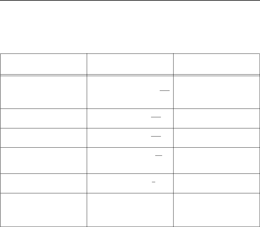
UPC-E
291
NOTE: Six digit UPC–EO data ends with 3. The third digit should be ranging
from 3 to 9. An error is printed when anything other than 3 through 9
is entered.
Table 66. Six-Digit Zero Expansion
if the 6 digit number ends
with: then the MFPS number is: and the Product Number is:
0
Example: 124560
the first 2 digits (of the zero
suppressed number) plus 000
12000
00 plus the THIRD, FOURTH
and FIFTH digit (of the zero
suppressed number)
00456
1
Example: 275831
the first two digits plus 100
27100
same as above
00583
2
Example: 412022
the first two digits plus 200
41200
same as above
00202
3
Example: 876543
the first three digits plus 00
87600
000 plus the FOURTH and
FIFTH digit
00054
4
Example: 753774
the first four digits plus 0
75370
0000 plus the FIFTH digit
00007
5, 6, 7, 8, 9
Examples:
213756
517019
the first five digits of the zero
suppressed number
21375
51701
0000 plus the SIXTH digit
00006
00009
292
Chapter 3
Barcodes
UPC-E Examples
The following command generated the horizontal default ratio UPC-E barcode
below. In the command sequence, graphics mode data is italicized and
barcode data is boldface. See Chapter 2 for a detailed description of
alphanumeric commands.
^PY^-^M10,10,000^KF^BYR123456^G^KF^-^PN^-
^PY^- turned on the graphics command sequence.
^M introduced the standard alphanumeric command.
The character height selected was 1.0 inches and character width was
selected at 1.0 inches.
A 0.0 justification value plus 0 additional dots was selected for the data
placement.
^KF activated Dark Print.
^B introduced the barcode command.
Y selected the standard 10 cpi font to print the optional readable data field.
Letter R selected the 6-digit, number system 0 UPC-E barcode type.
123456 is the 6-digit barcode data (the first character, 1, is the number
system character).
^G terminated the barcode command sequence.
^KF^- at the end of the barcode sequence turned off Dark Print.
^PN^- terminated the graphics mode.
The following command generated the vertical UPC-E barcode below using
standard 10 cpi font with the standard default ratio and data of 123456:
^PY^-^M10,10,000^KF^CYR123456^G^KF^-^PN^-
upce.ex1
upce.ex2
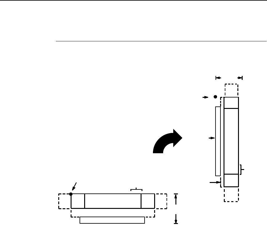
UPCSHIP
293
UPCSHIP
The UPCSHIP barcode structure is shown in Figure 27 and described on the
following pages.
Figure 27. UPCSHIP Structure
Quiet Zone
Both ends of the barcode structure have blank quiet zones. The quiet zones
should be at least 0.25 inches wide and completely blank to ensure accurate
reading of the start/stop codes and to prevent adjacent barcodes from
overlapping. You are responsible for providing sufficient space on the form for
the quiet zones.
Start/Stop Codes
Unique start and stop codes permit bidirectional scanning. Both start and stop
codes contain bars and spaces. They are automatically produced.
Data Field
The barcode symbol uses a series of wide and narrow bars and spaces to
represent numeric characters. The structure is 2 wide elements (bars or
spaces) and 3 narrow elements.
DATA FIELD
QUIETQUIET START STOP
LOWER GUARD BAND
CODE CODEZONE ZONE
OPTIONAL READABLE DATA FIELD
HEIGHT
STARTING
DATA
FIELD
QUIET
ZONE
QUIET
ZONE
STOP
CODE
START
CODE
OPTIONAL
READABLE
DATA
FIELD
HEIGHT
STARTING
GUARD
BAND
LOWER
CHECK
OPTIONAL
DIGIT
POSITION
POSITION
CHECK DIGIT
OPTIONAL
294
Chapter 3
Barcodes
Readable Data
The optional readable data field provides a readable interpretation of the
barcode data. barcode data is printed below the horizontal barcode symbol
and to the left of a vertical barcode symbol. The lower guard band is provided
when the readable data field is selected.
Check Digit
The modulo-10 check digit is automatically calculated and inserted in the
barcode symbol. The check digit provides the means to verify accurate
scanning.
UPCSHIP Command Format
NOTE: See page 164 for the IBARC, command format and definitions.
Default Ratio: cc) dir p $ data (cc)G
Variable Ratio: (cc) dir p [9] [:] $ [ratio] data (cc)G
(cc) Represents the Special Function Control Code
(SFCC). Enter the specific SFCC for your VGL
configuration.
dir Represents the direction of the barcode. Enter B for
horizontal barcodes; enter C for vertical barcodes.
pPrints the optional readable data field. The
readable data field is printed below a horizontal
barcode or on the left-hand side of a vertical
barcode.
Replace p in the barcode command with one of the
codes listed in Table 67 to print the readable data
field in the corresponding font with the specified
guard band gap.
Table 67. Printable Data Field Fonts
Font Gap p code
Standard 10 cpi 3 dots Y
OCR-A 3 dots O
OCR-A .1-inch S
OCR-B 3 dots B
OCR-B .1-inch T
None N

UPCSHIP
295
9 or : Selects the variable ratio length barcode feature,
which permits unique bar and space width ratios
adjusted for specific applications.
Enter the number 9 to select variable ratio
barcodes represented in line matrix printer dots (60
x 72 dpi).
Enter : to select variable ratio barcodes
represented in actual printer dots (203 x 203 dpi or
300 x 300 dpi, depending on the printer head being
used).
$ The type code for UPCSHIP. Enter $.
ratio Optional parameter (used in conjunction with 9 or :
above) representing the ratios for variable ratio
barcodes. Default ratios are overridden by the
variable ratio feature. The ratio data must be
hexadecimal numbers from 0 through 9 or A
through F. VGL automatically checks the input for
validity. If an invalid character is found in the ratio,
an error message is generated.
UPCSHIP barcodes use four-digit ratios. The ratios
are interpreted from left to right, measuring the size
of each bar or space, in dot width, in the following
pattern: narrow bar : narrow space : wide bar : wide
space. For example, enter 2266 in the ratio
parameter for:
2 dot-wide narrow bar
2 dot-wide narrow space
6 dot-wide wide bar
6 dot-wide wide space
NOTE: VGL automatically checks ratio data for validity only within the
allowable hexadecimal range. VGL does not verify that ratio data
creates acceptable wide/narrow element relationships for barcode
readability. For example, VGL accepts wide/narrow ratio values of 2
and 5, respectively; however a narrow element larger than the wide
element produces an unreadable barcode. When designing unique
ratio data, carefully plot wide and narrow ratios to conform to
readable barcodes.
data The barcode data. The UPCSHIP barcode requires
exactly 13 characters of data. The characters
available for the data field are 0 through 9 (hex 30
through 39).
(cc)G Terminates the barcode command. Enter the SFCC
for your VGL configuration immediately followed by
any valid command character or G, the universal
sequence terminator.
296
Chapter 3
Barcodes
UPCSHIP Example
The following command generates the horizontal default ratio UPCSHIP
barcode shown below. In the command sequence, graphics mode data is
italicized and barcode data is boldface. See Chapter 2 for a detailed
description of alphanumeric commands.
^M2020^IBARC,UPCSHIP,N,0001234567890^G^-
^M introduced the standard alphanumeric command.
The character height selected was 2.0 inches and character width was
selected at 2.0 inches.
^IBARC, introduced the barcode command.
UPCSHIP, selected the UPCSHIP barcode type.
N, selects no readable data field.
0001234567890 is the 13-character barcode data field.
^G^- terminated the barcode command sequence.
i25.ex1
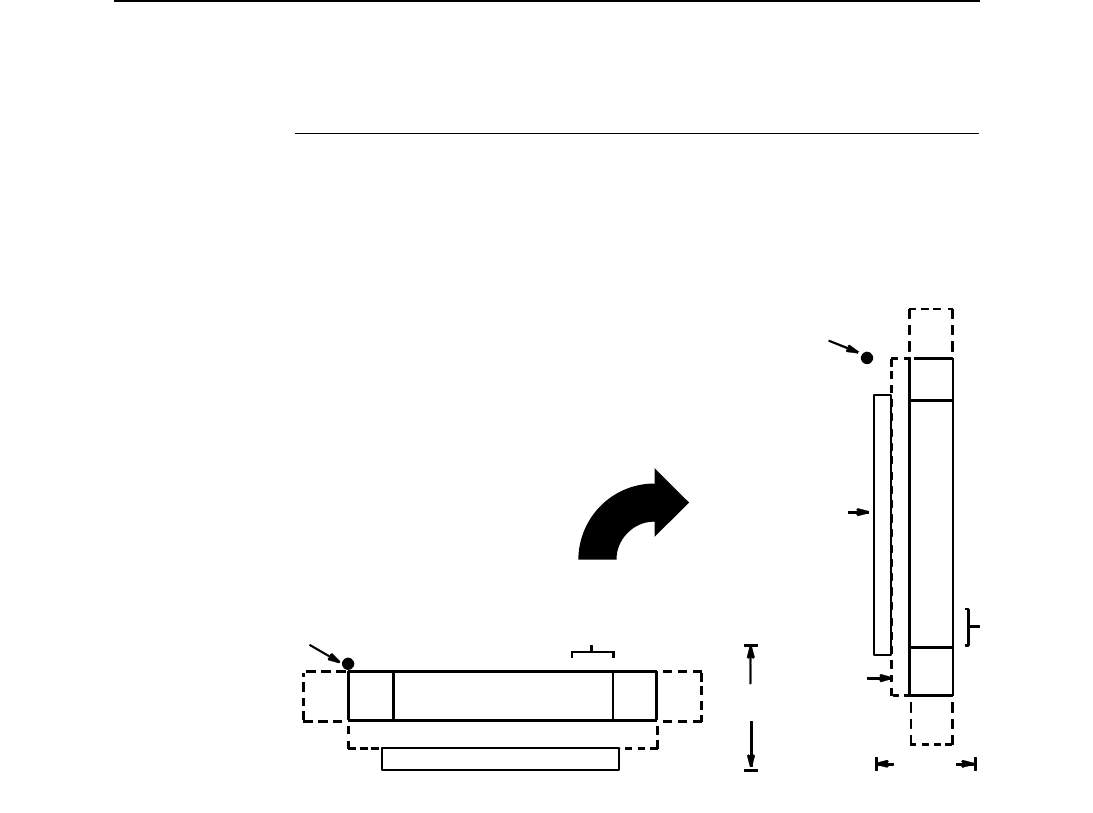
UPS 11
297
UPS 11
The UPS 11 barcode structure is shown in Figure 28 and described on the
following pages.
Figure 28. UPS 11 Structure
Quiet Zone
Both ends of the barcode structure require blank quiet zones. The quiet zones
must be at least 0.25 inches wide and completely blank to ensure accurate
reading of the start/stop codes and to prevent adjacent barcodes from
overlapping. Be sure to provide sufficient space on the form for the quiet
zones.
Start/Stop Codes
The start/stop codes identify the leading and trailing end of the barcode. Each
of the UPS 11 subsets uses a unique start code and a common stop code,
both automatically provided by VGL.
Data Field
UPS 11 is a special case of Code 128 (page 195). This barcode is restricted
to 10 data characters. The first character must be 0 through 9 or A through Z.
The remaining nine digits must be 0 through 9.
DATA FIELD QUIETQUIET START STOP
LOWER GUARD BAND
CODE CODEZONE ZONE
OPTIONAL READABLE DATA FIELD
CHECK DIGIT
OPTIONAL
HEIGHT
STARTING
POSITION
DATA
FIELD
QUIET
ZONE
QUIET
ZONE
START
CODE
STOP
CODE
OPTIONAL
READABLE
DATA
FIELD
CHECK
OPTIONAL
HEIGHT
STARTING
POSITION
DIGIT
GUARD
BAND
LOWER

298
Chapter 3
Barcodes
Readable Data
The optional readable data field provides a readable interpretation of the
barcode data. It can be printed above or below the barcode symbol.
Check Digit
The modulo-103 check digit is automatically calculated and inserted in the
barcode symbol. The check digit verifies accurate scanning. The start code is
included in the check digit algorithm.
UPS 11 Command Format
NOTE: See page 164 for the IBARC, command format and definitions.
Default Ratio: (cc) dir p u data (cc)G
Variable Ratio: (cc) dir p [9] [:] u [ratio] data (cc)G
(cc) Represents the Special Function Control Code
(SFCC). Enter the specific SFCC for your VGL
configuration.
dir Represents the direction of the barcode. Enter B for
horizontal barcodes; enter C for vertical barcodes.
pPrints the optional readable data field. The
readable data field is printed below a horizontal
barcode or on the left-hand side of a vertical
barcode.
Replace p in the barcode command with one of the
codes listed below to print the readable data field in
the corresponding font with the specified guard
band gap.
Table 68. Printable Data Field Fonts
Font Gap p code
Standard 10 cpi 3 dots Y
OCR-A 3 dots O
OCR-A .1-inch S
OCR-B 3 dots B
OCR-B .1-inch T
None N

UPS 11
299
9 or : Selects the variable ratio length barcode feature,
which permits unique bar and space width ratios
adjusted for specific applications.
Enter the number 9 to select variable ratio
barcodes represented in line matrix printer dots (60
x 72 dpi).
Enter : to select variable ratio barcodes
represented in actual printer dots (203 x 203 dpi or
300 x 300 dpi, depending on the printer head being
used).
u The type code for UPS 11. Enter u.
ratio Optional parameter (used in conjunction with 9 or :
above) representing the ratios for variable ratio
barcodes. Default ratios are overridden by the
variable ratio feature. The ratio data must be
hexadecimal numbers from 0 through 9 or A
through F; VGL automatically checks the input for
validity. If an invalid character is found in the ratio,
an error message is generated.
UPS 11 barcodes use eight-digit ratios. The ratios
are interpreted from left to right, measuring the size
of each bar or space in dot width, in the following
pattern: 1 module wide bar : 1 module wide space :
2 module wide bar : 2 module wide space : 3
module wide bar : 3 module wide space : 4 module
wide bar : 4 module wide space. For example,
enter 22446688 in the ratio data field for:
2 module wide bar
2 module wide space
4 module wide bar
4 module wide space
6 module wide bar
6 module wide space
8 module wide bar
8 module wide space
NOTE: VGL automatically checks ratio data for validity only within the
allowable hexadecimal range. VGL does not verify that ratio data
creates acceptable bar/space element relationships for barcode
readability. When designing unique ratio data, carefully plot bar/
space ratios to conform to readable barcodes.
data The barcode data. UPS 11 barcodes are restricted
to 11 data characters. The first character must be 0
through 9 or A through Z. The remaining ten digits
must be 0 through 9.
(cc)G Terminates the barcode command. Enter the SFCC
for your VGL configuration immediately followed by
any valid command character or G, the universal
sequence terminator.
300
Chapter 3
Barcodes
UPS 11 Examples
The following command generates the horizontal default ratio UPS 11
barcode shown below. In the command sequence, graphics mode data is
italicized and barcode data is boldface. See Chapter 2 for a detailed
description of alphanumeric commands.
^M1010010^BYu12345678902^G^-
^M introduced the standard alphanumeric command.
The character height selected was 1.0 inches and character width was
selected at 1.0 inches.
A 0.1 justification value plus 0 additional dots was selected for the data
placement.
^B introduced the barcode command.
Y selected the standard 10 cpi font to print the optional readable data field.
u selected the UPS 11 barcode type.
12345678902 is the barcode data field.
^G^- terminated the barcode command sequence.
The following command generated the vertical UPS 11 barcode below using
standard 10 cpi font with the standard default ratio and data of 12345678902:
^M1010040^CYu12345678902^G^-
301
4
Exercises And Examples
Practice Using VGL
The following examples and exercises are designed to provide experience in
using VGL. The VGL command standards used in the exercises are
described in Chapter 2. Be sure to specifically follow the format for VGL
commands to ensure proper VGL operation.
Most of the format parameters are standard to all the commands unless
otherwise noted. Where applicable, some of the practice examples could be
modified to use the comparable Version II commands as described in Chapter
2.
The practice exercise is presented for both normal and high resolution modes.
The practice exercise for normal resolution begins on page 302. The practice
exercise for high resolution begins on page 306.
NOTE: Using a different type of printer or a different configuration could
affect the appearance of your printed samples compared to those
shown in this manual. Additionally, depending on the paper top-of-
form setting and initial print position, the positioning of your printed
samples on the page may vary compared to the examples shown
here; these samples have been positioned on the page to correspond
with the related text.
Use the standard commands on your system to open a file to contain the
data, and to print the file when you're ready to print.
An explanation precedes each step in the practice exercises. Each command
sequence shows the general command format (Format) as detailed in
Chapter 2. Data following Enter represents the input data. The parameters of
each command have a specific order for data entry and a specific amount and
type of data that can be entered; input the data exactly as shown with the
possible exception of the SFCC. Always use the actual SFCC required by
your system wherever the ^ is shown.

302
Chapter 4
Practice Using VGL
Practice Graphic Exercise - Normal Resolution
NOTE: It is not necessary to enter the Dark Print (KF) commands where
instructed in the practice exercise steps. Dark Print is a feature of line
matrix printers only.
Creating Alphanumeric Text
1. Enable VGL for the Graphics Mode using the Graphics Mode Enable
command (PY). This is the first input to change VGL from the Normal
Mode to the Graphics Mode before any graphics data or commands can
be processed.
Format: (cc)PY(cc)-
Enter: ^PY^-
2. To avoid accidentally terminating the graphics command sequences by a
host-generated terminator, enable the Free Format command (F). This
allows VGL to accept the data as one continuous stream even though the
data may contain host-generated paper motion commands. When Free
Format is enabled, VGL only recognizes the Free Format command
terminators: carriage return (^-), form feed (^,), line feed (^*), vertical tab
(^+), and EVFU commands.
Format: (cc)F(cc)-
Enter: ^F^-
3. Create some alphanumeric text. Use the Standard Alphanumeric
command (M) to print "IGP" in characters 1.0 inches high (ht) and 1.0
inches wide (wd). Add a pass terminator (carriage return).
Format: (cc)M ht wd jus data
(cc)-
Enter: ^M10,10,000IGP
^-
4. To see the results, enter a sequence terminator. For example, enable the
Free Format Form Feed command (,) and print the file. The result should
look like the example shown in Figure 29.
Format: (cc),
Enter: ^,
Figure 29. Practice Alphanumeric Commands in Normal Resolution
Practice Graphic Exercise - Normal Resolution
303
Boxing the Alphanumeric Text
5. In order to put a box around "IGP," a certain amount of data positioning
must occur. Modify the standard alphanumeric command (M) previously
entered to include other commands before "IGP." Add a Justification
command (J) for a 1.2 inch justification (jus) to move "IGP" down. Add a
Horizontal Tab (T) command before "IGP" to move it 1.1 inches (dis) from
the left margin.
Format: (cc)M ht wd jus
(cc)J jus (cc)T dis data
Enter: ^M10,10,000
^J120^T0110IGP
6. Use the Box command (LB) to add the box around "IGP." The Box
command is part of the extended graphics command set; in this example,
it must be input as part of the alphanumeric command sequence (input
prior to the sequence terminator). Use a Horizontal Tab command (T) to
position the starting point of the box 0.9 inches (dis) from the left margin.
Use a Justification command (J) with a zero justification to begin the box
at the top of the form. Enter the Box command (LB) to create a box 4.2
inches wide (horz) and 2.5 inches tall (vert) with horizontal (h) and vertical
(v) borders 3 dot rows thick.
Format: (cc)T dis
(cc)LB horz vert h v
Enter: ^T0090^J000
^LB0420,0250,3,3
The input file now contains the following commands. Printing the file
creates a box around the name as shown in Figure 30.
^PY^-
^F^-
^M10,10,000
^J120^T0110IGP
^T0090^J000
^LB0420,0250,3,3
^-^,
Figure 30. Practice Alphanumeric Commands and Box
in Normal Resolution
304
Chapter 4
Practice Using VGL
Creating Horizontal Lines
7. To put a horizontal line under “IGP,” use another Justification (J) and
Horizontal Tab (T) sequence to position the line 2.3 inches (jus) down
which is 0.3 inches under the name. Tab the line to 1.0 inches (dis) from
the left margin which begins the line just inside the left edge of the box.
Use a Solid Line (LS) command to create a line 3.0 inches long
horizontally (horz) and 2 dots wide vertically (vert). Add this data to the file
before the sequence terminator. The printed result is shown in Figure 31.
Format: (cc)J jus (cc)T dis
(cc)LS horz vert h v
Enter: ^J230^T0100
^LS0300,0002
Figure 31. Practice Alphanumeric Commands, Box, and Line
in Normal Resolution
Creating More Alphanumeric Text
8. Use the Character Height command (H) to specify a new height (ht) of 0.2
inch. Use the Character Width command (W) to specify a new width (wd)
of 0.3 inches. Use a Justification command (J) to position the word
"INTELLIGENT" (data) at 0.1 inches (jus) from the starting position and a
Horizontal Tab command (T) to position "INTELLIGENT" 1.1 inches (dis)
from the left margin. Similarly, using the Justification and Tab sequence,
the word "GRAPHICS" can be positioned 0.4 inches down, 1.6 inches
from the left margin, and the word "PRINTING" 0.7 inches down, 2.1
inches from the left margin. Notice how it is possible to tab and justify to
any position. Tabs are related to the left margin and can be specified in
any print position left or right of the current print position. Justification is
relative to the starting point of the command sequence and can move
down and back up relative to that point.
Practice Graphic Exercise - Normal Resolution
305
Format: (cc)H ht (cc)W wd
(cc)J jus (cc)T dis data
Enter: ^H02^W03
^J010^T0110INTELLIGENT
^J040^T0160GRAPHICS
^J070^T0210PRINTING
9. Disable the Free Format command (O) and use the Graphics Mode
Disable command (PN).
Format: (cc)O(cc)-(cc)PN(cc)-
Enter: ^O^-^PN^-
The file now contains the following commands. The printout is shown in
Figure 32.
^PY^-
^F^-
^M10,10,000
^J120^T0110IGP
^T0090^J000
^LB0420,0250,3,3
^J230^T0100
^LS0300,0002
^H02^W03
^J010^T0110INTELLIGENT
^J040^T0160GRAPHICS
^J070^T0210PRINTING
^-^,
^O^-^PN^-
Figure 32. Completed Practice Example in Normal Resolution

306
Chapter 4
Practice Using VGL
Practice Graphic Exercise - High Resolution
The high resolution practice exercise is very similar to the normal resolution
exercise; the difference is that some parameters have been expanded to
allow sizing and positioning at greater levels of specificity (higher resolution).
Again, remember to properly terminate each command line and be sure that
the printer power is on and that the printer is ready and on line.
Enable VGL Graphics
1. Enable VGL for the Graphics Mode using the Graphics Mode Enable
command (PY). This is the first input to change VGL from the Normal
Mode to the Graphics Mode.
Format: (cc)PY(cc)-
Enter: ^PY^-
2. To avoid accidentally terminating the graphics command sequence by a
host-generated terminator, enable the Free Format command (F). This
allows VGL to accept the data as one continuous stream even though the
data may contain host-generated paper motion commands. When Free
Format is enabled, VGL only recognizes the Free Format command
terminators: Carriage Return (^-), Form Feed (^,), Line Feed (^*), Vertical
Tab (^+), and EVFU commands.
Format: (cc)F(cc)-
Enter: ^F^-
3. Once in Graphics Mode, type the following command to enable Extended
Graphics/High Resolution Mode:
Format: ^IPARAM,(mode)^G^-
Enter: ^IPARAM,EXTENDED^G^-
4. Create some alphanumeric text. Use the Standard Alphanumeric
command (M) to print "IGP" in characters 1.25 inches high (ht) and 1.25
inches wide (wd). Add a pass terminator (carriage return).
Format: (cc)M ht wd jus data
(cc)-
Enter: ^M125,125,00000IGP
^-
5. To see the results, enter a sequence terminator. For example, enable the
Free Format Form Feed command (,) and print the file. The result should
look like the example shown in Figure 33.
Format: (cc),
Enter: ^,

Practice Graphic Exercise - High Resolution
307
Figure 33. Practice Alphanumeric Commands in High Resolution
Boxing the Alphanumeric Text
6. In order to put a box around "IGP," a certain amount of data positioning
must occur. Modify the standard alphanumeric command (M) previously
entered to include other commands before "IGP." Add a Justification
command (J) for a .525 inch justification (jus) to move "IGP" down. Add a
Horizontal Tab (T) command before "IGP" to move it 1.125 inches (dis)
from the left margin.
Format: (cc)M ht wd jus
(cc)J jus (cc)T dis data
Enter: ^M125,125,00000
^J00525^T01125IGP
7. Use the Box command (LB) to add the box around "IGP." The Box
command is part of the extended graphics command set; in this example,
it must be input as part of the alphanumeric command sequence (input
prior to the sequence terminator). Use a Horizontal Tab command (T) to
position the starting point of the box .925 inches (dis) from the left margin.
Use a Justification command (J) with a zero justification to begin the box
at the top of the form. Enter the Box command (LB) to create a box 4.225
inches wide (horz) and 2.525 inches tall (vert) with horizontal (h) and
vertical (v) borders 1 dot row thick.
Format: (cc)T dis
(cc)LB horz vert h v
Enter: ^T00925^J00000
^LB04225,02525,1,1
The input file now contains the following commands. Printing the file
creates a box around the name as shown in Figure 34.
^PY^-
^F^-
^IPARAM,EXTENDED^G^
^M125,125,00000
^J00525^T01125IGP
^T00925^J00000
^LB04225,025525,1,1
^-^

308
Chapter 4
Practice Using VGL
,
Figure 34. Practice Alphanumeric Commands With a Box in High
Resolution
Creating Horizontal Lines
8. Use another Justification (J) and Horizontal Tab (T) sequence to place a
horizontal line under “IGP.” Position the line 2.025 inches (jus) down,
which is 1.5. inches under the name. Tab the line to 1.525 inches (dis)
from the left margin which begins the line just inside the left edge of the
box. Use a Solid Line (LS) command to create a line 2.925 inches long
horizontally (horz) and 0.005 inches wide vertically (vert). Add this data to
the file before the sequence terminator. The printed result is shown in
Figure 35.
Format: (cc)J jus (cc)T dis
(cc)LS horz vert h v
Enter: ^J02025^T01525
^LS02925,00005
ope

Practice Graphic Exercise - High Resolution
309
Figure 35. Practice Alphanumeric Commands, Box, and Line in High
Resolution
Creating More Alphanumeric Text
9. Use the Character Height command (H) to specify a new height (ht) of
.012 inch. Use the Character Width command (W) to specify a new width
(wd) of .012 inches. Use a Justification command (J) to position the word
"INTELLIGENT" (data) at .135 inches (jus) from the starting position and
a Horizontal Tab command (T) to position it 1.125 inches (dis) from the
left margin. Similarly, using the Justification and Tab sequence, the word
"GRAPHICS" can be positioned .245 inches down, 2.550 inches from the
left margin, and the word "PRINTING" .355 inches down, 3.775 inches
from the left margin.
Notice how it is possible to tab and justify to any position. Tabs are related
to the left margin and can be specified in any print position left or right of
the current print position. Justification is relative to the starting point of the
command sequence and can move down and back up relative to that
point.
Format: (cc)H ht (cc)W wd
(cc)J jus (cc)T dis data
Enter: ^H012^W012
^J00135^T01125INTELLIGENT
^J00245^T02550GRAPHICS
^J00355^T03775PRINTING
10. Disable the Free Format command (O) and use the Graphics Mode
Disable command (PN) to disable the Graphics Mode (and thus the
Extended Graphics/High Resolution Mode) to complete this exercise.
310
Chapter 4
Practice Using VGL
Format: (cc)O(cc)-(cc)PN(cc)-
Enter: ^O^-^PN^-
The file now contains the following commands. The printout is shown in
Figure 36.
^PY^-
^F^-
^IPARAM,EXTENDED^G^-
^M125,125,00000
^J01525^T01125IGP
^T00925^J00000
^LB04225,02525,1,1
^J02025^T01525
^LS02925,00005
^H012^W012
^J00135^T01125INTELLIGENT
^J00245^T02550GRAPHICS
^J00355^T03775PRINTING
^-^,
^O^-^PN^-
Figure 36. Completed Practice Example in High Resolution

Page Layout Considerations
311
Once familiar with the expanded command parameters used in high
resolution mode, you can perform the remaining exercises in high resolution
mode also. To do so, simply enable Extended Graphics/High Resolution
Mode as you did in this exercise and then modify the appropriate steps in the
exercises to include broader parameter definitions.
Form Example
The following exercise produces a complete form by sketching it out on a grid.
(Use the Standard Grid and Logo grid provided in Appendix C.) The starting
and ending values are the data for VGL command parameters. The form
includes a box, a logo, a barcode, vertical and horizontal lines and
alphanumeric data.
Page Layout Considerations
At 6 lines per inch (lpi) and 10 characters per inch (cpi) printing, a standard 8-
1/2 x 11-inch sheet of paper has a print area of 66 lines (rows) and 85
characters (columns). (The printable area varies if you are not printing at 6 lpi
and 10 cpi.) Thus, the grid used to design an 8-1/2 x 11-inch form should
accommodate this 66 x 85 area.
Planning the Form Layout
In this example, assume you work for the HandCraft Boat Company. Your
slogan is "Quality boats crafted by hand," and the owner, Mr. Handcraft, has
asked you to design a simple form that his salesman can use for special
orders. On the form, he wants a logo, the slogan, the customer's name,
spaces for other particulars of the order, and a barcode to distinguish the
sales region and boat division from other HandCraft enterprises. Begin your
task as described below.
All data and commands for the form are entered into a file on the host
computer. Again, use the standard commands on your system to open a file
to contain the data and to print the file.
Similar to the previous examples, the information you are to input is listed
under the word Enter. Input the data exactly as it is shown with the possible
exception of the SFCC. Always use the actual SFCC required by your system
wherever the ^ is shown. For each command sequence, the general
command format is listed under the word Format. In the general format, the
SFCC is shown as (cc).
Remember to properly terminate each command line. Make sure the printer
power is on and that the printer is ready and on line.
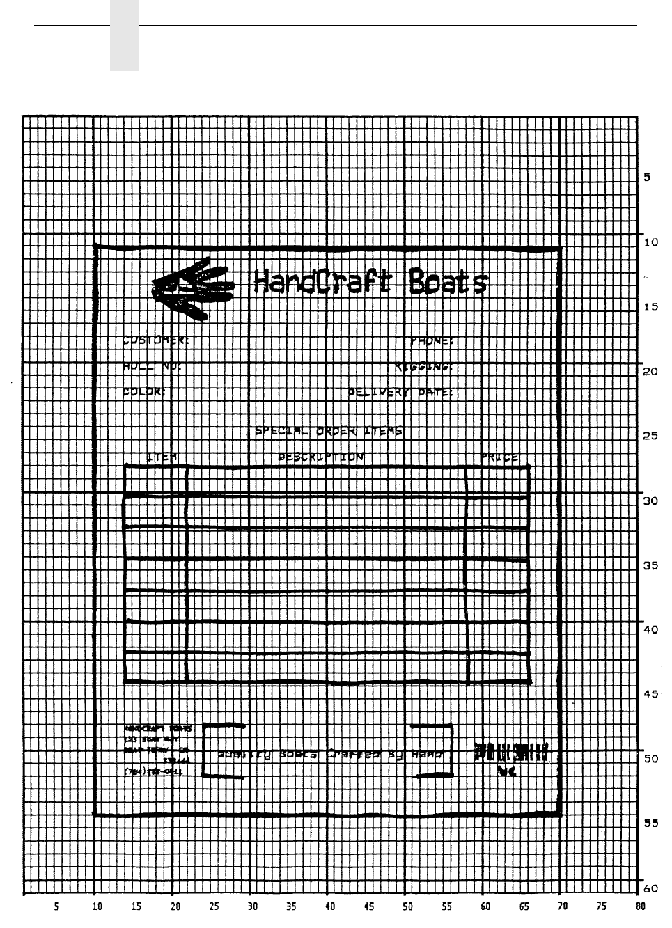
312
Chapter 4
Form Example
Figure 37. Sample Form Design

Planning the Form Layout
313
Design the Form
1. Design the form on a grid as shown in Figure 37. (A standard grid
program and example is provided in Appendix C.) Designing the form on
the grid allows you to decide where each form element is placed.
Compensate for expanded alphanumerics and plan for the logo.
Enable VGL Graphics
2. Use the Graphics Mode Enable command (PY) to enable VGL for the
Graphics Mode.
Format: (cc)PY(cc)-
Enter: ^PY^-
3. To avoid accidentally terminating the graphics command sequence by a
host-generated terminator, enable the Free Format command (F). This
allows VGL to accept the data as one continuous stream even though the
data may contain host-generated paper motion commands. When Free
Format is enabled, VGL only recognizes the Free Format command
terminators: Carriage Return (^-), Form Feed (^,), Line Feed (^*), Vertical
Tab (^+), and EVFU commands.
Format: (cc)F(cc)-
Enter: ^F^-
4. Send a Free Format Form Feed command (,), to begin form processing at
a top-of-form position.
Format: (cc),
Enter: ^,
VGL is now ready to accept the commands and data for the form. Most of
the form and form elements are designed using the extended graphics
command set. Consequently, one of the Alphanumeric commands or the
Interrupt command must be used to introduce, or enable, the extended
graphics commands.
5. Enter the Standard Alphanumeric command (M). No other Alphanumeric
command parameters are needed at this time.
Format: (cc)M
Enter: ^M
Position Form Elements
6. Each of the various form elements must be properly positioned within the
form. Use a Justification command (J) to adjust the vertical position and a
Horizontal Tab command (T) to adjust the horizontal position for the first
form element. Position the first element 1.1 inches (jus) down from the
current print position and 1.0 inches (dis) in from the left margin.
Format: (cc)J jus (cc)T dis
Enter: ^J110^T0100

314
Chapter 4
Form Example
Create the Box Around the Form
7. Use the Box command (LB) to create the outer box of the form. The box
will be 6.0 inches wide (horz), 7.4 inches tall (vert), with a 3-dot horizontal
(h) and vertical (v) line thickness.
Format: (cc)LB horz vert h v
Enter: ^LB0600,0740,3,3
Design the Logo
8. Define the logo, and return to the form to add the logo data. The
HandCraft logo is a hand with a sailboat as plotted in Figure 38. (Use the
Logo Grid in Appendix C to plot the dot positions for your logo the same
way.) Drawing the logo out on a grid permits the dot positions for each
vertical data byte in the logo to be computed and input as data in the
Plotting Graphics (Q) command. Notice that where dot positions are not
computed, the boat image in the hand emerges. The complete program
for the HandCraft logo starts on page 317.
Translate Logo Design into Data
Each hexadecimal data byte specifies a seven-bit dot row portion of the
logo, measuring 0.1 inch. The Most Significant Bit (MSB) of the data byte
corresponds to row 1 (the top bit row), and the bit rows continue through
the other bits to the Least Significant Bit (LSB) of the data byte, which
corresponds to row 1 (the bottom row). If the bit is set, a dot is printed in
the corresponding location. A hex data byte value of 7F prints dots in all
seven rows (64 + 32 + 16 + 8 + 4 + 2 + 1); a hex value of 40 (decimal 64)
prints a dot only in bit row 7. See page 129 in Chapter 2 for more
information on the Graphics Plotting (Columns) command.
For example, the values in Table 69 have been assigned to bits 1 through
7 for the first 0.1-inch row of data bytes (1 through 42) shown in Figure
38. Each byte was first calculated in decimal and then converted to the
equivalent hexadecimal value (using the ASCII chart in Appendix A). The
hexadecimal values are the data for the program shown on page 317.
Following this scheme, all hex data bytes for an entire 0.1 inch row (seven
vertical dot rows) of the logo can be calculated. Subsequent rows are
calculated similarly. To print each 0.1-inch row of the logo, the print
position is shifted down 0.1 inch using the Justification command, and
then the same vertical data byte columns are used. (See the second
example in Figure 38.)
Use the extended command for Graphics Plotting in columns (Q). The
Standard Alphanumeric command (M) introduces the Q command. The
Standard Alphanumeric command is also required with the Justification
(J) command to begin printing the logo 1.2 inches (jus) down from the
original print position and subsequently adjusted 0.1 inches with each
row. The Horizontal Tab (T) command is used to begin logo printing 1.7
inches and 5 dot rows (dis) from the left margin.
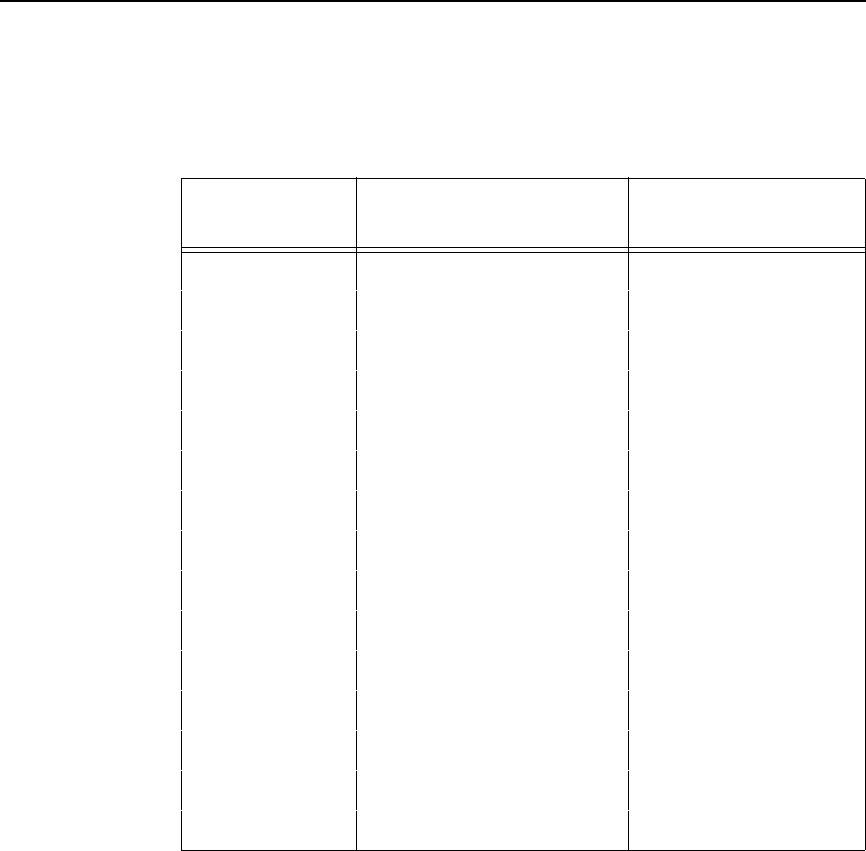
Planning the Form Layout
315
NOTE: Data Bytes containing no value (00), such as bytes 1 through 27
above, must be listed when actual data follows. However, any
remaining 00 data bytes following the end of data for that line, such
as bytes 42 through 80, need not be listed. (The universal terminator,
(cc)G, signals the end of data for that line.)
Following this scheme, all hex data bytes for an entire 0.1 inch row (seven
vertical dot rows) of the logo can be calculated. Subsequent rows are
calculated similarly. To print each 0.1-inch row of the logo, the print position is
shifted down 0.1 inch using the Justification command, and then same vertical
data byte columns are used. (See the second example in Figure 38 on
page 316.)
Use the extended command for Graphics Plotting in columns (Q). The
Standard Alphanumeric command (M) introduces the Q command. The
Standard Alphanumeric command is also required with the Justification (J)
command to begin printing the logo 1.2 inches (jus) down from the original
print position and subsequently adjusted 0.1 inches with each row. The
Horizontal Tab (T) command is used to begin logo printing 1.7 inches and 5
dot rows (dis) from the left margin.
Table 69. Translating Logo Design Into Data
Data
Byte # Decimal Value Converted to
Hexadecimal Value
1 through 27 00 00
28 01 01
29 03 03
30 03 03
31 07 (4+2+1) 07
32 15 (8+4+2+1) 0F
33 31 (16+8+4+2+1) 1F
34 31 1F
35 63 (32+16+8+4+2+1) 3F
36 63 3F
37 126 (64+32+16+8+4+2) 7E
38 124 (64+32+16+8+4) 7C
39 124 7C
40 120 (64+32+16+8) 78
41 112 (64+32+16) 70
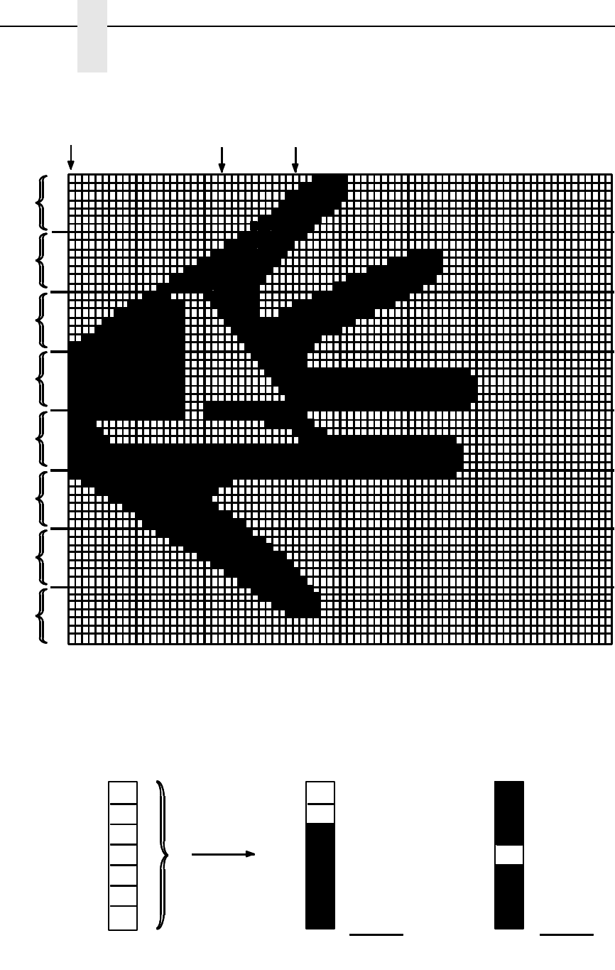
316
Chapter 4
Form Example
Figure 38. Logo Design
7
6
5
4
3
2
1
10 20 30 40 50 60 70
7
6
5
4
3
2
1
7
6
5
4
3
2
1
7
6
5
4
3
2
1
7
6
5
4
3
2
1
7
6
5
4
3
2
1
7
6
5
4
3
2
1
7
6
5
4
3
2
1
7 =
6 =
5 =
4 =
3 =
2 =
1 =
64
32
16
8
4
2
1
Byte 1 Byte 23 Byte 34
Bit # Weights
Decimal
Data Data Data
Row 1, Byte 34
0
16
8
4
2
1
+
Row 5, Byte 34
31
(decimal)
16
0
4
2
1
+
119
(decimal)
Example: Example:
NOTE: Actual size of this logo is approximately .8-inch tall by 1-inch wide.
Row 1
Row 2
Row 3
Row 4
Row 5
Row 6
Row 7
Row 8
064
32
*
* Each 7-bit vertical data byte equals .1-inch or 1 row."
NOTE: Actual size of this logo is approximately .8-inch tall by 1-inch wide.
*Each 7-bit vertical data byte equals .1-inch or 1 “row”.

Planning the Form Layout
317
Input the Logo Data
9. Input the command sequence for the Standard Alphanumeric command,
Justification command, Horizontal Tab command, and Graphics Plot
command for each 0.1-inch row of hex data in the logo. Each group of
data below represents, from top to bottom, the eight 0.1-inch rows
required to produce the logo. (The spaces separating each group are for
readability; do not include these spaces in your program.)
Format:
(cc)M(cc)J jus (cc)T dis (cc)Q data (cc)G
Enter:
^M^J120^T0175^Q
00,00,00,00,00,00,00,00,00,00,00,00,00,00,00,00,00,00,00,00,00,00,00,00,
00,00,00,01,03,03,07,0F,1F,1F,3F,3F,7E,7C,7C,78,70^G
Enter:
^M^J130^T0175^Q
00,00,00,00,00,00,00,00,00,00,00,00,00,01,01,03,03,07,07,0F,0F,1F,1F,3F,
3F,7F,7F,7F,7E,7C,78,70,60,40,40,00,00,00,00,01,01,03,03,03,07,07,07,0F,
0F,0F,1F,1F,1E,1E,1C^G
Enter:
^M^J140^T0175^Q
01,01,03,03,07,0F,0F,1F,1F,3F,3F,7F,7F,7F,7F,3F,3F,00,00,00,40,60,70,78,
7C,7E,7F,7F,0F,0F,0F,1F,1F,3F,3F,3F,7E,7C,7C,7C,78,78,70,70,70,60,60,
60,40,40^G
Enter:
^M^J150^T0175^Q
7F,7F,7F,7F,7F,7F,7F,7F,7F,7F,7F,7F,7F,7F,7F,7F,7F,00,00,00,01,01,01,01
,01,01,01,41,61,71,79,7D,7F,7F,7F,1F,1F,1F,1F,1F,1F,1F,1F,1F,1F,1F,1F,
1F,1F,1F,1F,1F,1F,1F,1F,1F,1F,1F,1F,0E^G
Enter:
^M^J160^T0175^Q
7F,7F,7F,7F,5F,4F,47,47,47,47,47,47,47,47,47,47,47,07,07,07,47,47,47,47,
47,47,47,47,47,67,67,67,67,77,7F,3F,1F,1F,0F,0F,0F,0F,0F,0F,0F,0F,0F,0F,
0F,0F,0F,0F,0F,0F,0F,0F,0F,07^G
Enter:
^M^J170^T0175^Q
40,40,60,60,70,70,78,78,7C,7C,7E,7F,7F,7F,7F,7F,7F,7F,7F,7F,7F,77,63,63
,41,41,40,40,40,40,40,40,40,40,40,40,40,40,40,40,40,40,40,40,40,40,40,40,
40,40,40,40,40,40,40,40,40^G
Enter:
^M^J180^T0175^Q
00,00,00,00,00,00,00,00,00,00,00,00,00,40,40,60,60,70,70,78,78,7C,7C,7E,
7E,7F,7F,3F,3F,1F,0F,0F,07,03,01^G

318
Chapter 4
Form Example
Enter:
^M^J190^T0175^Q
00,00,00,00,00,00,00,00,00,00,00,00,00,00,00,00,00,00,00,00,00,00,00,00,0
0,00,00,40,60,60,70,70,78,78,78,78,38^G
Enter the Company Heading
10. Next to the logo, print the company name, HandCraft Boats, in characters
0.3 inches high (ht) and 0.2 inches wide (wd) using the Standard
Alphanumeric command (M). Position the name 1.2 inches and 9 dot
rows (jus) down from the current print position, using the Justification
parameter of the Alphanumeric command and 3.1 inches (dis) from the
left margin using the Horizontal Tab (T) command. An Interrupt command
(I) is a most efficient way to input this type of data into various locations
on the form and it is used frequently in the remainder of the form
processing. Using the Interrupt command (followed by a Graphics Mode
carriage return), we can print what we have programmed so far, then
move the print position to 2.2 inches (dis) below the current start position.
Format: (cc)M ht wd jus (cc)T dis data (cc)G
(cc)I dis (cc)-
Enter: ^M03,02,129^T0310HandCraft Boats^G
^I220^-
The file on the host system for this form to this point contains all the
information listed below. Use your system standard command format to
print the file. The form should look like the one shown in Figure 39. If
errors occur, review your input and see Chapter 6.
^PY^-
^F^-
^,
^M
^J110^T0100
^LB0600,0740,3,3
^M^J120^T0175^Q
00,00,00,00,00,00,00,00,00,00,00,00,00,00,00,00,00,00,00,00,00,00,00,00,
00,00,00,01,03,03,07,0F,1F,1F,3F,3F,7E,7C,7C,78,70^G
^M^J130^T0175^Q
00,00,00,00,00,00,00,00,00,00,00,00,00,01,01,03,03,07,07,0F,0F,1F,1F,3F,
3F,7F,7F,7F,7E,7C,78,70,60,40,40,00,00,00,00,01,01,03,03,03,07,07,07,0F,
0F,0F,1F,1F,1E,1E,1C^G
^M^J140^T0175^Q
01,01,03,03,07,0F,0F,1F,1F,3F,3F,7F,7F,7F,7F,3F,3F,00,00,00,40,60,70,78,
7C,7E,7F,7F,0F,0F,0F,1F,1F,3F,3F,3F,7E,7C,7C,7C,78,78,70,70,70,60,60,
60,40,40^G
^M^J150^T0175^Q
7F,7F,7F,7F,7F,7F,7F,7F,7F,7F,7F,7F,7F,7F,7F,7F,7F,00,00,00,01,01,01,01
,01,01,01,41,61,71,79,7D,7F,7F,7F,1F,1F,1F,1F,1F,1F,1F,1F,1F,1F,1F,1F,
1F,1F,1F,1F,1F,1F,1F,1F,1F,1F,1F,1F,0E^G
^M^J160^T0175^Q
7F,7F,7F,7F,5F,4F,47,47,47,47,47,47,47,47,47,47,47,07,07,07,47,47,47,47,
47,47,47,47,47,67,67,67,67,77,7F,3F,1F,1F,0F,0F,0F,0F,0F,0F,0F,0F,0F,0F,
0F,0F,0F,0F,0F,0F,0F,0F,0F,07^G

Planning the Form Layout
319
^M^J170^T0175^Q
40,40,60,60,70,70,78,78,7C,7C,7E,7F,7F,7F,7F,7F,7F,7F,7F,7F,7F,77,63,63
,41,41,40,40,40,40,40,40,40,40,40,40,40,40,40,40,40,40,40,40,40,40,40,40,
40,40,40,40,40,40,40,40,40^G
^M^J180^T0175^Q
00,00,00,00,00,00,00,00,00,00,00,00,00,40,40,60,60,70,70,78,78,7C,7C,7E,
7E,7F,7F,3F,3F,1F,0F,0F,07,03,01^G
^M^J190^T0175^Q
00,00,00,00,00,00,00,00,00,00,00,00,00,00,00,00,00,00,00,00,00,00,00,00,
00,00,00,40,60,60,70,70,78,78,78,78,38^G
^M03,02,129^T0310HandCraft Boats^G
^I220^-
Figure 39. Box, Logo, and Alphanumeric Commands
Enter Alphanumeric Text Throughout the Form
11. Create the customer related information on the top portion of the form.
Send the Standard Alphanumeric command (M) to specify 0.1 inch high
(ht) and 0.1 inch wide (wd) characters. With the Horizontal Tab command
(T), position the CUSTOMER: data 1.5 inches (dis) from the left margin
and position the PHONE: data 5.1 inches (dis) from the left margin.
Format: (cc)M ht wd jus data
(cc)T dis data
Enter: ^M01,01,000
^T0150CUSTOMER:^T0510PHONE:
12. Other pieces of the customer type data can be added to the top part of the
form from within the same alphanumeric command sequence initiated in
the previous step. Using a Justification command (J), the print position
can be lowered 0.4 inches (jus). Using Horizontal Tab commands (T), the
HULL NO: data can be positioned 1.5 inches (dis) from the left margin
3.1” (dis) from left margin
to starting column for
“HandCraft Boats”
1.2” + 9 dot rows (jus) down from
top of form to starting row for
“HandCraft Boats”

320
Chapter 4
Form Example
and the RIGGING: data can be positioned 4.9 inches (dis) from the left
margin.
Format: (cc)J jus
(cc)T dis data
Enter: ^J040
^T0150HULL NO:^T0490RIGGING:
13. The next set of customer data can be input in a similar fashion. Use the
Justification command (J) to move the print position down 0.8 inches
(jus), use the Horizontal Tab command (T) to position the COLOR: data
1.5 inches (dis) from the left margin and the DELIVERY DATE: data 4.4
inches (dis) from the left margin.
Format: (cc)J jus
(cc)T dis data
Enter: ^J080
^T0150COLOR:^T0440DELIVERY DATE:
14. The remaining text on the top portion of the form can now be entered,
again using a combination of Justification (J) and Horizontal Tab (T)
commands. Begin by justifying the print position 1.4 inches (jus) down
and tabbing 3.2 inches (dis) from the left margin for the SPECIAL ORDER
ITEMS heading.
Justify the print position 1.8 inches (jus) and tab 1.7 inches (dis) for the
ITEM heading, 3.5 inches (dis) for the DESCRIPTION heading, and 6.0
inches (dis) for the PRICE heading. Notice that the Justification command
always moves the print position relative to the last printed row position of
the alphanumeric command sequence. For this reason, the SPECIAL
ORDER ITEMS heading justified at 1.4 inches is 0.4 inches above the
ITEM, DESCRIPTION, and PRICE headings justified at 1.8 inches.
Similarly, the Horizontal Tab command moves the print position relative to
the left margin. Unlike a conventional typewriter, this allows you to move
the print position to the left or the right of the current position by specifying
a different tab position relative to the left margin.
Use the Interrupt command (I) followed by a Graphics Mode carriage
return (-) to position this part of the form 2.0 inches (dis) from the
previously active graphics command sequence (the sequence that
constructed the customer data).
Format: (cc)J jus
(cc)T dis data
(cc)I dis (cc)-
Enter: ^J140
^T0320SPECIAL ORDER ITEMS
^J180
^T0170ITEM^T0350DESCRIPTION^T0600PRICE
^I200^-

Planning the Form Layout
321
Enter the Interior Box with Horizontal and Vertical Lines
15. Add the interior form (the box with vertical lines) for the item, description,
and price data. VGL Form command constructs a box complete with
vertical lines at specified positions.
A Standard Alphanumeric command (M) sequence must be entered to
introduce the extended graphics commands that are used. Use a
Horizontal Tab command (T) to move the print position 1.5 inches (dis)
from the left margin. In the same sequence, use the Form command (LF)
to specify a 5.2-inch horizontal width (horz) and 2.9-inch vertical height
(vert) of the box, both horizontal (h) and vertical (v) edges 2 dot line
thickness.
In the same Form command, specify one vertical line 0.8 inches (Line1)
from the edge of the form with a 1 dot line thickness (t) and another
vertical line 3.6 inches (Line2) from the previous line also with a 1-dot line
thickness (t).
Format: (cc)M (cc) T dis
(cc)LF horz vert h v line1 t line2 t
Enter: ^M^T0150
^LF0520,0290,2,2,0080,1,0360,1
16. Add the horizontal lines to the interior box. Again, an Interrupt (I)
command is used to process and print the data 0.4 inches (dis) lower than
the top border of the interior box. The Standard Alphanumeric command
(M) is used to introduce the other commands in the sequence. Use the
Horizontal Tab command (T) to tab 1.5 inches from the left margin for the
horizontal print position. The solid horizontal lines are generated using the
Solid Line (LS) command. Specify a 5.2 inch horizontal (horz) length and
a 0.0 and 1 dot vertical length (vert), used as the line thickness in this
case.
Format: (cc)I dis (cc)-
(cc)M (cc)T dis (cc)LS horz vert
Enter: ^I040^-
^M^T0150^LS0520,0001
17. Print five more horizontal lines identical to the one created in the previous
step and evenly spaced 0.4 inches apart. Use the same command as in
the previous step and repeat it five times. Use an Interrupt command (I)
followed by a Graphics Mode carriage return to move the print position
0.8 inches (dis) lower.
Enter: ^I040^-
^M^T0150^LS0520,0001
^I040^-
^M^T0150^LS0520,0001
^I040^-
^M^T0150^LS0520,0001
^I040^-
^M^T0150^LS0520,0001
^I040^-
^M^T0150^LS0520,0001
^I080^-
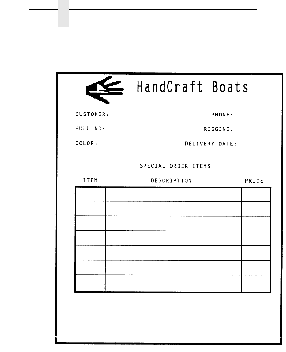

Planning the Form Layout
323
Enter the Corners
18. A series of lines can be drawn to create the corners around the slogan at
the bottom of the form. A Standard Alphanumeric command (M) is used to
introduce the command sequence. A Horizontal Tab command (T) is
used to move the print position of the upper left horizontal line of the
corner 2.5 inches (dis) from the left margin. A Solid Line command (LS) is
used to specify the upper left line of the corner as 0.5 inches plus 5 dots
horizontal length (horz) and 2 dots vertical length (vert).
Format: (cc)M (cc)T dis (cc)LS horz vert
Enter: ^M^T0250^LS0055,0002
19. Use another Horizontal Tab command (T), within the same alphanumeric
command sequence, to move the print position 5.1 inches (dis) from the
left margin for the upper right line of the corner. Use another Solid Line
command (LS) to specify the upper right line of the corner as 0.5 inches
plus 5 dots horizontal length (horz) and 2 dot vertical length (vert).
Format: (cc)M (cc)T dis (cc)LS horz vert
Enter: ^T0510^LS0055,0002
20. The two vertical lines of the corner set are drawn in a similar fashion
within the same command sequence. For the left vertical line, the
Horizontal Tab (T) command specifies a tab position 2.5 inches (dis) from
the left margin and the Solid Line (LS) command creates a line 2 dots in
horizontal length (horz) and 0.8 inches vertical length (vert). The right
vertical line is positioned by a tab 5.6 inches and 5 dots (dis) from the left
margin and the line is created 2 dots horizontal length (horz) and 0.8
inches vertical length (vert).
Format: (cc)T dis (cc)LS horz vert
Enter: ^T0250^LS0002,0080
^T0565^LS0002,0080
21. The left and right horizontal bottom lines of the corner set are justified 0.8
inches (jus) down using a Justification (J) command. Following the
justification, a Horizontal Tab (T) moves the print position 2.5 inches (dis)
from the left margin for the left line created by a Solid Line command (LS)
as 0.5 inches plus 5 dots horizontal length (horz) and 2 dots vertical
length (vert). The right bottom line is created 0.5 inches plus 5 dots
horizontal length (horz) and 2 dots vertical length (vert) at a position 5.1
inches from the left margin (dis).
Format: (cc)J jus (cc)T dis (cc)LS horz vert
(cc)T dis (cc)LS horz vert
Enter: ^J080^T0250^LS0055,0002
^T0510^LS0055,0002

324
Chapter 4
Form Example
22. To generate the HandCraft Boats company address and phone number
data on the lower left of the form, justify the text 2 dots (jus) down using
the Justification (J) command, tab in 1.5 inches (dis) from the left margin
with the Horizontal Tab (T) command, select the 17.65 cpi font with the
Compressed Print (S) command, and supply the HANDCRAFT BOATS
company name as the data.
Format: (cc)J jus (cc)T dis (cc)S f data
Enter: ^J002^T0150^S5HANDCRAFT BOATS
23. The street address line is justified 0.2 inches lower (jus) using a
Justification command (J), positioned 1.5 inches (dis) from the left margin
with a Horizontal Tab command (T), a 17.65 cpi compressed print
command (S5) is sent for each new line of data, and the data is supplied
as 123 BOAT WAY.
Format: (cc)J jus (cc)T dis (cc)S f data
Enter: ^J020^T0150^S5123 BOAT WAY
24. Using the same type of Justification command (J) and Horizontal Tab (T)
command set, the BOAT TOWN, CA city data is justified 0.3 plus 6 dots
(jus) down and tabbed 1.5 inches (dis); the 333444 zip code data is
justified 0.5 plus 5 dots (jus) and tabbed 1.9 inches plus 5 dots (dis); the
(714) 555-0011 phone number data is justified 0.7 plus 3 dots and tabbed
1.5 inches (dis). A new 17.65 cpi compressed print command (S5) is
required immediately preceding each line of data.
Format: (cc)J jus (cc)T dis (cc)S f data
Enter: ^J036^T0150^S5BOAT TOWN, CA
^J055^T0195^S5333444
^J073^T0150^S5(714)555-0011
Enter the Slogan
25. Add the slogan between the corners previously drawn. A Standard
Alphanumeric command (M) is used to specify a character 0.1 inch high
(ht), 0.1 inch wide (wd), and justified 0.4 inches (jus). The slogan is
tabbed 2.7 inches (dis) from the left margin, lowercase descending
characters are enabled by the Descending Characters (D) command, the
slogan Quality Boats Crafted By Hand is supplied as data.
Format: (cc)M ht wd jus
(cc)T dis (cc)D data
Enter: ^M01,01,040
^T0270^DQuality Boats Crafted By Hand

Planning the Form Layout
325
Enter the Barcode
26. Within the same alphanumeric command, the barcode can be generated.
Using the Character Height command (H), the character height is
changed to 0.3 inches (ht) and using the Justification command (J), the
position is moved down 0.5 inches (jus). The barcode is positioned 5.9
inches (dis) from the left margin by a Horizontal Tab (T) command. The
barcode itself is begun by the Horizontal Bar Code command (B), using
the standard 10 cpi readable data field (p), and barcode Code 39 Type A
(type) with the default ratio specified. The barcoded data is WC to
distinguish the HandCraft Boats company West Coast sales region and
the command sequence is terminated.
Format: (cc)H ht (cc)J jus (cc)T dis
(cc)B p type data (cc)G
Enter: ^H03^J050^T0590
^BYAWC^G
Disable VGL Graphics
27. To complete the form, enter an Interrupt command (I) moving the print
position back to the original position followed by a Graphics Mode
carriage return. Disable the Free Format command (O) and disable the
Graphics Mode of Operation (PN) also followed by a Graphics Mode
carriage return.
Format: (cc)I dis (cc)-
(cc)O(cc)-(cc)PN(cc)-
Enter: ^I000^-
^O^-^PN^-
The complete data for the form (the contents of the file for the form on the
host computer) appears below. The completed form is shown in Figure 41
on page 327.
^PY^-
^F^-
^,
^M^KF
^J110^T0100
^LB0600,0740,3,3
^M^J120^T0175^Q
00,00,00,00,00,00,00,00,00,00,00,00,00,00,00,00,00,00,00,00,00,00,00,00,00,00,00,
01,03,03,07,0F,1F,1F,3F,3F,7E,7C,78,70^G^M^J130^T0175^Q
00,00,00,00,00,00,00,00,00,00,00,00,00,01,01,03,03,07,07,0F,0F,1F,1F,3F,3F,7F,7F,
7F,7E,7C,78,70,60,40,40,00,00,00,00,01,01,03,03,03,07,07,07,0F,0F,0F,1F,1F,1E,
1E,1C^G
^M^J140^T0175^Q
01,01,03,03,07,0F,0F,1F,1F,3F,3F,7F,7F,7F,7F,3F,3F,00,00,00.40,60,70,78,7C,7E,
7F,7F,0F,0F,0F,1F,1F,3F,3F,3F,7E,7C,7C,7C,78,78,70,70,70,60,60,60,40,40^G
^M^J150^T0175^Q
7F,7F,7F,7F,7F,7F,7F,7F,7F,7F,7F,7F,7F,7F,7F,7F,7F,00,00,00,01,01,01,01,01,01,
01,41,61,71,79,7D,7F,7F,7F,1F,1F,1F,1F,1F,1F,1F,1F,1F,1F,1F,1F,1F,1F,1F,1F,1F,
1F,1F,1F,1F,1F,1F,1F,0E^G
^M^J160^T0175^Q
7F,7F,7F,7F,5F,4F,47,47,47,47,47,47,47,47,47,47,07,07,07,07,47,47,47,47,47,47,47,
47,47,67,67,67,67,77,7F,3F,1F,1F,0F,0F,0F,0F,0F,0F,0F,0F,0F,0F,0F,0F,0F,0F,0F,

326
Chapter 4
Form Example
0F,0F,0F,0F,07-G
^M^J170^T0175^Q
40,40,60,60,70,70,78,78,7C,7C,7E,7F,7F,7F,7F,7F,7F,7F,7F,7F,7F,77,63,63,41,41,
40,40,40,40,40,40,40,40,40,40,40,40,40,40,40,40,40,40,40,40,40,40,40,40,40,40,40,
40,40,40,40^G
^M^J180^T0175^Q
00,00,00,00,00,00,00,00,00,00,00,00,00,40,40,60,60,70,70,78,78,7C,7C,7E,7E,7F,7F
,3F,3F,1F,0F,0F,07,03,01^G
^M^J190^T0175^Q
00,00,00,00,00,00,00,00,00,00,00,00,00,00,00,00,00,00,00,00,00,00,00,00,00,00,00,
40,60,60,70,70,78,78,78,78,38^G
^M03,02,129^T0310HandCraft Boats^G
^I220^-
^M01,01,000^KF
^T0150CUSTOMER:^T0150PHONE:
^J040
^T0150HULL NO:^T0490RIGGING:
^J080
^T0150COLOR:^T0440DELIVERY DATE:
^J140
^T0320SPECIAL ORDER ITEMS
^J180
^T0170ITEM^T0350DESCRIPTION^T0600PRICE
^I200
^M^T0150^KF
^LF0520,0290,2,2,0080,1,0360,1
^I040
^M^KF^T0150^LS0520,0001
^I040
^M^KF^T0150^LS0520,0001
^I040
^M^KF^T0150^LS0520,0001
^I040
^M^KF^T0150^LS0520,0001
^I040
^M^KF^T0150^LS0520,0001
^I040
^M^KF^T0150^LS0520,0001
^I080
^M^KF^T0250^LS0055,0002
^T0510^LS0055,0002
^T0250^LS0002,0080
^T0565^LS0002,0080
^J080^T0250^LS0055,0002
^T0510^LS0055,0002
^M^J002^T0150^S5HANDCRAFT BOATS
^J020^T0150^S5123 BOAT WAY
^J036^T0150^S5BOAT TOWN, CA
^J055^T0195^S5333444
^J073^T0150^S5 (714) 555-0011
^M01,01,040
^T0270^DQuality Boats Crafted by Hand
^H03^J050^T0590
^BYAWC^G
^I000^-
^O^-^PN^-
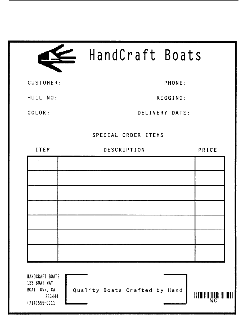
Planning the Form Layout
327
Figure 41. Completed Practice Form Example
formlogo.ex3
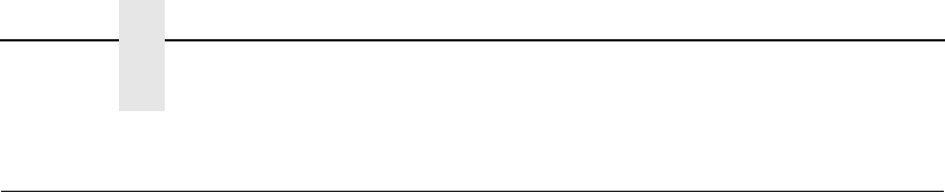
328
Chapter 4
Label Example
Label Example
This practice exercise is designed to provide experience in creating and
processing a sample label. The label includes:
• horizontal duplication
• alphanumeric data
• horizontal and vertical lines
• dynamic data fields
• boxes
• barcodes
As in the form example, all data for the labels is entered into a file on the host
computer. Use your standard system commands to open the file and print the
file as needed. Also, the same Enter/Format explanations are provided in this
example. You enter the data listed under Enter; the general command format
is listed under Format. Always use the actual SFCC required by your system
wherever the ^ is shown in the examples or where the (cc) is shown in the
general format. Do not forget to properly terminate each command line. Make
sure the printer power is on and that the printer is ready and on line.
NOTE: Similar to the previous example exercise, your printed output may
vary in appearance or location based on your type of printer and
printer configuration; these samples have been positioned on the
page to correspond with the related text.
The labels for this exercise are shown in Figure 42, complete with all label
elements and data. One label is actually created by VGL commands and then
duplicated horizontally on the page. When the first set of dynamic data is
supplied, it is inserted in the label and in the duplicate. The second set of
dynamic data is inserted in a second label and duplicate. This process could
be continued to produce any number of labels.
Planning the Form Layout
329
Figure 42. Sample Labels

330
Chapter 4
Label Example
Enable VGL Graphics
1. Use the Graphics Mode Enable command (PY), to enable VGL for the
Graphics Mode.
Format: (cc)PY(cc)-
Enter: ^PY^-
2. To avoid accidentally terminating the graphics command sequence by a
host-generated terminator, enable the Free Format command (F). This
allows VGL to accept the data as one continuous stream even though the
data may contain host-generated paper motion commands. When Free
Format is enabled, VGL only recognizes the Free Format command
terminators: Carriage Return (^-), Form Feed (^,), Line Feed (^*), Vertical
Tab (^+), and EVFU commands.
Format: (cc)F(cc)-
Enter: ^F^-
Enable Dynamic Form Processing
Dynamic form processing allows specific data fields within the form/label
to be identified. After all form or label components have been created,
different sets of data can be supplied to the fields as copies of the label
are produced.
3. To enable dynamic form processing, the Dynamic Form command (B) is
used followed by a Graphics Mode carriage return. It is part of the
standard graphics command set, and must be sent to VGL without being
introduced by an alphanumeric command. Once dynamic form
processing is enabled, VGL continues in the Dynamic Form Mode until
properly completed.
Format: (cc)B(cc)-
Enter: ^B^-
Enable Horizontal Duplication
One label is created and duplicated on the page horizontally. This
produces a duplicate copy of the label when the dynamic data is supplied.
All commands required to create the label must fall between Horizontal
Duplication on and off commands.
4. Begin with the Horizontal Duplication (S) command to turn horizontal
duplication on. Specify 2 copies (#) spaced 4.0 inches apart (gap). Send a
Graphics Mode carriage return after the Horizontal Duplication command.
Format: (cc)S # gap (cc)-
Enter: ^S0240^-

Planning the Form Layout
331
Create the Label Box
5. Use the extended graphics command set to create the label components.
The Standard Alphanumeric command (M) is used to introduce the
extended graphics command set. Use the Box command (LB) to create
the box for the outer border of the label. The box is 2.6 inches plus 4 dots
horizontally (horz) and 4.7 inches vertically (vert). Both the horizontal (h)
and vertical (v) borders of the box have a line thickness of 2 dots.
Format: (cc)M(cc)LB horz vert h v
Enter: ^M^LB0264,0470,2,2
Create the Corners
Two sets of corners are used in the label, one corner set around the
"From" data and the other set around the "To" data.
6. To create these corners, one vertical and horizontal line are justified and
tabbed into proper position for each corner piece, eight lines total (four
corner pieces) per corner set. All the commands required for the corner
sets are part of the alphanumeric command sequence initiated in the
previous step. A Justification command (J), Horizontal Tab command (T),
and a Solid Line command (LS) are used for each line.
Format: cc)J jus (cc)T dis (cc)LS horz vert
Enter: ^J010^T0020^LS0020,0002
^J010^T0220^LS0020,0002
^J010^T0020^LS0002,0020
^J010^T0240^LS0002,0020
^J080^T0020^LS0002,0020
^J080^T0240^LS0002,0020
^J100^T0020^LS0020,0002
^J100^T0220^LS0020,0002
^J110^T0020^LS0020,0002
^J110^T0220^LS0020,0002
^J110^T0020^LS0002,0020
^J110^T0240^LS0002,0020
^J160^T0020^LS0002,0020
^J160^T0240^LS0002,0020
^J180^T0020^LS0020,0002
^J180^T0220^LS0020,0002

332
Chapter 4
Label Example
Add TO/FROM Alphanumeric Data
7. To add the "From" data, use a series of Standard Alphanumeric
commands (M) to specify 0.1 inch high (ht) by 0.1 inch wide (wd)
characters justified 0.2 inches (jus) down for the FROM heading.
Use a Horizontal Tab (T) to position the heading 0.4 inches (dis) from the
margin. In a similar command sequence, specify 0.2 inch high and 0.2
inch wide characters justified 0.4 inches down for the Printronix heading,
also tabbed 0.4 inches from the margin.
Justify the street address data 0.6 inches plus 5 dots (jus) down using a
Justification command (J) and tab the address data 0.8 inches (dis) from
the margin using a Horizontal Tab command (T). In a similar Justification
and Horizontal Tab sequence, justify the city and state data 0.8 inches
down and tabbed 0.9 inches from the margin.
For the address data, select the 17.65 cpi compressed print font (f) using
the Compressed Print command (S) in a new Standard Alphanumeric
command (M) sequence. (A compressed print command must
immediately precede the compressed print data for each line where it is
used.)
Format: cc)M ht wd jus (cc)T dis data
(cc)M(cc)J jus (cc)T dis (cc)S f data
Enter: ^M01,01,020^T0040FROM
^M02,02,040^T0040ACME MOTOR
^M^J065^T0080^S512345 CUL DE SAC RD.
^J080^T0090^SUSCITY, CA 99999
8. The "To" data includes dynamic data fields for the name, street address,
and city data lines of the different companies.
Begin with a Standard Alphanumeric command (M) to specify the TO
heading as 0.1 inch high (ht) by 0.1 inch wide (wd) characters, justified
0.2 inches down (jus) and tabbed 0.4 inches (dis) from the left margin
using the Horizontal Tab command (T). Using a Justification (J) and
Horizontal Tab (T) command sequence, position the company name data
line 1.3 inches plus 4 dots (jus) down and 0.4 inches (dis) from the left
margin.
Use a Dynamic Form Field Length command ([) to specify the maximum
length (length) of the dynamic data field as 24 characters. Similarly, justify
the street address line 1.5 inches down, tabbed 0.4 inches from the left
margin, and 24 characters maximum length.
Justify the city and state data line 1.6 inches plus 5 dots down, tabbed 0.4
inches from the left margin, and 24 characters maximum length.
Format: cc)M ht wd jus (cc) T dis data
(cc)J jus (cc) T dis (cc) [ length (cc)G
Enter: ^M01,01,120^T0040TO
^J134^T0040^[024^G
^J150^T0040^[024^G
^J165^T0040^[024^G

Planning the Form Layout
333
Add Horizontal Lines
9. The three horizontal lines to separate the three barcode fields can be
added to the form using Justification (J), Horizontal Tab (T) and Solid Line
(LS) commands. All three lines are 2.6 inches plus 4 dots horizontally
(horz) and 1 dot vertically (vert), used as the line thickness, and all three
lines are tabbed 0.0 inches (dis) from the left margin (touching the left
edge of the label). Justify the first line 1.9 inches down (jus), the second
line 2.8 inches down, and the third line 3.7 inches down.
Format: (cc)J jus (cc)T dis (cc)LS horz vert
Enter: ^J190^T0000^LS0264,0001
^J280^T0000^LS0264,0001
^J370^T0000^LS0264,0001
Add Headings
10. The Sales Order (S.O.), Serial Number (S/N), and the Part Number (P/N)
headings can be added using a series of Justification (J) and Horizontal
Tab (T) commands. Each of the headings are tabbed 0.4 inches (dis)
from the left margin. Justify the S.O. heading 2.0 inches (jus) down, the
S/N heading 2.9 inches down, and the P/N heading 3.8 inches down.
Format: (cc)J jus (cc)T dis data
Enter: ^J200^T0040S.O.
^J290^T0040S/N
^J380^T0040P/N
Add Barcodes and Dynamic Bar Code Data
11. The three barcodes and dynamic barcode data fields can now be input. A
Standard Alphanumeric command (M) is used to specify each barcode
height at 0.6 inches (ht) and width (wd) at 0.1 inch. (The actual width of
the barcode is determined by the type of barcode, the data, and the ratio.)
The S.O. barcode is justified 2.1 inches plus 3 dots (jus) down, the S/N
barcode 3.0 inches plus 3 dots down, and the P/N barcode 3.9 inches
plus 3 dots down. Each barcode is tabbed 0.4 inches (dis) from the left
margin using a Horizontal Tab command (T). The horizontal Bar Code
command (B) with fixed ratio is used, the printable data field is selected
(p) to produce human readable data using OCR-B characters with the
barcode, and barcode type (type) Code 39 is selected for use.
The Dynamic Form Field Length command ([) specifies a maximum of 6
data characters for each barcode.
Format: (cc)M ht wd jus T dis data
(cc)B p type (cc)[ length (cc)G
Enter: ^M06,01,213^T0040
^BOA^[006^G
^M06,01,303^T0040
^BOA^[006^G
^M06,01,393^T0040
^BOA^[006^G

334
Chapter 4
Label Example
12. To complete processing, send an Interrupt command (I) moving the print
position to 5.5 inches (dis) lower followed by a Graphics Mode carriage
return (-), end the Horizontal Duplication command (S), and end the
Dynamic Form command (]).
Format: (cc) I (cc)-
(cc) S (cc)-
(cc) ]
Enter: ^I550^-
^S^-
^]
Add Dynamic Data
13. The lines of dynamic data can now be sent.
The first line of data sent is inserted in the first dynamic field previously
identified by the Dynamic Form Field Length command. In this case, the
first dynamic field identified was the company name data line (page 332).
Subsequent dynamic fields identified were the company street address,
city, S.O., S/N, and P/N data; the corresponding data should be sent line
by line in the proper order to fill the fields.
Sending a second set of the data generates a second form (with
duplication) inserting the data in the fields in the order provided. If any
particular data field contains less than the amount specified in the
Dynamic Form Field Length command, a Graphics Mode carriage return
(-) must also be sent as the last character in the data line. Any data
exceeding the maximum amount specified begins to fill subsequent fields.
Following the end of all data, a universal terminator (G) must be sent. The
two sets of data for the labels are entered as follows.
Enter: B AND D CO.^-
P.O. BOX 212^-
LOS ANGELES CA 90051^-
SO5995
011233
190204
PC CITY^-
125 BRADY^-
NEW YORK, NY 00222^-
SO5996
000535
104523^G

Planning the Form Layout
335
Disable Graphics Mode
14. Complete processing by sending a Graphics Mode form feed (,), disabling
the Free Format command (O), and disabling the Graphics Mode (PN).
Enter: ^,^O^-^PN^-
The complete program to generate the labels shown in Figure 42 on page
329 is listed below. Use your system standard commands to print the file
containing the program. If errors occur, check your input and refer to
Chapter 6.
^PY^-
^F^-
^B^-
^S0240^-
^M^LB0264,0470,2,2
^J010^T0020^LS0020,0002
^J010^T0220^LS0020,0002
^J010^T0020^LS0002,0020
^J010^T0240^LS0002,0020
^J080^T0020^LS0002,0020
^J080^T0240^LS0002,0020
^J100^T0020^LS0020,0002
^J100^T0220^LS0020,0002
^J110^T0020^LS0020,0002
^J110^T0220^LS0020,0002
^J110^T0020^LS0002,0020
^J110^T0240^LS0002,0020
^J160^T0020^LS0002,0020
^J160^T0240^LS0002,0020
^J180^T0020^LS0020,0002
^J180^T0220^LS0020,0002
^M01,01,020^T0040FROM
^M02,02,040^T0040ACME MOTOR
^M^J065^T0080^S512345 CUL DE SAC RD.
^J080^T0090^S5USCITY, CA 99999
^M01,01,120^T0040TO
^J134^T0040^[024^G
^J150^T0040^[024^G
^J165^T0040^[024^G
^J190^T0000^LS0264,0001
^J280^T0000^LS0264,0001
^J370^T0000^LS0264,0001
^J200^T0040S.O.
^J290^T0040S/N
^J380^T0040P/N
^M06,01,213^T0040
^BOA^[006^G
^M06,01,303^T0040
^BOA^[006^G
^M06,01,393^T0040
^BOA^[006^G
^I550^-
^S^-
336
Chapter 4
Solving Program Errors
^]
B AND D CO.^-
P.O. BOX 212^-
LOS ANGELES CA 90051^-
SO5995
011233
190204
PC CITY^-
125 BRADY^-
NEW YORK, NY 00222^-
SO5996
000535
104523^G
^,^O^-^PN^-
Solving Program Errors
If you make an error in your form program, a coded error message and the
program line containing the error prints when you print the form. As soon as
VGL discovers and identifies the error, the form is printed up to the point of
error, further text processing stops, and all remaining data up to the next
command sequence terminator is ignored.
From the description of the error message and the line identified by the error
message, you can easily locate and correct program errors. Coded error
messages are defined in detail in Chapter 6.
337
5
Multinational And
International Character
Sets
Multinational Character Sets
The Multinational Character Set accesses one of 32 international character
sets. Each character set is 96 characters long and can be accessed by
configuration selection or VGL command. Individual characters in the font can
be accessed with the use of data bit 8.
The Multinational Character Set provides VGL with space for 32 character
sets, 96 characters each. The character sets and their corresponding set
values are listed in Table 70.
Sets 0 through 11 are resident character sets. Sets 12 through 23 are
reserved spaces in font memory for future resident character sets. If a value
from 12 through 23 is called when attempting to choose a character set, the
character font defaults to ASCII. The last eight addressable character set
values, 24 through 31, are reserved for user-defined sets. You can create
custom character sets from existing characters in font memory. If you select a
set value from 24 through 31 when no new character set has been created or
assigned that value, the character font defaults to ASCII.
Table 70. Multinational Character Sets and Set Values
Character Set Value Character Set Value
U. S. ASCII 0Spanish 9
German 1Italian 10
Swedish 2Turkish 11
Danish 3CP 437 12
Norwegian 4CP 850 13
Finnish 5Reserved 14-15
English 6Dwn Overlay 16-23
Dutch 7User-Defined-Sets 24-31
French 8

338
Chapter 5
Multinational Character Sets
See page 349 for printouts of the primary and extended character sets and
their corresponding values.
To select one of the Multinational Character Sets, use the character set
selection command described on page 345.
Character Addresses
Both the ASCII and multinational character sets have hex values for each
character and symbol. The primary character set (ASCII characters) resides
at hex addresses ranging from 00 through 7F. The extended character set,
which contains the multinational characters, resides at hex addresses ranging
from 80 through FF. Table 72 shows each multinational character substitution
hex value and the applicable ASCII hex values. To access the extended
character set, VGL must be configured with the data bit 8 option enabled.
Making Character Substitutions
Multinational character sets are created by substituting the multinational
character values for the standard ASCII values. Each of the 12 multinational
character sets allows up to 16 character substitutions (located at hex 21, 22,
23, 24, 25, 26, 40, 5B, 5C, 5D, 5E, 60, 7B, 7C, 7D, and 7E). The most
common character substitutions specific to a particular country are provided
in each set and shown in Table 72.
For example, when the Danish character set (page 350) is selected, calling
character address cell 5B substitutes the Danish character residing at C6 (Æ)
from the Multinational Character Set (page 349); when the Spanish character
set (page 351) is selected, calling character address cell 7C substitutes the
Spanish character residing at F1 (ñ) from the Multinational Character
Set.These substitutions are automatically performed when a particular
Multinational Character Set is selected.
Making Character Substitutions
339
Table 71. Multinational Character Sets and Set Values, Line Matrix Printers
0XX
Standard 1XX
Arabic 2XX
Cyrillic 3XX
European 4XX
Greek 5XX
Hebrew 6XX
Turkish 7XX
Misc.
00 US ASCII ASMO 449 Cyrillic 866 Latin 2
8859-2
DEC 256
Greek
Hebrew
Old
Data Gen.
Turk
Block-Set
10cpi
01 German ASMO
449+
Cyrillic CP
437
Latin 2 852 ELOT 928
Greek
Hebrew
New
DEC
Turkish
Italics Set
02 Swedish ASMO 708 Cyrillic 113 Mazovia Greek 3 Hebrew
DEC
IBM
Turkish
Scanblock
10cpi
03 Danish ASMO
708+
Cyrillic
8859-5
Kamenicky ABY
Greek
Latin-1
Hebrew
Siemens
Turkish
PGL Thai
Sets
04 Norwegian MS DOS
CP710
ISO 915 Roman 8 ABG
Greek
Win. CP
1255
PTT
Turkish
05 Finnish MS DOS
CP720
Code
Page 855
PC-437
Slavic
ELOT 927
Greek
IBC
Turkish
06 English Sakr
CP714
7-bit
Cyrillic
Slavic
1250
Greek 851 Bull
Turkish
07 Dutch Aptec
CP715
Ukrainian Code Page
865
Greek 437 AS400
Turkish
08 French CP 786 Bulgarian Code Page
860
Greek
8859-7
Unisys
Turkish
09 Spanish Arabic
CP 864
Win. CP
1251
Latin 1
8859-1
Win. CP
1253
NCR
Turkish
10 Italian Arabic
CP 1046
Latin 5
8859-9
Greek 813
Euro
PST
Turkish
11 Turkish Arabic
Lam 1
Latin 9
8859-15
Greek 869
Euro
Unis-1
Turkish
12 CP 437 Arabic
Lam 2
Polish
POL1
Code
Page 853
13 CP 850 Win. CP
1256
Win. CP
1250
Info
Turkish
14 Farsi 1 Win. CP
1252
Win. CP
1254
15 Farsi 2 Win. CP
1257
Code
Page 857
16 1098 Farsi
1285
CP 858
Euro
17 Lith. CP
773
340
Chapter 5
Multinational Character Sets
18 Serbo
Croatic 1
19 Serbo
Croatic 2
20 CP 774
21 CP 775
22 ISO 8859-4
23 Reserved
24-31 User
Defined
Sets
Table 71. Multinational Character Sets and Set Values, Line Matrix Printers (continued)
0XX
Standard 1XX
Arabic 2XX
Cyrillic 3XX
European 4XX
Greek 5XX
Hebrew 6XX
Turkish 7XX
Misc.
Table 72. Substitution Set Hex Values
Character
Set Substitution Hex Value
U.S. ASCII 21 22 23 24 25 26 40 5B 5C 5D 5E 60 7B 7C 7D 7E
Danish C6 D8 C5 B0 E6 F8 E5
Dutch A3 80 81
English A3
Finnish A4 C4 D6 C5 E4 F6 E5 FC
French E0 FB E7 A7 F4 EA E9 F9 E8 EE
German A7 C4 D6 DC E4 F6 FC DF
Italian A7 B0 E9 83 F9 E0 F2 E8 EC
Norwegian A4 C9 C6 D8 C5 DC E9 E6 F8 E5 FC
Spanish 82 C3 D1 D5 A1 E3 F1 F5 BF
Swedish A4 C9 C4 D6 C5 DC E9 E4 F6 E5 FC
Turkish 84 C7 E7 85 86 D6 DC 87 88 89 F6 FC 8A
Data Bit 8
341
Accessing Characters and Character Sets
Data Bit 8
You can access individual characters using data bit 8 addressing. The
primary character set is ASCII. These character values reside at hex
addresses 20 through 7F. The Multinational or extended character sets reside
at hex addresses 80 through FF and are accessible without reconfiguration.
NOTE: Data bit 8 must be set high so that Multinational or extended
character sets are accessible without reconfiguration.
Power-Up Character Set Selection
You can select any one of the twelve resident multinational character sets
shown in Table 70 (0 through 11) or any of the International Sets shown in
Table 75 as the default character set at printer power-up. VGL configuration
settings determine which character set is the default character set at power-
up. Refer to your user's manual to configure VGL for a specific character set.
(See Select Font in the configuration menu.)
OCR and user-definable character sets cannot be configured as the default
character set at printer power-up.
NOTE: Each Multinational Character Set, including the power-up default,
must be accessed through the Graphics Mode.
Building a Character Translation Table
The character set for resident fonts on the Graphics Controller contains
special characters in hex values. These characters are not directly accessible
from the keyboard. As an example, the tilde (~) may not have a corresponding
key on the keyboard. There are three choices available if characters such as
this are required on a regular basis.
•
Select an ISO character set that contains the character as one of the
substitutions. See “Selecting an ISO Character Set” on page 348.
•
Use the ^IHEX command to transmit the character hex value to the
printer.
•
Build a character translation table.
A character translation table reassigns keys to the hex value of special
characters you want to print. Use the ^ITRANS command to build a character
translation table.
Mode Standard Graphics or Graphics with an Extended Graphics
Command selected
Format (cc) ITRANS,D,xxvv,xxvv,xxvv,xxvv, ... ,xxvv (cc) G (cc) -
(cc) Represents the Special Function Control Character
(SFCC). Enter the specific SFCC for your VGL
configuration.
342
Chapter 5
Accessing Characters and Character Sets
ITRANS,D The Build Character Translation Table command;
enter ITRANS,D (the comma is required).
xx The input hex value from the host.
vv The hex value that will replace the input hex value
before the data is sent to the printer.
(cc)G Terminator. Enter the SFCC for your VGL
configuration immediately followed by G, the
universal terminator, or another valid Graphics
Mode command to end the input of vertical line and
form data.
(cc)- Graphics Mode CR used as a sequence terminator.
Enter the SFCC for your IGP configuration
immediately followed by - to end the command
sequence.
Resetting the Character Set
Purpose Reset the character set. This will also clear the translation table
Mode Graphics
Format (cc) ITRANS,R,nn (cc) G (cc) -
(cc) Represents the Special Function Control Character
(SFCC). Enter the specific SFCC for your VGL
configuration.
ITRANS,D The Character Set Reset command; enter
ITRANS,R (the comma is required).
nn The identification of the new character set
(cc)G Terminator. Enter the SFCC for your VGL
configuration immediately followed by G, the
universal terminator, or another valid Graphics
Mode command to end the input of vertical line and
form data.
(cc)- Graphics Mode CR used as a sequence terminator.
Enter the SFCC for your IGP configuration
immediately followed by - to end the command
sequence.
If the character set identified by nn is not the current character set, the
translation table is reset and the selected nn character set becomes the
current character set.
nn Character Set
00 USA
01 UK
02 Sweden/Finland
03 Norway/Denmark
04 Japan
05 Germany
06 France
07 Italy

User-Defined Set Command
343
08 Spain
09 PC Subset
10 VGL Version 1
User-Defined Set Command
Purpose Creates custom character sets (except OCR fonts) from existing
characters stored on the flash memory.
Mode Graphics
Format (cc) u n ca fa (cc)-
(cc) Represents the Special Function Control Code
(SFCC). Enter the specific SFCC for your VGL
configuration.
u The User Set command; enter u.
nSelects the User Character Set number; enter a
value ranging from 1 through 8. Values outside this
range produce an error message and the entire
command sequence is ignored.
ca Represents the ASCII character address cell which
has its contents replaced with the character located
in the font address (fa). The ca value must be one
of the 16 hex values specified in Table 72. If the ca
value is not one of these ASCII characters, an error
message is displayed, the command sequence is
ignored, and only previous valid substitutions are
made.
fa Represents the hexadecimal value for the font
address of a specified character in the multinational
character set which replaces the current contents
of ca. The fa value is the character substitution for
the cell address (ca). The value of fa may range
from hex 20 through FF. If the fa value is outside
this range, an error message is displayed and no
substitutions occur.
(cc)- The command terminator. Enter the SFCC for your
VGL configuration immediately followed by -
(Graphics Mode CR) or other valid terminator. The
terminator must be entered to stop this function.
Comment The User Set command is a stand-alone command that must
appear in the first column of a line. You can define up to 16
character substitutions for each of the eight custom character
sets, but they need not be addressed all at one time with one
User Set command. Therefore, the maximum number of times
ca,fa can be called within each User Set command is 16.
344
Chapter 5
Accessing Characters and Character Sets
The character sets in the User Set command are numbered 1
through 8. The character set values in the Character Set
Selection command are numbered 24 through 31 and correspond
to the User Sets 1 through 8. The Character Set Selection
command, discussed on page 345, accesses a character set and
activates it for printing.
The User Set command (cc)un and the Character Set Selection
command (cc)in are related as shown below. Therefore, i24
selects the substitution set defined as u1, i29 selects u6, etc.
Example The following example defines User Set 1 to contain the
Multinational font addresses B1, A1, and BF at the hex character
addresses 23, 24, and 25, respectively.
For example, suppose ca = 23 and fa = B1; therefore, each time
character address 23 is called, it is substituted with the character
located at font address B1. Further, when ca = 24 and fa = A1,
each time character address 24 is called, it is substituted with the
character located at font address A1. And, when ca = 25 and fa =
BF, each time character address 25 is called, it is substituted with
the character located at font address BF.
NOTE: The command sequence contains no spaces.
^u1,23B1,24A1,25BF^-
User Set 1 now contains the plus or minus sign (hex B1) in place
of the number sign (hex 23), the upside down exclamation point
(hex A1) in place of the dollar sign (hex 24), and the upside down
question mark (hex BF) in place of the percent sign (hex 25).
User Set (un)corresponds
to Character Set (in)
n = 1 n = 24
n = 2 n = 25
n = 3 n = 26
n = 4 n = 27
n = 5 n = 28
n = 6 n = 29
n = 7 n = 30
n = 8 n = 31

Character Set Selection Command
345
Character Set Selection Command
Purpose Accesses one of the multinational (Table 70) or international
(Table 75) character sets. Use this command to access a
different character set from the configured power-up default
character set.
Mode Graphics
Format As a stand-alone command: (cc) i n (cc)-
Within a graphics command: (cc) i n M ht wd jus data (cc)-
(cc) Represents the Special Function Control Code.
i The Character Set Selection command; enter i.
nThe character substitution set number; enter a
value from the multinational (Table 70) or
international (Table 75) character set tables.
Character sets 0 through 23 represent resident
character sets. Values from 24 through 31
correspond to the customized user-defined
character sets 1 through 8, respectively. Character
sets 32 and above represent the International
Character sets listed in Table 75.
M ht wd jus data
See Chapter 2 for a description of these
alphanumeric command parameters.
(cc)- The command terminator. Enter the SFCC for your
VGL configuration immediately followed by -
(Graphics Mode CR) or other valid terminator. The
terminator must be entered to stop this function.
Comment The stand-alone command must appear in the first column of a
line.
Example The following example shows the Character Set Selection
command as a stand-alone command which activates the
German character set: ^i1^-
Issue the Character Set Selection command as many times as
required for a form. The character set selected remains active
until a new set is selected.
The (cc) i n (cc)- command is inactive in the Normal Mode.
However, plotted text data prints (in a compressed print mode) in
the character set selected.
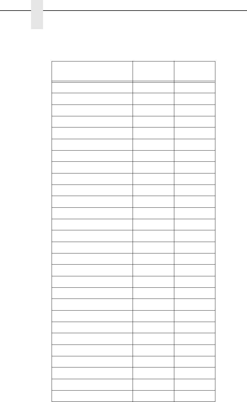
346
Chapter 5
Accessing Characters and Character Sets
Table 73. Alternate Character Sets
Character Set Name IF
(Intelligent) TT
(TrueType)
Windows Symbol AS
ATMType1 AT
ITC Zapf Dingbats/100 D1
ITC Zapf Dingbats/200 D2
ITC Zapf Dingbats/300 D3
ISO 60: Danish/Norweigan DN DN
PS ITC Zapf Dingbats DS
DeskTop DT DT
ISO 8859/1 Latin 1 (EC94) E1 E1
ISO 8859/2 Latin 2 E2 E2
ISO 8859/9 Latin 5 E5 E5
ISO 8859/10 Latin 6 E6 E6
ISO 69: French FR FR
ISO 21: German GR GR
ISO 15: Italian IT IT
Wingdings L$ WD
Legal LG LG
Math–8 M8 M8
Macintosh MC MC
PS Math MS MS
Microsoft Publishing PB PB
PC–8, Code Page 437 PC PC
PC–8 D/N, Code Page 437N PD PD
PC–852 Latin 2 PE PE
Pi Font PI PI
PC–850 Multilingual PM PM
PC–8 TK, Code Page 437T PT PT
PC–775 Baltic PV PV
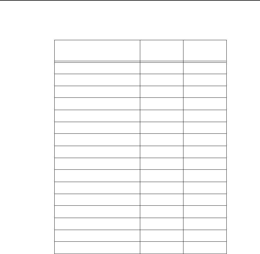
Character Set Selection Command
347
Non-UGL, Generic Pi Font PY
Roman–8 R8 R8
ISO 17: Spanish SP SP
ISO 11: Swedish SW SW
Symbol SY
PS Text TS TS
ISO 4: United Kingdom UK UK
ISO 6: ASCII US US
Ventura International VI VI
Ventura Math VM VM
Ventura US VU VU
Ventura 3.1 Latin 1 W1 W1
AgfaTidbits WD
Windows 3.1 Latin 2 WE WE
Windows 3.0 Latin 1 WO WO
Windows 3.1 Latin 5 WT WT
Table 73. Alternate Character Sets
Character Set Name IF
(Intelligent) TT
(TrueType)
348
Chapter 5
Accessing Characters and Character Sets
Selecting an ISO Character Set
Purpose Accesses one of nine ISO character sets.
Mode Standard Graphics or Graphics with an Extended Graphics
Command selected
Format (cc) IISO, n (cc)G
(cc) Represents the Special Function Control Code.
IISO, The ISO Character Set Selection command; enter
IISO, (the comma is required).
nThe character substitution set number; enter a
value ranging from 0 through 8 according to the
desired character set shown in Table 74. If n is not
a value from 0 through 8, an error message is
displayed and the command is ignored.
Table 74. IISO, Character Sets
(cc)G The universal terminator. Enter the SFCC for your
VGL configuration immediately followed by G to
terminate the IISO, command.
Comments
When the IISO, command is used in a Standard Graphics
command, the printer font set is changed to the new ISO
character set. When the IISO, command is used with an
Extended Graphics command selected, only the Extended
character set is changed to the new ISO character set.
n ISO Character Set
Hex Value:
0
1
2
3
4
5
6
7
8
23 24 40 5B 5C 5E 60 7B 7C 7D 7E
USA
UK
Swedish/Finnish
Norwegian/Danish
Japanese
German
French
Italian
Spanish
#
£
£
£
£
#
#
#
#
$
$
$
$
$
$
$
$
$
@
@
@
@
É
§
§
§
á
[
[
[
Ä
Æ
Ä
5
5
¡
\
\
Ö
Ø
¥
Ö
ç
ç
Ñ
5D
]
]
]
Å
Å
Ü
§
é
¿
^
^
Ü
Ü
^
^
^
^
^
`
`
`
`
`
`
`
é
ù
{
{
ä
æ
{
ä
é
à
5
|
|
|
ö
ø
ò
ñ
ù
ö
}
}
å
å
}
ü
è
ç
è
~
-
-
~
ü
ü
ß
¨
ì

Multinational Character Set Charts
349
Multinational Character Set Charts
IGP/VGL MULTINATIONAL Set
ASCII Set GERMAN Set
VGL MULTINATIONAL Set
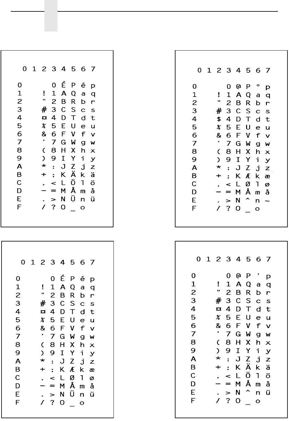
350
Chapter 5
Accessing Characters and Character Sets
SWEDISH Set DANISH Set
NORWEGIAN Set FINNISH Set
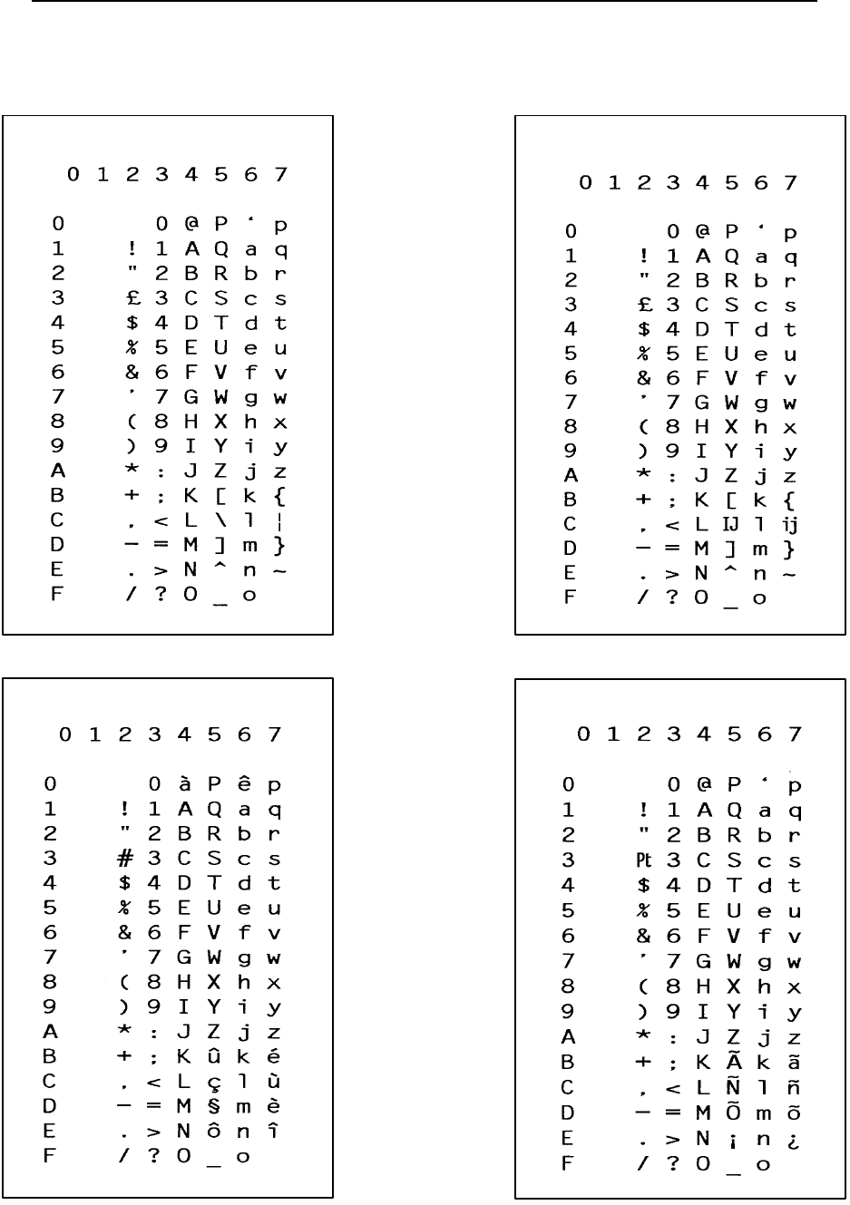
Multinational Character Set Charts
351
ENGLISH Set DUTCH Set
FRENCH Set SPANISH Set
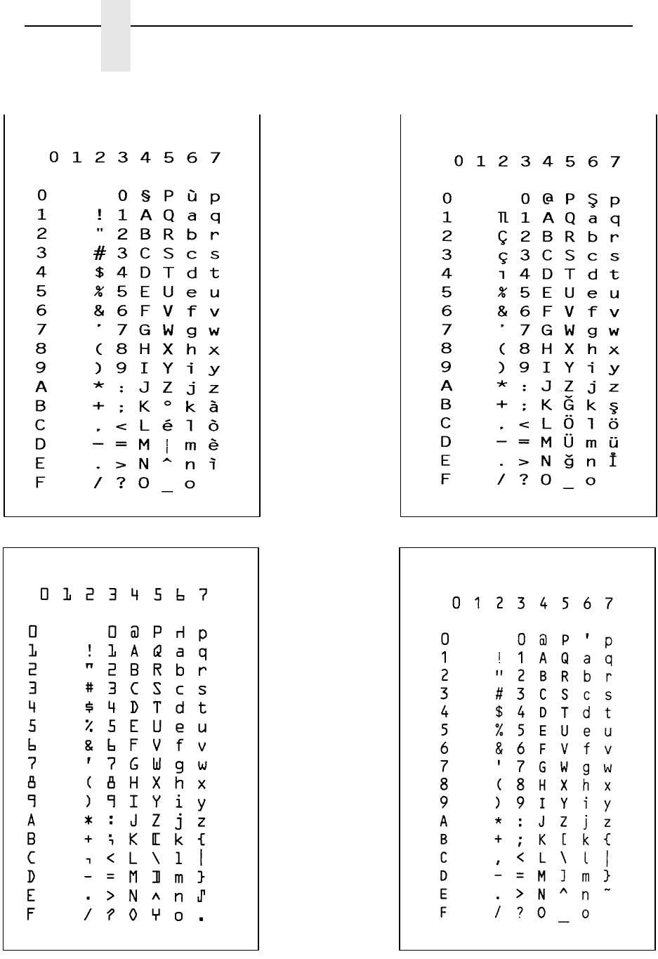
352
Chapter 5
Accessing Characters and Character Sets
ITALIAN Set TURKISH Set
OCR-A Set OCR-B Set
Multinational Character Set Charts
353
International Character Sets
The International Character Sets supported are listed in Table 75. Select
these sets from the configuration menu “Select Font” option, or through the
character set selection command described on page 345.
See Table 70 for a list of the Multinational Character Sets and their
corresponding set values.
Table 75. International Character Sets and Symbol Set Selection Values
Character Set Set Value Character Set Set Value
Arabic 32
Greek 33
Hebrew 34
Portuguese 35
Spanish 36
Latin 1 37
Slavic 852 (Latin 2) 38
Farsi 39
Turkish 40
OCR-A 41
OCR-B 42
Greek Sets
DEC 256 Greek 400
ELOT 928 Greek 401
Greek 3 402
ABY Greek 403
ABG Greek 404
ELOT 927 Greek 405
Greek 851 406
Greek 437 407
Greek 8859-7 408
Win CP 1253 409
Arabic Sets
ASMO 449 100
ASMO 449+ 101
ASMO 708 102
ASMO 708 103
MS DOS CP 710 104
MS DOS CP 720 105
Sakr CP 714 106
Aptec CP 715 107
CP 786 108
Arabic CP 864 109
Arabic CP 1046 110
Arabic Lam 1 111
Arabic Lam 2 112
Win CP 1256 113
Turkish Sets
Data General Turkish 600
DEC Turkish 601
IBM Turkish 602
Siemens Turkish 603
PTT Turkish 604
IBC Turkish 605
Bull Turkish 606
AS400 Turkish 607
Unisys Turkish 608
NCR Turkish 609
PST Turkish 610
Unis-1 Turkish 611
Code Page 853 612
INFO Turkish 613
Win CP 1254 614
Code Page 857 615
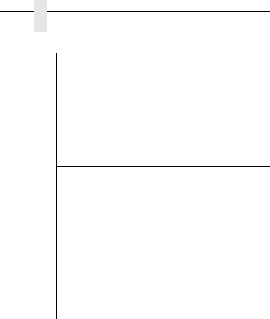
354
Chapter 5
International Character Sets
Character Set Set Value Character Set Set Value
Cyrillic Sets
Code Page 866 200
Cyrillic CP 437 201
Cyrillic 113 202
Cyrillic 8859-5 203
ISO 915 204
Code Page 855 205
7-bit Cyrillic 206
Ukranian 207
Bulgarian 208
Win CP 1251 209
Hebrew Sets
Hebrew Old 500
Hebrew New 501
Hebrew DEC 502
Latin-1 Hebrew 503
Win CP 1255 504
European Sets
Latin 2 8859-2 300
Latin 2 852 301
Mazovia 302
Kamenicky 303
Roman 8 304
PC-437 Slavic 305
Slavic 1250 306
Code Page 865 307
Code Page 860 308
Latin 1 8859-1 309
Latin 5 8859-9 310
Latin 9 8859-15 311
Polish Pol 1 312
Win CP 1250 313
Win CP 1252 314
Win CP 1257 315
Table 75. International Character Sets and Symbol Set Selection Values

355
6
Error Codes
The Purpose of Error Codes
VGL provides coded error messages to help debug programs. When VGL
detects an error, it stops text processing and prints out an error message. The
error message includes the appropriate error code, a brief description of the
error, and the erroneous data. All data up to the next command sequence
terminator is ignored, and the form (if any) is printed up to the point of the
error.
By VGL configuration, you can disable the printing of all error messages, you
can disable printing of off-page errors, or you can enable printing of error
location markers. Refer to your User's Manual for more information.
Starting below, each error code is listed in numerical order and described in
more detail.
Error Codes
01 Alpha Command Error
One of the alphanumeric commands has a non-numeric height or
width parameter.
02 Alpha Length Error
Alpha data has exceeded the length of the internal alpha text
buffer. The terminator of the data was not found.
03 Not defined.
04 Box Command Error
A Box command (LB) has non-numeric parameter(s).
05 Buffer Overflow Error
The internal sequence buffer has overflowed. No sequence
terminator found.
06 Compressed Print Error
A Compressed Print command (#x) has a non-numeric value for
the selected compressed print font, or the line terminator is
missing.
07 Special Font Error
A High Density Look-Up Font (S) command has an invalid value
for the font selected. Valid values for f are 1 through 9, inclusive.
08 Not defined.

356
Chapter 6
Error Codes
09 Form Memory Error
The form is too big and ran out of form memory during alpha or
vector buffer storage.
10 Character Height Command Error
A Character Height command (H) has a non-numeric character
for the height parameter.
11 Hex Data Error
An invalid character was found while expecting a hexadecimal
value. Only numeric characters or A, B, C, D, E, or F are allowed.
12 Vertical Justification Change Error
A Vertical Justification (J) command has a non-numeric character
for the justification parameter.
13 Form Command Error
A forms construction command (LF) has a non-numeric
parameter.
14 Undefined Line Command Error
The Line command (L) was not followed by B, D, F, or S.
15 Logo Command Error
A user-defined logo using the Z command contains an invalid
parameter value; valid values are 1 through 9 or A through F.
16 Plot Command Error
A Plot command (Q or C) contains invalid hexadecimal data
characters. Only numeric characters or A, B, C, D, E, or F are
allowed.
17 Not defined.
18 Vertical Duplication (Repeated Form) Terminator Missing
Error
A Vertical Duplication commands (R) does not have a line
terminator.
19 Horizontal Duplication Command Error
A Horizontal Duplication command (S) contains a non-numeric
character or gap space parameter or is not followed by a line
terminator.
20 Horizontal Tab Command Error
A Horizontal Tab command (T) contains a non-numeric distance
parameter.
21 Special Function Control Code Change Command Error
A Special Function Control Code (SFCC) change command (N)
contains an illegal value for x or is not followed by a line
terminator. x can be any character from hex 11 through hex FF
(decimal 17 through 255).

357
22 Undefined Command Error
An SFCC is not followed by a known command character.
In Non-Graphics Mode, the following characters are allowed: #,
B,C, D, E, H, I, K, L, M, N, Q, R, S, T, U, V, W, or @.
Within a repeated form, the following characters are allowed: #,
D, E, H, I, K, L, M, N, Q, R, S, T, U, W, Z, or -.
In Graphics Mode, the following characters are allowed: B, C, D,
E, G, H, I, J, K, L, M, Q, R, S, T, U, V, W, Z, or -.
23 Character Width Command Error
A Character Width command (W) contains a non-numeric width
parameter.
24 Serial Overflow Error
The serial input buffer is full. The host probably did not honor
VGL flow control to stop sending characters.
25 Line Parameter Error
A Line command (LS or LD) contains a non-numeric horizontal or
vertical length parameter.
26 Undefined Shading, Mask, or Dark Command Error
A shading (K) command (shading, shading mask, or dark print) is
followed by an unknown character. It must be followed by an H
for standard shading, an L for shading mask, or an F for dark
printing.
27 Shading Mask Factor Error
A Shading Mask command (KL) does not include a valid
hexadecimal mask parameter. Only numeric characters or A, B,
C, D, E, or F are allowed.
28 Vertical Duplication (Repeated Form) Parameter Error
A Vertical Duplication command (R) contains a non-numeric
repeat parameter or is not followed by a line terminator.
29 Inner Vertical Duplication (Repeated Form) Error
An inner (nested) Vertical Duplication command (R) contains a
non-numeric repeat parameter, is not followed by a line
terminator, or an inner loop already exists. Only one inner repeat
loop is allowed within a repeated form.
30 Plot Length Error
A Plot command (Q or C) exceeded the internal plot buffer size.
No terminator was found.
31 Auto Increment/Decrement Command Error
An Auto Increment/Decrement command (Y) has one of the
following faults:
• An invalid value was provided for the +/- parameter. Only + or
- is allowed.
• The increment/decrement amount is zero.
• The command is not followed by (cc)G.
• The increment/decrement has more characters than the
operand.

358
Chapter 6
Error Codes
32 Dot Slew Command Error
A Dot Slew command (D) contains a non-numeric dots
parameter.
33 Line Slew Command Error
A Line Slew command (K or W) contains a non-numeric lines
parameter.
34 Forms Length PI Error
A Forms Length command (L) must use the PI line, but VGL is
configured with PI disabled. Use the H Forms Length command.
35 Forms Length No PI Error
A Form Length command (H) cannot use the PI line, but VGL is
configured with PI enabled. Use the L Forms Length command.
36 Dynamic Form Copy Command Error
A Dynamic Form Copy command (C) contains a non-numeric
parameter.
37 Dynamic Form Field Length Command Error
A Dynamic Form Field Length command ([ length or { length)
contains a non-numeric length parameter.
38 Dynamic Form Nested Copy Error
A Dynamic Form Copy command (C) was encountered while
already within a copy loop. Copy commands cannot be nested.
39 Dynamic Data Repeat Count Error
A repeated dynamic form data element does not have a valid
repeat count. The repeat count must be four numeric characters.
40 Incomplete BarCode Error
An unexpected end of a barcode command was detected. No
barcode type was found, or not enough variable ratio characters
were given.
41 Undefined BarCode Type Error
An undefined barcode type was given.
43 BarCode Data Length Error
The length of the barcode data is too long or too short for the
barcode type selected.
44 Illegal BarCode Data Error
The barcode data contains a character which is not allowed by
this barcode type.
45 BarCode Off Page Error
The barcode does not fit on the page at the starting column.
47 LPI Parameter Error
The new lpi parameter in the Line Spacing command (@L)
contains a non-numeric or 0 value.
48 Element Off Page Error
The form element cannot fit on the page at the starting position.
49 Not defined.

359
50 User-Defined Logo Input Error
The input parameter is not within the specified range. You must
provide either a number ranging from 0 through 9, or a character
from A through F.
51 Not defined.
52 Character Set Command Error
The character set value specified at the Character Set Selection
command (i) was not within the range of 00 through 31.
53 User-Defined Character Set Command Error
The User-Defined Character Set command (u) contains a
parameter error. This is possibly caused by an incorrect value for
n, which must be a number from 1 through 8, or the values for ca
or fa were not within the specified ranges. The value for ca must
be one of the following 16 hex values: 21, 22, 23, 24, 25, 26, 40,
5B, 5C, 5D, 5E, 60, 7B, 7C, 7D, 7E; the value for fa must be from
hex 20 through FF.
54-55 Not defined.
56 Logo Generation Command Error
The parameters for the ILOGO command are incorrect. Logo
values of 41-49, 4A, 4B, 4C, 61 and 62 are allowed.
57 Pixel Expansion Command Error
The parameters for the IPEXP Pixel Expansion Command are
incorrect. Expansion values of 1 through 255 are allowed.
Horizontal and vertical expansion values must be separated by a
comma.
58 Default Font Command Error
The syntax or parameter(s) for the IFONT,S, command is
incorrect.
59 Vertical Dup Cmd Error
The syntax or parameter(s) for the IREPV is incorrect.
60 Horizontal Dup Cmd Error
The syntax or parameter(s) for the IREPH is incorrect.
61 Not defined.
62 PAGE Cmd Error
The syntax or parameter(s) for the IPAGE is incorrect.
63 TIFF Logo Cmd Error
The syntax or parameter(s) for the ITIFF command is incorrect.
64 Not defined.
65 Bit Image Plot Cmd Error
The syntax or parameter(s) for the IPLOT command is incorrect.
66 Load Font Command Error
The syntax or parameter(s) for the ILOAD command is incorrect.
67 Unsupported Cmd Error
The command is not supported.

360
Chapter 6
Error Codes
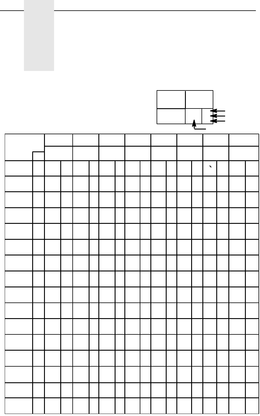
361
A
Standard ASCII Character
Set
KEY
ASCII CHARACTER
ESC
33
27
1B
OCTAL
DECIMAL
HEX
B7 00 0011 1 1
B6 0
B5 0 01101100011011
COLUMN
01234567
BITS
ROW
B4 B2B3 B1
0
1
2
3
4
5
6
7
8
9
10
11
12
13
14
15
0000
00 10
00 1 0
00 1 1
01 0 0
01 0 1
01 1 0
01 1 1
1000
10 0 1
10 1 0
10 1 1
11 0 0
11 0 1
11 1 0
11 1 1
NUL
SOH
STX
ETX
EOT
ENQ
ACK
BEL
BS
HT
LF
VT
FF
CR
SO
SI
0
0
0
1
1
1
2
2
2
3
3
3
4
4
4
5
5
5
6
6
6
7
7
7
10
8
8
11
9
9
12
10
A
13
11
B
14
12
C
15
13
D
16
14
E
17
15
F
DLE
DC1
DC2
DC3
DC4
NAK
SYN
ETB
CAN
EM
SUB
ESC
FS
GS
RS
US
(XON)
(XOFF)
20
16
10
21
17
11
22
18
12
23
19
13
24
20
14
25
21
15
26
22
16
27
23
17
30
18
24
31
25
19
32
26
1A
33
27
1B
34
28
1C
35
29
1D
36
30
1E
37
31
1F
SP
!
"
#
$
%
&
'
(
)
+
,
-
.
/
40
32
20
41
33
21
42
34
22
43
35
23
44
36
24
45
37
25
46
38
26
47
39
27
50
40
28
51
41
29
52
42
2A
53
43
2B
54
44
2C
55
45
2D
56
46
2E
57
47
2F
0
1
2
3
4
5
6
7
8
9
:
;
<
=
>
?
60
48
30
61
49
31
62
50
32
63
51
33
64
52
34
65
53
35
66
54
36
67
55
37
70
56
38
71
57
39
72
58
3A
73
59
3B
74
60
3C
75
61
3D
76
62
3E
77
63
3F
@
A
B
C
D
E
F
G
H
I
J
K
L
M
N
O
100
64
40
101
65
41
102
66
42
103
67
43
104
68
44
105
69
45
106
70
46
107
71
47
110
72
48
111
73
49
112
74
4A
113
75
4B
114
76
4C
115
77
4D
116
78
4E
117
79
4F
P
Q
R
S
T
U
V
W
X
Y
Z
[
\
]
_
120
80
50
121
81
51
122
82
52
123
83
53
124
84
54
125
85
55
126
86
56
127
87
57
130
88
58
131
89
59
132
90
5A
133
91
5B
134
92
5C
135
93
5D
136
94
5E
137
95
5F
a
b
c
d
e
f
g
h
i
j
k
l
m
n
o
140
96
60
141
97
61
142
98
62
143
99
63
144
100
64
145
101
65
146
102
66
147
103
67
150
104
68
151
105
69
152
106
6A
153
107
6B
154
108
6C
155
109
6D
156
110
6E
157
111
6F
p
q
r
s
t
u
v
w
x
y
z
{
|
}
~
DEL
160
112
70
161
113
71
162
114
72
163
115
73
164
116
74
165
117
75
166
118
76
167
119
77
170
120
78
171
121
79
172
122
7A
173
123
7B
174
124
7C
175
125
7D
176
126
7E
177
127
7F
10 1 1
B4 B2B3 B1
B7 B6 B5
001
BITS
0
0
0
0
0
0
^
*

362
Appendix A
Standard ASCII Character Set
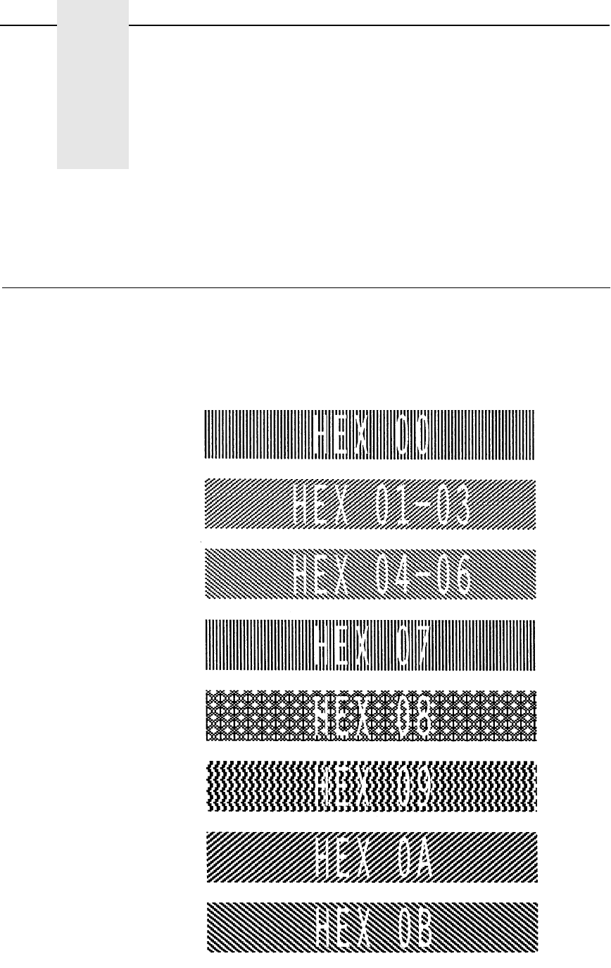
363
B
Shading Masks
Selecting Masks
The Shading Mask command (KL), described on page 142 of Chapter 2,
includes 132 different shading masks. Print samples of these masks are
illustrated below. Each mask is reverse printed with the appropriate
hexadecimal mask value. Replace the mask parameter in the KL command
with one of the following hexadecimal mask values.
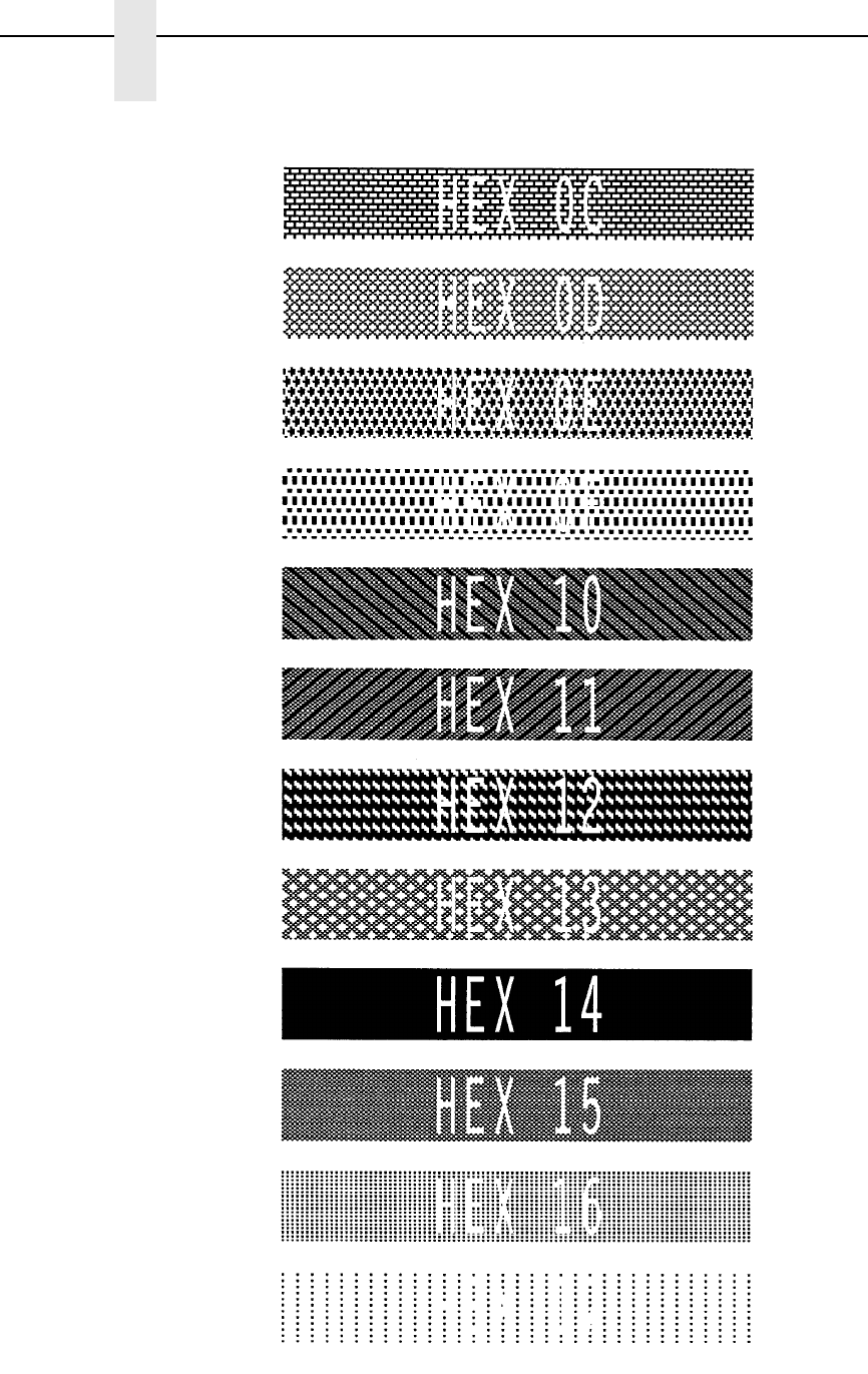
364
Appendix B
Shading Masks
NOTE: Both 18H and 19H produce a white shading mask when printed.
HEX 17
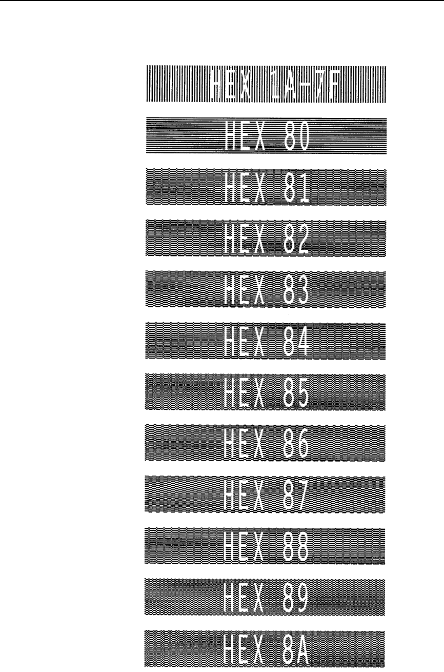
Selecting Masks
365

366
Appendix B
Shading Masks
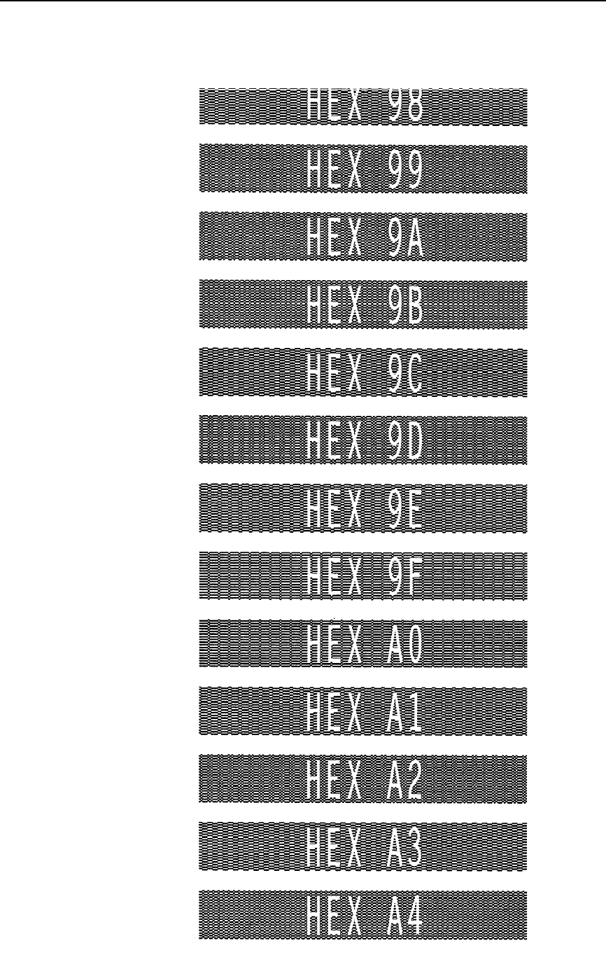
Selecting Masks
367
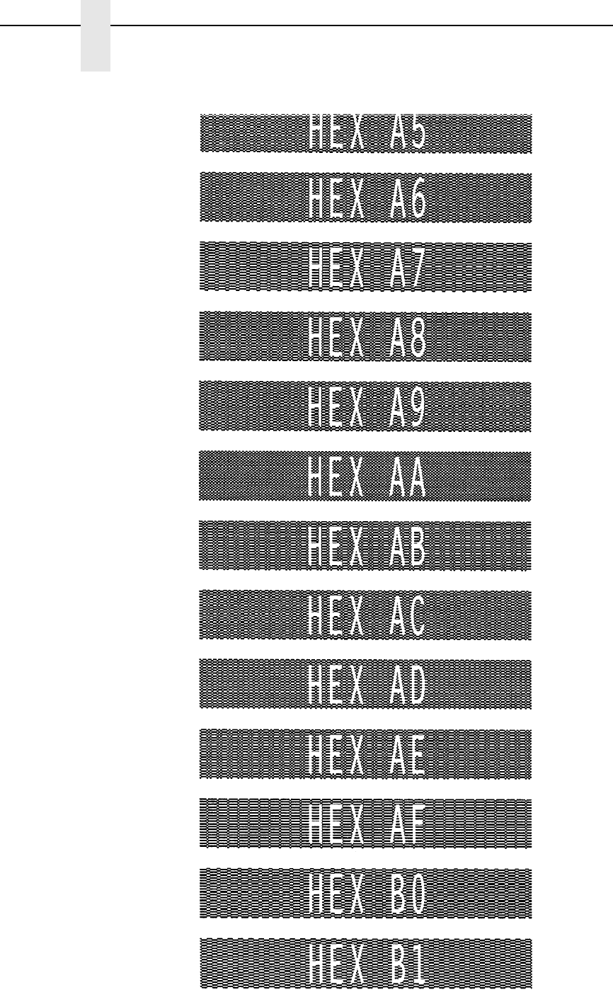
368
Appendix B
Shading Masks
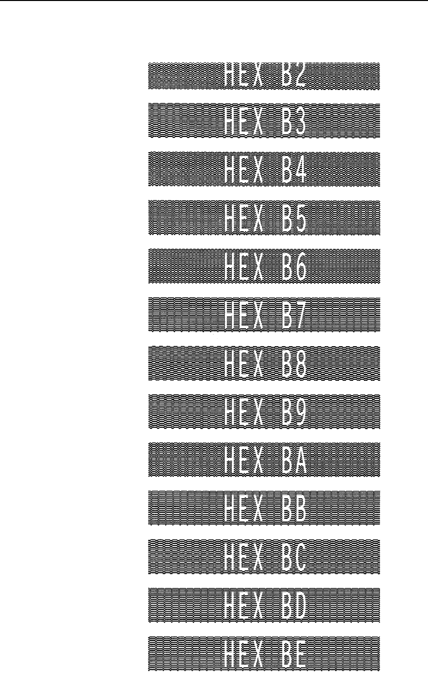
Selecting Masks
369
370
Appendix B
Shading Masks
Selecting Masks
371
372
Appendix B
Shading Masks
Selecting Masks
373
374
Appendix B
Shading Masks
375
C
Grid Samples
The Standard Grid, shown on page 376, is used to design your form layout.
At 6 lines per inch (lpi) and 10 characters per inch (cpi) printing, a standard
8-1/2 x 11-inch sheet of paper has a print area of 66 lines (rows) and 85
characters (columns). (The printable area will vary if you are not printing at 6
lpi and 10 cpi.) Thus, the grid used to design an 8-1/2 x 11-inch form should
accommodate this 66 x 85 area.
The Logo Grid, shown on page 377, is used to design custom logos.
Remember, with the logo grid, you must define the dot positions for each 7-bit
vertical data byte, and each vertical data byte equals 1/10-inch, or one “row.”
Each vertical data byte represents data used in the Plotting Graphics
(Columns) command (Q) described on page 129 of Chapter 2. See Chapter 4
for more information on designing a logo.
a
b

378
Appendix C
Grid Samples
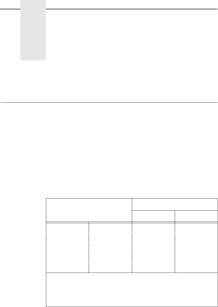
379
D
Page Boundaries
Paper Selection and Maximum Values
Although VGL commands do not require you to identify specific starting and
ending points within a command sequence, the limitations imposed by page
boundaries should be considered for optimum VGL performance. This
appendix addresses the page boundaries affecting VGL products for both cut-
sheet page printers and continuous form printers.
Certain print area boundaries exist according to the paper size selected.
These boundaries are identified in Table 76. The maximum dot values shown
in Table 76 are necessary to determine the maximum printable area on a form
when modifying top/bottom margin settings or offsetting for left margin print
positions. The following pages explain how to determine your Top/Bottom
Margin and Left Margin requirements.
Table 76. Paper Sizes and Maximum Print Area
Paper Size Dimensions Maximum Dot Value*
Page Width Page Length
Letter 8.5 x 11 510 792
Legal 8.5 x 14 510 1008
A4 8.268 x 11.693 496 841
B5 6.929 x 9.842 415 708
Computer 13.2 x 11 792 792
*Maximum Dot Values are calculated as follows:
1. Page Length x 72 dpi minus Top and Bottom Margin Values = maximum
height value;
2. Page Width x 60 dpi minus Left Margin Value = maximum width value.
Values exceeding maximum values produce an error message.
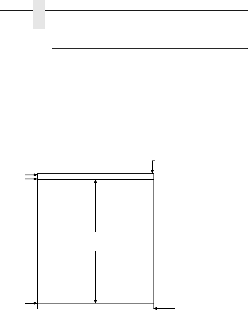
380
Appendix D
Paper Selection and Maximum Values
Setting Top/Bottom Margins
Using dot values to identify maximum vertical print positions, the page
boundary parameters of an 11-inch form are 792 dot rows at n/72-inch
vertically (72 dpi X 11 inches). (See Figure 43.)
With no Top/Bottom Margin configuration setting on an 11-inch form, the first
print position is Starting Row 1, Starting Column 1 (A, Figure 43). However, if
a Top/Bottom Margin value is set at 10, then the Starting Row 1 is adjusted
down by 10 dot rows (B, Figure 43), and the Ending Row is adjusted up 10 dot
rows (C, Figure 43), thereby reducing the maximum vertical printable area to
772 dots (792 - [10 + 10]). The greater the top/bottom margin setting, the
smaller the printable area on the form.
Figure 43. Top/Bottom Margin Example
Maximum Character Column
Maximum Vertical Dot 792
Maximum Horizontal Dot 510
Maximum Vertical
Print Area (772 dots)
Maximum Character Row 66
A
B
C
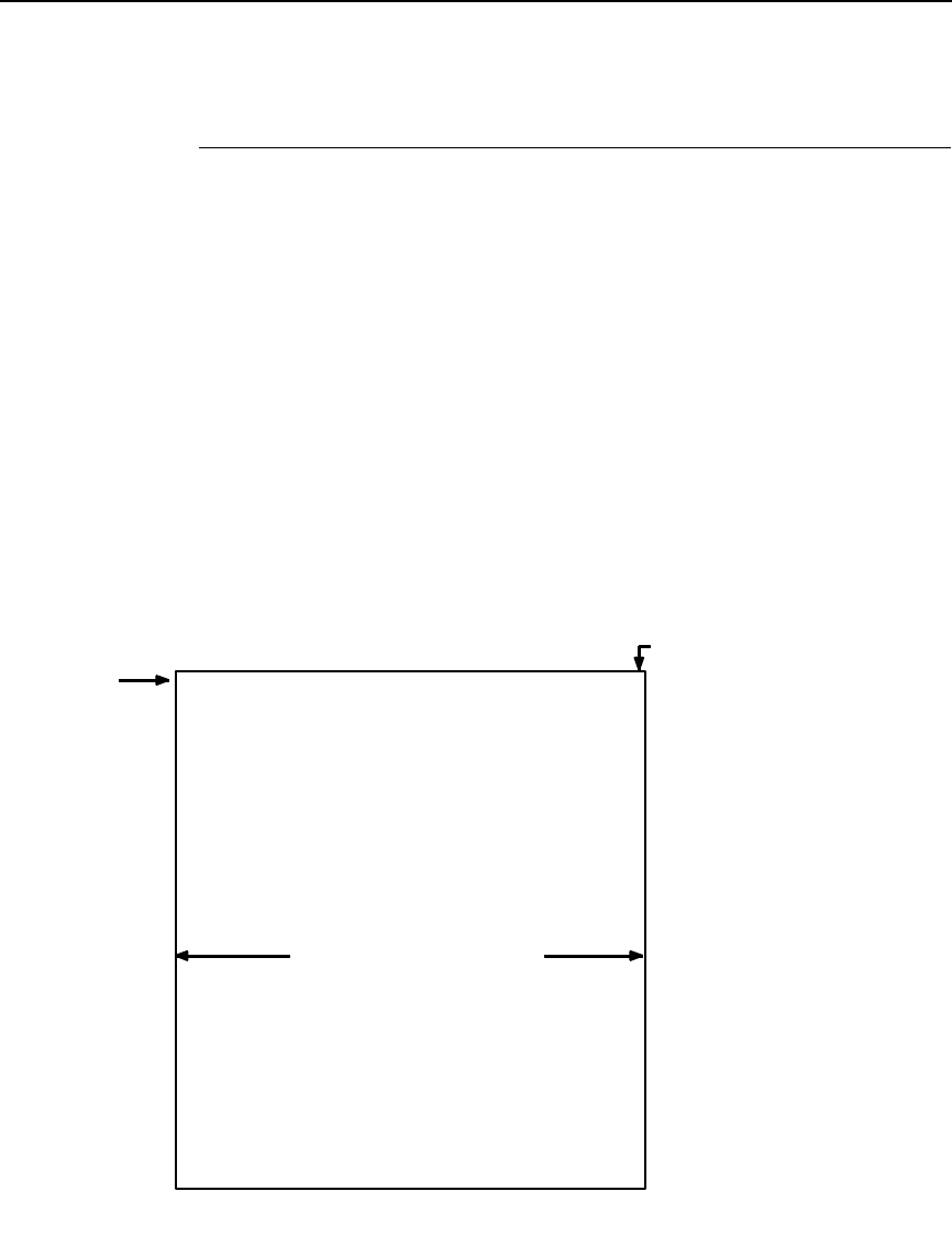
Setting Left Margins
381
Setting Left Margins
Using dot values to identify maximum horizontal print positions, the page
boundary parameters of an 8-1/2-inch wide form are 510 columns at n/60-inch
horizontally (60 dpi X 8.5 inches). (See Figure 43.) Setting a Left Margin value
repositions the Starting Column 1 position by the degree of offset required.
This offset must be a 0 or a positive value. The following examples explain
how setting the Left Margin affects printed output:
No Left Margin Setting - When the Left Margin configuration setting is 0 on an
8-1/2-inch form, the Starting Column is 1, and the Ending Column is 510
(Figure 44, A and B, respectively).
Positive Left Margin Setting - When the Left Margin setting is 20 on an
8.5-inch form, the left margin is offset by 20 dots, and that 20th dot position
becomes Starting Column 1 in VGL memory (A, Figure 45). This 20 dots also
offsets the Ending Column by 20 dots, thus narrowing the maximum print
width on the form from 510 to 490 dots (B, Figure 45).
Figure 44. Left Margin Example - No Setting
Maximum Character Column
Maximum Horizontal Dot 510
A
B
Maximum Horizontal
Print Area (510 dots)
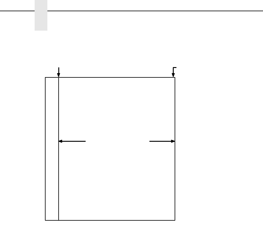
382
Appendix D
Paper Selection and Maximum Values
Figure 45. Left Margin Setting +20 Example
Maximum Horizontal Dot Column
AB
Dot Column 20
Becomes Column 1 (510) becomes 490, due to
Maximum Horizontal
Print Area (490 dots)
+20 offset

383
E
PTX_SETUP Option
Overview
NOTE: PTX_SETUP commands are not supported on L7032 printers.
The PTX_SETUP commands are a superset of commands which allow the
printer to perform several tasks by parsing commands either stored in flash or
sent to the printer by the host. Commands range from re-routing debug
statements to downloading complete printer configurations.
The PTX_SETUP Commands
Some concepts to keep in mind are as follows:
1. PTX_SETUP commands are not emulation specific. In a system with an
IGP, the IGP level emulation will process the PTX_SETUP commands. In
a system without an IGP, the PTX_SETUP commands will be processed
by the base emulation. The CTHI emulation will not process PTX_SETUP
commands.
2. Since there is no disk on a flash-based printer, DISK_IO commands are
now called FILE_IO. However, for backwards compatibility DISK_IO and
FILE_IO are synonymous.
3. The PTX_SETUP command set is case sensitive; all PTX_SETUP
commands are in upper case characters only.
4. The white space separating commands may be any number of spaces
and tabs. This allows a PTX_SETUP file to be formatted for easier
readability.
5. Any unknown command will terminate the PTX_SETUP processing. The
offending command will be the first line of printed text.
6. Although the original implementation of PTX_SETUP allowed for only a
single parameter, separated from the sub-command by a single
semicolon (;) character, the new PTX_SETUP command set allows for
multiple parameters separated by commas, semicolons, spaces or tabs.
384
Appendix E
The PTX_SETUP Commands
Commands
Each emulation has modes in which the PTX_SETUP commands could get
missed. For this reason, it is highly recommended that all PTX_SETUP
commands be placed between print jobs, rather than attempting to imbed
them within jobs.
PTX_SETUP commands have the following format:
(SFCC)PTX_SETUP
Command–Sub Command;Value
PTR_END
For example, if the SFCC assigned to the emulation you are using is the caret
(^, hex 5E), and you wanted to load configuration number 4 and capture all
incoming data to a file named “BIN”, you would use the following command:
^PTX_SETUP
CONFIG–LOAD;4 FILE_IO–CAPTURE;BIN
PTR_END
Table 77 lists all the command, sub-command, and parameter combinations
and gives a brief description of the command.
NOTE: When a file system error occurs, a message will be displayed on the
front panel indicating the error, and the action needed to take to
correct the error.
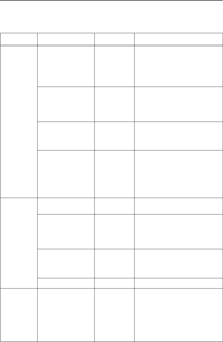
Commands
385
Table 77. PTX_SETUP Commands
Command Sub-Command Parameter Description
CONFIG LOAD Cfg Cfg can be 0-8. The PTX_SETUP
will load configuration Cfg. If
configuration Cfg was not previously
saved, the operator panel will
display an error message and the
current configuration will be kept.
SAVE Cfg Cfg must be 1-8. This command will
save the current configuration as
configuration Cfg. If Cfg is not in the
range of 1-8, the command is
ignored.
POWERUP Cfg Sets the power-up configuration to
Cfg and loads Configuration Cfg.
Cfg can be any value from 0-8,
where 0 is the factory default.
PRINT Cfg Print Configuration Cfg. Cfg can be
a number 1-8, or one of four pre-
defined configurations. The four
non-numeric configurations are
requested using the first character
for the CURRENT, FACTORY,
POWERUP, or ALL configuration(s).
CONFIG DELETE Cfg Deletes Configuration number Cfg.
Cfg must be in the range of 1-8.
UPLOAD Port;Cfg This command uploads the
configuration stored in location Cfg
to the port specified by Port. Port
must either be 1284 or SERIAL. Cfg
may be 1-8 or ALL.
DOWNLOAD Cfg This command saves the
configuration data that follows as
configuration Cfg. Cfg must be 1-8
or END.
RESET Reboots the printer.
LP MODE n/a Protocol Protocol must be 0-4. This
command resets the software
protocol, and is selected as follows:
0 - P-Series
1 - P-Series XQ
2 - Serial Matrix
3 - Proprinter III XL
4 - Epson FX-1050
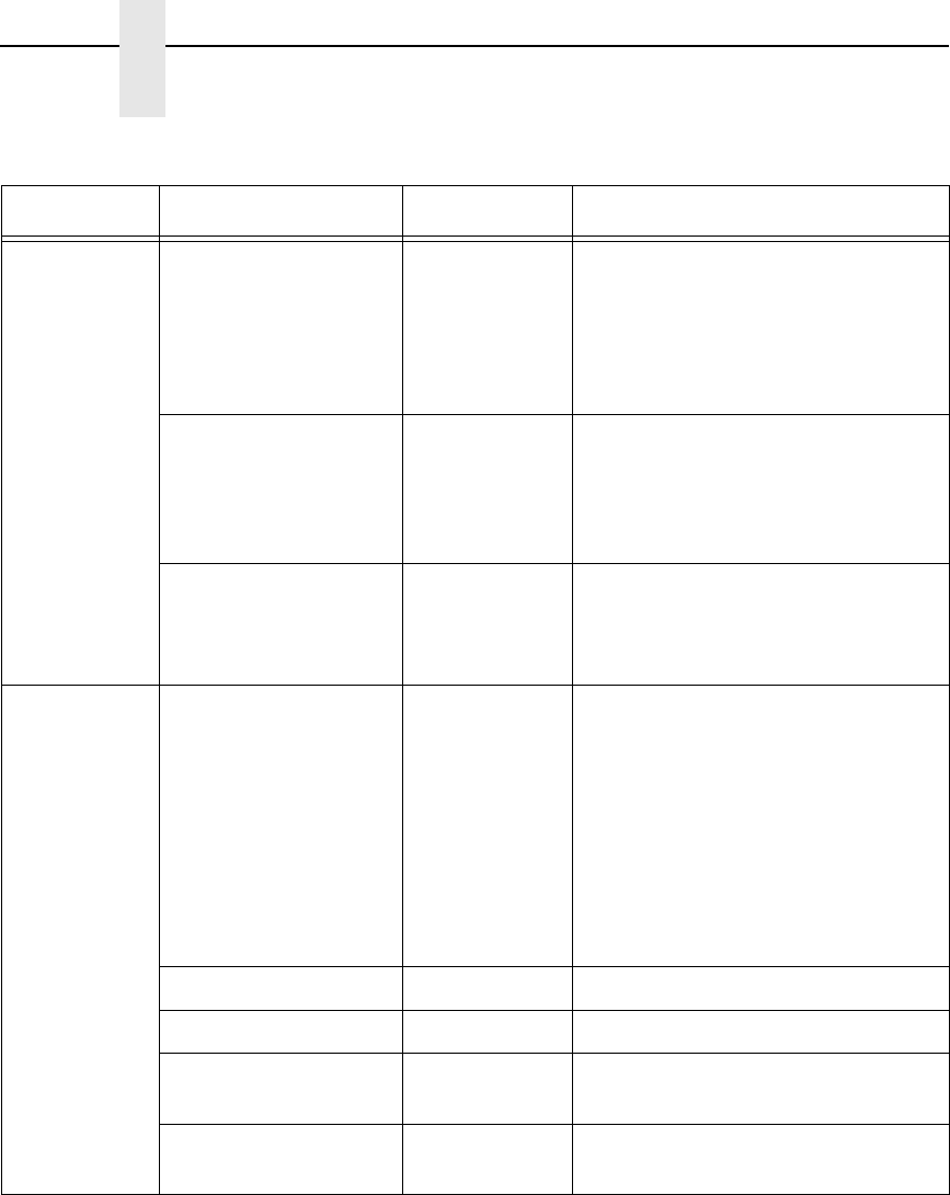
386
Appendix E
The PTX_SETUP Commands
FILE_IO
(DISK_IO)
CAPTURE Filename Captures all incoming data into a file
named Filename. Receipt of a
FILE_IO–CAPTURE command
without the Filename parameter will
force the file data to be written to
flash, and will end the file capture.
DRIVE Letter This command is parsed for
backwards compatibility. However,
since the flash file system is a single
device, the drive letter will be
ignored.
DEL Filename The DEL command will mark a file
as deleted. The space the file
occupied will be freed the next time
the printer is powered up.
FILE_IO
(DISK_IO)
RUNFILE File;Prop The RUNFILE command will open
the file named File for printing. After
the PTR_END command is
processed, the contents of File will
get printed before any more data is
read from the host. If the Prop field
is present, RUNFILE will verify that
Prop matches the saved file
properties. Any mismatch will cause
the command to be ignored.
MAXSIZE Kb For backwards compatibility.
MINSIZE Kb For backwards compatibility.
FONT FontName Downloads an HP** LaserJet** font
and saves it as FontName.
IFONT FontName Downloads a scaleable AGFA type
font and saves it as FontName.
Table 77. PTX_SETUP Commands (continued)
Command Sub-Command Parameter Description
Commands
387
ENGINE ALM_WIDE wide width Set the Auto Label Mapping wide
width (in units of 1/1000”; e.g., a
wide width value of 1000 = 1”),
which represents the width of the
image in the file sent from the host
which is to be auto label mapped
into several labels, each of which
will have a width of narrow width.
# of labels=wide width/narrow width
(rounded down)
ALM_NARROW narrow width Set the Auto Label Mapping narrow
width, which represents the width of
one auto mapped label (in units of
1/1000”; e.g., a narrow width value
of 1000 = 1”). This width should be
set prior to the wide width. In
addition, it can never exceed the
physical width of the printer. If it
does, the narrow width will be
automatically reduced to the Page
Width value set in the configuration
menu.
ALM_ENABLE N/W/* Set Auto Label Mapping to Narrow,
Wide, or Off. Enter N for Narrow, W
for Wide, or any other letter to
disable ALM. By default, only the
Narrow option is implemented.
Table 77. PTX_SETUP Commands (continued)
Command Sub-Command Parameter Description
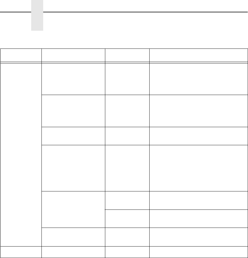
388
Appendix E
The PTX_SETUP Commands
ENGINE IMAGE_SHFT_H Value Shifts the image Value horizontally
in 1/1000” units. If Value is out of the
specified range (-1” to +1”), the
command will be ignored.
IMAGE_SHFT_V Value Shifts the image Value vertically in
1/1000” units. If Value is out of the
specified range (-1” to +6”), the
command will be ignored.
LENGTH Value Sets the Page Length (in 1/1000”
units).
MEDIA_HANDLING Value Sets the type of media handling:
0 - Continuous
1 - Tear-Off Strip
2 - Tear-Off
3 - Peel-Off
4 - Cut
MODE XSets the print mode to Thermal
Transfer.
DSets the print mode to Direct
Thermal.
WIDTH Value Sets the Page Width (in 1/1000”
units).
PTR_END (none) (none) Exits the PTX_SETUP.
Table 77. PTX_SETUP Commands (continued)
Command Sub-Command Parameter Description

Commands
389
Summary of the CONFIG Command
The UPLOAD and DOWNLOAD command can be used for uploading and
downloading complete printer configurations. If a customer needs to configure
50 printers identically, the customer needs only configure one printer and
UPLOAD the configurations. The UPLOADed configurations may then be
DOWNLOADed to other printers eliminating the necessity for the operator to
configure each printer manually.
The UPLOAD command will always place a header and a footer into the
uploaded data. This header will be the DOWNLOAD command followed by
the configuration number. The footer will be the DOWNLOAD END command.
The operator should be aware that the UPLOAD and DOWNLOAD
commands use a secondary copy of the menu structure which does not affect
the printer's active configuration. This allows the UPLOAD and DOWNLOAD
commands to operate without affecting the printer's current configuration. If
the operator intends to use one of the DOWNLOADed configurations, the
operator should reboot the printer to ensure proper operation. This can be
accomplished by adding the RESET command as the last command in your
setup file. This is necessary because the printer caches the active
configuration. Rebooting the printer ensures that the desired configuration is
correctly read from Non-Volatile RAM.
NOTE: While an upload or download is in progress, the Front Panel will be
unavailable.
The Configuration Save and Delete commands from the front panel can be
blocked by using the Protect Configurations feature. This is intended to
prevent someone from inadvertently reconfiguring a printer. The PTX_SETUP
commands, however, will override the protect configurations feature. All
PTX_SETUP commands will be honored regardless of the value of the
Protect Configurations feature.
Operation of the FILE_IO Command
When a file is opened for writing with the FILE_IO–CAPTURE;filename
command, the system will allocate RAM for file control blocks and 1 Kbyte for
data. If the file already exists on the Flash File System and the Overwrite
Enable feature in the Flash File System menu is set to disable, a warning will
be displayed on the front panel. After clearing the warning, the file data will be
printed. To overwrite the existing file, set the Overwrite Files option to enable.
Due to the nature of writing to flash, any data intended to be stored
permanently in flash must first be copied into RAM. As a result, the ability to
manipulate files in the Flash File System is dependent upon the printer having
sufficient RAM. None of the captured file data will be committed to flash until
the entire file is loaded. The PTX_SETUP parser will interpret the command
“FILE_IO–CAPTURE<lf>” as an end of file marker. Receipt of the command
will cause all file data to be written to flash. The file system allocates RAM for
temporary data storage in 1 Kbyte blocks. If at any time during the file
download the printer runs out of RAM, a warning will be displayed on the front
panel and as much of the file as possible will be saved in flash. To download
larger files you may need to add additional RAM to the printer.
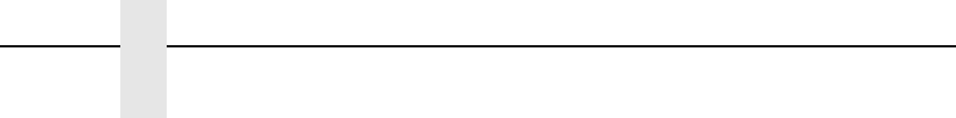
390
Appendix E
The PTX_SETUP Commands
Three things can limit the ability to save a file: insufficient RAM, insufficient
Flash, and lack of empty file system entries. Flash can only be written once
before it needs to be “optimized”. As a result, the maximum file size is limited
to the largest unwritten block of Flash. If any of these problems occur, the
printer will display an error message and will attempt to provide the operator
with a description of what steps to take to correct the error. Normally, the
solution will involve optimizing the Flash File System. This can be
accomplished by selecting the Optimize & Reboot function in the Flash File
System menu under MAINT/MISC.
NOTE: After selecting the Optimize & Reboot function, do not shut off the
printer's power until after the printer returns to the power-on state.
Loss of power during the optimize process may corrupt the printer's
program. If this occurs, first attempt to repeat the downloading
process. If that fails, contact an authorized service representative.
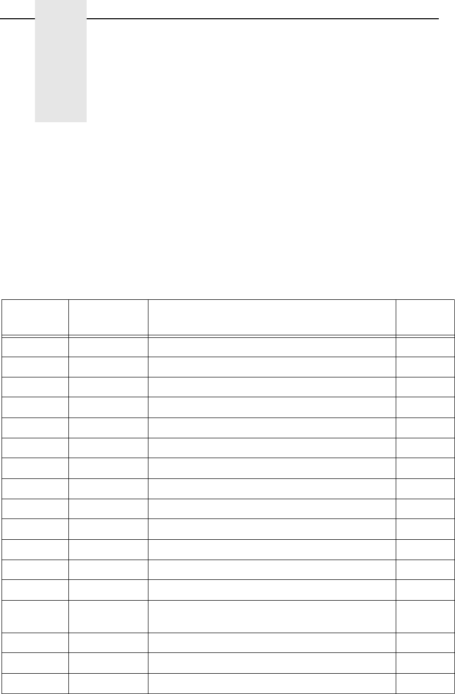
391
F
VGL Command Support on
L7032 Printers
The following table lists partially supported and non-supported commands on
the L7032 printer. For more information on each command, refer to the
corresponding page number.
Table 78. L7032 Printers - Partially Supported and Non-Supported Commands
VGL
Command Support Level Description Page
IPAGE Partial Page, Controlling Paper Options (Version II) 122
!Not Supported Send control characters to LP+ (0x01) 53
“Not Supported Send control characters to LP+ (0x02) 53
#Not Supported Send control characters to LP+ (0x03) 53
$Not Supported Send control characters to LP+ (0x04) 53
%Not Supported Send control characters to LP+ (0x05) 53
&Not Supported Send control characters to LP+ (0x06) 53
‘Not Supported Send control characters to LP+ (0x07) 53
(Not Supported Send control characters to LP+ (0x08) 53
.Not Supported Send control characters to LP+ (0x0E) 53
/Not Supported Send control characters to LP+ (0x0F) 53
>Not Supported Electronic Vertical Format Unit (EVFU), Start Load 73
?Not Supported Electronic Vertical Format Unit (EVFU), End Load 73
0 - 9 Not Supported Electronic Vertical Format Unit (EVFU),
Channel 1 through 10
73
:Not Supported Electronic Vertical Format Unit (EVFU), Channel 11 73
;Not Supported Electronic Vertical Format Unit (EVFU), Channel 12 73
<Not Supported Electronic Vertical Format Unit (EVFU), Channel 13 73
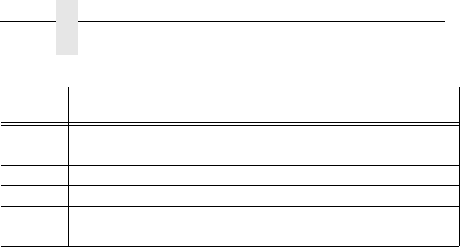
392
Appendix F
=Not Supported Electronic Vertical Format Unit (EVFU), Channel 14 73
IEMUL Not Supported Emulation Switch 77
@R Not Supported Reset 135
+Not Supported Tab, Vertical 155
QNot Supported Plotting Graphics 132
CNot Supported Plotting Graphics 157
Table 78. L7032 Printers - Partially Supported and Non-Supported Commands
VGL
Command Support Level Description Page

393
G
Glossary
A
Active column The horizontal location on the paper where the next
character prints. After printing a character, the printer
advances the active column.
Active line The vertical location on the paper where the next
character prints. After printing a line, the printer
advances the active line.
Active position The position on the paper where the next character
prints. The active position is defined by the horizontal
position (active column) and the vertical position (active
line).
ASCII Abbreviation of American Standard Code for
Information Interchange.
B
Baud A unit of speed that measures the rate at which
information is transferred. Baud rate is the reciprocal of
the length in seconds of the shortest pulse used to
carry data. For example, a system in which the shortest
pulse is 1/1200 second operates at 1200 baud. On RS-
232 serial lines, the baud rate equals the data flow rate
in bits per second (bps). To communicate properly, a
printer must be configured to operate at the same baud
rate as its host computer.
Bold A typeface with a heavy line thickness produced by a
double strike print method. See also character weight.
Compare with shadow printing.
Buffer A reserved area in printer memory that data is written to
and read from during data transfers.

394
Appendix G
Glossary
C
Character A graphical representation of data.
Character cell The invisible rectangular space occupied by a
character, including the white space around the
character. Used as a unit of spacing. The height of a
cell is equal to the current line spacing, and the width of
a cell remains constant even with changes in the
current character spacing.
Character Library The collection of all the glyphs for all fonts.
Character Location The location of a character in a font. The location of a
character is the same in all fonts.
Character set A protocol instructing the printer how to construct a set
of printable characters, including symbols, punctuation,
numbers, diacritical markings, and alphabet characters.
Each character is assigned a unique address in
memory.
Character weight The degree of lightness and thickness of printed text.
For example: Bold refers to a heavy or thick character
weight. Medium, normal, or book weight refer to the
character weight used in this sentence.
Code Point A value between 0 and 256 that defines the location of
a character within a character set.
Command sequence Two or more bytes that instruct the printer to perform a
special function. The first character in the sequence is a
Special Function Control Character (SFCC), which
alerts the printer that the string is a command
sequence. (See also SFCC.)
Compressed A font attribute referring to a typeface with a smaller
than normal character width, but no change to
character height.
cpi characters per inch: a measurement of monospaced
fonts indicating the horizontal character density. For
example, 10 cpi is 10 characters produced in a one-
inch (horizontal) space.
CSI Control Sequence Introducer: Two or more bytes that
describe a specific printer control function. In a control
sequence, the first byte is always the CSI character.

395
D
Decipoint One tenth of a point. A unit of measurement equal to 1/
720 inch. See also point.
Default A value, parameter, attribute, or option assigned by a
program or system when another is not specified by the
user.
Diagnostic Pertains to the detection and isolation of printer
malfunctions or mistakes.
Disable To deactivate or set to OFF.
E
Em A font width term equal to the maximum character width
obtainable in a given font. (Derived from the width of an
uppercase M, usually the widest character in a set.)
Emulation Refers to the ability of a printer to execute the
commands of another printer language or protocol.
En A font width term equal to one half em.
Enable To activate or set to ON.
Escape sequence Two or more bytes that describe a specific printer
control function. In an escape sequence, the first byte is
always the ASCII ESC character. (See also command
sequence, SFCC.)
Expanded A font enhancement referring to larger-than-normal
character width with no change in character height.
F
False Off or zero. Compare with true.
Family (or type) A set of all variations and sizes of a type style.
Fixed-pitch fonts See font, monospaced.

396
Appendix G
Glossary
Font The complete set of a given size of type, including
characters, symbols, figures, punctuation marks,
ligatures, signs, and accents. To fully describe a font,
you must specify seven characteristics: 1) type family,
2) spacing (proportional or monospaced), 3) type size
(12 point, 14 point, etc.), 4) scale factor (character
height/width ratio), 5) type style, 6) character weight,
and 7) character proportion (normal, condensed,
expanded).
Font Directory The header file that contains the tables describing
allowed the mode and pitch combinations. The file also
contains the tables used to set up the character sets
and the international languages within the character
sets.
Font name See typeface.
Font pattern A font pattern is the matrix of pels which represents a
character, symbol, or image.
Font, landscape A font printed parallel to the long edge of a page, or a
font capable of being produced on a landscape page
orientation.
Font, monospaced Also called fixed-pitch fonts. Every character,
regardless of actual horizontal size, occupies the same
amount of font pattern space. All monospaced fonts
use specific pitch size settings. Monospaced fonts are
sometimes used when strict character alignment is
desired (tables, charts, spreadsheets, etc.).
Font, portrait A font printed parallel to the short edge of a page.
Font, proportional A font in which the width of the character cell varies with
the width of the character. For example, “i” takes less
space to print than “m”. Using proportional fonts
generally increases the readability of printed
documents, giving text a typeset appearance. This
manual is printed in proportional fonts.
Font weight See character weight.
Font width The measurement of the width of a character cell in
dots.

397
G
Glyph The shape of a character in a print mode and pitch.
H
HGS Horizontal Grid Size.
Host computer The host computer stores, processes, and sends data
to be printed, and which communicates directly with the
printer. The term host indicates the controlling
computer, since modern printers are themselves
microprocessor-controlled computer systems.
I
ipm inches per minute: The speed at which graphics are
plotted.
Interface The hardware components used to link two devices by
common physical interconnection, signal, and
functional characteristics.
International
Language Character set in which characters have been
rearranged according to a substitution table for use in a
different country.
Invoke To put into effect or operation.
Italic A type style in which characters are slanted. This
sentence is set in italics.
L
lpi lines per inch: a measurement indicating the vertical
spacing between successive lines of text. For example,
8 lpi is 8 printed lines per vertical inch.
lpm lines per minute: A measurement indicating the number
of lines printed per minute. (lpm usually defines the
speed at which text prints.)
Logical link The parameters that specify data transfer, control, or
communication operations.

398
Appendix G
Glossary
M
Memory See RAM.
N
Nonvolatile memory Nonvolatile memory stores variables that must be
preserved when the printer is turned off, such as
configuration parameters and printer usage statistics.
Nonvolatile memory is preserved because RAM is
housed on the controller board, which contains an
independent, battery-operated power supply. When
printer power is turned off, the battery supplies the
power needed to keep stored data active. Nonvolatile
memory also includes storage on disk.
NOVRAM Acronym of NonVolatile Random-Access Memory. See
also nonvolatile memory.
O
OCR Optical Character Recognition is the process by which
a machine reads characters printed in a special
standardized font. Data are read by a photoelectric
optical scanner and recorded on magnetic tape or disk.
OCR-A and OCR-B are two widely used fonts.
P
Page Window A rectangular area on the physical page outside of
which the emulation does not print.
Parity (check) Parity checking is the addition of non-data bits to data,
resulting in the number of 1 bits being either always
even or always odd. Parity is used to detect
transmission errors. Parity represents the value in the
check digit of the received or transmitted data.

399
Parsing Parsing is the process of separating a programming
statement into basic units that can be translated into
machine instructions. A printer can recover from an
erroneous code sequence by performing as much of
the function as possible or, parsing the valid parameter
from the invalid.
Pel See pixel.
PI Paper instruction: A signal from the host with the same
timing and polarity as the data lines.
Pica A name indicating a monospaced font with a pitch of 10
cpi and usually a 12 point height. Pica is also used in
typography as a unit of measurement: 1 pica = 1/6
inch.
Pin configuration Establishes the physical attachment and protocol
conversion connections for the host interface.
Pitch The number of text characters printed per horizontal
inch. Specified in characters per inch or cpi.
Pixel Acronym of picture element or picture cell. The smallest
displayable picture element on a video monitor or
printable unit in a printer.
Point A unit of measure in printing and typography, used to
specify type sizes, heights of font characters, etc. There
are 72 points in a vertical inch; thus, one point equals 1/
72 inch, or approximately 0.0138 inch. Examples:
This is 6
point type.
This is 10 point type.
This is 16 point
type.
Port A channel used for receiving data from or transmitting
data to one or more external devices.
Print Mode The horizontal and vertical dot density at which the
characters are printed.
Print Pitch Defines the number of characters that can be printed in
one inch. It can be translated into the width of the
character.
Printer Configuration The operating properties that define how the printer
responds to signals and commands received from the
host computer. These properties are set to match the
operating characteristics of the host computer system.
Printer Interface The point where the data line from the host computer
plugs into the printer.

400
Appendix G
Glossary
Protocol A set of rules or conventions governing the exchange of
information between computer systems. For computer
printers, a protocol is the coding convention used to
convey and print data. A printer protocol includes
character codes, printer function codes, and machine-
to-machine communication codes.
R
RAM Random-Access Memory. Also called “main memory”
or “working memory,” this is the active memory of a
printer, into which programs are loaded. RAM is said to
be volatile because data in RAM are lost when power is
turned off or interrupted. Compare with ROM.
Read To retrieve data from memory or mass storage (hard
disk, floppy diskette, RAM, etc.).
Reset To turn off, deactivate, disable, or return to a previous
state.
Resolution A measure expressing the number of component units
in a given range used to create an image; in printing,
expressed as the number of dots per inch (dpi)
horizontally and vertically.
ROM Read-Only Memory. Programs, instructions, and
routines permanently stored in the printer. ROM is not
lost when power is turned off and cannot be written to-
hence the name “read only.” ROM-resident fonts are
permanently stored in a printer and available at any
time via software commands. Compare with RAM.
Roman A type style in which characters are upright. This
sentence is printed in roman type.

401
S
Serial
communications The sequential transmission of data, in which each
element is transferred in succession.
Set To turn on, activate, invoke, or enable.
SFCC Special Function Control Character. The first character
in a printer command sequence. In P-Series emulation
mode, you can select one of five characters as the
SFCC. In the Serial Matrix or Proprinter protocols, the
SFCC must always be the ASCII ESC character. See
also command sequence.
Shadow printing A typeface with a heavy line thickness produced when
the characters doublestrike just offset of the original
characters. See also character weight. Compare with
bold print.
Sixel A six pixel vertical column.
Slewing Rapid vertical paper movement.
SSCC Super-Set Control Code. The SSCC is used to activate
the super-set commands. It consists of the SFCC plus
the sequence | } ;
Start bit The signal that indicates the start of a character or
element.
Stop bits The signal that indicates the end of a character or
element.
String Two or more bytes of data or code treated as a unit.
Substitution Table A table that contains the code points within a character
set that need to be changed for an international
language.
Symbol set See character set.

402
Appendix G
Glossary
T
True On or 1. “High true” refers to a positive relative voltage
representing the ON state; “low true” refers to a
negative relative voltage representing the ON state.
Type style Refers to either the upright (roman) or italic character
style within a specific font family.
Typeface A descriptive name or brand name that identifies a
particular design of type.
Typographic font See font, proportional.
W
Weight See character weight.
Write To store data to memory or mass storage (hard disk,
floppy diskette, RAM, etc.).
403
H
Contact Information
Printronix Customer Support Center
IMPORTANT
Please have the following information available prior to calling the
Printronix Customer Support Center:
•
Model number
•
Serial number (located on the back of the printer)
•
Installed options (i.e., interface and host type if applicable to the problem)
•
Configuration printout:
Thermal Printer
See “Printing A Configuration” in the Quick Setup Guide.
Line Matrix Printer
Press PRT CONFIG on the control panel, then press Enter.
L7032 Printer
a. Press the Menu button.
b. Press the Left or Right arrow button until Test Print displays.
c. Press the Down arrow button to select the menu.
d. If necessary, press the Left or Right arrow button until Configuration
displays.
e. Press Shift + Down arrow to select the menu option and print the
current configuration.
•
Is the problem with a new install or an existing printer?
•
Description of the problem (be specific)
•
Good and bad samples that clearly show the problem (faxing or emailing
of these samples may be required)
Americas (714) 368-2686
Europe, Middle East, and Africa (31) 24 6489 410
Asia Pacific (65) 6548 4114
China (86) 800-999-6836
http://www.printronix.com/support.aspx
404
Appendix H
Printronix Supplies Department
Printronix Supplies Department
Contact the Printronix Supplies Department for genuine Printronix supplies.
Americas (800) 733-1900
Europe, Middle East, and Africa 33 (0) 1 46 25 19 07
Asia Pacific (65) 6548 4116
or (65) 6548 4182
China (86) 400-886-5598
India (800) 102-7869
http://www.printronix.com/supplies-parts.aspx
Corporate Offices
Printronix, Inc.
15345 Barranca Parkway
Irvine, CA 92618
U.S.A.
Phone: (714) 368-2300
Fax: (714) 368-2600
Printronix Inc.
c/o Printronix Nederland BV
Bijsterhuizen 11-38
6546 AS Nijmegen
The Netherlands
Phone: (31) 24 6489489
Fax: (31) 24 6489499
Printronix Schweiz GmbH
42 Changi South Street 1
Changi South Industrial Estate
Singapore 486763
Phone: (65) 6542 0110
Fax: (65) 6546 1588
Printronix Commercial (Shanghai) Co. Ltd
22F, Eton Building East
No.555, Pudong Av.
Shanghai City, 200120, P R China
Phone: (86) 400 886 5598
Fax: (86-21) 5138 0564
Visit the Printronix web site at www.printronix.com
405
Index
A
Accessing characters and character sets, 341
data bit 8, 341
Power-up character set selection, 341
Addresses, character, 338
AIAG form, 95
Alphanumeric text, creating, 302
Alphanumerics, 32
example, 35
inverted, 37
reverse string, 38
rotated clockwise, 35
rotated counterclockwise, 36
standard, 35
ASCII, standard character set, 361
Australian 4-State, 169
example, 172
standard command format, 170
structure, 169
Auto increment/decrement vertical duplication, 59
Automatic increment/decrement capability, 15
Automatic mode, Code 128, 196
B
Barcode
Australian 4-State, 169
BC412 Barcode, 174
Codabar, 178
Code 128, 195
Code 39, 184
Code 93, 191
command format, 162, 163
EAN 13, 209
EAN 8, 204
German Interleaved 2/5, 214
GS-1 Data Matrix, 230
GS1-128, 219
IBARC format, 164
Identicon, 239
Intelligent Mail 4-State, 242
Interleaved 2/5, 244
Maxicode, 249
MSI, 254
PDF-417, 260
Planet, 264
POSTNET, 269
ratio, 163, 164
resolution, 162
Royal Mail, 273
Telepen, 275
type, 163, 164
UPC-A, 282
UPC-E, 285
UPCSHIP, 293
UPS 11, 297
variable ratio size (D), 164
Barcode ratio, BC412 Barcode, 177
Barcodes, 167
BC412 Barcode, 174
barcode ratio, 177
data field, 174
example, 178
quiet/clear zone, 174
standard command format, 177
start/stop code, 174
BC412 Barcode, check code, 176
Bitmap images, plotting, 127
bottom margins, page boundaries, 380

406
Boxes command code, 39
Boxing alphanumeric text, 303
high resolution graphic exercise, 307
Brackets, 21
Building a Character Translation Table, 341
C
Carriage return command code, 41
Character addresses, 338
Character height, 23, 42
Character Set
resetting, 342
Character set selection command, 345
Character Sets
translation table, 341
Character sets
international, 353
Character sets, accessing, 341
Character sets, multinational, 337
Character set, Codabar, 181
Character Set, Code 39, 188
Character set, Standard ASCII, 361
Character substitutions, 338
Character Translation Table, 341
Character type, 46
Character width, 23, 44
Characters, accessing, 341
Charts, multinational character sets, 349
Check code
BC412 Barcode, 176
Check digit
Code 128, 196
Code 39, 185
Code 93, 192
EAN 13, 210
EAN 8, 205
German Interleaved 2/5, 215
Interleaved 2/5, 245
MSI, 255
Planet, 266
Royal Mail, 273
Telepen, 276
UPC-E, 286
UPCSHIP, 294
UPS 11, 298
Codabar, 178
character set, 181
command format, 179
data field, 179
examples, 182
quiet zone, 178
readable data, 179
start/stop codes, 179
Code 128, 195
automatic mode, 196
check digit, 196
commnd format, 198
data field, 196
example, 202
manual mode, 197
manual mode operation, 197
quiet zone, 195
readable data, 196
start/stop codes, 195
Code 39, 184
character set, 188
check digit, 185
command format, 185
data field, 184
examples, 189
quiet zone, 184
readable data, 185
start/stop codes, 184
Code 93, 191
check digit, 192
command format, 192
data fields, 191
example, 194
quiet zone, 191
readable data, 192
start/stop codes, 191
Comma, 22
Command
CONFIG, 389
FILE_IO, 389

407
Command codes, 26
alphanumerics, 32
boxes, 39
carriage return, 41
character height, 42
character type, 46
character width, 44
compressed print, 47
dark print, 49
descending characters, 51
direct printer commands, 53
dot slew, 54
duplication, horizontal, 54
duplication, horizontal (Version II), 56
duplication, vertical, 57
duplication, vertical (Version II), 63
dynamic form commands, 65
electronic vertical format unit (EVFU), 73
emphasized print, 76
emulation switch, 77
extended graphics, 29
extended graphics/high resolution, 31
font load, 77
fonts, compressed print density, 85
fonts, rotatable, 82
font, selecting default (Version II), 78
form feed, 88
form length, 89
forms construction, 90
forms, creating dynamic (Version II), 93
forms, deleting dynamic (Version II), 94
forms, executing dynamic (Version II), 94
forms, listing dynamic (Version II), 95
forms, resetting dynamic (Version II), 99
free format, 99
free format disable, non-graphics, 102
free format enable, non-graphics, 101
graphics mode disable, 104
graphics mode enable, 103
graphics mode enable commands, 26
Hex dump, 104
horizontal duplication, 54
horizontal duplication (Version II), 56
ignore data, 105
interrupt, 106
justification, vertical, 108
line feed, 110
line slew, 111
line spacing, 111
lines, dashed, 113
lines, solid, 116
logo, PCX, 120
logo, TIFF, 121
page, controlling paper options (Version II), 122
passing hex values, 124
pixel expansion (Version II), 125
plotting bitmap images, 127
plotting graphics (columns), 129
plotting graphics (Rows), 132
reset, 135
reverse print, 136
shading, 140
shading mask, 142
special function control code change, 144
standard graphics commands, 27
symbols, creating expanded user defined, 148
symbols, creating standard user defined, 145
symbols, printing, 150
tab, horizontal, 151
tab, vertical, 155
underlined print, 156
vertical duplication, 57
vertical duplication (Version II), 63
wait for online, 157
Command format
Barcodes, 163
Codabar, 179
Code 128, 198
Code 39, 185
Code 93, 192
Data Matrix, 230
EAN 13, 210
EAN 8, 205
German Interleaved 2/5, 215

408
Identicon, 240
Interleaved 2/5, 245
Maxicode, 249
MSI, 255
PDF417, 262
Planet, 267
POSTNET, 272
Royal Mail, 274
Telepen, 276
UCC/EAN-128, 224
UPC-E, 287
UPCSHIP, 294
UPS 11, 298
Command parameters, 21
Command sequence, 21
Command standards
brackets, 21
character height, width, and intercharacter
spacing, 23
comma, 22
command parameters, 21
command sequence, 21
spaces, 22
special function control code (SFCC), 21
terminator, 22
VGL, 20
Command Support, L7032 printers, 391
Commands
PTX_SETUP, 383
Scaling, 138
Compressed print, 47
Configure VGL, control panel, 17
Contact information, 403
Control characters, Maxicode, 252
Control panel, configure VGL, 17
Creating expanded user defined symbols, 148
Creating standard user defined symbols, 145
Customer Support Center, 403
D
Dark print, 49
Dashed lines, 113
Data bit 8
accessing characters and character sets, 341
Data field
BC412 Barcode, 174
Codabar, 179
Code 128, 196
Code 39, 184
Code 93, 191
Data Matrix, 230
EAN 13, 210
EAN 8, 205
German Interleaved 2/5, 214
Identicon, 239
Interleaved 2/5, 244
Maxicode, 249
MSI, 254
Planet, 266
Royal Mail, 273
Telepen, 275
UCC/EAN-128, 223
UPC-E, 286
UPCSHIP, 293
UPS 11, 297
Data Field, PDF-417, 261
Data Matrix
command format, 230
data field, 230
example, 238
quiet zone, 230
readable data, 230
special characters using SO, 233
symbol characteristics, 234
Data positioning, 24
explicit positioning commands, 25
implied relative positioning, 24
vertical dot density, 25
Default font (Version II), 78
Descending characters, 51
Direct printer commands, 53

409
Dot slew, 54
Duplication, horizontal, 54
Duplication, horizontal (Version II), 56
Duplication, vertical, 57
Duplication, vertical (Version II), 63
Dynamic form
copy fields, 69
field length, 67
repeat, 71
special command definitions, 66
Dynamic form commands, 65
dynamic form special command definitions, 66
dynamic form, copy fields, 69
dynamic form, field length, 67
dynamic form, repeat, 71
E
EAN 13, 209
check digit, 210
command format, 210
data field, 210
example, 212
number system character, 210
quiet zone, 209
readable data, 210
start/center/stop codes, 209
EAN 8, 204
check digit, 205
command format, 205
data field, 205
example, 208
quiet zone, 205
readable data, 205
start/center/stop codes, 205
Electronic vertical format unit (EVFU), 73
Emphasized print, 76
Emulation switch, 77
Enable VGL graphics, high resolution graphic
exercise, 306
Error codes, 355
purpose, 355
Errors, solving problems, 336
Example
alphanumerics, 35
BC412 Barcode, 178
Codabar, 182
Code 128, 202
Code 39, 189
Code 93, 194
Data Matrix, 238
EAN 13, 212
EAN 8, 208
Fonts, compressed print density, 87
form, 311
German Interleaved 2/5, 217
Interleaved 2/5, 247
label, 328
Maxicode, 253
MSI, 257
passing hex values, 124
Planet, 268
POSTNET, 272
Royal Mail, 274
Telpen, 279
UCC/EAN-128, 226
UPC-A, 284
UPC-E, 292
UPCSHIP, 296
UPS 11, 300
VGL, 301
Examples
dark print, 50
forms construction, 96, 98
Exercise
graphic, high resolution, 306
graphic, normal resolution, 302
VGL, 301
Explicit positioning commands, 25
Extended graphics
commands, 29
high resolution commands, 31
high resolution mode, 17
mode, 16

410
F
Features
automatic increment/decrement capability, 15
compressed print, 14
different, VGL, 15
expanded print, 14
international character sets, 15
label generation, 14
logos, 15
multinational character sets, 15
new, VGL, 15
on-line form, 14
reversed print, 15
rotated alphanumerics, 14
shaded print, 15
variable barcodes, 14
FILE_IO Command, Operation of, 389
Font load, 77
Fonts, compressed print density, 85
examples, 87
Fonts, rotatable, 82
Font, selecting default (Version II), 78
Form example, 311
create the box around the form, 314
design the form, 313
design the logo, 314
disable VGL graphics, 325
enable VGL graphics, 313
enter alphanumeric text throughout the form,
319
enter the barcode, 325
enter the company heading, 318
enter the corners, 323
enter the interior box with horizontal and
vertical lines, 321
enter the slogan, 324
input the logo data, 317
page layout considerations, 311
planning the form layout, 311
position form elements, 313
translate logo design into data, 314
Form feed, 88
Form length, 89
Forms
construction
examples, 96, 98
creating dynamic (Version II), 93
deleting dynamic (Version II), 94
executing dynamic (Version II), 94
listing dynamic (Version II), 95
predefined, 95
resetting dynamic (Version II), 99
Forms construction, 90
Free format, 99
disable, non-graphics, 102
enable, non-graphics, 101
G
German Interleaved 2/5, 214
check digit, 215
command format, 215
data field, 214
example, 217
quiet zone, 214
readable data, 215
start/stop codes, 214
Graphics
plotting (columns), 129
plotting (Rows), 132
Graphics mode, 16, 24
data positioning, 24
disable, 104
enable, 103
enable commands, 26
Grid
logo, 375
standard, 375
GS-1 Data Matrix, 230
GS1-128, 219

411
H
Hex dump, 104
High resolution graphic exercise
boxing alphanumeric text, 307
create more alphanumeric text, 309
enable VGL graphics, 306
horizontal lines, 308
Horizontal duplication, 54
Horizontal duplication (Version II), 56
Horizontal lines
graphic exercise, 304
high resolution graphic exercise, 308
Horizontal tab, 151
I
IBARC command format, 164
Identicon, 239
command format, 240
data field, 239
quiet zone, 239
readable data, 240
start/stop codes, 239
Ignore data, 105
Implied relative positioning, 24
Intelligent Mail 4-State, 242
Intercharacter spacing, 23
Interleaved 2/5, 244
check digit, 245
command format, 245
data field, 244
example, 247
quiet zone, 244
readable data, 245
start/stop codes, 244
International character sets, 15, 353
Interrupt, 106
Inverted alphanumerics, 37
ISO character set, ISO, 348
J
Justification, vertical, 108
L
Label example, 328
add barcodes and dynamic barcode data, 333
add dynamic data, 334
add headings, 333
add horizontal lines, 333
add TO/FROM alphanumeric data, 332
create the corners, 331
create the label box, 331
disable graphics mode, 335
enable dynamic form processing, 330
enable horizontal duplication, 330
enable VGL graphics, 330
Label generation, 14
Left margins, page boundaries, 381
Line feed, 110
Line slew, 111
Line Spacing, 138
Line spacing, 111
Lines
dashed, 113
solid, 116
Logo
grid, 375
PCX, 120
TIFF, 121
Logos, 15
L7032 Printers, command support, 391
M
Manual mode operation
Code 128, 197
subset A, 198
subset B and C switching, 197
Manual mode, Code 128, 197
Manual, overview, 13
Masks, selecting, 363
Maxicode, 249
command format, 249
control characters, 252
data field, 249
example, 253

412
readable data, 249
standard data field, 250
UPS shipping data field, 251
Maximum Print Area, 379
Maximum values, 379
Modes of operation
extended graphics mode, 16
extended graphics/high resolution mode, 17
graphics mode, 16
normal mode, 16
VGL, 19
Modulo-10 check digit, UCC/EAN-128, 224
Modulo-103 check digit, UCC/EAN-128, 224
MSI, 254
check digit, 255
command format, 255
data field, 254
example, 257
quiet zone, 254
readable data, 255
start/stop codes, 254
Multinational character sets, 15, 337
accessing characters and character sets, 341
character addresses, 338
character set selection command, 345
character substitutions, 338
charts, 349
selecting an ISO character set, 348
user-defined set command, 343
N
Normal mode, 16, 23
Normal resolution graphic exercise
boxing alphanumeric text, 303
create more alphanumeric text, 304
creating alphanumeric text, 302
horizontal lines, 304
Number system character
EAN 13, 210
UPC-E, 286
O
Odette Form, 95
On-line form, 14
Overview
manual, 13
PTX_SETUP, 383
P
Page boundaries
bottom margins, 380
left margins, 381
top margins, 380
Page layout considerations, form example, 311
Page, controlling paper options (Version II), 122
Paper selection, 379
Paper Sizes, 379
Passing hex values, 124
Passing hex values, examples, 124
PCX logo, 120
PDF, PDF-417, 261
PDF-417, 260
command format, 262
Data Field, 261
example, 263
PDF, 261
Quiet Zone, 261
Security Level, 261
Start/Stop Codes, 261
structure, 260
Pixel expansion (Version II), 125
Planet, 264
check digit, 266
command format, 267
data field, 266
example, 268
quiet zone, 266
start/stop code, 266
Planning the form layout, form example, 311
Plot data
byte format, 133
format, 133
line format, 134

413
Plotting
bitmap images, 127
graphics (columns), 129
Plotting graphics (Rows), 132, 133
plot data byte format, 133
plot data line format, 134
POSTNET, 269
command format, 272
example, 272
Power-up character set selection, accessing
characters and character sets, 341
Predefined Forms
AIAG form, 95
odette form, 95
primary metals form, 95
Primary Metals Form, 95
Print Area, Maximum, 379
Printing symbols, 150
PTX_SETUP
commands, 383
CONFIG command, 389
FILE_IO command, 389
overview, 383
Q
Quiet zone
Codabar, 178
Code 128, 195
Code 39, 184
Code 93, 191
Data Matrix, 230
EAN 13, 209
EAN 8, 205
German Interleaved 2/5, 214
Identicon, 239
Interleaved 2/5, 244
MSI, 254
PDF-417, 261
Planet, 266
Royal Mail, 273
Telepen, 275
UCC/EAN-128, 223
UPC-E, 285
UPCSHIP, 293
UPS 11, 297
Quiet/clear zone, BC412 Barcode, 174
R
Ratio, barccode, 164
Ratio, barcode, 163
Readable data
Code 128, 196
Code 39, 185
Code 93, 192
Data Matrix, 230
EAN 13, 210
EAN 8, 205
German Interleaved 2/5, 215
Identicon, 240
Interleaved 2/5, 245
Maxicode, 249
MSI, 255
Telepen, 276
UCC/EAN-128, 223
UPC-E, 286
UPCSHIP, 294
UPS 11, 298
Readable Data Field, 163
Readable data, Codabar, 179
Reset command code, 135
Resetting the Character Set, 342
Resolution, Barcodes, 162
Reverse print, 15, 136
Reverse string alphanumerics, 38
Rotatable fonts, 82
Rotated alphanumerics, 14
Rotated clockwise alphanumerics, 35
Rotated counter clockwise alphanumerics, 36
Royal Mail, 273
check digit, 273
command format, 274
data field, 273
example, 274
quiet zone, 273
start/stop code, 273

414
S
Scaling, 138
Security Level, PDF-417, 261
Shaded print, 15
Shading, 140
Shading mask, 142
selecting, 363
Solid lines, 116
Solving program errors, 336
SO, special Data Matrix characters, 233
Spaces, 22
Spacing, line, 138
Special characters using SO, Data Matrix, 233
Special function control code change, 144
Special function control code (SFCC), 21
Special information, 13
Standard alphanumerics, 35
Standard ASCII character set, 361
Standard command format, BC412 Barcode, 177
Standard data field
Maxicode, 250
Standard graphics commands, 27
Standard grid, 375
Start/center/stop codes
EAN 13, 209
EAN 8, 205
Start/stop codes
BC412 Barcode, 174
Codabar, 179
Code 128, 195
Code 39, 184
Code 93, 191
German Interleaved 2/5, 214
Identicon, 239
Interleaved 2/5, 244
MSI, 254
Planet, 266
Royal Mail, 273
Telepen, 275
UCC/EAN-128, 223
UPC-E, 285
UPCSHIP, 293
UPS 11, 297
Start/Stop Codes, PDF-417, 261
Subset A, manual mode operation, 198
Subset B and C switching, manual mode
operation, 197
Substitutions, character, 338
Supplies Department, 404
Symbol characteristics, Data Matrix, 234
Symbols
creating expanded user defined, 148
creating standard user defined, 145
printing, 150
T
Tab
horizontal, 151
vertical, 155
Telepen, 275
check digit, 276
command format, 276
data field, 275
example, 279
quiet zone, 275
readable data, 276
start/stop codes, 275
Terminator, 22
TIFF logo, 121
Top margins, page boundaries, 380
Translation Table, 341
Type, barcode, 163, 164
U
UCC/EAN-128
command format, 224
data field, 223
example, 226
Modolo-103 check digit, 224
Modulo-10 data field check digit, 224
quiet zone, 223
readable data, 223
start/stop codes, 223
Underlined print, 156

415
UPC-A, 282
UPC-A, example, 284
UPC-E, 285
check digit, 286
command format, 287
data field, 286
example, 292
number system character, 286
quiet zone, 285
readable data, 286
start/stop codes, 285
UPCSHIP, 293
check digit, 294
command format, 294
data field, 293
example, 296
quiet zone, 293
readable data, 294
start/stop codes, 293
UPS shipping data field, Maxicode, 251
UPS 11, 297
check digit, 298
command format, 298
data field, 297
example, 300
quiet zone, 297
readable data, 298
start/stop codes, 297
User-defined set command, 343
V
Variable barcodes, 14
Variable Ratio Size (D), barcode, 164
Vertical dot density, 25
Vertical duplication, 57
auto increment/decrement, 59
Vertical duplication (Version II), 63
Vertical justification, 108
Vertical tab, 155
VGL
command standards, 20
configuring with control panel, 17
different features, 15
examples, 301
exercises, 301
high resolution graphic exercise, 306
modes of operation, 19
new features, 15
normal resolution graphic exercise, 302
W
Wait for online, 157
Warning, 13

416
254079-001B
*254079-001*
