PTX_UM_P7_P7HD_CRP_254796G PTX UM P7 P7HD CRP 254796G
PTX_UM_P7_P7HD_CRP_254796G PTX_UM_P7_P7HD_CRP_254796G
PTX_UM_P7_P7HD_CRP_254796G PTX_UM_P7_P7HD_CRP_254796G
PTX_UM_P7_P7HD_CRP_254796G PTX_UM_P7_P7HD_CRP_254796G
User Manual: PTX_UM_P7_P7HD_CRP_254796G
Open the PDF directly: View PDF ![]() .
.
Page Count: 378 [warning: Documents this large are best viewed by clicking the View PDF Link!]
- 1 Introduction
- 2 Setting Up The Printer
- 3 Operating The Printer
- 4 The Configuration Menus
- Configuration Overview
- Dynamic Menu Options
- Active Emulations
- Main Menu
- QUICK SETUP Menu
- CONFIG. CONTROL Menu
- HOST INTERFACE Menu
- NETWORK SETUP Menu
- ACTIVE IGP EMUL and ACTIVE EMULATIONS Menus
- EMULATION Menu
- Coax/Twinax (CTHI) Emulation
- LinePrinter Plus Emulation
- LinePrinter Plus Emulation (With PCL-II)
- ANSI Emulation
- IGP/PGL Emulation
- IGP/VGL Emulation
- IPDS Emulation
- PCL - II Emulation
- LG Emulation
- OpenPrint POSTSCRIPT/PDF Emulation
- OpenPrint SURE SCAN Menu
- PRINTER CONTROL Menu
- ADVANCED USER Menu
- DIAGNOSTICS Menu
- DATE Menu
- PRINTER MGMT Menu
- 5 Interfaces
- 6 Reprogramming the Security Key
- 7 Troubleshooting
- A Printer Specifications
- B ASCII Character Set
- C Zero Tear Printer
- D Customer Support
- E Communication Notices
P7000 Cartridge Ribbon Printer
User’s Manual
Software License Agreement
CAREFULLY READ THE FOLLOWING TERMS AND
CONDITIONS BEFORE USING THIS PRINTER. USING THIS
PRINTER INDICATES YOUR ACCEPTANCE OF THESE
TERMS AND CONDITIONS. IF YOU DO NOT AGREE TO
THESE TERMS AND CONDITIONS, PROMPTLY RETURN
THE PRINTER AND ALL ACCOMPANYING HARDWARE
AND WRITTEN MATERIALS TO THE PLACE YOU
OBTAINED THEM, AND YOUR MONEY WILL BE
REFUNDED.
Definitions.
“Software” shall mean the digitally encoded, machine-readable
data and program. The term “Software Product” includes the
Software resident in the printer and its documentation. The
Software Product is licensed (not sold) to you, and Printronix,
Inc. either owns or licenses from other vendors who own, all
copyright, trade secret, patent and other proprietary rights in
the Software Product.
License.
1.
Authorized Use. You agree to accept a non-exclusive
license to use the Software resident in the printer solely
for your own customary business or personal purposes.
2.
Restrictions.
a. To protect the proprietary rights of Printronix, Inc.,
you agree to maintain the Software Product and
other proprietary information concerning the
typefaces in strict confidence.
b. You agree not to duplicate or copy the Software
Product.
c. You shall not sublicense, sell, lease, or otherwise
transfer all or any portion of the Software Product
separate from the printer, without the prior written
consent of Printronix, Inc.
d. You may not modify or prepare derivative works of
the Software Product.
e. You may not transmit the Software Product over a
network, by telephone, or electronically using any
means; or reverse engineer, decompile or
disassemble the Software.
f. You agree to keep confidential and use your best
efforts to prevent and protect the contents of the
Software Product from unauthorized disclosure or
use.
3.
Transfer. You may transfer the Software Product with the
printer, but only if the recipient agrees to accept the
terms and conditions of this Agreement. Your license is
automatically terminated if you transfer the Software
Product and printer.
Limited Software Product Warranty
Printronix, Inc. warrants that for ninety (90) days after delivery,
the Software will perform in accordance with specifications
published by Printronix, Inc. Printronix, Inc. does not warrant
that the Software is free from all bugs, errors and omissions.
Remedy
Your exclusive remedy and the sole liability of Printronix, Inc.
in connection with the Software is replacement of defective
software with a copy of the same version and revision level.
Disclaimer of Warranties and Limitation of Remedies
1.
THE PARTIES AGREE THAT ALL OTHER
WARRANTIES, EXPRESS OR IMPLIED, INCLUDING
WARRANTIES OF FITNESS FOR A PARTICULAR
PURPOSE AND MERCHANTABILITY ARE EXCLUDED.
Printronix, Inc. does not warrant that the functions
contained in the Software will meet your requirements or
that the operation of the Software will be uninterrupted or
error free. Printronix, Inc. reserves the right to make
changes and/or improvements in the Software without
notice at any time.
2.
IN NO EVENT WILL PRINTRONIX, INC. BE LIABLE
FOR LOST PROFITS, LOST DATA, BUSINESS
INTERRUPTIONS, OR ANY OTHER DIRECT,
INDIRECT, INCIDENTAL OR CONSEQUENTIAL
DAMAGES ARISING OUT OF THE USE OF OR
INABILITY TO USE THIS PRODUCT, EVEN IF
PRINTRONIX, INC. HAS BEEN ADVISED OF THE
POSSIBILITY OF SUCH DAMAGES, OR ANY
DAMAGES CAUSED BY THE ABUSE OR
MANIPULATION OF THE SOFTWARE. SOME STATES
DO NOT ALLOW THE EXCLUSION OR LIMITATION OF
LIABILITY FOR CONSEQUENTIAL OR INCIDENTAL
DAMAGES, SO THE ABOVE LIMITATION MAY NOT
APPLY TO YOU.
3.
Printronix, Inc. will not be liable for any loss or damage
caused by delay in furnishing a Software Product or any
other performance under this Agreement.
4.
Our entire liability and your exclusive remedies for our
liability of any kind (including liability for negligence
except liability for personal injury caused solely by our
negligence) for the Software Product covered by this
Agreement and all other performance or nonperformance
by us under or related to this Agreement are limited to the
remedies specified by this Agreement.
5.
California law governs this Agreement.
Termination of License Agreement
This License shall continue until terminated. This license may
be terminated by agreement between you and Printronix, Inc.
or by Printronix, Inc. If you fail to comply with the terms of this
License and such failure is not corrected within thirty (30) days
after notice. When this License is terminated, you shall return
to the place you obtained them, the printer and all copies of the
Software and documentation.
U.S. Government Restricted Rights
Use, duplication or disclosure by the Government is subject to
restrictions as set forth in the Rights in Technical Data and
Computer Software clause at FAR 242.227-7013, subdivision
(b) (3) (ii) or subparagraph (c) (1) (ii), as appropriate. Further
use, duplication or disclosure is subject to restrictions
applicable to restricted rights software as set forth in FAR
52.227-19 (c) (2).
Acknowledgement of Terms and Conditions
YOU ACKNOWLEDGE THAT YOU HAVE READ THIS
AGREEMENT, UNDERSTAND IT, AND AGREE TO BE
BOUND BY ITS TERMS AND CONDITIONS. NEITHER
PARTY SHALL BE BOUND BY ANY STATEMENT OR
REPRESENTATION NOT CONTAINED IN THIS
AGREEMENT. NO CHANGE IN THIS AGREEMENT IS
EFFECTIVE UNLESS WRITTEN AND SIGNED BY
PROPERLY AUTHORIZED REPRESENTATIVES OF EACH
PARTY. BY USING THIS PRINTER, YOU AGREE TO
ACCEPT THE TERMS AND CONDITIONS OF THIS
AGREEMENT.
READ THIS SOFTWARE LICENSE AGREEMENT BEFORE USING THIS PRINTER

User’s Manual
P7000 Cartridge Ribbon Printers

This document contains proprietary information protected by copyright. No
part of this document may be reproduced, copied, translated, or incorporated
in any other material in any form or by any means, whether manual, graphic,
electronic, mechanical, or otherwise, without the prior written consent of
Printronix.
Printronix makes no representations or warranties of any kind regarding this
material, including, but not limited to, implied warranties of merchantability
and fitness for a particular purpose. Printronix shall not be held responsible
for errors contained herein or any omissions from this material or for any
damages, whether direct or indirect, incidental or consequential, in connection
with the furnishing, distribution, performance, or use of this material. The
information in this manual is subject to change without notice.
COPYRIGHT 1997, 2012 PRINTRONIX, INC.
Trademark Acknowledgements
ANSI is a registered trademark of the American National Standards Institute,
Inc.
Artifex, the Artifex logo , Ghostscript, and the Ghostscript logo
are registered trademarks of Artifex Software, Inc.
PostScript is a trademark of Adobe Systems Incorporated.
Centronics is a registered trademark of Genicom Corporation.
CSA is a registered certification mark of the Canadian Standards Association.
Dataproducts is a registered trademark of Dataproducts Corporation.
EIA is a registered service mark of the Electronic Industries Association.
ENERGY STAR is a registered trademark of the United States Environmental
Protection Agency. As an ENERGY STAR
®
Partner, Printronix has
determined that this product meets the ENERGY STAR guidelines for energy
efficiency.
Epson is a registered trademark of Seiko Epson Corporation.
Ethernet is a trademark of Xerox Corporation.
IBM, AS/400, and Proprinter are registered trademarks, and Intelligent Printer
Data Stream and IPDS are trademarks of International Business Machines
Corporation.
IEEE is a registered service mark of the Institute of Electrical and Electronics
Engineers, Inc.
Printronix, PGL, LinePrinter Plus, and IGP are registered trademarks, and
P7005, P7010, P7015, P7205, P7210, P7215, P7220, and SureStak are
trademarks of Printronix, Inc.
QMS is a registered trademark, and Code V is a trademark of Quality Micro
Systems, Inc.
TUV is a registered certification mark of TUV Rheinland of North America, Inc.
UL is a registered certification mark of Underwriters Laboratories, Inc.

Table of Contents
1 Introduction........................................................... 11
Printer Overview .....................................................................................11
Printronix P7000 Cartridge Ribbon Printers (CRP) Series ...............11
Consumable Monitoring With PrintNet Enterprise ..................................13
Graphics Enhancements ........................................................................13
Taking Care Of Your Printer ...................................................................13
Conventions In This Manual ...................................................................13
Warnings And Special Information .........................................................14
Related Documents ................................................................................14
Contact Information ................................................................................15
Printronix Customer Support Center ................................................15
Printronix Supplies Department........................................................15
Corporate Offices .............................................................................16
2 Setting Up The Printer .......................................... 17
Before You Begin....................................................................................17
Power Requirements ..............................................................................17
Select A Site ...........................................................................................17
Printer Dimensions .................................................................................18
Printer Component Locations .................................................................21
3 Operating The Printer ........................................... 23
Powering On The Printer ........................................................................23
Operating Modes ....................................................................................23
The Control Panel...................................................................................24
Control Panel Keys ..........................................................................24
Cancel A Print Job ...........................................................................28
Operational Procedures..........................................................................29
Reload Paper ...................................................................................29
Unload Paper ...................................................................................38
Integrated Print Management System ....................................................41
Output Darkness ..............................................................................41
Loading a Used Ribbon Cartridge....................................................42
Lighter Or Darker Print .....................................................................42
Changing Ribbon Cartridge..............................................................43

Table of Contents
4 The Configuration Menus .....................................47
Configuration Overview ..........................................................................47
Main Menu .......................................................................................47
Changing Parameter Settings ..........................................................48
Saving Parameter Settings ..............................................................48
Default And Custom Configurations.................................................48
Navigating the Menus ......................................................................49
Changing Parameters Example .......................................................50
Auto Save Configuration ..................................................................53
Saving Your New Configuration .......................................................53
Optimizing Print Quality....................................................................58
Optimizing Print Speed ....................................................................59
Dynamic Menu Options ..........................................................................60
Active Emulations ...................................................................................61
Main Menu ..............................................................................................63
P7000 STD Firmware.......................................................................64
P7000 TN Firmware .........................................................................66
P7000 PCL-II Firmware....................................................................68
P7000 LG Firmware .........................................................................70
P7000 ANSI Firmware .....................................................................72
OpenPrint P7000 STD Postscript/PDF Firmware ............................74
OpenPrint P7000 HD Postscript/PDF Firmware ..............................76
QUICK SETUP Menu .............................................................................77
CONFIG. CONTROL Menu ....................................................................85
HOST INTERFACE Menu ......................................................................87
Auto Switching Submenu .................................................................88
IEEE 1284 Parallel (Bidirectional) Submenu....................................90
Centronics (Parallel) Submenu ........................................................92
Dataproducts Submenu ...................................................................95
Serial Submenu................................................................................97
E-Net Adapter Submenu ................................................................103
Ethernet Submenu .........................................................................104
NETWORK SETUP Menu ....................................................................105
ADAPTER ADDRESS....................................................................105
ADAPTER PARAMS ......................................................................106
ETHERNET ADDRESS .................................................................109
ETHERNET PARAMS....................................................................110
WLAN ADDRESS ..........................................................................112
WLAN PARAMS.............................................................................113
WLAN KERBEROS........................................................................117
WLAN LEAP...................................................................................119
WLAN EAP.....................................................................................120

Table of Contents
ACTIVE IGP EMUL and ACTIVE EMULATIONS Menus .....................121
EMULATION Menu...............................................................................123
Coax/Twinax (CTHI) Emulation ............................................................124
Standard.........................................................................................124
Simple Prot Conv ...........................................................................125
Coax Emulation..............................................................................126
Twinax Params ..............................................................................135
3270 Params..................................................................................141
5250 Params..................................................................................148
SPC Coax Params .........................................................................152
SPC Twx Params...........................................................................155
LinePrinter Plus Emulation ...................................................................157
LinePrinter Plus Emulation (With PCL-II)..............................................159
P-Series Emulation ........................................................................164
P-Series Emulation (with PCL-II)....................................................164
P-Series Emulation (With LG) ........................................................165
P-Series XQ Emulation ..................................................................172
Serial Matrix Emulation ..................................................................174
Proprinter XL Emulation .................................................................179
Epson FX Emulation ......................................................................183
ANSI Emulation ....................................................................................188
IGP/PGL Emulation ..............................................................................195
Features .........................................................................................195
Configuring The Emulation With The Control Panel.......................196
IGP/PGL Submenu ........................................................................197
IGP/PGL Submenu (With PCL-II)...................................................198
IGP/PGL Submenu (with LG).........................................................199
IGP/VGL Emulation ..............................................................................209
Features .........................................................................................209
Configuring The Emulation With The Control Panel.......................210
IGP/VGL Submenu ........................................................................210
IGP/VGL Submenu (with PCL-II)....................................................212
IGP/VGL Submenu (with LG).........................................................214
IPDS Emulation ....................................................................................225
PCL - II Emulation.................................................................................229
LG Emulation ........................................................................................233
OpenPrint POSTSCRIPT/PDF Emulation ............................................238
Postscript/PDF Interpreter..............................................................238
OpenPrint SURE SCAN Menu..............................................................242
PRINTER CONTROL Menu .................................................................251
ADVANCED USER Menu.....................................................................254
DIAGNOSTICS Menu...........................................................................261

Table of Contents
DATE Menu ..........................................................................................264
PRINTER MGMT Menu ........................................................................265
5 Interfaces ............................................................ 267
Overview...............................................................................................267
Dataproducts Parallel Interface ............................................................268
Dataproducts Parallel Interface Signals .........................................269
Centronics Parallel Interface.................................................................270
Centronics Parallel Interface Signals .............................................271
IEEE 1284 Parallel Interface.................................................................272
Compatibility Mode.........................................................................272
Nibble Mode ...................................................................................272
Byte Mode ......................................................................................272
Signals ...........................................................................................273
Terminating Resistor Configurations..............................................275
RS-232 And RS-422 Serial Interfaces ..................................................276
RS-232 ...........................................................................................277
RS-422 ...........................................................................................278
6 Reprogramming the Security Key....................... 279
Reprogramming The Security Key........................................................279
How To Program The Security Key................................................279
7 Troubleshooting .................................................. 281
Cleaning Requirements ........................................................................281
Exterior Cleaning............................................................................281
Interior Cleaning.............................................................................282
Diagnosing Problems............................................................................284
Bar Code Verification .....................................................................284
Printing A Hex Dump......................................................................285
Fault Messages..............................................................................286
A Printer Specifications.......................................... 317
Ribbon Cartridge Specifications ...........................................................317
Paper Specifications.............................................................................317
Labels ...................................................................................................318
Printer Weight And Dimensions............................................................318
Environmental Characteristics..............................................................318
Acoustic Noise Level ............................................................................319
Energy Star...........................................................................................319
Electrical Characteristics ......................................................................320
Interfaces..............................................................................................321
Printing Rates .......................................................................................321

Table of Contents
B ASCII Character Set........................................... 323
C Zero Tear Printer................................................ 325
Overview...............................................................................................325
Operation ..............................................................................................326
Position The Paper Input And Adjust The Paper Guides ...............326
Load Paper.....................................................................................328
Position The Paper Out Sensor .....................................................330
Set The Tear Bar Distance.............................................................331
Set The Top Of Form .....................................................................332
ZTP SETTINGS Menu ..........................................................................333
Performance Limitations .......................................................................334
D Customer Support.............................................. 337
Printronix Customer Support Center.....................................................337
Printronix Supplies Department ............................................................337
Corporate Offices..................................................................................338
E Communication Notices ..................................... 339
Notices..................................................................................................339
Energy Star...........................................................................................341
Communication Statements..................................................................341
Software License Agreement................................................................346

Table of Contents

11
1
Introduction
Printer Overview
This chapter provides a general overview of your printer and the conventions
used within this manual.
Printronix P7000 Cartridge Ribbon Printers (CRP)
Series
Printronix
®
has been the global leader in industrial printing solutions for over
30 years, earning a reputation for designing and manufacturing leading edge
products and delivering them to market with unsurpassed service and
support.
The Printronix P7000™ Line Matrix Printing Platform extends the series of
technology innovations that cement Printronix’s leadership position. Line
matrix printing is Printronix’s flagship technology, and it remains the
workhorse solution for supply-chain and back-office printing applications
because of its reliability, lower cost of ownership and flexibility of printing
applications.
•
Most reliable printer ever – provides more up time and lower operating
costs
•
Ultra capacity ribbons – deliver darker image, last longer, and costs less
to operate than other print technologies
•
Integrated print management system – provides precise control over print
quality, print costs, and job planning
•
Cabinet or Pedestal styles – best user access and forms handling
flexibility
•
Unsurpassed ease of use – simplifies operation and enhances
productivity

12
Chapter 1
Printer Overview
There are three printer configurations:
Enclosed Cabinet (P72XX)
•
The enclosed cabinet models provide for near silent operation, making
these printers perfectly suitable for use in the quietest of office
environments.
•
Provides the best paper handling for large print runs. All paper input and
output is contained inside the cabinet and protected from bumping and
contamination.
•
Highly effective combination of moveable fences and chains allows for
precise stacking all the way up to a full box of paper.
•
For tougher forms that tend not to refold well, a SureStak power stacker
option is available for the enclosed cabinet models.
•
Available in four print speeds – 500 line per minute, 1000 line per minute,
1500 line per minute, 2000 line per minute and HD models.
Pedestal (P70XX)
•
The pedestal model has a clamshell design that allows easy access to all
controls providing faster ribbon replacements and easier paper loading
•
Oversized casters are standard making movement easy.
•
Versatility to configure the paper path for either top or rear exit.
•
Using the top paper exit, this printer is ideal for short print runs and easy
access to output
•
Available in three print speeds – 500 line per minute, 1000 line per
minute, 1500 line per minute and HD models.
Zero Tear Pedestal (P70XXZT)
•
Special push tractor configuration enables printing from the very first to
the very last line of a form and then tear-off with no forms lost
•
The elimination of wasted forms between jobs can yield significant
savings.
•
An ideal solution for supply-chain and back-office applications.
•
Available in three print speeds – 500 line per minute, 1000 line per
minute, 1500 line per minute and HD models.

13
Consumable Monitoring With PrintNet Enterprise
The Integrated Print Management System works with PrintNet Enterprise
(PNE). PNE allows a system administrator to remotely view the current
consumable status of all printers. PNE can be configured to deliver alerts on
all consumable warnings. When a ribbon reaches the low state, PNE notifies
the system administrator remotely via an automated e-mail alert of the low
condition. This allows corrective action to be taken before the ribbon reaches
its end of life. If the ribbon is not changed, an alert will again be initiated once
the ribbon reaches the 0% end point. Refer to your PrintNet Enterprise
Remote Management Software manual for details.
Graphics Enhancements
The IGP/PGL and IGP/VGL emulations allow you to create and store forms,
generate logos, bar codes, expanded characters, and create other graphics.
Alphanumeric and bar code data are added as the form is printed.
These emulations are available as factory-installed or field-installed options.
For more information, contact your authorized service representative.
Taking Care Of Your Printer
Your printer will produce high print quality jobs if it is well taken care of.
Periodic cleaning, handling the printer properly, and using the correct printer
supplies such as ribbon and paper ensures optimum performance. Chapter 7
explains how to clean the printer, and printer supplies are listed in
Appendix A.
Conventions In This Manual
Control panel keys and indicators are highlighted in UPPERCASE BOLD
PRINT.
Example: Press the CANCEL key, then press the ON LINE/CLEAR key.
Quotation marks (“ ”) indicate messages on the Liquid Crystal Display (LCD).
Example: Press the ON LINE/CLEAR key. “OFFLINE” appears on the LCD.
The + (plus) symbol represents key combinations.
Example: “Press U + V” means press the U (UP) key and the V (DOWN)
key at the same time.

14
Chapter 1
Warnings And Special Information
Warnings And Special Information
Read and comply with all information highlighted under special headings:
WARNING
A warning notice calls attention to a condition that could harm you.
CAUTION
A caution notice calls attention to a condition that could damage the
printer.
IMPORTANT
Information vital to proper operation of the printer.
NOTE: A note gives you helpful tips about printer operation and
maintenance.
Related Documents
•
Quick Reference Guide — Explains how to set up the printer for basic
operation (load ribbon cartridge and media, and clear paper jams).
•
Maintenance Manual — Explains how to maintain and repair the line
matrix printer at the field service level of maintenance.
•
ANSI Programmer's Reference Manual — Provides host control codes
and character sets for the ANSI emulation.
•
Character Sets Reference Manual — Information about and examples of
the character sets available in line matrix printers.
•
Coax/Twinax Programmer's Reference Manual — Covers the host control
codes and character sets for the Coax and Twinax emulations.
•
Coax/Twinax Programmer's Reference Manual for the Simple Protocol
Converter Option — Covers the host control codes and character sets for
the Coax and Twinax Simple Protocol Converter emulations.
•
External Network Interface Card User’s Manual — Information about
network protocols, configuration, and operation.
•
IGP/PGL Programmer's Reference Manual — Provides information used
with the optional IGP Printronix emulation enhancement feature.
•
IGP/VGL Programmer's Reference Manual — Provides information used
with the optional Code V
TM
emulation enhancement feature.
•
Integrated Network Interface Card User's Manual — Information about
network protocols, configuration, and operation.
•
IPDS Twinax Emulation Programmer's Reference Manual — Provides an
overview of Intelligent Printer Data Stream
TM
(IPDS) features, commands,
and diagnostics.
•
LinePrinter Plus Programmer's Reference Manual — Covers the host
control codes for the LinePrinter Plus emulation.

Printronix Customer Support Center
15
Contact Information
Printronix Customer Support Center
IMPORTANT
Please have the following information available prior to calling the
Printronix Customer Support Center:
•
Model number
•
Serial number (located on the back of the printer)
•
Installed options (i.e., interface and host type if applicable to the problem)
•
Configuration printout (Press PRT CONFIG on the control panel, then
press ENTER)
•
Is the problem with a new install or an existing printer?
•
Description of the problem (be specific)
•
Good and bad samples that clearly show the problem (faxing of these
samples may be required)
Americas (714) 368-2686
Europe, Middle East, and Africa (31) 24 6489 410
Asia Pacific (65) 6548 4114
China (86) 800-999-6836
http://www.printronix.com/support.aspx
Printronix Supplies Department
Contact the Printronix Supplies Department for genuine Printronix supplies.
Americas (800) 733-1900
Europe, Middle East, and Africa 33 (0) 1 46 25 19 07
Asia Pacific (65) 6548 4116
or (65) 6548 4182
China (86) 400-886-5598
India (800) 102-7869
http://www.printronix.com/public/supplies/default.aspx

16
Chapter 1
Contact Information
Corporate Offices
Printronix, Inc.
15345 Barranca Parkway
Irvine, CA 92618
U.S.A.
Phone: (714) 368-2300
Fax: (714) 368-2600
Printronix Inc.
c/o Printronix Nederland BV
Bijsterhuizen 11-38
6546 AS Nijmegen
The Netherlands
Phone: (31) 24 6489489
Fax: (31) 24 6489499
Printronix Schweiz GmbH
42 Changi South Street 1
Changi South Industrial Estate
Singapore 486763
Phone: (65) 6542 0110
Fax: (65) 6546 1588
Printronix Commercial (Shanghai) Co. Ltd
22F, Eton Building East
No.555, Pudong Av.
Shanghai City, 200120, P R China
Phone: (86) 400 886 5598
Fax: (86-21) 5138 0564
Visit the Printronix web site at www.printronix.com

17
2
Setting Up The Printer
Before You Begin
Read this chapter carefully before installing and operating the printer. The
printer is easy to install. However, for your safety and to protect valuable
equipment, perform all the procedures in this chapter in the order presented.
Power Requirements
The printer must be connected to a power outlet that supplies 88 to 270 volts
AC. The printer automatically senses and adjusts itself to conform to the
correct voltage range.
Primary circuit protection is provided by the power switch, which is also a
circuit breaker. Consult an electrician if printer operation affects local
electrical lines.
IMPORTANT
Printer power should be supplied from a separate AC circuit protected
at 10 amperes for 100 - 120 volts or 5 amperes for 200 - 240 volts at 50 or
60 Hertz.
Select A Site
Select a printer site that meets all of the following requirements:
•
Permits complete opening of the printer cover and doors.
•
For cabinet models, allows at least three feet of clearance behind the
printer. (This permits air to circulate freely around the printer and provides
access to the paper stacking area.)
•
Has a standard power outlet that supplies 88-135 Volts AC or
178-270 Volts AC power, at 47 to 63 Hz.
•
Is relatively dust-free.
•
Has a temperature range of 10°
C
to 40° C (50° F to 104° F) and a
relative humidity from 15% to 90% non-condensing.
•
Is located within the maximum allowable cable length to the host
computer. This distance depends on the type of interface you plan to use,
as shown in Table 1.
18
Chapter 2
Printer Dimensions
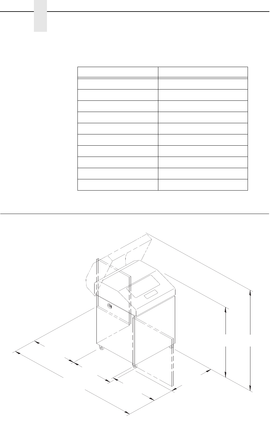
Printer Dimensions
Figure 1. Printer Dimensions - Cabinet Model
Table 1. Maximum Interface Connection Cable Length
Interface Type Maximum Cable Length
Centronics Parallel 5 meters (15 feet)
Dataproducts Parallel 12 meters (40 feet)
IEEE 1284 Parallel 10 meters (32 feet)
Serial RS-232 15 meters (50 feet)
Serial RS-422 1220 meters (4000 feet)
Coax 1500 meters (4920 feet)
Twinax 1500 meters (4920 feet)
Twinax (shielded cable) 1500 meters (4920 feet)
Twisted Pair / Type 3 300 meters (985 feet)
Ethernet 10/100Base-T 100 meters (328 feet)
183468b
27.0 in
(68.84 cm)
83.0 in
(210.8 cm)
29.0 in
(73.7 cm)
27.0 in
(68.6 cm)
27.0 in
(68.6 cm)
41.0 in
(104 cm) 57.5 in
(146.1 cm)
19
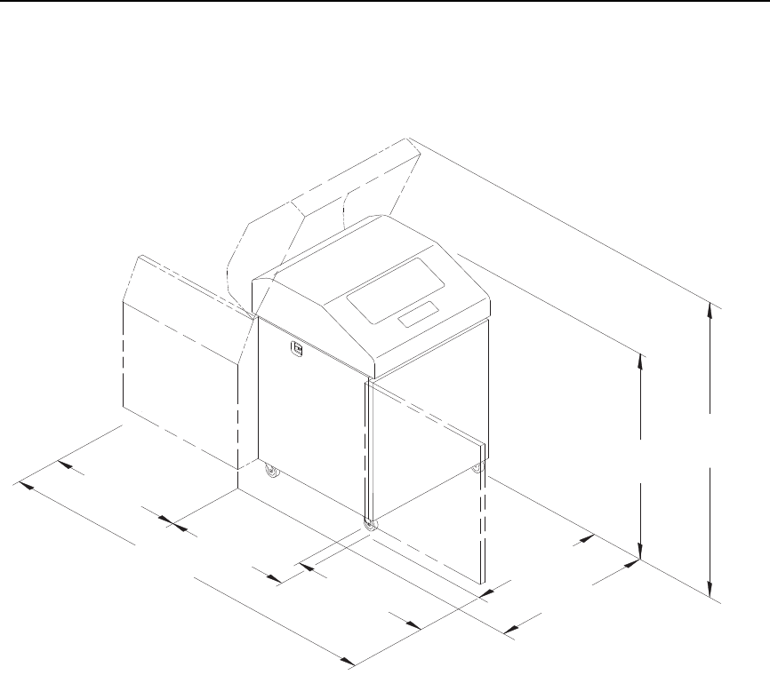
Figure 2. Printer Dimensions - Cabinet Model with Paper Stacker
183469b
27.0 in
(68.6 cm)
83.0 in
(210.8 cm)
32.5 in
(82.6 cm)
27.0 in
(68.6 cm)
27.0 in
(68.6 cm)
32.0 in
(81.3 cm)
42.5 in
(107.8 cm)
59.0 in
(149.9 cm)
20
Chapter 2
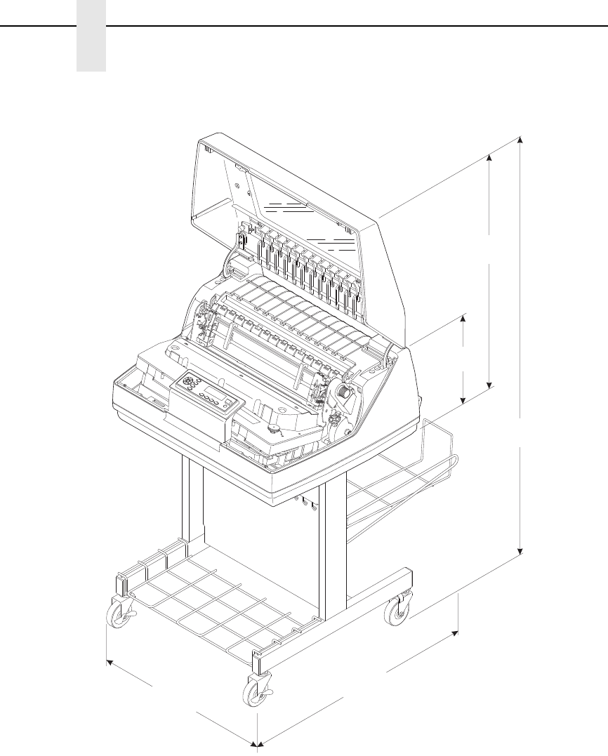
Printer Dimensions
Figure 3. Printer Dimensions - Pedestal Model
TOF
TOF
TOF
TOF
183882a
25 in.
(63.5 cm)
10.5 in.
(26.67 cm.)
48.0 in.
(122 cm)
30 in.
(76.2 cm.)
24.6 in.
(62.48 cm)
21
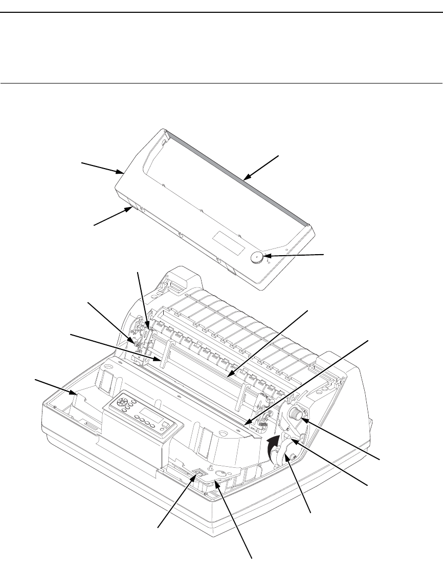
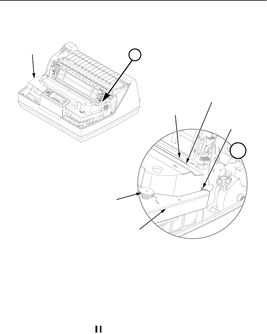
Printer Component Locations
Figure 4. Printer Component Locations
TOF
TOF
TOF
TOF
183871 REV A
183871a
Ribbon
Ribbon
Cartridge
Ribbon
Tension Knob
Air Shroud
Assembly
Tab (2)
Tab
Slot (2)
Blue Tractor
Lock (2)
Paper
Support (2)
Tractor (2)
Vertical
Position Knob
Platen Lever
Splined Shaft
Platen Stop
Hammer Bank
Cover and
Ribbon Mask
Ribbon Cartridge
Interface
Printer Component Locations

22
Chapter 2
Printer Component Locations

23
3
Operating The Printer
Powering On The Printer
When you power on the printer, it executes a self-test. The default power-up
state is online. When the self-test completes and the software has initialized
successfully, the status indicator light turns on, indicating the printer is online.
The default value of the type of emulation you have installed appears in the
upper right corner of the display. The ribbon life remaining is shown on the
second line.
If there is a fault during the self-test, the status indicator flashes and a specific
fault message appears on the display (such as “LOAD PAPER”). The alarm
also sounds if it is configured to do so. See “ LCD Message Troubleshooting
Table” on page 287 for information on fault messages and solutions.
Operating Modes
Online. In online mode, the printer can receive and print data sent from the
host. Pressing the ON LINE key toggles the printer from online to offline
mode. The status indicator is lit in online mode.
Offline. In offline mode, you can perform operator functions, such as loading
paper and setting top-of-form. You can also move within the printer
configuration menus. Pressing the ON LINE/CLEAR key toggles the printer
from offline to online mode. The status indicator is off in offline mode.
Fault. In fault mode, a condition exists which must be cleared before printing
can continue. The status indicator flashes, the alarm beeps (if configured to
sound), and a descriptive fault message displays.
The current operating mode can be selected via control panel keys or can
result from routine operations such as powering on the printer.
24
Chapter 3
The Control Panel
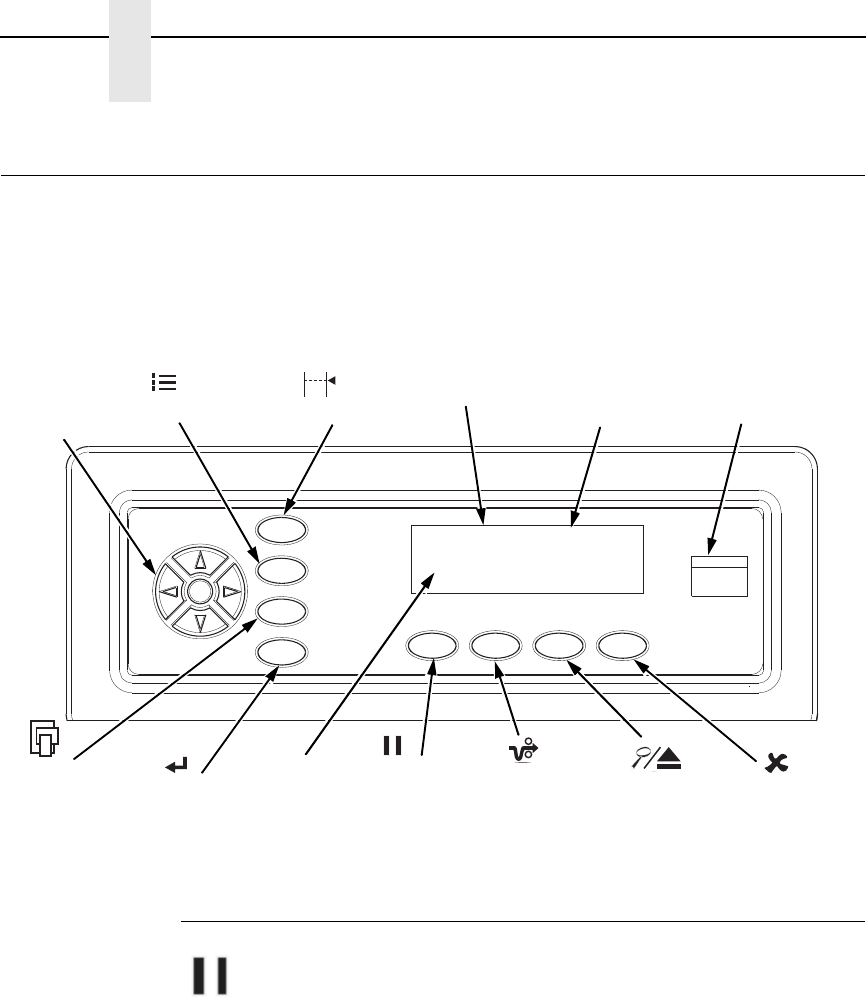
The Control Panel
Figure 5 shows the keys, displays, and indicators as they appear on the
control panel. The following section provides the descriptions, and functions
of the control panel keys.
Key combinations are indicated with the plus (+) sign. For example, “Press U
+ V” means to press the U key and the V key at the same time.
Figure 5. Control Panel
Control Panel Keys
ON LINE / CLEAR
Toggles the printer between online and offline modes. If a fault condition
exists, pressing this key will clear the fault message and return the printer
from fault mode to offline mode.
NOTE: If the fault condition is not corrected before pressing this key, the fault
message will reappear when attempting to place the printer online.
SET TOF
PRT CONFIG
JOB SELECT ENTER ON LINE/
CLEAR PAPER
ADVANCE VIEW/EJECT CANCEL
Status Indicator
Circular
Pad
ONLINE <PGL>
RIBBON LIFE 100%
Emulation
Ribbon Life
Indicator
Message Display

Control Panel Keys
25
PAPER ADVANCE
Performs advance to top-of-form, as defined by the current active form length.
The key works both online and offline.
•
If online with data in the printer buffer, the data will print and then the
paper will move to the next top-of-form.
•
In the fault state, PAPER ADVANCE will advance the paper. The first
press moves to the top of the next available form. All subsequent presses
advances one forms length as defined by the current active forms length.
NOTE:
VIEW / EJECT
When the printer is online or offline, pressing this key executes the view or
eject function, depending on whether the printer is a cabinet or a pedestal (or
zero tear pedestal).
If online with data in the printer buffer, the data prints and the key functions as
described below.
If in a fault state, this key will be ignored.
•
View Function — for cabinet models, pressing the
VIEW/EJECT key moves the last data printed to the tractor area for
viewing. While in the view state, the message "Printer in View" displays,
pressing the UP or DOWN arrow keys moves the paper up or down in 1/
72 inch increments. This is done to align the image within a pre-printed
form, for example. Refer to the UP and DOWN key functions for additional
details on the microstep feature. Pressing VIEW/EJECT a second time
moves the paper back to the adjusted print position.
•
Eject Function — for pedestal models, when the VIEW/EJECT key is
pressed, the bottom of the last printed form will move to the tear bar
position. The message "READY TO TEAR/EJECT To Return" displays.
While in this position, pressing the UP or DOWN arrow keys moves the
paper up or down in 1/72 inch increments. Refer to the Up and Down key
functions for additional details on the microstep feature. When the VIEW/
EJECT key is pressed a second time, the printer will move the paper to
enable printing on the next available form.
CANCEL
In offline mode, this key cancels all data in the print buffer, if enabled in the
“ADVANCED USER Menu” (see page 254). The print buffer is cleared without
printing any of the data and the current paper position is set as the top-of-
form. If this function is disabled, the CANCEL key will be ignored.
NOTE: 1. Use of this key will cause loss of data.
2. For OpenPrint products, pressing the CANCEL key advances the
paper to the next TOF.
26
Chapter 3
The Control Panel
SET TOF
Sets the top-of-form on the printer. This key is active only when the printer is
offline and will not operate if the printer is in a fault condition. The paper
moves down to the print position and aligns to the top-of-form. Refer to the
Quick Setup Guide for complete instructions on how to set the top-of-form.
NOTE: If there is any data in the buffer, the paper will move to the last print
position.
PRT CONFIG
In offline mode, PRT CONFIG prints the current short configuration. This key
requires a confirmation with the ENTER key; pressing any other key will exit
from this function. See “The Configuration Menus” on page 47 for an
explanation of configuration menus.
JOB SELECT
In offline mode, this key allows for fast selection of any of the previously
stored configurations. Pressing this key causes the printer to cycle through
the following messages: Load Config., Factory Config, Load Config 1, Load
Config 2, Load Config 3,...,Load Config 8.
ENTER
When navigating the configuration menus, ENTER selects the currently
displayed option value as the active value. An asterisk (*) appears next to the
active value on the display. ENTER is also used for starting and stopping
printer tests and generating a configuration printout.
NOTE: The ENTER key must be unlocked in order to function.
See UP + DOWN, below.
The ENTER key lock and unlock function can be configured to be a
key combination other than U + V (see page 259).
UP or DOWN (
U
or
V
)
Moves up or down between levels in the configuration menus and makes
vertical forms adjustment. After pressing VIEW, press U or V to adjust the
paper up or down in 1/72 inch increments for fine vertical forms alignment.
When the printer is in offline mode, press U or V to move through levels in
the configuration menus.

Control Panel Keys
27
UP + DOWN (U + V)
Locks and unlocks the ENTER key.
NOTE: The ENTER key lock and unlock function can be configured to be a
key combination other than U + V (see page 259).
PREV or NEXT (Y or Z)
Moves between the options on the current level of configuration menu. In the
configuration menu, press
Y
to scroll backward or press Z
to scroll forward
through the menu selections on the same level.
PREV + NEXT ( Y + Z)
When both keys are pressed simultaneously, the printer will reset to the
power-up configuration and reset its internal state (in offline mode).
U + ON LINE (IPDS Emulation only)
In offline mode, press U + ON LINE. If there is data in the printer buffer, the
printer will be placed in online mode, print one page, and return to the offline
mode. This action can be repeated until the end of a print job. Only one page
prints each time you press U + ON LINE. If there is no data in the printer
buffer, the printer is placed in online mode.
In the fault state, U + ON LINE does not work.
U + PAPER ADVANCE (IPDS Emulation only)
In offline mode, press U + PAPER ADVANCE. The printer will perform a
reverse linefeed. If you hold down the U + PAPER ADVANCE keys for longer
than 1/2 second, the printer moves to the previous top-of-form position. If
there is data in the printer buffer, the data does not print.
In the fault state, U + PAPER ADVANCE does not work.
U + VIEW (IPDS Emulation only)
In offline mode, press U + VIEW/EJECT. If there is data in the IPDS printer
buffer, the printer will be placed in online mode, print one line, and return to
offline mode. This action can be repeated until the end of the job. This
function prints only one line of text. If the data is not text, only 1/6 inch prints.
If there is no data in the printer buffer, the printer is placed in online mode for
one second and then returns to offline mode.
In the fault state, U + VIEW does not work.
Ribbon Life Indicator
The second line of the LCD displays the remaining life of the currently
installed ribbon. The default settings for this feature should match the
requirements for most applications; no special user setup is needed. If your
particular application requires darker printing or can tolerate lighter printing,
the ribbon end point can be adjusted as appropriate. Please refer “Ribbon
End Point” on page 83.

28
Chapter 3
The Control Panel
Cancel A Print Job
The procedure to cancel a print job depends on the printer emulation and your
application software. Contact your system administrator for additional
information.
1. If the printer is online, press
(
ON LINE/CLEAR) to place the printer in
offline mode.
2. From the host system, stop the print job.
NOTE: If the print job is not stopped from the host system before pressing
(
CANCEL), the print job continues with data missing when the
printer returns to online mode. Exercise caution to prevent unwanted
data loss occurrences, as this function deletes unprinted data in the
printer. This function is active only in offline mode; the purpose of this
function is to eliminate the necessity of printing unwanted data when
print jobs are canceled.
3. Press
(
CANCEL).
NOTE: You may need to enable the Cancel option on the front panel.
See “ADVANCED USER Menu” on page 254 for details.
4. Set the top-of-form. Refer to the Quick Reference Guide.
Reload Paper
29
Operational Procedures
This section contains routine printer operating procedures on how to:
•
reload paper
•
unload paper
Reload Paper
Do this procedure when “LOAD PAPER” displays. (This message occurs
when the last sheet of paper passes through the paper slot.) This procedure
reloads paper without removing the last sheet of the old paper supply, while
retaining the current top-of-form setting.
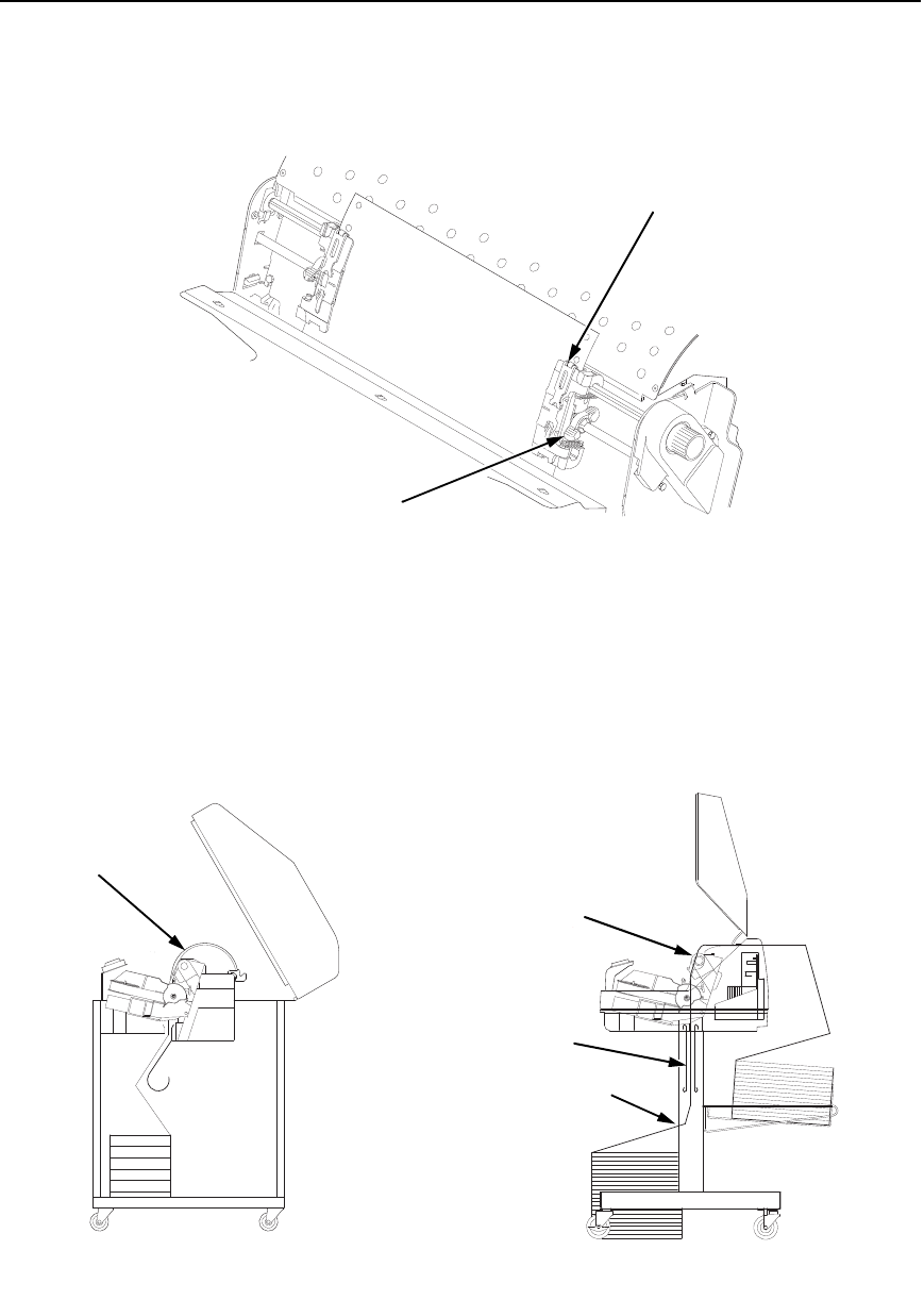
Figure 6. Paper Slot Location
1. Raise the printer cover. Raise the platen lever as far as it will go.
(See Figure 4 on page 21 for the location of the lever.)
2. Press ON LINE/CLEAR to turn off the alarm. Do not open the tractor
doors or remove the existing paper.
3. For cabinet models, open the front door. Align the paper supply with the
label on the floor. Ensure the paper pulls freely from the box.
4. Feed the paper up through the paper slot (see Figure 6). It may be easier
to feed one corner of the new paper up through the slot first. When this
corner can be grasped from the top, rotate the paper back to the normal
position.
NOTE: If you are using thick, multi-part forms and are unable to load the new
paper over the existing paper, go to step 15.
5. Hold the paper to prevent it from slipping down and through the paper
slot.
183440b
183439b
Paper
Slot
Cabinet Model Pedestal Model
Paper Slot
Metal Paper Guide
(P7220 and P7200HD)
Wire
Guide (2)
30
Chapter 3
Operational Procedures
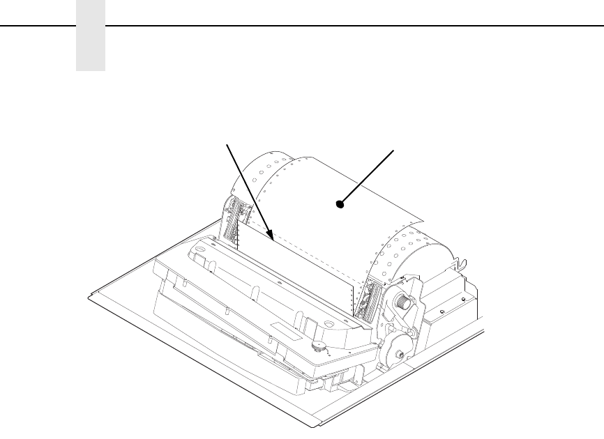
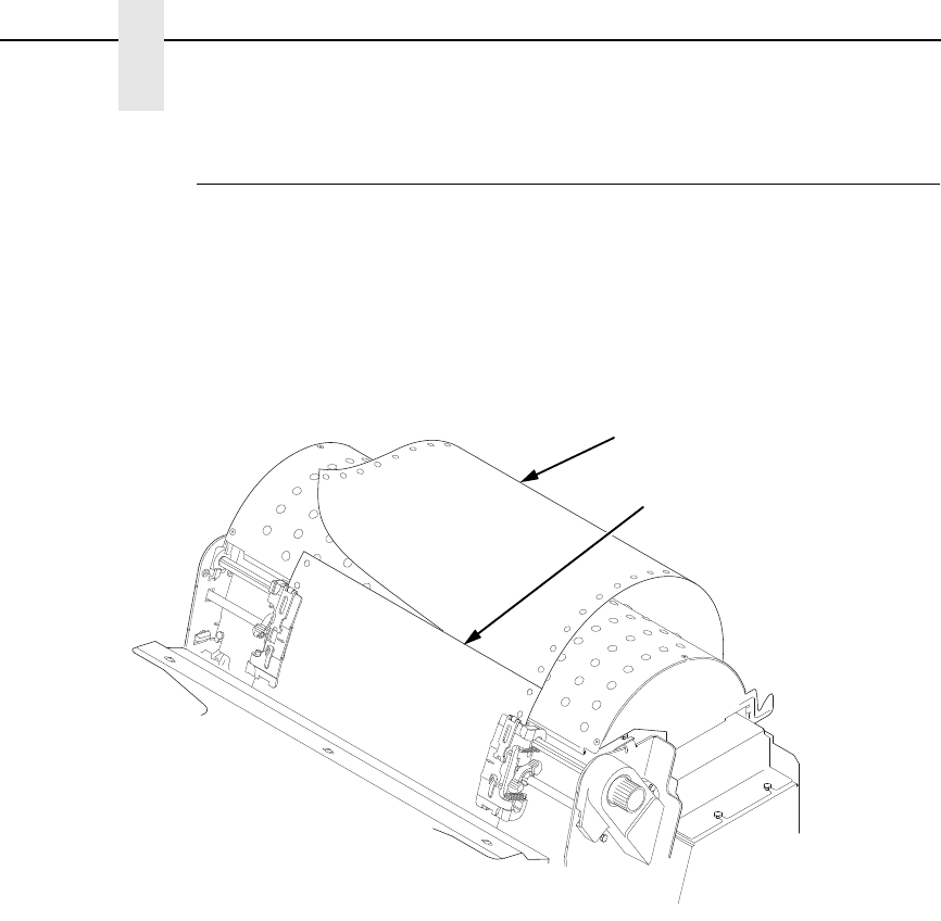
Figure 7. Loading New Paper into the Printer
6. Pull the new paper above and behind the ribbon mask, but in front of the
existing paper. See Figure 4 on page 21 for the ribbon mask location.
If necessary, gently press the existing paper back.
7. Align the top edge of the new paper with the top perforation of the existing
paper.
8. Load the new paper over the existing paper. Open and load the tractors
one at a time to prevent the paper from slipping.
NOTE: Make sure that the top edge of the new paper lines up with the top
horizontal perforation of the last page.
183888a
New Paper Existing Paper
Reload Paper
31
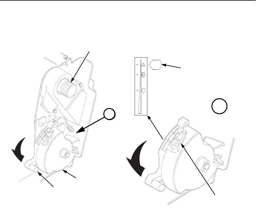
Figure 8. Setting the Platen Lever
9. Turn the platen stop knob clockwise or counterclockwise to match the
paper thickness. (The A-B-C scale corresponds approximately to 1-, 3-,
and 6-part paper thickness).
NOTE: If you are using the same thickness of paper, there is no need to
readjust.
10. Lower the platen lever until it stops.
11. Press ON LINE/CLEAR to remove the “LOAD PAPER” fault message
from the display.
12. Press PAPER ADVANCE several times to make sure the paper feeds
properly beyond the tractors and over the lower paper guide. Feed
sufficient paper to ensure the paper stacks correctly.
13. Close the printer top cover. Close the cabinet front door.
14. Press ON LINE/CLEAR
to place the printer in online mode and resume
printing.
183444b
183446b
Platen Lever
Vertical Position
Knob
Platen Stop
Knob
A
Platen
Stop
183445b
Paper Thickness
Indicator
A
32
Chapter 3
Operational Procedures
Figure 9. Paper Slots on the Printers
NOTE: Perform steps 15 to 32 only if you are unable to load the new paper
over the existing paper.
15. Open both tractor doors.
16. Remove the old paper from the tractors. Allow the paper to fall into the
paper supply area.
17. Feed the new paper up through the paper slot. Hold the paper to prevent
it from slipping down through the paper slot.
183440 REV B
183440b
183439 REV B
183439b
Paper
Slot
Cabinet Model Pedestal Model
Paper Slot
Metal Paper Guide
(P7220 and P7200HD)
Wire
Guide (2)

34
Chapter 3
Operational Procedures
Figure 11. Positioning the Left Tractor to Avoid Damage
CAUTION
To avoid damage to the printer caused by printing on the platen, always
position the left tractor unit directly to the left of the “1” mark on the
paper scale.
21. Normally, you should not need to adjust the position of the left tractor.
If adjustment is necessary, unlock the left tractor by placing the tractor
lock in the middle position. Slide the tractor until it is directly to the left of
the number “1” on the paper scale and lock it. (You can also use the
paper scale to count columns.)
183442b
Paper
Paper Scale
Tractor
Tractor
Splined Shaft
Tractor Lock
Reload Paper
35
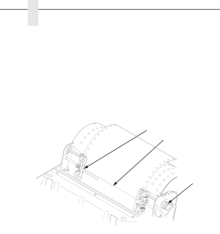
Figure 12. Loading Paper onto the Sprockets
22. Unlock the right tractor.
23. Load the paper onto the sprockets and close the tractor door.
If necessary, slide the right tractor to remove paper slack or to adjust for
various paper widths. Then, lock the tractor.
Figure 13. Using the Paper Guide to Orient the Paper
TOF
TOF
TOF
TOF
183443b
Tractor Lock
Tractor Door
183440b
183439 REV B
183439b
Cabinet Model Pedestal Model
Wire
Guide (2)
Paper Slot
Upper Paper
Guide
Upper Paper
Guide
36
Chapter 3
Operational Procedures
24. Pedestal models:
Using the vertical position knob to move the paper up, guide the paper
over the upper paper guide and through the slot to the rear of the top
cover. For pedestal models with the Quick Access Cover, refer to the
Quick Setup Guide for paper exiting options.
25. Press PAPER ADVANCE several times to make sure the paper feeds
properly beyond the tractors and over the lower paper guide. Feed
sufficient paper to ensure the paper stacks correctly.
26. Cabinet models:
Open the cabinet rear door. Make sure the paper is aligned with the label
in the output area (inside the cabinet). Close the front and rear doors.
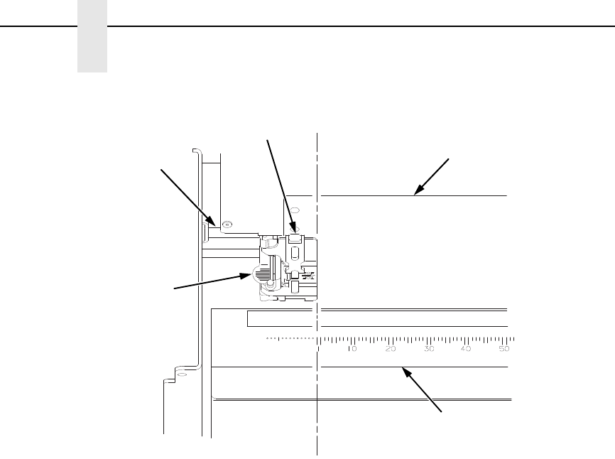
Figure 14. Aligning the Perforation with the TOF Indicator
27. Align the top of the first print line with the TOF indicator on the tractor by
rotating the vertical position knob. For best print quality, it is
recommended that the top-of-form be set at least one print line or more
below the perforation.
NOTE: For exact positioning, press the VIEW/EJECT key to move the last
data printed to the tractor area for viewing. While in View mode
“Printer in View” displays. Press the Up or Down Arrow keys to move
the paper vertically in small increments. Pressing the VIEW/EJECT
key a second time moves the paper back to the adjusted print
position. The key works both online and offline provided that the
printer is in View mode. (This procedure is applicable for both the
cabinet and pedestal models.)
TOF
TOF
TOF
TOF
183967a
TOF Indicator
Perforation
Vertical
Position
Knob
Reload Paper
37
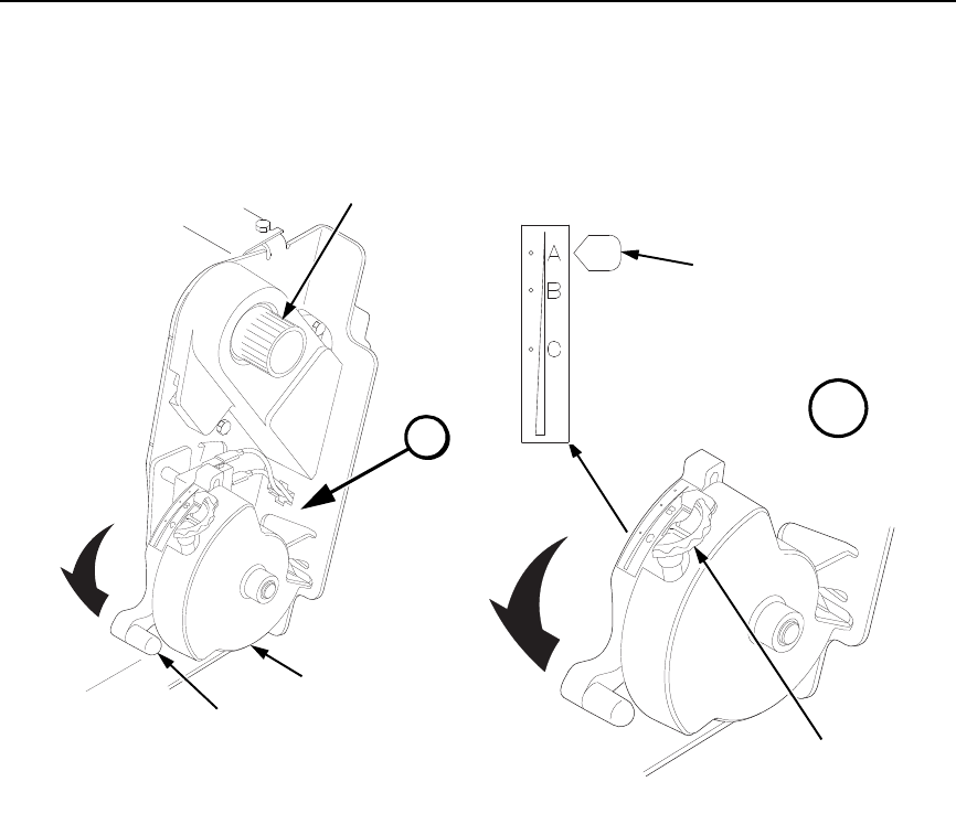
Figure 15. Adjusting the Platen Lever
28. Turn the platen stop knob clockwise or counterclockwise to match the
paper thickness. (The A-B-C scale corresponds approximately to 1-, 3-,
and 6-part paper thickness. Adjust until you have the desired print
quality).
NOTE: The platen stop allows you to set an optimum and consistent
thickness that is not affected when opening and closing the platen
lever.
29. Lower the platen lever until it stops.
30. Press ON LINE/CLEAR to clear any fault messages (such as “LOAD
PAPER”) from the LCD.
31. Press SET TOF. The top-of-form you have set moves down to the print
position. If there is data in the buffer, the paper moves forward to the last
print position on the next page.
32. Press ON LINE/CLEAR and close the printer cover.
183444 REV B
183444b
183446b
Platen Lever
Vertical Position
Knob
Platen Stop
Knob
A
Platen
Stop
183445b
Paper Thickness
Indicator
A
38
Chapter 3
Operational Procedures
Unload Paper
1. Press ON LINE/CLEAR to place the printer in offline mode and open the
printer cover.
2. For cabinet models, open the cabinet rear door. For models with the
power stacker installed, press the STACKER UP key on the rear control
panel.
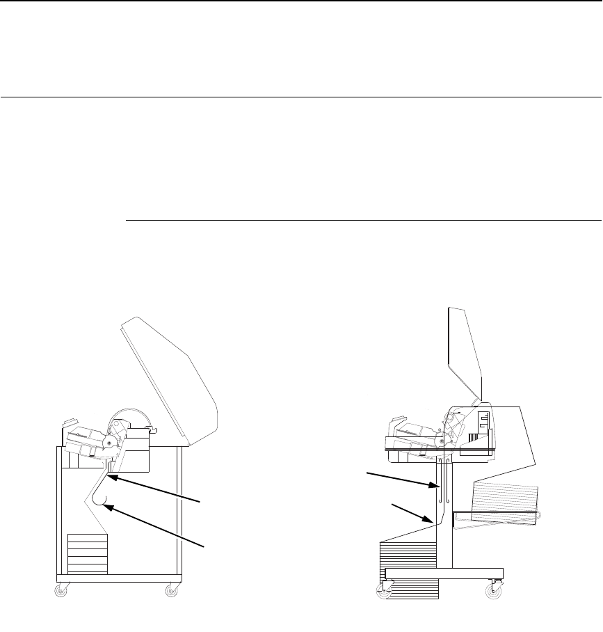
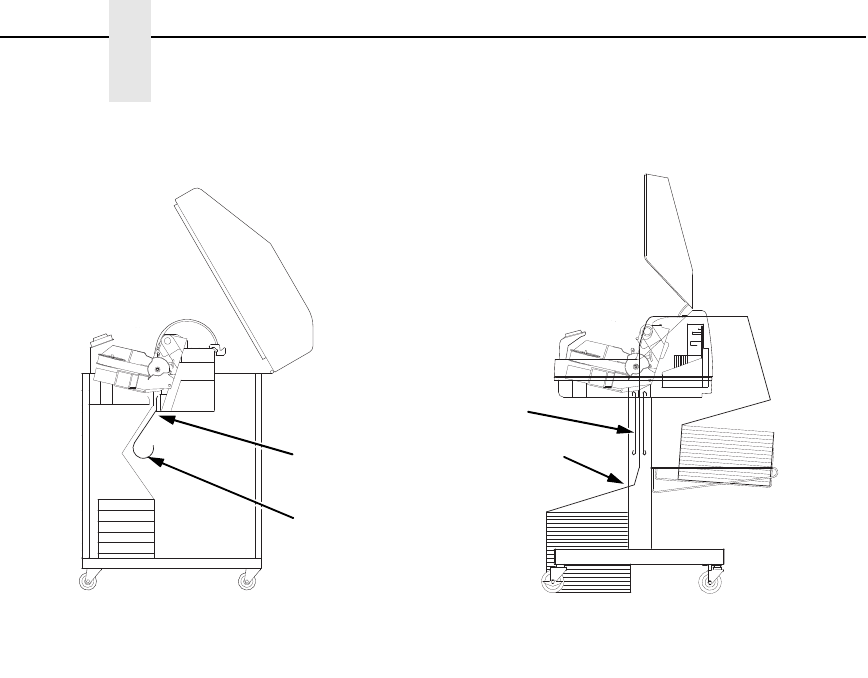
Figure 16. Unloading the Paper from the Printer
3. Tear off the paper at the perforation.
4. Allow the paper to fall to the back of the printer and into the paper
stacking area.
5. For pedestal models, remove the stacked paper from the paper tray.
TOF
TOF
TOF
TOF
183477b
Paper
Perforation
Unload Paper
39
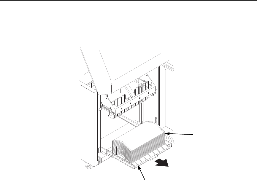
Figure 17. Removing Stacked Paper from the Printer
6. For cabinet models, remove the stacked paper from the rear cabinet floor.
For cabinet models with the power stacker installed, remove the paper
from the wire paper tent and press the STACKER DOWN key to lower the
stacker mechanism.
7. Close the cabinet rear door.
183478b
Paper
Power Stacker
40
Chapter 3
Operational Procedures
Figure 18. Completely Removing the Paper
8. To completely remove the paper from the printer:
a. Raise the platen lever as far as it will go and open both tractor doors.
CAUTION
Be careful when pulling any paper backward through the paper path,
especially when using a label stock. If you are not careful, labels can
detach and adhere to the printer within the paper path, where only an
authorized service representative can remove them.
b. Open the cabinet front door.
c. Gently pull the paper down through the paper slot. Allow the paper to
fall into the paper supply area.
d. Remove the paper from the paper supply area.
183904a
Platen Lever
Tractor Door

Output Darkness
41
Integrated Print Management System
The P7000 has a new feature that automatically monitors and communicates
the status of the ribbon life to help the operator know when to change ribbons.
Using an ink delivery system called the Cartridge Ribbon System (CRS), the
printer can automatically detect when a new or used ribbon is loaded, and all
ribbon properties. The ribbon is contained in a plastic box (the cartridge) and
feeds only in one direction. The CRS contains an interface board that allows
communication between the printer and the cartridge. Using the CRS, the
P7000 automatically detects when a new or used ribbon is installed and
determines the ribbon’s length, ink color, and expected yield. The ribbon life,
starting from 100% when new and decreasing to 0% when depleted, is always
displayed on the control panel. See Figure 5 on page 24.
When the ribbon life reaches 2%, a warning message “RIBBON UNDER 2%/
Change RBN soon” appears on the control panel display. The control panel
status indicator lamp flashes. The printer will continue printing in this condition
until the ribbon life reaches 0% at which time, printing will stop. The ribbon
may be changed at any time while the printer is in the “RBN END POINT/
Change Ribbon” condition without losing data in the printer’s buffer. If a new
ribbon is loaded, the system automatically detects the change, clears the
condition when the platen is closed, and restarts the life at 100%. If a partially
used ribbon is loaded, the system continues the life at the percentage
indicated for the used ribbon.
You may also resume printing for approximately two more minutes without
changing the ribbon by pressing the ON LINE/CLEAR key twice. This may be
done as many times as needed to complete the job in progress.
Ribbon usage information is calculated by maintaining a count of impressions
(dots) that is stored on the ribbon cartridge and updated periodically so that
the cartridge can be used on a different printer with the information intact. This
allows the system administrator to have precise control over print quality and
consumable costs. The accurate presentation of available ribbon life allows
for efficient planning of print jobs. For example, if the displayed ribbon life
were low, you can install a new ribbon before printing a large print job.
Output Darkness
By default the system is configured to meet most user requirements.
However, some applications require that the output remains darker than the
nominal set point while some applications are less critical and could tolerate a
lighter final image. The system can easily adjust to this variability. A setting
under the Printer Control menu is available that allows the user to adjust the
final output. The range is as follows:
Normal (Default)
Darker +1 through +6
Lighter -1 through -10
The ribbon life indicator always cycles between 100% and 0%, but if a darker
setting is selected, zero will be reached more quickly. If a lighter setting is
selected, the system will extend the amount of printing it takes to reach zero.

42
Chapter 3
Integrated Print Management System
Loading a Used Ribbon Cartridge
You can take the ribbon cartridge off the printer and reload it at a later time.
The ribbon life gauge automatically updates to reflect the correct remaining
capacity.
NOTE: Since the ribbon usage information is stored on the ribbon cartridge,
you can reload a partially used cartridge onto a different printer.
Lighter Or Darker Print
The ribbon life value as determined by the Integrated Print Management
System is factory set so that the image quality at the end of the ribbon life is
as good as it was when the ribbon was new. You may adjust the ribbon end
point for a lighter or darker image as required for your printing needs.
See “PRINTER CONTROL Menu” on page 251.
Changing Ribbon Cartridge
43
Changing Ribbon Cartridge
Before changing the ribbon cartridge, determine whether at the end of ribbon
life if you want to make the print lighter (extend the ribbon life) or darker
(shorten the ribbon life). If you want to make the print lighter or darker, go to
“Ribbon End Point” on page 83 and follow the procedures for adjusting the
image density. If you are satisfied with the print darkness, continue with the
following steps.
NOTE: Ribbon cartridge instructions and illustrations shown in the following
section are for the pedestal model. Follow the same procedures for
the cabinet model.
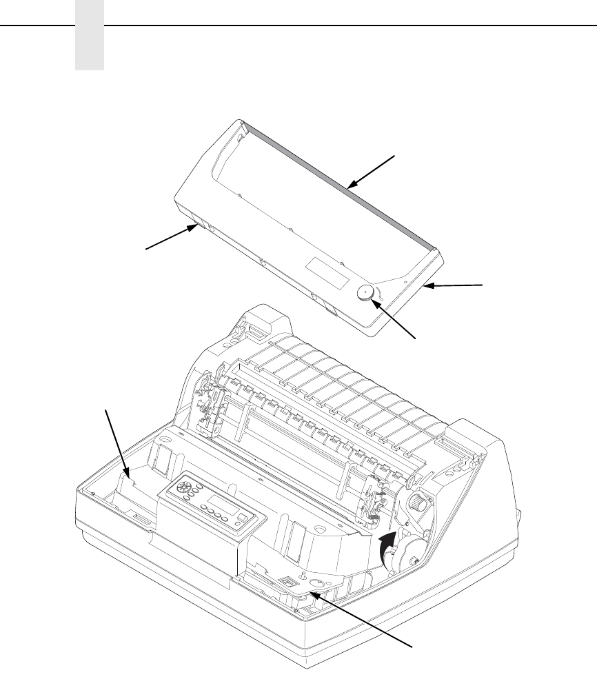
Figure 19. Preparing to Load the Ribbon
1. Open the printer cover.
2. Raise the platen lever as far as it will go.
3. Close the tractor doors.
4. Remove the old ribbon cartridge and discard properly.
TOF
TOF
183816a
Blue Tractor
Door (2)
Platen Lever
44
Chapter 3
Integrated Print Management System
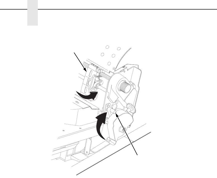
Figure 20. Installing the Ribbon Cartridge
5. Remove the ribbon slack on the new ribbon cartridge by turning the
ribbon tension knob clockwise.
CAUTION
Do not turn the ribbon tension knob counterclockwise. This could
damage the ribbon cartridge.
6. Hold the cartridge at an angle, so that the rear side nearest you is lower
than the side with the ribbon. Find the two tabs on the outside of the
cartridge and place them into the corresponding slots on the air shroud
assembly (see Figure 20).
TOF
TOF
TOF
TOF
183871a
Ribbon
Ribbon
Cartridge
Ribbon
Tension Knob
Air Shroud
Assembly
Tab (2)
Tab Slot (2)
Changing Ribbon Cartridge
45
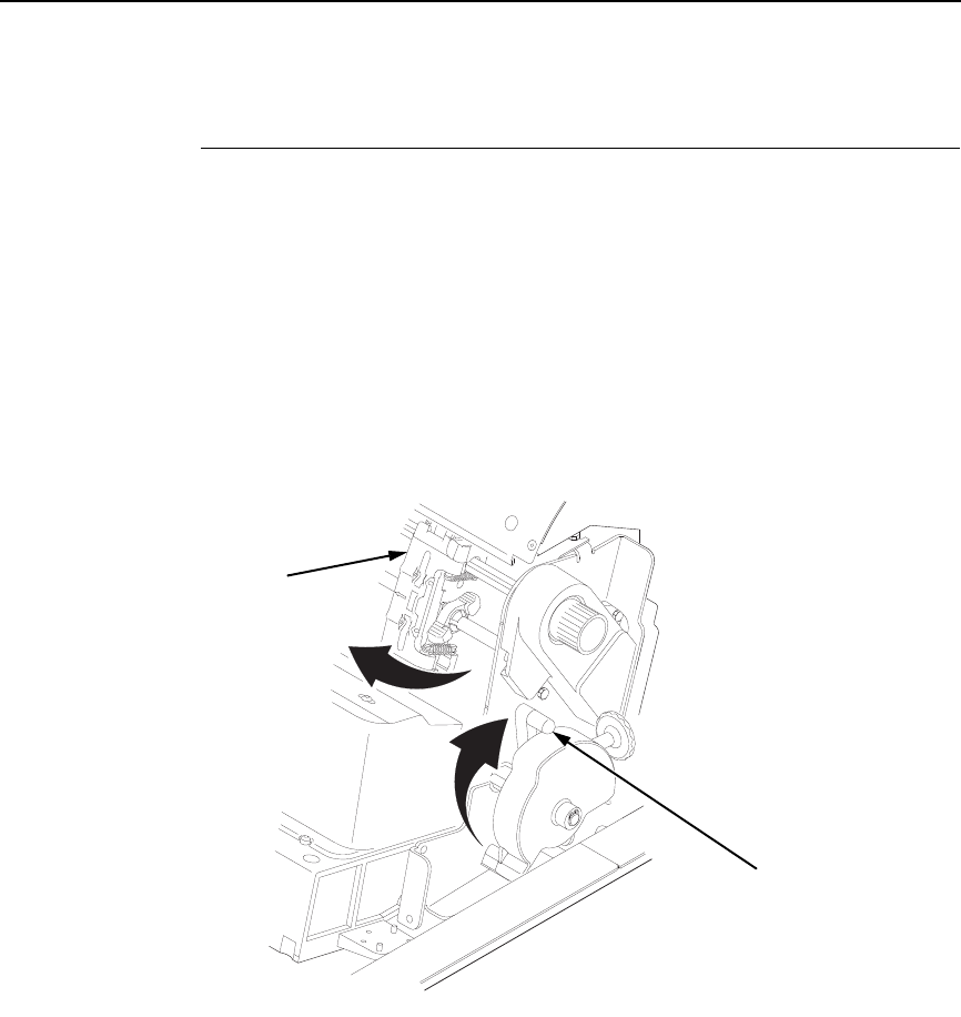
Figure 21. The Ribbon Cartridge Snapped in Place
7. Rock the cartridge downward, making sure that the ribbon goes between
the guide and the mask (see Figure 21). You will feel it snap into place.
CAUTION
Make sure that the ribbon does not twist or fold over.
8. Turn the ribbon tension knob clockwise a few times to make sure the
ribbon tracks correctly in the ribbon path.
9. Close the platen lever.
10. Close the printer top cover.
11. Press the
(
ON LINE/CLEAR) key twice to return the printer to
operation.
TOF
TOF
183872a
TOF
TOF
TOF
TOF
183874a
Ribbon
Cartridge
A
Hammerbank
Cover
Ribbon Mask
Ribbon Cartridge
Ribbon
Ribbon Tension Knob
A

46
Chapter 3
Integrated Print Management System

47
4
The Configuration Menus
Configuration Overview
To print data, the printer must respond correctly to signals and commands
received from the host computer. Configuration is the process of matching the
printer's operating characteristics to those of the host computer and to
specific tasks, such as printing labels or printing on different sizes of paper.
The characteristics which define the printer's response to signals and
commands received from the host computer are called configuration
parameters.
You can configure the printer using the configuration menus and the control
panel or by sending control codes in the data stream from a host computer
attached to the printer. This chapter provides an introduction to configuring
the printer and includes the configuration menus available (depending on
which emulation you have installed in the printer).
IMPORTANT
Configuration directly affects printer operation. Do not change the
configuration of your printer until you are thoroughly familiar with the
procedures in this chapter.
Main Menu
The Main Menu section (page 63) is organized based on the following
firmware types:
1. P7000 STD Firmware (Coax/Twinax/IPDS/PGL/VGL/LP+)
2. P7000 TN Firmware (TN/PGL/VGL/LP+)
3. P7000 PCL-II Firmware (PCL-II/PGL/VGL/LP+)
4. P7000 LG Firmware (LG/PGL/VGL/LP+)
5. P7000 ANSI Firmware (ANSI/PGL/VGL/LP+)
6. OpenPrint P7000 STD Postscript/PDF Firmware (PS/PGL/VGL/LP+)
7. OpenPrint P7000 HD Postscript/PDF Firmware (PS)

48
Chapter 4
Configuration Overview
Changing Parameter Settings
You may change a printer parameter setting, such as line spacing or forms
length, either by pressing keys on the control panel or by sending emulation
control codes in the data stream from a host attached to the printer. The
control panel allows you to configure the printer’s resident set of configuration
menus. An example procedure for using the control panel to change
parameter settings begins on page 50.
When control codes are sent from a host attached to the printer, they override
control panel settings. For example, if you set the line spacing to 6 lpi with the
control panel, and application software later changes this to 8 lpi with a control
code, the control code overrides the control panel setting.
Saving Parameter Settings
The parameter settings that you have changed can be permanently stored in
the printer’s memory as a configuration. See “Auto Save Configuration” on
page 53 and “Saving Your New Configuration” on page 53.
You may also save your new configurations using the PTX_SETUP command
host control code. See your LinePrinter Plus Programmer’s Reference
Manual for details.
Default And Custom Configurations
A configuration consists of a group of parameter settings, such as line
spacing, forms length, etc. Your printer provides a fixed default configuration
and allows you to define several custom configurations for use with particular
print jobs. The factory default configuration can be loaded, but it cannot be
altered.
Eight configurations can be modified for unique print job requirements. The
“Save Config.” option allows you to save eight groups of parameter settings in
memory as custom configurations numbered from 1 through 8. An
explanation on how to save a set of parameter values as a custom
configuration using the “Save Config.” menu option begins on page 53.
Navigating the Menus
49
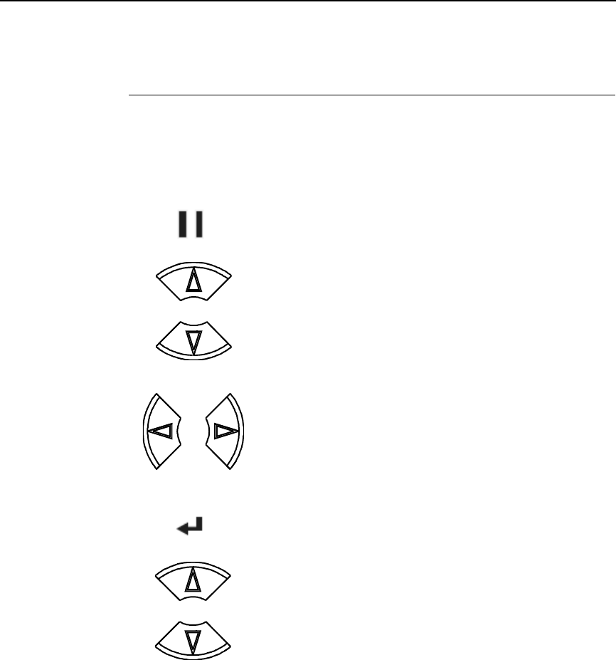
Navigating the Menus
To manipulate configurations review the following instructions about
navigating through the menus.
You must be offline to move within the menus.
To experiment with navigating the menus, use the example on the next page
as a tutorial.
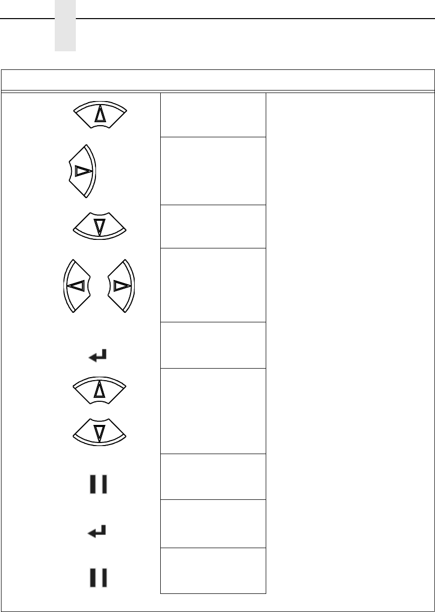
Press to toggle between ONLINE and OFFLINE. Menus are
accessed with the printer offline.
Press to move up or down through the menu levels.
Press to scroll through the available choices on a chosen
level.
Press to confirm selection.
Press to lock and unlock the ENTER key. The ENTER key is
locked by default to prevent you from accidentally changing
the printer configuration. The lock and unlock function can be
configured to be other than
U + V
(See “Set Lock Key” on
page 259.)
ON LINE/CLEAR
OR
OR
ENTER
+
50
Chapter 4
Configuration Overview
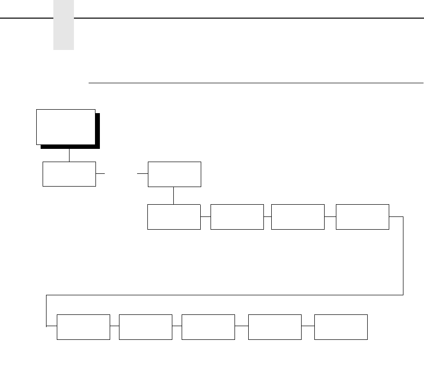
Changing Parameters Example
A configuration consists of several parameters. The default factory
configuration has a starting set of parameters. In the configuration menu
above, and in all the configuration menus in this chapter, the factory default
values are indicated by an asterisk (*).
Your print jobs may require parameter values which vary from the default
settings. This section provides an example procedure for changing individual
parameter values.
. . .
OFFLINE
QUICK
SETUP CONFIG.
CONTROL
Load
Config.
Save
Config.
Print
Config.
Power-Up
Config.
Delete
Config.
Protect
Configs.
1*
2-8
Current Short*
Current Full
Factory
Power-Up
All
1-8
Factory*
1-8
1*
2-8
Disable*
Enable
* = Factory Default
Name
Configs
1-8
Factory*
1-8
Reset Cfg
Names
1*
2-8
All
Auto
Save
Enable*
Disable
Changing Parameters Example
51
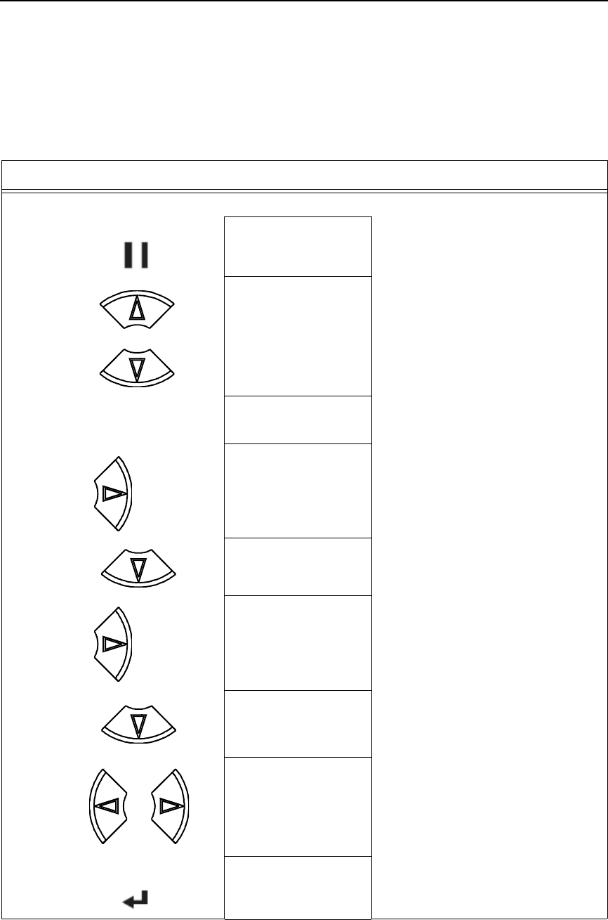
The following procedure shows how to change and save the settings for the
Barcode Quality and Language options. Use these guidelines to navigate the
configuration menus and change other parameters.
Step Press LCD Notes
1. Make sure the printer is on.
2. OFFLINE
QUICK SETUP
3. ENTER SWITCH
UNLOCKED
Allows you to make configuration changes.
OFFLINE
QUICK SETUP
4. OFFLINE
PRINTER CONTROL
5. PRINTER CONTROL
Ribbon End Point
6. PRINTER CONTROL
Barcode Quality
7. Barcode Quality
Dark*
8. Barcode Quality
Draft
Cycle through the choices.
9. Barcode Quality
Draft*
The * indicates this choice is active.
ON LINE/CLEAR
+
UNTIL
UNTIL
OR
ENTER
52
Chapter 4
Configuration Overview
10. PRINTER CONTROL
Barcode Quality
11. PRINTER CONTROL
Display Language
12. Display Language
English*
13. Display Language
Spanish
Press until the desired parameter displays.
14. Display Language
Spanish*
The * indicates this choice is active.
15. ENTER SWITCH
LOCKED
Locks the ENTER key.
16. ENTER = Save
ONLINE = No Save
Press ENTER to automatically save
configuration changes. Press ONLINE to
continue without saving.
17A. Cfg = 1*
= Power-Up Cfg
Configuration changes have been saved as
Configuration 1, and will be set as the
Power-Up config. The printer will then be
brought online.
17B. ONLINE
Ribbon Life = 100%
Places the printer online without
permanently saving the configuration
changes.
18. The printer is ready for operation
Step Press LCD Notes
UNTIL
OR
ENTER
+
ON LINE/CLEAR
ENTER
ON LINE/CLEAR

Auto Save Configuration
53
Auto Save Configuration
After any changes are made to the Factory Default configuration menu items,
you will be prompted to save the changes to “Config #” when you place the
printer online. “#” represents the next available unassigned configuration
number. When prompted, press one of the following:
•
Enter. Saves to Config 1 or the next available Config, and becomes the
power-up config.
•
Online. Changes will be implemented but saved only temporarily until
deliberately saved as a new configuration or until you power off the
printer. All changes will be lost when you power off the printer.
Saving Your New Configuration
The Save Config. option allows you to save up to eight custom configurations
to meet different print job requirements. Once you have changed all of the
necessary parameters, you may save them as a numbered configuration
(Example 1 on page 54) or a named configuration (Example 2 on page 56)
that can be stored and loaded later for future use. If you do not save your
configuration using the Auto Save, or this option, all of your parameter
changes will be erased when you power off the printer.
Once you have saved a custom configuration using this option, it will not be
lost if you power off the printer. You can load a configuration for a specific
print job (see “Load Config.” on page 85). You can also modify and resave it.
You may want to print your configurations (see “Print Config.” on page 85)
and store them in a safe place, such as inside the printer cabinet. If the
Protect Configs. parameter is enabled and you try to resave an existing
configuration, the new configuration will not be saved until the existing
configuration has been deleted (see “Delete Config.” on page 86).
NOTE: Once you change active emulations, any changes to the previously
selected emulation will be gone unless they have been saved.
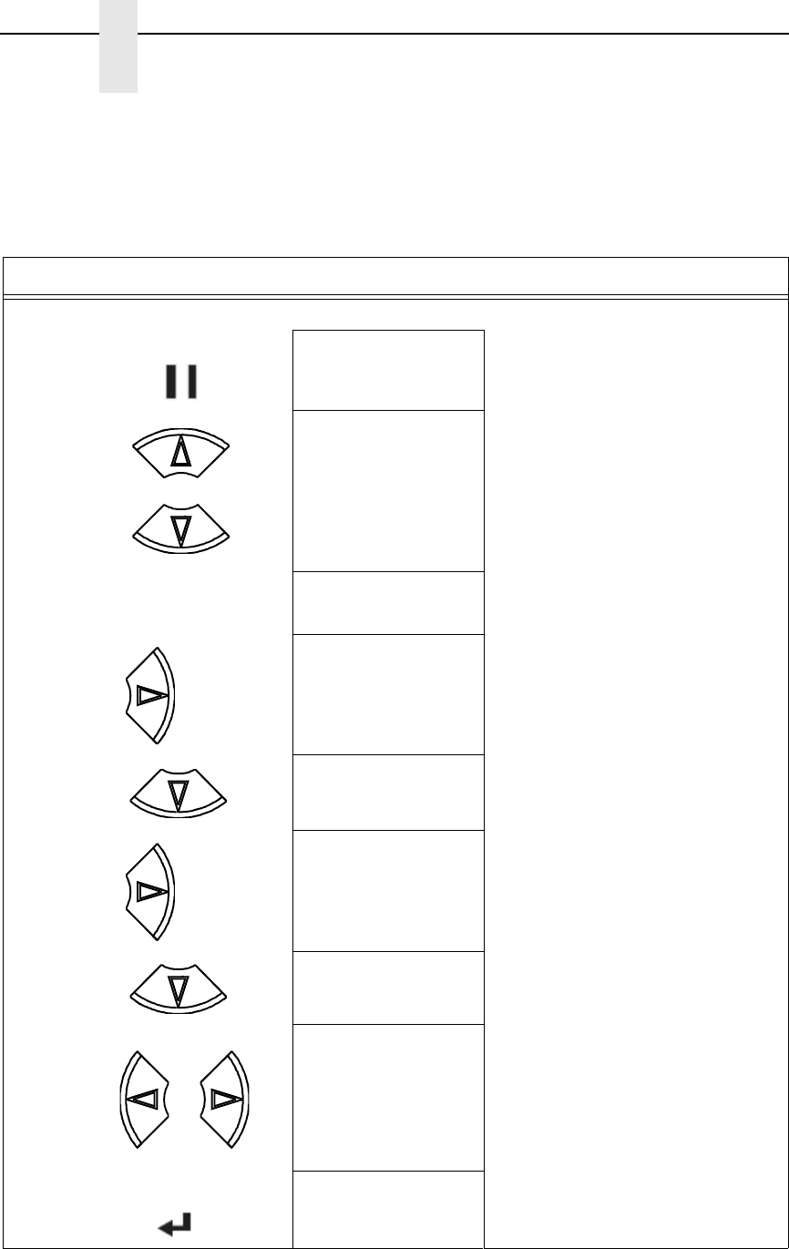
54
Chapter 4
Configuration Overview
Example 1
This example shows how to save a configuration as a numbered
configuration, then later print it.
Step Press LCD Notes
1. Make sure the printer is on.
2. OFFLINE
QUICK SETUP
3. ENTER SWITCH
UNLOCKED
Allows you to make configuration changes.
OFFLINE
QUICK SETUP
4. OFFLINE
CONFIG. CONTROL
5. CONFIG. CONTROL
Load Config.
6. CONFIG. CONTROL
Save Config.
7. Save Config.
1*
8. Save Config.
2
Cycle through the choices.
9. Save Config.
2*
The * indicates this choice is active.
ON LINE/CLEAR
+
UNTIL
UNTIL
OR
ENTER
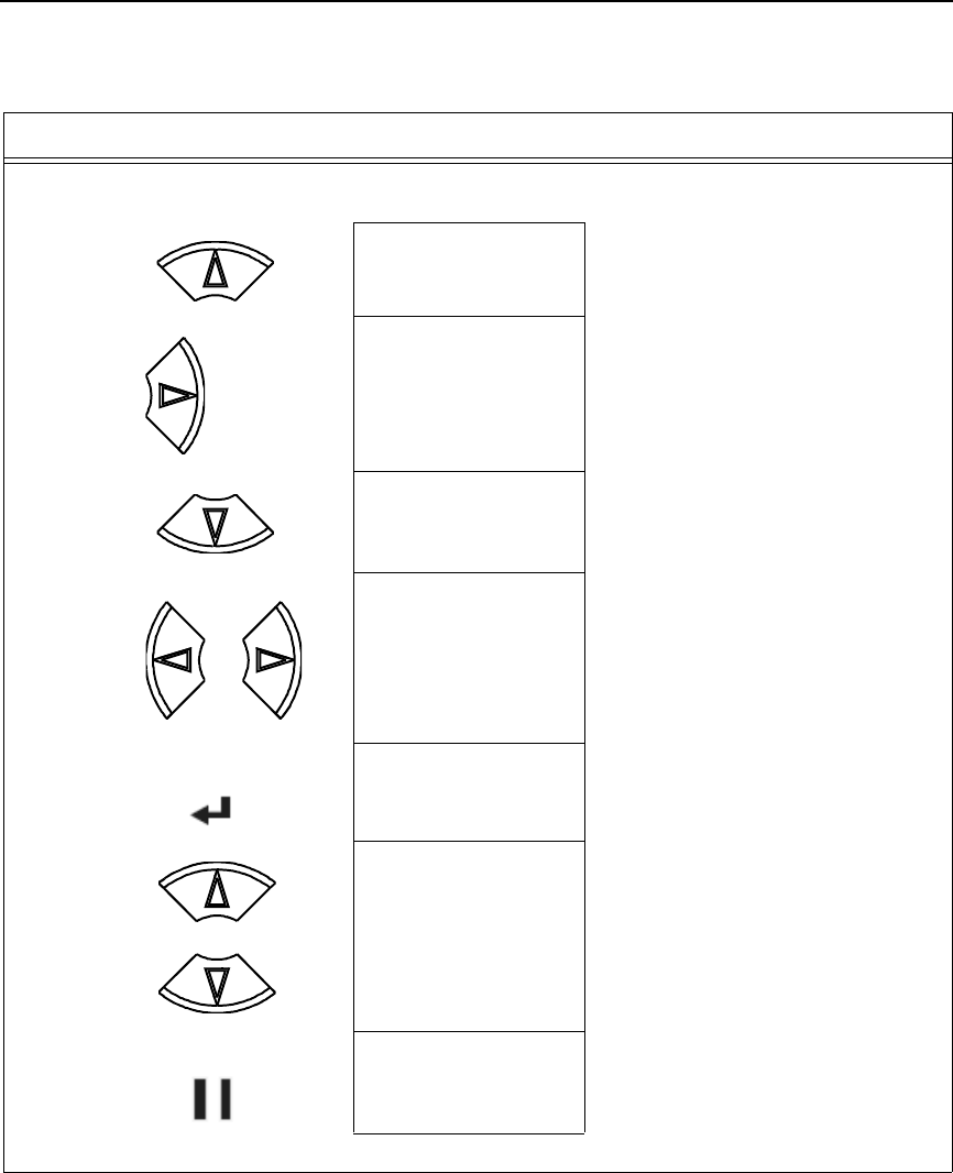
Saving Your New Configuration
55
NOTE: We recommend that you print the configuration. To print the configuration go to Step 9. To skip this
procedure and resume printer operation, go to Step 14.
10. CONFIG. CONTROL
Save Config.
11. CONFIG. CONTROL
Print Config.
12. Print Config.
Current
13. Print Config.
2
Press until the desired parameter displays.
14. OFFLINE
CONFIG. CONTROL
The selected configuration is printed.
15. ENTER SWITCH
LOCKED
Locks the ENTER key.
16. ONLINE
Ribbon Life = 100%
17. If you printed out the configuration, store it in a safe place. The printer is ready for operation.
Step Press LCD Notes
UNTIL
OR
ENTER
+
ON LINE/CLEAR
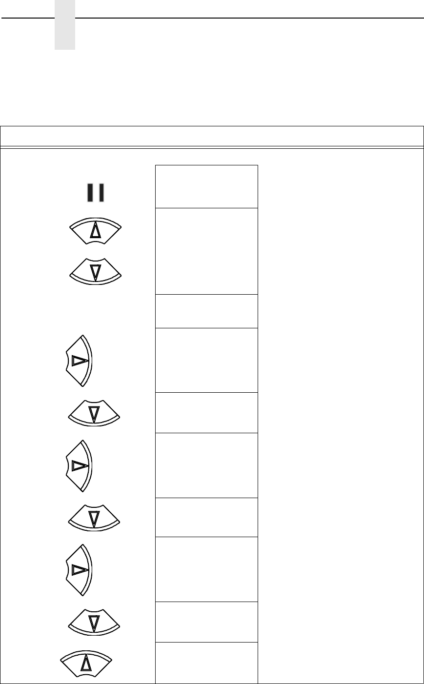
56
Chapter 4
Configuration Overview
Example 2
This example shows how to save a configuration as a named configuration.
Step Press LCD Notes
1. Make sure the printer is on.
2. OFFLINE
QUICK SETUP
3. ENTER SWITCH
UNLOCKED
Allows you to make configuration changes.
OFFLINE
QUICK SETUP
4. OFFLINE
CONFIG. CONTROL
5. CONFIG. CONTROL
Load Config.
6. CONFIG. CONTROL
Name Configs.
7. Name Configs.
1
The LCD flashes.
8. Name Configs
2
You will rename config 2.
9. 2
2*
10. 2
T
Cycle through the choices until “T” displays.
ON LINE/CLEAR
+
UNTIL
UNTIL
UNTIL
UNTIL
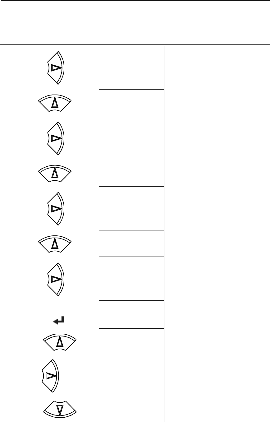
Saving Your New Configuration
57
11. 2
T_
Saves the first character.
12. 2
TE
Cycle through the choices until “E” displays.
13. 2
TE_
Saves the second character.
14. 2
TES
Cycle through the choices until “S” displays.
15. 2
TES_
Saves the third character.
16. 2
TEST
Cycle through the choices until “T” displays.
17. 2
TEST_
Saves the fourth character.
18. Name Configs
TEST
The configuration is renamed TEST.
19. CONFIG. CONTROL
Name Configs
20. CONFIG. CONTROL
Save Config.
21. Save Config.
1*
Step Press LCD Notes
UNTIL
UNTIL
UNTIL
ENTER
UNTIL
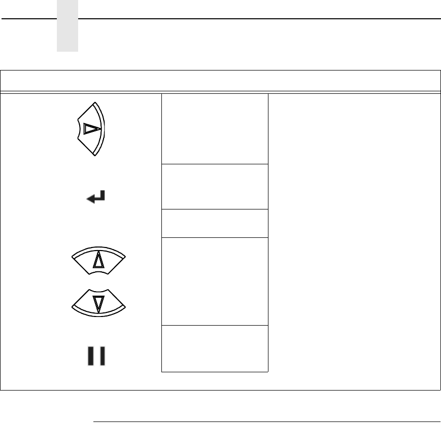
58
Chapter 4
Configuration Overview
Optimizing Print Quality
LP+, IGP/PGL, and IGP/VGL Emulations
You can optimize print quality for darker and sharper barcodes and
characters. Doing so, however, will decrease the printer speed.
To optimize print quality, you can change the values of the following
configuration parameters:
•
Bar Code Quality (Printer Control menu): Select “Dark” or “Draft.”
Dark prints the darkest images, but at the slowest speed. Draft prints at a
faster speed than Dark, but the characters are not as dark. (See page 252
for a written description of Bar Code Quality.)
•
Print Quality (IGP/PGL emulation): Select “Best” or “High.” Best prints
the darkest images, but at the slowest speed. High prints at a faster
speed than Best, but the characters are not as dark. (See page 197 for
the IGP/PGL Configuration Menu, and page 206 for a written description
of Print Quality.)
•
Print Quality (IGP/VGL emulation): Select “High.” (See page 210 for the
IGP/VGL Configuration Menu, and page 217 for a written description of
Print Quality.)
22. Save Config.
TEST
TEST now appears as one of configuration
choices.
23. Saving Configuration
Save Config.
TEST*
Your configuration is saved as TEST.
24. ENTER SWITCH
LOCKED
Locks the ENTER key.
25. ONLINE
Ribbon Life = 100%
Now you have the saved configuration for later use if needed.
Step Press LCD Notes
ENTER
+
ON LINE/CLEAR

Optimizing Print Speed
59
OpenPrint Postscript/PDF Emulations
You can optimize print quality for darker and sharper text and barcodes by
using the following configuration parameters:
•
Unidirectional (Printer Control menu): Select “Enable” for best quality
but reduced throughput (half speed).
•
Resolution (Postscript/PDF menu): Select higher values (horizontal by
vertical DPI) to get better print quality.
Optimizing Print Speed
LP+, IGP/PGL, and IGP/VGL Emulations
The printer has been configured at the factory for optimal print speed. To
optimize print quality instead, you can change values for specific configuration
parameters such as Barcode Quality and Print Quality. Doing so, however,
will decrease the printer speed.
If you have optimized the printer for print quality, you can change it to optimal
speed by selecting the values as follows:
•
Bar Code Quality (Printer Control menu): Select Draft.
(See page 63 for the Configuration Main Menu, and see page 252 for a
written description of Bar Code Quality.)
•
Print Quality (IGP/PGL emulation): Select Dataprocessing. (See
page 197 for the IGP/PGL Configuration Menu, and see page 206 for a
written description of Print Quality.)
•
Print Quality (IGP/VGL emulation): Select Dataprocessing. (See
page 210 for the IGP/VGL Configuration Menu, and see page 217 for a
written description of Print Quality.)
Coax/Twinax Emulation
You can increase print speed by selecting the Enable mode for the Early Print
Complete configuration parameter in the Coax/Twinax Emulation. However, if
an error occurs while in Enable mode, you may lose data. For more
information, refer to “Early Print Complete” on page 227. (For the Coax/
Twinax Emulation menu, see page 124.)
OpenPrint Postscript/PDF Emulations
The printer has been configured at the Factory for optimal print quality
through the Resolution configuration parameter (Postscript/PDF menu).
However, users can reduce the horizontal, vertical, or both DPI values of this
menu to increase printer speed. The downside of using a lower DPI value is
as follows:
•
Print quality is reduced and it can be difficult to read small characters.
•
Barcodes may not get detected and optimized (barcodes are not
searched for DPI values less than 120).
Users are encouraged to use the Resolution menu to find the right
combination of Print Quality, Barcode Optimization, and Print Speed.

60
Chapter 4
Dynamic Menu Options
Dynamic Menu Options
The main menus for each of the different firmware types have several
footnotes based on the possible options installed with the printer. This
includes HOST IO connectivity, various hardware/mechanical options, and
software emulations and features. The P7000 products dynamically detect
options installed and only include relevant menus for the user to configure.
The following is a description of the types of installation options and their
effect on the main menu:
•
HOST INTERFACE: Coax, Twinax, Ethernet, and WLAN related menus
are only present when the hardware is installed/enabled.
•
NETWORK SETUP: The NETWORK SETUP menu is only present when
Ethernet or WLAN is installed. The WLAN options can vary based on the
type of radio card installed with the printer. WLAN Kerberos is included
with the Symbol LA4121 radio card, WLAN LEAP is included with the
Cisco radio card, and WLAN EAP is included with the Symbol LA5127
radio card.
•
ZTP SETTINGS: The ZTP SETTINGS menu and its contents are only
included with the Zero Tear Pedestal printer.
•
DATE: This main menu is only present when the Real-Time Clock (RTC)
option is installed.
•
The Power Stacker and Auto Elevator options are also available for
configuration when the SureStak power stacker is installed.
•
QUICK SETUP: This menu is a collection of popular menus to help users
quickly configure the printer. It is also affected by the installed options.

61
Active Emulations
The emulations present in the printer are based on the firmware installed and
the emulation options included. Both are configured from the Factory and do
not require any action from the user.
IMPORTANT
Be sure to know which type of firmware and options are purchased
(see Table 2) to understand the ACTIVE IGP EMUL, ACTIVE
EMULATION, and EMULATION main menus.
Table 2. Available Firmware Types and Options
Firmware Type Optional
Emulations
Available
ACTIVE IGP
EMUL
1
ACTIVE
EMULATION
2
EMULATION
3
P7000 STD
IPDS
CTHI
PGL/VGL
IGP/PGL* N/A
IPDS
CTHI
IGP/PGL
LinePrinter+
IGP/VGL N/A
IPDS
CTHI
IGP/VGL
LinePrinter+
P7000 TN PGL/VGL
IGP/PGL* N/A IGP/PGL
LinePrinter+
IGP/VGL N/A IGP/VGL
LinePrinter+
P7000 PCL-II PGL/VGL N/A
PCL-II* PCL-II
IGP/PGL & LP+ IGP/PGL
LinePrinter+
IGP/VGL & LP+ IGP/VGL
LinePrinter+
NOTE:
* = Default Selection
1
The Active IGP EMULATION menu is only available when the PGL/VGL option is
installed.
2
The ACTIVE EMULATION menu shows the options “IGP/PGL & LP+” and
“IGP/VGL & LP+” when the PGL/VGL option is installed. Otherwise, “LinePrinter+”
replaces the options.
3
The selections under the EMULATION menu is based on the ACTIVE IGP EMULATION
or ACTIVE EMULATION settings with all Optional Emulations installed.
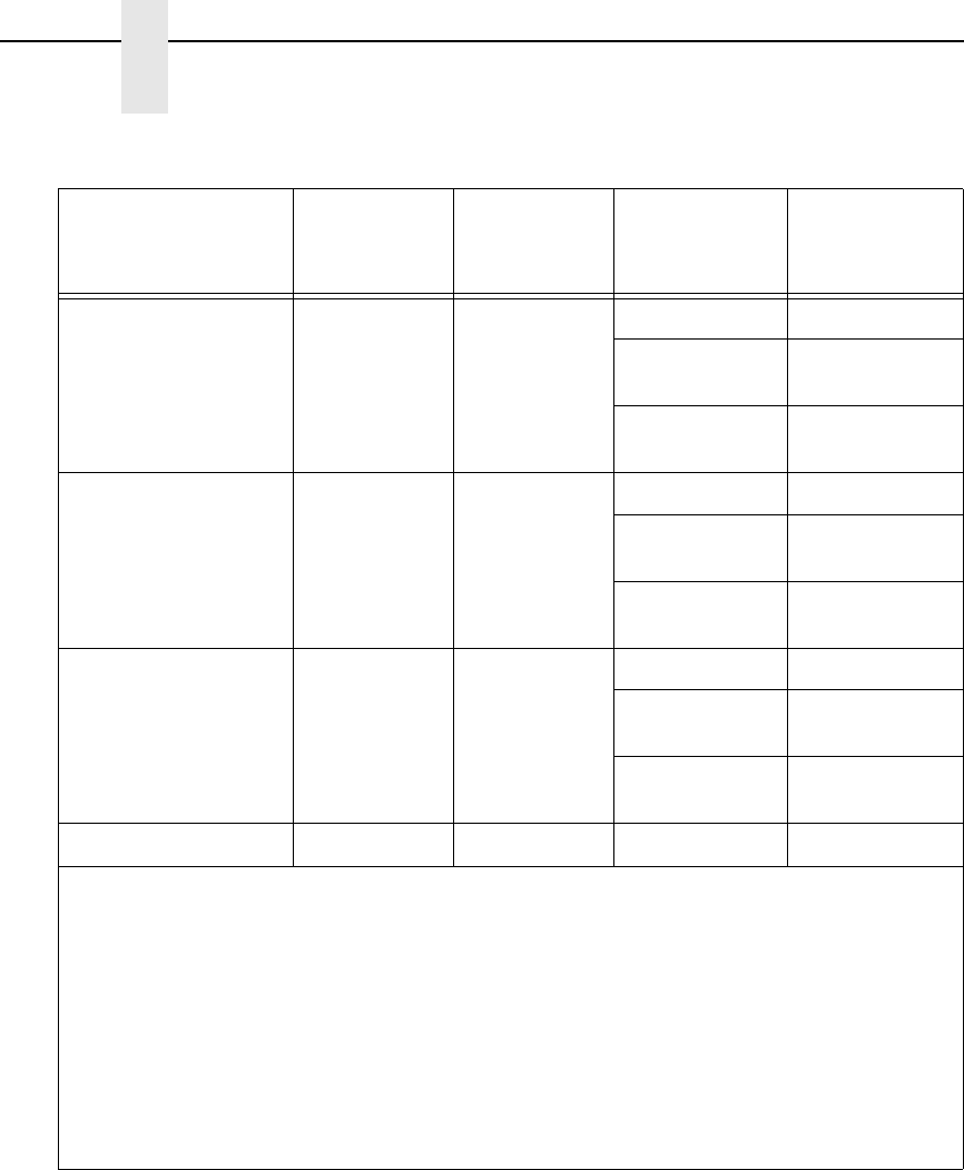
62
Chapter 4
Active Emulations
P7000 LG PGL/VGL N/A
LG* LG
IGP/PGL & LP+ IGP/PGL
LinePrinter+
IGP/VGL & LP+ IGP/VGL
LinePrinter+
P7000 ANSI PGL/VGL N/A
44/48XX-ANSI* 44/48XX-ANSI
IGP/PGL & LP+ IGP/PGL
LinePrinter+
IGP/VGL & LP+ IGP/VGL
LinePrinter+
OpenPrint P7000 STD PGL/VGL N/A
Postscript/PDF* Postscript/PDF
IGP/PGL & LP+ IGP/PGL
LinePrinter+
IGP/VGL & LP+ IGP/VGL
LinePrinter+
OpenPrint P7000 HD N/A NA N/A Postscript/PDF
NOTE:
* = Default Selection
1
The Active IGP EMULATION menu is only available when the PGL/VGL option is
installed.
2
The ACTIVE EMULATION menu shows the options “IGP/PGL & LP+” and
“IGP/VGL & LP+” when the PGL/VGL option is installed. Otherwise, “LinePrinter+”
replaces the options.
3
The selections under the EMULATION menu is based on the ACTIVE IGP EMULATION
or ACTIVE EMULATION settings with all Optional Emulations installed.
Table 2. Available Firmware Types and Options
Firmware Type Optional
Emulations
Available
ACTIVE IGP
EMUL
1
ACTIVE
EMULATION
2
EMULATION
3

63
Main Menu
Brief descriptions follow for the first-level configuration menu options:
•
QUICK SETUP — These options allow quick access to the most
frequently changed or inputted parameters during the installation of the
printer.
•
ZTP SETTINGS These options allow you to set parameters for zero tear
pedestal printers.
•
CONFIG. CONTROL — These options allow you to save, print, load,
delete, name, and reset entire sets of configuration parameters.
•
HOST INTERFACE — These options allow you to select either the Serial
RS-232, Serial RS-422, Centronics
®
parallel, Dataproducts
®
parallel and
Long Lines, Ethernet
™
, IEEE
®
1284 parallel, Auto Switching, Coax or
Twinax interface for the printer. This menu also allows you to configure
several parameters for each interface.
•
NETWORK SETUP — This option allows you to select from Ethernet
Address options and Ethernet Parameters options.
•
ACTIVE (IGP) EMUL — This menu allows you to select the PGL or VGL
emulation from the menu if IGP is installed.
•
ACTIVE EMULATION — This menu allows you to activate the desired
emulation or combination of emulations to be used with your printer.
•
EMULATION — This menu allows you to configure the options which are
available for the current operating (active) emulation. For example, if
LinePrinter+ is the active emulation, then the LinePrinter+ emulation
options can be configured using this menu.
•
SURE SCAN — This menu is available only for OpenPrint firmware; it
allows the user to configure barcode optimization that will replace
graphical barcodes with PSA barcodes optimized for the P7000
technology.
•
PRINTER CONTROL — This menu allows you to select parameters
common to a general user, such as display language and Barcode
quality.
•
ADVANCED USER — This menu allows you to select several advanced
operating parameters for the printer, such as the speed at which paper
will advance when slewing.
•
DIAGNOSTICS — This menu includes the diagnostic tests, system
memory, software build part number, Feature File (if one exists),
the shuttle type, and statistics of the printer.
•
DATE – This menu allows you to set the printer’s real time clock. The
parameters include hours, minutes, year, month, and day.
•
PRINTER MGMT – These options allow you to select the PNE port type,
port number, port timeout period, status port number, and management
port number.

64
Chapter 4
Main Menu
P7000 STD Firmware
OFFLINE
CONFIG.
CONTROL
page 85
HOST
INTERFACE
page 87
Load Config.
Save Config.
Print Config.
Delete Config.
Power-Up Config.
Protect Configs.
Name Configs
Reset Cfg Names
Auto Save
Auto Switching*
Centronics
Dataproducts
IEEE 1284
Serial
Twinax
1
Coax
1
E-Net Adapter
1
Ethernet
1
1
If installed.
2
If Twinax is selected.
3
If VGL is selected from the ACTIVE IGP EMUL menu.
4
If PGL is selected from the ACTIVE IGP EMUL menu.
5
Not available if PNE Port is set to Serial.
6
If Real Time Clock (RTC) option is installed.
7
Available for Zero Tear Pedestal printer only.
8
Based on WLAN radio installed.
9
If a Feature File has been downloaded.
NETWORK
SETUP
1
page 105
Adapter Address
1
Adapter Params
1
Ethernet Address
1
Ethernet Params
1
WLAN Address
1
WLAN Params
1
WLAN Kerberos
8
WLAN LEAP
8
WLAN EAP
8
QUICK
SETUP
page 77
HOST INTERFACE
Device ID
2
Adapter Address
1
Ethernet Address
1
WLAN Address
1
ZTP DataTime
7
ZTP WaitTime
7
ZTP TearDist
7
ACTIVE IGP EMUL
1
PGL SFCC
4
VGL SFCC
3
Printer Protocol
Form Length
Form Width
Select CPI
Select LPI
P-Series SFCC
Ribbon End Point
Save Config
Power Up Config
ZTP
SETTINGS
7
page 333
ZTP Function
ZTP TearDistance
ZTP Data Time
ZTP Wait Time
ZTP Platen Open
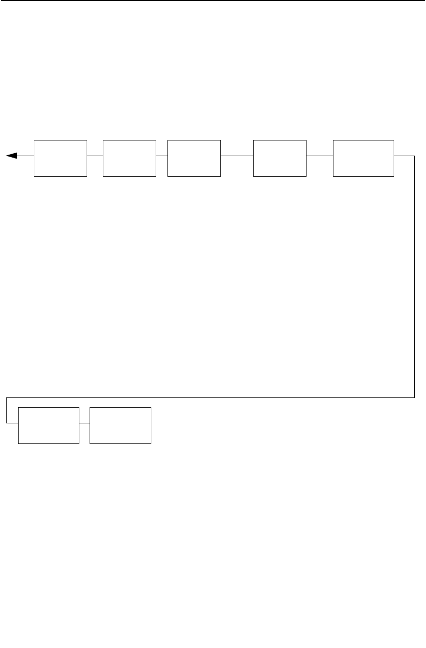
P7000 STD Firmware
65
EMULATION
page 123
CTHI
1
LinePrinter+
IGP/PGL
4
IGP/VGL
3
IPDS
1
PRINTER
CONTROL
page 251
Ribbon End Point
Open Platen @ BOF
Bar Code Quality
Tear Bar Dist.
View Function
7
Unidirectional
Display Language
Accented Chars.
PRINTER
MGMT
page 265
PNE Port
Mgmt Protocol
PNE Port Number
5
PNE Port Timeout
5
Status Port Numb
Mgmt Port Number
DATE
6
page 264
Hour
Minute
Year
Month
Day
DIAGNOSTICS
page 261
Printer Tests
Test Width
Paper Out Dots
System Memory
Print Statistics
Software Build
Feature File
9
Shuttle Type
ACTIVE
IGP EMUL
1
page 121
ADVANCED
USER
page 254
Ptx Setup Option
Hex Dump Mode
Power-up State
Downloaded Fonts
PMD Fault
Power Stacker
1
Auto Elevator
1
Auto Locking
File System
Set Sharing
Shuttle Timeout
Slow Paper Slew
Alarm
Power Saver Time
Pwr Save Control
Cancel Key
Ret. Status Port
Set Lock Key
RBN Low Warn@
RBN Low Action
RBN End Action
IGP/PGL*
IGP/VGL
1
If installed.
2
If Twinax is selected.
3
If VGL is selected from the ACTIVE IGP EMUL menu.
4
If PGL is selected from the ACTIVE IGP EMUL menu.
5
Not available if PNE Port is set to Serial.
6
If Real Time Clock (RTC) option is installed.
7
Available for pedestal printers only.
8
Based on WLAN radio installed.
9
If a Feature File has been downloaded.

66
Chapter 4
Main Menu
P7000 TN Firmware
OFFLINE
CONFIG.
CONTROL
page 85
HOST
INTERFACE
page 87
Load Config.
Save Config.
Print Config.
Delete Config.
Power-Up Config.
Protect Configs.
Name Configs
Reset Cfg Names
Auto Save
Auto Switching*
Centronics
Dataproducts
IEEE 1284
Serial
E-Net Adapter
1
Ethernet
1
NETWORK
SETUP
1
page 105
Adapter Address
1
Adapter Params
1
Ethernet Address
1
Ethernet Params
1
WLAN Address
1
WLAN Params
1
WLAN Kerberos
7
WLAN LEAP
7
WLAN EAP
7
QUICK
SETUP
page 77
HOST INTERFACE
Adapter Address
1
Ethernet Address
1
WLAN Address
1
ZTP DataTime
6
ZTP WaitTime
6
ZTP TearDist
6
ACTIVE IGP EMUL
1
PGL SFCC
2
VGL SFCC
3
Printer Protocol
Form Length
Form Width
Select CPI
Select LPI
P-Series SFCC
Ribbon End Point
Save Config
Power Up Config
ZTP
SETTINGS
6
page 333
ZTP Function
ZTP TearDistance
ZTP Data Time
ZTP Wait Time
ZTP Platen Open
1
If installed.
2
If PGL is selected from the ACTIVE IGP EMUL menu.
3
If VGL is selected from the ACTIVE IGP EMUL menu.
4
Not available if PNE Port is set to Serial.
5
If Real Time Clock (RTC) option is installed.
6
Available for Zero Tear Pedestal printer only.
7
Based on WLAN radio installed.
8
If a Feature File has been downloaded.
P7000 TN Firmware
67
EMULATION
page 123
LinePrinter+
IGP/PGL
2
IGP/VGL
3
PRINTER
CONTROL
page 251
Ribbon End Point
Open Platen @ BOF
Bar Code Quality
Tear Bar Dist.
View Function
6
Unidirectional
Display Language
Accented Chars.
PRINTER
MGMT
page 265
PNE Port
Mgmt Protocol
PNE Port Number
4
PNE Port Timeout
4
Status Port Numb
Mgmt Port Number
DATE
5
page 264
Hour
Minute
Year
Month
Day
DIAGNOSTICS
page 261
Printer Tests
Test Width
Paper Out Dots
System Memory
Print Statistics
Software Build
Feature File
8
Shuttle Type
ACTIVE
IGP EMUL
1
page 121
IGP/PGL*
IGP/VGL
ADVANCED
USER
page 254
Ptx Setup Option
Hex Dump Mode
Power-up State
Downloaded Fonts
PMD Fault
Power Stacker
1
Auto Elevator
1
Auto Locking
File System
Set Sharing
Shuttle Timeout
Slow Paper Slew
Alarm
Power Saver Time
Pwr Save Control
Cancel Key
Ret. Status Port
Set Lock Key
RBN Low Warn@
RBN Low Action
RBN End Action
1
If installed.
2
If PGL is selected from the ACTIVE IGP EMUL menu.
3
If VGL is selected from the ACTIVE IGP EMUL menu.
4
Not available if PNE Port is set to Serial.
5
If Real Time Clock (RTC) option is installed.
6
Available for pedestal printers only.
7
Based on WLAN radio installed.
8
If a Feature File has been downloaded.

68
Chapter 4
Main Menu
P7000 PCL-II Firmware
OFFLINE
CONFIG.
CONTROL
page 85
HOST
INTERFACE
page 87
Load Config.
Save Config.
Print Config.
Delete Config.
Power-Up Config.
Protect Configs.
Name Configs
Reset Cfg Names
Auto Save
Auto Switching*
Centronics
Dataproducts
IEEE 1284
Serial
E-Net Adapter
1
Ethernet
1
NETWORK
SETUP
1
page 105
Adapter Address
1
Adapter Params
1
Ethernet Address
1
Ethernet Params
1
WLAN Address
1
WLAN Params
1
WLAN Kerberos
9
WLAN LEAP
9
WLAN EAP
9
QUICK
SETUP
page 77
HOST INTERFACE
Adapter Address
1
Ethernet Address
1
WLAN Address
1
ZTP DataTime
8
ZTP WaitTime
8
ZTP TearDist
8
ACTIVE EMULATION
PGL SFCC
2
VGL SFCC
3
Printer Protocol
4
Form Length
4
Form Width
4
Select CPI
4
Select LPI
4
P-Series SFCC
4
Page Length Rep.
5
Max Line Width
5
Ribbon End Point
Save Config
Power Up Config
ZTP
SETTINGS
8
page 333
ZTP Function
ZTP TearDistance
ZTP Data Time
ZTP Wait Time
ZTP Platen Open
1
If installed.
2
If PGL is selected from the ACTIVE EMULATION menu.
3
If VGL is selected from the ACTIVE EMULATION menu.
4
If LP+ is selected from the ACTIVE EMULATION menu.
5
If PCL-II is selected from the ACTIVE EMULATION menu.
6
Not available if PNE Port is set to Serial.
7
If Real Time Clock (RTC) option is installed.
8
Available for Zero Tear Pedestal printer only.
9
Based on WLAN radio installed.
10
If a Feature File has been downloaded.
P7000 PCL-II Firmware
69
EMULATION
page 123
LinePrinter+
4
IGP/PGL
2
IGP/VGL
3
PCL-II
5
PRINTER
CONTROL
page 251
Ribbon End Point
Open Platen @ BOF
Bar Code Quality
Tear Bar Dist.
View Function
8
Unidirectional
Display Language
PRINTER
MGMT
page 265
PNE Port
Mgmt Protocol
PNE Port Number
6
PNE Port Timeout
6
Status Port Numb
Mgmt Port Number
DATE
7
page 264
Hour
Minute
Year
Month
Day
DIAGNOSTICS
page 261
Printer Tests
Test Width
Paper Out Dots
System Memory
Print Statistics
Software Build
Feature File
10
Shuttle Type
ACTIVE
EMULATION
page 121
PCL-II
IGP/PGL & LP+
1
IGP/VGL & LP+
1
or
PCL-II
LinePrinter+
(if IGP is not installed)
ADVANCED
USER
page 254
Hex Dump Mode
Power-up State
PMD Fault
Power Stacker
1
Auto Elevator
1
Auto Locking
File System
Shuttle Timeout
Slow Paper Slew
Alarm
Power Saver Time
Pwr Save Control
Cancel Key
Ret. Status Port
Set Lock Key
RBN Low Warn@
RBN Low Action
RBN End Action
1
If installed.
2
If PGL is selected from the ACTIVE EMULATION menu.
3
If VGL is selected from the ACTIVE EMULATION menu.
4
If LP+ is selected from the ACTIVE EMULATION menu.
5
If PCL-II is selected from the ACTIVE EMULATION menu.
6
Not available if PNE Port is set to Serial.
7
If Real Time Clock (RTC) option is installed.
8
Available for pedestal printers only.
9
Based on WLAN radio installed.
10
If a Feature File has been downloaded.

70
Chapter 4
Main Menu
P7000 LG Firmware
OFFLINE
CONFIG.
CONTROL
page 85
HOST
INTERFACE
page 87
Load Config.
Save Config.
Print Config.
Delete Config.
Power-Up Config.
Protect Configs.
Name Configs
Reset Cfg Names
Auto Save
Auto Switching*
Centronics
Dataproducts
IEEE 1284
Serial
E-Net Adapter
1
Ethernet
1
NETWORK
SETUP
1
page 105
Adapter Address
1
Adapter Params
1
Ethernet Address
1
Ethernet Params
1
WLAN Address
1
WLAN Params
1
WLAN Kerberos
9
WLAN LEAP
9
WLAN EAP
9
QUICK
SETUP
page 77
HOST INTERFACE
Adapter Address
1
Ethernet Address
1
WLAN Address
1
ZTP DataTime
8
ZTP WaitTime
8
ZTP TearDist
8
ACTIVE EMULATION
PGL SFCC
2
VGL SFCC
3
Printer Protocol
4
Form Length
4
Form Width
4
Select CPI
4
Select LPI
4
P-Series SFCC
4
Vert Forms
5
Horiz Forms
5
Ribbon End Point
Save Config
Power Up Config
ZTP
SETTINGS
8
page 333
ZTP Function
ZTP TearDistance
ZTP Data Time
ZTP Wait Time
ZTP Platen Open
1
If installed.
2
If PGL is selected from the ACTIVE EMULATION menu.
3
If VGL is selected from the ACTIVE EMULATION menu.
4
If LP+ is selected from the ACTIVE EMULATION menu.
5
If LG is selected from the ACTIVE EMULATION menu.
6
Not available if PNE Port is set to Serial.
7
If Real Time Clock (RTC) option is installed.
8
Available for Zero Tear Pedestal printer only.
9
Based on WLAN radio installed.
10
If a Feature File has been downloaded.
P7000 LG Firmware
71
EMULATION
page 123
LinePrinter+
4
IGP/PGL
2
IGP/VGL
3
LG
5
PRINTER
CONTROL
page 251
Ribbon End Point
Open Platen @ BOF
Bar Code Quality
Tear Bar Dist.
View Function
8
Unidirectional
Display Language
PRINTER
MGMT
page 265
PNE Port
Mgmt Protocol
PNE Port Number
6
PNE Port Timeout
6
Status Port Numb
Mgmt Port Number
DATE
7
page 264
Hour
Minute
Year
Month
Day
DIAGNOSTICS
page 261
Printer Tests
Test Width
Paper Out Dots
System Memory
Print Statistics
Software Build
Feature File
10
Shuttle Type
ACTIVE
EMULATION
page 121
LG
IGP/PGL & LP+
1
IGP/VGL & LP+
1
or
LG
LinePrinter+
(if IGP is not installed)
ADVANCED
USER
page 254
Hex Dump Mode
Power-up State
PMD Fault
Power Stacker
1
Auto Elevator
1
Auto Locking
File System
Shuttle Timeout
Slow Paper Slew
Alarm
Power Saver Time
Pwr Save Control
Cancel Key
Ret. Status Port
Set Lock Key
RBN Low Warn@
RBN Low Action
RBN End Action
1
If installed.
2
If PGL is selected from the ACTIVE EMULATION menu.
3
If VGL is selected from the ACTIVE EMULATION menu.
4
If LP+ is selected from the ACTIVE EMULATION menu.
5
If LG is selected from the ACTIVE EMULATION menu.
6
Not available if PNE Port is set to Serial.
7
If Real Time Clock (RTC) option is installed.
8
Available for pedestal printers only.
9
Based on WLAN radio installed.
10
If a Feature File has been downloaded.

72
Chapter 4
Main Menu
P7000 ANSI Firmware
OFFLINE
CONFIG.
CONTROL
page 85
HOST
INTERFACE
page 87
Load Config.
Save Config.
Print Config.
Delete Config.
Power-Up Config.
Protect Configs.
Name Configs
Reset Cfg Names
Auto Save
Auto Switching*
Centronics
Dataproducts
IEEE 1284
Serial
E-Net Adapter
1
Ethernet
1
NETWORK
SETUP
1
page 105
Adapter Address
1
Adapter Params
1
Ethernet Address
1
Ethernet Params
1
WLAN Address
1
WLAN Params
1
WLAN Kerberos
9
WLAN LEAP
9
WLAN EAP
9
QUICK
SETUP
page 77
HOST INTERFACE
Adapter Address
1
Ethernet Address
1
WLAN Address
1
ZTP DataTime
8
ZTP WaitTime
8
ZTP TearDist
8
ACTIVE EMULATION
PGL SFCC
2
VGL SFCC
3
Printer Protocol
4
Form Length
Form Width
Select CPI
Select LPI
P-Series SFCC
4
Margins
5
Ribbon End Point
Save Config
Power Up Config
ZTP
SETTINGS
8
page 333
ZTP Function
ZTP TearDistance
ZTP Data Time
ZTP Wait Time
ZTP Platen Open
1
If installed
2
If PGL is selected from the ACTIVE EMULATION menu.
3
If VGL is selected from the ACTIVE EMULATION menu.
4
If LP+ is selected from the ACTIVE EMULATION menu.
5
If ANSI is selected from the ACTIVE EMULATION menu.
6
Not available if PNE Port is set at Serial.
7
If Real Time Clock (RTC) option is installed.
8
Available for Zero Tear Pedestal printer only.
9
Based on WLAN radio installed.
10
If a Feature File has been downloaded.
P7000 ANSI Firmware
73
EMULATION
page 123
LinePrinter+
4
44/48XX-ANSI
5
IGP/PGL
2
IGP/VGL
3
PRINTER
CONTROL
page 251
Ribbon End Point
Open Platen @ BOF
Bar Code Quality
Tear Bar Dist.
View Function
8
Unidirectional
Display Language
Accented Chars.
PRINTER
MGMT
page 265
PNE Port
Mgmt Protocol
PNE Port Number
6
PNE Port Timeout
6
Status Port Numb
Mgmt Port Number
DATE
7
page 264
Hour
Minute
Year
Month
Day
DIAGNOSTICS
page 261
Printer Tests
Test Width
Paper Out Dots
System Memory
Print Statistics
Software Build
Feature File
10
Shuttle Type
ACTIVE
EMULATION
page 121
44/48XX-ANSI
IGP/PGL & LP+
1
IGP/VGL & LP+
1
or
44/48XX-ANSI
LinePrinter+
(if IGP is not installed)
ADVANCED
USER
page 254
Ptx Setup Option
Hex Dump Mode
Power-up State
Downloaded Fonts
PMD Fault
Power Stacker
1
Auto Elevator
1
Auto Locking
File System
Set Sharing
Shuttle Timeout
Slow Paper Slew
Alarm
Power Saver Time
Pwr Save Control
Cancel Key
Ret. Status Port
Set Lock Key
RBN Low Warn@
RBN Low Action
RBN End Action
1
If installed
2
If PGL is selected from the ACTIVE EMULATION menu.
3
If VGL is selected from the ACTIVE EMULATION menu.
4
If LP+ is selected from the ACTIVE EMULATION menu.
5
If ANSI is selected from the ACTIVE EMULATION menu.
6
Not available if PNE Port is set at Serial.
7
If Real Time Clock (RTC) option is installed.
8
Available for pedestal printers only.
9
Based on WLAN radio installed.
10
If a Feature File has been downloaded.

74
Chapter 4
Main Menu
OpenPrint P7000 STD Postscript/PDF Firmware
OFFLINE
CONFIG.
CONTROL
page 85
HOST
INTERFACE
page 87
Load Config.
Save Config.
Print Config.
Delete Config.
Power-Up Config.
Protect Configs.
Name Configs
Reset Cfg Names
Auto Save
Auto Switching*
Centronics
Dataproducts
IEEE 1284
Serial
E-Net Adapter
1
Ethernet
1
NETWORK
SETUP
1
page 105
Adapter Address
1
Adapter Params
1
Ethernet Address
1
Ethernet Params
1
WLAN Address
1
WLAN Params
1
WLAN Kerberos
9
WLAN LEAP
9
WLAN EAP
9
QUICK
SETUP
page 77
HOST INTERFACE
Adapter Address
1
Ethernet Address
1
WLAN Address
1
ZTP DataTime
8
ZTP WaitTime
8
ZTP TearDist
8
ACTIVE EMULATION
Resolution
5
Paper Size
5
PGL SFCC
2
VGL SFCC
3
Printer Protocol
4
Form Length
4
Form Width
4
Select CPI
4
Select LPI
4
P-Series SFCC
4
Ribbon End Point
Save Config
Power Up Config
ZTP
SETTINGS
8
page 333
ZTP Function
ZTP TearDistance
ZTP Data Time
ZTP Wait Time
ZTP Platen Open
1
If installed
2
If PGL is selected from the ACTIVE EMULATION menu.
3
If VGL is selected from the ACTIVE EMULATION menu.
4
If LP+ is selected from the ACTIVE EMULATION menu.
5
If Postscript/PDF is selected from the ACTIVE EMULATION menu.
6
Not available if PNE Port is set at Serial.
7
If Real Time Clock (RTC) option is installed.
8
Available for Zero Tear Pedestal printer only.
9
Based on WLAN radio installed.
10
If a Feature File has been downloaded.
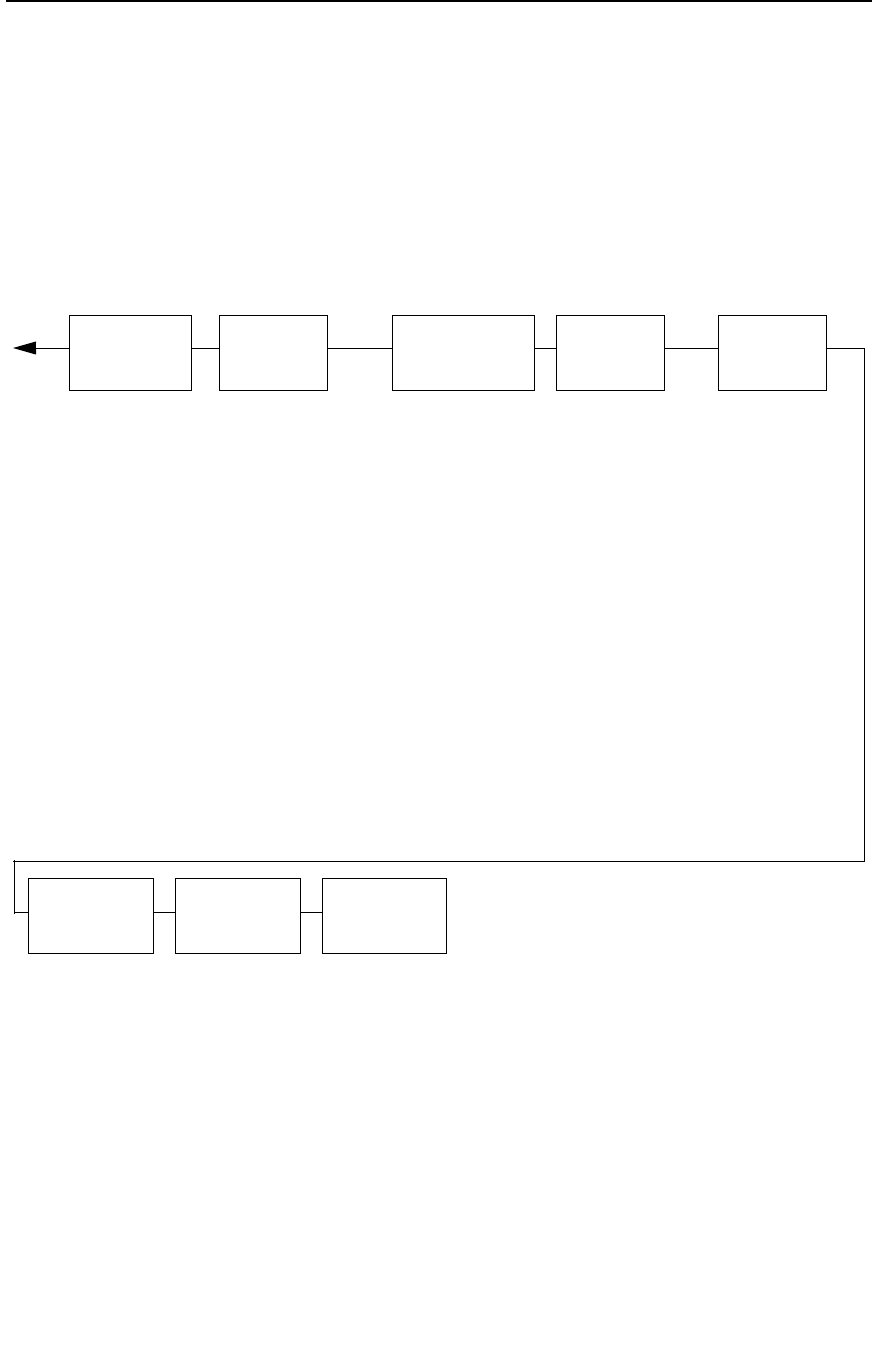
OpenPrint P7000 STD Postscript/PDF Firmware
75
EMULATION
page 123
LinePrinter+
4
IGP/PGL
2
IGP/VGL
3
Postscript/PDF
5
PRINTER
CONTROL
page 251
Ribbon End Point
Open Platen @ BOF
Bar Code Quality
Tear Bar Dist.
View Function
8
Unidirectional
Display Language
Accented Chars.
PRINTER
MGMT
page 265
PNE Port
Mgmt Protocol
PNE Port Number
6
PNE Port Timeout
6
Status Port Numb
Mgmt Port Number
DATE
7
page 264
Hour
Minute
Year
Month
Day
DIAGNOSTICS
page 261
Printer Tests
Test Width
Paper Out Dots
System Memory
Print Statistics
Software Build
Feature File
10
Shuttle Type
ACTIVE
EMULATION
page 121
Postscript/PDF
IGP/PGL & LP+
1
IGP/VGL & LP+
1
or
Postscript/PDF
LinePrinter+
(if IGP is not installed)
SURE SCAN
5
page 242
Optimize Barcode
Alignment
Hor. Quiet Zone
Ver. Erase Zone
Quiet Zone Fault
Update PDF
Barcodes On Page
Bcodes Optimized
1
If installed
2
If PGL is selected from the ACTIVE EMULATION menu.
3
If VGL is selected from the ACTIVE EMULATION menu.
4
If LP+ is selected from the ACTIVE EMULATION menu.
5
If Postscript/PDF is selected from the ACTIVE EMULATION menu.
6
Not available if PNE Port is set at Serial.
7
If Real Time Clock (RTC) option is installed.
8
Available for pedestal printers only.
9
Based on WLAN radio installed.
10
If a Feature File has been downloaded.
ADVANCED
USER
page 254
Ptx Setup Option
Hex Dump Mode
Power-up State
Downloaded Fonts
PMD Fault
Power Stacker
1
Auto Elevator
1
Auto Locking
File System
Set Sharing
Shuttle Timeout
Slow Paper Slew
Alarm
Power Saver Time
Pwr Save Control
Cancel Key
Rcv. Status Port
Ret. Status Port
Set Lock Key
RBN Low Warn@
RBN Low Action
RBN End Action
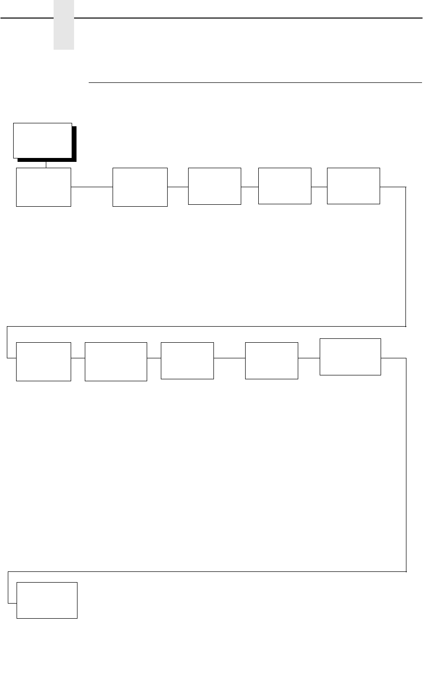
76
Chapter 4
Main Menu
OpenPrint P7000 HD Postscript/PDF Firmware
OFFLINE
CONFIG.
CONTROL
page 85
Load Config.
Save Config.
Print Config.
Delete Config.
Power-Up Config.
Protect Configs.
Name Configs
Reset Cfg Names
1
If installed.
2
Available for pedestal printers only.
3
If a Feature File has been downloaded.
4
Not available if PNE Port is set at Serial.
QUICK
SETUP
page 77
HOST INTERFACE
ETHERNET ADDRESS
WLAN Address
2
ZTP Data Time
2
ZTP Wait Time
2
ZTP Tear Dist
2
Resolution
Paper Size
Ribbon End Point
Load Config.
Save Config.
Power-Up Config.
DIAGNOSTICS
page 261
Printer Tests
Test Width
Paper Out Dots
System Memory
Print Statistics
Software Build
Feature File
3
Shuttle Type
ADVANCED
USER
page 254
Ptx Setup Option
Hex Dump Mode
Power-Up State
PMD Fault
Auto Locking
File System
Set Sharing
Shuttle Timeout
Slow Paper Slew
Alarm
Power Saver Time
Pwr Save Control
Cancel Key
Rcv. Status Port
Ret. Status Port
Set Lock Key
RBN Low Warn@
RBN Low Action
RBN End Action
HOST
INTERFACE
page 87
IEEE 1284
Ethernet
Auto Switching*
Centronics
Dataproducts
Serial
NETWORK
SETUP
1
page 105
Ethernet Address
Ethernet Params
WLAN Address
1
WLAN Params
1
WLAN EAP
1
PRINTER
CONTROL
page 251
Ribbon end Point
Open Platen @ BOF
Tear Bar Dist.
Unidirectional
Display Language
ZTP
SETTINGS
2
page 333
ZTP Function
ZTP TearDistance
ZTP Data Time
ZTP Wait Time
ZTP Platen Open
SURE SCAN
page 242
Optimize Barcode
Alignment
Hor. Quiet Zone
Ver. Erase Zone
Quiet Zone Fault
Update PDF
Barcodes On Page
Bcodes Optimized
EMULATION
page 123
Postscript/PDF
PRINTER
MGMT
page 265
PNE Port
Mgmt Protocol
PNE Port Number
4
PNE Port Timeout
4
Status Port Numb
Mgmt Port Number

OpenPrint P7000 HD Postscript/PDF Firmware
77
QUICK SETUP Menu
When the printer is in offline mode, QUICK SETUP is the first Main Menu
option that appears on the control panel. The QUICK SETUP menu offers
basic menu items required to configure your printer. This section describes
the options within the QUICK SETUP menu.
NOTE: The options in your menu will vary depending on the firmware, host
IO, emulations selected, and other features available with your
printer.
Host Interface
The Host Interface menu enables you to select and configure interfaces
between the printer and your host computer.
Device ID
This parameter defines the printer emulation as IPDS, 4234-2 or 5225. After
the emulation has been changed, a POR status is sent to the host. IPDS is
the default.
Adapter Address
•
IP Address. A numeric address such as 123.45.61.23 which identifies a
printer or server in a LAN or WAN.
•
Subnet Mask. A binary value used to divide IP networks into smaller
subnetworks or subnets. This mask is used to help determine whether IP
packets need to be forwarded to other subnets.
•
Gateway Address. A gateway address is the IP address of a hardware
device (gateway) that translates data between two incompatible
networks, which can include protocol translation.
•
MAC Address. This menu item is the Manufacturer’s Assigned Number,
and is unique for each printer. It is read-only.
•
DHCP. You can enable/disable the DHCP protocol using this option, but
consult your administrator for the appropriate setting.
QUICK SETUP Menu

78
Chapter 4
QUICK SETUP Menu
Ethernet Address
•
IP Address. A numeric address such as 123.45.61.23 which identifies a
printer or server in a LAN or WAN.
•
Subnet Mask. A binary value used to divide IP networks into smaller
subnetworks or subnets. This mask is used to help determine whether IP
packets need to be forwarded to other subnets.
•
Gateway Address. A gateway address is the IP address of a hardware
device (gateway) that translates data between two incompatible
networks, which can include protocol translation.
•
MAC Address. This menu item is the Manufacturer’s Assigned Number,
and is unique for each printer. It is read-only.
•
DHCP. You can enable/disable the DHCP protocol using this option, but
consult your administrator for the appropriate setting.
WLAN Address
•
IP Address. A numeric address such as 123.45.61.23 which identifies a
printer or server in a LAN or WAN.
•
Subnet Mask. A binary value used to divide IP networks into smaller
subnetworks or subnets. This mask is used to help determine whether IP
packets need to be forwarded to other subnets.
•
Gateway Address. A gateway address is the IP address of a hardware
device (gateway) that translates data between two incompatible
networks, which can include protocol translation.
•
MAC Address. This menu item is the Manufacturer’s Assigned Number,
and is unique for each printer. It is read-only.
•
DHCP. You can enable/disable the DHCP protocol using this option, but
consult your administrator for the appropriate setting.
ZTP DataTime
This option sets the pause time in the data stream that the ZTP requires
before moving the form to the tear bar once a print job is completed. The
values range from .5 to 5 seconds. The default is .5 seconds.
ZTP WaitTime
This option sets the minimum amount of time that the form stays at the tear
bar. This allows you time to remove the form before the form is retracted to
print the next form. The adjustable values range from 500 to 5000
milliseconds in increments of 500 milliseconds. The default value is 2
seconds.

OpenPrint P7000 HD Postscript/PDF Firmware
79
ZTP TearDist
This option sets the tear off distance from the current print position to the tear
bar. Adjustable values in increments of 1/144th of an inch range from 200 to
2880. The up and down arrows adjust the display value. When you press the
ENTER key, the selected value is stored and a scale is printed to indicate the
current tear off position. The default value is 1060.
NOTE: When a new value is selected, the printer will lose the current print
position. You must reset the top of form to automatically save the new
value.
Active Emulation
The Active Emulation menu enables you to select a combination of
emulations as described in Table 2 on page 61.
Active IGP Emulation
The Active IGP Emulation menu enables you to activate either the PGL or
VGL emulation. This menu is only available with the P7000 STD and TN
firmware as described in Table 2 on page 61.
PGL SFCC
You can specify which hex code (1-FF) will be used as the Special Function
Control Character (SFCC). The SFCC denotes that the following data is an
IGP command.
•
7E (default)
•
1 – FF
VGL SFCC
You can specify which hex code (1-FF) will be used as the Special Function
Control Character (SFCC). The SFCC denotes that the following data is an
IGP command.
•
5E (default)
•
1 – FF
Printer Protocol
Select the LinePrinter+ protocol you wish to use. Refer to the LinePrinter Plus
Programmer's Reference Manual for more information.
Form Length
Form length is the number of lines that can be printed on a page. You can set
the form length in inches, millimeters (mm), or as a function of the current lpi
(lines per inch).
QUICK SETUP Menu

80
Chapter 4
QUICK SETUP Menu
Form Width
The form width can be specified in inches, millimeters, or as a function of the
current cpi (characters per inch). The forms width set should not exceed the
actual paper width.
Select CPI
This parameter allows you to specify the characters per inch (cpi) values.
The options are 10.0, 12.0, 13.3, 15.0, 17.1, and 20.0. The factory default is
10.0 CPI.
Select LPI
This parameter allows you to specify the lines per inch (lpi) values.
The options are 6.0, 8.0, and 10.3 LPI. The factory default is 6.0 LPI.
P-Series SFCC
This parameter allows you to select which ASCII codes will function as the
Special Function Control Code (SFCC) command delimiter.
P-Series codes can use hex 00 through hex 7F. Options include the following:
•
SOH (hex 01) (default)
•
ESC (hex 1B)
•
ETX (hex 03)
•
CIRCUMFLEX (hex 5E) – also called caret (^)
•
TILDE (hex 7E) – (~)
NOTE: SOH, ETX, and ESC are non-printables. The characters (^) and (~)
are printable; however, do not use them as printables in the host data
stream if either is chosen as a delimiter because print errors will
occur.
Margins
•
Left Margin. Set in columns. Column zero is defined as the far left edge
of the page, and column numbering increments from left to right.
•
Right Margin. Set in columns. Column zero is defined as the far right
edge of the page, and column numbering increments from right to left.
•
Top Margin. Defined in lines, starting from line zero at the top of the page
and incrementing from the top down.
•
Bottom Margin. Defined in lines, starting from line zero at the bottom of
the page and incrementing from the bottom up.
Form Length
Form length is the number of lines that can be printed on a page. You can set
the form length in inches, millimeters (mm), or as a function of the current lpi
(lines per inch).

OpenPrint P7000 HD Postscript/PDF Firmware
81
Form Width
The form width can be specified in inches, millimeters, or as a function of the
current cpi (characters per inch). The forms width set should not exceed the
actual paper width.
Vert Forms
•
Bot Frm 66/6 (default). This option sets the bottom margin for the forms.
You must specify the bottom margin in lines (at 6 lines per inch), ranging
from 0 to 198 lines (33 inches). The default setting is 66. Press the right
arrow to increase the value, left arrow to decrease the value, and ENTER
to change units. Selecting a value for this option resets the top margin to
0, so the top margin must be redefined after this option is selected.
•
Top Mrg 6/0 This option sets the top margin for the forms. You must
specify the top margin in lines (at 6 lines per inch), ranging from 0 to 198
lines (33 inches). The default setting is 0. Press the right arrow to
increase the value, left arrow to decrease the value, and ENTER to
change units. The margins will automatically adjust so that the top and
bottom margins do not cross each other.
Horiz Forms
•
Left Mgr 0.00 (default). This sets the left margin for the forms. You must
specify the left margin in 1/10 inch increments, from 0 to 13.1 inches. The
default value is 0. Press the right arrow to increase the value, left arrow to
decrease the value, and ENTER to change units. The margins will
automatically adjust so that the left and right margins do not cross each
other.
•
Right Mrg 13.2. This sets the right margin for the forms. You must specify
the right margin in 1/10 inch increments, from 0.1 to 13.2 inches. The
default value is 13.2. Press NEXT to increase the value, PREV to
decrease the value, and ENTER to change units. The margins will
automatically adjust so that the left and right margins do not cross each
other.
Page Length Rep
•
Inches/Page (default). Allows the user to set the page length in inches.
•
Lines/Page. Allows the user to set the page length in number of lines.
Max Line Width
Set the maximum line width at either 13.2 inches or the maximum width of the
printer.
QUICK SETUP Menu

82
Chapter 4
QUICK SETUP Menu
Resolution
This parameter defines the default print resolution. This selection is used
when either the print resolution is not defined by the data stream or if the print
resolution defined by the data stream is not supported.
The following resolutions are available on OpenPrint P7000 STD:
•
120x144 DPI (default)
•
90 x 96 DPI
The following resolutions are available on Openprint P7000 HD:
•
180x180 DPI (default)
•
180x90 DPI
•
90x180 DPI
•
120x120 DPI
•
90x90 DPI
Paper Size
This parameter allows selection of available paper sizes. Available options
include:
•
Custom. Sets a user-defined paper size.
•
Width. Defines the paper width. The range is 1” to 15” in 0.1 inch
increments. The default is 13.6 inches.
•
Length. Defines the paper length. The default is 11 inches. Three
length options are available:
Inches. Defines the length in inches. The range is 1” to 24” in 0.1
inch increments.
1/6 Inch Lines. Defines the length in 1/6 inch lines. The range is 6
to 144 lines.
1/8 Inch Lines. Defines the length in 1/8 inch lines. The range is 8
to 192 lines.
To set a custom length, use the appropriate menu that allows for selection of
the exact paper length to avoid loss of top-of-form (i.e., if using a 12” paper,
select either the “Inches” menu set to 12” or the “1/6 Inch Lines” menu set to
72. However, if using a 11 2/3 inch paper length, the “1/6 Inch Lines” menu
must be used (set to 70) since that is exactly 11 2/3 inches. If the “Inches”
menu is used, the closest values would be 11.6 or 11.7 inches which are not
exact.
The printer will indicate which of the three length menus was used by showing
that submenu first when entering the “Length” menu. The configuration
printout will also show the length menu used.
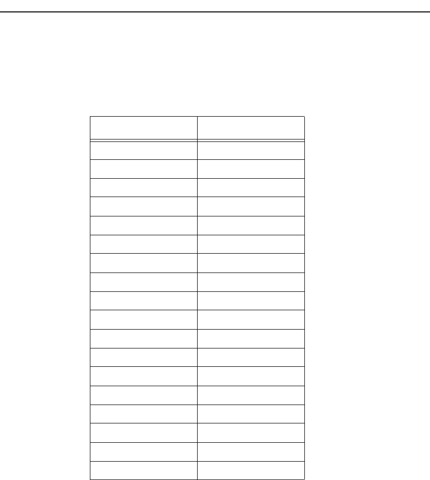
OpenPrint P7000 HD Postscript/PDF Firmware
83
•
See Table 3 for paper size options and actual sizes.
Ribbon End Point
This parameter adjusts the point at which the system will declare the ribbon
as being expended. The life count will always be from 100% to 0%, but if a
darker setting is selected 0% will be reached more quickly. If a lighter setting
is selected, the system will extend the time it takes to reach 0%.
Load Config.
The printer can store numerous configurations in memory. This parameter
allows you to select and load a specific configuration.
Table 3. Paper Size Options and Actual Size
Paper Size Actual Size
US Fanfold 13.6 x 11 in
Letter 8.5 x 11 in
Legal 8.5 x 14 in
Executive 7.3 x 10.5 in
A3 11.7 x 16.5 in
A4 8.3 x 11 2/3 in
A5 5.8 x 8.3 in
A6 4.1 x 5.8 in
Fanfold 10x14in 10 x 14 in
Tabloid 11x17in 11 x 17 in
Fanfold 12x12in 12 x 12 in
JIS B5 7.2 x 10.1 in
US Folio 8.5 x 13 in
No. 10 Envelope 4.1 x 9.5 in
DL Envelope 4.3 x 8.7 in
C5 Envelope 6.4 x 9 in
C6 Envelope 4.5 x 6.4 in
ISO B5 6.9 x 9.8 in
QUICK SETUP Menu

84
Chapter 4
QUICK SETUP Menu
Save Config
This option allows you to save up to eight configurations to meet different print
job requirements. This eliminates the need to change the parameter settings
for each new job. The configurations are stored in memory and will not be lost
if you turn off the printer. If the Protect Configs. parameter is enabled, the new
configuration will not be saved unless the existing configuration has been
deleted first. The factory default configuration cannot be changed. See
“Saving Your New Configuration” on page 53 for details.
Power Up Config
This option allows you to specify which of the nine configurations (Factory or
1-8) will be the power-up configuration.
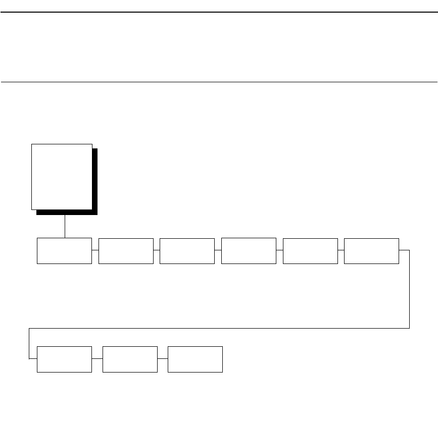
OpenPrint P7000 HD Postscript/PDF Firmware
85
CONFIG. CONTROL Menu
The CONFIG. CONTROL menu allows you to control your printer’s
configurations according to the specifications necessary for your print jobs.
Load Config.
The printer can store numerous configurations in memory. This parameter
allows you to select and load a specific configuration.
Save Config.
This option allows you to save up to eight configurations to meet different print
job requirements. This eliminates the need to change the parameter settings
for each new job. The configurations are stored in memory and will not be lost
if you turn off the printer. If the Protect Configs. parameter is enabled, the new
configuration will not be saved unless the existing configuration has been
deleted first. The factory default configuration cannot be changed. See
“Saving Your New Configuration” on page 53 for details.
Print Config.
This option is used to print a listing of various stored printer configurations.
Store printouts of your configurations in a safe place for quick referral.
Load
Config.
Save
Config.
Print
Config.
Delete
Config.
Power-Up
Config.
Protect
Configs.
Name
Configs
Factory*
1-8
1*
2-8
Current Short*
Current Full
Factory
Power-Up
All
1-8
1*
2-8
Factory*
1-8
Disable*
Enable
1-8
* = Factory Default
Reset Cfg
Names
1*
2-8
All
Auto Save
Enable*
Disable
CONFIG.
CONTROL
(from page 64,
66, 68, 70, 72,
74, and 76)
CONFIG. CONTROL Menu

86
Chapter 4
CONFIG. CONTROL Menu
Delete Config.
You can delete one or all of your eight customized configurations. The factory
default configuration cannot be deleted.
Power-Up Config.
You can specify which of the nine configurations (Factory or 1-8) will be the
power-up configuration.
Protect Configs.
You can specify whether or not a new configuration should overwrite an
existing configuration when you activate the Save Configs. parameter. When
disabled (default), the new configuration will overwrite the existing
configuration. When enabled, the new configuration will not overwrite the
existing configuration, and the message “CONFIG. EXISTS / Delete First”
displays.
Name Configs
You may specify a 15-character name which can be used to refer to a
configuration. The name you enter for a configuration will be used in the Load
Config., Save Config., Print Config., Delete Config., and Power-Up Config.
menus. The name can only be cleared by using the Reset Cfg Names menu.
When you move into the Name Configs. menu, the top line of the display
shows the current configuration name. The second line of the display is
initially the same as the top line. You can modify the second line of the display
without affecting the top line until the ENTER key is pressed, which sets the
modified name.
Press the UP or DOWN (U or V
)
keys to cycle through the values available
for that character at the cursor location. Press the NEXT (Z) key to move to
the next character to be modified. Press the PREV key (Y) to go back to a
character you have already modified. Continue until you have entered the
name you want to give to this configuration, then press ENTER to save. The
name you entered will now represent this configuration on the printer's front
panel. To exit this menu without saving, press any key other than the ENTER
key. The configuration name will revert to the last saved value.
Reset Cfg Names
You can reset specific configuration names back to the default value of the
configuration number.
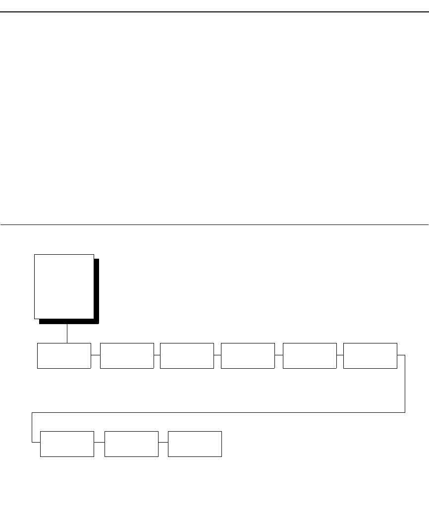
OpenPrint P7000 HD Postscript/PDF Firmware
87
Auto Save
•
Enable (default). When a change has been made to a Config. menu, this
option automatically prompts the user to save or not save the change to a
Config #.
If you are currently in the Factory Config. menus and make a change,
pressing ENTER saves to Config 1 or the next available Config. and
becomes the Power-Up Config. If the Current Config is Config 1 and a
menu change is made, pressing ENTER will save the change to Config 1.
•
Disable. The printer will not prompt you to save any changes made.
HOST INTERFACE Menu
The Host Interface Menu enables you to select and configure one of many
types of interfaces between the printer and your host computer. The currently
selected interface is indicated with an asterisk on the control panel message
display. Each interface has its own submenu with a set of interface
parameters which can be configured.
Twinax
1
Coax
1
IEEE 1284Auto
Switching*
Centronics Dataproducts
Serial Ethernet
1
(Available with
CT Option)
(Available with
CT Option)
(see page 90)
(see page 88) (see page 92) (see page 95)
(see page 97) (see page 104)
* = Factory Default
1
If installed.
E-Net
Adapter
1
(see page 103)
HOST
INTERFACE
(from page 64,
66, 68, 70, 72,
74, and 76)
HOST INTERFACE Menu
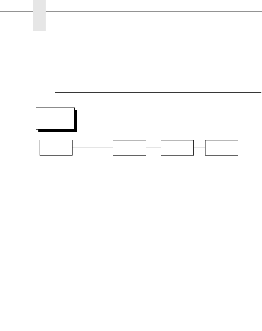
88
Chapter 4
HOST INTERFACE Menu
IMPORTANT
When switching between Twinax, Coax, or Auto Switching, the printer
will load the power-up configuration and the new interface parameters.
Any settings made and not saved before selecting these interfaces will
be lost.
Auto Switching Submenu
Auto Switching gives the printer the ability to handle multiple data streams
sequentially. With Auto Switching, the printer can service hosts attached to
the serial, parallel, Ethernet, coax and twinax ports as if they were the only
interface connected.
For example, if the host computer sends one print job to the RS-232 serial
port and a separate print job to the IEEE 1284 parallel port, the printer's Auto
Switching is able to handle both jobs, in the order they were received. The
user does not have to reconfigure the selected interface between jobs.
Auto Switching
(from page 87)
Parallel
Hotport
Serial
Hotport
C/T
Hotport
1
Port Type
Centronics*
(see page 92 for options)
Dataproducts
(see page 95 for options)
IEEE 1284
2
(see page 90 for options)
Disable
E-Net Adapter
1
(see page 103 for options)
Trickle Time
1/4 sec*
1/2 sec
1 sec
2 sec
4 sec
8 sec
16 sec
Off
Timeout
10 sec.*
(10-60)
Report Status
Disable*
Enable
Switch Out On
Data Timeout*
Session Close
Port Type
RS 232*
RS 422
Disable
Trickle Time
1/4 sec*
1/2 sec
1 sec
2 sec
4 sec
8 sec
16 sec
Off
Timeout
10 sec.*
(10-60)
Report Status
Disable*
Enable
Port Type
Twinax*
Coax
Disable
Timeout
10 sec.*
(10-60)
Report Status
Disable*
Enable
* = Factory Default
1
If Installed
2
Default for HD
Ethernet
Hotport
1
Timeout
10 sec.*
(10-60)
Switch Out On
Data Timeout
Session Close

Auto Switching Submenu
89
Port Type
Select the types of parallel, serial and/or C/T interfaces which are connected
to the printer. For example, if your printer is attached to one host with a
Centronics connection and a second host with an RS-422 serial connection,
you would select Centronics under the Parallel Hotport menu, RS-422 under
the Serial Hotport menu, and Disable under the C/T Hotport menu.
Trickle Time
When the printer is printing data from a host and a second job is received by
the printer from a different host, Trickle Time prevents the second host from
timing out while it is waiting for its data to be printed. In order to support this
feature, the port has to be able to accept data from the host and store it for
future use.
For example, if the printer is printing a job from the serial port, and then
receives a second print job from the parallel port, the data from the parallel
port will “trickle” bit by bit into the printer buffer to prevent a timeout error from
being sent back to the host connected to the parallel port.
The selected value is the time that the printer waits before getting the next
byte of data from the host. The Trickle Time value should be less than the
host time out value, but not too much shorter or else the printer fills up its
buffer too fast. This function is not applicable for C/T hotport.
Timeout
This is the value used by the printer to time out from the current port and
check the other selected port types for data to print. When the printer has not
received data from the host after a certain period of time, it needs to timeout in
order to service the other ports.
Report Status
•
Disable (default). When a fault occurs on the printer, only the active port
reports the fault to the host.
•
Enable. The port will report any fault even when it is not the current active
port.
Switch Out On
•
Data Timeout (default). Allows Autoswitching when no data has been
received for the selected Time Out period.
•
Session Close. Allows Autoswitching only when the Network Socket is
closed. If the Ethernet option is not installed the Network Socket is always
reported as closed and this menu option is ignored.
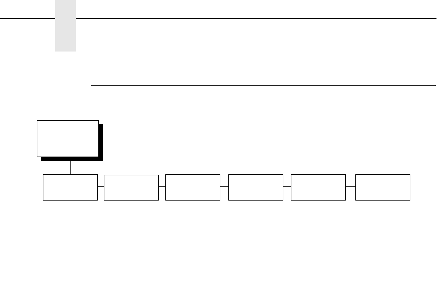
90
Chapter 4
HOST INTERFACE Menu
IEEE 1284 Parallel (Bidirectional) Submenu
The IEEE 1284 interface is faster and more versatile than Centronics and
supports bidirectional communication. Configuration of this interface is
controlled from the host. Refer to
ΙΕΕΕ 1284 Παραλλελ Ιντερφαχε
ον παγε 272
for more details about the available modes (Compatibility,
Nibble, and Byte).
Prime Signal
•
Enable (default). The parallel port will perform a warm start (reboot) if the
host asserts the prime signal.
•
Disable. The parallel port will not perform a warm start (reboot) if the host
asserts the prime signal.
TOF Action
•
Reset (default). A form feed is performed before a warm start when the
prime signal is asserted from the host. This setting is used only if the
prime signal parameter is enabled.
•
Do Nothing. Nothing occurs before a warm start when the prime signal is
asserted from the host.
Buffer Size in K
This option configures the amount of memory allocated for the IEEE 1284
parallel port buffer. You can specify between 1 and 16 Kbytes, in 1-Kbyte
increments. The default is 16K.
NOTE: OpenPrint HD products have a range of 1 to 256 and a default of 64K.
IEEE 1284
(from page 87)
Prime
Signal
TOF
Action
Buffer Size
in K
1
Enable*
Disable
Reset*
Do Nothing
16*
1-16
* = Factory Default
1
OpenPrint HD products have an extended range to 256.
Auto
Trickle
Disable*
Enable
Trickle
Time
1/4 sec*
1/2 sec
1 sec
2 sec
4 sec
8 sec
16 sec
Off
Offline
Process
Disable*
Enable

IEEE 1284 Parallel (Bidirectional) Submenu
91
Auto Trickle
Auto Trickle is used to prevent a host computer from timing out because the
parallel interface was busy for too long. When Auto Trickle is enabled and the
printer's buffers are almost full, the printer will begin to trickle data in (at the
rate set in the Trickle Time menu) until the buffers start to empty.
Trickle Time
When the printer is printing data from a host and a second job is received by
the printer from a different host, Trickle Time prevents the second host from
timing out while it is waiting for its data to be printed. In order to support this
feature, the port has to be able to accept data from the host and store it for
future use.
For example, if the printer is printing a job from the serial port, and then
receives a second print job from the parallel port, the data from the parallel
port will “trickle” bit by bit into the printer buffer to prevent a timeout error from
being sent back to the host connected to the parallel port.
The selected value is the time that the printer waits before getting the next
byte of data from the host. The Trickle Time value should be less than the
host time out value, but not too much shorter or else the printer fills up its
buffer too fast. This function is not applicable for C/T hotport.
Offline Process
•
Disable (default). When set to disable, the printer does not process
parallel/network data while offline.
•
Enable. When set to enable, the printer continues to process (but not
print) the current network/parallel job while the printer is offline until the
printer's buffer is full.
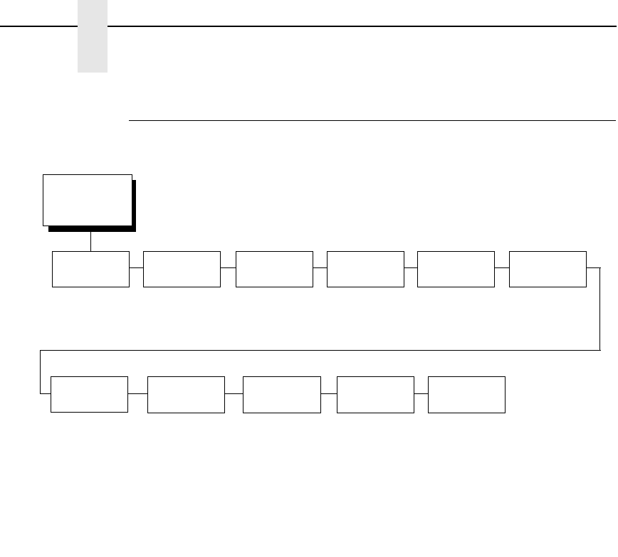
92
Chapter 4
HOST INTERFACE Menu
Centronics (Parallel) Submenu
Data Bit 8
•
Enable (default). Allows access to the extended ASCII character set.
•
Disable. The printer interprets bit 8 of each incoming data character as a
zero, regardless of its actual setting.
PI Ignored
The PI (Paper Instruction) signal is used to control vertical paper motion.
•
Enable (default). Ignores the PI signal and treats the data as characters
or control codes.
•
Disable. Causes the printer to interpret the eight data lines as VFU
commands when the PI signal is true.
Data Polarity
The Data Polarity parameter must be set to match the data polarity of your
host computer.
•
Standard (default). Does not expect the host computer to invert the data.
•
Inverted. Expects the data received on the data lines from the host
computer to be inverted. Ones become zeros, and vice versa.
Centronics
(from page 87)
Prime
Signal
TOF Action Buffer Size
in K
1
Enable*
Disable
Reset*
Do Nothing
16*
(1-16)
* = Factory Default
1
OpenPrint HD products have an extended range to 256.
Auto
Trickle
Disable*
Enable
Trickle
Time
1/4 sec*
1/2 sec
1 sec
2 sec
4 sec
8 sec
16 sec
Off
Data Bit 8
Enable*
Disable
PI Ignored
Enable*
Disable
Data
Polarity
Standard*
Inverted
Resp.
Polarity
Standard*
Inverted
Busy On
Strobe
Enable*
Disable
Latch
Data On
Leading*
Trailing

Centronics (Parallel) Submenu
93
Resp. Polarity
The Resp. Polarity parameter must be set to match the response polarity of
your host computer.
•
Standard (default). Does not invert the response signal.
•
Inverted. Inverts the response signal sent to the host computer.
Busy On Strobe
•
Enable (default). Asserts a busy signal after each character is received.
•
Disable. Asserts a busy signal only when the print buffers are full.
Latch Data On
Specifies whether the data is read on the leading or trailing edge of the data
strobe signal. The default is leading.
Prime Signal
•
Enable (default). The parallel port will perform a warm start (reboot) if the
host asserts the prime signal.
•
Disable. The parallel port will not perform a warm start (reboot) if the host
asserts the prime signal.
TOF Action
•
Reset (default). A form feed is performed before a warm start when the
prime signal is asserted from the host. This setting is used only if the
prime signal parameter is enabled.
•
Do Nothing. Nothing occurs before a warm start when the prime signal is
asserted from the host.
Buffer Size in K
Configures the amount of memory allocated for the Centronics parallel port
buffer. You can specify between 1 and 16 Kbytes, in 1-Kbyte increments.
The default is 16K.
NOTE: OpenPrint HD products have a range of 1 to 256 and a default of 64K.
Auto Trickle
Auto Trickle is used to prevent a host computer from timing out because the
parallel interface was busy for too long. When Auto Trickle is enabled and the
printer's buffers are almost full, the printer will begin to trickle data in (at the
rate set in the Trickle Time menu) until the buffers start to empty out.

94
Chapter 4
HOST INTERFACE Menu
Trickle Time
When the printer is printing data from a host and a second job is received by
the printer from a different host, Trickle Time prevents the second host from
timing out while it is waiting for its data to be printed. In order to support this
feature, the port has to be able to accept data from the host and store it for
future use.
For example, if the printer is printing a job from the serial port, and then
receives a second print job from the parallel port, the data from the parallel
port will “trickle” bit by bit into the printer buffer to prevent a timeout error from
being sent back to the host connected to the parallel port.
The selected value is the time that the printer waits before getting the next
byte of data from the host. The Trickle Time value should be less than the
host time out value, but not too much shorter or else the printer fills up its
buffer too fast. This function is not applicable for C/T hotport.
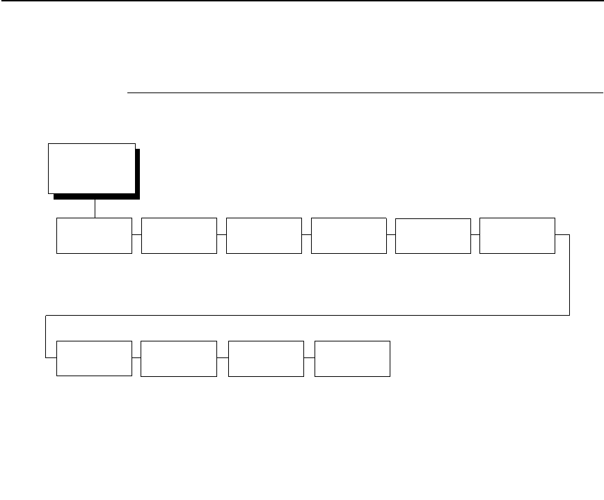
Dataproducts Submenu
95
Dataproducts Submenu
Data Bit 8
•
Enable (default). Allows access to the extended ASCII character set.
•
Disable. The printer interprets bit 8 of each incoming data character as a
zero, regardless of its actual setting.
PI Ignored
The PI (Paper Instruction) signal is used to control vertical paper motion.
•
Enable (default). Causes the printer to interpret the eight data lines as
DVFU commands when the PI signal is true.
•
Disable. Ignores the PI signal and treats the data as characters or control
codes.
Data Polarity
The Data Polarity parameter must be set to match the data polarity of your
host computer.
•
Standard (default). Does not expect the host computer to invert the data.
•
Inverted. Expects the data received on the data lines from the host
computer to be inverted. Ones become zeros, and zeros become ones.
Dataproducts
(from page 87)
Data Bit 8 PI Ignored Data
Polarity
Resp.
Polarity
Latch Data
On
Prime Signal
TOF Action Buffer Size
in K
1
Enable*
Disable
Enable*
Disable
Standard*
Inverted
Standard*
Inverted
Middle*
Trailing
Leading
Disable*
Enable
Reset*
Do Nothing
16*
(1-16)
* = Factory Default
1
OpenPrint HD products have an extended range to 256.
Auto
Trickle
Disable*
Enable
Trickle
Time
1/4 sec*
1/2 sec
1 sec
2 sec
4 sec
8 sec
16 sec
Off

96
Chapter 4
HOST INTERFACE Menu
Resp. Polarity
The Response Polarity parameter must be set to match the response polarity
of your host computer.
•
Standard (default). Does not invert the response signal.
•
Inverted. Inverts the response signal sent to the host computer.
Latch Data On
Specifies whether the data is read on the leading, middle, or trailing edge of
the data strobe signal. The default is Middle.
Prime Signal
•
Disable (default). The parallel port will not perform a warm start (reboot) if
the host asserts the prime signal.
•
Enable. The parallel port will perform a warm start (reboot) if the host
asserts the prime signal.
TOF Action
•
Reset (default). A form feed is performed before a warm start when the
prime signal is asserted from the host. This setting is used only if the
prime signal parameter is enabled.
•
Do Nothing. Nothing occurs before a warm start when the prime signal is
asserted from the host.
Buffer Size in K
Configures the amount of memory allocated for the Dataproducts parallel port
buffer. You can specify between 1 and 16 Kbytes, in 1-Kbyte increments.
The default is 16K.
NOTE: OpenPrint HD products have a range of 1 to 256 and a default of 64K.
Auto Trickle
Auto Trickle is used to prevent a host computer from timing out because the
parallel interface was busy for too long. When Auto Trickle is enabled and the
printer's buffers are almost full, the printer will begin to trickle data in (at the
rate set in the Trickle Time menu) until the buffers start to empty out.
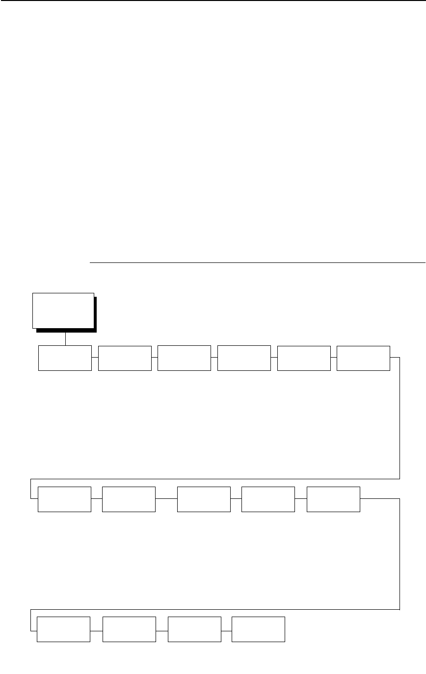
Serial Submenu
97
Trickle Time
When the printer is printing data from a host and a second job is received by
the printer from a different host, Trickle Time prevents the second host from
timing out while it is waiting for its data to be printed. In order to support this
feature, the port has to be able to accept data from the host and store it for
future use.
For example, if the printer is printing a job from the serial port, and then
receives a second print job from the parallel port, the data from the parallel
port will “trickle” bit by bit into the printer buffer to prevent a timeout error from
being sent back to the host connected to the parallel port.
The selected value is the time that the printer waits before getting the next
byte of data from the host. The Trickle Time value should be less than the
host time out value, but not too much shorter or else the printer fills up its
buffer too fast. This function is not applicable for C/T hotport.
Serial Submenu
Serial
(from page 87)
Interface
Type
Data
Protocol
Baud
Rate
Word
Length 8
Stop
Bits 1
Parity
Data Term
Ready
Request to
Send
Buffer Size
in K
1
Poll
Character
Poll
Response
RS 232*
RS 422
XON/XOFF*
ETX/ACK
ACK/NAK
Series1 1 Char
Series1 2 Char
ENQ/ACK
DTR
600 Baud
1200 Baud
2400 Baud
4800 Baud
9600 Baud*
19200 Baud
38400 Baud
57600 Baud
115200 Baud
8*
7
1*
2
None*
Odd
Even
Mark
Sense
True*
On-Line and BNF
Off-Line or BF
On-Line
False
On-Line and BNF*
Off-Line or BF
On-Line
False
True
16*
1-16
00 Hex*
(0-FF hex)
0 ms*
(1-30 ms)
* = Factory Default
1
OpenPrint HD products have an extended range to 256.
One Char
Enquiry
Disable*
Enable
Framing
Errors
Disable
Enable*
Idle
Response
Disable*
Enable
Offline
Process
Disable
Enable*

98
Chapter 4
HOST INTERFACE Menu
Interface Type
This parameter allows you to select either the RS-232 or RS-422 serial port
interface. The default is RS-232.
Data Protocol
You can select one of the following serial interface protocols to meet the host
interface requirements.
•
XON / XOFF (default). The printer controls the flow of communication
from the host by turning the transmission on and off. In some situations,
such as when the buffer is full or the timing of signals is too slow or too
fast, the printer will tell the host to stop transmission by sending an XOFF
character. An XOFF character is sent when the number of empty bytes in
the buffer is less than or equal to 25 percent of the buffer size. If the host
keeps sending data after an XOFF is sent, the printer firmware will
continue to send an XOFF for every 16 characters received. When
cleared, the printer will resume receiving data (XON). The data does not
have any End of Text codes;
XON / XOFF is a non-block protocol.
•
ETX / ACK. End of Text / Acknowledge. The host controls the flow of
communication to the printer by sending a block of data and ending the
block with an End of Text (ETX) signal. When the printer receives the ETX
signal, it will acknowledge the ETX, thereby acknowledging it has
received the entire block of data.
•
ACK / NAK. ACK means acknowledge; the device acknowledges it has
accepted a transmission. NAK means negative acknowledge; the device
did not receive the transmission.
•
SERIES1 1 CHAR. The printer controls the flow of communication from
the host by turning the transmission on and off using response characters
sent to the host. If the number of valid bytes in the buffer reaches 75
percent of the buffer size, the online or offline and buffer full response
character is sent. If the buffer is completely full, an online or offline buffer
full response is sent every time a character is sent from the host.
Whenever the printer state changes to online or offline, the appropriate
response character is sent. If the idle response option is enabled, the
printer will send a response character every two seconds while the
number of valid bytes in the buffer is less than 75 percent of the buffer
size. If a poll character is received (configurable from the Poll Character
xx Hex option on the front panel from hex 0 through FF), the printer will
send a response character n milliseconds later (configurable from the Poll
Character xx MS on the front panel from 0 through 30). This n
milliseconds is called the poll delay. The poll character will be removed
from the input data stream and will not be processed. This may cause
problems with the transmission of binary data (e.g., control codes, bit
image, etc.). If a poll delay is started due to the receipt of a poll character
and another poll character is received, the second poll character has no
effect and is removed from the input data stream. If a transition (from
buffer full to empty or online to offline) occurs during a poll delay, the new
printer state will be sent at the end of the poll delay.
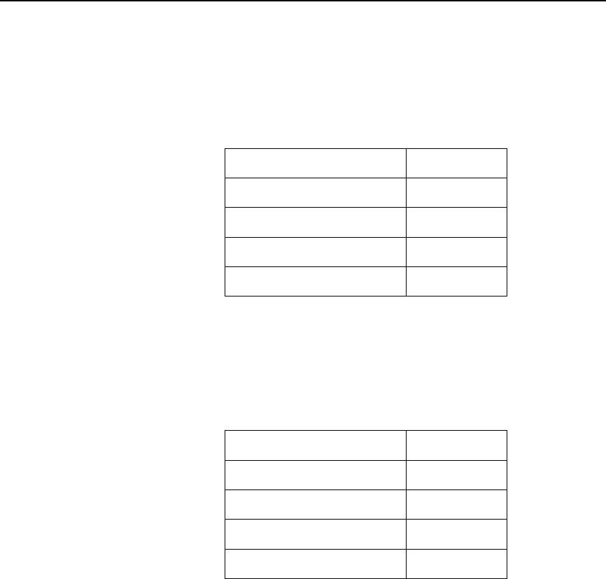
Serial Submenu
99
The response characters are described in Table 4.
•
SERIES1 2 CHAR. This protocol behaves exactly the same as the
Series1 Char except there is a two-character response to the host. The
response characters are described in Table 5.
•
ENQ/ACK. Enquiry/Acknowledge. The host controls the flow of data by
sending an ENQ (Enquiry, decimal 5, Control-E) approximately every 80
characters. When the printer is ready for more data, it replies with an ACK
(Acknowledge, decimal 6, Control-F).
•
DTR. The printer controls the data flow by sending this hardware signal to
the host. If there is enough room in the printer buffer, the printer will send
a high signal; if the buffer is full, the printer will send a low signal. DTR
tells the host if it is safe to send more data. (If the host sends data during
an unsafe condition, data will be lost.) DTR is not available when RS-422
is selected.
Table 4. Series1 1 Char Response Characters
Printer State Response
Online and Buffer Empty CR
Online and Buffer Full 3
Offline and Buffer Empty 0
Offline and Buffer Full 2
Table 5. Series1 2 Char Response Characters
Printer State Response
Online and Buffer Empty 1 CR
Online and Buffer Full 3 CR
Offline and Buffer Empty 0 CR
Offline and Buffer Full 2 CR

100
Chapter 4
HOST INTERFACE Menu
Baud Rate
Sets the baud rate of the serial interface in the printer. Baud rate is the speed
at which serial data is transferred between the host computer and the printer.
The choices for the RS-232 and RS-422 interfaces are 600, 1200, 2400,
4800, 9600, 19200, 38400, 57600, and 115200 Baud. The default is 9600
Baud.
NOTE: If you select a baud rate that is greater than 19200, you may need to
use RS-422 or select a lower baud rate to prevent data loss. You also
may need to increase the Buffer Size in K parameter to improve
performance.
Word Length
Sets the length of the serial data word. The length of the data word can be set
to 7 or 8 bits, and must match the corresponding data bits setting in the host
computer.
Stop Bits 1
Sets the number of stop bits in the serial data word. Either one or two stop bits
can be selected. The setting must match the corresponding stop bit setting in
the host computer.
Parity
Set for odd parity, even parity, mark, sense, or no parity. The setting must
match the corresponding parity setting in the host computer.
Data Term Ready
This configuration is part of hardware flow control and determines when the
Data Terminal Ready (DTR) signal is generated. This signal indicates if the
printer is ready to receive data.
•
True (default). Continuously asserts the DTR signal.
•
On Line and BNF (buffer not full). Asserts the DTR signal when the
printer is online and the internal serial buffer is not full.
•
Off Line or BF (buffer full). Asserts the DTR signal when the printer is
offline or the internal serial buffer is full.
•
On Line. Asserts the DTR signal when the printer is online.
•
False. Never asserts the DTR signal.

Serial Submenu
101
Request To Send
This configuration is part of hardware flow control and determines when the
Request to Send (RTS) signal is generated. This signal indicates whether or
not the printer is ready to receive data.
•
On Line and BNF (default). Asserts the RTS signal when the printer is
online and the internal serial buffer is not full.
•
Off Line or BF. Asserts the RTS signal when the printer is offline or the
internal serial buffer is full.
•
On Line. Asserts the RTS signal when the printer is online.
•
False. Never asserts the RTS signal.
•
True. Continuously asserts the RTS signal.
Buffer Size in K
This option configures the amount of memory allocated for the serial port
buffer. You may specify between 1 and 16 Kbytes, in 1-Kbyte increments.
The default is 16K.
NOTE: 1. If you select a baud rate that is 19200 or greater, you may need to
increase the Buffer Size in K parameter to improve performance.
2. OpenPrint HD products have a range of 1 to 256 and a default of
64K.
Poll Character
This option is for the Series1 protocol. Whenever the printer receives this
character, it sends a response to the host indicating the current state of the
printer (see Series1 protocol). It may be configured from 0 through FF
hexadecimal.
Poll Response
This option is for the Series1 protocol. After receiving a poll character, the
printer will wait the poll response time in milliseconds before sending the
response. It may be configured from 0 through 30.
Idle Response
This option is for the Series1 protocol.
•
Disable (default)
•
Enable. The printer will send a response character every two seconds
while the number of valid bytes in the buffer is less than 75 percent of the
buffer size.
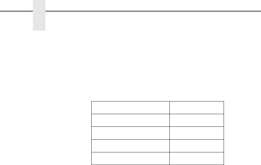
102
Chapter 4
HOST INTERFACE Menu
One Char Enquiry
The One Char Enquiry mode uses the Poll Character to detect a request from
the host and sends a response back to the host. This option also allows you to
turn on and off this feature.
The Poll Character is removed from the data stream. If the Data Protocol is
set to ETX/ACK, ACK/NAK, or Series 1, One Char Enquiry is automatically
disabled.
Framing Errors
Possible errors that can occur when the printer’s serial interface settings do
not match those of the host computer.
•
Enable (default). If a framing error occurs, a fault message will display on
the control panel.
•
Disable. If a framing error occurs, a fault message will not display on the
control panel.
Offline Process
•
Disable (default). When set to disable, the printer does not process
parallel/network data while in offline mode.
•
Enable. When set to enable, the printer continues to process without
printing the current network/parallel job while the printer is offline until the
printer’s buffer is full.
Table 6. One Char Enquiry Response Characters
Printer State Response (hex)
Online and Buffer Not Full 22
Online and Buffer Full 23
Offline and Buffer Not Full 20
Offline and Buffer Full 21

E-Net Adapter Submenu
103
E-Net Adapter Submenu
The E-Net Adapter interface allows you to locate the printer on a LAN rather
than attach the host directly into the printer. The detailed configuration of this
option is given in the PrintNet User's Manual.
Buffer Size in K
This option configures the amount of memory allocated for the Ethernet
buffer. You can specify between 1-16 Kbytes. The default is 16 Kbytes.
NOTE: OpenPrint HD products have a range of 1 to 256 and a default of 64K.
E-Net Adapter
(from page 87)
Buffer Size
in K
1
16*
1-16
* = Factory Default
1
OpenPrint HD products have an extended range to 256.
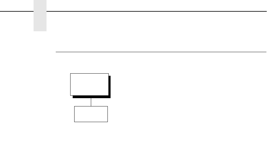
104
Chapter 4
HOST INTERFACE Menu
Ethernet Submenu
The Ethernet interface allows you to locate the printer on a LAN rather than
attach the host directly into the printer. The detailed configuration of this
option is given in the Network Interface Card User's Manual.
Buffer Size in K
This option configures the amount of memory allocated for the Ethernet
buffer. You can specify between 1 and 16 Kbytes, in 1-Kbyte increments.
The default is 16 Kbytes.
NOTE: OpenPrint HD products have a range of 1 to 256 and a default of 64K.
Ethernet
(from page 87)
Buffer Size
in K
1
16*
1-16
* = Factory Default
1
OpenPrint HD products have an extended range to 256.
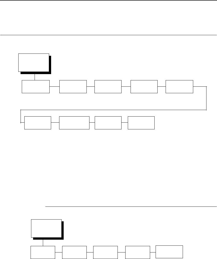
ADAPTER ADDRESS
105
NETWORK SETUP Menu
ADAPTER ADDRESS
IP Address
A numeric address such as 123.45.61.23 which identifies a printer or server in
a LAN or WAN.
Subnet Mask
A binary value used to divide IP networks into smaller subnetworks or
subnets. This mask is used to help determine whether IP packets need to be
forwarded to other subnets.
NETWORK
SETUP
(from page 64)
ADAPTER
ADDRESS
1
See page 105.
WLAN
ADDRESS
3
See page 112.
ETHERNET
PARAMS
2
See page 110.
ETHERNET
ADDRESS
2
See page 109.
ADAPTER
PARAMS
1
See page 106.
WLAN
PARAMS
3
See page 113.
WLAN
KERBEROS
4
See page 117.
WLAN
LEAP
5
See page 119.
1
Only if the Ethernet Adapter feature is installed.
2
Only if the Integrated Ethernet feature is installed.
3
Only if the Wireless Adapter feature is installed.
4
Only if a Symbol 4121 radio card is installed.
5
Only if a Cisco radio card is installed.
6
Only if a Symbol 5127 radio card is installed.
WLAN
EAP
3, 4, 6
See page 120.
ADAPTER
ADDRESS
(from page 105)
IP Address Subnet
Mask
xxx.xxx.xxx.xxx xxx.xxx.xxx.xxx xxx.xxx.xxx.xxx hhhhhhhhhhhh
* = Factory Default
Gateway
Address
MAC
Address
DHCP
Disable*
Enable
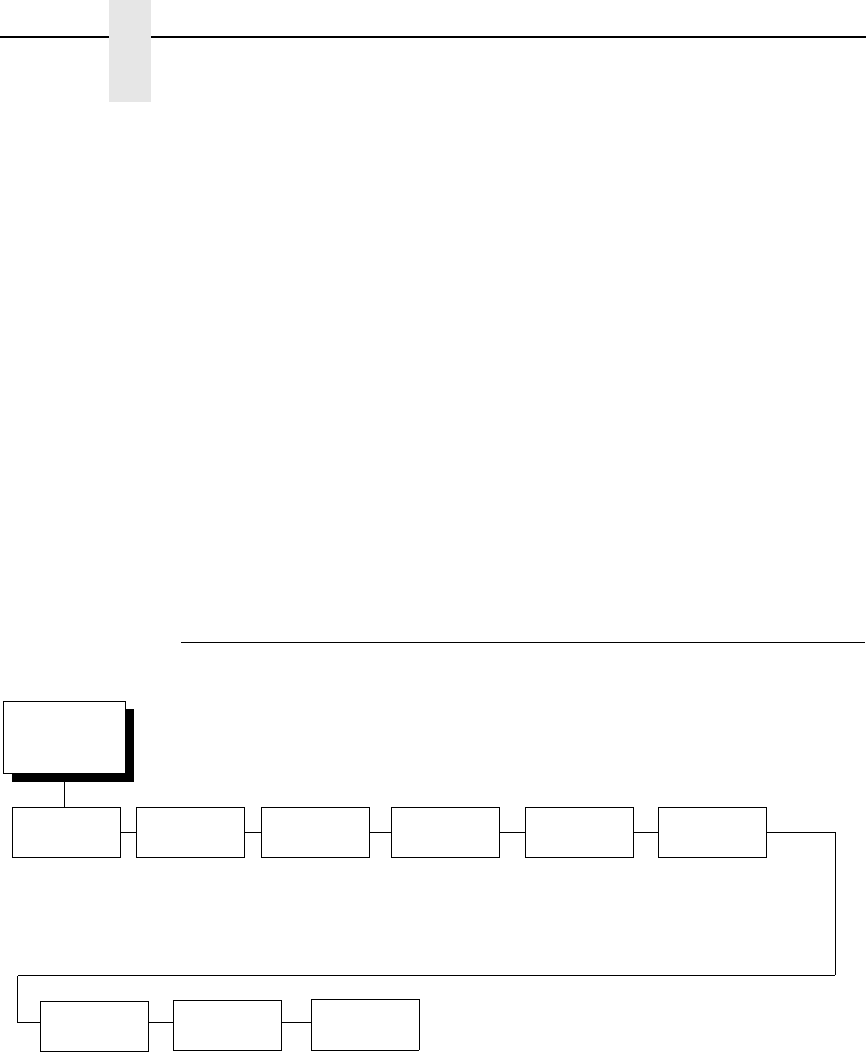
106
Chapter 4
NETWORK SETUP Menu
Gateway Address
A gateway address is the IP address of a hardware device (gateway) that
translates data between two incompatible networks, which can include
protocol translation.
MAC Address
This menu item is the Manufacturer’s Assigned Number, and is unique for
each printer. It is read-only.
DHCP
You can enable/disable the DHCP protocol using this option, but consult your
administrator for the appropriate setting.
The options include:
•
Disable (default)
•
Enable.
ADAPTER PARAMS
You may enable or disable the Novell or NetBIOS Protocols within this menu,
as well as selecting which Novell Frame scheme to use in processing Novell
signals. See the Novell chapter in the Network Interface Card User's Manual
for more details.
ADAPTER
PARAMS
(from page 105)
* = Factory Default
Novell
Frame
IPDS
Data Port
Ethernet
Speed
Ethernet 802.2*
802.2 Snap
Auto Sensing
Ethernet II
Ethernet 802.3
5001*
1023-65535
Auto Select*
10 Half Duplex
10 Full Duplex
100 Half Duplex
100 Full Duplex
Keep Alive
Timer
3 Minutes*
2 - 10 Minutes
Job Control
Standard*
Enhanced
Off
ASCII
Data Port
9100*
1023 - 65535
Novell
Protocol
Enable*
Disable
Nest Serv
Type
Auto*
Bindery
NDS
NetBIOS
Protocol
Enable*
Disable

ADAPTER PARAMS
107
Novell Protocol
This option determines whether the Novell protocol will be available. The
selections are as indicated below:
•
Enable (default). Makes the Novell protocol available with the ethernet
installed.
•
Disable. Makes the Novell protocol unavailable during printer operation.
Nest Serv Type
You can change the Nest Server using this option, but consult your
administrator for the appropriate setting.
The options are Auto (default), Bindery, and NDS.
NetBIOS Protocol
This option determines whether the NetBIOS protocol will be available. The
selections are as indicated below:
•
Enable (default). Makes the NetBIOS protocol available with the ethernet
installed.
•
Disable. Makes the NetBIOS protocol unavailable during printer
operation.
Novell Frame
This selection determines which framing scheme will be used in processing
Novell signals.
•
Ethernet 802.2 (default)
•
802.2 Snap
•
Auto Sensing
•
Ethernet II
•
Ethernet 802.3
ASCII Data Port
This option sets the port number for ASCII print jobs. The data port number
needs to match your host system setting.
•
9100 (default)
•
1023 - 65535
IPDS Data Port
This option allows you to set the port number for IPDS print jobs only if the
IPDS option is installed.
The range is 0 - 5000, and the default is 5001.

108
Chapter 4
NETWORK SETUP Menu
Keep Alive Timer
This is the time that the Keep Alive Timer will run. With the Keep Alive Timer
on, the tcp connection will stay connected even after the print job has
terminated.
•
3 Minutes (default)
•
2 - 10 Minutes
Ethernet Speed
This menu option only appears if a 10/100Base-T network interface card
(NIC) is installed. The Ethernet Speed menu allows compatibility with different
systems and networks. The factory default is Auto Select.
•
Auto Select. (default) This setting tells the 10/100Base-T NIC to perform
an auto detection scheme and configure itself to be 10 Half Duplex, 10
Full Duplex, 100 Half Duplex, or 100 Full Duplex.
•
10 Half Duplex. Tells the 10/100Base-T NIC to communicate at 10
Megabits per second using half duplex.
•
10 Full Duplex. Tells the 10/100Base-T NIC to communicate at 10
Megabits per second using full duplex.
•
100 Half Duplex. Tells the 10/100Base-T NIC to communicate at 100
Megabits per second using half duplex.
•
100 Full Duplex. Tells the 10/100Base-T NIC to communicate at 100
Megabits per second using full duplex.
Job Control
The job control mode has three options:
•
Standard (default). The NIC waits for the printer to finish receiving the
current job before sending another job. The status line shows “done”
when the job is completely received by the NIC.
•
Enhanced. The NIC waits for the printer to finish receiving the current job
before sending another job. The status line shows “done” when the job is
fully printed.
•
Off. No job synchonization between the NIC and the printer.
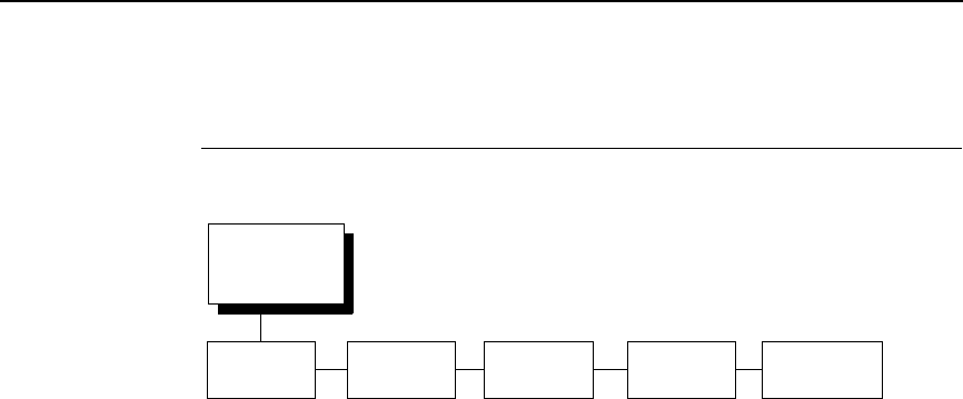
ETHERNET ADDRESS
109
ETHERNET ADDRESS
IP Address
A numeric address such as 123.45.61.23 which identifies a printer or server in
a LAN or WAN.
Subnet Mask
A binary value used to divide IP networks into smaller subnetworks or
subnets. This mask is used to help determine whether IP packets need to be
forwarded to other subnets.
Gateway Address
A gateway address is the IP address of a hardware device (gateway) that
translates data between two incompatible networks, which can include
protocol translation.
MAC Address
This menu item is the Manufacturer’s Assigned Number, and is unique for
each printer. It is read-only.
DHCP
You can enable/disable the DHCP protocol using this option, but consult your
administrator for the appropriate setting.
The options include:
•
Disable (default)
•
Enable.
ETHERNET
ADDRESS
(from page 105)
IP Address Subnet
Mask
xxx.xxx.xxx.xxx xxx.xxx.xxx.xxx xxx.xxx.xxx.xxx hhhhhhhhhhhh
* = Factory Default
Gateway
Address
MAC
Address
DHCP
Disable*
Enable
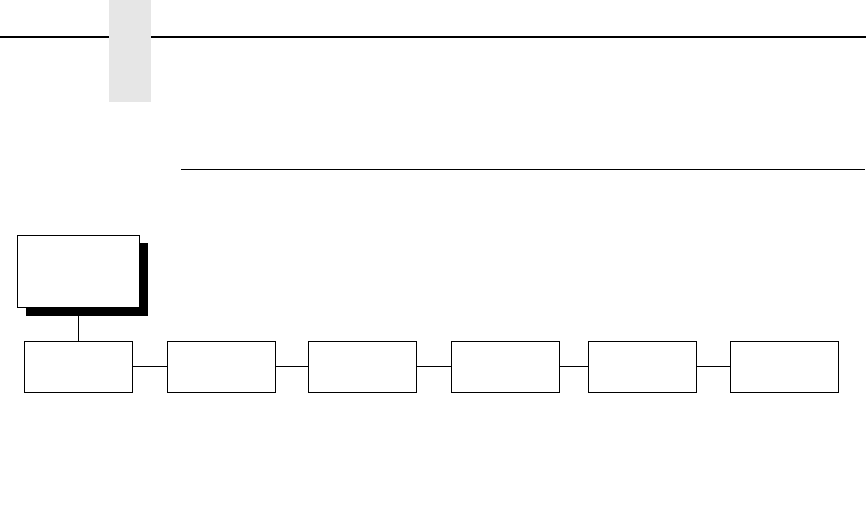
110
Chapter 4
NETWORK SETUP Menu
ETHERNET PARAMS
The ETHERNET PARAMS menu helps your printer communicate on a
network.
For information on assigning the IP Address, Gateway Address, Subnet
Mask, and MAC Address, refer to the Network Interface Card User's Manual.
NetBIOS Protocol
This option determines whether the NetBIOS protocol will be available. The
selections are as indicated below:
•
Enable (default). Makes the NetBIOS protocol available with the ethernet
installed.
•
Disable. Makes the NetBIOS protocol unavailable during printer
operation.
ASCII Data Port
This option sets the port number for ASCII print jobs. The data port number
needs to match your host system setting.
•
9100 (default)
•
1023 - 65535
IPDS Data Port
This option allows you to set the port number for IPDS print jobs only if the
IPDS option is installed.
The range is 1023 - 65535, and the default is 5001.
Keep Alive Timer
This is the time that the Keep Alive Timer will run. With the Keep Alive Timer
on, the tcp connection will stay connected even after the print job has
terminated.
•
3 Minutes (default)
•
2 - 10 Minutes
ETHERNET
PARAMS
(from page 105)
* = Factory Default
1
If installed
2
Available for OpenPrint product only.
ASCII
Data Port
Ethernet
Speed
9100*
1023 - 65535
Auto Select*
10 Half Duplex
10 Full Duplex
100 Half Duplex
100 Full Duplex
Keep Alive
Timer
3 Minutes*
2 - 10 Minutes
NetBIOS
Protocol
Enable*
Disable
Job Control
Standard*
Enhanced
Fast Standard
2
Off
IPDS Data
Port
1
5001*
1023 - 65535

ETHERNET PARAMS
111
Ethernet Speed
This menu option only appears if a 10/100Base-T network interface card
(NIC) is installed. The Ethernet Speed menu allows compatibility with different
systems and networks. The factory default is Auto Select.
•
Auto Select. (default) This setting tells the 10/100Base-T NIC to perform
an auto detection scheme and configure itself to be 10 Half Duplex, 10
Full Duplex, 100 Half Duplex, or 100 Full Duplex.
•
10 Half Duplex. Tells the 10/100Base-T NIC to communicate at 10
Megabits per second using half duplex.
•
10 Full Duplex. Tells the 10/100Base-T NIC to communicate at 10
Megabits per second using full duplex.
•
100 Half Duplex. Tells the 10/100Base-T NIC to communicate at 100
Megabits per second using half duplex.
•
100 Full Duplex. Tells the 10/100Base-T NIC to communicate at 100
Megabits per second using full duplex.
Job Control
The job control mode has four options:
•
Standard (default). The NIC waits for the printer to finish receiving the
current job before sending another job. The status line shows “done”
when the job is completely received by the NIC.
•
Enhanced. The NIC waits for the printer to finish receiving the current job
before sending another job. The status line shows “done” when the job is
fully printed.
•
Off. No job synchonization between the NIC and the printer.
•
Fast Standard. The EOJ (End of Job) packet is acknowledged
immediately. Use this selection if the job is timed out due to a delay in the
acknowledgement of the EOJ packet because of the amount of data
being printed.
NOTE: It is recommended to set this option to Enhanced if the emulation is
Postscript.
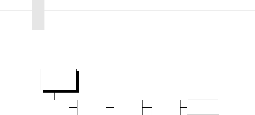
112
Chapter 4
NETWORK SETUP Menu
WLAN ADDRESS
IP Address
A numeric address such as 123.45.61.23 which identifies a printer or server in
a LAN or WAN.
Subnet Mask
A binary value used to divide IP networks into smaller subnetworks or
subnets. This mask is used to help determine whether IP packets need to be
forwarded to other subnets.
Gateway Address
A gateway address is the IP address of a hardware device (gateway) that
translates data between two incompatible networks, which can include
protocol translation.
MAC Address
This menu item is the Manufacturer’s Assigned Number, and is unique for
each printer. It is read-only.
DHCP
You can enable/disable the DHCP protocol using this option, but consult your
administrator for the appropriate setting.
The options include:
•
Disable (default)
•
Enable.
WLAN
ADDRESS
(from page 105)
IP Address Subnet
Mask
xxx.xxx.xxx.xxx xxx.xxx.xxx.xxx xxx.xxx.xxx.xxx hhhhhhhhhhhh
* = Factory Default
Gateway
Address
MAC
Address
DHCP
Disable*
Enable
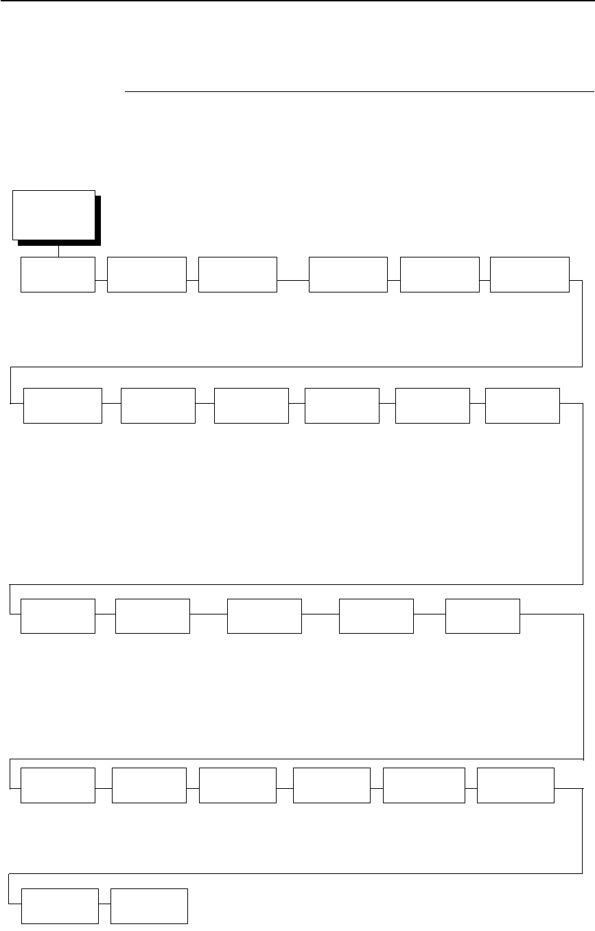
WLAN PARAMS
113
WLAN PARAMS
WLAN
PARAMS
(from page 105)
Signal
Strength
5
0%
SSID
Name
SSID Name (01 - 15)
SSID Name (16 - 30)
SSID Name (31 - 32)
Preamble
6
Default*
Short
Long
Operation
Mode
6
Infrastructure*
Pseudo IBSS
Ad Hoc
Ant. Diversity
Diverse*
Primary
Auxiliary
* = Factory Default
1
Only when 40 Bites is selected
2
Only when 128 Bits is selected
3
Only when a Symbol 4121 radio card is installed.
4
Only when a Cisco radio card is installed.
5
Read only
6
Not displayed if LA5127 radio card is installed.
7
Only if LA5127 radio card is installed.
Min xfer
Rate
Auto-negotiate*
1Mb/Sec
2Mb/Sec
5.5Mb/Sec
11Mb/Sec
Power
Mgmt
0 ms.*
100 ms.
200 ms.
300 ms.
400 ms.
500 ms.
600 ms.
700 ms.
800 ms.
900 ms.
1000 ms.
Channel
6
Default*
1 - 15
Reset SSID
Name
Transmit
Power
100%*
0 - 100 %
Antenna
7
Primary*
Auxiliary
Diverse
Internat.
Mode
Disable*
Enable
Auth
Method
Open*
Shared
Kerberos
3
LEAP
4
WEP Key 1
Key Format
Hexadecimal*
ASCII
Key Width
128 Bits*
40 Bits
Byte 1: - Bytes 5
1
Byte 1: - Bytes 13
2
WEP Key 2
Key Format
Hexadecimal*
ASCII
Key Width
128 Bits*
40 Bits
Byte 1: - Bytes 5
1
Byte 1: - Bytes 13
2
WEP Key 3
Key Format
Hexadecimal*
ASCII
Key Width
128 Bits*
40 Bits
Byte 1: - Bytes 5
1
Byte 1: - Bytes 13
2
WEP Key 4
Key Format
Hexadecimal*
ASCII
Key Width
128 Bits*
40 Bits
Byte 1: - Bytes 5
1
Byte 1: - Bytes 13
2
Reset WEP
Keys
Default WEP
Keys
WPA
Mode
7
Disable*
Enable
WPA
Cipher
7
TKIP*
AES
TKIP+AES
Disable
WPA
P-Phs (01-15)
7
XXX
3
WPA P-Phs
(16-30)
7
WPA P-Phs
(31-32)
7
Reset WPA
P-Phs
7

114
Chapter 4
NETWORK SETUP Menu
Signal Strength
This menu displays the strength of the wireless signal.
NOTE: This is a display value only and cannot be changed.
Operation Mode
Allows you to select the way the Wireless option communicates:
•
Infrastructure (default). The Wireless option must go through a server.
•
Pseudo IBSS. Proprietary, peer-to-peer communication (without a
server). The two peers must be specific to one manufacturer.
•
Ad Hoc. Standard, peer-to-peer communication (without a server).
The two peers can be from different manufacturers.
SSID Name
A 1 - 32 character, case sensitive string that identifies the group the printer
talks to.
NOTE: The SSID name may be edited in three parts (1-15), (16-30), and
(31-32).
For each part of the SSID name, press the MICRO UP or MICRO DOWN
keys to cycle through the values available for that character at the cursor
location. Press the SCROLL UP key to move to the next character to be
modified. Press the SCROLL DOWN key to go back to the name you want to
give to this SSID name, then press ENTER to save. The name you entered
will now represent this SSID name on the printer’s front panel. To exit this
menu without saving, press any key other than the ENTER key. The SSID
name will revert to the last saved value.
Reset SSID Name
Allows you to reset the SSID name.
Min Xfer Rate
Allows you to set the minimum speed at which the Wireless Option will accept
a connection (in million bits per second). The options are:
•
Auto-negotiate (default)
•
1Mb/Sec.
•
2Mb/Sec.
•
5.5Mb/Sec
•
11Mb/Sec
Channel
Allows you to select the RF channel. The options are Default (the factory
default) and 1-15.

WLAN PARAMS
115
Ant. Diversity
The type of antenna used:
•
Diverse (default). Select when you want to use the antenna with the best
reception.
•
Primary. Select when you want to use the Primary antenna on the server.
•
Auxiliary. Select when you want to use the Auxiliary antenna on the
server.
Preamble
The length of the preamble in transmit packets.
•
Default (default). The Wireless option automatically determines the
length.
•
Short. For newer printers which can handle higher transer rate speeds.
•
Long. For older printers which cannot handle higher transfer rate speeds.
Antenna
•
Primary (default). Select when you want to use the Primary antenna on
the RF card.
•
Auxiliary. Select when you want to use the Auxiliary antenna on the RF
card.
•
Diverse. Select when you want to use the antenna with the best
reception.
Power Mgmt
This allows you to set power-save mode and sleep time. A value specifying
the sleep time in milliseconds will be provided. If set to zero, power-save
mode will be disabled. The range includes:
•
0 ms. (default)
•
100 ms. - 1000 ms.
Transmit Power
The power level as a percentage of full power (0 - 100%).
Internat. Mode
When enabled, the Wireless option adapts to international frequency
requirements in Europe. The options include:
•
Disable (default)
•
Enable

116
Chapter 4
NETWORK SETUP Menu
Auth Method
This feature allows the user to select the authentication method used for the
wireless network interface.
•
Open (default). Selects open authentication.
•
Shared. Selects shared key authentication.
•
Kerberos. Selects Kerberos authentication (for use when a Symbol RF
card is installed).
•
LEAP. Selects LEAP authentication (for use with a Cisco RF card
installed).
WEP Key 1 Through WEP Key 4
•
WEP Key Format. Allows you to format the WEP keys in ASCII or
hexadecimal code. The default is hexadecimal.
•
WEP Key Width. This is the encryption strength. The options are 40 Bits
and 128 Bits; 40 Bits are weaker and 128 Bits are stronger.
NOTE: If you select 40 Bits, the WEP key BYTE6 through WEP Key BYTE13
menus will not display.
The default is 128 Bits.
•
WEP Key BYTE1 through BYTE13. These are the individual characters
of the encryption key.
Default WEP Key
This feature enables you to encrypt (scramble) information for security
purposes. With this feature, you can set up to four encryption keys, in either
ASCII or hexadecimal format, and in either 40 or 128 bits. (The more bits you
choose, the more difficult it will be to decode the information.)
NOTE: None of the WEP Key Configuration menus display on the
configuration printout.
Reset WEP Keys
Allows you to reset all four WEP keys (WEP Key 1 through WEP Key 4) at
one time.
WPA Mode
Selects the WPA wireless security mode.
•
Disable (default). WPA security is disabled.
•
Personal. Selects personal or pre-shared key mode for WPA security.
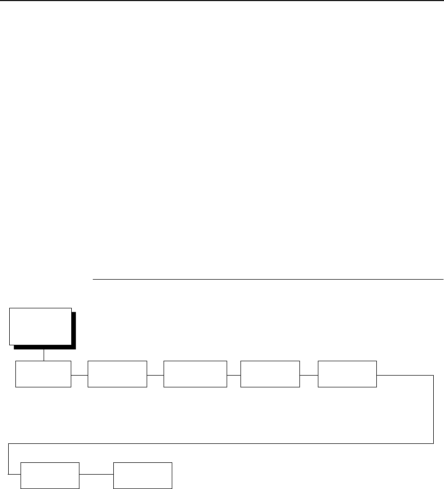
WLAN KERBEROS
117
WPA Cipher
Selects the WPA wireless security cipher setting. Options include:
•
TKIP (default)
•
AES
•
TKIP+AES
•
Disable
WPA P-Phs
Allows you to set the individual bytes of the WPA passphrase.
Reset WPA P-Phs
Allows you to reset all 32 bytes of the WPA passphrase at once.
WLAN KERBEROS
Kerberos Enable
•
Disable (default). Disables Kerberos authentication in the wireless
network interface.
•
Enable. Enables Kerberos authentication in the wireless network
interface.
WLAN
Kerberos
1
(from page 105)
Kerb.
Passwd
Kerb Pwd(01-15)
Kerb Pwd (16-30)
Kerb Pwd (31-40)
Reset
Kerb. Pwd
Ticket
Lifetime
Tckt Lifetime Units
Seconds*
Minutes
Hours
Days
Tckt Lifetime (SEC)
43200*
* = Factory Default
1
Only if a Symbol 4121 radio card is installed.
KDC Port
Number
88*
0-65535
Clock
Skew
Clock Skew Units
Seconds*
Minutes
Clock Skew (Sec)
300*
Renew
Lifetime
Renew Life Units
Seconds*
Minutes
Hours
Days
Renew Life (SEC)
0*
Kerberos
Enable
Disable*
Enable

118
Chapter 4
NETWORK SETUP Menu
Kerb. Passwd
•
Kerb. Pwd (01-15). The first 15 characters of the Kerberos password
(maximum number of characters is 40).
•
Kerb. Pwd (16-30). Characters 16 to 30 of the Kerberos password
(maximum number of characters is 40).
•
Kerb. Pwd (31-40). Characters 31 to 40 of the Kerberos password
(maximum number of characters is 40).
Reset Kerb. Pwd
Resets the Kerberos password to an empty string.
KDC Port Number
KDC (Key Distribution Center) port number is the 2-byte UDP/TCP port used
for Kerberos Communication.
The range is 0-65535, and the default is 88.
Clock Skew
Sets the maximum allowable amount of time in seconds or minutes that
Kerberos authentication will tolerate before assuming that a Kerberos
message is valid. The range for Seconds is 60-900, and the default is 300.
The range for Minutes is 1-15, and the default is 5.
Ticket Lifetime
Sets the maximum allowable amount of time in Seconds, Minutes, Hours, or
Days that a ticket obtained from the Kerberos server is valid before getting a
new one.
•
Seconds. The range is 300-259200, and the default is 43200.
•
Minutes. The range is 5-4320, and the default is 720.
•
Hours. The range is 1-72, and the default is 12.
•
Days. The range is 1-3, and the default is 1.
•
Tckt Lifetime (SEC). The ticket lifetime unit in seconds. The default is
43200.
Renew Lifetime
Sets the maximum allowable amount of time in Seconds, Minutes, Hours, or
Days before warning that a new Kerberos password is needed.
•
Seconds. The range is 0-604800, and the default is 0.
•
Minutes. The range is 0-10080, and the default is 0.
•
Hours. The range is 1-168, and the default is 0.
•
Days. The range is 0-7, and the default is 0.
•
Renew Life (SEC). Renew lifetime unit in seconds. The default is 0.
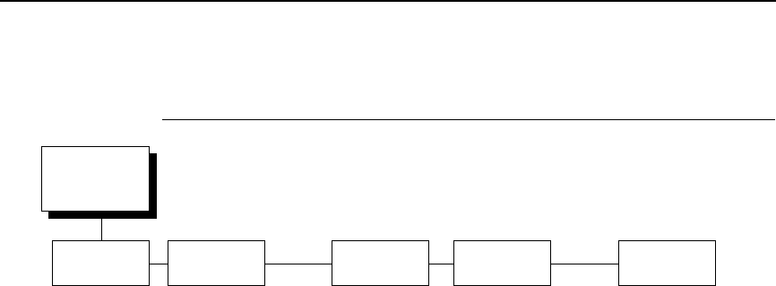
WLAN LEAP
119
WLAN LEAP
Auth Method
This feature allows the user to select the authentication method used for the
wireless network interface.
•
Open (default). Selects open authentication.
•
Shared. Selects shared key authentication.
•
LEAP. Selects LEAP authentication (for use with a Cisco RF card
installed).
LEAP Username
•
LEAP Username (01-15). The first 15 characters of the LEAP user name
(maximum number of characters is 32).
•
LEAP Username (16-30). Characters 16 to 30 of the LEAP user name
(maximum number of characters is 32).
•
LEAP User (31-32). Characters 31 to 32 of the LEAP user name
(maximum number of characters is 32).
Reset LEAP User
Resets the LEAP user name to an empty string.
LEAP Password
•
LEAP Password (01-15). The first 15 characters of the LEAP password
(maximum number of characters is 32).
•
LEAP Password (16-30). Characters 16 to 30 of the LEAP password
(maximum number of characters is 32).
•
LEAP Password (31-32). Characters 31 to 32 of the LEAP password
(maximum number of characters is 32).
Reset LEAP Password
Resets the LEAP password to an empty string.
WLAN
LEAP
2
(from page 105)
Auth Method
Open*
Shared
LEAP
1
* = Factory Default
1
Only if a Cisco radio card is installed.
LEAP
Username
Reset LEAP
User
LEAP Username (01-15)
LEAP Username (16-30)
LEAP Username (31-32)
LEAP
Password
LEAP Password (01-15)
LEAP Password (16-30)
LEAP Password (31-32)
Reset LEAP
Password
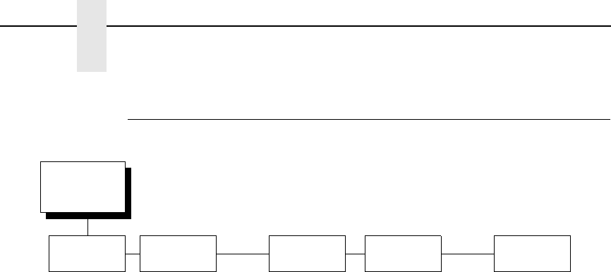
120
Chapter 4
NETWORK SETUP Menu
WLAN EAP
EAP Mode
This feature allows the user to select the mode used for the wireless network
interface.
•
None (default). EAP authentication is disabled.
•
LEAP. Selects Cisco LEAP authentication.
•
PEAP. Selects PEAP authentication.
•
TTLS. Selects TTLS authentication.
EAP Username
•
EAP Username (01-15). The first 15 characters of the EAP user name
(maximum number of characters is 32).
•
EAP Username (16-30). Characters 16 to 30 of the EAP user name
(maximum number of characters is 32).
•
EAP User (31-32). Characters 31 to 32 of the EAP user name (maximum
number of characters is 32).
Reset EAP User
Resets the EAP user name to an empty string.
EAP Password
•
EAP Password (01-15). The first 15 characters of the EAP password
(maximum number of characters is 32).
•
EAP Password (16-30). Characters 16 to 30 of the EAP password
(maximum number of characters is 32).
•
EAP Password (31-32). Characters 31 to 32 of the EAP password
(maximum number of characters is 32).
Reset EAP Password
Resets the EAP password to an empty string.
WLAN
EAP
1
(from page 105)
EAP Mode
None*
LEAP
PEAP
TTLS
* = Factory Default
1
Only if a Symbol 5127 radio card is installed.
EAP
Username
Reset EAP
User
EAP Username (01-15)
EAP Username (16-30)
EAP Username (31-32)
EAP
Password
LEAP Password (01-15)
LEAP Password (16-30)
LEAP Password (31-32)
Reset EAP
Pswd

WLAN EAP
121
ACTIVE IGP EMUL and ACTIVE EMULATIONS Menus
The emulation types present in the printer are based on the firmware installed
and the emulation options included. Both are configured from the Factory and
does not require any action from the user.
IMPORTANT
Be sure to know which type of firmware and options are purchased
(see Table 2) to understand the ACTIVE IGP EMUL, ACTIVE
EMULATION, and EMULATION main menus.
This ACTIVE IGP EMUL and ACTIVE EMULATION function allows you to
activate the desired emulation. There are two methods for selecting the
desired emulation. The first is by selecting the emulation directly from the
printer menu. The second is by sending a host command which will switch the
emulation automatically (see the appropriate Programmer's Reference
Manual for details).
When changing from one emulation to the other, the printer will load the
power-up configuration and the new emulation parameters. Any configuration
settings performed before selecting these emulations that are not saved in
NVRAM will be lost.
Table 7. Available Firmware Types and Options
Firmware Type ACTIVE IGP
EMUL
1
ACTIVE
EMULATION
2
EMULATION
3
P7000 STD
IGP/PGL* N/A
IPDS
CTHI
IPG/PGL
LinePrinter+
IGP/VGL N/A
IPDS
CTHI
IGP/VGL
LinePrinter+
P7000 TN
IGP/PGL* N/A IGP/PGL
LinePrinter+
IGP/VGL N/A IGP/VGL
LinePrinter+
NOTE:
* = Default Selection
1
The Active IGP EMULATION menu is only available when the PGL/VGL option is installed.
2
The ACTIVE EMULATION menu shows the options “IGP/PGL & LP+” and “IGP/VGL &
LP+” when the PGL/VGL option is installed. Otherwise, “LinePrinter+” replaces the options.
3
The selections under the EMULATION menu is based on the ACTIVE IGP EMULATION or
ACTIVE EMULATION settings with all Optional Emulations installed.
ACTIVE IGP EMUL and ACTIVE EMULATIONS Menus
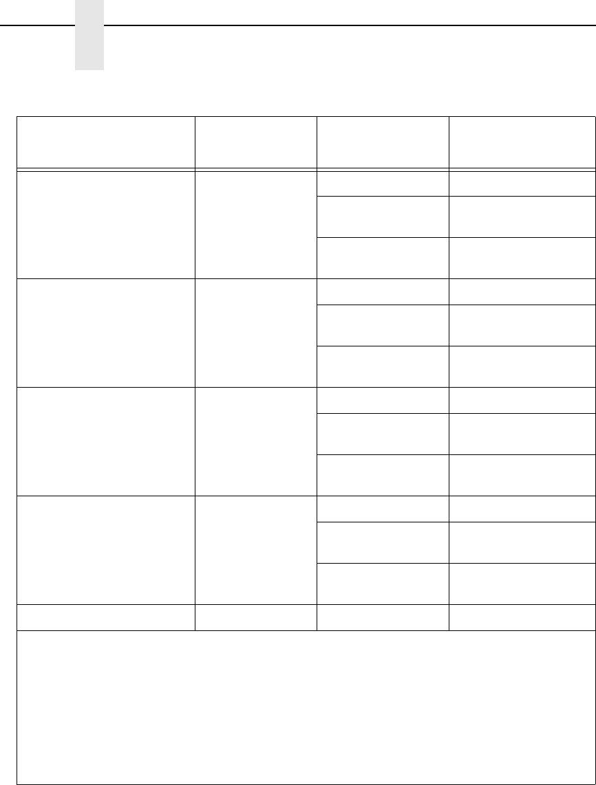
122
Chapter 4
ACTIVE IGP EMUL and ACTIVE EMULATIONS Menus
P7000 PCL-II N/A
PCL-II* PCL-II
IGP/PGL & LP+ IGP/PGL
LinePrinter+
IGP/VGL & LP+ IGP/VGL
LinePrinter+
P7000 LG N/A
LG* LG
IGP/PGL & LP+ IGP/PGL
LinePrinter+
IGP/VGL & LP+ IGP/VGL
LinePrinter+
P7000 ANSI N/A
44/48XX-ANSI* 44/48XX-ANSI
IGP/PGL & LP+ IGP/PGL
LinePrinter+
IGP/VGL & LP+ IGP/VGL
LinePrinter+
OpenPrint P7000 STD N/A
Postscript/PDF* Postscript/PDF
IGP/PGL & LP+ IGP/PGL
LinePrinter+
IGP/VGL & LP+ IGP/VGL
LinePrinter+
OpenPrint P7000 HD NA N/A Postscript/PDF
NOTE:
* = Default Selection
1
The Active IGP EMULATION menu is only available when the PGL/VGL option is installed.
2
The ACTIVE EMULATION menu shows the options “IGP/PGL & LP+” and “IGP/VGL &
LP+” when the PGL/VGL option is installed. Otherwise, “LinePrinter+” replaces the options.
3
The selections under the EMULATION menu is based on the ACTIVE IGP EMULATION or
ACTIVE EMULATION settings with all Optional Emulations installed.
Table 7. Available Firmware Types and Options
Firmware Type ACTIVE IGP
EMUL
1
ACTIVE
EMULATION
2
EMULATION
3
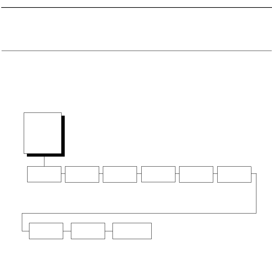
WLAN EAP
123
EMULATION Menu
The EMULATION menu allows you to configure the emulation used with your
printer. The Proprinter XL, Epson FX, P-Series, P-Series XQ, and Serial
Matrix emulations are all part of LinePrinter +. You can configure options for
the active emulation via the EMULATION menu. Emulation options are further
described in their corresponding Programmer's Reference Manual.
CTHI
1
LinePrinter+ 44/48XX-
ANSI
1
IGP/PGL
1
IGP/VGL
1
IPDS
1
page 124 page 157 page 188 page 195 page 209 page 225
* = Factory Default
1
Optional Emulation
2
OpenPrint firmware only.
PCL-II
1
page 229
LG
1
page 233
Postscript/
PDF
2
page 238
EMULATION
(from page 65,
67, 69, 71, 73,
75, and 76)
EMULATION Menu
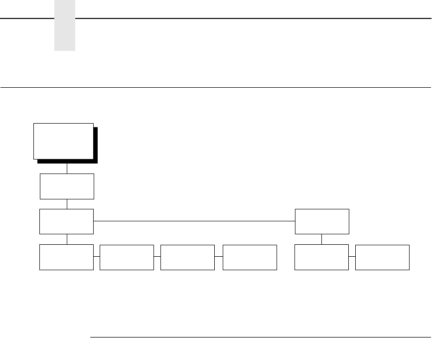
124
Chapter 4
Coax/Twinax (CTHI) Emulation
Coax/Twinax (CTHI) Emulation
Standard
With a standard coax interface, the printer emulates the following IBM coax
printer models:
•
3287 Models 1 and 2
•
4234 Model 1
With a standard twinax interface, the printer emulates the following IBM
twinax printer models:
•
4234 Models 2 and 12
•
5225 Models 1, 2, 3, and 4
NOTE: The standard Coax/Twinax emulation selection will only be available
if Coax or Twinax is selected from the HOST INTERFACE menu.
See page 87.
For more information, refer to the Coax/Twinax Programmer's Reference
Manual.
EMULATION
(from page 123)
Standard* Simp Prot
Conv
Coax
Params
Twinax
Params
SPC Coax
Params
SPC Twinax
Params
page 126 page 135 page 152 page 155
* = Factory Default
1
Coax/Twinax Host Interface.
2
Available for TN emulation only.
CTHI
1
3270
Params
2
page 141
5250
Params
2
page 148

Simple Prot Conv
125
Simple Prot Conv
The Simple Protocol Converter (SPC) option allows those who use third party
add-on Coax or Twinax protocol converters to produce the same output on a
Line Matrix printer with the Coax/Twinax (CTHI) capability as done using a
non-CT printer with the third party converter interfaces.
The SPC replaces the third party add-on protocol converters attached to older
line matrix printers.
The SPC gives the printer the operational ability to connect to any PC, or
network system supporting parallel or serial interfaces, and to three different
IBM host systems: System 3x, AS/400
®
,
and 3270 Mainframes.
The SPC will support the following third party models for Twinax: MODE 219,
MODE IBM, and MODE PROLINE.
The printer emulations supported by the SPC are Twinax 5225 and Coax
3287. The SPC also provides a range of interfaces available in your line
matrix printer: Centronics, Dataproducts, Serial, Coax, and Twinax. Also
supported are Epson, Proprinter, P-Series, Serial Matrix, IGP/VGL, and IGP/
PGL emulations.
The SPC has the ability to handle multiple print jobs concurrently through
Coax/Twinax and Parallel and Serial interfaces. This is accomplished through
the Auto Switching feature (see page 88). Because of hardware restrictions,
Coax and Twinax cannot be selected together.
For more information, consult the Coax/Twinax Programmer's Reference
Manual for the Simple Protocol Converter Option.
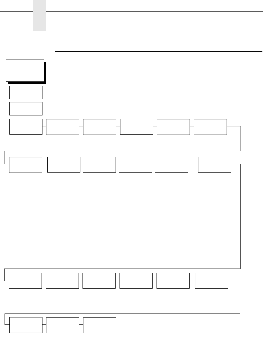
126
Chapter 4
Coax/Twinax (CTHI) Emulation
Coax Emulation
CTHI
(from page 124)
Char Set
Select
Translation
Tbl
Active Char
Set
Prt Partial
Line
PA1 PA2
Buffer
Reprint
Early Print
Cmpl
SCS Buffer
Cntrl
Cancel
IGP/DCU
PTX
Transparent
(see page 127) Secondary Set*
Primary Set
Enable*
Disable
Disable*
Enable
Don’t Wait*
Wait Until Done
Enable*
Disable
Lead-in Chars
Set 1 <%>*
Set 2 ¬¬$
Set 3 _%_
User Defined
Usr Defined HTRN
Start Code 1
5F* (40-FF)
Start Code 2
5F* (40-FF)
Stop Code
5B* (40-FF)
Alt. Set 80-9F
Printable*
Control Code
* = Factory Default
1
Valid only when the printer
emulates 3287.
Set Text
Orientn
Image Buf
Size
1
Intervention
Req
Compatibility
Op
Translate
Table
Host
Override
Format
Control
Max. Print
Width
Control By Host*
Left to Right
Right to Left
4K*
2K
Send To Host*
Do Not Send
(see page 128) Default*
Downloaded
Disable*
Enable
Disable*
Enable
13.2 inches*
Printer Width
Standard*
Coax
Params
Buffer Print
Disable*
Enable
Change
Case
Dual Case*
Mono Case

Coax Emulation
127
Char Set Select
(from page 126)
Primary
Sets
Secondary
Sets
0037 English US*
0037 Eng Nether
0285 English UK
0273 Austr/Germ
0274 Belg. Old
0275 Brazilian
0260 Canad Fren
0277 Danish
0287 Danish Alt
0278 Finnish
0288 Finn. Alt
0297 French
0500 Internat 5
0280 Italian
0281 Japan. Eng
0282 Portuguese
0284 Span Speak
0289 Span. Alt
0500 Swiss Bil
0500 Belg. New
0803 Hebrew Old
0424 Hebrew
0892 OCR A
0893 OCR B
0420 Arabic
0880 Cyril. Old
0423 Greek Old
0875 Gr New Euro
0871 Icelandic
0290 Japan Kata
0870 Latin 2
0838 Thai
1026 Turkish
0890 Yugos. Old
1097 Farsi
1025 Cyrillic
0905 Turk. Old
0256 Intern. 1
0924 Euro Lat-9
1140 Euro Eng.
1141 Euro Aust.
1142 Euro Dan.
1143 Euro Finn.
1144 Euro Ital.
1145 Euro Span.
1146 Euro UK
1147 Euro Fren.
1148 Euro Swiss
1149 Euro Ice.
English US*
English UK
Austrian/German
German (Alt)
Belgian
Brazilian
Canadian French
Danish/Norweg.
Danish (Alt)
Finnish/Swedish
Finnish (Alt)
French
International
Italian
Japanese Eng.
Japanese Katak.
Portuguese
Portug. (Alt)
Spanish
Spanish (Alt)
Spanish Speak.
Swiss Fren/Ger
Old Hebrew
Hebrew
Farsi/Latin
Greek Old
Greek New
Arabic
Turkish
Turkish Old
Latin 2/ROECE
Yugoslavian
* = Factory Default
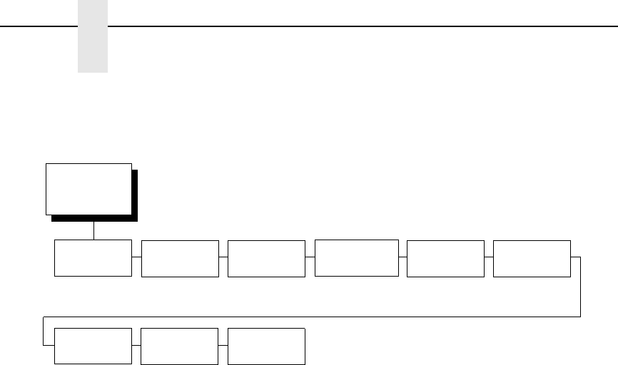
128
Chapter 4
Coax/Twinax (CTHI) Emulation
Char Set Select
Specifies the print language used by the printer. Character sets are shown in
detail in the Character Sets Reference Manual.
Translation Tbl
Prints out SCS and DSC/DSE tables of the Coax interface's current character
set. This operation is valid only when the Coax interface is selected as the
current interface (see
ΗΟΣΤ ΙΝΤΕΡΦΑΧΕ Μενυ ον παγε 87
).
Active Char Set
Selects which group of character sets (Primary or Secondary) will be active.
Secondary Set is the default.
Prt Partial Line
•
Enable (default). Forces the printer to print if a partial line is in the printer
(i.e., line not ending with a LF).
•
Disable. The last partial line of data will not be printed.
PA1
PA1 is only valid when the printer is in the offline state and the coax Systems
Network Architecture Character String (SCS) data stream is active. This
function displays the “PA1 ENABLED” message when the ENTER key is
pressed and sends a special operator request to the host when the printer is
put back in Online mode. Refer to the Coax/Twinax Programmer's Reference
Manual for more information about SCS.
NOTE: Selecting the PA1 menu item again (“PA1 DISABLED” appears on the
operator panel) or selecting the PA2 menu item will reset the pending
PA1 function.
Compatibility
Op
(from page 126)
CR At
MPP+1
NL At
MPP+1
Position Aft FF
(4234 only)
Last Char = FF Null
Suppression
FF Validity
Auto Skip
At End
FF After Job CR, EM & NL
(3287 only)
On*
Off
On*
Off
Off*
On
On*
Off
Off*
On
Off*
On
Off*
On
Off*
On
On*
Off
* = Factory Default

Coax Emulation
129
PA2
PA2 is only valid when the printer is in the Offline state and the coax SCS data
stream is active. This function displays the “PA2 ENABLED” message when
the ENTER key is pressed and sends a special operator request to the host
when the printer is put back in online mode.
NOTE: Selecting the PA2 menu item again (“PA2 DISABLED” appears on the
operator panel) or selecting the PA1 menu item will reset the pending
PA2 function.
Buffer Reprint
This option is valid only when the printer is printing in SCS mode. When the
ENTER key is pressed, “Buffer Reprint Enabled” is displayed and an
Intervention Required status is sent to the host. Pressing ENTER again
cancels the Buffer Reprint function and displays “Buffer Reprint Disabled.”
Early Print Cmpl
Allows the printer to send print (order) complete status to the host before the
printer is actually done printing all data. This option is valid only when the
printer is in DSC/DSE mode.
•
Disable (default). The printer will suppress the Early Print Complete
response until all printing is complete.
•
Enable. The printer will send an acknowledgment to the host when it is
able to accept more data.
NOTE: When Early Print Complete is enabled and an error occurs, you may
lose data.
SCS Buffer Cntrl
This option is used in Coax LU1/SCS mode only.
•
Don’t Wait (default). The printer does not wait for the job to be printed
before sending the print completion to the host.
•
Wait Until Done. The printer waits for the job to print before sending the
print completion to the host.
This option speeds up the LU1 job printing for short jobs. If you select “Don’t
Wait,” there is a risk that you may not be able to recover the print job when the
printer has fault.
Cancel IGP/DCU
•
Enable (default). Cancels all buffers when a job is put on hold from the
host or when the CANCEL key is pressed.
•
Disable. Does not cancel any internal buffer in the printer when a job is
put on hold from the host or when the CANCEL key is pressed.

130
Chapter 4
Coax/Twinax (CTHI) Emulation
PTX Transparent
Lead-in Chars
You can enable additional printer features which are not accessible through
standard Coax emulations. To access these features, send text commands in
the data stream. The commands must have a start and end code. Four sets
are available:
•
Set 1. start code: <%
stop code: >
•
Set 2. start code:
¬¬
stop code: $
•
Set 3. start code: _%
stop code: _
•
User Defined.
Usr Defined HTRN
This option is used in Twinax SPC emulation. The range is ASCII character.
This option allows users to define ther own lead-in characters for the
Printronix Specific commands. Select a hex value for the following codes for
the User Defined option:
•
Start Code 1 5F
•
Start Code 2 5F
•
Stop Code 5B
Alt. Set 80-9F
•
Printable. Prints data in the range of hex 80 through hex 9F.
•
Control Code. Interprets data in the range of hex 80 through hex 9F as a
control code.
Change Case
Specifies the font as Mono or Dual case. This option is available only in non-
SCS mode. The host will be notified of the change when the printer is placed
online. Mono Case prints the same as Dual Case if the character set is one of
the following “right to left” sets: Katak., Hebrew, Old Hebrew, and Farsi. The
default is Dual Case.
SCS (System Network Architecture Character String) mode is controlled by
the host computer.

Coax Emulation
131
Set Text Orientn
Specifies the direction in which characters are printed on the page. This
allows the printer to print languages which are printed right to left instead of
left to right.
•
Control By Host (default). Allows printers configured as a 4234 to use
the “Set Text Orientation” command from the host.
•
Left to Right.
•
Right to Left. When a right to left language is selected, the host will be
notified of print direction changes when the printer is placed online.
Image Buf Size
Allows you to select 2K or 4K as the image buffer size. This option is valid
only when the printer emulates the 3287. For the 4234 emulation, the buffer
size is fixed at 4K. A POR status is sent to the host when the printer is placed
online.
Intervention Req
•
Send to Host (default). The printer sends a signal to the host computer
when a printer fault or hold mode time-out occurs.
•
Do Not Send. No signal will be sent to the host computer.
Compatibility Op
The Compatibility Options allow you to select special printer functions in the
non-SCS mode based on the capabilities of the printer emulated.
CR At MPP+1
MPP is Maximum Print Position, which is also known as line length. This
option controls a carriage return at the end of a print line and at MPP+1.
•
On (default). Produces a carriage return to the first print position of the
next line.
•
Off. Produces a carriage return to the first print position of the current line.
NL At MPP+1
Controls how many lines are skipped when the carriage returns to a new line.
•
On (default). Moves to the first print position two lines down from the
current position.
•
Off. Moves to the first print position of the next print line.

132
Chapter 4
Coax/Twinax (CTHI) Emulation
Position Aft FF (4234 only)
Allows you to select the location of the print position after a form feed
command is sent.
•
On (default). Sets the printer to print at print position 1 of the first print line
on the next form.
•
Off. Sets the printer to print at print position 2 of the first print line on the
next form.
Last Char = FF
Determines the print line position when a form feed command is the last code
encountered in the print buffer.
•
On (default). Moves to the first print position on the second line of the next
form.
•
Off. Moves to the first print position on the first line of the next form.
NOTE: This option is ignored if Auto Skip At End is on.
If configured as a 3287, and a form feed occurs in the middle of a print buffer,
the printer defaults to the first print position on the second line of the next form
regardless of the setting of this option.
Null Suppression
•
Off (default). Ignores nulls. The print position does not move.
•
On. Treats nulls as blank spaces.
FF Validity
Determines if the position of a form feed command affects its execution.
•
Off (default). Performs a form feed only if it occurs at the first print
position in a line or at Maximum Print Position +1. A form feed command
at any other position is recognized as a space.
•
On. Allows the printer to perform a form feed command anywhere in the
data stream.
Auto Skip At End
Specifies whether or not to perform an automatic form feed at the end of a
print buffer. If form feed is the last character in the print order, the form feed
function is supplied by the Auto Skip At End option.
•
Off (default). Sets the printer to print at print position 1 of the next line.
•
On. Sets the printer to print at print position 1 of the first line of the next
form.

Coax Emulation
133
FF After Job
Determines the print position after an operator-initiated local copy (print
screen function).
•
Off (default). Performs an automatic new line command after completing
a print buffer (unless a new line, form feed, or carriage return command
was the last one executed). The printer is set to print at print position 1 of
the next line.
•
On. Performs an automatic form feed command unless a form feed was
the last one executed. The printer is set to print at print position 1 of the
first line on the next form.
CR, EM, & NL (3287 only)
CR (Carriage Return), EM (Error Message), and NL (New Line) specify that
the printer treat the CR, EM, and NL control codes either as spaces or as
control codes.
•
On (default). Treats the CR, EM, and NL commands as control codes.
•
Off. Treats the CR, EM, and NL commands as spaces.
Translate Table
Defines which translate table to use for printing.
•
Default (default). Translates data by using the default table of the current
character set.
•
Downloaded. Translates data from EBCDIC to internal code by using the
downloaded translate table.
Host Override
Determines whether the printer accepts certain commands sent by the host or
continues to use the current operator panel settings.
•
Disable (default). Allows the following host commands to override
operator panel settings: line length, forms length, lines per inch (LPI),
characters per inch (CPI), print quality, and text orientation. Note the
information appearing on the message display may not match the data
stream setting. No values will change upon initial selection of the disable
option.
•
Enable. The operator panel settings override the host commands.
Format Control
Enables the printer to reflect the same spacing as CTPC model printers after
absolute and relative move commands are executed.
•
Disable (default). Reflects distance, generated by the IGP/VGL feature,
IGP/PGL feature, and Hex Transparent control code sequence, in the
new position (after horizontal and vertical tabs are executed).
•
Enable. Does not reflect distance, generated by the IGP/VGL feature,
IGP/PGL feature, and Hex Transparent control code sequence, in the
new position (after horizontal and vertical tabs are executed).

134
Chapter 4
Coax/Twinax (CTHI) Emulation
Max. Print Width
Set the maximum print width at either 13.2 inches or the maximum width of
the printer. The default is 13.2 inches.
Buffer Print
•
Disable (default). The printer will print normally.
•
Enable. The printer prints the EBCDIC data and control codes received
from the host as hex values. Refer to page 285 for information on how to
obtain a hex code printout.
NOTE: Use of this parameter may alter print attributes set by the host
computer. A power cycle may be required after changing Buffer Print
from enable to disable.
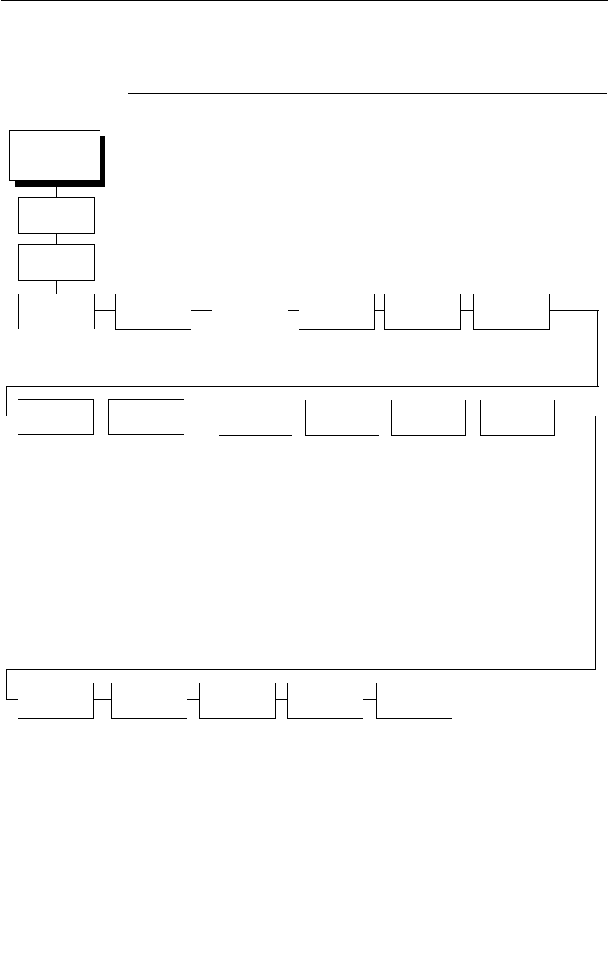
Twinax Params
135
Twinax Params
CTHI
(from page 124)
Char Set
Select
Active Char
Set
Prt Partial
Line
Device ID Device
Address
(see page 136) Secondary Set*
Primary Set
Enable*
Disable
IPDS*
5225
4234-2
Address 1*
Address (0-6)
Standard Char*
Extended Char
Lead-in Chars
Set 1 <%>*
Set 2 ¬¬$
Set 3 _%_
User Defined
Usr Defined HTRN
Start Code 1
5F* (40-FF)
Start Code 2
5F* (40-FF)
Stop Code
5B* (40-FF)
Alt. Set 80-9F
Printable*
Control Code
Enable*
Disable
60*
(40-FE hex)
* = Factory Default
Standard*
Twinax
Params
Set Text
Orientn
Host
Override
Format
Control
Max. Print
Width
Control By Host*
Left to Right
Right to Left
Disable*
Enable
Disable*
Enable
13.2 inches*
Printer Width
Buffer
Print
Disable*
Enable
Graphic Chek
Err
Graphic Chek
Cod
Cancel
IGP/DCU
Enable*
Disable
PTX
Transparent
5225 World
Trade
Enable*
Disable
LAC Option
On*
Off
LAC
Approx.

136
Chapter 4
Coax/Twinax (CTHI) Emulation
* = Factory Default
Char Set Select
(from page 135)
Primary
Sets
Secondary
Sets
0037 English US*
0037 Eng Nether
0500 Swiss Bil
0500 Belg. New
0273 Austr/Germ
0274 Belg. Old
0275 Brazilian
0260 Canad Fren
0277 Danish
0278 Finnish
0297 French
0280 Italian
0281 Japan. Eng
0282 Portuguese
0284 Span Speak
0285 English UK
0892 OCR A
0893 OCR B
0424 Hebrew
0803 Hebrew Old
0420 Arabic
0880 Cyril. Old
0423 Greek Old
0875 Gr New Euro
0871 Icelandic
0290 Japan Kata
0870 Latin 2
0838 Thai
1026 Turkish
0890 Yugos. Old
1097 Farsi
1025 Cyrillic
0256 Intern. 1
1112 Balt Mult
0924 Euro Latin-9
1122 Estonian
1140 Euro Eng.
1141 Euro Aust.
1142 Euro Dan.
1143 Euro Finn.
1144 Euro Ital.
1145 Euro Span.
1146 Euro UK.
1147 Euro Fren.
1148 Euro Swiss
1149 Euro Ice.
0500 Internat 5
English US*
Austrian/German
Belgian
Brazilian
Canadian French
Danish/Norweg.
Finnish/Swedish
French
Italian
Japanese Eng.
Japanese Katak.
Portuguese
Spanish
Spanish Speak.
English UK
Old Hebrew
Hebrew
Farsi/Latin
Greek Old
Greek New
Arabic
Turkish
Latin 2/ROECE
Yugoslavian
Multinational

Twinax Params
137
Char Set Select
Specifies the print language used by the printer. Character sets are shown in
detail in the Character Sets Reference Manual.
Active Char Set
This option selects which group of character sets (Primary or Secondary) will
be active. Secondary Set is the default.
Prt Partial Line
•
Enable (default). Forces the printer to print a partial line (i.e., line not
ending with a LF) before moving to the top of form on the next page.
•
Disable. The last partial line of data will not be printed.
Device ID
This parameter defines the printer emulation as IPDS, 5225, or 4234-2. After
the emulation has been changed, a POR status is sent to the host. IPDS is
the default.
Device Address
Allows you to set the device address from 0 through 6. The host directs data
and commands on the twinax line to a specific device based on its unique
device address. After the address has been changed, a POR status is sent to
the host.
5225 World Trade
The 5225 emulation has a standard multinational character set that serves as
a base and 14 extended world trade character set assortments.
Cancel IGP/DCU
•
Enable (default). Cancels all buffers when a job is put on hold from the
host or the CANCEL key is pressed.
•
Disable. Does not cancel any internal buffer in the printer when a job is
put on hold from the host or the CANCEL key is pressed.

138
Chapter 4
Coax/Twinax (CTHI) Emulation
PTX Transparent
Lead-in Chars
You can enable additional features that are not available in standard Twinax
emulations. To access these features, send text commands in the data
stream. The commands must have a start and end code. Three sets (each
containing a start and end code) are available:
•
Set 1. start code: <%
stop code: >
•
Set 2. start code:
¬¬
stop code: $
•
Set 3. start code: _%
stop code: _
•
User Defined
Usr Defined HTRN
This option is used in Twinax SPC emulation. The range is ASCII character.
This option allows users to define ther own lead-in characters for the
Printronix Specific commands. Select a hex value for the following codes for
the User Defined option:
•
Start Code 1 5F
•
Start Code 2 5F
•
Stop Code 5B
Alt. Set 80-9F
•
Printable (default). Prints data in the range of hex 80 through hex 9F.
•
Control Code. Interprets data in the range of hex 80 through hex 9F as a
control code.
Graphic Chek Err
Allows overriding of the host setting for the SGEA (Set Graphic Error Action)
command. For more information about the SGEA command, refer to the
Coax/Twinax Programmer's Reference Manual.
•
Enable (default). The host setting for the SGEA used by the printer. If the
SGEA command is requested to stop on graphic errors, the printer will
stop when a graphic error is detected.
•
Disable. Ignores the SGEA command from the host. The printer does not
stop when an error is detected; instead, it substitutes the character
selected in the Graphic Chek Code parameter.

Twinax Params
139
Graphic Chek Cod
Specifies the replacement character to print in place of any unprintable
character that is received from the host. Choose a hex character from 40
through FE. The character becomes the printer default when:
•
the printer is powered off and then powered on;
•
an SGEA command specifies to use the operator panel default;
•
the Graphic Chek Err parameter is disabled.
LAC Option
Allows the host system to load alternate character images into the printer.
This may be used for designing graphics, barcodes, and charts, or for printing
in foreign languages.
•
Enable (default). Prints the LAC character as defined.
•
Disable. Ignores the LAC definition from the host and prints from the
currently selected character set.
LAC Approx.
A process that reorganizes columns of dots so that clean, readable printing is
possible.
•
On (default). Converts the emulated character cells to standard cells for
the P7224 model.
•
Off. Converts character cells byte by byte and not by LAC approximation.
Set Text Orientn
Specifies the direction in which characters are printed on the page. This
allows the printer to print languages that are printed right to left instead of left
to right. The options include:
•
Control By Host (default)
•
Left to Right
•
Right to Left
Host Override
Determines whether the printer accepts certain commands sent by the host or
continues to use the current operator panel settings.
•
Disable (default). Allows the following host commands to override
operator panel settings: line length, forms length, lines per inch (LPI),
characters per inch (CPI), print quality, and text orientation. Note the
information appearing on the message display may not match the data
stream setting. No values will change upon initial selection of the disable
option.
•
Enable. The operator panel settings override the host commands.
NOTE: Host margin and tab settings will take precedence whether or not
Host Override is enabled.

140
Chapter 4
Coax/Twinax (CTHI) Emulation
Format Control
Enables the printer to reflect the same spacing as CTPC model printers after
absolute and relative move commands are executed.
•
Disable (default). Reflects distance, generated by the IGP/VGL feature,
IGP/PGL feature, and Hex Transparent control code sequence, in the
new position (after absolute and relative move commands are executed).
•
Enable. Does not reflect distance, generated by the IGP/VGL feature,
IGP/PGL feature, and Hex Transparent control code sequence, in the
new position (after absolute and relative move commands are executed).
Max. Print Width
Set the maximum print width at either 13.2 inches or the maximum width of
the printer. The default is 13.2 inches.
Buffer Print
•
Disable (default). The printer will print normally.
•
Enable. The printer prints the EBCDIC data and control codes received
from the host as hex values. Refer to page 285 for information on how to
obtain a hex code printout.
NOTE: Use of this parameter may alter print attributes set by the host
computer. A power cycle may be required after changing Buffer Print
from enable to disable.
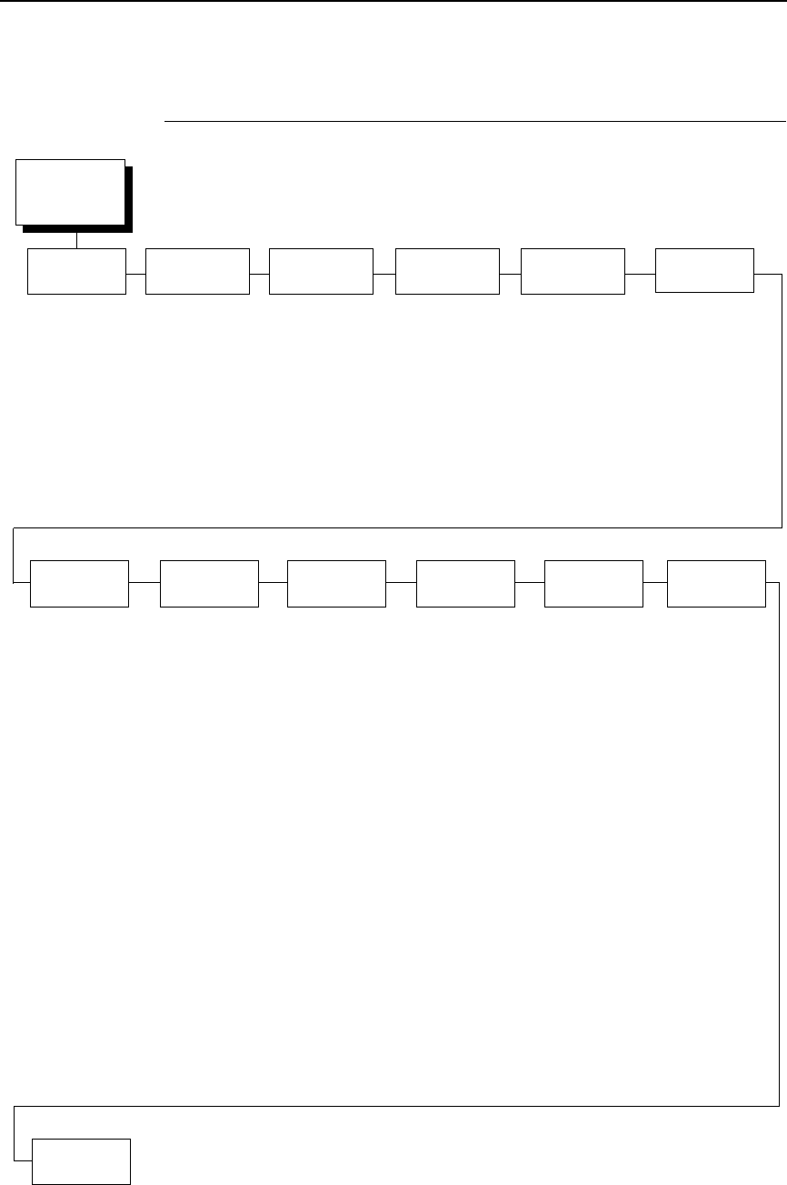
3270 Params
141
3270 Params
3270
Params
1
(from page 124)
Char Set
Select
(see page 142)
Translation
Tbl
Prt Partial
Line
Enable*
Disable
PTX
Transparent
Lead-in Chars
Set 1 <%>*
Set 2 ¬¬$
Set 3 _%_
User Defined
Usr Defined HTRN
Start Code 1*
Start Code 2
Stop Code
Alt. Set 80-9F
Printable*
Control Code
Host
Override
Disable*
Enable
Format
Control
Disable*
Enable
Change
Case
Left to Right*
Right to Left
Set Text
Orientn
Send to Host*
Do Not Send
Intervention
Req
Compatibility
Op
Max. Print
Width
13.2 inches*
Printer Width
CR At MPP + 1
On*
Off
NL At MPP + 1
On*
Off
Position Aft FF
On*
Off
Last Char = FF
On*
Off
Null Suppression
Off*
On
FF Validity
Off*
On
Auto Skip At End
Off*
On
FF After Job
Off*
On
CR, EM, & NL
On*
Off
Dual Case*
Mono Case
Active Char
Set
Secondary Sets*
Primary Sets*
Early Print
Cmpl
Disable*
Enable
* = Factory Default
1
This menu appears only if the TN3270 option is installed.
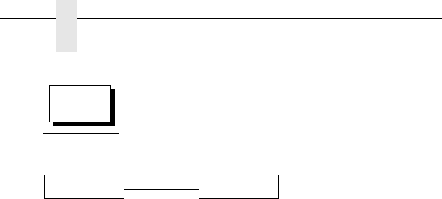
142
Chapter 4
Coax/Twinax (CTHI) Emulation
* = Factory Default
3270
Params
Primary Sets
0037 English US*
0037 Eng Nether
0285 English UK
0273 Austr/Germ
0274 Belg. Old
0275 Brazilian
0260 Canad Fren
0277 Danish
0287 Danish Alt
0278 Finnish
0288 Finn. Alt
0297 French
0500 Internat 5
0280 Italian
0281 Japan. Eng
0282 Portuguese
0284 Span Speak
0289 Span. Alt
0500 Swiss Bil
0500 Belg. New
0803 Hebrew Old
0424 Hebrew
0892 ORC A
0893 ORC B
0420 Arabic
0880 Cyril. Old
0423 Greek Old
0875 Gr New Euro
0871 Icelandic
0290 Japan Katak
0870 Latin 2
0838 Thai
1026 Turkish
0890 Yugos. Old
1097 Farsi
1025 Cyrillic
0905 Turk. Old
0256 Intern. 1
0924 Euro Lat-9
1140 Euro Eng.
1141 Euro Aust.
1142 Euro Dan.
1143 Euro Finn.
1144 Euro Ital.
1145 Euro Span.
1146 Euro UK
1147 Euro Fren.
1148 Euro Swiss
1149 Euro Ice.
Char Set Select
(from page 141)
Secondary Sets
English US*
English UK
Austrian/German
German (Alt)
Belgian
Brazilian
Canadian French
Danish/Norweg.
Danish (Alt)
Finnish/Swedish
Finnish (Alt)
French
International
Italian
Japanese Eng.
Japanese Katak.
Portuguese
Portug. (Alt)
Spanish
Spanish (Alt)
Spanish Speak.
Swiss Fren/Ger
Old Hebrew
Hebrew
Farsi/Latin
Greek Old
Greek New
Arabic
Turkish
Turkish Old
Latin 2/ROECE
Yugoslavian

3270 Params
143
Translation Tbl
Prints out a table of the Coax interface’s current character set. This operation
is valid only when the TN3270 interface is the current interface.
Active Char Set
Specifies which character language set will be the active set.
•
Secondary Sets (default)
•
Primary Sets
Prt Partial Line
•
Enable (default). When this option is enabled, it forces the printer to print
if a partial line is in the printer (i.e. line not ending with a LF).
•
Disable. When disabled, the last partial line of data will not be printed.
Early Print Cmpl
Early Print Complete allows the printer to send Print Complete status to the
host before the printer is actually done printing all data. Early Print Complete
is only available if the IPDS feature is installed.
•
Disable (default). Means the printer will suppress the Early Print
Complete response until all printing is complete.
•
Enable. Means the printer will send an acknowledgement to the host
when it is able to accept more data.
NOTE: When an Early Print Complete is enabled and an error occurs, the
data in the printer will remain in the buffer (regardless of the setting of
the Cancel Buffer option). It is recommended that local procedures be
followed to recover from the error.
Do not select Early Print Complete while a print job is in progress. If
this is done you will need to restart the printer.
PTX Transparent
Lead-in Chars
You can enable additional printer features which are not accessible through
standard TN3270 emulations. To access these features, send text commands
in the data stream. The commands must have a start and end code. Four sets
are available:
•
Set 1. start code: <% (default)
stop code: >
•
Set 2. start code:
¬¬
stop code: $
•
Set 3. start code: _%
stop code: _
•
User Defined.

144
Chapter 4
Coax/Twinax (CTHI) Emulation
Usr Defined HTRN
This option is used to set user defined lead-in characters. The range is ASCII
character. This option allows users to define ther own lead-in characters for
the Printronix Specific commands. Select a hex value for the following codes
for the User Defined option:
•
Start Code 1 5F (default)
•
Start Code 2 5F
•
Stop Code 5B
Alt. Set 80-9F
•
Printable (default). Prints data in the range of hex 80 through hex 9F.
•
Control Code. Interprets data in the range of hex 80 through hex 9F as a
control code.
Change Case
Specifies the font as Mono or Dual case. This option is available only in non-
SCS mode. The host will be notified of the change when the printer is placed
online. Mono Case prints the same as Dual Case if the character set is one of
the following “right to left” sets: Katak., Hebrew, Old Hebrew, and Farsi.
SCS (System Network Architecture Character String) mode is controlled by
the host computer.
•
Dual Case (default)
•
Mono Case
Set Text Orientn
Specifies the direction in which characters are printed on the page. This
allows the printer to print languages which are printed right to left instead of
left to right.
•
Left to Right (default).
•
Right to Left. When a right to left language is selected, the host will be
notified of print direction changes when the printer is put online.
Intervention Req
Select from the following:
•
Send To Host (default). The printer sends a signal to the host computer
when any of the following occur:
•
Printer faults occur.
•
Hold mode time–out occurs.
•
Not Send To Host
If not selected, the printer will only send the signal on printer faults that cause
data loss (paper jam, ribbon stall, online platen open, etc.).

3270 Params
145
Compatibility Op
The Compatibility Options allow you to select special printer functions in the
non-SCS mode based on the capabilities of the printer emulated.
CR At MPP+1
MPP is Maximum Print Position, which is also known as line length. This
option controls a carriage return at the end of a print line and at MPP+1.
•
On (default). Produces a carriage return to the first print position of the
next line.
•
Off. Produces a carriage return to the first print position of the current line.
NL At MPP+1
Controls how many lines are skipped when the carriage returns to a new line.
•
On (default). Moves to the first print position two lines down from the
current position.
•
Off. Moves to the first print position of the next print line.
Position Aft FF (4234 only)
Allows you to select the location of the print position after a form feed
command is sent.
•
On (default). Sets the printer to print at print position 1 of the first print line
on the next form.
•
Off. Sets the printer to print at print position 2 of the first print line on the
next form.
Last Char = FF
Determines the print line position when a form feed command is the last code
encountered in the print buffer.
•
On (default). Moves to the first print position on the second line of the next
form.
•
Off. Moves to the first print position on the first line of the next form.
NOTE: This option is ignored if Auto Skip At End is on.
If configured as a 3287, and a form feed occurs in the middle of a print buffer,
the printer defaults to the first print position on the second line of the next form
regardless of the setting of this option.
Null Suppression
•
Off (default). Ignores nulls. The print position does not move.
•
On. Treats nulls as blank spaces.

146
Chapter 4
Coax/Twinax (CTHI) Emulation
FF Validity
Determines if the position of a form feed command affects its execution.
•
Off (default). Performs a form feed only if it occurs at the first print
position in a line or at Maximum Print Position +1. A form feed command
at any other position is recognized as a space.
•
On. Allows the printer to perform a form feed command anywhere in the
data stream.
Auto Skip At End
Specifies whether or not to perform an automatic form feed at the end of a
print buffer. If form feed is the last character in the print order, the form feed
function is supplied by the Auto Skip At End option.
•
Off (default). Sets the printer to print at print position 1 of the next line.
•
On. Sets the printer to print at print position 1 of the first line of the next
form.
FF After Job
Determines the print position after an operator-initiated local copy (print
screen function).
•
Off (default). Performs an automatic new line command after completing
a print buffer (unless a new line, form feed, or carriage return command
was the last one executed). The printer is set to print at print position 1 of
the next line.
•
On. Performs an automatic form feed command unless a form feed was
the last one executed. The printer is set to print at print position 1 of the
first line on the next form.
CR, EM, and NL (3287 only)
CR (Carriage Return), EM (Error Message), and NL (New Line) specify that
the printer treat the CR, EM, and NL control codes either as spaces or as
control codes.
•
On (default). Treats the CR, EM, and NL commands as control codes.
•
Off. Treats the CR, EM, and NL commands as spaces.
Host Override
Determines whether the printer accepts certain commands sent by the host,
or continues to use the current operator panel settings.
•
Disable (default). Allows these host commands to override operator
panel settings: line length, forms length, lines per inch (LPI), characters
per inch (CPI), print quality, and text orientation. Note the information
appearing on the message display may not match the data stream
setting. No values will change upon initial selection of the disable option.
•
Enable. The operator panel settings override the host commands.

3270 Params
147
Format Control
Enables the printer to reflect the same spacing as CTPC model printers after
absolute and relative move commands are executed.
•
Disable (default). Reflects distance, generated by the VGL feature, PGL
feature, and Hex Transparent control code sequence, in the new position
(after horizontal and vertical tabs are executed).
•
Enable.
Max. Print Width
Set the maximum print width the printer will print when using a C/T host
interface. Set for 13.2 inches when printing files larger than the width of the
printer. All data exceeding the width of the maximum Printer Width will be
truncated.
•
13.2 inches (default)
•
Printer Width (the maximum width of the printer)
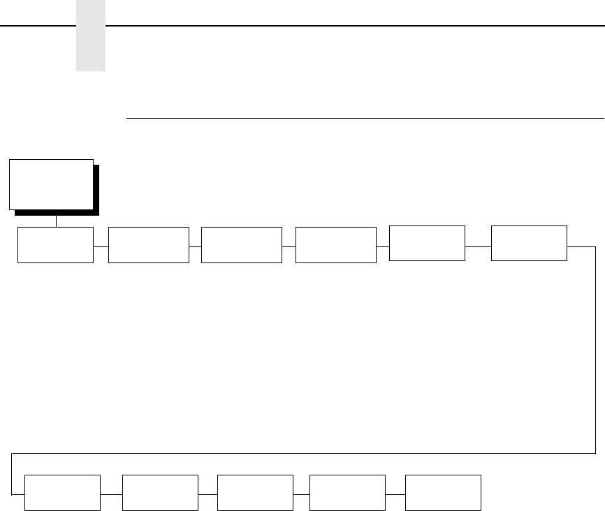
148
Chapter 4
Coax/Twinax (CTHI) Emulation
5250 Params
5250
Params
1
(from page 124)
Char Set
Select
(see page 149)
Translation
Tbl
Active Char
Set
Secondary Set*
Primary Set
Prt Partial
Line
Enable*
Disable
PTX
Transparent
Lead-in Chars
Set 1 <%>*
Set 2 ¬¬$
Set 3 _%_
User Defined
Usr Defined HTRN
Start Code 1*
Start Code 2
Stop Code
Alt. Set 80-9F
Printable*
Control Code
Enable*
Disable
Max. Print
Width
13.2 inches*
Printer Width
Graphic
Chek Err
60*
40-FE
Graphic
Chek Cod
Left to Right*
Right to Left
Set Text
Orientn
Disable*
Enable
Host
Override
Disable*
Enable
Format
Control
* = Factory Default
1
This menu appears only if the TN5250 option is installed.
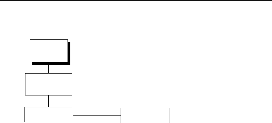
5250 Params
149
0037 English US*
0037 Eng Nether
0500 Swiss Bil
0500 Belg. New
0273 Austr/Germ
0274 Belg. Old
0275 Brazilian
0260 Canad Fren
0277 Danish
0278 Finnish
0297 French
0280 Italian
0281 Japan. Eng
0282 Portuguese
0284 Span Speak
0285 English UK
0892 OCR A
0893 OCR B
0424 Hebrew
0803 Hebrew Old
0420 Arabic
0880 Cyril. Old
0423 Greek Old
875 Gr New Euro
0871 Icelandic
0290 Japan Kata
0870 Latin 2
0838 Thai
1026 Turkish
0890 Yugos. Old
1097 Farsi
1025 Cyrillic
0256 Intern. 1
1112 Balt Mult
0924 Euro Lat-9
1122 Estonian
1140 Euro Eng.
1141 Euro Aust.
1142 Euro Dan.
1143 Euro Finn.
1144 Euro Ital.
1145 Euro Span.
1146 Euro UK
1147 Euro Fren.
1148 Euro Swiss
1149 Euro Ice.
0500 Internat 5
* = Factory Default
5250
Params
Primary Sets Secondary Sets
English US*
Austrian/German
Belgian
Brazilian
Canadian French
Danish/Norweg.
Finnish/Swedish
French
Italian
Japanese Eng.
Japanese Katak.
Portuguese
Spanish
Spanish Speak.
English UK
Old Hebrew
Hebrew
Farsi/Latin
Greek Old
Greek New
Arabic
Turkish
Latin 2/ROECE
Yugoslavian
Multinational
Char Set Select
(from page 148)

150
Chapter 4
Coax/Twinax (CTHI) Emulation
Translation Tbl
Prints out a table of the TN5250 interface’s current character set. This
operation is valid only when the TN5250 interface is the current interface.
Active Char Set
Selects which group of character sets (Primary or Secondary) will be active.
•
Secondary Set (default)
•
Primary Set
Prt Partial Line
•
Enable (default). When this option is enabled, it forces the printer to print
if a partial line is in the printer (i.e. line not ending with a LF).
•
Disable. When disabled, the last partial line of data will not be printed.
PTX Transparent
Lead-in Chars
You can enable additional printer features which are not accessible through
standard TN5250 emulations. To access these features, send text commands
in the data stream. The commands must have a start and end code. Four sets
are available:
•
Set 1. start code: <% (default)
stop code: >
•
Set 2. start code:
¬¬
stop code: $
•
Set 3. start code: _%
stop code: _
•
User Defined.
Usr Defined HTRN
This option is used to set user defined lead-in characters. The range is ASCII
character. This option allows users to define ther own lead-in characters for
the Printronix Specific commands. Select a hex value for the following codes
for the User Defined option:
•
Start Code 1 5F (default)
•
Start Code 2 5F
•
Stop Code 5B
Alt. Set 80-9F
•
Printable (default). Prints data in the range of hex 80 through hex 9F.
•
Control Code. Interprets data in the range of hex 80 through hex 9F as a
control code.

5250 Params
151
Graphic Chek Err
Allows overriding of the host setting for the SGEA (Set Graphic Error Action)
command. For more information about the SGEA command, refer to the
Coax/Twinax Programmer's Reference Manual.
•
Enable (default). The host setting for the SGEA used by the printer. If the
SGEA command is requested to stop on graphic errors, the printer will
stop when a graphic error is detected.
•
Disable. Ignores the SGEA command from the host. The printer does not
stop when an error is detected; instead, it substitutes the character
selected in the Graphic Chek Code parameter.
Graphic Chek Cod
Specifies the replacement character to print in place of any unprintable
character that is received from the host. Choose a hex character from 40
through FE. The character becomes the printer default when:
•
The printer is powered off and then powered on.
•
An SGEA command specifies to use the operator panel default.
•
The Graphic Chek Err parameter is disabled.
The value can be the following:
•
60 (default)
•
40 – F4
Set Text Orientn
Specifies the direction in which characters are printed on the page. This
allows the printer to print languages which are printed right to left instead of
left to right.
•
Left to Right (default)
•
Right to Left. When a right to left language is selected, the host will be
notified of print direction changes when the printer is put online.
Host Override
Determines whether the printer accepts certain commands sent by the host,
or continues to use the current operator panel settings.
•
Disable (default). Allows these host commands to override operator
panel settings: line length, forms length, lines per inch (LPI), characters
per inch (CPI), print quality, and text orientation. Note the information
appearing on the message display may not match the data stream
setting. No values will change upon initial selection of the disable option.
•
Enable. The operator panel settings override the host commands.
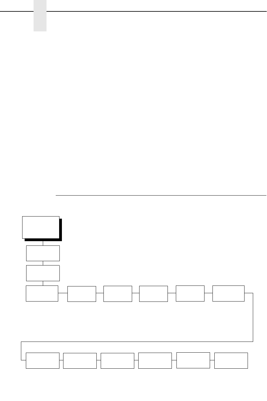
152
Chapter 4
Coax/Twinax (CTHI) Emulation
Format Control
Enables the printer to reflect the same spacing as CTPC model printers after
absolute and relative move commands are executed.
•
Disable (default). Reflects distance, generated by the VGL feature, PGL
feature, and Hex Transparent control code sequence, in the new position
(after horizontal and vertical tabs are executed).
•
Enable.
Max. Print Width
Set the maximum print width the printer will print when using a C/T host
interface. Set for 13.2 inches when printing files larger than the width of the
printer. All data exceeding the width of the maximum Printer Width will be
truncated.
•
13.2 Inches (default)
•
Printer Width (the maximum width of the printer)
SPC Coax Params
CTHI
(from page 124)
Logical Buf
Size
PA1 PA2 Buffer
Reprint
SPC
Null Supp
1920*
960
2560
3440
3564
Send to Host*
Do Not Send
Disable*
Enable
Disable*
Enable
Enable*
Disable
* = Factory Default
1
Option needs to be selected
Simp Prot
Conv
1
SPC Coax
Params
NL At
MPP+1
On*
Off
Intervention
Req
Buffer Print Translation
Tbl
Column 132
Wrap
Start Code 1
Start Code 2
Stop Code
Usr Defined
HTRN
SPC
Space Supp
Disable*
Enable

SPC Coax Params
153
Logical Buf Size
Refers to the size of the printer buffer, which should be set the same as the
host screen (buffer) size. If the host screen size is unknown, use 1920. Do not
change this parameter in the middle of a print job.
Intervention Req
•
Send to Host (default). The printer sends a signal to the host computer
when the CANCEL key is pressed or a printer fault or hold mode time-out
occurs.
•
Do Not Send. No signal will be sent to the host computer.
Buffer Print
•
Disable (default). The printer will print normally.
•
Enable. The printer prints the EBCDIC data and control codes received
from the host as hex values. Refer to page 285 for information on how to
obtain a hex code printout.
Translation Tbl
Prints a table of the Coax interface's current character set. This operation is
valid only when the Coax interface is selected (see
ΗΟΣΤ ΙΝΤΕΡΦΑΧΕ
Μενυ ον παγε 87
).
Column 132 Wrap
When enabled, this option causes the printer to line wrap at 132 characters
despite the current print density, allowing more characters per line. The
options include:
•
Disable (default)
•
Enable
Usr Defined HTRN
This option is used in Twinax SPC emulation. The range is ASCII character.
This option allows users to define ther own lead-in characters for the
Printronix Specific commands. Select a hex value for the following codes for
the User Defined option:
•
Start Code 1 5F
•
Start Code 2 5F
•
Stop Code 5B
PA1
PA1 is only valid when the printer is in the offline state and the Coax Systems
Network Architecture Character String (SCS) data stream is active. This
function displays the “PA1 ENABLED” message when the ENTER key is
pressed and sends a special operator request to the host when the printer is
placed online. Refer to the Coax/Twinax Programmer's Reference Manual for
more information about SCS.

154
Chapter 4
Coax/Twinax (CTHI) Emulation
PA2
PA2 is only valid when the printer is in the OFFLINE state and the Coax SCS
data stream is active. This function displays the “PA2 ENABLED” message
when the ENTER key is pressed and sends a special operator request to the
host when the printer is placed ONLINE.
Buffer Reprint
This option is valid only when the printer is printing in SCS mode. When the
ENTER key is pressed, “Buffer Reprint Enabled” is displayed and an
Intervention Required status is sent to the host. Pressing ENTER again
cancels the Buffer Reprint function and “Buffer Reprint Disabled” is displayed.
SPC Null Supp
•
Enable (default). Treats nulls as blank spaces.
•
Disable. Ignores nulls. The print position does not move.
SPC Space Supp
This option is only available in Coax SPC emulation and is used in LU3/DSC/
DSE mode only.
•
Disable (default). Treats nulls and spaces normally.
•
Enable. If the entire line consists of spaces and nulls, the line will be
discarded.
NL At MPP+1
Controls how many lines are skipped when the carriage returns to a new line.
•
On (default). Moves to the first print position two lines down from the
current position.
•
Off. Moves to the first print position of the next print line.
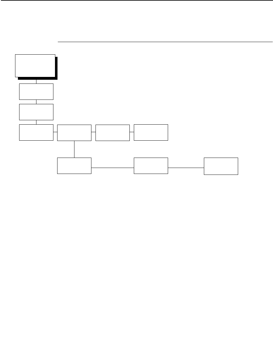
SPC Twx Params
155
SPC Twx Params
NOTE: To access the SPC Twinax Params menu, be sure to select the
Twinax option in the Host Interface menu.
Device Address
Allows you to set the device address from 0 through 6. The host directs data
and commands on the twinax line to a specific device based on its unique
device address. After the address has been changed, a POR status is sent to
the host.
Disable*
Enable
CTHI
(from page 124)
Device
Address
SPC Type Translation
Tbl
Buffer Print
MODE
219*
MODE
P5000
MODE
IBM
Address 1*
Address (0-6)
Printer Type
Impact/P-Series*
STD Centronics
IGP/VGL
IGP/PGL
SFCC Char
Logical Not*
Caret (^)
User Defined
User Defined HTRN
Start Code 1
Start Code 2
Stop Code
EVFU
Enable*
Disable
SPC Char Set
Multinational*
Austrian/German
Belgian
Canadian French
Danish/Norweg.
French
Spanish
English US
SPC Char Set
0500 Internat 5*
0037 English US
0273 Austr/Germ
0274 Belg. Old
0275 Brazilian
0260 Canad Fren
0277 Danish
0278 Finnish
0297 French
0280 Italian
0281 Japan. Eng
0290 Japan Kata
0282 Portuguese
0284 Span Speak
0285 English UK
SFCC Char
Logical Not*
Caret (^)
User Defined
User Defined HTRN
Start Code 1
Start Code 1
Stop Code
* = Factory Default
Simp Prot
Conv
SPC Twinax
Params

156
Chapter 4
Coax/Twinax (CTHI) Emulation
SPC Type
Allows you to select a specific type of Simple Protocol Convertor (SPC)
Twinax emulation: MODE 219 for Model 219 protocol convertor, MODE
P5000 for Printronix protocol convertor, and MODE IBM for the IBM protocol
convertor.
Printer Type
Determines the SPC Twinax emulation “Mode.” When set to Std Centronics,
IGP/VGL, or IGP/PGL, the Set Line Density and Set Print Density commands
are translated into a Carriage Return (CR), and vertical format commands are
ignored unless the EVFU is enabled.
SFCC Char
Determines what character is printed when an EBCDIC Logical Not character
¬ (Hex 5F) is received from the host.
User Defined HTRN
This option is used in Twinax SPC emulation. The range is ASCII character.
This option allows users to define ther own lead-in characters for the
Printronix Specific commands. Select a hex value for the following codes for
the User Defined option:
•
Start Code 1
•
Start Code 2
•
Stop Code
EVFU
•
Enable. The EVFU parameter allows vertical format control by the host in
all four printer type modes.
•
Disable. Vertical format control is only allowed in
IMPACT/P-SERIES mode.
SPC Char Set
Allows you to select the print language character set.
Translation Tbl
Prints out a table of the Twinax interface's current character set. This
operation is valid only when the Twinax interface is selected.
Buffer Print
•
Disable (default). The printer will print normally.
•
Enable. The printer prints the EBCDIC data and control codes received
from the host as hex values. Refer to page 285 for information on how to
obtain a hex code printout.
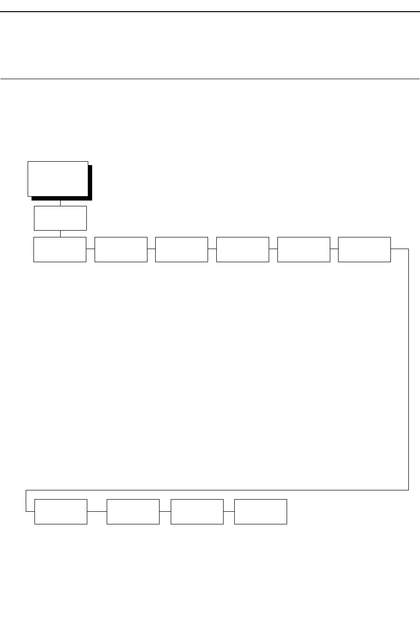
157
LinePrinter Plus Emulation
NOTE: When the printer is set to SPC Twx Params or SPC Coax Params, no
LP+ menu items will take effect on the same offline. The LP+
Emulation resets when the printer is taken offline.
EMULATION
(from page 123)
Printer
Protocol
CPI/LPI
Select
Host
Command
Font
Attributes
Page
Format
Print Char.
Set
Reset Cmd
CFG Ld
(see page 158) Select CPI
6.0 CPI
10.0 CPI*
12.0 CPI
13.3 CPI
15.0 CPI
17.1 CPI
20.0 CPI
Select LPI
6.0 LPI*
8.0 LPI
10.3 LPI
P/S Mode CPI
Changed*
Unchanged
Enable*
Ignore All
Ignore CPI
Ignore LPI
Ignore Unidir.
(see page 158) (see page 158)
Disable*
Power up config
Current config
Factory config
* = Factory Default
LinePrinter+
Set
Substitution
Inactive*
Active
Barcode
x-offset
Disable*
Enable
Barcode
Height
Disable*
Enable
LinePrinter Plus Emulation
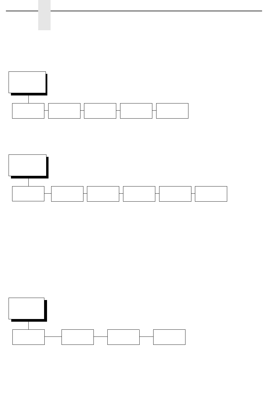
158
Chapter 4
LinePrinter Plus Emulation
Printer
Protocol
(from page 157)
P-Series* P-Series
XQ
Serial
Matrix
Proprinter
XL
Epson
FX
(see page 164) (see page 172) (see page 174) (see page 179) (see page 183)
Font Attributes
(from page 157)
Typeface Prop.
Spacing
Bold Print Italic Print Slashed
Zero
Text
Position
Data Processing*
NLQ
4
OCR-A
OCR-B
High Speed
NLQ Sans Serif
High Speed 100
NLQ 200
DP 200
High Speed 64
BARCODE 145
BARCODE 160
DP 144
High Speed 144
Disable*
Enable
Disable*
Enable
Disable*
Forward Slant
Backward Slant
Disable*
Enable
Top of Line*
Bottom of Line
Page Format
(from page 157)
Form
Length
Form
Width
Margins Perforation
Skip
1
Abs. Length IN
1
11.0* inches
(0.1-24)
Abs. Length MM
1
279.4* mm
(0.1-609.6)
Funct. of Lines
88* lines
(1-192)
Abs. Width IN
1
13.6* inches
(0.1-13.6)
Abs. Width MM
1
345.4* mm
(0.1-345.4)
Function of CPI
136
*2
characters
(1-272)
Left Margin
1
0* columns
(0-369)
Right Margin
1
0* columns
(0-369)
Bottom Margin
0* lines
(0-451)
Disable*
1/2 Inch
2/3 Inch
5/6 Inch
1 inch
* = Factory Default
1
These menus do not appear if the Coax or Twinax host interface is selected.
See page 87.
2
This value is 132 if the Coax or Twinax host interface is selected.
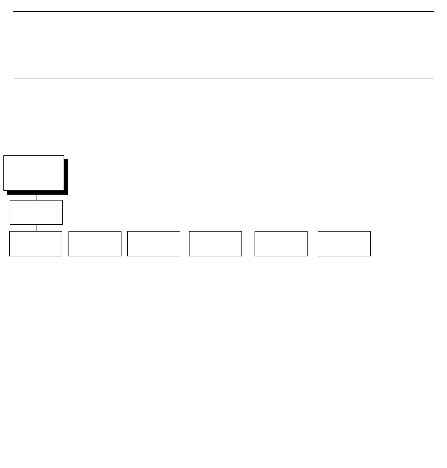
159
LinePrinter Plus Emulation (With PCL-II)
NOTE: When the printer is set to SPC Twx Params or SPC Coax Params, no
LP+ menu items will take effect on the same offline. The LP+
Emulation resets when the printer is taken offline.
Printer Protocol
Select the LinePrinter+ protocol you wish to use. Refer to the LinePrinter Plus
Programmer's Reference Manual for more information.
CPI/LPI Select
This parameter lets you specify the characters per inch (cpi) and lines per
inch (lpi) values.
EMULATION
(from page 123)
Printer
Protocol
CPI/LPI
Select
Font
Attributes
Page
Format
Print Char.
Set
Reset Cmd
CFG Ld
(see page 158) Select CPI
10.0 CPI*
12.0 CPI
13.3 CPI
15.0 CPI
17.1 CPI
20.0 CPI
Select LPI
6.0 LPI*
8.0 LPI
10.3 LPI
Typeface
Data Processing
NLQ
OCR-A
OCR-B
High Speed
NLQ San Serif
Prop. Spacing
Disable*
Enable
Bold Print
Disable*
Enable
Italic Print
Disable*
Forward Slant
Backward Slant
Slashed Zero
Disable*
Enable
Disable*
Power up config
Current config
Factory config
* = Factory Default
LinePrinter+
LinePrinter Plus Emulation (With PCL-II)

160
Chapter 4
LinePrinter Plus Emulation (With PCL-II)
Host Command
This parameter allows you to block certain host commands from being
acknowledged by the printer.
•
Enable (default). All host commands are acknowledged by the printer.
•
Ignore All. All host commands are ignored by the printer.
•
Ignore CPI. All CPI commands sent by the host are ignored by the
printer.
•
Ignore LPI. All LPI commands sent by the host are ignored by the printer.
•
Ignore Unidir. All Unidirectional commands sent by the host are ignored
by the printer.
Font Attributes
Typeface
•
Data Processing (default). A general purpose font printing out at
120 dpi horizontally and 72 dpi vertically. The width of the font will vary
with each cpi.
•
NLQ. A high quality font printing at 180 dpi horizontally and
96 dpi vertically. This font has serifs and the width of the font varies with
the cpi.
•
OCR-A / OCR-B. Optical character recognition fonts printing at 120 dpi
horizontally and 144 dpi vertically. Both fonts print only at 10 cpi.
•
High Speed. A draft quality font printing at 120 dpi horizontally and 48 dpi
vertically. The width of the font varies with the cpi.
•
NLQ Sans Serif. A high quality font printing at 180 dpi horizontally and 96
dpi vertically. This font prints without serifs. The width of the font varies
with the cpi.
•
High Speed 100. A draft quality font printing at 100 dpi horizontally and
48 dpi vertically. When chosen from the front panel, it defaults to 10 cpi.
The cpi can then be varied, but the width will not change.
•
NLQ 200. This NLQ font prints at 200 dpi horizontally and 96 vertically.
When chosen from the front panel, it defaults to 12 cpi. The cpi can then
be varied, but the width will not change.
•
DP 200. This Data Processing font prints at 200 dpi horizontally and 72
vertically. When chosen from the front panel, it defaults to 12 cpi. The cpi
can then be varied, but the width will not change.
•
High Speed 64. This font prints at 120 dpi horizontally and 64 vertically.
When chosen from the front panel, it defaults to
10 cpi. The cpi can then be varied, but the width will not change.
•
BARCODE 145. This Data Processing font prints at 145 dpi horizontally
and 72 vertically. When chosen from the front panel, it defaults to 12 cpi.
The cpi can then be varied, but the width will not change.
•
BARCODE 160. This Data Processing font prints at 160 dpi horizontally
and 72 vertically. When chosen from the front panel, it defaults to 13 cpi.
The cpi can then be varied, but the width will not change.
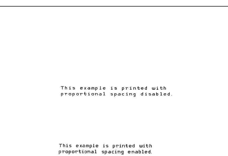
161
Prop. Spacing (Proportional Spacing)
Each printed character is contained inside a character cell. The width of the
character cell includes the character and the space around the character.
•
Disable (default). Each character cell is printed with the same width.
Each column in the printed text will line up.
•
Enable. The width of each character cell varies with the width of the
character. For example, [i] takes less space to print than [m]. Using
proportional fonts generally increases the readability of printed
documents, which gives text a typeset appearance.
Bold Print
•
Disable (default). Text is printed normally.
•
Enable. Text is printed with a heavy line thickness.
Italic Print
•
Disable (default). Text is printed normally.
•
Forward Slant. Text is printed with a forward slant.
•
Backward Slant. Text is printed with a backward slant.
Slashed Zero
This parameter allows you to print the numeral “0” with or without the slash.
This option applies to all character sets except OCR-A and OCR-B.
•
Disable (default). Zero is printed without a slash.
•
Enable. Zero is printed with a slash.
LinePrinter Plus Emulation (With PCL-II)
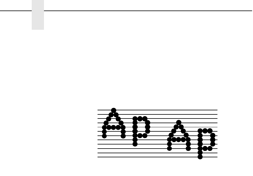
162
Chapter 4
LinePrinter Plus Emulation (With PCL-II)
Text Position
Specifies where the text will be positioned in the line space. When set to
Top-of-Line, text will be positioned at the top of the line space. When set to
Bottom-of-Line, the text will be positioned as if it were at the bottom of a 6 lpi
line space. The following example shows both Top-of-Line and Bottom-of-Line
text positions:
Page Format
Form Length
Forms length is the number of lines that can be printed on a page. You can set
the form length in inches, millimeters (mm), or as a function of the current lpi
(lines per inch).
Form Width
The form width can be specified in inches, millimeters, or as a function of the
current cpi (characters per inch). The forms width set should not exceed the
actual paper width.
Margins
•
Left Margin. Set in columns. Column zero is defined as the far left edge
of the page, and column numbering increments from left to right.
•
Right Margin. Set in columns. Column zero is defined as the far right
edge of the page, and column numbering increments from right to left.
•
Bottom Margin. Defined in lines, starting from line zero at the bottom of
the page and incrementing from the bottom up.
Perforation Skip
•
Disable (default). Allows printing on page perforation.
•
1/2 inch, 2/3 inch, 5/6 inch, 1 inch. You may set up a skip-over margin of
1/2 inch, 2/3 inch, 5/6 inch, or 1 inch. For example, a skip-over margin of
1 inch allows a 1 inch margin at the bottom of the page.
Top of Linespace
Bottom of 8 LPI Linespace
Bottom of 6 LPI Linespace
Dot
Row
Text Position
Top of Line Text Position
Bottom of Line
1
1
2
3
4
5
6
7
8
9
10
11
12
Text Position
Top-of-Line Text Position
Bottom-of-Line

163
Print Char. Set
When this selection is displayed and the ENTER key is pressed, the current
character set is printed.
Reset Cmd CFG Ld
When the printer receives a host data stream reset command
(ESC @ or ESC[K) in addition to resetting printer variables, the selected
configuration is loaded.
•
Disable (default). The active emulation parameters are loaded when the
reset command is executed.
•
Power-Up Config. The power-up configuration is loaded when the reset
command is executed.
•
Current Config. The currently selected configuration is loaded when the
reset command is executed.
•
Factory Config. The factory installed configuration is loaded when the
reset command is executed.
Set Substitution
When this option is activated, the character set overlay in RAM is activated.
This can also be accomplished through a host command of SFCC RX. In
either case, a flag is set indicating that the substitution table is active. If the
power-up configuration has Ld Set at Pwrup and Set Substitution both
enabled, the character set overlay is automatically activated at power-up or
during a soft reset. See the LinePrinter Plus Programmer's Reference Manual
for more information.
Barcode x-offset
•
Disable (default)
•
Enable. Allows text to print next to a barcode when xxxx and yyyy are not
set to the origin.
Barcode Height
•
Disable (default)
•
Enable. If Barcode x-offset is enabled, the barcode height follows P5000
legacy barcode behavior.
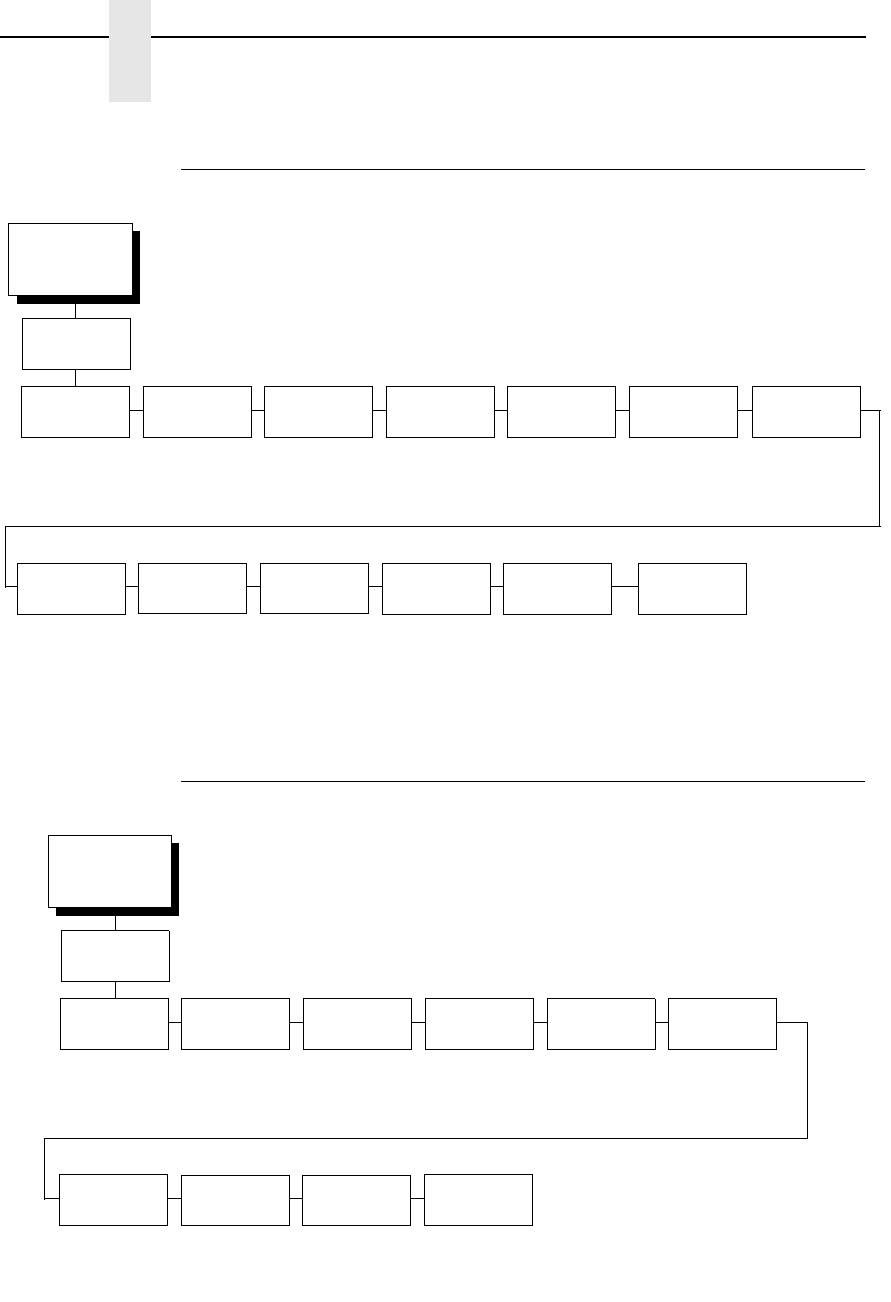
164
Chapter 4
LinePrinter Plus Emulation (With PCL-II)
P-Series Emulation
P-Series Emulation (with PCL-II)
Printer
Protocol
(from page 164)
Control Code
06
Control Code
08
Define CR
Code
Auto LF Overstrike Define LF
Code
P-Series
SFCC
VFU Select Alt. Set
80-9F
Character
Set
SFCC d
Command
PSeries Dbl
High
8.0 LPI*
10.3 LPI
6.0 LPI
Elongated*
Backspace
CR = CR*
CR = CR + LF
Disable*
Enable
Enable*
Disable
LF = CR + LF*
LF = LF
1*
(0-7F hex)
EVFU*
DVFU
CVFU
Disable
Control Code*
Printable
(see page 168) Even dot plot*
Double high
Normal*
P3/4/6/9 Compat
* = Factory Default
P-Series
FF valid
at TOF
Enable*
Disable
Printer
Protocol
(from page 164)
Control Code
06
Control Code
08
Define CR
Code
Auto LF Overstrike Define LF
Code
P-Series
SFCC
EVFU Select Alt. Set
80-9F
Character
Set
8.0 LPI*
10.3 LPI
6.0 LPI
Elongated*
Backspace
CR = CR*
CR = CR + LF
Disable*
Enable
Enable*
Disable
LF = CR + LF*
LF = LF
1*
(0-7F hex)
Enable*
Disable
Control Code*
Printable
(see page 170)
* = Factory Default
P-Series
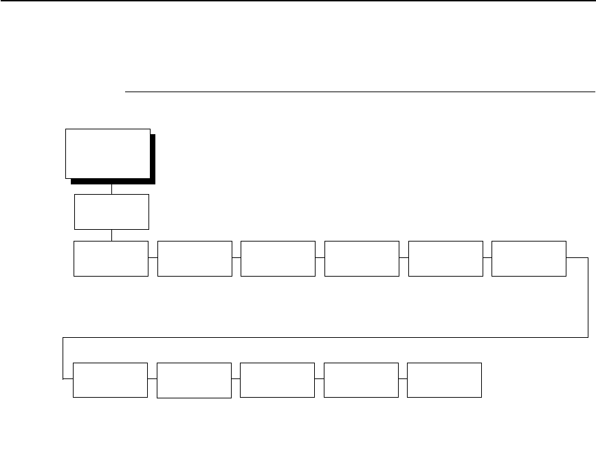
P-Series Emulation (With LG)
165
P-Series Emulation (With LG)
Control Code 06
Control Code 06 defines the function of ASCII code hex 06 (ACK). You can
select an alternate line spacing of 6, 8, or 10.3 LPI.
Control Code 08
Control Code 08 defines the function of ASCII code hex 08 (BS). You can
define the code to output the following character:
•
Elongated (default).
•
Backspace.
Define CR Code
This option controls the action of the printer when it receives a Carriage
Return code (hex 0D) from the host computer. If this feature is enabled, each
time the printer receives a carriage return, it inserts an additional Line Feed
code (hex 0A) into the data stream. Do not use this feature if the host
computer sends Line feeds to the printer.
•
CR = CR (default). Does not insert an extra line feed after each carriage
return.
•
CR = CR + LF. Inserts an extra line feed after each carriage return. The
next print position will be print position 1 of the next line.
Printer
Protocol
(from page 165)
Control Code
06
Control Code
08
Define CR
Code
Auto LF Overstrike Define LF
Code
P-Series
SFCC
EVFU Select Alt. Set
80-9F
Character
Set
8.0 LPI*
10.3 LPI
6.0 LPI
Elongated*
Backspace
CR = CR*
CR = CR + LF
Disable*
Enable
Enable*
Disable
LF = CR + LF*
LF = LF
1*
(0-7F hex)
Enable*
Disable
Control Code*
Printable
(see page 171)
* = Factory Default
P-Series
SFCC d
Command
Even dot plot*
Double high

166
Chapter 4
LinePrinter Plus Emulation (With PCL-II)
Auto LF
This option defines the printer action when print data is received past the
forms width setting.
•
Disable (default). Discards any data past the forms width.
•
Enable. Performs an automatic carriage return and line feed when data is
received past the forms width, causing the excess text to print on the next
line.
Overstrike
This option enables you to print bold characters.
•
Enable (disable). Turns on bold print. When enabled, overstrike printing
slows down the printer.
•
Disable. Turns off bold print.
Define LF Code
•
LF = CR + LF (default). Forces an automatic carriage return with each
line feed command. The next print position is print position 1 of the next
line.
•
LF = LF. Does not perform an automatic carriage return. The next print
position will be the current print position of the next line.
P-Series SFCC
This parameter allows you to select which ASCII codes will function as the
Special Function Control Code (SFCC) command delimiter.
P-Series codes can use hex 00 through hex 7F. Options include the following:
•
ESC (hex 1B)
•
SOH (hex 01)
•
ETX (hex 03)
•
CIRCUMFLEX (hex 5E)—also called caret (^)
•
TILDE (hex 7E)—(~)
NOTE: SOH, ETX, and ESC are non-printables. The characters (^) and (~)
are printable; however, do not use them as printables in the host data
stream if either is chosen as a delimiter because print errors will
occur.

P-Series Emulation (With LG)
167
VFU Select
Controls how the printer handles vertical formatting.
•
EVFU (default). Enables the VFU and selects P-Series compatible
Electronic Vertical Format Unit (EVFU).
•
DVFU. Enables the VFU and selects the Dataproducts compatible Direct
Access Vertical Format Unit (DVFU).
•
CVFU. Enables the VFU and selects the Centronics compatible Direct
Access Vertical Format Unit (CVFU).
•
Disable. Disables all VFU processing.
Alt. Set 80-9F
Determines whether the printer processes ASCII codes hex 80 through hex
9F as control codes or as printable characters. The options include:
•
Control Code (default)
•
Printable.
Character Set
Specifies a character set as shown in the
Π−Σεριεσ Χηαραχτερ Σετ
Μενυ ον παγε 168
. To use one of these sets, choose the desired group
heading (such as European Sets) and press ENTER. Then choose the
desired set within that group (such as Roman 8) and press ENTER. Both the
group and the desired set will be starred to indicate your selection. The UTF-8
selection allows printing of UTF-8 encoded Unicode ™. Character sets are
shown in detail in the Character Sets Reference Manual.
SFCC d Command
•
Even dot plot (default). This option interprets SFCC d Command as even
dot plot.
•
Double High. This option interprets SFCC d Command as double high.
Select this option for backward compatibility.
PSeries Dbl High
Allows printing compatibility between current and older model printers.
•
Normal (default). This is normal, double-high printing for current model
printers.
•
P3/4/6/9 Compat. Where older printers print two dot rows higher, this
option allows for compatibility by raising the print two dot rows to match
the current models dot row value (two dot rows lower).
FF Valid at TOF
•
Enable (default). Performs a form feed when the host sends a Form Feed
command and the printer is at the top of form.
•
Disable. Will not perform a form feed when the host sends a Form Feed
command and the printer is at the top of form.
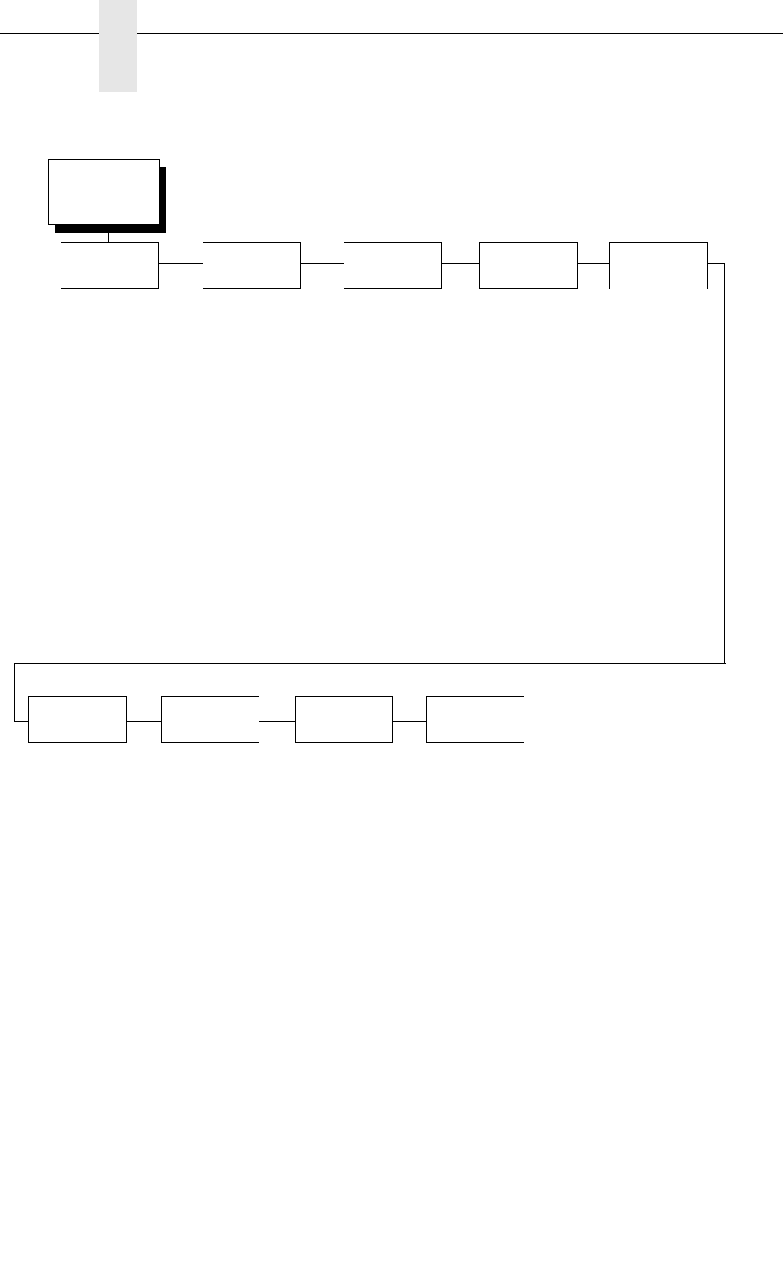
168
Chapter 4
LinePrinter Plus Emulation (With PCL-II)
P-Series Character Set Menu
Latin 2 8859-2*
Latin 2 852
Mazovia
Kamenicky
Roman 8
PC-437 Slavic
Slavic 1250
Code Page 865
Code Page 860
Latin 1 8859-1
Latin 5 8859-9
Latin 9 8859-15
Polish POL1
Win. CP 1250
Win. CP 1252
Win. CP 1257
CP 858 EURO
Lith. CP 773
Serbo Croatic 1
Serbo Croatic 2
CP 774
CP 775
ISO 8859-4
DEC 256 Greek*
ELOT 928 Greek
Greek 3
ABY Greek
ABG Greek
ELOT 927 Greek
Greek 851
Greek 437
Greek 8859-7
Win. CP 1253
Greek 813 EURO
Greek 869 EURO
Character Set
(from page 164)
Arabic
Sets
Cyrillic
Sets
European
Sets
Greek
Sets
Hebrew
Sets
Turkish
Sets
Misc.
Sets
ASMO 449*
ASMO 449+
ASMO 708
ASMO 708+
MS DOS CP710
MS DOS CP720
Sakr CP714
Aptec CP715
CP 786
Arabic CP 864
Arabic CP 1046
Arabic Lam 1
Arabic Lam 2
Win. CP 1256
Farsi 1
Farsi 2
1098 Farsi 1285
Cyrillic 866*
Cyrillic CP 437
Cyrillic 113
Cyrillic 8859-5
ISO 915
Code Page 855
7-bit Cyrillic
Ukrainian
Bulgarian
Win. CP 1251
Latvian 866
CP 1048
Hebrew Old*
Hebrew New
Hebrew DEC
Latin-1 Hebrew
Win. CP 1255
Data Gen. Turk.*
DEC Turkish
IBM Turkish
Siemens Turkish
PTT Turkish
IBC Turkish
Bull Turkish
AS400 Turkish
Unisys Turkish
NCR Turkish
PST Turkish
UNIS-1 Turkish
Code Page 853
INFO Turkish
Win. CP 1254
Code Page 857
Azeri
Block-set 10cpi*
Italics Set
Scanblock 10cpi
PGL Thai Set
Standard
Sets
See page 169.
UTF-8
* = Factory Default
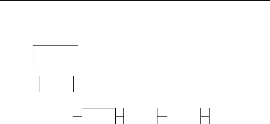
P-Series Emulation (With LG)
169
Standard
Sets*
IBM PC* Multinational ECMA Latin 1
Primary Subset
ASCII (USA)*
French
German
English
Danish
Swedish
Italian
Spanish
Japanese
French Canadian
Latin American
Norwegian
Danish II
Spanish II
Latin Am II
Extended Subset
Code Page 437*
Code Page 850
ASCII (USA)*
EBCDIC
Primary Subset
ASCII (USA)*
German
Swedish
Danish
Norwegian
Finnish
English
Dutch
French
Spanish
Italian
Turkish
Japanese
Extended Subset
Multinational*
Barcode 10 cpi
Mult. DP 10 cpi
Mult. DP 12 cpi
Mult. LQ 10 cpi
Greek DP 10 cpi
Greek DP 12 cpi
Greek LQ 10 cpi
Grap. DP 10 cpi
Grap. LQ 10 cpi
Sci. DP 10 cpi
Sci. DP 12 cpi
Sci. LQ 10 cpi
ASCII (USA)*
French
German
English
Norw./Danish
Swedish
Italian
Spanish
Japanese
French Canadian
Dutch
Finnish
Swiss
CP 858
EURO
Character Set
(P-Series)
(from page 164)
DEC Mult.

170
Chapter 4
LinePrinter Plus Emulation (With PCL-II)
P-Series Character Set Menu (with PCL-II)
Character Set
(from page 164)
IBM PC*
Primary Subset
ASCII (USA)*
French
German
English
Danish
Swedish
Italian
Spanish
Japanese
French Canadian
Latin American
Danish II
Spanish II
Latin Am II
Extended Subset
Code Page 437*
Code Page 850
Extended Subset
Multinational
ASCII (USA)*
EBCDIC
ECMA Latin 1
DEC Mult.
OCR-A
OCR-B
Latin 2 8859-2
Latin 2 852
Bulgarian
Latin 9 8859-15
Polish POL1
DEC 256 Greek
ELOT 928 Greek
Greek 3
ABY Greek
ABG Greek
ELOT 927 Greek
Greek 437
Greek 8859-7
PC851 LtGk [12G]
Greek-7 [12N]
Greek-8 [8G]
Hebrew Old
Hebrew New
Hebrew DEC
* = Factory Default

P-Series Emulation (With LG)
171
P-Series Character Set Menu (with LG)
Character Set
(from page 165)
IBM PC*
Primary Subset
ASCII (USA)*
French
German
English
Danish
Swedish
Italian
Spanish
Japanese
French Canadian
Latin American
Danish II
Spanish II
Latin Am II
Extended Subset
Code Page 437
Code Page 850
Multinational
ASCII (USA)*
EBCDIC
ECMA Latin 1
Primary Subset
ASCII (USA)*
German
Swedish
Danish
Norweigian
Finnish
English
Dutch
French
Spanish
Italian
Turkish
Japanese
Extended Subset
Multinational*
Barcode 10 CPI
Mult. DP 10 CPI
Mult. DP 12 CPI
Mult. LQ 10 CPI
Greek DP 10 CPI
Greek DP 12 CPI
Greek LQ 10 CPI
Grap. DP 10 CPI
Grap. LQ 10 CPI
Sci. DP 10 CPI
Sci. DP 12 CPI
Sci. LQ 10 CPI
* = Factory Default
DEC Mult.
ASCII (USA)*
French
German
English
Norw./Danish
Swedish
Italian
Spanish
Japanese
French Canadian
Dutch
Finnish
Swiss
OCR-A
OCR-B
Latin 9 8859-15
CP 858 Euro
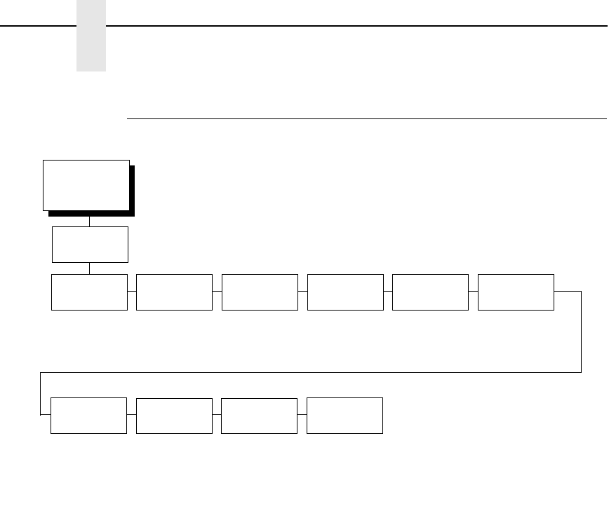
172
Chapter 4
LinePrinter Plus Emulation (With PCL-II)
P-Series XQ Emulation
Control Code 06
Control Code 06 defines the function of ASCII code hex 06 (ACK). You can
select an alternate line spacing of 6, 8, or 10.3 LPI.
Define CR Code
This option controls the action of the printer when it receives a Carriage
Return code (hex 0D) from the host computer. If this feature is enabled, each
time the printer receives a Carriage Return, it inserts an additional Line Feed
code (hex 0A) into the data stream. Do not use this feature if the host
computer sends line feeds to the printer.
•
CR = CR (default). Does not insert an extra line feed after each carriage
return.
•
CR = CR + LF. Inserts an extra line feed after each carriage return. The
next print position will be print position 1 of the next line.
Auto LF
This option defines the printer action when print data is received past the
forms width setting.
•
Disable (default). Discards any data past the forms width.
•
Enable. Performs an automatic carriage return and line feed when data is
received past the forms width.
Printer
Protocol
(from page 158)
Control Code
06
Define CR
Code
Auto LF Define LF
Code
Compressed Elong/Alt.
Font
HS Print VFU Select Upr. Case
Select
Slew
Relative
8.0 LPI*
10.3 LPI
6.0 LPI
CR = CR*
CR = CR + LF
Disable*
Enable
LF = CR + LF*
LF = LF
char 01 SOH*
char 03 ETX
char 09 HT
Elng=BS Font=SO*
Elng=SO Font=BS
char 02 STX*
char 03 ETX
char 09 HT
EVFU*
DVFU
CVFU
Disable
Disable*
Enable
1-15 lines*
1-16 lines*
* = Factory Default
P-Series
XQ

P-Series XQ Emulation
173
Define LF Code
•
LF = CR + LF (default). Forces an automatic carriage return with each
line feed command received. The next print position is print position 1 of
the next line.
•
LF = LF. Does not perform an automatic carriage return when a line feed
command is received. The next print position will be the current print
position of the next line.
Compressed Print
Controls which host command sets compressed printing.
•
Char 01 SOH (default)
•
Char 03 ETX
•
Char 09 HT
Elong/Alt. Font
Controls which host command sets elongated (double high) fonts and
extended character set.
•
Elng=BS Font=SO (default)
•
Elng=SO Font=BS
HS Print (High Speed Print)
Controls which host command sets high speed printing.
•
Char 02 STX (default)
•
Char 03 ETX
•
Char 09 HT
VFU Select
Controls how the printer handles vertical formatting. The choices are:
•
EVFU (default). Enables the VFU and selects P-Series compatible
Electronic Vertical Format Unit (EVFU).
•
DVFU. Enables the VFU and selects the Dataproducts compatible Direct
Access Vertical Format Unit (DVFU).
•
CVFU. Enables the VFU and selects the Centronics compatible Direct
Access Vertical Format Unit (CVFU).
•
Disable. Disables all VFU processing.
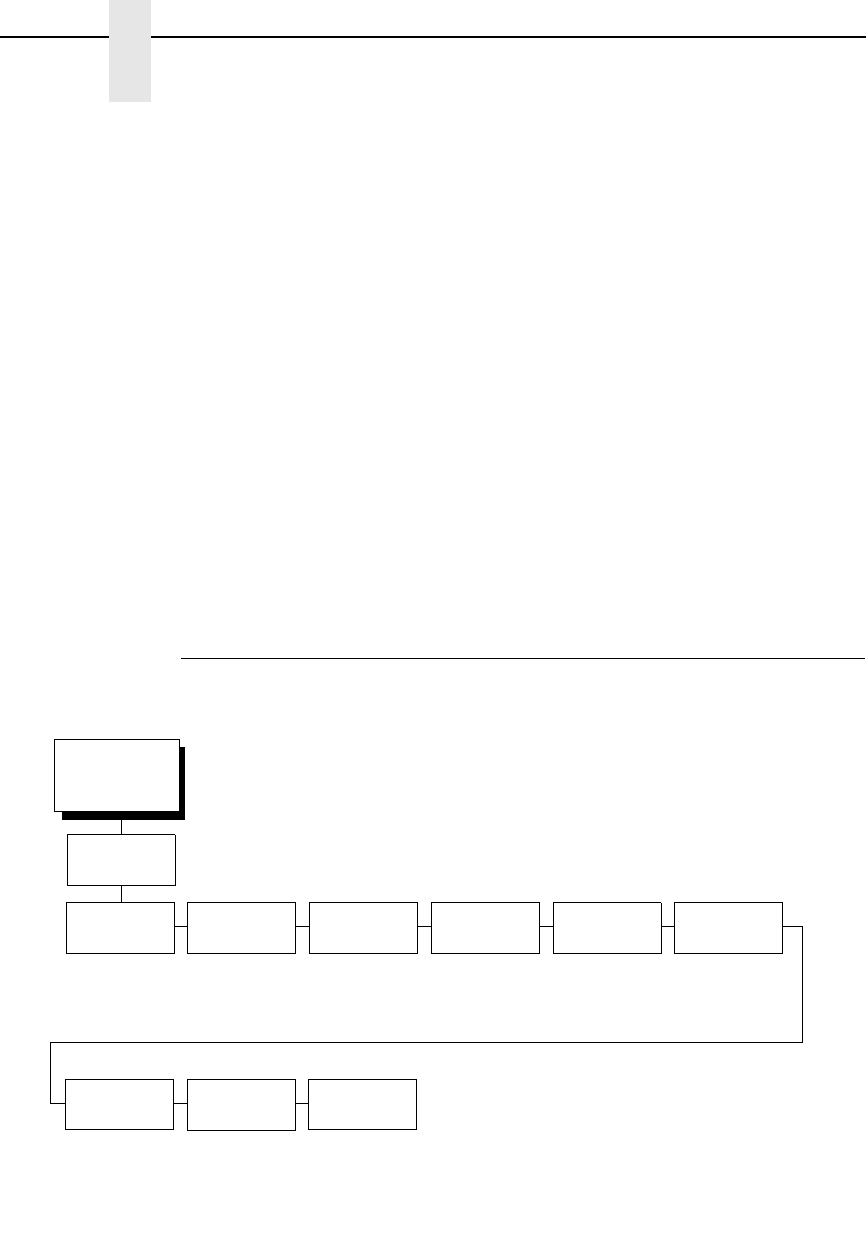
174
Chapter 4
LinePrinter Plus Emulation (With PCL-II)
Upr. Case Select
Controls how the printer handles lowercase characters it receives from the
host computer. When enabled, all characters will be printed in uppercase.
•
Disable (default). Prints lowercase characters received from the host
computer as lowercase, and prints uppercase characters received from
the computer as uppercase.
•
Enable. Prints lowercase characters received from the host computer as
their corresponding uppercase equivalents; uppercase characters
received from the computer print as uppercase.
Slew Relative
“Slewing” is rapid vertical paper movement. This parameter determines the
number of lines slewed (either 1-15 lines or 1-16 lines) when an EVFU Slew
Relative command is received. The options include:
•
1-15 Lines (default)
•
1-16 Lines
Serial Matrix Emulation
Printer
Protocol
(from page 158)
Control Code
06
Define CR
Code
Auto LF Overstrike Define LF
Code
Printer
Select
Alt. Set
80-9F
Character
Set
ESC d
command
8.0 LPI*
10.3 LPI
6.0 LPI
CR = CR*
CR = CR + LF
Enable*
Disable
Enable*
Disable
LF = LF*
LF = CR + LF
Disable*
Enable
Control Code*
Printable
(see page 177) Even dot plot*
Double high
* = Factory Default
Serial
Matrix

Serial Matrix Emulation
175
Control Code 06
Control Code 06 defines the function of ASCII code hex 06 (ACK). You can
select an alternate line spacing of 6, 8, or 10.3 LPI.
Define CR Code
This option controls the action of the printer when it receives a Carriage
Return code (hex 0D) from the host computer. If this feature is enabled, each
time the printer receives a Carriage Return, it inserts an additional Line Feed
code (hex 0A) into the data stream. Do not use this feature if the host
computer sends line feeds to the printer.
•
CR = CR (default). Does not insert an extra line feed after each carriage
return.
•
CR = CR + LF. Inserts an extra line feed after each carriage return. The
next print position will be print position 1 of the next line.
Auto LF
The Auto LF option defines the printer action when print data is received past
the forms width setting.
•
Enable (default). Performs an automatic carriage return and line feed
when data is received past the forms width.
•
Disable. Discards any data past the forms width.
Overstrike
This option enables you to print bold characters.
•
Enable (default). Turns on bold print. When enabled, overstrike printing
slows down the printer.
•
Disable. Turns off bold print.
Define LF Code
•
LF = LF (default). Does not perform an automatic carriage return when a
line feed command is received. The next print position will be the current
print position of the next line.
•
LF = CR + LF. Forces an automatic carriage return with each line feed
command received. The next print position is print position 1 of the next
line.

176
Chapter 4
LinePrinter Plus Emulation (With PCL-II)
Printer Select
•
Disable (default). Ignores the ASCII DC1 and DC3 control codes.
•
Enable. Disables the printer when a DC1 control code is received, and
enables the printer when a DC3 control code is received.
Alt. Set 80-9F
•
Control Code (default). Interprets data in the range of hex 80 through
hex 9F as a control code.
•
Printable. Prints data in the range of hex 80 through hex 9F.
Character Set
Specifies a character set as shown in the
Σεριαλ Ματριξ Χηαραχτερ
Σετ Μενυ ον παγε 177
. To use one of these sets, choose the desired
group heading (such as European Sets) and press ENTER. Then choose the
desired set within that group (such as Roman 8) and press ENTER. Both the
group and the desired set will be starred to indicate your selection. Character
sets are shown in detail in the Character Sets Reference Manual.
ESC d command
•
Even dot plot (default). Interprets the ESC d command as even dot plot.
•
Double high. Interprets the ESC d Command as double high. Select this
option for backward compatibility.
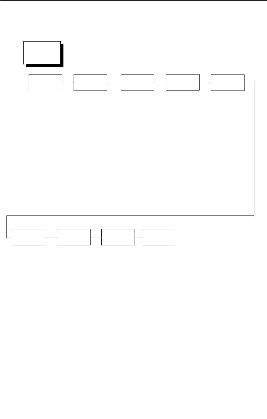
Serial Matrix Emulation
177
Serial Matrix Character Set Menu
DEC 256 Greek*
ELOT 928 Greek
Greek 3
ABY Greek
ABG Greek
ELOT 927 Greek
Greek 851
Greek 437
Greek 8859-7
Win. CP 1253
Greek 813 EURO
Greek 869 EURO
Character Set
(from page 174)
Arabic
Sets
Cyrillic
Sets
European
Sets
Greek
Sets
Hebrew
Sets
Turkish
Sets
Misc.
Sets
ASMO 449*
ASMO 449+
ASMO 708
ASMO 708+
MS DOS CP710
MS DOS CP720
Sakr CP714
Aptec CP715
CP 786
Arabic CP 864
Arabic CP 1046
Arabic Lam 1
Arabic Lam 2
Win. CP 1256
Farsi 1
Farsi 2
1098 Farsi 1285
Cyrillic 866*
Cyrillic CP 437
Cyrillic 113
Cyrillic 8859-5
ISO 915
Code Page 855
7-bit Cyrillic
Ukrainian
Bulgarian
Win. CP 1251
Latvian 866
CP 1048
Latin 2 8859-2*
Latin 2 852
Mazovia
Kamenicky
Roman 8
PC-437 Slavic
Slavic 1250
Code Page 865
Code Page 860
Latin 1 8859-1
Latin 5 8859-9
Latin 9 8859-15
Polish POL1
Win. CP 1250
Win. CP 1252
Win. CP 1257
CP 858 EURO
Lith. CP 773
Serbo Croatic 1
Serbo Croatic 2
CP 774
CP 775
ISO 8859-4
Hebrew Old*
Hebrew New
Hebrew DEC
Latin-1 Hebrew
Win. CP 1255
Data Gen. Turk.*
DEC Turkish
IBM Turkish
Siemens Turkish
PTT Turkish
IBC Turkish
Bull Turkish
AS400 Turkish
Unisys Turkish
NCR Turkish
PST Turkish
UNIS-1 Turkish
Code Page 853
INFO Turkish
Win. CP 1254
Code Page 857
Azeri
Block-set 10cpi*
Italics Set
Scanblock 10cpi
PGL Thai Set
Standard
Sets
(see page 178)
UTF-8
* = Factory Default
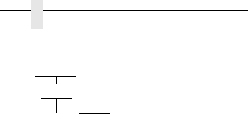
178
Chapter 4
LinePrinter Plus Emulation (With PCL-II)
Standard
Sets*
IBM PC* Multinational ECMA Latin 1
Primary Subset
ASCII (USA)*
French
German
English
Danish
Swedish
Italian
Spanish
Japanese
French Canadian
Latin American
Norwegian
Danish II
Spanish II
Latin Am II
Extended Subset
Code Page 437*
Code Page 850
ASCII (USA)*
EBCDIC
Primary Subset
ASCII (USA)*
German
Swedish
Danish
Norwegian
Finnish
English
Dutch
French
Spanish
Italian
Turkish
Japanese
Extended Subset
Multinational*
Barcode 10 cpi
Mult. DP 10 cpi
Mult. DP 12 cpi
Mult. LQ 10 cpi
Greek DP 10 cpi
Greek DP 12 cpi
Greek LQ 10 cpi
Grap. DP 10 cpi
Grap. LQ 10 cpi
Sci. DP 10 cpi
Sci. DP 12 cpi
Sci. LQ 10 cpi
ASCII (USA)*
French
German
English
Norw./Danish
Swedish
Italian
Spanish
Japanese
French Canadian
Dutch
Finnish
Swiss
CP 858
EURO
Character Set
(Serial)
(from page 177)
DEC Mult.
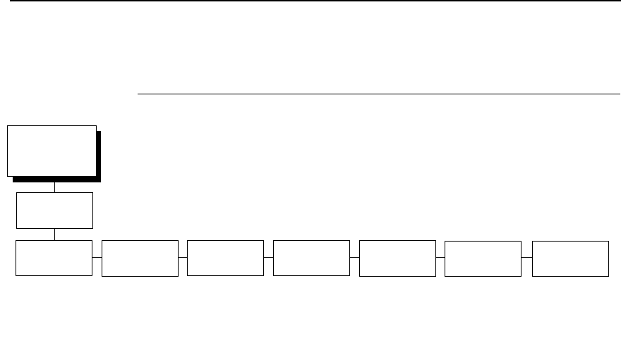
Proprinter XL Emulation
179
Proprinter XL Emulation
Define CR Code
This option controls the action of the printer when it receives a Carriage
Return code (hex 0D) from the host computer. If this feature is enabled, each
time the printer receives a Carriage Return, it inserts an additional Line Feed
code (hex 0A) into the data stream. Do not use this feature if the host
computer sends line feeds to the printer.
•
CR = CR (default). Does not insert an extra line feed after each carriage
return.
•
CR = CR + LF. Inserts an extra line feed after each carriage return.
Auto LF
This option defines the printer action when print data is received past the
forms width setting.
•
Enable (default). Performs an automatic carriage return and line feed
when data is received past the forms width.
•
Disable. Discards any data past the forms width.
Define LF Code
•
LF = LF (default). Does not perform an automatic carriage return when a
Line Feed command is received. The next print position will be the current
print position of the next line.
•
LF = CR + LF. Forces an automatic carriage return with each Line Feed
command received. The next print position is print position 1 of the next
line.
FF Valid at TOF
•
Enable (default). Performs a form feed when the host sends a Form Feed
command and the printer is at the top of form.
•
Disable. Will not perform a form feed when the host sends a Form Feed
command and the printer is at the top of form.
Printer
Protocol
(from page 158)
Define CR
Code
Auto LF Define LF
Code
FF valid at
TOF
Character
Set
Alt. Char
Set
20 CPI
Condensed
CR = CR*
CR = CR + LF
Enable*
Disable
LF = LF*
LF = CR + LF
Enable*
Disable
(see page 181) Set 1*
Set 2
Enable*
Disable
* = Factory Default
Proprinter
XL

180
Chapter 4
LinePrinter Plus Emulation (With PCL-II)
Character Set
Specifies a character set as shown in the
Προπριντερ ΞΛ Χηαραχτερ
Σετσ Μενυ ον παγε 181
. To use one of these sets, choose the desired
group heading (such as European Sets) and press ENTER. Then choose the
desired set within that group (such as Roman 8) and press ENTER. Both the
group and the desired set will be starred to indicate your selection. The UTF-8
selection allows printing of UTF-8 encoded Unicode ™. Character sets are
shown in detail in the Character Sets Reference Manual.
Alt. Char Set
This option determines if data in the range of hex 80 through hex 9F should
be interpreted as a control code or as a printable character.
•
Set 1 (default). Interprets data in the range of hex 80 through hex 9F as a
control code.
•
Set 2. Prints data for the characters at hex locations 03, 04, 05, 06, 15,
and 80 through 9F.
20 CPI Condensed
Compressed print characters are narrower than the normal character set.
This is helpful for applications where you need to print the maximum amount
of information on a page.
•
Enable (default). Prints characters about 60 percent the width of normal
characters when compressed print is chosen by the host computer.
•
Disable. Does not compress print widths, even if condensed print is
chosen by the host.
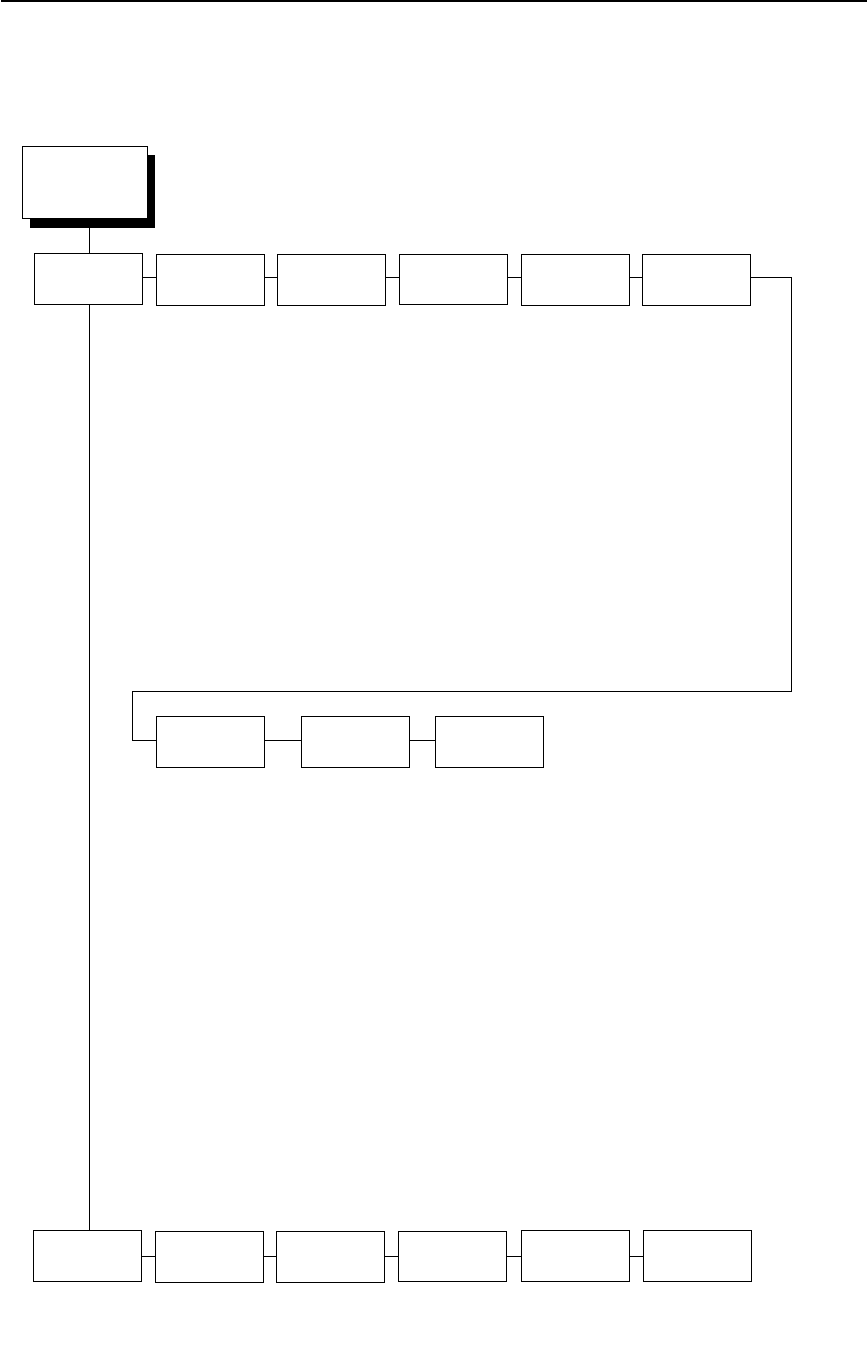
Proprinter XL Emulation
181
Proprinter XL Character Sets Menu
DEC 256 Greek*
ELOT 928 Greek
Greek 3
ABY Greek
ABG Greek
ELOT 927 Greek
Greek 851
Greek 437
Greek 8859-7
Win. CP 1253
Greek 813 EURO
Greek 869 EURO
Character Set
(from page 179)
Standard
Sets*
Arabic
Sets
Cyrillic
Sets
European
Sets
Greek
Sets
Hebrew
Sets
Code Page
437*
Code Page
850
OCR-A OCR-B
ASMO 449*
ASMO 449+
ASMO 708
ASMO 708+
MS DOS CP710
MS DOS CP720
Sakr CP714
Aptec CP715
CP 786
Arabic CP 864
Arabic CP 1046
Arabic Lam 1
Arabic Lam 2
Win. CP 1256
Farsi 1
Farsi 2
1098 Farsi 1285
Cyrillic 866*
Cyrillic CP 437
Cyrillic 113
Cyrillic 8859-5
ISO 915
Code Page 855
7-bit Cyrillic
Ukrainian
Bulgarian
Win. CP 1251
Latvian 866
CP 1048
Latin 2 8859-2*
Latin 2 852
Mazovia
Kamenicky
Roman 8
PC-437 Slavic
Slavic 1250
Code Page 865
Code Page 860
Latin 1 8859-1
Latin 5 8859-9
Latin 9 8859-15
Polish POL1
Win. CP 1250
Win. CP 1252
Win. CP 1257
CP 858 EURO
Lith. CP 773
Serbo Croatic 1
Serbo Croatic 2
CP 774
CP 775
ISO 8859-4
Hebrew Old*
Hebrew New
Hebrew DEC
Latin-1 Hebrew
Win. CP 1255
Multinational
ASCII (USA)*
EBCDIC
CP 858 EURO
Turkish
Sets
Data Gen. Turk.*
DEC Turkish
IBM Turkish
Siemens Turkish
PTT Turkish
IBC Turkish
Bull Turkish
AS400 Turkish
Unisys Turkish
NCR Turkish
PST Turkish
UNIS-1 Turkish
Code Page 853
INFO Turkish
Win. CP 1254
Code Page 857
Azeri
Misc.
Sets
Block-set 10cpi*
Italics Set
Scanblock 10cpi
PGL Thai Set
UTF-8
* = Factory Default

182
Chapter 4
LinePrinter Plus Emulation (With PCL-II)
Proprinter XL Character Sets Menu (with PCL-II)
Proprinter XL Character Sets Menu (with LG)
Character Set
(from page 179)
Code Page 437*
Code Page 850
OCR-A
OCR-B
Latin 2 8859-2
Latin 2 852
Bulgarian
Latin 9 8859-15
Polish POL1
Multinational
DEC 256 Greek
ELOT 928 Greek
Greek 3
ABY Greek
ABG Greek
ELOT 927 Greek
Greek 437
Greek 8859-7
PC851 LtGk [12G]
Greek-7 [12N]
Greek-8 [8G]
Hebrew Old
Hebrew New
Hebrew DEC
* = Factory Default
Character Set
(from page 179)
Code Page 437*
Code Page 850
OCR-A
OCR-B
Code Page 210
Code Page 220
Code Page 852
Code Page 855
Code Page 857
Code Page 862
Code Page 866
Lithuanian 1
Lithuanian 2
Hebrew New
Hebrew Dec
Hebrew Old
Latin 9 8859-15
CP 858 Euro
* = Factory Default
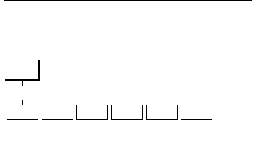
Epson FX Emulation
183
Epson FX Emulation
Define CR Code
The Define CR Code option controls the action of the printer when it receives
a Carriage Return code (hex 0D) from the host computer. If this feature is
enabled, each time the printer receives a carriage return, it inserts an
additional Line Feed code (hex 0A) into the data stream. Do not use this
feature if the host computer sends line feeds to the printer.
•
CR = CR (default). Does not insert an extra line feed after each carriage
return.
•
CR = CR + LF. Inserts an extra line feed after each carriage return.
Auto LF
This option defines the printer actions when print data is received past the
forms width setting.
•
Enable (default). Performs an automatic carriage return and line feed
when data is received past the forms width.
•
Disable. Discards any data past the forms width.
Define LF Code
The Define LF Code option controls the action of the printer when it receives a
Line Feed code (hex 0A) from the host computer. If this feature is enabled,
each time the printer receives a Line Feed, it inserts an additional Carriage
Return code (hex 0D) into the data stream. This feature is required if the host
computer does not send carriage returns to the printer.
•
LF = LF (default). Does not add a carriage return with a line feed.
•
LF = CR + LF. Adds an extra carriage return with each line feed.
Printer
Protocol
(from page 158)
Define CR
Code
Auto LF Define LF
Code
Printer
Select
Character
Set
20 CPI
Condensed
Alt. Set
80-9F
CR = CR*
CR = CR + LF
Enable*
Disable
LF = LF*
LF = CR + LF
Disable*
Enable
(see page 185) Enable*
Disable
Control Code*
Printable
* = Factory Default
Epson FX

184
Chapter 4
LinePrinter Plus Emulation (With PCL-II)
Printer Select
•
Disable (default). Ignores the ASCII DC1 and DC3 control codes.
•
Enable. Disables the printer when a DC1 control code is received, and
enables the printer when a DC3 control code is received.
Character Set
This parameter selects a character set for the Epson emulation, as shown in
the
Επσον ΦΞ Χηαραχτερ Σετ Μενυ ον παγε 185
.
NOTE: When OCR-A or OCR-B is selected as the print language, the Font
Attribute Typeface option under the LinePrinter Plus menu (page 157)
is changed to OCR-A or OCR-B, respectively.
To use one of these sets, choose the desired group heading (such as
European Sets) and press ENTER. Then choose the desired set within that
group (such as Roman 8) and press ENTER. Both the group and the desired
set will be starred to indicate your selection. The UTF-8 selection allows
printing of UTF-8 encoded Unicode ™. Character sets are shown in detail in
the Character Sets Reference Manual.
20 CPI Condensed
Compressed print characters are narrower than the normal character set.
This is helpful for applications where you need to print the maximum amount
of information on a page.
•
Enable (default). Prints about 60 percent of the width of normal
characters when compressed print is chosen by the host computer. For
example, a 12 CPI Draft font will compress to 20 CPI.
•
Disable. Does not compress print widths, even if condensed print is
chosen by the host.
Alt. Set 80-9F
•
Control Code (default). Interprets data in the range of hex 80 through
hex 9F as a control code.
•
Printable. Prints data in the range of hex 80 through hex 9F.
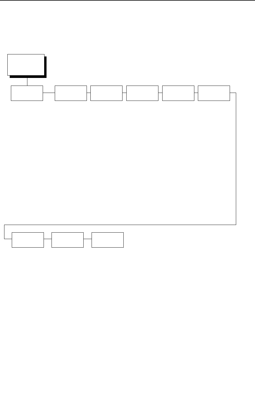
Epson FX Emulation
185
Epson FX Character Set Menu
Epson Set*
ASCII (USA)*
French
German
English
Danish I
Swedish
Italian
Spanish I
Japanese
Norwegian
Danish II
Spanish II
Latin Am I
French Canadian
Latin Am II
OCR-A
OCR-B
Multinational
ASCII (USA)*
EBCDIC
Code Page 850
CP 858 EURO
IBM PC
DEC 256 Greek*
ELOT 928 Greek
Greek 3
ABY Greek
ABG Greek
ELOT 927 Greek
Greek 851
Greek 437
Greek 8859-7
Win. CP 1253
Greek 813 EURO
Greek 869 EURO
Character Set
(from page 183)
Standard
Sets*
Arabic
Sets
Cyrillic
Sets
European
Sets
Greek
Sets
Hebrew
Sets
Turkish
Sets
Misc.
Sets
ASMO 449*
ASMO 449+
ASMO 708
ASMO 708+
MS DOS CP710
MS DOS CP720
Sakr CP714
Aptec CP715
CP 786
Arabic CP 864
Arabic CP 1046
Arabic Lam 1
Arabic Lam 2
Win. CP 1256
Farsi 1
Farsi 2
1098 Farsi 1285
Cyrillic 866*
Cyrillic CP 437
Cyrillic 113
Cyrillic 8859-5
ISO 915
Code Page 855
7-bit Cyrillic
Ukrainian
Bulgarian
Win. CP 1251
Latvian 866
CP 1048
Latin 2 8859-2*
Latin 2 852
Mazovia
Kamenicky
Roman 8
PC-437 Slavic
Slavic 1250
Code Page 865
Code Page 860
Latin 1 8859-1
Latin 5 8859-9
Latin 9 8859-15
Polish POL1
Win. CP 1250
Win. CP 1252
Win. CP 1257
CP 858 EURO
Lith. CP 773
Serbo Croatic 1
Serbo Croatic 2
CP 774
CP 775
ISO 8859-4
Hebrew Old*
Hebrew New
Hebrew DEC
Latin-1 Hebrew
Win. CP 1255
Data Gen. Turk.*
DEC Turkish
IBM Turkish
Siemens Turkish
PTT Turkish
IBC Turkish
Bull Turkish
AS400 Turkish
Unisys Turkish
NCR Turkish
PST Turkish
UNIS-1 Turkish
Code Page 853
INFO Turkish
Win. CP 1254
Code Page 857
Azeri
Block-set 10cpi*
Italics Set
Scanblock 10cpi
PGL Thai Set
UTF-8
* = Factory Default

186
Chapter 4
LinePrinter Plus Emulation (With PCL-II)
Epson FX Character Set Menu (with PCL-II)
Character Set
(from page 183)
* Factory Default
Epson Set*
ASCII (USA)*
French
German
English
Danish I
Swedish
Italian
Spanish I
Japanese
Norwegian
Danish II
Spanish II
Latin Am I
French Canadian
Latin Am II
OCR-A
OCR-B
Latin 8859-2
Latin 2 852
Cyrillic 866
Bulgarian
Latin 9 8859-15
Polish POL1
Multinational
ASCII (USA)*
EBCDIC
DEC 256 Greek
ELOT 928 Greek
Greek 3
ABY Greek
ABG Greek
ELOT 927 Greek
Greek 437
Greek 8859-7
PC851 LtGk [12G]
Greek-7 [12N]
Greek-8 [8G]
Hebrew Old
Hebrew New
Hebrew DEC
IBM PC

Epson FX Emulation
187
Epson FX Character Set Menu (with LG)
Character Set
(from page 183)
* Factory Default
Epson Set*
ASCII (USA)*
French
German
English
Danish I
Swedish
Italian
Spanish I
Japanese
Norwegian
Danish II
Spanish II
Latin Am I
French Canadian
Latin Am II
OCR-A
OCR-B
Code Page 210
Code Page 220
Code Page 852
Code Page 855
Code Page 857
Code Page 862
Code Page 866
Lithuanian 1
Lithuanian 2
Hebrew Old
Hebrew New
Hebrew Dec
Latin 9 8859-15
CP 858 Euro
IBM PC
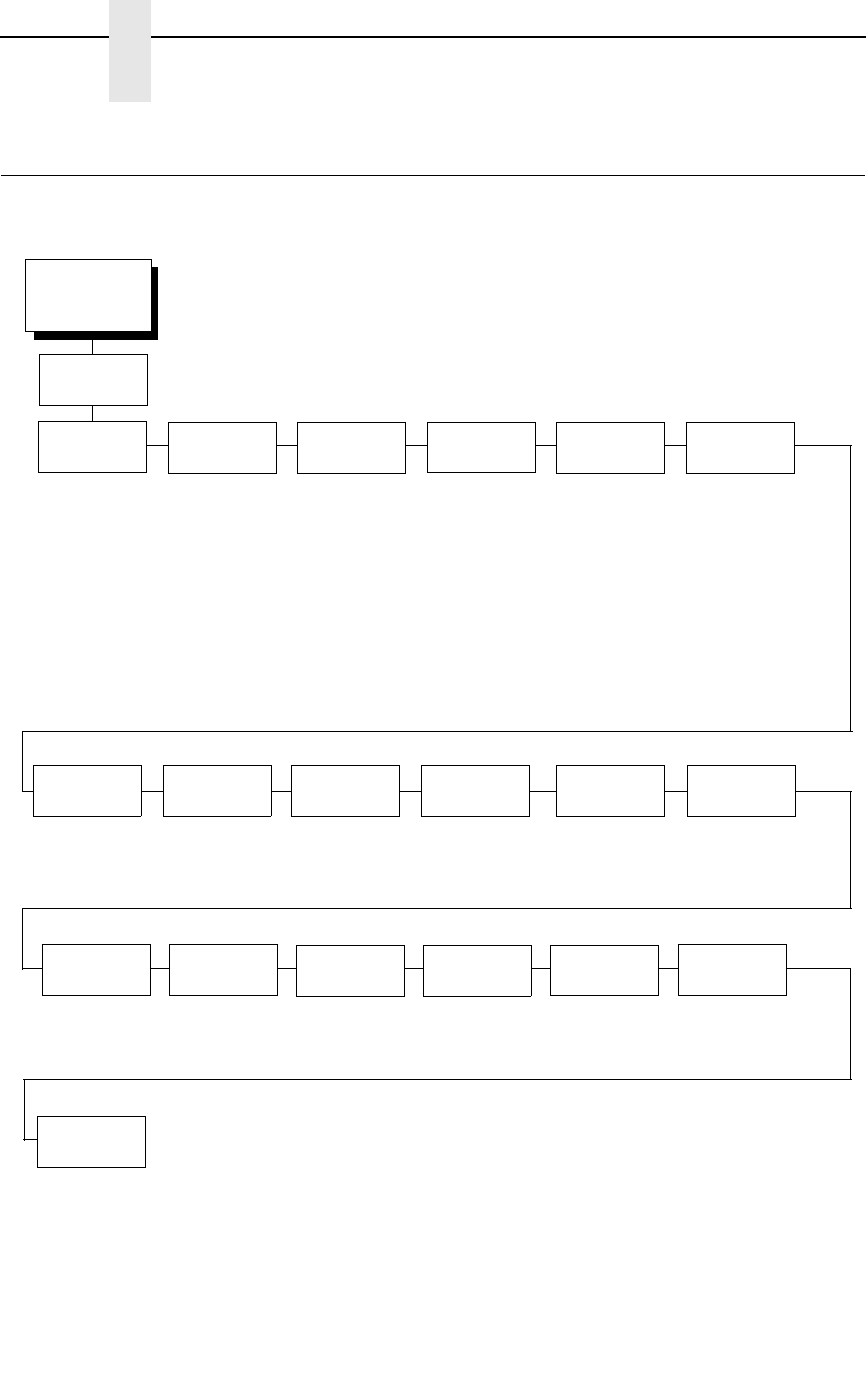
188
Chapter 4
ANSI Emulation
ANSI Emulation
EMULATION
(from page 123)
CPI/LPI
Select
Font
Attributes
Page
Format
Define CR
Code
Auto LF Define LF
Code
Select CPI
10.0* CPI
12.0 CPI
13.3. CPI
15.0 CPI
16.7 CPI
17.1 CPI
Select LPI
6.0* LPI
8.0 LPI
3.0 LPI
4.0 LPI
(see page 189) (see page 189) CR = CR*
CR = CR + LF
Disable*
Enable
LF = CR + LF*
LF = LF
* Factory Default
44/48XX-
ANSI
Pos. on
BC/OvrSz
BC Check
Digit
Barcode
darkmode
PUM
Default
Set to top*
Set to bottom
By host*
By printer
Enable*
Disable
Decipoints*
Lines/columns
Truncate PI
Slew
Truncate at TOF*
Disable
Character
Set
(see page 189)
Printer
Select
ON=DC1/
OFF=DC3*
Disable
ESC c
Sequence
Enable*
Disable
Reset Cmd
CFG Ld
Disable*
Power up config.
Current config
Factory config
Received
CR
Observe*
Ignore
Received
DEL
Observe*
Ignore
Private
Mode
Set 2*
Set 1
ETX/ACK
Disable*
Immediate
After Print
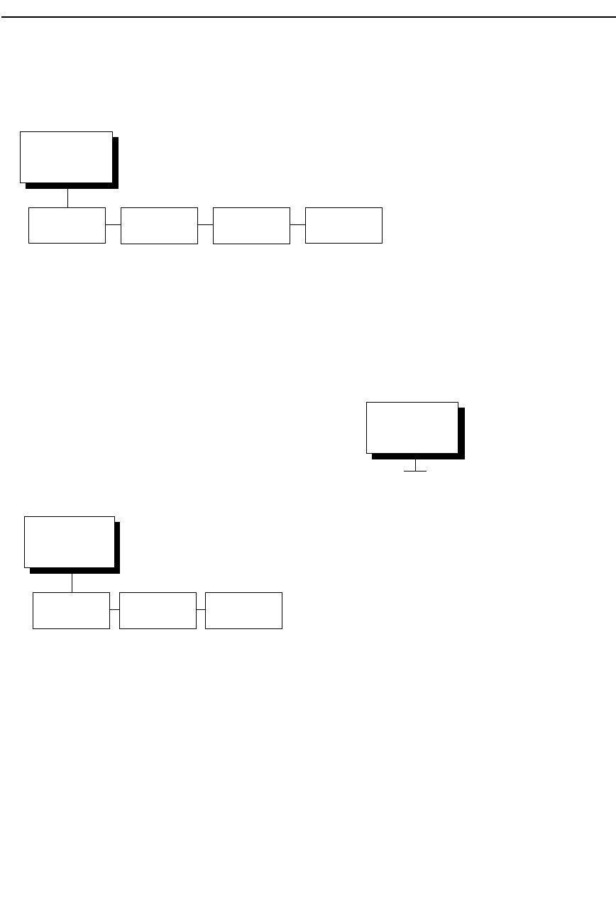
189
Font Attributes
(from page 188)
Typeface Prop.
Spacing
Bold Print Slashed
Zero
Data Processing*
Gothic NLQ
Char. Graphics
High Speed
Italics NLQ
Courier NLQ
OCR-A
OCR-B
Disable*
Enable
Disable*
Enable
Disable*
Enable
* = Factory Default
Page Format
(from page 188)
Margins Form
Length
Form Width
Left Margin
0 columns*
(0-369)
Right Margin
0 columns*
(0-369)
Top Margin
0 lines*
(0-451)
Bottom Margin
0 lines*
(0-451)
Funct. of lines
66 lines*
(1-192)
Function of CPI
136 Characters*
(1-272)
Character Set
(from page 188)
Latin 1 8859-1*
Cyrillic 8859-5
IBM PC-2 CP 437
IBM PC-2 CP 850
Slavic CP 852
Cyrillic CP 855
Fr. Can. CP 863
Russian CP 866
Greek CP 851
Turkish CP 853
Portug. CP 860
Arabic CP 864
Nordic CP 865
Latin 2 8859-2
Latin 3 8859-3
Latin 4 8859-4
Lat. Ara. 8859-6
Lat. Gre. 8859-7
Lat. Heb. 8859-8
Latin 5 8859-9
Turkish2 CP 867
Pol. Maz. CP 8576
Turkish CP 8577
Greek CP 8573
Italian CP 23
Spanish CP 24
Latin 9 8859-15
DEC 256 Greek
Turkish CP 857
USA
German
French A
French B
French Canadian
Dutch Netherlds
Italian
United Kingdom
Spanish
Danish/Norw. A
Danish/Norw. B
Danish/Norw. C
Danish/Norw. D
Swed./Finnish A
Swed./Finnish B
Swed./Finnish C
Swed./Finnish D
Swiss
USA
Yugoslavian
United Kingdm A
Turkish
Greek
DEC Mult.
Roman 8
ANSI Emulation
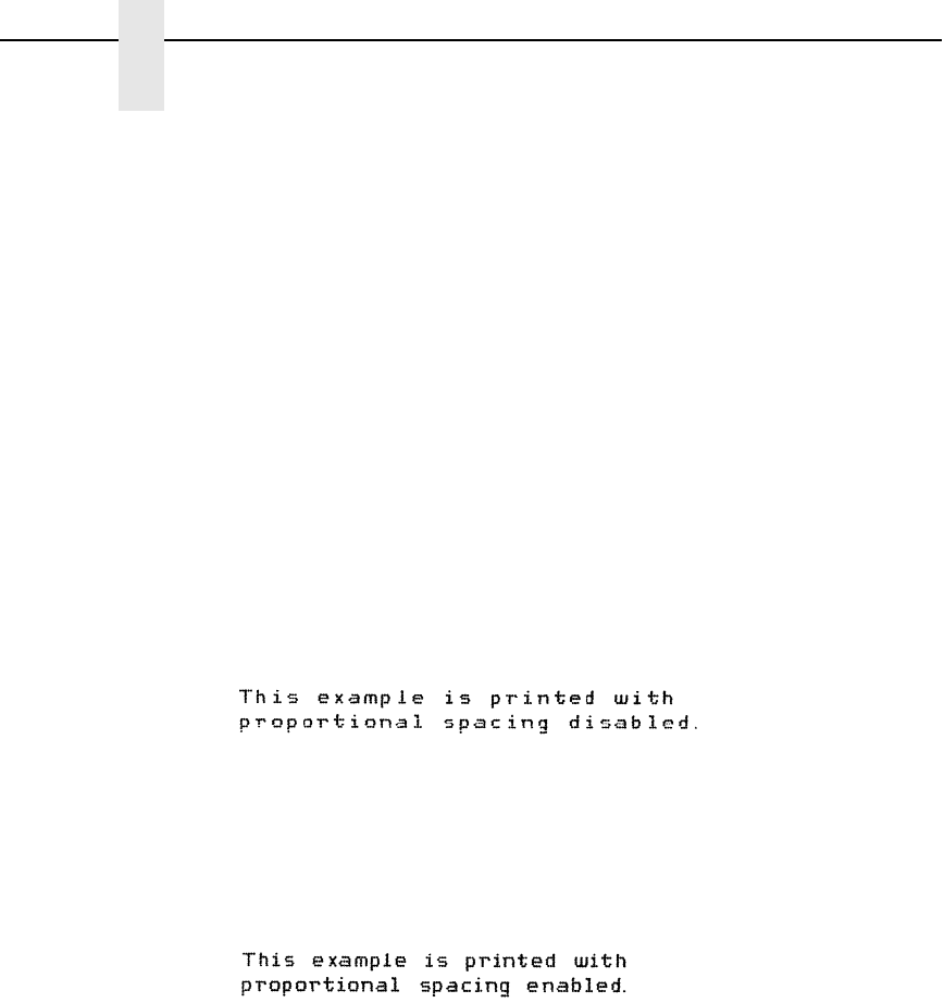
190
Chapter 4
ANSI Emulation
CPI/LPI Select
Defines the default values for the horizontal and vertical character spacing.
The number of characters per inch can range from 10.0 through 17.1. The
number of lines per inch can range from 3.0 through 8.0.
Font Attributes
Typeface
Choose a typeface from the available options.
Prop. Spacing (Proportional Spacing)
Each printed character is contained inside a character cell. The width of the
character cell includes the character and the space around the character.
•
Disable (default). Each character cell is printed with the same width.
Each column in the printed text will line up.
•
Enable. The width of each character cell varies with the width of the
character. For example, [i] takes less space to print than [m]. Using
proportional fonts generally increases the readability of printed
documents, giving text a typeset appearance.
Bold Print
•
Disable (default). Text is printed normally.
•
Enable. Text is printed with a heavy line thickness.
Slashed Zero
This parameter allows you to print the numeral “0” with or without the slash.
This option applies to all character sets except OCR-A and OCR-B.
•
Disable (default). Zero is printed without a slash.
•
Enable. Zero is printed with a slash.

191
Page Format
Margins
•
Left Margin. Defines where the first print column is located. The left
margin is specified as the number of characters from the left edge of the
form.
•
Right Margin. Defines where the last print column is located. The right
margin is specified as the number of characters from the right edge of the
form.
•
Top Margin. Defines the location of the first print line on the page. The
top margin is specified as the number of lines from the top of the form's
position.
•
Bottom Margin. Defines the location of the last print line on the page.
The bottom margin is specified as the number of lines from the bottom of
the form's position.
Form Length
Specifies the form length in lines. The maximum form length in lines depends
on the current LPI setting; it is equal to the maximum form length in inches
multiplied by the current LPI setting. For example, at 6 LPI the maximum form
length is 6 LPI x 24 inches = 144 lines.
Only valid form length values will be accepted. If you select a length that is
larger than the maximum length for the current LPI, the maximum length will
be used. If you need a longer page length, you must first change the LPI.
IMPORTANT
If the form length is set in lines and you change the LPI, the effective
page length changes to the form length in characters divided by the new
LPI.
NOTE: Receipt of a data stream control code which changes the form length
overrides the form length previously specified via the operator panel.
Form Width
Allows you to input the form width in characters from 1 through 272. The
maximum form width in characters depends on the current CPI setting; it is
equal to the maximum form width in inches multiplied by the current CPI
setting.
Only valid form width values will be accepted. If a width is selected that is
larger than the maximum width for the current CPI, then the maximum width
will be used. If a larger width value is desired, then the CPI value must be
changed first.
ANSI Emulation

192
Chapter 4
ANSI Emulation
Table 8 lists the maximum number of characters that can be printed for a
given Characters Per Inch (CPI) setting.
IMPORTANT
If the form width is set in characters and the CPI is changed, the
effective page width is changed to be equal to the form width in
characters divided by the new CPI.
Define CR Code
The Define CR Code option controls the action of the printer when it receives
a Carriage Return code (hex 0D) from the host computer. If this feature is
enabled, each time the printer receives a carriage return, it inserts an
additional Line Feed code (hex 0A) into the data stream. Do not use this
feature if the host computer sends line feeds to the printer.
•
CR = CR (default). No extra line feeds are inserted.
•
CR = CR + LF. Inserts an extra line feed after each carriage return.
Auto LF
Defines the printer actions when print data is received past the form width
setting.
•
Disable (default). Discards any data past the form width.
•
Enable. Performs an automatic carriage return and line feed when data is
received past the form width.
Define LF Code
Controls the action of the printer when it receives a Line Feed code (hex 0A)
from the host computer. If this feature is enabled, each time the printer
receives a line feed, it inserts an additional carriage return code (hex 0D) into
the data stream. This feature can be used in most installations, but it is
required if the host computer does not send carriage returns to the printer.
•
LF = CR + LF (default). Adds an extra carriage return with each line feed.
•
LF = LF. Does not add a carriage return with a line feed.
Table 8. Form Width
CPI Setting Maximum Form Width
(in characters)
10.0 136
12.0 163
13.3 181
15.0 204
16.7 227
17.1 272

193
Character Set
This parameter selects a character set for the ANSI emulation. Note that
when 0876 OCR-A or 0877 OCR-B is selected as the print language, the Font
Attributes Typeface parameter is changed to OCR-A or OCR-B, respectively.
Character sets are shown in detail in the Character Sets Reference Manual.
Printer Select
•
ON = DC1/OFF = DC3 (default). Disables the printer when a DC1 control
code is received, and enables the printer when a DC3 control code is
received.
•
Disable. Ignores the DC1 and DC3 control codes.
ESC c Sequence
•
Enable (default). An ESC c code received from the host resets the printer
parameters to the factory defaults.
•
Disable. An ESC c code received from the host is ignored.
Reset Cmd CFG Ld
When the printer receives a host data stream reset command
(ESC @ or ESC[K) in addition to resetting printer variables, the selected
configuration will be loaded.
•
Disable (default). The active emulation parameters are loaded when the
reset command is executed.
•
Power-Up Config. The power-up configuration is loaded when the reset
command is executed.
•
Current Config. The currently selected configuration is loaded when the
reset command is executed.
•
Factory Config. The factory installed configuration is loaded when the
reset command is executed.
Received CR
•
Observe (default). A CR code received from the host is handled as a
carriage return.
•
Ignore. A CR code received from the host is ignored.
Received DEL
•
Observe (default). A DEL code received from the host is handled as a
Delete command.
•
Ignore. A DEL code received from the host is ignored.
Private Mode
Determines the default type of character set (Set 1 or Set 2). This can also be
set by ESC sequences ESC [>5h and ESC [>5l. Refer to these descriptions in
the ANSI Programmer's Reference Manual for further details.
ANSI Emulation

194
Chapter 4
ANSI Emulation
Pos. on BC/OvrSz
•
Set to top (default). The paper is fed back to the top of barcodes or
oversized characters after they are printed. This allows printing on the
same line.
•
Set to bottom. The printer will continue printing without backing up.
BC Check Digit
•
By host (default). The host calculates the barcode check digit and sends
it along with the barcode. The check digit is not verified by the printer but
printed as it was received.
•
By printer. The barcode is sent without the check digit, and the printer
calculates and adds it in.
Barcode Darkmode
•
Enable (default). The barcodes are printed at a higher resolution.
•
Disable. The barcodes are printed at lower resolution but at a higher
speed.
PUM Default
This is the Unit of Measure (UOM) as it is used within the ANSI emulation.
Coordinates received in ESC sequences can be sent in two UOMs:
•
Decipoints (default). A unit of 1/720 inch
•
Lines or columns. Uses the current LPI and CPI values.
The UOM used is determined by this configuration setting.
Truncate PI Slew
•
Truncate at TOF (default). The slew is terminated when the next Top-of-
Form is reached. (This function applies to the ANSI EVFU only.)
•
Disable. PI slews will be completed independent of their length.
ETX/ACK
End of Text/Acknowledge. The host controls the flow of communcation to the
printer by sending a block of data and ending the block with an End of Text
(ETX) signal. When the printer receives the ETX signal, it acknowledges the
ETX, thereby acknowledging it has received the entire block of data.
•
Disable (default)
•
Immediate
•
Afterprint

Features
195
IGP/PGL Emulation
The PGL emulation is the software based Intelligent Graphics Processor
(IGP) for the line matrix family of printers. It is based upon, and is compatible
with, the IGP-100/200/400 board using the PGL. The IGP graphics
processing features are detailed below.
Features
On-Line Form and Label Generation makes it easy to create forms or labels
with a “preprinted” look for each application. IGP programs control all graphic
functions, dramatically reducing host computer programming and processing
time.
Graphic capabilities include boxes, vertical and horizontal lines with user-
selectable thickness, logos, and special alphanumeric print features. Forms
and graphic designs can be duplicated horizontally and vertically.
Alphanumeric data can appear as prepositioned “fixed” information (entered
when the form is created), be overlayed onto the form (positioned in a specific
location after the form is created), or can be dynamically merged with the
form.
Selectable Barcodes provide you with the appropriate barcode for your
application using standard wide-to-narrow ratios. A wide selection of
barcodes is available: Code 39, Interleaved 2 of 5, UPC-A, UPC-E, MSI A
through D, Code 128 Subset A, B, and C, EAN/UCC-128, EAN 8, EAN 13,
POSTNET, PostBar, Royal Mail, and PDF417. UPC and EAN barcodes can
specify add-on data.
Expanded and Compressed Character Print attract attention where
needed. Alphanumeric height and width are controlled independently for a
wide range of character sizes up to 113 times the standard character size (up
to 11.3 inches wide and tall). Compressed print sizes of 10, 12, 13, 15, 17,
and 20 characters per inch (cpi) are available.
Logos are created using alphanumeric commands and add many print and
shading features for a “customized” appearance to forms, reports, and labels.
Rotated Alphanumerics permit new concepts in form design. Normal,
expanded, and compressed character strings can be rotated 90 degrees
clockwise or counterclockwise, or they can be printed upside down.
Reversed Print permits highlighting and contrasting by printing white
characters on a dark background.
Automatic Increment/Decrement Capability allows batch form processing.
Individual alphabetic, numeric, and barcode data fields can be identified and
automatically incremented or decremented by any amount, beginning from a
specified reference point.
Scaling Capability permits graphic elements, such as corners or boxes, to
retain their physical shapes and sizes when printed in a horizontal and vertical
density other than the base density of 60 x 72 dpi.
Multinational Character Sets provide many international character sets,
each 96 characters in length. This feature also allows you to create your own
character sets using characters defined and stored in memory.

196
Chapter 4
IGP/PGL Emulation
Extended Character Sets provide 33 extended character sets, also
containing 96 characters in length. These are also stored in memory.
Configuring The Emulation With The Control Panel
You can select PGL default parameters directly from the control panel or by
control codes as explained in the IGP/PGL Programmer's Reference Manual.
The PGL parameters are described on the following pages. Parameters
marked with an asterisk (*) indicate the default value. The printer must be
offline to enter the configuration structure.
Pressing an invalid key to enter a parameter value may move you to another
level in the configuration or exit the configuration menu completely. Configure
the IGP/PGL according to your specific requirements.
IMPORTANT
BEFORE you reconfigure the IGP/PGL, print a configuration sheet to see
all of the current settings.
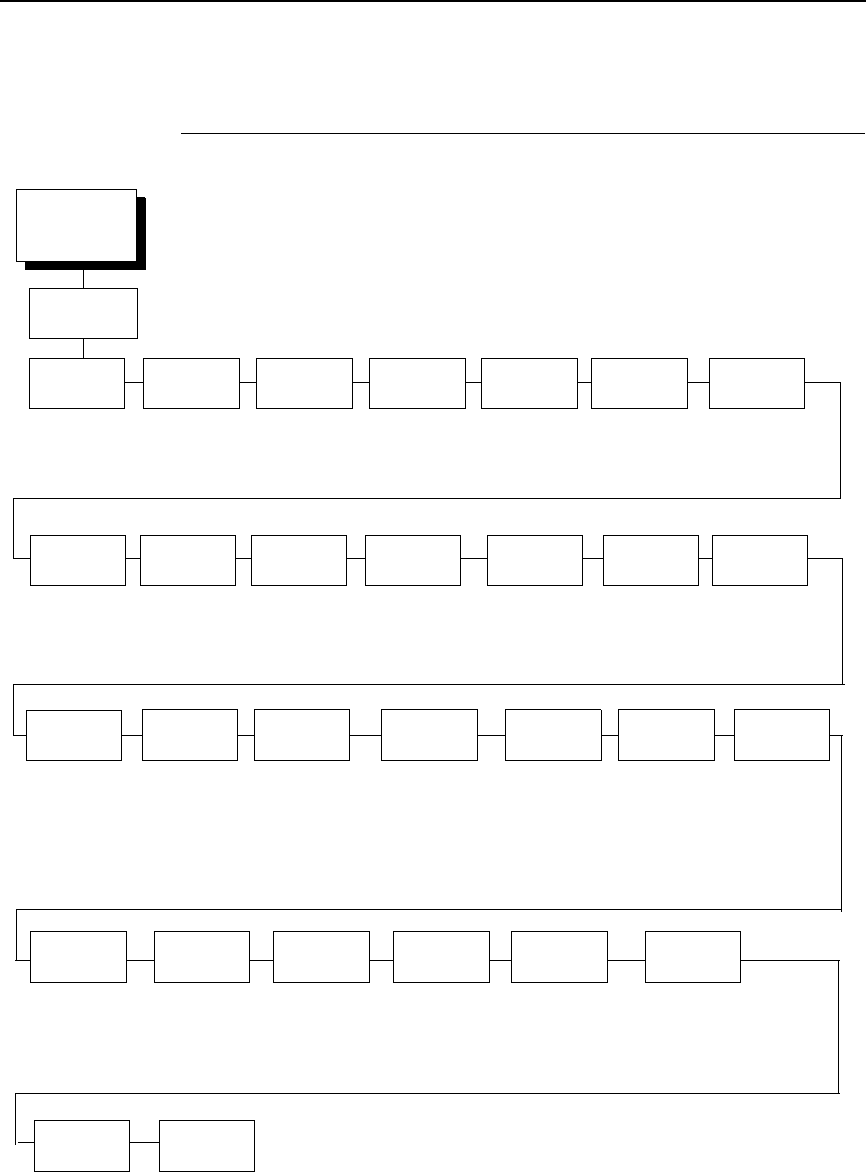
IGP/PGL Submenu
197
IGP/PGL Submenu
EMULATION
(from page 123)
Define CR
Code
Define LF
Code
CR = CR*
CR = CR + LF
LF = LF*
LF = CR + LF
Disable*
Enable
7E*
(1-255)
16*
15
Disable*
Enable
(see page 208)
Disable*
Enable
6.0*
8.0
9.0
10.0
Disable*
Enable
Enable*
Disable
Enable*
Disable
* = Factory Default
Disable*
Enable
Disable*
Light Font
Dark Font
Ignore Mode
Disable*
Enable
Select Char
0*
(0-255)
None*
MVP
L150
P3000
P6000
P9000
IGP/PGL
Autowrap PGL
SFCC
PI Slew
Range
CR Edit Select
Font
Slash 0 Select LPI Auto
Uppercase
Skip Cmd
Prefix
Power On
IGP/PGL
Ext Execute
Copy
Disable*
Enable
Host Form
Length
Add Nothing*
Add; 0
Add; X
Var Form
Type
Compressed
CPI
Ignore
Char
Compatbl.
Mode
Disable*
Auto Eject
Auto TOF
Forms
Handling
Barcode
Options
(see page 202) 00.0 inches*
(.1 - 3.0 inches)
Var Form
Adjust
Expanded
Font
Scalable*
Block
Alt Block 1
Alt Block 2
Scalable
Size
Normal*
Block
True Form
Slew
Printer PI
Line
Enable*
Disable
Enable*
Disable
Data Processing*
High
Best
Print
Quality
Power-on
S-Mode
0*
(0 - 5)
On*
Debug Mode
Fault
Off
Error
Report
Trunc Dyn
Data
Disable*
Enable
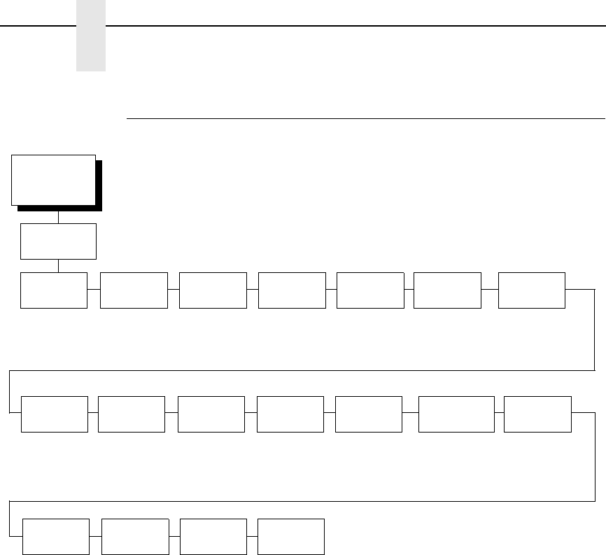
198
Chapter 4
IGP/PGL Emulation
IGP/PGL Submenu (With PCL-II)
EMULATION
(from page 123)
Define CR
Code
Define LF
Code
CR = CR*
CR = CR + LF
LF = LF*
LF = CR + LF
Disable*
Enable
7E* 16*
15
Disable*
Enable
0*
1-33
6.0*
8.0
9.0
10.0
Disable*
Enable
Enable*
Disable
Enable*
Disable
* = Factory Default
Disable*
Enable
Disable*
Enable
Ignore Mode
Disable*
Enable
Select Char
0*
(0-255)
Disable*
Enable
IGP/PGL
Autowrap PGL
SFCC
PI Slew
Range
CR Edit Select
Font
Select LPI Auto
Uppercase
Skip Cmd
Prefix
Power On
IGP/PGL
Ext Execute
Copy
Compressed
CPI
Ignore
Char
IGP100
Compatbl.
UPC
Descenders
Enable*
Disable
Optimized
Ratio
Disable*
Enable
Error
Report
On*
Debug Mode
Fault
Off
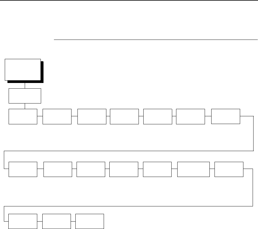
IGP/PGL Submenu (with LG)
199
IGP/PGL Submenu (with LG)
Define CR (Carriage Return) Code
This parameter forces the printer to insert an automatic Line Feed code into
the data stream whenever a Carriage Return code occurs. This is to be used
only if the host computer does not send line feeds to the printer.
•
CR = CR (default). Does not perform a line feed. The next print position
will be print position 1 of the current line.
•
CR = CR + LF. Performs an automatic line feed. The next print position
will be print position 1 of the next line.
EMULATION
(from page 123)
Define CR
Code
Define LF
Code
CR = CR*
CR = CR + LF
LF = LF*
LF = CR + LF
Disable*
Enable
7E* 16*
15
Disable*
Enable
0*
1-34
6.0*
8.0
9.0
10.0
Disable*
Enable
Enable*
Disable
Enable*
Disable
* = Factory Default
Disable*
Enable
Disable*
Enable
Ignore Mode
Disable*
Enable
Select Char
0*
(0-255)
Disable*
Enable
IGP/PGL
PGL
SFCC
PI Slew
Range
CR Edit Select Font
Select LPI Auto
Uppercase
Skip Cmd
Prefix
Power On
IGP/PGL
Ext Execute
Copy
Compressed
CPI
Ignore
Char
IGP100
Compatbl.
UPC
Descenders
Enable*
Disable
Optimized
Ratio
Disable*
Enable
Autowrap

200
Chapter 4
IGP/PGL Emulation
Define LF (Line Feed) Code
This parameter forces the printer to insert an automatic Carriage Return code
into the data stream whenever a Line Feed code occurs. This can be used in
most installations, but it is required if the host computer does not send
carriage returns to the printer.
•
LF = LF (default). Does not perform an automatic carriage return. The
next print position will be the current print position of the next line.
•
LF = CR + LF. Performs an automatic carriage return. The next print
position will be print position 1 of the next line.
Autowrap
This parameter determines if text will wrap to the next line when the line of
text exceeds the right margin.
•
Disable (default). Truncates the text beyond the right margin until a CR or
CR + LF is received.
•
Enable. Automatically inserts a CR + LF after a full print line.
PGL SFCC
You can specify which hex code (1-255) will be used as the Special Function
Control Code (SFCC). The factory default setting is 126. The SFCC denotes
that the following data is a PGL command.
PI Slew Range
You can specify how many lines the paper will feed.
•
16 (default). A paper slew of 0-15 will move 1-16 lines.
•
15. A paper slew of 1-15 will move 1-15 lines. A paper slew of 0 will move
1 line.
CR Edit
This parameter determines if a carriage return will be followed by a line feed.
•
Disable (default). The printer ignores all carriage returns that are not
followed by line feeds.
•
Enable. The printer processes all carriage returns, even for those that are
not followed by line feeds.
Select Font
Select Font specifies which language is currently selected for use with the
PGL. Refer to
ΙΓΠ/ΠΓΛ Φοντ Σετ Μενυ ον παγε 208
. for available
selections.

201
Slash 0
This parameter allows you to print the numeral “0” with or without the slash.
This option applies to all character sets except OCR A and OCR B.
•
Disable (default). Zero is printed without a slash.
•
Enable. Zero is printed with a slash.
Select LPI
This is the number of lines to be printed per inch. For
example, at 6 lpi there is
1/6 inch from the top of one print line to the top of the next print line. The
options are:
•
6.0 (default)
•
8.0
•
9.0
•
10.0
Auto Uppercase
This parameter enables the printer to print text in all uppercase when using
the ALPHA command.
•
Disable (default). The printer will print text in upper and lowercase.
•
Enable. The printer will print text in uppercase only.
Skip Cmd Prefix
This parameter determines if the printer will print any data before a PGL
command is received.
•
Enable (default). The printer ignores all data on the current line before an
IGP command.
•
Disable. The printer will print all data on the current line before an IGP
command.
Forms Handling
This submenu allows the user to handle the form in the following ways:
•
Disable (default). No effect.
•
Auto Eject. Automatically ejects a page at the end of the job to spill out
the last page.
•
Auto TOF. Automatically does a form feed (FF) at the end of each form to
the next top of form.
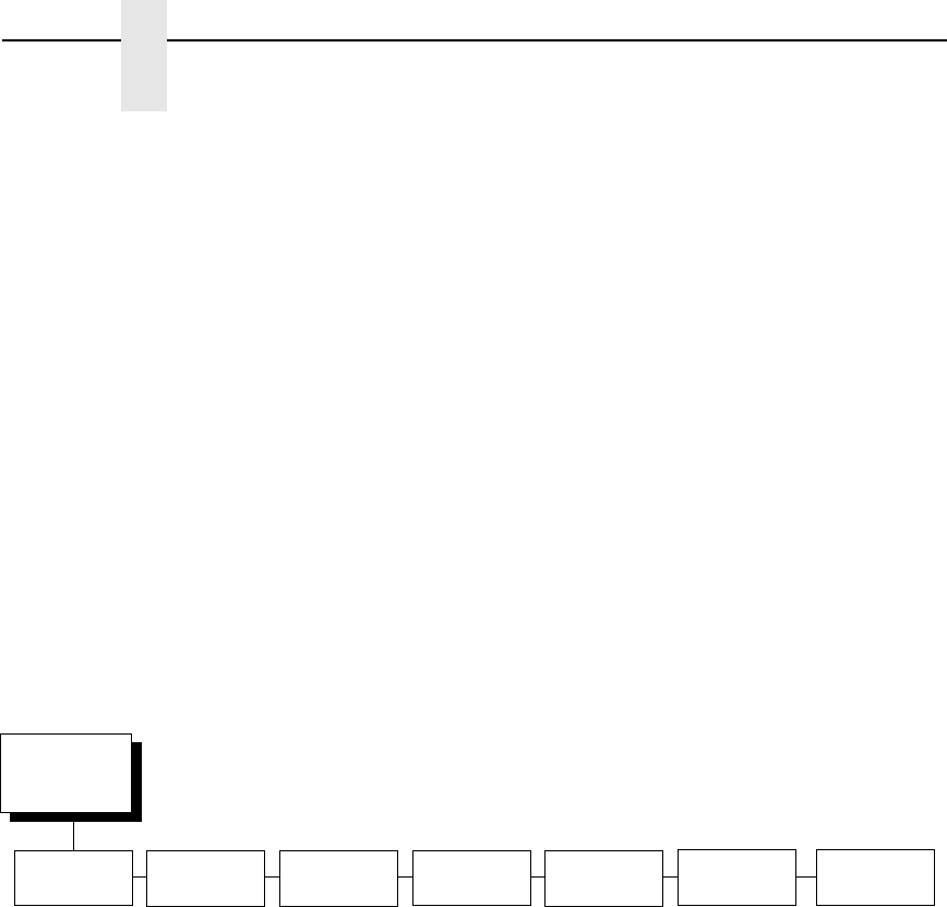
202
Chapter 4
IGP/PGL Emulation
Power On IGP/PGL
You can set the IGP feature so that it is enabled or disabled when the printer
is powered on.
•
Enable (default). The PGL is enabled when the printer is powered on.
(The PGL feature is initialized in the Normal mode.)
•
Disable. The PGL is disabled when the printer is powered on. (The PGL
feature is initialized to the Quiet mode.)
Ext Execute Copy
•
Disable (default). Dynamic data and overlay data are not allowed if the
optional Form Count parameter (number of forms to print) is specified as
part of the Execute command. (This setting is IGP-100 compatible.)
•
Enable. Only dynamic data is allowed within a form in which the Form
Count parameter is specified in the Execute command. In this case, the
exact same form (with identical dynamic data, etc.) is printed for the Form
Count. However, incremental data is not incremented since the page that
is printing is exactly the same. Also, each form is printed on a separate
page.
Barcode Options
The following sub-options help define specific options regarding barcode
printing.
UPC Descenders
This parameter allows you to print barcode descenders when human
readable data is not present in the UPC/EAN barcodes.
•
Always (default). UPC/EAN barcodes are printed with descenders, even
if there is no human readable data.
•
Never. UPC/EAN barcodes are printed without descenders if there is no
human readable data.
•
Only with PDF. UPC/EAN barcodes are printed with descenders only
when the PDF command is present.
Barcode
Options
(from page 197)
UPC
Descenders
Optimized
Ratio
I-2/5
Selection
AI 00
Spaces
Select SO
Char
Always*
Never
Only with PDF
Disable*
Enable
Leading Zero*
Trailing Space
X2 DPD
Modulo 7 CD
Disable*
Enable
14*
(0-255)
* = Factory Default
User-Def
Ratio
Enable*
Disable
C39
Compatbl.
Disable*
Enable

203
Optimized Ratio
This option selects different barcode ratios for certain barcodes including
Code 39 and I-2/5. It is included for compatibility with the IGP-X00 printers.
•
Disable (default). Use standard barcode ratios.
•
Enable. Select the alternate barcode ratios.
I-2/5 Selection
This option is added to be compatible with a special IGP-X00 customization.
Usually, if I-2/5 barcodes have an odd number of digits, a leading zero is
inserted in front of the data. However, this special IGP-X00 customization
gives you the option of adding a space character at the end of the barcode
instead.
•
Leading Zero (default). A leading zero is inserted in front of the printable
data field.
•
Trailing Space. A space is inserted at the end of the printable data field
and a zero is encoded with the corresponding space in the end of the
barcode.
•
X2 DPD. When selected, an I-2/5 barcode with an X2 magnification will
use the specially configured ratios 3:3:6:5 rather than 3:6:9:12 for
compatibility issues.
•
Modulo 7 CD. The I-2/5 barcode uses a modulo 7 check digit instead of
the default modulo 10 check digit.
AI 00 Spaces
This option is designated for EAN/UCC-128 barcodes whose application
identifier (AI) is 00.
•
Disable (default). The printable data field is printed with the AI enclosed
in parentheses. This is the standard EAN/UCC-128 format.
•
Enable. The printable data field is printed with the UCC fields separated
by spaces. This option is IGP-X00 compatible.
Select SO Char
Allows you to specify a decimal code from 0 through 255 to be used in place
of SO (Shift Out) as the control code. This allows access for the alternate set
of control function characters. See the description of the Code 128 barcodes
in the IGP/PGL Programmer's Reference Manual for details.
User-Def Ratio
•
Enable (default). User-defined ratios are accepted for barcodes.
•
Disable. User-defined ratios are ignored and the magnification X1 is used
in its place.

204
Chapter 4
IGP/PGL Emulation
C39 Compatbl.
This menu makes the old method of decoding C39 alternative character set
compatible with the new.
•
Disable (default) Uses the current way of decoding.
•
Enable. Matches the old method of decoding.
Host Form Length
Determines whether the form length specified in the CREATE command
changes the form length designated in the LP+ menu (see
ΛινεΠριντερ
Πλυσ Εμυλατιον ον παγε 157
) when the form is printed by the
EXECUTE command.
•
Disable (default). The LP+ form length is unaffected by the form being
printed.
•
Enable. The LP+ form length changes to match the length of the PGL
form being printed.
Var Form Adjust
(Ranges from 0 - 30). Default is 0. This menu value is tenths of inches. The
value of this menu specifies the amount of distance to add to PGL forms that
have variable form lengths. Variable length forms are forms that are defined
by using a “;0” in the CREATE statement: ~CREATE;FORM;0. Variable form
lengths are defined by the contents within the form - the form is only as long
as necessary to print the form. Changing this menu value adds additional
lengths to the form (in tenths of inches). Again, this only applies to forms that
use the “;0” variable length forms.
Var Form Type
This menu option applies only to the host command, CREATE;NAME or
CREATE;NAME;DISK. The host command CREATE;NAME followed by ;0, ;X
or a form length number will always override the menu option.
•
Add Nothing (default). No action.
•
Add; 0. When selected, the form length ends at the longest printed
element. Same as CREATE;NAME;0.
•
Add; X. When selected, the form length is the same as the physical page
length.
Compressed CPI
This parameter allows you to choose a compressed character (60% shorter)
for 17 or 20 cpi instead of the normal height character.
•
Disable (default). The PGL does not use compressed 17 or 20 cpi font.
•
Light Font. Uses the standard compressed 17 or 20 cpi font.
•
Dark Font. Uses a darker compressed 17 or 20 cpi font compatible with
the IGP-X00 printers.

205
Ignore Char
•
Ignore Mode
This parameter instructs the PGL to ignore the character selected under
the Select Character menu.
•
Disable (default). The PGL does not ignore any characters.
•
Enable. The PGL ignores the characters specified in the Select
Character menu.
•
Select Char
Instructs the PGL which decimal character (0-255) to ignore from the
host.
Compatbl. Mode
This option instructs the PGL to behave similarly to older versions of the IGP
with respect to certain commands.
All new users with new applications should select the “None” option. Selecting
this mode insures the printer will behave as described in this manual.
When replacing an older product operating with an existing application,
especially those using the PMODE and SMODE commands, you may need to
select a compatibility mode. In this case, select the printer model number
option that most closely matches the printer being replaced. The Compatibility
Mode options include:
•
None (default)
•
MVP
•
L150
•
P3000
•
P6000
•
P9000
Expanded Font
This option defines the type of expanded characters the PGL will select:
•
Scalable (default). These expanded characters have rounded edges.
•
Block. These are block characters compatible with the
IGP-X00 printers.
•
Alt Block 1 / Alt Block 2. Reserved block sets used only for compatibility
purposes.
Scalable Size
•
Normal (default). Controls the size of scalable characters to be either
normal size (as set by the user) or adjusted to match the size of block
fonts.
•
Block. Adjusts the size of scalable characters to exactly match its block
font alternative.

206
Chapter 4
IGP/PGL Emulation
True Form Slew
This option is related to slewing within forms when using the PMODE
command. Customers with new applications are advised to keep this option
enabled.
•
Enable (default). Form length is accurate according to the form length
parameter in the CREATE command.
•
Disable. Form length is IGP-X00 compatible when using PMODE.
Printer PI Line
This option enables the IGP to send PI instructions to the printer to slew the
form.
•
Enable (default). Send the PI instructions to the printer (LinePrinter Plus)
during form slew. This is IGP-X00 compatible.
•
Disable. Do not send PI instructions to the printer. LFs are sent instead.
Print Quality
•
Data Processing (default). The emulation prints at 60 x 72 dpi and lets
you choose between normal alphanumerics and barcodes and dark mode
alphanumerics and barcodes. This mode should be set if you want the
highest speed.
•
High. The emulation prints at 120 x 72 dpi, but all alphanumerics and
barcodes are automatically printed in dark mode.
•
Best. The emulation prints at 120 x 144 dpi and dark mode, which
produces a higher resolution, better-looking print image.
Power-on S-Mode
This option instructs the PGL to behave similarly to older versions of the IGP
with respect to certain commands.
All new users with new applications should select “0,” the default option.
Selecting this mode insures the printer will behave as described in this
manual.
Power on S-Mode sets the printer in an SMODE compatibility state at power-
up. The default is 0 (disabled, no power-on mode). To use this feature, select
a mode from 1 through 5, which puts IGP/PGL in an SMODE state according
to the compatibility mode set. If the compatibility mode set is None, then MVP
is assumed by default.
For more information, see the IGP/PGL Programmer’s Reference Manual.

207
Trunc Dyn Data
This submenu allows the user to truncate the dynamic data up to the
maximum data length specified in Create Mode.
•
Disable (default). If the dynamic data exceeds the maximum data length,
an error will report.
•
Enable. If the dynamic data exceeds the maximum data length, the data
truncates.
Error Report
Sets the error reporting capability for IGP/PGL forms.
•
On (default). Form boundary error checking reported. Any element which
falls off the current page is reported as an error.
•
Debug Mode. The printer is put in debug mode whenever a form is
defined in Create Form mode. Each line of the Create Form is printed
along with an error if one occurred. This is the same functionality as if
there were a slash (/) entered before the Create Form Name.
•
Fault. When an error occurs, the error is printed and the message “IGP/
PGL ERROR” appears on the printer front panel. The printer then stops
printing and goes offline. The error must be cleared before the printer can
resume normal operation.
•
Off. No form boundary checking. Graphic elements appear clipped if they
are beyond the page boundaries.
Select Font
Allows you to choose from various character sets, including IGP/PGL
Standard sets, 256 character multinational sets, and UTF-8 encoded
Unicode™.
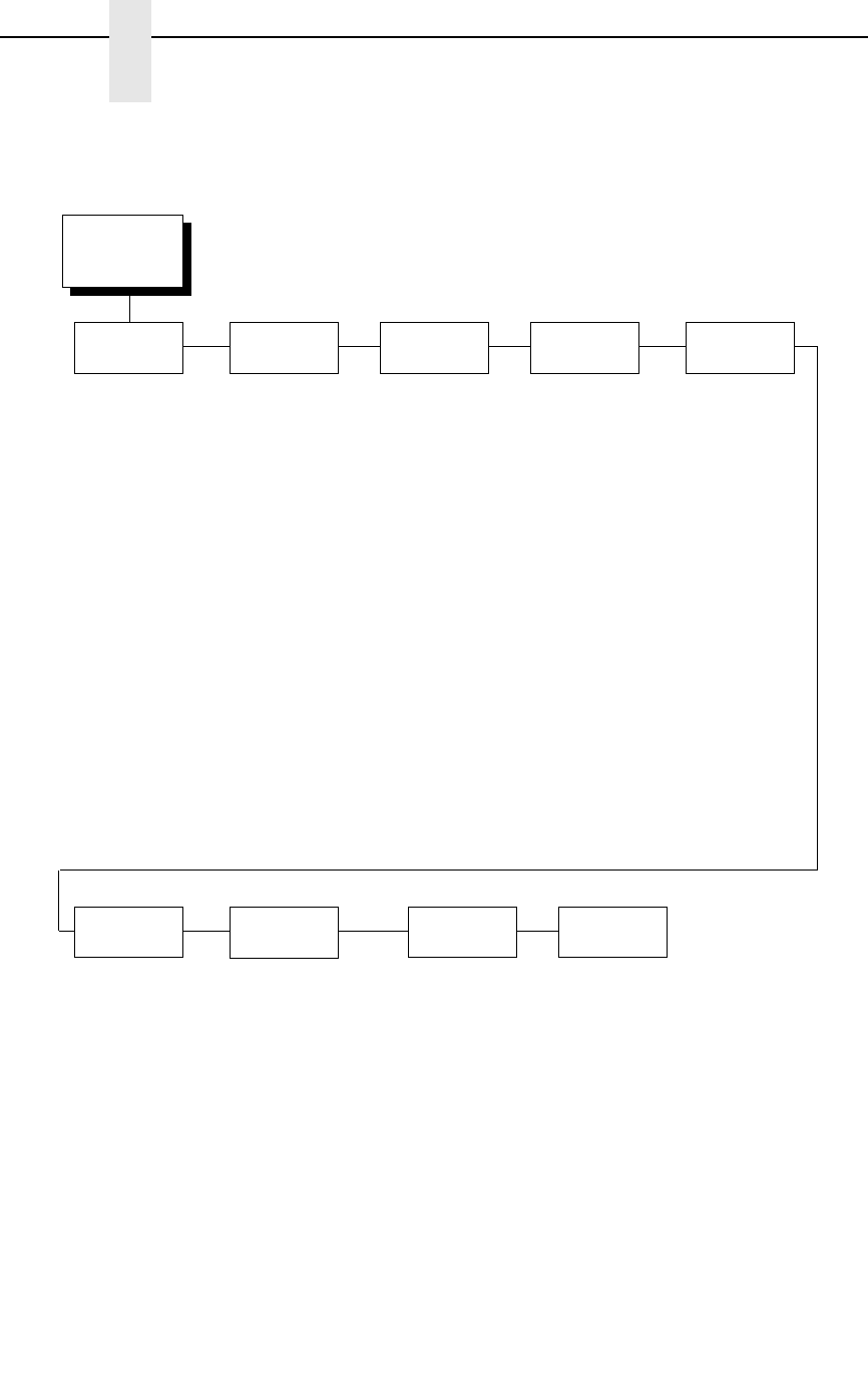
208
Chapter 4
IGP/PGL Emulation
IGP/PGL Font Set Menu
Select Font
(from page 197)
Standard
Sets*
Arabic
Sets
Cyrillic
Sets
European
Sets
Greek
Sets
Hebrew
Sets
Turkish
Sets
Misc.
Sets
0) ASCII*
1) German
2) Swedish
3) Danish
4) Norwegian
5) Finnish
6) English
7) Dutch
8) French
9) Spanish
10) Italian
11) Turkish
12) CP 437
13) CP 850
14-15) Reserved
16-23) Dwn Overlay
24-31) User Def.
ASMO 449*
ASMO 449+
ASMO 708
ASMO 708+
MS DOS CP710
MS DOS CP720
Sakr CP714
Aptec CP715
CP 786
Arabic CP 864
Arabic CP 1046
Arabic Lam 1
Arabic Lam 2
Win. CP 1256
Farsi 1
Farsi 2
1098 Farsi 1285
Code Page 866*
Cyrillic CP 437
Cyrillic 113
Cyrillic 8859-5
ISO 915
Code Page 855
7-bit Cyrillic
Ukrainian
Bulgarian
Win. CP 1251
Latvian 866
CP 1048
Latin 2 8859-2*
Latin 2 852
Mazovia
Kamenicky
Roman 8
PC-437 Slavic
Slavic 1250
Code Page 865
Code Page 860
Latin 1 8859-1
Latin 5 8859-9
Latin 9 8859-15
Polish POL1
Win. CP 1250
Win. CP 1252
Win. CP 1257
CP 858 EURO
Lith. CP 773
Serbo Croatic 1
Serbo Croatic 2
CP 774
CP 775
ISO 8859-4
DEC 256 Greek*
ELOT 928 Greek
Greek 3
ABY Greek
ABG Greek
ELOT 927 Greek
Greek 851
Greek 437
Greek 8859-7
Win. CP 1253
Greek 813 EURO
Greek 869 EURO
Hebrew Old*
Hebrew New
Hebrew DEC
Latin-1 Hebrew
Win. CP 1255
Data Gen. Turk.*
DEC Turkish
IBM Turkish
Siemens Turkish
PTT Turkish
IBC Turkish
Bull Turkish
AS400 Turkish
Unisys Turkish
NCR Turkish
PST Turkish
UNIS-1 Turkish
Code Page 853
INFO Turkish
Win. CP 1254
Code Page 857
Azeri
Block-set 10cpi*
Italics Set
Scanblock 10cpi
PGL Thai Set
* = Factory Default
UTF-8

Features
209
IGP/VGL Emulation
Code V Graphics language (VGL) is an Intelligent Graphics Printing (IGP)
software emulation designed for your Line Matrix printer. The IGP Code V
emulation of the QMS
®
Code V Version II programming language produces
online forms, barcodes, and alphanumeric text-generation. The graphics
processing features are detailed below.
Features
OnLine Form and Label Generation makes it easy to create forms or labels
with the “preprinted” look for each application. VGL programs control all
graphics functions, dramatically reducing host computer programming and
processing time. Graphics capabilities include boxes, vertical and horizontal,
solid and dashed lines with a variety of thickness, logos, and special
alphanumeric print features.
Variable Barcodes allow the barcode for your application to print with
standard or user-defined ratios in vertical or horizontal orientations. Available
barcodes are Codabar, Code 39, Code 93, Code 128 with Subsets A, B, and
C, and Code EAN/UCC 128, EAN 8, EAN 13, Interleaved 2 of 5, MSI, UPC-A,
UPC-E, POSTNET, PostBar, Royal Mail, and UPC Shipping. POSTNET is
available only in the horizontal direction. A dark print mode is included for
darker, high-contrast barcodes. The IBARC barcode command prints
barcodes in four orientations: horizontal, rotated 90, rotated 180, or rotated
270 degrees.
Expanded and Compressed Print draws attention where needed.
Alphanumeric height and width are controlled independently for a tremendous
range of character sizes up to 9.9 inches wide and tall. Several compressed
print sizes are available: 12, 13.33, 15, 17.65, and 20 (cpi), permitting up to
170 columns in an 8.5 inch printed area (20 cpi).
Rotated Alphanumerics permit new concepts in form design. Normal,
expanded, and compressed character strings can be rotated 90 degrees
clockwise, counterclockwise, or printed upside down.
Logos are easily created using alphanumeric commands and a variety of
print and shading features, which provides a “customized” appearance for
forms, reports, and labels. The registered trademark, copyright, TUV
®
, GS-
Mark, UL
®
, and CSA
®
symbols are provided as standard designs on the VGL,
and you can also define custom symbols.
Reverse and Shaded Print permit highlighting and contrasting by printing
white characters on a dark background or white characters on a gray, shaded
background. Various levels or patterns of gray shading and reverse printing
may combine with the many other print features to create distinctive designs.
Automatic Increment/Decrement Capability allows batch form processing.
Individual alphabetic, numeric, and barcode data fields can be identified and
automatically incremented or decremented by any amount, beginning from a
specified reference point.
Standard Character Sets provide you with many different character sets.
Based on the Multinational Character Set, you can create your own character
sets using characters defined and stored in flash memory.
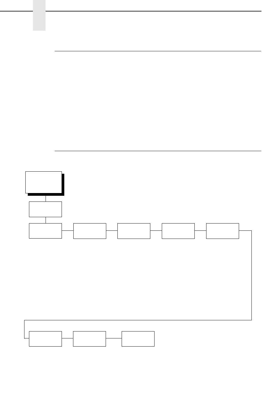
210
Chapter 4
IGP/VGL Emulation
Configuring The Emulation With The Control Panel
You can select VGL default parameters directly from the control panel or by
control codes as explained in the IGP/VGL Programmer's Reference Manual.
The VGL parameters are described on the following pages. Parameters
marked with an asterisk (*) indicate the default value. The printer must be
offline to enter the configuration structure.
IMPORTANT
BEFORE you reconfigure the IGP/VGL, print a configuration sheet to see
all of the current settings.
Pressing an invalid key to enter a parameter value may move you to another
level in the configuration menu or exit the menu completely.
IGP/VGL Submenu
EMULATION
(from page 123)
SFCC &
Pwrup
LPI Graphics
Options
Error
Handling
Ignore/DB8
Setup
Font Set PI Control Prt to
Emulate
VGL SFCC
5E*
Power-up ^X
Disable*
Enable
Power-up ^F
Disable*
Enable
Power-up ^PY
Disable*
Enable
6*
7
8
9
10
(see page 211) Error Msgs
Enable*
Disable
Error Markers
Enable*
Disable
Offpage Errors
Disable*
Enable
Barcode Errors
Enable*
Disable
Ignore Chars
Disable*
Char 1
Char 2
Char 1&2
Ignore Ch#1
0* (0-255)
Ignore Ch#2
0* (0-255)
Data Bit 8
Enable*
Disable
(see page 224) Printer PI
Disable*
Enable
Host PI
Disable*
Enable
Max PI 16
Enable*
Disable
Disable*
MVP/MVP 150B
L150
P3040
P6000
P9000
* = Factory Default
IGP/VGL
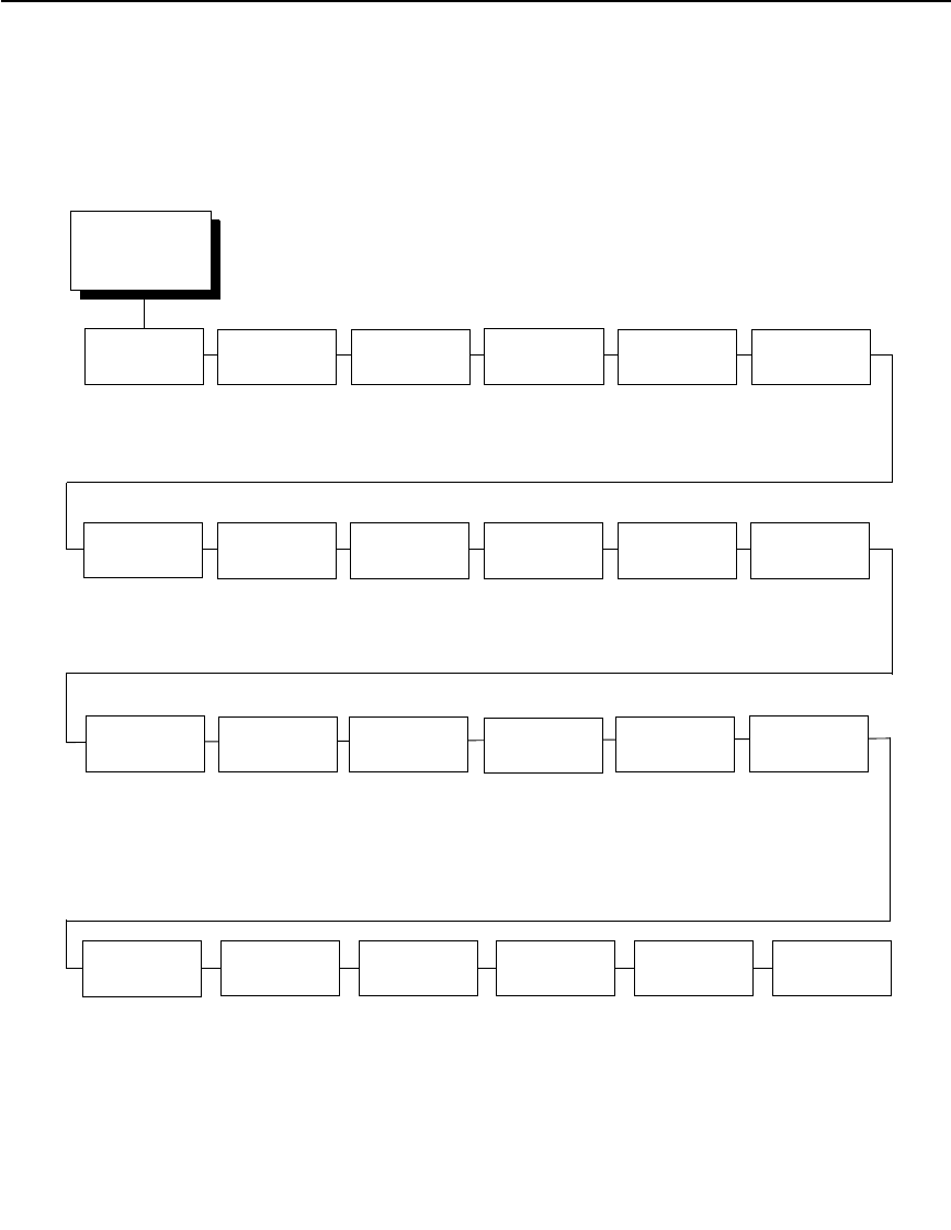
IGP/VGL Submenu
211
IGP/VGL Graphics Options Submenu
Graphics
Options
(from page 210)
Slash 0 Ignore Dots Append
Rotated
Truncate
Alpha
True Vert
1/10
Absorb After
^PY
UPC
Descenders
Rot. Char
Size
Ignore
Spaces
Midline PY Print
Quality
Expanded
Font
Disable*
Enable
Disable*
Enable
Disable*
Enable
Enable*
Disable
Disable*
Enable
Absorb Motion*
Absorb All
Disable
Enable*
Disable
Adjusted*
Not Adjusted
Disable*
Enable
Disable*
Enable
Data Processing*
High
Scalable*
Block
* = Factory Default
LP+ Font MSI Check
Digit
Width Limit Absorb After
^PN
IGP110
Compatbl.
Disable*
Enable
Print*
Don’t Print
Disable*
Enable
Disable*
Enable
Disable*
Enable
I25
Selection
I25 Odd Data*
Leading Zero
Check Digit
Convert Alpha
Disable*
Enable
Auto FF
at ^PN
Disable*
Enable
Ignore ^Lxx
Cmd.
Disable*
Enable
AI 00
Spaces
Disable*
Enable
PDF Size
Comp.
Disable*
Enable
C128 Mode
Comp
Disable*
Enable
C39
Compatbl.
Disable*
Enable
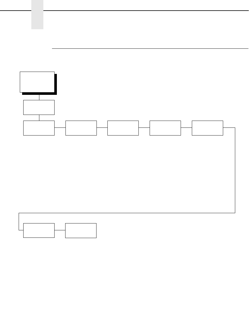
212
Chapter 4
IGP/VGL Emulation
IGP/VGL Submenu (with PCL-II)
EMULATION
(from page 123)
SFCC &
Pwrup
LPI Graphics
Options
Error
Handling
Ignore/DB8
Setup
ISO
Char Set
PI Control
Control Char
5E*
Ignore Mode
Disable*
Enable
Free Format
Disable*
Enable
Mgnum Conversion
Disable*
Enable
6*
7
8
9
10
(see page 213) Error Msgs
Enable*
Disable
Error Markers
Enable*
Disable
Offpage Errors
Disable*
Enable
Barcode Errors
Enable*
Disable
Ignore Nulls
Disable*
Enable
Data Bit 8
Enable*
Disable
0*
1-33
Printer PI
Disable*
Enable
Host PI
Disable*
Enable
Max PI 16
Enable*
Disable
* = Factory Default
IGP/VGL
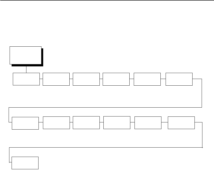
IGP/VGL Submenu (with PCL-II)
213
IGP/VGL (with PCL-II) Graphics Options
Graphics
Options
(from page 212)
Slashes in
Zeros
Ignore Dots Append
Rotated
Truncate
Alpha
True Vert
1/10
UPC
Descenders
Rot. Char
Size
Ignore
Spaces
Midline PY Convert
to U/C
Enable*
Disable
Disable*
Enable
Disable*
Enable
Enable*
Disable
Disable*
Enable
Enable*
Disable
Adjusted*
Not Adjusted
Disable*
Enable
Disable*
Enable
Disable*
Enable
* = Factory Default
Absorb After
^PN
Disable*
Enable
Absorb After
^PY
Absorb All*
Disable
Absorb Motion
IGP110
Compatbl.
Disable*
Enable
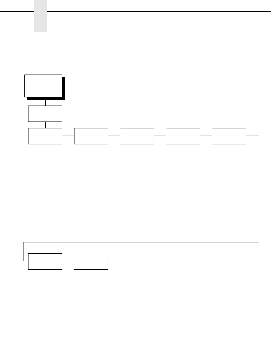
214
Chapter 4
IGP/VGL Emulation
IGP/VGL Submenu (with LG)
EMULATION
(from page 123)
SFCC &
Pwrup
LPI Graphics
Options
Error
Handling
Ignore/DB8
Setup
Font Set PCI Control
VGL SFCC
5E*
Power-Up ^X
Disable*
Enable
Power-Up ^F
Disable*
Enable
Power-Up ^ PY
Disable*
Enable
6*
7
8
9
10
(see page 215) Error Msgs
Enable*
Disable
Error Markers
Enable*
Disable
Offpage Errors
Disable*
Enable
Barcode Errors
Enable*
Disable
Ignore Chars
Disable
Char 1
Char 2
Char 1 & 2
Ignore Ch #1
0*
1 - 255
Ignore Ch #2
0*
1 - 255
Data Bit 8
Enable*
Disable
0*
1-33
Printer PI
Disable*
Enable
Host PI
Disable*
Enable
Max PI 16
Enable*
Disable
* = Factory Default
IGP/VGL
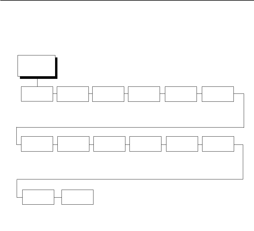
IGP/VGL Submenu (with LG)
215
IGP/VGL (with LG) Graphics Options
SFCC & Pwrup
This option has several sub-options which define the SFCC and power-up
configuration used with VGL.
VGL SFCC
This option selects the Special Function Control Code. The default value 5E.
Run a configuration printout to determine the currently selected VGL SFCC.
Power Up ^X
•
Disable (default).
•
Enable. Selects the ignore mode as the power-up default and selects the
graphics mode ^PY as the power-up default. All characters are ignored
until a ^A command is received.
Power Up ^F
•
Disable (default).
•
Enable. Selects free format mode as the power-up default and selects the
graphics mode ^PY as the power-up default. Free format causes the VGL
to ignore carriage returns, line feeds, and all characters below hex 20
sent from the host.
Graphics
Options
(from page 214)
Slash 0 Ignore Dots Append
Rotated
Truncate
Alpha
True Vert
1/10
UPC
Descenders
Rot. Char
Size
Ignore
Spaces
Midline PY
Disable*
Enable
Disable*
Enable
Disable*
Enable
Enable*
Disable
Disable*
Enable
Enable*
Disable
Adjusted*
Not Adjusted
Disable*
Enable
Disable*
Enable
* = Factory Default
Absorb After
^PN
IGP110
Compatbl.
Disable*
Enable
Disable*
Enable
Absorb After
^PY
Absorb Motion*
Absorb All
Disable
Dark
Barcode
Disable*
Enable
Width Limit
Disable*
Enable

216
Chapter 4
IGP/VGL Emulation
Power Up ^PY
•
Disable (default).
•
Enable. Selects the graphics mode ^PY as the power-up default.
LPI
The number of lines to be printed per inch. For example, at 6 lpi there is 1/6
inch from the top of one print line to the top of the next print line.
Graphics Options
The following are several options which configure printing output.
Slash 0
This parameter allows you to print the numeral “0” with or without the slash.
This option applies to all character sets except OCR-A and OCR-B.
•
Disable (default). Zero is printed without a slash.
•
Enable. Zero is printed with a slash.
Ignore Dots
•
Disable (default).
•
Enable. Causes the VGL to expect position values to be specified in only
1/10ths of an inch. If the dot position is also given, it is treated as text.
Append Rotated
•
Disable (default). Logos and alphanumeric strings are treated as
separate elements.
•
Enable. Appends logos to an alphanumeric string rotated in a clockwise,
counterclockwise, or inverted orientation.
Truncate Alpha
When enabled, this parameter prevents the printing of Error 48 (Element Off
Page Error) if alphanumeric data, including spaces, extends beyond the right
side of the form. The options include:
•
Enable (default)
•
Disable
True Vert 1/10
•
Disable (default). A vertical 1/10 of an inch parameter is used as 7/72 of
an inch. The absolute move is slightly smaller than expected. For
example, a one-inch move would be 70/72 of an inch. Vertical moves that
have the same value are identical in length.
•
Enable. A vertical 1/10 inch parameter is used as 1/10 inch. Rounding
occurs to the nearest 1/72 inch. This can cause vertical moves that have
the same value to differ by
±
1/72 inch.

217
Absorb After ^PY
•
Absorb Motion (default). The first paper motion following a ^PY
command is ignored.
•
Absorb All. The system ignores all the data and terminator until a host
generated motion terminator is detected.
•
Disable. System terminators following a graphics command are sent to
the printer and result in paper motion.
UPC Descenders
•
Enable (default). UPC/EAN barcodes are printed with descenders, even
if there is no human readable data.
•
Disable. UPC/EAN barcodes are printed without descenders if there is no
human readable data.
Rot. Char Size
•
Adjusted (default). Rotated (clockwise/counterclockwise), expanded
characters have a different size than an unrotated character with the
same size parameters.
•
Not Adjusted. Rotated, expanded characters are the same size as
unrotated characters with the same size parameters.
Ignore Spaces
•
Disable (default). Trailing spaces are not deleted from the last
alphanumeric element in a graphics pass.
•
Enable. Trailing spaces are deleted from the last alphanumeric element
in a graphics pass.
Midline PY (includes ^PN)
•
Disable (default). The Graphics mode Enable command, ^PY, must be
the first three characters of a line.
•
Enable. The ^PY or ^PN can occur anywhere in a line.
Print Quality
•
Data Processing (default). ALPHA text and barcodes are printed in
normal mode at 60 x 72 dpi. This mode should be set if the highest speed
is desired.
•
High. ALPHA text and barcodes are printed in dark mode at
120 x 72 dpi.
Expanded Font
•
Scalable (default). These expanded characters have rounded edges.
•
Block. These are block characters compatible with IGP-X10 printers.

218
Chapter 4
IGP/VGL Emulation
LP+ Font
•
Disable (default). The IGP/VGL uses its default half-dot font, which is
slightly different from the standard bitmap font used by LP+ at 12, 13, 15
and 17 cpi.
•
Enable. The IGP/VGL uses the same font as used by LP+ at all cpi.
MSI Check Digit
•
Print (default). The check digit is appended at the end of the printable
data field for MSI barcodes.
•
Don't Print. The check digit for MSI barcodes does not print.
I25 Selection
•
I25 Odd Data (default). When an odd number of data is provided, the
default setting, Leading Zero, will add a zero to the beginning of the bar
code data. The setting, Check Digit, will add a check digit to the end of the
bar code data so that the results add up to an even number of data.
•
Convert Alpha. Disable is the default. When enabled, each non-digit I25
bar code character will convert to “0.”
NOTE: If you use an Interleaved 2/5 barcode that automatically adds the
check digit (type code k or l, IBARC type code INT2/5CD or INT2/
5CDA), the check digit is added regardless of how this parameter is
set.
AI 00 Spaces
This option is designated for EAN/UCC-128 barcodes whose application
identifier (AI) is 00.
•
Disable (default). The printable data field is printed with the AI enclosed
in parentheses. This is the standard EAN/UCC-128 format.
•
Enable. The printable data field is printed with the UCC fields separated
by spaces. This option is IGP-X00 compatible.
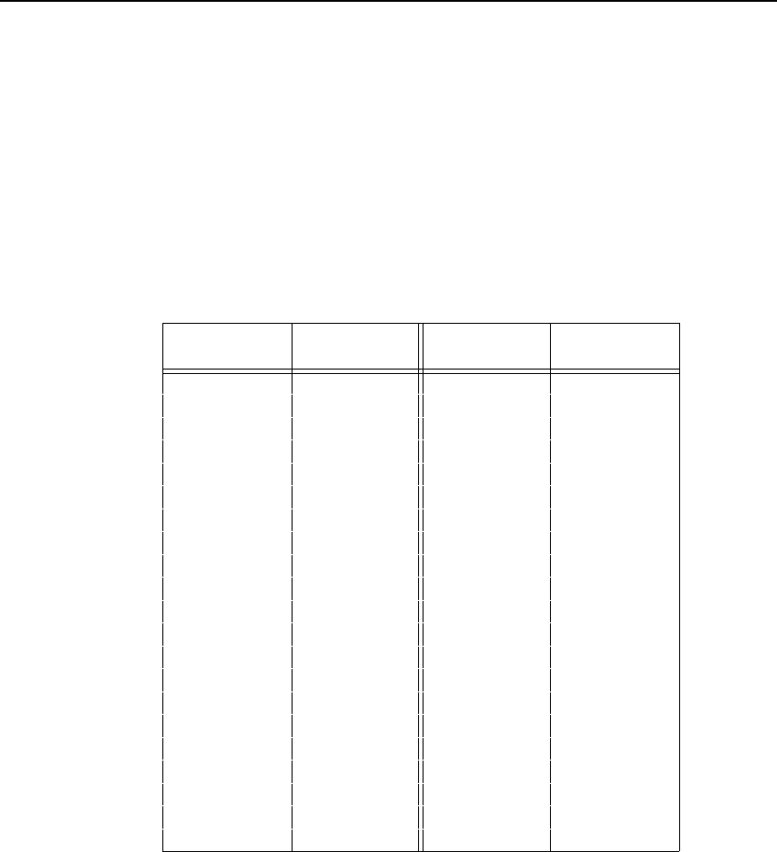
219
Width Limit
•
Disable (default).
•
Enable. The system will limit the length and width for expanded
characters to a limit shown in Table 9, which displays the maximum width
allowed for a specific height in the range of 00 through 40 (0.0 through 4.0
inches).
Absorb After ^PN
•
Disable (default). All line terminators that follow the ^PN command are
sent to the printer and processed.
•
Enable. The first motion line terminator that follows the ^PN command is
ignored.
IGP110 Compatbl.
This option instructs the VGL to behave similarly to the IGP-10 with respect to
certain commands. All new users with new applications should select the
“Disable” option. Selecting this mode insures the printer will behave as
described in this manual.
•
Disable (default). The IGP does not emulate the IGP-10 mode.
•
Enable. The IGP emulates the IGP-10 version.
Table 9. Width Limit Table
Height Param. Max. Width
Allowed Height Param. Max. Width
Allowed
00 99 21 51
01 99 22 53
02 323 56
03 624 58
04 825 61
05 11 26 63
06 13 27 66
07 16 28 68
08 18 29 71
09 21 30 73
10 23 31 76
11 26 32 78
12 28 33 81
13 31 34 83
14 33 35 86
15 36 36 88
16 38 37 91
17 41 38 93
18 43 39 96
19 46 40 98
20 48

220
Chapter 4
IGP/VGL Emulation
Auto FF at ^PN
•
Disable (default). A form feed will not be generated automatically when
the ^PN command is encountered.
•
Enable. A form feed will be generated automatically to slew to the top of
the next form when the ^PN command is encountered and when the
current vertical position is not at top of form.
PDF Size Comp.
This option is for compatability of the font size of the barcode printable data
field on the old build.
•
Disable (default). Uses the normal font size.
•
Enable. Matches the font size of the old build.
C128 Mode Comp
The menu is for compatibility of the old build in auto mode switch.
•
Disable (default). Uses auto mode switch.
•
Enable. Matches the old build on the auto mode switch.
C39 Compatbl.
This menu makes the old method of decoding C39 alternative character set
compatible with the new.
•
Disable (disable). Uses the current way of decoding.
•
Enable. Matches the old method of decoding.
Ignore ^Lxx Cmd.
•
Disable (default).
•
Enable. The ^Lxx command will always be ignored.
Error Handling
Following are several options which define how errors are reported.
Error Msgs
•
Enable (default). Command syntax is checked and error messages
printed when command parameters are incorrect.
•
Disable. Error checking and error messages are suppressed.

221
Error Markers
•
Enable (default). Prints the following error markers for those elements
that print beyond the page boundaries:
>> for elements that begin off the right side of the page;
<< for elements that begin at the indicated position but end off the page;
♦
for elements where the starting position of the command contains an
error other than an off-page error.
Offpage Errors
•
Disable (default). Does not report errors for elements that start or end
beyond the right edge of the page.
•
Enable. Reports errors for elements that start or end beyond the right
edge of the page.
Barcode Errors
•
Enable (default). An error message will print when invalid barcode data is
encountered.
•
Disable. VGL will not print an error for illegal barcode data; the barcode
will be skipped.
NOTE: When the Barcode Errors option is disabled, the VGL emulation will
try to make the best use of invalid data by either truncating extra
digits or adding zeros to the end of barcode data to meet minimum
data length requirements for some barcodes. Not all errors will be
corrected.
Ignore / DB8 Setup
Following are several options which define character filtering and Data Bit 8.
Ignore Chars
•
Disable (default). Character filtering is not enabled.
•
Char 1. Character 1 will be filtered. Select the option “Ignore CH#1” to
specify character 1.
•
Char 2. Character 2 will be filtered. Select the option “Ignore CH#2” to
specify character 2.
•
Char 1 & 2. Characters 1 & 2 will be filtered. Select the options “Ignore
CH#1” and “Ignore CH#2” to specify values for these characters.
Ignore CH#1
Specifies character 1 for the character filtering option. Valid decimal values
are from 0 through 255.
Ignore CH#2
Specifies character 2 for the character filtering option. Valid decimal values
are from 0 through 255.

222
Chapter 4
IGP/VGL Emulation
Data Bit 8
•
Enable (default). The PI line is not passed directly from host to printer; all
8 bits are used for data bits, and characters in the hex 80-FF range can
be accessed.
•
Disable. When the host PI line is enabled, Data Bit 8 internally indicates
PI line status. To use the PI line, disable Data Bit 8, and enable the Host
PI configuration option (under the PI Control option, below).
NOTE: Data Bit 8 is interpreted as either Data Bit 8 or PI signal, but never
both. When enabled as Data Bit 8, Data Bit 8 has priority over the PI
signal, and all data above hex 7F is used to access character data
and not to interpret PI line data.
Conversely, when Data Bit 8 is disabled and the PI signal is used,
Data Bit 8 of the data is reserved for use as the PI function, and you
cannot access characters in the hex 80-FF range. Therefore, to
access characters in the hex 80-FF range, Data Bit 8 must be
enabled.
Font Set
The Font Set specifies which language is currently selected for use with the
VGL. Refer to
ΙΓΠ/ςΓΛ Φοντ Σετ Μενυ ον παγε 224
for available
selections.
PI Control
Printer PI
•
Disable (default). The ASCII emulation is configured with the PI line
disabled.
•
Enable. The ASCII emulation is configured with the PI line enabled.
Host PI
•
Disable (default). The host does not send PI signals.
•
Enable. The host sends PI signals. The Data Bit 8 configuration option
must be disabled to transmit the PI line to the printer.
Max PI 16
•
Enable (default). A paper slew of 0-15 will move 1-16 lines.
•
Disable. A paper slew of 1-15 will move 1-15 lines. A paper slew of 0 will
always move 1 line.

223
Prt To Emulate
This option allows you to select an earlier model printer/IGP board
combination to emulate. When a printer emulation is selected, the scaling
command causes the printer to generate a graphic image in the same density
as the printer emulation chosen. Five types of printers can be emulated: MVP
or MVP 150B, L150, P3040, P6000, and P9000. Once a printer emulation is
selected, it remains active until the printer is turned off or another printer
emulation is selected. All new users with new applications should select the
“Disable” option, which insures the printer behaves as described in this
manual. The other compatibility modes are required to emulate the behaviors
of older printers which may be inconsistent with the documented VGL
functionality. Proper use of this feature requires the printer to be equipped
with high resolution hammer bank tips (12 mil).
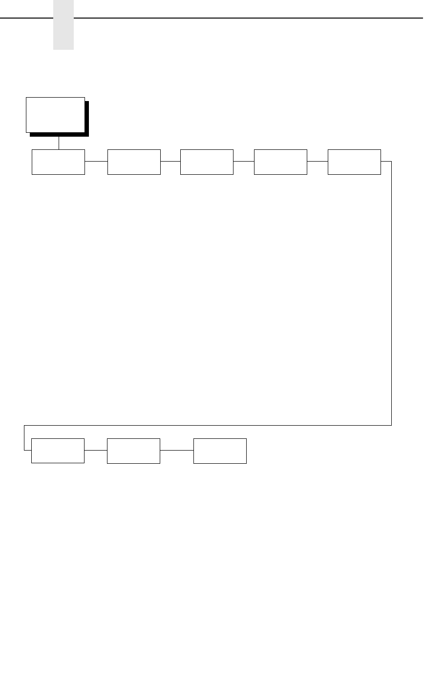
224
Chapter 4
IGP/VGL Emulation
IGP/VGL Font Set Menu
Font Set
(from page 210)
Standard
Sets*
Arabic
Sets
Cyrillic
Sets
European
Sets
Greek
Sets
Hebrew
Sets
Turkish
Sets
Misc.
Sets
0) ASCII*
1) German
2) Swedish
3) Danish
4) Norwegian
5) Finnish
6) English
7) Dutch
8) French
9) Spanish
10) Italian
11) Turkish
12) CP 437
13) CP 850
ASMO 449*
ASMO 449+
ASMO 708
ASMO 708+
MS DOS CP710
MS DOS CP720
Sakr CP 714
Aptec CP715
CP 786
Arabic CP 864
Arabic CP 1046
Arabic Lam 1
Arabic Lam 2
Win. CP 1256
Farsi 1
Farsi 2
1098 Farsi 1285
Code Page 866*
Cyrillic CP 437
Cyrillic 113
Cyrillic 8859-5
ISO 915
Code Page 855
7-bit Cyrillic
Ukrainian
Bulgarian
Win. CP 1251
Latvian 866
CP 1048
Latin 2 8859-2*
Latin 2 852
Mazovia
Kamenicky
Roman 8
PC-437 Slavic
Slavic 1250
Code Page 865
Code Page 860
Latin 1 8859-1
Latin 5 8859-9
Latin 9 8859-15
Polish POL1
Win. CP 1250
Win. CP 1252
Win. CP 1257
CP 858 EURO
Lith. CP 773
Serbo Croatic 1
Serbo Croatic 2
CP 774
CP 775
ISO 8859-4
DEC 256 Greek*
ELOT 928 Greek
Greek 3
ABY Greek
ABG Greek
ELOT 927 Greek
Greek 851
Greek 437
Greek 8859-7
Win. CP 1253
Greek 813 EURO
Greek 869 EURO
Hebrew Old*
Hebrew New
Hebrew DEC
Latin-1 Hebrew
Win. CP 1255
Data Gen. Turk.*
DEC Turkish
IBM Turkish
Siemens Turkish
PTT Turkish
IBC Turkish
Bull Turkish
AS400 Turkish
Unisys Turkish
NCR Turkish
PST Turkish
UNIS-1 Turkish
Code Page 853
INFO Turkish
Win. CP 1254
Code Page 857
Azeri
Block-set 10cpi*
Italics Set
Scanblock 10cpi
PGL Thai Set
* = Factory Default
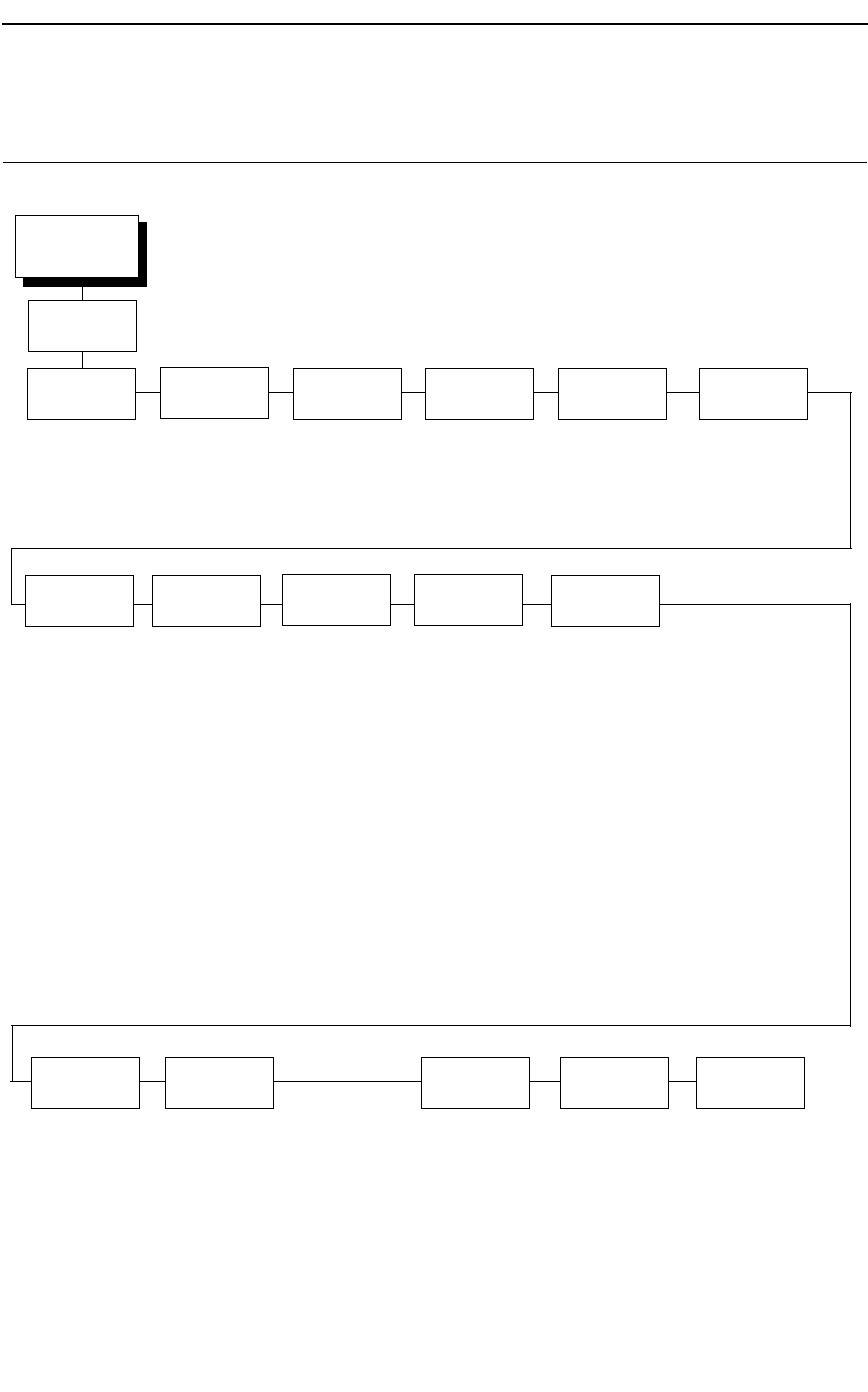
225
IPDS Emulation
Font Size Graphics
Quality
Barcode
Quality
Barcode
Speed
Early Print
Comp
Graphics
Scaling
Graphic
Charsize
I2/5
Checksum
Select By Host*
Standard
Compressed
High*
Select By Host
Low
High*
Select By Host
Low
High*
Select By Host
Low
Off*
On
Rounded*
Exact
4234*
67XX
Standard (1/3)*
Special (4/9)
* Factory Default
IPDS
EMULATION
(from page 123)
Print Quality
Select By Host*
Default Font
Barcode
Size
4234*
67XX
64XX
4224
Default Code
Pag
Internat. Set 5*
English/USA/Can
Austrian/German
Belgian Old
Brazilian
Canadian/French
Danish/Norw.
Finnish/Swedish
French Azerty
Italian
Japanese/Eng.
Katakana
Portuguese
Spanish
Spanish Speak.
English (UK)
Arabic
Greek
Icelandic
Turkish Latin 5
Latin 2/ROECE
Cyrillic Old
Thai
Hebrew
Farsi
Yugoslavian
Latin 9
Euro US/Can.
Euro Aust/Germ.
Euro Dan/Norw.
Euro Fin/Swed.
Euro Italian
Euro Spanish
Euro UK/Ireland
Euro French
Euro Internat.
Euro Icelandic
Code Page
Subset
Thai
Version 0*
Version 1
Version 2
Hexdump
Mode
Disable*
Enable
VPA Check
Enable*
Disable
Default
Font
DRAFT 10*
DRAFT 12
DRAFT 13
DRAFT 15
DRAFT 17
DRAFT 18
DP 10
DP 12
DP 13
DP 15
DP 17
DP 18
Print IPDS
Fonts
NLQ 10
NLQ 12
NLQ 13
NLQ 15
NLQ 17
NLQ 18
OCRA
OCRB
PSM
IPDS Emulation

226
Chapter 4
IPDS Emulation
Your IPDS printer emulates the IBM 4234 twinax models 008 and 012.
IPDS Twinax printers can only print IPDS data streams and nothing else.
Even a simple job, such as a screen print, is IPDS data in a twinax
attachment. Because the printer definition on a twinax host is either set
automatically (by auto configuration) or manually, the printer type is already
known.
NOTE: A general discussion about starting and stopping IPDS can be found
in the IBM 4234 Product and Programming Reference Manual
(GC31-3879). Sending a non-IPDS data stream to an IPDS printer
and vise versa will result in a hung spool file or writer.
Font Size
This parameter chooses the font size which will be used by IPDS.
•
Select By Host (default). The font ID is only affected by host commands.
•
Standard. The font ID is converted to a decompressed font ID.
•
Compressed. The font ID is converted to a compressed font ID.
Print Quality
This parameter chooses the print quality.
•
Select By Host (default). The application decides the print quality.
•
Default Font. The default font the printer uses.
Graphics Quality
This parameter chooses the print quality of graphics.
•
High (default). Graphics are printed at 144 dot rows per inch.
•
Select By Host. The application decides the quality of the graphics.
•
Low. Graphics are printed at 72 dot rows per inch.
Barcode Quality
This parameter chooses the horizontal print quality of barcode labels.
•
High (default). Label is printed at 144 dots per inch.
•
Select By Host. The application decides the quality of the labels.
•
Low. Label is printed at 72 dots per inch.
Barcode Speed
This parameter chooses the vertical print quality of barcode labels.
•
High (default). Barcodes are printed with less vertical dots, increasing
printing speed, but decreasing print quality.
•
Select By Host. The application decides the quality of the labels.
•
Low. Barcodes are printed with more vertical dots, decreasing printing
speed, but increasing print quality.

227
Barcode Size
This parameter will emulate the barcode sizes of the selected printer model.
•
4234 (default). IBM 4234
•
67XX. Decision Data 67XX
•
64XX. IBM 6400 series
•
4224. IBM 4224
Early Print Comp (Complete)
This parameter chooses when to send a Print Comp to the controller.
•
Off (default). Print Comp is sent if page is printed completely.
•
On. Print Comp is sent immediately. The next page will be created. This
improves the print performance when starting the next page.
NOTE: When Early Print Comp is enabled and an error occurs, you may lose
data.
Graphics Scaling
This parameter chooses the scaling factor for graphics when the Mapping
Control option of the IPDS Write Graphics Control command is SCALE TO
FIT:
•
Rounded (default). Calculations are rounded up in the desired output
resolution.
•
Exact. Graphics will be scaled as accurately as possible.
Graphic CharSize
This parameter will emulate the graphic character size of the selected printer
model.
•
4234 (default). IBM 4234
•
67XX. Decision Data 67XX
I2/5 Checksum
This parameter defines the printer checksum calculation method for
Interleaved 2 of 5 barcodes.
•
Standard (1/3) (default). The odd numbers will be multiplied by 3 and the
even numbers by 1 for calculation of the checksum.
•
Special (4/9). The odd numbers will be multiplied by 4 and the even
numbers by 9 for calculation of the checksum.
NOTE: “Odd” refers to the 1st, 3rd, 5th... character in the barcode, while
“even” refers to the 2nd, 4th, 6th... character in the barcode.
Default Code Pag
Choose which code page to use with the IPDS emulation. This option is
independent of the Character Set selection in the CTHI emulation.
IPDS Emulation

228
Chapter 4
IPDS Emulation
Code Page Subset
When the Thai code page is selected as the default, either from the front
panel or by a host command, you may choose from three different versions.
Default Font
Choose a font quality and size from the available selections. All fonts in the
Default Font menu are available in standard and compressed vertical
resolution (see page 225).
VPA Check
•
Enable (default). The printer checks for dots that fall outside the
intersection of the logical and physical pages. If dots fall outside the area,
the printer reports an error to the host if the IPDS Exception Handling
Control command setting requires error reporting.
•
Disable. The printer does not report dots outside the valid printable area.
Hexdump Mode
A hex code printout (or hex dump) translates all incoming data to hexadecimal
equivalents. A hex dump lists each ASCII data character received from the
host computer, together with its corresponding two-digit hexadecimal code.
Hex dumps can be used to troubleshoot some types of printer data reception
problems.
Print IPDS Fonts
This feature allows you to print a list of all resident fonts currently available in
the active IPDS emulation
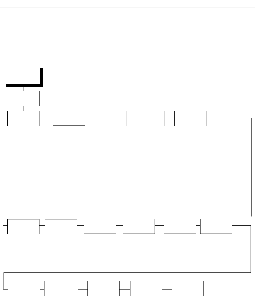
229
PCL - II Emulation
Primary Char.
Set
Page Length
Rep.
Max Line
Width
Face CPI
Delay
Graphics
Density
Perforation
Skip
Display
Functns
Line
Terminator
ID
0* - 109, xx
Symbol Set
See page 230
Pitch
10*, 12, 13.3
15, 16.67, 20
Density
Data Processing*
NLQ
OCR-A
OCR-B
High Speed
Inches/Page*
Lines/Page
13.2 inches*
13.6 inches
Enable*
Disable
60 DPI*
70 DPI
Disable*
Enable
Disable*
Enable
LF After CR
CR After LF
CR After FF
CR After VT
* = Factory Default
PCL-II
EMULATION
(from page 123)
Second Char.
Set
Symbol Set
Delay
Disable*
Enable
PTX
Linefeed
Disable*
Enable
LPI Adjust
6 LPI*
8 LPI
Page L./Lines
66 Lines*
12 - 96 Lines
Page L./Inches
11.0 Inches*
12.0 Inches
12.5 Inches
13.0 Inches
15.5 Inches
16.0 Inches
2.0 - 10.5 Inches
ID
0* - 109, xx
Symbol Set
See page 230
Pitch
10*, 12, 13.3
15, 16.67, 20
Density
Data Processing*
NLQ
OCR-A
OCR-B
High Speed
Symbol Set
Print
Reset Cmd
CFG Ld
Current Config*
Factory Config
Disable
Power Up Config
Config. Print
Perforation
Skip
Disable*
Enable
PCL - II Emulation
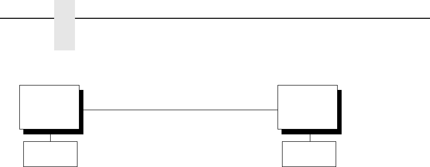
230
Chapter 4
PCL - II Emulation
Primary
Char. set
(from page 229)
Symbol Set
Roman-8[8U]*
Turkish-8[8T]
Arab-8[8V]
Cyrillic[8R]
PC858 MtLi[13U]
MC Text[12J]
Roman-9[4U]
Latin-9[9N]
Win3.0Lat-1[9U]
Hebrew Old
Japan Postnet
Katakana Post
ASCII[0U]
Math Sym[0A/0M]
LineDraw[0B/0L]
IS0 Den/Nor[0D]
Roman Ext.[0E]
IS0 UK[1E]
IS0 France[0F]
IS0 German[0G]
Hebrew[0H]
Japan ASCII[0K]
Katakana[1K]
Block Char[1L]
OCR-A[0O]
OCR-B[1O]
ISO Swe/Fin[0S]
ISO Spain[1S]
ISO Italian[0I]
ISO Portugu[4S]
Latin-1[0N]
Latin-2[2N]
Latin-5[5N]
Latin-6[6N]
Baltic[19L]
PC8 DanNor[11U]
PC8 Cd437[10U]
PC850 MtLi[12U]
PC851 LtGk[12G]
PC852 Lat2[17U]
PC Turkish[9T]
PC Hebrew[15H]
PC Lat/Ara[10V]
PC Cyrillic[3R]
Win3.1Lat1[19U]
Win3.1Lat-2[9E]
Win3.1Lat-5[5T]
Math-8[8M]
PS Math[5M]
Greek-7[12N]
Postnet4[15Y]
Postnet11.25
Greek-8[8G]
Hebrew-8[8H]
Katakana-8[8K]
DEC 256 Greek
ELOT 928 Greek
Greek 3
ABY Greek
ABG Greek
ELOT 927 Greek
Greek 437
Greek 8859-7
Symbol Set
(same as Primary
Character Set)
Secondary
Char. Set
(from page 229)

231
Primary Char. Set
You can select one of 92 pre-defined character sets by ID (although character
sets range from 0 - 109, not all sets are available on the LJ500 printer), or you
can select pitch, symbol set, and typeface individually. If the combination you
choose matches one of the 92 predefined sets, the ID submenu will reflect
that selection. If not, the ID menu will display
xx
to indicate that the current
character set does not match a pre-defined set. Set 0 is the default, and its
attributes are 10 cpi, Data Processing typeface, and Roman 8 symbol set.
Second Char. Set
Your printer can store an additional character set. To toggle between them,
send the Shift In (Decimal 15, to select the Primary character set) or Shift Out
(Decimal 14, to select the Secondary character set).
Page Length Rep.
•
Inches/Page (default). All page length calculations are based on the
inches displayed on the panel.
•
Lines/Page. All changes in LPI or density will be changed accordingly.
The length of the page is the number of lines per inch, or lpi.
For example, if the form in use is 82 lines at 6 lpi, the page is physically
13.67 inches. Since 13.67 inches is not selectable from the Length in
Inches menu, change the representation to lines, then set the number of
lines to 82. The inches menu will display 13.6 inches although the printer
internally keeps the exact form length of 13.67 inches.
Max Line Width
Set the maximum line width at 13.2 inches (default) or 13.6 inches.
Face CPI Delay
Allows the combination of different font densities on the same line.
•
Enable (default). Different font densities can be used on the same line.
•
Disable. Only the same font densities are allowed on the same line.
Graphics Density
Graphics can be printed in 60 DPI (default) or 70 DPI.
Perforation Skip
•
Disable (default). Allows printing on page perforation.
•
Enable. You may set up a skip-over margin. For example, a skip-over
margin of one inch creates a one inch margin at the bottom of the page.
PCL - II Emulation
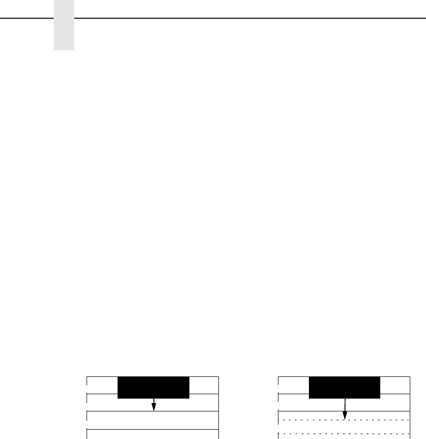
232
Chapter 4
PCL - II Emulation
Display Functions
•
Disable (default). Control characters are not printed.
•
Enable. Control characters are printed before they get executed. This is a
useful debugging tool.
Line Terminator
You can define the action of the line. Four options are available: LF after CR,
CR after LF, CR after FF, and CR after VT. Each of these options may be
enabled or disabled independent of one another.
PTX Linefeed
•
Disable (default). Linefeed is to be performed as calculated from the
bottom of the graphics or barcode, thereby disrupting the vertical text
alignment.
•
Enable. The Linefeed moves to the next line as calculated from the Top
of Form position, thereby retaining vertical text alignment. When printing
graphics or bar codes, you may want to set the PTX Linefeed parameter
to Enable to maintain text alignment.
LPI Adjust
This parameter lets you specify the lines per inch (lpi) values: 6 LPI (default)
or 8 LPI.
Page L./Lines
This parameter lets you set physical page length in lines from 12 to 96 at 6 lpi,
or 16 to 128 at 8 cpi. The default is 66 lines at 6 lpi.
NOTE: If 6 lpi is selected, you will be able to scroll the menu to 128 (an
invalid length). However, when you press ENTER to select this value,
the menu will return with the maximum lines for 6 lpi (i.e., 96 lines).
Similarly, selecting too few lines for 8 lpi will cause the menu to return
with 16 lines.
Page L./Inches
This parameter allows you to set physical page length from 2 to 16 inches, in
increments of half an inch. The default is 11 inches.
Linefeed
LINE 1
Linefeed
LINE 2
LINE 3
LINE 1
LINE 2
LINE 3
PTX Linefeed Enabled PTX Linefeed Disabled
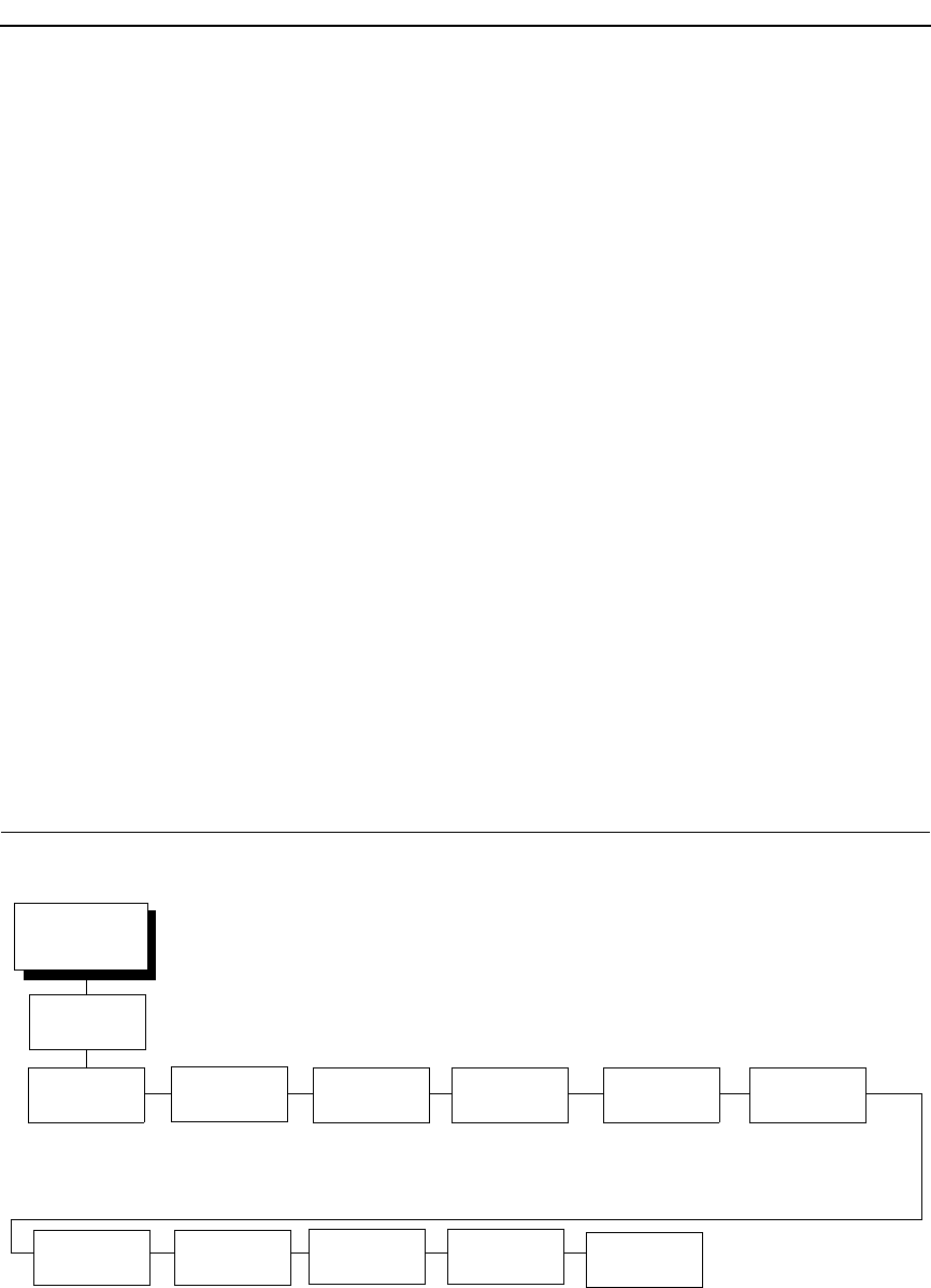
233
Config Print
This option prints the emulation's parameters and the currently selected
values.
Symbol Set Print
This option prints a list of all the available sets. The character set number
prints to the left of the character set sample.
Reset Cmd CFG Ld
When the printer receives a host data stream reset command in addition to
resetting printer variables, the selected configuration will be loaded.
•
Current Config (default). If you have preset and presaved multiple
configurations, then the currently selected presaved configuration is
loaded when the reset command is received.
•
Factory Config. The factory installed configuration is loaded when the
reset command is received.
•
Disable. The printer ignores the reset command when it is received and
continues to use the currently loaded configuration.
•
Power-Up Config. The power-up configuration is loaded when the reset
command is received.
LG Emulation
Font Horiz Forms Autowrap CR
FF Unsolicited
Rpt
Print Mode
Opt
Plot Mode
Opt
(see page 234) Left Mrg 00.0*
Right Mrg 13.2
No*
Yes
= CR*
= CR + LF
= FF*
= CR + FF
No*
Small
Big
Enable*
Disable
Enable*
Disable
* = Factory Default
LG
EMULATION
(from page 123)
Vert. Forms LF
= LF*
= CR + LF
I-2/5 Guard
Bars
Enable*
Disable
Bot Frm 66/6
Top Mrg 0/6
Bot Mrg 66/6
LG Emulation
234
Chapter 4
LG Emulation
DP 10 6*
DP 10 8
DP 12 6
DP 12 8
DP 15 6
DP 15 8
DP 15 10
HS 10 6
Corespon 5 6
Corespon 5 8
Corespon 6 6
Corespon 6 8
Corespon 10 6
Corespon 10 8
Corespon 12 6
Corespon 12 8
Corespon 15 6
Corespon 15 8
Corespon 15 10
OCR A
OCR B
Compress 6 6
Compress 6 8
Compress 8 6
Compress 8 8
Compress 13 6
Compress 13 8
Compress 13 10
Compress 16 6
Compress 16 8
Compress 16 10
DP 5 6
DP 5 8
DP 6 6
DP 6 8
GL Char Set
U.S. ASCII*
DEC Finnish
French
DEC Fr. Can.
German
Italian
JIS Roman
DEC Nor./Dan.
Spanish
DEC Swedish
DEC Great Brit.
ISO Nor./Dan.
DEC Dutch
DEC Swiss
DEC Portuguese
VT100 Graphics
DEC Suppl.
DEC Technical
ISO Katakana
7-Bit Hebrew
7-Bit Turkish
Greek Suppl.
Hebrew Suppl.
Turkish Suppl.
GR Char Set
DEC Suppl.*
DEC Technical
VT100 Graphics
ISO Katakana
ISO Latin 1
ISO Latin 2
ISO Latin 5
ISO Latin 9
ISO Cyrillic
ISO Greek
ISO Hebrew
Hebrew Suppl.
Turkish Suppl.
Style Character Set
Font
(from page 233)

235
Font
Select a default font style and character set for the LG emulation, as follows:
•
Style. This option allows you to specify a print quality that includes a
characters per inch (cpi) and lines per inch (lpi) setting, in the format Type
cpi lpi. The default setting is DP 10 6 (Data Processing, 10 cpi, 6 lpi). The
print quality types you may choose from are as follows:
DP = Data Processing (standard quality)
CORESPON = Correspondence (near letter quality)
COMPRESS = Compressed (vertically compressed for printing
long graphs and charts)
OCR A & OCR B = Optical Character Recognition, sets A
and B
HS = High Speed (Draft quality for high speed printing)
•
Character Set. This option allows you to select a character set. The
character set you select can be any of the Digital Multinational sets, which
include the U.S. ASCII set and several foreign language and special
character sets.
Vert Forms
•
Bot Frm 66/6 (default). This option sets the bottom margin for the forms.
You must specify the bottom margin in lines (at 6 lines per inch), ranging
from 0 to 198 lines (33 inches). The default setting is 66. Press the right
arrow to increase the value, left arrow to decrease the value, and ENTER
to change units. Selecting a value for this option resets the top margin to
0, so the top margin must be redefined after this option is selected.
•
Top Mrg 6/0.This option sets the top margin for the forms. You must
specify the top margin in lines (at 6 lines per inch), ranging from 0 to 198
lines (33 inches). The default setting is 0. Press the right arrow to
increase the value, left arrow to decrease the value, and ENTER to
change units. The margins will automatically adjust so that the top and
bottom margins do not cross each other.
•
Bot Mrg 66/6. This option sets the bottom margin for the forms. You must
specify the bottom margin in lines (at 6 lines per inch), ranging from 0 to
198 lines (33 inches). The default setting is 66. Press the right arrow to
increase the value, left arrow to decrease the value, and ENTER to
change units. Selecting a value for this option resets the top margin to 0,
so the top margin must be redefined after this option is selected.
LG Emulation

236
Chapter 4
LG Emulation
Horiz Forms
•
Left Mgr 0.00 (default). This sets the left margin for the forms. You must
specify the left margin in 1/10 inch increments, from 0 to 13.1 inches. The
default value is 0. Press the right arrow to increase the value, left arrow to
decrease the value, and ENTER to change units. The margins will
automatically adjust so that the left and right margins do not cross each
other.
•
Right Mrg 13.2. This sets the right margin for the forms. You must specify
the right margin in 1/10 inch increments, from 0.1 to 13.2 inches. The
default value is 13.2. Press the right arrow to increase the value, left
arrow to decrease the value, and ENTER to change units. The margins
will automatically adjust so that the left and right margins do not cross
each other.
Autowrap
This parameter determines if text will wrap to the next line when the line of
text exceeds the right margin.
•
No (default). Any print data received past the forms width setting is
discarded.
•
Yes. An automatic carriage return and line feed is performed when data is
received past the forms width setting.
CR
This option controls the action of the printer when it receives a Carriage
Return code (hex 0D) from the host computer. If this feature is enabled, each
time the printer receives a Carriage Return, it inserts an additional Line Feed
code (hex 0A) into the data stream. Do not use this feature if the host
computer sends line feeds to the printer.
•
= CR (default). Does not insert an extra line feed after each carriage
return.
•
= CR + LF. If this feature is enabled, each time the printer receives a
Carriage Return, it inserts an additional Line Feed code (hex 0A) into the
data stream. (Do not use this feature if the host computer sends Line
Feeds to the printer with each Carriage Return.)
LF
This parameter forces the printer to insert an automatic Carriage Return code
into the data stream whenever a Line Feed code occurs. This can be used in
most installations, but it is required if the host computer does not send
carriage returns to the printer.
•
= LF (default). Does not perform an automatic carriage return. The next
print position will be the current print position of the next line.
•
= CR + LF. Each time the printer receives a Line Feed, it inserts an
additional Carriage Return code (hex 0D) into the data stream. This
feature can be used in most installations, but it is required if the host
computer does not send Carriage Returns to the printer.

237
FF
This parameter forces the printer to insert an automatic Carriage Return code
into the data stream whenever a Form Feed code occurs. This can be used in
most installations, but it is required if the host computer does not send
carriage returns to the printer.
•
= FF (default). Does not perform an automatic carriage return. The next
print position will be the current print position of the next form.
•
= CR + FF. Performs an automatic carriage return. The next print position
will be print position 1 of the next form.
Unsolicited Rpt
This option enables or disables Printer Device Status Reports to be sent to
the host when a reportable status or error condition has occurred.
•
No (default). Disables all unsolicited status reports from the printer.
•
Small. Enables brief unsolicited status reports and sends an extended
status report to the host.
•
Big. Enables extended, unsolicited status reports and sends an extended
status report to the host.
Print Mode Opt
When enabled, this option affects the SPI, SHS, and DECSHORP
commands. The printer will no longer be forced into these commands and
print speed improves significantly when in portrait orientation. For SHS and
DECSHORP, the character size will change with the selected pitch. In
addition, SGR attributes such as bold, crossed-out, and italics, will be done in
print mode with greater efficiency.
•
Enable (default). Enables the print mode option.
•
Disable. Disables the fpirnt mode option. This provides compatibility with
older LG printer products.
Plot Mode Opt
When enabled, this option will plot with greater efficiency, particularly with
respect to the Postnet barcode. Postnet is printed in the same density as the
current print mode font so that reverse motion will be inhibited when possible.
•
Enable (default). Enables the print mode option.
•
Disable. Disables the print mode option. This provides compatibility with
older LG printer products.
I-2/5 Guard Bars
•
Enable (default). Horizontal guard bars are printed above and below each
Interleaved 2/5 bar code. This option only applies to Interleaved 2/5 bar
codes.
•
Disable. Interleaved 2/5 bar codes are printed normally, with no guard
bars.
LG Emulation
238
Chapter 4
OpenPrint POSTSCRIPT/PDF Emulation
OpenPrint POSTSCRIPT/PDF Emulation
Postscript/PDF Interpreter
The Postscript/PDF data is handled by Ghostscript by Artifex, an interpreter
compatible with the following:
•
Portable Document Format (“PDF”) 1.0, 1.1, 1.2, 1.4, 1.5, and 1.6 as
defined in the Portable Document Format Reference Manual, distributed
by Adobe Systems Incorporated.
•
PostScript (TM) Language Level 3, as defined in the PostScript Language
Reference Third Edition (ISBN 0-201-37922-8), published by Addison-
Wesley in mid-1999.
EMULATION
(from page 76)
Postscript/PDF
Resolution Paper Size
120x144 DPI*
1
90x96 DPI
1
180x180 DPI*
2
180x90 DPI
2
90x180 DPI
2
120x120 DPI
2
90x90 DPI
2
Custom
Width
Length
US Fanfold*
Letter
Legal
Executive
A3
A4
A5
A6
10x14 Inch
12x12 Inch
13.6x12 Inch
Tabloid 11x17in
JIS B5
US Folio
No. 10 Envelope
DL Envelope
C5 Envelope
C6 Envelope
ISO B5
Paper Size
Fault
Ignore*
Fault
* = Factory Default
1
Values for standard printers.
2
Values for HD printers.
Clip Page
Enable*
Disable
Move to TOF
Disable
At End of Job
At End of Page*
Gray Adjust
0*
-10 to 10

Postscript/PDF Interpreter
239
Ghostscript includes a set of 35 scalable outline fonts in PostScript Type 1
format, compatible in appearance and metrics with the fonts commonly
distributed under the following names:
•
Bookman (demi, demi italic, light, light italic)
•
Courier ((plain, oblique, bold, bold oblique)
•
Avant Garde (book, book oblique, demi, demi oblique)
•
Helvetica (plain, oblique, bold, bld oblique narrow, narrow oblique, narrow
bold, narrow bold oblique)
•
Palatino (roman, italic, bold, bold italic)
•
New Century Schoolbook (roman, italic, bold, bold italic)
•
Times (roman, italic, bold, bold italic)
•
Symbol
•
Zapf Chancery (medium italic)
•
Zapf Dingbats
The Ghostscript version used in the P7000 is 8.71.
Resolution
This parameter defines the default print resolution. This selection is used
when either the print resolution is not defined by the data stream or if the print
resolution defined by the data stream is not supported.
The following resolutions are available on OpenPrint P7000 STD products:
•
120x144 DPI (default)
•
90x96 DPI
The following resolutions are available on OpenPrint P7000 HD products:
•
180x180 DPI (default)
•
180x90 DPI
•
90x180 DPI
•
120x120 DPI
•
90x90 DPI

240
Chapter 4
OpenPrint POSTSCRIPT/PDF Emulation
Paper Size
This parameter allows selection of available paper sizes. This parameter
should be set according to the dimensions of the physical paper installed in
the printer. This parameter will be used to determine the TOF and is expected
to change when new media is installed. Available options include:
•
Custom. Sets a user-defined paper size.
•
Width. Defines the paper width. The range is 1” to 15” in 0.1 inch
increments. The default is 13.6 inches.
•
Length. Defines the paper length. The default is 11 inches. Three
length options are available:
Inches. Defines the length in inches. The range is 1” to 24” in 0.1
inch increments.
1/6 Inch Lines. Defines the length in 1/6 inch lines. The range is 6
to 144 lines.
1/8 Inch Lines. Defines the length in 1/8 inch lines. The range is 8
to 192 lines.
To set a custom length, use the appropriate menu that allows for selection of
the exact paper length to avoid loss of top-of-form (i.e., if using a 12” paper,
select either the “Inches” menu set to 12” or the “1/6 Inch Lines” menu set to
72. However, if using a 11 2/3 inch paper length, the “1/6 Inch Lines” menu
must be used (set to 70) since that is exactly 11 2/3 inches. If the “Inches”
menu is used, the closest values would be 11.6 or 11.7 inches which are not
exact.
The printer will indicate which of the three length menus was used by showing
that submenu first when entering the “Length” menu. The configuration
printout will also show the length menu used.
•
See Table 3 for paper size options and actual sizes.
Table 10. Paper Size Options and Actual Size
Paper Size Actual Size
US Fanfold 13.6 x 11 in
Letter 8.5 x 11 in
Legal 8.5 x 14 in
Executive 7.3 x 10.5 in
A3 11.7 x 16.5 in
A4 8.3 x 11 2/3 in
A5 5.8 x 8.3 in
A6 4.1 x 5.8 in
10x14 Inch 10 x 14 in
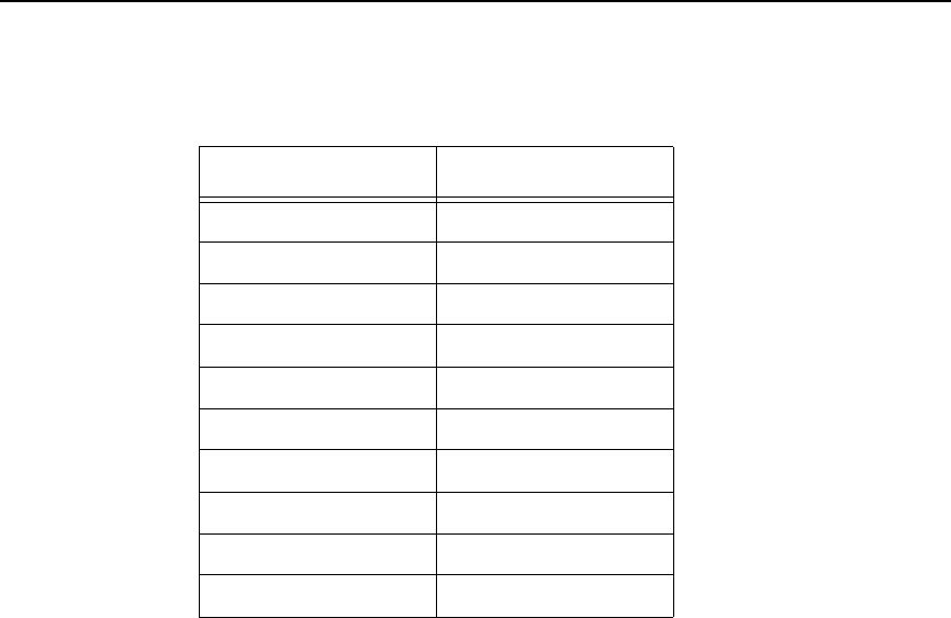
Postscript/PDF Interpreter
241
NOTE: When host jobs have page sizes that do not match the Paper Size
parameter, the printer will behave based on the Paper Size Fault, Clip
Page, and Move to TOF parameters.
Paper Size Fault
If a page is sent to the printer with dimensions that do not match the printer,
then the following will happen based on the Paper Size Fault menu selected.
•
Ignore (default). The page will print and the paper size length will be
ignored. However, the width will be clipped according to the front panel
width setting.
•
Fault. The printer enters a fault state and goes offline. The user will need
to either clear the fault and continue, or load new media and change the
Paper Size menu selection. Once the printer is back online, printing will
resume.
Clip Page
This menu defines the action when a page is sent to the printer with a length
that is longer than the selected paper size length.
•
Enable (default). The page will be clipped at the paper size length. In
cases where the sent page is longer than the paper size length, the
“Move to TOF” menu setting has no effect since the page is clipped at the
TOF position.
•
Disable. The page will not be clipped and printing continues on the next
page. The action taken by the printer when printing of the page completes
is determined by the Move to TOF menu.
NOTE: Page clipping at paper size width is always enabled to protect against
printing on the platen.
12x12 Inch 12 x 12 in
13.6x12 Inch 13.6 x 12 in
Tabloid 11x17in 11 x 17 in
JIS B5 7.2 x 10.1 in
US Folio 8.5 x 13 in
No. 10 Envelope 4.1 x 9.5 in
DL Envelope 4.3 x 8.7 in
C5 Envelope 6.4 x 9 in
C6 Envelope 4.5 x 6.4 in
ISO B5 6.9 x 9.8 in
Table 10. Paper Size Options and Actual Size
Paper Size Actual Size
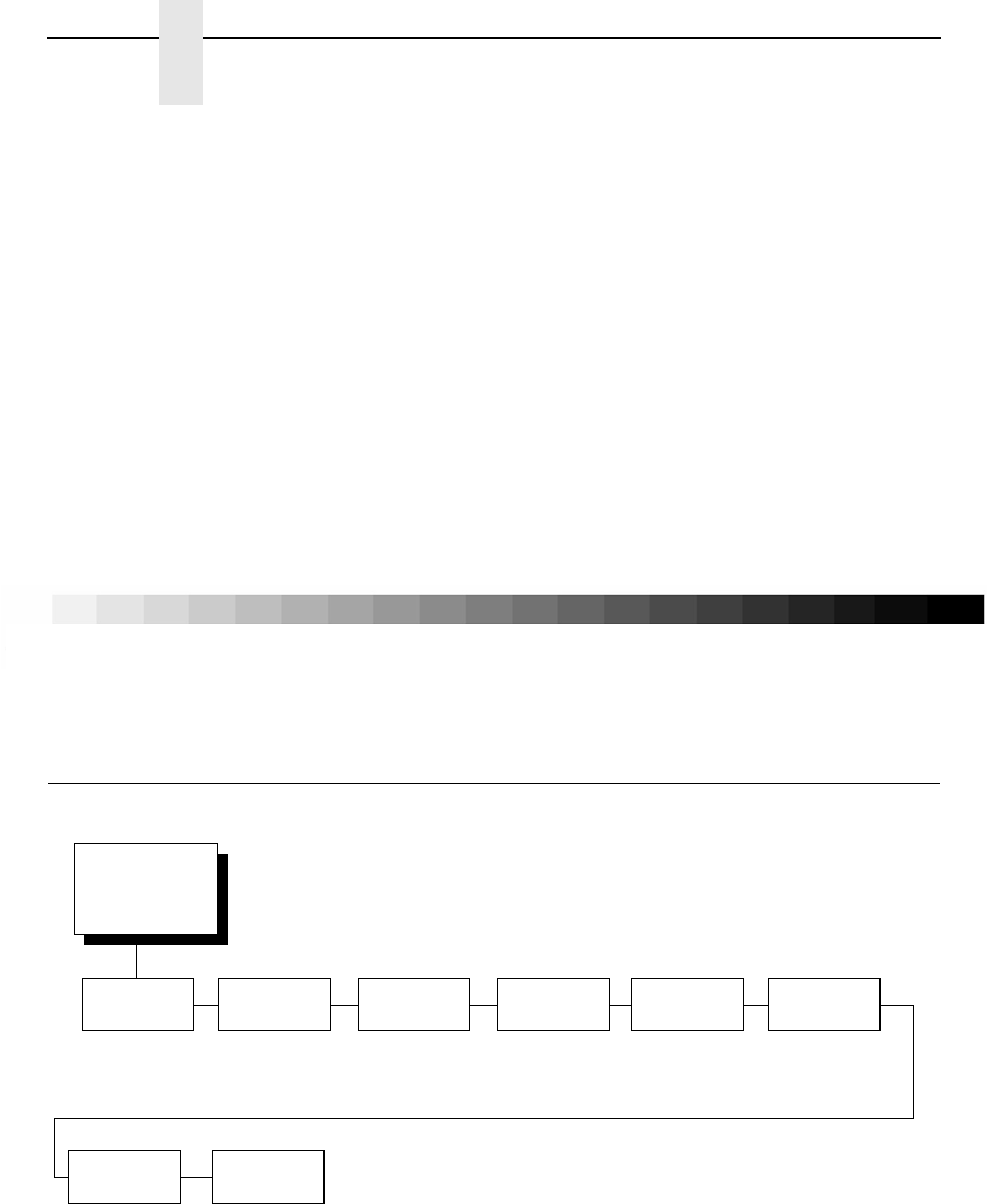
242
Chapter 4
OpenPrint SURE SCAN Menu
Move to TOF
When the page length given does not match the printer, the printer driver will
have to determine how the TOF is kept relative to each page printed. The
following menu options are available through the front panel and the driver:
•
Disable. Only when the FF key is pressed.
•
At End of Job. After the Current Job.
•
At End of Page (default). After each Page Printed.
Gray Adjust
This menu adjusts the darkness of the gray elements on the page by
gradually reducing or increasing the amount of dots that are placed in the
halftone patterns. Pure white and black colors are not affected by setting.
The menu ranges from -10 to +10. The default value is 0.
OpenPrint SURE SCAN Menu
-10
All
White
-9 -8 -7 -6 -5 -4 -3 -2 -1 0
Default
123 456 78 9 10
All
Black
SURE SCAN
1
(from page 75 and
page 76)
Optimize
Barcode
Yes*
No
Test
Alignment
Left
Center*
Right
Hor. Quiet
Zone
0.20 Inch*
0 to 0.99 inch
Ver. Erase
Zone
0.00 Inch*
(0 to 0.99 inch)
Update
PDF
Embedded Only*
Always
* = Factory Default
1
Available when Postscript/PDF is selected as the Active Emulation
on OpenPrint P7000 products.
2
Display menu only.
Quiet Zone
Fault
Enable*
Disable
Barcodes On
Page
Auto*
1, 2,...,20
Bcodes
Optimized
2
xxxxxx
2

Postscript/PDF Interpreter
243
Optimize Barcode
Defines whether the barcode optimization feature is active.
•
Yes (default). Activates the barcode optimization feature.
•
No. Deactiviates the barcode optimization feature.
•
Test. Boxes will print around all barcodes that are detected and
optimized. This provides a simple method to confirm that the software
correctly detects and optimizes all the barcodes on any given form.
NOTE: Barcodes will not optimize at densities of 96 dpi or less. For densities
with one dimension more than 96 and one 96 or less, barcodes will
only replace in one orientation. For instance, 180x90 picket fence
barcodes will be optimized and 90x180 ladder barcodes will be
optimized.
Alignment
Defines how the optimized replacement barcode will be positioned with
regard to the original barcode position if no obstacles exist to this placement.
It defines the first attempted position of the replacement barcode. If the first
attempted position causes a replacement barcode to interfere with any other
form elements (text, graphics, or dots), the replacement barcode
automatically adjusts away from these interfering elements until requested
horizontal quiet zones are observed. Selections for this menu are as follows:
•
Left. The first attempted position of the leftmost bar of the replacement
barcode will be the same position as the leftmost bar of the original
barcode. For instance, if the replacement barcode is smaller than the
original barcode, it will be placed as follows:
If the replacement barcode is larger than the original barcode, the
replacement barcode will begin at the left edge of the original barcode
and expand beyond the right edge.
Replacement Barcode
Original Barcode
OpenPrint SURE SCAN Menu
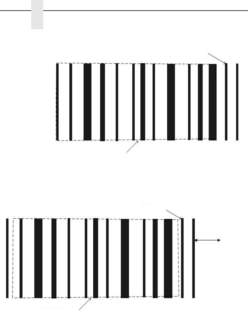
244
Chapter 4
OpenPrint SURE SCAN Menu
Any form elements (text, graphics, or dots) immediately to the right of the
original barcode can force this first attempted placement to be modified.
The replacement barcode will shift left to avoid obstacles on the right
provided that there are also no obstacles on the left.
Replacement Barcode
Original Barcode
Replacement Barcode
Original Barcode
Here is
an
obstacle
(text)
Quiet Zone
Distance
(picket)
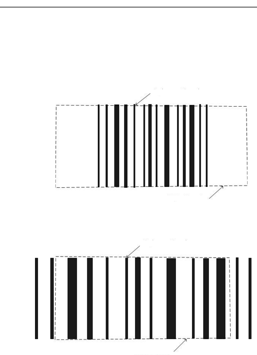
Postscript/PDF Interpreter
245
•
Center (default). The first attempted position of the center bar of the
replacement barcode will be the same position as the center bar of the
original barcode.
If the replacement barcode is smaller than the original barcode, it will be
replaced as follows:
If the replacement barcode is longer than the original barcode, it will still
be centered, but it will extend beyond the end of the original barcode on
both the left and the right.
Replacement Barcode
Original Barcode
Replacement Barcode
Original Barcode
OpenPrint SURE SCAN Menu
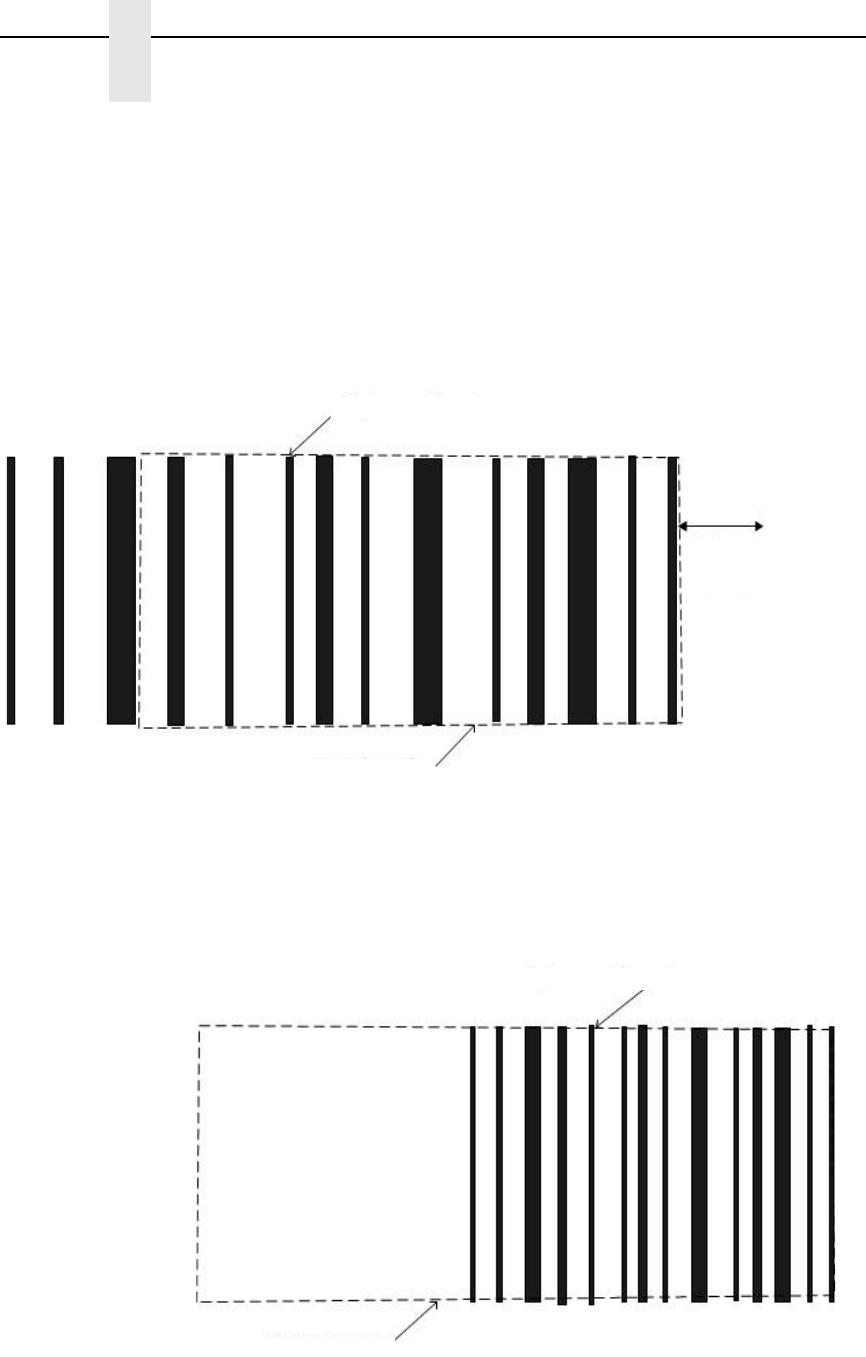
246
Chapter 4
OpenPrint SURE SCAN Menu
If form elements interfere with this placement on the right or the left, the
barcode will automatically adjust away from these obstacles. Form
obstacles may force a center-aligned barcode to look left or right aligned.
For instance, in the below picture, a center-aligned barcode has text 0.2
inches away from the right edge of the original barcode. With a horizontal
quiet zone of 0.2 inches, the resulting replacement barcode position is
exactly the same regardless of whether center, right, or left alignment is
chosen. Regardless of the first attempted position, the barcode will need
to shift to the left until the horizontal quiet zone can be observed.
•
Right. The first attempted position of the rightmost bar of the replacement
barcode will be the same position as the rightmost bar of the original
barcode.
For instance, if the replacement barcode is shorter than the original
barcode it will be placed as follows:
Replacement Barcode
Original Barcode
Here is
an
obstacle
(text)
Quiet Zone
Distance
(picket)
Replacement Barcode
Original Barcode
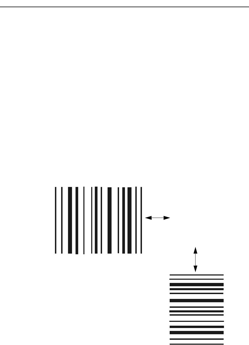
Postscript/PDF Interpreter
247
If the replacement barcode is larger than the original barcode, the
replacement barcode will end at the right edge of the original barcode and
extend past the left edge. Any form elements (text, graphics, or dots)
immediately to the left of the original barcode, however, can force this first
attempted placement to be modified. The replacement barcode will shift
right to avoid obstacles on the left provided that there are also no
obstacles on the right.
Hor. Quiet Zone
This menu defines the quiet zones (empty areas) width before and after the
start/stop codes regardless of picket fence or ladder orientation. When
positioning the barcode, the quiet zone is taken into account when detecting
collisions with other elements (dots) on the form. If one of the horizontal quiet
zones is violated, the barcode will automatically shift to the left or right (for
picket fence orientation) or up or down (for ladder orientation) to remove the
quiet zone violation.
The width of the area can be defined between 0 and 0.99 inches in 0.01 inch
increments. The default is 0.20 inches. This feature ensures that the
replacement barcodes will be properly scanned.
Barcodes are
automatically adjusted
away from text (or other
obstacles on the form)
until the Hor. Quiet
Zone distance is met.
Quiet Zone
distance
(picket)
Quiet Zone
distance
(ladder)
OpenPrint SURE SCAN Menu
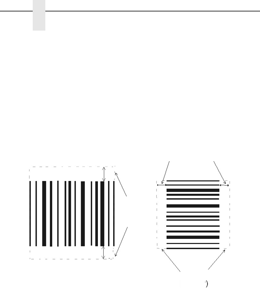
248
Chapter 4
OpenPrint SURE SCAN Menu
Ver. Erase Zone
This menu defines the area above and below the bars that will be erased,
regardless of picket fence or ladder orientation. It is used when the barcode
has extraneous data beyond the bars that need to be deleted as it is being
optimized.
The height of the area can be defined between 0 and 0.99 inches in 0.01 inch
increments. The default is 0 inches (no empty space). This feature can be
used to remove special attributes remainders of the original barcode such as
a guard bar or line that borders the top and bottom of the bars. It can also be
used to erase the original PDF if the user wants to force all PDFs to be
optimized (see Update PDF on page 249). The PDF occupies more than 1/6
of an inch.
Quiet Zone Fault
This menu defines whether a fault must be reported on the front panel LCD if
the BCDOPT feature cannot print the replacement barcode without violating
the quiet zone as defined in the “Hor. Quiet Zone” menu, where the width of
the replacement barcode plus quiet zones is too large to fit the available white
space on the page.
•
Enable (default). If this fault occurs, reduce the quiet zone to see if the
barcode fits.
•
Disable. Quiet zone violations are not reported, but adjacent page
elements could be drawn too close to replacement barcodes and possibly
overlap.
Vertical Erase Distance
Vertical Erase Distance
Vertical Erase Distance
Erase
Area
(picket)
Erase
Area
(ladder)
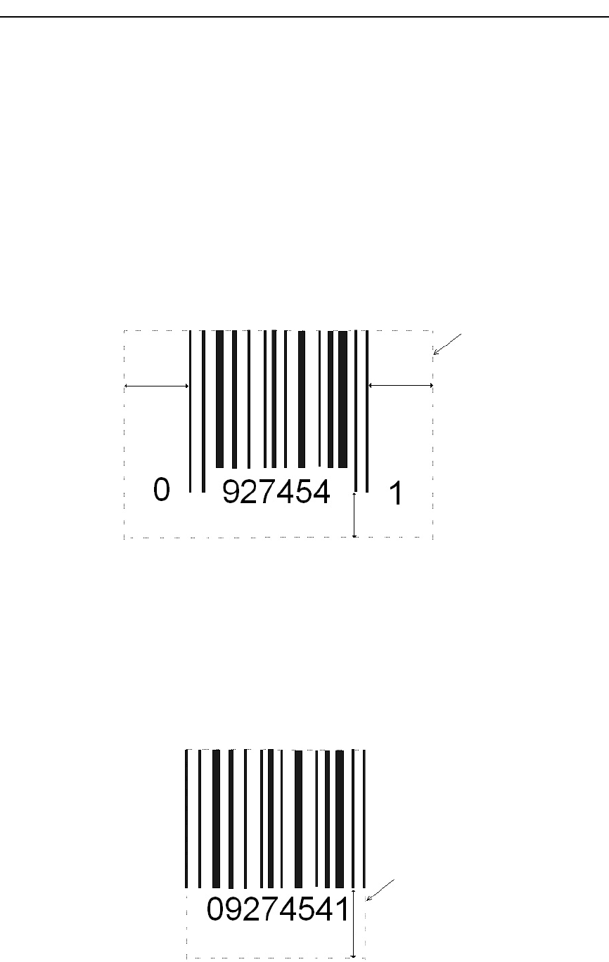
Postscript/PDF Interpreter
249
Update PDF
There are two distinct cases with barcode PDFs. In the first case, the PDF is
partially embedded in the barcode such that erasing the bars also erases the
PDF. In the second case, the PDF is printed entirely above or below the
barcode and is not disturbed by the barcode replacement.
Whenever the PDF is embedded in the barcode such that erasing the bars
also erases the PDF, the embedded PDF will be automatically detected and
replaced. An area surrounding the barcode will be erased to remove the
portions of the former PDF that extended beyond the bounds of the original
barcode. The erase area is shown in the figure below. Since embedded PDFs
are automatically replaced, the Upeate PDF menu option has no effect on this
type of PDF.
When the PDF is printed above or below the barcode, the behavior will
depend on the Update PDF menu setting.
•
Embedded Only (default). Embedded PDFs will not be replaced. This
allows the user to keep the present PDF data and its font, etc.
•
Always. PDFs will always reprint. For instance, since the original PDF will
not be centered with respect to the replaced barcode, the user may want
to always replace the PDF. When set to Always, an extra 1/6” is erased to
remove the original PDF. If the original PDF is not fully erased, it is up to
the user to increase the Ver. Erase Zone setting such that the original
PDF will be completely erased prior to the replacement being printed.
Erase
Area
1/6 ”
1/6 ”
1/6 ”1/6 ”
Erase
Area
Erase
Area
1/6 ”
OpenPrint SURE SCAN Menu

250
Chapter 4
OpenPrint SURE SCAN Menu
Barcodes on Page
This setting defines the number of barcodes that must be detected on the
form. If the value is set to “Auto” (default), no particular number of barcodes
are required to be detected. If the value is set to a number between 1 to 20,
then the number of barcodes set is required to be detected on each form. If
the printer detects fewer barcodes than the value set, the fault “x/y
BARCODES / Not Found” is declared. x represents the number of barcodes
not found, and y represents the Barcodes on Page value. Printing will not
continue until the user clears this fault.
Bcodes Optimized
This is a display menu that continuously counts the number of barcodes that
have been optimized since power-up. This statistic only resets to zero when
the printer is powered off. This menu can be used as a diagnostic to check the
number of barcodes optimized over a period of time or over a batch file.
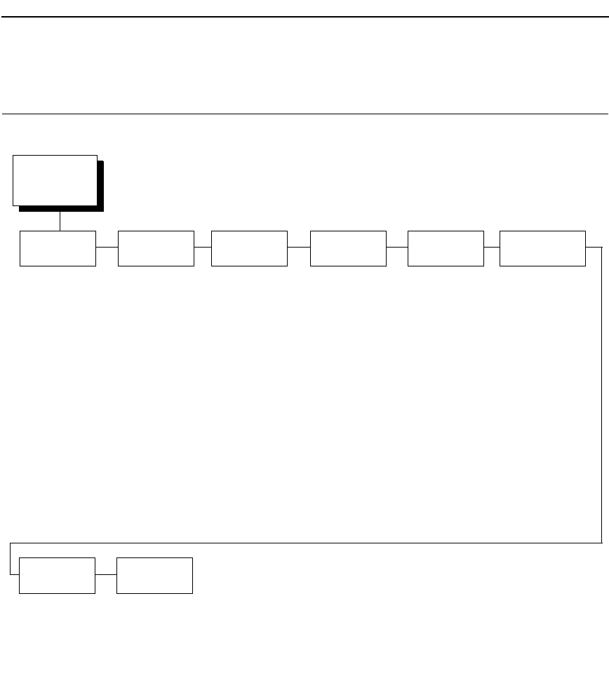
Postscript/PDF Interpreter
251
PRINTER CONTROL Menu
Ribbon End Point
This parameter adjusts the point at which the system will declare the ribbon
as being expended. The life count will always be from 100% to 0%, but if a
darker setting is selected 0% will be reached more quickly. If a lighter setting
is selected, the system will extend the time it takes to reach 0%. The range of
values are as follows:
•
Normal (default)
•
Darker +1 through Darker +6
•
Lighter -1 through Lighter -10
NOTE: This value can be adjusted at any time and the display will
automatically adjust to show the correct percentage relative to the
new end point.
PRINTER
CONTROL
(from page 65)
Unidirectional
Accented
Char
1
Open Platen
@BOF
Tear Bar
Dist.
2
Display
Language
Disable*
Enable
Standard*
Tall
Disable*
Enable
7.46 inches.*
(4.5 - 10.5)
English*
German
French
Italian
Spanish
Portuguese
* Factory Default
1
Not available in LG or PCL-II
2
Available for Pedestal printers only.
3
Not available when Postscript/PDF is active.
Bar Code
Quality
3
Dark*
Draft
Ribbon End
Point
Darker +6
Darker +5
Darker +4
Darker +3
Darker +2
Darker +1
Normal*
Lighter -1
Lighter -2
Lighter -3
Lighter -4
Lighter -5
Lighter -6
Lighter -7
Lighter -8
Lighter -9
Lighter -10
View
Function
2
Disable*
Enable
PRINTER CONTROL Menu

252
Chapter 4
PRINTER CONTROL Menu
Open Platen @ BOF (Bottom of Form)
Some special forms have perforation areas that are too thick to pass through
the print station. This parameter, when enabled, opens and closes the platen
when the perforations move across the platen. When enabling this parameter,
you must set the forms length to match the physical distance between
perforations.
Bar Code Quality
Determines the bar code resolution for all emulations, except IPDS. (See
“IPDS Emulation” on page 225 to set the bar code quality for IPDS.)
•
Dark (default). Bar code resolution is set at 120 x 72.
•
Draft. Bar code resolution is set at 60 x 72.
Tear Bar Dist. (Distance)
Allows fine and course adjustment of the tear bar position. For a pedestal
model printer using the top paper exit, the default (7.46 inches) is used. You
can specify 4.5 to 10.5 inches in .01 inch increments to accommodate
variations in cover and form design.
View Function
•
Disable (default). Disables the View Function which allows you to press
the VIEW/EJECT key to move the last data printed to the tractor area for
viewing.
•
Enable. Enables the View Function.
NOTE: Default setting is Enable for Indian language printers.
Unidirectional
The Unidirectional feature affects both print quality and printing speed. By
setting this feature, you can configure the printer to print in both directions of
the shuttle sweep (bidirectional), or to print in one direction only
(unidirectional).
•
Disable (default). The printer will print all data in both directions of the
shuttle sweep (bidirectional printing). This choice produces higher printing
speed.
•
Enable. The printer will print all data in only one direction of the shuttle
sweep (unidirectional printing). Although enabling this feature reduces
print speed, it enhances the vertical alignment of dots and produces
cleaner, sharper barcodes and text.
Display Language
This parameter chooses the language that will appear on the LCD: English,
German, French, Italian, Spanish, or Portuguese.
The factory default is English.

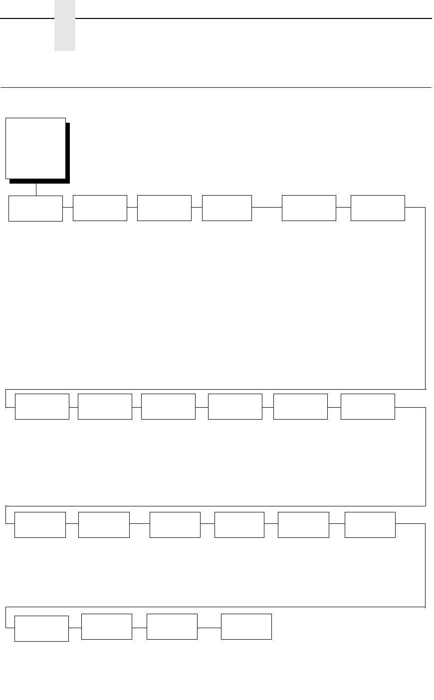
254
Chapter 4
ADVANCED USER Menu
ADVANCED USER Menu
Power
Stacker
2
Auto
Elevator
2
Auto
Locking
Shuttle
Timeout
PTX Setup
Option
3
Enable*
Disable
Enable*
Disable
Disable*
Enable
Setup Parse
Enable*
Ignore
Disable
Setup SFCC
21h*
(1-FF hex)
* = Factory Default
1
If you have the CT option, Enable is the default value.
2
If installed
3
Not available in PCL-II
4
Not available in LG or PCL-II
5
Available for OpenPrint P7000 HD products only.
File
System
Overwrite Files
Enable*
Disable
View File List
Delete Files
Flash Avail.
Optimize&Reboot
Print File List
Set
Sharing
4
Disable*
Enable
Downloaded
Fonts
4
Hex Dump
Mode
Disable*
Enable
Power-up
State
Online*
Offline
PMD Fault
Enable*
Disable
Slow Paper
Slew
Alarm
On*
Cont. Beep
Off
Pwr Save
Control
Cancel
Key
1
Disable*
Enable
Enable*
Disable
Disable*
Enable
5 Seconds*
1-60 Seconds
Power Saver
Time
15 minutes*
(1 min - 240 min)
Instant
(5 sec - 30 sec)
RBN Low
Action
Warn & Continue*
Warn & Pause
RBN End
Action
Ignore RBN End*
Stop At RBN End
Char Operations
Delete frm Flash
Load from Flash
Save to Flash
Delete from RAM
Ld Char at Pwrup
Disable*
Enable
Set Operations
Delete frm Flash
Load from Flash
Save to Flash
Delete from RAM
Ld Set at PwrUp
Disable*
Enable
RBN Low
Warn @
Under 2%*
Under 5%
Under 10%
Under 20%
Under 30%
Ret. Status
Port
Disable
E-Net Data Port
Serial
E-Net Status Port
IEEE 1284
Automatic*
Set Lock
Key
Rcv. Status
Port
5
Automatic*
Serial
ADVANCED
USER
(from page 65,
67, 69, 71, 73,
75, and 76)

Postscript/PDF Interpreter
255
PTX Setup Option
Selects the Special Function Control Code for the PTX_SETUP command
and functions.
•
Setup Parse. Disables or enables the PTX_SETUP command.
•
Setup SFCC. Allows you to choose the hex value of the ASCII character
you wish to use as the SFCC for the PTX_SETUP command. Valid hex
values are 01-FF. The default value is hex 21, which corresponds to the
“!” character.
Hex Dump Mode
A hex code printout (or hex dump) translates all incoming data to hexadecimal
equivalents. A hex dump lists each ASCII data character received from the
host computer, together with its corresponding two-digit hexadecimal code.
Hex dumps can be used to troubleshoot some types of printer data reception
problems. The options include:
•
Disable (default)
•
Enable
Figure 26 on page 285. shows a hex dump sample.
Power-Up State
•
Online (default). The printer powers up in the online state.
•
Offline. The printer powers up in the offline state.
NOTE: This option is not available in the PCL-II or LG emulation.
Downloaded Fonts
Allows you to download a substitution table to replace any character in the
current character set with a different character in the same font.
•
Char Operations. Allows you to delete a character from flash, load a
character from flash, save a character to flash, and delete a character
from RAM.
•
Ld Char at Pwrup. Allows you to disable or enable loading a character at
power up.
•
Set Operations. Allows you to delete a character set from flash, load a
character set from flash, save a character set to flash, and delete a
character set from RAM.
•
Ld Set at PwrUp. Allows you to disable or enable loading a character set
at power up.
NOTE: This option is not available in the PCL-II or LG emulation.
ADVANCED USER Menu

256
Chapter 4
ADVANCED USER Menu
PMD (Paper Motion Detection) Fault
•
Enable (default). In the event of a paper jam, an audible alarm beeps,
“CLEAR PAPER JAM” appears on the message display, and the printer
stops printing.
•
Disable. You should disable PMD only if special paper requires it.
CAUTION
Once PMD is disabled, paper motion is not monitored. If a paper jam
occurs, the printer ignores the condition and continues to print,
possibly causing damage to the printer.
Power Stacker
This parameter allows you to enable or disable the power paper stacker
(provided this option is installed).
Auto Elevator
This parameter exists only on printers with the power paper stacker installed.
The power stacker has a sensor which detects paper movement and raises
the stacker as the printed paper stack grows. If the printer has been printing
for three minutes continually and the sensor has not detected any growth in
the paper stack, the stacker raises itself 1/4 inch automatically.
•
Enable (default). The automatic elevator on the power stacker operates
normally.
•
Disable. The stacker does not raise automatically every three minutes
and is entirely dependent on the sensor. Diable is used with extremely
high-quality print jobs that take a long time to print.
Auto Locking
•
Disable (default). The ENTER key must be locked manually.
•
Enable. The printer automatically locks the ENTER key five minutes after
the last front panel key press.
File System
•
Overwrite Files. Allows you to prevent files from being overwritten by
disabling the overwrite function.
•
View File List. Displays the list of files in the file system. Pressing the
DOWN key displays the file size.
•
Delete Files. Displays the list of files in the file system. Pressing the
ENTER key deletes the file displayed on the front panel.
•
Flash Avail. The amount of flash available for the user to save or
download files into flash.
•
Optimize&Reboot. Reclaims flash space from deleted flash files. After
pressing ENTER, wait for the printer to reboot.
NOTE: When the Optimize&Reboot option is executed, the message,
“Optimizing Flash Files” does not display before printer rebooting
takes place.

Postscript/PDF Interpreter
257
•
Print File List. Prints a summary of the files stored in flash memory and
several statistics on File System usage.
IMPORTANT
Do not turn the printer off until it has completely rebooted and is either
back online or offline.
Set Sharing
This option allows character sets to be shared between the active LP+
protocol and the active IGP emulation. If CT is installed and active, choosing a
character set in the CT activates that character set in the active IGP and LP+
protocols. (These changes will not be visible on the front panel.) If Set Sharing
is not selected, only the LP+ will share the CT's character set.
Switching host interfaces from CT to Centronics when the Set Sharing is
enabled will cause the LP+ character set to be activated to the same
character set of the active IGP, if possible.
In a non-CT system, changing characters sets in LP+ causes the active IGP
to change to the same character set if the selected set exists in IGP. If the
active IGP has no access to the selected set, no changes are made. Selecting
a new character set in the active IGP causes the LP+ to change to the same
character set if the selected character set exists in the active LP+ protocol.
Not all sets are shared between emulations in the Standard group of character
sets. As a result, selecting a set in the Standard group of LP+ or IGP
emulation may or may not cause the other emulation to have the same set.
NOTE: The Set Sharing front panel option has no effect on the LP+ and CT/
LP+ builds. The option only applies to the builds with IGP.
This option is not available in the PCL-II or LG emulation.
Shuttle Timeout
The amount of time the shuttle continues moving after no data is received. If
your host is slow, setting the number to a higher value will prevent the printer
from spending time shuttling up and down between data bursts.
Slow Paper Slew
•
Disable (default). The paper will slew and stack paper at maximum
speed.
•
Enable. Causes the paper to stack at a slower rate. This ensures that
certain forms will stack neatly.
Alarm
•
On (default). An audible alarm sounds (3 beeps) when a fault occurs,
such as a paper jam.
•
Cont. Beep. A continuous audible alarm sounds when a fault occurs,
which can be stopped by pressing CLEAR.
•
Off. No audible alarm will sound.
ADVANCED USER Menu

258
Chapter 4
ADVANCED USER Menu
Power Saver Time
The time interval you specify for this parameter sets the amount of idle time
before the printer goes into Power Saver mode. When Instant is chosen, the
printer goes into Power Saver mode as soon as it is able to stop the shuttle
properly. The time allotted to perform this function depends upon the shuttle
timeout value which can be set in the menu.
NOTE: Power Saver Mode will not be shown on the control panel even
though the function still exists. Sending a print job to the printer will
turn off Power Saver mode.
Pwr Save Control
Allows you to enable or disable the Power Save (Energy Star) mode.
•
Enable (default). Allows you to enable the Power Save (Energy Star)
mode.
•
Disable. Allows you to disable the Power Save (Energy Star) mode.
Cancel Key
•
Disable (default)
•
Enable. The CANCEL key may be used to clear all data in the print buffer
without printing any of the data.
Rcv. Status Port
This option defines the interface being used to receive the emulation status
command.
•
Automatic (default). When selected, the status command is sent to the
printer with the print data through the active host interface.
•
Serial. When selected, the status command is sent to the printer through
the serial interface regardless of the active host interface.
Ret. Status Port
This option selects the port for the Return Status Commands (i.e., ~STATUS
(PGL) and ~HS (ZGL)) to send the status data back to the Host.
The options are Automatic (factory default), Serial, E-NET Stat Port,
IEEE 1284, Disable, and E-NET Data Port.

Postscript/PDF Interpreter
259
Set Lock Key
Normally, to lock or unlock the printer menu, the UP and DOWN keys are
pressed at the same time. The Set Lock Key parameter lets you choose
different keys to lock or unlock the printer menu. You may choose almost any
group of keys as the new lock and unlock keys. You cannot use the ENTER
key or any key combinations which are already used for another function.
There is no limit to how many keys you can select.
To set the new lock key, follow these steps:
1. Work your way through the configuration menu until the display reads
“Set Lock Key” (follow the menu structure on page 254).
2. Press ENTER. The display reads, “Select a new lock key.”
3. Press the combination of keys you want to be the new lock key. Make
sure you press all keys selected at the same time.
4. If the selection is valid, the display will read, “Enter the new lock key
again.” If the selection is invalid, the display will read, “Invalid key
selection.” Return to step 2 and start over.
5. Press the same combination of keys a second time. If the new lock key
combination is entered again correctly, the display will read, “Lock key
has been changed.” If it was entered incorrectly, the display will read
“Verification failed.” Start over at step 2.
6. After entering the new lock combination successfully, press the ON LINE
key to put the printer back online.
NOTE: The new lock combination will remain even if the printer is powered
off and back on.
RBN Low Warn @
This option allows the user to select the Ribbon Life value at which point the
printer will declare a ribbon low condition and display the "RIBBON UNDER
XX% / Change RBN Soon" warning message. The default is Under 2%. See
“RBN Low Action” below for details of how the printer behaves once a ribbon
low condition is reached.
The values are Under 2% (default), Under 5%, Under 10%, Under 20%, and
Under 30%.
ADVANCED USER Menu

260
Chapter 4
ADVANCED USER Menu
RBN Low Action
This menu determines how the printer behaves once a ribbon low condition is
reached.
•
Warn & Continue (default). Once a ribbon low condition is reached the
printer beeps and displays the "RIBBON UNDER XX% / Change RBN
Soon" warning message. Printing will continue without interruption. The
warning message can be cleared by pressing the ONLINE/Clear button,
however the message will persist again in two minutes. This action will
continue until a ribbon out (ribbon life reaches 0%) condition occurs.
•
Warn & Pause. This setting is similar to the Warn & Continue selection
with one exception. When a ribbon low condition is reached the printer will
still display the "RIBBON UNDER XX%/Change RBN Soon" warning
message, however the printer will stop printing. This is meant to get the
user’s attention. To resume printing the user must press the ONLINE/
Clear key.
NOTE: Printing will only stop on the first occurrence of a ribbon low condition.
Once the user clears the warning message, subsequent warnings will
display the warning message but printing will continue.
RBN End Action
This menu allows the user to override the normal ribbon low warning and
ribbon out conditions.
•
Stop At RBN End (default). When this factory default option is selected
the printer displays a warning message when a ribbon low condition is
reached and display a ribbon out fault when ribbon life reaches 0%.
•
Ignore RBN End. When this menu option is selected it overrides the
ribbon low and ribbon out conditions, i.e. no warning or fault messages is
displayed and printing continues even after ribbon life reaches 0%.
However, once the ribbon life reaches an excess wear condition as
indicated by the fault message "EXCESS RBN WEAR / Install New RBN",
printing will stop and the user must install a new ribbon before printing
can resume.
NOTE: The excess ribbon wear is set below the "Lighter -10" Ribbon End
Point setting.
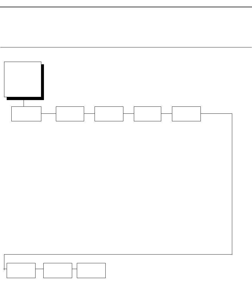
Postscript/PDF Interpreter
261
DIAGNOSTICS Menu
Printer Tests
These tests are used to check the print quality and operation of the printer.
NOTE: Your authorized service representative will typically run the tests.
They are described in more detail in the Maintenance Manual.
•
Shift Recycle. A sliding alphanumeric pattern which identifies missing or
malformed characters, improper vertical alignment, or vertical
compression.
•
All E's. A pattern of all uppercase E's which identifies missing characters,
misplaced dots, smeared characters, improper phasing problems, or light/
dark character variations.
•
E's + TOF. A pattern of all E's followed by a form feed to the next page
top-of-form, which identifies paper motion or feeding problems.
Printer Tests
Shift Recycle*
All E’s
E’s + TOF
All H’s
All Underlines
All Black
Shuttle Slow
Shuttle Fast
Shuttle Only
Phase Printer
Paperout Adj.
Burnin Test
Print Error Log
3
Clear Error Log
3
Adapter Test
1
Ethernet Test
6
Acoustics
2
Demo
Dice 5
Prnt Ribbon Log
Checker
Full Width*
80 col.
40 dots*
(4-76)
76 dots *,
5
(40 - 112)
5
32 Megabytes
* = Factory Default
1
If Ethernet adapter is present
2
Not available in PCL-II or LG
3
Not available in LG
4
If a Feature File exists.
5
Values for OpenPrint P7000 HD printers.
6
If the network is enabled.
Test Width Paper Out
Dots
System
Memory
On: x.x Hrs.
Print: x.x Hrs
Print Strokes:
xxxxxx
Print Lines:
xxxxxx
11 inch Pages:
xxx
Print
Statistics
SW P/N + Ver
Software
Build
P/N of File
Feature
File
4
xxxx
Shuttle
Type
DIAGNOSTICS
(from page 65,
67, 69, 71, 73,
75 and 76.)
DIAGNOSTICS Menu

262
Chapter 4
DIAGNOSTICS Menu
•
All H's. A pattern of all uppercase H's used to detect missing characters,
misplaced dots, smeared characters, or improper phasing.
•
All Underlines. An underline pattern useful for identifying hammer bank
misalignment.
•
All Black. A condition where all dot positions are printed, creating a solid
black band.
•
Shuttle Slow. Verifies proper operation by exercising shuttle and ribbon
motion at low speed.
•
Shuttle Fast. Verifies proper operation by exercising shuttle and ribbon
motion at fast speed.
•
Shuttle Only. Exercises only the shuttle at fast speed.
•
Phase Printer. Checks for wavy print. The initial phase value is set in the
factory. Run the test and check the quality. (The phase value prints on the
left margin.) If the print looks too wavy, change the Phase Value
parameter while the test is running. While the phase printer test runs,
press the DOWN key. To change the value, press the PREV or NEXT key
until the desired value displays and then press ENTER.
•
Paperout Adj.. Verifies the current Paper Out Dots setting, which
determines where the last line of text will print when there is a paper out
condition. Setting this parameter correctly prevents printing on the platen.
•
Burnin Test. Reserved for factory use.
•
Print Error Log. Prints the current log of errors. Most non-routine faults
(ribbon stall, voltage faults) are stored in the error log.
•
Clear Error Log. Clears entries in the error log.
•
Adapter Test. Prints the Ethernet adapter statistics stored on the
Ethernet adapter (if present).
•
Ethernet Test. Prints the Ethernet statistics stored on the Ethernet (if
present).
•
Acoustics. A particular test pattern that is used to measure acoustics.
•
Demo. Demonstration of various print attributes.
•
Dice 5. Pattern used to measure print density.
•
Prnt Ribbon Log. Prints log of cartridge installed in the printer.
•
Checker. For factory use. This pattern helps identify marginal printhead
elements, quality of edge sharpness, and uneven print quality.
Test Width
Set this parameter to run the self-tests at full width or 80 columns.
Paper Out Dots
CAUTION
Only authorized service representatives should set this parameter.
This parameter is used to adjust the paper out distance from the perforation;
you can specify where the last line on the page will print when there is a paper
out condition. Setting this parameter correctly prevents printing on the platen.

Postscript/PDF Interpreter
263
System Memory
Displays the amount of RAM installed.
Print Statistics
You can view various printer statistics and refer to them for preventive
maintenance purposes. Printer statistics accumulate continuously; they do
not reset when you turn off the printer. All of the printer statistics are set to
zero at the factory after burn-in testing.
•
On. The cumulative time in hours the printer has been powered on. The
range is 0 to 30,000 hours.
•
Print. The cumulative time in hours the printer has actually been printing.
The range is 0 to 30,000 hours.
•
Print Strokes. The cumulative number of back-and-forth shuttle strokes
the printer has printed during normal printer operation. The range is 0 to
2,147,483,647 shuttle strokes.
•
Print Lines. The cumulative number of lines the printer has printed. The
range is 0 to 2,147,483,647 print lines.
•
11 inch Pages. The cumulative number of pages the printer has printed.
The range in print pages is 0 to 2,147,483,647 total inches of paper
movement divided by 11.
•
Poweron Pages. The number of pages the printer has printed since
power-up.
Software Build
Displays the part number and version of the printer firmware.
Feature File
Displays the part number of the file if one has been downloaded to the printer.
Shuttle Type
Displays the type of shuttle installed, i.e. 2000s, 1500, 1000, 500, or high
definition.
DIAGNOSTICS Menu
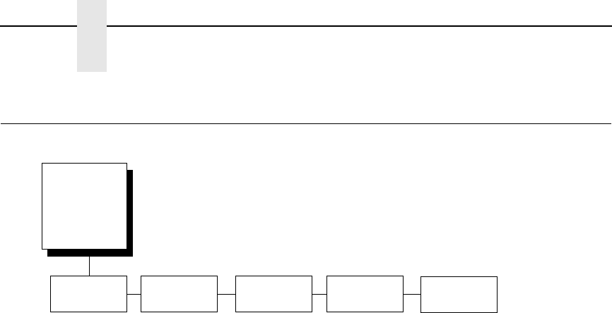
264
Chapter 4
DATE Menu
DATE Menu
Hour
This option allows you to set the hour. The factory default is 00 and the range
is from 00 to 23 hours.
Minute
This option allows you to set the minutes. The factory default is 00 and the
range is from 00 to 59 minutes.
Year
This option allows you to set the year. The factory default is 2099 and the
range is from the year 2000 to 2099.
Month
This option allows you to set the month. The factory default is Jan and the
range is from Jan to Dec.
Day
This option allows you to set the day. The factory default is 01 and the range
is from 01 to 31 days.
DATE
1
(from page 65,
67, 69, 71, 73,
and 75)
Hour
00*
00 - 23
Minute Year
00*
00 - 59
2099*
2000 - 2099
Month
Jan*
Jan - Dec
Day
01*
01 - 31
* = Factory Default
1
Appears only if the real time clock option is installed.
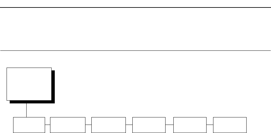
Postscript/PDF Interpreter
265
PRINTER MGMT Menu
PNE Port
This menu selects which port the printer expects PNE to connect to, via
Ethernet or Serial. The factory default is Ethernet. If the network is not
enabled, the default is Disable.
Mgmt Protocol
Since PXML and UCP management protocols share the same Ethernet Port,
only one can be active at a time. This menu selects the active Management
Protocol Interface, either PXML or UCP. The factory default is UCP.
PNE Port Number
This menu selects the port number the printer expects the PNE to connect
through. The factory default is 3001 and the range is from 1023 to 65535.
PNE Port Timeout
If the PNE has not communicated to the printer within a timeout period, the
PNE session closes. The factory default is 100 seconds. The range is from 1
to 255 seconds.
Status Port Numb
This menu selects the port number the printer sends the emulation status.
The factory default is 3001 and the range is from 1023 to 65535.
Mgmt Port Number
This menu selects the port number the printer expects the PXML or UCP to
connect through. The factory default is 3007 and the range is from 1023 to
65535.
PNE Port
UCP*
PXML
3001*
1023 - 65535
100 Seconds*
1-255 Seconds
* = Factory Default
1
Not available if PNE Port is set to Serial.
Mgmt Protocol PNE Port
Number
1
PNE Port
Timeout
1
3002*
1023 - 65535
Status Port
Numb
3007*
1023 - 65535
Mgmt Port
Number
Ethernet*
Disable
Serial
PRINTER MGMT
(from page 65, 67,
69, 71, 73, and 75)
PRINTER MGMT Menu

266
Chapter 4
PRINTER MGMT Menu

267
5
Interfaces
Overview
This chapter describes the host interfaces provided with the printer. The
printer interface is the point where the data line from the host computer plugs
into the printer. The interface processes all communications signals and data
to and from the host computer. Plus, with the Auto Switching feature, you can
configure the printer to accept several interfaces at the same time (see “Auto
Switching Submenu” on page 88).
IMPORTANT
To comply with Electromagnetic Compatibility (EMC) regulatory
requirements all electrical signal interface cables connected to this
printer must be of a minimal quality level, be of the correct length, and
be properly installed.
The RS-232 port and parallel port interface cables must meet the
following specifications:
•
The cable design must be double shielded with a copper braid over
an aluminum mylar foil and not just a conductive foil spiral wrapped
around a drain wire.
•
The shield must terminate coaxially (360 degrees) to a metal
connector housing and not be terminated by just a simple wire lead.
•
The cable length, including connectors, must be 3 meters or less.
•
The cable connector anchor screws must be securely seated into
the printer receptor hardware.
For reference purposes only, two specific Centronics parallel port
cables that have been tested and found to comply with these
requirements are Belkin
®
part number F2A046-10 and Primelogic
®
part
number PLU 2823224. Other electrically equivalent cables are
acceptable.
This chapter describes the interfaces provided with the printer.
Standard Host Interfaces:
•
IEEE 1284 parallel
•
RS-232 Serial

268
Chapter 5
Dataproducts Parallel Interface
Optional Host Interfaces:
•
Ethernet 10/100BaseT
•
Coax/Twinax (not available in Taiwan)
•
RS-422 Serial (not available in Taiwan)
In addition to descriptions for the multi-line interfaces, this chapter also
provides instructions for configuration of terminating resistors for the parallel
interfaces.
Dataproducts Parallel Interface
The length of the data cable from the host computer to the printer must not
exceed 40 feet (12 meters).
Table 11. Dataproducts Parallel Interface Connector Pin Assignments
(with a 50-pin AMP HDH-20 Data Cable Connector)
Input Signals Output Signals Miscellaneous
Signal Pin Signal Pin Signal Pin
DATA LINE 1
Return
19
3
READY
Return
22
6
CABLE VERIFY 45, 46
DATA LINE 2
Return
20
4
ONLINE
Return
21
5
GROUND 39
DATA LINE 3
Return
1
2
DEMAND/DATA REQ.
Return
23
7
DATA LINE 4
Return
41
40
PARITY ERROR 27
11
DATA LINE 5
Return
34
18
DATA LINE 6
Return
43
42
DATA LINE 7
Return
36
35
DATA LINE 8
Return
28
44
DATA STROBE
Return
38
37
PAPER INSTRUCTION
Return
30
14
BUFFER CLEAR
Return
31
15
NOTE: Pins not listed are not connected.

Dataproducts Parallel Interface Signals
269
Dataproducts Parallel Interface Signals
Data Lines 1 through 8. Provides eight standard or inverted levels from the
host that specify character data, plot data, or a control code. Data Line 8
allows access to the extended ASCII character set. You can enable or disable
this line via the Data Bit 8 parameter on the Dataproducts submenu (see page
page 95).
Data Strobe. Carries a high true pulse from the host when data is ready. The
data strobe remains high until the Data Request line goes false. The active
edge of the strobe signal can be configured as leading, middle (default), or
trailing.
Paper Instruction (PI). Carries a DVFU signal from the host with the same
timing and polarity as the data lines.
Ready. Carries a high true signal from the printer when AC power and DC
voltages are present, paper is loaded properly, and the printer is not in a
check condition.
Online. Carries a high true signal from the printer when the Ready Line is true
and the ON LINE key on the control panel has been pressed. When the
printer is in online mode, it may accept data from the host.
Demand/Data Request. Carries a high true signal from the printer when the
printer is ready to accept character data from the host. This signal changes to
false shortly after the leading edge of the data strobe signal.
Cable Verify. Two pins on the interface connector are jumpered together to
allow the user to verify proper installation of the interface connector.
Buffer Clear. A high true level from the host to indicate the printer should
perform a reboot.
Parity Error. Always carries a low false signal from the printer indicating there
is no parity error.

270
Chapter 5
Centronics Parallel Interface
Centronics Parallel Interface
The length of the data cable from the host computer to the printer must not
exceed 15 feet (5 meters).
Table 12. Centronics Interface Connector Pin Assignments
Input Signals Output Signals Miscellaneous
Signal Pin Signal Pin Signal Pin
DATA LINE 1
Return
2
20
ACKNOWLEDGE
Return
10
28
CHASSIS GROUND 17
DATA LINE 2
Return
3
21
ONLINE
Return
13
28
GROUND 30
DATA LINE 3
Return
4
22
FAULT
Return
32
29
Spares 14
DATA LINE 4
Return
5
23
PAPER EMPTY
Return
12
28
No Connection 34,35,
36
DATA LINE 5
Return
6
24
BUSY
Return
11
29
+5 Volts 18
DATA LINE 6
Return
7
25
DATA LINE 7
Return
8
26
DATA LINE 8
Return
9
27
DATA STROBE
Return
1
19
PAPER INSTRUCTION
Return
15
29
PRIME
Return
31
30

Centronics Parallel Interface Signals
271
Centronics Parallel Interface Signals
Data Lines 1 through 8. Provides eight standard or inverted levels from the
host that specify character data, plot data, or a control code. Data Line 8
allows access to the extended ASCII character set. You may enable or
disable this line via the Data Bit 8 parameter on the Centronics submenu (see
page 92).
Data Strobe. Carries a low true, 100 ns minimum pulse from the host that
clocks data into the printer.
Acknowledge. A low true pulse from the printer indicating the character or
function code has been received and the printer is ready for the next data
transfer.
Online. A high true level from the printer to indicate the printer is ready for
data transfer and the ON LINE key on the control panel has been activated.
When the printer is in online mode, it may accept data from the host.
Paper Empty (PE). A high true level from the printer to indicate the printer is
in a paper empty or paper jam fault.
Busy. A high true level from the printer to indicate the printer cannot receive
data.
Prime. A high true level from the host to indicate the printer should perform a
warm start (printer is reset to the power-up configuration values).
Paper Instruction (PI). Carries a CVFU signal from the host with the same
timing and polarity as the data line.
Fault. A low true level from the printer indicates a printer fault.

272
Chapter 5
IEEE 1284 Parallel Interface
IEEE 1284 Parallel Interface
The 1284 supports three operating modes, which are determined by
negotiation between the printer and the host.
Compatibility Mode
This mode provides compatibility with Centronics-like host I/O (see Table 13).
Data is transferred from the host to the printer in 8-bit bytes over the data
lines.
Compatibility Mode can be combined with Nibble and Byte Modes to provide
bidirectional communication.
Nibble Mode
Eight bits equals one byte. When a byte of data is sent to the printer, the eight
bits are sent over eight data lines.
Some devices cannot send data over their eight data lines. To bypass this,
the 1284 permits data to be sent as half a byte over four status lines. (Half a
byte equals one nibble.) Two sequential four-bit nibbles are sent over the
lines.
Data is transferred from printer to host in four-bit nibbles over the status lines,
and the host controls the transmission.
Byte Mode
The printer and host send data to each other along eight data lines (one bit
per line).
If bidirectional communication is supported by the printer and the host, the
host will take control of the data transfer.
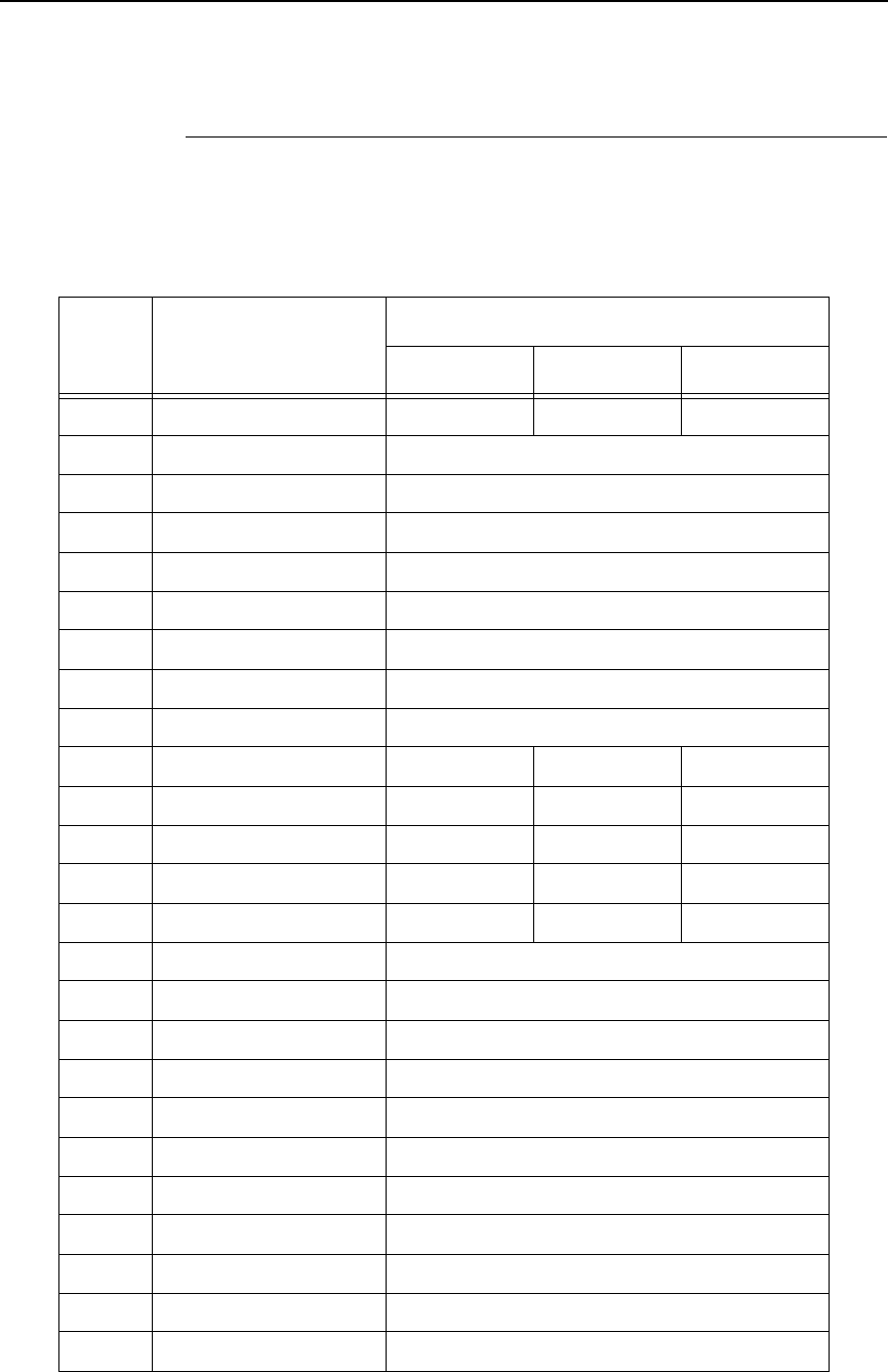
Signals
273
Signals
Table 13 lists each of the signals associated with the corresponding pins on
the 1284 interface. Descriptions of the signals follow.
Table 13. 1284 Signals
Pin Source of Data Type of Mode
Compatible Nibble Byte
1Host nStrobe HostClk Host/Clk
2Host/Printer Data 1 (LSB)
3Host/Printer Data 2
4Host/Printer Data 3
5Host/Printer Data 4
6Host/Printer Data 5
7Host/Printer Data 6
8Host/Printer Data 7
9Host/Printer Data 8 (MSB)
10 Printer nAck PtrClk PtrClk
11 Printer Busy PtrBusy PtrBusy
12 Printer PError AckDataReq AckDataReq
13 Printer Select Xflag Xflag
14 Host nAutoFd Host Busy HostAck
15 Not Defined
16 Logic Grid
17 Chassis Grid
18 Printer Peripheral Logic High
19 Signal Ground (nStrobe)
20 Signal Ground (Data 1)
21 Signal Ground (Data 2)
22 Signal Ground (Data 3)
23 Signal Ground (Data 4)
24 Signal Ground (Data 5)
25 Signal Ground (Data 6)
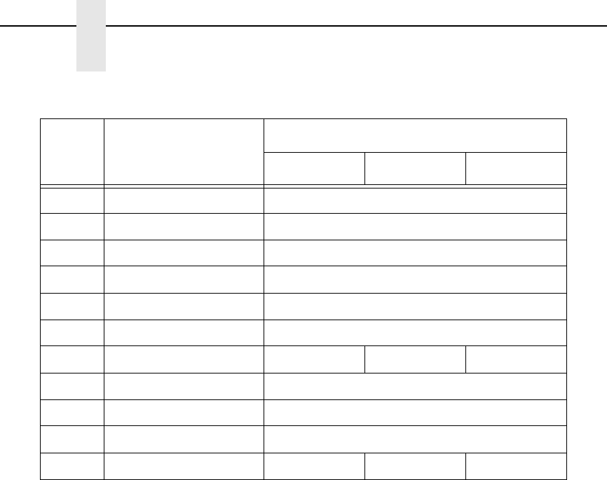
274
Chapter 5
IEEE 1284 Parallel Interface
NOTE: The length of the data cable from the host computer to the printer
should not exceed 32 feet (10 meters).
Host Clock / nWrite. Driven by host. Data transferred from host to printer.
When printer sends data, two types are available. If Nibble mode, signal is set
high. If Byte mode, signal is set low.
Data 1 through Data 8. These pins are host-driven in Compatibility mode and
bidirectional in Byte mode. They are not used in Nibble mode. Data 1 is the
least significant bit; Data 8 is the most significant bit.
Printer Clock / Peripheral Clock / Interrup. Driven by the printer. A signal
from the printer indicating the character or function code has been received
and the printer is ready for the next data transfer.
Printer Busy / Peripheral Acknowledge / nWait. Driven by the printer.
Indicates the printer cannot receive data. (Data bits 4 and 8 in Nibble mode.)
Acknowledge Data Request / nAcknowledge Reverse. Driven by the
printer. Indicates the printer is in a fault condition. (Data bits 3 and 7 in Nibble
mode.)
Xflag. Driven by the printer. A high true level indicating the printer is ready for
data transfer and the printer is on line. (Data bits 2 and 6 in Nibble mode.)
Host Busy / Host Acknowledge / NDStrobe. Driven by the host. Activates
auto-line feed mode.
Peripheral Logic High. Driven by the printer. When the line is high, the
printer indicates all of its signals are in a valid state. When the line is low, the
printer indicates its power is off or its signals are in an invalid state.
nReverse Request. Driven by the host. Resets the interface and forces a
return to Compatibility mode idle phase.
26 Signal Ground (Data 7)
27 Signal Ground (Data 8)
28 Signal Ground (PError, Select, nAck)
29 Signal Ground (Busy, nFault)
30 Signal Ground (nAutoFd, nSelectIn, nInit)
31 Host nInit
32 Printer NFault nDataAvail aDataAvail
33 Not Defined
34 Not Defined
35 Not Defined
36 Host nSelectIn 1284 Active 1284 Active
Table 13. 1284 Signals (continued)
Pin Source of Data Type of Mode
Compatible Nibble Byte
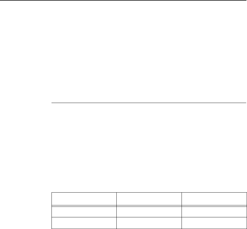
Terminating Resistor Configurations
275
nData Available / nPeripheral Request. Driven by the printer. Indicates the
printer has encountered an error. (Data bits 1 and 5 in Nibble mode.)
1284 Active / nAStrobe. Driven by the host. A peripheral device is selected.
Host Logic High—Driven by the host. When set to high, the host indicates all
of its signals are in a valid state. When set to low, the host indicates its power
is off or its signals are in an invalid state.
nInit —Resets init interface from the host.
Terminating Resistor Configurations
V6 Controller Board
For parallel interface configurations, the printer is equipped with 470 Ohm and
and 1K Ohm terminating reistors on the controller board. These are suitable
for most applications. See Figure 23.
If the standard terminating resistor pack is not compatible with the particular
interface driver requirements of the host computer, other RP1 and RP2 values
may be required. 220 Ohm and 330 Ohm alternate terminating resistors are
provided with the printer. If you install the 220 Ohm resistor, you must also
install the 330 Ohm resistor. Possible terminating resistor combinations are
shown below.
Configuration RP1 RP2
Factory Default 470 Ohm 1K Ohm
Alternate 220 Ohm 330 Ohm
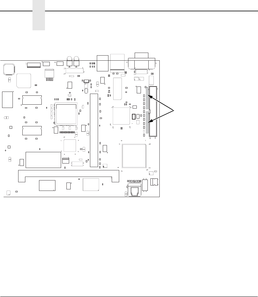
276
Chapter 5
RS-232 And RS-422 Serial Interfaces
Figure 23. Terminating Resistors, V6 Controller Board
Removal And Installation
The procedure for removing and installing terminating resistors is provided in
your Maintenance Manual.
CAUTION
This is an involved maintenance procedure. To avoid damage to the
equipment, only a trained technician should perform this procedure.
RS-232 And RS-422 Serial Interfaces
NOTE: The RS-232 and RS-422 serial interface circuit characteristics are
compatible with the Electronic Industry Association Specifications
EIA-232-E and EIA-422-B.
The RS-232 and RS-422 serial interfaces enable the printer to operate with bit
serial devices that are compatible with an RS-232 controller. The input serial
data transfer rate (in baud) is selectable from the printer's control panel. Baud
rates of 600, 1200, 2400, 4800, 9600, 19200, 38400, 57600, and 115200
baud rates are available.
NOTE: If you select a baud rate that is greater than 19200, you may need to
use RS-422 to prevent data loss.
The length of the data cable from the host computer to the printer must not
exceed 50 feet (15 meters) for RS-232 or 4000 feet (1220 meters) for RS-422.
(A copper conductor, twisted-pair telephone cable with a shunt capacitance of
16 pF/foot [52.5 pF/meter] terminated in a 100 ohm resistive load must be
used for the RS-422.)
183480a
Default: 470/1K Ohm
Alt: 220/330 Ohm
RP1 and RP2

RS-232
277
RS-232
Receive Data (RD). Serial data stream to the printer.
Transmit Data (TD). Serial data stream from the printer for transmitting status
and control information to the host. Subject to protocol selection.
Request To Send (RTS). Control signal from the printer. Subject to
configuration.
Clear To Send (CTS). Status signal to the printer indicating the host is ready
to receive data/status signals from the printer.
Data Set Ready (DSR). Status signal to the printer indicating the host is in a
ready condition.
Data Carrier Detect (DCD). Status signal to the printer. The ON condition is
required for the printer to receive data.
Data Terminal Ready (DTR). Control signal from the printer. Subject to
configuration.
Table 14. Standard 500, 1000, 1500, and 2000 lpm Models
RS-232 Serial Interface Connector Pin Assignments
Input Signals Output Signals Miscellaneous
Signal Pin Signal Pin Signal Pin
Receive Data (RD) 3Transmit Status & Control
Data (TD)
2Chassis Ground 1
Clear To Send (CTS) 5Request To Send (RTS) 4Signal Ground 7
Data Set Ready (DSR) 6Data Terminal Ready (DTR) 20
Data Carrier Detect (DCD) 8
Table 15. RS-232 Serial Interface Connector Pin Assignments
Input Signals Output Signals Miscellaneous
Signal Pin Signal Pin Signal Pin
Receive Data (RD) 2Transmit Status & Control
Data (TD)
3Chassis/Signal Ground 5
Clear To Send (CTS) 8Request To Send (RTS) 7
Data Set Ready (DSR) 6Data Terminal Ready (DTR) 4
Data Carrier Detect (DCD) 1
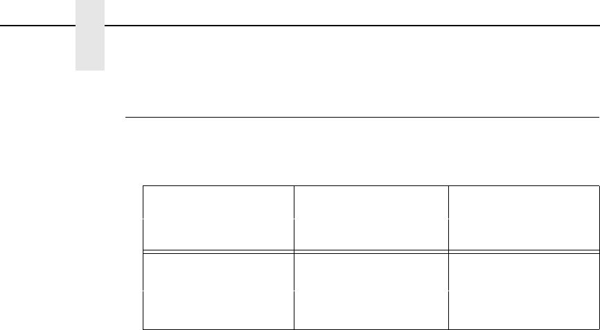
278
Chapter 5
RS-232 And RS-422 Serial Interfaces
RS-422
+RD, -RD.Serial data stream differentially received by printer.
+TD, -TD.Differentially driven serial data stream for transmitting status and
control information to the host. Subject to protocol selection.
NOTE:
±
RD and
±
TD form signal and return paths of a differential line signal.
Table 16. PSA3 RS-422 Serial Interface Connector Pin Assignments
Input Signals Output Signals Miscellaneous
Signal Pin Signal Pin Signal Pin
- Receive Data
(-RD)
1- Transmit Data
(-TD)
3Chassis/Signal
Ground
5
+ Receive Data
(+RD)
6+ Transmit Data
(+TD)
8

279
6
Reprogramming the
Security Key
Reprogramming The Security Key
The security key on the PSA3 controller board can be reprogrammed with a
Software Program Exchange (SPX) module. The SPX is an intelligent module
that plugs into the debug port on the back of printers equipped with the PSA3
“Hurricane” controller board. The SPX is used only once; it automatically
overwrites itself after successfully reprogramming a security key. This allows
the end user or a service technician to enable features such as new
emulations without having to remove covers and install a new security key on
the controller board.
The SPX is used at power-up only and is not left in the printer during normal
operation. Because it is a single-use disposable item the user is not required
to return it to the vendor or manufacturer.
How To Program The Security Key
1. Power off the printer.
2. On cabinet models, open the rear door. On pedestal models, refer to
Figure 24 to locate the debug port at the rear of the printer.
3. Insert the SPX into the debug port as shown.
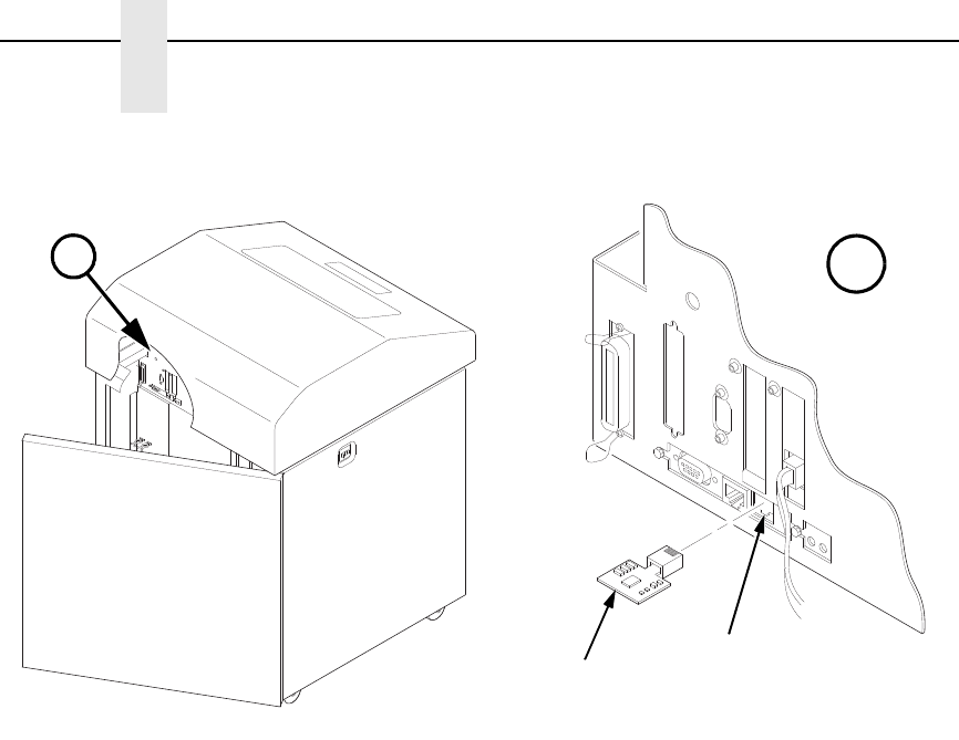
280
Chapter 6
Reprogramming The Security Key
Figure 24. Inserting The SPX into the Debug Port
4. Power on the printer. The printer will begin its boot-up sequence.
5. When the printer detects a valid SPX, the control panel displays:
“NEW SPX DETECTED
PRESS ENTER”
NOTE: If an error message displays, find the message in the Message List in
Chapter 7 and follow the troubleshooting instructions.
6. Press the ENTER key to activate the reprogramming sequence. The
display will read:
“PROGRAMMING. PLEASE WAIT.”
7. When the security key is reprogrammed, the display will read:
“REMOVE USED SPX
THEN PRESS ENTER”
8. Remove the SPX from the debug port at the rear of the printer.
9. Press the ENTER key. The printer will reboot itself and you may resume
normal printing.
10. You may need to download a new program file to use the new feature.
11. You may need to set additional menu parameters for any new features
that have been added or enabled.
183482b
183481b
A
A
Debug Port
SPX

281
7
Troubleshooting
Cleaning Requirements
Clean the printer every six months or after every 1000 hours of operation,
whichever occurs first. If the printer is located in a dusty area or is used for
heavy duty printing, clean it more often.
WARNING
Disconnect the power source before cleaning the printer.
Vor dem Säubern des Druckers ist die Netzverbindung zu unterbrechen.
Débranchez l’alimentation avant de nettoyer l’imprimante.
Desconecte la fuente de energía antes de limpiar la impresora.
Staccare la fonte di energia prima della pulitura della stampante.
Exterior Cleaning
Clean the outside of the cabinet with a soft, lint-free cloth and mild detergent
soap. (Dishwashing liquid works well.) Do not use abrasive powders or
chemical solvents. Clean the windows with plain water or mild window
cleaner. Always apply the cleaning solution to the cloth; never pour cleaning
solution directly onto the printer.
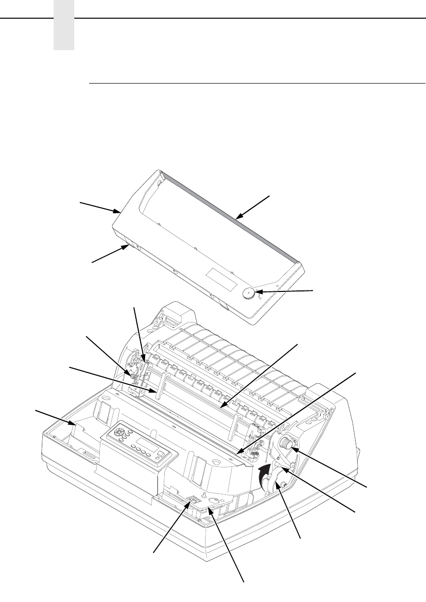
282
Chapter 7
Cleaning Requirements
Interior Cleaning
Over time, particles of paper and ink accumulate inside the printer. This is
normal. Paper dust and ink build-up must be periodically removed to avoid
degraded print quality. Most paper dust accumulates around the ends of the
platen and ribbon path.
Figure 25. Interior Printer Components
TOF
TOF
TOF
TOF
183871 REV A
183871a
Ribbon
Ribbon
Cartridge
Ribbon
Tension Knob
Air Shroud
Assembly
Tab (2)
Tab
Slot (2)
Blue Tractor
Lock (2)
Paper
Support (2)
Tractor (2)
Vertical
Position Knob
Platen Lever
Splined Shaft
Platen Stop
Hammer Bank
Cover and
Ribbon Mask
Ribbon Cartridge
Interface

Interior Cleaning
283
To clean the interior of the printer perform the following steps.
1. Power off the printer and unplug the printer power cord.
2. Open the printer cover.
3. Fully raise the platen lever.
4. Unload the paper.
5. Remove the ribbon cartridge.
6. Lift the ribbon out of the ribbon path.
7. Brush the paper dust and ribbon lint off the tractors, shuttle cover
assembly, and base casting with a soft-bristled, non-metallic brush
(such as a toothbrush). Vacuum up the residue.
CAUTION
Vacuum carefully around the hammer bank and surrounding area to
avoid damage. To avoid corrosion damage, use only alcohol when
cleaning the printer mechanical elements. Solutions used to clean
mechanical elements must contain no water.
8. Wipe the splined shaft with a soft cloth.
9. Check the ribbon mask and hammer bank cover for bits of torn paper or
ribbon lint.
10. Remove dust and ink from the platen using a soft cloth lightly moistened
with anhydrous alcohol. (The platen is the thick silver bar behind the
hammer bank cover that rotates when the platen lever is rotated.)
CAUTION
When cleaning the platen, be very careful not to get any alcohol in the
hammer bank, because alcohol will cause severe damage to the
hammer bank. Only a trained service technician should clean the shuttle
assembly.
11. Brush and vacuum the accumulated dust or residue inside the lower
cabinet.
12. Wipe the lower cabinet interior with a clean, lint-free cloth dampened (not
wet) with water and mild detergent or window cleaning solution. Dry the
lower cabinet interior by wiping it down with a clean, lint-free cloth.
13. Install the ribbon and load paper.

284
Chapter 7
Diagnosing Problems
Diagnosing Problems
This section is designed to help you fix problems which may arise with normal
printer operation.
Bar Code Verification
The most important consideration when printing a bar code is to ensure that
the bar code will be scanned properly. Incorporating a bar code quality
procedure in the printing process is the best way to ensure that bar codes are
being printed correctly. A properly implemented verification procedure will
increase overall bar code quality, reduce waste from misprinted bar codes,
and achieve high first-time read rates. A high first-time read rate is an
increasingly important factor in newer, more efficient systems where manually
entered data is not acceptable as a backup function. Verification also
minimizes the costs of returned products due to poor reading or
unaccountable bar codes.
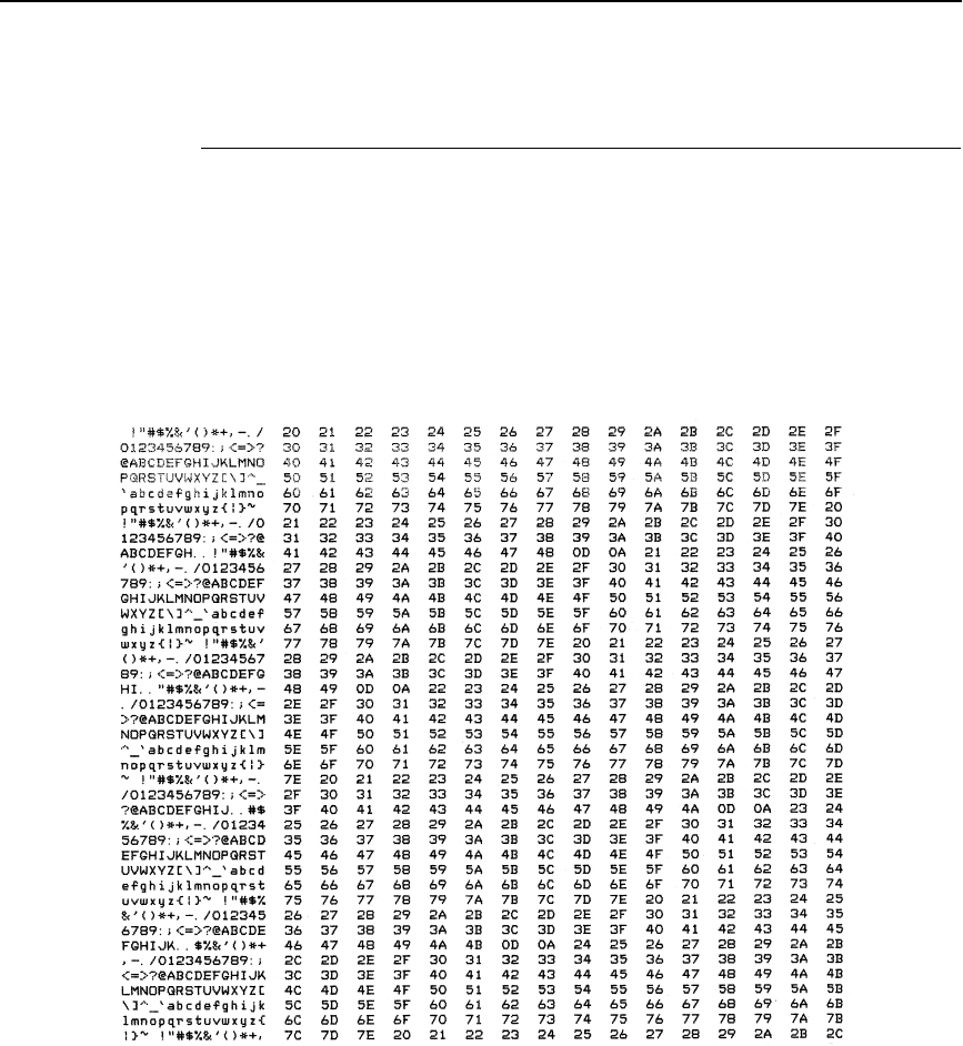
Printing A Hex Dump
285
Printing A Hex Dump
A hex code printout (or hex dump) is a translation of all host interface data to
its hexadecimal equivalent, listing all ASCII character data received from the
host computer with their corresponding two-digit hexadecimal codes. Hex
dumps are used to troubleshoot printer data reception problems.
Printable characters print as the assigned symbol; nonprintable characters
are indicated by a period (.).
Figure 26 shows an example of a hex dump.
Figure 26. Hex Dump Sample

286
Chapter 7
Diagnosing Problems
Fault Messages
If a fault condition occurs in the printer, the status indicator on the control
panel flashes on and off, and the message display indicates the specific fault.
Fault messages are summarized in Table 17.
Displayed faults fall into one of two categories:
•
Operator correctable
•
Field service required
For the operator-correctable faults, follow the suggested solution in Table 17.
After correcting the displayed fault, press the CANCEL key to clear the error
message and status indicator and resume printing. If the fault message
reappears, contact your authorized service representative.
NOTE: The Maintenance Manual provides more detailed information and
procedures for resolving fault conditions. However, many of the
procedures described there must be performed only by your
authorized service representative.
Fault Messages Requiring Field Service Attention
If a fault is not correctable by the operator, the fault message is followed by an
asterisk (*). This usually indicates that an authorized service representative is
needed. You may try two steps to clear the fault before calling your authorized
service representative:
1. Set the printer power switch to O (Off), wait 15 seconds, then turn the
printer on again. Run your print job again. If the message does not
appear, it was a false indication and no further attention is required.
2. If the message reappears, press the CANCEL key. If the message
disappears, it was a false indication and no further attention is required. If
the message reappears, call your authorized service representative.

Fault Messages
287
Table 17. LCD Message Troubleshooting Table
Displayed Message Can User
Correct? Explanation Solution
06 HOST REQUEST Yes Host attention message. The host computer or printer
controller requires attention.
08 HOLD PRINT
TIMEOUT
Yes Printer was offline more
than 10 minutes, and the
“Intervention Required”
parameter is set to “Send
to Host.”
Press ON LINE to put printer in
online state.
8.5V PWR FAIL* No 8.5 Volt power failed.
Internal power failure.
Contact your authorized service
representative.
1
15 COMM CHECK Yes A message that appears
in the CT emulation
meaning the line is not
active on a twinax
interface.
Check cable connection.
15V CTL FAIL* No Controller voltage failure. Contact your authorized service
representative.
1
22 INVALID ADDR Yes Unit address not
recognized by printer.
(Twinax interface)
Ensure that printer address
matches host setting.
23.5V CTL FAIL* No 23.5 Volt Controller
failed: a voltage failure on
the controller board.
Contact your authorized service
representative.
1
31 PAPER OUT
TIMEOUT
Yes A timeout message is
sent to the host if paper is
not loaded 10 minutes
after ON LINE/CLEAR
was pressed to clear the
paper out fault.
Load paper and run a print test. If
the message reappears, contact
your authorized service
representative.
1
32 PAPER JAM
TIMEOUT
Yes A timeout message is
sent to the host if no
paper motion has
occurred for 10 minutes
after ON LINE/CLEAR
was pressed to clear the
jam fault.
Clear paper jam and reload paper.
33 PLATEN OPEN
TIMEOUT
Yes The forms thickness lever
has been open for at
least one minute.
Load paper, close the forms
thickness lever, and press ON LINE/
CLEAR.

288
Chapter 7
Diagnosing Problems
34 RIBBON STALL
TIMEOUT
Yes In the CT emulation with
a coax interface, the
ribbon has not moved for
10 minutes after
ON LINE/CLEAR was
pressed to clear the
ribbon drive fault.
Reload the ribbon.
48V CIRCUIT*
See User Manual
No Either the power supply is
not generating a proper
48 Volts or the controller
board is not detecting a
48 Volt output from the
power supply board.
Contact your authorized service
representative.
1
48V PWR FAIL* No Internal power failure. Contact your authorized service
representative.
1
A TO D OVERUN* No Analog to Digital
Overrun. The analog-to-
digital converter
overflowed.
Contact your authorized service
representative.
1
ACCESS NULL PTR* No Access Null Pointer: The
processor tried to access
a pointer that contains
nothing (null).
Contact your authorized service
representative.
1
ACTIVATE LOST No The printer detects a
twinax protocol
communication error and
reports the error.
Contact your authorized service
representative.
1
B00 STATUS: SDRAM
DETECTION 166MHZ
No Status message: the
printer has begun its
boot-up routines and is
checking for the
presence of SDRAM.
No action required.
B01 STATUS: 8245
SDRAM TEST 32MB
No Status message: printer
boot-up routines are
testing SDRAM.
No action required.
B10 ERROR: NO
DRAM DETECTED*
No SDRAM DIMM may not
be properly installed.
Boot-up routines did not
detect the presence of
the SDRAM DIMM.
Cycle power to see if the message
clears, if not, contact your
authorized service representative.
1
B11 ERROR: RAM
TEST FAILED*
No SDRAM failed the boot
initialization test. SDRAM
DIMM may not be
properly installed.
Cycle power to see if the message
clears, if not, contact your
authorized service representative.
1
Table 17. LCD Message Troubleshooting Table
Displayed Message Can User
Correct? Explanation Solution

Fault Messages
289
B12 ERROR:
PROGRAM MISSING*
Yes The printer does not see
a program in flash
memory.
There is no program in printer
memory. Download an emulation.
B13 ERROR: NOT
COMPATIBLE*
No Attempting to download a
program that is not
compatible with the
printer.
Cycle power to see if the message
clears, if not, contact your
authorized service representative.
1
B19 ERROR: DC
RETURNED*
No The message indicates
an incorrectly assembled
and tested machine.
Cycle power to see if the message
clears, if not, contact your
authorized service representative.
1
B20 STATUS :00%
DOWNLOAD MODE
No Status message
informing the operator
that software is being
downloaded. Percentage
figure indicates
approximate amount
loaded into the printer.
No action is required.
B21 STATUS:
PRINTER RESET
No Status message
informing the operator
that the printer is
undergoing a system
reset.
No action is required.
B22 ERROR:
DECOMPRESS SIZE*
No FLASH memory has not
passed boot initialization
tests.
Cycle power to see if the message
clears, if not, contact your
authorized service representative.
1
B23 ERROR:
DECOMPRESS
CKSUM*
No FLASH memory has not
passed boot initialization
tests.
Cycle power to see if the message
clears, if not, contact your
authorized service representative.
1
B30 STATUS:
INITIALIZING...
N/A Status message: the
printer is running its
initialization routines after
startup and successful
memory tests.
No action is required.
B35 STATUS:
WAITING FOR EC
STATUS
N/A Status message: the DC
on the controller board is
waiting for
communication with the
EC. If this message does
not clear witin a few
seconds there is an
electrical or electronic
problem on the controller
board.
Cycle power to see if the message
clears, if not, contact your
authorized service representative.
1
Table 17. LCD Message Troubleshooting Table
Displayed Message Can User
Correct? Explanation Solution

290
Chapter 7
Diagnosing Problems
B40 ERROR: SDRAM
EEPROM CKSUM
BAD*
No Flash memory has not
passed boot initialization
tests.
Cycle power to see if the message
clears, if not, contact your
authorized service representative.
1
B41 ERROR: DIM
MEMORY NOT
SDRAM*
No The DRAM DIMM
installed on the controller
board is not Synchronous
DRAM (SDRAM).
Cycle power to see if the message
clears, if not, contact your
authorized service representative.
1
B42 ERROR: SDRAM
ROWS NOT
ALLOWED*
No Printer boot initialization
tests detect incorrect
SDRAM.
Cycle power to see if the message
clears, if not, contact your
authorized service representative.
1
B43 ERROR: SDRAM
TOO MANY BANKS*
No Printer boot initialization
tests detect incorrect
SDRAM.
Cycle power to see if the message
clears, if not, contact your
authorized service representative.
1
B44 ERROR: SDRAM
NOT 64 BITS WIDE*
No Printer boot initialization
tests detect incorrect
SDRAM.
Cycle power to see if the message
clears, if not, contact your
authorized service representative.
1
B45 ERROR: SDRAM
IS WRONG VOLTAGE*
No Printer boot initialization
tests detect incorrect
SDRAM.
Cycle power to see if the message
clears, if not, contact your
authorized service representative.
1
B46 ERROR: SDRAM
HAS MIXED SIZES*
No Printer boot initialization
tests detect incorrect
SDRAM.
Cycle power to see if the message
clears, if not, contact your
authorized service representative.
1
B47 ERROR: SDRAM
LARGER THAN 256M*
No Printer boot initialization
tests detect incorrect
SDRAM.
Cycle power to see if the message
clears, if not, contact your
authorized service representative.
1
B49 ERROR: SDRAM
# LOGICAL BANKS*
No Printer boot initialization
tests detect incorrect
SDRAM.
Cycle power to see if the message
clears, if not, contact your
authorized service representative.
1
B50 ERROR: SDRAM
LOGIC COMB BANKS*
No SDRAM DIMM is not
compatible with the
computer. SDRAM DIMM
may not be properly
installed.
Cycle power to see if the message
clears, if not, contact your
authorized service representative.
1
B50 STATUS: XX%
CLEAR FLASH
No Emulation software
sucessfully loaded in
RAM. Old program being
deleted from flash
memory.
No action is required.
Table 17. LCD Message Troubleshooting Table
Displayed Message Can User
Correct? Explanation Solution

Fault Messages
291
B51 STATUS: XX%
LOADING...
No Status message: printer
boot-up routines are
loading printer system
software into flash
memory and SDRAM.
No action required.
B53 ERROR: 12C NO
ARBITRATION
No There is a problem on the
I
2
C bus which allows the
SDRAM DIMM to
communicate with the
GPIO or CT interface.
Cycle power to see if the message
clears, if not, contact your
authorized service representative.
1
B54 ERROR: SDA
LINE STUCK LOW
No The SDRAM or a PCI
card is shorting out the
serial data bus on the
controller board.
Cycle power to see if the message
clears, if not, contact your
authorized service representative.
1
B55 STATUS: SEND
PROGRAM TO EC
No EC program downloaded
and being programed in
EC.
No action is required.
x/y BARCODES /
Not Found
Yes In the OpenPrint
products, SURE SCAN
detects fewer barcodes
than the set value for
"Barcodes on Page"
menu option. x
represents the number of
barcodes not found, and
y represents the
"Barcodes on Page"
value.
SURE SCAN success depends on
the symbology, quality of the
barcode graphic, and dimensions of
the barcode. See “OpenPrint SURE
SCAN Menu” on page 242 for more
information.
BUFFER OVERRUN Yes The print buffer has
overflowed on a serial
interface. The printed
output may contain
random * (asterisk)
characters. Make a
configuration printout.
Verify that the printer matches the
host serial interface configuration
settings for Data Protocol, Baud
Rate, Data Bits, Stop Bits, Parity,
Data Terminal Ready, and Request
to Send. Set printer serial interface
parameters to match those of the
host.
CLEAR PAPER JAM Yes No paper motion. Clear jam and reload paper. If this
message recurs, contact your
authorized service representative.
1
Table 17. LCD Message Troubleshooting Table
Displayed Message Can User
Correct? Explanation Solution

292
Chapter 7
Diagnosing Problems
CLEARING
PROGRAM FROM
FLASH
No Status message:
emulation software
successfully loaded into
printer RAM and the
checksum matched. The
old program is now being
deleted from flash
memory.
No action is required.
CLOSE PLATEN Yes The platen lever is open. Close the platen lever.
COIL HOT No One or more hammer
coils are overheating.
Contact your authorized service
representative.
1
CRTG COMM ERR
See User Manual
No The hardware cannot
communicate properly
with the cartridge.
1. Make sure the ribbon cartridge
is seated properly.
2.
Remove and replace the ribbon
cartridge if necessary.
3.
Contact your authorized
service representative.
1
CRTG MISSING
Install new RBN
Yes The ribbon cartridge is
missing or installed
improperly.
1. Make sure a ribbon cartridge is
installed in the printer.
2.
Make sure the ribbon cartridge
is seated properly.
3.
Remove and replace the
cartridge if necessary.
4.
Contact your authorized
customer service
representative.
1
CRTG NOT SETx
Re-install RBN
Yes The ribbon cartridge is
not properly positioned.
1. Make sure a ribbon cartridge is
installed in the printer.
2.
Make sure the ribbon cartridge
is seated properly.
3.
Remove and replace the
cartridge if necessary.
4.
Contact your authorized
customer service
representative.
1
CTL VOLT FAIL* No Controller Voltage
Failure. 15 V failure on
the controller board.
Contact your authorized service
representative.
1
D50 Status %XX
Clearing Flash
No Status message: The
printer is clearing its flash
memory, where %XX
represents the
percentage completed.
No action is required.
Table 17. LCD Message Troubleshooting Table
Displayed Message Can User
Correct? Explanation Solution

Fault Messages
293
D51 Status %XX
Programming...
No Status message: The
printer is loading
firmware, where %XX
represents the
percentage completed.
No action is required.
D55 Status: Send
Program to EC
No Status message: The
printer is loading the
engine controller program
into the engine controller
(EC).
No action is required.
DIAGNOSTIC
PASSED
No Status message: the
printer passed its
memory and hardware
initialization tests.
No action is required.
DO NOT POWER OFF No Status message: The
printer is performing an
operation that must be
completed before you
can cycle power.
No action is required, but do not
power off the printer until the
operation is complete.
DP FIFO Busy* Yes There is a timing problem
in the Engine Controller
firmware.
1. Cycle power. Run the print job
again. If the message appears,
download the emulation
software again.
2.
Cycle power. Run the print job
again. If the message appears
again, contact your authorized
service representative.
1
DRVR CIR BAD* No Driver Circuit Bad. The
hammer coil count test
failed.
Contact your authorized service
representative.
1
E00 EXE @ ADDR0
See User Manual
Yes An illegal or unsupported
instruction was attempted
in the application
program.
1. Cycle Power. Run the print job
again. If the message appears,
load the latest emulation
software.
2.
Cycle power. Run the print job
again. If the message appears,
record the display message
and send it to your next higher
support facility.
Table 17. LCD Message Troubleshooting Table
Displayed Message Can User
Correct? Explanation Solution

294
Chapter 7
Diagnosing Problems
E01A TYPE 0x40
See User Manual
Yes An illegal or unsupported
instruction was attempted
in the application
program.
1. Cycle Power. Run the print job
again. If the message appears,
load the latest emulation
software.
2.
Cycle power. Run the print job
again. If the message appears,
record the display message
and send it to your next higher
support facility.
E01B TYPE 0x60
See User Manual
Yes An illegal or unsupported
instruction was attempted
in the application
program.
1. Cycle Power. Run the print job
again. If the message appears,
load the latest emulation
software.
2.
Cycle power. Run the print job
again. If the message appears,
record the display message
and send it to your next higher
support facility.
E02 MACHINE CHK
See User Manual
Yes An illegal or unsupported
instruction was attempted
in the application
program.
1. Cycle Power. Run the print job
again. If the message appears,
load the latest emulation
software.
2.
Cycle power. Run the print job
again. If the message appears,
record the display message
and send it to your next higher
support facility.
E03A DSI HASH L
See User Manual
Yes An illegal or unsupported
instruction was attempted
in the application
program.
1. Cycle Power. Run the print job
again. If the message appears,
load the latest emulation
software.
2.
Cycle power. Run the print job
again. If the message appears,
record the display message
and send it to your next higher
support facility.
E03B DSI HASH S
See User Manual
Yes An illegal or unsupported
instruction was attempted
in the application
program.
1. Cycle Power. Run the print job
again. If the message appears,
load the latest emulation
software.
2.
Cycle power. Run the print job
again. If the message appears,
record the display message
and send it to your next higher
support facility.
Table 17. LCD Message Troubleshooting Table
Displayed Message Can User
Correct? Explanation Solution

Fault Messages
295
E03C DSI BAT PL
See User Manual
Yes An illegal or unsupported
instruction was attempted
in the application
program.
1. Cycle Power. Run the print job
again. If the message appears,
load the latest emulation
software.
2.
Cycle power. Run the print job
again. If the message appears,
record the display message
and send it to your next higher
support facility.
E03D DSI BAT PS
See User Manual
Yes An illegal or unsupported
instruction was attempted
in the application
program.
1. Cycle Power. Run the print job
again. If the message appears,
load the latest emulation
software.
2.
Cycle power. Run the print job
again. If the message appears,
record the display message
and send it to your next higher
support facility.
E03E DSI CXIWX
See User Manual
Yes An illegal or unsupported
instruction was attempted
in the application
program.
1. Cycle Power. Run the print job
again. If the message appears,
load the latest emulation
software.
2.
Cycle power. Run the print job
again. If the message appears,
record the display message
and send it to your next higher
support facility.
E03F DSI CXOWX
See User Manual
Yes An illegal or unsupported
instruction was attempted
in the application
program.
1. Cycle Power. Run the print job
again. If the message appears,
load the latest emulation
software.
2.
Cycle power. Run the print job
again. If the message appears,
record the display message
and send it to your next higher
support facility.
E03G DSI ECXIWX
See User Manual
Yes An illegal or unsupported
instruction was attempted
in the application
program.
1. Cycle Power. Run the print job
again. If the message appears,
load the latest emulation
software.
2.
Cycle power. Run the print job
again. If the message appears,
record the display message
and send it to your next higher
support facility.
Table 17. LCD Message Troubleshooting Table
Displayed Message Can User
Correct? Explanation Solution

296
Chapter 7
Diagnosing Problems
E03H DSI ECXOWX
See User Manual
Yes An illegal or unsupported
instruction was attempted
in the application
program.
1. Cycle Power. Run the print job
again. If the message appears,
load the latest emulation
software.
2.
Cycle power. Run the print job
again. If the message appears,
record the display message
and send it to your next higher
support facility.
E04A ISI NO TRA
See User Manual
Yes An illegal or unsupported
instruction was attempted
in the application
program.
1. Cycle Power. Run the print job
again. If the message appears,
load the latest emulation
software.
2.
Cycle power. Run the print job
again. If the message appears,
record the display message
and send it to your next higher
support facility.
E04B ISI DIRECT
See User Manual
Yes An illegal or unsupported
instruction was attempted
in the application
program.
1. Cycle Power. Run the print job
again. If the message appears,
load the latest emulation
software.
2.
Cycle power. Run the print job
again. If the message appears,
record the display message
and send it to your next higher
support facility.
E04C ISI PROTEC
See User Manual
Yes An illegal or unsupported
instruction was attempted
in the application
program.
1. Cycle Power. Run the print job
again. If the message appears,
load the latest emulation
software.
2.
Cycle power. Run the print job
again. If the message appears,
record the display message
and send it to your next higher
support facility.
E06 NOT ALIGNED
See User Manual
Yes An illegal or unsupported
instruction was attempted
in the application
program.
1. Cycle Power. Run the print job
again. If the message appears,
load the latest emulation
software.
2.
Cycle power. Run the print job
again. If the message appears,
record the display message
and send it to your next higher
support facility.
Table 17. LCD Message Troubleshooting Table
Displayed Message Can User
Correct? Explanation Solution

Fault Messages
297
E07 ILLEGAL INS
See User Manual
Yes An illegal or unsupported
instruction was attempted
in the application
program.
1. Cycle Power. Run the print job
again. If the message appears,
load the latest emulation
software.
2.
Cycle power. Run the print job
again. If the message appears,
record the display message
and send it to your next higher
support facility.
E08 FLOATINGPNT
See User Manual
Yes An illegal or unsupported
instruction was attempted
in the application
program.
1. Cycle Power. Run the print job
again. If the message appears,
load the latest emulation
software.
2.
Cycle power. Run the print job
again. If the message appears,
record the display message
and send it to your next higher
support facility.
E12 SYSTEM CALL
See User Manual
Yes An illegal or unsupported
instruction was attempted
in the application
program.
1. Cycle Power. Run the print job
again. If the message appears,
load the latest emulation
software.
2.
Cycle power. Run the print job
again. If the message appears,
record the display message
and send it to your next higher
support facility.
E13 TRACE INT
See User Manual
Yes An illegal or unsupported
instruction was attempted
in the application
program.
1. Cycle Power. Run the print job
again. If the message appears,
load the latest emulation
software.
2.
Cycle power. Run the print job
again. If the message appears,
record the display message
and send it to your next higher
support facility.
E16 ITRANS MISS
See User Manual
Yes An illegal or unsupported
instruction was attempted
in the application
program.
1. Cycle Power. Run the print job
again. If the message appears,
load the latest emulation
software.
2.
Cycle power. Run the print job
again. If the message appears,
record the display message
and send it to your next higher
support facility.
Table 17. LCD Message Troubleshooting Table
Displayed Message Can User
Correct? Explanation Solution

298
Chapter 7
Diagnosing Problems
E17 DLOAD MISS
See User Manual
Yes An illegal or unsupported
instruction was attempted
in the application
program.
1. Cycle Power. Run the print job
again. If the message appears,
load the latest emulation
software.
2.
Cycle power. Run the print job
again. If the message appears,
record the display message
and send it to your next higher
support facility.
E18 DSTORE MISS
See User Manual
Yes An illegal or unsupported
instruction was attempted
in the application
program.
1. Cycle Power. Run the print job
again. If the message appears,
load the latest emulation
software.
2.
Cycle power. Run the print job
again. If the message appears,
record the display message
and send it to your next higher
support facility.
E19 BREAKPOINT
See User Manual
Yes An illegal or unsupported
instruction was attempted
in the application
program.
1. Cycle Power. Run the print job
again. If the message appears,
load the latest emulation
software.
2.
Cycle power. Run the print job
again. If the message appears,
record the display message
and send it to your next higher
support facility.
E20 SYS MANAGE
See User Manual
Yes An illegal or unsupported
instruction was attempted
in the application
program.
1. Cycle Power. Run the print job
again. If the message appears,
load the latest emulation
software.
2.
Cycle power. Run the print job
again. If the message appears,
record the display message
and send it to your next higher
support facility.
E30 DEBUGGER
See User Manual
Yes An illegal or unsupported
instruction was attempted
in the application
program.
1. Cycle Power. Run the print job
again. If the message appears,
load the latest emulation
software.
2.
Cycle power. Run the print job
again. If the message appears,
record the display message
and send it to your next higher
support facility.
Table 17. LCD Message Troubleshooting Table
Displayed Message Can User
Correct? Explanation Solution

Fault Messages
299
E31A EVENT O BP
See User Manual
Yes An illegal or unsupported
instruction was attempted
in the application
program.
1. Cycle Power. Run the print job
again. If the message appears,
load the latest emulation
software.
2.
Cycle power. Run the print job
again. If the message appears,
record the display message
and send it to your next higher
support facility.
E31B EVENT 1 BP
See User Manual
Yes An illegal or unsupported
instruction was attempted
in the application
program.
1. Cycle Power. Run the print job
again. If the message appears,
load the latest emulation
software.
2.
Cycle power. Run the print job
again. If the message appears,
record the display message
and send it to your next higher
support facility.
E31C EVENT 2 BP
See User Manual
Yes An illegal or unsupported
instruction was attempted
in the application
program.
1. Cycle Power. Run the print job
again. If the message appears,
load the latest emulation
software.
2.
Cycle power. Run the print job
again. If the message appears,
record the display message
and send it to your next higher
support facility.
E31D EVENT 3 BP
See User Manual
Yes An illegal or unsupported
instruction was attempted
in the application
program.
1. Cycle Power. Run the print job
again. If the message appears,
load the latest emulation
software.
2.
Cycle power. Run the print job
again. If the message appears,
record the display message
and send it to your next higher
support facility.
E31E EVENT 4 BP
See User Manual
Yes An illegal or unsupported
instruction was attempted
in the application
program.
1. Cycle Power. Run the print job
again. If the message appears,
load the latest emulation
software.
2.
Cycle power. Run the print job
again. If the message appears,
record the display message
and send it to your next higher
support facility.
Table 17. LCD Message Troubleshooting Table
Displayed Message Can User
Correct? Explanation Solution

300
Chapter 7
Diagnosing Problems
E31F EVENT 5 BP
See User Manual
Yes An illegal or unsupported
instruction was attempted
in the application
program.
1. Cycle Power. Run the print job
again. If the message appears,
load the latest emulation
software.
2.
Cycle power. Run the print job
again. If the message appears,
record the display message
and send it to your next higher
support facility.
E31G EVENT 6 BP
See User Manual
Yes An illegal or unsupported
instruction was attempted
in the application
program.
1. Cycle Power. Run the print job
again. If the message appears,
load the latest emulation
software.
2.
Cycle power. Run the print job
again. If the message appears,
record the display message
and send it to your next higher
support facility.
E31H EVENT 7 BP
See User Manual
Yes An illegal or unsupported
instruction was attempted
in the application
program.
1. Cycle Power. Run the print job
again. If the message appears,
load the latest emulation
software.
2.
Cycle power. Run the print job
again. If the message appears,
record the display message
and send it to your next higher
support facility.
E32A CND 0 BP
See User Manual
Yes An illegal or unsupported
instruction was attempted
in the application
program.
1. Cycle Power. Run the print job
again. If the message appears,
load the latest emulation
software.
2.
Cycle power. Run the print job
again. If the message appears,
record the display message
and send it to your next higher
support facility.
E32B CND 1 BP
See User Manual
Yes An illegal or unsupported
instruction was attempted
in the application
program.
1. Cycle Power. Run the print job
again. If the message appears,
load the latest emulation
software.
2.
Cycle power. Run the print job
again. If the message appears,
record the display message
and send it to your next higher
support facility.
Table 17. LCD Message Troubleshooting Table
Displayed Message Can User
Correct? Explanation Solution

Fault Messages
301
E32C CND 2 BP
See User Manual
Yes An illegal or unsupported
instruction was attempted
in the application
program.
1. Cycle Power. Run the print job
again. If the message appears,
load the latest emulation
software.
2.
Cycle power. Run the print job
again. If the message appears,
record the display message
and send it to your next higher
support facility.
E32D CND 3 BP
See User Manual
Yes An illegal or unsupported
instruction was attempted
in the application
program.
1. Cycle Power. Run the print job
again. If the message appears,
load the latest emulation
software.
2.
Cycle power. Run the print job
again. If the message appears,
record the display message
and send it to your next higher
support facility.
E32E CND 4 BP
See User Manual
Yes An illegal or unsupported
instruction was attempted
in the application
program.
1. Cycle Power. Run the print job
again. If the message appears,
load the latest emulation
software.
2.
Cycle power. Run the print job
again. If the message appears,
record the display message
and send it to your next higher
support facility.
E32F CND 5 BP
See User Manual
Yes An illegal or unsupported
instruction was attempted
in the application
program.
1. Cycle Power. Run the print job
again. If the message appears,
load the latest emulation
software.
2.
Cycle power. Run the print job
again. If the message appears,
record the display message
and send it to your next higher
support facility.
E32G CND 6 BP
See User Manual
Yes An illegal or unsupported
instruction was attempted
in the application
program.
1. Cycle Power. Run the print job
again. If the message appears,
load the latest emulation
software.
2.
Cycle power. Run the print job
again. If the message appears,
record the display message
and send it to your next higher
support facility.
Table 17. LCD Message Troubleshooting Table
Displayed Message Can User
Correct? Explanation Solution

302
Chapter 7
Diagnosing Problems
E32H CND 7 BP
See User Manual
Yes An illegal or unsupported
instruction was attempted
in the application
program.
1. Cycle Power. Run the print job
again. If the message appears,
load the latest emulation
software.
2.
Cycle power. Run the print job
again. If the message appears,
record the display message
and send it to your next higher
support facility.
E33 WRITE BP
See User Manual
Yes An illegal or unsupported
instruction was attempted
in the application
program.
1. Cycle Power. Run the print job
again. If the message appears,
load the latest emulation
software.
2.
Cycle power. Run the print job
again. If the message appears,
record the display message
and send it to your next higher
support facility.
E34 TRACE CMPLT
See User Manual
Yes An illegal or unsupported
instruction was attempted
in the application
program.
1. Cycle Power. Run the print job
again. If the message appears,
load the latest emulation
software.
2.
Cycle power. Run the print job
again. If the message appears,
record the display message
and send it to your next higher
support facility.
E99 UNKNOWN INT
See User Manual
Yes An illegal or unsupported
instruction was attempted
in the application
program.
1. Cycle Power. Run the print job
again. If the message appears,
load the latest emulation
software.
2.
Cycle power. Run the print job
again. If the message appears,
record the display message
and send it to your next higher
support facility.
E Net Test Unavailable Yes The ethernet PCBA did
not initialize correctly.
Cycle power. Wait for “E Net Ready”
to display, then retry operation. If it
still fails, contact your authorized
service representative.
1
Table 17. LCD Message Troubleshooting Table
Displayed Message Can User
Correct? Explanation Solution

Fault Messages
303
ERROR: CPLD NOT
PROGRAMMED
No The Complex
Programmable Logic
Device (CPLD) on the
controller board is not
programmed. The EC
cannot read the version
bits in the CPLD which
tell the EC which
configuration version is
installed.
Contact your authorized service
representative.
1
ERROR: DC
PROGRAM NOT
VALID
Yes The printer cannot find
the data controller
program or the validation
checksum is corrupt.
Download the program again. If the
message appears, contact your
authorized service representative.
1
ERROR: DRAM AT
ADDRESS XXXXXXXX
Yes The printer cannot find
the engine controller
program or the validation
checksum is corrupt.
Download the program again. If the
message appears, contact your
authorized service representative.
1
ERROR: EC
PROGRAM NOT
VALID
The printer cannot find
the engine controller
program or the validation
checksum is corrupt.
Download the program again. If the
message occurs again, contact your
authorized service representative.
1
ERROR: EC
STOPPED AT STATE
XXXX
No XXXX is a number from
0000 to 0010. The
Engine Controller has
stopped and is in the
state identified by the
number displayed.
Contact your authorized service
representative.
1
ERROR: FLASH DID
NOT PROGRAM
Yes The printer encountered
an error trying to program
flash memory.
Download the program again. If the
message displays again, contact
your authorized service
representative.
1
ERROR: FLASH NOT
DETECTED
No The printer could not find
flash memory.
Contact your authorized service
representative.
1
ERROR: LOCKED
SN=nnnnnnnnnnnnnnn
nnnnnn
No nnnnnnnnnnnnnnnnnnnn
n is the serial number of
the printer’s security key.
The SPX serial number
does not match the
printer’s serial number
and cannot be used with
the printer.
Contact your authorized service
representative.
1
ERROR: NO DRAM
DETECTED
No The printer could not find
any DRAM.
Contact your authorized service
representative.
1
Table 17. LCD Message Troubleshooting Table
Displayed Message Can User
Correct? Explanation Solution

304
Chapter 7
Diagnosing Problems
ERROR: NVRAM
FAILURE
No The non-volatile SRAM
on the controller board
has failed.
Contact your authorized service
representative.
1
ERROR OCCURRED
FLUSHING QUEUES*
No An interim message that
displays while the printer
discards host data it
cannot use because a
fault condition exists.
Contact your authorized service
representative.
1
ERROR: PROGRAM
NEEDS MORE DRAM
No The printer requires more
DRAM to run the
downloaded program.
Contact your authorized service
representative.
1
ERROR: PROGRAM
NEEDS MORE FLASH
No The printer requires more
flash memory to run the
downloaded program
Contact your authorized service
representative.
1
ERROR: PROGRAM
NOT COMPATIBLE
Yes The printer is not
compatible with the
downloaded program.
Use the correct emulation software
options(s) for this printer model.
ERROR: PROGRAM
NOT VALID
Yes The printer does not see
a program in flash
memory.
There is no program in printer
memory. Download the emulation.
ERROR: SECURITY
KEY NOT DETECTED
No The security key is not
present or failed.
Contact your authorized service
representative.
1
ERROR: SHORT AT
ADDRESS XXXX
No Hardware failure in
SDRAM or controller
circuitry.
Contact your authorized service
representative.
1
ERROR: WRITING TO
FLASH
No Hardware or software
fault in flash memory.
Contact your authorized service
representative.
1
ERROR: WRONG
CHECKSUM
No The printer received the
complete program but the
checksum did not match.
The data may have been
corrupted during
downloading.
Contact your authorized service
representative.
1
ERROR: WRONG
OEM
No The SPX inserted in the
debug port is not
intended for this model
printer or this OEM.
Contact your authorized service
representative.
1
ERROR: WRONG
PRINTER TYPE
No The SPX inserted in the
debug port is not
intended for this model
printer or this OEM.
Contact your authorized service
representative.
1
Table 17. LCD Message Troubleshooting Table
Displayed Message Can User
Correct? Explanation Solution

Fault Messages
305
ETHERNET ADAPTER
BEING INITIALIZED
N/A Status message
indicating that the
ethernet interface is
processing the boot
procedure.
No action is required.
ETHERNET
DETECTED
N/A Status message
indicating that the
Network Interface Card
has established
connection.
No action is required.
ETHERNET
INITIALIZING
No Status message: the
internal Network Interface
Card is processing the
boot procedure. (May
occur with older versions
of microcode.)
No action is required.
EXCESS RBN WEAR
Install New RBN
Yes Status message that
displays when ribbon
reaches end of life,
whether the Integrated
Print Management
System is enabled or not.
Install a new ribbon.
EXHAUST FAN FLT
(Cabinet model only)
Yes Sensors cannot detect
current in fan circuit.
Power off the printer and remove
the paper path (see Maintenance
Manual). Check that the fan cable
connector is connected. Check for
obstruction of vents and fan airway,
and remove any obstructions.
Check for items beneath the printer
blocking cabinet vents. Power back
on the printer. If this message
appears again, contact your
authorized service representative.
1
FIRMWARE ERROR* No Application software tried
to perform an illegal
printer function or
damaged memory
detected on the controller
board.
Contact your authorized service
representative.
1
FM HEADER ERROR* No Frame Header Error.
Application software has
violated header
parameters.
Contact your system administrator.
Table 17. LCD Message Troubleshooting Table
Displayed Message Can User
Correct? Explanation Solution

306
Chapter 7
Diagnosing Problems
FRAMING ERROR Yes The printed output may
contain random !
(exclamation point)
characters.
Make a configuation printout. Set
printer serial interface parameters to
match host configuration settings
for Data Protocol, Baud Rate, Data
Bits, Stop Bits, Parity, Data Terminal
Ready, and Request to Send.
FREEFORM OFF Yes A control panel key is
stuck in the down
position.
Press the key again.
FREEFORM ON: OFF
HOLD KEY @ PWRUP
No This message appears if
the freeform feature is
enabled. This feature is
for manufacturing use
only and is never used by
the customer or field
maintenance personnel.
Contact your authorized service
representative.
1
GRF CHK ERROR
PRESS STOP
Yes Graphic Check Error: in
the CT emulation over a
twinax interface, the
printer received a non-
printable character.
Press ON LINE/CLEAR.
H00: PCI SLOT ?
See User Manual
No The controller board is
not communicating with a
PCI card. This could
indicate a bad PCI card,
poor connection, or
problem in the PCI bus.
Contact your authorized service
representative.
1
H01: PCI J12
See User Manual
No The controller board is
not communicating with
the PCI card in PCI slot
J12. This could indicate a
bad PCI card, poor
connection, or problem in
the PCI bus.
Contact your authorized service
representative.
1
H02: PCI J13
See User Manual
No The controller board is
not communicating with
the PCI card in PCI slot
J13. This could indicate a
bad PCI card, poor
connection, or problem in
the PCI bus.
Contact your authorized service
representative.
1
Table 17. LCD Message Troubleshooting Table
Displayed Message Can User
Correct? Explanation Solution

Fault Messages
307
<Online, etc...>
Half Speed Mode
No Status message: The
controller samples the
operating temperature of
key components of the
print mechanism. When
higher than normal
temperatures are sensed,
the print speed is
automatically reduced by
50% and the message
sent the LCD. When the
components cool down,
the print speed returns to
100% and the message
clears.
No action is required. If the
message appears often, contact
your authorized service
representative.
1
HAM. COIL OPEN* No Hammer Coil Open.
Electrical malfunction of
one or more hammer
coils.
Contact your authorized service
representative.
1
HAMMER COIL BAD*
#, #, #, ...etc
No Hammer coil # failed
current test at power up.
Contact your authorized service
representative.
1
HAMMER SHORT*
See User Manual
No Electrical malfunction of
one or more hammer
coils.
Contact your authorized service
representative.
1
HB NOT INSTALLD* No Hammer Bank Not
Installed. Self-test
routines do not detect
hammer coils at printer
start-up.
Contact your authorized service
representative.
1
HMR BANK FAN FLT Yes Sensors cannot detect
current in fan circuit.
Check that fan cable is connected.
Check for obstruction of vents and
fan airway; remove any
obstructions. Check for items
beneath the printer blocking cabinet
vents. Power back on the printer. If
this message recurs, contact your
authorized service representative.
1
ILL EXT BUS ACC* No Illegal External Bus
Access. Firmware error
on the controller board.
Contact your authorized service
representative.
1
ILL INST ACCSS* No Illegal Instruction
Accessed. Firmware
error on the controller
board.
Contact your authorized service
representative.
1
Table 17. LCD Message Troubleshooting Table
Displayed Message Can User
Correct? Explanation Solution

308
Chapter 7
Diagnosing Problems
ILLGL OPR ACCSS* No Illegal Operand
Accessed. Firmware
error on controller board.
Contact your authorized service
representative.
1
INCOMPAT E-NET
Remove NIC
Yes Incompatible network
interface card (NIC) is
installed.
Install a compatible NIC to the
printer then reboot. If this message
still appears, contact your
authorized service representative.
1
INTAKE FAN FAULT Yes Sensors cannot detect
current in fan circuit.
Cycle power. If the message
appears, press ON LINE/CLEAR.
If the message does not clear,
contact your authorized service
representative.
1
INTERRUPT UNUSED
VECTOR 00
No The controller board
receives an interrupt it
does not understand. The
problem can be created
by electrical noise, by a
software problem, or by a
hardware problem.
Cycle power. If this message
occurred once and never again, you
can ignore it. If the message
reappears or appears consistently,
contact your authorized service
representative.
1
INVALID ACTIVATE No Printer detects a twinax
protocol communication
error.
Contact your authorized service
representative.
1
INVALID COMMAND No Printer detects a twinax
protocol communication
error and reports the
error.
Contact your authorized service
representative.
1
LO DRV. SHORT * No Lower Driver Short.
Circuit(s) on the hammer
bank or in the hammer
bank power cable
shorted to ground.
Contact your authorized service
representative.
1
LOAD PAPER Yes Printer is out of paper. Load paper and press ON LINE/
CLEAR.
LOADING PROGRAM
FROM PORT XX%
No Status message: the new
emulation program is
loading into printer RAM.
XX% indicates how much
of the program has
loaded.
No action is required.
LOADING PROGRAM
INTO FLASH
No The printer has deleted
the previous program
from flash memory and is
loading the new program
into flash memory.
No action is required.
Table 17. LCD Message Troubleshooting Table
Displayed Message Can User
Correct? Explanation Solution

Fault Messages
309
NEW SPX DETECTED
PRESS ENTER
No The printer detects an
SPX installed at the
debug port and the SPX
is valid for the printer.
Contact your authorized service
representative.
1
NON VOLATILE
MEMORY FAILED
No Large emulations reduce
the amount of space
available for saving
configurations, which
means that sometimes
fewer than eight
configurations can be
saved.
Contact your authorized service
representative.
1
ON LINE N/A Printer state message:
printer is online and in
communication with host.
No action is required.
ONLINE
28 CU NOT ENAB
Yes Controller Unit Not
Enabled. Poll
time-out error. The printer
was not polled for one
minute across a coax
interface.
Check cable connection and host
system.
ONLINE
8344 FAILED*
No Link-level code test
detects hardware failure.
Contact your authorized service
representative.
1
ONLINE
CU TIMED OUT
Yes Controller Unit Timed
Out. The printer was not
enabled for one minute or
more on a coax interface.
Check cable connection and host
system.
PAP BAD TABLE* No Paper Bad Table. The
paper feed process on
the controller board has a
corrupted table.
Contact your authorized service
representative.
1
PAP BSY TOO LNG* No Paper Busy Too Long.
Firmware error on
controller board.
Contact your authorized service
representative.
1
PAP FD DRVR CIR*
See Manual
No Paper Feed Driver
Circuit. The paper feed
driver circuit on the
controller board is
drawing too much
current.
Contact your authorized service
representative.
1
PAP FIFO OVERFL* No Paper First In First Out
Overflow. Firmware error
on controller board.
Contact your authorized service
representative.
1
Table 17. LCD Message Troubleshooting Table
Displayed Message Can User
Correct? Explanation Solution

310
Chapter 7
Diagnosing Problems
PAP FIFO UNDRFL* No Paper First In First Out
Underflow. Firmware
error on controller board.
Contact your authorized service
representative.
1
PAP ILLGL ST* No Paper Illegal State.
Firmware error on
controller board.
Contact your authorized service
representative.
1
PAP INCMPL ENER* No Paper Incompletely
Energized. Firmware
error on controller board.
Contact your authorized service
representative.
1
PAP INVLD CMD* No Paper Invalid Command.
Firmware error on
controller board.
Contact your authorized service
representative.
1
PAP INVLD PARM* No Paper Invalid Parameter.
Firmware error on
controller board.
Contact your authorized service
representative.
1
PAP NOT SCHED* No Paper Not Scheduled.
The paper feed process
is not scheduling on the
controller board, and the
printer cannot feed paper.
Contact your authorized service
representative.
1
PAP NT AT SPEED* No Paper Not At Speed.
Firmware error on
controller board.
Contact your authorized service
representative.
1
PAP UNEXP INT* No Paper Unexpected
Interrupt. Firmware error
on controller board.
Contact your authorized service
representative.
1
PARAMETER ERROR* No Illegal parameter value
received in command
code over a coax/twinax
interface.
Contact your system administrator.
PAPER REQUESTED:
A4
Yes A paper size mismatch is
detected.
Check the paper size setting and if
necessary, load new media and
change the paper size menu option.
PARITY ERROR Yes The printed output may
contain a random ?
(question mark)
characters.
Check your printer serial interface
parameter settings; if necessary,
adjust them so that they match the
settings of the attached host.
PLAT INV CMD* No Platen Invalid Command.
Firmware error on
controller board.
Contact your authorized service
representative.
1
PLAT INV PARM* No Platen Invalid Parameter.
Firmware error on
controller board.
Contact your authorized service
representative.
1
Table 17. LCD Message Troubleshooting Table
Displayed Message Can User
Correct? Explanation Solution

Fault Messages
311
PLAT INV STATE* No Platen Invalid State.
Firmware error on
controller board.
Contact your authorized service
representative.
1
PLEASE WAIT...
RESET IN
PROGRESS
N/A Status message: the
printer finished loading
the program into flash
memory and is
automatically resetting
itself.
No action is required.
POWER SUPPLY HOT Yes Power supply sensors
report high temperatures.
Check printer environment. If hot or
dusty, relocate printer. Contact your
authorized service representative if
this occurs frequently.
1
PRINTER HOT Yes This message indicates
internal temperatures
over 60° Celsius (140°
Fahrenheit).
Check printer environment. If hot or
dusty, relocate printer. Contact your
authorized service representative if
this occurs frequently.
1
PRINTER UNDER
REMOTE CONTROL
No Status message: The
printer is under the
control of PrintNet
Enterprise (PNE) remote
management software.
No action is required.
PROTECTED INSTR* No Protected Instruction.
Firmware error on
controller board.
Contact your authorized service
representative.
1
PS/PDF ERROR:
JOB ABORTED
Yes Fault displayed when
Postscript/PDF failed to
process a job, e.g. an
unsupported command or
a large job which requires
more DRAM to process.
Clear the fault. Postscript/PDF will
continue with the next job.
PWR SUPP VOLT * No Power Supply Voltage.
The power supply has
failed.
Replace power supply board.
QUEUE OVERRUN No In CT twinax emulation,
the print buffer has
overflowed.
Contact your authorized service
representative.
1
RBN AT END POINT
Change Ribbon
Yes Integrated Print
Management System
software has determined
that the ribbon is out of
ink.
Install a new ribbon.
Table 17. LCD Message Troubleshooting Table
Displayed Message Can User
Correct? Explanation Solution

312
Chapter 7
Diagnosing Problems
REGIONx MISMATCH
Use Correct RBN
Yes The incorrect cartridge
type is being used for the
printer. “X” indicates the
region of the printer.
Install Region X ribbon cartridge in
the printer.
NOTE: Specify the region of the
printer when ordering
ribbons.
REMOVE USED SPX
THEN PRESS ENTER
No Status message: An SPX
is depleted because it
has successfully
reprogrammed the
security key on the
controller board.
Contact your authorized service
representative.
1
RESTORING BOOT
CODE
No Normal download
initialization message.
No action is required.
RIB INVLD CMD*
See User Manual
Yes Ribbon Invalid
Command. Firmware
error on the controller
board.
Cycle power. Run the print job
again. If the message appears,
download the emulation software
again. If the message appears
again, contact your authorized
service representative.
1
RIBBON DRIVE No The controller board does
not detect a ribbon drive
motor.
Contact your authorized service
representative.
1
RIBBON STALL Yes The controller board does
not detect ribbon
movement.
Check the ribbon path for jams.
Turn the Ribbon Tension Knob
clockwise a few rotations. If
necessary, install a new ribbon.
RIBBON UNDER 2%
Change RBN Soon
Yes Status message
indicating the Integrated
Print Management
System is enabled and
ribbon ink level is 2%.
Install a new ribbon.
RWP DOWNLOAD
Please Wait
No Status message
indicating the software in
the cartridge is being
updated. The user must
wait for the update to
complete.
No action is required.
SCS COMMAND
ERROR*
No In the CT emulation, the
printer received
undefined control
character (hex 40).
Contact your system administrator.
SECURITY
VIOLATION*
No Security code of PAL on
controller board does not
match code of firmware
on the controller board.
Contact your authorized service
representative.
1
Table 17. LCD Message Troubleshooting Table
Displayed Message Can User
Correct? Explanation Solution

Fault Messages
313
SECURITY KEY NOT
DETECTED
No The security key is not
present or has failed.
Contact your authorized service
representative.
1
SENDING PROGRAM
TO EC PROCESSOR
No Status message: the
printer is loading the
engine controller program
into the engine controller.
No action is required.
SF ERROR No Structured Field Error.
Application software has
violated structured data
field parameters.
Not a printer problem. Have the
system administrator correct
applications data or configuration.
SHTL MISMATCH
Use Correct RBN
Yes This message displays
when an Extended Life
Ribbon is mounted on a
500 lpm printer.
Install Standard Life Ribbon.
SHUT DRVR CIR*
See User Manual
No The shuttle driver circuit
on the controller board is
drawing too much
current.
Contact your authorized service
representative.
1
SHUTL INV CMD* No Shuttle Invalid
Command. Firmware
error on controller board.
Contact your authorized service
representative.
1
SHUTL INV PARM* No Shuttle Invalid
Parameter. Firmware
error on controller board.
Contact your authorized service
representative.
1
SHUTL OVR SPEED* No The shuttle is oscillating
too rapidly.
Contact your authorized service
representative.
1
SHUTTLE JAM Yes No shuttle movement or
shuttle moving at the
wrong speed.
Check for obstruction to shuttle, a
twisted ribbon, or platen lever
closed too tightly. If fault source is
not apparent, contact your
authorized service representative.
1
SHUTTLE STALL Yes The shuttle is not moving.
See “SHUTTLE JAM” on
page 313.
Set the platen lever to match the
thickness of paper, but not too
tightly. Check and adjust the platen
gap. Inspect the ribbon mask for
deformation that snags and
interferes with shuttle movement. If
fault source is not apparent, contact
your authorized service
representative.
1
Table 17. LCD Message Troubleshooting Table
Displayed Message Can User
Correct? Explanation Solution

314
Chapter 7
Diagnosing Problems
SHUTTLE TYPE NOT
SUPPORTED*
No The shuttle type was not
detected at power-up or
the shuttle installed in the
printer is not supported
by the firmware.
Contact your authorized service
representative.
1
SOFTWARE ERROR*
CYCLE POWER
No Application software tried
to perform illegal printer
function, or damaged
logic circuits found on
controller board.
Contact your authorized service
representative.
1
SPX FOUND, ERROR:
KEY NOT DETECTED
No The controller board does
not have a security key.
Contact your authorized service
representative.
1
SPX NOT NEEDED
OPTIONS ENABLED
No The user has attempted
to use the SPX to turn on
printer options that are
already enabled.
Contact your authorized service
representative.
1
STACK OVERFLOW* No Firmware error on
controller board.
Contact your authorized service
representative.
1
STACK UNDERFLOW* No Firmware error on the
controller board.
Contact your authorized service
representative.
1
STACKER FAULT Yes Stacker is not functioning
correctly.
Check for obstructions in the
stacker area. If fault persists,
contact your authorized service
representative.
1
STACKER FULL Yes Status message: the
power paper stacker is
full of paper.
Unload the stacker. If fault persists,
contact your authorized service
representative.
1
STACKER JAM Yes This message is
triggered if there is paper
inside the throat of the
stacker elevator, but the
elevator is not moving.
1. Open the cabinet rear door and
check for obstructions preventing
elevator movement. Remove any
obstructions.
2. Run the print job again. If the
message appears again, contact
your authorized service
representative.
1
TABLE MISMATCH
DOWNLOAD AGAIN
No Indicates that the
software update has
failed and should be
reloaded.
Contact your authorized service
representative.
1
TCB CORRUPTED* No Task Control Block
Corrupted. Firmware
error on controller board.
Contact your authorized service
representative.
1
Table 17. LCD Message Troubleshooting Table
Displayed Message Can User
Correct? Explanation Solution

Fault Messages
315
TCP PORT BUSY Yes Error message reported
by the Printer Manager
when ethernet interface
option is installed. The
network address given in
the printer properties was
reached, but the printer
port is busy.
Refer to the Printronix P7000
Maintenance Manual.
TIP MISMATCH
Use Correct RBN
Yes The incorrect cartridge
type is being used for the
printer.
Install the correct ribbon cartridge
type in the printer.
UNDEF INTERRUPT* No Undefined Interrupt.
Firmware error on
controller board.
Contact your authorized service
representative.
1
UNDFNED OPCODE* No Undefined Opcode.
Firmware error on
controller board.
Contact your authorized service
representative.
1
UNKNOWN RBN1
Install New RBN
Yes The sensor detects a bar
code, but the ribbon
model is not permitted on
this printer.
Install a new ribbon.
UP DRV. SHORT* No Upper Driver Short.
Hammer driver circuits on
the boards shorted to
ground.
Cycle power to see if the message
clears, if not, contact your
authorized service representative.
1
WAITING FOR
ETHERNET ADAPTER
N/A Status message: Appears
when the printer is first
powered on if the optional
Network Interface Card is
installed.
No action is required.
WELD NOT DETECT
See User Manual
No The cartridge weld was
not detected.
Contact your authorized service
representative.
1
WELD RESET ERROR
See User Manual
No The cartridge weld
circuitry lost power.
Contact your authorized service
representative.
1
WELD SNSR MISSING
See User Manual
Yes The incorrect cartridge
type is being used for the
printer.
1. Make sure that the correct
ribbon cartridge type is
installed in the printer.
2.
Contact your authorized
service representative.
1
1
Before contacting an authorized service representative, power off the printer, wait 15 seconds, then
power it back on and rerun your print job. If the message reappears, press ON LINE/CLEAR. If the fault
message still displays, then contact your authorized service representative.
Table 17. LCD Message Troubleshooting Table
Displayed Message Can User
Correct? Explanation Solution

316
Chapter 7
Diagnosing Problems
317
A
Printer Specifications
Ribbon Cartridge Specifications
Paper Specifications
P/N Europe North
America South
America M.E. & Asia China &
India
255048
Ext Life ASCII
(-401) 4 Pack (-402) 4-Pack (-403) 4-Pack (-403) 4-Pack (-404) 4-Pack
255049
Std Life ASCII
(-401) 4 Pack
(-101) Single
(-402) 4-Pack
(-102) Single
(-403) 4-Pack
(-103) Single
(-403) 4-Pack
(-103) Single
(-404) 4-Pack
(-104) Single
255050
Ext Life
HD/HANZI
(-401) 4 Pack (-402) 4-Pack (-403) 4-Pack (-403) 4-Pack (-404) 4-Pack
255041
Std life HD/
HANZI
N/A N/A (-103) Single (-403) 4-Pack
(-103) Single
(-404) 4-Pack
(-104) Single
Type: Edge-perforated, fan-fold, 3 to 17 inches (7.62 to 43.18 cm)
wide, 2 to 12 inches (5.08 to 30.48 cm) long.
SureStak Power Stacker option works with forms 5 to 12 inches
(12.7 to 30.48 cm) long and up to 16 inches (41 cm) wide with-
out the paper tent or 15.5 inches (39.5 cm) wide with the paper
tent installed.
Thickness: Single-part: 15 to 100 pound (6.80 to 45.36 kg) stock;
Multi-part: 1- to 6-part forms (maximum 12 lb [5.44 kg] ply of
upper plies)
Sheet Thickness: 0.025 inch (0.064 cm) maximum
Drive: Adjustable tractors (6-pin engagement)
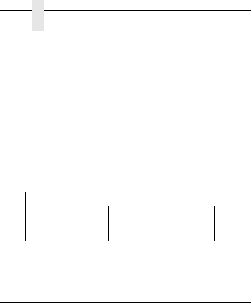
318
Appendix A
Labels
Labels
Printer Weight And Dimensions
* With a power stacker, the weight increases by 21 lbs. and the depth
increases by 4.75 inches for a deeper rear door.
** With the ZTP option, the weight increases by 12 lbs. and the height is
increased by 7 inches.
Environmental Characteristics
On Backing: One-part continuous perforated fanfold back form. Labels must be placed at
least 1/6 inch (0.42 cm) from the fan-fold perforation. Backing adhesive must not
be squeezed out during printing.
Sheet Size: 3 to 17 inches (7.62 to 43.18 cm) wide, including the two standard perforated
tractor feed strips. A maximum sheet length of 16 inches (40.64 cm) between
top and bottom perforations.
NOTE: A 16 inch rear door is needed for the cabinet model. Power Paper
Stacker option is 5 to 12 inches (12.7 to 30.48 cm) long.
Thickness: Not to exceed 0.025 inch (0.064 cm) (including backing sheet)
Cabinet Type Dimensions Weight
Height Width Depth Unpacked Packaged
Floor Cabinet 42.5 inches 27 inches 29 inches* 225 lbs. 285 lbs.*
Pedestal 35 inches** 26 inches 21 inches 105 lbs.** 115 lbs.**
Temperature:
Operating: 50° to 104° F (10° to 40° C) up to 5000 feet
(1524 meters)
50° to 90° F (10° to 32° C) up to 8000 feet
(2438 meters)
Storage: -40° to 158° F (- 40° to 70° C)
Relative Humidity
Operating: 15% to 80% (noncondensing)
Storage: 15% to 90% (noncondensing)
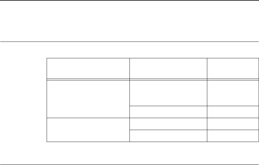
319
Acoustic Noise Level
Energy Star
The printers described in this User’s Manual comply with the requirements of
the
E
NERGY
S
TAR
®
Office Equipment Program of the U.S. Environmental
Protection Agency.
Acoustic Noise Levels per
ISO 9296 Cabinet Models Pedestal
Models
Printing 50 dB (500 lpm/1000 lpm)
52 dB (1500 lpm)
55 dB (2000 lpm)
65 dB
65 dB
NA
6.8 Bel 8.0 Bel
Standby 48 dB 50 dB
6.3 Bel 6.5 Bel
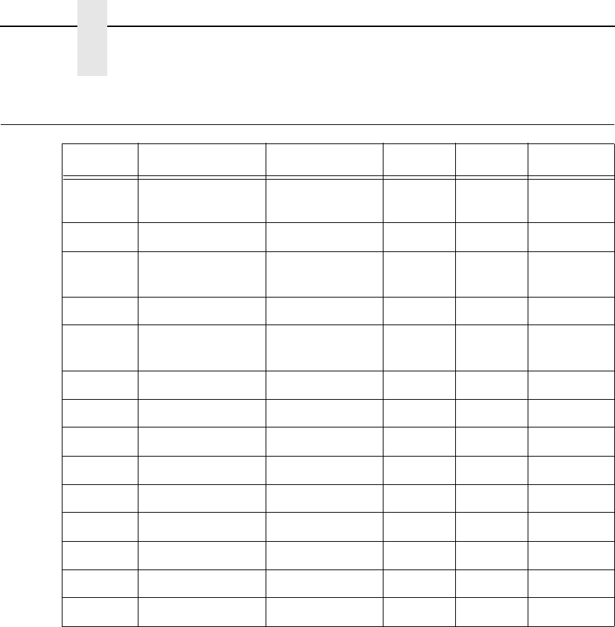
320
Appendix A
Electrical Characteristics
Electrical Characteristics
The above values are calculated while printing 136 column, all upper case
high speed “E’s”. The stand-by (Energy Saver mode) wattage is 28W (96
BTU/Hr) for all models.
Voltage (+/-10%) Freq (+/-10%) Amps Watts BTU/Hr
P7005
P70052T
AC 100-120V 50/60 Hz 3275 940
AC 200-240V 50/60 Hz 1.5 275 940
P7010
P70102T
AC 100-120V 50/60 Hz 3.5 300 1025
AC 200-240V 50/60 Hz 1.6 300 1025
P7015
P70152T
AC 100-120V 50/60 Hz 4.5 430 1469
AC 200-240V 50/60 Hz 1.9 430 1469
P7205 AC 100-120V 50/60 Hz 3.5 350 1195
AC 200-240V 50/60 Hz 1.6 350 1195
P7210 AC 100-120V 50/60 Hz 3.5 350 1195
AC 200-240V 50/60 Hz 1.6 350 1195
P7215 AC 100-120V 50/60 Hz 5460 1571
AC 200-240V 50/60 Hz 2460 1571
P7220 AC 100-120V 50/60 Hz 5.5 540 1844
AC 200-240V 50/60 Hz 2.1 540 1844

321
Interfaces
Printing Rates
The printing speed of text is measured in lines per minute (lpm) and is a
function of the selected font and the vertical dot density. Printing speed is
independent of the number of characters configured in the character set
repertoire. Print rates for lines containing attributes such as bold or
emphasized printing, superscripts, subscripts, or elongated attributes will
decrease to not less than half the rates of the font without such attributes. The
exact print rate of lines containing these attributes depends on the specific
print job, but software maximizes the throughput by dynamically determining
which dot rows contain adjacent dots and must be printed in two strokes.
The reverse paper feed capability allows the printing of multiple densities on a
single line. This is useful in printing forms and text together or in mixing
different fonts on a print line. Use of multiple densities and reverse paper feed
also affects throughput.
Type: Standard: IEEE 1284 Parallel, RS-232 serial
Optional: Ethernet 10/100Base-T, Coax*, Twinax*,
RS-422 serial*
*Not available in Taiwan.
Logic Levels: TTL/EIA
®
-232E/EIA-422B
Transfer Rates: Up to 200 Kilobytes on parallel interface.
Up to 19.2K baud on RS-232 serial interface.
Up to 115.2K baud on RS-422 serial interface

322
Appendix A
Printing Rates
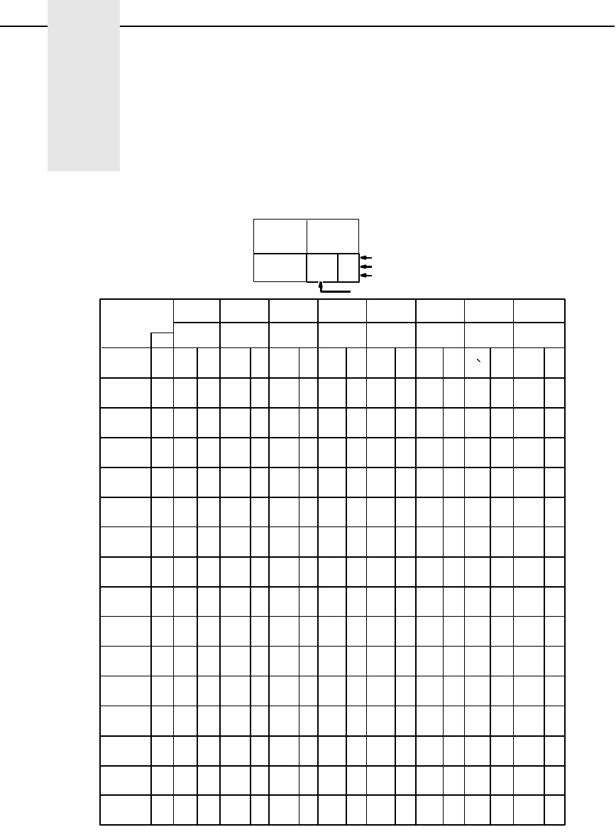
323
B
ASCII Character Set
KEY
ASCII Character Name
ESC
33
27
1B
OCTAL equivalent
DECIMAL equivalent
HEX equivalent
B7 0 0 0 0 1 1 1 1
B6 0
B5 0 01101100011011
COLUMN
01234567
BITS
ROW
B4 B2B3 B1
0
1
2
3
4
5
6
7
8
9
10
11
12
13
14
15
0000
00 10
001 0
001 1
010 0
010 1
011 0
011 1
1000
100 1
101 0
101 1
110 0
110 1
111 0
111 1
NUL
SOH
STX
ETX
EOT
ENQ
ACK
BEL
BS
HT
LF
VT
FF
CR
SO
SI
0
0
0
1
1
1
2
2
2
3
3
3
4
4
4
5
5
5
6
6
6
7
7
7
10
8
8
11
9
9
12
10
13
11
14
12
15
13
16
14
17
15
DLE
DC1
DC2
DC3
DC4
NAK
SYN
ETB
CAN
EM
SUB
ESC
FS
GS
RS
US
(XON)
(XOFF)
20
16
10
21
17
11
22
18
12
23
19
13
24
20
14
25
21
15
26
22
16
27
23
17
30
18
24
31
25
19
32
26
1A
33
27
1B
34
28
1C
35
29
1D
36
30
1E
37
31
1F
SP
!
"
#
$
%
&
'
(
)
+
,
-
.
/
40
32
20
41
33
21
42
34
22
43
35
23
44
36
24
45
37
25
46
38
26
47
39
27
50
40
28
51
41
29
52
42
2A
53
43
2B
54
44
2C
55
45
2D
56
46
2E
57
47
2F
0
1
2
3
4
5
6
7
8
9
:
;
<
=
>
?
60
48
30
61
49
31
62
50
32
63
51
33
64
52
34
65
53
35
66
54
36
67
55
37
70
56
38
71
57
39
72
58
3A
73
59
3B
74
60
3C
75
61
3D
76
62
3E
77
63
3F
@
A
B
C
D
E
F
G
H
I
J
K
L
M
N
O
100
64
40
101
65
41
102
66
42
103
67
43
104
68
44
105
69
45
106
70
46
107
71
47
110
72
48
111
73
49
112
74
4A
113
75
4B
114
76
4C
115
77
4D
116
78
4E
117
79
4F
P
Q
R
S
T
U
V
W
X
Y
Z
[
\
]
_
120
80
50
121
81
51
122
82
52
123
83
53
124
84
54
125
85
55
126
86
56
127
87
57
130
88
58
131
89
59
132
90
5A
133
91
5B
134
92
5C
135
93
5D
136
94
5E
137
95
5F
a
b
c
d
e
f
g
h
i
j
k
l
m
n
o
140
96
60
141
97
61
142
98
62
143
99
63
144
100
64
145
101
65
146
102
66
147
103
67
150
104
68
151
105
69
152
106
6A
153
107
6B
154
108
6C
155
109
6D
156
110
6E
157
111
6F
p
q
r
s
t
u
v
w
x
y
z
{
|
}
DEL
160
112
70
161
113
71
162
114
72
163
115
73
164
116
74
165
117
75
166
118
76
167
119
77
170
120
78
171
121
79
172
122
7A
173
123
7B
174
124
7C
175
125
7D
176
126
7E
177
127
7F
10 1 1
B4 B2B3 B1
B7 B6 B5 001
BITS
0 A
0 B
0 C
0 D
0 E
0 F
*
~
^

324
Appendix B

325
C
Zero Tear Printer
Overview
The P7000 Zero Tear (ZT) printer can print a form and present it for tear off
without losing a form between print jobs. The printer automatically presents
the current print line to the tear bar when it finishes printing and no data are
being sent to the printer. When it receives more data from the host computer,
the printer pulls the form down to the print station and resumes printing.
The ZT printer is available:
•
as a 500 lpm, 1000 lpm, 1500 lpm standard ASCII printer
•
with HD printers.
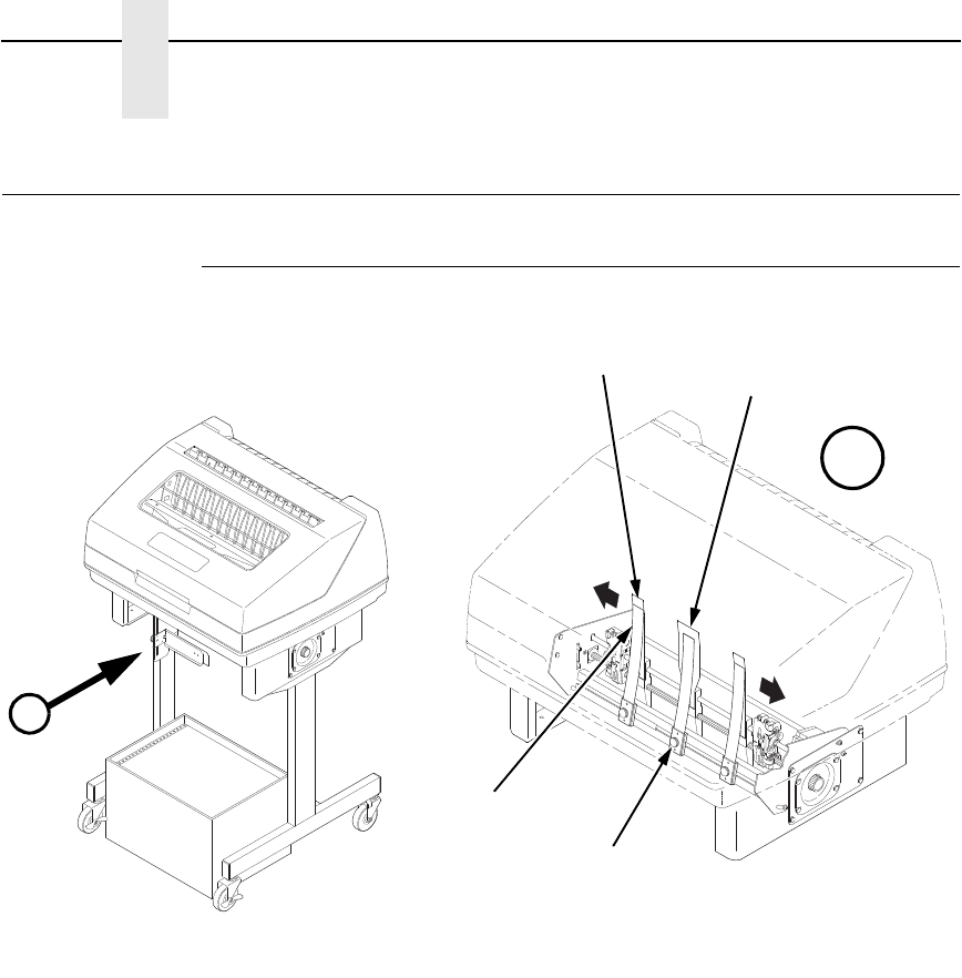
326
Appendix C
Operation
Operation
Position The Paper Input And Adjust The Paper Guides
Figure 27. Adjusting The Paper Guides
NOTE: Ensure that the paper guides are not damaged.
1. Remove the left paper guide knob and the left, front paper guide leaf.
(See Figure 27.)
2. Remove the right paper guide knob and the right, front paper guide leaf.
3. Remove the center paper guide knob and the center, front paper guide
leaf.
183483b
183484b
A
Paper Guide
Knob (3)
Center Paper
Guide Leaf
A
Outer Paper
Guide Leaf (2)
Front Paper
Guide Leaf (3)
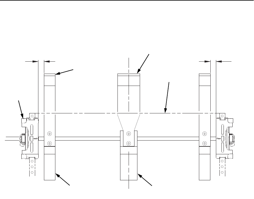
Position The Paper Input And Adjust The Paper Guides
327
Figure 28. Adjusting Paper Guide Leaves
4. Slide the left outboard mount block so that the left outer paper guide leaf
is .5 inches from the left tractor. (See Figure 28).
5. Slide the right outboard mount block so that the right outer paper guide
leaf is .5 inches from the right tractor.
6. Slide the center mount block so that the center paper guide leaf is
centered between the left and right outer paper guide leaves.
7. Install the paper guide knobs and front paper guide leaves.
(See Figure 27.)
183485b
Paper
Tractor (2)
Outer Paper
Guide Leaf (2)
Center Paper
Guide Leaf
.5
''
.5
''
Outboard Mount
Block (2) Center Mount
Block
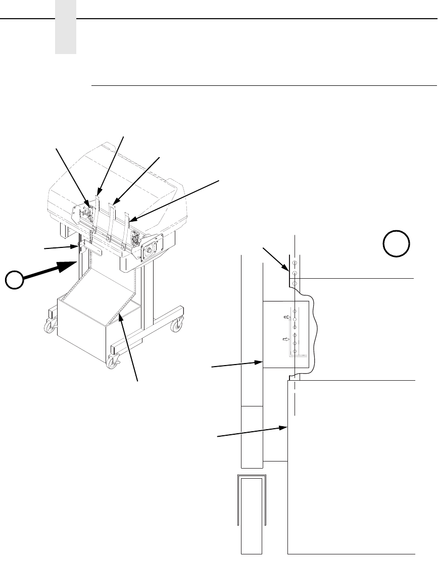
328
Appendix C
Operation
Load Paper
Figure 29. Loading Paper Onto The Printer
1. Align the paper supply box with the label on the bottom left side of the
modesty panel. (See Figure 29 on page 328.)
2. Unlock and open the tractor doors and slide the paper from below,
through the black paper out sensor slot on the left side, and up between
all front and rear paper guides.
3. Load the paper on the left tractor sprockets and close the tractor door.
4. Load the paper onto the right tractor sprockets and close the tractor door.
183487b
183486 REV B
183486b
Paper
Paper Out
Sensor
Center Paper
Guide Leaf
Front Paper
Guide Leaf (3)
Tractor Door
Outer Paper
Guide Leaf (2)
A
A
Paper Supply
Box
Paper
Label
Edge
of
Paper
Box
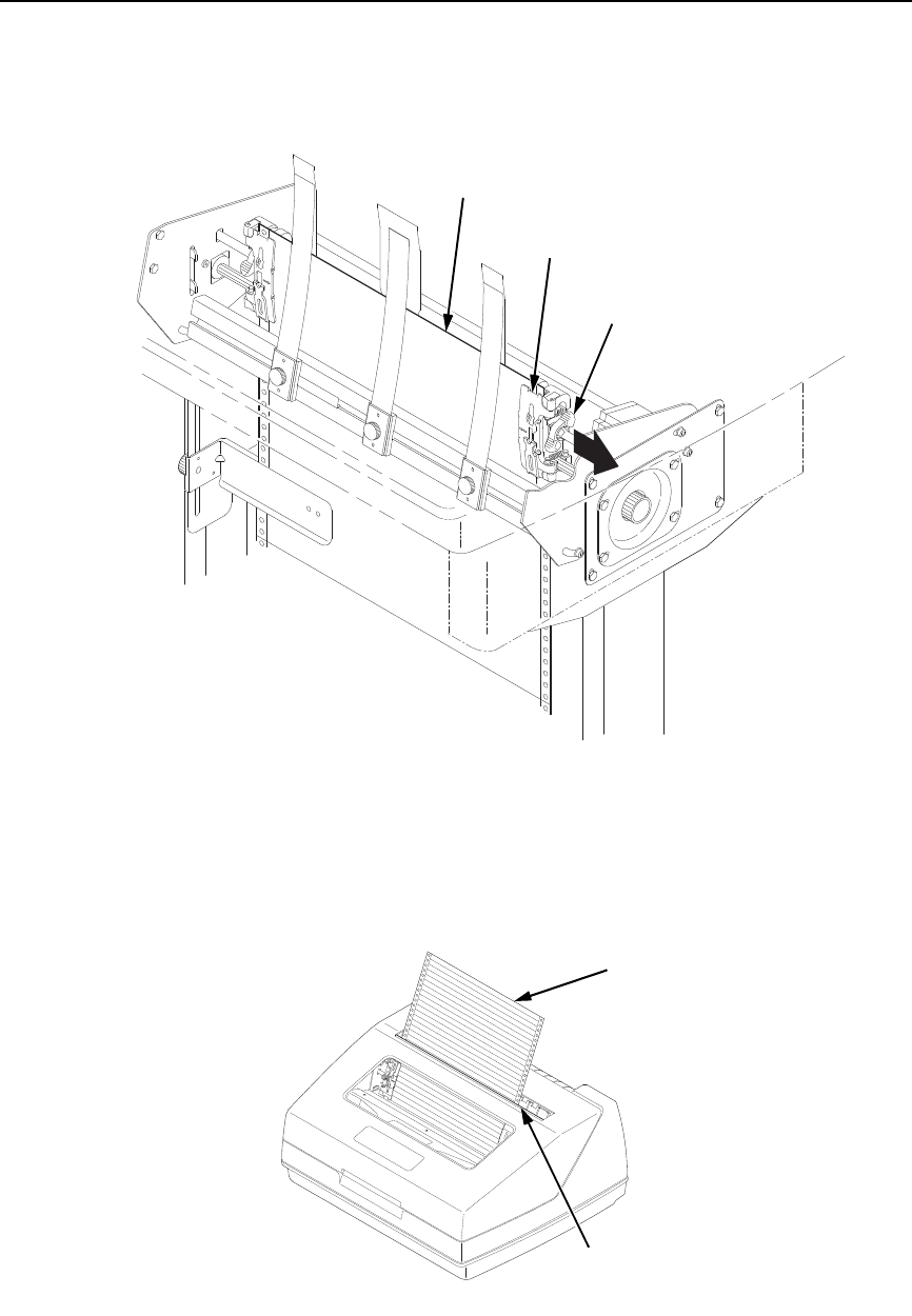
Load Paper
329
Figure 30. Adjusting the Horizontal Paper Tension
5. Adjust the paper web tightness by sliding the right tractor to remove slack
or to adjust for various paper widths. (See Figure 30.)
6. Lock the tractors in position by pressing down on the tractor locks.
Figure 31. Paper Exiting the Top of the Printer
183488b
Tractor
Lock (2)
Tractor (2)
Paper
183489b
TOF
TOF
Paper
Tear Bar
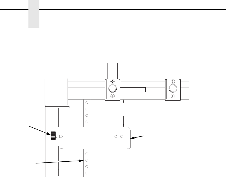
330
Appendix C
Operation
Position The Paper Out Sensor
Figure 32. The Paper Out Sensor
The paper out sensor indicates when the printer runs out of paper. (The
sensor does not work with black backed forms.) Unlike the standard pedestal
printer, the ZT printer requires you to load the paper through the paper out
sensor slot (Figure 29 and Figure 32). Correct positioning of the paper out
sensor ensures that the last form the printer prints will be properly presented
to the tear bar. To position the paper out sensor, do the following:
1. Position the paper properly at the tear bar (page 332).
2. Loosen the paper out sensor by turning the sensor knob
counterclockwise.
3. Position the paper out sensor so that there are at least 2 inches between
the bottom of the aluminum extrusion bar and the top of the paper out
sensor.
IMPORTANT
For optimal performance, 2 inches is recommended for 11 inch forms.
For shorter forms, position the paper out sensor so that there are at
least 2 inches between a perforation and the top of the paper out sensor.
4. Tighten the paper out sensor by turning the sensor knobs clockwise.
5. Press ON LINE/CLEAR. When the first print job is sent to the printer, the
paper is drawn into the printer, the top of form aligns with the print station,
and the print job begins.
183490b
Sensor Knob
Paper Out Sensor
Paper
At least 2 inches
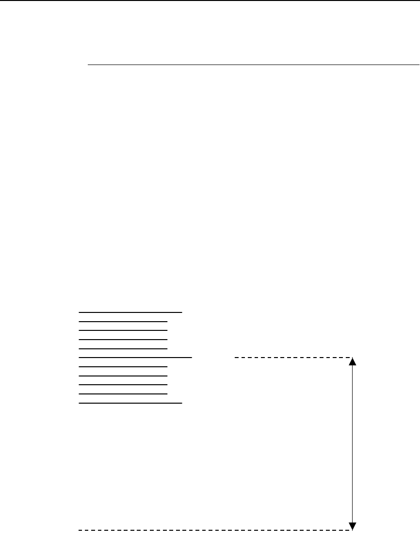
Set The Tear Bar Distance
331
Set The Tear Bar Distance
To set the tear bar distance, do the following steps:
1. Make sure the printer is offline.
2. Press ENTER key to enter the menu.
3. Press the right arrow Z until “OFFLINE/ZTP Menu” displays.
4. Press the down arrow V. “ZTP Data Time” displays.
5. Press the right arrow Z until “ZTP TearDistance” displays.
6. Press the down arrow V. “ZTP TearDistance/xx/144 Inch” displays.
7. Press the left arrow Y or right arrow Z to decrease or increase the tear
bar distance in increments of 1/144th of an inch.
8. Press ENTER to select the desired value. An asterisk appears next the
selected value and a scale prints to indicate the tear bar distance in
relation to the tear bar. For correct tear bar distance, the zero should align
with the tear bar. See Figure 33.
NOTE: The Tear Distance value must be changed to print the scale.
Figure 33. Correct Tear Bar Distance
NOTE: When a new ZTP Tear Bar Dist value is selected, the printer will lose
the current print position until you reset the top of form to
automatically save the new value.
9. Reset the top of form using the procedure on page 332.
+50
-50
0
P
rint Stati
on
Correct
TearBar
D
istan
ce
P
hysical TearBa
r
P
ositi
on
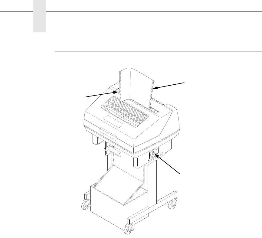
332
Appendix C
Operation
Set The Top Of Form
Figure 34. Setting The Tear Off Position
The ZT printer uses the tear bar as the reference point for setting the tear off
position. To set the position of the forms perforation to the tear bar, use the
SET TOF button as follows:
1. Make sure the paper guides are adjusted correctly and the paper is
properly loaded.
2. Press the SET TOF button on the control panel. The printer display will
read “Align at TearBar/Then Press TOF”.
3. Use the form advance knob to move the top of the form to the tear off bar.
4. Position the perforation so it aligns with the tear off bar.
NOTE: This is easily done by advancing one complete sheet above the tear
off bar and folding it over at the perforation.
5. Position the fold exactly at the tear bar.
6. Tear the sheet off to ensure proper positioning.
NOTE: If you do not want to lose a form, position the top of the form at the
tear bar. Run a finger along the back of the form along the tear bar to
ensure the perforation is presented at the tear off point.
7. Press the SET TOF button again. The printer display will read “Top Of
Form Set/Press ONLINE”. The printer will then be brought OFFLINE and
the top of form will be set.
8. Press the ON LINE/CLEAR key to bring the printer online.
183491b
Form Advance
Knob
Paper
Tear Bar
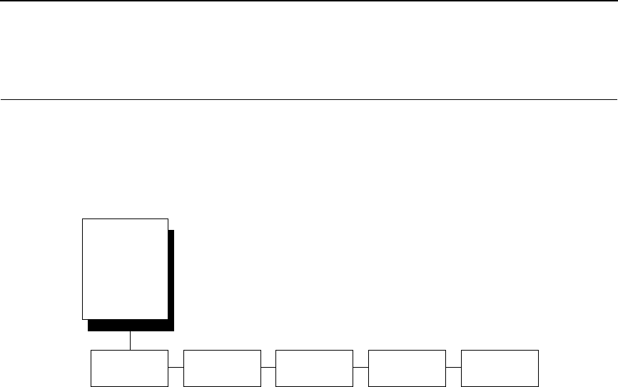
Set The Top Of Form
333
ZTP SETTINGS Menu
The ZTP SETTINGS menu includes the ability to enable and disable features
unique to the Zero Tear printer (ZTP), set the tear bar distance, set the auto
present data time, and set the auto present wait time. This section defines
these options.
ZTP Function
This option enables or disables all unique ZTP functions. The default is
Enable.
NOTE: When the ZTP Function is enabled, the VIEW/EJECT key is disabled
and Slow Paper Slew is enabled.
ZTP TearDistance
This option sets the tear off distance from the current print position to the tear
bar. Adjustable values in increments of 1/144th of an inch range from 200 to
2880. The up and down arrows adjust the display value. When you press the
ENTER key, the selected value is stored and a scale is printed to indicate the
current tear off position. The default value is 1060.
NOTE: When a new value is selected, the printer will lose the current print
position. You must reset the top of form to automatically save the new
value.
ZTP Data Time
This option sets the pause time in the data stream that the ZTP requires
before moving the form to the tear bar once a print job is completed. The
values range from .5 to 15 seconds. The default is .5 seconds.
ZTP Wait Time
This option sets the minimum amount of time that the form stays at the tear
bar. This allows you time to remove the form before the form is retracted to
print the next form. The adjustable values range from 1 to 10 seconds in
increments of 1 second. The default value is 2 seconds.
ZTP
SETTINGS
1
(from page 64,
66, 68, 70, 72,
74, and 76)
ZTP
Function
ZTP
TearDistance
ZTP
Data Time
ZTP
Wait Time
ZTP
Platen Open
Enable*
Disable
1060/144 Inch* .5 Sec*
1.0 - 15.0 Sec
2 Sec*
3 - 10 Sec
1 Sec
Enable*
Disable
* = Factory Default
1
Available for Zero Tear Pedestal printers only.

334
Appendix C
Performance Limitations
ZTP Platen Open
This option allows the user to have the platen open whenever forms are
reversed. Enabled is the default, used for most papers and labels. The feature
can be disabled as required by some multi-part forms.
Performance Limitations
Forms Type
The paper feed tractors on the ZT printer push the paper up through the print
station instead of pulling it through, as in the standard pedestal printer. This
limits the variety of forms the ZT printer can use. If the forms do not fall within
the range specified in Table 18, dot compression and line separation may
occur. The user should match the media to the application to ensure
acceptable print quality. Also, because paper is pushed from below the print
station, the last form in the tractors may not print fully or may not be presented
to the printer exit for retrieval.
All paper used in the ZT printer requires standard half inch spaced tractor
feed holes. Cut sheet and continuous friction fed paper is not supported. The
forms specified in Table 18 can have no more than one form per page
horizontally.
NOTE: If you use forms outside these limits, the print quality may not be
optimum, the printer may lose top-of-form, or the frequency of paper
jams will increase.
Table 18. Forms Type
Description Length Width
(edge to edge)
One to three part, continuous, with carbon, fan-folded,
edge-perforated paper forms
3 to 12 inches 7 to 16.5 inches
One to four part, continuous, with carbon, fan-folded,
edge-perforated paper forms
3 to 12 inches 7 to 12 inches
One to four part, continuous, carbonless,
fan-folded, edge-perforated paper forms
3 to 12 inches 7 to 16.5 inches
One to six part, continuous, carbonless, fan-folded, edge-
perforated paper forms
3 to 12 inches 7 to 12 inches
Forms with a paper weight of 20 to 100 pounds and a maxi-
mum thickness of 0.025 inches
3 to 12 inches 7 to 16.5 inches
Forms with a paper weight of 18 to 100 pounds and a maxi-
mum thickness of 0.025 inches
3 to 12 inches 7 to 12 inches
Forms with all approved types of interleaf edge attachment
except those using metallic or other hard devices

Set The Top Of Form
335
Paper Jams
Printer jams can occur if you tear off the form incorrectly. If you experience
two or more paper jams per box of forms, follow these guidelines to help
reduce jams:
•
Position the lower paper guides properly
•
Align the paper web tightness properly
•
Position the form perforation against the tear bar
•
Time the tear, while the paper is not moving
•
Direct the tear force toward the user and across the tear bar, not upward.
To Clear Paper Jams
1. Raise the platen lever to open the platen.
2. Open the left and right tractor doors.
3. Pull the paper upward through the top of the printer.
NOTE: DO NOT pull the paper downwards from the bottom. This could cause
the paper guides to bend.
4. Reload the paper (see page 328).

336
Appendix C
Performance Limitations

337
D
Customer Support
Printronix Customer Support Center
IMPORTANT
Please have the following information available prior to calling the
Printronix Customer Support Center:
•
Model number
•
Serial number (located on the back of the printer)
•
Installed options (i.e., interface and host type if applicable to the problem)
•
Configuration printout:
Line Matrix Printer
Press PRT CONFIG on the control panel, then press ENTER.
•
Is the problem with a new install or an existing printer?
•
Description of the problem (be specific)
•
Good and bad samples that clearly show the problem (faxing or emailing
these samples may be required)
Americas (714) 368-2686
Europe, Middle East, and Africa (31) 24 6489 311
Asia Pacific (65) 6548 4114
China (86) 800-999-6836
http://www.printronix.com/support.aspx
Printronix Supplies Department
Contact the Printronix Supplies Department for genuine Printronix supplies.
Americas (800) 733-1900
Europe, Middle East, and Africa 33 (0) 1 46 25 19 07
Asia Pacific (65) 6548 4116
or (65) 6548 4182
China (86) 400-886-5598
India (800) 102-7869
http://www.printronix.com/supplies-parts.aspx

338
Appendix D
Corporate Offices
Corporate Offices
Printronix, Inc.
15345 Barranca Parkway
Irvine, CA 92618
U.S.A.
Phone: (714) 368-2300
Fax: (714) 368-2600
Printronix Inc.
c/o Printronix Nederland BV
Bijsterhuizen 11-38
6546 AS Nijmegen
The Netherlands
Phone: (31) 24 6489489
Fax: (31) 24 6489499
Printronix Schweiz GmbH
42 Changi South Street 1
Changi South Industrial Estate
Singapore 486763
Phone: (65) 6542 0110
Fax: (65) 6546 1588
Printronix Commercial (Shanghai) Co. Ltd
22F, Eton Building East
No.555, Pudong Av.
Shanghai City, 200120, P R China
Phone: (86) 400 886 5598
Fax: (86-21) 5138 0564
Visit the Printronix web site at www.printronix.com

339
E
Communication Notices
Notices
This information was developed for products and services offered in the
U.S.A.
Printronix may not offer the products, services, or features discussed in this
document in other countries. Consult your Printronix representative for
information on the products and services currently available in your area. Any
reference to an Printronix product, program, or service is not intended to state
or imply that only that Printronix product, program, or service may be used.
Any functionally equivalent product, program, or service that does not infringe
any Printronix intellectual property rights may be used instead. However, it is
the user’s responsibility to evaluate and verify the operation of any non-
Printronix product, program, or service.
Printronix may have patents or pending patent applications covering subject
matter described in this document. The furnishing of this document does not
give you any license to these patents. You can send license inquires, in
writing, to:
Printronix, Inc.
15345 Barranca Parkway
Irvine, CA 92618
U.S.A.
The following paragraph does not apply to the United Kingdom or any
other country where such provisions are inconsistent with local law:
PRINTRONIX PROVIDES THIS PUBLICATION “AS IS” WITHOUT
WARRANTY OF ANY KIND, EITHER EXPRESS OR IMPLIED, INCLUDING,
BUT NOT LIMITED TO, THE IMPLIED WARRANTIES OF NON-
INFRINGEMENT, MERCHANTABILITY OR FITNESS FOR A PARTICULAR
PURPOSE. Some states do not allow disclaimer of express or implied
warranties in certain transactions, therefore, this statement may not apply to
you.
This information could include technical inaccuracies or typographical errors.
Changes are periodically made to the information herein; these changes will
be incorporated in new editions of the publication. Printronix may make
improvements and/or changes in the product(s) described in this publication
at any time without notice.
Any references in this information to non-Printronix Web sites are provided for
convenience only and do not in any manner serve as an endorsement of
those Web sites. The materials at those Web sites are not part of the
materials for this Printronix product and use of those Web sites is at your own
risk.

340
Appendix E
Notices
Any performance data contained herein was determined in a controlled
environment. Therefore, the results obtained in other operating environments
may vary significantly. Some measurements may have been made on
development-level systems and there is no guarantee that these
measurements will be the same on generally available systems. Furthermore,
some measurement may have been estimated through extrapolation. Actual
results may vary. Users of this document should verify the applicable data for
their specific environment.
Information concerning non-Printronix products was obtained from the
suppliers of those products, their published announcements or other publicly
available sources. Printronix has not tested those products and cannot
confirm the accuracy of performance, compatibility or any other claims related
to non-Printronix products. Questions on the capabilities of non-Printronix
products should be addressed to the suppliers of those products.
Printronix encourages owners of information technology (IT) equipment to
responsibly recycle their equipment when it is no longer needed. Printronix
offers a variety of programs and services to assist equipment owners in
recycling their IT products. Information on these product recycling offerings
can be found on Printronix’s Internet site at http://www.printronix.com.
If you are viewing this information softcopy, the photographs and color
illustrations may not appear.
For online versions of this book, we authorize you to:
•
Copy, modify, and print the documentation contained on the media, for
use within your enterprise, provided you reproduce the copyright notice,
all warning statements, and other required statements on each copy or
partial copy.
•
Transfer the original unaltered copy of the documentation when you
transfer the related Printronix product (which may be either machines you
own, or programs, if the program’s license terms permit a transfer). You
must, at the same time, destroy all other copies of the documentation.
You are responsible for payment of any taxes, including personal property
taxes, resulting from this authorization.
Your failure to comply with the terms above terminates this authorization.
Upon termination, you must destroy your machine readable documentation.
Before using this information and the product it supports, read the information and
Communication Statements on page 341.
Note!

341
Energy Star
The Environmental Protection Agency E
NERGY
S
TAR
® Computers program is
a partnership effort with manufacturers of data processing equipment to
promote the introduction of energy-efficient personal computers, monitors,
printers, fax machines, and copiers to help reduce air pollution and global
warming caused by electricity generation.
Printronix participates in this program by introducing printers that reduce
power consumption when they are not being used. As an E
NERGY
S
TAR
®
Partner, Printronix has determined that this product meets the E
NERGY
S
TAR
®
guidelines for energy efficiency.
NOTE: The E
NERGY
S
TAR
® emblem does not represent EPA endorsement of
any product or service.
Communication Statements
Federal Communications Commission (FCC) Statement
This equpment has been tested and found to comply with the limits for a
Class A digital device, pursuant to Part 15 of the FCC Fules. These limits are
designed to provide reasonable protection against harmful interference when
the equipment is operated in a commercial environment. This equipment
generates, uses, and can radiate radio frequency energy and, if not installed
and used in accordance with the instructions, may cause harmful interference
to radio communications. Operation of this equipment in a residential area is
likely to cause harmful interference in which case the user will be required to
correct the interference at his own expense.
Properly shielded and grounded cables and connectors must be used in order
to meet FCC emission limits. Printronix is not responsible for any radio or
television interference caused by using other than recommended cables and
connectors or by unauthorized changes or modifications to this equipment.
Unauthorized changes or modifications could void the user’s authority to
operate the equipment.
342
Appendix E
Communication Statements
This device complies with Part 15 of the FCC Fules. Operation is subject to
the following two conditions: (1) this device may not cause harmful
interference, and (2) this device must accept any interference received,
including interference that may cause undesired operation.
European Union (EU) Conformity Statement
Printronix cannot accept responsibility for any failure to satisfy the protection
requirements resulting from a non-recommended modification of the product,
including the fitting of non-Printronix option cards.
This product has been tested and found to comply with the limits for Class A
Information Technology Equipment according to European standard EN
55022. The limits for Class A equipment were derived for commercial and
industrial environments to provide reasonable protection against interference
with licensed communication devices.
Properly shielded and grounded cables and connectors must be used in order
to reduce the potential for causing interference to radio and TV
communications and to other electrical or electronic equipment. Printronix
cannot accept responsibility for any interference caused by using other than
recommended cables and connectors.
Industry Canada Compliance Statement
This Class A digital apparatus complies with Canadian ICES-003.
Cet appareil numérique de la classe A conform á la norme NMB-003 du
Canada.
Statement of CISPR 22 Compliance
Attention: This is a Class A Product. In a domestic environment this product
may cause radio interference in which case the user may be required to take
adequate measures.
Hereby, Printronix declares that this
product is in compliance with the essential
requirements and other relevent
provisions of Directive 1999/5/EC.
This is a Class A product. In a domestic environment this product may cause radio
interference in which case the user may be required to take adequate measures.
WARNING
343
Japanese VCCI Class A
German Conformity Statement
Handbuchtexte: FCC class A entspricht: EMVG Klasse A
Text Für alle in Deutschland vertriebenen EN 55022 Klasse A Geräte:
Zulassungsbescheinigung laut dem Deutschen Gesetz über die
elektromagnetische Verträglichkeit von Geräten (EMVG) vom 18. September
1998 (bzw. der EMC EG Richtlinie 89/336):
Dieses Gerät ist berechtigt in Übereinstimmung mit dem Deutschen EMVG
das EG-Konformitätszeichen - CE - zu führen. Verantwortlich für die
Konformitätserklärung nach Paragraph 5 des EMVG ist die:
Printronix GmbH
Goethering 56
D-63067 Offenbach Germany
Informationen in Hinsicht EMVG Paragraph 4 Abs. (1) 4:
Das Gerät erfüllt die Schutzanforderungen nach EN 55024 und EN 55022
Klasse A.
EN 55022 Klasse A Geräte müssen mit folgendem Warnhinweis versehen
werden: “Warnung: dies ist eine Einrichtung der Klasse A. Diese Einrichtung
kann im Wohnbereich Funkstörungen verursachen; in diesem Fall kann vom
Betreiber verlangt werden, angemessene Maßnahmen durchzuführen und
dafür aufzukommen.”
EN 55024 Hinweis:
Wird dieses Gerät in einer industriellen Umgebung betrieben (wie in EN
55024 festgelegt), dann kann es dabei eventuell gestört werden. In solch
einem Fall ist der Abstand bzw. die Abschirmung zu der industriellen
Störquelle zu öergrvßern.
Anmerkung:
Um die Einhaltung des EMVG sicherzustellen sind die Geräte, wie in den
Printronix Handbüchern angegeben, zu installieren und zu betreiben.

344
Appendix E
Communication Statements
China
Declaration:
This is a Class A product. In a domestic environment this product may cause
radio interference in which case the user may need to perform practical
actions.
Altitude and Non-Tropical Climate Statement
345
Taiwan
Warning:
This is a Class A product. In a domestic environment this product may cause
radio interference in which case the user will be required to take adequate
measures.
CAUTION:
This product is equipped with a 3-wire power cord and plug for the user’s
safety. Use this power cord in conjunction with a properly grounded electrical
outlet to avoid electrical shock.

346
Appendix E
Software License Agreement
Software License Agreement
Your printer contains, among other software, Printronix operating software
including, but not limited to the Embedded Configurable Operating System
(the “eCos Software”) as embedded software. The terms of this Agreement
apply only to the eCos Software, and all other embedded software supplied
with the printer. You accept the terms of this Agreement by your initial use of
your printer.
eCos License
This file is part of eCos, the Embedded Configurable Operating System.
Copyright (C) 1998, 1999, 2000, 2001, 2002 Red Hat, Inc.
eCos is free software; you can redistribute it and/or modify it under the terms
of the GNU General Public License as published by the Free Software
Foundation; either version 2 or (at your option) any later version.
You should have received a copy of the GNU General Public License along
with eCos; if not, write to the Free Software Foundation, Inc., 59 Temple
Place, Suite 330, Boston, MA 02111-1307 USA.
eCos is distributed in the hope that it will be useful, but WITHOUT ANY
WARRANTY; without even the implied warranty of MERCHANTABILITY or
FITNESS FOR A PARTICULAR PURPOSE. See the GNU General Public
License for more details.
As a special exception, if other files instantiate templates or use macros or
inline functions from this file, or you compile this file and link it with other
works to produce a work based on this file, this file does not by itself cause
the resulting work to be covered by the GNU General Public License.
However the source code for this file must still be made available in
accordance with section (3) of the GNU General Public License.
This exception does not invalidate any other reasons why a work based on
this file might be covered by the GNU General Public License.
Alternative licenses for eCos may be arranged by contacting Red Hat, Inc. at
http://sources.redhat.com/ecos/ecos-license/
GNU GENERAL PUBLIC LICENSE
Version 2, June 1991
Copyright (C) 1989, 1991 Free Software Foundation, Inc., 51 Franklin Street,
Fifth Floor, Boston, MA 02110-1301 USA Everyone is permitted to copy and
distribute verbatim copies of this license document, but changing it is not
allowed.

347
Preamble
The licenses for most software are designed to take away your freedom to
share and change it. By contrast, the GNU General Public License is intended
to guarantee your freedom to share and change free software--to make sure
the software is free for all its users. This General Public License applies to
most of the Free Software Foundation's software and to any other program
whose authors commit to using it. (Some other Free Software Foundation
software is covered by the GNU Lesser General Public License instead.) You
can apply it to your programs, too.
When we speak of free software, we are referring to freedom, not price. Our
General Public Licenses are designed to make sure that you have the
freedom to distribute copies of free software (and charge for this service if you
wish), that you receive source code or can get it if you want it, that you can
change the software or use pieces of it in new free programs; and that you
know you can do these things.
To protect your rights, we need to make restrictions that forbid anyone to deny
you these rights or to ask you to surrender the rights. These restrictions
translate to certain responsibilities for you if you distribute copies of the
software, or if you modify it.
For example, if you distribute copies of such a program, whether gratis or for
a fee, you must give the recipients all the rights that you have. You must make
sure that they, too, receive or can get the source code. And you must show
them these terms so they know their rights.
We protect your rights with two steps: (1) copyright the software, and (2) offer
you this license which gives you legal permission to copy, distribute and/or
modify the software.
Also, for each author's protection and ours, we want to make certain that
everyone understands that there is no warranty for this free software. If the
software is modified by someone else and passed on, we want its recipients
to know that what they have is not the original, so that any problems
introduced by others will not reflect on the original authors' reputation.
Finally, any free program is threatened constantly by software patents. We
wish to avoid the danger that redistributors of a free program will individually
obtain patent licenses, in effect making the program proprietary. To prevent
this, we have made it clear that any patent must be licensed for everyone's
free use or not licensed at all.

348
Appendix E
Software License Agreement
The precise terms and conditions for copying, distribution, and modification
follow.
GNU GENERAL PUBLIC LICENSE
TERMS AND CONDITIONS FOR COPYING, DISTRIBUTION, AND
MODIFICATION
This License applies to any program or other work which contains a notice
placed by the copyright holder saying it may be distributed under the terms of
this General Public License. The "Program", below, refers to any such
program or work, and a "work based on the Program" means either the
Program or any derivative work under copyright law: that is to say, a work
containing the Program or a portion of it, either verbatim or with modifications
and/or translated into another language. (Hereinafter, translation is included
without limitation in the term "modification".) Each licensee is addressed as
"you".
Activities other than copying, distribution and modification are not covered by
this License; they are outside its scope. The act of running the Program is not
restricted, and the output from the Program is covered only if its contents
constitute a work based on the Program (independent of having been made
by running the Program). Whether that is true depends on what the Program
does.
1. You may copy and distribute verbatim copies of the Program's source
code as you receive it, in any medium, provided that you conspicuously
and appropriately publish on each copy an appropriate copyright notice
and disclaimer of warranty; keep intact all the notices that refer to this
License and to the absence of any warranty; and give any other recipients
of the Program a copy of this License along with the Program.
You may charge a fee for the physical act of transferring a copy, and you
may at your option offer warranty protection in exchange for a fee.
2. You may modify your copy or copies of the Program or any portion of it,
thus forming a work based on the Program, and copy and distribute such
modifications or work under the terms of Section 1 above, provided that
you also meet all of these conditions:
a. You must cause the modified files to carry prominent notices
stating that you changed the files and the date of any change.
b. You must cause any work that you distribute or publish, that in
whole or in part contains or is derived from the Program or any part
thereof, to be licensed as a whole at no charge to all third parties
under the terms of this License.
c. If the modified program normally reads commands interactively
when run, you must cause it, when started running for such
interactive use in the most ordinary way, to print or display an
announcement including an appropriate copyright notice and a notice
that there is no warranty (or else, saying that you provide a warranty)
and that users may redistribute the program under these conditions,
and telling the user how to view a copy of this License. (Exception: if
the Program itself is interactive but does not normally print such an
announcement, your work based on the Program is not required to
print an announcement.)

349
These requirements apply to the modified work as a whole. If identifiable
sections of that work are not derived from the Program, and can be
reasonably considered independent and separate works in themselves,
then this License, and its terms, do not apply to those sections when you
distribute them as separate works. But when you distribute the same
sections as part of a whole which is a work based on the Program, the
distribution of the whole must be on the terms of this License, whose
permissions for other licensees extend to the entire whole, and thus to
each and every part regardless of who wrote it.
Thus, it is not the intent of this section to claim rights or contest your rights
to work written entirely by you; rather, the intent is to exercise the right to
control the distribution of derivative or collective works based on the
Program.
In addition, mere aggregation of another work not based on the Program
with the Program (or with a work based on the Program) on a volume of a
storage or distribution medium does not bring the other work under the
scope of this License.
3. You may copy and distribute the Program (or a work based on it, under
Section 2) in object code or executable form under the terms of Sections
1 and 2 above provided that you also do one of the following:
a. Accompany it with the complete corresponding machine-readable
source code, which must be distributed under the terms of Sections 1
and 2 above on a medium customarily used for software interchange;
or,
b. Accompany it with a written offer, valid for at least three years, to give
any third party, for a charge no more than your cost of physically
performing source distribution, a complete machine-readable copy of
the corresponding source code, to be distributed under the terms of
Sections 1 and 2 above on a medium customarily used for software
interchange; or,
c. Accompany it with the information you received as to the offer to
distribute corresponding source code. (This alternative is allowed
only for noncommercial distribution and only if you received the
program in object code or executable form with such an offer, in
accord with Subsection b above.)
The source code for a work means the preferred form of the work for
making modifications to it. For an executable work, complete source
code means all the source code for all modules it contains, plus any
associated interface definition files, plus the scripts used to control
compilation and installation of the executable. However, as a special
exception, the source code distributed need not include anything that
is normally distributed (in either source or binary form) with the major
components (compiler, kernel, and so on) of the operating system on
which the executable runs, unless that component itself accompanies
the executable.

350
Appendix E
Software License Agreement
If distribution of executable or object code is made by offering access
to copy from a designated place, then offering equivalent access to
copy the source code from the same place counts as distribution of
the source code, even though third parties are not compelled to copy
the source along with the object code.
4. You may not copy, modify, sublicense, or distribute the Program except
as expressly provided under this License. Any attempt otherwise to copy,
modify, sublicense or distribute the Program is void, and will automatically
terminate your rights under this License. However, parties who have
received copies, or rights, from you under this License will not have their
licenses terminated so long as such parties remain in full compliance.
5. You are not required to accept this License, since you have not signed it.
However, nothing else grants you permission to modify or distribute the
Program or its derivative works. These actions are prohibited by law if you
do not accept this License. Therefore, by modifying or distributing the
Program (or any work based on the Program), you indicate your
acceptance of this License to do so, and all its terms and conditions for
copying, distributing or modifying the Program or works based on it.
6. Each time you redistribute the Program (or any work based on the
Program), the recipient automatically receives a license from the original
licensor to copy, distribute or modify the Program subject to these terms
and conditions. You may not impose any further restrictions on the
recipients' exercise of the rights granted herein. You are not responsible
for enforcing compliance by third parties to this License.
7. If, as a consequence of a court judgment or allegation of patent
infringement or for any other reason (not limited to patent issues),
conditions are imposed on you (whether by court order, agreement or
otherwise) that contradict the conditions of this License, they do not
excuse you from the conditions of this License. If you cannot distribute so
as to satisfy simultaneously your obligations under this License and any
other pertinent obligations, then as a consequence you may not distribute
the Program at all. For example, if a patent license would not permit
royalty-free redistribution of the Program by all those who receive copies
directly or indirectly through you, then the only way you could satisfy both
it and this License would be to refrain entirely from distribution of the
Program.
If any portion of this section is held invalid or unenforceable under any
particular circumstance, the balance of the section is intended to apply
and the section as a whole is intended to apply in other circumstances.
It is not the purpose of this section to induce you to infringe any patents or
other property right claims or to contest validity of any such claims; this
section has the sole purpose of protecting the integrity of the free
software distribution system, which is implemented by public license
practices. Many people have made generous contributions to the wide
range of software distributed through that system in reliance on consistent
application of that system; it is up to the author/donor to decide if he or
she is willing to distribute software through any other system and a
licensee cannot impose that choice.
This section is intended to make thoroughly clear what is believed to be a
consequence of the rest of this License.

351
8. If the distribution and/or use of the Program is restricted in certain
countries either by patents or by copyrighted interfaces, the original
copyright holder who places the Program under this License may add an
explicit geographical distribution limitation excluding those countries, so
that distribution is permitted only in or among countries not thus excluded.
In such case, this License incorporates the limitation as if written in the
body of this License.
9. The Free Software Foundation may publish revised and/or new versions
of the General Public License from time to time. Such new versions will
be similar in spirit to the present version, but may differ in detail to
address new problems or concerns.
Each version is given a distinguishing version number. If the Program
specifies a version number of this License which applies to it and "any
later version", you have the option of following the terms and conditions
either of that version or of any later version published by the Free
Software Foundation. If the Program does not specify a version number
of this License, you may choose any version ever published by the Free
Software Foundation.
10. If you wish to incorporate parts of the Program into other free programs
whose distribution conditions are different, write to the author to ask for
permission. For software which is copyrighted by the Free Software
Foundation, write to the Free Software Foundation; we sometimes make
exceptions for this. Our decision will be guided by the two goals of
preserving the free status of all derivatives of our free software and of
promoting the sharing and reuse of software generally.
NO WARRANTY
11. BECAUSE THE PROGRAM IS LICENSED FREE OF CHARGE, THERE
IS NO WARRANTY FOR THE PROGRAM, TO THE EXTENT
PERMITTED BY APPLICABLE LAW. EXCEPT WHEN OTHERWISE
STATED IN WRITING THE COPYRIGHT HOLDERS AND/OR OTHER
PARTIES PROVIDE THE PROGRAM "AS IS" WITHOUT WARRANTY
OF ANY KIND, EITHER EXPRESSED OR IMPLIED, INCLUDING, BUT
NOT LIMITED TO, THE IMPLIED WARRANTIES OF
MERCHANTABILITY AND FITNESS FOR A PARTICULAR PURPOSE.
THE ENTIRE RISK AS TO THE QUALITY AND PERFORMANCE OF
THE PROGRAM IS WITH YOU. SHOULD THE PROGRAM PROVE
DEFECTIVE, YOU ASSUME THE COST OF ALL NECESSARY
SERVICING,

352
Appendix E
Software License Agreement
REPAIR OR CORRECTION
12. IN NO EVENT UNLESS REQUIRED BY APPLICABLE LAW OR
AGREED TO IN WRITING WILL ANY COPYRIGHT HOLDER, OR ANY
OTHER PARTY WHO MAY MODIFY AND/OR REDISTRIBUTE THE
PROGRAM AS PERMITTED ABOVE, BE LIABLE TO YOU FOR
DAMAGES, INCLUDING ANY GENERAL, SPECIAL, INCIDENTAL OR
CONSEQUENTIAL DAMAGES ARISING OUT OF THE USE OR
INABILITY TO USE THE PROGRAM (INCLUDING BUT NOT LIMITED
TO LOSS OF DATA OR DATA BEING RENDERED INACCURATE OR
LOSSES SUSTAINED BY YOU OR THIRD PARTIES OR A FAILURE OF
THE PROGRAM TO OPERATE WITH ANY OTHER PROGRAMS),
EVEN IF SUCH HOLDER OR OTHER PARTY HAS BEEN ADVISED OF
THE POSSIBILITY OF SUCH DAMAGES.
END OF TERMS AND CONDITIONS
Artifex Portions Software Copyright Notices
Portions Copyright
©
2001/2009 Artifex Software Inc.
This software is based in part on the work of the Independent JPEG Group.
Portions Copyright
©
1998 Soft Horizons.
All Rights Reserved.

353
Index
A
A TO D OVERUN * message, 288
Absorb After ^PN, 219
Absorb After ^PY, 217
Accented Char, PRINTER CONTROL, 253
ACCESS NULL PTR * message, 288
Acknowledge, Centronics Parallel Interface
Signals, 271
Acoustic noise level, 319
ACTIVATE LOST message, 288
Active Char Set, 128, 137
3270 Params menu, 143
5250 Params menu, 150
Active Emulation, 79
Active IGP Emulation, 79
Adapter Address, 77
ADAPTER ADDRESS Menu, 105
DHCP, 106
Gateway Address, 106
IP address, 105
MAC address, 106
Subnet Mask, 105
ADAPTER PARAMS Menu, 106
ASCII data port, 107
Ethernet speed, 108
IPDS Data Port, 107
Job Control, 108
Keep alive timer, 108
Nest Serv Type, 107
NetBIOS protocol, 107
Novell frame, 107
Novell protocol, 107
ADVANCED USER Menu, 254
Alarm, 257
Auto Elevator, 256
Auto Locking, 256
Cancel Key, 258
Downloaded Fonts, 255
File System, 256
Hex Dump Mode, 255
PMD (Paper Motion Detection) Fault, 256
Power Saver Time, 258
Power Stacker, 256
Power-Up State, 255
PTX Setup Option, 255
Pwr Save Control, 258
RBN End Action, 260
RBN Low Action, 260
RBN Low Warn @, 259
Rcv. Status Port, 258
Ret. Status Port, 258
Set Lock Key, 259
Set Sharing, 257
Shuttle Timeout, 257
Slow Paper Slew, 257
AI 00 Spaces, 203, 218
Alarm, ADVANCED USER Menu, 257
Alignment, 243
Alt. Char Set, Proprinter XL Emulation, 180
Alt. Set 80-9F, 130, 167
Epson FX Emulation, 184
PTX Transparent, 138
Serial Matrix Emulation, 176

354
ANSI Emulation menu, 188
Auto LF, 192
Barcode Darkmode, 194
BC Check Digit, 194
Character Set, 193
CPI/LPI Select, 190
Define CR Code, 192
Define LF Code, 192
ESC c Sequence, 193
ETX/ACK, 194
Font Attributes, 190
Page Format, 191
Pos. on BC/OvrSz, 194
Printer Select, 193
Private Mode, 193
PUM Default, 194
Received CR, 193
Received DEL, 193
Reset Cmd CFG Ld, 193
Truncate PI Slew, 194
Antenna, WLAN PARAMS Menu, 115
Ant. Diversity, WLAN PARAMS Menu, 115
Append Rotated, 216
ASCII Character Set, 323
ASCII data port, Adapter Params Menu, 107
ASCII data port, Ethernet Params Menu, 110
Auth Method, WLAN LEAP Menu, 119
Auth Method, WLAN PARAMS Menu, 116
Auto Elevator, ADVANCED USER Menu, 256
Auto FF at ^PN, 220
Auto LF, 166
ANSI Emulation menu, 192
Epson FX Emulation, 183
Proprinter XL Emulation, 179
P-Series XQ Emulation, 172
Serial Matrix Emulation, 175
Auto Locking, ADVANCED USER Menu, 256
Auto Save Configuration, 53
Auto Save CONFIG. CONTROL menu
Auto Save, 87
Auto Skip At End, 132, 146
Auto Switching submenu, 88
Port Type, 89
Report Status, 89
Switch Out On, 89
Timeout, 89
Trickle Time, 89
Auto Trickle
Centronics (Parallel) submenu, 93
Dataproducts submenu, 96
IEEE 1284 Parallel (Bidirectional) Submenu, 91
Auto Uppercase, 201
Autowrap, 200
Autowrap, LG Emulation, 236
B
Bar Code Quality, PRINTER CONTROL, 252
Bar Code Verification, 284
Barcode Darkmode, ANSI Emulation menu, 194
Barcode Errors, 221
Barcode Options, 202
AI 00 Spaces, 203
C39 Compatbl., 204
I 2/5 Selection, 203
Optimized Ratio, 203
Select SO Char, 203
UPC Descenders, 202
User-Def Ratio, 203
Barcode Quality, IPDS Emulation, 226
Barcode Size, IPDS Emulation, 227
Barcode Speed, IPDS Emulation, 226
Barcodes on Page, 250
Baud Rate, Serial submenu, 100
BC Check Digit, ANSI Emulation menu, 194
Bcodes Optimized, 250
Buffer Clear, Dataproducts Parallel Interface
Signals, 269
BUFFER OVERRUN message, 291
Buffer Print, 134, 140, 153
SPC Twx Params, 156
Buffer Reprint, 129, 154

355
Buffer Size in K
Centronics (Parallel) submenu, 93
Dataproducts submenu, 96
Ethernet submenu, 103, 104
IEEE 1284 Parallel (Bidirectional) Submenu, 90
Serial submenu, 101
Busy On Strobe, Centronics (Parallel) submenu, 93
Busy, Centronics Parallel Interface Signals, 271
Byte Mode, IEEE 1284 Parallel Interface, 272
B00 STATUS SDRAM DETECTION 166MHZ
message, 288
B01 STATUS 8245 SDRAM TEST 32MB
message, 288
B10 ERROR NO DRAM DETECTED*
message, 288
B11 ERROR RAM TEST FAILED* message, 288
B12 ERROR PROGRAM MISSING* message, 289
B13 ERROR NOT COMPATIBLE* message, 289
B19 ERROR DC RETURNED* message, 289
B20 STATUS 00% DOWNLOAD MODE
message, 289
B21 STATUS PRINTER RESET message, 289
B22 ERROR DECOMPRESS SIZE* message, 289
B23 ERROR DECOMPRESS CKSUM*
message, 289
B30 STATUS INITIALIZING, 289
B35 WAITING FOR EC STATUS, 289
B40 ERROR PROM CKSUM BAD* message, 290
B41 ERROR DIM MEMORY NOT SDRAM*
message, 290
B42 ERROR SDRAM ROWS NOT ALLOWED*
message, 290
B43 ERROR SDRAM TOO MANY BANKS*
message, 290
B44 ERROR SDRAM NOT 64 BITS WIDE*
message, 290
B45 ERROR SDRAM IS WRONG VOLTAGE*
message, 290
B46 ERROR SDRAM HAS MIXED SIZES*
message, 290
B47 ERROR SDRAM LARGER THAN 256M*
message, 290
B49 ERROR SDRAM # LOGICAL BANKS*
message, 290
B50 ERROR SDRAM LOGIC COMB BANKS*
message, 290
B50 XX% CLEAR FLASH, 290
B51 XX% LOADING, 291
B53 ERROR 12C NO ARBITRATION, 291
B54 ERROR SDA LINE STUCK LOW, 291
B55 STATUS SEND PROGRAM TO EC, 291
C
Cable Verify, Dataproducts Parallel Interface
Signals, 269
Cancel a print job, 28
Cancel IGP/DCU, 129, 137
CANCEL key, 25
Cancel Key, ADVANCED USER Menu, 258
Cartridge Ribbon System (CRS), 41
Centronics Parallel Interface, 270
Centronics Parallel Interface Signals, 271
Acknowledge, 271
Busy, 271
Data Lines 1 through 8, 271
Data Strobe, 271
Fault, 271
Online, 271
Paper Empty (PE), 271
Paper Instruction (PI), 271
Prime, 271
Centronics (Parallel) submenu, 92
Auto Trickle, 93
Buffer Size in K, 93
Busy On Strobe, 93
Data Bit 8, 92
Data Polarity, 92
Latch Data On, 93
PI Ignored, 92
Prime Signal, 93
Resp. Polarity, 93
TOF Action, 93
Trickle Time, 94
Change Case, 130
Change Case, 3270 Params menu, 144

356
Changing parameter settings, 48
Changing parameters, example, 50
Changing Ribbon Cartridge, 43
Channel, WLAN PARAMS Menu, 114
Char Set Select, 128, 137
Character Set, 167
ANSI Emulation menu, 193
ASCII, 323
Epson FX Emulation, 184
Proprinter XL Emulation, 180
Serial Matrix Emulation, 176
Characteristics, environmental, 318
Cleaning
exterior, 281
interior, 282
Cleaning requirements, 281
CLEAR key, 24
CLEAR PAPER JAM message, 291
Clear to Send (CTS), RS-232, 277
CLEARING PROGRAM FROM FLASH
message, 292
Clip Page, 241
Clock Skew, WLAN KERBEROS Menu, 118
CLOSE PLATEN message, 292
Coax Emulation menu, 126
Active Char Set, 128
Buffer Print, 134
Buffer Reprint, 129
Cancel IGP/DCU, 129
Change Case, 130
Char Set Select, 128
Compatibility Op, 131
Early Print Cmpl, 129
Format Control, 133
Host Override, 133
Image Buf Size, 131
Intervention Req, 131
Max. Print Width, 134
PA1, 128
PA2, 129
Prt Partial Line, 128
PTX Transparent, 130
SCS Buffer Cntrl, 129
Set Text Orientn, 131
Translate Table, 133
Translation Tbl, 128
Coax/Twinax (CTHI) Emulation menu, 124
Simple Prot Conv, 125
Standard, 124
Code Page Subset, IPDS Emulation, 228
COIL HOT message, 292
Column 132 Wrap, 153
Compatbl. Mode, 205
Compatibility Mode, IEEE 1284 Parallel Interface,
272
Compatibility Op, 131
Auto Skip At End, 132, 146
CR at MPP+1, 131, 145
CR, EM, and NL (3287 only), 146
CR, EM, & NL (3287 only), 133
FF After Job, 133, 146
FF Validity, 132, 146
Last Char = FF, 132, 145
NL At MPP+1, 131, 145
Null Suppression, 132, 145
Position Aft FF (4234 only), 132, 145
Compatibility Op, 3270 Params menu, 145
Compliance, Energy Star, 319
Component locations, printer, 21
Compressed CPI, 204
Compressed Print, P-Series XQ Emulation, 173
Config Print, PCL-II Emulation, 233
Configuration
Main Menu, 47
overview, 47
Configurations
custom, 48
default, 48
saving, 53
Configuration, Auto Save, 53
CONFIG. CONTROL Menu, 85

357
CONFIG. CONTROL menu
Delete Config., 86
Load Config., 85
Name Configs, 86
Power-Up Config., 86
Print Config., 85
Protect Configs., 86
Reset Cfg Names, 86
Save Config., 85
Contact information, 15
Control Code 06, 165
P-Series XQ Emulation, 172
Serial Matrix Emulation, 175
Control Control Code 08, 165
Control panel, 24
Control panel keys
CANCEL, 25
CLEAR, 24
ENTER, 26
JOB SELECT, 26
ON LINE, 24
PAPER ADVANCE, 25
PREV or NEXT, 27
PREV + NEXT, 27
PRT CONFIG, 26
SET TOF, 26
UP or DOWN, 26
UP + DOWN, 27
VIEW/EJECT key, 25
Conventions, manual, 13
CPI/LPI Select, 159
ANSI Emulation menu, 190
CR at MPP+1, 131, 145
CR Edit, 200
CRTG COMM ERR message, 292
CRTG MISSING message, 292
CRTG NOT SETx message, 292
CR, EM, and NL (3287 only), 146
CR, EM, & NL (3287 only), 133
CR, LG Emulation, 236
CTL VOLT FAIL * message, 292
Custom configurations, 48
Customer Support Center, 15, 337
C128 Mode Comp, 220
C39 Compatbl., 204, 220
D
Darker print, Integrated Print Management
System, 42
Data Bit 8, 222
Centronics (Parallel) submenu, 92
Dataproducts submenu, 95
Data Carrier Detect (DCD), RS-232, 277
Data Lines 1 through 8
Centronics Parallel Interface Signals, 271
Dataproducts Parallel Interface Signals, 269
Data Polarity
Centronics (Parallel) submenu, 92
Dataproducts submenu, 95
Data Protocol, Serial submenu, 98
Data Set Ready (DSR), RS-232, 277
Data Strobe
Centronics Parallel Interface Signals, 271
Dataproducts Parallel Interface Signals, 269
Data Term Ready, Serial submenu, 100
Data Terminal Ready (DTR), RS-232, 277
Dataproducts Parallel Interface, 268
Dataproducts Parallel Interface Signals, 269
Buffer Clear, 269
Cable Verify, 269
Data Lines 1 through 8, 269
Data Strobe, 269
Demand/Data Request, 269
Online, 269
Paper Instruction (PI), 269
Parity Error, 269
Ready, 269
Dataproducts submenu, 95
Auto Trickle, 96
Buffer Size in K, 96
Data Bit 8, 95
Data Polarity, 95
Latch Data On, 96
PI Ignored, 95
Prime Signal, 96

358
Resp. Polarity, 96
TOF Action, 96
Trickle Time, 97
DATE Menu, 264
Day, 264
Hour, 264
Minute, 264
Month, 264
Year, 264
Day, DATE Menu, 264
Default Code Page, IPDS Emulation, 227
Default configurations, 48
Default Font, IPDS Emulation, 228
Default WEP Key, WLAN PARAMS Menu, 116
Define CR Code, 165, 199
ANSI Emulation menu, 192
Epson FX Emulation, 183
Proprinter XL Emulation, 179
P-Series XQ Emulation, 172
Serial Matrix Emulation, 175
Define LF Code, 166, 200
ANSI Emulation menu, 192
Epson FX Emulation, 183
Proprinter XL Emulation, 179
P-Series XQ Emulation, 173
Serial Matrix Emulation, 175
Delete Config., 86
Demand/Data Request, Dataproducts Parallel
Interface Signals, 269
Device Address, 137, 155
Device ID, 77, 137
DHCP
Adapter Address Menu, 106
Ethernet Address Menu, 109
WLAN Address Menu, 112
DIAGNOSTIC PASSED message, 293
DIAGNOSTICS Menu, 261
Feature File, 263
Paper Out Dots, 262
Print Statistics, 263
Printer Tests, 261
Shuttle Type, 263
Software Build, 263
System Memory, 263
Test Width, 262
Dimensions, printer, 18, 318
Display Functions, PCL-II Emulation, 232
Display Language, PRINTER CONTROL, 252
DO NOT POWER OFF message, 293
Documentation list, 14
Downloaded Fonts, ADVANCED USER Menu, 255
DP FIFO Busy* message, 293
DRVR CIR BAD * message, 293
D50 STATUS%XX Clearing Flash message, 292
D50 STATUS%XX Programming, 293
D55 STATUS Send Program to EC, 293
E
E Net Test Unavailable, 302
EAP Mode, WLAN EAP Menu, 120
EAP Username, WLAN EAP Menu, 120
Early Print Cmpl, 129
3270 Params menu, 143
Early Print Comp (Complete), IPDS Emulation, 227
Electrical Characteristics, 320
Elong/Alt. Font, P-Series XQ Emulation, 173
EMULATION Menu, 123
Postscript/PDF Interpreter, 238
EMULATION menu, 242
Emulation, IGP/PGL, 195
Energy Star compliance, 319
E-Net Adapter submenu, 103
ENTER key, 26
Environmental characteristics, 318
Epson FX Character Set menu, 185
PCL-II, 186
Epson FX Emulation, 183
Alt. Set 80-9F, 184
Auto LF, 183
Character Set, 184
Define CR Code, 183
Define LF Code, 183
Printer Select, 184
20 CPI Condensed, 184

359
ERROR CPLD NOT PROGRAMMED
message, 303
ERROR DC PROGRAM NOT VALID message, 303
ERROR DRAM AT ADDRESS XXXXXXXX
message, 303
ERROR EC PROGRAM NOT VALID message, 303
ERROR EC STOPPED AT STATE XXXX
message, 303
ERROR FLASH DID NOT PROGRAM
message, 303
ERROR FLASH NOT DETECTED message, 303
Error Handling, 220
Barcode Errors, 221
Error Markers, 221
Error Msgs, 220
Offpage Errors, 221
ERROR LOCKED SN=nnnnnnnnnnnnnnnnnnnnn
message, 303
Error Markers, 221
Error Msgs, 220
ERROR NO DRAM DETECTED message, 303
ERROR NVRAM FAILURE message, 304
ERROR OCCURRED FLUSHING QUEUES*
message, 304
ERROR PROGRAM NEEDS MORE DRAM
message, 304
ERROR PROGRAM NEEDS MORE FLASH
message, 304
ERROR PROGRAM NOT COMPATIBLE
message, 304
ERROR PROGRAM NOT VALID message, 304
Error Report, 207
ERROR SECURITY KEY NOT DETECTED
message, 304
ERROR SHORT AT ADDRESS XXXX
message, 304
ERROR WRITING TO FLASH message, 304
ERROR WRONG CHECKSUM message, 304
ERROR WRONG OEM message, 304
ERROR WRONG PRINTER TYPE message, 304
ESC c Sequence, ANSI Emulation menu, 193
ESC d command, Serial Matrix Emulation, 176
ETHERNET ADAPTER BEING INITIALIZED
message, 305
Ethernet Address, 78
ETHERNET ADDRESS Menu, 109
DHCP, 109
Gateway address, 109
IP address, 109
MAC address, 109
Subnet mask, 109
ETHERNET DETECTED message, 305
ETHERNET INITIALIZING message, 305
ETHERNET PARAMS Menu, 110
ASCII data port, 110
Ethernet speed, 111
IPDS Data Port, 110
Job Control, 111
Keep alive timer, 110
NetBIOS protocol, 110
Ethernet speed, Adapter Params Menu, 108
Ethernet speed, Ethernet Params Menu, 111
Ethernet submenu, 104
Buffer Size in K, 103, 104
ETX/ACK, ANSI Emulation menu, 194
EVFU, SPC Type, 156
EXCESS RBN WEAR message, 305
EXHAUST FAN FLT message, 305
Expanded Font, 205, 217
Ext Execute Copy, 202
Exterior cleaning, 281
E00 EXE @ ADDR0 message, 293
E01A TYPE 0x40 message, 294
E01B TYPE 0x60 message, 294
E02 MACHINE CHK message, 294
E03A DSI HASH L message, 294
E03B DSI HASH S message, 294
E03C DSI BAT PL message, 295
E03D DSI BAT message, 295
E03E DSI CXIWX message, 295
E03F DSI CXOWX message, 295
E03G DSI ECXIWX message, 295
E03H DSI ECXOWX message, 296
E04A ISI NO TRA message, 296

360
E04B ISI DIRECT message, 296
E04C ISI PROTEC message, 296
E06 NOT ALIGNED message, 296
E07 ILLEGAL INS message, 297
E08 FLOATINGPNT message, 297
E12 SYSTEM CALL message, 297
E13 TRACE INT message, 297
E16 ITRANS MISS message, 297
E17 DLOAD MISS message, 298
E18 DSTORE MISS message, 298
E19 BREAKPOINT message, 298
E20 SYS MANAGE message, 298
E30 DEBUGGER message, 298
E31A EVENT 0 BP message, 299
E31B EVENT 1 BP message, 299
E31C EVENT 2 BP message, 299
E31D EVENT 3 BP message, 299
E31E EVENT 4 BP message, 299
E31F EVENT 5 BP message, 300
E31G EVENT 6 BP message, 300
E31H EVENT 7 BP message, 300
E32A CND 0 BP message, 300
E32B CND 1 BP message, 300
E32C CND 2 BP message, 301
E32D CND 3 BP message, 301
E32E CND 4 BP message, 301
E32F CND 5 BP message, 301
E32G CND 6 BP message, 301
E32H CND 7 BP message, 302
E33 WRITE BP message, 302
E34 TRACE CMPLT message, 302
E99 UNKNOWN INT message, 302
F
Face CPI Delay, PCL-II Emulation, 231
Fault messages, 286
A TO D OVERUN *, 288
ACCESS NULL PTR *, 288
ACTIVATE LOST, 288
BUFFER OVERRUN, 291
B00 STATUS SDRAM DETECTION
166MHZ, 288
B01 STATUS 8245 SDRAM TEST 32MB, 288
B10 ERROR NO DRAM DETECTED*, 288
B11 ERROR RAM TEST FAILED*, 288
B12 ERROR PROGRAM MISSING*, 289
B13 ERROR NOT COMPATIBLE*, 289
B19 ERROR DC RETURNED*, 289
B20 STATUS 00% DOWNLOAD MODE, 289
B21 STATUS PRINTER RESET, 289
B22 ERROR DECOMPRESS SIZE*, 289
B23 ERROR DECOMPRESS CKSUM*, 289
B30 STATUS INITIALZING, 289
B35 STATUS WAITING FOR EC STATUS, 289
B40 ERROR SDRAMEE PROM CKSUM
BAD*, 290
B41 ERROR DIM MEMORY NOT
SDRAM*, 290
B42 ERROR SDRAM ROWS NOT
ALLOWED*, 290
B43 ERROR SDRAM TOO MANY
BANKS*, 290
B44 ERROR SDRAM NOT 64 BITS
WIDE*, 290
B45 ERROR SDRAM IS WRONG
VOLTAGE*, 290
B46 ERROR SDRAM HAS MIXED SIZES*, 290
B47 ERROR SDRAM LARGER
THAN 256M*, 290
B49 ERROR SDRAM # LOGICAL
BANKS*, 290
B50 ERROR SDRAM LOGIC COMB
BANKS*, 290
B50 XX% CLEAR FLASH, 290
B51 XX% LOADING, 291
B53 ERROR 12C NO ARBITRATION, 291
B54 ERROR SDA LINE STUCK LOW, 291
B55 STATUS SEND PROGRAM TO EC, 291
CLEAR PAPER JAM, 291
CLEARING PROGRAM FROM FLASH, 292
CLOSE PLATEN, 292
COIL HOT, 292
CRTG COMM ERR, 292
CRTG MISSING, 292
CRTG NOT SETx, 292

361
CTL VOLT FAIL *, 292
DIAGNOSTIC PASSED, 293
DO NOT POWER OFF, 293
DP FIFO Busy*, 293
DRVR CIR BAD *, 293
D50 STATUS%XX Clearing Flash, 292
D51 STATUS%XX Programming, 293
D55 STATUS Send Program to EC, 293
ERROR CPLD NOT PROGRAMMED, 303
ERROR DC PROGRAM NOT VALID, 303
ERROR DRAM AT ADDRESS
XXXXXXXX, 303
ERROR EC PROGRAM NOT VALID, 303
ERROR EC STOPPED AT STATE XXXX, 303
ERROR FLASH DID NOT PROGRAM, 303
ERROR FLASH NOT DETECTED, 303
ERROR LOCKED
SN=nnnnnnnnnnnnnnnnnnnnn, 303
ERROR NO DRAM DETECTED, 303
ERROR NVRAM FAILURE, 304
ERROR OCCURRED FLUSHING
QUEUES*, 304
ERROR PRINTER TYPE, 304
ERROR PROGRAM NEEDS MORE
DRAM, 304
ERROR PROGRAM NEEDS MORE
FLASH, 304
ERROR PROGRAM NOT COMPATIBLE, 304
ERROR PROGRAM NOT VALID, 304
ERROR SECURITY KEY NOT
DETECTED, 304
ERROR SHORT AT ADDRESS XXXX, 304
ERROR WRITING TO FLASH, 304
ERROR WRONG CHECKSUM, 304
ERROR WRONG OEM, 304
ETHERNET ADAPTER BEING
INITIALIZED, 305
ETHERNET DETECTED, 305
ETHERNET INITIALIZING, 305
EXCESS RBN WEAR, 305
EXHAUST FAN FLT, 305
E00 EXE @ ADDR0, 293
E01A TYPE 0x40, 294
E01B TYPE 0x60, 294
E02 MACHINE CHK, 294
E03A DSI HASH L, 294
E03B DSI HASH S, 294
E03C DSI BAT PL, 295
E03D DSI BAT, 295
E03E DSI CXIWX, 295
E03F DSI CXOWX, 295
E03G DSI ECXIWX, 295
E03H DSI ECXOWX, 296
E04A ISI NO TRA, 296
E04B ISI DIRECT, 296
E04C ISI PROTEC, 296
E06 NOT ALIGNED, 296
E07 ILLEGAL INS, 297
E08 FLOATINGPNT, 297
E12 SYSTEM CALL, 297
E13 TRACE INT, 297
E16 ITRANS MISS, 297
E17 DLOAD MISS, 298
E18 DSTORE MISS, 298
E19 BREAKPOINT, 298
E20 SYS MANAGE, 298
E30 DEBUGGER, 298
E31A EVENT 0 BP, 299
E31B EVENT 1 BP, 299
E31C EVENT 2 BP, 299
E31D EVENT 3 BP, 299
E31E EVENT 4 BP, 299
E31F EVENT 5 BP, 300
E31G EVENT 6 BP, 300
E31H EVENT 7 BP, 300
E32A CND 0 BP, 300
E32B CND 1 BP, 300
E32C CND 2 BP, 301
E32D CND 3 BP, 301
E32E CND 4 BP, 301
E32F CND 5 BP, 301
E32G CND 6 BP, 301
E32H CND 7 BP, 302
E33 WRITE BP, 302

362
E34 TRACE CMPLT, 302
E99 UNKNOWN INT, 302
FIRMWARE ERROR, 305
FM HEADER ERROR, 305
FRAMING ERROR, 306
FREEFORM OFF, 306
FREEFORM ON OFF HOLD KEY
@ PWRUP, 306
GRF CHECK ERROR PRESS STOP, 306
HAMMER COIL BAD, ###, 307
HAM. COIL OPEN *, 307
HB NOT INSTALLD *, 307
HMR BANK FAN FLT, 307
H00: PCI SLOT ?, 306
H01: PCI J12, 306
H02: PCI J13, 306
ILL EXT BUS ACC *, 307
ILLGL OPR ACCSS *, 308
INCOMPAT E-NET, 308
INTAKE FAN FAULT, 308
INTERRUPT UNUSED VECTOR 00, 308
INVALID ACTIVATE, 308
INVALID COMMAND, 308
LO DRV. SHORT *, 308
LOAD PAPER, 308
LOADING PROGRAM FROM PORT XX%, 308
LOADING PROGRAM INTO FLASH, 308
NEW SPX DETECTED, 309
NON VOLATILE MEMORY FAILED, 309
ON LINE, 309
ONLINE CU TIMED OUT, 309
ONLINE 28 CU NOT ENAB, 309
ONLINE 8344 FAILED, 309
PAP BAD TABLE *, 309
PAP BSY TOO LNG *, 309
PAP FIFO OVERFL *, 309
PAP FIFO UNDRFL *, 310
PAP ILLGL ST *, 310
PAP INCMPL ENER *, 310
PAP INVLD CMD *, 310
PAP INVLD PARM *, 310
PAP NOT SCHED *, 310
PAP NT AT SPEED *, 310
PAP UNEXP INT *, 310
PAPER REQUESTED A4, 310
PARAMETER ERROR, 310
PARITY ERROR, 310
PLAT INV CMD *, 310
PLAT INV PARM *, 310
PLAT INV STATE *, 311
PLEASE WAIT...RESET IN PROGRESS, 311
POWERSUPPLY HOT *, 311
PRINTER HOT *, 311
PRINTER UNDER REMOTE CONTROL, 311
PROTECTED INSTR *, 311
PS/PDF ERROR JOB ABORTED, 311
PWRSUPP VOLT *, 311
QUEUE OVERRUN*, 311
RBN AT END POINT, 311
REGIONx MISMATCH, 312
REMOVE USED SPX, 312
RESTORING BOOT CODE, 312
RIB INVLD CMD*, 312
RIBBON DRIVE, 312
RIBBON STALL, 312
RIBBON UNDER 2%, 312
RWP DOWNLOAD, 312
SCS COMMAND ERROR, 312
SECURITY KEY NOT DETECTED, 313
SECURITY VIOLATION, 312
SENDING PROGRAM TO EC
PROCESSOR, 313
SF ERROR, 313
SHTL MISMATCH, 313
SHUTL INV CMD *, 313
SHUTL INV PARM *, 313
SHUTL OVR SPEED*, 313
SHUTTLE JAM, 313
SHUTTLE STALL, 313
SHUTTLE TYPE NOT SUPPORTED*, 314
SOFTWARE ERROR* CYCLE POWER, 314
SPX FOUND, ERROR KEY NOT
DETECTED, 314
SPX NOT NEEDED OPTIONS ENABLED, 314

363
SSTACKER JAM, 314
STACK OVERFLOW*, 314
STACK UNDERFLOW*, 314
STACKER FAULT, 314
STACKER FULL, 314
TABLE MISMATCH DOWNLOAD AGAIN, 314
TCB CORRUPTED*, 314
TCP PORT BUSY, 315
TIP MISMATCH, 315
UNDEF INTERRUPT*, 315
UNDFNED OPCODE*, 315
UNKNOWN RBN1, 315
UP DRV. SHORT*, 315
WAITING FOR ETHERNET ADAPTER, 315
WELD NOT DETECT, 315
WELD RESET ERROR, 315
WELD SNSR MISSING, 315
x/y BARCODES / Not Found, 291
06 HOST REQUEST, 287
08 HOLD PRINT TIMEOUT, 287
15 COMM CHECK, 287
15V PWR FAIL *, 287
22 INVALID ADDR, 287
23.5V PWR FAIL *, 287
31 PAPER OUT TIMEOUT, 287
32 PAPER JAM TIMEOUT, 287
33 PLATEN OPEN TIMEOUT, 287
34 RIBBON STALL TIMEOUT, 288
48V CIRCUIT*, 288
48V PWR FAIL *, 288
8.5V PWR FAIL *, 287
Fault, Centronics Parallel Interface Signals, 271
Feature File, DIAGNOSTICS, 263
Features, printer, 11
FF After Job, 133, 146
FF Valid at TOF, Proprinter XL Emulation, 179
FF Validity, 132, 146
FF, LG Emulation, 237
File System, ADVANCED USER Menu, 256
FIRMWARE ERROR message, 305
FM HEADER ERROR message, 305
Font Attributes, 160
ANSI Emulation menu, 190
Font Set, 222
Font Size, IPDS Emulation, 226
Font, LG Emulation, 235
Form Length, 79, 80
Form Width, 80, 81
Format Control, 133, 140
3270 Params menu, 147
5250 Params menu, 152
Forms Handling, 201
FRAMING ERROR message, 306
Framing Errors, Serial submenu, 102
FREEFORM OFF message, 306
FREEFORM ON OFF HOLD KEY @ PWRUP
message, 306
G
Gateway Address
Adapter Address Menu, 106
Gateway address
Ethernet Address Menu, 109
WLAN Address Menu, 112
Graphic CharSize, IPDS Emulation, 227
Graphic Chek Cod, 139
Graphic Chek Cod, 5250 Params menu, 151
Graphic Chek Err, 138
Graphic Chek Err, 5250 Params menu, 151
Graphics Density, PCL-II Emulation, 231
Graphics enhancement, 13
Graphics Options, 216
Absorb After ^PN, 219
Absorb After ^PY, 217
AI 00 Spaces, 218
Append Rotated, 216
Auto FF at ^PN, 220
C128 Mode Comp, 220
C39 Compatbl., 220
Expanded Font, 217
Ignore Dots, 216
Ignore Spaces, 217
Ignore ^Lxx Cmd., 220
IGP110 Compatbl., 219

364
I25 Selection, 218
LP+ Font, 218
Midline PY (includes ^PN), 217
MSI Check Digit, 218
PDF Size Comp., 220
Print Quality, 217
Rot. Char Size, 217
Slash 0, 216
True Vert 1/10, 216
Truncate Alpha, 216
UPC Descenders, 217
Width Limit, 219
Graphics Print, IPDS Emulation, 226
Graphics Quality, IPDS Emulation, 226
Graphics Scaling, IPDS Emulation, 227
Gray Adjust, 242
GRF CHECK ERROR PRESS STOP
message, 306
H
HAMMER COIL BAD, ### Message, 307
HAM. COIL OPEN * message, 307
HB NOT INSTALLD * message, 307
Hex Dump Mode, ADVANCED USER Menu, 255
Hex Dump, printing, 285
Hexdump Mode, IPDS Emulation, 228
HMR BANK FAN FLT Message, 307
Horiz Forms, 81
Horiz Forms, LG Emulation, 236
Hor. Quiet Zone, 247
Host Command, 160
Host Form Length, 204
Host Interface, 77
HOST INTERFACE Menu, 87
Auto Switching, 88
Centronics (Parallel), 92
Dataproducts, 95
E-Net Adapter, 103
Ethernet, 104
IEEE 1284 Parallel (Bidirectional), 90
Serial, 97
Host Override, 133, 139
3270 Params menu, 146
5250 Params menu, 151
Host PI, 222
Hour, DATE Menu, 264
HS Print (High Speed Print), P-Series XQ
Emulation, 173
H00: PCI SLOT ? message, 306
H01: PCI J12 message, 306
H02: PCI J13 message, 306
I
I 2/5 Selection, 203
Idle Response, Serial submenu, 101
IEEE 1284 Parallel Interface, 272
Byte Mode, 272
Compatibility Mode, 272
Nibble Mode, 272
Signals, 273
IEEE 1284 Parallel (Bidirectional) Submenu, 90
Auto Trickle, 91
Buffer Size in K, 90
Offline Process, 91
Prime Signal, 90
TOF Action, 90
Trickle Time, 91
Ignore Char, 205
Ignore Chars, 221
Ignore CH#1, 221
Ignore CH#2, 221
Ignore Dots, 216
Ignore Spaces, 217
Ignore ^Lxx Cmd., 220
Ignore/DB8 Setup, 221
Data Bit 8, 222
Ignore Chars, 221
Ignore CH#1, 221
Ignore CH#2, 221
IGP/PGL Emulation, 195
configuring with the control panel, 196

365
IGP/PGL submenu, 197
Auto Uppercase, 201
Autowrap, 200
Barcode Options, 202
Compatbl. Mode, 205
Compressed CPI, 204
CR Edit, 200
Define CR (Carriage Return) Code, 199
Define LF (Line Feed) Code, 200
Error Report, 207
Expanded Font, 205
Ext Execute Copy, 202
Forms Handling, 201
Host Form Length, 204
Ignore Char, 205
LG, 199
PCL-II, 198
PGL SFCC, 200
PI Slew Range, 200
Power On IGP/PGL, 202
Power on S-Mode, 206
Print Quality, 206
Printer PI Line, 206
Scalable Size, 205
Select Font, 200, 207
Select LPI, 201
Skip Cmd Prefix, 201
Slash 0, 201
True Form Slew, 206
Trunc Dyn Data, 207
Var Form Adjust, 204
Var Form Type, 204
IGP/PGL, Font Set menu, 208
IGP/VGL Emulation, 209
configuring with the control panel, 210
IGP/VGL Font Set Menu, 224
IGP/VGL submenu, 210
Error Handling, 220
Font Set, 222
Graphics Options, 216
Ignore/DB8 Setup, 221
LG, 214
LPI, 216
PCL-II, 212
PI Control, 222
Prt to Emulate, 223
SFCC & Pwrup, 215
IGP110 Compatbl., 219
ILL EXT BUS ACC * message, 307
ILLGL OPR ACCSS * message, 308
Image Buf Size, 131
INCOMPAT E-NET message, 308
INTAKE FAN FAULT message, 308
Integrated Print Management System, 41
Darker Print, 42
Lighter Print, 42
Interface Type, Serial submenu, 98
Interfaces
printer, 267
specifications, 321
Interior cleaning, 282
Internat. Mode, WLAN PARAMS Menu, 115
INTERRUPT UNUSED VECTOR 00 message, 308
Intervention Req, 131, 153
Intervention Req, 3270 Params menu, 144
INVALID ACTIVATE message, 308
INVALID COMMAND message, 308
IP address
Adapter Address Menu, 105
Ethernet Address Menu, 109
WLAN Address Menu, 112
IPDS Data Port, Adapter Params Menu, 107
IPDS Data Port, Ethernet Params Menu, 110
IPDS Emulation, 225
Barcode Quality, 226
Barcode Size, 227
Barcode Speed, 226
Code Page Subset, 228
Default Code Page, 227
Default Font, 228
Early Print Comp (Complete), 227
Font Size, 226
Graphic CharSize, 227
Graphics Quality, 226

366
Graphics Scaling, 227
Hexdump Mode, 228
I2/5 Checksum, 227
Print IPDS Fonts, 228
Print Quality, 226
VPA Check, 228
I2/5 Checksum, IPDS Emulation, 227
I-2/5 Guard Bars, LG Emulation, 237
I25 Selection, 218
J
Job Control, Adapter Params Menu, 108
Job Control, Ethernet Params Menu, 111
JOB SELECT key, 26
K
KDC Port Number, WLAN KERBEROS Menu, 118
Keep alive timer, Adapter Params Menu, 108
Keep alive timer, Ethernet Params Menu, 110
Kerberos Enable, WLAN KERBEROS Menu, 117
Kerb. Passwrd, WLAN KERBEROS Menu, 118
L
Label specifications, 318
LAC Approx., 139
LAC Option, 139
Last Char = FF, 132, 145
Latch Data On
Centronics (Parallel) submenu, 93
Dataproducts submenu, 96
Lead-in Chars, 130
PTX Transparent, 138
LEAP Password, WLAN LEAP Menu, 119, 120
LEAP Username, WLAN LEAP Menu, 119
LG Emulation
Autowrap, 236
CR, 236
FF, 237
Font, 235
Horiz Forms, 236
I-2/5 Guard Bars, 237
LP, 236
Plot Mode Opt, 237
Print Mode Opt, 237
Unsolicited Rpt, 237
Vert Forms, 235
Lighter print, Integrated Print Management
System, 42
Line Terminator, PCL-II Emulation, 232
LinePrinter Plus Emulation submenu, 157
Barcode Height, 163
Barcode x-offset, 163
CPI/LPI Select, 159
Font Attributes, 160
Host Command, 160
Page Format, 162
PCL-II, 159
Print Char. Set, 163
Printer Protocol, 159
Reset Cmd CFG Ld, 163
Set Substitution, 163
LO DRV. SHORT * message, 308
Load Config., 83, 85
LOAD PAPER message, 308
LOADING PROGRAM FROM PORT XX%
message, 308
LOADING PROGRAM INTO FLASH message, 308
Loading Used Ribbon, 42
Logical Buf Size, 153
LPI, 216
LPI Adjust, PCL-II Emulation, 232
LP, LG Emulation, 236
LP+ Font, 218
M
MAC address
Adapter Address Menu, 106
Ethernet Address Menu, 109
WLAN Address Menu, 112
Main Menu
OpenPrint P7000 STD Postscript, 74
P7000 ANSI Firmware, 72
P7000 HD OpenPrint Postscript/PDF
Firmware, 76
P7000 LG Firmware, 70
P7000 PCL-II Firmware, 68

367
P7000 STD Firmware, 64
P7000 TN Firmware, 66
Maintenance, 13
Manual
conventions, 13
related documents, 14
special information, 14
warnings, 14
Margins, 80
Max Line Width, 81
Max Line Width, PCL-II Emulation, 231
Max PI 16, 222
Max. Print Width, 134, 140
3270 Params menu, 147
5250 Params menu, 152
Menu
ADVANCED USER, 254
CONFIG. CONTROL, 85
DATE, 264
DIAGNOSTICS, 261
EMULATION, 123, 242
IGP/PGL Font Set, 208
navigating, 49
NETWORK SETUP, 105
PRINTER CONTROL, 251
PRINTER MGMT, 265
Mgmt Port Number, PRINTER MGMT Menu, 265
Mgmt Protocol, PRINTER MGMT Menu, 265
Midline PY (includes ^PN), 217
Min Xfer Rate, WLAN PARAMS Menu, 114
Minute, DATE Menu, 264
Month, DATE Menu, 264
Move to TOF, 242
MSI Check Digit, 218
N
Name Configs, 86
Navigating the menus, 49
Nest Serv Type, Adapter Params Menu, 107
NetBIOS protocol, Adapter Params Menu, 107
NetBIOS protocol, Ethernet Params Menu, 110
NETWORK SETUP Menu, 105
ADAPTER ADDRESS, 105
ADAPTER PARAMS, 106
ETHERNET ADDRESS, 109
ETHERNET PARAMS, 110
WLAN ADDRESS, 112
WLAN EAP, 120
WLAN KERBEROS, 117
WLAN LEAP, 119
WLAN PARAMS, 113
NEW SPX DETECTED message, 309
Nibble Mode, IEEE 1284 Parallel Interface, 272
NL At MPP+1, 131, 145, 154
noise level, acoustic, 319
NON VOLATILE MEMORY FAILED message, 309
Novell frame, Adapter Params Menu, 107
Novell protocol, Adapter Params Menu, 107
Null Suppression, 132, 145
O
Offline Process
IEEE 1284 Parallel (Bidirectional) Submenu, 91
Offline Process, Serial submenu, 102
Offpage Errors, 221
ON LINE key, 24
ON LINE message, 309
One Char Enquiry, Serial submenu, 102
Online
Centronics Parallel Interface Signals, 271
Dataproducts Parallel Interface Signals, 269
ONLINE CU TIMED OUT message, 309
ONLINE 28 CU NOT ENAB message, 309
ONLINE 8344 FAILED message, 309
Open Platen @ BOF (Bottom of Form)
PRINTER CONTROL, 252
OpenPrint P7000 STD Postscript/PDF,
Main Menu, 74
OpenPrint SURE SCAN menu, 242
Alignment, 243
Barcodes on Page, 250
Bcodes Optimized, 250
Hor. Quiet Zone, 247
Optimize Barcode, 243

368
Update PDF, 249
Ver. Erase Zone, 248
Operating modes, 23
Operation Mode, WLAN PARAMS Menu, 114
Operational procedures
cancel a print job, 28
reload paper, 29
unload paper, 38
Optimize Barcode, 243
Optimized Ratio, 203
Optimizing print quality, 58
Optimizing print speed, 59
Output Darkness, 41
Overstrike, 166
Serial Matrix Emulation, 175
Overview, Main Menu, 47
Overview, printer models, 11
P
Page Format, 162
ANSI Emulation menu, 191
Page Length Rep, 81
Page Length Rep, PCL-II Emulation, 231
Page L./Inches, PCL-II Emulation, 232
Page L./Lines, PCL-II Emulation, 232
PAP BAD TABLE * message, 309
PAP BSY TOO LNG * message, 309
PAP FIFO OVERFL * message, 309
PAP FIFO UNDRFL * message, 310
PAP ILLGL ST * message, 310
PAP INCMPL ENER * message, 310
PAP INVLD CMD * message, 310
PAP INVLD PARM * message, 310
PAP NOT SCHED * message, 310
PAP NT AT SPEED * message, 310
PAP UNEXP INT * message, 310
Paper
reload, 29
unload, 38
PAPER ADVANCE key, 25
Paper Empty (PE)
Centronics Parallel Interface Signals, 271
Paper Instruction (PI)
Centronics Parallel Interface Signals, 271
Dataproducts Parallel Interface Signals, 269
Paper Out Dots, DIAGNOSTICS, 262
PAPER REQUESTED A4 message, 310
Paper Size, 82, 240
Paper Size Fault, 241
Paper specifications, 317
Parallel Interface
Centronics, 270
Dataproducts, 268
PARAMETER ERROR message, 310
Parameter settings
changing, 48
saving, 48
Parameters, changing, example, 50
Parity Error
Dataproducts Parallel Interface Signals, 269
PARITY ERROR message, 310
Parity, Serial submenu, 100
PA1, 128, 153
PA2, 129, 154
PCL-II Emulation, 229
Config Print, 233
Display Functions, 232
Face CPI Delay, 231
Graphics Density, 231
Line Terminator, 232
LPI Adjust, 232
Max Line Width, 231
Page Length Rep, 231
Page L./Inches, 232
Page L./Lines, 232
Perforation Skip, 231
Primary Char. Set, 231
PTX Linefeed, 232
Reset Cmd CFG Ld, 233
Second Char. Set, 231
Symbol Set Print, 233
PDF Size Comp., 220
Perforation Skip, PCL-II Emulation, 231
PGL SFCC, 79, 200

369
PI Control, 222
Host PI, 222
Max PI 16, 222
Printer PI, 222
PI Ignored
Centronics (Parallel) submenu, 92
Dataproducts submenu, 95
PI Slew Range, 200
PLAT INV CMD * message, 310
PLAT INV PARM * message, 310
PLAT INV STATE * message, 311
PLEASE WAIT...RESET IN PROGRESS
message, 311
Plot Mode Opt, LG Emulation, 237
PMD (Paper Motion Detection) Fault, ADVANCED
USER, 256
PNE Port Number, PRINTER MGMT Menu, 265
PNE Port Timeout, PRINTER MGMT Menu, 265
PNE Port, PRINTER MGMT Menu, 265
Poll Character, Serial submenu, 101
Poll Response, Serial submenu, 101
Port Type, Auto Switching submenu, 89
Position Aft FF (4234 only), 132, 145
Postscript/PDF Interpreter, 238
Postscript/PDF submenu
Clip Page, 241
Gray Adjust, 242
Move to TOF, 242
Paper Size, 240
Paper Size Fault, 241
Resolution, 239
Pos. on BC/OvrSz, ANSI Emulation menu, 194
Power Consumption, 320
Power Mgmt, WLAN PARAMS Menu, 115
Power On IGP/PGL, 202
Power requirements, 17
Power Saver Time, ADVANCED USER, 258
Power Stacker, ADVANCED USER Menu, 256
POWER SUPPLY HOT * message, 311
Power Up ^ F, 215
Power Up ^ X, 215
Power Up ^PY, 216
Powering on the printer, 23
Power-on S-Mode, 206
Power-Up Config, 84
Power-Up Config., 86
Power-Up State, ADVANCED USER Menu, 255
Preamble, WLAN PARAMS Menu, 115
PREV or NEXT key, 27
PREV + NEXT key, 27
Primary Char. Set, PCL-II Emulation, 231
Prime Signal
Centronics (Parallel) submenu, 93
Dataproducts submenu, 96
IEEE 1284 Parallel (Bidirectional) Submenu, 90
Prime, Centronics Parallel Interface Signals, 271
Print Char. Set, 163
Print Config., 85
Print IPDS Fonts, IPDS Emulation, 228
Print job, cancel, 28
Print Mode Opt, LG Emulation, 237
Print Quality, 206, 217
optimizing, 58
Print speed, optimizing, 59
Print Statistics, DIAGNOSTICS, 263
Printer
component locations, 21
control panel, 24
dimensions, 18, 318
exterior cleaning, 281
features, 11
interior cleaning, 282
maintenance, 13
models, 11
operating modes, 23
powering on, 23
site requirements, 17
weight, 318
PRINTER CONTROL Menu, 251
Accented Char, 253
Bar Code Quality, 252
Display Language, 252
Open Platen @ BOF (Bottom of Form), 252
Ribbon End Point, 251

370
Tear Bar Dist. (Distance), 252
Unidirectional, 252
View Function, 252
PRINTER HOT * message, 311
Printer interfaces, 267
PRINTER MGMT Menu, 265
Mgmt Port Number, 265
Mgmt Protocol, 265
PNE Port, 265
PNE Port Number, 265
PNE Port Timeout, 265
Status Port Numb, 265
Printer PI, 222
Printer PI Line, 206
Printer Protocol, 79, 159
Printer Select
ANSI Emulation menu, 193
Epson FX Emulation, 184
Serial Matrix Emulation, 176
Printer Tests, DIAGNOSTICS, 261
Printer Type, SPC Type, 156
PRINTER UNDER REMOTE CONTROL
message, 311
Printing rates, 321
Printing, Hex Dump, 285
PrintNet Enterprise, consumable monitoring, 13
Private Mode, ANSI Emulation menu, 193
Proprinter XL Character Set menu, 181
LG, 182
PCL-II, 182
Proprinter XL Emulation, 179
Alt. Char Set, 180
Auto LF, 179
Character Set, 180
Define CR Code, 179
Define LF Code, 179
FF Valid at TOF, 179
20 CPI Condensed, 180
Protect Configs., 86
PROTECTED INSTR * message, 311
PRT CONFIG key, 26
Prt Partial Line, 128, 137
3270 Params menu, 143
5250 Params menu, 150
Prt to Emulate, 223
P-Series Character Set menu, 168
LG, 171
PCL-II, 170
PSeries Dbl High, 167
P-Series Emulation, 164, 165
Alt. Set 80-9F, 167
Auto LF, 166
Character Set, 167
Control Code 06, 165
Control Code 08, 165
Define CR Code, 165
Define LF Code, 166
FF Valid at TOF, 167
LG, 165
Overstrike, 166
PCL-II, 164
PSeries Dbl High, 167
P-Series SFCC, 166
SFCC d Command, 167
VFU Select, 167
P-Series SFCC, 80, 166
P-Series XQ Emulation, 172
Auto LF, 172
Compressed Print, 173
Control Code 06, 172
Define CR Code, 172
Define LF Code, 173
Elong/Alt. Font, 173
HS Print (High Speed Print), 173
Slew Relative, 174
Upr. Case Select, 174
VFU Select, 173
PS/PDF ERROR JOB ABORTED message, 311
PTX Linefeed, PCL-II Emulation, 232
PTX Setup Option, ADVANCED USER Menu, 255
PTX Transparent, 130, 138
Alt. Set 80-9F, 130, 138
Lead-in Chars, 130, 138
Usr Defined HTRN, 130, 138

371
3270 Params menu, 143
5250 Params menu, 150
PUM Default, ANSI Emulation menu, 194
Pwr Save Control, ADVANCED USER, 258
PWRSUPP VOLT * message, 311
P7000 ANSI Firmware, Main Menu, 72
P7000 HD OpenPrint Postscript/PDF Firmware,
Main Menu, 76
P7000 LG Firmware, Main Menu, 70
P7000 PCL-II Firmware, Main Menu, 68
P7000 STD Firmware, Main Menu, 64
P7000 TN Firmware, Main Menu, 66
Q
QUEUE OVERRUN* message, 311
QUICK SETUP menu
Active Emulation, 79
Active IGP Emulation, 79
Adapter Address, 77
Device ID, 77
Ethernet Address, 78
Form Length, 79, 80
Form Width, 80, 81
Horiz Forms, 81
Host Interface, 77
Load Config., 83
Margins, 80
Max Line Width, 81
Page Length Rep, 81
Paper Size, 82
PGL SFCC, 79
Power-Up Config, 84
Printer Protocol, 79
P-Series SFCC, 80
Resolution, 82
Ribbon End Point, 83
Save Config, 84
Select CPI, 80
Select LPI, 80
Vert Forms, 81
WLAN Address, 78
ZTP Data Time, 78
ZTP TearDistance, 79
ZTP Wait Time, 78
Quiet Zone Fault, 248
R
RBN AT END POINT message, 311
RBN End Action, ADVANCED USER Menu, 260
RBN Low Action, ADVANCED USER Menu, 260
RBN Low Warn @, ADVANCED USER Menu, 259
Rcv. Status Port, ADVANCED USER Menu, 258
Ready, Dataproducts Parallel Interface
Signals, 269
Receive Data (RD), RS-232, 277
Received CR, ANSI Emulation menu, 193
Received DEL, ANSI Emulation menu, 193
REGIONx MISMATCH message, 312
Reload paper, 29
REMOVE USED SPX message, 312
Renew Lifetime, WLAN KERBEROS Menu, 118
Report Status, Auto Switching submenu, 89
Request to Send
RS-232, 277
Serial submenu, 101
Requirements
power, 17
printer site, 17
Reset Cfg Names, 86
Reset Cmd CFG Ld, 163
ANSI Emulation menu, 193
Reset Cmd CFG Ld, PCL-II Emulation, 233
Reset EAP Password, WLAN EAP Menu, 120
Reset EAP User, WLAN EAP Menu, 120
Reset Kerb. Pwd, WLAN KERBEROS Menu, 118
Reset LEAP Password, WLAN LEAP Menu, 119
Reset LEAP User, WLAN LEAP Menu, 119
Reset SSID Name, WLAN PARAMS Menu, 114
Reset WEP Keys, WLAN PARAMS Menu, 116
Reset WPA P-Phs, WLAN PARAMS Menu, 117
Resistor configurations, terminating, 275
Resistors
installation, 276
removal, 276
Resistors, terminating
location of, 276

372
Resolution, 82, 239
Resp. Polarity
Centronics (Parallel) submenu, 93
Dataproducts, 96
RESTORING BOOT CODE message, 312
Ret. Status Port, ADVANCED USER Menu, 258
RIB INVLD CMD* message, 312
Ribbon Cartridge, changing, 43
RIBBON DRIVE message, 312
Ribbon End Point, 83
Ribbon End Point, PRINTER CONTROL, 251
RIBBON STALL message, 312
RIBBON UNDER 2% message, 312
Rot. Char Size, 217
RS-232, 277
Clear to Send (CTS), 277
Data Carrier Detect (DCD), 277
Data Set Ready (DSR), 277
Data Terminal Ready (DTR), 277
Receive Data (RD), 277
Request to Send (RTS), 277
Transmit Data (TD), 277
RS-232 Serial Interfaces, 276
RS-422, 278
RS-422 Serial Interfaces, 276
RWP DOWNLOAD message, 312
S
Save Config, 84, 85
Save, Auto, 53
Saving new configurations, 53
Saving parameter settings, 48
Scalable Size, 205
SCS Buffer Cntrl, 129
SCS COMMAND ERROR message, 312
Second Char. Set, PCL-II Emulation, 231
SECURITY KEY NOT DETECTED message, 313
SECURITY VIOLATION message, 312
Select CPI, 80
Select Font, 200, 207
Select LPI, 80, 201
Select SO Char, 203
SENDING PROGRAM TO EC PROCESSOR
message, 313
Serial Interfaces
RS-232, 276
RS-422, 276
Serial Matrix Character Set menu, 177
Serial Matrix Emulation, 174
Alt. Set 80-9F, 176
Auto LF, 175
Character Set, 176
Control Code 06, 175
Define CR Code, 175
Define LF Code, 175
ESC d command, 176
Overstrike, 175
Printer Select, 176
Serial submenu, 97
Baud Rate, 100
Buffer Size in K, 101
Data Protocol, 98
Data Term Ready, 100
Framing Errors, 102
Idle Response, 101
Interface Type, 98
Offline Process, 102
One Char Enquiry, 102
Parity, 100
Poll Character, 101
Poll Response, 101
Request to Send, 101
Stop Bits 1, 100
Word Length, 100
Set Lock Key, ADVANCED USER Menu, 259
Set Sharing, ADVANCED USER Menu, 257
Set Text Orientn, 131, 139
3270 Params menu, 144
5250 Params menu, 151
SET TOF key, 26
SF ERROR message, 313
SFCC Char, SPC Type, 156
SFCC d Command, 167

373
SFCC & Pwrup, 215
Power Up ^ F, 215
Power Up ^ PY, 216
Power Up ^ X, 215
VGL SFCC, 215
SHTL MISMATCH message, 313
SHUTL INV CMD * message, 313
SHUTL INV PARM * message, 313
SHUTL OVR SPEED* message, 313
SHUTTLE JAM message, 313
SHUTTLE STALL message, 313
Shuttle Timeout, ADVANCED USER Menu, 257
SHUTTLE TYPE NOT SUPPORTED*
message, 314
Shuttle Type , DIAGNOSTICS, 263
Signal Strenth, WLAN PARAMS Menu, 114
Signals
Centronics Parallel Interface, 271
Dataproducts Parallel Interface, 269
IEEE 1284 Parallel Interface, 273
Simple Prot Conv, 125
Site requirements, 17
Skip Cmd Prefix, 201
Slash 0, 201, 216
Slew Relative, P-Series XQ Emulation, 174
Slow Paper Slew, ADVANCED USER Menu, 257
Software Build, DIAGNOSTICS, 263
SOFTWARE ERROR* CYCLE POWER
message, 314
SPC Char Set, SPC Type, 156
SPC Coax Params, 152
Buffer Print, 153
Buffer Reprint, 154
Column 132 Wrap, 153
Intervention Req, 153
Logical Buf Size, 153
NL At MPP+1, 154
PA1, 153
PA2, 154
SPC Null Supp, 154
SPC Space Supp, 154
Translation Tbl, 153
Usr Defined HTRN, 153
SPC Null Supp, 154
SPC Space Supp, 154
SPC Twx Params, 155
Buffer Print, 156
SPC Type, 156
Translation Tbl, 156
SPC Type, 156
EVFU, 156
Printer Type, 156
SFCC Char, 156
SPC Char Set, 156
Usr Defined HTRN, 156
Special information, 14
Specifications
interfaces, 321
label, 318
paper, 317
Speed print, 321
SPX FOUND, ERROR KEY NOT DETECTED
message, 314
SPX NOT NEEDED OPTIONS ENABLED
message, 314
SSID Name, WLAN PARAMS Menu, 114
STACK FAULT message, 314
STACK OVERFLOW* message, 314
STACK UNDERFLOW* message, 314
STACKER FULL message, 314
STACKER JAM message, 314
Standard, CTHI, 124
Status Port Numb, PRINTER MGMT Menu, 265
Stop Bits 1, Serial submenu, 100
Submenu
IGP/PGL, 197
IGP/PGL with LG, 199
IGP/PGL with PCL-II, 198
IGP/VGL, 210
IGP/VGL with LG, 214
IGP/VGL with PCL-II, 212

374
Subnet mask
Adapter Address Menu, 105
Ethernet Address Menu, 109
WLAN Address Menu, 112
Supplies Department, 15, 337
SURE SCAN menu
Quiet Zone Fault, 248
Switch Out On, Auto Switching submenu, 89
Symbol Set Print, PCL-II Emulation, 233
System Memory, DIAGNOSTICS, 263
T
TABLE MISMATCH DOWNLOAD AGAIN
message, 314
TCB CORRUPTED* message, 314
TCP PORT BUSY message, 315
Tear Bar Dist. (Distance), PRINTER
CONTROL, 252
Terminating resistor configurations, 275
Terminating resistors
location of, 276
Test Width, DIAGNOSTICS, 262
Ticket Lifetime, WLAN KERBEROS Menu, 118
Timeout, Auto Switching submenu, 89
TIP MISMATCH message, 315
TOF Action
Centronics (Parallel) submenu, 93
Dataproducts submenu, 96
IEEE 1284 Parallel (Bidirectional) Submenu, 90
Translate Table, 133
Translation Tbl, 128, 153
SPC Twx Params, 156
3270 Params menu, 143
5250 Params menu, 150
Transmit Data (TD), RS-232, 277
Transmit Power, WLAN PARAMS Menu, 115
Trickle Time
Centronics (Parallel) submenu, 94
Dataproducts submenu, 97
IEEE 1284 Parallel (Bidirectional) Submenu, 91
Trickle Time, Auto Switching submenu, 89
True Form Slew, 206
True Vert 1/10, 216
Trunc Dyn Data, 207
Truncate Alpha, 216
Truncate PI Slew, ANSI Emulation menu, 194
Twinax Params menu, 135
Active Char Set, 137
Buffer Print, 140
Cancel IGP/DCU, 137
Char Set Select, 137
Device Address, 137
Device ID, 137
Format Control, 140
Graphic Chek Cod, 139
Graphic Chek Err, 138
Host Override, 139
LAC Approx., 139
LAC Option, 139
Max. Print Width, 140
Prt Partial Line, 137
PTX Transparent, 138
Set Text Orientn, 139
5225 World Trade, 137
U
UNDEF INTERRUPT* message, 315
UNDFNED OPCODE* message, 315
Unidirectional, PRINTER CONTROL, 252
UNKNOWN RBN1 message, 315
Unload paper, 38
Unsolicited Rpt, LG Emulation, 237
UP DRV. SHORT* message, 315
UP or DOWN key, 26
UP + DOWN key, 27
UPC Descenders, 202, 217
Update PDF, 249
Upr. Case Select, P-Series XQ Emulation, 174
User-Def Ratio, 203
Usr Defined HTRN, 130, 153
Usr Defined HTRN, PTX Transparent, 138
Usr Defined HTRN, SPC Type, 156
UTF-8, 208

375
V
Var Form Adjust, 204
Var Form Type, 204
Vert Forms, 81
Vert Forms, LG Emulation, 235
Ver. Erase Zone, 248
VFU Select, 167
VFU Select, P-Series XQ Emulation, 173
VGL SFCC, 215
View Function, PRINTER CONTROL, 252
VIEW/EJECT key, 25
Voltage, 320
VPA Check, IPDS Emulation, 228
W
WAITING FOR ETHERNET ADAPTER
message, 315
Warnings, 14
Weight, printer, 318
WELD NOT DETECT message, 315
WELD RESET ERROR message, 315
WELD SNSR MISSING message, 315
WEP Key 1, WLAN PARAMS Menu, 116
WEP Key 2, WLAN PARAMS Menu, 116
WEP Key 3, WLAN PARAMS Menu, 116
WEP Key 4, WLAN PARAMS Menu, 116
Width Limit, 219
WLAN Address, 78
WLAN ADDRESS Menu, 112
DHCP, 112
Gateway address, 112
IP address, 112
MAC address, 112
Subnet mask, 112
WLAN EAP Menu, 120
EAP Mode, 120
EAP Username, 120
Reset EAP Password, 120
Reset EAP User, 120
WLAN KERBEROS Menu, 117
Clock Skew, 118
KDC Port Number, 118
Kerberos Enable, 117
Kerb. Passwrd, 118
Renew Lifetime, 118
Reset Kerb. Pwd, 118
Ticket Lifetime, 118
WLAN LEAP Menu, 119
Auth Method, 119
LEAP Password, 119, 120
LEAP Username, 119
Reset LEAP Password, 119
Reset LEAP User, 119
WLAN PARAMS Menu, 113
Antenna, 115
Ant. Diversity, 115
Auth Method, 116
Channel, 114
Default WEP Key, 116
Internat. Mode, 115
Min Xfer Rate, 114
Operation Mode, 114
Power Mgmt, 115
Preamble, 115
Reset SSID Name, 114
Reset WEP Keys, 116
Reset WPA P-Phs, 117
Signal Strength, 114
SSID Name, 114
Transmit Power, 115
WEP Key 1, 116
WEP Key 2, 116
WEP Key 3, 116
WEP Key 4, 116
WPA Cipher, 117
WPA Mode, 116
WPA P-Phs, 117
Word Length, Serial submenu, 100
WPA Cipher, WLAN PARAMS Menu, 117
WPA Mode, WLAN PARAMS Menu, 116
WPA P-Phs, WLAN PARAMS Menu, 117

376
X
x/y BARCODES / Not Found message, 291
Y
Year, DATE Menu, 264
Z
Zero Tear Pedestal (ZTP)
adjust paper guides, 326
clear paper jams, 335
forms type, 334
load paper, 328
menu, 333
overview, 325
paper jams, 335
position paper, 326
position paper out sensor, 330
set tear bar distance, 331
set top of form, 332
ZTP Data Time, 333
ZTP Function, 333
ZTP Platen Open, 334
ZTP TearDistance, 333
ZTP Wait Time, 333
ZTP Data Time, 78, 333
ZTP Function, 333
ZTP Platen Open, 334
ZTP TearDistance, 79, 333
ZTP Wait Time, 78, 333
/PDF, 74
06 HOST REQUEST message, 287
08 HOLD PRINT TIMEOUT message, 287
15 COMM CHECK message, 287
15V PWR FAIL * message, 287
20 CPI Condensed
Epson FX Emulation, 184
Proprinter XL Emulation, 180
22 INVALID ADDR message, 287
23.5V PWR FAIL * message, 287
31 PAPER OUT TIMEOUT message, 287
32 PAPER JAM TIMEOUT message, 287
3270 Params, 141
3270 Params menu
Active Char Set, 143
Change Case, 144
Compatibility Op, 145
Early Print Cmpl, 143
Format Control, 147
Host Override, 146
Intervention Req, 144
Max. Print Width, 147
Prt Partial Line, 143
PTX Transparent, 143
Set Text Orientn, 144
Translation Tbl, 143
33 PLATEN OPEN TIMOUT message, 287
34 RIBBON STALL TIMOUT message, 288
48V CIRCUIT* message, 288
48V PWR FAIL * message, 288
5225 World Trade, 137
5250 Params, 148
5250 Params menu
Active Char Set, 150
Format Control, 152
Graphic Chek Cod, 151
Graphic Chek Err, 151
Host Override, 151
Max. Print Width, 152
Prt Partial Line, 150
PTX Transparent, 150
Set Text Orientn, 151
Translation Tbl, 150
8.5V PWR FAIL * message, 287
254796-001G
*254796-001*
