PTX_UM_PrintNet_Ethernet_P8_257367A PTX_UM_Print Net_Ethernet_P8_259771b PTX UM Print Net Ethernet P8 259771b
User Manual: PTX_UM_PrintNet_Ethernet_P8_259771b
Open the PDF directly: View PDF ![]() .
.
Page Count: 152 [warning: Documents this large are best viewed by clicking the View PDF Link!]
- Trademark Acknowledgements
- 1 Introduction
- Overview
- Logical Printer Architecture
- Interfaces
- PrintNet Card LED
- Conventions Used in this Manual
- Notes and Notices
- 2 Installation And Configuration
- Installation
- Configuration Tools
- 3 PrintNet Web Server
- Overview
- Configuration
- Network Configuration
- Print Path Configuration
- Print Model Configuration
- Log Path Configuration
- TN5250/3270 Configuration
- SNMP Configuration
- Administration Configuration
- System Configuration
- Firmware Upgrade
- Job Capture
- Status
- Status - I/O Port
- Status - Network
- Help
- 4 Windows Configuration
- Overview
- Windows Environment Description
- Windows PrintNet Configuration
- 5 Unix Configuration
- Overview
- Unix Environment Description
- Unix PrintNet Configuration
- Unix Host Configuration
- PrintNet Installation on HP-UX
- Solaris 2.6 – 7 PrintNet Setup
- 6 z/OS Configuration, IPDS Printer
- Overview
- Configuring PSF for z/OS to Print IPDS Files
- Sharing Line Matrix Printers on z/OS
- Handling z/OS Connectivity Problems
- 7 AS/400 Configuration, ASCII Printer
- Overview
- Configuring AS/400 for ASCII using TCP/IP
- Configuring the AS/400 for Printing
- Remote Printer Queue name
- IP Address
- Setting Up Printing for ASCII Files
- To use LPR Manually
- Remote System
- Printer Queue (PRTQ)
- Destination Type (DESTTYP)
- Transform (TRANSFORM)
- Manufacturer Type and Model (MFRTYPMDL)
- Internet Address (INTNETADR)
- To Create an Automatic Remote Output Queue
- Output Queue (OUTQ)
- Remote System (RMTSYS)
- Remote Printer Queue (RMTPRTQ)
- Writer to Autostart (AUTOSRTWTR)
- Connection Type (CNNTYPE)
- Destination Type (DESTTYP)
- Transform (TRANSFORM)
- Manufacturer Type (MFRTYPMDL)
- Troubleshooting
- Internet address (INTNETADR)
- Verify Printing on AS/400
- AS/400 ASCII Troubleshooting
- 8 AS/400 Configuration, IPDS Printer
- Configuring on AS/400 as an IPDS Printer
- Printing AFP, IPDS, and SCS Files
- Requirements
- Configuration Checklist
- Configuring an AS/400 TCP/IP Interface with ADDTCPIFC
- Configuring PSF/400 for IPDS on V3R2
- Configuring PSF/400 for IPDS on V3R7 and Above
- Configuring PSF for IPDS on V4R2 and Above
- Configuring AFP with CRTPSFCFG on V4R3 and Above (Optional)
- Configuring PSF with CRTDEVPRT on V4R2 and Above
- Verifying the IPDS Configuration on AS/400
- Sharing the AS/400 Printer on the Network
- AS/400 Troubleshooting
- 9 z/OS Configuration, TN3270E
- z/OS Configuration for a TN3270E Printer
- Coax Printer Support FMID
- Program Materials
- Configuration Screens
- 10 AS/400 Configuration TN5250
- Setting Up TN5250 Print Queues on AS/400
- Setting Up a TN5250 Connection/Device via a Telnet Session
- Using Telnet Commands for TN5250
- TN5250 Job Formatting
- Font Identifier (FONT) - Help
- 11 Monitoring Printers
- Implementing Printer Management
- Monitoring Tools
- 12 Commands
- Command Shell Overview
- Complete Command List
- 13 Extra Features
- PrintNet Security
- PrintNet Naming Schemes
- Periodic Ping
- Windows Troubleshooting Tips
- Technical Support
- PrintNet cannot be Found on the Network
- HTML Configuration Forms will not Display
- Errors Occur when Defining an LPR Printer
- Cannot Browse the PrintNet on the Network
- Printer Errors when Printing or No Output
- TCP/IP Access Problem
- Web Browser/HTTP Problem
- Windows NT 4.0 or 2000 Host Setup Problems
- Unix Troubleshooting Tips
- Printronix Customer Support Center

PrintNet Ethernet User’s Manual
P8000 Series Printers
READ THIS SOFTWARE LICENSE AGREEMENT BEFORE USING THIS PRINTER
Software License Agreement
CAREFULLY READ THE FOLLOWING TERMS AND
CONDITIONS BEFORE USING THIS PRINTER. USING THIS
PRINTER INDICATES YOUR
ACCEPTANCE OF THESE TERMS
AND CONDITIONS. IF YOU DO NOT AGREE TO THESE TERMS
AND CONDITIONS, PROMPTLY RETURN
THE PRINTER AND
ALL ACCOMPANYING HARDWARE AND WRITTEN MATERIALS
TO THE PLACE YOU OBTAINED THEM, AND YOUR MONEY
WILL BE REFUNDED.
Definitions
“Software” shall mean the digitally encoded, machine-readable
data and program. The term “Software Product” includes the
Software resident in the
printer and its documentation. The
Software Product is licensed (not sold) to you, and Printronix, LLC.
either owns or licenses from other vendors who
own, all copyright,
trade secret, patent and other proprietary rights in the Software
Product.
License
1.
Authorized Use. You agree to accept a non-exclusive license
to use the Software resident in the printer solely for your own
customary business or
personal purposes.
2.
Restrictions.
a.
To protect the proprietary rights of Printronix, LLC., you
agree to maintain the Software Product and other
proprietary information
concerning the typefaces in
strict confidence.
b.
You agree not to duplicate or copy the Software
Product.
c.
You shall not sublicense, sell, lease, or otherwise
transfer all or any portion of the Software Product
separate from the printer, without
the prior written
consent of Printronix, LLC.
d.
You may not modify or prepare derivative works of the
Software Product.
e.
You may not transmit the Software Product over a
network, by telephone, or electronically using any
means; or reverse engineer, decompile
or disassemble
the Software.
f.
You agree to keep confidential and use your best
efforts to prevent and protect the contents of the
Software Product from unauthorized
disclosure or use.
3.
Transfer. You may transfer the Software Product with the
printer, but only if the recipient agrees to accept the terms
and conditions of this
Agreement. Your license is
automatically terminated if you transfer the Software Product
and printer.
Limited Software Product Warranty
Printronix, LLC. warrants that for ninety (90) days after delivery, the
Software will perform in accordance with specifications published
by Printronix,
LLC. Printronix, LLC. does not warrant that the
Software is free from all bugs, errors and omissions.
Remedy
Your exclusive remedy and the sole liability of Printronix, LLC. in
connection with the Software is replacement of defective software
with a copy of the
same version and revision level.
Disclaimer of Warranties and Limitation of Remedies
1.
THE PARTIES AGREE THAT ALL OTHER WARRANTIES,
EXPRESS OR IMPLIED, INCLUDING WARRANTIES OF
FITNESS FOR A
PARTICULAR PURPOSE AND
MERCHANTABILITY ARE EXCLUDED.
Printronix, LLC. does not warrant that the functions contained
in the Software will meet your requirements or that the
operation of the Software
will be uninterrupted or error free.
Printronix, LLC. reserves the right to make changes and/or
improvements in the Software without notice at
any time.
2.
IN NO EVENT WILL PRINTRONIX, LLC. BE LIABLE FOR
LOST PROFITS, LOST DATA, BUSINESS
INTERRUPTIONS, OR ANY OTHER
DIRECT, INDIRECT,
INCIDENTAL OR CONSEQUENTIAL DAMAGES ARISING
OUT OF THE USE OF OR INABILITY TO USE THIS
PRODUCT, EVEN IF HAS BEEN ADVISED OF THE
POSSIBILITY OF SUCH DAMAGES, OR ANY DAMAGES
CAUSED BY THE ABUSE
OR MANIPULATION OF THE
SOFTWARE. SOME STATES DO NOT ALLOW THE
EXCLUSION OR LIMITATION OF LIABILITY FOR
CONSEQUENTIAL OR INCIDENTAL DAMAGES, SO THE
ABOVE LIMITATION MAY NOT APPLY TO YOU.
3.
Printronix, LLC. will not be liable for any loss or damage
caused by delay in furnishing a Software Product or any other
performance under this
Agreement.
4.
Our entire liability and your exclusive remedies for our liability
of any kind (including liability for negligence except liability for
personal injury caused
solely by our negligence) for the
Software Product covered by this Agreement and all other
performance or nonperformance by us under or
related to this
Agreement are limited to the remedies specified by this
Agreement.
5.
California law governs this Agreement.
Termination of License Agreement
This License shall continue until terminated. This license may be
terminated by agreement between you and Printronix, LLC. or by
Printronix, LLC. if
you fail to comply with the terms of this License
and such failure is not corrected within thirty (30) days after notice.
When this License is terminated,
you shall return to the place you
obtained them, the printer and all copies of the Software and
documentation.
U.S. Government Restricted Rights
Use, duplication or disclosure by the Government is subject to
restrictions as set forth in the Rights in Technical Data and
Computer Software clause
at FAR 242.227-7013, subdivision (b) (3) (ii) or subparagraph (c) (1) (ii), as appropriate. Further use,
duplication or disclosure is subject to restrictions
applicable to
restricted rights software as set forth in FAR 52.227-19 (c) (2).
Acknowledgement of Terms and Conditions
YOU ACKNOWLEDGE THAT YOU HAVE READ THIS
AGREEMENT, UNDERSTAND IT, AND AGREE TO BE BOUND
BY ITS TERMS AND
CONDITIONS. NEITHER PARTY SHALL BE
BOUND BY ANY STATEMENT OR REPRESENTATION NOT
CONTAINED IN THIS AGREEMENT. NO
CHANGE IN THIS
AGREEMENT IS EFFECTIVE UNLESS WRITTEN AND SIGNED
BY PROPERLY AUTHORIZED REPRESENTATIVES OF EACH
PARTY. BY USING THIS PRINTER, YOU AGREE TO ACCEPT
THE TERMS AND CONDITIONS OF THIS AGREEMENT.
This document contains proprietary information protected by copyright.
No part of this document may be
reproduced, copied, translated or
incorporated in any other material in any form or by any means,
whether
manual, graphic, electronic, mechanical or otherwise, without the prior written consent of
Printronix®.
Printronix makes no representations or warranties of any kind regarding
this material, including, but not
limited to, implied warranties of
merchantability and fitness for a particular purpose. Printronix shall not be
held responsible for errors contained herein or any omissions from this
material or for any damages,
whether direct or indirect, incidental or
consequential, in connection with the furnishing, distribution,
performance, or use of this material. The information in this manual is
subject to change without notice.
Copyright 2009, 2015, Printronix, LLC. All rights reserved.
Trademark Acknowledgements
Portions of this manual used by permission of Wyndham Technologies,
Inc. Copyright 1991-1999
Wyndham Technologies Inc.
IGP, LinePrinter Plus, PGL, Network Interface Card, PrintNet and
Printronix are registered trademarks of
Printronix, LLC.
AIX, AS/400, NetView, and OS/2 are registered trademarks, and
AFP, Intelligent Printer Data Stream,
IPDS, Print Services Facility,
and PSF are trademarks of International Business Machines
Corporation.
Unix is a registered trademark of X/Open Company Limited.
Microsoft, MS-DOS, Windows, Windows 95, Windows 98, Windows Me,
WIndows NT and Windows 2000
are registered trademarks of Microsoft
Corporation.
FTP Software and OnNet are trademarks or registered trademarks of
FTP Software, Inc.
NetManage and Chameleon are trademarks or registered trademarks of
NetManage, Inc.
Frontier Technologies and SuperTCP are trademarks or registered
trademarks of Frontier Technologies
Corporation.
Solaris is a registered trademark of Sun Microsystems, Inc.
HP-UX is a registered trademark of Hewlett-Packard Company.
DG/UX is a registered trademark of Data
General Corporation.
LINUX is a registered trademark of Linus Torvalds.
Ultrix is a registered trademark of Digital Equipment Corporation.
IRIX is a registered trademark of Silicon
Graphics, Inc.

Table of Contents
Trademark Acknowledgements .................................................................... 3
Introduction .................................................................. 11
Overview ............................................................................................................ 11
What is the PrintNet? .................................................................................. 11
What Special Features are Available? ........................................................ 11
Logical Printer Architecture ............................................................................... 11
Destinations/Queues ................................................................................... 13
Models ......................................................................................................... 13
Interfaces ........................................................................................................... 13
PrintNet Card LED ............................................................................................. 14
Speed Setting for 10/100Base-T ................................................................ 14
Conventions Used in this Manual ...................................................................... 15
Notes and Notices ............................................................................................. 15
Installation And Configuration ...................................... 17
Installation ......................................................................................................... 17
Connecting to the Network .......................................................................... 17
Configuration Tools ........................................................................................... 17
Printing an Ethernet Test Page ................................................................... 17
PrintNet Verification .................................................................................... 17
HTML Forms ............................................................................................... 18
Telnet .......................................................................................................... 18
Setup through Data Stream ........................................................................ 18
PrintNet Web Server .................................................... 19
Overview ............................................................................................................ 19
Configuration ..................................................................................................... 20
Network Configuration ....................................................................................... 21
TCP/IP Network .......................................................................................... 21
Print Path Configuration .................................................................................... 22
Destination Settings .................................................................................... 23
Chosen Model Settings ............................................................................... 24
Chosen Logpath .......................................................................................... 24
Print Model Configuration .................................................................................. 24
Log Path Configuration ...................................................................................... 26
TN5250/3270 Configuration .............................................................................. 27
SNMP Configuration .......................................................................................... 30
Administration Configuration ............................................................................. 34
System Information ..................................................................................... 34
Passwords................................................................................................... 35
System Configuration ........................................................................................ 35

Firmware Upgrade ............................................................................................. 36
Job Capture ....................................................................................................... 36
Status................................................................................................................. 37
Status - I/O Port ................................................................................................. 37
Status - Network ................................................................................................ 37
Help ................................................................................................................... 37
Windows Configuration ................................................ 39
Overview ............................................................................................................ 39
Windows Environment Description .................................................................... 39
Windows PrintNet Configuration ....................................................................... 39
Mandatory ................................................................................................... 39
Optional ....................................................................................................... 39
Configuration using ARP ............................................................................. 39
Communicating Across Routers ................................................................. 40
Changing Destination Names ..................................................................... 41
Unix Configuration ....................................................... 43
Overview ............................................................................................................ 43
Unix Environment Description ........................................................................... 43
Unix PrintNet Configuration ............................................................................... 43
Mandatory ................................................................................................... 43
Optional ....................................................................................................... 43
Using ARP................................................................................................... 43
Using BOOTP ............................................................................................. 44
Communicating Across Routers ................................................................. 45
Unix Host Configuration..................................................................................... 45
Manual System V Host Setup ..................................................................... 46
PrintNet Installation on HP-UX .......................................................................... 46
Solaris 2.6 – 7 PrintNet Setup ........................................................................... 47
Manual LPR/LPD Host Setup ..................................................................... 47
PrintNet Configuration for AIX 4.................................................................. 48
AIX Remote Queue Time–Out Setting ........................................................ 50
Printing from AIX ......................................................................................... 50
Printing with FTP ......................................................................................... 50
Alternate FTP Printing ................................................................................. 51
Direct Socket Printing ................................................................................. 51
z/OS Configuration, IPDS Printer ................................. 53
Overview ............................................................................................................ 53
Requirements .............................................................................................. 53
Configuration Checklist ............................................................................... 53
Configuring PSF for z/OS to Print IPDS Files ................................................... 53
Configuration Procedure ............................................................................. 53

Verifying a TCP/IP-Attached Printer on z/OS ............................................. 60
Sharing Line Matrix Printers on z/OS ................................................................ 61
JES Spool Printer Sharing .......................................................................... 61
Port Switching Printer Sharing .................................................................... 62
Handling z/OS Connectivity Problems .............................................................. 62
Ping is not Successful ................................................................................. 62
Ping is Successful ....................................................................................... 63
AS/400 Configuration, ASCII Printer ............................ 65
Overview ............................................................................................................ 65
Configuring AS/400 for ASCII using TCP/IP ..................................................... 66
Configuring with ADDTCPIFC..................................................................... 67
Configuring a Router Definition with ADDTCPRTE .................................... 67
Configuring a Local Domain and Hostname ............................................... 67
Configuring A TCP/IP Host Table Entry ...................................................... 68
Configuring the AS/400 for Printing ................................................................... 68
Setting Up Printing for ASCII Files .............................................................. 68
Verify Printing on AS/400 .................................................................................. 73
AS/400 ASCII Troubleshooting ......................................................................... 73
AS/400 Configuration, IPDS Printer ............................. 75
Configuring on AS/400 as an IPDS Printer ....................................................... 75
Printing AFP, IPDS, and SCS Files ............................................................ 75
Requirements .............................................................................................. 75
Configuration Checklist ............................................................................... 75
Configuring an AS/400 TCP/IP Interface with ADDTCPIFC ....................... 76
Configuring PSF/400 for IPDS on V3R2 ..................................................... 77
Configuring PSF/400 for IPDS on V3R7 and Above .................................. 81
Configuring PSF for IPDS on V4R2 and Above.......................................... 85
Configuring AFP with CRTPSFCFG on V4R3 and Above (Optional) ......... 85
Configuring PSF with CRTDEVPRT on V4R2 and Above .......................... 87
Verifying the IPDS Configuration on AS/400 ..................................................... 89
Sharing the AS/400 Printer on the Network ...................................................... 90
Printer Sharing Parameters ........................................................................ 90
AS/400 Troubleshooting .................................................................................... 92
Cannot PING the Printer ............................................................................. 92
PSF/400 Terminates when Initialized ......................................................... 93
Spooled Print File Remains in PND Status ................................................. 93
Spooled Files Disappear without Printing ................................................... 93
Data is Being Clipped ................................................................................. 93
z/OS Configuration, TN3270E ...................................... 95
z/OS Configuration for a TN3270E Printer ........................................................ 95
Coax Printer Support FMID ............................................................................... 95

Program Materials ............................................................................................. 95
VTAM Definitions for SCS and DSE TN3270E ........................................... 96
TCPIP Configuration with TN3270E ........................................................... 98
Printer Inventory Manager as Defined with TN3270E ................................ 99
Configuration Screens ..................................................................................... 105
AS/400 Configuration TN5250 ................................... 109
Setting Up TN5250 Print Queues on AS/400 .................................................. 109
Setting Up a TN5250 Connection/Device via a Telnet Session ...................... 109
User Supplied Values ............................................................................... 110
Using Telnet Commands for TN5250 .............................................................. 110
Command List ........................................................................................... 110
Getting Started .......................................................................................... 110
TN5250 Job Formatting ................................................................................... 111
Font Identifier (FONT) - Help ........................................................................... 113
Monitoring Printers ..................................................... 115
Implementing Printer Management ................................................................. 115
Agent/Manager Model ............................................................................... 115
MIB ............................................................................................................ 115
SNMP ........................................................................................................ 116
Monitoring Tools .............................................................................................. 116
Monitoring with AIX NetView/6000 ........................................................... 116
PrintNet Enterprise Suite .......................................................................... 116
Setting the SNMP Community Name ....................................................... 116
Disable SNMP Protocol ............................................................................ 117
Commands ................................................................ 119
Command Shell Overview ............................................................................... 119
npsh Access Methods ............................................................................... 119
Main npsh Command Prefixes .................................................................. 119
Getting Command Help ............................................................................ 119
Complete Command List ................................................................................. 119
Store Commands ...................................................................................... 120
Set Commands ......................................................................................... 126
List Commands ......................................................................................... 132
Miscellaneous Commands ........................................................................ 134
Extra Features ........................................................... 137
PrintNet Security .............................................................................................. 137
Users and Passwords ............................................................................... 137
Reset the PrintNet Password .................................................................... 138
TCP Access Lists ...................................................................................... 138
PrintNet Naming Schemes .............................................................................. 139

Periodic Ping ................................................................................................... 139
Troubleshooting Tips ................................................. 141
Windows Troubleshooting Tips ....................................................................... 141
Technical Support ..................................................................................... 141
PrintNet cannot be Found on the Network ................................................ 141
HTML Configuration Forms will not Display .............................................. 141
Errors Occur when Defining an LPR Printer ............................................. 142
Cannot Browse the PrintNet on the Network ............................................ 142
Printer Errors when Printing or No Output ................................................ 142
TCP/IP Access Problem ........................................................................... 142
Web Browser/HTTP Problem .................................................................... 143
Windows NT 4.0 or 2000 Host Setup Problems ....................................... 143
Unix Troubleshooting Tips ............................................................................... 144
PrintNet Cannot be Found on the Network ............................................... 144
Nothing Prints............................................................................................ 144
Stair-Stepped Output ................................................................................ 145
No Form Feed or Extra Page Comes Out ................................................ 145
Front Panel Message – Dynamically Set Params Read Only .................. 146
Customer Support ...................................................... 147
Printronix Customer Support Center ................... Error! Bookmark not defined.
Corporate Offices ................................................ Error! Bookmark not defined.
Glossary .................................................................... 150

11
Introduction
Overview
This chapter introduces you to the PrintNet architecture and special features, as well as providing
information on installation and configuration tools.
What is the PrintNet?
PrintNet adds 10/100 network interface to Printronix printers. Network settings can be configured through
the printer's control panel, telnet, or webpage.
What Special Features are Available?
PrinNet offers an extensive list of features including:
• built-in HTML forms for easy cross-platform configuration
• availability of PrintNet® Enterprise, a remote management software utility
• a detailed and easy-to-use command shell built-in to the firmware
• multi-level configuration security through passwords, permission levels, and access lists
• WAN-wide communication access
• numerous printer logging methods (e.g., automatic email) to record printer errors and usage
• remote management through HTML forms, Telnet sessions, commands, SNMP, and pre-defined log
methods
• extensive built-in troubleshooting tools
• built-in ping client
• protocols can be individually disabled
• multiple destinations/queues for versatile printer manipulation and distinct print setups
• header and trailer strings to instruct printers on font, pitch, printing, etc.
• flexible naming conventions
• automatic network connection and frame type sensing
• simultaneous printing across all I/O ports and all supported protocols
• multiple network protocol support
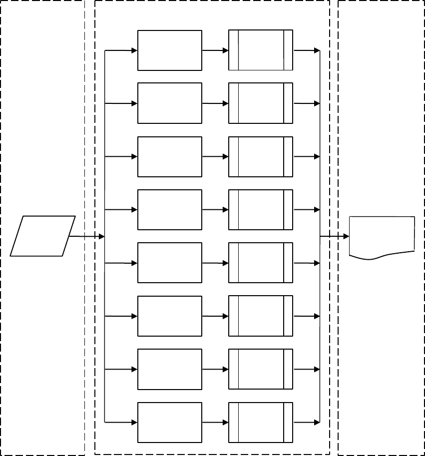
Logical Printer Architecture
PrintNet provides a logical printer architecture which gives the system administrator the possibility to
configure the print server to handle and act upon the print data in several ways. When a print job comes
through the print server, there is a certain logical print path that it follows before it gets to the printer. Each
logical print path consists of a sequence of logical steps where extra processing may be performed on the
print data before it is sent to the printer. This ability to preprocess the print data before it is sent to the
12
printer allows elimination of certain printing problems, or implementation of printer enhancements that
may be difficult and time consuming to solve or introduce at the system, spool or queue level. The
preprocess ability is also simplistic to perform at the print server level.
The logical print path for a print job going through PrintNet consists of three different
phases:
• Phase 1 - the host sends the job to a destination or queue on PrintNet (e.g. d1prn).
• Phase 2 - the print job passes through the associated “model” (e.g. model “m1”) on PrintNet for any
extra processing associated with the model.
• Phase 3 - the processed print job is directed to the printer for output.
Figure 1 Print Path
Model 1
(m1)
Destination 2
(d2prn) Model 2
(m2)
Destination 3
(d3prn) Model 3
(m3)
Destination 4
(d4prn) Model 4
(m4)
Destination 5
(d5prn) Model 5
(m5)
Destination 6
(d6prn) Model 6
(m6)
Destination 7
(d7prn) Model 7
(m7)
Destination 8
(d8prn) Model 8
(m8)
Host
Destination 1
(d1prn)
Printer
Phase 1
Phase 2
Phase 3
13
Destinations/Queues
For every I/O port on PrintNet, there is at least one pre-defined logical print queue or destination to accept
print jobs destined for it. This includes print jobs that are sent directly to the I/O port, such as port 9100.
These queue or destination names are pre-defined but can be changed by the user.
Models
For every destination or queue, there is a pre-defined model associated with it. The model defines how
the print job will be processed as it passes through to the printer. Models are a set of mini filters that can
be used to modify the print data stream. The functions available for each model are as follows:
1.
Insert carriage return after line feed
2.
Insert a banner page before or after each print job
3.
Insert header strings
4.
Insert trailer strings
5.
Log one or all of the following information as each print job passes through the
model
• Job ID and username
• User ID and three messages per job about the start and finish
• Miscellaneous messages from the printer
• Status of the printer based on the port interface signals
6.
Load a specific printer configuration before processing a print job
• Specify a printer configuration to be associated with a print queue.
• When a job is sent to that print queue, the associated printer configuration will be loaded
before the job is processed.
• Feature allows you to define up to eight unique and independent printer personalities in a
single printer.
• Allows you to effectively have eight virtual printers in one.
Interfaces
The Ethernet interfaces with the host printer through an Ethernet 10/100Base-T interface connector.
PrintNet is enabled with a security element.
14
PrintNet Card LED
Table 1 PrintNet LED Indicator
NET Indication Description
ON flashes Indicates activity
OFF constant Indicates that the link is good at 10 Mbps
ON constant Indicates that the link is good at 100 Mbps
Speed Setting for 10/100Base-T
When the router is set to auto-negotiation enable, the following is the correct behavior of the PrintNet with
each setting:
1. 10mbps Half Duplex
Use parallel detection because the PrintNet is using force mode and thus has auto-
negotiation disabled.
PORs to 10mbps Half Duplex. Resets to 10mbps Half Duplex. Reconnection at switch
maintains 10mbps Half Duplex.
2. 10mbps Full Duplex
Use parallel detection because the PrintNet is using force mode and thus has auto-
negotiation disabled.
PORs to 10mbps Full Duplex. Resets to 10mbps Full Duplex. Reconnection at switch
maintains 10mbps Full Duplex.
3.
100mbps Half Duplex
Use parallel detection because the PrintNet is using force mode and thus has auto-
negotiation disabled.
PORs to 100mbps Half Duplex. Resets to 100mbps Half Duplex. Reconnection
at switch results in 100mbps Half Duplex.
4.
100mbps Full Duplex
Use parallel detection because the PrintNet is using force mode and thus has auto-
negotiation disabled.
PORs to 100mbps Full Duplex. Resets to 100mbps Full Duplex. Reconnection
at switch results in 100mbps Full Duplex.
5.
PrintNet in Auto mode in 100mbps Full Duplex environment
Use auto negotiation to the highest common local and remote capability, i.e. 100 mbps
Full Duplex in this case.
PORs to 100 mbps Full Duplex. Resets to 100 mbps Full Duplex. Reconnection at
switch remains 100 mbps Full Duplex.
15
6.
PrintNet in Auto mode in 10mbps Half Duplex environment
(determined using 10 mbps Half Duplex hub)
Use auto-negotiation to the highest common local and remote capability, i.e. 10 mbps Half Duplex
in this case.
PORs to 10 mbps Half Duplex. Resets to 10 mbps Half Duplex. Reconnection at switch maintains
10 mbps Half Duplex.
NOTE: With parallel detection, only speed can be determined. The duplex mode sets to half duplex.
Conventions Used in this Manual
All uppercase print indicates control panel keys.
Example: Press the CLEAR key, then press the ONLINE key.
Quotation marks (“ ”) indicate messages on the Liquid Crystal Display (LCD).
Example: Press the ONLINE key. “OFFLINE” appears on the LCD.
Command syntax and examples are formatted as follows:
• The Courier font in boldface indicates commands that you type. For example:
• At the prompt, type:
ping ftp.CompanyWebsite.com
• Regular Courier font indicates references to command syntax and output. For example:
The ftp.CompanyWebsite.com site is working properly.
• Variable values are shown in italics in command syntax, output, and in text. For example:
ping ipname
The ipname is working properly.
Notes and Notices
For your safety and to protect valuable equipment, read and comply with the notes included in this
manual. A description follows:
NOTE: A Note gives you helpful information and tips about printer operation and maintenance.
16

17
Installation And
Configuration
Installation
The printer has an RJ-45 connector on the back panel for 10/100Base-T (UTP) networks. Print a test
page to confirm that the Ethernet is installed. Contact your service representative if the Ethernet is not
installed.
Connecting to the Network
To attach the PrintNet to a network, plug the network cable into the RJ-45 connector.
Configuration Tools
There are two parts to a PrintNet setup:
• Configuring the PrintNet so it can be seen on the network. This involves network-related settings
(e.g., an IP address within TCP/IP environments) configured through the built-in command shell,
npsh, or from the control panel.
• Configuring a host with a new printer so it knows how to send data to the PrintNet. Just being able to
see the printer on the network does not mean you can automatically print to it. A host has to be told
where to send the data.
NOTE: Some network environments do not require any network settings to be configured on the PrintNet.
However, all network setups require configuration on the host end.
The following methods are available for configuring the Ethernet:
• via the control panel
• HTML forms
• Telnet
• PTX_SETUP
Printing an Ethernet Test Page
Always print an Ethernet Test page before performing any updates or network configuration. Refer to the
Admin Manual for instructions on printing a test page.
PrintNet Verification
Before performing the verification, you must connect PrintNet to the local area network.
1.
Print an Ethernet Test page to verify the settings you selected.
2.
Verify the network setting is correct.
18
HTML Forms
The network settings can be configured over TCP/IP through a standard Web browser. The PrintNet Web
pages provide a way to access some of the commands built into the print server.
NOTE: If a router is used, make sure a Gateway value is configured.
To access the PrintNet home page:
1.
Make sure the print server has an IP address and Subnet Mask so it is recognizable
on your TCP/IP network.
2.
Make sure your network station can successfully ping the PrintNet over the
network.
3.
Direct your Web browser to the URL http://IPaddress
(e.g., http://192.75.11.9)
where IPaddress is the IP address of your PrintNet.
See PrintNet Web Server on page 19 for details.
Besides the HTML forms and software provided, the PrintNet internal command shell, npsh, can also be
reached using Telnet, FTP, and Data Stream:
Telnet
Telnet commands can be used to configure PrintNet settings remotely. A TCP/IP host starts a Telnet
session with the print server and logs into the device command shell to alter and view settings.
Example:
telnet 192.75.11.9
NOTE: The default User ID is root. There is no password by default, just press ENTER. If you have
changed the default User ID and password, use the current User ID and the associated password
instead of the defaults. For more information on setting passwords, see PrintNet Security on page
137.
Setup through Data Stream
The PTX_SETUP command can also be used to configure PrintNet settings through a printer data port
(serial, parallel, or network etc.). This is done by creating a text file containing the PTX_SETUP command
and PrintNet internal command shell (npsh) commands. The text file is then sent to the printer through a
data port to perform the PrintNet configuration. The following is an example of a PTX_SETUP file that can
be used to configure the PrintNet:
!PTX_SETUP
NIC_SETUP
store net 1 addr 190.168.2.11
END_NIC_SETUP
PTX_END
19
PrintNet Web Server
Overview
The PrintNet comes with a printer management tool that allows you to monitor, configure, and manage
both the printer and its print job. The PrintNet comes with a web server that allows System Administrators
and users access to its printer management capabilities from a standard web browser.
The PrintNet printer’s IP address is used as a URL, similar to the URL of an Internet web page. When a
web browser is activated and the printer’s IP address is entered, the printer’s embedded web server
displays its home page, with links to the printer’s status and configuration settings.
All of PrintNet's configuration settings are protected by a password so unauthorized users cannot make
changes. When you try to open any of the PrintNet 's configuration pages, you are asked for your user
name and password. At the prompt, you need to enter root (unless you have another user configured
with root privileges) followed by the associated password. If there is no password, just press ENTER. For
more information on setting passwords, refer to PrintNet Security on page 137.
After you configure the PrintNet settings, and click the SUBMIT button on the related form, re-power the
PrintNet to ensure the latest settings are in use. To reset the PrintNet, go to the System form under the
Configuration Menu and click the REBOOT button.
The embedded PrintNet HTML server gives you the ability to configure the network setting, printer
operation, monitor printer status, and to manage print jobs. The PrintNet Web page structure is divided
into several menus.
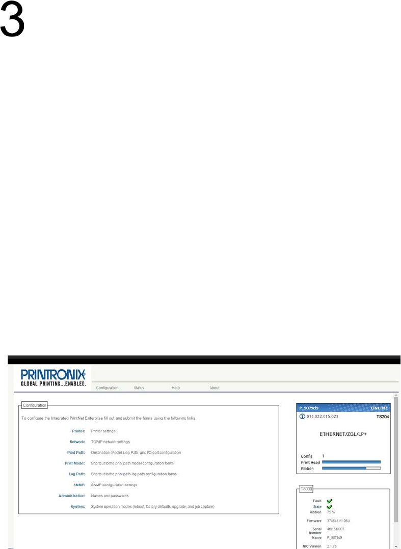
Figure 2 PrintNet Webpage
The main page is divided into three major sections: Configuration, Printer Status, and Print Server. The
Printer Status and Print Server sections display on the right side amongst other pages.

20
Configuration
This area allows the user to configuration the printer and network settings. The user can click each link to
go to page options.
Printer Virtual Panel
This area displays the printer operator panel. Clicking the virtual panel will trigger a full operator panel
display. The user can click the front panel keys like the real panel. There is no LED on the Virtual Panel.
To press multiple keys at the same time, hold down the shift key on the key board of the host system that
runs the browser and click the multi-key one at a time and then release the shift key.
Since the browser can sometimes miss the display update, if you are questioning the display or a blank
screen on the virtual panel, you can click the refresh button or press function key F5 to update the
display.
NOTE: When using older version of browser, you may need to enable compatibility View setting in order
to receive proper display.
Printer Status
This area displays the printer type and information, control panel display, and printer state. The user can
click “State” to change the printers between Online and Offline mode.
This section also shows PrintNet information and active print jobs.
Configuration
The Configuration menu items allow you to configure the settings for the following items:
• Printer - this menu item allows you to configure the printer. You can change the printer’s form size,
character set, and emulation settings. You can also load/save configuration files, print configurations,
and manage file systems.
• Network - this menu item allows you to change the TCP/IP network setting over TCP/IP.
• Print Path - this menu item allows you to change the name of the destination queues, and define how
the print job will be preprocessed before printing. It allows you to select what information to log.
• Print Model - this menu item allows you to specify the print model name. It also allows you to select
banner page types, filters, header and trailer strings, and printer configurations.
• Log Path - this menu item allows you to specify the logpath name, type, and destination.
• TN5250/3270 - this menu item allows you to configure the TN5250/3270 settings if TN is enabled in
the printer.
• SNMP - this menu item allows you to configure the SNMP trap manager settings. It also allows you to
define the printer event types to monitor, and the e-mail address that should receive alert
notifications.
• Administration - this menu item allows you to define or change the printer name, location, description,
etc. It also allows you to change the root and guest user passwords, and to specify the SMTP
server’s IP address.
• System - this menu item allows you to reboot the printer, restore its settings to the factory default,
upgrade printer firmware, and capturing the print data.
21
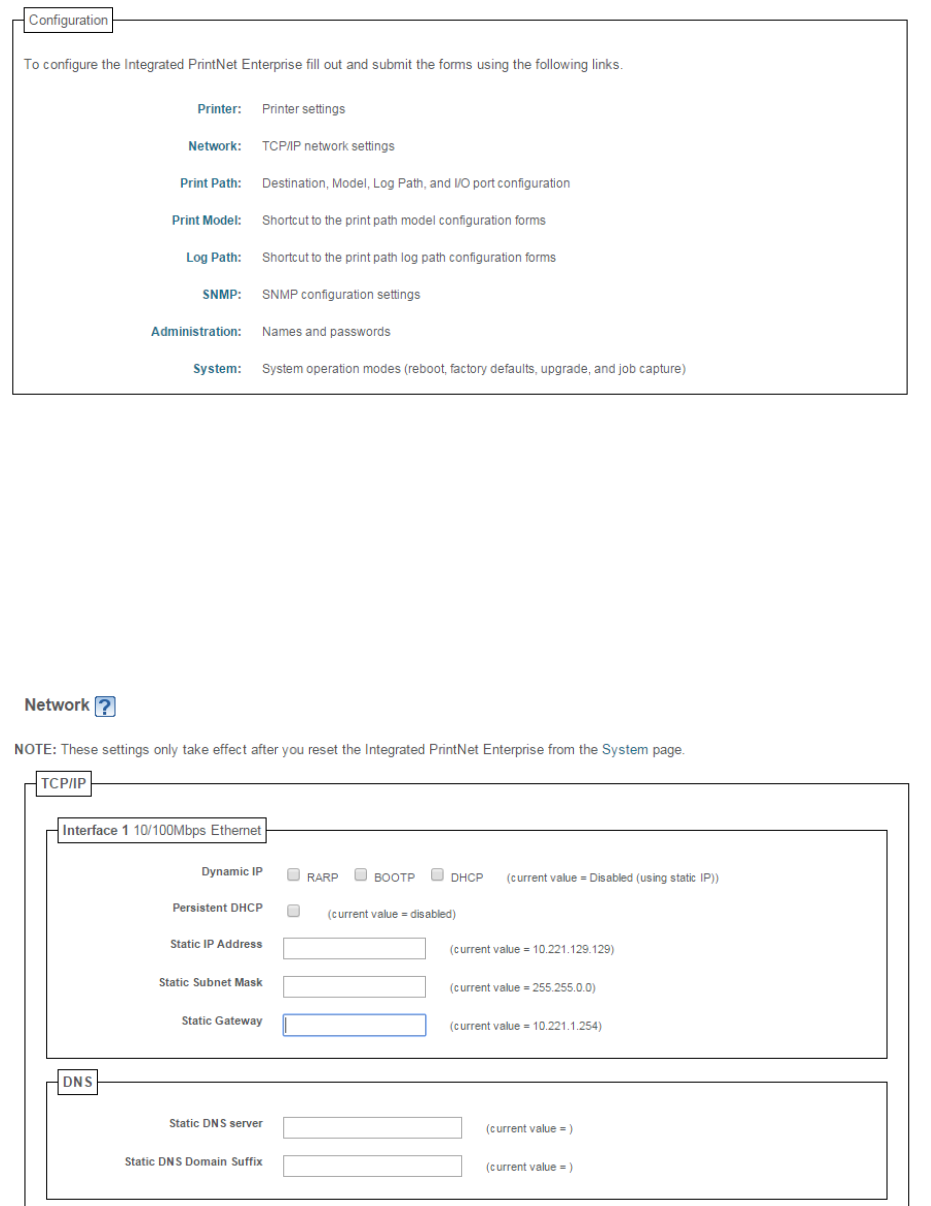
Network Configuration
The network configuration allows you to specify the setting for each network protocol. Beside each
protocol name is a checkbox which allows you to enable or disable each protocol depending on your
network printing needs.
NOTE: TCP/IP is the only supported protocol which is always enabled.
TCP/IP Network
Figure 3 TCP/IP Network Configuration
22
Interface
The three editable fields contain the PrintNet's IP address, subnet mask, and Gateway. The check boxes
enable the BOOTP, DHCP, and Persistent DHCP protocols, which are alternate methods of assigning IP
addresses. On most networks, you want to enter a permanent IP address and subnet mask and disable
BOOTP and DHCP. However, if your network requires one of these, you should clear the IP address (and
possibly the subnet mask) fields and ensure that the appropriate check box is selected.
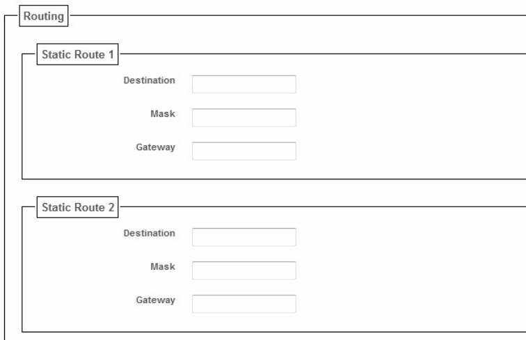
Figure 4 TCP/IP Static Route
Routing
The routing table tells the PrintNet which router or gateway to use to access other subnets or hosts. In
most situations, you can simply add your router's IP address as the default router. All packets destined for
other subnets will be forwarded to the default router for delivery to the destination host. If you have more
complex routing requirements, add static routing entries for specific hosts or networks in the remaining
Routing rows. Packets with IP addresses that match a given Destination and Mask (from the first two
fields in a Routing row) will be routed to the router/gateway named in the third field. Packets which do not
match any of the listed Destinations and Masks will be routed to the default router if one is set.
Print Path Configuration
The PrintNet print path is the path a print job takes when it reaches the printer's Ethernet interface. First
the job goes to a destination/ queue (e.g. d1prn) where it then passes through an associated model (e.g.
m1) for extra processing and logpath (e.g. l1) for job and printer logging. Finally the job reaches printer's
data parser. The "Print Path" Webpage displays one destination's settings at a time. From here, you can
then select another destination or you can go directly to an I/O port to configure port settings.
23
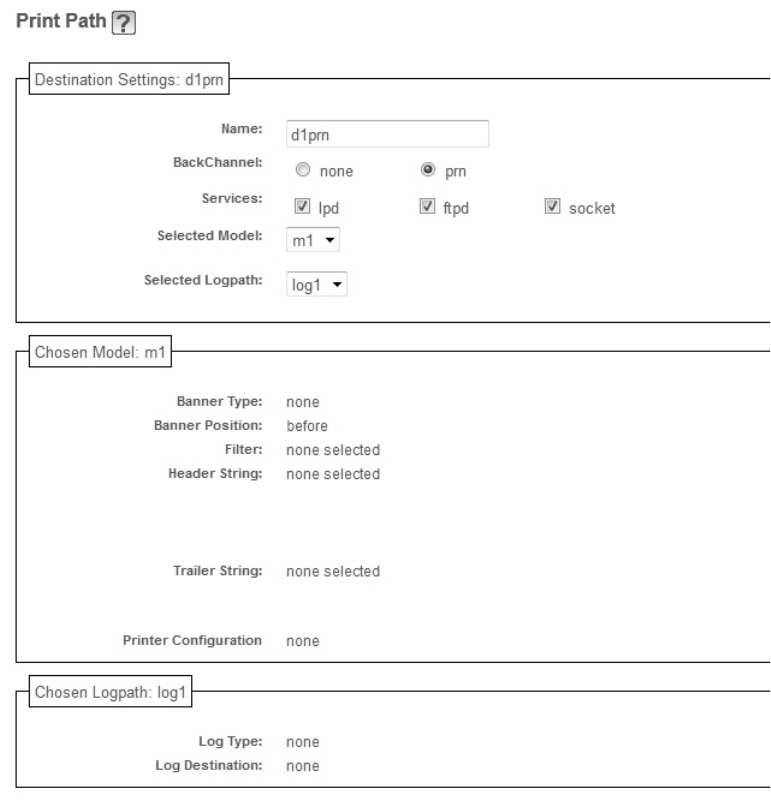
Destination Settings
Figure 5 Print Path Configuration
Name
Name of the destination. The default destination queue names are d1prn, d2prn, d3prn, d4prn, d5prn,
d6prn, d7prn, and d8prn. The destination name can be modified by entering a new name in the field and
clicking “Submit”.
Back Channel
I/O port to receive printer feedback when a print job passes through this destination. By default, the
backchannel for all print queues is enabled.
Services
Define what type(s) of print services the destination will support. By default all services enabled.
24
Parameter
socket Printing to a TCP port number (e.g. 9100) on
the PrintNet
lpd Remote printing using the Line Printer Daemon
ftpd printing using the File Transfer Protocol (FTP)
Selected Model
Defines the model configuration that is to be associated with the current destination. The default model
names are m1, m2, m3, m4, m5, m6, m7, and m8.
Selected Logpath
Defines the logpath configuration associated with the current destination. The default logpath names are
l1, l2, l3, l4, l5, l6, l7, and l8.
Chosen Model Settings
This section displays the model associated with the displayed destination. To change Print Model
settings, see Print Model Configuration on page 24.
Chosen Logpath
This section displays the logpath setting associated with the displayed destination. To change Log Path
settings, see Log Path Configuration on page 26.
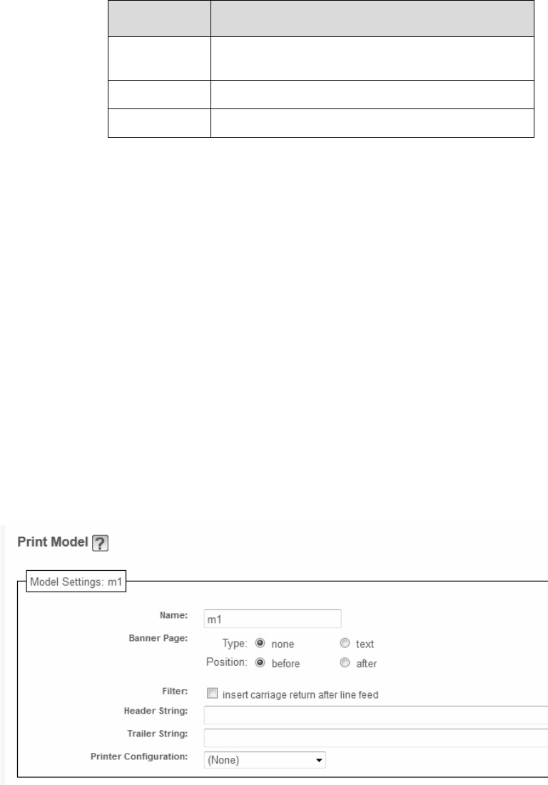
Print Model Configuration
Figure 6 Print Model Configuration, Model Settings
25
Name
Name of the model. The default model names are m1, m2, m3, m4, m5, m6, m7, and m8. The model
name can be modified by entering a new name in the field and clicking “Submit”.
Banner Page
Tells the Ethernet Interface to produce a banner page with each print job. The type of banner page data
can be text. You can also specify whether the banner page should come at the front or the end of a print
job.
Filter
Specify whether the Ethernet Interface is to add carriage returns to print jobs passing through that contain
solitary linefeeds. This is common with Unix text jobs resulting in stair-stepped output.
Header String
Define an escape sequence to be sent to the printer before each print job. For example, you may want to
send a sequence to print the job in landscape mode. You can specify up to four separate sequences per
header string. The Ethernet Interface will execute them in order from top to bottom. If specifying fewer
than four sequences, be sure to start at the top leaving undefined fields at the bottom.
Trailer String
Define an escape sequence to be sent to the printer after each print job. For example, you may want to
send a sequence to add a formfeed so you don't have to manually press the formfeed button on the
printer. You may also want to tell the printer to reset itself in case you have set a header string which tells
the printer to do something special with the job. You can specify up to three separate sequences per
trailer string. The Ethernet Interface executes them in order from top to bottom. If specifying fewer than
four sequences, be sure to start at the top leaving undefined fields at the bottom.
The most common sequence is listed on the form:
• Formfeed - tells the printer to do a formfeed at the end of the data. See page 128.
Printer Configuration
Specify a printer configuration number to be loaded before processing the print job. This ability to
associate a printer configurations to a logical printer model allows you to define up to eight unique and
independent printer personalities in a single printer. Using this feature, you effectively have eight different
printers in one.
To associate a printer configuration to the currently selected destination queue, just select the desired
printer configuration number from the drop down list. Once a printer configuration has been associated
with a destination queue, any print job sent to that destination queue name will cause the printer to load
the associated printer configuration before processing the print job.

26
Log Path Configuration
Figure 7 Log Path Settings
Name
Name of the log path. The default names are l1, l2, l3, l4, l5, l6, l7, and l8. The Log Path name can be
modified by entering a new name and clicking “Submit”.
Logpath Type
Define what type of log information will be tracked for each print job passing through the associated
destination. The types are:
• Print Job Started - A notification is sent to 'Destination' when a print job is received in the PrintNet.
• Printer Error - A notification is sent to 'Destination' when a printer error occurs during printing. If no
print job exists in the PrintNet, the notification will not be sent.
Logpath Port
Define where logging information for print jobs passing through the associated destination will be
reported. The choices are:
• None (default) - do not report any logging information
• Email - to an e-mail address (SMTP server address is set in the Administration page)
• UDP Syslog - to a host (specified by the IP address in the edit field) running a SYSLOG daemon
• TCP/IP port - to a TCP port number.
27
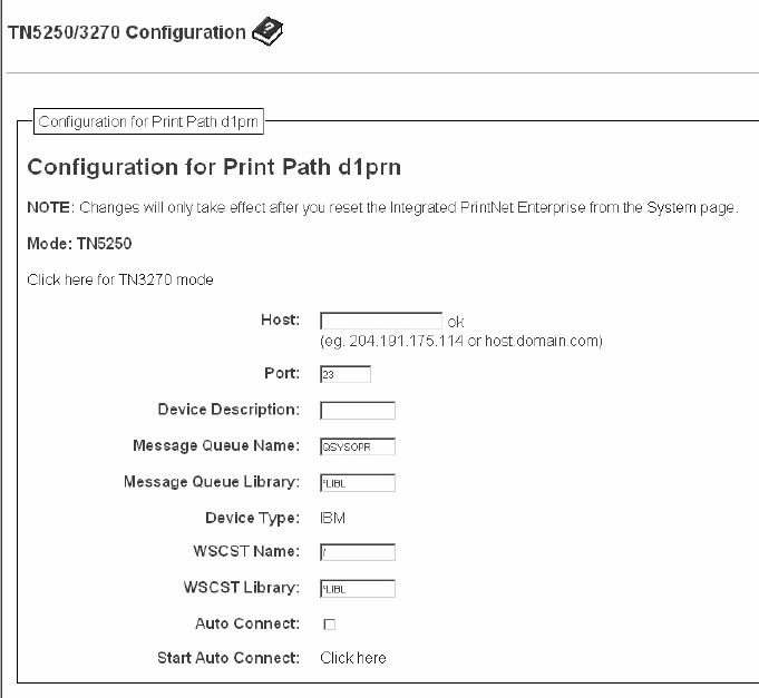
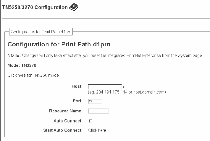
TN5250/3270 Configuration
The TN5250/3270 configuration form allows you to specify settings for up to eight different TN5250/3270
sessions.
NOTE: The standard Printronix PrintNet module does not support TN5250/3270 protocol. However, the
TN5250/3270 software is available as an option you can order or as factory installed.
Figure 8 TN5250/3270 Configuration, TN5250 Mode
28
Figure 9 TN5250/3270 Configuration, TN3270 Mode
Mode
Specifies the TN protocol mode for the current configuration.
Default: TN5250
Host IP
Specifies the IP address or domain name of the host (AS/400 for TN5250) for the current configuration.
Default: Unconfigured (empty) host.
Port
Specifies the UDP port number of the TN5250 or TN3270 server for the current configuration.
Default: 23
Resource Name
(TN3270 mode) Specifies the name of the AS/400 LU session for the current configuration. The resource
name entered will be the name of the printer device created on the AS/400 host for the current session.
The name is limited to 10 characters in length, must start with an alpha character (a-z, A-Z), and contain
only alphanumeric characters and underscores.
Default: Unconfigured (empty) resource name
Device Description
(TN5250 mode) Specifies the name of the printer device for the current configuration. The description
entered will be the name of the printer device created on the AS/400 host for the current session. The
name is limited to 10 characters in length, must start with an alpha character (a-z, A-Z), and contain only
alphanumeric characters and underscores.
Default: Unconfigured (empty) description
Message Queue Name
(TN5250 mode) Specifies the queue name to which system messages will be logged.
29
Default: QSYSOPR
Message Queue Library
(TN5250 mode) Specifies the queue library to which system messages will be logged.
Default: *LIBL
Device Type
By default, the device type is always set to IBM.
WSCST Name
(TN5250 mode) As declared on the AS/400 host for the created printer device.
Default: *NONE
WSCST Library
(TN5250 mode) As declared on the AS/400 host for the created printer device.
Auto Connect
Specifies whether the PrintNet will automatically connect to the host.
Default: Disabled
Start/Stop Auto Connect
Specifies whether the PrintNet should retry automatic connection to the host.
Default: 'Start' if Auto Connect is currently stopped, 'Stop' if Auto Connect is currently started.
NOTE: TN manage needs to stay connected to the TN server in order to continue receiving data. To
print to the ASCII port, the user will need to end the TN print queue writer first.
30
SNMP Configuration
The SNMP Configuration form allows you to configure SNMP trap managers and the e-mail alert features
of PrintNet. It allows you to configure how SNMP alerts are processed by a SNMP trap manager, a Unix
syslog logging daemon, and/or have e-mail notifications sent. Up to 10 SNMP trap managers and e-mail
recipients may be specified. Individual alerts fall into one of 14 alert group categories, providing the ability
to filter alert notices as desired.
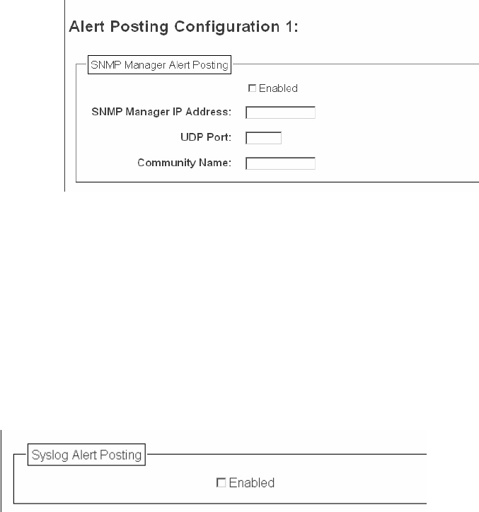
SNMP Manager Alert Posting Settings
Figure 10 SNMP Manager Alert Posting Configuration
Specifies whether alerts from the enabled alert group categories for this configuration will be sent to the
SNMP manager. If this option is enabled, the following information must be entered:
• SNMP Manager IP Address - specifies the IP address of the SNMP trap manager
• UDP Port - specifies the UDP port number used by the SNMP trap manager for receiving trap
messages. Acceptable values are 162 and 49157 through 65535
• Community Name - up to 15 character string specifying the trap community name.
Syslog Alert Posting Settings
Figure 11 SNMP Syslog Alert Posting Configuration
Specifies whether alerts from the enabled alert group categories for this configuration will be sent to the
Unix syslog daemon. If this option is enabled, the syslog daemon IP address must be entered in the
syslog field in the System Information section of the Administration Configuration form.
Default: Disabled
31
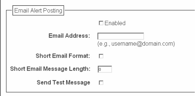
E-mail Alert Posting Settings
Figure 12 SNMP Email Alert Posting Configuration
Specifies whether alerts from the enabled alert group categories for this configuration will be sent to the
specified e-mail address. If this option is enabled, the following information must be entered:
• E-mail Address - specifies an e-mail address to which alert information will be sent
• Short E-mail Format - specifies whether a short (15-80 character) alert e-mail message should be
sent.
If enabled, the message will contain the alert description, the severity level, device description, and
device name (unless the length of the message exceeds the Short E-mail Message Length, in which
case the message will be truncated).
If disabled, the message will contain additional information including the device description, device
name and location, alert description, alert group, alert severity level, and printer status.
Default: Disabled
• Short E-mail Message Length - Specifies the maximum size of the short e-mail message.
Acceptable values are 15 to 80 characters.
Default: 80 characters
• Send Test Message - Provides a way to test the validity of the e-mail address/SMTP server address.
If checked, a test message will be sent to the specified e-mail address when the submit button is
pressed.
Default: All alert groups are disabled by default.
If the alert message is to be sent to a cellular phone or pager, the Short E-mail Format option should be
enabled. Once this option is enabled, you may specify the maximum e-mail message length (15-80
characters). When enabled, the message will contain the alert description, the severity level, device
description, and device name (unless the length of the message exceeds the Short E-mail Message
Length, in which case the message will be truncated).
If the Short E-mail format is disabled, the message will contain additional information Including the device
name and location, alert description, alert group, alert severity level, and printer status.
To test the validity of the e-mail address and the SMTP server address, enable the Send Test Message
option. If the Send Test Message box is checked, a test message will be sent to the specified e-mail
address when the submit button is pressed.
32
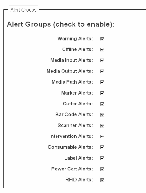
Alert Groups
Figure 13 SNMP Alert Groups Configuration
Specifies which alert groups are enabled for reporting for this configuration. When an alert occurs that is
contained in one of the enabled alert groups, it will be posted to the specified SNMP manager, Unix
syslog daemon, and/or e-mail address. The following table describes which printer events belongs to
which Alert Group.
Default: All alert groups are enabled by default.

33
Table 2 Alert Groups and Printer Events
Alert Group Printer Events
Warning File System Full
File Exist
Hex Dump Mode
Half Speed Mode
Offline Printer is Offline
Media Input Load Paper
Media Output Stacker Full
Stacker Jam Time Out
Stacker Full Time Out
Stacker Fault Time Out
Stacker Jam
Stacker Fault
Stack Over Flow8
Stack Under Flow
Stacker Fail
Stacker Interlock Fail
Media Path Clear Paper Jam
Marker Ribbon Stall Time Out
Ribbon Ink Out
Ribbon Stall
Ribbon Drive
Shuttle Over Speed
Ribbon Fault
Ribbon Detected
Barcode Barcode Fail Specification
Barcode Quiet Zone Too Small
Barcode Improper Data Format
Intervention
These are error messages that need some
kind of user intervention to solve them.
Consumable Ribbon Low
NOTE: Not all of the alerts are available on all of the printers. The alerts available for monitoring will
depend on the printer type and the options installed on the printer.
34
Administration Configuration
The Administration Configuration form is broken down into general print server-related settings and
password security.
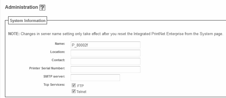
System Information
Figure 14 Administration Configuration, System Information
The System Information form allows you to specify the following information about the printer:
Name
Name given to the print server in Windows environment. The default name is “P_xxxxxx” where "xxxxxx"
equals the last six digits of the PrintNet’s Ethernet address. (e.g. P_01001C). The user can change the
printer name in this field.
Location
Optional field to help identify the printer’s physical location.
Contact
Optional field to help identify the individual or group responsible for the printer.
Printer Serial Number
Allows the user to enter the printer’s serial number. If the printer's controller board is replaced, this field
will be blank. The service representative can enter the printer's serial number in this field.
SMTP Server
Specifies the IP address or domain name of the SMTP server to be used for processing email messages
generated by the PrintNet.
Default: Unconfigured (empty).
TCP Services
There are two protocols that users can disable. Usually major corporations prefer to disable ftp and telnet
once configuration of the printer is complete. ftp and telnet protocols are set to enable by default. If these
protocols are disabled, you can use the Webpage to enable them.
35
If HTTP protocol is disabled along with ftp and telnet, the only way to enable these protocols is by
sending a print job with PTX_SETUP commands. (Refer to printer’s User's Manual for PTX_SETUP
syntax.)
Passwords
Figure 15 Administration Configuration, Passwords
Only a user with root privileges can alter the PrintNet's settings. Guest users can only view settings but
cannot alter them. Both types of users can be assigned passwords. To change a password, type in the
old password in the "Old" field. Then type the new password twice: once in the "New" field, and once in
the "Confirm" field.
Default: No passwords for root or guest users.
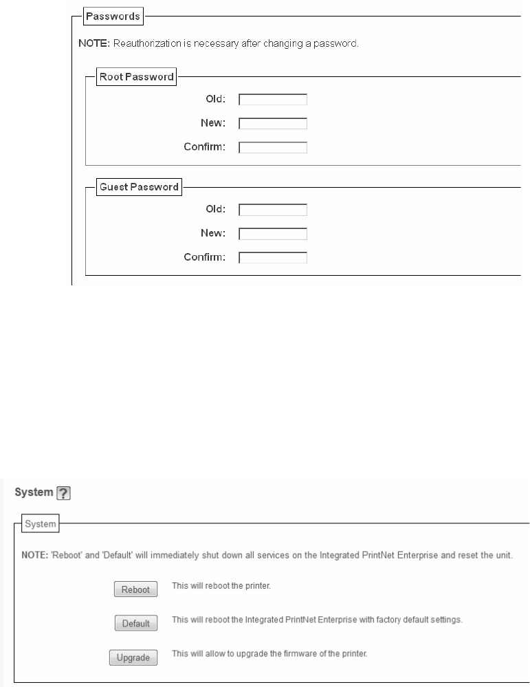
System Configuration
Figure 16 System Configuration
The System Configuration form allows you to change the PrintNet's operation mode. Select "Reboot" to
re-power the print server. Select "Default" to reset the print server and have it come up with factory
default settings.
36
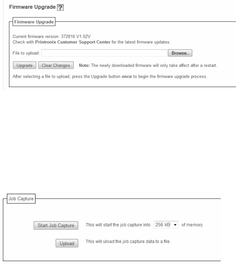
Firmware Upgrade
Click "Upgrade" to upgrade the printer's firmware. The Firmware Upgrade webpage displays below.
Figure 17 Firmware Upgrade Webpage
1.
To find the upgrade file click the Printronix Customer Support Center link.
2.
Click “Browse...” to navigate to the directory, then click “Upgrade”.
NOTE: Upgrading the printer firmware will erase all printer configurations except network setting. You
may want to upload the configuration and save it to your PC before the upgrade process.
IMPORTANT The upgrade process may take a few minutes. the process cannot be interrupted
during upgrade or the printer will not be able to power up again.
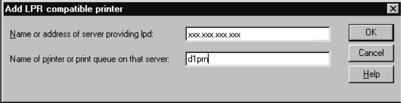
Job Capture
Figure 18 Job Capture Webpage
Sometimes the job does not work or your barcode does not print. Job Capture allows you to capture data
sent to the printer. To start capturing data, click “Start Job Capture”. To stop capturing data, click “Stop
Job Capture”. Upon job capture completion, click “Upload” to load the data from the printer to your host
system. The captured file size depends on your available DRAM size.
37
Status
The Status menu items allow you to view the current status of both the printer and the network. The
submenu items available are as follows:
• I/O Port - this menu item allows you to view the current status of the printer, including the print jobs
that are queued or are currently active.
• Network - this menu item allows you to view the current status of the network connection.
Status - I/O Port
The I/O Port Status form allows you to remotely see what is happening on the PrintNet I/O port. The port's
status and a list of active and queued jobs will be displayed. You can cancel a job (as long as you have
permission) by clicking the Cancel icon beside the desired job. If you see "waiting" in the "Status" line, this
indicates the PrintNet is either waiting for data from the host or for feedback from the printer. If you see
"blocked" in this line, this indicates the printer is not allowing the PrintNet to send any more data. The
printer could be busy processing data it has already received or it could be in an error state.
The printer status display is automatically refreshed every minute.
NOTE: You cannot cancel a print job with an IPDS Emulation. Do not click the Cancel icon.
The printer’s buffer size may not allow you to monitor the real time status of the printer and the
print job at the same time. The status feedback to the host usually reads “printer idle” unless the
print job is significantly large.
Status - Network
This form allows you to view the current status of the network. The statistical data provided is broken
down by network protocol. You can use this form to troubleshoot network-related problems.
Help
Through the provided HTML forms, you can configure settings on the Integrated PrintNet Enterprise and
view printer status.
38

39
Windows Configuration
Overview
This chapter details a complete Windows configuration setup including:
• Identifying the PrintNet on the network using TCP/IP as the underlying protocol
• Configuring the PrintNet with its mandatory TCP/IP settings (IP address and subnet mask)
• Configuring a new printer on the Windows station
Windows Environment Description
The PrintNet supports network printing under Windows environments by using TCP/IP. In a Windows
setup, pure TCP/IP is used as the network protocol.
Windows PrintNet Configuration
The IP address and subnet mask are mandatory TCP/IP settings and are needed before the print server
can be detected on the network. There are also additional optional settings. This section offers alternative
methods for configuring your PrintNet in a Windows environment and describes some of the more
common optional settings available.
Mandatory
Since TCP/IP is used for Windows printing, the PrintNet must be configured with a minimum of an IP
address and subnet mask before it can be seen on the network.
Optional
Additional settings, like routing entries, can be configured. This allows communication across subnets
when no other router exists.
You can configure the PrintNet from the printer control panel, Web browser, host commands, or other
Printronix utility software. To configure these options, see Configuration Tools on page 17.
Configuration using ARP
To configure the PrintNet with its IP settings using a manual arp command:
1.
Log on to a Windows station with TCP/IP loaded and located on the same subnet as the PrintNet.
2.
Find the Ethernet address for the PrintNet on the configuration printout. It must be entered as part
of this procedure.
40
3.
Use the arp command to add an entry into the Windows station ARP table for the
PrintNet. This is the most common syntax for this command:
Syntax:
arp -s ipaddress ethernetaddress
Example for Microsoft®TCP stacks:
arp -s 192.75.11.9 00-08-96-07-00-60
This example specifies a PrintNet using IP address
192.75.11.9 and Ethernet address 00-08-96-07-00-60.
4.
Check if the ARP entry was accepted.
arp -a
You should see an entry in the listed ARP table with the IP address and Ethernet
address specified in Step 3.
5.
Ping this IP address to see if the PrintNet can be seen on your network.
At this point, you should be able to communicate with the PrintNet from your local
Windows station. This means the print server knows about an IP address and subnet
mask and has these settings in its current memory. However, if the PrintNet is power
cycled, these settings will disappear unless you store them into flash memory. To do
this:
a.
Load a Web browser on your Windows station and direct it to the URL:
http://IPaddress
(e.g., http://192.75.11.9)
where IPaddress is the IP address of your PrintNet.
NOTE: If prompted for a “User ID” and password first, type root for the ID and press ENTER at the
password prompt (since there is no password by default).
b.
At the “Network Configuration” HTML form that displays, click in the field below
the “IP Address” heading and type in the IP address for the PrintNet.
c.
Under the “Subnet Mask” heading, enter the PrintNet subnet mask.
NOTE: If you would like to communicate with the PrintNet from across routers, you will need to fill in an
entry within the “Routing” section. Please see Communicating Across Routers on page 40 for
more details.
6.
Click on the SUBMIT button when done and physically repower the printer to make the new
settings take effect.
Communicating Across Routers
Since Windows environments rely on TCP/IP to communicate with the PrintNet, crossing routers
becomes an issue.
After you have followed one of the PrintNet configuration methods mentioned, most likely you will only be
able to communicate with the print server from the same subnet. This means any hosts across a router
will not be able to see your PrintNet. In order for hosts across a router to see your PrintNet, store a
default router/gateway within the print server so that any packets destined for another subnet get
forwarded to this router automatically. The router (or series of routers) can then take over, ensuring the
packets get to their final destination on another subnet on your network.
To configure a default router/gateway within the PrintNet:
1.
Load a Web browser on your Windows station and direct it to the URL.
41
NOTE: If prompted for a “User ID” and password first, type in root for the ID and press ENTER at the
password prompt (since there is no password by default).
2.
At the “Network Configuration” HTML form that displays, click in the first field below the “Gateway”
heading and type in the IP address of the default router/gateway for the PrintNet subnet.
3.
Click on the SUBMIT button when done and physically repower the print server to make the new
settings take effect.
Changing Destination Names
When defining some printers within Windows environments, the PrintNet requires that you specify a
predefined destination rather than any name you would like. For example, when creating a new printer
under Windows NT, a screen similar to Figure 19 displays.
Figure 19 Windows NT Print Setup Dialogue Box
The first field requires the IP address for the PrintNet, and the second field must be filled in with a valid
destination from the print server (e.g., d1prn). Otherwise, LPR will not be able to access the printer.
This name can be changed to something more meaningful using the built-in HTML forms.
To do this:
1.
Load a Web browser on your Windows station and direct it to the URL:
http://NICIPaddress/destConf.html
(e.g., http://192.75.11.9/networkConf.html).
NOTE: If prompted for a “User ID” and password first, type in root for the ID and press ENTER at the
password prompt (since there is no password by default).
2.
At the “Print Path Configuration” HTML form that displays, select a destination link from the top of
the page to bring up the appropriate destination form. By default, you should see a line near the top
of the form showing the destinations.
3.
Once the desired destination HTML form displays, highlight the “Name” field and type in the new
name for this destination.
4.
Click the SUBMIT button when done and physically repower the print server to make the new
setting take effect.
42

43
Unix Configuration
Overview
This chapter details a complete Unix setup including:
• Configuring the PrintNet with its mandatory TCP/IP settings (e.g., IP address and subnet mask).
• Configuring the Unix host station with a new printer.
Unix Environment Description
The PrintNet supports network printing under various TCP/IP environments including all variations of
Unix. Printing can come from multiple hosts directly or through central spooling machines.
Unix PrintNet Configuration
There are mandatory settings needed before the print server can be detected on the network, as well as
some additional optional settings. This section offers alternative methods for configuring your PrintNet
and mentions some of the more common optional settings available.
Mandatory
Since TCP/IP is used, the PrintNet must be configured with a minimum of an IP address and subnet mask
before it can be seen on the network. To configure these options, see Configuration Tools on page 17.
Optional
Additional settings, like routing entries, can be configured allowing for communication across subnets.
Configuration of the PrintNet can be done from the control panel or through host commands. To configure
these options, see Configuration Tools on page 17.
Using ARP
To configure the Ethernet Interface with its TCP/IP settings using a manual arp command, the syntax is:
arp -s ipaddress ethernetaddress
For the aix command, the syntax is:
aix -s ether ipaddress Mac_address
To use either of these commands:
1.
Log on to a Unix station as superuser or root. This station must be located on the same subnet
as the PrintNet since ARP is limited to subnets.
2.
Find the Ethernet address for the PrintNet by printing a configuration or reading it
from the control panel. It must be entered as part of this procedure.
3.
Use the arp command to add an entry into the Unix station ARP table for this
PrintNet. Here is the most common syntax for this command:
arp -s ipaddress ethernetaddress
44
Example for Microsoft TCP stacks:
arp -s 192.75.11.9 00:08:96:07:00:60
This example specifies a PrintNet using IP address
192.75.11.9 and Ethernet address 00:08:96:07:00:60.
4.
Verify that the ARP entry was properly applied.
arp -a
You should see an entry in the listed ARP table with the IP address and Ethernet
address specified in step 3.
5.
Try to ping this IP address to see if the PrintNet can be seen on your network.
At this point, you should be able to communicate with the PrintNet from your local Unix station. This
means the printer knows about an IP address and subnet mask and has these settings in its current
memory. However, if the PrintNet is shut off, these settings will be lost unless you store them in flash
memory, as follows:
1.
Load a Web browser on your Windows station and direct it to the URL:
http://NICIPaddress/networkConf.html (e.g.,
http://192.75.11.9/networkConf.html).
NOTE: If prompted for a “User ID” and password first, type in root for the ID and press ENTER at the
password prompt (since there is no default password).
2.
At the “Network Configuration” HTML form that displays, click in the field below the “IP
Address” heading and type in the IP address for the PrintNet.
3.
Under the Subnet Mask heading, enter the PrintNet subnet mask.
NOTE: If you would like to communicate with the PrintNet from across routers, you will need to fill in an
entry within the “Routing” section. Please see Communicating Across Routers on page 45 for
further details.
4.
Click the Submit button when done and physically repower the print server to make sure the new
settings are in effect.
Using BOOTP
BOOTP allows you to dynamically assign an IP address to the PrintNet upon bootup. In addition, the
BOOTP server can provide additional details like a default router/gateway address. To configure the
PrintNet with its TCP/IP settings using BOOTP:
1.
On your BOOTP server, make an entry in the /etc/bootptab file for the PrintNet.
Syntax:
IPname:\
:sm=netmask:\
:hd=homedirectory:\
:bf=null:\
:gw=defaultgateway:\
:ht=ethernet:\
:ha=ethernetaddress:\
:ip=ipaddress:\
:ts=timeserver:\
:to=timezone:
45
Example:
spike:\
:sm=255.255.255.0:\
:hd=/usr/null:\
:bf=null:\
:gw=192.75.11.1:\
:ht=ethernet:\
:ha=000896070060:\
:ip=192.75.11.9:\
:ts=192.75.11.7:\
:to=25200:
2.
Turn the PrintNet on so that it immediately sends out a BOOTP request. Wait one
minute to allow the IP address assignment process to complete.
3.
Try to ping the PrintNet IP address from a network station to see if it can be seen
on your network.
NOTE: You will be able to communicate with the PrintNet from network stations on different subnets if
the print server has been told about its default router/gateway in the BOOTP response from the
BOOTP server.
Communicating Across Routers
Since Unix environments rely on TCP/IP to communicate with the PrintNet, crossing routers becomes an
issue.
After you have followed one of the PrintNet configuration methods mentioned (other than the BOOTP
method), most likely, you will only be able to communicate with the print server from the same subnet.
This means any host across a router will not be able to see your PrintNet. In order to communicate across
a router, store a default router/gateway within the print server so that any packets destined for another
subnet get forwarded to this router automatically. The router (or series of routers) can then take over the
process of ensuring the packets get to their final destination on another subnet on your network.
To configure a default router/gateway within the PrintNet:
1.
Load a Web browser on your Windows station and direct it to the URL
http://NICIPaddress/networkConf.html
(e.g., http://192.75.11.9/networkConf.html).
NOTE: If prompted for a User ID and password first, type in root for the ID and press ENTER at the
password prompt (since there is no default password).
2.
At the Network Configuration HTML form that displays, click the first field below
Gateway and type in the IP address of the default router/gateway for the PrintNet
subnet.
3.
Click Submit when done and physically repower the print server to make sure the new setting
is in effect.
Unix Host Configuration
There may be times when you would prefer or have to perform the manual setup steps for a new printer
definition. There may also be times when you require a less common print solution such as direct socket
capabilities. This section covers these additional setups.
46
Manual System V Host Setup
This setup involves any Unix operating system using System V print spooling (e.g., SCO, Solaris®, HP-
UX®, DG/UX®, etc.). This means an interface file is used for each defined printer and, in the case of any
System V print setup involving a PrintNet, the RSHD protocol is used to transfer data from the host to the
print server.
To manually configure a new System V printer on a Unix station, create a dummy device file that acts as
a locking mechanism between contending print jobs.
Syntax:
touch /dev/NICname.portname
where NICname is the host or IP name of the print server and
portname is one of its four I/O ports.
Example:
touch /dev/spike.prn
PrintNet Installation on HP-UX
LPR is supported in HP/UX Version 9.0 and greater. To configure a print queue using LPR, issue the
following commands.
NOTE: Requires root privilege. The default BSD interface file “rmodel” will be used.
Syntax:
lpshut
lpadmin -pqueue_name -mrmodel -v/dev/null
-orm[printer_ip] -orpd1prn -ob3
lpsched
accept queue_name
enable queue_name
queue_name = any unique printer name
[printer_ip] = IP address of the printer or the DNS name (without brackets)
d1prn = PrintNet remote printer name*
Explanation of command line:
-m indicates the model rmodel
-v indicates the use of /dev/null as a file interlock to avoid contention
-orm is the name of remote Print Server
-orp is the name of the remote printer on the remote Print Server
-ob3 declares that the remote Print Server is a BSD type
NOTE: The “lpshut” command stops the HP spooling system; do not perform when print jobs are active.
The default PrintNet destination name is d1prn, however, this name can be changed. To verify the queue
name, print an Ethernet Test Page or telnet to the print server’s IP address and run a “list dest”
command.
To print to this queue, use normal lp syntax:
# lp -dqueue_name filename
47
Solaris 2.6 – 7 PrintNet Setup
NOTE: Requires Superuser privilege in the borne shell. Assume that you can ping and Telnet to the
adapter.
The IP address of the PrintNet must be placed in the /etc/hosts file.
Syntax:
lpadmin -p [queue_name] -v /dev/null
lpadmin -p [queue_name] -i /usr/lib/lp/model/
netstandard
lpadmin -p [queue_name] -o dest=[host_name] -o
protocol=bsd -o timeout=60
lpadmin -p [queue_name] -s [host_name]!d1prn -I any
enable {queue_name]
accept [queue_name]
where
[queue _name] = any name, but not the name in the etc/hosts file or d1prn
[host_name] = name in etc/hosts file
Troubleshooting
This installation procedure assumes that the PrintNet is configured with the correct IP address, subnet
mask, and gateway (if required). You can also ping and telnet to the PrintNet.
Print an E-Net Test Page to verify the Ethernet settings. See Printing an Ethernet Test Page on page 17.
The default PrintNet queue name is d1prn, however, the name can be changed. To verify the queue
name, print an E-Net Test Page or telnet to the print server’s IP address and run a “list dest” command.
NOTE: Depending on the shell, preceed the ! character with a \ to avoid shell script errors.
Manual LPR/LPD Host Setup
The PrintNet also supports Unix operating systems which follow a BSD print system (e.g., SunOS 4.1.x).
This means a printcap file is used to define all printers available on the host, and interface scripts are not
commonly used. Instead, LPR/LPD printers are defined.
To manually configure an LPR/LPD printer on a BSD Unix system:
1.
Define an entry for this new printer within the printcap file, /etc/ printcap.
Syntax:
printername:
:sh:pw#80:mx#0:\
:rm=NICname:\
:rp=NICdestination:\
:lp=:\
:sd=/usr/spool/lpd/printername:\
:lf=/usr/spool/lpd/printername/log:\
:af=/usr/spool/lpd/printername/acct:
where printername is any name you would like to give to this new printer, ICname is the host or IP
name of the print server, and NICdestination is one of the pre-defined destinations/queues on the
device.
48
Example:
P5000:
:sh:pw#80:mx#0:\
:rm=spike:\
:rp=d1prn:\
:lp=:\
:sd=/usr/spool/lpd/ P5000:\
:lf=/usr/spool/lpd/ P5000/log:\
:af=/usr/spool/lpd/ P5000/acct:
2.
Create the spool directory specified by the sd= entry in the printcap entry for this printer.
Example:
touch /usr/spool/lpd/ P5000
3.
Create the log and account files specified by the lf= and af=
entries in the printcap entry for this printer.
Example:
touch /usr/spool/lpd/P5000/log
touch /usr/spool/lpd/P5000/acct
4.
Change permissions and ownership on the spool directory and everything within it.
Example:
chmod -R g+rwX,o+rX /usr/spool/lpd/ P5000
chmod -R daemon.daemon /usr/spool/lpd/ P5000
5.
Start the printer daemon for this new printer.
Example:
lpc start P5000
You now have a new printer which relies on LPR/LPD to print to a PrintNet printer. Use the following
command to test printing:
Syntax:
lpr -P printername filename
Example:
lpr -P P5000 /etc/hosts
PrintNet Configuration for AIX 4
Before you set up the printer, it is good to know the ways a print job can be filtered.
1.
Standard processing. Filtering is done on the printer with no processing on the
host.
2.
Local Filtering. Filtering is done on the host. Be sure to specify the printer model
during install.
Standard Processing
1.
Enter SMIT select devices.
2.
Select Printer/Plotter.
3.
Select Print Spooling.
4.
Add a Remote Print Queue.

49
5.
Set the type of Remote Printing to Standard processing.
6.
Enter the following Remote printer settings:
Name of queue any_name, user selectable
Host Name of Remote Server name in /etc/hosts file or
the PrintNet IP address
Name of Queue on
Remote Server
d1prn
Type of Print Spooler BSD (Press the list button and
choose BSD)
Local Filtering
1.
Enter smitty mkvirprt.
2.
Add a Remote Print Queue.
3.
Set the type of Remote Printing to Local Filtering...
4.
Set the Printer Manufacturer to IBM.
5.
Set the Printer Type to IBM4202.
IMPORTANT You must change the printer emulation to Proprinter.
6.
Enter the following Remote Print Queue with Local Filtering settings:
Name of queue any_name, user selectable
Host Name of Remote Server name in /etc/hosts file or
the PrintNet IP address
Name of Queue on
Remote Server
d1prn
Type of Print Spooler BSD (Press the list button and
choose BSD)
Leave Pass-Through Flag Yes
Troubleshooting
This installation procedure assumes that the PrintNet is configured with the correct IP address, subnet
mask, and gateway (if required). In addition you can also ping and telnet to the PrintNet.
To verify the PrintNet settings, print an E-net Test Page. See Printing an Ethernet Test Page on page 17.
The default PrintNet queue name is d1prn (in lower case), however the name can be changed. To verify
the queue name, print an E- Net Test Page or telnet to the print server’s IP address and do a “list dest”
command.
50
AIX Remote Queue Time–Out Setting
Symptoms: Print jobs restart or queue goes down.
If the queue is set up for standard processing (not local filtering), add -T50 flag to rembak to the queue
device stanza for the queue in /etc/qconfig
backend = /usr/lib/lpd/rembak -T50
If the queue was set up for local filtering edit the file
/usr/lib/lpd/pio/etc/piorlfb and change the line;
typeset piorlfb_rbflags=’’’’
to
typeset priorlfb_rbflags=”-T50”
Printing from AIX
Version 4.0 and higher of AIX® offers LPR/LPD support for network printing. This means, to set up a new
printer under this operating system, you only need to define these two parameters:
1.
PrintNet IP address. The IP address or host name of the print server to which you want to print.
2.
PrintNet destination/queue. A pre-defined name on the print server telling the device to which
I/O port to send the jobs. Most likely, you will use d1prn for the PRN.
Printing with FTP
Print jobs can also be sent to the PrintNet using the File Transfer Protocol (FTP). To do this:
1.
On your network station, change to the directory containing the file you want to print.
2.
Open an FTP session with the PrintNet.
Syntax:
ftp NICIPaddress
3.
Log in as root.
4.
At the password prompt, press ENTER (since there is no default password).
5.
Change to the dest directory.
Syntax:
cd dest
6.
List the contents of this directory using the dir command and determine which destination/queue
you would like to send the print job through. Most likely, you will select d1prn for the PRN port.
7.
Change to this destination directory.
Example:
cd d1prn
8.
Change the mode to correspond with the type of file you are going to print. By default, ASCII is set
for text-only files, but if you need to print both text and graphics, select binary using the bin
command.
51
9.
Place the file to be printed within this directory on the PrintNet, so it can be spooled and printed.
Syntax:
put filename
10.
Close the FTP session, unless you have more jobs to print.
Syntax:
quit
Alternate FTP Printing
1.
Change the default ftp directory by entering the following command:
store pserver ftp dest
2.
Open an FTP session with the PrintNet.
Syntax:
ftp NICIPaddress
3.
Log in as root.
4.
At the password prompt, press ENTER (since there is no default password).
5.
Change the mode to correspond with the type of file you are going to print. By
default, ASCII is set for text-only files, but if you need to print both text and graphics,
select binary using the bin command.
6.
Send the file to be printed here.
Syntax:
put filename d1prn
7.
Close the FTP session, unless you have more jobs to print.
Syntax:
quit
Direct Socket Printing
Within TCP/IP environments, there are some setups which require the host to print directly to a TCP port
number on the PrintNet, bypassing all of the higher level destination/queue names. If you run into a setup
which requires this, you will need to define two parameters for a new print setup:
1.
PrintNet IP address. The IP address or host name of the print server to which you want to print.
2.
PrintNet TCP port number. A predefined number for the I/O port on the print server. 9100 is the
default port number.
Though the host will be sending directly to a TCP port number on the PrintNet, the port numbers are still
mapped to destinations/ queues in case there is some type of special processing or logging to be done to
the job. However, the destination name is of no concern in this type of printer definition. Only the two
parameters mentioned above need to be defined for printing to work.
52

53
z/OS Configuration, IPDS
Printer
Overview
Use this chapter to configure z/OS to print IPDS files on your line matrix network printer.
To print IPDS files, you must have the IPDS option on the printer.
Requirements
Verify that you have the following required software:
• PSF Version 2.2.0 with APAR OW15599 (for TCP/IP support)
• z/OS Scheduler with APAR OW12236 to support two new PRINTDEV keywords: IPADDR and
PORTNO
• TCP/IP Version 3 Release 1, or higher, installed and configured on z/OS
To obtain the PTFs associated with these APARs, contact the support center.
Configuration Checklist
All of the following configuration steps carried out on z/OS require appropriate RACF authority.
1.
Set TCP/IP addresses for the printer, such as IP address, gateway address, or subnet mask. See
Configuration Tools on page 17.
2.
Configure the host environment. See Configuring PSF for z/OS to Print IPDS Files on page
53.
3.
Verify the configuration. See Verifying a TCP/IP-Attached Printer on z/OS on page 60.
4.
If you want to share the printer, do the procedure in Sharing Line Matrix Printers on z/OS on page
61.
5.
If you have problems, refer to Handling z/OS Connectivity Problems on page 62.
Configuring PSF for z/OS to Print IPDS Files
To perform this procedure, you need the IP address of the Ethernet.
Configuration Procedure
Configuring PSF to print IPDS files includes the following steps:
1.
Define the z/OS communications control unit to z/OS. See Define the Communications Control Unit
to z/OS on page 54.
2.
Modify the TCP/IP profile on your z/OS system, if necessary. See Modify the TCP/IP Profile in
z/OS on page 54.
3.
“Ping” the printer. See Verify the Printer Connection on page 56.
54
4.
Define the printer as a writer-controlled printer to JES. See Define the Printer to JES on page
56.
5.
Define the printer to PSF with a PRINTDEV statement, including the IP address.
See Define the Printer to PSF on page 57.
This section does not provide all the information you need to install and configure TCP/IP on your z/OS
system. For more information on installing TCP/IP, refer to TCP/IP for z/OS: Customization and
Administration Guide.
The routing of information is determined on the basis of the IP address, and is performed by IP gateways.
After the network is configured correctly, the z/OS host appears to be communicating directly with the
TCP/IP-attached printer.
Define the Communications Control Unit to z/OS
If you have not already done so, define the communications control unit for the z/OS host, such as the
3172 or the 3745 control unit, to z/OS. Use either an z/OS configuration program (MVSCP) or a hardware
configuration definition (HCD), depending on the version of your z/OS system:
• When using a version earlier than z/OS 4.1.0, use an MVSCP.
• When using a version of z/OS 4.1.0 or later, use an HCD or an MVSCP.
For more information about using these methods, refer to:
• MVS/ESA* Migration Planning: Dynamic I/O Configuration
• MVS/ESA Hardware Configuration: Using the Dialog
Modify the TCP/IP Profile in z/OS
The TCP/IP profile contains system configuration statements used to initialize the TCP/IP address space.
Of those statements, the following are subject to special considerations when you are printing from PSF
on TCP/IP-attached printers. Samples of these statements are printed in bold in the example shown in
Figure 20.

55
ACBPOOLSIZE 1000
ADDRESSTRANSLATIONPOOLSIZE 1500
CCBPOOLSIZE 150
DATABUFFERPOOLSIZE 160 32768
ENVELOPEPOOLSIZE 750
IPROUTEPOOLSIZE 300
LARGEENVELOPEPOOLSIZE 50
RCBPOOLSIZE 50
SCBPOOLSIZE 256
SKCBPOOLSIZE 256
SMALLDATABUFFERPOOLSIZE 256
TCBPOOLSIZE 512
TINYDATABUFFERPOOLSIZE 256
UCBPOOLSIZE 100
KEEPALIVEOPTIONS INTERVAL 10 SENDGARBAGE FALSE ENDKEEPALIVEOPTIONS
GATEWAY
;
* Network
First hop
Linkname
Packet Size
Subnet mask
Subnet value
9
=
BPCLAN
2000
0.255.255.0
0.99.12.0
DEFAULTNET
9.99.12.254
BPCLAN
2000
0.255.255.0
0
Figure 20 Modifying TCP/IP Profile
This section contains information about the statements, the special considerations that apply to them, and
the changes they may make necessary. If you change any of the values in the TCP/IP profile, restart
TCP/IP to pick up the changes.
DATABUFFERPOOLSIZE
The DATABUFFERPOOLSIZE statement defines the number and size of the data buffers. For printing on
TCP/IP-attached printers, it is recommended that you specify at least 160 data buffers, 32768 buffer size.
SMALLDATABUFFERPOOLSIZE
The SMALLDATABUFFERPOOLSIZE statement defines the number of small data buffers. For printing on
TCP/IP-attached printers, it is recommended that you specify at least 256 small data buffers.
TINYDATABUFFERPOOLSIZE
The TINYDATABUFFERPOOLSIZE statement defines the number of tiny data buffers. For printing on
TCP/IP-attached printers, it is recommended that you specify at least 256 tiny data buffers.
KEEPALIVEOPTIONS
PSF relies on TCP to detect when a connection with a TCP/IP- attached printer is no longer usable.
When no data has been exchanged between PSF and its connection partner, TCP sends keep-alive
probes to the connection partner periodically. These periodic probes, called keep-alive transmissions,
enable TCP to discover when a connection is no longer usable even if the connection partner is abruptly
powered off or is no longer accessible through the network.
56
The frequency of keep-alive transmissions is controlled by the INTERVAL parameter on the
KEEPALIVEOPTIONS statement. The frequency applies to all TCP applications that direct TCP to send
keep-alive transmissions. The default frequency is after about two hours of inactivity.
For printing on TCP/IP-attached printers, it is recommended that you specify a shorter interval than the
default, such as 10 minutes, for the interval between keep-alive transmissions.
Also, if any target host requires that the keep-alive packet contain data, specify SENDGARBAGE TRUE. For
example:
KEEPALIVEOPTIONS INTERVAL 5 SENDGARBAGE TRUE ENDKEEPALIVEOPTIONS
GATEWAY
NOTE: If the host has keep-alive enabled, be sure to to disable the printer's keep-alive function. See
page 124 for the keep-alive command.
The Packet Size parameter of the GATEWAY statement defines the maximum transmission unit (MTU)
for the z/OS host. For 10/100Base-T Ethernet Interface printers, the MTU size is fixed at 1024 bytes. The
value cannot be adjusted.
Verify the Printer Connection
To verify that the z/OS system can establish a connection with the TCP/IP-attached printer, “ping” the
printer from the MVS system.
From a TSO session, enter the following command:
TSO PING ip_address
In JES2, enter the following command from the System Display and Search Facility (SDSF) menu 6:
ping ip_address
ip_address specifies the IP address of the Ethernet.
Here is an example of a successful “ping” command:
EZA0458I Ping V3R1: Pinging host 9.99.12.33
(Use ATTN to interrupt.)
EZA0463I PING: Ping #1 response took 0.084 seconds.
Successes so far = 1.
Here is an example of an unsuccessful “ping” command:
EZA0458I Ping V3R1: Pinging host 9.99.12.33
(Use ATTN to interrupt.)
EZA0464I PING: Ping #1 timed out
NOTE: If you have problems “ping”-ing a printer, refer to Handling z/OS Connectivity Problems on page
62.
Define the Printer to JES
When a TCP/IP-attached printer is to be used with JES, it must be defined for deferred printing mode with
JES.
JES2 Printer Definitions
Below is an example of the JES2 printer definition initialization member, located in the system PARMLIB:
FSS(FSS1),PROC=PSFPROC,HASPFSSM=HASPFSSM
PRT1 FSS=FSS1,MODE=FSS,PRMODE=(LINE,PAGE,SOSI1),
CLASS=C,UCS=0,SEP,NOSEPDS,CKPTPAGE=100,
DRAIN,MARK,TRKCELL=YES
The above example is correct for JES2 3.11 and above. For earlier versions of JES2, the statement is
named FSSDEF and would be stated as FSSDEF FSSNAME=FSS1.

57
The value you specify for the PROC parameter must match the name on the PSF Startup procedure.
JES3 Printer Definitions
Below is an example JES3 printer definition. This example is not executable, but it is intended to help the
JES3 systems programmer define the printer to the z/OS host.
FSSDEF,TYPE=WTR,FSSNAME=FSS1,PNAME=PSFPROC,SYSTEM=SYS1,
TERM=NO DEVICE,JNAME=PRT1,JUNIT=(,SYS1,,OFF),
FSSNAME=FSS1, MODE=FSS,PM=(LINE,PAGE,SOSI1),
CHARS=(YES,GT12),
The value you specify for the JNAME parameter must match the name of the printer in the PSF Startup
procedure.
The value you specify for the PNAME parameter must match the name on the PSF Startup procedure.
Define the Printer to PSF
Each TCP/IP-attached printer must be defined to PSF with a PRINTDEV statement in the PSF startup
procedure.
Figure 21 shows a sample PSFPROC procedure that you can modify to suit your installation. The
PRINTDEV statement shows the required IPADDR keyword.
No line matrix printer-specific writer procedure is currently supplied. You can, however, copy the
APSWPROT sample from the APAR medium and modify it for the line matrix printer.
NOTE: The line matrix printer supports only resident symbol sets.
//PSFPROC PROC
//**************** NETWORK PRINTERS WRITER PROCEDURE ****************
//*
//*01* MODULE-NAME = PSFPROC
//*
//*01* DESCRIPTIVE-NAME = START PROCEDURE FOR PSF:
//*TCP/IP ATTACHED NETWORK PRINTERS
//*
//*01* NOTES = THE FULL NAME OF THE DEFAULT PAGEDEF IS
//*P1A06462.
//*THE FULL NAME OF THE DEFAULT FORMDEF IS
//*F1A10110.
//*THE FULL NAMES OF THE DEFAULT FONTS ARE
//*X0GF10, X0GS10, X0TU10, AND X0GU10.
//*THE FULL NAME OF THE SEPARATOR PAGE PAGEDEF IS
//*P1V06483.
//*THE FULL NAME OF THE SEPARATOR PAGE FONT IS

58
//*X0GT15.
//*
//*
//*01* CHANGE-ACTIVITY:
//*
//**** END OF SPECIFICATIONS ***/
//STEP01EXEC PGM=APSPPIEP,REGION=4096K
//JOBHDR OUTPUT PAGEDEF=V06483,/* JOB SEPARATOR PAGEDEF*/
//FORMDEF=A10110,CHARS=GT15/* JOB SEPARATOR FORMDEF*/
//JOBLTR OUTPUT PAGEDEF=V06483,/* JOB SEPARATOR PAGEDEF*/
//FORMDEF=A10110,CHARS=GT15/* JOB SEPARATOR FORMDEF*/
//DSHDR OUTPUT PAGEDEF=V06483,/* DS SEPARATOR PAGEDEF*/
//FORMDEF=A10110,CHARS=GT15/* DS SEPARATOR FORMDEF*/
//MSGDS OUTPUT PAGEDEF=A06462,/* MESSAGE DATASET PAGEDEF*/
//FORMDEF=A10110/* MESSAGE DATASET FORMDEF*/
//FONT300DDDSN=SYS1.FONT300,/* SYSTEM FONTS - 300 PEL*/
//DISP=SHR
//PSEG01DDDSN=SYS1.PSEGLIB,/* SYSTEM PAGE SEGMENTS*/
//DISP=SHR
//OLAY01DDDSN=SYS1.OVERLIB,/* SYSTEM MEDIUM OVERLAYS*/
//DISP=SHR/*
//PDEF01DDDSN=SYS1.PDEFLIB,/* SYSTEM PAGEDEFS*/
//DISP=SHR
//FDEF01DDDSN=SYS1.FDEFLIB,/* SYSTEM FORMDEFS*/
//DISP=SHR
//* ***********************************************************************/

59
//*PRINTDEV
//* **************************************************************************/
//PRT1CNTL
//PRT1PRINTDEV FONTDD=*.FONT300,/* 300 PEL FONT LIBRARY DD*/
//OVLYDD=*.OLAY01,/* OVERLAY LIBRARY DD*/
//PSEGDD=*.PSEG01,/* SEGMENT LIBRARY DD*/
//PDEFDD=*.PDEF01,/* PAGEDEF LIBRARY DD*/
//FDEFDD=*.FDEF01,/* FORMDEF LIBRARY DD*/
//JOBHDR=*.JOBHDR,/* JOB HEADER SEPARATOR*/
//*/* OUTPUT*/
//JOBTRLR=*.JOBTLR,/* JOB TRAILER SEPARATOR*/
//*/* OUTPUT*/
//DSHDR=*.DSHDR,/* DATA SET HEADER*/
//*/* SEPARATOR*/
//MESSAGE=*.MSGDS,/* MESSAGE DATA SET OUTPUT*/
//BUFNO=5,/* NUMBER OF WRITE DATA BUFFERS*/
//PAGEDEF=A06462,/* DEVICE PAGEDEF DEFAULT*/
//FORMDEF=A10110,/* DEVICE FORMDEF DEFAULT*/
//CHARS=(GF10,/* DEVICE*/
//GS10,TU10,GU10),/* DEFAULT FONT SET*/
//PIMSG=YES,/* ACCUMULATE DATA SET*/
//*/* MESSAGES*/
//DATACK=BLOCK,/* REPORT ALL DATA-CHECK*/
//*/* ERRORS*/
//TRACE=NO,/* CREATE INTERNAL TRACE*/
//FAILURE=WCONNECT,/* PSF ACTION ON PRINTER*/

60
Figure 21 Sample PSFPROC procedure
NOTE: To specify a TCP/IP address space name other than the default, TCPIP, code the following exec
statement in the writer procedure:
//STEP01EXEC PGM=ASPPIEP,REGION=4096K,
PARM=(,,,,tcpip_name)
where tcpip_name is the name of the TCP/IP address space. If this parameter
is not coded, PSF uses the default name, TCPIP.
The IP address is the only required parameter. Other parameters may be set to facilitate printer sharing
as described in Sharing Line Matrix Printers on z/OS on page 61. For a description of the PRINTDEV
statement, which is not given here, see the PSF System Programming Guide.
IPADDR
Specifies the IP address for the printer or attachment, in dotted- decimal notation. Do not specify a
hostname in place of the dotted- decimal address.
Verifying a TCP/IP-Attached Printer on z/OS
To operate a TCP/IP-attached printer, use JES operator commands.
Starting a TCP/IP-attached Printer
To start a TCP/IP-attached printer, do the following:
1.
Start TCP/IP.
2.
Power on the printer.
3.
Start the printer FSA.
• On JES2, the command is:
$Sprinter_name
• On JES3, the command is:
*VARY printer_name,ON
//*/* FAILURE*/
//TIMEOUT=REDRIVE/* PSF ACTION ON TIMEOUT*/
//MGMTMODE=OUTAVAIL,/* PRINTER MANAGEMENT MODE*/
//DISCINTV=15,/* DISCONNECT INTERVAL IN*/
//*/* SECONDS*/
//IPADDR=’xxx.xxx.xxx.xxx’/* IP ADDRESS FOR TCP/IP*/
//PRT1ENDCNTL
61
Stopping a TCP/IP-attached Printer
You can stop a TCP/IP-attached printer in several ways:
• The preferred method is to first stop the PSF FSA for the printer by entering the following command
from the z/OS console:
JES2:
$Pprinter_name
JES3:
*VARY printer_name,OFF
*CANCEL printer_name
where printer_name specifies the name of the printer FSA.
Then you can turn off power to the printer.
• To end the PSF FSA for the printer, use the JES commands. If you are unable to purge or cancel the
printer by use of the JES commands, enter the following command:
MODIFY FSSname,FORCE,printer_name
Resolving IPDS Printing Problems
If you have problems printing, do the following:
• Print an Ethernet Test Page. Refer to your User’s Manual.
• Verify that the IPDS service is enabled.
• Verify the service name.
• Verify that port number 5001 is being used.
If you are still unable to print IPDS files, contact the support center.
Sharing Line Matrix Printers on z/OS
Line matrix printers can be shared on PSF in one of two ways:
• By using the MGMTMODE and DISCINTV parameters via the JES spool.
• By port switching on the printer.
JES Spool Printer Sharing
JES spool printer sharing is valid for TCP/IP attached network printers. A session with the printer is
maintained while there is output on the JES spool and the printer is available. When there is no more
output on the spool and the disconnect interval expires, PSF ends the session with the printer. PSF
attempts to restart the session when there is more work on the spool for the printer. After the session is
restarted, PSF must reload the resources required for the print jobs. When using this method of network
printer sharing, PSF cannot determine if another print driver is active.
You can request this method of network printer sharing by specifying the following parameters in the PSF
Startup Proc.
MGMTMODE=OUTAVAIL
FAILURE=WCONNECT
TIMEOUT=REDRIVE
DISCINTV=n
62
MGMTMODE
Set to OUTAVAIL. OUTAVAIL requests that PSF start a communications session with the printer only
when output is available on the JES spool.
FAILURE
Specifies the action PSF is to take after a printer failure or a TCP/IP network failure. If
FAILURE=WCONNECT and the printer is connected to another host when PSF attempts to establish a
connection on TCP/IP, PSF continuously retries (up to the limit specified by CONNINTV) until the printer
becomes available. FAILURE=STOP stops the attempt to connect to the printer.
TIMEOUT
Specifies the action that PSF is to take after a timeout when no output is available on JES. The
DISCINTV parameter specifies the timeout interval. TIMEOUT=REDRIVE requests that PSF redrive the
printer FSA using the value of the MGMTMODE parameter. TIMEOUT=STOP requests that PSF stop the
printer FSA, which can then be restarted only by an operator command.
DISCINTV
Specifies the disconnect interval in seconds. The value can range from zero through 86400. It is
recommended that you set the value to 15. When no output is available from JES for this time period,
PSF ends the session with the network printer. If the value is set to zero, PSF does not end the session
because of lack of output.
NOTE: PSF supports two other methods of printer sharing, which are not applicable to 10/100Base-T
Ethernet Interface printers. VTAM RELREQ is available for printer sharing under SNA. Port
switching is available for SNA- and TCP/ IP-attached printers when a printer can support multiple
active ports.
Port Switching Printer Sharing
To support printer sharing, 10/100Base-T Ethernet Interface printers automatically switch among all
attached ports (serial port, the twinax or coax port, or the Ethernet network port). Basically, the printer
prints jobs for one port until no new jobs appear and the port “times out”. The printer then switches to the
next port and does the same thing.
To change the default “time out” value for a port, update the TIMEOUT value for the port on the
appropriate menu (Serial Interface, Ethernet, Twinax Interface, or Coax Interface).
Handling z/OS Connectivity Problems
If you encounter problems when “ping”-ing a network printer from z/OS, here is how to resolve them.
Ping is not Successful
If the “ping” is not successful, verify the following:
• The printer is powered on.
• The IP address is unique in the TCP/IP network. If the IP address of the z/OS system is not unique,
see your network administrator to resolve the IP address problem.
63
• The Maximum Transmission Unit (MTU) size of the IP packet for the z/OS system is equal to the
MTU size of the printer. For information about the values recommended for the z/OS system, see
Modify the TCP/IP Profile in z/OS on page 54.
To change the MTU size for the z/OS system, change the GATEWAY statement in the z/OS TCP/IP
profile, and restart TCP/IP to pick up the changes.
You cannot change the MTU size on a 10/100Base-T Ethernet Interface printer. The MTU size is
fixed at 1024 bytes.
If these items are all in order, consult your TCP/IP network administrator about a possible network
problem.
Ping is Successful
A successful “ping” usually indicates that the z/OS system can communicate with the printer; however,
you might receive a successful “ping” even though the IP address of the TCP/IP- attached printer is a
duplicate of another IP address.
If PSF is unable to establish a network connection with the TCP/IP- attached printer or if PSF output for
this printer prints elsewhere, follow these steps to determine whether the IP address of the printer is
unique:
1.
Turn the printer off.
2.
Wait at least 5 minutes for TCP/IP to clear the Address Resolution Protocol (ARP) tables. (If your
installation specified a longer interval on the ARPAGE configuration statement in the TCP/IP
profile, you may need to wait longer. For information about the ARPAGE statement, refer to the
TCP/IP z/OS Customization and Administration Guide.)
3.
Enter the “ping” command again from the z/OS system.
NOTE: If you receive a successful response to the “ping” command, there is a duplicate IP address.
Consult your TCP/IP network administrator.
64

65
AS/400 Configuration, ASCII
Printer
Overview
This chapter details a complete AS/400 configuration setup including:
• Developing Line Descriptions with CRTLINETH
• Configuring the AS/400 for TCP/IP
• Configuring the AS/400 for Printing
• Verifying Printing from the AS/400
This document assumes no AS/400 printer configuration has been done. If any configuration has been
done, please follow the procedure to the point at which continued configuration is required.
Developing Line Descriptions With CRTLINETH
For each PrintNet printer on the AS/400, a line description needs to be created. This is required for
Release V3R2 and V3R7.
If a line description already exists, make sure the SSAP list includes default options “AA” and “12.” You
must also know the LAN speed for the AS/400 LAN printer.
NOTE: To change a line description, you need to vary the line off before making the change. After
making the change, you need to vary the line back on.
To change an existing line description, use the CHGLINETH command. To create a line description, use
CRTLINETH.
NOTE: SSAPS of “AA” and “12” are automatically set as default values in the line description when
“*CALC” is used in creating new line descriptions. You do not need to set these values unless
they have been changed.
To create a line description, enter the following command:
CRTLINETH LIND(ETHLAN) RSRCNAME(LIN041)
Your completed screen should look like Figure 22.
.
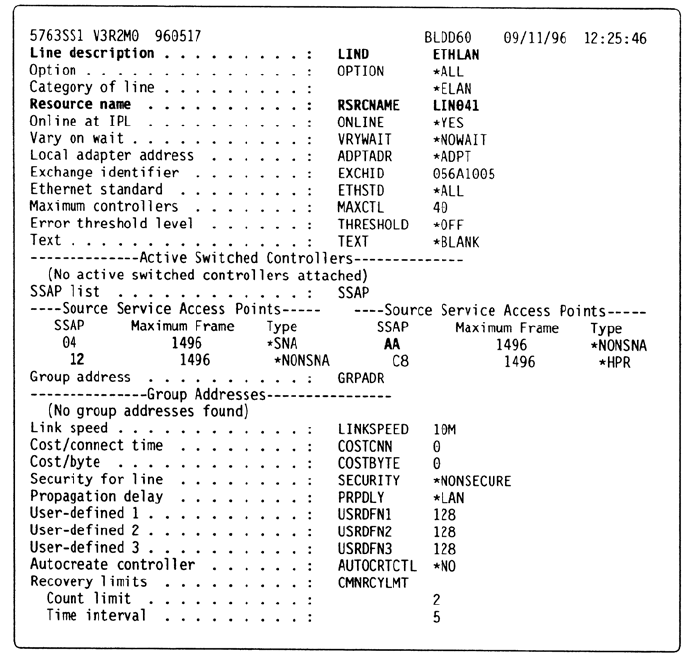
66
Figure 22 Example PrintNet Line Description
The following three parameters must be specified:
Line Description (LIND)
The line description name is the user's name for the AS/400 network printer. This name must be identical
to the name entered when the TCP/IP is configured on the AS/400.
Resource Name (RSRCNAME)
The system-assigned name for the interface (for example, LIN041).
SSAP
When *CALC is used, the values of “12” and “AA” are entered automatically as defaults. Verify that those
SSAP values have not been changed.
Configuring AS/400 for ASCII using TCP/IP
The next step is to configure the interface on the AS/400 for TCP/IP.
NOTE: The AS/400 interface is not the PrintNet. Do not set the AS/ 400 interface address to the same
address as the PrintNet IP address. Also, do not add the PrintNet to the AS/400 TCP/IP interface
list.

67
Configuring with ADDTCPIFC
ADDTCPIFC is used to add a TCP/IP interface to the AS/400. This step configures the AS/400 for
attachments to a TCP/IP network.
At the AS/400 command line, enter the following command:
ADDTCPIFC INTNETADR ('9.99.15.188') LIND(ETHLAN)
SUBNETMASK('255.255.255.0')
Your completed screen should look like Figure 23.
System: BLDD6
Internet address: 9.99.15.188
Subnet mask: 255.255.255.0
Line description: ETHLAN
Line type: *Elan
Interface status: Inactive
Type of service: *Normal
Maximum transmission unit: *Lind
Automatic start: *Yes
Figure 23 Example of ADDTCPIFC Interface
The following parameters must be specified:
Internet Address
Internet address of the AS/400 LAN printer.
NOTE: Do not use the IP address of the PrintNet.
Subnet Mask
The Subnet Mask for this AS/400 TCP/IP interface (for example, 255.255.255.0).
Line Description
The name assigned to the AS/400 line description as described in Developing Line Descriptions With
CRTLINETH on page 65.
NOTE: Each AS/400 LAN printer will have its own line description.
Configuring a Router Definition with ADDTCPRTE
If necessary, use the ADDTCPRTE command to create a route definition. This is required if the printer is
somewhere other than on a local segment and must cross bridges.
Configuring a Local Domain and Hostname
The AS/400 print commands, described in Setting Up Printing for ASCII Files on page 68, require a local
name and hostname. If you have already configured LAN attached TCP/IP printers on the AS/400
system, you will have a local domain name and hostname configured on the system.
68
NOTE: If you already have a local domain name and hostname configured on the system, do not change
your setup.
If the local domain name and hostname file is empty, the file must be set up. This control file information
is used to determine if a print request comes from an authorized host.
To configure the local domain and hostname, you will run the CFGTCP command and select Option “12”
from the menu. Enter a local domain name, such as city.company.com. Enter a local hostname, such
as as400-01. This is the name of your AS/400 system and must match the hostname for your system in
the host entry table. Refer to Configuring A TCP/IP Host Table Entry for more information.
NOTE: If the printer and AS/400 are not on the same local LAN segment, use CFGTCP Option 2 to verify
that there is a route defined in the TCP/IP route list.
Configuring A TCP/IP Host Table Entry
Although creating a TCP/IP host table entry is optional, it is a good idea to take this step. Add the AS/400
name and the IP address of the LAN printer to the “Host Table Entries.”
Configuring the AS/400 for Printing
To configure an AS/400 for printing, you must:
• set up the printing capability, and
• verify the setup with a print job.
You will need the following information:
Remote Printer Queue name
Set to ‘d1prn’ through ‘d8prn’.
NOTE: The Remote Printer Queue name must be in lowercase letters. Do not use “PASS.”
NOTE: When the IPDS feature is installed, the queue name ‘d4prn’ is not available.
IP Address
The IP address for the PrintNet.
Setting Up Printing for ASCII Files
The next step is to set up the remote printing capability. There are two ways to do this: you can either
specify the LPR parameters manually each time you send a file to the printer, or use Remote Writer and a
remote output queue for automatic printing to the printer.
To use LPR Manually
1.
Start TCP/IP, if it is not already running, by entering the command STRTCP.
2.
At the AS/400 command line, enter LPR.
3.
Figure 24 displays in bold the parameters you need to specify.

69
Send TCP/IP Spooled File (LPR)
Type choices, press Enter.
Remote system RMTSYS > *INTNETADR
Printer queue PRTQ > ‘d1prn’
Job name JOB *
User
Number
Spooled file number SPLNMBR *ONLY
Destination type DESTTYP *OTHER
Transform SCS to ASCII TRANSFORM *YES
Manufacturer type and model MFRTYPMDL > *IBM6400EP
Internet address INTNETADR > ‘9.99.2.3’
Figure 24 ASCII LPR Parameters
The following parameter values are required:
Remote System
Enter the hostname of your printer or *INTNETADR, which then prompts you to specify the IP address of
your printer.
Printer Queue (PRTQ)
Set to ‘d1prn’ through ‘d8prn’. The remote printer queue name must be in lowercase letters, entered
in single quotes.
NOTE: When the IPDS feature is installed, queue name ‘d4prn’ is not available.
Destination Type (DESTTYP)
Specify *OTHER for the DESTTYP parameter.
Transform (TRANSFORM)
Specify *YES.
Manufacturer Type and Model (MFRTYPMDL)
Select a manufacturer type and model. This is the name of the WSCO. Select *IBM6400EP for Epson
emulation or *IBM6400 or *IBM42023 for Proprinter Emulation if you have AS/400 V3R2 and above or
V3R7 and above.
NOTE: Select the Manufacturer Type Model based on the data type.
a.
Report printing, text only, no IGP or barcodes.
Manufacturer Type Model = *IBM42023
Workstation customizing object = *NONE
70
Since IBM42023 is a Printronix XL emulation, the printer emulation must also be switched to
Proprinter emulation. Be sure to save the printer emulation as the power-up configuration.
Alternate selection:
Manufacturer Type Model = *IBM6400EP
Workstation Customizing Object = *NONE
Since IBM6400EP is an Epson emulation, the printer emulation must be also switched to
Epson emulation. Be sure to save the printer emulation as the power-up configuration.
b.
PGL or VGL or PPI program.
Manufacturer Type Model = *WSCSTCONT132
Workstation Customizing Object = QWPDEFAULT
Library = QSYS
This selects a generic object that passes the data unchanged without any escape
codes to the printer. Text files will print in the currently selected printer
configuration, cpi, lpi, and form length. OS/400 versions below V3R7 may not
have this selection and may require manual creation of a generic WSCST. Please
contact Printronix Technical Support for assistance.
NOTE: For occasional text reports, create a printer configuration for each report and use the [Job Select]
key to select a report configuration.
Internet Address (INTNETADR)
The IP address of the PrintNet.
NOTE: You may specify either *INTNETADR (and the PrintNet IP address) or the hostname for the
PrintNet (if you added the printer to the host table entry as directed in Configuring A TCP/IP Host
Table Entry on page 68).
To Create an Automatic Remote Output Queue
1.
From the AS/400 command line, enter CRTOUTQ.
2.
Figure 25 displays in bold the parameters you need to specify.

71
Send TCP/IP Spooled File (LPR)
Type choices, press Enter.
Output queue OUTQ > USERNAME
Library
*CURLIB
Maximum spooled file size: MAXPAGES
Number of pages
*NONE
Staring time
Ending time
+ for more values
Order of files on queue SEQ *FIFO
Remote system RMTSYS > *INTNETADR
Remote printer queue
RMTPRTQ
> ‘d1prn’
Writer to autostart AUTOSTRWTR 1
Queue for writer messages MSGQ QSYSOPR
Library
*LIBL
Connection type CNNTYPE > *IP
Destination type DESTTYP *OTHER
Host print transform TRANSFORM *YES
Manufacturer type and model MFRTYPMDL > (See Note on
page 69)
Workstation Customizing Object WSCST > (See Note on
page 69)
Library
Internet address INTNETADR > ‘9.99.57.173’
Destination options DESTOPT *NONE
Print separator page SEPPAGE *YES
User defined option USRDFNOPT *NONE
Figure 25 Automatic Remote Output Queue Configuration
72
3.
Enter values for the following parameters:
Output Queue (OUTQ)
The name of the AS/400 output queue. The name can be anything you would like. This name is not the
same as the printer internal queue name, ‘d1prn’.
Remote System (RMTSYS)
Internet address of the PrintNet on the printer (*INTNETADR prompts you for this) or the hostname of the
PrintNet.
Remote Printer Queue (RMTPRTQ)
Default name of the network printer. Set for any of ‘d1prn’ through ‘d8prn’. The remote printer
queue name must be lowercase, entered in single quotes.
NOTE: When the IPDS feature is installed, queue name ‘d4prn’ is not available.
Writer to Autostart (AUTOSRTWTR)
Set the value to 1. This will start the Remote Writer when the queue is created, and it automatically starts
the Remote Writer after each IPL of the AS/400 and whenever STRTCP is started.
Connection Type (CNNTYPE)
Specify this value as *IP.
Destination Type (DESTTYP)
Specify *OTHER. *OTHER is a performance enhancement, in which data is not required to be
transformed again if the connection is interrupted and allows printing of multiple copies.
Transform (TRANSFORM)
Specify this value as *YES.
Manufacturer Type (MFRTYPMDL)
Select a manufacturer type and model. This is the name of the WSCO. Select *IBM6400EP for Epson
emulation or *IBM6400PR or *IBM42023 for Proprinter Emulation.
Troubleshooting
This installation procedure assumes that the PrintNet is configured with the correct IP address, subnet
mask, and gateway (if required). In addition you can also ping and telnet to the PrintNet.
Print an E-net Test Page to verify the Ethernet settings. See Printing an Ethernet Test Page on page 17.
The default PrintNet queue name is d1prn, however, the name can be changed. Substitute the changed
name for the RMTPRTQ parameter. To verify the queue name, print an E-Net Test Page or telnet to the
PrintNet and perform a “list dest” command.
Internet address (INTNETADR)
Specify the IP address of the printer.
73
Verify Printing on AS/400
This section verifies that the printer is capable of printing ASCII files and that the printer can be pinged on
the network.
To test ASCII printing:
1.
Start TCP/IP, if it is not already running, by entering the command STRTCP.
2.
Verify that the AS/400 TCP/IP interface is active.
3.
Ping the printer from an AS/400 workstation with the command:
ping ip_address.
Where ip_address is the Internet address of the remote system printer (the
PrintNet) or the hostname of the printer (if you put the hostname in the host entry table
as directed in Configuring A TCP/IP Host Table Entry on page 68).
4.
If the printer cannot be pinged, proceed to AS/400 ASCII Troubleshooting on
page 73.
5.
Use one of the following methods to send a spooled file to the printer:
• Enter the LPR command on the AS/400 command line with the appropriate parameters. See
To use LPR Manually on page 68.
• Enter STRRMTWTR name on the AS/400 command line, where name is the name of the
AS/400 remote output queue (not the printer Internet queue, as described on To Create an
Automatic Remote Output Queue on page 70).
• Use the WRKOUTQ command to send jobs.
AS/400 ASCII Troubleshooting
During power up, the printer performs an interface hardware test. The presence of the ETHERNET
PARAMS menu selection at the printer control panel indicates that the PrintNet hardware is functioning
properly. See the User's Manual for configuration menu information.
If you have trouble pinging the printer:
1.
Verify the configuration of the AS/400, including the printer and any intervening devices such as
routers and bridges.
2.
Verify that the AS/400 line description is varied on and the printer is turned on and displays an
ONLINE status.
3.
Verify that the AS/400 TCP/IP is active.
74

75
AS/400 Configuration, IPDS
Printer
Configuring on AS/400 as an IPDS Printer
NOTE: The IPDS emulation is not supported on the T4M printer.
Use this chapter to configure your printer on AS/400 as an IPDS printer. To print IPDS, you must install
the IPDS option on your printer. Once configured as an IPDS printer, the printer can also print AFP™ and
SCS, but these datastreams must be converted to IPDS first.
NOTE: Do not cancel IPDS print jobs by using WebPage cancel. To cancel IPDS print jobs hold the job
on the AS/400 writer or press the printer Cancel key.
Printing AFP, IPDS, and SCS Files
Printers configured as IPDS only print IPDS files. AFP and SCS files can be printed, but they must be
transformed to IPDS before printing.
• AFP files are transformed directly by Print Services Facility™ (PSF/400, an integrated feature of
OS/400), which then sends the transformed file to the printer.
• SCS files are transformed into IPDS by setting the IPDSPASTHR parameter to YES (see Figure 28
on page 80 or Figure 29 on page 82). This path yields the best performance by sending IPDS files
directly to the printer with no transform.
Requirements
Contact technical support to obtain the latest PTFs for PSF/400.
For IPDS printing, you also need to install the IPDS option for the printer.
Configuration Checklist
NOTE: All of the following configuration steps carried out on the AS/400 may require “create” or “change”
authority.
1.
If you have not already done so, set up the printer and install the PrintNet.
2.
Using the printer control panel, set up the parameters and values for IPDS.
3.
Set TCP/IP addresses for the printer, such as an IP Address, Gateway Address, or Subnet Mask.
See Configuration Tools on page 17.
4.
If the printer and AS/400 are not on the same LAN segment, verify there is a route defined in the
TCP/IP route list. If necessary, use the ADDTCPRTE command to create a route definition. You
need this if your printer is somewhere other than on a local segment.
5.
You need the PrintNet IP address to configure the PrintNet.
6.
If you have not done so yet, create a line description for your PrintNet. See Developing Line
Descriptions With CRTLINETH on page 65.
76
7.
Create or verify the existence of an AS/400 TCP/IP interface for PrintNet. See Configuring an
AS/400 TCP/IP Interface with ADDTCPIFC on page 76.
8.
The next step depends on your AS/400 release. Configure your printer with one of these procedures:
• Configuring PSF/400 for IPDS on V3R2 on page 77.
• Configuring PSF/400 for IPDS on V3R7 and Above on page 81.
9.
Notice that when the IPDS feature is installed, the queue name ‘dipdsprn’ displays in the print queue
in place of d4prn.
10.
Verify the printer is ON using the VFYCFG command.
11.
Verify that TCP/IP has been started using the STRTCP command.
12.
Test your configuration. See Verifying the IPDS Configuration on AS/400 on page 89.
13.
To share the printer on the network, verify that the necessary parameters have been
set correctly. See Sharing the AS/400 Printer on the Network on page 90.
14.
If you have problems, refer to AS/400 Troubleshooting on page 92.
Configuring an AS/400 TCP/IP Interface with ADDTCPIFC
NOTE: Do not enter the IP address of the PrintNet. Do not set the AS/400 interface address to the same
address as the PrintNet IP address. Also, do not add the PrintNet to the AS/400 TCP/IP interface
list.
Configuring An Interface For Ethernet
ADDTCPIFC is used to add a TCP/IP interface to AS/400. This step configures the AS/400 for
attachments to a TCP/IP network.
1.
At the AS/400 command line, enter the following command:
ADDTCPIFC INTNETADR ('9.99.15.188') LIND(ETHLAN)
SUBNETMASK('255.255.255.0')
2.
Your completed screen should look like Figure 26.
System: BLDD60
Internet address: 9.99.15.188
Subnet mask: 255.255.255.0
Line description: ETHLAN
Line type: *ELAN
Interface status: Inactive
Type of service: *NORMAL
Maximum transmission unit: *LIND
Automatic start: *YES
Figure 26 Example ADDTCPIFC Interface
77
3.
The following parameters must be specified:
a.
Internet Address
Internet address of the AS/400 Ethernet LAN printer.
NOTE: Do not use the IP address of the PrintNet.
b.
Subnet Mask
The Subnet Mask for this AS/400 TCP/IP interface (for example, 255.255.255.0).
c.
Line Description
The name assigned to the AS/400 line description as described in Developing
Line Descriptions With CRTLINETH on page 65. Each AS/400 LAN printer will
have its own line description.
Configuring a TCP/IP Host Table Entry
Although optional, it is recommended that you create a TCP/IP host table entry. Add the AS/400 name
and the IP address of the LAN printer to the “Host Table Entries.” Also, add the hostname and IP address
of the printer to the list. You can access the host table entries function by using the CFGTCP command,
then selecting option 10 from the menu.
You can also add entries to your host table for both the hostname and the fully qualified network name for
your system. The entry name should match the name you configured for host and domain. For example, if
your hostname is “RCHASM03” and your domain name is “RCHLAND.PTX.COM”, your fully qualified
network name is “RCHASM03.RCHLAND.PTX.COM”. In your host entry table, enter both RCHASM03
and RCHASM03.RCHLAND.PTX.COM.
Configuring PSF/400 for IPDS on V3R2
To configure IPDS on AS/400 V3R2, use the following commands:
• CRTDEVPRT
• CRTPSFCFG
Configuring PSF with CRTDEVPRT on V3R2
This section describes how to create a printer device description.
1.
At the AS/400 command line, enter a command in the form:
CRTDEVPRT DEVD(printer_type) DEVCLS(*RMT) TYPE(*IPDS) MODEL(0) AFP(*YES)
AFPATTACH(*APPC) FONT(11) RMTLOCNAME(TCPIP) FORMFEED(*CONT)
TEXT(‘printer_type NETWORK PRINTER’)
Where printer_type (e.g., P8000) is the model of your printer.
2.
A completed screen looks like the example shown in Figure 27 on page 78.

78
Display Device Description
Device Description: DEVD printer_type
Option: OPTION *ALL
Category of device:
*PRT
Automatically created:
NO
Device class: DEVCLS *RMT
Device type: TYPE *IPDS
Device model: MODEL 0
Advanced function printing: AFP *YES
AFP attachment: AFPATTACH *APPC
Online at IPL: ONLINE *YES
Font: FONT
Identifier:
011
Point size:
*NONE
Form feed: FORMFEED *CONT
Separator drawer: SEPDRAWER *FILE
Separator program: SEPPGM *NONE
Library:
Printer error message: PRTERRMSG *INQ
Message queue: MSGQ QSYSOPR
Library:
*LIBL
Maximum pending requests: MAXPNDRQS 6
Print while converting: PRTCVT *YES
Print request timer: PRTRQSTMR *NOMAX
Form definition: FORMDF F1C10110
Library: *LIBL
Character identifier: CHRID *SYSVAL
Remote location: RMTLOCNAME TCPIP
Local location: LCLLOCNAME *NETATR
Remote network identifier: RMTNETID *NETATR
Mode: MODE QSPWTR
Dependent location name: DEPLOCNAME *NONE
Text: TEXT ‘printer_type
Network Printer’
Figure 27 Example of CRTDEVPRT Command (V3R2)
79
3.
Values must be entered for the following parameters:
a.
Device Description (DEVD)
The device description or name. This value must match the value entered for the PSFCFG
parameter in Configuring AFP with CRTPSFCFG on V3R2 on page 79.
b.
Device Class (DEVCLS)
Specify *RMT.
c.
Device Type (TYPE)
Specify *IPDS.
d.
Device Model (MODEL)
Specify 0.
e.
Advanced Function Printing (AFP)
Specify *YES.
f.
AFP Attachment (AFPATTACH)
Specify *APPC. CRTPSFCFG overrides this value.
g.
Font (FONT)
Enter an appropriate value.
h.
Form Feed (FORMFEED)
Specify *CONT.
i.
Remote Location (RMTLOCNAME)
Enter the remote location name.
Configuring AFP with CRTPSFCFG on V3R2
The PSF™ configuration object created with this command is used by PSF/400 when printing IPDS files.
The object is used by AS/400 V3R2 only if the object is in the QGPL library and has the same name as
the printer device description. This information overrides the APPC configuration information specified in
the printer device description.
To configure AS/400 for IPDS printing on V3R2:
1.
At the AS/400 command line, enter a command in the form:
CRTPSFCFG PSFCFG(printer_type IPDSPASTHR(*YES)
RLSTMR(*SEC15) TEXT(‘printer_type NETWORK PRINTER’)
RMTLOCNAME(‘128.99.12.134’)
PORT(5001)
where printer_type (e.g., P8000) is the model of your printer.
2.
A completed screen looks like Figure 28.

80
PSF configuration: printer_type
Library: QGPL
User resource library: *JOBLIBL
IPDS pass through: *YES
Activate release timer: *NORDYF
Release timer: *SEC15
Restart timer: *IMMED
SNA retry count: 2
Delay time between retries: 0
Blank page: *YES
Page size control: *NO
Resident fonts: *YES
Resource retention: *YES
Edge orient: *NO
Remote location:
Name or address: 128.99.12.134
TCP/IP port: 5001
TCP/IP activation timer: 170
PSF defined options:
Text description: printer_type Network Printer
Device resource library list: *DFT
Figure 28 Example CRTPSFCFG Command (V3R2)
3.
The following parameters are required:
a.
PSF Configuration (PSFCFG)
The name of the printer device you are configuring.
b.
Library
Specify QGPL.
c.
IPDS pass through (IPDSPASTHR)
To print SCS files, specify *YES. PSF/400 transforms SCS into IPDS before printing.
d.
Activate release timer (ACTRLSTMR)
Specifies the point at which the release timer (RLSTMR) is activated. Set to
*NORDYF. This means that the release timer is activated when there are no
spooled files in the printer’s output queue with a status of RDY and the last page
81
of the last spooled file processed has printed.
*NORDYF is used so that all files with a status of RDY are printed before
releasing the session (which does not terminate the writer, however).
e.
Release timer (RLSTMR)
Specifies the amount of time to wait before a session or dialog is released without
terminating the writer. The ACTRLSTMR parameter specifies when this timer is to
be activated. Set the parameter to a value at least equal to the TIMEOUT value on
the printer. The recommended value is
*SEC15.
f.
Remote Location name or address (RMTLOCNAME)
Enter the IP address or hostname of the printer.
g.
TCP/IP port (PORT)
Specify 5001.
h.
TCP/IP activation time (ACTTMR)
This value specifies the number of seconds that PSF/400 waits for a printer to
respond to an activation request. If only one system is using the printer, use the
default value (170 seconds). If more than one system is using the printer, specify
*NOMAX, which causes PSF/400 to wait indefinitely for a response to an
activation request.
Configuring PSF/400 for IPDS on V3R7 and Above
To configure IPDS on AS/400 V3R7 and above, use the following commands:
• CRTPSFCFG (Optional)
• CRTDEVPRT
Configuring AFP with CRTPSFCFG on V3R7 or V4R1 (Optional)
New for V3R7 is the ability to specify three TCP/IP-related parameters for PSF in a printer device
description: RMTLOCNAME, PORT, and ACTTMR. In V3R2, CRTPSFCFG, which replaced WRKAFP2, was
used to specify these same parameters, along with other parameters. In V3R7 and higher, these three
parameters are ignored when specified in a PSF configuration object, since they are specified in a printer
device description. However, you may wish to use a PSF configuration object to specify other
parameters, such as IPDS passthrough and so on.
The PSF configuration object created with this command is used by PSF/400 when printing IPDS files
only if the object is specified with the USRDFNOBJ parameter in the printer device description.
To configure AS/400 for IPDS printing on V3R7 or V4R1:
1.
At the AS/400 command line, enter a command in the form:
CRTPSFCFG PSFCFG(AFP/printer_typeNETPRT)
IPDSPASTHR(*YES) RLSTMR(*SEC15)
TEXT(‘printer_type NETWORK PRINTER’)
where printer_type (e.g., P8000) is the model of your printer.
2.
A completed screen looks like Figure 29.

82
PSF Configuration Information
PSF configuration: printer_typeNETPRT Library: AFP
User resource library: *JOBLIBL
IPDS pass through: *YES
Activate release timer: *NORDYF
Release timer: *SEC15
Restart timer: *IMMED
SNA retry count: 2
Delay time between retries: 0
Blank page: *YES
Page size control: *NO
Resident fonts: *YES
Resource retention: *YES
Edge orient: *NO
Remote location:
Name or address: *NONE
TCP/IP port: *NONE
TCP/IP activation timer: 170
PSF defined options:
*NONE
Text description: printer_type Network
Device resource library list: *DFT
Figure 29 Example CRTPSFCFG Command (V3R7 or V4R1)
NOTE: The lines in bold in Figure 29 are not used by PSF/400. Instead, PSF/400 uses the information
entered in the device description screen.
3.
The following parameters are recommended:
a.
PSF configuration (PSFCFG)
The name used for this PSF configuration object. The name must match the user-defined
object name (USRDFNOBJ) in the printer DEVD.
b.
IPDS pass through (IPDSPASTHR)
To print SCS files, specify *YES, PSF/400 transforms SCS into IPDS before printing.
c.
Activate release timer (ACTRLSTMR)
Specifies the point at which the release timer (RLSTMR) is activated. Set to *NORDYF.

83
d.
Release timer (RLSTMR)
Specifies the amount of time to wait before a session or dialog is released without terminating
the writer. The ACTRLSTMR parameter specifies when this timer is to be activated. Set the
parameter to a value at least equal to the TIMEOUT value on the printer. The recommended
value is
*SEC15.
Configuring PSF with CRTDEVPRT on V3R7 and Above
This section describes how to create a printer device description.
1.
At the AS/400 command line, enter a command in the form:
CRTDEVPRT DEVD(printer_type) DEVCLS(*LAN) TYPE(*IPDS)
MODEL(0) LANATTACH(*IP) AFP(*YES) PORT(5001)
FONT(11) FORMFEED(*CONT)
RMTLOCNAME(‘128.9.12.134’)
USRDFNOBJ(AFP/5000NETPRT *PSFCFG)
TEXT(‘printer_type NETWORK PRINTER’)
Where printer_type (e.g., P8000) is the model of your printer.
NOTE: Only use the USRDFNOBJ parameter if it was defined in the previous procedure. See
Configuring AFP with CRTPSFCFG on V3R7 or V4R1 (Optional) on page 81.
2.
A completed screen looks like the example shown in Figure 30.
Display Device Description
5716SS1 V3R7M0 961108 BLDRB1
Device Description: DEVD printer_type
Option: OPTION *ALL
Category of device:
*PRT
Device class: DEVCLS *LAN
Device type: TYPE *IPDS
Device model: MODEL 0
LAN attachment: LANATTACH *IP
User-defined object: USRDFNOBJ printer_type NETPRT
Library:
AFP
Object type:
*PSFCFG
Data transform program: USRDTATFM *NONE
User-defined driver program: USRDRVPGM *NONE
Advanced function printing: AFP *YES
Port number: PORT 5001
Online at IPL: ONLINE *YES
Font: FONT

84
Identifier:
011
Point size:
*NONE
Form feed: FORMFEED *CONT
Separator drawer: SEPDRAWER *FILE
Separator program: SEPPGM *NONE
Library:
Printer error message: PRTERRMSG *INQ
Message queue: MSGQ QSYSOPR
Library:
*LIBL
Activation timer: ACTTMR 170
Maximum pending requests: MAXPNDRQS 6
Print while converting: PRTCVT *YES
Print request timer: PRTRQSTMR *NOMAX
Form definition: FORMDF F1C10110
Library:
*LIBL
Remote location: RMTLOCNAME
Name or address:
128.9.12.134
Dependent location name: DEPLOCNAME *NONE
Text: TEXT printer_type
Network Printer
User-defined options: USRDFNOPT
Figure 30 Example CRTDEVPRT Command (V3R7 and above)
3.
Values must be entered for the following parameters:
a.
Device Description (DEVD)
The device description or name.
b.
Device Class (DEVCLS)
Specify *LAN
c.
Device Type (TYPE)
Specify *IPDS
d.
Device Model (MODEL)
Specify 0
e.
LAN Attachment (LANATTACH)
Specify *IP
85
f.
Port Number (PORT)
Specify 5001
g.
Font (FONT)
Enter an appropriate value.
h.
Form Feed (FORMFEED)
Specify *CONT
i.
Activation Timer (ACTTMR)
This value specifies the number of seconds that PSF/400 waits for a printer to
respond to an activation request. If only one system is using the printer, use the
default value (170 seconds). If more than one system is using the printer, specify
*NOMAX, which causes PSF/400 to wait indefinitely for a response to an
activation request.
j.
Remote Location (RMTLOCNAME)
Enter the IP address or hostname of the printer.
k.
User-Defined Object (USRDFNOBJ)
To use a PSF configuration object, specify its name and library here. This object
type must be *PSFCFG. For V3R7 and higher, a single PSF configuration object
may be referenced by multiple device descriptions, if required.
Configuring PSF for IPDS on V4R2 and Above
To configure IPDS on the iSeries V4R3, use the following commands:
• CRTDEVPRT
• CRTPSFCFG (Optional)
Configuring AFP with CRTPSFCFG on V4R3 and Above (Optional)
To configure the iSeries for IPDS printing on V4R3:
1.
At the iSeries command line, enter a command in the form:
CRTPSFCFG PSFCFG(AFP/NETPRTP8000) IPDSPASTHR(*YES) RLSTMR(*SEC15)
TEXT(‘PRINTRONIX P8000 NETWORK ATTACHED PRINTER’) PAGSIZCTL(*YES)
ACTRLSTMR(*NORDYF)
2.
A completed screen looks like Figure 31.

86
Create PSF Configuration (CRTPSFCFG)
PSF configuration ....................
Name
Library .................................
>*CURLIB
Name, *CURLIB
User resource library list ............
*JOBLIBL
*JOBLIBL, *CURLIB, *NONE
Device resource library list .........
*DFT
Name, *DFT
+ for more values
IPDS pass through ...................
>*NO
*NO, *YES
Activate release timer.................
*NORDYF
*NORDYF, *IMMED...
Release timer ............................
>*NOMAX
1-1440, *NOMAX, *SEC15...
Restart timer...............................
*IMMED
1-1440, *IMMED
APPC and TCP/IP retry count ....
15
1-99, *NOMAX
Delay between APPC retries......
90
0-999
Acknowledgment frequency .......
100
1-32767
Printer response timer
*NOMAX
5-3600, *NOMAX
Generate PDF output
*NONE
*NONE, SPLF, *STMF, *MAIL
Text 'description' ......................
>*BLANK
Additional Parameters
Automatic session recovery:
Enabled ................................
*NO
*NO, *YES
Message option ....................
*INFO, *INQ
Blank page .................................
*YES
*YES, *NO
Page size control.....................
>*YES
*NO, *YES
Resident fonts ...........................
*YES
*YES, *NO
Resource retention ....................
*YES
*YES, *NO
Edge orient ...............................
*NO
*YES, *NO
Use outline fonts....................... *NO *YES, *NO
PSF defined option...................
*NONE
+ for more values
Font substitution messages......
*YES
*YES, *NO
Capture host fonts at printer .....
*NO
*NO, *YES
Font resolution for formatting ...
*SEARCH
*SEARCH, 240, 300
Font mapping table...................
*NONE
Name, *NONE
Library..................................
Name
Cut sheet emulation mode ........
*NONE
*NONE, *CHKFIRST, *CHKALL
Use DBCS simulation fonts
*NO
*YES, *NO
Replace .....................................
*YES
*YES, *NO
Authority ....................................
*LIBCRTAUT
Name, *LIBCRTAUT,
*CHANGE...
Figure 31 Example CRTPSFCFG Command (V4R2 and above)
3.
The following parameters are recommended: PSF configuration (PSFCFG)
The name used for this PSF configuration object. The name must match the user-defined object name
(USRDFNOBJ) in the printer DEVD.

87
PSF configuration (PSFCFG)
The name used for this PSF configuration object. The name must match the user-defined object name
(USRDFNOBJ) in the printer DEVD.
IPDS pass through (IPDSPASTHR)
To print SCS files, specify *YES, PSF transforms SCS into IPDS before printing.
Release timer (RLSTMR)
Specifies the amount of time to wait before a session or dialog is released without terminating the writer.
The ACTRLSTMR parameter specifies when this timer is to be activated. Set the parameter to a value at
least equal to the TIMEOUT value on the printer. Printronix recommends *SEC15.
Page size control (PAGSIZCTL)
Specifies if the page size (forms) is set by PSF. Usually set to
*YES.
Remote Location name or address (RMTLOCNAME)
Enter the IP address or hostname of the printer.
Configuring PSF with CRTDEVPRT on V4R2 and Above
This section describes how to create a printer device description.
1.
At the iSeries command line, enter a command in the form:
CRTDEVPRT DEVD(P8000) DEVCLS(*LAN) TYPE(*IPDS) MODEL(0)
LANATTACH(*IP) AFP(*YES) PORT(5001) FONT(11) FORMFEED(*CONT)
RMTLOCNAME(‘128.9.12.134’)
USRDFNOBJ(AFP/NETPRTP8000 *PSFCFG) TEXT(‘Printronix P8000 NETWORK
PRINTER’)
Only use the USRDFNOBJ parameter if it was defined in the previous procedure.
A completed screen looks like the example shown in Figure 32.
Create Device Desc (Printer) (CRTDEVPRT)
Device description.........................:
>P8000
Name
Device class ................................... :
>*LAN
*LCL, *RMT, *VRT, *SNPT, *LAN
Device type..................................... :
>*IPDS
3287, 3812, 4019, 4201...
Device model..................................:
>0
0, 1, 2, 3, 4, 10, 13, 301...
LAN attachment ............................. :
>*IP
*LEXLINK, *IP, *USRDFN
Advanced function printing ..............
*YES
*NO, *YES
Port number ................................... :
>5001
0-65535
Online at IPL .................................... :
*YES
*YES, *NO
Font:
Identifier ....................................
>011
3, 5, 11, 12, 13, 18, 19...
Point size....................................
*NONE
000.1-999.9, *NONE
Form feed ........................................
*CONT
*TYPE, *CONT, *CONT2, *CUT...
Separator drawer .............................
*FILE
1-255, *FILE
Separator program...........................
*NONE
Name, *NONE
Library ........................................
Name, *LIBL, *CURLIB
Printer error message ......................
*INQ
*INQ, *INFO
Message queue ...............................
*CTLD
Name, *CTLD, *SYSOPR, QSYSOPR
Library ........................................
Name, LIBL, *CURLIB

88
Activation timer ................................
170
1-2550, *NOMAX
Image configuration .........................
*NONE
*NONE, *IMGA01, *IMGA02...
Maximum pending requests.............
6
1-31
Print while converting.......................
*YES
*NO, *YES
Print request timer ...........................
*NOMAX
1-3600, *NOMAX
Form definition .................................
F1C10110
Name
Library ........................................
*LIBL
Name, *LIBL, *CURLIB
Remote location:
Name or address ......................
User-defined options........................
*NONE
Character value, *NONE
+ for more values
User-defined object:
Object ........................................
*NONE
Name, *NONE
Library .................................
Name, *LIBL, *CURLIB
Object type................................
*DTAARA, *DTAQ, *FILE...
Data transform program...................
*NONE
Name, *NONE
Library ........................................
Name, *LIBL, *CURLIB
User-defined driver program............
*NONE
Name, *NONE
Library ........................................
Name, *LIBL, *CURLIB
Secure connection ...........................
*NO
*NO, *YES
Validation list ....................................
*NONE
Name, *NONE
Library ........................................
Name, *LIBL, *CURLIB
Publishing information:
Support duplex...........................
*UNKNOWN
*UNKNOWN, *SIMPLEX, *DUPLEX
Support color..............................
*UNKNOWN
*UNKNOWN, *NOCOLOR, *COLOR
Pages per minute black .............
*UNKNOWN
1-32767, *UNKNOWN
Pages per minute color ..............
*UNKNOWN
1-32767, *UNKNOWN
Location .....................................
*BLANK
Data steams supported..............
*UNKNOWN
*UNKNOWN, *PCL, *PS, *PDF
+ for more values
Text ‘description’
*BLANK
Additional Parameters
Remote network identifier................
*NETATR
Name, *NETATR, *NONE
Workstation customizing object .......
*NONE
Name, *NONE
Library ........................................
Name, *LIBL, *CURLIB
Authority ..........................................
*ALL
Name, *LIBCRTAUT, *CHANGE...
Figure 32 Example CRTDEVPRT Command (V4R2 and above)
2.
Values must be entered for the following parameters:
Device Description (DEVD)
The device description or name.
Device Class (DEVCLS)
Specify *LAN.
Device Type (TYPE)
Specify *IPDS.
89
Device Model (MODEL)
Specify 0.
LAN attachment (LANATTACH)
Specify *IP.
Port number (PORT)
Specify 5001.
Font (FONT)
Enter an appropriate value.
Form Feed (FORMFEED)
Specify *CONT.
Activation timer (ACTTMR)
This value specifies the number of seconds that PSF waits for a printer to respond to an activation
request. If only one system is using the printer, use the default value (170 seconds). If more than one
system is using the printer, specify *NOMAX, which causes PSF to wait indefinitely for a response to an
activation request.
Remote Location (RMTLOCNAME)
Enter the IP address or hostname of the printer.
User-Defined Object (USRDFNOBJ)
To use a PSF configuration object, specify its name and library here. This object type must be *PSFCFG.
For V3R7 and higher, a single PSF configuration object may be referenced by multiple device
descriptions, if required.
Verifying the IPDS Configuration on AS/400
To test IPDS printing:
1.
If it is not already on, vary on the line description:
VRYCFG CFGTYPE(*LIN)
2.
To start TCP/IP, enter STRTCP.
3.
Verify that the AS/400 TCP/IP interface is active. Use the command:
WRKTCPSTS
and then select option 1.
4.
Turn the printer on and wait until the printer control panel displays “ETHERNET IS READY.”
5.
To verify the printer is connected to AS/400, ping the printer from an AS/400 workstation with
one of the following commands:
PING ip_address
or
PING hostname
where ip_address is the Internet address of the remote system printer (the PrintNet), and
hostname is the hostname you defined for the printer, if any.
• If the ping is not successful, refer to Cannot PING the Printer on page 92.

90
• If the ping is successful, vary on the printer device description with the command:
VRYCFG (printer_device) CFGTYPE(*DEV)
STATUS(*ON)
6.
To use PSF/400 to send an IPDS file to the printer, enter:
STRPRTWTR DEV (printer_device)
where printer_device is the name of the printer.
7.
If you have problems printing, do the following:
• Print an Ethernet Test Page. Refer to your User's Manual.
• Verify that port number 5001 is being used.
8.
If you are still unable to print IPDS files, contact technical support.
Sharing the AS/400 Printer on the Network
To support printer sharing, your printer automatically switches among all attached ports (serial,
twinax/coax, LAN). Basically, the printer prints jobs for one port until no new jobs appear and the port
“times out.” The printer then switches to the next port and does the same thing.
To change the default “time out” value for a port, update the TIMEOUT value for the port on the
appropriate menu (Serial Interface, Ethernet Parameters, Twinax Interface, or Coax Interface).
Printer Sharing Parameters
To set up AS/400 for printer sharing, set the following parameters.
Table 3 Printer Sharing
AS/400
Version
Where Set
Parameter Recommended
Value
Description
V3R2 CRTPSFCFG
CHGPSFCFG
RLSTMR *NORDYF Specifies the point at
which the release timer
(RLSTMR) is activated.
Set to *NORDYF. This
means that the release
timer is activated when
there are no spooled files
in the printer’s output
queue with a status of
RDY and the last page of
the last spooled file
processed has printed.
*NORDYF is used so that
all files with a status of
RDY are printed before
releasing the session
(which does not
terminate the writer).

91
Table 3 Printer Sharing
AS/400
Version
Where Set
Parameter Recommended
Value
Description
V3R2 CRTPSFCFG
CHGPSFCFG
ACTRLSTMR *SEC15 Specifies the amount of
time to wait before a
session or dialog is
released without
terminating the writer.
The ACTRLSTMR
parameter specifies
when this timer is to be
activated. Set the
parameter to a value at
least equal to the
TIMEOUT value on the
printer. The
recommended value is
*SEC15
V3R2 CRTPSFCFG
CHGPSFCFG
ACTTMR *NOMAX The value specifies the
number of seconds that
PSF/400 will wait for a
printer to respond to an
activation request. If
only one system will be
using the printer, use the
default value (170
seconds). If more than
one system will be using
the printer, set the value
to *NOMAX, which
causes PSF/400 to wait
indefinitely for a
response to an activation
request.
V3R7
V4R1
CRTPSFCFG
CHGPSFCFG
ACTRLSTMR *NORDYF Specifies the point at
which the release timer
(RLSTMR) is activated.
Set to *NORDYF. This
means that the release
timer is activated when
there are no spooled
files in the printer’s
output queue with a
status of RDY and the
last page of the last
spooled file processed
has printed. *NORDYF is
used so that all files with
a status of RDY are
printed before releasing
the session (which does
not terminate the
writer)

92
Table 3 Printer Sharing
AS/400
Version
Where Set
Parameter Recommended
Value
Description
V3R7
V4R1
CRTPSFCFG
CHGPSFCFG
RLSTMR *SEC15 Specifies the amount of
time to wait before a
session or dialog is
released without
terminating the writer.
The ACTRLSTMR
parameter specifies
when this timer is to be
activated. Set the
parameter to a value at
least equal to the
TIMEOUT value on the
printer. The
recommended value is
*SEC15
V3R7
V4R1
CRTDEVPRT
CHGDEVPRT
ACTTMR *NOMAX The value specifies the
number of seconds that
PSF/400 will wait for a
printer to respond to an
activation request. If
only one system will be
using the printer, use the
default value (170
seconds). If more than
one system will be using
the printer, set the value
to *NOMAX, which
causes PSF/400 to wait
indefinitely for a
response to an activation
request.
AS/400 Troubleshooting
Use this section to resolve problems configuring AS/400 on TCP/IP networks.
Cannot PING the Printer
If you have problems trying to ping the printer:
• Verify the configuration of AS/400, including the printer and any intervening devices such as routers
and bridges.
• Verify that the AS/400 line description is varied on and the printer is turned on and displays a status
of ONLINE.
• Verify that the AS/400 TCP/IP interface is active.
93
PSF/400 Terminates when Initialized
If PSF/400 terminates when you initialize it for IPDS printing and issues message PQT3603, check for the
following error codes:
• Code 10 means an incorrect RMTSYS or RMTLOCNAME (V3R2, V3R7, or V4R1) has been specified
for the printer.
• Code 15 means that PSF/400 timed out waiting for the printer’s response. Check the value you
entered for Activation Timer when using WRKAFP2, CRTPSFCFG (V3R2), or CRTDEVPRT (V3R7 or
V4R1).
• Codes 20-39 indicate a general communications failure. Make sure all of the components in your
network are operational, such as routers. If necessary, call Printronix technical support.
• Codes 40-59 indicate a logic error between PSF and the printer control unit. Contact Printronix
technical support.
Spooled Print File Remains in PND Status
Check the output queue with the command:
WRKOUTQ queuename
This typically indicates that PSF/400 is waiting for a response from the printer. This can be verified by
displaying the QSPL subsystem, WRKACTJOBSBS (QSPL). If the status of the PDJ job for the printer is
SELW, then PSF/400 is waiting for a response from the printer. Make sure that the printer is in ONLINE
mode and that all network connections (for example, routers) between the AS/400 and the printer are
active.
Spooled Files Disappear without Printing
To resolve this problem:
• Check that the correct printer queue name and correct IP address have been used.
• Ping the IP address. If the ping is successful, disconnect the network cable from the printer/print
server, and ping the address again. If the ping is still successful, there is another printer with that
IP address on the network.
Data is Being Clipped
To resolve this problem, you may want to set the PSC (Page Size Control) parameter to *YES in the
CRTPSFCFG command (V3R2, V3R7, or V4R1).
94

95
z/OS Configuration,
TN3270E
z/OS Configuration for a TN3270E Printer
The following configuration information shows how a line matrix printer can be configured on z/OS and
Info Print Server to print TN3270E. Modtabs are provided for both an SCS and DSC printer. The z/OS
level is 1.3.
These basic configurations provided a starting point for users new to printing in this manner.
NOTE: Since Info Print Server (IPS) treats the TN3270E printer as a COAX attached printer, additional
COAX feature for IPS is required.
Coax Printer Support FMID
Coax Printer Support consists of the following FMID:
HPRT100
Program Materials
A program is identified by a program number and a feature number. The program number for Coax
Printer Support is 5697-F51.
Additional information regarding the telnet server and Info Print Server can be found in the following
manuals.
• For z/OS V1R2 and above, the TCPIP information can be found in SG24-5227-3, Communications
Server for z/OS V1R2 TCP/IP Implementation Guide.
• InfoPrint Server Customization Guide, S544-5744-03.
• InfoPrint ServerOperation and Administration, S544-5745-03.
1. Look at the JES definition defining and associating printer, PRINTER9 with INFOPRINT SERVER.
/* PRT9 AND FSSDEF FOR LINE MATRX 06/27/97 MM */
PRINTER9 CLASS=K,SEP,NOMARK,MODE=FSS,FSS=PRINTWAY,
X
PRMODE=(LINE,PAGE),WS=(W,Q),SETUP=NOHALT,START=NO
/* ASSOCIATE PRINTWAY WITH ITS START UP PROCEADURE
*/
FSS(PRINTWAY) PROC=COURWTR,AUTOSTOP=YES
Figure 33 JES Definition Defining PRINTER9
96
Figure 34 Example Of Proc Used To Start INFOPRINT Server
Figure 35 Example Of The APPLID That Represents A Copy Of IPS
VTAM Definitions for SCS and DSE TN3270E
The following are VTAM definitions for SCS and DSE TN3270E printers.
NOTE: These definitions are identical to those of COAX attached printers.
Figure 36 MODTAB Entries
//COURWTR PROC
//* -------------------------------------------------------------*
//IEFPROC EXEC PGM=ANFFIEP,REGION=3M,PARM='INV=AOP1' z/OS4 INV
//STEPLIB DD DSN=IPPW.PW311.SANFLOAD,DISP=SHR
//ANFQUEUE DD DSN=ANDREE.z/OS4.QUEUE,DISP=SHR
//ANFMMSG DD DSN=ANDREE.z/OS4.MSGFILE,DISP=SHR
//SYSPRINT DD SYSOUT=*
//SYSABEND DD SYSOUT=*
//SYSUDUMP DD SYSOUT=*
//
NETSPL1 VBUILD TYPE=APPL
*
*
APPL REPRESENTING IPS
*
APIPP101 APPL MODETAB=MODETAB1,DLOGMOD=SCS,AUTH=(ACQ)
LUPRT101 APPL MODETAB=MODETAB1,DLOGMOD=SCS
APPL AUTH=(ACQ),EAS=1,PARSESS=NO,SESSLIM=YES,
MODETAB=MODETAB1,DLOGMOD=SCS
*
* LU3 Printer
APPL AUTH=(ACQ),EAS=1,PARSESS=NO,SESSLIM=YES,
MODETAB=MODE4245,DLOGMOD=LU3PRT
********************************************
* JES2 TN3270E VTAM MAJOR NODE *
********************************************
*
* LU1 Printer
MODETAB=MODETAB1 DLOGMOD=SCS
97
*
PRINTER
WITH SNA CHARACTER SET (LU_1)
**********************************************************************
**************************************************
MODEENT
LOGMODE=SCS,FMPROF=X'03',TSPROF=X'03',PRIPROT=X'B1',
*
*
*
PSNDPAC=X'01',SRCVPAC=X'01'
TITLE 'DSC4K'
*
*
*
@DA22961*
DSC PRINTER (LU_3)
**********************************************************************
***************************************************
LU3PRT
MODEENT LOGMODE=LU3PRT,FMPROF=X'03',TSPROF=X'03',
PRIPROT=X'B1',SECPROT=X'20',COMPROT=X'3080', X
X
PSNDPAC=X'80',PSERVIC=X'03800000000018502B507F00'
*
*
*

98
TCPIP Configuration with TN3270E
The following is the portion of the system’s TCPIP configuration involved with TN3270E printers.
NOTE: Only additions required for the TN3270E printers are shown.
;
; Define the VTAM parameters required for the Telnet server.
;
BeginVTAM
;
PRTGROUP PGRPLU1
RMT2
ENDPRTGROUP
PRTGROUP PGRPLU3
RMT3
ENDPRTGROUP
IPGROUP TESTPRT
9.99.98.62
ENDIPGROUP
IPGROUP TESTPRT3
9.99.98.67
ENDIPGROUP
PRTMAP PGRPLU1 TESTPRT GENERIC
PRTMAP PGRPLU3 TESTPRT3 GENERIC
; End telnet printer section
EndVTAM
99
Printer Inventory Manager as Defined with TN3270E
The following screens show areas of the Printer Inventory Manager involved with the definition of the
TN3270E printers.
1.
At main panel, select option 4 to look at the FSS definition.
2.
Select option 5 from this panel to list the FSSs.
InfoPrint Server: Printer Inventory Manager
Option
===>
Printer
Definitions
Add a printer definition
List printer definitions
Select printer definitions to list
Other
Functions
Manage other inventory definitions
PrintWay Queue View IP PrintWay transmission queue
6 PrintWay Message View IP PrintWay message log
7 Configure Change panel configuration
Printer Definition List
Row 17 of 23
FSA, FSS, and Pool Management
Option ===>
FSA
1
Add
Add an FSA
2
List
List FSAs
3
Select
Select FSAs to list
FSS
4
Add
Add an FSS
5
List
List FSSs
6
Select
Select FSSs to list
Pool of Printer Definitions
7 Add Add a Pool
8
List
List Pools
9
Select
Select Pools to list

100
3.
From the panel below, browse the PRINTWAY FSS to see how the TN3270E FSS
was defined.
The panel below shows how the FSS (PRINTWAY) is associated with its VTAM Applid APIPP101.
4.
Next look at the printer definition for the DSE (LU_3) printer in the printer inventory.
5.
Select option 2 from the Printer Inventory Manager main panel, to list the printers.
Command ===>
FSS List
Row 1 of 3
Scroll ===> HALF
Actions:
A-Add B-Browse C-Copy D-Delete E-Edit
A FSS Name Type Description
= ======== ====
==============================================================
B
PRINTWAY IPPW APPLID for TN3270E Printers APIPP101
IPPW Howard's PrintWay FSS
WTRES700 PSF Howard's FSS
************************** Bottom of data**************************
Browse
Command ==>
IP PrintWay FSS
FSS name. . . PRINTWAY
Description . APPLID for TN3270E Printers APIPP101
(extend)
Old-style translation
Hiperspace
blocks . .
TCP/IP
job name . . .
Document
code page. .
Applid.
. . . . . . . APIPP101
National
language . . 1 1. English 2. Japanese
Trace
mode. . . . . . 1 1. None 2. Internal 3. No printing 4. Full
Trace prompt
Trace table size .
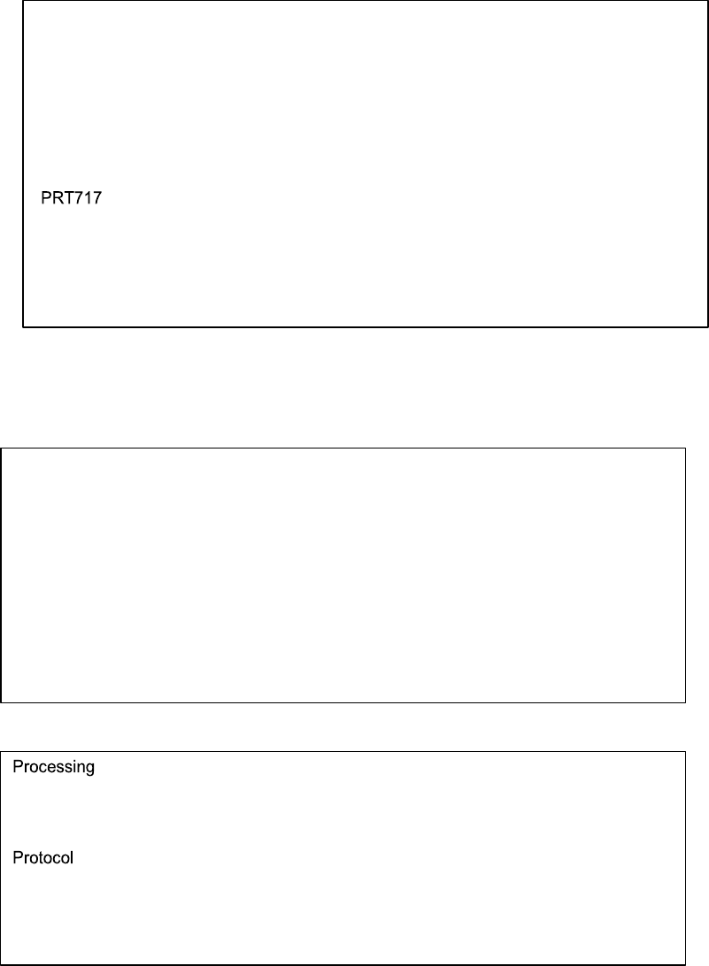
101
6.
While browsing VTAM_DSE1, notice that the DSC printer is defined to IPS as a COAX attached
printer.
Command ===>
************************** Bottom of data *************************
= ================= ==== ============ ============ ======== =
========
========
PSF LINE MATRIX IPDS B5 lab PRT717 Y
A-Add B-Browse
A Printer Name
C-Copy D-Delete E-Edit X-Chg type
C FORMS LU Name
Scroll ===> HALF
Actions:
Type Description Location
DEST
B VTAM_DSE1 IPPW A TN327E Pri IMPACT LAB K
VTAM_SCS1 IPPW A TN327E Pri IMPACT LAB J
VTAM_SCS2 IPPW L
Browse
Command ==>
IP PrintWay Printer Definition
Printer definition name . VTAM_DSE1
Description
. A TN327E Printer using the DSE (LU_3) Datastream. (extend)
Location.
. . IMPACT LAB (extend)
Section
Allocation
Component name Custom values
(enter to browse) (enter to browse)
=>
=> *
=>
NetSpool options
=>
NetSpool
end-of-file =>
IP
PrintWay
options =>
=>
/ Use DEST, CLASS, and FORMS for IP PrintWay printer selection
NetSpool LU name . LU classes . . (extend)
=> *
=>
=>
=> *
=>
*

102
The following panel shows the Allocation section of the setup, where the printer is associated with Class
K jobs.
In the IP Printway options, retry time, retry limit, and response timeout is already for the printer.
NOTE: The values of these settings are account specific. Other values may best serve your printing
environment.
Browse
Command ==>
Allocation
Printer definition name . VTAM_DSE1
+
Spool allocation values:
CLASS . . . . K LINECT. . .
DEST. . . . . PRMODE. . .
JES node. . . PRTY. . . .
FCB . . . . . SEGMENT . .
FLASH count . THRESHLD. .
FLASH name. . UCS . . . .
FORMS . . . .
GROUPID . . .
USERDATA
. .
BURST . . . .
HOLD. . . . .
WRITER. . .
(extend)
1. Yes 2. No
1. Yes 2. No
OUTDISP . . . 1. Purge 2. Leave 3. Keep 4. Hold 5. Write
Values
for Separator Pages:
Address
. . (extend)
Building . .

103
Browse
Command ==>
IP PrintWay Options
Printer definition name . VTAM_DSE1
+
Retention period:
Successful. . . .
Failure . .
Retry time . . . . . 0000:05:00
Retry limit.
......... 2
Connection
timeout . 30
Response
timeout . . 100
Exits:
Begin data set. . End data set. . Record. .
Document header . .
/ Translate document header
Document trailer . .
/ Translate document trailer
(extend)
(extend)
Dataset grouping . . 2 1. None 2. Job 3. Concatenate job
Formatting:
Line termination. . . .

104
The following shows where the VTAM parameters were set for the printer. For the DSE printer we chose
RMT3 and the logmode of LU3PRT.
Browse
Command ==>
IP PrintWay Options
Printer definition name . VTAM_DSE1
More: -
Document header . .
/ Translate document header
Document
trailer . .
/ Translate document trailer
(extend)
(extend)
Dataset grouping . . 2 1. None 2. Job 3. Concatenate job
Formatting:
Line termination. . . .
Transparent data char . 35
Carriage control type . 2 1. None 2. Machine 3. ANSI
Delete form feed. . . . 4 1. None 2. Leading 3. Trailing 4. Both
Formatting. . . . . . . 1. None 2. Standard
3. Translate only 4. Use FCB
PostScript header . . . 1. Add 2. Ignore
3. Landscape 4. Always landscape
Omit line termination at EOF
Browse
Command ==>
VTAM Protocol
Printer definition name . VTAM_DSE1
Printer
LU name. . . RMT3
VTAM
Processing Options:
Printer logmode. . . LU3PRT
Checkpoint pages . . 5
Send as transparent data
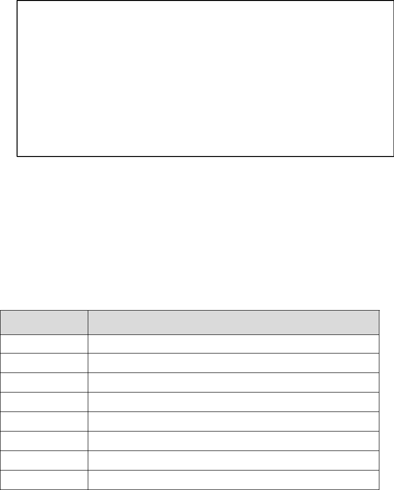
105
The next panel shows these settings for the SCS printer.
The last thing you need to configure is the printer.
NOTE: A this time, InfoPrint Server and all related LUs should be active.
Using the printer's web pages go to the configuration screen
Configuration Screens
1.
To configure the line matrix printer, fill out and submit the forms using the following links.
Table 4 Configuration Forms
Configuration HTML Forms
Network TCP/IP (including Windows) and Novell network settings
Print Path Destination, Model, Log Path, and I/O port configuration
Print Model Shortcut to the print path model configuration forms
Log Path Shortcut to the print path log path configurations form
TN5250/3270 TN5250/3270 configuration settings
SNMP SNMP configuration settings
Administration Names and passwords
System System operation modes (reboot, factory defaults)
2.
Select the TN5250/3270 section from the configuration screen.
NOTE: Changes will only take effect after you reset the line matrix printer from the System page.
Browse
Command ==>
VTAM Protocol
Printer definition name . VTAM_SCS1
Printer LU name. . . RMT2
VTAM
Processing Options:
Printer logmode. . . SCS
Checkpoint pages . . 5
Send as transparent data

106
The following displays:
3.
Select TN3270E Mode.
The following displays:
NOTE: Changes will only take effect after you reset the line matrix printer from the System page.
4.
Enter the address of your system for the host IP address
The port address is the port configured for your telnet server. It is usualy port 23.
The Resource name will be the printer name defined in the VTAM portion of your Telnet server
configuration. For this example use RMT3.
5.
Select auto connect.
6.
Go to the system page and reboot for the changes to take effect.
7.
After the printer reboots, enter the command /DTCPIP, T, CONN from the SDSF
console. The following messages show that the printer is connected.
Mode: TN5250
Host
Click here for TN3270 mode
ok
(eg. 204.191.175.114 or
host.domain.com)
Port
Device
Description
Message
Queue Name
Message
Queue Library
Device
Type
WSCST
Name
WSCST
Library
Auto
Connect
Start
Auto Connect
GENERIC PRINTER
Click here
Configuration for Print Path d2prn
Mode: TN3270
Host
host.domain.com)
Port
Resource
Name
Auto
Connect
Stop
Auto Connect
Click here for TN5250 mode
ok (eg. 204.191.175.114 or
23
Click
here

107
You are now ready to print.
D TCPIP,,T,CONN
EZZ6064I TELNET CONNECTION DISPLAY 044
EN
TSP
CONN
TY IPADDR..PORT LUNAME APPLID PTR LOGMODE
-------- -- ---------------------- -------- -------- --- --------
00000468 9.99.98.62..2000 RMT3
*PRINTER PPE LU3PRT
----- PORT:
23 ACTIVE
PROF: CURR CONNS: 1
------------------------------------------------------------
3 OF 3 RECORDS DISPLAYED
108

109
AS/400 Configuration
TN5250
Setting Up TN5250 Print Queues on AS/400
Start with V3R7 or later and the most recent PTF level. The AS/400 should have tcpip installed, be fully
configured, and functional. To set up the TN5250 print queues, do the following:
1.
Make sure the AS/400 has sufficient resources to add additional virtual devices.
2.
Establish the IP value (not the dns name) of the AS/400.
3.
Set the IP, subnet mask, and default router on the PrintNet.
4.
Use a telnet session or web browser session to configure three items per dest (logical PrintNet
queue) for use as a logical network connection to the AS/400.
NOTE: The three values (i.e., 192.168.168.34) represent the AS/400 IP in dotted notation and are the
entries for the AS/400.
The newly created TN5250 device/queue (i.e. pallet form, first chair is alpha, 10 char. max) assumes the
new name “devicedesc.”
5.
Determine whether or not to autoconnect (initiate connection on power up or through PrintNet reset)
the TN5250 device/ queue.
NOTE: It is not necessary to set up the devd or queue name on the AS/400 manually or in advance. The
configuration and reset of the PrintNet automatically sets up the devd or queue name.
Setting Up a TN5250 Connection/Device via a Telnet
Session
In a telnet session, the command “list TN5250” shows the configured values. To set up a TN5250
connection/device via a telnet session, use the commands “store TN5250...” and the following:
NOTE: The PrintNet sessions can be configured either by a web browser or by telnet.
1.
Use cmd WRKCTLD *VWS, choice 5, display, enter to list the number of virtual devices this
controller.
2.
Use cmd DSPSYSVAL QAUTOVRT. Note the number of auto- configured virual devices permitted
on the system. This number must be greater than one.
3.
Use cmd DSPYSYVAL QCHRID. This is the system language (code page) available.
4.
Use cmd WRKTCPSTS *IFC to deterimine the IP address of the AS/400. This value is used in
setting the PrintNet TN5250 devices.
110
User Supplied Values
Host: For this session, use the IP value from (step 4 above).
Device description: This is the name of the virtual device.
Auto connect:
• If true (enabled) then queue and device automatically attach.
• If not true (disabled) the command “tn dest dxprn start/stop” allows individual sessions to start or stop.
NOTE: Leave other values at their default descriptions.
Example of telnet session commands:
store tn dest d8prn host 192.168.168.34
store tn dest d8prn devicedesc palletform
store tn dest d8prn autoconnect
reset
This example creates a device/queue named “palletform” on the AS/400 host with IP 192.168.168.34.
The PrintNet initiates the connection each time it is reset or the printer power is cycled.
Using Telnet Commands for TN5250
Command List
The following commands for TN5250 are available via a Telnet session with the PrintNet.
Store Commands
store tn dest <dxprn> host <IPaddress>
store tn dest <dxprn> port <portnumber>
store tn dest <dxprn> devicedesc <devicename>
store tn dest <dxprn> msgqname <msgqname> msgqlib <msgqlib>
store tn dest
<dxprn> WSCSTname <WSCSTname> WSCSTlib <WSCSTlib>
store tn dest <dxprn> from default
store tn dest <dxprn> [-]autoconnect
store tn dest <dxprn> copytimeout <copytimeoutvalue>
See page 120 for store command descriptions.
List Commands
list tn
list tn dxprn - shows detail of a specific tn print queue.
list stored tn
list default tn
See page 132 for list command descriptions.
TN5250 Auto Connect Command
tn dest <dxprn> start|stop
See page 136 for a detailed description.
Getting Started
Set the following items when first configuring the PrintNet for use with an AS/400 running TN5250:

111
• The IP address of the AS/400 you are planning to use.
Example: store tn dest d1prn as400 192.75.11.1
• The device description or queue name you want built on the AS/400 for the printer. This must be
unique to the printer.
Example: store tn dest d1prn devicedesc tnqueue
• Enable the printer to autmatically connect to the AS/400 when it is first powered up or automatically
reconnect if the original connection is lost.
Example: store tn dest d1prn autoconnect
In most circumstances, all other settings can be left as default. The printer should be reset (powered
off and on again) for the settings to take effect.
If you do not wish the printer to connect automatically when powered up then leave the autoconnect
disabled and control the connection manually with the following command:
Example: tn dest d1prn start
By using the manual method, time is allowed to properly prepare the AS/400 after the printer is
powered up but before a connection is established. This method should only be used during an initial
installation until the printer and the AS/400 are synchronized. The normal method is to have
autoconnect enabled.
The autoconnect feature has a cycle time of approximately one minute. A little patience may be
required when first turning on the printer before the connection becomes visible on the AS400.
TN5250 Job Formatting
Forms width, forms length, CPI and LPI are controlled by the TN5250 data stream unless the front panel
TN5250 Host Override option is enabled. The CPI is controlled through TN5250 via the font selection in
the Change Device Description (CHGDEVPRT) command.
A completed screen looks like the example shown in Figure 37.
Change Device Desc (Printer) (CHGDEVPRT)
Type choices, then press Enter.
Device description DEVD
Online at IPL ONLINE *NO
Font: FONT
Identifier
011
Point Size
*NONE
Form Feed FORMFEED *CONT
Separator drawer SEPDRAWER *FILE
Separator program SEPPGM *NONE
Library
Printer error message PRTERMSG *INFO

112
Change Device Desc (Printer) (CHGDEVPRT)
Library
*LIBL
Host print transform TRANSFORM *NO
Manufacturer type and model MFRTYPMDL *SAME
Paper source 1 PPRSRC1 *MFRTYPMDL
Paper source 2 PPRSRC2 *MFRTYPMDL
Envelope source ENVELOPE *MFRTYPMDL
ASCII code page 899 support ASCII899 *NO
Image configuration IMGCFG *NONE
Character identifier: CHRID
Graphic character set
*SAME
Code page
User-defined options USRDFNOPT *SAME
+ for more values
User-defined object: USRDTATFM
Object
*NONE
Library
Object type
Data transform program USRDTATFM *NONE
Library
User-defined driver program USRDRVPGM *NONE
Library
Text ‘description TEXT ‘Device created
for S1045PXM.’
Workstation customizing object WSCST *NONE
Library
Figure 37 Example of CHGDEVPRT Command

113
Font Identifier (FONT) - Help
The print quality/typeface setting in TN5250 mode is NOT set by the TN5250 data stream. It is only set
through the front panel. This is true regardless of the front panel TN5250 Host Override setting.
Specifies the font identifier used by the 3812, 3816, and 5219 printers (including ASCII
printers emulating the 5219 printer), and the IPDS printers.
The Printer Font Table (Font Parameter) in the CRTDEVPRT command lists the valid
font identifiers, the display values, the characters per inch value implied with each font
style, a description of each font style, and whether the font is supported on a particular
printer.
NOTE: Some fonts may be substituted by the printer. Consult the various printer
reference guides of details.
The possible values are:
• identifier. Specify the 3-, 4-, or 5-digit identifier associated with this printer.
• point-size. Specify a point size ranging from 0.1 through 999.9. If you do not
specify a point size, the system will set one.
• *SAME. This value does not change.
114

115
Monitoring Printers
Implementing Printer Management
Printer management includes the following tasks:
• Monitoring the status of network printers
• Responding to alarms
• Gathering statistics on printer operations
The three elements of network printer monitoring and management are:
• Agent/manager model
• The management information database (MIB)
• SNMP, the protocol used to get management information
Agent/Manager Model
The elements of a monitoring system, MIB and SNMP, are implemented in an agent/manager model:
• The MANAGER is a console, workstation, or server on working hubs or routers which has a global
knowledge of NICs and printers.
• AGENTS are utilities that reside on devices, such as a PrintNet, that respond through SNMP to
management requests for information. The information is stored in an MIB.
MIB
An MIB contains information a device makes available through SNMP. The MIB is a management
information base that describes information about actual objects to be managed and controlled.
Standards Of Network Printer MIBs
The Printer MIB is based on the following standards:
• System and Interfaces Group MIB (RFC 1213 of March 1991)
• Host Resource MIB (RFC 1514 of September 1993)
• Printer MIB (RFC 1759 of March 1995)
• PrintNet contains the Standard Printer MIB per RFC 1759, available from www.ietf.org.
Information Provided By The MIB
The printer MIB contains the following types of information about network printers:
Descriptions. Printer configuration, location, and contact.
Status. Current operating status of printers.
Alerts. Reportable events from printers.
116
General Information About MIBs
For further information on SNMP and MIB, refer to the following:
• RFC 1155 — Structure and Identification of Management Information for TCP/IP-based Internets
(SMI)
• RFC 1156 — Management Information Base for Management of TCP/IP Internets (MIB)
• RFC 1157 — A Simple Network Management Protocol (SNMP)
• The Simple Book: An Introduction to Management of TCP/IP-based Internets
Getting the Latest MIB Information
The latest copy of these and other RFCs can be obtained from the Internet Engineering Task Force
(IETF) at http://www.ielf.org.
SNMP
SNMP is the protocol used to communicate between manager and agent. Managers request information,
usually through automated polling at specified intervals, and agents respond. PrintNet SNMP is used on
TCP/IP network only.
SNMP is a standard by which a network manager can get statistics and configuration information from the
print servers and other devices on the network. This is done through a Network
Management Station (NMS) such as NetView®. Currently only
SNMP version 1 protocol is supported.
Monitoring Tools
Many tools can be used to monitor printers with SNMP agents. One of these tools is NetView. There are
also other MIB browsers which are not described here.
Monitoring with AIX NetView/6000
The AIX NetView/6000 program can manage any IP-addressable device with an SNMP agent.
NetView/6000 can be used to set a network topology, monitor a network, diagnose problems, and
measure network performance.
Through its MIB Browser, information about the resources affecting an event (such as an alarm) can be
obtained.
PrintNet Enterprise Suite
PrintNet Enterprise Suite (PNE) is a versatile remote management software utility. It allows you to
organize all of the printers in your office remotely in a single database, download software and printer
settings from a host computer with a single mouse click, and use a virtual operator's panel to configure
printers in the same room or on the other side of the world. Refer to the PrintNet Enterprise Suite User’s
Manual or www.Printronix.com for more details on this tool.
Setting the SNMP Community Name
The default SNMP read-only community name is “public” and cannot be changed.
Change the SNMP R/W community name with the command:
set user passwd snmp com_name
save
where com_name is the new SNMP R/W community name. The default is no R/W community name.
117
NOTE: Changing SNMP community names or access rights may hinder or disable applications that are
monitoring your printers.
Disable SNMP Protocol
Enter the following command to disable SNMP protocol:
disable snmp
118

119
Commands
Command Shell Overview
The PrintNet comes with an in-depth command shell called npsh. It allows you to manipulate objects like
destinations, I/O ports, and models and provides monitoring and troubleshooting capabilities.
npsh Access Methods
There are many ways this command shell can be accessed:
• built in HTML forms
• a Telnet session from a TCP/IP host to the PrintNet
• a single remote shell command (e.g., rsh, rcmd, remsh) from a TCP/IP host
• a PTX_SETUP command file containing one or more npsh commands sent through a printer data
port (serial, parallel, etc.)
Main npsh Command Prefixes
All configurable commands either start with store or set, and view commands start with list.
NOTE: If the store prefix is used, the PrintNet must be repowered to make the changes take effect.
Since store affects flash memory settings only, the print server must reset and read the new
settings now in flash memory.
NOTE: If the set prefix is used, a save command must be executed as well so that the new settings
are retained after power cycles. Since set only affects the settings in memory, they will be lost
after a power cycle unless they are saved to flash memory.
Getting Command Help
The PrintNet command shell provides several online help tools, including:
“?” Command
Typing “?” when logged in to the command shell will produce a full list of all available commands.
Command Prefixes
Typing in the first portion of a command will produce an error message showing the correct syntax. For
example, typing in store tcpip will produce a list of all commands that start with this prefix.
Complete Command List
This section outlines the entire PrintNet command set including the command syntax, a description, and
in most cases, an example for each command listed.
NOTE: If you see the word ifnum in any npsh commands, you should substitute a 1. The 1 represents
the one network interface (e.g., Ethernet) supported.
120
Store Commands
These commands change the settings stored in flash memory and do not affect the current or working
settings in memory. A power cycle is needed before the stored settings become current.
store ftpc addr <IPADDRESS>
Example: store ftpc addr 192.168.10.10
Store the ftpc server IP address. The printer starts an ftp client session at the power up time if ftpc is
enabled. The print will connect to the IP address provided with this setting.
store ftpc user <USER-NAME>
Example: store ftpc user joe
The user ID used to log into ftp server.
store ftpc passwd <PASSWORD>
Example: store ftpc passwd super
To enter the password that allows the user to log into ftp server.
store ftpc file <FILENAME>
Example: store ftpc file printer.inf
This is the name of the file that is stored in the ftp server. The file will be loaded to the printer at the power
up time if ftpc is enabled.
store ifc from default
Set all UTP settings back to factory defaults.
store ifc from current
Store all current UTP settings to flash memory so they are retained after a power cycle. This ensures all
current settings match what is stored in flash memory.
store ifc default <IFNUM>|<0> (0 for no default)
Store the specified interface as the default interface. The other interface is no longer active after power
cycle. The 0 allows for both interfaces to be active.
store ifc <IFNUM> mode auto|10half|10full|100half|100full
Store the specified interface mode as automatic, 10mbps half duplex, 10mbps full duplex, 100mbps half
duplex, 100mbps full duplex. See page 14.
store pping opts [-]enable
Example: store pping opts enable
Store the state of periodic ping flag. If the periodic ping flag is enabled the PrintNet periodic ping client will
attempt to ping its default gateway on its active PrintNet interfaces.
Default: disabled
121
store pping packet <NUMBER OF PACKETS>
Example: store pping packet 1
Store the value of the packet. It is the number of ICMP Echo Request packets that will be sent by the
periodic ping client on each period.
Default: 1
store pping period <MINUTES>
Example: store pping period 5
Store the value of the period. <minutes> is the amount of time from 1 to 5 minutes defines the periodic
ping sequence will be repeated.
Default: 5
store pping from default
Example: store pping from default
Store all the periodic ping default settings to flash memory so that they are retained after power up.
store pserver opts [[-]jobsecurity][jobtimeout <SECONDS>]
[jobcontrol[off|standard| enhanced|fast]] [[-]multcp]
Example: store pserver opts -jobsecurity
jobcontrol is not used in this product.
Example: store pserver opts jobcontrol [fast]
jobcontrol is used to have different levels of secure printing. This is available as a performance
enhancement for LPR, TCP socket printing etc. When jobcontrol is set to enhanced all jobs will be
supported with job flow control.
NOTE: When jobcontrol is disabled, dynamic config loading on a model change is also disabled.
• off. no job control; no SOJ/EOJ commands. The printer prints faster in off mode.
• standard. (the default) traditional job control with immediate acknowledgements of SOJ/EOJ
commands.
• enhanced. job control with EOJ acknowledgements held off by the printer until job is fully printed.
The printer prints slower in enhanced mode.
• fast. The EOJ (End of Job) packet is acknowledged immediately. Use this selection if the job is timed
out due to a delay in the acknowledgement of the EOJ packet because of the amount of data printing.
To monitor the printer, use the telnet command “lpstat.” The normal status reported on the first line of the
lpstat response is the status of the queue (LPQ) within the PrintNet. The status reported does not reflect
the state of the print job once it has been sent from the PrintNet to the printer.
The new line at the bottom of the lpstate response labeled “printer job:” can report one of two status
values:
a.
In Progress. A job in the printer is not yet finished.
b.
Done. There are no jobs in the printer. All previous jobs are finished.
Example: store pserver opts jobtimeout 5
The jobtimeout applies to the active job only and starts counting from zero each time data has been
handed over to the printer successfully. If a blocked condition occurs for instance no data can be written
the the printer, the print job will be cancelled after the timeout. The default for jobtimeout is 0 which is
disable.
122
The multcp option determines how many concurrent socket connections are allowed.
Example: store pserver opts -multcp
When multcp is disabled, only a single socket connection is allowed at a time.
Example: store pserver opts multcp
With this option, multiple concurrent socket connections are allowed. The default multcp is set to be
enabled.
store pserver tcpsocket <TCP-PORT> port <NEW-TCP-PORT>
Example: store pserver tcpsocket 4000 port 5000
Change a pre-defined TCP port number (<tcp-port>) on the PrintNet to a new TCP port number (<new-
tcp-port>). The default number is 9100 for prn.
store pserver tcpsocket <TCP-PORT> dest <DEST>
Example: store pserver tcpsocket 5000 dest d1prn
Assign a pre-defined TCP port number (<tcp-port>) to a particular destination (<dest>) on the PrintNet.
Therefore, if you are using a print method that sends jobs directly to a TCP port number, you still have the
option to process the job data through this destination setting.
store pserver tcpsocket add <TCP-PORT> dest <DEST>
Example: store pserver tcpsocket add 9101 dest d2prn
Maps the port number to a destination.
store pserver tcpsocket del <TCP-PORT> dest <DEST>
Example: store pserver tcpsocket del 9101 dest d2prn
Deletes a mapped port number destination already defined by listed commands.
store pserver lpd [-]dest1default
Example: store pserver lpd dest1default
If dest1default is disabled and upon verification, the printer name supplied by the LPR protocol and the
destination name do not match, then an error message is returned and the service is refused. If
dest1default is enabled and upon verification, the printer name supplied by the LPR protocol and the
destination name do not match, then the job is automatically routed to the first destination and the service
is accepted.
Default: enabled
store pserver ftp [-]dest
Example: store pserver ftp dest
This command is to set the default directory when ftp is launched. Example commands as follows:
set dest d1prn name pr1
store pserver ftp dest
save
The first command changes <dest> d1prn to pr1. The second command tells ftp to start at directory dest.
To send the print job, ftp to the printer and enter 'put printjob pr1'.
123
store pserver from default
Set all general print server settings back to factory defaults.
store pserver from current
Store all current general print server settings to flash memory so they are retained after a power cycle.
This ensures all current settings match what is stored in flash memory.
store ptrmgmt pne <PNE PORT NUMBER>
Change the port number to communicate with Printnet Enterprise.
Default: 9001
store ptrmgmt status <STATUS PORT NUMBER>
Example: store ptrmgmt status 1025
Receives printer status, print job status, and/or emulation verification data. The data sent through this port
is defined by the printer code.
Default: 9002
store ptrmgmt mgmt <MGMT PORT NUMBER>
Used in PXML operation.
Default: 9007
store tcpip <IFNUM> addr <ADDRESS>
Example: store tcpip 1 addr 192.75.11.9
Store the IP address for the PrintNet.
store tcpip <IFNUM> mask <MASK>
Example: store tcpip 1 mask 255.255.255.0
Store the subnet mask for the PrintNet.
store tcpip <IFNUM> opts [[-]rarp] [[-]bootp] [[-]dhcp]
[-]persistdhcp]
Example: store tcpip 1 opts -bootp -dhcp
Enable or disable the automatic RARP, BOOTP, DHCP, or persistent DHCP requests for IP addresses
upon bootup. If you are storing the PrintNet TCP/IP network settings within the device, you will not need
to rely on BOOTP or DHCP for new settings.
store tcpip route add default[1|2] <ROUTER> <IFNUM> [<METRIC>]
Example: store tcpip route add default1 192.75.11.1 1
Store a default router/gateway defined by router IP Address (<router> <ifnum>) so the PrintNet knows
where to direct packets destined for another subnet. It is easier to store one default entry rather than an
entry per remote host or network as in the previous command.
124
store tcpip del default [1|2]
Example: store tcpip route del default1 192.75.11.1 1
Delete a default router/gateway defined by router IP Address (<router> <ifnum>) so the PrintNet knows
where to direct packets destined for another subnet.
store tcpip route add [host|net] <NETWORK> [/mask>] <ROUTER> <IFNUM>
[<METRIC>]
Example: store tcpip route add net 192.75.12.0 1
Add a static route to a particular TCP/IP host or subnet specified by <network> so the PrintNet knows
how to communicate with it. Normally one entry for a default router/ gateway is all that is needed for
communications between different subnets. Please see the next command for details.
store tcpip route del [host|net] <NETWORK>
Example: store tcpip route del net 192.75.12.0 1
Delete a static route to a particular TCP/IP host or subnet specified by <network> so the PrintNet knows
how to communicate with it. Normally one entry for a default router/ gateway is all that is needed for
communications between different subnets. Please see the next command for details.
store tcpip tcp rxwin <PACKETS>
Example: store tcpip tcp rxwin 2
Determine the receive window size for the PrintNet. Usually the packets value ranges from 2 to 8, with
the lower number allowing for more simultaneous TCP connections with the print server.
store tcpip tcp opts [-]zeroIPArp [-]keepalivedata [-]protocoID
Example: store tcpip tcp opts keepalive
Control whether the PrintNet maintains a connection with a host when data cannot be accepted into its
buffer. The keepalivedata option controls whether the keepalive packet contains a data byte for hosts that
require it. If zeroIPArp is disabled then a PrintNet with an IP address of 0.0.0.0 will not allow IP access
until the IP address is configured. If zeroIPArp is enabled on a PrintNet with an IP address of 0.0.0.0 then
any attempted access with a valid IP address is assumed for this PrintNet and an Arp lookup is
performed. When the protocolID is enabled, the PrintNet informs the printer when ftp, lpd protocol is used.
Default: enabled
store tcpip from default|current
Example: store tcpip from default
Set all TCP/IP network settings back to factory defaults.
Example: store tcpip from current
Store all current TCP/IP network settings to flash memory so they are retained after a power cycle. This
ensures all current settings match what is stored in flash memory.
store tn dest <DXPRN> mode 5250|3270
Example: store tn dest d1prn mode 3270
Store the TN protocol mode.
Default: 5250
125
store tn dest <DXPRN> host <IPADDRESS>
Example: store tn dest d1prn host 192.75.11.1
Store the IP address of the TN5250/3270 host
Default: Unconfigured (empty) IP address
store tn dest <DXPRN> port <PORTNUM>
Example: store tn dest d1prn port 27
Store the UDP port number of the TN server.
Default: 23
store tn dest <DXPRN> devicedesc <DEVNAME>
Example: store tn dest d1prn devicedesc MOCHA3812
Store the name of the printer device. The description entered will be the name of the printer device
created on the AS/400 host for the current session.
Default: Unconfigured (empty) description.
store tn dest <DXPRN> connect <RESOURCENAME>
Example: store tn dest d1prn connect MYRESNM
Store the resource name for the host session. The resource name must be the same as the name of the
printer device created on the host for the session.
Default: Unconfigured (empty) resource name
store tn dest <DXPRN> msgqname <MSGQNAME>
Example: store tn dest d1prn msqqname QSYSOPR
Store the queue name to which system messages will be logged.
Default: QSYSOPR
store tn dest <DXPRN> msgqlib <MSGQLIB>
Example: store tn dest d1prn msgqlib *LIBL
Store the queue library to which system messages will be logged.
Default: *LIBL
store tn dest <DXPRN> WSCSTname <WSCSTname>
Example: store tn dest d1prn WSCSTname *NONE
Store the queue name to which system messages will be logged.
Default: *NONE
store tn dest <DXPRN> WSCSTlib <WSCSTlib>
Example: store tn dest d1prn WSCSTlib *LIBL
Store the queue library to which system messages will be logged.
Default: *LIBL
126
store tn dest <DXPRN> [-]autoconnect
Example: store tn dest d1prn autoconnect
Store the state of the autoconnect flag. If the autoconnect flag is enabled the PrintNet tn client will attempt
a connection and binding with the specified tn host automatically on power-up. This connection sequence
will be repeated every 60 seconds until successful or the autoconnect flag is disabled.
See “tn dest <dxprn> start | stop” command page 136.
Default: disabled
store tn dest <DXPRN> copytimeout
Example: store tn dest d1prn copytimeout 1000
Store the value of the copytimeout. When consecutive TN5250/3270 jobs are sent to the PrintNet, they
are treated differently depending how soon they arrive. In an attempt to provide a perception of collation
when multiple copies are sent from one host, if the time between jobs is less than the copytimeout value
then they are treated as copies and the job is given precedence over other host documents. This keeps
documents, which are sent in rapid succession together as if they were copies of the same document. A
higher value improves the likelihood of collation but impacts performance.
Default: 500
store tn from default|current
Example: store tn from default
Store all tn default settings or current settings to flash memory so that they are retained after power up.
Set Commands
These settings alter the current or working settings in memory only. Therefore, they will be lost if the
PrintNet is power cycled. To ensure this does not happen, issue a save command so the current
settings get written to flash memory.
set dest <DEST> name <NEW_NAME>
Example: set dest d1prn name laser
Change the current name of the <dest> to a new name as indicated by <new_name>. These names are
case sensitive.
set dest <DEST> backchannel [prn]
Example: set dest d1prn backchannel prn
Establish a return path for printer feedback for a given destination (<dest>). The PrintNet I/O port is bi-
directional, however, you will most likely use the same I/O port to which the destination is currently
sending jobs.
set dest <DEST> model <MODEL>
Example: set dest d1prn model m4
Associate a model with a destination. Jobs sent to the named destination (<dest>) are processed
according to the options defined in the named model.
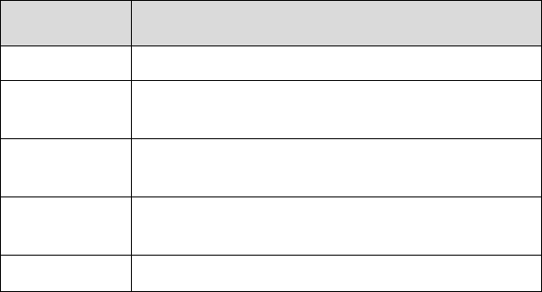
127
set dest <DEST> logpath <LOGPATH>
Example: set dest d1prn logpath l4
Associate a logpath with a destination. Jobs sent to the named destination (<dest>) are logged according
to the settings defined in the named logpath.
set dest <DEST> service [[-]socket][[-]lpd] [[-]ftpd] [[-]tn]
Example: set dest d1prn service
Set the destination (<dest>) to handle only certain print services. To add a service, specify the service
name. To disable a service, use “-” before the name. The available services are described in the
following table.
Services
socket Direct socket printing via TCP/IP.
lpd LPR printing with TCP/IP, including LPR clients
on any platform.
ftpc File Transfer Protocol Client. This
protocol initiates file transfers from an
ftpd Printing using the File Transfer Protocol (FTP)
via TCP/IP.
tn Printing using the TN5250/3270 session.
set dest from default
Set all destination settings back to factory defaults.
set dest from stored
Set all current destination settings to the values stored in flash memory.
set logpath <LOG_NAME> name <NEW_NAME>
Example: set logpath l1 name pagecount
Change the current name of the logpath (<logpath>) to a new name as indicated by <new_name>. These
names are case sensitive.
set logpath <LOG_NAME> type [[-]job] [[-]pfault]
Example: set logpath l2 type job user printer
Establish the type of printer and print job logging to be done within this <logpath>. The option is:
job Job ID, username, etc.
pfault Printer fault
set logpath <LOG_NAME> email <EMAIL>@<IPADDRESS>
128
Example: set logpath l3 user@printronix.com
Determine where the log information should be sent for a print job or attached printer. The choice is:
email Particular user's email address. This address is set using the set
sysinfo email emailname@IPaddress or
emailname@domain.com command.
set logpath from default|stored
Set all logpath settings back to factory defaults or the values stored in flash memory.
set lpd [-]bytecount
Example: set lpd -bytecount
Set the job control on the file size of a Line Printer Daemon (LPD). If bytecount is enabled, the printer
does not allow the LPD client to send a job with an unconventional file size.
Usually the unrecognized numeric operand in the LPD Receive Data File command attributes to this
behavior. The print job stream is canceled and its TCP connection is closed.
Default: Disabled.
set lpd [-]offlinedata
The offlinedata flag helps minimize host disconnects when the printer goes offline for an extended time.
Enable this option if you experience host disconnects when the printer goes offline.
set model <MODEL> name <NEW_NAME>
Example: set model m1 name landscape
Change the current name of the model (<model>) to a new name as indicated by <new_name>. These
names are case sensitive.
set model <MODEL> banner [text][after]
Example: set model m2 banner text
Determine whether a banner page should be added for print jobs passing through the <model> mapped
destination/queue. By default, banner pages are added to the front of the job.
If after is set, the banner page will come at the end.
set model <MODEL> stty [[-]onlcr] [[-]descramble] [xtab <1-6>|none]
Example: set model m3 stty onlcr
Control extra job processing done by the <model>. The processing options are:
onlcr Carriage return insertion for Unix text jobs. Adds carriage returns to text jobs with solitary
linefeeds. This will prevent stair-stepped output or output running off the right side of the
page.
descramble Automatic descrambling of print jobs passing through which have been scrambled using
Printronix proprietary Unix scramble utility, npscramble.
xtab Tab expansion from 1 to 16 spaces.
129
set model <MODEL> header [<STRING>]
Example: set model m1 header 0x20
Set a header string to be sent to the printer at the start of any print jobs passing through this <model>.
The headerstring (<string>) can consist of up to nine elements. An example element is a hexadecimal
code (e.g., 0x04) or a pre-defined variable on the print server (e.g., $FF for a formfeed). Use list var
to see all available variables. To erase the header, send the command with no headerstring value; for
example ‘set model m1 header’.
set model <MODEL> trailer [<STRING>]
Example: set model m7 trailer $FF
Set a trailer string to be sent to the printer at the end of any print jobs passing through this <model> . The
trailerstring (<string>) can consist of up to nine elements. An example element is a hexadecimal code
(e.g., 0x04) or a pre-defined variable on the print server (e.g., $FF for a formfeed). Use list var to see
all available variables. To erase the trailer, send the command with no trailerstring value; for example ‘set
model m1 trailer’.
set model <MODEL> config [config_num]
Set a printer configuration number config_num to be loaded prior to printing a job on the specified model.
If the command is sent with config_num set to 0, the factory configuration is loaded before the job prints.
If config_num is in the range 1 through 8, the corresponding configuration number is loaded before the
job prints. To return to the default state where no configuration is loaded, send the command with no
config_num value; for example ‘set model m1 config’. When no new configuration is loaded, the current
configuration settings will be in effect for any jobs sent to model <model>. To see which configuration, if
any, will be loaded at the start of a job, use the command ‘list model’ or ‘list model <model>’.
set model from default
Set all model settings back to factory defaults.
set model from stored
Set all current model settings to the values stored in flash memory.
set snmp
To add a user named snmp with root privileges, follow the steps below:
1.
Login to the Ethernet as a root user.
2.
Add a user named snmp:
set user add snmp
3.
Set the user type to root:
set user type snmp root
4.
Set the password for the snmp user:
set user passwd snmp snmppassword
5.
Save the changes:
save
The user snmp is now created and snmppassword is the only community string which will allow write
access.
130
set snmp on|off
SNMP service can be disabled by telneting to the printer and enter ‘set snmp off’. To reenable SNMP,
enter ‘set snmp on’. The default is enabled. (check with redlines)
set snmp manager <INDEX> <IPADDRESS> <TRAP-COMMUNITY>
The PrintNet continuously generates traps. To set the PrintNet to send traps to a particular SNMP
manager, use this command to add an SNMP manager to the trap table.
<index> is the index number of the trap table. <ipaddress is the IP address of the SNMP manager
receiving traps. <trap- community> is the community string sent along with the trap information.
set snmp trapport <INDEX> <UDP_PORT>
Set the UDP port number in the SNMP trap manager table. This value should correspond to the port
number monitored by the SNMP manager application running on the host at the IP address specified in
the ‘set snmp manager’ command.
<index> is the index number of the SNMP trap manager table.
<udp_port> is the desired UDP port number. Acceptable values are 162, and 49152 through 65535.
set snmp trap <INDEX> [-]active
Enable or disable an SNMP trap manager table entry.
The index is the index number of the SNMP trap manager table. “active” enables the table entry, “-active”
disables the entry.
set snmp emailaddr <INDEX> <EMAILADDRESS>
The PrintNet can also send SNMP alert messages to a desired e-mail address. To specify an e-mail
address to send alert messages to, use this command to add the e-mail address to the SNMP alert table.
<index> is the index number of the SNMP trap manager table. The emailaddress is the desired e-mail
address of the form user@domain.com.
set snmp emailformat <INDEX> [-]short
Enable or disable the short e-mail message format for an SNMP alert table entry. When enabled, the
short e-mail format can be used when messages will be viewed on devices having a limited display size
(a cellular phone or pager, for example).
<index> is the index number of the SNMP alert table. “short” enables the short e-mail format, “-short”
disables it.
set snmp shortmsglen <INDEX> <LENGTH>
Specify the length of the short e-mail message format for an SNMP alert table entry. This command is
effective only when the short e-mail message format for an SNMP alert table entry is enabled.
<index> is the index number of the SNMP alert table. “length” specifies the length of the short e-mail
message, and has an acceptable range of 15 to 80 characters.
set snmp email <INDEX> [-]active
Enable or disable sending e-mail alert messages for an SNMP alert table entry.
<index> is the index number of the SNMP alert table. “active” enables sending e-mail alert mesages, “-
active” disables it.
131
set snmp alerts <index> [-]all | [[-]warning] [[-]offline]
[[-]mediainput] [[-]mediaoutput] [[-]mediapath] [[-]marker]
[[-]cutter] [[-]barcode] [[-]scanner] [[-]intervention]
[[-]consumable] [[-]label][[-]powercart] [[-]rfid]
Example: set snmp alerts 1 warning -cutter
Specifies which alert groups are enabled for reporting via an SNMP manager, e-mail alert message,
and/or Unix syslog daemon. See Table 2 on page 33 for a description of specific printer events belonging
to each group.
The index is the index number of the SNMP manager/alert table.
“-all” disables and “all” enables reporting of alerts in all alert groups. Individual alert groups can be
selectively enabled or disabled via combinations of alert group switches. For example, to enable warning
alerts and disable cutter alerts for SNMP table entry 1, enter the following:
set snmp alerts 1 warning -cutter
set sysinfo label|name [<STRING>]
Example: set sysinfo name salesprinter
Set a descriptive name defined by <string> for PrintNet identification purposes. This is not used in the
operation of the print server in any way.
set sysinfo contact [<STRING>]
Example: set sysinfo contact Paul_Harris
Set a person or department to contact in case of print server trouble.
set sysinfo location [<STRING>]
Example: set sysinfo location salesdept
Set the physical location of the PrintNet. This is for identification purposes and is not used in the
operation of the print server in any way.
set sysinfo prnserial [<STRING>]
Example: set sysinfo prnserial 000123456789
Sets the printer serial number.
set sysinfo smtpserver <IPaddress> [port <PORTNUM>]
Example: set sysinfo smtpserver 192.75.11.5 port 25
Define the SMTP (Simple Mail Transfer Protocol) server IP address or domain name and port number
where the mail is stored on your network.
Default: Unconfigured, 25
set user add|del <NAME>
Example: set user add eng
Add or remove a user on the PrintNet defined by <name>.
IMPORTANT Do not delete the root user, or you will be unable to configure any further settings
on the print server. You will have to go back to factory defaults to correct this
problem.
132
set user passwd <NAME> [<PASSWORD>]
Example: set user passwd eng mplex1
Assign a password to a defined user on the PrintNet.
set user type <NAME> root|guest
Example: set user type eng root
Assign root or guest privileges to a particular user defined by username. Guest permissions allow
viewing of settings only. Root permissions allow complete control of the PrintNet.
set user from default
Set all user settings back to factory defaults.
set user from stored
Set all current user settings to the values stored in flash memory.
set user passwd snmp <COM_NAME>
Set the new SNMP R/W community name as the <com_name> value.
set var <VAR> [<VARIABLE-STRING>]
Example: set var LANDSCAPE 0x1b 0x26 0x6c 0x31 0x4f
Define a new variable to be used in header, trailer, or switch strings on the PrintNet and call it
<variable-string>. <variable-string> can be a space-separated list of words, hexadecimal
numbers (e.g., 0x04), or references to other pre-defined variables. It is easiest to make up the
<variable-string> with hexadecimal values, as shown in the example.
NOTE: One variable counts as one element within header and trailer strings.
Defined variables are referenced in strings by placing a “$” before the variable name (e.g., set model
m1 trailer $FF).
set var from default
Set all variable settings back to factory defaults.
set var from stored
Set all current variable settings to the values stored in flash memory.
List Commands
These commands list the current or working settings for a particular section within the command shell. To
view stored settings in flash memory, insert stored after list. For example, list prn shows the
current printer settings but list stored prn shows the settings in flash memory. Normally these
should match. To view default settings in flash memory, insert default after list.
list all
Lists all current settings.
133
list arp
List the current ARP table that the PrintNet adheres to in a TCP/IP network.
list dest [destination]
List the current destination settings (e.g., names and mapped I/O ports, models, logpaths, and services.).
list diff
List the differences between the current settings and the stored settings in flash memory. Normally, you
want these values to match, so issue a save command followed by a reset command.
list ifc
Lists the current PrintNet interface settings (e.g., link integrity).
list logins
List any active user logins on the PrintNet.
list logpath [logpath]
List the current logpath settings (e.g., names and mapped destinations).
list model [model]
List the current model settings (e.g., names and mapped destinations). With no model parameter, a table
of values for name, type, banner, config and the size in bytes of header and trailer are shown for all
models m1 through m8. When the model parameter is supplied, the specific bytes used in the header and
trailer are shown, along with the banner type, data type and configuration number for that specific model.
list net
List all current TCP/IP network settings (e.g., IP address and subnet mask).
list pping
List all the current periodic ping setting.
list pserver
List the current general print server settings (e.g., print server).
list ptrcfg
List the printer configuration
list ptrmgmt
List the current printer management port numbers.
list snmp
List the Trap Table containing SNMP Managers.
list sysinfo
List the current PrintNet system information (e.g., contact name and protocol stacks enabled).
134
list tcpip
List all current TCP/IP network settings (e.g., IP address and subnet mask).
list test
List the status of output tests on the I/O ports.
list tn
List all current tn protocol settings.
list uptime
Lists how long the PrintNet has been up and running from the last reset.
list user
List the current user definitions (e.g., user names and types).
list var
List all pre-defined variables including any newly created ones. Any of these defined variables can be
referenced in a string by placing a “$” before the variable name (e.g., set model m1 trailer $FF).
list dhcp
List all DHCP information for the PrintNet provided that DHCP is enabled.
list lpd
List the Line Printer Daemon (LPD) information, such as whether the bytecount is enabled or disabled.
Miscellaneous Commands
These commands do not fall under any specific section of the command shell, but they are used quite
frequently.
save [default]
Save the current settings to flash memory so they are available after power cycles. Sysinfo, destination,
model, logpath, variable, user, and I/O port settings will be saved. If default is specified as well, factory
settings will be saved, overwriting any new settings you have configured.
reboot
Perform a warm boot or hardware reset to simulate a power-on reset. This restores current settings to
those stored in flash memory, since the flash memory settings will be read and loaded into memory upon
bootup.
reset
Perform a warm boot or hardware reset to simulate a power-on reset. This restores current settings to
those stored in flash memory, since the flash memory settings will be read and loaded into memory upon
bootup.
135
load [default]
Load the settings stored in flash memory and use them as the current or working settings. If default is
specified as well, factory settings will be loaded.
lpstat [jobID]
Example: lpstat
Display active and queued jobs and printer status for a given printer or jobID. Specifying one of
these parameters will shorten the output and focus on the particular I/O port or print job specified.
cancel jobID
Example: cancel d1prn-10
Remove a job from an I/O port queue. Use lpstat to find a particular job ID first.
start emi|fox
Example: start fox prn
Begin a test on the PrintNet. The tests available are:
fox A continuous stream of text sent to the attached printer. This is a good test for
troubleshooting hardware as long as the attached printer supports text output.
emi This is reserved.
stop
Stop the current test running.
disable destination|ftpc|ftp|telnet
Example: disable
Disable a protocol or disable a destination so jobs cannot be queued to it. You can also disable ftpc,
ftp, or telnet protocol using the disable command.
enable destination|printermgr|ftpc|ftp|telnet
Example: enable printermgr
Enables the printer debug port to allow remote printer management software to function. You can enable
ftpc, ftp, or telnet protocols using the enable command.
close tcp TCPindexnumber <SD> | all
Example: close tcp 3
Close the a TCP/IP connection between a TCP/IP host and the PrintNet. <SD> is the socket destination.
The TCPindexnumber <SD> can be retrieved from “debug tcp” output.
136
ping [-s] hostIPaddress [datasize [packetnumber]]
Example: ping 192.75.11.30
ping another TCP/IP host specified by hostIPaddress on the PrintNet network.
datasize is the datagram packet size which defaults to 64 bytes if no size is included
in the syntax and packetnumber is the number of requests to be sent.
NOTE: To use a host or IP name instead of the address, you must have set the DNS server on the
PrintNet. Use the command set sysinfo dns... to do this.
tn dest destination start|stop
Example: tn dest d1prn start
Set the tn autoconnect flag temporarily, to enable (start) or disable (stop). See “store tn dest destination
[-]autoconnect” command for further definition.
chr <STRING>
Echo < string> or redirect <string> to an I/O port using the chr <string> ioport.
`
keycode
Determine the hexadecimal value for a key to be used as the escape character with the PrintNet built-in
telnet command.
? (Help)
Lists all available commands.

137
Extra Features
PrintNet Security
There are TCP access lists available to restrict host connections with the device.
Users and Passwords
The PrintNet supports two user types:
root Access to everything within the print server including all configurable
settings.
guest Ability to list settings only.
Passwords can be set for each user type. However, most often you will just set a password for the root
user to protect the PrintNet configuration. Guest users cannot alter the print server configuration in any
way.
To configure a root password on your PrintNet:
1.
Load a Web browser on a network station that can communicate with the print server over TCP/IP.
The commands to set a root password are:
Syntax:
set user passwd username password
save
Example:
set user passwd root your_password_for_root
save
2.
Direct your Web browser to URL:
http://NICIPaddress/adminConf.html
(e.g., http://192.75.11.9/adminConf.html).
NOTE: If prompted for a “User ID” and password first, type in root for the user ID and press ENTER at
the password prompt (since there is no password by default).
3.
At the “Administration Configuration” HTML form that displays, scroll down to the “Passwords”
section.
4.
Click within the “Old” field beside the “Root Password” heading and enter the existing root
password. By default, there is no root password, so you can go to the next step without typing
anything in this field.
5.
Within the “Root Password” section, click within the “New” field and enter the new root password.
6.
Within the “Root Password” section, click within the “Confirm” field and enter the new root password
again. Remember this is case sensitive.
7.
Click on the SUBMIT button when done and physically repower the print server to make the new
setting take effect.
138
From this point on, anytime you log in to the PrintNet as root, you will need to specify this password or
your login attempt will fail.
NOTE: To clear this password or change it, use the same “Administration Configuration” HTML form.
Just enter the appropriate “Old” password and put in the new one (or nothing if you do not want a
root password any longer). The commands directly on the PrintNet are:
set user from default
save
Reset the PrintNet Password
Occassionally a user will set a root user password on the PrintNet and then forget it. This is the procedure
to reset the root password back to the default (no password).
1.
Turn the printer on.
2.
Take the printer offline and unlock the front panel by pressing the up and down
arrows keys at the same time, then releasing.
3.
Press all four arrow keys (up, down, prev, next) at the same time, and release.
4.
Press the right (next) arrow until PNE Access appears.
5.
Press the down arrow and then the right (next) arrow until “E- NET To DEFAULT”
appears.
6.
Press Enter.
7.
Re-program the IP address information from the front panel.
NOTE: Steps 1 – 5 also clears the IP address information and sets the PrintNet back to the factory
default.
TCP Access Lists
Within TCP/IP environments, the PrintNet can restrict host access to destinations/queues and remote
command (e.g., rsh, rcmd, remsh, and telnet) execution services. This is done using an access list similar
in function to the Unix .rhosts file.
NOTE: Access list settings are not configurable through the HTML forms provided with the PrintNet.
To view the current access list on the print server:
1.
Start a Telnet session with the PrintNet.
Syntax:
telnet NICIPaddress
2.
Log in as root and press ENTER at the password prompt since there is no
password by default (or your password for your home set).
3.
List the current access list. Syntax:
list tcpip
If the list is empty, all hosts have access to the PrintNet services. If there are entries in the
list, only those hosts specified have access to printing and remote command execution.
To add and delete access list entries, the commands are:
Syntax:
store tcpip tcp access add|del hostIPaddress| networkaddress
reset
139
where hostIPaddress is the IP address of a TCP/IP host on your network and networkaddress is the
address of a subnet on your network.
Example:
store tcpip tcp access add 192.75.11.25
store tcpip tcp access add 192.75.12.0
store tcpip tcp access del 192.75.11.25
reset
NOTE: Although the maximum number of entries in the access list is 10, each entry can refer to a
network rather than a specific host. This allows all hosts on that specified network and any
individual hosts specified in the list to have access.
PrintNet Naming Schemes
A single I/O Port destination can be configured with a variety of model and logpath combinations. For
instance, once you set the parameters for m1 and l1, you can assign the model and logpath to more than
one I/O port destination such as d1prn, d2prn, and d8prn. You may now use the same set of model and
logpath parameters more than once without having to redefine those parameters each time for another
I/O Port destination.
Periodic Ping
This feature when enabled executes background ping from the print server to its default gateway. The
operation is executed on every user defined period. This mechanism has no TCP traffic from the print
server to anything on the network to keep route information alive. Since every member in the VLAN is
subject to aging from bridging cache, a switch or bridge in between may be forgotten in the table at which
port the printer was connected. If one ping is run from printer server to its default gateway through the
switch, the switch learns again and the route is seen. The problem will not be seen with TCP since the
ACKs keep the bridge relearning in a switch. Periodically send ICMP Echo Request between a print
server and its gateway that is typically situated in the same VLAN and connected with the same switch or
bridge.
The printer server allows a periodic group of ping packets [1 – 5] to be issued by a set time [1– 5]
minutes, to the gateway value the PrintNet has from its routing table. This feature can be enabled or
disabled. The default is disable.
This periodic ping is different from the normal ping process. The purpose of this ping is not an attempt at
dead gateway detection. There is no ping client created in the print server and the ICMP Echo Reply
packets received from the gateway are deleted without being processed by the ping client. This reduces
the processing load on the print server. The data size of ICMP Echo Request Message is set to 16 bytes
such that the Ethernet frame is set to 64 bytes to minimize the impact of bandwidth on the network. This
process applies to all the active PrintNet interfaces.
140

141
Troubleshooting Tips
Windows Troubleshooting Tips
This section provides information on possible solutions to some standard Windows and PrintNet
configuration errors.
Technical Support
If you require technical support, please have the following information available when you call:
1.
What level of software are you running?
2.
What type of attachment do you have?
3.
What is your host operating system?
4.
Give a detailed description of the problem.
5.
How often, and when, does the problem occur?
6.
Give a detailed description of your network and the components attached.
7.
Provide printer configuration and E-Net test page in either hardcopy or softcopy if
possible.
PrintNet cannot be Found on the Network
Please follow these tips to determine what the problem may be with your PrintNet configuration.
• Have you assigned the PrintNet a unique and valid IP address which corresponds with the other IP
addresses on your network? For example, are you sure no other device is using this IP address? To
find whether the IP address is unique, unplug your ethernet cable and ping the IP address to make
sure it is not alive.
• Are you sure you are trying to talk to the PrintNet from a Windows station on the same subnet? The
print server can only be seen locally unless you configured a routing entry earlier.
• If you look at the back of the printer, is the STAT LED flashing once a second, or is it quicker than
that? A slower, once-a- second rate indicates that the print server is in fact configured with an IP
address. A faster rate means it knows nothing about this, so you may need to try the configuration
process again.
• Have you confirmed that the network connection to the PrintNet is working correctly? Trying different
network cables and locations will help narrow down the problem.
HTML Configuration Forms will not Display
• Can you ping PrintNet from the Windows station? If not, refer to PrintNet Cannot be Found on the
Network on page 144.
• Have you used the correct URL for the PrintNet home page? It should be http://PrintNetIPaddress
(e.g., http://192.75.11.9).
142
• Is HTTP support enabled? If not, refer to Web Browser/HTTP Problem on page 143.
Errors Occur when Defining an LPR Printer
• Can you ping the PrintNet from your Windows NT station? If not, please refer to PrintNet Cannot be
Found on the Network on page 144.
• Did you specify the correct IP address or host name for the PrintNet in the first field of the “Add LPR
Compatible Printer” box?
• Did you specify a valid destination/queue on the PrintNet in the second field of the “Add LPR
Compatible Printer” dialogue box? If so, did you also enter it in lowercase letters?
Cannot Browse the PrintNet on the Network
• Have you looked under the right Windows workgroup? By default, the PrintNet will be found under
“WORKGROUP.”
• Are you able to browse other Windows stations and devices on the network from this same station?
• Has this Windows station been given enough time to update its registry so it can see this newly
added workgroup device? Sometimes Windows stations can take considerable time, depending on
the size of the network.
Printer Errors when Printing or No Output
• Is there a large job currently printing which is taking up all of the printer resources? Usually when
printing from Windows 95/98 stations, a busy printer can cause Windows to display a printer error
message. This is because it demands immediate printer attention rather than holding the data until
the printer is ready again. The best way around this is to use a central spooling station like an NT
server.
• Have you tried restarting the spooler under “Control Panel:Services”? Sometimes this is needed to
get printing started.
NOTE: As a last resort, you may want to reboot the Windows station. Sometimes this is the only option to
completely clear this situation. The PrintNet usually has nothing to do with this problem.
TCP/IP Access Problem
If you can ping the printer from a workstation, but you cannot Web browse, Telnet, or print to the printer
through the PrintNet, there may be an incorrect entry in the TCP access list. In order for this workstation
to use the PrintNet interface in this case, one of two things must happen.
• The TCP list must have an entry added to grant access to this workstation, or
• All entries must be deleted from the TCP list to grant all workstations/hosts access to the above TCP
services.
To view the current access list, use the printer control panel to access the configuration menu (see the
User's Manual for configuration menu information). From the DIAGNOSTICS/Printer Tests menu choose
the Ethernet Test Page. When the page prints, look under the “TCP Sockets” section for the TCP access
list entries.
To add/delete a TCP access list entry, refer to TCP Access Lists on page 138.
NOTE: When the following procedure is used, the TCP access list will be cleared, but all IP addresses
will need to be entered again after the procedure is complete.
To reset all Integrated PrintNet TCP/IP values to the factory defaults when access is impossible, contact
your Printronix service representative for assistance.
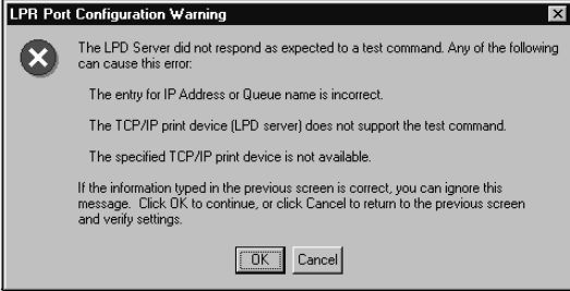
143
If you are still experiencing difficulty accessing or browsing the printer, contact the Customer Solutions
Center for further assistance.
Web Browser/HTTP Problem
In some cases, you may not be able to browse the printer Web page simply because the PrintNet HTTP
may be turned off.
If you cannot ping the PrintNet IP address, make sure the IP Address, subnet mask, and default
gateway are set correctly by checking the Ethernet Parameters menu from the operator panel. See the
User's Manual for configuration menu information.
If you can ping the PrintNet IP address but cannot access the Web pages, perform the following
procedure to verify the PrintNet HTTP is turned on.
1.
Telnet into the PrintNet and log in as root. There is no password by default.
2.
At the system prompt, enter the following commands:
config http on
save
reset
3.
After approximately 30 seconds, point your browser to the PrintNet IP address.
The printer Web pages should now be accessible.
If you are still experiencing difficulty accessing or browsing the printer, contact the Customer Solutions
Center for further assistance.
Windows NT 4.0 or 2000 Host Setup Problems
The installation procedure covered earlier in this chapter assumes that the PrintNet is configured with the
correct IP address, subnet mask and gateway (if required), and that the administrator can ping and
telnet to the PrintNet from the server console. If this is not the case, use the printer front panel to
configure the PrintNet before proceeding.
Installing Microsoft TCP/IP Printing
The PrintNet installation for Windows NT 4.0/2000 also requires the “Microsoft TCP/IP Printing” service
on the server. To install this service, click the Network icon in the Control Panel and click the Services
tab. Click Add Service and select Microsoft TCP/IP printing.
• Do you have administrative privileges?
This installation requires administrator privileges.
• “LPR port” is not listed.
Cancel the installation and install the Microsoft TCP/IP printing service on the server.
• LPR configuration warning.
144
The Ethernet cable is not plugged in or the printer is not turned on. This message is a communication
failure between the NT/2000 server and the PrintNet. Check cabling, IP address settings, gateway, etc.
• Test page does not print or prints incorrectly:
1.
Is the printer online? Re-send test page.
2.
The print queue name should be d1prn; however, the name can be changed. To
verify the queue names, print an E-Net Test Page. Refer to your User's Manual for
information.
3.
The Printronix NT print driver requires P-Series emulation active on the printer.
The Generic/Text driver should print in any printer emulation.
4.
Delete then re-install the Microsoft TCP/IP Print service on the server.
If you are still experiencing difficulty accessing or browsing the printer, contact the Customer Solutions
Center for further assistance.
Unix Troubleshooting Tips
This section provides information on possible solutions to some standard configuration errors. If you
require technical support, please have as much of the following information available when you call:
1.
What level of software are you running?
2.
What type of attachment do you have?
3.
What is your host operating system?
4.
How often, and when, does the problem occur?
5.
Give a detailed description of the problem.
6.
Give a detailed description of your network and the components attached.
PrintNet Cannot be Found on the Network
• Have you configured the PrintNet with a unique and valid IP address which corresponds with the
other IP addresses on your network? For example, are you sure no other device is using this IP
address?
• Are you sure you are trying to talk to the PrintNet from a Unix station on the same subnet? Currently,
the print server can only be seen locally unless you configured it with a routing entry.
• If you look at the back of the printer, is the STAT LED flashing once a second or is it quicker than
that? A slower, once-a- second rate tells you that the print server is in fact configured with an IP
address. A faster rate indicates it knows nothing about this, so you may need to try the configuration
process again.
• Have you confirmed that the network connection to the PrintNet is working correctly? Trying different
network cables and locations will help narrow down the problem.
Nothing Prints
• Can you ping the PrintNet from your Unix station? If not, please refer to PrintNet Cannot be Found
on the Network shown above.
• Is the PrintNet able to communicate with the attached printer? To test this, you can:
1.
Telnet to the print server (e.g., telnet 192.75.11.9) and log in as root.
2.
Enter the command start fox prn.
145
3.
Execute stop prn right after starting the test.
4.
This test will send the same text line over and over to the attached printer.
• Is the job getting stuck in the Unix host queue? If so, check that the printer is online. If it is, there is a
configuration error on the Unix station, so creating a new print setup may be needed.
• Is the control panel showing any activity to indicate it is receiving data? If so, but there is nothing
printing, check if a manual form feed is needed. Also, ensure that the printer can support the type of
job coming through.
• Do all jobs fail or just certain ones? For example, is it possible that jobs from a certain application are
the only ones to fail? If so, check the type of data it sends to make sure it matches the printer
emulation. Check the application printer configuration for mistakes.
• If you are using System V, was the spooler restarted?
Stair-Stepped Output
Stair-stepped output is print which starts at the top left of the page but every line thereafter starts a little
further over to the right. It also refers to Unix jobs that print one line of text at the top of a page followed
by a series of blank pages.
This kind of output happens only with Unix text jobs if carriage return insertion is not incorporated into the
print setup. The printer may be told to do a linefeed, but the Unix job does not specify anything about a
carriage return to follow this.
To fix this, carriage return insertion must be enabled somewhere in the print setup. The easiest and most
common location is on the PrintNet itself within the appropriate model. The feature is called “onlcr” and
the command syntax is:
set model modelname stty onlcr
save
For example, if printing to the destination, d1prn, the associated model is m1. Therefore, the command
is:
set model m1 stty onlcr
save
No Form Feed or Extra Page Comes Out
Unix text jobs may also have problems outputting the last page of a job especially when the BSD Remote
(LPD) print method is used. This means the form feed button has to be pressed on the printer to get this
last page out.
To make this process automatic, tell the PrintNet to handle this task by setting this feature “on” in the
appropriate model. The command syntax is:
set model modelname trailer $FF
save
For example, if printing to the destination, d2prn, the associated model is m2. Therefore, the command
is:
set model m2 trailer $FF
save
For default destination model mappings of the PrintNet, please see PrintNet Naming Schemes on page
139.
146
Front Panel Message – Dynamically Set Params Read Only
This is not an error. It is an informational message warning that the IP address has been dynamically set
by either dhcp, rarp, or bootp.
To assign a static IP address, turn off the rarp, bootp, and dhcp on the PrintNet. Use the following
procedure:
1.
Telnet to the PrintNet. Login = root, password = (Enter key)
Telnet commands are:
store tcpip 1 opts -bootp -dhcp
store tcpip tcp opts -zeroIPArp reset
Wait two minutes for the PrintNet to reset.
2.
Program the IP address, Subnet Mask and Gateway (if required) from the front panel.

147
Customer Support
Printronix Customer Support Center
IMPORTANT Please have the following information available prior to calling the
Printronix
Customer Support Center:
• Model number
• Serial number (located on the back of the printer)
• Installed options (i.e., interface and host type if applicable to the problem)
• Configuration printout: (See “Printing A Configuration” ) in your printers
Administrator’s manual.
• Is the problem with a new install or an existing printer?
• Description of the problem (be specific)
• Good and bad samples that clearly show the problem (faxing or emailing
of these samples may be required)
Americas (714) 368-2686
Europe, Middle East, and Africa (31) 24 6489 311
Asia Pacific (65) 6548 4114
China (86) 800-999-6836
http://www.printronix.com/support.aspx
Printronix Supplies Department
Contact the Printronix Supplies Department for genuine Printronix supplies.
Americas (800) 733-1900
Europe, Middle East, and Africa (33) 1 46 25 19 07
Asia Pacific (65) 6548 4100
China (86) 400-886-5598
India 1800 102 7869
http://www.printronix.com/supplies-parts.aspx

148
Corporate Offices
Printronix, LLC.
15345 Barranca Parkway
Irvine, CA 92618
U.S.A.
Phone: (714) 368-2300
Fax: (714) 368-2600
Printronix LLC.
c/o Printronix Nederland BV
Bijsterhuizen 11-38
6546 AS Nijmegen
The Netherlands
Phone: (31) 24 6489489
Fax: (31) 24 6489499
Printronix Schweiz GmbH
3 Changi Business Park Vista
#04-05 AkzoNobel House
Singapore 486051
Phone: (65) 6548 4100
Fax: (65) 6548 4111
Printronix Commercial (Shanghai) Co. Ltd.
Room 903, 9th Floor
No. 199, North Xizang Road
200070 Shanghai P.R. China
Phone: (86) 400 886 5598
Fax: (8621) 61171256
Printronix India Pvt Ltd
B-808/809, BSEL Tech Park
8th Floor, Sector 30A
Vashi Navi Mumbai 400705
India
Toll Free No.: 1800 102 7896
Fax: (9122) 4158 5555
Visit the Printronix web site at www.printronix.com
149

150
Glossary
ARP Address Resolution Protocol. Associates a selected IP
address with a network device Ethernet address.
bps Bits per second.
Centronics Parallel port interface standard found on most printers.
daemon A continuously running process that handles system-
wide functions like print spooling.
default router Local device that forwards any IP packets destined for
another subnet.
destination Logical print queue on the PrintNet to which hosts send
their print jobs. There are eight destinations by default.
DHCP Dynamic Host Configuration Protocol. Allows a network
device to discover its IP address dynamically upon
bootup. The IP address does not need to be stored
within the device itself permanently.
Download Mode Refers to the condition of the PrintNet when in a startup
condition, downloading configuration information.
DNS Domain Name Server. Host providing responses to
queries for a given host name IP address.
EEPROM Electrically Erasable/Programmable Read- Only
Memory.
factory defaults Settings shipped with the PrintNet.
Factory Settings S2 jumper position stating all factory default settings are
to be used while the PrintNet is up and running.
Firmware Panic Unrecoverable errors detected by the PrintNet firmware
force the Print Server into Firmware Panic mode.
Manually reset the PrintNet to resume operation.
Flash Stores firmware code and configurable settings. Allows
for upgrades without replacing hardware inside the
PrintNet.
FTP File Transfer Protocol. Used for transferring files from
one TCP/IP host to another and used in the upgrade
process.
gateway Hardware device that translates data between two
incompatible networks.
gateway address The IP address of a gateway.
Hardware Exception Bus errors, address errors, and illegal instructions force
the PrintNet into this PrintNet non-operational mode.
151
HTML HyperText Markup Language. Format used for
documents viewable on the World Wide Web.
ifnum Interface Number. Represents the network interface.
With a PrintNet, this will always be “1” for Ethernet.
interface script Unix host filter file that processes the print job before it is
sent over the network to the PrintNet.
IP Address The Internet Protocol Address. A numeric address such
as 123.45.61.23 which identifies a printer or server in a
LAN or WAN.
LAN Local Area Network.
LED Light Emitting Diode. The printer has an LED display
which shows the status of the printer to the operator.
logpath Determines the type of print job and printer logging
needed per job. One logpath is associated with every
destination.
LPD/LPR Line Printer Daemon. The most common TCP/IP remote
printing protocol that crosses all hardware utilizing IP.
MAC Machine Address Code.
MIB Management Information Base. A set of variables
(database) managed by an SNMP manager application.
model Defines how a print job should be processed (e.g.,
banner pages added, ASCII to PostScript conversion) as
it passes through the PrintNet. One model is associated
with every destination.
NetBIOS Network Basic Input Output System. Common interface
among PC networks.
Monitor Mode Refers to the condition of the PrintNet with no
configuration or IP address loaded.
npsh Extensive built-in command shell within the PrintNet.
PDF Portable Document Format. Encodes different types of
documents enabling them to be read across multiple
platforms.
Persistent DHCP When this option is enabled, the IP Address, Gateway,
and Subnet Mask obtained through DHSP is saved. If
the DHCP server does not provide an address, the
device will use the previously saved DHCP IP address.
This option only works when DHCP is enabled. The
default disable.
ping Standard command to test a TCP/IP connection. (e.g.,
ping 192.75.11.9)
print path Three-stage path a print job takes when it is sent from a
host to a printer through the PrintNet.
protocol A set of rules or conventions governing the exchange of
information between computer systems or between a
printer and a host computer. For computer printers, a
protocol is the coding convention used to convey and
print data. A printer protocol includes codes for printing
text and graphics, as well as codes instructing the printer
152
to perform special operations and machine-to-machine
communication codes.
PSERVER Print Server. A Novell print method where the PrintNet
continuously polls the Novell file server print queue
looking for print jobs.
RAM Random Access Memory. Volatile memory within the
PrintNet that contains current/ working settings. Settings
are lost once the power is removed.
RARP Reverse Address Resolution Protocol. Allows a network
device to discover its IP address dynamically upon
bootup. The IP address does not need to be stored
within the device itself permanently.
ROM Read-Only Memory.
router A device that forwards IP packets to their destination.
Also called a gateway.
RPRINTER Remote Printer. A Novell print method where the
PrintNet waits for jobs to be sent to it from a defined
PSERVER.
SNMP Simple Network Management Protocol. A standard
protocol used to monitor network devices called “SNMP
agents.”
socket TCP connection between two hosts consisting of a
source and destination TCP port number at each end.
subnet mask A binary value used to divide IP networks into smaller
sub-networks or subnets. This mask is used to help
determine whether IP packets need to be forwarded to
other subnets.
TCP/IP Transmission Control Protocol/Internet Protocol. Suite of
protocols that act as the base protocol for the Internet.
TCP port A logical connection point in the software of a TCP host
or device. When two IP devices talk, they establish a
socket which consists of a source and destination TCP
port number on both ends.
telnet Command and protocol to establish a terminal
connection between two hosts on an IP network.
UTP Unshielded Twisted Pair. A cable used for telephone and
computer-to-computer connections.
WAN Wide Area Network.
259771-001B
