Config(PWC) PWC
User Manual: PWC
Open the PDF directly: View PDF ![]() .
.
Page Count: 112 [warning: Documents this large are best viewed by clicking the View PDF Link!]
- QUICK REFERENCE INDEX
- Table of Contents
- BASIC INSPECTION
- FUNCTION DIAGNOSIS
- COMPONENT DIAGNOSIS
- ECU DIAGNOSIS
- SYMPTOM DIAGNOSIS
- NONE OF THE POWER WINDOWS CAN BE OPERATED USING ANY SWITCH
- DRIVER SIDE POWER WINDOW DOES NOT OPERATE
- FRONT PASSENGER SIDE POWER WINDOW DOES NOT OPERATE
- REAR LH SIDE POWER WINDOW DOES NOT OPERATE
- REAR RH SIDE POWER WINDOW DOES NOT OPERATE
- ANTI-PINCH SYSTEM DOES NOT OPERATE NORMALLY (DRIVER SIDE)
- ANTI-PINCH SYSTEM DOES NOT OPERATE NORMALLY (PASSENGER SIDE)
- POWER WINDOW RETAINED POWER OPERATION DOES NOT OPERATE PROPERLY
- AUTO OPERATION DOES NOT OPERATE BUT MANUAL OPERATE NORMALLY (DRIVER SIDE)
- AUTO OPERATION DOES NOT OPERATE BUT MANUAL OPERATE NORMALLY (PASSENGER SIDE)
- DOES NOT OPERATE BY KEY CYLINDER SWITCH
- KEYLESS POWER WINDOW DOWN DOES NOT OPERATE
- POWER WINDOW LOCK SWITCH DOES NOT FUNCTION
- POWER WINDOW SWITCH ILLUMINATION DOES NOT ILLUMINATE
- PRECAUTION
- ON-VEHICLE REPAIR
- POWER SUPPLY ROUTING CIRCUIT
- FUSE BLOCK - JUNCTION BOX (J/B)
- FUSE, FUSIBLE LINK AND RELAY BOX

PWC-1
BODY EXTERIOR, DOORS, ROOF & VEHICLE SECURITY
C
D
E
F
G
H
I
J
L
M
SECTION PWC A
B
PWC
N
O
P
CONTENTS
POWER WINDOW CONTROL SYSTEM
BASIC INSPECTION .................................... 4
DIAGNOSIS AND REPAIR WORKFLOW .......... 4
WorkFlow ..................................................................4
INSPECTION AND ADJUSTMENT ..................... 5
ADDITIONAL SERVICE WHEN REMOVING BAT-
TERY NEGATIVE TERMINAL .....................................5
ADDITIONAL SERVICE WHEN REMOVING
BATTERY NEGATIVE TERMINAL : Description ......5
ADDITIONAL SERVICE WHEN REMOVING
BATTERY NEGATIVE TERMINAL : Special Re-
pair Requirement .......................................................5
ADDITIONAL SERVICE WHEN REPLACING
CONTROL UNIT ..........................................................5
ADDITIONAL SERVICE WHEN REPLACING
CONTROL UNIT : Description ..................................5
ADDITIONAL SERVICE WHEN REPLACING
CONTROL UNIT : Special Repair Requirement .......6
FUNCTION DIAGNOSIS ............................... 7
POWER WINDOW SYSTEM ............................... 7
System Diagram .......................................................7
System Description ...................................................7
Component Parts Location ......................................9
Component Description .............................................9
DIAGNOSIS SYSTEM (BCM) ............................11
COMMON ITEM .........................................................11
COMMON ITEM : CONSULT-III Function (BCM -
COMMON ITEM) .....................................................11
RETAINED PWR .......................................................12
RETAINED PWR : CONSULT-III Function (BCM -
RETAINED PWR) ...................................................12
COMPONENT DIAGNOSIS .........................13
POWER SUPPLY AND GROUND CIRCUIT ......13
BCM ...........................................................................13
BCM : Diagnosis Procedure ....................................13
POWER WINDOW MAIN SWITCH ............................13
POWER WINDOW MAIN SWITCH : Diagnosis
Procedure ................................................................13
FRONT POWER WINDOW SWITCH (PASSEN-
GER SIDE) .................................................................14
FRONT POWER WINDOW SWITCH (PASSEN-
GER SIDE) : Diagnosis Procedure ..........................14
REAR POWER WINDOW SWITCH ...........................15
REAR POWER WINDOW SWITCH : Diagnosis
Procedure ................................................................15
REAR POWER WINDOW SWITCH ..................17
Description ...............................................................17
Component Function Check ....................................17
Diagnosis Procedure ...............................................17
Component Inspection .............................................18
POWER WINDOW MOTOR ..............................19
DRIVER SIDE .............................................................19
DRIVER SIDE : Description .....................................19
DRIVER SIDE : Component Function Check ..........19
DRIVER SIDE : Diagnosis Procedure .....................19
DRIVER SIDE : Component Inspection ...................20
PASSENGER SIDE ....................................................20
PASSENGER SIDE : Description ............................20
PASSENGER SIDE : Component Function Check
....20
PASSENGER SIDE : Diagnosis Procedure ............20
PASSENGER SIDE : Component Inspection ..........21
REAR LH ....................................................................22
REAR LH : Description ............................................22
REAR LH : Component Function Check .................22
REAR LH : Diagnosis Procedure .............................22
REAR LH : Component Inspection ..........................23
Revision: 2007 November 2008 EX35

PWC-2
REAR RH .................................................................. 23
REAR RH : Description .......................................... 23
REAR RH : Component Function Check ................ 23
REAR RH : Diagnosis Procedure ........................... 24
REAR RH : Component Inspection ........................ 25
DOOR SWITCH ................................................. 26
Description .............................................................. 26
Component Function Check ................................. 26
Diagnosis Procedure .............................................. 26
Component Inspection ............................................ 27
ENCODER CIRCUIT .......................................... 28
DRIVER SIDE ............................................................ 28
DRIVER SIDE : Description .................................... 28
DRIVER SIDE : Component Function Check ......... 28
DRIVER SIDE : Diagnosis Procedure .................... 28
PASSENGER SIDE ................................................... 30
PASSENGER SIDE : Description ........................... 30
PASSENGER SIDE : Component Function Check
... 30
PASSENGER SIDE : Diagnosis Procedure ........... 30
DOOR KEY CYLINDER SWITCH ...................... 33
Description .............................................................. 33
Component Function Check ................................... 33
Diagnosis Procedure .............................................. 33
Component Inspection ............................................ 34
POWER WINDOW SERIAL LINK ..................... 35
Description .............................................................. 35
Component Function Check ................................... 35
Diagnosis Procedure .............................................. 35
POWER WINDOW SYSTEM ............................. 37
Wiring Diagram - POWER WINDOW SYSTEM - ... 37
ECU DIAGNOSIS ........................................ 43
BCM (BODY CONTROL MODULE) .................. 43
Reference Value ..................................................... 43
Wiring Diagram - BCM - ......................................... 67
Fail-safe .................................................................. 73
DTC Inspection Priority Chart .............................. 75
DTC Index .............................................................. 77
POWER WINDOW MAIN SWITCH .................... 79
Reference Value ..................................................... 79
Wiring Diagram - POWER WINDOW SYSTEM - ... 81
Fail Safe ................................................................. 86
FRONT POWER WINDOW SWITCH (PAS-
SENGER SIDE) .................................................. 88
Reference Value ..................................................... 88
Wiring Diagram - POWER WINDOW SYSTEM - ... 90
Fail Safe ................................................................. 95
SYMPTOM DIAGNOSIS ............................. 97
NONE OF THE POWER WINDOWS CAN BE
OPERATED USING ANY SWITCH ................... 97
Diagnosis Procedure ............................................... 97
DRIVER SIDE POWER WINDOW DOES NOT
OPERATE .......................................................... 98
Diagnosis Procedure ............................................... 98
FRONT PASSENGER SIDE POWER WIN-
DOW DOES NOT OPERATE ............................ 99
POWER WINDOW MAIN SWITCH IS OPERATED ... 99
POWER WINDOW MAIN SWITCH IS OPERAT-
ED : Diagnosis Procedure ....................................... 99
WHEN BOTH POWER WINDOW MAIN SWITCH
AND FRONT POWER WINDOW SWITCH ARE
OPERATED ............................................................... 99
WHEN BOTH POWER WINDOW MAIN SWITCH
AND FRONT POWER WINDOW SWITCH ARE
OPERATED : Diagnosis Procedure ........................ 99
REAR LH SIDE POWER WINDOW DOES
NOT OPERATE ................................................100
WITH BOTH POWER WINDOW MAIN SWITCH
AND REAR POWER WINDOW SWITCH LH ..........100
WITH BOTH POWER WINDOW MAIN SWITCH
AND REAR POWER WINDOW SWITCH LH : Di-
agnosis Procedure ................................................100
WITH REAR POWER WINDOW SWITCH LH
ONLY .......................................................................100
WITH REAR POWER WINDOW SWITCH LH
ONLY : Diagnosis Procedure ................................100
REAR RH SIDE POWER WINDOW DOES
NOT OPERATE ................................................101
WITH BOTH POWER WINDOW MAIN SWITCH
AND REAR POWER WINDOW SWITCH RH .........101
WITH BOTH POWER WINDOW MAIN SWITCH
AND REAR POWER WINDOW SWITCH RH : Di-
agnosis Procedure ................................................101
WITH REAR POWER WINDOW SWITCH RH
ONLY .......................................................................101
WITH REAR POWER WINDOW SWITCH RH
ONLY : Diagnosis Procedure ................................101
ANTI-PINCH SYSTEM DOES NOT OPERATE
NORMALLY (DRIVER SIDE) ...........................102
Diagnosis Procedure .............................................102
ANTI-PINCH SYSTEM DOES NOT OPERATE
NORMALLY (PASSENGER SIDE) ..................103
Diagnosis Procedure .............................................103
POWER WINDOW RETAINED POWER OP-
ERATION DOES NOT OPERATE PROPERLY
..104
Diagnosis Procedure .............................................104
Revision: 2007 November 2008 EX35

PWC-3
C
D
E
F
G
H
I
J
L
M
A
B
PWC
N
O
P
AUTO OPERATION DOES NOT OPERATE
BUT MANUAL OPERATE NORMALLY
(DRIVER SIDE) .................................................105
Diagnosis Procedure ............................................. 105
AUTO OPERATION DOES NOT OPERATE
BUT MANUAL OPERATE NORMALLY (PAS-
SENGER SIDE) ................................................106
Diagnosis Procedure ............................................. 106
DOES NOT OPERATE BY KEY CYLINDER
SWITCH ............................................................107
Diagnosis Procedure ............................................. 107
KEYLESS POWER WINDOW DOWN DOES
NOT OPERATE ................................................108
Diagnosis Procedure ............................................. 108
POWER WINDOW LOCK SWITCH DOES
NOT FUNCTION ...............................................109
Diagnosis Procedure .............................................109
POWER WINDOW SWITCH ILLUMINATION
DOES NOT ILLUMINATE ...............................110
Diagnosis Procedure .............................................110
PRECAUTION ............................................111
PRECAUTIONS ...............................................111
Precaution for Supplemental Restraint System
(SRS) "AIR BAG" and "SEAT BELT PRE-TEN-
SIONER" ...............................................................111
Precaution Necessary for Steering Wheel Rota-
tion after Battery Disconnect .................................111
ON-VEHICLE REPAIR ...............................112
POWER WINDOW MAIN SWITCH ................. 112
Exploded View .......................................................112
Removal and Installation .......................................112
Revision: 2007 November 2008 EX35

PWC-4
< BASIC INSPECTION >
DIAGNOSIS AND REPAIR WORKFLOW
BASIC INSPECTION
DIAGNOSIS AND REPAIR WORKFLOW
WorkFlow INFOID:0000000003573452
DETAILED FLOW
1.OBTAIN INFORMATION ABOUT SYMPTOM
Interview the customer to obtain the malfunction information (conditions and environment when the malfunc-
tion occurred) as much as possible when the customer brings the vehicle in.
>> GO TO 2.
2.REPRODUCE THE MALFUNCTION INFORMATION
Check the malfunction on the vehicle that the customer describes.
Inspect the relation of the symptoms and the condition when the symptoms occur.
>> GO TO 3.
3.IDENTIFY THE MALFUNCTIONING SYSTEM WITH “SYMPTOM DIAGNOSIS”
Use “Symptom diagnosis” from the symptom inspection result in step 2 and then identify where to start per-
forming the diagnosis based on possible causes and symptoms.
>> GO TO 4.
4.IDENTIFY THE MALFUNCTIONING PARTS WITH “COMPONENT DIAGNOSIS”
Perform the diagnosis with “Component diagnosis” of the applicable system.
>> GO TO 5.
5.REPAIR OR REPLACE THE MALFUNCTIONING PARTS
Repair or replace the specified malfunctioning parts.
>> GO TO 6.
6.FINAL CHECK
Check that malfunctions are not reproduced when obtaining the malfunction information from the customer,
referring to the symptom inspection result in step 2.
Are the malfunctions corrected?
YES >> INSPECTION END
NO >> GO TO 3.
Revision: 2007 November 2008 EX35

INSPECTION AND ADJUSTMENT
PWC-5
< BASIC INSPECTION >
C
D
E
F
G
H
I
J
L
M
A
B
PWC
N
O
P
INSPECTION AND ADJUSTMENT
ADDITIONAL SERVICE WHEN REMOVING BATTERY NEGATIVE TERMINAL
ADDITIONAL SERVICE WHEN REMOVING BATTERY NEGATIVE TERMINAL : De-
scription INFOID:0000000003573453
When the negative terminal of battery is disconnected, the initialization is necessary.
If any of the following operations are performed, the initialization is necessary as well as when the negative
terminal of battery is disconnected.
• Power supply to the power window main switch or power window motor is cut off by the removal
of battery terminal or the battery fuse is blown.
• Disconnection and connection of power window main switch harness connector.
• Removal and installation of motor from regulator assembly.
• Operation of regulator assembly as an independent unit.
• Removal and installation of glass.
• Removal and installation of door glass run.
The following specified operations can not be performed under the non-initialized condition.
• Auto-up operation
• Anti-pinch function
ADDITIONAL SERVICE WHEN REMOVING BATTERY NEGATIVE TERMINAL : Spe-
cial Repair Requirement INFOID:0000000003573454
INITIALIZATION PROCEDURE
1. Disconnect battery negative terminal or power window main switch connector. Reconnect it after a minute
or more.
2. Turn ignition switch ON.
3. Operate power window switch to fully open the window. (This operation is unnecessary if the window is
already fully open)
4. Continue pulling the power window switch UP (AUTO-UP operation). Even after glass stops at fully closed
position, keep pulling the switch for 2 seconds or more.
5. Initializing procedure is completely.
6. Inspect anti-pinch function.
CHECK ANTI-PINCH FUNCTION
1. Fully open the door window.
2. Place a piece of wood near fully closed position.
3. Close door glass completely with AUTO-UP.
• Check that glass lowers for approximately 150 mm (5.9 in) or 2 seconds without pinching piece of wood and
stops.
• Check that glass does not rise when operating the power window main switch while lowering.
CAUTION:
• Perform initial setting when auto-up operation or anti-pinch function does not operate normally.
• Check that AUTO-UP operates before inspection when system initialization is performed.
• Do not check with hands and other body parts because they may be pinched. Do not get pinched.
• It may switch to fail-safe mode if open/close operation is performed continuously without full close.
Perform initial setting in that situation. Refer to PWC-86, "Fail Safe"
• Finish initial setting. Otherwise, next operation cannot be done.
1. Auto-up operation
2. Anti-pinch function
ADDITIONAL SERVICE WHEN REPLACING CONTROL UNIT
ADDITIONAL SERVICE WHEN REPLACING CONTROL UNIT : Description
INFOID:0000000003729875
When the control unit is replace, the initialization is necessary.
If any of the following operations are performed, the initialization is necessary as well as when the control unit
is disconnected.
• Power supply to the power window main switch or power window motor is cut off by the removal
of battery terminal or the battery fuse is blown.
Revision: 2007 November 2008 EX35

PWC-6
< BASIC INSPECTION >
INSPECTION AND ADJUSTMENT
• Disconnection and connection of power window main switch harness connector.
• Removal and installation of motor from regulator assembly.
• Disconnection and connection of battery negative terminal.
• Removal and installation of glass.
• Removal and installation of door glass run.
The following specified operations can not be performed under the non-initialized condition.
• Auto-up operation
• Anti-pinch function
ADDITIONAL SERVICE WHEN REPLACING CONTROL UNIT : Special Repair Re-
quirement INFOID:0000000003729876
INITIALIZATION PROCEDURE
1. Disconnect battery negative terminal or power window main switch connector. Reconnect it after a minute
or more.
2. Turn ignition switch ON.
3. Operate power window switch to fully open the window. (This operation is unnecessary if the window is
already fully open)
4. Continue pulling the power window switch UP (AUTO-UP operation). Even after glass stops at fully closed
position, keep pulling the switch for 2 seconds or more.
5. Initializing procedure is completely.
6. Inspect anti-pinch function.
CHECK ANTI-PINCH FUNCTION
1. Fully open the door window.
2. Place a piece of wood near fully closed position.
3. Close door glass completely with AUTO-UP.
• Check that glass lowers for approximately 150 mm (5.9 in) or 2 seconds without pinching piece of wood and
stops.
• Check that glass does not rise when operating the power window main switch while lowering.
CAUTION:
• Perform initial setting when auto-up operation or anti-pinch function does not operate normally.
• Check that AUTO-UP operates before inspection when system initialization is performed.
• Do not check with hands and other body parts because they may be pinched. Do not get pinched.
• It may switch to fail-safe mode if open/close operation is performed continuously without full close.
Perform initial setting in that situation. Refer to PWC-86, "Fail Safe"
• Finish initial setting. Otherwise, next operation cannot be done.
1. Auto-up operation
2. Anti-pinch function
Revision: 2007 November 2008 EX35
POWER WINDOW SYSTEM
PWC-7
< FUNCTION DIAGNOSIS >
C
D
E
F
G
H
I
J
L
M
A
B
PWC
N
O
P
FUNCTION DIAGNOSIS
POWER WINDOW SYSTEM
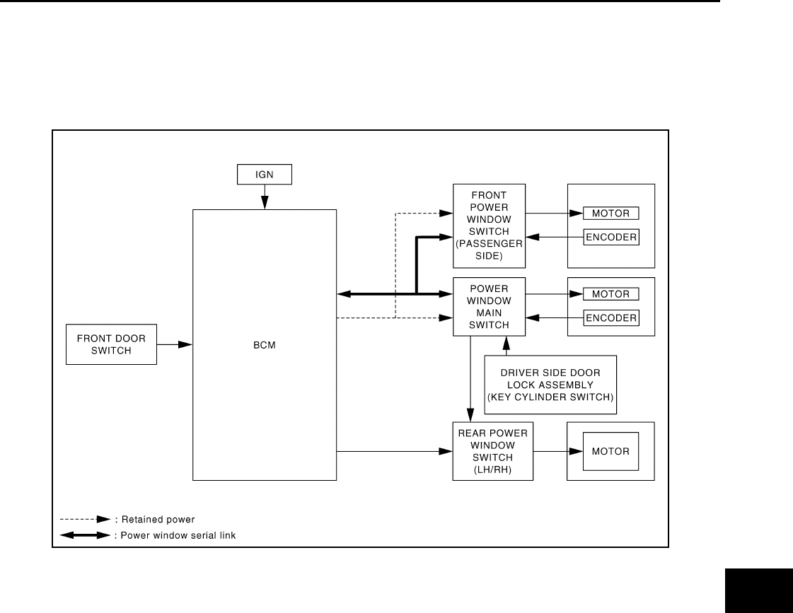
System Diagram INFOID:0000000003573457
System Description INFOID:0000000003573458
POWER WINDOW OPERATION
• Power window system is operable during the retained power operation timer after turning ignition switch
OFF.
• Power window main switch can open/close all windows.
• Front & rear power window switch can open/close the corresponding windows.
POWER WINDOW AUTO-OPERATION (FRONT SIDE)
• AUTO UP/DOWN operation can be performed when power window main switch turns to AUTO.
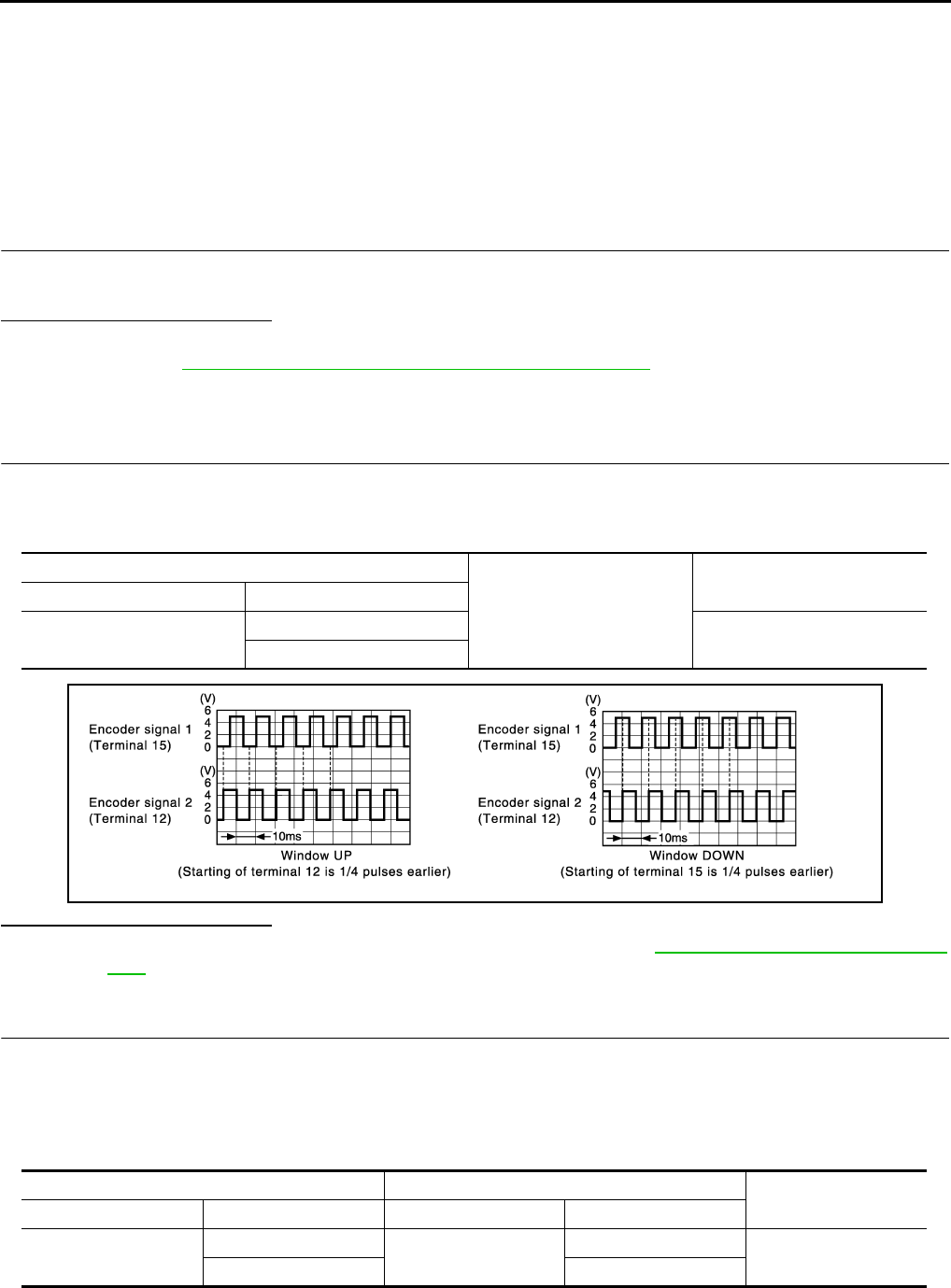
• Encoder continues detecting the movement of power window motor and output to power window switch as
the encoder pulse signal while power window motor is operating.
• Power window switch reads the changes of encoder signal and stops AUTO operation when door glass is at
fully opened/closed position.
• Auto function is inoperable in case encoder is malfunctioning.
RETAINED POWER OPERATION
Retained power operation is an additional power supply function that enables power window system to oper-
ate for 45 seconds even when ignition switch is turned OFF.
RETAINED POWER FUNCTION CANCEL CONDITIONS
• Front door CLOSE (door switch OFF) → OPEN (door switch ON).
• When ignition switch is ON again.
• When timer time passes. (45 seconds)
POWER WINDOW LOCK
Ground circuit inside power window main switch shuts off when power window lock switch is ON. This inhibits
power window switch operation except with the power window main switch.
JMKIA1829G
B
Revision: 2007 November 2008 EX35

PWC-8
< FUNCTION DIAGNOSIS >
POWER WINDOW SYSTEM
ANTI-PINCH SYSTEM (FRONT SIDE)
• Pinch foreign material in the door glass during AUTO-UP operation, and it is the anti-pinch function that low-
ers the door glass 150 mm (5.9 in) or 2 seconds when detected.
• Encoder continues detecting the movement of front power window motor and transmits to power window
main switch as the encoder pulse signal while front power window motor is operating.
• Resistance is applied to the front power window motor rotation that changes the frequency of encoder pulse
signal if foreign material is trapped in the door glass.
• Power window main switch controls to lower the window glass for 150 mm (5.9 in) or 2 seconds after it
detects encoder pulse signal frequency change.
OPERATION CONDITION
• When front door glass AUTO-UP operation is performed (anti-pinch function does not operate just before the
door glass closes and is fully closed)
NOTE:
Depending on environment and driving conditions, if a similar impact or load is applied to the door glass, it
may lower.
DOOR KEY CYLINDER SWITCH OPERATION
Hold the door key cylinder to the LOCK or UNLOCK direction for 1.5 seconds or more to OPEN or CLOSE all
power windows when ignition switch is OFF. In addition, it stops when key position is moved to NEUTRAL dur-
ing operating.
OPERATION CONDITION
• Ignition switch OFF.
• Hold door key cylinder to LOCK position for 1.5 seconds or more to perform CLOSE operation of the door
glass.
• Hold door key cylinder to UNLOCK position for 1.5 seconds or more to perform OPEN operation of the door
glass.
KEYLESS POWER WINDOW DOWN FUNCTION
All power windows open when the unlock button on Intelligent Key is activated and kept pressed for more than
3* seconds with the ignition switch OFF. The windows keep opening if the unlock button is continuously
pressed.
The power window opening stops when the following operations are performed.
• The unlock button is kept pressed more than 15 seconds.
• The ignition switch is turned ON while the power window opening is operated.
• The unlock button is released.
While retained power operation activate, keyless power window down function cannot be operated.
Keyless power window down operation mode can be changed by “PW DOWN SET” mode in “WORK SUP-
PORT”. Refer to DLK-49, "INTELLIGENT KEY : CONSULT-III Function (BCM - INTELLIGENT KEY)".
NOTE:
Use CONSULT-III to change settings.
MODE 1 (3 sec) / MODE 2 (OFF) / MODE 3 (5 sec)
Revision: 2007 November 2008 EX35
POWER WINDOW SYSTEM
PWC-9
< FUNCTION DIAGNOSIS >
C
D
E
F
G
H
I
J
L
M
A
B
PWC
N
O
P
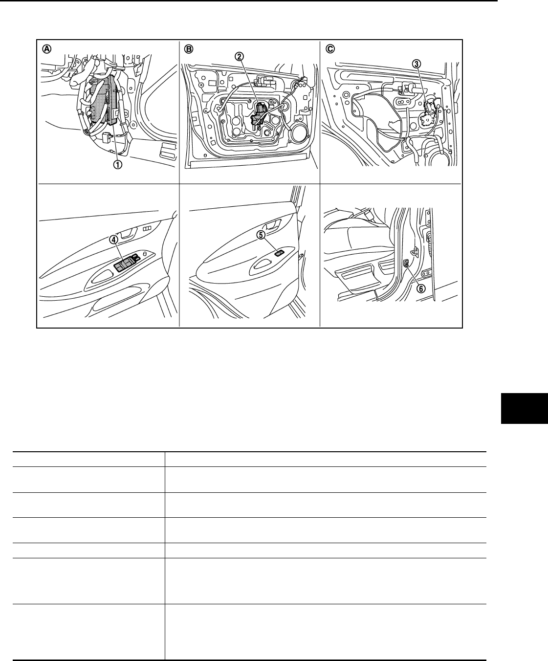
Component Parts Location INFOID:0000000003573459
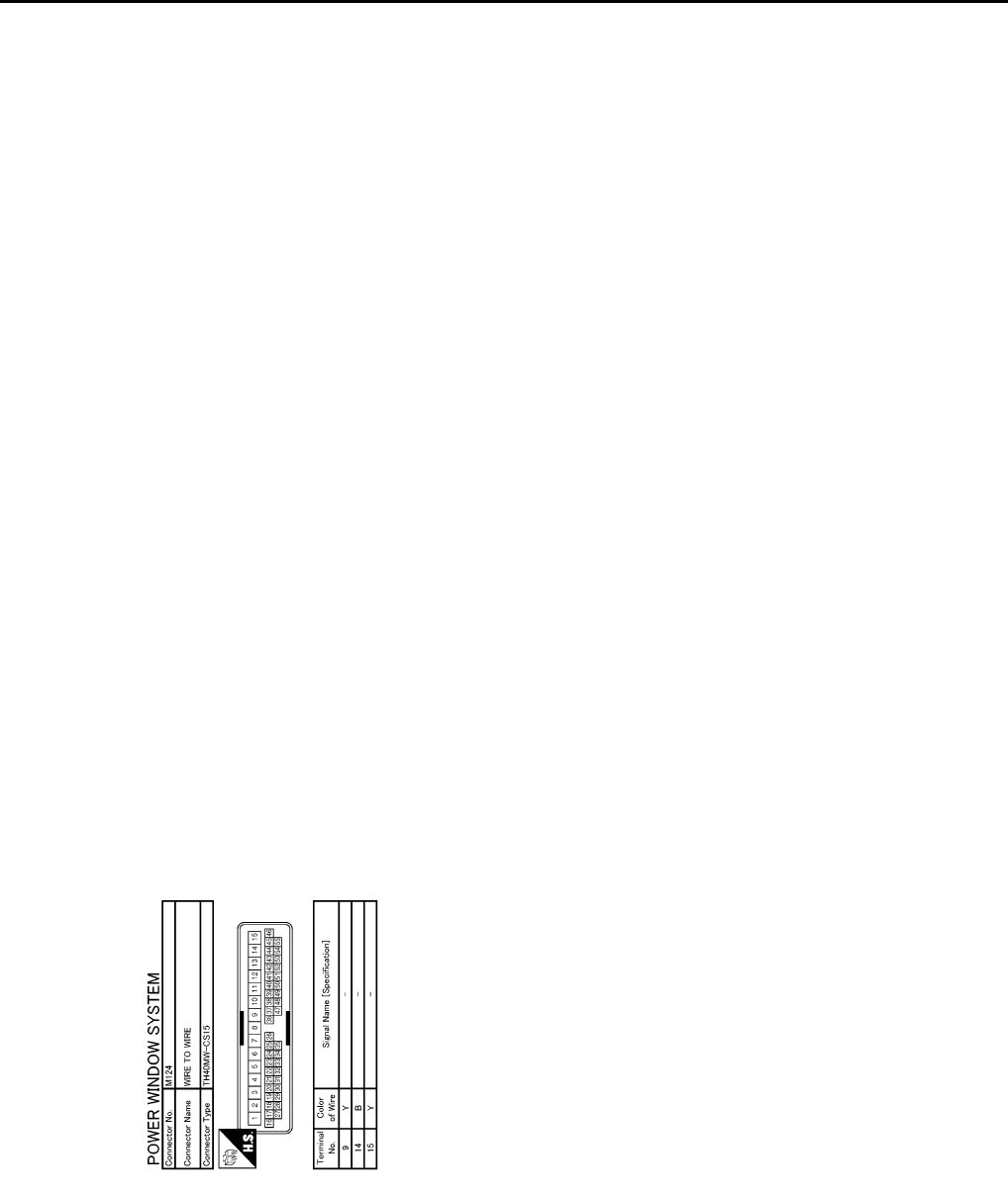
Component Description INFOID:0000000003573460
1. BCM
M118, M119, M122, M123
2. Front power window motor (driver side)
D10
3. Rear power window motor LH
D52
4. Power window main switch
D8, D9 5. Rear power window switch LH
D54 6. Front door switch (driver side)
B16
A. Dash side lower (passenger side) B. View with front door finisher removed. C. View with rear door finisher re-
moved.
JMKIA2075ZZ
Component Function
BCM • Supplies the power to power window switch
• Controls retained power function
Power window main switch • Directly controls all power window motor of all doors
• Controls anti-pinch operation of power window
Front power window switch (passenger
side)
• Controls power window motor of front passenger side door
• Controls anti-pinch operation of power window
Rear power window switch (LH & RH) Controls power window motor of rear right and left doors
Front power window motor (driver side)
• Integrates the encoder and power window motor
• Starts operating with signals from power window main switch
• Outputs front power window motor (driver side) rotation as a pulse signal to power
window main switch
Front power window motor (passenger
side)
• Integrates the encoder and power window motor
• Starts operating with signals from power window main switch & front power window
switch (passenger side)
• Outputs front power window motor (passenger side) rotation as a pulse signal to front
power window switch (passenger side)
Revision: 2007 November 2008 EX35

PWC-10
< FUNCTION DIAGNOSIS >
POWER WINDOW SYSTEM
Rear power window motor (LH & RH) Starts operating with signals from power window main switch & rear power window
switch (LH & RH)
Front door switch (front side) Door open/close condition and input to BCM
Component Function
Revision: 2007 November 2008 EX35

DIAGNOSIS SYSTEM (BCM)
PWC-11
< FUNCTION DIAGNOSIS >
C
D
E
F
G
H
I
J
L
M
A
B
PWC
N
O
P
DIAGNOSIS SYSTEM (BCM)
COMMON ITEM
COMMON ITEM : CONSULT-III Function (BCM - COMMON ITEM) INFOID:0000000003703253
APPLICATION ITEM
CONSULT-III performs the following functions via CAN communication with BCM.
SYSTEM APPLICATION
BCM can perform the following functions for each system.
NOTE:
It can perform the diagnosis modes except the following for all sub system selection items.
×: Applicable item
NOTE:
*: This item is displayed, but is not used.
FREEZE FRAME DATA (FFD) AND IGN COUNTER
Freeze Frame Data
Diagnosis mode Function Description
Work Support Changes the setting for each system function.
Self Diagnostic Result Displays the diagnosis results judged by BCM.
CAN Diag Support Monitor Monitors the reception status of CAN communication viewed from BCM. Refer to CONSULT-III opera-
tion manual.
Data Monitor The BCM input/output signals are displayed.
Active Test The signals used to activate each device are forcibly supplied from BCM.
Ecu Identification The BCM part number is displayed.
Configuration • Read and save the vehicle specification.
• Write the vehicle specification when replacing BCM.
System Sub system selection item Diagnosis mode
Work Support Data Monitor Active Test
Door lock DOOR LOCK ×××
Rear window defogger REAR DEFOGGER ××
Warning chime BUZZER ××
Interior room lamp timer INT LAMP ×××
Exterior lamp HEAD LAMP ×××
Wiper and washer WIPER ××
Turn signal and hazard warning lamps FLASHER ×××
— AIR CONDITONER*
• Intelligent Key system
• Engine start system INTELLIGENT KEY ×××
Combination switch COMB SW ×
Body control system BCM ×
IVIS - NATS IMMU ××
Interior room lamp battery saver BATTERY SAVER ×××
— TRUNK* ××
Vehicle security system THEFT ALM ×××
RAP system RETAINED PWR ×
Signal buffer system SIGNAL BUFFER ××
TPMS TPMS (AIR PRESSURE MONITOR) ×××
Revision: 2007 November 2008 EX35

PWC-12
< FUNCTION DIAGNOSIS >
DIAGNOSIS SYSTEM (BCM)
The BCM records the following condition at the moment a particular DTC is detected.
• Vehicle Speed
• Odd Trip Meter
• Vehicle Condition (BCM detected condition)
IGN Counter
IGN counter indicates the number of times that ignition switch is turned ON after DTC is detected.
• The number is 0 when a malfunction is detected now.
• The number increases like 1 → 2 → 3...38 → 39 after returning to the normal condition whenever ignition
switch OFF → ON.
• The number is fixed to 39 until the self-diagnosis results are erased if it is over 39.
RETAINED PWR
RETAINED PWR : CONSULT-III Function (BCM - RETAINED PWR) INFOID:0000000003573462
Data monitor
CONSULT screen terms Description
SLEEP>LOCK While turning BCM status from low power consumption mode to normal mode (Power supply
position is “LOCK”)
SLEEP>OFF While turning BCM status from low power consumption mode to normal mode (Power supply
position is “OFF”.)
LOCK>ACC While turning power supply position from “LOCK” to “ACC”
ACC>ON While turning power supply position from “ACC” to “IGN”
RUN>ACC While turning power supply position from “RUN” to “ACC” (Vehicle is stopping and selector
lever is except P position.)
CRANK>RUN While turning power supply position from “CRANKING” to “RUN” (From cranking up the en-
gine to run it)
RUN>URGENT While turning power supply position from “RUN“ to “ACC” (Emergency stop operation)
ACC>OFF While turning power supply position from “ACC” to “OFF”
OFF>LOCK While turning power supply position from “OFF” to “LOCK”
OFF>ACC While turning power supply position from “OFF” to “ACC”
ON>CRANK While turning power supply position from “IGN” to “CRANKING”
OFF>SLEEP While turning BCM status from normal mode (Power supply position is “OFF”.) to low power
consumption mode
LOCK>SLEEP While turning BCM status from normal mode (Power supply position is “LOCK”.) to low pow-
er consumption mode
LOCK Power supply position is “LOCK” (Ignition switch OFF with steering is locked.)
OFF Power supply position is “OFF” (Ignition switch OFF with steering is unlocked.)
ACC Power supply position is “ACC” (Ignition switch ACC)
ON Power supply position is “IGN” (Ignition switch ON with engine stopped)
ENGINE RUN Power supply position is “RUN” (Ignition switch ON with engine running)
CRANKING Power supply position is “CRANKING” (At engine cranking)
Monitor Item Description
DOOR SW-DR Indicates [ON/OFF] condition of driver side door switch.
DOOR SW-AS Indicates [ON/OFF] condition of passenger side door switch.
Revision: 2007 November 2008 EX35
POWER SUPPLY AND GROUND CIRCUIT
PWC-13
< COMPONENT DIAGNOSIS >
C
D
E
F
G
H
I
J
L
M
A
B
PWC
N
O
P
COMPONENT DIAGNOSIS
POWER SUPPLY AND GROUND CIRCUIT
BCM
BCM : Diagnosis Procedure INFOID:0000000003573463
1.CHECK FUSE AND FUSIBLE LINK
1.Turn ignition switch OFF.
2.Check that the following fuse and fusible link are not blown.
Is the fuse fusing?
YES >> Replace the blown fuse or fusible link after repairing the affected circuit if a fuse or fusible link is
blown.
NO >> GO TO 2.
2.CHECK POWER SUPPLY CIRCUIT
1. Disconnect BCM connectors.
2. Check voltage between BCM harness connector and ground.
Is the inspection result normal?
YES >> GO TO 3.
NO >> Repair or replace harness or connector.
3.CHECK GROUND CIRCUIT
Check continuity between BCM harness connector and ground.
Is the inspection result normal?
YES >> INSPECTION END
NO >> Repair or replace harness or connector.
POWER WINDOW MAIN SWITCH
POWER WINDOW MAIN SWITCH : Diagnosis Procedure INFOID:0000000003573464
1.CHECK POWER SUPPLY CIRCUIT 1
1. Turn ignition OFF.
2. Disconnect power window main switch connector.
3. Turn ignition switch ON.
4. Check voltage between power window main switch harness connector and ground.
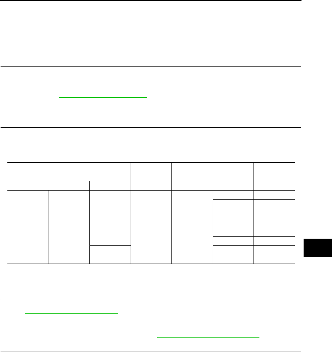
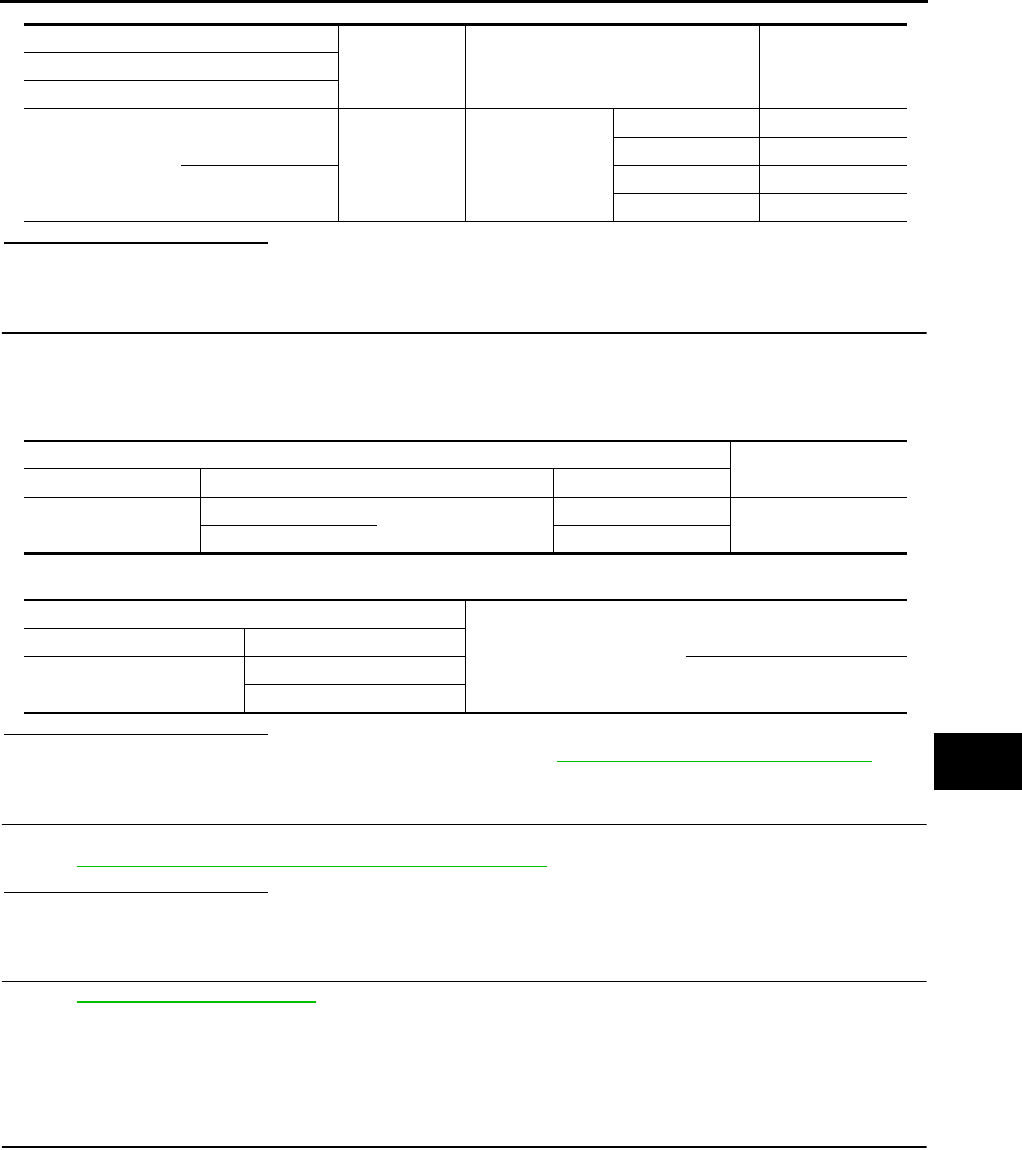
Terminal No. Signal name Fuse and fusible link No.
1Battery power supply K (40A)
11 10 (10A)
(+)
(−)Voltage
(Approx.)
BCM
Connector Terminal
M118 1 Ground Battery voltage
M119 11
BCM
Ground Continuity
Connector Terminal
M119 13 Existed
Revision: 2007 November 2008 EX35

PWC-14
< COMPONENT DIAGNOSIS >
POWER SUPPLY AND GROUND CIRCUIT
Is the inspection result normal?
YES >> GO TO 2.
NO >> GO TO 3.
2.CHECK GROUND CIRCUIT
1. Turn ignition switch OFF.
2. Check continuity between power window main switch harness connector and ground.
Is the inspection result normal?
YES >> INSPECTION END
NO >> Repair or replace harness.
3.CHECK POWER SUPPLY CIRCUIT 2
1. Turn ignition switch OFF.
2. Disconnect BCM connector.
3. Check continuity between BCM harness connector and power window main switch harness connector.
4. Check continuity between BCM harness connector and ground.
Is the inspection result normal?
YES >> Replace BCM. Refer to BCS-84, "Removal and Installation".
NO >> Repair or replace harness.
FRONT POWER WINDOW SWITCH (PASSENGER SIDE)
FRONT POWER WINDOW SWITCH (PASSENGER SIDE) : Diagnosis Procedure
INFOID:0000000003573465
1.CHECK POWER SUPPLY CIRCUIT 1
1. Turn ignition switch OFF.
2. Disconnect front power window switch (passenger side) connector.
3. Turn ignition switch ON.
4. Check voltage between front power window switch (passenger side) harness connector and ground.
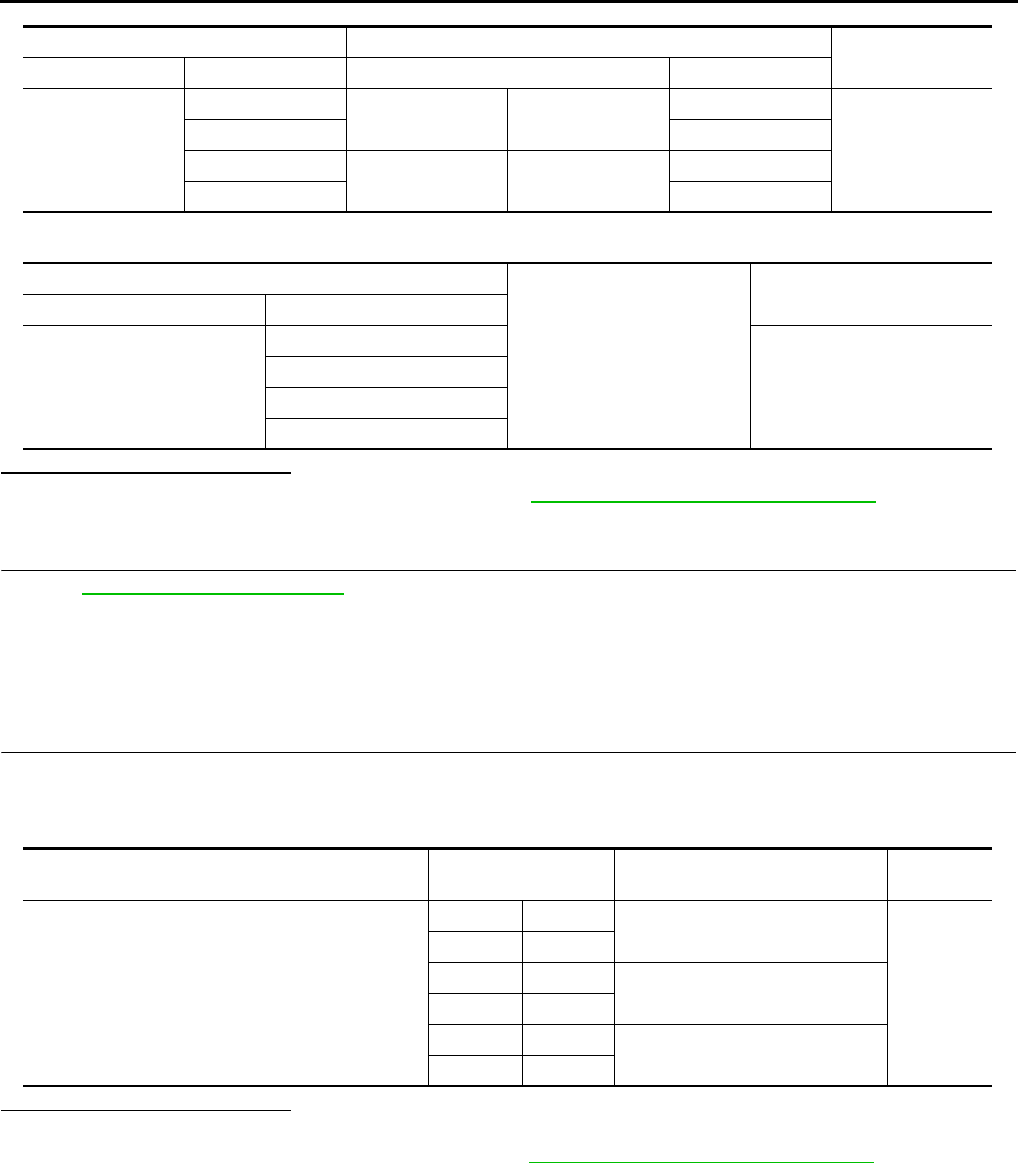
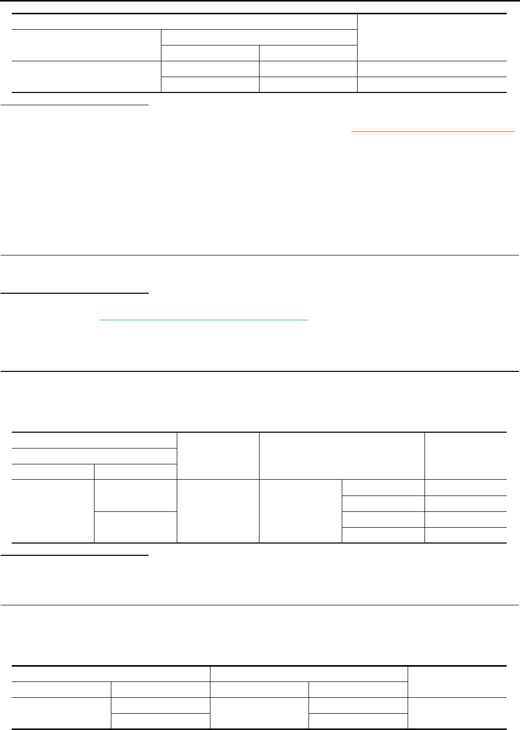
(+)
(–) Voltage (V)
(Approx.)
Power window main switch
Connector Terminal
D8 10 Ground Battery voltage
D9 19
Power window main switch
Ground Continuity
Connector Terminal
D9 17 Existed
BCM Power window main switch Continuity
Connector Terminal Connector Terminal
M118 2D919
Existed
3D810
BCM
Ground
Continuity
Connector Terminal
M118 2Not existed
3
Revision: 2007 November 2008 EX35
POWER SUPPLY AND GROUND CIRCUIT
PWC-15
< COMPONENT DIAGNOSIS >
C
D
E
F
G
H
I
J
L
M
A
B
PWC
N
O
P
Is the inspection result normal?
YES >> INSPECTION END.
NO >> GO TO 2.
2.CHECK POWER SUPPLY CIRCUIT 2
1. Turn ignition switch OFF.
2. Disconnect BCM connector.
3. Check continuity between BCM harness connector and front power window switch (passenger side) har-
ness connector.
4. Check continuity between BCM harness connector and ground.
Is the inspection result normal?
YES >> Replace BCM. Refer to BCS-84, "Removal and Installation".
NO >> Repair or replace harness.
REAR POWER WINDOW SWITCH
REAR POWER WINDOW SWITCH : Diagnosis Procedure INFOID:0000000003573466
1.CHECK POWER SUPPLY CIRCUIT 1
1. Turn ignition switch OFF.
2. Disconnect rear power window switch connector.
3. Turn ignition switch ON.
4. Check voltage between rear power window switch harness connector and ground.
Is the inspection result normal?
YES >> INSPECTION END.
NO >> GO TO 2.
2.CHECK POWER SUPPLY CIRCUIT 2
1. Turn ignition switch OFF.
2. Disconnect BCM connector.
3. Check continuity between BCM harness connector and rear power window switch harness connector.
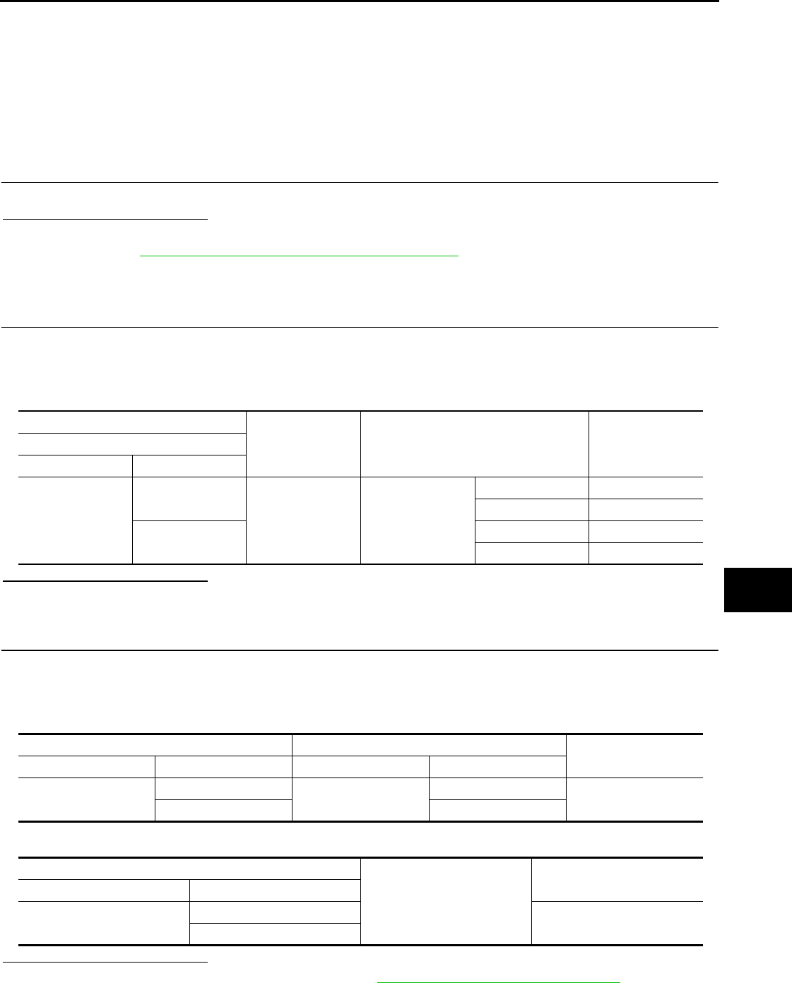
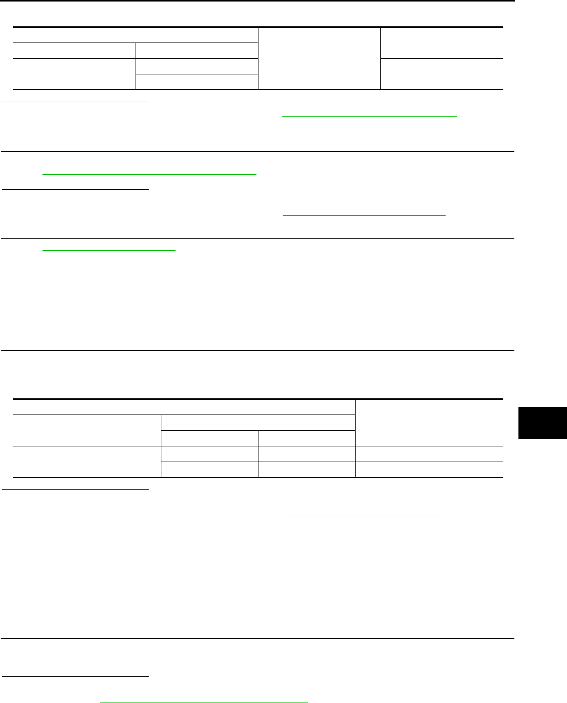
(+)
(–) Voltage (V)
(Approx.)
Front power window switch (passenger side)
Connector Terminal
D38 10 Ground Battery voltage
BCM Front power window switch (passenger side) Continuity
Connector Terminal Connector Terminal
M118 2 D38 10 Existed
BCM
Ground Continuity
Connector Terminal
M118 2 Not existed
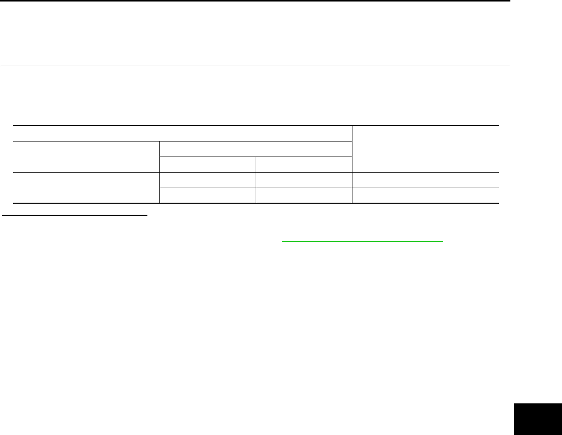
(+)
(–) Voltage (V)
(Approx.)
Rear power window switch
Connector Terminal
LH D54 1 Ground Battery voltage
RH D74
Revision: 2007 November 2008 EX35

PWC-16
< COMPONENT DIAGNOSIS >
POWER SUPPLY AND GROUND CIRCUIT
4. Check continuity between BCM harness connector and ground.
Is the inspection result normal?
YES >> Replace BCM. Refer to BCS-84, "Removal and Installation".
NO >> Repair or replace harness.
BCM Rear power window switch Continuity
Connector Terminal Connector Terminal
M118 3 LH D54 1 Existed
RH D74
BCM
Ground Continuity
Connector Terminal
M118 3 Not existed
Revision: 2007 November 2008 EX35
REAR POWER WINDOW SWITCH
PWC-17
< COMPONENT DIAGNOSIS >
C
D
E
F
G
H
I
J
L
M
A
B
PWC
N
O
P
REAR POWER WINDOW SWITCH
Description INFOID:0000000003573467
Rear power window motor will be operated if rear power window switch is operated.
Component Function Check INFOID:0000000003573468
1. CHECK REAR POWER WINDOW SWITCH FUNCTION
Check rear power window motor operation with rear power window switch.
Is the inspection result normal?
YES >> Rear power window switch is OK.
NO >> Refer to PWC-17, "Diagnosis Procedure".
Diagnosis Procedure INFOID:0000000003573469
1.CHECK REAR POWER WINDOW SWITCH INPUT SIGNAL
1. Turn ignition switch OFF.
2. Disconnect rear power window switch connector.
3. Turn ignition switch ON.
4. Check voltage between rear power window switch harness connector and ground.
Is the inspection result normal?
YES >> GO TO 2.
NO >> GO TO 3.
2.CHECK REAR POWER WINDOW SWITCH
Check rear power window switch.
Refer to PWC-18, "Component Inspection".
Is the inspection result normal?
YES >> GO TO 4.
NO >> Replace rear power window switch. Refer to PWC-112, "Removal and Installation".
3.CHECK REAR POWER WINDOW SWITCH CIRCUIT
1. Turn ignition switch OFF.
2. Disconnect power window main switch connector.
3. Check continuity between power window main switch harness connector and rear power window switch
harness connector.
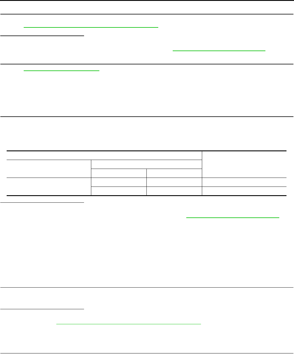
(+)
(–) Condition Voltage (V)
(Approx.)
Rear power window switch
Connector Terminal
LH D54
2
Ground
Power window
main switch: LH
UP Battery voltage
DOWN 0
3UP 0
DOWN Battery voltage
RH D74
2Power window
main switch: RH
UP Battery voltage
DOWN 0
3UP 0
DOWN Battery voltage
Revision: 2007 November 2008 EX35
PWC-18
< COMPONENT DIAGNOSIS >
REAR POWER WINDOW SWITCH
4. Check continuity between power window main switch harness connector and ground.
Is the inspection result normal?
YES >> Replace power window main switch.Refer to PWC-112, "Removal and Installation".
NO >> Repair or replace harness.
4.CHECK INTERMITTENT INCIDENT
Refer to GI-38, "Intermittent Incident".
>> INSPECTION END
Component Inspection INFOID:0000000003573470
1.CHECK REAR POWER WINDOW SWITCH
1. Turn ignition switch OFF.
2. Disconnect rear power window switch connector.
3. Check rear power window switch.
Is the inspection result normal?
YES >> INSPECTION END
NO >> Replace rear power window switch. Refer to PWC-112, "Removal and Installation".
Power window main switch Rear power window switch Continuity
Connector Terminal Connector Terminal
D8
1LH D54 2
Existed
33
5RH D74 3
72
Power window main switch
Ground
Continuity
Connector Terminal
D8
1
Not existed
3
5
7
Rear power window switch Terminal Rear power window switch condi-
tion Continuity
•D54 (LH)
•D74 (RH)
15 UP
Existed
34
34 NEUTRAL
25
14 DOWN
25
Revision: 2007 November 2008 EX35
POWER WINDOW MOTOR
PWC-19
< COMPONENT DIAGNOSIS >
C
D
E
F
G
H
I
J
L
M
A
B
PWC
N
O
P
POWER WINDOW MOTOR
DRIVER SIDE
DRIVER SIDE : Description INFOID:0000000003573471
Door glass moves UP/DOWN by receiving the signal from power window main switch.
DRIVER SIDE : Component Function Check INFOID:0000000003573472
1. CHECK FRONT POWER WINDOW MOTOR (DRIVER SIDE) OPERATION
Check front power window motor (driver side) operation with power window main switch.
Is the inspection result normal?
YES >> Front power window motor (driver side) is OK.
NO >> Refer to PWC-19, "DRIVER SIDE : Diagnosis Procedure".
DRIVER SIDE : Diagnosis Procedure INFOID:0000000003573473
1.CHECK POWER WINDOW MOTOR (DRIVER SIDE) INPUT SIGNAL
1. Turn ignition switch OFF.
2. Disconnect front power window motor (driver side) connector.
3. Turn ignition switch ON.
4. Check voltage between power window motor (driver side) harness connector and ground.
Is the inspection result normal?
YES >> GO TO 3.
NO >> GO TO 2.
2.CHECK POWER WINDOW MOTOR CIRCUIT
1. Turn ignition switch OFF.
2. Disconnect power window main switch connector.
3. Check continuity between power window main switch harness connector and front power window motor
(driver side) harness connector.
4. Check continuity between power window main switch harness connector and ground.
Is the inspection result normal?
YES >> Replace power window main switch.Refer to PWC-112, "Removal and Installation".
NO >> Repair or replace harness.
(+)
(–) Condition Voltage (V)
(Approx.)
Power window motor (driver side)
Connector Terminal
D10
1
Ground Power window
main switch
UP Battery voltage
DOWN 0
2UP 0
DOWN Battery voltage
Power window main switch Front power window motor (driver side) Continuity
Connector Terminal Connector Terminal
D8 8D10 2Existed
11 1
Power window main switch
Ground
Continuity
Connector Terminal
D8 8Not existed
11
Revision: 2007 November 2008 EX35
PWC-20
< COMPONENT DIAGNOSIS >
POWER WINDOW MOTOR
3.CHECK FRONT POWER WINDOW MOTOR (DRIVER SIDE)
Check front power window motor (driver side).
Refer to PWC-20, "DRIVER SIDE : Component Inspection".
Is the inspection result normal?
YES >> GO TO 4.
NO >> Replace power window motor (driver side). Refer to GW-20, "Removal and Installation".
4.CHECK INTERMITTENT INCIDENT
Refer to GI-38, "Intermittent Incident".
>> INSPECTION END
DRIVER SIDE : Component Inspection INFOID:0000000003573474
1.CHECK FRONT POWER WINDOW MOTOR (DRIVER SIDE)
1. Turn ignition switch OFF.
2. Disconnect front power window motor (driver side) connector.
3. Check motor operate by connecting the battery voltage directly to front power window motor (driver side)
connector.
Is the inspection result normal?
YES >> INSPECTION END
NO >> Replace front power window motor (driver side). Refer to GW-20, "Removal and Installation".
PASSENGER SIDE
PASSENGER SIDE : Description INFOID:0000000003573475
Door glass moves UP/DOWN by receiving the signal from power window main switch or front power window
switch (passenger side).
PASSENGER SIDE : Component Function Check INFOID:0000000003573476
1. CHECK FRONT POWER WINDOW MOTOR (PASSENGER SIDE) OPERATION
Check front power window motor (passenger side) operation with power window main switch or front power
window switch (passenger side).
Is the inspection result normal?
YES >> Power window motor (passenger side) is OK.
NO >> Refer to PWC-20, "PASSENGER SIDE : Diagnosis Procedure".
PASSENGER SIDE : Diagnosis Procedure INFOID:0000000003573477
1.CHECK FRONT POWER WINDOW MOTOR (PASSENGER SIDE) INPUT SIGNAL
1. Turn ignition switch OFF.
2. Disconnect front power window motor (passenger side) connector.
3. Turn ignition switch ON.
4. Check voltage between front power window motor (passenger side) harness connector and ground.
Front power window motor (driver side)
Motor condition
Connector Terminal
(+) (–)
D10 12 DOWN
21 UP
Revision: 2007 November 2008 EX35
POWER WINDOW MOTOR
PWC-21
< COMPONENT DIAGNOSIS >
C
D
E
F
G
H
I
J
L
M
A
B
PWC
N
O
P
Is the inspection result normal?
YES >> GO TO 3.
NO >> GO TO 2.
2.CHECK FRONT POWER WINDOW MOTOR (PASSENGER SIDE) CIRCUIT
1. Turn ignition switch OFF.
2. Disconnect front power window switch (passenger side) connector.
3. Check continuity between front power window switch (passenger side) harness connector and front power
window motor (passenger side) harness connector.
4. Check continuity between front power window switch (passenger side) harness connector and ground.
Is the inspection result normal?
YES >> Replace front power window switch (passenger side).PWC-112, "Removal and Installation".
NO >> Repair or replace harness.
3.CHECK FRONT POWER WINDOW MOTOR (PASSENGER SIDE)
Check front power window motor (passenger side).
Refer to PWC-21, "PASSENGER SIDE : Component Inspection".
Is the inspection result normal?
YES >> GO TO 4.
NO >> Replace front power window motor (passenger side). Refer to GW-20, "Removal and Installation".
4.CHECK INTERMITTENT INCIDENT
Refer to GI-38, "Intermittent Incident".
>> INSPECTION END
PASSENGER SIDE : Component Inspection INFOID:0000000003573478
1.CHECK FRONT POWER WINDOW MOTOR (PASSENGER SIDE)
1. Turn ignition switch OFF.
2. Disconnect front power window motor (passenger side) connector.
3. Check motor operate by connecting the battery voltage directly to front power window motor (passenger
side) connector.
(+)
(–) Condition Voltage (V)
(Approx.)
Front power window motor (passenger side)
Connector Terminal
D40
1
Ground
Front power win-
dow switch
(passenger side)
UP 0
DOWN Battery voltage
2UP Battery voltage
DOWN 0
Front power window switch (passenger side) Front power window motor (passenger side) Continuity
Connector Terminal Connector Terminal
D38 9D40 1Existed
82
Front power window switch (passenger side)
Ground
Continuity
Connector Terminal
D38 9Not existed
8
Revision: 2007 November 2008 EX35
PWC-22
< COMPONENT DIAGNOSIS >
POWER WINDOW MOTOR
Is the inspection result normal?
YES >> INSPECTION END
NO >> Replace front power window motor (passenger side). Refer to GW-20, "Removal and Installation".
REAR LH
REAR LH : Description INFOID:0000000003573479
Door glass moves UP/DOWN by receiving the signal from power window main switch or rear power window
switch LH.
REAR LH : Component Function Check INFOID:0000000003573480
1.CHECK REAR POWER WINDOW MOTOR LH OPERATION
Check rear power window motor LH operation with power window main switch or rear power window switch
LH.
Is the inspection result normal?
YES >> Rear power window motor LH is OK.
NO >> Refer to PWC-22, "REAR LH : Diagnosis Procedure"
REAR LH : Diagnosis Procedure INFOID:0000000003573481
1.CHECK REAR POWER WINDOW MOTOR LH INPUT SIGNAL
1. Turn ignition switch OFF.
2. Disconnect rear power window motor LH connector.
3. Turn ignition switch ON.
4. Check voltage between rear power window motor LH harness connector and ground.
Is the inspection result normal?
YES >> GO TO 3.
NO >> GO TO 2.
2.CHECK REAR POWER WINDOW MOTOR LH CIRCUIT
1. Turn ignition switch OFF.
2. Disconnect rear power window switch LH connector.
3. Check continuity between rear power window switch LH harness connector and rear power window motor
LH harness connector.
Front power window motor (passenger side)
Motor condition
Connector Terminal
(+) (–)
D40 12 DOWN
21 UP
(+)
(–) Condition Voltage (V)
(Approx.)
Rear power window motor LH
Connector Terminal
D52
1
Ground Rear power win-
dow switch LH
UP Battery voltage
DOWN 0
3UP 0
DOWN Battery voltage
Rear power window switch LH Rear power window motor LH Continuity
Connector Terminal Connector Terminal
D54 4D52 3Existed
51
Revision: 2007 November 2008 EX35
POWER WINDOW MOTOR
PWC-23
< COMPONENT DIAGNOSIS >
C
D
E
F
G
H
I
J
L
M
A
B
PWC
N
O
P
4. Check continuity between rear power window switch LH harness connector and ground.
Is the inspection result normal?
YES >> Replace rear power window switch LH.Refer to PWC-112, "Removal and Installation".
NO >> Repair or replace harness.
3.CHECK REAR POWER WINDOW MOTOR LH
Check rear power window motor LH.
Refer to PWC-23, "REAR LH : Component Inspection".
Is the inspection result normal?
YES >> GO TO 4.
NO >> Replace rear power window motor LH. Refer to GW-26, "Removal and Installation".
4.CHECK INTERMITTENT INCIDENT
Refer to GI-38, "Intermittent Incident".
>> INSPECTION END
REAR LH : Component Inspection INFOID:0000000003573482
COMPONENT INSPECTION
1.CHECK REAR POWER WINDOW MOTOR LH
1. Turn ignition switch OFF.
2. Disconnect rear power window motor LH connector.
3. Check motor operate by connecting the battery voltage directly to rear power window motor LH connector.
Is the inspection result normal?
YES >> INSPECTION END
NO >> Replace rear power window motor LH. Refer to GW-26, "Removal and Installation".
REAR RH
REAR RH : Description INFOID:0000000003573483
Door glass moves UP/DOWN by receiving the signal from power window main switch or rear power window
switch RH.
REAR RH : Component Function Check INFOID:0000000003573484
1. CHECK REAR POWER WINDOW MOTOR RH OPERATION
Check rear power window motor RH operation with power window main switch or rear power window switch
RH.
Is the inspection result normal?
YES >> Rear power window motor RH is OK.
NO >> Refer to PWC-24, "REAR RH : Diagnosis Procedure".
Rear power window switch LH
Ground
Continuity
Connector Terminal
D54 4Not existed
5
Rear power window motor LH
Motor condition
Connector Terminal
(+) (–)
D52 31 DOWN
13 UP
Revision: 2007 November 2008 EX35

PWC-24
< COMPONENT DIAGNOSIS >
POWER WINDOW MOTOR
REAR RH : Diagnosis Procedure INFOID:0000000003573485
1.CHECK REAR POWER WINDOW MOTOR RH INPUT SIGNAL
1. Turn ignition switch OFF.
2. Disconnect rear power window motor RH connector.
3. Turn ignition switch ON.
4. Check voltage between rear power window motor RH harness connector and ground.
Is the inspection result normal?
YES >> GO TO 3.
NO >> GO TO 2.
2.CHECK REAR POWER WINDOW MOTOR RH CIRCUIT
1. Turn ignition switch OFF.
2. Disconnect rear power window switch RH connector.
3. Check continuity between rear power window switch RH harness connector and rear power window motor
RH harness connector.
4. Check continuity between rear power window switch RH harness connector and ground.
Is the inspection result normal?
YES >> Replace rear power window switch RH.Refer to PWC-112, "Removal and Installation".
NO >> Repair or replace harness.
3.CHECK REAR POWER WINDOW MOTOR RH
Check rear power window motor RH.
Refer to PWC-25, "REAR RH : Component Inspection".
Is the inspection result normal?
YES >> GO TO 4.
NO >> Replace rear power window motor RH. Refer to GW-26, "Removal and Installation".
4.CHECK INTERMITTENT INCIDENT
Refer to GI-38, "Intermittent Incident".
>> INSPECTION END
(+)
(–) Condition Voltage (V)
(Approx.)
Rear power window motor RH
Connector Terminal
D72
1
Ground Rear power win-
dow switch RH
UP Battery voltage
DOWN 0
3UP 0
DOWN Battery voltage
Rear power window switch RH Rear power window motor RH Continuity
Connector Terminal Connector Terminal
D74 4D72 3Existed
51
Rear power window switch RH
Ground
Continuity
Connector Terminal
D74 4Not existed
5
Revision: 2007 November 2008 EX35
POWER WINDOW MOTOR
PWC-25
< COMPONENT DIAGNOSIS >
C
D
E
F
G
H
I
J
L
M
A
B
PWC
N
O
P
REAR RH : Component Inspection INFOID:0000000003573486
COMPONENT INSPECTION
1.CHECK REAR POWER WINDOW MOTOR RH
1. Turn ignition switch OFF.
2. Disconnect rear power window motor RH connector.
3. Check motor operation by connecting the battery voltage directly to rear power window motor RH connec-
tor.
Is the inspection result normal?
YES >> INSPECTION END
NO >> Replace rear power window motor RH. Refer to GW-26, "Removal and Installation".
Rear power window motor RH
Motor condition
Connector Terminal
(+) (–)
D72 31 DOWN
13 UP
Revision: 2007 November 2008 EX35
PWC-26
< COMPONENT DIAGNOSIS >
DOOR SWITCH
DOOR SWITCH
Description INFOID:0000000003573487
Detects door open/closed condition.
Component Function Check INFOID:0000000003573488
1.CHECK FUNCTION
Check door switches (“DOOR SW-DR”, “DOOR SW-AS”) in “Data Monitor” mode with CONSULT-III.
Is the inspection result normal?
YES >> Door switch is OK.
NO >> Refer to PWC-26, "Diagnosis Procedure".
Diagnosis Procedure INFOID:0000000003573489
1.CHECK FRONT DOOR SWITCH INPUT SIGNAL
1. Turn ignition switch OFF.
2. Disconnect malfunction front door switch connector.
3. Check signal between malfunction front door switch harness connector and ground with oscilloscope.
Is the inspection result normal?
YES >> GO TO 3.
NO >> GO TO 2.
2.CHECK DOOR SWITCH CIRCUIT
1. Disconnect BCM connector.
2. Check continuity between BCM harness connector and malfunction door switch harness connector.
3. Check continuity between BCM harness connector and ground.
Monitor item Door condition Display
DOOR SW-DR CLOSE → OPEN OFF → ON
DOOR SW-AS
(+)
(–) Voltage (V)
(Approx.)
Front door switch
Connector Terminal
Driver side B16
2Ground
Passenger side B216
JPMIA0011GB
BCM Front door switch Continuity
Connector Terminal Connector Terminal
M123 124 B216 2 Exists
150 B16
BCM
Ground
Continuity
Connector Terminal
M123 124 Not exist
150
Revision: 2007 November 2008 EX35
DOOR SWITCH
PWC-27
< COMPONENT DIAGNOSIS >
C
D
E
F
G
H
I
J
L
M
A
B
PWC
N
O
P
Is the inspection result normal?
YES >> Replace BCM. Refer to BCS-84, "Removal and Installation".
NO >> Repair or replace harness.
3.CHECK FRONT DOOR SWITCH
Check front door switch.
Refer to PWC-27, "Component Inspection".
Is the inspection result normal?
YES >> GO TO 4.
NO >> Replace malfunction front door switch. Refer to DLK-257, "Removal and Installation".
4.CHECK INTERMITTENT INCIDENT
Refer to GI-38, "Intermittent Incident".
>> INSPECTION END
Component Inspection INFOID:0000000003573490
1.CHECK FRONT DOOR SWITCH
1. Turn ignition switch OFF.
2. Disconnect malfunction front door switch connector.
3. Check malfunction front door switch.
Is the inspection result normal?
YES >> Front door switch is OK.
NO >> Replace malfunction front door switch. Refer to DLK-257, "Removal and Installation".
(+)
(-) Condition ContinuityFront door switch
Connector Terminal
Driver side B16 2 Ground part of
door switch
Door switch pressed Not exist
Door switch released Exists
Passenger side B216 2 Door switch pressed Not exist
Door switch released Exists
Revision: 2007 November 2008 EX35
PWC-28
< COMPONENT DIAGNOSIS >
ENCODER CIRCUIT
ENCODER CIRCUIT
DRIVER SIDE
DRIVER SIDE : Description INFOID:0000000003573491
Detects condition of the front power window motor (driver side) operation and transmits to power window main
switch as pulse signal.
DRIVER SIDE : Component Function Check INFOID:0000000003573492
1.CHECK ENCODER OPERATION
Check front driver side door glass perform AUTO open/close operation normally with power window main
switch.
Is the inspection result normal?
YES >> Encoder operation is OK.
NO >> Refer to PWC-28, "DRIVER SIDE : Diagnosis Procedure"
DRIVER SIDE : Diagnosis Procedure INFOID:0000000003573493
Encoder Circuit Check
1.CHECK ENCODER SIGNAL
1. Turn ignition switch ON.
2. Check signal between power window main switch harness connector and ground with oscilloscope.
Is the inspection result normal?
YES >> Replace power window main switch. Refer to PWC-112, "Removal and Installation".
NO >> GO TO 2.
2.CHECK ENCODER SIGNAL CIRCUIT
1. Turn ignition switch OFF.
2. Disconnect power window main switch connector and front power window motor (driver side) connector.
3. Check continuity between power window main switch harness connector and front power window motor
(driver side) harness connector.
4. Check continuity between power window main switch harness connector and ground.
Power window main switch
Ground
Signal
(Reference value)
Connector Terminal
D8 9Refer to following signal
13
JMKIA0220G
B
Power window main switch Front power window motor (driver side) Continuity
Connector Terminal Connector Terminal
D8 9D10 3Existed
13 5
Revision: 2007 November 2008 EX35
ENCODER CIRCUIT
PWC-29
< COMPONENT DIAGNOSIS >
C
D
E
F
G
H
I
J
L
M
A
B
PWC
N
O
P
Is the inspection result normal?
YES >> GO TO 3.
NO >> Repair or replace harness.
3.CHECK ENCODER POWER SUPPLY
1. Connect power window main switch connector.
2. Turn ignition switch ON.
3. Check voltage between front power window motor (driver side) harness connector and ground.
Is the inspection result normal?
YES >> GO TO 4.
NO >> GO TO 5.
4.CHECK GROUND CIRCUIT
1. Turn ignition switch OFF.
2. Check continuity between power window main switch connector and front power window motor (driver
side) harness connector.
3. Check continuity between front power window motor (driver side) harness connector and ground.
Is the inspection result normal?
YES >> Replace front power window motor. Refer to GW-20, "Removal and Installation"
NO >> Repair or replace harness or connector.
5.CHECK POWER SUPPLY CIRCUIT
1. Turn ignition switch OFF.
2. Check continuity between power window main switch harness connector and front power window motor
(driver side) harness connector.
3. Check continuity between power window main switch harness connector and ground.
Is the inspection result normal?
YES >> Replace power window main switch. Refer to PWC-112, "Removal and Installation".
Power window main switch
Ground
Continuity
Connector Terminal
D8 9Not existed
13
Front power window motor (driver side)
Ground
Voltage (V)
(Approx.)
Connector Terminal
D10 4 Battery voltage
Power window main switch Front power window motor (driver side) Continuity
Connector Terminal Connector Terminal
D8 2 D10 6 Existed
Front power window motor (driver side)
Ground Continuity
Connector Terminal
D10 6 Not existed
Power window main switch Front power window motor (driver side) Continuity
Connector Terminal Connector Terminal
D8 15 D10 4 Existed
Power window main switch
Ground Continuity
Connector Terminal
D8 15 Not existed
Revision: 2007 November 2008 EX35
PWC-30
< COMPONENT DIAGNOSIS >
ENCODER CIRCUIT
NO >> Repair or replace harness.
PASSENGER SIDE
PASSENGER SIDE : Description INFOID:0000000003573494
Detects condition of the front power window motor (passenger side) operation and transmits to front power
window switch (passenger side) as pulse signal.
PASSENGER SIDE : Component Function Check INFOID:0000000003573495
1.CHECK ENCODER OPERATION
Check front driver side door glass perform AUTO open/close operation normally with front power window
switch (passenger side).
Is the inspection result normal?
YES >> Encoder operation is OK.
NO >> Refer to PWC-30, "PASSENGER SIDE : Diagnosis Procedure"
PASSENGER SIDE : Diagnosis Procedure INFOID:0000000003573496
1.CHECK ENCODER SIGNAL
1. Turn ignition switch ON.
2. Check signal between front power window switch (passenger side) harness connector and ground with
oscilloscope.
Is the inspection result normal?
YES >> Replace front power window switch (passenger side). Refer to PWC-112, "Removal and Installa-
tion".
NO >> GO TO 2.
2.CHECK ENCODER SIGNAL CIRCUIT
1. Turn ignition switch OFF.
2. Disconnect front power window switch (passenger side) connector and front power window motor (pas-
senger side) connector.
3. Check continuity between front power window switch (passenger side) harness connector and front power
window motor (passenger side) harness connector.
4. Check continuity between front power window switch (passenger side) harness connector and ground.
Front power window switch (passenger side)
Ground
Signal
(Reference value)
Connector Terminal
D38 12 Refer to following signal
15
JMKIA2265ZZ
Front power window switch (passenger side) Front power window motor (passenger side) Continuity
Connector Terminal Connector Terminal
D38 12 D40 5Existed
15 3
Revision: 2007 November 2008 EX35

ENCODER CIRCUIT
PWC-31
< COMPONENT DIAGNOSIS >
C
D
E
F
G
H
I
J
L
M
A
B
PWC
N
O
P
Is the inspection result normal?
YES >> GO TO 3.
NO >> Repair or replace harness or connector.
3.CHECK ENCODER POWER SUPPLY
1. Connect front power window switch (passenger side) connector.
2. Turn ignition switch ON.
3. Check voltage between front power window motor (passenger side) harness connector and ground.
Is the inspection result normal?
YES >> GO TO 4.
NO >> GO TO 5.
4.CHECK GROUND CIRCUIT
1. Turn ignition switch OFF.
2. Check continuity between front power window switch (passenger side) harness connector and front power
window motor (passenger side) harness connector.
3. Check continuity between front power window motor (passenger side) harness connector and ground.
Is the inspection result normal?
YES >> Replace front power window motor (passenger side).Refer toGW-20, "Removal and Installation"
NO >> Repair or replace harness or connector.
5.CHECK POWER SUPPLY CIRCUIT
1. Turn ignition switch OFF.
2. Check continuity between front power window switch (passenger side) harness connector and front power
window motor (passenger side) harness connector.
3. Check continuity between front power window switch (passenger side) harness connector and ground.
Is the inspection result normal?
Front power window switch (passenger side)
Ground
Continuity
Connector Terminal
D38 12 Not existed
15
Front power window motor (passenger side)
Ground
Voltage (V)
(Approx.)
Connector Terminal
D40 4 Battery voltage
Front power window switch (passenger side) Front power window motor (passenger side) Continuity
Connector Terminal Connector Terminal
D383D406Existed
Front power window motor (passenger side)
Ground Continuity
Connector Terminal
D40 6 Existed
Front power window switch (passenger side) Front power window motor (passenger side) Continuity
Connector Terminal Connector Terminal
D384D404Existed
Front power window switch (passenger side)
Ground Continuity
Connector Terminal
D38 4 Not existed
Revision: 2007 November 2008 EX35

DOOR KEY CYLINDER SWITCH
PWC-33
< COMPONENT DIAGNOSIS >
C
D
E
F
G
H
I
J
L
M
A
B
PWC
N
O
P
DOOR KEY CYLINDER SWITCH
Description INFOID:0000000003573497
Power window main switch detects condition of the door key cylinder switch and transmits to BCM as the
LOCK or UNLOCK signals.
Component Function Check INFOID:0000000003573498
1.CHECK DOOR KEY CYLINDER SWITCH INPUT SIGNAL
Check (“KEY CYL LK-SW”, “KEY CYL UN-SW”) in “DATA MONITOR” mode for “POWER DOOR LOCK SYS-
TEM” with CONSULT-III. Refer to DLK-48, "DOOR LOCK : CONSULT-III Function (BCM - DOOR LOCK)".
Is the inspection result normal?
YES >> Door key cylinder switch is OK.
NO >> Refer to PWC-33, "Diagnosis Procedure".
Diagnosis Procedure INFOID:0000000003573499
1.CHECK DOOR KEY CYLINDER SWITCH SIGNAL
1. Turn ignition switch OFF.
2. Disconnect front door lock assembly (driver side) (key cylinder switch) connect.
3. Turn ignition switch ON.
4. Check voltage between front door lock assembly (driver side) (key cylinder switch) harness connector and
ground.
Is the inspection result normal?
YES >> GO TO 3.
NO >> GO TO 2.
2.CHECK DOOR KEY CYLINDER SWITCH CIRCUIT
1. Turn ignition switch OFF.
2. Disconnect power window main switch connector.
3. Check continuity between power window main switch harness connector and front door lock assembly
(driver side) (key cylinder switch) harness connector.
4. Check continuity between power window main switch harness connector and ground.
Monitor item Condition
KEY CYL LK-SW Lock : ON
Neutral / Unlock : OFF
KEY CYL UN-SW Unlock : ON
Neutral / Lock : OFF
(+)
(–) Voltage (V)
(Approx.)
Front door lock assembly (driver side) (key cylinder switch)
Connector Terminal
D15 5Ground 5
6
Power window main switch Front door lock assembly (driver side) (key cylinder
switch) Continuity
Connector Terminal Connector Terminal
D8 4D15 6Existed
65
Revision: 2007 November 2008 EX35
PWC-34
< COMPONENT DIAGNOSIS >
DOOR KEY CYLINDER SWITCH
Is the inspection result normal?
YES >> Replace power window main switch. Refer to PWC-112, "Removal and Installation".
NO >> Repair or replace harness.
3.CHECK DOOR KEY CYLINDER SWITCH GROUND CIRCUIT
Check continuity between front door lock assembly (driver side) (key cylinder switch) harness connector and
ground.
Is the inspection result normal?
YES >> GO TO 4.
NO >> Repair or replace harness.
4.CHECK DOOR KEY CYLINDER SWITCH
Check front door lock assembly (driver side) (key cylinder switch).
Refer to PWC-34, "Component Inspection".
Is the inspection result normal?
YES >> GO TO 5.
NO >> Replace front door lock assembly (driver side) (key cylinder switch). Refer to PWC-34, "Compo-
nent Inspection".
5.CHECK INTERMITTENT INCIDENT
Refer to GI-38, "Intermittent Incident".
>> INSPECTION END
Component Inspection INFOID:0000000003573500
COMPONENT INSPECTION
1.CHECK DOOR KEY CYLINDER SWITCH
1. Turn ignition switch OFF.
2. Disconnect front door lock assembly (driver side) (key cylinder switch) connector.
3. Check front door lock assembly (driver side) (key cylinder switch).
Is the inspection result normal?
YES >> INSPECTION END
NO >> Replace front door lock assembly (driver side) (key cylinder switch). Refer to DLK-244, "DOOR
LOCK : Removal and Installation".
Power window main switch
Ground
Continuity
Connector Terminal
D8 4Not existed
6
Front door lock assembly (driver side) (key cylinder switch)
Ground Continuity
Connector Terminal
D15 4 Existed
Front door lock assembly (driver side) (key cylinder switch) Key position Continuity
Connector Terminal
D15
5
4
Unlock Existed
Neutral / Lock Not existed
6Lock Existed
Neutral / Unlock Not existed
Revision: 2007 November 2008 EX35
POWER WINDOW SERIAL LINK
PWC-35
< COMPONENT DIAGNOSIS >
C
D
E
F
G
H
I
J
L
M
A
B
PWC
N
O
P
POWER WINDOW SERIAL LINK
Description INFOID:0000000003573501
Power window main switch, front power window switch (passenger side), and BCM transmit and receive the
signal by power window serial link.
The signal mentioned below is transmitted from BCM to power window main switch, front power window (pas-
senger side).
• Keyless power window down signal
The signal mentioned below is transmitted from power window main switch to front power window switch (pas-
senger side).
• Passenger side door window operation signal
• Power window control by key cylinder switch signal
• Power window lock switch signal
• Retained power operation signal
Component Function Check INFOID:0000000003573502
1.CHECK POWER WINDOW SWITCH OUTPUT SIGNAL
Check (“CDL LOCK SW ”, “CDL UNLOCK SW”) in “DATA MONITOR” mode for “POWER DOOR LOCK SYS-
TEM” with CONSULT-III. Refer toDLK-48, "DOOR LOCK : CONSULT-III Function (BCM - DOOR LOCK)".
Is the inspection result normal?
YES >> Power window serial link is OK.
NO >> Refer to PWC-35, "Diagnosis Procedure".
Diagnosis Procedure INFOID:0000000003573503
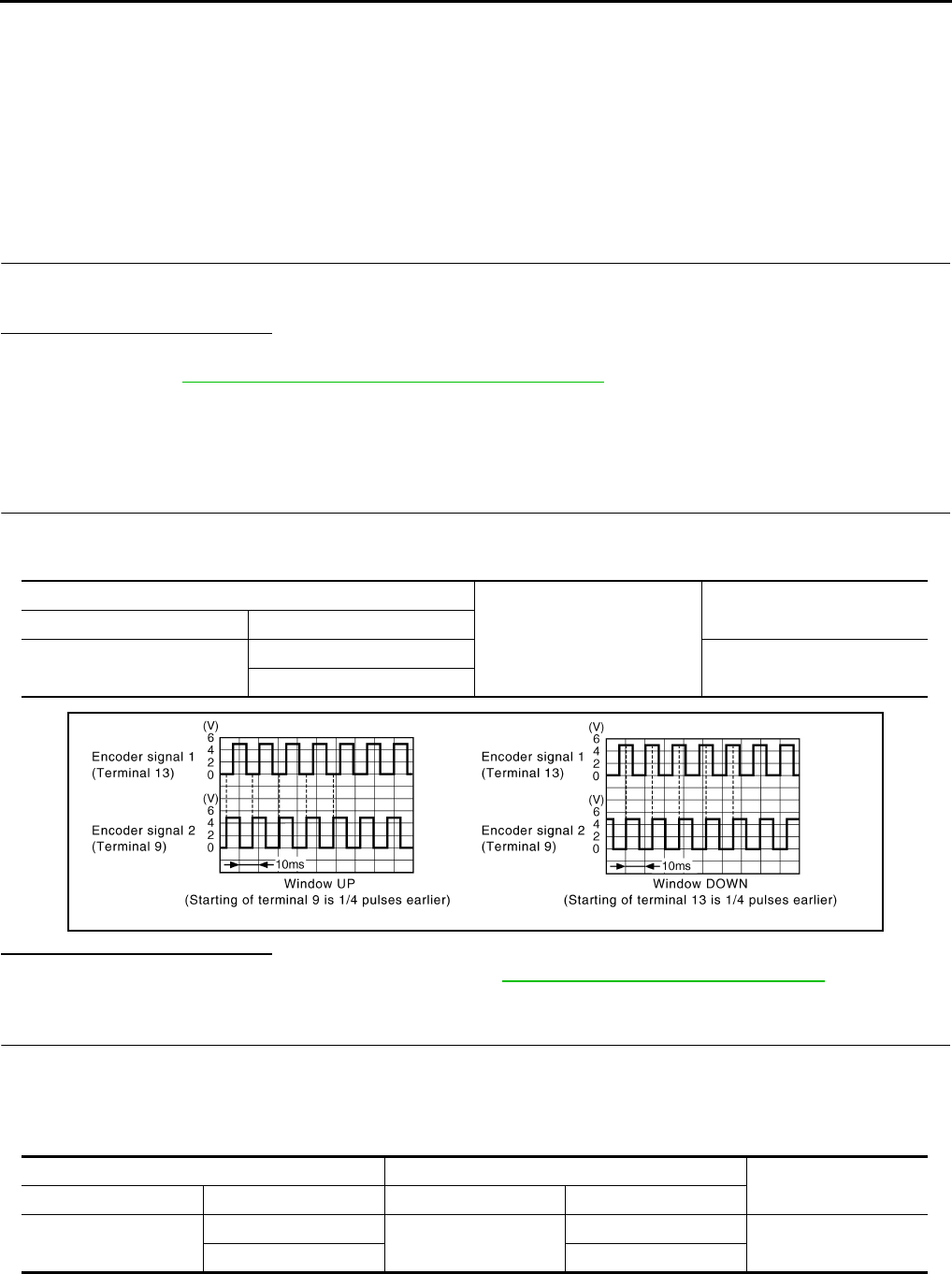
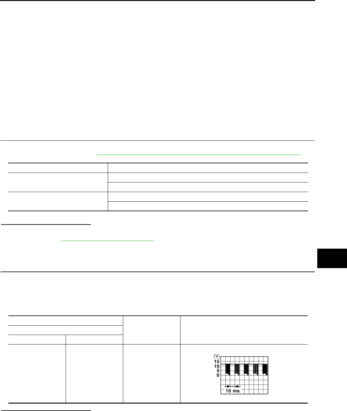
1.CHECK POWER WINDOW SWITCH OUTPUT SIGNAL
1. Close doors of driver side and passenger side.
2. Check signal between BCM harness connector and ground with oscilloscope when door lock and unlock
switch (driver side and passenger side) is turned to “LOCK” or “UNLOCK”.
3. Check that signals which are shown in the figure below can be detected during 10 seconds just after door
lock and unlock switch (driver side and passenger side) is turned to “LOCK” or “UNLOCK”.
Is the inspection result normal?
YES >> GO TO 2.
NO >> GO TO 3.
Monitor item Condition
CDL LOCK SW LOCK : ON
UNLOCK : OFF
CDL UNLOCK SW LOCK : OFF
UNLOCK : ON
(+)
(–) Signal
(Reference value)
BCM
Connector Terminal
M123 132 Ground
JPMIA0013G
B
Revision: 2007 November 2008 EX35
PWC-36
< COMPONENT DIAGNOSIS >
POWER WINDOW SERIAL LINK
2.CHECK BCM OUTPUT SIGNAL
Check power window serial link (“PW REMOTO DOWN SET”) in “ACTIVE TEST” mode with CONSULT-III.
Is the inspection result normal?
YES >> GO TO 4.
NO >> Replace BCM. Refer to BCS-84, "Removal and Installation".
3.CHECK POWER WINDOW SERIAL LINK CIRCUIT
1. Turn ignition switch OFF.
2. Disconnect BCM connector.
3. Disconnect power window main switch connector and front power window switch (passenger side) con-
nector.
4. Check continuity between BCM connector and power window main switch connector.
5. Check continuity between BCM connector and ground.
Is the inspection result normal?
YES >> Replace BCM. Refer to BCS-84, "Removal and Installation" .
NO >> Repair or replace harness.
4.CHECK INTERMITTENT INCIDENT
Refer to GI-38, "Intermittent Incident".
>> INSPECTION END
Test item Description
POWER WINDOW DOWN ON Driver side window and passenger side window OPEN
BCM Power window switch Continuity
Connector Terminal Connector Terminal
M123 132 Driver side D8 14 Existed
Passenger side D38 16
BCM
Ground Continuity
Connector Terminal
M123 132 Not existed
Revision: 2007 November 2008 EX35
POWER WINDOW SYSTEM
PWC-37
< COMPONENT DIAGNOSIS >
C
D
E
F
G
H
I
J
L
M
A
B
PWC
N
O
P
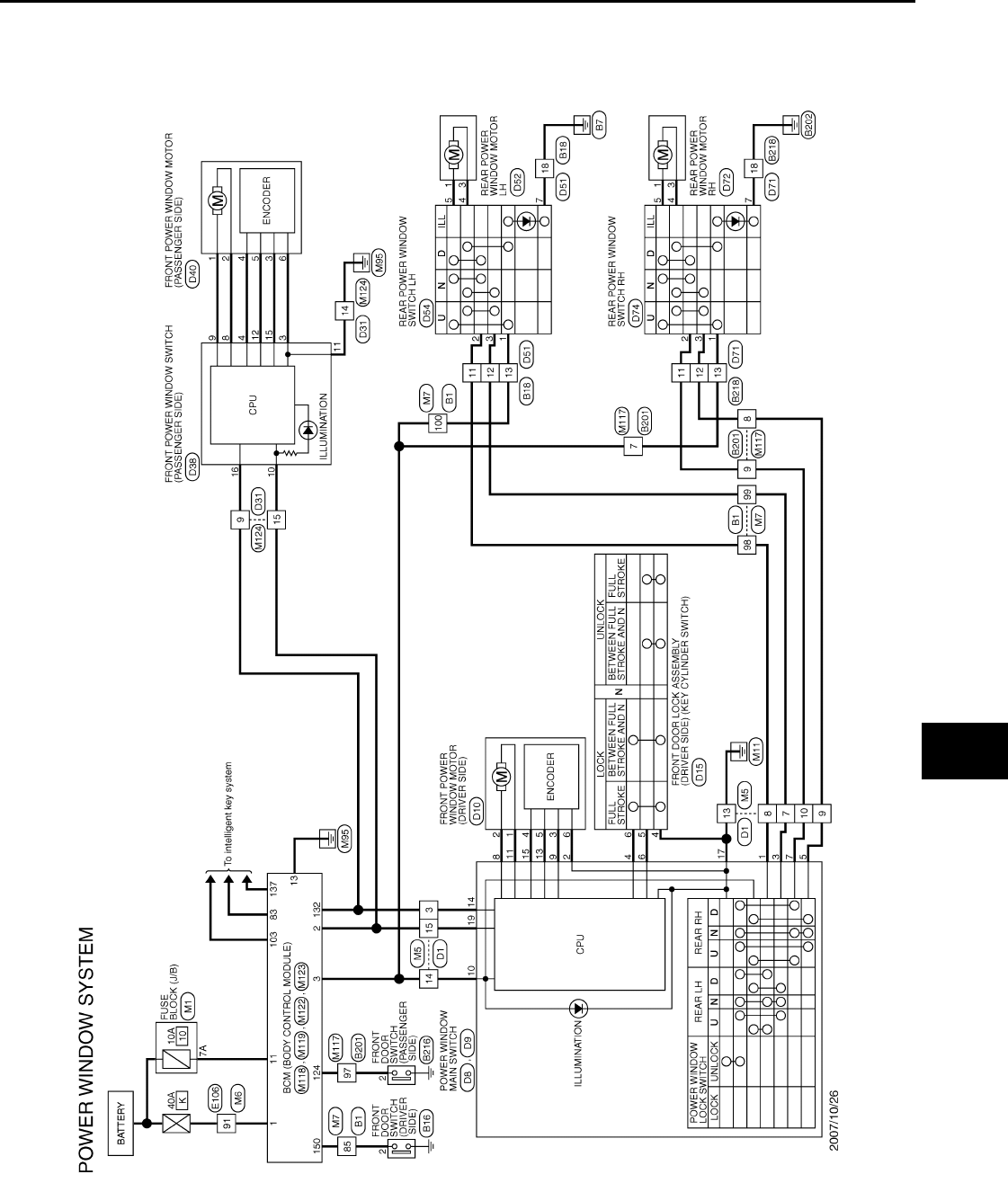
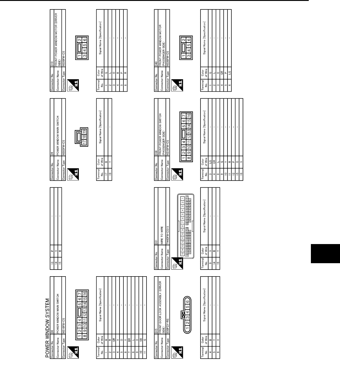
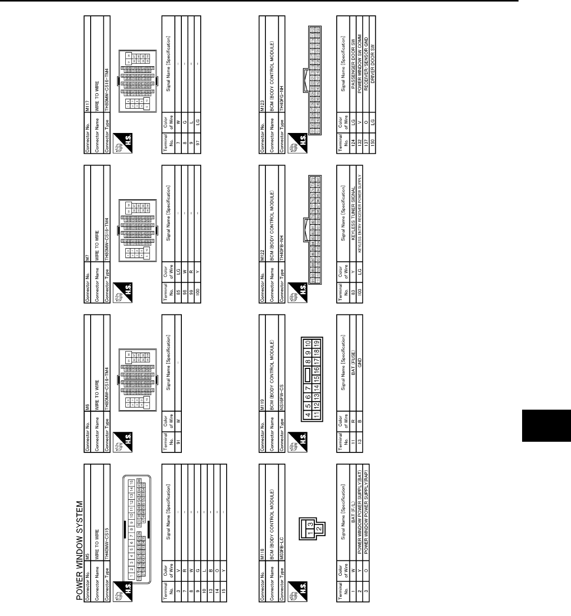
POWER WINDOW SYSTEM
Wiring Diagram - POWER WINDOW SYSTEM - INFOID:0000000003757462
JCKWM1093
GB
Revision: 2007 November 2008 EX35

PWC-38
< COMPONENT DIAGNOSIS >
POWER WINDOW SYSTEM
JCKWM1094
GB
Revision: 2007 November 2008 EX35
POWER WINDOW SYSTEM
PWC-39
< COMPONENT DIAGNOSIS >
C
D
E
F
G
H
I
J
L
M
A
B
PWC
N
O
P
JCKWM1095
GB
Revision: 2007 November 2008 EX35

PWC-40
< COMPONENT DIAGNOSIS >
POWER WINDOW SYSTEM
JCKWM1096
GB
Revision: 2007 November 2008 EX35
POWER WINDOW SYSTEM
PWC-41
< COMPONENT DIAGNOSIS >
C
D
E
F
G
H
I
J
L
M
A
B
PWC
N
O
P
JCKWM1097
GB
Revision: 2007 November 2008 EX35
PWC-42
< COMPONENT DIAGNOSIS >
POWER WINDOW SYSTEM
JCKWM1098
GB
Revision: 2007 November 2008 EX35

BCM (BODY CONTROL MODULE)
PWC-43
< ECU DIAGNOSIS >
C
D
E
F
G
H
I
J
L
M
A
B
PWC
N
O
P
ECU DIAGNOSIS
BCM (BODY CONTROL MODULE)
Reference Value INFOID:0000000003773244
VALUES ON THE DIAGNOSIS TOOL
CONSULT-III MONITOR ITEM
Monitor Item Condition Value/Status
FR WIPER HI Other than front wiper switch HI Off
Front wiper switch HI On
FR WIPER LOW Other than front wiper switch LO Off
Front wiper switch LO On
FR WASHER SW Front washer switch OFF Off
Front washer switch ON On
FR WIPER INT Other than front wiper switch INT Off
Front wiper switch INT On
FR WIPER STOP Front wiper is not in STOP position Off
Front wiper is in STOP position On
INT VOLUME Wiper intermittent dial is in a dial position 1 - 7 Wiper intermittent dial position
RR WIPER ON Other than rear wiper switch ON Off
Rear wiper switch ON On
RR WIPER INT Other than rear wiper switch INT Off
Rear wiper switch INT On
RR WASHER SW Rear washer switch OFF Off
Rear washer switch ON On
RR WIPER STOP Rear wiper is in STOP position Off
Rear wiper is not in STOP position On
TURN SIGNAL R Other than turn signal switch RH Off
Turn signal switch RH On
TURN SIGNAL L Other than turn signal switch LH Off
Turn signal switch LH On
TAIL LAMP SW Other than lighting switch 1ST and 2ND Off
Lighting switch 1ST or 2ND On
HI BEAM SW Other than lighting switch HI Off
Lighting switch HI On
HEAD LAMP SW 1 Other than lighting switch 2ND Off
Lighting switch 2ND On
HEAD LAMP SW 2 Other than lighting switch 2ND Off
Lighting switch 2ND On
PASSING SW Other than lighting switch PASS Off
Lighting switch PASS On
AUTO LIGHT SW Other than lighting switch AUTO Off
Lighting switch AUTO On
FR FOG SW Front fog lamp switch OFF Off
Front fog lamp switch ON On
Revision: 2007 November 2008 EX35

PWC-44
< ECU DIAGNOSIS >
BCM (BODY CONTROL MODULE)
RR FOG SW NOTE:
The item is indicated, but not monitored. Off
DOOR SW-DR Driver door closed Off
Driver door opened On
DOOR SW-AS Passenger door closed Off
Passenger door opened On
DOOR SW-RR Rear RH door closed Off
Rear RH door opened On
DOOR SW-RL Rear LH door closed Off
Rear LH door opened On
DOOR SW-BK Back door closed Off
Back door opened On
CDL LOCK SW Other than power door lock switch LOCK Off
Power door lock switch LOCK On
CDL UNLOCK SW Other than power door lock switch UNLOCK Off
Power door lock switch UNLOCK On
KEY CYL LK-SW Other than driver door key cylinder LOCK position Off
Driver door key cylinder LOCK position On
KEY CYL UN-SW Other than driver door key cylinder UNLOCK position Off
Driver door key cylinder UNLOCK position On
KEY CYL SW-TR NOTE:
The item is indicated, but not monitored. Off
HAZARD SW Hazard switch is OFF Off
Hazard switch is ON On
REAR DEF SW NOTE:
The item is indicated, but not monitored. Off
TR CANCEL SW NOTE:
The item is indicated, but not monitored. Off
TR/BD OPEN SW Back door opener switch OFF Off
While the back door opener switch is turned ON On
TRNK/HAT MNTR NOTE:
The item is indicated, but not monitored. Off
RKE-LOCK LOCK button of the key is not pressed Off
LOCK button of the key is pressed On
RKE-UNLOCK UNLOCK button of the key is not pressed Off
UNLOCK button of the key is pressed On
RKE-TR/BD NOTE:
The item is indicated, but not monitored. Off
RKE-PANIC PANIC button of the key is not pressed Off
PANIC button of the key is pressed On
RKE-P/W OPEN UNLOCK button of the key is not pressed Off
UNLOCK button of the key is pressed and held On
RKE-MODE CHG
LOCK/UNLOCK button of the key is not pressed and held simulta-
neously Off
LOCK/UNLOCK button of the key is pressed and held simulta-
neously On
Monitor Item Condition Value/Status
Revision: 2007 November 2008 EX35

BCM (BODY CONTROL MODULE)
PWC-45
< ECU DIAGNOSIS >
C
D
E
F
G
H
I
J
L
M
A
B
PWC
N
O
P
OPTICAL SENSOR Bright outside of the vehicle Close to 5 V
Dark outside of the vehicle Close to 0 V
REQ SW -DR Driver door request switch is not pressed Off
Driver door request switch is pressed On
REQ SW -AS Passenger door request switch is not pressed Off
Passenger door request switch is pressed On
REQ SW -RR NOTE:
The item is indicated, but not monitored. Off
REQ SW -RL NOTE:
The item is indicated, but not monitored. Off
REQ SW -BD/TR Back door request switch is not pressed Off
Back door request switch is pressed On
PUSH SW Push-button ignition switch (push switch) is not pressed Off
Push-button ignition switch (push switch) is pressed On
IGN RLY2 -F/B Ignition switch in OFF or ACC position Off
Ignition switch in ON position On
CLUCH SW NOTE:
The item is indicated, but not monitored. Off
BRAKE SW 1 The brake pedal is not depressed On
The brake pedal is depressed Off
DETE/CANCL SW Selector lever in P position Off
Selector lever in any position other than P On
SFT PN/N SW Selector lever in any position other than P and N Off
Selector lever in P or N position On
S/L -LOCK Steering is locked Off
Steering is unlocked On
S/L -UNLOCK Steering is unlocked Off
Steering is locked On
S/L RELAY-F/B Ignition switch in OFF or ACC position Off
Ignition switch in ON position On
UNLK SEN -DR Driver door is unlocked Off
Driver door is locked On
PUSH SW -IPDM Push-button ignition switch (push-switch) is not pressed Off
Push-button ignition switch (push-switch) is pressed On
IGN RLY1 -F/B Ignition switch in OFF or ACC position Off
Ignition switch in ON position On
DETE SW -IPDM Selector lever in P position Off
Selector lever in any position other than P On
SFT PN -IPDM Selector lever in any position other than P and N Off
Selector lever in P or N position On
SFT P -MET Selector lever in any position other than P Off
Selector lever in P position On
SFT N -MET Selector lever in any position other than N Off
Selector lever in N position On
Monitor Item Condition Value/Status
Revision: 2007 November 2008 EX35

PWC-46
< ECU DIAGNOSIS >
BCM (BODY CONTROL MODULE)
ENGINE STATE
Engine stopped Stop
While the engine stalls Stall
At engine cranking Crank
Engine running Run
S/L LOCK-IPDM Steering is locked Off
Steering is unlocked On
S/L UNLK-IPDM Steering is unlocked Off
Steering is locked On
S/L RELAY-REQ Ignition switch in OFF or ACC position Off
Ignition switch in ON position On
VEH SPEED 1 While driving Equivalent to speedometer reading
VEH SPEED 2 While driving Equivalent to speedometer reading
DOOR STAT-DR
Driver door is locked LOCK
Wait with selective UNLOCK operation (5 seconds) READY
Driver door is unlocked UNLOCK
DOOR STAT-AS
Passenger door is locked LOCK
Wait with selective UNLOCK operation (5 seconds) READY
Passenger door is unlocked UNLOCK
ID OK FLAG Ignition switch in ACC or ON position Reset
Ignition switch in OFF position Set
PRMT ENG STRT The engine start is prohibited Reset
The engine start is permitted Set
PRMT RKE STRT NOTE:
The item is indicated, but not monitored. Reset
KEY SW -SLOT The key is not inserted into key slot Off
The key is inserted into key slot On
RKE OPE COUN1 During the operation of the key Operation frequency of the key
RKE OPE COUN2 NOTE:
The item is indicated, but not monitored. —
CONFRM ID ALL
The key ID that the key slot receives does not accord with any key
ID registered to BCM. Yet
The key ID that the key slot receives accords with any key ID regis-
tered to BCM. DONE
CONFIRM ID4
The key ID that the key slot receives does not accord with the fourth
key ID registered to BCM. Yet
The key ID that the key slot receives accords with the fourth key ID
registered to BCM. DONE
CONFIRM ID3
The key ID that the key slot receives does not accord with the third
key ID registered to BCM. Yet
The key ID that the key slot receives accords with the third key ID
registered to BCM. DONE
CONFIRM ID2
The key ID that the key slot receives does not accord with the sec-
ond key ID registered to BCM. Yet
The key ID that the key slot receives accords with the second key
ID registered to BCM. DONE
Monitor Item Condition Value/Status
Revision: 2007 November 2008 EX35

BCM (BODY CONTROL MODULE)
PWC-47
< ECU DIAGNOSIS >
C
D
E
F
G
H
I
J
L
M
A
B
PWC
N
O
P
CONFIRM ID1
The key ID that the key slot receives does not accord with the first
key ID registered to BCM. Yet
The key ID that the key slot receives accords with the first key ID
registered to BCM. DONE
TP 4 The ID of fourth key is not registered to BCM Yet
The ID of fourth key is registered to BCM DONE
TP 3 The ID of third key is not registered to BCM Yet
The ID of third key is registered to BCM DONE
TP 2 The ID of second key is not registered to BCM Yet
The ID of second key is registered to BCM DONE
TP 1 The ID of first key is not registered to BCM Yet
The ID of first key is registered to BCM DONE
AIR PRESS FL Ignition switch ON (Only when the signal from the transmitter is re-
ceived) Air pressure of front LH tire
AIR PRESS FR Ignition switch ON (Only when the signal from the transmitter is re-
ceived) Air pressure of front RH tire
AIR PRESS RR Ignition switch ON (Only when the signal from the transmitter is re-
ceived) Air pressure of rear RH tire
AIR PRESS RL Ignition switch ON (Only when the signal from the transmitter is re-
ceived) Air pressure of rear LH tire
ID REGST FL1 ID of front LH tire transmitter is registered DONE
ID of front LH tire transmitter is not registered Yet
ID REGST FR1 ID of front RH tire transmitter is registered DONE
ID of front RH tire transmitter is not registered Yet
ID REGST RR1 ID of rear RH tire transmitter is registered DONE
ID of rear RH tire transmitter is not registered Yet
ID REGST RL1 ID of rear LH tire transmitter is registered DONE
ID of rear LH tire transmitter is not registered Yet
WARNING LAMP Tire pressure indicator OFF Off
Tire pressure indicator ON On
BUZZER Tire pressure warning alarm is not sounding Off
Tire pressure warning alarm is sounding On
Monitor Item Condition Value/Status
Revision: 2007 November 2008 EX35
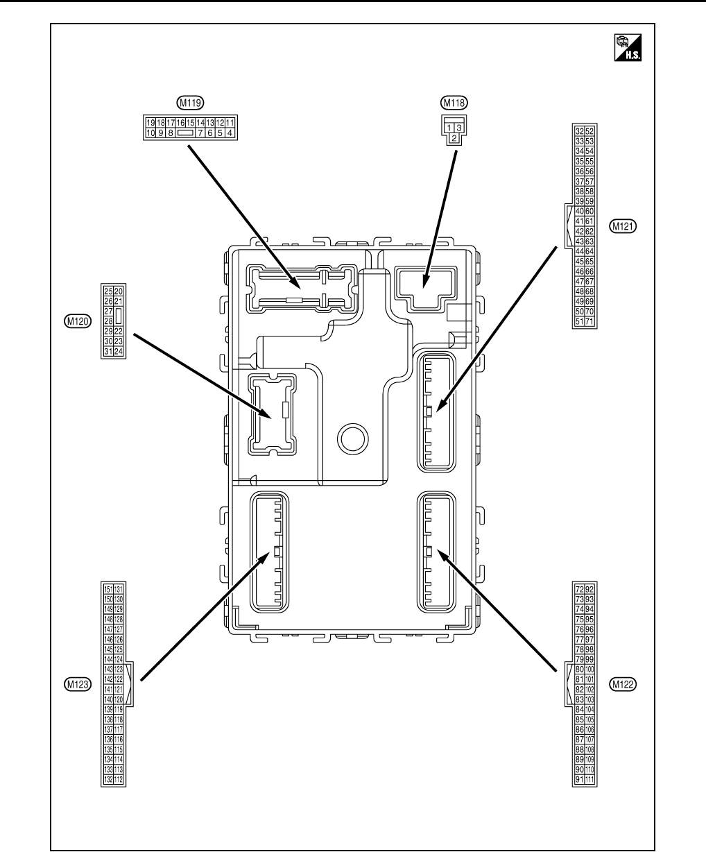
PWC-48
< ECU DIAGNOSIS >
BCM (BODY CONTROL MODULE)
TERMINAL LAYOUT
PHYSICAL VALUES
JPMIA0062ZZ
Revision: 2007 November 2008 EX35
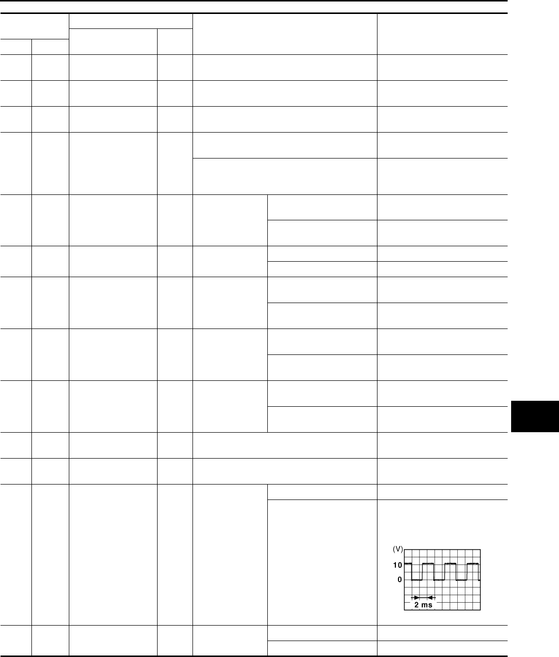
BCM (BODY CONTROL MODULE)
PWC-49
< ECU DIAGNOSIS >
C
D
E
F
G
H
I
J
L
M
A
B
PWC
N
O
P
Terminal No.
(Wire color)
Description
Condition Value
(Approx.)
Signal name Input/
Output+–
1
(W) Ground Battery power supply Input Ignition switch OFF Battery voltage
2
(Y) Ground P/W power supply
(BAT) Output Ignition switch OFF Battery voltage
3
(O) Ground P/W power supply
(RAP) Output Ignition switch ON Battery voltage
4
(LG) Ground Interior room lamp
power supply Output
Interior room lamp battery saver is activated.
(Cuts the interior room lamp power supply) 0 V
Interior room lamp battery saver is not activat-
ed.
(Outputs the interior room lamp power supply)
Battery voltage
5
(L) Ground Passenger door UN-
LOCK Output Passenger door
UNLOCK
(Actuator is activated) Battery voltage
Other than UNLOCK
(Actuator is not activated) 0 V
7
(Y) Ground Step lamp Output Step lamp ON 0 V
OFF Battery voltage
8
(V) Ground All doors, fuel lid
LOCK Output All doors
LOCK
(Actuator is activated) Battery voltage
Other than LOCK
(Actuator is not activated) 0 V
9
(G) Ground Driver door, fuel lid
UNLOCK Output Driver door
UNLOCK
(Actuator is activated) Battery voltage
Other than UNLOCK
(Actuator is not activated) 0 V
10
(BR) Ground Rear RH door and
rear LH door UN-
LOCK
Output Rear RH door
and rear LH door
UNLOCK
(Actuator is activated) Battery voltage
Other than UNLOCK
(Actuator is not activated) 0 V
11
(R) Ground Battery power supply Input Ignition switch OFF Battery voltage
13
(B) Ground Ground — Ignition switch ON 0 V
14
(W) Ground
Push-button ignition
switch illumination
ground Output Tail lamp
OFF 0 V
ON
NOTE:
When the illumination brighten-
ing/dimming level is in the neutral
position
15
(Y) Ground ACC indicator lamp Output Ignition switch OFF or ON Battery voltage
ACC 0 V
JSNIA0010GB
Revision: 2007 November 2008 EX35
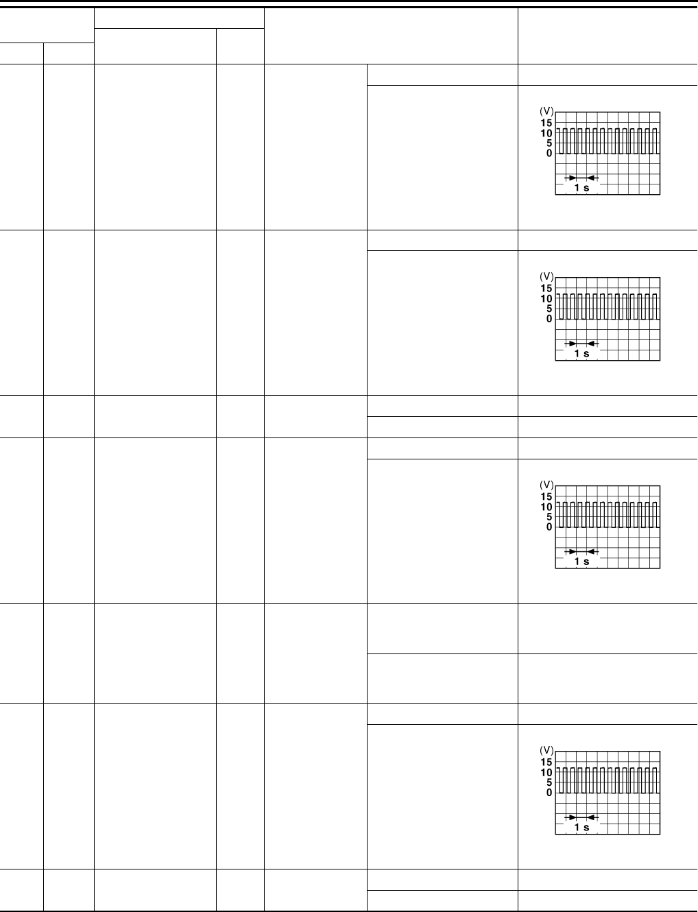
PWC-50
< ECU DIAGNOSIS >
BCM (BODY CONTROL MODULE)
17
(W) Ground Turn signal RH
(Front) Output Ignition switch
ON
Turn signal switch OFF 0 V
Turn signal switch RH
6.5 V
18
(O) Ground Turn signal LH
(Front) Output Ignition switch
ON
Turn signal switch OFF 0 V
Turn signal switch LH
6.5 V
19
(V) Ground Room lamp timer
control Output Interior room
lamp
OFF Battery voltage
ON 0 V
20
(V) Ground Turn signal RH
(Rear) Output Ignition switch
ON
Turn signal switch OFF 0 V
Turn signal switch RH
6.5 V
23
(G) Ground Back door opening Output Back door
OPEN
(Back door opener actuator
is activated)
Battery voltage
Other than OPEN
(Back door opener actuator
is not activated) 0 V
25
(G) Ground Turn signal LH (Rear) Output Ignition switch
ON
Turn signal switch OFF 0 V
Turn signal switch LH
6.5 V
26
(G) Ground Rear wiper Output Rear wiper OFF (Stopped) 0 V
ON (Operated) Battery voltage
Terminal No.
(Wire color) Description
Condition Value
(Approx.)
Signal name Input/
Output+–
PKID0926E
PKID0926E
PKID0926E
PKID0926E
Revision: 2007 November 2008 EX35
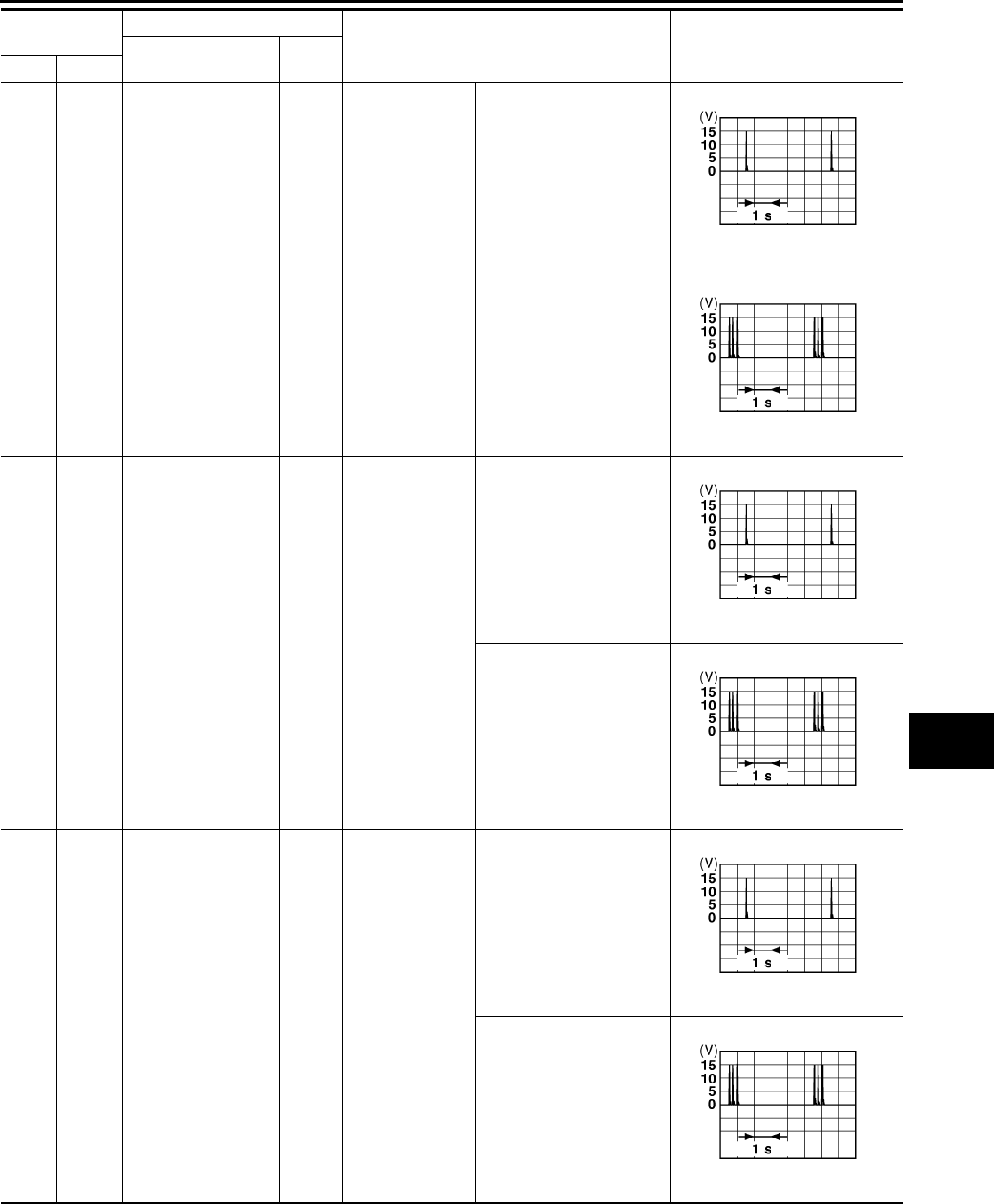
BCM (BODY CONTROL MODULE)
PWC-51
< ECU DIAGNOSIS >
C
D
E
F
G
H
I
J
L
M
A
B
PWC
N
O
P
34
(SB) Ground Luggage room anten-
na 1 (−)Output Ignition switch
OFF
When Intelligent Key is in
the passenger compart-
ment
When Intelligent Key is not
in the passenger compart-
ment
35
(V) Ground Luggage room anten-
na 1 (+) Output Ignition switch
OFF
When Intelligent Key is in
the passenger compart-
ment
When Intelligent Key is not
in the passenger compart-
ment
38
(B) Ground Rear bumper anten-
na (−)Output
When the back
door request
switch is operat-
ed with ignition
switch OFF
When Intelligent Key is in
the antenna detection area
When Intelligent Key is not
in the antenna detection
area
Terminal No.
(Wire color) Description
Condition Value
(Approx.)
Signal name Input/
Output+–
JMKIA0062G
B
JMKIA0063G
B
JMKIA0062G
B
JMKIA0063G
B
JMKIA0062G
B
JMKIA0063G
B
Revision: 2007 November 2008 EX35
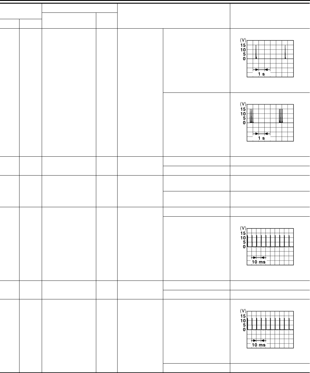
PWC-52
< ECU DIAGNOSIS >
BCM (BODY CONTROL MODULE)
39
(W) Ground Rear bumper anten-
na (+) Output
When the back
door request
switch is operat-
ed with ignition
switch OFF
When Intelligent Key is in
the antenna detection area
When Intelligent Key is not
in the antenna detection
area
47
(Y) Ground Ignition relay (IPDM
E/R) control Output Ignition switch OFF or ACC Battery voltage
ON 0 V
52
(SB) Ground Starter relay control Output Ignition switch
ON
When selector lever is in P
or N position Battery voltage
When selector lever is not
in P or N position 0 V
61
(W) Ground Back door opener re-
quest switch Input Back door re-
quest switch
ON (Pressed) 0 V
OFF (Not pressed)
1.0 V
64
(V) Ground Request switch buzz-
er Output Request switch
buzzer
Sounding 0 V
Not sounding Battery voltage
65
(O) Ground Rear wiper stop posi-
tion Input Rear wiper In stop position
1.0 V
Not in stop position 0 V
Terminal No.
(Wire color) Description
Condition Value
(Approx.)
Signal name Input/
Output+–
JMKIA0062G
B
JMKIA0063G
B
JPMIA0016G
B
JPMIA0016G
B
Revision: 2007 November 2008 EX35
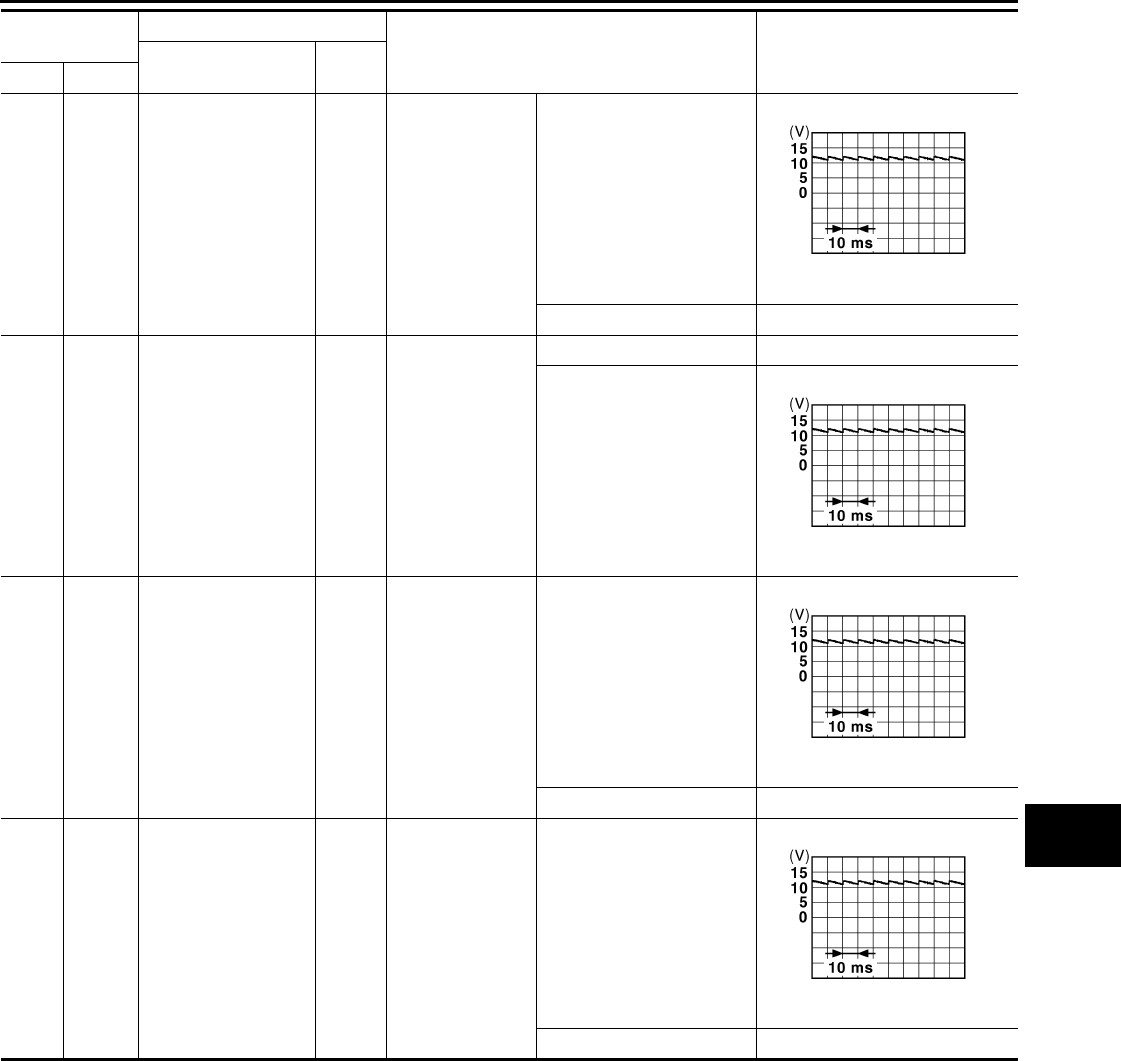
BCM (BODY CONTROL MODULE)
PWC-53
< ECU DIAGNOSIS >
C
D
E
F
G
H
I
J
L
M
A
B
PWC
N
O
P
66
(R) Ground Back door switch Input Back door switch OFF (Door close)
11.8 V
ON (Door open) 0 V
67
(GR) Ground Back door opener
switch Input Back door opener
switch
Pressed 0 V
Not pressed
11.8 V
68
(BR) Ground Rear RH door switch Input Rear RH door
switch
OFF (Door close)
11.8 V
ON (Door open) 0 V
69
(R) Ground Rear LH door switch Input Rear LH door
switch
OFF (Door close)
11.8 V
ON (Door open) 0 V
Terminal No.
(Wire color) Description
Condition Value
(Approx.)
Signal name Input/
Output+–
JPMIA0011GB
JPMIA0011GB
JPMIA0011GB
JPMIA0011GB
Revision: 2007 November 2008 EX35
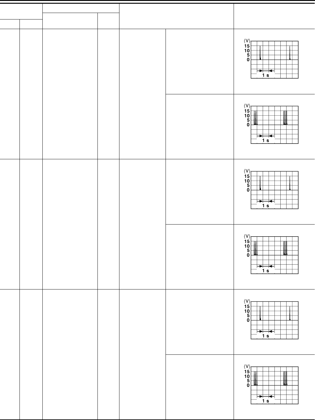
PWC-54
< ECU DIAGNOSIS >
BCM (BODY CONTROL MODULE)
72
(R) Ground Room antenna 2 (−)
(Center console) Output Ignition switch
OFF
When Intelligent Key is in
the passenger compart-
ment
When Intelligent Key is not
in the passenger compart-
ment
73
(G) Ground Room antenna 2 (+)
(Center console) Output Ignition switch
OFF
When Intelligent Key is in
the passenger compart-
ment
When Intelligent Key is not
in the passenger compart-
ment
74
(SB) Ground Passenger door an-
tenna (−)Output
When the pas-
senger door re-
quest switch is
operated with ig-
nition switch OFF
When Intelligent Key is in
the antenna detection area
When Intelligent Key is not
in the antenna detection
area
Terminal No.
(Wire color) Description
Condition Value
(Approx.)
Signal name Input/
Output+–
JMKIA0062G
B
JMKIA0063G
B
JMKIA0062G
B
JMKIA0063G
B
JMKIA0062G
B
JMKIA0063G
B
Revision: 2007 November 2008 EX35

BCM (BODY CONTROL MODULE)
PWC-55
< ECU DIAGNOSIS >
C
D
E
F
G
H
I
J
L
M
A
B
PWC
N
O
P
75
(GR) Ground Passenger door an-
tenna (+) Output
When the pas-
senger door re-
quest switch is
operated with ig-
nition switch OFF
When Intelligent Key is in
the antenna detection area
When Intelligent Key is not
in the antenna detection
area
76
(V) Ground Driver door antenna
(−)Output
When the driver
door request
switch is operat-
ed with ignition
switch OFF
When Intelligent Key is in
the antenna detection area
When Intelligent Key is not
in the antenna detection
area
77
(LG) Ground Driver door antenna
(+) Output
When the driver
door request
switch is operat-
ed with ignition
switch OFF
When Intelligent Key is in
the antenna detection area
When Intelligent Key is not
in the antenna detection
area
Terminal No.
(Wire color) Description
Condition Value
(Approx.)
Signal name Input/
Output+–
JMKIA0062G
B
JMKIA0063G
B
JMKIA0062G
B
JMKIA0063G
B
JMKIA0062G
B
JMKIA0063G
B
Revision: 2007 November 2008 EX35
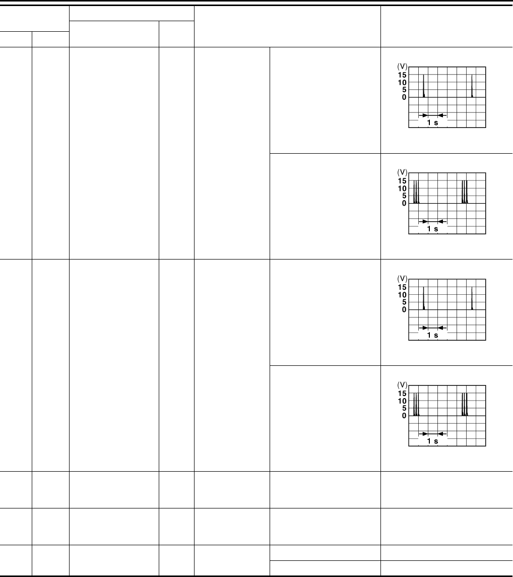
PWC-56
< ECU DIAGNOSIS >
BCM (BODY CONTROL MODULE)
78
(Y) Ground Room antenna (−)
(Instrument panel) Output Ignition switch
OFF
When Intelligent Key is in
the passenger compart-
ment
When Intelligent Key is not
in the passenger compart-
ment
79
(BR) Ground Room antenna (+)
(Instrument panel) Output Ignition switch
OFF
When Intelligent Key is in
the passenger compart-
ment
When Intelligent Key is not
in the passenger compart-
ment
80
(GR) Ground NATS antenna amp
(Built in key slot)
Input/
Output During waiting Ignition switch is pressed
while inserting the key into
the key slot.
Just after pressing ignition
switch. Pointer of tester should
move.
81
(W) Ground NATS antenna amp
(Built in key slot)
Input/
Output During waiting
Ignition switch is pressed
while inserting the key into
the key slot.
Just after pressing ignition
switch. Pointer of tester should
move.
82
(R) Ground Ignition relay [Fuse
block (J/B)] control Output Ignition switch OFF or ACC 0 V
ON Battery voltage
Terminal No.
(Wire color) Description
Condition Value
(Approx.)
Signal name Input/
Output+–
JMKIA0062G
B
JMKIA0063G
B
JMKIA0062G
B
JMKIA0063G
B
Revision: 2007 November 2008 EX35
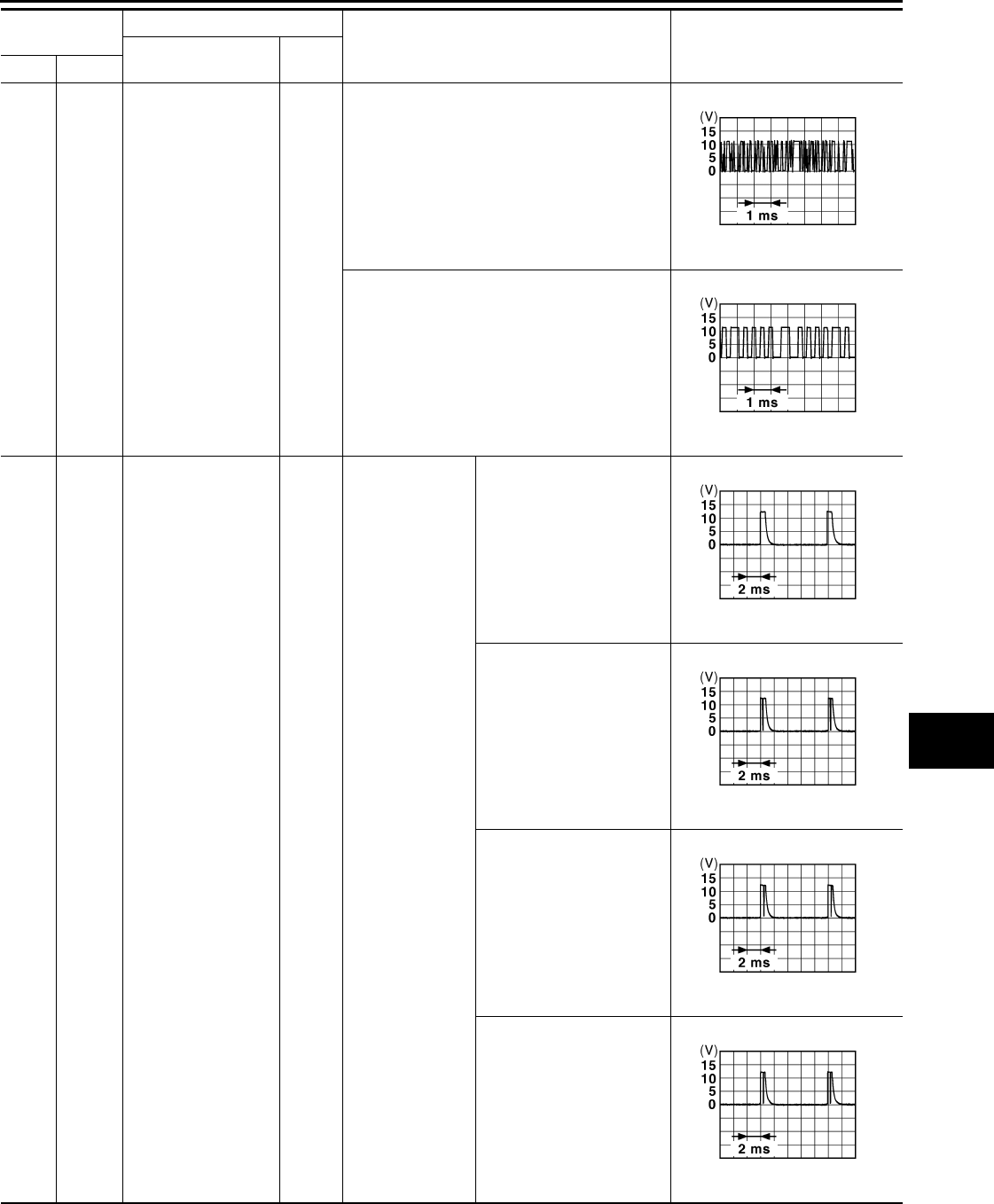
BCM (BODY CONTROL MODULE)
PWC-57
< ECU DIAGNOSIS >
C
D
E
F
G
H
I
J
L
M
A
B
PWC
N
O
P
83
(Y) Ground Remote keyless entry
receiver signal
Input/
Output
During waiting
When operating either button on the key
87
(BR) Ground Combination switch
INPUT 5 Input Combination
switch
All switch OFF
(Wiper intermittent dial 4)
1.4 V
Front fog lamp switch ON
(Wiper intermittent dial 4)
1.3 V
Rear wiper switch ON
(Wiper intermittent dial 4)
1.3 V
Any of the conditions below
with all switch OFF
• Wiper intermittent dial 1
• Wiper intermittent dial 2
• Wiper intermittent dial 6
• Wiper intermittent dial 7
1.3 V
Terminal No.
(Wire color) Description
Condition Value
(Approx.)
Signal name Input/
Output+–
JMKIA0064G
B
JMKIA0065G
B
JPMIA0041G
B
JPMIA0037G
B
JPMIA0039G
B
JPMIA0040G
B
Revision: 2007 November 2008 EX35
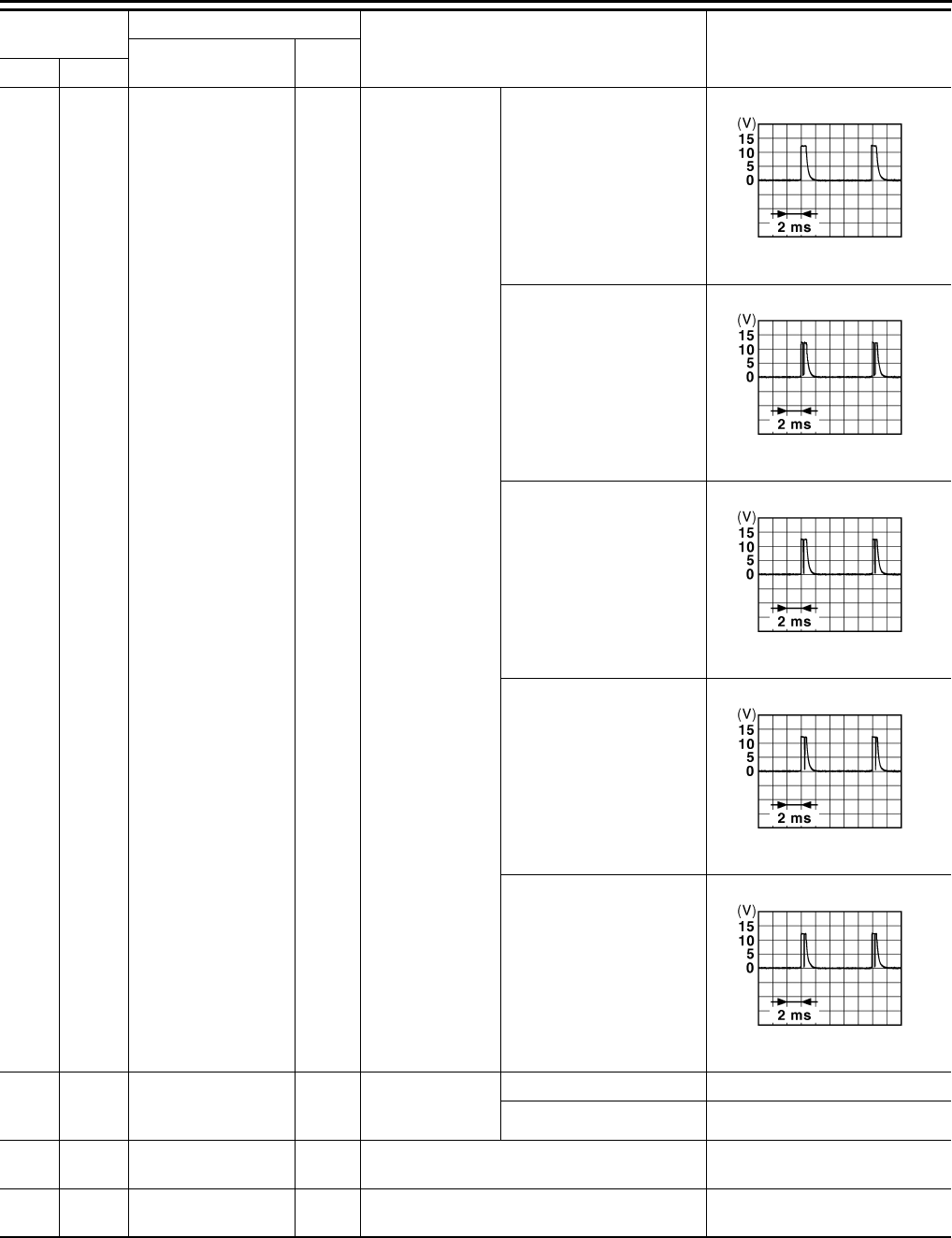
PWC-58
< ECU DIAGNOSIS >
BCM (BODY CONTROL MODULE)
88
(V) Ground Combination switch
INPUT 3 Input Combination
switch
All switch OFF
(Wiper intermittent dial 4)
1.4 V
Lighting switch HI
(Wiper intermittent dial 4)
1.3 V
Lighting switch 2ND
(Wiper intermittent dial 4)
1.3 V
Rear washer switch ON
(Wiper intermittent dial 4)
1.3 V
Any of the conditions below
with all switch OFF
• Wiper intermittent dial 1
• Wiper intermittent dial 2
• Wiper intermittent dial 3
1.3 V
89
(BR) Ground Push-button ignition
switch (Push switch) Input
Push-button igni-
tion switch (push
switch)
Pressed 0 V
Not pressed Battery voltage
90
(P) Ground CAN-L Input/
Output ——
91
(L) Ground CAN-H Input/
Output ——
Terminal No.
(Wire color) Description
Condition Value
(Approx.)
Signal name Input/
Output+–
JPMIA0041G
B
JPMIA0036G
B
JPMIA0037G
B
JPMIA0039G
B
JPMIA0040G
B
Revision: 2007 November 2008 EX35
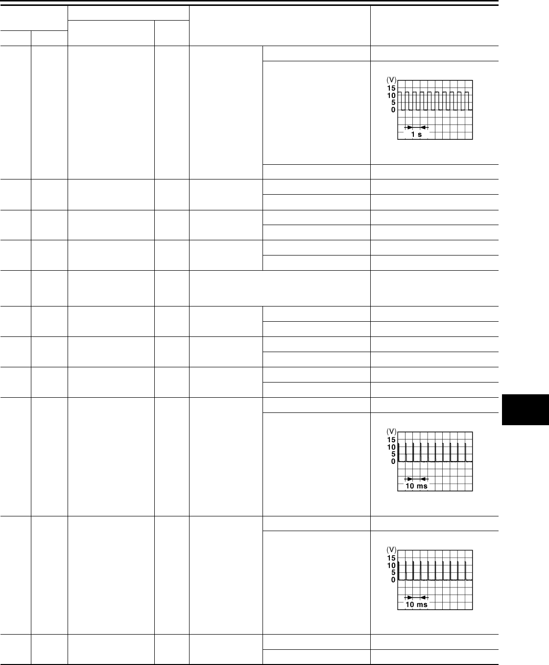
BCM (BODY CONTROL MODULE)
PWC-59
< ECU DIAGNOSIS >
C
D
E
F
G
H
I
J
L
M
A
B
PWC
N
O
P
92
(LG) Ground Key slot illumination Output Key slot illumina-
tion
OFF Battery voltage
Blinking
6.5 V
ON 0 V
93
(V) Ground ON indicator lamp Output Ignition switch OFF or ACC Battery voltage
ON 0 V
94
(Y) Ground Puddle lamp control Output Puddle lamp OFF Battery voltage
ON 0 V
95
(O) Ground ACC relay control Output Ignition switch OFF 0 V
ACC or ON Battery voltage
96
(GR) Ground
Control device (De-
tention switch) power
supply
Output — Battery voltage
97
(L) Ground Steering lock condi-
tion No. 1 Input Steering lock LOCK status 0 V
UNLOCK status Battery voltage
98
(P) Ground Steering lock condi-
tion No. 2 Input Steering lock LOCK status Battery voltage
UNLOCK status 0 V
99
(R) Ground Selector lever P posi-
tion switch Input Selector lever P position 0 V
Any position other than P Battery voltage
100
(G) Ground Passenger door re-
quest switch Input Passenger door
request switch
ON (Pressed) 0 V
OFF (Not pressed)
1.0 V
101
(SB) Ground Driver door request
switch Input Driver door re-
quest switch
ON (Pressed) 0 V
OFF (Not pressed)
1.0 V
102
(O) Ground Blower fan motor re-
lay control Output Ignition switch OFF or ACC 0 V
ON Battery voltage
Terminal No.
(Wire color) Description
Condition Value
(Approx.)
Signal name Input/
Output+–
JPMIA0015G
B
JPMIA0016G
B
JPMIA0016G
B
Revision: 2007 November 2008 EX35
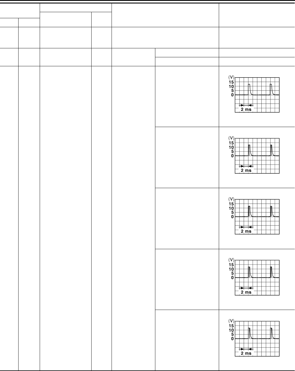
PWC-60
< ECU DIAGNOSIS >
BCM (BODY CONTROL MODULE)
103
(LG) Ground
Remote keyless entry
receiver power sup-
ply
Output Ignition switch OFF Battery voltage
106
(W) Ground Steering wheel lock
unit power supply Output Ignition switch OFF or ACC Battery voltage
ON 0 V
107
(LG) Ground Combination switch
INPUT 1 Input
Combination
switch
(Wiper intermit-
tent dial 4)
All switch OFF
1.4 V
Turn signal switch LH
1.3 V
Turn signal switch RH
1.3 V
Front wiper switch LO
1.3 V
Front washer switch ON
1.3 V
Terminal No.
(Wire color) Description
Condition Value
(Approx.)
Signal name Input/
Output+–
JPMIA0041G
B
JPMIA0037G
B
JPMIA0036G
B
JPMIA0038G
B
JPMIA0039G
B
Revision: 2007 November 2008 EX35
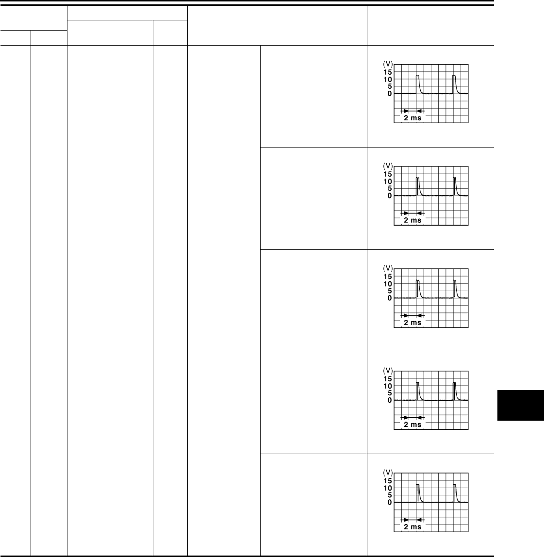
BCM (BODY CONTROL MODULE)
PWC-61
< ECU DIAGNOSIS >
C
D
E
F
G
H
I
J
L
M
A
B
PWC
N
O
P
108
(R) Ground Combination switch
INPUT 4 Input Combination
switch
All switch OFF
(Wiper intermittent dial 4)
1.4 V
Lighting switch AUTO
(Wiper intermittent dial 4)
1.3 V
Lighting switch 1ST
(Wiper intermittent dial 4)
1.3 V
Rear wiper switch INT
(Wiper intermittent dial 4)
1.3 V
Any of the conditions below
with all switch OFF
• Wiper intermittent dial 1
• Wiper intermittent dial 5
• Wiper intermittent dial 6
1.3 V
Terminal No.
(Wire color) Description
Condition Value
(Approx.)
Signal name Input/
Output+–
JPMIA0041G
B
JPMIA0038G
B
JPMIA0036G
B
JPMIA0040G
B
JPMIA0039G
B
Revision: 2007 November 2008 EX35
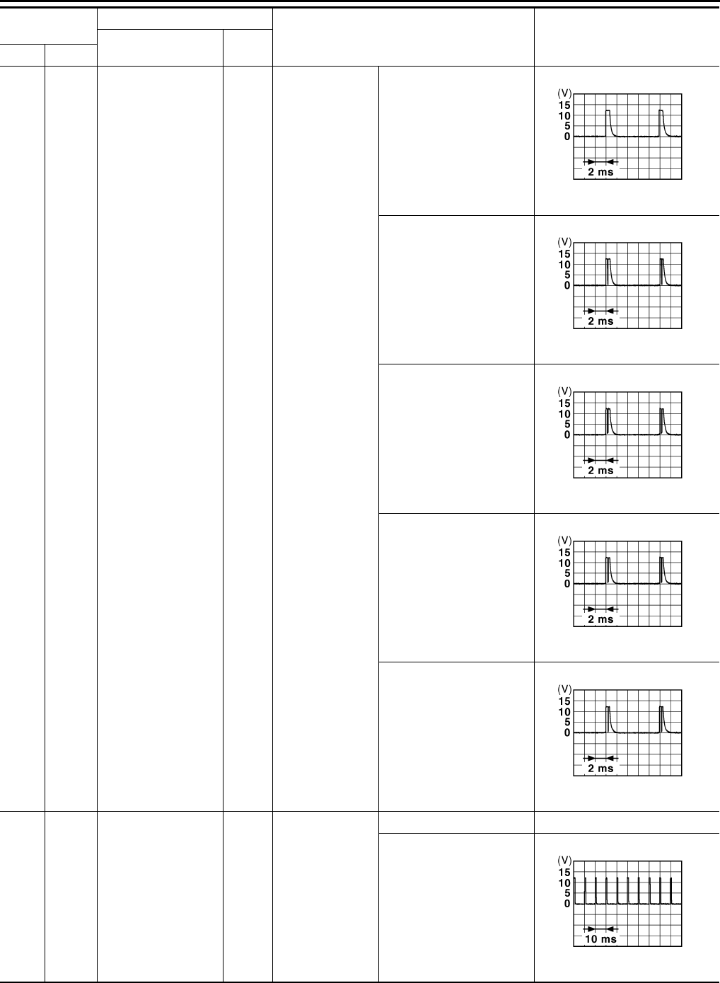
PWC-62
< ECU DIAGNOSIS >
BCM (BODY CONTROL MODULE)
109
(Y) Ground Combination switch
INPUT 2 Input
Combination
switch
(Wiper intermit-
tent dial 4)
All switch OFF
1.4 V
Lighting switch PASS
1.3 V
Lighting switch 2ND
1.3 V
Front wiper switch INT
1.3 V
Front wiper switch HI
1.3 V
110
(G) Ground Hazard switch Input Hazard switch
ON 0 V
OFF
1.1 V
Terminal No.
(Wire color) Description
Condition Value
(Approx.)
Signal name Input/
Output+–
JPMIA0041G
B
JPMIA0037G
B
JPMIA0036G
B
JPMIA0038G
B
JPMIA0040G
B
JPMIA0012G
B
Revision: 2007 November 2008 EX35
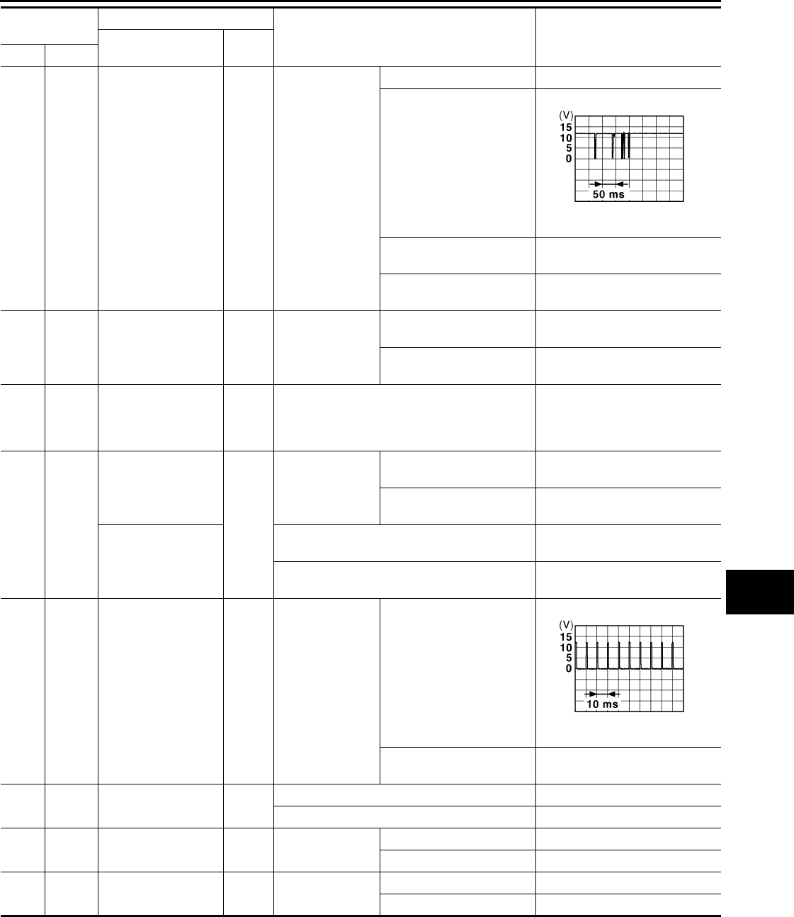
BCM (BODY CONTROL MODULE)
PWC-63
< ECU DIAGNOSIS >
C
D
E
F
G
H
I
J
L
M
A
B
PWC
N
O
P
111
(Y) Ground Steering lock unit
communication
Input/
Output Steering lock
LOCK status Battery voltage
LOCK or UNLOCK
For 15 seconds after UN-
LOCK Battery voltage
15 seconds or later after
UNLOCK 0 V
113*
(P) Ground Optical sensor signal Input Ignition switch
ON
When bright outside of the
vehicle Close to 5 V
When dark outside of the
vehicle Close to 0 V
116
(SB) Ground
Fuse check [Stop
lamp switch, ICC
brake hold relay
(With ICC)]
Input — Battery voltage
118
(P) Ground
Stop lamp switch
(Without ICC)
Input
Stop lamp switch
OFF (Brake pedal is not
depressed) 0 V
ON (Brake pedal is de-
pressed) Battery voltage
Stop lamp switch and
ICC brake hold relay
(With ICC)
Stop lamp switch OFF (Brake pedal is not de-
pressed) and ICC brake hold relay OFF 0 V
Stop lamp switch ON (Brake pedal is de-
pressed) or ICC brake hold relay ON Battery voltage
119
(SB) Ground
Front door lock as-
sembly driver side
(unlock sensor) Input Driver door
LOCK status
(Unlock sensor switch
OFF)
1.1 V
UNLOCK status
(Unlock switch sensor ON) 0 V
121
(BR) Ground Key slot switch Input When the key is inserted into key slot Battery voltage
When the key is not inserted into key slot 0 V
122
(V) Ground ACC feedback signal Input Ignition switch OFF 0 V
ACC or ON Battery voltage
123
(W) Ground IGN feedback signal Input Ignition switch OFF or ACC 0 V
ON Battery voltage
Terminal No.
(Wire color) Description
Condition Value
(Approx.)
Signal name Input/
Output+–
JMKIA0066G
B
JPMIA0012G
B
Revision: 2007 November 2008 EX35
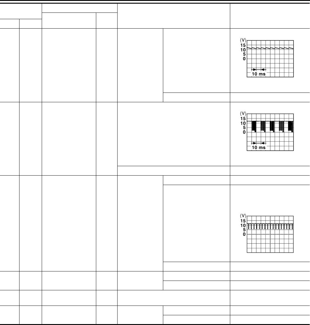
PWC-64
< ECU DIAGNOSIS >
BCM (BODY CONTROL MODULE)
124
(LG) Ground Passenger door
switch Input Passenger door
switch
OFF (Door close)
11.8 V
ON (Door open) 0 V
132
(V) Ground Power window switch
communication Input/
Output
Ignition switch ON
10.2 V
Ignition switch OFF or ACC Battery voltage
133
(W) Ground Push-button ignition
switch illumination Output
Push-button igni-
tion switch illumi-
nation
ON (Tail lamps OFF) 9.5 V
ON (Tail lamps ON)
NOTE:
The pulse width of this wave is
varied by the illumination bright-
ening/dimming level.
OFF 0 V
134
(GR) Ground LOCK indicator lamp Output LOCK indicator
lamp
OFF Battery voltage
ON 0 V
137
(O) Ground Receiver and sensor
ground Input Ignition switch ON 0 V
138
(Y) Ground Sensor power supply Output Ignition switch OFF 0 V
ACC or ON 5.0 V
Terminal No.
(Wire color) Description
Condition Value
(Approx.)
Signal name Input/
Output+–
JPMIA0011GB
JPMIA0013G
B
JPMIA0159G
B
Revision: 2007 November 2008 EX35
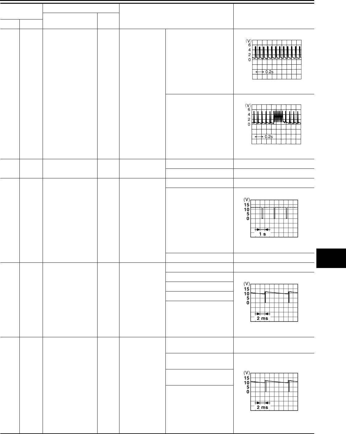
BCM (BODY CONTROL MODULE)
PWC-65
< ECU DIAGNOSIS >
C
D
E
F
G
H
I
J
L
M
A
B
PWC
N
O
P
139
(L) Ground Tire pressure receiv-
er signal
Input/
Output
Ignition switch
ON
Standby state
When receiving the signal
from the transmitter
140
(GR) Ground Selector lever P/N
position signal Input Selector lever P or N position Battery voltage
Except P and N positions 0 V
141
(G) Ground Security indicator sig-
nal Output Security indicator
ON 0 V
Blinking
11.3 V
OFF Battery voltage
142
(O) Ground Combination switch
OUTPUT 5 Output
Combination
switch
(Wiper intermit-
tent dial 4)
All switch OFF 0 V
Lighting switch 1ST
10.7 V
Lighting switch HI
Lighting switch 2ND
Turn signal switch RH
143
(P) Ground Combination switch
OUTPUT 1 Output Combination
switch
All switch OFF
(Wiper intermittent dial 4) 0 V
Front wiper switch HI
(Wiper intermittent dial 4)
10.7 V
Rear wiper switch INT
(Wiper intermittent dial 4)
Any of the conditions below
with all switch OFF
• Wiper intermittent dial 1
• Wiper intermittent dial 2
• Wiper intermittent dial 3
• Wiper intermittent dial 6
• Wiper intermittent dial 7
Terminal No.
(Wire color) Description
Condition Value
(Approx.)
Signal name Input/
Output+–
OCC3881D
OCC3880D
JPMIA0014G
B
JPMIA0031G
B
JPMIA0032G
B
Revision: 2007 November 2008 EX35
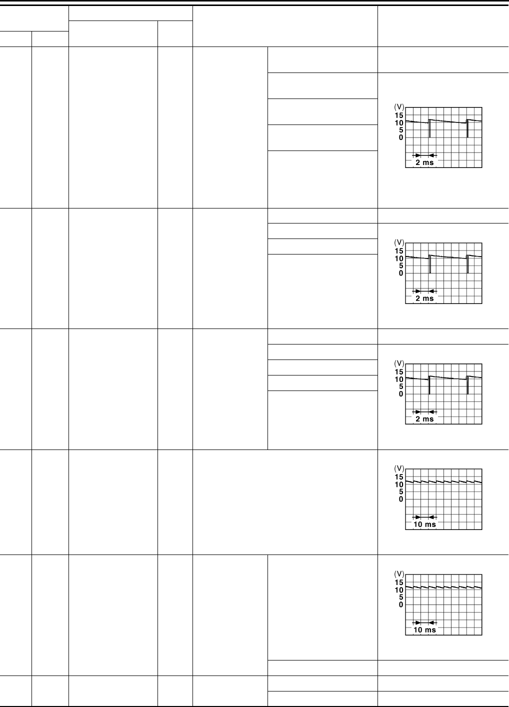
PWC-66
< ECU DIAGNOSIS >
BCM (BODY CONTROL MODULE)
144
(G) Ground Combination switch
OUTPUT 2 Output Combination
switch
All switch OFF
(Wiper intermittent dial 4) 0 V
Front washer switch ON
(Wiper intermittent dial 4)
10.7 V
Rear wiper switch ON
(Wiper intermittent dial 4)
Rear washer switch ON
(Wiper intermittent dial 4)
Any of the conditions below
with all switch OFF
• Wiper intermittent dial 1
• Wiper intermittent dial 5
• Wiper intermittent dial 6
145
(L) Ground Combination switch
OUTPUT 3 Output
Combination
switch
(Wiper intermit-
tent dial 4)
All switch OFF 0 V
Front wiper switch INT
10.7 V
Front wiper switch LO
Lighting switch AUTO
146
(SB) Ground Combination switch
OUTPUT 4 Output
Combination
switch
(Wiper intermit-
tent dial 4)
All switch OFF 0 V
Front fog lamp switch ON
10.7 V
Lighting switch 2ND
Lighting switch PASS
Turn signal switch LH
149
(W) Ground Tire pressure warn-
ing check switch Input Ignition switch ON
11.8 V
150
(LG) Ground Driver door switch Input Driver door
switch
OFF (Door close)
11.8 V
ON (Door open) 0 V
151
(G) Ground Rear window defog-
ger relay Output Rear window de-
fogger
Active 0 V
Not activated Battery voltage
Terminal No.
(Wire color) Description
Condition Value
(Approx.)
Signal name Input/
Output+–
JPMIA0033G
B
JPMIA0034G
B
JPMIA0035G
B
JPMIA0011GB
JPMIA0011GB
Revision: 2007 November 2008 EX35
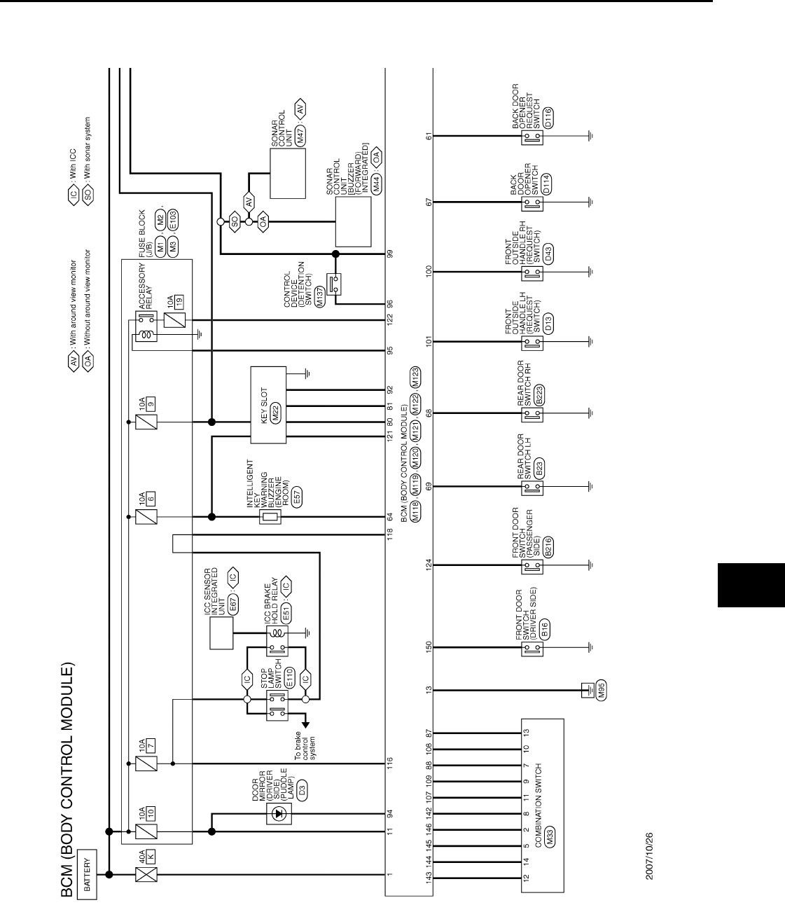
BCM (BODY CONTROL MODULE)
PWC-67
< ECU DIAGNOSIS >
C
D
E
F
G
H
I
J
L
M
A
B
PWC
N
O
P
NOTE:
*: With auto light system
Wiring Diagram - BCM - INFOID:0000000003773245
JCMWM1398
GB
Revision: 2007 November 2008 EX35
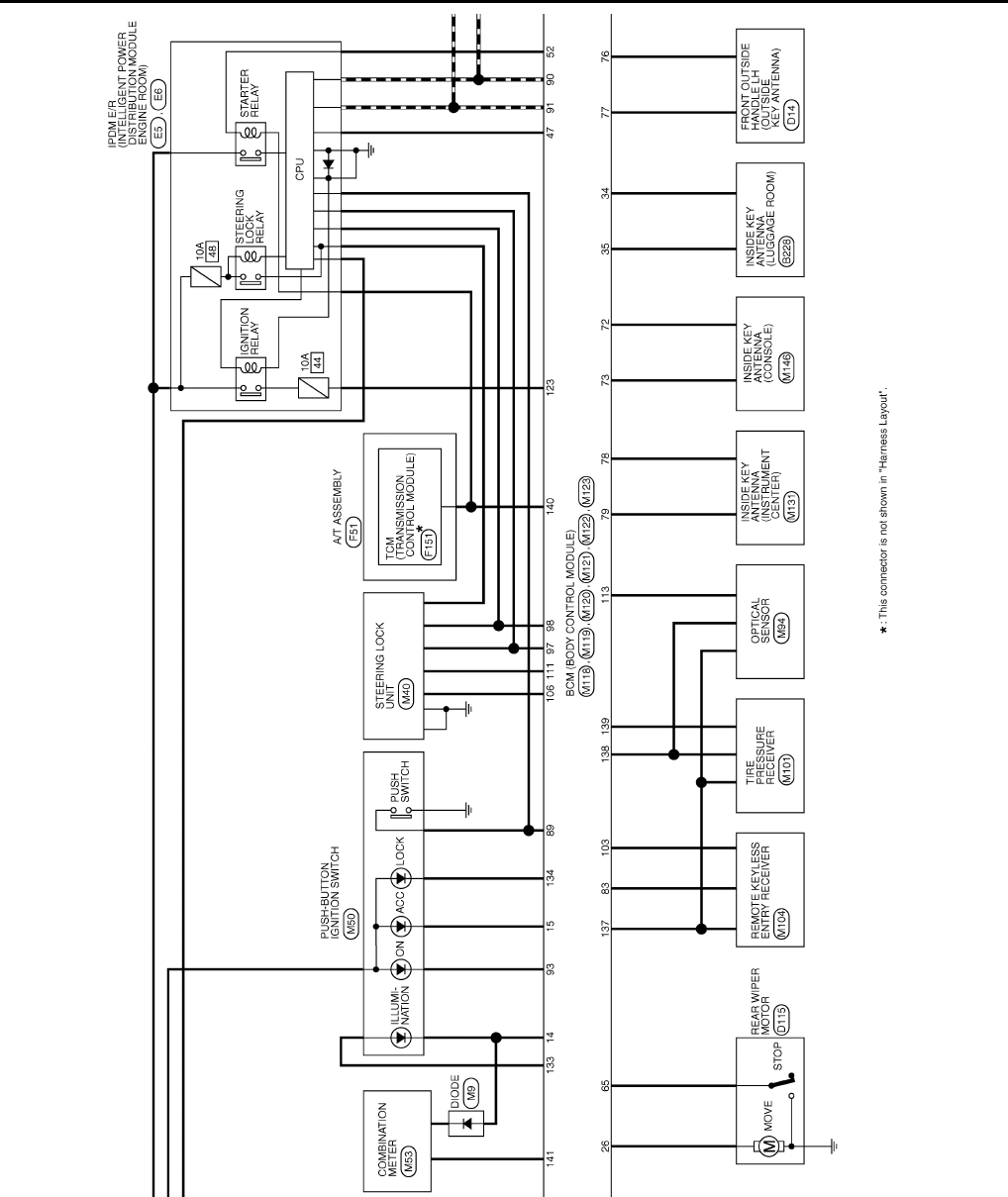
PWC-68
< ECU DIAGNOSIS >
BCM (BODY CONTROL MODULE)
JCMWM1399
GB
Revision: 2007 November 2008 EX35
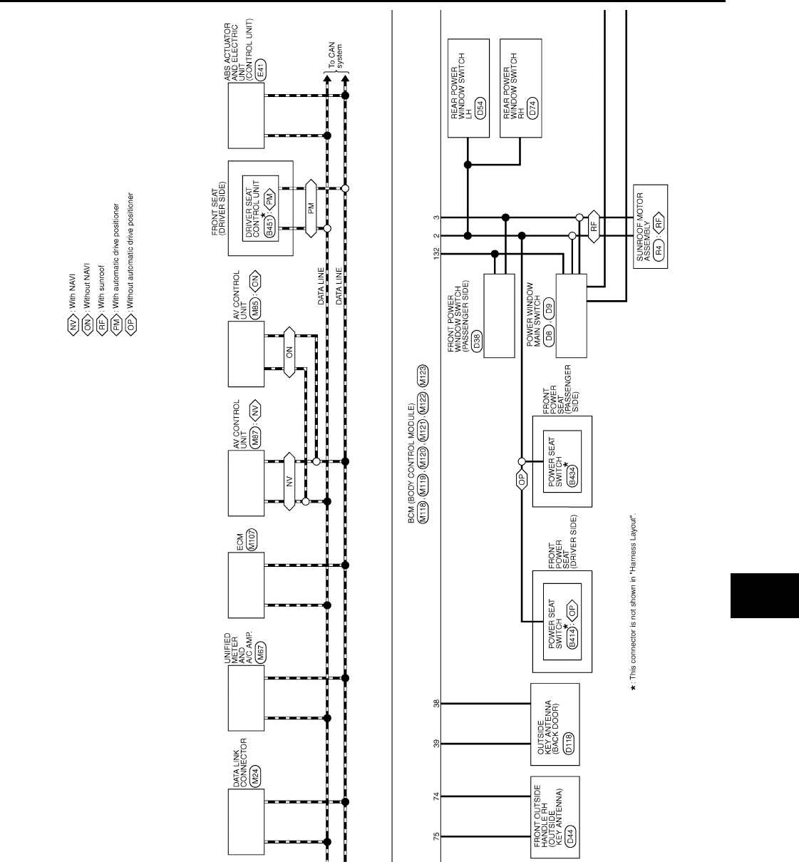
BCM (BODY CONTROL MODULE)
PWC-69
< ECU DIAGNOSIS >
C
D
E
F
G
H
I
J
L
M
A
B
PWC
N
O
P
JCMWM1400
GB
Revision: 2007 November 2008 EX35
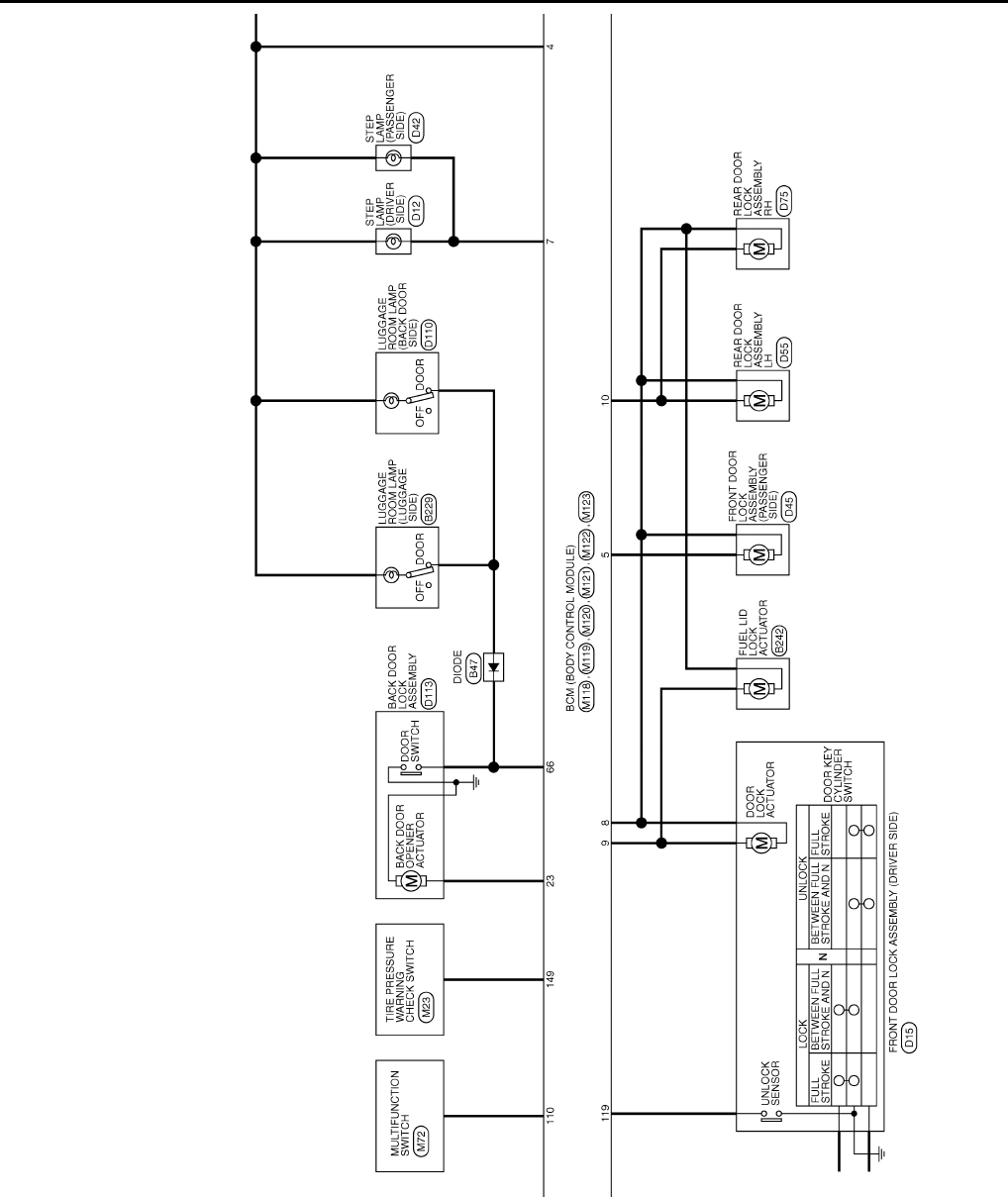
PWC-70
< ECU DIAGNOSIS >
BCM (BODY CONTROL MODULE)
JCMWM1401
GB
Revision: 2007 November 2008 EX35
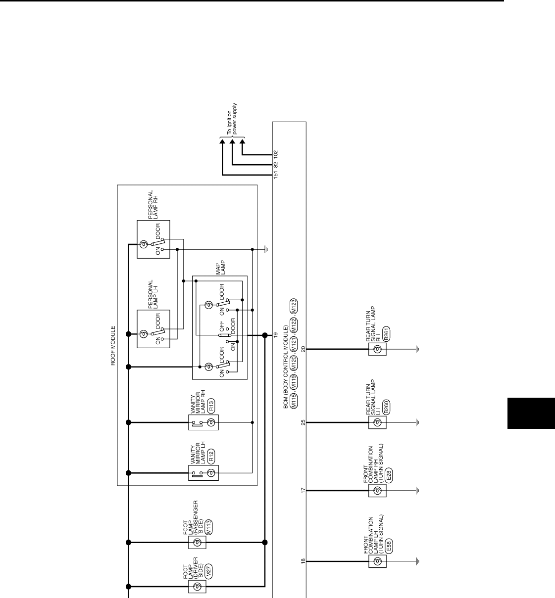
BCM (BODY CONTROL MODULE)
PWC-71
< ECU DIAGNOSIS >
C
D
E
F
G
H
I
J
L
M
A
B
PWC
N
O
P
JCMWM1402
GB
Revision: 2007 November 2008 EX35
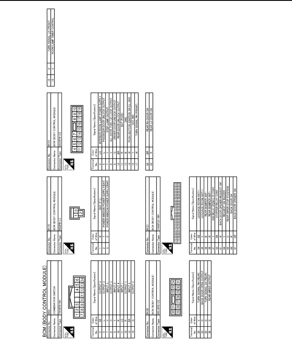
PWC-72
< ECU DIAGNOSIS >
BCM (BODY CONTROL MODULE)
JCMWM1403
GB
Revision: 2007 November 2008 EX35
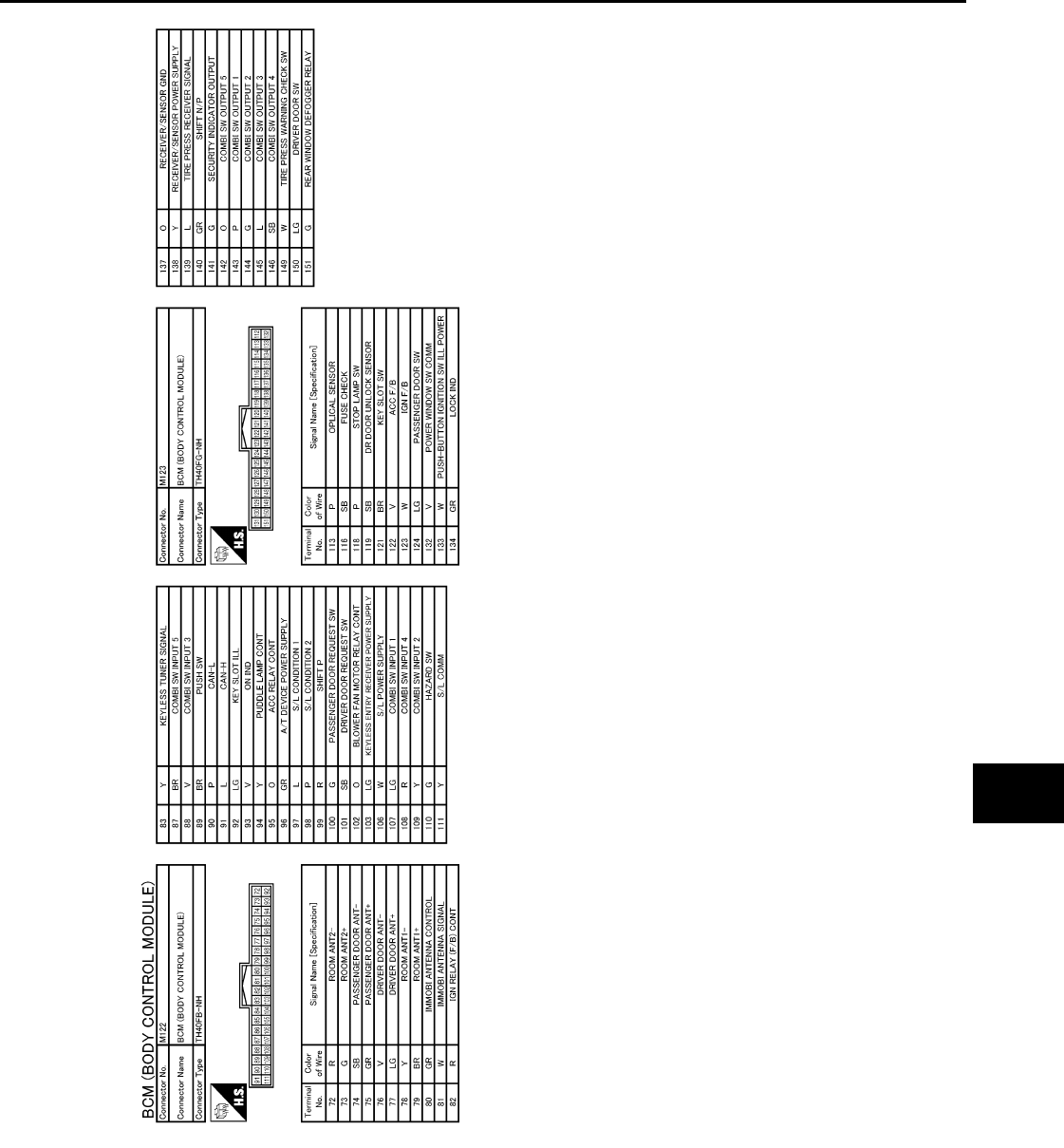
BCM (BODY CONTROL MODULE)
PWC-73
< ECU DIAGNOSIS >
C
D
E
F
G
H
I
J
L
M
A
B
PWC
N
O
P
Fail-safe INFOID:0000000003773246
FAIL-SAFE CONTROL BY DTC
BCM performs fail-safe control when any DTC is detected.
JCMWM1404
GB
Revision: 2007 November 2008 EX35

PWC-74
< ECU DIAGNOSIS >
BCM (BODY CONTROL MODULE)
Display contents of CONSULT Fail-safe Cancellation
B2013: ID DISCORD BCM-S/L Inhibit engine cranking Erase DTC
B2014: CHAIN OF S/L-BCM Inhibit engine cranking Erase DTC
B2190: NATS ANTENNA AMP Inhibit engine cranking Erase DTC
B2191: DIFFERENCE OF KEY Inhibit engine cranking Erase DTC
B2192: ID DISCORD BCM-ECM Inhibit engine cranking Erase DTC
B2193: CHAIN OF BCM-ECM Inhibit engine cranking Erase DTC
B2557: VEHICLE SPEED Inhibit steering lock When normal vehicle speed signals have been received from ABS
actuator and electric unit (control unit) for 500 ms
B2560: STARTER CONT RELAY Inhibit engine cranking
500 ms after the following CAN signal communication status has
become consistent
• Starter control relay signal
• Starter relay status signal
B2601: SHIFT POSITION Inhibit steering lock
500 ms after the following signal reception status becomes consis-
tent
• Selector lever P position switch signal
• P range signal (CAN)
B2602: SHIFT POSITION Inhibit steering lock
5 seconds after the following BCM recognition conditions are ful-
filled
• Ignition switch is in the ON position
• Selector lever P position switch signal: Except P position (battery
voltage)
• Vehicle speed: 4 km/h (2.5 MPH) or more
B2603: SHIFT POSI STATUS Inhibit steering lock
500 ms after the following BCM recognition conditions are fulfilled
• Ignition switch is in the ON position
• Selector lever P position switch signal: Except P position (battery
voltage)
• Selector lever P/N position signal: Except P and N positions (0 V)
B2604: PNP SW Inhibit steering lock
500 ms after any of the following BCM recognition conditions is ful-
filled
•Status 1
- Ignition switch is in the ON position
- Selector lever P/N position signal: P and N position (battery volt-
age)
- P range signal or N range signal (CAN): ON
•Status 2
- Ignition switch is in the ON position
- Selector lever P/N position signal: Except P and N positions (0 V)
- P range signal and N range signal (CAN): OFF
B2605: PNP SW Inhibit steering lock
500 ms after any of the following BCM recognition conditions is ful-
filled
• Ignition switch is in the ON position
- Power position: IGN
- Selector lever P/N position signal: Except P and N positions (0 V)
- Interlock/PNP switch signal (CAN): OFF
•Status 2
- Ignition switch is in the ON position
- Selector lever P/N position signal: P or N position (battery volt-
age)
- PNP switch signal (CAN): ON
B2606: S/L RELAY Inhibit engine cranking
500 ms after the following CAN signal communication status has
become consistent
• Steering lock relay signal (Request signal)
• Steering lock relay signal (Condition signal)
B2607: S/L RELAY Inhibit engine cranking
500 ms after the following CAN signal communication status has
become consistent
• Steering lock relay signal (Request signal)
• Steering lock relay signal (Condition signal)
Revision: 2007 November 2008 EX35

BCM (BODY CONTROL MODULE)
PWC-75
< ECU DIAGNOSIS >
C
D
E
F
G
H
I
J
L
M
A
B
PWC
N
O
P
HIGH FLASHER OPERATION
BCM detects the turn signal lamp circuit status by the current value.
BCM increases the turn signal lamp blinking speed if the bulb or harness open is detected with the turn signal
lamp operating.
NOTE:
The blinking speed is normal while activating the hazard warning lamp.
DTC Inspection Priority Chart INFOID:0000000003773247
If some DTCs are displayed at the same time, perform inspections one by one based on the following priority
chart.
B2608: STARTER RELAY Inhibit engine cranking
500 ms after the following signal communication status becomes
consistent
• Starter motor relay control signal
• Starter relay status signal (CAN)
B2609: S/L STATUS • Inhibit engine cranking
• Inhibit steering lock
When the following steering lock conditions agree
• BCM steering lock control status
• Steering lock condition No. 1 signal status
• Steering lock condition No. 2 signal status
B260A: IGNITION RELAY Inhibit engine cranking
500 ms after the following conditions are fulfilled
• IGN relay (IPDM E/R) control signal: OFF (Battery voltage)
• Ignition ON signal (CAN to IPDM E/R): OFF (Request signal)
• Ignition ON signal (CAN from IPDM E/R): OFF (Condition signal)
B260F: ENG STATE SIG LOST Maintains the power supply
position attained at the time
of DTC detection
When any of the following conditions is fulfilled
• Power position changes to ACC
• Receives engine status signal (CAN)
B2612: S/L STATUS • Inhibit engine cranking
• Inhibit steering lock
When any of the following conditions is fulfilled
• Steering lock unit status signal (CAN) is received normally
• The BCM steering lock control status matches the steering lock
status recognized by the steering lock unit status signal (CAN
from IPDM E/R)
B2617: STARTER RELAY CIRC Inhibit engine cranking 1 second after the starter motor relay control inside BCM becomes
normal
B2618: BCM Inhibit engine cranking 1 second after the ignition relay (IPDM E/R) control inside BCM be-
comes normal
B2619: BCM Inhibit engine cranking 1 second after the steering lock unit power supply output control in-
side BCM becomes normal
B261E: VEHICLE TYPE Inhibit engine cranking BCM initialization
B26E1: ENG STATE NO RECIV Inhibit engine cranking When any of the following conditions is fulfilled
• Power position changes to ACC
• Receives engine status signal (CAN)
B26E9: S/L STATUS • Inhibit engine cranking
• Inhibit steering lock
When BCM transmits the LOCK request signal to steering lock unit,
and receives LOCK response signal from steering lock unit, the fol-
lowing conditions is fulfilled
• Steering condition No. 1 signal: LOCK (0V)
• Steering condition No. 2 signal: LOCK (Battery voltage)
Display contents of CONSULT Fail-safe Cancellation
Priority DTC
1 B2562: LOW VOLTAGE
2• U1000: CAN COMM CIRCUIT
• U1010: CONTROL UNIT (CAN)
3
• B2190: NATS ANTENNA AMP
• B2191: DIFFERENCE OF KEY
• B2192: ID DISCORD BCM-ECM
• B2193: CHAIN OF BCM-ECM
Revision: 2007 November 2008 EX35

PWC-76
< ECU DIAGNOSIS >
BCM (BODY CONTROL MODULE)
4
• B2013: ID DISCORD BCM-S/L
• B2014: CHAIN OF S/L-BCM
• B2553: IGNITION RELAY
• B2555: STOP LAMP
• B2556: PUSH-BTN IGN SW
• B2557: VEHICLE SPEED
• B2560: STARTER CONT RELAY
• B2601: SHIFT POSITION
• B2602: SHIFT POSITION
• B2603: SHIFT POSI STATUS
• B2604: PNP SW
• B2605: PNP SW
• B2606: S/L RELAY
• B2607: S/L RELAY
• B2608: STARTER RELAY
• B2609: S/L STATUS
• B260A: IGNITION RELAY
• B260B: STEERING LOCK UNIT
• B260C: STEERING LOCK UNIT
• B260D: STEERING LOCK UNIT
• B260F: ENG STATE SIG LOST
• B2612: S/L STATUS
• B2614: ACC RELAY CIRC
• B2615: BLOWER RELAY CIRC
• B2616: IGN RELAY CIRC
• B2617: STARTER RELAY CIRC
• B2618: BCM
• B2619: BCM
• B261A: PUSH-BTN IGN SW
• B261E: VEHICLE TYPE
• B26E1: ENG STATE NO RECIV
• B26E9: S/L STATUS
• B26EA: KEY REGISTRATION
• C1729: VHCL SPEED SIG ERR
• U0415: VEHICLE SPEED SIG
5
• C1704: LOW PRESSURE FL
• C1705: LOW PRESSURE FR
• C1706: LOW PRESSURE RR
• C1707: LOW PRESSURE RL
• C1708: [NO DATA] FL
• C1709: [NO DATA] FR
• C1710: [NO DATA] RR
• C1711: [NO DATA] RL
• C1712: [CHECKSUM ERR] FL
• C1713: [CHECKSUM ERR] FR
• C1714: [CHECKSUM ERR] RR
• C1715: [CHECKSUM ERR] RL
• C1716: [PRESSDATA ERR] FL
• C1717: [PRESSDATA ERR] FR
• C1718: [PRESSDATA ERR] RR
• C1719: [PRESSDATA ERR] RL
• C1720: [CODE ERR] FL
• C1721: [CODE ERR] FR
• C1722: [CODE ERR] RR
• C1723: [CODE ERR] RL
• C1724: [BATT VOLT LOW] FL
• C1725: [BATT VOLT LOW] FR
• C1726: [BATT VOLT LOW] RR
• C1727: [BATT VOLT LOW] RL
• C1734: CONTROL UNIT
6• B2621: INSIDE ANTENNA
• B2622: INSIDE ANTENNA
• B2623: INSIDE ANTENNA
Priority DTC
Revision: 2007 November 2008 EX35

BCM (BODY CONTROL MODULE)
PWC-77
< ECU DIAGNOSIS >
C
D
E
F
G
H
I
J
L
M
A
B
PWC
N
O
P
DTC Index INFOID:0000000003773248
NOTE:
The details of time display are as follows.
• CRNT: A malfunction is detected now.
• PAST: A malfunction was detected in the past.
IGN counter is displayed on Freeze Frame Data. For details of Freeze Frame Data and IGN Counter, refer to
BCS-16, "COMMON ITEM : CONSULT-III Function (BCM - COMMON ITEM)".
CONSULT display Fail-safe Freeze Frame
Data
Intelligent Key
warning lamp ON
Tire pressure
monitor warning
lamp ON
Reference
page
No DTC is detected.
further testing
may be required.
—————
U1000: CAN COMM CIRCUIT — — — — BCS-37
U1010: CONTROL UNIT (CAN) — — — — BCS-38
U0415: VEHICLE SPEED SIG — — — — BCS-39
B2013: ID DISCORD BCM-S/L ××——SEC-48
B2014: CHAIN OF S/L-BCM ××——SEC-49
B2190: NATS ANTENNA AMP ×———SEC-42
B2191: DIFFERENCE OF KEY ×———SEC-45
B2192: ID DISCORD BCM-ECM ×———SEC-46
B2193: CHAIN OF BCM-ECM ×———SEC-47
B2553: IGNITION RELAY — ×——PCS-49
B2555: STOP LAMP — ×——SEC-52
B2556: PUSH-BTN IGN SW — ××—SEC-54
B2557: VEHICLE SPEED ×××—SEC-56
B2560: STARTER CONT RELAY ×××—SEC-57
B2562: LOW VOLTAGE — ×——BCS-40
B2601: SHIFT POSITION ×××—SEC-58
B2602: SHIFT POSITION ×××—SEC-61
B2603: SHIFT POSI STATUS ×××—SEC-63
B2604: PNP SW ×××—SEC-66
B2605: PNP SW ×××—SEC-68
B2606: S/L RELAY ×××—SEC-70
B2607: S/L RELAY ×××—SEC-71
B2608: STARTER RELAY ×××—SEC-73
B2609: S/L STATUS ×××—SEC-75
B260A: IGNITION RELAY ×××—PCS-51
B260B: STEERING LOCK UNIT — ××—SEC-79
B260C: STEERING LOCK UNIT — ××—SEC-80
B260D: STEERING LOCK UNIT — ××—SEC-81
B260F: ENG STATE SIG LOST ×××—SEC-82
B2612: S/L STATUS ×××—SEC-86
B2614: ACC RELAY CIRC — ××—PCS-53
B2615: BLOWER RELAY CIRC — ××—PCS-57
B2616: IGN RELAY CIRC — ××—PCS-59
B2617: STARTER RELAY CIRC ×××—SEC-90
Revision: 2007 November 2008 EX35

PWC-78
< ECU DIAGNOSIS >
BCM (BODY CONTROL MODULE)
B2618: BCM ×××—PCS-61
B2619: BCM ×××—SEC-92
B261A: PUSH-BTN IGN SW — ××—SEC-93
B261E: VEHICLE TYPE ××
× (Turn ON for 15
seconds) —SEC-96
B2621: INSIDE ANTENNA — ×——DLK-56
B2622: INSIDE ANTENNA — ×——DLK-58
B2623: INSIDE ANTENNA — ×——DLK-60
B26E1: ENG STATE NO RES ×××—SEC-83
B26E9: S/L STATUS ××
× (Turn ON for 15
seconds) —SEC-84
B26EA: KEY REGISTRATION — ×
× (Turn ON for 15
seconds) —SEC-85
C1704: LOW PRESSURE FL — — — ×
WT-16
C1705: LOW PRESSURE FR — — — ×
C1706: LOW PRESSURE RR — — — ×
C1707: LOW PRESSURE RL — — — ×
C1708: [NO DATA] FL — — — ×
WT-18
C1709: [NO DATA] FR — — — ×
C1710: [NO DATA] RR — — — ×
C1711: [NO DATA] RL — — — ×
C1712: [CHECKSUM ERR] FL — — — ×
WT-21
C1713: [CHECKSUM ERR] FR — — — ×
C1714: [CHECKSUM ERR] RR — — — ×
C1715: [CHECKSUM ERR] RL — — — ×
C1716: [PRESSDATA ERR] FL — — — ×
WT-24
C1717: [PRESSDATA ERR] FR — — — ×
C1718: [PRESSDATA ERR] RR — — — ×
C1719: [PRESSDATA ERR] RL — — — ×
C1720: [CODE ERR] FL — — — ×
WT-26
C1721: [CODE ERR] FR — — — ×
C1722: [CODE ERR] RR — — — ×
C1723: [CODE ERR] RL — — — ×
C1724: [BATT VOLT LOW] FL — — — ×
WT-29
C1725: [BATT VOLT LOW] FR — — — ×
C1726: [BATT VOLT LOW] RR — — — ×
C1727: [BATT VOLT LOW] RL — — — ×
C1729: VHCL SPEED SIG ERR — — — ×WT-32
C1734: CONTROL UNIT — — — ×WT-33
CONSULT display Fail-safe Freeze Frame
Data
Intelligent Key
warning lamp ON
Tire pressure
monitor warning
lamp ON
Reference
page
Revision: 2007 November 2008 EX35
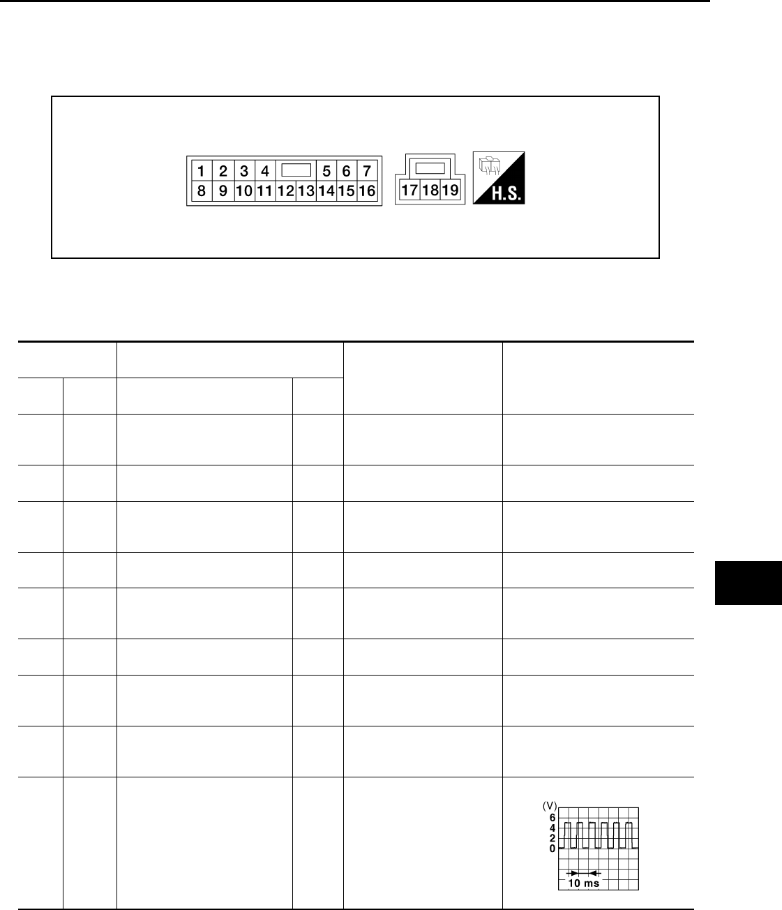
POWER WINDOW MAIN SWITCH
PWC-79
< ECU DIAGNOSIS >
C
D
E
F
G
H
I
J
L
M
A
B
PWC
N
O
P
POWER WINDOW MAIN SWITCH
Reference Value INFOID:0000000003573510
TERMINAL LAYOUT
PHYSICAL VALUES
POWER WINDOW MAIN SWITCH
LIIA2455E
Terminal No.
(Wire color) Description
Condition Voltage [V]
(Approx.)
+ - Signal name Input/
Output
1
(W) Ground Rear power window motor LH
UP signal Output
When rear LH switch in pow-
er window main switch is UP
at operated
Battery voltage
2
(R) Ground Encoder ground — — 0
3
(GR) Ground Rear power window motor LH
DOWN signal Output
When rear LH switch in pow-
er window main switch is
DOWN at operated
Battery voltage
4
(V) Ground Door key cylinder switch LH
LOCK signal Input Key position
(Neutral → Locked) 5 → 0
5
(O) Ground Rear power window motor RH
DOWN signal Output
When rear RH switch in
power window main switch
is DOWN at operated
Battery voltage
6
(Y) Ground Door key cylinder switch LH
UNLOCK signal Input Key position
(Neutral → Unlocked) 5 → 0
7
(BR) Ground Rear power window motor RH
UP signal Output
When rear RH switch in
power window main switch
is UP at operated
Battery voltage
8
(L) Ground Front power window motor
(driver side) UP signal Output When front LH switch in
power window main switch
is UP at operated
Battery voltage
9
(O) Ground Encoder pulse signal 2 Input When front power window
motor (driver side) operates
JMKIA0070G
B
Revision: 2007 November 2008 EX35
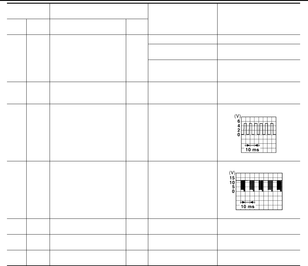
PWC-80
< ECU DIAGNOSIS >
POWER WINDOW MAIN SWITCH
10
(SB) Ground Retained power signal Input
Ignition switch ON Battery voltage
Within 45 seconds after igni-
tion switch is turned to OFF Battery voltage
When driver side or passen-
ger side door is opened dur-
ing retained power operation
0
11
(G) Ground Front power window motor
(driver side) DOWN signal Output
When front LH switch in
power window main switch
is DOWN at operated Battery voltage
13
(P) Ground Encoder pulse signal 1 Input When front power window
motor (driver side) operates.
14
(V) Ground Power window serial link Input/
Output Ignition switch ON or power
window timer operating
15
(B) Ground Encoder power supply Output Ignition switch ON Battery voltage
17
(B) Ground Ground — — 0
19
(Y) Ground Battery power supply Input Ignition switch OFF Battery voltage
Terminal No.
(Wire color) Description
Condition Voltage [V]
(Approx.)
+ - Signal name Input/
Output
JMKIA0070G
B
JPMIA0013G
B
Revision: 2007 November 2008 EX35
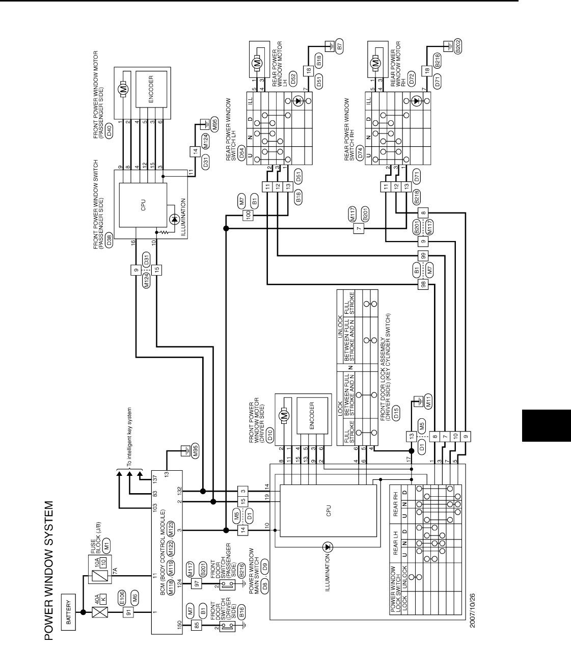
POWER WINDOW MAIN SWITCH
PWC-81
< ECU DIAGNOSIS >
C
D
E
F
G
H
I
J
L
M
A
B
PWC
N
O
P
Wiring Diagram - POWER WINDOW SYSTEM - INFOID:0000000003573511
JCKWM1093
GB
Revision: 2007 November 2008 EX35
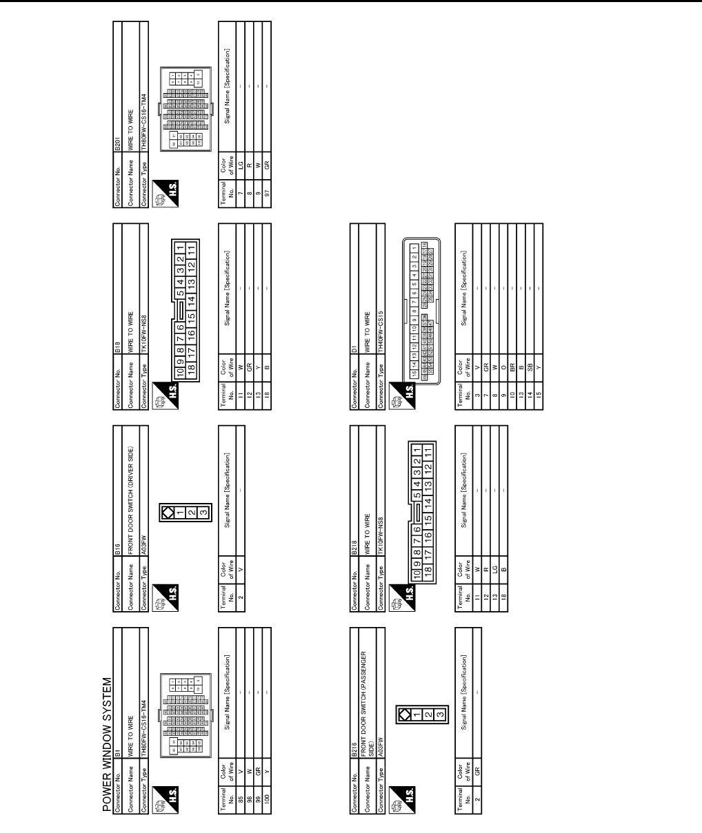
PWC-82
< ECU DIAGNOSIS >
POWER WINDOW MAIN SWITCH
JCKWM1094
GB
Revision: 2007 November 2008 EX35

POWER WINDOW MAIN SWITCH
PWC-83
< ECU DIAGNOSIS >
C
D
E
F
G
H
I
J
L
M
A
B
PWC
N
O
P
JCKWM1095
GB
Revision: 2007 November 2008 EX35
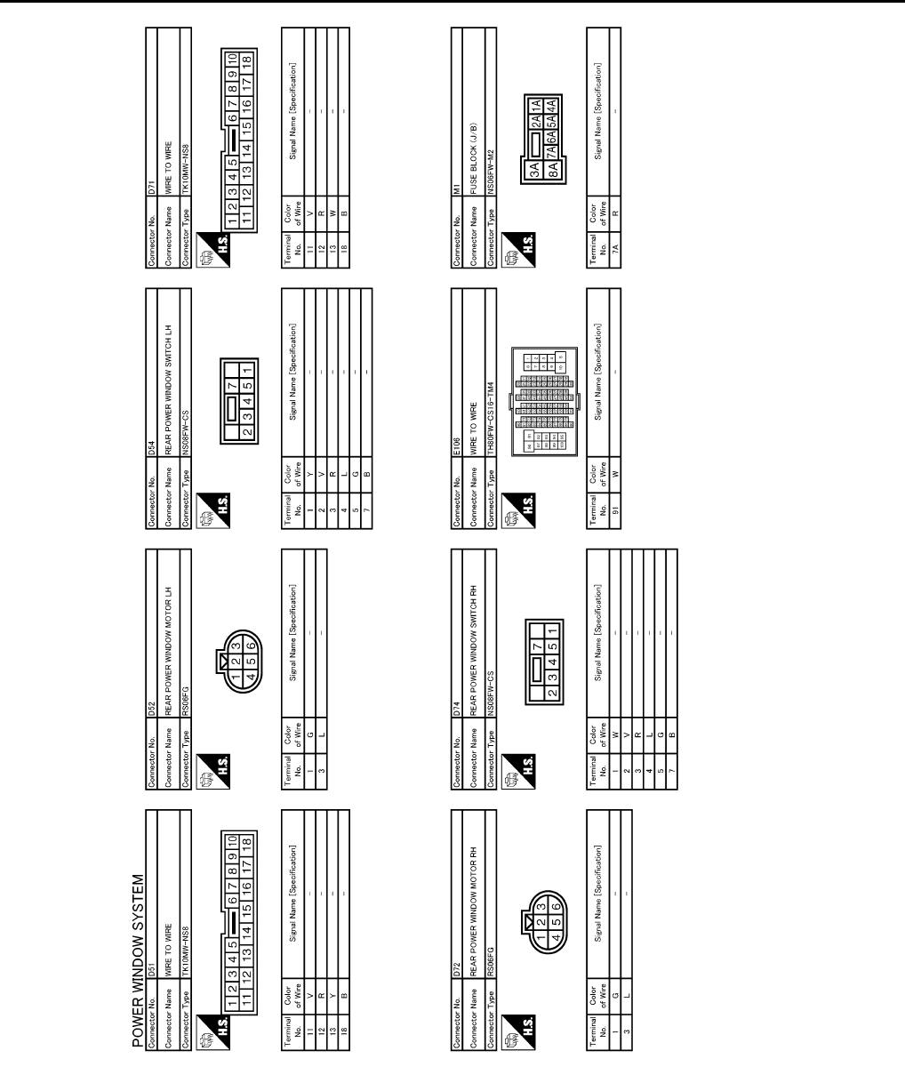
PWC-84
< ECU DIAGNOSIS >
POWER WINDOW MAIN SWITCH
JCKWM1096
GB
Revision: 2007 November 2008 EX35

POWER WINDOW MAIN SWITCH
PWC-85
< ECU DIAGNOSIS >
C
D
E
F
G
H
I
J
L
M
A
B
PWC
N
O
P
JCKWM1097
GB
Revision: 2007 November 2008 EX35

PWC-86
< ECU DIAGNOSIS >
POWER WINDOW MAIN SWITCH
Fail Safe INFOID:0000000003573513
FAIL-SAFE CONTROL
Switches to fail-safe control when malfunction is detected in encoder signal that detects up/down speed and
direction of door glass. Switches to fail-safe control when error beyond regulation value is detected between
the fully closed position and the actual position of the glass.
JCKWM1098
GB
Revision: 2007 November 2008 EX35

POWER WINDOW MAIN SWITCH
PWC-87
< ECU DIAGNOSIS >
C
D
E
F
G
H
I
J
L
M
A
B
PWC
N
O
P
It changes to condition before initialization and the following functions do not operate when switched to fail-
safe control.
• Auto-up operation
• Anti-pinch function
• Retained power function
Perform initial operation to recover when switched to fail-safe mode. However, it switches back to fail-safe
control when malfunction is found in power window switch or front power window motor.
Error Error condition
Pulse sensor malfunction When only one side of pulse signal is being detected for more than the specified value.
Both pulse sensors mal-
function
When both pulse signals have not been detected for more than the specified value during glass open/
close operation.
Pulse direction malfunction When the pulse signal that is detected during glass open/close operation detects the opposite condition
of power window motor operating direction.
Glass recognition position
malfunction 1
When it detects the error between glass fully closed position in power window switch memory and actual
fully closed position during glass open/close operation is more than the specified value.
Glass recognition position
malfunction 2 When it detects pulse count more than the value of glass full stroke during glass open/close operation.
Malfunction of not yet up-
dated closed position of
glass
When glass open/close operation is continuously performed without fully closing more than the specified
value (approximately 10 strokes).
Revision: 2007 November 2008 EX35
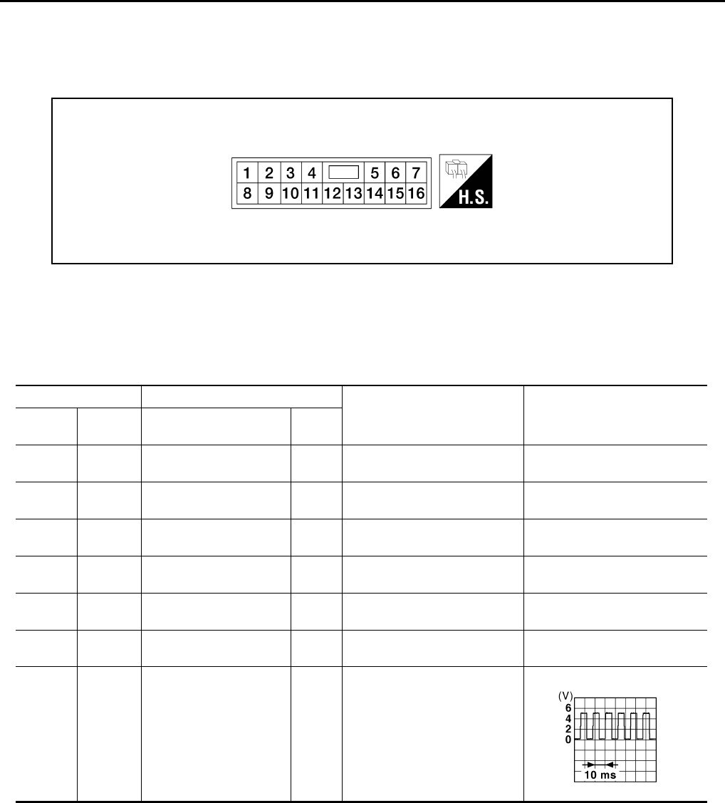
PWC-88
< ECU DIAGNOSIS >
FRONT POWER WINDOW SWITCH (PASSENGER SIDE)
FRONT POWER WINDOW SWITCH (PASSENGER SIDE)
Reference Value INFOID:0000000003573514
TERMINAL LAYOUT
PHYSICAL VALUES
FRONT POWER WINDOW SWITCH (PASSENGER SIDE)
LIIA2454E
Terminal No. Description
Condition Voltage [V]
(Approx.)
+ - Signal name Input/
Output
3
(LG) Ground Encoder ground — — 0
4
(GR) Ground Encoder power supply Output When ignition switch ON or
power window timer operates Battery voltage
8
(L) 9Power window motor
UP signal Output When power window motor is
UP at operated. Battery voltage
9
(G) 8Power window motor
DOWN signal Output When power window motor is
DOWN at operated. Battery voltage
10
(Y) Ground Battery power supply Input — Battery voltage
11
(B) Ground Ground — — 0
12
(P) 3 Encoder pulse signal 1 Input When power window motor op-
erates.
JMKIA0070G
B
Revision: 2007 November 2008 EX35
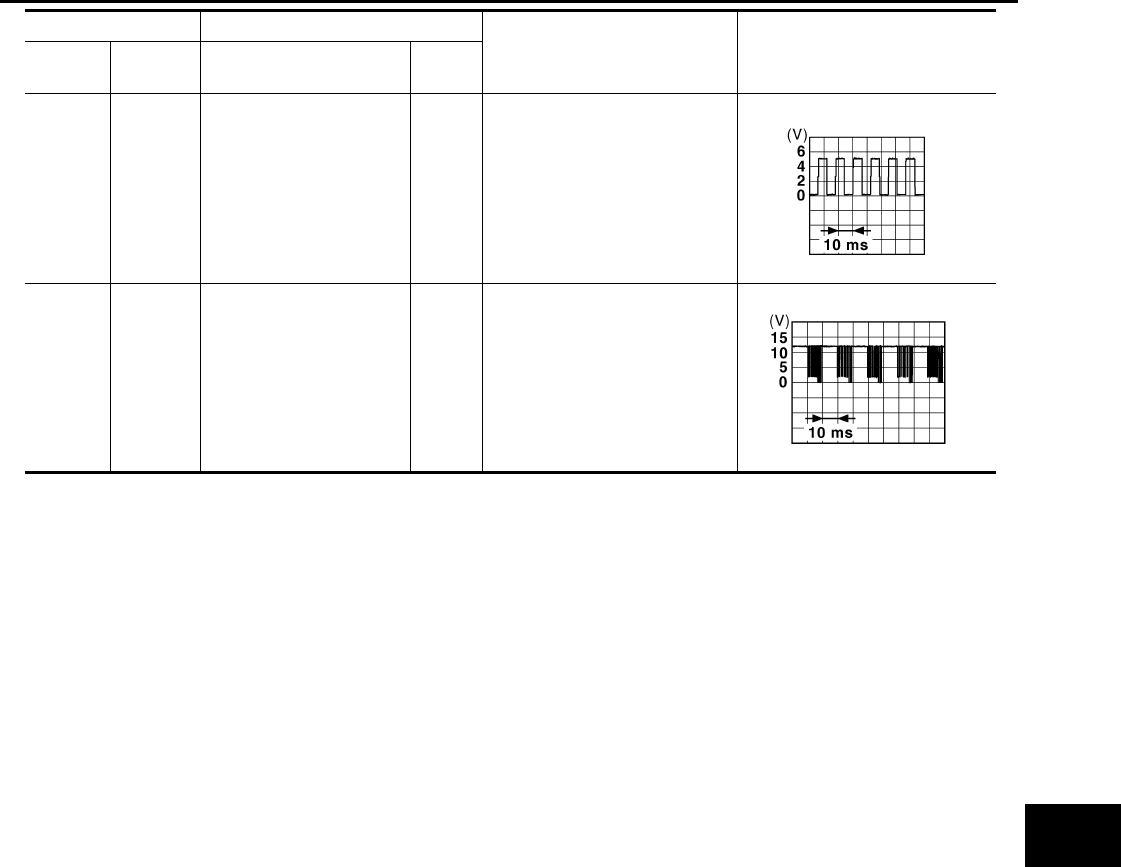
FRONT POWER WINDOW SWITCH (PASSENGER SIDE)
PWC-89
< ECU DIAGNOSIS >
C
D
E
F
G
H
I
J
L
M
A
B
PWC
N
O
P
15
(O) 3 Encoder pulse signal 2 Input When power window motor op-
erates.
16
(V) Ground Power window serial link Input/
Output Ignition switch ON or power win-
dow timer operating.
Terminal No. Description
Condition Voltage [V]
(Approx.)
+ - Signal name Input/
Output
JMKIA0070G
B
JPMIA0013G
B
Revision: 2007 November 2008 EX35
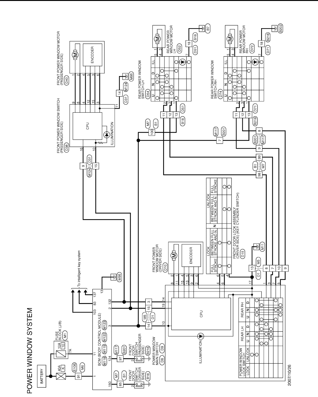
PWC-90
< ECU DIAGNOSIS >
FRONT POWER WINDOW SWITCH (PASSENGER SIDE)
Wiring Diagram - POWER WINDOW SYSTEM - INFOID:0000000003733367
JCKWM1093
GB
Revision: 2007 November 2008 EX35
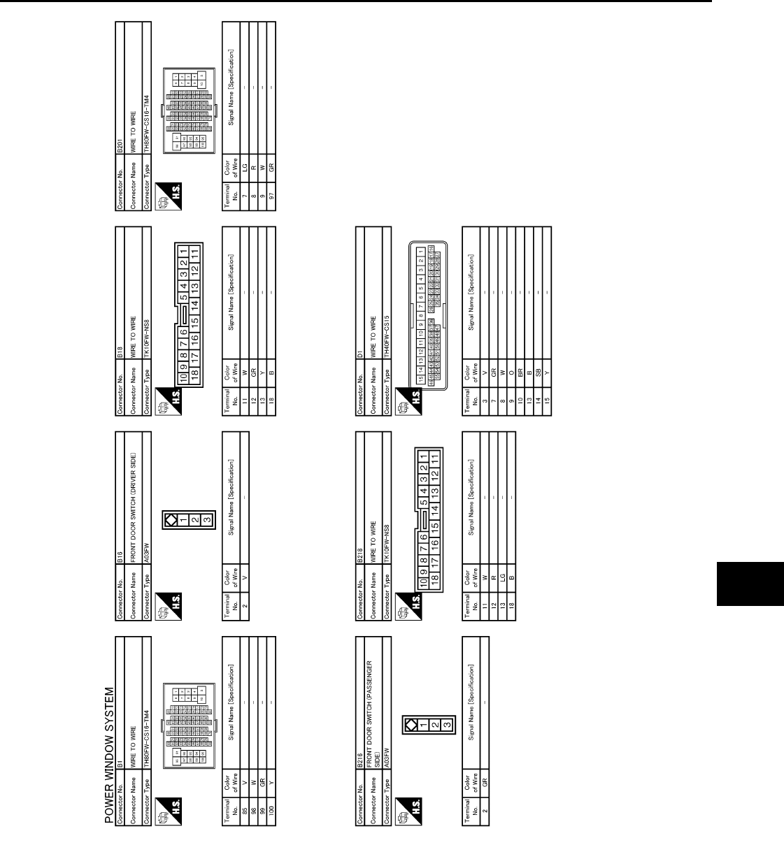
FRONT POWER WINDOW SWITCH (PASSENGER SIDE)
PWC-91
< ECU DIAGNOSIS >
C
D
E
F
G
H
I
J
L
M
A
B
PWC
N
O
P
JCKWM1094
GB
Revision: 2007 November 2008 EX35
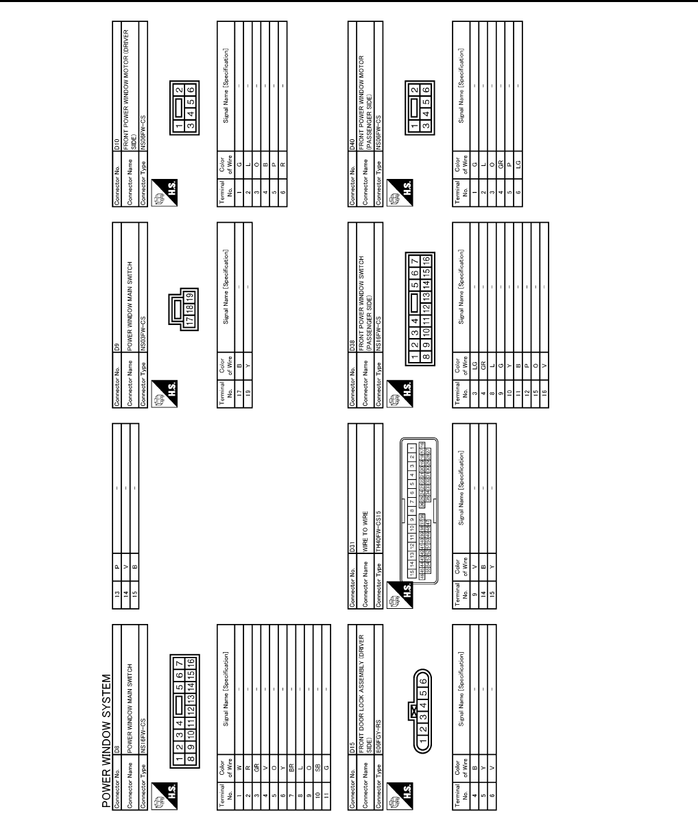
PWC-92
< ECU DIAGNOSIS >
FRONT POWER WINDOW SWITCH (PASSENGER SIDE)
JCKWM1095
GB
Revision: 2007 November 2008 EX35
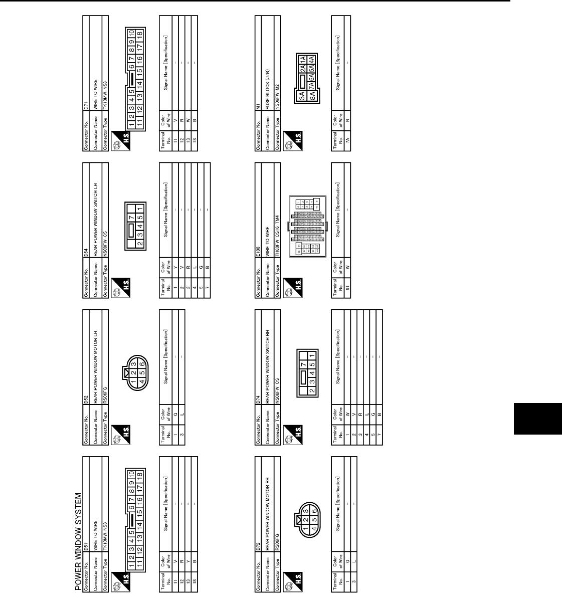
FRONT POWER WINDOW SWITCH (PASSENGER SIDE)
PWC-93
< ECU DIAGNOSIS >
C
D
E
F
G
H
I
J
L
M
A
B
PWC
N
O
P
JCKWM1096
GB
Revision: 2007 November 2008 EX35
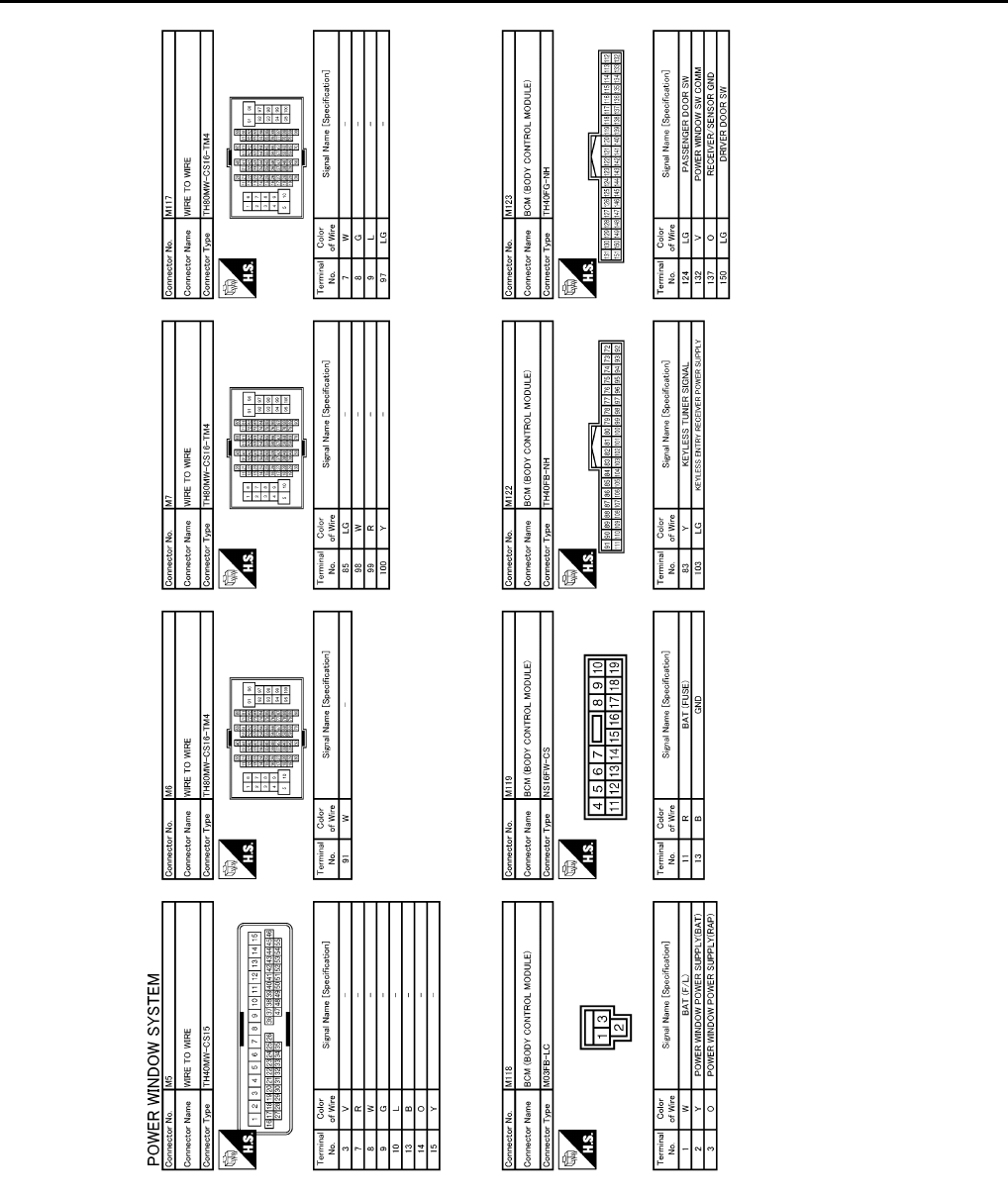
PWC-94
< ECU DIAGNOSIS >
FRONT POWER WINDOW SWITCH (PASSENGER SIDE)
JCKWM1097
GB
Revision: 2007 November 2008 EX35
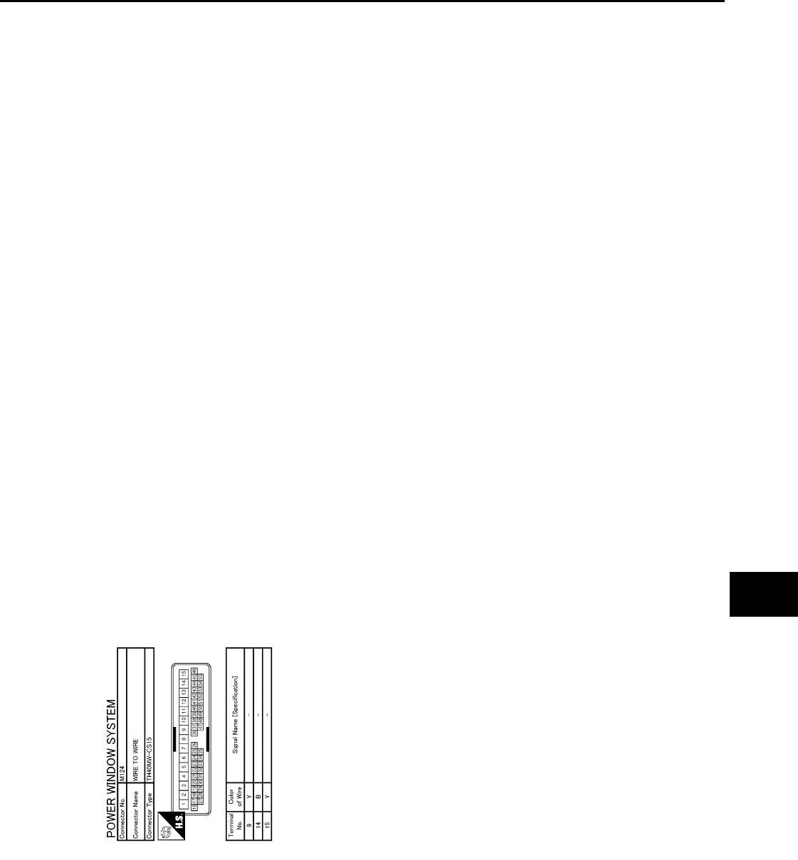
FRONT POWER WINDOW SWITCH (PASSENGER SIDE)
PWC-95
< ECU DIAGNOSIS >
C
D
E
F
G
H
I
J
L
M
A
B
PWC
N
O
P
Fail Safe INFOID:0000000003573516
FAIL-SAFE CONTROL
Switches to fail-safe control when malfunction is detected in encoder signal that detects up/down speed and
direction of door glass. Switches to fail-safe control when error beyond regulation value is detected between
the fully closed position and the actual position of the glass.
JCKWM1098
GB
Revision: 2007 November 2008 EX35

PWC-96
< ECU DIAGNOSIS >
FRONT POWER WINDOW SWITCH (PASSENGER SIDE)
It changes to condition before initialization and the following functions do not operate when switched to fail-
safe control.
• Auto-up operation
• Anti-pinch function
• Retained power function
Perform initial operation to recover when switched to fail-safe mode. However, it switches back to fail-safe
control when malfunction is found in power window switch or in front power window motor.
Error Error condition
Pulse sensor malfunction When only one side of pulse signal is being detected for more than the specified value.
Both pulse sensors mal-
function
When both pulse signals have not been detected for more than the specified value during glass open/
close operation.
Pulse direction malfunction When the pulse signal that is detected during glass open/close operation detects the opposite condition
of power window motor operating direction.
Glass recognition position
malfunction 1
When it detects the error between glass fully closed position in power window switch memory and actual
fully closed position during glass open/close operation is more than the specified value.
Glass recognition position
malfunction 2 When it detects pulse count more than the value of glass full stroke during glass open/close operation.
Malfunction of not yet up-
dated closed position of
glass
When glass open/close operation is continuously performed without fully closing more than the specified
value (approximately 10 strokes).
Revision: 2007 November 2008 EX35

NONE OF THE POWER WINDOWS CAN BE OPERATED USING ANY SWITCH
PWC-97
< SYMPTOM DIAGNOSIS >
C
D
E
F
G
H
I
J
L
M
A
B
PWC
N
O
P
SYMPTOM DIAGNOSIS
NONE OF THE POWER WINDOWS CAN BE OPERATED USING ANY
SWITCH
Diagnosis Procedure INFOID:0000000003573517
1.CHECK BCM POWER SUPPLY AND GROUND CIRCUIT
Check BCM power supply and ground circuit.
Refer to PWC-13, "BCM : Diagnosis Procedure".
Is the inspection result normal?
YES >> GO TO 2.
NO >> Repair or replace the malfunctioning parts.
2.CHECK POWER WINDOW MAIN SWITCH POWER SUPPLY AND GROUND CIRCUIT
Check power window main switch power supply and ground circuit.
Refer to PWC-13, "POWER WINDOW MAIN SWITCH : Diagnosis Procedure".
Is the inspection result normal?
YES >> GO TO 3.
NO >> Repair or replace the malfunctioning parts.
3.CONFIRM THE OPERATION
Confirm the operation again.
Is the result normal?
YES >> Check intermittent incident. Refer to GI-38, "Intermittent Incident".
NO >> GO TO 1.
Revision: 2007 November 2008 EX35

PWC-98
< SYMPTOM DIAGNOSIS >
DRIVER SIDE POWER WINDOW DOES NOT OPERATE
DRIVER SIDE POWER WINDOW DOES NOT OPERATE
Diagnosis Procedure INFOID:0000000003573518
1.CHECK FRONT POWER WINDOW MOTOR (DRIVER SIDE)
Check power window motor.
Refer to PWC-19, "DRIVER SIDE : Component Function Check".
Is the inspection result normal?
YES >> GO TO 2.
NO >> Repair or replace the malfunctioning parts.
2.CONFIRM THE OPERATION
Confirm the operation again.
Is the result normal?
YES >> Check intermittent incident. Refer to GI-38, "Intermittent Incident".
NO >> GO TO 1.
Revision: 2007 November 2008 EX35

FRONT PASSENGER SIDE POWER WINDOW DOES NOT OPERATE
PWC-99
< SYMPTOM DIAGNOSIS >
C
D
E
F
G
H
I
J
L
M
A
B
PWC
N
O
P
FRONT PASSENGER SIDE POWER WINDOW DOES NOT OPERATE
POWER WINDOW MAIN SWITCH IS OPERATED
POWER WINDOW MAIN SWITCH IS OPERATED : Diagnosis Procedure INFOID:0000000003671434
1.REPLACE FRONT POWER WINDOW SWITCH (PASSENGER SIDE)
Replace front power window switch (passenger side).
Refer to PWC-112, "Removal and Installation"
Is the inspection result normal?
YES >> GO TO 2.
NO >> Repair or replace the malfunctioning parts.
2.CONFIRM THE OPERATION
Confirm the operation again.
Is the inspection result normal?
YES >> Check intermittent incident. Refer to GI-38, "Intermittent Incident".
NO >> GO TO 1.
WHEN BOTH POWER WINDOW MAIN SWITCH AND FRONT POWER WINDOW
SWITCH ARE OPERATED
WHEN BOTH POWER WINDOW MAIN SWITCH AND FRONT POWER WINDOW
SWITCH ARE OPERATED : Diagnosis Procedure INFOID:0000000003671435
1.CHECK POWER WINDOW SWITCH SERIAL LINK CIRCUIT
Check power window switch serial link circuit.
Refer to PWC-35, "Component Function Check".
Is the inspection result normal?
YES >> GO TO 2.
NO >> Repair or replace the malfunctioning parts.
2.CHECK PASSENGER SIDE POWER WINDOW MOTOR CIRCUIT
Check passenger side power window motor circuit.
Refer to PWC-20, "PASSENGER SIDE : Component Function Check".
Is the inspection result normal?
YES >> GO TO 3.
NO >> Repair or replace the malfunctioning parts.
3.CONFIRM THE OPERATION
Confirm the operation again.
Is the inspection result normal?
YES >> Check intermittent incident. Refer to GI-38, "Intermittent Incident".
NO >> GO TO 1.
Revision: 2007 November 2008 EX35

PWC-100
< SYMPTOM DIAGNOSIS >
REAR LH SIDE POWER WINDOW DOES NOT OPERATE
REAR LH SIDE POWER WINDOW DOES NOT OPERATE
WITH BOTH POWER WINDOW MAIN SWITCH AND REAR POWER WINDOW
SWITCH LH
WITH BOTH POWER WINDOW MAIN SWITCH AND REAR POWER WINDOW
SWITCH LH : Diagnosis Procedure INFOID:0000000003573522
1.CHECK REAR POWER WINDOW SWITCH
Check rear power window switch.
Refer to PWC-17, "Component Function Check".
Is the inspection result normal?
YES >> GO TO 2.
NO >> Repair or replace the malfunctioning parts.
2.CHECK REAR POWER WINDOW MOTOR LH
Check rear power window motor LH.
Refer to PWC-22, "REAR LH : Component Function Check".
Is the inspection result normal?
YES >> GO TO 3.
NO >> Repair or replace the malfunctioning parts.
3.CONFIRM THE OPERATION
Confirm the operation again.
Is the result normal?
YES >> Check intermittent incident. Refer to GI-38, "Intermittent Incident".
NO >> GO TO 1.
WITH REAR POWER WINDOW SWITCH LH ONLY
WITH REAR POWER WINDOW SWITCH LH ONLY : Diagnosis Procedure
INFOID:0000000003573523
1.CHECK REAR POWER WINDOW SWITCH POWER SUPPLY AND GROUND CIRCUIT
Check rear power window switch power supply and ground circuit.
Refer to PWC-15, "REAR POWER WINDOW SWITCH : Diagnosis Procedure".
Is the inspection result normal?
YES >> GO TO 2.
NO >> Repair or replace the malfunctioning parts.
2.CHECK REAR POWER WINDOW SWITCH
Check rear power window switch.
Refer to PWC-17, "Component Function Check".
Is the inspection result normal?
YES >> GO TO 3.
NO >> Repair or replace the malfunctioning parts.
3.CONFIRM THE OPERATION
Confirm the operation again.
Is the result normal?
YES >> Check intermittent incident. Refer to GI-38, "Intermittent Incident".
NO >> GO TO 1.
Revision: 2007 November 2008 EX35

REAR RH SIDE POWER WINDOW DOES NOT OPERATE
PWC-101
< SYMPTOM DIAGNOSIS >
C
D
E
F
G
H
I
J
L
M
A
B
PWC
N
O
P
REAR RH SIDE POWER WINDOW DOES NOT OPERATE
WITH BOTH POWER WINDOW MAIN SWITCH AND REAR POWER WINDOW
SWITCH RH
WITH BOTH POWER WINDOW MAIN SWITCH AND REAR POWER WINDOW
SWITCH RH : Diagnosis Procedure INFOID:0000000003573524
1.CHECK REAR POWER WINDOW SWITCH
Check rear power window switch.
Refer to PWC-17, "Component Function Check".
Is the inspection result normal?
YES >> GO TO 2.
NO >> Repair or replace the malfunctioning parts.
2.CHECK REAR POWER WINDOW MOTOR RH
Check rear power window motor RH.
Refer to PWC-23, "REAR RH : Component Function Check".
Is the inspection result normal?
YES >> GO TO 3.
NO >> Repair or replace the malfunctioning parts.
3.CONFIRM THE OPERATION
Confirm the operation again.
Is the result normal?
YES >> Check intermittent incident. Refer to GI-38, "Intermittent Incident".
NO >> GO TO 1.
WITH REAR POWER WINDOW SWITCH RH ONLY
WITH REAR POWER WINDOW SWITCH RH ONLY : Diagnosis Procedure
INFOID:0000000003573525
1.CHECK REAR POWER WINDOW SWITCH POWER SUPPLY AND GROUND CIRCUIT
Check rear power window switch power supply and ground circuit.
Refer to PWC-15, "REAR POWER WINDOW SWITCH : Diagnosis Procedure".
Is the inspection result normal?
YES >> GO TO 2.
NO >> Repair or replace the malfunctioning parts.
2.CHECK REAR POWER WINDOW SWITCH
Check rear power window switch.
Refer to PWC-17, "Component Function Check".
Is the inspection result normal?
YES >> GO TO 3.
NO >> Repair or replace the malfunctioning parts.
3.CONFIRM THE OPERATION
Confirm the operation again.
Is the result normal?
YES >> Check intermittent incident. Refer to GI-38, "Intermittent Incident".
NO >> GO TO 1.
Revision: 2007 November 2008 EX35

PWC-102
< SYMPTOM DIAGNOSIS >
ANTI-PINCH SYSTEM DOES NOT OPERATE NORMALLY (DRIVER SIDE)
ANTI-PINCH SYSTEM DOES NOT OPERATE NORMALLY (DRIVER SIDE)
Diagnosis Procedure INFOID:0000000003573526
1.PERFORM INITIALIZATION PROCEDURE
Initialization procedure is executed and operation is confirmed.
Refer to PWC-5, "ADDITIONAL SERVICE WHEN REMOVING BATTERY NEGATIVE TERMINAL : Special
Repair Requirement".
Is the inspection result normal?
YES >> INSPECTION END
NO >> GO TO 2.
2.CHECK ENCODER CIRCUIT
Check encoder circuit.
Refer to PWC-28, "DRIVER SIDE : Component Function Check".
Is the inspection result normal?
YES >> GO TO 3.
NO >> Repair or replace the malfunctioning parts.
3.CONFIRM THE OPERATION
Confirm the operation again.
Is the result normal?
YES >> Check intermittent incident. Refer to GI-38, "Intermittent Incident".
NO >> GO TO 1.
Revision: 2007 November 2008 EX35

ANTI-PINCH SYSTEM DOES NOT OPERATE NORMALLY (PASSENGER SIDE)
PWC-103
< SYMPTOM DIAGNOSIS >
C
D
E
F
G
H
I
J
L
M
A
B
PWC
N
O
P
ANTI-PINCH SYSTEM DOES NOT OPERATE NORMALLY (PASSENGER
SIDE)
Diagnosis Procedure INFOID:0000000003573527
1.PERFORM INITIALIZATION PROCEDURE
Initialization procedure is executed and operation is confirmed.
Refer to PWC-5, "ADDITIONAL SERVICE WHEN REMOVING BATTERY NEGATIVE TERMINAL : Special
Repair Requirement".
Is the inspection result normal?
YES >> INSPECTION END
NO >> GO TO 2.
2.CHECK ENCODER CIRCUIT
Check encoder circuit.
Refer to PWC-30, "PASSENGER SIDE : Component Function Check".
Is the inspection result normal?
YES >> GO TO 3.
NO >> Repair or replace the malfunctioning parts.
3.CONFIRM THE OPERATION
Confirm the operation again.
Is the result normal?
YES >> Check intermittent incident. Refer to GI-38, "Intermittent Incident".
NO >> GO TO 1.
Revision: 2007 November 2008 EX35

PWC-104
< SYMPTOM DIAGNOSIS >
POWER WINDOW RETAINED POWER OPERATION DOES NOT OPERATE
PROPERLY
POWER WINDOW RETAINED POWER OPERATION DOES NOT OPER-
ATE PROPERLY
Diagnosis Procedure INFOID:0000000003573528
1.CHECK DOOR SWITCH
Check door switch.
Refer to PWC-26, "Component Function Check".
Is the inspection result normal?
YES >> GO TO 2.
NO >> Repair or replace the malfunctioning parts.
2.CONFIRM THE OPERATION
Confirm the operation again.
Is the result normal?
YES >> Check intermittent incident. Refer to GI-38, "Intermittent Incident".
NO >> GO TO 1.
Revision: 2007 November 2008 EX35

AUTO OPERATION DOES NOT OPERATE BUT MANUAL OPERATE NORMAL-
LY (DRIVER SIDE)
PWC-105
< SYMPTOM DIAGNOSIS >
C
D
E
F
G
H
I
J
L
M
A
B
PWC
N
O
P
AUTO OPERATION DOES NOT OPERATE BUT MANUAL OPERATE NOR-
MALLY (DRIVER SIDE)
Diagnosis Procedure INFOID:0000000003573529
1.PERFORM INITIALIZATION PROCEDURE
Initialization procedure is executed and operation is confirmed.
Refer to PWC-5, "ADDITIONAL SERVICE WHEN REMOVING BATTERY NEGATIVE TERMINAL : Special
Repair Requirement".
Is the inspection result normal?
YES >> INSPECTION END
NO >> GO TO 2.
2.CHECK ENCODER
Check encoder.
Refer to PWC-28, "DRIVER SIDE : Component Function Check".
Is the inspection result normal?
YES >> GO TO 3.
NO >> Repair or replace the malfunctioning parts.
3.CONFIRM THE OPERATION
Confirm the operation again.
Is the result normal?
YES >> Check intermittent incident. Refer to GI-38, "Intermittent Incident".
NO >> GO TO 1.
Revision: 2007 November 2008 EX35

PWC-106
< SYMPTOM DIAGNOSIS >
AUTO OPERATION DOES NOT OPERATE BUT MANUAL OPERATE NORMAL-
LY (PASSENGER SIDE)
AUTO OPERATION DOES NOT OPERATE BUT MANUAL OPERATE NOR-
MALLY (PASSENGER SIDE)
Diagnosis Procedure INFOID:0000000003573530
1.PERFORM INITIALIZATION PROCEDURE
Initialization procedure is executed and operation is confirmed.
Refer to PWC-5, "ADDITIONAL SERVICE WHEN REMOVING BATTERY NEGATIVE TERMINAL : Special
Repair Requirement".
Is the inspection result normal?
YES >> INSPECTION END
NO >> GO TO 2.
2.CHECK ENCODER
Check encoder.
Refer to PWC-28, "DRIVER SIDE : Component Function Check".
Is the inspection result normal?
YES >> GO TO 3.
NO >> Repair or replace the malfunctioning parts.
3.CONFIRM THE OPERATION
Confirm the operation again.
Is the result normal?
YES >> Check intermittent incident. Refer to GI-38, "Intermittent Incident".
NO >> GO TO 1.
Revision: 2007 November 2008 EX35

DOES NOT OPERATE BY KEY CYLINDER SWITCH
PWC-107
< SYMPTOM DIAGNOSIS >
C
D
E
F
G
H
I
J
L
M
A
B
PWC
N
O
P
DOES NOT OPERATE BY KEY CYLINDER SWITCH
Diagnosis Procedure INFOID:0000000003573531
1. PERFORM INITIALIZATION PROCEDURE
Perform initialization procedure.
Refer to PWC-5, "ADDITIONAL SERVICE WHEN REMOVING BATTERY NEGATIVE TERMINAL : Special
Repair Requirement".
Is the inspection result normal?
YES >> GO TO 2.
NO >> Repair or replace the malfunctioning parts.
2. CHECK FRONT DOOR LOCK ASSEMBLY LH (KEY CYLINDER SWITCH)
Check front door lock assembly LH (key cylinder switch).
Refer to PWC-33, "Component Function Check".
Is the inspection result normal?
YES >> GO TO 3.
NO >> Repair or replace the malfunction parts.
3. CONFIRM THE OPERATION
Confirm the operation again.
Is the inspection result normal?
YES >> Check intermittent incident. Refer to GI-38, "Intermittent Incident".
NO >> GO TO 1.
Revision: 2007 November 2008 EX35

PWC-108
< SYMPTOM DIAGNOSIS >
KEYLESS POWER WINDOW DOWN DOES NOT OPERATE
KEYLESS POWER WINDOW DOWN DOES NOT OPERATE
Diagnosis Procedure INFOID:0000000003573532
1. CHECK INTELLIGENT KEY FUNCTION
Check Intelligent Key function.
Refer to DLK-94, "Component Function Check".
Is the inspection result normal?
YES >> GO TO 2.
NO >> Replace BCM. Refer to BCS-84, "Removal and Installation".
2. CONFIRM THE OPERATION
Confirm the operation again.
Is the inspection result normal?
YES >> Check intermittent incident. Refer to GI-38, "Intermittent Incident".
NO >> GO TO 1.
Revision: 2007 November 2008 EX35

POWER WINDOW LOCK SWITCH DOES NOT FUNCTION
PWC-109
< SYMPTOM DIAGNOSIS >
C
D
E
F
G
H
I
J
L
M
A
B
PWC
N
O
P
POWER WINDOW LOCK SWITCH DOES NOT FUNCTION
Diagnosis Procedure INFOID:0000000003573533
1.REPLACE POWER WINDOW MAIN SWITCH
Replace power window main switch.
>> Refer toPWC-112, "Removal and Installation".
Revision: 2007 November 2008 EX35

PWC-110
< SYMPTOM DIAGNOSIS >
POWER WINDOW SWITCH ILLUMINATION DOES NOT ILLUMINATE
POWER WINDOW SWITCH ILLUMINATION DOES NOT ILLUMINATE
Diagnosis Procedure INFOID:0000000003761724
1.REPLACE POWER WINDOW MAIN SWITCH
Replace power window main switch.
>> Refer toPWC-112, "Removal and Installation".
Revision: 2007 November 2008 EX35

PRECAUTIONS
PWC-111
< PRECAUTION >
C
D
E
F
G
H
I
J
L
M
A
B
PWC
N
O
P
PRECAUTION
PRECAUTIONS
Precaution for Supplemental Restraint System (SRS) "AIR BAG" and "SEAT BELT
PRE-TENSIONER" INFOID:0000000003751409
The Supplemental Restraint System such as “AIR BAG” and “SEAT BELT PRE-TENSIONER”, used along
with a front seat belt, helps to reduce the risk or severity of injury to the driver and front passenger for certain
types of collision. This system includes seat belt switch inputs and dual stage front air bag modules. The SRS
system uses the seat belt switches to determine the front air bag deployment, and may only deploy one front
air bag, depending on the severity of a collision and whether the front occupants are belted or unbelted.
Information necessary to service the system safely is included in the “SRS AIRBAG” and “SEAT BELT” of this
Service Manual.
WARNING:
• To avoid rendering the SRS inoperative, which could increase the risk of personal injury or death in
the event of a collision which would result in air bag inflation, all maintenance must be performed by
an authorized NISSAN/INFINITI dealer.
• Improper maintenance, including incorrect removal and installation of the SRS, can lead to personal
injury caused by unintentional activation of the system. For removal of Spiral Cable and Air Bag
Module, see the “SRS AIRBAG”.
• Do not use electrical test equipment on any circuit related to the SRS unless instructed to in this
Service Manual. SRS wiring harnesses can be identified by yellow and/or orange harnesses or har-
ness connectors.
Precaution Necessary for Steering Wheel Rotation after Battery Disconnect
INFOID:0000000003751395
NOTE:
• Before removing and installing any control units, first turn the push-button ignition switch to the LOCK posi-
tion, then disconnect both battery cables.
• After finishing work, confirm that all control unit connectors are connected properly, then re-connect both
battery cables.
• Always use CONSULT-III to perform self-diagnosis as a part of each function inspection after finishing work.
If a DTC is detected, perform trouble diagnosis according to self-diagnosis results.
This vehicle is equipped with a push-button ignition switch and a steering lock unit.
If the battery is disconnected or discharged, the steering wheel will lock and cannot be turned.
If turning the steering wheel is required with the battery disconnected or discharged, follow the procedure
below before starting the repair operation.
OPERATION PROCEDURE
1. Connect both battery cables.
NOTE:
Supply power using jumper cables if battery is discharged.
2. Turn the push-button ignition switch to ACC position.
(At this time, the steering lock will be released.)
3. Disconnect both battery cables. The steering lock will remain released with both battery cables discon-
nected and the steering wheel can be turned.
4. Perform the necessary repair operation.
5. When the repair work is completed, re-connect both battery cables. With the brake pedal released, turn
the push-button ignition switch from ACC position to ON position, then to LOCK position. (The steering
wheel will lock when the push-button ignition switch is turned to LOCK position.)
6. Perform self-diagnosis check of all control units using CONSULT-III.
Revision: 2007 November 2008 EX35
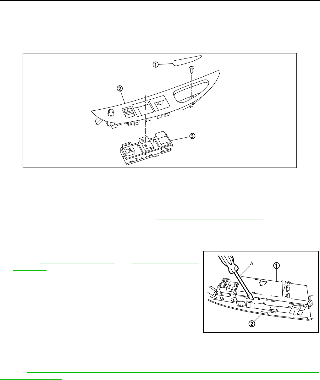
PWC-112
< ON-VEHICLE REPAIR >
POWER WINDOW MAIN SWITCH
ON-VEHICLE REPAIR
POWER WINDOW MAIN SWITCH
Exploded View INFOID:0000000003573537
NOTE:
The same procedure is also performed for front power window switch (passenger side) and rear power switch
(LH & RH).
Refer to removal and installation procedure. Refer to PWC-112, "Removal and Installation".
Removal and Installation INFOID:0000000003573538
REMOVAL
1. Remove the power window main switch finisher (2).
Refer to GW-20, "Exploded View" and GW-20, "Removal and
Installation".
2. Power window main switch (1) is removed from power window
main switch finisher (2) using flat-head screw driver (A) etc.
CAUTION:
Do not fold the pawl of power window main switch finisher.
NOTE:
The same procedure is also performed for front power window
switch (passenger side) and rear power window switch (LH & RH).
INSTALLATION
Install in the reverse order of removal.
NOTE:
Power window main switch is exchanged or is detached it is necessary to do the initialization procedure.
Refer to PWC-5, "ADDITIONAL SERVICE WHEN REMOVING BATTERY NEGATIVE TERMINAL : Special
Repair Requirement".
JMKIA2076ZZ
1. Pull handle cover 2. Power window main switch 3. Power window main switch finisher
JMKIA1822ZZ
Revision: 2007 November 2008 EX35
