1 960624 00 SM PX4&6i Cover PX4i&PX6i Service Manual
User Manual: PX4i&PX6iServiceManual
Open the PDF directly: View PDF ![]() .
.
Page Count: 282 [warning: Documents this large are best viewed by clicking the View PDF Link!]
- Disclaimer
- Copyright Information
- Trademarks
- Contents
- Before You Begin
- Introduction
- 1 Models and Options
- 2 Front and Keyboard
- 3 Covers and Doors
- 4 Chassis
- 5 Media Supply
- 6 Label Slack Absorber
- 7 Transfer Ribbon Mechanism
- 8 Print Unit
- 9 Liner Takeup Kit
- 10 Label Taken Sensor (LTS)
- 11 Paper Cutter
- 12 Electronics Compartment
- 13 Power Supply
- 14 Driver Board
- 15 CPU Board
- 16 Interfaces
- Introduction
- RS-232 Serial Communication Port ("uart1:")
- USB Interface ("usb1:")
- Bar Code Wand Interface (wand:) (Fingerprint only)
- Installing an Optional Interface Board
- Serial/Industrial Interface Board (Fingerprint only)
- Double Serial Interface Board (Fingerprint only)
- IEEE 1284 Parallel Interface Board
- EasyLAN Ethernet Interface Board
- EasyLAN Wireless Interface Board
- 17 Troubleshooting
- Diagnosing
- No Reaction at Power Up
- Printer Stops Working after Startup
- CPU Board Failures
- Power Supply Unit Failures
- Driver Board Failures
- Console Errors
- Error Messages
- No Communication (general)
- No Serial Communication
- Network Communication Trouble
- Sensors Malfunctions
- Printing Trouble
- Transfer Ribbon Trouble
- Liner Takeup Trouble
- Memory Card Trouble
- Paper Cutter Trouble
- Appendix A Program Overviews
- Appendix B Firmware Upgrading
- Appendix C Measuring the Brake Torque

Service Manual
EasyCoder PX4i and
EasyCoder PX6i
Bar Code Label
Printers
Intermec Technologies Corporation
Corporate Headquarters
6001 36th Ave. W.
Everett, WA 98203
U.S.A.
www.intermec.com
The information contained herein is proprietary and is provided solely for the purpose of allowing
customers to operate and service Intermec-manufactured equipment and is not to be released, repro-
duced, or used for any other purpose without written permission of Intermec.
Information and specifi cations contained in this document are subject to change without prior
notice and do not represent a commitment on the part of Intermec Technologies Corporation.
© 2004 by Intermec Technologies Corporation. All rights reserved.
The word Intermec, the Intermec logo, Norand, ArciTech, CrossBar, Data Collection Browser,
dcBrowser, Duratherm, EasyCoder, EasyLAN, Enterprise Wireless LAN, EZBuilder, Fingerprint,
i-gistics, INCA (under license), InterDriver, Intermec Printer Network Manager, IRL, JANUS,
LabelShop, Mobile Framework, MobileLAN, Nor*Ware, Pen*Key, Precision Print, PrintSet, Route-
Power, TE 2000, Trakker Antares, UAP, Universal Access Point, and Virtual Wedge are either trade-
marks or registered trademarks of Intermec Technologies Corporation.
Throughout this manual, trademarked names may be used. Rather than put a trademark (™ or ®)
symbol in every occurrence of a trademarked name, we state that we are using the names only in an
editorial fashion, and to the benefi t of the trademark owner, with no intention of infringement.
There are U.S. and foreign patents pending.
The name Centronics is wholly owned by GENICOM Corporation.
Kimdura is a registered trademark of Kimberly Clark.
Microsoft is a registered trademark of Microsoft Corporation.
Torx is a registered trademark of Camcar Division of Textron Inc.
TrueDoc is a registered trademark of Bitstream, Inc.
TrueType is a trademark of Apple Computer Inc.
Unicode is a trademark of Unicode Inc.
Valeron is a registered trademark of Valéron Strength Films, an ITW Company.
Windows is a trademark of Microsoft Corporation.
EasyCoder PX4i and PX6i Service Manual iii
Contents
Contents
Before You Begin .................................................................................................................vii
Safety Summary .................................................................................................vii
Safety Icons .......................................................................................................vii
Global Services and Support .............................................................................viii
Warranty Information ............................................................................. viii
Web Support ........................................................................................... viii
Telephone Support .................................................................................. viii
Who Should Read This Document? ........................................................ viii
Related Documents ................................................................................. viii
Introduction ........................................................................................................................ix
1 Models and Options
1.1 Identifi cation ..............................................................................................................2
1.2 EasyCoder PX4i Specifi cations ...................................................................................8
1.3 EasyCoder PX6i Specifi cations .................................................................................10
1.4 Measures EasyCoder PX4i ........................................................................................12
1.5 Measures EasyCoder PX6i ........................................................................................13
2 Front and Keyboard
2.1 Front........... .............................................................................................................16
2.2 Keyboard/Display ...................................................................................................17
2.3 Console pcb. ............................................................................................................21
3 Covers and Doors
3.1 Right-Hand Door ....................................................................................................26
3.2 Front Door ...............................................................................................................27
3.3 Left-Hand Cover ......................................................................................................28
4 Chassis
4.1 Description ..............................................................................................................30
4.2 Center Section .........................................................................................................32
4.3 Bottom Plate ............................................................................................................32
4.4 Rear Plate .................................................................................................................33
5 Media Supply
5.1 Internal Supply ........................................................................................................36
5.2 Paper Sensor .............................................................................................................39
5.3 Three-inch Adapters .................................................................................................40
5.4 Media Roll Retainer .................................................................................................41
5.5 Fan-Fold Guides .......................................................................................................42
6 Label Slack Absorber
6.1 Description ..............................................................................................................46
6.2 Dismantling .............................................................................................................47
iv EasyCoder PX4i and PX6i Service Manual
Contents
7 Transfer Ribbon Mechanism
7.1 Description ..............................................................................................................50
7.2 Ribbon Supply Unit .................................................................................................51
7.3 Ribbon Rewind Unit ................................................................................................54
7.4 Ribbon Sensor ..........................................................................................................57
8 Print Unit
8.1 Description ..............................................................................................................60
8.2 Platen Roller ............................................................................................................67
8.3 Stepper Motor ..........................................................................................................70
8.4 Belts .........................................................................................................................72
8.5 Label Stop Sensor .....................................................................................................76
8.6 Printhead .................................................................................................................84
8.7 Headlift Sensor ........................................................................................................93
8.8 Headlift Mechanism .................................................................................................96
8.9 Ribbon Assist Roller ...............................................................................................100
8.10 Media Feed Principles ............................................................................................102
9 Liner Takeup Kit
9.1 Description ............................................................................................................106
9.2 Main Parts ..............................................................................................................109
9.3 Liner/Batch Takeup Unit ........................................................................................111
10 Label Taken Sensor
10.1 Description ............................................................................................................114
10.2 Installation .............................................................................................................115
10.3 Activating the LTS .................................................................................................116
10.4 Adjustment ............................................................................................................116
11 Paper Cutter
11.1 Description ............................................................................................................118
11.2 Installation .............................................................................................................119
11.3 Controlling the Cutter ...........................................................................................122
11.4 Media Load ............................................................................................................122
11.5 Servicing ................................................................................................................123
11.6 Spring Replacement ...............................................................................................124
12 Electronics Compartment
11.1 Introduction ...........................................................................................................126
11.2 Accessing the Electronics Compartment .................................................................126
11.3 Main Parts ..............................................................................................................127
13 Power Supply
13.1 Description ............................................................................................................130
13.2 Replacements .........................................................................................................133
13.3 Components ..........................................................................................................134
13.4 Schematics .............................................................................................................136
EasyCoder PX4i and PX6i Service Manual v
Contents
14 Driver Board
14.1 Description ............................................................................................................138
14.2 Replacement ..........................................................................................................138
14.3 Components ..........................................................................................................140
14.4 Schematics .............................................................................................................142
15 CPU Board
15.1 Description ............................................................................................................144
15.2 Circuits ..................................................................................................................145
15.3 Connections ...........................................................................................................150
15.4 Test Points ..............................................................................................................151
15.5 Startup ...................................................................................................................152
15.6 Components ..........................................................................................................153
15.7 Schematics .............................................................................................................155
15.8 Replacing the CPU board ......................................................................................164
16 Interfaces
16.1 Introduction ...........................................................................................................166
16.2 Serial Communication Port "uart1:" ......................................................................167
16.3 USB Interface .........................................................................................................168
16.4 Bar Code Wand Interface .......................................................................................169
16.5 Installing an Optional Interface Board ...................................................................170
16.6 Serial/Industrial Interface Board .............................................................................174
16.7 Double Serial Interface Board ................................................................................184
16.8 IEEE 1284 Parallel Interface Board ........................................................................194
16.9 EasyLAN Ethernet Interface Board ........................................................................198
16.10 EasyLAN Wireless Interface Board .........................................................................203
17 Troubleshooting
17.1 Diagnosing ............................................................................................................ 210
17.2 No Reaction at Power Up ......................................................................................213
17.3 Printer Stops Working after Startup ....................................................................... 214
17.4 CPU Board Failures ..............................................................................................216
17.5 Power Supply Unit Failures ...................................................................................218
17.6 Driver Board Failures ............................................................................................219
17.7 Console Errors ......................................................................................................220
17.8 Error Messages ...................................................................................................... 222
17.9 No Communication (general) ...............................................................................224
17.10 No Serial Communication ....................................................................................225
17.11 No Network Communication ............................................................................... 227
17.12 Sensor Malfunctions ..............................................................................................231
Label Stop Sensor (LSS) ................................................................................. 231
Headlift Sensor ............................................................................................... 232
Label Taken Sensor (LTS) ............................................................................... 232
Ribbon Sensor ................................................................................................ 233
Paper Sensor ................................................................................................... 233
17.13 Printing Troubles ................................................................................................... 234
17.14 Transfer Ribbon Troubles ......................................................................................238
17.15 Liner Takeup Troubles ...........................................................................................240
17.16 Memory Card Troubles .........................................................................................241
17.17 Paper Cutter Troubles ............................................................................................242
vi EasyCoder PX4i and PX6i Service Manual
Contents
A Program Overviews
Intermec Shell Overview ...................................................................................................246
Setup Mode Overviews (Fingerprint) ...............................................................................247
Setup Mode Overviews (IPL) ............................................................................................256
B Firmware Upgrading
Introduction......................................................................................................................262
General Principles .............................................................................................................262
Upgrading From a Memory Card ......................................................................................263
Upgrading From the Host .................................................................................................265
C Measuring the Break Torque
Measuring the Brake Torque .............................................................................................270

EasyCoder PX4i and PX6i Service Manual vii
Before You Begin
Before You Begin
This section provides you with safety information, technical support infor-
mation, and sources for additional product information.
Safety Summary
Your safety is extremely important. Read and follow all warnings and cau-
tions in this document before handling and operating Intermec equipment.
You can be seriously injured, and equipment and data can be damaged if
you do not follow the safety warnings and cautions.
Do not repair or adjust alone
Do not repair or adjust energized equipment alone under any circum-
stances. Someone capable of providing fi rst aid must always be present for
your safety.
First aid
Always obtain fi rst aid or medical attention immediately after an injury.
Never neglect an injury, no matter how slight it seems.
Resuscitation
Begin resuscitation immediately if someone is injured and stops breath-
ing. Any delay could result in death. To work on or near high voltage, you
should be familiar with approved industrial fi rst aid methods.
Energized equipment
Never work on energized equipment unless authorized by a responsible
authority. Energized electrical equipment is dangerous. Electrical shock
from energized equipment can cause death. If you must perform autho-
rized emergency work on energized equipment, be sure that you comply
strictly with approved safety regulations.
Safety Icons
This section explains how to identify and understand dangers, warnings,
cautions, and notes that are in this document. You may also see icons that
tell you when to follow ESD procedures.
A warning alerts you of an operating procedure, practice, condition, or
statement that must be strictly observed to avoid death or serious injury
to the persons working on the equipment.
A caution alerts you to an operating procedure, practice, condition, or
statement that must be strictly observed to prevent equipment damage
or destruction, or corruption or loss of data.
This icon appears at the beginning of any procedure in this manual
that could cause you to touch components (such as printed circuit
boards) that are susceptible to damage from electrostatic discharge
(ESD). When you see this icon, you must follow standard ESD guide-
lines to avoid damaging the equipment you are servicing.
Note: Notes either provide extra information about a topic or contain spe-
cial instructions for handling a particular condition or set of circumstances.

viii EasyCoder PX4i and PX6i Service Manual
Before You Begin
Global Services and Support
Warranty Information
To understand the warranty for your Intermec product, visit the Intermec
web site at http://www.intermec.com and click Service & Support. The
Intermec Global Sales & Service page appears. From the Service & Support
menu, move your pointer over Support, and then click Warranty.
Web Support
Visit the Intermec web site at http://www.intermec.com to download
our current documents in PDF format. To order printed versions of the
Intermec manuals, contact your local Intermec representative or distribu-
tor.
Visit the Intermec technical knowledge base (Knowledge Central) at
http://intermec.custhelp.com to review technical information or to request
technical support for your Intermec product.
Telephone Support
Contact your local Intermec representative. To search for your local repre-
sentative, from the Intermec web site, click Contact.
Who Should Read This Document?
This Service Manual provides you with in-depth information about the
EasyCoder PX4i and PX6i printers and how to maintain, repair, and trou-
bleshoot them. It is primarily intended for authorized service technicians.
Related Documents
The Intermec web site at http://www.intermec.com contains our current
documents that you can download in PDF format. To order printed ver-
sions of the Intermec manuals, contact your local Intermec representative
or distributor.
We recommend that the service technician keeps the following manuals
easily accessible in electronic or printed form:
• Intermec EasyCoder PX4i, User’s Guide (Fingerprint version)
• Intermec EasyCoder PX6i, User’s Guide (Fingerprint version)
• Intermec EasyCoder PX4i, User’s Guide (IPL version)
• Intermec EasyCoder PX6i, User’s Guide (IPL version)
• Intermec EasyCoder PX4i and PX6i, Spare Parts Catalog
• Installation Instructions for various options
• Intermec Direct Protocol v8.30 (or later), Programmer’s Reference Manual
• Intermec Fingerprint v8.00 (or later), Tutorial
• Intermec Fingerprint v8.30 (or later), Programmer’s Reference Manual
• IPL Programming, Reference Manual (rev. 007 or later)
• EasyLAN Interface Kit, Installation Instructions
• EasyLAN Wireless Interface Kit, Installation Instructions
• EasyLAN, User’s Guide
• EasyLAN Network Setup, User’s Guide
EasyCoder PX4i and PX6i Service Manual ix
Before You Begin
Introduction
This Service Manual is intended to facilitate installation, troubleshoot-
ing and repair of the Intermec EasyCoder PX4i and PX6i printers in the
versions delivered at the date of publishing. Thus, all information on the
Intermec Fingerprint (FP) fi rmware is based on version 8.30 and informa-
tion on the Intermec Programming Language (IPL) is based on version
2.30. The on-going product improvement can be followed in the Printer
Technical Bulletins from Intermec.
Note that even if the printers are technical identical (with the exception of
the keyboard overlay), Fingerprint and IPL make the printer work quite
differently and certain devices and options are not supported by IPL.
Generally, illustrations in this manual show printers with a Fingerprint-
compatible keyboard.
Please note that the operations described in this manual only should be car-
ried out by skilled and authorized personnel with proper training and full
understanding of written English. The printers contain wires and circuits
with up to 380V, which implies the risk of electrical shock. Moving parts
may also cause harm, if incorrectly manipulated.
It is assumed that the reader possesses reasonable skills in mechanics and
electronics and is familiar with the Intermec programming languages
(Fingerprint or IPL) and their related standard application programs.
It is also assumed that the reader has access to the standard tools of an
electronics workshop.
x EasyCoder PX4i and PX6i Service Manual
Before You Begin

EasyCoder PX4i and PX6i Service Manual 1
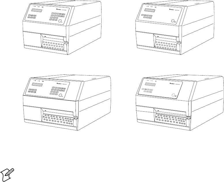
1 Models and Options
This chapter describes how to identify the various models in the EasyCoder
PX4/6i-series of printers, provides comprehensive technical specifi cations,
and gives all important measurements.
2 EasyCoder PX4i and PX6i Service Manual
Chapter 1 — Models and Options
1.1 Identification
Main Models
The EasyCoder PX4i and PX6i constitute a series of direct thermal/thermal
transfer printers, which can run either Intermec Fingerprint Programming
Language (FP) v8.30 (or later) or Intermec Programming Language (IPL)
v2.30 or later. Externally, the difference is visible on the keyboard overlay.
Fingerprint printers have 23 keys or a full alphanumeric keyboard and IPL
printers have 8 keys (see Chapter 2).
EasyCoder PX4i has a maximum print width of 112 mm (4.4 in).
EasyCoder PX6i has a maximum print width of 167.4 mm (6.59 in).
Printers running Fingerprint are available with an 8 dots/mm (203.2 dpi)
or 11.81 dots/mm (300 dpi) printhead density, whereas printers running
IPL only are available with an 8 dots/mm (203.2 dpi) printhead.
A number of options and accessories, such as cutter, internal liner takeup,
label taken sensor, and various types of interface boards, allow the printers
to be tailor-made or adapted for specifi c applications.
EasyCoder PX4i
Fingerprint model
EasyCoder PX4i
IPL model
EasyCoder PX6i
Fingerprint model
EasyCoder PX6i
IPL model
Note: Unless otherwise stated, illustrations in this manual show an Easy-
Coder PX4i running Intermec Fingerprint.
EasyCoder PX4i and PX6i Service Manual 3
Chapter 1 — Models and Options
Machine
label
To identify the printer, start by reading the machine label attached to the
rear of the printer. The machine label contains type, part number, serial
number, and signs of approval.
The printer can use any 90 to 265 VAC, 45 to 65Hz voltage. The switched
power supply eliminates the need for any manual voltage selector.
4 EasyCoder PX4i and PX6i Service Manual
Chapter 1 — Models and Options
Cutter
Liner/batch takeup unit
Fan-fold guide
Media
roll
retainer
3-inch adapter
(included)
Label taken sensor
Alphanumeric
keyboard
(Fingerprint only)
EasyLAN antenna
Options for EasyCoder PX4i
The EasyCoder PX4i can be fi tted with a number of options:
• Label Taken Sensor (see Chapter 10)
• Integral Liner/Batch Takeup Unit (see Chapter 9)
• 3-inch Adapter (for media supply hub) (see Chapter 5)
• Media Roll Retainer (for media supply hub) (see Chapter 5)
• Fan-Fold Guides (see Chapter 5)
• Cutter (see Chapter 11)
• Real Time Clock Circuit (not IPL) (see Chapter 15)
• Alphanumeric keyboard (not IPL) (see Chapter 2)
• One or two interface boards of various types
(only one parallel board with IPL) (see Chapter 16)
• EasyLAN interface (Ethernet or Wireless) (see Chapter 16)
#LOSED
/PEN
EasyCoder PX4i and PX6i Service Manual 5
Chapter 1 — Models and Options
Cutter
Liner takeup unit
Fan-fold guide
3-inch adapters
(included)
Label taken sensor
Alphanumeric
keyboard
(Fingerprint only)
EasyLAN antenna
Options for EasyCoder PX6i
The EasyCoder PX6i can be fi tted with a number of options:
• Label Taken Sensor (see Chapter 10)
• Integral Liner Takeup Unit (see Chapter 9)
• 3-inch Adapter (for media supply hub) (see Chapter 5)
• Fan-Fold Guides (see Chapter 5)
• Cutter (see Chapter 11)
• Real Time Clock Circuit (not IPL) (see Chapter 15)
• Alphanumeric keyboard (not IPL) (see Chapter 2)
• One or two interface boards of various types
(only one parallel board with IPL) (see Chapter 16)
• EasyLAN interface (Ethernet or Wireless) (see Chapter 16)
6 EasyCoder PX4i and PX6i Service Manual
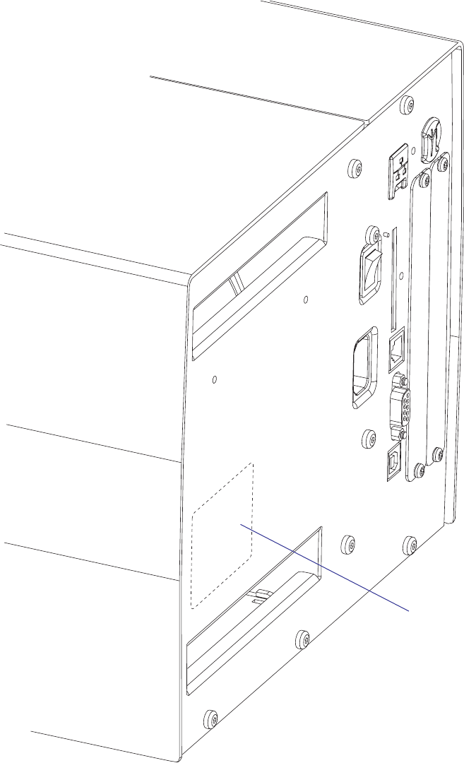
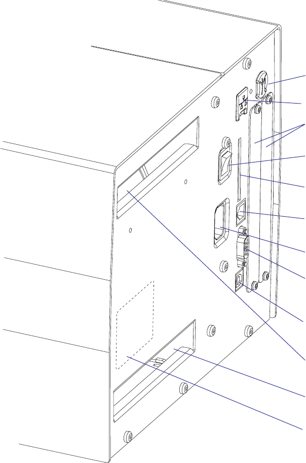
Chapter 1 — Models and Options
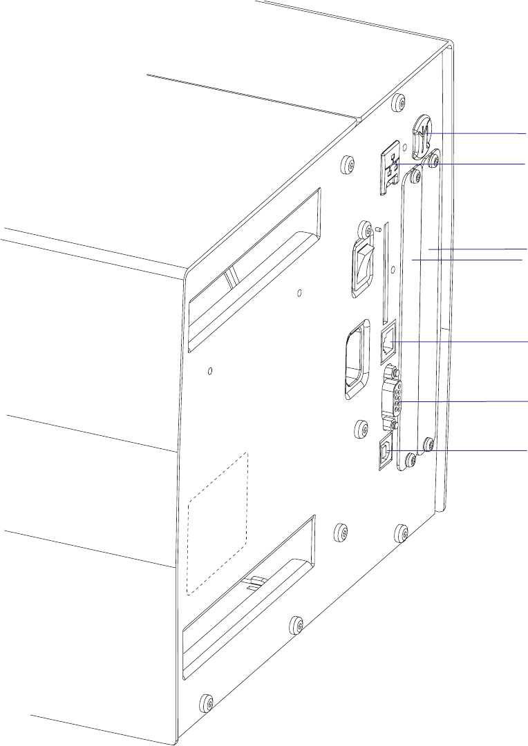
Interfaces
The printers are as standard provided with one serial RS-232 port, one
serial USB port, and one wand interface. The wand interface is not sup-
ported by IPL. In addition, one EasyLAN interface and one or two extra
interface boards can be fi tted, see Chapter 14. IPL does only support one
EasyLAN interface and one parallel interface board.
Serial Port (RS-232)
USB Port
Provision for
one or two interface
boards (only the left
slot used with IPL)
Provision for Ether-
net connector
Wand interface
(not used with IPL)
Provision for Easy-
LAN antenna

Checking Hardware and Firmware
Finally, you may want to inspect the electronics compartment. To do so,
carefully follow the instructions in Chapter 12.
Always switch off the power and remove the power cord before removing
the cover over the electronics compartment! Dangerous voltage!
In the electronics compartment, check:
• Type of CPU board?
- Check number and size of Flash SIMMs.
- Check size of SDRAM SIMM.
• Any optional interface board fi tted?
- Check type, straps, and optional circuits.
Refer to Chapters 15 and 16 for more information.
Being delivered with either Intermec Fingerprint v8.30 programming lan-
guage or IPL v2.30 (or later versions), the printer can easily be converted
from Fingerprint to IPL or vice versa using a fi rmware card or special
software. The keyboard overlay will also need to be replaced. The type of
fi rmware is indicated by the messages in the display window at startup.
Fingerprint only
If the printer is working and possible startup program can be interrupted,
the type of program in the printer can be identifi ed. Connect printer
and computer, open a suitable communication program, and start up the
printer in Fingerprint’s immediate mode. The instruction FILES allows
you to check what fi les the various parts of the printer's memory contain.
The statements FONTS and IMAGES can be used for the same purpose
regarding fonts and images. Use the VERSION$ function to check version
of the Intermec Fingerprint fi rmware.
You can read the setup in the Setup Mode or using Intermec Shell, which
also allows you to print test labels containing the present setup values. To
enter Shell if a custom-made autoexec-fi le prevents access, lift the printhead
and press any key on the printer's keyboard (except the <Shift> key),
then turn on the power while continuing to press the key. When the Shell
countdown begins, release the key and press <Enter> to start Shell. Do not
forget to lower the printhead if you want to print anything, for example
test labels. Refer to the User’s Guide and to Appendix A in this Service
Manual for more information on the Setup Mode and the Intermec Shell
startup program.
If the printer still does not work, you may need to interview the user.
IPL only
The Test/Service part of the Setup Mode allows several types of test labels
to be printed (see the User’s Guide and Appendix A). IPL also has a number
of commands that return valuable information on the printer’s status (see
IPL Programming, Reference Manual).
EasyCoder PX4i and PX6i Service Manual 7
Chapter 1 — Models and Options

Printing
Print Technique Direct Thermal and Thermal Transfer
Printhead Resolution 8 dots/mm (203.2 dpi) or
11.81 dots/mm (300 dpi) Not supported by IPL
Print Speed (variable) 100 to 300 mm/sec. (≈ 4 to 12 in./sec.)
Print Width (max) 112 mm (4.4 in.)
Print Length (max) 32767 dots
= 409.5 cm (161.25 in.) at 203.2 dpi1
= 277.5 cm (109.23 in.) at 300 dpi1
Media Width (min/max) 25 to 120 mm (1 to 4.72 in.)
Media Roll Diameter (max) 213 mm (8.38 in.)
205 mm (8.07 in.)
Tear-off & Cut-off
Peel-off & batch takeup
Media Roll Core Diameter 38 to 40 mm (1.5 in.) or
76 mm (3 in.) with adapter fi tted
Ribbon Width (min/max) 55 to 120 mm (2.16 to 4.72 in.)
Ribbon Roll Diameter (outer), max. 80 mm (3.15 in.) ≈ 450 m (1476 ft) length
Ribbon Roll Core Diameter (inner) 25 mm (1.00 in.)
Print Directions 4
Modes of Operation
Tear-Off (Straight-through) Yes
Cut-Off Option With cutter
Peel-Off (Self-strip) Option With rewinder
Internal Batch Takeup Option With rewinder
Fingerprint Firmware
Operating System Intermec Fingerprint v8.30 Incl. Direct Protocol
Smooth Fonts TrueDoc and TrueType fonts
Resident Scaleable Fonts 15 Unicode fonts2
Resident Bar Codes 59
Startup Program (std) Intermec Shell v8.2
IPL Firmware
Operating System IPL v2.30
Smooth Fonts 13 scaleable + 21 simulated bitmap
Resident Bar Codes 44
Physical Measures
Dimensions (W × L × H) 275 × 482 × 238 mm
(10.8 × 19.0 × 9.4 in)
Weight (excluding media) 12.85 kg (28.4 pounds)
Ambient Operating Temperature +5°C to +40°C (+41°F to +104°F)
Storage Temperature -20°C to +70°C (-4°F to +152°F)
Humidity 10 to 90% non-condensing
Electronics
Microprocessor 32 bit RISC
On-board Flash SIMMs 2 sockets for 4MB or 8MB each Std. 1 x 4MB
On-board SDRAM SIMM 1 socket for 16MB (Std. 16MB)
8 EasyCoder PX4i and PX6i Service Manual
Chapter 1 — Models and Options
1.2 EasyCoder PX4i Specifications

Power Supply
AC Voltage 90 to 265 VAC, 45 to 65 Hz
PFC Regulation IEC 61000-3-2
Power Consumption Standby 20W; Continuous, average 175W;
Peak 400W
Sensors
Label Gap/Black Mark/Out of Media Yes Variable position
Printhead Lifted Yes
Ribbon End/Ribbon Low Yes
Paper Sensor Yes
Controls
Indicator Lamps 3
Display 2 x 16 character LCD Background light
Keyboard (Fingerprint) 22 keys membrane-switch type
Keyboard (IPL) 7 keys membrane-switch type
Print (FP) or Feed/Pause (IPL) button 1
Beeper Yes
Data Interfaces
Serial 1 x RS-232 + 1 x USB
Bar Code Wand Yes Not supported by IPL
Connection for Optional Interface Boards 1 EasyLAN + 2 other (Fingerprint/DP)
IPL: 1 other + 1 EasyLAN
Cutter Interface 1
Memory Card Adapter 1, for CompactFlash cards IPL: Not as memory
Accessories and Options
Integral Self-strip Unit with Liner Takeup Option3,4 For peel-off and batch
takeup
Media Roll Retainer Option5
Fan-fold Guide Option5
Cutter Option5
Label Taken Sensor Option3,4
Real Time Clock Option3,4 Not supported by IPL
RS-232 Cable Option
Parallel Interface Cable Option
Parallel Interface Board Option
Double Serial Interface Board Option3,4 Not supported by IPL
Serial/Industrial Interface Board Option3,4 Not supported by IPL
EasyLAN Ethernet Interface Option3,4
EasyLAN Wireless Interface Option3,4
Built-in Alphanumeric Keyboard Option3,4 Not supported by IPL
External Keyboard Converter Option5
CompactFlash Cards Option58MB-1GB
CompactFlash Protection Plate Option5
1/. The max. print length is also restricted by the amount of free SDRAM memory.
2/. Latin, Greek, and Cyrillic fonts according to Unicode standard are included.
3/. Factory installed option
4/. Field-installable kit. Installation should be performed by a service technician.
5/. Operator-installable option.
EasyCoder PX4i and PX6i Service Manual 9
Chapter 1 — Models and Options

Printing
Print Technique Direct Thermal and Thermal Transfer
Printhead Resolution 8 dots/mm (203.2 dpi) or
11.81 dots/mm (300 dpi) Not supported by IPL
Print Speed (variable) 100 to 225 mm/sec. (≈ 4 to 8.85 in./sec.)
Print Width (max) 167.4 mm (6.59 in.)
Print Length (max) 32767 dots
= 409.5 cm (161.25 in.) at 203.2 dpi1
= 277.5 cm (109.23 in.) at 300 dpi1
Media Width (min/max) 76 to 170 mm (3 to 6.69 in.)
Media Roll Diameter (max) 213 mm (8.38 in.)
205 mm (8.07 in.)
Tear-off & Cut-off
Peel-off & batch takeup
Media Roll Core Diameter 38 to 40 mm (1.5 in.) or
76 mm (3 in.) with adapter fi tted
Ribbon Width (min/max) 76.2 to 170 mm (3 to 6.69 in.)
Ribbon Roll Diameter (outer), max. 80 mm (3.15 in.) ≈ 450 m (1476 ft) length
Ribbon Roll Core Diameter (inner) 25 mm (1.00 in.)
Print Directions 4
Modes of Operation
Tear-Off (Straight-through) Yes
Cut-Off Option With cutter
Peel-Off (Self-strip) Option With rewinder
Fingerprint Firmware
Operating System Intermec Fingerprint v8.30 Incl. Direct Protocol
Smooth Fonts TrueDoc and TrueType fonts
Resident Scaleable Fonts 15 Unicode fonts2
Resident Bar Codes 59
Startup Program (std) Intermec Shell v8.2
IPL Firmware
Operating System IPL v2.30
Smooth Fonts 13 scaleable + 21 simulated bitmap
Resident Bar Codes 44
Physical Measures
Dimensions (W × L × H) 335 × 482 × 238 mm
(13.2 × 19.0 × 9.4 in)
Weight (excluding media) 14.8 kg (32.6 pounds)
Ambient Operating Temperature +5°C to +40°C (+41°F to +104°F)
Storage Temperature -20°C to +70°C (-4°F to +152°F)
Humidity 10 to 90% non-condensing
Electronics
Microprocessor 32 bit RISC
On-board Flash SIMMs 2 sockets for 4MB or 8MB each Std. 1 x 4MB
On-board SDRAM SIMM 1 socket for 16MB (Std. 16MB)
10 EasyCoder PX4i and PX6i Service Manual
Chapter 1 — Models and Options
1.3 EasyCoder PX6i Specifications

Power Supply
AC Voltage 90 to 265 VAC, 45 to 65 Hz
PFC Regulation IEC 61000-3-2
Power Consumption Standby 20W; Continuous, average 175W;
Peak 400W
Sensors
Label Gap/Black Mark/Out of Media Yes Variable position
Printhead Lifted Yes
Ribbon End/Ribbon Low Yes
Paper Sensor Yes
Controls
Indicator Lamps 3
Display 2 x 16 character LCD Background light
Keyboard (Fingerprint) 22 keys membrane-switch type
Keyboard (IPL) 7 keys membrane-switch type
Print (FP) or Feed/Pause (IPL) button 1
Beeper Yes
Data Interfaces
Serial 1 x RS-232 + 1 x USB
Bar Code Wand Yes Not supported by IPL
Connection for Optional Interface Boards 1 EasyLAN + 2 other (Fingerprint/DP)
IPL: 1 other + 1 EasyLAN
Cutter Interface 1
Memory Card Adapter 1, for CompactFlash cards IPL: Not as memory
Accessories and Options
Integral Self-strip Unit with Liner Takeup Option3,4 For peel-off operation
Fan-fold Guide Option5
Cutter Option5
Label Taken Sensor Option3,4
Real Time Clock Option3,4 Not supported by IPL
RS-232 Cable Option
Parallel Interface Cable Option
Parallel Interface Board Option
Double Serial Interface Board Option3,4 Not supported by IPL
Serial/Industrial Interface Board Option3,4 Not supported by IPL
EasyLAN Ethernet Interface Option3,4
EasyLAN Wireless Interface Option3,4
Built-in Alphanumeric Keyboard Option3,4 Not supported by IPL
External Keyboard Converter Option5
CompactFlash Cards Option58MB-1GB
CompactFlash Protection Plate Option5
1/. The max. print length is also restricted by the amount of free SDRAM memory.
2/. Latin, Greek, and Cyrillic fonts according to Unicode standard are included.
3/. Factory installed option
4/. Field-installable kit. Installation should be performed by a service technician.
5/. Operator-installable option.
EasyCoder PX4i and PX6i Service Manual 11
Chapter 1 — Models and Options
MM
MM
2MM
MMMM
MM
MM
$OT.O
MM
MM
MM
2MM
MM
MM
MM
MM
MM
MM
0APERSLOT
0APERSLOT
12 EasyCoder PX4i and PX6i Service Manual
Chapter 1 — Models and Options
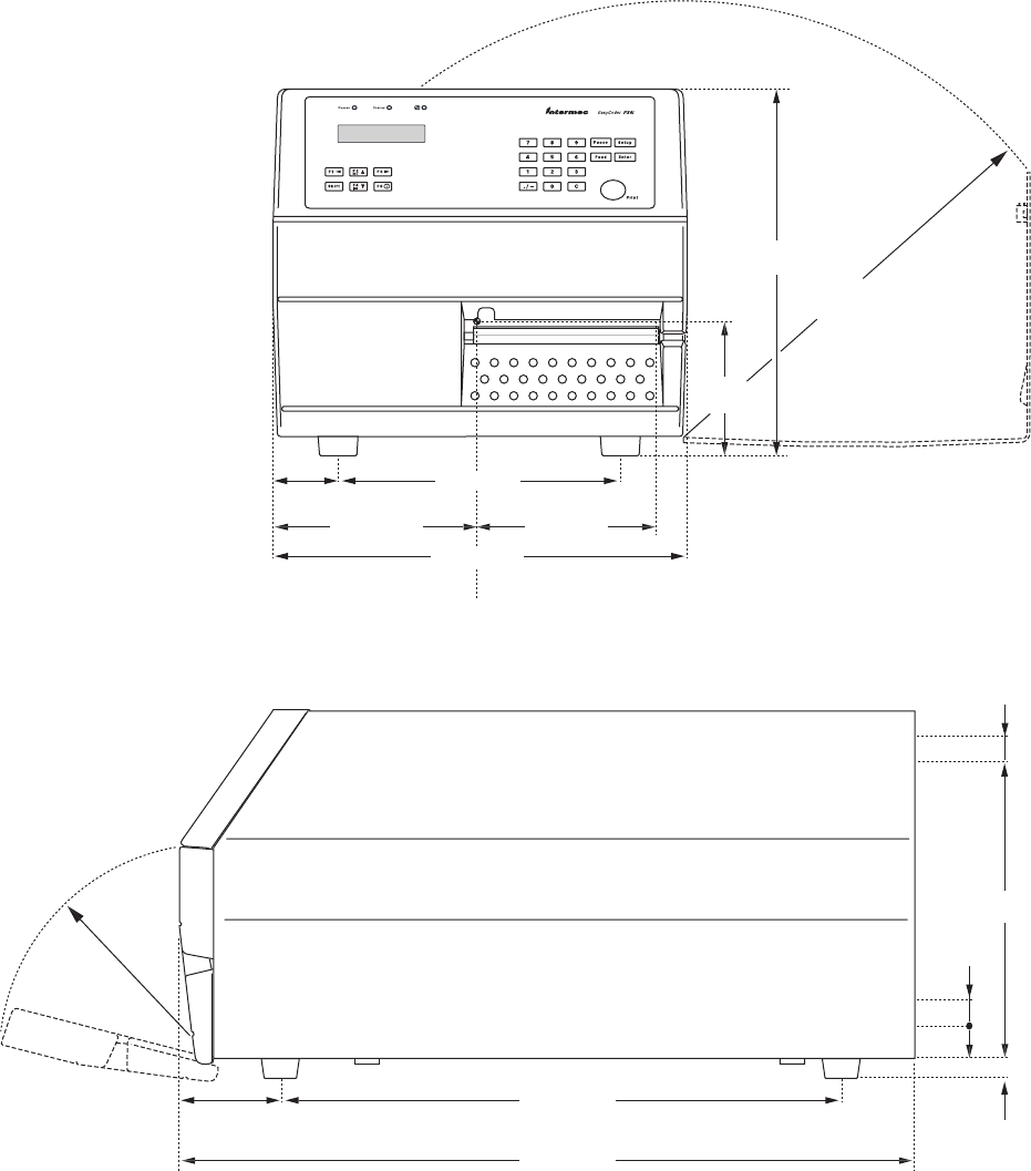
1.4 Measures EasyCoder PX4i
Front View
Side View
An optional paper cutter increases the printer’s total length by 28 mm (1.1 inches).
At least 90 mm (3.5 inches) of free space behind the printer is required for the connectors,
and for inserting and removing a memory card.
MM
MM
2MM
MMMM
MM
MM
$OT.O
MM
MM
MM
2MM
MM
MM
MM
MM
MM
MM
0APERSLOT
0APERSLOT
EasyCoder PX4i and PX6i Service Manual 13
Chapter 1 — Models and Options
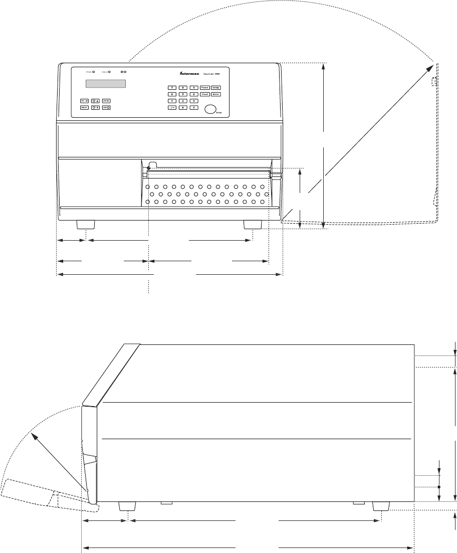
1.5 Measures EasyCoder PX6i
Front View
Side View
An optional paper cutter increases the printer’s total length by 28 mm (1.1 inches).
At least 90 mm (3.5 inches) of free space behind the printer is required for the connectors,
and for inserting and removing a memory card.
14 EasyCoder PX4i and PX6i Service Manual
Chapter 1 — Models and Options

EasyCoder PX4i and PX6i Service Manual 15
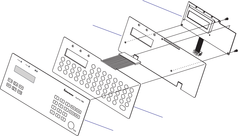
2 Front and Keyboard
This chapter describes the keyboard and display fi tted at the front of the
EasyCoder PX4i and PX6i printers in both Fingerprint and IPL versions,
the only differences being the designation on the overlay and the width of
the front moulding. Illustrations in this chapter shows an EasyCoder PX4i
running Fingerprint.
16 EasyCoder PX4i and PX6i Service Manual
Chapter 2 — Front and Keyboard
2.1 Front
The moulded front part is attached to the center section using four #T20
screws and to the bottom plate using two #T20 screws. The front mould-
ing is provided with holes for mounting a cutter connector (4-pin female
DIN-type).
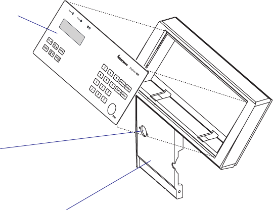
At the top part of the front moulding, there is a cavity for the keyboard/
display assy. This assembly is affi xed using two 2 mm hexagon grub screws
underneath the keyboard part of the front moulding.
Keyboard/display assy.
Provision for cutter
connection
Front moulding
EasyCoder PX4i and PX6i Service Manual 17
Chapter 2 — Front and Keyboard
2.2 Keyboard/Display
The keyboard/display assy. is connected to J50 at the front of the CPU
board via a 10-p fl at cable. This cable must be disconnected before the
keyboard/display can be removed.
The keyboard/display must be manipulated carefully when it is lifted out
of its cavity. Do not use any force! If the assembly seems to be stuck, open
the right-hand door and remove the left-hand cover to check that the grub
screws do not interfere with the brackets.
We also recommend you to remove the left-hand cover before you start
to fi t the keyboard/display assy. back into the front moulding, because it
makes it easier to align the brackets with the grub screws.
The keyboard/display assy. consists of a plate with two brackets, a self-
adhesive membrane switch keyboard, an self-adhesive overlay, and a
console pcb. The membrane switch keyboard is connected to P2 on the
console pcb. via a semi-transparent cable running through a slot in the
plate.
Membrane-switch
keyboard
Overlay (5 types)
Keyboard plate
Console pcb.
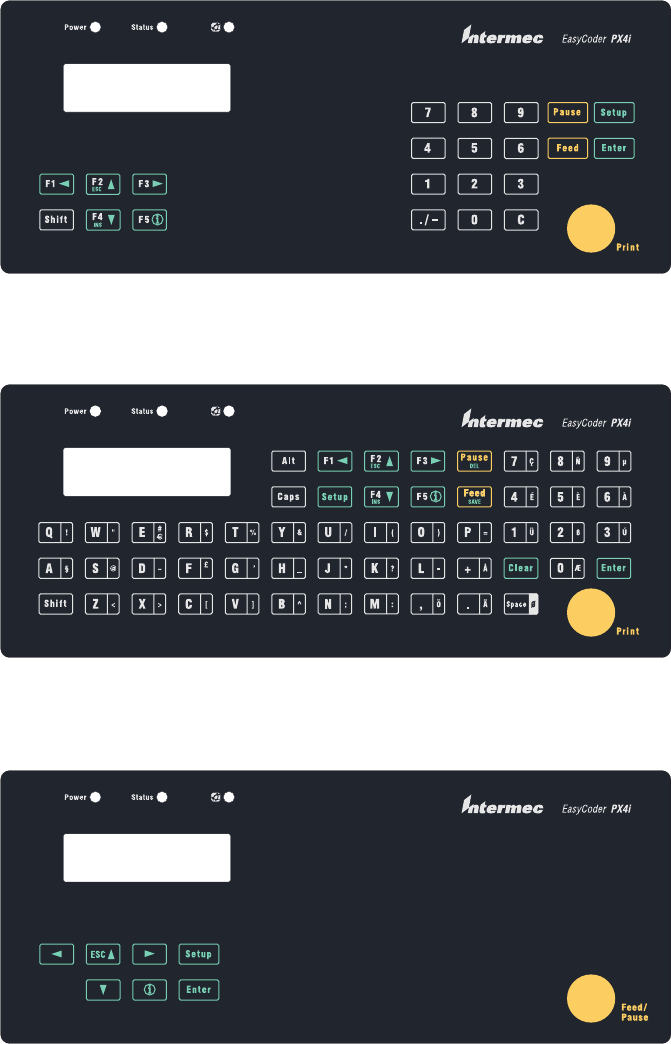
EasyCoder PX4i Fingerprint version
EasyCoder PX4i Fingerprint version, Alphanumeric keyboard (option)
EasyCoder PX4i IPL version
18 EasyCoder PX4i and PX6i Service Manual
Chapter 2 — Front and Keyboard
Keyboard Overlays
The keyboard overlays are self-adhesive with a non-permanent adhesive
to allow easy replacement. Custom-made overlays could also be printed
and used to replace the standard overlays for customized applications or in
areas, where the English text is not acceptable. Pulling away an overlay and
replacing it with another is a simple operation that the customer easily can
perform himself. Use isopropyl alcohol to remove any adhesive residue.
There are three types of overlay for each printer model:

EasyCoder PX6i Fingerprint version
EasyCoder PX6i Fingerprint version, Alphanumeric keyboard (option)
EasyCoder PX6i IPL version
EasyCoder PX4i and PX6i Service Manual 19
Chapter 2 — Front and Keyboard
Keyboard
The keyboard is of membrane switch type and is glued to the keyboard
plate. There are 54 switches, but only 23 of these are used unless the
printer has an alphanumeric overlay (Fingerprint only). One switch is a
Shift key, that provides a dual functionality to each of the other keys. The
keys have fi xed functions in the immediate and setup modes, but can also
be assigned various functions in Intermec Fingerprint programs. In IPL,
the keys are not user-programmable.
A fl at cable connects the membrane-switch keyboard to P2 on the console
pcb.
Keyboard Plate
The keyboard plate keeps the assembly together and to affi x it in the cavity
of the front moulding. There are one slot for the display and another for
the cable running from the membrane-switch keyboard to the console pcb.
Two brackets at the lower edge are used to connect the plate to the front
moulding using two 2 mm hexagon grub screws.
20 EasyCoder PX4i and PX6i Service Manual
Chapter 2 — Front and Keyboard
EasyCoder PX4i and PX6i Service Manual 21
Chapter 2 — Front and Keyboard
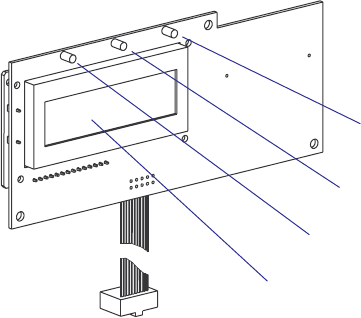
2.3 Console pcb.
The console pcb manages the keyboard, the display and two of the three
LED indicators using a slave processor. The communication to and from
the CPU board goes via an I2C bus on a 10-p fl at cable. This cable is per-
manently affi xed to the console pcb and connected to J50 a the front end
of the CPU board.
The display is a LCD display with background light. It has 2 × 16 charac-
ter with a 5 × 7 dots matrix. There is no display contrast adjustment.
The left-hand LED indicator (marked “Power”) shines green when the
power is on. Power on is also indicated by the display’s background light.
The center LED (marked “Status”) is solid green (OK), fl ashing green
(communicating) or solid red (error).
The right-hand LED (Intermec Readiness Indicator) is solid blue, fl ashing
blue, or off which indicates the readiness of the printer to work as a part of
a network solution (see the User’s Guide).
In Fingerprint, the Status LED is programmable using the instructions
LED ON and LED OFF. There is no such functionality in IPL.
Intermec Readiness
Indicator (blue)
Status LED (green or red)
Power On LED (green)
LCD display
0
0 $)30
)#
)#
0
#
#
#
#
#
#
#
#
#
#
#
#
#
#
#
#
#
#
#
#
#
2 2
2 2
2 2
2 2
2
2
2
2
2
2
2
2
2
2
2
2
2
2
2
2
2
2
2
2
2
2
2
2
2
2
2
2
2
2
2
2
2
2
2
2
2
2
2
2
2
2
2
2
2
2
2
2
2
2
2
2
2
)#
4
#%"
$
+.#
!
#
0
$ $ $
$)30
22 EasyCoder PX4i and PX6i Service Manual
Chapter 2 — Front and Keyboard
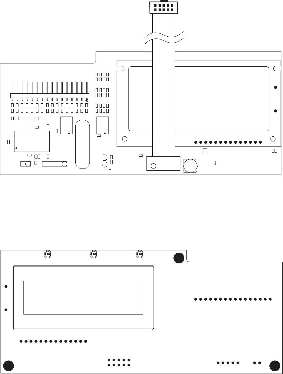
1-971653-30 Console pcb, Component Side
1-971653-30 Console pcb, Soldering Side
SNMULOC7
DRAOBYEK
G
NIMM
A
RGO
R
P
L
A
I
RESTI
U
C
R
I
C
-
N
I
1CI
2CI
S
WOR9
05CI
R56
14
04R
R17
R63
3
R74
05CI
41TCHA
05D
2131
05CI
01
11
05CI
C50
65
05CI
89
05CI
2
1
05CI
4
3
3
2
1
R50
R51
R52
R53
R54
R55
R57
2
1
06D
R67
R60
R61
R62
R64
R65
R66
R70
3
2
1
07D
R77
R71
R72
R73
R75
R76
3
4R
24R
C21
2
1
3P
C2
31
21
1
1
01
6
5
4
3
2
1
8
9
2CI
C5
C6
C7
C8
C9
C10
C11
C12
C13
C14
C15
C16
C17
C18
C19
C20
14R
93R
8
3
R
73R
63R
53R
43R
3
3
R
23R
13R
03R
92R
82R
72R
62R
R25
R23
R24
R21
R22
R20
R19
9
8
7
6
5
4
3
2
61
51
41
31
21
11
01
1
2P
R14
9
R
C4
3T
R2
C1
C3
D4
R3
R15
R18
R1
5R
4
R
6R
R16
9
8
7
6
5
4
3
2
01
1
1P
0
2
81
71
61
51
4
1
31
21
11
82
72
62
5
2
42
32
22
12
7
6
5
4
3
2
9
1
8
01
9
1
1C
I
9
8
7
6
5
4
3
2
16
15
13
12
11
10
1
1PSID
5
4
3
2
1
4P
1DN
G
=DN
G
;CCV=C
C
V
1DNG=DN
G
;CCV=
C
CV
YFITON_C2I
41T
C
HA
4
1
TCHA
1DNG=DNG;CCV
=C
CV
1DNG=DNG;CCV=CCV
41TCHA
1D
N
G
=DN
G
;C
CV=CC
V
W/R
1DNG=DNG;CCV=CCV
DE
L
YALPSID
3
L
OC
5
L
O
C
KLC_WOR
RLC_WOR
METSYS
DELDEL
1DNG=DNG;CCV=CCV
4D
YF
ITO
N
A
D
S
LCS
LCS
ADS
ATAD_WOR
4LOC
2LOC
1LOC
0LOC
HSLOC
461CHA47
41TCHA41T
C
HA
5D
6D
7D
E
SR
PPV
2
78F61CIP
TESER
1DEL
2
DEL
CCV
D3
D2
D1
D0
D4
D5
D6
D7
CCV
W/R
PSIDV
E
SR
DN
G
A
K
7C
R
6CR
5CR
4CR
3C
R
2CR
1CR
0
C
R
7B
R
6BR
5BR
4BR
3BR
2B
R
1BR
0BR/TNI
CCV
PPV/RLCM
0AR
1AR
2AR
FERV/3AR
I
KCO
T/4A
R
5AR
NIKLC
TUOKLC
DNG
D
N
G
/1C
R
&
>1<D1
>2<D1
>3<D1
>
4
<D1
>5<D1
>6<D1
>7<D1
>0<
D
1
CCV
CCV
CCV
CCV
CC
V
C
C
V
CC
V
CCVCCV
CC
V
C
CV
T
+
CCV
C
CV
EasyCoder PX4i and PX6i Service Manual 23
Chapter 2 — Front and Keyboard
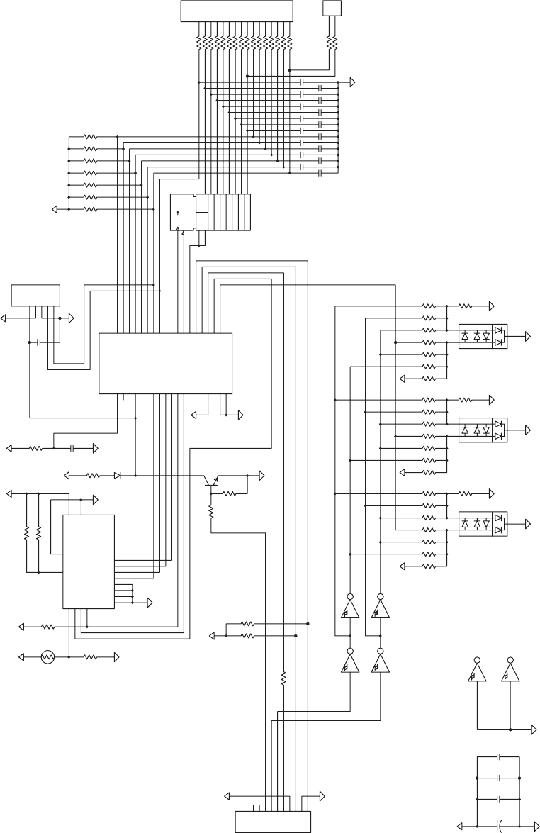
1-971653-30 Console pcb, Schematics
24 EasyCoder PX4i and PX6i Service Manual
Chapter 2 — Front and Keyboard

EasyCoder PX4i and PX6i Service Manual 25
3 Covers and Doors
This chapter describes the covers and doors on the EasyCoder PX4i and
PX6i printers. It covers the following topics:
• The right-hand door, that is, the doors that cover the print mechanism
and media compartment.
• The front door, that protects the front of the print mechanism.
• The left-hand cover that protects the electronics compartment.
26 EasyCoder PX4i and PX6i Service Manual
Chapter 3 — Covers and Doors
3.1 Right-Hand Door
Description
The right-hand door gives access to:
• The media supply
• The ribbon supply
• The print mechanism
The right-hand door is fi tted to the bottom plate using two hinges that
allow the door to be swung 180˚ downwards to a vertical attitude. The
door is kept shut using a magnetic lock. The door can easily be removed
from the hinges by pushing it forward until the snap-lock at the rear hinge
becomes disengaged.
At the inside of the door, there is a label showing how to load the media
and transfer ribbon.
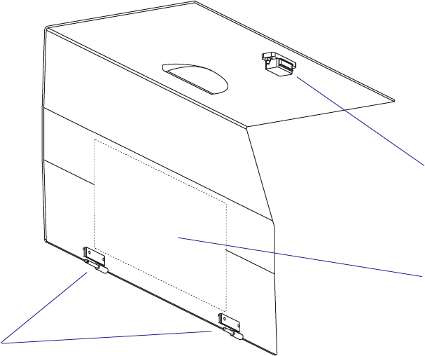
Illustration shows the right-hand door of an EasyCoder PX4i. The door of the EasyCoder PX6i has a wider top part.
Adjustment
The hinges can be adjusted using two pairs of #T10 Torx screws visible
on the outside. Possibly, the other parts of the hinges, which are fi tted to
the bottom plate, may require adjustment too. Shut the door, loosen the
screws slightly and align the door with the front moulding. Tighten the
screws and check that the door runs freely and is kept shut by the magnetic
lock.
Magnetic lock
Label
Hinges
EasyCoder PX4i and PX6i Service Manual 27
Chapter 3 — Covers and Doors
3.2 Front Door
The front door gives access to:
• The front part of the print mechanism
• The paper cutter connector
• The optional label taken sensor
The front hatch is fi tted to the bottom plate using two hinges of the same
type as those of the right-hand door. The front hatch is kept shut by a
snap-lock and can be swung down almost to a vertical position. The hatch
can be removed from its hinges by pushing it to the left until the snap-lock
on the right-hand hinge disengages.
The front hatch can be replaced by an optional paper cutter unit, see
Chapter 11.
Alignment is performed in the same way as the right-hand door, see the
previous page.
The front hatch can be removed by pushing it to the left when open
(illustration shows an EasyCoder PX4i).
28 EasyCoder PX4i and PX6i Service Manual
Chapter 3 — Covers and Doors
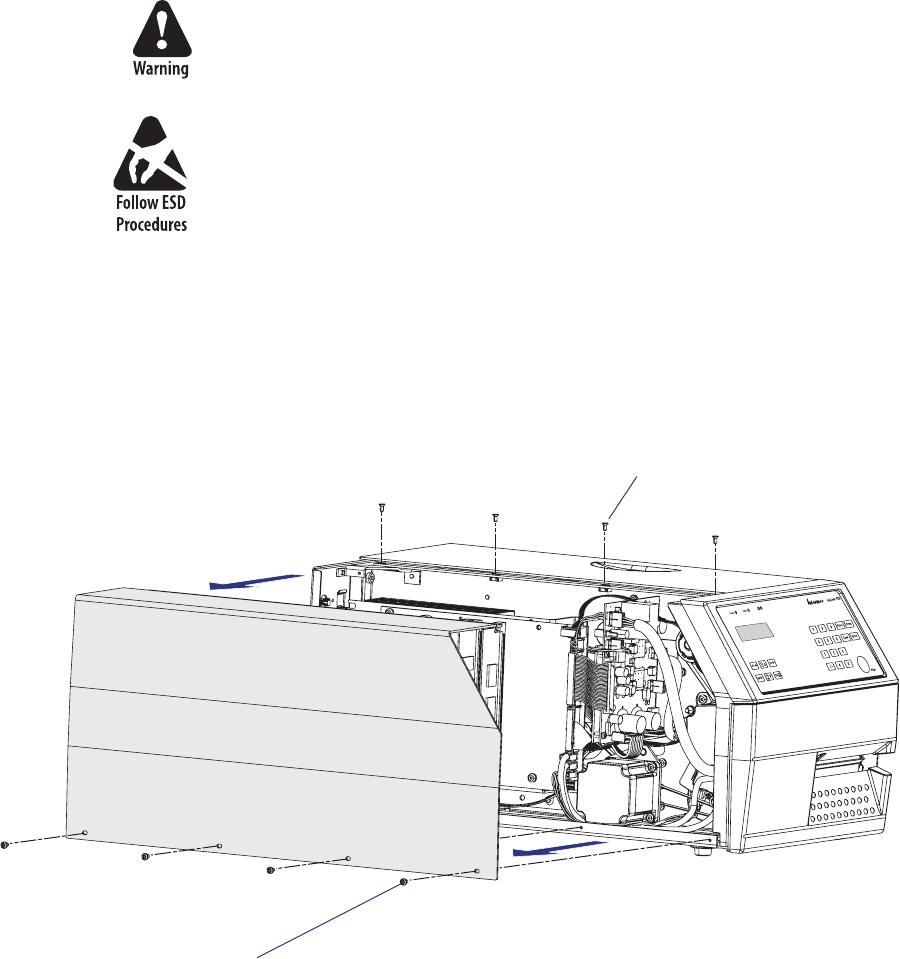
3.3 Left-Hand Cover
The left-hand cover gives access to:
• The electronics incl. CPU board, AC connection, power supply, driver
board, and any optional interface boards.
• The motors, belts and pulleys of the media feed, ribbon feed, and the
optional liner/batch takeup unit.
The left-hand cover plate is fi tted to the printer’s frame using a total of
eight #T10 Torx screws; four along the lower edge and another four along
the top.
The electronic compartment contains wires and components with
dangerous voltage (up to 380V). Make sure that the printer is switched
off and the power cord is disconnected, before the left-hand cover is
removed.
Before removing the left-hand cover, take standard precautions to avoid
causing any electrostatic discharges.
After having disconnected the power cord, open the right-hand door.
Using a #T10 Torx screwdriver, remove the four screws along the lower
edge fi rst, then remove the four upper screws. Put the cover plate aside on
a soft cloth or similar material to avoid scratches.
Fit back the left-hand cover in reverse order. Before fi nally tightening the
screws, check that the cover is aligned with the front moulding and the
rear plate and that it does not interfere with the right-hand door.
#T10 Torx screws (x4)
#T10 Torx screws (x4)

EasyCoder PX4i and PX6i Service Manual 29
4 Chassis
This chapter describes the center section, bottom plate, rear plate, hinges,
and rubber feet, of the EasyCoder PX4i and PX6i printers.
30 EasyCoder PX4i and PX6i Service Manual
Chapter 4 — Chassis
4.1 Description
The printer’s chassis consists of three main parts:
• The center section
• The bottom plate
• The rear plate
Bottom plate
Center section
Rubber foot (x4)
Hinges
Rear plate
Hinges
(front door
or cutter)
Hinges
(right-hand door)
EasyCoder PX4i
EasyCoder PX4i and PX6i Service Manual 31
Chapter 4 — Chassis
Bottom plate
Center section
Rubber foot (x4)
Rear plate
Hinges
(front door
or cutter) Hinges
(right-hand door)
EasyCoder PX6i
The main differences between the chassis of EasyCoder PX4i and PX6i are
the widths of the bottom plate and the rear plate.

32 EasyCoder PX4i and PX6i Service Manual
Chapter 4 — Chassis
4.2 Center Section
The center section is where most parts are fi tted, such as the print mecha-
nism, the transfer ribbon mechanism, the liner takeup unit, and the media
supply. The center section is fi tted to the bottom plate by four #T20 To r x
screws and to the rear plate using three #T20 Torx screws and a bracket.
In the electronics compartment, the CPU board, the driver board, and
power supply unit are fi tted to the center section.
4.3 Bottom Plate
The bottom plate is fi tted to the center section using four #T20 Torx
screws and to the rear plate using three #T20 Torx screws. In case of Easy-
Coder PX6i, there are also two #T20 Torx screws holding the outer gable
of the print unit.
The electronic compartment contains wires and components with dan-
gerous voltage. Make sure that the printer is switched off and the power
cord is disconnected before the bottom plate is removed.
The bottom plate is fi tted with four easily replaceable rubber feet. These
feet could be removed and the holes be used to bolt the printer to a frame,
table or similar. The holes have a diameter of 7.1 mm (0.28 inches). To
reduce noise, fi t rubber dampeners between the table and the printer if you
bolt it in place.
When fi tting a replacement foot, insert it through the bottom plate and
fi rmly press the pin so the rivet expands on the upper side of the plate.
The bottom plate is provided with two pairs of hinges for the front door or
cutter and for the right-hand door.
The two keyholes must not be used to bolt the printer to a frame, or the
bottom plate may be bent. These holes are intended for fi xtures during
manufacturing.
EasyCoder PX4i and PX6i Service Manual 33
Chapter 4 — Chassis
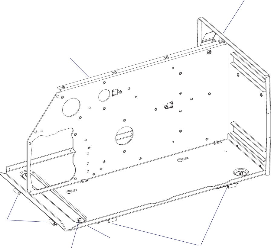
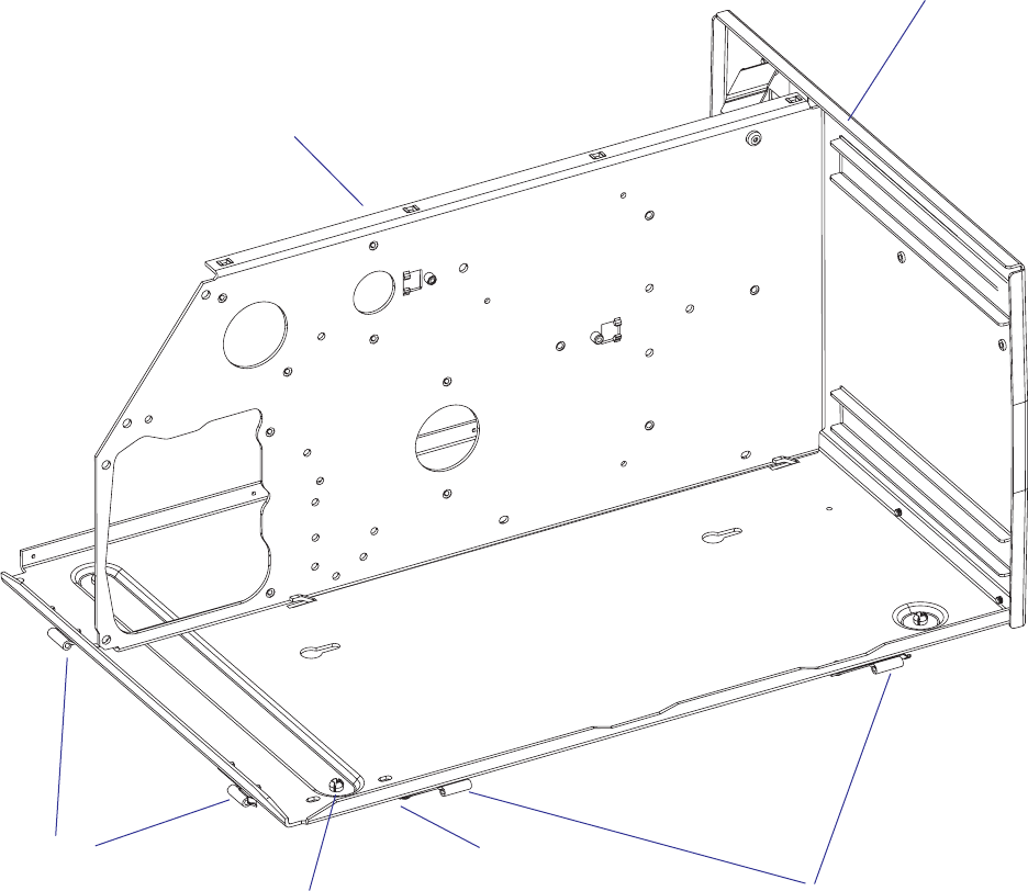
4.4 Rear Plate
The rear plate is attached to the bottom plate using three #T20 Torx
screws and to the center section by two #T20 Torx screws. There is also a
bracket between the rear plate and the center section. The rear plate has a
number of slots for connectors, switches etc., as illustrated below.
On/Off switch
AC power cord receptacle
CompactFlash memory card slot
RS-232 serial interface
Provision for optional interface
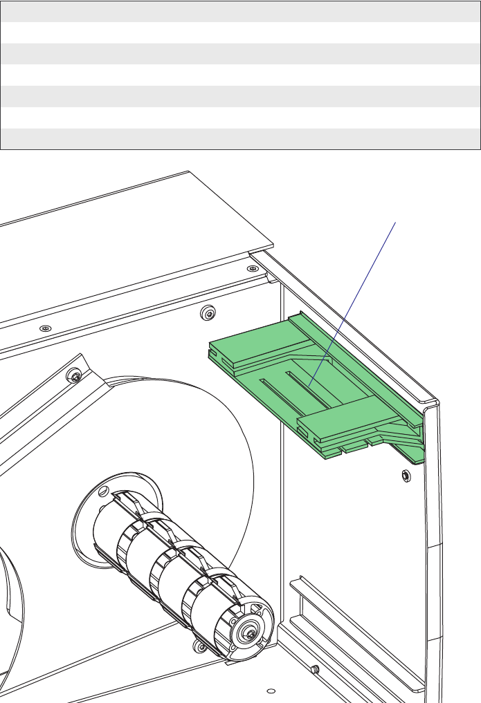
board(s)
Bar code wand Interface (not used with
IPL)
Upper external media intake
Lower external media intake
USB interface
Provision for EasyLAN Ethernet
connector
Provision for EasyLAN Wireless antenna
Machine label
34 EasyCoder PX4i and PX6i Service Manual
Chapter 4 — Chassis

EasyCoder PX4i and PX6i Service Manual 35
5 Media Supply
This chapter explains the rotating media supply hub with the 3-inch
adapter, the media roll retainer, and the paper sensor. Finally, it describes
how an external media supply can be used in an EasyCoder PX4i and PX6i
printer fi tted with a fan-fold guide.
#LOSED
/PEN
36 EasyCoder PX4i and PX6i Service Manual
Chapter 5 — Media Supply
5.1 Internal Supply
Description
The internal media supply consists of a shaft with four or fi ve modular
hubs. The shaft is screwed into a fl ange fi tted to an almost circular plate
using two #T20 Torx screws. The plate is fi tted to the center section using
four #T20 Torx screws. The hub modules are spring-loaded in order to
fi t media roll cores with an inner diameter between 38 and 40 mm (1.5
inches).
A large crescent-shaped guide plate keeps the media roll aligned with the
print mechanism. Inside the guide plate and protruding through a slot in
the circular plate, the paper sensor is fi tted to the center section.
Maximum diameter of an internal media roll is 213 mm (8.38 inches),
except in the case of peel-off and batch takeup operation when the diam-
eter is restricted to 205 mm (8 inches). Maximum width is 120 mm (4.72
inches) for EasyCoder PX4i and 170 mm (6.69 inches) for EasyCoder
PX6i.
EasyCoder PX4i and PX6i Service Manual 37
Chapter 5 — Media Supply
Paper sensor
Unwind unit
Guide plate
Hub modules
38 EasyCoder PX4i and PX6i Service Manual
Chapter 5 — Media Supply
The media supply hub package can be dismantled by removing the #T20
Torx screw at the end of the shaft. Inside the outermost hub module, there
is a spring that presses the hub package towards a felt pad in order to break
the rotation. Else, the momentum of a large and heavy media roll might
cause excessive media to be unwound when the printing is stopped. The
brake torque should be 70 ±20 Nmm (see Appendix C).
The rotation of the code disc fi tted at the innermost part of the hub pack-
age is detected by the paper sensor.
Be careful to fi t the studs of the innermost hub module into the holes in
the code disc when the package is assembled.
Flange
Nylon disc
#T20 Torx screw
Washer
Spring
Shaft
(short in EasyCoder PX4i,
long in EasyCoder PX6i)
Felt Pad
Disc
Hub modules
(4 in EasyCoder PX4i,
5 in EasyCoder PX6i)
Code disc
Plate
EasyCoder PX4i and PX6i Service Manual 39
Chapter 5 — Media Supply
5.2 Paper Sensor
Description
The paper sensor allows the fi rmware to detect when the diameter of the
remaining media becomes less than a value set in the Setup Mode.
In Fingerprint, this affects SYSVAR(46) which switches from 0 to 1.
Thus, a Fingerprint program can be created, that reads SYSVAR(46) and
uses it to issue for example audible alarms or error messages to notify the
operator of a pending out-of-media condition. A trap is also sent that can
be detected when the printer is connected to a network via an EasyLAN
interface.
In IPL, a trap is sent that can be detected when the printer is connected to
a network via an EasyLAN interface.
The sensor detects the saw-tooth shape of the code disc at the inner end of
the media supply hub. By comparing the rotation speed of the hub and the
print speed, the fi rmware can calculate the diameter of media roll.
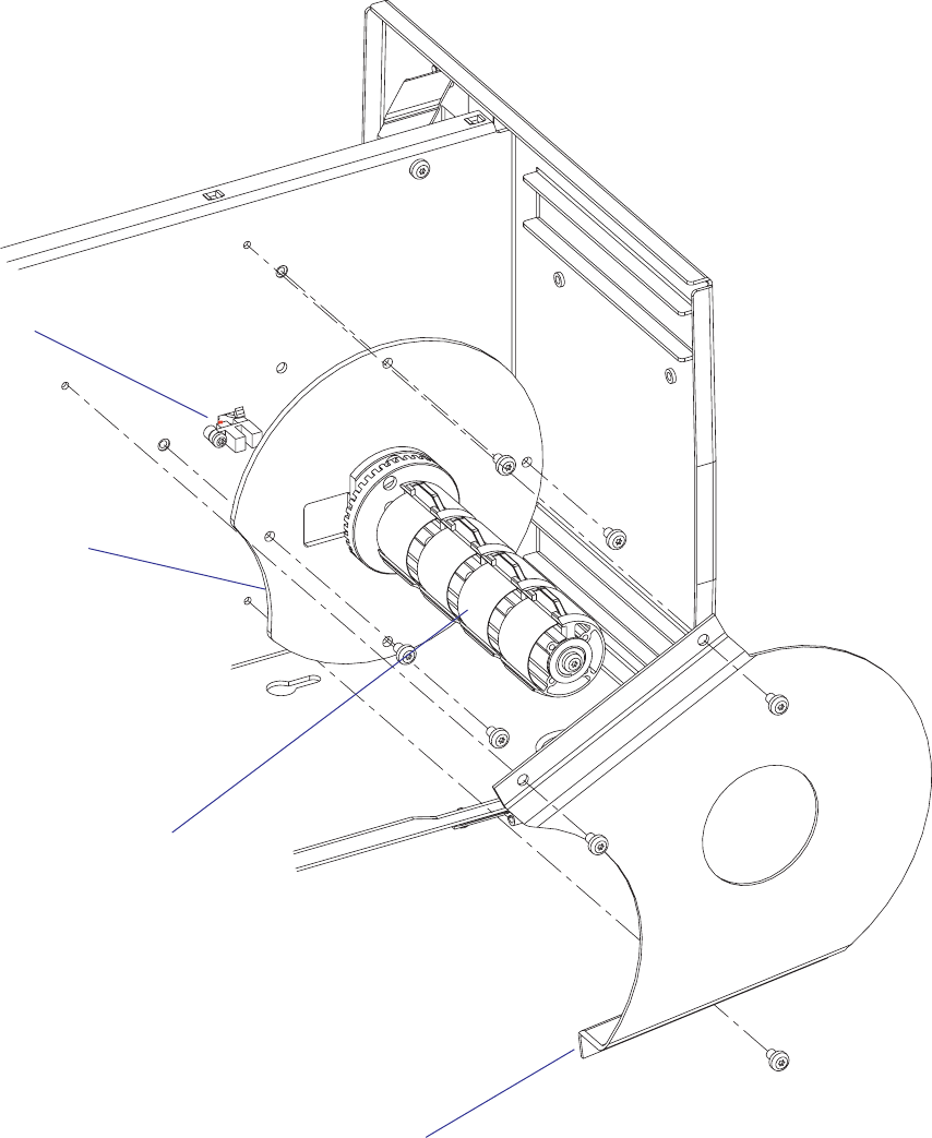
The paper sensor assy is fi tted to the center section using a #10 Torx screw
and is connected to J57 on the CPU board (see Chapter 15.3).
Adjustment
Refer to the chapter “Setting Up the Printer” in the User’s Guide for the
printer in question.
Replacement
• Switch off the power, disconnect the power cord, and remove the left-
hand cover.
• Disconnect the cable from J57 on the CPU board.
• Remove the crescent-shaped guide plate, which is held by three #T20
Torx screws.
• Remove the entire media supply unit which is held by four #T20 Torx
screws.
• Remove the single #T10 Torx screw that holds the sensor to the center
section.
• Carefully pull out the sensor and its cable through the hole in the center
section.
• Install a new sensor assembly in reverse order.
#LOSED
/PEN
40 EasyCoder PX4i and PX6i Service Manual
Chapter 5 — Media Supply
3-inch adapter
3-inch adapters
5.3 Three-inch Adapters
One or two adapters (standard accessories) can be fi tted onto the media
supply hub in order to accept media rolls with 76 mm (3 inches) cores.
EasyCoder PX4i has one adapter and EasyCoder PX6i has two. Each
adapter is locked using a #T20 Torx screw. Be careful not to let the screw
hit the leaf springs or the cams of the hub modules.
EasyCoder PX4i and PX6i Service Manual 41
Chapter 5 — Media Supply
Media roll
retainer
5.4 Media Roll Retainer
An optional media roll retainer can be pressed on the hub package (but
not on the adapter) of an EasyCoder PX4i in order to hold large media
rolls and to prevent the media from getting misaligned on the roll. The
retainer is not intended for EasyCoder PX6i
42 EasyCoder PX4i and PX6i Service Manual
Chapter 5 — Media Supply
Fan-Fold Guides in upper
position (EasyCoder PX4i)
5.5 Fan-Fold Guides
Description
Instead of an internal media roll, the EasyCoder PX4i and PX6i printers
can also use media from an external supply, for example an external roll or
a stack of fan-folded tickets. The media is inserted into the printer through
either the upper or lower slot in rear plate.
It is important that the media path is properly aligned in parallel with the
printer’s center section. Therefore, Intermec offers an optional “Fan Fold
Kit” consisting of a bracket with two guides that can be fi tted in either the
upper or lower slot in the rear plate. The outer guide is adjustable for dif-
ferent media widths.
Max. Media Width (Fan-Fold Guides)
EasyCoder PX4i: 120 mm (4.72 in)
EasyCoder PX6i: 170 mm (6.69 in)
Min. Media Width (Fan-Fold Guides)
EasyCoder PX4i: 40 mm (1.575 in)
EasyCoder PX6i: 76.2 mm (3.00 in)
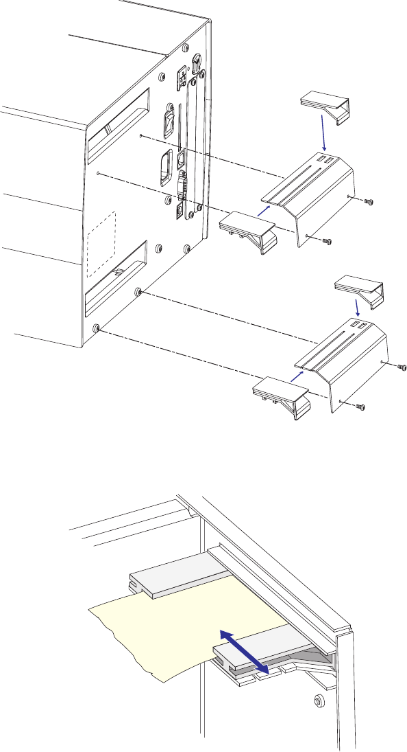
EasyCoder PX4i and PX6i Service Manual 43
Chapter 5 — Media Supply
Installation
The bracket with the two guides can be fi tted either at the upper or lower
slot in the rear plate, depending on how the media supply is located in
relation to the printer. The principles are the same for EasyCoder PX4i and
EasyCoder PX6i.
Insert the complete unit through the slot from the outside and attach it to
the rear plate using two #T20 Torx screws. In case of the upper position,
use the screws included in the kit, and in case of the lower position, use the
two existing screws that hold the rear plate to the bottom plate.
Adjustment
Adjust the position of the outer guide to fi t the width of the media.
44 EasyCoder PX4i and PX6i Service Manual
Chapter 5 — Media Supply
Media Load
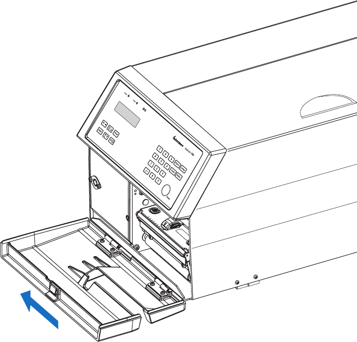
Load the media according to the illustrations below.
The external supply should be protected from dust, sand, grit and other
particles that may damage the printhead or impair the printout qual-
ity.
Note: If the printer is to be permanently used with an external media
supply only, the entire internal media supply unit could easily be removed
(see Chapter 5.1).

EasyCoder PX4i and PX6i Service Manual 45
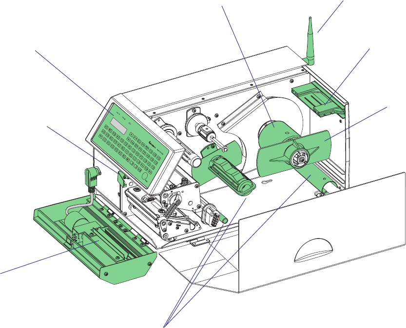
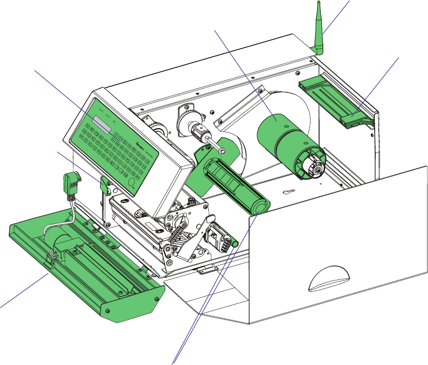
6 Label Slack Absorber
This chapter describes the label slack absorber fi tted as standard in the
EasyCoder PX4i and PX6i printers. It covers the following topics:
• Description
• Dismantling
46 EasyCoder PX4i and PX6i Service Manual
Chapter 6 — Label Slack Absorber
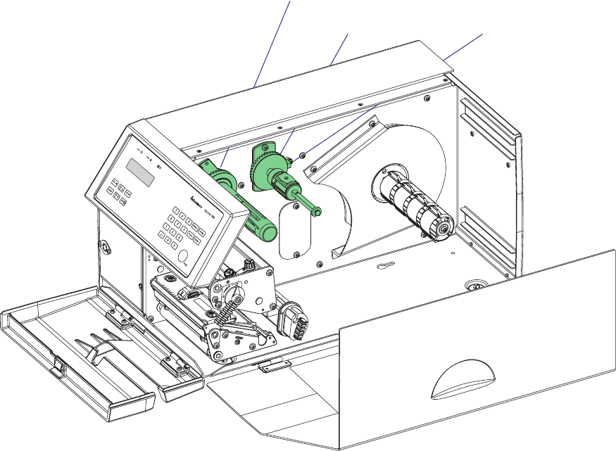
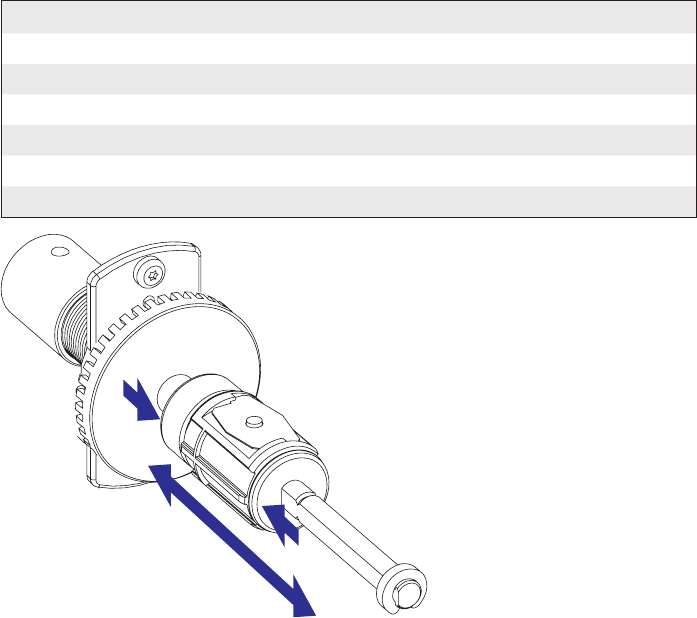
6.1 Description
The label slack absorber compensates for sudden jerks at the media, for
example when high speed printing is started and stopped. When the
printing starts, the tension is increased and the absorber is pulled forward/
upward. As soon the heavy media roll starts to rotate, the tension decreases.
The spring-loaded absorber can then return towards its original position.
During the printing, the absorber will fl utter back and forth, compensating
for the variations in tension.
To facilitate media load, the label slack absorber can be rotated 180° clock-
wise. It can be locked in open position using a snap-lock. Remember to
unlock the slack absorber before starting to print.
An adjustable edge guide is fi tted on the label slack absorber to prevent
media misalignment. The guide is fi tted as standard, but can be removed
to facilitate media load when there are other means of guiding the media,
for example a media roll retainer or fan-fold guides (see Chapter 5).
Edge
guide
Slack absorber
EasyCoder PX4i and PX6i Service Manual 47
Chapter 6 — Label Slack Absorber
#T20 Torx screws (2x)
Flange
#T10 Torx screw
Torsion spring
Grip (green)
Edge guide
(green)
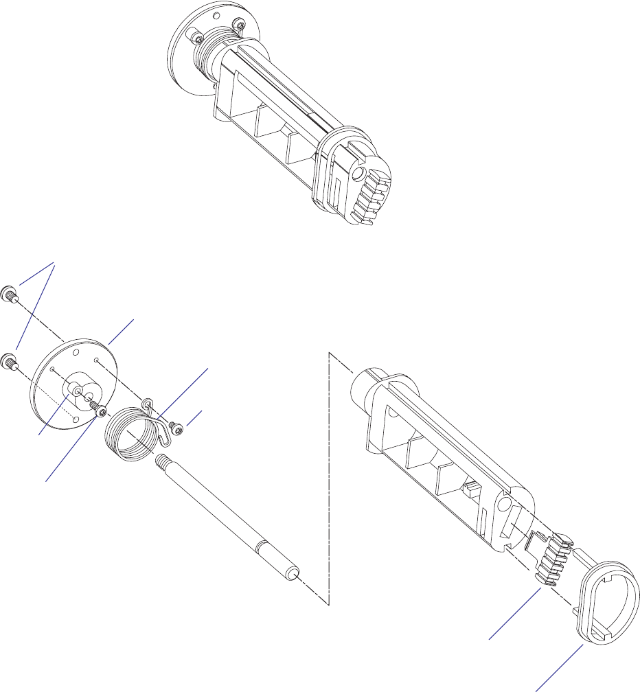
6.2 Dismantling
The label slack absorber unit is fi tted to the center section using two #T20
Torx screws inserted through the center section from the electronics com-
partment. The shaft should be screwed into the fl ange with a tightening
torque of 5 Nm.
EasyCoder PX4i
#T10 Torx screw
Spacer
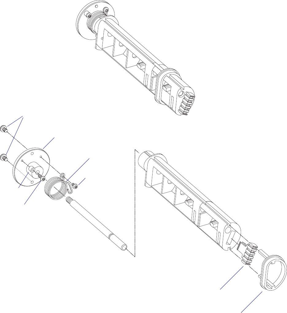
48 EasyCoder PX4i and PX6i Service Manual
Chapter 6 — Label Slack Absorber
#T20 Torx screws (2x)
Flange
#T10 Torx screw
Torsion spring
Grip (green)
Edge guide
(green)
EasyCoder PX6i
#T10 Torx screw
Spacer

EasyCoder PX4i and PX6i Service Manual 49
7 Transfer Ribbon Mechanism
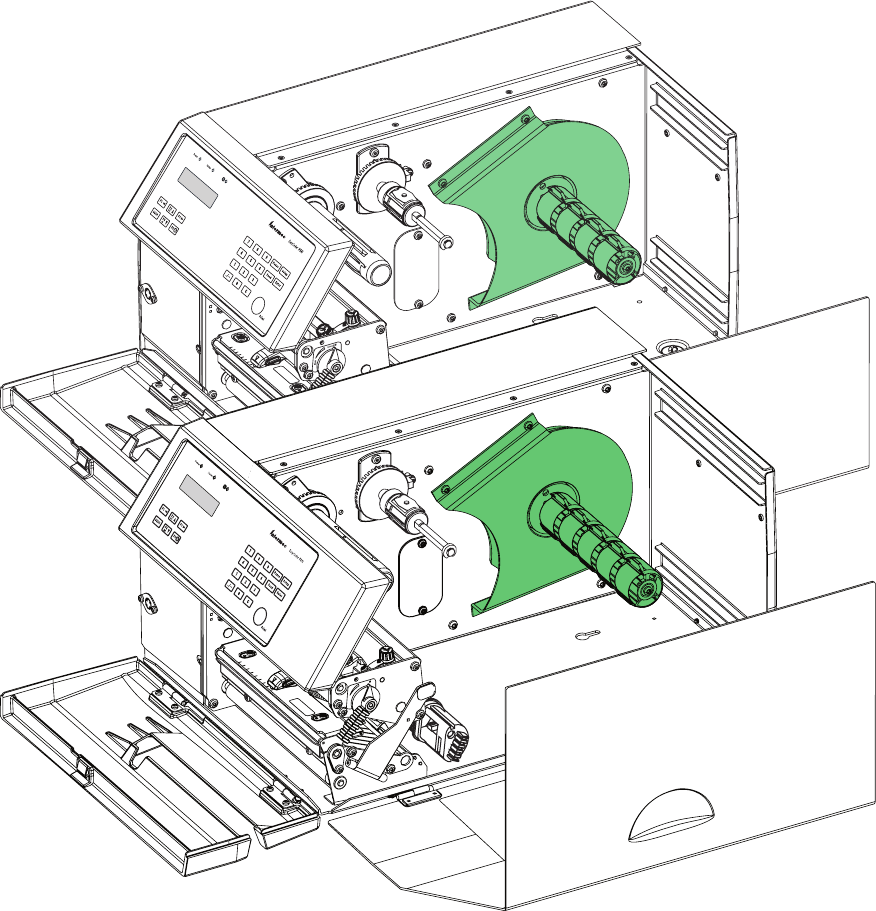
This chapter describes the mechanism that drives the thermal transfer
ribbon in the EasyCoder PX4i and PX6i printer. It covers the following
topics:
• Description
• Ribbon supply unit
• Ribbon rewind unit
• Ribbon sensor
50 EasyCoder PX4i and PX6i Service Manual
Chapter 7 — Transfer Ribbon Mechanism
7.1 Description
The thermal transfer ribbon mechanism is standard in EasyCoder PX4i
and PX6i. The mechanism consists of three main parts:
• Ribbon supply unit (see Chapter 7.2)
• Ribbon rewind unit (see Chapter 7.3)
• Ribbon sensor (see Chapter 7.4)
Adjustment of the ribbon assist roller to remedy wrinkling of the ribbon is
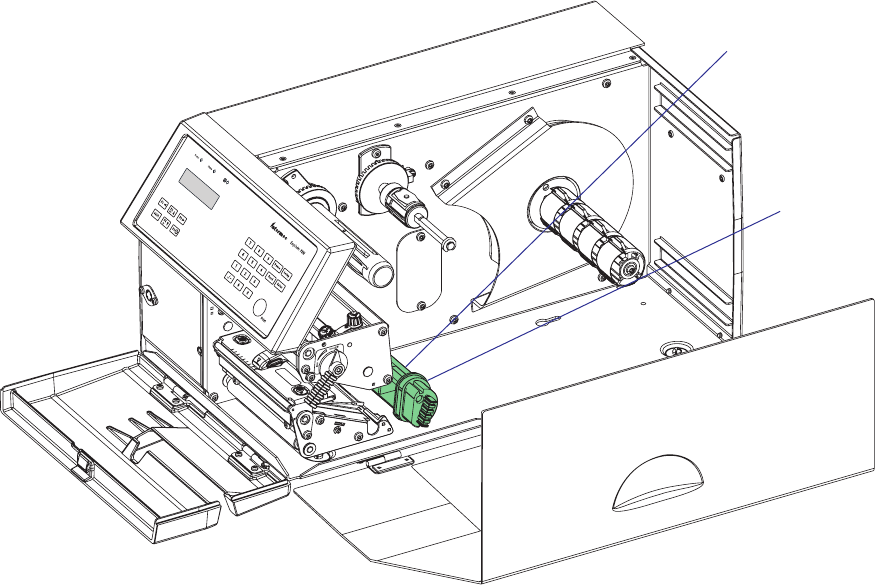
described in Chapter 8.9.
Ribbon Supply Unit
Ribbon Rewind Unit
Ribbon Sensor
EasyCoder PX4i and PX6i Service Manual 51
Chapter 7 — Transfer Ribbon Mechanism
7.2 Ribbon Supply Unit
Description
The ribbon supply unit is the same for EasyCoder PX4i and EasyCoder
PX6i with the exception of the strength of the spring in the spring brake.
It is used to accommodate the fresh supply of thermal transfer ribbon. For
optimum printout quality and trouble-free operation, only original transfer
ribbon from Intermec should be used.
The unit is designed to keep the ribbon tight all the time in order to avoid
wrinkling, which would ruin the printout. It consists of a shaft on which
a hub is fi tted. The hub can pivot ± 1.3° on the shaft and the hub can be
moved sideways between 6 fi xed positions.
Adjustment
It is most important for avoiding ribbon wrinkling that the pivoting point
of the hub is centered in relation to the ribbon width. Therefore, the shaft
is provided with six grooves which correspond to the standard widths of
Intermec transfer ribbons (see table below). The three innermost grooves
are used with EasyCoder PX4i, whereas the three outermost grooves only
are used with the wider EasyCoder PX6i. By compressing the hub, its
snap-lock will disengage from the presently engaged groove and the hub
can be moved sideways to another position. Make sure that the snap-lock
has engaged a groove by trying to move the hub without compressing it.
Ribbons with a width less than 55 mm (2.16 inches) can be used provided
they are wound on a core with a width of at least 45 mm (1.77 inches).
Ribbon Width Position (groove) Note
55-60 mm (2.16-2.36 in) 1:st (innermost) PX4i only
88-90 mm (3.5 in) 2:nd All
110 mm (4.3 in) 3:rd All
130 mm (5.1 in) 4:th PX6i only
154 mm (6.0 in) 5:th PX6i only
≤ 166 mm (6.5 in) 6:th (outermost) PX6i only
52 EasyCoder PX4i and PX6i Service Manual
Chapter 7 — Transfer Ribbon Mechanism
Working Principles
The ribbon supply is braked by a spring affi xed to the printer’s center sec-
tion, partly enveloped by a sleeve affi xed to the shaft. Initially, the spring
expands towards the inner wall of the sleeve, thereby breaking the rotation
of the shaft. When the bobbin is forced to rotate (that is, when the ribbon
is unwound), the breaking spring is compressed. After approximately half
a turn, the diameter of the spring has been compressed enough to allow
the sleeve to slip. The brake torque should be 55 ±5 Nmm (see Appendix
C). The sleeve is fi lled with ball bearing grease. If the brake torque deviates
from the recommended value, replace the grease. We recommend Castrol
Sinplex 2. The expected interval between replacing the grease is 8 to 10
million print cycles.
When the rotating force ceases, the spring tends to pull back the ribbon,
keeping it tight.
Pivot assy.
Brake sleeve
Grub screw
Locking washer
Torque spring
(diff ers between
models)
Ball bearing
Flange
Shaft
Grooves
Grub screw
Fixing ring
Code disc
Ball bearing
Locking washer
EasyCoder PX4i and PX6i Service Manual 53
Chapter 7 — Transfer Ribbon Mechanism
Replacement
The unit is attached to the center section by two #T20 Torx screws
inserted from the media compartment side.
#T20 Torx screw
#T20 Torx screw
54 EasyCoder PX4i and PX6i Service Manual
Chapter 7 — Transfer Ribbon Mechanism
7.3 Ribbon Rewind Unit
Description
The ribbon rewind unit is the same for EasyCoder PX4i and EasyCoder
PX6i. It pulls the transfer ribbon around the printhead and winds it up on
a cardboard core. The unit is driven via a belt by the same stepper motor
that drives the platen roller.
The rewind unit is provided with a friction brake in order to keep the
ribbon tight.
Adjustment
There is no manual adjustment of the ribbon rewind unit other than the
tension of the belt to the stepper motor (see Chapter 8.4).
EasyCoder PX4i and PX6i Service Manual 55
Chapter 7 — Transfer Ribbon Mechanism
Working Principles
The ribbon rewind unit is driven by the same motor that drives the platen
roller in the print unit via a belt that engages the timing belt pulley. The
torque spring allows the stepper motor to drive the rewind hub rotate
counter-clockwise only. When the media is fed back, the ribbon will not
move.
The torque spring arrangement automatically compensates for the gradu-
ally increasing diameter of the used ribbon on the rewind hub, so the
ribbon will always be fed at the same speed as the media.
Bobbin
Bobbin plate
Shaft
Timing belt pulley
Flange
Flange
Torque spring
Brake sleeve
Slide bearing
Grub screw
Ball bearing
Locking
washers (x3)
Slide bearing
Ball bearing
Slide
bearing
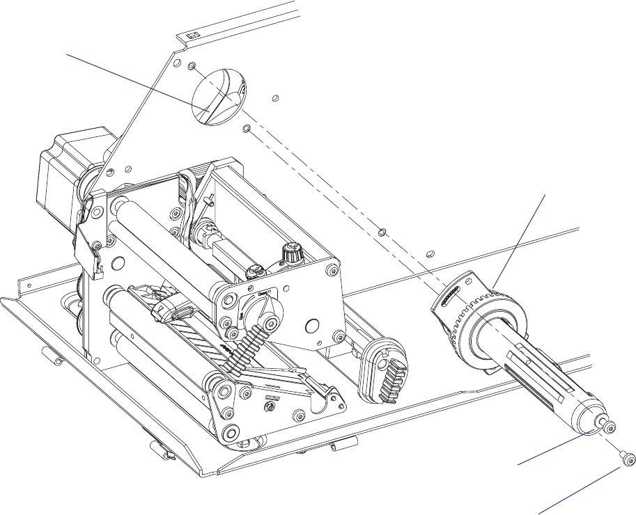
56 EasyCoder PX4i and PX6i Service Manual
Chapter 7 — Transfer Ribbon Mechanism
Replacement
The ribbon rewind unit is fi tted to the center section using two #T20 Torx
screws inserted from the media compartment. One of the screws runs in a
crescent-shaped slot to allow adjustment or removal of the belt.
• Remove the left-hand cover as described in Chapter 3.3.
• Remove the two #T20 Torx screws and the single washer that hold the
ribbon rewind unit.
• Free the belt from the pulley of the rewind unit.
• Pull out the unit into the media compartment.
• Do not dismantle the ribbon rewind unit.
• Fit the new ribbon rewind unit in reverse order, making sure that the
belt is properly attached to the pulley, but do not tighten the screws.
• Adjust the tension of the belt as described in Chapter 8.5.
• Tighten the screws.
#T20 Torx screw
Washer & #T20 Torx screw
Belt
Pulley (hidden)
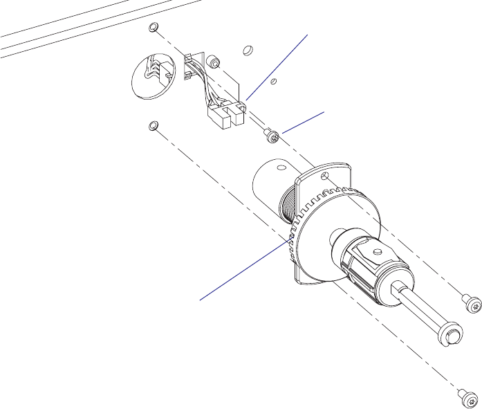
EasyCoder PX4i and PX6i Service Manual 57
Chapter 7 — Transfer Ribbon Mechanism
7.4 Ribbon Sensor
Description
The ribbon sensor is fi tted to the center section from the media compart-
ment side and is partly enclosed by the ribbon supply unit (see Chapter
7.2). The sensor consists of a plastic housing with a LED and a photoelec-
tric sensor plus a cable.
The light from the LED is intermittently blocked by the saw-toothed edge
of the rotating code disc. The signals from the sensor allow the fi rmware
to detect the speed with which the bobbin rotates and compare it with
the speed of the media feed. Thus, both “out of ribbon” and “ribbon low”
conditions can be detected.
If no bobbin rotation is detected during media feed, the Fingerprint
fi rmware assumes an error condition (error 1027 “Out of transfer ribbon”)
provided the printer is set for thermal transfer printing. In IPL, the error
message “Ribbon out” is displayed.
The ribbon sensor is connected to J56 on the CPU board (see Chapter
15.3).
Replacement
• Remove the cover over the electronics compartment as described in
Chapter 3.3, taking all precautions against electric shock.
• Remove any transfer ribbon from the ribbon supply unit.
• Remove the ribbon supply unit as described in Chapter 6.2.
• Disconnect the sensor’s cable from J56 on the CPU board.
• Remove the #T10 Torx screw that holds the sensor to the center section.
• Install a replacement sensor unit in reverse order.
Ribbon sensor
Ribbon supply unit
#T10 Torx screw

58 EasyCoder PX4i and PX6i Service Manual
Chapter 7 — Transfer Ribbon Mechanism
Adjustment (Fingerprint)
Low diameter
In the Setup Mode (see Appendix A), it is possible to specify the diameter
(in millimeters) of the ribbon supply roll, when a ribbon low condition
should occur. By default, this parameter is set to 0, which disables the
function. To enable it, enter the desired value.
The status of the ribbon sensor can be polled by reading SYSVAR(26) in a
Fingerprint application program. SYSVAR(26) returns 0 if the diameter of
the ribbon supply roll is greater and 1 if it is less than the value entered in
the Setup Mode. A trap is also sent that can be detected when the printer is
connected to a network via an EasyLAN interface.
Note that a full forward rotation of the supply bobbin must have been
completed. If not, 0 will be returned.
Note: When the ribbon low function is enabled, error condition 1083
“Ribbon low” is reported every tenth time SYSVAR(26) = 1 is detected in
connection with a PRINTFEED.
Sensitivity
• Enter the Setup Mode and follow the path:
Media/Paper Type/Transfer/Ribbon Sensor
• In the Ribbon Sensor menu, press <Enter> to perform a Testfeed.
• The printer will feed out a few labels and feed the ribbon accordingly.
• While the ribbon mechanism is operating, the ribbon sensor is
autoadjusted and the resulting adjustment value is shown in the lower
line of the menu (read-only).
Adjustment (IPL)
In the Setup Mode (see Appendix A), it is possible to specify the value
in millimeters of the ribbon supply roll for the ribbon sensor. When the
diameter of remaining ribbon supply roll reaches the set value, an SNMP
trap is sent to the printer’s home page, provided the printer has an optional
EasyLAN connection. Range: 0-80 with preset values at an interval of 5. A
value larger than 80 sets the ribbon sensor to 0. Default value: 0
The ribbon low sensor can also be set using an IPL command:
<STX><SI>kn<ETX>
There is no facility for adjusting the sensitivity of the ribbon sensor in IPL.

EasyCoder PX4i and PX6i Service Manual 59
8 Print Unit
This chapter describes the print unit of the EasyCoder PX4i and PX6i
printer and explains how to adjust the various functions and replace part
subject to wear. It covers the following topics:
• Description
• Platen roller
• Stepper motor
• Belts
• Label stop sensor
• Printhead
• Headlift sensor
• Headlift mechanism
• Media feed principles
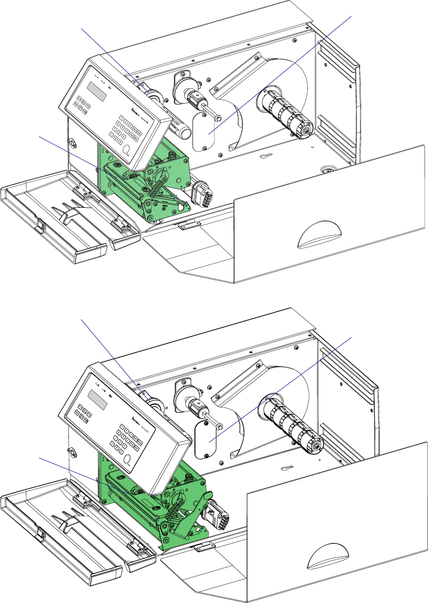
#LOSED
/PEN
60 EasyCoder PX4i and PX6i Service Manual
Chapter 8 — Print Unit
8.1 Description
The print unit is partly integrated with the ribbon rewind unit (see Chap-
ter 7.3) and optional liner/batch takeup unit (see Chapter 9).
EasyCoder PX4i
EasyCoder PX6i
Print unit
Ribbon rewind unit
Provision for liner/batch
takeup unit
Print unit
Ribbon rewind unit
Provision for liner takeup
unit
EasyCoder PX4i and PX6i Service Manual 61
Chapter 8 — Print Unit
The main parts of the print unit are:
• The rubber-coated platen roller drives the media forward under the
printhead and provides the necessary counter-pressure.
• The stepper motor drives the platen roller via one belt and the ribbon
assist roller and the ribbon rewind unit via another. The liner drive roller
is idle, unless a liner/batch takeup kit is fi tted, see Chapter 9.
• The tear bar makes it easier to tear off continuous and pre-perforated
media stock. It is also used for peel-off (self-strip) operation.
• The label stop sensor (LSS) controls the media feed and checks for out-
of-paper conditions.
• The printhead produces the heat that melts the “ink” on the transfer
ribbon or blackens the direct thermal paper in patterns that make up the
text, graphics, or bar codes.
• The headlift mechanism presses the printhead against the media or
transfer ribbon, or raises the printhead to allow media and ribbon load.
The print unit is a self-contained module and attached to the printer's
center section by means of four #T20 Torx screws. There are also a number
of cables running from the print mechanism to the driver and CPU boards
(see Chapters 14.1 and 15.3), which are not illustrated.
The ribbon rewind unit is driven by a belt from the motor of the print
unit via an idle pulley attached to the inside of the center section. The liner
drive roller (fi tted underneath the platen roller) is either idle or driven by a
belt to the optional liner/batch takeup stepper motor. These belts have to
be removed before the print unit can be pulled out.
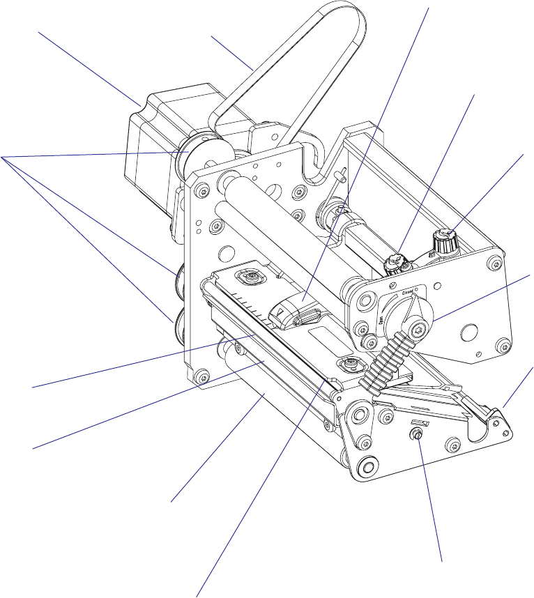
62 EasyCoder PX4i and PX6i Service Manual
Chapter 8 — Print Unit
EasyCoder PX4i
The parts of the EasyCoder PX4i print unit, as seen from the media
compartment side of the center section, are illustrated below. Cables are
excluded.
Printhead with
bracket
Printhead
pressure
adjustment
Pressure arm
Pulleys
LSS adjustment screw
Stepper motor
Edge guide
Tear bar
Platen roller
(barely visible)
Liner drive roller
Printhead lift
lever
Belt to ribbon
rewind unit Printhead
position
adjustment
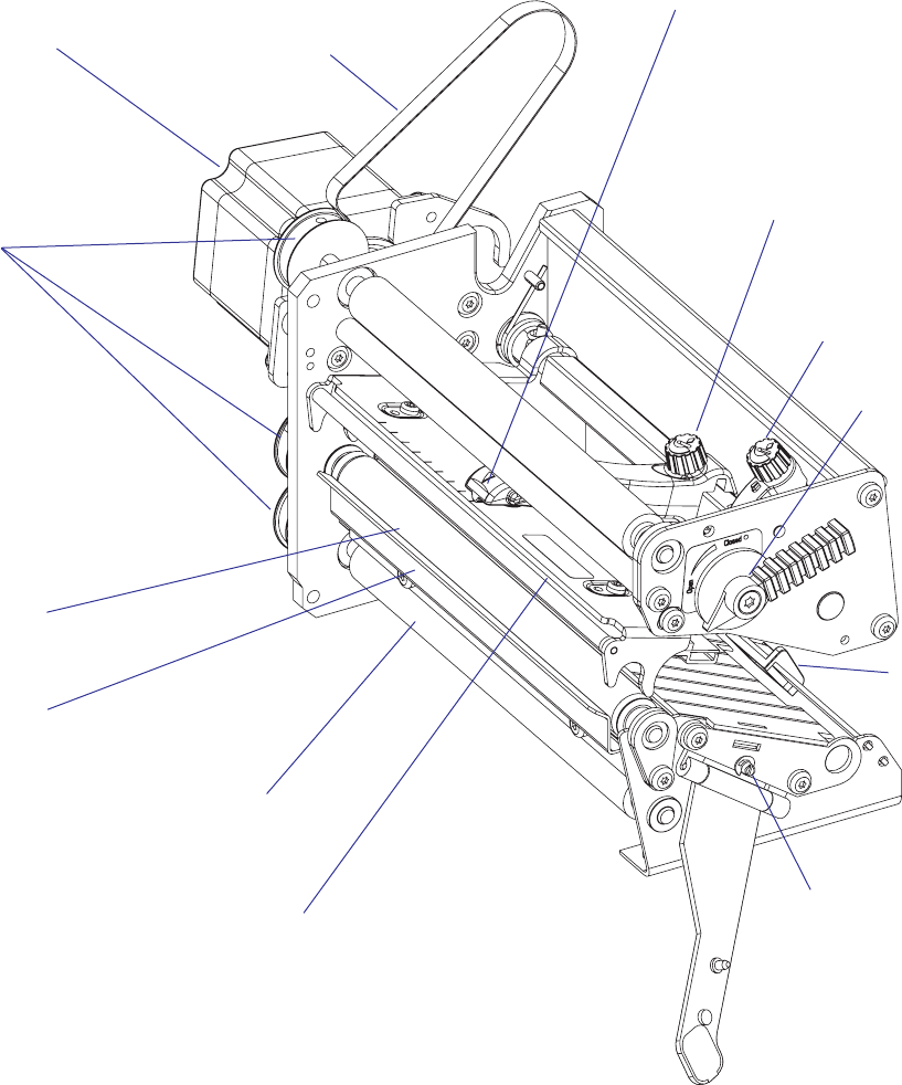
EasyCoder PX4i and PX6i Service Manual 63
Chapter 8 — Print Unit
EasyCoder PX6i
The parts of the EasyCoder PX6i print unit, as seen from the media
compartment side of the center section, are illustrated below. Cables are
excluded.
Printhead with
bracket
Printhead
pressure
adjustment
Pressure arm
Pulleys
LSS adjustment
screw
Stepper motor
Edge
guide
Tear bar
Platen roller
Liner drive roller
Printhead
lift lever
Belt to ribbon
rewind unit
Printhead
position
adjustment
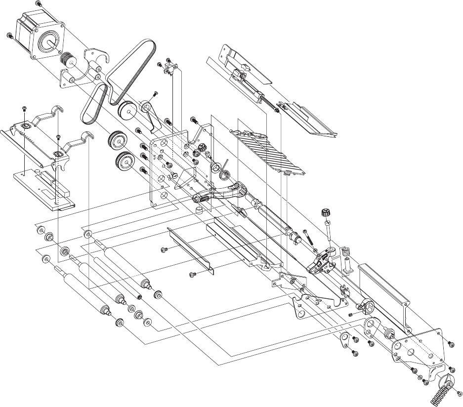
64 EasyCoder PX4i and PX6i Service Manual
Chapter 8 — Print Unit
EasyCoder PX4i
This overview illustrates the various parts in the print unit except cables.
The idle pulley fi tted to the center section and the ribbon rewind unit are
not included. Note that many of the parts illustrated here are not available
as separate spare parts, but must be bought as ready-assembled units.
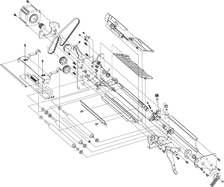
EasyCoder PX4i and PX6i Service Manual 65
Chapter 8 — Print Unit
EasyCoder PX6i
This overview illustrates the various parts in the print unit except cables.
The idle pulley fi tted to the center section and the ribbon rewind unit are
not included. Note that many of the parts illustrated here are not available
as separate spare parts, but must be bought as ready-assembled units.
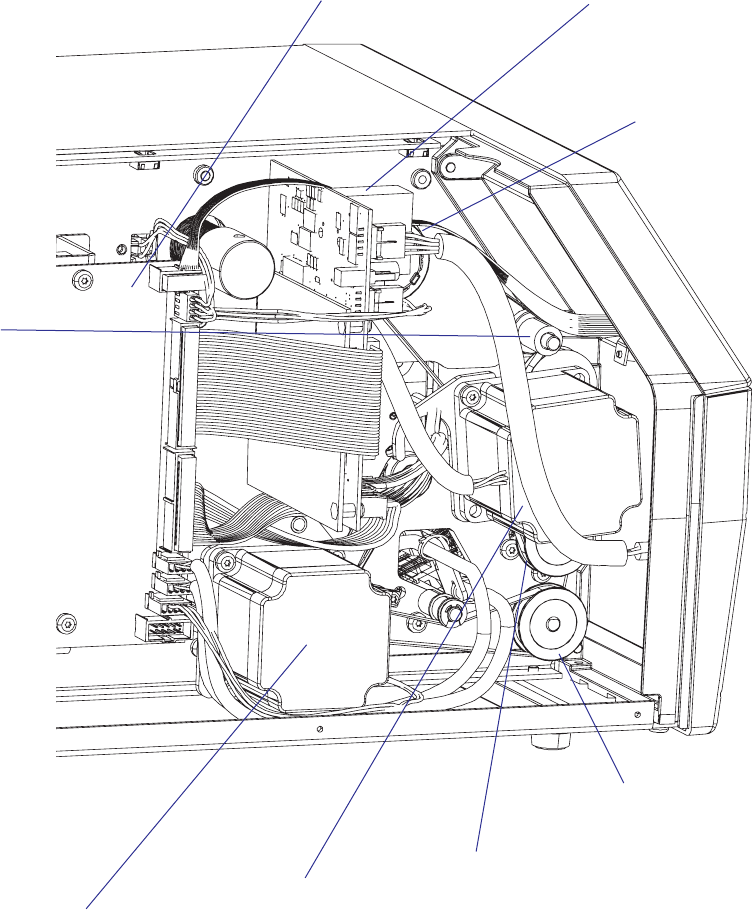
66 EasyCoder PX4i and PX6i Service Manual
Chapter 8 — Print Unit
The parts of the print mechanism fi tted inside the electronics compart-
ment in an EasyCoder PX4i printer are illustrated below.
Stepper motor
(platen roller & ribbon
rewind unit)
Pulley & belt
(liner drive
roller)
Pulley & belt
(platen roller)
Stepper motor
(liner takeup)
Driver board
Ribbon
rewind unit
CPU board
Idle roller

EasyCoder PX4i and PX6i Service Manual 67
Chapter 8 — Print Unit
8.2 Platen Roller
Description
The platen roller is coated with silicon rubber. It is imperative that the
roller is kept clean and is free from uneven wear or dents. The platen roller
is identical to the liner drive roller, so these rollers could be switched. The
same applies to the pulleys and belts. It is normal that the platen roller
needs to be replaced after a period of time depending on print volume and
other circumstances.
If the platen roller is manually rotated, while the power is switched
on, the stepper motor may work as a generator and damage the stepper
motor driver on the driver board (see Chapter 14). A typical example
is when the operator tears out media that has stuck on the platen roller
without switching off the power fi rst.
Replacement
This description also applies to the liner drive roller.
• Switch off the power to the printer and disconnect the power cord.
• Open the front and right hand doors.
• Remove the cover over the electronics compartment, which is held by
eight #T10 Torx screws, see Chapter 3.3.
• Remove the tension of the belt to the ribbon rewind unit by loosening
the two #T20 screws that holds the ribbon rewind unit.
• Dismantle the stepper motor from the bracket by removing the two
#T20 Torx screws.
• Free the belt from the pulley of the ribbon rewind unit and manipulate
the stepper motor so it comes free from both belts. Remove the stepper
motor.
• Remove the belt from the pulley of the platen roller.
• Insert a 2 mm hexagon key through the semicircular slot in the front
plate and loosen the grub screw that holds the pulley on the shaft of the
platen roller.
• Using a #T20 screwdriver, remove the bracket that holds the outer end
of the platen roller and pull out the entire package.
• Reassemble in reverse order using a fresh set of roller and bearings.
When fi tting back the pulley on the platen roller shaft, check that
the distance between the pulley and the inner gable of the print unit
becomes 5 mm (0.2 inches.)
• When putting back the stepper motor, fi t the short belt fi rst, while
letting the long belt hang loosely on the idler in a loop, through which
you can insert the pulley of the stepper motor. Do not put the long belt
around the pulley of the ribbon rewind unit until you have fi tted the
stepper motor to the bracket and checked that both belts are engaged by
the stepper motor’s pulleys.
• Adjust the tension of the belts as described in Chapter 8.4 and put back
the cover.
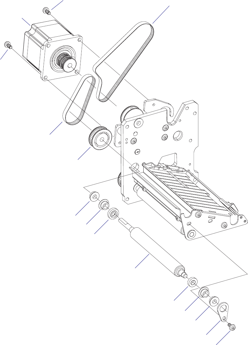
68 EasyCoder PX4i and PX6i Service Manual
Chapter 8 — Print Unit
Pulley
Platen roller
Belt to platen roller
#T20 Torx screw
EasyCoder PX4i
In the illustration below, the upper parts of the print unit and the label
stop sensor have been removed to improve visibility.
#T20 Torx
screw
Stepper motor
Ball bearing
Plastic bearing
Spacer
Plastic bearing
Ball bearing
Bracket
#T20 Torx screw
Belt to ribbon
rewind unit
Spacer
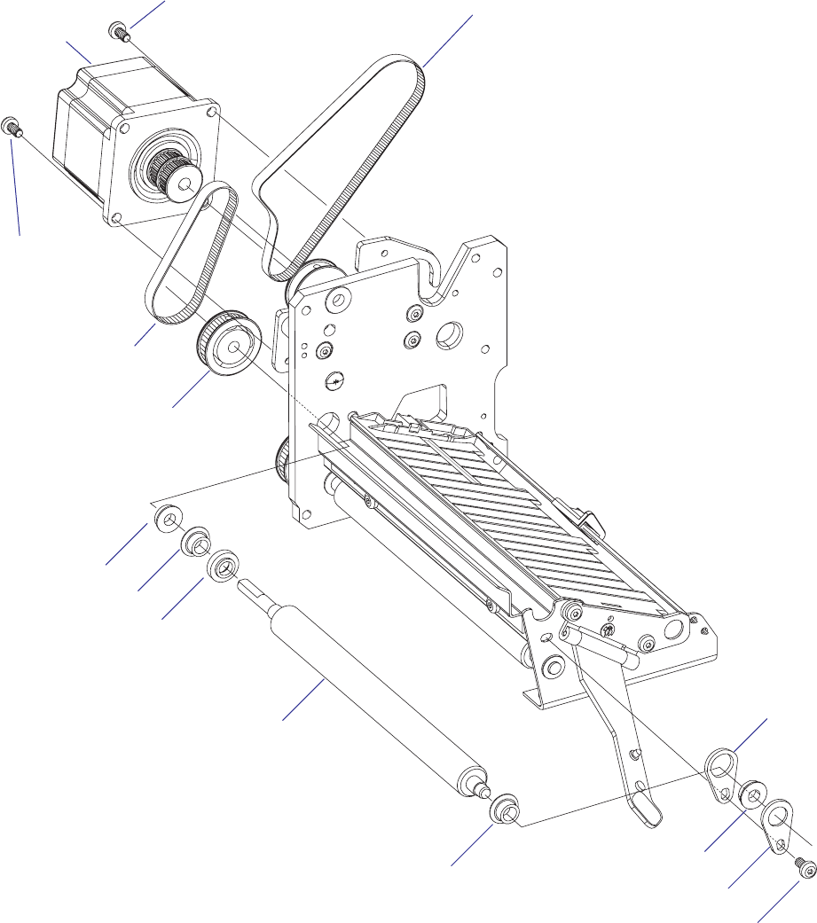
EasyCoder PX4i and PX6i Service Manual 69
Chapter 8 — Print Unit
EasyCoder PX6i
In the illustration below, the upper parts of the print unit and the label
stop sensor have been removed to improve visibility.
Pulley
Platen roller
Belt to platen roller
#T20 Torx screw
#T20 Torx
screw
Stepper
motor
Ball bearing
Plastic bearing
Spacer
Plastic bearing Ball bearing
Bracket
#T20 Torx screw
Belt to ribbon
rewind unit
Bracket
70 EasyCoder PX4i and PX6i Service Manual
Chapter 8 — Print Unit
8.3 Stepper Motor
Description
The stepper motor drives the platen roller via a short belt and the ribbon
assist roller and the ribbon rewind unit via another, longer belt. A freely
rotating pulley attached to the printer’s center section makes the outside of
the longer belt drive the ribbon assist roller.
The stepper motor is driven in microsteps (8 microsteps per full step) at all
speeds.
The stepper motor is fi tted by two #T20 Torx screws to a bracket, which in
its turn is attached to the print unit gable by three #T20 Torx screws. The
pulleys of the stepper motor are permanently glued to the motor’s shaft.
Replacement
Replace the stepper motor as follows:
• Switch off the power and disconnect the power cord.
• Open the front and right hand doors.
• Remove the cover over the electronics compartment, which is held by
eight #T10 Torx screws, see Chapter 3.3.
• Disconnect the cable to the stepper motor from the driver board.
• Remove the tension of the belt to the ribbon rewind unit by loosening
the two #T20 screws that hold the unit, see Chapter 7.3.
• Dismantle the stepper motor from the bracket by removing the two
#T20 Torx screws.
• Free the belt from the pulley of the ribbon rewind unit and manipulate
the stepper motor so it comes free from both belts. Remove the stepper
motor.
• When putting back the stepper motor, fi t the short belt fi rst, while
letting the long belt hang loosely on the idler in a loop, through which
you can insert the pulley of the stepper motor. Do not put the long belt
around the pulley of the ribbon rewind unit until you have fi tted the
stepper motor to the bracket and checked that both belts are engaged by
the pulleys.
• Connect the cable of the stepper motor to upper connector along the
inner edge of the driver board (P10).
• Adjust the tension of the belts as described in Chapter 8.4 and put back
the cover.
Refer to illustration on the next page!
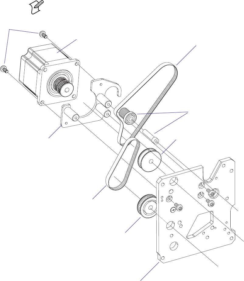
EasyCoder PX4i and PX6i Service Manual 71
Chapter 8 — Print Unit
#T20 Torx
screws (×2)
Platen roller pulley
Ribbon assist roller pulley
Platen roller belt
Ribbon rewind unit and
ribbon assist roller belt
Idle roller with shaft
(fi tted to center section)
In the illustration below, most parts of the print unit have been omitted to
improve visibility.
Note: The bracket does not need to be removed from the inner print unit
gable when the stepper motor is replaced.
Stepper motor
Bracket
(do not
remove!)
Inner print unit gable
72 EasyCoder PX4i and PX6i Service Manual
Chapter 8 — Print Unit
8.4 Belts
Description
The print unit has at least two timing belts, one that drives the platen
roller and another that drives the ribbon assist roller and the ribbon rewind
unit. There is also a third belt if an optional liner/batch takeup unit is
fi tted (see Chapter 9). The belts are subject to wear and may need periodi-
cal replacement. Properly adjusted tension and alignment of the pulleys
will increase time between replacements.
Replacement
• Switch off the power and disconnect the power cord.
• Open the front and right hand doors.
• Remove the cover over the electronics compartment, which is held by
eight #T10 Torx screws, see Chapter 3.3.
• Remove the tension of the belt to the ribbon rewind unit by loosening
the two #T20 screws that hold the unit, see Chapter 7.3.
• Dismantle the stepper motor from the bracket by removing the two
#T20 Torx screws.
• Free the belt from the pulley of the ribbon rewind unit and manipulate
the stepper motor so it comes free from both belts. Remove the stepper
motor.
• Replace the defective belt or belts.
• When putting back the stepper motor, fi t the short belt fi rst, while
letting the long belt hang loosely on the idler in a loop, through which
you can insert the pulley of the stepper motor. Do not put the long belt
around the pulley of the ribbon rewind unit until you have fi tted the
stepper motor to the bracket and checked that both belts are engaged by
the pulleys.
• Adjust the tension of the belts as described later in this chapter and put
back the cover.
Refer to illustration on the next page!
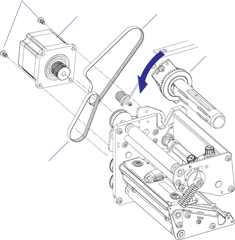
EasyCoder PX4i and PX6i Service Manual 73
Chapter 8 — Print Unit
#T20 Torx
screws (×2)
Platen roller belt
Ribbon rewind unit and
ribbon assist roller belt
Stepper motor
Ribbon rewind unit
74 EasyCoder PX4i and PX6i Service Manual
Chapter 8 — Print Unit
Adjustment; Platen Roll Belt
Oversized holes allow the position of the stepper motor relative to the
bracket to be adjusted so the tension of the belt does not become too tight,
causing unnecessary wear. Check that the platen roller can be rotated freely
by the belt, which should fl ex just a little when you press it with your
fi nger.
Stepper motor
Stepper motor pulley
Belt
Platen roller pulley
#T20 Torx screw
#T20 Torx screw
EasyCoder PX4i and PX6i Service Manual 75
Chapter 8 — Print Unit
Adjustment; Ribbon Rewinder Belt
The belt should be adjusted so it neither jump the cogs nor becomes sub-
ject to unnecessary wear.
Before adjusting this belt, check the tension of the platen roller belt as
described on the previous page.
Slightly loosen the two #T20 Torx screws that hold the fl ange of the
ribbon rewind unit.
Turn the ribbon rewind unit so the belt becomes tight, yet will fl ex slightly
when you press it with a fi nger. Tighten the screws.
Check that the parts can rotate freely and without any unpleasant sound
and that the belt does not jump the cogs when you rotate the ribbon
rewind unit forcefully.
The ribbon return roller should be easy to rotate manually. Once the
motor starts, the belt will be tight and will drive the ribbon assist roller.
If the idler roller starts to squeak, lubricate the inside of the belt with a
small quantity of grease.
Stepper motor
Stepper motor pulley
Belt
Ribbon rewind
unit pulley
#T20 Torx screw
inside media
compartment
Ribbon assist
roller pulley
Idler roller
#T20 Torx screw
inside media
compartment
76 EasyCoder PX4i and PX6i Service Manual
Chapter 8 — Print Unit
8.5 Label Stop Sensor
Description
The label stop sensor (LSS) controls the media feed and consists of a slid-
ing carriage on which two photoelectric sensors are fi tted. Both sensors
are identical and contain one light-emitting diode and one light-sensitive
receiver. The distance from the light path between the two parts of the LSS
to the dot line on the printhead is 46.3 mm (1.82 inches). The sensors can
be moved up to 50 mm (1.97 inches) out from the inner edge of the media
path using a screw protruding through the lower outer gable of the print
unit. In EasyCoder PX6i, this screw is only accessible when the locking
handle is folded down. The label stop sensor is hidden inside the print
mechanism and covered by two plastic guide plates, which can be removed
for cleaning.
Working Principles
The label stop sensor serves a number of purposes, depending on how the
printer is set up in regard of media type in Fingerprint and IPL respec-
tively:
Label (w gaps)/Gap
A beam of light is emitted from the diode in the lower part and received
by the sensor in the upper part. The fi rmware detects the front of each
label, that is, when the light is completely interrupted by the opaque
label, as opposed to the semi-transparent liner in the gaps between labels.
If no label has been detected during a media feed corresponding to more
than 150% of the set label length, a “next-label-not-found” condition is
assumed. If a renewed print operation gives the same result, an “out-of-
paper” condition is assumed.
Ticket (w mark)/Mark
Normally, a beam of light is emitted from the diode in the lower part. The
beam is refl ected back to the sensor in the lower part by the white media,
or is absorbed by a black mark. The fi rmware detects when the front edge
of a black mark passes the sensor, that is, when light starts to be absorbed.
If no mark has been detected during a media feed corresponding to more
than 150% of the set ticket length, a “next-label-not-found” condition is
assumed. If a renewed print operation gives the same result, an “out-of-
paper” condition is assumed.
By switching the cables from the upper and lower part of the LSS on the
CPU board, black marks on top of the media can be detected.
Ticket (w gaps)/Gap
The light is emitted from the diode in the lower part and received by the
sensor in the upper part. The light will either pass uninterrupted through
a detection gap in the media or be blocked by the non-transparent ticket.
The fi rmware detects the rear edges of detection gaps, that is, when the
light starts being interrupted. If no ticket has been detected during a media
feed corresponding to more than 150% of the set ticket length, a “next-
label-not-found” condition is assumed. If a renewed print operation gives
the same result, an “out-of-paper” condition is assumed.

EasyCoder PX4i and PX6i Service Manual 77
Chapter 8 — Print Unit
Var. Length Strip and Fix Length Strip/Continuous
The light is emitted from the diode in lower part and received by the
sensor in the upper part. The beam will either be blocked by the media
or be completely uninterrupted when the printer runs out of continuous
stock. The fi rmware assumes an out-of-paper condition if the light has not
been interrupted within a media feed corresponding to 150% of the set
length.
General
The information on where the gaps or marks are presently positioned
relative the LSS (and thereby also relative the dot line on the printhead) is
saved as an “invisible” fi le in the fl ash memory’s fi le operating system (see
Chapter 15.2). However, if the printhead is raised, or if the power is inter-
rupted during printing, this fi le may be cleared, which will affect any labels
between the LSS and the dot line. In this case, readjust the LSS using a
TESTFEED operation (Fingerprint) or by pressing the <Feed/Pause>
button (IPL).
Note (Fingerprint only): It is possible to decide if the media feed data
should be cleared or not when the printhead is raised using the Fingerprint
instruction SYSVAR(28). By default, the media feed data are not cleared.
The LSS checks for gaps or marks at every dot of positive media feed (feed
out/print), but gaps or marks are ignored at negative media feed (retract).
Gaps and black marks up to 170 dots (21.3 mm/0.84 inches) are allowed.
Testing the LSS
In the Print Defi nes part of the Setup Mode, you have two ways to test the
label stop sensor if you encounter a detection problem; LSS Auto and LSS
Manual.
The menus only provide indications from the label stop sensor unit. The
testing menus can determine if the sensor unit is not physically in position,
is blocked by dust or stuck labels, or is defective in some way. Furthermore,
this is an aid if media has detection complications.
Note: There is no way to adjust the LSS-function; the menus only indicate
values from the LSS obtained by performing a testfeed operation.
LSS Auto is the quick and normal way to determine if the label stop sensor
works properly and is able to detect gaps, slots, or black marks.
LSS Manual shows the actual setting provided by the latest testfeed
operation. It is also possible to try other settings. LSS Manual is primarily
intended for service and is not described in the User’s Guide.
LSS Auto
• Check that the printer is set up for the type of media loaded in your
printer.
• Perform a testfeed by simultaneously pressing the <Shift> and <Feed>
keys on the printer’s keyboard (Fingerprint) or by pressing the <Feed/
Pause> key (IPL).
• Make sure that there is a label—not a gap or mark—at the LSS.

78 EasyCoder PX4i and PX6i Service Manual
Chapter 8 — Print Unit
• Check that the media is routed as close to the center section as the
guides allow.
• Enter the Setup Mode and go to Setup Mode→Print Defi nes→LSS
Test→LSS Auto (Fingerprint) or Setup Mode→Test/Service→LSS
Test→LSS Auto (IPL).
• The menu should look like this with the cursor placed in the center:
LSS Auto
• Gap or slot detection:
Lift the printhead and pull out the media slowly. When the LSS detects
a gap or a detection slot, the cursor moves to the right.
LSS Auto
• Black mark detection:
Lift the printhead and pull out the media slowly. When the LSS detects
a black mark, the cursor moves to the left.
LSS Auto
• It is possible to refresh the centered cursor position by pressing the <d>
key.
• If the cursor behaves as described above, the LSS is working and is prop-
erly aligned with the gaps, slots, or black marks.
• If the cursor does not react on a gap, slot, or black mark, check this:
- Is the LSS laterally aligned with the slots or black marks?
- Are both the upper and lower part of the LSS aligned with each
other?
- Is the transfer ribbon properly loaded so it does not interfere with the
LSS?
- Are the sensors clean from dust and the LSS guides free from stuck
labels or other objects that will interfere with the light that goes from
one part of the LSS to the other? If not, clean as described in the
User's Guide.
- Does the media have some kind of preprint that can disturb the
detection?
- Is there too little difference between the black marks and the sur-
rounding areas?
- Does the liner have too little transparency?
- Does the LSS work with another type of media? (Remember to
change the Media Type setup and perform a new testfeed.)

EasyCoder PX4i and PX6i Service Manual 79
Chapter 8 — Print Unit
LSS Manual
The LSS Manual option shows the actual setting given by the automatic
testfeed. The cursor on the lower line indicates the response on the actual
testfeed values for the Gain (sensitivity) and Drive (intensity).
LSS [G: 2]D: 6
You can toggle between gain (G) and drive (D) using the <`> and <_> keys
and decrease or increase the value using the <b> and <a> keys respec-
tively.
Note: Changing the gain and drive does not reset the LSS. It only affects
the testing. Once you leave the LSS Manual node, the values obtained by
the automatic testfeed become effective again.
If there are preprinted areas on the liner or cut-out slots etc., it can disturb
the automatic testfeed. To identify the problem, manually move the media
can check the response from the sensor in detail on the display. The solu-
tion is often to move the sensor sideways to a position where the preprint
or similar is not disturbing.
Other problems, such as low gap opacity, semi-transparent labels when
using gap detection, or black marks that do not absorb the light suffi -
ciently, can also be identifi ed by changing the gain and drive manually.
If there is no dust or other things mechanically interfering with the LSS,
check the hardware by changing fi rst the gain and secondly the drive
values. If the cursor is positioned in either the extreme left or right position
and refuses to move, check cables, replace the LSS, or—as a last resort—
replace the CPU board.
Sensitivity Adjustment
The LSS should always be adjusted when the user changes to another
brand (sometimes even a new batch) of media, and when a defective sensor
has been replaced. This is especially the case with self-adhesive labels on
liner, because the transparency of the liner may vary and the difference
between labels and gaps may be too small. Before starting the adjust-
ment, check that both the upper and lower sensor are clean and free from
obstructions and that the edge guides are adjusted so as to guide the media
with a minimum of play. Also check that both parts of the LSS are in the
same lateral position and aligned with any gaps or black marks.
Fingerprint only
As standard, there are four ways to adjust the LSS:
• Performing a TESTFEED by simultaneously pressing the “Shift” and
“Feed” keys on the printer’s built-in keyboard.
• Selecting the TESTFEED option in Intermec Shell.
• Selecting the TESTFEED option in the Setup Mode.
• Executing a TESTFEED statement in a Fingerprint program.
The printer feeds out 1.5 times the set label length or less while testing
all levels of the LSS at each millimeter of media feed. The LSS is adjusted
according to the result of the check and a full label is fed out according to
the present feedadjust setup.
/54 ).
/54 ).
80 EasyCoder PX4i and PX6i Service Manual
Chapter 8 — Print Unit
The label stop sensor/black mark sensor can be turned off for a specifi ed
amount of media feed using the LBLCOND statement, see Intermec Fin-
gerprint v8.xx Programmer’s Reference Manual.
IPL only
The sensitivity of the LSS is confi gured at startup. To force adjustment of
the sensitivity (corresponding to a TESTFEED in Fingerprint), raise and
close the printhead and then press the <Feed/Pause> key.
Adjustment of the LSS Lateral Position
The label stop/black mark sensor (LSS) can be laterally adjusted within a
range of 0 to 50 mm (1.96 inches) from the inner edge of the media path
by means of a screw accessible through the outer lower gable. Turning the
screw clockwise will move the LSS inwards and vice versa. The position of
the LSS in relation to the media is best checked by looking head on into
the print unit when the printhead is raised. Align the centerpoint of the V-
shaped upper sensor with the center of the slots or marks to be detected.
The linear markings on the lower guide plate can also be used for position-
ing of the LSS as they are spaced with an interval of exactly 1 cm (0.39
inches) from the edge that guides the media. This method is especially
useful for black marks (measure the lateral position of the black marks with
a ruler before loading the media.)
If using irregularly shaped labels, align the LSS with the front tips of the
labels.
EasyCoder PX4i and PX6i Service Manual 81
Chapter 8 — Print Unit
Removing the Guide Plates
The LSS guide plates will need to be removed for occasional cleaning,
replacement and when replacing a defective sensor.
• To remove the upper guide plate, just pull it straight out.
• To remove the lower guide plate, disengage the snap-lock (accessible
through a slot in the lower gable) using for example a screwdriver and
lift the outer end of the guide plate. Then pull it out.
When cleaning the guide plates, use a soft cloth moistened with isopropyl
alcohol. Do not use any other type of chemicals. Blow the sensors free
from dust.
Isopropyl alcohol [(CH3)2CHOH; CAS 67-63-0] is a highly fl ammable,
moderately toxic, and mildly irritating substance.

82 EasyCoder PX4i and PX6i Service Manual
Chapter 8 — Print Unit
Replacing the Sensors
To remove the LSS bracket from the carriage, for example in connection
with cleaning or replacing a sensor, proceed as follows:
• Switch off the power, remove the power cord and remove the cover over
the electronics compartment.
• Remove the upper and lower plastic guide plates.
• Adjust the LSS to approximately center position.
• Disconnect the cables from J54 and J55 on the CPU board.
• Disengage the snap-lock, using a screwdriver from the media compart-
ment side, and push the outer end of the LSS bracket upward. Then
pull the bracket out from the carriage, taking care not to damage the
cables.
Note! The snap-lock is fragile.
• Remove the two #TX8 Torx screws that hold the defective sensor and
replace it.
Snap-lock
Upper sensor
Lower sensor
Carriage
LSS bracket
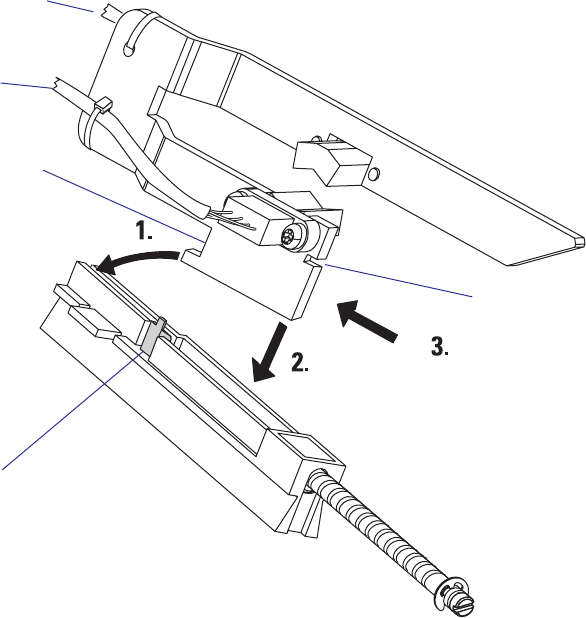
EasyCoder PX4i and PX6i Service Manual 83
Chapter 8 — Print Unit
To reassemble the LSS, proceed as follows:
• Thread the cables through the hole in the inner gable.
• Place the inner, lower corner of the bracket into the groove in the car-
riage, almost at the innermost end.
• Tilt the bracket up at the outer end and push it inwards so the inner
notch in the bracket engages the carriage.
• Press down the outer end of the bracket, so the snap-lock engages the
outer notch.
• Press the bracket inwards as far as it goes and check that the bracket is
secured by the snap-lock.
• Connect the cable from the lower sensor to J54 (marked “GAP”) and
the cable from the upper sensor to J55 (marked “BM”) on the CPU
board.
• Put back the guide plates, the electronics compartment cover, and the
power cord.
• Adjust the lateral position of the LSS.
Snap-Lock
Inner notch
Outer notch
Connect to J55
on CPU board
Connect to J54
on CPU board
84 EasyCoder PX4i and PX6i Service Manual
Chapter 8 — Print Unit
8.6 Printhead
Description
The printing is produced by the thermal printhead, which consists of a
line of very small, closely spaced resistors on a ceramic tile fi tted across the
media path. When a current is led through the resistors, commonly called
“dots,” these will be heated very quickly. When the current is shut off, the
dots cool down just as fast.
As the media is fed past the dots, the hot dots will produce a number of
black spots on heat sensitive (direct thermal) media, or on other face mate-
rials via a thermal transfer ribbon. The spots can be combined into bitmap
patterns, which make up characters, bar codes, images, lines, and boxes.
The direct thermal printing method requires special media coated with a
thin layer of heat-sensitive chemicals. As the media is fed past the dots, the
heat from the dots will make the chemicals react, producing a dark salt,
which makes up the imprint under each dot.
In the thermal transfer printing method, a special “ink”-coated transfer
ribbon is used. When the ribbon is heated by a dot on the printhead, the
“ink” melts and sticks to the receiving face material, where the ink imme-
diately becomes solid again, producing a black spot. Transfer ribbons nor-
mally do not smear at room temperature, neither before nor after printing.
Nor do the printed labels smear, even if the printout may be smudged by
extensive rubbing if an unfortunate combination of ribbon and face mate-
rial is used. The thermal transfer method makes it possible to use a wide
range of face materials for printing, for example papers, boards, plastics,
foils, etc. However, an original transfer ribbon from Intermec should
always be used.
Information on how to switch between direct thermal and thermal transfer
printing is provided in the User’s Guide.
The basis for all measures and positioning in both the Fingerprint and IPL
programming languages is the size of printhead dots.
In an 8 dots/mm (203.2 dpi) printhead, each dot has a nominal size of
0.125 mm (4.92 mils). This means that a heated dot under standardized
conditions will produce a black spot which has a diameter of 0.125 mm
(4.92 mils).
In an 11.81 dots/mm (300 dpi) printhead (Fingerprint only), each dot
has a nominal size of 0.086 mm (3.33 mils). This means that a heated dot
under standardized conditions will produce a black spot which has a diam-
eter of 0.086 mm (3.33 mils).
Depending on dot temperature, exposure time, media and ribbon charac-
teristics, etc., the spot may actually be somewhat smaller (weak print) or
larger (black print), but that does not affect the calculation of distances,
sizes, and positions.
At startup, the printer auto-detects the printhead density as well as the
head resistance. The printhead can also be checked using the Finger-
print instructions HEAD, FUNCTEST, and FUNCTEST$. In IPL, the
number and size of the dots in the printhead is returned to the host by the
command <STX><ESC>H<ETX>.
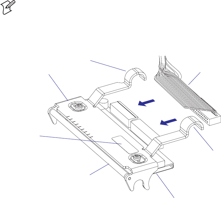
EasyCoder PX4i and PX6i Service Manual 85
Chapter 8 — Print Unit
The printhead is fi tted to a bracket using two screws. The printhead, the
printhead ribbon break shaft, and the bracket are always delivered as a
complete assembly and must not be dismantled. Two hooked fi ngers at
the rear of the bracket are fi tted over the headlift shaft so as to hold the
printhead in place. A U-shaped tab on either side of the bracket engage
the platen roller bearings when the printhead is closed, making sure that
the printhead becomes properly aligned with the platen roller. There are
no facilities for adjusting the position of the printhead relative the platen
roller, neither longitudinally nor laterally.
There are two sets of cables in a harness running to the printhead:
• The innermost cable is used for the power to the printhead and is con-
nected to P5 on the driver board.
• The outermost cable is used for data to the printhead and is connected
to J40 on the CPU board.
Note: It is important that the cable harness does not prevent the printhead
from moving or adjusting itself when it is lowered.
Illustration shows the printhead of an EasyCoder PX4i.
The printhead of EasyCoder PX6i looks in principle the same but is wider.
Printhead
Bracket Cable harness
“Finger”
“Finger”
Printhead ribbon
break shaft
Label
&%%$
$)2%#4)/.
$OT
$OTLINE
ONPRINTHEAD
$OT
MMIN
0RINT7IDTH
MAXMMIN
-EDIA7IDTH
MMIN
86 EasyCoder PX4i and PX6i Service Manual
Chapter 8 — Print Unit
Print Window PX4i
The EasyCoder PX4i has an 8 dots/mm (203.2 dpi) printhead or, in the
Fingerprint version only, an 11.81 dots/mm (300 dpi) printhead.
8 dots/mm Printhead
Density 8 dots/mm (203.2 dots per inch)
Print width 112 mm (4.4 inches)
Number of dots 896
Dot size 0.125 mm (4.92 mils)
&%%$
$)2%#4)/.
$OT
$OTLINE
ONPRINTHEAD
$OT
MMIN
0RINT7IDTH
MAXMMIN
-EDIA7IDTH
MMIN
EasyCoder PX4i and PX6i Service Manual 87
Chapter 8 — Print Unit
11.81 dots/mm Printhead (not IPL)
Density 11.81 dots/mm (300 dots per inch)
Print width 112 mm (4.4 inches)
Number of dots 1322
Dot size 0.085 mm (3.33 mils)
&%%$
$)2%#4)/.
$OT
$OTLINE
ONPRINTHEAD
$OT
MMIN
0RINT7IDTH
MAXMMIN
-EDIA7IDTH
MMIN
88 EasyCoder PX4i and PX6i Service Manual
Chapter 8 — Print Unit
Print Window PX6i
The EasyCoder PX6i has an 8 dots/mm (203.2 dpi) printhead or, in the
Fingerprint version only, an 11.81 dots/mm (300 dpi) printhead.
8 dots/mm Printhead
Density 8 dots/mm (203.2 dots per inch)
Print width 167.4 mm (6.59 inches)
Number of dots 1344
Dot size 0.125 mm (4.92 mils)

&%%$
$)2%#4)/.
$OT
$OTLINE
ONPRINTHEAD
$OT
MMIN
0RINT7IDTH
MAXMMIN
-EDIA7IDTH
MMIN
EasyCoder PX4i and PX6i Service Manual 89
Chapter 8 — Print Unit
11.81 dots/mm Printhead (not IPL)
Density 11.81 dots/mm (300 dots per inch)
Print width 167.4 mm (6.59 inches)
Number of dots 1984
Dot size 0.085 mm (3.33 mils)

90 EasyCoder PX4i and PX6i Service Manual
Chapter 8 — Print Unit
Replacing the Printhead
The printhead is a consumable part subject to wear from both the thermal
paper or transfer ribbon, and from the rapid heating and cooling process
during printing. Thus, it will require periodical replacement depending on
print volume, type of print media, amount of energy to the printhead, and
several other factors.
To replace a defective or worn printhead, proceed as follows:
• Switch off the power.
• Open the front and right-hand doors.
• Turn the printhead lift lever to “Open” position.
• Remove any media and/or transfer ribbon from the print unit.
• Carefully pull the printhead bracket away from the magnet in the lift
arm.
• Disconnect the hooked fi ngers at the rear of the bracket from the
headlift shaft and pull out the printhead as far as the cables allow.
• Disconnect the two cables from the printhead.
Note the snap-lock on the inner connector. Pull at the connectors, not at
the cables!
• Connect the cables to the replacement printhead assy with the ribbon
cable to the right.
• Insert the printhead assy into the print unit, fi tting the bracket’s fi ngers
over the headlift shaft.
• Check so the cables will not interfere with the transfer ribbon, prevent
the printhead from moving freely, or have become jammed between
parts in the print unit.
• Turn the printhead lift lever to “Closed” position, so the magnet engages
the printhead bracket.
• Switch on the power. The printer’s fi rmware automatically measures the
printhead resistance at power-up.
• Load media and, if so required, transfer ribbon again.
Refer to the illustrations on the next page! Detailed step-by-step illustra-
tions can be found in the User's Guide, Chapter “Maintenance.”
EasyCoder PX4i and PX6i Service Manual 91
Chapter 8 — Print Unit
EasyCoder PX4i
EasyCoder PX6i
92 EasyCoder PX4i and PX6i Service Manual
Chapter 8 — Print Unit
Precautions
Some simple measures can be taken by the user to prevent premature wear-
out:
• Clean the printhead regularly, as described in the User’s Guide. Not only
will a dirty printhead produce an inferior printout, but any residue on
the dots will prevent heat to dissipate through the media.
• Follow the Intermec’s recommendations regarding Paper Type or Media
Sensitivity setup. Too much energy to the printhead will wear it out
rapidly.
• Do not use higher Print Speed setting than necessary.
• Low ambient temperature requires more energy to the printhead dots
than room temperatures and will therefore cause more wear to the
printhead. High print speed accelerates the wear. Thus, at low tempera-
tures, select as low a print speed as acceptable.
• In Fingerprint, do not use a higher Contrast setting than necessary, espe-
cially not in combination with the highest Label Constant or Ribbon
Constant settings.
• In IPL, do not use a higher Darkness setting than necessary.
• Do not use a higher printhead pressure than necessary.
• Never print outside the media path. Dots that are not in contact with
the media will not be cooled properly.
• When using media with less than full width, be careful to adjust the
printhead lift arm so there is an even pressure across the media. Not
only will an uneven pressure impair the printout quality, but it may also
prevent the dots from being properly cooled. Moreover, a sharp outer
media edge in direct contact with the printhead may cause excessive
mechanical wear on some dots, which may be visible when printing on
wider media later.
• When using preprinted labels or labels with some type of varnish or
non-standard top coating for direct thermal printing, use original
Intermec labels or inks recommended by leading manufacturers of direct
thermal media. The labels must not contain any aggressive substances
such as chloride or grinding substances such as titanium dioxide.
• Only use transfer ribbons recommended by Intermec.

EasyCoder PX4i and PX6i Service Manual 93
Chapter 8 — Print Unit
8.7 Headlift Sensor
Description
The purpose of the headlift sensor is to detect whether the printhead is
raised or lowered. To avoid the risk of overheating the printhead dots,
printing can not be performed when the sensor detects that the printhead
is raised (the media serves to cool the printhead). An ever so slightly raised
printhead would also impair the printout quality. Thus, it is important that
the printhead is properly lowered and a suffi cient pressure is applied before
the sensor detects a “Closed” condition.
The photoelectric sensor is attached to the electronics compartment side
of the inner print unit gable by means of two #T10 Torx screws. When the
printhead is raised, a beam of light is interrupted by an arm connected to
the headlift shaft. This is detected by the fi rmware so an error message will
be returned if you try to print a label. In Fingerprint, error message 1022
“Head Lifted” will be returned if you try to print a label with the printhead
lifted. In IPL, the error message “Print Head Up/Press Feed” is displayed.
The headlift sensor is connected to J58 (marked “HEADL”) on the CPU
board.
The arm that blocks the light through the sensor is attached to the headlift
shaft using a #T10 Torx screw. If the screw is not tightened suffi ciently or
if the arm is not fi tted in the correct angle, a malfunction will occur.
Adjusting the Sensor Arm
• Perform an adjustment of the printhead pressure as described in Chapter
8.8.
• Without switching off the power, remove the cover over the electronics
compartment.
The electronics compartment contains wires and circuits with danger-
ous voltage. Take precautions to avoid electrical shock, short-circuits,
and electrostatic discharges.
• Place a 1 mm (0.04 inches) thick feeler gauge between the printhead
and the platen roller and lower the printhead. Be careful not to damage
the delicate printhead dots!
• Loosen the #T10 Torx screw that holds the sensor arm.
• In case of Fingerprint printers, run the program listed on the next page.
• Move the sensor arm from open position towards closed position until
the Error LED goes out, which indicates the correct position.
• Tighten the screw and check that the arm runs freely inside the fork-
shaped sensor.
• Put back the cover.
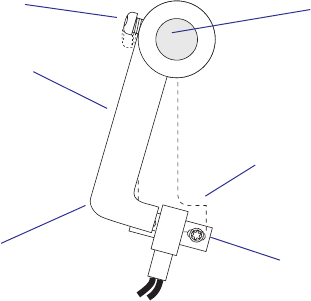
94 EasyCoder PX4i and PX6i Service Manual
Chapter 8 — Print Unit
Sensor Arm
Headlift shaft
#T10 Torx Screw
Sensor
In Fingerprint, run this program which assists you in adjusting the headlift
sensor arm:
Status LED red = Printhead open.
Status LED off = Printhead closed.
The correct position is exactly when the Status LED goes off.
You can break the program execution either by pressing <Shift> + <Pause>
on the printer's keyboard or by transmitting the character X (uppercase!)
from the host.
NEW
10 BREAK 1, 88
20 BREAK 1 ON
30 ON BREAK 1 GOSUB 1000
40 LED 1 OFF
50 WHILE (PRSTAT AND 1)=0: WEND
60 LED 1 ON
70 WHILE (PRSTAT AND 1)=1: WEND
80 GOTO 40
1000 BREAK 1 OFF
1010 END
RUN
In IPL, check that the sensor is properly adjusted using the Label Path
Open Sensor Value command (<STX>L<ETX>), see IPL Programming,
Reference Manual.
“Printhead Open“
position
“Printhead Closed” position
EasyCoder PX4i and PX6i Service Manual 95
Chapter 8 — Print Unit
Sensor Replacement
Before replacing the sensor, check that the sensor arm is properly adjusted
and that the sensor is free from dust, paper shreds, and other things that
can block the light.
Replace the sensor as follows:
• Switch off the power, remove the power cord, and remove the cover over
the electronics compartment.
• Check that the printhead is lowered.
• Remove the #T10 Torx screw that holds the front of the sensor.
• Raise the printhead.
• Remove the #T10 Torx screw that holds the rear of the sensor.
• Pull out the sensor and disconnect its cable from the CPU board.
• Reassemble in reverse order. The sensor’s cable should be connected to
J58 (marked “HEADLIFT”) on the CPU board.
• In Fingerprint, check that the sensor works properly using a PRSTAT
statement, see Intermec Fingerprint v8.xx, Programmer’s Reference
Manual.
• In IPL, check that the sensor works properly using the Label Path Open
Sensor Value command (<STX>L<ETX>), see IPL Programming, Refer-
ence Manual.
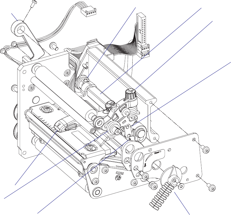
96 EasyCoder PX4i and PX6i Service Manual
Chapter 8 — Print Unit
8.8 Headlift Mechanism
Description
The headlift mechanism is an integrated part of the print unit. The mecha-
nism is activated by the green printhead lift lever at the outside of the
upper part of the print unit. The knob is fi tted on a shaft, which has a disk
with an eccentrically fi tted pin on the inside of the upper, outer gable of
the print unit. This pin activates a fork-shaped pressure adjuster, that via
a linkage is connected to the headlift shaft. The pressure adjuster is fi tted
with a spring and an adjusting screw. Thus, the operator can easily apply
more or less pressure of the printhead against the platen roller depending
on type of media, print method, media thickness, and other circumstances.
The headlift shaft is connected to the headlift sensor arm on the inside
of the print unit (see Chapter 8.7.) On the headlift shaft, the S-shaped
headlift arm is also fi tted. At the tip of the headlift arm is a magnet that
engages the printhead bracket. The arm can be moved along the headlift
shaft, so the pressure can be applied laterally at the center of the media
path, even when narrow media are used. The hooked fi ngers of the
printhead bracket are hung on the headlift shaft. The concept allows the
printhead to align itself vertically to the platen roller, while maintaining a
fi xed alignment in the other two dimensions.
Headlift arm
Pressure adjuster
Linkage
Printhead lift lever
Return spring
Sensor arm
EasyCoder PX4i
Printhead pressure
grub screw
(factory-adjustment)
Headlift shaft
Eccenter
EasyCoder PX4i and PX6i Service Manual 97
Chapter 8 — Print Unit
Headlift sensor
Headlift arm
Pressure adjuster
Linkage
Printhead lift lever
Return spring
Sensor arm
Printhead pressure
grub screw
(factory-adjustment)
EasyCoder PX6i
Headlift shaft

98 EasyCoder PX4i and PX6i Service Manual
Chapter 8 — Print Unit
Printhead Pressure Adjustment
The pressure of the thermal printhead against the ribbon or media is fac-
tory adjusted. However, the use of thicker or thinner media than normal
could require the printhead pressure to be readjusted.
Turn the green adjustment knob clockwise for increased pressure, or coun-
terclockwise for less pressure. Print a few labels, preferably test labels, and
check the printout. Increased pressure generally gives a blacker printout
and vice versa. Repeat until the desired result is obtained.
To fi nd the basic setting, proceed as follows:
• Remove the transfer ribbon (if any).
• Load the printer with full width media and close the printhead.
• Adjust the headlift arm to center position.
• Turn the green adjustment knob counterclockwise until it feels loose (no
pressure left).
• Take up the slack in the green knob until you notice an increased resis-
tance.
• Using a 2 mm hexagonal key, loosen the factory adjustment grub screw
(see illustration on the previous page) until the printhead starts to come
up.
• Carefully tighten the grub screw until you just start noticing a small
resistance when trying to pull out the media.
It is possible to apply very high printhead pressure using the factory
adjustment grub screw. Such high pressure may damage the printhead,
the platen roller, and the headlift arm.
Do not use a higher printhead pressure than necessary, because it may
increase the wear of the printhead and thus shorten its life.
• Apply some locking fl uid on the grub screw.
• Raise and lower the printhead.
• EasyCoder PX4i:
Turn the knob 4 full turns clockwise. Each turn increases the pressure by
approx. 1 kp to a total of 4 kp (39.2 N).
EasyCoder PX6i:
Turn the knob 5 full turns clockwise. Each turn increases the pressure by
approx. 1 kp to a total of 5 kp (49.0 N).
• Fine-adjust using test labels and the trial-and-error method (if necessary
after having loaded the transfer ribbon again).
Refer to the illustrations on the next page!
#LOSED
/PEN
EasyCoder PX4i and PX6i Service Manual 99
Chapter 8 — Print Unit
EasyCoder PX4i
EasyCoder PX6i
Adjustment knob
(green)
Adjustment knob
(green)
100 EasyCoder PX4i and PX6i Service Manual
Chapter 8 — Print Unit
8.9 Ribbon Assist Roller
Description (EasyCoder PX4i and PX6i)
The purpose of the ribbon assist roller is to help the ribbon rewind unit to
keep the transfer ribbon tight, thereby avoiding ribbon wrinkling, which
could ruin the printout. The angle of the ribbon assist roller relative to the
printhead is adjustable.
The ribbon assist roller is subject to very little wear and is expected to last
as long as the printer as a whole. Replacement involves removing the belt
and pulley as well as the upper, outer gable of the print unit (see illustra-
tions in Chapter 8.8.)
Adjustment (EasyCoder PX4i and PX6i)
If the ribbon becomes wrinkled, a few checks should be performed before
the ribbon assist roller is readjusted:
• Is the printhead pressure properly adjusted?
• Is the green edge guide correctly positioned?
• Is there anything that may interfere with the transfer ribbon, for exam-
ple the printhead cables.
If the wrinkling problem remains, proceed as follows:
• Using a #T20 Torx screwdriver, loosen the locking screw that runs in the
crescent-shaped hole in front of the headlift lever.
• Insert a #T20 Torx screwdriver as illustrated on the next page. By turn-
ing the screwdriver, you can move the outer end of the roller back and
forth:
- Turn the screwdriver clockwise to move the end of the roller forward.
- Turn it counterclockwise to move the end of the roller rearward.
• If the ribbon gets wrinkled at the inner edge, you should move the end
of the roller slightly rearward, that is, rotate the screwdriver counter-
clockwise and vice versa.
• Select an appropriate layout, for example a test label, and print it repeat-
edly while carefully moving the end of the roller back or forth, depend-
ing on which side the wrinkling has occurred.
• When the wrinkling ceases, continue the movement ever so slightly to
create a small safety margin. The movement is best detected by the rela-
tion between the roller bearing and the hole through the upper gable.
Another method is to determine the positions where wrinkling starts at
either side and adjust the roller to the middle.
• You will need to print several labels before a new adjustment has any
noticeable effect.
• When you are satisfi ed that the problem is cleared, tighten the locking
screw and test again by printing several more labels. Readjust if neces-
sary.
Refer to the illustrations on the next page!
#LOSED
/PEN
EasyCoder PX4i and PX6i Service Manual 101
Chapter 8 — Print Unit
EasyCoder PX4i
EasyCoder PX6i
Wrinkling Turn Screwdriver
Inner side Counterclockwise
Outer side Clockwise
#T20 Torx screwdriver
Ribbon assist roller
#T20 Torx locking screw
#T20 Torx screwdriver
Ribbon assist roller
#T20 Torx locking screw
,ABEL3TOP
3ENSOR
$OT,INEON0RINTHEAD
4EAR"AR
MM
$EFAULT4EAROFF
3TART!DJUST
3TOP!DJUST
102 EasyCoder PX4i and PX6i Service Manual
Chapter 8 — Print Unit
8.10 Media Feed Principles
Fingerprint only
The Start and Stop Adjust parameters in the Fingerprint Setup Mode con-
trol how the media will be positioned in relation to the printhead when the
printing starts and after the printing is completed, respectively. By default,
the Start and Stop Adjust parameters are both set to 0, which is suitable for
tearing off the media against the tear bar, for example between labels or at
the perforation in a pre-perforated continuous stock. However, because the
dot line on the printhead is situated 15.7 mm (0.62 inches) back from the
tear bar, the printing will not start at the top of the label but further back
along the media path.
Note: Due to several factors, media feed measurements are not exact and
may vary somewhat between applications and individual printers. There
is inevitably a small amount of slippage between media and platen roller,
which in its turn is affected by printhead pressure, type of media or liner,
thickness of the media, roll size, type of media supply device, etc. The
platen roller may be worn, giving it a slightly smaller diameter and/or less
friction. There is also a certain amount of inexactness in the media feed
mechanics and belts and so on. Therefore, the operator cannot expect to
reach exact Start and Stop Adjust values simply by calculation. Use the
measurements given in this chapter to calculate rough starting points and
use the trial-and-error method to fi nd values that give the desired result.
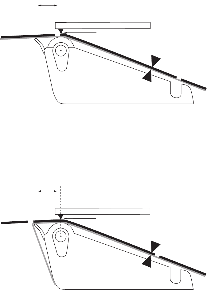
,ABEL3TOP
3ENSOR
$OT,INEON0RINTHEAD
4EAR/FF%DGE
MM 4EAROFFPRINTATTOPOFLABEL
3TART!DJUSTATDPI
3TOP!DJUSTATDPI
,ABEL3TOP
3ENSOR
$OT,INEON0RINTHEAD
4EAR"AR
MM
0EELOFFPRINTATTOPOFLABEL
3TART!DJUSTATDPI
3TOP!DJUSTATDPI
EasyCoder PX4i and PX6i Service Manual 103
Chapter 8 — Print Unit
In many cases, it is desired to start the printing immediately at the top
of the label. Actually, what you want to do is to pull back the edge of the
media to the dot line. You can do this by means of a negative Start Adjust
value, for example -108 dots = 13.5 mm/0.53 inches for a 8 dots/mm
(203.2 dpi) printer. Be careful not to enter too large a value, or the media
may come loose from platen roller.
When using peel-off operation, the labels would drop from the liner and
get stuck on for example the desk if you use the default Start Adjust value
0. Use a Stop Adjust value of around -40/-60 (= 5.5 mm/0.22 inches)
instead: that is, after the printing is completed 5.5 mm/0.22 inches less
of media feed than normal will be performed. However, if you still want
to print from the top of the label, you must compensate by a Start Adjust
value of around -80/-115 (= 10.0 mm/0.39 inches).
A special case is tickets with black marks. It is recommended to place the
black mark adjacent to the perforation or the intended tear-off line. If the
black mark is placed further down the media, this must be compensated
for by a negative Stop Adjust setting.
104 EasyCoder PX4i and PX6i Service Manual
Chapter 8 — Print Unit
IPL only
In IPL, the media feed is affected by the mode of operation. There are
three such modes:
• Tear-off (straight-through)
(default)
• Peel-off (self-strip)
(enabled/disabled by <STX><SI>Tn<ETX> command)
• Cut-off
(activated/deactivated when the cutter is enabled/disabled in the Setup
Mode or by <STX><SI>Cn<ETX> command)
Each mode has a fi xed amount of media feed, which can be fi ne-adjusted
using the Label Rest Point parameter in the Setup Mode (See Appendix A,
Setup/Media/Lbl Rest Point) or an <STX><SI>fn<ETX> command.
The type of detection is decided by the Media Type parameter in the Setup
Mode (See Appendix A, Setup→Media→Media Type).

EasyCoder PX4i and PX6i Service Manual 105
9 Liner Takeup Kit
This chapter describes the optional liner takeup unit and covers the follow-
ing topics:
• Description
• Main parts
• Liner/batch takeup unit
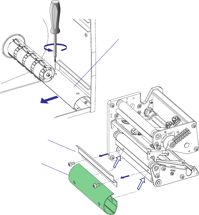
The batch takeup guide plate is only used in EasyCoder PX4i.
106 EasyCoder PX4i and PX6i Service Manual
Chapter 9 — Liner Takeup Kit
9.1 Description
The liner takeup kit is an optional factory-installed device that makes
it possible to auto-dispense self-adhesive labels from the liner (peel-off/
self-strip operation), and—in case of EasyCoder PX4i—also to wind up
printed labels, tickets, or continuous stock internally (batch takeup opera-
tion.) The kit consists of two or three main parts:
• A stepper motor that drives the liner drive roller in the print unit and
the liner/batch takeup unit. The liner drive roller is fi tted as standard
even when the kit is not installed.
• A liner/batch takeup unit that takes up the spent liner or the printed
media to be rewound for later use.
• A guide plate (EasyCoder PX4i only) that replaces the tear bar when
labels or other types of printed media are wound up internally (see
below). When not used, the guide plate is fi tted using one #T20 Torx
screw at the rear of the media compartment.
When no rewind unit is fi tted, the hole through the center section is cov-
ered by a plate held by two #T20 screws.
Rewind guide
(position when not fi tted)
Rewind guide
Tear bar
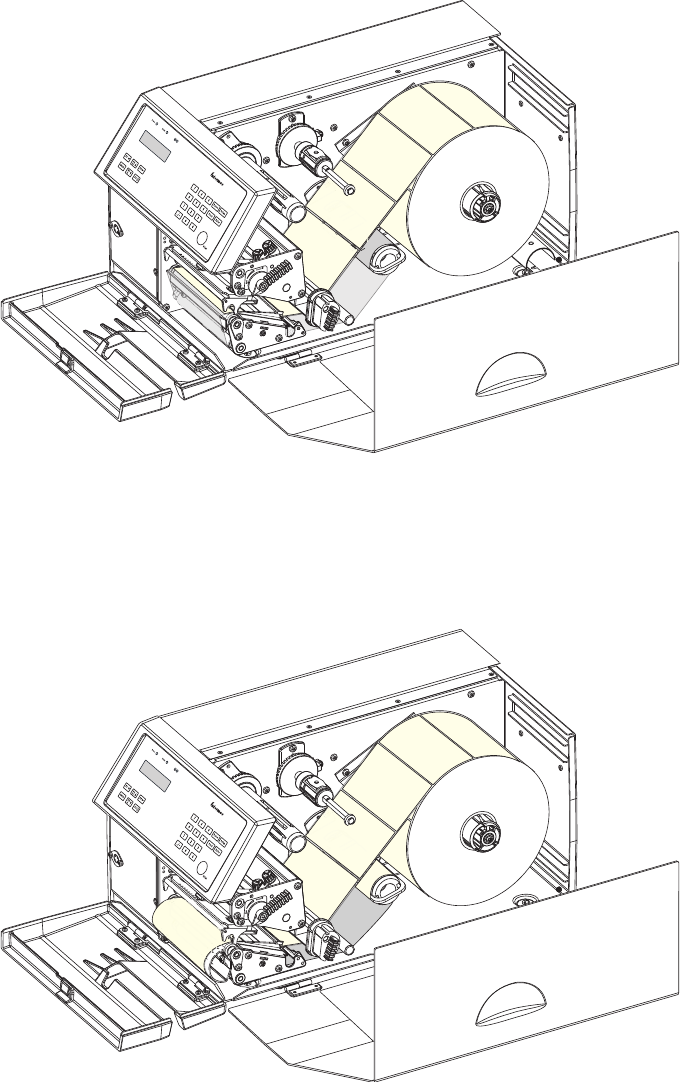
&BTZ$PEFS19J
&BTZ$PEFS19J
EasyCoder PX4i and PX6i Service Manual 107
Chapter 9 — Liner Takeup Kit
EasyCoder PX4i; Peel-Off (Self-strip) Operation
The liner takeup unit can accommodate the liner from a full roll of labels.
EasyCoder PX4i; Batch Takeup Operation
The batch takeup unit can accommodate approximately 1/4 to 1/3 of a full
label roll depending on media thickness.
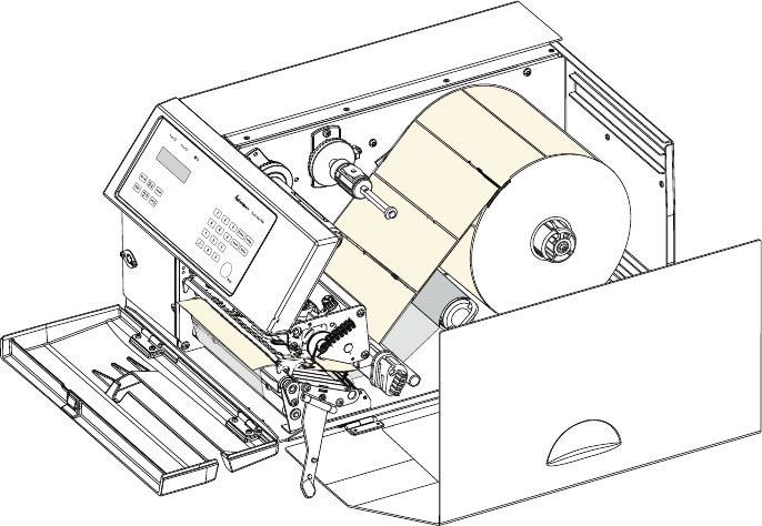
#LOSED
/PEN
108 EasyCoder PX4i and PX6i Service Manual
Chapter 9 — Liner Takeup Kit
EasyCoder PX6i; Peel-Off (Self-strip) Operation
The liner takeup unit can accommodate the liner from a full roll of labels.
EasyCoder PX4i and PX6i Service Manual 109
Chapter 9 — Liner Takeup Kit
9.2 Main Parts
The stepper motor is fi tted to the printer’s center section using a motor
support plate. It drives the liner/batch takeup unit and the liner drive roller
in the print unit via two belts. The tension of these belts can be slightly
adjusted by moving the stepper motor and/or support plate before the
screws are tightened.
The takeup unit is fi tted with a brace, that holds the liner or media. The
unit is fi tted to the printer’s center section using two #T20 Torx screws
inserted from media compartment.
A break shaft in front of the takeup unit guides the liner or media under
the slack absorber.
The stepper motor is connected to P11 on the driver board, see Chapter
14.
EasyCoder PX4i
Tension roller
Belt to liner/batch takeup unit
Belt to
liner drive roller
Stepper motor
Motor support plate
Brace
Break shaft
Liner/batch takeup unit
110 EasyCoder PX4i and PX6i Service Manual
Chapter 9 — Liner Takeup Kit
EasyCoder PX6i
Tension roller
Belt to liner takeup unit
Belt to
liner drive roller
Stepper motor
Motor support plate
Brace
Break shaft
Liner takeup unit
EasyCoder PX4i and PX6i Service Manual 111
Chapter 9 — Liner Takeup Kit
9.3 Liner/Batch Takeup Unit
The liner/batch takeup unit is fi tted to the printer’s center section from
the media compartment side using a fl ange with two bearings. The fl ange
is held by two #T20 Torx screws. On the inner side of the center section
is a pulley, which is part of a two-way spring brake. The pulley is held by a
snap ring.
On the outer side, the hub and its attached gable are fi tted. The rotation is
controlled by the spring brake which works the same way as in the ribbon
supply unit (see Chapter 7.2). Thereby, it is possible to wind up liner or
media manually without running the motor. The spring brake also takes
up sudden jerks. A plate helps to hold possible takeup cores. The assembly
is held together by snap rings and a pin inserted through the rewind hub
and its shaft.
Note: The Liner Takeup Unit of an EasyCoder PX6i is not able to rewind
printed labels—only to wind up liner.
The wind-up torque should be 310 to 380 Nmm and the slip torque 30
to 70 Nmm. Refer to Appendix 2 for a description of how to check the
torque. If the wind-up torque deviates from the recommended value,
replace the entire spring brake assy.
EasyCoder PX4i
Pulley
Bearing
Flange
Spring
Shaft
Brake sleeve
Bearing
Bobbin
#T10 Torx
screws (x2)
Bobbin plate
Bobbin gable
Bearing
Snap ring
Snap ring
Bearing
Pin
Bearing
Snap ring
Flange
Spring brake assy.
112 EasyCoder PX4i and PX6i Service Manual
Chapter 9 — Liner Takeup Kit
EasyCoder PX6i
Pulley
Bearing
Flange
Spring
Shaft
Brake sleeve
Bearing
Bobbin
#T10 Torx
screws (x2)
Bobbin
plate
Bobbin gable
Bearing
Snap ring
Snap ring
Bearing
Pin
Bearing
Snap ring
Flange
Spring brake assy.

EasyCoder PX4i and PX6i Service Manual 113
10 Label Taken Sensor
This chapter describes the optional label taken sensor and covers the fol-
lowing topics:
• Description
• Installation
• Activating the LTS
• Adjustment
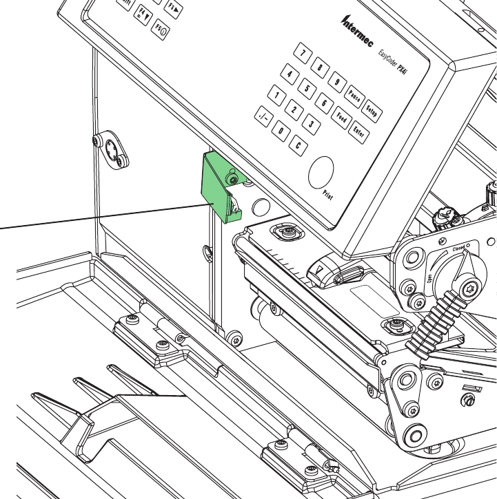
114 EasyCoder PX4i and PX6i Service Manual
Chapter 10 — Label Taken Sensor
10.1 Description
The label taken sensor (LTS) is an optional device, which enables the
printer's fi rmware to detect if the latest printed label, ticket, tag etc. has
not been removed and hold the printing on the next label until the present
label has been taken away from the outfeed area.
The label taken sensor is usually factory-fi tted, but it is also available as a
kit for upgrading of existing printers by an authorized service technician. It
cannot be fi tted in combination with a paper cutter.
The label taken sensor consists of a photoelectric sensor with a bracket and
a connection cable. The sensor is fi tted inside the front door, see illustra-
tion below.
The photoelectric sensor emits a narrow beam of light, which will be
refl ected back to the sensor by any label, ticket, tag, piece of strip, or liner,
that has not been removed from the outfeed area.
The LTS is connected to J53 on the CPU board. The sensitivity is adjusted
in the Setup Mode, see Chapter 10.4.
The point of detection of the LTS is situated 10 mm (0.39 inches) outside
the inner edge of the media path and 22 mm (0.87 inches) in front of the
dot line on the printhead.
Label taken sensor
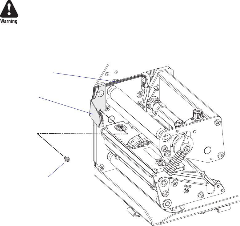
EasyCoder PX4i and PX6i Service Manual 115
Chapter 10 — Label Taken Sensor
10.2 Installation
The Label Taken Sensor Kit consists of:
• One Refl ecting Sensor assy. with cable and connector
• One Sensor Bracket
• One Screw
• One Installation Instructions booklet
The only tools needed are a set of Torx screwdrivers.
Install the label taken sensor this way:
• Open the right-hand doors and remove the left-hand cover as described
in Chapter 3.3.
The electronic compartment contains wires and components with
dangerous voltage (up to 380V). Make sure that the printer is switched
off and the power cord is disconnected, before the left-hand cover is
removed.
• Using the screw included in the kit, fi t the sensor/bracket assembly to
the inner wall of the print unit as shown by the two illustrations below.
Fit the cable underneath the top part of the bracket, as illustrated below.
• Slip the cable of the label taken sensor through the hole in the center
section of the printer into the electronics compartment.
• Connect the cable to J53 on the CPU board. Be careful so the cable
does not interfere with any moving mechanical parts or the transfer
ribbon.
• Put back the left-hand cover, connect the power cord and switch on the
power.
LTS
#T10 Torx screw
LTS cable
116 EasyCoder PX4i and PX6i Service Manual
Chapter 10 — Label Taken Sensor
10.3 Activating the LTS
In Fingerprint, the label taken sensor is enabled using the instruction
LTS& ON.
In IPL, the self-strip mode must be enabled. This can also be done by
executing the following commands:
<STX>R<ETX> (Enter print/confi guration mode)
<STX><SI>t1<ETX> (Enable self-strip)
10.4 Adjustment
The sensitivity of the Label Taken Sensor (LTS) may need to be adjusted
according to the ambient light conditions and the refl ective characteristics
of the back side of the media.
Fingerprint
The sensitivity can be adjusted in the Setup Mode (see Appendix A), or by
using setup fi les or setup strings (see Intermec Fingerprint v8.xx, Program-
mer’s Reference Manual). In the Setup Mode, the LTS setup options are
only displayed if an optional label taken sensor is installed in the printer.
• LTS Adjust:
Press <Enter>. A label is fed out. Remove the label and press <Enter>
again. A menu shows the sensitivity automatically selected by the fi rm-
ware and the range in which the LTS will work. Press <Enter> again and
you will proceed to the LTS Test menu.
• LTS Test:
Press <Enter>. A label is fed out. Remove the label and a new label
should be fed out automatically. Repeat until you are sure the LTS
works properly. Then press <Enter> to stop and exit.
• LTS Value:
Press <Enter>. You can enter a new value in the range indicated in the
LTS Adjust menu (see above). Min/max values are in the range 0-10.
IPL
The sensitivity can be adjusted in the Setup Mode (see Appendix A).
• In the Setup Mode, select the Confi guration option.
• Select LTS Calibration and press the T key.
• Press <Enter>
• A number of labels are fed out. Remove the labels and press <Enter>.
• The sensor has now been automatically adjusted and the resulting
sensitivity is displayed as a numeric value in the range of 8 to 14.

EasyCoder PX4i and PX6i Service Manual 117
11 Paper Cutter
This chapter describes the optional paper cutters for EasyCoder PX4i and
PX6i. The chapter covers the following topics:
• Description
• Installation
• Controlling the cutter
• Media load
• Servicing
• Spring replacement
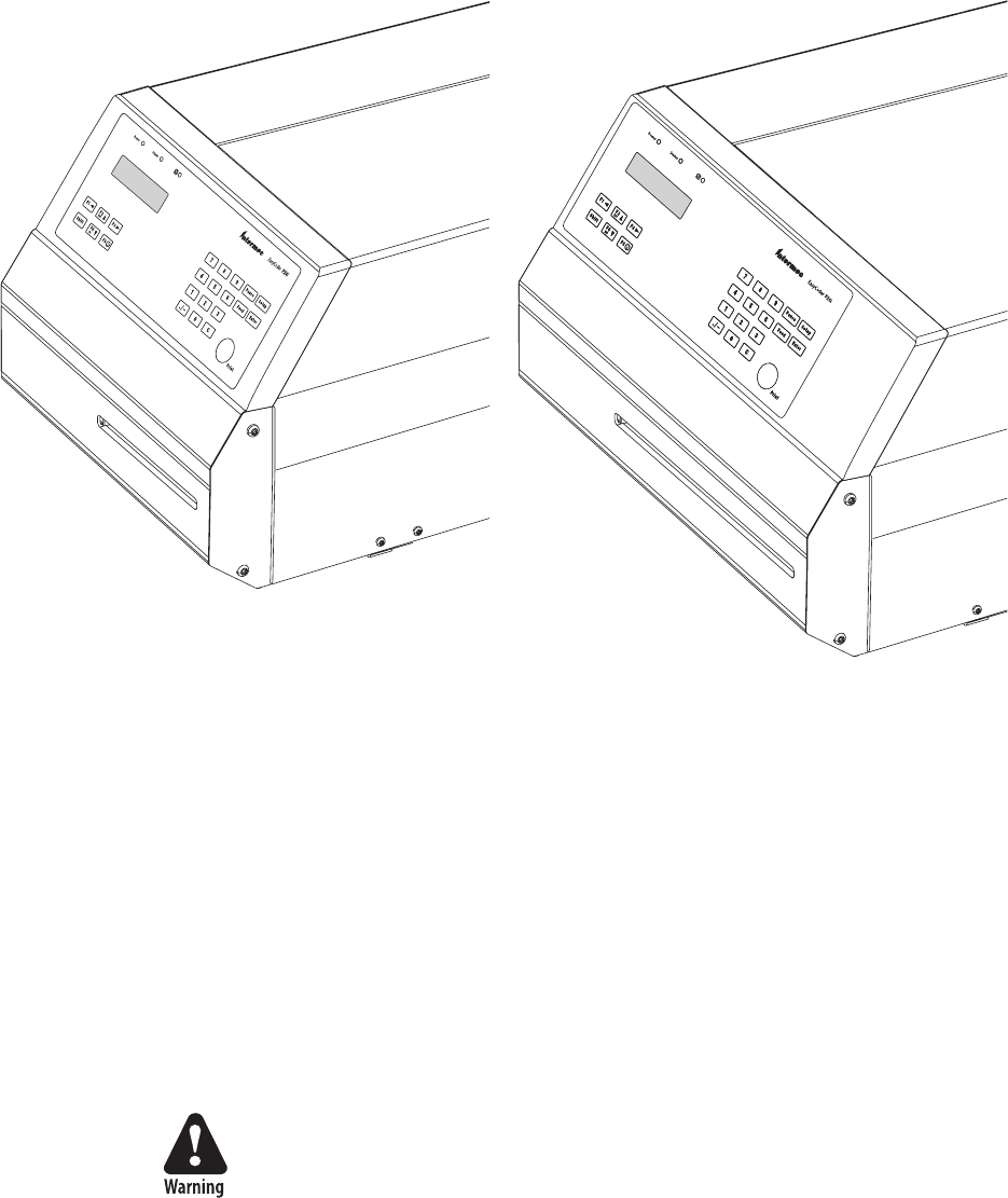
118 EasyCoder PX4i and PX6i Service Manual
Chapter 11 — Paper Cutter
11.1 Description
The EasyCoder PX4i and PX6i can easily be fi tted with an optional cutter
unless the printer is not already fi tted with an label taken sensor (see
Chapter 10). The cutter unit is fi tted on the same hinges as the front door,
which it replaces, and is connected by a single cable to the DIN-connector
on the printer’s front.
The cutter is available both as a factory-installed option and as a fi eld-
installable upgrading kit.
The cutter is intended to cut through continuous non-adhesive paper strip
or through the liner between labels. It must not be used to cut through any
kind of adhesive or other soft material, that may stick to the cutting parts
and render the cutter inoperable or even damage the electric motor.
Maximum paper thickness is 175 µm (≈ 175 g/m2) for normal paper-based
materials.
Minimum practical copy length is 38.1 mm (1.5 inches.)
The cutter increases the total weight of EasyCoder PX4i and PX6i respec-
tively by approx. 1.0/1.65 kg (2.2/3.6 pounds). In both cases, the length is
increased by 28 mm (1.1 inches).
The cutter can be tilted forward in order to facilitate cleaning and media
load.
The cutting edge will rotate to home position when the power is
switched on and when the printer is rebooted. Always keep the cutter
unit in closed position during operation
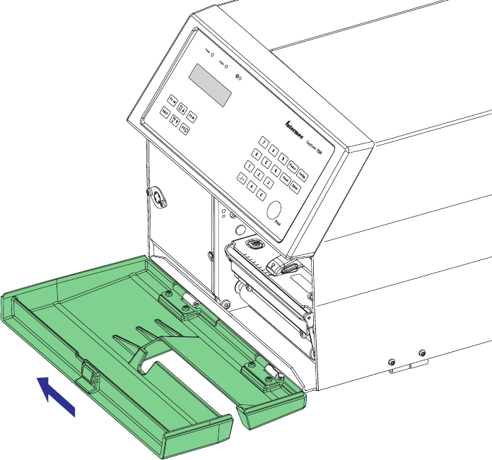
0RESS
SIDEWAYS
EasyCoder PX4i and PX6i Service Manual 119
Chapter 11 — Paper Cutter
11.2 Installation
• Switch off the power and remove the power cord.
• Open the printer’s front door.
• Hold the printer fi rmly and press the front door sideways to the left so
as to disengage the hinges.
• Remove the door completely.
• If the printer is fi tted with a label taken sensor (LTS), it has to be
removed before the cutter can be fi tted, see Chapter 10.
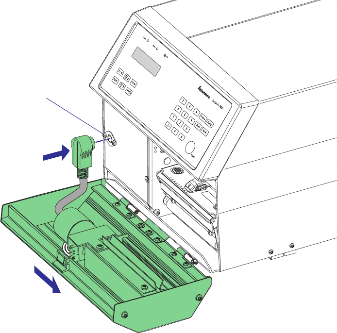
0RESS
SIDEWAYS
120 EasyCoder PX4i and PX6i Service Manual
Chapter 11 — Paper Cutter
• Fit the cutter unit to the vacant hinges. Make sure that the locking plate
snaps into the groove of the right-hand hinge and that the angled plate
at the bottom of the cutter is inserted under the printer’s bottom plate.
• Connect the cable from the cutter unit to the DIN socket on the print-
er’s front.
• Tilt the cutter unit upwards until it locks into place. If the cutter does
not lock properly, the hinges of the cutter unit may need to be adjusted
using a #T10 Torx screwdriver.
• Connect the power cord and switch on power. The cutter will perform
an idle cycle in order to occupy its home position.
• Switch off the power. Tilt down the cutter and route the media through
the cutter unit between the guide plates (see illustration above). Then
tilt the cutter up again and lock it in closed position. Check that the
printhead is lowered and switch on the power. Now the printer is ready
for operation.
DIN socket
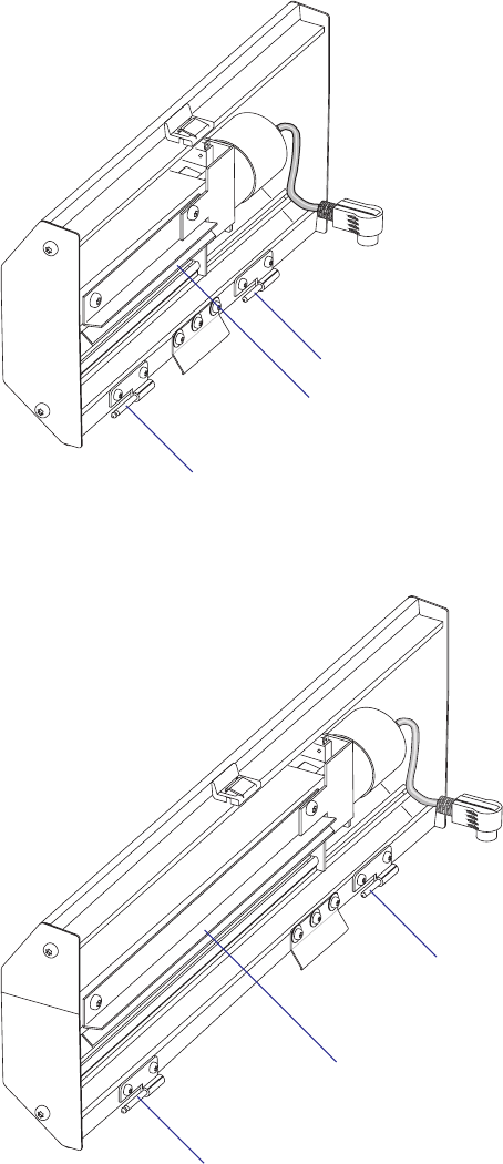
EasyCoder PX4i and PX6i Service Manual 121
Chapter 11 — Paper Cutter
Hinge
Guide plates
(insert media between the plates)
Hinge
Hinge
Guide plates
(insert media between the plates)
Hinge
EasyCoder PX4i Cutter
EasyCoder PX6i Cutter

122 EasyCoder PX4i and PX6i Service Manual
Chapter 11 — Paper Cutter
11.3 Controlling the Cutter
Fingerprint
The cutter is activated by CUT or CUT ON statements, see the Intermec
Fingerprint v8.xx, or the Intermec Direct Protocol v8.xx manuals. Applica-
tion programs may have related facilities for operating the cutter.
The edge will cut through the media approx. 37 mm (1.5 inches) in front
of the printer’s dot line. The following values are recommended for cut-
ting:
Type of Cutting 8 dots/mm
printhead
11.81 dots/mm
printhead
Cut between labels w. gaps
Start adjust: - 287 dots - 424 dots
Stop adjust: + 176 dots + 260 dots
Cut fi x and variable length strip (no liner!)
Start adjust: - 294 dots - 434 dots
Stop adjust: + 298 dots + 440 dots
IPL
The cutter can be enabled/disabled in the Confi guration part of the setup
mode or using the command <STX><SI>Cn<ETX>, where n= 0 dis-
ables the cutter and n=1 enables it. When the cutter is enabled, the media
feed is automatically adjusted for cut-off operation.
When the cutter is not enabled, a cut operation (advance label and cut)
can be executed using the command <STX><SO><ETX>.
Also see IPL Programming, Reference Manual.
11.4 Media Load
Load media following the descriptions in the User’s Guide for Media Load/
Cut-Off operation (optionally with Quick-Load guides). The cutter is held
by a snap lock and can be tilted forward to facilitate media load. Always
engage the printhead in order to hold the media before closing the cutter.

EasyCoder PX4i and PX6i Service Manual 123
Chapter 11 — Paper Cutter
11.5 Servicing
The cutter mechanism becomes accessible when the cover is opened.
The cutter shears will need to be cleaned from adhesive residue if the cutter
has been used for cutting through labels, something that is not advisable.
Use isopropyl alcohol (see warning text on the container), but be careful
only to apply it where there is any adhesive residue so you do not dissolve
the lubrication.
Do not force the spring-loaded anvil blade open more than 5-10 mm
(0.2–0.4 inches), or the spring may be damaged. Refer to Chapter 11.6 for
information on how to replace the spring.
Switch off the power or disconnect the cutter before cleaning. Keep fi n-
gers away from cutting parts!
Fingerprint only
If the following errors occur, clean the shears from adhesive residue.
• 1701 “Cutter error1”
A cut has been performed but the shear has stopped on its way back to
home (bottom) position.
• 1702 “Cutter error2”
The cutter has failed to cut after several attempt (3 is default) and the
shear has returned to home (bottom) position.
• 1703 “Cutter error3”
The cutter has failed to cut and the shear has stopped before returning
to home (bottom) position.
If the cutter cable connector has come loose from DIN connector, Error
37, “Cutter device not found” or Error 1059, “Cutter does not respond” will
occur.
If the microswitch in the cutter assy is faulty, Error 1704, “Cutter open” will
occur, even if the cutter in fact is closed.
IPL only
IPL reports if the cutter has failed to return to home position by display-
ing the message “Open&shut cutter.” Follow that instruction. If the error
persists, clean the shears from adhesive residue and check the microswitch.
124 EasyCoder PX4i and PX6i Service Manual
Chapter 11 — Paper Cutter
11.6 Spring Replacement
The spring that presses the anvil blade against the rotating shear may
eventually get slack, especially if the anvil blade is forced open, for example
during cleaning. A slack spring must be replaced as follows:
• Remove the right-hand gable of the cutter (two #T20 Torx screws).
• Remove the right-hand gable of the cutter mechanism (two #T20 Torx
screws + three Posidrive screws).
• Replace the spring and assemble in reverse order, making sure to put
back all the washers.

EasyCoder PX4i and PX6i Service Manual 125
12 Electronics Compartment
This chapter describes how to access the electronics compartment and
shows the main parts.
The electronics compartment contains wires and circuits with high
voltage. Before removing the left-hand cover or the bottom plate, make
sure that the power is off and the power cord is disconnected from the
printer.
Before starting to work inside the electronics compartment, take stan-
dard precautions for avoiding electrostatic discharges.
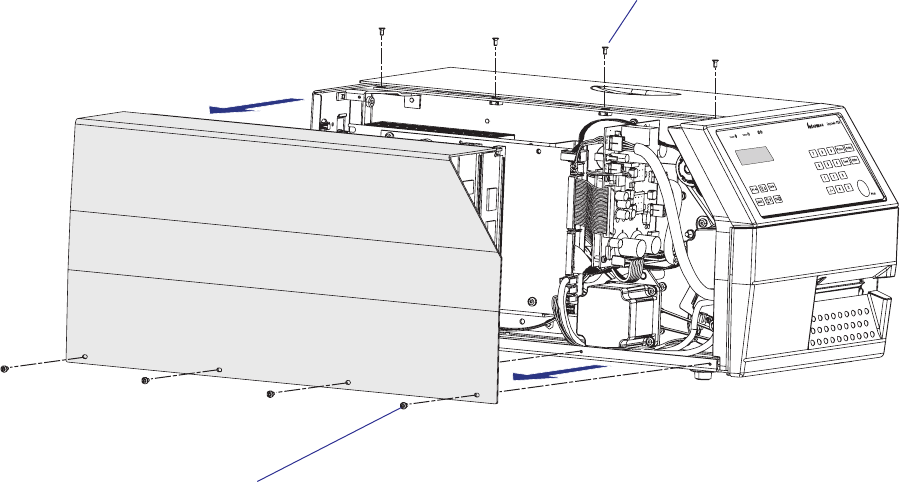
126 EasyCoder PX4i and PX6i Service Manual
Chapter 12 — Electronics Compartment
12.1 Introduction
The Electronics Compartment is off limits to the normal user, but for the
authorized service technician, it contains a number of parts of great inter-
est:
• The stepper motor and timing belts of the platen roller and ribbon
rewind unit.
• The stepper motor and belts of the optional liner/batch takeup unit.
• The headlift mechanism and sensor.
• The CPU board.
• The driver board.
• The power supply unit.
• Optionally one or two extra interface boards and/or one EasyLAN
board.
12.2 Accessing the Electronics Compartment
To gain access to the electronics compartment, remove the left-hand cover
as described in Chapter 3.3.
#T10 Torx screws (x4)
#T10 Torx screws (x4)
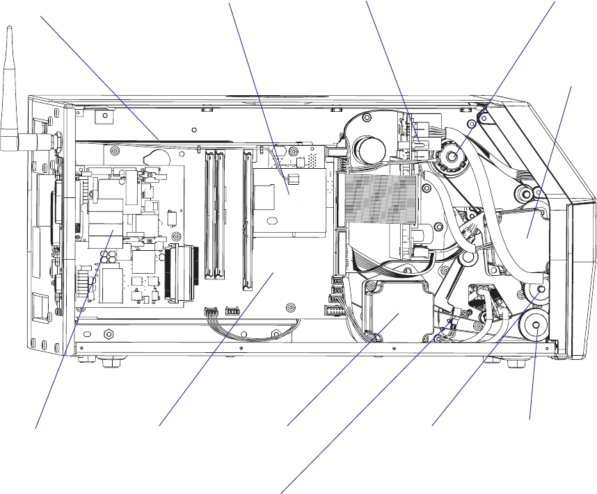
EasyCoder PX4i and PX6i Service Manual 127
Chapter 12 — Electronics Compartment
CPU board
Driver board
Stepper motor
(liner/batch
takeup)
Platen roller
belt and pulley
Liner drive roller
belt and pulley
Power supply
(behind CPU board)
Stepper motor
(platen &
ribbon rewind)
12.3 Main Parts
This is what you may see when you remove the front/left-hand cover from
an EasyCoder PX4i or PX6i printer.
Ribbon rewind unit
Optional
interface boards
Optional EasyLAN board
Headlift sensor
128 EasyCoder PX4i and PX6i Service Manual
Chapter 12 — Electronics Compartment

EasyCoder PX4i and PX6i Service Manual 129
13 Power Supply
This chapter describes the power supply unit (PSU) which is fi tted in the
electronics compartment, see Chapter 12.
The chapter covers the following topics:
• Description
• Replacement
• Components
• Schematics
The electronics compartment contains wires and circuits with high
voltage. Before removing the left-hand cover or the bottom plate, make
sure that the power is off and the power cord is disconnected from the
printer.
Before touching the driver board, take precautions to avoid any electro-
static discharges.
130 EasyCoder PX4i and PX6i Service Manual
Chapter 13 — Power Supply
6!#
(Z
6$#
0OWER&AIL
4EMP-ONITOR
0OWER3UPPLY"OARD
7STANDBY
7PEEK
-AINS
2ECTIFIER6
#ONTROL6OUT
6
&ORWARD
#ONVERTER
"OOSTER
#ONVERTER
0ULSE7IDTH
-ODULATOR
W0OWER&ACTOR#ONTR
0ULSE7IDTH
-ODULATOR
&ORWARD
4EMPERATURE#ONTROL
0OWER&AIL)NTERRUPT
13.1 Description
The Power Supply Unit (PSU) is identical in all EasyCoder PX4i and
PX6i-series printers. It is situated inside the electronics compartment
between the CPU board and the center section.
No attempt to repair this unit is allowed. Never replace a blown fuse, but
replace the entire PSU.
The power supply unit is primary-switched with power correction factor
controller so as to comply with the CE regulations, which require a sinus-
shaped load curve. It is designed for input voltages in the range of 90 to
265 VAC, 45 to 65Hz. There is no manual switch.
The PSU delivers 20W at standby and 400W peak. Typical consumption
during printing is approximately 100W. The PSU produces 24 VDC only;
all other voltages are transformed from 24 VDC by the driver board and
CPU board. The CPU board controls the PSU over the I2C bus via the
driver board, where also identifi cation and error signals are transmitted to
the CPU board. Voltage and temperature are monitored and the unit is
over-current protected.
The working principles of the PSU are illustrated by this diagram:

EasyCoder PX4i and PX6i Service Manual 131
Chapter 13 — Power Supply
Power Factor Control
The power factor control transforms the AC input voltage to 385 VDC
by sensing the shape of the curve of the input voltage and chopping it to
short pulses, where the pulse amplitude follows the shape of the curve. The
booster is protected by two 7A fuses.
Forward Converter
The forward converter transforms 385 VDC to 24 VDC 0-17A. The 24
VDC is the bulk voltage. Other voltages needed for internal devices are
converted from 24 VDC by the driver board and the CPU board.
Connections
P2 24 VDC to driver board.
P3 Temperature and power fail signals to driver board
X1 Input voltage 90 to 265 VAC, 45 to 65Hz
Overheating Protection
The power supply unit is fi tted with a sensor that will shut down the unit
in case of overheating (Power Fail Interrupt or PFI) and another sensor
that will warn the main CPU if the power supply is getting hot (Notify).
A Power Fail Interrupt (PFI) signal will warn the logics so valuable data
can be saved before power is lost. Before a print operation is executed,
the Notify signal is checked. If the Notify signal is activated, a warning is
shown in the display and the main CPU will reduce the power consump-
tion to avoid shutdown by detaining the printing until the Notify signal is
deactivated.
Primary switched power supplies are generally diffi cult to repair. If one
component fails due to aging or overload, a number of other compo-
nents will also break as a consequence. They are hard to troubleshoot,
because the PSU often is “dead” or the fuses blow immediately. It is
also impossible to guarantee the life of a repaired PSU, because com-
ponents may still work but be on the verge of failing. Thus, if a fuse
blows, do not attempt repairing the PSU, but replace the entire unit!
132 EasyCoder PX4i and PX6i Service Manual
Chapter 13 — Power Supply
Label
Bracket
Protection Sheet
(shown separately)
PSU Board
On/Off Switch
Power cord
socket
Physical Appearance
The PSU comes as a complete unit consisting of a large metal bracket to
which the following parts are factory-fi tted:
• Plastic protection sheet
• Power supply pcb (attached to the bracket using four #T10 Torx screws
and washers)
• AC power cord socket (attached to the bracket using two #T10 Torx
screws and nuts)
• On/off switch (attached to the bracket using snap-locks)
• Label
The bracket is fi tted to the center section and rear plate using a total of fi ve
#T20 Torx screws.
Power supply unit (simplifi ed drawing)
EasyCoder PX4i and PX6i Service Manual 133
Chapter 13 — Power Supply
13.2 Replacement
• Take precautions to avoid any electrostatic discharges.
• Switch off the printer and disconnect the power cord and all interface
cables on the rear plate.
• Remove the left-hand cover as described in Chapter 3.3.
• Remove any interface board connected or attached to the CPU board.
• Disconnect all cables from the CPU board and remove it (see Chapter
15.3). The CPU board is held to the PSU bracket using four #T20
screws and one hexagonal spacer.
• Disconnect the cables that run between the PSU and the driver board.
• Remove the three #T20 Torx screws that hold the PSU assy to the center
section and two #T20 Torx screw that hold it to the rear plate.
• Do not dismantle the PSU. Replace the entire unit!
• Assemble in reverse order. Fit the top screw at the rear plate fi rst.
#T20 Torx screws (x2)
Cables to driver pcb
Fit this screw fi rst!
PSU assy
#T20 Torx screws (x3)
134 EasyCoder PX4i and PX6i Service Manual
Chapter 13 — Power Supply
13.3 Components
1-971632-25 Power Supply Unit; Component side
EasyCoder PX4i and PX6i Service Manual 135
Chapter 13 — Power Supply
1-971632-25 Power Supply Unit; Soldering side
136 EasyCoder PX4i and PX6i Service Manual
Chapter 13 — Power Supply
13.4 Schematics
1-971632-25 Power Supply Unit; Schematics
1Q
1YT

EasyCoder PX4i and PX6i Service Manual 137
14 Driver Board
This chapter describes the driver board which is fi tted in the electronics
compartment, see Chapter 12.
The chapter covers the following topics:
• Description
• Replacement
• Components
• Schematics
The electronics compartment contains wires and circuits with high
voltage. Before removing the left-hand cover or the bottom plate, make
sure that the power is off and the power cord is disconnected from the
printer.
Before touching the driver board, take precautions to avoid any electro-
static discharges.
138 EasyCoder PX4i and PX6i Service Manual
Chapter 14 — Driver Board
14.1 Description
While the power supply unit (PSU) transforms the AC input voltage to
24 VDC, the driver board converts the 24 VDC to various voltages and
distributes them to CPU board, stepper motors, cutter, and printhead.
The driver board is connected to the PSU via two cables (see Chapter
13). One cable, connected to P2, supplies the driver board with 24 VDC
and the other one, connected to P3, contains temperature and power fail
signals.
The driver board converts the 24 VDC to various voltages required by the
printer and distributes them as follows:
P1 24 VDC to CPU board and control signals between driver board and
CPU board
P5 24 VDC to thermal printhead
P7 0-12 VDC to fan (presently not used)
P10 33 VDC to platen roller/ribbon rewind stepper motor
P11 33 VDC to liner/batch rewind unit stepper motor
P12 24 VDC to cutter interface
At start-up, the PIC processor on the driver board checks that the 24 VDC
to the printhead and 33 VDC to the stepper motors are within allowed
limits. If any extreme values are found, an error condition occurs.
14.2 Replacement
• Take precautions to avoid any electrostatic discharges.
• Switch off the printer and disconnect the power cord
• Remove the left-hand cover as described in Chapter 3.3.
• Disconnect all cables to the driver board.
• From the media compartment, remove the two #T20 Torx screws that
hold the driver board assembly.
• The driver board and its plate come as an assembled spare part. Do not
dismantle any further. Do not attempt to repair a faulty driver board,
but replace it with a new one, unless you know for sure that you have
made the fuse blow by causing a short-circuit (see Chapter 17.6).
• Assemble in reverse order.
The driver board and its attachment plate come as an assembled spare part.
EasyCoder PX4i and PX6i Service Manual 139
Chapter 14 — Driver Board
+
.#
.#
!
+
#.
.#
!
+
#.
.#
!
+
.#
.#
!
+
#.
.#
!
+
.#
.#
!
#
%
"
#
% "
#
%"
#
%
"
#
%"
' 3
$
'
3
$
'3
$
#
#
#
#
#
#
#
#
#
#
#
#
#
#
#
#
#
#
#
#
#
#
#
#
#
#
#
#
#
#
#
#
#
#
#
#
#
#
2
2
2
2
2
2
2
2
2
2
2
2
2
2
2
2
2
2
2
2
2
2
2
2
2
2
2
2
2
2
2
2
2
2
2
2
2
2
2
2
2
2
2
2
2
2
2
2
2
2
2
2
2
2
2
2
2
2
2
2
2
2
2
2
2
2
2
2
2
2
2
2
2
2
2
2
2
2
2
2
2
2
2
2
2
2
2
2
2
$
2
2$
2
2
2
2
#2
2#
"2
2"
!
2
!
2!
2!
2"
2"
2#
2#
2!
2!
2"
2"
2#
2#
!
2
!
"2
2"
#2
2#
2!
2!
2"
2"
2#
2#
2#
2#
2"
2"
2!
2!
5
#
#
#
#
#
#
#
#
#
#
#
#
#
#
#
#
#
#
:
:
:
5
#
#
#
#
#
1
1
0
0
0
$
$
$
5
5
#
#
#
0
$
$
$
$
$
$
,
,
,
,
,
1
1
1
1
1
1
1
1
5
5
!
0
!
0
0
0
0
#
&
&
1
1
1
1
1
,
0
0
#$.'
'.$#
#
$
.'
'.$#
#$.'
'.$#
0
$
$
5
2
2
2
2
5
5
"0
0"
#
0
#
5
140 EasyCoder PX4i and PX6i Service Manual
Chapter 14 — Driver Board
14.3 Components
1-971652-26 Driver Board; Component Side

#
#
#
#
#
#
#
#
#
#
#
#
#
#
#
#
#
#
#
#
#
#
#
2
2
2
2
2
2
2
2
2
2
2
2
2
#
#
#
#
#
#
#
#
#
#
#
#
#
#
#
#
#
#
#
#
#
#
#
#
1-971652-26 Driver Board; Soldering Side
EasyCoder PX4i and PX6i Service Manual 141
Chapter 14 — Driver Board
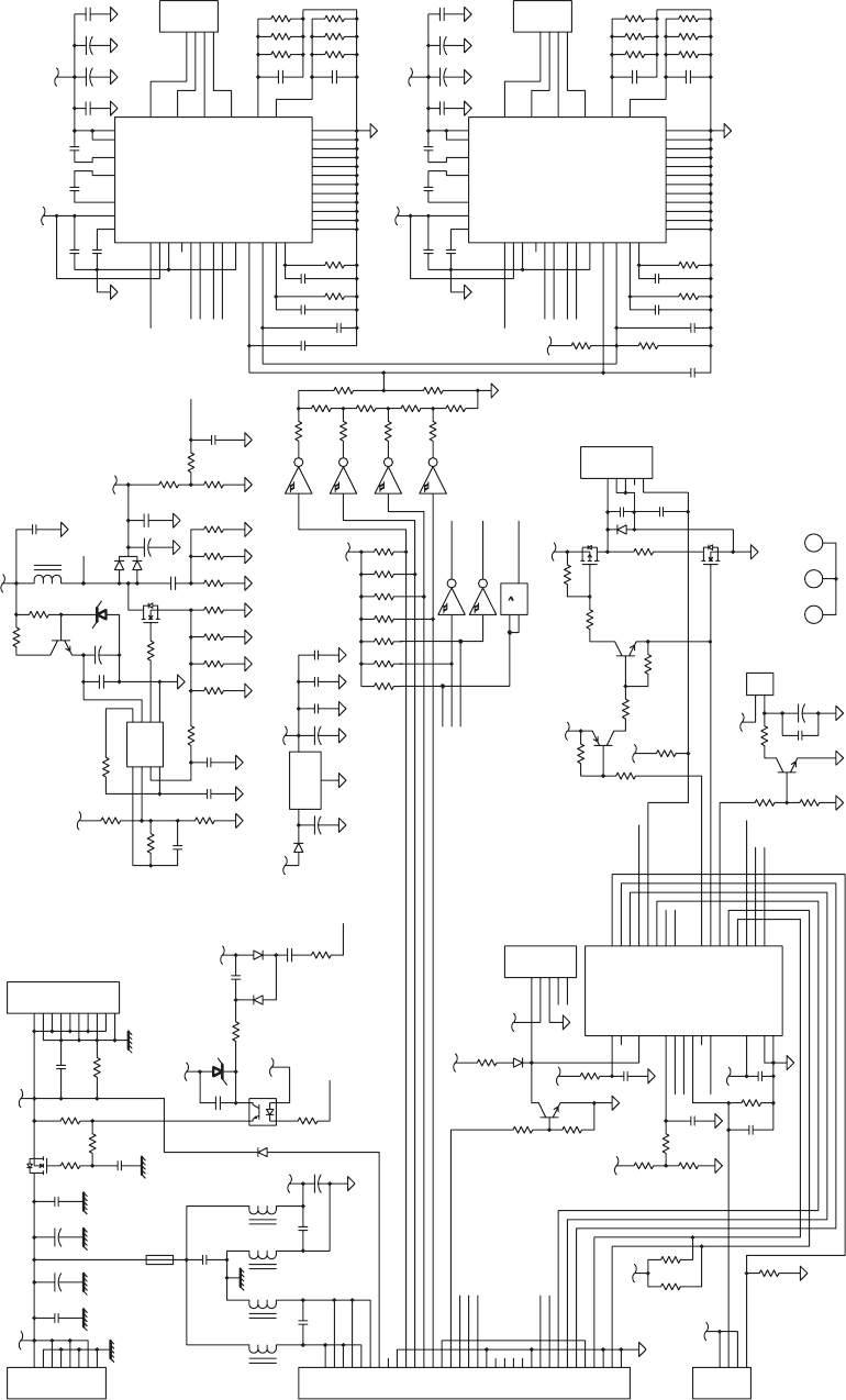
7
OI_REVIRD
6OI_REVIRD
N_TNI_
U
SP
N
O
C
UP
C
R
O
TCENNOC RSI
+R
O
T
OM
-ROTOM
MOC:
E
MOH
ON:E
MOH
R
E
T
TUC
NE
4
2P
N
AF
V93
-N
A
F
2 REPPETS
1 REPPETS
LC
S
ADS
PU PETS V33
L
R
TC USP
+N
A
F
TU
O HPT V4
2
TED
_
IFP
N_TON_USP
5
O
I_REV
I
RD
4OI_
R
EVIRD
01OI_R
E
VIRD
E
VIR
D
ET
AG
1
Q
NI
R
E
W
OP V4
2
LCS
43
4Q
SV42
2
SM
92
N
O
M
_PM
E
T
C27
L4
1U
R54A
8D
R19
3CDNG
2C
DNG1CD
N
G
52C
6D
1Q
R25
07R
67R
1
7R
27R
37R
6Q
7Q
47R
5
7R
5
4
3
2
1
21P
77R
9Q
8Q
R33 R32
R31
R30
R20
R21
3
4
2
1
U7
89
2U
65
2U
4
2
U
2
1
2U
4
3
2
1
3P
9
8
7
6
5
4
3
3
2
3
13
03
3
82
7
2
6
2
52
4
2
32
2
2
12
02
2
91
81
71
61
51
41
31
2
1
11
01
1
1
P
42C
L1
C23
8
7
6
5
4
3
2
1
2P
R3
R1
R2
R4
6R
R5
C50
R7
C51
C52
C80
0
2
81
71
6
1
5
1
41
31
21
11
82
72
62
5
2
42
32
22
12
7
6
5
4
3
2
91
8
0
1
9
1
R9 R8
2Q
R12
D2
R11
5
4
3
2
1
8P
L2
62C
L3
3C
D1
F1
C70
86R
R65
4D
1Z
R67
66R
4
6R
82
C
9
8
7
6
5
4
3
2
01
1
5P
C20
C1
C2
C21
R69
22C
92
C
5D
R16 R15
3Q
7
1R
C34
4C
5C
2
1
7P
1
6U
C6
3D
R63
R62
16R
1
7C
R60
C72
8
2
7
4
6
5
1
5
U
C86
85R
95
R
R22
R23
R24
R54B
R54C
55R
C36
7C
R54D
5Q
58C
R53A
R53B
8
C
2Z
L5
C53
C54
C55
C56
C57
R37
92R
8
2R
72R
R35
R36
R34
R38
C81
C82
R39
32
16
36
25
43
13
6
2
24
12
72
41
51
01
33
24
23
22
13
12
11
2
44
35
34
1
9
82
8
1
0
4
6
91
0
2
4
14
5
38
37
3U
0
4
C
62R
C62
C61
R53C
53C
R51
R52
05R
C66
R46
06
C
R47
C83
C84
32
16
36
25
43
13
62
24
12
72
41
51
01
33
24
23
22
13
12
11
2
44
35
34
1
9
8
2
81
0
4
6
91
02
4
14
5
38
37
4
U
24
C
1
4
C
3
4
C
54C44
C56C
75
R
R56
8
5C
R41A
95C
R40A
R41B
R41C
R40B
R40C
C30
C9
C10
4
3
2
1
01P
C31
R49A
36C
46C
R48A
R49B
R49C
R48B
R48C
C32
C11
C12
4
3
2
1
11P
C33
4A
V5
S
V
42
B
5
4
83C
U
MTS
V
V5
SV42
B
7
48
C
B
HP_V42
TE
SE
R
_C
I
P
2
78
F
61C
I
P
V
5
1CMTS
2C
M
TS
3CMTS
4C
M
TS
V5
1
V42
NO4
2
P
N
O4
2
P
WS
EMOH
2SM
1
S
M
N
_
T
E
S
E
R
C
B
1
SM
C
B
D
V51
V
5
TED
_I
F
P
SV42
M
W
P_NAF
N
_TE
S
ER
M
TSV
PCV
T
U
C
EMOH
V5
V42DA
V5
V5
M
TSV
V5
M
T
S
V
V
42
PC
V
MT
S
DA
V5
V
5
41T
CH
A
41TCHA
41TCHA
S
V
4
2
V
5
I_
R
ID
V5
V5
A
DS
2P
ET
S
1PE
T
S
N_1PETS
R
I
D
RID
MTSDA
N_TESER
N_2P
E
TS
TUC
N
_
T
O
N_
US
P
N
_
T
NI_USP
NE42
P
EMOH
ROT
O
MTU
C
EK
AR
B
VH
P
T
4
1
TCH
A
V5
V0.5
SV42
SV42
2SM
1SM
+
7CR
6CR
5C
R
4C
R
3C
R
2C
R
1CR
0
CR
7
B
R
6BR
5B
R
4
BR
3BR
2B
R
1
BR
0BR/TNI
CCV
P
P
V/
R
LCM
0
A
R
1AR
2AR
FERV/3AR
I
KCOT/4AR
5AR
NIKLC
TUO
K
LC
DNG
DNG
7793A
N_TESER
2ESNES
A
2
TUO
2
CR
1CR
DFP
F
E
R
RID
N
_RS
2SM
PETS
1SM
N_ELBANE
N_PEELS
B2
T
UO
CP2
CP1
VDD
VBB
VBB
B1T
U
O
A1TUO
1ESNES
PGND
PGND
PGND
PGND
PGND
PGND
PGND
PGND
PGND
PGND
PGND
PGND
N_EMOH
VREG
VCP
7793A
N_TES
E
R
2ESNES
A2TUO
2C
R
1CR
DFP
F
E
R
R
I
D
N
_
RS
2SM
PETS
1SM
N
_E
L
BANE
N_PE
EL
S
B
2T
U
O
CP2
CP1
VDD
VBB
VBB
B
1T
UO
A
1
TUO
1ESNES
PGND
PGND
PGND
PGND
PGND
PGND
PGND
PGND
PGND
PGND
PGND
PGND
N
_E
MO
H
VREG
VCP
+
+
+
+
+
+
JDA/
DN
G
T
U
OVNIV
+
BFV
ESNES
DNG
C
/R
PMOC
TUO
CCV
FERV
+
+
+
+
3
3
3
3
2
3
73C
83C
4
1
2
8U
2131
2U
01
11
2
U
I_RID
R
ID
23G1TCHA
N_2PETS
N_1PETS
1PETS
2PE
T
S
41TCHA
41TCHA
1
142 EasyCoder PX4i and PX6i Service Manual
Chapter 14 — Driver Board
14.4 Schematics
1-971652-26 Driver Board

EasyCoder PX4i and PX6i Service Manual 143
15 CPU Board
This chapter describes the CPU board which is fi tted in the electronics
compartment, see Chapter 12.
The chapter covers the following topics:
• Description
• Circuits
• Connectors
• Test points
• Startup
• Components
• Schematics
• Replacement
Note: Devices and fi le systems, such as "/c:" or "uart1:", are only used in
Fingerprint. Some may also exist in IPL, but are hidden to the user.
The electronics compartment contains wires and circuits with high
voltage. Before removing the left-hand cover or the bottom plate, make
sure that the power is off and the power cord is disconnected from the
printer.
Before touching the CPU board, take precautions to avoid any electro-
static discharges.
144 EasyCoder PX4i and PX6i Service Manual
Chapter 15 — CPU Board
15.1 Description
The CPU board is a four-layer board with most of its circuits surface-
mounted. Inside the laminate are a combined VCC layer (5V/3.3V/2.5V)
and a GND layer. The front and back sides are signal routing layers.
The hardware contains of the following main functions:
• Processor core
• Thermal printhead driver
• Stepper motor control logic
• Sensor drivers
• Communication, such as UART, USB, etc.
• Flash memory SIMM for the fi rmware and non-volatile storage
• SDRAM SIMM for working memory
• A/D converter for sensor adjustment, etc.
• Compact Flash memory card expansion
• Expansion bus
• PCI bus (custom)
1-971630-26 CPU board; Block Diagram
(numbers refer to schematics in Chapter 15.7)
)#BUS
0OWERCONVERSION
6
6
6
6)N
3TEPPERCONTROLSIGNALS
ONLYONEOPTIONAL
BOARDIN0&SERIES
035-OTOR
INTERFACE
3ENSORS
!$CONVERTER
40(
#ONSOLE
&INISHER
#LOCK
-(Z
#,)#
3UPPORTLOGIC
"OARDID
2ESET
%XPINTERFACE
/PTIONALBOARD
/PTIONALBOARD
&LASHMEMORY #OMPACT&LASH 53"
5!24 0#)BUS
CUSTOM
.ETWORK
CARD
"EEPERI"UTTON7AND
#05
2)3#CORE
-EMORYCONTROLLER
0#)INTERFACE
03!
40(LOGIC
3TEPPERLOGIC
)NTERRUPT
)#MASTER
"USISOLATION #05BOARD
%%02/-
3$2!-
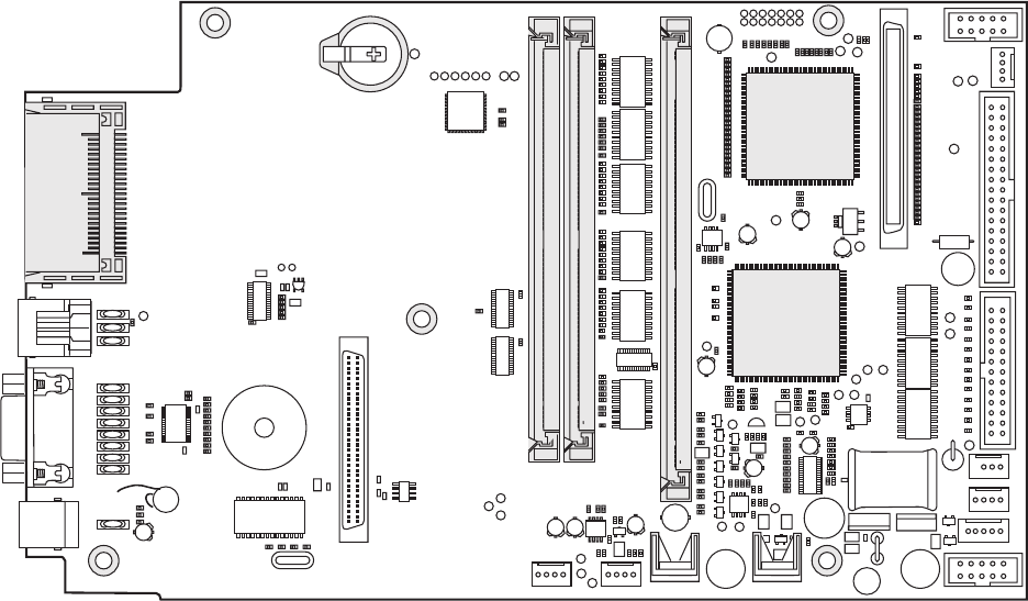
EasyCoder PX4i and PX6i Service Manual 145
Chapter 15 — CPU Board
15.2 Circuits
Components mentioned in this chapter are marked with gray in the draw-
ing below.
Processor (U13)
The processor is a 32-bit RISC offering about 125 MIPS at the internal
clock speed 96MHz. The internal bus speed is twice the external bus speed
at 48MHz. The processor has several features, such as integrated SDRAM
controller, PCI bridge, DMA, UART, timers, etc.
Support Chip (U30)
The PSA (Processor Support ASIC) is a programmable logic device, which
is programmed by the fi rmware at each startup. It contains most of the
printer-specifi c and other logic functions, such as
• Printhead data and strobe control
• Stepper and DC motor logic
• Sensor interface
• Timers and interrupt control
• Control logic for bar code wand and the electronic key/RTC
• I2C master
• Beeper signal generation
• Interface to A/D converter, console, fi nisher, etc.
0
*
24#02/'2!-+%9
"//4&,!3(
#/-0!#4&,!3(
* * *
0/
5
0ROCESSOR
5
3UPPORT
#HIP

146 EasyCoder PX4i and PX6i Service Manual
Chapter 15 — CPU Board
Flash Memory (J20 and J21)
There are two sockets for Flash SIMMs (marked “BOOT FLASH” and
“EXP FLASH”). A SIMM (Single Inline Memory Module) must always
be fi tted in J20 since this bank is the Bootbank. As standard, a single 4MB
fl ash SIMM is fi tted. It contains the following sectors:
1/. Devices are used in Fingerprint, but are hidden in IPL.
2/. This sector can be used for the kernel or for the fi le system (/c). If it is used for the fi le
system, the kernel is placed in the fi le system under the /c/boot directory, which is the
normal confi guration, enabling the size difference between 2048K and the real kernel
size to be used in /c. Refer to the Intermec Fingerprint v8.xx, Programmer’s Reference
Manual for a complete list of fi les stored in /c and /rom by default. The kernel includes
Fingerprint or IPL fi rmware, bar codes, standard fonts, standard images, Intermec Shell,
auxiliary programs, default setup values, and the EasyLAN home page fi les.
The fl ash memory retains its content at power off without any battery
backup. It consists of sectors that can be erased and written to over and
over again. This is done automatically in the background. At power-up,
the fl ash memory is reorganized to avoid fragmentation. Before a sector is
erased, its content will be copied to a temporary area as a safety measure
if something should go wrong, for example a power failure. For the /c fi le
system in Fingerprint, this area is 64K and is included in the sectors in the
table above. For the parameters, it is the 32K TMP sector.
The Boot sector is necessary for Intermec Fingerprint or IPL to start.
There is a boot sector in all fl ash SIMMs at delivery, but the fi rmware
will only accept the boot sector of a SIMM fi tted in J20 (marked “BOOT
FLASH”). The boot sector is only protected when the fl ash SIMM is fi tted
in socket J20 (”BOOT FLASH”). If you move fl ash SIMMs from one
CPU board to another, make sure that the SIMM containing the boot
sector is fi tted in J20 (“BOOT FLASH”) on the other board, or the boot
sector will be overwritten.
The Intermec Fingerprint fi rmware is either stored in the /c fi le system
or in a dedicated area on the boot fl ash (2MB large). If it is stored in
the fi le system, removing or exchanging an EXP FLASH in J21 may
render the printer unstartable. To cure this condition, use a Compact-
Flash card containing an upgrade fi le (kernel) to reload the fi rmware.
As illustrated in the table above, a total nominal capacity of 3904K is used
for the /c fi le system (MIFS, or FOS) and fonts. In Fingerprint, practically,
around 2MB are available to the user (about 200-400K less if the kernel is
in the dedicated area).
Exactly which fonts, images, fi les, and programs are stored in the
Fingerprint fi le system may vary between customers and applications.
Device1Size Type Used for
– 128K Boot Startup
/c 2048K User fi le system or Kernel1FP: Customer’s programs, fi les, images
IPL: Formats, images, fonts
/c 1856K User fi le system FP: Customer’s programs, fi les, images
IPL: Formats, images, fonts
– 32K TMP area Media feed info, odometer value, etc.
– 32K Parameters Media feed info, odometer value, etc.
EasyCoder PX4i and PX6i Service Manual 147
Chapter 15 — CPU Board
The parameters sectors store the PFSVARs (see SETPFSVAR Fingerprint
statement), odometer values, and a few other “invisible” fi les with data,
that are required for the printer to start up with the same settings as when
it was shut off, for example information on the position of label gaps in
relation to the LSS.
The printer’s permanent memory can be expanded by fi tting a second
4MB or 8MB fl ash memory SIMMs in sockets J21. 4MB and 8MB fl ash
SIMMs can be mixed at will. Flash SIMMs are custom-made and can only
be ordered from Intermec.
Note: The fi rst time the printer is started with a SIMM in J21 (“EXP
FLASH”), the memory is not increased to enable cloning the fi rst SIMM.
The expansion is not done until the second time the printer is started.
Flash Memory Available to the User
J20 (Boot) J21 (Exp) J20 (Boot) J21 (Exp) SUM
4MB SIMM – 1.8MB – 1.8MB
4MB SIMM 4MB SIMM 1.8MB 4MB 5.8MB
4MB SIMM 8MB SIMM 1.8MB 8MB 9.8MB
8MB SIMM – 5.8MB – 5.8MB
8MB SIMM 4MB SIMM 5.8MB 4MB 9.8MB
8MB SIMM 8MB SIMM 5.8MB 8MB 13.8MB
148 EasyCoder PX4i and PX6i Service Manual
Chapter 15 — CPU Board
SDRAM Memory (J10)
The SDRAM memory (Synchronous Dynamic Random Access Memory)
is the printer’s temporary memory (Fingerprint device "tmp:"). It will lose
its content when the power is switched off or at a power failure. Thus, it
should only be used for data that can easily be recreated or that are only
relevant for one power-on cycle. It is much faster than the fl ash memory.
Therefore, at startup the kernel is copied from the Flash memory to the
SDRAM, where the various instructions are executed.
One SDRAM SIMM (standard size 16MB) must always be installed in
socket J10 (SDRAM0-1).
The SDRAM is also used for the font cache and various buffers. The
remainder is used for the two print image buffers where the bitmap pat-
terns are stored prior to printing. One buffer is used for the label that is
being printed, while the other receives the bitmap for next label as the
Intermec Fingerprint instructions are processed. By switching between the
buffers, batch printing without stopping between labels can be achieved.
The size of the buffers depends on two factors:
• Number of physical dots on the printhead.
• Present label length setup value in dots.
Calculate the buffer size according to this formula:
(No. of dots / 8 + 4) × (Media length in dots) = Buffer size in bytes
(Buffer size in bytes) / 1024 = Buffer size in kbytes
Buffer size in kbytes × 2 = Memory requirement in kbytes
Example:
The number of dots on the 8 dots/mm printhead of an EasyCoder PX4i is 896.
“Media; Length” is set to 1500 dots (= 187.5 mm/7.38 inches)
[[(896 / 8) + 4) × (1500)] / 1024] × 2 = 340 kbyte total
Regardless of memory size there is an absolute print length limit of 32,767
dots (4,095 mm/161.2 inches).

EasyCoder PX4i and PX6i Service Manual 149
Chapter 15 — CPU Board
Electronic Key Circuit (J30), Fingerprint-only option
The optional electronic key circuit is an iButton which contains a real-time
clock. It has a built-in battery backup with a life of at least 10 years. When
the printer is on, the circuit is power-supplied via the CPU board and will
not consume any power from the battery. The circuit also contains 4Kbits
(500 bytes) of battery backed-up memory for the devices "lock:" and "stor-
age:".
The Electronic Key Circuit (J30) contains an integrated lithium bat-
tery. Replace only with original Electronic Key Circuits from Intermec.
Dispose of used Electronic Key Circuits according to local regulations
for lithium batteries.
Since the communication between the RISC processor and the electronic
key circuit is comparatively slow, the content of the key circuit is copied
to SDRAM at startup and used from there. At power off, the content is
read back to the key circuit, provided there is time enough. Thus, there is
a small risk that new data may be lost, before it has been saved back to the
electronic key circuit. The original data in the electronic key circuit will
not be damaged, if the read-back process should fail.
Memory Card Adapter (J22)
The CPU board has a built-in memory card adapter which can use
standard Type I CompactFlash memory cards with a size of 8MB to 1GB
(thickness 3.3 mm/0.13 in.). It is not suited for other types of memory or
I/O cards! Cards marked “CF+” and Type II cards (thickness 5.0 mm/0.20
in.) cannot be used.
In Fingerprint, CompactFlash cards can be used to expand the printer’s
memory (device "card1:"). IPL does not support CompactFlash cards as a
means of expanding the memory.
Memory cards are only detected by the fi rmware at startup and must thus
be inserted in the memory card adapter before the power is switched on
or the printer is rebooted. Memory cards must only be emoved when the
power is off.
Preprogrammed CompactFlash Memory Cards
There are four types of preprogrammed CompactFlash memory cards from
Intermec.
• Font Cards
Font stored in font cards can only be used while the card is present in the
printer’s memory card adapter.
• Font Install Cards (Fingerprint only)
Install additional fonts in the printer’s memory. These fonts can be used
without the card being present.
• Firmware Cards
Install a new fi rmware kernel in the printer including standard fonts. Used
for upgrading the fi rmware or switching between Fingerprint and IPL.
• Confi guration Cards
Confi gures a CPU board for the type of printer in which it is installed, see
Chapter 15.8, or changes the printer’s EasyLAN setup.
150 EasyCoder PX4i and PX6i Service Manual
Chapter 15 — CPU Board
15.3 Connections
The following connectors on the CPU board are used in the printer for
communication with various devices and sensors.
Left side (from top down)
J59 Bar Code Wand (not supported by IPL)
J61 RS-232
J60 USB
Bottom (from left to right)
J62 Expansion board connection (optional interface boards)
J57 Paper Sensor
J53 Label Taken Sensor (option)
J51 Finisher (not used)
Top (from left to right)
J84 PCI (EasyLAN interface, option)
J50 Console (keyboard, display, and print or feed/pause button)
Right side (from top down)
J56 Ribbon Low sensor
J52 Power from driver board
J40 Data to printhead
J55 LSS (gap)
J54 LSS (black mark)
J58 Headlift sensor
*
*
*
0
2353"
*
* &).)3(%2
0!0%2 *,43
*
%80"/!2$
7!.$
*
*
0#)
*
*
*
*
'!0
*
"-
*
(%!$,)&4 02).4(%!$ 0/7%2
#/.3/,%
2)""/.
*
0/

EasyCoder PX4i and PX6i Service Manual 151
Chapter 15 — CPU Board
15.4 Test Points
The CPU board is provided with many test points. Only those of immedi-
ate interest to the fi eld service technician are shown below. If further test-
ing or servicing is required, exchange the CPU board and return the faulty
board to a service center.
Test Points
If available, use an oscilloscope to measure the various voltages. When
using for example a multimeter, a fl uttering value may indicate an errone-
ous voltage.
GND Ground
2.5V 2.5V –> GND (max ± 0.2V)
3.3V 3.3V –> GND (max ± 0.2V)
5.0V R718 –> GND (max ± 0.2V)
24V F70 left side –> GND (allowed deviation ± 2V)
(If no voltage on the left side, check the right side. If voltage
there, fuse is blown; else cable, driver board, or PSU trouble.)
DONE High level = U30 programmed, see Chapter 15.5
DEBUG Startup check, see Chapter 15.5
WAND Use an oscilloscope. OK if there is a pulse train when the wand is
reading a bar code.
0
7!.$
&
2
6
6
'.$
*
$/.%
$%"5'
0/
152 EasyCoder PX4i and PX6i Service Manual
Chapter 15 — CPU Board
15.5 Startup
The prerequisite for the printer to start is that a fl ash memory SIMM with
a boot sector is fi tted in J20. A SDRAM SIMM must also be installed in
J10.
At power up, the printer starts executing code in the boot sector and one of
the following sequences will be performed:
1. A Compact Flash card with a firmware is recognized.
- The fi rmware will be copied from the memory card to the internal
SDRAM.
- The processor will start to execute code from SDRAM.
- The fi rmware on the memory card will be copied to the internal fl ash
memory.
2. A valid firmware is recognized in the internal flash memory.
- The fi rmware will be copied to SDRAM and the processor will start
execute code from SDRAM.
If the printer is fi tted with an EasyLAN interface, there are also facilities
for updating the fi rmware from the printer’s home page.
After the initial boot sequence is performed, the number of steps will be
taken before the printer starts, which includes programming the support
chip (U30). The startup procedure can be followed on the printer’s display.
You can also follow the startup from the host provided a strap is temporar-
ily fi tted at J23 (DEBUG) on the CPU board. Connection between printer
and host should use the default serial communication setup (9600 baud, 8
bits, parity none, 1 stop bit) on the standard serial port "uart1:". For each
of the steps, either “OK” or “Fail” is returned on "uart1:". In addition,
some other useful information is also returned.
Refer to Appendix B for information on how to upgrade the fi rmware.
EasyCoder PX4i and PX6i Service Manual 153
Chapter 15 — CPU Board
15.6 Components
1-971630-51 CPU Board; Component Side
J22
17
U
47L
27
T
004L
514L
204L
27L 17
L
85
J
45J
75J
J56
55
J
35J
29U
42J
C706
C510
21C
C975
06
C1
6
C
407C
207C
C404
C511
11C
36C
46C
56C
6
6
C
1
04C
C405
C512
C974
004C
60
4
C
307C
C705
C973
C403
C509
C951
259C
3
5
9
C
4
5
9C
559C
659C
759C
859C
C961 C963
56
9
C
C966
C967
C971
C972
C976
4
6
9C
C716
C540
T44
T40 T41 T42
T43T45 T46 T47
07T
17T
08T
1
T
9
3
9
R
83
9
R
7
39R
6
39R
5
3
9
R
439R
R932
951R
851R
751R
6
5
1
R
551R
45
1
R
351R
251R
151R
0
5
1
R
9
4
1
R
841R
741R
641R
541R
4
4
1R
341R
24
1
R
14
1
R
041R
9
31R
831R
7
3
1
R
R904
04
4
R
934R
8
34R
7
3
4
R
6
3
4
R
5
34R
4
34R
334R
23
4
R
134R
R430
598R
R894
398R
298R
4
2
6
R
5
2
6R
326R
R136
926R
512R
612R
712R
812R
9
12R
022R
122R
222R
322R
4
2
2R
522R
6
2
2R
722R
822R
922R
032R
132R
232R
332R
432R
532R
632R
732R
832R
9
32R
042R
142R
242R
342R
442R
542R
642R
742R
842R
942R
052R
152R
2
5
2
R
352R
452R
5
52R
652R
752R
306R
40
6
R
1
26R
011
R
2
03R
5
2
3
R
81
4R
9
1
4R024
R
10
7
R
60
7
R
1
2
7
R
327R
12
4
R
8
03R
213R
613R
423
R8
2
3R
804R
R618
9
1
6
R
026R
R915
7
13R
R704
20
6
R
506R
614R
R422
R410
0
16R
1
16R
216R
3
16R
41
6R
51
6
R
103R
403R
623
R
7
0
4
R
617R
227
R
703R
113R
513
R
323R
0
0
7
R
2
0
7
R
507R
91
7
R
R720
R101
R102
R103
R905
324R
714R
8
1
3
R
51
4
R
R100
031R
3
0
2
R
402R
5
03R
9
0
3
R
313R
12
3R
424R
R525
R526
807R
907R
R710
698R
798R
8
98R
R914
R922
R923
629R
379R
579R
879R
0
8
9
R
189R
389R
303R
71
7
R
6
0
3
R
01
3
R
413R
223R
723R
00
4
R
104R
2
04R
604R
2
1
4
R
3
1
4
R
414R
R509 R510
R520
R521
R522
R523
R600
R601
3
0
7R
707R
31
9
R
504R
404R
R411
R339
R124
R123
R125
R126
R128
R127
R920
R200
R921
R129
R300
R847
R924
R202
R925
5
6
2
R
60
2
R
1
19R
21
9
R
0
05R
1
5
9
R
259R
559R
759R
0
6
9
R
2
6
9
R
369R
769R
969R
479R
989R
099R
2
9
9
R
5
9
9
R
6
9
9
R
8
9
9
R
999R
779R
589R
279R
0
79R
459R
9
5
9
R
5
6
9
R
669R
399R
D40
07D
17D
05D
317R
R711
R712
304
R
R724
R524
913R
904R
023R
51
7
R
417R
18J
J84
817R
06P
R
C717
007C
07L
27D
0
5J
15J
J21
J20
07
Z
U72
U61
06
U
18
U
15
U
0
4
U
86
L
76L
66L
56L
46L
36L
26
L
16L
06L
2
5
L
15L
05L
03J
38J
32J
0
7
F
0
0
9
C
017C
N
_TNI_BSU
PSU_INT_N
DNA
W
SMT
IDT
K
C
T
14P
P
23PP
N_TNI_2PXE
N_
T
NI_1PXE
PSA_TDO
PROG
95PP
85PP
75PP
65PP
55PP
4
5
PP
3
5
PP
25PP
15PP
05PP
04PP
PP31
03PP
INIT
D
N
G
0
D
ENOD
K
L
CC
V
3.3
V5.2
839C
C712
26C
01C
129C
705
C
907C
C701
805C
C402
80
7C
0
6B
0
9
U
U80
U91
U70
U26
07YHT
J59
17HM 07HM
J10
J60 J61
J40 J52
03U
31U
25
U
14U
U32
U50
11U
06Y
Y10
U31
U43 U42
U20U21 U22U23U24U25
J62
C
EB
C
EB C
EB C
EB
C
EB
C
EB C
EB C
EB
CEB
CEB
CEB
CEB
K
NC A
KCNA
KCNA
KCNA
1
K
CNA
134
3568
154 EasyCoder PX4i and PX6i Service Manual
Chapter 15 — CPU Board
1-971630-51 CPU Board; Soldering Side
014C
C981
979
C
779C
C980
8
79
C
2
99
C
C990
C989 C988
789C 689C
5
89
C
4
8
9C 389C 28
9
C
C991
C32
C33
C714
C713
707C
C968
C969
C970
7
04
C
C30
C31
4
1
9C
51
9C
C916C917C918C919C920
2
39C
4
49
C
13
9
C
34
9
C
03
9
C
249C
929C
93
5
C
8
35
C
C503 C504
C531
C530
3
35
C
C532
804C
904C
C502
C501 C513
535C
63
5
C4
35
C
C537
C506
C505
609C709C8
0
9
C909C
01
9
C
1
1
9C2
1
9
C3
19
C
C901C902C903C904C905
C933C934
C948
C935
C949
C936
C950
C937
749C
8
29
C
649C
729C
5
4
9C
6
29
C529C
C941
C924
C940
C923
C939
C922
C711
5
17
C
81
7
C
144R
3
39
R
13
9
R
638R
0
3
9R
9
29
R
23
8
R
53
1
R
43
1
R
33
1
R
231R
131R
R890
R889
R207
R210
R208
R209
R900
10
9
R
R902
R903
689R
6
5
9R
8
59
R
16
9
R
359R
1
79
R
8
69
R
4
69
R
88
9
R
789
R
4
8
9
R289R
979R
679R
7
99
R
499R
199R
05
9
R
5
2
7R
524R
R335
R333
R334
R338
R337
R336
42
8R
4
3
8R
7
38
R
838
R
5
3
8R
7
28
R
418R
018R
038R
628R
31
8R
908R 9
28R
528R
218R 8
08R
828R
5
48
R
448R
3
48
R
248R
9
38R
0
48
R
148R
6
48R
1
3
8R
1
1
8R
51
8
R
88
8
R
958R
25
8
R
0
6
8R
35
8
R
978R
088R
0
5
8
R
7
58
R
94
8
R
558R
848R
778R
588R
68
8
R
788R
878R
858R 158R
6
58
R
388R
578R
67
8R 488R
28
8
R
188R 478R
37
8
R
0
78
R
668R
7
6
8R
86
8
R
968R
168R
458R
268R 368R
178R
56
8
R
4
68
R
829R
00
8
R
50
8
R
1
0
8R
12
8
R
8
18
R
718R
40
8
R
02
8
R
618R
729R
3
38
R
708R
3
08
R
328R
918R
608R 208R
2
28
R
9
23
R
626
R
726R
8
26
R
01
9
R
845R
9
4
5R
R546
745R
R514 R515
R536
R537
R534
R535
R532
R533
0
3
5R
R531
724R
62
4
R
924R
8
24
R
R513
R512
R519
R518
045R
145R
R539
8
3
5R
2
45R
34
5
R
545R
R544
R517
R516
102R
111
R
278R
998
R
REVIRDKCOLC
UPC
))71..
22(
A_
M
L
C
N
I
(
EDOM
MMISMARDS
631
R
04
V
3
.
3
7
N
_0SC
_
DS
441R
57
22
21
58
731R
041R
9
3
1R
831R
1
41
R
2
4
1R
34
1
R
6
51
R
551R
951R
8
51R
7
51R
541R
6
41
R
741R
8
41R
9
41
R
051
R
151R
251R
351R
451R
IDT
0
01
R
67
17
16
15
14
1
3
12
11
1
66
65
64
63
62
61
6
33
23
02
91
81
7
1
51
41
5
5
4
5
73
5
3
43
31
2
1
75
97
08
8
7
77
57
83
27
06
95
04
9
3
5
3
9
2
72
42
22
07
86
9
5
6
36
05
84
54
3
4
9
6
7
6
46
26
7
94
7
4
44
24
03
82
52
32
01
8
4
2
47
3
7
2
5
3
5
8
5
01J
01Y
4
3
8
2
6
5
1
1
1U
101R
201R
301R
0
1
1R
32
1R
421R
521
R
62
1R
7
21
R
821R
92
1
R
03
1R
13
1
R
23
1R
3
31R
4
31R
531R
238R
338R
4
38R
538R
638R
738
R
838R
938R
0
4
8R
1
4
8R
2
48R
3
48R
448R
548R
648R
7
4
8R
1
1
1R
21C
11C
01
C
77
111
99
89
69
59
74
73
71
203
193
173
163
151
141
121
7
184
183
181
131
82
62
7
2
207
208
185
186
188
187
2
11
01
2
3
13
9
8
03
3
43
33
5
4
9
2
1
621
421
91
1
159
157
3
5
1
221
811
321
721
158
6
5
1
451
821
5
2
1
551
241
921
711
601
8
0
1
70
1
501
104
103
102
251
941
101
841
741
641
541
441
341
931
8
31
731
631
100
5
3
1
431
331
2
3
1
611
511
411
31
1
211
901
97
96
52
95
64
206
205
204
201
191
194
93
91
87
85
80
76
65
67
74
71
73
75
79
84
86
90
92
94
15
72
54
56
60
61
63
55
53
0
5
94
70
66
200
199
198
197
196
195
1
2
0
2
91
81
51
41
8
4
54
44
31
34
24
14
93
83
53
82
4
2
32
190
169
166
165
164
168
161
160
78
88
81
68
64
63
62
202
61
192
182
172
162
051
0
41
031
021
011
98
6
167
174
171
170
175
176
189
177
180
178
179
25
83
31U
N
_
T
E
S
E
R
N
_
SAR_DS
29
2
BUS_DIR_N
KL
C
_C
I
LC
K
LC_U
PC
4
1
1DP_DS
4
0DP_DS
11
>
0
.
.13<
D
_M
1
3
01
1
1
0
2
>1
.
.22
<A
_M
22
32
8
7
K
L
C_
DS
1
2
2TSCP
N_D
I
N_KCA
V3.3
2
2
02
91
81
71
61
51
41
31
21
11
01
9
8
7
6
5
4
3
2
1
1TSCP
N_SDA
N_AMD
V3.3
03
72
82
52
42
6
2
22
32
91
0
2
71
81
61
41
5
1
2
1
11
31
9
8
01
7
21
9
22
6
5
4
2
3
1
0
8
23
7
24
25
6
5
26
27
4
3
28
1
0
31
15
16
17
14
18
13
19
12
KLC_UPC
N
_R
RES_IC
P
N_0EBC_ICP
RAP
_
I
CP
N_KCOL_ICP
N
_POTS_ICP
N_S
D_ICP
N_YDRT_IC
P
N_2EBC_ICP
N
_
3E
BC
_ICP
K
LC
_
I
CP
PCI_GNT2_N
INT0_N
TDI
TMS
TCK
PCST2
EJ_DBOOT
ID_N
ACK_N
DMA_N
N
_
1E
BC_ICP
4
2
61
52
71
62
81
91
02
12
92
0
3
V3.3
8
0
1
9
2
01
3
21
5
31
41
6
51
2
3
4
5
7
6
8
9
01
1
1
31
41
N_1EB_DS
21A_DS
N_
0EB
_
D
S
51
7
22
7
1
81
02
1
2
2
11
V3.3
1
N
_1EB_DS
N_1SC_DS
8
2
4
5
6
9
0
1
2
1A_
D
S
N_0EB_DS
3
1
51
91
N_1SC_DS
N_3EB_DS
6
1
N_0S
C
_DS
N_EW_DS
N_SAR_DS
EKC_DS
3
7
2
N_EW_
D
S
N_SAC_DS
A1
7
02YC
12
N_RREP_ICP
N_EMARF_ICP
TRST_N
PCST0
PCST1
PCI_REQ2_N
INT1_N
CPU_TDO
EJ_TMS
PCI_RES_N
N_EO_DS
2
1
N_SAC
_
DS
z
h
M2
1
N
_
2EB
_
DS
92
KLC_DS
N
_3SC_DS
N_2SC_DS
K
LC_
ASP
30
)0..13(DA_ICP
1
3
N_Y
D
R
I_ICP
N_0QER_ICP
N_0TNG_ICP
ADS_N
0TSCP
>
0..5
<
TR
A
U
5
BUS_EN_N
M_WAIT_N
M_RD_N
CS0_N
PSA_CS_N
CS2_N
EXP1_CS_N
CF_CS_N
M_WR_N
DMA_DONE_N
2
3
4
PCI_INT_N
0
1
AKLC
CKL
C
DNG
TUOLATX
N
I
L
A
TX
CCV
SF/EO
BKLC
N_
R
RE
S
_ICP
N
_
EO
_5
4
2_
DS
N
_
E
W_DS
N_0EB_DS
N_SAC_DS
1O
C
C
V
N_0SC_DS
N_
1
SC_
DS
N_SAR_DS
N_0S_DS
N_1S_DS
2DNG
2
OC
CV
KLC_TUO
3DNG
1ICCV
21A_
D
S
21A_M
11A_M
01A_M
9A_M
8A_M
7A
_M
6A_M
5
A
_M
2A_M
3A
_
M
4A_M
EK
C
_DS
N
_3SC
_D
S
N_2EB_DS
N
_
3EB_DS
31A_M
4DNG
3OCCV
4
1
A_
M
5
1A_M
61A_M
71A_M
81A_M
91A_M
N_2SC_DS
0
2
A_
M
12A_M
5DNG
4
OCCV
2
2
A_
M
01D_M
11D_M
02D_
M
N_SER_DLOC
M_D12
M_D19
M_D13
M_D18
M_D14
GND6
VCCO5
M_D17
M_D16
VCCI2
M_D15
MAST_CLK
M_D31
M_D0
M_D30
GND7
VCCO6
M_D1
M_D29
M_D2
M_D28
M_D3
M_D27
M_D4
VCCP
GNDP
M_D26
M_D5
GND8
VCCI3
245_DT_R_N
M_D25
M_D6
M_D24
M_D7
GND9
VCCO7
M_D23
M_D8
M_D22
M_D9
M_D21
NMI_N
PCI_AD6
PCI_AD5
PCI_AD4
PCI_AD3
PCI_AD2
VCCO8
GND10
PCI_AD1
PCI_AD0
7DA_ICP
N
_0EB_ICP
8DA_ICP
9
D
A
_
I
CP
01DA_I
C
P
11DNG
9
OCCV
1
1D
A_
IC
P
21DA_ICP
31DA_ICP
41DA
_
ICP
51DA_ICP
R
AP_ICP
21DNG
01OCCV
N_RREP_ICP
N_KCOL_ICP
N_POTS_ICP
N_SD_ICP
N_YDRT_ICP
N_YDRI_ICP
N_EMARF
_
ICP
N_2EB_I
C
P
31DNG
4
I
C
CV
61DA_
I
CP
71DA_ICP
81DA_
I
CP
91DA_
IC
P
02DA_ICP
1
2DA_ICP
22DA_ICP
3
2
D
A_ICP
41
D
N
G
11OCCV
N
_3EB_I
C
P
42DA_ICP
52D
A
_ICP
62DA_ICP
72DA_ICP
82DA_ICP
92DA_ICP
0
3
DA_IC
P
51
D
N
G
21OCCV
13DA_ICP
N_0QER_ICP
N_0TNG_ICP
KL
C
_
I
C
P
N
_1TNG
_I
CP
PCI_REQ2_N
PCI_GNT2_N
PCI_RST_N
INT0_N
INT1_N
GND16
VCCO13
JTAG_TDI
JTAG_TDO
JTAG_TMS
EJTAG_TMS
JTAG_TCK
JTAG_TRST_N
EJATG_PCST0
EJATG_PCST1
GND17
VCCO14
EJTAG_PCST2
EJTAG_DCLK
EJTAG_DBOOT
DB_CPU_ID_N
DB_CPU_ADS_N
DB_CPU_ACK_N
DB_CPU_DMA_N
VCCI5
GND18
VCCI6
VCCI7
SPI_SS_N
SPI_SCK
SPI_MISO
SPI_MOSI
M_245_OE_N
M_WAIT_N
GND19
VCCO15
M_OE_N
M_CS0_N
M_CS1_N
DMA_RDY0_N
M_CS2_N
M_CS3_N
M_CS4_N
M_CS5_N
M_WE0_N
GND20
VCCO16
M_WE1_N
M_WE2_N
M_WE3_N
UART_TX0
UART_RX0
23323CR
N_1EB_ICP
1DNG
N_1EB_DS
D
D
MMIS_MARDS
9D
2SSV
41
A
DS
31ADS
*
1S
C
0D
P
1DP
4
CN
3
CN
9SSV
2
CN
*0SC
*WE
8SSV
13D
32D
03D
22D
7CCV
9
2D
12D
82D
02D
7SSV
3MQD
2MQD
*S
A
C
*S
AR
6
C
CV
0E
KC
0KLC
6SSV
72D
91
D
62D
8
1D
5CCV
52D
7
1
D
4
2D
61D
5SSV
0
M
QD
1CN
2
1A
D
S
4CCV
11ADS
0
1A
DS
9ADS
8A
DS
4S
SV
51D
7D
41D
6D
3
CCV
31
D
5D
21D
4D
3SSV
7ADS
6ADS
5
ADS
4A
DS
2CCV
3ADS
2ADS
0ADS
11D
3D
0
1D
2D
1C
C
V
1D
8D
0D
1
SSV
1
M
QD
1ADS
DD
D
D
+
EasyCoder PX4i and PX6i Service Manual 155
Chapter 15 — CPU Board
15.7 Schematics
1-971630-26 CPU Board; Core (Schematics #1)
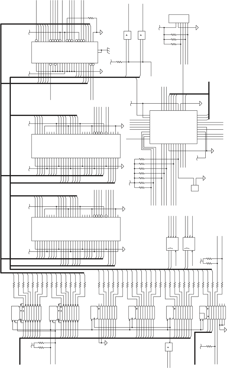
HSALFPXE
DNG
=
*LESCNEH
W
REVIRD/ROTAL
O
SI
SSERDDA/SUB
CILC
SMT_CILC
IDT_
C
I
L
C
ODT_CI
LC
K
CT
_
C
I
LC
D
NG
CCV
G
ATJ
G
NI
MMARGORP
T
R
OP
G
U
BE
D
HSALFTCAPMOC
HSALFTOOB
ED
O
M
RE
TSA
M
R210
R209
R208
6
5
4
3
2
1
4
2J
R207
62
35
15
01
42
9
11
34
36
3
3
1
44
43
14
13
12
8
7
6
5
42
41
40
39
38
37
23
1
3
0
3
3
92
82
7
2
32
22
21
20
19
18
16
2
5
2
17
4
29U
9
1
8
1
7
1
61
5
1
41
31
21
1
2
3
4
5
6
7
8
9
11
4
2
U
91
81
7
1
6
1
5
1
4
1
3
1
21
1
2
3
4
5
6
7
8
9
11
32U
91
81
7
1
61
51
4
1
31
21
1
2
3
4
5
6
7
8
9
11
2
2
U
5
62R
8
01
9
1
9U
6
5
4
1
9U
63
04
33
8
3
31
44
3
4
14
64
5
3
2
4
43
42
7
3
05
1
5
4
84
74
6
5
4
3
2
32
13
03
92
82
7
2
94
2
2
12
9
3
23
7
52
6
2
9
01
11
2
1
4
1
5
1
61
7
1
81
8
91
0
2
22J
1
3
2
0
9U
11
21
3
1
41
5
1
6
1
7
1
8
1
91
1
9
8
7
6
5
4
3
2
52U
R203
R204
6
0
2R
2
0
2R
R201
R200
2
1
32J
512R
612
R
71
2
R
81
2
R
91
2
R
022R
122R
222R
322R
42
2
R
622
R
522
R
822R
7
2
2R
92
2R
R895
R894
R893
R892
R890
R889
03
2
R
132R
232R
3
3
2R
4
3
2R
63
2R
5
3
2R
73
2R
932R
832R
04
2R
14
2R
24
2R
3
4
2R
44
2R
5
4
2R
74
2
R
642R
84
2R
9
4
2R
0
5
2R
2
5
2R
1
52
R
35
2R
452
R
5
52
R
652
R
752
R
7
6
5
4
3
2
1
6
2
U
9
01
11
2
1
3
1
41
5
1
62U
91
1
1
1
21
31
41
51
6
1
71
8
1
9
8
7
6
5
4
3
2
1
2U
1
7
16
1
5
1
4
13
1
2
11
1
8
6
6
6
6
5
64
6
3
62
61
6
46
56
7
6
0
7
96
2
7
06
95
85
75
54
44
3
4
24
3
6
26
5
3
92
7
2
4
2
2
2
9
7
03
82
52
32
01
8
4
2
4
1
21
83
5
3
3
3
0
2
8
1
74
5
5
4
5
35
25
51
0
5
94
84
0
4
93
7
3
43
2
3
9
1
71
31
0
2J
17
16
1
5
1
4
13
12
11
1
8
6
66
6
5
64
6
3
6
2
61
6
4
6
56
7
6
07
96
2
7
06
95
85
75
5
4
44
34
2
4
36
2
6
5
3
92
72
42
22
9
7
0
3
8
2
5
2
3
2
01
8
4
2
41
2
1
83
53
33
0
2
8
1
7
4
5
5
45
35
2
5
51
05
94
84
0
4
93
7
3
43
23
91
71
31
12
J
9
1
1
1
1
21
31
41
51
61
7
1
81
9
8
7
6
5
4
3
2
02U
N
_
PS
AD_FC
N
_
0
SC_F
C
YD
R
OI_FC
QR
T
NI_
FC
N_DR_FC
N
_RW
_F
C
N_
1SC
_F
C
N_
1D
C
_F
C
N_
G
AIDP_FC
N
_TESE
R
N
_
2DC
_FC
N_61SCOI_FC
1
N
_3
S
C
_
L
F
>0..51<
D
V3.
3
02
DN
GD=DNG;V3.3=CCV
9
8
N
_
R
W
_
S
U
B
N
_
3S
C
_
LF
N_2SC_LF
23CHA
01
)
0..51(D
N_RW_FC
4
1
D
NGD
=DN
G
;
V
3
.
3=CCV
D
NGD
=DN
G
;
V
3
.
3
=CC
V
71
42
3
V3.3
5
4
2
CHA
51
5
4
75C
HA
11
5
4
2
CH
A
1DP_DS
0D
P
_DS
N
_
S
E
R_ICP
NE
_
PPV
N
_TED_ICP
6
CLIC_CLK
V3.3
0D
P_B
_
L
F
1
D
P_B_LF
N_TINI_
A
SP
N
_
G
ORP_ASP
EN
O
D
_
AS
P
KC
T
_CI
L
C
S
M
T_CI
L
C
IDT_CILC
20
C
VL
23CHA
DNGD=DNG;V3.3=CCV
145CH
A
DNGD=DNG;V3.
3
=CCV
N
_SDA
DNGD
=DNG
;V3
.3=CC
V
K
L
C
_D
S
475CHA
1
7
51
21
N_DR_SUBN_DR_SUB
N
_TESE
R
N_1SC
_
L
F
N_RW
_
S
U
B
N
_0SC
_
LF
>
0..13<D_
M
1
V3.3
>
1
..
5
1<A_M
DNGD=DN
G;V3
.3=CCV
02
V3.3
42
71
DNGD=DN
G
;
V
3.3
=CC
V
DNGD=DN
G
;V3.3
=CC
V
2
01
32
22
12
V3
.
3
51
1
2
931CHA
51
7
52 42
N
_RW
_
M
3
1
2
4
5
6
7
0
1
9
2
1
41
32
22
0
2
9
8
4
5
6
7
42
52
71
8
1
3
2
1
11
2
1
31
4
1
51
01
4
5
6
8
9
21
31
4
1
1
2
3
4
5
6
7
8
9
01
1
1
2
1
31
41
61
22
1
2
52
0
5
1
91
11
8
N_DR_M
N_RID_SUB
N
_N
E_SUB
6
1
31
475CHA
DNGD=DNG
;
V3.
3
=CCV
DNGD=DNG;V3.3=CCV
0
V3
.
3
31
21
11
41
3
4
7
2
0
2
V
3.3
7
5
1
61
91
81
12
22
V3.3
0
1
8
9
2
3
01
11
8
1
9
2
01
3
11
4
4
21
5
31
5
31
7
41
61
51
71
42
91
81
V3.3
1
2
0
2
22
32
5
4
V3.3
0
8
1
9
2
01
3
11
1
2
3
1
1
4
4
21
3
1
6
4
1
7
51
2
1
5
6
31
N
_
1SC_FC
N
_0
S
C
_FC
41
>1..52
<A
32
N_SC_FC
6
931CHA
3
91
N_TESER
9
N_R
W
_
S
UB
N
_
DR_S
U
B
8
1
01
N_
0
SC_LF
N
_
1SC_LF
N_2SC_LF
N_
SC_2PX
E
N_SC_BSU
N
_
0SC
N
_
2SC
5
N
_S
C_DI
V3.3
5
6
7
V3
.
3
SMT_C
ILC
IDT_CILC
K
CT
_
C
ILC
RESET_N
ID_CS_N
CF_CS_N
BUS_WR_N
ODT_CILC
N_DR_FC
N_TESERA
USB_RES_N BUS_RD_N
VPP_EN
P24EN
PSA_RES_N
1
3
1
0
2
4
V3.3
N
E_P
P
V
EXP2_RES_N
EXP1_RES_N
1DP_B_LF
8
0DP_B_L
F
6
N_
1
SV
_
FC
N_2SV_
FC
D
D
D
D
L
X
6
3
5
9
CX
IO_GCK2
1OI
1DNG
3OI
4OI
5OI
6OI
I
DT
SMT
K
CT
IO7
IO8
IO9
81OI
IO25
VCCINT1
IO10
GND2
IO11
IO12
IO13
IO14
IO15
2OI
R
S
G_
O
I
3KCG_O
I
22OI
12OI
02OI
91OI
71OI
OICCV
3DNG
ODT
61O
I
IO_GCK1
IO28
IO27
IO26
IO24
IO23
IO_GTS1
VCCINT2
IO_GTS2
NE
D1
1C
NE
D1
1C
NE
D1
1
C
1
1
HSAL
F
TCA
P
MOC
1
UF
R
2UFR
*PSAD
*0SC
0
1
A
2DNG
01D
9D
8D
YDROI
*2SV
QRTN
I
*
EW
*
1SV
*
DROI
*RWOI
*1SC
51D
41D
3
1D
21D
*1DC
11D
2D
1D
3A
4A
6A
1CCV
8
A
7A
9A
*LESATA
7D
6
D
4D
1DNG
3
D
MTG1
MTG2
*
G
AIDP
5A
*TESER
*LESC
2CCV
5
D
2A
1A
0
A
0D
*2DC
*61SCO
I
2_
C
1
&
NE
0
3
G
1
0
3
2
0
1
X
U
M
D
0
3
G
1
0
3
2
0
1
X
UM
D
D
D
D
D
D
1
]BA[2NE3
]AB[1NE3
3G
2
01D
3D
11D
41A
7
A
51A
5SS
V
61A
2CN
1
C
N
3CN
5CCV
4C
N
42A
71A
81A
6SSV
91A
02A
22A
12A
6CCV
32A
5CN
6CN
7
C
N
7SS
V
8CN
*0
S
CF
*RWSYS
*1SC
F
*
TE
SER
7C
CV
*DR
S
YS
P
PV
0
DP
9CN
8S
S
V
1DP
1SSV
0D
8D
1D
9D
2D
1CCV
2SSV
8A
1A
9A
2A
2
CCV
3A
01A
11A
4A
3SSV
4D
21D
5D
31D
3CCV
41D
6D
7D
4SSV
5
1D
21A
5A
6A
31A
4
C
C
V
01D
3D
11D
41A
7
A
51A
5
S
SV
61A
2CN
1C
N
3CN
5CCV
4CN
42A
71A
81A
6
S
SV
91A
02A
22A
1
2
A
6CCV
32A
5CN
6CN
7
CN
7SSV
8CN
*0SCF
*RWSYS
*1SC
F
*
T
ESER
7CCV
*DRSY
S
PPV
0DP
9C
N
8SSV
1DP
1SSV
0
D
8D
1D
9D
2
D
1CCV
2SSV
8A
1
A
9
A
2A
2CCV
3A
01A
11A
4A
3
SSV
4D
21D
5D
31D
3CCV
41D
6D
7D
4SSV
51
D
21A
5A
6A
31A
4CCV
1
]
B
A
[
2
N
E
3
]
A
B[1
NE
3
3
G
2
D
D
D
156 EasyCoder PX4i and PX6i Service Manual
Chapter 15 — CPU Board
1-971630-26 CPU Board; Flash Interfaces (Schematics #2)
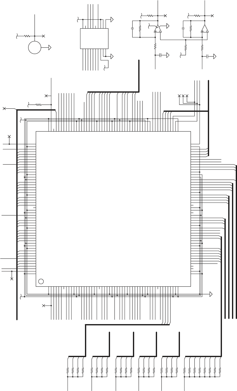
NOTTUBI
TSUJDAROSNES
RETREVNOC-D/A
23PP
33C
23C
SMT
KCT
ODT_AS
P
13C
0
3C
1
2
0
3J
923R
0D
KLCC
ENOD
GOR
P
T
INI
13P
P
0
3
PP
933R
003R
4
3
3R
733R
3
3
3R
633
R
313R
413R
513R
6
1
3R
713R
913R
81
3R
023R
523R
7
23R
623R
82
3R
2
1
3
R
113R
0
1
3R
903R
8
03R
70
3
R
603R
5
03R
40
3R
3
0
3R
2
03R
10
3
R
12
3R
223R
323
R
423R
5
7
6
23U
833R
8
3
1
4
2
23U
533R
02
31
51
21
91
0
1
41
7
1
8
1
9
61
8
7
6
5
4
3
2
1
11
13U
7
1
1
501
92
78
65
53
93
6
2
208
197
184
170
651
441
0
3
1
21
3
41
8
21
811
91
76
66
83
82
196
186
171
31
2
157
159
207
601
56
55
54
05
25
741
641
241
141
0
4
1
931
831
63
1
53
1
43
1
4
1
331
231
921
721
62
1
521
321
221
12
1
02
1
0
1
9
11
511
4
11
311
21
1
111
01
1
901
801
9
102
101
100
99
98
97
96
95
94
90
8
89
88
87
86
84
83
82
81
75
74
7
73
71
70
69
68
67
63
62
61
60
6
59
58
57
9
4
8
4
7
4
6
4
5
4
44
34
5
24
1
4
7
3
63
53
43
3
3
13
03
92
4
72
4
2
32
22
1
2
206
02
205
204
203
202
201
200
199
195
194
193
81
192
191
189
188
187
181
180
179
178
176
7
1
175
174
173
172
168
167
166
165
164
163
61
162
161
160
451
2
5
1
1
51
051
941
84
1
5
1
3
701
72
64
15
0
4
23
52
91
198
190
183
177
169
1
1
158
54
1
7
31
131
421
6
11
103
93
85
79
1
185
182
77
80
104
351
5
51
03U
3
)0..41(OI_R
E
VIRD
I
D_DA
GID
_
LP
GID_L
R
V3
.
3
M393M
L
V
5.2
N
ES
_
LR
N
E
S_
L
P
ERP_PAG
E
RP_
MB
E
DO
I
D
_M
B
E
R
P
_
L
R
ERP_LP
)0..3(NI
A
G_P
A
G
)0.
.
3
(
N
I
AG_MB
)0..3(EVIRD_MB
)0..3(NIAG_LR
)0
..3(NIA
G_
LP
3
2
1
0
3
2
1
0
3
2
1
0
3
2
1
0
3
1
2
0
)0..
7
(
N
I
A
G
_
ST
L
NES_STL
1
0
2
3
4
5
6
7
LTS_DIG
NE
_
SAEM_HPT
N_
0
TNI
1OI_NOC
0OI_N
O
C
V
3
.
3
NOTTUB
ITSNI_STL
NES_LR
V5
V
5
KLC_DA
ID_
D
A
N
_SC_DA
7
8
9
5
6
4
2
0
21
9
22
23
8
7
24
6
5
25
26
4
27
3
28
2
29
1
30
31
16
15
17
14
18
13
12
19
20
11
10
1
4
3
2
6
5
7
8
0
1
2
0
1
3
1
0
2
3
2
3
0
1
2
3
0
1
2
5
4
3
6
7
TCK
)
1
..
8
(
A
TA
D
_HPT
)0..3(EV
I
RD_MB
)
0..3(NIAG_MB
)0
..3(NIA
G
_
P
A
G
)0..
3
(NIAG_LR
1
0
3
2
L
CS
A
DS
2NIAG_HPT
0NIAG_HPT
2
LAC
_HPT
1LAC_HPT
0LA
C_HPT
N_T
O
N
_NIF
0OI
_
N
I
F
1OI_
N
I
F
2
OI_NIF
YDROI_FC
N_
1
TNI
N_TNI_1PXE
DNA
W
N
_
TNI_BSU
PEE
B
PSA_CLK
PSA_CS_N
M_RD_N
K
LC
_
D
A
RL_DIG
PL_DIG
N
_SC_
A
SP
PL_INST
HEADLIFT
KLC_H
P
T
N_HCTAL_HPT
N
_
B
RT
S_HPT
N_SC_DA
0
T
S
N
I_
LR
2OI
_NOC
N_TON_NOC
N_TNI_USP
N_TON_USP
V5
.2
E
N
O
D_AS
P
N_TINI
_
ASP
N_GO
R
P_ASP
0
QRTNI_FC
N_ENOD_AMD
N_
T
N
I
_2
PXE
1NIAG_HPT
1
NOTTUBI
>0
..13<
D
_M
S
M
T
N_
R
W_M
N_AMD
N_KC
A
N_TIAW_M
N_SER_ASP
V3
.3
PSA_TDO
CPU_TDO
ADS_N
V3.3
V
5
M39
3
ML
OD_DA
NE42P
MREHT
NES_LP
SER_H
P
T
NES_MB
NES_PAG
OD
_
D
A
01
1
1
21
41
V3.3
31
D
D
D
D
DNG
ATAD
D
D
V5 CN
ID
1H
C
2HC 3HC 4HC 5
H
C6HC
7HC
MOC DN
GADNG FER *ES
O
D
S
RAS KLC
8380CLT
*
SC
0HC
D
03
S2
CX
NI
D
ESU
T
O
NC
N_HT
I
W
S
N
I
P
IO136_NC
CN_101OI
CN_57O
I
IO64_NC
IO40_NC
CN_13OI
CN_5OI
03OI
SMT
1OI
2OI
IO139
IO138
IO137
IO135
IO134
IO133
VCCO15
VCCINT12
NC2
NC1
7DN
G
6
3OI
GND24
GND23
GND22
GND21
GND20
GND19
81DNG
71DN
G
61DNG
51DNG
41DNG
GND13
GND12
GND11
GND10
GND9
GND8
9
1
O
I
2T
N
I
C
CV
02OI
12OI
22OI
5DNG
32OI
42OI
52OI
62OI
72OI
3TNICCV
6D
NG
82OI
92OI
23OI
3
3
O
I
0M
1DNG
4OI
3OI
2
DNG
8OI
7OI
6O
I
21OI
1
1OI
01OI
9OI
1
TNICCV
61
OI
51OI
41OI
3
DN
G
31
OI
2OCCV
4
DN
G
81OI
71OI
3
O
C
C
V
IO107
TDI
TDO
IO113
VCCINT10
IO115
IO114
IO120
IO119
IO118
IO117
IO116
IO124
IO123
IO122
IO121
VCCINT11
GCK3
GCK2
IO128
IO127
IO126
IO125
IO131
IO132
IO130
IO129
IO140
TCK
401OI
501OI_NID
3
01
O
I
201OI
99OI
001OI
89
OI
69OI
7
9O
I
9TNICCV
29OI
39OI
4
9
OI
59OI
88OI
98OI
09
OI
19OI
58
O
I
68OI
8TNICCV
78O
I
1
8OI
28OI
38OI
48O
I
08OI
97OI
7TNICCV
8
7
OI
77OI
67OI
47O
I
37OI
27OI
1
7
OI
07O
I_N_TIN
I
N_
M
ARG
OR
P
IO68
IO69
DONE
IO67
IO60
VCCINT6
IO61
IO62
IO63
IO65
IO66
GCK0
IO52
IO53
IO54
IO55
IO56
IO57
IO58
IO59
IO47
IO48
IO49
IO50
IO51
VCCINT5
GCK1
IO41
IO42
IO43
VCCINT4
IO44
IO45
IO46
IO39
IO37
IO38
M2
ASP
VCCO5
VCCO6
VCCO7
8O
CCV
9OCC
V
01OCCV
11OCCV
21OCCV
VCCO13
VCCO14
VCCO16
1OC
CV
43OI
VCCO4
1M
53OI
002S2CX&051S2CX,001S2CX,05S2CX
,03
S2CX
IO112_NC
IO111
IO110
IO109
IO108
KLCC
601OI_TUOD
EasyCoder PX4i and PX6i Service Manual 157
Chapter 15 — CPU Board
1-971630-26 CPU Board; PSA (Schematics #3)
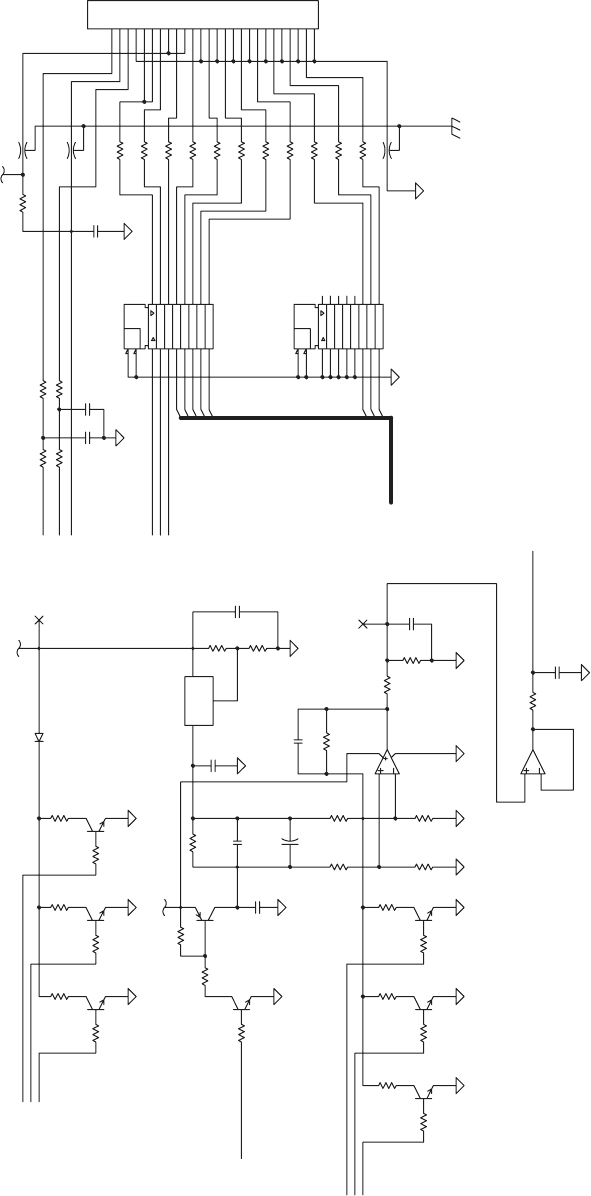
TSETECNATSISERTOD TIUCRIC
FOY
B
T
S
UMDRAOB
G
N
IDNOPSERROC
E
HT
8
ATAD
7ATAD
6ATAD
5ATAD
C
C
V
2EBOR
T
S
DNG
C
C
V
HC
T
A
L
1
EB
O
R
TS
2MREHT
KLCC2I
D
NG
D
NG
DN
G
DNG
2
A
T
AD
3A
T
AD
AT
A
DC2
I
DNG
DNG
1ATA
D
KC
OL
C
1M
R
EHT
4ATAD
DNG
U
SPNO
E
D
O
I
D
LAMREHT )HPT(DAEHTNIRP
EPYTEMAS
01
4
C
144R
0
4
4
R
934R
834R
734R
63
4R
5
34R
4
34R
33
4R
234R
134R
034R
14PP
514L
2
0
4L
004
L
04D
04PP
90
4
C80
4
C
924
R824
R
7
24R624R
7
0
4C
424R
124R0
2
4R
7
1
4
R6
1
4R
5
14R
914R
8
14R
1
14R
0
14R
504R404R304R
404C
414
R314
R2
1
4
R
20
4R
224
R
3
2
4R
10
4R
0
0
4R
80
4R
7
04R
6
04R
9
0
4R
11
2
1
31
41
5
1
8
1
71
6
1
91
1
9
8
7
6
5
2
3
4
34U
81
7
1
61
5
1
41
3
1
21
11
91
1
2
3
4
5
6
7
8
9
24U
5
7
6
14
U
EC
B
54T
EC
B
6
4T
0
04C
EC
B
74T
8
3
1
4
2
14
U
204C
104C
EC
B
34T
E
C
B
44T
EC
B
04T
EC
B
14
T
304C
2
3
1
0
4U
6
04C
5
0
4
C
9
8
7
6
5
4
3
6252423
222
12
02
2
918171615141312
1
1
1
01
1
04J
EC
B
2
4T
5
24R
M853ML
SER
_
HP
T
M
8
53
M
L
NE_SAEM_HPT
A
D
S
N_BRTS_HPT
S
_
V4
2
145TCHA
DNGD=DNG;V5=CCV
VHPT
V5
>1..8<ATAD_HPT
2
N
IAG
_HPT
1N
I
A
G
_
HP
T
0NI
A
G_H
P
T
MREHT
2
8
7
5
4
3
1
KLC_HPT
145TCHA
DNGD=DN
G
;
V5
=CC
V
LCS
1
L
A
C
_H
P
T
0L
A
C_HPT
2LAC_HPT
N
_
H
C
TAL
_
HPT
HPT_V5
H
P
T
_DNG
6
D
D
1_C
DD
+
D
D
TU
O
JDA
NI
D
D
DD
D
D
&
NE
&
NE
DDD
D
DD D
158 EasyCoder PX4i and PX6i Service Manual
Chapter 15 — CPU Board
1-971630-26 CPU Board; Thermal Printhead Interface (Schematics #4)
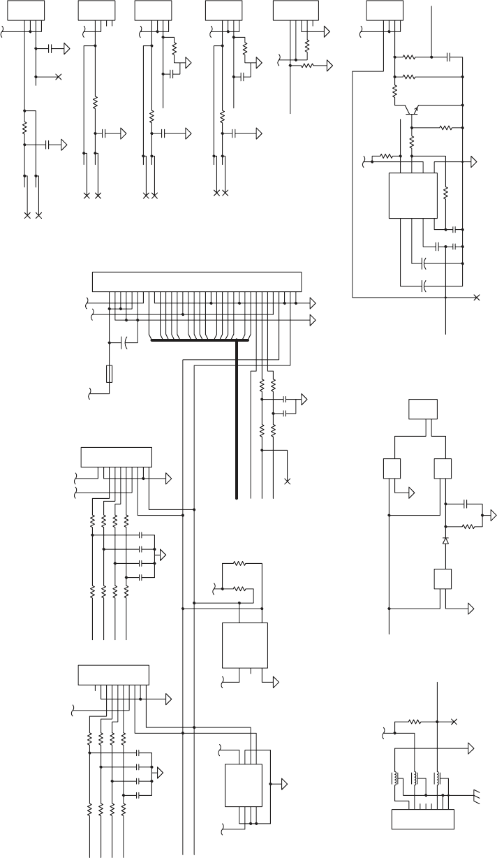
SECAFRETNIC2I
REHSINIF
SROSNES
KRAMKCALB
TFILDAEH
STL
DNAW
/USP
WOLNOBBBIR
REPEEB
E
LOS
NO
C
P
AG
SR
E
V
IR
DROTO
M
W
OL
REPA
P
4
3
2
1
45J
07F
N_TN
I
_U
SP
DNAW
05D
045
C
6
5
4
08U
8
01
9
0
8
U
1
1
3
1
21
08
U
2
1
06B
126R
007
C
15PP
05PP
1
05C
6
5
4
3
2
1
9
5
J
95PP
45PP
85PP
75PP
6
5
PP
55PP
35PP
2
5
PP
845R
745R
C538
C539
645R
945R
335R
235R
C530
135R
035R
C531
C532
C533
735R
635R
435R
535R
1
4
5R
045R
935R
83
5R
C534
C535
C536
245R
5
45
R
445R
C537
34
5R
25
L
1
5L
0
5
L
2
1
5
C
625R
4
5
3
6
8
7
1
2
25U
9
8
7
6
5
4
3
2
01
1
15
J
9
8
7
6
5
4
3
2
01
1
05
J
315C
2
1
5R
205C
315R
605C
405C
505C
305C
61
5
R
415R
8
15R 9
15R
5
4
3
2
1
85J
715R
515R
4
3
2
1
75J
705C
C510
C511
9
0
5C
805C
025
R32
5
R
2
2
5
R
EC
B
1T
125R
4
3
2
1
65J
4
3
2
1
5
5
J
525R
4
25R
4
3
2
1
3
5J
7
8
5
6
4
3
2
1
0
5
U
005R
1
4
5
3
2
1
5
U
015R905R
9
8
7
6
5
4
4
33323
1
3
03
3
9282726
25
2423222
1
2
02
2
918
1716
15
14
1312
1
11
0
1
1
25J
GI
D
_S
TL
41
31
21
1
1
01
>0..41<
OI
_REV
I
RD
V5
ER
P
_LR
NES_LP
ERP_MB
NE
S_MB
EDOID_MB
N_TON_USP
1
OI
_NI
F
2OI_NIF
VHP
T
TSNI_STL
I_
V
42
2
4
6
8
N
E
S_LR
E
R
P
_L
P
ERP_PAG
S
_V42
REZZUB
N_T
ON
_
N
I
F
0OI_NIF
765ML
DNAW
68CHA68CHA
6
8C
HA
DNGD=DNG;V5=
C
CVDNGD=DNG
;
V5=CCV
4961CTL
V5
V5
V
5
V
5
V5
0
1
3
5
7
9
V
5
V5
TFILDAE
H
NE
S
_PAG
TSNI_LR
TSNI_LP
ADS
V5
V5
V5
N_TNI_USP
V5
V
5
V
5
N_T
O
N
_NO
C
1OI_NOC
P
EEB
L
CS
2OI_NOC
0
O
I_NOC
V
5
NE42P
D
NG
D=
DNG
;
V
5=CCV
N
E
S_STL
D
D
2
S
UB
MS
1SUBMS
DNG
C/N
CCV
DD
D
1=
1
=
1=
D
D
+
D
D
1GTM
2GTM
D
DD
2_C
DN
G
CCV
ENO
T
TUO
R
E
T
LI
F
T
UO
R
E
TL
I
F
N
I
NIENOT
PACEMIT
D
D
D
D
DD
D
D
+
+
D
DNGI42
D
A
2
0
C4
2
0A
1
A
DNG
2A
CCV
PW
ADS LCS
EasyCoder PX4i and PX6i Service Manual 159
Chapter 15 — CPU Board
1-971630-26 CPU Board; Internal Interfaces (Schematics #5)
S
TR-OSIM_I
P
S-3
R
S
D-KC
S_I
P
S-4
STC-ISOM_I
P
S-2
DX
T-
0
X
T
_
T
RA
U-1
DXR-0XR_TRAU-0
RTD-N_1TNG_ICP-5
SUBPXE
232SR
TCET
E
D
RE
I
RRA
C
A
T
A
D-DCD
2
32SR
SNIPU
PC
.
ONS
U
B
S
CT
NI
Q
E
RD KCAD KCAD QERD
SC
LCS
ERAPS
2TOL
S
TNI
1TOLS
ERAPS
A
DS
DNESOTTSEUQER-STR
YDAERTESATAD-RSD
YDAERLA
N
IMRETA
T
AD-RTD
DXR
RTD
R
O
T
AC
I
DNIGNIR-IR
DNESOTRAELC-STC
ATAD
EV
IEC
ER
-DR
ATA
DTI
M
S
NART-
DS
DN
UOR
GLA
NGIS
-
G
S
1
5
3
2
4
6
7
8
9
TESER
RSD
TESER
1AS
1AS
+
D
C
N
DN
G
9BDDRADN
A
TSMBI-ECNER
E
FER
ST
RSTC
DNG
DXT
CN
C
N
BSU
D
D
V
-D
92
6
R
5
26R
4
2
6
R
326R
N_T
N
I_B
S
U
N_TNI_1PXE
N
_
TNI
_
2
PXE
0
6P
R
8
6L
2GTM
1
G
TM
9
8
7
6
5
4
3
2
1
16J
76L
66
L
5
6L
46L
36L
26L
16L
C60
C61
R605
06Y
R615
R614
R613
R612
R611
R610
4
06R
306R
206R
91
6
R8
1
6R
026R
72
6
2
3
2
2
81
61
2
4
2
52
4
32
1
2
5
9
1
0
2
6
51
4
1
31
21
1
1
0
1
9
8
1
82
71
7
06
U
R600
R601
36C
62
72
4
21
71
01
91
7
22
6
32
5
42
41
8
1
11
0
2
9
6
1
12
8
51
2
31
1
3
82
5
2
16U
4
6
C
0
6
L
26C
4
3
2
1
06J
56C
626R
66C
826R726R
5
83
4
86
43
7
6
3
3
66
2
3
5
6
13
46
73
03
3692268
2
1
6
72066295
3
52854275326
52255
12
45
63
0
235
91
25
811
571
05
61
9
4
2
51
84
4
1
74
3
1
6
4
21
54
11
4
4
53
01
3
4
9
24
8
14
7
0
4
6
9
3
1
2
6
J
N_RW_SUB
V3.3
>0..51<
D
V5
N
_
TNI_
BSU
N_TNI_2PXE
N_
S
C
_
2P
X
E
N
_
SE
R_
2
PXE
N
_
TNI_1P
X
E
N
_
SC_1PXE
N_SER_1PXE
LCS
ADS
S
_V42
N_TIAW_M
N_DR_SUB
V5
6
N_RW
_
SUB
V3.3
V3.3
4
0
2
1
11
01
9
8
7
5
4
3
2
1
5
1
41
31
21
1
1
0
1
9
8
7
5
3
2
1
V
3.3
V3.
3
5
6
0
2
3
zh
M
42
2
0
1
4069NBSU
4
5
3
6
7
4
>1..42<
A
N_DR_
SUB
N
_SER
_BSU
4
>0..5<TRAU
1
V3.3
N_SC_BSU
*SC *D
R
KS_R
W
+D-D
*
T
ESER
*KCAD
7D
DNGA 3.3
V
D
N
G
CCV
1
E
D
OM
D
NG
NIX
TUO
X
0
E
D
O
M
T
UOKLC
Q
RD
R
TN
I
IS_ELA_0A
4D3D2D
1D
6D5
D
OS_
0D
D
E7323XAM
D
U
ABM
N
I3R NI2R
TUO3R TUO2R
NI
2
T
TUO
5
TTUO4T TUO3
TTUO2T TUO
1
T
NI
5
TNI4T NI3T
NI1T
T
U
O1
R
BT
U
O
1
R
N
I
1R
CCV
+V
-V
D
NG
+1C -
1C
+2C -2C
*
N
E
*N
DH
S
2
_C
D
+
2GTM
1GTM
D
2_C
D
D
D
2
_
C
D
160 EasyCoder PX4i and PX6i Service Manual
Chapter 15 — CPU Board
1-971630-26 CPU Board; External Interfaces (Schematics #6)
V3.3OTV5
TAELOHTNUOM BCPNOTFELREWOL
V5.2OTV5
!Y
L
NOTNIOPSIHT
NI
D
NATNIOPSIHTNI07HMHTIW )D(DNUORGLATIGIDTIUC
R
ICTROH
S
EC
RU
O
S
V42
OTT
SE
S
OLC
EL
OHT
N
UO
M
RETREVNOCV5OTV42
47L
17
L
2
7
L
617C
81
7
C
71
7
C
2
1
7
C
907C
5
1
7
C
41
7
C317C
17HM
307C
9
07R
3
1
2
07YHT
CA
07Z
8
0
7
C
7
0
7C
5
27R
4
2
7
R
3
2
7R
227R
12
7R7
1
7R91
7
R
027R617R
817R
27
D
51
7
R
41
7
R
607C
S
G
D
27T
507C
31
7
R
1
7
D
07D
EC
B
17T
217R
117
R
EC
B
0
7T
0
1
7
R
0
7
L
4
07
C
70
7R
80
7
R
207C
607R
4
07
R
307
R
50
7
R
207R
107R
007
R
2
1
6
4
1
31
7
3
01
9
4
5
11
8
51
61
2
1
07U
107C
2
3
1
1
7U
V3.3
V5.2
DN
G
117
C
2
3
4
1
27
U
0
17C
07HM
V
5
V
5.2
V3.3
V5
V5
I_V42
S_V42
2
_
C
1
_
C
+
4
9
5LT
CC
V
TR
1C
1
E
2C
2
E
FER
DNG
CO
-
N
I
2
+NI
2
-
NI1
+NI1
TC
B
F
C
T
D
+
JDA/DNG
N
IV
TUOV
DD D
J
D
A/DNG
N
IV
BAT
TUO
V
D
+
D
D
N
G
I
42
DD
+
++
EasyCoder PX4i and PX6i Service Manual 161
Chapter 15 — CPU Board
1-971630-26 CPU Board; Power (Schematics #7)
SNW
O
D-LL
UPC
S
I
M
SPU-LLU
PCSI
M
G
ATJ
E
ROTARENEGTESER
TESER
.
TXE
SPU-LLUPSUB
ICP
939R
839
R
739R
6
39
R
53
9
R
439R
339R
2
3
9
R
1
3
9
R
40
9
R
209R
R901
R900
R903
509R
9
8
7
6
5
4
3
2
413121
1
1
01
1
18J
019R
43
0
3
62
2
2
81
4
1
01
6
83
2
57
17
76
36
95
55
1
5
74
34
04
6
3
7
3
9
3
5
3
8
7
77
7
1
61
3
5
47
3
7
13
4
5
31
5
1
75
33
23
85
6
5
27
5
2
91
25
6
4
8
7
5
4
5
4
4
4
0
7
96
3
92
8682
7
2
66
5
6
4
6
4
2
32
26
24
1
6
1
2
0602
21
1
1
0
5
9
4
9
84
14
1
97
67
08
48J
5
1
3
4
2
18U
999R
899R
799
R
69
9R
5
99
R
4
99
R
399R
299
R
199R
099R
98
9R
889R
7
89R
68
9
R
589R
48
9
R
3
8
9
R
2
89
R
R981
R979
R980
R977
R978
R975
R976
R973
R974
R971
R972
R969
R970
R967
R968
R965
R966
R963
R964
R961
R962
R959
R960
R957
R958
R955
R956
R953
R954
R952
R951
R950
6
29
R
7
2
9
R
829R
92
9
R
0
3
9R
529R
429R
329R
229R
129R
029R
9
9
8
R
898R
798R
69
8R
R848
R849
R850
R851
R852
R853
R854
R855
R856
R857
R858
R859
R860
R861
R862
R863
R864
R865
R866
R867
R868
R869
R870
R871
R872
R873
R874
R875
R876
R877
R878
R879
R880
R881
R882
R883
R884
R885
R886
R887
R888
R911
R912
3
2
1
08U
3
19R
EC
B
08T
51
9
R
2
1
38
J
419R
518R
41
8
R
31
8
R
2
18R
11
8
R
018R
908R
038R
138R
9
2
8R
828R
728R
6
28
R
52
8R
8
0
8R
708R
6
08R
50
8
R
4
08
R
3
0
8R
2
0
8R
10
8R
00
8R
42
8R
328R
228R
128R
028R
918R
818
R
7
18R
618R
QR
TNI
_FC
TOOBD
_
JE
N_SD_IC
P
N
_EMARF_ICP
N_
6
1S
COI_FC
N
_
2S
V
_
FC
N_1SV_FC
N
_
G
A
IDP_
F
C
N
_
PSAD_
F
C
N_0EBC_
I
CP
N
_
1E
BC_IC
P
RAP_ICP
N_RRES_I
C
P
N
_KCO
L
_
IC
P
N_RREP_ICP
N
_SD_
I
CP
N
_
POTS
_IC
P
N_YDR
T
_ICP
N_EMARF_ICP
N
_YDRI_
I
C
P
N
_
2E
B
C_ICP
N_3EBC_ICP
N_0QER_IC
P
N_TNI_ICP
N_0TNG_ICP
N_2QER_ICP
N_3SC_DS
N_2TNG_ICP
N_2SC_DS
N_1SC_
DS
N_0
S
C_DS
N_2SC
N_EO_DS
N_0S
C
N
_
1
T
N
I
N_0
T
NI
N_TIAW_M
N_ENOD_AMD
N_TON_NIF
N_TON_USP
N
_
T
ON
_
N
O
C
N_TNI_USP
SMT
N_TNI_BSU
N_TNI_2PXE
N_
TNI_
1PXE
V3.3
6
2
42
22
R
A
P_ICP
31
3
N
_
Y
DRT_
I
C
P
8
2
52
N_
2
QER_ICP
21
V3.3
82
N_
S
E
R
_ICP
N
_
T
ED
_ICP
0
1
68CHA
DNGD=DNG;V5=CCV
5283SPT
V3.3
N
_T
S
R
T
SMT_
J
E
KC
T
N
_
T
E
S
ER_E
IDT
V3.3
)1..
5
2(A
)0..51(D
1
2
4
5
6
8
9
10
12
11
13
14
15
17
16
18
19
20
22
21
23
24
25
1
2
0
4
3
7
6
5
9
8
10
12
13
14
15
11
21
)0
..13
(
DA_
I
C
P
3
222
K
L
C_ICP
21
N
_
TESERA
62
N
_3
E
B
C
_
I
C
P
7
2
N_
2
EBC_ICP
N_
KCO
L_
I
C
P
V3
.
3
N_TESER_
E
)0..
1
3
(
D_
M
ADS
LCS
N_
0
EBC_ICP
03
N
_
RR
ES
_I
CP
N_R
R
E
P_
I
C
P
9
N_0Q
E
R_ICP
1
30
29
28
27
26
25
24
22
20
19
18
17
16
14
13
12
10
9
8
7
6
5
4
3
2
1
0
15
0
2
1
4
3
6
8
5
9
7
0
1
41
11
31
61
71
51
91
02
12
32
72
52
92
V3.3
0
3
13
V
3.
3
V
5
0
3
4
6
8
11
41
51
61
81
12
9
2
2
5
7
31
71
9
1
02
4
2
13
N
_TNI_
I
C
P
V3.3
N_1DC_FC
N
_
2
DC
_
FC
V3.
3
N_POTS_ICP
N_0TN
G
_IC
P
23
11
81
N_
1
EBC_
I
CP
7
N_YD
R
I_IC
P
O
DT
_
U
PC
1
=
D
D
D
D
0
8
ACS
6SSV
9CCV
N
_
T
SR
_
I
CP
2N_Q
ER
_ICP
KLC_ICP
2N_
EB
C_IC
P
81DA_ICP
3
2DA_
I
CP
42DA_ICP
N_TS
R
T
IDT
0
1
SSV
O
D
T
SMT
KCT
9SSV
N_TNI_
I
C
P
0N_TNG_ICP
0N
_
QE
R
_ICP
8
SSV
92DA_ICP
72
D
A_ICP
62DA_ICP
7SSV
3N_EBC_ICP
22DA_ICP
1
2
DA
_
IC
P
61DA_ICP
5SSV
N
_Y
D
RT_ICP
N_
P
O
TS
_I
C
P
4SSV
N_
K
C
O
L_
IC
P
5
1
DA_I
CP
4
1
DA_
IC
P
RAP_ICP
3
SSV
2
SSV
4
D
A_IC
P
3DA_ICP
1SSV
0DA_ICP
01DA
_
ICP
0N_EBC_ICP
2CCV
V4
2
N_TED_ICP
ADS
L
CS
1CN
8
C
CV
13DA_
ICP
03DA_ICP
82DA_ICP
7CCV
5
2
DA_I
CP
6C
C
V
0
2D
A_I
C
P
91
D
A
_
ICP
71DA_
I
CP
5
C
CV
N
_EMAR
F
_ICP
N
_
Y
DR
I
_
ICP
N_
L
E
SVED_
IC
P
4CC
V
N
_RRE
P_
IC
P
N_RRES_ICP
1N
_EB
C
_I
C
P
3CCV
31DA_ICP
2
1DA_
I
CP
7DA_ICP
5
DA_
I
CP
1CCV
2
DA_I
C
P
1DA_
I
CP
11
DA_I
CP
9DA_ICP
8DA_ICP
6DA_ICP
TES
ER
DNG
*TE
S
ER
DDV
*
R
M
D
162 EasyCoder PX4i and PX6i Service Manual
Chapter 15 — CPU Board
1-971630-26 CPU Board; Pull-ups (Schematics #8)
SROTICAPACSSAPYB/GNILPUOCED
203
MORPEE0
5
U
C
ILC
1
11
853ML14U
71
93
UPC
31
U
89
V3.
3
A
S
P
145T
C
H
A
3
4
U
2
3C
H
A
1
9U
145TC
H
A
2
4U
CIPU-
LL
U
P15
U
7
3
163
151
208
184
82
39
3ML23U
193
29U
R
EV
I
RD
K
COL
C11
U
REVIRDKC
O
LC11U
14
5C
H
A52U
475CHA42
U
475
C
HA32U
475
CHA2
2U
5
4
2CHA12U
5
4
2
CHA0
2U
68CHA08U
20CVL09U
501
D/A13U
21
197
69
341
821
811
171
181
197
V
5.
2ASP
31
03U
651
71
1
03
1
441
170
131
91
76
66
92
65
53
72
59
62
183
7
82
74
931CHA62U
ROTAR
E
NEGTESER18
U
173
REVIRDB
SU
0
6U
REVIRD232
SR
1
6
U
7
65M
L
25U
141
78
8
3
03U
12
1
99
199C
099
C
989C
889C
589C
609
C
7
0
9
C
6
89C
809C
9
0
9
C
789C
0
1
9
C
4
8
9
C3
8
9C2
8
9
C
189C
979C
7
7
9
C
089C
879C
299C
46
5
09U
0
1
9
8
09U
31
21
11
09U
679C
8
59C
759
C
659C
559C
459C
359C
259C
1
59C
5
0
9
C
4
0
9
C
3
0
9
C
20
9
C
109C
009C
119
C
6
6
9
C
469C5
6
9C
3
6
9
C
1
6
9
C
279C
179C
079C
969C
8
6
9
C
7
6
9C
37
9
C
529C
4
7
9
C
57
9
C
629C
729C
829C
739C
64
9
C54
9
C
74
9C
219C
319C
41
9
C
02
9
C
9
1
9
C
81
9
C
7
19
C
519C
619C
4
2
9
C
32
9
C
22
9
C
1
2
9C
039C929C
1
39C
2
3
9
C
639C
5
39C
439C
149C
049C
939C
339
C
839C
449C349C249C
059C
949C
8
4
9
C
D
NGD=DNG;V3.3
=
CCV
D
NG
D=
D
NG
;V
3.3=
C
C
V
DNGD=DNG;V3.
3
=CCV
V3.3
V
5.
2
V
3.3
V3.
3
V3.3
V3.3
V
3.3
V
3.
3
V
3
.3
V5
V3.3
V
3.3
V3.3
V
5.2
V5.
2
V5.2
S_V42
V3.3
20CVL
20CVL
20CVL
V3.3
V5.2
D
+
D
D
D
D
D
D
D
D
D
D
D
+
D
D
D
DD
1
D
1
1
D
D
+
D
EasyCoder PX4i and PX6i Service Manual 163
Chapter 15 — CPU Board
1-971630-26 CPU Board; Bypass/Decoupling (Schematics #9)
164 EasyCoder PX4i and PX6i Service Manual
Chapter 15 — CPU Board
15.8 Replacing the CPU board
Replace the CPU board this way:
• Switch off the power.
• Remove the left-hand cover as described in Chapter 3.3.
• Remove any optional interface boards.
• Disconnect all cables from the CPU board.
• Remove the four #T20 Torx screws and the hexagonal spacer that hold
the CPU board to the plate that covers the power supply unit.
• Lift out the CPU board and remove all SIMMs and any real time clock.
Take precautions against electrostatic discharges!
• Fit the SIMMs and possibly the real-time clock on the new board and
install it in reverse order.
The same CPU-board can be used for a range of EasyCoder printers. How-
ever, the fi rmware can not detect in which type of printer the CPU board
is installed. All replacement CPU boards are preprogrammed for the Easy-
Coder PF2/4i-series printers, which means that replacement CPU boards
always must be reconfi gured after being installed in an EasyCoder PX4i or
PX6i printer.
If the printer feeds out labels in a peculiar way, the CPU board may be
confi gured for the wrong type of printer (there is a difference in the dis-
tance between the dot line and the LSS position). You can easily check if
the CPU board is correctly confi gured by printing the “Hardware Info” or
“HW” test label in the Setup Mode or sending the Fingerprint instruction
PRINT VERSION$(1).
If the CPU board needs to be reconfi gured, do like this:
• Switch off the power.
• Insert a confi guration card in the memory card slot.
• Switch on the power.
• Using the same method as in the Setup Mode, select the correct printer
type from the menus shown in the display window.
• Switch off the power.
• Remove the card.
• Switch on the power again and check.

EasyCoder PX4i and PX6i Service Manual 165
16 Interfaces
This chapter describes the various communication interfaces for the Easy-
Coder PX4i and PX6i printers. However, some interfaces are not sup-
ported by the Intermec Programming Language (IPL) even though the
connectors are present.
The chapter describes three categories:
• Standard built-in interfaces
RS-232 interface
USB interface
Bar code wand interface (Fingerprint only)
• Optional interface boards
Serial/Industrial interface board (Fingerprint only)
Double Serial interface board (Fingerprint only)
IEEE 1284 Parallel interface board
• EasyLAN interface boards
EasyLAN Ethernet interface
EasyLAN Wireless interface
The EasyCoder PX4i and PX6i can—in addition to the standard built-in
interfaces—also be fi tted with one or two optional interface boards and
one EasyLAN interface board.
Note: Device designations, such as "uart1:", "usb1:", or "net1:", only
apply to Fingerprint, not to IPL.
166 EasyCoder PX4i and PX6i Service Manual
Chapter 16 — Interfaces
16.1 Introduction
In Fingerprint, "auto" is by default the standard IN and OUT commu-
nication port, that is, the printer will scan all communication channels
for incoming data. To select a specifi c communication port as standard
IN and/or standard OUT port, use an Intermec Fingerprint SETSTDIO
statement (see Intermec Fingerprint v8.xx, Programmer’s Reference Manual).
This gives better performance. Note that many application programs, for
example Intermec Shell, contain instructions that select the correct stan-
dard I/O for the application in question. The settings for the selected com-
munication channel will appear in the display window when pressing the
<info> key on the printer’s keyboard.
In IPL, all communication channels are always scanned for incoming data
and the fi rmware automatically switches to the same channel for output
too. The settings for the active communication channel will appear in the
display window when pressing the <info> key on the printer’s keyboard.
The standard interfaces (RS-232, USB, and Wand) are fi tted directly on
the rear of the CPU board with connectors protruding through slots in the
printer’s rear plate. Wand is not supported by IPL.
All optional interface boards, except the EasyLAN boards, are fi tted in a
slot on the printer’s standard rear plate and connected to the CPU board
via a fl at cable. If no interface board is fi tted, the slot is closed by two cover
plates.
The EasyLAN boards are fi tted directly to the front of the CPU board and
connected by wire to a connector or antenna. There are provisions for both
the wired EasyLAN connector and the EasyLAN wireless antenna on the
standard rear plate. All rear plates have slots for two interface boards as well
as for the standard interface connectors.
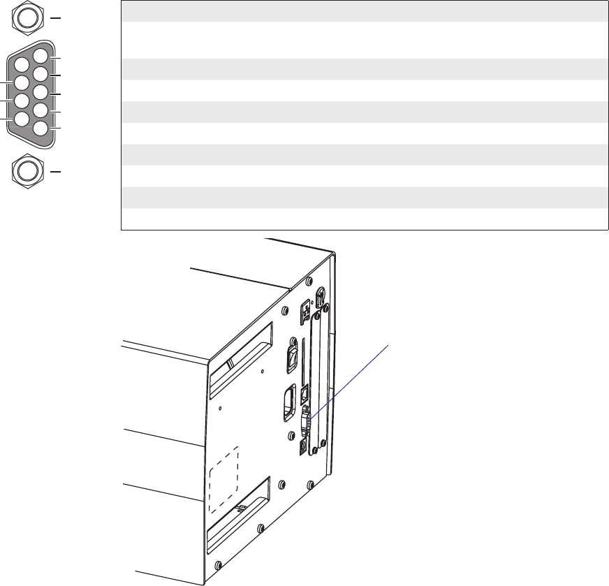
4
5
3
2
1
8
9
7
6TXD out
+5V DC
RXD in
DSR in
GND
MTG
MTG
DTR out
CTS in
RTS out
EasyCoder PX4i and PX6i Service Manual 167
Chapter 16 — Interfaces
16.2 RS-232 Serial Communication Port ("uart1:")
The EasyCoder PX4i and PX6i printers are always fi tted with one RS-
232 communication port. In Intermec Fingerprint, this port is designated
"uart1:" (uart = Universal Asynchronous Receiver and Transmitter.) The
circuitry is fi tted on the CPU board (see Chapter 15) and has a fi xed set of
signals in a DB-9pin female connector which protrudes through a slot in
the printer’s rear plate.
Protocol
Default setup
Baud rate: 9600
Char length: 8 bits
Parity: None
Stop bits: 1
RTS/CTS: Disabled
ENQ/ACK: Disabled
XON/XOFF: Disabled in both directions
New line: CR/LF
Signals on serial port ("uart1:")
DB-9 socket Signal Meaning
1 External +5VDC max 500 mA (automatic switch-off at
overload, short-circuit protected)
2 TXD Transmit data
3 RXD Receive data
4 DSR Data set ready
5 GND Ground
6 DTR Data terminal ready
7 CTS Clear to send
8 RTS Request to send
9 – Not used
RS-232 socket
("uart1:")
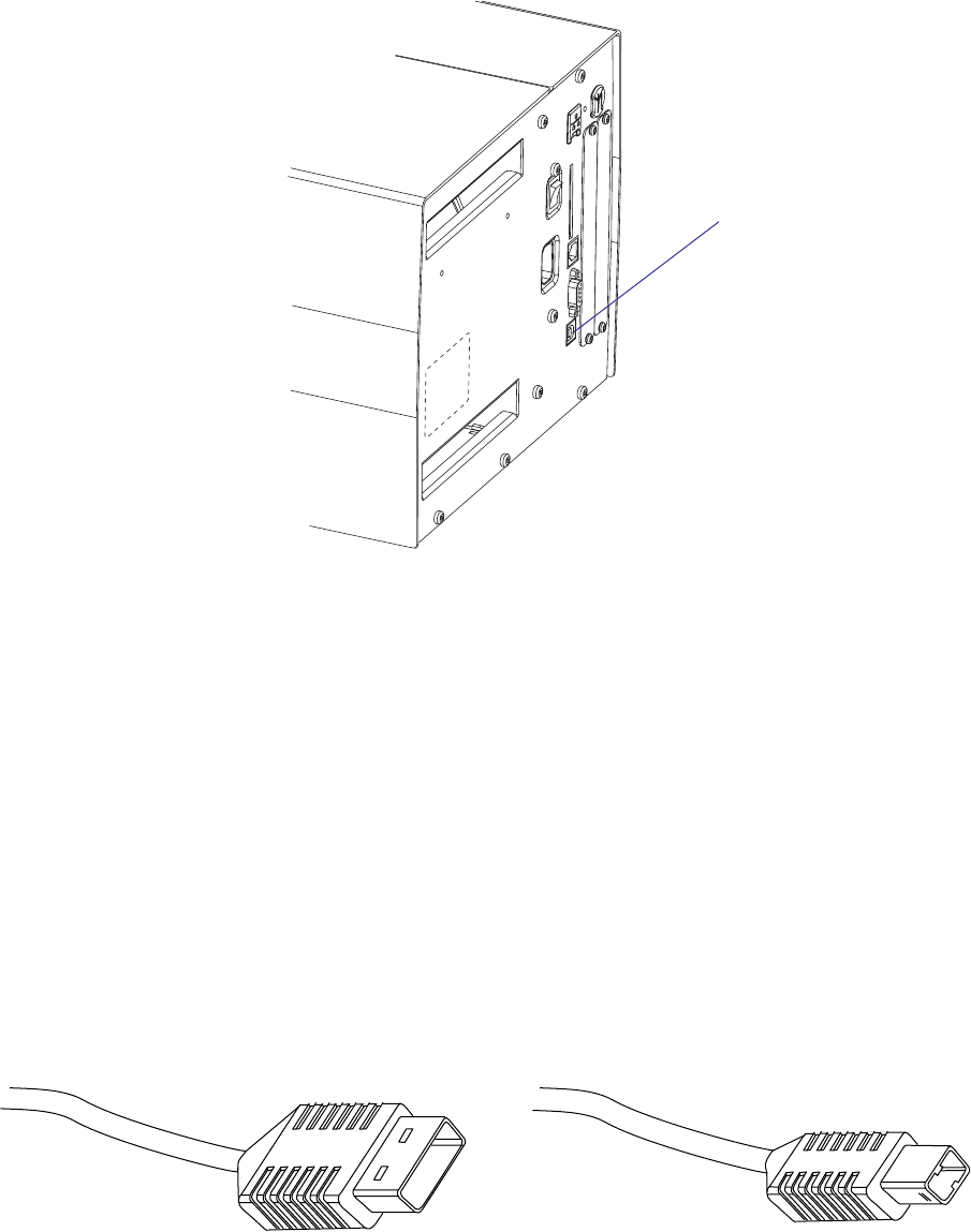
168 EasyCoder PX4i and PX6i Service Manual
Chapter 16 — Interfaces
16.3 USB Interface ("usb1:")
The EasyCoder PX4i and PX6i printers are, as standard, fi tted with a USB
(Universal Serial Bus) interface connector on the CPU board.
The supported USB version is USB 1.1 (also called “USB 2.0 full speed”).
To use the USB interface for printing from a PC, you need a USB-compat-
ible Intermec InterDriver installed in your PC. The printer works only as a
“slave”, that is, the USB interface is not suitable for programming. Unlike
for example RS-232, there is no communication setup in regard of baud
rate, parity, handshaking, etc. Select the USB interface as standard IN/
OUT channel in Intermec Fingerprint, the Intermec Direct Protocol, or
Intermec Shell as device "usb1:" (communication channel 6).
The EasyCoder PX4i and PX6i printers are so called “self-powered
devices.” We recommend that you only connect one printer to each USB
port on the host, either directly or via a hub. Other devices, like a keyboard
and a mouse, can be connected to the same hub. If you need to connect
more than one Intermec USB printer to a host, you should use different
USB ports.
Using a USB Class A/B cable, connect the Class A plug to the PC or hub
and the Class B plug to the printer.
USB Class A connector.
Connect to PC or hub.
USB Class B connector.
Connect to USB port on
printer’s rear plate.
USB
("usb1:")
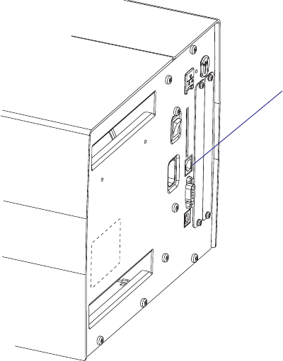
EasyCoder PX4i and PX6i Service Manual 169
Chapter 16 — Interfaces
16.4 Bar Code Wand Interface (wand:) (Fingerprint only)
The printer has a socket (J59) on the CPU board for connecting a bar code
wand or scanner. The socket is accessible through a slot in the printer’s rear
plate. The bar code wand interface is not supported by IPL.
If the Code 128 bar code that contains the character FNC3 is read via this
port, the data will be treated as a setup string and will change the printer’s
setup accordingly. A setup bar code may contain a single parameter or a
combination of up to 3 or 4 setup parameters. Refer to the EasySet Bar
Code Wand Setup manual for more information on how to produce setup
bar codes.
The printer will acknowledge that a bar code has been successfully read by
emitting a short beep signal.
If no FNC3 character is found in the bar code, the data will be stored in a
buffer which could be read by specifying the "wand:" device. The buffer is
small, so it is recommended to use short bar code data (max. 36 characters)
and read the buffer regularly to avoid overfl ow.
For more demanding applications or for reading bar codes other than
Code 128, choose a regular bar code scanner from Intermec’s wide product
range and connect it to a serial port.
Wand interface
("wand:")
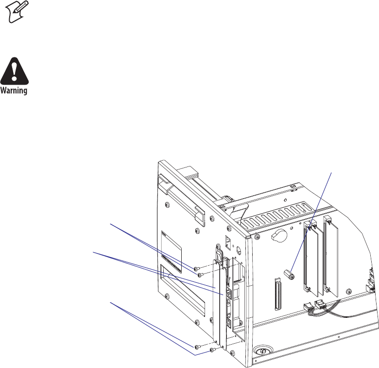
170 EasyCoder PX4i and PX6i Service Manual
Chapter 16 — Interfaces
16.5 Installing an Optional Interface Board
To install an optional interface board, proceed according to the step-by-
step instructions below.
Note: This chapter does not apply to installation of any type of EasyLAN
interface board, which instead is described in Chapter 16.9.
• Open the electronics compartment, see Chapter 3.3.
Switch off the power and disconnect the power cord. The electronics
compartment contains high voltage components and wires. Do not open
the electronics compartment before the printer is safely disconnected
from any AC supply.
• Remove the one or two cover plates depending on how many interface
boards you are going to install. Each plate is held by two #T10 Torx
screws. Always start installation at the innermost position.
• Save the cover plate(s) for possible later use. Keep the screws.
• Remove the #T20 Torx screw fi tted on the hexagonal spacer at the
center of the CPU board. Keep the screw.
• If necessary, reconfi gure the interface board by fi tting or removing cir-
cuits and straps according to the descriptions of each board later in this
chapter.
• Attach the fl at cable included in the kit to connector J62 (marked “EXP
BOARD”) on the CPU board (see illustration on the next page).
• Insert the interface board with the component side facing right, as seen
from behind.
#T10 Torx screws
Cover plates
Spacer and screw
#T10 Torx screws
J61
P35
J62
EXP BOARD
P2
BA
C50
1-971643-01 P01
C67
RS232: IC11, J2A
RS422: IC12, J3, J4
RS485: IC13, J1, J4*
* IF END OF CABLE
UARTA
C40
C51
C34
C36
C60
C21
C22
C65
R26
R27
R35
R34
R33
R32
R31
R41
R42
R51
R52
R36
R37
R38
IC20
C61
R21
R22
R23
R24
R25
R28
IC21
IC27
IC28
C33
C35
C66
IC3
IC22
C32
C56
C57
R10
R18
R5
R8
R9
C55
C64
C23
C24
C25
C26
C27
C28
R43
R44
R45
R46
R47
R53
R54
R55
R56
R57
IC24
IC23IC26
C62
REL3
REL4
REL1
REL2
C63
R48
R58
P3
F2 F3 F4 F5F8F7F1 F6
R12
R13
R14
R15
R17 R16
J3
J2
J4
C54
IC9
C3
C4
C1
C2
IC12
IC11
IC13
IC10
C31
C52
IC6
IC5
IC4
IC1
C53
R1
R6
R7
C30
J1
R11
R2
R3
R4
P1
IC2
IC25
P1
EasyCoder PX4i and PX6i Service Manual 171
Chapter 16 — Interfaces
• Installation of one board: Attach the interface board in the innermost
slot in the printer’s rear plate using the two screws left over when you
removed the original cover plate. Using the #T20 Torx screw you previ-
ously removed, attach the interface board to the hexagonal spacer at the
center of the CPU board.
• Installations of two boards: First install the inner board, then the outer
one. Put the hexagonal spacer included in the kit between the inner and
the outer interface board, and fi nally secure the outer board with the
screw.
Outer interface board
Component side
Flat cable (two types)
#T10 Torx screws
Flat cable
(two types)
Hexagonal
spacer
Inner interface board
#T20 Torx screw
and spacer(s)
$16#PBSE
*OOFS*OUFSGBDF#PBSE
4QBDFSFYJTUJOH
4DSFXFYJTUJOH
$BCMF
$16#PBSE
*OOFS*OUFSGBDF#PBSE
4QBDFSGSPNLJU
4QBDFSFYJTUJOH
4DSFXFYJTUJOH
0VUFS*OUFSGBDF#PBSE
$BCMF
172 EasyCoder PX4i and PX6i Service Manual
Chapter 16 — Interfaces
• The kit contains two fl at cables, one with two connectors for use with a
single interface board and one with three connectors for use with double
interface boards. Connect the appropriate fl at cable to connector P1 on
the interface board, as illustrated below.
• The fl at cable should run as illustrated below.
• Put back the cover over the electronics compartment.
• Connect the communication cables to the connectors on the printer’s
rear plate.
• Connect the power cord and switch on the power.
• In case the interface board provides additional serial communication
ports, enter the Setup Mode to set the proper communication param-
eters for these ports.
EasyCoder PX4i and PX6i Service Manual 173
Chapter 16 — Interfaces
Allowed interface combinations (Fingerprint)
Left-hand slot Ports Right-hand slot Ports
Double Serial uart2: + uart3: – –
Double Serial uart2: + uart3: Double Serial uart4: + uart5:
Double Serial uart2: + uart3: Serial Industrial uart4:
Double Serial uart2: + uart3: IEEE 1284 centronics:
Serial/Industrial uart2: – –
Serial/Industrial uart2: Serial/Industrial uart3:
Serial/Industrial uart2: Double Serial uart3: + uart4:
Serial/Industrial uart2: IEEE 1284 centronics:
IEEE 1284 centronics: – –
IEEE 1284 centronics: Double Serial uart2: + uart3:
IEEE 1284 centronics: Serial/Industrial uart2:
Allowed interface combinations (IPL)
Left-hand slot Ports Right-hand slot Ports
IEEE 1284 parallel – –
Remarks:
• The left-hand slot is the slot closest to the center section.
• Always start by fi tting an interface board in the left-hand slot.
• RS-485 is only supported by "uart2:"
When fi tting driver circuit and straps before installing the interface
board, make sure that the circuit is not fi tted upside down (see front
end markings in the illustrations). Also make sure that the “legs” of the
circuit fi t into the slots in the socket and are not bent. Take ample pre-
cautions to protect the board and circuits from electrostatic discharges.
174 EasyCoder PX4i and PX6i Service Manual
Chapter 16 — Interfaces
16.6 Serial/Industrial Interface Board (Fingerprint only)
Description
The Serial/Industrial Interface Board is a Fingerprint-only optional device
for EasyCoder PX4i and PX6i. It provides these printers with two extra
interfaces.
The Serial/Industrial Interface kit contains:
• One Industrial Interface Board fi tted with straps and circuits for RS-232
• One hexagonal spacer
• Two fl at cables
• One Installation Instruction booklet
Serial Interface ("uart2:", "uart3:", or "uart4:")
This interface contains one serial communication port ("uart2:", "uart3:",
or "uart4:") which can be confi gured for one of the following alternatives:
• RS-232 non-isolated
• RS-422 isolated, full duplex (reconfi guration required)
• RS-485 isolated, half duplex (reconfi guration required, "uart2:" only)
Selection of type of serial interface is decided by fi tting various types of
socket-mounted driver circuits and straps.
Industrial Interface
This interface contains eight digital IN and eight digital OUT ports with
optocouplers, plus four OUT ports with relays.
The status of all ports can be read by means of PORTIN functions and
the OUT ports can be set using PORTOUT ON/OFF statements (see
Intermec Fingerprint v8.xx, Programmer's Reference Manual). Thus, it is pos-
sible to design Intermec Fingerprint application programs which control
not only the printer but also various external devices, for example in a
production line. The digital IN ports can read the status of various sensors
and the program can, for example, switch control lamps on or off, open
or close gates, and start or stop conveyor belts accordingly using the relays
and the digital OUT ports.
Industrial Interface
(DB-44pin socket)
Serial Interface
"uart2:"
(DB-9pin socket)
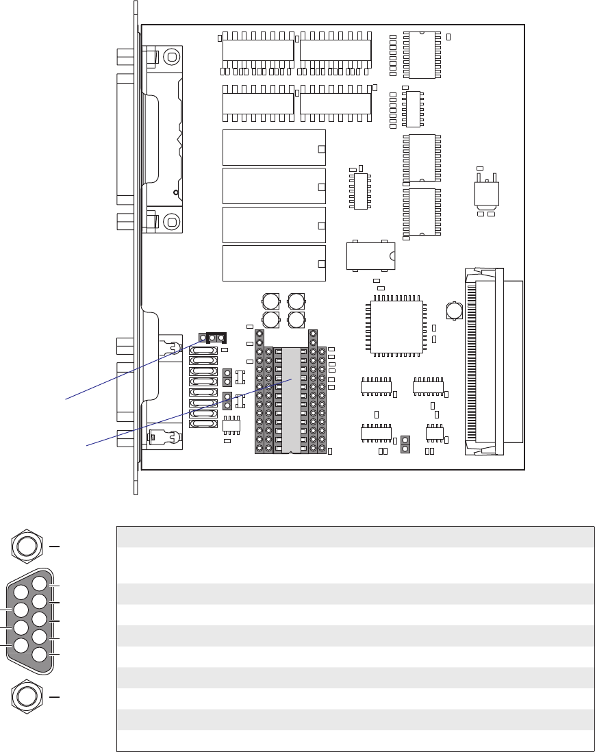
EasyCoder PX4i and PX6i Service Manual 175
Chapter 16 — Interfaces
Serial Port Configuration
The serial communication port "uart2:", "uart3:", or "uart4:" are confi g-
ured for RS-232 as standard but can be reconfi gured for two other types
of serial communication by fi tting certain driver circuits and straps. The
circuits can be ordered separately from Intermec:
• RS-422 isolated, full duplex
• RS-485 isolated, half duplex ("uart2:" only!)
RS-232 Non-isolated (standard)
Strap fi tted on J2 A
RS-232 circuit fi tted on
IC11
Connector Configuration (RS-232 on "uart2:", "uart3:", or "uart4:")
DB-9 socket Signal Meaning
1 External +5VDC max 500 mA (automatic switch-off at
overload, short-circuit protected)
2 TXD Transmit data
3 RXD Receive data
4 DSR Data set ready
5 GND Ground
6 DTR Data terminal ready
7 CTS Clear to send
8 RTS Request to send
9 – Not used
P2
BA
C50
1-971643-01 P01
C67
RS232: IC11, J2A
RS422: IC12, J3, J4
RS485: IC13, J1, J4*
* IF END OF CABLE
UARTA
C40
C51
C34
C36
C60
C21
C22
C65
R26
R27
R35
R34
R33
R32
R31
R41
R42
R51
R52
R36
R37
R38
IC20
C61
R21
R22
R23
R24
R25
R28
IC21
IC27
IC28
C33
C35
C66
IC3
IC22
C32
C56
C57
R10
R18
R5
R8
R9
C55
C64
C23
C24
C25
C26
C27
C28
R43
R44
R45
R46
R47
R53
R54
R55
R56
R57
IC24
IC23IC26
C62
REL3
REL4
REL1
REL2
C63
R48
R58
P3
F2 F3 F4 F5F8F7F1 F6
R12
R13
R14
R15
R17 R16
J3
J2
J4
C54
IC9
C3
C4
C1
C2
IC12
IC11
IC13
IC10
C31
C52
IC6
IC5
IC4
IC1
C53
R1
R6
R7
C30
J1
R11
R2
R3
R4
P1
IC2
IC25
4
5
3
2
1
8
9
7
6TXD out
+5V DC
RXD in
DSR in
GND
MTG
MTG
DTR out
CTS in
RTS out
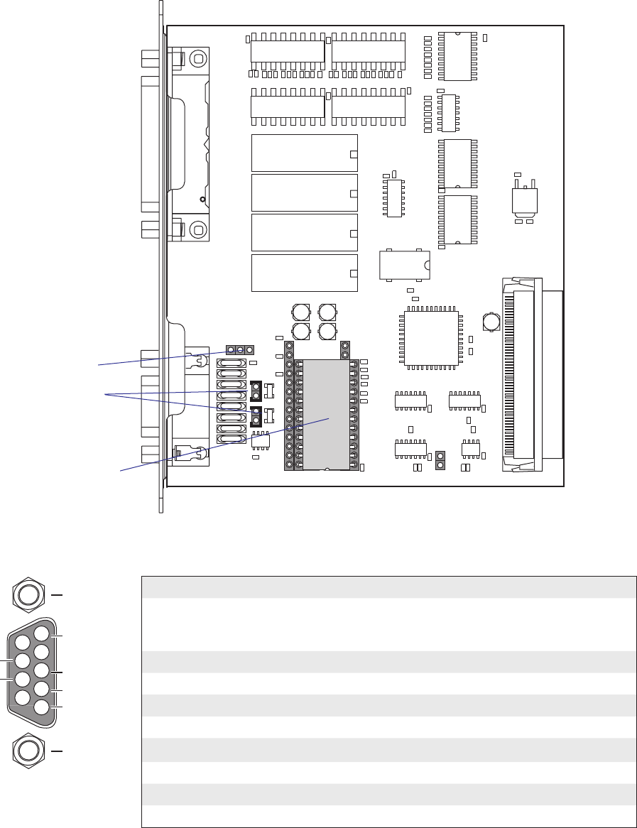
P2
BA
C50
1-971643-01 P01
C67
RS232: IC11, J2A
RS422: IC12, J3, J4
RS485: IC13, J1, J4*
* IF END OF CABLE
UARTA
C40
C51
C34
C36
C60
C21
C22
C65
R26
R27
R35
R34
R33
R32
R31
R41
R42
R51
R52
R36
R37
R38
IC20
C61
R21
R22
R23
R24
R25
R28
IC21
IC27
IC28
C33
C35
C66
IC3
IC22
C32
C56
C57
R10
R18
R5
R8
R9
C55
C64
C23
C24
C25
C26
C27
C28
R43
R44
R45
R46
R47
R53
R54
R55
R56
R57
IC24
IC23IC26
C62
REL3
REL4
REL1
REL2
C63
R48
R58
P3
F2 F3 F4 F5F8F7F1 F6
R12
R13
R14
R15
R17 R16
J3
J2
J4
C54
IC9
C3
C4
C1
C2
IC12
IC11
IC13
IC10
C31
C52
IC6
IC5
IC4
IC1
C53
R1
R6
R7
C30
J1
R11
R2
R3
R4
P1
IC2
IC25
4
5
3
2
1
8
9
7
6
+TXD
+5V DC
if GND strap
fitted
+RXD
GNDE
MTG
MTG
-RXD
-TXD
176 EasyCoder PX4i and PX6i Service Manual
Chapter 16 — Interfaces
RS-422 Isolated, Full Duplex (reconfiguration required)
Fit straps on J3 and J4
Remove RS-232 circuit
on IC11
Fit RS-422 circuit on IC12
Connector Configuration
(RS-422 Isolated on "uart2:", "uart3:", or "uart4:")
DB-9 socket Signal Meaning
1 External +5VDC max 500 mA (automatic switch-off at
overload, short-circuit protected) provided strap is fi tted
on J2:A which spoils the galvanical isolation
2 +TXD +Transmit data
3 +RXD +Receive data
4–
5 GNDE Ground
6-
7 -RXD -Receive data
8 -TXD -Transmit data
9–
Remove strap on J2 A
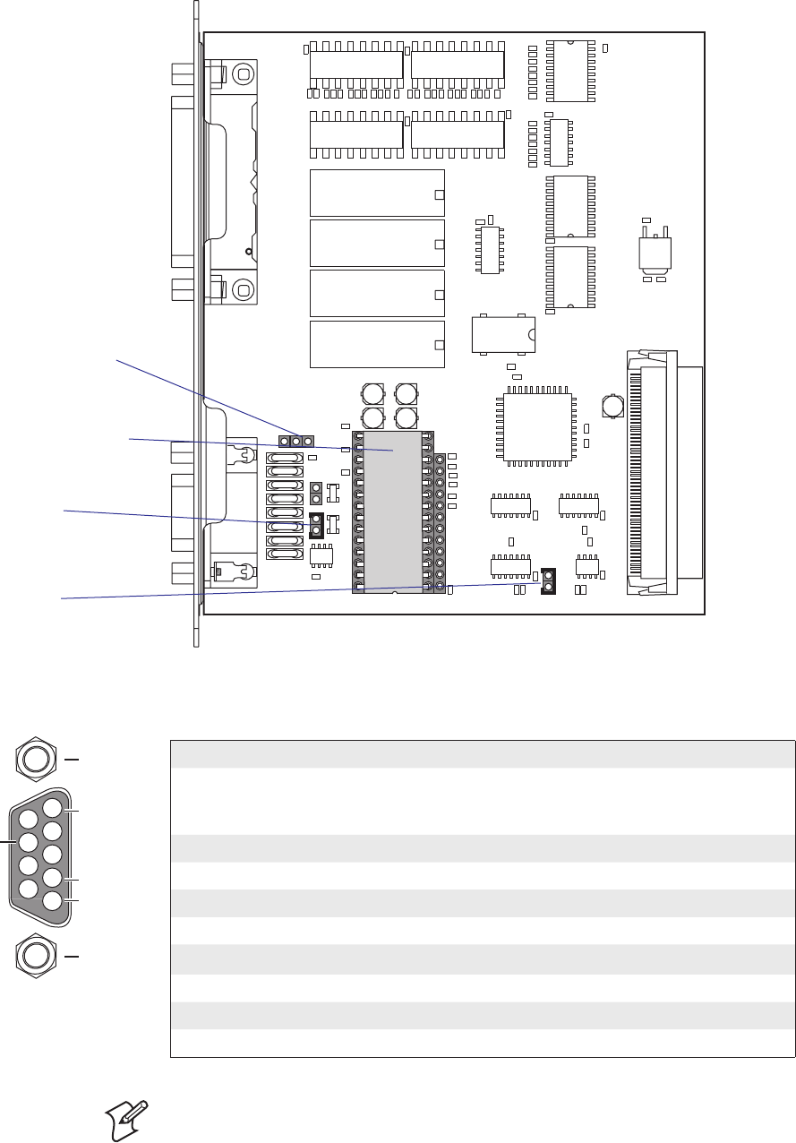
4
5
3
2
1
8
9
7
6
+DATA
+5V DC
if GND
strap fitted
GNDE
MTG
MTG
-DATA
P2
BA
C50
1-971643-01 P01
C67
RS232: IC11, J2A
RS422: IC12, J3, J4
RS485: IC13, J1, J4*
* IF END OF CABLE
UARTA
C40
C51
C34
C36
C60
C21
C22
C65
R26
R27
R35
R34
R33
R32
R31
R41
R42
R51
R52
R36
R37
R38
IC20
C61
R21
R22
R23
R24
R25
R28
IC21
IC27
IC28
C33
C35
C66
IC3
IC22
C32
C56
C57
R10
R18
R5
R8
R9
C55
C64
C23
C24
C25
C26
C27
C28
R43
R44
R45
R46
R47
R53
R54
R55
R56
R57
IC24
IC23IC26
C62
REL3
REL4
REL1
REL2
C63
R48
R58
P3
F2 F3 F4 F5F8F7F1 F6
R12
R13
R14
R15
R17 R16
J3
J2
J4
C54
IC9
C3
C4
C1
C2
IC12
IC11
IC13
IC10
C31
C52
IC6
IC5
IC4
IC1
C53
R1
R6
R7
C30
J1
R11
R2
R3
R4
P1
IC2
IC25
EasyCoder PX4i and PX6i Service Manual 177
Chapter 16 — Interfaces
Connector Configuration
(RS-485 Isolated on "uart2:" only)
DB-9 socket Signal Meaning
1 External +5VDC max 500 mA (automatic switch-off at
overload, short-circuit protected) provided strap is fi tted
on J2:A which spoils the galvanical isolation
2+DATA
3–
4–
5 GNDE Ground
6–
7–
8 -DATA
9–
RS-485 Isolated, Half Duplex (reconfiguration required)
Fit strap on J4
if end of cable
(terminator)
Remove RS-232 circuit
on IC11
Fit RS-485 driver circuit
Fit strap on J1
Remove strap on J2 A
Note: The increased use of LAN networks has made the RS-485 interface
somewhat obsolete, because RS-485 requires a special communication
protocol and a dedicated wiring system limited to 1,200 m (4,000 ft). We
only recommend RS-485 for existing applications and advice the customer
to consider a LAN network solution for new applications.
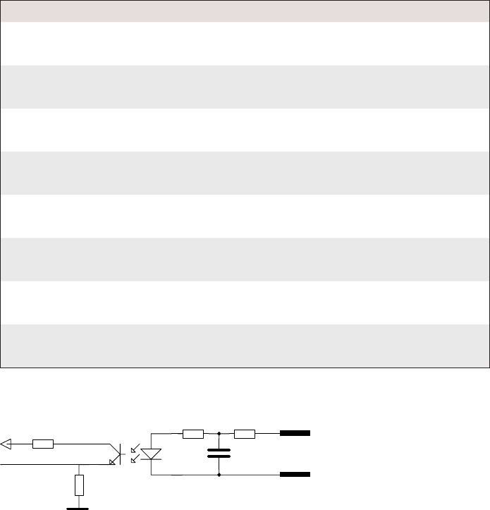
GND
INA
IN
K
178 EasyCoder PX4i and PX6i Service Manual
Chapter 16 — Interfaces
Industrial Interface Configuration
The Industrial Interface provides:
• 8 digital IN ports with optocouplers (Opto In)
• 8 digital OUT ports with optocouplers (Opto Out)
• 4 OUT ports with relays (Relay Out)
The Industrial Interface has no straps or circuits to be fi tted or removed.
All signals are available on a DB-44pin socket and the various ports are
controlled by the Intermec Fingerprint instructions PORTIN and POR-
TOUT ON/OFF (see Intermec Fingerprint v8.xx, Programmer's Reference
Manual).
Digital Opto In
The status of the digital IN ports can be read using PORTIN functions. If
a current is led through the optocoupler of the port, PORTIN returns the
value -1 (true), else it returns the value 0 (false).
Signal Description Min. Typical Max.
Vin [High] Input Voltage High 10V 24V 40V
Vin [Low] Input Voltage Low -1V 0V 1V
Connector Configuration
The Fingerprint reference numbers inside the parentheses refer to a second
Serial/Industrial interface board.
Simplifi ed schematics of a digital IN port.
Pin Signal Name Description Fingerprint Ref. No.
10 IN1A Anode Opto In Channel 1 + 101 (301)
40 IN1K Cathode Opto In Channel 1 -
26 IN2A Anode Opto In Channel 2 + 102 (302)
11 IN2K Cathode Opto In Channel 2 -
41 IN3A Anode Opto In Channel 3 + 103 (303)
27 IN3K Cathode Opto In Channel 3 -
12 IN4A Anode Opto In Channel 4 + 104 (304)
42 IN4K Cathode Opto In Channel 4 -
28 IN5A Anode Opto In Channel 5 + 105 (305)
13 IN5K Cathode Opto In Channel 5 -
43 IN6A Anode Opto In Channel 6 + 106 (306)
29 IN6K Cathode Opto In Channel 6 -
14 IN7A Anode Opto In Channel 7 + 107 (307)
44 IN7K Cathode Opto In Channel 7 -
30 IN8A Anode Opto In Channel 8 + 108 (308)
15 IN8K Cathode Opto In Channel 8 -
VCC
OUTa
OUTc
EasyCoder PX4i and PX6i Service Manual 179
Chapter 16 — Interfaces
Digital Opto Out
The current to each optocoupler of the digital OUT ports can be turned
on and off using PORTOUT ON/OFF statements.
The status of the ports can be read using PORTIN functions. If a current
is led through the optocoupler of the port, PORTIN returns the value -1
(true), else it returns the value 0 (false).
Signal Description Max.
Vceo Collector-Emitter breakdown voltage 35V
Veco Emitter-Collector breakdown voltage 6V
Collector Current 15 mA
Vog Output to ground (optocoupler) 100V
Connector Configuration
The Fingerprint reference numbers inside the parentheses refer to a second
Serial/Industrial interface board.
Simplifi ed schematics of a digital OUT port.
Pin Signal Name Description Fingerprint Ref. No.
20 Out1c Collector Opto Out Channel 1 221 (421)
5 Out1e Emitter Opto Out Channel 1
35 Out2c Collector Opto Out Channel 2 222 (422)
21 Out2e Emitter Opto Out Channel 2
6 Out3c Collector Opto Out Channel 3 223 (423)
36 Out3e Emitter Opto Out Channel 3
22 Out4c Collector Opto Out Channel 4 224 (424)
7 Out4e Emitter Opto Out Channel 4
37 Out5c Collector Opto Out Channel 5 225 (425)
23 Out5e Emitter Opto Out Channel 5
8 Out6c Collector Opto Out Channel 6 226 (426)
38 Out6e Emitter Opto Out Channel 6
24 Out7c Collector Opto Out Channel 7 227 (427)
9 Out7e Emitter Opto Out Channel 7
39 Out8c Collector Opto Out Channel 8 228 (428)
25 Out8e Emitter Opto Out Channel 8
1
0.5
0.1
10 20 30 40 50 100
DC Voltage (VDC)
a: resistive load
b: inductive load L/R=20 ms
DC current (A)
a
b
VCC
REL com
REL nc
REL no
180 EasyCoder PX4i and PX6i Service Manual
Chapter 16 — Interfaces
Relay Out
The relays of the OUT ports can be individually activated using PORT-
OUT ON/OFF statements.
The status of the ports can be read by means of PORTIN functions. If a
relay is activated, PORTIN returns the value -1 (true), else it returns the
value 0 (false).
Max AC Load Breaking Capacity
Signal Description Max.
I Current 1A
Psw AC Switching power 100VA AC
Usw AC Switching voltage 100V AC
Max DC Load Breaking Capacity
Connector Configuration
The Fingerprint reference numbers inside the parentheses refer to a second
Serial/Industrial interface board.
Simplifi ed schematics of a relay OUT port.
Pin Signal Name Description Fingerprint Ref. No.
16 REL1nc Relay 1 Normally Closed 201 (401)
1 REL1no Relay 1 Normally Open
31 REL1com Relay 1 Common
17 REL2nc Relay 2 Normally Closed 202 (402)
2 REL2no Relay 2 Normally Open
32 REL2com Relay 2 Common
18 REL3nc Relay 3 Normally Closed 203 (403)
3 REL3no Relay 3 Normally Open
33 REL3com Relay 3 Common
19 REL4nc Relay 4 Normally Closed 204 (404)
4 REL4no Relay 4 Normally Open
34 REL4com Relay 4 Common
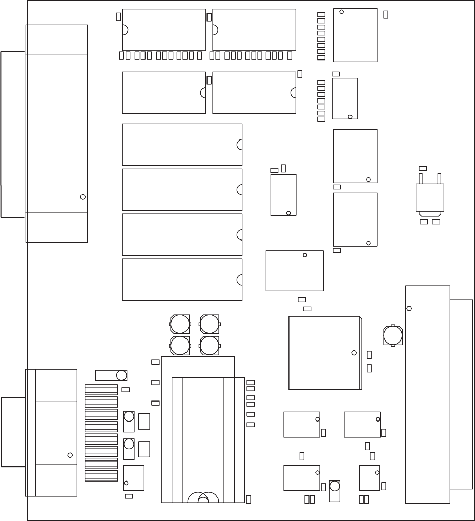
RS232: IC11, J2A
RS422: IC12, J3, J4
RS485: IC13, J1, J4*
*: IF END OF CABLE
BABA
UARTA
C40
C51
IC2
35
1
P1
C50
C34
C36
C31
68
34
C52
C60
C21
C22
C65
R26
R27
R35
R34
R33
R32
R31
R41
R42
R51
R52
R36
R37
R38
IC20
C61
C67
R21
R22
R23
R24
R25
R28
IC21
IC27
IC28
C33
C35
C66
IC3
IC22
C32
C53
C56
C57
IC4IC6
R1
R10
R18
R5
R6
R7
R8
R9
IC10
C30
C55
IC1IC5
J1
R11
R2
R3
R4
C64
C23
C24
C25
C26
C27
C28
R43
R44
R45
R46
R47
R53
R54
R55
R56
R57
IC23IC24
C62
REL3
REL4
IC25 IC26
C3C4
REL1
REL2
C1C2
R12
R13
R14
R15
IC11
R17 R16
IC13
IC12
C63
R48
R58
P2
F2 F3F4 F5F8F7
J3J4
J2
C54
F1 F6
IC9
P3
EasyCoder PX4i and PX6i Service Manual 181
Chapter 16 — Interfaces
Components
1-971643-26 Serial/Industrial Interface Board; Component side
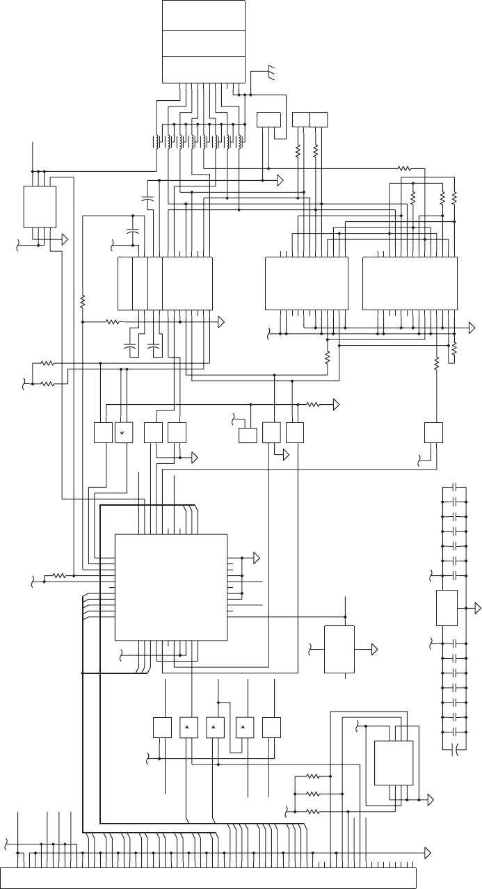
P1
C54
C55
C57
C30
C31
C32
C33
C34
C35
C36
5V
LD1117
IC2
R1 R2 R3
5V
3.3V
16C550
MR
RTS*
DTR*
NC
OUT1*
OUT2*
INTRPT
A0
A1
A2
RXRDY*
RCLK
D5
SIN
D7
D6
NC
BAUDOUT*
CS2*
SOUT
CS1
CS0
RD2
TXRDY*
DDIS
RD1*
ADS*
NC
XIN
VSS
WR2
XOUT
WR1*
VCC
RI*
DCD*
DSR*
CTS*
NC
D1
D0
D2
D3
D4
IC10
1
AHC32
VCC=3.3V
1
AHC32
VCC=3.3V
1
AHC32
VCC=3.3V
3.3V
3.3V
P2
9PIN DSUB
C
F1
F2
F3
F4
F5
F6
F7
F8
5V
5V
R17
R13
R14
R12
J4
J3
R16
R11
R10
R9
R18
R8
MAX1480
MAX1490
=1
VCC=3.3V
AHC86
=1
VCC=3.3V
AHC86
=1
VCC=3.3V
AHC86
=1
VCC=5V
AHCT86
=1
VCC=5V
AHCT86
=1
VCC=5V
AHCT86
=1
VCC=5V
AHCT86
3.3V
5V
J1
3.3V
MAX238
5V
5V
J2
POWER_SWITCH
C53
C52
C51
C56
R5
R6 R7
R4
R15
+
C1
+
C50
+
C2
+
C3
+
C4
1.8432MHZ
IC3
1
AHC32
VCC=3.3V
=1
VCC=3.3V
AHC86
VCC
A0
A1
GND
A2 WP
SDA
SCL
IC1
5V
3.3V
5V
DTR
*: IF END OF CABLE
B
A
RS485
RTS
RS485
TXD
+5V
RS422 RS485
GND
DSR
RXD
+TXD
+RXD
GNDE
-RXD
-TXD -DATA
GNDE
TERM.REC.
RS422
TERM.TRA.
GND-SHIELD
CTS
+DATA
RS232
EXTERNAL 5V
SWITCH FOR
INTERFACE CONFIGURATION
RS232: IC11, J2A
RS422: IC12, J3, J4
RS485: IC13, J1, J4*
RS232
485_DIR
0
10
8
10
9
IC5
11 13
12
IC4
4
3
1
2
8
7
6
5
3
2
1
4
IC9
3
2
1
9
15
11
20
21
24
19
1
18
2
5
17 16
22 23
43
67
8
14
13
12
10
IC11
2
1
1113
12
IC6
32
1
IC6
65
4
IC6
8
10
9
IC6
65
4
IC5
11 13
12
IC5
32
1
IC5
18
17
10
8
2
1
7
11 14
22
13
21
15
16
12
5
6
9
4
3
19
23
24
20
IC12
14
10
8
2
1
7
13
18
26
15
24
22
19
21
17
16
20
12
5
6
9
11
4
3
25
27
28
23
IC13
2
1
2
1
MTG2
MTG1
9
8
7
6
5
4
3
2
1
8
10
9
IC4
65
4
IC4
32
1
IC4
19
18
21
20
22
44
27
13
11
32
36
4325
24
10 35
38
34
23
12
1
39
33
37
41
26 42
9
8
7
6
5
4
3
2
40
16
15
14
17
28
29
30
31
23
1
7
8
5
6
4
3
2
1
5
38
4
68
34
67
33
66
32
65
31
64
37
30
63
29
62
28
61
27
60
26
59
3
25
58
24
57
23
56
22
55
21
54
36
20
53
19
52
18
51
17
50
16
49
2
15
48
14
47
13
46
12
45
11
44
35
10
43
9
42
8
41
7
40
6
39
1
SCL
SDA
RESET_N
CLK
T1OUT
INTA
RXDA
Z
IRCDRV
+24VI
GND
INT_N
RESET_N
RD_N
A<12..1>
OC_N
OUT
OUT
OUT
IN
EN_N
IN
GND
5V_EXT_EN_N
VCC3
1
VCC
GND
OUT
NC/EN_N
5V_EXT
SA1
CS_N
INT_N
9
10
11
VIN
GND
VOUT
GND1
AC2
12
1
6
12
8
7
15
6
5
2
3
4
13
11
9
8
7
3
GND2
RO
DI
SD
VCC2
VCC1
D1
D2
IRLED
IVCC2
ICOM1
Y
B
A
AC1
VCC5
RO_N
GND2
VCC4
DE
DI
SD
FS
D2
D1
VCC2
IRLED
ICOM2
IDEDRV
AC1
IVCC2
IDIDRV
B
A
FS
VCC1
IRCDRV
IVCC1
AC2
GND1
ICOM1
IDEIN
IDIIN
VCC3
VCC4
3
2
1
0
2
3
5
6
7
WR_N
RESET
4
IDIDRV
IVCC1
2
DCDA_N
12
TXDA
OVERCURRENT_N
D<15..0>
1
14
5
4
WR_N WRB_N
WAIT_N
RD_N
WR_N
11
CSA_N
RESET
RTSA_N
C1-
C1+
T2IN
T1IN
C2-
R2OUT
R3OUT
R4OUT
V-
V+
T2OUT
T3OUT
T4OUT
R2IN
R1IN
R3IN
R4IN
C2+
VCC
DTRA_N
R1OUT
T4IN
T3IN
DSRA_N
INTA
CSB_N
CTSA_N
182 EasyCoder PX4i and PX6i Service Manual
Chapter 16 — Interfaces
Schematics; Serial Port ("uart2:", "uart3:", or "uart4:")
1-971643-26 Serial/Industrial Interface Board; Schematics 1
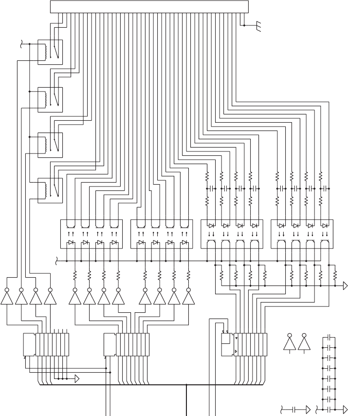
R34
C60
C61
C62
C63
C64
C65
C66
C67
5V
3.3V
OPTO_COUPLER
OPTO_COUPLER
OPTO_COUPLER
OPTO_COUPLER
C21
C22
C23
C24
C25
C26
C27
C28
R32
R31
5V
R21
R22
R23
R24
R25
R26
R27
R28
RESET
CLK
D
AHCT273
VCC=5V
RESET
CLK
D
AHCT273
VCC=5V
ULN2003A
IC28
ULN2003A
IC27
ULN2003A
IC27
ULN2003A
IC27
ULN2003A
IC27
ULN2003A
IC27
ULN2003A
IC27
ULN2003A
IC27
ULN2003A
IC28
ULN2003A
IC28
ULN2003A
IC28
ULN2003A
IC28
ULN2003A
IC28
ULN2003A
IC28
R33
P3
R41 R51
EN
&
AHC541
VCC=3.3V
R52R42
R53R43
R54R44
R55
R38
R45
R56R46
R57R47
R58
R37
R48
5V
R36
R35
C
C40
IN5K
IN3A
OUT3E
SIGNAL
S
REL3NC
REL3NO
REL4CO
M
REL1NO
IN1K
IN1A
IN2K
IN2A
IN3K
IN4K
IN4A
IN5A
IN6K
IN6A
IN7K
IN7A
IN8K
IN8A
OUT8E
OUT8C
OUT7E
OUT7C
OUT6E
OUT6C
OUT5E
OUT5C
OUT4E
OUT4C
OUT3C
OUT2E
OUT2C
OUT1E
OUT1C
REL4NO
REL4NC
REL3CO
M
REL2CO
M
REL2NO
REL2NC
REL1CO
M
REL1NC
9
10
11
12
13
14
15
16
8
7
6
5
4
3
2
1
IC26
9
10
11
12
13
14
15
16
8
7
6
5
4
3
2
1
IC25
9
10
11
12
13
14
15
16
8
7
6
5
4
3
2
1
IC24
9
10
11
12
13
14
15
16
8
7
6
5
4
3
2
1
IC23
14
12
11
A2
A1
REL1
14
12
11
A2
A1
REL2
14
12
11
A2
A1
REL3
14
12
11
A2
A1
REL4
MTG2
MTG1
9
8
7
6
5
44
43
42
41
40
4
39
38
37
36
35
34
33
32
31
30
3
29
28
27
26
25
24
23
22
21
20
2
19
18
17
16
15
14
13
12
11
10
1
11
6
10
7
15
2
14
3
13
4
12
5
16
1
15
2
14
3
13
4
12
5
11
6
10
7
16
1
2
5
6
9
12
15
16
19
1
11
3
4
7
8
13
14
17
18
IC22
2
5
6
9
12
15
16
19
1
11
3
4
7
8
13
14
17
18
IC21
11
12
13
14
15
16
17
18
19
1
9
8
7
6
5
4
3
2
IC20
COM
VCC=5V
VCC=5V
7
A1
A2
NO
COM
NC
RESET_N
WRB_N
11
10
9
8
0
1
2
3
4
5
6
RD_N
CSB_N
NC
COM
NO
A2
A1
NC
COM
NO
A2
A1
NO
A1
A2
NC
D<15..0>
1
2
3
4
5
6
7
DSUB44
0
EasyCoder PX4i and PX6i Service Manual 183
Chapter 16 — Interfaces
Schematics; Industrial Interface
1-971643-26 Serial/Industrial Interface Board; Schematics 2
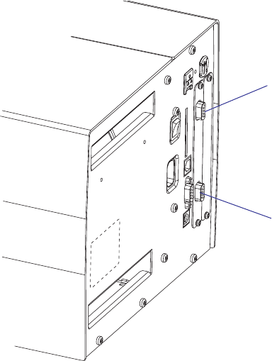
184 EasyCoder PX4i and PX6i Service Manual
Chapter 16 — Interfaces
16.7 Double Serial Interface Board (Fingerprint only)
Description
The Double Serial Interface Board (DUART) is a Fingerprint-only
optional device for EasyCoder PX4i and PX6i printers. It provides these
printers with two extra serial interfaces.
"uart2:", "uart3:", or "uart4:"
This interface (marked “UART A” on the interface board) can be fi tted
with straps and circuits for one of the following alternatives:
• RS-232 non-isolated
• RS-422 isolated, full duplex
• RS-485 isolated, half duplex ("uart2:" only)
"uart3:", "uart4;", or "uart5:"
This interface (marked “UART B” on the interface board) can be fi tted
with straps and circuits for one of the following alternatives:
• RS-232 non-isolated
• RS-422 non isolated, full duplex
• 20 mA Current Loop.
The Double Serial Interface Kit contains:
• One interface board fi tted for RS-232 on both ports.
• Two fl at cables
• One hexagonal spacer
• One Installation Instruction booklet
Circuits for modifying the board for RS-422 non-isolated, RS-422 iso-
lated, RS-485 isolated, or 20 mA current loop can be bought separately
from Intermec.
"uart3:"
(DB-9pin socket)
"uart2:"
(DB-9pin socket)
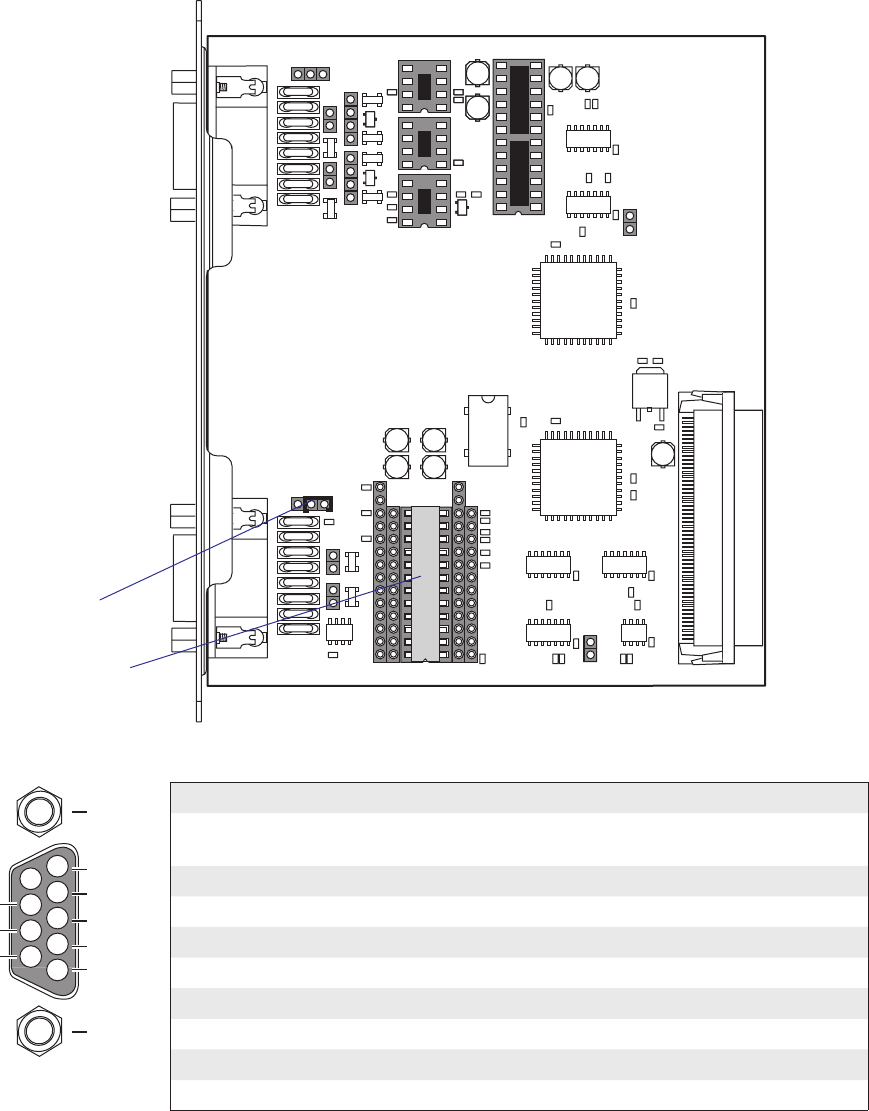
4
5
3
2
1
8
9
7
6TXD out
+5V DC
RXD in
DSR in
GND
MTG
MTG
DTR out
CTS in
RTS out
A
B
C
C
B
A
UARTB BA
A
B
C
C
B
A
BA
UARTA
A
B
C
C
B
A
BA
RS232: IC21, J6A
RS422: IC22, J6B, J7, J8
20MACL: IC23, IC24, J5 J9*, J10*
*: TRANSM.=J9, RECEIV.=J10
RS232: IC11, J2A
RS422: IC12, J3, J4
RS485: IC13, J1, J4*
*: IF END OF CABLE
PASSIVE=B, ACTIVE=A+C
BA
P1
C50
C42
C51
C31
C52
C10 C12
C61
IC8
J5
IC7
IC6
IC5
IC4
IC1
R23
R24
C36
C60
C40
R20
R21
R22
IC20
IC21
C33
C34
C35
C41
IC2
C32
C53
C56
C57
R1
R10
R18
R5
R6
R7
R8
R9
IC10
C30
C55
J1
R11
R2
R3
R4
C11
C13
R27
C63
R30
R34R33
R35
ANC
K
Z2
IC23
IC24
IC22
C62
C64
ANC
K
D1
R26
R28 R29
R19
ANC
K
Z1
C3
C4
IC3
C1
C2
R12
R13
R14
R15
R17 R16
IC12
IC11
IC13
F13J6
J7
J10
J9
P3
F14 F10 F15 F11 F16 F12
F9
R32
R31
P2
F2 F3F4 F5F8F7
J3
J2
J4
C54
F1 F6
IC9
ANC
K
ANC
K
R25
ANC
K
1-971642-01 P01
J8
EasyCoder PX4i and PX6i Service Manual 185
Chapter 16 — Interfaces
"uart2:", "uart3:" & "uart4" Configuration (connector UART A)
The serial communication ports "uart2:", "uart3:", and "uart4:" can be
confi gured for up to three different types of serial communication respec-
tively by fi tting or removing certain driver circuits and straps:
• RS-232 non-isolated
• RS-422 isolated, full duplex
• RS-485 isolated, half duplex ("uart2:" only!)
RS-232 Non-isolated (standard)
Strap fi tted on J2 A
RS-232 circuit fi tted on
IC11
Connector Configuration (RS-232 on "uart2:", "uart3:", or "uart4:")
DB-9 socket Signal Meaning
1 External +5VDC max 500 mA (automatic switch-off at
overload, short-circuit protected)
2 TXD Transmit data
3 RXD Receive data
4 DSR Data set ready
5 GND Ground
6 DTR Data terminal ready
7 CTS Clear to send
8 RTS Request to send
9 – Not used
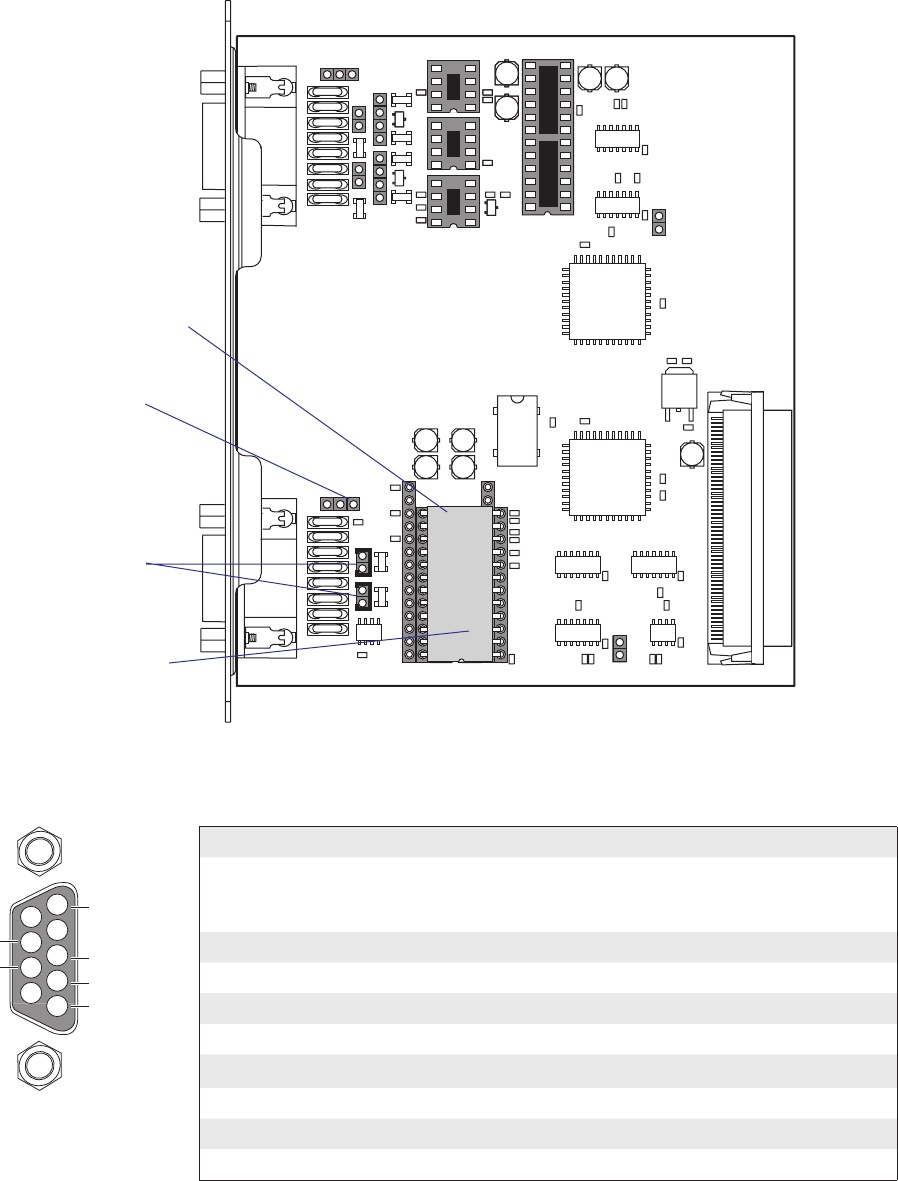
A
B
C
C
B
A
UARTB BA
A
B
C
C
B
A
BA
UARTA
A
B
C
C
B
A
BA
RS232: IC21, J6A
RS422: IC22, J6B, J7, J8
20MACL: IC23, IC24, J5 J9*, J10*
*: TRANSM.=J9, RECEIV.=J10
RS232: IC11, J2A
RS422: IC12, J3, J4
RS485: IC13, J1, J4*
*: IF END OF CABLE
PASSIVE=B, ACTIVE=A+C
BA
P1
C50
C42
C51
C31
C52
C10 C12
C61
IC8
J5
IC7
IC6
IC5
IC4
IC1
R23
R24
C36
C60
C40
R20
R21
R22
IC20
IC21
C33
C34
C35
C41
IC2
C32
C53
C56
C57
R1
R10
R18
R5
R6
R7
R8
R9
IC10
C30
C55
J1
R11
R2
R3
R4
C11
C13
R27
C63
R30
R34R33
R35
ANC
K
Z2
IC23
IC24
IC22
C62
C64
ANC
K
D1
R26
R28 R29
R19
ANC
K
Z1
C3
C4
IC3
C1
C2
R12
R13
R14
R15
R17 R16
IC12
IC11
IC13
F13J6
J7
J10
J9
P3
F14 F10 F15 F11 F16 F12
F9
R32
R31
P2
F2 F3F4 F5F8F7
J3
J2
J4
C54
F1 F6
IC9
ANC
K
ANC
K
R25
ANC
K
1-971642-01 P01
J8
4
5
3
2
1
8
9
7
6
+TXD
+5V (0.5 A)
if GND strap
fitted
+RXD
GNDE
-RXD
-TXD
186 EasyCoder PX4i and PX6i Service Manual
Chapter 16 — Interfaces
RS-422 Isolated, Full Duplex (reconfiguration required)
Fit straps on J3 and J4
Fit RS-422 circuit on IC12
Connector Configuration (RS-422 Isolated on "uart2:", "uart3:", or
"uart4:")
DB-9 socket Signal Meaning
1 External +5VDC max 500 mA (automatic switch-off at
overload, short-circuit protected) provided strap is fi tted
on J2:A which spoils the galvanical isolation
2 +TXD +Transmit data
3 +RXD +Receive data
4–
5 GNDE Ground
6-
7 -RXD -Receive data
8 -TXD -Transmit data
9–
Remove strap on J2 A
Remove RS-232 circuit on
IC11
A
B
C
C
B
A
UARTB
BA
A
B
C
C
B
A
BA
UARTA
A
B
C
C
B
A
BA
RS232: IC21, J6A
RS422: IC22, J6B, J7, J8
20MACL: IC23, IC24, J5 J9*, J10*
*: TRANSM.=J9, RECEIV.=J10
RS232: IC11, J2A
RS422: IC12, J3, J4
RS485: IC13, J1, J4*
*: IF END OF CABLE
PASSIVE=B, ACTIVE=A+C
BA
P1
C50
C42
C51
C31
C52
C10 C12
C61
IC8
J5
IC7
IC6
IC5
IC4
IC1
R23
R24
C36
C60
C40
R20
R21
R22
IC20
IC21
C33
C34
C35
C41
IC2
C32
C53
C56
C57
R1
R10
R18
R5
R6
R7
R8
R9
IC10
C30
C55
J1
R11
R2
R3
R4
C11
C13
R27
C63
R30
R34R33
R35
ANC
K
Z2
IC23
IC24
IC22
C62
C64
ANC
K
D1
R26
R28 R29
R19
ANC
K
Z1
C3
C4
IC3
C1
C2
R12
R13
R14
R15
R17 R16
IC12
IC11
IC13
F13
J6
J7
J10
J9
P3
F14 F10 F15 F11 F16 F12
F9
R32
R31
P2
F2 F3F4 F5F8F7
J3
J2
J4
C54
F1 F6
IC9
ANC
K
ANC
K
R25
ANC
K
1-971642-01 P01
J8
4
5
3
2
1
8
9
7
6+DATA
+5V (0.5 A)
if GND strap
fitted
GNDE
-DATA
EasyCoder PX4i and PX6i Service Manual 187
Chapter 16 — Interfaces
RS-485 Isolated, Half Duplex (reconfiguration required)
Fit strap on J4
if end of cable
(terminator)
Fit RS-485 driver
circuit on IC13
Fit strap on J1
Connector Configuration (RS-485 Isolated on "uart2:" only)
DB-9 socket Signal Meaning
1 External +5VDC max 500 mA (automatic switch-off at
overload, short-circuit protected) provided strap is fi tted
on J2:A which spoils the galvanical isolation
2+DATA
3–
4–
5 GNDE Ground
6–
7–
8 -DATA
9–
Note: The increased use of LAN networks has made the RS-485 interface
somewhat obsolete, because RS-485 requires a special communication
protocol and a dedicated wiring system limited to 1,200 m (4,000 ft). We
only recommend RS-485 for existing applications and advice the customer
to consider a LAN network solution for new applications.
Remove strap on J2 A
Remove RS-232 circuit on
IC11
188 EasyCoder PX4i and PX6i Service Manual
Chapter 16 — Interfaces
"uart3:" , "uart4:", and "uart5:" Configuration (connector UART B)
The serial communication ports "uart3:", "uart4:", and "uart5:" can be
confi gured for three different types of serial communication by fi tting or
removing certain driver circuits and straps:
• RS-232 non-isolated
• RS-422 non-isolated, full duplex
• 20 mA Current Loop
RS-232 Non-isolated (standard)
A
B
C
C
B
A
UARTB BA
A
B
C
C
B
A
BA
UARTA
A
B
C
C
B
A
BA
RS232: IC21, J6A
RS422: IC22, J6B, J7, J8
20MACL: IC23, IC24, J5 J9*, J10*
*: TRANSM.=J9, RECEIV.=J10
RS232: IC11, J2A
RS422: IC12, J3, J4
RS485: IC13, J1, J4*
*: IF END OF CABLE
PASSIVE=B, ACTIVE=A+C
BA
P1
C50
C42
C51
C31
C52
C10 C12
C61
IC8
J5
IC7
IC6
IC5
IC4
IC1
R23
R24
C36
C60
C40
R20
R21
R22
IC20
IC21
C33
C34
C35
C41
IC2
C32
C53
C56
C57
R1
R10
R18
R5
R6
R7
R8
R9
IC10
C30
C55
J1
R11
R2
R3
R4
C11
C13
R27
C63
R30
R34R33
R35
ANC
K
Z2
IC23
IC24
IC22
C62
C64
ANC
K
D1
R26
R28 R29
R19
ANC
K
Z1
C3
C4
IC3
C1
C2
R12
R13
R14
R15
R17 R16
IC12
IC11
IC13
F13J6
J7
J10
J9
P3
F14 F10 F15 F11 F16 F12
F9
R32
R31
P2
F2 F3F4 F5F8F7
J3
J2
J4
C54
F1 F6
IC9
ANC
K
ANC
K
R25
ANC
K
1-971642-01 P01
J8
Strap fi tted on J6 A
RS-232 driver circuit
fi tted on IC21
Connector Configuration (RS-232 on "uart3:", "uart4:", or "uart5:")
DB-9 socket Signal Meaning
1 External +5VDC max 500 mA (automatic switch-off at
overload, short-circuit protected)
2 TXD Transmit data
3 RXD Receive data
4 DSR Data set ready
5 GND Ground
6 DTR Data terminal ready
7 CTS Clear to send
8 RTS Request to send
9 – Not used
4
5
3
2
1
8
9
7
6TXD out
+5V DC
RXD in
DSR in
GND
MTG
MTG
DTR out
CTS in
RTS out
A
B
C
C
B
A
UARTB BA
A
B
C
C
B
A
BA
UARTA
A
B
C
C
B
A
BA
RS232: IC21, J6A
RS422: IC22, J6B, J7, J8
20MACL: IC23, IC24, J5 J9*, J10*
*: TRANSM.=J9, RECEIV.=J10
RS232: IC11, J2A
RS422: IC12, J3, J4
RS485: IC13, J1, J4*
*: IF END OF CABLE
PASSIVE=B, ACTIVE=A+C
BA
P1
C50
C42
C51
C31
C52
C10 C12
C61
IC8
J5
IC7
IC6
IC5
IC4
IC1
R23
R24
C36
C60
C40
R20
R21
R22
IC20
IC21
C33
C34
C35
C41
IC2
C32
C53
C56
C57
R1
R10
R18
R5
R6
R7
R8
R9
IC10
C30
C55
J1
R11
R2
R3
R4
C11
C13
R27
C63
R30
R34R33
R35
ANC
K
Z2
IC23
IC24
IC22
C62
C64
ANC
K
D1
R26
R28 R29
R19
ANC
K
Z1
C3
C4
IC3
C1
C2
R12
R13
R14
R15
R17 R16
IC12
IC11
IC13
F13J6
J7
J10
J9
P3
F14 F10 F15 F11 F16 F12
F9
R32
R31
P2
F2 F3F4 F5F8F7
J3
J2
J4
C54
F1 F6
IC9
ANC
K
ANC
K
R25
ANC
K
1-971642-01 P01
J8
4
5
3
2
1
8
9
7
6
+TXD
+5V (0.5 A)
+RXD
GND
-RXD
-TXD
EasyCoder PX4i and PX6i Service Manual 189
Chapter 16 — Interfaces
RS-422 Non Isolated, full duplex (reconfiguration required)
Fit RS-422 driver
circuit on IC22
Move strap from
J6 A to J6 B
Fit straps on
J7 and J8
Connector Configuration
(RS-422 Non-isolated on "uart3:", "uart4:", or "uart5: )
DB-9 socket Signal Meaning
1 External +5VDC max 500 mA (automatic switch-off at
overload, short-circuit protected) if strap is moved from
J6 B to J6 A.
2 +TXD +Transmit data
3 +RXD +Receive data
4–
5 GNDE Ground
6-
7 -RXD -Receive data
8 -TXD -Transmit data
9–
Remove RS-232 driver
circuit from IC21
A
B
C
C
B
A
UARTB BA
A
B
C
C
B
A
BA
UARTA
A
B
C
C
B
A
BA
RS232: IC21, J6A
RS422: IC22, J6B, J7, J8
20MACL: IC23, IC24, J5 J9*, J10*
*: TRANSM.=J9, RECEIV.=J10
RS232: IC11, J2A
RS422: IC12, J3, J4
RS485: IC13, J1, J4*
*: IF END OF CABLE
PASSIVE=B, ACTIVE=A+C
BA
P1
C50
C42
C51
C31
C52
C10 C12
C61
IC8
J5
IC7
IC6
IC5
IC4
IC1
R23
R24
C36
C60
C40
R20
R21
R22
IC20
IC21
C33
C34
C35
C41
IC2
C32
C53
C56
C57
R1
R10
R18
R5
R6
R7
R8
R9
IC10
C30
C55
J1
R11
R2
R3
R4
C11
C13
R27
C63
R30
R34R33
R35
ANC
K
Z2
IC23
IC24
IC22
C62
C64
ANC
K
D1
R26
R28 R29
R19
ANC
K
Z1
C3
C4
IC3
C1
C2
R12
R13
R14
R15
R17 R16
IC12
IC11
IC13
F13J6
J7
J10
J9
P3
F14 F10 F15 F11 F16 F12
F9
R32
R31
P2
F2 F3F4 F5F8F7
J3
J2
J4
C54
F1 F6
IC9
ANC
K
ANC
K
R25
ANC
K
1-971642-01 P01
J8
4
5
3
2
1
8
9
7
6+TXD
+5V DC
if GND strap
fitted
+RXD
MTG
MTG
-RXD
-TXD
190 EasyCoder PX4i and PX6i Service Manual
Chapter 16 — Interfaces
20 mA Current Loop (reconfiguration required)
Fit optocouplers
on IC23 and IC24
Fit strap on J5
Fit strap on J10
if printer is receiver:
A + C = active
B = passive
Fit strap on J9
if printer is transmitter:
A + C = active
B = passive
Connector Configuration
(20 mA Current Loop on "uart3:", "uart4:", or "uart5:")
DB-9 socket Signal Meaning
1 External +5VDC max 500 mA (automatic switch-off
at overload, short-circuit protected) provided a strap is
fi tted on J6 A which spoils the galvanic isolation.
2 +TXD +Transmit data
3 +RXD +Receive data
4–
5 GNDE Ground
6-
7 -RXD -Receive data
8 -TXD -Transmit data
9–
Remove RS-232 driver
circuit from IC21
Remove strap from J6 A
Note: Max. recommended baud rate 9600.
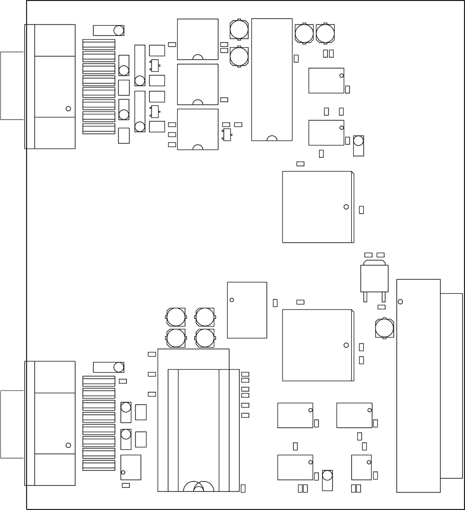
A
B
C
C
B
A
UARTB BA
RS232: IC21, J6A
RS422: IC22, J6B, J7, J8
20MACL: IC23, IC24, J5 J9*, J10*
*: TRANSM.=J9, RECEIV.=J10
RS232: IC11, J2A
RS422: IC12, J3, J4
RS485: IC13, J1, J4*
*: IF END OF CABLE
PASSIVE=B, ACTIVE=A+C
UARTA BA
A
B
C
C
B
A
UARTB BA
RS232: IC21, J6A
RS422: IC22, J6B, J7, J8
20MACL: IC23, IC24, J5 J9*, J10*
*: TRANSM.=J9, RECEIV.=J10
RS232: IC11, J2A
RS422: IC12, J3, J4
RS485: IC13, J1, J4*
*: IF END OF CABLE
PASSIVE=B, ACTIVE=A+C
UARTA BA
A
B
C
C
B
A
UARTB BA
RS232: IC21, J6A
RS422: IC22, J6B, J7, J8
20MACL: IC23, IC24, J5 J9*, J10*
*: TRANSM.=J9, RECEIV.=J10
RS232: IC11, J2A
RS422: IC12, J3, J4
RS485: IC13, J1, J4*
*: IF END OF CABLE
PASSIVE=B, ACTIVE=A+C
UARTA BA
35
1
P1
C50
C42
C51
C31
68
34
C52
C10 C12
C61
IC8
R23
R24
C36
C40 C60
IC7
J5
R20
R21
R22
IC20
IC21
C33
C34
C35
C41
IC2
C32
C53
C56
C57 IC4IC6
R1
R10
R18
R5
R6
R7
R8
R9
IC10
C30
C55
IC1IC5
J1
R11
R2
R3
R4
C11
C13
C63
J10
R27
R30
R34
R35
ANC
K
Z2
IC23
C62
C64
ANC
K
D1
J9
R26
R28 R29
R19
R33
ANC
K
Z1
IC22
IC24
C3C4 IC3
C1C2
R12
R13
R14
R15
R17 R16
IC11
IC13
IC12
F11
F12
F13
F16
J7
J6
P3
F10
F14
F15
F9
J8
R32R31
P2
F2 F3F4 F5F8F7
J3J4
J2
C54
F1 F6
IC9
ANC
K
ANC
K
R25
ANC
K
EasyCoder PX4i and PX6i Service Manual 191
Chapter 16 — Interfaces
Components
1-971642-26 Double Serial Interface Board; Component side

C54
C55
C57
C30
C31
C32
C33
C34
C35
C36
R1 R2 R3
5V
3.3V
1
AHC32
VCC=3.3V
1
AHC32
VCC=3.3V
1
AHC32
VCC=3.3V
3.3V
3.3V
P2 9PIN DSUB
C
F1
F2
F3
F4
F5
F6
F7
F8
5V
5V
R17
R13
R14
R12
J4
J3
R16
R11
R10
R9
R18
R8
MAX1480
MAX1490
=1
VCC=3.3V
AHC86
=1
VCC=3.3V
AHC86
=1
VCC=3.3V
AHC86
=1
VCC=5V
AHCT86
=1
VCC=5V
AHCT86
=1
VCC=5V
AHCT86
=1
VCC=5V
AHCT86
3.3V
5V
J1
3.3V
MAX238
5V
5V
J2
POWER_SWITCH
C53
C52
C51
R5
R6 R7
R4
R15
+
C1
+
C50
+
C2
+
C3
+
C4
1
AHC32
VCC=3.3V
=1
VCC=3.3V
AHC86
5V
5V
3.3V
16C550
MR
RTS*
DTR*
NC
OUT1*
OUT2*
INTRPT
A0
A1
A2
RXRDY*
RCLK
D5
SIN
D7
D6
NC
BAUDOUT*
CS2*
SOUT
CS1
CS0
RD2
TXRDY*
DDIS
RD1*
ADS*
NC
XIN
VSS
WR2
XOUT
WR1*
VCC
RI*
DCD*
DSR*
CTS*
NC
D1
D0
D2
D3
D4
IC10
C56
5V
1.8432MHZ
IC3
P1
3.3V
IC2
VCCA0
A1
GND
A2 WP
SDA
SCL
IC1
B
A
RS422
GND-SHIELD
RS232
RS485
SWITCH FOR
EXTERNAL 5V
RS485
RTS
DTR
TXD
+5V
RS422 RS485
GND
DSR
+TXD
GNDE
-RXD
-TXD -DATA
TERM.REC.
CTS
+DATA
TERM.TRA.
*: IF END OF CABLE
RS485: IC13, J1, J4*
RS422: IC12, J3, J4
RS232: IC11, J2A
UARTA CONFIGURATION
RS232
GNDE
+RXDRXD
33
11
IC4
D<15..0>
810
9
IC5
11 13
12
IC4
4
31
2
8
7
6
5
3
2
1
4
IC9
3
2
1
9
15
11
2021 2419 118 25
17 16
22 23
43
67
814
13
12
10
IC11
2
1
1113
12
IC6
32
1
IC6
65
4
IC6
810
9
IC6
65 4
IC5
11 13
12
IC5
32
1
IC5
18
17
10
8
2
1
7
11 14
22
13
21
15
16
12
5
6
9
4
3
19
23
24
20
IC12
14
10
8
2
1
7
13
18
26
15
24
22
19
21
17
16
20
12
5
6
9
11
4
3
25
27
28
23
IC13
2
1
2
1
MTG2
MTG1
9
8
7
6
5
4
3
2
1
810
9
65
4
IC4
32
1
IC4
19
18
21
20
22
44
27
13
32
36
4325
24
10 35
38
34
23
12
1
39
33
37
41
26 42
9
8
7
6
5
4
3
2
40
16
15
14
17
28
29
30
31
23
1
7
8
5
6
4
3
2
1
5
38
4
68
34
67
66
32
65
31
64
37
30
63
29
62
28
61
27
60
26
59
3
25
58
24
57
23
56
22
55
21
54
36
20
53
19
52
18
51
17
50
16
49
2
15
48
14
47
13
46
12
45
11
44
35
10
43
9
42
8
41
7
40
6
39
1
RD_N
9
+24VI
WAIT_N
SCL
SDA
SA1
CS_N
INT_N
CTSA_N
C2-
DE IVCC2
RESET
INTA
WR_N
INTB
INTA
INT_N
RESET_N
CSB_N
EN_N
RTSA_N
DTRA_N
T3IN
T4IN
R2OUT
R3OUT
R4OUT
R3IN
R4IN
T4OUT
T3OUT
T2OUT
DSRA_N
VIN
GND
NC/EN_N
VCC
OVERCURRENT_N
5V_EXT_EN_N
VCC1
T1IN
C2+
C1-
CSA_N
T2IN
R1OUT
R2IN
R1IN
GND1
IN
IN
OC_N
C1+
V-
T1OUT
RXDA
D2
GND1
IDIIN
IDEIN
GND2
RO_N
VCC5
IDEDRV
IRLED
VCC3
VCC2
D1
D2
ICOM1
IDIDRV
IRLED
IVCC1
SD
VCC4
RD_N
RESET
A<12..1>
12
2
RO
TXDA
DCDA_N
V+
GND
485_DIR
4
WR_N
7
6
5
3
2
0
1
2
3
VCC3
ICOM1
AC2
IVCC1
IRCDRV
VCC1
FS
A
B
IDIDRV
AC1
ICOM2
VCC2
D1
FS
SD
DI
VCC4
AC1
IRCDRV
A
B
Z
Y
IVCC2
DI
GND2
1
3
5
7
8
10
11
13
4
3
2
5
6
14
15
7
8
12
4
6
1
12
11
AC2
VCC
CLK
VOUT
GND
11
10
9
RESET_N
5V_EXT
OUT
1
0
GND OUT
OUT
OUT
192 EasyCoder PX4i and PX6i Service Manual
Chapter 16 — Interfaces
Schematics UART A
1-971642-26 Double Serial Interface Board; Schematics 1
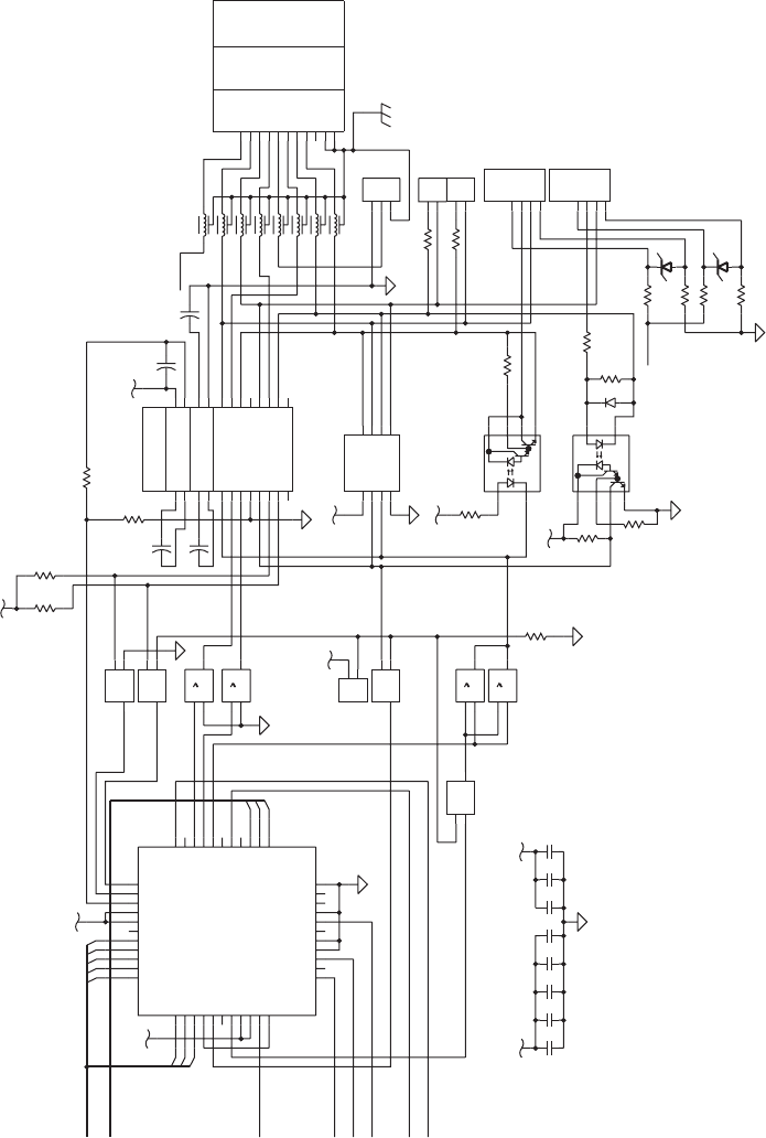
P39PIN DSUB
J9
J10
=1
VCC=3.3V
AHC86
C60
C61
C62
C63
C64
C40
C41
C42
5V 3.3V
R21 R22
R20
R23
R27
R28
R26
R25
+
C10
+
C11
+
C12
+
C13
5V
C
J7
F9
J8
R32
R31
R24
F10
5V
MAX238
=1
VCC=3.3V
AHC86
=1
VCC=3.3V
AHC86
F11
3.3V
J5
5V
F12
=1
VCC=3.3V
AHC86
F13
3.3V
16C550
MR
RTS*
DTR*
NC
OUT1*
OUT2*
INTRPT
A0
A1
A2
RXRDY*
RCLK
D5
SIN
D7
D6
NC
BAUDOUT*
CS2*
SOUT
CS1
CS0
RD2
TXRDY*
DDIS
RD1*
ADS*
NC
XIN
VSS
WR2
XOUT
WR1*
VCC
RI*
DCD*
DSR*
CTS*
NC
D1
D0
D2
D3
D4
IC20
F14
3.3V
J6
DS2981
6N139
6N139
F15
5V
5V
1
AHCT32
VCC=5V
1
AHCT32
VCC=5V
1
AHCT32
VCC=5V
1
AHCT32
VCC=5V
F16
R30
R29
R33
R19
R34
R35
D1
Z2
Z1
GND-SHIELD
20MACL: IC23, IC24, J5, J9*, J10*
UARTB CONFIGURATION
RS232: IC21, J6A
RS422: IC22, J6B, J7, J8
*: TRANSM.=J9, RECEIV.=J10
PASSIVE=B, ACTIVE=A+C
CURR-FEED
RECEIVER
B
A
C
C
B
B
A
A
TERM.REC.
TERM.TRA.
GND GNDE
DTR
CTS
RTS -TXD TXDOUT
TXD +TXD
+RXDRXD TXDIN
RXDIN
20MACL
+5V
-RXD
DSR
RS422
CURR-FEED
TRANSM.
RS232
RS232
RS422
20MACL
RXDOUT
20MACL
1113
12
IC7
4
3
2
1
4
3
2
1
CACA
32
1
IC8
1113
12
IC8
810
9
IC8
65
4
IC8
8
5
7
63
2
IC24
8
5
7
6
3
2
IC23
1
27
84
5
6
3
IC22
3
2
1
19
18
21
20
22
44
27
13
11
32
36
4325
24
10 35
38
34
23
12
1
39
33
37
41
26 42
9
8
7
6
5
4
3
2
40
16
15
14
17
28
29
30
31
810
9
IC7
2
1
65 4
IC7
321
IC7
9
15
11
20
21
24
19 1
18
2
5
17 16
22 23
43
67
8
14
13
12
10
IC21
2
1
2
1
MTG2
MTG1
9
8
7
6
5
4
3
2
1
TXDB
+24VI
R4IN
T3IN
C2-
D<15..0>
C1+
C1-
T2IN
T1IN
C2+
T1OUT
VCC
RESET
CSB_N
5V_EXT
WR_N
CLK
RD_N
7
6
5
3
2
2
3
4
1
0
10V
10V
RI-
RI+
DO+
DO-VCC
R3IN
R1IN
R2IN
T4OUT
T3OUT
T2OUT
GND
V+
V-
R3OUT
R2OUT
R1OUT
T4IN
DCDB_N
CTSB_N
DTRB_N
RTSB_N
R4OUT
GND
DI
RO
RXDB
1
A<12..1>
INTB
DSRB_N
CL_EN_N
EasyCoder PX4i and PX6i Service Manual 193
Chapter 16 — Interfaces
Schematics UART B
1-971642-26 Double Serial Interface Board; Schematics 2
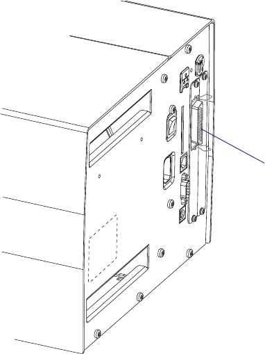
194 EasyCoder PX4i and PX6i Service Manual
Chapter 16 — Interfaces
16.8 IEEE 1284 Parallel Interface Board
Description
The IEEE 1284 Parallel Interface Board is an optional device for Easy-
Coder PX4i and PX6i printers. It provides these printers with one parallel
interface port and is supported by both Fingerprint and IPL.
The parallel communication port is addressed in Intermec Fingerprint as
device centronics: (communication channel 4). The board is IEEE1284-I
compatible. Nibble Mode and device ID is supported. Byte, ECP, and EPP
modes from printer to host are presently not supported.
The IEEE 1284 Parallel Interface kit contains:
• One Parallel Interface Board
• Two fl at cables
• One hexagonal spacer
• One Installations Instructions booklet.
There are neither any straps nor any other types of physical confi guration
on this interface board, nor any options in the Setup Mode.
IEEE 1284 interface
("centronics:")

EasyCoder PX4i and PX6i Service Manual 195
Chapter 16 — Interfaces
Connector Configuration
The IEEE 1284 board has a standard 36pin IEEE 1284 B socket with the
following confi guration:
Pin Signal Remark
1 DSTROBE
2 DATA 0
3 DATA 1
4 DATA 2
5 DATA 3
6 DATA 4
7 DATA 5
8 DATA 6
9 DATA 7
10 ACK
11 BUSY
12 PE
13 SELECT
14 AF
15 N/C
16 GND
17 SCREEN
18 External +5VDC max 500 mA (automatic switch-
off at overload, short-circuit protected)
19 GND
20 GND
20 GND
21 GND
22 GND
23 GND
24 GND
25 GND
26 GND
27 GND
28 GND
29 GND
30 GND
31 INIT
32 ERROR
33 N/C
34 N/C
35 N/C
36 SELECTIN
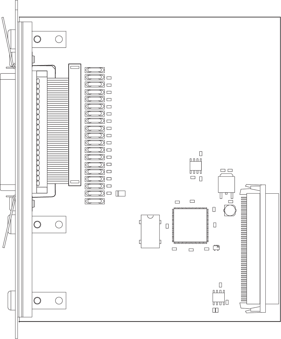
C14
C2
C12
C13
C11
C9
C8
C3
C1
IC3
IC2
IC5
R19 R18
IC6
C10
C7
C6
C5
C4
IC1
R20
R22
R21
R17
R16
R15
R14
R13
R12
R8
R10
R11
F12
F11
F10
F18
F17
F16
F15
F14
F13
F8
F7
R3
R7
R6
R5
R4
R9
R2
R1
F19
F1
F2
F3
F9
D1
F6
F5
F4
IC4
P3
P1
1-971641-02 P01
196 EasyCoder PX4i and PX6i Service Manual
Chapter 16 — Interfaces
Components
1-971641-27 IEEE 1284 Parallel Interface Board; Component side
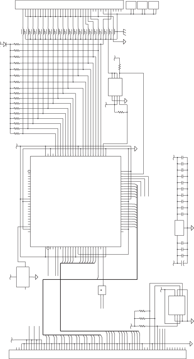
5V
C11
C12
C13
C1
C2
C3
C4
C5
C6
C8
5V
P3
5V
3.3V
POWER_SWITCH
F9
R1 R2 R3R4 R5 R6 R7 R8R9 R10 R11R12 R13R14 R15 R16 R17
D1
C
R20 R21 R22
BR1
+C14
BR2
BR3
3.3V
1
AHC1G32
VCC=3.3V
5V
3.3V
5V
F1
F2
F3
F4
F5
F6
F7
F8
F10
F11
F12
F13
F14
F15
F16
F17
F18
F19
R18
R19
C10
C9
C7
VCCA0
A1
GND
A2 WP
SDA
SCL
IC2
3.3V
P1
XCS05XL-4
IC1
OSC.
IC4
IC3
SELIN
EXT-5V
SCREEN
18
36
GND
GND
35
GND
INIT
GND
ERROR
AFEED
13
16
30
31
17
15
34
33
ACK
BUSY
GND
GND
GND
GND
GND
DATA6
DATA7 26
25
29
9
8
28
10
7DATA5
GND
GND
GND
DATA2
DATA4
DATA3
20
21
22
23
3
4
6
5
24
DATA0 2
CABLE ASSEMBLY
CENTRONICS CONN.
STROBE
GND 19
1
40-PIN RIBBON CABLE
CONNECTOR -> 36-PIN
36-PIN40-PIN -
DATA1
27
11
12PERROR
14
32
SELECT
49
3.3V
WR_N
2
A<12..1>
1
53
43
68
59
94
100
57
23
3
37
5
61
63
64
65
4
CCLK
VCC8
O/TDO
77
10
9
RD_N
VCC
WR_N
CS_N
IO33
IO36
INIT_N/IO38
GND2
5V_EXT_EN_N
SCL
SDA
SA1
RESET_N
CS_N
MTG1
MTG2
MTG1
MTG2
MTG1
MTG2
NC/EN_N
MAX1607
1
0
3
2
5
4
6
7
9
11
10
12
2
1
14
15
4
3
6
5
7
8
10
9
11
12
0
1
4
5
6
7
8
11
12
13
14
15
WAIT_N
2
3
5
6
7
8
9
10
11
12
D<15..0>
1
0
13
3
2
RD_N
WAIT_N
INT_N
OC_N
OUT
OUT
OUT
IN
EN_N
IN
GND
WR_N
OUT
GND
GND
VIN
IO64
GND8
IO69/GCK7
IO70/CS1
IO72
IO71
IO73
IO74
IO75
IO76
IO77
GND1
IO1
VCC1
IO2
IO3
IO4
IO6
IO5
IO7
IO8
IO9
IO10/GCK8
VCC2
GND6
DONE
IO47
IO46
IO43
IO42
IO41
IO40
IO39
VCC5
IO37
IO35
IO34
IO32
IO31
IO30
GCK3/IO29
PWRDWN_N
GCK1/IO11
IO12
TDI/IO13
TCK/IO14
TMS/IO15
IO16
IO17
IO18
IO22
IO21
IO23
IO24
IO25
IO27
IO26
GND4
M1
M0
VCC4
IO67/DOUT
IO66/DIN
IO63
IO60
IO59
GND7
VCC7
IO58
IO57
IO56
IO55
IO54
IO49
PROG_N
IO65
IO62
IO61 IO19
IO50/GCK5
IO51
IO52
GND3
VCC3
IO20
SELIN
ERROR
INIT
AFEED
SELECT
PERROR
BUSY
CD5
CD6
CD2
CD0
CD1
STROBE
RESET_N
ACK
CS_N
CD7
IO45
IO44
IO53
INT_N
CD4
CD3
GCK2/IO28
GND5
OVERCURRENT_N
IO68
8
GCK4/IO48
VCC6
1
39
6
40
7
41
8
42
9
10
35
44
11
45
12
46
13
47
14
48
15
49
16
50
17
51
18
52
19
53
20
36
54
21
55
22
56
24
58
25
3
26
60
27
61
28
62
29
63
30
64
31
65
32
66
33
67
34
4
38
1
2
3
46
5
8
732
1
10
11
12
13
14
15
16
17
18
19
2
20
21
22
23
24
25
26
27
28
29
3
30
31
32
33
34
35
36
37
38
39
4
40
5
6
7
8
9
IC5
4
1
2
3
5
6
7
8
24
74
50
88
1
11
23
38
90
99
2
3
4
5
6
7
8
9
10
91
13
14
15
16
17
18
19
20
21
27
92
28
29
30
31
32
33
34
35
36
39
93
40
41
42
43
44
45
46
47
48
54
55
56
57
58
59
60
62
95
66
67
68
69
70
71
72
73
78
79
96
80
81
82
83
84
85
86
87
97
98
24
22
76
52
26
89
12
25
37
51
75
IC6
2
14
EasyCoder PX4i and PX6i Service Manual 197
Chapter 16 — Interfaces
Schematics
1-971641-27 IEEE 1284 Parallel Interface Board; Schematics

198 EasyCoder PX4i and PX6i Service Manual
Chapter 16 — Interfaces
16.9 EasyLAN Ethernet Interface Board
Description
This section describes how to install an EasyLAN Ethernet network inter-
face in an EasyCoder PX4i and PX6i printer and how to connect it to a
100base TX Fast LAN, WAN, Intranet, or Internet network via a wired
connection.
The installation instructions describes how to physically install the inter-
face board in a printer. Confi guration and setup are described in the
EasyLAN Interface Kit, Installation Instructions and the Intermec EasyLAN,
User’s Guide on the attached CD-ROM.
This interface kit must only be physically installed by an authorized
service technician.
Printer Firmware
The printer must either be fi tted with Intermec Fingerprint v8.30 (or
later) or IPL v2.30 (or later). In Intermec Fingerprint, the network port is
addressed as device "net1:" (communication channel #5).
Installation Kit
The EasyLAN Interface Kit contains:
• One EasyLAN interface board
• One light guide
• One hexagonal threaded spacer
• One network extension cable
• One cable tie
• One serial number label
• One CD-ROM with software and manuals
• One Installation Instruction booklet
The only tool required for the installation is a #T20 Torx screwdriver.
EasyCoder PX4i and PX6i Service Manual 199
Chapter 16 — Interfaces
Installation Instructions
Also see illustration on the next page.
• Switch off the printer and disconnect the power cord.
• Disconnect all communication cables.
• Remove the left-hand cover as described in Chapter 3.3.
• Remove the LAN connector plug, which is snap-locked at the top of the
rear plate.
• Remove the #T20 Torx screw that holds the upper/front part of the
CPU board to the power supply unit and replace it with the hexagonal
spacer included in the kit. Keep the screw.
• Connect the EasyLAN board to the PCI connector (J84) on the CPU
board so the hole in the interface board becomes aligned with the spacer.
• Secure the EasyLAN board with the #T20 Torx screw you previously
removed.
• From the inside of the electronics compartment, press the metal socket
of the network extension cable into the square hole in the rear plate
(where you removed the LAN plug) until it is held by its snap-lock.
• Route the extension cable over the SIMMs on the CPU board and con-
nect it to the RJ-45 socket on the EasyLAN interface board (J2).
• From the outside, insert the thin end of the light guide through the
small hole next to the RJ-45 socket on the rear plate. Press the clear plas-
tic “lamp” in place. Connect the other end to the black plastic socket
(D1) on the EasyLAN interface board.
• Pull the cable tie through the hole in the upper edge of the CPU board
between the SIMMs and the RTC socket. Secure both the extension
cable and the light guide with the cable tie.
• Fit the serial number label on the rear plate to the left of the RJ-45
socket.
• Put back the left-hand cover. Route the cable from the display unit
above the ribbon motor. Connect the cable to connector J50 at the
upper front corner of the CPU board.
• Connect the power cord and switch on the power.
• Enter the Setup Mode and print the test label “Hardware Info” in Fin-
gerprint or “HW” in IPL to see if the printer detects the EasyLAN Eth-
ernet interface board. For information on how to enter the Setup Mode
and print test labels, refer to the User’s Guide for the printer in question.
• After startup, enter the Setup Mode to set up the network parameters.
See Appendix A. Setting the network parameters in IPL, when the server
does not support DHCP or BOOTP, is described in EasyLAN Interface
kit, Installation Instructions.
LAN connector plug
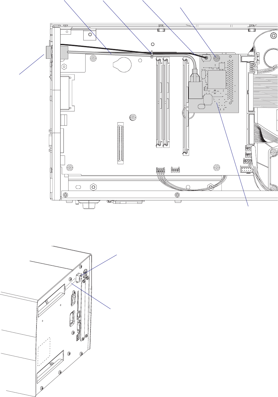
200 EasyCoder PX4i and PX6i Service Manual
Chapter 16 — Interfaces
Network extension cable
EasyLAN Ethernet
interface board
Light guideCable tie #T20 Torx screw
and spacer
RJ-45 Ethernet connector
("net1:")
Serial number label (MAC address)
RJ-45 Ethernet
connector
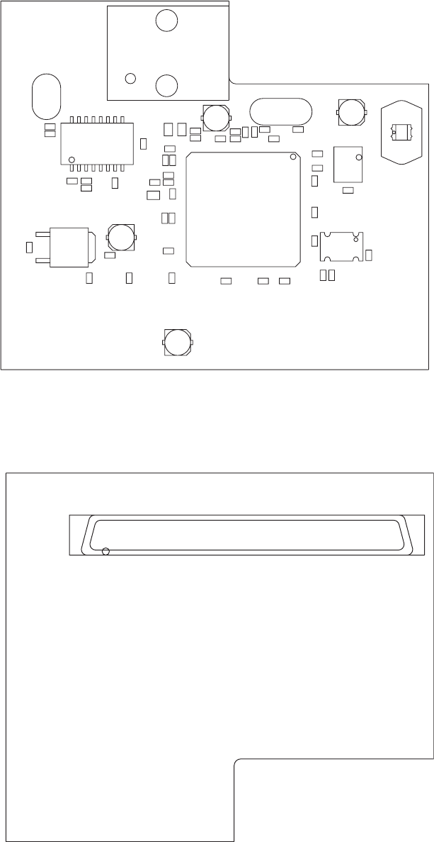
1
J1
IC1
M1
C1
C10
C11
C13
C14C15
C16
C17
C18
C19
C2
C20
C21
C22
C23C24
C26
C27
C28
C29
C30
C31
C32
C34
C35
C36
C37
C5
C7 C4
C6
C38
C12
C25
C3
C39IC2
L3
L2
L1
IC3
Y1
R9
R5
R6 R7
R12
R13
R4
R11
R8
R1
R2
R3
J2
D1
C33
Y2
EasyCoder PX4i and PX6i Service Manual 201
Chapter 16 — Interfaces
Components
1-971645-26 EasyLAN Interface Board; Soldering side
1-971645-26 EasyLAN Interface Board; Component side
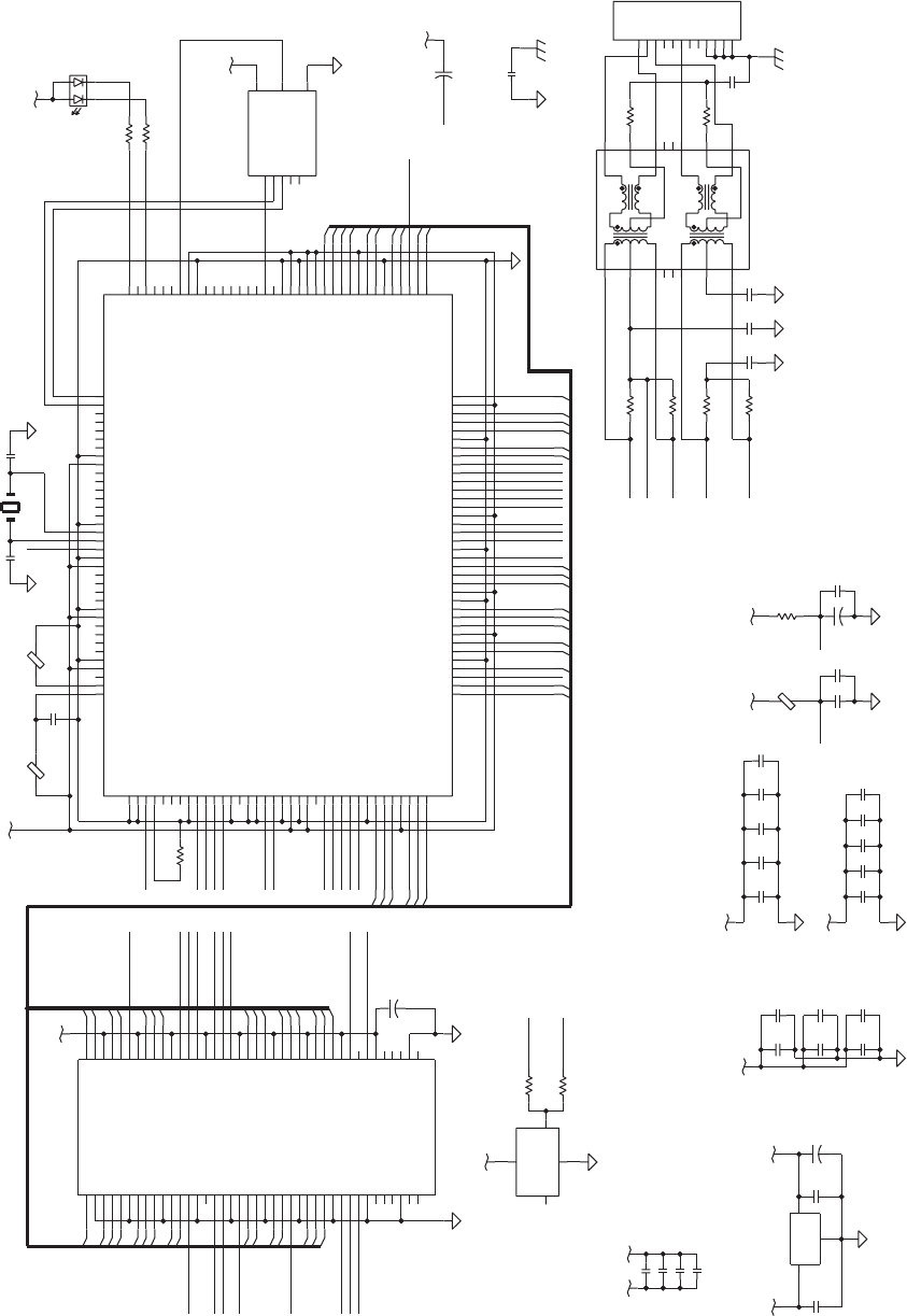
3.3V
R4
5V
R5
R6
R7
R8
C30
C29
L2
L3
+
C3
C1
C2
C17
C13
C16
C18
3.3V
3.3V
C15
C14
C19
C21
C22
3.3V
C4
C5
3.3V
C6
C7
C10
C11
C20
C24
R9
C32
C31
R13
R12
C33
C34
C
C
C35
C36
C37
5V
3.3V
C38
R11
DP83815/6
TQFP144
IC1
+
C39
3.3V
3.3V
3.3V
5V
J2
RJ45
M1
1CT:1CT
EEPROM
IC2
3.3V
IC3
L1
C23
R1
3.3V
C26
+
C25
3.3V
25MHZ
Y2
R2
R3
C27
C28
D1
32.768MHZ
Y1
+
C12
SCA80
J1
FOR DP83815
R1=0OHM
FOR DP83815
ONLY POPULATED
BOUNDARY
CROSSING 5V TO 3.3V
FOR PCI SIGNALS
AC RETURN PATHS
56/58
UNPOPULATED
NORMALLY
NORMALLY UNPOPULATED
L2+C17 ONLY POPULATED
FOR DP83816
C39 ONLY POPULATED
DP83816
R4=10K FOR
PINS
BYPASS CAPACITORS
IC2
33 PINS
IC1
85
125 137
27
117
Y1
94/107
TX+
TX-
RX-
RX+
69/80
9
R4=9K31 FOR
IC1
DP83815 AND
PINS
21
IC1
PCI_PAR
PCI_IRDY_N
18
17
84
90
8
77
65
57
55
52
51
49
44
38
35
32
26
20
16
136
114
103
40
85
30
25
24
23
22
31
93
54
53
46
45
126
37
96
98
13
14
15
12
11
10
7
6
62
50
41
127
64
48
123
59
97
94
80
69
117
107
60
99
43
42
34
131
130
4
5
141
140
139
138
135
134
133
132
129
124
125
3
2
1
144
143
142
92
61
76
63
36
91
128
95
29
28
75
89
100
111
19
9
58
56
47
39
33
27
21
137
109
110
112
113
115
116
66
67
118
68
70
71
72
73
74
78
79
81
82
119
83
86
87
88
101
102
104
105
106
108
120
121
122
4
31
2
4
3
2
1
23
1
8
2
6
7
5
43
1
15
16
14
2
1
3
10
11
9
7
6
8
13
12
5
4
MTG4
MTG3
MTG2
MTG1
8
7
6
5
4
3
2
1
34
30
26
22
18
14
10
6
38
2
75
71
67
63
59
55
51
47
43
40
36
37
39
35
78
77
17
16
53
74
73
31
54
13
15
57
33
32
58
56
72
25
19
52
46
8
7
45
5
44
4
70
69
3
29
6828
27
66
65
6424
23
62
42
6121
6020
12
11
50
49
9
48
41
1
79
76
80
TPTDM
PCI_CBE1_N
PCI_AD(31..0)
PIN19
RXD3/MA9
PCI_PAR
PCI_AD19
AD31
VSS_77
AD25
AD24
AD19
AD10
PCI_TRDY_N
PCI_AD28
PCI_AD1
PCI_CBE1_N
RXD0/MA6
PCI_CBE0_N
AD2
6
REGEN
22
RESERVED_41
3VAUX
REGEN
TPTDM
PCICLK
RXAVDD
PCI_REQ_N
PCI_GNT_N
PCI_RST_N
PCI_CLK2
PCI_INT_N
TPTDP
TPRDP
TPRDM
RXAVDD
PCI_SERR_N
PCI_PERR_N
PCI_STOP_N
PCI_DEVS_N
PCI_IRDY_N
PCI_FRAME_N
PCI_CBE2_N
PCI_CBE3_N
AUXVDD_47
REGEN
AD9
CBEN0
AD8
AD7
AD6
VSS_114
AD4
AD5
PCIVDD_117
AD3
AD1
PWRGOOD
MACVSS2/NC83816
SUBGND3/NC83816
RESERVED_127
MCS_N
EESEL
MWR_N
MD0
MRD_N
MD2
MD1/CFGDIS_N
MD3
AUXVDD_137
VSS_136
MD4/EEDO
MD5
MD6
MD7
MA0/LEDACT_N
MA1/LED10_N
MA2/LED100_N
AD26
AD27
AD30
AD29
PCIVDD_69
VSS_65
REQ_N
GNT_N
RST_N
INTA_N
TPTDP
VSS_55
AUXVDD_56
VSS_52
TPTDM
RESERVED_50
VSS_49
VSS_51
VSS_44
TPRDP
TPRDM
NC_42
NC_43
AUXVDD_39
VREF
VSS_38
MA3/EEDI
MA5
MDIO
MDC
RXCLK
VSS_8
AUXVDD_9
RXD1/MA7
RXD2/MA8
RXOE
RXER/MA10
RXDV/MA11
VSS_16
X1
C1
X2
AD11
AD12
PCIVDD_107
AD13
VSS_103
AD14
CBEN1
AD15
PAR
SERR_N
STOP_N
IRDY_N
FRAME_N
VSS_90
CBEN2
VSS_20
TXD0/MA12
AUXVDD_21
TXD1/MA13
TXD2/MA14
VSS_26
AUXVDD_27
CRS
COL/MA16
TXEN
TXCLK
VSS_32
NC_34
AUXVDD_33
VSS_35
FXVDD/NC83816
AD16
AD17
VSSIO4/NC83816
AD20
AD21
AD23
IDSEL
CBEN3
RXAVDD
TPRDM
PCI_SERR_N
PCI_AD13
PCI_CBE_N0
PCI_AD7
PCI_CBE_N1
PCI_DEVS_N
PCI_AD2
PCI_FRAME_N
VSS2
16
EN/NC
VCC
GND
OUT
PCI_RST_N
PCI_CLK1
PCI_INT_N
PCI_GNT_N
PCI_REQ_N
PCI_CBE3_N
PCI_TRDY_N
PCI_STOP_N
PCI_CBE0_N
PCI_PERR_N
PCI_SERR_N
29
26
27
PCI_CLK
PCI_AD21
VSS3
PCI_AD4
PCI_AD6
VCC2
PCI_FRAME_N
PCI_AD17
PCI_AD20
PCI_AD3
PCI_AD8
PCI_AD9
PCI_AD11
PCI_PAR
PCI_AD14
PCI_AD15
VSS4
PCI_STOP_N
PCI_AD16
VSS6
PCI_LOCK_N
VSS7
VSS8
TCK
PCI_AD5
PCI_PERR_N
PCI_AD23
VCC6
VCC5
VCC4
PCI_IRDY_N
PCI_AD24
SDA
SCL
VCC7
NC1
VCC9
PCI_AD0
PCI_AD12
VCC3
PCI_AD31
VCC1
VSS10
TDO
TMS
VSS1
PCI_CBE_N2
VSS5
PCI_TRDY_N
PCI_AD27
TRST_N
TDI
PCI_AD29
PCI_AD26
PCI_CBE_N3
PCI_DET_N
PCI_AD10
22
18
16
15
14
11
9
8
31
25
24
19
20
17
13
12
10
4
0
3
67
5
2
1
TX+
10
VIN
GND
VOUT
31
24
11
23
20
21
19
27
26
28
29
30
15
14
12
11
8
9
5
4
7
1
0
2
3
25
13
TD-
RX+
RXCT
TXCT
TX-
RD+
RDCT
NC2
NC1
RD-
NC4
TX+
RX-
RX+
TD+
TDCT
RX-
TX-
TPTDP
TPRDP
CS
VCC
SK
DI DO
NC
21
30
18
17
PCI_AD18
23
PCI_REQ_N2
24V
PCI_CLK1
PCI_GNT_N0
PCI_REQ_N0
PCI_CBE2_N
PCI_AD25
28
PCI_CLK2
MA4/EECLK
TXD3/MA15
PERR_N
DEVSEL_N
TRDY_N
AD18
AD22
AD28
PCI_INT_N
VSS9
VDDIO4/NC83816
AD0
PCI_DEVSEL_N
NC3
GND
ORG/NC
MACVDD2/NC83816
VCC8
PCI_RST_N
PIN19
RXAVDD
PCIVDD_94
PMEN/CLKRUN_N
AUXVDD_58
VSS_57
PCI_AD22
PCI_AD30
PCIVDD_80
SUBGND1/NC83816
202 EasyCoder PX4i and PX6i Service Manual
Chapter 16 — Interfaces
Schematics
1-971645-26 EasyLAN Interface Board; Schematics

EasyCoder PX4i and PX6i Service Manual 203
Chapter 16 — Interfaces
16.10 EasyLAN Wireless Interface Board
Description
This section describes how to install an EasyLAN Wireless network inter-
face in an EasyCoder PX4i and PX6i printer and how to connect it to a
LAN, WAN, Intranet, or Internet network via a wireless connection.
The installation instructions describes how to physically install the inter-
face board in a printer. Confi guration and setup are described in the
EasyLAN Wireless Kit, Installation Instructions and the Intermec EasyLAN,
User’s Guide on the attached CD-ROM.
This interface kit must only be physically installed by an authorized
service technician. The device is country/region specifi c and must be
ordered for the correct country/region. Use of this device in other region
than shown on the device home page/test label may violate applicable
law.
Printer Firmware
The printer must either be fi tted with Intermec Fingerprint v8.30 (or
later) or IPL v2.30 (or later). In Intermec Fingerprint, the network port is
addressed as device "net1:" (communication channel #5).
Installation Kit
The EasyLAN Interface Kit contains:
• One EasyLAN adapter board complete with radio module fi tted
• Rear plate (for EasyCoder PF2/4i-series printers only)
• RJ-45 plug (for EasyCoder PM4i, PX4i, and PX6i only)
• One light guide
• One hexagonal threaded spacer
• One antenna extension cable
• One antenna
• One cable clip
• One cable tie
• One CD-ROM with software and manuals
• One Installation Instruction booklet
The only tools required for the installation are #T10 and #T20 Torx screw-
drivers and a small wrench.
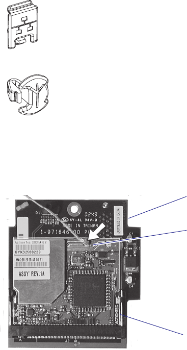
204 EasyCoder PX4i and PX6i Service Manual
Chapter 16 — Interfaces
Installation Instructions
• Switch off the printer and disconnect the power cord.
• Disconnect all communication cables.
• Remove the left-hand cover as described in Chapter 3.2.
• Remove any present EasyLAN Ethernet interface including cables etc.
Fit the RJ-45 plug included in the kit into the square hole left by the
RJ-45 Ethernet connector.
• Remove the antenna plug, which is snap-locked into the rear plate.
• Connect the antenna cable to the radio module, which is factory-fi tted
on the EasyLAN adapter board, as illustrated below. Support the upper
edge of the radio module with a fi nger while connecting the cable.
• Remove the #T20 Torx screw that holds the upper/front part of the
CPU board to the power supply unit and replace it with the hexagonal
spacer included in the kit. Keep the screw.
• Connect the EasyLAN adapter board to the PCI connector (J84) on the
CPU board so the hole in the board becomes aligned with the spacer
and secure the board with the #T20 Torx screw.
• Route the antenna cable over the SIMMs on the CPU board towards
the rear plate and secure it using the cable clips included in the kit.
One clip is factory-fi tted on the EasyLAN adapter board and the other
should be fi tted in the small hole at the top of the CPU board immedi-
ately to the rear of the memory SIMM sockets.
• From the inside of the electronics compartment, insert the antenna
connector through the round hole in the rear plate and lock it with the
washer and nut on the outside.
Connect antenna
cable here
Radio module
Adapter board
EasyCoder PX4i and PX6i Service Manual 205
Chapter 16 — Interfaces
• Fit the antenna to the connector of the antenna cable and bend the
hinge so the antenna points straight up.
• From the outside, insert the thin end of the light guide through the
small hole next to the antenna on the rear plate. Press the clear plastic
“lamp” in place. Connect the other end to the black plastic socket (D1)
at the top of the EasyLAN adapter board. Secure it with the cable tie
through the hole at the upper edge of the CPU board.
• Put back the left-hand cover. Route the cable from the display unit
above the ribbon motor. Connect the cable to connector J50 at the
upper front corner of the CPU board.
• Connect the power cord and switch on the power.
• Enter the Setup Mode and print the test label “Hardware Info” in
Fingerprint or “HW” in IPL to see if the printer detects the EasyLAN
Wireless interface board. For information on how to enter the Setup
Mode and print test labels, refer to the User’s Guide for the printer in
question.
• Set up the network parameters. There are several methods:
- Connect the printer and a PC and run the EasyLAN Network Setup
wizard, which can be found on the attached CD-ROM. Requires a
PC running Windows 98 or later.
- Insert a CompactFlash Card containing a confi guration fi le in the
printer and start it up. Confi guration Compact Flash cards can be
created using the EasyLAN Network Setup wizard on the attached
CD-ROM.
- Fingerprint:
Establish an RS-232 communication with the printer and set it up
using Fingerprint setup strings or setup fi les. IP address, netmask,
default router, and name server can also be set using the printer’s
built-in keyboard. Only requirement on the PC side is a terminal pro-
gram that can transmit and receive ASCII characters on an RS-232
line. See EasyLAN Wireless Kit, Installation Instructions.
- IPL:
Establish an RS-232 communication with the printer and set it up
using IPL commands. Only requirement on the PC side is a terminal
program that can transmit and receive ASCII characters on an RS-
232 line. Select the method of obtaining IP address, netmask, default
router, and name server automatically from the server using the print-
er’s built-in keyboard. This requires a server that supports DHCP
and/or BOOTP. See EasyLAN Wireless Kit, Installation Instructions.
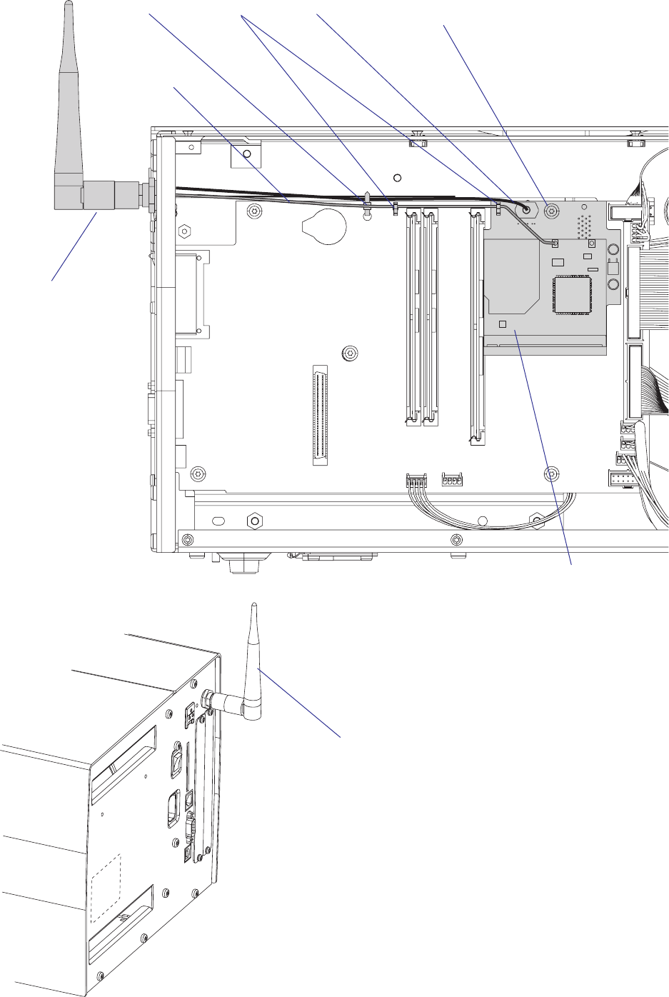
206 EasyCoder PX4i and PX6i Service Manual
Chapter 16 — Interfaces
Antenna
EasyLAN
adapter board
Light guideCable clips #T20 Torx screw
and spacer
Antenna cable
Cable tie
Antenna
(packed separately when the EasyLAN Wireless
interface is factory-installed)
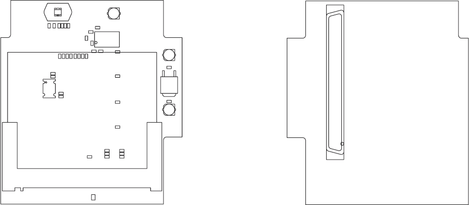
Primary Side Secondary Side
J1
1
J2
J2
IC2
IC2
D1
D1
R30
R3 0
R29
R2 9
R28
R2 8
R27
R2 7
R26
R2 6
R25
R2 5
R24
R2 4
R23
R2 3
R22
R2 2
R21
R2 1
R20
R2 0
R19
R1 9
R18
R1 8
R17
R1 7
R16
R1 6
R15
R1 5
R14
R1 4
R2
R2
R1
R1
R8
R8
R11
R1 1
R4
R4
R13
R1 3
R12
R1 2
R7
R7
R6
R6
R5
R5
R9
R9
Y1
Y1
IC1
IC1
L1
L1
C11
C11
C1
C1
C4
C4
C12
C12
C9
C9
C10
C10
C8
C8
C3
C3
C6
C6
C7
C7
C5
C5
C2
C2
1 3 123
123
124
124
2 4
EasyCoder PX4i and PX6i Service Manual 207
Chapter 16 — Interfaces
Components
1-971646-26 Adapter Board
CROSSING 5V TO 3.3V
FOR PCI SIGNALS
ONLY
R26 OR R27
COLOR SWITCH
POPULATED
IF IC2
POPULATED
DECOUPLING IC2
DO NOT POPULATE
PRINTER PCI INTERFACE
RESISTORS
LED BLINK ONE-SHOT CIRCUIT
BOUNDARY
ONLY IC2 OR
SOURCE SIDE
UNUSED PART
COLOR SWITCH
POPULATED
R29OR R30
TERMINATION OF UNUSED
MINI-PCI SIGNALS
AC RETURN PATHS
MINI-PCI INTERFACE
RESISTORS
SINK SIDE
61
3.3V
CBE1_N
SERR_N
PERR_N
DEVSEL_N
13
10
14
22
AC_SDATA_OUT
AC_CODEC_ID0_NAC_BIT_CLK
AC_CODEC_ID1_N
LED2_YELP
AHCT123
3.3V
VCC=5V;GND=GND
11
5V
32.768MHZ
3.3V
LED2_YELN
3.3V
CBE3_N
CBE2_N
PERR_N
AC_RESET_N
27
LED2_YELN
LED1_GRNP
5V
AC_RESET_N
LED_LINKN
STOP_N
CBE2_N
PAR
21
16
GNT_N
AC_CODEC_ID0_N
24
5V
AC_BIT_CLK
AC_SDATA_OUT
AC_SYNC
CLKRUN_N
AC_CODEC_ID1_N
PCI_AD(31..0)
INT_N
VCC=5V;GND=GND
LED1_GRNN
CBE1_N
FRAME_N
TRDY_N
CBE0_N
17
5V
LED_ACTN
28
30
3.3V
LED_ACTP
LED_LINKP
5V
15
3
26
11
24
20
16
18
13
9
6
0
4
2
3.3V
1
5
2
7
5V
0
4
3
6
8
31
29
27
25
23
21
19
17
14
12
10
8
12
19
20
23
25
30
31
7
5
1
9
15
18
22
29
3.3V
CLK1
CLK2
CLK2
SERR_N
GNT_N
LED1_GRNN
AC_SYNC
LED1_GRNP
IRDY_N
DEVSEL_N
FRAME_N
CBE0_N
PAR
STOP_N
TRDY_N
INT_N
REQ_N
CLK1
CBE3_N
26
28
AHCT123
REQ_N
GREEN/YELLOW
LED_LINKN
RST_N
RST_N
11
LED2_YELP
J1
80
76
79
1
41
9
49
50
11
12
20 60
21
42
62
23
24 64
65
66
27
2868
29
3
69
70
4
44
5
45
7
8
46
52
19
25
72
56
58
32
33
57
15
13
54
31
73
74
53
16
17
77
78
35
39
37
36
40
43
47
51
55
59
63
67
71
75
2
38
6
10
14
18
22
26
30
34
IC1
1
3
2
Y1
2
1
3
4
R1
R2
C4
C2 C3
C1
J2
1
10
100
101 102
103 104
105 106
107 108
109
11
110
111 112
113 114
115 116
117 118
119
12
120
121 122
123 124
13 14
15 16
17
18
19
2
20
21
22
23 24
25 26
27 28
29
3
30
31
32
33 34
35 36
37 38
39
4
40
41
42
43 44
45 46
47 48
49
5
50
51
52
53 54
55 56
57 58
59
6
60
61
62
63 64
65 66
67 68
69
7
70
71
72
73 74
75 76
77 78
79
8
80
81
82
8384
8586
8788
89
9
90
91
92
9394
9596
9798
99
MTG1
MTG2
R11
R12
R13
R14
R15
R16
R17
R25
R22
R21
R18
R6
R5
R8
R7
L1
C5
C6
C7
C8
C9C10
IC2
14
15
3
2
1
13
4
R28
C11
R19
R23
R24
R26
R29
R30
R4
R9
IC2
6
7
11
10
95
12
D1
1
2
3
4
C12
48
IRDY_N
CLKRUN_N
5V
LED_ACTN
LED_ACTP
LED_LINKP
R27
R20
VSS6
VCC9
PCI_RST_N
PCI_REQ_N2
PCI_CLK
PCI_CBE_N2
PCI_AD18
PCI_AD23
PCI_AD24
TRST_N
TDI
VSS10
TDO
TMS
TCK
VSS9
PCI_INT_N
PCI_GNT_N0
PCI_REQ_N0
VSS8
PCI_AD29
PCI_AD27
PCI_AD26
VSS7
PCI_CBE_N3
PCI_AD22
PCI_AD21
PCI_AD16
VSS5
PCI_TRDY_N
PCI_STOP _N
VSS4
PCI_LOCK_N
PCI_AD15
PCI_AD14
PCI_PAR
VSS3
VSS2
PCI_AD4
PCI_AD3
VSS1
PCI_AD0
PCI_AD10
PCI_CBE_N0
VCC2
24V
PCI_DET_N
SDA
SCL
NC1
VCC8
PCI_AD31
PCI_AD30
PCI_AD28
VCC7
PCI_AD25
VCC6
PCI_AD20
PCI_AD19
PCI_AD17
VCC5
PCI_FRAME_N
PCI_IRDY_N
PCI_DEVSEL_N
VCC4
PCI_PERR_N
PCI_SERR_N
PCI_CBE_N1
VCC3
PCI_AD13
PCI_AD12
PCI_AD7
PCI_AD5
VCC1
PCI_AD2
PCI_AD1
PCI_AD11
PCI_AD9
PCI_AD8
PCI_AD6
++
C
C
C
A
REXT/CEXT
Q
B
CEXT
CLR
Q
+
A
REXT/CEXT
Q
B
CEXT
CLR
Q
VIN
GND
VOUT
EN/NC
OUT
GND
VCC
208 EasyCoder PX4i and PX6i Service Manual
Chapter 16 — Interfaces
Schematics
1-971646-26 Adapter Board

EasyCoder PX4i and PX6 Service Manual 209
1 7 Troubleshooting
This chapter explains how to diagnose and fi x troubles that may occur in
an EasyCoder PX4i or PX6i printer, even if great effort has been made to
safeguard troublefree printing. Some parts are, however, subject to wear
and may need periodical replacement, such as the printhead.
Please note that replacement parts are generally only available as complete
modules (see the Spare Parts Catalog or Spare Parts List).
This chapter is supplemented by the Technical Bulletins that are distrib-
uted as soon as any new problem has been reported and a remedy has been
found.

210 EasyCoder PX4i and PX6i Service Manual
Chapter 17 — Troubleshooting
17.1 Diagnosing
To diagnose the printer for faults, take steps in the following order:
• In case the printer is running the Intermec Fingerprint fi rmware, use
Intermec Shell to check printer’s setup and functions. Intermec Shell
can be accessed regardless of any running autoexec.bat fi les as described
below.
• Browse through the remainder of this chapter to fi nd symptoms that
apply to the faulty printer.
• Refer to the Printer Technical Bulletins for updated information.
Fingerprint only
The keyboard, display messages, sounds, and other functions will be
custom-confi gured, if a custom-made program is running in the printer.
Normally, such a program is started at power-on using an autoexec.bat fi le.
The procedure of starting up Intermec Shell, bypassing any other auto-
exec.bat fi les the printer’s memory, is called the Test Mode. In fact, the
Test Mode is just a convenient way of accessing Intermec Shell and, via
Intermec Shell, also the Setup Mode.
Note: Any changes done in the Test Mode will remain after leaving the
Test Mode.
Entering Intermec Shell in the Test Mode
• Switch off the power.
• Raise the printhead.
• Press any key on the printer’s built-in keyboard, with the exception of
<Shift>, and keep on pressing it.
• Switch on the power.
• The printer will start the initialization procedure.
• Release the key.
• The printer will start up Intermec Shell.
• Press <Enter> before the 5 sec. countdown is completed.
Inside Intermec Shell you have a variety of options, for example:
• Enter the Setup Mode to check or change the setup. Before changing
the setup, you should print out or write down the settings so you can
restore them before returning the printer.
• Make a printout of the present setup values.
• Perform testfeed operations.
• Print test labels to check the printout quality.
• Reset all setup values to default. Before resetting the setup, you should
print out or write down the settings so you can restore them before
returning the printer.
• Enter Intermec Fingerprint, for example to check what fi les the printer’s
memory contains or to list fi les.
EasyCoder PX4i and PX6 Service Manual 211
Chapter 17 — Troubleshooting
• Restart the printer and leave the Test Mode.
Refer to the Intermec Shell Overview in Appendix 1 or in the User’s
Guide.
If the printer works normally in the Test Mode, it is likely that the mal-
function is either due to communication problems, abnormal conditions at
the site of operation, or a custom-made program.
Returning to Factory Default Setup ( Fingerprint and IPL)
There are four ways to return to the factory default setup of the printer:
A Insert a special CompactFlash memory card and restart the printer.
B Use the Default Setup option in Intermec Shell (Fingerprint only).
C Use the Memory Reset option in the Test/Service part of the Setup
Mode (IPL only).
D Use the printer’s built-in keyboard as described below:
1 Lift the printhead.
2 Switch on the power to the printer and press the <i> key and wait until
the printer beeps.
3 Swiftly press the following keys:
<d> t <c/Esc> t <c/Esc> t <e>
4 The following message will be displayed:
Factory Default?
Enter=Yes ESC=No
5 Within 10 seconds, press <Enter> to reset the printer to factory default.
The parameters will be reset and the printer will continue the normal
startup.
If you press <c/Esc> or wait until the 10 seconds time-out has passed,
the normal startup will continue without any reset being performed.
Note: The factory default will remove all fi les used to store settings. It will
not reset settings that already has been read when the fi les are removed.
This means that EasyLAN Wireless settings (SSID, keys, etc.) will retain
their values from the previous start. However, the next reboot will reset
them to factory default.
212 EasyCoder PX4i and PX6i Service Manual
Chapter 17 — Troubleshooting
Troubleshooting short-list (Fingerprint and IPL)
Use this short-list to fi nd the symptom that applies to the printer:
Symptom See
• No reaction at power up 17.2
• Printer stops working after startup 17.3
• CPU board failures 17.4
• Power supply unit failures 17.5
• Driver board failures 17.6
• Console errors 17.7
• Error messages 17.8
• No communication (general) 17.9
• No serial communication 17.10
• Sensor malfunctions 17.11
- Label stop sensor
- Headlift sensor
- Label taken sensor
- Ribbon end sensor
• Printing troubles 17.12
- No printout at all
- Overall weak printout
- Weaker printout on either inner or other part of label
- Overall dark printout (bleeding)
- Weak or missing printout of some dots
- Unexpected black printout (completely or partially)
- Only fi rst part of label printed
- Media feed does not work properly
• Ribbon troubles 17.13
- Transfer ribbon breaks
- Transfer ribbon wrinkles
- No transfer printout
• Liner takeup troubles 17.14
• Memory card troubles 17.15
• Paper cutter troubles 17.16
EasyCoder PX4i and PX6 Service Manual 213
Chapter 17 — Troubleshooting
17.2 No Reaction at Power Up
Description:
There is no visible reaction when the power to the printer is switched on.
• The Power LED does not light up.
• There is no text in the display window.
Possible Causes and Suggested Remedies:
• No power in AC wall socket.
- Check with some other electrical device or a voltage meter.
• Power cord connectors not completely inserted in printer’s power cord
receptacle or in wall socket.
- Disconnect and fi rmly connect both ends of power cord. Try again.
• Faulty power cord.
- Replace and try again.
• Cables between power supply, driver board and CPU board not prop-
erly connected.
- Test as described in Chapter 17.5 using test points on CPU board
(see Chapter 15.5).
• Power Supply overload.
- Too high a temperature in the power supply unit. Leave the power
on and wait for the power supply to cool off (may take up to half
an hour). When the temperature returns to normal, the printer will
automatically restart. If the error persists, examine the power supply
as described in Chapter 17.5.
• Faulty power supply unit.
- Refer to Chapter 17.5.
• Faulty driver board.
- Refer to Chapter 17.6.
• Faulty console unit.
- Refer to Chapter 17.7.
214 EasyCoder PX4i and PX6i Service Manual
Chapter 17 — Troubleshooting
17.3 Printer Stops Working after Startup
Description:
The printer stops working after a successful startup.
• The Power LED is lit.
• The <Feed>, <Setup>, and <Print> keys, work properly.
Possible Causes and Suggested Remedies:
• Communication problems?
- Refer to Chapters 17.9-17.11.
• Printer malfunction?
- Check if the printer can print test labels in the Setup Mode.
Description:
The printer stops working after a successful startup.
• The Power LED is lit.
• There is no reaction on software commands.
• There is no reaction on any keys on the printer’s keyboard.
Possible Causes and Suggested Remedies:
• The printer’s main program has halted due to high external disturbances
from other electrical sources.
- Restart the printer and fi nd out if there are disturbances coming via
the AC supply, via a communication channel, or from other electrical
appliances.
• CPU board failures.
- Refer to Chapter 17.4.
• Power Supply Unit failures.
- Refer to Chapter 17.5.
• Driver board failures.
- Refer to Chapter 17.6.
• Console errors.
- Refer to Chapter 17.7.
EasyCoder PX4i and PX6 Service Manual 215
Chapter 17 — Troubleshooting
Description:
The printer stops working after a successful startup.
• The Power LED is not lit.
Possible Causes and Suggested Remedies:
• Error in the supply of AC power to the printer.
- Refer to Chapter 17.2.
• Faulty console, faulty power LED, or faulty cabling between CPU
board and console.
- Refer to Chapter 17.7.
216 EasyCoder PX4i and PX6i Service Manual
Chapter 17 — Troubleshooting
17.4 CPU Board Failures
Description:
The power LED is lit, but the printer has one of the following faults:
• The printer refuses to start.
• The program execution is halted.
• The stepper motor does not work.
• At startup, the message “Starting” is displayed followed by the message
“Timed Out.”
Possible Causes and Suggested Remedies:
• Flash or SDRAM SIMMs not properly fi tted.
- A SIMM is not fully inserted in its socket. Remove all SIMMs and fi t
them back again, making sure they are being fi rmly held by the snap-
locks.
• No Boot Flash SIMM in socket J20.
- A Flash SIMM containing a boot sector must be fi tted in socket J20,
or the printer will not start.
• Fluttering voltages.
- Check voltages on the CPU board test points, see Chapter 13.4.
If a voltage fl utters with an interval of approximately one second,
there may be a short-circuit on the CPU board. If a voltage is miss-
ing, there is probably an error in the power supply unit or the driver
board, see Chapters 17.5 and 17.6.
• Startup error.
- Execution of the initial boot sequence can be checked as described in
Chapter 15.5. If the execution stops prematurely, try changing to a
Flash SIMM that works in another printer. If that does not help, note
where the startup sequence is halted and contact Intermec’s Printer
Product Support dept.
- If there is no reaction neither on the display nor on the serial channel,
there is a major error on the CPU board. Check the Flash and
SDRAM SIMMs by installing them in another printer. Inspect the
CPU board visually in the area of the processor (U13) and the sup-
port chip (U30). If no obvious fault is detected, replace the CPU
board.
EasyCoder PX4i and PX6 Service Manual 217
Chapter 17 — Troubleshooting
Description:
The power LED does not become lit when the power is switched on.
Possible Causes and Suggested Remedies:
• Blown fuse.
- First check that the fault is not caused by an interruption of the 90-
265 VAC input voltage, a faulty power cord, or a disconnected power
cord.
- Inspect the fuse F70. If the fuse has blown and you are positively sure
that the fuse has blown because of a short-circuit of your own doing,
you can cut off the legs of the fuse and solder a new fuse in its place.
If the fuses blows again, replace the CPU board.

218 EasyCoder PX4i and PX6i Service Manual
Chapter 17 — Troubleshooting
17.5 Power Supply Unit Failures
Description:
The printer refuses to print.
• The message “Temperature high please wait" (FP) or “Printhead hot”
(IPL) appears in the display window.
The power supply unit contains wires and circuits with dangerous
voltages. For safety reasons, it is strictly forbidden to try to repair a
power supply unit or to replace a blown fuse. Generally, in a primary-
switched power supply, a blown fuse is an indication that components
in the power supply has been damaged or degraded. Even if you could
get the power supply working by replacing a fuse, there is a risk that it
soon will fail again and more components will be damaged. Therefore,
whenever a fuse blows, always replace the entire power supply unit.
Possible Causes and Suggested Remedies:
• Power Failure Interrupt signal activated because of a Power Supply
overload.
- Too high a temperature in the power supply unit, for example caused
by extreme ambient temperatures (possibly in connection with large
black areas in the print image, high speed printing, and media that
require a high energy level), triggers the automatic overheating pro-
tection switch.
Leave the power on and wait for the power supply to cool down (may
take up to half an hour). When the temperature returns to normal,
the printer will automatically restart. If the error persists, examine the
power supply (also see Chapter 13).
Description:
The printer stops working or functions are unstable.
• The power LED is unstable, weak or not lit..
Possible Causes and Suggested Remedies:
• Wrong or missing 24 VDC voltage from power supply.
- Check the 24 VDC output on connector P2.
- Check the cables between the power supply unit, the driver board,
and the CPU board. If the cables are OK, try to fi nd out whether
the power supply or driver board is faulty (also see Chapter 17.6).
Replace the faulty unit.
- If there is no 24 VDC and you can rule out that the PSU has been
shut down because of overheating (see above), check for a blown fuse
in power supply. If any of the fuses F1 or F2 has blown, replace the
entire power supply unit. Do not replace a blown fuse and do not
attempt to repair the power supply unit (see “Warning” notice above).
EasyCoder PX4i and PX6 Service Manual 219
Chapter 17 — Troubleshooting
17.6 Driver Board Failures
Description:
• Some or all of the following functions do not work properly.
- Console
- Printhead
- Platen roller/ribbon rewind stepper motor
- Liner rewind stepper motor
- Cutter
Possible Causes and Suggested Remedies:
• Faulty driver board.
- Check voltages using the test points on the CPU board, see Chapter
15.4. If all voltages are missing, check the 24 VDC output from the
CPU board and the cable between the power supply and the driver
board. If the 24 VDC input to the driver board is OK, the trouble is
likely to be in the driver board.
- Check the 24 VDC to the CPU board on connector P1, pin 1.
- Check the 24 VDC to the printhead on connector P5 while perform-
ing a print operation.
- Check the 33 VDC to the platen roller/ribbon rewinder stepper
motor on connector P10 while performing a feed or print opera-
tion. The stepper motor driver may be damaged because the platen
roller has been manually rotated while power was on, unintentionally
making the stepper motor work as a generator.
- Check the 33 VDC to the platen roller/ribbon rewinder stepper
motor on connector P11 while performing a feed or print operation.
- Check the 24 VDC to the cutter on connector P12 while performing
a cut operation.
If the any of the voltages are missing or are wrong, replace the driver
board without attempting to repair it. The only exception is if you are
positively sure that the fuse F1 has blown because of a short-circuit of
your own doing. In that case, you can cut off the legs of the fuse and
solder a new 4A fuse in its place.
220 EasyCoder PX4i and PX6i Service Manual
Chapter 17 — Troubleshooting
17.7 Console Errors
Description:
The complete console is “dead”.
• Power LED is not lit.
• Green background lighting in display window is not lit.
• The 5V on the CPU board is OK (see Chapter 15.4).
Possible Causes and Suggested Remedies:
• Defective cable.
- The cable between the CPU board and the console pcb. may be
defective or not properly connected. Check cable and connector J50
on CPU board.
• Defective console pcb.
- Replace. Do not attempt to repair.
Description:
No keys on the keyboard seem to be working or no keybeep.
• Power LED is lit.
• Green background lighting in display window is lit.
Possible Causes and Suggested Remedies:
• Bad connection between keypad and console pcb.
- Check connections on the two fl at cables between the keypad and con-
nectors P2 and P3 on console pcb.
• Keys disabled or keyboard remapped by a custom-made program (Fin-
gerprint only).
- If the printer does not respond to any keys in the Test Mode, the
keyboard is defective and needs to be replaced.
• Keybeep disabled by a custom-made program (Fingerprint only).
- If no beep is heard when the keys are pressed in the Test Mode, but
the printer nevertheless responds to the keys, the beeper is out of
order.
• Keyboard damaged by moisture.
- Soaking the keyboard with, for example, water or cleaning fl uids, may
cause short-circuits. Let it dry, replace if necessary.
EasyCoder PX4i and PX6 Service Manual 221
Chapter 17 — Troubleshooting
Description:
No messages appear in the display window after power-up.
• Power LED is lit.
• Green background lighting in display window is lit.
Possible Causes and Suggested Remedies:
• Display not utilized by custom-made program (Fingerprint only).
- If there is no display function in the Test Mode, the display is out of
order and the console unit needs to be replaced. Else, check out the
custom-made program.
222 EasyCoder PX4i and PX6i Service Manual
Chapter 17 — Troubleshooting
17.8 Error Messages
Description:
An error message appears in the display window or is returned via a serial
port.
• The printer stops functioning.
• The Error LED is usually lit.
• Consult the Intermec Fingerprint v8.xx, Programmer’s Reference Manual
or IPL Programming, Reference Manual for the meaning of the different
error codes and use that information to correct the error.
Depending on the fi rmware, printer’s mode, or running program, there are
different ways of giving the error message.
Immediate Mode (Fingerprint only)
• The fi rmware can detect and return three error conditions, provided the
printhead is lowered and a media feed is executed.
- Error 1005 (“Out of paper”)
- Error 1027 (“Out of transfer ribbon”)
- Error 1031 (“Next label not found”)
Programming Mode (Fingerprint only)
• At every erroneous instruction during programming, the printer trans-
mits an error code on the selected standard OUT channel (serial com-
munication only), provided the verbosity is not disabled. The same
applies if programming errors are detected when the program is run.
• When a program is executed, the same errors as in the Immediate Mode
will be detected. The execution stops and an error message is transmit-
ted. It is recommended to included some kind of error handler in any
custom-made application program, for example ERRHAND.PRG.
Intermec Direct Protocol (Fingerprint only)
• Eleven error conditions can be detected. Note that by default verbosity
is off in the Intermec Direct Protocol.
- Error 15 ("Font not found")
- Error 18 ("Disc full")
- Error 37 ("Cutter device not found")
- Error 43 ("Memory overfl ow")
- Error 1003 ("Field out of label")
- Error 1005 (“Out of paper”)
- Error 1006 (“No fi eld to print”)
- Error 1022 (“Head lifted”)
- Error 1027 (“Out of transfer ribbon”)
- Error 1031 (“Next label not found”)
- Error 1606 (“Testfeed not done”)
The Intermec Direct Protocol has a programmable error-handler. Refer
to the Intermec Direct Protocol v8.xx, Programmer’s Reference Manual.
EasyCoder PX4i and PX6 Service Manual 223
Chapter 17 — Troubleshooting
IPL only
• Ten possible errors are indicated by messages in the display window:
Error Displayed message
Empty/Paused PAUSE
Out of media PAPER OUT
Out of ribbon RIBBON OUT
Printhead lifted PRINT HEAD UP/PRESS FEED
Cutter error OPEN&SHUT CUTTER
Ribbon fi tted RIBBON FITTED
Paper fault PAPER FAULT
Power supply error PSU ERROR
Power supply too hot PSU OVER TEMP
Printhead too hot PRINTHEAD HOT
Some additional errors can be returned to the host as an ASCII number
by the <BEL> command, see IPL Programming, Reference Manual.
Firmware Error
• In case the CPU is unable to access data on a given address, the internal
program will light up the red error LED regardless of any error-handling
program.
224 EasyCoder PX4i and PX6i Service Manual
Chapter 17 — Troubleshooting
17.9 No Communication (general)
Description:
The following actions are valid for all communication interfaces installed
in the printer.
Possible Causes and Suggested Remedies:
• Defective cable between printer and host.
- Check that the communication cable is correctly inserted and that it
is of the correct type and is correctly confi gured.
- Check that any clips or ground screws are properly engaged.
- Inspect cable for physical damage.
- Disconnect and connect the cable a few times to rub off possible
oxide from the connectors.
- Try using another identical cable.
• Defective cable between interface board and CPU board. This does not
apply to the serial port ("uart1:"), the USB port, or any EasyLAN board
which all are fi tted directly on the CPU board.
- Check that the cable is connected correctly.
- Inspect cable for physical damage.
- Disconnect and connect the cable a few times to rub off possible
oxide from the connectors.
- Replace the cable.
• Error in host.
- Try connecting the printer to another host computer.
• Erroneous data.
- If using Fingerprint, check if the data string contains the correct char-
acters using the Line Analyzer program included in Intermec Shell
(see the User’s Guide).
EasyCoder PX4i and PX6 Service Manual 225
Chapter 17 — Troubleshooting
17.10 No Serial Communication
Description:
The following actions are valid for the standard RS-232 serial interface
("uart1:" in Fingerprint) fi tted on the CPU board and to some extent also
to any other serial interfaces on optional interface boards. Also see Chapter
17.8.
Possible Causes and Suggested Remedies:
• Communication setup mismatch.
- Press the <i> key or enter the Setup Mode to check that the printer
and host are set for the same communication parameters, such as
baud rate, parity, character length, stopbits, new line and handshak-
ing. It is strongly recommended to use some kind of handshaking, for
example XON/XOFF or RTS/CTS.
• Damaged RS-232 driver circuit.
- With the aid of an oscilloscope, or some kind of line analyzer (“break-
out box”), verify that the interface signals to and from the CPU board
are correct. The RS-232 driver (U61) could have been damaged as a
result of voltage transients from the interface, necessitating the CPU
board to be replaced. Repeated damage is an indication of insuffi cient
cable screening, or the electrical environment being too noisy.
• Circuits or straps on an optional interface board missing or fi tted
incorrectly.
- See confi guration instructions in Chapter 16.
• No supply voltage.
- Verify that the +3.3 VDC and +5 VDC voltages are present (see
Chapter 15.4).
• No external +5 VDC.
- The printer supplies max. 500 mA. The current is automatically
switched off at higher loads. Check the consumption of the con-
nected device.
- The switch (RP60 on the CPU board; IC9 on the Industrial Interface
Board and the Double Serial Interface Board) may be out of range
and need to be replaced.
• Too long communication cables.
- RS-232 max. 10-17 m (33-49 ft).
- RS-422 max. 1,200 m (4,000 ft).
- RS-485 max. 1,200 m (4,000 ft).
- Current Loop max. 500 m (1,500 ft).
226 EasyCoder PX4i and PX6i Service Manual
Chapter 17 — Troubleshooting
• Input buffer on host overfl ow.
- The input buffer should normally be handled by the software of the
host. Increase the receive buffer in the printer to a large value, restart
the host to empty its input buffer and try again.
• No response from printer a custom-made program is run (Fingerprint
only).
- The verbosity can be controlled using the Fingerprint instructions
VERBON/VERBOFF and SYSVAR(18). In the Intermec Direct Pro-
tocol, verbosity is disabled by default. Check the program for instruc-
tions that affect the verbosity.
- Verify that the correct communication port is selected as standard
IN/OUT channel.
• Interface type mismatch (Fingerprint only).
- A communication cable is connected to a port confi gured for another
type of serial interface; for example an RS-232 cable is connected to
an RS-422 port. In the Setup Mode, the type of interface for which
the interface board is confi gured is indicated for each communication
port ("uart2:" to "uart5:"), see Appendix A.
EasyCoder PX4i and PX6 Service Manual 227
Chapter 17 — Troubleshooting
17.11 Network Communication Troubles
This section applies both to EasyLAN Ethernet and EasyLAN Wireless
communication between a printer and a local area network. It does not
cover general network troubles in other types of equipment, such as wiring,
access points, routers, switches, servers, etc. It is assumed that the network
is in good working order, that is, other devices connected to the network
works well and the trouble can be pinpointed to the printer.
Description:
The printer cannot communicate with the network after the network
interface has been installed.
Possible Causes and Suggested Remedies:
• Defect interface board or bad connection between interface board and
CPU board.
- Print a Hardware test label in the Setup Mode to see if the printer
recognizes the interface board. Also check if the Network node is
shown in the Setup Mode. If not, switch off the power, disconnect
the interface board, clean the connectors, and connect the interface
again. Switch on the power. Print a new Hardware test label. If the
troubles remains, replace the interface board.
Wireless only: Also check visually that the radio module is properly
connected to the adapter board. If the radio module is not connected
properly, the Network node will be displayed in the Setup Mode
but the wireless interface will not be recognized on the hardware test
label.
• Bad internal cabling.
- Ethernet only: Check that the network extension cable is properly
connected to the interface board. Visually check the cable for breaks
or shavings.
- Wireless only: Check that the antenna cable is properly connected to
the connection point marked “MAIN” on the radio module. Visually
check the cable for breaks or shavings.
Check that the antenna is properly connected and is pointing straight
up.
• Bad connection between printer and an Ethernet network
- Check the network LED indicator at the back of the printer. There
should be a green light fl ashing occasionally showing network activ-
ity or a solid yellow background light if connected to a 100 Mbps
network. Note that there is no background light indication provided
for 10 Mbps wired networks.
- Check that the network cable is connected correctly to the network
wall socket, hub, or similar and to the RJ-45 socket on the printer’s
rear plate.
228 EasyCoder PX4i and PX6i Service Manual
Chapter 17 — Troubleshooting
- Check that the cable connecting to the network is not of "crossover"
type. Use a straight "pin to pin" cable to connect to a LAN, but use a
crossover cable to connect directly to a PC.
If you are trying to connect the printer directly to a PC via a crossover
network cable, you may need to disable the web browser’s proxy set-
tings on your computer to get in contact with the printer’s web pages.
• Bad communication between printer and a Wireless network
- Check the network LED indicator at the back of the printer. There
should be a green light fl ashing occasionally showing network activ-
ity, or a solid yellow background light if the network card is associated
with an access point, or fl ashing yellow light if the network card is
searching for an access point.
- Press the <i> key on the printer’s front panel and browse to the net-
work information. There you can see the present signal strength and
channel. If both are 0, the network card is not associated with any
access point and/or the WLAN settings are wrong.
- Check if the access point is on.
- Check if the access point lists the MAC address of the network card.
- Check if other devices associated with this access point are working.
- Inspect the location and see if there is any reason why the radio trans-
mission between printer and access point is prevented, such as shield-
ing objects like walls, shelves, fork lifts, metal grids, etc. Sometimes,
just moving the printer around a little may help.
For demanding applications, Intermec offers a series of high gain
antennas that can replace the standard antenna.
- Check SSID settings.
- Check WEP settings. Note that you must have the same WEP key
settings in both the printer and the access point in regard of both the
content of the WEP keys and the order of the WEP keys. However,
you can have one active WEP key selected in the printer and another
in the access point.
- Check the region setting, which can be found on the Network Info
test label.
Description:
The printer seems to be physically connected to the network but cannot
communicate.
Possible Causes and Suggested Remedies:
• Bad IP Settings in printer
- Use a PC connected to the same network as the printer. First of all
verify the network confi guration of the printer as described in the
Installation Instructions provided with the kit.

EasyCoder PX4i and PX6 Service Manual 229
Chapter 17 — Troubleshooting
PC Settings
You should verify that the PC has a working connection to the net-
work. Do this by opening a Command Prompt and type the com-
mand that corresponds to your operating system:
- For Windows 95, 98 and ME, use the command WINIPCFG.
- For Windows NT4, 2000 and XP, use the command IPCONFIG.
The PC will show a table with its confi guration containing the set-
tings for IP-address, Subnet Mask and Default Gateway. Verify these
settings to be sure that the computer is correctly confi gured to access
your network.
Printer Settings
Check the IP address of the printer. Press the <i> key on the printer’s
keyboard and use the <W> and <X> keys to browse to the IP address.
In Fingerprint, a prerequisite is that the standard IN port is set either
to "auto" or "net1:", which can be done using Intermec Shell.
Another method is using the Setup Mode:
Press the <Setup> key, on the printer’s internal keyboard, and step
your way to “NETWORK” using the <X> key.
By pressing <Enter> on the printer, you can step through the confi gu-
ration to verify the settings.
Press <Setup> to exit the Setup Mode.
More information about confi guration settings can be obtained by
printing a test label.
Also check on the printer’s home page (Confi guration [TCP/IP]) that
the net1 TCP Port Number is correct (default 9100).
Verifying IP Address
In the User’s Guide of the printer, you will fi nd information on how
to print test labels in the chapter “Setting Up the Printer”. Print the
network test label and fi nd the IP Address fi eld. If the IP address is set
to 0.0.0.0, the network card has not received a IP address. Verify the
IP SELECTION setting under the NETWORK menu in the Setup
Mode. See the Installation Instructions for information on various
methods for setting the IP address automatically or manually.
Verifying Subnet Mask
Check subnet mask of PC and printer and make sure they belong to
the same segment. For example:
If they have the subnet mask The numbers in the PC and Printer IP
addresses have to be
255.255.255.0 <Same>.<Same >.<Same >.<Any >
255.255.0.0 <Same>.<Same >.<Any >.<Any >
255.0.0.0 <Same>.<Any >.<Any >.<Any >
Other subnet masks Contact the network administrator
230 EasyCoder PX4i and PX6i Service Manual
Chapter 17 — Troubleshooting
In case the addresses are not in the same network segment, the
printer may not be reachable from the LAN side. Check the confi gu-
ration with the administrator.
Pinging the Printer
Start the Command Prompt. In the Command Prompt, type Ping
<printer IP-Address> and then click OK.
This command sends an echo command to the EasyLAN to check
if the PC and the printer can reach each other through the network.
The following fi gure shows a correct response to the Ping command.
The fi rst reply to the fi rst Ping command often takes more time than
the following. This is a normal behavior. The fi rst time the Ping
command is executed, the PC needs some extra time to perform a
“discovery” of the network address (ARP request). The Ping com-
mand makes the printer’s network LED fl ash green.
If you have completed the test procedure and all the conditions are
met, but you do not get any answer to the Ping command, then you
probably have a hardware problem.
Description:
The performance of a Wireless network connection ceases to work or the
performance deteriorates after having worked properly for some time after
installation.
Possible Causes and Suggested Remedies:
• Bad radio connection between printer and access point.
- Either the printer or the access point has been moved after instal-
lation or some kind of obstruction has come between printer and
access point. In principle, there should be a free line-of sight between
the access point and the antenna. There is also a distance limit.
Check the signal strength.
- Check network test label for statistics.
- Try moving either the printer or the access point (or both) or con-
sider fi tting a higher gain antenna.
• Slow response.
- Too many devices associated with the same access point.

EasyCoder PX4i and PX6 Service Manual 231
Chapter 17 — Troubleshooting
17.12 Sensor Malfunctions
Label Stop Sensor (LSS)
Description:
Label (ticket) gap or black mark not detected by the label stop sensor (LSS)
or wrong amount of media feed.
Possible Causes and Suggested Remedies:
• Lost or obsolete media feed data, for example after a headlift, change
of media, or replacement of the sensor.
- In Fingerprint, perform a TESTFEED operation, for example by
simultaneously pressing <Shift> and <Feed> or selecting the Testfeed
option in the Setup Mode.
- In IPL, adjust the media feed by pressing the Feed/Pause button.
• Bad LSS lateral alignment.
- Check that the gaps or marks actually pass between the upper and
lower parts the label stop sensor (lateral alignment), see Chapter 7.5.
- Check that both parts of the LSS are adjusted to the same lateral posi-
tion, see Chapter 7.5.
• Light path obstructed.
- Check that both the upper and lower sensors are free from dust and
the slots in the upper and lower guide plates are free from stuck
labels, or other matters that may interfere with the path of light.
• Printer set for wrong media type.
- Set up the printer for the correct media type.
• Media feed detection using PRSTAT (Fingerprint only).
- PRSTAT AND 8 only checks for out-of-media conditions once as
opposed to the normal error checking (errors 1005 and 1031) that
checks for out-of-media conditions almost continuously. Thus, when
using PRSTAT, a dark spot or a bad media angle can give an incorrect
out-of-media indication, especially when using tickets (w. mark).
• Bad connection
- Check the LSS cables and make sure that they are correctly connected
to J54 and J55 on the CPU board, see Chapter 13.3.
• Faulty sensor or diode.
- Replace LSS as described in Chapter 7.5.
• CPU board not confi gured for the right type of printer.
- Reconfi gure the CPU board as described in Chapter 15.8.
Note: The LSS Test option in the Setup Mode is useful for identifying LSS
troubles. Refer to Chapter 8.5.
232 EasyCoder PX4i and PX6i Service Manual
Chapter 17 — Troubleshooting
Headlift Sensor
Description:
• The printer does not work, although the printhead is lowered.
• Error condition 1022 “Head lifted” (FP) or “Print Head UP/Press Feed”
(IPL) is indicated at any attempt of printing a label.
Possible Causes and Suggested Remedies:
• Headlift sensor blocked.
- Check the sensor for dust or foreign objects.
• Bad connection.
- Check that the sensor’s cable is connected to J58 on the CPU board.
Inspect cable for damage.
• Faulty sensor.
- Replace as described in Chapter 7.8.
Label Taken Sensor (LTS)
Description:
The label taken sensor (LTS) is not working properly.
Possible Causes and Suggested Remedies:
• Intermec Fingerprint instruction missing.
- The LTS must either be enabled using an LTS& ON statement, or
the status of the LTS must be polled using a PRSTAT function in the
current Intermec Fingerprint program.
• IPL instruction missing.
- The self-strip mode must be enabled using the commands
<STX>R<ETX> and <STX><SI>t1<ETX>.
• Bad connection.
- Check that the LTS is correctly connected to J53 on the CPU board.
- Check that the cable between CPU board and sensor is not damaged.
• Dirty sensor.
- Make sure that the active parts of the sensor are not obstructed by
dust or foreign objects.
• Wrong LTS sensitivity.
- The sensitivity of the sensor’s receiver and the light intensity of the
sensor’s emitter are adjustable, see Chapter 10.4.
• Interference from sunlight or lamps.
- Shield the sensor from interfering light source.
• Defective sensor.
- If still no reaction, the sensor is probably defective. Replace.
EasyCoder PX4i and PX6 Service Manual 233
Chapter 17 — Troubleshooting
Ribbon Sensor
Description:
The ribbon sensor is not working properly.
Possible Causes and Suggested Remedies:
• Bad sensor adjustment (Fingerprint only).
- Adjust the sensor in the Setup Mode as described in Chapter 6.4.
• Bad connection or faulty sensor.
- Cable between the ribbon sensor and J56 on the CPU board dam-
aged or not correctly connected?
- Sensor blocked by dust or foreign matters? Clean.
- Faulty ribbon sensor? Replace.
• Bad detection pattern inside ribbon supply bobbin.
- Check the black and silvery sector pattern at the inner end of the
ribbon supply bobbin for scratches or dust.
Paper Sensor
Description:
The ribbon sensor is not working properly.
Possible Causes and Suggested Remedies:
• Bad sensor adjustment.
- Adjust the sensor in the Setup Mode.
• Bad connection or faulty sensor.
- Cable between the paper sensor and J57 on the CPU board damaged
or not correctly connected?
- Sensor blocked by dust or foreign matters? Clean.
- Faulty paper sensor? Replace.
• Bad detection pattern inside media supply bobbin.
- Check the black and silvery sector pattern at the inner end of the
media supply bobbin for scratches or dust.
234 EasyCoder PX4i and PX6i Service Manual
Chapter 17 — Troubleshooting
17.13 Printing Troubles
The best way to start is to get an overall check of the printout quality by
printing a series of test labels in the Test Mode.
If you suspect a defective printhead, you can check it out using the fol-
lowing Intermec Fingerprint instructions (see Intermec Fingerprint v8.xx,
Programmer’s Reference Manual):
• FUNCTEST$ ("HEAD")
• HEAD
• SYSVAR(21)
• SYSVAR(22)
Description:
No printout at all.
Possible Causes and Suggested Remedies:
• Bad connection.
- Is the cable between the printhead and P5 on the driver board fi tted
correctly and not broken or otherwise damaged?
- Is the cable between the printhead and J40 on the CPU board fi tted
correctly and not broken or otherwise damaged?
• Dirty printhead.
- Is the printhead clean? Residue from label adhesive, thermal paper
topcoating, or preprint ink prevents the printhead from functioning
correctly. Clean the printhead as described in the User’s Guide.
• Wrong type of direct thermal media.
- In case of direct thermal printing, verify that the media is intended
for direct thermal printing (not thermal transfer!) and of an approved
quality.
• Wrong type of thermal transfer ribbon.
- In case of thermal transfer printing, verify that the stock of ribbon is
of an approved quality.
• Transfer ribbon loaded incorrectly.
- Verify if the ribbon is loaded with the ink-coated side facing the
receiving face material. If not, reload the ribbon as described in the
User’s Guide.
• Transfer ribbon mechanism failure.
- See Chapter 17.14
• Wrong printhead voltage.
- Check the printhead voltage +24 VDC ±2V (see Chapter 15.4). If the
power on the CPU board is OK, but the trouble remains, disconnect
the power cable on the inner side of the printhead and use probes to
measure the voltage during printing between two adjacent lines in the
socket. If wrong voltage, check driver board and cables.
EasyCoder PX4i and PX6 Service Manual 235
Chapter 17 — Troubleshooting
• Wrong printhead pressure.
- Check the printhead pressure, see Chapter 8.8.
• Headlift sensor out of order.
- Check the headlift sensor as described in Chapter 17.11.
Description:
Overall weak printout.
Possible Causes and Suggested Remedies:
• Various reasons.
- Check as for “No printout at all”.
• Wrong Contrast/Darkness setup.
- Check setup for extremely low value.
• Wrong Paper Type/Media Sensitivity setup.
- Verify that setup matches the direct thermal media or the combina-
tion of transfer ribbon and media.
• Wrong printhead voltage.
- Measure the +24 VDC on the CPU board, see Chapter 17.3 “No
printout at all.”
• Printhead pressure too low.
- Adjust as described in Chapter 8.8.
Description:
Weaker printout on either inner or outer part of label.
Possible Causes and Suggested Remedies:
• Bad printhead pressure alignment.
- Adjust the position of the headlift arm as described in Chapter 8.8.
Description:
Overall too dark printout (bleeding). Too dark a printout is particularly
troublesome when printing compact bar codes, in which case spaces
between the bars become less distinctive, and consequently less readable.
Possible Causes and Suggested Remedies:
• Wrong Contrast/Darkness setup.
- Check Contrast/Darkness setup for extremely high value.
• Wrong Paper Type/Media Sensitivity setup.
- Verify that setup matches the direct thermal media or the combi-
nation of transfer ribbon and media.
• Wrong printhead voltage.
- Measure the +24 VDC on the CPU board, see Chapter 17.3 “No
printout at all.”
236 EasyCoder PX4i and PX6i Service Manual
Chapter 17 — Troubleshooting
Description:
Weak or missing printout of some dots.
Possible Causes and Suggested Remedies:
• Dirty printhead or platen roller.
- Examine the printhead and the platen roller for dust, adhesive resi-
due, or visible damage.
- Clean or replace.
• One or two missing dots.
- May be due to mechanical damage to the printhead. Try to establish
why such damage have occurred in order to prevent future failures of
this kind. (Hard foreign particles, electrostatic discharge?)
- If the printer has been used for printing on less than full width labels
for some time, the platen roller and possibly also the printhead may
have become worn from the outer edge of the media. This will show
up when reverting to wider labels. Change the platen roller and pos-
sibly also the printhead.
• Preprinted ink has got stuck to the dot line.
- Avoid preprinted labels with ink that has a low melting point (less
than +225°C/+437°F).
• Many dots, or a block of dots, are missing.
- The internal IC circuit of the printhead is probably damaged. Replace
the printhead.
Description:
Unexpected black printout (completely or partially).
Possible Causes and Suggested Remedies:
• Wrong printhead voltage.
- If the printer unexpectedly produces completely or partially black
printout, or prints a black line across the media at startup (regard-
less of label layout), check the printhead voltage +24 VDC ±2V
(see Chapter 15.4). If the power on the CPU board is OK, but the
trouble remains, disconnect the power cable on the inner side of the
printhead and use probes to measure the voltage during printing
between two adjacent lines in the socket. If too high, in the range of
40 to 50V during printing, replace the power supply unit.
- The printhead is most certainly damaged too and will also need to be
replaced.
EasyCoder PX4i and PX6 Service Manual 237
Chapter 17 — Troubleshooting
Description:
Media feed does not work properly.
Possible Causes and Suggested Remedies:
• Faulty stepper motor.
- Connect a replacement stepper motor to P10 on the driver board
(see Chapter 14) and perform a print or feed operation. If this motor
runs, the original stepper motor is probably damaged and needs to be
replaced (see Chapter 7.3).
• Dirty or worn platen roller.
- Inspect the platen roller for visible wear. Replace if necessary (see
Chapter 8.2).
- Clean the platen roller using a cleaning card or a soft cloth moistened
with isopropyl alcohol. Paper dust or adhesive residue can deteriorate
the media feed function or make the media slip.
• Intermec Fingerprint instruction missing.
- Verify that a print command is actually issued in the current Intermec
Fingerprint program.
• Power Supply Unit malfunction or bad connection.
- The stepper motor could be incorrectly connected to P10 on the
driver board, or its drive circuit (U3) on the driver board could be
damaged.
- Check that all pins in the connector of the stepper motor’s cable are
fully inserted.
- Measure the +24 VDC on the driver board, see Chapter 14. If there
is no power, when an attempt to print is made, the power supply unit
or driver board is probably faulty.
• CPU board confi gured for wrong printer model.
- A replacement CPU board must be confi gured for the correct printer
model after installation. Refer to Chapter 15.8.
Description:
Excessive wear of printhead.
Possible Causes and Suggested Remedies:
• Various reasons.
- Refer to Chapter 8.6 “Printhead/Precautions” for advices on how to
reduce the wear of the printhead.
238 EasyCoder PX4i and PX6i Service Manual
Chapter 17 — Troubleshooting
17.14 Transfer Ribbon Troubles
Description:
The thermal transfer ribbon breaks.
Possible Causes and Suggested Remedies:
• Wrong brand of ribbon.
- Check if the transfer ribbon is of an approved brand. If not, recom-
mend the customer to use approved brands only.
• Bad ribbon load.
- Check that the ribbon is routed so it runs above upper guide (that is,
the one where the upper part of the LSS is fi tted).
• Wrong paper type setup.
- Check that the printer is set up correctly for the type of thermal
transfer ribbon in use, see the User’s Guide.
• Wrong printhead voltage.
- Check printhead voltage, see Chapter 15.4.
Description:
The thermal transfer ribbon wrinkles.
Possible Causes and Suggested Remedies:
• Media misalignment.
- Are the edge guides positioned so as to guide the media closely along
the printer’s center section?
- Is the media supply roll as far in on the hub as possible?
• Ribbon misalignment.
- Are both the ribbon supply roll and the ribbon rewind core pressed as
far in on their hubs as possible?
• Ribbon path obstructed.
- Check that nothing obstructs the path of the transfer ribbon.
• Wrong or uneven printhead pressure.
- Check that the pressure arm is center-aligned in the relation to the
width of the media, see Chapter 8.8.
- Check the printhead pressure, see Chapter 8.8. Decrease the pressure
somewhat and test for both wrinkles and printout contrast. You may
need to feed out 25-50 cm of ribbon (1-2 ft.) before you can see any
effect.
• Bad ribbon break shaft adjustment.
- Check the adjustment of the ribbon assist roller, see Chapter 8.9.
Do not change the adjustment before you have performed all other
checks mentioned above.
EasyCoder PX4i and PX6 Service Manual 239
Chapter 17 — Troubleshooting
Description:
No transfer printout.
Possible Causes and Suggested Remedies:
• Refer to Chapter 17.13 for general printout troubles.
• Bad ribbon load.
- Transfer ribbon loaded incorrectly so the ink-coated side does not face
the receiving face material. Reload ribbon.
Description:
Ribbon fed out in front of printer.
Possible Causes and Suggested Remedies:
• Printer is set up for direct thermal printing, but a ribbon is loaded.
- Remove ribbon or change the paper type setup to thermal transfer.
• Ribbon rewinder belt broken.
- Replace as described in Chapter 8.4.
240 EasyCoder PX4i and PX6i Service Manual
Chapter 17 — Troubleshooting
17.15 Liner Takeup Troubles
Description:
The internal liner takeup unit does not work properly.
Possible Causes and Suggested Remedies:
• Bad liner takeup or bad separation of labels from liner at the tear bar.
- Check that the media is routed correctly as described in the User’s
Guide.
- Check that the liner is securely locked to the takeup hub by the brace,
so it cannot slip.
- Check the setup for incorrect media type and feed adjust settings.
• Takeup unit slips.
- Spring clutch inside the takeup hub is broken.
- Either the outside of the pulley or the inside of the hub has become
worn.
• Either the liner drive roller in the print mechanism or the takeup hub
is not driven by the stepper motor.
- Check if any of the belts from the stepper motor is broken or has
come off the pulleys, see Chapter 9.2.
• Neither the liner drive roller in the print mechanism nor the takeup
hub is driven by the stepper motor.
- Check if the stepper motor runs. If not, check as for “Media feed does
not work” in Chapter 17.13.
- Check if both the belts from the stepper motor are broken or have
come off the pulleys, see Chapter 9.2.
EasyCoder PX4i and PX6 Service Manual 241
Chapter 17 — Troubleshooting
17.16 Memory Card Troubles
Description:
The printer cannot read a memory card. Note that in IPL, memory cards
are not used to expand the printer’s memory.
Possible Causes and Suggested Remedies:
• Memory card not inserted at startup.
- The card must be inserted before the power is switched on or the
printer is rebooted.
• Memory card incorrectly inserted.
- Check that the card is inserted as far as it goes.
• Bad contact between card and adapter.
- Switch off the printer. Pull out and insert the card a few times to rub
off any oxide on the connectors.
• Wrong type of memory card.
- The memory cards must be Type I CompactFlash cards (thickness 3.3
mm/0.13 in.) commonly used with digital cameras. PCMCIA-cards
or Type II CompactFlash cards (thickness 5 mm/0.20 in.) cannot
be used. If a CompactFlash card is marked CF+, it is probably not a
regular memory card and cannot be used.
• Error in content of the card.
- If you have access to a PC equipped with a CompactFlash card reader,
list the memory content of the PC memory card to see if it is correct.
- If you can communicate with the printer via a PC, you could see
what fi les are stored in the memory card and their sizes with the aid
of Intermec Fingerprint command FILES "card1:".
- The memory card must be formated for FAT12 or FAT16
- If the memory card is formated for FAT32, an "ERROR 41" message
will occur.
- Try to format the card in the printer using the Fingerprint instruction
FORMAT "card1:",A. Also see Intermec Fingerprint v8.xx, Program-
mer’s Reference Manual.
• Hardware error.
- Inspect the memory card for mechanical damage.
- Examine the memory card adapter on the CPU board for damaged
card mating pins, breakage, or bad soldering.
242 EasyCoder PX4i and PX6i Service Manual
Chapter 17 — Troubleshooting
17.17 Paper Cutter Troubles
Description:
The printer cannot detect the cutter.
• In Fingerprint, error 37, “Cutter device not found” or Error 1059, “Cutter
does not respond” occurs.
Possible Causes and Sugged Remedies:
• No reboot has been performed after installation.
- Cycle the power to the printer.
• Cable between cutter pcb and CPU board is not fi tted properly.
- Check that the cable has not come loose from the cutter interface
connector, see Chapter 11.2.
- Check that the cable from the cutter interface connector is properly
connected to P12 on the driver board.
• Faulty cable, driver board, or CPU board.
- Replace one at the time, reboot, and check.
Description:
The cutter does not cut.
Possible Causes and Suggested Remedies:
• Error 1704, “Cutter open” occurs in Fingerprint.
- Check that the cutter is positively in closed position.
- The home position microswitch in the cutter assy may be defect.
Replace the cutter assy.
- Faulty cable, driver board, or CPU board. Replace one at the time,
reboot, and check.
• Errors 1701-1703 occurs in Fingerprint.
- Check the cutting shears and cutter mechanism for adhesive residue,
label shavings, stuck labels, or other things that may prevent the
cutter from operating mechanically. Clean if necessary, but do not use
any solvent that can dissolve the grease.
- Replace the cutter assy or cutter pcb, one at the time.
• No error occurs but cutter does still not cut.
- If using Fingerprint, check that the application program utilizes the
Fingerprint statements CUT or CUT ON/OFF correctly. See the
Intermec Fingerprint v8.xx, Programmer’s Reference Manual.
- If using IPL, check that the cutter has been enabled in the Setup
Mode.
EasyCoder PX4i and PX6 Service Manual 243
Chapter 17 — Troubleshooting
Description:
The cutter cuts at the wrong place.
Possible Causes and Suggested Remedies:
• Faulty LSS or bad Feedadjust setup.
- In Fingerprint, perform a Testfeed to adjust the LSS.
- In IPL, adjust the media feed by pressing the Feed/Pause button.
- Check Start- and Stopadjust setup values (Fingerprint only).
- Check application for FORMFEED<nnn> instructions (Fingerprint
only).
244 EasyCoder PX4i and PX6i Service Manual
Chapter 17 — Troubleshooting

EasyCoder PX4i and PX6i Service Manual 245
A Program Overviews
This appendix shows overviews of the Intermec Shell and the Intermec
Fingerprint Setup Mode followed by overviews of the IPL Setup Mode.
Refer to the User’s Guides for information on the various parameters and
instructions for navigation.
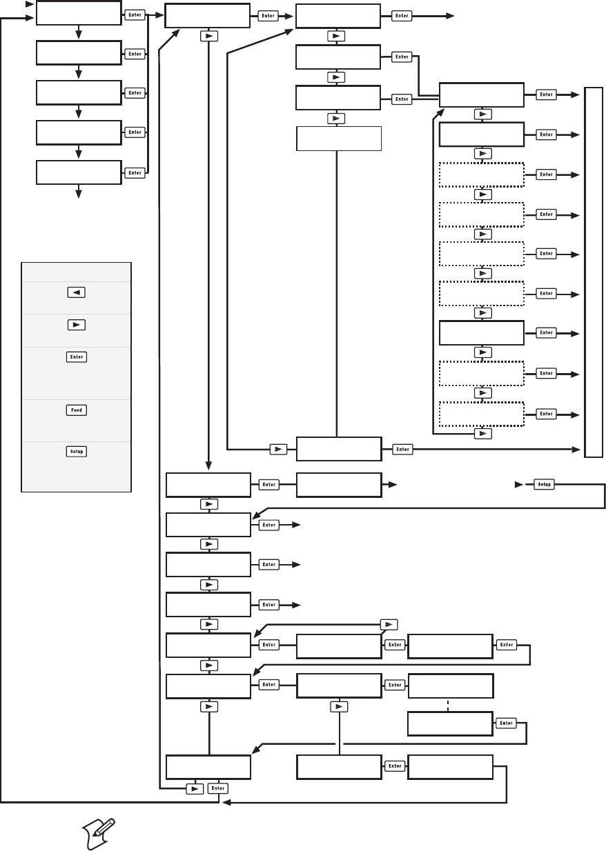
246 EasyCoder PX4i and PX6i Service Manual
Appendix A — Program Overviews
Intermec Shell v8.2 Overview
Note: To enter Intermec Shell if an autoexec-fi le prevents access, lift the
printhead and press any key (except the <Shift> key), then turn on the
power while continuing to press the key. When the Shell countdown
begins, release the key and press <Enter> to start Shell. Do not forget to
lower the printhead if you, for example, want to print test labels.
SHELL
TEST LABEL
SHELL
TESTFEED
SHELL
DEFAULT SETUP
Performs a Testfeed (feeds out a number of blank copies
while autoadjusting the label stop sensor).
Prints test labels “Diamonds”, “Chess”, “Bar Codes #1”, and “Bar Codes #2” in a loo
p
Press Enter for each new label.
SHELL
REBOOT
Restarts the printer (same as power off/on)
Printer rebooted
automatically.
STD I/O CHANNEL
uart2:
STD I/O CHANNEL
uart3:
SEL. APPLICATION
Fingerprint 8.30
SHELL
SETUP
See the chapter “Setup Mode”
Prints a list of current setup values (test label “Setup Info”).
Note: Dotted channels are only shown if
the corresponding optional interface pcb
is fitted.
SHELL
PRINT SETUP
ENTER=SHELL
5 sec. v.8.2
ENTER=SHELL
4 sec. v.8.2
ENTER=SHELL
3 sec. v.8.2
ENTER=SHELL
2 sec. v.8.2
ENTER=SHELL
1 sec. v.8.2
Last selected
application is started
Default:
Fingerprint 8.30 w. std I/O = "auto"
Last selected application is started
The selected application is started
POWER ON
Return to previous menu.
Proceed to next menu.
Accept displayed option
and proceed, or
execute displayed option.
Perform a Testfeed
anywhere in Intermec Shell.
Enter the Setup Mode
from anywhere
in Intermec Shell.
Legend:
SHELL
SEL. APPLICATION
SEL. APPLICATION
Direct Protocol
SEL.APPL rom:
LINE_AXP.PRG
Optional application
programs
SETUP:
SER-COM,UART1
SEL. APPLICATION
CURRENT APPL.
ARE YOU SURE?
YES=ENTER/NO=ESC
DEFAULT SETUP
PERFORMED
SHELL
SOFTWARE UPDATE
UPDATE:
COMPACT FLASH?
UPDATE:
FIRMWARE?
TRANSFER
COMPLETED
TRANSFER FILE
USING ZMODEM
STD I/O CHANNEL
centronics:
STD I/O CHANNEL
net1:
STD I/O CHANNEL
usb1:
STD I/O CHANNEL
auto
STD I/O CHANNEL
uart1:
STD I/O CHANNEL
uart4:
STD I/O CHANNEL
uart5:
TRANSFER FILE
USING ZMODEM
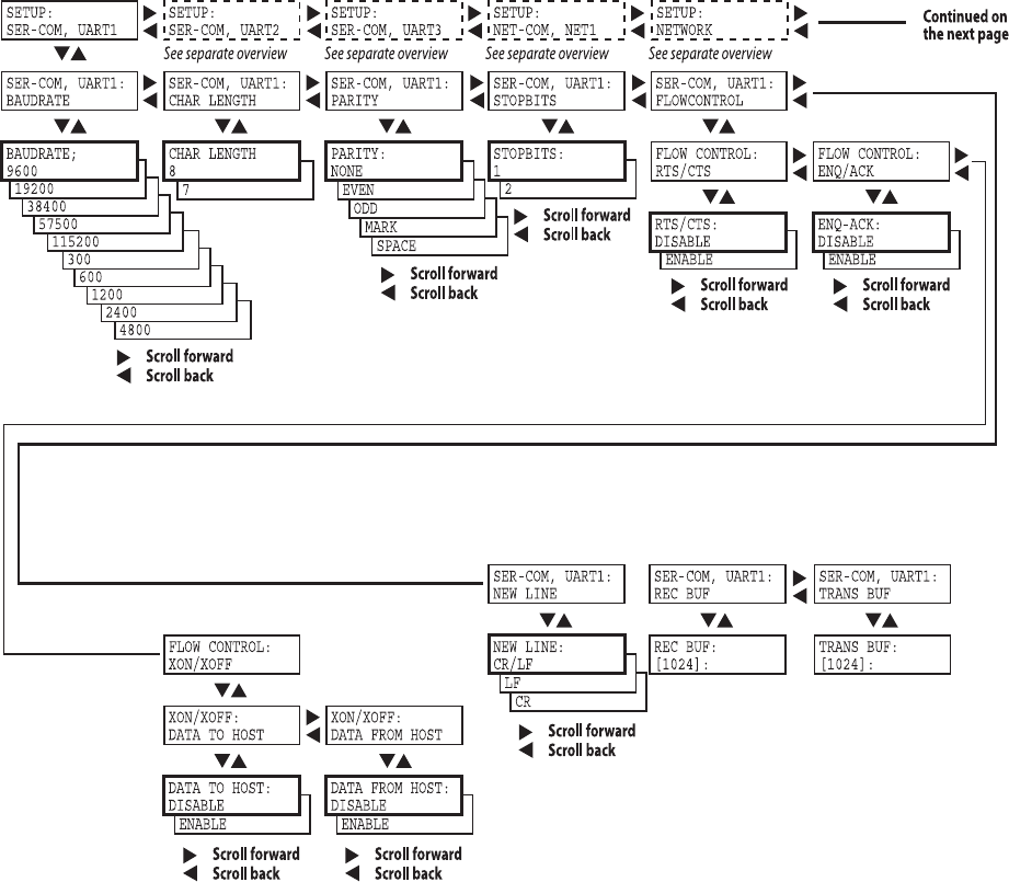
EasyCoder PX4i and PX6i Service Manual 247
Appendix A — Program Overviews
Setup Mode Overview (FP v8.30) Ser-Com, uart1:
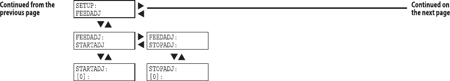
248 EasyCoder PX4i and PX6i Service Manual
Appendix A — Program Overviews
Setup Mode Overview (FP v8.30) Feed Adjust
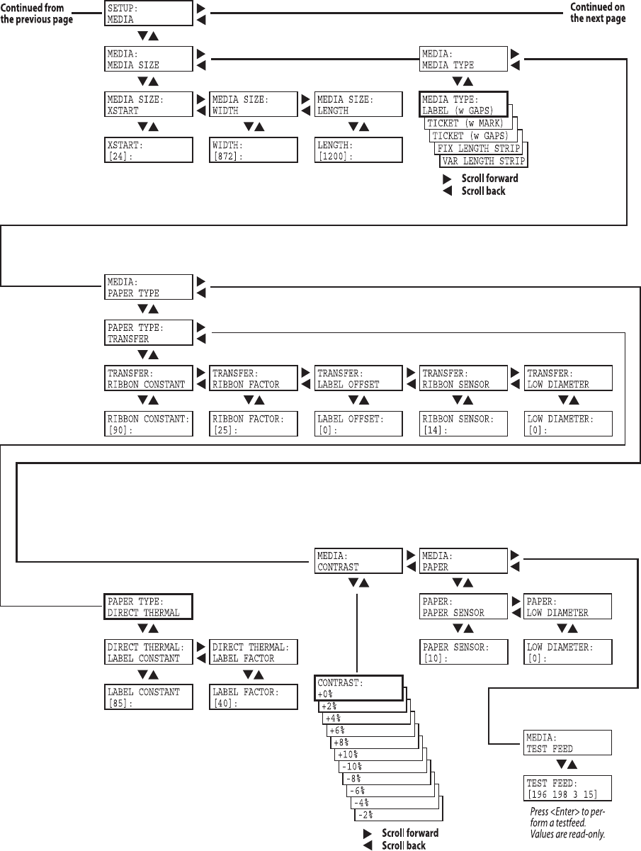
EasyCoder PX4i and PX6i Service Manual 249
Appendix A — Program Overviews
Setup Mode Overview (FP v8.30) Media
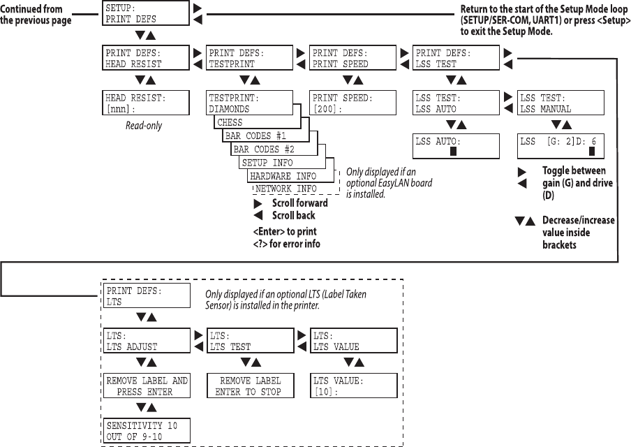
250 EasyCoder PX4i and PX6i Service Manual
Appendix A — Program Overviews
Setup Mode Overview (FP v8.30) Print Defs
EasyCoder PX4i and PX6i Service Manual 251
Appendix A — Program Overviews
Setup Mode Overview (FP v8.30) Ser-Com, uart2
"!5$2!4%
"!5$2!4%
"!5$2!4%
"!5$2!4%
"!5$2!4%
"!5$2!4%
"!5$2!4%
"!5$2!4%
"!5$2!4%
3%4503%450
3%2#/-5!24
3%2#/-5!24
"!5$2!4%
"!5$2!4%
252 EasyCoder PX4i and PX6i Service Manual
Appendix A — Program Overviews
Setup Mode Overview (FP v8.30) Ser-Com, uart3

EasyCoder PX4i and PX6i Service Manual 253
Appendix A — Program Overviews
Setup Mode Overview (FP v8.30) Ser-Com, uart4
254 EasyCoder PX4i and PX6i Service Manual
Appendix A — Program Overviews
Setup Mode Overview (FP v8.30) Ser-Com, uart5
EasyCoder PX4i and PX6i Service Manual 255
Appendix A — Program Overviews
Setup Mode Overview (FP v8.30) Network Communication
256 EasyCoder PX4i and PX6i Service Manual
Appendix A — Program Overviews
Setup Mode Overview (IPL v2.30) Serial Communication
BAUDRATE;
4800
BAUDRATE;
2400
BAUDRATE;
1200
BAUDRATE;
115200
BAUDRATE;
57500
BAUDRATE;
38400
BAUDRATE;
19200
PARITY:
SPACE
PARITY:
ODD
PARITY:
EVEN
CHAR LENGTH
7
STOP BITS:
2
SETUP:
SER-COM
SER-COM:
BAUDRATE SER-COM:
DATA BITS SER-COM:
PARITY SER-COM:
STOP BITS SER-COM:
PROTOCOL
BAUDRATE:
9600 DATA BITS:
8PARITY:
NONE STOP BITS:
1ENQ/ACK:
STANDARD
PROTOCOL:
XON/XOFF
Continued on
the next page
Scroll forward
Scroll back
Scroll forward
Scroll back
Scroll forward
Scroll back
Scroll forward
Scroll back
EasyCoder PX4i and PX6i Service Manual 257
Appendix A — Program Overviews
Setup Mode Overview (IPL v2.30) Network (option)
PARITY:
BOOTP
PARITY:
DHCP
PARITY:
MANUAL
SETUP:
NETWORK
NETWORK:
IP SELECTION
NETWORK:
IP ADDRESS
NETWORK:
NETMASK
NETWORK:
DEFAULT ROUTER
NETWORK:
NAMESERVER
IP SELECTION:
DHCP+BOOTP
IP ADDRESS:
0.0.0.0
NETMASK:
0.0.0.0
DEFAULT ROUTER:
0.0.0.0
NAMESERVER:
0.0.0.0
NETWORK:
MAC ADDRESS
MAC ADDRESS:
nnnnnnnnnnnn
Read-only Read-only Read-only Read-only Read-only
These menus will only be displayed when an optional EasyLAN interface board is installed.
258 EasyCoder PX4i and PX6i Service Manual
Appendix A — Program Overviews
Setup Mode Overview (IPL v2.30) Test/Service
TEST LABELS:
PRINT QUALITY
CONFIG:
NETWORK
CONFIG:
HW
SETUP:
TEST/SERVICE
TEST/SERVICE:
TESTPRINT
TESTPRINT:
CONFIG
TESTPRINT:
FORMAT
CONFIG:
SW
FORMAT:
ALL
ALL:
PRINT FORMATS
TESTPRINT:
TEST LABELS
TEST LABELS:
PITCH
TESTPRINT:
PAGE
PAGE:
ALL
ALL:
PRINT PAGES
TESTPRINT:
UDC
UDC:
ALL
ALL:
PRINT UDC
TESTPRINT:
FONT
Continued from
the previous page
Continued on
the next page
Scroll forward
Scroll back
Scroll forward
Scroll back
CONFIG:
YES
TEST/SERVICE:
DATA DUMP
DATA DUMP:
NO
Scroll forward
Scroll back
CONFIG:
CONFIGURATION
TEST/SERVICE:
MEMORY RESET
MEMORY RESET:
ALL
Scroll forward
Scroll back
TEST/SERVICE:
LSS TEST
LSS TEST:
LSS AUTO
LSS AUTO:
EasyCoder PX4i and PX6i Service Manual 259
Appendix A — Program Overviews
Setup Mode Overview (IPL v2.30) Media
CONFIG:
CONTINUOUS
CONFIG:
MARK
SETUP:
MEDIA
MEDIA :
MEDIA TYPE
MEDIA TYPE:
GAP
MEDIA :
PAPER TYPE
Continued from
the previous page
Continued on
the next page
Scroll forward
Scroll back
CONFIG:
TTR
PAPER TYPE:
DT
MEDIA :
LBL LENGTH DOTS
LBL LENGTH DOTS:
1200
Scroll forward
Scroll back
Scroll forward
Scroll back
Scroll forward
Scroll back
MEDIA :
SENSITIVITY
SENSITIVITY:
420
Scroll forward
Scroll back
MEDIA :
DARKNESS
DARKNESS:
0
Scroll forward
Scroll back
MEDIA :
LBL REST POINT
LBL REST POINT:
0
MEDIA :
FORM ADJ DOTS X
FORM ADJ DOTS X:
0
MEDIA :
FORM ADJ DOTS Y
FORM ADJ DOTS Y:
0
100/200/400/800/
1200/1600/2000/
2500/3000/3600/
4200/4800
120/130/140/160/170/
180/222/226/236/238/
366/369/420/440/450/
460/470/480/513/527/
533/563/565/567/623/
627/633/647/673/677/
687/720/854/864
0/1/2/3/4/5/6/7/8/
9/10/-10/-9/-8/-7/
-6/-5/-4/-3/-2/-1
0/2/4/6/8/10/15/20/25/
30/-30/-25/-20/-15/-10/
-8/-6/-4/-2
Scroll forward
Scroll back
0/2/4/6/8/10/15/20/25/
30/-30/-25/-20/-15/-10/
-8/-6/-4/-2
Scroll forward
Scroll back
0/2/4/6/8/10/15/20/25/
30/-30/-25/-20/-15/-10/
-8/-6/-4/-2
MEDIA :
RIBBON LOW
RIBBON LOW:
0
Scroll forward
Scroll back
0/5/10/15/20/25/30/35/
40/45/50/55/60/65/70/
75/80
MEDIA :
PAPER LOW
PAPER LOW:
0
Scroll forward
Scroll back
0/10/20/30/40/50/60/70/
80/90/100/110/120/130/
140/150
260 EasyCoder PX4i and PX6i Service Manual
Appendix A — Program Overviews
Setup Mode Overview (IPL v2.30) Configuration
PRINT SPPED:
12 IN/SEC
PRINT SPPED:
11 IN/SEC
PRINT SPPED:
10 IN/SEC
PRINT SPPED:
9 IN/SEC
PRINT SPPED:
8 IN/SEC
PRINT SPPED:
7 IN/SEC
PRINT SPPED:
6 IN/SEC
PRINT SPPED:
5 IN/SEC
SETUP:
CONFIGURATION
CONFIGURATION:
LTS CALIBRATION
LTS CALIBRATION:
PRESS <ENTER>
REMOVE LABEL AND
PRESS ENTER
CONFIGURATION:
PWRUP EMULATION
Continued from
the previous page
Return to
the start of
the loop
CONFIG:
DISABLE
CONFIG:
ENABLE
CUTTER:
NOT INSTALLED
Scroll forward
Scroll back
Labels are fed out
SENSITIVITY 9
OUT OF 8-14
<Enter>
Read only,
press<Enter>
CONFIG:
86XX-15MIL
CONFIG:
86XX-10MIL
PWRUP EMULATION:
NONE
Scroll forward
Scroll back
CONFIGURATION:
PRINT SPEED
PRINT SPEED:
4 IN/SEC
Scroll forward
Scroll back
CONFIGURATION:
CUTTER

EasyCoder PX4i and PX6i Service Manual 261
B Firmware Upgrading
This appendix describes various methods for upgrading the printer’s fi rm-
ware and for switching from Intermec Fingerprint to IPL or vice versa.

262 EasyCoder PX4i and PX6i Service Manual
Appendix B — Firmware Upgrading
Introduction
All EasyCoder PX4i and PX6i printers can use both Fingerprint v8.xx and
IPL v2.xx fi rmware. There are many ways to upgrade or exchange printer’s
fi rmware. Use the most convenient way. You can either do it from host by
sending the fi le to the printer or by inserting a CompactFlash card in the
memory card slot at the printer’s rear plate. There are 3 different fi le types
containing the fi rmware. The fi le types are related to the way of upgrade
procedure. The fi les can be obtained from Intermec.
File Description
Another format is .uff fi les, which are created by, for instance, NetPrintSet.
They contain the kernel and optional instructions (if necessary), images,
fonts, etc. To be stored in CompactFlash memory cards.
General Principles
• During upgrading, do not switch off the printer. Wait and follow the
prompts in the printer’s display.
• If changing fi rmware from IPL to Fingerprint, we recommend to erase
memory to factory setup setting [FORMAT "/c",A] after the upgrade
procedure is completed.
• Some update of Fingerprint may show the error “mcs: Error during
setup” at host terminal. This just means that there was an instruction
that erased "/c" [FORMAT "/c",A]. This is a normal condition! The
error shows that no setup fi le [.setup.saved] is detected on "/c". The
"/rom" setup fi le is copied automatically into "/c" which gives printer a
factory setup setting.
• If an EasyLAN interface board is installed, by default only admin is
allowed to upgrade. See EasyLAN User's Guide for more information.
File name Type of fi le
1-972020-xx.bin (for FP)
1-972105-xx.bin (for IPL)
These .bin fi les contain the fi rmware kernel fi le only. To
be sent on serial port to printer using a communication
program, for example HyperTerminal or Printset, or via
FTP. Can also be stored on a CompactFlash card.
1-972021-xx.bin (for FP)
1-972106-xx.bin (for IPL)
These .bin fi les contain the fi rmware kernel fi le and the
factory default setup parameter values. To be stored on a
CompactFlash card.
Note: These fi les remove all fi les except the fi rmware
fi les, so it is advised to make a backup before running
such a fi le. They are primarily intended to allow restor-
ing forgotten passwords.
EasyCoder PX4i and PX6i Service Manual 263
Appendix B — Firmware Upgrading
Upgrading From a Memory Card
This chapter describes how to upgrade the printer from a CompactFlash
card.
1 Insert the card and switch on the printer. The printer’s display will auto-
matically show ongoing steps. The procedure ends with a normal startup
of the printer.
2 Switch off the printer and remove the card. Printer is ready for use.
CompactFlash cards with fi rmware (Fingerprint or IPL) can be ordered
from Intermec. Empty CompactFlash cards can be ordered from Intermec
or procured locally.
If there are more than one fi rmware fi les on the memory card, it is not
foreseeable which one will be selected. However, by renaming the desired
fi le to FIRMWARE.BIN, you can make sure that the fi le will be selected.
How to make an upgrading card
There are two possible places to program a CompactFlash card. One is
your PC CompactFlash card slot, another is the printer’s card slot.
At the PC-side
1 Use a computer fi tted with a PCMCIA slot and a CompactFlash adapter
and insert the CompactFlash card.
2 Copy the upgrade .bin or .uff fi le to the CompactFlash card.
At the printer side (Fingerprint only)
1 Insert the CompactFlash card in the slot at the printer’s rear plate.
2 Start up the printer and select Intermec Shell.
3 Press <Enter> to go to the “Sel. Application” menu.
4 Press <⇒> repeatedly to browse to ”SOFTWARE UPDATE”.
5 Press <Enter> to go to ”UPDATE: COMPACT FLASH?”
6 Press <Enter>.
7 Start sending the fi le using a communication program, for example
HyperTerminal. The communication program must use zmodem.
(There is a one-minute time-out on the printer side.) Shell will auto-
matically rename the fi le to FIRMWARE.BIN to make sure that this fi le
will upgrade the printer.
8 Switch off the printer and remove the card.

264 EasyCoder PX4i and PX6i Service Manual
Appendix B — Firmware Upgrading
Note: A special case is if the CompactFlash card already has a Fingerprint
fi rmware. Inserting such card will always install fi rmware in the printer
according to CompactFlash card. However, perhaps you like to install a
later fi rmware version picked from the web. If so, proceed like this:
1 Insert the CompactFlash card with a upgrade fi rmware on. Switch on
and wait for a completed upgrade and the normal startup of the printer
so you are in Fingerprint mode.
2 Activate the Shell program from "/rom" like this:
LOAD "/rom/SHELLXP.PRG"
MERGE "/rom/ERRHAND.PRG"
RUN
3 In Shell, select the option “UPDATE: COMPACT FLASH?” and press
<Enter>.
4 Send the .bin or .uff fi le from the host using zmodem.
EasyCoder PX4i and PX6i Service Manual 265
Appendix B — Firmware Upgrading
Upgrading From the Host
Software Suggestions
1. Intermec PrintSet (IPL and Fingerprint)
Install Intermec Printset software and a serial cable. Intermec PrintSet is
included in the printer companion CD. It can also be obtained from the
Intermec Printer Support Web.
2. Terminal program (Fingerprint only)
Use Terminal program included in Windows (95/98/Me or NT/2000/XP)
and a serial cable. At serial communication, the software has to be prepared
by a protocol Zmodem and have same communication settings on both
side. We recommend hardware handshaking (RTS/CTS).
3. Command prompt with FTP
Use command prompt in Windows (95/98/Me or NT/2000/XP) and an
Ethernet network.
4. Intermec NetPrintSet (Fingerprint only)
Use Intermec NetPrintSet software and a serial cable. Intermec NetPrintSet
can be obtained from the Intermec Printer Support Web.
Cable Suggestions
RS-232 Serial Cable
DB-9pin female -> DB-9pin male (see Spare Parts Catalog)
Ethernet Cable
Intermec does not provide any Ethernet cable. The cables are normally
provided locally. At a straight connection between a host and printer, a
cross RJ-45 cable is needed.
Parallel Cable
(see Spare Parts Catalog)
How to use Intermec PrintSet and serial cable.
1 Connect a serial cable between host and printer
2 Start up the printer and select Fingerprint via Shell and to listen on
serial port "uart1:" on for example baud rate 115,200.
3 Start PrintSet. The program will automatically set the communication
parameters and is ready for use.
4 Select ”DataXfer\Change fi rmware”. Depending on settings, PrintSet
may ask for the admin password.
5 Send one of the following fi les:
1-972020-xx.bin (Fingerprint)
1-972105-xx.bin (IPL)
6 After fi le is received in printer, it will automatically replace the fi rmware
and boot up with the new one.
7 The printer’s display will automatically show ongoing steps. The proce-
dure ends with a normal startup of the printer.
266 EasyCoder PX4i and PX6i Service Manual
Appendix B — Firmware Upgrading
How to use MS HyperTerminal and a serial cable (Fingerprint only)
1 Connect a serial cable between host and printer.
2 Start the HyperTerminal or a similar terminal program. Select port
com1. Use a high communication speed (115,200 baud).
3 Start up the printer and select Fingerprint via Intermec Shell1 to listen
on serial port "uart1:".
4 Make sure that your are in contact with printer by typing for example
FONTS and the printer will respond showing fonts.
5 Type a download command2 so printer is ready for receiving data:
RUN "dlk"
Select .bin upgrade fi le. Now printer waits for about 1 minute to get the
fi le sent using zmodem as protocol.
6 Go to “Send fi le” and send it.
7 After fi le is received in printer, it will automatically replace the fi rmware
and the printer will boot up with the new one.
8 The printer’s display will automatically show ongoing steps. The proce-
dure ends with a normal startup of the printer.
1/. In Intermec Shell it is also possible to select printer to be in the receiving mode. Start
up Intermec Shell and use <⇒> to browse to “Software Update\Update:Firmware”. (You
have one minute to send the fi le.) Also check the printer’s baud rate in the Setup Mode.
Continue with items 6-8. If the printer is fi tted with an EasyLAN board, user must be
allowed to upgrade.
2/. dlk only works if the current user is allowed to update. RUN "su admin" could be
required.

EasyCoder PX4i and PX6i Service Manual 267
Appendix B — Firmware Upgrading
How to use command prompt FTP and Ethernet
1 Connect a printer on Ethernet LAN or by a cross cable between host
and printer
2 Open an FTP session to the printer typing this command from your
Windows command prompt: FTP <ip address of the printer>
3 You will get a prompt asking you for User: type admin or user. You
may get a prompt for a Password: type pass (default; case sensitive).
Note: The user you log in as must be allowed to upgrade.
4 After some answers on your screen you will see the prompt FTP>. At
this point type bin + <Enter>, then type hash + <Enter>.
5 Now send the fi rmware to the printer with the command:
put <filename.bin> FLASH
6 Some ###### will appear on your screen showing the ongoing transfer.
7 The printer’s display will automatically show ongoing steps. The proce-
dure ends with a normal startup of the printer.
8 Close FTP session typing bye + <Enter>.
9 After fi le is received in printer it will automatically replace the fi rmware
and the printer will boot up with the new one. The printer’s display will
automatically show ongoing steps and the procedure ends with a normal
startup of the printer.
How to use Intermec NetPrintSet and serial cable (Fingerprint only)
What is NetPrintSet
NetPrintSet is a printer confi guration utility for Intermec printers that
allows you to upgrade or confi gure the printer. Makes font upgrades and
other maintenance a child’s play. Available both as Netscape plugin and
standalone executable.
• NetPrintSet can merge printer’s necessary fi le to one fi le either using a
CompactFlash card or download direct to printer. Necessary fi les are for
example Images, Fonts, Firmware, or other custom-made fi les.
• How to use? Please refer to the Help included in the software.
If upgrading directly via NetPrintSet and printer
1 Start up the printer and select Shell. Press <Enter> to go to the “SEL.
APPLICATION” menu. Use <⇒> to browse to “SOFTWARE
UPDATE”. Press <Enter> to go to the “UPDATE: COMPACT
FLASH?” menu. Use <⇒> to go to “UPDATE: FIRMWARE?”. Finally,
press <Enter>.
User might not be allowed to update.
2 Start to send the fi le from the software. (There is a one-minute time-out
before the printer exits the receive mode.)
3 After fi le is received in printer, it will automatically replace the fi rmware
and the printer will boot up with the new one.
268 EasyCoder PX4i and PX6i Service Manual
Appendix B — Firmware Upgrading

EasyCoder PX4i and PX6i Service Manual 269
C Measuring the Brake Torque
This appendix describes a simple way to measure the brake torque when
advanced tools are not available.
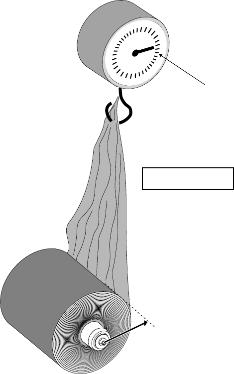
270 EasyCoder PX4i and PX6i Service Manual
Appendix C — Measuring the Break Torque
Measuring the Brake Torque
If you do not have access to a torque-measuring instrument, you could
easily make a provisional instrument using a roll of spent transfer ribbon, a
simple dynamometer and a ruler:
• Fit the ribbon roll on the spool you want to check. The larger roll, the
better accuracy.
• Measure the radius from the center of the spool to the edge of the
ribbon roll.
• Fit the end of the ribbon to the dynamometer and pull.
• Read the dynamometer.
• Calculate the torque using the formula:
Torque (Nmm) = Radius (mm) × Force (N)
Force
Radius
Formula:
Torque = Force x Radius
Dynamometer

Intermec Technologies Corporation
Corporate Headquarters
6001 36th Avenue West
Everett, WA 98203
U.S.A.
tel 425.348.2600
fax 425.355.9551
www.intermec.com
*1-960624-00*
EasyCoder PX4i & PX6i Service Manual
*1-960624-00*
