PXW FS7 V400 GB Manual
User Manual: Rent a Sony PXW-FS7 4K Digital Cinema Camera E Mount at LensProToGo.com
Open the PDF directly: View PDF ![]() .
.
Page Count: 145 [warning: Documents this large are best viewed by clicking the View PDF Link!]

4-562-025-15 (1)
© 2014 Sony Corporation
Solid-State Memory
Camcorder
Operating Instructions
Before operating the unit, please read this manual thoroughly
and retain it for future reference.
PXW-FS7
Software Version 4.0

2
Overview
System Configuration ............................................................... 6
Location and Function of Parts ............................................... 7
Viewfinder .................................................................... 11
Eyepiece ....................................................................... 11
Lens (PXW-FS7K only) ............................................... 11
Grip Remote Control .................................................... 11
Infrared Remote Control .............................................. 12
Extension Unit (Option) ............................................... 12
Screen Display ......................................................................... 13
Viewfinder Screen ........................................................ 13
Status Screen ................................................................ 15
Preparation
Power Supply ........................................................................... 18
Using a Battery Pack .................................................... 18
Using AC Power .......................................................... 19
Attaching Devices .................................................................... 20
Attaching the Microphone Holder ............................... 20
Attaching the Viewfinder ............................................. 21
Attaching the Eyepiece ................................................ 22
Attaching a Lens .......................................................... 23
Attaching the Grip Remote Control ............................. 24
Setting the Clock ..................................................................... 25
Configuring Basic Camcorder Operation ............................ 26
Shooting Mode ............................................................. 26
Color Space .................................................................. 26
Image Sensor Scan Mode ............................................. 26
Using XQD Memory Cards .................................................... 27
About XQD Memory Cards ......................................... 27
Recommended Media ................................................... 28
Inserting an XQD Memory Card .................................. 30
Ejecting XQD Memory Cards ...................................... 30
Switching Between XQD Memory Cards .................... 30
Formatting (Initializing) XQD Memory Cards ............ 30
Checking the Remaining Recording Time ................... 31
Table of Contents

3
Using a UTILITY SD Card .................................................... 31
Supported SD Cards ..................................................... 31
Inserting an SD Card .................................................... 31
Ejecting the SD Card .................................................... 31
Formatting (Initializing) SD Cards .............................. 32
Checking the Remaining Capacity ............................... 32
Using the XDCA-FS7 .............................................................. 32
Attaching the XDCA-FS7 ............................................ 32
Removing the XDCA-FS7 ........................................... 33
Attaching the Battery Pack ........................................... 33
Removing the Battery Pack .......................................... 34
Switching the Timecode Input/Output ......................... 34
Using an HXR-IFR5 and AXS-R5 ......................................... 34
Connecting the HXR-IFR5 to the Camcorder .............. 34
Removing the HXR-IFR5 ............................................ 34
Using the Infrared Remote Control ...................................... 35
Using Wi-Fi Remote Control ................................................. 36
Shooting
Basic Operation Procedure .................................................... 38
Adjusting the Focus Automatically .............................. 40
Adjusting the Focus Manually ..................................... 40
Monitoring Audio ......................................................... 41
Switching Between XQD Memory Cards .................... 41
Changing Basic Settings ......................................................... 42
Selecting the Recording Format ................................... 42
Adjusting the Brightness .............................................. 42
Adjusting for Natural Colors (White Balance) ............ 43
Setting the Audio to Record ......................................... 44
Specifying Time Data .................................................. 45
Useful Functions ...................................................................... 46
Assignable Buttons/Dials ............................................. 46
Slow & Quick Motion .................................................. 47
Recording Video Intermittently (Interval Rec) ............ 47
Picture Cache Recording (Picture Cache Rec) ............. 49
Reviewing a Recording (Rec Review) ......................... 49
Self Portrait Mode ........................................................ 50
Displaying Peaking ...................................................... 51
Displaying Zebra .......................................................... 51
Video Signal Monitor ................................................... 51
Obtaining Location Information (GPS) ....................... 51
Shooting in Cine EI Mode ............................................ 52
Recording RAW Video ................................................ 52

4
Adding Audio Input Connectors .................................. 53
Connecting Devices using Wireless LAN .............................. 54
Attaching the IFU-WLM3 ............................................ 54
Attaching the CBK-WA100 ......................................... 54
One-touch Connection of NFC-enabled Devices
(Using IFU-WLM3 Only) ...................................... 55
Displaying the Wi-Fi Remote Control .................................. 56
Thumbnail Screen
Thumbnail Screen ................................................................... 57
Screen Layout ............................................................... 57
Playing Clips ............................................................................ 58
Playing Recorded Clips ................................................ 58
Clip Operations ....................................................................... 59
Thumbnail Menu Operations ....................................... 59
Thumbnail Menu Items ................................................ 59
Menu Display and Settings
Setup Menu Configuration and Hierarchy .......................... 60
Setup Menu Organization ............................................ 60
Setup Menu Operations .......................................................... 62
Setup Menu List ...................................................................... 63
User Menu .................................................................... 63
Edit User Menu ............................................................ 64
Camera Menu ............................................................... 64
Paint Menu ................................................................... 70
Audio Menu ................................................................. 76
Video Menu .................................................................. 79
VF Menu ...................................................................... 81
TC/UB Menu ................................................................ 85
Recording Menu ........................................................... 86
Thumbnail Menu .......................................................... 88
Media Menu ................................................................. 89
File Menu ..................................................................... 90
System Menu ................................................................ 92
External Device Connection
Connecting External Monitors and Recording Devices .... 100
External Synchronization ..................................................... 101

5
Managing/Editing Clips using a Computer ........................ 102
Connecting using a USB Cable .................................. 102
Appendix
Usage Precautions ................................................................. 104
Output Formats and Limitations ........................................ 105
Video Formats and Output Signals ............................ 105
Error/Warning Messages ..................................................... 118
Error Messages ........................................................... 118
Warning Messages ..................................................... 118
Caution and Operation Messages ............................... 119
Items Saved in Files .............................................................. 120
Block Diagrams ..................................................................... 130
Audio Input (CH1&CH2) .......................................... 130
Audio Input (CH3&CH4) .......................................... 131
Audio Output .............................................................. 132
Licenses .................................................................................. 133
MPEG-4 Visual Patent Portfolio License .................. 133
Obtaining Software Under the GPL/LGPL
License ................................................................. 133
END USER LICENSE AGREEMENT ..................... 134
Open Software Licenses ............................................. 138
Specifications ......................................................................... 139
General ....................................................................... 139
Camera Section .......................................................... 141
Audio Section ............................................................. 141
Input/Output Section .................................................. 142
Display Section .......................................................... 142
Media Slot Section ..................................................... 142
Supplied Accessories ................................................. 142
Software Downloads .................................................. 144
Trademarks ................................................................. 144
6
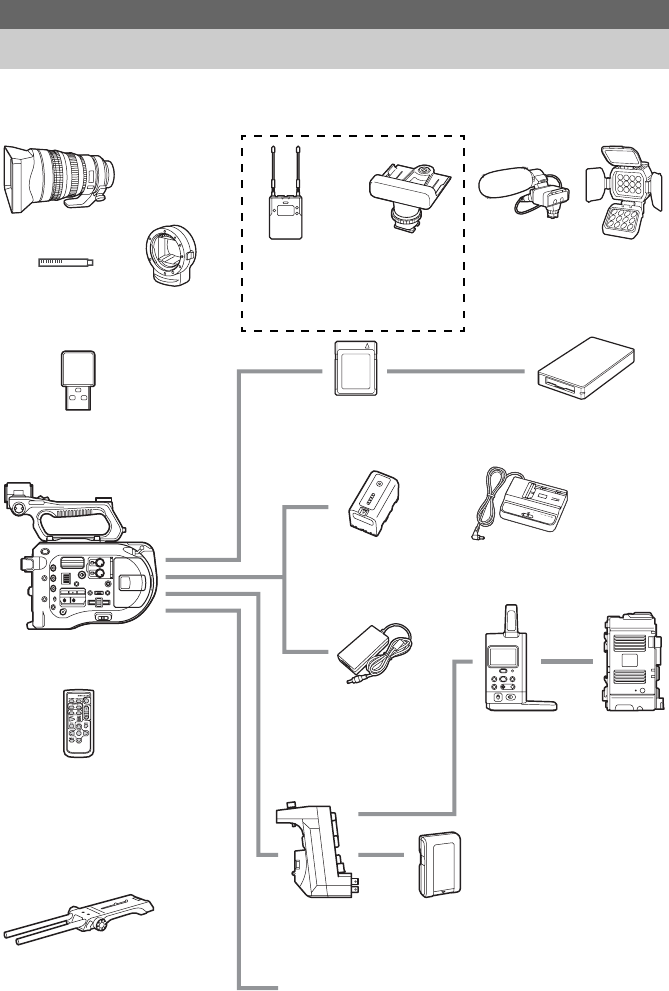
This section shows an example of a camera system configuration.
Overview
System Configuration
ECM-MS2
Microphone
SELP28135G
SEL1635Z
SELP18200
Lens
UWP-D11
UWP-D12
Wireless
Microphone
Package
HVL-LBPC
Video Light
PXW-FS7
LA-EA3
LA-EA4
A-Mount
Adaptor
IFU-WLM3 (supplied)
USB Wireless LAN Module
VCT-FS7
Shoulder Adaptor
S/N/M/H/G-series
XQD Memory Card
MRW-E80
XQD Card Reader
HXR-IFR5
Interface Unit
AXS-R5
Portable
Memory
Recorder
BP-U30 (supplied),
BP-U60, BP-U60T,
BP-U90
Battery Pack
AC Adaptor (supplied)
AC-UES1230
XDCA-FS7
Extension Unit
BP-L80S, BP-FL75
Battery Pack
CBK-WA100
Wireless Adaptor
RMT-845 (supplied)
Infrared Remote Control
BC-U1 (supplied), BC-U2
Battery Charger
Grip Remote Control
(supplied)
SMAD-P3
Multi-Interface
Shoe Adaptor
XLR-K2M
XLR
Adaptor Kit
7
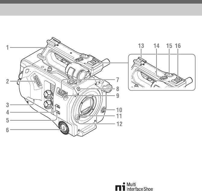
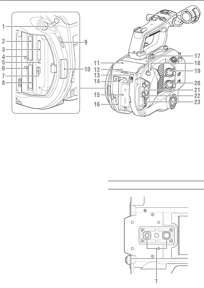
For details about the usage and function of each part, see the referenced page.
1. Handle (page 8)
2. Viewfinder connector (page 21)
3. REMOTE connector (page 24)
4. INPUT1 (LINE/MIC/MIC+48V) switch
(page 44)
5. INPUT2 (LINE/MIC/MIC+48V) switch
(page 44)
6. Grip attachment (page 24)
7. USB wireless LAN module connector
8. Recording indicator (page 96)
Flashes when the remaining capacity on the
recording media or battery is low.
9. Tape measure hook
The tape measure hook is on the same plane as
the image sensor. To measure the distance
between the camcorder and the subject
accurately, use this hook as a reference point.
You can attach the end of a tape measure to the
hook to measure the distance from the subject.
10. WB SET (white balance set) button
(page 44)
11. Lens lock pin (page 23)
12. Lens release button (page 23)
13. Accessory shoe
14. Handle record START/STOP button
The record button cannot be operated when the
lock lever is in the lock position.
15. Handle zoom lever (page 68)
16. Multi-interface shoe
For details about accessories supported by the
multi-interface shoe, contact your sales
representative.
Location and Function of Parts
WB SET
8
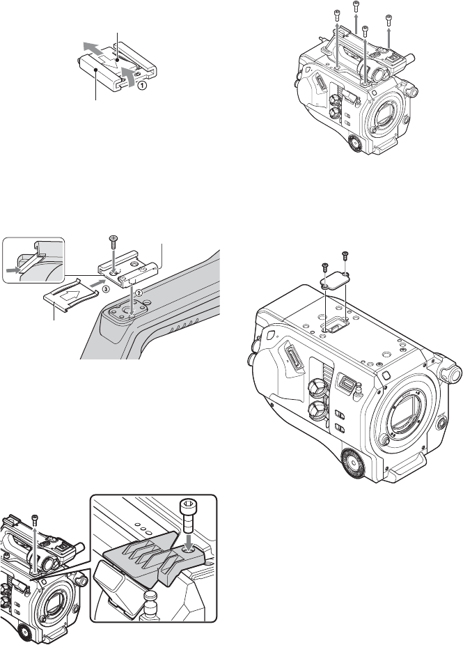
Attaching the accessory shoe
1Lift the front edge of the shoe spring, and pull the
spring in the opposite direction to the arrow engraved
on the spring.
2Position the accessory shoe on the accessory shoe
mount, aligning the protrusions on the shoe with the
corresponding points on the mount, and tighten the
four screws.
3Insert the shoe spring in the direction of the arrow so
that the U-shaped portion fits onto the end of the
accessory shoe.
Removing the accessory shoe
Remove the show spring as described in step 1 in
“Attaching the Accessory Shoe,” unscrew the four
screws, and remove the accessory shoe.
Attaching the USB wireless LAN module guard
plate
1Remove the handle attachment screw.
2Attach the guard plate, and tighten the screw.
Removing the handle
Remove the four handle attachment screws, and
remove the handle from the camcorder.
Attaching the handle connector protective cap
(supplied)
When using the camcorder with the handle
removed, protect the connector using the supplied
protective cap.
Protecting the connector terminals
Attach the cover to unused connectors to protect
the connector terminals.
Shoe spring
Accessory shoe
Accessory shoe
Shoe spring
12
9
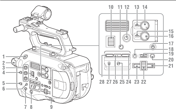
1. Record START/STOP button
2. ND FILTER dial (page 43)
3. ASSIGN (assignable) 1 to 3 buttons
(page 46)
4. PUSH AUTO IRIS button (page 42)
5. PUSH AUTO FOCUS button (page 40)
6. FOCUS switch (page 40)
7.
DISPLAY button
(page 13)
8. FULL AUTO button (page 38)
9. POWER switch (page 18)
10. IRIS dial (page 46)
11. STATUS CHECK button (page 15)
12. HOLD switch (page 96)
13. CH1 LEVEL CONTROL switch (page 44)
14. CH1 INPUT LEVEL dial (page 44)
15. CH2 LEVEL CONTROL switch (page 44)
16. CH2 INPUT LEVEL dial (page 44)
17. SLOT SELECT (XQD memory card
select) button (page 30)
18. CANCEL/BACK button (page 58)
19. MENU button (page 60)
20. THUMBNAIL button (page 57)
21. Right button
Used to set numeric values and to move the
cursor to the right on thumbnail screens and
menus.
22. SEL/SET (select/set) dial
Turn the dial to move the cursor up/down to
select menu items or settings. Press to apply the
selected item.
23. Left button
Used to set numeric values and to move the
cursor to the left on thumbnail screens and
menus.
24. SHUTTER button (page 43)
25. WHT BAL (white balance memory select)
switch (page 43)
26. WHT BAL (white balance) button
(page 43)
27. GAIN (gain select) switch (page 42)
28. ISO/Gain button (page 42)
10
1. Headphone connector (page 41)
2. XQD card slot A (page 30)
3. UTILITY SD card slot (page 31)
4. XQD (A) access indicator (page 30)
5. SD card access indicator (page 31)
6. XQD (B) access indicator (page 30)
7. USB connector
Connect to a computer using a USB cable to
access recording media in an XQD card slot on
the camcorder.
8. XQD card slot B (page 30)
9. Built-in speaker (page 41)
10. Media cover release button (page 30)
11. Extension unit connector (page 32)
12. Rear recording indicator (page 38)
13. DC IN connector (page 19)
14. BATT RELEASE (battery release) button
(page 18)
15. Battery (page 18)
16. Battery pack attachment (page 18)
17. Infrared remote control receiver sensor
(page 35)
18. Internal microphone (page 44)
Narration microphone for recording ambient
sound.
19. INPUT1 (audio input 1) connector
(page 44)
20. INPUT2 (audio input 2) connector
(page 44)
21. SDI OUT 1 connector (page 100)
22. SDI OUT 2 connector (page 100)
23. HDMI OUT connector (page 100)
Underside
1. Tripod screw hole (1/4 inch, 3/8 inch)
Compatible with 1/4-20UNC screws and
3/8-16UNC screws.
Attach to a tripod (option, screw length of
5.5 mm or less).
11
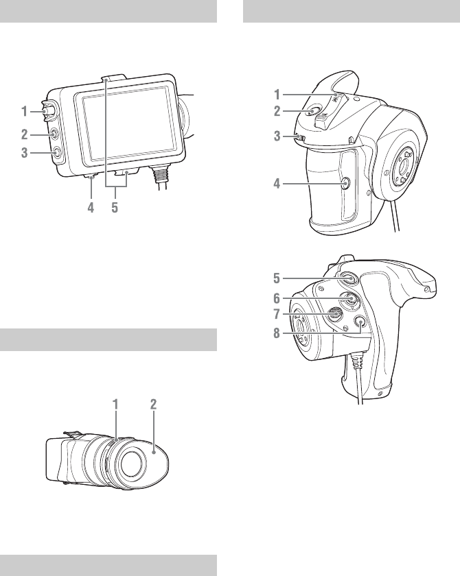
For details about attaching the viewfinder
(supplied) and eyepiece, see page 21.
1. CONTRAST knob
2. PEAKING button
3. ZEBRA button
4. MIRROR switch
5. Eyepiece attachment hooks
For details about attaching the eyepiece
(supplied), see page 22.
1. Diopter adjustment knob
2. Eyecup
For details, refer to the operation manual for the
lens.
For details about attaching the grip remote control
(supplied), see page 24.
1. Zoom lever
2. ASSIGN (assignable) 4 button
3. Assignable dial
4. ASSIGN (assignable) 6 button
5. Record START/STOP button
6. Multi selector
7. Grip rotation button
8. ASSIGN (assignable) 5 button
Viewfinder
Eyepiece
Lens (PXW-FS7K only)
Grip Remote Control
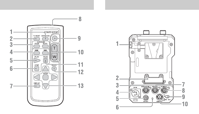
12
1. DATA CODE button
Not used on this version.
2. TC RESET button
3. SCAN/SLOW button
4. ./> (PREV/NEXT) buttons
5. PLAY button
6. STOP button
7. DISPLAY button
8. Remote control transmitter
9. START/STOP button
10. Zoom lever
11. PAUSE button
12. MODE button
Not used on this version.
13. b/B/v/V/ENTER buttons
For details about attaching an extension unit
(option), see page 32.
1. BATT RELEASE button
2. Battery connector
3. GENLOCK IN connector
4. DC IN connector
5. DC OUT connector
6. Recording indicator
7. REF OUT connector
8. TC IN/OUT connector
9. TC IN/OUT switch
10. RAW OUT connector
Infrared Remote Control Extension Unit (Option)
13
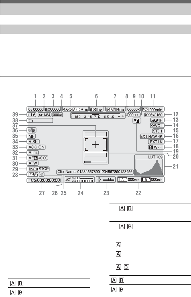
During shooting (recording/standby) and playback, the camcorder status and settings are superimposed
on the image displayed in the viewfinder.
You can show/hide the information using the DISPLAY button.
You can also select to show/hide each item independently (page 81).
The 17:9 aspect ratio picture captured by the image sensor is displayed in the viewfinder. In 16:9 recording
formats, the dark portions on the left and right edges are not recorded.
1. Shutter mode/shutter speed indicator
(page 43)
2. ND filter indicator (page 43)
3. Gain indicator (page 42)
Displayed as an EI value when Base Setting
(page 92) >Shooting Mode in the System menu
is set to “Cine EI.”
4. Focus position indicator
Displays the focus position (if a lens that
supports focus setting display is attached).
5. Recording mode, slot A/B icon, and status
indicators
Screen Display
Viewfinder Screen
Information displayed on the screen while shooting
/zRec Recording
/Stby Standby
S&Q / zRec Slow & Quick Motion,
High Frame Rate mode
recording
S&Q / Stby Slow & Quick Motion,
High Frame Rate mode
standby
Int /zRec Interval Rec recording
Int /zStby Interval Rec image
loading standby
Int / Stby Interval Rec recording
standby
/zPicture cache recording
/zCache Picture cache standby

14
6. Slot B icon and status indicators
7. External RAW recording indicator
(page 52)
8. Depth-of-field indicator
9. Color temperature indicator (page 43)
10. S&Q Motion frame rate indicator
(page 86)/Interval Rec recording interval
display (page 47)
11. Remaining battery capacity/DC IN
voltage indicator (page 19)
12. Recording format (picture size) indicator
(page 26, 93)
Displays the picture size for recording on XQD
memory cards.
The image sensor scan mode (F: 2K Full, C: 2K
Center) is displayed on the left of the picture
size. Only the scan mode is displayed if Codec
is set to “RAW” (2KF: 2K Full, 2KC: 2K
Center).
13. Recording format (frame rate and scan
method) indicator
14. Recording format (codec) indicator
(page 42)
Displays the name of the format for recording
on XQD memory cards.
15. Gamma/monitor LUT indicator (page 71,
79)
Displays the gamma setting. When Shooting
Mode (page 92) is set to “Cine EI,” it displays
the gamma or monitor LUT setting for recording
video on XQD memory cards.
16. External output format indicator
(page 79)
17. Timecode external lock indicator
Displays “EXT-LK” when locked to the
timecode of an external device.
18. Wi-Fi connection status indicator
(page 54)
Displayed when the Wi-Fi function is set to
“Enable.” When the IFU-WLM3 is not attached
to the camcorder, is not displayed.
19. GPS status indicator (page 51)
Displays the GPS status.
20. Focus assist indicator (page 41)
Displays a detection frame (focus area marker)
indicating the area for detection of focus, and a
level bar (focus assist indicator) indicating the
degree of focus within that area.
21. Video signal monitor (page 51)
Displays a waveform, vectorscope, and
histogram.
When Shooting Mode (page 92) is set to Cine
EI, monitor LUT information for the monitor is
also displayed (page 51).
22. Slot A/B media status/remaining capacity
indicator (page 31)
Recording media when the left side of the icon
is orange.
Playback media when the green indicator on the
top right of the icon is on.
23. Spirit level indicator
Displays the horizontal level and the front-to-
rear slope in ±1° increments up to ±20°.
24. Audio level meter
CH3 and CH4 can be monitored on the status
screen.
25. Clip name indicator (page 57)
26. Focus indicator (page 40)
27. Time data display (page 45)
28. SD card indicator
29. SDI output control status indicator
(page 100)
30. White balance mode indicator (page 43)
31. AE mode indicator (page 42)
32. Auto iris indicator (page 42)
33. AGC indicator (page 42)
34. Auto shutter indicator (page 43)
35. Focus mode indicator
36. Image stabilization mode indicator
zRec Recording
Stby Standby
W:P Preset mode
W:A Memory mode A
W:B Memory mode B
15
37. Focus area indicator
Displays the focus area for auto focus.
When push auto focus is available
During auto focus
Not displayed when Focus Area (page 66) is set
to Wide.
38. Zoom position indicator
Displays the zoom position in the range 0 (wide
angle) to 99 (telephoto) (if a lens that supports
zoom setting display is attached).
It can also be displayed as a bar graph (page 83).
39. Iris position indicator
Displays the iris position (if a lens that supports
iris setting display is attached).
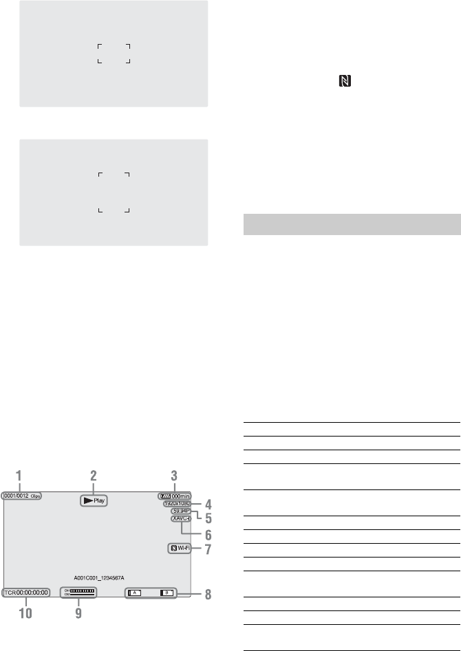
Information displayed on the screen during
playback
The following information is superimposed on
the playback picture.
1. Clip number / total number of clips
2. Playback mode
3. Remaining battery capacity indicator
4. Playback format (picture size) indicator
5. Playback format (frame rate) indicator
6. Playback format (codec) indicator
7. Wi-Fi connection status indicator
(page 54)
Displayed when the Wi-Fi function is set to
“Enable.” When the IFU-WLM3 is not attached
to the camcorder, is not displayed.
8. Media indicator
9. Audio level indicator
Displays the audio level when recording.
10. Time data display
When Display On/Off >Timecode in the VF
menu is set to “On,” it displays the time data
when the DISPLAY button is pressed.
To display the status screen:
• Push the STATUS CHECK button.
To switch to the status screen:
• Turn the SEL/SET dial.
• Move the multi selector up/down.
To hide the status screen:
• Push the STATUS CHECK button.
Camera Status screen
Displays the electronic shutter setting of the
camera and the lens status.
Status Screen
ISO/Gain/EI<H> ISO/Gain/EI<H> setting
ISO/Gain/EI<M> ISO/Gain/EI<M> setting
ISO/Gain/EI<L> ISO/Gain/EI<L> setting
Shutter Shutter setting (Speed/Angle/
ECS/Off)
Iris F-stop value obtained from the
lens
Zebra1 Zebra1 On/Off setting and level
Zebra2 Zebra2 On/Off setting and level
Gamma Gamma Select setting
White White balance mode and settings
Focal Length Focal length value obtained from
the lens
AE Level AE level setting
AE Speed AE control speed setting
AGC Limit Maximum gain setting of the
AGC function

16
Audio Status screen
Displays the input setting, audio level meter, and
wind noise reduction filter setting for each
channel.
System Status screen
Displays the video signal settings.
Video Output Status screen
Displays the SDI, HDMI, and video output
settings.
Assignable Button Status screen
Displays the functions assigned to each of the
assignable buttons.
Battery Status screen
Displays information about the battery and DC IN
source.
A.SHT Limit Fastest shutter speed of the auto
shutter function
AE Mode AE mode setting (Backlight/
Standard/Spotlight)
CH1 level meter Channel 1 audio level meter
CH1 Source Channel 1 input source
CH1 Ref./Sens. Channel 1 input reference level
CH1 Wind Filter Channel 1 microphone wind
reduction filter setting
CH2 level meter Channel 2 audio level meter
CH2 Source Channel 2 input source
CH2 Ref./Sens. Channel 2 input reference level
CH2 Wind Filter Channel 2 microphone wind
reduction filter setting
CH3 level meter Channel 3 audio level meter
CH3 Source Channel 3 input source
CH3 Wind Filter Channel 3 microphone wind
reduction filter setting
CH4 level meter Channel 4 audio level meter
CH4 Source Channel 4 input source
CH4 Wind Filter Channel 4 microphone wind
reduction filter setting
Audio Input Level Audio input level setting
Monitor CH Monitor channel setting
HDMI Output CH HDMI output audio channel
combination setting
Headphone Out Headphone output type setting
Country NTSC or PAL region setting
Rec Format Format for recording to XQD
memory cards
Picture Size Picture size for recording to XQD
memory cards
Frame Rate Frame rate for recording to XQD
memory cards
Rec Function Enabled special recording format
and settings
Simul Rec Simul Rec On/Off status
Picture Cache Rec Picture Cache Rec On/Off status
Video Light Set HVL-LBPC Video Light (option)
on/off indicator
Imager Scan Scan mode of the image sensor
SDI1 Output picture size
Color space
Screen display output
Gamma
SDI2 Output picture size
Color space
Screen display output
Gamma
HDMI Output picture size
Color space
Screen display output
Gamma
REF Output picture size
RAW Output picture size
1 Function assigned to the ASSIGN
1 button
2 Function assigned to the ASSIGN
2 button
3 Function assigned to the ASSIGN
3 button
4 Function assigned to the ASSIGN
4 button
5 Function assigned to the ASSIGN
5 button
6 Function assigned to the ASSIGN
6 button
IRIS Dial Function assigned to the IRIS dial
Assignable Dial Function assigned to the
assignable dial
Detected Battery Type of battery
Remaining Remaining capacity (%)
Charge Count Number of recharges
Capacity Remaining capacity (Ah)
Voltage Voltage (V)
Manufacture Date Date of battery manufacture
Video Light
Remaining
Displays the remaining capacity
of the video light battery.
Power Source Power supply source
Supplied Voltage Supplied power source voltage

17
Media Status screen
Displays the remaining capacity and remaining
recording time of recording media (XQD memory
cards A and B).
Rec Button Settings Screen
Displays the settings of the record START/STOP
buttons on the camcorder and handle (page 39).
Media A
information
Displays the media icon when
recording media is inserted in slot
A.
Media A
protection
Displays the lock icon when the
recording media inserted in slot A
is protected (locked).
Note
XQD memory cards cannot be
protected using the camcorder.
Media A
remaining capacity
meter
Displays the remaining capacity
of recording media inserted in slot
A expressed as a percentage on a
bar graph.
Media A
remaining
recording time
Displays an estimate of the
remaining recording time of the
recording media inserted in slot A
in units of minutes under the
current recording conditions.
Media B
information
Displays the media icon when
recording media is inserted in slot
B.
Media B protection Displays the lock icon when the
recording media inserted in slot B
is protected (locked).
Note
XQD memory cards cannot be
protected using the camcorder.
Media B remaining
capacity meter
Displays the remaining capacity
of recording media inserted in slot
B expressed as a percentage on a
bar graph.
Media B remaining
recording time
Displays an estimate of the
remaining recording time of the
recording media inserted in slot B
in units of minutes under the
current recording conditions.
SD card
information
Displays the media icon when
media is inserted in the UTILITY
SD card slot.
SD card protection Displays the lock icon when the
media inserted in the UTILITY
SD card slot is protected (locked).
SD card remaining
capacity meter
Displays the remaining capacity
of media inserted in the UTILITY
SD card slot expressed as a
percentage on a bar graph.
SD card remaining
capacity
Displays the remaining capacity
of media inserted in the UTILITY
SD card slot expressed in units of
GB.
SD card life Displays the operating life of
media in the UTILITY SD card
slot as a percentage.
Rec Button Displays the slots for recording
controlled by the recording
START/STOP button.
Handle Rec Button Displays the slots for recording
controlled by the recording
START/STOP button on the
handle.
18
You can use a battery pack or AC power supply
from an AC adaptor.
For safety, use only the Sony battery packs and
AC adaptors listed below.
Lithium ion battery packs
BP-U30 (supplied)
BP-U60
BP-U60T
BP-U90
Battery chargers
BC-U1 (supplied)
BC-U2
AC adaptor (supplied)
AC-UES1230
Do not store battery packs in locations exposed to
direct sunlight, flame, or high temperature.
Notes
• The camcorder cannot be powered from the BC-U1/
BC-U2 battery charger acting as an external power
source.
• When operating from a power outlet, use the supplied
AC adaptor.
• Always set the POWER switch to the Off position
before connecting a battery or AC adaptor. If it is
connected with the POWER switch in the On position,
the camcorder may be unable to start in some cases. If
the unit cannot be started, set the POWER switch to the
Off position and disconnect the battery pack or AC
adaptor temporarily, then wait about 30 seconds before
attempting to connect again. (If the AC adaptor is
connected while the camcorder is operating from the
battery pack, it can be connected with the POWER
switch in the On position without problem.)
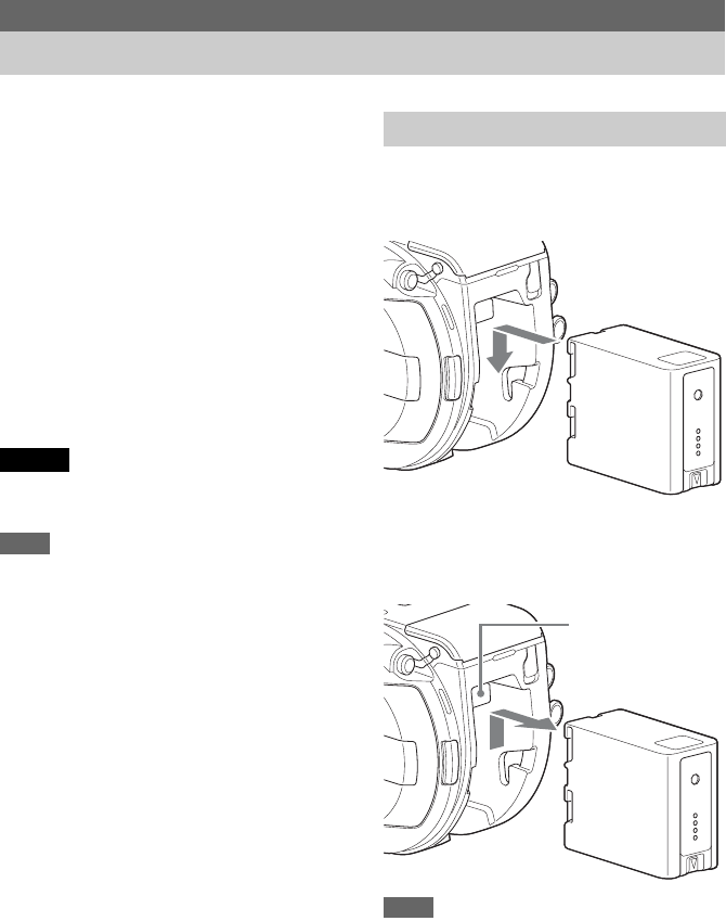
To attach a battery pack, plug the battery pack
into the attachment (page 10) as far as it will go,
and then slide it down to lock it into position.
To remove a battery pack, press and hold the
BATT RELEASE button (page 10), slide the
battery pack up and then pull it out of the
attachment.
Notes
• Before attaching a battery pack, charge the battery
using the dedicated BC-U1 or BC-U2 battery charger.
• Charging a battery immediately after use while it is
still warm may not fully recharge the battery.
Preparation
Power Supply
Caution
Using a Battery Pack
BATT RELEASE
button
19
Checking the remaining capacity
When shooting/playing using a battery pack, the
remaining battery capacity is displayed in the
viewfinder
(page 13)
.
The camcorder indicates the remaining capacity
by calculating the available time with the battery
pack if operation is continued at the current rate
of power consumption.
When using an extension unit
When using the XDCA-FS7 Extension Unit, the
battery voltage or the remaining battery capacity
is displayed, depending on the battery used.
Note
The camcorder battery pack cannot be used when an
XDCA-FS7 unit is attached to the camcorder. You must
attach a battery pack to the XDCA-FS7 or connect an
external power supply.
If the battery pack charge becomes low
If the remaining battery charge falls below a
certain level during operation (Low BATT state),
a low-battery message appears, the recording
indicator starts flashing, and a beep sound will
warn you.
If the remaining battery charge falls below the
level at which operation cannot continue (BATT
Empty state), a battery-empty message appears.
Replace with a charged battery pack.
Changing the warning levels
The Low BATT level is set to 10% of full battery
charge and the BATT Empty level is set to 3% by
factory default. You can change the warning level
settings using Camera Battery Alarm (page 98) in
the System menu.
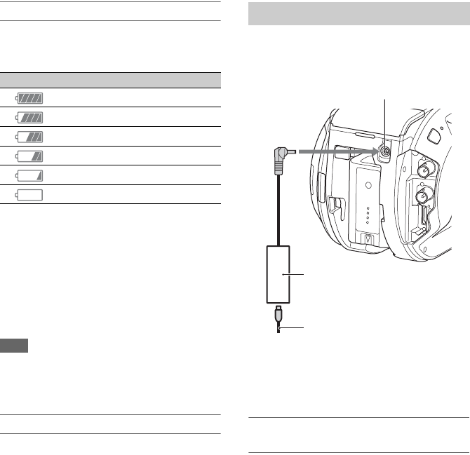
Connecting the camcorder to a power outlet
allows use without worrying about the need to
recharge the battery pack.
Connect the AC adaptor to the DC IN connector
on the camcorder, and connect the power cord
(supplied) to a power outlet.
If the output voltage from the AC adaptor
becomes low
If the output voltage from the AC adaptor falls
below a certain level during operation (DC Low
Voltage1 state), a message appears informing you
that the AC adaptor output voltage has dropped,
the recording indicator starts flashing, and a beep
sound is emitted.
If the output voltage from the AC adaptor falls
below the level at which operation cannot
continue (DC Low Voltage2 state), a message
appears informing you that the AC adaptor output
voltage is too low.
If this occurs, the AC adaptor may be faulty.
Check the AC adaptor, as required.
Changing the warning levels
The DC Low Voltage1 level is set to 11.5 V and
the DC Low Voltage2 level is set to 11.0 V by
factory default. You can change the warning level
settings using Camera DC IN Alarm (page 98) in
the System menu.
Icon Remaining capacity
91% to 100%
71% to 90%
51% to 70%
31% to 50%
11% to 30%
0% to 10%
Using AC Power
AC adaptor
DC IN connector
Power cord
To power outlet
20
AC adaptors
• Do not connect and use an AC adaptor in a
confined space, such as between a wall and
furniture.
• Connect the AC adaptor to the nearest power
outlet. If a problem occurs during operation,
immediately disconnect the power cord from
the outlet.
• Do not short-circuit the metal parts of the plug
of the AC adaptor. Doing so will cause a
malfunction.
• The battery cannot be charged while attached to
the camcorder, even if the AC adaptor is
connected.
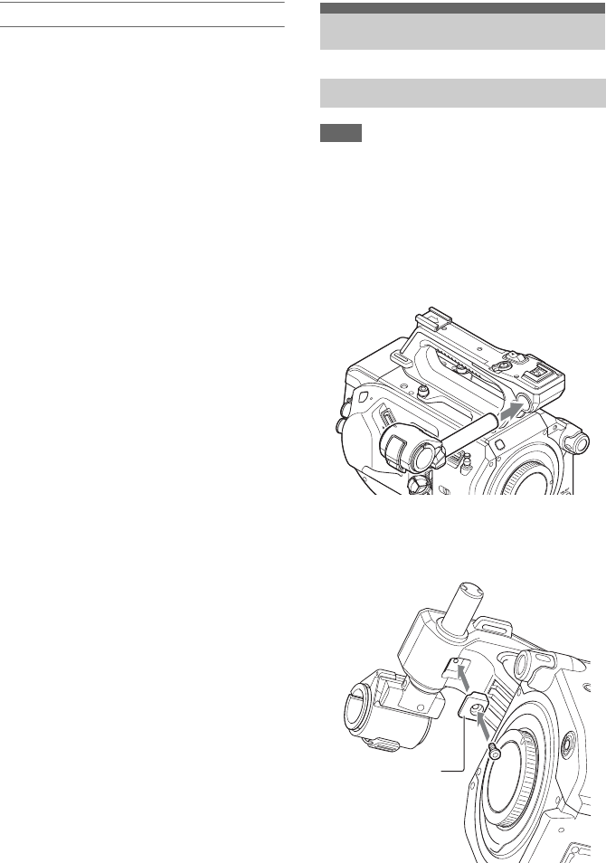
Notes
• The microphone holder is attached when shipped from
the factory.
• Attach/remove the microphone holder while the
camcorder is turned off.
• Attach/remove the microphone holder with the mount
cap attached so as not to damage the image sensor.
1Insert the microphone holder into the
handle.
2Insert the stopper into the recess, and
tighten the screw to secure the holder.
Attaching Devices
Attaching the Microphone Holder
Stopper
21
Removing the microphone holder
Remove the stopper, and use the reverse
procedure of attaching the microphone holder.
Note
Attach/remove the viewfinder while the camcorder is
turned off.
1Loosen the viewfinder clamp and insert
the viewfinder onto the protrusion on
the front of the handle.
2Adjust the left/right positioning of the
viewfinder, tighten the clamp, and then
connect the viewfinder cable to the
viewfinder connector of the camcorder.
Note
Check that the viewfinder is securely attached. The
viewfinder may fall off during shooting if the clamp is
loose.
Adjusting the angle of the viewfinder
Tilt the viewfinder up/down to adjust the angle of
the viewfinder.
You can adjust the angle so that the viewfinder is
facing the subject. Setting the MIRROR switch
(page 50) to the B/T position flips the left and
right sides of the image on the LCD screen, but
the image is recorded in the correct orientation.
Adjusting the viewfinder contrast
Turn the CONTRAST knob to adjust the contrast.
You can adjust the brightness in the viewfinder
using VF Setting >Brightness (page 81) in the VF
menu.
Removing the viewfinder
Loosen the viewfinder clamp, and use the reverse
procedure of attaching the viewfinder.
Attaching the Viewfinder
Clamp
22
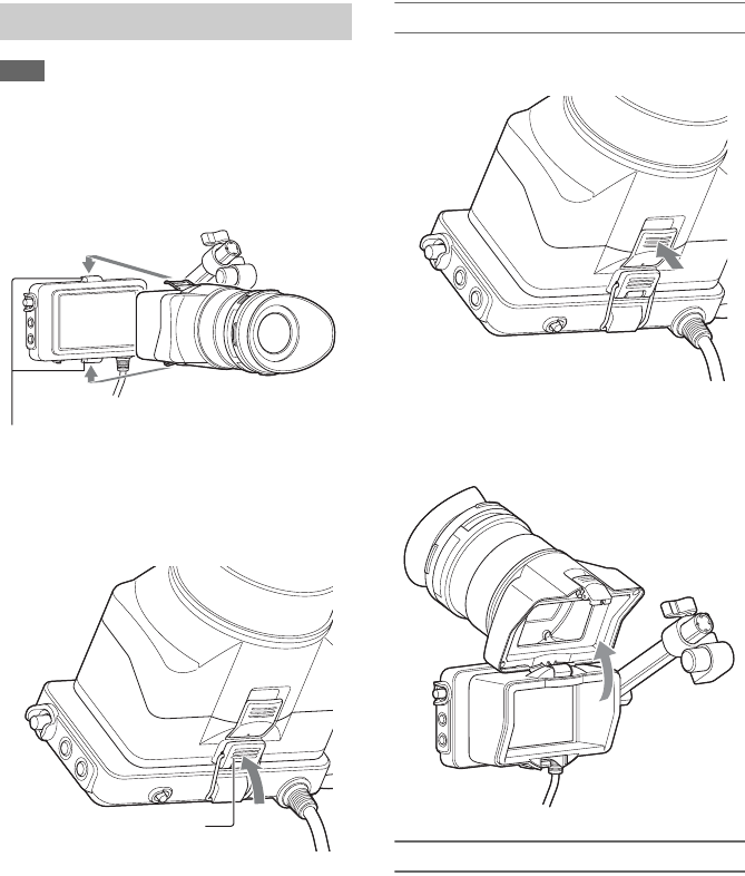
Note
Attach/remove the eyepiece while the camcorder is
turned off.
1Attach the metal clips of the eyepiece to
the eyepiece attachment hooks on the
viewfinder.
2Push the lock plate on the bottom of the
eyepiece in the direction of the arrow to
lock the eyepiece into position.
Opening the eyepiece
Press the button indicated by the arrow.
Open the eyepiece upwards when the lock
disengages. The viewfinder is directly visible
when the eyepiece is opened.
Removing the eyepiece
Unclip the eyepiece lock, and remove the
eyepiece from the viewfinder.
Attaching the Eyepiece
Eyepiece attachment hooks
Lock plate
23
Recommended lenses
SELP28135G
SEL1635Z
SELP18200
For details about lenses supported by the camcorder,
contact your Sony service representative.
Do not leave the lens facing the sun. Direct
sunlight can enter through the lens, be focused in
the camcorder, and may cause a fire.
Notes
• Attach/remove a lens while the camcorder is turned
off.
• A lens is a precision component. Do not place the lens
on a surface with the lens mount face down. Attach the
supplied lens mount cap.
Attaching to a tripod
Use the tripod screw holes on the camcorder
when attaching to a tripod. Using the tripod
mount on the lens may cause damage.
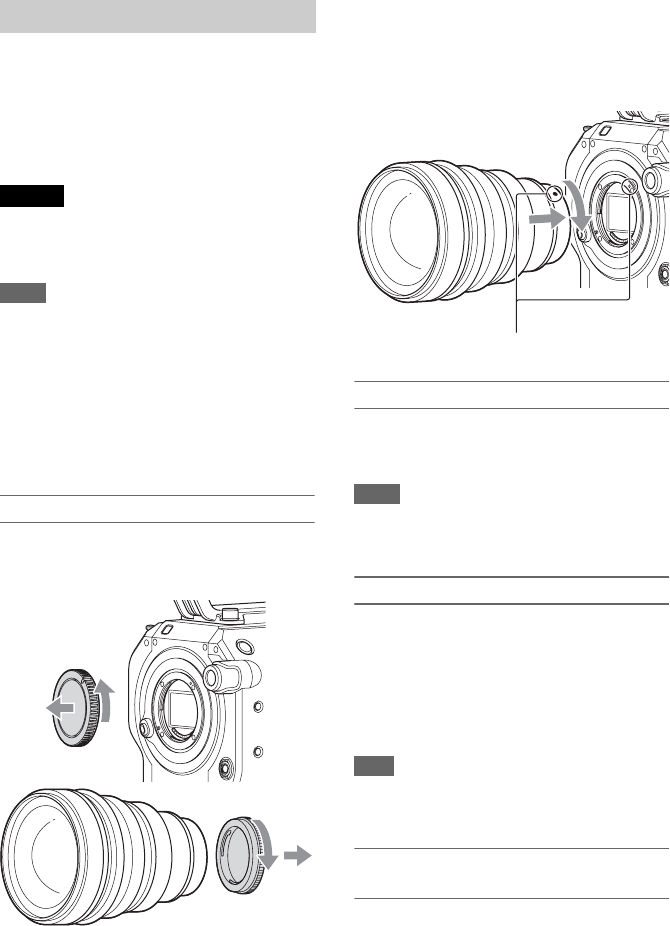
Attaching an E-mount lens
1Remove the lens cap and cover from the
camcorder and the lens.
2Align the lens mount mark (white) with
the camcorder, carefully insert the lens,
and then turn the lens clockwise.
The lens makes a click sound when it locks into
position.
Attaching an A-mount lens
To use an A-mount lens, attach a lens mount
adaptor (option) and then attach the A-mount
lens.
Notes
• When using an A-mount lens, Iris is set to manual.
• When focus is set to AF with an LA-EA2 or LA-EA4
attached, Iris is set to F3.5 or fully open.
Removing a lens
Remove a lens using the following procedure.
1Press and hold the lens release button
and turn the lens counterclockwise.
2Pull the lens out in the forward
direction.
Note
If another lens will not be attached immediately, fit the
lens mount into the recess part of the lens mount cap and
turn clockwise.
Iris adjustments for lenses with Auto Iris
switch
• When the lens Auto Iris is set to AUTO, the iris
is adjusted automatically and can also be
adjusted manually from the camcorder.
• When the lens Auto Iris is set to MANUAL, the
iris can only be adjusted using the lens ring. Iris
operation from the camcorder has no effect.
Attaching a Lens
Caution
Mount mark (white)
24
Focus adjustments for lenses with focus
switch
• When the lens focus switch is set to AF/MF or
AF, the focus is adjusted automatically and can
also be adjusted manually from the camcorder.
• When the lens focus switch is set to Full MF or
MF, the focus can only be adjusted using the
lens ring. Focus operation from the camcorder
has no effect.
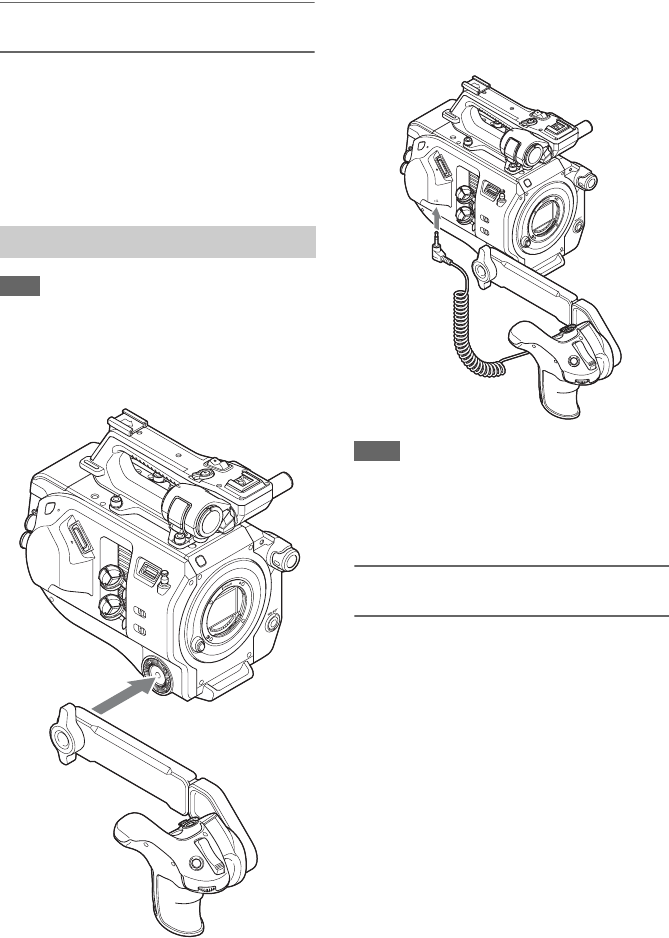
Note
Attach/remove the grip remote control while the
camcorder is turned off.
1Attach the arm to the grip attachment,
and tighten the screw.
2Connect the grip remote control cable
to the REMOTE connector on the
camcorder.
Notes
• Check that the arm and grip remote control are
securely attached. They may fall off during shooting if
the screws are loose.
• Do not support the weight of the camcorder by holding
just the grip remote control.
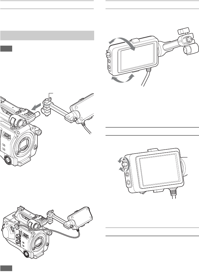
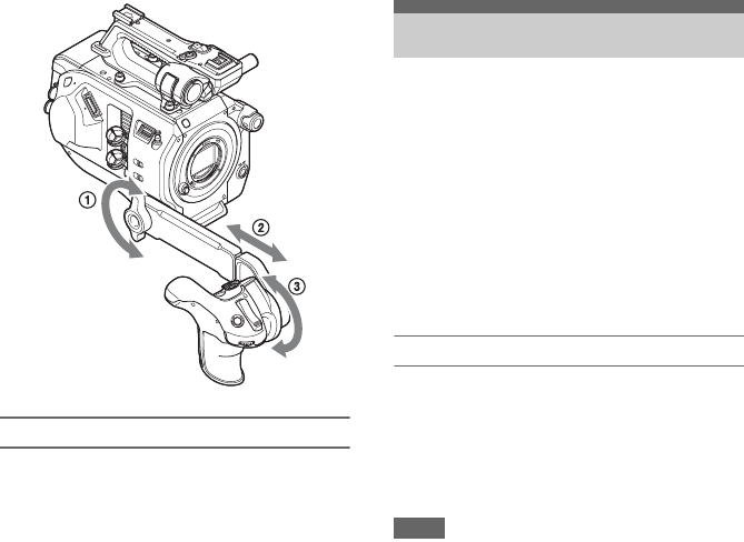
Adjusting the position of the grip remote
control
Adjust the arm angle (1).
Loosen the two screws on the rear side of the arm
using a coin or similar object, adjust the arm
length (2), and then tighten the two screws.
Press the grip rotation button (page 11) to adjust
the angle of the grip remote control (3).
Attaching the Grip Remote Control
25
Removing the grip remote control
1Disconnect the grip remote control
cable from the REMOTE connector on
the camcorder.
2Remove the arm from the camcorder.
The initial settings screen appears in the
viewfinder the first time the camcorder is turned
on or after the backup battery has become
completely discharged.
Set the date and time of the internal clock using
this screen.
Time Zone
Time Zone sets the time difference from UTC
(Coordinated Universal Time). Change the
setting as required.
Setting the date and time
Turn the SEL/SET dial (page 9) to select items
and settings, then press the SEL/SET dial to apply
the settings and start the clock running.
Once the settings screen is closed, you can change
the date, time, and time zone settings using Clock
Set (page 97) in the System menu.
Notes
• If the clock setting is lost because the backup battery
becomes fully discharged due to power being
disconnected for an extended period (no battery pack
and no DC IN power source), the initial settings screen
will be displayed when you next turn the camcorder
on.
• While the initial settings screen is displayed, no other
operation, except turning the power off, is permitted
until you finish the settings on this screen.
• The camcorder has a built-in rechargeable battery for
storing the date, time, and other settings even when the
camcorder is turned off. For details about the built-in
rechargeable battery, see page 104.
Setting the Clock

26
Before shooting, configure the basic operation of
the camcorder to suit the application.
You can switch the shooting mode between
“Custom” mode to create images flexibly on-site,
and “Cine EI” mode (where the camcorder is
operated similarly to a film camera, with footage
developed in post production).
You can select the mode using Base Setting
(page 92) >Shooting Mode in the System menu.
Color Space selects the base color gamut for
recorded signals and output signals.
When the shooting mode is set to Custom mode,
Color Space is set to “Matrix.”
Matrix: Selects the color gamut using the Matrix
setting, similar to conventional video
cameras.
When the shooting mode is set to Cine EI mode,
Color Space selects the color gamut of the video
output with MLUT set to Off.
S-Gamut/SLog2: Wide color gamut comparable to
film cameras.
S-Gamut3.Cine/SLog3: Easy to adjust color
gamut for digital cinema (DCIP3).
S-Gamut3/SLog3: Wide color gamut, for
compatibility with future standard gamuts,
optimized using Sony image distortion
correction technology.
You can select the color gamut using Base Setting
(page 92) >Color Space in the System menu.
You can set the scan mode of the image sensor.
You can select the mode using Base Setting
(page 92) >Imager Scan Mode in the System
menu.
Normal: When not using Slow & Quick Motion
high-frame rate mode, this scans the full
angle-of-view of Super 35mm size.
When S&Q Motion (page 86) >High Frame
Rate Mode in the Recording menu is set to
“Full Scan,” this scans the full angle-of-view
of Super 35mm size and converts the signal to
2K data. When set to “Center Scan,” this
scans a 2K angle-of-view of half Super 35mm
size at the center of the image.
2K Full: Scans the full angle-of-view of
Super 35mm size and converts the signal to
2K.
2K Center: Scans a 2K angle-of-view of half
Super 35mm size at the center of the image.
Note
The recording format resolution is restricted to 2K or
lower when Imager Scan mode (page 93) is set to 2K
Full or 2K Center.
Configuring Basic
Camcorder Operation
Shooting Mode
Color Space
Image Sensor Scan Mode

27
The camcorder records audio and video on XQD
memory cards (available separately) inserted in
the card slots.
Use the following Sony XQD memory cards in
the camcorder.
For details on operations with media from other
manufacturers, refer to the operating instructions
for the media or consult the manufacturer’s
information.
S-series XQD memory cards
H-series XQD memory cards
N-series XQD memory cards
M-series XQD memory cards
G-series XQD memory cards
The use of memory cards other than Sony XQD
memory cards is not guaranteed.
For details about using XQD memory cards and
usage precautions, refer to the operating instructions
for the XQD memory card.
Using XQD Memory
Cards
About XQD Memory Cards

28
The guaranteed operating conditions will vary depending on the Rec Format and Recording settings.
Yes: Operation supported
No: Normal operation not guaranteed
Recommended Media
Format XQD G
XQD S
(EB Stream)
XQD N
XQD M
Discontinued
XQD H
XQD S
(non EB
Stream)
32/64/128 GB
32/64/128
*1
GB
16/32/64 GB
XAVC-I 4096×2160P – 59.94P Yes No No
50P Yes No No
29.97P Yes No No
25P Yes No No
24P Yes No No
23.98P Yes No No
3840×2160 – 59.94P Yes No No
50P Yes No No
29.97P Yes No No
25P Yes No No
23.98P Yes No No
1920×1080 Normal mode or
S&Q (excluding
HFR *2)
59.94P Yes No No
59.94i Yes Yes No
50P Yes No No
50i Yes Yes No
29.97P Yes Yes No
25P Yes Yes No
23.98P Yes Yes No
S&Q (HFR mode) 59.94P Yes No No
50P Yes No No
29.97P Yes No No
25P Yes No No
23.98P Yes No No

29
*1 M-series only
*2 HFR: High Frame Rate
XAVC-L 3840×2160 – 59.94P Yes Yes No
50P Yes Yes No
29.97P Yes Yes No
25P Yes Yes No
23.98P Yes Yes No
1920×1080 Normal mode or
S&Q (excluding
HFR)
59.94P Yes Yes Yes
50P Yes Yes Yes
59.94i Yes Yes Yes
50i Yes Yes Yes
29.97P Yes Yes Yes
25P Yes Yes Yes
23.98P Yes Yes Yes
1920×1080 S&Q (HFR mode) 59.94P Yes Yes No
50P Yes Yes No
29.97P Yes 50 Mbps: No
35 Mbps: Yes No
25P Yes No No
23.98P Yes No No
MPEG HD
422
1920×1080 – 59.94i Yes Yes Yes
50i Yes Yes Yes
29.97P Yes Yes Yes
25P Yes Yes Yes
23.98P Yes Yes Yes
1280×720 – 59.94P Yes Yes Yes
50P Yes Yes Yes
29.97P Yes Yes Yes
25P Yes Yes Yes
23.98P Yes Yes Yes
ProRes 422
HQ
1920×1080 – 59.94i Yes No No
50i Yes No No
29.97P Yes No No
25P Yes No No
23.98P Yes No No
ProRes 422 1920×1080 – 59.94i Yes Yes No
50i Yes Yes No
29.97P Yes Yes No
25P Yes Yes No
23.98P Yes Yes No
Format XQD G
XQD S
(EB Stream)
XQD N
XQD M
Discontinued
XQD H
XQD S
(non EB
Stream)
32/64/128 GB
32/64/128
*1
GB
16/32/64 GB

30
1Press the media cover release button
(page 10) to open the media cover of the
card slot section.
2Insert an XQD memory card with the
XQD label facing to the left.
The access indicator (page 10) is lit red, then
changes to green if the card is usable.
3Close the media cover.
Notes
• The memory card, memory card slot, and image data
on the memory card may be damaged if the card is
forced into the slot in the incorrect orientation.
• When recording to media inserted in both XQD card
slots A and B, insert media in both slots that is
recommended for operation with the format of the
recording.
Press the media cover release button (page 10) to
open the media cover of the card slot section, and
lightly press the memory card in to eject the card.
Notes
• If the camcorder is turned off or the memory card is
removed while the memory card is being accessed, the
integrity of data on the card cannot be guaranteed. All
data recorded on the card may be discarded. Always
make sure the access indicator is lit green or not lit
before turning off the camcorder or removing the
memory card.
• When removing an XQD memory card immediately
after recording is finished, the XQD memory card may
be hot, but this does not indicate a problem.
When XQD memory cards are loaded in both card
slots A and B, you can switch the card used for
recording by pressing the SLOT SELECT button
(page 9).
If a card becomes full during recording, the
camcorder automatically switches to the other
card.
Note
The SLOT SELECT button is disabled during playback.
The memory cards are not switched even if you press the
button. The button is enabled while the thumbnail screen
(page 57) is displayed.
If an unformatted XQD memory card or an XQD
memory card that was formatted in a different
specification is inserted, the message “Media
Needs to be Formatted” is displayed in the
viewfinder.
Format the card using the following procedure.
Select Format Media (page 89) >Media(A)
or Media(B) in the Media menu, then select
Execute. When a confirmation message
appears, select Execute again.
A message is displayed while formatting is in
progress, and the access indicator is lit red.
When formatting is completed, a completion
message is displayed. Press the SEL/SET dial to
dismiss the message.
If formatting fails
Protected XQD memory cards and memory cards
not supported by the camcorder cannot be
formatted.
A warning message is displayed. Follow the
instructions to replace the card with a supported
XQD memory card.
Note
Formatting a memory card erases all data, including
recorded video data and setup files.
Inserting an XQD Memory Card
Ejecting XQD Memory Cards
Switching Between XQD Memory
Cards
Formatting (Initializing) XQD
Memory Cards

31
When shooting (recording/standby), you can
monitor the remaining capacity of the XQD
memory card in each slot using the slot A/B
media capacity indicators in the viewfinder
(page 13).
The remaining recording time is calculated from
the remaining capacity of the media in each slot
and the current video format (recording bit rate),
and is displayed in units of minutes.
Note
A mark is displayed if the media is protected.
XQD memory card replacement timing
• When the total remaining recording time on the
two memory cards becomes less than 5 minutes,
the message “Media Near Full” appears, the
recording indicator starts flashing, and a beep
sound (headphone output) will warn you.
Replace with media that has free space.
• If you continue recording until the total
remaining recording time reaches zero, the
message changes to “Media Full” and recording
stops.
Note
Up to approximately 600 clips can be recorded on one
XQD memory card.
If the number of recorded clips reaches the limit, the
remaining recording time indicator becomes “0” and the
message “Media Full” is displayed.
You can save camera configuration data for the
camcorder on an SD card (available separately).
Saved data files can be imported from the SD
card.
SDHC memory cards*
SD memory cards*
* Referred to collectively as “SD cards” in this manual.
1Press the media cover release button
(page 10) to open the media cover of the
card slot section.
2Insert the SD memory card with the SD
card label facing to the left.
The access indicator (page 10) is lit red, then
goes off if the card is usable.
3Close the media cover.
Press the media cover release button
(page 10) to open the media cover of the
card slot section, and lightly press the SD
card in to eject the card.
Notes
• If the camcorder is turned off or the SD card is
removed while the SD card is being accessed, the
integrity of data on the card cannot be guaranteed. All
data recorded on the card may be discarded. Always
make sure the access indicator is not lit before turning
off the camcorder or removing the SD card.
• Take caution to prevent the SD card from flying out
when inserting/ejecting the card.
Checking the Remaining
Recording Time Using a UTILITY SD Card
Supported SD Cards
Inserting an SD Card
Ejecting the SD Card
32
SD cards must be formatted the first time they are
used in the camcorder.
SD cards for use in the camcorder should be
formatted using the format function of the
camcorder. If a message appears when the SD
card is inserted into the camcorder, format the SD
card.
Select Format Media (page 89) >SD Card in
the Media menu, then select Execute. When
a confirmation message appears, select
Execute again.
A message and progress status are displayed
while formatting is in progress, and the access
indicator is lit red.
When formatting is completed, a completion
message is displayed. Press the SEL/SET dial to
dismiss the message.
Note
Formatting an SD card erases all data on the card. The
card cannot be restored.
You can check the remaining capacity on an SD
card on the Media Status screen (page 17).
Note
A mark is displayed if the SD card is protected.
To use an SD card formatted on the camcorder in
the slot of another device
First, make a backup of the card, then reformat
the card in the device to be used.
You can add functions to the camcorder, such as
a V-shoe battery or external sync signal, by
attaching an XDCA-FS7 Extension Unit (option)
to the camcorder.
Notes
• The camcorder battery pack cannot be used when an
XDCA-FS7 unit is attached to the camcorder. You
must attach a battery pack to the XDCA-FS7 or
connect an external power supply.
• Attach/remove the XDCA-FS7 while the camcorder is
turned off.
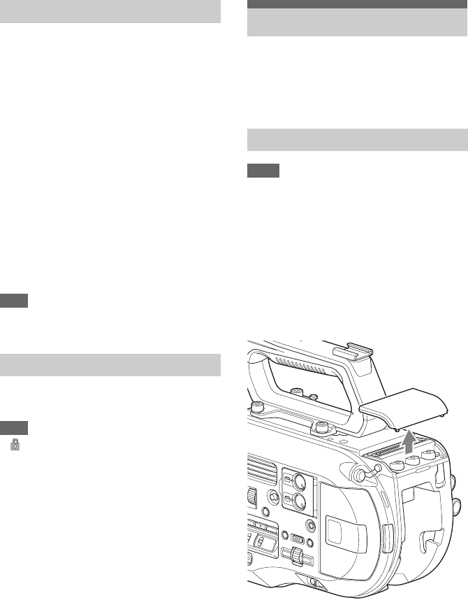
1Remove the battery pack (page 18)
attached to the camcorder.
2Remove the cover of the extension unit
connector section.
Formatting (Initializing) SD Cards
Checking the Remaining Capacity
Using the XDCA-FS7
Attaching the XDCA-FS7
33
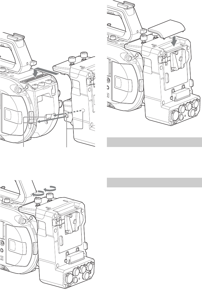
3Align the protrusions of the XDCA-FS7
with the left and right grooves of the
camcorder and slide all the way in, then
slide the XDCA-FS7 down into the
connector section.
4Tighten the two screws on the top of the
XDCA-FS7 to secure the XDCA-FS7.
The cover of the extension unit connector
section can be inserted into the top of the
extension unit.
Loosen the two screws on the top of the
XDCA-FS7, and remove the XDCA-FS7 from
the camcorder.
Insert the battery pack into the battery pack
attachment on the XDCA-FS7.
The following Sony genuine battery packs are
supported.
Lithium-ion battery packs
BP-L80S
BP-FL75
Grooves Protrusions
Removing the XDCA-FS7
Attaching the Battery Pack
34
Pull the battery pack out from the battery pack
attachment on the XDCA-FS7 while holding
down the BATT RELEASE button.
You can switch the timecode input/output using
the TC IN/OUT switch (page 12).
For details, see page 102.
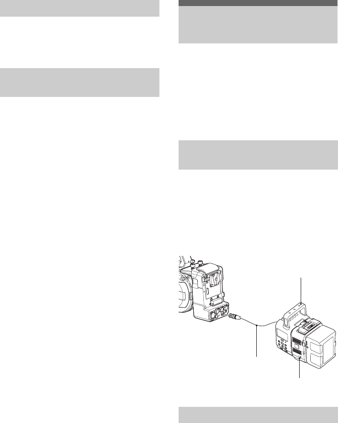
You can record RAW video (page 52) to an
AXS-R5 RAW Recorder (option) using an HXR-
IFR5 Interface Unit (option) and an XDCA-FS7
(option).
For details about setting up the HXR-IFR5 and
AXS-R5, refer to the HXR-IFR5 operation
manual.
1Attach the XDCA-FS7 to the camcorder
(page 32).
2Connect the RAW OUT connector of
the XDCA-FS7 to the SDI IN (RAW)
connector of the HXR-IFR5 using an
SDI cable.
Disconnect the SDI cable from the RAW
OUT connector of the XDCA-FS7.
Removing the Battery Pack
Switching the Timecode Input/
Output
Using an HXR-IFR5 and
AXS-R5
Connecting the HXR-IFR5 to the
Camcorder
Removing the HXR-IFR5
SDI cable
HXR-IFR5
AXS-R5
35
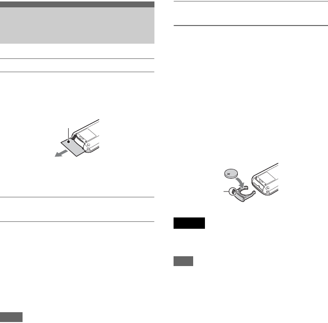
When using for the first time
Pull out the insulating sheet from the battery
holder when using the supplied infrared remote
control for the first time.
A CR2025 lithium-ion battery is installed in the
battery holder at the factory.
Controlling the camcorder using the
remote control
To use remote control, first turn on the camcorder
and then enable remote control operation.
Use the setup menu to enable/disable the remote
control function.
To enable using the menu
Press the MENU button to switch the camcorder
to menu mode, then set IR Remote (page 98) in
the System menu to On.
Notes
• Point the remote control at the remote control receiver
sensor on the camcorder.
• Set up the camcorder so that the remote control
receiver sensor is not exposed to direct sunlight or
strong light from other sources. Strong light can
prevent proper remote control operation.
• Other video decks may operate by mistake when using
the supplied remote control to operate the camcorder.
In this case, switch the remote control mode switch on
the video deck to DVD2, or shield the remote control
receiver sensor using black paper.
Changing the battery of the remote
control
The remote control uses a standard CR2025
battery.
Do not use a battery other than the CR2025.
1Push the tab in, and remove the battery
holder by placing a fingernail in the
groove.
2Insert a new battery with the + terminal
facing up.
3Insert the battery holder until it clicks
into place.
Do not store battery packs in locations exposed to
direct sunlight, flame, or high temperature.
Note
Replacing the battery with a non-specified battery may
cause device failure. Always replace with the specified
battery.
Dispose of used batteries in accordance with federal and
local laws.
Using the Infrared
Remote Control
Insulating sheet
Caution
Tab
36
You can operate the camcorder from a web
browser by connecting a smartphone, tablet, or
other device that supports a web browser to the
camcorder using a wireless LAN connection.
This function is called Wi-Fi remote control.
This function is useful when operating the
camcorder from a remote location, for example,
when the camcorder is mounted on a crane.
For details of the Wi-Fi remote control setup
procedure, see page 56.
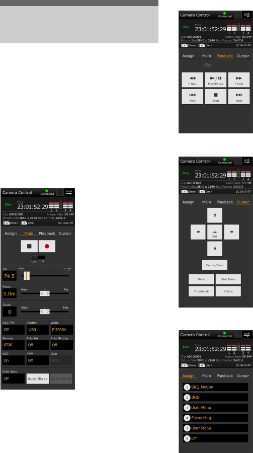
Wi-Fi Remote screen (smartphone)
Main screen
Playback screen
Cursor screen
Assign screen
Using Wi-Fi Remote
Control
• Shooting settings
S&Q FPS, Shutter,
White, Sensitivity/Gain/
Exposure Index,
Gamma, MLUT, Color
Bars, Auto Black, Auto
White, Rec Start/Stop,
Lock, Iris, Focus, Zoom,
Auto Iris, Auto Shutter,
AGC, ATW
• Status display
• Playback buttons
Play/Pause, Stop, F Fwd,
F Rev, Next, Prev
• Status display
• Cursor buttons
Up, Down, Left, Right,
Set, Cancel/Back, Menu,
Status, Thumbnail, User
Menu
• Status display
• Assignable buttons
Assignable buttons 1 to 6
37
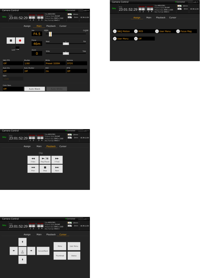
Wi-Fi Remote screen (tablet)
Main screen
• Shooting settings
S&Q FPS, Shutter, White, Sensitivity/Gain/Exposure
Index, Gamma, MLUT, Color Bars, Auto Black, Auto
White, Rec Start/Stop, Lock, Iris, Focus, Zoom, Auto
Iris, Auto Shutter, AGC, ATW
Playback screen
• Status display
• Playback buttons
Play/Pause, Stop, F Fwd, F Rev, Next, Prev
Cursor screen
• Status display
• Cursor buttons
Up, Down, Left, Right, Set, Cancel/Back, Menu,
Status, Thumbnail, User Menu
Assign screen
• Status display
• Assignable buttons
Assignable buttons 1 to 6

38
Basic shooting is conducted using the following
procedure.
1Attach the necessary devices, and check
that power is being supplied.
2Insert the memory card(s).
3Set the POWER switch to the ON
position.
The camera image appears in the viewfinder.
4Press the record button (page 7).
The recording indicator lights up, and the
camcorder starts recording.
5To stop recording, press the record
button again.
Recording stops, and the camcorder switches
to STBY (standby) mode.
Note
If the record button is pressed within a few seconds after
turning the camcorder on, the recording indicator lights
up to indicate the unit is in the recording state, but
recording to media may not occur for the first few
seconds, depending on the selected recording format.
Shooting (Full Auto mode)
Press the FULL AUTO button, turning the button
indicator on.
The auto iris (compatible lenses only), AGC, auto
shutter, ATW (auto tracing white balance)
functions are enabled to control the brightness
and white balance automatically (full auto mode).
To control each function manually, turn Full Auto
mode off.
Recording continuously when changing
memory cards (Relay Rec)
When memory cards are inserted in both slots A
and B, recording automatically switches to the
second memory card just before the remaining
capacity on the first card is reduced to zero.
Notes
• Do not eject a memory card while recording to it is in
progress. When recording, only change memory cards
in slots for which the slot access indicator is not lit.
• When the remaining capacity on the memory card
being recorded becomes less than one minute and a
recordable memory card is inserted in the other slot, a
“Will Switch Slots Soon” message appears. The
message disappears after switching memory card slots.
• Relay recording may not operate if recording is started
when the remaining memory card capacity is less than
one minute. For correct relay recording, check that the
remaining memory card capacity is more than one
minute before starting recording.
• Video created using the camcorder relay recording
function cannot be played back seamlessly on the
camcorder.
• To combine video created using the camcorder relay
recording function, use Catalyst Browse software.
Shooting
Basic Operation Procedure

39
Recording to memory cards A and B
simultaneously (Simul Rec)
You can simultaneously record using both
memory cards A and B.
Set Simul Rec >Setting in the Recording
menu to “On.”
Note
Simultaneous recording is not supported in Slow &
Quick Motion mode (page 86) or Picture Cache
recording mode (page 86).
Also, simultaneous recording is not supported for the
following recording formats (page 93).
NTSC Area
XAVC-I
4096×2160 59.94P, 4096×2160 29.97P,
4096×2160 24.00P, 4096×2160 23.98P,
3840×2160 59.94P, 3840×2160 29.97P,
3840×2160 23.98P, 1920×1080 59.94P
XAVC-L
3840×2160 59.94P, 3840×2160 29.97P,
3840×2160 23.98P
RAW (with XDCA-FS7, HXR-IFR5, and
AXS-R5 connected)
4096×2160 59.94P, 4096×2160 29.97P,
4096×2160 23.98P, 2048×1080 59.94P,
2048×1080 29.97P, 2048×1080 23.98P
RAW & XAVC-I (with XDCA-FS7, HXR-IFR5,
and AXS-R5 connected)
4096×2160 59.94P, 2048×1080 59.94P
ProRes 422 HQ, ProRes 422
(with XDCA-FS7 connected)
1920×1080 59.94i, 1920×1080 29.97P,
1920×1080 23.98P
PAL Area
XAVC-I
4096×2160 50P, 4096×2160 25P, 3840×2160 50P,
3840×2160 25P, 1920×1080 50P
XAVC-L
3840×2160 50P, 3840×2160 25P
RAW (with XDCA-FS7, HXR-IFR5, and
AXS-R5 connected)
4096×2160 50P, 4096×2160 25P,
2048×1080 50P, 2048×1080 25P
RAW & XAVC-I (with XDCA-FS7, HXR-IFR5,
and AXS-R5 connected)
4096×2160 50P, 2048×1080 50P
ProRes 422 HQ, ProRes 422
(with XDCA-FS7 connected)
1920×1080 50i, 1920×1080 25P
Changing the settings of the record
START/STOP buttons on the camcorder
and handle
When the simultaneous recording (Simul Rec) is
enabled, you can start/stop recording to each
memory card independently using the record
START/STOP buttons on the camcorder and the
handle.
By factory default, both buttons are set to start/
stop simultaneous recording to both memory
cards A and B.
• “Rec Button [SlotA SlotB] Handle Rec Button
[SlotA SlotB]”
When the buttons are set to control recording for
different memory cards, SDI/HDMI Rec Control
and RAW Rec Control follow the recording state
of slot A.
To change the setting
Select Simul Rec >Rec Button Set in the
Recording menu.
Rec Button Set Buttons and memory
cards
“Rec Button [SlotA
SlotB] Handle Rec
Button [SlotA SlotB]”
Starts/stops simultaneously
recording to memory cards A
and B using either button.
“Rec Button [SlotA]
Handle Rec Button
[SlotB]”
The record START/STOP
button starts/stops recording to
memory card A, and the record
START/STOP button on the
handle starts/stops recording to
memory card B.
“Rec Button [SlotB]
Handle Rec Button
[SlotA]”
The record START/STOP
button starts/stops recording to
memory card B, and the record
START/STOP button on the
handle starts/stops recording to
memory card A.

40
A lens that supports auto focus is required. Set the
FOCUS switch (page 9) on the camcorder to the
“AUTO” position. If the lens is fitted with a focus
selector switch, set the switch to the “AF/MF” or
“AF” position. If the switch is set to the “Full
MF” or “MF” position, lens focusing cannot be
operated from the camcorder (page 24).
Note
The LA-EA1/3 (option) supports push auto focus only.
Setting the auto focus area (Focus Area)
You can set the target area for auto focus using
Focus >Focus Area (page 66) in the Camera
menu.
Note
On the LA-EA2/4 (option), the position cannot be
set.
Temporarily stopping auto focus (Focus
Hold)
Press the PUSH AUTO FOCUS button (page 9)
when in auto focus mode to override auto focus.
This is useful, for example, when something
crosses in front of the subject that you do not want
to focus on, or when auto focus is lost.
To adjust the focus manually, set the FOCUS
switch (page 9) to “MAN.”
This allows you to adjust the focus manually
according to the shooting conditions.
Manual focusing is useful for the following types
of subjects.
- Subjects on the far side of a window covered
in water droplets
- Subjects with low contrast against the
background
- Subjects further away than nearby subjects
Adjusting focus rapidly using manual
focus (Push Auto Focus)
Position the subject that you want to adjust focus
for in the center of the image, then press the
PUSH AUTO FOCUS button (page 9).
The focus returns to the previous setting when
you release the button.
This is useful when you want to quickly focus on
a subject before starting to shoot.
You can set the position for focusing using Focus
>Focus Area (Push AF) (page 67) in the Camera
menu.
Notes
• The Push Auto Focus function does not operate if the
lens is set for manual focusing.
• During Push Auto Focus operation when using an LA-
EA2/4, Full Auto mode is On.
• During focus magnification, the focus adjusts to fit the
magnified display position.
Focus indicator
Indicates the focus state.
• (Lit): Subject is in focus.
• (Flashing): Subject is out of focus. Since
focusing is not automatic, change the
composition and focus settings to achieve
focus.
Focusing using magnified view (Focus
Magnifier)
By factory default, the Focus Magnifier x4/x8
function is assigned to the ASSIGN4 button on
the grip remote control (page 46).
Press the ASSIGN4 button.
The focus magnifier screen appears with the
center magnified by approximately four times.
Press the button again to increase the
magnification to approximately eight times. This
function is useful for checking the focus.
Press the button again to return to the normal
screen.
You can move the position to be magnified during
focus magnification using the multi selector.
Pressing the multi selector returns to the center of
the image. You can also control the position using
the left/right buttons and SEL/SET dial on the
camcorder, infrared remote controller, or Wi-Fi
remote controller.
If push auto focus is used during focus
magnification, the focus adjusts to fit the
magnified display position.
Notes
• The recorded image or SDI/HDMI output image is not
magnified when the focus is magnified.
• During focus magnification, the STATUS CHECK
button and menu buttons have no effect.
Adjusting the Focus Automatically
Adjusting the Focus Manually
41
• The focus position is cleared when the camcorder is
turned off. When the camcorder is turned on again, the
focus magnification position returns to the center of
the image when switching to the focus magnifier
screen.
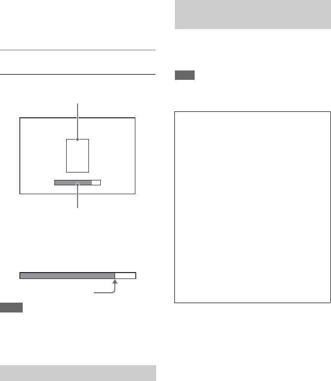
Adjusting focus using the focus assist
indicator
The focus position is indicated by the maximum
reach of the bar. Adjust the focus to maximize the
length of the bar.
Notes
• The focus indicator may show little or no variation
when you are shooting subjects with little surface
variation or dark scenes.
• The detection range cannot be set.
You can monitor the audio that is being recorded
using headphones.
Connecting a set of headphones to the headphone
connector (page 10) enables you to monitor the
audio being recorded. You can also monitor the
playback audio (page 58) using the built-in
speaker (page 10) or headphones.
You can select the audio channel to monitor and
adjust the volume using Audio Output (page 78)
in the Audio menu.
When two XQD memory cards are inserted, press
the SLOT SELECT button (page 9) to switch
cards.
Note
You cannot switch between memory cards during
playback mode. Also, continuous playback of a clip
spanning media in slot A and slot B is not supported.
Monitoring Audio
Focus detection range frame
(Focus area marker)
Focus assist indicator
In-focus: Position of
maximum reach of the bar
Switching Between XQD Memory
Cards
Clips (recorded data)
When you stop recording, the video, audio, and
accompanying data from the start to the end of
the recording are saved as a single “clip” on an
XQD memory card.
Clip names
Each clip recorded by the camcorder is
automatically assigned a clip name comprising
the word “Clip” and a 4-digit number. The 4-
digit number automatically increments with
each recording.
You can change the “Clip” prefix using Clip in
the Media menu.
Maximum clip duration
Up to 6 hours per clip.
Multiple clips are recorded in succession
during relay recording, but recording will stop
automatically after approximately 13 hours.

42
You can change the settings based on the video
application or recording conditions.
The formats available for selection vary
depending on the Country (region of use) and
Codec settings.
Select a format using Rec Format >Video Format
in the System menu.
You can adjust the brightness by adjusting the
iris, gain, shutter speed, and by adjusting the light
level using ND filters.
When adjusting the brightness without using ND
filters, turn Full Auto mode (page 38) off.
You can adjust the brightness control target level
in the setup menu.
Adjusting the control target level
Set the level using Auto Exposure (page 66)
>Level in the Camera menu.
Note
The brightness cannot be adjusted automatically in Cine
EI mode.
Adjusting the iris automatically
This function adjusts the brightness according to
the subject. A lens that supports auto iris is
required.
1If a lens with Auto Iris switch is
attached, set the switch to AUTO.
2Press the IRIS button (page 46) to turn
Auto Iris on.
The setting toggles between on and off each
time the IRIS button is pressed.
Note
The iris cannot be adjusted automatically on an A-
mount lens.
Adjusting the iris manually
Press the IRIS button to turn Auto Iris off,
then adjust using the IRIS dial.
You can also assign the IRIS function to an
assignable dial (page 46).
Temporarily adjusting the iris automatically
Press and hold the PUSH AUTO IRIS button to
turn auto iris on temporarily.
The iris returns to the previous setting when you
release the button.
Note
When the Auto Iris switch of the lens is set to
“MANUAL,” the Auto Iris and Push Auto Iris functions
on the camcorder have no effect. Manual iris adjustments
on the camcorder also have no effect.
Adjusting the gain automatically
Press the ISO/Gain button (page 9) to turn AGC
on.
Or select Auto Exposure (page 66) >AGC in the
Camera menu and set to “On.”
Adjusting the gain manually
You can control the gain when you want to adjust
the exposure while using a fixed iris setting or
when you want to prevent the gain increasing due
to AGC.
1Press the ISO/Gain button (page 9) to
turn AGC off.
2Set the GAIN switch (page 9) to H, M,
or L.
Controlling the gain (fine adjustment)
Turn the IRIS dial, or the assignable dial assigned
with the ISO/Gain/EI function, to adjust the gain
value set by the GAIN switch.
This is useful when you want to adjust the
exposure by one step without changing the depth
of field.
The adjusted gain value is canceled by switching
the GAIN switch or by turning AGC on.
Changing Basic Settings
Selecting the Recording Format
Adjusting the Brightness

43
Shooting using auto shutter
This function adjusts the shutter speed
automatically in response to the image brightness.
Press the SHUTTER button (page 9).
If the settings screen was displayed, press the
button again.
Or set Auto Exposure (page 66) >Auto Shutter in
the Camera menu to On.
Shooting with a fixed shutter
You can shoot with a set shutter speed.
Press the SHUTTER button to display a screen
with the supported shutter values, and select and
set a value using the SEL/SET dial. If you press
the SHUTTER button again instead of the SEL/
SET dial, auto shutter is enabled.
Setting in the Camera menu
Select Shutter (page 67) in the Camera menu and
set the shutter mode and speed.
Adjusting the light level (ND filter)
In conditions where the lighting is too bright, you
can set the appropriate brightness by changing the
ND filter.
Turn the ND FILTER dial (page 9) to select Clear
t 1/4 t 1/16 t 1/64 t Clear in sequence.
You can select the adjustment mode to suit the
shooting conditions.
ATW (auto tracing white balance)
This function adjusts the white balance
automatically to an appropriate level.
The white balance is automatically adjusted when
the color temperature of the light source changes.
Pressing the WHT BAL button (page 9) switches
ATW on/off.
You can select the speed of adjustment (five
steps) using White (page 70) >ATW Speed in the
Paint menu.
You can freeze the current white balance setting
by assigning the ATW Hold function to an
assignable button (page 46), and pressing the
assignable button to temporarily pause ATW
mode.
Notes
• ATW cannot be used in Cine EI mode.
• It may not be possible to adjust to the appropriate
colors using ATW, depending on the lighting and
subject conditions.
Examples:
- When a single color dominates the subject, such as
sky, sea, ground, or flowers.
- When the color temperature is extremely high or
extremely low.
If the appropriate effect cannot be obtained
because the ATW auto tracking speed is slow or
for other reasons, run auto white balance.
Adjusting the white balance manually
1Turn Full Auto mode (page 38) off.
2When white balance is set to ATW
mode, press the WHT BAL button
(page 9) to set manual mode.
3Select B, A, or PRESET using the WHT
BAL switch (page 9).
B: Memory B mode*
A: Memory A mode
PRESET: Preset mode
* B can be assigned to ATW ON.
Adjusting for Natural Colors
(White Balance)

44
Preset mode
This mode adjusts the color temperature to a
preset value (factory default is 3200K).
Memory A/Memory B mode
This mode adjusts the white balance to the setting
saved in memory A or B, respectively.
Note
The settings of the WHT BAL switch in Cine EI mode
are fixed as follows.
B: 5500K
A: 4300K
PRESET: 3200K
Running auto white balance
1Press the ISO/Gain button (page 9) to
turn AGC on.
Or select Auto Exposure (page 66) >AGC in
the Camera menu and set to “On.”
2To save an adjustment value in
memory, select memory A mode or
memory B mode.
3Place white paper (or other object) in a
location with the same lighting source
and conditions as the subject, then zoom
in on the paper to show white on the
screen.
4Adjust the brightness.
Adjust the iris using the procedure in
“Adjusting the iris manually” (page 42).
5Press the WB SET button (page 7).
If auto white balance is set in memory mode,
the adjustment value is saved in the memory
(A or B) selected in step 2.
If auto white balance is set in ATW mode, the
white balance adjustment returns to the ATW
mode white balance when adjustment ends.
Notes
• Auto white balance cannot be performed in Cine EI
mode.
• If the adjustment is not successful, an error message is
displayed on the screen for about three seconds. If the
error message persists after repeated attempts to set
white balance, contact your Sony service
representative.
You can specify the audio to be recorded using
the input connectors, switches, and dials of the
camcorder.
External audio input connectors and selector
switches
INPUT1 connector (page 10)
INPUT2 connector (page 10)
INPUT1 (LINE/MIC/MIC+48V) switch (page 7)
INPUT2 (LINE/MIC/MIC+48V) switch (page 7)
Switches for setting the audio level
CH1 LEVEL CONTROL switch (page 9)
CH2 LEVEL CONTROL switch (page 9)
CH1 INPUT LEVEL dial (page 9)
CH2 INPUT LEVEL dial (page 9)
Selecting the audio input device
1Select the audio input connector.
Select the audio input using Audio Input
>CH1 Input Select or CH2 Input Select in the
Audio menu.
Set to INPUT1 or INPUT2 to correspond to
the connector for the connected device. If
using a shoe microphone or XLR adaptor,
specify Shoe 1 or Shoe 2 in the same way.
For details about the XLR adaptor, see
“Adding Audio Input Connectors”
(page 53).
Note
The camcorder is equipped with an internal
microphone. Although it is not suitable for final
audio, it can be used for syncing with other
equipment. In such cases, specify Internal MIC.
Setting the Audio to Record

45
2Select the input audio source.
Set the INPUT1/INPUT2 (LINE/MIC/
MIC+48V) switches to the devices
connected to the INPUT1/INPUT2
connectors, respectively.
• Selecting “MIC+48V” and connecting a
microphone that is not compatible with a
+48V source may damage the connected
device. Check the setting before
connecting the device.
• If noise is a concern on connectors with
no device connected, set the
corresponding INPUT1/INPUT2 (LINE/
MIC/MIC+48V) switches to “LINE.”
Adjusting the audio recording level
automatically
Set the CH1/CH2 LEVEL CONTROL switches
for the channels to adjust automatically to
“AUTO.”
For CH3/CH4, set Audio Input >CH3 Level
Control and CH4 Level Control in the Audio
menu to “Auto” (page 76).
Adjusting the audio recording level
manually
Use the following procedure to adjust the audio
recording level for CH1/CH2.
1Set the CH1/CH2 LEVEL CONTROL
switches for the channels to adjust
manually to “MAN.”
2During shooting or standby, turn the
INPUT LEVEL (CH1)/(CH2) dials of
the corresponding channels to adjust
the audio level.
You can also adjust the recording level using
the assignable dial (page 46), if assigned
with the Audio Input Level function, or from
the setup menu.
For CH3/CH4, set Audio Input >CH3 Level
Control and CH4 Level Control in the Audio
menu to “Manual,” and then set the audio
recording level in CH3 Input Level and CH4
Input Level (page 76).
Notes
• The Audio Input Level settings may be
disabled, depending on the combination of
settings in the Audio menu. For details, see the
diagram on page 130.
• If either Audio Input >CH1 Input Select or CH2
Input Select in the Audio menu is set to
“Internal MIC,” CH2 is switched to automatic/
manual in conjunction with the CH1 LEVEL
CONTROL switch. Also, the CH2 audio
recording level is set in conjunction with the
CH1 INPUT LEVEL dial (page 76).
• The camcorder supports combinations of
various settings. For details, see the diagram on
page 130.
Setting the timecode
Set the timecode to record using Timecode
(page 85) in the TC/UB menu.
Displaying time data
Press the DISPLAY button to display time data
on the screen (page 14).
Set the timecode to display using TC Display
(page 85) >Display Select in the TC/UB menu.
Pressing an assignable button (page 46) with
DURATION/TC/U-BIT assigned will switch the
display between the timecode, user bits, and
duration in sequence.
Connected device Switch position
External audio source (e.g.
mixer)
LINE
Dynamic microphone,
battery-operated
microphone
MIC
+48 V phantom power
feed microphone
MIC+48V
Specifying Time Data

46
There are six assignable buttons (page 9,
page 11) on the camcorder to which you can
assign functions.
You can also assign functions to the IRIS dial
(page 9) on the camcorder and the assignable dial
(page 11) on the grip remote control.
Changing the button function
Use Assignable Button (page 94) in the System
menu.
You can view the assigned functions on the
Assignable Button Status screen (page 16).
Functions assigned to each assignable button by
factory default
Assignable functions
•Off
•Marker
•Zebra
• Peaking
• Video Signal Monitor
• DURATION/TC/U-BIT
• Focus Magnifier x4/x8
• Focus Magnifier x4
• Focus Magnifier x8
• Push AF/Focus Hold
• Focus Area
• Focus Area (Push AF)
•VF Mode
•IRIS
•AGC
• SHUTTER
• Auto Exposure Level
• Push Auto Iris
• Push AGC
• Spotlight
• Backlight
•ATW
•ATW Hold
• SteadyShot
•Color Bars
• User Menu
•Rec Lamp
• S&Q Motion
• Picture Cache Rec
• Rec Review
• Thumbnail
• Shot Mark1
• Shot Mark2
•Clip Flag OK
•Clip Flag NG
• Clip Flag Keep
• High/Low Key
Changing the dial function
Use Assignable Dial (page 96) in the System
menu.
You can view the assigned functions on the
Assignable Button Status screen (page 16).
IRIS is assigned by factory default.
Assignable functions
•Off
•IRIS
• ISO/GAIN/EI
• Focus
• Audio Input Level
Useful Functions
Assignable Buttons/Dials
Button 1 S&Q Motion
Button 2 IRIS
Button 3 User Menu
Button 4 Focus Magnifier x4/x8
Button 5 User Menu
Button 6 Off

47
When the video format (page 92) is set to one of
the following values, you can specify a different
value for the recording frame rate and playback
frame rate.
NTSC Area
XAVC-I
4096×2160 59.94P, 4096×2160 29.97P,
4096×2160 24.00P, 4096×2160 23.98P,
3840×2160 59.94P, 3840×2160 29.97P,
3840×2160 23.98P,1920×1080
59.94P,1920×1080 29.97P, 1920×1080
23.98P
XAVC-L
3840×2160 59.94P, 3840×2160 29.97P,
3840×2160 23.98P, 1920×1080 59.94P 50,
1920×1080 59.94P 35, 1920×1080 29.97P
50, 1920×1080 29.97P 35, 1920×1080
23.98P 50, 1920×1080 23.98P 35
PAL Area
XAVC-I
4096×2160 50P, 4096×2160 25P,
3840×2160 50P, 3840×2160 25P,
1920×1080 50P, 1920×1080 25P
XAVC-L
3840×2160 50P, 3840×2160 25P,
1920×1080 50P 50, 1920×1080 50P 35,
1920×1080 25P 50, 1920×1080 25P 35
You can set the frame rate for recording by
pressing and holding an assignable button to
which S&Q Motion has been assigned.
Notes
• Slow & Quick Motion cannot be set during recording,
playback, or while the thumbnail screen is displayed.
• Audio recording is not supported in Slow & Quick
Motion mode.
• The auto focus function is disabled in Slow & Quick
Motion mode.
• The following conditions apply when shooting at
frame rates higher than 60 fps.
- The focus assist indicator, depth of field indicator,
focus position indicator, iris position indicator, and
zoom position indicator are all turned off.
NTSC Area
PAL Area
The camcorder’s Interval Rec function allows
you to capture time-lapse video to the
camcorder’s internal memory. This function is an
effective way to shoot slow-moving subjects.
When you start recording, the camcorder
automatically records a specified number of
frames at a specified interval time.
This function is enabled when the camcorder is set
to any of the following video formats
(page 92)
.
XAVC-I
XAVC-L*
MPEG HD 422*
Slow & Quick Motion Format Resolution Frame
rate
High frame
rate
XAVC-I 2160 1 to 60 fps Not supported
(59.94P, 29.97P, 24.00P,
23.98P)
1080 1 to 60 fps 72/75/80/90/96/
100/110/120/
125/135/144/
150/160/168/
175/180 fps
(59.94P, 29.97P, 23.98P)
XAVC-L 2160 1 to 60 fps Not supported
(59.94P, 29.97P, 23.98P)
1080 1 to 60 fps 72/75/80/90/96/
100/110/120 fps
(59.94P 50, 59.94P 35,
29.97P 50, 29.97P 35,
23.98P 50, 23.98P 35)
Format Resolution Frame
rate
High frame
rate
XAVC-I 2160 1 to 60 fps Not supported
(59P, 25P)
1080 1 to 60 fps 72/75/80/90/96/
100/110/120/
125/135/144/
150 fps
(59P, 25P)
XAVC-L 2160 1 to 60 fps Not supported
(59P, 25P)
1080 1 to 60 fps 72/75/80/90/96/
100/110/120 fps
(50P 50, 50P 35, 25P 50, 25P
35)
Recording Video Intermittently
(Interval Rec)
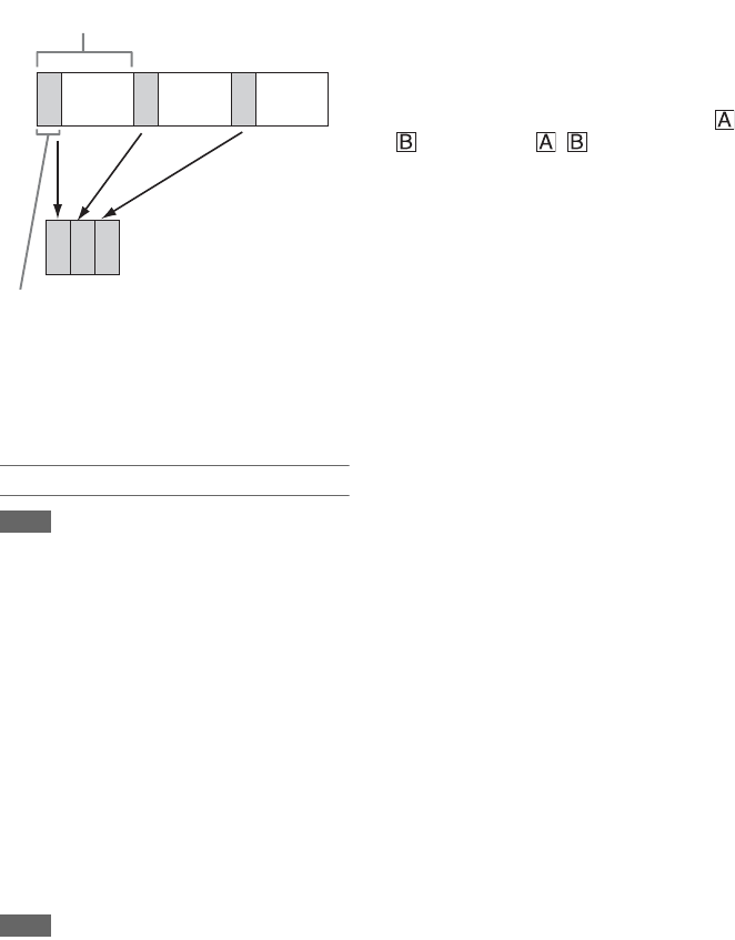
48
* 59.94i and 50i are not supported.
When Interval Rec is enabled, the HVL-LBPC
(option) video light automatically turns on before
recording starts, which allows you to record
pictures under stable light and color temperature
conditions (pre-lighting function).
Interval Rec settings and shooting
Notes
• Only one special recording function, such as Interval
Rec recording, can be used at any one time.
If another special recording mode is enabled while
Interval Rec is in use, Interval Rec is automatically
released.
• Interval Rec mode is automatically released after
changing system settings, such as the video format.
• Interval Rec settings cannot be changed during
recording or playback, or when the thumbnail screen is
displayed.
To set Interval Rec
Set Interval Rec (page 86) >Setting in the
Recording menu to On, and set Number of
Frames and Interval Time.
If using the HVL-LBPC video light (option), set
the time interval for turning on the video light
before recording starts in Pre-Lighting in the
Interval Rec menu, as required.
Notes
• If you want to turn the video light on before the start of
recording, set the video light switch to AUTO. The
video light turns on and off automatically according to
the setting of Video Light Set (page 69) in the Camera
menu.
• If you turn the video light switch on, the video light is
always lit (video light does not turn on/off
automatically).
• If the video light is configured so that it would turn off
for a duration of 5 seconds or less, the video light does
not turn off.
The camcorder exits Interval Rec mode when it is
powered off, but the Number of Frames, Interval
Time, and Pre-lighting settings are maintained.
You do not need to set them again the next time
you shoot in Interval Rec mode.
To shoot using Interval Rec
Press the record button to start recording. “Int /
zRec” and “Int / zStby” appears
alternately in the viewfinder.
If you are using the pre-lighting function, the
video light turns on before recording starts.
To stop shooting
Stop the recording.
When shooting ends, the video data stored in
memory up to that point is written to the media.
To exit Interval Rec mode
Do one of the following.
• Set the POWER switch to Off.
• In recording standby mode, set Interval Rec
>Setting in the Recording menu to Off.
Also, Interval Rec mode is automatically released
when the camcorder is restarted.
Limitations during recording
• Audio is not recorded.
• Reviewing the recording (Rec Review) is not
possible.
• Genlock is not applied.
If the camcorder is turned off during recording
• If the POWER switch on the camcorder is set to
the Off position, the media is accessed for
several seconds to record the images stored in
memory up till that moment, and then the power
turns off automatically.
• If power is lost because the battery was
removed, the DC power cord was disconnected,
or the power was turned off from the AC
adaptor, then the video and audio data shot up to
that point may be lost (maximum 10 seconds).
Care should be exercised when exchanging the
battery.
Interval time
Number of frames in one take

49
The picture cache recording function allows you
to capture video retroactively when you start
recording and then record it to XQD memory
cards by maintaining an internal cache memory of
a specified duration when shooting. The picture
cache recording time is set using Picture Cache
Rec >Cache Rec Time (page 86) in the Recording
menu.
Supported recording formats
*1: XAVC-I 59.94P and 50P are not supported.
Notes
• Picture Cache Rec cannot be on at the same time as
Interval Rec or Slow & Quick Motion. When Picture
Cache Rec is turned on, these other recording modes
are forcibly turned off.
• Picture Cache Rec mode cannot be selected while
recording or Rec Review is in progress.
• When Picture Cache Rec is on, the timecode is
recorded in Free Run mode regardless of the setting in
the TC/UB menu (page 85).
• The Output Format setting may not be configurable in
Picture Cache Rec mode. If this occurs, temporarily set
Picture Cache Rec to Off, and then change the setting.
Configuring before shooting
Configure Picture Cache Rec (page 86) in the
Recording menu before shooting.
You can also assign the Picture Cache Rec
function to an assignable button (page 46) and
switch Picture Cache Rec >Setting on/off using
the button.
When configured, the z (green) indicator
appears in the viewfinder (page 13).
Picture cache recording
When you press the record button, recording
starts and video is written to XQD memory cards
starting from the video stored in the cache
memory.
To cancel Picture Cache Rec
Turn off Picture Cache Rec >Setting in the
Recording menu or press an assignable button
assigned with the Picture Cache Rec function.
Notes
• Changing the recording format clears the video in
cache memory stored up to that point, and starts
caching new video. Consequently, picture cache
recording of pictures before changing format is not
possible, even if you start recording immediately after
changing format.
• If Picture Cache Rec is turned on/off immediately after
inserting an XQD memory card, cache data may not be
recorded on the card.
• Video is stored in cache memory when the cache
recording function is turned on. Video prior to the
function being turned on is not cached.
• Video is not stored in cache memory while an XQD
memory card is being accessed, such as during
playback, Rec Review, or thumbnail screen display.
Picture cache recording of video during that interval is
not possible.
• You can change the cache recording time setting using
the menu while recording is in progress, but the new
value does not come into effect until after recording
ends.
You can check the video of the most recently
recorded clip on the screen.
When recording is stopped, press the
assignable button (page 46) with Rec
Review assigned.
The clip is played to the end, Rec Review ends,
and the camcorder returns to STBY (standby)
mode.
Press and hold the button to start playback in the
reverse direction. When the button is released, the
clip is played to the end.
To stop Rec Review
Press the assignable button with Rec Review
assigned.
Picture Cache Recording (Picture
Cache Rec)
Recording
format
Resolution Cache time [sec.]
RAW 4096×2160
2048×1080
Not supported
XAVC *1 4096×2160
3840×2160
0 to 2
1920×1080 0 to 2/2 to 4/4 to 6/6
to 8
MPEG-2 1920×1080 0 to 2/2 to 4/4 to 6/6
to 8/ 8 to 10/13 to 15
ProRes422 1920×1080 Not supported
Reviewing a Recording (Rec
Review)
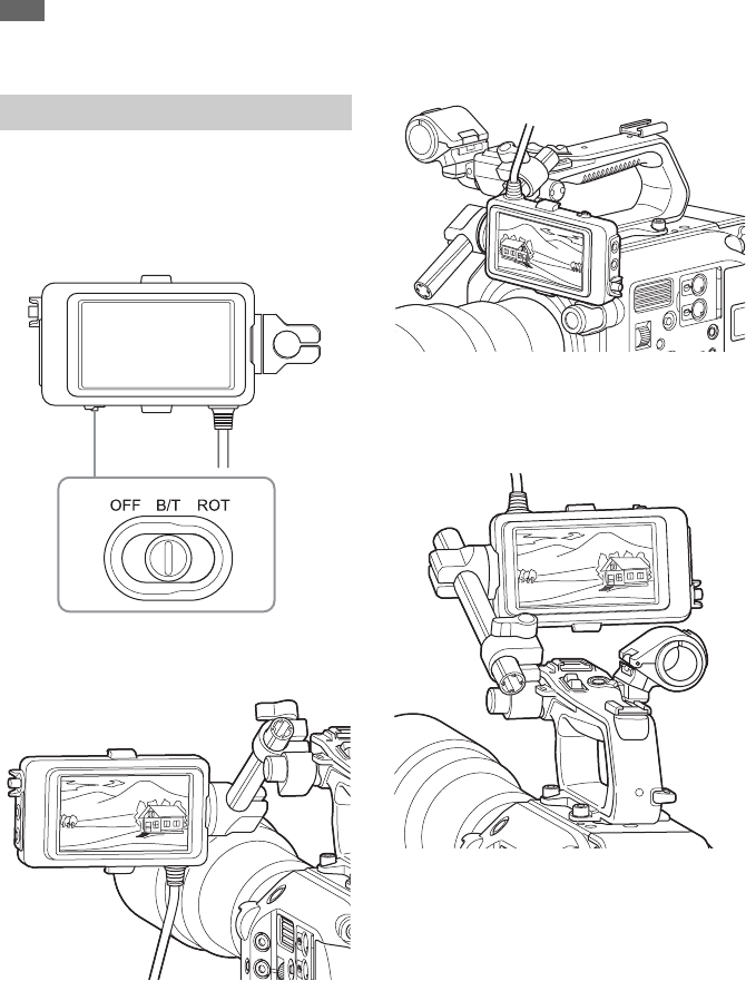
50
Note
Rec Review is not supported if the video format is
changed after recording a clip.
You can flip the image in the viewfinder
(page 11) vertically or horizontally/vertically
using the MIRROR switch.
This allows you to turn the viewfinder 180°
toward the lens.
OFF
The image is not inverted.
B/T
The image is flipped vertically.
The information display is flipped vertically and
horizontally.
ROT
The image is flipped vertically and horizontally.
The information display is also flipped vertically
and horizontally.
Self Portrait Mode
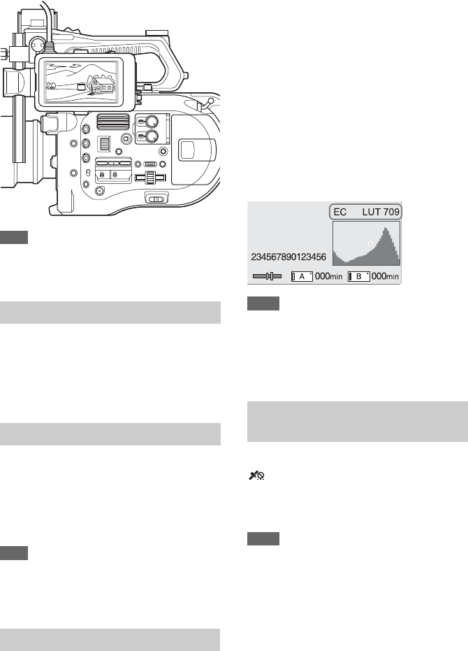
51
Note
The B/T and ROT view are displayed in the viewfinder
only. The output video and recorded video remain
unaffected.
You can turn peaking on/off by pressing the
PEAKING button on the viewfinder (page 11).
You can turn peaking on/off and set the peaking
type and peaking frequency using Peaking
(page 81) in the VF menu.
You can turn zebra pattern display on/off by
pressing the ZEBRA button on the viewfinder
(page 11).
You can turn zebra pattern display on/off, and set
the zebra pattern type and display level using
Zebra (page 81) in the VF menu.
Note
The camcorder measures the image in the viewfinder. In
Cine EI mode, adjust the display level and other
parameters in accordance with the viewfinder monitor
LUT (page 79) setting.
You can set the type of video signal to display on
the viewfinder screen to waveform, vectorscope,
or histogram using Video Signal Monitor
>Setting (page 84) in the VF menu.
The video signal monitor of the camcorder
measures the video signal in the video output
stage. Accordingly, if the output video is edge
cropped with respect to the recorded video, the
cropped signal component will not be measured.
When this occurs, “EC” is displayed at the top left
of the video signal monitor.
When the video output is set to 2K or lower in
Cine EI mode, you can measure the video signal
from either the SDI1 system or SDI2 system
using Video Signal Monitor >Source (page 84) in
the VF menu. The monitor LUT setting (page 79)
of the specified SDI system is displayed at the top
right of the video signal monitor.
Notes
• When Display On/Off >Setting (page 83) is set to Off
in the VF menu, the video signal monitor is not
displayed.
• When the specified SDI system monitor LUT setting is
set to Off, the Color Space setting (page 92) is
displayed at the top right of the video signal monitor.
Set GPS to “On” in the System menu.
is displayed when the camcorder is seeking
GPS satellites. When positioning is established,
location information is recorded when shooting
video.
Notes
• The GPS setting in the System menu cannot be set to
“On” when the handle is not attached, as the GPS
receiver is built into the handle.
• The icon displayed varies, depending on the signal
reception from the GPS satellites.
Displaying Peaking
Displaying Zebra
Video Signal Monitor
Obtaining Location Information
(GPS)
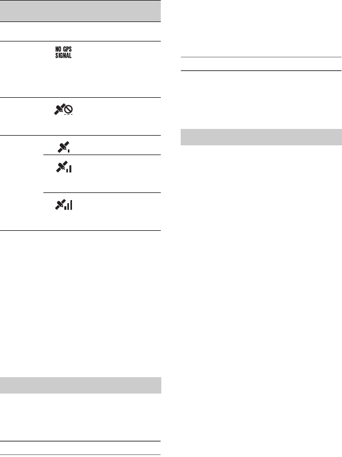
52
• GPS is set to “On” by factory default. Location and
time information of video shot when positioning is
enabled is recorded by the camcorder.
• If a positioning icon is not displayed after several
minutes, there may be a problem with signal reception.
Start shooting without location information, or move
to an area with a clear view of the sky. Shooting when
a positioning icon is not displayed means that location
information will not be recorded.
• The GPS signal may not be received when indoors or
near tall structures. Move to a location with a clear
view of the sky.
• The recording of location information may be
interrupted, depending on the strength of the received
signal, even if a positioning icon is displayed.
This mode mimics the way a film camera works,
and assumes “developing” occurs in post-
production.
Cine EI mode constraints
• Functions that cannot be adjusted automatically
(tracking)
- White balance
-Gain
- Shutter
- Iris
- Auto Exposure
• Functions that cannot be configured
-Gain
- Paint menu settings
-Scene File
-Lens File
Functions available in Cine EI mode only
• Exposure Index
• Monitor LUT
• High/Low Key
• RAW video recording
You can record RAW video to an AXS-R5
(option) by converting the signal output from the
RAW OUT connector of an XDCA-FS7 (option)
attached to the camcorder using an HXR-IFR5
(option) (page 34).
1Set up the external RAW recorder unit
(page 34).
2Set Base Setting >Shooting Mode in the
System menu to Cine EI.
3Set Codec >Select in the System menu to
RAW.
Selecting RAW & XAVC-I will
simultaneously record RAW video to the
external RAW recorder and HD video to the
XQD memory cards in the camcorder.
4Set the resolution using Imager Scan
Mode in the System menu.
When set to Normal, the RAW resolution is
4096×2160.
5Set the frame rate in Rec Format
>RAW Output Format in the System
menu.
6Check that the external recorder is
turned on, then press the record button
on the camcorder.
The supported RAW output formats are shown
below.
Positioning
status
Display GPS reception state
Off No display GPS is set to “Off” or an
error occurred.
Positioning
not available
Location information
could not be obtained
because GPS signal could
not be received. Move to
a location with a clear
view of the sky.
Searching for
satellites
Searching for GPS
satellites. Several
minutes may be required
to acquire satellites.
Positioning A weak GPS signal is
being received.
A GPS signal is being
received. Location
information can be
acquired.
A strong GPS signal is
being received. Location
information can be
acquired.
Shooting in Cine EI Mode
Recording RAW Video

53
NTSC Area
PAL Area
Recording status indicator
If Display On/Off (page 83) >HXR-IFR5 Rec
Control in the VF menu is set to “On,” the RAW
recording status is displayed in the viewfinder
using an icon.
Slow & Quick Motion Recording
If S&Q Motion >Setting in the Recording menu is
set to “On,” RAW video is recorded in Slow &
Quick Motion mode.
RAW output Slow & Quick Motion is supported
only for 2K resolution at 120/240 fps (NTSC) and
100/200 fps (PAL).
Notes
• The RAW OUT connector of the camcorder only
controls recording by transmitting a Rec Control signal
to the external recorder, hence the camcorder may
indicate RAW video recording is in progress when the
external recorder is not actually recording. Check the
indicator on the external recorder to obtain the correct
operating status.
• When recording is started on an external recorder,
without using the record button on the camcorder, clips
may not be recorded properly.
You can connect up to four channels of XLR
audio devices to the camcorder at the same time
by using an XLR-K2M XLR adaptor (not
supplied).
Attach the XLR adaptor to the MI shoe, and set
Audio Input >CH3 Input Select to “Shoe 1” and
CH4 Input Select to “Shoe 2” in the Audio menu.
Camcorder functions that overlap will be disabled
for channels on which the XLR adaptor is
selected as the input. Use the switches and dials
on the XLR adaptor to perform adjustments.
Notes
• If Audio Input >CH3 Level and CH4 Level in the
Audio menu are set to “Audio Input Level,” Audio
Input Level of the camcorder will be set to match the
level adjusted on the XLR adaptor. Audio Input Level
is also enabled when the XLR adaptor switch is set to
AUTO. When “Through” is specified, audio will be
recorded at the level adjusted with the XLR adaptor
(page 131).
• You can also assign to CH1 and CH2 by attaching an
XLR adaptor and setting Audio Input >CH1 Input
Select and CH2 Input Select in the Audio menu to
“Shoe 1” and “Shoe 2,” respectively. However, if input
from an XLR adaptor is assigned to both CH1 and
CH2, input from the INPUT1/INPUT2 connectors on
the camcorder can no longer be assigned to the
channels.
Codec >Select
setting
RAW output formats
RAW / RAW &
XAVC-I / RAW
&XAVC-L / RAW
&MPEG HD422
4096×2160 59.94P
4096×2160 29.97P
4096×2160 23.98P
2048×1080 59.94P
2048×1080 29.97P
2048×1080 23.98P
Codec >Select
setting
RAW output formats
RAW / RAW &
XAVC-I / RAW
&XAVC-L / RAW
&MPEG HD422
4096×2160 50P
4096×2160 25P
2048×1080 50P
2048×1080 25P
Adding Audio Input Connectors
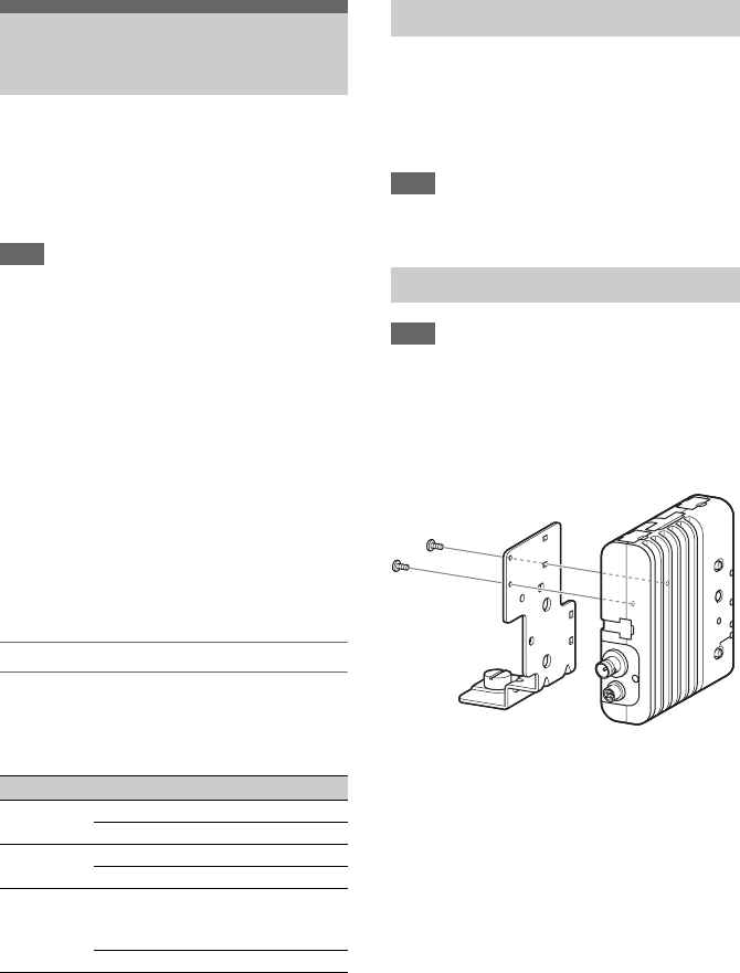
54
The camcorder can connect to smartphones,
tablets, and other devices using wireless LAN
connection by attaching the IFU-WLM3 USB
Wireless LAN Module (supplied) or a
CBK-WA100 Wireless Adaptor (option).
Note
USB wireless modules other than the IFU-WLM3 are not
supported.
The following are supported from devices
connected by wireless LAN.
• Remote control
Enables remote control of the camcorder.
• Video monitoring (CBK-WA100 only)
Enables monitoring of the video from the
camcorder.
CBK-WA100 (option) and the Content
Browser Mobile application are required.
For details about the Content Browser Mobile
application, contact your Sony sales or service
representative.
Compatible devices
You can use a smartphone, tablet, or computer to
configure and operate the camcorder. The
supported devices, OS, and browsers are shown
in the following table.
Plug the IFU-WML3 into the USB wireless LAN
module connector (page 7).
After attaching the unit, set Wi-Fi >Wi-Fi
(page 97) in the System menu to “Enable” to
enable wireless LAN.
Note
Attach/remove the IFU-WLM3 while the camcorder is
turned off.
Note
Attach/remove the CBK-WA100 while the camcorder is
turned off.
1Attach the CBK-WA100 to the
mounting bracket, and tighten the two
screws.
Connecting Devices
using Wireless LAN
Device OS Browser
Smartphone Android 5.1 Chrome
iOS 9 Safari
Tablet Android 5.1 Chrome
iOS 9 Safari
Computer Microsoft Windows 7/
Microsoft Windows 8.1/
Microsoft Windows 10
Chrome
Mac OS 10.10/10.11 Safari
Attaching the IFU-WLM3
Attaching the CBK-WA100
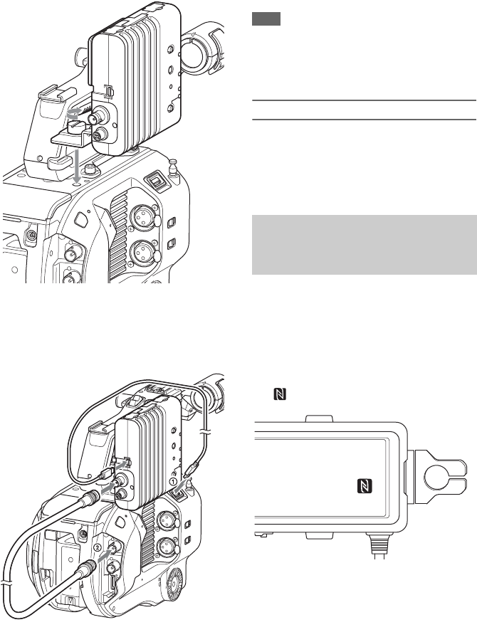
55
2Attach the CBK-WA100 mounting
bracket on the camcorder, and tighten
the screws.
3Connect the CBK-WA100 USB cable to
the USB wireless LAN module
connector (1), and the SDI cable to the
SDI OUT connector (2).
4Turn the CBK-WA100 on, and then
turn the camcorder on.
5When connection is completed, the
wireless LAN must be enabled by
setting Wi-Fi >Wi-Fi (page 97) in the
System menu to Enable.
Note
The SDI OUT output setting must be configured to use
the CBK-WA100 with the camcorder. However, the
camcorder cannot output a signal compatible with the
CBK-WA100 when using XAVC-I 24.0P or ProRes
23.98P (page 79).
About the CBK-WA100
The CBK-WA100 has functions for recording
low-resolution proxy files on an SD card, and for
transferring the files to a server via a wireless
LAN. For details, refer to the operation manual
for the CBK-WA100.
Devices that support NFC can be connected (one-
touch connection) using NFC.
1Attach an IFU-WLM3 to the camcorder
(page 54), and set Wi-Fi >Wi-Fi
(page 97) in the System menu to
“Enable” to enable wireless LAN.
appears on the screen.
2Open “Settings” on the device, select
“More,” and place a check mark in the
NFC checkbox.
The various settings will vary depending on
the device. For details, refer to the instruction
manual for the device.
One-touch Connection of NFC-
enabled Devices (Using IFU-
WLM3 Only)
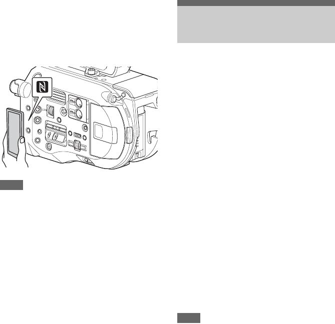
56
3Touch the camcorder using the device.
The device connects to the camcorder,
launches a web browser, and displays the
Wi-Fi remote control. Authentication is
required the first time that the device
connects.
Notes
• Disable sleep mode and screen lock beforehand.
• Touch and hold the device still until the “Content
Browser Mobile” application launches (1 to
2 seconds).
The Wi-Fi Remote screen is automatically
resized to match the screen size of the connected
device.
1Connect the camcorder and device
using a Wireless LAN connection
(page 55).
2Launch a browser on the device and
enter “http://IP address of camcorder
(Wi-Fi >IP Address in System menu)/
rm.html” in the URL bar.
For example, if the IP address is 192.168.1.1,
enter “http://192.168.1.1/rm.html” in the
URL bar.
3Enter the user name and password
(Basic Authentication >User Name and
Password in the System menu).
When connection is successful, the Wi-Fi
Remote screen appears on the device.
You use the Wi-Fi Remote screen to operate
the camcorder.
You can disable the record button operation
by sliding the Lock knob to the right.
Notes
• To display the page for a smartphone, change
“rm.html” to “rms.html” in the URL. To display the
page for a tablet, change “rm.html” to “rmt.html” in
the URL. When “rm.html” is entered, the page
automatically switches for display on the
corresponding device. However, the appropriate page
may not be displayed, depending on the device.
• The Wi-Fi Remote screen may not match the
camcorder settings under the following circumstances.
If this occurs, reload the browser window.
- If the camcorder is restarted while connected
- If the camcorder is operated directly while
connected
- If the device has been reconnected
- If the browser Forward/Back buttons have been
used
• The Wi-Fi remote control may not function if the
wireless signal strength becomes weak.
Displaying the Wi-Fi
Remote Control
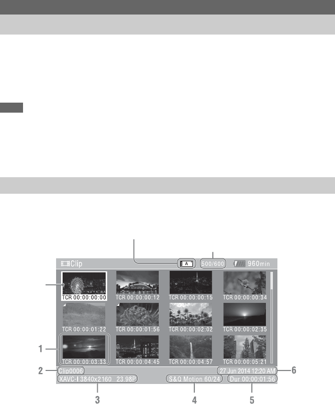
57
The thumbnail screen appears if you press the THUMBNAIL button (page 9). The thumbnail screen
displays the clips stored on XQD memory cards as thumbnails (index pictures).
You can select a clip on the thumbnail screen and start playback of that clip. The playback image can be
displayed in the viewfinder and on an external monitor.
Pressing the THUMBNAIL button again closes the thumbnail screen and returns to the camera image.
Notes
• Only the clips recorded in the currently selected recording format are displayed on the thumbnail screen. If an expected
recorded clip is not displayed, check the recording format. Take special note of this fact before formatting (initializing)
media.
• When Codec >Select in the System menu is set to one of the following, recording cannot be started during playback or
when the thumbnail screen is displayed.
RAW & XAVC-I, RAW & XAVC-L, RAW & MPEG HD422
Information for the clip at the cursor position is displayed at the bottom of the screen.
1. Thumbnail (index picture)
Displays the index picture of a clip. When a clip
is recorded, its first frame is automatically set as
the index picture.
Clip/frame information is displayed below the
thumbnail. You change the information
displayed using Customize View (page 88)
>Thumbnail Caption in the Thumbnail menu.
2. Clip name
Displays the name of the selected clip.
3. Recording video format
Displays the file format of the selected clip.
Thumbnail Screen
Thumbnail Screen
Screen Layout
Clip number/Total number of clips
Cursor
(yellow)
Currently selected XQD memory card indicator
(A lock icon is displayed if the card is protected.)

58
4. Special recording information
Displays the recording mode only if the clip was
recorded using a special recording mode.
For Slow & Quick Motion clips, the frame rate
is displayed on the right.
5. Clip duration
6. Creation date You can play recorded clips when the camcorder
is in recording standby (Stby) mode.
1Insert an XQD memory card for
playback.
2Press the THUMBNAIL button.
3Turn the SEL/SET dial (page 9) to move
the cursor to the thumbnail for the clip
you want to play.
4Press the SEL/SET dial.
Playback begins from the start of the selected
clip.
You can control playback by pressing the
following buttons.
SEL/SET dial:
Pauses playback.
Press again to return to normal playback.
Press left/right buttons:
Jumps to start of clip/start of next clip.
Press and hold left/right buttons:
Fast reverse/forward.
Returns to normal playback when you release
the button.
CANCEL/BACK button:
Stops playback, and returns to recording
standby mode.
Notes
• There may be momentary picture breakup or still
image display at the boundary between clips. You
cannot operate the camcorder during this period.
• When you select a clip in the thumbnail screen and
begin playback, there may be momentary picture
breakup at the start of the clip. To view the start of the
clip without breakup, put the camcorder into playback
mode, pause, then use the left button of the SEL/SET
dial to return to the start of the clip, and start playback
again.
• You can also control playback using the supplied
remote control.
Playing Clips
Playing Recorded Clips

59
On the thumbnail screen, you can operate the
clips or check clip properties using the thumbnail
menu.
The thumbnail menu (page 88) appears when you
press the MENU button and select a thumbnail.
Turn the SEL/SET dial (page 9) to select a
function, then press the SEL/SET dial.
Press the CANCEL/BACK button (page 9) to
return to the previous screen.
Note
Some items cannot be selected, depending on the state
when the menu was displayed.
Display Clip Properties
Set Index Picture
Thumbnail View
Set Shot Mark
Set Clip Flag
Lock/Unlock Clip
Delete Clip
Filter Clips
Customize View
For details about clip operation menus, see
“Thumbnail Menu” (page 88).
Displaying clip properties
Select Display Clip Properties (page 88) in the
Thumbnail menu to display the clip properties
screen.
Displaying the essence mark thumbnail
screen
Select Thumbnail View (page 88) >Essence
Mark Thumbnail in the Thumbnail menu and
select the essence mark type to display a
thumbnail view of the frames that have the
specified essence mark.
Displaying the filtered clip thumbnail
screen
Select Filter Clips (page 88) in the Thumbnail
menu and select a clip flag type to display only
those clips that have the specified flag.
To display all the clips, select Thumbnail View
>Essence Mark Thumbnail in the Thumbnail
menu to All.
Deleting clips
You can delete clips from XQD memory cards.
Select Delete Clip >Select Clip or All Clips in the
Thumbnail menu.
Select Clip:
Deletes the selected clip. Multiple clip
selection is supported.
All Clips:
Deletes all of the displayed clips.
Changing the information displayed on
the thumbnail screen
You can change the clip/frame information
displayed below the thumbnail.
Select Customize View >Thumbnail Caption in
the Thumbnail menu and select the information to
display.
Date Time:
Displays the date and time the clip was
created and last modified.
Time Code:
Displays the timecode.
Duration:
Displays the duration of the clip.
Sequential Number:
Displays a sequential number on each
thumbnail.
Clip Operations
Thumbnail Menu Operations
Thumbnail Menu Items

60
Press the MENU button to display the setup menu
in the viewfinder to specify various items for
shooting, recording, and playback (menu can also
be displayed on an external monitor). The setup
menu comprises the following menus.
User menu:
Contains menu items configured by the user
using Edit User Menu.
Edit User menu:
Contains menu items for editing the User
menu.
Camera menu:
Contains settings related to shooting.
Paint menu:
Contains settings related to image quality.
Audio menu:
Contains settings related to audio.
Video menu:
Contains settings related to video output.
VF menu:
Contains settings to the viewfinder display.
TC/UB menu:
Contains settings related to timecode and
user bits.
Recording menu:
Contains settings related to recording.
Thumbnail menu:
Contains settings related to thumbnail
display.
Media menu:
Contains settings related to media.
File menu:
Contains settings related to files.
System menu:
Contains settings related to the system.
Menu Display and Settings
Setup Menu Configuration and Hierarchy
Setup Menu Organization
User
(Factory settings)
Country
Base Setting
Rec Format
Codec
S&Q Motion
Picture Cache Rec
Simul Rec
Output Format
Monitor LUT
Clip
VF Setting
Assignable Button
Assignable Dial
Format Media
Edit User Menu
Edit User Add Item
Customize Reset
Camera ISO/Gain/EI
Auto Exposure
Focus
Shutter
Color Bars
Noise Suppression
Flicker Reduce
SteadyShot
Handle Zoom
Auto Black Balance
AF Micro Adjustment
Video Light Set
Paint White
Offset White
Black
Gamma
Black Gamma
Knee
White Clip
Detail(HD Mode)
Skin Detail
Aperture
Matrix
Multi Matrix
Maintenance
Audio Audio Input
Audio Output

61
Video Output On/Off
Output Format
Output Setting
Monitor LUT
Output Display
VF VF Setting
Peaking
Zebra
Marker
Display On/Off
Video Signal Monitor
TC/UB Timecode
TC Display
Users Bit
HDMI TC Out
Recording S&Q Motion
Interval Rec
Picture Cache Rec
Simul Rec
SDI/HDMI Rec Control
Thumbnail Display Clip Properties
Set Index Picture
Thumbnail View
Set Shot Mark
Set Clip Flag
Lock/Unlock Clip
Delete Clip
Filter Clips
Customize View
Media Update Media
Format Media
Clip
File All File
Scene File
User Menu Item
User Gamma
Monitor LUT
Monitor 3D LUT
Lens File
System Base Setting
Codec
Rec Format
Genlock
Assignable Button
Assignable Dial
Rec Lamp
Fan Control
HOLD Switch Setting
Lens
Language
Clock Set
Country
Hours Meter
Basic Authentication
Wi-Fi
GPS
IR Remote
Camera Battery Alarm
Camera DC IN Alarm
Ext. Unit Battery Alarm
Ext. Unit DC IN Alarm
All Reset
APR
Camera Config
Ve r s i o n
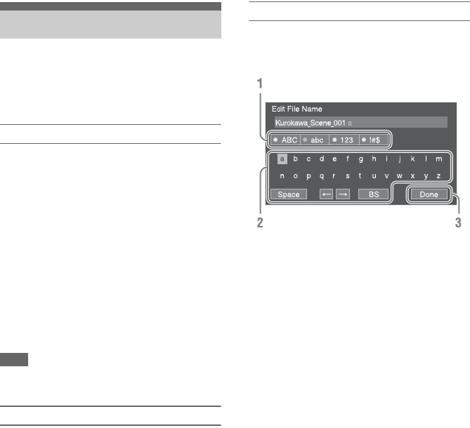
62
Press the MENU button to display the setup menu
in the viewfinder to specify various items for
shooting, recording, and playback (menu can also
be displayed on an external monitor).
Menu controls
MENU button (page 9)
Turns menu mode for setup menu operations on/
off.
Left button/Right button (page 9)
SEL/SET dial (page 9)
Press the left/right button to move the cursor left/
right to select menu items or settings.
Turn the SEL/SET dial to move the cursor up/
down to select menu items or settings.
Press the SEL/SET dial to apply the selected item.
CANCEL/BACK button (page 9)
Cancels a setting before it is applied, and moves
one level up in the menu hierarchy.
Note
The setup menu cannot be operated when in focus
magnifier mode (page 40).
Setting menu items
Turn the SEL/SET dial to move the cursor to the
menu item to set, then press the SET/SEL dial to
select the item.
• The menu item selection area displays up to
eight lines. If the available options for an item
cannot be displayed at the same time, scroll the
display by moving the cursor up/down.
• If an item has a large range of available options
(for example, –99 to +99), the selection area is
not displayed. The current setting is highlighted
to indicate that the value can be changed.
• Selecting [Execute] for a function will execute
the corresponding function.
• Selecting an item that requires confirmation
before execution will temporarily hide the menu
and display a confirmation message. Check the
message, and then select whether to execute or
cancel the function.
Entering a character string
When you select an item, such as a file name,
which requires character entry, the character
entry screen appears.
1Turn the SEL/SET dial to select a
character type, the press the dial.
ABC: Uppercase alphabetic characters
abc: Lowercase alphabetic characters
123: Numeric characters
!#$: Special characters
2Select a character from the selected
character type, then press the dial.
The cursor moves to the next field.
Space: Enters a space character at the cursor
position.
T/t: Moves the position of the cursor.
BS: Deletes the character on the left of the
cursor (backspace).
3When finished, select [Done] and press
the dial.
The character string is confirmed and the
character entry screen disappears.
Setup Menu Operations

63
This section describes the function and settings of the items in each menu.
Factory default settings are shown in bold (for example, 18dB).
Setup Menu List
User Menu
User
Item Sub-item setting Description
Country
Region settings
See Country in the System menu.
Base Setting
Base settings
See Base Setting in the System
menu.
Rec Format
Recording format settings
See Rec Format in the System
menu.
Codec
Codec settings
See Codec in the System menu.
S&Q Motion
Slow & Quick Motion mode
settings
See S&Q Motion in the Recording
menu.
Picture Cache Rec
Picture cache recording mode
settings
See Picture Cache Rec in the
Recording menu.
Simul Rec
Simultaneous recording settings
See Simul Rec in the Recording
menu.
Output Format
Output format settings
See Output Format in the Video
menu.
Monitor LUT
Monitor LUT settings
See Monitor LUT in the Video
menu.
Clip
Settings related to clip names
See Clip in the Media menu.
VF Setting
Viewfinder settings
See VF Setting in the VF menu.
Assignable Button
Settings for assigning functions to
assignable buttons
See Assignable Button in the
System menu.
Assignable Dial
Settings for assigning functions to
assignable dials
See Assignable Dial in the System
menu.
Format Media
Format (initializes) memory cards
See Format Media in the Media
menu.
Edit User Menu
Edit the User menu items
Edits the items in the User menu.
When “Edit User Menu” is selected, the Edit
User menu moves to the top level, and the
menu items are displayed.

64
The Edit User menu is displayed at the top level when “Edit User Menu” is selected in the User menu.
Edit User Menu
Edit User
Item Sub-item setting Description
Add Item
Add an item to the User menu
Adds a menu item to the User menu.
Customize Reset
Reset the items in the User menu
Restores the menu items registered in the User
menu to the factory default.
Menu item selected during editing Delete Deletes the registered menu item from the User
menu.
Move Rearranges the registered menu items within
the User menu.
Edit Sub Item Deletes the registered menu sub-item in the
User menu.
Camera Menu
Camera
Item Sub-item setting Description
ISO/Gain/EI
Gain settings
Mode
ISO/dB
Selects the gain setting mode.
ISO/Gain<H>
When Mode is set to ISO and
dynamic range is 460%:
ISO 800 / ISO 1000 /
ISO 1250 / ISO 1600 /
ISO 2000 / ISO 2500 /
ISO 3200/ ISO 4000 /
ISO 5000/ ISO 6400
When Mode is set to ISO and
dynamic range is 800%:
ISO 1600 / ISO 2000 /
ISO 2500 / ISO 3200 /
ISO 4000 / ISO 5000 /
ISO 6400 / ISO 8000 /
ISO 10000 / ISO 12500
Sets the <H> gain preset value.
When Mode is set to ISO and dynamic range is 1300%
(Gamma Category is set to S-Log2 or S-Log3):
ISO 2000 / ISO 2500 / ISO 3200 /
ISO 4000 / ISO 5000 / ISO 6400 /
ISO 8000 / ISO 10000 / ISO 12500 /
ISO 16000
When Mode is set to dB:
–3dB / 0dB / 3dB / 6dB /
9dB / 12dB / 18dB
The dynamic range is determined by the gamma.
Gamma Dynamic range
STD / HG1 / HG2 / HG3 / HG4 460%
HG7 / HG8 / User 800%
S-Log2 / S-Log3 1300%

65
ISO/Gain<M>
(Same settings as ISO/
Gain<H>)
Sets the <M> gain preset value.
The default values are given below.
When Mode is set to ISO and dynamic range is 460%:
ISO1600
When Mode is set to ISO and dynamic range is 800%:
ISO3200
When Mode is set to ISO and dynamic range is 1300%
(Gamma Category is set to S-Log2 or S-Log3):
ISO4000
When Mode is set to dB:
6dB
ISO/Gain<L>
(Same settings as ISO/
Gain<H>)
Sets the <L> gain preset value.
The default values are given below.
When Mode is set to ISO and dynamic range is 460%:
ISO800
When Mode is set to ISO and dynamic range is 800%:
ISO1600
When Mode is set to ISO and dynamic range is 1300%
(Gamma Category is set to S-Log2 or S-Log3):
ISO2000
When Mode is set to dB:
0dB
Exposure Index<H>
500EI / 4.0E
640EI / 4.3E
800EI / 4.7E
1000EI / 5.0E
1250EI / 5.3E
1600EI / 5.7E
2000EI / 6.0E
2500EI / 6.3E
3200EI / 6.7E
4000EI / 7.0E
5000EI / 7.3E
6400EI / 7.7E
8000EI / 8.0E
Sets the <H> exposure index value.
Available in Cine EI mode only.
Exposure Index<M>
(Same settings as Exposure
Index<H>)
Sets the <M> exposure index value.
The default value is 1600EI / 5.7E
Exposure Index<L>
(Same settings as Exposure
Index<H>)
Sets the <L> exposure index value.
The default value is 800EI / 4.7E
Shockless Gain
On / Off
Turns the shockless gain function on/off.
Camera
Item Sub-item setting Description

66
Auto Exposure
Automatic
exposure
adjustment
settings
Level
–2.0 / –1.75 / –1.5 / –1.25 /
–1.0 / –0.75 / –0.5 / –0.25 / 0 /
+0.25 / +0.5 / +0.75 / +1.0 /
+1.25 / +1.5 / +1.75 / +2.0
Sets the brightness level for the automatically detected
exposure.
Mode
Backlight / Standard /
Spotlight
Sets the control mode.
Backlight:
Backlight mode (mode for reduced darkening of a subject
when the subject is backlit)
Standard:
Standard mode
Spotlight:
Spotlight mode (mode for reduced clipped whites when
subject is lit by spotlighting)
Speed
–99 to +99 (±0)
Sets the adjustment speed.
AGC
On / Off
Turns the AGC (auto gain control) function on/off.
AGC Limit
When ISO/Gain/EI Mode is set to
dB:
3dB / 6dB / 9dB / 12dB /
15dB / 18dB
When ISO/Gain/EI Mode is set to
ISO and dynamic range is 460%:
ISO1000 / ISO1600 / ISO2000 /
ISO3200 / ISO4000 / ISO6400
Sets the maximum gain of the AGC function.
When ISO/Gain/EI Mode is set to ISO and dynamic range is
800%:
ISO2000 / ISO3200 / ISO4000 / ISO6400 /
ISO8000
/
ISO12500
When ISO/Gain/EI Mode is set to ISO and dynamic range is
1300%:
ISO2500 / ISO4000 / ISO5000 / ISO8000 / ISO10000 /
ISO16000
Auto Shutter
On / Off
Turns the auto shutter control function on/off.
A.SHT Limit
1/100 / 1/150 / 1/200 / 1/250 /
1/2000
Sets the fastest shutter speed of the auto shutter function.
Clip High light
On / Off
Turns the function that ignores brightest areas to provide a
flatter reaction to high luminance on/off.
Detect Window
1 / 2 / 3 / 4 / 5 / 6
Sets the light meter range for automatically adjusting the
exposure according to the brightness of the subject. (Not
available when adjusting exposure manually)
Detect Window Indication
On / Off
Turns the Detect Window function on/off.
Focus
Focus settings
Focus Area
Wide / Center / Flexible
Sets the target area for auto focus (page 40).
Wide:
Searches for a subject over a wide angle of the image when
focusing.
Center:
Focuses on a subject in the center of the image.
Flexible Spot:
Focuses on a specified position in the image.
Camera
Item Sub-item setting Description

67
Focus Area (Push AF)
Center / Flexible
Sets the target area for push auto focus (page 40).
Center:
Focuses on a subject in the center of the image.
Flexible Spot:
Focuses on a specified position in the image.
Note
On the LA-EA2/4 (option), the position cannot be set.
AF Assist
On / Off
When set to On, allows you to temporarily override auto focus
and set focus manually.
Shutter
Electronic shutter
operating
condition settings
Mode
Speed / Angle / ECS / Off
Selects the operating mode of the electronic shutter.
Speed/Angle (standard mode):
Used for shooting fast-moving subjects clearly. Selects the
mode for setting the shutter speed in seconds (Speed) or as
a shutter angle (Angle).
ECS (Extended Clear Scan):
Used for shooting without scrolling horizontal bars
appearing on the monitor screen.
Shutter Speed
1/3 to 1/9000
Sets the shutter speed when Mode is set to Speed. The
available settings vary depending on the frame frequency of
the selected video format.
59.94P/59.94i:
1/4, 1/8, 1/15, 1/30, 1/60, 1/90, 1/100, 1/125, 1/180, 1/250,
1/350, 1/500, 1/725, 1/1000, 1/1500, 1/2000, 1/3000,
1/4000, 1/6000, 1/9000
50P/50i:
1/3, 1/6, 1/12, 1/25, 1/50, 1/60, 1/100, 1/120, 1/150, 1/215,
1/300, 1/425, 1/600, 1/1000, 1/1250, 1/1750, 1/2500,
1/3500, 1/6000, 1/9000
29.97P:
1/4, 1/8, 1/15, 1/30, 1/60, 1/90, 1/100, 1/125, 1/180, 1/250,
1/350, 1/500, 1/725, 1/1000, 1/1500, 1/2000, 1/3000,
1/4000, 1/6000, 1/9000
25P:
1/3, 1/6, 1/12, 1/25, 1/50, 1/60, 1/100, 1/120, 1/150, 1/215,
1/300, 1/425, 1/600, 1/1000, 1/1250, 1/1750, 1/2500,
1/3500, 1/6000, 1/9000
24P:
1/3, 1/6, 1/12, 1/24, 1/40, 1/48, 1/50, 1/60, 1/96, 1/100,
1/120, 1/144, 1/192, 1/200, 1/288, 1/400, 1/576, 1/1200,
1/2400, 1/4800, 1/9000
23.98P:
1/3, 1/6, 1/12, 1/24, 1/40, 1/48, 1/50, 1/60, 1/96, 1/100,
1/120, 1/144, 1/192, 1/200, 1/288, 1/400, 1/576, 1/1200,
1/2400, 1/4800, 1/9000
Note
1/1 can be set when the S&Q recording frame rate is set to
1fps.
Shutter Angle
5.625° / 11.25° / 22.5° / 45° /
90° / 120° / 144° / 150° /
172.8° / 180° / 216° / 300°
Sets the shutter angle when Mode is set to Angle.
Camera
Item Sub-item setting Description
68
ECS Frequency
23.99 to 8000
Sets the ECS frequency when Mode is set to ECS. The
available settings vary depending on the frame frequency of
the selected video format.
The default values are given below.
59.94P: 60.00
59.94i: 60.00
50P: 50.00
50i: 50.00
29.97P: 30.00
24P: 24.02
23.98P: 23.99
25P: 25.02
Color Bars
Color bar settings
Setting
On / Off
Turns the color bars on/off.
Note
Cannot be set to On when configured to record RAW video.
Type
ARIB / SMPTE / 75% / 100%
Selects the color bar type.
Noise
Suppression
Noise suppression
settings
Setting
On / Off
Turns the noise suppression function on/off.
Default value is Off if Base Setting >Shooting Mode in the
System menu is set to Cine EI.
Level
Low / Mid / High
Sets the noise suppression level.
Flicker Reduce
Flicker correction
settings
Mode
Auto / On / Off
Sets the flicker correction mode.
Frequency
50Hz / 60Hz
Sets the frequency of the power source supplying the lighting
that is causing the flicker.
SteadyShot
Image stabilization
settings
Setting
Active SteadyShot /
SteadyShot / Off
Turns the image stabilization function on/off.
Note
Enabled when a compatible lens is attached.
Handle Zoom
Handle zoom
settings
Zoom Speed Type
Fix / Variable / Off
Sets the mode of the zoom lever on the handle.
Note
Disabled when the handle is not attached.
Zoom Speed
1 to 8 (3)
Sets the speed of the handle zoom.
(Enabled when Zoom Speed Type is set to Fix)
Note
Disabled when the handle is not attached.
Auto Black
Balance
Auto black
balance settings
Auto Black Balance
Execute / Cancel
Runs the auto black balance function.
Notes
• Run the auto black balance function with the lens cap
attached.
• Cannot be run during recording or color bar display.
• Cannot be run when in Interval Rec mode or Slow & Quick
Motion mode.
Camera
Item Sub-item setting Description

69
AF Micro
Adjustment
Focus position
micro adjustment
(Enabled when
LA-EA2/4
(option) is used)
Setting
On / Off
Turns the auto focus micro adjustment function on/off.
Amount
–20 to 0 to +20
Sets the auto focus micro adjustment level.
Use the following procedure to adjust A-mount lenses.
1Attach the lens you want to adjust using an LA-EA2/4
(option).
2Set Setting to On, and adjust the Amount value.
Positive values move the focus behind the subject, and
negative values move the focus in front of the subject.
It is recommended that you check the result using one-push
AF, for example, while adjusting the focus.
Clear All
Execute / Cancel
Initializes the saved adjustment values.
Video Light
Set
Video light
settings (when
using HVL-LBPC
(option))
Video Light Set
Power Link / Rec Link /
Rec Link + Stby
Sets the lighting control method for the video light attached to
the multi-interface shoe.
Power Link:
Turns the video light on/off when the camcorder is turned
on/off.
Rec Link:
Turns the video light on/off when the camcorder starts/
stops recording.
Rec Link + Stby:
Turns the video light on/off when the camcorder is
recording or in standby mode.
Camera
Item Sub-item setting Description

70
Paint Menu
Paint
Item Sub-item setting Description
White
White balance
settings
Preset White
2100K to 10000K (3200K)
Sets the white balance preset value.
Color Temp <A>
1500K to 50000K (3200K)
Displays the white balance color temperature saved in
memory A.
Color Temp. Balance <A>
–99 to +99 (±0)
Sets the white balance gain value saved in memory A (linked
to R gain and B gain).
R Gain <A>
–99 to +99 (±0)
Sets the white balance R gain value saved in memory A.
B Gain <A>
–99 to +99 (±0)
Sets the white balance B gain value saved in memory A.
Color Temp <B>
1500K to 50000K (3200K)
Displays the white balance color temperature saved in
memory B.
Color Temp. Balance <B>
–99 to +99 (±0)
Sets the white balance gain values saved in memory B (linked
R gain and B gain).
R Gain <B>
–99 to +99 (±0)
Sets the white balance R gain value saved in memory B.
B Gain <B>
–99 to +99 (±0)
Sets the white balance B gain value saved in memory B.
Filter White Memory
On / Off
Turns the function that sets the white balance memory area for
each ND filter on/off.
On: Sets the white balance memory for each ND filter.
Off: Sets white balance memory common to all ND filters.
Shockless White
Off / 1 / 2 / 3
Sets the white balance response speed when switching white
balance mode.
Off: Switches instantaneously.
1 to 3: Switches more slowly the higher the number.
White Switch<B>
Memory / ATW
Selects the white balance adjustment mode that is selected
when the WHT BAL switch is set to B.
ATW Speed
1 / 2 / 3 / 4 / 5
Sets the response speed in ATW mode.
1: Fastest response speed
71
Offset White
White balance
offset settings
Offset White <A>
On / Off
Selects whether to add (On) or not to add (Off) an offset value
to the white balance in memory A.
Warm Cool <A>
–99 to +99 (±0)
Sets the offset added to the white balance in memory A as a
color temperature when Offset White <A> is set to “On.”
Warm Cool Balance <A>
–99 to +99 (±0)
Sets a more precise color temperature, for use when a
satisfactory image cannot be obtained using Warm Cool <A>.
Offset White <B>
On / Off
Selects whether to add (On) or not to add (Off) an offset value
to the white balance in memory B.
Warm Cool <B>
–99 to +99 (±0)
Sets the offset added to the white balance in memory B as a
color temperature when Offset White <B> is set to “On.”
Warm Cool Balance <B>
–99 to +99 (±0)
Sets a more precise color temperature, for use when a
satisfactory image cannot be obtained using Warm Cool <B>.
Offset White<ATW>
On / Off
Selects whether to add (On) or not to add (Off) an offset value
to the ATW white balance.
Warm Cool<ATW>
–99 to +99 (±0)
Sets the offset added to the ATW white balance as a color
temperature when Offset White<ATW> is set to “On.”
Warm Cool Balance<ATW>
–99 to +99 (±0)
Sets a more precise color temperature, for use when a
satisfactory image cannot be obtained using Warm
Cool<ATW>.
Black
Black settings
Setting
On / Off
Turns black correction on/off.
Master Black
–99 to +99 (±0)
Sets the master black level.
Note
Fine adjustment is supported by turning the SEL/SET dial
slowly. In this case, the displayed value may not change.
R Black
–99 to +99 (±0)
Sets the R black level.
B Black
–99 to +99 (±0)
Sets the B black level.
Gamma
Gamma correction
settings
Setting
On / Off
Turns the gamma correction function on/off.
Step Gamma
0.35 to 0.45 to 0.90
Sets a gamma correction value in 0.05 steps.
Master Gamma
–99 to +99 (±0)
Sets the master gamma level.
R Gamma
–99 to +99 (±0)
Sets the R gamma level.
G Gamma
–99 to +99 (±0)
Sets the G gamma level.
B Gamma
–99 to +99 (±0)
Sets the B gamma level.
Gamma Category
STD / HG / User / S-Log2 /
S-Log3
Selects use of standard gamma (STD), HyperGamma (HG),
user gamma (User), S-Log2, or S-Log3.
Paint
Item Sub-item setting Description

72
Gamma Select
When Gamma Category is set to
STD:
STD1 DVW / STD2 x 4.5 /
STD3 x 3.5 / STD4 240M /
STD5 R709 / STD6 x 5.0
When Gamma Category is set to
HG:
HG1 3250G36 / HG2 4600G30
/ HG3 3259G40 / HG4
4609G33 / HG7 8009G40 /
HG8 8009G33
When Gamma Category is set to
User:
User 1 / User 2 / User 3 /
User 4 / User 5
When Gamma Category is set to
SLog2:
S-Log2
When Gamma Category is set to
SLog3:
S-Log3
Selects the gamma table used for gamma correction.
See the table below for details about hypergamma and
S-Log2/S-Log3.
Black Gamma Setting
On / Off
Turns the black gamma correction function on/off.
(Enabled when Gamma >Gamma Category is set to STD)
Note
The Black Gamma and Knee >Knee Saturation functions
cannot be used at the same time.
Range
Low / Mid / High
Selects the effective range of the black gamma correction.
Master Black Gamma
–99 to +99 (±0)
Sets the master black gamma level.
Knee Setting
On / Off
Turns the knee correction function on/off.
(Enabled when Gamma >Gamma Category is set to STD)
Auto Knee
On / Off
Turns the auto knee correction function on/off.
Point
75% to 109% (90%)
Sets the knee point.
Slope
–99 to +99 (±0)
Sets the knee slope.
Knee Saturation
On / Off
Enables/disables knee saturation adjustment (adjusts coloring
above the knee point).
Note
The Black Gamma and Knee >Knee Saturation functions
cannot be used at the same time.
Knee Saturation Level
–99 to +99 (±0)
Sets the level for adjusting the coloring above the knee point
(knee saturation).
Paint
Item Sub-item setting Description
Name Dynamic
range
White
limit
18% gray
card video
output (20%
video input)
HG1 3250G36 325% 100% 36%
HG2 4600G30 460% 100% 30%
HG3 3259G40 325% 109% 40%
HG4 4609G33 460% 109% 33%
HG7 8009G40 800% 109% 40%
HG8 8009G33 800% 109% 33%
S-Log2 1300% – 32%
S-Log3 1300% – 41%

73
White Clip
White clip
adjustment
settings
Setting
On / Off
Turns the white clip adjustment function on/off.
Notes
• The setting is reset to On when the camcorder is turned off.
To set to Off permanently, set Level to 109%.
• Cannot be set when Gamma >Gamma Category is set to
S-Log2 or S-Log3.
Level
90.0% to 109.0%
The default setting varies
depending on the country of
purchase.
NTSC Area: 108.0%
PAL Area: 105.0%
Sets the white clip level.
Detail
Detail adjustment
settings
Setting
On / Off
Turns the detail adjustment function on/off.
Level
–99 to +99 (±0)
Sets the detail level.
H/V Ratio
–99 to +99 (±0)
Sets the mix ratio between the H detail level and the V detail
level.
Crispening
–99 to +99 (±0)
Sets the crispening level.
Level Depend
On / Off
Turns the level dependence adjustment function on/off.
Level Depend Level
–99 to +99 (±0)
Sets the level dependence level.
Frequency
–99 to +99 (±0)
Sets the center frequency of the detail (detail thickness).
The detail is thinner the higher the center frequency, and
thicker the lower the center frequency.
Knee Aperture
On / Off
Turns the knee aperture correction function on/off.
Knee Aperture Level
–99 to +99 (±0)
Sets the knee aperture level.
Limit
–99 to +99 (±0)
Sets the detail limiter for both the white-side and black-side
directions.
White Limit
–99 to +99 (±0)
Sets the white-side detail limiter.
Black Limit
–99 to +99 (±0)
Sets the black-side detail limiter.
V Black Limit
–99 to +99 (±0)
Sets the black-side V detail limiter.
V Detail Creation
NAM / Y / G / G+R
Sets the signal source for creating the V detail to NAM (G or
R, whichever is higher), Y, G, or G+R.
Paint
Item Sub-item setting Description

74
Skin Detail
Skin detail
correction settings
Setting
On / Off
Turns the skin detail correction function on/off.
Area Detection
Execute / Cancel
Detects the color used for skin detail correction.
Execute: Run detection
Area Indication
On / Off
Turns the function that displays zebra in areas of the color
used for skin detail correction on/off.
Level
–99 to +99 (±0)
Sets the skin detail level.
Saturation
–99 to +99 (±0)
Sets the saturation of the color targeted for skin detail
correction.
Hue
0 to 359
Sets the hue of the color targeted for skin detail correction.
Width
0 to 90 (40)
Sets the range for the hue of the color targeted for skin detail
correction.
Aperture
Aperture
correction settings
Setting
On / Off
Enables/disables aperture correction (processing that
improves resolution by adding a high-frequency aperture
signal to the video signal to correct deterioration due to high-
frequency characteristics).
Level
–99 to +99 (±0)
Sets the aperture correction level.
Paint
Item Sub-item setting Description

75
Matrix
Matrix correction
settings
Setting
On / Off
Turns the matrix correction function on/off.
Adaptive Matrix
On / Off
Turns the adaptive matrix function on/off.
Preset Matrix
On / Off
Turns the preset matrix function on/off.
Preset Select
Standard
High Saturation
FL Light
Cinema
F55 709 Like
Selects a preset matrix.
User Matrix
On / Off
Turns the user matrix correction function on/off.
Level
–99 to +99 (±0)
Adjusts the color saturation of the entire image.
Phase
–99 to +99 (±0)
Adjusts the color tone (phase) of the entire image.
User Matrix R-G
–99 to +99 (±0)
Sets a user-defined R-G user matrix.
User Matrix R-B
–99 to +99 (±0)
Sets a user-defined R-B user matrix.
User Matrix G-R
–99 to +99 (±0)
Sets a user-defined G-R user matrix.
User Matrix G-B
–99 to +99 (±0)
Sets a user-defined G-B user matrix.
User Matrix B-R
–99 to +99 (±0)
Sets a user-defined B-R user matrix.
User Matrix B-G
–99 to +99 (±0)
Sets a user-defined B-G user matrix.
Multi Matrix
Multi matrix
correction settings
Setting
On / Off
Turns the multi matrix correction function on/off.
Area Indication
On / Off
Turns the area indication function on/off.
Color Detection
Execute / Cancel
Detects the color used for multi matrix correction.
Axis
B / B+ / MG– / MG / MG+ /
R / R+ / YL– / YL / YL+ / G– /
G / G+ / CY / CY+ / B–
Selects the axis.
Hue
–99 to +99 (±0)
Sets the hue of the color used for multi matrix correction.
Saturation
–99 to +99 (±0)
Sets the saturation of the color used for multi matrix
correction.
Maintenance
Maintenance
settings
Test Saw
On / Off
Turns the test signal on/off.
Paint
Item Sub-item setting Description

76
Audio Menu
Audio
Item Sub-item setting Description
Audio Input
Audio input
settings
CH1 Input Select
INPUT1 / Internal MIC /
Shoe 1
Switches the input source for recording on channel 1.
CH2 Input Select
INPUT1 / INPUT2 /
Internal MIC / Shoe 2
Switches the input source for recording on channel 2.
CH3 Input Select
Off / Internal MIC / Shoe 1
Switches the input source for recording on channel 3.
CH4 Input Select
Off / Internal MIC / Shoe 2
Switches the input source for recording on channel 4.
INPUT1 MIC Reference
–60dB / –50dB / –40dB
Sets the reference recording level for XLR microphone input
from INPUT1.
INPUT2 MIC Reference
–60dB / –50dB / –40dB
Sets the reference recording level for XLR microphone input
from INPUT2.
CH1 Wind Filter
On / Off
Enables/disables the wind reduction filter for channel 1
recording.
CH2 Wind Filter
On / Off
Enables/disables the wind reduction filter for channel 2
recording.
CH3 Wind Filter
On / Off
Enables/disables the wind reduction filter for channel 3
recording.
CH4 Wind Filter
On / Off
Enables/disables the wind reduction filter for channel 4
recording.
CH3 Level Control
Auto / Manual
Selects automatic audio input level adjustment or manual
adjustment for recording channel 3.
Note
If either CH3 Input Select or CH4 Input Select is set to
“Internal MIC,” CH4 is switched to automatic/manual in
conjunction with this setting.
CH4 Level Control
Auto / Manual
Selects automatic audio input level adjustment or manual
adjustment for recording channel 4.
Note
If either CH3 Input Select or CH4 Input Select is set to
“Internal MIC,” CH4 is switched to automatic/manual in
conjunction with the CH3 Level Control setting.
CH3 Input Level
0 to 99 (49)
Sets the audio input level for recording channel 3.
Note
If either CH3 Input Select or CH4 Input Select is set to
“Internal MIC,” the CH4 Input Level is switched in
conjunction with this setting.

77
CH4 Input Level
0 to 99 (49)
Sets the audio input level for recording channel 4.
Note
If either CH3 Input Select or CH4 Input Select is set to
“Internal MIC,” the CH4 Input Level is switched in
conjunction with the CH3 Input Level setting.
Audio Input Level
0 to 99
Sets the audio input level.
Can be used as the master volume, according to the settings of
CH1 Level to CH4 Level.
Limiter Mode
Off / –6dB / –9dB /
–12dB / –15dB / –17dB
Selects the limiter characteristic for large input signals when
adjusting the audio input level manually.
CH1&2 AGC Mode
Mono / Stereo
Sets the auto level adjustment mode for recording channel 1
and channel 2.
CH3&4 AGC Mode
Mono / Stereo
Sets the auto level adjustment mode for recording channel 3
and channel 4.
AGC Spec
–6dB / –9dB / –12dB /
–15dB / –17dB
Selects the AGC characteristic.
1kHz Tone on Color Bars
On / Off
Turns the 1 kHz reference tone signal on/off when displaying
color bars.
Note
When set to On, the 1 kHz reference tone signal is set for
recording on channel 3 and channel 4, even if CH3 Input
Select and CH4 Input Select are set to Off.
CH1 Level
Input without XLR adaptor
Audio Input Level / Side /
Level+Side
Input with XLR adaptor (page 53)
Audio Input Level / Through
Sets the combination of audio input level adjustments enabled
for recording channel 1.
Note
“Side” refers to the CH1 INPUT LEVEL dial on the side of
the camcorder. When Level+Side is selected, the audio
recording level is determined by the combination of the Audio
Input Level and dial settings (page 130).
CH2 Level
Input without XLR adaptor
Audio Input Level / Side /
Level+Side
Input with XLR adaptor (page 53)
Audio Input Level / Through
Sets the combination of audio input level adjustments enabled
for recording channel 2.
Note
“Side” refers to the CH2 INPUT LEVEL dial on the side of
the camcorder. When Level+Side is selected, the audio
recording level is determined by the combination of the Audio
Input Level and dial settings (page 130).
CH3 Level
Input without XLR adaptor
Audio Input Level / CH3 Input
Level / Level+CH3 Input
Level
Input with XLR adaptor (page 53)
Audio Input Level / Through
Sets the combination of audio input level adjustments enabled
for recording channel 3.
Note
When Level+CH3 Input Level is selected, the audio recording
level is determined by the combination of the Audio Input
Level and CH3 Input Level settings (page 131).
Audio
Item Sub-item setting Description

78
CH4 Level
Input without XLR adaptor
Audio Input Level / CH4 Input
Level / Level+CH4 Input
Level
Input with XLR adaptor (page 53)
Audio Input Level / Through
Sets the combination of audio input level adjustments enabled
for recording channel 4.
Note
When Level+CH4 Input Level is selected, the audio recording
level is determined by the combination of the Audio Input
Level and CH4 Input Level settings (page 131).
Audio Output
Audio output
settings
Monitor CH
CH1/CH2 / CH3/CH4 / MIX
ALL / CH1 / CH2 / CH3 / CH4
Selects the audio channel output to the headphone connector
and built-in speaker.
Note
If audio for multiple channels is set for simultaneous output,
the output level for each channel is reduced for output to
prevent clipping.
Monitor Volume
0 to 15 (7)
Adjusts the monitor audio level output to the headphone
connector and built-in speaker.
Headphone Out
Mono / Stereo
Selects whether the headphone connector output is monaural
(Mono) or stereo (Stereo).
Alarm Volume
0 to 7 (4)
Adjusts the volume of the alarm.
Output Limiter
On / Off
Turns the audio output limiter on/off.
HDMI Output CH
CH1/CH2 / CH3/CH4
Sets the combination of audio channels on the HDMI output.
Audio
Item Sub-item setting Description
79
Video Menu
Video
Item Sub-item setting Description
Output On/Off
Video output
settings
SDI
On / Off
Turns SDI output on/off.
HDMI
On / Off
Turns HDMI output on/off.
Output Format
Output format
settings
SDI Sets the SDI and HDMI output resolution.
For details about settings, see “Video Formats and Output
Signals” (page 105).
Note
The Output Format setting may not be configurable in Picture
Cache Rec mode. If this occurs, temporarily set Picture Cache
Rec to Off, and then change the setting.
HDMI
REF
Output Setting
Output conversion
mode settings
HDMI Target Device
Recorder / Monitor
Sets the type of HDMI input device connected to the HDMI
output.
Recorder:
Outputs the same video as SDI1 to HDMI when in Cine EI
mode.
Monitor:
Outputs the same video as SDI2 to HDMI when in Cine EI
mode.
4K/2K to HD Conv.
Edge Crop / Letter Box
Sets the conversion mode for HD video output of 17:9 video.
Monitor LUT
Monitor LUT
settings
Available in Cine
EI mode only.
Note
Monitor LUT may
not be able to be
set independently
for each system
(page 117).
Category
LUT / Look Profile / User 3D
LUT
Sets the type of Look applied as a monitor LUT.
LUT:
Outputs video with applied preset LUT or user LUT.
Look Profile:
Outputs video close to print film or video which is suitable
as the start point of color grading, by selecting a Look
number.
User 3D LUT:
Outputs video with applied user 3D LUT.
Note
User 3D LUT cannot be selected if Base Setting >Color Space
is set to S-Gamut/S-Log2 in the System menu.

80
LUT Select
P1: 709 (800%)
P2: HG8009G40
P3: HG8009G33
P4: S-Log2
P5: S-Log3
U1
U2
U3
U4
U5
U6
Selects the LUT type, when Monitor LUT >Category is set to
LUT.
709(800%):
Signal with ITU-R709 base curve with extended dynamic
range up to 800%.
HG8009G40:
Signal using HyperGamma with 800% dynamic range,
109% white limit, and 18% gray card video output of 40%.
HG8009G33:
Signal using HyperGamma with 800% dynamic range,
109% white limit, and 18% gray card video output of 33%.
S-Log2:
Log signal with 1300% dynamic range that takes visibility
on a video monitor into account, with footage developed in
post production.
(Enabled when Base Setting >Color Space in the System
menu is set to S-Gamut/SLog2)
S-Log3:
Log signal with 1300% dynamic range that mimics film
characteristics, close to Cineon Log curve.
(Enabled when Base Setting >Color Space in the System
menu is set to S-Gamut3.Cine/SLog3 or S-Gamut3/SLog3)
U1 to U6:
User LUT signals imported from an SD card.
Note
When creating a LUT using RAW Viewer, select F55/F5 as
the output format.
Create the following folder on the SD card and store LUT files
in the folder.
\PRIVATE\SONY\PRO\CAMERA\PMWF55_F5
Look Profile Select
1: LC-709
2: LC-709typeA
3: SLog2-709
4: Cine+709
Selects the type of Look profile, when Monitor LUT
>Category is set to Look Profile.
User 3D LUT Select
User 3D-1
User 3D-2
User 3D-3
User 3D-4
Selects the type of user 3D LUT.
SDI1 & Internal Rec
MLUT On / MLUT Off
Selects whether to apply monitor LUT to the SDI OUT1
output video and the video recorded on XQD memory cards.
SDI2
MLUT On / MLUT Off
Selects whether to apply monitor LUT to the SDI OUT2
output video.
HDMI
MLUT On / MLUT Off
Displays whether monitor LUT is applied to the HDMI output
video (page 117).
Viewfinder
MLUT On / MLUT Off
Selects whether to apply monitor LUT to the viewfinder
output video.
Output Display
Output signal
settings
SDI2
On / Off
Selects whether to superimpose menus and status on the SDI
output signal and HDMI output signal.
HDMI
On / Off
Video
Item Sub-item setting Description
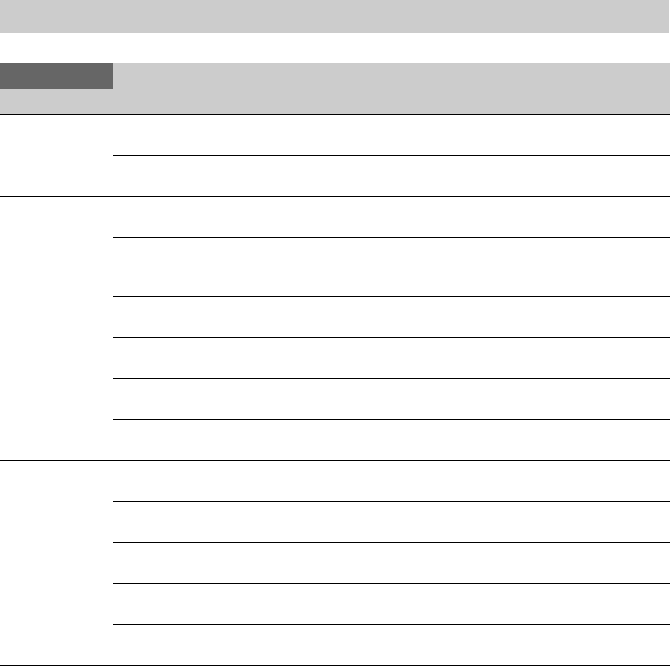
81
VF Menu
VF
Item Sub-item setting Description
VF Setting
Viewfinder
settings
Brightness
–99 to +99 (±0)
Adjusts the brightness of the viewfinder image.
Color Mode
Color / B&W
Selects the display mode of the viewfinder in E-E/recording
mode.
Peaking
Peaking settings
Setting
On / Off
Turns the peaking function on/off.
Peaking Type
Normal / Color
Selects the peaking type.
Normal: Normal peaking
Color: Color peaking
Frequency
Normal / High
Selects the peaking frequency.
Normal Peaking Level
0 to 99 (50)
Sets the normal peaking level.
Color
B&W / Red / Yellow / Blue
Selects the color of the color peaking signal.
Color Peaking Level
0 to 99 (50)
Sets the color peaking level.
Zebra
Zebra pattern
settings
Setting
On / Off
Turns the Zebra function on/off.
Zebra Select
1 / 2 / Both
Selects the zebra pattern type (Zebra 1, Zebra 2, Both).
Zebra1 Level
0% to 107% (70%)
Sets the Zebra 1 display level.
Zebra1 Aperture Level
1% to 20% (10%)
Sets the Zebra 1 aperture level.
Zebra2 Level
0% to 109% (100%)
Sets the Zebra 2 display level.

82
Marker
Marker display
settings
Setting
On / Off
Turns the display of all markers on/off.
Color
White / Yellow / Cyan / Green /
Magenta / Red / Blue
Selects the marker signal color.
Center Marker
1 / 2 / 3 / 4 / Off
Turns the center marker on/off.
Safety Zone
On / Off
Turns the safety zone marker on/off.
Safety Area
80% / 90% / 92.5% / 95%
Selects the size of the safety zone marker (as a percentage of
total screen size).
Aspect Marker
Line / Mask / Off
Selects the type of aspect marker.
Aspect Mask
0 to 15 (12)
Sets the level of the video signal outside the marker relative to
the signal inside the marker as a percentage.
Aspect Safety Zone
On / Off
Turns the aspect safety zone marker on/off.
Aspect Safety Area
80% / 90% / 92.5% / 95%
Selects the size of the aspect safety zone marker (as a
percentage of total screen size).
Aspect Select
4:3 / 1.66:1 / 1.85:1 / 2.35:1 /
2.4:1
Sets the mode when displaying the aspect marker.
User Box
On / Off
Turns the box cursor display on/off.
User Box Width
3 to 479 (240)
Sets the box cursor width (distance from the center to the left
and right edges).
User Box Height
3 to 269 (135)
Sets the box cursor height (distance from the center to the top
and bottom edges).
User Box H Position
–476 to +476 (0)
Sets the horizontal position of the box cursor center.
User Box V Position
–266 to +266 (0)
Sets the vertical position of the box cursor center.
100% Marker
On / Off
Turns the 100% marker on/off.
Guide Frame
On / Off
Turns the guide frame display on/off.
VF
Item Sub-item setting Description

83
Display On/Off
Display item
settings
Setting
On / Off
Selects the items to display in the viewfinder.
Shutter Setting
On / Off
ND Filter Position
On / Off
Gain Setting
On / Off
Rec/Play Status
On / Off
HXR-IFR5 Rec Control
On / Off
Color Temp.
On / Off
Frame Rate / Interval
On / Off
Battery Remain
On / Off
Timecode
On / Off
Audio Manual
On / Off
Audio Level Meter
On / Off
Media Status
On / Off
Focus Position
Meter / Feet / Off
Iris Position
On / Off
Zoom Position
Number / Bar / Off
SteadyShot
On / Off
Focus Mode
On / Off
Focus Area Indicator
On / Off
Focus Area Ind. (Push AF)
On / Off
Focus Indicator
On / Off
Auto Shutter
On / Off
AGC
On / Off
Auto Iris
On / Off
VF
Item Sub-item setting Description

84
AE Mode
On / Off
Auto Exposure Level
On / Off
White Balance Mode
On / Off
SDI/HDMI Rec Control
On / Off
Rec Format
On / Off
Gamma
On / Off
Timecode Lock
On / Off
Wi-Fi Condition
On / Off
Clip Name
On / Off
Focus Assist Indicator
On / Off
Focus Area Marker
On / Off
Video Level Warning
On / Off
Clip Number
On / Off
GPS
On / Off
Level Gauge
On / Off
Lens Info
Meter / Feet / Off
Notice Message
On / Off
Video Signal
Monitor
Video signal
monitor settings
(page 51)
Setting
Off / Waveform / Vector /
Histogram
Sets the type of video signal monitor.
Note
Not displayed when Display On/Off >Setting is set to Off.
Source
In Cine EI mode with video
output resolution 2K or lower:
SDI1 & Internal Rec / SDI2
In Custom mode, or in Cine EI
mode with video output
resolution higher than 2K:
Internal Rec
Sets the measurement source of the video signal monitor.
VF
Item Sub-item setting Description
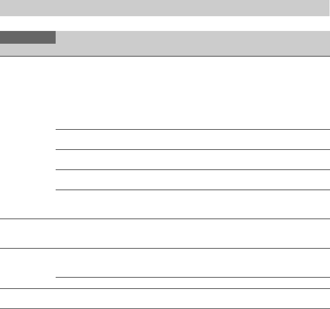
85
TC/UB Menu
TC/UB
Item Sub-item setting Description
Timecode
Timecode settings
Mode
Preset / Regen / Clock
Sets the timecode running mode.
Preset:
Starts running from a preset value.
Regen:
Starts running from the timecode of the end of the previous
clip.
Clock:
Uses the internal clock as the timecode.
Run
Rec Run / Free Run
Rec Run: Runs only when recording.
Free Run: Always running, regardless of camcorder operation.
Setting Sets the timecode to an arbitrary value.
SET: Set the value.
Reset
Execute / Cancel
Resets the timecode to 00:00:00:00.
Execute: Reset timecode
TC Format
DF / NDF
Sets the timecode format.
DF: Drop Frame
NDF: Non-Drop Frame
TC Display
Time data display
settings
Display Select
Timecode / Users Bit /
Duration
Switches the time data display.
Users Bit
Settings related to
user bits.
Mode
Fix / Time
Sets the user bit mode.
Fix: Uses an arbitrary fixed value in user bits.
Time: Uses the current time in user bits.
Setting Sets the user bits to an arbitrary value.
HDMI TC Out Setting
On / Off
Sets whether to output the timecode to devices for other
purposes, using HDMI.

86
Recording Menu
Recording
Item Sub-item setting Description
S&Q Motion
Slow & Quick
Motion mode
settings (page 47)
Setting
On / Off
Turns Slow & Quick Motion on/off.
When set to On, the following functions are disabled.
• Auto iris
• Auto focus
High Frame Rate Mode
Off / Full Scan / Center Scan
Enables higher speed imaging than 60P.
Off:
Higher speed imaging than 60P is disabled.
Full Scan:
High-speed imaging of Super 35mm size angle-of-view.
Center Scan:
High-speed imaging of half the Super 35mm size angle-of-
view at the center of the image.
Note
This setting cannot be set to conform with Imager Scan Mode
when Imager Scan Mode is set to 2K Full or 2K Center.
Frame Rate
Up to 240fps
Sets the frame rate for Slow & Quick Motion shooting.
Note
The initial value varies depending on the Codec, Country,
Video Format, and RAW Output Format settings.
Interval Rec
Interval Rec
settings (page 47)
Setting
On / Off
Turns the interval recording mode on/off. (Setting this mode to
On will set all other special modes to Off.)
Interval Time
1 / 2 / 3 / 4 / 5 / 6 / 7 / 8 / 9 /
10 / 15 / 20 / 30 / 40 / 50 (sec)
1 / 2 / 3 / 4 / 5 / 6 / 7 / 8 / 9 / 10 /
15 / 20 / 30 / 40 / 50 / (min) 1 /
2 / 3 / 4 / 6 / 12 / 24 (hour)
Sets the interval between recordings in Interval Rec recording
mode (when Interval Rec is set to On).
Number of Frames
1frame / 2frames / 3frames /
6frames / 9frames / 12frames
Sets the number of frames to record per take in Interval Rec
recording mode (when Interval Rec is set to On).
The available settings vary depending on the frame frequency
of the selected video format.
50P/59.94P:
2frames / 6frames / 12frames
23.98P / 25P / 29.97P / 50i / 59.94i:
1frame / 3frames / 6frames / 9frames
Pre-Lighting
Available only when using the
HVL-LBPC (option).
Off / 2sec / 5sec / 10sec
Sets the number of seconds that the video light turns on before
recording starts in Interval Rec recording mode.
Picture Cache
Rec
Picture cache
recording mode
settings (page 49)
Setting
On / Off
Turns the picture cache recording function on/off.
Cache Rec Time
0-2sec / 2-4sec / 4-6sec /
6-8sec / 8-10sec / 10-12sec /
12-14sec / 13-15sec
Sets the picture cache recording time, when Picture Cache Rec
is set to On.

87
Simul Rec
Simultaneous
recording settings
(page 39)
Setting
On / Off
Turns the simultaneous recording function on/off and sets the
recording destination media.
Rec Button Set
“Rec Button [SlotA SlotB]
Handle Rec Button [SlotA
SlotB]” / “Rec Button [SlotA]
Handle Rec Button [SlotB]” /
“Rec Button [SlotB] Handle
Rec Button [SlotA]”
Assigns the record buttons used to control each recording
media.
SDI/HDMI Rec
Control
SDI/HDMI
recording control
settings
Setting
On / Off
Turns recording start/stop control for an external connected
device, using SDI/HDMI signals, on/off.
When different buttons are assigned using Rec Button Set, the
recording control signal follows the recording state of slot A.
Note
When set to On, this starts/stops recording on an external
connected device, even if no XQD card is currently inserted.
Recording
Item Sub-item setting Description

88
Thumbnail Menu
Thumbnail
Item Sub-item setting Description
Display Clip
Properties
Display clip
properties screen
Displays the clip properties screen.
Set Index
Picture
Clip index picture
settings
Sets the index picture of a clip.
Thumbnail
View
Thumbnail screen
settings
Essence Mark Thumbnail
All / Rec Start / Shot Mark1 /
Shot Mark2 / Shot Mark3 /
Shot Mark4 / Shot Mark5 /
Shot Mark6 / Shot Mark7 /
Shot Mark8 / Shot Mark9 /
Shot Mark0
Displays thumbnails of frames with essence marks.
Clip Thumbnail Displays thumbnails of recorded clips.
Set Shot Mark
Shot mark settings
Add Shot Mark1 Adds Shot Mark1.
Delete Shot Mark1 Deletes Shot Mark1.
Add Shot Mark2 Adds Shot Mark2.
Delete Shot Mark2 Deletes Shot Mark2.
Set Clip Flag
Clip flag settings
Add OK Adds an OK flag.
Add NG Adds an NG flag.
Add KEEP Adds a Keep flag.
Delete Clip Flag Deletes all flags.
Lock/Unlock
Clip
Clip protection
Select Clip Selects and locks/unlocks a clip.
Lock All Clips Locks all clips.
Unlock All Clips Unlocks all clips.
Delete Clip
Delete clips
Select Clip Deletes the selected clip.
All Clips Deletes all of the displayed clips.
Filter Clips
Filtered clip
display settings
OK Display only clips that have an OK flag.
NG Display only clips that have an NG flag.
KEEP Display only clips that have a Keep flag.
None Display only clips that have no flag.
Customize
View
Thumbnail screen
settings
Thumbnail Caption
Date Time / Time Code /
Duration / Sequential Number
Switches the information displayed below thumbnails.

89
Media Menu
Media
Item Sub-item setting Description
Update Media
Update memory
cards
Media (A)
Execute / Cancel
Updates the management file on the XQD memory card in slot
A.
Execute: Update card
Media (B)
Execute / Cancel
Updates the management file on the XQD memory card in slot
B.
Execute: Update card
Format Media
Format (initializes)
memory cards
Media (A)
Execute / Cancel
Initializes the XQD memory card in slot A.
Execute: Initialize card
Media (B)
Execute / Cancel
Initializes the XQD memory card in slot B.
Execute: Initialize card
SD Card
Execute / Cancel
Initializes the UTIILITY SD card.
Execute: Initialize card
Clip
Clip name settings
Auto Naming
Cam ID + Reel# / Title
Sets the method for naming clips.
Cam ID + Reel#:
Camera ID + Reel Number + Shot Number + Date +
random string
Title:
String set using Title Prefix + Clip Number
Note
When Simul Rec is set to On, Cam ID + Reel# cannot be
configured.
Camera ID
A to Z
Sets the camera ID when Auto Naming is set to Cam ID +
Reel#.
Reel Number
001 to 999
Sets the numeric part of Reel Number when Auto Naming is
set to Cam ID + Reel#.
Camera Position
C / L / R
Sets the Shot Number prefix when Auto Naming is set to Cam
ID + Reel#.
Title Prefix Sets the title portion of the clip name when Auto Naming is
set to Title.
(Initial value is a model-specific ID, comprising the last three
digits of the serial number.)
(The value is entered using the character entry screen
(page 62).)
Number Set
0001 to 9999
Sets the numeric portion of the clip name when Auto Naming
is set to Title.

90
File Menu
File
Item Sub-item setting Description
All File
Settings related to
ALL files.
Load SD Card
Execute / Cancel
Loads an ALL file.
Execute: Load file
Save SD Card
Execute / Cancel
Saves an ALL file.
Execute: Save file
File ID Assigns a name to the file.
Scene File
Scene file settings
Recall Internal Memory
Execute / Cancel
Loads a scene file from internal memory.
Execute: Load file
Store Internal Memory
Execute / Cancel
Saves a scene file in internal memory.
Execute: Save file
Load SD Card
Execute / Cancel
Loads a scene file from an SD card.
Execute: Load file
Save SD Card
Execute / Cancel
Saves a scene file to an SD card.
Execute: Save file
File ID Assigns a name to the file.
Scene White Data
On / Off
Sets whether to apply the white balance data when loading
scene files.
User Menu
Item
User menu item
settings
Load SD Card
Execute / Cancel
Loads User menu settings on an SD card into internal
memory.
Execute: Load settings
Save SD Card
Execute / Cancel
Saves User menu settings on an SD card.
Execute: Save settings
File ID Displays the File ID specified for the file loaded using Load
SD Card. Also sets (edits) the File ID when saving a file using
this menu.
User Gamma
User gamma file
settings
Current Settings Displays a list of the current user gamma file settings (file
names).
Load SD Card
Execute / Cancel
Loads user gamma settings on an SD card into internal
memory.
Execute: Load gamma
To use user gamma files created using CvpFileEditor™ V4.2
with the camcorder, save files in the following folder on the
SD card.
PRIVATE\SONY\PRO\CAMERA\HD_CAM
Reset
1 / 2 / 3 / 4 / 5 / All
Initial value: 709(800%)
Resets the user gamma files in internal memory to default
values.
1 to 5: Reset individual user gamma
All: Reset all user gammas

91
Note
Place files in the following folders on the SD card.
ALL files, Scene files, User Menu Item:
PRIVATE\Sony\PRO\CAMERA\PXW-FS7
User gamma files:
PRIVATE\Sony\PRO\CAMERA\HD_CAM
Monitor LUT files, monitor 3D LUT files:
PRIVATE\Sony\PRO\CAMERA\PMWF55_F5
Monitor LUT
Monitor LUT file
settings
Current Settings Displays a list of the current monitor LUT file settings (file
names).
Load SD Card
Execute / Cancel
Loads monitor LUT settings on an SD card into internal
memory.
Execute: Load LUT settings
Save user LUT files generated using RAW Viewer in the
following folder on the SD card.
PRIVATE\SONY\PRO\CAMERA\PMWF55_F5
Reset
1 / 2 / 3 / 4 / 5 / 6 / All
Resets the monitor LUT data in internal memory to default
values.
1 to 6: Reset individual monitor LUT
All: Reset all monitor LUTs
Monitor 3D
LUT
Monitor 3D LUT
file settings
Current Settings Displays a list of the current monitor 3D LUT file settings (file
names).
Load SD Card
Execute / Cancel
Loads monitor 3D LUT settings on an SD card into internal
memory.
Execute: Load 3D LUT settings
You can import CUBE files (*.cube) with lattice resolution of
17 or 33 created using Catalyst Browse, RAW Viewer, or
BMD Da Vinci Resolve*.
* Verified with Resolve V9.0, V10.0, and V11.0.
If creating a CUBE file using Catalyst Browse or RAW
Viewer, set the Source setting in Catalyst Browse or the Input
setting in RAW Viewer to S-Gamut3.Cine/S-Log3.
Set Format to Resolve when exporting the CUBE file.
Save the created 3D LUT data (user 3D LUT file) in the
following folder on the SD card.
PRIVATE\SONY\PRO\CAMERA\PMWF55_F5
Note
The monitor 3D LUT function cannot be used if Base Setting
>Color Space is set to S-Gamut/S-Log2 in the System menu
on the camcorder.
Reset
1 / 2 / 3 / 4 / All
Resets the monitor 3D LUT data in internal memory to default
values.
1 to 4: Reset individual monitor 3D LUT
All: Reset all monitor 3D LUTs
Lens File
Lens file settings
White Offset R
–99 to +99 (±0)
Sets the white balance offset R channel correction value for
the lens in the lens file.
White Offset B
–99 to +99 (±0)
Sets the white balance offset B channel correction value for
the lens in the lens file.
File
Item Sub-item setting Description

92
System Menu
System
Item Sub-item setting Description
Base Setting
Base settings
Shooting Mode
Custom / Cine EI
Sets the shooting mode.
Color Space
S-Gamut/SLog2 /
S-Gamut3.Cine/SLog3 /
S-Gamut3/SLog3 / Matrix
Sets the color space.
Imager Scan Mode
Normal / 2K Full / 2K Center
Sets the scan mode for capturing information by the image
sensor (page 26).
Codec
Codec settings
Select
RAW / RAW & XAVC-I / RAW
& XAVC-L / RAW & MPEG
HD 422 / XAVC-I / XAVC-L /
MPEG HD 422 / ProRes 422
HQ / ProRes 422
Sets the recording/playback mode.
Notes
• RAW / RAW & XAVC-I / RAW & XAVC-L / RAW &
MPEG HD 422 are available when an XDCA-FS7 is
connected and Base Setting >Shooting Mode is set to Cine
EI.
• ProRes 422 HQ / ProRes 422 are available only when an
XDCA-FS7 is connected.

93
Rec Format
Recording format
settings
Video Format
• For NTSC systems:
When Codec >Select is set to
XAVC-I:
4096×2160 59.94P
4096×2160 29.97P
4096×2160 24.00P
4096×2160 23.98P
3840×2160 59.94P
3840×2160 29.97P
3840×2160 23.98P
1920×1080 59.94P
1920×1080 59.94i
1920×1080 29.97P
1920×1080 23.98P
When Codec >Select is set to
XAVC-L:
3840×2160 59.94P
3840×2160 29.97P
3840×2160 23.98P
1920×1080 59.94P 50
1920×1080 59.94P 35
1920×1080 59.94i 50
1920×1080 59.94i 35
1920×1080 59.94i 25
1920×1080 29.97P 50
1920×1080 29.97P 35
1920×1080 23.98P 50
1920×1080 23.98P 35
When Codec >Select is set to
MPEG HD422:
1920×1080 59.94i 50
1920×1080 29.97P 50
1920×1080 23.98P 50
1280×720 59.94P 50
1280×720 29.97P 50
1280×720 23.98P 50
When Codec >Select is set to
ProRes 422 HQ or ProRes 422:
1920×1080 59.94i
1920×1080 29.97P
1920×1080 23.98P
Sets the recording format.
•For PAL systems:
When Codec >Select is set to XAVC-I:
4096×2160 50P
4096×2160 25P
3840×2160 50P
3840×2160 25P
1920×1080 50P
1920×1080 50i
1920×1080 25P
When Codec >Select is set to XAVC-L:
3840×2160 50P
3840×2160 25P
1920×1080 50P 50
1920×1080 50P 35
1920×1080 50i 50
1920×1080 50i 35
1920×1080 50i 25
1920×1080 25P 50
1920×1080 25P 35
When Codec >Select is set to MPEG HD422:
1920×1080 50i 50
1920×1080 25P 50
1280×720 50P 50
1280×720 25P 50
When Codec >Select is set to ProRes 422 HQ or ProRes 422:
1920×1080 50i
1920×1080 25P
Notes
• “---” is grayed out when Codec >Select is set to RAW.
• The fixed values are grayed out when Codec >Select is set to
RAW & XAVC-I, RAW & XAVC-L, or RAW & MPEG HD
422.
• The recording format cannot be set to 4096×2160 or
3840×2160 when Imager Scan Mode is set to 2K Full or 2K
Center.
System
Item Sub-item setting Description

94
RAW Output Format
• For NTSC systems:
When Codec >Select is set to an
item that includes RAW, and
Imager Scan Mode is set to
Normal:
4096×2160 59.94P
4096×2160 29.97P
4096×2160 23.98P
When Codec >Select is set to an
item that includes RAW, and
Imager Scan Mode is set to 2K
Full or 2K Center:
2048×1080 59.94P
2048×1080 29.97P
2048×1080 23.98P
Sets the recording format for an external RAW recorder.
•For PAL systems:
When Codec >Select is set to an item that includes RAW, and
Imager Scan Mode is set to Normal:
4096×2160 50P
4096×2160 25P
When Codec >Select is set to an item that includes RAW, and
Imager Scan Mode is set to 2K Full or 2K Center:
2048×1080 50P
2048×1080 25P
Genlock
Genlock settings
Reference
Internal / External (HD) /
External (SD)
Displays the genlock state. It displays the signal type if
genlock is applied.
Internal: External genlock not applied.
External (HD): Genlock to HD signal.
External (SD): Genlock to SD signal.
Assignable
Button
Assignable button
settings
<1> to <6>
Off / Marker / Zebra / Peaking /
Video Signal Monitor / Focus
Magnifier x4/x8 / Focus Magnifier
x4 / Focus Magnifier x8 / Focus
Area / Focus Area (Push AF) / VF
Mode / IRIS / Push Auto Iris /
AGC / Push AGC / SHUTTER /
Auto Exposure Level / Spotlight /
Backlight / ATW / ATW Hold /
Push AF/Focus Hold / SteadyShot
/ Color Bars / User Menu / Rec
Lamp / S&Q Motion / Picture
Cache Rec / Rec Review /
Thumbnail / Shot Mark1 / Shot
Mark2 / Clip Flag OK / Clip Flag
NG / Clip Flag Keep /
DURATION/TC/U-BIT / High/
Low Key
Assigns functions to assignable buttons.
Marker:
Turns the marker function on/off.
Zebra:
Turns the Zebra function on/off.
Peaking:
Turns the peaking function on/off.
Video Signal Monitor:
Switches the video signal monitor (such as a waveform
monitor).
Focus Magnifier x4/x8:
Focus Magnifier x4:
Focus Magnifier x8:
Turns the focus magnifier function on/off.
Focus Area:
Focus Area (Push AF):
Opens the Focus Area setup screen.
VF Mode:
Switches the viewfinder display between color and B&W.
IRIS:
Switches the iris function between Auto and Manual.
Push Auto Iris:
Enables the auto iris function while the button is pressed.
AGC:
Turns the AGC function on/off.
System
Item Sub-item setting Description

95
Push AGC:
Enables the AGC function while the button is pressed.
SHUTTER:
Switches the shutter between Auto and Manual.
Auto Exposure Level:
Opens the Auto Exposure Level screen.
Spotlight:
Switches between Spotlight and Standard.
Backlight:
Switches between Backlight and Standard.
AT W:
Turns the ATW function on/off.
AT W H o l d :
Pauses ATW function operation.
Push AF/Focus Hold:
Runs the push auto focus function or focus hold function.
SteadyShot:
Switches between Active SteadyShot, SteadyShot, and Off.
Color Bars:
Turns the color bars on/off.
User Menu:
Opens/closes the User menu.
Rec Lamp:
Turns the recording indicator light on/off.
S&Q Motion:
Turns Slow & Quick Motion on/off.
Sets the recording frame rate if pressed and held.
Picture Cache Rec:
Turns picture cache recording mode on/off.
Rec Review:
Turns the Rec Review function on/off.
Thumbnail:
Opens/closes the thumbnail screen.
Shot Mark1:
Runs the Add Shot Mark1 function.
Shot Mark2:
Runs the Add Shot Mark2 function.
Clip Flag OK:
Runs the Add OK function.
Press twice to execute Delete Clip Flag.
Clip Flag NG:
Runs the Add NG function.
Press twice to execute Delete Clip Flag.
Clip Flag Keep:
Runs the Add Keep function.
Press twice to execute Delete Clip Flag.
DURATION/TC/U-BIT:
Switches between Time Code, Users Bit, and Duration.
High/Low Key:
Switches between High Key (display for checking for
blown-out whites), Low Key (display for checking for
underexposed areas), and Off (normal display) in that
order.
Applicable for systems where Monitor LUT is set to On.
System
Item Sub-item setting Description

96
Assignable
Dial
Assignable dial
settings
Assignable Dial
Off / ISO/Gain/EI / IRIS /
Focus / Audio Input Level
Assigns functions to the assignable dial on the grip remote
control.
ISO/Gain/EI: Adjusts the gain or EI.
IRIS: Adjusts the iris.
Focus: Adjusts the focus.
Audio Input Level: Adjusts the audio level.
IRIS Dial
(Same settings as Assignable
Dial)
Assigns functions to the IRIS dial.
Assignable Dial Direction
Normal / Opposite
Sets the direction of rotation of the assignable dial on the grip
remote control.
Normal: Turn in forward direction.
Opposite: Turn in opposite direction.
IRIS Dial Direction
Normal / Opposite
Sets the direction of rotation of the IRIS dial.
Normal: Turn in forward direction.
Opposite: Turn in opposite direction.
Rec Lamp
Recording
indicator settings
Rec Lamp
On / Off
Turns the recording indicator light on/off.
Fan Control
Fan control mode
settings
Setting
Auto / Minimum / Off in Rec
Sets the control mode of the camcorder fan.
Note
Even when “Off in Rec” is selected, the fan will operate if the
internal temperature of the camcorder rises above a certain
value.
HOLD Switch
Setting
Hold switch
settings
with Rec Button
On / Off
Sets whether or not to lock the recording button.
with Hand Grip Remote
On / Off
Sets whether to lock operation of the grip remote control.
Lens
Lens settings
Zoom Ring Direction
Left (W)/Right (T) / Right
(W)/Left (T)
Sets the direction of zoom ring operation.
Note
Enabled only when using an E-mount lens that supports zoom
ring direction switching.
Distortion Comp.
Auto / Off
Turns automatic distortion compensation on/off.
Notes
• Not available in picture cache recording mode or when
recording.
• Distortion compensation is not applied during 4K or QFHD
recording.
• When “Auto” is selected, there are some restrictions to
Monitor LUT (page 117).
Language
Language settings
Select Sets the display language.
SET: Set language.
System
Item Sub-item setting Description

97
Clock Set
Internal clock
settings
Time Zone
UTC 12:00 Kwajalein to UTC
+14:00
Sets the time difference from UTC in 30-minute units.
Date Mode
YYMMDD / MMDDYY /
DDMMYY
Selects the display format for dates.
YYMMDD: Year, month, day
MMDDYY: Month, day, year
DDMMYY: Day, month, year
12H/24H
12H / 24H
Selects the clock display format.
12H: 12-hour mode
24H: 24-hour mode
Date Sets the current date.
SET: Set the value.
Time Sets the current time.
SET: Set the value.
Country
Region settings
NTSC/PAL Area
NTSC Area / PAL Area
The default setting varies depending
on the country of purchase.
Sets the region of use.
Hours Meter
Hours meter
settings
Hours (System) Displays the accumulated hours of use (cannot be reset).
Hours (Reset) Displays the accumulated hours of use (can be reset).
Reset
Execute / Cancel
Resets the Hours (Reset) display to 0.
Execute: Reset
Basic
Authentication
Basic network
authentication
settings
User Name
(admin)
Sets a desired user name (1 to 16 alphanumeric characters).
SET: Set the value.
Password
(pxw-fs7)
Sets a password (1 to 16 alphanumeric characters).
SET: Set the value.
Wi-Fi
Wireless LAN
connection
settings
Wi-Fi
Enable / Disable
Selects whether to enable or disable Wi-Fi connection.
SSID & Password Displays the SSID and password.
Wi-Fi Direct Connection
Execute / Cancel
Starts a “Wi-Fi Direct” network connection.
Execute: Connect
Client Displays information about the connected client device
(model name and MAC address).
IP Address
192.168.1.1
Displays the IP address of the camcorder.
Note
Not displayed when using the CBK-WA100.
Subnet Mask
255.255.0.0
Displays the subnet mask.
Note
Not displayed when using the CBK-WA100.
MAC Address Displays the MAC address of the Wi-Fi module attached to
the camcorder.
Regenerate Password
Execute / Cancel
Creates a new password.
Execute: Regenerate
GPS
GPS settings
GPS
On / Off
Turns the GPS function on/off.
Note
The GPS module is built into the handle.
System
Item Sub-item setting Description

98
IR Remote
Remote control
settings
Setting
On / Off
Enables/disables control from the supplied infrared remote
control.
Camera
Battery Alarm
Battery low-
voltage alarm
settings
Low BATT
5% / 10% / 15% / ... / 45% /
50%
Sets the remaining battery level to display a battery low-
voltage alarm (5% increments).
BATT Empty
3% to 7%
Sets the remaining battery level to display a battery empty
alarm.
Camera DC IN
Alarm
Input voltage
alarm settings
DC Low Voltage1
11.5V to 17.0V
Sets the voltage to display a DC IN low input voltage alarm.
DC Low Voltage2
11.0V to 14.0V
Sets the voltage to display a DC IN insufficient input voltage
alarm.
Ext. Unit
Battery Alarm
XDCA-FS7
battery settings
Near End:Info Battery
5% to 100%
Sets the remaining battery level to display a Info-Lithium
battery low-voltage alarm (5% increments).
End:Info Battery
0% to 5%
Sets the remaining battery level to display a Info-Lithium
battery end alarm and to stop media access.
Near End:Sony Battery
11.5V to 17.0V
Sets the remaining battery level to display a battery low-
voltage alarm for a non Info-Lithium battery.
End:Sony Battery
11.0V to 11.5V
Sets the remaining battery level to display a battery end alarm
for a non Info-Lithium battery and to stop media access.
Near End:Other Battery
11.5V to 17.0V (11.8V)
Sets the remaining battery level to display a battery low-
voltage alarm for an Anton/Bauer battery.
End:Other Battery
11.0V to 14.0V
Sets the remaining battery level to display a battery end alarm
for an Anton/Bauer battery and to stop media access.
Detected Battery Displays the type of battery connected to the XDCA-FS7.
If a battery is connected to the XDCA-FS7, “Info Battery,”
“Sony Battery,” or “Other Battery” is displayed. If a DC
source is connected, “DC IN” is displayed.
If powered by a battery or DC source connected to the
camcorder, “ --- ” is displayed.
Ext. Unit DC IN
Alarm
XDCA-FS7 input
voltage alarm
settings
DC Low Voltage1
11.5V to 17.0V
Sets the voltage to display a DC IN low input voltage alarm.
DC Low Voltage2
11.0V to 14.0V
Sets the voltage to display a DC IN insufficient input voltage
alarm.
All Reset
Reset factory
defaults
Reset
Execute / Cancel
Resets all settings to their factory defaults.
Execute: Reset
APR
Run APR
APR
Execute / Cancel
Runs APR (Automatic Pixel Restoration) for image sensor
auto adjustment.
Execute: Run
Note
Always attach the lens cap before running APR.
Camera Config
Down-converter
output settings
HD/2K Modulation
High / Low
Sets the down-converter output bandwidth for conversion to
HD and 2K.
System
Item Sub-item setting Description

99
Version
Display version
Number
x.xx
Displays the software version of the camcorder.
Version Up
Execute / Cancel
Upgrades the camcorder.*
Execute: Upgrade
* Upgrading updates the camcorder software.
Ext. Unit Version Number
x.xx
Displays the software version of the XDCA-FS7.
Ext. Unit Version Up
Execute / Cancel
Upgrades the XDCA-FS7.*
Execute: Upgrade
* Upgrading updates the XDCA-FS7 software.
System
Item Sub-item setting Description

100
To display recorded/playback pictures on an
external monitor, select the camcorder output
signal and use an appropriate cable for the
monitor to be connected.
You can also connect recording devices, such as a
VTR, and record the output signal from the
camcorder.
You can display the same information that is
visible in the viewfinder, such as status
information and menus, on an external monitor.
Set Output Display (page 80) in the Video menu
to “On” for the corresponding type of signal to
output to the monitor.
SDI OUT connector (BNC type)
Turn the output on/off and set the output format
using the Video menu (page 79).
Use a commercially available 75 Ω coaxial cable
for connection.
Note
Check that the connection between the camcorder and
the external device is grounded before turning the
devices on.
(It is recommended that the camcorder and external
device be turned on after connecting the 75 Ω coaxial
cable.)
If the external device must be connected to the
camcorder while the camcorder is on, connect the 75 Ω
coaxial cable to the external device first and then connect
it to the camcorder.
To start recording on the camcorder and external
device simultaneously
With SDI signal output enabled, set SDI/HDMI
Rec Control (page 87) >Setting in the Recording
menu to “On” to enable output of a REC trigger
signal to the external device connected to the SDI
OUT connector. This will synchronize recording
on the external device with the camcorder.
Notes
• If a connected external device does not support a REC
trigger signal, the device cannot be operated.
• When the record START/STOP button and the handle
record START/STOP are set to control different
media, the REC trigger signal is output in accordance
with the operation of slot A.
• Only the REC trigger signal is output when there is no
media currently inserted.
HDMI OUT connector (Type A connector)
Turn the output on/off and set the output format
using the Video menu (page 79).
Use a commercially available high-speed HDMI
cable for connection.
Select the type of the connected device using
HDMI Target Device (page 117) in the Video
menu.
RAW OUT connector (BNC type)
Attaching an XDCA-FS7 Extension Unit to the
camcorder provides support for an external RAW
recorder, such as the AXS-R5, to be connected to
the RAW OUT connector of the XDCA-FS7
(page 34).
External Device Connection
Connecting External Monitors and Recording Devices

101
When shooting using multiple camcorder units,
the camcorders can be synchronized to a specific
reference signal or timecodes synchronized via
the Genlock connector of the XDCA-FS7 units
(page 12) attached to the camcorders.
Note
The camcorder battery pack cannot be used when an
XDCA-FS7 unit is attached to the camcorder. You must
attach a battery pack to the XDCA-FS7 or connect an
external power supply.
Synchronizing the phase of the video
signals (genlock)
Enable genlock by supplying a reference signal to
the Genlock connector (page 12) of the
XDCA-FS7 units connected to the camcorders.
The reference signals that can be used vary
depending on the frame rate of the selected
recording format.
For NTSC Area
For PAL Area
Notes
• If the selected recording format is 1280×720 60P, you
must supply both a video signal and a time signal.
• If the reference signal is unstable, genlock cannot be
achieved.
• The subcarrier is not synchronized.
Locking the timecode to other devices
Set the unit that supplies the timecode to a mode
in which the timecode output keeps running (such
as Free Run or Clock).
1Set Timecode in the TC/UB menu as
follows.
Mode: Preset
Run: Free Run
2Press the assignable button (page 46)
assigned with the DURATION/TC/
U-BIT function to display the timecode
on the screen.
3Check that the TC IN/OUT switch
(page 12) on the XDCA-FS7 is set to the
IN position, and supply an HD or SD
reference video signal and a timecode
synchronized to the video signal to the
Genlock and TC IN/OUT connectors,
respectively.
The timecode generator of the camcorder
acquires lock with the reference timecode, and
“EXT-LK” appears on the screen.
Once about ten seconds have elapsed after the
timecode locks, the external lock state is
maintained even if the external reference
timecode source is disconnected.
Notes
• Check that the supplied reference timecode and the
reference video signal are in a phase relationship that
complies with the SMPTE timecode standard.
• When operating with external lock, the timecode
instantly acquires lock with the external timecode and
the external timecode value appears in the data display
area. However, do not start recording immediately.
Wait for a few seconds until the timecode generator
stabilizes before recording.
• If the frequency of the reference video signal and the
frame frequency on the camcorder are not the same,
lock cannot be acquired and the camcorder will not
operate properly. If this occurs, the timecode will not
acquire successful lock with the external timecode.
External Synchronization
Frame rate of
recording format
Supported input
reference signals
59.94P 1920×1080 59.94i
720×486 59.94i
1280×720 59.94P
29.97P 1920×1080 59.94i
720×486 59.94i
24.0P 1920×1080 48i (24PsF)
23.98P 1920×1080 47.95i
(23.98PsF)
59.94i 1920×1080 59.94i
720×486 59.94i
Frame rate of
recording format
Supported input
reference signals
50P 1920×1080 50i
720×576 50i
1280×720 50P
25P 1920×1080 50i
720×576 50i
50i 1920×1080 50i
720×576 50i

102
• If the external timecode source is disconnected, the
timecode may shift by one frame per hour with respect
to the reference timecode.
To release external lock
Change the Timecode setting in the TC/UB menu,
or turn the camcorder off.
External lock is also released if you start
recording in Slow & Quick Motion mode.
Synchronizing the timecode of another
device with the timecode of the
camcorder
Set the unit that supplies the timecode to a mode
in which the timecode output keeps running (such
as Free Run or Clock).
1Set the timecode of the camcorder using
Timecode (page 85) in the TC/UB menu.
2Check that the TC IN/OUT switch
(page 12) is set to the OUT position, and
connect the TC IN/OUT connector and
Genlock connector (page 12) to the
timecode input and reference signal
input, respectively, of the device you
want to synchronize.
Using an XQD card reader (option)
Connect an MRW-E80 XQD Card Reader
(option) using a USB cable, and insert a memory
card in the slot. The memory card is recognized as
a computer extension drive.
Using mass storage mode
Connect the camcorder using a USB cable, and
insert a memory card in the slot. The memory
card is recognized as a computer extension drive.
1Turn the camcorder POWER switch to
the ON position.
A message appears on the screen or
viewfinder asking whether to enable USB
connection.
The USB connection confirmation message is not
displayed while another confirmation message or
progress message is displayed, for example, when
formatting or restoring an XQD memory card.
The confirmation message is displayed when the
formatting or restoring execution ends. The USB
confirmation message is also not displayed when
the clip properties screen is displayed. The message
is displayed when processing ends or when you
return to the thumbnail screen.
2Turn the SEL/SET dial and select
Execute.
Managing/Editing Clips
using a Computer
Connecting using a USB Cable
Note

103
3On Windows, check that the card is
added as a removable disk in the “My
Computer” window.
On Macintosh, check that a folder
called “NO NAME” or “Untitled”
(editable) is created on the Desktop.
Notes
• Do not perform the following operations if the access
lamp is lit red.
- Turning the power off Disconnecting the power
cord
- Removing the XQD memory card
- Disconnecting the USB cable
• Operation is not guaranteed to work on all computers.
Using nonlinear editing systems
In a nonlinear editing system, editing software
(option) that supports the formats recorded by the
camcorder is required.
Use dedicated application software to save the
clips you want to edit on the HDD of the
computer beforehand.

104
The fan is a consumable part that will need
periodic replacement.
When operating at room temperature, a normal
replacement cycle will be about 5 years.
However, this replacement cycle represents only
a general guideline and does not imply that the
life expectancy of this part is guaranteed. For
details on parts replacement, contact your dealer.
If the unit is suddenly taken from a cold to a warm
location, or if ambient temperature suddenly
rises, moisture may form on the outer surface of
the unit and/or inside of the unit. This is known as
condensation. If condensation occurs, turn off the
unit and wait until the condensation clears before
operating the unit. Operating the unit while
condensation is present may damage the unit.
The LCD panel fitted to this unit is manufactured
with high precision technology, giving a
functioning pixel ratio of at least 99.99%. Thus a
very small proportion of pixels may be “stuck”,
either always off (black), always on (red, green,
or blue), or flashing. In addition, over a long
period of use, because of the physical
characteristics of the liquid crystal display, such
“stuck” pixels may appear spontaneously. These
problems are not a malfunction. Note that any
such problems have no effect on recorded data.
The battery terminal of this unit (the connector for
battery packs and AC adaptors) is a consumable
part.
Power may not be supplied to the unit properly if
the pins of the battery terminal are bent or
deformed by shock or vibrations, or if they
become corroded due to prolonged outdoor use.
Periodic inspections are recommended to keep
the unit working properly and to prolong its
usable lifetime. Contact a Sony service or sales
representative for more information about
inspections.
About the built-in rechargeable battery
The camcorder has a built-in rechargeable battery
for storing the date, time, and other settings even
when the camcorder is turned off. The built-in
rechargeable battery will become charged after
24 hours have elapsed if the unit is connected to a
power outlet using the AC adaptor or if a fully
charged battery pack is attached, regardless of
whether the camcorder is turned on/off. The
rechargeable battery will be fully discharged in
about 3 months if the AC adaptor is not
connected or the camcorder is used without the
battery pack attached. Use your camcorder after
charging the battery. However, even if the built-
in rechargeable battery is not charged, the
camcorder operation will not be affected as long
as you are not recording the time and date.
Appendix
Usage Precautions
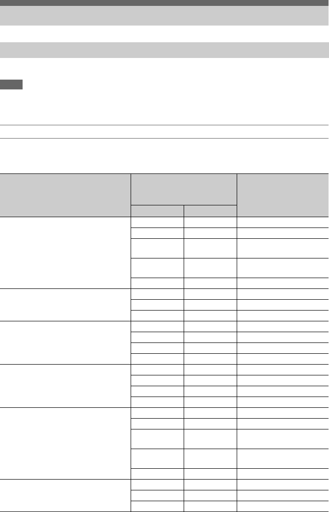
105
Factory default settings are shown in bold (for example, 2048×1080P (Level A)).
Notes
• The resolution of the recording format is limited by the Base Setting >Imager Scan Mode setting in the System menu
(page 92).
• No playback picture is output if the video output resolution is higher than the resolution of the picture.
SDI OUT connector output formats
When Country >NTSC/PAL Area in the System menu is set to NTSC Area
When using basic configuration (XAVC-I / XAVC-L / MPEG HD)
Output Formats and Limitations
Video Formats and Output Signals
Recording format settings
(Rec Format >Video Format in the
System menu)
SDI/HDMI output settings
(Output Format >SDI and
HDMI in the Video menu)
SDI output signal
SDI HDMI
4096×2160 59.94P – 4096×2160P No output
– 3840×2160P No output
1920×1080P
(Level A)
1920×1080P 1920×1080 59.94P Level-A
1920×1080P
(Level B)
– 1920×1080 59.94P Level-B
1920×1080i 1920×1080i 1920×1080 59.94i
4096×2160 29.97P – 4096×2160P No output
– 3840×2160P No output
1920×1080PsF 1920×1080i 1920×1080 29.97PsF
4096×2160 24.00P – 4096×2160P No output
– 3840×2160P No output
1920×1080PsF – 1920×1080 24PsF
– 1920×1080P No output
4096×2160 23.98P – 4096×2160P No output
– 3840×2160P No output
1920×1080PsF – 1920×1080 23.98PsF
– 1920×1080P No output
3840×2160 59.94P – 4096×2160P No output
– 3840×2160P No output
1920×1080P
(Level A)
1920×1080P 1920×1080 59.94P Level-A
1920×1080P
(Level B)
– 1920×1080 59.94P Level-B
1920×1080i 1920×1080i 1920×1080 59.94i
3840×2160 29.97P – 4096×2160P No output
– 3840×2160P No output
1920×1080PsF 1920×1080i 1920×1080 29.97PsF

106
3840×2160 23.98P – 4096×2160P No output
– 3840×2160P No output
1920×1080PsF – 1920×1080 23.98PsF
– 1920×1080P No output
1920×1080 59.94P 2048×1080P
(Level A)
– 2048×1080 59.94P Level-A
2048×1080P
(Level B)
– 2048×1080 59.94P Level-B
1920×1080P
(Level A)
1920×1080P 1920×1080 59.94P Level-A
1920×1080P
(Level B)
– 1920×1080 59.94P Level-B
1920×1080i 1920×1080i 1920×1080 59.94i
– 720×480i No output
– 720×480P No output
1920×1080 59.94i 1920×1080i 1920×1080i 1920×1080 59.94i
– 720×480i No output
– 720×480P No output
1920×1080 29.97P 2048×1080PsF – 2048×1080 29.97PsF
1920×1080PsF 1920×1080i 1920×1080 29.97PsF
– 720×480i No output
1920×1080 23.98P 2048×1080PsF – 2048×1080 23.98PsF
1920×1080PsF – 1920×1080 23.98PsF
– 1920×1080P No output
1920×1080i (2-
3PD)
1920×1080i (2-
3PD)
1920×1080 59.94i (2-3PD)
– 720×480i (2-
3PD)
No output
1280×720 59.94P 1280×720P 1280×720P 1280×720 59.94P
– 720×480i No output
– 720×480P No output
1280×720 29.97P 1280×720P 1280×720P 1280×720 59.94P (2-2RP)
– 720×480i No output
1280×720 23.98P 1280×720P (2-
3PD)
1280×720P (2-
3PD)
1280×720 59.94P (2-3PD)
– 720×480i (2-
3PD)
No output
Recording format settings
(Rec Format >Video Format in the
System menu)
SDI/HDMI output settings
(Output Format >SDI and
HDMI in the Video menu)
SDI output signal
SDI HDMI

107
When using extension unit (RAW)
Recording format settings
(Rec Format >RAW Output Format
and Video Format in the System
menu)
SDI/HDMI output settings
(Output Format >SDI and
HDMI in the Video menu)
SDI output signal
SDI HDMI
RAW Output Format
4096×2160 59.94P
Video Format (fixed value)
1920×1080 59.94P
2048×1080P
(Level A)
– 2048×1080 59.94P Level-A
2048×1080P
(Level B)
– 2048×1080 59.94P Level-B
1920×1080P
(Level A)
1920×1080P 1920×1080 59.94P Level-A
1920×1080P
(Level B)
– 1920×1080 59.94P Level-B
1920×1080i 1920×1080i 1920×1080 59.94i
RAW Output Format
4096×2160 59.94P
Video Format (fixed value)
1280×720 59.94P
2048×1080P
(Level A)
– 2048×1080 59.94P Level-A
2048×1080P
(Level B)
– 2048×1080 59.94P Level-B
1920×1080P
(Level A)
1920×1080P 1920×1080 59.94P Level-A
1920×1080P
(Level B)
– 1920×1080 59.94P Level-B
1280×720P 1280×720P 1280×720 59.94P
RAW Output Format
2048×1080 59.94P
Video Format (fixed value)
1920×1080 59.94P
2048×1080P
(Level A)
– 2048×1080 59.94P Level-A
2048×1080P
(Level B)
– 2048×1080 59.94P Level-B
1920×1080P
(Level A)
1920×1080P 1920×1080 59.94P Level-A
1920×1080P
(Level B)
– 1920×1080 59.94P Level-B
1920×1080i 1920×1080i 1920×1080 59.94i
RAW Output Format
2048×1080 59.94P
Video Format (fixed value)
1280×720 59.94P
2048×1080P
(Level A)
– 2048×1080 59.94P Level-A
2048×1080P
(Level B)
– 2048×1080 59.94P Level-B
1920×1080P
(Level A)
1920×1080P 1920×1080 59.94P Level-A
1920×1080P
(Level B)
– 1920×1080 59.94P Level-B
1280×720P 1280×720P 1280×720 59.94P
RAW Output Format
4096×2160 29.97P
Video Format (fixed value)
1920×1080 29.97P
2048×1080PsF – 2048×1080 29.97PsF
1920×1080PsF 1920×1080i 1920×1080 29.97PsF
RAW Output Format
2048×1080 29.97P
Video Format (fixed value)
1920×1080 29.97P
2048×1080PsF – 2048×1080 29.97PsF
1920×1080PsF 1920×1080i 1920×1080 29.97PsF

108
When using extension unit (ProRes 422)
*1 Cannot output a signal compatible with the CBK-WA100.
When Country >NTSC/PAL Area in the System menu is set to PAL Area
When using basic configuration (XAVC-I / XAVC-L / MPEG HD)
RAW Output Format
4096×2160 23.98P
Video Format (fixed value)
1920×1080 23.98P
2048×1080PsF – 2048×1080 23.98PsF
1920×1080PsF – 1920×1080 23.98PsF
– 1920×1080P No output
RAW Output Format
2048×1080 23.98P
Video Format (fixed value)
1920×1080 23.98P
2048×1080PsF – 2048×1080 23.98PsF
1920×1080PsF – 1920×1080 23.98PsF
– 1920×1080P No output
Recording format settings
(Rec Format >Video Format in the
System menu)
SDI/HDMI output settings
(Output Format >SDI and
HDMI in the Video menu)
SDI output signal
SDI HDMI
1920×1080 59.94i 1920×1080i 1920×1080i 1920×1080 59.94i
1920×1080 29.97P 1920×1080PsF 1920×1080i SDI OUT 1
1920×1080 29.97P
SDI OUT 2
1920×1080 29.97PsF
1920×1080 23.98P 1920×1080P 1920×1080P 1920×1080 23.98P *1
Recording format settings
(Rec Format >Video Format in the
System menu)
SDI/HDMI output settings
(Output Format >SDI and
HDMI in the Video menu)
SDI output signal
SDI HDMI
4096×2160 50P – 4096×2160P No output
– 3840×2160P No output
1920×1080P
(Level A)
1920×1080P 1920×1080 50P Level-A
1920×1080P
(Level B)
– 1920×1080 50P Level-B
1920×1080i 1920×1080i 1920×1080 50i
4096×2160 25P – 4096×2160P No output
– 3840×2160P No output
1920×1080PsF 1920×1080i 1920×1080 25PsF
3840×2160 50P – 4096×2160P No output
– 3840×2160P No output
1920×1080P
(Level A)
1920×1080P 1920×1080 50P Level-A
1920×1080P
(Level B)
– 1920×1080 50P Level-B
1920×1080i 1920×1080i 1920×1080 50i
Recording format settings
(Rec Format >RAW Output Format
and Video Format in the System
menu)
SDI/HDMI output settings
(Output Format >SDI and
HDMI in the Video menu)
SDI output signal
SDI HDMI

109
When using extension unit (RAW)
3840×2160 25P – 4096×2160P No output
– 3840×2160P No output
1920×1080PsF 1920×1080i 1920×1080 25PsF
1920×1080 50P 2048×1080P
(Level A)
– 2048×1080 50P Level-A
2048×1080P
(Level B)
– 2048×1080 50P Level-B
1920×1080P
(Level A)
1920×1080P 1920×1080 50P Level-A
1920×1080P
(Level B)
– 1920×1080 50P Level-B
1920×1080i 1920×1080i 1920×1080 50i
– 720×576i No output
– 720×576P No output
1920×1080 50i 1920×1080i 1920×1080i 1920×1080 50i
– 720×576i No output
– 720×576P No output
1920×1080 25P 2048×1080PsF – 2048×1080 25PsF
1920×1080PsF 1920×1080i 1920×1080 25PsF
– 720×576i No output
1280×720 50P 1280×720P 1280×720P 1280×720 50P
– 720×576i No output
– 720×576P No output
1280×720 25P 1280×720P 1280×720P 1280×720 50P (2-2RP)
– 720×576i No output
Recording format settings
(Rec Format >RAW Output Format
and Video Format in the System
menu)
SDI/HDMI output settings
(Output Format >SDI and
HDMI in the Video menu)
SDI output signal
SDI HDMI
RAW Output Format
4096×2160 50P
Video Format (fixed value)
1920×1080 50P
2048×1080P
(Level A)
– 2048×1080 50P Level-A
2048×1080P
(Level B)
– 2048×1080 50P Level-B
1920×1080P
(Level A)
1920×1080P 1920×1080 50P Level-A
1920×1080P
(Level B)
– 1920×1080 50P Level-B
1920×1080i 1920×1080i 1920×1080 50i
Recording format settings
(Rec Format >Video Format in the
System menu)
SDI/HDMI output settings
(Output Format >SDI and
HDMI in the Video menu)
SDI output signal
SDI HDMI

110
When using extension unit (ProRes 422)
RAW Output Format
4096×2160 50P
Video Format (fixed value)
1280×720 50P
2048×1080P
(Level A)
– 2048×1080 50P Level-A
2048×1080P
(Level B)
– 2048×1080 50P Level-B
1920×1080P
(Level A)
1920×1080P 1920×1080 50P Level-A
1920×1080P
(Level B)
– 1920×1080 50P Level-B
1280×720P 1280×720P 1280×720 50P
RAW Output Format
2048×1080 50P
Video Format (fixed value)
1920×1080 50P
2048×1080P
(Level A)
– 2048×1080 50P Level-A
2048×1080P
(Level B)
– 2048×1080 50P Level-B
1920×1080P
(Level A)
1920×1080P 1920×1080 50P Level-A
1920×1080P
(Level B)
– 1920×1080 50P Level-B
1920×1080i 1920×1080i 1920×1080 50i
RAW Output Format
2048×1080 50P
Video Format (fixed value)
1280×720 50P
2048×1080P
(Level A)
– 2048×1080 50P Level-A
2048×1080P
(Level B)
– 2048×1080 50P Level-B
1920×1080P
(Level A)
1920×1080P 1920×1080 50P Level-A
1920×1080P
(Level B)
– 1920×1080 50P Level-B
1280×720P 1280×720P 1280×720 50P
RAW Output Format
4096×2160 25P
Video Format (fixed value)
1920×1080 25P
2048×1080PsF – 2048×1080 25PsF
1920×1080PsF 1920×1080i 1920×1080 25PsF
RAW Output Format
2048×1080 25P
Video Format (fixed value)
1920×1080 25P
2048×1080PsF – 2048×1080 25PsF
1920×1080PsF 1920×1080i 1920×1080 25PsF
Recording format settings
(Rec Format >Video Format in the
System menu)
SDI/HDMI output settings
(Output Format >SDI and
HDMI in the Video menu)
SDI output signal
SDI HDMI
1920×1080 50i 1920×1080i 1920×1080i 1920×1080 50i
1920×1080 25P 1920×1080PsF 1920×1080PsF SDI OUT 1
1920×1080 25P
SDI OUT 2
1920×1080 25PsF
Recording format settings
(Rec Format >RAW Output Format
and Video Format in the System
menu)
SDI/HDMI output settings
(Output Format >SDI and
HDMI in the Video menu)
SDI output signal
SDI HDMI

111
HDMI OUT connector output formats
When Country >NTSC/PAL Area in the System menu is set to NTSC Area
When using basic configuration (XAVC-I / XAVC-L / MPEG HD)
Recording format settings
(Rec Format >Video Format in the
System menu)
SDI/HDMI output settings
(Output Format >SDI and
HDMI in the Video menu)
HDMI output signal
SDI HDMI
4096×2160 59.94P – 4096×2160P 4096×2160 59.94P
– 3840×2160P 3840×2160 59.94P
1920×1080P
(Level A)
1920×1080P 1920×1080 59.94P
1920×1080P
(Level B)
– No output
1920×1080i 1920×1080i 1920×1080 59.94i
4096×2160 29.97P – 4096×2160P 4096×2160 29.97P
– 3840×2160P 3840×2160 29.97P
1920×1080PsF 1920×1080i 1920×1080 29.97PsF
4096×2160 24.00P – 4096×2160P 4096×2160 24P
– 3840×2160P 3840×2160 24P
1920×1080PsF – No output
– 1920×1080P 1920×1080 24P (Pure)
4096×2160 23.98P – 4096×2160P 4096×2160 23.98P
– 3840×2160P 3840×2160 23.98P
1920×1080PsF – No output
– 1920×1080P 1920×1080 23.98P (Pure)
3840×2160 59.94P – 4096×2160P 4096×2160 59.94P
– 3840×2160P 3840×2160 59.94P
1920×1080P
(Level A)
1920×1080P 1920×1080 59.94P
1920×1080P
(Level B)
– No output
1920×1080i 1920×1080i 1920×1080 59.94i
3840×2160 29.97P – 4096×2160P 4096×2160 29.97P
– 3840×2160P 3840×2160 29.97P
1920×1080PsF 1920×1080i 1920×1080 29.97PsF
3840×2160 23.98P – 4096×2160P 4096×2160 23.98P
– 3840×2160P 3840×2160 23.98P
1920×1080PsF – No output
– 1920×1080P 1920×1080 23.98P (Pure)

112
1920×1080 59.94P 2048×1080P
(Level A)
– No output
2048×1080P
(Level B)
– No output
1920×1080P
(Level A)
1920×1080P 1920×1080 59.94P
1920×1080P
(Level B)
– No output
1920×1080i 1920×1080i 1920×1080 59.94i
– 720×480i 720×480 59.94i
– 720×480P 720×480 59.94P
1920×1080 59.94i 1920×1080i 1920×1080i 1920×1080 59.94i
– 720×480i 720×480 59.94i
– 720×480P 720×480 59.94P
1920×1080 29.97P 2048×1080PsF – No output
1920×1080PsF 1920×1080i 1920×1080 29.97PsF
– 720×480i 720×480 59.94i (PsF)
1920×1080 23.98P 2048×1080PsF – No output
1920×1080PsF – No output
– 1920×1080P 1920×1080 23.98P (Pure)
1920×1080i (2-
3PD)
1920×1080i (2-
3PD)
1920×1080 59.94i (2-3PD)
– 720×480i (2-
3PD)
720×480 59.94i (2-3PD)
1280×720 59.94P 1280×720P 1280×720P 1280×720 59.94P
– 720×480i 720×480 59.94i
– 720×480P 720×480 59.94P
1280×720 29.97P 1280×720P 1280×720P 1280×720 59.94P (2-2RP)
– 720×480i 720×480 59.94i (PsF)
1280×720 23.98P 1280×720P (2-
3PD)
1280×720P (2-
3PD)
1280×720 59.94P (2-3PD)
– 720×480i (2-
3PD)
720×480 59.94i
Recording format settings
(Rec Format >Video Format in the
System menu)
SDI/HDMI output settings
(Output Format >SDI and
HDMI in the Video menu)
HDMI output signal
SDI HDMI

113
When using extension unit (RAW)
Recording format settings
(Rec Format >RAW Output Format
and Video Format in the System
menu)
SDI/HDMI output settings
(Output Format >SDI and
HDMI in the Video menu)
HDMI output signal
SDI HDMI
RAW Output Format
4096×2160 59.94P
Video Format (fixed value)
1920×1080 59.94P
2048×1080P
(Level A)
– No output
2048×1080P
(Level B)
– No output
1920×1080P
(Level A)
1920×1080P 1920×1080 59.94P
1920×1080P
(Level B)
– No output
1920×1080i 1920×1080i 1920×1080 59.94i
RAW Output Format
4096×2160 59.94P
Video Format (fixed value)
1280×720 59.94P
2048×1080P
(Level A)
– No output
2048×1080P
(Level B)
– No output
1920×1080P
(Level A)
1920×1080P 1920×1080 59.94P
1920×1080P
(Level B)
– No output
1280×720P 1280×720P 1280×720 59.94P
RAW Output Format
2048×1080 59.94P
Video Format (fixed value)
1920×1080 59.94P
2048×1080P
(Level A)
– No output
2048×1080P
(Level B)
– No output
1920×1080P
(Level A)
1920×1080P 1920×1080 59.94P
1920×1080P
(Level B)
– No output
1920×1080i 1920×1080i 1920×1080 59.94i
RAW Output Format
2048×1080 59.94P
Video Format (fixed value)
1280×720 59.94P
2048×1080P
(Level A)
– No output
2048×1080P
(Level B)
– No output
1920×1080P
(Level A)
1920×1080P 1920×1080 59.94P
1920×1080P
(Level B)
– No output
1280×720P 1280×720P 1280×720 59.94P
RAW Output Format
4096×2160 29.97P
Video Format (fixed value)
1920×1080 29.97P
2048×1080PsF – No output
1920×1080PsF 1920×1080i 1920×1080 29.97PsF
RAW Output Format
2048×1080 29.97P
Video Format (fixed value)
1920×1080 29.97P
2048×1080PsF – No output
1920×1080PsF 1920×1080i 1920×1080 29.97PsF

114
When using extension unit (ProRes 422)
When Country >NTSC/PAL Area in the System menu is set to PAL Area
When using basic configuration (XAVC-I / XAVC-L / MPEG HD)
RAW Output Format
4096×2160 23.98P
Video Format (fixed value)
1920×1080 23.98P
2048×1080PsF – No output
1920×1080PsF – No output
– 1920×1080P 1920×1080 23.98P (Pure)
RAW Output Format
2048×1080 23.98P
Video Format (fixed value)
1920×1080 23.98P
2048×1080PsF – No output
1920×1080PsF – No output
– 1920×1080P 1920×1080 23.98P (Pure)
Recording format settings
(Rec Format >Video Format in the
System menu)
SDI/HDMI output settings
(Output Format >SDI and
HDMI in the Video menu)
HDMI output signal
SDI HDMI
1920×1080 59.94i 1920×1080i 1920×1080i 1920×1080 59.94i
1920×1080 29.97P 1920×1080PsF 1920×1080i 1920×1080 29.97PsF
1920×1080 23.98P 1920×1080P 1920×1080P 1920×1080 23.98P (Pure)
Recording format settings
(Rec Format >Video Format in the
System menu)
SDI/HDMI output settings
(Output Format >SDI and
HDMI in the Video menu)
HDMI output signal
SDI HDMI
4096×2160 50P – 4096×2160P 4096×2160 50P
– 3840×2160P 3840×2160 50P
1920×1080P
(Level A)
1920×1080P 1920×1080 50P
1920×1080P
(Level B)
– No output
1920×1080i 1920×1080i 1920×1080 50i
4096×2160 25P – 4096×2160P 4096×2160 25P
– 3840×2160P 3840×2160 25P
1920×1080PsF 1920×1080i 1920×1080 25PsF
3840×2160 50P – 4096×2160P 4096×2160 50P
– 3840×2160P 3840×2160 50P
1920×1080P
(Level A)
1920×1080P 1920×1080 50P
1920×1080P
(Level B)
– No output
1920×1080i 1920×1080i 1920×1080 50i
3840×2160 25P – 4096×2160P 4096×2160 25P
– 3840×2160P 3840×2160 25P
1920×1080PsF 1920×1080i 1920×1080 25PsF
Recording format settings
(Rec Format >RAW Output Format
and Video Format in the System
menu)
SDI/HDMI output settings
(Output Format >SDI and
HDMI in the Video menu)
HDMI output signal
SDI HDMI

115
When using extension unit (RAW)
1920×1080 50P 2048×1080P
(Level A)
– No output
2048×1080P
(Level B)
– No output
1920×1080P
(Level A)
1920×1080P 1920×1080 50P
1920×1080P
(Level B)
– No output
1920×1080i 1920×1080i 1920×1080 50i
– 720×576i 720×576 50i
– 720×576P 720×576 50P
1920×1080 50i 1920×1080i 1920×1080i 1920×1080 50i
– 720×576i 720×576 50i
– 720×576P 720×576 50P
1920×1080 25P 2048×1080PsF – No output
1920×1080PsF 1920×1080i 1920×1080 50i (PsF)
– 720×576i 720×576 50i (PsF)
1280×720 50P 1280×720P 1280×720P 1280×720 50P
– 720×576i 720×576 50i
– 720×576P 720×576 50P
1280×720 25P 1280×720P 1280×720P 1280×720 50P (2-2RP)
– 720×576i 720×576 50i (PsF)
Recording format settings
(Rec Format >RAW Output Format
and Video Format in the System
menu)
SDI/HDMI output settings
(Output Format >SDI and
HDMI in the Video menu)
HDMI output signal
SDI HDMI
RAW Output Format
4096×2160 50P
Video Format (fixed value)
1920×1080 50P
2048×1080P
(Level A)
– No output
2048×1080P
(Level B)
– No output
1920×1080P
(Level A)
1920×1080P 1920×1080 50P
1920×1080P
(Level B)
– No output
1920×1080i 1920×1080i 1920×1080 50i
RAW Output Format
4096×2160 50P
Video Format (fixed value)
1280×720 50P
2048×1080P
(Level A)
– No output
2048×1080P
(Level B)
– No output
1920×1080P
(Level A)
1920×1080P 1920×1080 50P
1920×1080P
(Level B)
– No output
1280×720P 1280×720P 1280×720 50P
Recording format settings
(Rec Format >Video Format in the
System menu)
SDI/HDMI output settings
(Output Format >SDI and
HDMI in the Video menu)
HDMI output signal
SDI HDMI

116
When using extension unit (ProRes 422)
RAW Output Format
2048×1080 50P
Video Format (fixed value)
1920×1080 50P
2048×1080P
(Level A)
– No output
2048×1080P
(Level B)
– No output
1920×1080P
(Level A)
1920×1080P 1920×1080 50P
1920×1080P
(Level B)
– No output
1920×1080i 1920×1080i 1920×1080 50i
RAW Output Format
2048×1080 50P
Video Format (fixed value)
1280×720 50P
2048×1080P
(Level A)
– No output
2048×1080P
(Level B)
– No output
1920×1080P
(Level A)
1920×1080P 1920×1080 50P
1920×1080P
(Level B)
– No output
1280×720P 1280×720P 1280×720 50P
RAW Output Format
4096×2160 25P
Video Format (fixed value)
1920×1080 25P
2048×1080PsF – No output
1920×1080PsF 1920×1080i 1920×1080 25PsF
RAW Output Format
2048×1080 25P
Video Format (fixed value)
1920×1080 25P
2048×1080PsF – No output
1920×1080PsF 1920×1080i 1920×1080 25PsF
Recording format settings
(Rec Format >Video Format in the
System menu)
SDI/HDMI output settings
(Output Format >SDI and
HDMI in the Video menu)
HDMI output signal
SDI HDMI
1920×1080 50i 1920×1080i 1920×1080i 1920×1080 50i
1920×1080 25P 1920×1080PsF 1920×1080i 1920×1080 50i (PsF)
Recording format settings
(Rec Format >RAW Output Format
and Video Format in the System
menu)
SDI/HDMI output settings
(Output Format >SDI and
HDMI in the Video menu)
HDMI output signal
SDI HDMI
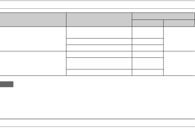
117
HDMI output settings for HDMI devices
Notes
• If the current Output Display setting becomes unavailable for selection after changing HDMI Target Device, the Output
Display setting changes as follows.
– Forcibly changes to the default value.
– If the default value is not available for selection, forcibly changes to “SDI=On, HDMI=On.”
• HDMI Target Device cannot be set to Recorder if Codec is set to ProRes.
States When Monitor LUT Cannot be Configured Independently
In the following cases, Monitor LUT >SDI2, HDMI, and Viewfinder in the Video menu cannot be set
individually. They are synced with the SDI1 & Internal Rec setting.
– When Output Format >HDMI in the Video menu is set to 4096×2160 or 3840×2160
– When S&Q Motion >Setting in the Recording menu is set to On
– When Lens >Distortion Comp. in the System menu is set to Auto
Output Setting >HDMI Target
Device in the Video menu
Output Display >SDI/HDMI in
the Video menu
HDMI output
OSD On/Off MLUT On/Off
Recorder (default) SDI=On, HDMI=On (default)
* Grayed out, cannot be selected.
– Follows SDI1
SDI=On, HDMI=Off Off
SDI=Off, HDMI=Off Off
Monitor SDI=On, HDMI=On (default) On Follows SDI2
SDI=On, HDMI=Off
* Grayed out, cannot be selected.
–
SDI=Off, HDMI=Off Off

118
If a warning, caution, or operating condition that requires confirmation occurs on the camcorder, a
message is displayed in the viewfinder, the recording indicators start flashing, and a warning sound is
emitted.
The warning sound is emitted from the built-in speaker and headphones connected to the headphone
connector.
The camcorder will stop operation when the following kind of display occurs.
Follow the instructions provided if the following display occurs.
Error/Warning Messages
Error Messages
Viewfinder message Warning
sound
Recording
indicator
Cause and Solution
E + error code Continuous High-speed
flashing
Indicates an abnormality in the camcorder. Recording stops,
even if zREC is displayed in the viewfinder.
Turn off the camcorder, and check for any problem with
connected devices, cables, or media. If the error persists when
the camcorder is turned on again, contact your Sony service
representative.
(If the camcorder does not turn off when the POWER switch
is set to OFF, remove the battery or disconnect the DC IN
supply.)
Warning Messages
Viewfinder message Warning
sound
Recording
indicator
Cause and Solution
Media Near Full Intermittent Flashing The remaining capacity on the XQD memory card is getting
low.
Replace at the earliest convenience.
Media Full Continuous High-speed
flashing
Clips could not be recorded, copied, or split because there is
no remaining capacity on the XQD memory card.
Replace immediately.
Battery Near End Intermittent Flashing The remaining capacity of the battery pack is getting low.
Recharge at the earliest convenience.
Battery End Continuous High-speed
flashing
The battery pack is empty. Recording is disabled.
Stop operation and replace the battery pack.
Temperature High Intermittent Flashing The internal temperature is high.
Turn off the camcorder and allow it to cool down before
operating it again.
Voltage Low Intermittent Flashing The DC IN voltage is low (level 1). Check the power source.
Insufficient Voltage Continuous High-speed
flashing
The DC IN voltage is too low (level 2). Recording is disabled.
Connect a different power source.

119
The following caution and operation messages may appear in the center of the screen. Follow the
instructions provided to resolve the issue.
1) “Media (B)” is displayed for the card in slot B.
Caution and Operation Messages
Display message Cause and Solution
Battery Error
Please Change Battery
An error was detected in the battery pack.
Replace with a normal battery pack.
Backup Battery End
Please Change
The remaining capacity of the backup battery is insufficient.
Charge the backup battery.
Unknown Media (A) 1)
Please Change
A memory card that has been partitioned or a memory card containing
more clips that can be handled by the camcorder was inserted.
The card cannot be used in the camcorder, and must be replaced.
Cannot Use Media (A) 1)
Unsupported File System
A card using a different file system or an unformatted card was inserted.
The card cannot be used in the camcorder, and must be replaced or
formatted using the camcorder.
Media Error
Media (A)1) Needs to be Restored
An error occurred on the memory card, and the card must be restored.
Restore the memory card.
Media Error
Cannot Record to Media (A) 1)
The memory card may be damaged, and can no longer be used for
recording.
Playback is possible, so making a copy and replacing the memory card is
recommended.
Media Error
Cannot Use Media (A) 1)
The memory card may be damaged, and can no longer be used for
recording or playback.
The card cannot be used in the camcorder, and must be replaced.
Media (A) 1) Error
Recording Halted
Playback Halted
Recording and playback was stopped because an error occurred while
using the memory card.
If the problem persists, replace the memory card.
Media Reached Rewriting Limit
Change Media (A) 1)
The memory card has reached the end of its life.
Make a backup, and replace the card immediately. If you continue using
the card, the card may not be able to record or play.
For details, refer to the operating instructions for the memory card.
Fan Stopped The built-in fan stopped.
Avoid use at high temperatures, disconnect the power, and contact your
Sony service representative.
Invalid setting value was reset:
Media/Clip Naming/Camera Position
Please save All File again
The Clip Naming format setting was reset because an invalid ALL file
was loaded.
Configure the desired format settings, and try to save the ALL file again.

120
Yes: Item is saved.
No: Item is not saved.
Items Saved in Files
LEVEL 1 LEVEL 2 LEVEL 3 All File Scene File
Camera ISO/Gain/EI Mode Yes Yes
ISO/Gain<H> Yes Yes
ISO/Gain<M> Yes Yes
ISO/Gain<L> Yes Yes
Exposure Index<H> Yes Yes
Exposure Index<M> Yes Yes
Exposure Index<L> Yes Yes
Shockless Gain Yes Yes
Auto Exposure Level Yes Yes
Mode Yes Yes
Speed Yes Yes
AGC Yes Yes
AGC Limit Yes Yes
Auto Shutter Yes Yes
A.SHT Limit Yes Yes
Clip High light Yes Yes
Detect Window Yes Yes
Detect Window Indication Yes Yes
Focus Focus Area Yes No
Focus Area (Push AF) Yes No
AF Assist Yes No
Shutter Mode Yes Yes
Shutter Speed Yes Yes
Shutter Angle Yes Yes
ECS Frequency Yes Yes
Color Bars Setting No No
Type Yes No
Noise Suppression Setting Yes Yes
Level Yes Yes
Flicker Reduce Mode Yes No
Frequency Yes No
SteadyShot Setting Yes No
Handle Zoom Zoom Speed Type Yes No
Zoom Speed Yes No
Auto Black Balance Auto Black Balance – –
AF Micro Adjustment Setting No No
Amount No No
Clear All – –
Video Light Set Video Light Set Yes No

121
Paint White Preset White Yes Yes
Color Temp <A> Yes Yes
Color Temp Balance <A> Yes Yes
R Gain <A> Yes Yes
B Gain <A> Yes Yes
Color Temp <B> Yes Yes
Color Temp Balance <B> Yes Yes
R Gain <B> Yes Yes
B Gain <B> Yes Yes
Filter White Memory Yes No
Shockless White Yes Yes
White Switch<B> Yes No
ATW Speed Yes Yes
Offset White Offset White <A> Yes Yes
Warm Cool <A> Yes Yes
Warm Cool Balance <A> Yes Yes
Offset White <B> Yes Yes
Warm Cool <B> Yes Yes
Warm Cool Balance <B> Yes Yes
Offset White<ATW> Yes Yes
Warm Cool<ATW> Yes Yes
Warm Cool Balance<ATW> Yes Yes
Black Setting Yes Yes
Master Black Yes Yes
R Black Yes Yes
B Black Yes Yes
Gamma Setting Yes Yes
Step Gamma Yes Yes
Master Gamma Yes Yes
R Gamma Yes Yes
G Gamma Yes Yes
B Gamma Yes Yes
Gamma Category Yes Yes
Gamma Select Yes Yes
Black Gamma Setting Yes Yes
Range – –
Master Black Gamma Yes Yes
Knee Setting Yes Yes
Auto Knee Yes Yes
Point Yes Yes
Slope Yes Yes
Knee Saturation Yes Yes
Knee Saturation Level Yes Yes
White Clip Setting Yes Yes
Level Yes Yes
LEVEL 1 LEVEL 2 LEVEL 3 All File Scene File

122
Detail Setting Yes Yes
Level Yes Yes
H/V Ratio Yes Yes
Crispening Yes Yes
Level Depend Yes Yes
Level Depend Level Yes Yes
Frequency Yes Yes
Knee Aperture Yes Yes
Knee Aperture Level Yes Yes
Limit Yes Yes
White Limit Yes Yes
Black Limit Yes Yes
V Black Limit Yes Yes
V Detail Creation Yes Yes
Skin Detail Setting Yes Yes
Area Detection – –
Area Indication No No
Level Yes Yes
Saturation Yes Yes
Hue Yes Yes
Width Yes Yes
Aperture Setting Yes Yes
Level Yes Yes
Matrix Setting Yes Yes
Adaptive Matrix Yes Yes
Preset Matrix Yes Yes
Preset Select Yes Yes
User Matrix Yes Yes
Level Yes Yes
Phase Yes Yes
User Matrix R-G Yes Yes
User Matrix R-B Yes Yes
User Matrix G-R Yes Yes
User Matrix G-B Yes Yes
User Matrix B-R Yes Yes
User Matrix B-G Yes Yes
Multi Matrix Setting Yes Yes
Area Indication No No
Color Detection – –
Axis No No
Hue Yes Yes
Saturation Yes Yes
Maintenance Test Saw Yes No
LEVEL 1 LEVEL 2 LEVEL 3 All File Scene File

123
Audio Audio Input CH1 Input Select Yes No
CH2 Input Select Yes No
CH3 Input Select Yes No
CH4 Input Select Yes No
INPUT1 MIC Reference Yes No
INPUT2 MIC Reference Yes No
CH1 Wind Filter Yes No
CH2 Wind Filter Yes No
CH3 Wind Filter Yes No
CH4 Wind Filter Yes No
CH3 Level Control Yes No
CH4 Level Control Yes No
CH3 Input Level Yes No
CH4 Input Level Yes No
Audio Input Level Yes No
Limiter Mode Yes No
CH1&2 AGC Mode Yes No
CH3&4 AGC Mode Yes No
AGC Spec Yes No
1kHz Tone on Color Bars Yes No
CH1 Level Yes No
CH2 Level Yes No
CH3 Level Yes No
CH4 Level Yes No
Audio Output Monitor CH Yes No
Monitor Volume Yes No
Headphone Out Yes No
Alarm Volume Yes No
Output Limiter Yes No
HDMI Output CH Yes No
Video Output On/Off SDI Yes No
HDMI Yes No
Output Format SDI Yes No
HDMI Yes No
REF No No
Output Setting HDMI Target Device Yes No
4K/2K to HD Conv. Yes No
Monitor LUT Category Yes No
LUT Select Yes No
Look Profile Select Yes No
User 3D LUT Select Yes No
SDI1 & Internal Rec Yes No
SDI2 Yes No
HDMI Yes No
Viewfinder Yes No
Output Display SDI2 Yes No
HDMI Yes No
LEVEL 1 LEVEL 2 LEVEL 3 All File Scene File

124
VF VF Setting Brightness Yes No
Color Mode Yes No
Peaking Setting Yes No
Peaking Type Yes No
Frequency Yes No
Normal Peaking Level Yes No
Color Yes No
Color Peaking Level Yes No
Zebra Setting Yes No
Zebra Select Yes No
Zebra1 Level Yes No
Zebra1 Aperture Level Yes No
Zebra2 Level Yes No
Marker Setting Yes No
Color Yes No
Center Marker Yes No
Safety Zone Yes No
Safety Area Yes No
Aspect Marker Yes No
Aspect Mask Yes No
Aspect Safety Zone Yes No
Aspect Safety Area Yes No
Aspect Select Yes No
User Box Yes No
User Box Width Yes No
User Box Height Yes No
User Box H Position Yes No
User Box V Position Yes No
100% Marker Yes No
Guide Frame Yes No
LEVEL 1 LEVEL 2 LEVEL 3 All File Scene File

125
Display On/Off Setting Yes No
Shutter Setting Yes No
ND Filter Position Yes No
Gain Setting Yes No
Rec/Play Status Yes No
HXR-IFR5 Rec Control Yes No
Color Temp. Yes No
Frame Rate / Interval Yes No
Battery Remain Yes No
Timecode Yes No
Audio Manual Yes No
Audio Level Meter Yes No
Media Status Yes No
Focus Position Yes No
Iris Position Yes No
Zoom Position Yes No
SteadyShot Yes No
Focus Mode Yes No
Focus Area Indicator Yes No
Focus Area Ind. (Push AF) Yes No
Focus Indicator Yes No
Auto Shutter Yes No
AGC Yes No
Auto Iris Yes No
AE Mode Yes No
Auto Exposure Level Yes No
White Balance Mode Yes No
SDI/HDMI Rec Control Yes No
Rec Format Yes No
Gamma Yes No
Timecode Lock Yes No
Wi-Fi Condition Yes No
Clip Name Yes No
Focus Assist Indicator Yes No
Focus Area Marker Yes No
Video Level Warning Yes No
Clip Number Yes No
GPS Yes No
Level Gauge Yes No
Lens Info Yes No
Notice Message Yes No
Video Signal Monitor Setting Yes No
Source Yes No
LEVEL 1 LEVEL 2 LEVEL 3 All File Scene File

126
TC/UB Timecode Mode Yes No
Run Yes No
Setting No No
Reset – –
TC Format Yes No
TC Display Display Select Yes No
Users Bit Mode Yes No
Setting No No
HDMI TC Out Setting Yes No
Recording S&Q Motion Setting Yes No
High Frame Rate Mode Yes No
Frame Rate Yes No
Interval Rec Setting No No
Interval Time Yes No
Number of Frames Yes No
Pre-Lighting Yes No
Picture Cache Rec Setting Yes No
Cache Rec Time Yes No
Simul Rec Setting Yes No
Rec Button Set Yes No
SDI/HDMI Rec Control Setting Yes No
Thumbnail Display Clip Properties – –
Set Index Picture – –
Thumbnail View Essence Mark Thumbnail – –
Clip Thumbnail – –
Set Shot Mark Add Shot Mark1 – –
Delete Shot Mark1 – –
Add Shot Mark2 – –
Delete Shot Mark2 – –
Set Clip Flag Add OK – –
Add NG – –
Add KEEP – –
Delete Clip Flag – –
Lock/Unlock Clip Select Clip – –
Lock All Clips – –
Unlock All Clips – –
Delete Clip Select Clip – –
All Clips – –
Filter Clips OK – –
NG – –
KEEP – –
None – –
Customize View Thumbnail Caption Yes Yes
LEVEL 1 LEVEL 2 LEVEL 3 All File Scene File

127
Media Update Media Media(A) – –
Media(B) – –
Format Media Media(A) – –
Media(B) – –
SD Card – –
Clip Auto Naming Yes No
Camera ID Yes No
Reel Number Yes No
Camera Position Yes No
Title Prefix Yes No
Number Set No No
File All File Load SD Card – –
Save SD Card – –
File ID Yes No
Scene File Recall Internal Memory – –
Store Internal Memory – –
Load SD Card – –
Save SD Card – –
File ID No Yes
Scene White Data Yes No
User Menu Item Load SD Card – –
Save SD Card – –
File ID No No
User Gamma Current Settings – –
Load SD Card – –
Reset – –
Monitor LUT Current Settings – –
Load SD Card – –
Reset – –
Monitor 3D LUT Current Settings – –
Load SD Card – –
Reset – –
Lens File White Offset R No No
White Offset B No No
LEVEL 1 LEVEL 2 LEVEL 3 All File Scene File

128
System Base Setting Shooting Mode Yes No
Color Space Yes No
Imager Scan Mode Yes No
Codec Select Yes No
Rec Format Video Format Yes No
RAW Output Format Yes No
Genlock Reference – –
Assignable Button <1> Yes No
<2> Yes No
<3> Yes No
<4> Yes No
<5> Yes No
<6> Yes No
Assignable Dial Assignable Dial Yes No
IRIS Dial Yes No
Assignable Dial Direction Yes No
IRIS Dial Direction Yes No
Rec Lamp Rec Lamp Yes No
Fan Control Setting Yes No
HOLD Switch Setting with Rec Button Yes No
with Hand Grip Remote Yes No
Lens Zoom Ring Direction Yes No
Distortion Comp. Yes No
Language Select Yes No
Clock Set Time Zone Yes No
Date Mode Yes No
12H/24H Yes No
Date No No
Time No No
Country NTSC/PAL Area Yes No
Hours Meter Hours(System) – –
Hours(Reset) – –
Reset – –
Basic Authentication User Name No No
Password No No
Wi-Fi Wi-Fi Yes No
SSID & Password – –
Wi-Fi Direct Connection – –
Client – –
IP Address – –
Subnet Mask – –
MAC Address – –
Regenerate Password – –
GPS GPS Yes No
IR Remote Setting Yes No
LEVEL 1 LEVEL 2 LEVEL 3 All File Scene File
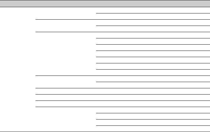
129
Camera Battery Alarm Low BATT Yes No
BATT Empty Yes No
Camera DC IN Alarm DC Low Voltage1 Yes No
DC Low Voltage2 Yes No
Ext. Unit Battery Alarm Near End:Info Battery Yes No
End:Info Battery Yes No
Near End:Sony Battery Yes No
End:Sony Battery Yes No
Near End:Other Battery Yes No
End:Other Battery Yes No
Detected Battery No No
Ext. Unit DC IN Alarm DC Low Voltage1 Yes No
DC Low Voltage2 Yes No
All Reset Reset – –
APR APR – –
Camera Config HD/2K Modulation Yes No
Version Number – –
Version Up – –
Ext. Unit Version Number – –
Ext. Unit Version Up – –
LEVEL 1 LEVEL 2 LEVEL 3 All File Scene File
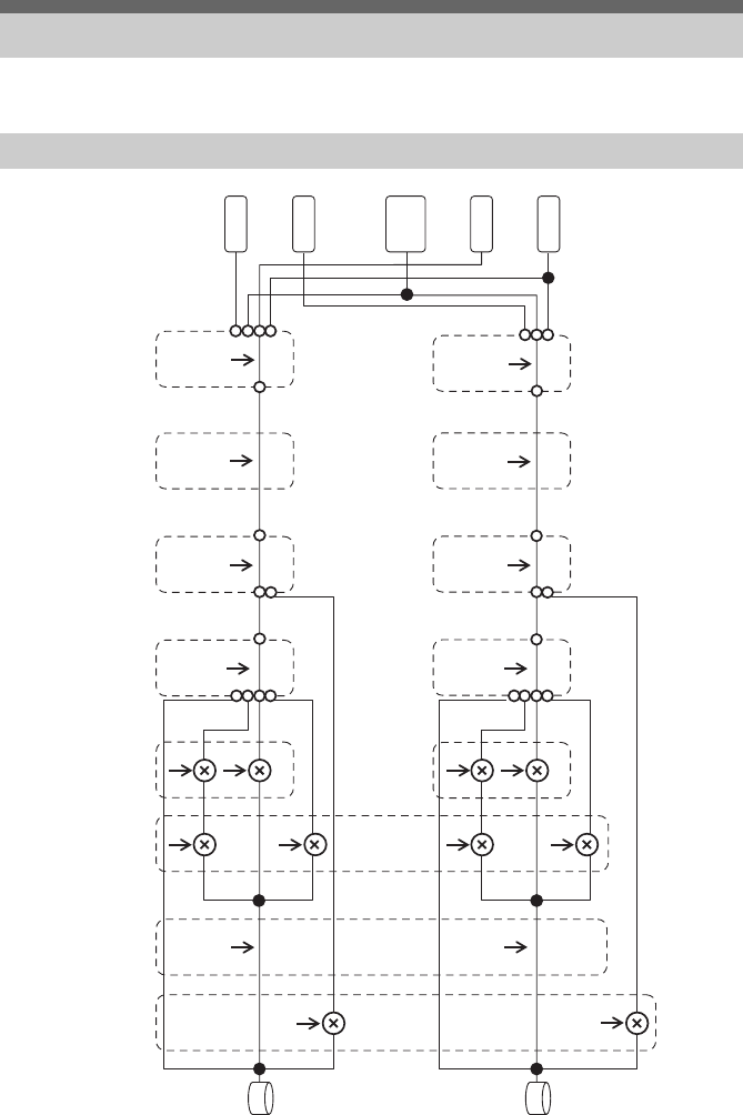
130
See related items in “Setting the Audio to Record” (page 44) and “Setup Menu List” (page 63).
* Set to MAN when audio is input from XLR adaptor.
Block Diagrams
Audio Input (CH1&CH2)
<CH1 Input Select>
Input1
Internal MIC
Shoe1
<CH1 Wind Filter>
On
Off
CH1 LEVEL CONTROL*
AUTO
MAN
<CH1 Level>
Audio Input Level
Side
Level + Side
Through
CH1 INPUT
LEVEL
0~10
<CH1 Input Select>
Input1
Input2
Internal MIC
Shoe2
<CH2 Wind Filter>
On
Off
CH2 LEVEL CONTROL*
AUTO
MAN
<CH2 Level>
Audio Input Level
Side
Level + Side
Through
CH2 INPUT
LEVEL
0~10
<Audio Input Level>
0~99
<Limiter Mode>
Off, −6dB
−9dB, −12dB
−15dB, −17dB
<CH1&2 AGC Mode>
Mono
Stereo
INPUT1
Shoe1
Shoe2
INPUT2
Internal
MIC
CH1
CH2
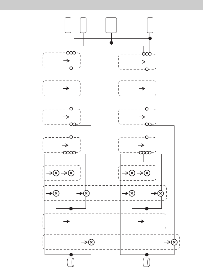
131
* Set to Manual when audio is input from XLR adaptor.
Audio Input (CH3&CH4)
<CH3 Input Select>
Off
Internal MIC
Shoe1
<CH3 Wind Filter>
On
Off
<CH3 Level Control>*
Auto
Manual
<CH3 Level>
Audio Input Level
CH3 Input Level
Level + CH3 Input Level
Through
<CH3 Input Level>
0~99
<CH4 Input Select>
Off
Internal MIC
Shoe2
<CH4 Wind Filter>
On
Off
<CH4 Level Control>*
Auto
Manual
<CH4 Level>
Audio Input Level
CH4 Input Level
Level + CH4 Input Level
Throu
g
h
<CH4 Input Level>
0~99
<Audio Input Level>
0~99
<Limiter Mode>
Off, −6dB
−9dB, −12dB
−15dB, −17dB
<CH3&4 AGC Mode>
Mono
Stereo
Off
CH3
CH4
Shoe1
Shoe2
Internal
MIC
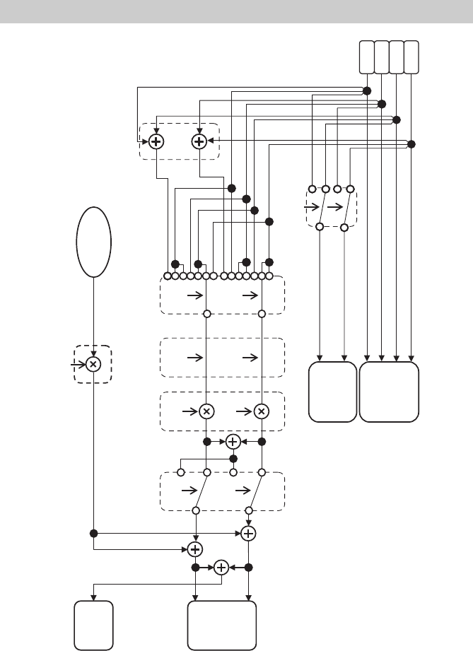
132
Audio Output
L
R
CH1
SDI OUT
<Monitor CH>
CH1, CH2, CH3, CH4,
CH1/CH2, CH3/CH4,
MIX ALL
<Output Limiter>
On/Off
<Monitor Volume>
0~15
<Headphone Out>
Mono/Stereo
<Alarm Volume>
0~7
Alarm
<HDMI Output CH>
CH1/CH2, CH3/CH4
Headphone
Internal
Speaker
HDMI OUT
CH2
CH3
CH4
Ch MIX

133
THIS PRODUCT IS LICENSED UNDER THE
MPEG-4 VISUAL PATENT PORTFOLIO
LICENSE FOR THE PERSONAL AND NON-
COMMERCIAL USE OF A CONSUMER FOR
(i) ENCODING VIDEO IN COMPLIANCE
WITH THE MPEG-4 VISUAL STANDARD
(“MPEG-4 VIDEO”)
AND/OR
(ii) DECODING MPEG-4 VIDEO THAT WAS
ENCODED BY A CONSUMER ENGAGED
IN A PERSONAL AND NON-
COMMERCIAL ACTIVITY AND/OR WAS
OBTAINED FROM A VIDEO PROVIDER
LICENSED BY MPEG LA TO PROVIDE
MPEG-4 VIDEO.
NO LICENSE IS GRANTED OR SHALL BE
IMPLIED FOR ANY OTHER USE.
ADDITIONAL INFORMATION INCLUDING
THAT RELATING TO PROMOTIONAL,
INTERNAL AND COMMERCIAL USES AND
LICENSING MAY BE OBTAINED FROM
MPEG LA, LLC. SEE HTTP://
WWW.MPEGLA.COM
This product uses software to which the GPL/
LGPL applies. This informs you that you have a
right to have access to, modify, and redistribute
source code for these software programs under
the conditions of the GPL/LGPL.
The source code is provided on the internet. Use
the following URL and follow the download
instructions.
http://www.sony.net/Products/Linux/common/
search.html
We would prefer that you do not contact us about
the contents of the source code.
For the content of these licenses, see
“License1.pdf” in the “License” folder of the
supplied CD-ROM.
Adobe Reader must be installed on your
computer to view PDF files.
If Adobe Reader is not installed on your
computer, you can download it by accessing the
following URL.
http://get.adobe.com/reader/
Licenses
MPEG-4 Visual Patent Portfolio
License
Obtaining Software Under the
GPL/LGPL License

134
IMPORTANT:
BEFORE USING THE SOFTWARE
CONTAINED IN THE SOLID STATE
MEMORY CAMCORDER, PLEASE READ
THIS END USER LICENSE AGREEMENT
(“EULA”) CAREFULLY. BY USING THE
SOFTWARE YOU ARE ACCEPTING THE
TERMS OF THIS EULA. IF YOU DO NOT
ACCEPT THE TERMS OF THIS EULA, YOU
MAY NOT USE THE SOFTWARE.
This EULA is a legal agreement between you
and Sony Corporation (“SONY”). This EULA
governs your rights and obligations regarding the
software of SONY and/or its third party licensors
(including SONY’s affiliates) and their
respective affiliates (collectively, the “THIRD-
PARTY SUPPLIERS”) contained in the wireless
adapter, together with any updates/ upgrades
provided by SONY, any printed, on-line or other
electronic documentation for such software, and
any data files created by operation of such
software (collectively, the “SOFTWARE”).
Notwithstanding the foregoing, any software in
the SOFTWARE having a separate end user
license agreement (including, but not limited to,
GNU General Public license and Lesser/Library
General Public License) shall be covered by such
applicable separate end user license agreement in
lieu of the terms of this EULA to the extent
required by such separate end user license
agreement (“EXCLUDED SOFTWARE”).
SOFTWARE LICENSE
The SOFTWARE is licensed, not sold. The
SOFTWARE is protected by copyright and other
intellectual property laws and international
treaties.
COPYRIGHT
All right and title in and to the SOFTWARE
(including, but not limited to, any images,
photographs, animation, video, audio, music, text
and “applets” incorporated into the
SOFTWARE) is owned by SONY or one or
more of the THIRD-PARTY SUPPLIERS.
GRANT OF LICENSE
SONY grants you a limited license to use the
SOFTWARE solely in connection with the
wireless adapter and only for your individual use.
SONY and the THIRD-PARTY SUPPLIERS
expressly reserve all rights, title and interest
(including, but not limited to, all intellectual
property rights) in and to the SOFTWARE that
this EULA does not specifically grant to you.
REQUIREMENTS AND LIMITATIONS
You may not copy, publish, adapt, redistribute,
attempt to derive source code, modify, reverse
engineer, decompile, or disassemble any of the
SOFTWARE, whether in whole or in part, or
create any derivative works from or of the
SOFTWARE unless such derivative works are
intentionally facilitated by the SOFTWARE.
You may not modify or tamper with any digital
rights management functionality of the
SOFTWARE. You may not bypass, modify,
defeat or circumvent any of the functions or
protections of the SOFTWARE or any
mechanisms operatively linked to the
SOFTWARE. You may not separate any
individual component of the SOFTWARE for
use on more than one wireless adapter unless
expressly authorized to do so by SONY. You
may not remove, alter, cover or deface any
trademarks or notices on the SOFTWARE. You
may not share, distribute, rent, lease, sublicense,
assign, transfer or sell the SOFTWARE. The
software, network services or other products
other than SOFTWARE upon which the
SOFTWARE’S performance depends might be
interrupted or discontinued at the discretion of
the suppliers (software suppliers, service
suppliers, or SONY). SONY and such suppliers
do not warrant that the SOFTWARE, network
services, contents or other products will continue
to be available, or will operate without
interruption or modification.
EXCLUDED SOFTWARE AND OPEN
SOURCE COMPONENTS
Notwithstanding the foregoing limited license
grant, you acknowledge that the SOFTWARE
may include EXCLUDED SOFTWARE.
Certain EXCLUDED SOFTWARE may be
covered by open source software licenses (“Open
Source Components”), which means any
software licenses approved as open source
licenses by the Open Source Initiative or any
substantially similar licenses, including but not
limited to any license that, as a condition of
distribution of the software licensed under such
END USER LICENSE AGREEMENT
135
license, requires that the distributor make the
software available in source code format. If and
to the extent disclosure is required, please visit
www.sony.com/linux or other SONY-designated
web site for a list of applicable OPEN SOURCE
COMPONENTS included in the SOFTWARE
from time to time, and the applicable terms and
conditions governing its use. Such terms and
conditions may be changed by the applicable
third party at any time without liability to you.
To the extent required by the licenses covering
EXCLUDED SOFTWARE, the terms of such
licenses will apply in lieu of the terms of this
EULA. To the extent the terms of the licenses
applicable to EXCLUDED SOFTWARE
prohibit any of the restrictions in this EULA with
respect to such EXCLUDED SOFTWARE, such
restrictions will not apply to such EXCLUDED
SOFTWARE. To the extent the terms of the
licenses applicable to Open Source Components
require SONY to make an offer to provide source
code in connection with the SOFTWARE, such
offer is hereby made.
USE OF SOFTWARE WITH
COPYRIGHTED MATERIALS
The SOFTWARE may be capable of being used
by you to view, store, process and/or use content
created by you and/or third parties. Such content
may be protected by copyright, other intellectual
property laws, and/or agreements. You agree to
use the SOFTWARE only in compliance with all
such laws and agreements that apply to such
content. You acknowledge and agree that SONY
may take appropriate measures to protect the
copyright of content stored, processed or used by
the SOFTWARE. Such measures include, but
are not limited to, counting the frequency of your
backup and restoration through certain
SOFTWARE features, refusal to accept your
request to enable restoration of data, and
termination of this EULA in the event of your
illegitimate use of the SOFTWARE.
CONTENT SERVICE
PLEASE ALSO NOTE THAT THE
SOFTWARE MAY BE DESIGNED TO BE
USED WITH CONTENT AVAILABLE
THROUGH ONE OR MORE CONTENT
SERVICES (“CONTENT SERVICE”). USE OF
THE SERVICE AND THAT CONTENT IS
SUBJECT TO THE TERMS OF SERVICE OF
THAT CONTENT SERVICE. IF YOU
DECLINE TO ACCEPT THOSE TERMS,
YOUR USE OF THE SOFTWARE WILL BE
LIMITED. You acknowledge and agree that
certain content and services available through the
SOFTWARE may be provided by third parties
over which SONY has no control. USE OF THE
CONTENT SERVICE REQUIRES AN
INTERNET CONNECTION. THE CONTENT
SERVICE MAY BE DISCONTINUED AT
ANY TIME.
INTERNET CONNECTIVITY AND THIRD
PARTY SERVICES
You acknowledge and agree that access to
certain SOFTWARE features may require an
Internet connection for which you are solely
responsible. Further, you are solely responsible
for payment of any third party fees associated
with your Internet connection, including but not
limited to Internet service provider or airtime
charges. Operation of the SOFTWARE may be
limited or restricted depending on the
capabilities, bandwidth or technical limitations
of your Internet connection and service. The
provision, quality and security of such Internet
connectivity are the sole responsibility of the
third party providing such service.
EXPORT AND OTHER REGULATIONS
You agree to comply with all applicable export
and re-export restrictions and regulations of the
area or country in which you reside, and not to
transfer, or authorize the transfer, of the
SOFTWARE to a prohibited country or
otherwise in violation of any such restrictions or
regulations.
HIGH RISK ACTIVITIES
The SOFTWARE is not fault-tolerant and is not
designed, manufactured or intended for use or
resale as on-line control equipment in hazardous
environments requiring fail-safe performance,
such as in the operation of nuclear facilities,
aircraft navigation or communication systems,
air traffic control, direct life support machines, or
weapons systems, in which the failure of the
SOFTWARE could lead to death, personal
injury, or severe physical or environmental
damage (“HIGH RISK ACTIVITIES”). SONY,
each of the THIRD-PARTY SUPPLIERS, and
each of their respective affiliates specifically
disclaim any express or implied warranty, duty
or condition of fitness for HIGH RISK
ACTIVITIES.
136
EXCLUSION OF WARRANTY ON
SOFTWARE
You acknowledge and agree that use of the
SOFTWARE is at your sole risk and that you are
responsible for use of the SOFTWARE. The
SOFTWARE is provided “AS IS,” without
warranty, duty or condition of any kind.
SONY AND EACH OF THE THIRD-PARTY
SUPPLIERS (for purposes of this Section,
SONY and each of the THIRD-PARTY
SUPPLIERS shall be collectively referred to as
“SONY”) EXPRESSLY DISCLAIM ALL
WARRANTIES, DUTIES OR CONDITIONS,
EXPRESS OR IMPLIED, INCLUDING, BUT
NOT LIMITED TO, THE IMPLIED
WARRANTIES OF MERCHANTABILITY,
NONINFRINGEMENT AND FITNESS FOR A
PARTICULAR PURPOSE. SONY DOES NOT
WARRANT OR MAKE ANY CONDITIONS
OR REPRESENTATIONS (A) THAT THE
FUNCTIONS CONTAINED IN ANY OF THE
SOFTWARE WILL MEET YOUR
REQUIREMENTS OR THAT THEY WILL BE
UPDATED, (B) THAT THE OPERATION OF
ANY OF THE SOFTWARE WILL BE
CORRECT OR ERROR-FREE OR THAT ANY
DEFECTS WILL BE CORRECTED, (C) THAT
THE SOFTWARE WILL NOT DAMAGE ANY
OTHER SOFTWARE, HARDWARE OR
DATA, (D) THAT ANY SOFTWARE,
NETWORK SERVICES (INCLUDING THE
INTERNET) OR PRODUCTS (OTHER THAN
THE SOFTWARE) UPON WHICH THE
SOFTWARE’S PERFORMANCE DEPENDS
WILL CONTINUE TO BE AVAILABLE,
UNINTERRUPTED OR UNMODIFIED, AND
(E) REGARDING THE USE OR THE
RESULTS OF THE USE OF THE SOFTWARE
IN TERMS OF ITS CORRECTNESS,
ACCURACY, RELIABILITY, OR
OTHERWISE.
NO ORAL OR WRITTEN INFORMATION OR
ADVICE GIVEN BY SONY OR AN
AUTHORIZED REPRESENTATIVE OF
SONY SHALL CREATE A WARRANTY,
DUTY OR CONDITION OR IN ANY WAY
INCREASE THE SCOPE OF THIS
WARRANTY. SHOULD THE SOFTWARE
PROVE DEFECTIVE YOU ASSUME THE
ENTIRE COST OF ALL NECESSARY
SERVICING, REPAIR OR CORRECTION.
SOME JURISDICTIONS DO NOT ALLOW
THE EXCLUSION OF IMPLIED
WARRANTIES, SO THESE EXCLUSIONS
MAY NOT APPLY TO YOU.
LIMITATION OF LIABILITY
SONY AND EACH OF THE THIRD-PARTY
SUPPLIERS (for purposes of this Section,
SONY and each of the THIRD-PARTY
SUPPLIERS shall be collectively referred to as
“SONY”) SHALL NOT BE LIABLE FOR ANY
INCIDENTAL OR CONSEQUENTIAL
DAMAGES FOR BREACH OF ANY
EXPRESS OR IMPLIED WARRANTY,
BREACH OF CONTRACT, NEGLIGENCE,
STRICT LIABILITY OR UNDER ANY
OTHER LEGAL THEORY RELATED TO THE
SOFTWARE, INCLUDING, BUT NOT
LIMITED TO, ANY DAMAGES ARISING
OUT OF LOSS OF PROFITS, LOSS OF
REVENUE, LOSS OF DATA, LOSS OF USE
OF THE SOFTWARE OR ANY ASSOCIATED
HARDWARE, DOWN TIME AND USER’ S
TIME, EVEN IF ANY OF THEM HAVE BEEN
ADVISED OF THE POSSIBILITY OF SUCH
DAMAGES. IN ANY CASE, EACH AND ALL
OF THEIR AGGREGATE LIABILITY UNDER
ANY PROVISION OF THIS EULA SHALL BE
LIMITED TO THE AMOUNT ACTUALLY
PAID FOR THE PRODUCT. SOME
JURISDICTIONS DO NOT ALLOW THE
EXCLUSION OR LIMITATION OF
INCIDENTAL OR CONSEQUENTIAL
DAMAGES, SO THE ABOVE EXCLUSION
OR LIMITATION MAY NOT APPLY TO
YOU.
CONSENT TO USE OF NON-PERSONAL
INFORMATION, LOCATION DATA, DATA
SECURITY
You acknowledge and agree that SONY and its
affiliates, partners and agents may read, collect,
transfer, process and store certain information
collected from the SOFTWARE, including but
not limited to information about (i) the
SOFTWARE and (ii) the software applications,
contents and peripheral devices that interact with
your wireless adapter and the SOFTWARE
(“Information”). Information includes, but is not
limited to: (1) unique identifiers relating to your
wireless adapter and its components; (2)
performance of the wireless adapter, the
137
SOFTWARE and their components; (3)
configurations of your wireless adapter, the
SOFTWARE and the software applications,
contents and peripheral devices that interact with
the wireless adapter and the SOFTWARE; (4)
use and frequency of use of the functions of (x)
the SOFTWARE, and (y) the software
applications, contents and peripheral devices that
interact with the SOFTWARE; and (5) location
data, as indicated below. SONY and its
affiliates, partners and agents may use and
disclose Information subject to applicable laws
in order to improve its products and services or
to provide products or services to you. Such uses
include, but are not limited to: (a) administering
the functionalities of the SOFTWARE; (b) to
improve, service, update or upgrade the
SOFTWARE; (c) improving, developing and
enhancing the current and future products and
services of SONY and other parties; (d) to
provide you with information about the products
and services offered by SONY and other parties;
(e) complying with applicable laws or
regulations; and (f) to the extent offered,
providing you with location-based services of
SONY and other parties, as indicated below. In
addition, SONY retains the right to use
Information to protect itself and third parties
from illegal, criminal or harmful conduct.
Certain services available through the
SOFTWARE may rely upon location
information, including, but not limited to, the
geographic location of the wireless adapter. You
acknowledge that for the purpose of providing
such services, SONY, the THIRDPARTY
SUPPLIERS or their partners may collect,
archive, process and use such location data, and
that such services are governed by the privacy
policies of SONY or such third party. By
reviewed the privacy policies applicable to such
services and consent to such activities.
SONY, its affiliates, partners and agents will not
intentionally use Information to personally
identify the owner or user of the SOFTWARE
without your knowledge or consent. Any use of
Information will be in accordance with the
privacy policies of SONY or such third party.
Please contact applicable contact address of each
area or country for SONY’ s current privacy
policy. Please contact applicable third parties for
privacy policies relating to personally
identifiable and other information you provide
when you use or access third party software or
services.
Information may be processed, stored or
transferred to SONY, its affiliates or agents
which are located in countries outside of your
country of residence. Data protection and
information privacy laws in certain countries
may not offer the same level of protection as
your country of residence and you may have
fewer legal rights in relation to Information
processed and stored in, or transferred to, such
countries. SONY will use reasonable efforts to
take appropriate technical and organizational
steps to prevent unauthorized access to or
disclosure of Information, but does not warrant it
will eliminate all risk of misuse of such
Information.
AUTOMATIC UPDATE FEATURE
From time to time, SONY or the THIRD-
PARTY SUPPLIERS may automatically update
or otherwise modify the SOFTWARE, including,
but not limited to, for purposes of enhancement
of security functions, error correction and
improvement of functions, at such time as you
interact with SONY’ s or third parties’ servers, or
otherwise. Such updates or modifications may
delete or change the nature of features or other
aspects of the SOFTWARE, including, but not
limited to, functions you may rely upon. You
acknowledge and agree that such activities may
occur at SONY’ s sole discretion and that SONY
may condition continued use of the SOFTWARE
upon your complete installation or acceptance of
such update or modifications. Any updates/
modifications shall be deemed to be, and shall
constitute part of, the SOFTWARE for purposes
of this EULA. By acceptance of this EULA, you
consent to such update/modification.
ENTIRE AGREEMENT, WAIVER,
SEVERABILITY
This EULA and SONY’ s privacy policy, each as
amended and modified from time to time,
together constitute the entire agreement between
you and SONY with respect to the SOFTWARE.
The failure of SONY to exercise or enforce any
right or provision of this EULA shall not
constitute a waiver of such right or provision. If

138
any part of this EULA is held invalid, illegal, or
unenforceable, that provision shall be enforced to
the maximum extent permissible so as to
maintain the intent of this EULA, and the other
parts will remain in full force and effect.
GOVERNING LAW AND JURISDICTION
The United Nations Convention on Contracts for
the International Sale of Goods shall not apply to
this EULA. This EULA shall be governed by the
laws of Japan, without regards to conflict of laws
provisions. Any dispute arising out of this
EULA shall be subject to the exclusive venue of
the Tokyo District Court in Japan, and the parties
hereby consent to the venue and jurisdiction of
such courts.
EQUITABLE REMEDIES
Notwithstanding anything contained in this
EULA to the contrary, you acknowledge and
agree that any violation of or noncompliance
with this EULA by you will cause irreparable
harm to SONY, for which monetary damages
would be inadequate, and you consent to SONY
obtaining any injunctive or equitable relief that
SONY deems necessary or appropriate in such
circumstances. SONY may also take any legal
and technical remedies to prevent violation of
and/or to enforce this EULA, including, but not
limited to, immediate termination of your use of
the SOFTWARE, if SONY believes in its sole
discretion that you are violating or intend to
violate this EULA. These remedies are in
addition to any other remedies SONY may have
at law, in equity or under contract.
TERMINATION
Without prejudice to any of its other rights,
SONY may terminate this EULA if you fail to
comply with any of its terms. In case of such
termination, you must: (i) cease all use, and
destroy any copies, of the SOFTWARE; (ii)
comply with the requirements in the section
below entitled “Your Account Responsibilities”.
AMENDMENT
SONY RESERVES THE RIGHT TO AMEND
ANY OF THE TERMS OF THIS EULA AT ITS
SOLE DISCRETION BY POSTING NOTICE
ON A SONY DESIGNATED WEB SITE, BY
EMAIL NOTIFICATION TO AN EMAIL
ADDRESS PROVIDED BY YOU, BY
PROVIDING NOTICE AS PART OF THE
PROCESS IN WHICH YOU OBTAIN
UPGRADES/ UPDATES OR BY ANY OTHER
LEGALLY RECOGNIZABLE FORM OF
NOTICE. If you do not agree to the amendment,
you should promptly contact SONY for
instructions. Your continued use of the
SOFTWARE after the effective date of any such
notice shall be deemed your agreement to be
bound by such amendment.
THIRD-PARTY BENEFICIARIES
Each THIRD-PARTY SUPPLIER is an express
intended thirdparty beneficiary of, and shall have
the right to enforce, each provision of this EULA
with respect to the SOFTWARE of such party.
Should you have any questions concerning this
EULA, you may contact SONY by writing to
SONY at applicable contact address of each area
or country.
Copyright © 2012 Sony Corporation.
On the basis of license contracts between Sony
and the software copyright holders, this product
uses open software.
To meet the requirements of the software
copyright holders, Sony is obligated to inform
you of the content of these licenses.
For the content of these licenses, see
“License1.pdf” in the “License” folder of the
supplied CD-ROM.
Open Software Licenses
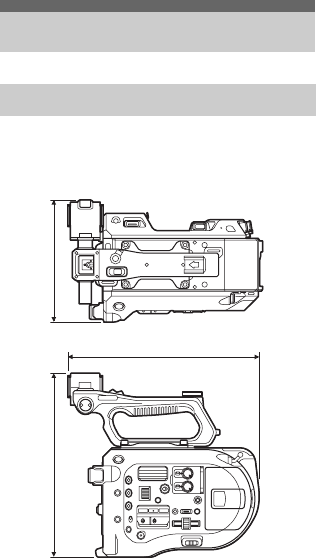
139
Mass Approx. 2.0 kg (4 lb 6.5 oz) (body only)
Dimensions
(Unit: mm (inch), body only) 1)
1) The values for dimensions are approximate.
Power requirement
12 V DC (11 V to 17.0 V)
Power consumption
Approx. 19 W (body, SELP28135G
lens, XAVC-I QFHD 59.94P recording,
viewfinder on)
Operating temperature
0 °C to 40 °C (32 °F to 104 °F)
Storage temperature
–20 °C to +60 °C (–4 °F to +140 °F)
Continuous operating time
Approx. 60 minutes (using BP-U30)
Recording format (video)
XAVC Intra
AVC/H.264 High 4:2:2 Intra Profile
QFHD: VBR, 600 Mbps max.
4K: VBR, 600 Mbps max.
HD: CBG, 222 Mbps
XAVC Long
AVC/H.264 High Profile
QFHD: VBR, 150 Mbps max., 4:2:0
Long
HD: VBR, 50 Mbps max., 4:2:2 Long
MPEG HD 422
MPEG-2 Long GOP
HD422 mode: CBR, 50 Mbps, MPEG-2
422P@HL
ProRes 422 HQ 1)
Apple ProRes 422 HQ
4:2:2, 10-bit, VBR, 220 Mbps max.
ProRes 422 1)
Apple ProRes 422
4:2:2, 10-bit, VBR, 147 Mbps max.
Recording format (audio)
LPCM 24-bit, 48 kHz, 4-channel
Recording frame rate
XAVC Intra
4096×2160/59.94P, 50P, 29.97P, 24P,
23.98P, 25P
3840×2160/59.94P, 50P, 29.97P,
23.98P, 25P
1920×1080/59.94P, 50P, 59.94i, 50i,
29.97P, 23.98P, 25P
XAVC Long
3840×2160/59.94P, 50P, 29.97P,
23.98P, 25P
1920×1080/59.94P, 50P, 59.94i, 50i,
29.97P, 23.98P, 25P
MPEG HD 422
1920×1080/59.94i, 50i, 29.97P, 23.98P,
25P
1280×720/59.94P, 50P, 29.97P, 23.98P,
25P
ProRes 422 HQ 1)
1920×1080/59.94i, 50i, 29.97P, 25P,
23.98P
ProRes 422 1)
1920×1080/59.94i, 50i, 29.97P, 25P,
23.98P
Specifications
General
247 (9 3/4)
239 (9 1/2) 156 (6 1/4)
140
Recording/playback time
XAVC Intra 4096×2160/3840×2160
59.94P
Approx. 22 minutes: Using
QD-G128A
Approx. 11 minutes: Using
QD-G64A
50P
Approx. 26 minutes: Using
QD-G128A
Approx. 13 minutes: Using
QD-G64A
29.97P
Approx. 44 minutes: Using
QD-G128A
Approx. 22 minutes: Using
QD-G64A
23.98P/24P
Approx. 55 minutes: Using
QD-G128A
Approx. 27 minutes: Using
QD-G64A
25P
Approx. 52 minutes: Using
QD-G128A
Approx. 26 minutes: Using
QD-G64A
XAVC Intra 1920×1080
59.94P
Approx. 59 minutes: Using
QD-G128A
Approx. 30 minutes: Using
QD-G64A
50P
Approx. 71 minutes: Using
QD-G128A
Approx. 35 minutes: Using
QD-G64A
59.94i
Approx. 118 minutes: Using
QD-G128A
Approx. 59 minutes: Using
QD-G64A
50i
Approx. 141 minutes: Using
QD-G128A
Approx. 70 minutes: Using
QD-G64A
29.97P
Approx. 118 minutes: Using
QD-G128A
Approx. 59 minutes: Using
QD-G64A
23.98P
Approx. 147 minutes: Using
QD-G128A
Approx. 74 minutes: Using
QD-G64A
25P
Approx. 141 minutes: Using
QD-G128A
Approx. 70 minutes: Using
QD-G64A
XAVC Long 3840×2160
59.94P/50P
Approx. 87 minutes: Using
QD-G128A
Approx. 44 minutes: Using
QD-G64A
29.97P/23.98P/25P
Approx. 131 minutes: Using
QD-G128A
Approx. 66 minutes: Using
QD-G64A
XAVC Long 1920×1080
50M mode
Approx. 262 minutes: Using
QD-G128A
Approx. 131 minutes: Using
QD-G64A
35M mode
Approx. 374 minutes: Using
QD-G128A
Approx. 187 minutes: Using
QD-G64A
25M mode
Approx. 524 minutes: Using
QD-G128A
Approx. 262 minutes: Using
QD-G64A
MPEG HD 422
Approx. 262 minutes: Using
QD-G128A
Approx. 131 minutes: Using
QD-G64A

141
ProRes 422 HQ 1)
59.94i/29.97P
Approx. 60 minutes: Using
QD-G128A
Approx. 30 minutes: Using
QD-G64A
50i/25P
Approx. 72 minutes: Using
QD-G128A
Approx. 36 minutes: Using
QD-G64A
23.98P
Approx. 74 minutes: Using
QD-G128A
Approx. 37 minutes: Using
QD-G64A
ProRes 422 1)
59.94i/29.97P
Approx. 90 minutes: Using
QD-G128A
Approx. 45 minutes: Using
QD-G64A
50i/25P
Approx. 108 minutes: Using
QD-G128A
Approx. 54 minutes: Using
QD-G64A
23.98P
Approx. 112 minutes: Using
QD-G128A
Approx. 56 minutes: Using
QD-G64A
1) With XDCA-FS7 (option) connected
Note
The recording/playback time may vary due to usage
conditions and memory characteristics.
Imaging device (type)
Super 35 equivalent CMOS image
sensor
Number of pixels
11.6 Megapixels (total),
8.8 Megapixels@17:9/
8.3 Megapixels@16:9 (effective)
ND filters
1: Clear
2: 1/4ND
3: 1/16ND
4: 1/64ND
Sensitivity
Video Gamma: T14@24p
(2000 lx, 89.9% reflectance, 3200K)
ISO sensitivity
S-Log3 Gamma ISO2000 (D55 light
source)
Minimum subject illumination
0.7 lx (18 dB, 23.98P, Shutter: OFF, ND
Clear, F1.4)
Lens mount
E-mount
Latitude
14-stop
Video S/N
57 dB (Video Gamma/Noise
Suppression: off)
Shutter speed
1/3 to 1/9000 sec. (23.98P)
Shutter angle
5.6° to 300°
Slow & Quick Motion
XAVC QFHD: 1 to 60P,
XAVC HD: 1 to 180P
White balance
Preset mode (2100K to 10000K),
Memory mode A, B (1500K to 50000K)
Gain –3, 0, 3, 6, 9, 12, 18 dB
Gamma curve
STD1, STD2, STD3, STD4, STD5,
STD6, HG1, HG2, HG3, HG4, HG7,
HG8, S-Log2, S-Log3, USER1, USER2,
USER3, USER4, USER5
Sampling frequency
48 kHz
Quantization
24-bit
Frequency response
XLR input MIC mode:
50 Hz to 20 kHz (±3 dB or less)
XLR input LINE mode:
20 Hz to 20 kHz (±3 dB or less)
Dynamic range
90 dB (typical)
Camera Section
Audio Section

142
Distortion
0.08% or lower (–40 dBu input level)
Built-in speaker
Monaural
Internal microphone
Monaural
Inputs
INPUT 1/2:
XLR type, 3-pin, female
LINE / MIC / MIC+48V switchable
MIC: Reference –40, –50, –60 dBu
Outputs
SDI OUT 1/2:
BNC type, 0.8 Vp-p, unbalanced
(3G HD/1.5G HD output)
SMPTE ST424 Level A/B, SMPTE
ST425 Level A/B, SMPTE ST292-1
standard compliant
4-channel audio
Headphones (stereo mini jack):
–16 dBu (reference level output,
maximum monitor volume, 16 Ω load)
HDMI: Type A, 19-pin
Other
DC IN: EIAJ compliant, 11 V to 17 V DC
Extension unit connector:
Dedicated (144-pin)
Multi-interface shoe:
Dedicated (21-pin)
REMOTE:
Φ2.5 3-pole sub-mini type
USB: 2.0 standard compliant, type AB mini for
mass storage (1)
Type A for W-LAN connection (1)
VF: Dedicated (40-pin)
LCD monitor
Screen size
8.8 cm (3.5 inch) diagonal
Aspect ratio
16:9
Number of pixels
960 (H) × 540 (V)
XQD card slots for video recording (2)
UTILITY SD card slot (1)
Viewfinder (including eyepiece, eyecup, rod,
clamp)
Grip remote control
USB wireless LAN module (IFU-WLM3)
Infrared remote control (RMT-845)
AC adaptor
AC-UES1230
Rated input: 100 V to 240 V AC,
50 Hz/60 Hz, 0.40 A to 0.75 A
Rated output: 12 V DC, 3.0 A
Battery pack (BP-U30)
Maximum voltage: 16.4 V DC
Nominal voltage: 14.4 V DC
Capacity: 28 Wh
Battery charger (BC-U1)
Power requirements: 100 V to 240 V
AC, 50 Hz/60 Hz
Power consumption: 38 W
Rated output: Charging 16.4 V, 1.9 A/
1.5 A
Power cords (2)
Mini USB cable (1)
Option mounting bracket (1)
Lens mount cap (1)
Handle connector protective cap (including two
M2 screws) (1)
USB wireless LAN module cap (2)
W-LAN connector cover spare (1)
Extension unit connector cover spare (1)
Accessory shoe kit (accessory shoe (1), shoe plate
(1), screws (4))
Before Using this Unit (1)
Operating Instructions (CD-ROM) (1)
Design and specifications are subject to change
without notice.
Input/Output Section
Display Section
Media Slot Section
Supplied Accessories

143
SONY WILL NOT BE LIABLE FOR
DAMAGES OF ANY KIND RESULTING
FROM A FAILURE TO IMPLEMENT
PROPER SECURITY MEASURES ON
TRANSMISSION DEVICES,
UNAVOIDABLE DATA LEAKS
RESULTING FROM TRANSMISSION
SPECIFICATIONS, OR SECURITY
PROBLEMS OF ANY KIND.
Notes
• Always make a test recording, and verify that
it was recorded successfully.
SONY WILL NOT BE LIABLE FOR
DAMAGES OF ANY KIND INCLUDING,
BUT NOT LIMITED TO,
COMPENSATION OR REIMBURSEMENT
ON ACCOUNT OF FAILURE OF THIS
UNIT OR ITS RECORDING MEDIA,
EXTERNAL STORAGE SYSTEMS OR
ANY OTHER MEDIA OR STORAGE
SYSTEMS TO RECORD CONTENT OF
ANY TYPE.
• Always verify that the unit is operating
properly before use.
SONY WILL NOT BE LIABLE FOR
DAMAGES OF ANY KIND INCLUDING,
BUT NOT LIMITED TO,
COMPENSATION OR REIMBURSEMENT
ON ACCOUNT OF THE LOSS OF
PRESENT OR PROSPECTIVE PROFITS
DUE TO FAILURE OF THIS UNIT,
EITHER DURING THE WARRANTY
PERIOD OR AFTER EXPIRATION OF
THE WARRANTY, OR FOR ANY OTHER
REASON WHATSOEVER.
• SONY WILL NOT BE LIABLE FOR
CLAIMS OF ANY KIND MADE BY
USERS OF THIS UNIT OR MADE BY
THIRD PARTIES.
• SONY WILL NOT BE LIABLE FOR THE
LOSS, REPAIR, OR REPRODUCTION OF
ANY DATA RECORDED ON THE
INTERNAL STORAGE SYSTEM,
RECORDING MEDIA, EXTERNAL
STORAGE SYSTEMS OR ANY OTHER
MEDIA OR STORAGE SYSTEMS.
• SONY WILL NOT BE LIABLE FOR THE
TERMINATION OR DISCONTINUATION
OF ANY SERVICES RELATED TO THIS
UNIT THAT MAY RESULT DUE TO
CIRCUMSTANCES OF ANY KIND.

144
When the unit is used with a PC connection,
download device drivers, plug-ins, and
application software, where applicable, from the
Sony Professional products web site.
Sony Professional products web site homepage:
Sony Creative Software, software download page
http://www.sonycreativesoftware.com/
download/software_for_sony_equipment
• XDCAM is a trademark of Sony Corporation.
• XAVC and are registered trademarks
of Sony Corporation.
• XQD and are trademarks of
Sony Corporation.
• HDMI, the HDMI logo, and High-Definition
Multimedia Interface are trademarks or
registered trademarks of HDMI Licensing, LLC
in the United States and/or other countries.
All other company names and product names are
registered trademarks or trademarks of their
respective owners. Trademarked items are not
indicated by ® or ™ symbols in this document.
Software Downloads
U.S.A http://pro.sony.com
Canada http://www.sonybiz.ca
Latin America http://sonypro-latin.com
Europe
http://www.pro.sony.eu/pro
Middle East and
Africa
http://sony-psmea.com
Russia http://sony.ru/pro/
Brazil http://sonypro.com.br
Australia http://pro.sony.com.au
New Zealand http://pro.sony.co.nz
Japan http://www.sonybsc.com
Asia http://pro.sony-asia.com
Korea http://bp.sony.co.kr
China http://pro.sony.com.cn
India http://pro.sony.co.in
Trademarks