Panasonic_AG AC160_Basic Panasonic AG AC160 Basic
User Manual: Panasonic_AG-AC160_Basic
Open the PDF directly: View PDF ![]() .
.
Page Count: 42
- Read this first!
- How to use the camera
- Please read before use
- Operating precautions
- Before using the camera
- Accessories
- Optional accessories
- Description of parts
- Recharging the battery
- Power sources
- Adjusting the hand strap
- Attaching the shoulder strap
- Attaching/removing the lens hood
- Attaching/removing the lens cap
- Fitting the eye cup
- The remote control
- Turning the camera ON/OFF
- Setup menu basic operations
- Setting the calendar
- Setup menu structure
- Specifications
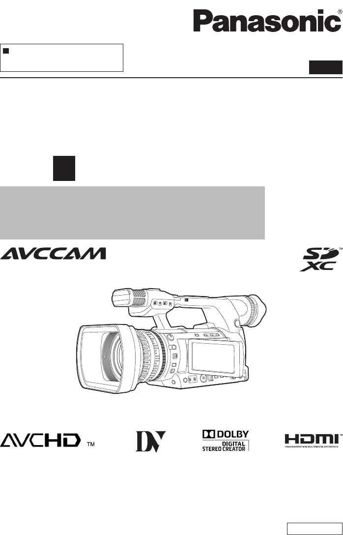
Model No. AG-AC160P
AG-AC160EJ
AG-AC160EN
SS0811SI0 -YI
Printed in Japan VQT3T51
ENGLISH
Vol.1
Note that Operating Instructions Vol.1 describes basic operations of
the Memory Card Camera-Recorder.
For instructions on advanced operations of the Memory Card
Camera-Recorder, refer to Operating Instructions Vol.2 (pdf file)
contained in the supplied CD-ROM.
This product is eligible for the AVCCAM
3 Year Warranty Repair Program. For
details, see page 9. Operating Instructions
Memory Card Camera-Recorder
Before operating this product, please read the instructions carefully and save this manual for
future use.
Volume 1
2
indicates safety information.
WARNING:
• Toreducetheriskofreorelectricshock,donotexpose
this equipment to rain or moisture.
• To reduce the risk of re or electric shock hazard, keep
this equipment away from all liquids. Use and store only
inlocationswhicharenotexposedtotheriskofdripping
or splashing liquids, and do not place any liquid containers
on top of the equipment.
WARNING:
Always keep memory cards or accessories (coin battery,
microphone holder screws, microphone holder adaptor,
INPUT terminal covers) out of the reach of babies and small
children.
CAUTION:
To reduce the risk of fire or electric shock and annoying
interference, use the recommended accessories only.
CAUTION:
Do not jar, swing, or shake the unit by its handle while the
conversion lens or another accessory is attached.
Due to the added weight of the conversion lens, any strong
jolt to the handle may damage the unit or result in personal
injury.
CAUTION:
The mains plug of the power supply cord shall remain
readily operable.
The AC receptacle (mains socket outlet) shall be installed
near the equipment and shall be easily accessible.
To completely disconnect this equipment from the AC
mains, disconnect the power cord plug from the AC
receptacle.
CAUTION:
Dangerofexplosionorfireifbatteryisincorrectlyreplaced
or mistreated.
• Donotdisassemblethebatteryordisposeofitinre.
• Do not store in temperatures over 60°C (140°F).
• Donotexposethebatterytoexcessiveheatsuchassun-
shine,reorthelike.
For Battery Pack
• Usespeciedcharger.
• Replaceonlywithsameorspeciedtype.
For Battery of Remote Controller
• Replace battery with part No. CR2025 only.
• Do not recharge the battery.
CAUTION:
In order to maintain adequate ventilation, do not install or
place this unit in a bookcase, built-in cabinet or any other
confined space.
Topreventriskofelectricshockorfirehazarddue
to overheating, ensure that curtains and any other
materials do not obstruct the ventilation.
CAUTION:
Do not lift the unit by its handle while the tripod is attached.
When the tripod is attached, its weight will also affect
the unit’s handle, possibly causing the handle to break
and hurting the user. To carry the unit while the tripod is
attached, take hold of the tripod.
CAUTION:
Excessivesoundpressurefromearphonesand
headphones can cause hearing loss.
CAUTION:
Do not leave the unit in direct contact with the skin for long
periods of time when in use.
Low temperature burn injuries may be suffered if the high
temperature parts of this unit are in direct contact with the
skin for long periods of time. When using the equipment for
long periods of time, make use of the tripod.
CAUTION:
Keep metal objects (such as necklaces and hairpins) away
from the battery.
Short-circuiting may occur across the terminals, causing the
battery to heat up, and you may seriously burn yourself if
you touch the battery in this state.
Read this first!
The lightning flash with arrowhead symbol,
within an equilateral triangle, is intended to
alert the user to the presence of uninsulated
“dangerous voltage” within the product’s
enclosure that may be of sufficient magnitude
to constitute a risk of electric shock to persons.
Theexclamationpointwithinanequilateral
triangle is intended to alert the user to
the presence of important operating and
maintenance (servicing) instructions in the
literature accompanying the appliance.
CAUTION
RISK OF ELECTRIC SHOCK
DO NOT OPEN
CAUTION: TO REDUCE THE RISK OF ELECTRIC
SHOCK, DO NOT REMOVE COVER (OR BACK).
NO USER-SERVICEABLE PARTS INSIDE.
REFER TO SERVICING TO QUALIFIED SERVICE
PERSONNEL.

3
CAUTION:
This apparatus can be operated at a voltage in the range of 110-240 V AC.
Voltages other than 120 V are not intended for U.S.A. and Canada.
Operation at a voltage other than 120 V AC may require the use of a different AC plug. Please contact either
alocalorforeignPanasonicauthorizedservicecenterforassistanceinselectinganalternateACplug.
FCC NOTICE (USA)
Declaration of Conformity
Model Number: AG-AC160P
Trade Name: Panasonic
Responsible Party:
Panasonic Corporation of North America One Panasonic Way, Secaucus, NJ 07094
Support contact: 1-800-524-1448
This device complies with Part 15 of the FCC Rules.
Operation is subject to the following two conditions:
(1) This device may not cause harmful interference, and (2) this device must accept any interference
received, including interference that may cause undesired operation.
To assure continued compliance, follow the attached installation instructions and do not make any
unauthorizedmodifications.
CAUTION:
This equipment has been tested and found to comply with the limits for a Class B digital device,
pursuant to Part 15 of the FCC Rules. These limits are designed to provide reasonable protection
against harmful interference in a residential installation. This equipment generates, uses and can
radiate radio frequency energy and, if not installed and used in accordance with the instructions,
may cause harmful interference to radio communications. However, there is no guarantee
that interference will not occur in a particular installation. If this equipment does cause harmful
interference to radio or television reception, which can be determined by turning the equipment off
and on, the user is encouraged to try to correct the interference by one of the following measures:
• Reorient or relocate the receiving antenna.
• Increase the separation between the equipment and receiver.
• Connect the equipment into an outlet on a circuit different from that to which the receiver is connected.
• Consultthedealeroranexperiencedradio/TVtechnicianforhelp.
The user may find the booklet “Something About Interference”
available from FCC local regional offices helpful.
FCC Warning:
To assure continued FCC emission limit compliance, follow the attached installation instructions and the user
must use only shielded interface cables when connecting to host computer or peripheral devices. Also any
unauthorizedchangesormodificationstothisequipmentcouldvoidtheuser'sauthoritytooperatethisdevice.
NOTIFICATION (Canada)
This class B digital apparatus complies with Canadian ICES-003.
Cet appareil numéique de la classe B est conforme à la norme NMB-003 du Canada.
For AG-AC160P Only indicates safety information.

4
IMPORTANT SAFETY INSTRUCTIONS
1) Read these instructions.
2) Keep these instructions.
3) Heed all warnings.
4) Follow all instructions.
5) Do not use this apparatus near water.
6) Clean only with dry cloth.
7) Do not block any ventilation openings. Install in accordance with the manufacturer’s instructions.
8) Do not install near any heat sources such as radiators, heat registers, stoves, or other apparatus
(including amplifiers) that produce heat.
9)Donotdefeatthesafetypurposeofthepolarizedorgrounding-typeplug.Apolarizedplughastwo
blades with one wider than the other. A grounding-type plug has two blades and a third grounding prong.
The wide blade or the third prong are provided for your safety. If the provided plug does not fit into your
outlet, consult an electrician for replacement of the obsolete outlet.
10) Protect the power cord from being walked on or pinched particularly at plugs, convenience
receptacles,andthepointwheretheyexitfromtheapparatus.
11) Onlyuseattachments/accessoriesspecifiedbythemanufacturer.
12) Use only with the cart, stand, tripod, bracket, or table specified by the manufacturer,
orsoldwiththeapparatus.Whenacartisused,usecautionwhenmovingthecart/
apparatus combination to avoid injury from tip-over.
13) Unplug this apparatus during lightning storms or when unused for long periods of time.
14) Refer all servicing to qualified service personnel. Servicing is required when the
apparatus has been damaged in any way, such as power-supply cord or plug is damaged, liquid has
beenspilledorobjectshavefallenintotheapparatus,theapparatushasbeenexposedtorainor
moisture, does not operate normally, or has been dropped.
IMPORTANT
“Unauthorizedrecordingofcopyrightedtelevisionprograms,videotapesandothermaterialsmayinfringethe
right of copyright owners and be contrary to copyright laws.”
For USA-California Only
This product contains a CR Coin Cell Lithium Battery which contains Perchlorate Material – special
handling may apply.
Seewww.dtsc.ca.gov/hazardouswaste/perchlorate
Alithiumion/polymerbatterythatisrecyclablepowerstheproductyouhavepurchased.
Please call 1-800-8-BATTERY for information on how to recycle this battery.
5
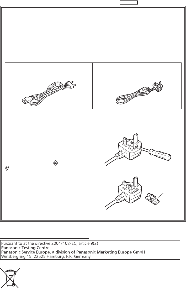
Caution for AC Mains Lead
For battery charger
FOR YOUR SAFETY PLEASE READ THE FOLLOWING TEXT CAREFULLY.
This product is equipped with 2 types of AC mains cable. One is for continental Europe, etc.
and the other one is only for U.K.
Appropriate mains cable must be used in each local area, since the other type of mains cable is
not suitable.
TYPE C
(FOR CONTINENTAL EUROPE, ETC.
Not to be used in the U.K.)
TYPE BF
(FOR U.K. ONLY)
How to replace the fuse
1. Open the fuse compartment with a
screwdriver.
2. Replace the fuse.
Fuse
FOR U.K. ONLY
This appliance is supplied with a moulded
three pin mains plug for your safety and
convenience.
A 5 amp fuse is fitted in this plug.
Should the fuse need to be replaced please
ensure that the replacement fuse has a
rating of 5 amps and that it is approved by
ASTA or BSI to BS1362.
Check for the ASTA mark or the BSI mark
on the body of the fuse.
If the plug contains a removable fuse cover
you must ensure that it is refitted when the
fuse is replaced.
If you lose the fuse cover the plug must
not be used until a replacement cover is
obtained.
A replacement fuse cover can be purchased
from your local Panasonic Dealer.
indicates safety information.
For AG-AC160EJ Only
EEE Yönetmeliğine Uygundur.
EEE Complies with Directive of Turkey.
EU
6
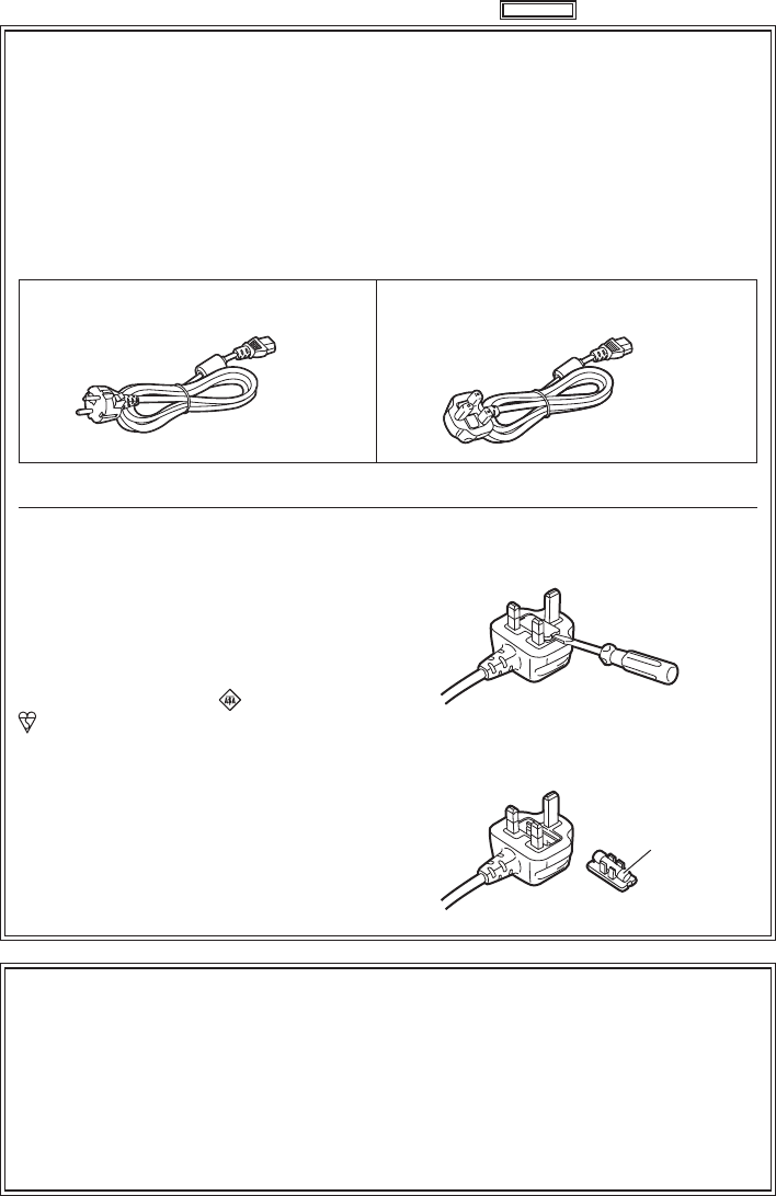
Caution for AC Mains Lead
For AC adaptor
FOR YOUR SAFETY PLEASE READ THE FOLLOWING TEXT CAREFULLY.
This product is equipped with 2 types of AC mains cable. One is for continental Europe, etc.
and the other one is only for U.K.
Appropriate mains cable must be used in each local area, since the other type of mains cable is
not suitable.
FOR CONTINENTAL EUROPE, ETC.
Not to be used in the U.K.
FOR U.K. ONLY
How to replace the fuse
1. Open the fuse compartment with a
screwdriver.
2. Replace the fuse.
Fuse
FOR U.K. ONLY
This appliance is supplied with a moulded
three pin mains plug for your safety and
convenience.
A 13 amp fuse is fitted in this plug.
Should the fuse need to be replaced please
ensure that the replacement fuse has a rating
of 13 amps and that it is approved by ASTA
or BSI to BS1362.
Check for the ASTA mark or the BSI mark
on the body of the fuse.
If the plug contains a removable fuse cover
you must ensure that it is refitted when the
fuse is replaced.
If you lose the fuse cover the plug must
not be used until a replacement cover is
obtained.
A replacement fuse cover can be purchased
from your local Panasonic Dealer.
indicates safety information.
For AG-AC160EJ Only
WARNING:
This equipment must be earthed
To ensure safe operation, the three-pin plug must be inserted only into a standard three-pin power
point which is effectively earthed through normal house-hold wiring.
Extensioncordsusedwiththeequipmentmusthavethreecoresandbecorrectlywiredtoprovide
connectiontotheearth.Wronglywiredextensioncordsareamajorcauseoffatalities.
The fact that the equipment operates satisfactorily does not imply that the power point is earthed
or that the installation is completely safe. For your safety, if you are in any doubt about the effective
earthing of the power point, please consult a qualified electrician.

7
EMC NOTICE FOR THE PURCHASER/USER OF THE APPARATUS
1. Applicable standards and operating environment
The apparatus is compliant with:
• standards EN55103-1 and EN55103-2 2009, and
• electromagnetic environments E1, E2, E3 and E4.
2. Pre-requisite conditions to achieving compliance with the above standards
<1> Peripheral equipment to be connected to the apparatus and special connecting cables
• Thepurchaser/useris urgedto useonlyequipmentwhichhas beenrecommended byusas
peripheral equipment to be connected to the apparatus.
• Thepurchaser/userisurgedtouseonlytheconnectingcablesdescribedbelow.
<2>
For the connecting cables, use shielded cables which suit the intended purpose of the apparatus.
• Video signal connecting cables
Usedouble-shieldedcoaxialcables,whicharedesignedfor75-ohmtypehigh-frequencyap-
plications, for SDI (Serial Digital Interface).
Coaxialcables,whicharedesignedfor75-ohmtypehigh-frequencyapplications,arerecom-
mended for analog video signals.
• Audio signal connecting cables
IfyourapparatussupportsAES/EBUserialdigitalaudiosignals,usecablesdesignedforAES/EBU.
Use shielded cables, which provide quality performance for high-frequency transmission ap-
plications, for analog audio signals.
• Other connecting cables (IEEE1394, USB)
Use double-shielded cables, which provide quality performance for high-frequency applica-
tions, as connecting cables.
• When connecting to the DVI signal terminal, use a cable with a ferrite core.
• If your apparatus is supplied with ferrite core(s), they must be attached on cable(s) following
instructions in this manual.
3. Performance level
The performance level of the apparatus is equivalent to or better than the performance level
required by these standards.
However, the apparatus may be adversely affected by interference if it is being used in an EMC
environment, such as an area where strong electromagnetic fields are generated (by the presence
ofsignaltransmissiontowers,cellularphones,etc.).Inordertominimizetheadverseeffectsofthe
interference on the apparatus in cases like this, it is recommended that the following steps be taken
with the apparatus being affected and with its operating environment:
1. Place the apparatus at a distance from the source of the interference.
2. Change the direction of the apparatus.
3. Change the connection method used for the apparatus.
4.
Connect the apparatus to another power outlet where the power is not shared by any other appliances.
For AG-AC160EJ/AG-AC160EN Only
For AG-AC160EN Only
Caution for AC Mains Lead
AC adaptor (Battery charger)
FOR YOUR SAFETY PLEASE READ THE FOLLOWING TEXT CAREFULLY.
This product is equipped with 2 types of AC mains cable, Type C and Type BF.
Appropriate mains cable must be used in each local area, since the other type of mains cable is
not suitable.
TYPE C TYPE BF
indicates safety information.
8
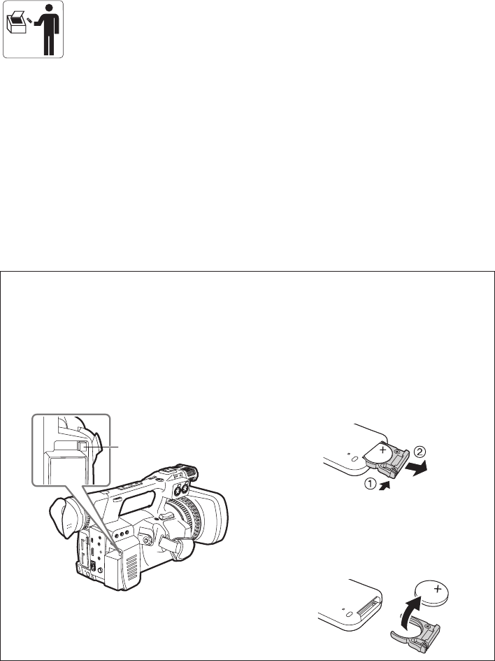
To remove the battery
Para remover a bateria
Main Power Battery (Lithium ion Battery)
Bateria Principal de Energia
(Refer to page 26 for the detail.)
Press the battery release button.
Pressione o botão para liberar a bateria.
Back-up Battery (Lithium Battery)
• For the removal of the battery for disposal at
the end of its service life, please consult your
dealer.
Battery release button
Botão de liberação da
bateria
Remote Control Battery (Lithium Battery)
Bateria do Controle Remoto
1) Push the catch in the direction shown by
arrow 1 to remove the holder.
Empurreatravanadireçãoexibidapelaseta
1 para remover o suporte.
2) Remove the button-type battery from the
battery holder.
Remova a bateria tipo botão do suporte da
bateria.
Brazil Only
Brasil Apenas
Manuseio de baterias usadas
BRASIL
Apósouso,aspilhase/oubateriaspoderão
ser entregues ao estabelecimento comercial
ourededeassistênciatécnicaautorizada.
Cobrir os terminais positivo (+) e negativo (-) com uma fita isolante adesiva, antes de depositar numa
caixadestinadaparaorecolhimento.Ocontatoentrepartesmetálicaspodecausarvazamentos,gerar
calor,romperablindagemeproduzirfogo.
Nãodesmonte,nãoremovaoinvólucro,nemamasseabateria.Ogásliberadopelabateriapodeirritara
garganta,danificarolacredoinvólucroouovazamentoprovocarcalor,rupturadablindagemeproduzir
fogo devido ao curto circuito dos terminais. Não incinere nem aqueça as baterias, elas não podem ficar
expostasatemperaturassuperioresa100°C(212°F).Ogásliberadopelabateriapodeirritaragarganta,
danificarolacredoinvólucroouovazamentoprovocarcalor,rupturadablindagemeproduzirfogodevido
ao curto circuito dos terminais provocado internamente.
Eviteocontatocomoliquidoquevazardasbaterias.Casoistoocorra,lavebemaparteafetadacom
bastanteágua.Casohajairritação,consulteummédico.

9
Battery Charger / AC Adaptor
The rating plate is on the underside of the Battery Charger and AC Adaptor. Disconnect the AC mains
plug from the AC mains socket when not in use.
*1: Please note that this extended warranty is not available in some countries/regions. *2: Not all models eligible for extended warranty coverage.
*3: The basic warranty period may vary depending on the country/region. *4: Not all repair work is covered by this extended warranty.
Purchase
AVCCAM product
Register online
within 1 month
“Registration Notice”
e-mail sent
Details about user registration and the extended warranty: http://panasonic.biz/sav/pass_e
Free 3 years of Warranty Repairs
Customers who register as users on the website will receive an extended warranty repair valid for up to
three years.
AVCCAM 3 Year Warranty Repair Program*1
Thank you for purchasing this Panasonic AVCCAM device.
Register as a user for this device to receive a special service warranty up to three years of free warranty repairs.
Make sure to save the “Registration Notice” e-mail
during the warranty period.
Please note, this is a site that is not maintained by Panasonic Canada Inc. The Panasonic Canada Inc. privacy policy does not apply and is not applicable in relation to any
information submitted. This link is provided to you for convenience.
1st year 2nd year 3rd year
AVCCAM device*2Basic warranty*3Extended warranty repair*4
It has been found that counterfeit battery packs which look very similar to the genuine product are
made available to purchase in some markets. Some of these battery packs are not adequately
protected with internal protection to meet the requirements of appropriate safety standards. There is
a possibility that these battery packs may lead to fire or explosion. Please be advised that we are not
liable for any accident or failure occurring as a result of use of a counterfeit battery pack. To ensure that
safe products are used we would recommend that a genuine Panasonic battery pack is used.
■ Batteries that may be used with this product (Correct as of September 2011)
Panasonic VW-VBG6 battery may be used with this product.
The VW-VBG6 battery contains a function to enable verification as to whether they may be safely used
with this product.

10
■■How to read this document
Illustrations
•Illustrations of the camera, menu screens, and other items, may vary from the actual items.
•In order to identify the terminals on the camera body, the supplied protective caps are not illustrated
exceptin“Descriptionofparts”(Pages22,23).
Reference pages
•Reference pages in this document are indicated by (Page 00).
SD/SDHC/SDXC memory cards
•SD/SDHC/SDXCmemorycardsarealldescribedasmemorycards.Eachnameisdescribedwhen
explainedindividually.
Notations
•The menu items displayed on the screen are enclosed in square brackets like [Menu items], and
characters printed on camera and the remote control are enclosed in angle brackets as in <item name>.
Menu display language
•[English] is set in the factory settings. You can change the display language in [LANGUAGE] item of the
[OTHER FUNCTIONS] screen.
•TheSDHClogoandSDXClogoaretrademarksofSD-3C,LLC.
•“AVCHD” and the “AVCHD” logo are trademarks of Panasonic Corporation and Sony Corporation.
•The “DV” is a registered trademark.
•Manufactured under license from Dolby Laboratories.
Dolby and the double-D symbol are trademarks of Dolby Laboratories.
•HDMI,theHDMIlogo,andHigh-DenitionMultimediaInterfacearetrademarksorregisteredtrademarks
of HDMI Licensing LLC.
•Microsoft®, Windows®, and Windows Vista® are either registered trademarks or trademarks of Microsoft
CorporationintheUnitedStatesand/orothercountries.
•Screenshots are used in accordance with Microsoft Corporation guidelines.
•IBMandPC/ATareregisteredtrademarksofInternationalBusinessMachinesCorporation.
•Intel®isaregisteredtrademarkoratrademarkofIntelCorporationintheUnitedStatesand/orother
countries.
•Apple®, Macintosh®, and Mac OS® are trademarks or registered trademarks of Apple Inc. in the United
Statesand/orothercountries.
•Other model names, company names, and product names listed in these operating instructions are
trademarks or registered trademarks of their respective companies.
•This product is licensed under the AVC Patent Portfolio License for the personal and non-commercial
use of a consumer, and no license is granted or shall be implied for any use other than the personal uses
detailed below.
- To encode video in compliance with the AVC standard (“AVC Video”)
- To decode AVC Video that was encoded by a consumer engaged in a personal and non-commercial
activity
- To decode AVC Video that was obtained from a video provider licensed to provide AVC Video
AdditionalinformationmaybeobtainedfromMPEGLA,LLC(http://www.mpegla.com).
- Separate license contracts must be obtained from MPEG LA where SD Memory Cards containing
information recorded with this product are to be distributed to end users for commercial purposes. “End
user”referstopersonsororganizationshandlingsuchcontentsforpersonaluse.
11
How to use the camera
This camera is equipped with a 1/3, 2.2 mega pixel 3MOS sensor and an optical 22X cam-type zoom lens.
It supports simultaneous and relay recording using two memory card slots. In addition, it is a hand-held
camera-recorder that supports commercial HD mode (AVCHD)/SD mode (DV) recording that can deliver
diverse image representations by supporting slow/quick motion.
•In this document, “HD mode” is referred to as “AVCHD mode” and “SD mode” is referred to as “DV
mode”.
LOCK
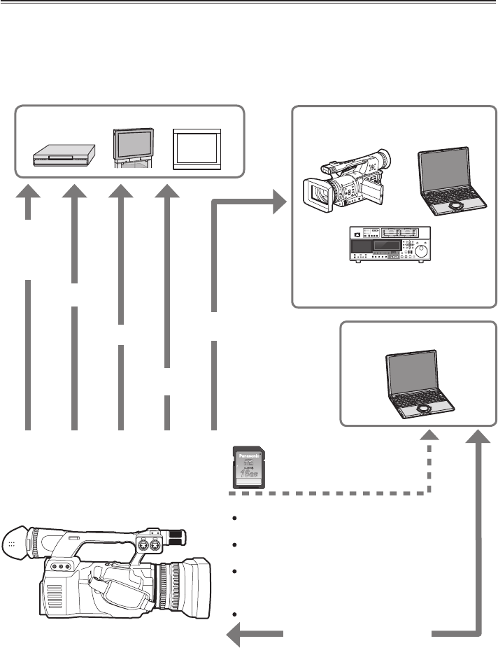
AG-AC160
DV tape equipment/memory card
camera-recorder/computer, etc.
Computer
Video equipment/television/monitor
Data can be transferred for
backup/dubbing/editing.
IEEE1394 (DV) cable
(can only be used in DV mode)
BNC Cable (SDI)
Audio pin cable
Video pin cable
HDMI cable
(can only be
used in
AVCHD mode)
Memory card
AVCHD mode
Speed class 4 or higher can be used when in PH/HA
mode.
Speed class 6 or higher can be used during VFR
recording.
DV mode
Speed class 6 or higher can be used.
USB2.0 connection cable
* The AG-AC160EJ cannot write to a memory card from a
computer.
Saves and reads the setting
values of scene files or user
files on the memory card.
Speed class 2 or higher can be used when in PM/HE
mode.
12
Read this rst! ................................................ 2
How to use the camera ................................ 11
Please read before use ................................ 14
Compatible memory card for this camera ..... 14
(SD speed class 4) ....................... 15
(SD speed class 6) ....................... 15
Operating precautions ................................. 16
Before use
Before using the camera.............................. 18
Accessories .................................................. 20
Optional accessories ................................... 20
Description of parts
Description of parts ...................................... 21
Left side ........................................................ 21
Top and right side ......................................... 22
Front side and rear side ................................ 23
Remote control ............................................. 24
Preparation
Recharging the battery ................................ 24
Recharging ................................................... 24
Power sources .............................................. 26
Using the battery........................................... 26
Using the AC adaptor.................................... 27
Adjusting the hand strap ............................. 27
Attaching the shoulder strap ....................... 28
Attaching/removing the lens hood ............. 28
Attaching/removing the lens cap ................ 28
Fitting the eye cup ........................................ 29
The remote control ....................................... 29
Inserting the battery ...................................... 29
Remote control usable range........................ 29
Turning the camera ON/OFF ........................ 30
SwitchingtoAVCHDmode/DVmode ........... 30
Setup menu basic operations ..................... 31
Using the setup menu ................................... 31
Initializingthesetupmenu ............................ 32
Setting the calendar ..................................... 33
Menu
Setup menu structure .................................. 35
<CAMERA> mode menu .............................. 35
Playback <PB> mode menu ......................... 37
Reference
Specications ............................................... 38
Contents
Volume 1 (This Book)

13
Volume 2 (CD)
Shooting
Using the viewnder
Tally lamp
Basic shooting operations
Using the zoom function
Shooting in manual mode
Shooting in 1080i/480i/576i progressive
mode
Using convenient shooting functions
Using special functions for recording
Adjusting the shutter speed
Changing audio input
Using shooting settings (scene les)
Storing scene les and other settings on
memory cards
Clip metadata (AVCHD mode only)
Using the counter
Charging the built-in battery/setting the
time code
Playback
Basic playback operations
Thumbnail screen
Playback settings [PLAY SETUP]
Thumbnail operations
Useful playback functions
Editing
Connecting external devices
Nonlinear editing
How to handle data recorded on the
memory card
Dubbing
Displays
Screen displays
Menu
Setup menu list
Reference
Before calling for service
Updating the rmware incorporated into
the unit
Cleaning
Storage precautions
Recording format list
Index
14
Compatible memory card for this camera
Shooting in AVCHD mode
Speedclass4oraboveisrequiredforrecordinginPHmode/HAmode.Speedclass2oraboveisrequired
forrecordinginPMmode/HEmode.Speedclass6oraboveisrequiredwhenusingtheVFRfunction.Itis
recommended that you use the following Panasonic memory cards. (As of September, 2011)
Shooting in DV mode
Speed class 6 or above memory cards are required. It is recommended that you use the following
Panasonic memory cards. (As of September, 2011)
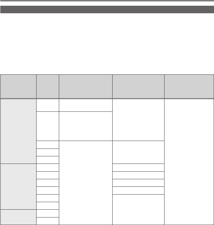
Memory card
type
Storage
capacity
AVCHD
shooting/playback
DV
shooting/playback
Saving/reading user
les and scene les
and reading metadata
(AVCHD only)
SD memory card
8 MB
16 MB Cannot be used.
Cannot be used.
Can be used.
32 MB
64 MB
128 MB
256 MB
Successful operation is
not guaranteed.
Shooting may suddenly
stop with certain SD
memory cards.
512 MB
Can be used.
Can be used.1 GB
2 GB
SDHC memory
card
4 GB Can be used.
6 GB —
8 GB Can be used.
12 GB —
16 GB
Can be used.
32 GB
SDXCmemory
card
48 GB
64 GB
—: No available Panasonic memory cards
•Please see our support page at the following website for the latest information not included in these
operating instructions.
http://pro-av.panasonic.net/
•This camera supports FAT12 and FAT16 formatted SD memory cards, FAT32 formatted SDHC memory
cards,andexFATformattedSDXCmemorycardsthatarecompliantwiththeSDstandard.
•SDHCmemorycardsof4GBorabovethatdonothavetheSDHClogoandSDXCmemorycardsof48
GBorabovethatdonothavetheSDXClogoarenotcompliantwiththeSDstandard.
•Use this camera to format memory cards. Formatting memory cards on computers or other devices may
cause recording to take longer than normal, or may cause memory cards to become incompatible with
this product. (Page 13 of Vol.2) (Use this camera to reformat any memory cards that have been formatted
on computers or other devices.)
•Multimedia cards cannot be used.
Please read before use

15
(SD speed class 4)
This refers to a class 4 speed standard (SD speed class) for the continuous writing of data between SD
compatible devices and memory cards as designated by the SD standard.
When the use of an SD speed class 4 memory card is recommended for SD-compatible products, this
indicates that stable recording operation can be achieved by using memory cards of class 4 and above.
(SD speed class 6)
This refers to a class 6 speed standard (SD speed class) for the continuous writing of data between SD
compatible devices and memory cards as designated by the SD standard.
When the use of an SD speed class 6 memory card is recommended for SD-compatible products, this
indicates that stable recording operation can be achieved by using memory cards of class 6 and above.
Reminders for handling
•Do not allow dirt, water, or other substances to come into contact with the terminal on the back of the
memory card.
•Do not leave the memory card in the following places:
- Direct sunlight or places of high temperature, such as near heating equipment
- Humid and dusty locations
- Locations with high variations in temperature (where condensation occurs)
- Locations that are subject to static electricity and electromagnetic waves
•Store memory cards in bags or cases after use.

16
When using the camera in the rain, snow, or at
the beach, do not allow water to get into it.
•Doing so will cause damage to the camera and
the memory card. (This may result in irreparable
damage.)
Keep the camera away from devices (such
as TV sets and video game machines) that
generate magnetic elds.
•Using the camera on top of or near a television
set may cause distortions in the image or sound
due to the electromagnetic waves that the
television emits.
•The powerful magnetic elds generated by
speakers or large motors may damage recorded
content or distort images.
•The electromagnetic waves emitted from a
microcomputer may adversely affect the camera
and cause images or sound to be distorted.
•If the camera is adversely affected by devices
that generate magnetic elds and it no longer
operates properly, turn it off and remove the
battery or unplug the AC adaptor from the power
outlet. Then install the battery again or reconnect
the AC adaptor. After this, turn the camera back
on.
Do not use the camera near radio transmitters
or high-voltage equipment.
•Using the camera near radio transmitters or high-
voltage equipment may adversely affect the
recorded images or sound.
Do not allow sand or dust to get into the
camera when using it at the beach or other
similar places.
•Sand and dust can damage the camera or
memory card. (Be careful when inserting or
removing a memory card.)
AC adaptor (battery charger) and battery
•If the <CHARGE> lamp continues to ash even
when the battery temperature is normal, the
battery or AC adaptor (battery charger) might be
damaged. Contact your dealer.
•The battery takes longer to charge when it is
warm.
•Using the AC adaptor (battery charger) near
radios may distort their sound. Keep the AC
adaptor (battery charger) 1 meter or more away
from radios.
•The AC adaptor (battery charger) may make
some noise when in use, but this is normal.
Be careful not to drop the camera when
carrying it around.
•Strong impacts may damage the camera unit and
cause it to stop working properly.
•Handle the camera with care using the hand
strap or shoulder strap to carry it.
Do not spray the camera with insecticides or
other volatile substances.
•Spraying the camera with insecticides or other
volatile substances may deform it or cause the
coating to peel off.
•Do not leave the camera in contact with rubber or
PVC products for extended periods of time.
After use, remove the battery or disconnect the
AC power supply cord from the power outlet.
Battery characteristics
This camera uses a rechargeable lithium ion
battery. It generates electrical energy through
an internal chemical reaction. This reaction is
easily inuenced by the ambient temperature
and humidity, and the effective operating time of
the battery is reduced as the temperature rises
or falls. If you use this camera at locations with
extremely low temperatures, its operating time will
be reduced.
If the battery becomes extremely hot, a protective
function will engage and you will not be able to use
it for a while.
Operating precautions

17
Make sure to remove the battery after use.
Completely remove the battery from the camera.
(Even if you turn the camera off, leaving the
battery attached still consumes a small amount of
electricity.) The battery will over-discharge if you
leave it in the camera for long periods of time and
may become impossible to recharge.
Do not remove the battery when the POWER
switch is ON.
Turn the POWER switch OFF and make sure that
the mode lamp is completely off before removing
the battery.
Protect the battery terminals.
Do not allow dust or foreign substances to cling to
the battery terminals.
If you accidentally drop the battery, check the body
and terminals if they have been deformed.
Inserting a deformed battery into the camera or
the AC adaptor (battery charger) may damage the
camera or the AC adaptor (battery charger).
Reminders when discarding memory cards or
transferring them to others
Formatting memory cards or deleting data using
the functions of this camera or a computer will
merelychangethelemanagementinformation
and will not completely erase the data stored
in the memory cards. It is recommended that
you physically destroy memory cards when
discarding them, or use data deletion software for
commercially available for computers to completely
erase the data when transferring them to others.
Users are responsible for managing the data stored
in their memory cards.
Liquid crystal displays
•Images or characters can linger on the screen of
theLCDorviewnderiftheyareleftdisplayed
foralongtime,butyoucanxthisbyleavingthe
camera off for several hours.
•The LCD monitor is managed with high precision
toensurethat99.99%ofthepixelsareeffective
leavingonly0.01%ofpixelsthatareeitherdead
or remain on all the time. This is normal and will
have no effect on recorded images.
•Dew may form on the LCD monitor if you use
the camera in locations of intensely varying
temperatures. Wipe it dry with a soft, dry cloth.
•The LCD monitor may appear a little dimmer right
after turning on a cold camera. The brightness will
go back to normal when the internal temperature
increases.
Do not point the eyepiece of the lens or
viewnder at the sun.
Doing so may damage the internal parts.
Protective caps for the terminals
Keepprotectivecapsttedoverconnecting
terminals that are not being used.
Mosaic-like noise may appear on the playback
images in the following shooting conditions.
•Whenthereisacomplexpatterninthe
background
•When moving the camera a long distance or
moving quickly
•When the subject is moving quickly
(Especially when shooting in HE mode)
Depending on the signal reading system of the
pickup devices (MOS sensor), the following
problems may occur.
•A subject that quickly crosses the screen may
appear distorted in some shooting conditions.
•Whenasubjectislitbytheash,thescreenmay
appearsplithorizontally.
(The possibility of the occurrence may be
reduced by setting the shutter speed lower.)
18
Before using the camera
Always take trial shots
•Whenshootingimportantevents(suchasweddings),makesuretotaketrialshotstoconrmthatsound
and image are being properly recorded before actual shooting.
Be sure to check and set the calendar and time zone
•These settings affect the control and playback sequence of recorded contents. Check and set the
calendarandtimezonebeforeshooting.(Page33)
There are no guarantees for recorded content
•In the unlikely event that content that was not recorded due to a malfunction in the camera or the memory
card in use, please understand that no compensation can be provided.
Copyrights
•Copyright laws forbid the use of video and audio material that you recorded for any purpose other than
your own personal enjoyment.
Caution regarding laser beams
•The lens may suffer damage if struck by a laser beam. Make sure that laser beams do not strike the lens
when shooting in an environment where laser devices are used.
Media that can be used with this camera
•SD/SDHC/SDXCmemorycardscanbeused.Seepage14fordetails.
Attaching the camera to a tripod
•Thetripodholesupports1/4-20UNCand3/8-16UNCscrews.Useitaccordingtothexingscrew
diameter of the tripod.
•Thedepthofthetripodholeis5.5mm.Donottightenthetripodscrewexcessivelywhenattachingthis
camera to a tripod.
Attach the tripod to the tripod hole on the bottom side.
Before use

19
Before use
■What is AVCHD?
AVCHDisastandardforrecordingandplaybackofhighdenitionvideo.
VideoiscompressedintheMPEG-4AVC/H.264format,andaudioisrecordedinDolbyDigitalorlinear
PCM.
■What is DV?
DVisaformatthatadoptstheAVIType2leformatthatcanrecordandplaybackvideoinDVmode.
It records audio in linear PCM format.
Regarding SDHC/SDXC memory card and recorded video compatibility, take note
of the following:
SDHC/SDXC memory cards
•SDHC/SDXCmemorycardscannotbeusedwithnon-SDHC/SDXC-
compatible equipment.
•Whenusinganotherdevice,ensurethatitsupportsSDHC/SDXCmemory
cards.
Compatibility of video recorded in AVCHD mode
•Recorded video cannot be used with non-AVCHD-compatible equipment.
•Playback may not always be possible on all AVCHD-compatible equipment. In such instances, play your
video using this camera.
•Thiscamerasupportsthesystemformats59.94Hzand50Hz.
InAVCHDmode,contentsindifferentsystemformats,recordedin59.94Hzandin50Hzcannotexist
on the same memory card.
Compatibility of video recorded in DV mode
•Thiscamerasupportsthesystemformats59.94Hzand50Hz.
InDVmode,contentsindifferentsystemformats,recordedin59.94Hzandin50Hzcanexistonthe
same memory card.
•When playing back memory cards recorded using the DV mode of the camera in Panasonic AG-HMC80
series
- [ ?] is displayed on the clip on the thumbnail screen.
- The playback will be images only. Audio is not played back.
- You cannot delete or repair a recorded clip, or add or remove a shot mark.
•When playing back a memory card recorded using a camera in Panasonic AG-HMC80 series on this
camera
- [ ?] is displayed on the clip on the thumbnail screen.
- Both image and audio can be played back.
- You cannot delete or repair a recorded clip, or add or remove a shot mark.
•For details about clips, see “Thumbnail screen” (Page 55 of Vol.2).
20
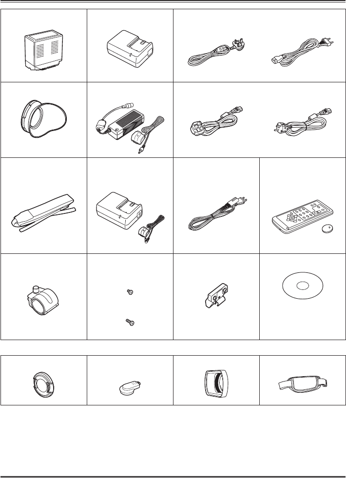
Optional accessories
•XLR microphone
AG-MC200G
•Battery
VW-VBG6(7.2V,5800/5400(typ./min.)mAh)
Battery* Battery charger
(for AG-AC160EJ)
AC power supply cables (for AG-AC160EJ/EN)
TYPE BF TYPE C
Eye cup (Page 29) AC adaptor/DC cord
(for AG-AC160EJ)
AC power supply cables (for AG-AC160EJ)
For the U.K.
For areas other than the U.K.
Shoulder strap (Page 28)
AC adaptor (Battery charger)/
DC cord
(for AG-AC160P/EN)
AC power supply cables
(for AG-AC160P)
Wireless remote control and
coin battery (CR2025)
(Page 29)
Microphone holder
(Page 67 of Vol.2)
Microphone holder screws
(Page 67 of Vol.2)
M4 length 6 mm (2 pieces)
M4 length 12 mm (2 pieces)
Microphone holder adaptor
(Page 67 of Vol.2)
CD-ROM
- Operating Instructions (PDF)
- AVCCAM Restorer Software
- AVCCAM SD Card File
Recovery Software
The following accessories are attached to the unit.
Lens cap (Page 28) INPUT terminal cap
(2 pieces)
Lens hood (Page 28) Hand strap (Page 27)
* For the part number of the battery, see “Optional accessories”.
•For the part number of the battery, see page 9.
•Consult your dealer when purchasing additional accessories.
•Adequately process the AC cord cap and the packaging material after taking out the product.
Accessories
21
Description
of parts Before use
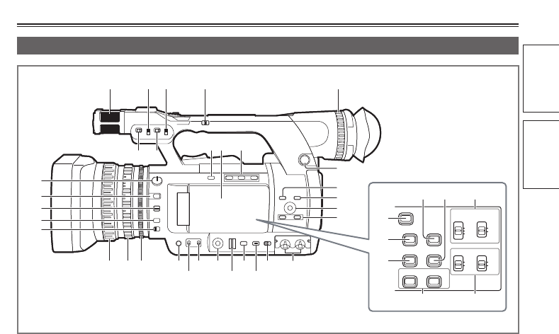
Left side
BARS
EVF DTL
LCD
COUNTER-RESET/TC SET
ZEBRA
CH1 SELECT
AUDIO
INT(L) INT(R)
INPUT1
INPUT2
INPUT2
CH2 SELECT
WFM
AUTO
MANU
CH2
AUTO
MANU
CH1
1 4
8 9 10
5
16
3
6 7
21 24
25
26 27
28
29
30
31 3222 23
2
17
18
19
20
11
12
13
14
15
35
39 40
38
33 34
36
37
Description of parts
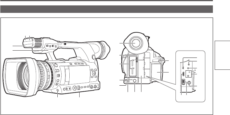
1 Built-in microphone (Page 41 of Vol.2)
2 INPUT1 switch (MIC POWER + 48V) (Page 42
of Vol.2)
3 INPUT2 switch (MIC POWER + 48V) (Page 42
of Vol.2)
4 HANDLE ZOOM switch (Page 17 of Vol.2)
5 Diopter adjustment dial (Page 5 of Vol.2)
6 INPUT1 LINE/MIC switch (Page 42 of Vol.2)
7 INPUT2 LINE/MIC switch (Page 42 of Vol.2)
8 OIS button (Page 27 of Vol.2)
9 LCD monitor (Page 6 of Vol.2)
10 USER button (Page 27 of Vol.2)
11 ND FILTER dial (Page 20 of Vol.2)
12 FOCUS ASSIST button (Page 19 of Vol.2)
13 FOCUS switch (Page 18 of Vol.2)
14 PUSH AUTO button (Page 18 of Vol.2)
15 ZOOM switch (Page 17 of Vol.2)
16 SCENE FILE dial (Page 44 of Vol.2)
17 MENU button (Page 31)
18 EXEC button (Page 61 of Vol.2)
19 OPERATION lever (Page 31)
20 AUDIO MON/ADV button (Page 29 of Vol.2)
21 Focus ring (Page 18 of Vol.2)
22 Zoom ring (Page 17 of Vol.2)
Ifyoudonotneedthezoomringpin,attachitto
thezoomringpinhole(Page22)topreventtheloss.
23 IRIS ring (Page 19 of Vol.2)
24 IRIS button (Page 19 of Vol.2)
25 GAIN switch (Page 20 of Vol.2)
26 WHITE BAL switch (Page 20 of Vol.2)
27 FUNCTION knob (Page 26 of Vol.2)
28 SHTR/F.RATE dial (Page 37 of Vol.2)
29 DIAL SEL button (Page 37 of Vol.2)
30 DISP/MODE CHK button (Page 25 of Vol.2)
31 AUTO/MANU switch (Page 18 of Vol.2)
32 AUDIO LEVEL knob (CH1, CH2) (Page 43 of
Vol.2)
33 ZEBRA button (Page 25 of Vol.2)
34 WFM button (Page 28 of Vol.2)
35 AUDIO CH1/CH2 SELECT switch (Page 41 of
Vol.2)
36 BARS button (Page 28 of Vol.2)
37 EVF DTL button (Page 6 of Vol.2)
38 LCD button (Page 8 of Vol.2)
39 COUNTER-RESET/TC SET button (Page 50 of
Vol.2)
40 AUDIO AUTO/MANU CH1/CH2 switch (Page 43
of Vol.2)
Description of parts
22
Top and right side
14 15
8
21
3
4
5
6
97
11 131210
16
1 VIDEO OUT (TC PRESET IN/OUT) terminal
(Page 70 of Vol.2)
2 AUDIO OUT CH1/CH2 terminal (Page 70 of
Vol.2)
3 Mode lamp (Page 30)
4 POWER/MODE switch (Page 30)
5 Lock release button (Page 30)
6 START/STOP button (Page 11 of Vol.2)
7 Protective caps
8 Shoulder strap mounting location (Page 28)
9 Zoom lever (handle side) (Page 17 of Vol.2)
10 REC CHECK button (Page 12 of Vol.2)
11 Zoom lever (Page 17 of Vol.2)
12 AUDIO INPUT1/2 terminal (XLR 3-pin) (Page 42
of Vol.2)
13 Zoom ring pin hole
14 HOLD switch (Page 24 of Vol.2)
15 START/STOP button (handle side) (Page 24 of
Vol.2)
16 Accessory shoe
23
Description
of parts
Front side and rear side
1 2
5 6
3
4
7
8
9
10
11
12
13
14 15 16
18
19
20
21
23
17
22
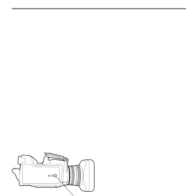
1 Remote control sensor (front) (Page 29)
2 Natural light sensor (Page 22 of Vol.2)
3 Tally lamp (front) (Page 9 of Vol.2)
4 Built-in speaker (Page 66 of Vol.2)
5 AWB button (Page 20 of Vol.2)
6 Tripod hole (bottom) (Page 18)
7 Viewnder (Page 5 of Vol.2)
8 Memory card slot cover and OPEN lever
(Page 10 of Vol.2)
9 Memory card slot and memory card access
lamp (Page 12 of Vol.2)
10 Tally lamp (rear) (Page 9 of Vol.2)
11 Remote control sensor (rear) (Page 29)
12 Battery release button (Page 26)
13 Battery compartment (Page 26)
14 HD indicator (Page 30)
15 SLOT SEL button (Page 12 of Vol.2)
16 Protective caps
Keepprotectivecapsttedoverconnecting
terminals that are not being used.
17 USB2.0 terminal (Page 68 of Vol.2)
18 Headphone jack (3.5 mm stereo mini jack)
(Page 67 of Vol.2)
19 INDEX REMOTE jack (2.5 mm super mini
jack)
20 CAM REMOTE jack* FOCUS/IRIS (3.5 mm
mini jack)
You can connect a remote control unit (optional)
to control the FOCUS and IRIS operations.
ZOOM S/S (2.5 mm super mini jack)
You can connect a remote control unit to control
thezoomandrecordingstart/stopoperation.
* Donotconnectanyequipmentexcepttheremote
control to the <CAM REMOTE> jack. Connecting
any equipment other than the remote control may
cause the image brightness to change or the images
to appear out of focus.
21 SDI OUT terminal (Page 70 of Vol.2)
22 HDMI OUT terminal (Page 70 of Vol.2)
23 DV OUT terminal (Page 69 of Vol.2)
24
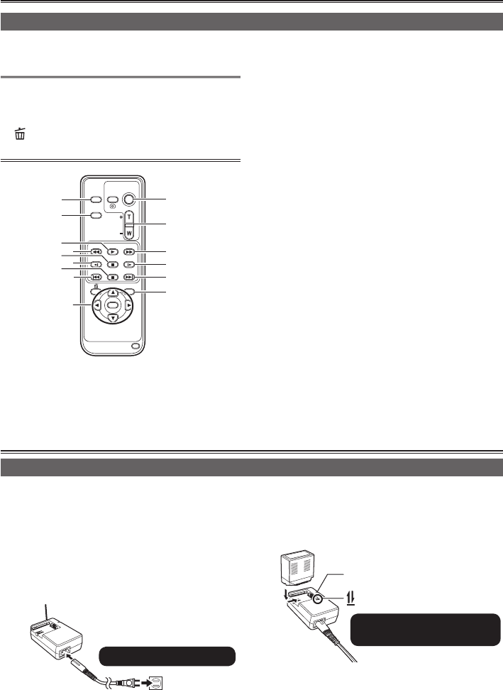
Remote control
When using the remote control, set the [IR REMOTE] on the [OTHER FUNCTIONS] menu to [ON]. The
factory setting is set to [OFF]. (Page 97 of Vol.2)
Take note that the following buttons are for
functionsthatcannotbeexecutedonthis
camera.
• button
•PHOTO SHOT button
ZOOM
START/
STOP
PHOTO
SHOT
EXT
DISPLAY
DATE/
TIME
VOL
PLAY
STOPSKIP SKIP
MENU
ENTER
PAUSE
SEARCH
STILL ADV STILL ADV
SEARCH
3
4
6
8
1
2
5
78
910
11
6
10
12
Remote control usable range (Page 29)
1 EXT DISPLAY button
(Page 66 of Vol.2)
2 DATE/TIME button (Page 66 of Vol.2)
3 START/STOP button
Samefunctionasthe<START/STOP>button
on the camera.
4 ZOOM/VOL button
(Page 66 of Vol.2)
5 PLAY button (Page 54 of Vol.2)
6 SEARCH button (Page 54 of Vol.2, Page 65 of
Vol.2)
7 PAUSE button (Page 54 of Vol.2)
8 STILL ADV button (Page 66 of Vol.2)
9 STOP button (Page 54 of Vol.2)
10 SKIP button (Page 54 of Vol.2, Page 65 of Vol.2)
11 OPERATION buttons
Same function as the OPERATION lever on the
camera.
12 MENU button
Same function as the MENU button on the
camera.
Preparation
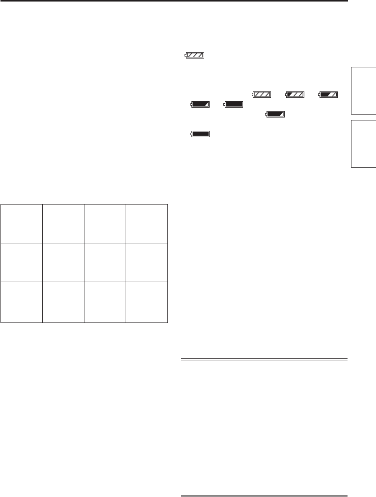
Recharging
1 Connect the power cord to the AC adaptor.
•Disconnect the DC cord. The battery cannot
be charged if the DC cord is connected. (For
AG-AC160P/AG-AC160ENonly)
(1) (2)
Insert until fully in place.
DC cord
Example: AG-AC160P
2 Insert the battery.
Charging lamp <CHARGE>
Align the battery with the mark
and insert fully.
The battery is not charged at the time of purchase. Charge the battery before use.
Itisrecommendedthatyoukeeponeextrabatteryasaspare.
Recharging the battery
25
Description
of parts
Preparation
Charging lamp
ON: Charging
OFF: Charging complete
Flashing: See below
If the charging lamp is ashing
Conrmthatthereisnodirt,dust,orforeign
substances attached to the connectors of the
battery or the AC adaptor and ensure that the
adaptor has been connected correctly.
•If there is dirt, dust, or foreign substances on the
connectors, disconnect the power plug from the
socket before cleaning.
•Ifthecharginglampcontinuestoash,the
battery or the AC adaptor may be damaged.
Consult the dealer where it was purchased.
Charging time and available recording time
standards
Battery
model
Voltage/
capacity
Charging
time
Maximum
continuous
recording
time
CGA-E/625
(bundled)
7.2V/
5800/5400
(typ./min.)
mAh
Approx.5
hours and
50 minutes
Approx.3
hours and
30 minutes
VW-VBG6
(optional)
7.2V/
5800/5400
(typ./min.)
mAh
Approx.5
hours and
50 minutes
Approx.3
hours and
30 minutes
•Theguresintheprecedingtablearefornormal
temperatureconditions(temperature25°C(77°F)/
humidity 60%). This only serves as a guide
since charging may take longer in high or low
temperatures.
•Charging may take longer if the battery has not
been in use for a long period of time.
•Givenherearethestandardmaximumcontinuous
recordingtimeswhenrecordinginPH1080/60i
(PH1080/50i)modeusingtheviewnderwithno
connectionstoanyexternaldevicesandwiththe
LCD monitor closed.
•This serves only as a guide as available recording
times may vary according to usage conditions.
•Charging times are based on the time to charge
batteries from an empty state.
Remaining battery capacity display
When using Panasonic batteries that are
compatible with this product, the remaining battery
capacity is displayed in minutes.
[] 1h30m
The time remaining (as shown previously) is
displayed after a brief pause.
•As battery capacity decreases, the display will
change as follows:
[ ][ ][ ]
[][ ].
When there are only 3 minutes
or less of capacity left, [ ] will be displayed
in red, and when the battery becomes empty,
[]willash.
•The remaining battery capacity may not be
displayed correctly when the battery is used in
high or low temperatures, or when the battery
has not been used for a long period of time. To
ensure that the remaining battery capacity is
displayed correctly, use the battery completely
from a fully-charged state and charge it again.
(Remaining battery capacity may still not be
displayed correctly if the battery has been used
for long periods in high or low temperatures,
or if the battery has already been recharged
numerous times.)
•This only serves as a guide as remaining battery
capacity display times may vary according to
usage conditions.
•The remaining battery capacity display will
momentarily disappear when switching between
modes, when conducting REC CHECK
operations, or when changing the LCD brightness
since the capacity is recalculated during these
times.
•This is not displayed when using the AC adaptor.
•The battery and the camera itself becomes hot
while it is being used or charged.
•Available recording time is reduced if you
repeatedly start and stop recording.
•The battery takes longer to charge when it is
warm.
•Using the AC adaptor near radios may distort
their sound. Keep the AC adaptor 1 meter or
more away from radios.
•The AC adaptor may make some noise when
in use, but this is normal.
•The battery cannot be recharged when a DC
cord is connected to the AC adaptor.
26
Power sources
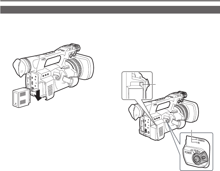
Using the battery
Installation
1 Insert the battery until it clicks into place.
Removal
1 Turn the POWER/MODE switch <OFF> (Page 30),
and confirm that the mode lamp is off.
2 Remove the battery while pressing the
battery release button.
Support the battery with your hand to ensure
that it will not fall.
Battery release
button
Mode lamp
27
Preparation
Using the AC adaptor
Installation
1 Connect the DC cord to the AC adaptor.
2 Plug the AC cord into the power outlet.
3 Insert the DC cord’s battery connector until
it clicks into place.
DC cord’s battery connector
Example: AG-AC160P
Removal
1 Turn the POWER/MODE switch <OFF> (Page 30),
and confirm that the mode lamp is off.
2 Remove the DC cord’s battery connector
while pressing the battery release button.
3 Disconnect the AC cord from the power
outlet.
•The battery cannot be recharged when a DC
cord is connected to the AC adaptor. (For AG-
AC160P/AG-AC160ENonly)
•Disconnect the AC cord from the power outlet
when this device is not in use.
CAUTION:
• This apparatus can be operated at a volt-
age in the range of 110 – 240 V AC.
Voltages other than 120 V are not intended
for U.S.A. and Canada.
Operation at a voltage other than 120 V AC
may require the use of a different AC plug.
Please contact either a local or foreign
Panasonic authorized service center for as-
sistance in selecting an alternate AC plug.
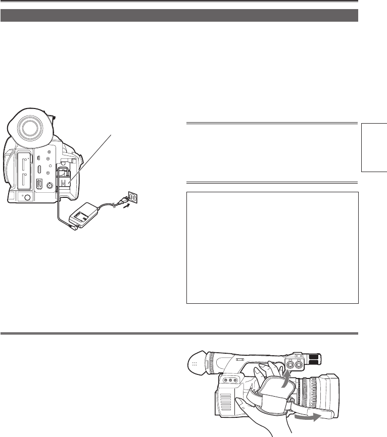
Adjusting the hand strap
Adjust the hand strap to suit your hand.
1 Open the cover and adjust the length of the
strap.
2 Close the cover.
•Makesurethatthecoverisrmlyclosed.
28
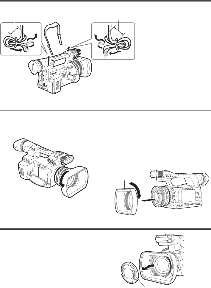
Attaching the shoulder strap
It is recommended that you attach the shoulder strap to avoid dropping the camera.
20 mm or longer
20 mm or longer
Attaching/removing the lens hood
Removing the lens hood
•Turn the lens hood counterclockwise to remove
it.
Attaching the lens hood
•Attach the lens hood to the camera with the lens
hood guide facing up and aligned to the center of
the camera.
•Turn the lens hood clockwise until it clicks and
locks into place.
(1)
(2)
Center of the camera
The side with lens
hood guide
Attaching/removing the lens cap
Removing the lens cap
•Pinch the lens cap to remove it.
Attaching the lens cap
•Pinch the lens cap to attach it.
•Keep the lens cap attached when the camera is
not in use to protect the lens.
Lens cap
29
Preparation
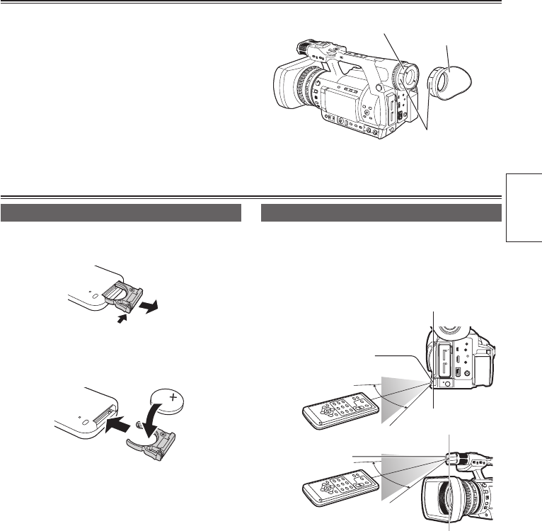
Fitting the eye cup
Attachtheeyecupbyttingtheeyecupholderand
the ridges of the eye cup together.
•Turning the eye cup after attaching it may
cause the eye cup holder to come off. If the eye
cup holder does come off, see “Cleaning the
viewnder”(Page106ofVol.2)andretit.
Eye cup holder
Eye cup
Ridges
The remote control
Inserting the battery
1 Remove the holder while pushing the catch
in the direction shown by arrow (1).
(1)
(2)
2 Insert the battery with the side marked with
<+> facing up.
3 Return the holder to its original position.
•When the battery (CR2025) runs out, replace
it with a new one. (Battery life depends on the
frequencyofusagebutisapproximatedat
about one year.)
If the remote control unit fails to work even
when it is operated near the camera’s remote
control sensor, it means that the battery has
run out.
•Keep the battery out of the reach of
children.
Remote control usable range
For the remote control sensor,
Distance:Approx.within5m
Angle:Approx.10°upward,15°downward,and
15° sideways
(using the accessory battery)
Remote control
sensor (rear)
Remote control
sensor (front)
•These are the operation range values when the
remote control is used indoors. If used outdoors
or if strong light is hitting the remote control
sensor, the remote control may not operate
properly even within the said ranges.
•The remote control is set to [OFF] in the factory
settings. When using the remote control, set the
[IR REMOTE] on the [OTHER FUNCTIONS]
menu to [ON]. (Page 97 of Vol.2)
30
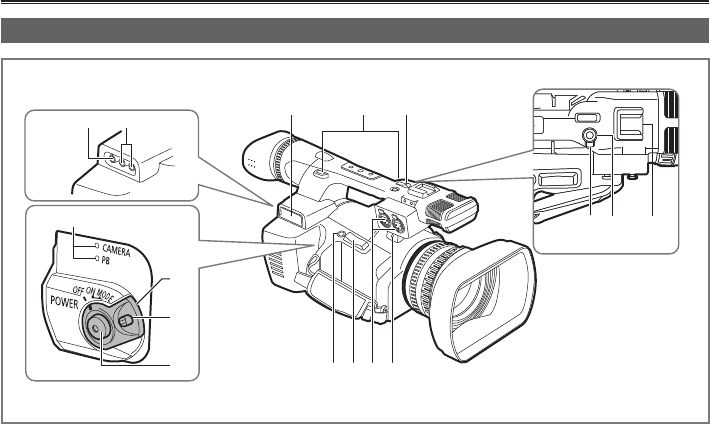
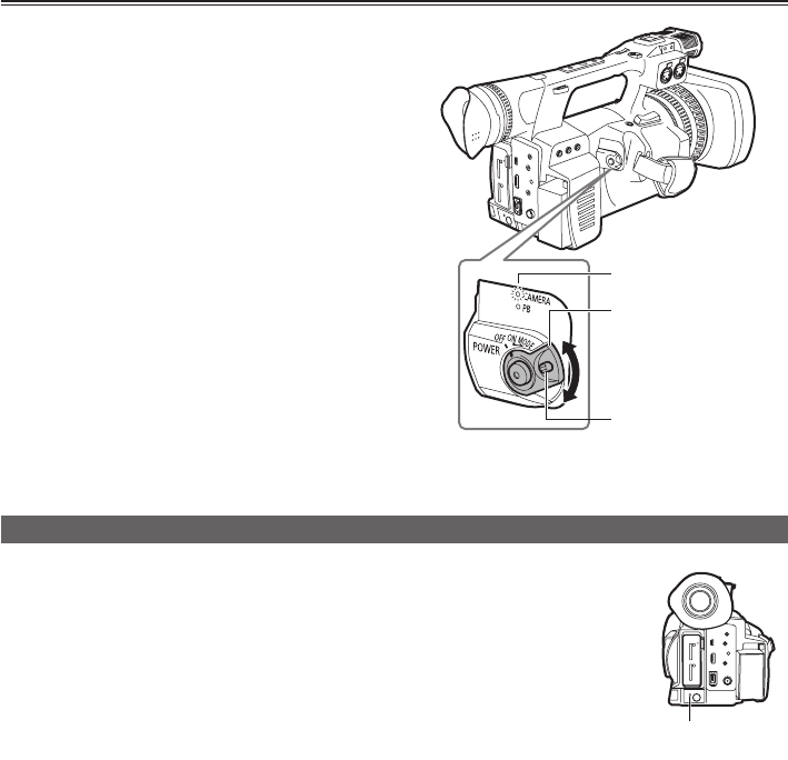
Turning the camera ON/OFF
Turning on the power:
TurnthePOWER/MODEswitchuptothe<ON>
position while pressing the lock release button.
The mode lamp <CAMERA> lights up in red and
the camera goes to recording standby status
(<CAMERA> mode).
•IfthePOWER/MODEswitchisturneduptothe
<MODE> position, the mode lamp <PB> will light
up in green and the camera goes to <PB> mode.
(Page 54 of Vol.2)
•Every time the switch is turned to the <MODE>
position, the mode will change between
<CAMERA> mode and <PB> mode.
Turning off the power:
TurnthePOWER/MODEswitchuptothe<OFF>
position while pressing the lock release button.
Themodelamp<CAMERA>/<PB>goesoff.
Lock release button
POWER/MODE switch
Mode lamp
Switching to AVCHD mode/DV mode
1 Turn the camera’s POWER/MODE switch <ON>. (Page 30)
2 Press the <MENU> button.
3 Set [AVCHD] or [DV] from the [HD/SD MODE] items in the setup menu
[RECORDING SETUP] screen.
4 When the [TURN POWER OFF] message is displayed, turn the power
OFF and then ON again.
When the power is turned on again, the mode changes.
•ForinstructionsonhowtoturnthecameraON/OFF,refertopage30.
•When you switch to AVCHD mode, <HD> indicator will light up in blue.
•When you switch to DV mode, <HD> indicator will turn off.
<HD> indicator
31
Preparation
You can change camera settings using the setup
menu according to the shooting scene and
recording details.
<MENU> button
OPERATION
lever
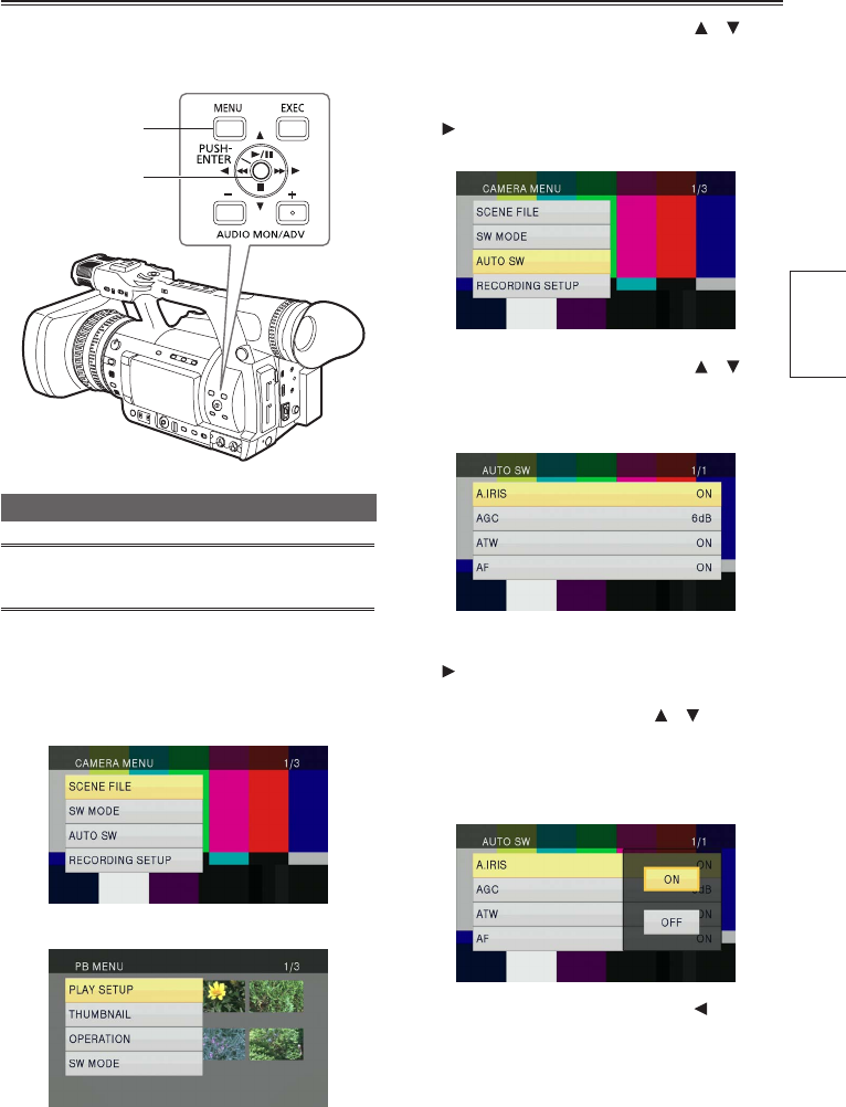
Using the setup menu
•The menu items displayed in gray characters
cannot be changed.
1 Press the <MENU> button when the camera
is not shooting or playing back video.
The following menu screens are displayed on
the viewnder and LCD monitor.
<CAMERA> mode (Example)
<PB> mode (Example)
2 Tilt the OPERATION lever in the < >< >
directions to move the yellow cursor to the
function you wish to set.
3 Press the OPERATION lever (or tilt it in the
<> direction) to display the setting items.
Example:
4 Tilt the OPERATION lever in the < >< >
directions to move to the function you wish
to set.
Example:
5 Press the OPERATION lever (or tilt it in the
<> direction) to make the setting.
When changing values or other parameters, tilt
the OPERATION lever in the < >< > directions
to change the setting value. Select the item you
wish to set, and then press the OPERATION
lever to conrm.
Example:
•Tilt the OPERATION lever in the < > direction
to return to the previous menu.
Setup menu basic operations

32
6 Repeat steps 4 to 5 to change other items.
Press the <MENU> button to complete settings
and return to the normal screen.
•In some menus, tilting the OPERATION
lever in the < > direction or pushing the
OPERATION lever changes the setting value
and returns the previous menu.
7 Repeat steps 2 to 5 to change other
functions.
Press the <MENU> button to complete settings
and return to the normal screen.
Initializing the setup menu
Thesetupmenuisdividedintouserlesandscene
lesandyoucaninitializeeachonetoitsfactory
settings.
To initialize user les (all items other than
scene les)
Byselecting[INIT]inthe[LOAD/SAVE/INIT]item
of the [USER FILE] screen, you can restore the
currentuserlemenusettingtoitsfactorysetting.
To initialize scene les
Amongthesixsceneles,selecttheleyouwish
toinitializeusingthe<SCENEFILE>dial.Then
byselecting[INIT]inthe[LOAD/SAVE/INIT]item
of the [SCENE FILE] screen, you can restore the
settingvalueofonlytheselectedsceneletoits
factory setting.
•Toinitializeuserlesandscenelesatthe
sametime,restoreauserleandallsixscene
lestotheirfactorysettingsbyselecting
[YES] in the [MENU INIT] item of the [OTHER
FUNCTIONS] screen.
•Timecode/[OPERATIONTIME]item/[CLOCK
SET]item/[TIMEZONE]itemsettingvalues
arenotinitialized.
33
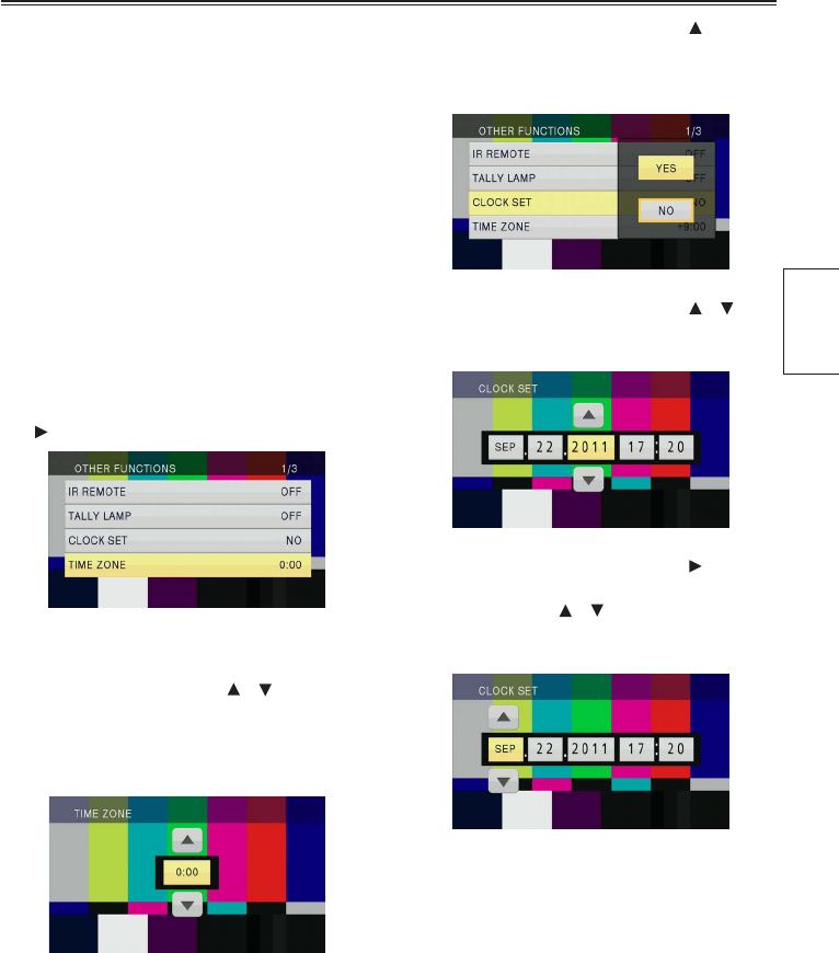
Preparation
The [CLOCK SET] value is recorded in the
contents (clip) and affects the playback sequence
of the thumbnails. Before shooting, be sure to
check/setthe[TIMEZONE]and[CLOCKSET].
Thissectionwillexplainthestepsonhowtosetthe
calendar to September 22, 2011, 17:20.
1 Turn the camera’s POWER/MODE switch
<ON>. (Page 30)
2 Press the <MENU> button.
•Menu operation (Page 31)
•Operations can also be performed using
buttons on the remote control that correspond
to those on the camera. For details, see
“
Remote control
”
(Page 24).
3 Select the [TIME ZONE] item on the setup
menu [OTHER FUNCTIONS] screen and
press the OPERATION lever (or tilt it to the
<> direction).
4 Since pressing the OPERATION lever
will display the settings screen, tilt the
OPERATION lever in the < >< > directions
to set the time difference from Greenwich
Mean Time, then press the OPERATION
lever again.
Factory default setting is [0:00].
5 Tilt the OPERATION lever in the < >
direction and select [YES] in the [CLOCK
SET] item on the setup menu [OTHER
FUNCTIONS] screen.
6 Tilt the OPERATION lever in the < >< >
directions to set to [2011].
Example: AG-AC160P
7 Tilt the OPERATION lever in the < >
direction to change to the next item, then tilt
the lever in the < >< > directions to set to
[09].
Example: AG-AC160P
Setting the calendar

34
8 Repeat steps 6 and 7 to set the remaining
items.
Example: AG-AC160P
•The date can be set to any date between
January 1, 2000 and December 31, 2039.
•For any date after December 31, 2039, [--] will
appear on the display.
•Time is displayed in the 24-hour format.
9 When settings are complete, press the
OPERATION lever.
•Thetimecanbeinaccuratesoconrmthatthe
time is correct before shooting.
•When using the camera overseas, do not set
the [CLOCK SET] to the local time but instead
enter the time difference from Greenwich
MeanTimeaccordingtothe[TIMEZONE].
(Page 98 of Vol.2)

35
Menu Preparation
Setup menu structure
<CAMERA> mode menu
CAMERA MENU
SCENE FILE LOAD/SAVE/INIT
(Page 83 of Vol.2) VFR MODE*2
FRAME RATE*2
SW MODE FUNCTION KNOB SYNC SCAN TYPE
(Page 86 of Vol.2) LOW GAIN SYNCHRO SCAN
MID GAIN DETAIL LEVEL
HIGH GAIN V DETAIL LEVEL
SUPER GAIN DETAIL CORING
ATW CHROMA LEVEL
MF ASSIST CHROMA PHASE
HANDLEZOOM COLOR TEMP Ach
USER1 COLOR TEMP Bch
USER2 MASTER PED
USER3 A.IRIS LEVEL
WFM DRS
LCD DRS EFFECT
FACE FRAMING GAMMA
KNEE
MATRIX
SKIN TONE DTL
CARD READ
CARD WRITE
NAME EDIT
AUTO SW A.IRIS
(Page 88 of Vol.2) AGC
ATW
AF
RECORDING SETUP HD/SDMODE
(Page 89 of Vol.2) REC FORMAT
ASPECT CONV*1
TC/UBSETUP TC MODE*3 PREREC MODE
(Page 91 of Vol.2) TCG SIMUL REC
TC PRESET RELAY REC
UB MODE*1 INTERVAL REC*2
UB PRESET TIME STAMP
EXTTCLINK PH AUDIO MODE*2
AUDIO LIMITER CH1
AUDIO LIMITER CH2
MIC GAIN1
MIC GAIN2
AV OUT SETUP SDI&HDMI OUT SEL*2
(Page 92 of Vol.2) SDI OUT
SDI 24PsF*2 *3
SDI EDH
DOWNCON MODE
*
2
HP MODE
TEST TONE
VIDEO SETUP*3
AUDIO OUT
*1 Only in DV mode.
*2 Only in AVCHD mode.
*3 CanonlybeusedwhenSYSTEMFREQ=59.94HzissetinOTHERFUNCTIONSintheCAMERAmode.
Menu

36
DISPLAY SETUP ZEBRADETECT1
(Page 93 of Vol.2) ZEBRADETECT2
Y GET MARKER
SAFETYZONE*4
CARD FUNCTIONS CARD FORMAT CENTER MARKER
(Page 96 of Vol.2) CARD STATUS FOCUS BAR
IRIS METER
REC COUNTER
VIDEO OUT OSD
USER FILE CARD READ DATE/TIME
(Page 96 of Vol.2) CARD WRITE DATE FORMAT
LOAD/SAVE/INIT LEVEL METER
ZOOM&FOCUS
CARD&BATTERY
OTHER DISPLAY
LCD SET
META DATA*2 CARD READ EVF SET
(Page 97 of Vol.2) RECORD LCD BACKLIGHT
USER CLIP NAME SELF SHOOT
META DATA PROP EVF MODE
CLIP COUNTER RST EVF COLOR
META INIT SET
OTHER FUNCTIONS IR REMOTE
(Page 97 of Vol.2) DV CONTROL*1
DV CMD SEL*1
TALLY LAMP
OPTION MENU*1*5 1394 STATUS CLOCK SET
(Page 99 of Vol.2) 1394 CONFIG TIMEZONE
LANGUAGE
SYSTEM FREQ
SYSTEM INFO
MENU INIT
OPERATION TIME
*1 Only in DV mode.
*2 Only in AVCHD mode.
*4 Only Limited functions are available in DV mode.
*5 YoucandisplaytheOPTIONMENUbypressingtheCHKbuttonwhilepressingtheDISP/MODECHKbutton.

37
Menu
Playback <PB> mode menu
PB MENU
PLAY SETUP PB FORMAT*2
(Page 99 of Vol.2) REPEAT PLAY
RESUME PLAY
THUMBNAIL THUMBNAIL MODE SKIP MODE*2
(Page 100 of Vol.2) INDICATOR
DATA DISPLAY
DATE FORMAT
OPERATION DELETE
(Page 100 of Vol.2) INDEX*2
CLIP PROTECT*2
REPAIR*1
SW MODE USER1
(Page 86 of Vol.2) USER2
USER3
LCD
AV OUT SETUP SDI&HDMI OUT SEL*2
(Page 92 of Vol.2) SDI OUT
SDI 24PsF*2 *3
SDI EDH
DOWNCON MODE*2
VIDEO SETUP*3 VIDEO OUT OSD
AUDIO OUT DATE/TIME
DATE FORMAT
LEVEL METER
CARD&BATTERY
OTHER DISPLAY
LCD SET
DISPLAY SETUP EVF SET
(Page 93 of Vol.2) LCD BACKLIGHT
EVF MODE
EVF COLOR
CARD FUNCTIONS CARD FORMAT
(Page 96 of Vol.2) CARD STATUS
CLIP PROPERTY
USER FILE CARD READ
(Page 96 of Vol.2) CARD WRITE
LOAD/SAVE/INIT
OTHER FUNCTIONS IR REMOTE
(Page 97 of Vol.2) CLOCK SET
TIMEZONE
LANGUAGE
SYSTEM INFO
OPERATION TIME
*1 Only in DV mode.
*2 Only in AVCHD mode.
*3 CanonlybeusedwhenSYSTEMFREQ=59.94HzissetinOTHERFUNCTIONSintheCAMERAmode.

38
General
Supply voltage
DC7.2V(whenthebatteryisused)/
DC 7.3 V (when the AC adaptor is used)
Power consumption
Recording: 11.8 W
indicates safety items.
Ambient operating temperature
0°C - 40°C (32°F to 104°F)
Ambient operating humidity
10% to 80% (no condensation)
Weight
Approx.2.4kg(5.3lb)(excludingthebatteryand
accessories)
Dimensions (W x H x D)
180mmx195mmx438mm(7inchesx7-11/16
inchesx17-1/4inches)
(excludingwidth,height,depth,andprotruding
part)
Camera
Pickup devices
1/3MOSxedpickupdevicex3
(2.2megapixelsprogressivesupported)
Lens
Opticalimagestabilizerlens,
Electric/manualswitching,22Xzoom,
F1.6 - 3.2 (f = 3.9 mm to 86 mm)
(35 mm conversion: 28 mm - 616 mm)
Color separation optical system
Prism format
Filter diameter
72 mm
ND lter
OFF,1/4,1/16,1/64
Minimum shooting distance
Approx.1m
Gain settings
0/+3/+6/+9/+12/+15/+18/+24/+30dB
* +24 dB and +30 dB are assigned to the USER
button (S.GAIN)
Color temperature settings
ATW, ATW LOCK, preset 3200 K,
preset 5600 K, preset VAR, Ach, Bch
Digital zoom
2X/5X/10X
* assigned to the USER button (ratio is changed
every time the button is pressed)
Minimum subject illumination
0.4lx(F1.6,gain+30dB,shutterspeed1/30
seconds)
Lens hood
Wideeldlargelenshood
Shutter speed
Preset
whenSYSTEMFREQ=59.94Hz:
60i/60Pmode:
1/60,1/100,1/120,1/250,1/500,1/1000,
1/2000seconds
30P mode:
1/30,1/50,1/60,1/120,1/250,1/500,
1/1000,1/2000seconds
24P mode:
1/24,1/50,1/60,1/120,1/250,1/500,
1/1000,1/2000seconds
whenSYSTEMFREQ=50Hz:
50i/50Pmode:
1/50,1/60,1/120,1/250,1/500,1/1000,
1/2000seconds
25P mode:
1/25,1/50,1/60,1/120,1/250,1/500,
1/1000,1/2000seconds
* Underline indicates value when shutter is OFF
Synchro scan
whenSYSTEMFREQ=59.94Hz:
when SYNC SCAN TYPE = sec
60i/60Pmode:
1/60.0seconds-1/249.8seconds
30P mode:
1/30.0seconds-1/249.8seconds
24P mode:
1/24.0seconds-1/249.8seconds
when SYNC SCAN TYPE = deg
3.0d - 180.0d - 360.0d
(0.5d increments, angle display)
whenSYSTEMFREQ=50Hz:
when SYNC SCAN TYPE = sec
50i/50Pmode:
1/50.0seconds-1/250.0seconds
25P mode:
1/25.0seconds-1/250.0seconds
when SYNC SCAN TYPE = deg
3.0d - 180.0d - 360.0d
(0.5d increments, angle display)
Specications
Reference

39
Reference
Slow shutter speed (can only be set when the
VFR MODE in the SCENE FILE screen is OFF)
whenSYSTEMFREQ=59.94Hz:
60i/60Pmode:
1/8,1/15,1/30seconds
30P mode:
1/8,1/15seconds
24P mode:
1/6,1/12seconds
whenSYSTEMFREQ=50Hz:
50i/50Pmode:
1/6,1/12,1/25seconds
25P mode:
1/6,1/12seconds
Image/Recording/Playback
AVCHD mode
Recording format
AVCHD standard compliant
Compression formats
MPEG-4AVC/H.264
Recording media
SD memory card:
512 MB, 1 GB, up to 2 GB
(FAT12, FAT16 formats supported)
SDHC memory card:
4 GB, 6 GB, 8 GB, 12 GB, 16 GB, 32 GB
(FAT32 format supported)
SDXCmemorycard:
48 GB, 64 GB, up to 2 TB
(exFATformatsupported)
However, memory cards above Class 4 is
supportedinPH/HAmode,memorycardsabove
Class2issupportedinPM/HEmode,and
memory cards above Class 6 is supported during
VFR recording.
Recording format (recording mode and
resolution)
whenSYSTEMFREQ=59.94Hz(Theframe
rates in the setup menu are 60P, 60i, 30P, and
24P.):
PH1080/59.94i
PH1080/29.97P
PH1080/23.98P(Nativerecording)
PH720/59.94P
PH720/29.97P
PH720/23.98P(Nativerecording)
PM720/59.94P
HA1080/59.94i
HE1080/59.94i
whenSYSTEMFREQ=50Hz:
PH1080/50i
PH1080/25P
PH720/50P
PH720/25P
PM720/50P
HA1080/50i
HE1080/50i
Transmission rate
PHmode:Approx.21Mbps(VBR)
PMmode:Approx.8Mbps(VBR)
HAmode:Approx.17Mbps(VBR)
HEmode:Approx.6Mbps(VBR)
Interval recording
OFF/1s/10s/30s/1min/2min
*Fortherecordingmode,PH1080/24P(when
SYSTEMFREQ=59.94Hz),PH1080/25P
(whenSYSTEMFREQ=50Hz)xed,and
shootingtimehasamaximumof168hours
(1 week)
VFR recording
whenRECFORMAT=1080/24P,1080/30P:
2*/6/9/12/15/18/20/21/22/24/25/
26/27/28/30/32/34/36/40/44/48/
54/60frames/second
whenRECFORMAT=1080/25P:
2*/6/9/12/15/18/20/21/22/23/24/
25/26/27/28/30/32/34/37/42/45/
48/50frames/second
*Gainvalueisxedat0dBandthecamerais
set to manual focus mode.
DV mode
Recording format
DV standard compliant
File format
AVI Type2
Recording media
SD memory card:
512 MB, 1 GB, 2 GB
(FAT12, FAT16 formats supported)
SDHC memory card:
4 GB, 8 GB, 16 GB, 32 GB
(FAT32 format supported)
SDXCmemorycard:
48 GB, 64 GB, up to 2 TB
(exFATformatsupported)
However, it is possible to use Class 6 or higher.
Recording format (recording mode and
resolution)
whenSYSTEMFREQ=59.94Hz(Theframe
rates in the setup menu are 60i, 30P, and 24P.):
480/59.94i
480/29.97P
480/23.98P
whenSYSTEMFREQ=50Hz:
576/50i
576/25P

40
Image output
AVCHD mode
SDI OUT terminal
BNC,0.8V[p-p],75Ω
HD SDI
whenSYSTEMFREQ=59.94Hz:
1080/60i,1080/24PsF,720/60P
whenSYSTEMFREQ=50Hz:
1080/50i,720/50P
SD SDI
whenSYSTEMFREQ=59.94Hz:
480/60i
whenSYSTEMFREQ=50Hz:
576/50i
HDMI OUT terminal
HDMI (HDMI Type A terminal)
whenSYSTEMFREQ=59.94Hz:
1080/60i,720/60P,480/60P
whenSYSTEMFREQ=50Hz:
1080/50i,720/50P,576/50P
(VIERA Link not supported)
VIDEO OUT terminal
Pinjack,1.0V[p-p],75Ω
whenSYSTEMFREQ=59.94Hz:
480/60i
whenSYSTEMFREQ=50Hz:
576/50i
DV mode
SDI OUT terminal
SD SDI
whenSYSTEMFREQ=59.94Hz:
480/60i
whenSYSTEMFREQ=50Hz:
576/50i
VIDEO OUT terminal
Pinjack,1.0V[p-p],75Ω
whenSYSTEMFREQ=59.94Hz:
480/60i
whenSYSTEMFREQ=50Hz:
576/50i
Audio recording playback
AVCHD mode
Compression formats
Recording/Playback:
PH Mode
DolbyDigital/2ch,linearPCMswitch
PM/HA/HEmode
DolbyDigital/2ch
Sampling frequency
48kHz
Encoding
16 bit
Compressed bit rate
PH mode: 384 kbps
PM/HA/HEmode:256kbps
DV mode
Compression formats
Recording/Playback:
linear PCM (digital 2 ch)
Sampling frequency
48kHz
Encoding
16 bit
Audio input
Built-in microphone
Stereo microphone
XLR input
XLR(3-pin)x2(AUDIOINPUT1,AUDIO
INPUT2),LINE/MICselectable,highimpedance
LINE: 0 dBu
MIC:-40/-50/-60dBu(menuselectable)
MICPOWER+48VON/OFFswitchable
Audio output
Audio output
Outputlevel:600Ω,316mV
Pinjackx2(CH1,CH2)
SDI OUT
2 ch (linear PCM)
HDMI OUT (AVCHD mode only)
2ch(linearPCM)/5.1ch(DolbyDigital)
Headphones
3.5mmdiameter,stereominijackx1
Speaker
Round, 20 mm diameter

41
Reference
Inrush current, measured according to European
standard EN55103-1: 6.5 A (AC Adaptor),
5.5 A (Battery charger)
Other terminals
Camera remote terminal
2.5mmdiameter,superminijackx1(ZOOMS/S)
3.5mmdiameter,minijackx1(FOCUS/IRIS)
INDEX remote terminal
2.5mmdiameter,superminijackx1
TC PRESET IN/OUT terminal
VIDEO OUT terminal dual-purpose
IN:1.0V-4.0V[p-p],10kΩ
OUT: 2.0 V±0.5 V [p-p], low impedance
USB2.0 terminal
Memorycardreader/writerfunction(without
copyright protection)
Type mini B connector (USB2.0 compliant)
DV OUT terminal (DV mode only)
6-pin (IEEE1394 standard compliant), digital
output only
Monitor
LCD
3.45 inch wide LCD color monitor
(approx.920,000dots)
Viewnder
0.45 inch wide LCD color monitor
(approx.1,220,000dotsequivalent)
AC adaptor
(For AG-AC160P/AG-AC160EN only)
Power Source:
110V-240VAC,50Hz/60Hz
22 W
Power Output:
7.3 V DC, 1.75 A (Camera-recorder)
8.4 V DC, 1.3 A (Charge)
indicates safety items.
Weight
Approx.140g(0.31lb)
Dimensions (W x H x D)
103mmx36mmx62mm
(4-1/16inchesx1-13/32inchesx2-7/16inches)
AC adaptor (For AG-AC160EJ only)
Power Source:
100V-240VAC,50Hz-60Hz
0.4 A
Power Output: 7.3 V DC, 1.95 A
indicates safety information.
Weight
Approx.165 g
Dimensions (W x H x D)
42 mm x 31 mm x 104.4 mm
Battery charger (For AG-AC160EJ only)
Power Source:
110V-240VAC,50Hz
/
60Hz
22 W
Power Output: 8.4 V DC, 1.3 A
indicates safety information.
Weight
Approx.140 g
Dimensions (W x H x D)
103 mm x 36 mm x 62 mm

Information for Users on Collection and Disposal of Old Equipment and used
Batteries
Thesesymbolsontheproducts,packaging,and/oraccompanyingdocumentsmeanthat
usedelectricalandelectronicproductsandbatteriesshouldnotbemixedwithgeneral
household waste.
For proper treatment, recovery and recycling of old products and used batteries, please take
them to applicable collection points, in accordance with your national legislation and the
Directives2002/96/ECand2006/66/EC.
By disposing of these products and batteries correctly, you will help to save valuable
resources and prevent any potential negative effects on human health and the environment
which could otherwise arise from inappropriate waste handling.
EU For more information about collection and recycling of old products and batteries, please
contact your local municipality, your waste disposal service or the point of sale where you
purchased the items.
Penalties may be applicable for incorrect disposal of this waste, in accordance with national
legislation.
Cd
EU
For business users in the European Union
If you wish to discard electrical and electronic equipment, please contact your dealer or
supplier for further information.
Information on Disposal in other Countries outside the European Union
These symbols are only valid in the European Union. If you wish to discard these items,
please contact your local authorities or dealer and ask for the correct method of disposal.
Note for the battery symbol (bottom two symbol examples):
This symbol might be used in combination with a chemical symbol. In this case it complies
with the requirement set by the Directive for the chemical involved.
2011
