PDF Panasonic KX T336 System Ref Vol 1
KX-T 336 System Ref Vol 1 6483ya KX-T 336 System Ref Vol 1 6483ya
User Manual: PDF T E X T F I L E S
Open the PDF directly: View PDF ![]() .
.
Page Count: 689 [warning: Documents this large are best viewed by clicking the View PDF Link!]
- Volume One
- Contents
- TELEPHONE COMPANY and FCC REQUIREMENTS AND RESPONSIBILITIES
- OTHERS
- IMPORTANT SAFETY INSTRUCTIONS
- SAFETY INSTALLATION INSTRUCTIONS
- Section 1 ---- System Outline
- Contents
- A. Overview
- B. System Components
- C. Features
- D. Administration
- E. System Configuration
- 1.00 Basic Shelf
- 2.00 Expansion Shelf
- 3.00 Attendant Console
- 4.00 CPU Card
- 5.00 TSW Card
- 6.00 Power Unit
- 7.00 LCOT Card
- 8.00 GCOT Card.
- 9.00 PLC Card
- 10.00 SLC Card
- 11.00 SLC Card
- 12.00 ATLC Card
- 13.00 DISA Card
- 14.00 DID Card
- 15.00 OPX Card
- 16.00 DPH Card
- 17.00 AGC Card
- 18.00 RMTCard
- 19.00 T-SW Conference Expansion Card
- 20.00 OHCA Card
- 21.00 T-SW OHCA Expansion Card
- 22.00 OPX Power Unit
- Section 2 ---- Installation
- Section 3 ---- System Features and Operation
- Contents
- A. Preparation
- B. Basic Features
- 1.00 Flexible Numbering.
- 2.00 Directory Number (DN)
- 3.00 Floating Directory Number (FDN)
- 4.00 Tenant Service
- 5.00 Operator
- 6.00 Class of Service (COS)
- 7.00 Group.
- 8.00 Night Service
- 9.00 Mixed Station Capacities
- 10.00 Variable Time-Out
- 11.00 Lockout
- 12.00 Automatic Station Release
- 13.00 Distinctive Dial Tone
- 14.00 Distinctive Busy Torte
- 15.00 Confirmation Tone
- 16.00 Tone and Ringing Patterns
- C. Outgoing Call Features
- D. Receiving Features.
- E. Holding Features
- F. Other Features
- 1.00 Station Message Detail Recording (SMDR)
- 2.00 0ff Premise Extension (OPX)
- 3.00 Walking Station.
- 4.00 outgoing Message (OGM) Recording and Playing Back
- 5.00 Intercept Routing-No Answer (IRNA)
- 6.00 Rerouting
- 7.00 Calling Party Control (CPC) Signal Detection
- 8.00 CO Busy Cut
- 9.00 Parallel Connection of Extensions
- 10.00 Voice Processing System (VPS)
- 11.00 Call Accounting Summary
- 12.00 Waiting for Second Dial tone
- 13.00 Timed Reminder with CGM (Wake-up Call)
- Section 4 ---- Station Features and Operation [Proprietary Integrated Telephone System (PITS)]
- Contents
- A. Preparation
- B. Feature Buttons
- C. Outgoing Call Features
- D. Receiving Features
- E. Holding Features
- F. Transferring Features
- G. Conversation Features
- 1.00 Programmable Privacy
- 2.00 Privacy Release
- 3.00 Privacy Attach
- 4.00 Hands-Free Conversation
- 5.00 Conference
- 6.00 Unattended Conference
- 7.00 Doorphone
- 8.00 Flash
- 9.00 External Feature Access.
- 10.00 Microphone Mute
- 11.00 Intercom Off-Hook Call Announcement (OHCA)
- 12.00 Tone Through (End to End DTMF Signaling)
- H. Paging Features
- I. Other Features
- 1.00 Night Service
- 2.00 Account Code Entry
- 3.00 Account Code Entry
- 4.00 Background Music (BGM)
- 5.00 Secret Dialing
- 6.00 Data Line Security
- 7.00 Absent Message Capability
- 8.00 Message Waiting
- 9.00 Electronic Station Lock Cut
- 10.00 Assigned Feature Clear
- 11.00 Remote Station Feature Control
- 12.00 DSS Console
- 13.00 Outgoing Message (OGM) Recording and Playing Back
- 14.00 Remote Timed Reminder - One Time
- Section 5 ---- Station Features and Operation [Single Line Telephone (SLT)]
- Section 6 ---- Station Features and Operation [Attendant Console (ATT)]
- Contenrs
- A. Preparation
- B. Mode Structure
- C. Useful Screens
- 1.00 Layout of Screen Display.
- 2.00 LOOP Key and Trunk Group Screen
- 3.00 Busy Lamp Field (BLF) Screen
- 4.00 Speed Dial Screen
- 5.00 Extension Directory Screen
- 6.00 Call Park System Screen
- 7.00 Extension Management Screen
- 8.00 Pickup Group Management Screen..
- 9.00 CO Management Screen..
- 10.00 Attendant Management Screen..
- 11.00 Help Screen..
- D. Outgoing Call Features
- E. Receiving Features
- F. Holding Features
- G. Transferring Features
- H. Conversation Features
- I. Paging Features
- J. Other Features
- 1.00 Nignt Service
- 2.00 Account Code Entry
- 3.00 Secret Dialing
- 4.00 Secret Dialing
- 5.00 Remote Station Feature Control
- 6.00 Dial Tone Transfer
- 7.00 Search by Name/Department
- 8.00 Outgoing Message (OGM) Recording and Playing Back
- 9.00 Trunk Verify
- 10.00 CO Access Control
- 11.00 Power Failure Operation
- 12.00 intercept Routing-No Answer (IRNA)
- 13.00 Remote Timed Reminder - One Time
- 14.00 Call Display at Attendant Console
Panasonic
KX-T336 SYSTEM
System Reference Manual
Vol. 1
Panasonic Company
Division of Matsushita Electric Corporation of America
One Panasonic Way, Secaucus, New Jersey 07094
Panasonic Company (West) of America,
Division of Matsushita Electric Corporation of America
6550 Katella Avenue, Cypress, California 90630
Panasonic Sales Company (“PSC”),
Division of Matsushita Electric of Puerto Rico, Inc.
San Gabriel Industrial Park, 65th Infantry Avenue, KM 9.5, Carolina, P. FL 00630
KX - A220
Printed in Japan ., PQQX6483YA Q069101053M
Contents
Vol. 1 Section
1
---- System Outline
Section 2 ---- Installation
Section 3 ---- System Features and Operation
Section 4 ---- Station Features and Operation
Proprietary Integrated Telephone System (PITS)
Section 5 ---- Station Features and Operation
Single Line Telephone (SLT)
Section 6 ---- Station Features and Operation
Attendant Console (ATT)
Vol. 2 Section 7 ---- Preparation for Programming and Maintenance
VT220 and Compatibles
Section 8 ---- Preparation for Programming and Maintenance
Dumb Type Terminal
Section 9 ---- System Programming
VT220 and Compatibles
Section 10 ---- System Programming
Dumb Type Terminal
Section 11 ---- System Programming
Proprietary Integrated Telephone System (PITS)
Section 12 ---- Station Programming
Proprietary Integrated Telephone System (PITS)
Section 13 ---- Station Programming
Attendant Console (ATT)
Section 14 ---- Maintenance
VT220 and Compatibles
Section 15 ---- Maintenance
Dumb Type Terminal
Section 16 ---- Backup Utility-On-Site
Section 17 ---- Backup Utility-Remote Location
Section 18 ---- Abbreviations
Section 19 ---- Index
NOTIFY THE TELEPHONE COMPANY
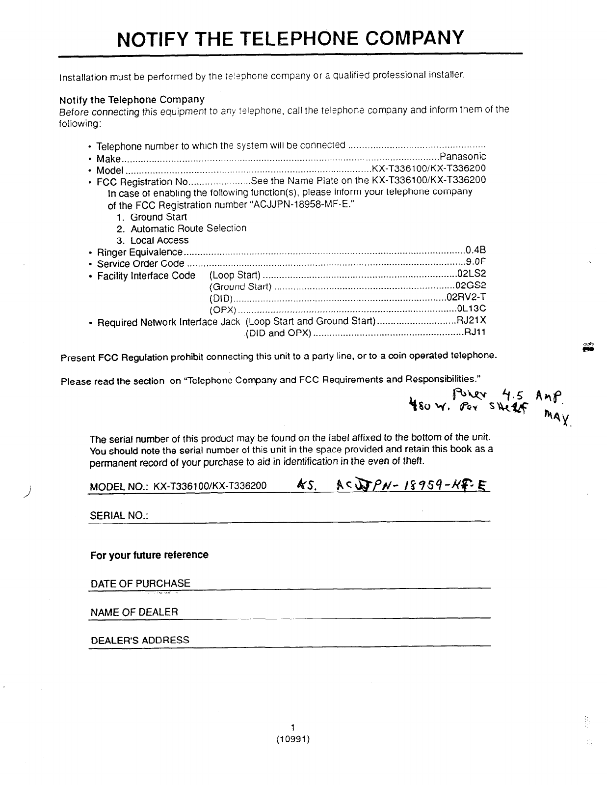
Installation must be performed by the te!?phone company or a qualified professional installer.
Notify the Telephone Company
Before connecting this equipment to any talephone, call the telephone company and inform them of the
following:
l
Telephone number to which the system will be connected ..................................................
. Make.. .................................................................................................................. Panasonic
. Model ........................................................................................ ..KX-T336 1 OO/KX-T336200
. FCC Registration No.. ..................... See the Name Plate on the KX-T3361 OO/KX-T336200
In case of enabling the following function(s), please inform your telephone company
of the FCC Registration number “ACJJPN-18958-MF-E.”
1. Ground Start
2. Automatic Route Selection
3. Local Access
.
Ringer Equivalence ...................................................................................................... .0.48
. Service Order Code ...................................................................................................... 9.OF
l
Facility interface Code (Loop Start) ....................................................................... 02LS2
(Ground Start) .................................................................. 02GS2
(DID) .............................................................................. 02RV2-T
(OPX) ................................................................................ OL13C
. Required Network Interface Jack (Loop Start and Ground Start). ............................ RJ21X
(DID and OPX) ....................................................... RJll
Present FCC Regulation prohibit connecting this unit to a party line, or to a win operated telephone.
Please read the section on “Telephone Company and FCC Requirements and Responsibilities.”
4
The serial number of this product may be found on the label affixed to the bottom of the unit.
You should note the serial number of this unit in the space provided and retain this book as a
permanent record of your purchase to aid in identification in the even of theft.
i MODEL NO.: KX-T3361 OO/KX-T336200 4Q/s, ~~~pr/- cmv?-~~ c
SERIAL NO.:
For your future reference
DATE OF PURCHASE
---.
NAME OF DEALER
DEALER’S ADDRESS
(lOl91,
.:
TELEPHONE COMPANY and
FCC REQUIREMENTS AND RESPONSIBILITIES
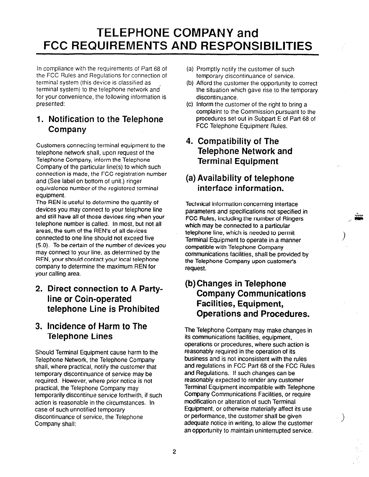
In compliance with the requirements of Part 68 of
the FCC Rules and Regulations for connection of
terminal system (this device is classified as
terminal system) to the telephone network and’
for your convenience, the following information is
presented:
1. Notification to the Telephone
Company
Customers connecting terminal equipment to the
telephone network shall, upon request of the
Telephone Company, inform the Telephone
Company of the particular line(s) to which such
connection is made, the FCC registration number
and (See label on bottom of unit.) ringer
equivalence number of the registered terminal
equipment.
The REN is useful to determine the quantity of
devices you may connect to your telephone line
and still have all of those devices ring when your
telephone number is called. In most, but not all
areas, the sum of the REN’s of all devices
connected to one line should not exceed five
(5.0). To be certain of the number of devices you
may connect to your line, as determined by the
REN, your should contact your local telephone
company to determine the maximum REN for
your calling area.
2. Direct connection to A Party-
line or Coin-operated
telephone Line is Prohibited
3. Incidence of Harm to The
Telephone Lines
Should Terminal Equipment cause harm to the
Telephone Network, the Telephone Company
shall, where practical, notify the customer that
temporary discontinuance of service may be
required. However, where prior notice is not
practical, the Telephone Company may
temporarily discontinue service forthwith, if such
action is reasonable in the circumstances. In
case of such unnotified temporary
discontinuance of service, the Telephone
Company shall:
(4
(b)
(cl
4.
Promptly notify the customer of such
temporary discontinuance of service.
Afford the customer the opportunity to correct
the situation which gave rise to the temporary
discontinuance.
Inform the customer of the right to bring a
complaint to the Commission pursuant to the
procedures set out in Subpart E of Part 68 of
FCC Telephone Equipment Rules.
Compatibility of The
Telephone Network and
Terminal Equipment
(a) Availability of telephone
interface information.
Technical information concerning interface
parameters and specifications not specified in
FCC Rules, including the number of Ringers
which may be connected to a particular
telephone line, which is needed to permit
Terminal Equipment to operate in a manner
compatible with Telephone Company
communications facilities, shall be provided by
the Telephone Company upon customer’s
request.
(b) Changes in Telephone
Company Communications
Facilities, Equipment,
Operations and Procedures.
The Telephone Company may make changes in
its communications facilities, equipment,
operations or procedures, where such action is
reasonably required in the operation of its
business and is not inconsistent with the rules
and regulations in FCC Part 68 of the FCC Rules
and Regulations. If such changes can be
reasonably expected to render any customer
Terminal Equipment incompatible with Telephone
Company Communications Facilities, or require
modification or alteration of such Terminal
Equipment, or otherwise materially affect its use
or performance, the customer shall be given
adequate notice in writing, to allow the customer
an opportunity to maintain uninterrupted service.
OTHERS
l
Keep the unit away from heating appliances
and electrical noise generating devices such as
fluorescent lamps, motors and television.
These noise sources can interfere with the
performance of the EASA-PHONE.
l
This unit should be kept free of dust, moisture,
high temperature and vibration, and should not
be exposed to direct sunlight.
l
Never attempt to insert wires, pins, etc. into
the vents or other holes of this unit.
l
If there is trouble, disconnect the unit from the
telephone line. Plug the telephone directly into
the telephone line. If the telephone operates
properly, do not reconnect the unit to the line
until the trouble has been repaired by an
authorized Panasonic Factory Service Center.
If the telephone does not operate properly,
chances are that the trouble is in the telephone
system, and not in the unit.
l
Do not use benzine, thinner, or similar solvents.
Do not use abrasive powder to clean the
cabinet. Wipe it with a soft cloth.
NOTE: This equipment has been tested and
found to comply with the limits for a Class A
digital device, pursuant to Part 15 of the FCC
Rules. These limits are designed to provide
reasonable protection against harmful
interference when the equipment is operated
in a commercial environment.
This equipment generates, uses, and can
radiate radio frequency energy and, if not
installed and used in accordance with the
instruction manual, may cause harmful
interference to radio communications.
Operation of this equipment in a residential
area is likely to cause harmful interference in
which case the user will be required to correct
the interference at his own expense.
WARNING:
TO PREVENT FIRE OR SHOCK HAZARD, DO
NOT EXPOSE THIS PRODUCT TO RAIN OR
MOISTURE.
3

IMPORTANT SAFETY INSTRUCTIONS
When using your telephone equipment,
basic safety precautions should always
be followed to reduce the risk of fire,
electric shock and injury to persons,
including the following:
1 . Read and understand all instructions.
2.
3.
4.
5.
6.
i.
Follow all warnings and instructions marked
on the product.
Unplug this product from the wall outlet
before cleaning. Do not use liquid cleaners
or aerosol cleaners. Use a damp cloth for
cleaning.
Do not use this product near water, for
example, near a bath tub, wash bowl, kitchen
sink, or laundry tub, in a wet basement, or
near a swimming pool.
Do not place this product on an unstable cart,
stand, or table. The product may fall,
causing serious damage to the product.
Slots and openings in the cabinet and the
back or bottom are provided for ventilation, to
protect it from overheating, these openings
must not be blocked or covered. The
openings should never be blocked by placing
the product on the bed, sofa, rug, or other
similar surface. This product should never be
placed near or over a radiator or heat
register. This product should not be placed in
a built-in installation unless proper ventilation
is provided.
This product should be operated only from
the type of power source indicated on the
marking label. If you are not sure of the type
of power supply to your home, consult your
dealer or local power company.
8. This product is equipped with a three wire
grounding type plug, a plug having a third
(grounding) pin. This plug will only fit into a
grounding type power outlet. This is a safety
feature. If you are unable to insert the plug
into the outlet, contact your electrician to
replace your obsolete outlet. Do not defeat
the safety purpose of the grounding type
plug.
9. Do not allow anything to rest on the power
cord. Do not locate this product where the
cord will be abused by persons walking on it.
10. Do not overload wall outlets and extension
cords as this can result in the risk of fire or
electric shock.
11. Never push objects of any kind into this
product through cabinet slots as they may
touch dangerous voltage points or short out
parts that could result in a risk of fire or
electric shock. Never spill liquid of any kind
on the product.
12. To reduce the risk of electric shock, do not
disassemble this product, but take it to a
qualified serviceman when some service or
repair work is required. Opening or removing
covers may expose you to dangerous
voltages or other risks. Incorrect reassembly
can cause electric shock when the appliance
is subsequently used.
4
:.-
‘.:,
:I .:
13. Unplug this product from the wall outlet and
refer servicing to qualified service personnel
under the following conditions:
14. Avoid using a telephone (other than a
cordless type) during an electrical storm.
There may be a remote risk of electric shock
from lightning.
A. When the power supply cord or plug is
damaged or frayed.
B. If liquid has been spilled into the product.
C. If the product has been exposed to rain or
water.
15. Do not use the telephone to report a gas leak
in the vicinity of the leak.
D. If the product does not operate normally
by following the operating instructions.
SAVE THESE
Adjust only those controls, that are
covered by the operating instructions
because improper adjustment of other
controls may result in damage and will
often require extensive work by a qualified
technician to restore the product to normal
operation.
INSTRUCTIONS
E. If the product has been dropped or the
cabinet has been damaged.
F. If the product exhibits a distinct change in
performance.
Y
SAFETY INSTALLATION INSTRUCTIONS
When installing telephone wiring, basic
safety precautions should always be
followed to reduce the risk of fire, electric
shock and injury to persons, including
the following;
1. Never install telephone wiring during a
lightning storm.
2. Never install telephone jacks in wet locations
unless the jack is specifically designed for
wet locations.
3. Never touch uninsulated telephone wires or
terminals unless the telephone line has been
disconnected at the network interface.
4. Use caution when installing or modifying
telephone lines.
5

Section 1
System Outline
(Section 1)
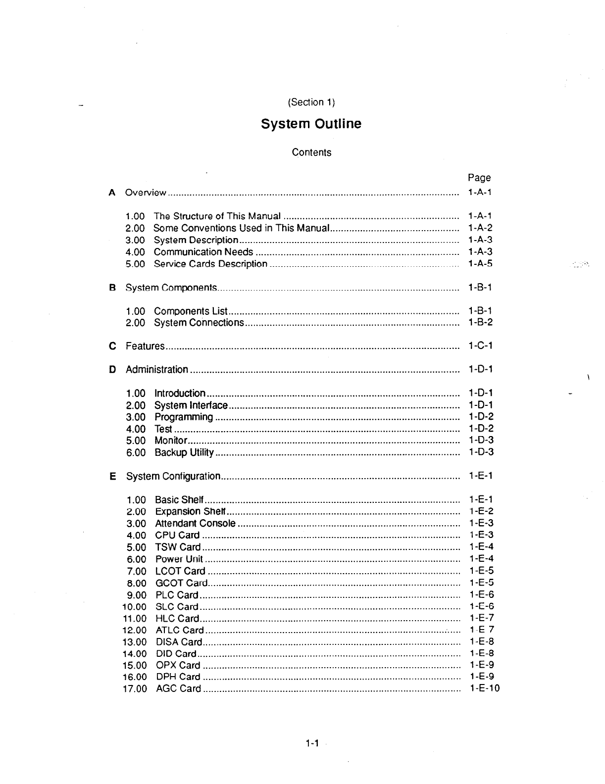
System Outline
Contents
A
B
C
D
E
Overview . . . . . . ..__..__...___......_.._.....................__..._.__..........._....._............................
1 .OO The Structure of This Manual ................................................................
2.00 Some Conventions Used in This Manual.. .............................................
3.00 System Description.. ..............................................................................
4.00 Communication Needs ..........................................................................
5.00 Service Cards Description .....................................................................
System Components . . . . . . . . . . . . . . . . . . .._.................._..._..__.................__..._._._.............
1 .OO Components List.. .................................................................................. 1 -B-l
2.00 System Connections.. ............................................................................ 1 -B-2
Features . . . . . . . . . . . . . . . . . . . . . . . . . . . _ . . . . . . . . . . . . . . . . . . . . . . . . . . . . . . . . . . . . . . . . . . . . . . . . . . . . . . . . . . .._.................. 1 -C-l
Administration . . . . . . . . . . . . . . . . . . . . . . . . . . . . . . . . . . . . . . . . . . . . . . . . . . . .._............................................ 1 -D-l
1 .OO Introduction ............................................................................................ 1 -D-l
2.00 System Interface.. .................................................................................. 1 -D-l
3.00 Programming ......................................................................................... 1 -D-2
4.00 Test ........................................................................................................ 1 -D-2
5.00 Monitor.. ................................................................................................. 1 -D-3
6.00 Backup Utility ......................................................................................... 1 -D-3
System Configuration . . . . . . . . . . . . . . . . . . . . . . . . . . . .._......................................................... 1 -E-l
1 .oo
2.00
3.00
4.00
5.00
6.00
7.00
8.00
9.00
10.00
11.00
12.00
13.00
14.00
15.00
16.00
17.00
Basic Shelf.. ...........................................................................................
Expansion Shelf.. ...................................................................................
Attendant Console .................................................................................
CPU Card ..............................................................................................
TSW Card.. ............................................................................................
Power Unit .............................................................................................
LCOT Card ............................................................................................
GCOT Card.. ..........................................................................................
PLC Card.. .............................................................................................
SLC Card ...............................................................................................
HLC Card.. .............................................................................................
ATLC Card ....................................................................................... :.
....
DISA Card ..............................................................................................
DID Card ................................................................................................
OPX Card ..............................................................................................
DPH Card ..............................................................................................
AGC Card ..............................................................................................
Page
1 -A-l
1 -A-l
1 -A-2
1 -A-3
1 -A-3
1 -A-5
1 -B-l
1 -E-l
1 -E-2
1 -E-3
1 -E-3
1 -E-4
1 -E-4
1 -E-5
1 -E-5
1 -E-6
1 -E-6
1 -E-7
1 -E-7
1 -E-8
1 -E-8
1 -E-9
1 -E-9
1-E-10
\
l-l
Page
18.00 RMTCard.. ............................................................................................ 1-E-10
19.00 T-SW Conference Expansion Card.. ...................................................... 1 -E-l 1
20.00 OHCA Card.. .......................................................................................... 1 -E-l 1
21 .OO T-SW OHCA Expansion Card ................................................................ 1 -E-l1
22.00 OPX Power Unit.. ................................................................................... 1 -E-l1
l-2

A. Overview
1 .OO The Structure of This Manual
introduction
This system reference manual provides general
technical information on Panasonic KX-T336
system.
This includes a description of the system, its
hardware and software, features and service,
environmental requirements.
This manual is intended to serve as an overall
technical reference for the system.
Organization
This manual is comprised of the following 19
sections.
Section 1 System Outline
This section describes the overall information of
the system and the constnxtion of this Service
Reference Manual.
Section 2 installation
This section describes how to install and start up
the system.
Section 3 System Features and Operation
This section describes the basic system features.
Section 4 Station Features and Operation
(PITS)
This section describes the basic features and
operations from the viewpoint of Proprietary
Integrated Telephone System (PITS) users.
The basic features and required operations for
DSS console are
also described.
Section 5 Station Feature and Operation (SLT)
This section describes the basic features and
operations from the viewpoint of Single Line
Telephone (SLT) users.
Section 6 Station Feature and Operation (ATT)
This section describes the basic features and
operations from the viewpoint of the Attendant
Console (ATT) Operator.
Section
7
Preparation for Programming and
Operation (VT220 and Compatibles)
This section describes the basic usage and
available functions of VT220 and Compatibles.
Section 8 Preparation for Programming and
Operation (Dumb)
This section describes the basic usage and
command reference of Dumb terminal.
Section 9 System Programming (VT220 and
Compatibles)
This section provides information for the
programming of the system database using VT220
and Compatibles.
Section 10 System Programming (Dumb)
This section provides information for the
programming of the
system
database
using Dumb
terminal.
Section 11 System Programming (PITS)
This section provides information for a certain
programming of the system database using PITS
telephone.
Section 12 Station Programming (PITS)
This section provides information for the
programming of various features specific to each
PITS telephone and DSS console using PITS
telephone.
Section 13 Station Programming (ATT)
This section provides information for the
programming and the back-up of the attendant
console database using the attendant console.
Section 14 Maintenance (VT220 and
Compatibles)
This section describes the information necessary
for monitoring, testing, and maintaining the system
using VT220 and Compatibles.
Section 15 Maintenance (Dumb)
This section describes the information necessary
for monitoring, testing, and maintaining the system
using Dumb terminal.
Section 16 Backup Utility-On-Site
This section provides the information for saving
and loading of the system programming data
(including attendant console database) at on-site.
Section 17 Backup Utility-Remote Location
This section provides the information for saving
and loading the system programing data (including
attendant console database) from a remote
location.
Section 18 Abbreviations
This section provides a list of abbreviations used
in this manual.
Section 19 index
1 -A-l

i
2.00 Some Conventions Used in
- This Manual
In this manual “system features” are described in
Section 3 and ‘station (PITS, SLT, AlT) features”
are described in Section 4 to Section 6. In these
sections, information for each feature is
presented under the following four headings:
Description, Programming, Conditions, and
Operation.
Description
Defines the feature, describes what it does for
the user, and how it is used.
Programming
Provides tabular listing of items required for
system programming as follows:
<l>
System Programming
“System-Class of Service”,
Executive Busy Override
Deny
“System-Numbering Plan’:
Busy Override Deny Set
Busy Override Deny Cancel
<2> I
Refl
VT
404.01
9-D-6.04
<3>
ence
Dumb
lo-c-7.00
lo-c-lO.oc
interpret this table as follows:
<l> shows the required programming items for
the described feature.
<2> shows the reference number for
programming (VT 220 user)
For example, interpret “9-D-4.01” as follows.
9-D-4.01
L Title Number
IL Subsection Number
Section Number
<Example>
4.00
Class of
Service
4.01 Class of Ssrvice (112)
P: System
- Class of Service
_________________--__-_--_________-----
Tile Number
Class of Service 03X) lb.
l ------ -----___- - -------- ----
I Toll Restriction Level (Cmr) ----
I Toll Kestrictica Level #i&t.) ---
I Pax. Dialing Digits -------------
I Call Forvardins / 90 Hot Disturb -
<3> shows the reference number for
programming (Dumb terminal user)
(Note)
In this manual, all reference numbers are
described using Section Number, Subsection
Number, and Title Number.
<Example>
2.00 System Administration from
a Remote Location
Description
From a remote location, you can perform system
programming, diagnosis
and traffic measurements
using a Dumb terminal.
For details about communication parameters, refer
“Communication Interface.”
Conditions
l
RMT card
(Modem) must be installed in the
system and
assign the telephone number of
Interface
- Communicstion Interface
Title Number 1-------------__________I
c-------------e
Item I SIO e1
I
(Terminal)
I---- -----+ __--__ - ----
I NL-code , gii
I Bmud Rate I 1200 bmud
Conditions
Describes the applications and benefits of the
feature, followed by factors to be considered
when the feature is used.
Operation
Provides instructions for a user of PITS
telephone (Section 4), Single Line Telephone
(Section 5) and Attendant Console (Section 6)
individually.
1 -A-2
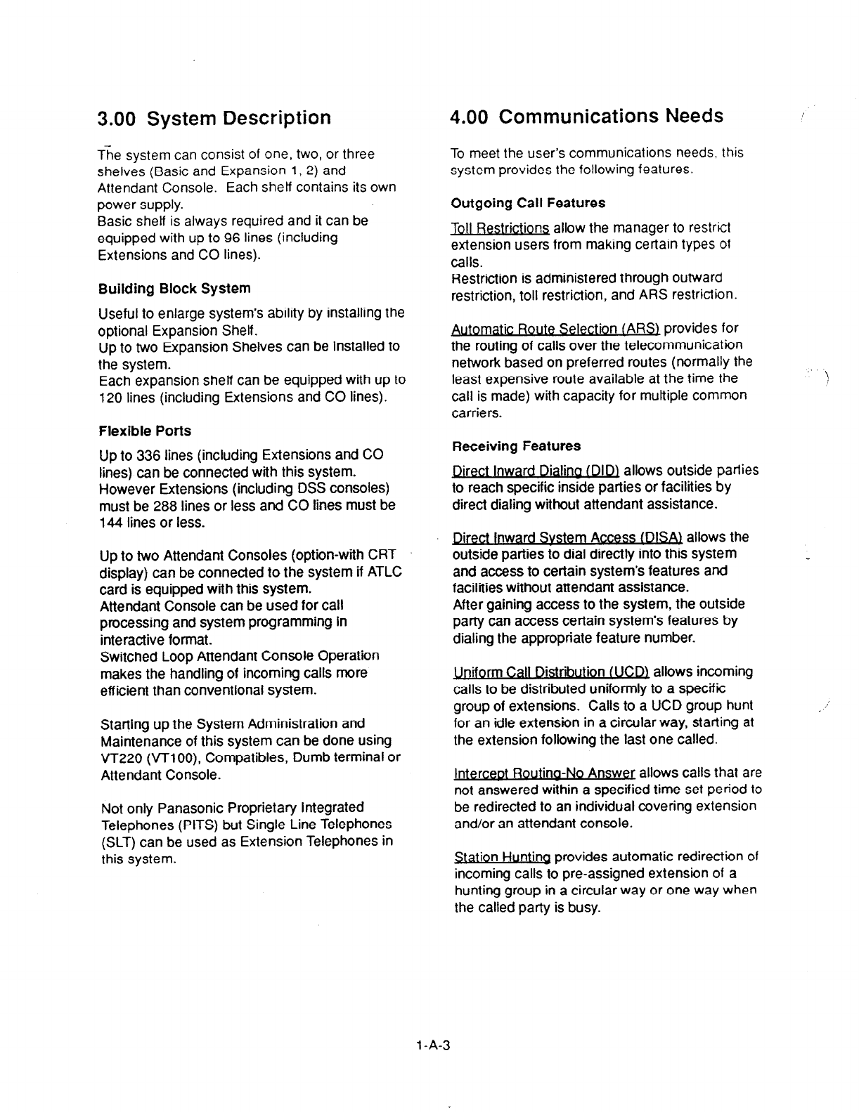
3.00 System Description 4.00 Communications Needs
The system can consist of one, two, or three
shelves (Basic and Expansion l(2) and
Attendant Console. Each shelf contains its own
power supply.
Basic shelf is always required and it can be
equipped with up to 96 lines (including
Extensions and CO lines).
Building Block System
Useful to enlarge system’s ability by installing the
optional Expansion Shelf.
Up to two Expansion Shelves can be installed to
the system.
Each expansion shelf can be equipped with up to
120 lines (including Extensions and CO lines).
Flexible Ports
Up to 336 lines (including Extensions and CO
lines) can be connected with this system.
However Extensions (including DSS consoles)
must be 288 lines or less and CO lines must be
144 lines or less.
Up to two Attendant Consoles (option-with CRT
display) can be connected to the system if ATLC
card is equipped with this system.
Attendant Console can be used for call
processing and system programming in
interactive format.
Switched Loop Attendant Console Operation
makes the handling of incoming calls more
efficient than conventional system.
Starting up the System Administration and
Maintenance of this system can be done using
VT220 (VTlOO), Compatibles, Dumb terminal or
Attendant Console.
Not only Panasonic Proprietary Integrated
Telephones (PITS) but Single Line Telephones
(SLT) can be used as Extension Telephones in
this system.
To meet the user’s communications needs, lhis
system provides the following features.
Outgoing Call Features
Toll Restrictions allow the manager to restrict
extension users from making certain types of
calls.
Restriction is administered through outward
restriction, toll restriction, and ARS restriction.
Automatic Route Selection tARSI provides for
the routing of calls over the telecommunication
network based on preferred routes (normally the
least expensive route available at the time the
call is made) with capacity for multiple common
carriers.
. . !
Receiving Features
Q&ct inward Dialina (DID1 allows outside parties
to reach specific inside parties or facilities by
direct dialing without attendant assistance.
Direct Inward Svstem Access (DlSAj allows the
outside parties to dial directly into this system
and access to certain system’s features and
facilities without attendant assistance.
After gaining access to the system, the outside
party can access certain system’s features by
dialing the appropriate feature number.
Uniform Call Distribution t UCDZ allows incoming
calls to be distributed uniformly to a specific
group of extensions. Calls to a UCD group hunt
for an idle extension in a circular way, starting at
the extension following the last one called.
InterceDt Routing-No Answec allows calls that are
not answered within a specified time set period to
be redirected to an individual covering extension
and/or an attendant console.
Station Hunting provides automatic redirection of
incoming calls to pre-assigned extension of a
hunting group in a circular way or one way when
the called party is busy.
l-A-3
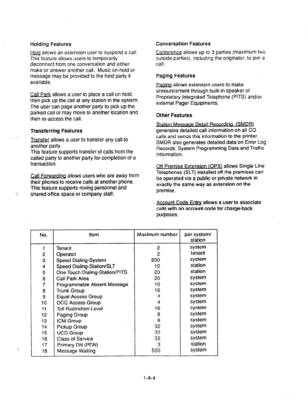
Holding Features Conversation Features
w allows an extension user to suspend a call.
This feature allows users to temporarily
disconnect from one conversation and either
make or answer another call. Music on-hold or
message may be provided to the held party if
available.
Conference allows up to 3 parties (maximum two
outside parties), including the originator, to join a
call.
Call Park allows a user to place a call on hold,
then pick up the call at any station in the system.
The user can page another party to pick up the
parked call or may move to another location and
then re-access the call.
Paging Features
&C&Q allows extension users to make
announcement through built-in speaker of
Proprietary Integrated Telephone (PITS) and/or
external Pager Equipments.
Other Features
Transferring Features
Jransfer allows a user to transfer any call to
another party.
This feature supports transfer of calls from the
called party to another party for completion of a
transaction.
IOII Message netall Recordina fa)
generates detailed call information on all CO
calls and sends this information to the printer.
SMDR also generates detailed data on Error Log
Records, System Programming Data and Traffic
Information.
I;all Forwarding allows users who are away from
their phones to receive calls at another phone.
This feature supports roving personnel and
shared off ice space or company staff.
Off Premise Fxtension (OPa allows Single Line
Telephones (SLT) installed off the premises can
be operated via a public or private network in
exactly the same way as extension on the
premise.
No. Item Maximum number
1 Tenant 2
2 Operator 2
3 Speed Dialing-System 200
4 Speed Dialing-StationISLT 10
5 One Touch Dialing-Station/PITS 23
6 Call Park Area 20
7 Programmable Absent Message 10
8 Trunk Group 16
9 Equal Access Group 4
10 OCC Access Group 4
11 Toll Restriction Level 16
12 Paging Group 8
13 ICM Group 8
14 Pickup Group 32
15 UCD Group 32
16 Class of Service 32
17 Primary DN (PDN) 3
18 Message Waiting 500
Account Code Fntrv allows a user to associate
calls with an account code for charge-back
purposes.
3
per system/
station
system
tenant
system
station
station
system
system
system
system
system
system
system
system
system
system
system
station
system
1 -A-4
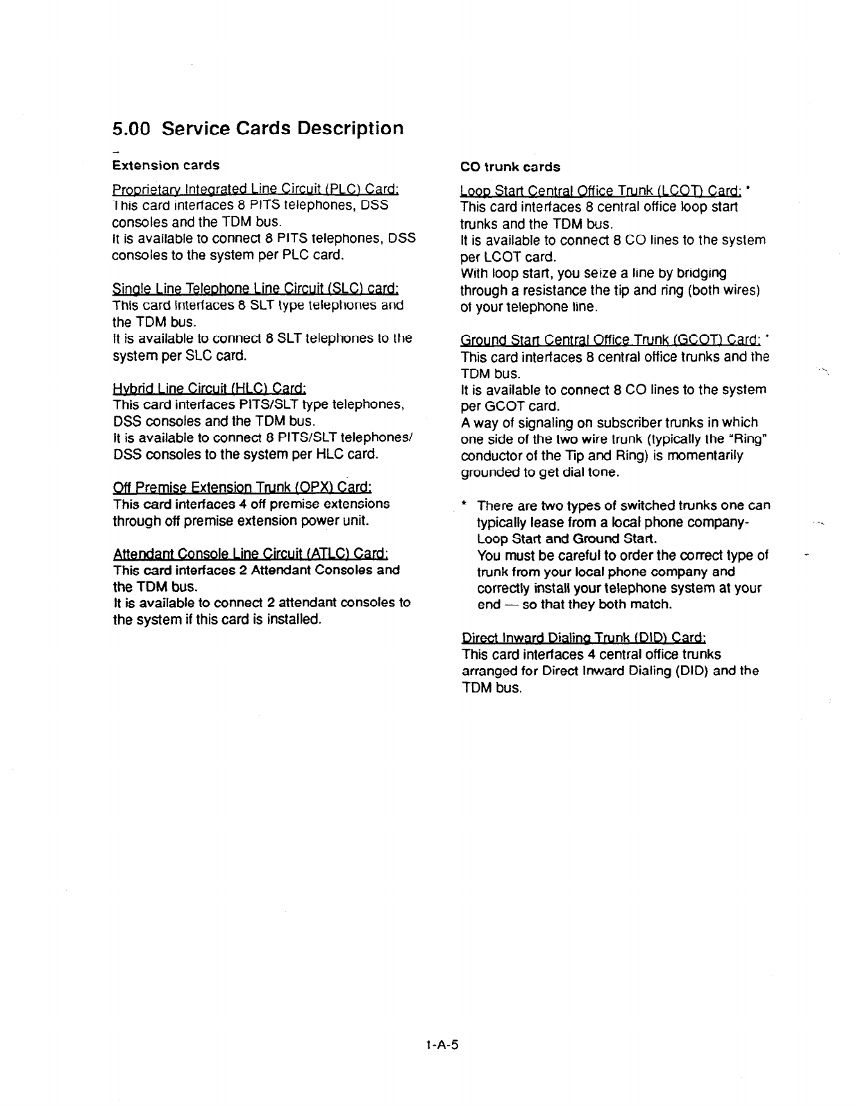
5.00 Service Cards Description
Extension cards CO trunk cards
Proorietarv lntearated 1 ine Circuit (PLCJ Card:
This card interfaces 8 PITS telephones, DSS
consoles and the TDM bus.
It is available to connect 8 PITS telephones, DSS
consoles to the system per PLC card.
rt Central Off ice Trunk (LCOT) Card
This card interfaces 8 central off ice loop start
trunks and the TDM bus.
It is available to connect 8 CO lines to the system
per LCOT card.
Sinale Line Teleohone 1 ine Circuit ISLC) &
This card interfaces 8 SLT type telephones and
the TDM bus.
It is available to connect 8 SLT telephones to the
system per SLC card.
. .
nd Ltne Circuit fHt.Q Card;
This card interfaces PITS/SLT type telephones,
DSS consoles and the TDM bus.
It is available to connect 8 PITS/SLT telephones/
DSS consoles to the system per HLC card.
Off Premise Extension Trunk (OPX) Card:
This card interfaces 4 off premise extensions
through off premise extension power unit.
. . .
Console I me Crrcutt 1AILC) Card;
This card interfaces 2 Attendant Consoles and
the TOM bus.
It is available to connect 2 attendant consoles to
the system if this card is installed.
l
With loop start, you seize a line by bridging
through a resistance the tip and ring (both wires)
of your telephone line.
This card interfaces 8 central office trunks and the
TDM bus. \
It is available to connect 8 CO lines to the system
per GCOT card.
A way of signaling on subscriber trunks in which
one side of the two wire trunk (typically the “Ring”
conductor of the Tip and Ring) is momentarily
grounded to get dial tone.
l
There are two types of switched trunks one can
typically lease from a focal phone company-
Loop Start and Ground Start.
You must be careful to order the correct type of
trunk from your local phone company and
correctly install your telephone system at your
end - so that they both match.
-_
-
Direct Inward Dialing Trunk 1 DID) Card;
This card interfaces 4 central office trunks
arranged for Direct Inward Dialing (DID) and the
TDM bus.
1 -A-5
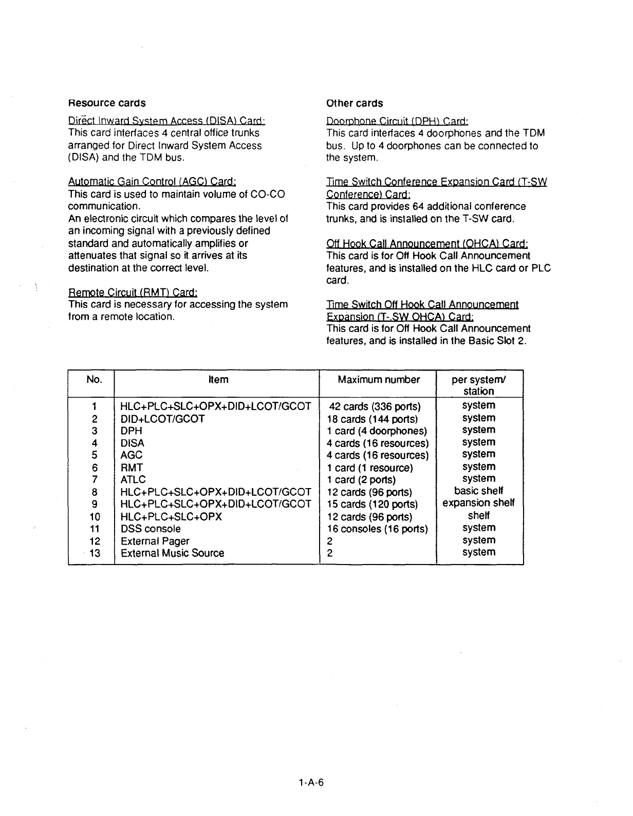
Resource cards
D’rect Inward Svste
I
m Access (C)ISA\ Card;
This card interfaces
4 central office trunks
arranged for Direct Inward System Access
(DISA) and the TDM bus.
Other cards
!&orDhone Circuit IDPHJ Ca d;
This card interfaces 4 doorp:ones and the TDM
bus. Up to 4 door-phones can be connected to
the system.
Automatic Gain Control IAGC) Card;
This card is
used to
maintain volume of CO-CO
communication.
An electronic circuit which compares the level of
an incoming signal with a previously defined
standard and automatically amplifies or
attenuates that signal so it arrives at its
destination at the correct level.
te Circuit (RMT) Card;
This card is necessary for accessing the system
from a remote location.
Time Switch Conference Fxoansion Card (T-SW
Conferem
This card provides 64 additional conference
trunks, and is installed on the T-SW card.
Off Hook Call mement (OHCAI Cacd;
This card is for Off Hook Call Announcement
features, and is installed on the HLC card or PLC
card.
Time Switch Off Hook Call Announcem
ston IT-.SW OHCA) Card;
This card is for Off Hook Call Announcement
features, and is installed in the Basic Slot 2.
No. Item Maximum number per system/
stat-on
1 HLC+PLC+SLC+OPX+DID+LCOT/GCOT 42 cards (336 ports) system
2 DI D+LCOT/GCOT 18 cards (144 ports) system
3 DPH 1 card (4 doorphones) system
4 DISA 4 cards (16 resources) system
5 AGC 4 cards (16 resources) system
6 RMT 1 card (1 resource) system
7 ATLC 1 card (2 ports) system
8 HLC+PLC+SLC+OPX+DID+LCOT/GCOT 12 cards (96 ports) basic shelf
9 HLC+PLC+SLC+OPX+DID+LCOT/GCOT 15 cards (120 ports) expansion shelf
10 HLC+PLC+SLC+OPX 12 cards (96 ports) shelf
11 DSS console 16 consoles (16 ports) system
12 External Pager 2 system
13 External Music Source 2 system
1 -A-6

B. System Components
1 .OO Components List
Model No. Name
KX-T336100 Basic Shelf
KX-T336101 CPU card
KX-T336102 T-SW card
KX-T336200 Expansion Shelf
KX-T96300 Attendant Console
KX-T96145 Attendant Console Keyboard
KX-T96186 Off Premise Extension Power Unit
KX-T96180 Loop Start Central Office Trunk (LCOT)
Card
KX-T96181 Ground Start Central Office Trunk (GCOT) Card
KX-T96172 Proprietary ITS Line Circuit (PLC) Card
KX-T96174 Single Line Telephone Line Circuit (SLC) Card
KX-T96170 Hybrid Line Circuit (HLC) Card
KX-T96141 Attendant Console Line Circuit (ATLC) Card
KX-T96191 Direct Inward System Access (DISA) Card
KX-T96182 Direct Inward Dialing Trunk (DID) Card
KX-T96185 Off Premise Extension Trunk (OPX) Card
KX-T96161 Doorphone Circuit (DPH) Card
KX-T96193 Automatic Gain Control(AGC) Card
KX-T96196 Remote Circuit (RMT) Card
KX-T336104 Time Switch Conference (T-SW Conference) Expansion Card
KX-T96136 Off Hook Call Announcement (OHCA) Card
KX-T336105 Time Switch Off Hook Call Announcement (T-SW OHCA) Card
Model No.
KX-T30820
KX-T30830
KX-T30850
KX-T61620
KX-T61630
Name
Proprietary Telephone (3 CO’s)
Proprietary Telephone with LCD (3 CO’s, 8 DSS’s)
Proprietary Telephone (3 CO’s)
Proprietary Telephone (6 CO’s)
Proprietary Telephone with LCD (6 CO’s)
KX-T61650
KX-T123220
KX-T123230
KX-T123230D
KX-T123235
KX-T123250
KX-T7020
KX-T7030
KX-T7050
KX-T7130
KX-T61640
KX-T123240
KX-T7040
KX-T30865
KX-T30890
KX-A26D
Proprietary Telephone (6 CO’s)
Proprietary Telephone (12 CO’s)
Proprietary Telephone with LCD
Proprietary Telephone with LCD
Proprietary Telephone with LCD
Proprietary Telephone (12 CO’s)
Proprietary Telephone (12 CO’s)
Proprietary Telephone with LCD
Proprietary Telephone (12 CO’s)
12 CO’S)
12 CO’S)
12 CO’S)
12 CO’S)
Proprietary Telephone with LCD (12 CO’s)
DSS Console (lG’DSS’s, 16 PF buttons)
DSS Console (32 DSS’s, 16 PF buttons)
DSS Console (32 DSS’s, 16 PF buttons)
Doorphone
Headset
Battery Adapter
1 -B-l
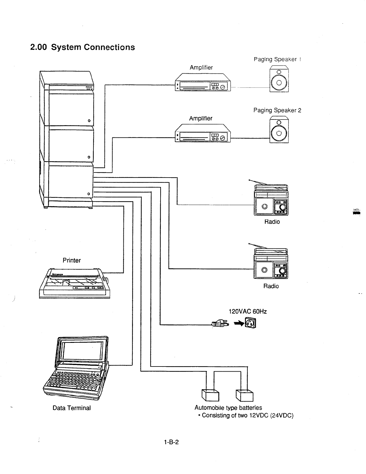
2.00 System Connections
Amplifier
Paging Speaker 1
Amplifier
Paging Speaker 2
Printer
Data Terminal
Radio
Radio
12OVAC 60Hz
Automobile type batteries
l
Consisting of two 12VDC (24VDC)
1 -B-2
\
\
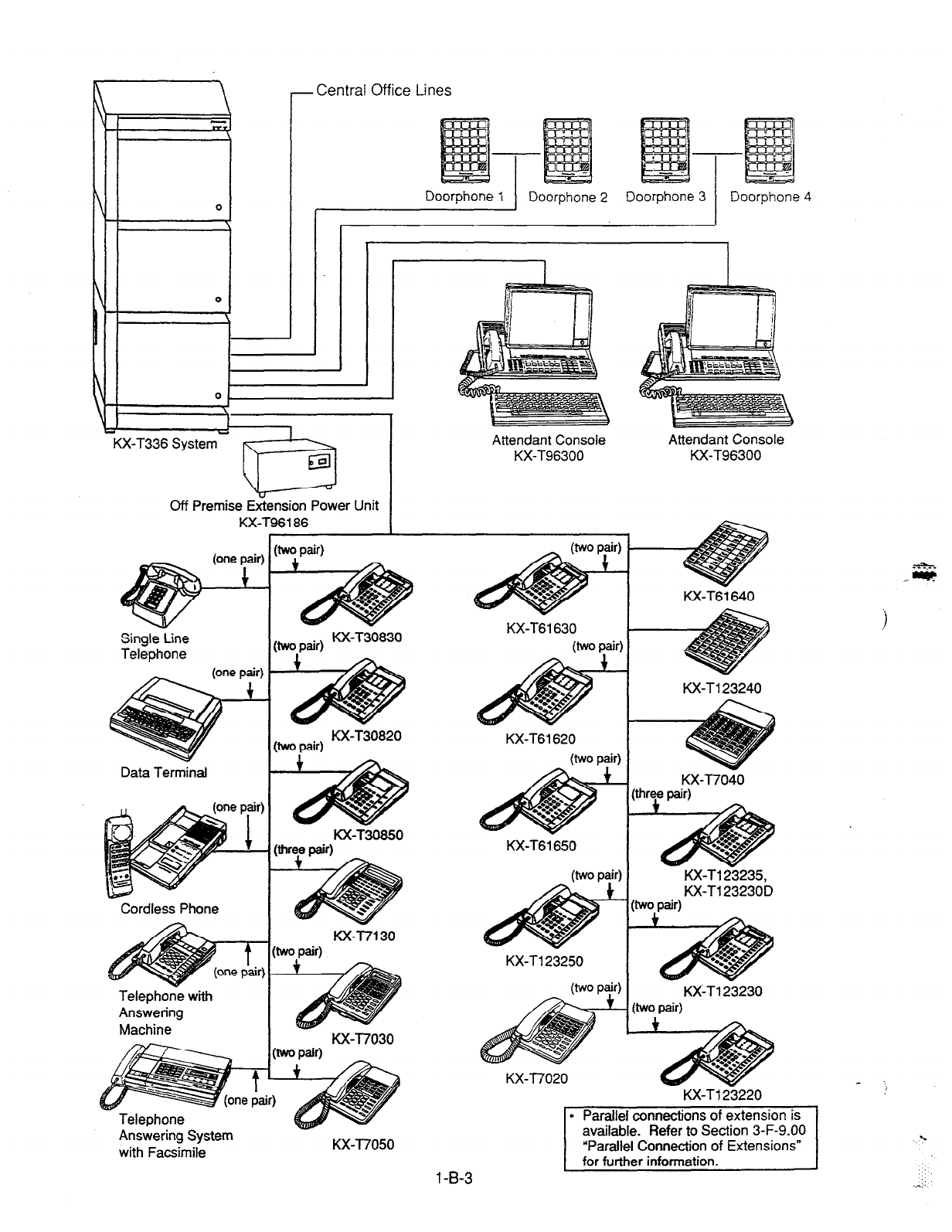
r
- Central
Off
ice Lines
KX-T336 System
Doorphone 1 Doorphone 2 Doorphone 3 I Doorphone 4
Off Premise EGension Power Unit
KX-T96186 I
Attendant Console
KX-T96300
SingleCine
Telephone
Data Terminal
Cordless Phone
Telephone with
Answering
Machine
(two pair)
(two pair) KX-T30830
(two pair) KX-T30820
KX-T-0
KX-T7130
KX-T7030
Answering System
with Facsimile KX-T7050
1 -B-3
KX-T61630
(two pair)
KX-T61620
(two pair)
. . I
KX-T61650
(two pair)
KX-T123250
Wo pW
- @
c
KX-T6i 640
KX-T123240
KX-T7040
Iree pair)
KX-T123235,
KX-T123230D
HO pair)
KX-T123230
Jvo pair)
KX-T7020
KX-T123220
l
Parallel connections of extension is
Refer to Section 3-F-9.00
I
/-
/t
.
E
I
\-
I
I
I
I
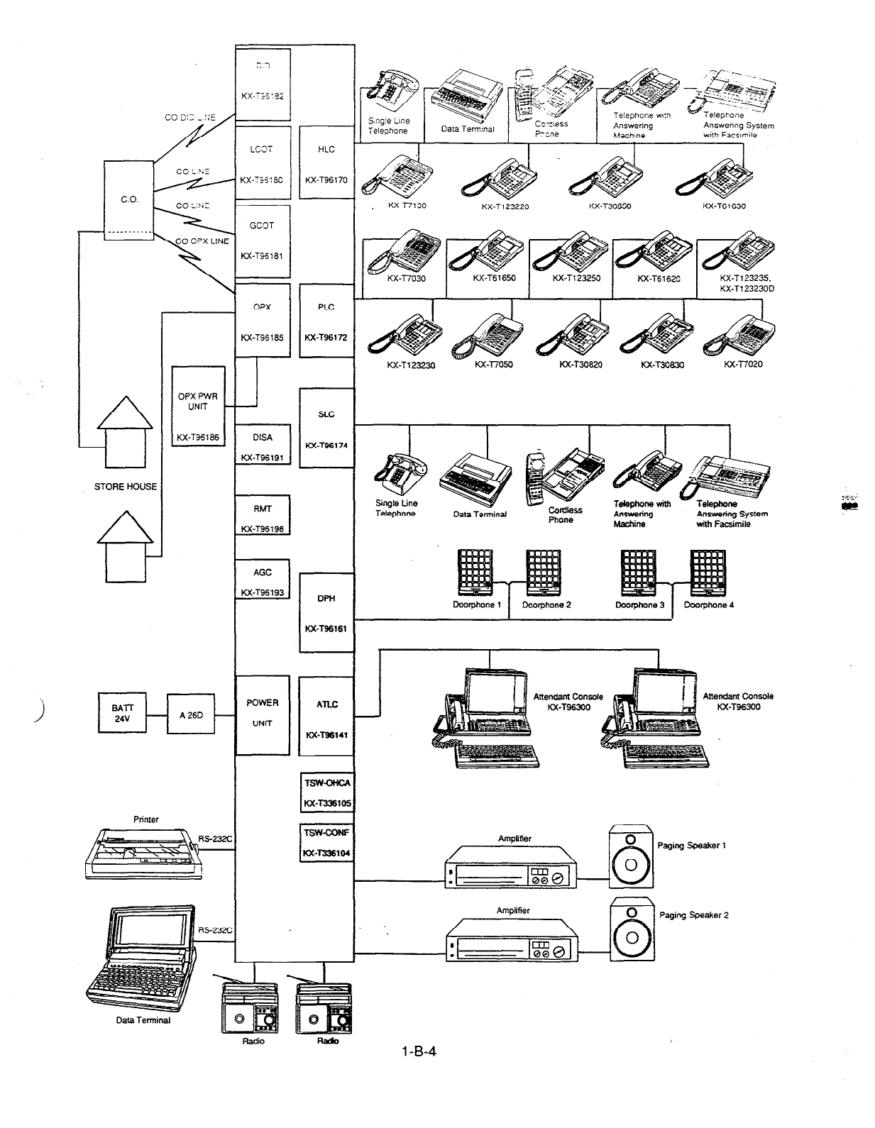
co 013 _ :‘c
<L
C.O.
- . .._-....._
S.ng!e LIlx
Te!ephane
LCI?T
7
<X-TS:6C
with Facsm~le
KX-T123220 KX-T30650 KX-T61630
- KX-T7030 KX-T6 1650 KX-Tl23250 KX-T616X KX-T123235.
KX-T123230D
I I I I 1
KX-Tl23230 KX-l7050 KX-T3083U Kx-T7020
OPX PWR
UNlT
KX-T36186
6
STORE HOUSE
A
Telephone Data Terminal Answing System
with Facsimile
r
DPH
AGC
M-T96193
I-
Kx-T96161
POWER ATLC
III
UNIT
KsT96141
Allendant Conrole Anendanl consola
KX-T96300 KX-T96300
TSWOHCA
M-T336105
/ A Paging Speaker1
-23X
4
Paging Speaker 2
1 -B-4
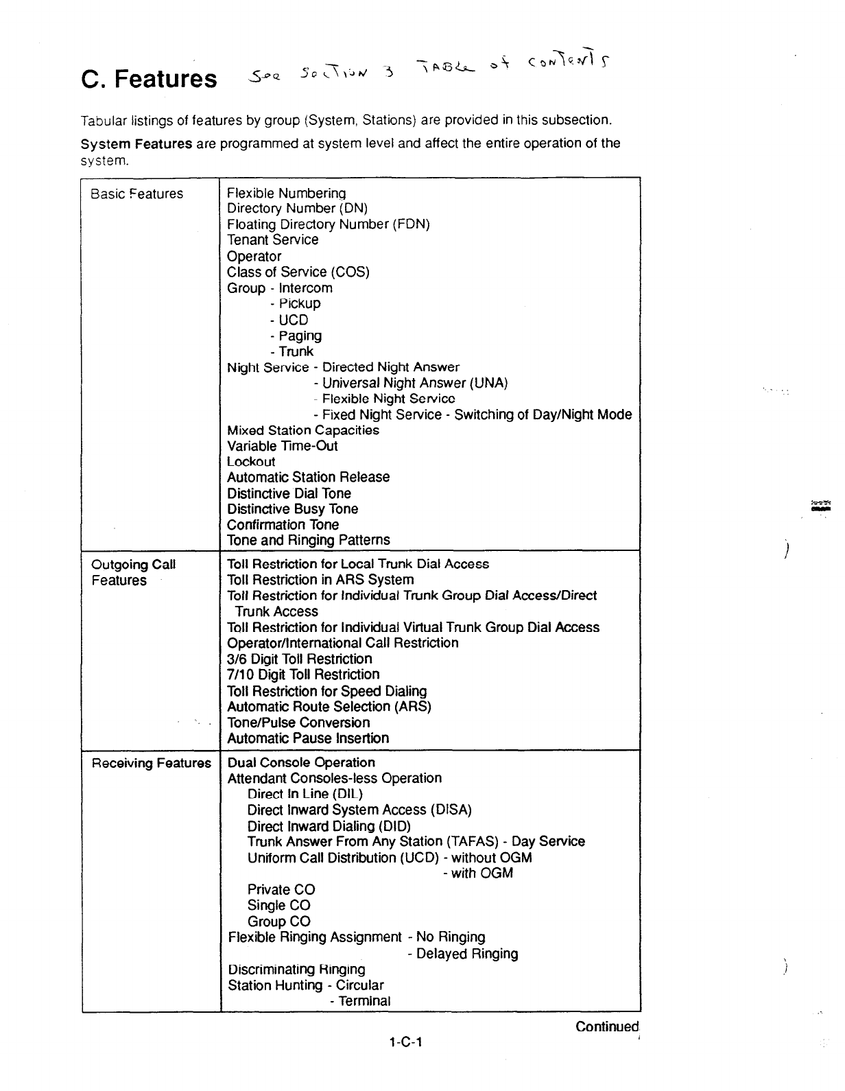
Tabular listings of features by group (System, Stations) are provided in this subsection.
System Features
are programmed at system level and affect the entire operation of the
system.
asic Features Flexible Numbering
Directory Number (DN)
Floating Directory Number (FDN)
Tenant Service
Operator
Class of Service (COS)
Group - Intercom
- Pickup
- UCD
- Paging
- Trunk
Night Service - Directed Night Answer
- Universal Night Answer (UNA)
- Flexible Night Service
- Fixed Night Service - Switching of Day/Night Mode
Mixed Station Capacities
Variable Time-Out
Lockout
Automatic Station Release
Distinctive Dial Tone
Distinctive Busy Tone
Confirmation Tone
Tone and Ringing Patterns
lutgoing Call
eatures Toll Restriction for Local Trunk Dial Access
Toll Restriction in ARS System
Toll Restriction for Individual Trunk Group Dial Access/Direct
Trunk Access
Toll Restriction for Individual Virtual Trunk Group Dial Access
Operator/International Call Restriction
3/6 Digit Toll Restriction
7/l 0 Digit Toll Restriction
Toll Restriction for Speed Dialing
Automatic Route Selection (ARS)
I. Tone/Pulse Conversion
Automatic Pause Insertion
receiving Features Dual Console Operation
Attendant Consoles-less Operation
Direct In Line (DIL)
Direct Inward System Access (DISA)
Direct Inward Dialing (DID)
Trunk Answer From Any Station (TAFAS) - Day Service
Uniform Call Distribution (UCD) -without OGM
- with OGM
Private CO
Single CO
Group CO
Flexible Ringing Assignment - No Ringing
- Delayed Ringing
Discriminating Ringing
Station Hunting - Circular
- Terminal
l-C-1 Continued
/
‘.
i
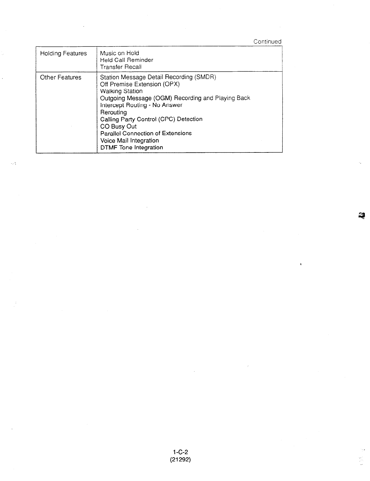
Continued
Holding Features Music on Hold
Held Call Reminder
Transfer Recall
Other Features Station Message Detail Recording (SMDR)
Off Premise Extension (OPX)
Walking Station
Outgoing Message (OGM) Recording and Playing Back
Intercept Routing - No Answer
Rerouting
Calling Party Control (CPC) Detection
CO Busy Out
Parallel Connection of Extensions
Voice Mail Integration
DTMF Tone Integration
1 -c-2
(21292)
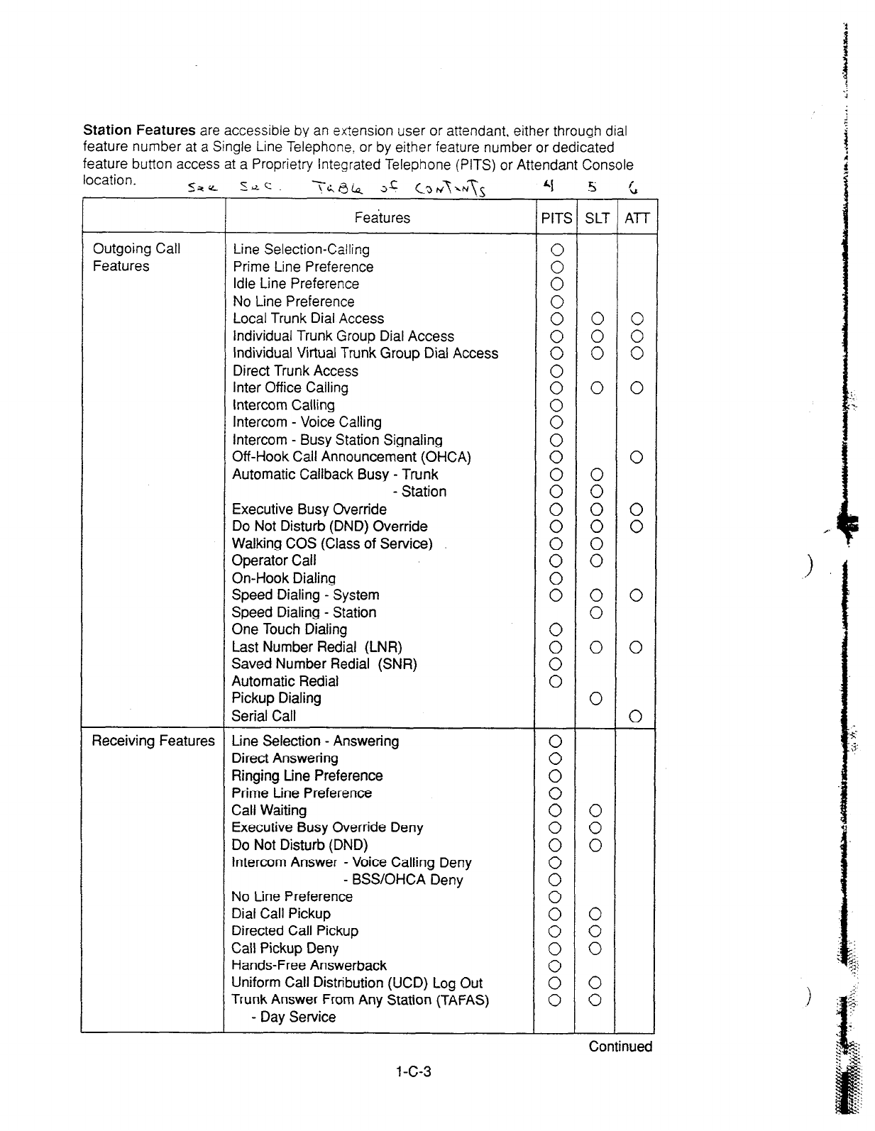
Station Features are accessible by an extension user or attendant, either through dial
feature number at a Single Line Telephone. or by either feature number or dedicated
feature button access at a Proprietry integrated Telephone (PITS) or Attendant Console
location.
Feaiures PITS SLT Al-T
Outgoing Call Line Selection-Calling
Features Prime Line Preference :
Idle Line Preference
No Line Preference :
Local Trunk Dial Access 0 0 0
Individual Trunk Group Dial Access 0 0 0
Individual Virtual Trunk Group Dial Access 0 0 0
Direct Trunk Access
Inter Office Calling : 0 0
Intercom Calling
Intercom - Voice Calling :
Intercom - Busy Station Signaling
Off-Hook Call Announcement (OHCA) 00
0
Automatic Callback Busy - Trunk
- Station 00 :
Executive
Busy Override 0 0 0
Do Not Disturb (DND) Override 0 0 0
Walking COS (Class of Service)
Operator Call 00 00
On-Hook Dialing
Speed Dialing - System : 0 0
Speed Dialing - Station
0
One Touch Dialing
Last Number Redial (LNR) : 0 0
Saved Number Redial (SNR)
Automatic Redial :
Pickup Dialing
0
Serial Call
0
Receiving Features Line Selection - Answering
Direct
Answering :
Ringing Line Preference
Prime tine
Preference :
Call Waiting
Executive Busy Override Deny : :
Do Not Disturb (DND) 0 0
Intercom Answer - Voice Calling Deny
- BSS/OHCA Deny 00
No Line Preference
Dial Call Pickup : 0
Directed Call Pickup
Call Pickup Deny : :
Hands-Free Answerback
Uniform Call Distribution (UCD) Log Out E 0
Trunk Answer From Any Station (TAFAS) 0 0
- Day Service
1 -c-3
Continued
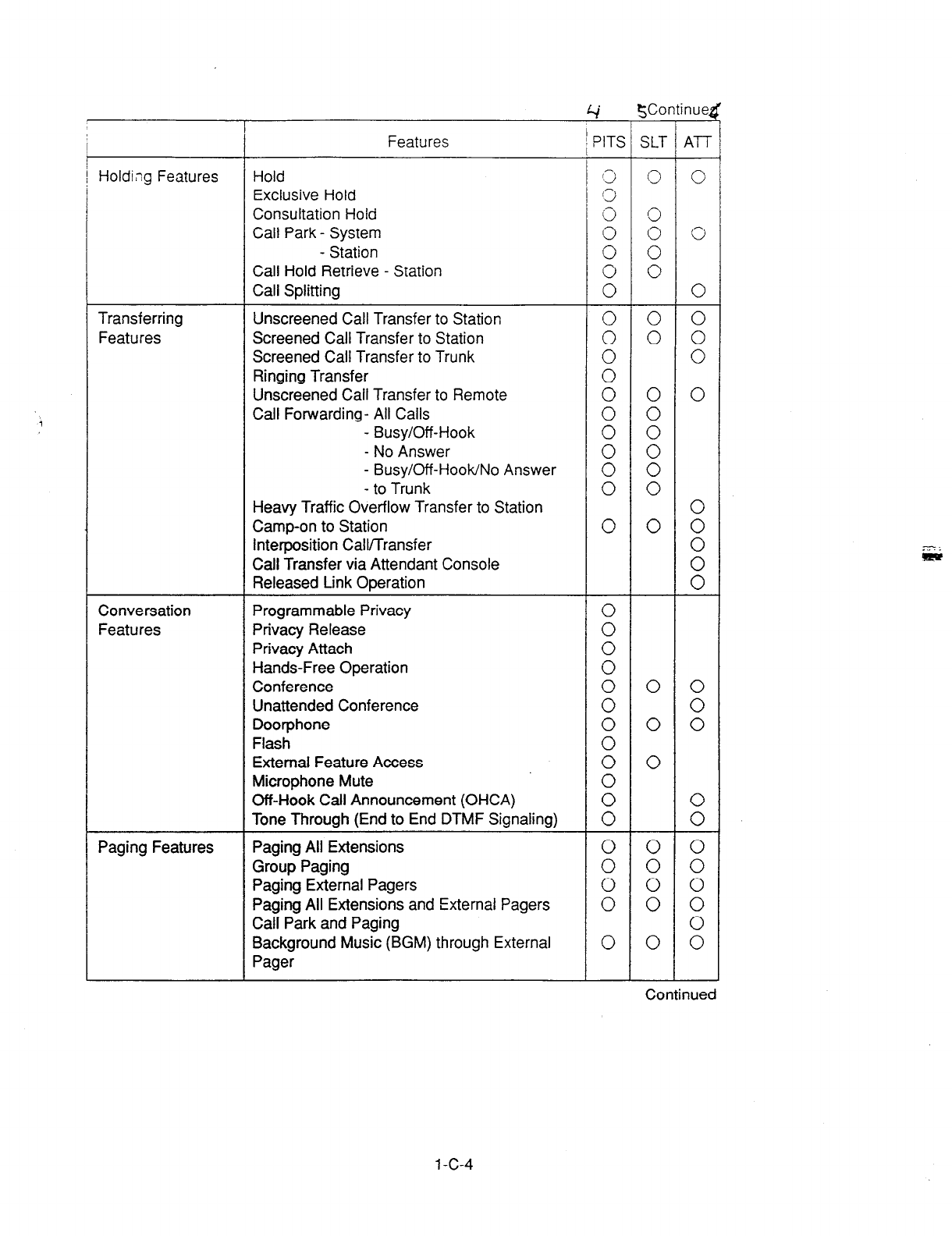
Holding Features Hold
Exclusive Hold
Consultation Hold
Call Park - System
Transferring
Features
Conversation
Features
Paging Features
-!-
Features
- Station
Call Hold Retrieve - Station
Call Splitting
Unscreened Call Transfer to Station
Screened Call Transfer to Station
Screened Call Transfer to Trunk
Ringing Transfer
Unscreened Call Transfer to Remote
Call Forwarding- All Calls
- Busy/Off-Hook
- No Answer
- Busy/Off-HooWNo Answer
- to Trunk
Heavy Traffic Overflow Transfer to Station
Camp-on to Station
Interposition Callmransfer
Call Transfer via Attendant Console
Released Link Operation
Programmable Privacy
Privacy Release
Privacy Attach
Hands-Free Operation
Conference
Unattended Conference
Doorphone
Flash
External Feature Access
Microphone Mute
Off-Hook Call Announcement (OHCA)
Tone Through (End to End DTMF Signaling)
Paging All Extensions
Group Paging
Paging External Pagers
Paging All Extensions and External Pagers
Call Park and Paging
Background Music (BGM) through External
Pager
4
SContinued
i
A
PITS SLT
0
:
0
0
0
0
0
Continued
1 -c-4

Other Features
Features
Un!versal Night Answer
Night Service - Manual Change
Flexible Night Service
Account Code Entry
Zmed Reminder
Background Music (BGM)
Secret Dialing
Assigned Feature Clear
Electronic Station Lock Out
Remote Station Feature Control
Absent Message Capability
Message Waiting
Data Line Security
DSS Console features
- Automatic Transfer
Dial Tone Transfer
CO Access Control
Search by Name/Department
OGM Recording and Playing Back
Power Failure Operation
Trunk Verify
4
‘ITS
ontibed
Y
SLT
0
E
0
0
:
:
0
0
:
0
0
0
0
:
0
0
:
1 -c-5 . .

D. Administration
1 .OO Introduction
Starting up the system administration can be
done using one of the following devices.
l
VT220 (VT1 OO)(default setting), Compatibles
l
Dumb Terminal
l
Attendant Console
Only one terminal can perform system
administration at any one time.
Starting up the system administration from a
remote location is available. For details about
Remote Operation, refer to Section 14-B-2.00
“System Administration from a Remote Location.”
System Configurations
A. VT220 and Dumb terminal
Main Unit vT220,
compatibles,
or Dumb
Terminal.
+ c
RC-232C Cable
B. Attendant console
Attendant
C. Remote operation
Main Unit Remote Terminal
RMT
Central
Office
.
2.00 System Interface
The programming and diagnostics features can
be accessed either locally or remotely using the
system RS-232C interface.
The system may be configured for local direct
access from the data terminal, or via a modem
connection that allows the data terminal to be
located at a greater distance from the system
than is allowed for an RS-232C interface.
For remote access, a data terminal and modem
are required at the maintenance location, and
the RMT card (Modem) at the system.
Two RS-232C interfaces are provided by the
system.
These connections provide communication either
locally or remotely between the system and
devices for programming and diagnostics,
external system programming data storage and
Station Message Detailed Recording (SMDR).
SIO ##2 is used for SMDR only. SIO #I is for
programming and diagnostics, and external
system programming data storage functions.
Typical devices would include VT220,
compatibles, personal computers and line
printers.
Refer to Section 9-D-7.00 “Communication
Interface” for further information.
l-D-1
3.00 Programming 4.00 Test
Before starting up the basic system data
programming, general feature description must
be read.
For further information about
general feature
description, refer to Section 3 “System Features
and Operation.”
Basic system data programming can be done
using VT220, compatibles, dumb terminal and
attendant console.
(VT220 and Compatibles user)
Refer to Section 7 “Preparation for Programming
and Maintenance (VT220 and Compatibles)” and
Section 9 “System Programming (VT220 and
Compatibles).”
(Dumb terminal user)
Refer to Section 8 “Preparation for Programming
and Maintenance (Dumb)” and Section 10
“System Programming (Dumb).”
System’s built-in maintenance capabilities and
the basic diagnostics in fault diagnosis and
corrective maintenance are described in Section
14 “Maintenance (VT220 and Compatibles)” and
Section 15 “Maintenance (Dumb).”
Self-Test (System-Detected Troubles)
System’s built-in on-line diagnostic test program
monitors the troubles generated by hardware or
software
during on-line communication mode.
(VT220 and Compatibles user)
Refer to Section 14-D “Self-Test (System-
Detected Troubles)” for further information.
(Dumb terminal user)
Refer to Section 15-D “Self-Test (System-
Detected Troubles)” for further information.
Functional test by entering commands
Functional test is done by entering specific test
commands when you install the new device and
so on.
(VT220 and Compatibles user)
Refer to Section 14-F “Functional Test by
Entering Commands” for further information.
(Dumb terminal user)
Refer to Section 15-E “Functional Test by
Entering Commands” for further information.
1 -D-2
5.00 Monitor 6.00 Backup Utility
Monitor function provides displaying current
status of “Error Log,” “Device Status” and “Traffic
Information” individually on the screen.
Error Log
When a system maintenance object begins to fail
periodic testing, the system automatically
generates an error record which is stored in the
Error Log.
Consulting the error log should be the first step in
diagnosing system related troubles.
For further information, refer to Section 14-D-2.
02 “Consulting the Error Log.”
Device Status
Provides information about current operation
status of the following items individually on the
screen.
l
System
l
Card
l
Port
l
Conference Trunk
Traffic
Provides current traffic information about
following items individually.
l
Station
l
Trunk Group
l
Attendant Console
l
DISA
l
OGMl
l
OGM2
l
AGC
Making backups of the system programming data
and keeping it is extremely important in the
unlikely event that system programming data are
lost in a system failure.
Backup Utility consists of “save” and “load.”
Save is to transmit a file of data from your system
to backup device.
Load is to send a file of data on your system from
backup device.
Before beginning saving or loading, check
carefully that you are going to the direction you
want.
It’s very easy to erase files if you make a mistake
and confuse saving and loading.
Starting up the backup operation can be done
both at on-site and from a remote location.
Refer to Section 16 “Backup-Utility on-site” and
Section 17 “Backup Utility-Remote Location” for
further information.
Refer to Section 14-G “Monitor” for further
information about monitor.
1 D-3
E. System Configuration
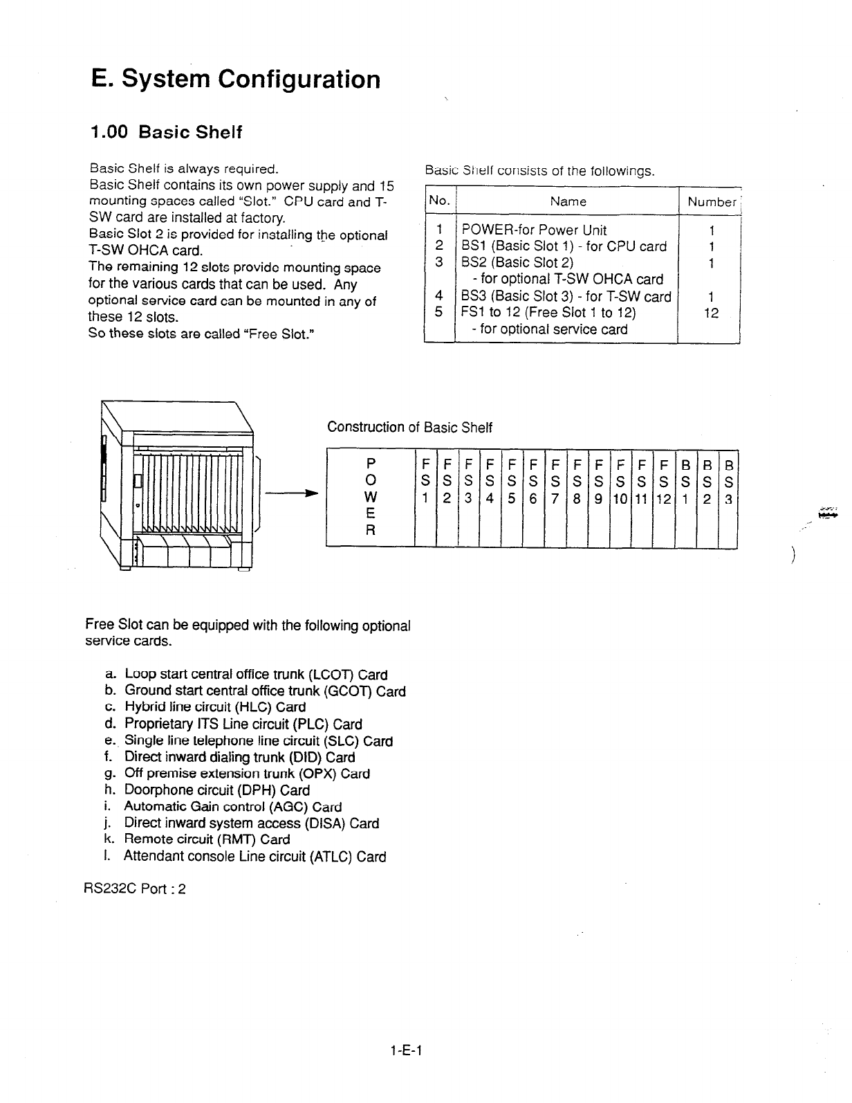
1 .OO Basic Shelf
Basic Shelf is always required. Basic Shelf consists of the followings
Basic Shelf contains its own power supply and 15
mounting spaces called “Slot.” CPU card and T-
SW card are installed at factory.
Basic Slot 2 is provided for installing the optional
T-SW OHCA card.
The remaining 12 slots provide mounting space
for the various cards that can be used. Any
optional service card can be mounted in any of
these 12 slots.
So these slots are called “Free Slot.”
r
-
JO.
-
1
2
3
4
5
Name
POWER-for Power Unit
BSl (Basic Slot 1) - for CPU card
BS2 (Basic Slot 2)
- for optional T-SW OHCA card
BS3 (Basic Slot 3) - for T-SW card
FSl to 12 (Free Slot 1 to 12)
- for optional service card
T
Number
Construction of Basic Shelf
P FFFFFFFFFFFFBBB
0 sssssssssssssss
W 1 2 3 4 5 6 7 8 9 10 11 12 1 2 3
E
R
Free Slot can be equipped with the following optional
service cards.
a. Loop start central
office trunk (LCOT) Card
b. Ground start central office trunk (GCOT) Card
c. Hybrid line circuit (HLC) Card
d. Proprietary ITS tine circuit (PLC) Card
e. Single line telephone line circuit (SLC) Card
f. Direct inward dialing trunk (DID) Card
g. Off premise extension trunk (OPX) Card
h. Door-phone circuit (DPH) Card
i. Automatic Gain control (AGC) Card
j. Direct inward system access (DISA) Card
k. Remote circuit (RMT) Card
I. Attendant console Line circuit (ATLC) Card
RS232C
Port : 2
1 -E-l
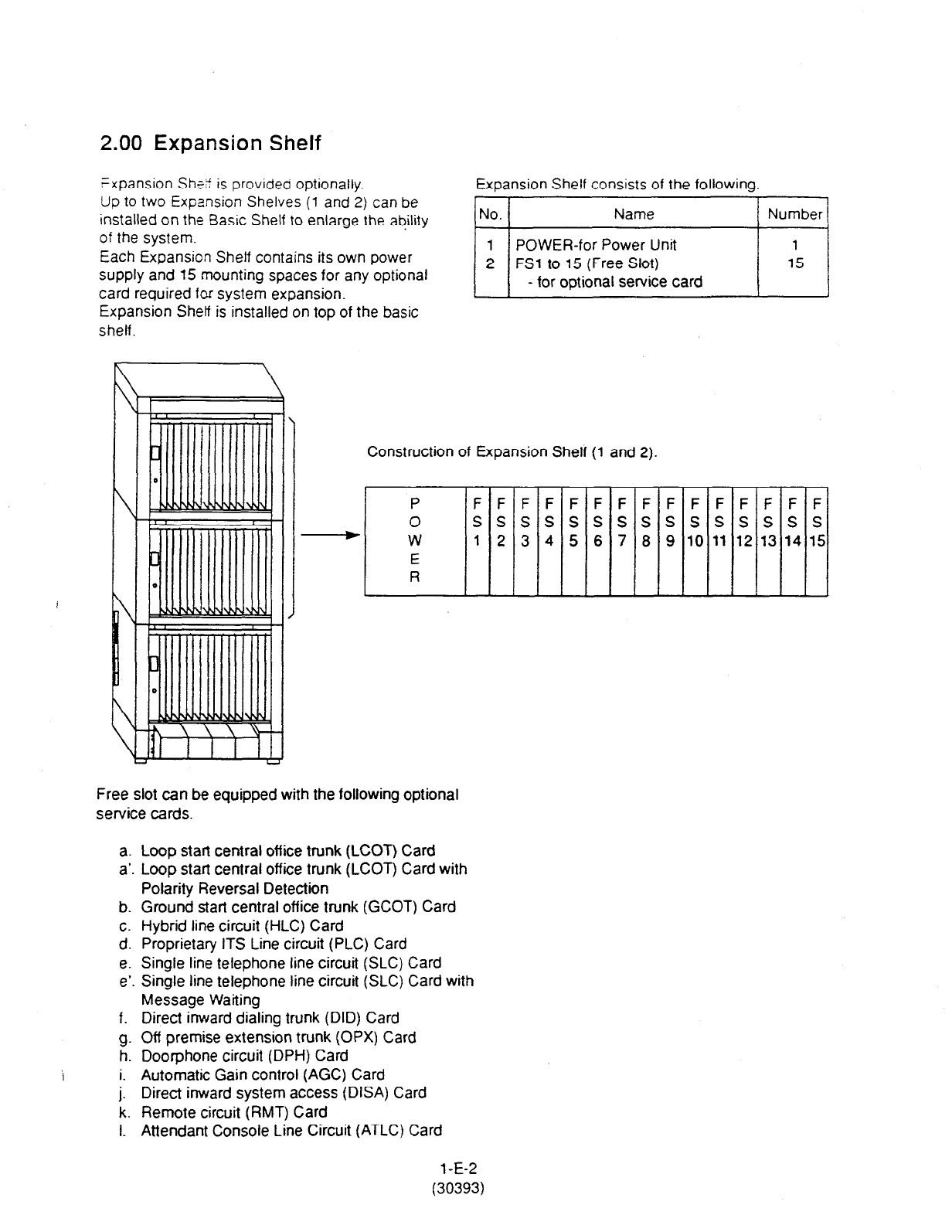
2.00 Expansion Shelf
Expansion ShG is provided optionally. Expansion Shelf consists of the followinq
Up to two Expansion Shelves (1 and 2) can be
installed on the Basic Shelf to enlarge the ability
of the system.
Each Expansion Shelf contains its own power
supply and 15 mounting spaces for any optional
card required for system expansion.
Expansion Shetf is installed on top of the basic
shelf.
Construction of Expansion Shelf (1 and 2).
P FFFFFFFFFF
0 ssssssssss
Y W 12 3 4 5 6 7 8 910
E
R
Free slot can be equipped with the following optional
service cards.
a. Loop start central office trunk (LCOT) Card
a’. Loop start central office trunk (LCOT) Card with
Polarity Reversal Detection
b. Ground start central off ice trunk (GCOT) Card
c. Hybrid line circuit (HLC) Card
d. Proprietary ITS Line circuit (PLC) Card
e. Single line telephone line circuit (SLC) Card
e’. Single line telephone line circuit (SLC) Card with
Message Waiting
f. Direct inward dialing trunk (DID) Card
g. Off premise extension trunk (OPX) Card
h. Doorphone circuit (DPH) Card
i. Automatic Gain control (AGC) Card
j. Direct inward system access (DISA) Card
k. Remote circuit (RMT) Card
1. Attendant Console Line Circuit (ATLC) Card
1 -E-2
(30393)
3.00 Attendant Console
Functions
Up to two Attendant
Consoles (optional-with CRT
display) can be equipped with the system.
The attendant console allows one or two
attendants to answer, screen, and control
incoming calls using Switched Loop Operation.
With attendant operation, incoming calls
can be
screened and forwarded to the proper party for
resolution, messages taken for absent users, or
forwarded to alternate locations.
The attendant console is not dedicated to call
processing and feature accessing, and can be
used for system data programming and
diagnostics.
Refer to Section 6 “Station Features and
Operation-Attendant Console” for further
information about attendant console call
processing features, and Section 13 “Station
Programming-Attendant Console” for further
information about attendant console local
programming mode.
Operation
Attendant console is operable for the following.
l
Call Processing mode
l
System programming
l
Diagnostics
l
Editing local data
4.00 CPU Card
Functions
(1) Call process and basic shelf main protocol.
(Microprocessor 8OC286).
Tme switch (TSW) control, detection of
system clock alarm, basic shelf power down
and expansion shelf power down alarm,
watch dog.
(2) System switch interface.
There are Operation Switch (MODE) (10
modes, 0 to 9) and System Administration
Device Selection Switch (SYSTEM) (10
modes, 0 to 9) on the CPU rotary switch.
When the system lost the programming data
because of system resetting, set system
operation mode using these switches when
starling up the system again.
(3) Terminal interface.
CPU card has two RS-232C terminal
interfaces.
Operation
(1) Operation Switch (MODE) and System
Administration Device Selection Switch
(SYSTEM) are set by turning with screw
driver.
(2) Reset switch is non-lock push switch.
(3) LED for battery alarm lights when voltage of
Lithium-battery becomes too low (less than
2SV).
(4) LED for watch dog lights when CPU’s
software is running away.
i
(5) Watch dog is detecting CPU’s running away.
l-E-3
5.00 TSW Card
Functions
(1) Time switch.
Capability of switching voice is 512ch x
512ch.
(2) Generation of system clocks.
System clocks are 2,048MHz (PCM clock),
8kHz (PCM frame clock).
(3) Generation of call progress tone.
Call progress tones are 350+440Hz, 620Hz,
480+620Hz and 440+480Hz.
(4) Conference circuit.
T-SW card has 3 party x 8 conference’s
circuits.
For CO-CO speech amp., AGC card can be
inserted to a free slot of basic or expansion
shelf.
(5) Paging interface.
T-SW card has 2 pre-amp. circuits for paging.
In order to adjust volume, each amp circuit is
equipped with a knob.
(6) Music-in interface.
T-SW card has 2 interface circuits for music
on hold or BGM.
Operation
(1) A knob for adjusting volume of external
paging is turned with a screw driver from front
of T-SW card.
6.00 Power Unit
Functions
(1) Power supp!y (+5, f15, GND) for a shelf.
(2) External battery interface. (+24)
Battery power (+24) is input from a battery
interface unit in basic shelf with a 2 wire
cable.
(3) Power failure detection.
A circuit in POW detects power failures of
+5VDC, kl S/DC, 1 OOVAC, and 2 power
alarm signals is sent to CPU card as DC
alarm and AC alarm.
(4) Generation of bell signal. (20H2, 1 OOVop)
(2) LED indicatoi or ihe T-SW card lights when
system reset or T-SW local reset occurs.
1 -E-4
7.00 LCOT Card 8.00 GCOT Card
Functions
LCOT (KX-T96180) -----Loop Start Central Office
Trunk card (8 CO Lines/
card)
(1) Loop start CO interface.
CPC detection, 1 DTMF driver.
With loop start, you seize a line by bridging
through a resistance the tip and ring (both
wires) of your telephone line.
(2) Power failure transfer (PFT) by each port.
Tip/Ring of CO are connected to a CO
interface circuit, and directly to LCOT PFT
modular. When power failure occurs, CO
Tip/ring leads are directly connected to SLT
Tip/Ring leads, but LCOT PFT modular and
SLT PFT modular should be connected each
other with connection cord in advance.
(3) Diagnostic transfer (DT) by each port.
A diagnostic relay is placed in Tip/Ring of
each port.
During diagnostic test, only one diagnostic
relay in an LCOT of a system is activated.
Operation
LED indicator on the LCOT card lights when the
system reset or LCOT local reset occurs.
Functions
GCOT (KX-T96181) ----Ground Stan Central Office
Trunk card (8 CO Lines/
card)
(1) Ground start CO interface.
CPC detection, 1 DTMF driver.
A way of signaling on subscriber trunks in which
one side of the two wire trunk (typically the
“Ring” conductor of the Tip and Ring) is
momentarily grounded to get dial tone.
(2) Power failure transfer (PFT) by each port.
Tip/Ring of CO are connected to a CO interface
circuit, and directly to GCOT PFT modular.
When power failure occurs, CO Tip/Ring leads
are directly connected to SLT Tip/Ring leads,
but GCOT PFT modular and SLT PFT modular
should be connected each other with
connection cords in advance.
(3) Diagnostic transfer (DT) by each port.
A diagnostic relay is placed in Tip/Ring of each
pod.
During diagnostic test, only one diagnostic relay
in a GCOT of a system is activated.
Operation
LED indicator on the GCOT card lights when the
system reset or GCOT local reset occurs.
l-E-5
..,:.
.
9.00 PLC Card 10.00 SLC Card
Functions Functions
PLC card (KX-T96 172) SLC card (KX-T96174)
(1) PITS and DSS console interface. (8 circuits/
card)
Maximum loop resistance : 40 ohms
Power supply 1 : +24V (supplied through
speech path, and with
current limitation circuit).
Power supply 2 : +15V (supplied through
data line).
(1) Standard SLT interface.
Maximum loop resistance : 600 ohms.
(including SLT)
Power supply : +24V (with current limitation
circuit.)
2 DTMF receivers, dial pulse detector.
(2) PITS (KX-T123230D, KX-T123235, KX-
T7130) interface with OHCA feature.
When a PITS with OHCA feature is connected
to a port, an OHCA piggy back card (KX-
T96136) should be mounted to its interface
circuit.
(2) Power Failure Transfer (PFT) by each port.
When power failure occurs, SLT Tip / Ring are
led by a PFT relay, but SLT PFT modular and
LCOT / GCOT modular should be connected
each other by connection cords in advance.
Operation
LED indicator on the PLC card lights when the
system reset or PLC local reset occurs.
(3) Diagnostic transfer (DT) by each port.
Diagnostic relay is placed in Tip / Ring of each
port-
During diagnostic test, only one diagnostic
relay in the SLT of a system is activated.
Operation
LED indicator on the SLC card lights when
system reset or SLC local reset occurs.
1 -E-6

11 .OO HLC Card 12.00 ATLC
Card
Functions
HLC card (KX-T96170) is ior PITS, DSS console
and SLT.
(8 extensions / card)
(1) Standard SLT interface. SLT interface is quite
same as that of SLT card.
(2) PITS and DSS console interface. PITS and
DSS console interface is quite same as that of
PLC card.
(3) Interface for PITS (KX-T123230D, KX-
T123235, KX-l-7130) with OHCA feature.
Interface for PITS (KX-T123230D, KX-
T123235, KX-l7130) with OHCA feature is
quite same as that of PLC.
(4) Power failure transfer by each port. (when
using SLT)
Power failure transfer is quite same as that of
SLC card.
(5) Diagnostic transfer by each port. Diagnostic
transfer is quite same as that of SLC card.
Operation
LED indicator on the HLC card lights when the
system reset or HLC local reset occurs.
Functions
(1) ATLC card. (KX-T96141)
Attendant console interface. (2 circuits / card)
(Attendant console : KX-T96300)
Operation
LED indicator on the ATLC card lights when the
system reset or attendant console local reset
occurs.
l-E-7 ’

13.00 DISA Card
Functions
DISA (Direct Inward System Access) card.
(KX-T96191) chc r, OGT i-“?SS \ 6~. ?
7, rn*b lLe-l”\DDSy
(1) 4 OGM trunks.
OGM duration : 30 seconds,.
OGM Battery Backup : 5 days.
The number of OGM : 1,
Recording Algorithm : ADPCM.
(2) 4 CO-CO speech paths without amp.
A CO-CO speech path consists of up-path
and down-path.
Up-path is from call-originate CO to call-
answer CO, and 1 DTMF receiver and one
speech end detector is connected to it.
Down-path is from call-answer CO to call-
originate CO and one speech end detector is
connected to it.
(3) Speech end detector.
Speech end detector detects call progress
tones.
Operation
LED indicator on the DISA card lights when the
system reset or DISA local reset occurs.
14.00 DID Card
Functions
DID (Direct Inward Dialing) card (KX-T96182)
Wink start/immediate start DID interface.
(4 circuits/card) yt /\s, Irv c,
45V used in circuits is originated from DC-DC OCk,\
sr 1
converter in DID card. ‘YGbW,
Operation y-CD
LED indicator on the DID card lights when the
system reset or DID local reset occurs.
1 -E-8

15.00 OPX Card 16.00 DPH Card
Functions
OPX (KX-T96185) -----Off Premise Extension.
(4 OPX Lines / card)
OPX Power Unit is
necessary.
OPX Power Unit should be connected with OPX
card, and Single Line Telephones for OPX should
be connected with OPX card.
- G G!Qs rnP-f,-. D“1 ?a \‘J _
22. GA
Functions
Doorphone card (KX-T96161)
(1) Doorphone interface (4 circuits / card)
4 doorphones can be connected using a
modular connector.
Doorphone chime is sent to both extension
and doorphone at a time when a doorphone
button is pressed.
(2) Door opener interface (4 circuits / card)
DPH card has 4 relays for door opener.
(12OVAC, 1A)
The relay opens for doorlock, closes for door
release. It also opens in the case of power
failure.
Operation
Terminal plate on the DPH card has 8 terminals,
2 leads from door opener are directly connected
to two of 8 terminals.
Operation interval of door opener is 3 seconds.
1 -E-9
17.00 AGC Card 13.00 RMT Card
Functions
AGC (Automatic Gain Control) card
(KX-T96193)
(1) 4 CO-CO speech paths
with AGC Amp. and
Echo-Suppressor.
A CO-CO speech path consists of up-path
and down-path, up-path is from call-originate
CO to call-answer CO, and AGC amp is
inserted and speech end detector is
connected.
Maximum amplitude rate of AGC is 14 dB.
Echo-Suppressor is inserted in a CO-CO
speech path.
(2) 4 DTMF receivers.
DTMF transceiver is used as DTMF repeater.
So, AGC card microprocessor controls DTMF
repeater.
(3) 8 Speech End
Detectors.
Speech
end detector of AGC
is quite same as
that of DISA card.
Functions
RMT (Remote Circuit) card (KX-T96196)
Modem (300/1200 bps) for remote administration.
Modem protocol (1) free wheeling (TTY).
Operation
LED indicator on the RMT card lights when the
system reset or RMT local reset occurs.
Operation
LED indicator on the AGC card lights when the
system reset or AGC local reset occurs.
1-E-10

19.00 T-SW Conference Expan-
sion Card
Functions
T-SW Conference Expansion card (KX-T336104)
Mounted on T-SW card.
3 party x 64 conference circuits.
20.00 OHCA Card
Functions
OHCA (Off Hook Call Announcement) card
(KX-T96136)
This card is mounted on HLC card (KX-T96170)
or PLC card (KX-T96172)
This card includes 2 OHCA circuits.
Allows an extension user to intrude through the
speaker into another extension that is in
conversation using the handset.
This feature is available only against the following
PITS telephones: KX-Ti 23230D, KX-T123235,
KX-l7130.
21.00 T-SW OHCA Expansion
Card
T-SW OHCA Expansion card (KX-T336105)
This card is mounted on Basic Slot 2 for OHCA
feature.
OHCA card (KX-T96136) for extension port must
be installed on the HLC card or PLC card in
advance.
22.00 OPX Power Unit
Functions
OPX (Off Premise Extension) Power Unit
(KX-T96186).
Input is 120VAC 60Hz.
Output is Ringing Signal (1 OOVAC, 20Hz) and
46V DC for OPX Card.
1 -E-l 1
Section 2
Installation

(Section 2)
Installation
Contents
Page
A Preparation . . . . . . . . . . . . . . . . . . . . . . . . . . . . . . . . . . . . . . . . . . . . . . . . . . . . . . . . . . . . . . . . . . . . . . . . . . . . . . . . . . . . . . . . . . . . . . . . . . . . . . 2-A-l
1 .OO introduction . . . . . . . . . . . . . . . . . . . . . . . . . . . . . . . . . . . . . . . . . . . . . . . . . . . . . . . . . . . . . . . . . . . . . . . . . . . . . . .
. . . . . . . . . . . . . 2-A-l
2.00 Before Installation . . . . . . . . . . . . . ..*......................................................-........... 2-A-2
B Installation of Shelf . . . . . . . . . . . . . . . . . . . . . . . . . . . . . . . . . . . . . . . . . . . . . . . . . . . . . . . . . . . . . . . . . . . . . . . . . . . . . . . . . . . . . . . . . . . 2-B-l
1 .OO Basic Shelf ............................................................................................. 2-B-l
1.01 Basic Shelf Assembly .................................................................. 2-B-Z
1.02 Removing the Panels .................................................................. 2-B-3
1.03 Cable Connections ...................................................................... 2-B-5
2.00 Expansion to 2-Shelf System I.~ .............................................................. 2-B-6
2.01 Expansion Shelf Assembly .......................................................... 2-B-7
2.02 Removing the Panels .................................................................. 2-B-8
2.03 Stacking on the Basic Shelf ......................................................... 2-B-l 0
2.04 Installation of Top Cover .............................................................. 2-B-l 1
2.05 Cable Connections ...................................................................... 2-B-12
3.00 Expansion to 3-Shelf System ................................................................. 2-B-l 3
3.01 Stacking on the 2-Shelf System .................................................. 2-B-l 4
3.02 Installation of Top Cover .............................................................. 2-B-l 5
3.03 Cable Connections ...................................................................... 2-B-l 6
4.00 Ground Wiring.. ...................................................................................... 2-B-l 8
5.00 Fixing on the Floor ................................................................................. 2-B-l 9
5.01 Setting Out and Drilling ................................................................ 2-B-l 9
5.02 Fixing on the Floor ....................................................................... 2-B-22
C Installation of Cards ......................................................................................... 2-c-1
1 .OO Before Installation ............................................................................... ...2-c- 1
1.01 Slot Construction ......................................................................... 2-c-1
1.02 Guide Plate.. ................................................................................ 2-c-2
2.00 Connection of Standard System ........................................................... 2-C-3
2.01 CPU Card .................................................................................... 2-C-3
2.02 T-SW Card.. ................................................................................. 2-C-3
2.03 Power Unit ................................................................................... 2-C-3
3.00 Connection of Optional Cards ............................................................... 2-C-4
3.01 T-SW Conference Expansion Card (KX-T336104). ..................... 2-C-4
3.02 T-SW OHCA Card (KX-T336105) ................................................ 2-C-5
3.03 OHCA Card (KX-T96136). ...........................................................
3.04 ATLC Card (KX-T96141) ............................................................. N&
3.05 DPH Card (KX-T96161). .............................................................. 2-c-1 0
3.06 HLC Card (KX-T96170). .............................................................. 2-c-1 4
3.07 PLC Card (KX-T96172) ............................................................... 2-C-l 6
3.08 SLC Card (KX-T96174) ............................................................... 2-C-l 8
3.09 LCOT Card (KX-T96180) ............................................................. 2-c-21
2-l
Page
3.10 GCOT Card (KX-T96181). ........................................................... 2-C-22
3.11 DID Card (KX-T96182). ............................................................... 2-C-25
3.12 OPX Card (KX-T96185). .............................................................. 2-C-26
3.13 DISA Card (KX-T96191). ............................................................. 2-C-28
3.14 AGC Card (KX-T96193) .............................................................. 2-C-28
3.15 RMT Card (KX-T96196) .............................................................. 2-C-28
4.00 Parallel Connection of the Extensions .................................................. 2-c-29
5.00 Auxiliary Connection for Power Failure Transfer ................................... 2-C-30
6.00 Connection of the Battery Adaptor (KX-A26D) ...................................... 2-C-32
D Connection of Optional Peripheral Equipments . . . . . . . . . . . . . . . . . . . . . . . . . . . . . . . . . . . . . . . . . . . . . . . 2-D-l
1.00 Paging Equipment .................................................................................. 2-D-l
2.00 External Music Source ........................................................................... 2-D-2
3.00 RS-232C Interface .................................................................................. 2-D-3
3.01 Connection to the Printer ............................................................. 2-D-5
3.02 Connection to the Data Terminal ................................................. 2-D-6
E Installation of Attendant Console . . . . . . . . . . . . . . . . . . . . . . . . . . . . . . . . . . . . . . . . . . . . . . . . . . . . . . . . . . . . . . . . . . . . . 2-E-l
1.00
2.00
3.00
4.00
5.00
6.00
7.00
8.00
Configuration ......................................................................................... 2-E-l
Attendant Console Assembly ................................................................. 2-E-3
Handset Connection .............................................................................. 2-E-4
Installation and Removal of CRT Unit .................................................... 2-E-5
4.01 CRT Unit Installation .................................................................... 2-E-5
4.02 CRT Unit Removal.. ..................................................................... 2-E-7
Keyboard Connection ............................................................................ 2-E-8
Connection with KX-T336 System ........................................................ 2-E-9
AC Power Cord Connection.. ................................................................. 2-E-l 0
Various Adjustments .............................................................................. 2-E-l 1
F Starting Up the KX-T336 System . . . . .._.............................................................. 2-F-l
1 .OO System Power-Up
Prokedure
................................................................ 2-F-l
2.00 CPU Rotary-Switch Features.. ............................................................... 2-F-2
2.01 Operation Switch (MODE) ........................................................... 2-F-2
2.02 System Administration Device Selection Switch (SYSTEM). ...... 2-F-5
2.03 Operation Sequence for System Starting Up .............................. 2-F-6
2-2

A. Prepa.ration
1 .OO Introduction
This section describes !?e prwedures required to install the KX-T336 System.
Detailed instruct,ons fo- panning the installation site, installing the shelves and optional
cards, and
cabimg
of cwoheral equipments are provided.
Further information on system exDansion and peripheral equipment installation is
included.
2-A-i
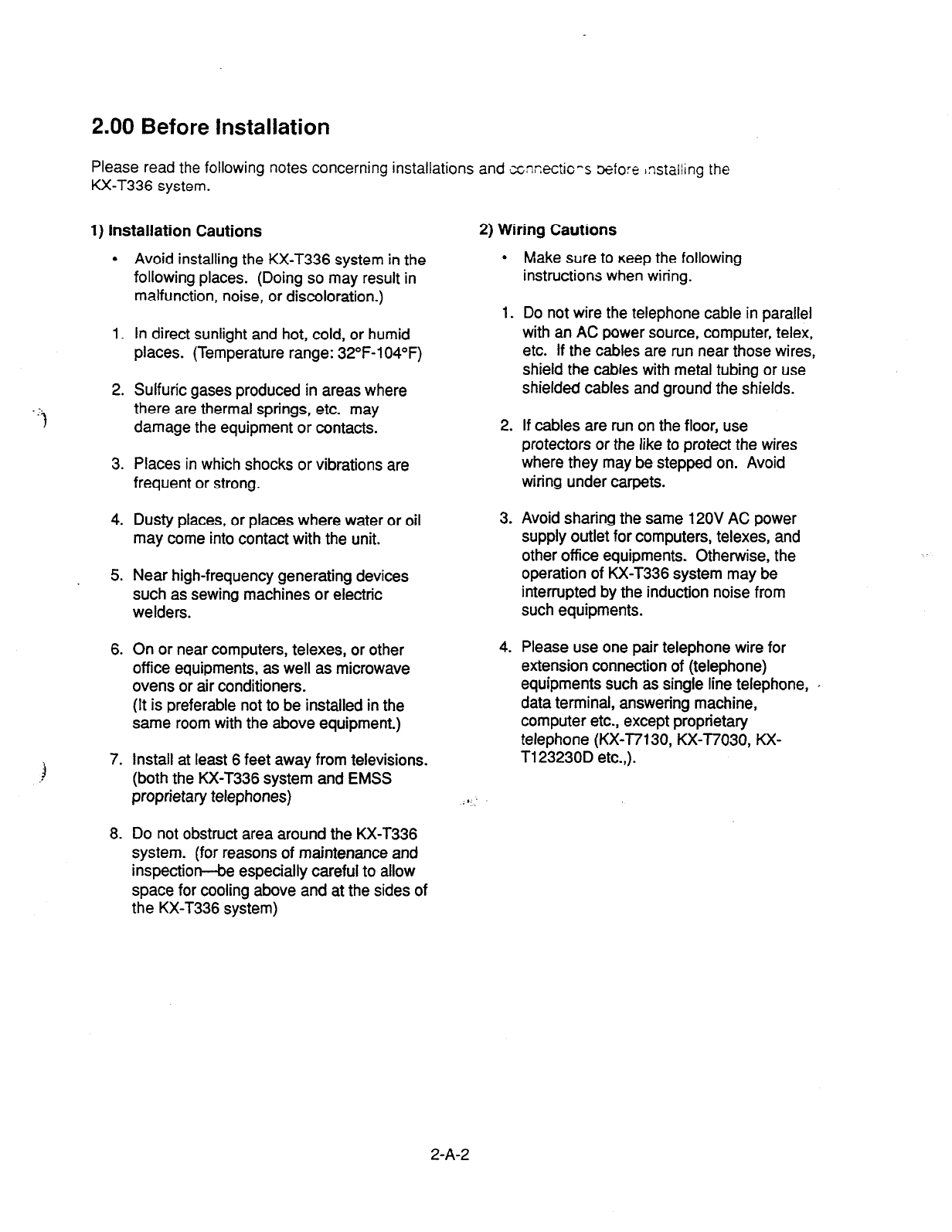
2.00 Before Installation
Please read the following notes concerning installations and xxectic-s More Installing the
KX-T336 system.
1) Installation Cautions
l
Avoid installing the KX-T336 system in the
following places. (Doing so may result in
malfunction, noise, or discoloration.)
1. In direct sunlight and hot, cold, or humid
places. (Temperature range: 32”F-104°F)
2. Sulfuric gases produced in areas where
there are thermal springs, etc. may
damage the equipment or contacts.
3. Places in which shocks or vibrations are
frequent or strong.
4. Dusty places, or places where water or oil
may come into contact with the unit.
5. Near high-frequency generating devices
such as sewing machines or electric
welders.
6. On or near computers, telexes, or other
offrce equipments, as well as microwave
ovens or air conditioners.
(It is preferable not to be installed in the
same room with the above equipment.)
7. Install at least 6 feet away from televisions.
(both the KX-T336 system and EMSS
proprietary telephones)
8. Do not obstruct area around the KX-T336
system. (for reasons of maintenance and
inspectiorr-be especially careful to allow
space for cooling above and at the sides of
the KX-T336 system)
2) Wiring Cautions
l
Make sure to Keep the following
instructions when wiring.
1. Do not wire the telephone cable in parallel
with an AC power source, computer, telex,
etc. If the cables are run near those wires,
shield the cables with metal tubing or use
shielded cables and ground the shields.
2. If cables are run on the floor, use
protectors or the like to protect the wires
where they may be stepped on. Avoid
wiring under carpets.
3. Avoid sharing the same 120V AC power
supply outlet for computers, telexes, and
other office equipments. Otherwise, the
operation of KX-T336 system may be
interrupted by the induction noise from
such equipments.
4. Please use one pair telephone wire for
extension connection of (telephone)
equipments such as single line telephone,
data terminal, answering machine,
computer etc., except proprietary
telephone (KX-T7130, KX-T7030, KX-
Tl23230D etc.,).
1
2-A-2

B. Installation of Shelf
This subsection describes the installation of the she?. with information on expanding the
capacity of an existing system.
Building Block System provides the eclaqe-ent of system’s ability by installing the
optional Expansion Shelf.
Up to two Expansion Shelves can be instaf’ed to !‘-e system
Each expansion shelf can be equipped
with up to 120 lines (including Extensions and
CO lines).
The system can consist of one, two or three shelves (Basic, Expansion 1 and
Expansion 2).
Each shelf contains its own power supply.
1 .OO Basic Shelf
Basic Shelf is always required and it can be equipped with up to 96 lines (including
Extension and CO lines).
The basic shelf includes top cover and base shelf.
The following figure shows a basic system composed of a basic shelf only.
l
2-B-l
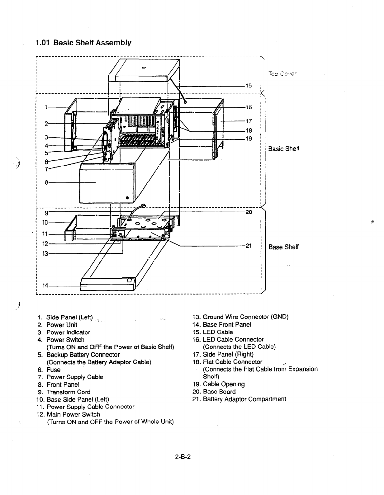
1 .Ol Basic Shelf Assembly
r----- _______________--___---------------------------------------------
,16
17
18
19
1. Side Panel (Left) ..)--
2.
Power Unit .- ._
3. Power Indicator
4.
Power Switch
(Turns ON and OFF the Power of Basic Shelf)
5. Backup Battery Connector
(Connects the Battery Adaptor Cable)
6.
Fuse
7.
Power Supply Cable
8. Front Panel
9. Transform Cord
10. Base Side Panel (Left)
11. Power Supply Cable Connector
12. Main Power Switch
(Turns ON and OFF the Power of Whole Unit)
I
\,
I
/
Basic Sheff
Base Shelf
13. Ground Wire Connector (GND)
14. Base Front Panel
15. LED Cable
16. LED Cable Connector
(Connects the LED Cable)
17. Side Panel (Right)
18. Flat Cable Connector
(Connects the Flat Cable from Expansion
Shelf)
19. Cable Opening
20. Base Board
21. Battery Adaptor Compartment
2-B-2
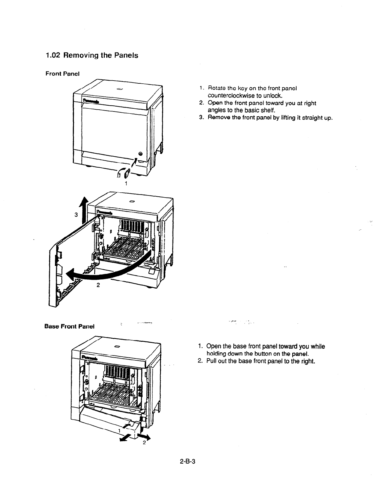
1.02 Removing the Panels
Front Panel
Base Front Panel
1.
2.
3.
1.
2.
-
Rotate the key on the front panel
counterclockwise to unlock.
Open the front panel toward you at right
angles to the basic shelf.
Remove the front panel by lifting it straight up.
_i- _
/.
Open the base front panel toward you while
holding down the button on the panel.
Pull out the base front panel to the right.
2-B-3

Side Panel
d
Screws 4-f
/
8 Screws
1. Remove the right side panel by loosening the eight screws.
2. Remove the upper left side panel by loosening the four screws.
Base Side Panel
4/
/
d Screws
1. Remove the lower left side panel by loosening the four screws.
Note :
If the system is to be expanded to 2-Shelf System, proceed to Section 2-B-2.00
“Expansion to 2-Shelf System.”
2-B-4
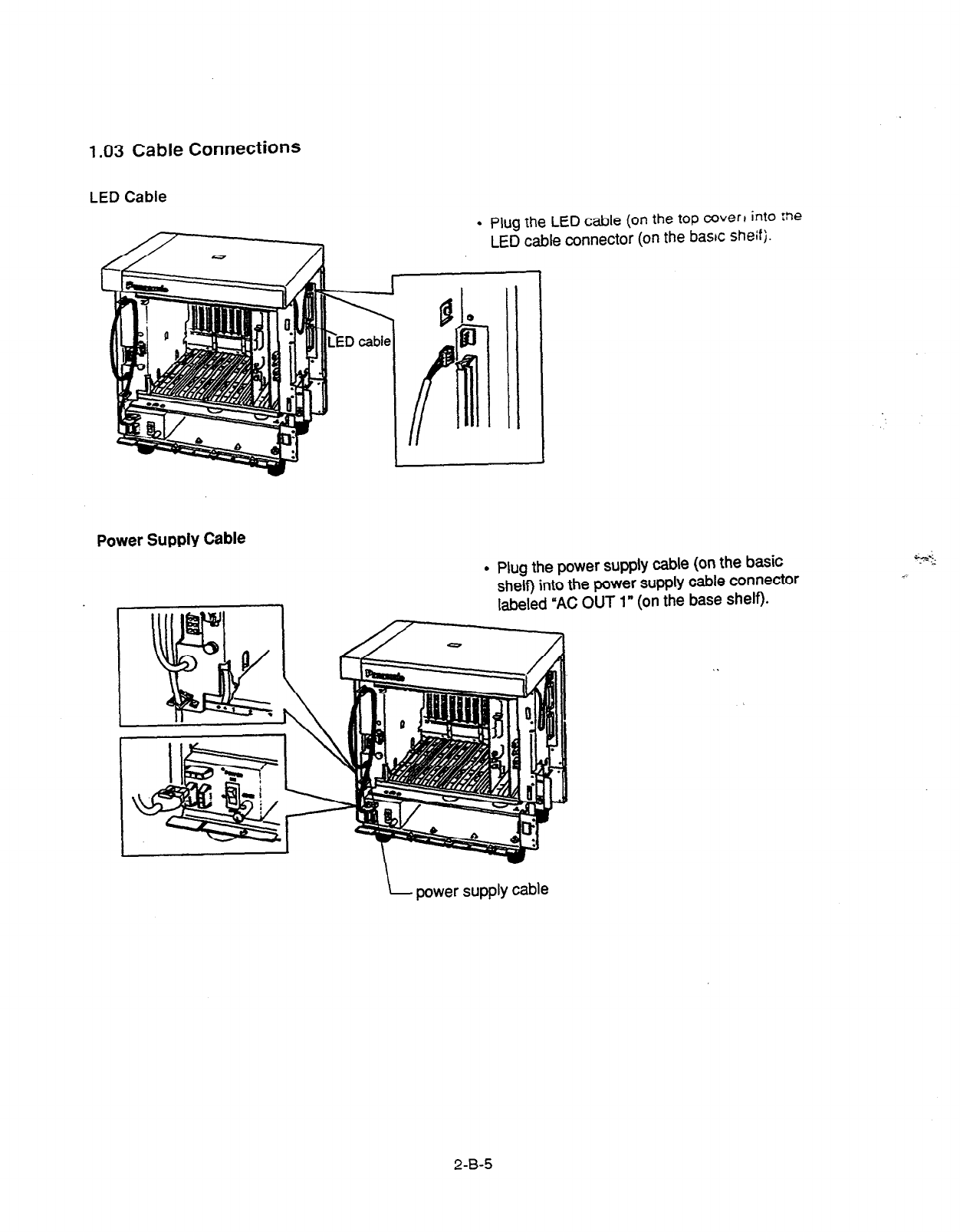
1.03 Cable Connections
LED Cable
. Plug
the
LED
cable (on the top mverl into :ne
LED cable connector (on the bashc
sheifj.
Power Supply
Cable
l
Plug the power supply cable (on the basic
shelf) into the power supply cable connector
labeled “AC OUT 1” (on the base shelf).
\ power supply cable
2-B-5

2.00 Expansion to 2-Shelf System
The KX-T336 System can be expanded to 2-Shelf System by installing the Expansion
Shelf 1 on the Basic Shelf.
The 2-Shelf system can be equipped with up to 216 lines (including extensions and CO
lines).
The following figure shows a 2-Shelf System composed of a basic shelf and an expansion
shelf.
2-B-6
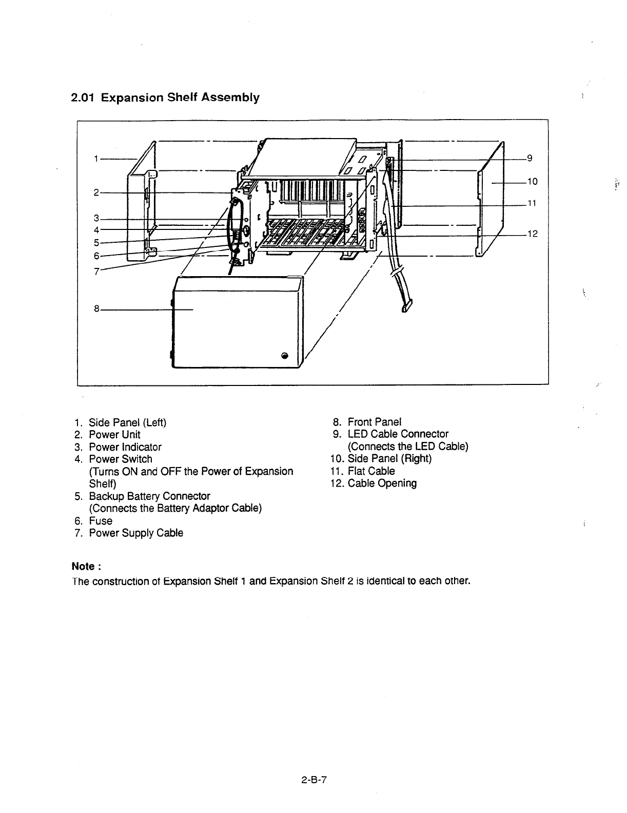
2.01 Expansion Shelf Assembly
1. Side Panel (Left)
2. Power Unit
3. Power Indicator
4. Power Switch
(Turns ON and OFF the Power of Expansion
Shelf)
5. Backup Battery Connector
(Connects the Battery Adaptor Cable)
6. Fuse
7. Power Supply Cable
8. Front Panel
9. LED Cable Connector
(Connects the LED Cable)
10. Side Panel (Right)
11. Flat Cable
12. Cable Opening
Note :
The construction of Expansion Shelf 1 and Expansion Shelf 2 is identical to each other.
2-B-7

2.02 Removing the Panels
<Basic Shelf>
Removing the Top Cover
2)
TOP
/ oover
\ LED cable
1. Disconnect the LED cable (on the top cover) from the LED cable connector (on the
basic shelf).
2. Remove the top cover by loosening the four screws.
2-B-8
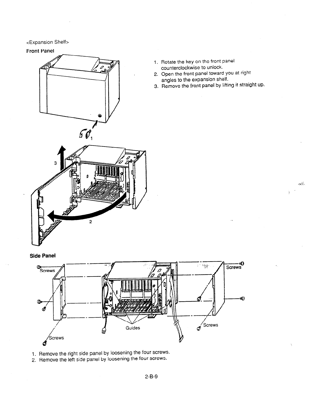
<Expansion Shelf>
Front Panel
1. Rotate the key on the front panel
counterclockwise to unlock.
2. Open the front panel toward you at right
angles to the expansion shelf.
3. Remove the front panel by lifting it straight up.
Side Panel
,
/
Screws
d
Q
Guides
v
1. Remove the right side panel by loosening the four screws.
2. Remove the left side panel by loosening the four screws.
2-B-9

2.03 Stacking on the Basic Shelf
Expansion
shelf
Basic shelf
l
To connect the expansion shelf with basic shelf,
place the holes of the expansion shelf exactly
on the holes of the basic shelf.
l
When the holes are placed properly, fix them
with the three screws immediately to prevent
the expansion shelf from falling down.
\ Note :
If the system is to be expanded-to 3-Shelf System, proceed to Section 2-B-3.00
“Expansion to 3-Shelf System.”
2-B-l 0
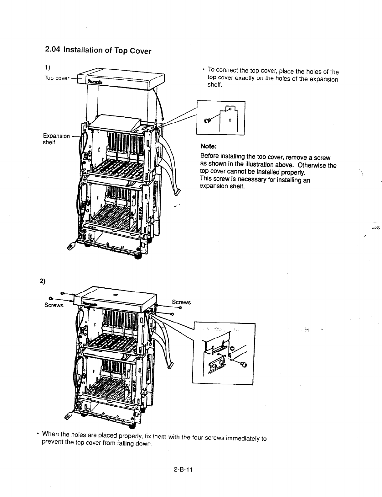
2.04 Installation of Top Cover
Expans
shelf
To connect the top cover, place the holes of the
top cover exactly on the holes of the expansion
shelf.
Note:
Before installing the top cover, remove a screw
as shown in the illustration above. Otherwise the
top cover cannot be installed properly.
This screw is necessary for installing an
expansion shelf.
,: .
-.
_C.
<cc.
l
When the holes are placed properly, fix them with the four screws immediately to
prevent the top cover from falling down.
2-B-l 1

2.05 Cable Connections
LED Cable/Flat Cable
Basic shelf -
Base shelf- ,
Top
cover
Expansion shelf -
Flat cable
. 1. Plug the LED cable (on the top cover) into the LED cable connector (on the expansion
shelf).
2. Plug the flat cable (on the expansion shelf) into the flat cable connector (on the basic
shelf). . .
Power Supply Cable
MI1 I- traslc snelf
Base snelf
.
Plug the power supply cable into the power supply cable connector (“AC OUT 2”).
2-B-12
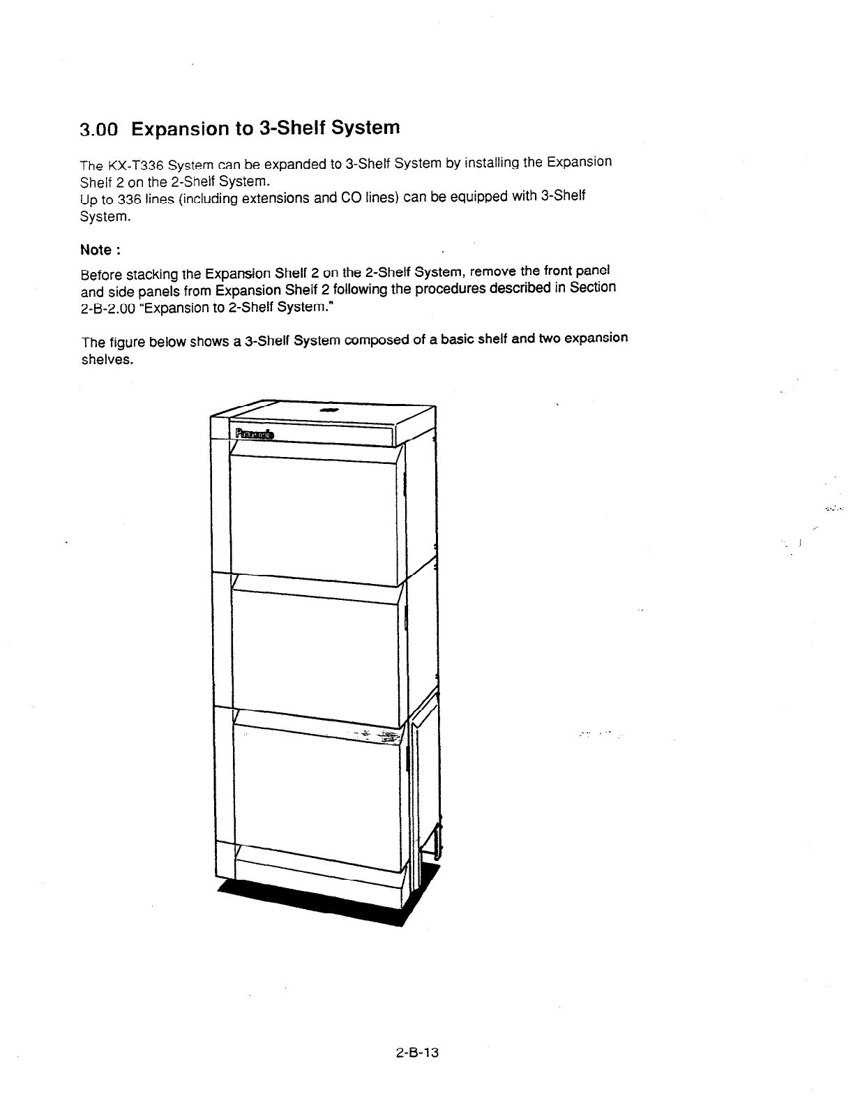
3.00 Expansion to 3-Shelf System
The KX-1336 System can be expanded to 3-Shelf System by installing the Expansion
Shelf 2 on the 2-Shelf System.
Up to 336 lines (including extensions and CO lines) can be equipped with 3-Shelf
System.
Note :
Before stacking the Expansion Shelf 2 on the 2-Shelf System, remove the front panel
and side panels from Expansion Shelf 2 following the procedures described in Section
2-B-2.00 *‘Expansion to 2-Shelf System.”
The figure below shows a 3-Shelf System composed of a basic shelf and two expansion
shelves.
:
/
/
/
c
?
2-B-l 3

3.01 Stacking on the Z-Shelf System
1)
Expansion
shelf 2
Expansion
shelf 1
. To connect the expansion shelf 2 with 2-Shelf
System,
place the holes of the expansion shelf
2 exactly on the holes of the expansion shelf 1.
.
When the holes are placed properly, fix them with the three screws immediately to
prevent the expansion shelf 2 from falling down.
2-B-l 4
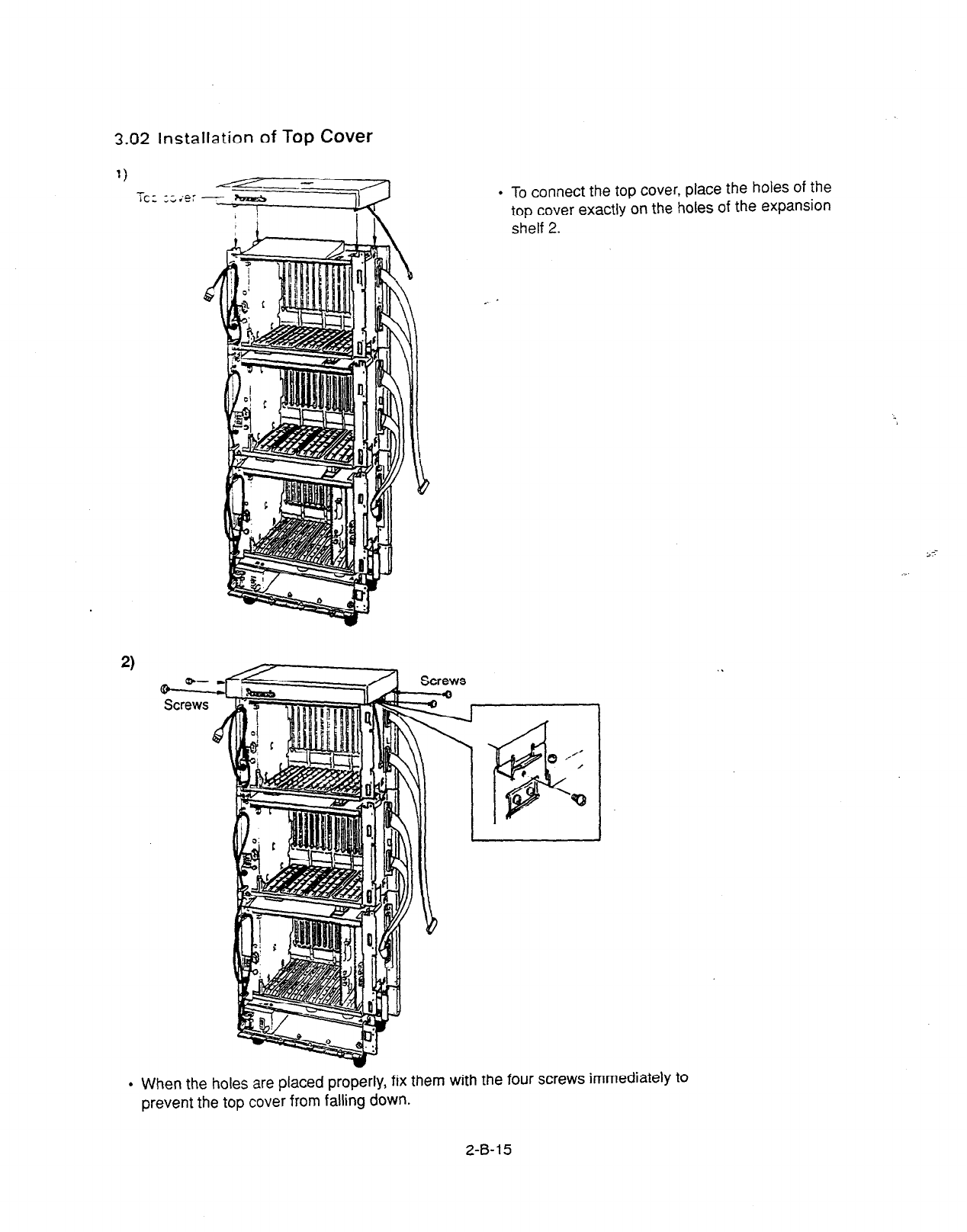
3.02 lnsta
llation
of Top Cover
2)
m
Screws
. To connect the top cover, place the holes of the
top cover exactly on the holes of the expansion
shelf 2.
. When the holes are placed properly, fix them with the four screws immediately to
prevent the top cover from falling down.
. .
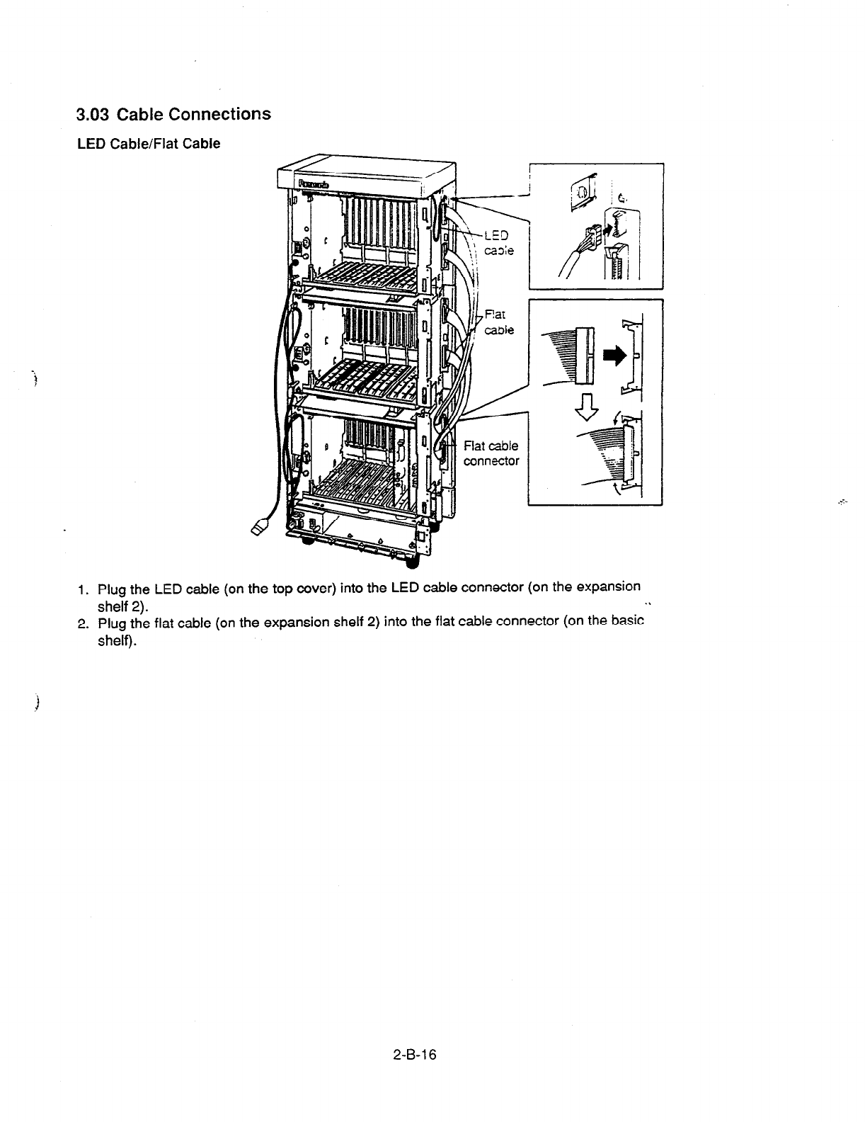
3.03 Cable Connections
LED Cable/Flat Cable
-.
?
1. Plug the LED cable (on the top cover) into the LED cable connector (on the expansion
shelf 2). .I
2. Plug the flat cable (on the expansion shelf 2) into the flat cable connector (on the basic
shelf).
2-B-l 6
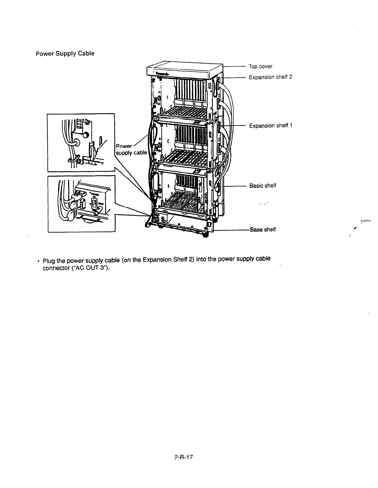
Power Supply Cable
Top cover
Expansion shelf 2
Expansion shelf 1
Basic shelf
-Base shelf
.
Plug the power supply cable (on the Expansion Shelf 2) into the power supply cable
connector (“AC OUT 3”). .
2-B-l 7

4.00 Ground Wiring
.’ 1.
3
IMPORTANT!!!
I
Make sure to connect the frame c’ :?e KX-‘323 syc’e~
to the earth ground properly to protxt the “- :
,
.
Connect the ground wire to the ground wire connector (GND).
2-B-l 8
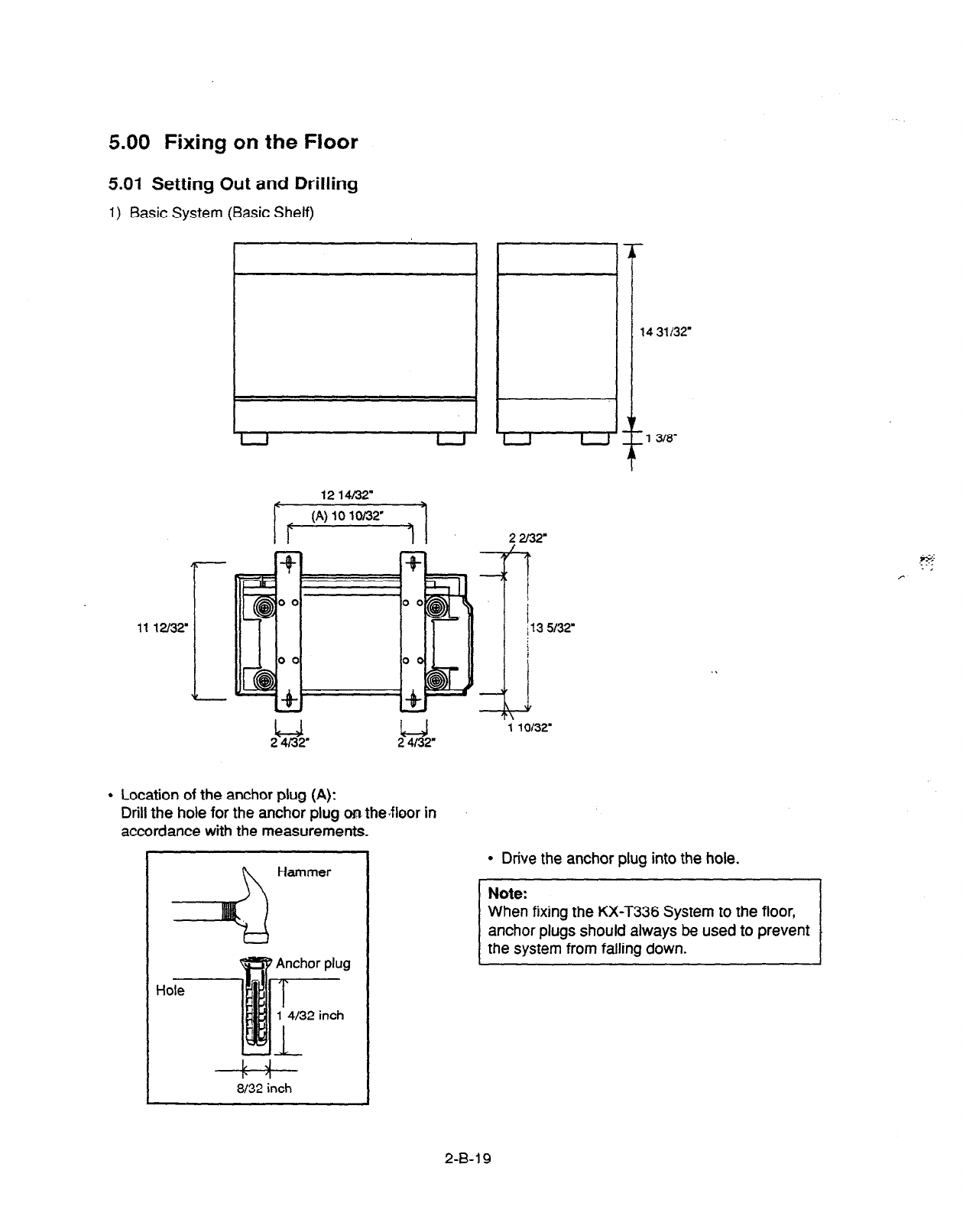
5.00 Fixing on the Floor
5.01 Setting Out and Drilling
1) Basic System (Basic Shelf)
1214/32
/.
l
Location of the anchor plug (A):
Drill the hole for the anchor plug on the-floor in
accordance with the measurements.
n
Hammer
I# J
al32 inch
143lf32
1 lot32
l
Drive the anchor plug into the hole.
When fixing the KX-T336 System to the floor
anchor plugs should always be used to prevent
2-B-i 9
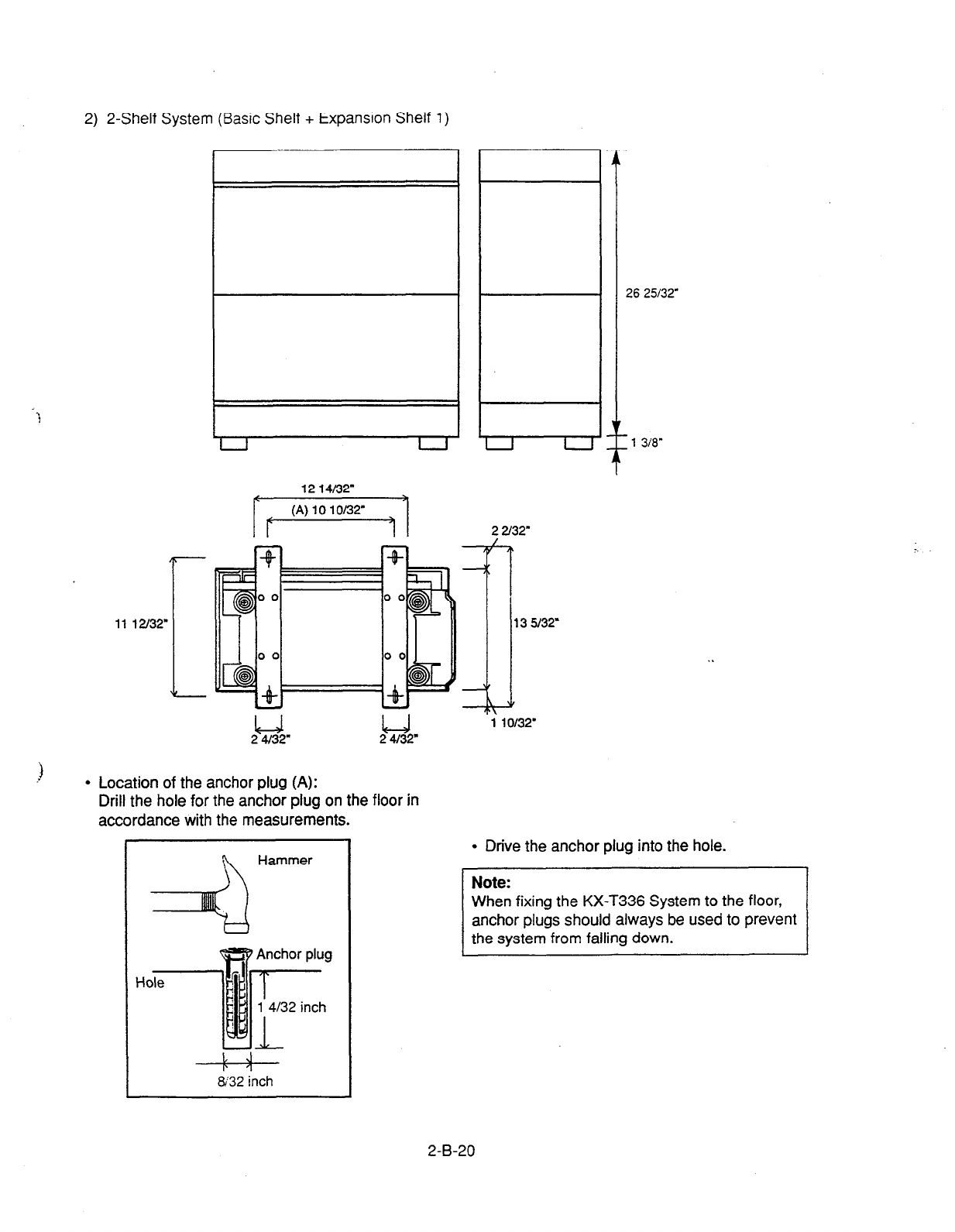
2) 2-Shelf System (Basic Shelf + Expansion Shelf 1)
11 l2l32
-
1214K32"
Tr'*""'""
-@OO
7
00
B,. -
l
Location of the anchor plug (A):
Drill the hole for the anchor plug on the floor in
accordance with the measurements.
4
Hammer
L J
&32 inch
26 25132
_I
1 318"
22l32
:
13932
1 10132
l
Drive the anchor plug into the hole.
When fixing the KX-T336 System to the floor,
anchor plugs should always be used to prevent
2-B-20
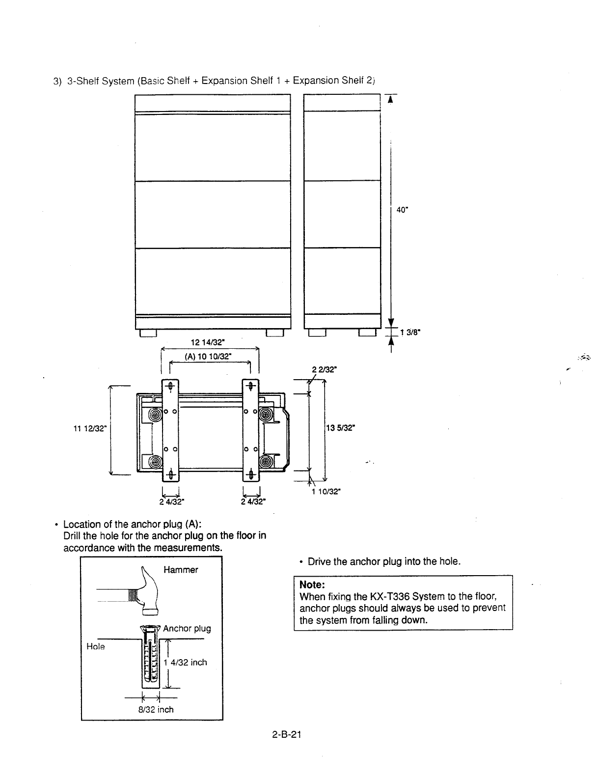
3) 3-Shelf System
(Basic Shelf
+ Expansion Shelf 1 + Expansion Shelf 2j
1112/32
1
1214/32
24/32" 24I32
l
Location of the anchor plug (A):
Drill the hole for the anchor plug on the floor in
accordance with the measurements.
1
:4
Hammer
8132 inch
i
13 5l3T
10132
l
Drive the anchor plug into the hole.
When fixing the KX-T336 System to the floor,
anchor plugs should always be used to prevent
2-B-21
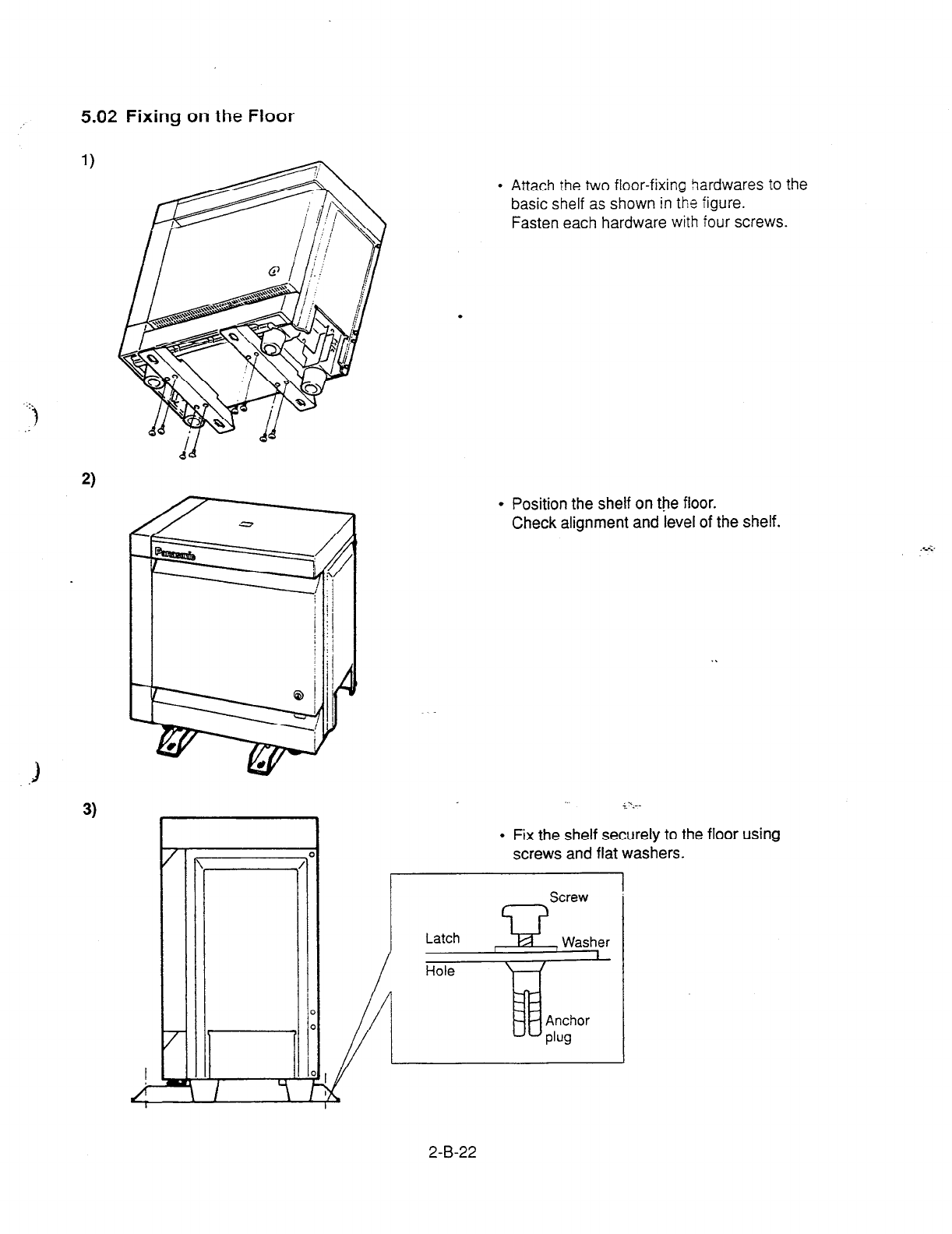
5.02 Fixing on the Floor
..:.
.:)
l
Attach the two floor-fixing 9ardwares to the
basic shelf as shown in the figure.
Fasten each hardware with four screws.
.
l
Position the shelf on the floor.
Check alignment and level of the shelf.
l
Fix the shelf securely to the floor using
screws and flat washers.
Screw
2-B-22
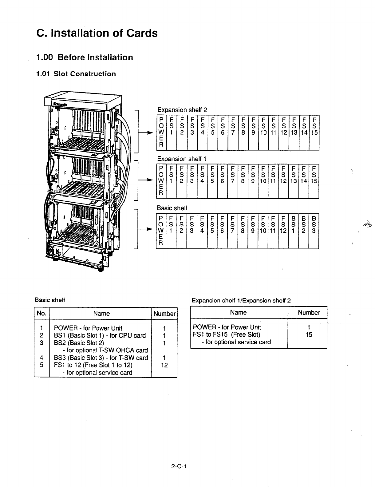
C. Installation of Cards
.OO Before Installation
.Ol Slot Construction
1
I--
l-
I-+
Expansion shelf 2
PEFFFFFFFFFFFFF
ossssssssssssss
W 1 2 3 4 5 6 7 8 9 10 11 12 13 14
:
Expansion shelf 1
Basic shelf
PFFFFFFFFFFFFBB
ossssssssssssss
W 1 2 3 4 5 6 7 8 9 10 11 12 1 2
Ei
Basic shelf Expansion shelf l/Expansion shelf 2
Name 1 Number]
POWER - for Power Unit
BSl (Basic Slot 1) - for CPU card
BS2 (Basic Slot 2)
- for optional T-SW OHCA card
BS3 (Basic Slot 3) - for T-SW card
FSl to 12 (Free Slot 1 to 12)
- for optional service card
1
12
F :
1 ”
1:
Ls
1 i
3
2-c-1
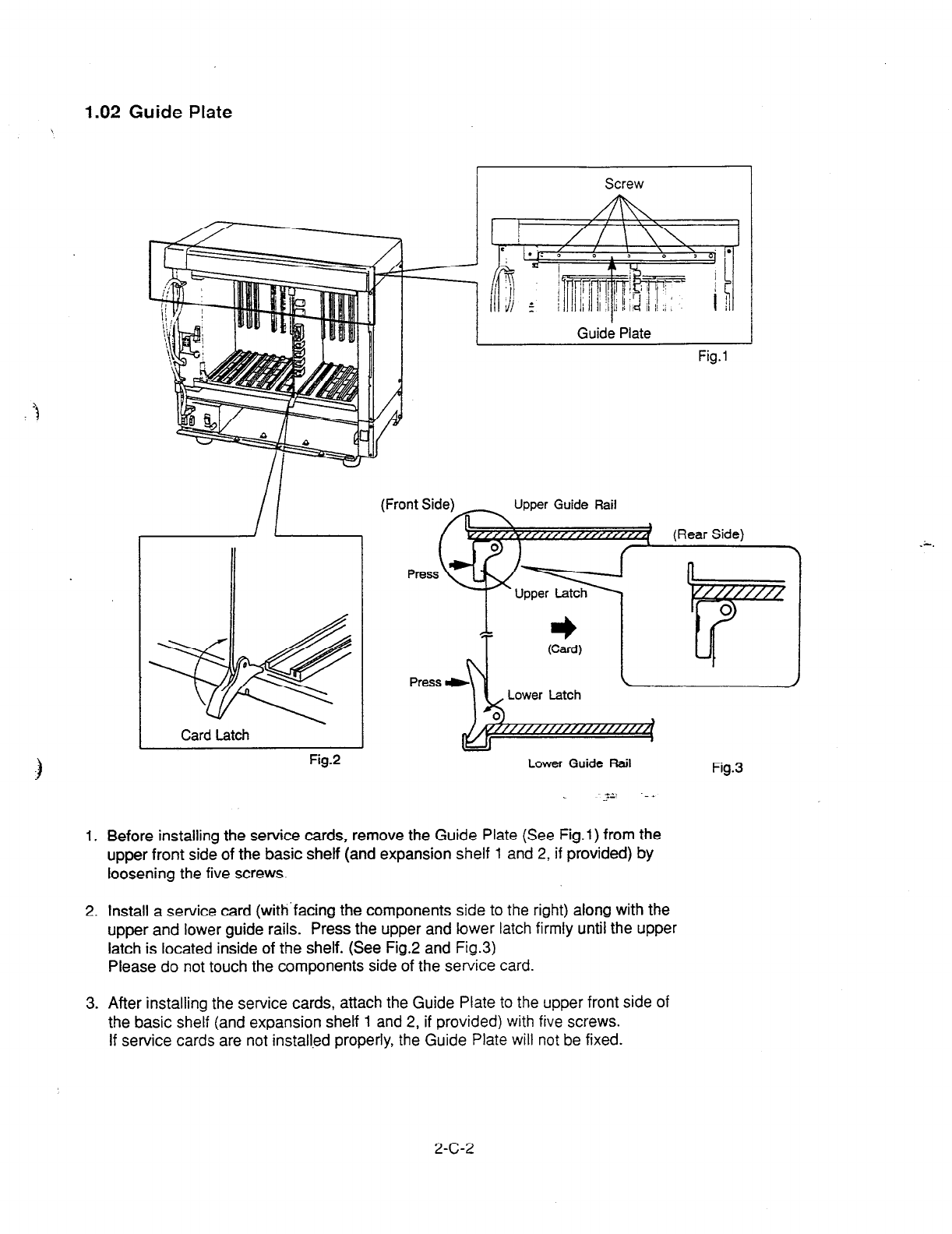
1.02 Guide Plate
Screw
Card Latch
Fig.2
Upper Guide Rail
Lower Guide Rail
J2 ._A
Fig.3
1. Before installing the service cards, remove the Guide Plate (See Fig.1) from the
upper front side of the basic shelf (and expansion shelf 1 and 2, if provided) by
loosening the five screws.
2. Install a service
card
(with’facing the components side to the right) along with the
upper and lower guide rails. Press the upper and lower latch firmly until the upper
latch is located inside of the shelf. (See Fig.2 and Fig.3)
Please do not touch the components side of the service card.
3. After installing the service cards, attach the Guide Plate to the upper front side of
the basic shelf (and expansion shelf 1 and 2, if provided) with five screws.
If service cards are not installed properly, the Guide Plate will not be fixed.
2-c-2
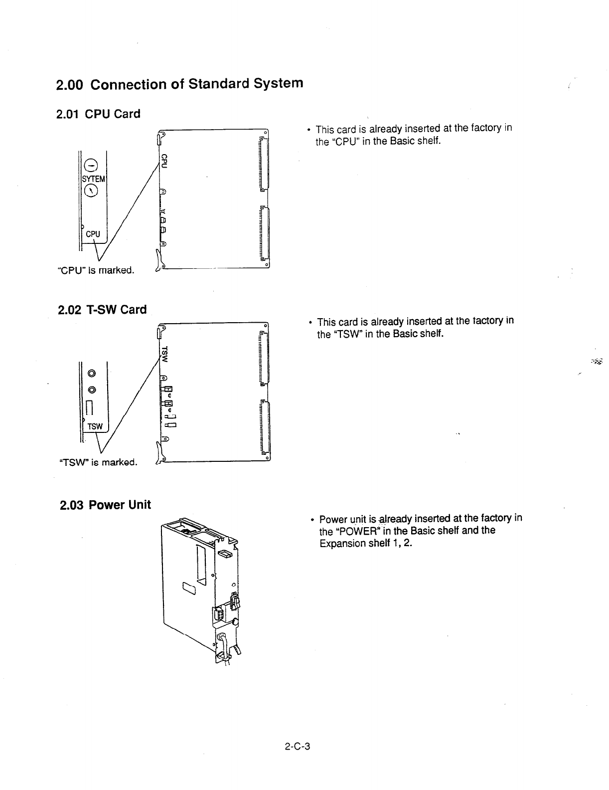
2.00 Connection of Standard System
2.01 CPU Card
“CPU” is marked.
2.02 T-SW Card
“TSW” is marked.
2.03 Power Unit
l
This card is already inserted at the factory in
the “CPU” in the Basic shelf.
l
This card is already inserted at the factory in
the “TSW” in the Basic shelf.
l
Power unit is ajre.ady inserted at the factory in
the “POWER” in the Basic shelf and the
Expansion shelf 1,2.
2-C-3
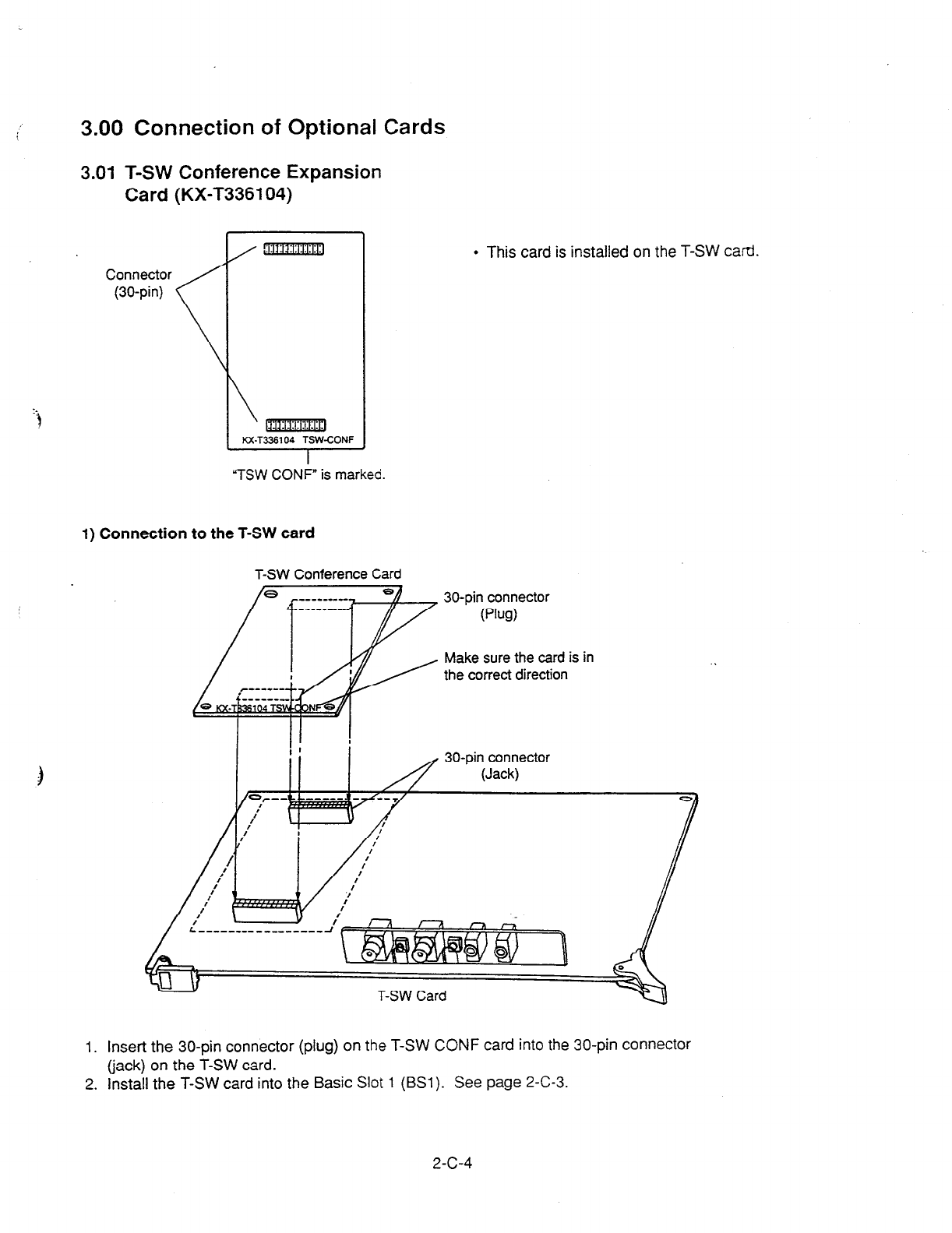
3.00 Connection of Optional Cards
3.01 T-SW Conference Expansion
Card (KX-T336104)
Connector
(30-pin)
m
1 K&T336104 ;SbVCONF
“TSW CONF” is marked.
1) Connection to the T-SW card
l
This card is installed on the T-SW card.
T-SW Conference Card
30-pin connector
(pul)
Make sure the card is in
the correct direction
30-pin connector
(Jack)
T-SW Card
1. Insert the 30-pin connector (plug) on the T-SW CONF card into the 30-pin connector
(jack) on the T-SW card.
2. install the T-SW card into the Basic Slot
1 (BSl). See page 2-C-3.
2-C-4
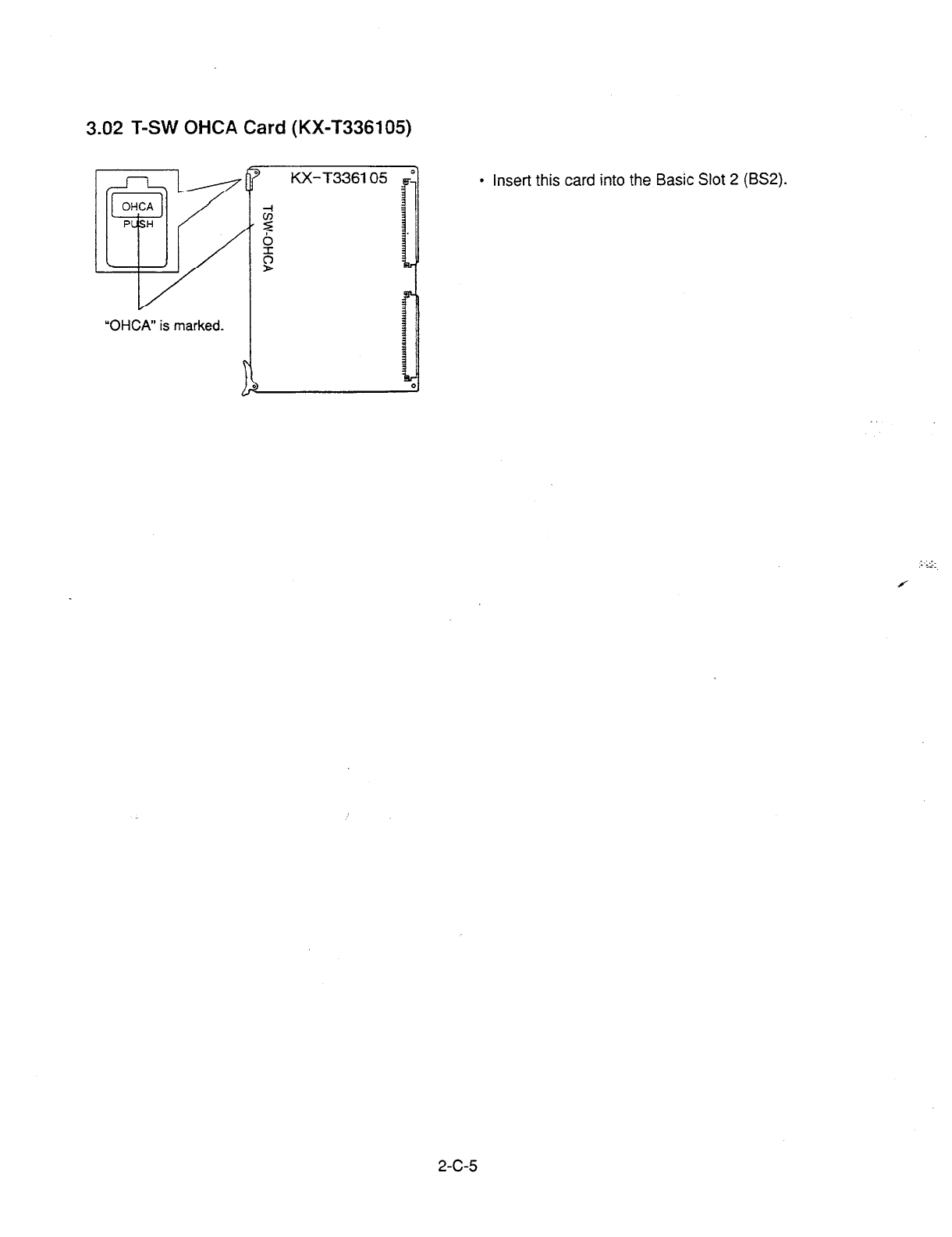
3.02 T-SW OHCA Card (KX-T336105)
“OHM” is marked.
a
l
insert this card into the Basic Slot 2 (BS2).
2-c-5
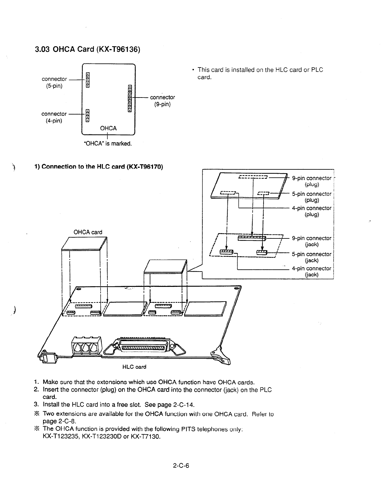
3.03 OHCA Card (KX-T96136)
l
This card is installed on the HLC card or PLC
card.
(Spin)
connector
(4-pin)
- connector
(g-pin)
3
1) Connection to the HLC card (KX-T96170)
g-pin connector
(Ph)
Spin connector
(P&l)
i :
4-pin connector
(PW
g-pin connector
(jack)
Spin connector
(jack)
.
4-pin connector
_
(jack)
1. Make sure that the extensions which use OHCA function have OHCA cards.
2. Insert the connector (plug) on the OHCA card into the connector (jack) on the PLC
card.
3. Install the HLC card into a free slot. See page 2-C-l 4.
-% Two extensions are available for the OHCA function with one OHCA card. Refer to
page 2-C-8.
-% The OHCA function is provided with the following PITS telephones only:
KX-Tl23235, KX-T123230D or KX-l7130.
I
i
2-C-6
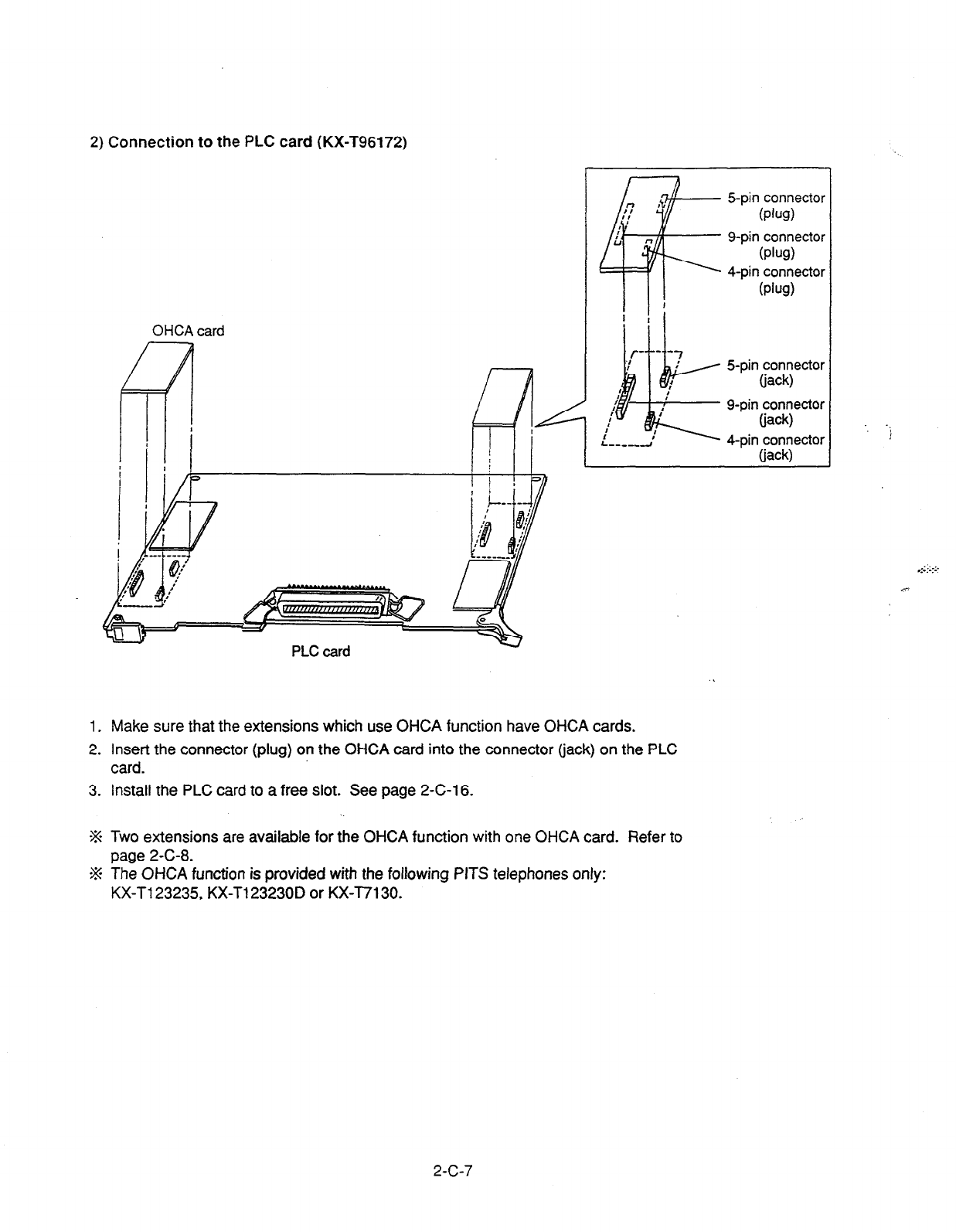
2) Connection to the PLC card (KX-T96172)
OHCA card
l--l
i
I
-+
7 ,
Spin connector
I (PW
n
F
B-pin connector
(PW
4-pin connector
(PW
! i
,:
J
I
I
:
:
I
I--,--d
Spin connector
(jack)
g-pin connector
(jack)
4-pin connector
liack)
1. Make sure that the extensions which use OHCA function have OHCA cards.
2. Insert the connector (plug) on the OHCA card into the connector (jack) on the PLC
card.
3. Install the PLC card to a free slot. See page 2-C-l 6.
1
J
% Two extensions are available for the OHCA function with one OHCA card. Refer to
page 2-C-8.
a% The OHCA function is provided with the following PITS telephones only:
KX-T123235, KX-T123230D or KX-T7130.
2-C-7

3) Wiring Table
I2NN.i 3A SLE COLOF
“tN 1
I
20 vvt-tT-f3Lu
< , !
I BLU-WHT
,17 WHT-ORN
2 I ORN-WHT
28 WHT-GRN
3 / , GRN-WHT
29 I WHT-BRN
4 i BRN-WHT
30 1 WHT-SLT
5 I SLT-WHT
CLll
NO
l
Connection of the Proprietary Telephones:
KX-T123235, KX-T123230D, or KX-T7130.
T: Tip Dl : Data 1 Pl: 3 Pair Voice
R: Ring D2: Data 2 P2: 3 Pair Voice
l
OHCA NO.
(HLC card)
Extension OHCA
Extension
NO1
A
Dl
D2
::
ti
Dl
D2
Pl
P2
T
R
Dl
D2
Pl
P2
A
Dl
D2
;:
T
Cl
D2
Pl
P2
G
Dl
D2
Pl
P2
T
R
Dl
D2
;:
A
Dl
D2
Pl
P2
NO.1
NO.2
NO.3
NO.4
NO.5
NO.6
NO.7
NO.8
7
8
9
10
11
12
13
14
15
16
17
18
-iii
20
21
22
23
24
25
26
27
28
29
30
RED-BLU
BLU-RED
RED-ORN
ORN-RED
RED-GRN
GRN-RED
RED-BRN
31
6
32
7
33
8
34
9
35
10
36
11
37
12
OHCA
rl
NO2
NO2
BRN-RED
RED-SLT
SLT-RED
BLK-BLU
BLU-BLK
BLK-ORN
ORN-BLK
BLK-GRN
GRN-BLK
BLK-BRN
BRN-BLK
BLK-SLT
SLT-BLK
38
13
39
14
40
15
(PLC card)
NO3
YEL-BLU
BLU-YEL
YEL-ORN
ORN-YEL
YEL-GRN
GRN-YEL
YEL-BRN
BRN-YEL
31
:z
34
35
36
37
38
39
40
41
42
43
44
45
46
47
48
-
49
50
41
16
42
17
43
18
44
19
45
20
46
21
47
22
48
23
49
24
50
25
YEL-SLT
SLT-YEL
VIO-BLU
BLU-VI0
VIO-ORN
ORN-VI0
VIO-GRN
GRN-VI0
VIO-BRN
BRN-VI0
VIO-SLT
SLT-VI0
NO4
2-C-8
(10991)
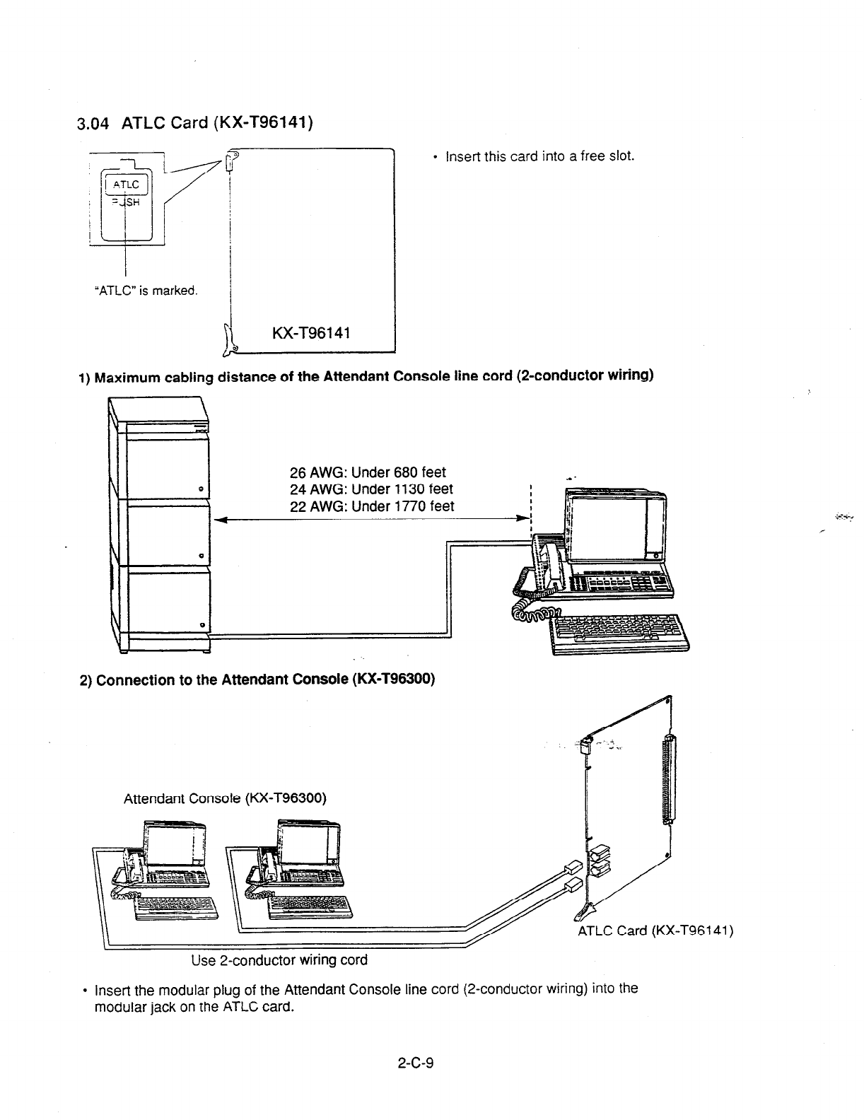
3.04 ATLC Card (KX-T96141)
“ATLC” is marked. /
1
\I
KX-T96141
l
Insert this card into a free slot.
1) Maximum cabling distance of the Attendant Console line cord (2-conductor wiring)
26 AWG: Under 680 feet
4
24 AWG: Under 1130 feet
22 AWG: Under 1770 feet
2) Connection to the Attendant Console (KX-T96300)
Attendant Console (KX-T96300)
Use 2-conductor wiring cord
l
insert the modular plug of the Attendant Console line cord (2-conductor wiring) into the
modular jack on the ATLC card.
2-c-9
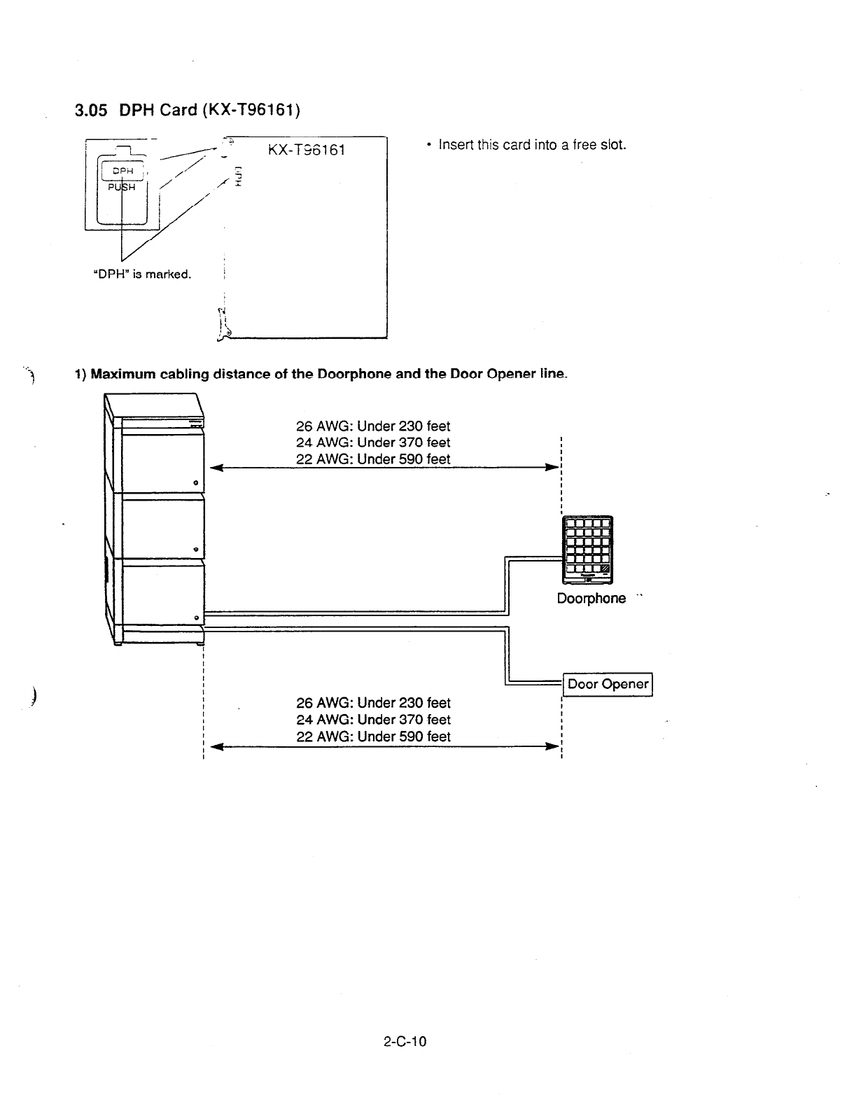
3.05
DPH Card (KX-T96161)
“DPH” is marked. /
ri
l
Insert this card into a free slot.
. .
3
1) Maximum cabling distance of the Doorphone and the Door Opener line.
26 AWG: Under 230 feet
24 AWG: Under 370 feet I
22 AWG: Under 590 feet :
*I I
Doorphone ”
26 AWG: Under 230 feet
24 AWG: Under 370 feet
I
I
I
I+
I 22 AWG: Under 590 feet
2-c-1 0
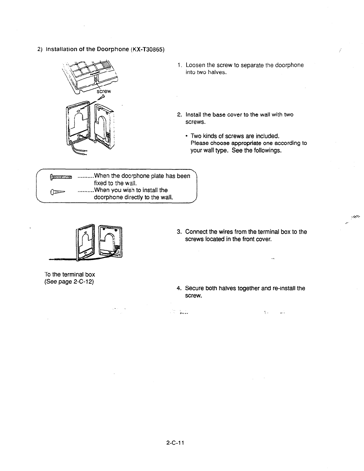
2) Installation of the
Doorphone (KX-T30865)
1. Loosen the screw to separate the door-phone
into two halves.
2. Install the base cover to the wall with two
screws.
l
Two kinds of screws are included.
Please choose appropriate one according to
your wall type. See the followings.
. . . . . . . . . . When the doorphone plate has been
,c
3. Connect the wires from the terminal box to the
screws located in the front cover.
.I
To the terminal box
(See page 2-C-l 2) 4. Secure both halves together and reinstall the
screw.
. +,.. --. -.
2-c-1 1

3) Wiring of the Doorphone
4-conductor wiring NY--~-
is required.
Terminal Box 1
.-
Doorp -T30865)
(KX-Tg6’ ” )
Terminal Box 2
. Doorphone 3 (KX-T30865) Doorphone 4 (KX-T30865)
3
i
1. Connect the DPH Card to the terminal box using a 4-conductor modular connector.
2. Connect the wires of doorphone 1 to the red and green screws of the terminal box 1.
3. Connect the wires of doorphone 2 to the yellow and black screws of the terminal box 1.
4.
5. Connect the wires of doorphone 3 to the red.,and green screws of the terminal box 2.
Connect the wires of doorphone 4 to the yellow and black screws of the terminal box 2.
2-c-1 2
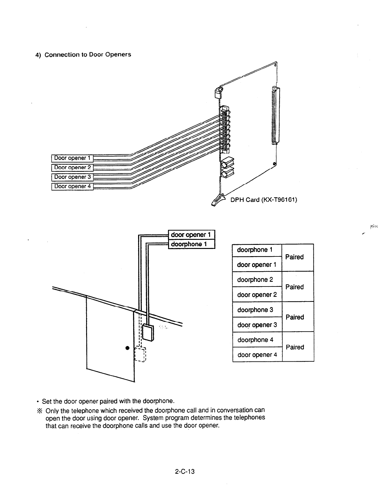
4) Connection to Door Openers
door opener
1
DPH Card (KX-T96161)
Paired
doorphone 2
door opener 2
doorphone 3
door opener 3
doorphone 4
door opener 4
Paired
Paired
Paired
l
Set the door opener paired with the doorphone.
-% Only the telephone which received the doorphone call and in conversation can
open the door using door opener. System program determines the telephones
that can receive the doorphone calls and use the door opener.
2-C-l 3
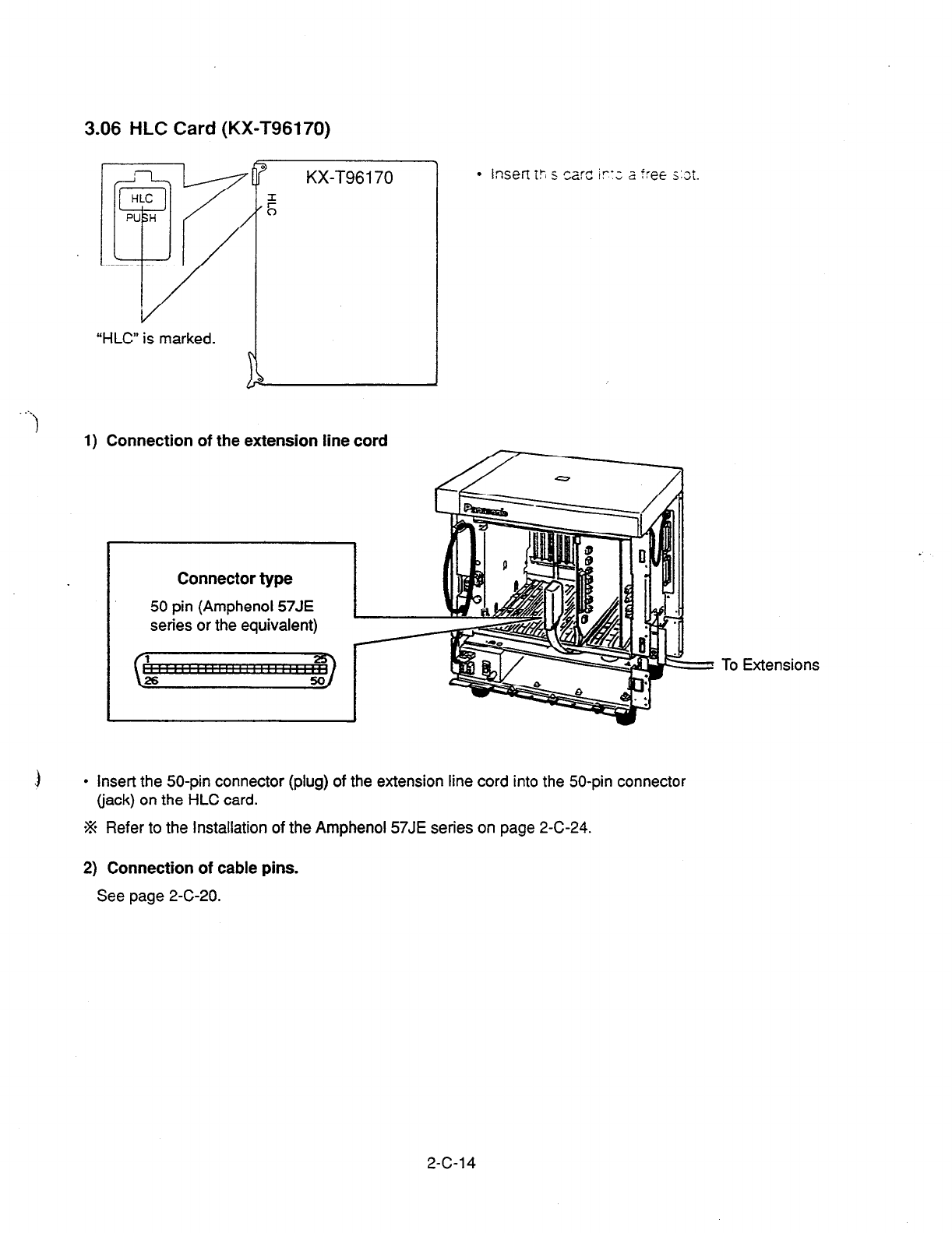
3.06 HLC Card (KX-T96170)
0
HLC
PU H
qv
KX-T96170
F
0
“HLC” is marked.
1) Connection of the extension line cord
Connector
type
50 pin (Amphenol 57JE
series or the equivalent)
To Extensions
.3
l
Insert the 50-pin connector (plug) of the extension line cord into the 50-pin connector
(jack) on the HLC card.
% Refer to the Installation of the Amphenol 57JE series on page 2-C-24.
2) Connection of cable pins.
See page 2-C-20.
2-C-l 4
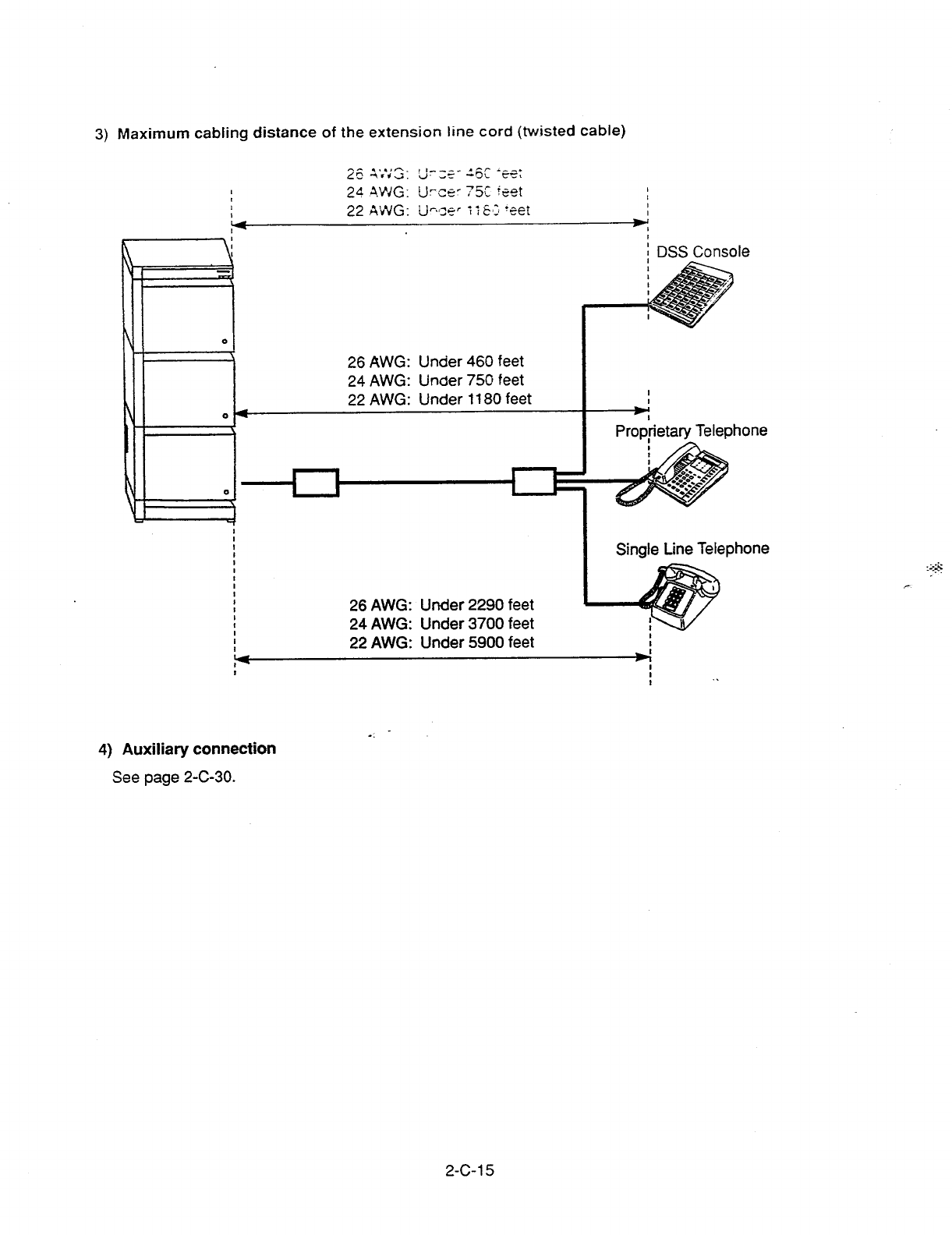
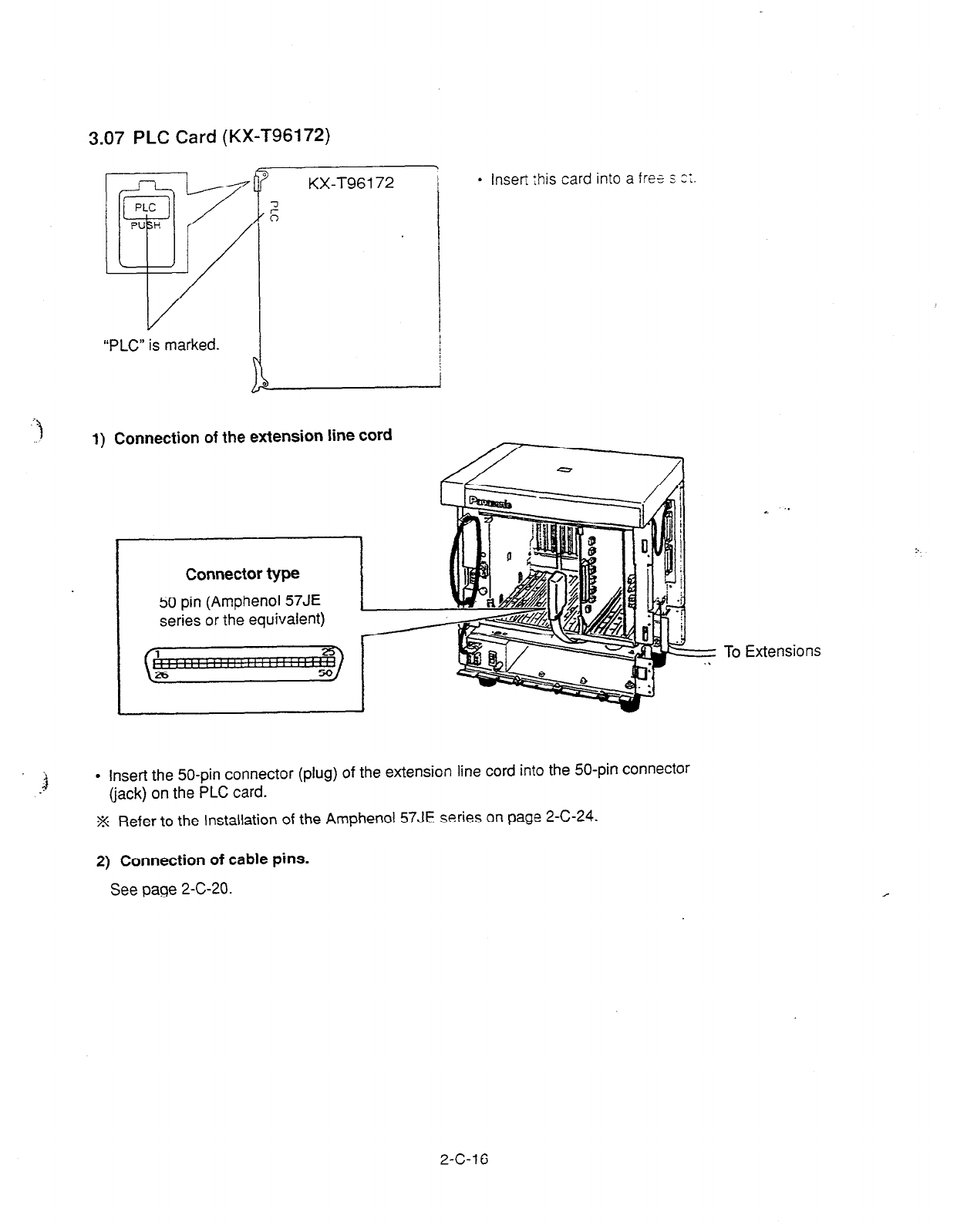
3.07 PLC Card (KX-T96172)
KX-T96172
l
lnsefi this card into a free s t‘;
“PLC” is marked.
1) Connection of the extension line cord
Connector type
50 pin (Amphenol 57JE
series or the equivalent)
3 l
insert the 50-pin connector (plug) of the extension line cord into the 50-pin connector
(jack) on the PLC card.
.% Refer to the lnstaltation of the Amphenol 57JE series on page 2-C-24.
. . ‘.
To Extensions
2) Connection of cable pins.
See
page 2-C-20.
2-c-1 6
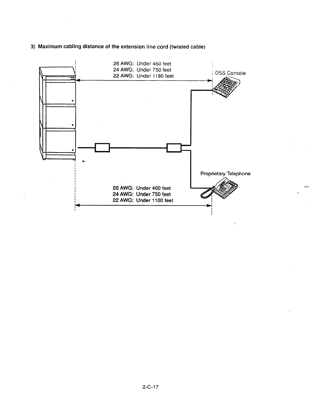
3) Maximum cabling distance of the extension line cord (twisted cable)
26 AWG: Under 460 feet
le
26 AWG: Under 460 feet
24 AWG: Under 750 feet
22 AWG: Under
1180 feet
Proprietary Telephone
I
P4
:
1
2-c-1 7
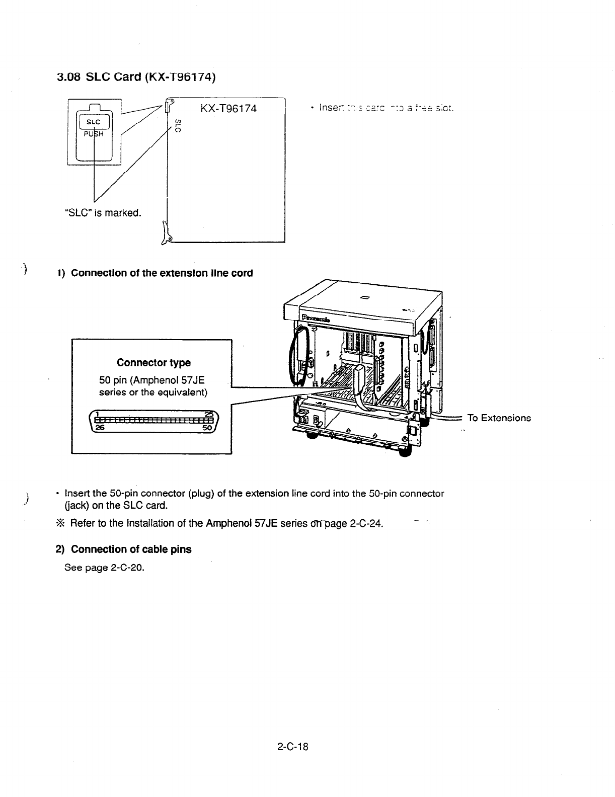
3.08 SLC Card (KX-T96174)
“SLC” is marked.
3
KX-T96174
P
0
-I
1) Connection of the extension line cord
Connector type
50 pin (Amphenol 57JE
series or the equivalent)
l
Insert the 50-pin connector (plug) of the extension line cord into the 50-pin connector
(jack) on the SLC card.
W Refer to the Installation of the Amphenol 57JE series oWpage 2-C-24. --
= To Extensions
2) Connection of cable pins
See page 2-C-20.
2-C-l 8

3) Maximum cabling distance of the extension line cord (twisted cable)
26 AWG: Under 2290 feet
24 AWG: Under 3700 feet
22 AWG: Under 5900 feet
_ 4) Auxiliary connection
See
page 2-C-30.
2-c-1 9
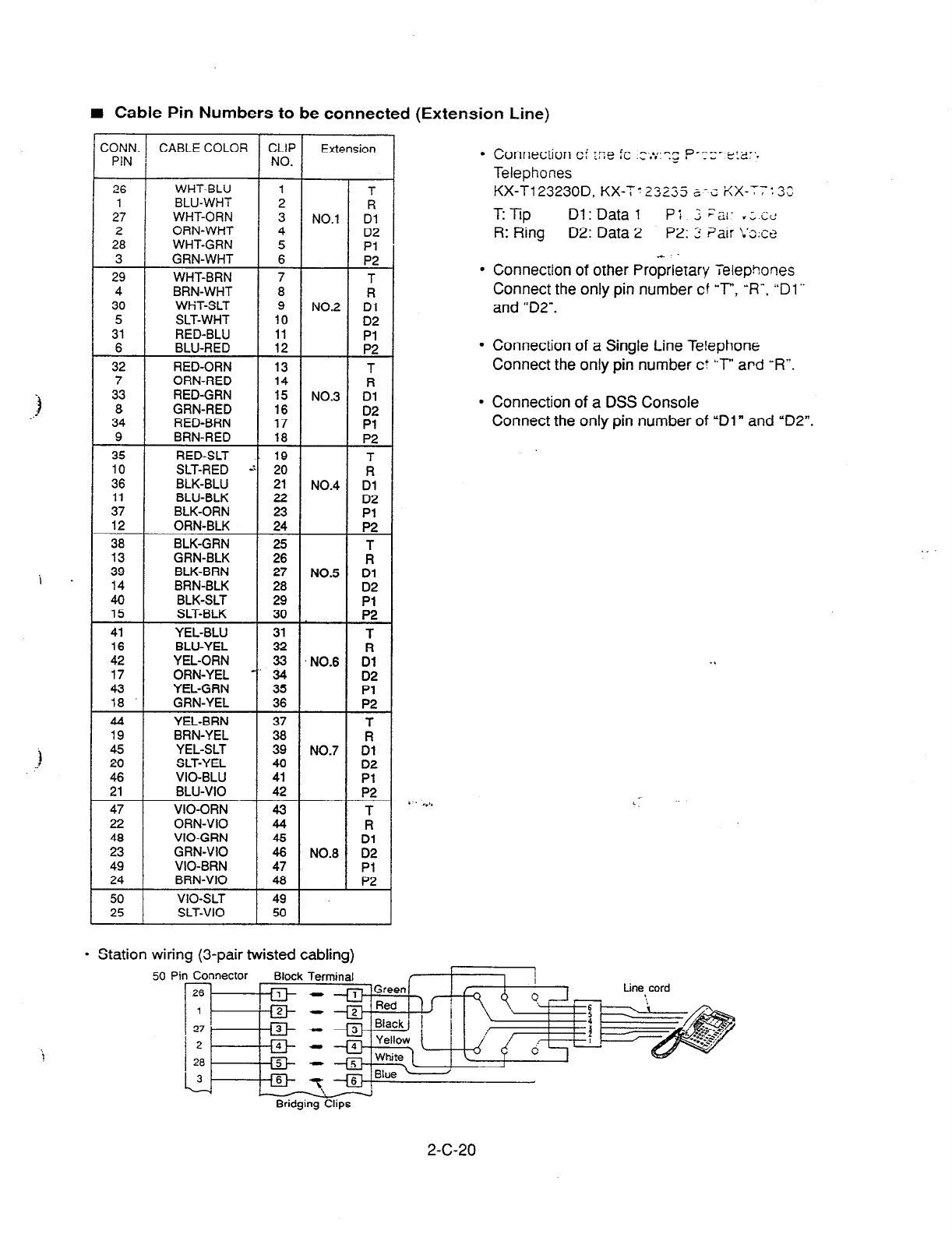
I Cable Pin Numbers to be connected (Extension Line)
ZONN
PIN CABLE COLOR CLIF
NO. Extension
l
Conneciion c: xe ,L ._ . . .z ,
I^ ^..,.^” p---e &fl’.
__ __-. .
Telephones
KX-T123230D, KX-T123235 a-z %X-7-:3:
TTip Dl: Data
1
p; ; ;a[- .;c<
R: Ring D2: Data 2 P2:
2 ?air L’s:c~
1
l
Connection of other Proprietary Telephones
Connect the only pin number cf ‘T”, ‘9”. “Dl”
and “D2”.
26 WHT-BLU
1
BLU-WHT
27 WHT-ORN
2 ORN-WHT
28 WHT-GRN
3 GRN-WHT
29
4
30
5
31
6
32
7
33
8
34
9
35
10
36
11
37
12
38
13
39
14
40
15
41
16
42
17
43
18
44
19
45
20
46
21
47
22
48
23
49
24
50
25
WHT-BRN
BRN-WHT
WHT-SLT
SLT-WHT
RED-BLU
BLU-RED
RED-ORN
ORN-RED
RED-GRN
GRN-RED
RED-BRN
BRN-RED
RED-SLT
SLT-RED
BLK-BLU
BLU-BLK
BLK-ORN
ORN-BLK
BLK-GRN
GRN-BLK
BLK-BRN
BRN-BLK
BLK-SLT
SLT-BLK
YEL-BLU
BLU-YEL
YEL-ORN
ORN-YEL
YEL-GRN
GRN-YEL
YEL-BRN
BRN-YEL
YEL-SLT
SLT-YEL
VIO-BLU
BLU-VI0
VIO-ORN
ORN-VI0
VIO-GRN
GRN-VI0
VIO-BRN
BRN-VI0
VIO-SLT
SLT-VI0
7
8
9
10
11
12
13
14
15
16
17
18
19
20
21
22
::
25
26
27
28
29
30
31
32
ii
35
36
37
38
39
40
41
42
43
44
2
47
48
49
50
NO.1
NO.2
NO.3
NO.4
NO.5
NO.6
NO.7
NO.8
T
R
Dl
D2
Pl
P2
T
fl
D2
Pl
EL
T
R
::
Pl
P2
A
Dl
D2
::
RT
Dl
::
P2
ii
Dl
D2
::
T R
::
;:
:
;:
Pl
P2
l
Station wiring (3-pair twisted cabling)
l
Connection of a Single Line Telephone
Connect the only pin number ct kT” ard “R”.
l
Connection of a DSS Console
Connect the only pin number of “Dl” and “D2”.
50 Pin Connector Block
Terminal
rfq- - .
Bridging Clips
2-c-20
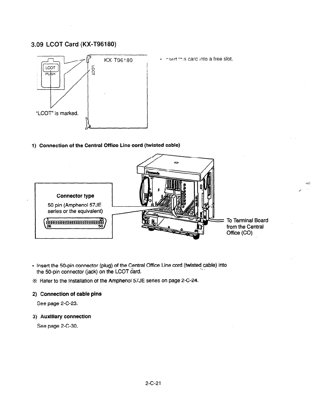
3.09 LCOT Card (KX-T96180)
KX-T96: 80 . -sert :“:s cart Into a free slot.
I
“LCOT” is marked. )
1) Connection of the Central Office Line cord (twisted cable)
Connector type
50 pin (Amphenol 57JE
series or the equivalent)
To Terminal Board
from the Central
Office (CO)
l
Insert the 50-pin connector (plug) of the Central Office Line cord (twisted cable) into
the 50-pin connector (jack) on the LCOT card. -_
.% Refer to the Installation of the Amphenol 57JE series on page 2-C-24.
2) Connection of cable pins
See page 2-C-23.
3) Auxiliary connection
See page 2-C-30.
2-c-21
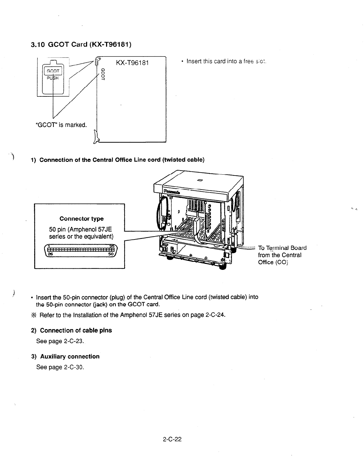
3.10 GCOT Card (KX-T96181)
“GCOT” is marked.
\
1
9
KX-T96181
g
-I
l
Insert this card into a free SO:
1) Connection of the Central Office Line cord (twisted cable)
Connector type
50 pin (Amphenol 57JE
series or the equivalent)
l
Insert the 50-pin connector (plug) of the Central Office Line cord (twisted cable) into
the 50-pin connector (jack) on the GCOT
card.
% Refer to the installation of the Amphenol 57JE series on page 2-C-24.
2) Connection of cable pins
See page 2-C-23.
To Terminal Board
from the Central
Office (COj
3) Auxiliary connection
See page 2-C-30.
2-c-22
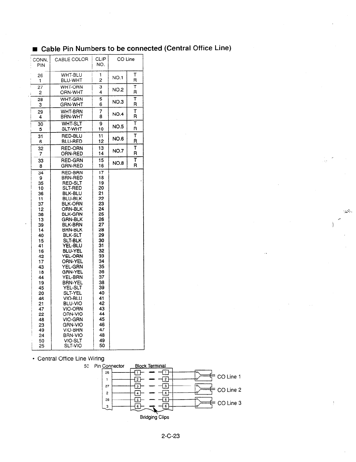
I Cable Pin Numbers to be connected (Central Office Line)
’
CONN.
: PIN CABLE COLOR
26 WHT-BLU
'1
BLU-WHT
27
.i
2
-
28
3
29
4
30
5
31
6
32
7
33
8
34
9
35
10
36
11
37
12
38
13
39
14
40
15
41
16
42
17
43
18
44
19
45
20
46
21
47
22
48
23
49
24
50
/ 25
WHT-ORN
ORN-WHT
WHT-GRN
GRN-WHT
WHT-BRN
BRN-WHT
WHT-SLT
SLT-WHT
RED-BLU
BLU-RED
RED-ORN
ORN-RED
RED-GRN
GRN-RED
RED-BRN
BRN-RED
RED-SLT
SLT-RED
BLK-BLU
BLU-BLK
BLK-ORN
ORN-BLK
BLK-GRN
GRN-BLK
BLK-BRN
BRN-BLK
BLK-SLT
SLT-BLK
YEL-BLU
BLU-YEL
YEL-ORN
ORN-YEL
YEL-GRN
GRN-YEL
YEL-BRN
BRN-YEL
YEL-SLT
SLT-YEL
VIO-BLU
BLU-VI0
VIO-ORN
ORN-VI0
VIO-GRN
GRN-VI0
‘/IO-BRN
BRN-VI0
VIO-SLT
SLT-VI0
ZLIP
NO.
1
2
3
4
5
6
7
8
9
10
11
12
13
14
15
16
17
18
19
20
21
22
23
24
25
26
27
26
29
30
31
32
33
34
35
36
37
38
39
40
41
42
43
44
45
46
47
48
49
50
CO Line
NO.6 I A
l
Central Office Line Wiring
X Pin Connector
< CO Line 2
{ CO Line 3
Bridging.Clips
2-C-23
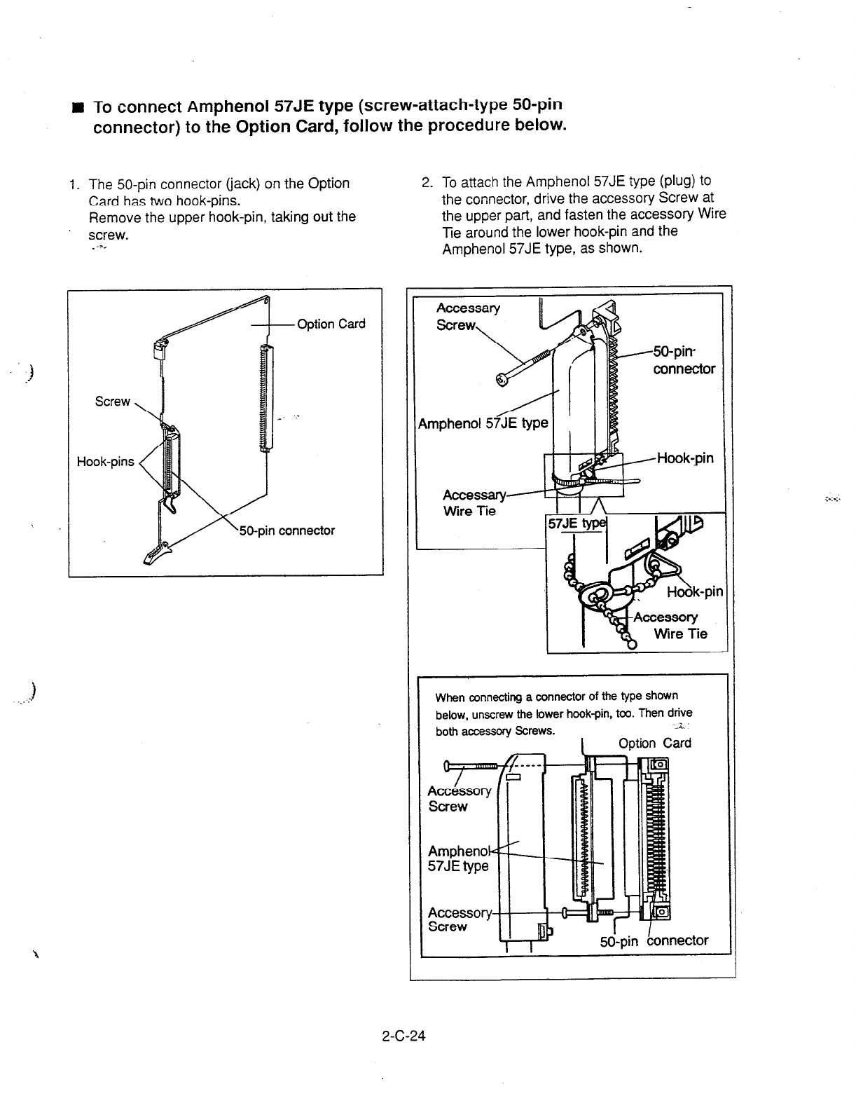
I To connect Amphenol 57JE type (screw-attach-type 50-pin
connector) to the Option Card, follow the procedure below.
1.
The
50-pin
connector (jack) on the Option
Card has two hook-pins.
Remove the upper hook-pin, taking out the
screw.
Screw
Hook-pins
x50-pin connector
2. To attach the Amphenol 57JE type (plug) to
the connector, drive the accessory Screw at
the upper part, and fasten the accessory Wire
Tie around the lower hook-pin and the
Amphenol 57JE type, as shown.
When
connecting a connector of the type shown
below, unscrew the lower hook-pin, too. Then drive
both accessory Screws. .I
2-C-24
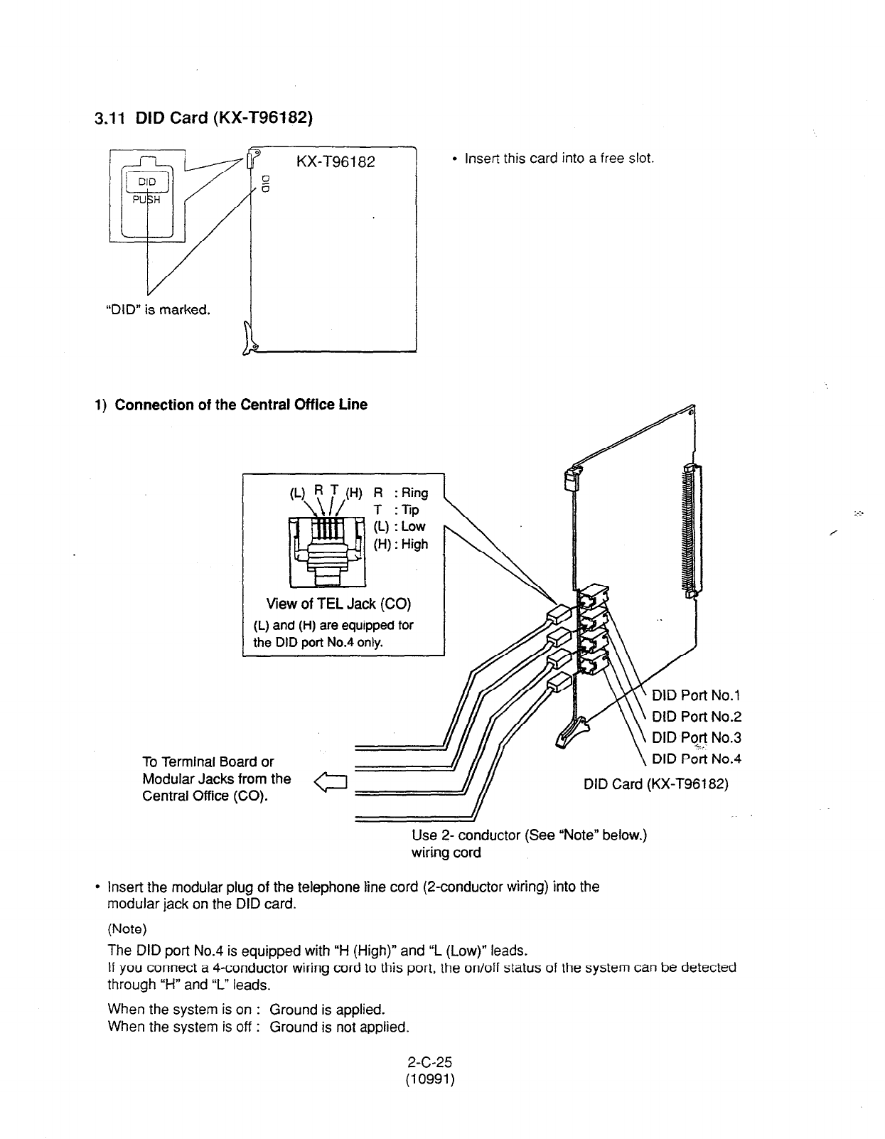
3.11 DID Card (KX-T96182)
KX-T96182
“DID” is marked.
1) Connection of the Central Office Line
View of TEL Jack (CO)
(L) and (H) are equipped for
the DID port No.4 only.
l
Insert this card into a free slot.
To Terminal Board or
Modular Jacks from the
Central Office (CO).
DID Port No.4
Use 2- conductor (See “Note” below.)
wiring cord
l
Insert the modular plug of the telephone line cord (2-conductor wiring) into the
modular jack on the DID card.
(Note)
The DID port No.4 is equipped with “H (High)” and “L (Low)” leads.
If you connect a 4-conductor wiring cord to this port, the on/off status of the system can be detected
through “H” and “L” leads.
When the system is on : Ground is applied.
When the system is off : Ground is not applied.
2-c-25
(10991)

3.12 OPX Card (KX-T96185)
“OPX” is marked. ~
9
0
KX-T96185
;:
1
1) Connection to private lines
Single Line Telephone
l
Insert
this
card into a
free slot
22 AWG: Under 6 miles
R:Ring
T:Xp
rPX Port No.2
OPX Port No.3
OPX Port No.4
l
Insert the modular plug of the Single Line Telephone Line cord (2-conductor
wiring) into the modular jack on the OPX card.
2) Connection to public lines
OPX Central
Office Line
View of TEL Jack (CO)
Jo.1
Use 2- conductor wiring cord
l
Insert the modular plug of the Single Line Telephone Line cord (2-conductor
wiring) into the modular jack on the OPX card.
2-C-26
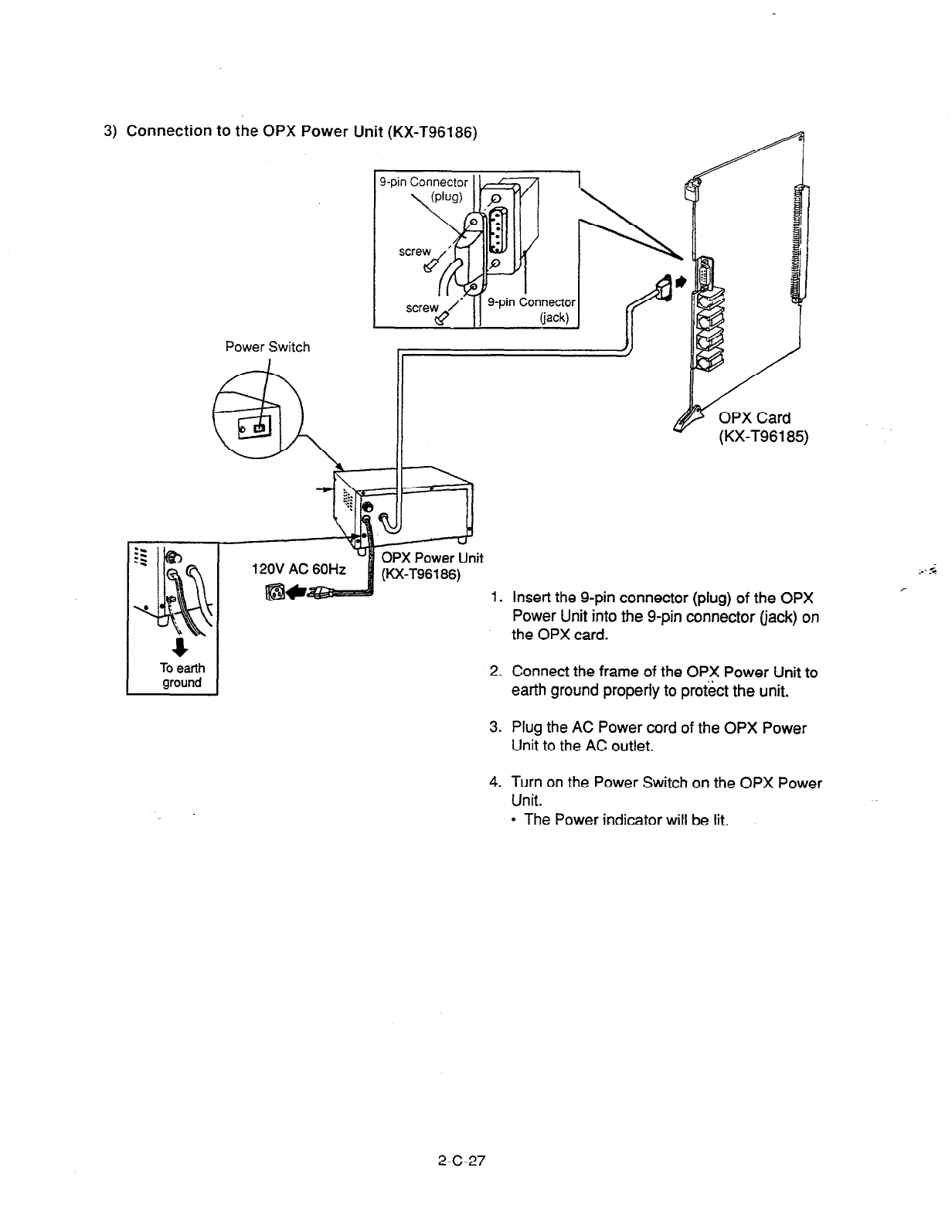
3) Connection to the OPX Power Unit (KX-T96186)
4
To earth
ground
Power Switch
(KX-196185)
12OV AC 60Hz .- .‘-
1. Insert the g-pin connector (plug) of the OPX c
Power Unit into the g-pin connector (jack) on
the OPX card.
2. Connect the frame of the OPX Power Unit to
earth ground properly to pro&t the unit.
3. Plug the AC Power cord of the OPX Power
Unit to the AC outlet.
4. Turn on the Power Switch on the OPX Power
Unit.
l
The Power indicator will be lit.
2-C-27
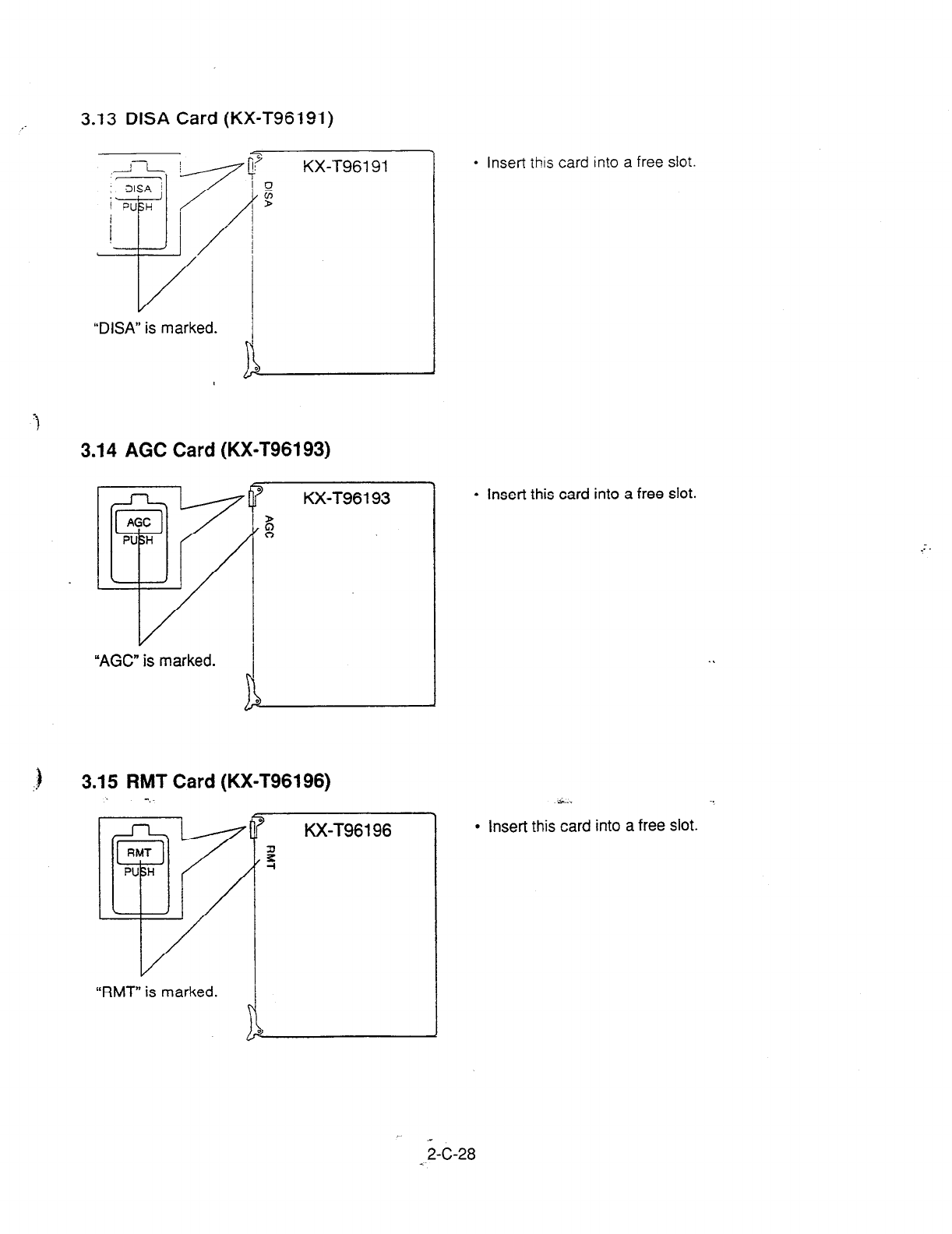
3.13 DISA Card (KX-T96191)
KX-T96191
“DISA” is marked. h
3.14 AGC Card (KX-T96193)
KX-T96193
l
Insert this card into a free slot.
“AGC” is marked.
. .
l
insert thts card into a free slot.
3.15 RMT Card (KX-T96196)
: -.
KX-T96196
s... . .
l
Insert this card into a free slot.
“RMT” is marked.
j-C-28
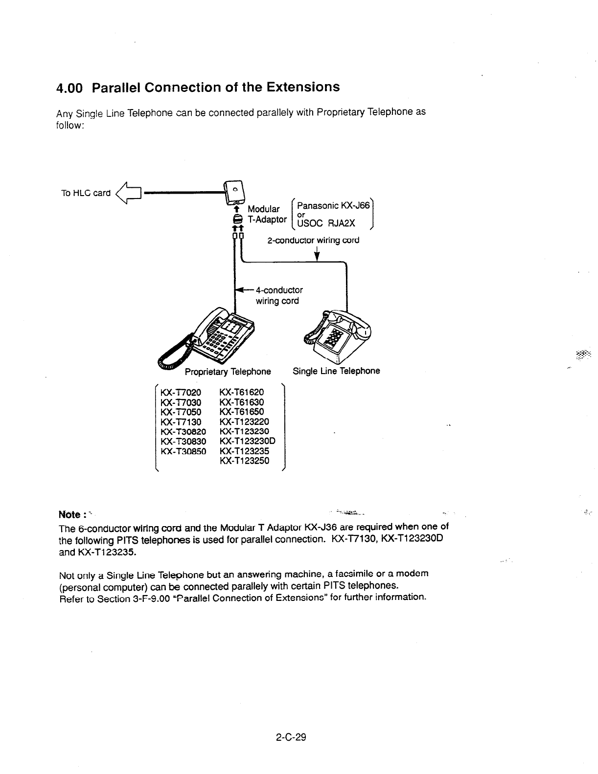
4.00 Parallel Connection of the Extensions
Any Single Line Telephone can be connected parallely with Proprietary Telephone as
follow:
Panasonic KX-J66
1
4-conductor
wiring cord I
Single tine Telephone
Kx-77020 KX-T61620
Kx-77030 Kx-T61630
ux-77050 Kx-T61650
Kx-77130
KX-T123220
KX-T30820 tWT123230
K&T30830
KX-T123230D
KX-T30850
KX-T123235
KX-T123250
Mote : 1 :‘,G- -.
The 6-conductor wiring cord and the Modular T Adaptor KX-J36 are required when one of
the following PITS telephoms is used for parallel connection. KX-I7130, KX-T123230D
and KX-T123235.
Not only a Single tine Telephone but an answering machine, a facsimile or a modem
(personal computer) can be connected parallely with certain PITS telephones.
Refer to Section 3-F-9.00 Parallel Connection of Extensions” for further information.
2-C-29
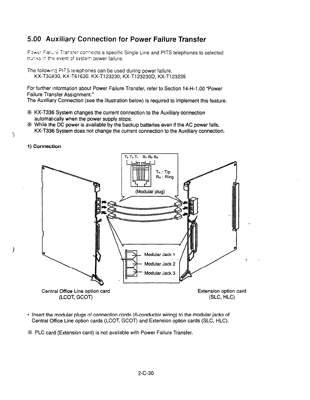
5.00 Auxiliary Connection for Power Failure Transfer
Fs.+E-: Fali--- e frarsfe: corr.ects a specific Single Line and PITS telephones to selected
t:;ir.kS
i” t!-
t event of system power failure.
The follow!rg ?lTS telephones can be used during power failure.
KX-T3C630, KX-T61630. KX-T123230, KX-Tl23230D, KX-T123235
For further information about Power Failure Transfer, refer to Section 14-H-1 .OO “Power
Failure Transfer Assignment.”
The Auxiliary Connection (see the illustration below) is required to implement this feature.
*% KX-T336 System changes the current connection to the Auxiliary connection
automattcally when the power supply stops.
-% While the DC power is available by the backup batteries even if the AC power fails,
KX-T336 System does not change the current connection to the Auxiliary connection.
t
1) Connection
T3 Tz Tj RI !+
R3
I
(Modular plug)
Modular
Jack
1
Modular Jack 3
Central Office Line option card Extension option card
(LCOT, GCOT) (SLC, HLC)
l
Insert the modular plugs of connection cords (&conductor wiring) to the modular jacks of
Central Office Line option cards (LCOT, GCOT) and Extension option cards (SLC, HLC).
% PLC card (Extension card) is not available with Power Failure Transfer.
2-C-30
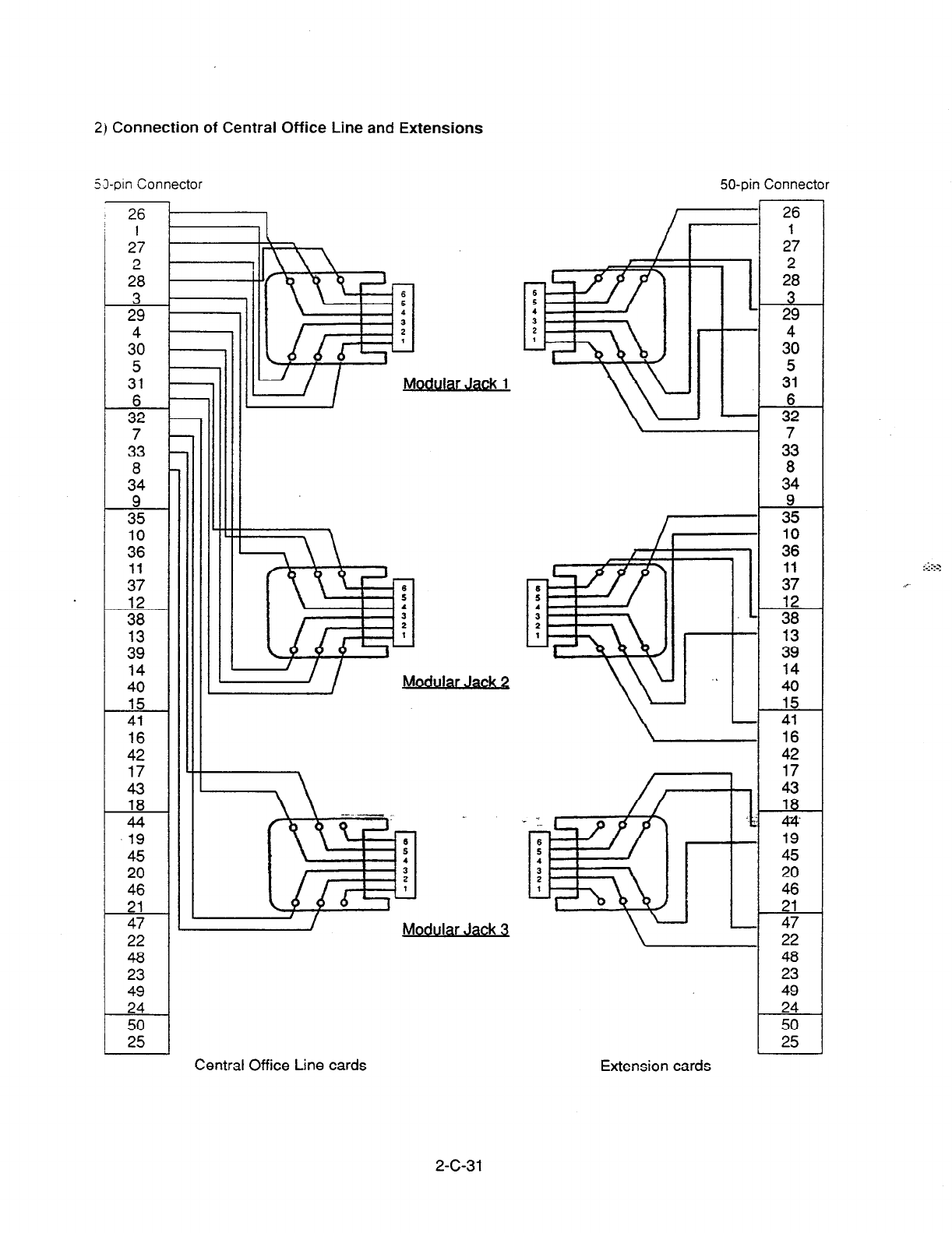
2) Connection of Central Office Line and Extensions
53pin Connector
1
27
2
28
3 29
3”o
5
31
A..-
32
7
33
8
34
9 35
10
36
11
37
;:
13
39
14
40
15
41
16
42
17
43
18
44
.19
45
20
46
21
47
22
48
23
49
24
50
25
Modular Jack 7 w /
Modular Jack 3
50-pin Connector
26
27
228
3 29
4
30
5
31
362
7
33
8
34
9 35
10
36
11
37
12
38
Ai
14
40
15
41
16
42
17
-g- .
19
45
20
46
21
47
22
46
23
49
24
50
25
Central Office Line cards Extension cards
2-C-31
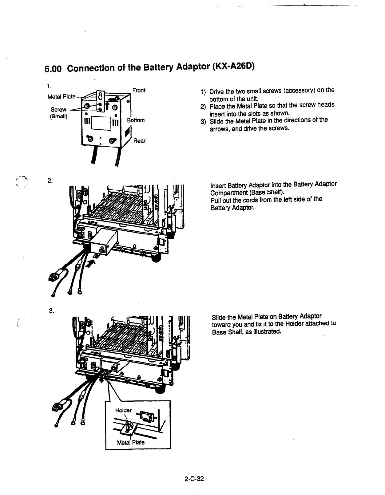
6.00 Connection of the Battery Adaptor (KX-A26D)
1) Drive the two small screws (accessory) on the
bottom of the unit.
2) Place the Metal Plate so that the screw heads
insert into the slots as shown.
3) Slide the Metal Plate in the directions of the
arrows, and drive the screws.
Metal Plate
Insert Battery Adaptor into the Battery Adaptor
Compartment (Base Shelf).
Pull out the cords from the left side of the
Battery Adaptor.
i-
i
Slide the Metal Plate on Battery Adaptor
toward you and fix it to the Holder attached to
Base Shelf, as illustrated.
2-C-32
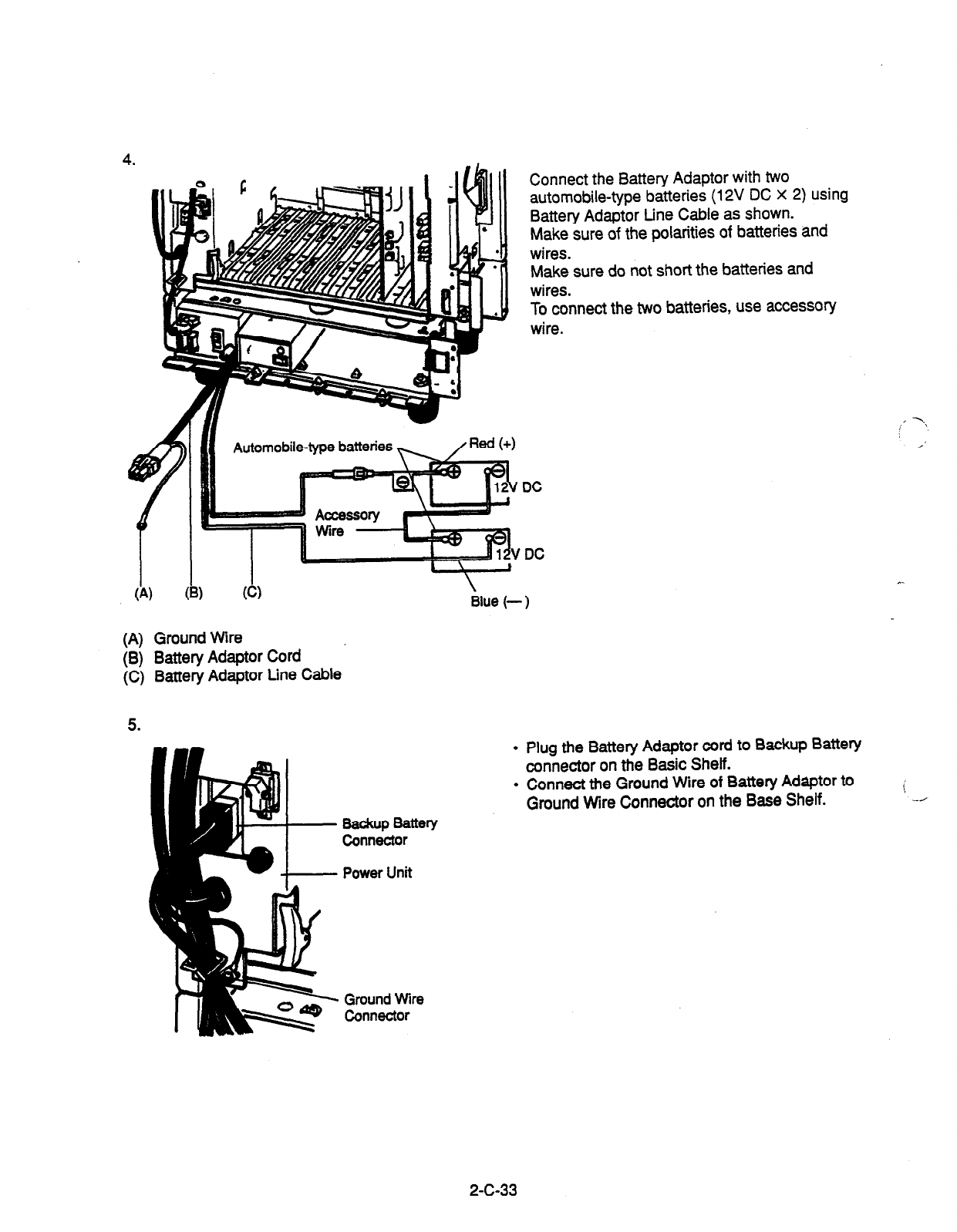
Automobile-type batteries
f
I I I II’?V
‘DC
I I I
(A) (W (Cl
c ’ t
Blue (-
Connect the Battery Adaptor with two
automobile-type batteries (12V DC X 2) using
Battery Adaptor tine Cable as shown.
Make sure of the polarities of batteries and
wires.
Make sure do not short the batteries and
wires.
To connect the two batteries, use accessory
wire.
-1
(A) Ground Wire
(6) Battery Adaptor Cord
(C) Battery Adaptor Line Cable
5.
.
Plug the Battery Adaptor cord to Backup Battery
connector on the Basic Shelf.
l
Connect the Ground Wire of Battety Adaptor to
Ground Wire Connector on the Base Shelf.
Eiicztr
Power Unit
Ground Wire
Connector
2-C-33
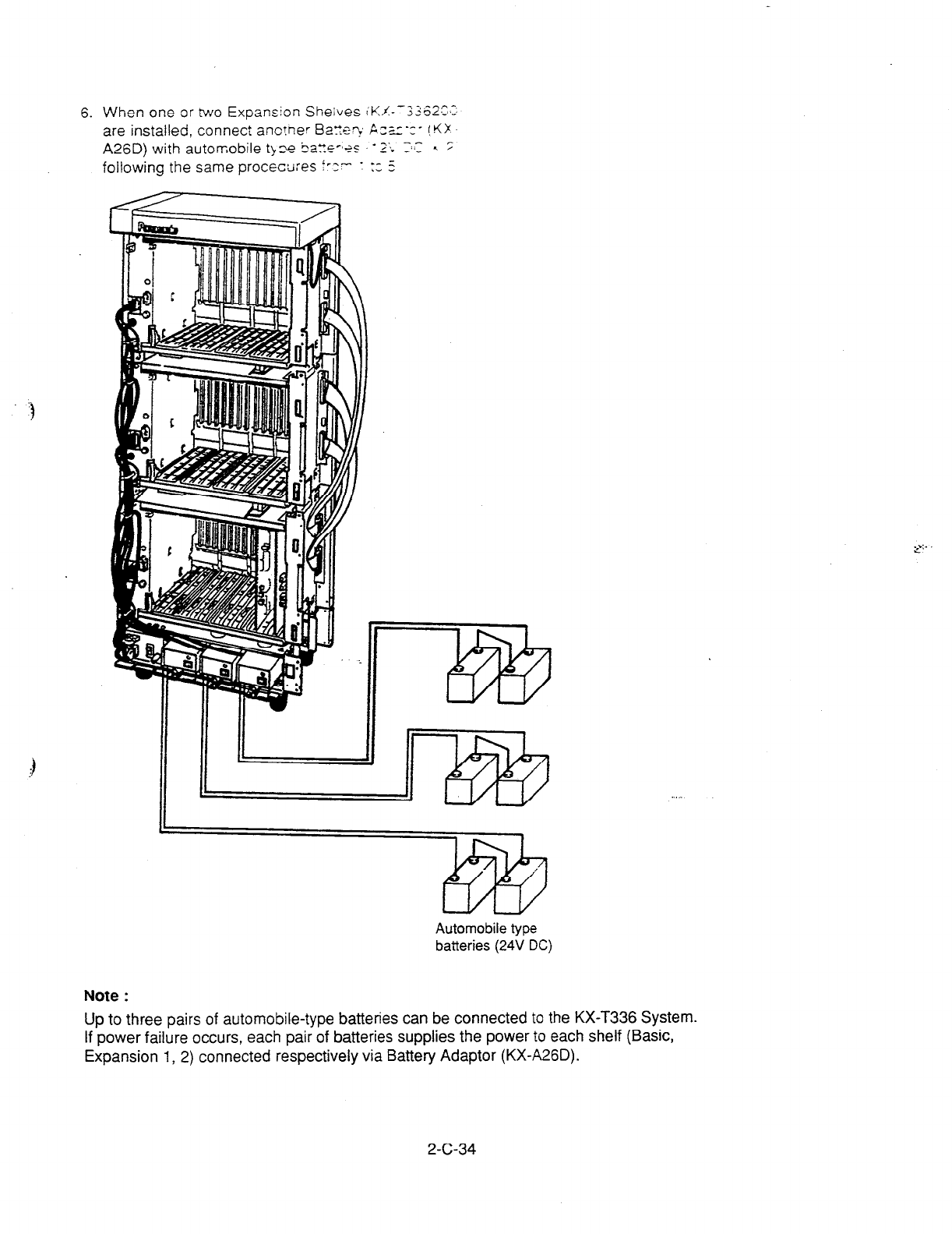
6. When one or two Expansion She;ves
iKL--3362S-3:
are installed, connect ano?ner Ba:?rs? Pz;_r-c- !tiX
A26D) with automobile tb E tiatrs-*+: - 2’~. r:.C < 2
following the same procecu:es f-z- : :; 5
Automobile type
batteries
(24V
DC)
Note :
Up to three pairs of automobile-type batteries can be connected to the KX-T336 System.
If power failure occurs, each pair of batteries supplies the power to each shelf (Basic,
Expansion 1, 2) connected respectively via Battery Adaptor (KX-A26D).
2-C-34
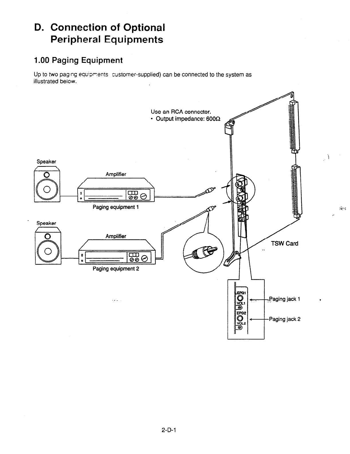
D. Connection of Optional
Peripheral Equipments
1 .OO Paging Equipment
Up to two paging equiprents customer-supplied) can be connected to the system as
illustrated below.
Use an RCA connector.
l
Output impedance: 6OOL2
Speaker
/ \
I \
0 Amplifier
Speaker
Paging equipment 1
aging equtpment 2
i
,
2-D-l
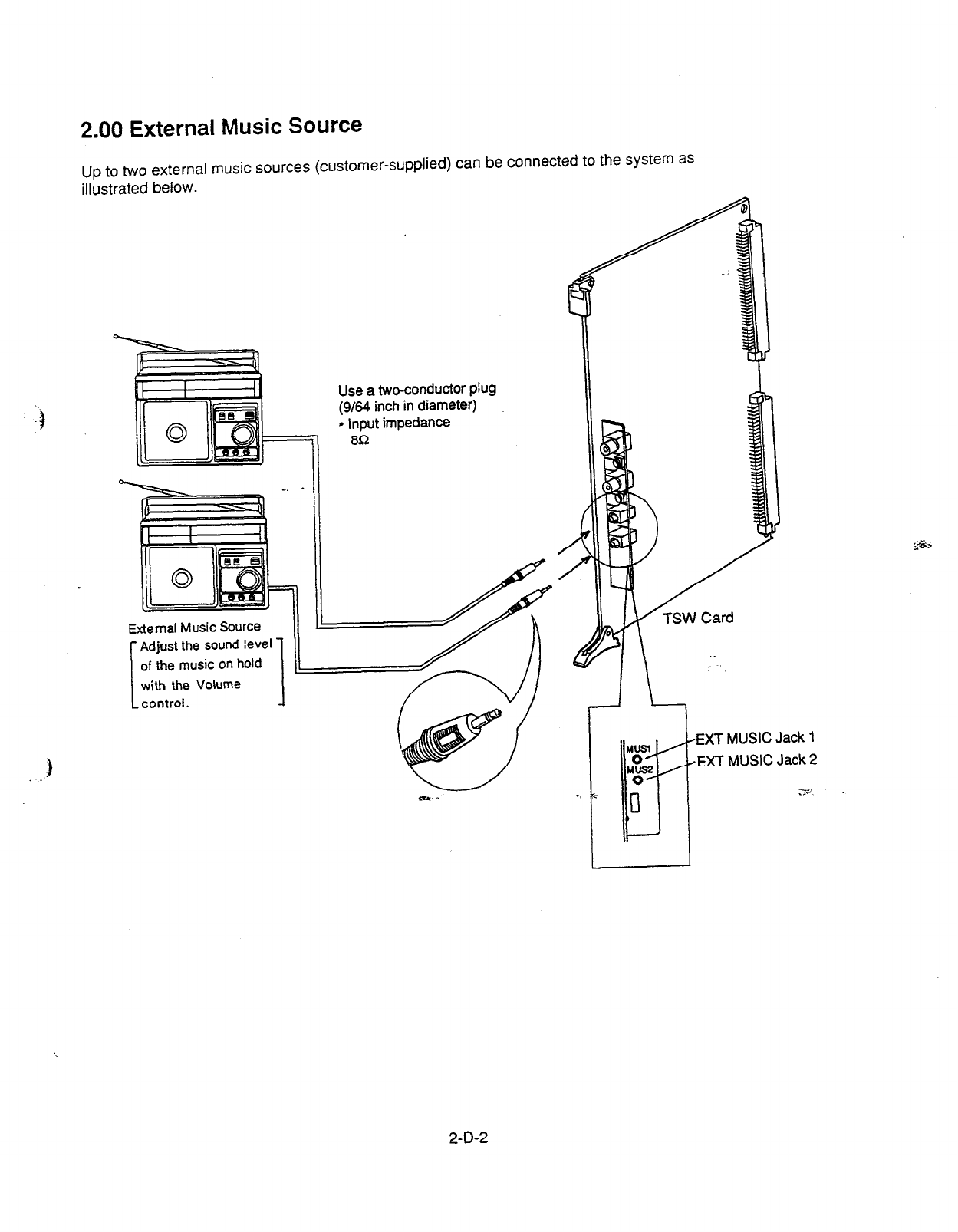
2.00 External Music Source
Up to two external music sources (customer-supplied) can be connected to the system as
illustrated below.
.)
. .-
Use
a two-conductor plug
(g/64 inch in diameter)
9 Input impedance
80
EXT MUSIC Jack 1
EXT MUSIC Jack 2
2-D-2
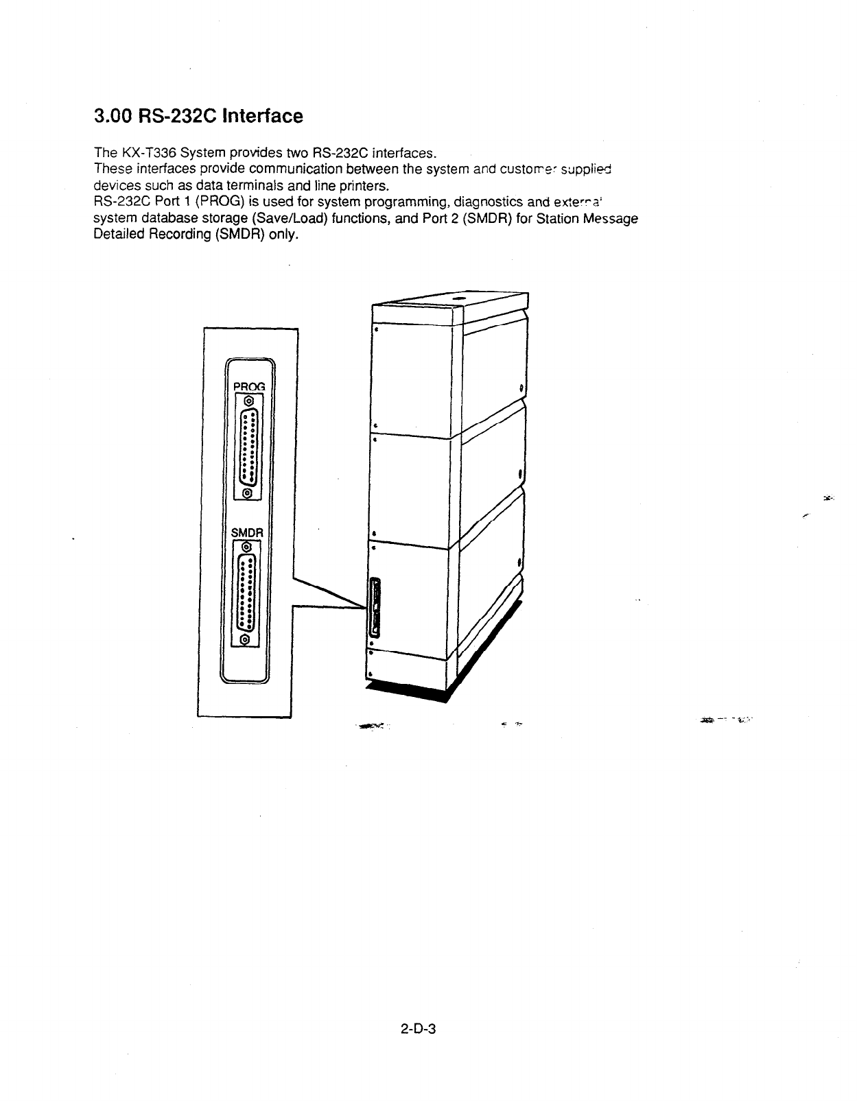
3.00 RS-232C Interface
The KX-T336 System provides two RS-232C interfaces.
These interfaces provide communication between the system and custorre: stipplied
devices such as data terminals and line printers.
RS-232C Port 1 (PROG) is used for system programming, diagnostics and exterra’
system database storage (Save/Load) functions, and Port 2 (SMDR) for Station Message
Detailed Recording (SMDR) only.
SMDF
Y-.
c
2-D-3
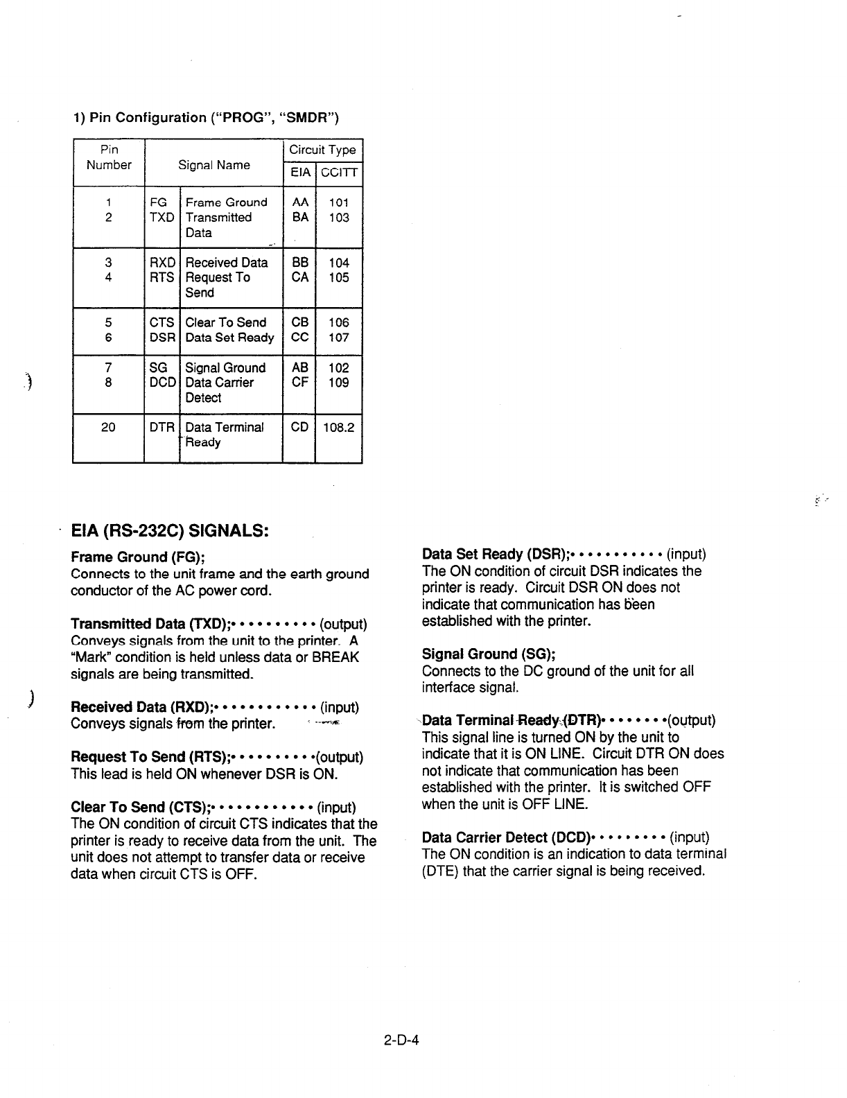
1) Pin Configuration (“PROG”, “SMDR”)
Circuit Type
Signal Name t-r
EIA Ccl-i7
1 FG
2 TXD
3 RXD
4 RTS
5 CTS
6 DSR
7
7 SG SG
8
8 DCD DCD
20 DTR
/
Frame Ground AA
Transmitted BA
Data . .
Received Data BB
Request To CA
Send
101
103
104
105
Clear To Send CB 106
Data Set Ready CC 107
Signal Ground AB
Data Carrier CF
Detect
Data Terminal CD
heady
102
109
108.2
. EIA (RS-232C) SIGNALS:
Frame Ground (FG);
Connects to the unit frame and the earth ground
conductor of the AC power cord.
Transmitted Data (TXD);.
l l l l l l l l l
(output)
Conveys signals from the unit to the printer.
A
“Mark” condition is held unless data or BREAK
signals are being transmitted.
Received Data (RXD);.
l l l l l l l l l l l
(input)
Conveys signals fmm the printer. --6%
Request To Send (RTS);.
l l l l l l l l
*(output)
This lead is held ON whenever DSR is ON.
Clear To Send (CTS)?
l l l l l l l l l l l
(input)
The ON condition of circuit CTS indicates that the
printer is ready to receive data from the unit. The
unit does not attempt to transfer data or receive
data when circuit CTS is OFF.
Data Set Ready (DSR);.
l l l l l l l l l l
(input)
The ON condition of circuit DSR indicates the
printer is ready. Circuit DSR ON does not
indicate that communication has tjeen
established with the printer.
Signal Ground (SG);
Connects to the DC ground of the unit for all
interface signal.
-Data Terminal-Ready.@TR)-
l l l l l l
*(output)
This signal line is turned ON by the unit to
indicate that it is ON LINE. Circuit DTR ON does
not indicate that communication has been
established with the printer. It is switched OFF
when the unit is OFF LINE.
Data Carrier Detect (DCD)*
l l l l l l l l
(input)
The ON
condition is an indication to data terminal
(DTE) that the carrier signal is being received.
2-D-4

3.01 Connection to the Printer
Serial Printer
Serial
Interface
( RS-232C )
l
Connect the R-S-232C connector of the printer to “SMDR”.
l
Cables must be shielded and the maximum cabling distance is 6.5 feet.
.
l
Connection Chart
RS-232C (SMDR) port on the Basic Shelf (KX-T336100) RS-232C
port on the printer
Circuit Type (EIA)
Signal Name bin No.
Pin No. . -
Signal Name Circuit Type (EIA)
AA FG 1 1 FG AA
BA TXD 2 ) 3
RXD BB
BB RXD
3 < 2 TXD BA
cc DSR 6 < 20 DTR CD
AB SG 7 7 SG AB
CD DTR 20 5 CTS CB
A
I
)
) 6 DSR cc
) 8 DCD CF
2-D-5
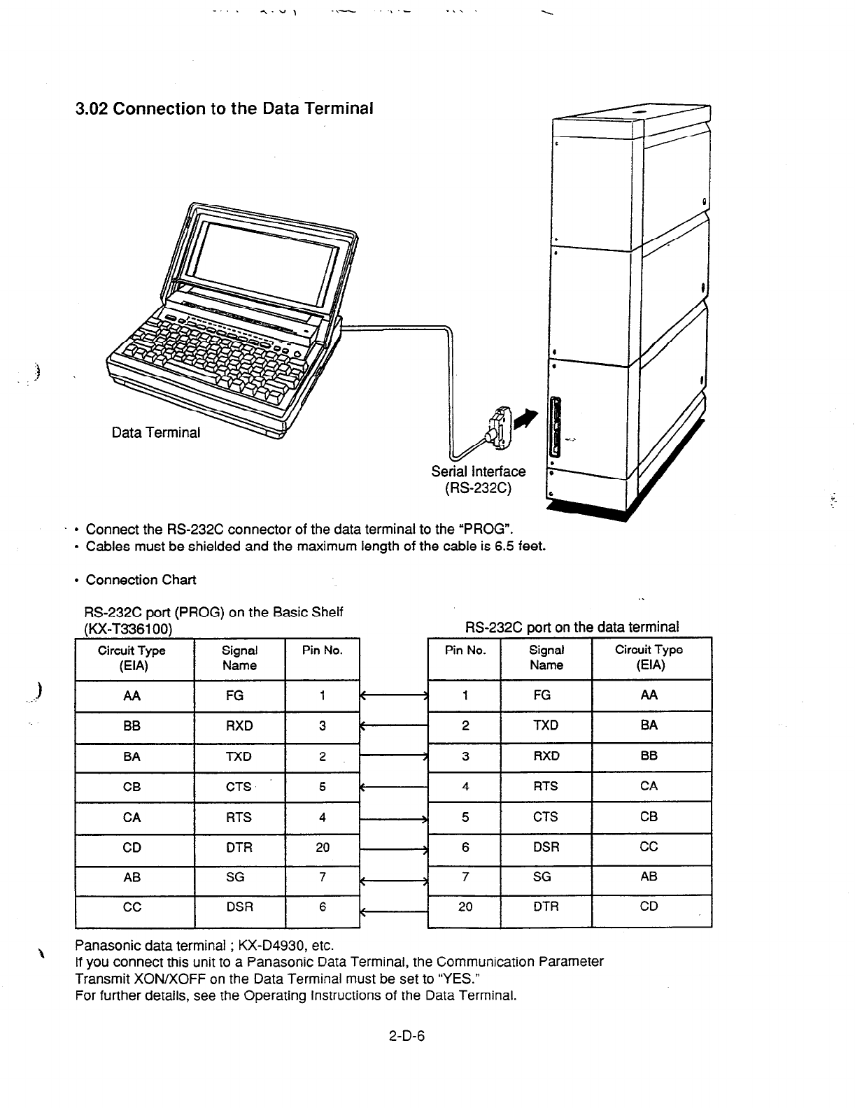
-“. -,.“’ .\- .) .- .\\ .
3.02 Connection to the Data Terminal
Serial Interface
(RS232C)
l
Connect the RS-232C connector of the data terminal to the “PROG”.
l
Cables must be shielded and the maximum length of the cable is 6.5 feet.
0
‘
. /
0
e
. /
I
l
Connection Chart
RS-232C sort (PROG) on the Basic Shelf
\
Panasonic data terminal ; KX-D4930, etc.
If you connect this unit to a Panasonic Data Terminal, the Communication Parameter
Transmit XON/XOFF on the Data Terminal must be set to “YES.”
For further details, see the Operating Instructions of the Data Terminal.
2-D-6
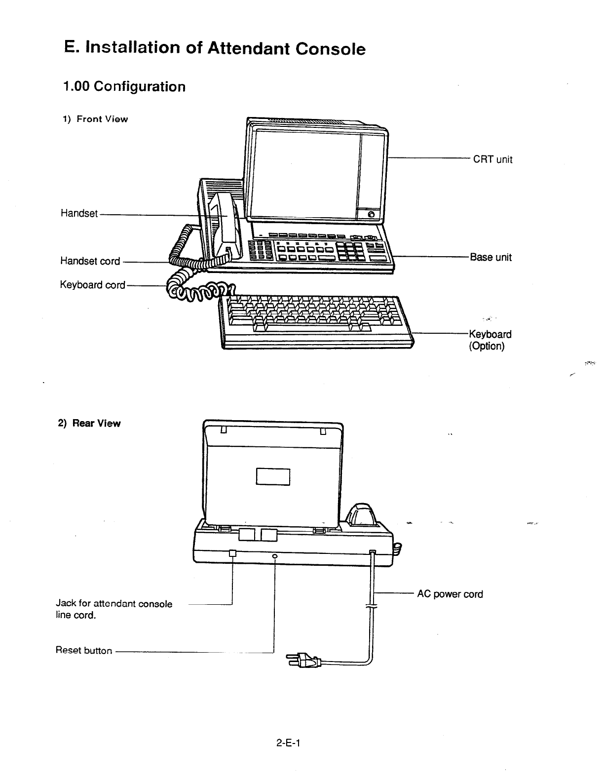
E. Installation of Attendant Console
1 .OO Configuration
1) Front View
Keyboard cord
CRT unit
Base unit
-...
Keyboard
(Option)
2) Rear View
Jack for attendant console
line cord.
Reset button
AC power cord
2-E-l
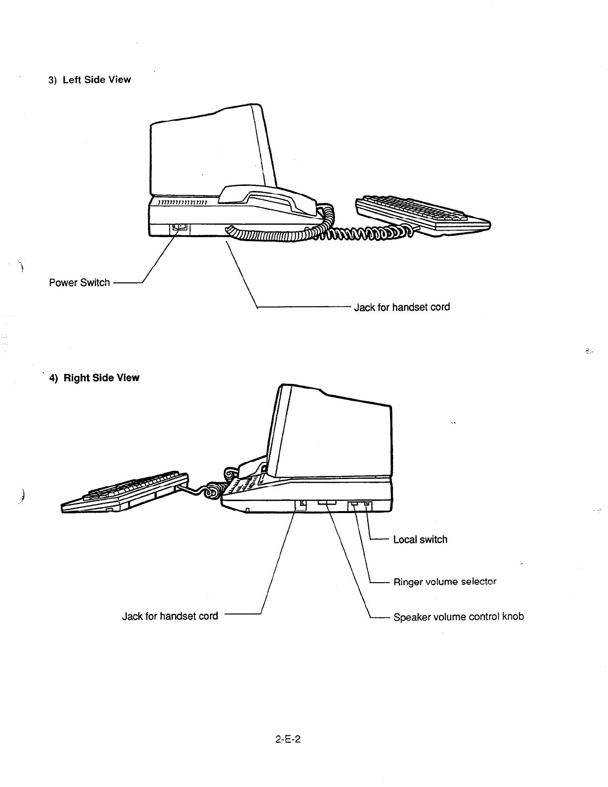
3) Left Side View
. .
i
Power Switch
Jack for handset cord
4) Right Side View
\
Ringer volume selector
Jack for handset cord L Speaker volume control knob
2-E-2
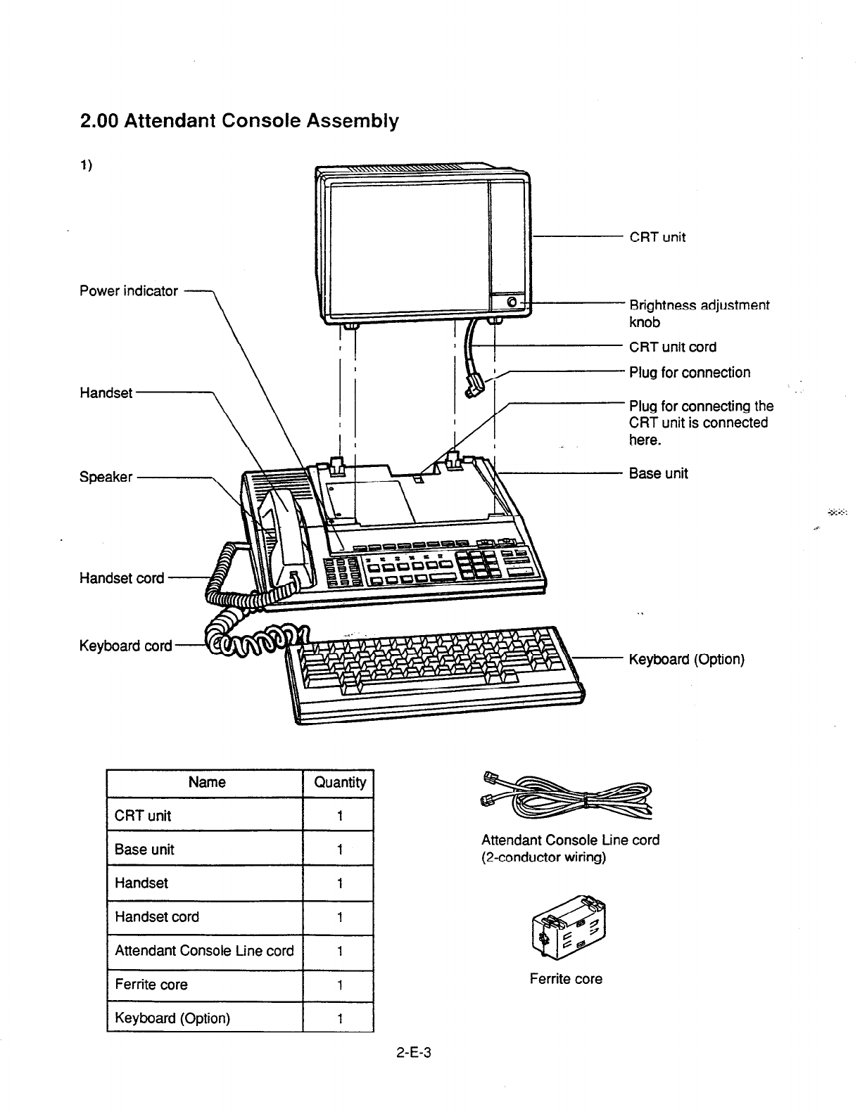
2.00 Attendant Console Assembly
Power indicator
CRT unit
Plug for connection
Plug for connecting the
CRT unit is connected
here.
Base unit
Keyboard (Option)
Name 1 Quantity
CRT unit
Brightness adjustment
knob
CRT unit cord
Attendant Console Line cord
(2-conductor wiring)
Ferrite core
2-E-3

3.00 Handset Connection
Base unit
Piug /
Handset cord Plug I Plug
Handset cord
‘1.
Plug the coiled
handset
cord into the jack labeled YO HANDSET” either right side or
left side of the base unit.
2. Plug the other end of the coiled cord into the handset, and then hang up.
% You can use either of the right and left jacks.
:-:
2-E-4
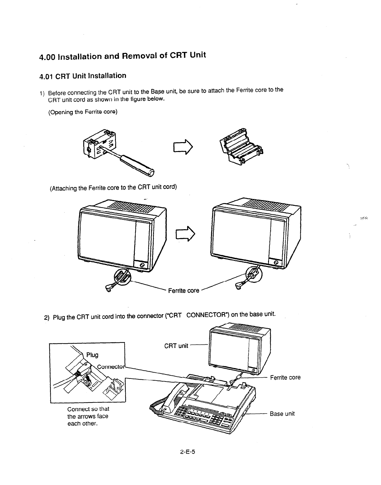
4.00 Installation and Removal of CRT Unit
4.01 CRT Unit Installation
1) Before connecting the CRT unit to the Base unit, be sure to attach the Ferrite core to the
CRT unit cord as shown in the figure below.
(Opening the Ferrite core)
(Attaching the Ferrite core to the CRT unit cord)
Ferrite core
2) Plug the CRT unit cord into the connector (“CRT CONNECTOR”) on the base unit.
I
I
CRT unit -
II
Connect so that
the arrows face
each other.
Base unit
2-E-5
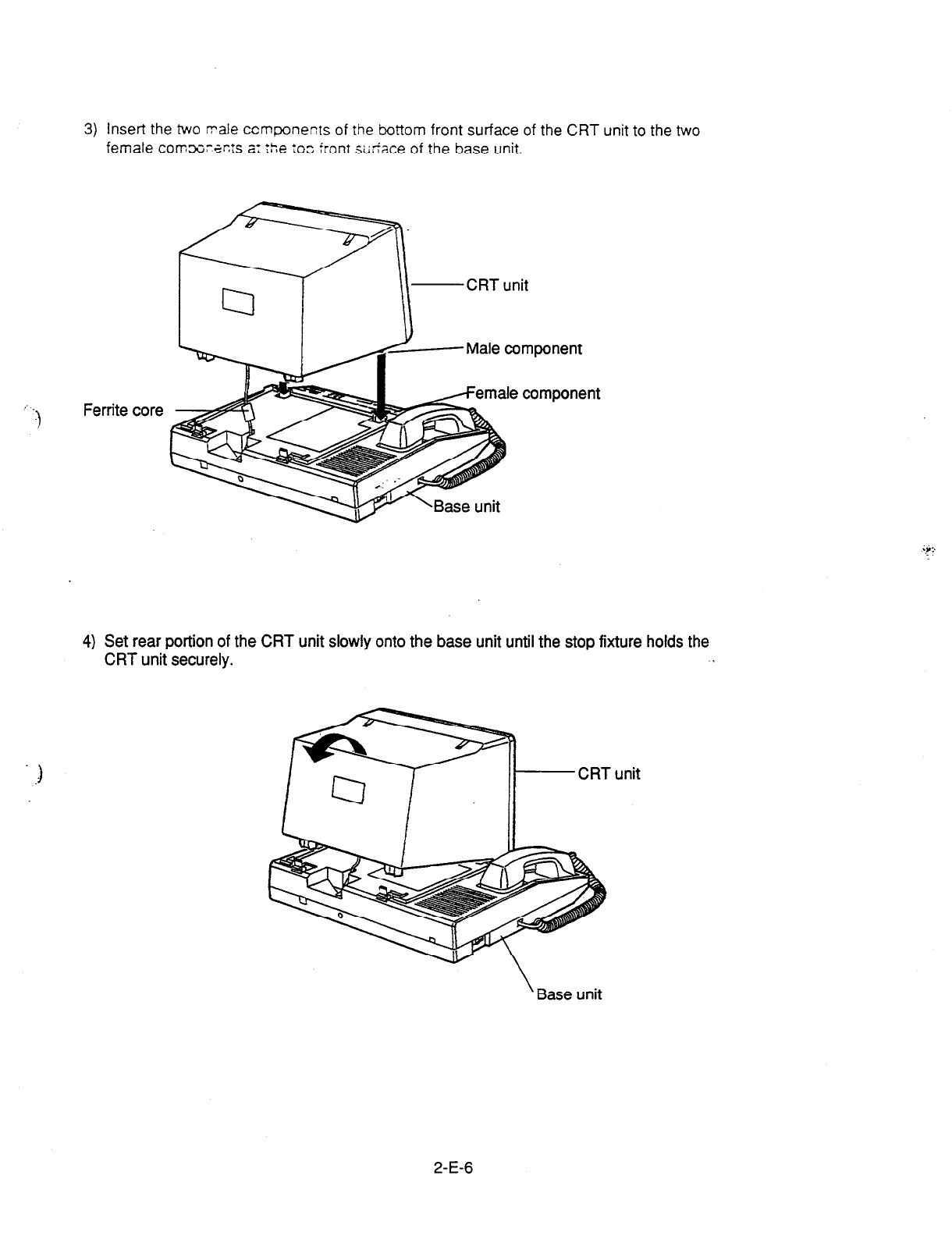
3) Insert the two rrale ccmponents of the bottom front surface of the CRT unit to the two
female comx~a~!s t: :he to3 front si;tiace of the base unit.
-CRT unit
Ferrite
core
4) Set rear portion of the CRT unit slowly onto the base unit until the stop fixture holds the
CRT unit securely. .
‘Base unit
2-E-6

4.02 CRT Unit Removal
7-
Confirm
that
the AC power cord has been removed.
1. Press the stop fixture toward you and hold it pressed, then lift up the rear portion
of the CRT unit.
2. Unplug the CRT unit cord from the base unit connector.
2-E-7
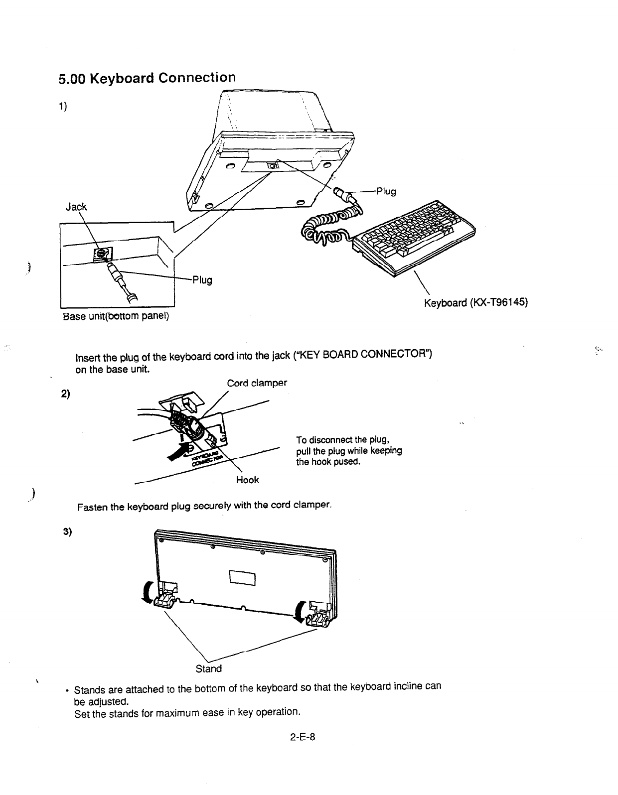
5.00 Keyboard
1)
Connection
/)i---J ,~
Base unit(bottom panel)
Insert the plug of the keyboard cord into the jack (“KEY BOARD CONNECTOR”)
on the base unit.
Cord clamper
2)
To disconnect the piug,
pull the plug while keeping
the hook pused.
Fasten the keyboard plug securely with the cord clamper.
3)
Stand
\ .
Stands are attached to the bottom of the keyboard so that the keyboard incline can
be adjusted.
Set the stands for maximum ease in key operation.
2-E-8
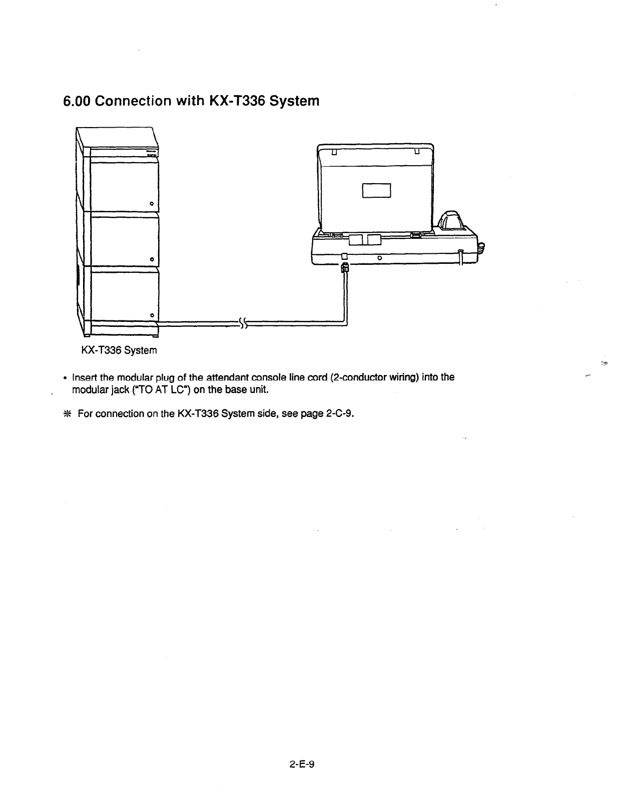
6.00 Connection with KX-T336 System
\
7
\
0
I
h
0
\
4
J
KX-T336 System
I
l
Insert the modular plug of the attendant console line cord (2-conductor wiring) into the
modular jack (“TO AT Lc”) on the base unit.
% For connection on the KX-T336 System side, see page 2-C-9.
2-E-9
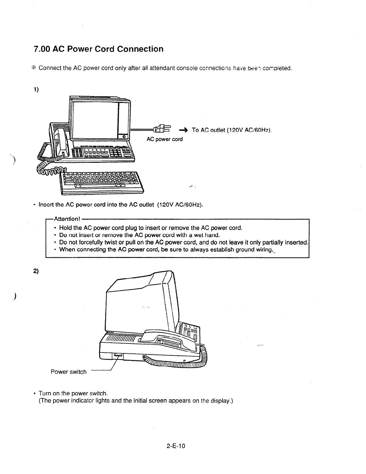
7.00 AC Power Cord Connection
.
!
% Connect the AC power cord only after all attendant console connections have ke? cor:pleted.
To AC outlet (12OV
AC!GOHz).
l
Insert the AC power cord into the AC outlet (12OV AC/GOHz).
Attention!
l
Hold the AC power cord plug to insert or remove the AC power cord.
l
Do not insert or remove the AC power cord with a wet hand.
l
Do not forcefully twist or pull on the AC power cord, and do not leave it only partially inserted.
l
When connecting the AC power cord, be sure to always establish ground wiring...
2)
Power switch
,_-.
l
Turn on the power switch.
(The power indicator lights and the initial screen appears on the display.)
2-E-l 0
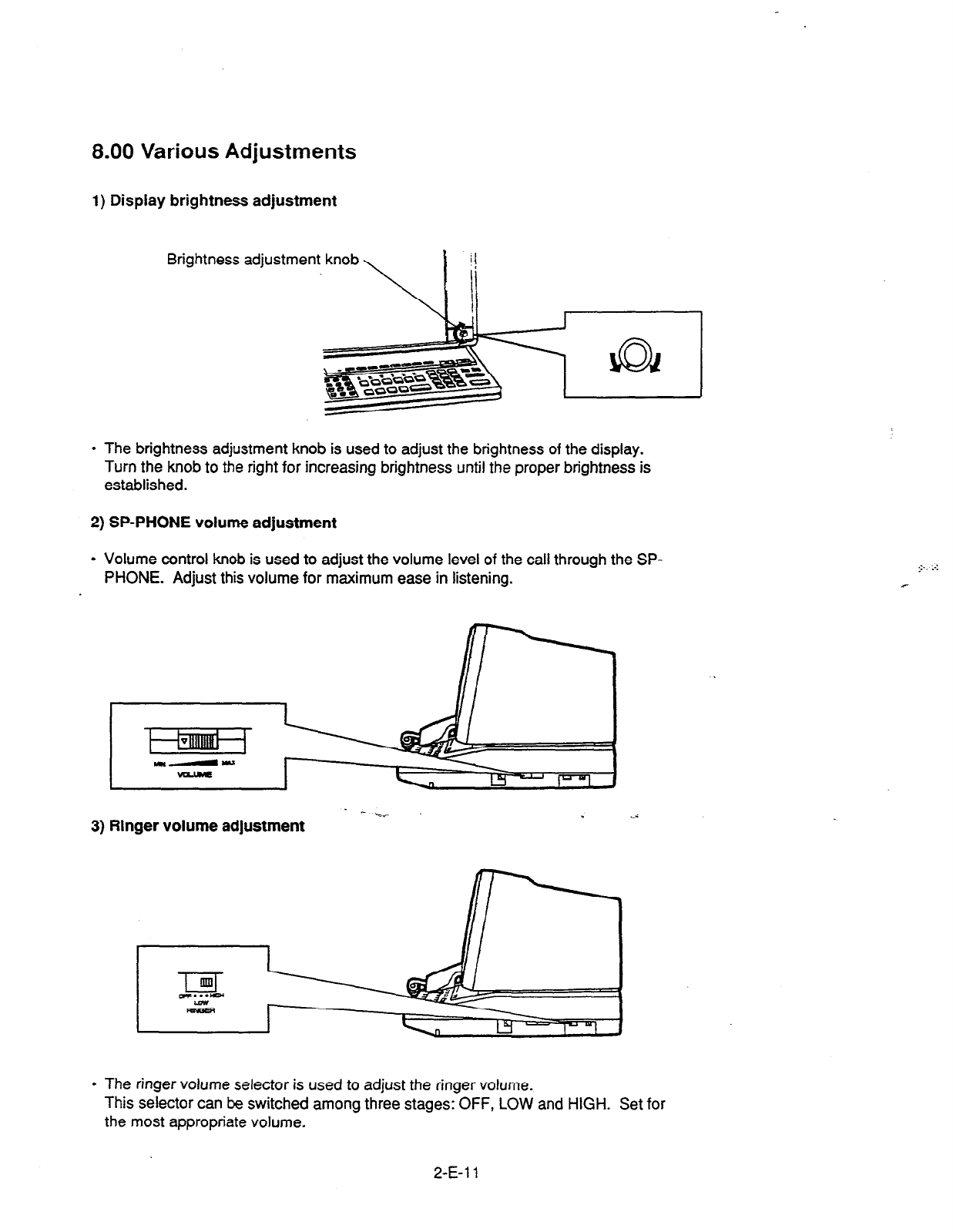
8.00 Various Adjustments
1) Display brightness adjustment
Brightness adjustment knob
l
The brightness adjustment knob is used to adjust the brightness of the display.
Turn the knob to the right for increasing brightness until the proper brightness is
established.
2) SP-PHONE volume adjustment
l
Volume control knob is used to adjust the volume level of the call through the SP-
PHONE. Adjust this volume for maximum ease in listening.
- %-
3) Ringer volume adjustment
r
l
The ringer volume selector is used to adjust the ringer
volume.
This selector can be switched among three stages: OFF, LOW and HIGH. Set for
the most appropriate volume.
2-E-l 1

F. Starting Up the KX-T336 System
1 .OO System Power-Up Procedure
+S Complete and check all installation procedures before connecting the AC power
cord (packaged separately).
1. First insert the AC power cord into the AC power cord connector on the back of the
base shelf as shown in Figure 1.
2. Then insert the other end of the AC power cord into the AC outlet (12OV AC/GOHz)
as shown in Figure 2.
3. Turn on the Main Power Switch on the base shelf.
4. Turn on the power switch on the power unit of each shelf.
l
The power indicator on the power unit will light.
Note :
j Each shelf may be powered down individually, without powering down the entire
system.
AC outlet (12OV AC/GOHz) Figure 2.
1.
2-F-l

2.00 CPU Rotary-Switch Features
r
LED
1
(CPU failure)
LED 2 (Battery power down)
RESET button RESET button
Operation Operation Switch 0 to 9 (MODE Switch 0 to 9 (MODE
System Administration Device System Administration Device
Selection Switch: 0 to 9 (SYSTEM) Selection Switch: 0 to 9 (SYSTEM)
I I
2.01
Operation
Switch (MODE)
-
h Operation BVOG ,
CowauPT SYS nJao*\
Mode tk T& liVith sYstm MemoW Without System Memory
I
I
6
I
a
I
9
On-line
Off-line
Starts up the system with current system
programming data I
. System programming data
is
verified logically -+ on-line
l
System programming data is not
verified logically + off-line
Starts up the system with current system Starts up the system with default
programming data values
Starts up the system with current system Enters to off-line mode without
programming data initializing the data
._.. (Power faiture transfer status)
Special Operation
(Examination on the finished product)
Holds the current system programming data
Assigns default values automatically and “System Installation” screen is displayed
(Installation)
Initializes the current system programming data and “System Installation” screen
is.displayed (Installation)
Holds the current programming data and ‘System Intallation” screen is displayed
(Enters to “Password Entry” screen compulsorily)
Reserved for future expansion
(Functions same as “0”)
Reserved for future expansion
(Functions same as “0”)
2-F-2

[Note]
a) When you start up the system after installation, the Operation Switch (,MODE) should be set to “5” or
“6.”
l No.5
. . ..When you program the system data based on the factory programmed default values.
l
No.6 . . ..When you program the system data without the factory programmed default values.
b) When system programming is finished, the Operation Switch (MODE) should be set to “0,” “1” or “2.”
l No.0
. . . . . When CPU runaway occurs due to a loss of system programming data or the RESET button is
pressed, the system enters to on-line mode if system programming data is verified logically, or
the system enters to off-line mode if system programming data is not verified logically.
l No.1
. . ..When CPU runway occurs due to a loss of system programming data or the RESET button is
! pressed, default value is loaded and the system enters to on-line mode.
If system programming data is not lost, reset-routine will be activated and enters to on-line
mode with the current system programming data.
l
No.2 . . ..When CPU runaway occurs due to a loss of system programming data or the RESET button is
pressed, the system enters to off-line mode with the current System programming data.
c) With System Memory
System memory is provided.
d) Without System Memory
System memory is not provided.
e) Off-line
It is available to perform system data programming but call processing and functional test are not
i available in off-line mode.
..a
1) Power failure transfer
Connects preassigned CO lines and extensions directly, bypassing the system.
g) After you entered the system administration mode, keep the following considerations in mind when
setting the Operation Switch. - -. ~. ._
.-
9
No.5 . . ..Current programming data will be defaulted.
l
No.6 . . ..Current programming data will be removed.
2-F-3
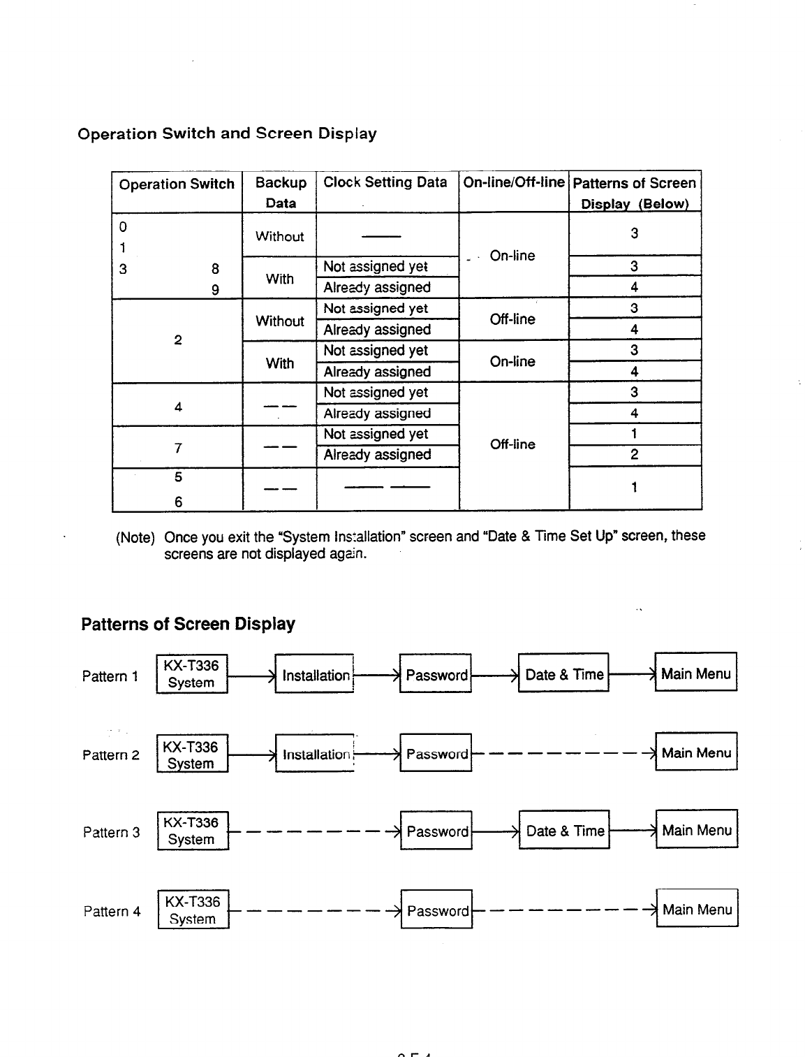
Operation Switch and Screen Display
Operation Switch Backup Clock Setting Data On-line/Off-line Patterns of Screen
Data Display (Below)
0 Without - 3
1
3 8
2
4
7
5
Not assigned yet - On-line 3
With Already assigned 4
Not assigned yet 3
Without Already assigned Ott-line 4
3
With Not assigned yet
Already assigned On-line 4
Not assigned yet
-- Already assigned
Not assigned yet
-- Already assigned Off-line
-- --
(Note) Once you exit the ‘System Ins:allation” screen and “Date & Time Set Up” screen, these
screens are not displayed aga%.
Patterns of Screen Display
Pattern 1 El-i=/ > Password > Date & Time. > Main Menu
Pattern 3 Et-------+ Password > Date & Time > Main Menu
Pattern 4 it-------~~t--------~~l
2-F-4
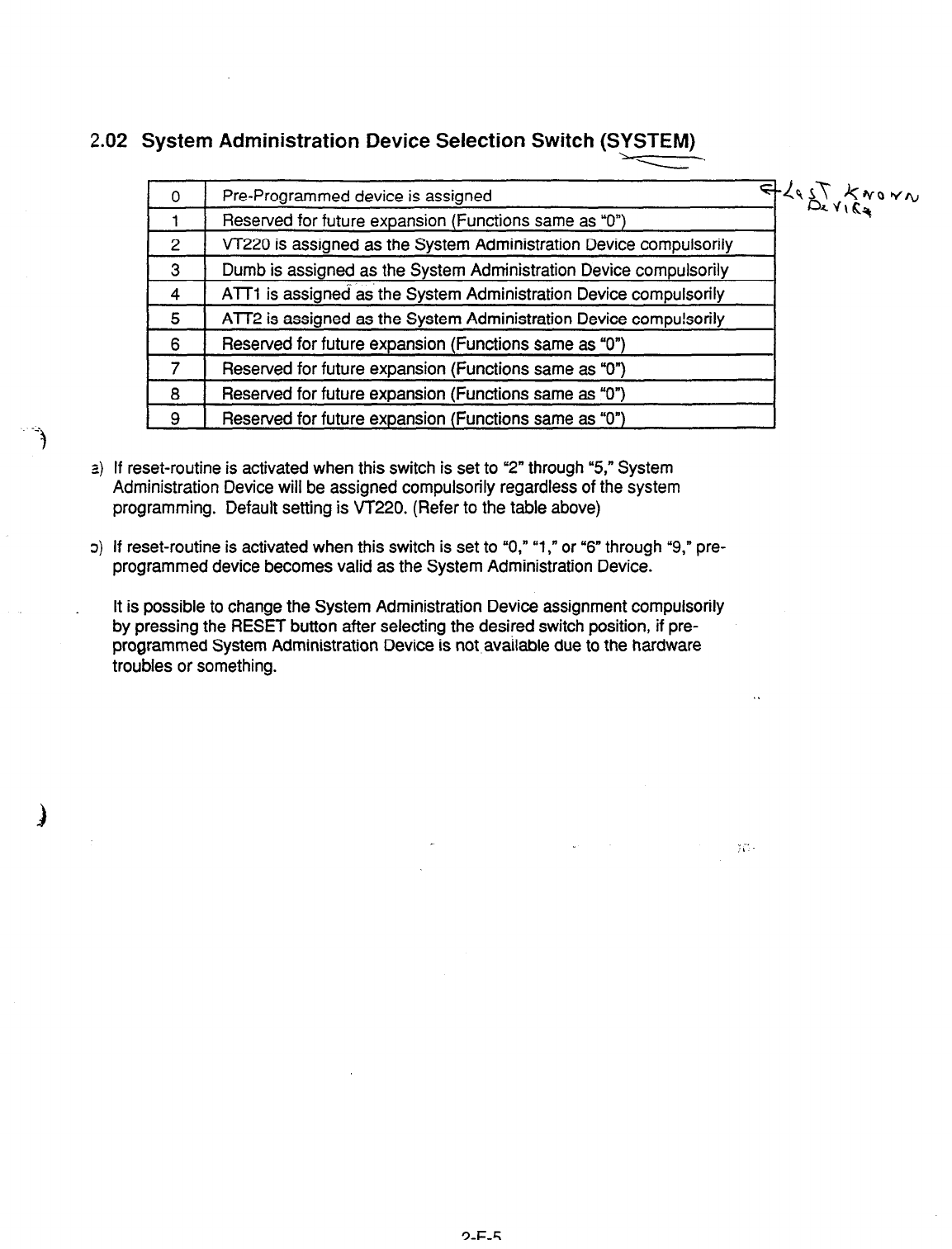
2.02 System Administration Device Selection Switch (SYSTEM)
I
0
Pre-Programmed device is assigned w\ 5-T kwo WI))
1
Reserved for future expansion (Functions same as UO”) 04c;%
2 VT220 is assigned as the System Administration Device compulsorily
3 Dumb is assigned as the System Administration Device compulsorily
4 ATT1 is assigned as the System Administration Device compulsorily
5 ATT2 is assigned as the System Administration Device compu!sorily
6 Reserved for future expansion (Functions same as “On)
7 Reserved for future expansion (Functions same as “0”)
8 Reserved for future expansion (Functions same as .O”)
9 Reserved for future expansion (Functions same as “0”)
a) If reset-routine is activated when this switch is set to “2” through “5,” System
Administration Device will be assigned compulsorily regardless of the system
programming. Default setting is VT220. (Refer to the table above)
o) If reset-routine is activated when this switch is set to “0,” “1,” or ‘6” through “9,” pre-
programmed device becomes valid as the System Administration Device.
It is possible to change the System Administration Device assignment compulsorily
by pressing the RESET button after selecting the desired switch position, if pre-
programmed System Administration Device is not available due to the hardware
troubles or something.
.
2-F-5
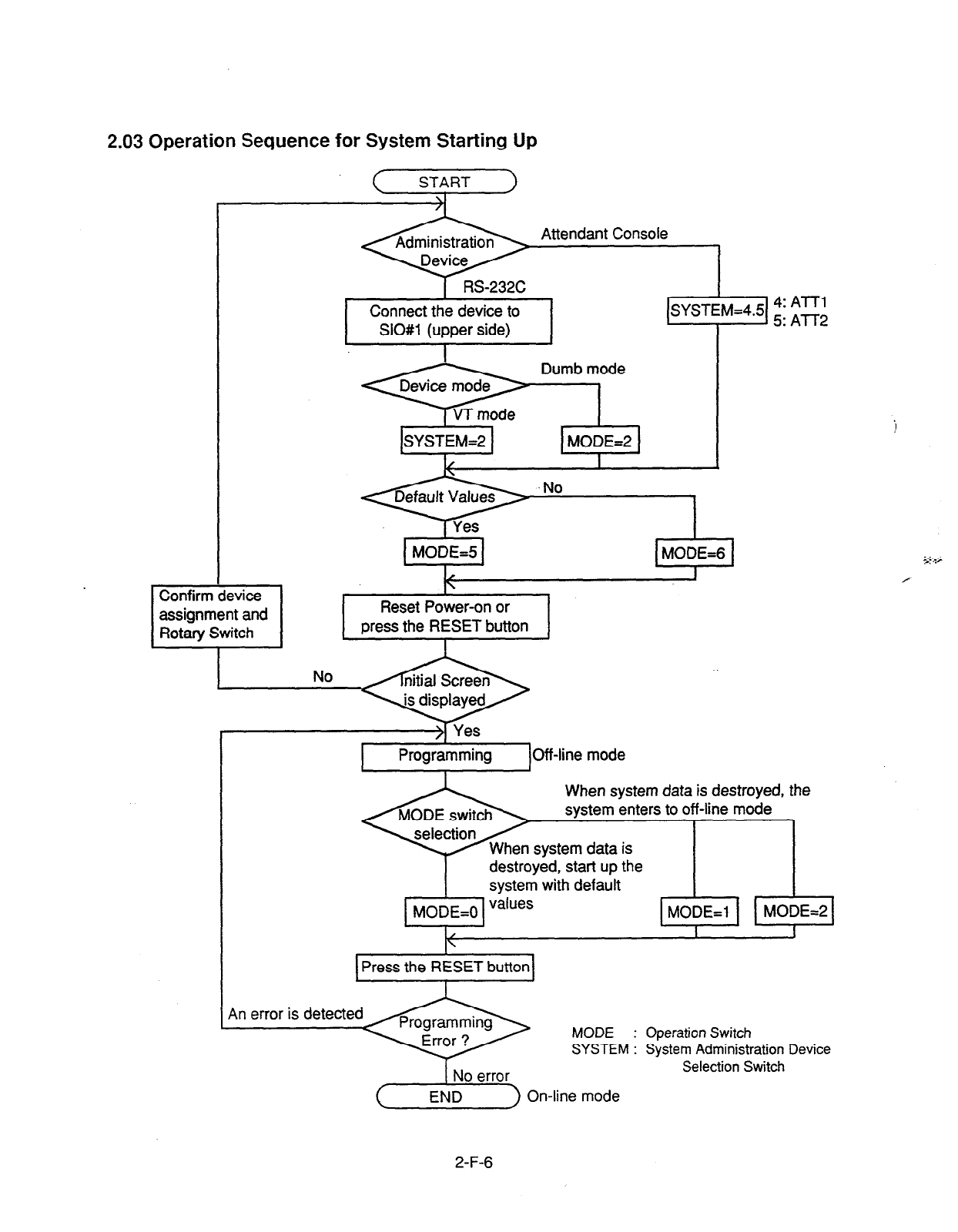
2.03 Operation Sequence for System Starting Up
START
>1
1 Connect the device to I [SYSTEM=43 s”i ;;;
I
SIO#l (upper side) 1 I
Attendant Console
,No -I
MODE=5 MODE=6
I
1
)/Off-line mode
When system data is destroyed, the
system enters to off-line mode
destroyed, start up the
system with default
MODE=0 va’ues MODE=1 MODE=2
I
1 Press the RESET button 1
I I I I
‘B*onw,in;l;;e : Of=;;~;;;,i,
SYSTEM : System Admmlstratlon Device
2-F-6
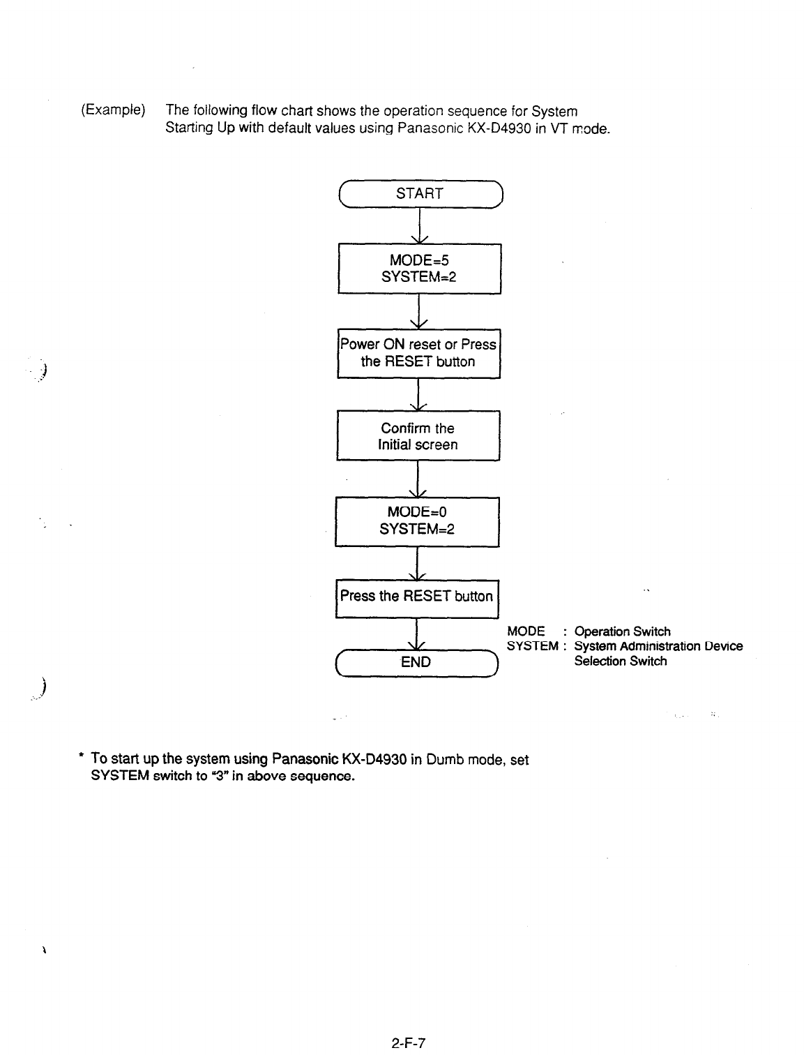
(Example) The following flow chart shows the operation sequence for System
Starting Up with default values using
Panasonic KX-D4930 in VT mode.
Power ON reset or Press
the
RESET button
Confirm the
Initial screen A
\/
MODE=0
SYSTEM=2
Press the RESET button . .
MODE : Operation Switch
SYSTEM : System Administration Device
Selection Switch
l
To start up the system using Panasonic KX-D4930 in Dumb
mode, set
SYSTEM switch to “3” in above sequence.
2-F-7

Section 3
System Features and Operation
(Section 3)
System Features and
Contents
Operation
Page
A Preparation . . . . . . . . . . . . . . . . .
. . . .._................................................. . . . . . .._...................... 3-A-l
B Basic Features 3-B-l
. . . . . .._.......................
. . . . ..-.............................. . . . . . . . . . . . . . . . ..s-..........
1 .oo
2.00
3.00
4.00
5.00
6.00
7.00
8.00
9.00
10.00
11.00
12.00
13.00
z. &. 14.00
15.00
16.00
C
Outgoing Call Features . . . . . .
. . . . . . . . . . . . . ..__.___.....__........................
. . . . . . . . . . . . . . . . . . . . . . . . . . 3-c-1
Flexible Numbering.. .............................................................................. 3-B-l
Directory Number (DN) .......................................................................... 3-B-5
Floating Directory Number (FDN) .......................................................... 3-B-6
Tenant Service ............................................... .._ .................................... 3-B-7
Operator.. ............................................................................................... 3-B-8
Class of Service (COS)
..........................................................................
Group. .................................................................................................... z-i-ip
- -
7.01 Intercom Group.. .......................................................................... 3-B-11
7.02 Call Pickup Group ........................................................................ 3-B-l 2
7.03 Uniform Call Distribution (UCD) Group ........................................ 3-B-l 2
7.04 Paging Group. ............................................................................. 3-B-l 3
7.05 Trunk Group.. .............................................................................. 3-B-13
Night Service ......................................................................................... 3-B-14
8.01 Directed Night Answer ................................................................. 3-B-l 5
8.02 Universal Night Answer (UNA) .................................................... 3-B-16
8.03 Flexible.Night Service .................................................................. 3-B-l 7
8.04 Fixed Night Service ..................................................................... 3-B-l 7-1
.~
8.05 Switching of Day/Night Mode ...................................................... 3-B-l 8
Mixed Station Capacities ....................................................................... 3-B-l 9
Variable Time-Gut .................................................................................. 3-B-20
Lockout .................................................................................................. 3-B-21
Automatic Station Release .................................................................... 3-B-21
Distinctive Dial Tone .............................................................................. 3-B-22
Distinctive Busy Torte..
................................. .............................. 3-B-23
Confirmation Tone :...:” z..
...................................................................... ‘-3-B-24 .............
Tone and Ringing Patterns .................................................................... 3-B-25
1.00 Toll Restriction .......................................................................................
1 .Ol Toll Restriction for Local Trunk Dial Access ................................
1.02 Toll Restriction in Automatic Route Selection (ARS) System.. ....
1.03 Toll Restriction for Individual Trunk Group Dial Access/Direct
Trunk Access. ..............................................................................
1.04 Toll Restriction for Individual Virtual Trunk Group Dial Access ....
1 .05 Operator/International Call Restriction ........................................
1.06 3/6 Digit Toll Restriction ...............................................................
1.07 7/l 0 Digit Toll Restriction .............................................................
2.00 Automatic Route Selection (ARS) ..........................................................
3.00 Tone/Pulse Conversion .........................................................................
4.00 Automatic Pause Insertion ....................................................................
3-c-1
3-C-2
3-c-5
3-c-7
3-c-1 0
3-c-1 3
3-c-1 5
3-C-20
3-C-21
3-C-36
3-c-37
Page - .-.
D Receiving Features.. ... . .................................................................................... 3-D-1
1.00 Attendant Console (ATT) Operation ...................................................... 3-D-1
1 .Ol Load Sharing ............................................................................... 3-D-2-l
1.02 Simultaneous Ringing..
................................................................ 3-D-2-2
1.03 Interconsole IRNA ....................................................................... 3-D-2-3
2.00 Attendant Console-less Operation ........................................................ 3-D-3
2.01 Direct In Line (DIL) ...................................................................... 3-D-3
2.02 Direct Inward System Access (DISA) .......................................... 3-D-4
2.03 Direct Inward Dialing (DID). ......................................................... 3-D-7
2.04 Trunk Answer From Any Station (TAFAS)-Day Service.. ............. 3-D-8
2.05 Uniform Call Distribution (UCD)-General..................................... 3-D-9
2.06 Uniform Call Distribution (UCD)-with/without OGM ..................... 3-D-11
2.07 Private CO (PCO). ....................................................................... 3-D-15
2.08 Single CO (SCO). ........................................................................ 3-D-16
2.09 Group CO (GCO)
......................................................................... 3-D-l 7
2.10 Flexible SCO/GCO Assignment .................................................. 3-D-1 7-l
2.11 Multiple GCO Assignment ........................................................... 3-D-l 7-4
3.00 Flexible Ringing Assignment ................................................................ 3-D-18
3.01 Flexible Ringing Assignment-No Ringing .................................... 3-D-18
3.02 Flexible Ringing Assignment-Delayed Ringing ........................... 3-D-18
4.00 Discriminating Ringing.. ......................................................................... 3D-19
5.00 Station Hunting :.I.. ........... ...
;.;. .............................................................. 3-D-20
5.01 Station Hunting-Circular .............................................................. 3-D-20
5.02 Station Hunting-Terminal ............................................................. 3-D-21
E Holding Features.. ............................................................................................ 3-E-l
1.00 Music on Hold ....................................................................................... 3-E-l
2.06 Held Call Reminder..: .%. ............................... :r.; ..;. ................................. 3-E-2 ;L .
3.08 Transfer Recall ..................................................................................... 3-E-3
F Other Features . . . . . . . . . . . . . . . . . . . . . . . . . . . . . . . . . . . . . . . . . . . . . . . . . . . . . . . . . . . . . . . . . . . . . . . . . . . . . . . . . . . . . . . . . . . . . . . . . 3-F-l
1.00
2.00
3.00
4.00
5.00
6.00
7.00
8.00
9.00
10.00
11 .oo
12.00
13.00
Station Message Detail Recording (SMDR) .......................................... 3-F-l
0ff Premise Extension (OPX) ................................................................ 3-F-3
Walking Station.. .................................................................................... 3-F-3
outgoing Message (OGM) Recording and Playing Back ...................... 3-F-5
Intercept Routing-No Answer (IRNA). .................................................... 3-F-8
Rerouting ............................................................................................... 3-F-9
Calling Party Control (CPC) Signal Detection ....................................... 3-F-l 0
CO Busy Cut .......................................................................................... 3-F-11
Parallel Connecttin of Extensions.. ....................................................... 3-F-l 2
Voice Processing System (VPS). ........................................................... 3-F-l 3
10.01 Voice Mail Integration ................................................................ 3-F-15
10.02 DTMF-Tone Integration ............................................................. 3-F-21
Call Accounting Summary ..................................................................... 3-F-52
Waiting for Second Dial tone ................................................................. 3-F-62
Timed Reminder with CGM (Wake-up Call) .......................................... 3-F-64
A. Preparation
This section provides the basic information on
each of the system features which are
programmed at system level.
System features are those that affect the entire
operation of the system.
In this section, system features are divided into
the following five categories.
. Basic Features
l
Outgoing Call Features
l
Receiving Features
l
Holding Features
l
Other Features
3-A-l
B. Basic Features
1 .OO Flexible Numbering
Description
This system comes wi?h a varier! S! serdli+-%
and
the
feature numbers used wr,en exec,:.?g
these services can be set as required.
Feature numbers can be from one to four clglts.
‘utilizing numbers “0” through “9” as well as --”
and “#.”
Directory Numbers (DN) can be three or four
digits in length, and it is acceptable for some to
have three digits and others four digits.
When three-digit DN’s are used, any number can
be set as the initial digit; when four-digit DN’s are
:) used, any numbers can be set as the initial two
digits.
The feature numbers
are
set in the “System-
Numbering Plan” screens.
Two default parameters sets are provided for the
feature numbers and when either is used in its
original form, the Numbering Plan option in the
“System-Operation” screen is set to “Fixed 1” or
. “Fixed 2.”
In this case, the settings cannot be changed in
the “System-Numbering Plan” screen. When a
feature number is to be changed, select Flex in
the “System-Operation”, Numbering Plan before
making the change in the “System-Numbering
Plan.”
.)
Programming
~~
Conditions
Ttie followings are
examples
oi feature number
conflicts:
Examples: 2 and 21, 32 and 321, etc.
Conversely, the following numbers can be used
without conflict:
Examples: 2 and 3,3 and 41: 41 and 42,450
and 451, etc.
=*” and “#” cannot be used for extension
numbers (extension blocks).
When u*” and “#I” are included in a feature
number, it will not be possible to execute the
corresponding feature using a dial pulse type of
Single Line Telephone (SLT).
Only “0”, ‘1” to “9”, u*A” and “#” are valid for
entering feature numbers into One Touch dial
buttons.
When “FLASH”, y-m ,
“PAUSE” and “SECRET” are
included into feature numbers, reorder tone is
sent and the features cannot be executed.
“V cannot be used for the feature numbers listed
below, for those features require r$” as a
delimiter when setting the feature:
“Call Forwarding-to TrunK
“Pickup Dialing Programming”
“Speed Dialing-Station”
The feature numbers which have been set in the
“System-Numbering Plan* screens can be used
when dial tone is heard. However, feature
number for “Account Code” may be used at times
other
than
when dial tone is heard.
3-B-l
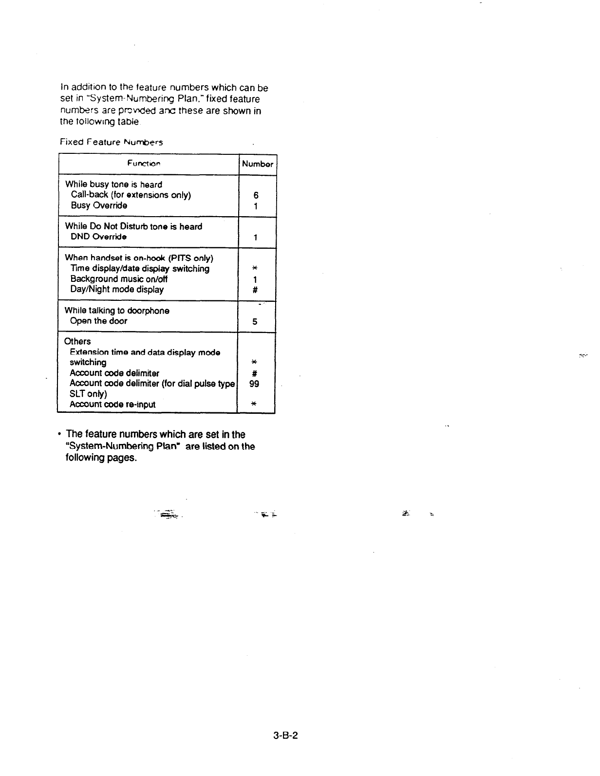
In addition to the feature numbers which can be
set in System-Nun&ring Plan,” fixed feature
numbers are prcv&d ant these are shown in
the following table
Fixed Feature Numbers
Functor!
While busy tone is heard
Call-back (for extensions only)
Busy Override
While Do Not Disturb tone is heard
DND Override
When handset is on-hook (PITS only)
Time display/date display switching
Background music onioff
Day/Night mode display
While talking to doorphone
Open the door
Others
Extension time and data display mode
switching
Account code delimiter
Account code delimiter (for dial pulse type
SLT only)
Account code re-input
-I-
I
I
Numbs
6
1
1
*
1
#
5
*
#
99
*
l
The feature numbers which are set in the
“System-Numbering Plan” are listed on the
following pages.
._ --.
--
w
e..
F F
3-B-2
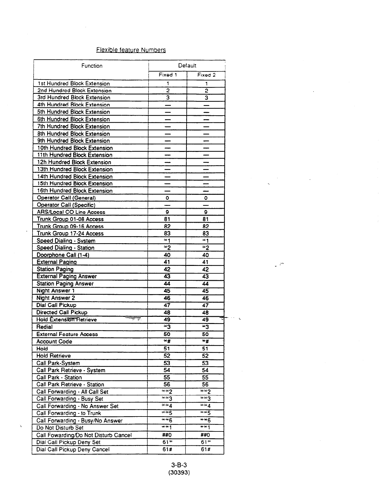
Flexible feature Number6
Operator Call (Specific)
ARS/Locaf CO Line Access
Trunk Group 01-08 Access
I - -
9 9
81 81
Trunk Group 09-l 6 Access 82 I 82
Trunk Group 17-24 Access I 83 83 I
1 1. dl I
Speed Dialino - System
Doorphone Call (l-4)
Speed Dialing - Station
External Paoina
1
40
42
I 40
I
I
42
41
I
I
41
4-J
I
I 45
I
I
44
I
44 I
I ss I 45
46 A6
Station Paaino
cxternar ragtng Answer
Station Paaina Answer
------.- -a
Night Answer 1
Nioht Answer 2
s-------- - -
Dial Call Pickup
HoM ExtenskSK’Retrieve
Redinl
. .--.-.
External Feature Access
Account Code
I
I
50 50
u # *#
i
Do Not Disturb Set
Call Fowardinq/Do Not Disturb Cancel
Dial Call Pickup Deny Set
Dial Call Pickup Deny Cancel
I ++, ++1
##O MO
61’ 61+
I 61# 61#
3-B-3
(30393)
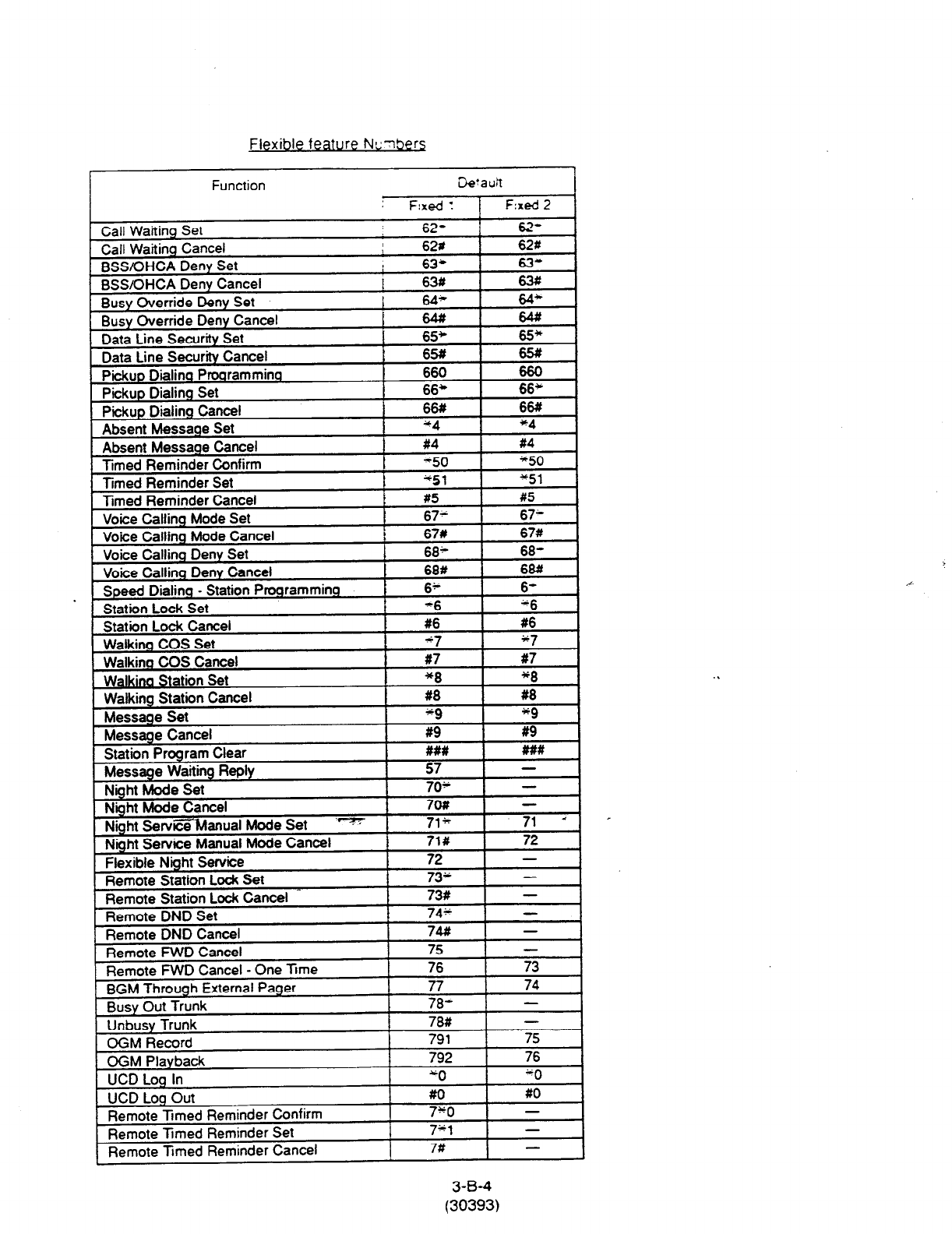
Flexible feature NL’clbers
Remote Tmed Reminder Confirm
Remote Timed Reminder Set
Remote Timed Reminder Cancel
I 73 -
7*1 -
7# -
3-B-4
(30393)
4

2.00 Directory Number (DN)
Description <Example>
Directory numbers are the software type logical
numbers which are programmed to match the
hardware type physical numbers (port numbers)
attached to ports of extensions.
Accordingly, directory numbers are extension
numbers.
System-Numbering Plan
F--S------------------------‘----r---~---~----~----,
1 No. 1 Feature ; DGll DG21 DG31 DG41
;- ’
T------------------------;----:---;---~----~---~
; 1 ; 1 st Hundred Block Extension ; 5 f : - ; - ;-
r--T----------------- -------,----r---1--- -r----l
; 2 ;2nd Hundred Block Extension ; 6 ; ; - ; - i
r--+------------------------t ----p---*----p---,
1
Directory numbers are assigned in “Configuration-
DN Assignment” to be three or four digits.
Only numeric characters “0 to 9” can be used as a
Directory Number.
D’
lrec o
t ry number setting follows the setting in
“System-Numbering Plan”, 1 st Hundred Block
Extension through 16th Hundred Block Extension.
Programming
I
System Programming Reference
VT 1 Dumb
Numbering Plan (l/9)
I 3 !3rd Hundred Block Extension i 7 : 0 : - f - I
c--+------------------------i------~---~----~---~
i 4 /4th Hundred Block Extension i 8 [ 0 i - i - i
DNs from 8000
to
8099
are assignable.
DNs from 7000 to 7099 are assignable.
DNs from 600 to 699 are assignable.
DNs from 500 to 599 are assignable. p
‘Configuration-DN Assignment” 9-c-3.00 lo-c-3.00
. “System-Numbering Plan (l/9) (2/g)“, 9-D-6.01 10-C-10.00
1 st Hundred Block Extension 9-D-6.02
.
.
I
16th Hundred Block
Extension I I I . .
Conditions
There are two types of directory numbers: the
Primary Directory Number (PDN) and the
Secondary Directory Number (SDN).
For further details of PDN, refer to Section 4-B-3.01
“PDN Butto??’ For SDN, refer to’Se&ion 4-B-3.02
“SDN Button.”
If you assign only one digit in “System-Numbering
Plan”, 1 st Hundred Block Extension through 16th
Hundred Block Extension, you can assign three-
digit DNs which start with the pre-assigned digit in
“Configuration-DN Assignment.”
If you assign leading two digits in “System-
Numbering Plan,” you can assign fourdigit DNs
which start with the pre-assigned two digits in
“Configuration-DN Assignment.”
3-B-5
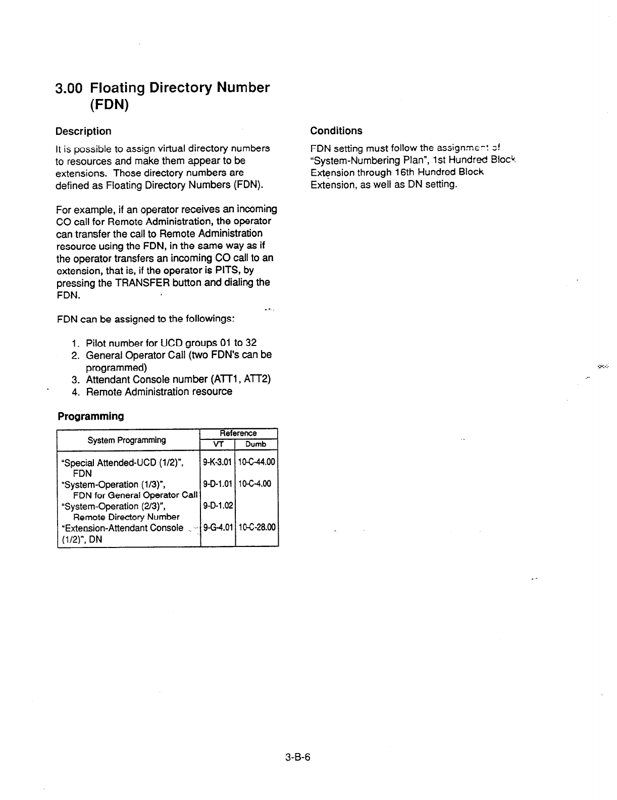
3.00 Floating Directory Number
FW
Description
It is possible to assign virtual directory numbers
to resources and make them appear to be
extensions. Those directory numbers are
defined as Floating Directory Numbers (FDN).
For example, if an operator receives an incoming
CO call for Remote Administration, the operator
can transfer the call to Remote Administration
resource using the FDN, in the same way as if
the operator transfers an incoming CO call to an
extension, that is, if the operator is PITS, by
pressing the TRANSFER button and dialing the
FDN. ^.
FDN can be assigned to the followings:
1. Pilot number for UCD groups 01 to 32
2. General Operator Call (two FDN’s can be
programmed)
3. Attendant Console number (Al7 , AlT2)
4. Remote Administration resource
Programming
Reference
System Programming VT Dumb
‘Special Attended-UCD (l/2)“, 9-K-3.01 1 O-WLOC
FDN
‘System-Operation (l/3)“, 9-D-l .Ol 1O-c-4.00
FDN for General Operator Call
“System-Operation (2/3)“, 9-D-l .02
Remote Directory Number
“Extension-Attendant Console ._ ..I 9-G-4.01 10-&28.00
(l/2)-, DN
Conditions
FDN setting must follow the assigmmer! z!
“System-Numbering Plan”,
1
st Hundred Bloc4
Extqsion through 16th Hundred Block
Extension, as well as DN setting.
3-B-6
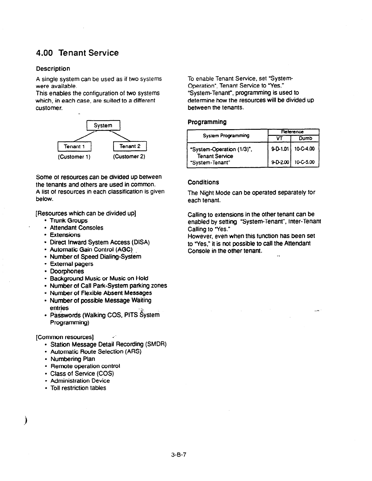
4.00 Tenant Service
Description
A single system can be used as if two systems
were available.
This enables the configuration of two systems
which, in each case, are suited to a different
customer.
(Customer
1)
(Customer 2)
Some of resourcescan be divided up between
the tenants and others are used in common.
A list of resources in each classification is given
below.
[Resources which can be divided up]
l
Trunk Groups
l
Attendant Consoles
l
Extensions
l
Direct inward System Access (DISA)
l
Automatic Gain Control (AGC). _
l
Number of Speed Dialing-System
l
External pagers
l
Doorphones
l
Background Music or Music on Hold
l
Number of Call Park-System parking zones
l
Number of Flexible Absent Messages
l
Number of possible Message Waiting
entrjes
. Passwords (Walking COS, PlTS‘zystem
Programming)
[Common resources]
l
Station Message Detail Recording (SMDR)
l
Automatic Route Selection (ARS)
l
Numbering Plan
l
Remote operation control
l
Class of Service (COS)
l
Administration Device
l
Toll restriction tables
To enable Tenant Service, set “System-
Operation’, Tenant Service to “Yes.”
“System-Tenanr, programming is used to
determine how the resources will be divided up
between the tenants.
Programming
11
Conditions
The Night Mode can be operated separately
for
each tenant.
Calling to extensions in the other tenant can be
enabled by setting “System-Tenant”, Inter-Tenant
Calling to yes.”
However, even when this function has been set
to “Yes,” it is not possible to call the Attendant
Console in the other tenant. . .
3-B-7

5.00 Operator
Description
The system allows the operator to answer,
monitor and control the incoming calls.
Up to two operators (operator 1 and 2) can be
assigned in the system.
If tenant service is employed, up to two operators
can be assigned to each tenant individually.
Not only the ATT (attendant console) operator but
the extension user can be assigned as an
operator.
“Operator 1” must always be selected when only
one operator is assigned.
If an attendant console is connected to the
system, the operator assignment should be
arranged as follows.
(When one attendant console is connected)
operator 1 Fj or p
Operator 2 extension
(When two attendant consoles are connected)
Operator 1 1 AlT 1
Operator 2 I ATr I
The operator assignment can be done in the
system programming “System-Operation (3/3).”
dperatdr 1 and O$&tor 2.
The following list shows the special functions available with each operator.
14 Local Alarm Indication
0 0
X
15 Remote Timed Reminder
0 0* 0’
l In case of an extension, only a PITS with display is available. 0 : available
x : not available
3-B-8
(40993)
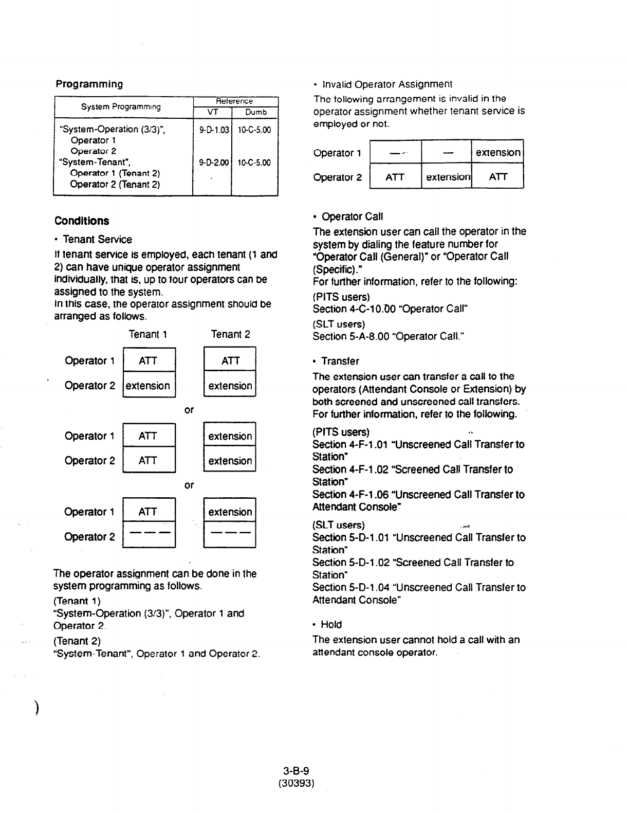
Programming
System Programmq Reference
VT / Dumb
“System-Operation (3/3)“,
Operator
1
Operator 2
“System-Tenant”,
Operator 1 (Tenant 2)
Operator 2 (Tenant 2)
9-D1.03 10-c-5.00
902.00 10-c-5.00
Conditions
l
Tenant Service
If tenant service is employed, each tenant (1 and
2) can have unique operator assignment
individually. that is, up
to
four operators can be
assigned to the system.
In this case, the operator assignment should be
arranged as follows.
Tenant
1
Tenant 2
Operator 1
Operator 2
The operator assignment can be done in the
system programming as follows.
(Tenant 1)
“System-Operation (3!3)“, Operator
1
and
Operator 2.
(PITS users) .\
Section 4-F-l .Ol “Unscreened Call Transfer to
Station”
&t;; 4-F-l .02 “Screened Call Transfer to
. ”
Section 4-F-l -06 “Unscreened Call Transfer to
Attendant Console”
(SLT users) ..ri
Section 5-D-l .Ol “Unscreened Call Transfer to
Station”
Section 5-D-l -02 “Screened Call Transfer to
Station”
Section 5-D-l .04 “Unscreened Call Transfer to
Attendant Console”
l
Hold
(Tenant 2) The extension user cannot hold a call with an
“System-Tenant”, Operator
1
and Operator 2. attendant console operator.
l
Invalid Operator Assignment
The following arrangement is invalid in the
operator assignment whether tenant service is
employed or not.
Operator
1
fi[
Operator 2 ATT
l
Operator Call
The extension user can call the operator in the
system by dialing the feature number for
“Operator Call (General)” or “Operator Call
(Specific) .”
For further information, refer to the following:
(PITS users)
Section 4-C-l 0.60 “Operator Call”
(SLT users)
Section 5-A-8.00 “Operator Call.”
l
Transfer
The extension user can transfer a call to the
operators (Attendant Console or Extension) by
both screened and unscreened call transfers.
For further information, refer to the following.
3-B-9
(30393)
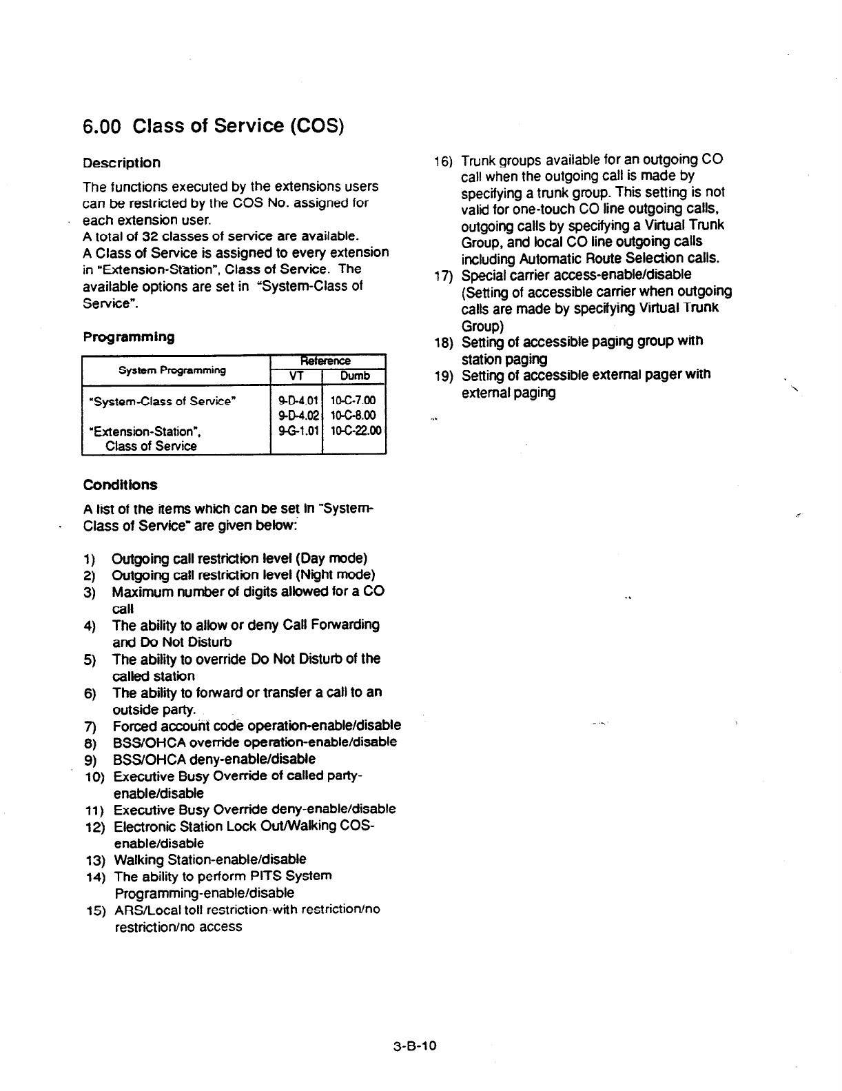
6.00
Class of Service (COS)
Description
16)
The functions executed by the extensions users
can be restricted by the COS No. assigned for
each extension user.
A total of 32 classes of service are available.
A Class of Service is assigned to every extension
in “Extension-Station”, Class of Service. The
available options are set in “System-Class of
Service”.
17)
Programming
18)
System Programming
“System-Class of Service”
“Extension-Station”,
Class of Service
Heference
VT Dumb
9-D-4.01
lo-c-7.00
9-D-4.02 1o-c-8.00
9-G-l .Ol lo-c-22.00
19)
Conditions
A list of the items which can be set in “System-
. Class of Service’ are given below!
1) Outgoing call restriction level (Day mode)
2) Outgoing call restrictiin level (Night mode)
3) Maximum number of digits allowed for a CO
call
4) The ability to allow or deny Call Forwarding
and Do Not Disturb
5) The ability to override Do Not Disturb of the
called station
6) The ability to forward or transfer a call to an
outside party.
7) Forced account code operation-enable/disable
8) BSS/OHCA override operation-enable/disable
9) BSS/OHCA deny-enable/disable
10) Executive Busy Override of called party-
enable/disable
restriction/no access
11) Executive Busy Override deny-enable/disable
12) Electronic Station Lock Out/Walking COS-
enable/disable
13) Walking Station-enable/disable
14) The ability to perform PITS System
Programming-enable/disable
15) ARS/Local toll restriction-with restriction/no
Trunk groups available for an outgoing CO
call when the outgoing call is made by
specifying a trunk group. This setting is not
valid for one-touch CO line outgoing calls,
outgoing calls by specifying a Virtual Trunk
Group, and local CO line outgoing calls
including Automatic Route Selection calls.
Special carrier access-enable/disable
(Setting of accessible carrier when outgoing
calls are made by specifying Virtual Trunk
Group)
Setting of accessible paging group with
station paging
Setting of accessible external pager with
external paging
‘\
. .
-.
3-B-l 0
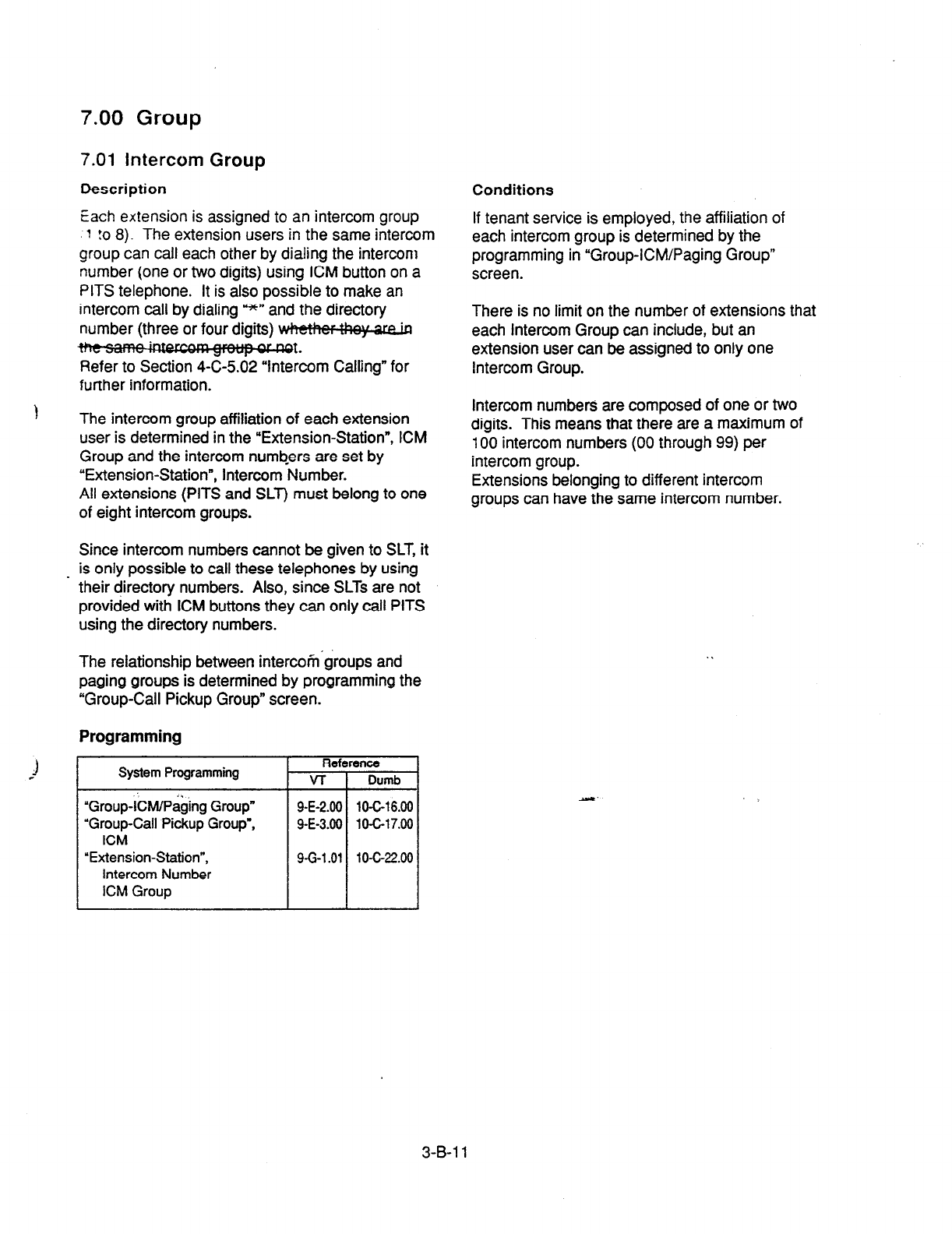
7.00 Group
7.01 Intercom
Group
Description
Conditions
Each extension
is assigned to an intercom group
‘1 !o 8). The extension users in the same intercom
group can call each other by dialing the intercom
number (one or two digits) using ICM button on a
PITS telephone. It is also possible to make an
intercom call by dialing u*” and the directory
number (three or four digits) B
vt*
Refer to Section 4-C-5.02 “Intercom Calling” for
further information.
If tenant service is employed, the affiliation of
each intercom group is determined by the
programming in “Group-ICM/Paging Group”
screen.
There is no limit on the number of extensions that
each Intercom Group can include, but an
extension user can be assigned to only one
Intercom Group.
1 The intercom group affiliation of each extension
user is determined in the “Extension-Station”, ICM
Group and the intercom numbers are set by
“Extension-Station”, Intercom Number.
All extensions (PITS and SLT) must belong to one
of eight intercom groups.
Intercom numbers are composed of one or two
digits. This means that there are a maximum of
100 intercom numbers (00 through 99) per
intercom group.
Extensions belonging to different intercom
groups can have the same intercom number.
Since intercom numbers cannot be given to SLT, it
_ is only possible to call these telephones by using
their directory numbers.
Also,
since SLTs are not
provided with ICM buttons they can only call PITS
using the directory numbers.
The relationship between intercom’groups and
paging groups is determined by programming the
‘Group-Call-Pickup Group” screen.
Programming
?
i
System Programming
UGroup-kl/P&q Group”
“Group-Call Pickup Group”,
ICM
“Extension-Station”,
Intercom Number
ICM Group
Reference
VI- Dumb
9-E-2.00 10-C-l 6.00
9-E-3.00 1 O-C-l 7.00
9-G-l .Ol 10-c-22.00
.I
-
3-B-1
1
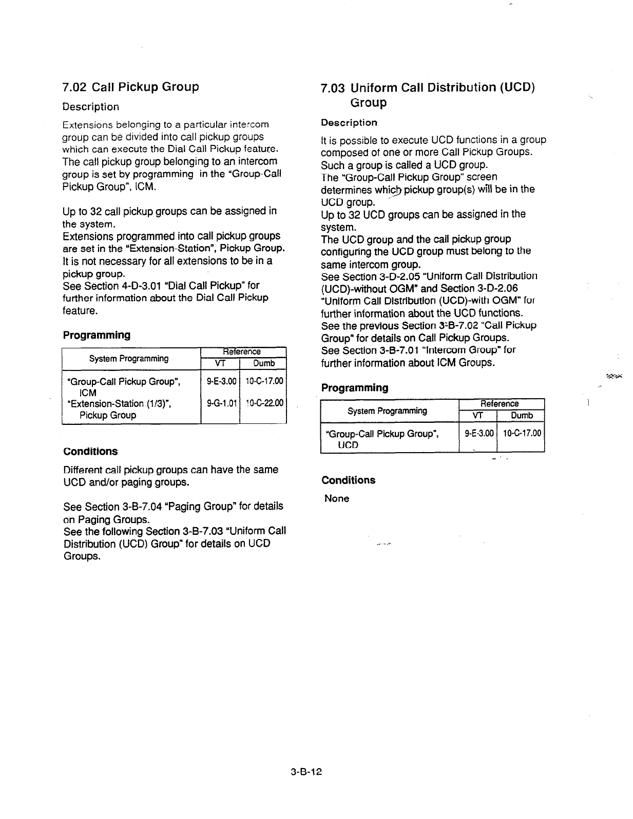
7.02 Call Pickup Group 7.03 Uniform Call Distribution (UCD)
Description
Group
Extensions belonging to a particular intercom
group can be divided into call pickup groups
which can execute the
Dial Call Pickup feature.
The call pickup group belonging to an intercom
group is set by programming in the “Group-Call
Pickup Group”, ICM.
Description
It is possible to execute
UCD
functions in a group
composed of one or more Call Pickup Groups.
Such a group is called a UCD group.
The “Group-Call Pickup Group” screen
determines whic.J pickup group(s) will be in the
UCD group. A
Up to 32 UCD groups can be assigned in the
system.
The UCD group and the call pickup group
configuring the UCD group must belong to the
same intercom group.
See Section 3-D-2.05 “Uniform Call Distribution
(UCD)-without OGM” and Section 3-D-2.06
“Uniform Call Distribution (UCD)-with OGM” for
further information about the UCD functions.
See the previous Section 3:B-7.02 “Call Pickup
Group” for details on Call Pickup Groups.
See Section 3-B-7.01 “Intercom Group” for
further information about ICM Groups.
Up to 32 call pickup groups can be assigned in
the system.
Extensions programmed into call pickup groups
are set in the “Extension-Station”, Pickup Group.
It is not necessary for all extensions to be in a
pickup group.
See Section 4-D-3.01 “Dial Call Pickup” for
further information about the Dial Call Pickup
feature.
Programming
.~~I Programming
System Programming Reference
VT 1 Dumb
Conditions
Different call
pickup
groups can have the same
UCD and/or paging groups.
See Section 3-B-7.04 “Paging Group” for details
on Paging Groups.
See the following Section 3-B-7.03 “Uniform Call
Distribution (UCD) Group” for details on UCD
Groups.
“Group-Call Pickup Group”,
UCD
1 9-E-3.00 1
10-C-17.00 (
Conditions
None
3-B-12

7.04 Paging
Group
Description Description
It IS F;ssible :a execure paging functions in a
grol;p
composed of one or more pickup
groups.
Such a group IS called a “Paging Group.”
Up to eight paging groups can be assigned in the
system.
When Tenant Service is employed, the “Group-
ICM/Paging Group” screen sets which tenant the
paging group belongs to.
The ‘Group-Call Pickup Group” screen sets
which pickup group(s) make up a paging group.
To
suppon efficient utilization of trunks, they can
be grouped together (up to 16 groups) if all
trunks in the group perform the same function.
The following six kinds of trunk groups can be
assigned in the system.
The items listed below are set in the “Group-
Trunk Group” screen.
Programming
(4
@I
(c)
(d)
(e)
1 f)
19)
(h)
;;;
(k)
(1)
I;)
(0)
(P)
(4)
(0
(9
0)
Trunk group type
Trunk group name
Tenant selection
Trunk group direction
Incoming destination (Day)
Incoming destination (Night)
Intercept Routing (Day)
Intercept Routing (Night)
Toll restriction level
Toil restriction table
Dialing plan selection
Disconnect time selection
Pause time selection
Hookswitch flash time selection
DID digit modification table selection
Entry of PBX access code (No restriction)
Entry of PBX access
code (Restriction)
Restriction
time on CO-CO calls
DIL (I:N) destination
Maximum number of digits after External
Feature Access
CO appearance type
System Programming Reference
VT 1 Dumb
Conditions
If tenant service is employed, pickup groups
which can be used to configure a paging group
are limited,within the same tenant.
See Section 4-H-l .OO “Paging” for further
information about paging features.
7.05 Trunk Group
(u)
The “Trunk-CO Line”, Trunk Group determines
which trunk group the CO line belongs to.
Programming
System Programming Referenoe
VT Dumb
“Group-Trunk Group”
g-E-1.01 lO-CL14.00
g-E-1.02 10-C-15.00
“Trunk-CO Line”. Trunk Grow 9-F-1.00
10-C-18.00
Conditions
A single CO line cannot belong to more than one
trunk
group.
3-B-l 3
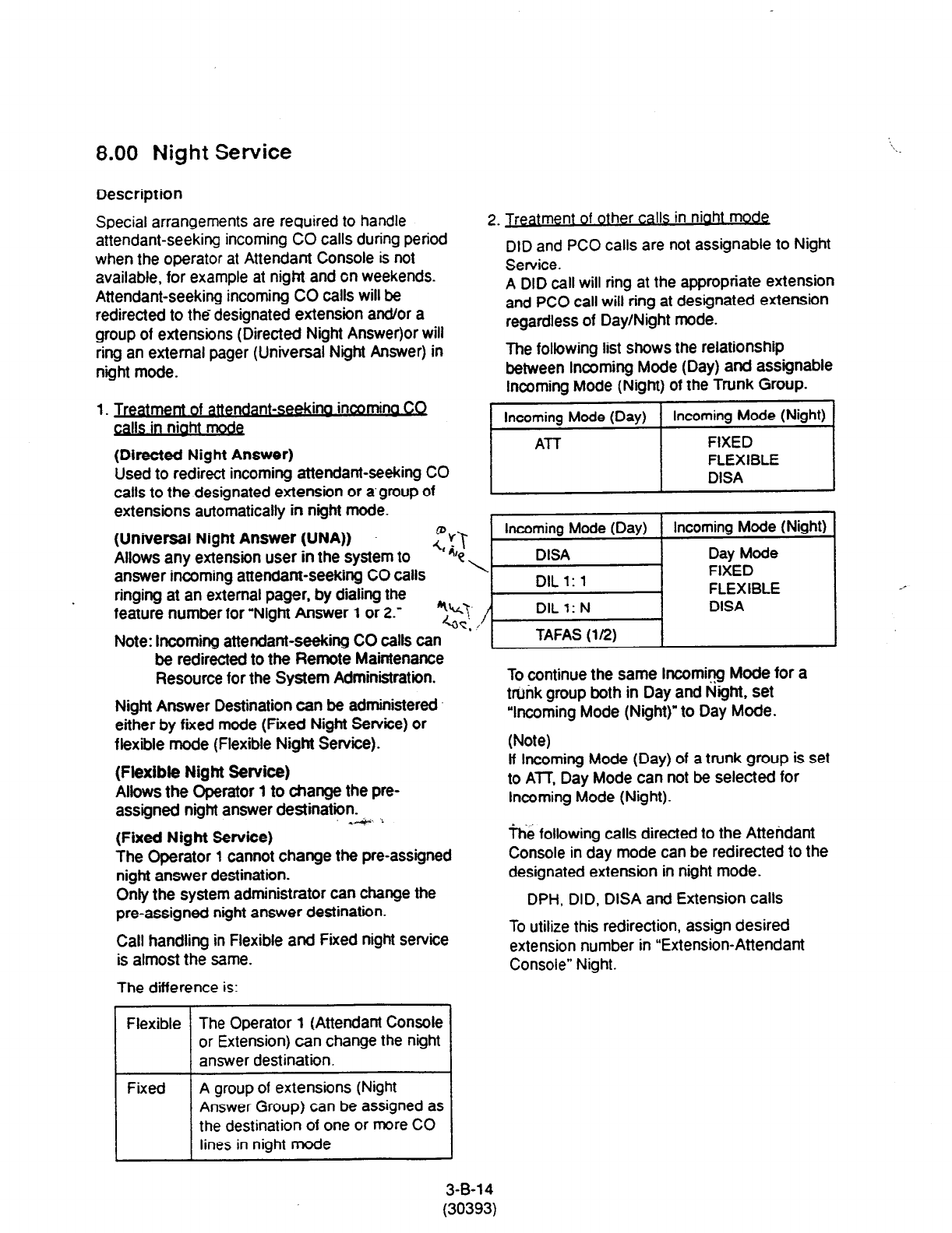
8.00 Night Service
Description
Special arrangements are required to handle
attendant-seeking incoming CO calls during period
when the operator at Attendant Console is not
available, for example at night and on weekends.
Attendant-seeking incoming CO calls will be
redirected to the designated extension an&or a
group of extensions (Directed Night Answer)or will
ring an external pager (Universal N.ght Answer) in
night mode.
1. Treatment of attendant-seekina incomina
CQ
calls in niaht mode
(Directed Night Answer)
Used to redirect incoming attendant-seeking CO
calls to the designated extension or a group of
extensions automatically in night mode.
(Universal Night Answer (UNA)) Erl
2. Treatment of other calls in niaht mode
DID and PC0 calls are not assignable to Night
Service.
A DID call will ring at the appropriate extension
and PC0 call will ring at designated extension
regardless of Day/Night mode.
The following list shows the relationship
between incoming Mode (Day) and assignable
Incoming Mode (Night) of the Trunk Group.
/ lhcomini Mode (Day) 1 IhCOg (Night) /
Allows any extension user in the system to
Incoming Mode (Day) Incoming Mode (Night)
DISA Day Mode
answer incoming attendant-seeking CO calls
ringing at an external pager. by dialing the
feature number for “Night Answer 1 or 2.” i-lI$Fi EFB~E / ;
Note: Incoming attendant-seeking CO calls can
be redirected to the Remote Maintenance
Resource for the System Administration. To continue the same Incoming Mode for a
Night Answer Destination can be administered trunk group both in Day and Night, set
either by fifed mode (Fixed Night Se&e) or “Incoming Mode (Night)” to Day Mode.
flexible mode (Flexible Night Service). (Note)
(Flexible Night Service) if Incoming Mode (Day) of a trunk group is set
Allows the Operator 1 to change the pre- to ATT, Day Mode can not be selected for
assigned night answer destination- Incoming Mode (Night).
-4. ,,
(Fixed Night Service)
The Operator 1 cannot change the pre-assigned
night answer destination.
Only the system administrator can change the
pre-assigned night answer destination.
Call handling in Flexible and Fixed night service
is almost the same.
The difference is:
The following calls directed to the Attendant
Console in day mode can be redirected to the
designated extension in night mode.
DPH, DID, DISA and Extension calls
To utilize this redirection, assign desired
extension number in “Extension-Attendant
Console” Night.
Flexible The Operator 1 (Attendant Console
or Extension) can change the night
answer destination.
Fixed A group of extensions (Night
Answer Group) can be assigned as
the destination of one or more CO
lines in night mode
3-B-l 4
(30393)

8.01 Directed Night Answer
3. Switchina of DaviNioht Mode
It is assignable to switch Day/Night mode either
automatically at pre-assigned time or manually
by the Operator 1 (Attendant Console or
Extension User)
at
any time desired.
(Automatic Switching)
The system willswitch the day and night modes
at the programmed time automatically each day.
(Manual Switching)
Operator 1 can switch the Day/Night mode at
desired time.
(Supplement)
The following programming items may be
assigned in a different way between day mode
and night mode.
l
“System-Class of Service”
Toll Restriction Level (Day)
Toll Restriction Level (Night)
(Refer to Section 9-D-4.01 “Class of
Service (l/2).“)
l
“Group-Trunk Group”
incoming Mode (Day)
Incoming Mode (Night)
Intercept Routing (Day)
Intercept Routing (Night)
(Refer to Section 9-E-l .Ol “Trunk Group
(W.“)
l
“Extension-Station”
Day Ring
Night Ring
(Refer to Section 9-G-l -02 “Station (B).“)
Description
Lrsec ;o redirect Incoming attendant-seeking CO
calls to !?e designated extension or a group of
extensor& (Night
Answer
Group) automatically in
nght moue.
To activate
this feature, set “Group-Trunk
Group”
Incoming Mode (Night) to FIXED or FLEXIBLE
and “Trunk-CO Line” Night
Answer Point to EXT:
xxxx or NAG (Night
Answer Group).
Night Answer Group
A single group of extensions (called the Night
Answer Group) can be created to receive Calls at
night.
Calls from more than one CO line may arrive at
this group.
The size
limit of the group is 32 extensions.
co1 co2 co3
v
Night Answer Group
To utilize this feature, program as follows.
1. Assign “Group-Trunk Group” Incoming Mode
(Night) to “FIXED.”
2. Assign ‘Trunk-CO Line” Night Answer Point to
“NAG.”
This CO line must belong to the Trunk Group
whose Incoming Mode (Night) is assigned to
FIXED.
3. Assign the DN of the destination extensions
by using NAG command.
3-B-15
(30393)
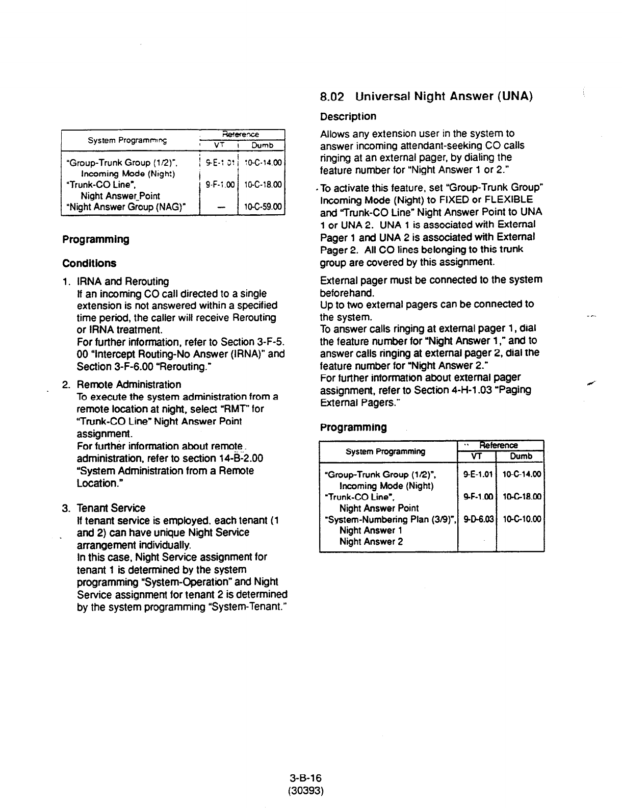
System Programmrg
:0-c-14.00
lG-C-18.00
10-G59.00
Programming
Conditions
1.
RNA and Rerouting
lf an incoming CO call directed to a single
extension is not answered within a specified
time period, the caller will receive Rerouting
or IRNA treatment.
For further information, refer to Section 3-F-5.
00 “Intercept Routing-No Answer (IRNA)” and
Section 3-F-6.00 “Rerouting.”
2. Remote Administration
To execute the system administration from a
remote location at night, select “RMT” for
“Trunk-CO Line” Night Answer Point
assignment.
For further information about remote,.
administration, refer to section 14-B-2.00
“System Administration from a Remote
Location .”
3. Tenant Service
If tenant service is employed, each tenant (1
. and 2) can have unique Night Service
arrangement individually.
In this case, Night Service assignment for
tenant 1 is determined by the system
programming “System-Operation” and Night
Service assignment for tenant 2 is determined
by the system programming “System-Tenant.”
8.02 Universal Night Answer (UNA)
Description
Allows any extension user in
the system to
answer incoming attendant-seeking CO calls
ringing at an external pager, by dialing the
feature number for “Night Answer 1 or 2.”
. To activate this feature, set “Group-Trunk Group”
Incoming Mode (Night) to FIXED or FLEXIBLE
and “Trunk-CO Line” Night Answer Point to UNA
1 or UNA 2. UNA 1 is associated with External
Pager 1 and UNA 2 is associated with External
Pager 2. All CO lines belonging to this trunk
group are covered by this assignment.
External pager must be connected to the system
beforehand.
Up to two external pagers can be connected to
the system.
To answer calls ringing at external pager 1, dial
the feature number for “Night Answer 1,” and to
answer calls ringing at external pager 2, dial the
feature number for “Night Answer 2.”
For further information about external pager
assignment, refer to Section 4-H-l .03 “Paging
External Pagers.”
Programming
System Programming
“Group-Trunk Group
(1 R)“,
Incoming
Mode (Night)
“Trunk-CO
Line”,
9-F-1 .OO lOG18.00
Night Answer Point
‘System-Numbering Plan (319) 9-D-6.03 10-G10.00
Night Answer 1
Night Answer 2
3-B-l 6
(30393)

Conditions
1. UNA and TAFAS
Call handling in UNA is identical to TAFAS.
The difference is that TAFAS is available in
day mode and UNA is available in night
mode.
For further information about TAFAS, refer to
Section 4-D-4.00 “Trunk Answer From Any
Station (TAFAS)-Day Service.”
2. IRNA and Rerouting
If incoming CO calls are not answered for any
reason within a specified time period, the
caller will receive Rerouting or IRNA
treatment.
For further information, refer to section 3-F-6.
00 “Rerouting” and Section 3-F-5.00
“Intercept Routing-No Answer (IRNA).”
3. Remote Administration
To execute the system administration from a
remote location at night, select “RMT” for
‘Trunk-CO Line” Night Answer Point
assignment.
For further information about remote
administration, refer to Section 14-B-2.00
“System Administration from a Remote
Location.”
4. Tenant Service
If tenant service is employed, each tenant (1
and 2) can have a unique Night Service
arrangement individually.
The affiliation pf each external pager is
determined by the system programming in
‘Trunk-Pager & Music Source”, External
Pager- Tenant.
Extension users cannot answer the UNA calls
ringing at an external pager in the diierent
tenant.
Operation
Refer to the following:
(PITS) Section 4-l-l .Ol “Universal Night
Answer (UNA)”
(SLT) Section 5-G-l .Ol “Universal Night
Answer (UNA)”
8.03 Flexible Night Service
DescriptBon
Flex&e
Kqn:
Service allows the Operator 1
(AttendaT Console or Extension user) to change
the assignea night answer destination on a CO
line bavs cy dialing the feature number for
“Flexibie Night Service.”
To utilize this feature, set “Group-Trunk Group”
Incoming Mode (Night) to FLEXIBLE. All CO
lines which belong to this trunk group are
covered by this assignment.
If FIXED is selected for the above setting, the
assigned night answer destination can not be
changed by the Operator l_
Call handling in Flexible and Fixed night service
is almost the same.
The difl erence is:
Flexible I The Operator 1 (Attendant Console
I
or Extension) can change the night
answer destination.
Fixed ’ A group of extensions (Night
Answer Group) can be assigned as
the destination of one or more CO
, lines in night mode
Programming
System Programming
“Group-Tank Group (l/2)“.
IncomIng Mode (Night)
“Trunk-CO Line”,
Night Answer Point
“System-Numbering Plan (8/9)”
Flexibia Night Service
Conditions
Tenant Service
. .
Refc
VT
SE-1 .Ol
SF-l.00
SO608
once
Dumb
lo-c-14.00
10-C-18.00
1o-G10.00
If tenant service is employed, the night answer
destination for a CO line can only be changed by
the Operator 1 in the same tenant.
Operation
For the operation of changing the Night Answer
destination. refer to the following:
(PITS) Section 4-l-l .02 “Flexible Night Service”
(SLT) Section 5-G-l .02 “Flexible Night Service”
(ATT) Section 6-J-l .Ol “Flexible Night Service”
3-B-l 7
(30393)

8.04 Fixed Night
Service
Description Programming
Call handling in Flexrble ano Fixed nqnl seryce is
almost the same.
The difference is:
1
Reference
System Programming VT Dumb
Flexible The Operator 1 (Attendant Console
or Extension) can change the nqht
answer destination.
Fixed A group of extensions (Night
Answer Group) can be assigned as
the destination of one or more CO
lines in night mode
If FIXED is selected, the assigned night answer
destination can not be changed by the Operator
1.
To utilize this feature, set “Group-Trunk Group”
Incoming Mode (Night) to “FIXED.” All CO lines
belong to this trunk group are covered by this
assignment.
. Night Answer Group
A single group of extensions (called the Night
Answer Group) can be created to receive calls at
night.
Calls from more than one CO line may arrive at
this group.
The size limit of the group is 32 extensions.
Night Answer Group
To utilize this feature, program as follows.
I Assign “Group-Trunk Group” Incoming Mode
(Night) to “FIXED.”
2. Assign “Trunk-CO Line” Night Answer Point to
“NAG.”
This CO line must belong to the Trunk Group
whose Incoming Mode (Night) is assigned to
FIXED.
3. Assign the DN of the destination extensions by
using NAG command.
Conditions
None
Operation
None
3-B-17-1
(30393)
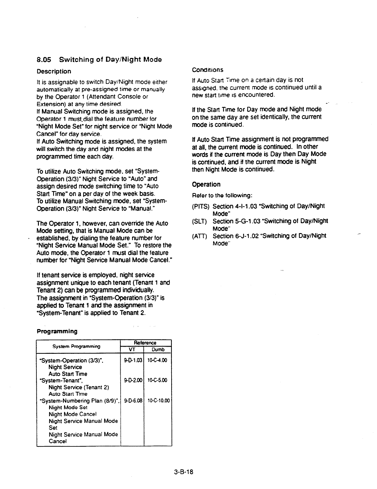
8.05 Switching of Day/Night Mode
Description
It is assignable to switch Day/Night mode either
automatically at pre-assigned time or manually
by the Operator 1 (Attendant Console or
Extension) at any time desired.
If
Manual Switching mode is assigned, the
Operator 1 must-dial the feature number for
“Night Mode Set” for night service or “Night Mode
Cancel” for day service.
If Auto Switching mode is assigned, the system
will switch the day and night modes at the
programmed time each day.
To utilize Auto Switching mode, set “System-
Operation (s/3)” Night
Service to “Auto” and
assign desired mode switching time to “Auto
Start Time” on a per day of the week basis.
To utilize Manual Switching mode, set “System-
Operation (3/3)” Night Service to “Manual.”
The Operator 1, however, can override the Auto
Mode setting, that is Manual Mode can be
. established, by dialing the feature number for
“Night Service Manual Mode Set.” To restore the
Auto mode, the Operator 1 must dial the feature
number for “Night Service Manual Mode Cancel.”
If tenant service is employed, night service
assignment unique to each tenant (Tenant 1 and
Tenant 2) can be programmed individually.
The assignment in “System-Operation (33)” is
applied to Tenant 1 and the assignment in
“System-Tenant” is applied to Tenant 2.
Programming
System Programming Reference
VT Dumb
‘System-Operation (3/3)“. 9431.03
lo-t-4.00
Night Service
Auto
Start Ttme
“System-Tenant”, 9-D-2.00 10-c-5.00
Night Service (Tenant 2)
Auto Stan Time
“System-Numbering Plan (8/9)“. SD6.08
la-10.00
Night Mode Set
Night Mode Cancel
Night Service Manual Mode
Set
Night Service Manual Mode
Cancel
Conditions
If Auto
Stan Tvme on a certain day is not
assigned. the current mode fs continued until a
new stat7 time Is encountered. --
If the Start Ttme for
Day mode and Night mode
on the same day are set identically, the current
mode is continued.
lf Auto Start Time assignment is not programmed
at all, the current mode is continued. In other
words ii the current mode is Day then Day Mode
is continued, and if the current mode is Night
then Night Mode is continued.
Operation
Refer to the following:
(PITS) Section 4-l-l -03 “Switching of Day/Night
Mode”
(SLT) Section 5-G-l .03 “Switching of Day/Night
Mode”
(ATT) Section 6-J-l .02 “Switching of Day/Night
Mode”
3-B-l 8
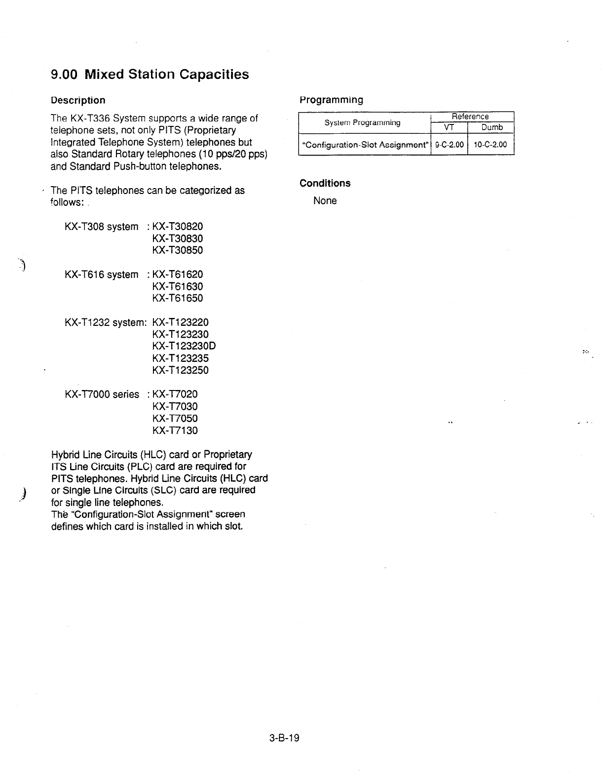
9.00 Mixed Station Capacities
Description
The KX-T336 System supports a wide range of
telephone sets, not only PITS (Proprietary
Integrated Telephone System) telephones but
also Standard Rotary telephones (10 pps/20 pps)
and Standard Push-button telephones.
Programming
System Programming Reference
VT
Dumb
“Configuration-Slot Assignment” 9-C-2.00 10-C-2.00
. The PITS telephones can be categorized as
!ollows:
Conditions
None
KX-T308 system : KX-T30820
KX-T30830
KX-T30850
KX-T616 system : KX-T61620
KX-T61630
KX-T6 1650
KX-T1232 system: KX-T123220
KX-Tl23230
KX-T123230D
KX-T123235
KX-Tl23250
KX-T7000 series : KX-T7020
KX-T7030
KX--I7050
KX-l7130
Hybrid Line Circuits (HLC) card or Proprietary
ITS tine Circuits (PLC) card are required for
PITS
telephones. Hybrid tine Circuits (HLC) card
or Single Line Circuits (SLC) card are required
for single line telephones.
ThB “Configuration-Slot Assignment” screen
defines which card is installed in which slot.
3-B-l 9
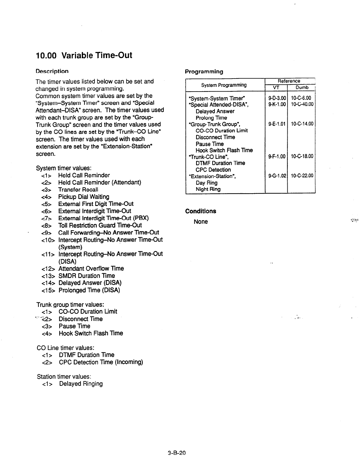
10.00 Variable Time-Out
Description Programming
The timer values listed below can be set and
changed in system programming.
Common system timer values are set by the
“System-System Timer” screen and ‘Special
Attendant-DISA” screen. The timer values used
with each trunk group are set by the “Group-
Trunk Group” screen and the timer values used
by the CO lines are set by the “Trunk-CO Line”
screen. The timer values used with each
extension are set by the “Extension-Station”
screen.
System timer values:
<l> Held Call Reminder
<2> Held Call Reminder (Attendant)
~3s Transfer Recall
c4> Pickup Dial Waiting
<5> External First Digit Trme-Out
<6> External Interdigit Time-Out
c7> External Interdigit Time-Out (PBX)
<8> Toll Restriction Guard Time-Out
<9> Call Forwarding-No Answer Time-Out
~10~
Intercept Routing-No Answer Time-Out
(System)
~11s Intercept Routing-No Answer Time-Out
(DISA)
~12s Attendant Overflow Time
cl 3> SMDR Duration Time
<14>
Delayed Answer (DISA)
~15 Prolonged Time (DISA)
Trunk group timer values:
cl> CO-CO Duration Limit
“.X2> Disconnect Time
~3s Pause Time
<4> Hook Switch Flash Time
CO Line timer values:
cl> DTMF Duration Time
<2> CPC Detection Time (Incoming)
r
System Programming
“System-System Timer”
“Special Attended-DIM”,
Delayed Answer
Prolong Time
“Group-Trunk Group”,
CO-CO Duration Limit
Disconnect Time
Pause Time
Hook Switch Flash Time
“Trunk-CO Line”,
DTMF Duration lime
,CPC Detection
‘Extension-Station”,
Day Ring
Night Ring
Reference
v-r Dumb
9-D-3.00 1 O-C-6.00
9-K-l 90 1 O-C-40.00
9-E-l .Ol 10-C-t 4.00
9-F-l .OO 10-C-18.00
9-G-l .02 1 O-G22.00
Conditions
None
Station timer values:
cl
> Delayed
Ringing
3-B-20
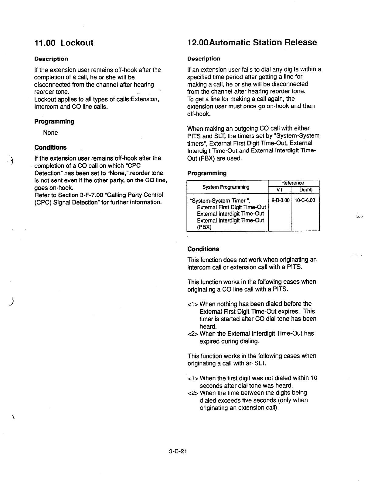
11 .OO Lockout 12.00Automatic Station Release
Description
If the extension user remains off-hook after the
completion of a call, he or she will be
disconnected from the channel after hearing
reorder tone. .I
Lockout applies to all types of calls:Extension,
Intercom and CO line calls.
Description
If an extension user fails to dial any digits within a
specified time period after getting a line for
making a call, he or she will be disconnected
from the channel after hearing reorder tone.
To get a line for making a call again, the
extension user must once go on-hook and then
off-hook.
Programming
None
Conditions
If the extension user remains off-hook after the
completion of a CO call on which “CPC
Detection” has been set to “None,“-reorder tone
is not sent even if the other party, on the CO line,
goes on-hook.
Refer to Section 3-F-7.00 “Calling Party Control
(CPC) Signal Detection” for further information.
When making an outgoing CO call with either
PITS and SLT, the timers set by “System-System
timers”, External First Digit Tme-Out, External
Interdigit Time-Out and External Interdigit Time-
Out (PBX) are used.
Programming
Reference
System Programming VT Dumb
“System-System Timer n, 9-D-3.00 10-c6.00
External First Digit
Time-Out
External Interdigit
Time-Out
External Interdigit
Time-Out
F’W
Conditions
This function does not work when originating an
intercom call or extension call with a PITS.
This function works in the following cases when
originating a CO line call with a PITS.
cl> When nothing has been dialed before the
External First Digit
Time-Out
expires. This
timer is started after ‘CO dial tone has been
heard.
c2> When the External Interdigit Time-Out has
expired during dialing.
This function works in the following cases when
originating a call with an SLT.
4 > When the first digit was not dialed within 10
seconds after dial tone was heard.
c2> When the time between the digits being
dialed exceeds five seconds (only when
originating an extension call).
3-B-21
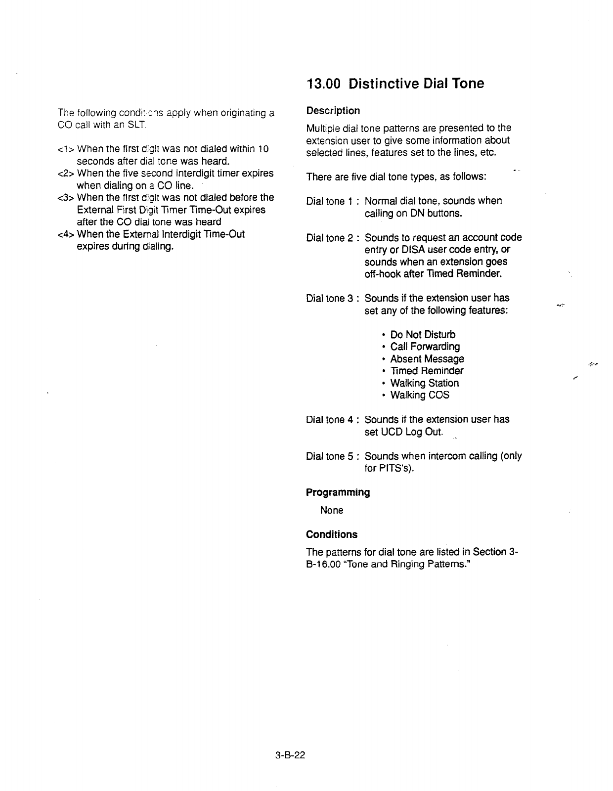
13.00 Distinctive Dial Tone
The following condi: ens apply when originating a
CO call with an SLT.
cl> When the first digit was not dialed within 10
seconds after dial tone was heard.
c2> When the five second interdigit timer expires
when dialing on a CO line.
<3> When the first digit was not dialed before the
External First Digit Timer Time-Out expires
after the CO diai tone was heard
c4>
When the External Interdigit Time-Out
expires during dialing.
Description
Multiple dial tone patterns are presented to the
extension user to give some information about
selected lines, features set to the lines, etc.
There are five dial tone types, as follows:
Dial tone 1 : Normal dial tone, sounds when
calling on DN buttons.
Dial tone 2 : Sounds to request an account code
entry or DISA user code entry, or
sounds when an extension goes
off-hook after Timed Reminder.
Dial tone 3 : Sounds if the extension user has
set any of the following features:
l
Do Not Disturb
l
Call Forwarding
l
Absent Message
l
Timed Reminder
l
Walking Station
l
Walking COS
Dial tone 4 : Sounds if the extension user has
set UCD Log Out. .I
Dial tone 5 : Sounds when intercom calling (only
for PITS’s).
Programming
None
Conditions
The patterns for dial tone are listed in Section 3-
B-l 6.00 “Tone and Ringing Patterns.”
3-B-22
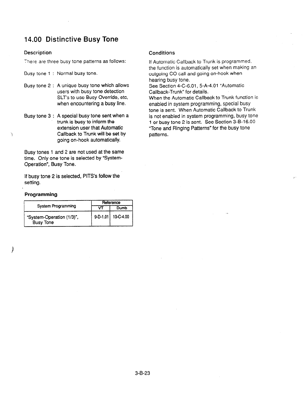
14.00 Distinctive Busy Tone
Description Conditions
There are three busy tone patterns as follows: If Automatic Callback to Trunk is programmed.
the function is automatically set when making an
outgoing CO call and going on-hook when
hearing busy tone.
See Section 4-C-6.01, 5-A-4.01 “Automatic
Callback-Trunk” for details.
When the Automatic Callback to Trunk function is
enabled in system programming, special busy
tone is sent. When Automatic Callback to Trunk
is not enabled in system programming, busy tone
1 or busy tone 2 is sent. See Section 3-B-16.00
“Tone and Ringing Patterns” for the busy tone
patterns.
Busy tone 1 : Normal busy tone.
Busy tone 2 : A unique busy tone which allows
users with busy tone detection
SLT’s to use Busy Override, etc,
when encountering a busy line.
Busy tone 3 : A special busy tone sent when a
trunk is busy to inform the
extension user that Automatic
Callback to Trunk will be set by
going on-hook automatically.
Busy tones 1 and 2 are not used at the same
time. Only one tone is selected by “System-
Operation”, Busy Tone.
If busy tone 2 is selected, PITS’s follow the
setting.
Programming
System
Programming
Reference
VT I Dumb
“System-Operation (l/3)“,
Busv Tone / 9-D-1.01 / 10-C-4.00 1
3-B-23
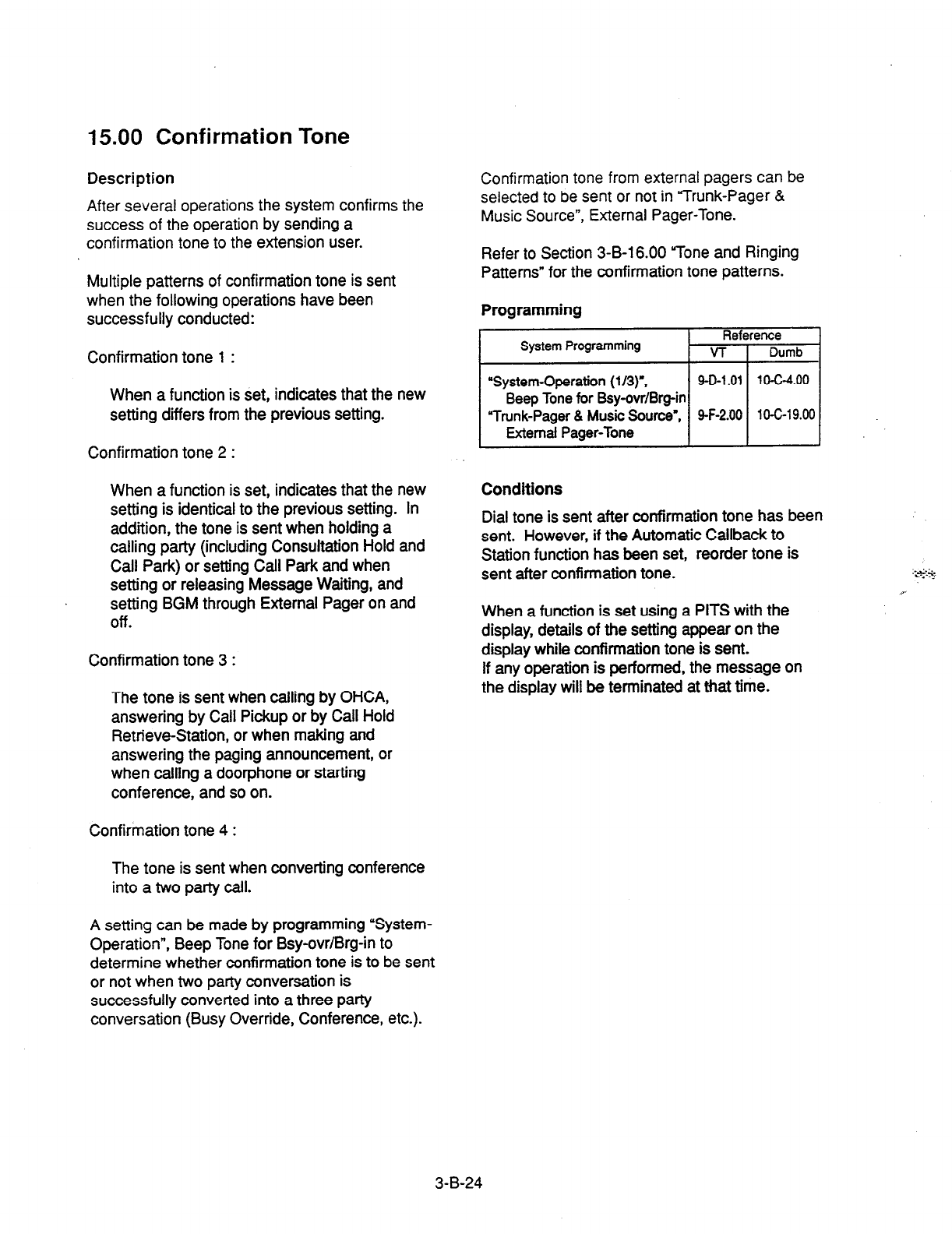
15.00 Confirmation Tone
Description
After several operations the system confirms the
success of the operation by sending a
confirmation tone to
the
extension user.
Multiple patterns of confirmation tone is sent
when the following operations have been
successfully conducted:
Confirmation tone
1 :
When a function is set, indicates that the new
setting differs from the previous setting.
Confirmation tone 2 :
When a function is set, indicates that the new
setting is identical to the previous setting. In
addition, the tone is sent when holding a
calling party (including Consultation Hold and
Call Park) or setting Call Park and when
setting or releasing Message Waiting, and
setting BGM through External Pager on and
Off.
Confirmation tone 3 :
The tone is sent when calling by OHCA,
answering by Call Pickup or by Call Hold
Retrieve-Station, or when making and
answering the paging announcement, or
when calling a doorphone or starting
conference, and so on.
Confirmation tone 4 :
The tone is sent when converting conference
into a two party call.
A setting can be made by programming “System-
Operation”, Beep Tone for Bsy-ovr/Brg-in to
determine whether confirmation tone is to be sent
or not when two party conversation is
successfully converted into a three party
conversation (Busy Override, Conference, etc.).
Confirmation tone from external pagers can be
selected to be sent or not in “Trunk-Pager &
Music Source”, External Pager-Tone.
Refer to Section 3-B-16.00 “Tone and Ringing
Patterns” for the confirmation tone patterns.
Programming
Reference
System Programming VT Dumb
“System-Operation
(l/3)‘,
9-D-l .Ol 1o-c-4.00
Beep Tone for Bsy-cvr/Brg-in
Trunk-Pager & Music Source”, 9-F-2.00 1 O-C-l 9.00
External Pager-Tone
Conditions
Dial tone is sent after confirmation tone has been
sent. However, if the Automatic Callback to
Station function has been set, reorder tone is
sent after confirmation tone.
When a function is set using a PITS with the
display, details of the setting appear on the
display while confirmation tone is sent.
If
any operation is performed, the message on
the display will be terminated at that time.
3-B-24

16.00 Tone and Ringing Patterns
Description
-i ^ ^, _. . -
s ,*a> sf>\=.., cffe:s ~arioc;s tone patterns and
ringirc xtle:“5 2-r
listed below:
Tone Patterns
Busy tone 1
Busy tone 2
Busy tone 3
Reorder tone
L I I I
Ringback tone i I 1 . .
I
i
I I
Do Not Disturb (DND) 711
tone pn l-l
ill l-l
I
1
1
1
I I I I I I
I I I , I
Confirmation tone 1 I I I I I
1 I I t I
,
Confirmation tone 2
I I / I i I
Confirmation tone 3
Confirmation tone 4
Warning tone
CO-CO timeout
warning tone I I I L I /
I t I I
Held Call Reminder !-I I I I
21: : P /
1
I I
3-B-25
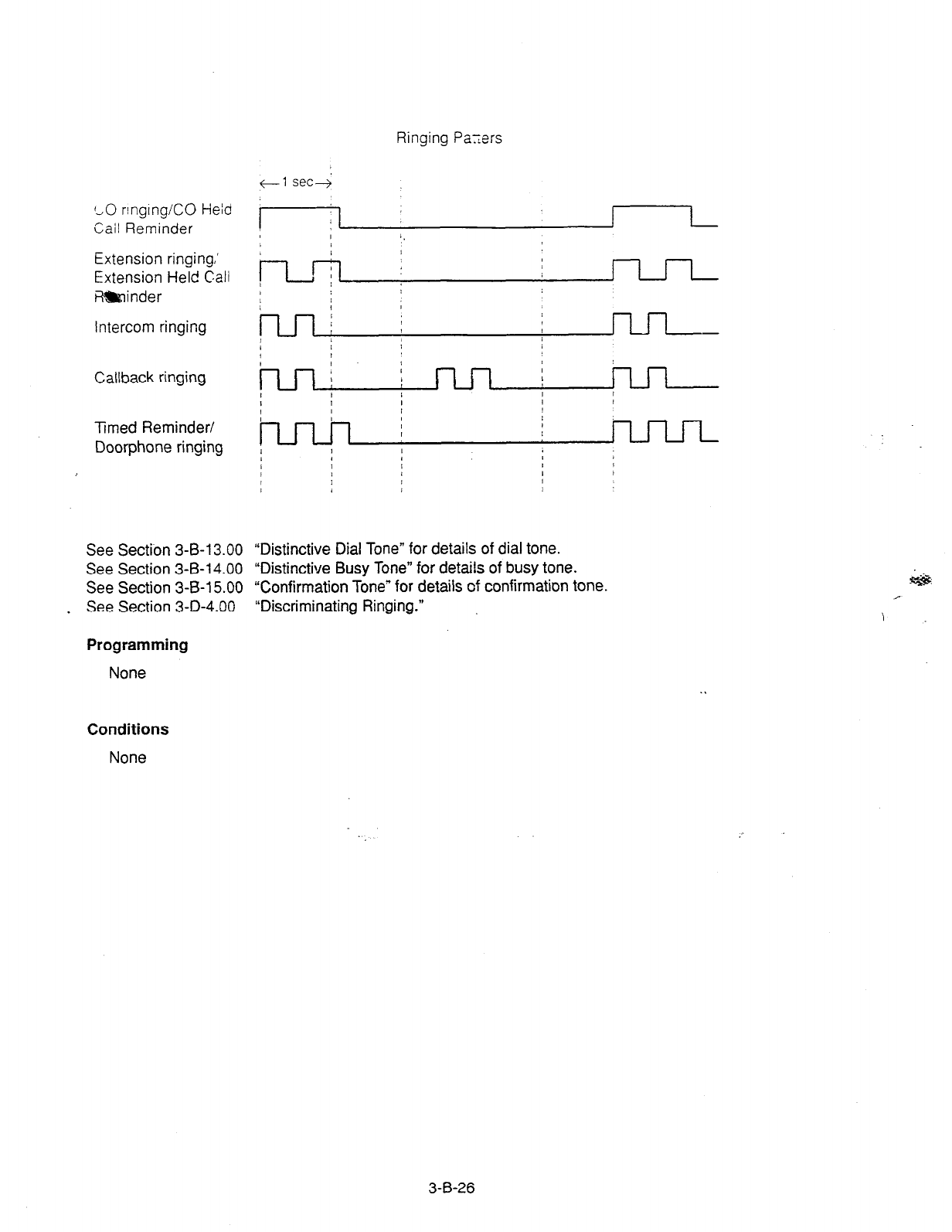
Ringing Payers
+-1 secj
LO rlnglng/CO Held
Cail
Reminder
Extension ringing,’
Extension Held
Call
R!&inder
intercom ringing
Callback ringing
Timed Reminder/
Doorphone ringing
See Section 3-B-l 3.00
See Section 3-B-l 4.00
See Section 3-B-l 5.00
. See Section 3-D-4.00
Programming
None
“Distinctive Dial Tone” for details of dial tone.
“Distinctive Busy Tone” for details of busy tone.
“Confirmation Tone” for details of confirmation tone.
“Discriminating Ringing.”
Conditions
None
3-B-26
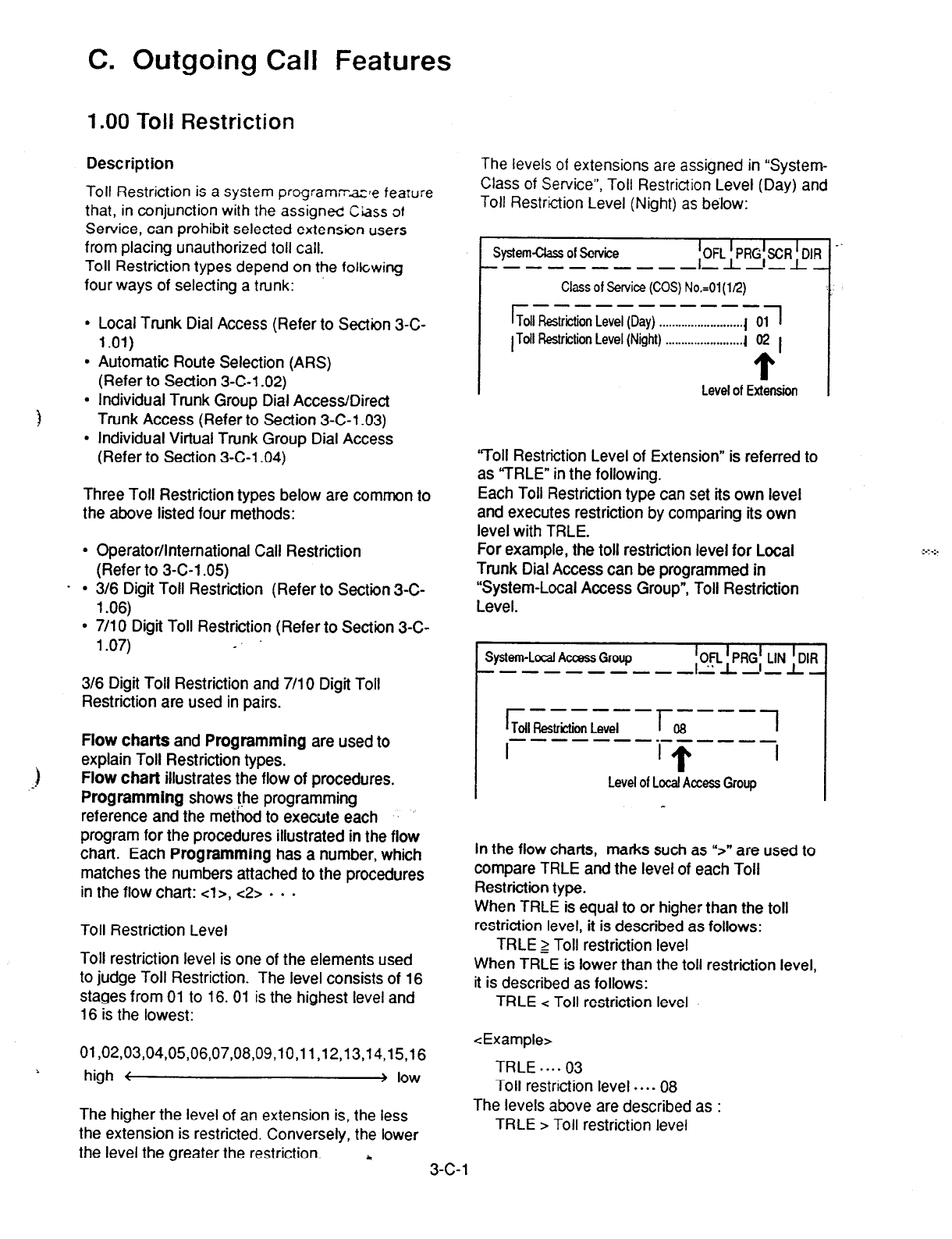
C. Outgoing Call Features
1 .OO Toll Restriction
Description
Toll Restriction is a system program;razle fearure
that, in conjunction with the assign& Ciass of
Service, can prohibit selected extension users
from placing unauthorized toll call.
Toll Restriction types depend on the following
four ways of selecting a trunk:
. Local Trunk Dial Access (Refer to Section 3-C-
l .Ol)
l
Automatic Route Selection (ARS)
(Refer to Section 3-C-l .02)
1
l
Individual Trunk Group Dial Access/Direct
Trunk Access (Refer to Section 3-C-l -03)
l
Individual Virtual Trunk Group Dial Access
(Refer to Section 3-C-l .04)
Three Toll Restriction types below are common to
the above listed four methods:
l
Operator/International Call Restriction
(Refer to 3-C-l .05)
. . 3/6 Digit Toll Restriction (Refer to Section 3-C-
l .06)
l
7/l 0 Digit Toll Restriction (Refer to Section 3-C-
l .07) _
3/6 Digit Toll Restriction and 7/l 0 Digit Toll
Restriction are used in pairs.
1
--
Flow charts and Programming are used to
explain Toll Restriction types.
Flow chart illustrates the flow of procedures.
Programming shows !be programming
reference and the method to execute each .: ..
program for the procedures illustrated in the flow
chart. Each Programming has a number, which
matches the numbers attached to the procedures
in the flow chart: cl>, c2> . . .
Toll Restriction Level
Toll restriction level is one of the elements used
to judge Toll Restriction. The level consists of 16
stages from 01 to 16. 01 is the highest level and
16 is the lowest:
3-c-1
01,02,03,04,05,06,07,08,09,10,11,12,13,14,15,16
% high i > low
The higher the level of an extension is, the less
the extension is restricted. Conversely, the lower
the level the greater the restriction. c
The levels of extensions are assigned in “System-
Class of Service”, Toll Restriction Level (Day) and
Toll Restriction Level (Night) as be’low:
System& of Service ;OFL~R+CR+lR
----s-----m __ _
Class of Service (COS)
No.=01
(112)
r A----------
Toll
Restriction Level (Day) . . . . . . . . . . . . . . . . . . . . . . . . . . 1 1
01
1 Toll Restriction Level (Night) . . . . . . . . . . . . . . . . . . . . . . . . 1 02 1
Level of Extension
-I
‘7011 Restriction Level of Extension” is referred to
as YRLE” in the following.
Each Toll Restriction type can set its own level
and executes restriction by comparing its own
level with TRLE.
For example, the toll restriction level for Local
Trunk Dial Access can be programmed in
“System-Local Access Group”, Toll Restriction
Level.
System-Local Access Group fC+Gf LINPR
--s----m--- -- -
r ------
Tofl Restriction Level l-,----1
------mm------
I I T I
Level of Local Access Group
In the flow charts, marks such as “>” are used to
compare TRLE and the level of each Toll
Restriction type.
When TRLE is equal to or higher than the toll
restriction level, it is described as follows:
TRLE 2 Toll restriction level
When TRLE is lower than the toll restriction level,
it is described as follows:
TRLE
c
Toll restriction level
<Example>
TRLE ,... 03
Toll restriction level . . . . 08
The levels above are described as :
TRLE > Toll restriction level
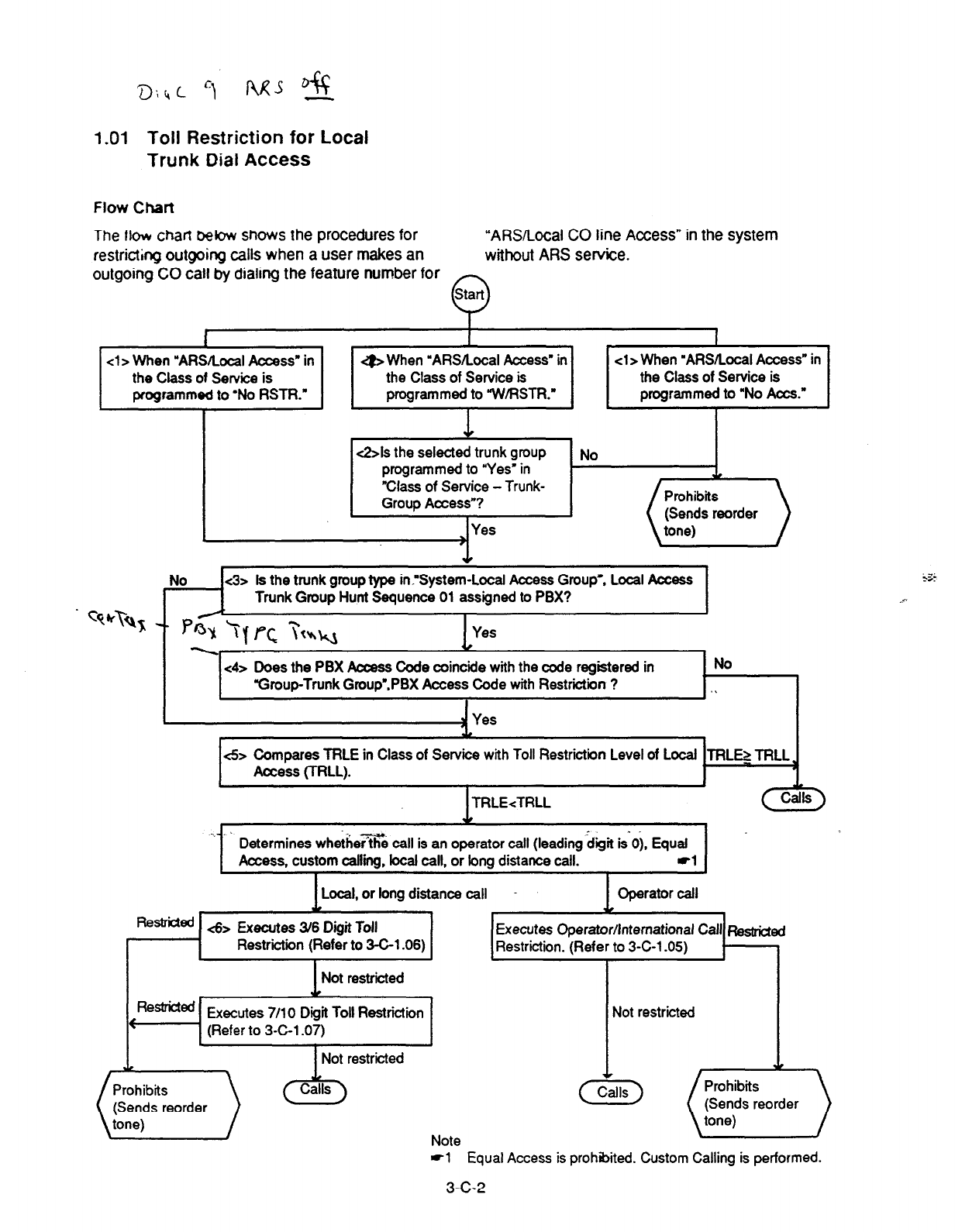
1.01 Toll Restriction for Local
Trunk Dial Access
Flow Chart
The llovr
chat-l
bebw shows the procedures for
restricting outgoing calls when a user makes an
outgoing CO call by dialing the feature number for
“ARSbcal
CO
line Access” in the system
without
ARS service.
f
P
cl > When
“AfWLocal
Access”
in g> When ‘AR.S/Local Access” in cl> When ‘ARSRocal Access” in
the Class of Service is the Class of Service is the Class of Service is
programmed to ‘No RSTR.” programmed to “W/RSTR.” programmed to “No Acts.”
I I I
&Is the selected trunk group
programmed to “Yes’ in
“Class of Service - Trunk-
Group Access”?
Yes
No
No <3> Is the trunk group type innSystem-Local Access Group’: Local Access
Trunk Group Hunt Sequence 01 assigned to PBX?
A
c4>
Does the PBX Access Code coincide with the code registered in
“Group-Trunk Group’.PBX Access Code with Restriction ?
I
No
.I
- Yes
<5> Compares TRLE in Class of Service with Toll Restriction Level of Local TRLEl TRLL
Access (TRLL).
1 TRLE<TRLL
~._. L
Determines whethefi% call is an operator call (leading &it is-u). Equal
Access, custom caflff. local call. or long distance call. -1
Local, or long distance call Cperator call
Remed .&B Executes 3/6 Digit Toll Executes Operator/International Call ~estrfcted
Restriction (Refer to 3-C-l .06) Restriction. (Refer to 3-C-l -05)
Not restricted I
Executes 7/l 0 Digit Toll Restriction
(EiF.Feorder ) * Note
4 Equal Access is prohibited. Custom Calling is performed.
3-C-2
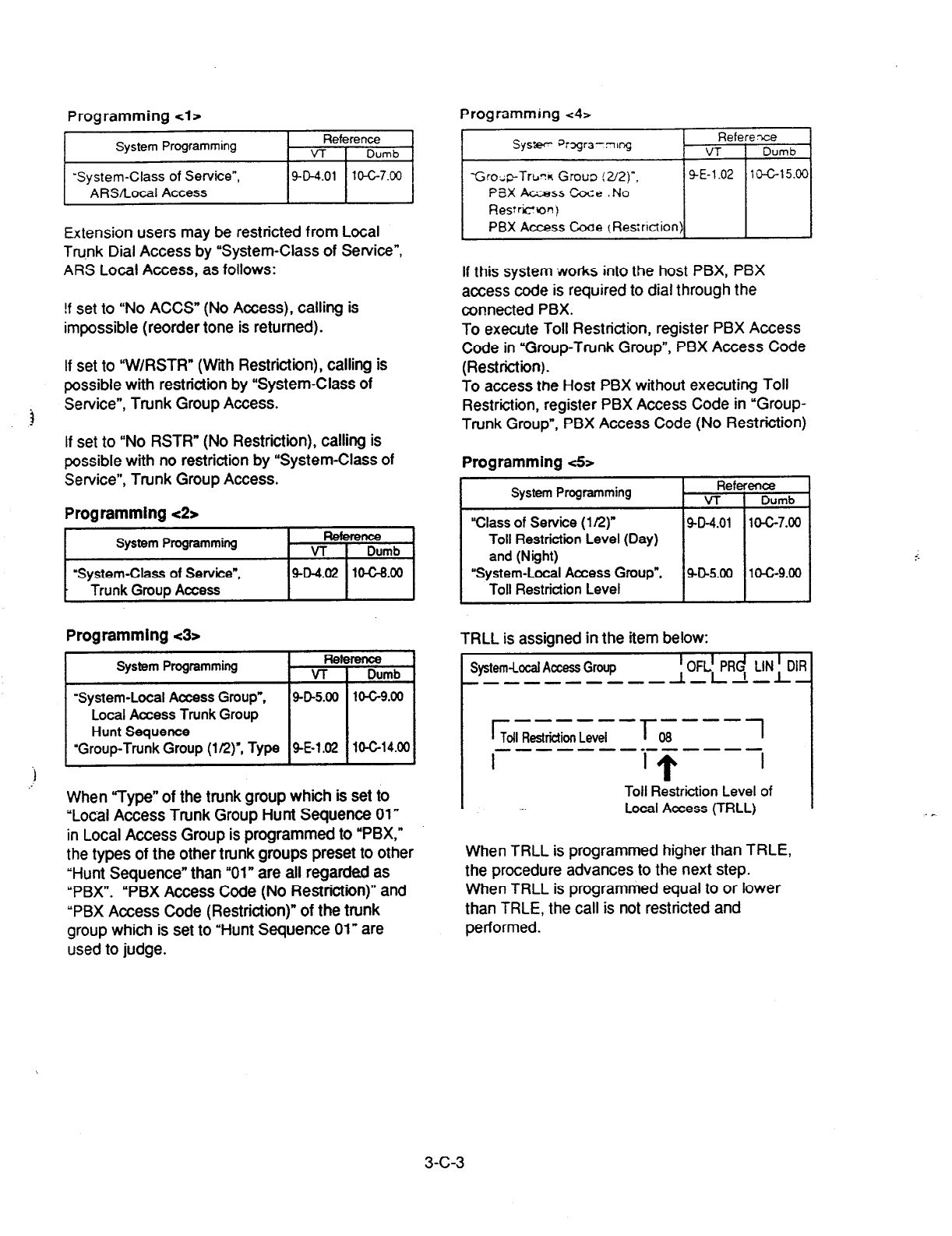
Programming tl> Programming <4>
I
System Programming Reference
Vl 1 Dumb
I
‘System-Class
of Service”,
ARSILocal Access Pol l’G7.w I
Extension users may be restricted from Local
Trunk Dial Access by “System-Class of Service”,
ARS Local Access, as follows:
!f set to “No ACCS” (No Access), calling is
impossible (reorder tone is returned).
If set to “W/RSTR” (With Restriction), calling is
possible with restriction by “System-Class of
Service”, Trunk Group Access.
If set to “No RSTR” (No Restriction), calling is
possible with no restriction by ‘System-Class of
Service”, Trunk Group Access.
Programming t2>
System Programming Reference
VT Dumb
‘System-Class of Service”,
9-0-4.02 104-8.00
* Trunk Grout Access
Programming 43~ TRLL is assigned in the item below:
System
Programming
When “Type” of the trunk group which is set to
“Local Access Trunk Group Hunt Sequence 01”
in Local Access Group is programmed to “PBX,”
the types of the other trunk groups preset to other
“Hunt Sequence” than “01” are all regarded as
“PBX”. “PBX Access Code (No Restriction)” and
“PBX Access Code (Restriction)” of the trunk
group which is set to “Hunt Sequence 01” are
used to judge.
Referexe
VT 1 Dumb
If this system works into the host PBX, PBX
access code is required to dial through the
connected PBX.
To execute Toll Restriction, register PBX Access
Code in “Group-Trunk Group”, PBX Access Code
(Restriction).
To access the Host PBX without executing Toll
Restriction, register PBX Access Code in ‘Group-
Trunk Group”, PBX Access Code (No Restriction)
Programming <5>
System
Programming
“Class of Service (1 R) 9-D-4.01 10-C-7.00
Toll Restriction
Level (Day)
and (Night)
“System-Local Access Group”,
40-5.00 1c-G9.00
Toll Restriction Level
System-Local
Access Group I OFLl PRd LIN l DIR
-------m-w I,LI-L-
r ------
Tofl Restrictii
Level &y----1
--------------
I
Toll R&triction Level of
Local Access (TRLL)
When TRLL is programmed higher than TRLE,
the procedure advances to the next step.
When TRLL is programmed equal to or lower
than TRLE, the call is not restricted and
performed.
3-c-3
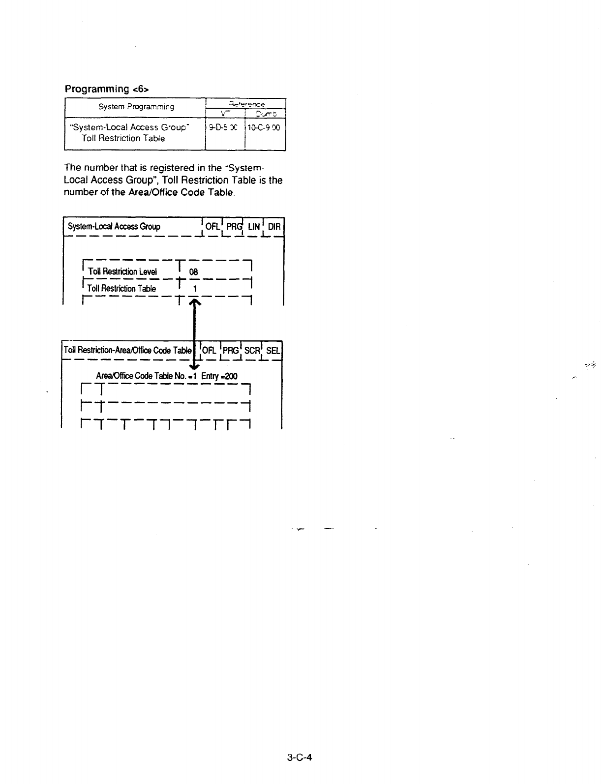
Programming t6>
T
System Progra;;lmlng I t*e??rm?
, ,-
: . ! 5-s 4
“System-Local Access Grow‘ w-5 32 l&c-330
Toll Restriction Table
The number that is registered in the “System-
Local Access Group”, Toll Restriction Table is the
number of the Area/Office Code Table
System-Local Access Group IOFLl
PRd LIN’ C
----------
-L-L-!-L
r ------ ----
Toll Restrictiin Level L8 1
t- ------ ----
Toll Restriition Table L -l
, r------T ---- 1
T
.
Toll Restriiion-Area/Off&3 Code
---e--m- PCj
S&SEl
Are&Mike Code Table No.
=l Entry dO0
r-f----------l
t--f----------l
1 ~-f-T--rl--rl-r~
. .
3-c-4
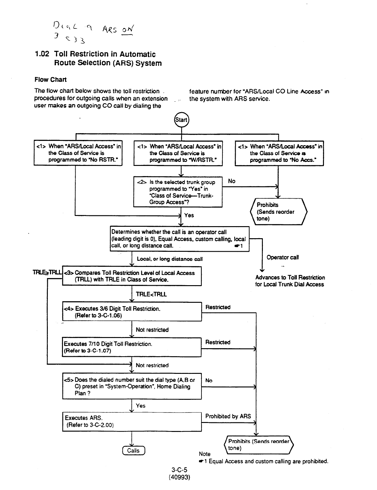
r30,L
3 v-3 ‘i fiqs d
1.02 Toll Restriction in Automatic
Route Selection (AM) System
Flow
Chart
The flow chart below shows the toll restriction
feature number
for ‘AM/Local CO Line Access’ rn
procedures for outgoing calls when an extension the system with ARS service.
user makes an outgoing CO call by dialing the
I
<l> When =ARS/Local Access” in
the Class of Service is
programmed to ‘No RSTR.’
cl > When ‘ARSRocal Access’ in
the Class of Service is
programmed to 7N/RSTR.’
cl > When DARSILocal Access’ in
theClassofSewices
programmed to “No Acts.’
c2> ls the selected trunk group No
programmed to ‘Yes’ in )
“Class of Service-Trunk-
Group Access”?
Determines whether the call is an operator call
(leading digit is 0), Equal Access, custom calling, local
call, or long distance call. -1
Local, or long distance call Operator call
. .
wlJ= c3> Compares Toll Restriction Level of Local Access 1
(TRU) with TFiLE in Class of Setvice. Advances to Toll Restrictiin
I for Local Trunk Dial Access
1 TRLE<TRLL
<4> Executes 316 Digit Toll Restriction.
(Refer to 3-C-l .06)
I
1 Not restricted
Restricted
, &
Executes 7/l 0 Digit Toll Restriction.
(Refer to 3-C-1.07)
Restricted
-4 Not restricted
<5> Does the dialed number suit the dial type (A,B or No
C) preset in “System-Operation”, Home Dialing
Plan ?
Yes
Executes ARS.
(Refer to 3-C-2.00)
Prohibited by ARS
c5
Calls
Note (~rf$ibits (Sends reorde?
~1
Equal Access and custom calling are prohibited.
3-c-5
(40993)
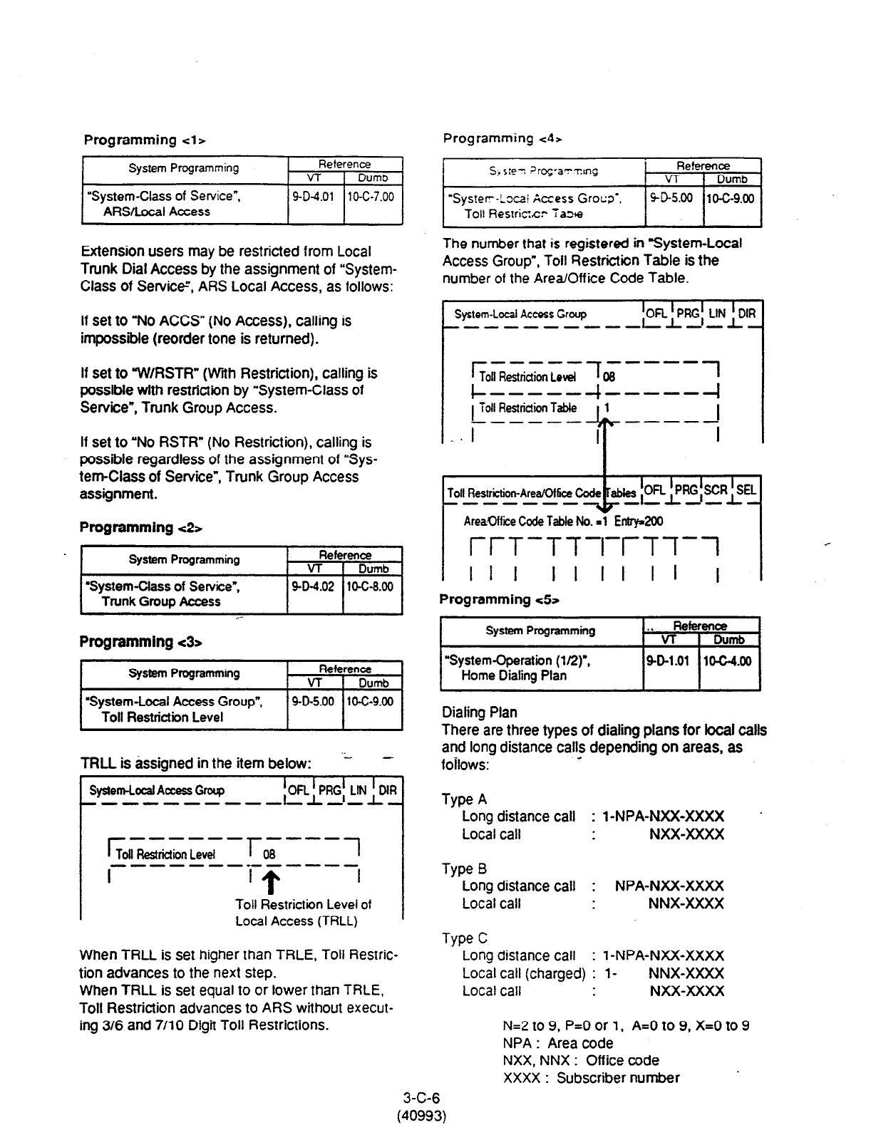
Programming cl >
Programming ~4,
System Programming Reference
VT 1 Dumb
“System-Class of Service”,
AFWLocal Access
9-D-4.01
10-C-7.00
Extension users may be restricted from Local
Trunk Dial Access by the assignment of “System-
Class of Service”, ARS Local Access, as follows:
The number that is registered in System-Local
Access Group”,
Toll Restriction Table is the
number of the Area/Off ice Code Table.
If set to “No ACCS” (No Access), calling is
impossible (reorder tone is returned).
I
System-Local Access Group !OFL !PRG! LIN ; DIR
If set to ‘7NIRSTR” (With Restriction), calling is
possible with restriction by “System-Class of
Service”, Trunk Group Access.
If set to “No RSTR” (No Restriction), calling is
possible regardless of the assignment of “Sys-
tem-class of Service”, Trunk Group Access
assignment.
Programming ~2s
I
System Programming Reference
VI- i Dumb
l
SystemClass of Service”,
Trunk Group Access . .
9-D-4.02 lo-c-8.00
Toll Restriion-Area/Office
------- IOR ~PRG+R&
-- -
Are&office Code Table No. -1 Entry200
r/-T-Tl-rr-T-T-1
I I I
IIII Il l
Programming ~52
Programming t3~
System Programming Reference
VT 1 Dumb
“System-Local Access Group”,
Toll Restriction Level
9-D-5.00 10-C-9.00
3-C-6
(40993)
Dialing Plan
TRLL is assigned in the item below: -2 -
There are three types of dialing plans for local calls
and long distance calls depending on areas, as
f0ii0ws: -
System-Local Access Group !OFL f PRG! LM ! DIR
I
Toll Restridion Level I
08 I
--------------
I ‘T I
Type A
Long distance call : l-NPA-NXX-XXXX
Local call NXX-XXXX
Toil
Restriction Level of
Local Access
(TRLL)
When TRLL is set higher than TRLE, Toll Restric-
tion advances to the next step.
When TRLL is set equal to or lower than TRLE,
Toll Restriction advances to ARS without execut-
ing 3/6 and 7/l 0 Digit Toll Restrictions.
We C
Long distance call : 1 -NPA-NM-XXXX
Local call (charged) : l- NNX-XXXX
Local call NXX-XXXX
r -----
Toll Restriction Level x-----~
I I I
r------i-
I
Toll
Restriction Table
i
------ -----
, . I I
Long distance call : NPA-NXX-XXXX
Local call NNX-XXXX
N=2 to 9, P=O or
1,
A=0 to 9, X=0 to 9
NPA : Area code
NXX, NNX : Office code
XXXX : Subscriber number
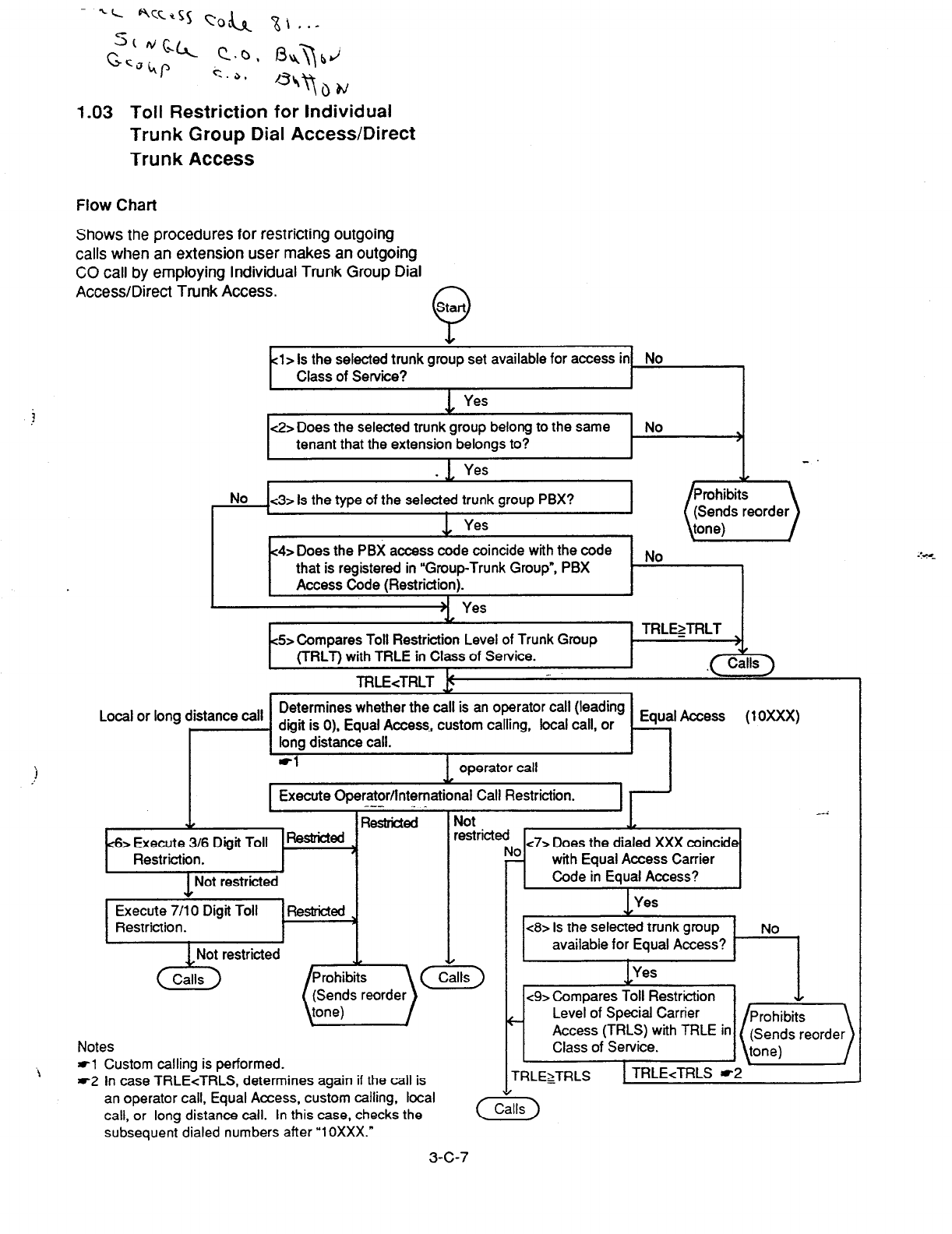
1.03 Toll Restriction for Individual
Trunk Group Dial Access/Direct
Trunk Access
Flow Chart
Shows the
procedures for restricting outgoing
calls when an extension user makes an outgoing
CO call by employing Individual Trunk Group Dial
Access/Direct Trunk Access. Start
Q
cl>
Is the selected
trunk
group set available for access in No
Class of Service?
No
<3> Is the type of the selected trunk group PBX?
1 Yes
! LL .
Prohibits
(Sends reorder
tone)
c2> Does the selected trunk group belong to the same No
tenant that the extension belongs to? 1
I
c4> Does the PBX access code coincide with the code
that is registered in “Group-Trunk Group”, PBX
Access Code (Restriction).
No
45~ Compares Toll Restriction Level of Trunk Group
(TRLT) with TRLE in Class of Service.
TRLEcTRLT I! _
TRL~TRLT
”
Local or long distance call Determines whether the call is an operator call (leading
I , digit is 0). Equal Access, custom calling, local call, or
Access (10XxX)
> Execute 316 Digit Toll ReskicM
Restriction. t-l I
I
1 Not restricted I I
I
Execute 7/10 Digit Toll
Restriction.
Notes
tl Custom calling is performed.
*2 In case TRLEcTRLS. determines again if the call is
with Equal Access Carrier
Code in Equal Access?
<8> Is the selected trunk group
available for Equal Access? No
<9> Compares Toll Restriction ”
c Level of Special Carrier
Access (TRLS) with TRLE in
Class of Service.
TRLEzTRLS
an operator call, Equal Access, custom calling, local
call, or long distance call. In this case, checks the
subsequent dialed numbers after “1OXXX.”
3-c-7
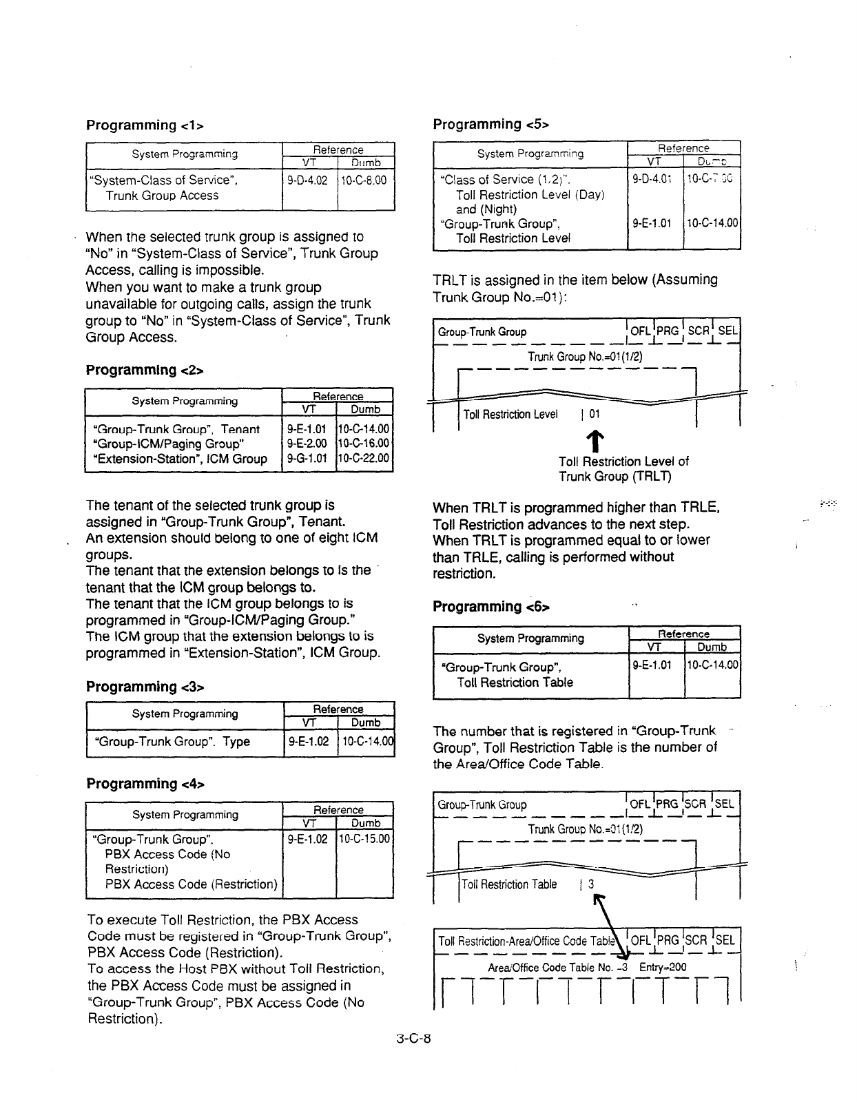
Programming
cl>
~1
When the selected trunk group is assigned to
“No” in “System-Class of Service”, Trunk Group
Access, calling is impossible.
When you want to make a trunk group
unavailable for outgoing calls, assign the trunk
group to “No” in “System-Class of Service”, Trunk
Group Access.
Programming ~2s
System Programming Reference
VT I Dumb
“Group-Trunk Group”, Tenant 9-E-i .Oi 10-C-14.00
“Group-ICM/Paging Group” 9-E-2.00 IO-Gt6.00
“Extension-Station”, ICM Group 9-G-l .Ol 10-C-22.00
The tenant of the selected trunk group is
assigned in “Group-Trunk Group”, Tenant.
. An extension should belong to one of eight ICM
groups.
The tenant that the extension belongs to is the
tenant that the ICM group belongs to.
The tenant that the ICM group belongs to is
programmed in “Group-ICM/Paging Group.”
The iCM group that the extension belongs to is
programmed in “Extension-Station”, ICM Group.
Programming
c3>
System Programming
‘Group-Trunk Group”. Type
Reference
VT Dumb
9-E-1.02 10-C-l 4.00
Programming ~4,
System Programming
“Group-Trunk Group”.
Reference
VT I Dumb
9-E-l .02 11 O-C-l 5.00
PB% Access Code (No
Restriction)
PBX Access Code (Restriction) I I I
To execute Toll Restriction, the PBX Access
Code must be registered in “Group-Trunk Group”,
PBX Access Code (Restriction).
To access the Host
PBX
without Toll Restriction,
the PBX Access Code
must
be assigned in
“Group-Trunk Group”, PBX Access Code (No
Restriction).
Programming
c5>
System Progr2mming
“Class
of Service (l(2)“.
Toll
Restriction Level (Day)
and (Night)
“Group-Trunk Group”,
Toil Restriction Level
Reference
VT DL-C
904.0; I o-c-; ;i
9-E-l .Ol 1 O-C-l 4.00
TRLT is assigned in the item below (Assuming
Trunk Group No.=01 ):
Toll Restriction Level
Toll Restriction Level of
Trunk Group (TRLT)
When TRLT is programmed higher than TRLE,
Toll Restriction advances to the next step.
When TRLT is programmed equal to or lower
than TRLE, calling is performed without
restriction.
Programming <6>
*I
The number that is registered in “Group-Trunk ..
Group”, Toll Restriction Table is the number of
the Area/Office Code Table.
I
Trunk Group No.=31 (1!2)
I r ____------- 1 I
/r7-r-n-r-i-T-n 1
. .
3-C-8
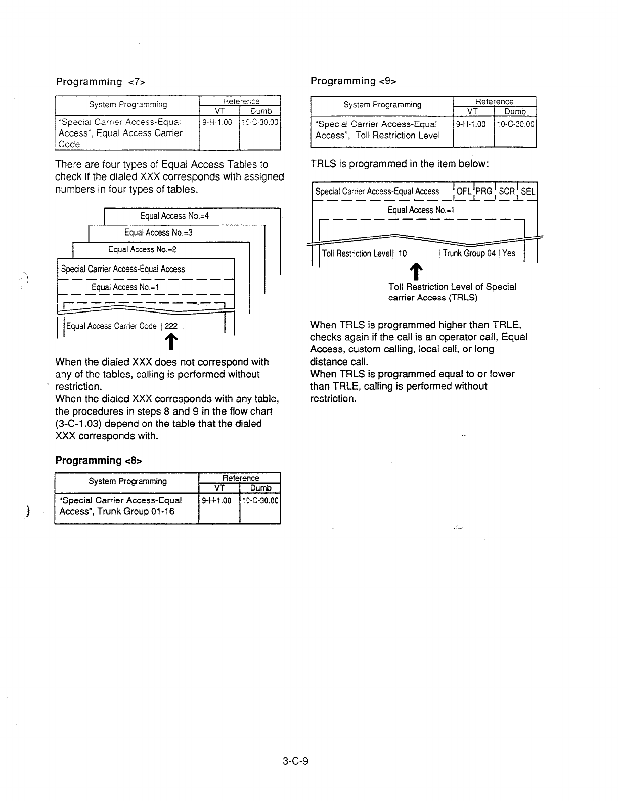
Programming <7> Programming <9>
System Frogramming
“Special Carrier Access-Equal
Access”, Equal Access Carrier
Code
Referexe
VT Gumb
9-H-l .OO ! S-C-30.00
There are four types of Equal Access Tables to
check if the dialed XXX corresponds with assigned
numbers in four types of tables.
I
Equal Access No.=3
, 1 Equal Access No.=2 ,
Special Carrier Access-Equal Access
r 1 Equal
Access No.=4 ,
L
Equal Access No.=1
----------- -1
‘r
\
lr---- -----.-.
I I
II
Equal Access Carrier Code I222 /
When the dialed XXX does not correspond with
any of the tables, calling is performed without
. restriction.
When the dialed XXX corresponds with any table,
the procedures in steps 8 and 9 in the flow chart
(3-C-l .03) depend on the table that the dialed
XXX corresponds with.
Programming <8>
System Programming Reference
VT 1 Dumb
System Programming Reference
VT 1 Dumb
“Special Carrier Access-Equal
Access”, Toll Restriction Level
/ 9-H-l .OO / ! O-C-30.001
TRLS is programmed in the item below:
Special Carrier Access-Equal Access
{j
Toll Restriction Level 1 IO / Trunk Group 04 ! Yes
Toll Restriction Level of Special
carrier
Access (TRLS)
When TRLS is programmed higher than TRLE,
checks again if the call is an operator call, Equal
Access, custom calling, local call, or long
distance call.
When TRLS is programmed equal to or lower
than TRLE, calling is performed without
restriction.
. .
.f
“Special
Carrier Access-Equal
Access”, Trunk Group 01-l
6
/ 9-H-l .OO / ! ?-C-30.001
_-
3-c-9
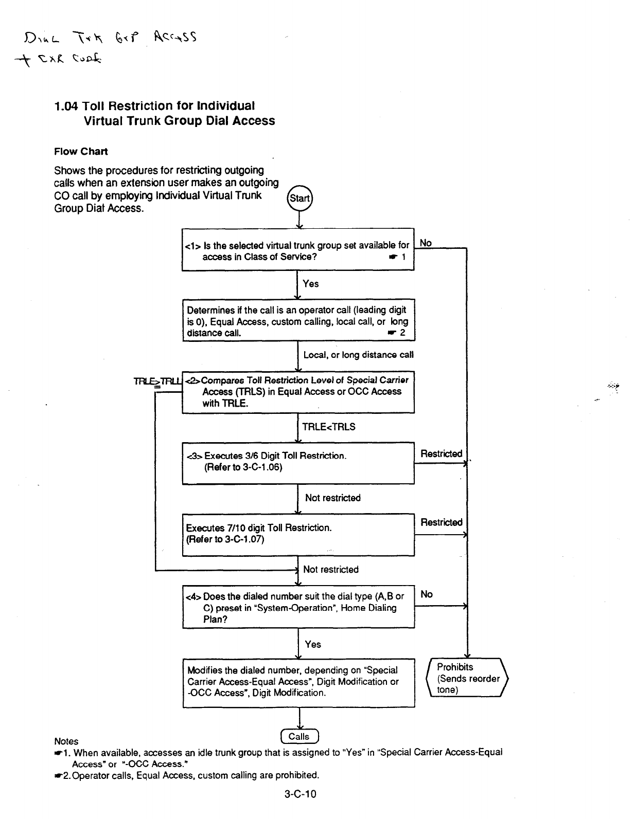
1.04 Toll Restriction for Individual
Virtual Trunk Group Dial Access
Flow Chart
Shows the procedures for restricting outgoing
calls when an extension user makes an outgoing
CO call by employing Individual Virtual Trunk
Start
Group Diat Access.
Q
cl> Is the selected virtual trunk group set available for
access in
Class of Service? -1 I
Yes
Y
Determines if the call is an operator call (leading digit
is 0), Equal Access, custom calling, local call, or long
distance call. -2
Local, or long distance call
v
I ‘
I
with TRiE. ’ ’
I
TRLEcTRLS
&Compares Toll Restriction Level of Special Carrier
Access fTRLS1 in Eaual Access or OCC Access I
No
1
c3> Executes 3/6 Digit Toll Restriction.
(Refer to 3-C-l .06)
I
Not restricted
I
Executes 7/10 digit Toll Restriction.
(Refer to 3-C-l .07)
-11 Not restricted
c4=- Does the dialed number suit the dial type (A,B or No
C) preset in “System-Operation”, Home Dialing
Plan? t-
I
I Yes
7 ,
Modifies the dialed number, depending on “Special
Carrier Access-Equal Access”, Digit Modification or
-0CC Access”, Digit Modification.
( SFFeorder)
#I3
Calls
Notes
-1. When available, aazesses an idle trunk group that is assigned to “Yes” in “Special Carrier Access-Equal
Access” or “-CCC Access.”
02.Operator calls, Equal Access, custom calling are prohibited.
P
3-c-1 0
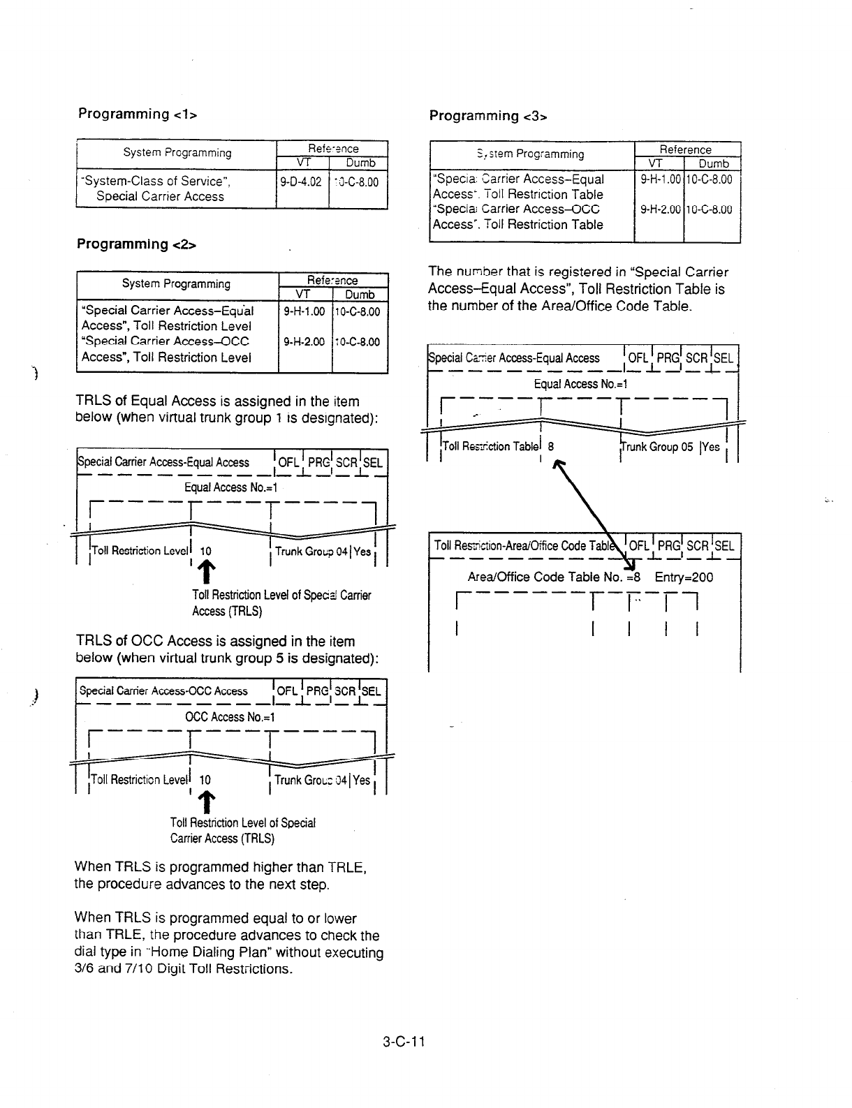
Programming cl> Programming <3>
System Programming Refe-2nce
VT 1 Dumb
System-Class of Service”,
Special Carrier Access 9-D-4.02 ‘J-C-8.00
Programming <2>
System Programming Refe:37ce
VT 1 Dumb
“Special
Carrier Access-Eqtial
Access”, Toll Restriction Level
“Special Carrier Access-OCC
Access”, Toll Restriction Level
9-H-l .OO
1
O-C-8.00
9-H-2.00 70-C-8.00
TRLS of Equal Access is assigned in the item
below (when virtual trunk group 1 is designated):
pecial Carrier Access-Equal Access
Toll Restriction Level of Speczi Carrier
Access (TRLS)
TRLS of OCC Access is assigned in the item
below (when virtual trunk group 5 is designated):
Special Carrier Access-OCC Access
OCC Access No.=1
Toll Restriction Level of Special
Carrier Access (TRLS)
When TRLS is programmed higher than TRLE,
the procedure advances to the next step.
I
S,. slem Prog:amming
“Specia. Carrier Access-Equal
Access-. Toll Restriction Table
Access’. Toll Restriction Table
The number that is registered in “Special Carrier
Access-Equal Access”, Toll Restriction Table is
the number of the Area/Office Code Table.
Czzer Access-Equal Access f OFLkRG; SCRPL
SD-------- -- -l
Equal Access No.=1 I
---
r-7-r T----
--------m
Area/Office Code Table No. =8 Entry=200
I I I I
I
r ------ l---F-7-1
When TRLS is programmed equal to or lower
than TRLE, the procedure advances to check the
dial type in “Home Dialing Plan” without executing
3/6 and 7/l 0 Digit Toll Restrictions.
3-c-1 1
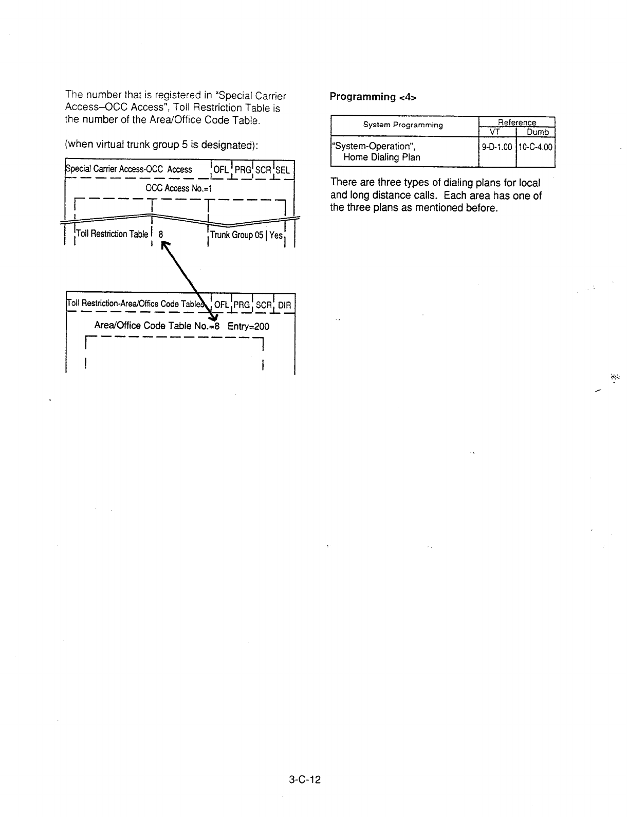
The number that is registered in “Special
Carrier
Access-CCC Access”, Toll Restriction Table is
the number of the Area/Office Code Table.
(when virtual trunk group 5 is designated):
\
roll Restriction-Area/Office Code Tabl
---------
Area/Office Code Table No.=8 Entry=200
r -----e--m-- 1
I I
Programming <4>
zi
There are three types of dialing plans for local
and long distance calls. Each area has one of
the three plans as mentioned before.
3-C-12
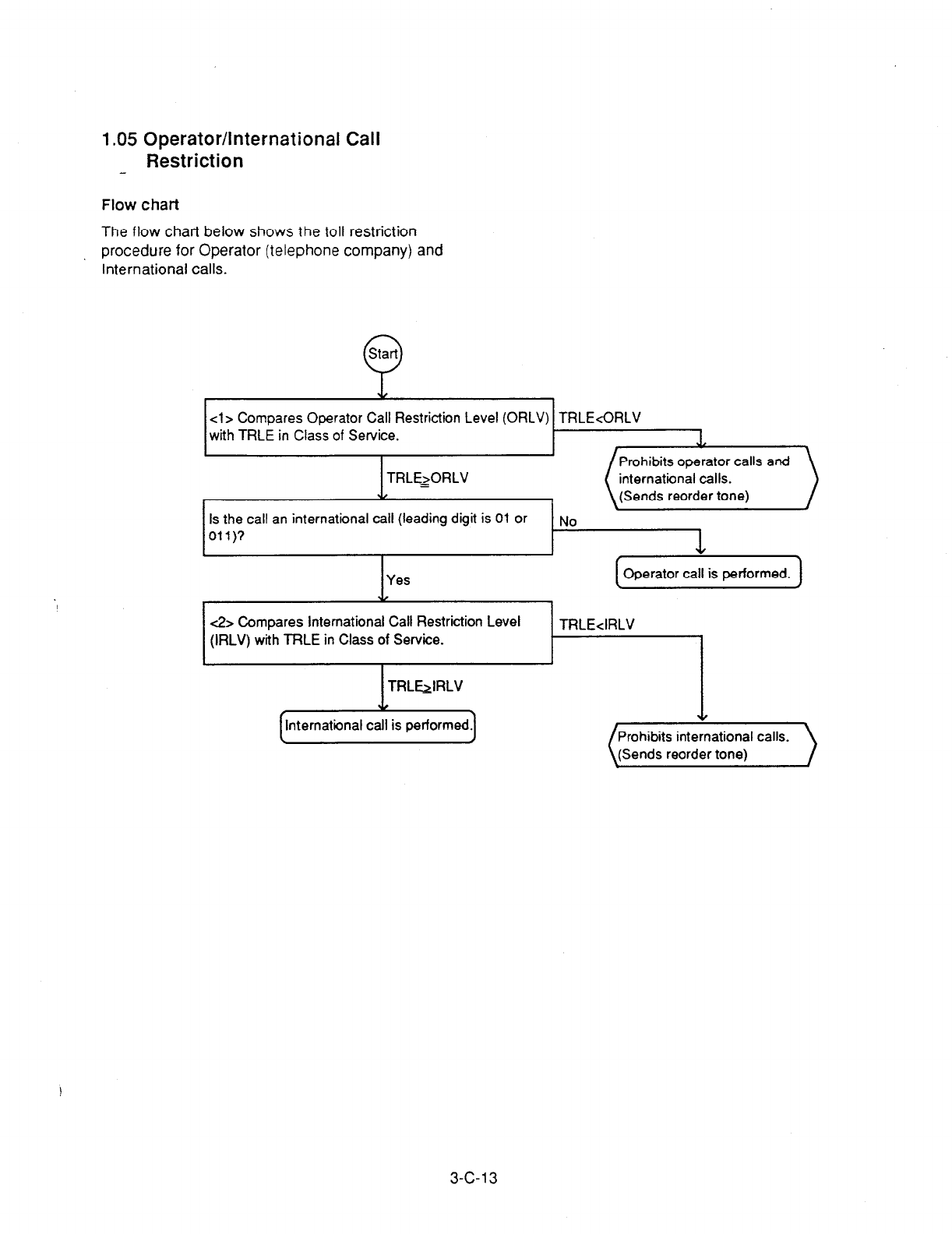
1.05 Operator/International Call
Restriction
-
Flow chart
The flow chart below shows the toll restriction
procedure for Operator (telephone company) and
International calls.
cl> Compares Operator Call Restriction Level (ORLV) TRLEcORLV
with TRLE in Class of Service. .I,
Prohibits operator calls and
TRLE=>ORLV international calls.
Y (Sends reorder tone)
Is the call an international call (leading digit is 01 or fqo
Oil)? I
I I +
I I \
1 Operator call is performed. 1
45 Compares International Call Restriction Level
(IRLV) with TRLE in Class of Service.
TRL&IRLV
Y
nternational call is performed
TRLE<IRLV
(Sends reorder tone)
3-c-13
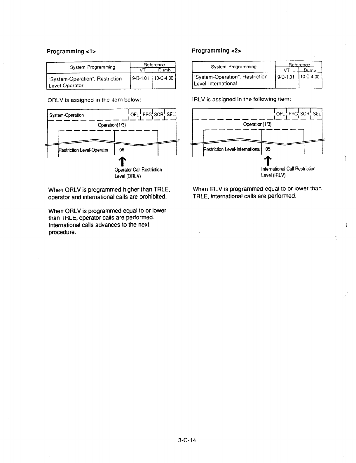
Programming <la Programming c2>
;I
“System-Operation , Restrb2on
ORLV is assigned in the item below:
System-Operation
_-----_ 1 OFL>RG; SCR>EL
_--_ _- -
Operat’bn( l/3)
I
r------l-----1 I
Restriction Level-Operator 06
Cperator Call Restrictiin International Call Restriction
Level (ORLV) Level (IRLV)
When ORLV is programmed higher than TRLE,
operator and international calls are prohibited.
System Programming
“System-Operation”, Restriction
Level-international
RekB
VT
SD-1 01 10-C-4 C0
IRLV is assigned in the following item:
When IRLV is programmed equal to or lower than
TRLE, international calls are performed.
When ORLV is programmed equal to or lower
than TRLE, operator calls are performed.
International calls advances to the next
procedure.
3-c-1 4
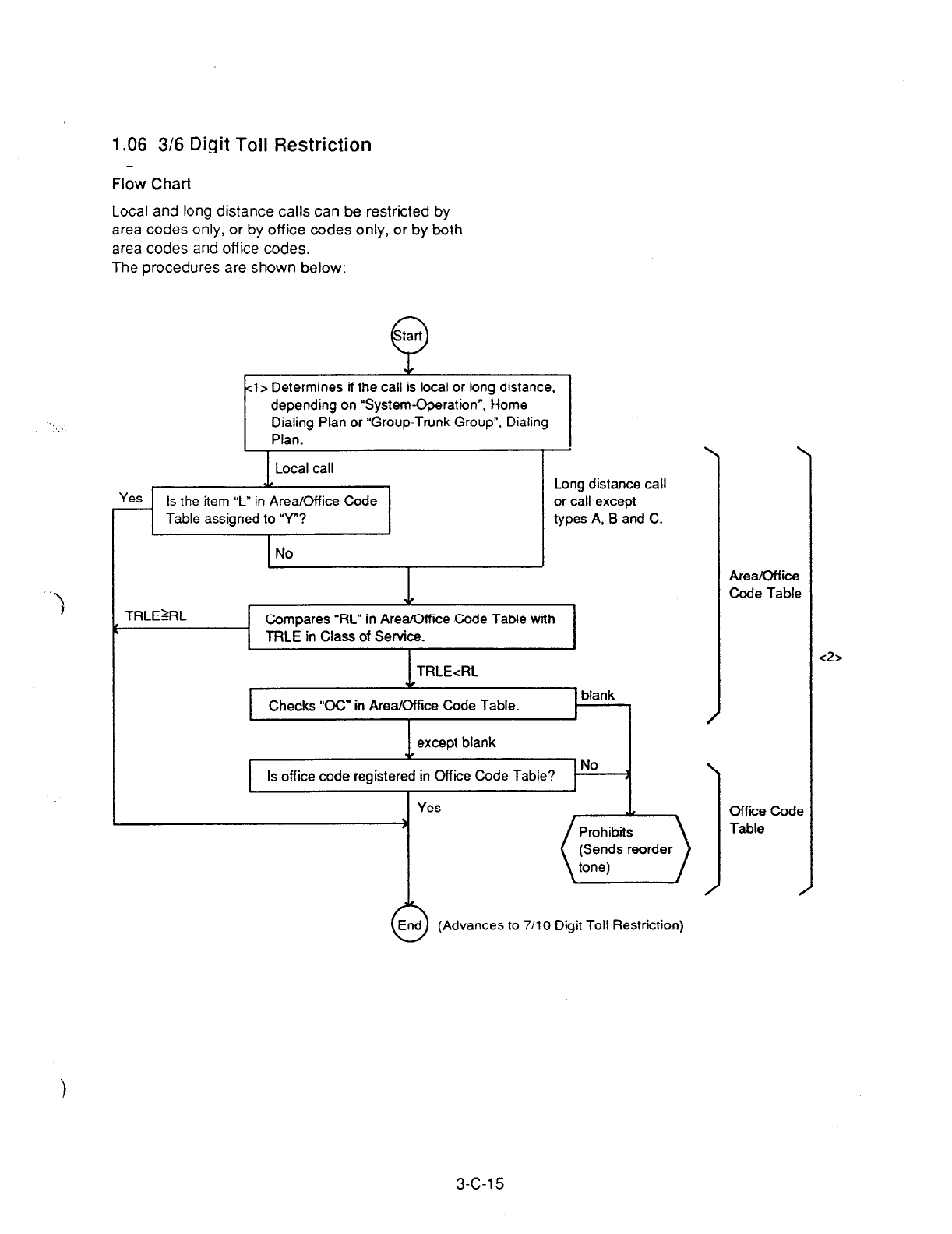
1.06 3/6 Digit Toll Restriction
Flow Chart
Local and long distance calls can be restricted by
area codes only, or by off ice codes only, or by both
area codes and off ice codes.
The procedures are shown below:
Q
tart
l> Determines if the call is local or tong distance,
depending on “System-Operation”, Home
Dialing Plan or “Group-Trunk Group”, Dialing
1 Plan.
Local call
Is the item “L” in Area/Office Code
Table assigned to “Y”?
I I
No J
Long distance call
or call except
types A, B and C.
TRLE%L Compares “RL” in Area/Office Code Tabte with
TRLE in Class of Service.
I
Checks ‘CC” in Area/Office Code Table.
I
blank
I
No
Is off ice code register I
Are-i
Code Table
Office Code
Table
<2>
(Advances to 7/l 0 Digit Toll Restriction)
3-c-1 5

Programming <la
t
System Programming Reference
VT 1 Dumb
“System-Operation”,
Home Dialing Plan
“Group-Trunk Group”,
Dialing Plan
9-D-1.01 l@C-4.00
9-E-1.01 10-C-14.00
When a call is made by ARS or Individual Virtual
Trunk Group Dial Access, the call is judged by
“System-Operation”, Home Dialing Plan.
When a call is made by Local Trunk Dial Access
or Individual Trunk Group Dial Access/Direct
Trunk Access, the call is judged by “Group-Trunk
Group”, Dialing Plan.
Programming <2>
System Programming Reference
VT 1 Dumb
“loll Restriction-Area/Office Code 9-l-l .OO 10-C-32.00
Tables”
“Toll Restriction-Office Code 9-I-2.00 10-C-33.00
Tables”
l
Eight Area/Office Code Tables are prepared to
program various restrictions for calling ways
such as Local
Trunk
Group Dial Access,
Individual Trunk Group Dial Access, etc. Each
table consists of 16 screens:
l
64 Off ice Code Tables are also prepared.
Each table
consists of four screens:
I
. =64
.
.
.
I
=02
Toll Restriction-Office Code Tables
t
----s-m--
Office Code Table No.=01
I
1 I
(1) Programming
the 3/6 Digit
Toll
Restriction plan
(General)
Before programming the toll restriction plan,
determine the TRLE of each extension user in
Class of Service programming.
Table 1 Toll Restriction Level of each Extension
user
I
ITRLE 1 RLl IRf.2 IRL3jRL4jRL5 /RL6 I
President 1 A A A A A A
Vice-President 2 RAAAAA
Part-Timer 2 6 RRRRRA
Legend:
TRLE - Toll Restriction Level of Extension
RL - Restriction Level
A - Allowed
R
- Restricted
3-C-l 6

Assuming that your telephone system is located
in-the area, Area Code (AC)=200, Off ice Code
(OC)=320, accordingly, your CO number is
(1) +
200 + 320 + XXXX.
Determine the Restriction Level of each AC and
OC respectively according to the TRLE of each
extension user (Table 1).
Table 2 Restriction Level of each AC and OC
I I
1C=213 I I
AC=21 4
3L=l I I
I
O&322 O&320
Ix=1
I
I I
OC=321
I I
AC=209 1 I
X=321 I I AC=210
RL=2
-I I I
I
OC=322
I
OC=320 1 IRL=2 1
I I t
oc=3; !l AC=205 , I AC=206
RL=3 I I
; OC=322 O&320 ; I RL=3
_ _ _ OC=321 1 OC=321 _ _ _ _
AC-201 I AC=202
RL=4 ;OC=322 O&320; &RL=4
I I
X=320 _ _ ______ _ 0~~321 I I 1 _ OC=321 .-------- o&322
OC=320 AC=200 ’ O&322
_ -----
O&320 - - O&321 : O&322 - - - - - - - OG322
OC=320 RL=5 t RL=5
-'- - - - -, OC=322
I----
._ - - : pzq :---,
; OC=320 ;
’ RL=6 1
OC=322 I-----,-----I O&320
OC=320
OC=322 _ _ _ _ _ _ _ _ O&324 j ;Lc_23 _ _ _ _ _ _ _ _ _ O&320
RL=5 O’S320
X=322 . _ _ _ _ _ _ _ _ 0~~321 I
O&321
--------. OC=320
I I
O&321 AC=204 :OC=320 OC=322: AC=203 OC=321
.-------- - - - - - _ - -
RG4 I ’ RL=4
I
I I
_------- AC=208 : OC=322 OC=322 : - _ _ - - _ _ _
AC=207
OC=32 1 RL=3 I I RL=3 OC=321
I
I I OC=321
I OC=320 OC=322 I
AC=21 2 I f AC=21 1
RL=2 I I RL=2
, I
I I
AC=2161 OC=321 I O&320 OC=322 I
I I
the boundaries of Area Code
-_-__---- the boundaries of Office Code
3-c-1 7
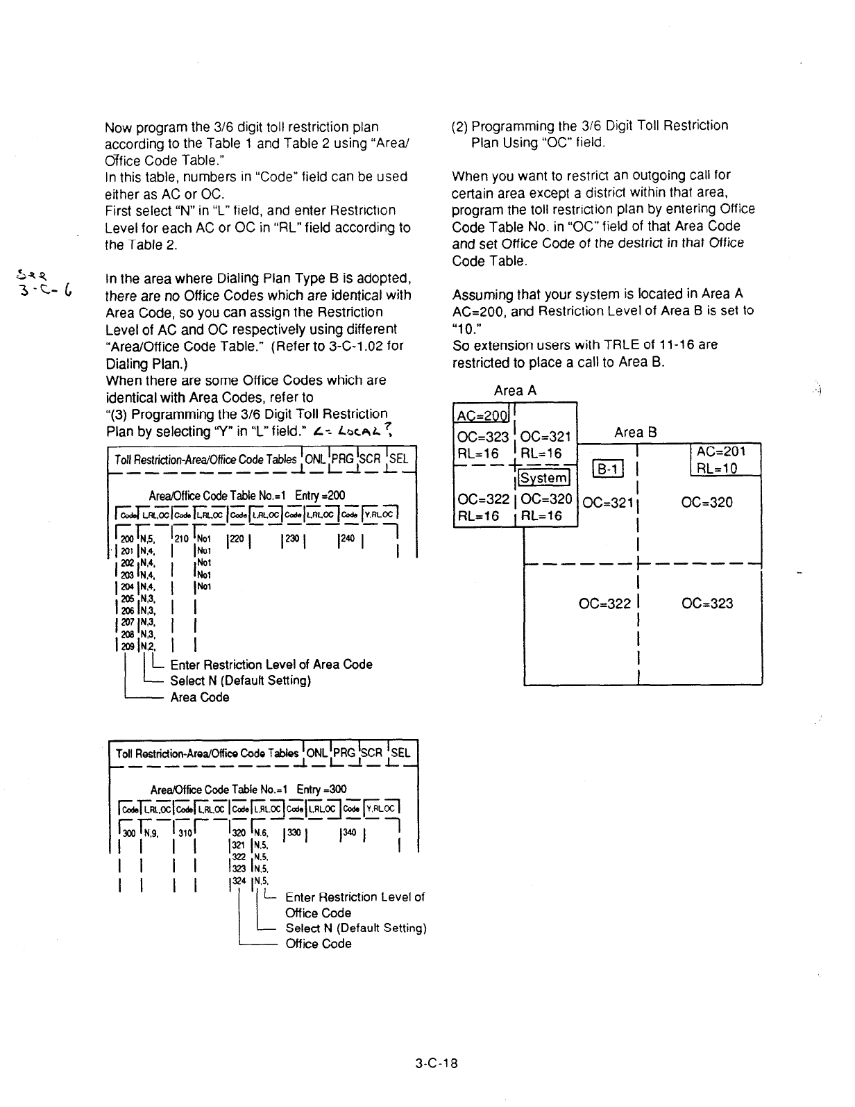
Now program the 3/6 digit toll restriction plan
according to the Table 1 and Table 2 using “Area/
Office Code Table.”
In this table, numbers in “Code” field can be used
either as AC or OC.
First select “N” in “L” field, and enter Restriction
Level for each AC or OC in “RL” field according to
the Table 2.
294
3-c- iI In the area where Dialing Plan Type B is adopted,
there are no Office Codes which are identical with
Area Code, so you can assign the Restriction
Level of AC and OC respectively using different
“Area/Off ice Code Table.” (Refer to 3-C-l .02 for
Dialing Plan.)
When there are some Office Codes which are
identical with Area Codes, refer to
“(3) Programming the 3/6 Digit Toll Restriction
Plan by selecting ‘Y” in I” field.” L= LJX~L?
Toll Restriction-Area/Offi& Code Tabk>F $X *L
_-----_--- - -- -
Area/Office Code Table No.=1 Entry =200
---------
'210 ‘No1
I bl
I 1::
I lb’
I I
Ino I lrnl 12* I
I- Enter Restriction Level of Area Code
Select N (Defautt Setting)
Area Code
Toil Restriction-Area/Office Code Tabi~~~~$R kL
_--------- - -
Area/Office Code Table No.=1 Entry =300
Enter Restriction Level of
Office Code
Select N (Defautt Setting)
Office Code
(2) Programming the 3/6 Digit Toll Restriction
Plan Using “OC” field.
When you want to restrict an outgoing call for
certain area except a district within that area,
program the toll restriction plan by entering Office
Code Table No. in “OC” field of that Area Code
and set Office Code of the destrict in that Office
Code Table.
Assuming that your system is located in Area A
AG200, and Restriction Level of Area 6 is set to
“10.”
So extension users with TRLE of 11-16 are
restricted to place a call to Area B.
Area A
AC=2001 !
I
O&322 i O&320 OC=320
RL=l6 f RL=16
L
I
I
I
------ ---s-w
l-
OC=322
I
I
I
I
I
L
O&323
3-C-l 8
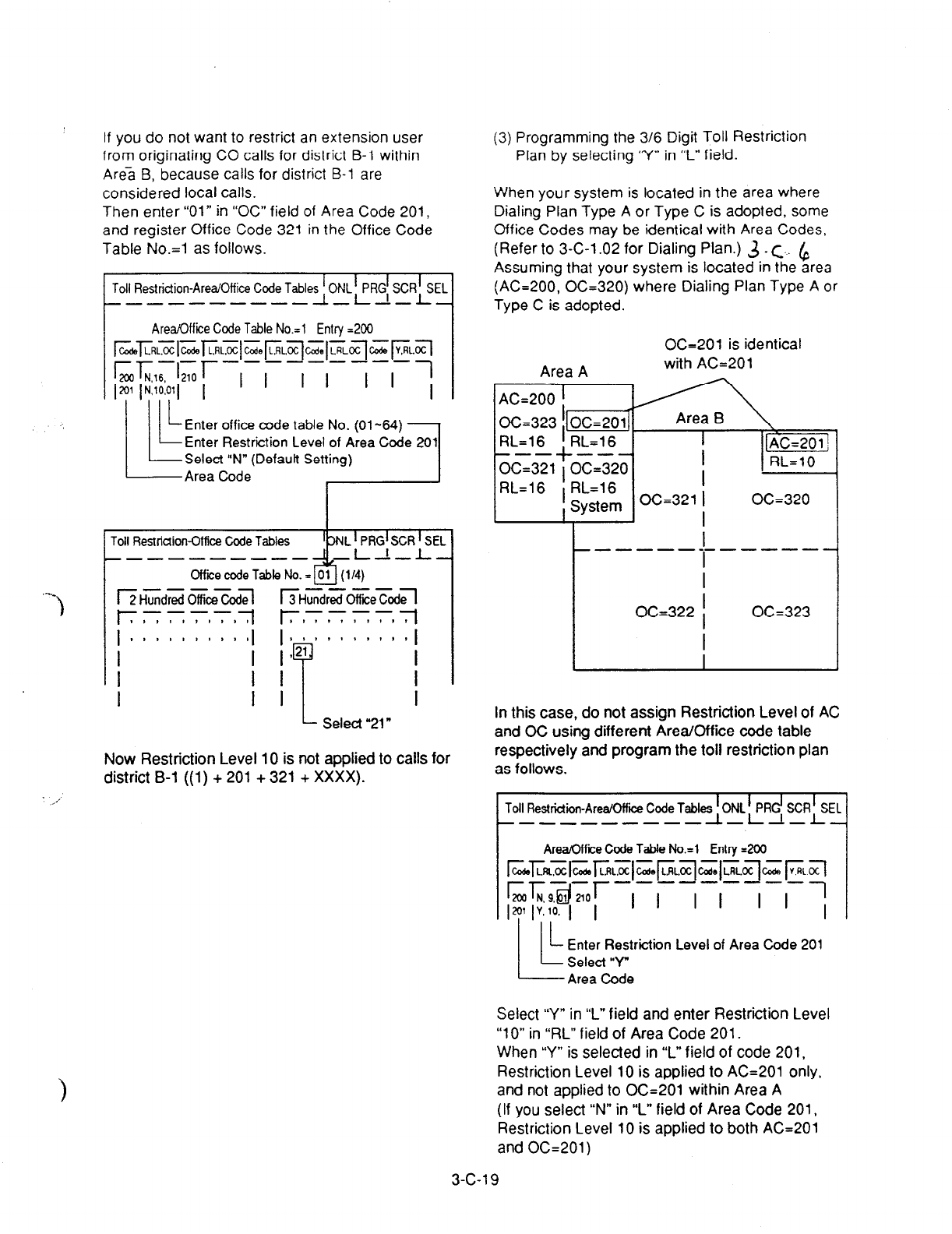
If you do not want to restrict an extension user
from originating CO calls for district B-l within
Area B, because calls for district B-l are
considered local calls.
Then enter “01” in “OC” field of Area Code 201,
and register
Office Code 321 in the Office Code
Table No.=1 as follows.
.-
1
roll Restriction-Area/Office Code Tables f ONL t PRG! SCRkEL
____------ -- -
Area/Office Code Table No.=1 Entry =200
roll Restridion-Office Code Tables
m--------s
Office code Table No. =
----
/2 Hundred Off ice ~4
----
EHHundred Office CodJ
‘EL
I
I- Select"21"
Now Restriction Level 10 is not applied to calls for
district B-l ((1) + 201 + 321 + XXXX).
(3) Programming the 3/6 Digit Toll Restriction
Plan by selecting “Y” in “L” field.
When your system is located in the area where
Dialing Plan Type A or Type C is adopted, some
Office Codes may be identical with Area Codes,
(Refer to 3-C-l .02 for Dialing Plan.) 3 _ c.. ,$
Assuming that your system is located in the area
(AC=200, O&320) where Dialing Plan Type A or
Type C is adopted.
OC=201 is identical
with AC=201
I
RL=16 / RL=16
, System I O&321 i OC=320
I I
I 8 I
I I I
I
_------------- I
I
I
OC=322 I OC=323
I
I
In this case, do not assign Restriction Level of AC
and OC using different Area/Office code table
respectively and program the toll restriction plan
as follows.
L
Toll Restriction-AreaIOffii Code Tables !
ONL t PRd
SCR?L
--s----s- - -
Area/Office Code Table No.=1 Entry -200
rr:7-r::I-~.-j-1-7-r7
cc& Lfnoc cd0 LRLCC Code LRLOC Code LFiL.cc cc& YRLCC
L Enter Restriction Level of Area Code 201
L!z
Select “Y
Area Code
Select “Y” in “L” field and enter Restriction Level
“10” in “RL” field
of Area Code 201.
When “Y” is selected in “L” field of code 201,
Restriction Level 10 is applied to AC=201 only,
and not applied to O&201 within Area A
(If you select “N” in “L” field of Area Code 201,
Restriction Level 10 is applied to both AC=201
and OC=201)
3-c-1 9
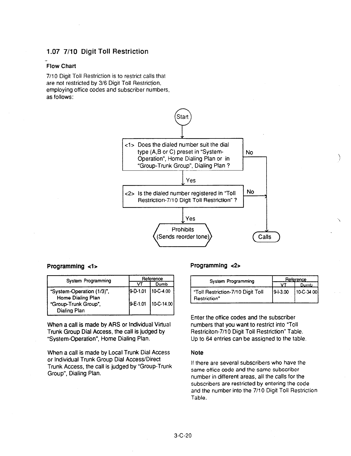
1.07 7/10 Digit Toll Restriction
Flow
Chart
7/l 0 Digit Toll Restriction is to restrict calls that
are not restricted by 3/6 Digit Toll Restric!ion,
employing off ice codes and subscriber numbers,
as follows:
Start
0
cl> Does the dialed number suit the dial
/ type(A:B;rC)pr;n“System-. /NO ,
Operation , Home Dlallng Plan or In
“Group-Trunk Group”, Dialing Plan ?
I Yes 1 I
e2> Is the dialed number registered in “Toll . No
Restriction-7/l 0 Digit Toll Restriction” ? 
I
Yes
. .
(iiiiik+
Programming 4~ Programming <2>
System Programming Reference
VT 1 Dumb
“System-Operation (l/3)“,
Home Dialing Plan
“Group-Trunk Group”,
Dialing Plan
SD-1 .Ol 10-C-4.00
SE-1 .Ol 10-C-14.00
When a call
is
made by
ARS
or individual Virtual
Trunk Group Dial
Access,
the call is judged by
“System-Operation”, Home Dialing Plan.
A
Calls
7
System Programming Reference
VT O&
“Toll Restriction-70 0 Digit Toll 41-3.00 10-c-34 00
Restriction”
Enter the off ice codes and the subscriber
numbers that you want to restrict into “Toll
Restriciton-7/10 Digit Toll Restriction” Table.
Up to 64 entries can be assigned to the table
When a call is made bv Local Trunk Dial Access
Note
or Individual Trunk G&p Dial Access/Direct
Trunk Access, the call is judged by “Group-Trunk
Group”, Dialing Plan.
If there are several subscribers who have the
same off ice code and the same subscriber
number in different areas, all the calls for the
subscribers are restricted by entering the code
and the number into the 7/l 0 Digit Toll Restriction
Table.
3-C-20

2.00 Automatic Route Selection
(A w
Description
Automatic Route Selection (ARS) is a system
programmab!e feature that automatically selects
the least expensive route available at the time an
outgoing CO calf is made. It is executed by dialing
the feature number for ‘ARS/Local CO Line
Access” from a DN button, then making a long
distance call or local call.
To utilize the ARS feature, program the preferred
call routing plan
in the system
programming
“Automatic Route Selection,” then set “System-
Operation”, Automatic Route Selection to “Yes.”
Programming _
SystemProgramming
“System-Operation”,
Automatic Route Selection
Home Dialing Plan
“System-Numbering Plan (2’9)‘.
AM/Local CD Line Access
‘Automatic Route Selection”,
Leading Digit Table
Offii code Tables
(ARS)
Route Plan Tables
Route Lists Tables
Modified Digit Tables
Condtions
Reference
VT Dumb
g-D-1.01 1o-c-4.00
w-6.02 lo-c-10.00
g-J-1.00 lo-c-35.00
g-J-2.00 1oG36.00
g-J-3.00 lo-c-37.00
9-J-4.00 lo-c-38.00
SJ-5.00 lo-c-39.00
Automatic Route Selection is applied after the toil
restri bn procedure.
Automatic Route Selection is ineffective for
telephone numbers which start with “10,” “11.”
“* ” or Y#.” When a caller dials those numbers,
he hears reorder tone.
ARS is restricted by “System-Class of Service”,
ARSRocai Access. as follows:
If “No ACCS” (No Access) is set, making an
outgoing CO call is impossible (reorder tone is
returned.)
If “No RSTR (No Restriction) is set, calling is
possible regardless of the assignment of “System-
Class of Service”, Trunk Group Access.
ARS feature is not applied to a call made by
specifying a trunk group.
Operation
1. Lii the
handset or press the SP-
PHONE button.
2. Dial the feature number for
ARSRocai CO Line Access “9”
(default).
3. Dial the telephone number of the
external party.
l
The system follows the pre-
programmed sequence and
selects the least expensive route.
” The dialed digits are then sent
after ARS adds or deletes digits
according to programming.
If “WIRSTR” (With Restriction) is set , calling is
possible with restriction by “System-Class of
j Service”, Trunk Group Access.
3-c-21
(40993)
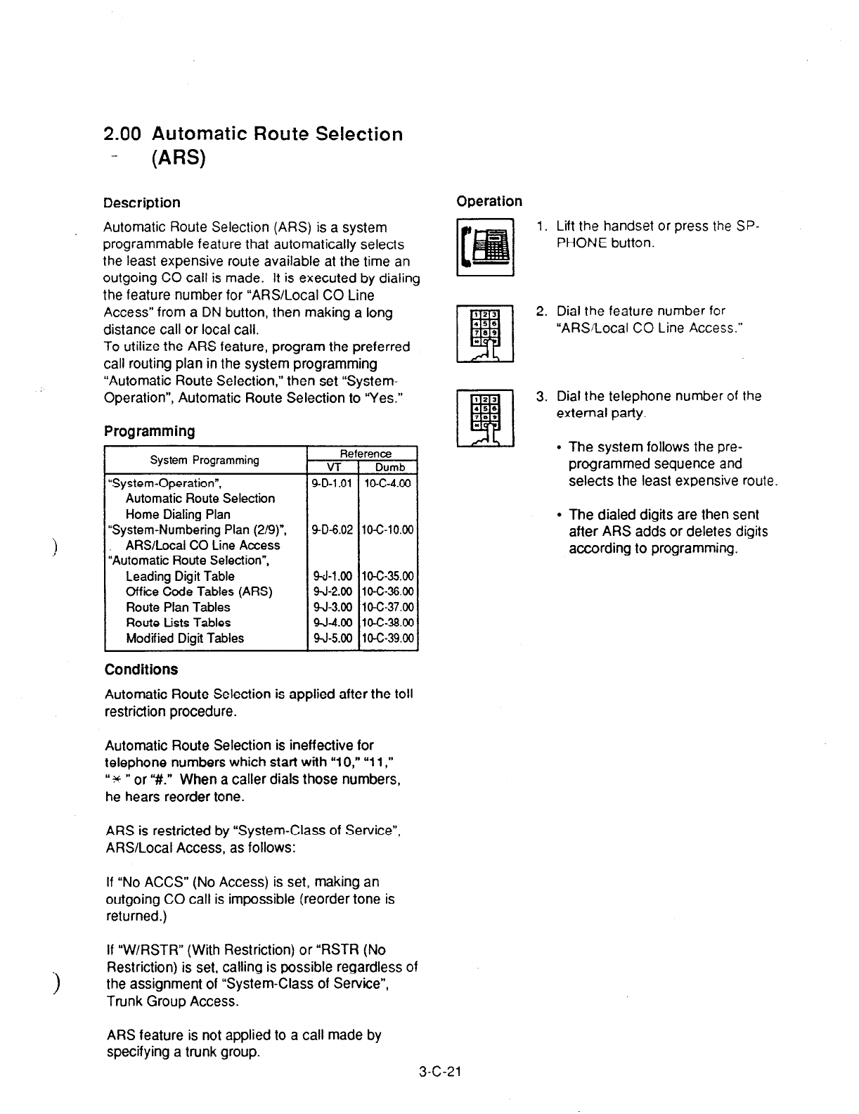
2.00 Automatic Route Selection
- (ARS)
Description
Automatic Route Selection (ARS) is a system
programmable feature that automatically selects
the least expensive route available at the time an
outgoing CO call is made. It is executed by dialing
the feature number for “ARS/Local CO Line
Access” from a DN button, then making a long
distance call or local call.
To utilize the ARS feature, program the preferred
call routing plan in the system programming
“Automatic Route Selection,” then set “System-
Operation”, Automatic Route Selection to “Yes.”
Programming
System Programming
“System-Operation”,
Automatic Route Selection
Home Dialing Plan
“System-Numbering Plan (2/g)“,
ARS/Local CO Line Access
“Automatic Route Selection”,
Leading Digit Table
Office Code Tables (ARS)
Route
Plan Tables
Route Lists Tables
Modified Digit Tables
9-D-6.02 10-C-10.00
9-J-l .OO 10-C-35.00
9-J-2.00
10-C-36.00
9J-3.00 lo-c-37.00
9-J-4.00 10-C-38.00
9-J-5.00 104-39.00
Conditions
Automatic Route Selection is applied after the toll
restriction procedure.
Automatic Route Selection is ineffective for
telephone numbers which start with “10,” “11,”
“?c ” or “#.” When a caller dials those numbers,
he hears reorder
tone.
ARS is restricted by “System-Class of Service”,
ARS/Local Access, as follows:
If “No ACCS” (No Access) is set, making an
outgoing CO call is impossible (reorder tone is
returned.)
If “W/RSTR” (With Restriction) or “RSTR (No
>
Restriction) is set, calling is possible regardless of
the assignment of “System-Class of Service”,
Trunk Group Access.
Operation
1. Lift
the
handset or press the SP-
PHONE button.
2. Dial the feature number for
“ARSLocal CO Line Access.”
3. Dial the telephone number of the
external party.
l
The system follows the pre-
programmed sequence and
selects the least expensive route.
l
The dialed digits are then sent
after ARS adds or deletes digits
according to programming.
ARS feature is not applied to a call made by
specifying a trunk group.
3-C-21

Explanation <Example>
ARS Programming
The following is an example to show the procedures
for programming ARS feature.
Five types of tables are used to program ARS
feature;
The ARS feature, when accessed, selects the least
expensive route as follows.
Explains the procedures to program ARS plan for
calling the XYi’ Company, which has the
telephone number “201-234-5678” and is long
distance.
Three telephone service companies are available
to call the XYZ Company: telephone company A,
B and C.
Telephone companies A and B are the long
distance carriers.
Proqrams Routinq Procedures
Dial
I
(Toll Restriction)
I
Leading Digit Table - - - -
Office Code Tables [Analyze theldialed digit]
Route Plan Tables- - - - - Analyze the time of day
1
Route Lists Tables- - - - - Check the restriction
level of trunk groups
and search an idle
trunk group
I
JI
Modified Digit Tables- - - Modify the dialed digits
1
Sends the dialed number
Telephone company A has:
l
Local access code: 765-4321
l
Authorization number: 012345
Telephone company B has:
l
Local access code: 987-6543
l
Authorization number: 567890
Telephone company A is connected to trunk group
01.
Telephone company B is connected to trunk group
02.
Telephone company C is connected to trunk group
03.
Telephone companies A, B, and C charges for
Monday are as follows:
high
T
Charge
12 3 6 9 12 3 6 9
a.m. p.m.
+ Time
(Table 1)
3-C-22
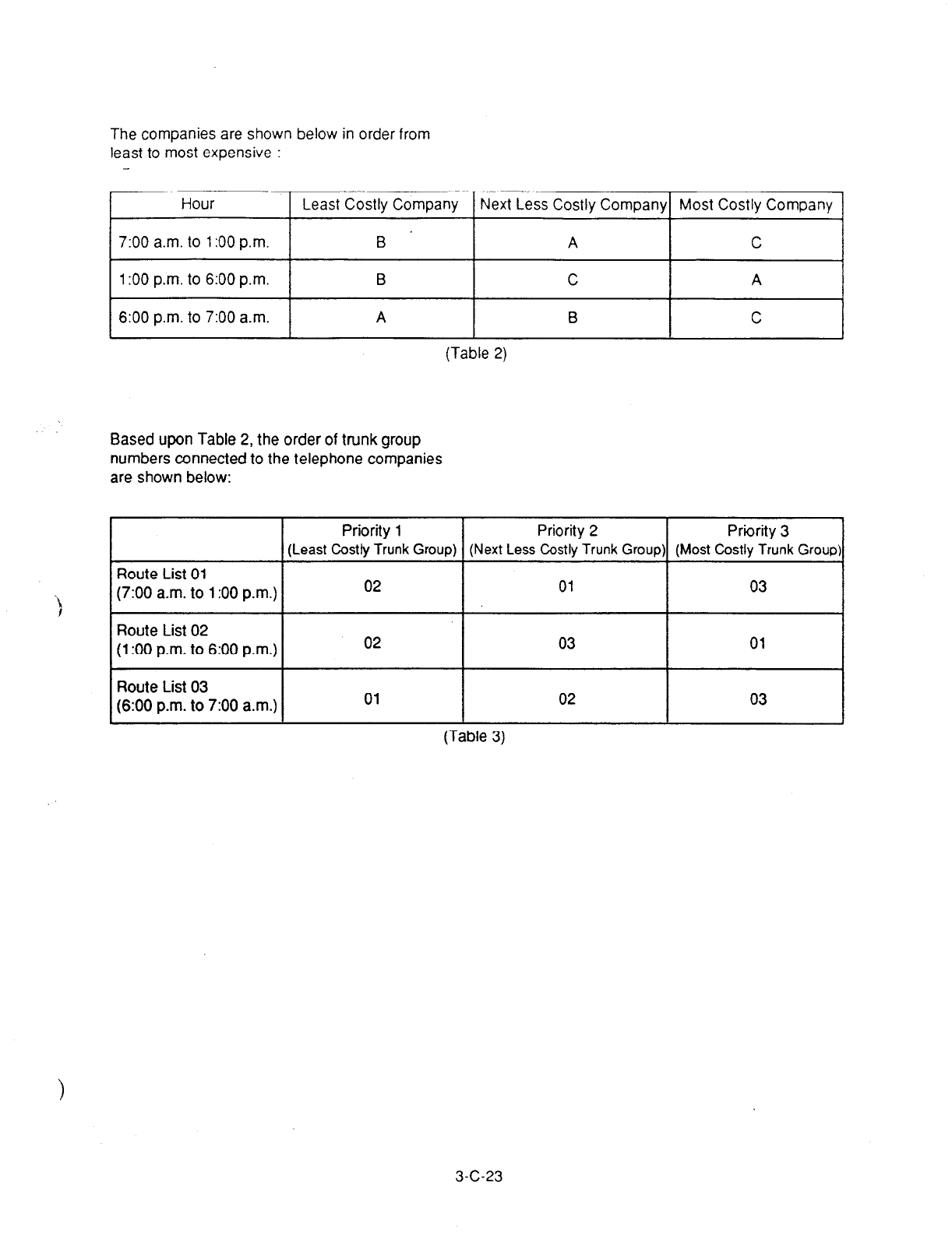
The companies are shown below in order from
least to most expensive :
Hour Least Costly Company Next Less Costly Company Most Costly Company
7:00
a.m. to 1:OO p.m. B A C
1:OO p.m. to 6:00 p.m. B C A
6:00 p.m.
to 7:00
a.m. A B C
(Table 2)
Based upon Table 2,
the order of trunk group
numbers connected to the telephone companies
are shown below:
Priority 1 Priority 2
Priirity 3
(Least Costly Trunk Group) (Next Less Costly Trunk Group) (Most Costly Trunk Group)
Route List 01
(7:00 a.m. to 1:OO p.m.) 02 01 03
Route List 02
(1:OO p.m. to 6:00 p.m.) 02 03 01
Route List 03
(6:00 p.m. to 7:00 a.m.) 01 02 03
(Table 3)
3-C-23
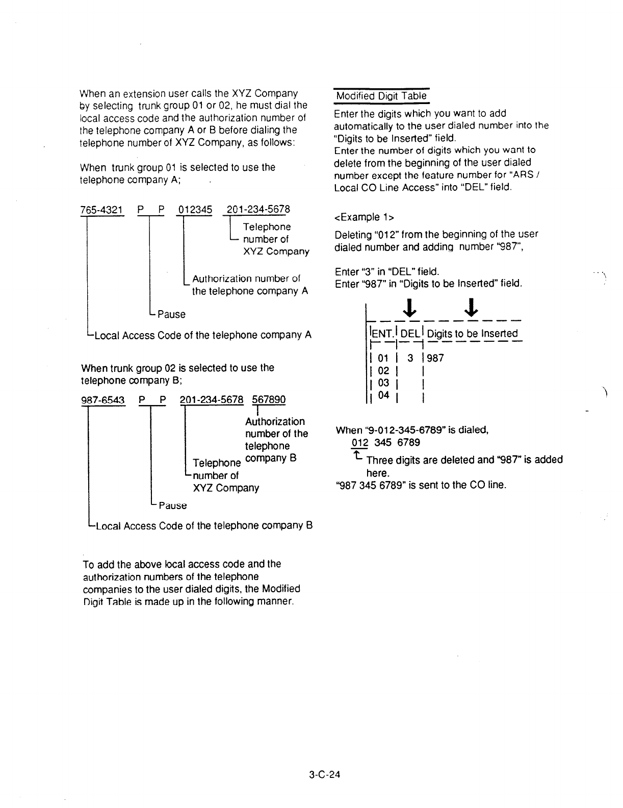
When an extension user calls the XYZ Company
by selecting trunk group 01 or 02, he must dial the
local access code and the authorization number of
the telephone company A or B before dialing the
telephone number of XYZ Company, as follows:
When trunk group 01 is selected to use the
telephone company A;
765-4321 P P 012345 201-234-5678
II
r
E
XYZ Company
Authorization number of
the telephone company A
Pause
Local Access Code of the telephone company A
When trunk group 02 is selected to use the
telephone company B;
P ;
-
Pause
U-234-5678 567890
I
Authorization
number of the
telephone
Telephone company B
.number of
XYZ Company
LLocal Access Code of the telephone company B
Modified Dioit Table
Enter the digits which you want to add
automatically to the user dialed number into the
“Digits to be Inserted” field.
Enter the number of digits which you want to
delete from the beginning of the user dialed
number except the feature number for “ARS /
Local CO Line Access” into “DEL” field.
<Example l>
Deleting “012” from the beginning of the user
dialed number and adding number ‘987”,
Enter “3” in “DEL” field.
Enter “‘987” in “Digits to be Inserted” field.
La J+ A----- ----
IENT.1 DELI Digits to be Inserted
l--l--l-------
I 01 I 3 I987
;::; I
I
PI I
When “9-012-345-6789” is dialed,
012 345 6789
T Three digits are deleted and “987” is added
here.
“987 345 6789” is sent to the CO line.
. \
To add the above focal access code and the
authorization numbers of the telephone
companies to the user dialed digits, the Modified
Digit Table is made up in the following manner.
3-C-24
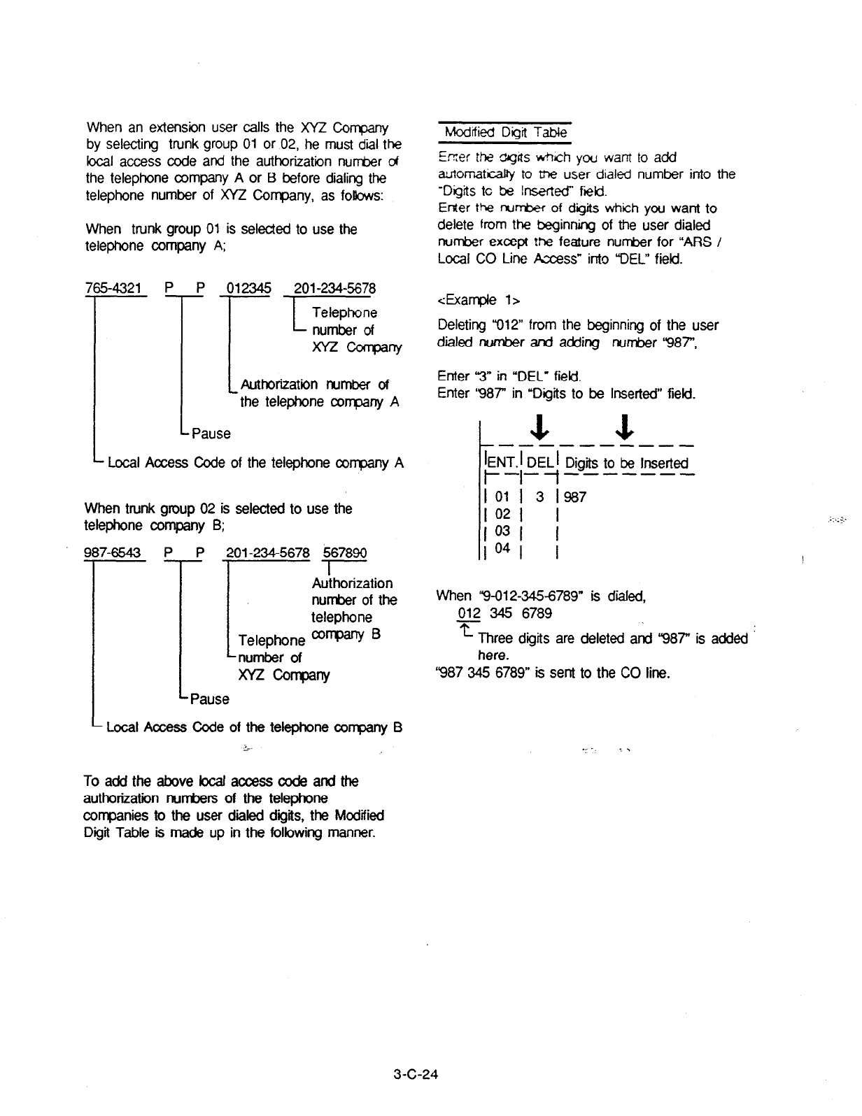
When an extension user calls the XYi’ Company
by selecting trunk group 01 or 02, he must dial the
focal access code and the authorization nut-r&r of
the telephone company A or B before dialing the
telephone number of XYZ Company, as follows:
When trunk group 01 is selected to use the
telephone company A;
54321 p 12345 201-234-5678
--
x=cosrQaw
, Authorization number of
the telephone company A
L Pause
* Local Access Code of the telephone corqoany A
When trunk group 02 is selected to use the
telephone company B;
P
-
7-6543 p 2f X-234-5678 567890
I~
I
Authorization
number of the
telephone
Telephone company ’
number of
XYz oany
Pause
Local Access Code of the telephone company B
LvL--
Modified Dioit Table
Erzer the ~C!AS which you want to add
automaticalty to tne user dialed number into the
-Digits tc be Inserted” field.
Enter the r-rum of digits which you want to
delete from the beginning of the user dialed
number except the feature number for “ARS /
Local CO Line Axess” into DEL” field.
iExan-qle l>
Deleting “012” from the beginning of the user
dialed number and adding number ‘987”,
Enter 3” in “DEL’ field.
Enter ‘987” in ‘Digits to be Inserted” field.
-----------
IENT.1 DELI Digits to be Inserted
l---I--t-------
R 3 ‘987
I
PI I
IO41 I
When ‘9-012-3456789” is died,
p12 345 6789
L Three digits are deleted and ‘987” is added
here.
‘987 345 6789” is sent to the CO line.
Toaddtheabovelocalaccesscodeandthe
authorization numbers of the telephone
companies to the user dialed digits, the Modified
Digit Table is ma& up in the following manner.
3-C-24

dxample 2>
To register the bcal access c&e and the
authorization number of the telephone corrpany A
which you want to add automatically when trunk
group 01 or 02 is accessed, enter those numbers
into “Digits to be Inserted” field.
When trunk group 02 is accessed:
987-6543 P P 201-234-5678 567890
I I
Enter these numbers into “Digits to
When trunk group 01 is accessed: be Inserted” field of “ENT’ 02.
7654321 P P 012345 201-234-5678
I
L
Enter these numbers into “Digits to
be Inserted” field of “ENT” 01.
4utornatic Route Selection-Modified Digit Table 1 OFLj PRq SCRl DIR
_---------------s------s-----------
1121 I
(Table 4)
The numbers stored in “Digits to be lnserteg is
sent to the CO line first before the user dialed
number is sent.
To insert the user dialed number into the stored
number, enter “H” at the proper place. Then the
user dialed number is insarted where ‘Ii” is
.I entered and sent to the CO line.
The registered numbers in the above table are
i sent to the CO line as follows: i’
When ‘7654321 PPO1234” is stored:
7654321
m
_
-xz
012345 2012345678 is sent to the CO line.
A r User dialed number
Automatically added number
When “9876543PPH56789” is registered :
9876543
T Automatically added number
2012345678 567890 is sent to the CO line.
Automatically added number
User dialed number
3-C-25

Route Lists Table
Entering ‘TG’
Enter the trunk group nur&ers in “TG-
field
according to the Table 3.
Enter the numbers “02” “01” “03” (7100 a.m. to
1:OO p.m.) in Route List ##Ol.
Enter the numbers “02” “03” ‘01” (1 XXI p.m. to
6:00 p.m.) in Route List ##02.
Enter the numbers “01” “02” ‘03” (6:OO p.m. to
7:00 a.m.) in Route List #O3.
Automatic Route Selection-Route Lists Table I OFL 1 PRG 1 SCR I DIR
Route Lists Table (l/6)
Gioutel
I List t
I I
---
I #ml I
I #02 I
I #03 I
I *04 I
I #a5 I
----
p&m 1 r-T--p~~j-----i--
T I
i I
I I I
Trunk group
--
ALV 1
--I
I
I
I
I
number
(Table 5)
----
Priority 3
I
03 I
ITl
--i- - -
M_o_ELI dALVT TG7 &s
I-+-+--t-- I
Il l I I
Il l l I
ll I l I
II I l I
Entering WOD”
Selact the digits that you want to add to or delete
from the telephone number depending on Modified
Digit Tabte (Table 4) and enter the applicable
“ENT” number in “MOD” fiekl.
I.
For trunk group 01, enter ENT “01” in “MOD” field.
For trunk group. 02, enter ENT “02” in “MOD” field.
.- -
I
Automatic Route Selectiin-Route Lists Table I~FLIPRGISCRI DIR 1
Route Liis Table (l/6)
1 #04 I
I I
----
iii? TG IMOD
-t,,-l,l-
I 03 1
I 02
1 02
t- “ENT’ number in Modified Digit Table (Table 4)
(Table 6)
Leave “MOD” field blank if there are no digits to be entered or deleted.
3-C-26

Entering “ALV
It is possible to set
ARS restriction levels from
“01” to “16” for Priority 2, 3, and 4. Enter ARS
restriction level into “ALV” fiekl.
k I
---- -.-
rTE
k:Drd
xJ TG 1
MOD
w
%V
1 T&ODi~A~V~ yGT&
ä -+-+-i--i--i--~t--i-I--i-t-t-l--f
I I II I I II I I II I I I
I I II I I II I I II I I I
Entering ‘W
It is programmable to send the warning tone to
the user or not when the trunk group of Priority 2
to 4 are seized, by selecting “Y” in ‘WT” field of
Priority 2.
4 a 4
I
1
-- ---- _-.- -A.-
TG TM~D,~ EJ TG I MODri+-r ALV I T$ MOD~~A~V~ TG~~J
~-+-+-i--i--i--~t--i-1--i-+-t-l-i
I I II I I
I I II I I
II I I II I I I
II I I II I I I
(Table 8)
Route Plan Table Route Plan Table No. =Ol
Enter the starting Hour designated in Table
2 in the “Start Hour” field.
Enter the Route List Number” in Route
Lists Tabfe (Table 6) depending on the
trunk group in Table 3 into “Route List
Number” field.
r --- --------------
1 1
1 Start Hour I Route List Number (01-64)
r-i-t---l--
1. ._
I--T’T-T-7-1
1 Hour
lAM/PMI MON. I TUE. IWED. I THU. I FRI. I SAT. I SUN. I
l-T--f--l-- r-t-t-t-t-1
l7lAw01l I I I I I I
Enter Route List Number “01” for “Hour” :
7:00 a.m. to 1:00 p.m..
Enter Route List Number “02” for “Hour” :
1:00 p.m. to 6:00 p.m..
Enter Route List Number “03” for “Hour” :
6:00 p.m. to 7:00 a.m..
r-r--r-l-7-1-l--,--,--I
I l I PM I O2 I I I I I I I
,-,--r-r-T-T-7--l
I
Enter the “Route List Number” in Route
Lists Table (Table 6) into each field
divided by hour and the day of the week.
Enter the starting Hour according to Table 2.
(Table 9)
3-C-27
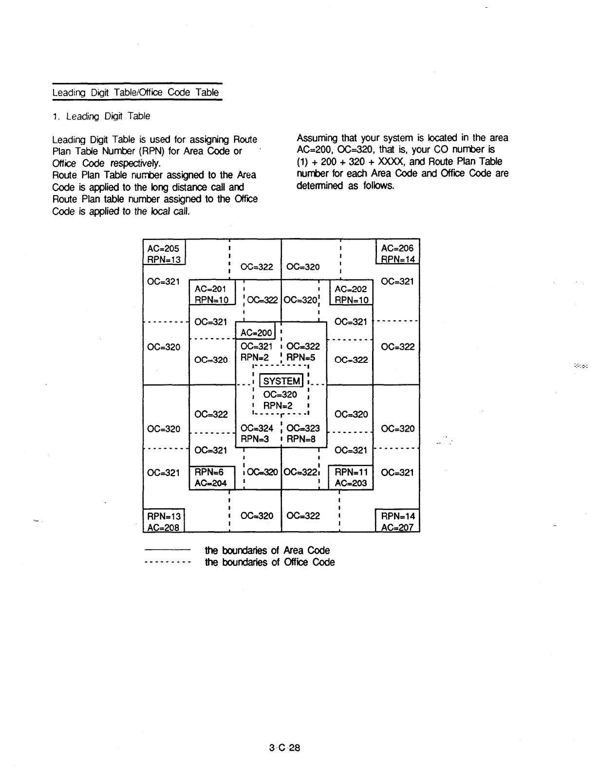
Leadina Didit Table/Office Code Table
1. Leading Digit Table
Leading Digit Table is used for assigning Route Assuming that your system is located in the area
Plan Tabfe Number (RPN) for Area Code or A&200, OG320, that is, your CO number is
office code respectively. (1) + 200 + 320 + XXXX, and Route Plan Table
Route Plan Table number assigned to the &ea number for each Area Code and Offii Code are
Code is applied to the long distance call and determined as follows.
Route Plan table number assigned to the Offii
Code is applied to the local call.
AC-205
--.I
RPN=13
I I
I I
;
CC=322 OC=320
;
CC=321
-------
OC=320
1 I
AC=201 1 AC-202
RPN=lO : OG322 OC=32Oj RPN=lO
O&321
--mm---
OG322
OC-321 OC-321
_--___--
_--___--
OC-322 OC-322
OC-320
--m--v-.
I I
RPN=l3 ’ CC=320 OC=322
'
RPN=14
AC=208
I I
AC-207
the boundaries of Area Code
-m------- the boundaries of Office Code
3-C-28
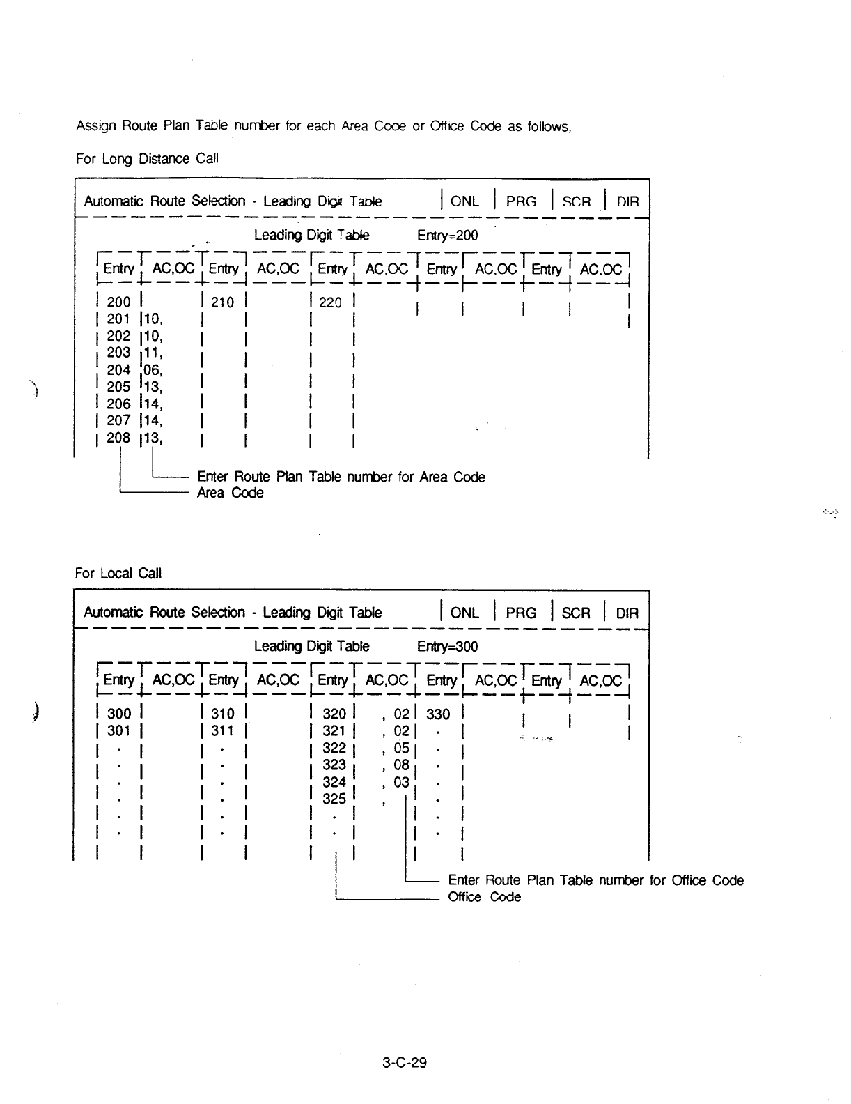
Assign Route Plan Table number for each Area C&e or Office Cc&? as follows,
For Long Distance
Call
t
Automatic Route Selection - Leading Digu Tab& 1 ONL 1 PRG 1 SCR 1 DIR
--------------------------____
Leading Digit Talk Entry=200
r-r
--f-,---r-r--7--r--r-~--~
Entry AC,OC Entry AC,OC Entry AC,OC Entry AC,OC Entry AC,OC
~-C--I-~---C-C--$--~--t-~--~
I 200 I 1210 I
I
220
I
I
201
110, I I
I I
I I
1
202
110, 1 1
I 203 p I I
I I
1 204 113 06,
I I
205
I I I I
1 206 114: 1 1
I I
I 207
114, I I
I I :
I I
Enter Route plan Table nun-her for Area Code
For Local Call
Automatic Route Selection - Leading Dgit Table 1 ONL 1 PRG 1 SCR 1 DIR
-------------------------------
Leading Digit Table Entry=300
r-r--T-,---r-~--T--r--r-7--~
Entry
l---l-
AC,OC Entry AC,OC Entry AC,OC Entry AC,OC Entry AC,OC
I
300
I
--~-~---c-c--~--~--+-~--~
I
310
I
1 320 1 , 02
I
330
I I
I
301 I 1311 I
1 321
1 , 02 1 1 I I - . ,~ 1
I-I I-I
1 322 1 , 05 1 - 1
Ill Ill I 323
324
I
,09
I 325 1 ,03 1
-
-
I
. I
1.1’ 1-I
I * I I - I
I I I I I/I I I
- Enter Route Plan Table number for Office Code
L Office Code
3-c-29

2. Office Code Table
Route Plan Table number for Area Code is
applied to the long distance call, accordingly,
the same Route Plan Table number is applied
to all Office Codes within that area.
Office Code Table is used when you want
assign another Route Plan Table number to
an Cffice Code within that area.
Assuming that your system is located in the
area AC=201, CG320, and Route Plan Table
number 7 is applied to the calls for Area A,
AC=200.
Area A
AC=200 1 I
RPN=7 1 OC=321 - 1 d&322
OC=320 1 I
------------
I I
OC=323 1 OC=324 1 OC=325
I
1 RPN=5
------m-m---
Area B
I
OC=326 O&327
I
I I
O&326 O&320 ’ O&323
RPN=2 lSysteml
I
I
the boundaries of Area Code
__---____ the boundaries of Office Code
In above case, usually Route Plan Table number
7 is applied to all Cffiie Codes within Area A,
AC=200.
But if you want to assign Route Plan Table
number 5 to CC=325 and Route Plan Table
number 2 to CC=328 withii Area A, program the
Leading Digit Table as follows.
3-c-30
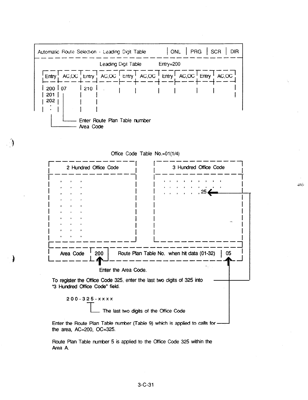
Automatic ficute Seklron - Leading Dkjt Tabk 1 ONL 1 PRG 1 SCR 1 DIR
-- --------------------m---- ---
Leading Dgn Table Entry=200
Enter Route Plan Table number
office Code Table No.=01(1/4)
r------------f I--3~“;red--~
2 Hundred Office Code
e--------s----
-----------s-m
l I I I
’ : : : I I ::::::::: I
’ , , ,
I , I , I I ,.,,,,25+ I
I I I
I , , I I I I
’ , I > I I I
’ , # 1 I I I
’ > , I . .
I I I
I ” ’ I I I
I ” ’
c -------em--
-----
I
Area Code
r-
L
200
1
J L-----------4
-------------------
----A* Route Plan Table No. when hit data (0132) 1 05 I
----------------- “t -I
Enter the Area Code.
To register the Office Code 325, enter the last two digits of 325 into
“3 Hundred Office Code” fieki.
200-325-xxxx
IL The last two digits of the Office Code
Enter the Route Plan Table number (TabIe 9) which is applied to calls for
the area, AC=200, OC=325.
Route Plan Table number 5 is applied to the Office Code 325 within the
Area A.
3-c-31
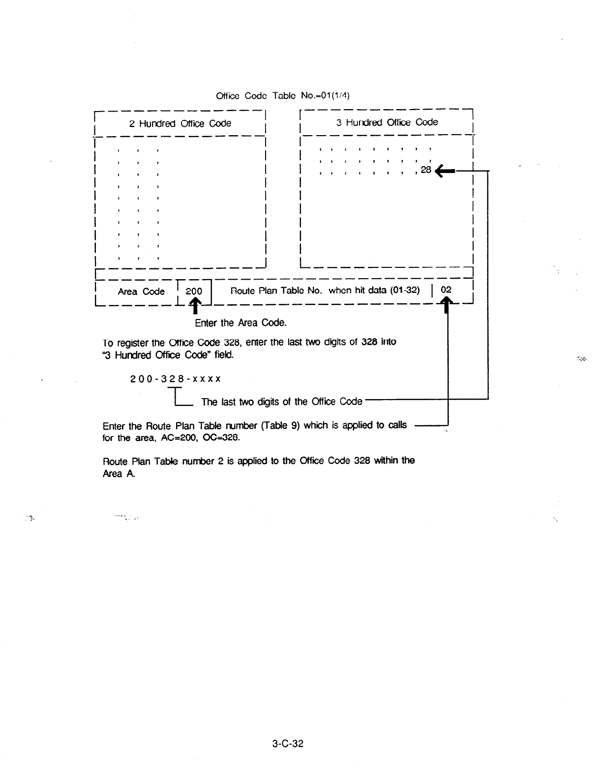
Office Code Table No.=01
(l/4)
r- _-----__- ---
, r------------7
I 2 Hundred Office Code I I
3
Hundred Office Code I
-----__---- _----B---v-
--.
_- -
I
I I I
1 : : : I I :::;;:::: I
1 , , I I I I>,,,,.
I , , , I I
,++--
I , t I I I I
1 , , * I I I
1 # I I I I I
1 I , > I I I
1 I , I I I I
I ” ’
r --------A--
J L-----------;
------
__------------------
I
L
Route Plan Table No. when hii data (01-32) 1 02 I
_------------- --- T- J
Enter the Area Code.
To register the Office Code 328, enter the last two digits of 328 into
‘3 Hundred Office code” field.
200-328-xxxx
-L
The last two digits of the Office Code
Enter the Route Plan Table number (Table 9) whiih is applied to calls
for the area, AC=200, OG328.
Route Plan Table number 2 is applied to the Office Code 328 within the
Area A.
.
3-C-32
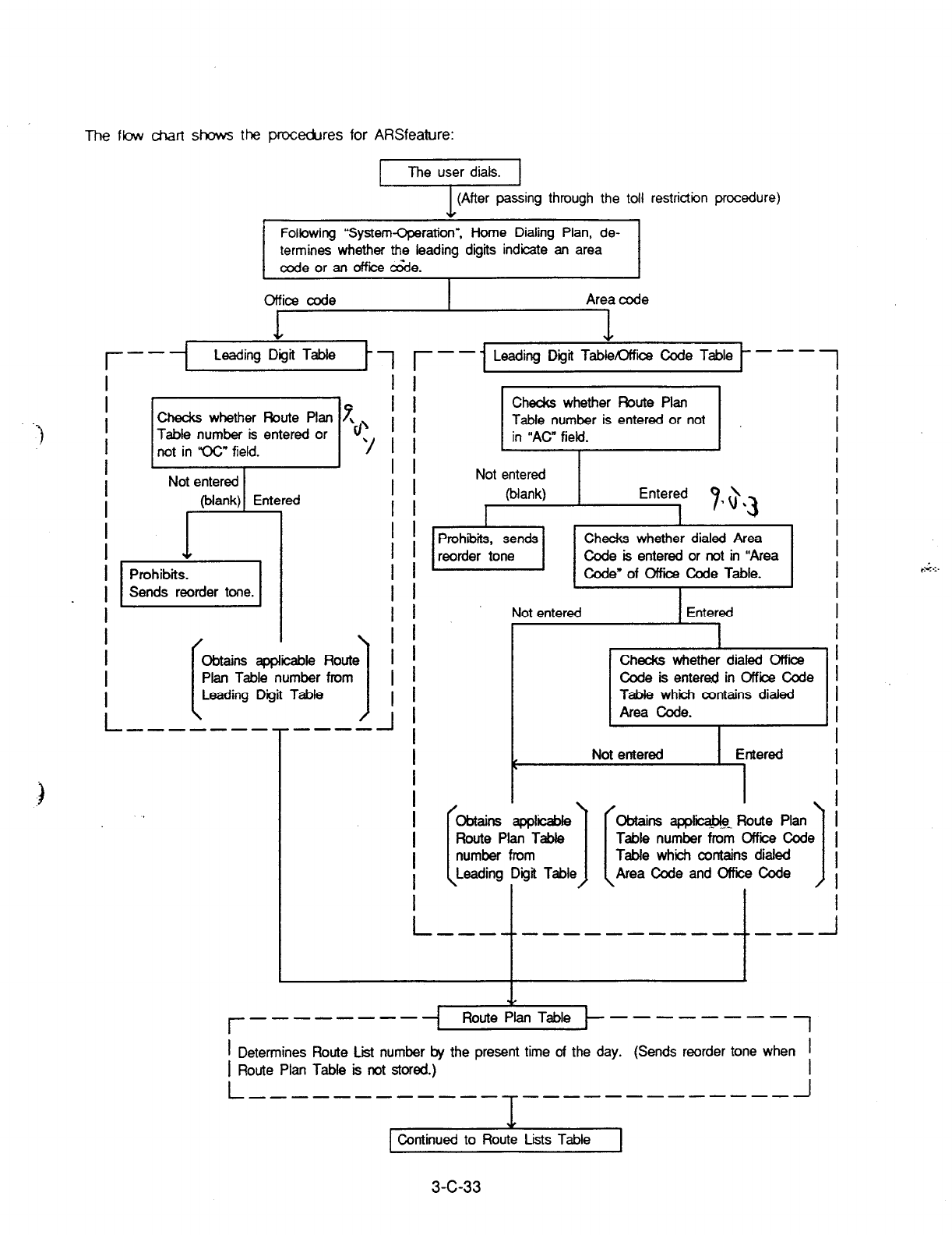
The
flow
chart shows the procedures for ARSfeature:
The user dials.
r
I
I
I
I
I
I
I
I
I
I
I
I
I
I
I
I
1 (After passing through the toll restriction procedure)
Following “System-Cperation”, Home Dialing Plan, de-
termines whether the leading digits indicate an area
code or an office &de.
Office code
1
Area code
--- Leading Digit Tabfe 17 r--l Leading Dgit TableOffii code Table -es
1
c2wcks whether Route Plan 7
Table number is entered or ‘t/’
not in ‘CC” field. 7
Table number from
.j
I I
I I
I I
I I
I I
I I
/ f
/ I
I I
I /
; I
I I
.----A
i
I
I
I
I
I
I
I
I
Prohibits, sends Checks whether dialed Area
I
reorder tone Code is entered or not in “Area
I
Code” of Office Code
Table.
I
I
Not entered Entered
I
I I
Checks whether dialed Office
I
Code is entered in Office Code I
Table which contains dialed I
Area code.
I
I
Not entered
Entered
I
I
I
I
I
I
obtains applii
Obtains appfii Route Plan
- ,_-
1
I
Route Plan Table Table number from Office Code I
number from
Table which contains dialed
Leading Area Code and Office Code
I
\ I I
I
L --A -t ---------- ---
-t -I
I
Checks whether Route Plan
I
Table number is entered or not
in “AC” field.
I
I
Not entered
(blank)
I
I
Entered
I 9
3
*a. I
I
r -------- ---------j
I
Determines Route Lii number by the present time of the day. (Sends reorder tone when
I
I

Continued from Route Plan Table
.‘”
--- _------
Route Lists Table ------------/
I
I
I
I
I
I
I
I
I
I
I
I
I
I
I
I
I
I
I
. I
I
I
I
I
I
I
I
I
I
I
I
I
I
I
I
I
I
I
I
I
1 assigned or not.
L ------
r --------------- __------
I
I
I
I
I
I
I
I
I
I
I
I
I
I
I
I
I
I
-&,
No --
I Yes
.L
Not obtainable Checks whether an idle line
1 is obtainable or not from the
As: aned si!
I L
Ched<s whether
the next priority is
assigned or not. I
Not assigned
Continued to Modified Digit Table
W TRLE : toll restriction level of extension assigned
in Class of Service.
3-c-34
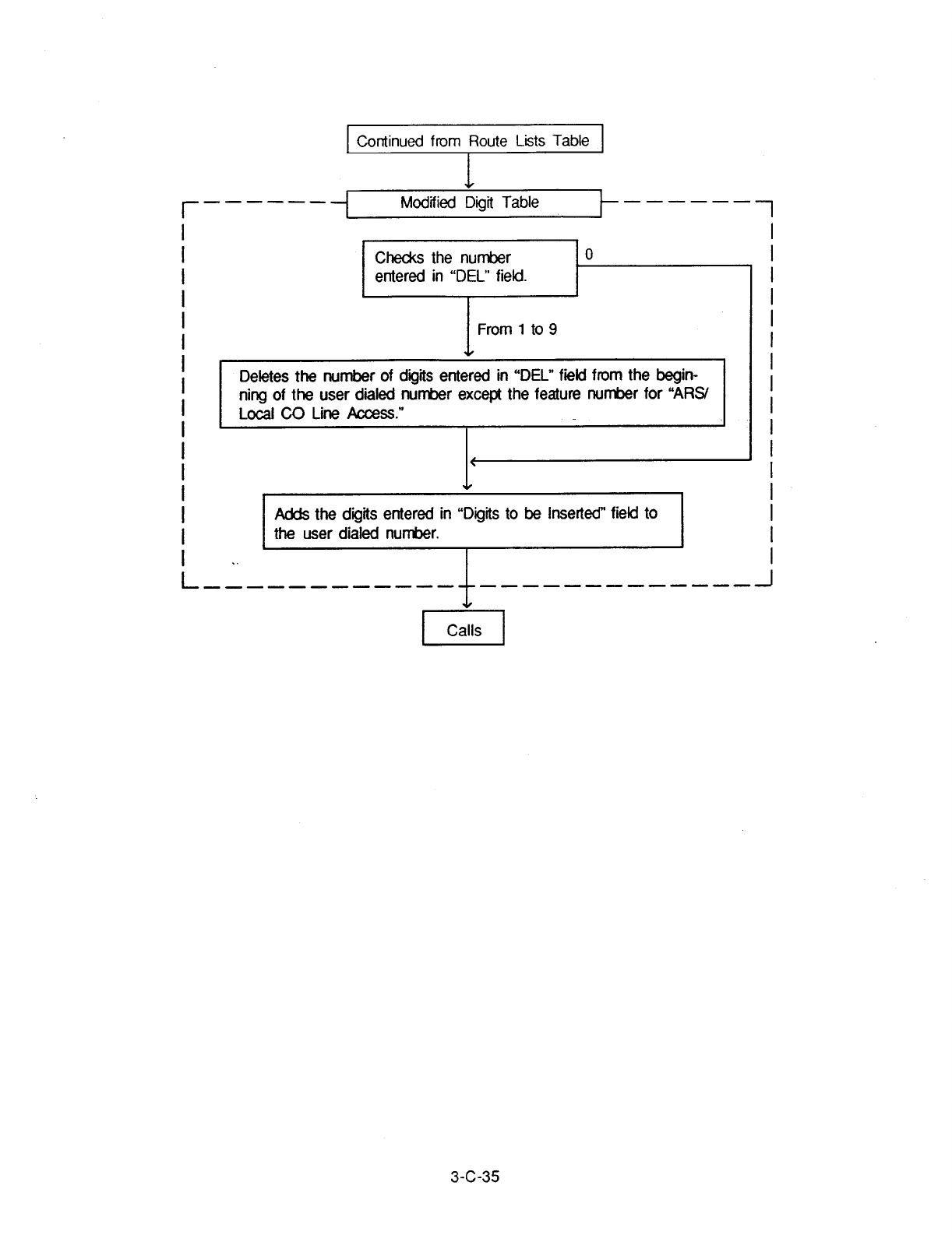
I
Continued from Route
Lists Table 1
r _----_
Deletes the number of digits entered in “DEL” field from the begin-
I ning of the user dialed nun&?r except the feature number for “A%/
Local CO Line Access.”
I
I
I
I v
I
I
Adds the digits entered in “Digits to be Inserted” field to
I
I
the user dialed number.
I
.
I ,. I I
L -4
------------ ----------es- -J
3-c-35
3.00 Tone/Pulse Conversion
Description
Conditions
When the DTMF dial mode is established on a
CO line, the dial signal sent from an extension
(tone or pulse dial mode) is converted into DTMF
signals by the COT (LCOT,GCOT) card and sent
to the Central Office.
If the PULSE dial mode is established on a CO
line, the dial signal sent from an extension (tone
or pulse dial mode) is converted into pulse signal
by the COT card and.,sent to the Central Office.
When making a CO call, if the trunk is assigned
to a PULSE dial mode, in the following conditions
the dial signal is converted into DTMF signal after
sending a telephone number.
1) A telephone number belongs to “Special
Carrier Access-OCC Access.”
2) The selected trunk group belongs to the
trunk group in “Special Carrier Access-
OCC Access.”
The “DTMF dial mode” or “PULSE dial mode” is
set in “Trunk-CO Line”, Dial Mode.
Set “DTMF” for a CO line which can accept both ‘--
DTMF and PULSE dialing.
Programming
System Programming
“Trunk-CO Line”, Dial Mode
Reference
VT Dumb
9-F-l .OO 1 O-C-1 8.00
After External Feature Access, until the
maximum digits are dialed,‘the’dialing mode is
changed to the mode set in “Trunk-CO Line”, Dial t
Mode.
(With a PITS, Tone Though mode is released
temporarily during this time.)
With a PITS, Tone Through mode is established
automatically after the dialing sequence. 4
After pressing the Tone Through Break button,
until the maximum digits are dialed, the dialing
mode becomes the dialing mode set in “Trunk-
CO Line”, Dial Mode. Tone Through mode is .
released temporarily during the time.
Refer to Section 4-G-l 2.00 “Tone Through (End
to End DTMF Signaling)” for further information.
3-C-36
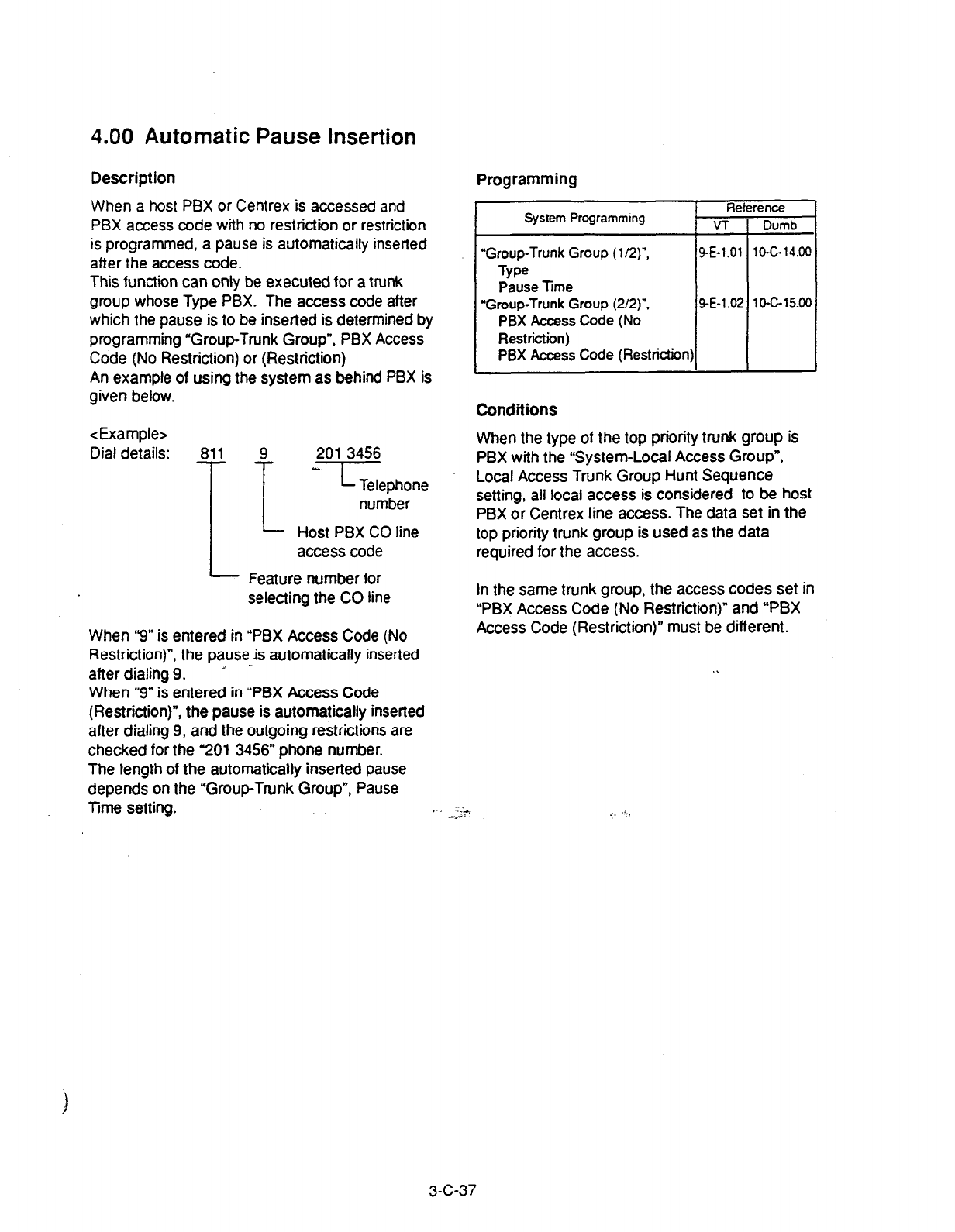
4.00
Automatic Pause Insertion
Description
When a host PBX or Centrex is accessed and
PBX access code with no restriction or restriction
is programmed, a pause is automatically inserted
after the access code.
This function can only be executed for a trunk
group whose Type PBX. The access code after
which the pause is to be inserted is determined by
programming “Group-Trunk Group”, PBX Access
Code (No Restriction) or (Restriction)
An example of using the system as behind PBX is
given below.
<Example>
Dial details: 811 9 201 3456
I
-Tephone
number
Host PBX CO line
accesscode
Feature number for
selecting the CO line
When “9” is entered in “PBX Access Code (No
Restriction)“, the pause b automatically inserted
after dialing 9. * -
When “9” is entered in ‘PBX Access Code
(Restriction)“, the pause is automatically inserted
after dialing 9, and the outgoing restrictions are
checked for the “201 3456” phone number.
The length of the automatically inserted pause
depends on the “Group-Trunk Group”, Pause
Time setting.
Programming
He
System Programmtng VT
“Group-Trunk Group (l/2)“,
9-E-l
.Ol
Type
Pause
lime
“Group-Trunk Group (2/2)“, SE-1 .O:
PBX Access Code (No
Restriction)
PBX Access Code (Restriction)
Conditions
When the type of the top priority trunk group is
PBX with the “System-Local Access Group”,
Local Access Trunk Group Hunt Sequence
setting, all local access is considered to be host
PBX or Centrex line access. The data set in the
top priority trunk group is used as the data
required for the access.
In the same trunk group, the access codes set in
“PBX Access Code (No Restriition)” and “PBX
Access Code (Restriction)” must be different.
3-c-37
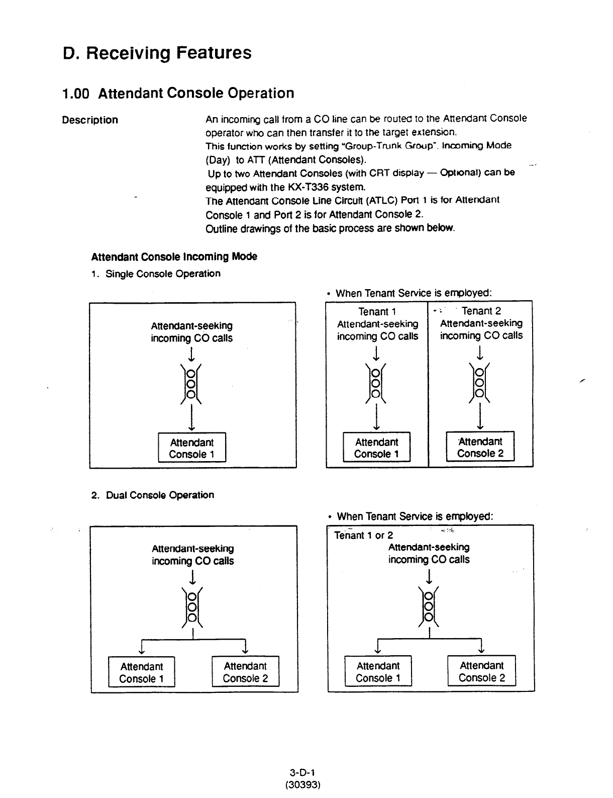
D. Receiving Features
1 .OO Attendant Console Operation
Description An incoming call from a CO line can be routed to the Attendant Console
operator who can then transfer it to the target extension.
This function works by setting “Group-Trunk Group’. Incoming Mode
(Day) to ATT (Attendant Consoles).
--- Up to two Attendant Consoles (with CRT display - Optbnaf) can be
equipped with the KX-T336 system.
The Attendant Console Line Circuit (ATLC) Port 1 is for Attendant
Console 1 and Port 2 is for Attendant Console 2.
Outline drawings of the basic process are shown bebw.
Attendant Console Incoming Mode
1. Single Console Operation
l
When Tenant Service is employed:
Attendant-seeking
incoming CO calls
1
2. Dual Console Operation
Attendant-seeking
incoming CO calls
l
When Tenant Service is employed:
Tenant 1 or 2
q :--&
Attendant-seeking
incoming CO calls
1 ‘.-
3-D-l
(30393)
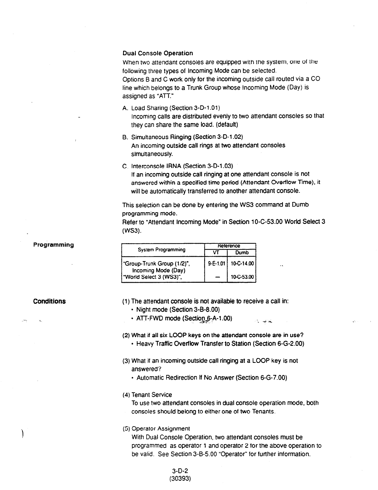
Programming
Dual Console Operation
When two attendant consoles are equipped with the system, one of the
following three types of incoming Mode can be selected.
Options B and C work only for the incoming outside call routed via a CO
line which belongs to a Trunk Group whose Incoming Mode (Day) is
assigned as “ATT.”
A. Load Sharing (Section 3-D-l .Ol)
Incoming calls are distributed evenly to two attendant consoles so that
they can share the same load. (default)
B. Simultaneous Ringing (Section 3-D-l .02)
An incoming outside call rings at two attendant consoles
simultaneously.
C. Interconsole IRNA (Section 3-D-l .03)
If an incoming outside call ringing at one attendant console is not
answered within a specified time period (Attendant Overflow Time), it
will be automatically transferred to another attendant console.
This selection can be done by entering the WS3 command at Dumb
programming mode.
Refer to “Attendant Incoming Mode” in Section 10-C-53.00 World Select 3
(WS3).
System Programming Reference
VT I
Dumb
Conditions
“Group-Trunk Group
(l/2)“,
Incoming Mode (Day)
“World Select 3 (WS3)“.
9-E-1.01 10-C-14.00 . .
- 10-c-53.00
(1) The attendant console is not availabfe to receive a call in:
l
Night mode (Section 3-B-8.00)
l
ATT-FWD mode (Sectio$&A-1.00) .- 3 ,‘i
(2) What if all six LOOP keys on the attendant console are in use?
l
Heavy Traffic Overflow Transfer to Station (Section 6-G-2.00)
(3) What if an incoming outside call ringing at a LOOP key is not
answered?
. Automatic Redirection If No Answer (Section 6-G-7.00)
(4) Tenant Service
To use two attendant consoles in dual console operation mode, both
consoles should belong to either one of two Tenants.
:
(5) Operator Assignment
With Dual Console Operation, two attendant consoles must be
programmed as operator 1 and operator 2 for the above operation to
be valid. See Section 3-B-5.00 “Operator” for further information.
3-D-2
(30393)
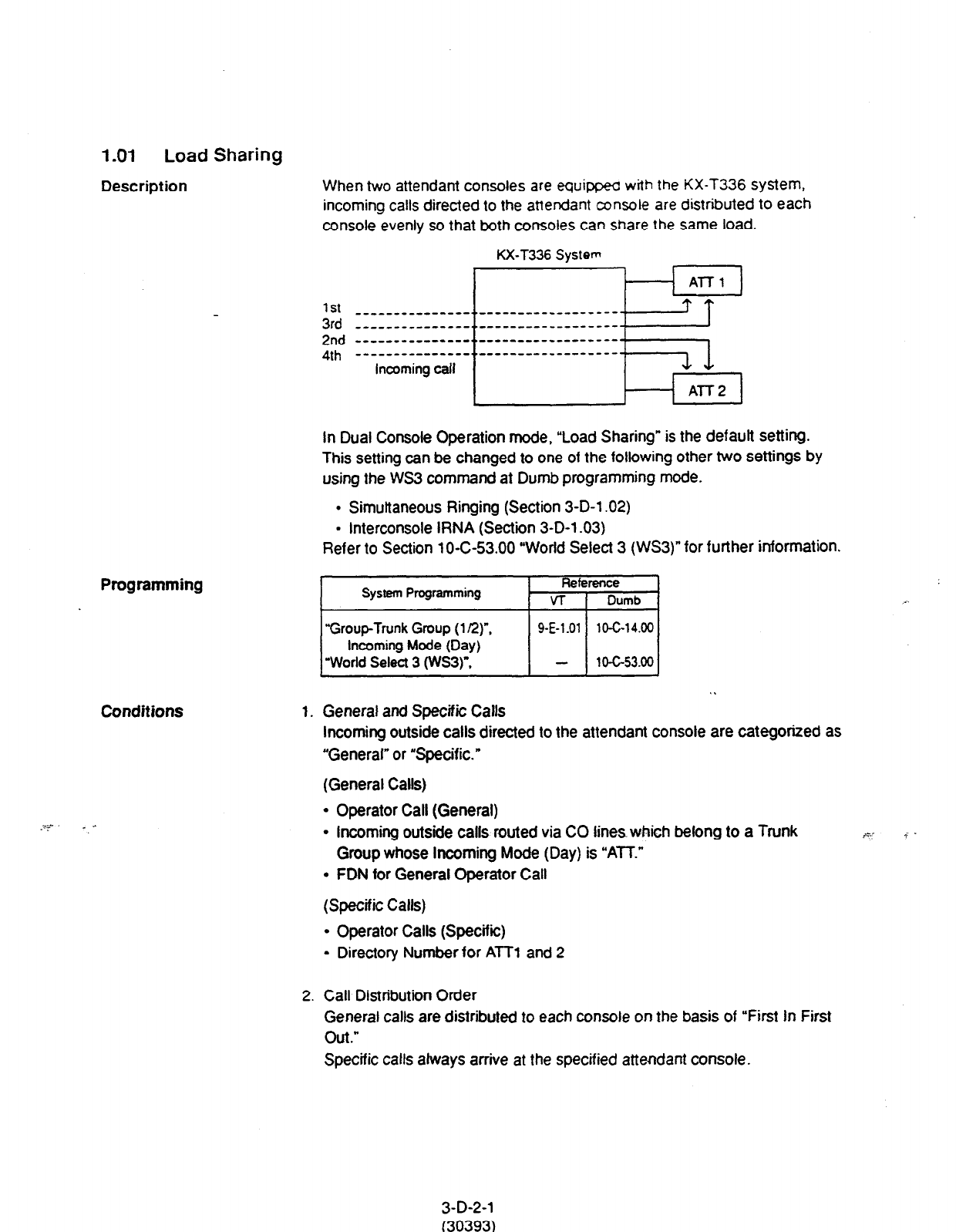
1.01 Load Sharing
Description
When two attendant consoles are equippec
with the
KX-T336 system,
incoming calls directed to the attendant
console
are distributed to each
console evenly so that both consoles can
share the same
load.
KX-T336 System
Al-T.1
1st -------_-------.._-----------------
3rd _ _ _ _ _ _ _ _ _ _ _ _ _ _ _. . __ _ _ _ _ _ _ _ _ _ _ _ _ _ _ - - 71
2nd -----_-_------_..---________________L
4th ---------------..------------------
Incoming call Ll
Al-f2
In Dual Console Operation mode, “Load Sharing” is the default setting.
This setting can be changed to one of the following other two settings by
using the WS3 command at Dumb programming mode.
l
Simultaneous Ringing (Section 3-D-l .02)
l
Interconsole IRNA (Section 3-D-l .03)
Refer to Section 10-C-53.00 “World Select 3 (WS3)” for further information.
Programming
Conditions
I
System Programming Reference
VT 1 Dumb
“Group-Trunk Group (1 LZ)“,
Incoming Mode (Day)
“World Select 3 (wS3)“.
9-E-1.01 10-G14.00
1o-c-53.00
. .
1. General and Specific Calls
Incoming outside calls directed to the attendant console are categorized as
“General” or “Specific.”
(General Calls)
l
Operator Call (General)
l
Incoming outside calls routed via CO lines which belong to a Trunk
Group whose Incoming Mode (Day) is “ATT.”
l
FDN for General Operator Call
(Specific Calls)
l
Operator Calls (Specific)
- Directory Number for ATT1 and 2
2. Call Distribution Order
General calls are distributed to each console on the basis of “First In First
Out.”
Specific
calls always arrive at the specified attendant console.
3-D-2-l
(30393)
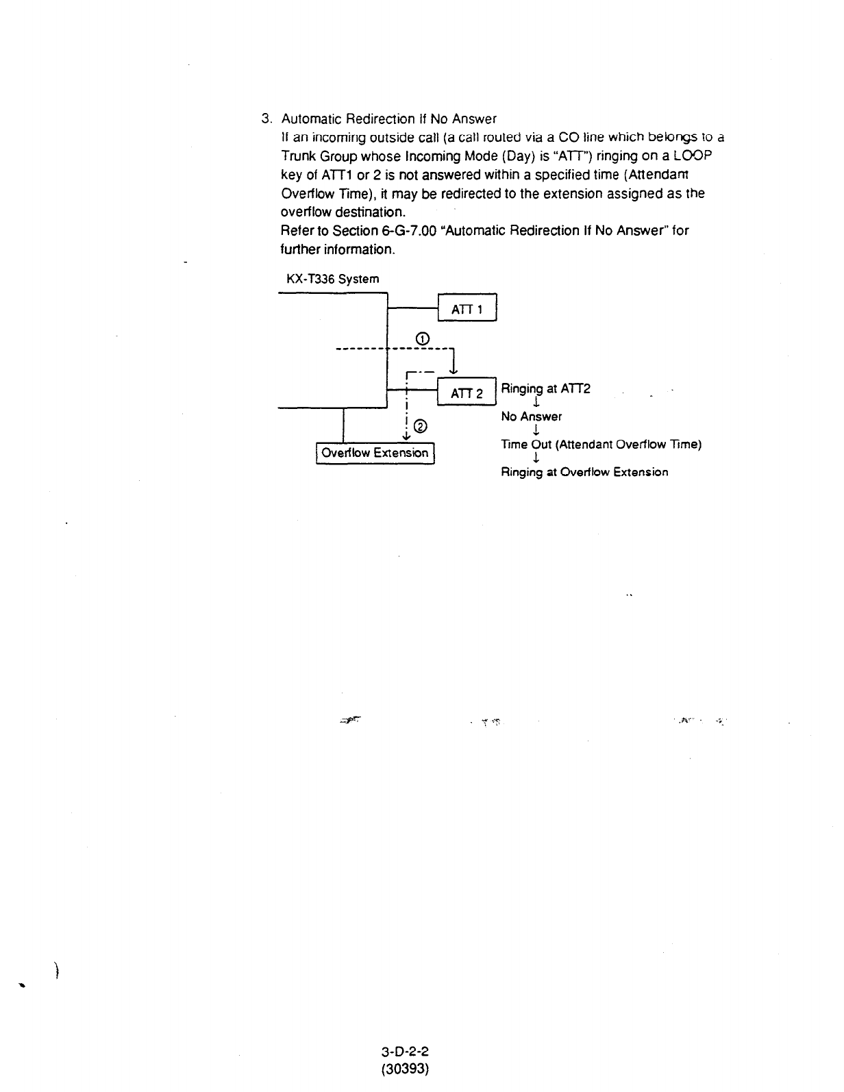
3. Automatic Redirection If No Answer
If an incoming outside call (a call routed via a CO line which belongs to a
Trunk Group whose incoming Mode (Day) is “ATT”) ringing on a LOCP
key of ATT1 or 2 is not answered within a specified time (Attendant
Overflow Time), it may be redirected to the extension assigned as the
overflow destination.
Refer to Section S-G-7.00 “Automatic Redirection If No Answer” for
further information.
KX-T336 System
Al-T1
I
AT-T 2 Ringing at ATT2
i 1
;o No Answer
1
Overflow Extension lime ‘1”’ (Attendant Overflow Time)
Ringing at Overflow Extension
3-D-2-2
(30393)

1.02 Simultaneous Ringing
Description
When two arrendanr wnsoks are equipped with the KX-T336 system, an
incoming outside tail directed to the attendant console will ring on a LOOP
key of both attendant consoles simultaneously.
Programming
KX-T336
System
t
r _-mm-- --m-m) All-l Ringing
: a ’
--------------------------------~
Incoming outside call : 0
L _--m-e ---me) AIT2 Ringing
Conditions
In Dual Console Operation mode,
“Load
Sharing” is the default setting.
This “Simultaneous Ringing’ setting can be selected by using the WS3
command at Dumb programming mode.
Refer
to
Section 1 O-C-53.00 “World Select 3 (WSS)” for further information.
1.
A
call
will ring simultaneously at both AlTl and 2 when:
l
An incoming call is routed via a CO line which belongs to a Trunk
Group whose Incoming Mode (Day) is assigned as “ATE”
l
Both ATT1 and 2 are available to receive a call.
l
An idle LOOP key is available at both ATT1 and 2.
Otherwise, a call will ring at either one of two attendant consoles.
2. Automatic Redirection If No Answer
If an incoming outside call (a call routed via a CO line which belongs to
a Trunk Group whose Incoming Mode (Day) is “ATT”) ringing on a
LOOP key of two attendant consoles simultaneously is not answered
within a specified time (Attendant Overflow Time), it may be redirected
to the extension assigned as the overflow destination.
Refer to Section 6-G-7.00 “Automatic Redirection If No Answer” for
further information.
KX-T336 System
I I
--------J ,
I i
I
, k.-.-
L __-. ___-- 3
Al-f2
Overflow Extension
Ringing
Ringing !
No Answer
1
Time Out
1
Ringing at overflow extension
3-D-2-3
(30393)
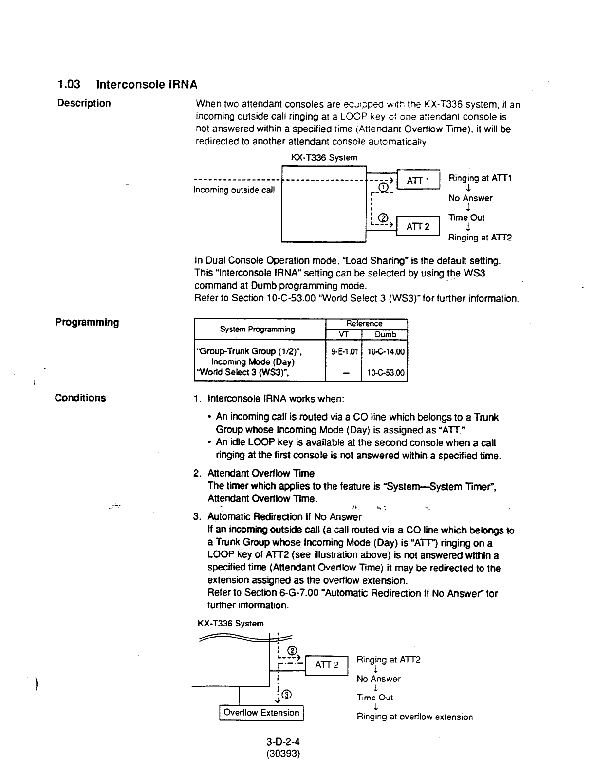
1.03 Interconsole IRNA
Description
When two attendant consoles are eqd~ped wflr: the KX-T336 system, if an
incoming outside call ringing at a LOOP key o: one atiendant console is
not answered within a specified time (Attendant Overtrow Time), it will be
redirected to another attendant console automatically
KX-T336 System
,
Programming
Conditions 1. Interconsole IRNA works when:
Incoming outside
call I
No Answer
0 1
Trne Out
All-2 1
Ringing at AlT2
In Dual Console Operation mode, “Load Sharing” is the defautt setting.
This “Interconsole IRNA” setting can be selected by using the WS3
.’
command at Dumb programming mode.
Refer to Section 10-C-53.00 “World Select 3 (WSS)” for further information.
System Programming Reference
VT 1 Dumb
“Group-Trunk Group (l/2)“,
Incoming Mode (Day)
“World Select 3 (WS3)“.
GE-l.01 10-C-14.00
-
1 o-c-53.00
l
An incoming call is routed via a CO line which belongs to a Trunk
Group whose Incoming Mode (Day) is assigned as “ATT.”
l
An idle LOOP key is available at the second console when a call
ringing at the first console is not answered within a specified time.
--..
.-.
2. Attendant Overflow Time
The timer which applies to the feature is “System--System Timer”,
Attendant Overflow Time. ‘: 4’
3. Automatic Redirection If No At&& 1 .-._
If an incoming outside call
(a
call routed via a CO line which belongs to
a Trunk Group whose Incoming Mode (Day) is “ATI”) ringing on a
LOOP key of ATT2 (see illustration above) is not answered within a
specified time (Attendant Overflow Time) it may be redirected to the
extension assigned as the overflow extension.
Refer to Section 6-G-7.00 “Automatic Redirection If No Answer” for
further information.
KX-T336 System
Ringing at AlT2
1
No Answer
1
lime Out
Overflow Extension 1
Ringing at overflow extension
3-D-2-4
(30393)
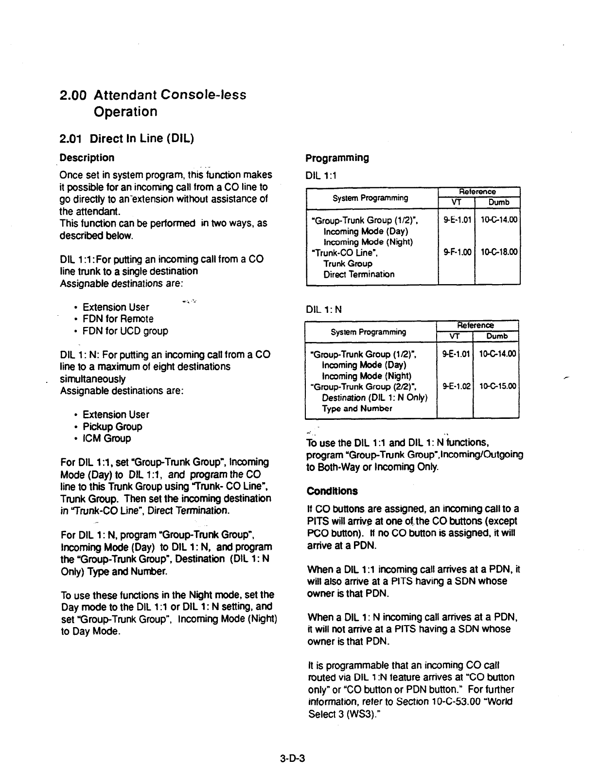
2.00 Attendant Console-less
Operation
2.01 Direct In Line (DIL)
Description .-
Once set in system program, this function makes
it possible for an incoming call from a CO line to
go directly to an-extension without assistance of
the attendant.
This function can be performed in two ways, as
described below.
DIL 1 :l : For putting an incoming call from a CO
line trunk to a single destination
Assignable destinations are:
l
Extension User .,.i .‘.’
l
FDNfor Remote
l
FDN for UCD group
DIL 1: N: For putting an incoming call from a CO
line to a maximum of eight destinations
simqltaneously
Assignable destinations are:
l
Extension User
l
Pickup Group
l
ICM Group
For DIL 1 :l , set “Group-Trunk Group”, Incoming
Mode (Day) to OIL 1:1, and program the CO
line to thii Trunk Group using Trunk- CO Line”,
Trunk Group. Then set the incoming destination
in “Trunk-CO Line”, Direct Termination.
For DIL 1: N, program “Group-Trunk Group”,
Incoming Mode (Day) to DIL 1: N, and program
the “Group-Trunk Group”, Destination (DIL 1: N
Only) Type and Number.
To use these functions in the Night mode, set the
Day mode to the DIL
1 :l
or DIL 1: N setting, and
set “Group-Trunk Group”, Incoming Mode (Night)
to Day Mode.
Programming
DIL 1:l
System Programming Refc
VT
“Group-Trunk Group (l/2)“,
Incoming Mode (Day)
Incoming Mode (Night)
“Trunk-CO Line”,
Trunk Group
Direct Termination
9-E-1.01
SF-1 .oO
rence
Dumb
10-C-14.00
lO-Gl8.00
DILl:N
System Programming Reference *
VT 1 Dumb
I I
-Group-Trunk Group (1 R)“, 9-E-l .Ol
Incoming Mode (Day)
Incoming Mode (Night)
“Group-Trunk Group (2Q)“. 9-E-l .02
Destination (DIL 1: N Only)
Type and Number
10-C-14.00
r
10-C-15.00
;d use the DIL 1 :l and DIL
1:
N’&ctions,
program “Group-Trunk Group”,IncomingKIutgoing
to Both-Way or Incoming Only.
Conditions
If CO buttons are assigned, an incoming call to a
PITS will arrive at one otthe CO buttons (except
PC0 button). lf no CO button is assigned, it will
arrive at a PDN.
When a DIL 1
:l
incoming call arrives at a PDN. it
will also arrive at a PITS having a SDN whose
owner is that PDN.
When a DIL 1: N incoming call arrives at a PDN,
it will not arrive at a PITS having a SDN whose
owner is that PDN.
It is programmable that an incoming CO call
routed via DIL 1 :N feature anives at “CO button
only” or “CO button or PDN button.” For further
information, refer to Section 1 O-C-53.00 “World
Select 3 (WS3).”
3-D-3
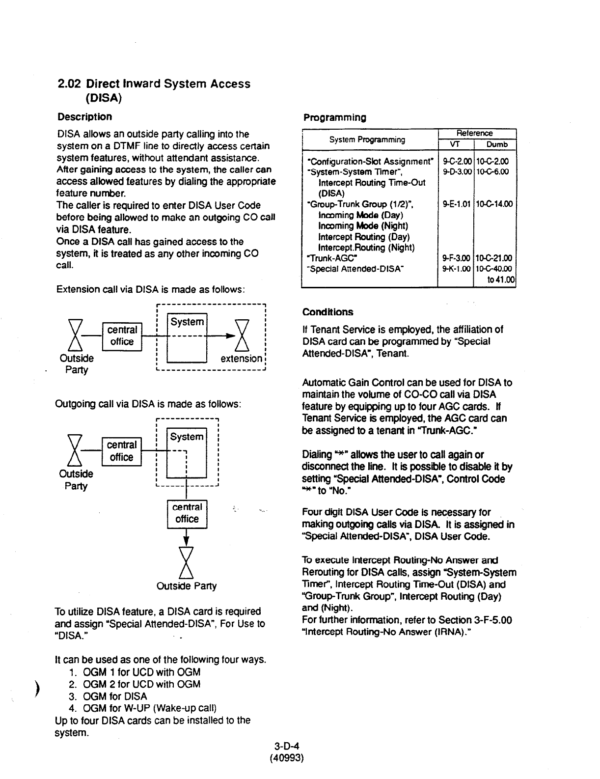
2.02 Direct Inward System Access
(DISA)
Description
DISA allows an outside party calling into the
system on a DTMF line to directly access certain
system features, without attendant assistance.
After gaining access to the system, the caller can
access allowed features by dialing the appropriate
feature number.
The caller is required to enter DISA User Code
before being allowed to make an outgoing CO call
via DISA feature.
Once a DISA call has gained access to the
system, it is treated as any other incoming CO
call.
Extension call via DISA is made as follows:
JgpiEq-/-~~gbn~
Party L-----------------,--~
Outgoing call via DISA is made as follows:
Outside
Party
central .:- *__
off ice
i-1
X
Outside Party
To utilize DISA feature, a DISA card is required
and assign “Special Attended-DISA”, For Use to
“DISA.” _
It can be used as one of the following four ways.
1. OGM 1 for UCD with OGM
2. OGM 2 for UCD with OGM
3. OGM for DISA
4. OGM for W-UP (Wake-up call)
Up to four DISA cards can be installed to the
system.
Programming
System Programming
Zonfiguratbn-Sbt Assignment”
‘System-System limer”,
Intercept Routing Time-Out
(DISA)
‘Group-Trunk Group (l/2)“,
Incoming Mode (Day)
Incoming Mode (Night)
Intercept Routing (Day)
InterceptRouting (Night)
Trunk-AGC
‘Special Attended-DISA”
Reference
VT Dumb
9-c-2.00 lo-c-2.00
9-D-3.00 104-6.00
9-E-l .Ol lO-Gl4.00
9-F-3.00 10-C-21 .OO
9-K-l .oo 1 o-C-40.00
to 41 .oc
Conditions
If Tenant Service is employed, the affiliation of
DISA card can be programmed by “Special
Attended-DISA*, Tenant-
Automatic Gain Control can be used for DISA to
maintain the volume of CO-CO call via DISA
feature by equipping up to four AGC cards. lf
Tenant Service is employed, the AGC card can
be assigned to a tenant in ‘Trunk-AGC.”
Dialing *’ allows the user to call again or
disconnect the line. It is possible to disable it by
setting ‘Special Attended-DISA’, Control Code
*“to “No.”
Four digit DISA User Code is necessary for
making outgoing calls via DISA. It is assigned in
“Special Attended-DISA”, DISA User Code.
To execute Intercept Routing-No Answer and
Rerouting for DISA calls, assign “System-System
Timer”, Intercept Routing Time-Out (DISA) and
“Group-Trunk Group”, Intercept Routing (Day)
and (Night).
For further information, refer to Section 3-F-5.00
‘Intercept Routing-No Answer (RNA).”
3-D-4
(40993)
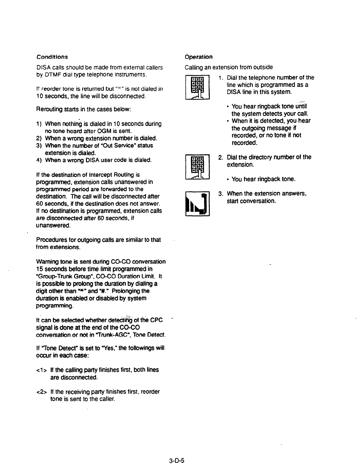
Conditions
DISA calls should be made from external callers
by DTMF dial type telephone instruments.
I! reorder tone is returned but WW is not dialed in
10 seconds, the line will be disconnected.
Rerouting starts in the cases below:
1)
2)
3)
4)
When nothing is dialed in 10 seconds during
no tone heard after OGM is sent.
When a wrong extension number is dialed.
When the number of “Out Service” status
extension is dialed.
When a wrong DISA user code is dialed.
If the destination of Intercept Routing is
programmed, extension calls unanswered in
programmed period are forwarded to the
destination. The call will be disconnected after
60 seconds, if the destination does not answer.
If no destination is programmed, extension calls
are disconnected after 60 seconds, if
unanswered.
Procedures for outgoing calls are similar to that
from extensions.
Warning tone is sent during CO-CO conversation
15 seconds before time limit programmed in
“Group-Ttunk Group”, CO-CO Duration Limit. It
is possible to prolong the duration by dialing a
digit other than *” and Y.” Prolonging the
duration is enabled or disabled by system
programming.
It-can be selected whether dete&& of fhe CPC
signal is done at the end of the CO-CO
conversation or not in %unk-AGC”, Tone Detect.
If “Tone Detect” is set to “Yes,” the followings will
occur in each case:
cl> tf the calling party finishes first, both lines
are disconnected.
Operation
Calling an extension from outside
Dial the telephone number of the
line which is programmed as a
DISA line in this system.
l
You hear ringback tone u&l
the system detects your call.
l
When it is detected, you hear
the outgoing message if
recorded, or no tone if not
recorded.
Dial the directory number of the
extension.
l
You hear ringback tone.
When the extension answers,
start conversation.
<2> If the receiving party finishes first, reorder
tone is sent to the caller.
3-D-5
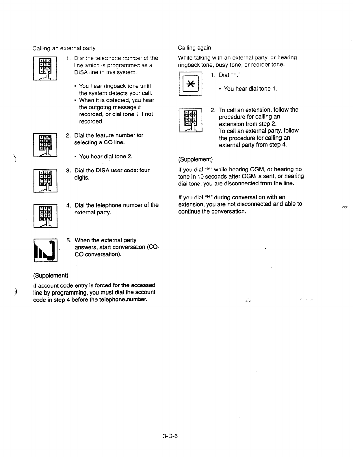
Calling an external oafly
1. Da. ye :&es-oze -*l--a- of the
U,. -_.
1ir.e ivnich is orogrammez as a
DlSA ilne ir iEqs system.
L Ak I
l
You hear ringback tont until
the system detects yo,r call.
l
When it is detected, ycu hear
the outgoing message
if
recorded, or dial tone t if not
recorded.
2. Dial the feature number for
selecting a CO line.
) -
l
You hear dial tone 2.
3. Dial the DISA user code: four
digits.
4. Dial the telephone number of the
external party.
\
id
I
5. When the external.party
answers, start conversation (CO-
CO conversation).
(Supplement)
If account code entry is forced for the accessed
line by programming, you must dial the account
code in step 4 before the telephone-number.
Calling again
While talking with an external party, or hearing
ringback tone, busy tone, or reorder tone.
11 1. Dial I‘*.”
l
You hear dial tone 1.
(13
q
2. To call an extension, follow the
456
7*0 procedure for calling an
* extension from step 2.
To call an external party, follow
the procedure for calling an
external party from step 4.
(Supplement)
If you dial u*n while hearing OGM, or hearing no
tone in 10 seconds after OGM is sent, or hearing
dial tone, you are disconnected from the line.
If you dial U*” during conversation with an
extension, you are not disconnected and able to
continue the conversation.
3-D-6

2.03 Direct inward Dialing (DID)
Description
Incoming calls can be put through directly to
extensions in accordance with the subscriber
numbers sent from the Central Office.
Either an Attendant Console or UCD group may
serve as the destination of the incoming calls.
DID lines are for incoming calls only. They cannot
be employed for outgoing calls.
To make use of DID trunks, program “Group-
Trunk Group”, Type to DID, and assign the CO
lines to be used for DID by programming the
“Trunk-CO tine”, Trunk Group option. It is also
necessary to set the DID Start Arrangement in
“Trunk-CO Line* and the DID Digit Modification
Table in “Group-Trunk Group (2/2)“. The digit
modification table is used to convert the
subscriber numbers sent from the Central Office
into DNs or Floating Directory Numbers (FDN).
The number of received digits, the number of
digits to be deleted and the digits to insert are
programmed in the “Special Attended-DID”
screen.
Programming
System Programming
‘Group-Trunk Group”,
Type
DID Digit Modification Table
“Trunk-CO Line”,
Trunk Group
DID
Start Arrangement
“Special Attended-DID”,
Receive Digit
Delete Digit
Insert Dial No.
Rei
v-r
9-E-l
.Ol
9-E-l .02
9-F-l .OO
9-K-2.00
ence
DWTlb
10-c-14.00
10-G15.00
10-C-18.00
1O-c-q.00
Conditions
Exactly
how
a subscriber number received from
the Central Office is converted into a DN or FDN
in the DID Digit Modification Table is explained
below using an example.
<Example>
“Special Attended-DID” Table settings
Receive Digit: 4
Delete Digit: 2
Insert Dial No.: 2
Subscriber number received from the Central
Office: 43112
Processing
cl> The “2” in 43112 is ignored since there are
four receive digits. This leaves 4311.
c2> “43” is deleted since there are two delete
digits. This leaves 11. Note that the digits
are deleted from the front of the number.
<3> Insert Dial No. ‘2” makes the final number
211 which serves as the DN or FDN. Note
that digits are inserted at the front of the
number.
Reorder tone is sent to the DID caller if the
number of digits received is less than the number
programmed in “Special Attended-DID”, Receive
Digit.
The subscriber number received from the Central
Office is converted into a DN or FDN. If it could
not be put through to the incoming call
destination, because the DN or FDN does not
exist or the destination is Out of Service, the call
is sent
to
the destinatfdn specified by the “Group-
Trunk Group”, Intercept Routing (Day/Night). If
there is nothing programmed for intercept routing
then the call is sent to Operator 1.
When the CO Forward Mode function has been
programmed in “System-Class of Service” for
the DID incoming call destination, forwarding will
not take place, and the call will be put through to
the extension.
3-D-7
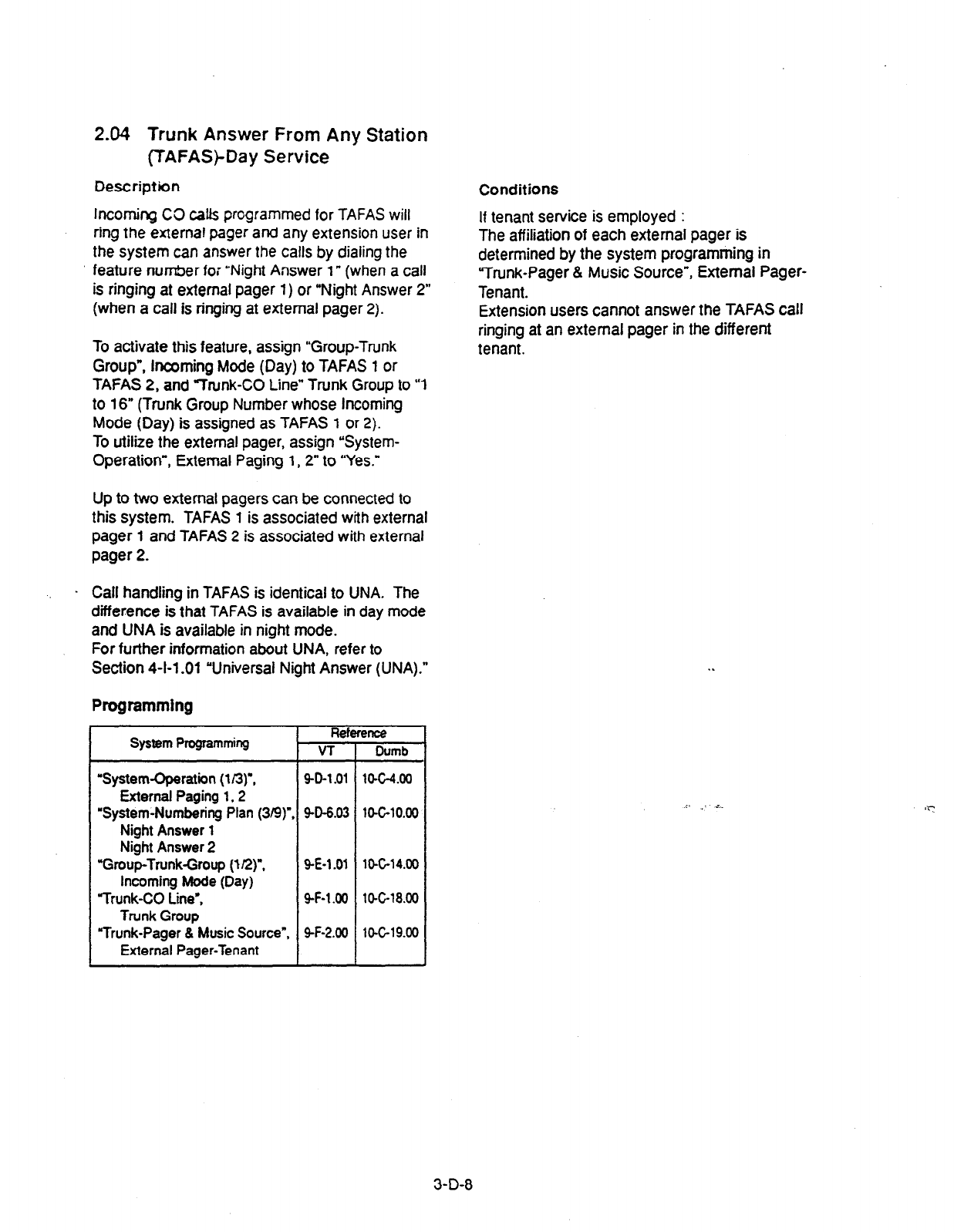
2.04 Trunk Answer From Any Station
(TAFAS)-Day Service
Description
Incoming CO calts programmed for TAFAS will
ring the external pager
and
any extension user in
the system can answer the calls by dialing the
feature number for ‘Night Answer 1” (when a call
is ringing at external pager 1) or “Night Answer 2”
(when a call is ringing at external pager 2).
To activate this feature, assign “Group-Trunk
Group”, incoming Mode
(Day) to TAFAS 1 or
TAFAS 2,
and
“Trunk-CO Line” Trunk Group to “1
to 16” (Trunk Group Number whose Incoming
Mode (Day) is assigned as TAFAS 1 or 2).
To utilize the external pager, assign “System-
Operation”, External Paging 1,2” to “Yes.”
Up to two external pagers can be connected to
this system. TAFAS 1 is associated with external
pager 1 and TAFAS 2 is associated with external
pager 2.
. Call handling in TAFAS is identical to UNA. The
difference is that TAFAS is available in day mode
and UNA is available in night mode.
For
further information
about UNA, refer to
Section 4-l-l -01 “Universal Night Answer (UNA).”
Programming
System Propmmkg Reference
VT Dumb
‘System-Operation (I/3)‘.
9-D-l .Ol ltMz-4.00
External Paging
1,2
‘System-Numbering Plan (3B)“. 9-D-6.03
lO-GlO.00
Night Answer
1
Night Answer 2
“Group-Trunk-Group (I@“. Q-E-1
.Ol 10-C-14.00
incoming Mode (Day)
“Trunk-CO Lie’. SF-l.00
lo-C-18.00
Trunk Group
“Trunk-Pager & Music Source”, 9-F-2.00
lO-C-19.00
External Pager-Tenant
Conditions
If tenant service is employed :
The affiliation of each external pager is
determined by the system programming in
“Trunk-Pager & Music Source”, External Pager-
Tenant.
Extension users cannot answer the TAFAS call
ringing at an external pager in the different
tenant.
,l ,. i.
3-D-8
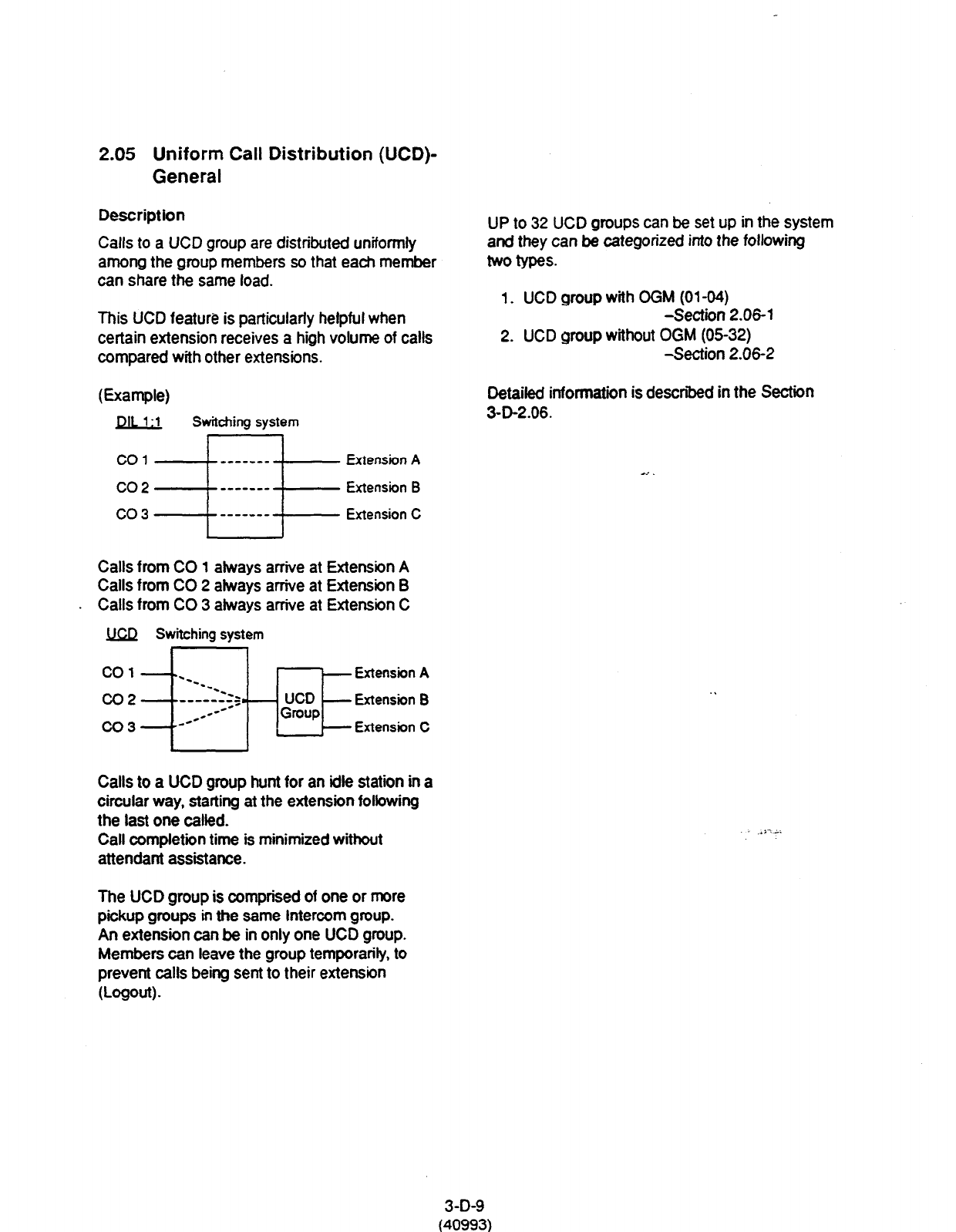
2.05 Uniform Call Distribution (UCD)-
General
Description
Calls to a UCD group are distributed unifomtly
among the group members so that each member
can share the same load.
This UCD feature is particularly helpful when
certain extension receives a high volume of calls
compared with other extensions.
E=mpW
DIL 1:l
Switching
system
co1 Extension A
co2 Extension B
co3 Extension C
Calls from CO 1 akays arrive at Extension A
Calls from CO 2 always arrive at Extension B
Calls from CO 3 always arrive at Extension C
M Switching
system
Calls to a UCD group hunt for an idle station in
a
circular way, starting at the extension folbwing
the last one called.
Call completion time is minimized without
attendant assistance.
UP to 32 UCD groups can he set up in the system
and they can be categorized into the following
two types.
1. UCD group with CGM (01-04)
-Section 2.06-l
2. UCD group without OGM (0532)
-Section 2.06-2
Detaifed information is described in the Section
3-D-2.06.
.*i7-.
The UCD group is comprised of one or more
pickup groups in the same Intercom group.
An extension can be in only one UCD group.
Members can leave the group temporarity, to
prevent calls being sent to their extension
o-ogw -
3-D-9
(40993)
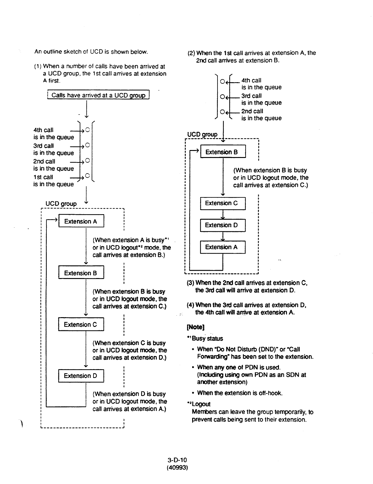
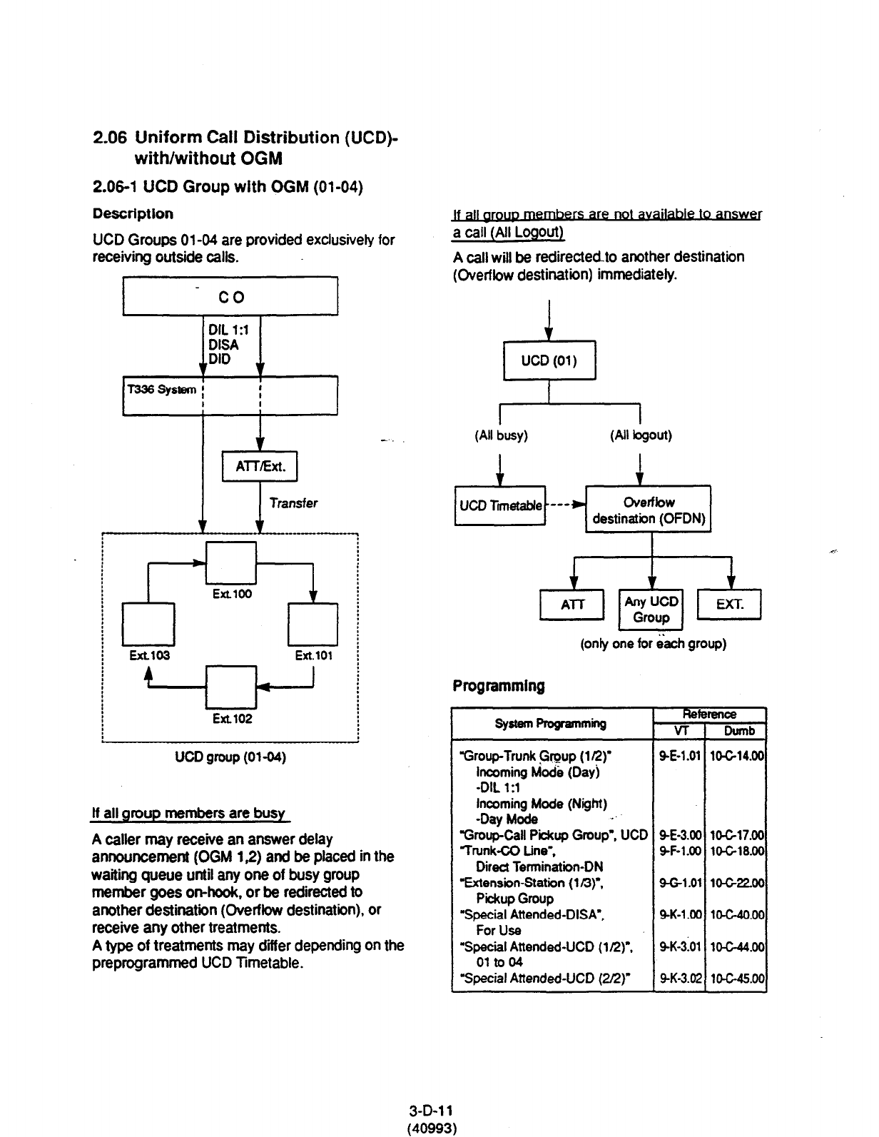
2.06 Uniform Call Distribution (UCD)-
with/without OGM
2.06-l
UCD Group
with OGM (01-04)
Description
UCD Groups 0144 are provided exclusively for
receiving outside calls.
co
;;
-.
, lrj-LJyl]
EXLlOi Ext.101
4 < I
I J
Ext.102
UCD group (01-04)
If all
group members are busy
A caller may receive an answer delay
announcement (OGM 1,Z) and be placed in the
waiting queue until any one of busy
group
member goes on-hook, or be redirected to
another destination (Overflow destination), or
receive any other treatments.
A type of treatments may diier depending on the
preprogrammed UCD Timetable.
a call (All Logout
A call will be redirected-to another destination
(Overflow destination) immediately.
1
1 UCDW) 1
(All busy)
(only one for each group)
Programming
“Group-Trunk Group (1 R)
incoming Mod&
(Dayj
-DIL
1 :l
Incoming Mode (Night)
-Day Mode .’
“Group-Call Piiup Group”. UCD
Trunk-CO Line”,
Direct Termination-DN
‘Extension-Station
(1 n)“,
Pickup Group
“Special Attended-DISA”,
For Use
“Special Attended-UCD
(1 R)".
01 to 04
Special Aftended-UCD (2f2)
--la
VT
SE-l.01
9-E-3.00 1&c-17.00
SF-l.00 lo-c-18.00
9-G-1.01 10-GZOO
SK-l.00 1O-C-4O.00
SK-3101 1O-G44.00
9-K-3.02 1tX-45.00
3-D-l 1
(40993)

Condttions
1. Calts which can arrive at a UCD group (with
OGM) are:
l
Incoming outside calls via DIL( 1 :l) for which
destination is set as FDN of a UCD group
l
Incoming outside calls via DID by dialing
FDN of a UCD group
l
Incoming outside calls via DISA by dialing
FDN of a UCD group
l
incoming outside calls transferred by an
attendant console or extension
2. Login and Logout
Members can leave the group temporarily
when they will be away from their desks, to
prevent calls being sent to their extension.
o-ogw
They can return to the group when they are
ready to answer a call. (Login)
Refer to Section 4-D-8.00 “Uniform Call
Diiributlon (UCD)-Log Out” for more
information on login and logout.
3. Busy status
l
When ‘Do Not Disturb (DND)” or “Call
Forwarding” has been set to the extension.
l
When any one of PDN has been used.
(Including using own PDN as an SDN at
another extension)
l
When the extension is off-hook.
4. Auto-Logout
When a group member does not answer a call
more than a set time period (“Call Forwarding-
No Answer Time-Out”), the call will be
automatically transferred to another member’s
extension.
If “No Answer Time-Out” occurs twice in
succession, the extension is automatically set
to bgout status.
What if all members are logged-out?
Assuming that a UCD group has three
members and twc are already logged out, and
)
a call rings into the UCD.
lf the member that is logged-in does not
answer after two cycles, “Auto-Logout
happens.
3-D-l 2
(40993)
Then depending on your software version, the
call is handled as follows.
(Software version 8. XX and above)
The call overflows to the overflow destination
immediately after the Auto-Logout.
This is changed from 6.XX versions.
(Software version 6.XX and below)
The call is put in the wafting queue.
But continues to hear ringback tone.
Not timetable.
5 Overflow destination
One of the following three destinations can be
assigned as the overflow destination (OFDN)
per UCD group (0144).
l
Attendant Console
l
Extension
l
Another UCD Group (0%04), (0532)
(Treatment of the calls transferred to the overflow
destination (OFDN))
(1) What-if the.overfbw destination is busy?
The call is put in the waiting queue, and will
begin to ring at the overflow destination as
soon as it becomes idle.
or
The call may begin to ring at a group
member’s extension, if it becomes idle while
overflow destination is still busy.
Thecallisputin *No Is ovetfbw
the waiting queue. destination idle?
I
Ir
The call begins to
ring at overflow
1 destination.
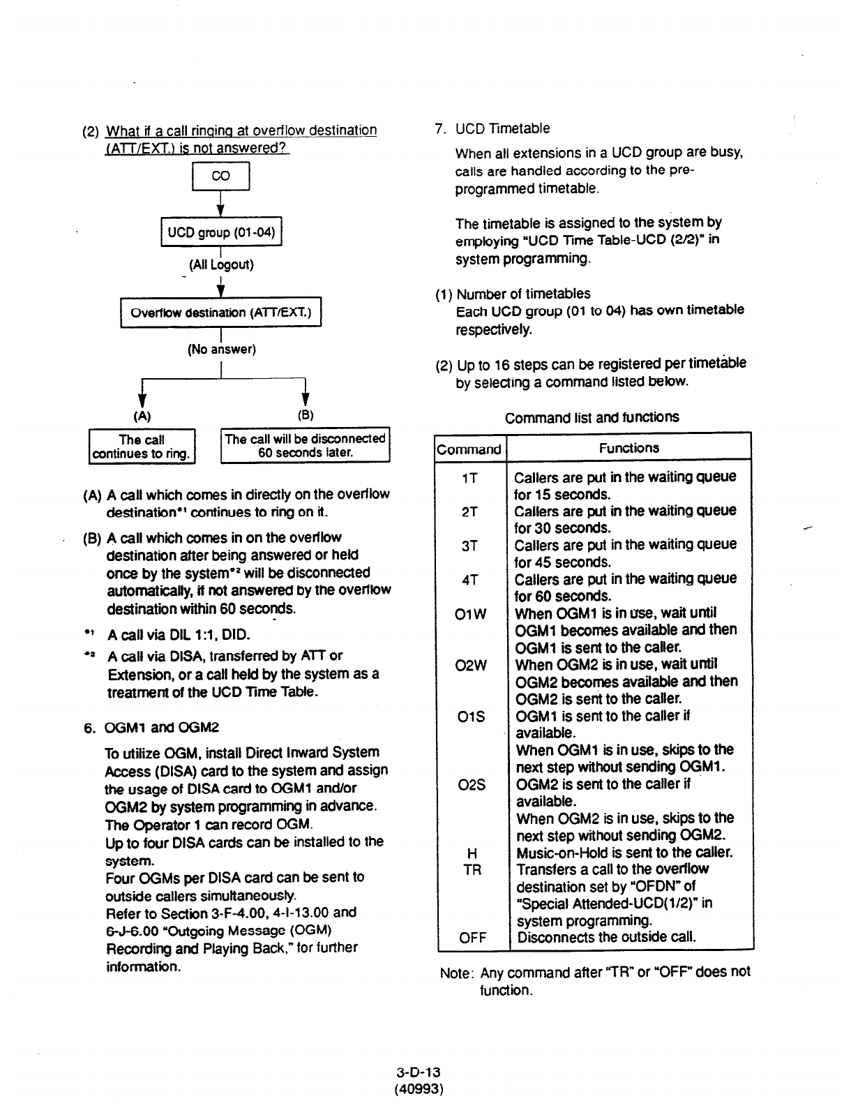
(2) What if a call rinoina at overflow destination
/AlT/EXT.) is not answered?
Overfbw destination (ATT/EXT.)
I
(No answer)
(A) A call which comes in directly on the overflow
destination*’ continues to ring on it.
(B) A call which comes in on the overflow
destination after being answered or held
once by the system’2 will be disconnected
automatically, if not answered by the overflow
destination within 60 seconds.
l
’ A call via DIL 1 :l , DID.
l
2 A call via DISA, transferred by ATT or
Extension, or a call held by the system as a
treatment of the UCD Time Table.
6.
OGMl
and OGM2
To utilize OGM, install Direct Inward System
Access (DISA) card to the system and assign
the usage of DISA card to ffiM1 and/or
OGM2 by system programming in advance.
The Operator 1 can record OGM.
Up to four DISA cards can be installed to the
system.
Four OGMs per DISA card can be sent to
outside callers simultaneously.
Refer to Section 3-F-4.00,4-l-l 3.00 and
6-J-6.00 “Outgoing Message (OGM)
Recording and Playing Back,” tor further
information.
7. UCD TImetable
When all extensions in a UCD group are busy,
calls are handled according to the pre-
programmed timetable.
The timetable is assigned to the system by
employing “UCD Time Table-UCD (2Q)” in
system programming.
(1) Number of timetables
Each UCD group (01 to 04) has own timetable
respectively.
(2) Up to 16 steps can be registered par timetable
by selecting a command listed below.
Command list and functions
Command Functions
1T Callers are put in the waiting queue
for 15 seconds.
2T Callers are put in the waiting queue
for 30 seconds.
3T Callers are put in the waiting queue
for 45 seconds.
4T Callers are put in the waiting queue
for 60 seconds.
OlW When OGMl is in use, wait until
OGMl becomes available and then
OGMl is sent to the caller.
02w When OGM2 is in use, wait until
OGM2 becomes available and then
OGM2 is sent to the caller.
01s OGMl is sent to the caller if
available.
02s
H
TR
OFF
When OGMl is in use, skips to the
next step without sending OGMl .
OGM2 is sent to the caller if
available.
When OGM2 is in use, skips to the
next step without sending OGM2.
Music-on-Hold is sent to the caller.
Transfers a call to the overflow
destination set by “OFDN” of
“Special Attended-UCD( l/2)” in
system programming.
Disconnects the outside call.
Note: Any command after “TR” or “OFF” does not
function.
3-D-13
(40993)
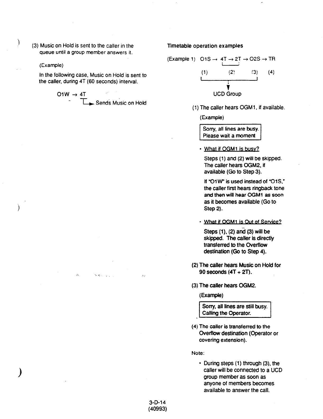
i
(3) Music on Hold is sent to the caller in the
queue until a group member answers it.
(Example)
In the following case, Music on Hold is sent to
the caller, during 4T (60 seconds) interval.
OlW+4T ~
--L Sends MJsic on Hold
Timetable operation examples
(Example
1) 01s -+ 4T -+ 2T+ 02s + TR
I
(1)
(2) (3) (4)
f
UCD Group
(1) The caller hears OGMl , if available.
(Example)
I
Sorry, all lines are busy.
Please wait a moment I
.
atdOGM1 is&&
Steps (1) and (2) will be skipped.
The caller hears OGM2, if
available (Go to Step 3).
lf “01 W is used instead of ‘YXS.’
the caller first hears ringback tone
and then will hear OGMl as soon
as it becomes available (Go to
Step 2).
.
at rf ffiM1 IS Out of Service?
Steps (1). (2) a& (3) will be
skipped. The caller is directly
transferred to the Overflow
destination (Go to Step 4).
(2) The caller hears Music on Hold for
90 seconds (4T + 2T).
(3) The caller hears OGM2.
(E=mW
I
Sorry, all lines are still busy.
Calling the Operator. I
(4) The caller is transferred to the
Overflow destination (Operator or
covering extension).
Note:
l
During steps (1) through (3), the
caller will be connected to a UCD
group member as soon as
anyone of members becomes
available to answer the call.
3-D-l 4
(40993)
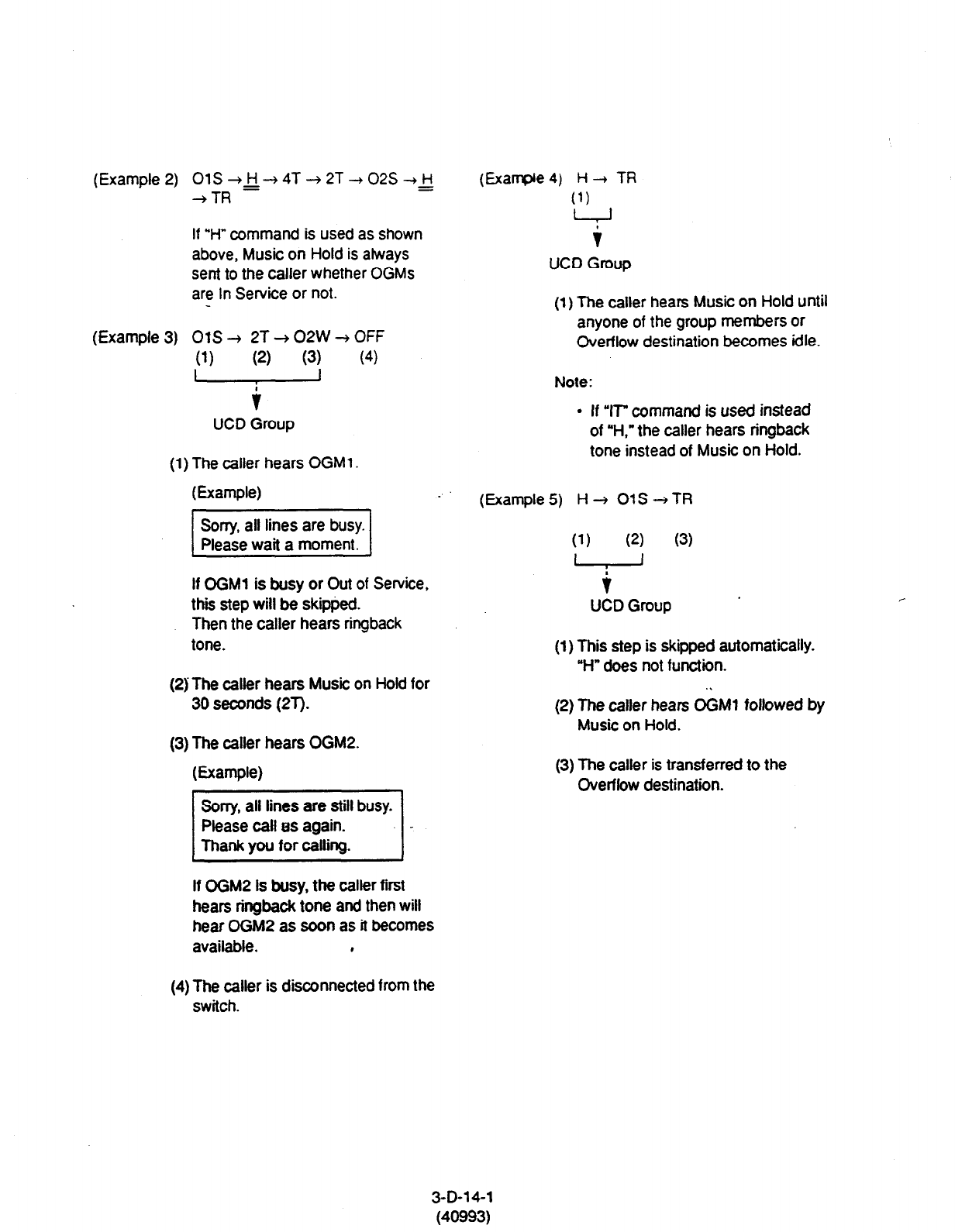
(Example 2)
(Example 3)
01S+&-+4T-+2T--+02S-+H =
+TR
If “H” command is used as shown
above, Music on Hold is always
sent to the caller whether OGMs
are In Service or not.
OtS+ 2T+02W+OFF
(1)
(2)
(3)
(4)
- 1
UCD Group
(1) The caller hears OGMl .
(E=wle)
If OGM1 is busy or Out of Service,
thii step will be skipped.
Then the caller hears ringback
tone.
(2) The caller hears Music on Hold for
30 seconds (2T).
(3) The caller hears OGM2.
WwW
If OGM2 is busy, the caller first
hears ringback tone and then will
hear OGM2 as soon as it becomes
available. ,
(4) The caller is disconnected from the
switch.
(Example
4) H + TR
(1)
+ 1
UCD
Group
(1) The caller hears Music on Hold until
anyone of the group members or
Overflow destination becomes idle.
Note:
l
If ‘IT” command is used instead
of “H,” the caller hears ringback
tone instead of Music on Hold.
(Example 5) H + 01s + TR
(1)
(2)
(3)
L , 1
i
UCDGroup ’
(1) This step is skipped automatically.
“H” does not function.
(2) The caller hears O&l followed by
Music on Hold.
(3) The caller is transferred to the
Overflow destination.
3-D-14-1
(40993)
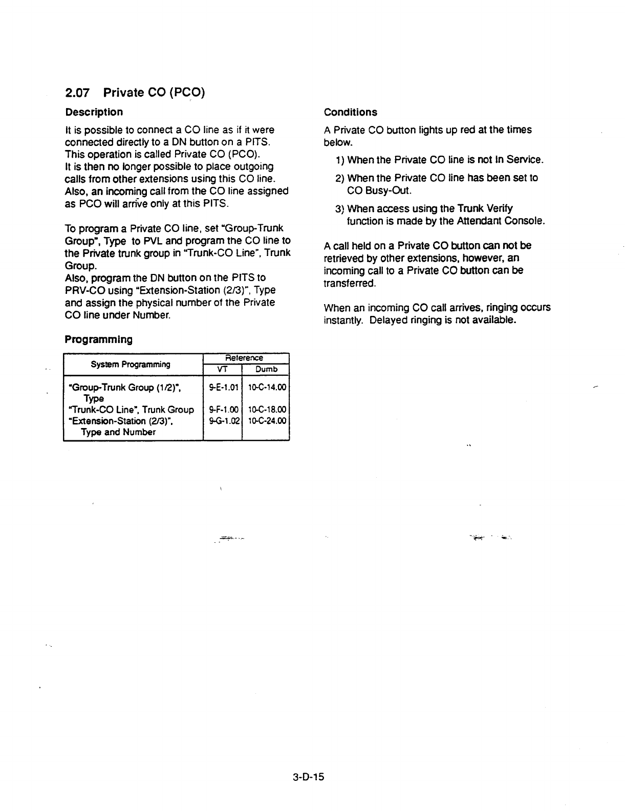
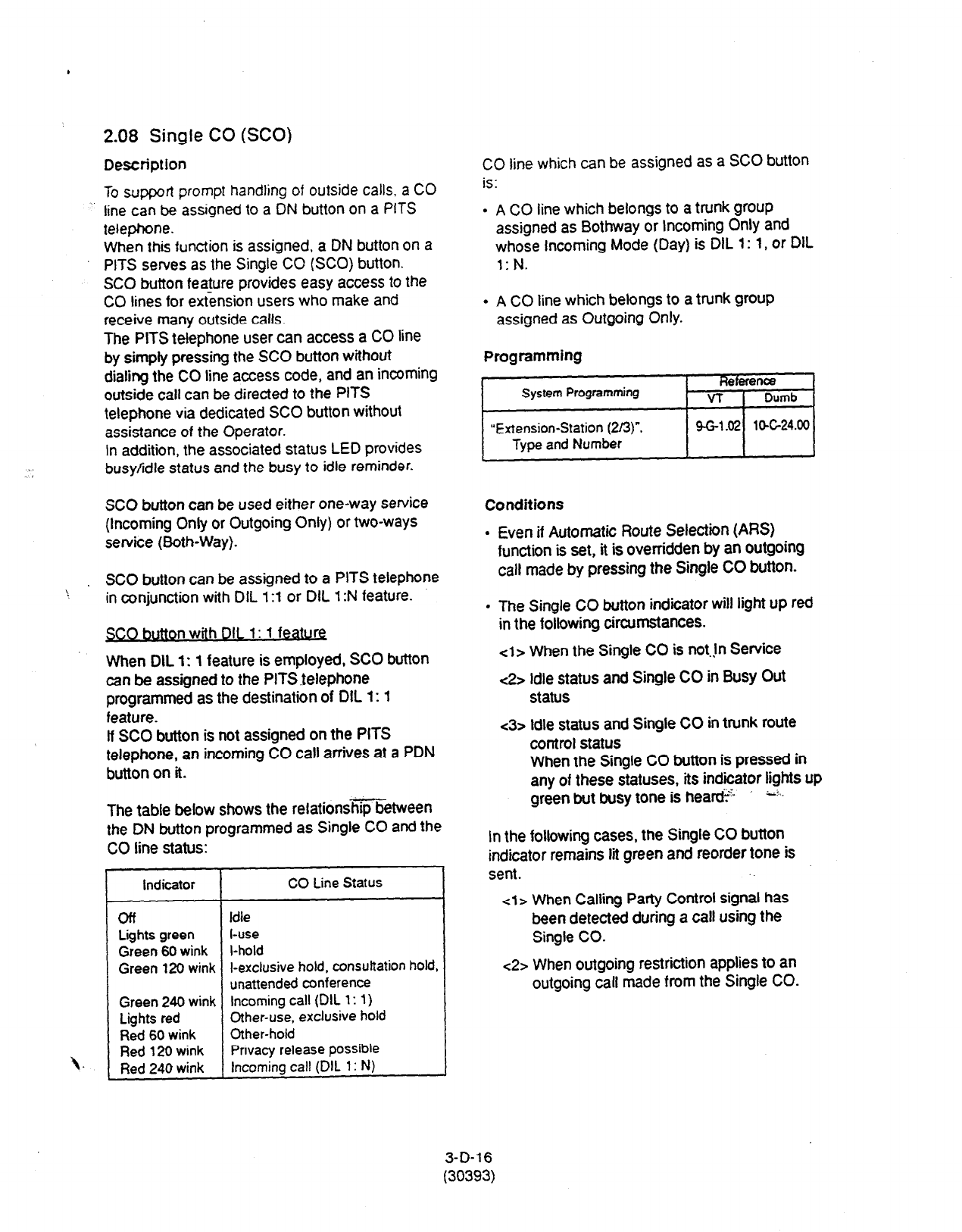
2.08
Single CO (SCO)
,
Description
To support prompt handling of outside calls. a CO
line can be assigned to a DN button on a PITS
telephone.
When this function is assigned, a DN button on
a
PITS serves as the Single CO (SCO) button.
SC0 button feature provides easy access to the
CO lines for extension users who make and
receive many outside calls.
The PITS telephone user can access a CO line
by simpiy pressing the SC0 button without
dialing the CO line access code, and an incoming
outside
call can be directed to the
PITS
telephone via dedicated SC0 button without
assistance
of the Operator.
In
addition, the associated status LED provides
busy/idle status and the busy to idle reminder.
SC0 button can be used either one-way service
(Incoming Only or Outgoing Only) or two-ways
service (Both-Way).
. SC0 button can be assigned to a PITS telephone
\ in conjunction with DIL 1:l or DIL 1 :N feature.
SC0 button with 011 1: 1 feature
When DIL 1: 1 feature is employed, SC0 button
can be assigned to the PITSfelephone
programmed as the destination of DIL 1: 1
feature.
If SC0 button is not assigned on the PITS
telephone, an incoming CO call arrives at a PDN
button on it.
The table below shows the relationsmetween
the DN button programmed as Single CO and the
CO line status:
\.-
Indicator
CO Line Status
off Idle
Lights green l-use
Green 60 wink l-hold
Green 120 wink
l-exclusive hold,
consultation hold,
unattended conference
Green 240 wink Incoming call (DIL
1: 1)
Lights red
Other-use, exclusive hold
Red 60 wink Other-hold
Red 120 wink Privacy release possible
Red 240 wink Incoming call (DIL 1: N)
CO line which can be assigned as a SC0 button
is:
. A CO line which belongs to a trunk group
assigned as Bothway or Incoming Only and
whose Incoming Mode (Day) is DIL
1: 1, or DIL
. .
. A CO line which belongs to a trunk group
assigned as Outgoing Only.
i
Programming
e efenca
System Programming VT Dumb
“Extension-Station (2/3)“. m-1 a lo-c24.00
Type and Number
Conditions
. Even if Automatic Route Selection (ARS)
function is set, it is overridden by an outgoing
call made by pressing the Single CO button.
. The Single CO button indicator will light up red
in the following circumstances.
cl>
When the Single CO is not.@ Service
<2> Idle status and Single CO in Busy Out
status
<3> Idle status and Single CO in trunk route
control status
When the Single CO button is pressed in
any of these statuses, its indicator lights up
“i
green but busy tone is heati.- Lt.-
In the following cases, the Single CO button
indicator remains lit green and reorder tone is
sent.
4 > When Calling
Party
Control signal
has
been detected during a call using the
Single CO.
~2>
When outgoing restriction applies to an
outgoing call made from the Single CO.
3-D-16
(30393)
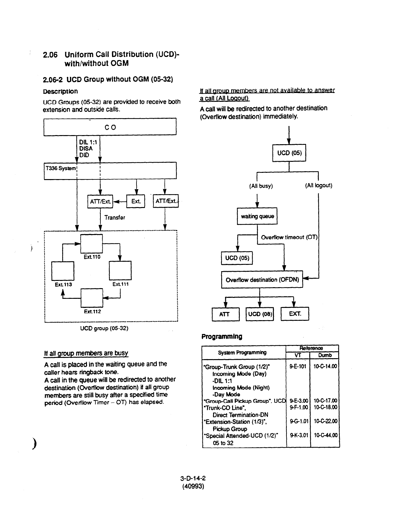
2.06 Uniform Call Distribution (UCD)-
with/without OGM
2.06-Z UCD Group without OGM (05-32)
DescrlptCon
UCD Groups (05-32) are provided to receive both
extension and outside calls.
I co
r-.
Extw
Extlll
UCD group (05-32)
If all qmup members are busy
A call is placed in the waiting queue and the
caller hears ringbadc tone.
A call in the queue will be redirected to another
destination (Overflow destination) it all group
members are still busy after a specified time
period (Overflow hmer - OT) has elapsed.
are not
a call (All Loaout)
A call will be redirected to another destination
(Overflow destination) immediately.
2%
UCD (05)
(All busy)
(All logout)
1
Overflow timeout
(01
.
Overflow destination
(OFDN) -
I
Programming
System Programming Refemloe
VT
Dumb
“Group-Trunk Group (l/2) SE-101 l&C14.0(
Incoming Mode
(Day)
-DIL
1:l
Incoming Mode (Night)
-Day Mode
‘GroupCall Pickup Group”, UCD Q-E-3.00
lO-Gl7.oL
‘Trunk-CC tine”, SF-1 .OO lo-C18.00
Direct Termination-DN
‘Extension-Station (In)“, 9-G-l .Ol 10-C-22.00
Pickup Group
‘Special Attended-UCD (112)” SK-3.07 lW-44.0(1
05to32
3-D-14-2
(40993)
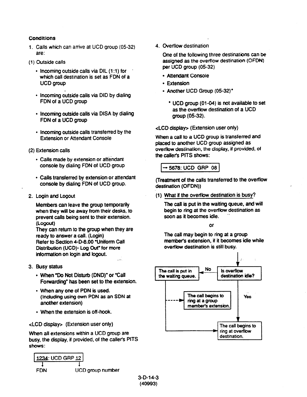
Condftlons
1. Calls which can arrive at UCD group (0532)
are:
(1)
Outside calls
l
Incoming outside calls via DIL (1 :l) for ’
which call destination is set as FDN of a
UCD group
l
Incoming c&ide calls via DID by dialing
FDN of a UCD group
l
Incoming outside calls via DISA by dialing
FDN of a UCD group
l
Incoming outside calls transferred by the
Extension or Attendant Console
(2) Extension calls
l
Calls made by extension or attendant
console by dialing FDN of UCD group
l
Calls transferred by extension or attendant
console by dialing FDN of UCD group.
2. Login and Logout
Members can leave the group temporarily
when they will be away from their desks, to
prevent calls being sent to their extension.
wxw)
They can return to the group when they are
ready to answer a call. (Login)
Refer to Section 4-D-8.00 YJniform Calt
Diiributiin (UCD)- Log Out” for more
information on bgin and bgout. d 9
3. Busy status
l
When ‘Do Not Disturb (DND)” or “Call
Forwarding. has been set to the extension.
l
When any one of PDN is used.
(Induding using own PDN as an SDN at
another extension)
. When the extension is off-hook.
<LCD display> (Extension user only)
When all extensions within a UCD group are
busy, the display, if provided, of the callets PITS
shows:
4. Overflow destination
One of the following three destinations can be
assigned as the overflow destination (OFDN)
per UCD group (0532)
l
Attendant Console
l
Extension
l
Another UCD Group (05-32)’
l
UCD group (01-04) is not available to set
as the overflow destination of a UCD
group (0532).
<LCD display> (Extension user only)
When a call to a UCD group is transferred and
placed to another UCD group assigned as
ovetfbw destination, the display, if provided, of
the calleh PITS shows:
I- 5678: UCD GRP 08 1
(Treatment of the calls transferred to the overflow
destination (OFDN))
(1) What if the overflow destination is busy?
The caff is put in the waiting queue, and will
begin to ring at the overfbw destination as
soon as it becomes idle. ”
or
r
The call may begin to ring at a group
member’s extension, if it becomes idle while
overfbw destination is still busy.
Thecallisputin *No Is overfbw
the waiting queue. destination idle?
I
FDN UCD group number
3-D-l 4-3
(40993)
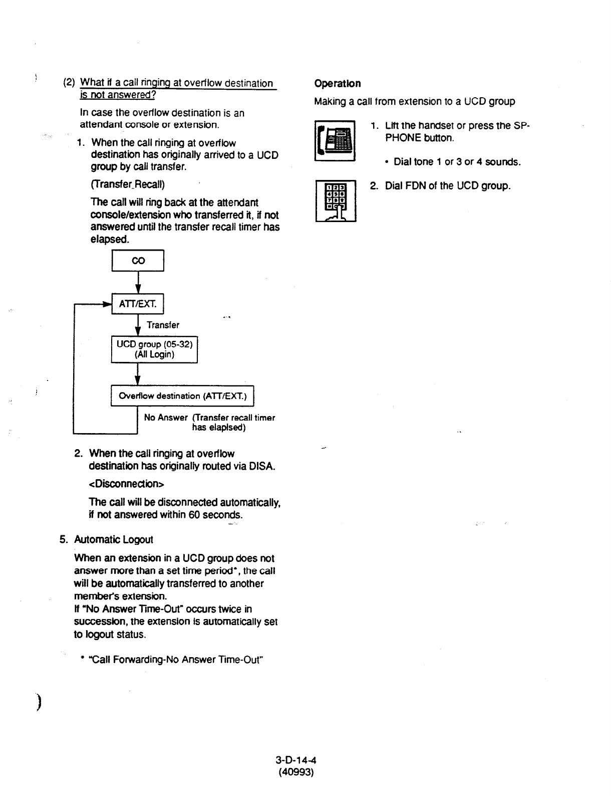
1
(2)
What if a call ringing at overflow
destination
is not answered?
In case the overflow destination is
an
Operation
Making a call from extension to a UCD group
attendant console or extension. z
1.
Lii the handset or press the SP-
L-l
PHONE button.
&==
l
Dial tone 1 or 3 or 4 sounds.
1. When the call ringing at overflow
destination has originally arrived to
a UCD
group by call transfer.
(Transfer&call)
The call will ring back at the attendant
console/extension who transferred it, if not
answered until the transfer recall timer has
elapsed.
F-l
2. Dial FDN of the UCD group.
AlTEXT.
Transfer
UCD group (0532)
(All Login)
1
2. When the call ringing at overflow
destination has originally routed via DISA.
<Disconnection>
The call will be disconnected automatically,
if not answered within 60 seconds.
5. Automatic Logout
When an extension in a UCD group does not
answer more than a set time period’, the call
will be automatically transferred to another
membel’s extension.
If “No Answer Time-Out” occurs twice in
succession, the extension is automatically set
to logout status.
l
“Call Forwarding-No Answer Time-Out”
3-D-1 4-4
(40993)
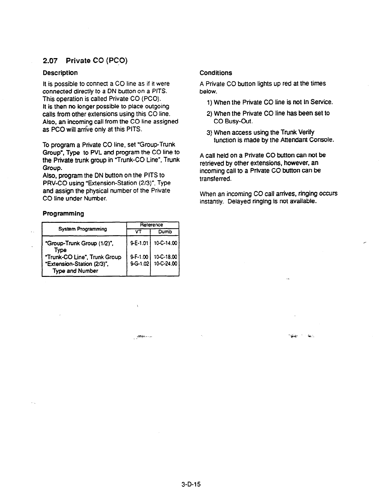
2.07 Private CO (PCO)
Description Conditions
It is possible to connect a CO line as if it were
connected directly to a DN button on a PITS.
This operation is called Private CO (PCO).
It is then no longer possible to place outgoing
calls from other extensions using this CO line.
Also, an incoming call from the CO line assigned
as PC0 will arrive only at this PITS.
A Private CO button lights up red at the times
below.
1) When the Private CO line is not In Service.
2) When the Private CO line has been set to
CO Busy-Out.
3) When access using the Trunk Verify
function is made by the Attendant Console.
To program a Private CO line, set “Group-Trunk
Group’, Type to PVL and program the CO line to
the Private trunk group in ‘Trunk-CO Line”, Trunk
Group.
Also, program the DN button on the PITS to
PRV-CO using “Extension-Station (Z/S)“, Type
and assign the physical number of the Private
CO line under Number.
Programming
System Programming Retefence
VT 1 Dumb
I
‘Group-Trunk Group (l/2)“, 9-E-l .ot
10-C-14.00
Type
“Trunk-CO Line”, Trunk Group 9-F-1.00 10-C-18.00
“Extension-Station (2/a)“,
g-G-1.02 10-c-24.00
Type and Number
A call held on a Private CO button can not be
retrieved by other extensions, however, an
incoming call to a Private CO button can be
transferred.
When an incoming CO calf arrives, ringing occurs
instantly. Delayed ringing is not available.
zF.+. .-
-.-
iye.+-. i.
3-D-l 5

2.08
Single CO (SCO)
Description
To
support prompt handling of outside calls, a CO
line can be assigned to a DN button on a PITS
telephone.
When this
function is assigned, a DN button on a
PITS serves as the Single CO (SCO) button.
SC0 button feature provides easy access to the
CO lines for
extension
users who make and
receive many outside calls.
The PITS telephone user can access a CO line
by simply pressing the SC0 button without
dialing the CO line access code, and an incoming
outside call can be directed to the PITS
telephone via dedicated SC0 button without
assistance of the Operator.
In addition, the associated status LED provides
busy/idle status and the busy to idle reminder.
SC0 button can be used either one-way service
(Incoming Only or Outgoing Only) or two-ways
service (Both-Way).
. SC0 button can be assigned to a PITS telephone
\ in conjunction with DIL 1 :l or DIL 1 :N feature.
SC0 button with DIL 1: 1 feature
When DIL 1: 1 feature is employed, SC0 button
can be assigned to the PlTSfelephone
programmed as the destination of DIL 1: 1
feature.
lf SC0 button is not assigned on the PITS
telephone, an incoming CO call arrives at a PDN
button on it.
The table below shows the relations@&tween
the DN button programmed as Single CO and the
CO line status:
Indicator CO Line Status
off Idle
Lights green l-use
Green 60 wink l-hold
Green 120 wink l-exclusive hold, consultation hold,
unattended conference
Green 240 wink Incoming call (DIL
1: 1)
Lights red Other-use, exclusive hold
Red 60 wink Other-hold
Red 120 wink Privacy release possible
Red 240 wink Incoming call (DIL 1: N)
CO line which can be assigned as a
SC0
button
is:
l
A CO line which belongs to a trunk group
assigned as Bothway or Incoming Only and
whose Incoming Mode (Day) is DIL 1: 1, or DIL
1: N.
l
A CO line which belongs to a trunk group
assigned as Outgoing Only.
Programming
Conditions
l
Even if Automatic Route Selection (ARS)
function is set, it is ovemdden by an outgoing
call made by pressing the Single CO button.
l
The Single CO button indicator will light up red
in the following circumstances.
cl> When the Single CO is not& Service
<2> Idle status and Single CO in Busy Out
status
c3>
Idle status and Single CO in trunk route
control status
When the Single CO button is pressed in
any of these statuses, its indicator lights up
green but busy tone is heard? ;-:..
In the following cases, the Single CO button
indicator remains fit green and reorder tone is
sent.
cl> When Calling Party Control signal has
been detected during a call using the
Single CO.
<2> When outgoing restriction applies to an
outgoing call made from the Single CO.
3-D-l 6
(30393)

2.09 Group CO (GCO)
Description
To support efficient utilization of CO lines, a
group of CO lines (trunk group) can be assigned
to a DN button on a PITS telephone.
When this function is assigned, a DN button on a
PITS serves as the Group CO (GCO) button.
GCO button feature provides better service with
a given number-of CO lines.
GCO button can be assigned to a PITS
telephone in conjunction with DIL 1: N feature.
incoming calls on any CO line in the trunk group
can be directed to a maximum of eight
destinations (extension user, ICM group, pickup
group) simultaneousty.
In this case, incoming calls arrive at GCO buttons
on the PITS telephone.
If GCO button is not assigned, incoming CO calls
via DIL 1: N feature arrive at a PDN button on it.
To make an outside call, a PITS telephone user
can access an idle CO line in the group by simply
pressing the dedicated GCO button.
The table below shows the relationship between
the DN button programmed as Group CO and the
CO line status:
Indicator CO Line Status
off Free CO line in trunk group and no
incoming CO call
Lights green l-use
Green 60 wink l-hold
Green 120 wink l-exclusive hotd. consuhation hold,
unattended conference
Green 240 wink -
Lights red No idle CO lines in trunk group
and no incoming call in trunk
group
Red 60 wink -
Red 120 wink -
Red 240 wink CO line receiving an incoming call
in trunk group
Trunk group which can be assigned as a GCO
button is:
l
A trunk group assigned as Bothway or
Incoming Only, and whose Incoming Mode
(Day) is DIL 1 :l or DIL 1: N.
l
A trunk group assigned as Outgoing Only.
Programming
Conditions . .
When the ARS function is set, it is overridden by
outgoing calls made by the Group CO button.
Pressing a Group CO button when it is red
serves to set the ‘Automatic Callback to Trunk”
function.
See Section 4-C-6.01,5-A-4.01 “Automatic
Callback-Trunk” for details.
In the following cases, the Group CO button
indicator remains green and reorder tone is sent.
cl> When Calling Party Control signal has
been detected during a call using the
Group CO.
c2>
When outgoing restriction applies to an
outgoing call made from a Group CO.
3-D-l 7
(30393)

2.10 Flexible SCOlGCO Assignment
Descrtption
1. Restricxns”on SCOGCO Assianment has been lifted.
Therefore. CO lines of the same trunk group can be assigned to both GCO
(as a group unit) and SC0 (as a single unit) at a time.
*’ Refer to CO Appearance Type in Section 9-E-l .02 “Trunk Group (U2).”
Assuming that Trunk Group 01
consists of the following CO lines.
Case 1. Case 2. Case 3.
-1 r-l r-
EXT.100 EXT.100 EXT.1 00
sco-1011
sco-1012
x0-01
Old version
Case 1 1 Case 2 Case 3
Available * 2 Not Available
1 New version 1 Avaifabfe I
*2 In old version. either Case 1 or 2 is avail&k for the Trunk Group 01
depending on the setting of “Group-Trunk Group: CO,Appearance
Type.
(Appearance of the call indication in Case 3.)
SC0 has priority over GCO when incoming CO calls come.
When an outside call via CO line-l
011
comes in on an extension, the
call indication appears on SCO-1011, not on GCO-01.
However
it may appear on GCO-01, if SCO-1011 is in use as follows.
3-D-17-1
(40993)
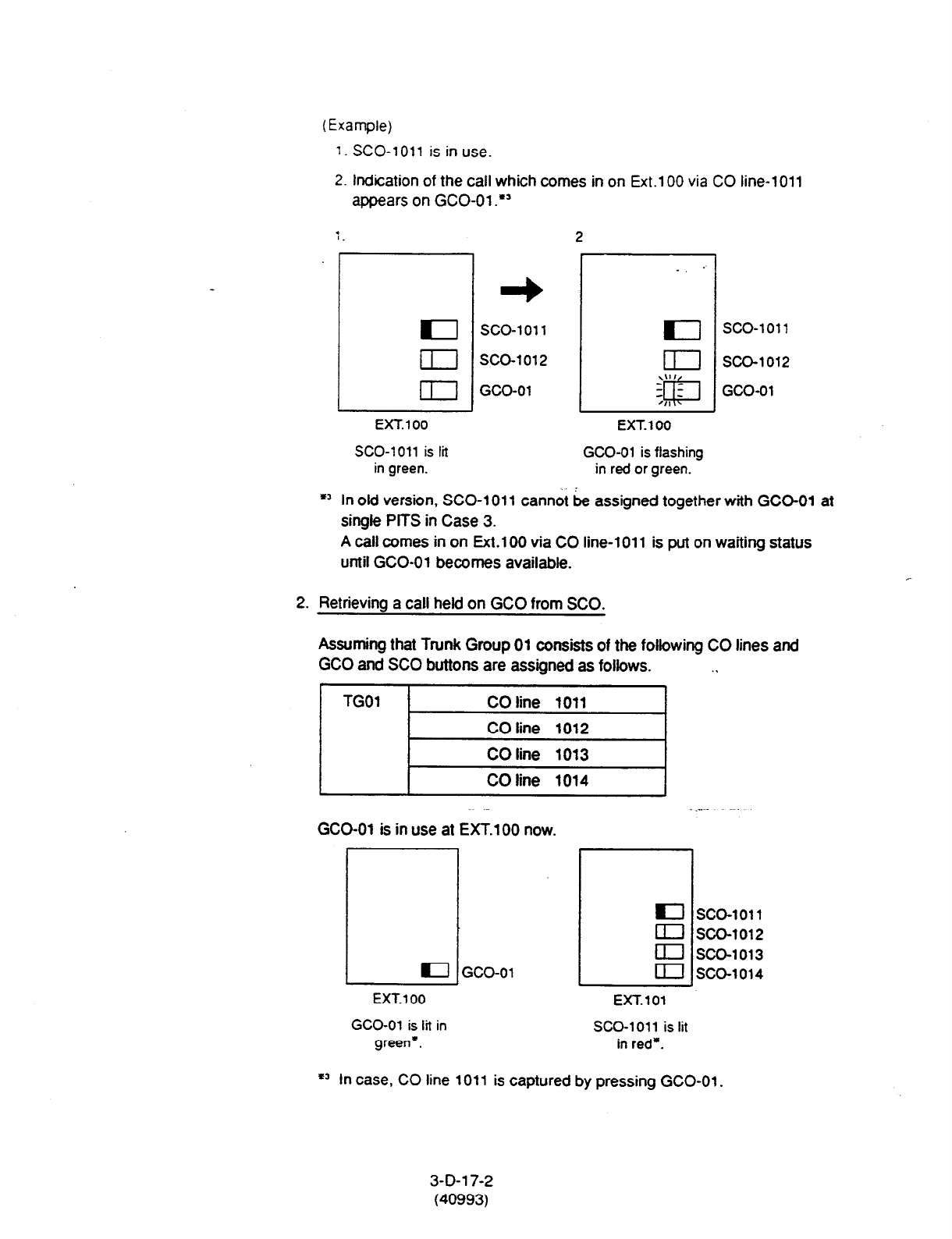
(Example)
1. SCO-1011 is in use.
2. Indication
of
the call which comes in on Ext.100
via CO
line-1011
appears on (X0-01 .*’
7.
2
EXT.100
SCO-1011 is lit
in green.
sco-1011
SCO-1012
GCO-01
EXT. 100
GCO-01 is flashing
in red or green.
*’ In old version, SCO-1011 cannot be assigned together with GCC-01 at
single PtTS in Case 3.
sco-1011
SCO-1012
GCO-01
A call comes in on Ext.1 00 via CO line-l 011 is put on waiting
status
until (X0-01 becomes available.
2. Retrieving a call held on GCO from SCO.
Assuming that Trunk Group 01 consists of the following CO lines and
GCO and SC0 buttons are assigned as follows. .,
TGOl CO line 1011
CO line 1012
CO line 1013
CO line 1014
--. “,
GCO-01 is in use at EXT.100 now.
_ ,-... . . .
/ I IGco-ol
EXT. 100 EXT.101
GCO-01 is lit in SCO-1011 is lit
green*. in red*.
I sco-1011
Ei ;z:::3’
m sco-1014
=a In case, CO line 1011 is captured by pressing GCO-01.
3-D-l 7-2
(40993)

Programming
When a
call
on GCO-01
is
put on hold at EXT.1 00.
GCO-01 begins to
flash in green and SCO-1011 on En.101 %xyx 1:: t!ash in fed
as
follows:
L
sco-01
EXT.101
sco-1011
sco-1012
sco-1013
sco-1014
EXT.101 can retrieve a call held on GCO-01 by simply pressing the red
flashing SCO-1011.
Conditions None
- --i--
3-D-l 7-3
(40993)
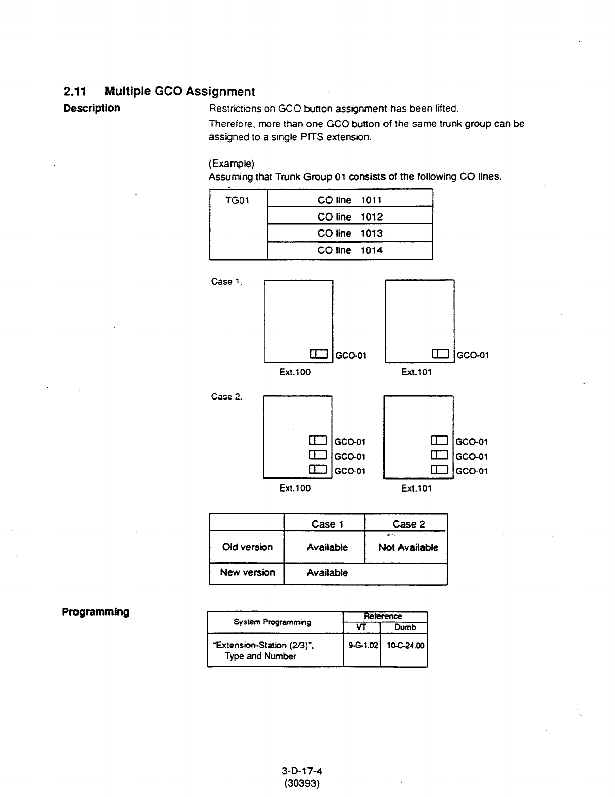
2.11 Multiple GCO Assignment
Description
Restrictions on GCO button assignment has been lifted.
Therefore, more than one GCO button of the same trunk group can be
assigned to a srngle PlTS extension.
(Example)
Assuming that Trunk Group
01
consists of the following CO lines.
Programming
Case 1.
q
m
GCO-01
Ext.1 00
Case 2.
/
Ext.1 00
GCO-01
GCO-01
GCO-01
~ CD
Ext.101
a
II
a
Ext.101
Old version
Case 1
Available
Case 2
r-.
Not Available
1 New version 1
Available I
System Programming Fteference
VT
I
Dumb
“Extension-Station (213)“.
Type and Number
GCO-01
3-D-l 7-4
(30393)
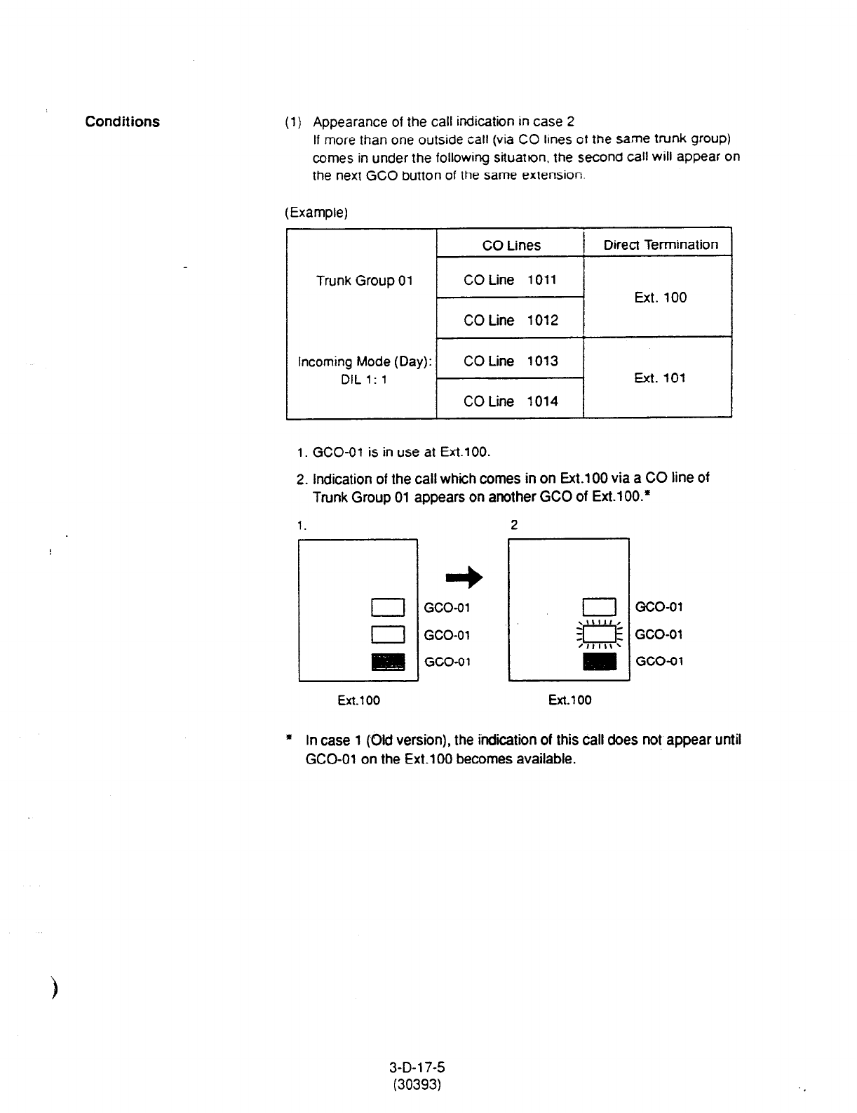
Conditions
(1) Appearance of the call indication in case 2
If more than one outside call (via CO lines of the same trunk group)
comes in under the following situation. the seCOnd call will appear on
the next GCO button of
the
same extension.
(Example)
Trunk Group 01
CO Lines
CO Line
1011
CO Line
1012
Direct Termination
Ext. 100
Incoming Mode (Day):
DIL
1: 1
CO Line 1013
CO Line 1014
Ext. 101
1. GCO-01 is in use at Ext.1 00.
2. Indication of the call which comes in on Ext.1 00 via a CO line of
Trunk Group 01 appears on another GCO of Ext.100.’
1.
2
El
I
L
GCO-01
GCO-01
GCO-01
c3co-01
GCO-01
GCO-01
Ext. 100
Ext.1
00
* In case 1 (Old version), the indication of this call does not appear until
GCO-01 on the Ext.100 becomes available.
3-D-l 7-5
(30393)
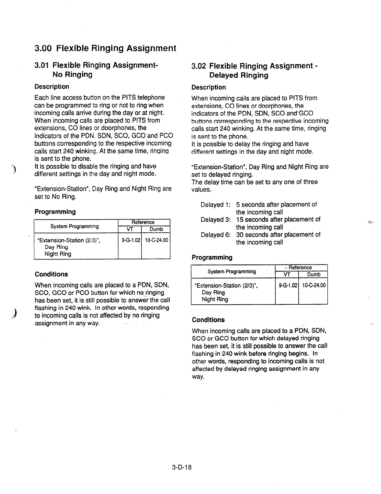
3.00 Flexible Ringing Assignment
3.01 Flexible Ringing Assignment- 3.02 Flexible Ringing Assignment -
No Ringing Delayed Ringing
Description Description
Each line access button on the PITS telephone
can be programmed to ring or not to ring when
incoming calls arrive during the day or at night.
When incoming calls are placed to PITS from
extensions, CO lines or doorphones, the
indicators of the PDN: SDN, SCO, GCO and PC0
buttons corresponding to the respective incoming
calls start 240 winking. At the same time, ringing
is sent to the phone.
It is possible to disable the ringing and have
different settings in the day and night mode.
When incoming calls are placed to PITS from
extensions, CO lines or door-phones, the
indicators of the PDN, SDN, SC0 and+GCO
buttons corresponding to the respective incoming
calls start 240 winking. At the same time, ringing
is sent to the phone.
It is possible to delay the ringing and have
different settings in the day and night mode.
“Extension-Station”, Day Ring and Night Ring are
set to delayed ringing.
The delay time can be set to any one of three
values.
“Extension-Station”, Day Ring and Night Ring are
set to No Ring.
Programming
System Programming Reference
VT i Dumb
“Extension-Station (2/3)“,
Day Ring
Night Ring
9-G-l .02 1 O-C-24.00
Conditions
..;$
When incoming calls are placed to a PDN, SDN,
SCO, GCO or PC0 button for which no-ringing
has been set, it is still possible to answer the call
flashing in 240 wink. In other words, responding
to incoming calls is not affected by no ringing
assignment in any way.
Delayed 1: 5 seconds after placement of
the incoming call
Delayed 3: 15 seconds after placement of
the incoming call
Delayed 6: 30 seconds after placement of
the incoming call
Programming
System Programming
“Extension-Station (2/3)“,
Day Ring
Night Ring
. s Reference
VT Dumb
9-G-l .02 1 O-C-24.00
Conditions
When incoming calls are placed to a PDN, SDN,
SC0 or GCO button for which delayed ringing
has been set, it is still possible to answer the call
flashing in 240 wink before ringing begins. In
other words, responding to incoming calls is not
affected by delayed ringing assignment in any
way.
::f- . .
. .
3-D-l 8
4.00 Discriminating Ringing
Description
It is possible to identify the type of an incoming call
by the ringing pattern.
In an SLT, the Held Call Reminder for CO cats :s
the same as the CO line incoming ringing
pattern. The ringing for extension hold is the
same as the extension incoming ringing pattern.
The ringing patterns are listed on Section 3-B-l 6.
00 ‘Tone and Ringing Patterns.” There is no distinction made for calls to an Off
Premise Extension (OPX): The CO line incoming
Programming
None
Conditions
All Transfer Recall signals have the same ringing
pattern as Held Call Reminder.
If there are multiple incoming calls on an extension
when the extension user goes on-hook, the calls
are rung in the following sequence.
cl > Consultation Held Call Reminder
c2> tn a PITS, an incoming call from a line in which
the Prime Line Preference (incoming) function
has been set
<3> Call Waiting. The call was waiting when the
user was off-hook.
<4> CO line incoming call, extension incoming call,
intercom incoming call, door-phone incoming
call, Held Call Reminder, Transfer Recall,
Unattended Conference Recall.
When there is more than one of the above
incoming calls in a PITS, the calls are
prioritized in DN sequence (PDN takes top
priority). Intercom incoming calls have the
lowest priority.
.- .<5> Automatic Callback ..-,*.
“F. .
<6> Timed Reminder
When a multiple number of incoming calls arrive at
a PITS in the on-hook status, priority as to which
calls should be rung is generally on a “first-come
first-served” basis. However, when the Prime tine
Preference (incoming) function has been set. this
line takes precedence.
ringing pattern only.
.I.;. .
e.. .
When there are multiple calls placed to an SLT
which is on-hook, priority as to which calls should
be rung is generally on a “first-come first-served”
basis.
3-D-i 9

5.00 Station Hunting
5.01 Station Hunting-Circular
Description
Station Hunting provides automatic redirection of
incoming calls to an idle member of a hunt group
when the called extension is busy. Idle extensions
are automatically hunted in accordance with the
hunting sequence set in the system program, and
the call is put through to an idle extension.
See Section 3-B-7.03 “Uniform Call Distribution
(UCD) Group” for details on UCD groups.
See Section 3-D-2.05, 2.06 “Uniform Call
Distribution (UCD)-without OGM/-with OGM” for
details on the UCD function.
The following calls do not receive the Station
Hunting treatment.
.j
The hunting sequence is set by “Extension-
Station”, Next Hunt Station.
The group formed by this setting is called a
hunting group.
Busy status applies when there are no idle PDNs
for the extension
and
when the extension is Out of
Service or in fault condition.
When the incoming destination extension is in
any of the following statuses, the operation below
is %ccomplished.
Circular hunting is enabled when the last DN in the
hunting group sets the first
DN
as the Next Hunt
Station as follows.
DN 100
DN 200 <- incoming call
5. c
J
DN 110
t-- : Hunting
&
DN 120
Status Operation
Idle PDN Incoming call processed (caller
hears ringback tone)
FWD setting FWD processing
DND setting DND processing
Depending on the status of the hunted
extensions, the operation below is accomplished
after hunting starts.
;3
Hunting Group - Circular
When an incoming call cannot be put through
even after hunting all the extensions belonging to
the hunting group, busy tone is sent to the calling
w-W.
Programming
The call forwarded to a busy extension/Voice
Mail Port receives the treatment of the Station
Hunting if programmed.
Refer to Section 3-F-l 0.00 “Voice Processing
System (VPS)” for further information.
Conditions
A call redirected to another PITS extension by
the Station Hunting feature always rings on a
PDN button on it even if a call is originally routed
on a SC0 or GCO button.
\ Extensions can be in only one hunting group.
Extensions in a UCD group cannot belong to
hunting groups. Similarly, extensions in hunting
groups cannot belong to UCD groups.
3-D-20
(21292)
l
A call on the ICM button.
l
An incoming outside call routed via DIL 1 :N
or Private CO feature.
l
A call on the SDN button.
Status
Operation
Hunting proceeds to next station
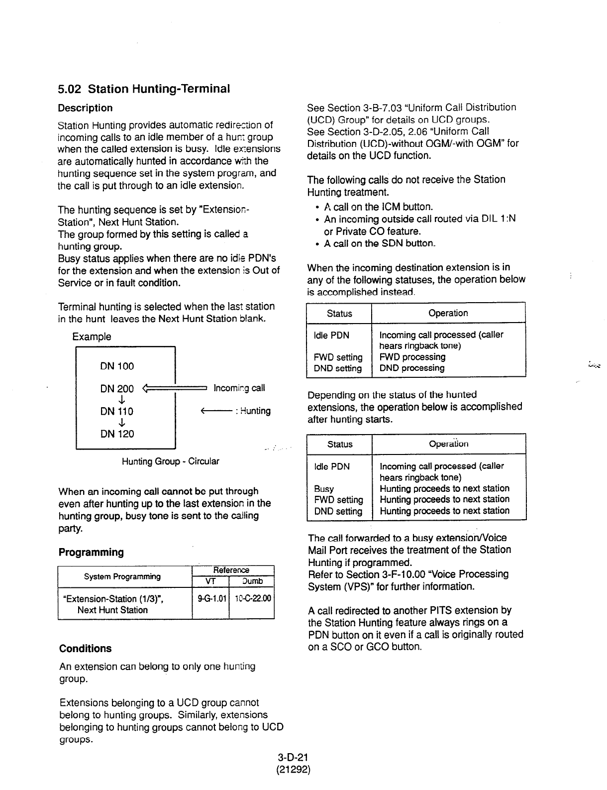
5.02 Station Hunting-Terminal
Description
Station Hunting provides automatic redirection of
incoming calls to an idle member of a hum group
when the called extension is busy. Idle ex!ensions
are automatically hunted in accordance v&f-r the
hunting sequence set in the system program, and
the call is put through to an idle extension.
See Section 3-B-7.03 “Uniform Call Distribution
(UCD) Group” for details on UCD groups.
See Section 3-D-2.05, 2.06 “Uniform Call
Distribution (UCD)-without OGM/-with OGM” for
details on the UCD function.
The hunting sequence is set by “Extensioc-
Station”, Next Hunt Station.
The group formed by this setting is called a
hunting group.
Busy status applies when there are no idle PDN’s
for the extension and when the extension Is Out of
Service or in fault condition.
The following calls do not receive the Station
Hunting treatment.
l
A call on the ICM button.
l
An incoming outside call routed via DIL 1 :N
or Private CO feature.
l
A call on the SDN button.
When the incoming destination extension is in
any of the following statuses, the operation below
is accomplished instead.
Terminal hunting is selected when the last station
in the hunt leaves the Next Hunt Station blank.
Example
I status I
Operation I
DN 100
DN 200 <= Incoming call
.L
DN 110 t-- : Hunting
A
DN 120
_. :
Depending on the status of the hunted
extensions, the operation below is accomplished
after hunting starts.
Hunting Group - Circular
When an incoming call cannot be put through
even after hunting up to the last extension in the
hunting group, busy tone is sent to the calling
party.
Programming
(1
The call forwarded to a busy extension/Voice
Mail Port receives the treatment of the Station
Hunting if programmed.
Refer to Section 3-F-l 0.00 “Voice Processing
System (VPS)” for further information.
Conditions
3-D-21
(21292)
A call redirected to another PITS extension by
the Station Hunting feature always rings on a
PDN button on it even if a call is originally routed
on a SC0 or GCO button.
An extension can belong to only one hunting
group.
Extensions belonging to a UCD group cannot
belong to hunting groups. Similarly, extensions
belonging to hunting groups cannot belong to UCD
groups.
Idle PDN
FWD setting
DND setting
Incoming cell processed (caller
hears ringback tone)
FWD processing
DND processing
Status Open&on I
Idle PDN Incoming call processed (caller
hears ringback tone)
Busy Hunting proceeds to next station
FWD setting Hunting proceeds to next station
DND setting Hunting proceeds to next station
E. Holding Features
1.00 Music on Hold
Description Conditions
The
external music device (up
to
two units can be
accommodated by this system) automatically
sends Music on Hold to a party on Hold.
Music on Hold is not sent to the party on Hold
unless the settings outlined in description have
been made.
This function will only be executed when
“System-Operation”, External Music Source 1,2
is set to Yes, “Trunk-Pager & Music Source”,
Music Source - For Use set either to “HOLD” or
“HOLD & BGM” and the external music device
has been connected.
Programming
I
System Programming 1 $efyen& 1
“System-Operation
(l/3)“, 9-D-1 .Ol 10-c-4.00
External Music Source
1.2
“Trunk-Pager & Music Source”, 9-F-2.00 10-C-20.00
Music Source - For Use
Music Source - Tenant
If Tenant Service is employed, the “Trunk-Pager
& Music Source”, Music Source - Tenant setting
determines which tenant the external music
device belongs to.
When both external music devices are
accommodated in the same tenant and the
applications of both devices are set identically,
the device connected to port 1 is used as the
Music on Hold.
An example of this is given below.
<Example>
Port
number
1
2
Trunk-Pager & Music Source
Tenant For Use
1 HOLD
1
HOLD
3-E-l
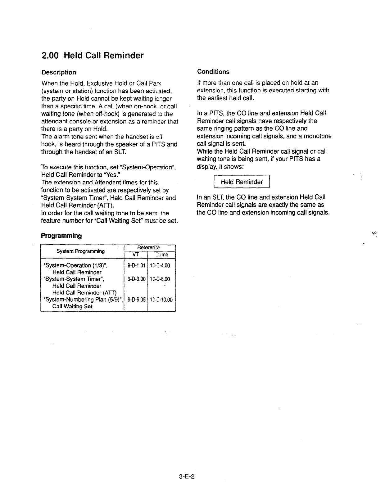
2.00 Held Call Reminder
Description
When the Hold, Exclusive Hold or Call Pa-<
(system or station) function has been activated,
the party on Hold cannot be kept waiting icnger
than a specific time. A call (when on-hook or call
waiting tone (when off-hook) is generated :s the
attendant console or extension as a reminier that
there is a party on Hold.
The alarm tone sent when the handset is c?f
hook, is heard through the speaker of a PITS and
through the handset of an SLT.
Conditions
If more than one call is placed on hold at an
extension, this function is executed starting with
the earliest held call.
To execute this function, set “System-Operation”,
Held Call Reminder to “Yes.”
The extension and Attendant times for this
function to be activated are respectively stt by
“System-System Timer”, Held Call Remincsr and
Held Call Reminder
(ATT).
in order for the call waiting tone to be seni the
feature number for “Call Waiting Set” mus: be set.
Programming
System Programming Referenz
VT :cJmb
‘System-Operation (l/3)“, 9-D-l .Ol 1 C-X.00
I Held Call Reminder
“System-System Timer”, 9-D-3.00 lC-X.00
Held Call Reminder
Held Call Reminder (AU)
“System-Numbering Plan (5/g)“, 9-D-6.05 1 C-Z-1 0.00
Call Waiting Set
In a PITS, the CO line and extension Held Call
Reminder call signals have respectively the
same ringing pattern as the CO line and
extension incoming call signals, and a monotone
call signal is sent.
While the Held Call Reminder call signal or call
waiting tone is being sent, if your PITS has a
display, it shows:
In an SLT, the CO line and extension Held Call
Reminder call signals are exactly the same as
the CO line and extension incoming call signals.
3-E-2

3.00 Transfer Recall
Description Conditions
If a call tratsferrec by the Unscreened Call
Transfer. Camp-@ Transfer or Ringing Transfer
function is not answered by the destination party
within a preprogrammed time period, the call will
return to the extension user or attendant console
that transferred the call.
When there are more than one parties on hold,
this function is started from the earliest time for
the transfer operation.
When the handset is on-hook or off-hook, the
Transfer Recall call signal or call waiting tone,
respectively, enables the party attempting the
transfer to be advised that the call has not been
answered. The call waiting tone sent when the
handset is off-hook, is heard through the speaker
in the case of a PITS and through the handset in
the case of an SLT.
In a PITS,
the
CO line and extension Transfer
Recall call signals have the same ringing pattern
as the CO line and extension incoming call
signals,
and a
monotone call signal is sent.
While the Transfer Recall call signal or call
waiting tone is being sent, if your PITS has a
display, it shows:
l
When the transfer destination extension does
not have a name programmed:
The time taken to ac$ivate this function for the
extension or attendant console is set by “System-
System Timer”, Transfer Recall.
Programming
I
System Programming Reference
VT
I
Dumb
“System-System TimeP,
Transfer Recall
_..
<Example>
RCL: Ext 1234
-r L Extension number (DN)
l
When the transfer destination extension has a
name programmed:
<Example>
In an SLT, the CO line and extension Transfer
Recall signals are exactly the same as the CO
line and extension incoming call signals.
~.
3-E-3
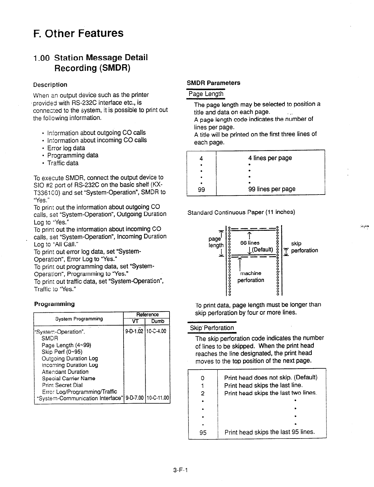
F. Other Features
1.00 Station Message Detail
Recording (SMDR)
Description
SMDR Parameters
When an output device such as the printer
‘provided with RS-232C interface etc., is
connected to the system, it is possible to print out
the foliowing information.
l
Information about outgoing CO calls
l
Information about incoming CO calls
l
Error log data
l
Programming data
l
Traffic data
Page Length
The page length may be selected to position a
title and data on each page. _ ,,
A page length code indicates the number of
lines per page.
A title will be printed on the first three lines of
each page.
To execute SMDR, connect the output device to
SIO #2
port of
RS-232C on the basic shelf (KX-
T3361 CO) and set ‘System-Operation”, SMDR to
“Yes.”
4
.
.
.
9’9
4 lines per page
.
.
.
b9 lines per page
To print out the information about outgoing CO
calls, set ‘System-Operation”, Outgoing Duration
Log to -Yes.”
Standard Continuous Paper (11 inches)
To print out the information about incoming CO
. calls, set “System-Operation”, Incoming Duration
Log to -All Call.”
To print out error log data, set “System-
Operation”, Error Log to “Yes.”
To prinr out programming data, set “System-
Operaiion”, Programming to “Yes.”
To prinT out traffic data, set ‘System-Operation”,
T
page
length
L
g-e -w-s
! T :
x
66
lines
8
Fi JJDefault) i
o-----o
:
x
8
T 8
%
machine 0’
H perforation E
8
! !
Tra’ff ic io “Yes.”
Programming
System Programming
;ysterr;-Operation”,
SMDR
Page
Length (4-99)
Skip
Perf (O-95)
OutGoing Duration Log
Incorning Duration
Log
Atiendant Duration
Special Carrier Name
Prim Secret Dial
Error Log/Programming/Traffic
System-Communication Interface”
skip
1 perforation
To print data, page length must be longer than
skip perforation by four or more lines.
Skip’ Perforation
The skip perforation code indicates the number
of lines to be skipped. When the print head
reaches the line designated, the print head
moves to the top position of the next page.
0
Print head does not skip. (Default)
1 Print head skips the last line.
2 Print head skips the last two lines.
. .
.
I I
.
.
.
/,‘,I l
Print head skips the last 95 lines.
3-F-l
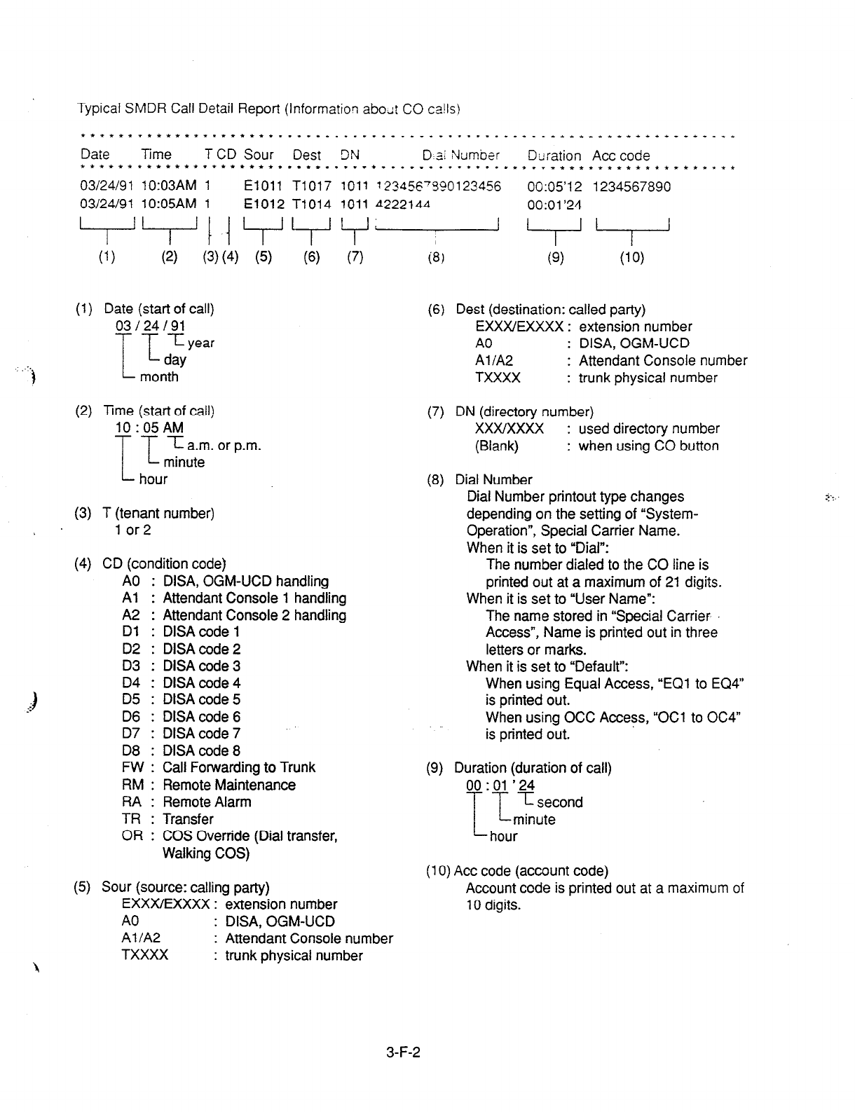
Typical SMDR Call Detail
Report
(Informatiorl abodt CO ca!Is)
t*tC*~r**tfttl.l*ttt**.*.........*..~..*~.~~ . ..I ..*tff.tt****ttltfr.1*
Date Time T CD Sour Dest 3N D a1 Number Duration Act code
f**t*t****t*trtttt****...*..*.~*~..~~.~~..*..**~ r-~tf*tttt~*ft*l**tt**
03/24/91 10:03AM 1 El011 T1017 1011 ~23456'3?0123456 00:05'12 1234567890
03/24/91 10:05AM 1 El012 T1014 1011 4222144 00:01'24
. ..'
(1) Date (start of call)
03124191
IT
Iyear
day
)
month
(2) Time (start of call)
10:05AM
I -r- 5a.m.orp.m.
minute
hour
(3) T (tenant number)
5
lor2
(4) CD (condition code)
(6) (7) ia, (9) (10)
A0 : DISA, OGM-UCD handling
Al : Attendant Console 1 handling
A2 : Attendant Console 2 handling
Dl : DISA code 1
D2 : DlSAcode 2
D3 : DlSAcode 3
04 : DISA code4
D5 : DISA code 5
D6 : DlSAcode 6
D7 : DISA code 7
D8 : DlSAcode 8
FW : Call Forwarding to Trunk
RM : Remote Maintenance
RA : Remote Alarm
TR : Transfer
OR : COS Override (Dial transfer,
Walking COS)
(5) Sour (source: calling party)
EXXXIEXXXX : extension number
A0 : DISA, OGM-UCD
Al IA2 : Attendant Console number
TXXXX : trunk physical number
(6)
Dest (destination: called party)
EXXXIEXXXX : extension number
A0 : DISA, OGM-UCD
Al/A2
: Attendant Console number
TXXXX : trunk physical number
(7)
DN
(directory number)
xxxlxxxx : used directory number
(Blank) : when using CO button
(8) Dial Number
Dial Number printout type changes
depending on the setting of “System-
Operation”, Special Carrier Name.
When it is set to “Dial”:
The number dialed to the CO line is
printed out at a maximum of 21 digits.
When it is set to “User Name”:
The name stored in “Special Carrier
Access”, Name is printed out in three
letters or marks.
When it is set to “Default”:
When using Equal Access, “EC?1 to EQ4”
is printed out.
When using OCC Access, “OCl to OC4”
is printed out.
(9) Duration (duration of call)
00 : 01 ’ 24
I’-
71 second
minute
hour
(10) Act code (account code)
Account code is printed out at a maximum of
10 digits.
3-F-2

2.00 Off Premise Extension
(OW
Description
Single line telephones .-staI!ed c” the premise
can be operated via a public or prrvate network in
exactly the same way as extension which are on
the premise.
Up to 80 Off Premise Extensions can be installed
per system.
The OPX card and OPX Power Unit are required.
OPX must be set in the ‘Configuration-Slot
Assignment.”
Programming
Conditions
When an incoming call is placed to OPX, ringing
is heard in all the CO line incoming patterns.
A doorphone incoming call cannot be sent to an
OPX telephone.
-.y,
With a PITS, this function is executed from a
;” <&‘DN. t
The telephone type (PITS, SLT, OPX) must be the
same at the source and destination.
3-F-3
If a busy tone is heard when dialing the feature
number for “Walking Station Cancel” and the
extension number, it means that the moving
extension is being used (possibly by another
station with an SDN of the moving station) and
the function cannot be completed. In cases like
this, dial a ain. If
ckd
our PITS has a display, it
shows: Try Agarn
Dialing the feature number for “Walking Station
Cancel” and the extension number at the move
destination in a PITS cannot be done with the SP-
PHONE on.
First lift the handset and then proceed.
3.00 Walking Station
Description
It is possible to move an extension to a new
location without re-programming.
When moving a telephone, dial the feature
number for “Walking Station Set” at both the
source and destination telephones.
After the move, dial the feature number for
“Walking Station Cancel” and the original
extension number of the moved extension. Up
to two telephones in a system can be moved
simultaneously.
Before executing this function, assign ‘System-
Class of Service (1/2)n, Walking Station to “Yes”
for the extension.
Programming
Reference
System Programming VT Dumb
System-Class of Service (l/2)“, 9-D-4.01 10-C-7.00
Walking Station
“System-Numbering Plan (7/g)“, 9-D-6.07 10-C-10.00
Walking Station Set
Walking Station Cancel
Conditions
It is possible to move a telephone to an extension
which is in the preinstall status. .Ln this case, dial
the feature number for “Walking Station Set” only
at the extension to be moved, and dial the feature
number for “Walking Station Cancel” and the
original extension number at the destination
extension.
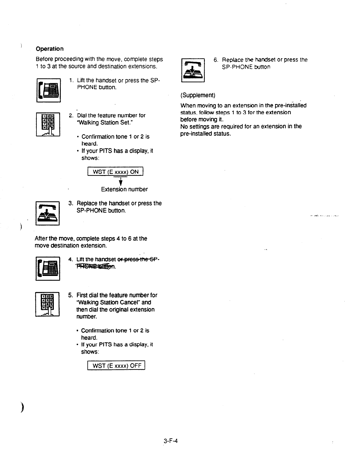
I
Operation
Before proceeding with the move, complete steps
1 lo 3 at the source and destination extensions.
1. Lift the handset or press the SP-
PHONE button.
6.
Replace the handset or press the
SP-PHONE button
(Supplement)
When moving to an extension in the pre-iniialied
t 23
q
2. Dial the feature number for status, follow steps
1
to 3
for the
extension
4s. before moving it.
7..
“Walking Station Set.”
I No settings are required for an extension in the
. Confirmation tone 1 or 2 is
heard.
pre-installed status.
.
If your PITS has a display, it
shows:
WST (E xxxx) ON
$
Extension number
3. Replace the handset or press the
SP-PHONE button.
After the move, complete steps 4 to 6 at the
move destination extension.
4. Lii the handset s-
B-
5. First dial the feature number for
“Walking Station Cancel” and
then dial the original extension
number.
l
Confirmation tone
1
or 2 is
heard.
. If your PITS has a display, it
shows:
1 WST (E xxxx) OFF ]
3-F-4
4.00
Outgoing Message (OGM)
Recording and Playing Back
Description
Up to four types of OGM’s can be recorded by the
Operator 1 (Attendant Console or PITS user) so
that different messages can be used for different
situations.
The following four types of OGM can be recorded
respectively:
DISA, UCDl, UCDP and W-UP (Wake-up)
OGM for outside parties
OGM for DISA is played to the outside patty who
called the system via DISA feature.
(See Section 3-D-2.02 “Direct Inward System
Access (DISA).“)
OGM for UCD 1 and UCD 2 are played to the
outside party in conjunction with UCD feature.
(See Section 3-D-2.06 “Uniform Call Distribution
(UCD)-with OGM.“)
OGM for extension users
OGM for W-UP (Wake-up) can be used as a wake-
up message for the extension user.
(See Section 3-F-13.00 Tmed Reminder y-ith
OGM (Wake-up Call).“)
Each OGM can be up to 30 seconds long.
A DISA card is required to record OGM and up to
four DISA cards can be installed to the system.
..;
Usage of each DISA card is determined by the’
system programming.
(See Section 9-K-l .OO “Special Attended-DISA.“)
Programming
I
System Programming
Conditions
( 1) Tenant Service
If tenant service is employed, the affiliation of
each DISA card is determined by the system i
programming “Special Attendant-DISA” tenant.
The Operator 1 of each tenant can record and
play back the OGM within the same tenant.
(2) Recording of OGM
. OGM recording is executed by selecting an
OGM type (usage of DISA card) from the
following four types:
1.
OGMl for UCD with OGM
2. OGM2 for UCD with OGM
3. OGM for DISA - 4. OGM for W-UP (Wake-up call)
l
If the type of multiple DISA cards are the
same in a tenant, the same message is
recorded for them at a time.
(3) Playing back of OGM
l
The following two ways are available:
A. By selecting an OGM type
B. By designating the logical number of
each DISA card directly.
l
If there are multiile DISA cards of the same
type in the system or a tenant and the OGM
type is selected to play back, playback starts
from the lowest DISA card physical number.
(4) o?hers
Call Waiting tone and so on are prohibited
during OGM recording and playing.
‘System-Numbering Plan (g/9)‘, 9-06.09 10-C-10.00
OGM Record
OGM Playback
‘Special Attended-DISA”. For Use 9-K-1.00 10-G40.00
3-F-5
(40993)
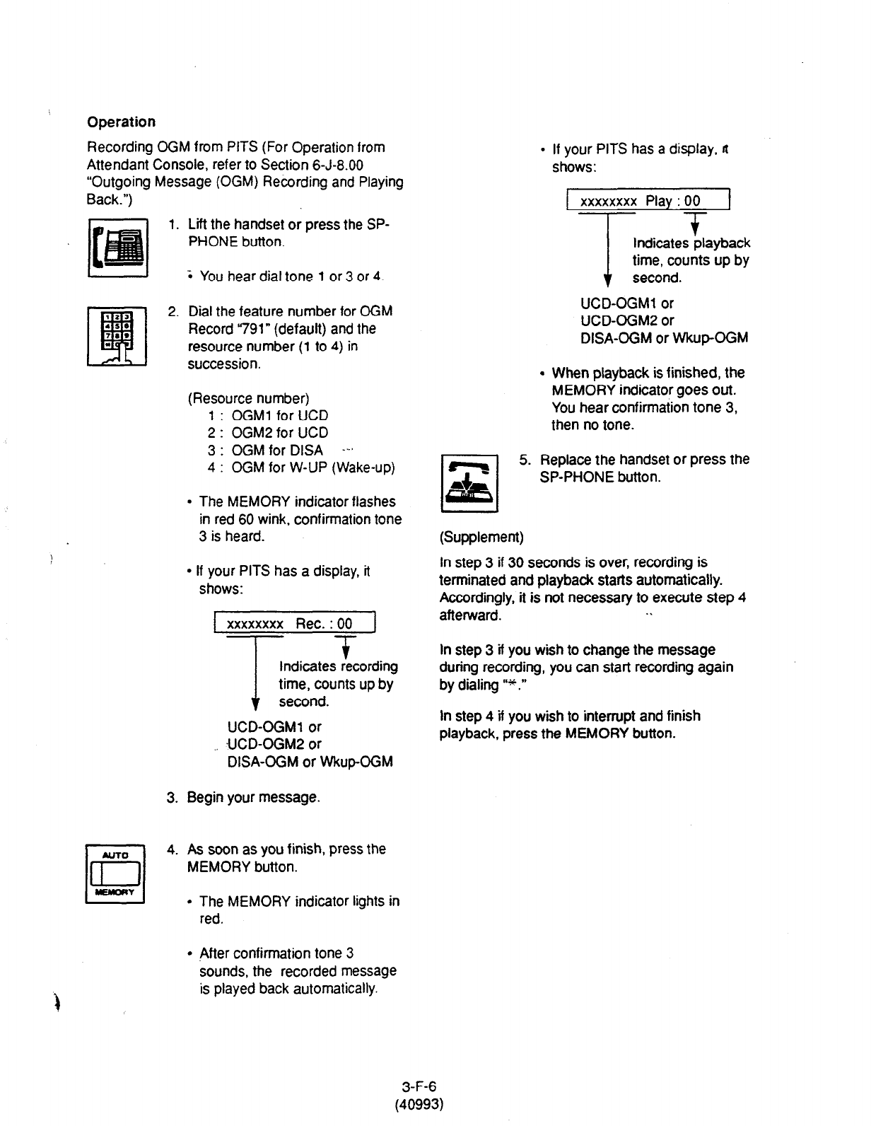
Operation
Recording OGM from PITS (For Operation from
Attendant Console, refer to Section 6-J-8.00
“Outgoing Message (OGM) Recording and Playing
Back.“)
1.
3. Begin your message.
NJ-m
q
4.
a
WY
Lift the handset or press the SP-
PHONE button.
; You hear dial tone 1 or 3 or 4.
Dial the feature number for CGM
Record ‘791” (default) and the
resource number (1 to 4) in
succession.
(Resource number)
1 : OGMl for UCD
2 : OGM2 for UCD
3 : OGM for DISA --’
4 : OGM for W-UP (Wake-up)
l
The MEMORY indicator flashes
in red 60 wink, confirmation tone
3 is heard.
l
If your PITS has a display, it
shows:
xxxxxxxx Rec. : 00
T
T
Indicates recording
time, counts up by
second.
UCD-OGMl or
UCD-OGM2 or
DISA-OGM or WkupOGM
As soon as you finish, press the
MEMORY button.
l
The MEMORY indicator lights in
red.
l
After confirmation tone 3
sounds, the recorded message
is played back automatically.
If your PITS has a display, n
shows:
1 xxxxxxxx Play : 00 J
T +
Indicates playback
time, counts up by
second.
UCD-OGMl or
UCD-OGM2 or
DISA-OGM or Wkup-GGM
When playback is finished, the
MEMORY indicator goes out.
You hear confirmation tone 3,
then no tone.
Replace the handset or press the
SP-PHONE button.
(Supplement)
In step 3 if 30 seconds is over, recording is
terminated and playback starts automatically.
Accordingly, it is not necessary to execute step 4
afterward. .\
In step 3 if you wish to change the message
during recording, you can start recording again
by dialing I’++.”
In step 4 if you wish to intenupt and finish
playback, press the MEMORY button.
3-F-6
(40993)
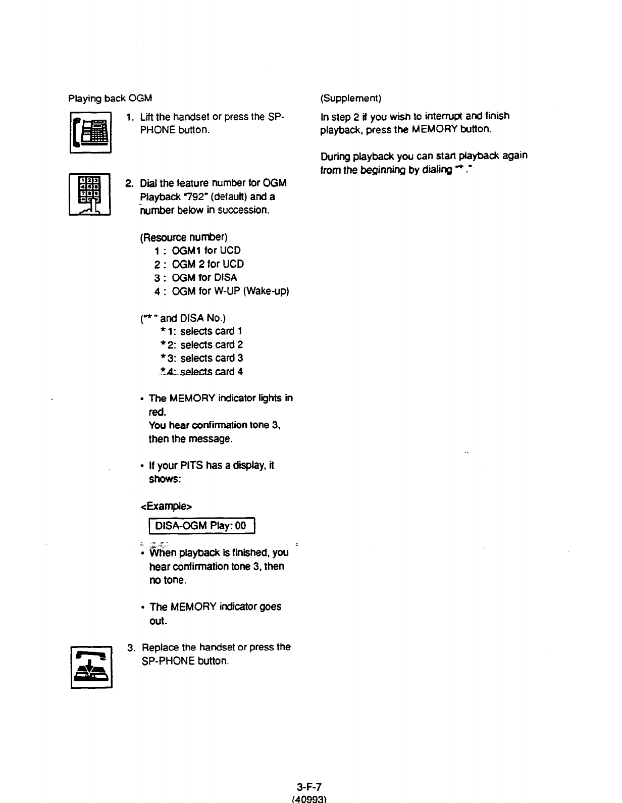
Playing back OGM (Supplement)
1. Lift the handset or press the SP- In step 2 if you wish to interrupt and finish
PHONE button. playback, press the MEMORY button.
L I During playback you can start pfaybadc again
from the beginning by dialing rc .-
2. Dial the feature number for OGM
Playback 792” (default) and a
number below in succession.
(Resource number)
1 : OGMl for UCD
2: OGM2forUCD
3 : OGM for DISA
4 : OGM for W-UP (Wake-up)
(“” and DISA No.)
l
1: selectscard 1
* 2: selects card 2
* 3: selects card 3
*m
-- card 4
l
The MEMORY indicator lights in
fed.
You hear confirmation tone 3,
then the message.
l
If your PITS has a display, it
shows:
<Example>
(DISA-OGM Play: 00 f
; -When playback is finished, you
hear confirmation tone 3, then
no tone.
l
The MEMORY indicator goes
Out.
3. Replace the handset or press the
SP-PHONE button.
3-F-7
(40993)

5.00 Intercept Routing-No
Answer (IRNA)
Description
If an incoming outside call directed to a single
extension is not answered in a specified time:
period, it can be redirected to another destination
in the system.
Another destination can be:
l
An Attendant Console
l
An extension user
l
A Voice Mail extension
For further information about IRNA and a Voice
Mail extension, refer to Section 3-F-l 0.00 “Voice
Processing System (VPS).” -*-
This feature also applies to the following calls.
l
When an incoming outside call rings back at the
extension who once put the call on hold, is not
answered in a specified time period. (Held
i
Reminder Call)
l
When an incoming outside call rings back at the
extension who once transferred the call to
another extension, is not answered in a
specified time period. (Transfer Recall)
The destination of Intercept Routing during day
and night are assigned in “Group-Trunk Group”,
Intercept Routing (Day) and Intercept Routing
(Night) on a trunk group basis.
Set the duration to start Intercept Routing in
“System-System lamer”, Intercept Routing Time-
Out (System).
The duration to start Intercept Routing for D&A
calls follows the setting in “System-System Timer”.
Intercept Routing Time-Out (DISA).
For details about DISA, refer to Section 3-D-2.02
“Direct Inward System Access (DISA).”
Programming
System Programming
“Group-Trunk Group (11’2)“.
Intercept Routing (Day)
Intercept Routing (Night)
“System-System Timer”.
Intercept Routing Time-Out
(System)
Intercept Routing Time-Out
WW
Conditions
Intercept Routing-No Answer works for the
following incoming CO calls.
1. All incoming CO calls other than calls
placed on DlLl : N, Private CO, Attendant
Consoles, Remote and UCD
2. Transfer Recall calls (except those to
Attendant Consoles)
3. Held Call Reminder calls (except those to
Attendant Consoles, calls on Exclusive
Hold, calls on hold on Private CO lines)
4.
An incoming outside call via DISAIDID
which comes in on an extension in the DND
mode.
Call Forwarding or Do Not Disturb feature
assigned on the IRNA destination does not work
on the call which has been transferred to it by the
IRNA
feature.
If the IRNA destination is not currently available to
answer the call transferred by the IRNA feature,
the call may receive the treatment of the Station
Hunting feature.
If the destination extension of a direct incoming
outside call is in the data line security mode,
IRNA feature does not work on it.
Refer to Section 4-I-6.00 “Data Line Security” for
further information.
If the destination is a PITS with display, it shows:
<Example>
1 + CO: PANASONIC/
3-F-8
(30393)

6.00 Rerouting
Description
If an incoming outside call cannot be placed
anywhere, the call can be routed to another
destination. This is called Rerouting.
Rerouting will take place in the following cases.
,l. lf the system cannot determine the
destination to place the call (for example,
no destination is assigned).
2. if the system determines the destination but
the destination cannot currently receive the
call (for example, it is not “In Service”).
3. If a call arrives at a trunk which is set to
“Outgoing Only.”
If a call is rerouted, the call will be s& to the
following destinatiotis:
1. lf “Group-Trunk Group”, Intercept Routing
(Day/Night) is assigned, the call is sent to
the assigned destination.*
2. If it is not assigned, the call is sent to
Operator 1 in the receiving tenant.
* If the assigned destination is a Voice Mail
extension, the call is not sent to it.
Refer to Section 3-F-l 0.00 “Voice Processing
System (VPS). for further information.
Programming
~1
Conditions
If a call is rerouted to an extension user and the
user’s PITS has a display, if shows:
-&le>
--w CO : PANASONIC
f
Indicates the name of the CO line.
3-F-9
(21292)
7.00 Calling Party Control (CPC)
Signal Detection
Description Programming
CPC (Calling Party Control) signal is the on-hook
indication (disconnect signal) sent through the CO
line when either calling or called party goes on-
hook.
System Programming
To support efficient utilization of the CO lines, the
system monitors the status of the CO lines, and
when CPC signal is detected, the system
disconnects the CO lines connected compulsorily.
In default mode, CPC signal detection works on
incoming CO calls, and does not work on outgoing
CO calls (except once they are placed on hold or
consultation hold).
In this case, if the extension user remains off-hook
after the completion of an outgoing CO call, the
system does not release ail the switches used to
establish the connection, and a CO line connected
will continue to be seized by the extension user
ineffectively.
“Trunk-CO Line”, CPC Detection 9-F-l .OO 1 O-C-18.00
‘CPC Signal Detect Timing- - 1 o-c-49.00
Outgoing CO Calls (CPC).
Conditions
Some switching system of the central office may
send CPC-like signal in dialing sequence and the
attempt of making a call may be terminated.
If your switching system does not send CPC-like
signal in dialing sequence, we recommend to
make CPC signal detection work on outgoing CO
calls.
To prevent the extension users from such invalid
. seizure of CO lines, it is administrable to make
CPC signal detection effect on outgoing CO calls
by using CPC command at dumb programming
mode.
This feature is assignable on a CO line basis.
Refer to Section 1 O-C-49.00 “CPC Detect Timing-
Outgoing CO Calls (CPC)” for further information.
CPC signal detection can be assigned to
incoming CO calls only or both on incoming and
outgoing CO calls. If CPC signal detection is
assigned to.outgoing CO calls only, it does not
function.
Reference
VT ( Dumb
3-F-i 0
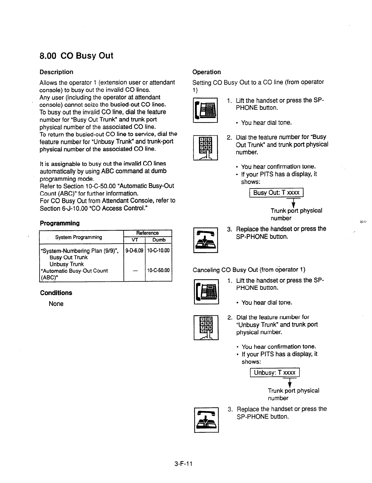
8.00
CO Busy Out
Description Operation
Setting CO Busy Out to a CO line (from operator
1)
Allows the operator 1 (extension user or attendant
console) to busy out the invalid CO lines.
Any user (including the operator at attendant
console) cannot seize the busied-out CO lines.
To busy out the invalid CO line, dial the feature
number for “Busy Out Trunk” and trunk port
physical number of the associated CO line.
To return the busied-out CO line to service, dial the
feature number for “Unbusy Trunk” and trunk-port
physical number of the associated CO line.
1. Lift the handset or press the SP-
PHONE button.
l
You hear dial tone.
2. Dial the feature number for “Busy
Out Trunk” and trunk port physical
number.
It is assignable to busy out the invalid CO lines
automatically by using ABC command at dumb
programming mode.
Refer to Section 1 O-C-50.00 “Automatic Busy-Out
Count (ABC)n for further information.
For CO Busy Out from Attendant Console, refer to
Section 6-J-l 0.00 “CO Access Control.”
l
You hear confirmation tone.
l
If your PITS has a display, it
shows:
1 Busy Out: T xxxx 1
-?-
Programming
Reference
System Programming v-r Dumb
System-Numbering Plan (9/g)“, 9-O-6.09 104-10.00
Busy Out
Trunk
Unbusy Trunk
“Automatic Busy-Out Count - 10-c-50.00
(ABC)”
Trunk port physical
number
3. Replace the handset or press the
SP-PHONE button.
Canceling CO Busy Out (from dperator 1)
1. Lift the handset or press the SP-
PHONE button.
Conditions
None
l
You hear dial tone.
__
9 13
q
2. Dial the feature number for
45s
,a* “Unbusy Trunk” and trunk port
Is physical number.
l
You hear confirmation tone.
l
If your PITS has a display, it
shows:
1 Unbusy: T xxxx 1
T
Trunk port physical
number
3. Replace the handset or press the
SP-PHONE button.
3-F-l 1
9.00 Parallel Connection of
Extensions
Description
Programming
An):
‘+g!e L,?e Telep3one can be conneced
parallely
with
a PITS telephone.
When
para!!ei connection is made, an extension
user
caq make and answer a call by usinc either of
both telephones.
However, the operation of parallely connected
Conditions
Single Line Telephone is somewhat restriced as
follows:
Features not available are:
l
External Feature Access
l
Conference
l
Pickup Dialing
l
Account Code Entry
Cannot make a call when parallely conneded PITS
telephone is:
l
In the BGM mode
l
Being paged through built-in speaker
l
In the PITS programming mode
Will not ring if parallely connected PITS telephone
is:
l
In the Intercom Automatic Answer mode
l
In the Voice Alerting mode
Not only a Single Line Telephone but an
answering machine, a facsimile, or a modem
(personal computer) can be connected parallely
with certain PITS telephones.
The parallel connection of a Single Line
Telephone and a PITS telephone becomes
available under the following conditions. _ ,
- Parallely connected PITS telephones are
interfaced with HLC card.
- The number of Single Line Telephones which
can be connected parallely with PITS
telephones must be within 48 lines per shelf.
To make parallel connection effective, assign
“Extension-Station,” Parallel Connect to “Yes” at
parallely connected PITS telephone side.
3-F-l 2
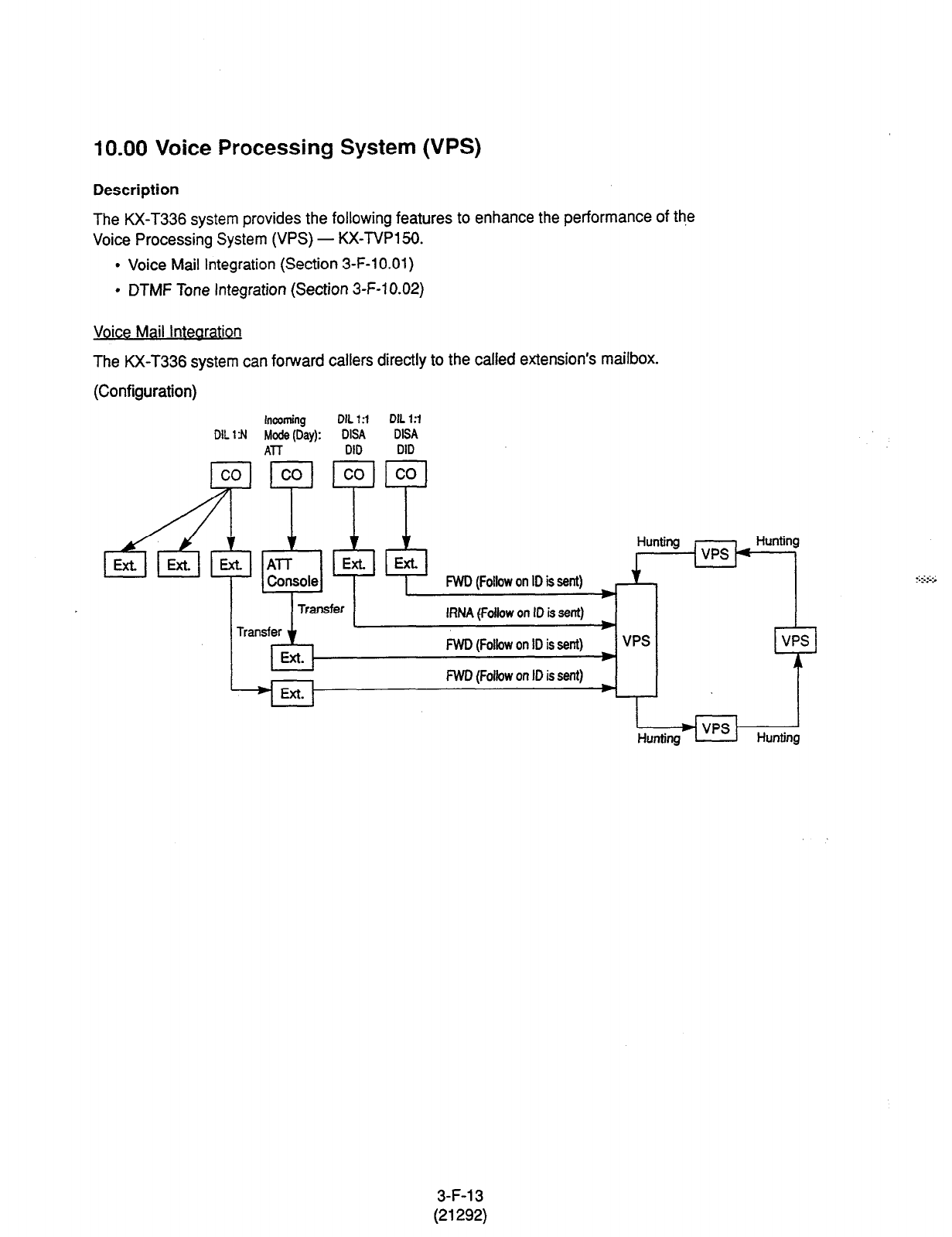
10.00 Voice Processing System (VPS)
Description
The KX-T336 system provides the following features to enhance the performance of th,e
Voice Processing System (VPS) - KX-TVP15D.
l
Voice Mail Integration (Section 3-F-l 0.01)
l
DTMF Tone Integration (Section 3-F-l 0.02)
Voice Mail lntearation
The KX-T336 system can forward callers directly to the called extension’s mailbox.
(Configuration)
incoming
DIL 13 DIL 1 :I
DIL 1 fl MO& (Day): DISA DISA
ATT DID DID
co co co co
v Hunting
ExLlI
Ext. Ext. ATT
VPS
Hunting
Console FWD (Follow on ID is sent)
IRNA (Follow
on ID is sent)
i
FWD (Follow
on ID is sent) VPS VPS
FWD (Follow on ID is sent)
3-F-l 3
(21292)
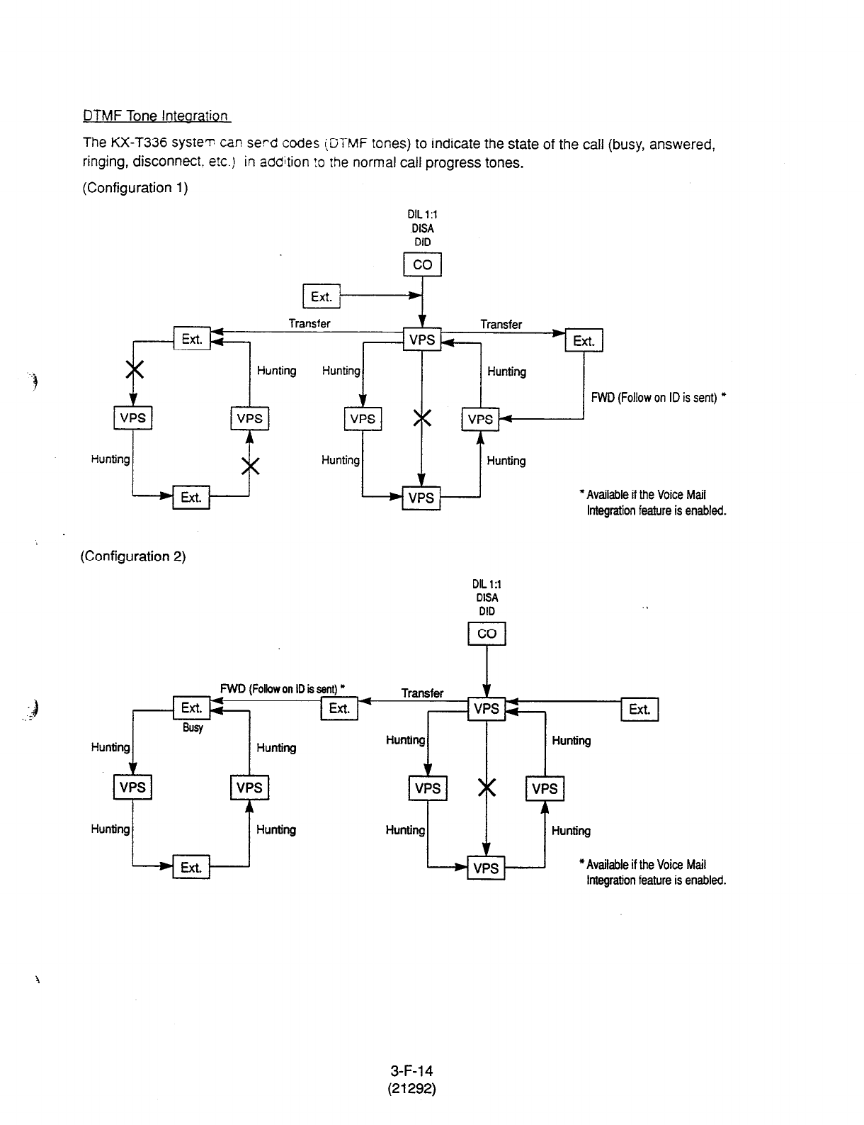
DTMF Tone lntearation
The KX-T336 syste-r: can serd codes (DTMF tones) to indicate the state of the call (busy, answered,
ringing, disconnect,
e!c.)
in
addition
?o the normal call progress tones.
(Configuration 1)
DIL 1 :l
DlSA
DID
co
Ext. 1 *
Transfer
I
Ext.
Hunting
VPS
$
,!s, c * ] FWD(FollowonIDissent)*
Hunting I I Hunting
(Configuration 2)
DIL 1:l
DISA
DID
I co I
FWD (Follow on ID is sent)
l nL
I
*Available if the Voice Mail
Integration feature is enabled.
. .
Hunting
I
I
Hunting
1 Hunting 1 Hunting
*Available if the Voice Mail
Integration feature is enabled.
3-F-l 4
(21292)

10.01 Voice Mail Integration
Description The KX-T336 system can forward callers directly to the called extension’s
voice mailbox, if the caller is forwarded to a Voice Mail Port (all calls, busy
or no answer) and this feature is enabled by the extension user.
The KX-T336 system automatically sends the digits of mailbox number of
the called extension with DTMF tones to the Voice Mail Port before
connecting the caller.
These digits are commonly known as the Follow on ID.
A max of 16 extension ports (HLC or SLC card) of the KX-T336 system
can be programmed for connection to the Voice Processing System
KX-TVP150.
This feature applies to the following calls.
Calls transferred by :
l
Call Forwarding - All Calls
l
Call Forwarding - Busy/Off-hook
l
Call Forwarding - No Answer
l
Call Forwarding - Busy/No Answer
(including the calls transferred to the extensions on which one of the
above mentioned Call Forwarding feature is assigned.)
l
Intercept Routing - No Answer (RNA)
(including the transfer recalled outside call and held reminder outside
call)
Extensions assigned as Voice Mail Port are not allowed to connect to
each other. For example, an Automated Attendant Port is not allowed to
connect to another Voice Mail Port.
Note this feature can be programmed in Dumb mode only.
Programming
(Dumb programming mode) 1) Press [CTRLI key and
q
key simultaneously when Main Menu
screen is displayed at VT programming mode.
2) Enter m F] I[ and press [G/ key when Dumb programming
mode initial prompt ( ; > ) is displayed. Then programming mode initial
prompt ( ; PRG > ) is displayed on the screen.
3) Program the required items as follows:
3-F-l 5
(21292)

Voice Mail Port Assignment:
Input Format PRG>VMD AT i;eT yk -::&r 1 ’ .: 5~ 1; 7
Input Value for
Item Number
To remove the existing setting, use ‘%CLR” command.
For further information about prcgrammng, refer to Section 1 O-C-54.00
“Voice Mail Directory Number (VMD).”
Mailbox Number Assignment:
Input Format PRG>MBN AT index Number CR
index Number = Physical Number of Extension Port or DN
Input Value for
Item Number Item
-* Assigning Items ’ Input
Value
Number
None Mailbox Number Up to 10 digits of numeric
characters (O-9), “*” and ” # ”
(Default = Extension Number)
Mailbox
Number specific to each extension (same as the extension
number) is assigned to all extensions by default.
To remove the existing setting, use “$CLR” command. . .
For further information about programming, refer to Section 1 O-C-55.00
“Mailbox Number (MBN).”
Conditions
1) Station Hunting Group - Circular
To use the Voice Mail Integration feature efficiently, we recommend to
program
a
station
hunting group among the Voice Mail (VM) Extensions,
this would reduce the possibility of the callers encountering the busy
status.
When
“Station Hunting Group - Circular” is programmed among the VM
Extensions, a cal! transferred to the busy VM Extension (including “Not
INS” status) by Call Forwarding
(FWD) or Intercept Routing
No Answer
(RNA)
feature will be automatically transferred to an idle VM Extension.
3-F-l 6
(2 1292)
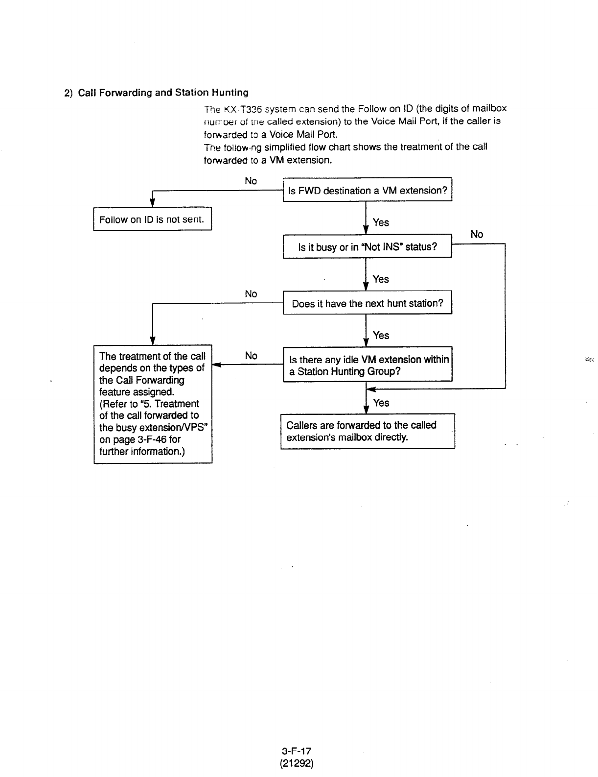
2) Call Forwarding and Station Hunting
The KX-T336
system can send the
Follow
on ID (the digits of mailbox
number
of
tne called extension) to the Voice Mail Port, if the caller is
forwarded :3 a Voice Mail Port.
The foilowng simplified flow chart shows the treatment of the call
forwarded to a VM extension.
t
Follow on ID is not sent.
Is FWD destination a VM extension?
No
k
Does It have the next hunt station
1 I
Yes
t
.
The treatment of the call
depends on the types of
the Call Forwarding
feature assigned.
(Refer to “5. Treatment
of the call forwarded to
the busy extension/VPS”
on page 3-F-46 for
further information.)
‘&LStation Hunting Group?
Is there any idle
VM
extension within
I Yes I
Callers are forwarded to the called
extension’s mailbox directly.
I
3-F-l 7
(21292)
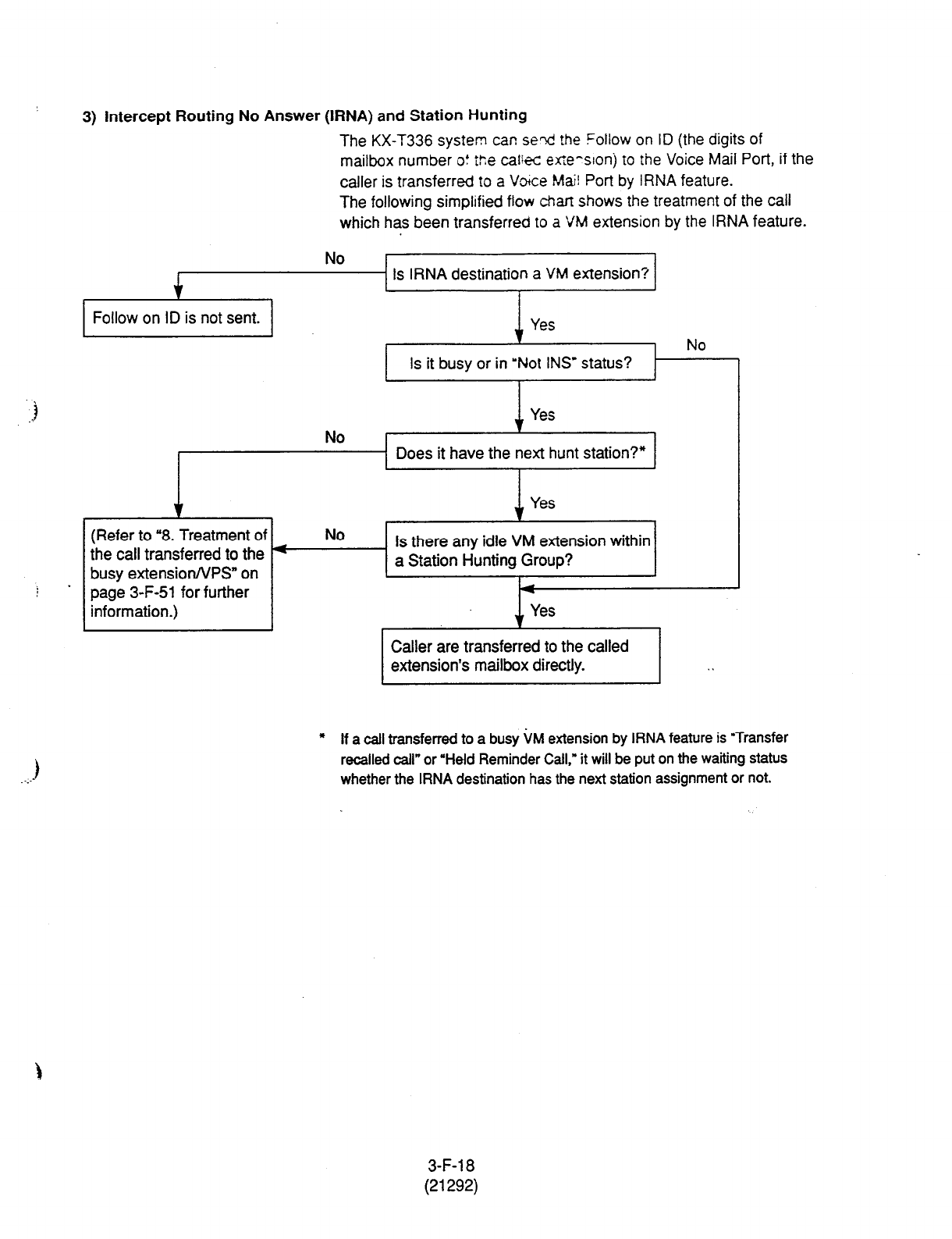
3) intercept Routing No Answer (IRNA) and Station Hunting
The KX-T336 system car! seti the Follow on ID (the digits of
mailbox number o!
i%
cali+z efle-slonj to the Voice Mail Port, if the
caller is transferred 10 a Voke Ma2 Port by IRNA feature.
The following simplified flow than shows the treatment of the call
which has been transferred 10 a VM extension by the IRNA feature.
No
4
Is IRNA destination a VM extension?
I
1
Follow on ID is not sent.
No
J Yes
NO v
I I
I . -- 1 Does it have the next hunt station?* 1
4 Yes
(Refer to “8. Treatment of No
the call transferred to the 4 Is there any idle VM extension within
busy extensionNPS” on a Station Hunting Group?
. page 3-F-51 for further
information.)
Caller are transferred to the called
* If a call transferred to a b&y i&l extension by IRNA feature is “Transfer
recalled call” or “Held Reminder Call.” it will be put on the waiting status
whether the IRNA destination has the next station assignment or not.
3-F-l 8
(21292)

4) Call Transfer and Voice Mail MegratIon
Nor only an morning call directed to the extension, but a transferred call
jbo? screened and unscreened call transfer) is applied to the Voice Mail
Integration teature.
Camp-on
Transfer to
a VM extension and Transfer Recall
Example
VM. 108 (busy) VM.107 (busy) VM.106 (busy)
Ext.100
Ext.101
I-
> 1
Making a
Transferring
call
a call FWD-All Calls
to VM.106
1. The Ext.1 00 makes a call to the Ext.1 01.
2. The Ext.101 answers the call from the Ext.100. and transfers it to the
Ext.1 02 (Call Forwarding - All Calls to VM 106 is assigned). Then
replaces the handset.
3. Since FWD destination VM.106 and all other VM extensions in the
Station Hunting Group are busy, the call from Ext.1 00 is put on the
waiting status.
&-on Transfer to a VM extension>
If VM.106 becomes idle before the transfer recall timer has been elapsed,
the call is connected to the VM.106, and the caller can access the
Mailbox of the fZxt.100 automatically.
Camp-on Transfer to a VM extension is only available when “Call
Forwarding-All Calls” is assigned to the Ext.1 02.
<Transfer R&all> .
If kM.106 is still busy after the transfer recall timer has been elapsed, the
call will ring back at Ext. 101.
What if Call Forwarding (FWD)-No Answer is assigned on the
extension where a call has been transferred without announcement
(Unscreened Call Transfer) ?
A call is forwarded
to the
FWD destination after the Call Forwarding No
Answer timer has been expired.
If the FWD destination is busy, the forwarded call will ring back at the
extension who transferred the call.
(Note)
In above
case, if the destination of Call Forwarding-No Answer is an
Attendant Console, the transferred call is not forwarded to an Attendant
Console.
The transferred call rings back at the extension who transferred the call
after the Call Forwarding No Answer timer has been expired.
3-F-l 9
(21292)
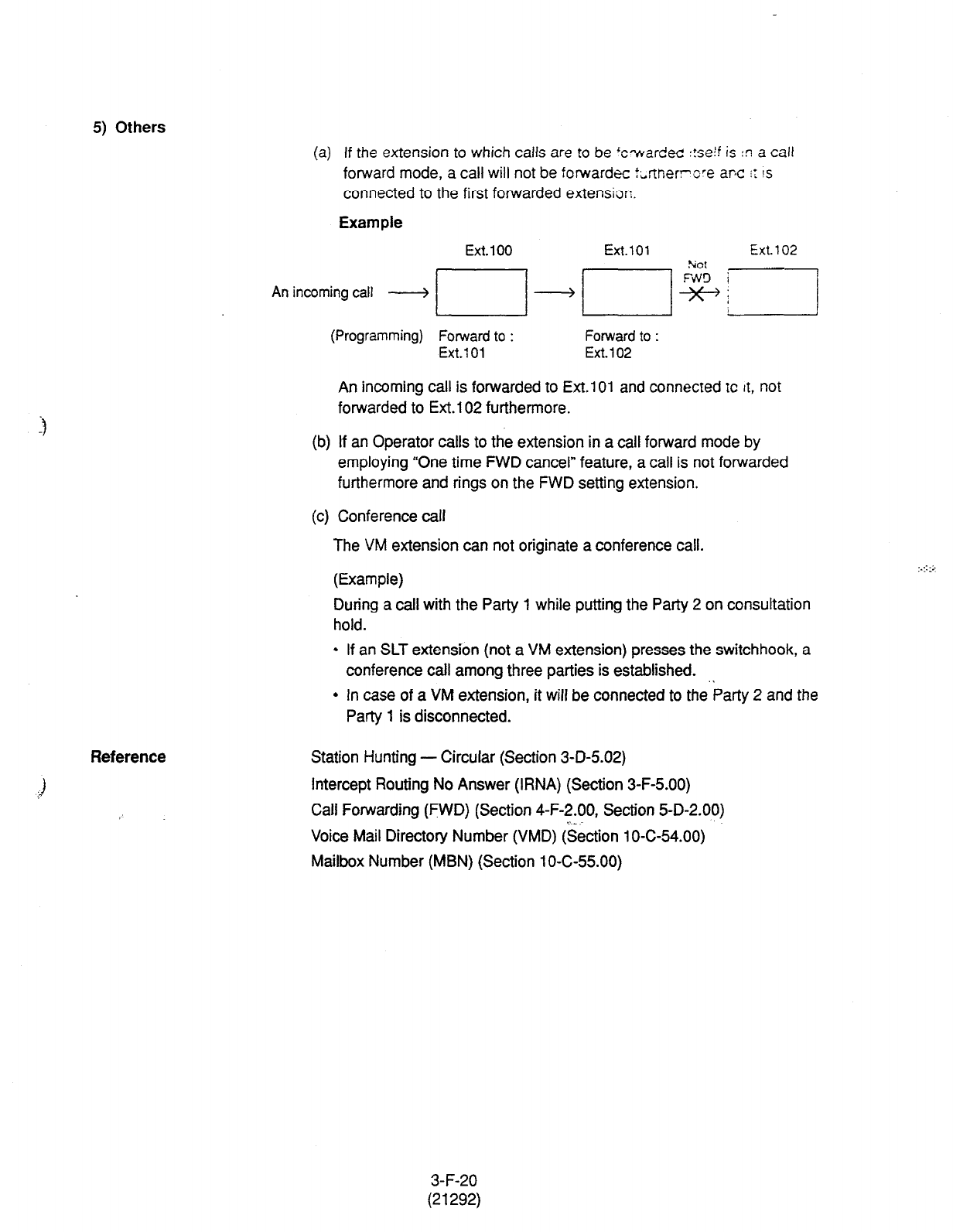
5) Others
(a) If the extension to which calls are to be ‘cwardec! :!seif is !n a call
forward mode, a call will not be forward= t,nnerrve arc ir IS
connected to the first forwarded extension.
Example
Ext. 100 Ext.101
Ext. 102
Anincomingcall _j // __j /I $+ ‘1
(Programming) Forward to : Forward to :
Ext.1 01 Ext.102
An incoming call is forwarded to Ext.1 01 and connected tc tt, not
forwarded to Ext.1 02 furthermore.
(b) If an Operator calls to the extension in a call forward mode by
employing “One time FWD cancel” feature, a call is not forwarded
furthermore and rings on the FWD setting extension.
(c) Conference call
The VM extension can not originate a conference call.
(Example)
During a call with the Party 1 while putting the Party 2 on consultation
hold.
l
If an SLT extension (not a VM extension) presses the switchhook, a
conference call among three parties is established. .I
l
In case of a VM extension, it will be connected to the Party 2 and the
Party 1 is disconnected.
Reference Station Hunting - Circular (Section 3-D-5.02)
Intercept Routing No Answer (IRNA) (Section 3-F-5.00)
Call Fowarding (FWD) (Section 4-F-2.00, Section 5-D-2.00)
.- _
Voice Mail Directory Number (VMD) (Section 1 O-C-54.00)
Mailbox Number (MBN) (Section 1 O-C-55.00)
3-F-20
(21292)
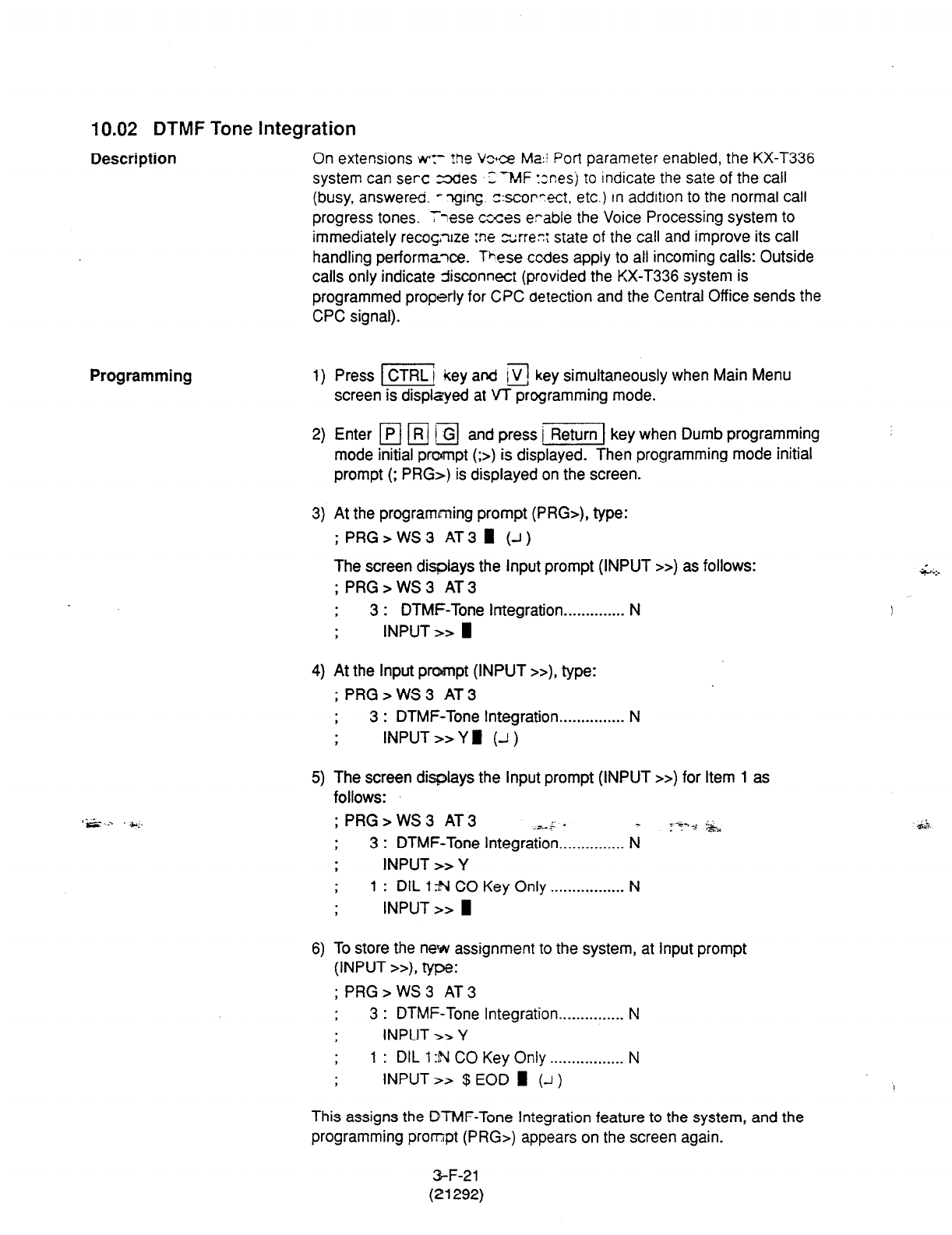
10.02 DTMF Tone Integration
Description
On extensions ~7 +
.he Vz+ce Ma:! Port parameter enabled, the KX-T336
system can set-c =36es 3 7vtF xnesj to indicate the sate of the call
(busy, answered. - -qing. sscorrect, etc.) in addition to the normal call
progress tones. I
‘;lese ccces erable the Voice Processing system to
immediately recoqxe :ne zrrez state of the call and improve its call
handling performaxe. These codes apply to all incoming
calls:
Outside
calls only indicate 5sconnect (provided the KX-T336 system is
programmed properly for
CPC
detection and the Central Office sends the
CPC signal).
Programming
‘.S... *;.
1) Press m key and 13 key simultaneously when Main Menu
screen is displayed at VT programming mode.
2) Enter p/ /R) EI and press j-1 key when Dumb programming
mode initial prompt (;>) is displayed. Then programming mode initial
prompt (; PRG>) is displayed on the screen.
3) At the programming prompt (PRG>), type:
;PRG>WS3 AT31 (J)
The screen displays the Input prompt (INPUT >>) as follows:
; PRG>WS3 AT3
t 3 : DTMF-Tone Integration . . . . .._....... N
I INPUT >>
4) At
the
Input
prompt (INPUT >>), type:
; PRG>WS3 AT3
, 3 : DTMF-Tone Integration . . . . . . . . . . . . . . . N
, INPUT >> Y fl (--I )
5) The screen displays the Input prompt (INPUT >>) for Item 1 as
follows:
; PRG > WS 3 AT 3 -As _ _ ::-i-, .%*
, 3 : DTMF-Tone Integration . . . . . . . . . . . . . . . N
.
. INPUT >> Y
> 1 : DIL 1 N CO Key Only . . . . . . . . . . . . . . . . . N
INPUT >> I
6) To store the nets assignment to the system, at Input prompt
(INPUT >>), type:
; PRG>WS3 AT3
3 : DTMF-Tone Integration . . . . . . . . . . . . . . . N
, INPUT >> Y
1 : DIL 1 :N CO Key Only . . . . . . . . . . . . . . .._ N
INPUT >> $ EOD m (-I)
This assigns the DTMF-Tone Integration feature to the system, and the
programming prompt (PRG>) appears on the screen again.
3-F-21
(21292)

Conditions
The
following table describes
the
DTMF
codes, call state and typicai
condition where the KX-T336 system would send the code.
Code
mIl
@ml
mzl
IZIEI
Elrzl
Em
Call State
Ringback Tone
Busy Tone
Reorder Tone
DND Tone
Answer
Forwarded to Voice
Mail (Ringing)
Forwarded to Voice
Mail (Busy)
Forwarded to
Extension (Ringing)
Confirmation Tone
Disconnect
(Reorder Tone)
Typical
Conditions I
Sent to the VPS when the exteqsion 17 ,
dialed is ringing.
Sent to the VPS when the extension it
dialed is busy.
Sent to the VPS if it dials an invaiid
extension number or if it is
inadvertently connected to another
VPS.
Sent to the VPS if the dialed extension
has set DND feature (Do Not Disturb).
Sent to the VPS when the called
extension answers the call.
Sent to the VPS if the caller is
forwarded to a voice mail port and that
voice mail port is available to accept
the call.
Sent to the VPS if the caller is
forwarded to a voice mail port and that
voice mail port is not avaiiable to
accept the call.
Sent to the VPS if the caller is
forwarded to another, non-voice mail,
extension.
Sent to the VPS when it successfully _
dials a message waiting lamp on or
message waiting lamp off code.
Sent to the VPS when the calling party
disconnects.
3-F-22
(21292)
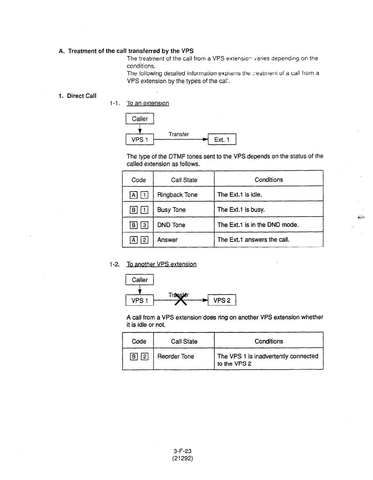
A. Treatment of the call transferred by the VPS
The treatment of the call from a VPS extensio- svaries depending on the
conditions.
The following detailed information expiains the Treatment of a call from a
VPS extension by the types of the cai:.
1. Direct Call
l-l. To an extension
Transfer Ext. 1
The type
of the
DTMF
tones sent to the VPS depends on the status of the
called extension as follows.
Code Call
State
Conditions
lmzl Ringback Tone The Ext.1 is idle.
q
111 Busy Tone The Ext.1 is busy.
IBIn DND Tone The Ext.1 is in the DND mode.
mzl Answer The
Ext.1
answers the call.
l-2. To another VPS extension
A call from a VPS extension~doeis ring on another VPS extensibn whether
it is idle or not.
Code Call State
Conditions
mzl
Reorder Tone The VPS 1 is inadvertently connected
to the VPS 2
3-F-23
(21292)
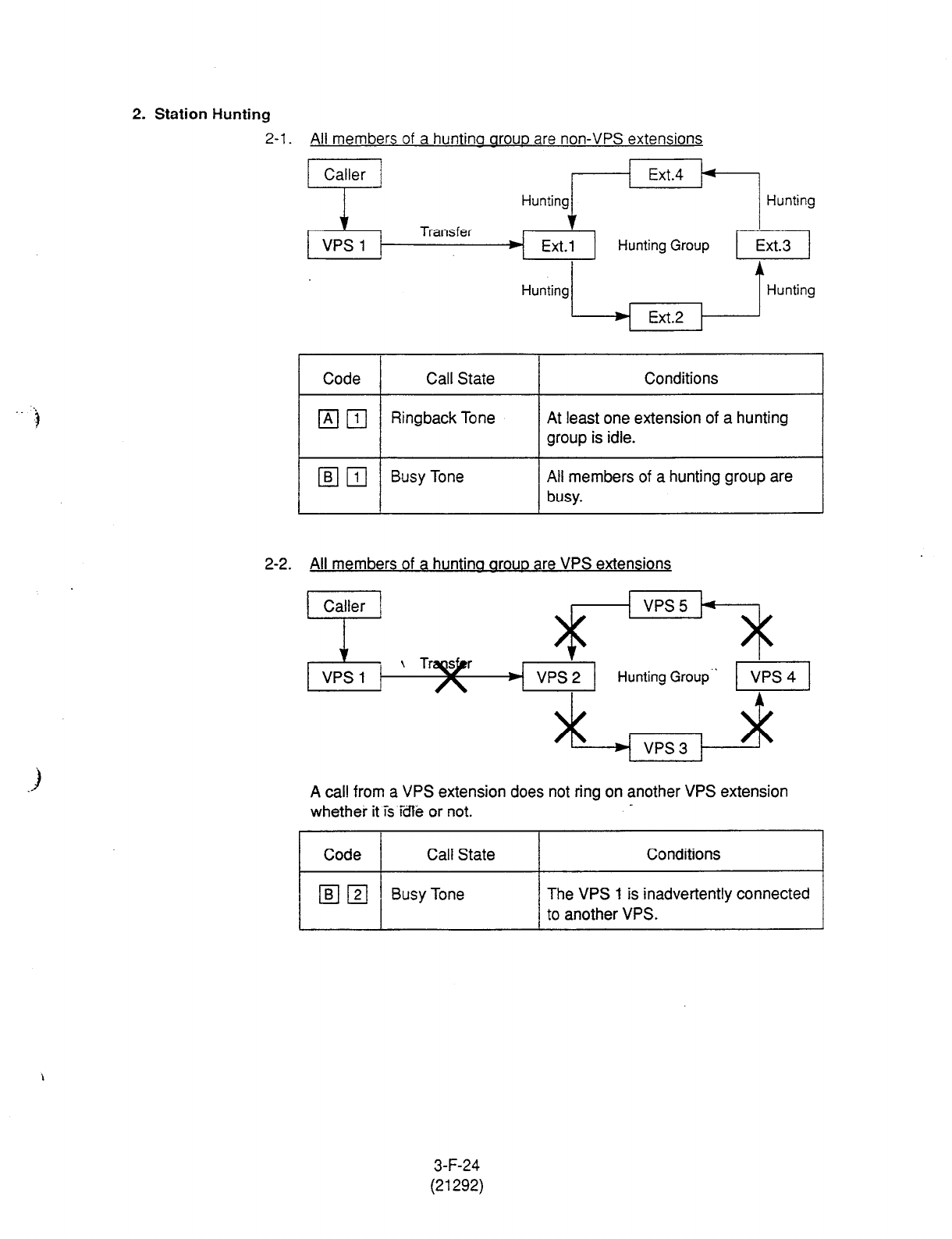
2. Station Hunting
2-l. All
members of a huntino arouo are non-VPS extensions
Hunting~EkP~ Hunting
Transfer f
Ext.1
Hunting Group
Hunting1 IHunting
~ Ext.2 ,
Code Call State I Conditions
Ringback Tone At least one extension of a hunting
group is idle.
Busy
Tone All members of a hunting group are
busy.
2-2. All members of a huntina arouo are VPS extensions
VPS3 1
A call from a VPS extension does not ring on another VPS extension
whether it is idle or not.
Code Call State Conditions
lmzl Busy Tone The VPS I is inadvertently connected
to another VPS.
3-F-24
(21292)

2. Station Hunting (continued)
2-3. Both VPS and non-VPS extensions are members of
a
huntina aroup
A) When the destination is a VPS extension
A call from a VPS extension does not ring on another VPS extension
whether it is idle or not.
Conditions
The VPS
1 is inadvertently connected
to another VPS.
B) When the destination is a non-VPS extension.
VPS 1 Ext.1
Hunting Group
* 1 Hunting ~ vps 2 ,
The call hunts for the idle non-VPS extension only.
Code Call State Conditions
(A ii] Ringback Tone
13 /?$ Busy Tone
The Ext.1 or 2 is idle.
Both Ext.1 and 2 are busy. *
* This way, the VPS 1, typically an A&omatad-Attendant, knows it must give the
caller an opportunity to leave a message before releasing the call.
3-F-25
(21292)
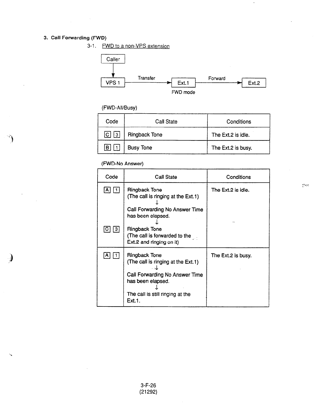
3. Call Forwarding
(FWD)
3-1. FWD to a non-VPS extension
Caller
VPS 1
FWD
mode
Forward Ext.2
(FWD-All/Busy)
Code Call State
Ell3l Ringback Tone
[a 111 Busy Tone
Conditions
The Ext.2 is idle.
The Ext.2 is busy.
(FWD-No Answer)
Code
Em
Em
Em
Call State Conditions
Ringback Tone
(The call is ringing at the Ext.1)
1
The Ext.2 is idle.
Call Forwarding No Answer Time
has been elapsed.
1
. .
Ringback Tone
(The call is forwarded to the ^
Ext.2 and ringing on it)
Ringback Tone
(The call is y ng at the Ext.1 )
Call Forwarding No Answer Time
has been elapsed.
The Ext.2 is busy.
The call is still ringing at the
Ext.1.
3-F-26
(21292)
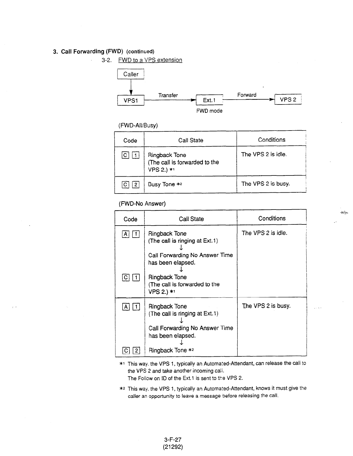
3. Call Forwarding (FWD)
(continued)
3-2. FWD to a VPS extension
x Forward . 4 VPs 2 / Transfer 4~
FWD mode
(FWD-All/Busy)
Code Call State Conditions ;
/
Em Ringback Tone The VPS 2 is idle.
i
(The call is forwarded to the I
/
VPS 2.) *’ I
I
Busy
Tone ** The VPS 2 is busy. :
I
(FWD-No Answer)
Code Call State
(A( 111 ’ Ringback Tone
(The call is ringing at Ext.1)
.L
Conditions
The VPS 2 is idle.
Call Forwarding No Answer Time
has been elapsed.
L
@ 111 RingbackTone
(The call is forwarded to the
VPS 2.) *’
1x1 FJ Ringback Tone
(The call is ringing at Ext.1)
1
The VPS 2 is busy.
Call Forwarding No Answer Trme
has been elapsed.
1
El@/ Ringback Tone **
J
*1 This way. the VPS 1, typically an Automa!ed-Attendant, can release the call to
the VPS 2 and take another incoming c&i.
The Follow on ID of the Ext.1 is sent to tie VPS 2.
** This way, the VPS 1, typically an Automated-Attendant, knows it must give the
caller an opportunity to leave a message before releasing the call.
3-F-27
(21292)
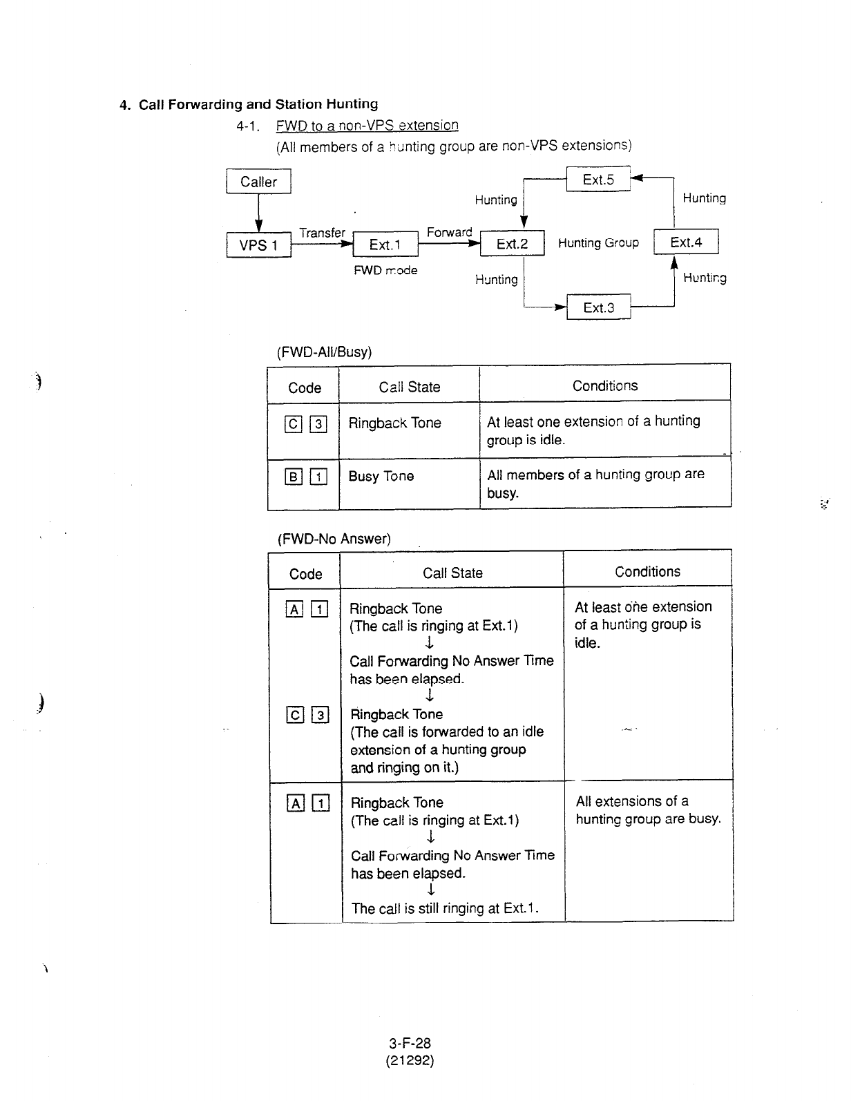
4. Call Forwarding and Station Hunting
4-l. FWD to a non-VPS extension
(All members of a titinting group are non-VPS extensions)
FWD r:ode
(FWD-Ail/Busy)
Code Call State Conditions
El131 Ringback Tone At least one extension of a hunting
group is idle.
Elm Busy Tone All members of a hunting group are
busy.
(FWD-No Answer)
Code Call State Conditions
ElII]
Elm
El111
Ringback Tone
(The call is rtging at Ext.1)
Call Forwarding No Answer Time
has been elapsed.
Ringback Tone
(The call is forwarded to an idle
extension of a hunting group
~ and ringing on it.)
Ringback Tone
(The call is r:ging at Ext.1)
Call Forwarding No Answer Time
has been elapsed.
The call is still ringing at Ext.1.
At least dhe extension
of a hunting group is
idle.
All extensions of a
hunting group are busy.
3-F-28
(21292)
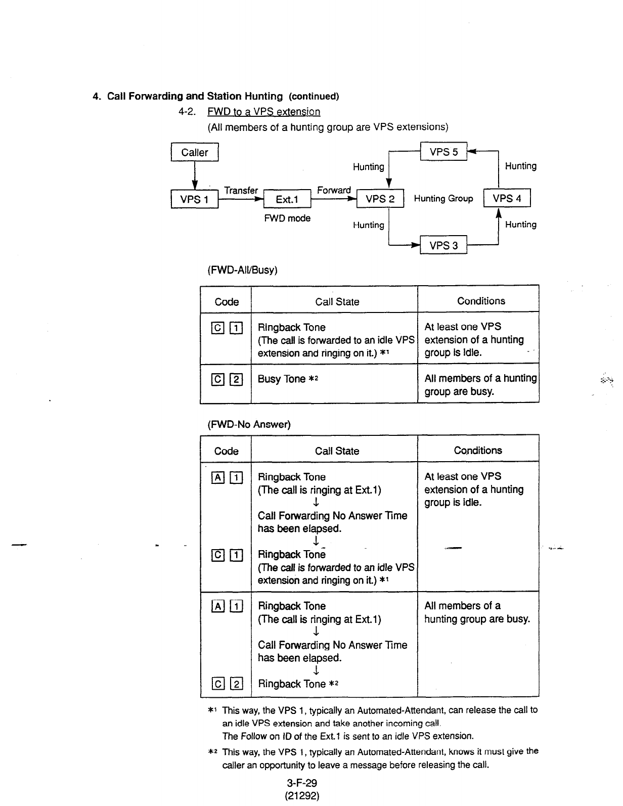
4. Call Forwarding and Station Hunting (continued)
4-2. FWD
to a
VPS extension
(All members of a hunting group are VPS extensions)
FWD mode
(FWD-All/Busy)
Code Call State Conditions
q n1
c 1
Ringback Tone At least one VPS
(The call is forwarded
to
an idle VPS extension of a hunting
1 &tension and ringing on it.) *l
1 group is idle. -.I
m 121 Busy Tone *2 All members of a hunting
group are busy.
(MID-No Answer)
Code Call State Conditions
%lm Ringback Tone At least one VPS
(The call is r?ng at Ext.1) extension of a hunting
group is idle.
Call Forwarding No Answer Time
has been elapsed.
-L
q q
RingbackTone
(The call is forwarded to an idle VPS
extension and ringing on it.) *1
q
111 Ringback Tone All members of a
(The call is ringing at Ext.l) hunting group are busy.
1
Call Forwarding No Answer Time
has been elapsed.
L
Em Ringback Tone **
*1 This way, the VPS 1, typically an Automated-Attendant, can release the call to
an idle VPS extension and take another incoming call.
The Follow on ID of the Ext. 1 is sent to an idle VPS extension.
** This way, the VPS 1, typically an Automated-Attendant, knows it must give the
caller an opportunity to leave a message before releasing the call.
3-F-29
(21292)
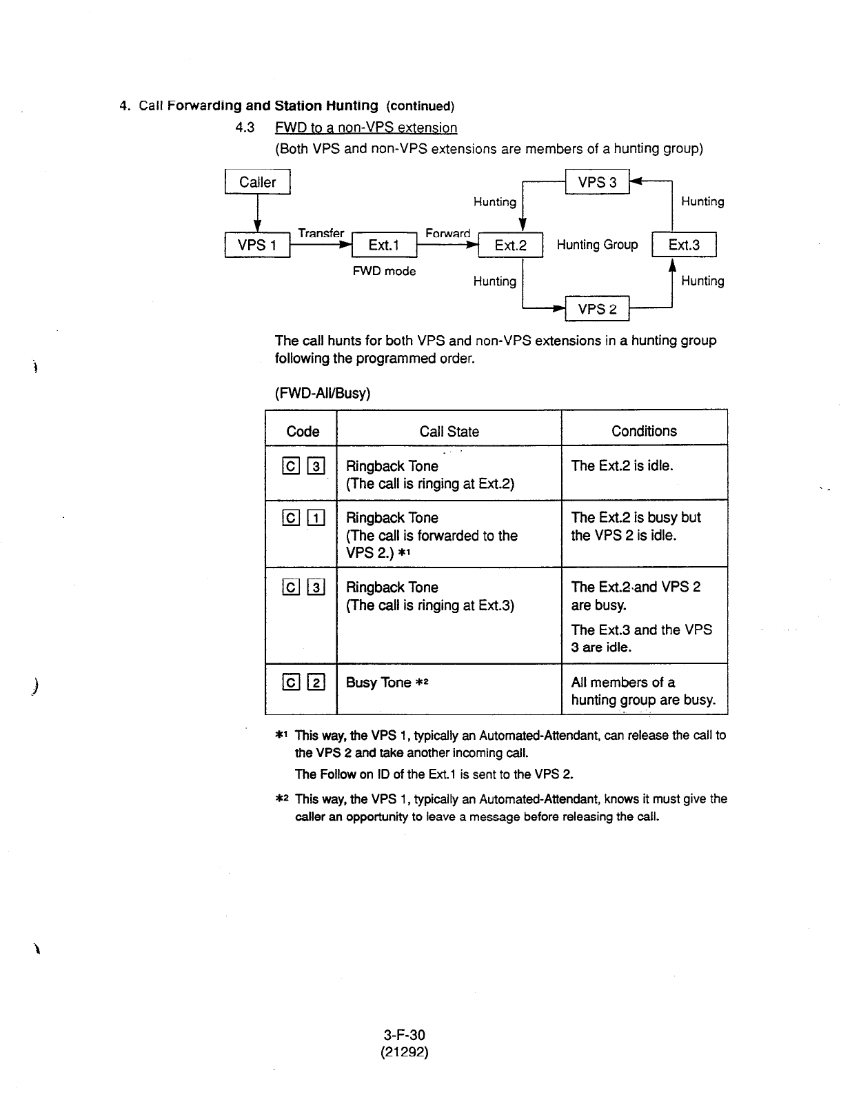
i
4.
Call
Forwarding
and Station Hunting (continued)
(Both VPS and non-VPS
extensions are members of a hunting group)
FWD mode
The call hunts for both VPS and non-VPS extensions in a hunting group
following the programmed order.
(FWD-All/Busy)
Code Call State
14 131 Ringback Tone -
(The call is ringing at Ext.2)
Conditions
The Ext.2 is idle.
IZIEI
Ringback Tone The Ext.2 is busy but
(The call is forwarded to the the VPS 2 is idle.
VPS 2.) *’
lclm
Ringback Tone The Ext.%and VPS 2
(The call is ringing at Ext.3) are busy.
The Ext.3 and the VPS
3
are idle.
13 121 Busy Tone ** All members of a
hunting group are busy.
*l This way, the VPS 1, typically an Automated-Attendant, can release the call to
the VPS 2 and take another incoming call.
The Follow on ID of the
Ext.1
is sent to the VPS 2.
** This way, the VPS 1, typically an Automated-Attendant, knows it must give the
caller an opportunity to leave a message before releasing the call.
3-F-30
(21292)
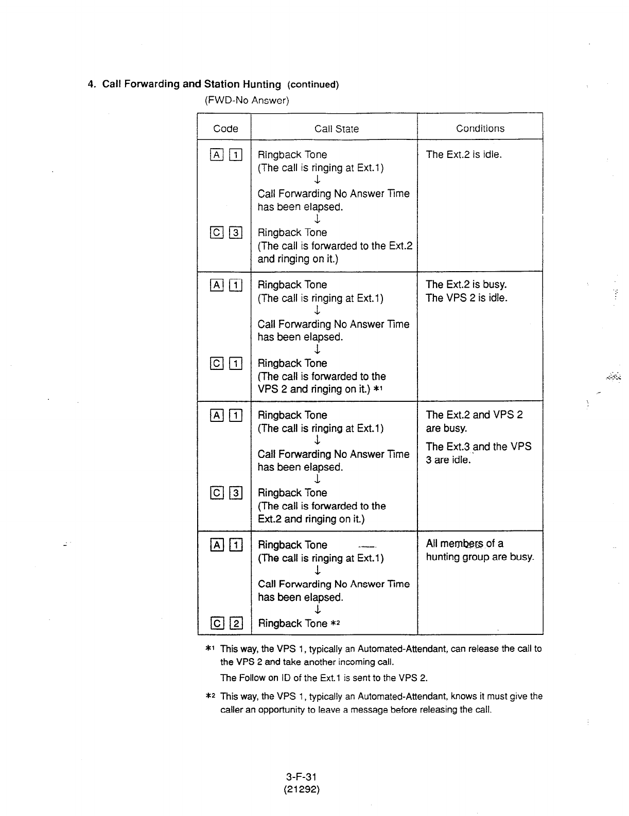
4.
Call Forwarding
and Station Hunting (continued)
(FWD-No Answer)
Code Call State Conditions
IAIm Ringback Tone The Ext.2 is idle.
(The call is ringing at Ext.1)
1
Call Forwarding No Answer l7me
has been elapsed.
.l-
Em Ringback Tone
(The call is forwarded to the Ext.2
and ringing on it.)
Em Ringback Tone The Ext.2 is busy.
(The call is ringing at Ext.1) The VPS 2 is idle.
.L
Call Forwarding No Answer Time
has been elapsed.
L
Em Ringback Tone
(The call is forwarded to the
VPS 2 and ringing on it.) *I
Fj r/ Ringback Tone The Ext.2 and VPS 2
(The call is ying at Ext.1) are busy.
Call Forwarding No Answer TTme The Ext.3 and the VPS
has been elapsed.
3
are idle.
1
Em Ringback Tone
(The call is forwarded to the
Ext.2 and ringing on it.)
mm Ringback Tone --- All member. of a
(The call is yging at Ext.1) hunting group are busy.
Call Forwarding No Answer Time
has been elapsed.
1
q
121 Ringback Tone *2
*l This way, the VPS 1, typically an Automated-Attendant, can release the call to
the VPS 2 and take another incoming call.
The Follow on ID of the Ext.1 is sent to the VPS 2.
*2 This way, the VPS 1, typically an Automated-Attendant, knows it must give the
caller an opportunity to leave a message before releasing the call.
3-F-31
(21292)
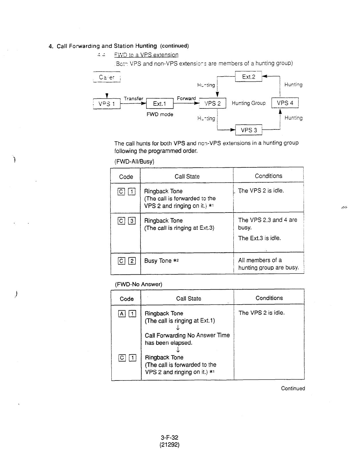
4. Call Forwarding and Station Hunting (continued)
1 I
--
‘:v’:3 io a VPS extension
3~:: VPS and non-VPS extensio-s are members of a hunting group)
cz ,e: i
4,
t-i,-ting /
Ext.2 ;
I_ Hunting
Hunting Group
FWD
mode A
H-t:ing 1 Hunting
I
The call hunts for both VPS and ncn-VPS extensions in a hunting group
following the programmed order.
(FWD-All/Busy)
Code Call State Conditions I
I
E!iIl Ringback Tone 1 The VPS 2 is idle.
(The call is forwarded to the 1
VPS 2 and ringing on it.) *1
I
I I
q q
Ringback Tone i The VPS 2.3 and 4 are
(The call is ringing at Ext.3) i busy.
1
I
/ The Ext.3 is idle. 1
I
( q q
Busy Tone *z j All members of a
1 hunting group are busy. ,
(FWD-No Answer)
Code Call State
q
m Ringback Tone
(The call is ringing at Ext.1)
1
Conditions
The VPS 2 is idle.
Call Forwarding No Answer Time
has been elapsed.
m 111 Ringback Toie
(The call is forwarded to the
VPS 2 and ringing on it.) *l
Continued
3-F-32
(21292)
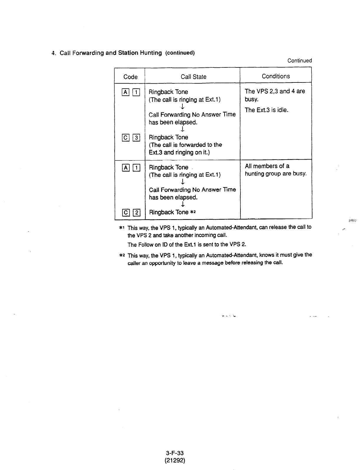
4. Call Forwarding
and Station Hunting (continued)
Continued
Code Call State Conditions
m 111 Ringback Tone The VPS 2,3 and 4 are
(The call is Tging at Ext.1) busy.
Call Forwarding No Answer mrne The Ext.3 is idle.
has been elapsed.
1
m 131 Ringback Tone
(The
call is forwarded
to the
Ext.3 and ringing on it.)
q
111 RingbackTone All members of a
(The call is rying at Ext.1) hunting group are busy.
Call Forwarding No Answer lime
has been elapsed.
1
a
q
Ringback Tone **
*1 This way, the VPS 1, typically an Automated-Attendant, can release the call to
the VPS 2 and take another incoming call.
The Follow on ID of the Ext.1 is sent to the VPS 2.
** This way, the VPS 1, typically an Automated-Attendant, knows it must give the
caller an opportunity to leave a message before releasing the call.
. t. . i
3-F-33
(21292)
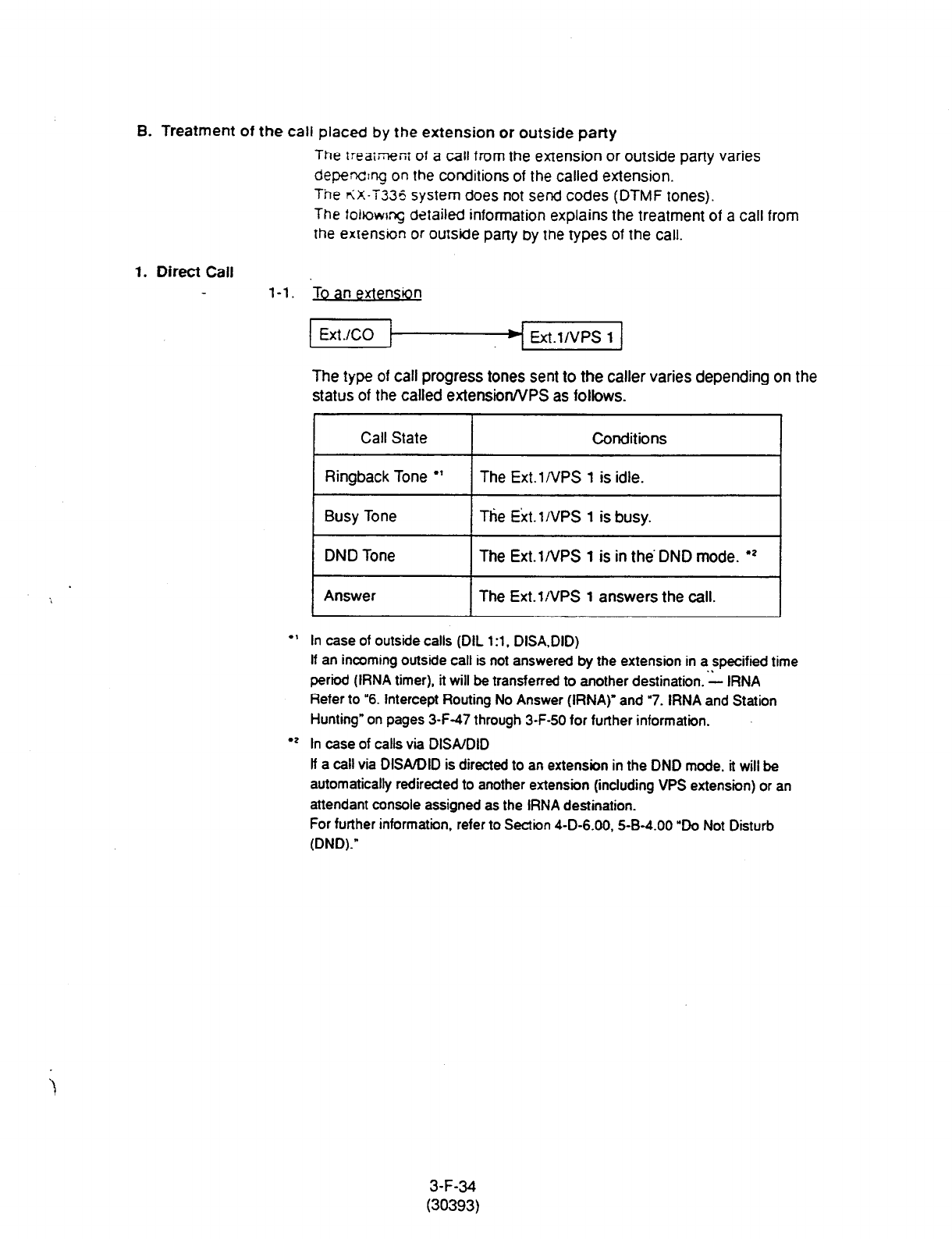
B. Treatment of the call placed by the extension or outside party
The
treaiJ%nr
of a call from the extension or outside party varies
depending on the conditions of the called extension.
The <X-i335 system does not send codes (DTMF tones).
The fohowq detailed information explains the treatment of a call from
the extension or outside party by the types of the call.
1. Direct Call l-l. ‘To an extension
Ext.l/VPS 1
The type of call progress tones sent to the caller varies depending on the
status of the called extensionA/PS as follows.
Call State Conditions
I
Ringback Tone
l
’ I The Ext.lNPS 1 is idle. I
Busy Tone Ttie Ext.l/VPS 1 is busy.
DND Tone The Ext.l/VPS 1 is in the’ DND mode.
l
z
Answer The Ext.l/VPS 1 answers the call.
In case of outside calls (DIL 1 :l, DISA.DID)
If an incoming outside call is not answered by the extension in a specified time
period (IRNA timer), it will be transferred to another destination. ‘L IRNA
Refer to “6. Intercept Routing No Answer (IRNA)” and “7. IRNA and Station
Hunting” on pages 3-F-47 through 3-F-50 for further information.
l
? In case of calls via DlSAlDlD
lf a call via DISA/DID is directed to an extension in the DND mode, it will be
automatically redirected to another extension (including VPS extension) or an
attendant console assigned as the IRNA destination.
For further information, refer to Section 4-D-6.00, S-B-4.00 “Do Not Disturb
(DND).”
3-F-34
(30393)

2. Station Hunting
2-I.
Call State
Ringback Tone
l
Conditions
At least one extension of a hunting
group is idle.
Busy Tone All members of a hunting group are
busy.
*
In case of outside calls (DIL
1 :l
. DISA.DID)
In an incoming outside call is not answered
by the extension in a specified time
period (IRNA timer), it will be transferred to another destination. - IRNA
Refer to “6. Intercept Routing No Answer (IRNA)” and “7. IRNA and Station
Hunting” on pages 3-F-47 through 3-F-50 for further information.
2-2. etg~ are VP
Hunting?, Hunting
Ext
JCO VPS 1
Hunting
Group
? unting 1 ’ ~ vps2 , Fg
Call State
Ringback Tone
l
Conditions
At ieast one VPS extension of a
hunting group is idle.
Busy Tone All members of a hunting group are
busy.
* The KX-T336 system sends Follow on ID (mailbox number of the called
extension) when a VPS extension answers the call.
3-F-35
(21292)
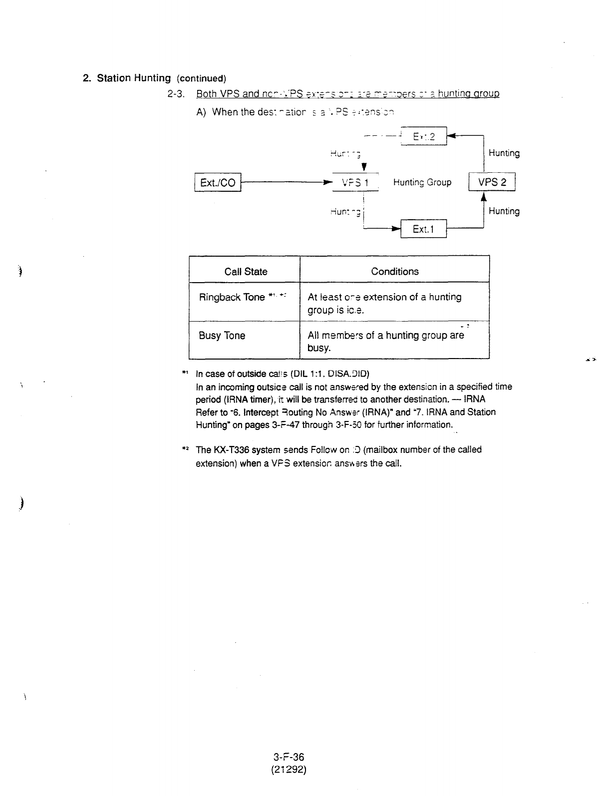
2. Station Hunting
(continued)
2-3. Both VPS and nc--‘..PS 5x:5-s 3-1 2-2 -$-:3ers :- ? huntina arouD
A) When the des: -Ziior s =, . . ?S +;:-3ns 3~
Call State
Ringback Tone *’ +-5
Busy Tone
Conditions
At least o-e extension of a hunting
group is ice.
-T
All members of a hunting group are
busy.
*I In case of outside c&r (DIL 19. DISA.3lD)
In an incoming outsica call is not answrred by the extension in a specified time
period (IRNA timer), ir will be transfer& to another destination. - IRNA
Refer to -6. Intercept ?outing No Answer (IRNA)” and ‘7. IRNA and Station
Hunting” on pages 3-S-47 through 3-F-50 for further information.
*2 The KX-T336 system sends Follcw on .9 (mailbox number of the called
extension) when a VFS extension. ansv*srs the call.
3-F-36
(21292)
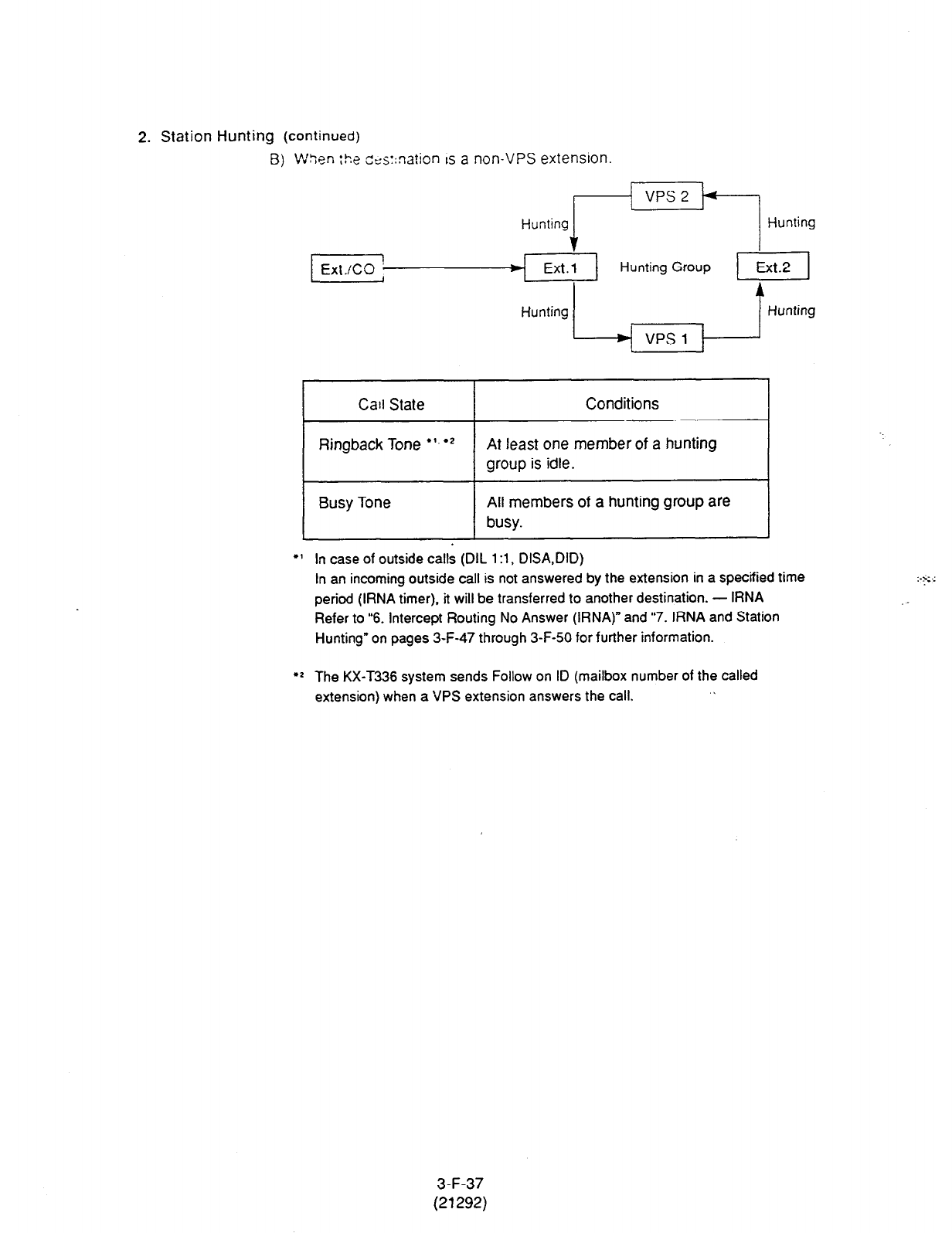
2. Station Hunting
(continued)
B) W>;en :!y CC
j::nation ~5 a non-VPS extension.
Hunting riEkl Hunting
v
Ext.1 Hunting Group
I
Hunting / 1 Hunting ~
Call State Conditions
Ringback Tone
l
‘.
l
* At least one member of a hunting
group is idle.
Busy Tone All members of a hunting group are
busy.
In case of outside calls (DIL 1 :l, DISA,DID)
In an incoming outside call is not answered by the extension in a specified time
period (IRNA timer), it will be transferred to another destination. - IRNA
Refer to “6. Intercept Routing No Answer (IRNA)” and “7. IRNA and Station
Hunting” on pages 3-F-47 through 3-F-50 for further information.
l Z The KX-T336 system sends Follow on ID (mailbox number of the called
extension) when a ‘JPS extension answers the call. \
. ..-.
.__
3-F-37
(21292)
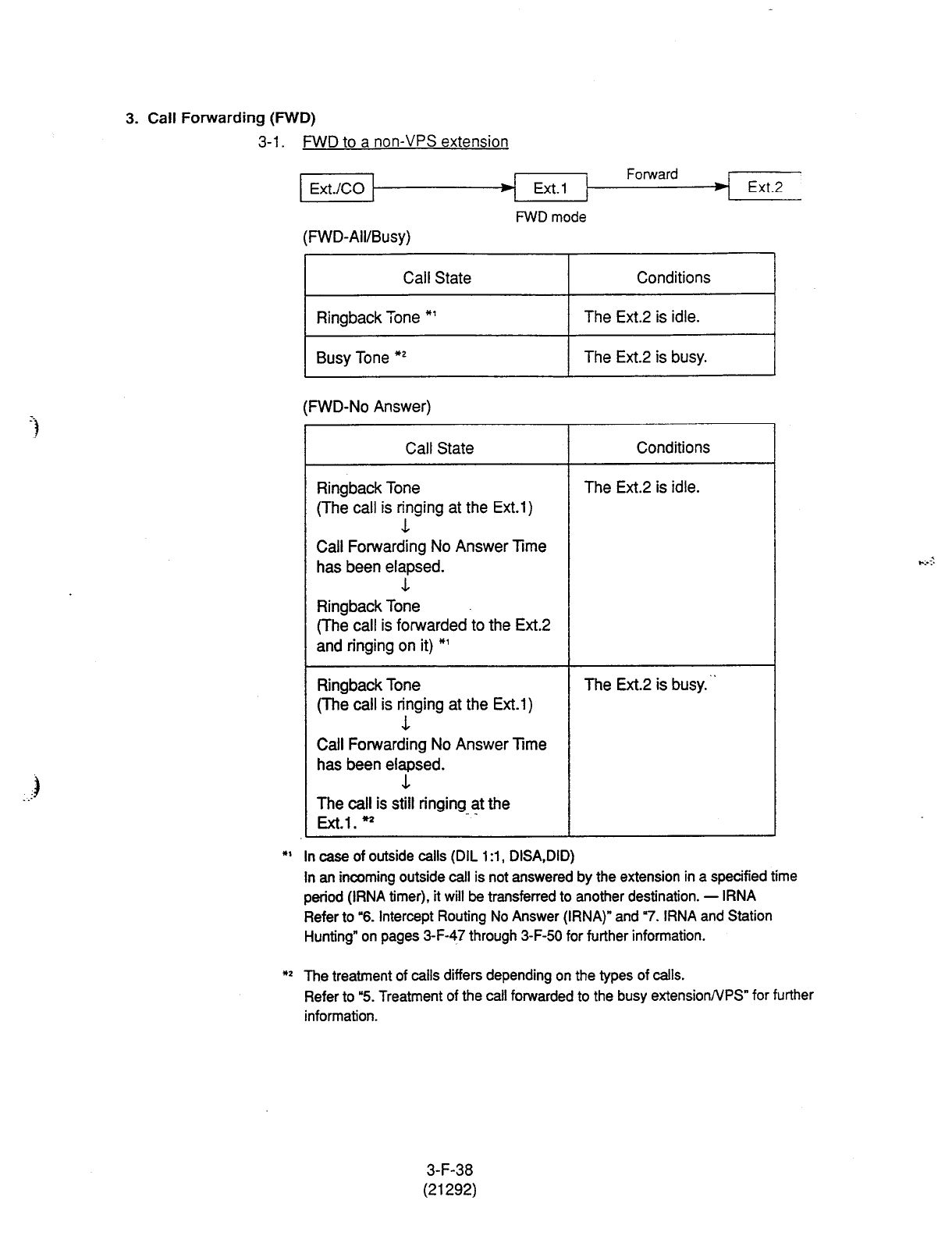
3. Call Forwarding (FWD)
3-l
_ FWD to a non-VPS extension
Ext./CO
(FM/D-All/Busy)
Call State
Ringback Tone *’
Busy Tone *’
Ext. 1
FWD mode
Conditions
The Ext.2 is idle.
The Ext.2 is busy.
Ext.2
(FWD-No Answer)
Call State Conditions
Ringback Tone
(The call is ying at the Ext.1)
Call Forwarding No Answer Time
has been elapsed.
1
Ringback Tone
(The call is forwarded to the Ext.2
and ringing on it) *’
The Ext.2 is idle.
Ringback
Tone
(The call is ying at the
Ext.1)
Call Forwarding No Answer Time
has been elapsed.
1
The Ext.2 is busy. ~
The
call is still ringing at the
_ _
Ext.1. *
*I In ease of outside calls (DIL 1 :l, DISA,DID)
In an incoming outside call is not answered by the extension in a specified time
period (IRNA timer), it will be transferred to another destination. - IRNA
Refer to “6. Intercept Routing No Answer (IRNA)” and “7. IRNA and Station
Hunting” on pages 3-F-47 through 3-F-50 for further information.
** The treatment of calls differs depending on the types of calls.
Refer to “5. Treatment of the call forwarded to the busy extensionNPS” for further
information.
3-F-38
(21292)
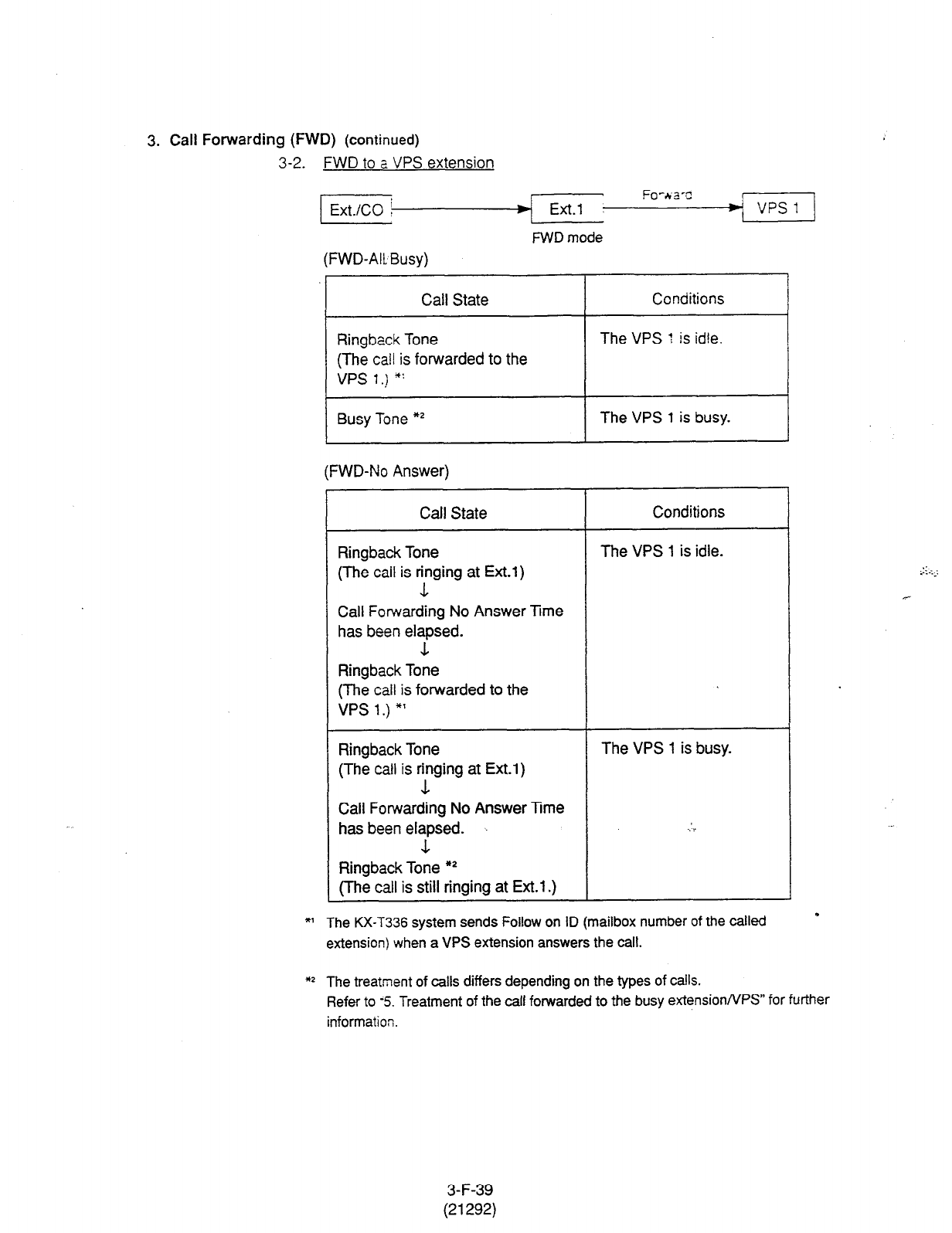
3.
Call
Forwarding (FWD)
(continued)
3-2. FWD to a
VPS
extension
(Ext.iCO
(FWD-All
Busy)
Ext.1
FWD mode
Fo-&-a-c
Call State
Ringback Tone
(The call is forwarded to the
VPS I.,) *:
Conditions
The VPS : is idle.
Busy Tone *’ The VPS 1 is busy.
(FWD-No Answer)
Call State Conditions
Ringback Tone
(The call
is Fing at Ext.1)
Call Forwarding No Answer Trne
has been elapsed.
The VPS 1 is idle.
Ringback Tone
(The call is forwarded to the
VPS
1.) *’
Ringback Tone
(The call is rfinging at Ext.1)
Call Forwarding No Answer Ime
has been elapsed.
&
The VPS 1 is busy.
. . r
Ringback Tone **
(The call is still ringing at Ext.1 .)
*I The KX-T336 system sends Follow on ID (mailbox number of the called
extension) when a VPS extension answers the call.
** The treatment of calls differs depending on the types of calls.
Refer to -5. Treatment of the call forwarded to the busy extensionNPS” for further
information.
: ._
3-F-39
(21292)
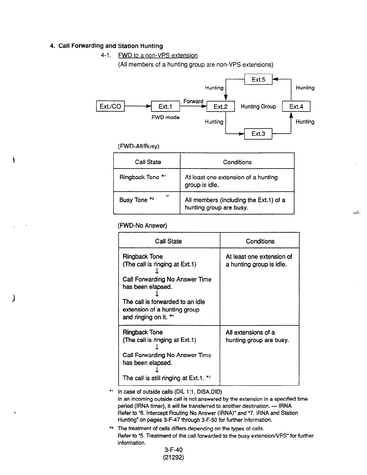
4. Call Forwarding and Station Hunting
4-1. FWD tc a non-VPS extension
(All
members of a hunting group
are non-VPS extensions)
Hunting r’=+l Hunting
t
Ext.2
FWD mode
Ext.3 1
(FWD-Ail/Busy)
t
Hunting
Call State
Ringback Tone *’
Conditions
At least one extension of a hunting
group is idle.
Busy Tone O2
l
t All members (including the Ext.1) of a
hunting group are busy.
(RND-No Answer)
Call State Conditions
Ringback Tone
(The call is ying at Ext.1)
Call Forwarding No Answer Time
has been elapsed.
At least one extension of
a hunting group is idle.
The call is forwarded to an idle
extension of a hunting group
and ringing on it. *’
Ringback Tone
(The call is ringing at Ext.1)
1
All extensions of a
hunting group are busy.
Call Forwarding No Answer Time
has been elapsed.
3.
The call
is
still ringing at Ext.1. w
*’ In case of outside calls (DIL 1 :l , DISA,DID)
In an incoming outside call is not answered by the extension in a specified time
period (IRNA timer), it will be transferred to another destination. - IRNA
Refer to “6. Intercept Routing No Answer (IRNA)” and “7. IRNA and Station
Hunting” on pages 3-F-47 through 3-F-50 for further information.
*p The treatment of calls differs depending on the types of calls.
Refer to ‘5. Treatment of the call forwarded to the busy extension/VPS” for further
information.
3-F-40
(21292)
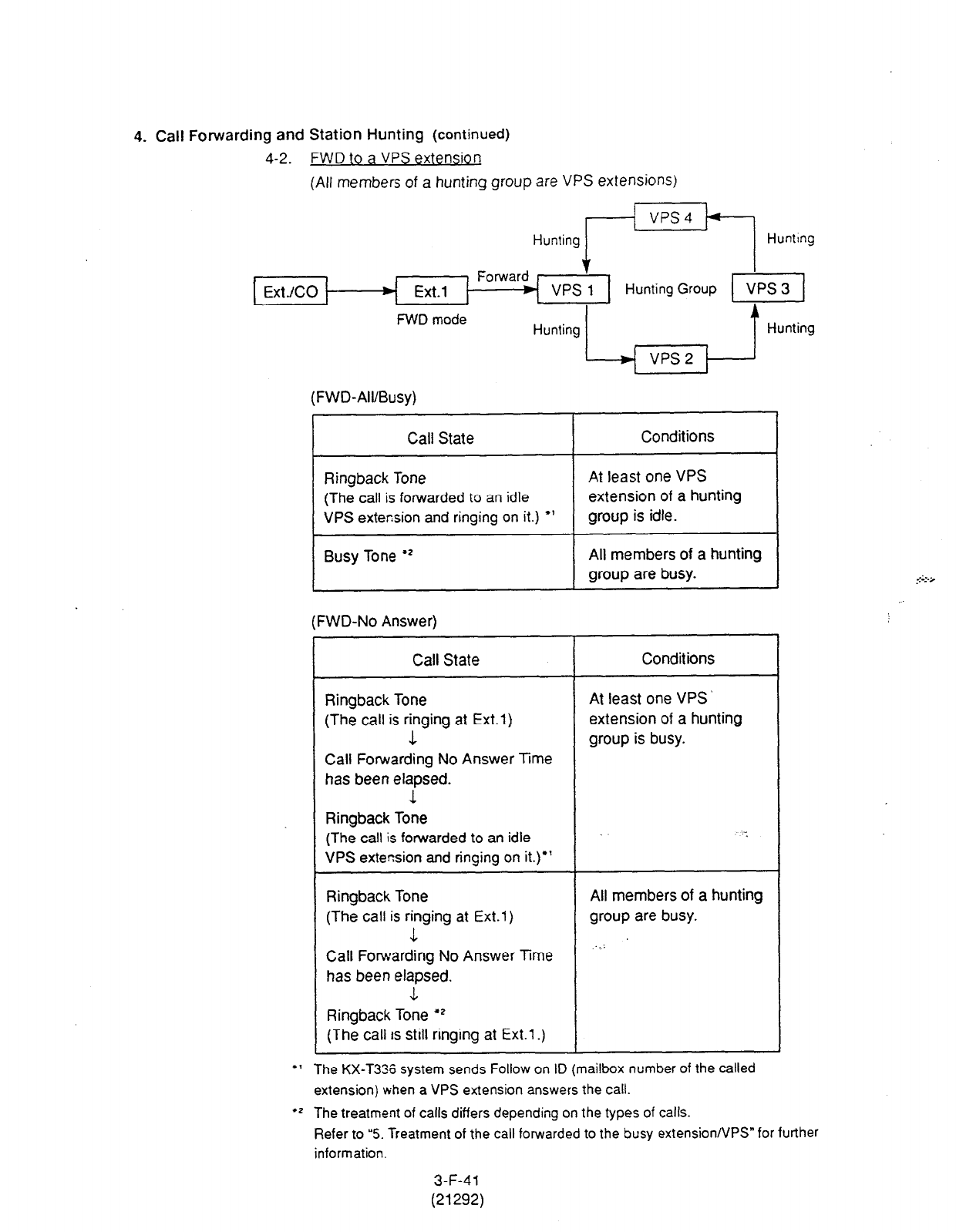
4. Call Forwarding and Station Hunting
(continued)
4-2. FWD to a VPS extension
(All members of a hunting group
are
VPS extensions)
Hunting pzI Huntrng
FWD mode
f
VPS 1
Hunting Group
Hunting t Hunting
(FWD-All/Busy)
Call State
Ringback Tone
(The call is forwarded to an idle
VPS
extension
and ringing on it.)
l
’
Busy Tone +’
Conditions
At least one
VPS
extension of a hunting
group is idle.
All members of a hunting
group are busy.
l 1
(FWD-No Answer)
Call State Conditions
Ringback Tone At least one VPS
(The call is ringing at Ext.1)
extension of a hunting
1 group is busy.
Call Forwarding No Answer Time
has been elapsed.
1
Ringback Tone
(The call is forwarded to an idle
VPS extension and ringing on it.)*’
Ringback Tone
(The call is ringing at Ext.1)
-1
All members of a hunting
group are busy.
‘.’ Call Fonvarding No Answer Time
has been elapsed.
L
Ringback Tone
l
2
(The
call is still ringing at Ext.1 .)
The KX-T336 system sends Follow on ID (mailbox number of the called
extension) when
a
VPS extension answers the call.
rZ The treatment of calls differs depending on the types of calls.
Refer to “5. Treatment of the call forwarded to the busy extension/VPS” for further
information.
3-F-41
(21292)
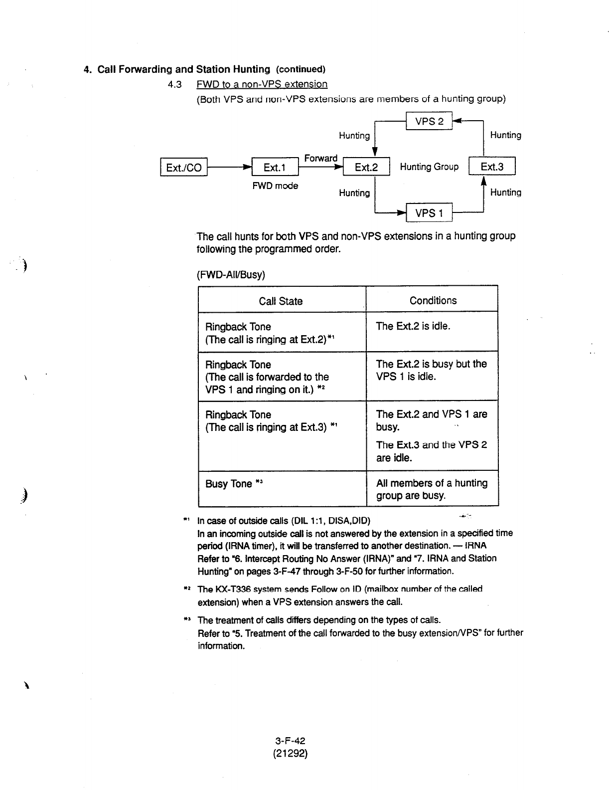
4. Call Forwarding and Station Hunting (continued)
4.3 FWD to a non-VPS extension
(Both VPS and non-VPS extensions are members of a hunting group)
Hunting rm+j Hunting
Ext./CO
FWD mcde
$
Ext.2
Hunting t Hunting
VPS 1
)
‘The call hunts for both VPS and non-VPS extensions in a hunting group
following the programmed order.
(PWD-All/Busy)
Call State
Ringback Tone
(The call is ringing at Ext.2)*’
Ringback Tone
(The call is forwarded to the
VPS 1 and ringing on it.) **
Ringback Tone
(The call is ringing at Ext.3) *’
Busy Tone *’
Conditions
The Ext.2 is idle.
The Ext.2 is busy but the
VPS 1 is idle.
The Ext.2 and VPS 1 are
busy. . .
The Ext.3 and the VPS 2
are idle.
Ail members of a hunting
group are busy.
*I In case of outside calls (DIL 1 :l , DISA,DID) 4,‘:
In an incoming outside call is not answered by the extension in a specified
time
period (IRNA timer), it will be transferred to another destination. - IRNA
Refer to “6. Intercept Routing No Answer (IRNA)” and ‘7. IRNA and Station
Hunting” on pages 3-F-47 through 3-F-50 for further information.
** The KX-T336 system sends Follow on ID (mailbox number of the called
extension) when a VPS extension answers the call.
*’ The treatment of calls diirs depending on the types of calls.
Refer to 4. Treatment of the call forwarded to the busy extension/VPS” for further
information.
3-F-42
(21292)
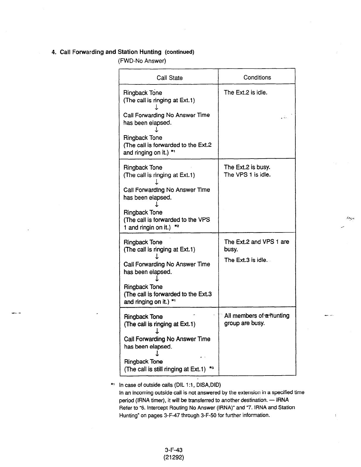
4. Call Forwarding and Station Hunting (continued)
(FWD-No Answer)
-..
Call State
Ringback Tone
(The call is Fing at Ext.1)
Call Forwarding No Answer Time
has been elapsed.
Conditions
The Ext.2 is idle.
- . . .
3.
Ringback Tone
(The call is forwarded to the Ext.2
and ringing on it.) *’
Ringback Tone
(The call is Fing at Ext.1)
Call Forwarding No Answer Time
has been elapsed.
The Ext.2 is busy.
The VPS 1 is idle.
1
Ringback Tone
(The call is forwarded to the VPS
1 and ringin on it.) *2
Ringback Tone
(The call is Fng at Ext.1)
Call Forwarding No Answer Time
has been elapsed.
The Ext.2 and VPS 1 are
busy.
The Ext.3 is idle.
Ringback Tone
(The call is forwarded to the Ext.3
and ringing on it.) *’
Ringback Tone ‘. All members ofa?iunting
(The call is rfirging at Ext.1) group are busy.
Call Forwarding No Answer IRrne
has been elapsed.
1 -
Ringback Tone
(The call is still tinging at Ext.1) *3
*’ In case of outside
calls (DIL 1 :l , DISA,DID)
In an incoming outside call is not answered by the extension in a specified time
period
(IRNA
timer), it wilt be transferred to another destination. - IRNA
Refer to ‘6. intercept Routing No Answer (IRNA)” and “7. IRNA and Station
Hunting” on pages 3-F-47 through
3-F-50
for further information.
--
3-F-43
(21292)
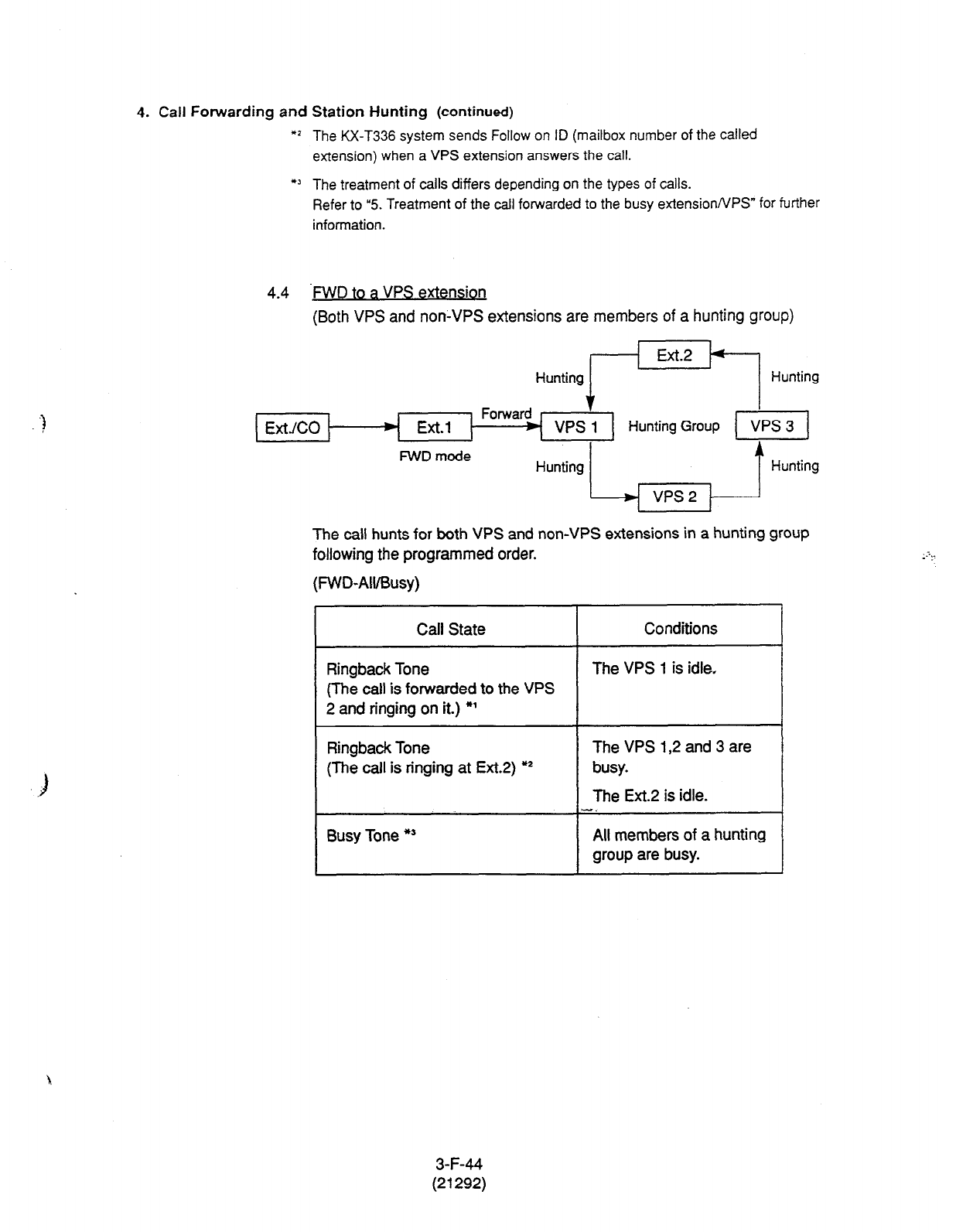
4. Call Forwarding and Station Hunting (continued)
*I The KX-T336 system sends Follow on ID (mailbox number of the called
extension) when a VPS extension answers the call.
l ’ The treatment of calls differs depending on the types of calls.
Refer to “5. Treatment of the call forwarded to the busy extensionNPS” for further
information.
4.4 -MD to a VPS extension
(Both VPS and non-VPS extensions are members of a hunting group)
Forward
Ext.1
’
Hunting/-ET
VPS 1
Hunting Group
Hunti;
VPS 3
FWD mode blunting
L vps2 , ] Hunting
The call hunts for both VPS and non-VPS extensions in a hunting group
following the programmed order.
(FWD-Ail/Busy)
Call State
Ringbaok Tone
(The call is forwarded to the VPS
2 and ringing on it.) *’
Conditions
The VPS 1 is idle.
Ringback Tone
(The call is ringing at Ext.2) *I
The VPS 1,2 and 3 are
busy.
The Ext.2 is idle.
-.
Busy Tone *’ All members of a hunting
group are busy.
3-F-44
(21292)
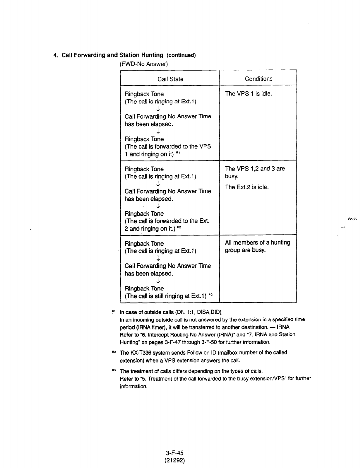
4. Call Forwarding
and Station Hunting (continued)
(FWD-No Answer)
Call State
Ringback Tone
(The call is y ing at Ext.1)
Call Forwarding No Answer Time
has been elapsed.
Conditions
The VPS 1 is idle.
1
Ringback Tone
(The call is forwarded to the VPS
1 and ringing on it) *’
Ringback Tone
(The call is yging at Ext.1)
Call Forwarding No Answer Time
has been elapsed.
The VPS 1,2 and 3 are
busy.
The Ext.2 is idle.
J.
Ringback Tone
(The call is forwarded to the Ext.
2 and ringing on it.) *2
Ringback Tone All members of a hunting
(The call is Fing at Ext.i) group are busy.
Call Forwarding No Answer Time
has been elapsed.
Ringback Tone
(The call is still ringing at Ext.1) *’
*I In case of outside calls
(DIL l:l,
DISA,DID) _
In an incoming
outside call is not answered by the extension in a specified time
period (RNA timer), it will be transferred to another destination. - IRNA
Refer to “6. Intercept Routing No Answer (IRNA)” and 7. IRNA and Station
Hunting” on pages 3-F-47 through 3-F-50 for further infonnation.
*2 The KX-T336 system sends Follow on ID (mailbox number of the called
extension) when a VPS extension answers the call.
*’ The treatment
of calls differs depending on the types of calls.
Refer to ‘5. Treatment of the call forwarded to the busy extension/VPS” for further
information.
,‘...C’
.-- __
3-F-45
(21292)
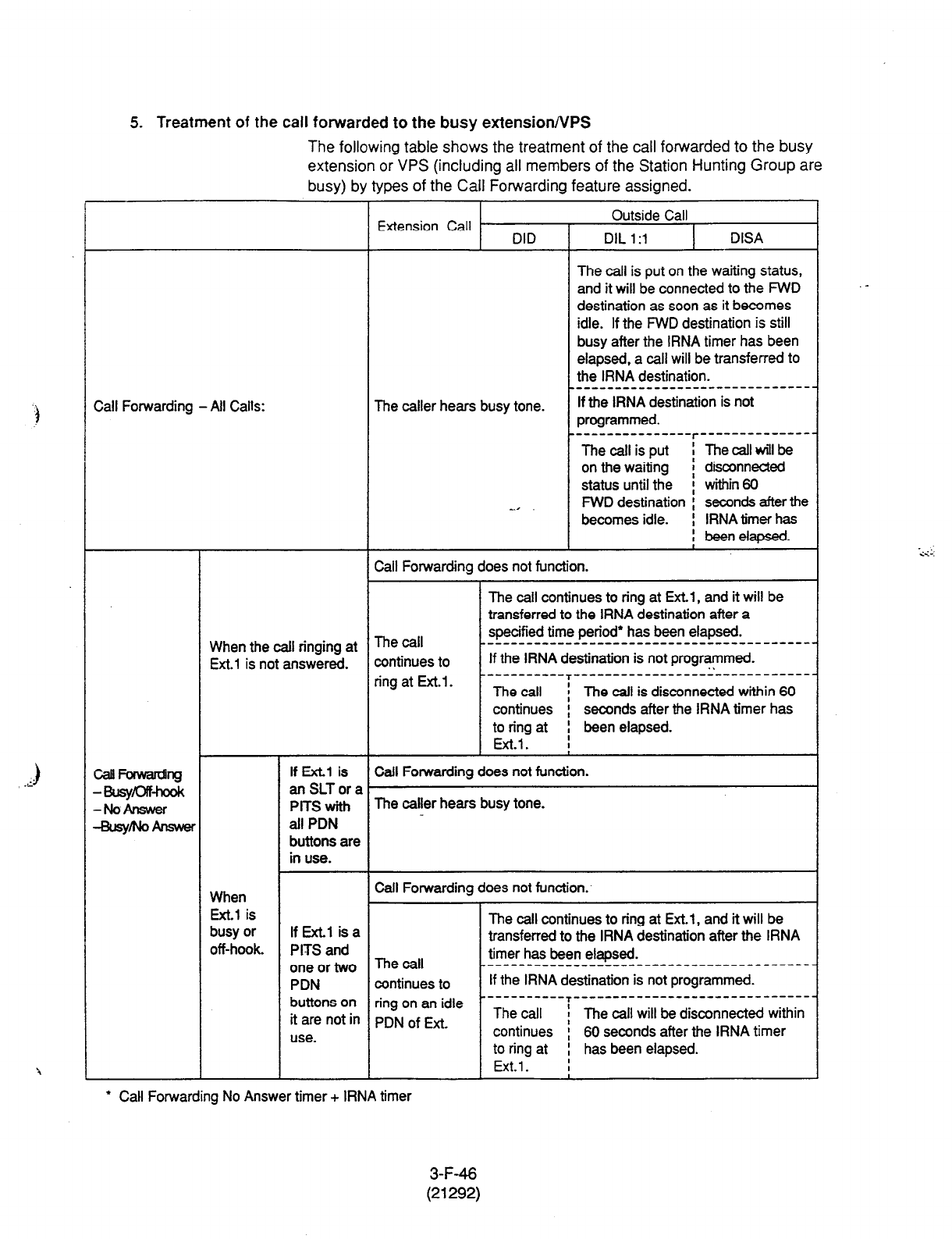
5. Treatment of the call forwarded to the busy extensionNPS
The following table shows the treatment of the call forwarded to the busy
extension or VPS (including all members of the Station Hunting Group are
busy) by types of the Call Forwarding feature assigned.
Extension Call DID
Outside Call
DIL 1 :l DISA
The call is put on the waiting status,
and it will be connected to the FWD
destination as soon as it becomes
idle. If the FWD destination is still
busy after the IRNA timer has been
elapsed. a call will be transferred to
the IRNA destination.
Call Forwarding - All Calls:
_________________--------------
The caller hears busy tone. If the IRNA destination is not
programmed.
-------‘--------r------‘---------
The call is put I Thecallwillbe
on the waiting ! disconnected
status until the f within60
__* FWD destination I seconds after the
becomes idle. i IRNA timer has
, beenelapsed.
I
Call Forwarding does not function.
The call continues to ring at Ext.1, and it will be
transferred to the IRNA destination after a
When the call ringing at The call specified time period* has been elapsed.
-__---------------------------------------
Ext.1 is not answered. continues to If the IRNA destination is not programmed.
. .
ring at Ext.1. --------‘--T’-‘---------------------------
The call / The call is disconnected within 60
continues i seconds after the IRNA timer has
to ring at I been elapsed.
Ext.1. I
If Ext.1 is Call Forwarding does not function.
anSLTora
PlTS with The caller hears busy tone.
all PDN
buttons are
in use.
When Call Forwarding does not function.
Ext.1 is
busy or If Ext.1 isa The call continues to ring at Ext.1, and it will be
transferred to the IRNA destination after the IRNA
off-hook. PITS and The 4 timer has been elapsed.
one or two ___----____________-----------------------
PDN continues to If the IRNA destination is not programmed.
buttons on ring on an idle -----------T----------------------- -------
it are not in pDN of f=fi. The call ! The call will be disconnected within
use. continues i 60 seconds after the IRNA timer
to ring at I has been elapsed.
Ext.1. I
l
Call Forwarding No Answer timer + IRNA timer
3-F-46
(21292)

6. Intercept Routing No Answer (IRNA)
6-1. IRNA to a non-VPS extension
co Ext.2
DIL 1:l
DISA
DID
Call State Conditions
Ringback Tone The Ext.2 is idle.
Busy Tone * The Ext.2 is busy.
* Refer to S. Treatment of the call transferred to the busy extensionNPS by IRNA
feature’ for further information.
6-2. IRNA to a VPS extension
co VPS 1
DIL 1:i
DISA
DID
Call State I Conditions I
Ringback Tone
(The call is transferred to the
VPS 1.) *’
The VPS 1 is idle.
I The VPS 1 is busy. I
*I The KX-T336 system sends Follow on ID (mailbox number of the called
extension) when a VPS extension answers the call.
** Refer to “8. Treatment of the call transferred to the busy extension/VPS by IRNA
feature” for further information.
3-F-47
(21292)
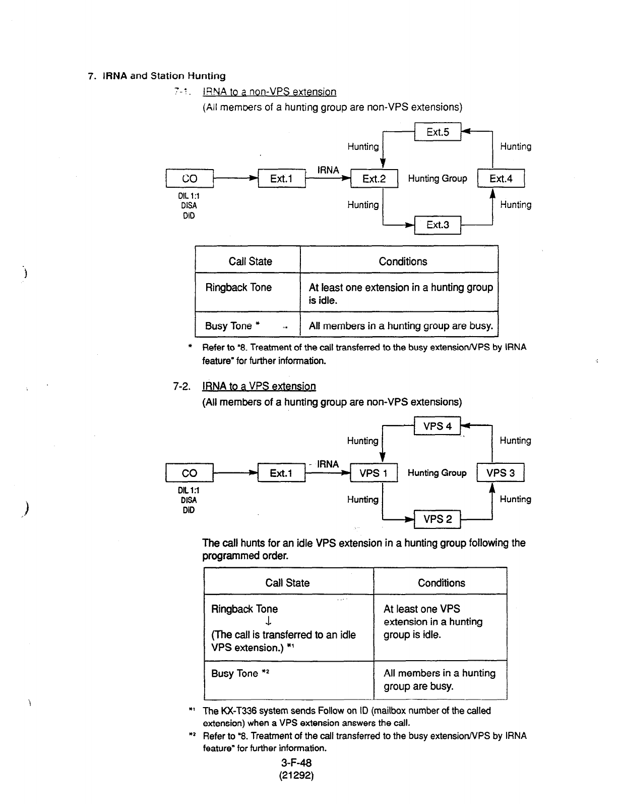
7. IRNA and Station Hunting
7-t .
IWA to a non-VPS extension
(All memoers of a hunting group are non-VPS extensions)
Hunting +X+1 Hunting
+
Ext.1 Ext.2
OIL 1:i
DISA
DID
Hunting 1 Ext.3 , 1 Hunting
Call State Conditions
Ringback Tone At least one extension in a hunting group
is idle.
Busy Tone * *.
All members in a hunting group are busy.
* Refer to ‘8. Treatment of the call transferred to the busy extension/VPS by RNA
feature” for further
information.
7-2. IRNA to a VPS extension
(All members of a hunting group are non-VPS extensions)
Hunting rkq Hunting
Ext.1
t
VPS 1 Hunting Group
DIL 1:l
DISA
DID
Hunting L vps2 , 1 Hunting
The call hunts for an idle VPS extension in a hunting group following the
programmed order.
Call State
Ringback Tone
1
(The call is transferred to an idle
VPS extension.) *’
Conditions
At least one VPS
extension in a hunting
group is idle.
Busy Tone *2 All members in a hunting
group are busy.
*I The KX-T336 system sends Follow on ID (mailbox number of the called
extension) when a VPS extension answers the call.
*I Refer to “8. Treatment of the call transferred to the busy extension/VPS by IRNA
feature” for further information.
3-F-48
(21292)
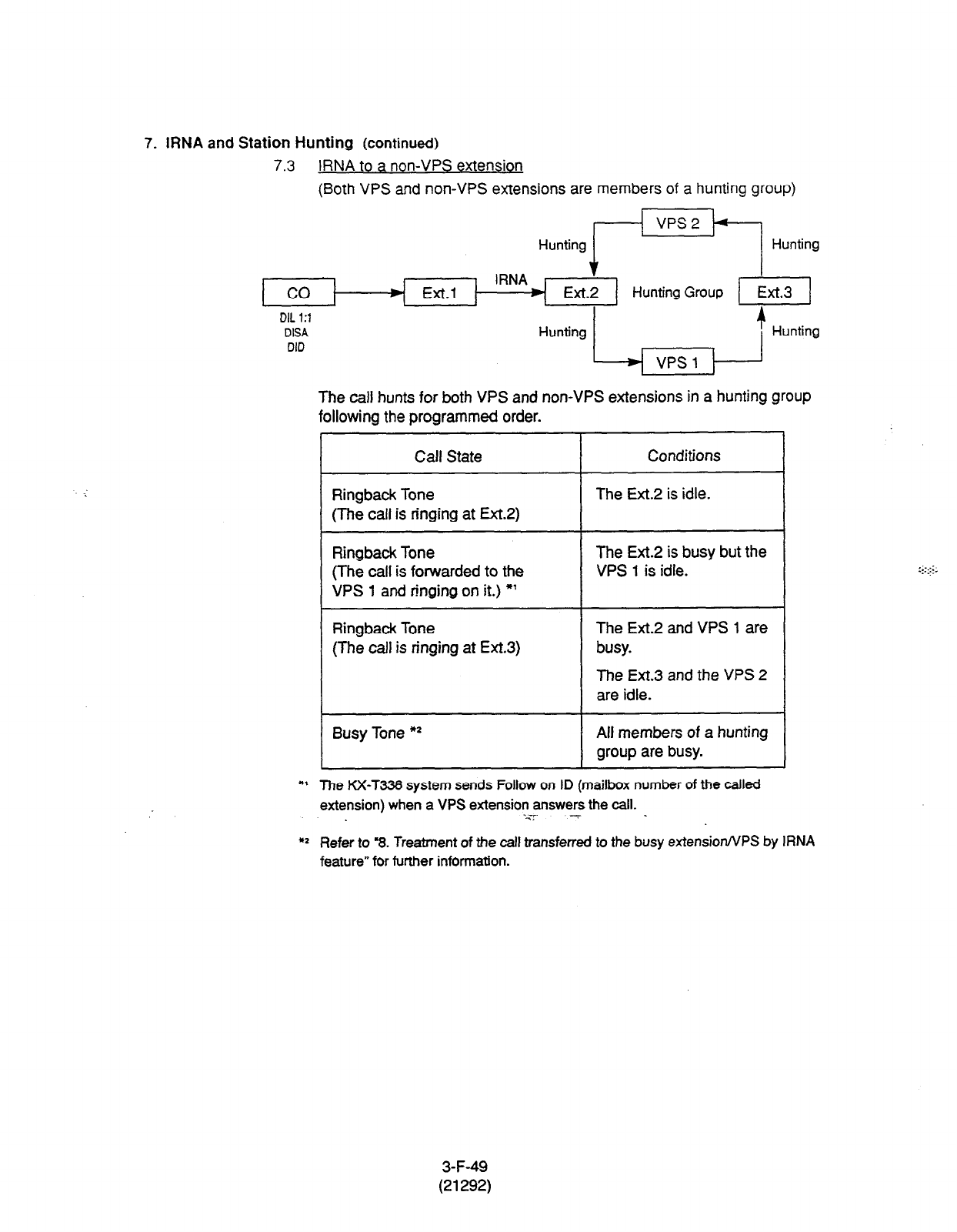
7. IRNA and Station Hunting
(continued)
7.3 to
IRNA
(Both VPS and non-VPS extensions are members of a hunting group)
Hunting FE/ Hunting
$
Ext.2
DIL 1:1
DISA
DID
Hunting L vpS 17 1 Hunting
The call hunts for both VPS and non-VPS extensions in
a hunting group
following the programmed order.
r
Calf State
Ringback Tone
(The call is ringing at Ex-t.2)
Conditions
The Ext.2
is idle.
Ringback Tone
(The call is forwarded to the
VPS 1 and ringing on
it.) *’
The Ext.2 is busy but the
VPS 1 is idle.
Ringback Tone
(The call is ringing at Ext.3) The Ext.2 and VPS 1 are
busy.
The Ext.3 and the VPS 2
are idle.
Busy Tone **
All members of a hunting
group are busy.
1
*I The KX-T336 system sends Follow on ID (mailbox number of the called
extension) when a VPS extension answers the call.
-<z --7
:::.::.
. _.
*2 Refer to 3. Treatment of the call transferred to the busy exfensionNPS by IRNA
feature” for further information.
3-F-49
(21292)
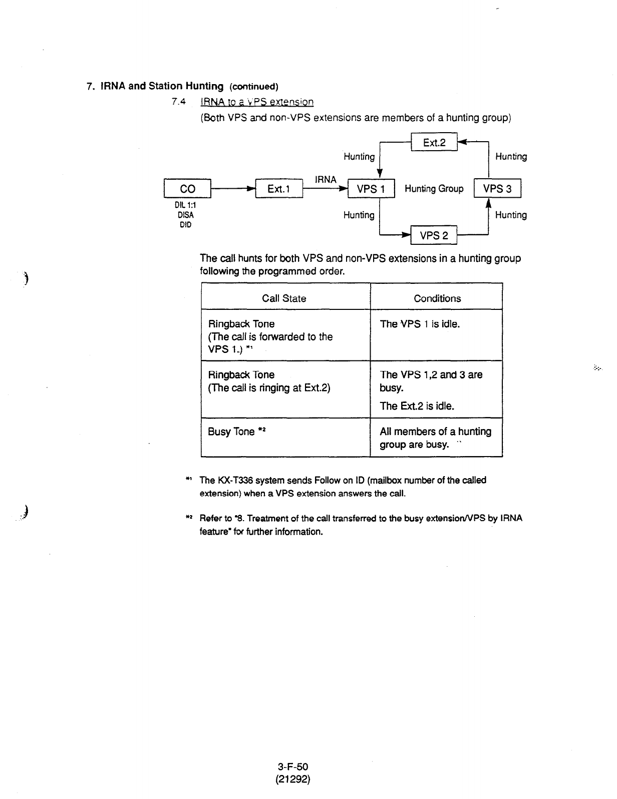
7. IRNA and Station Hunting (continued)
7.4
IRNA to a L’PS exlwssion
(Both VPS and non-VPS extensions are members of a hunting group)
Hunting r’=/ Hunting
Ext.1
t
VPS 1 Hunting Group
DIL 1:l
DISA
DID
Hunting L vps2 , 1 Hunting
The call hunts for both VPS and non-VPS extensions in a hunting group
following the programmed order.
I Call
State
Conditions
Ringback Tone
(The call is forwarded to the
VPS l..) *’
The .VPS 1 is idle.
Ringback Tone
(ihe call is ringing at Ext.2)
The VPS 1,2 and 3 are
busy.
The Ext.2 is idle.
Busy Tone *)I All members of a hunting
group are busy. .*
*’ The KX-T336 system sends Follow on ID (mailbox number of the called
extension) when a VPS extension answers the call.
*1 Refer to ‘8. Treatment of the call transferred to the busy extension/VPS by IRNA
feature’ ti further information.
3-F-50
(21292)

8. Treatment of the call transferred to the busy extension/VPS by IRNA feature
The following table shows the treatment of the call transferred to the busy
extension or VPS (including all members of a Station Hunting Group are
busy.)
DID
The call continues to
ring at the called
extension or VPS, and
it will not be
transferred to the
IRNA destination by
the IRNA feature.
DIL 1:l DISA
The call is put on the waiting status, and it will
be connected to the IRNA destination as soon
as it becomes idle.
__-__--------------_--------------------
If the IRNA destination does not become idle.
--------------------r---‘------‘------’-
A call continues to be f
on the waiting status
; The call will be
; disconnected if the
until the IRNA : IRNA destination
destination becomes : does not become idle
idle. i within 1 minute.
! (In case of the IRNA
I destination is an
:
I attendant console, a
i calt will be
I disconnected within 3
:
I minutes.)
I
3-F-51
(21292)
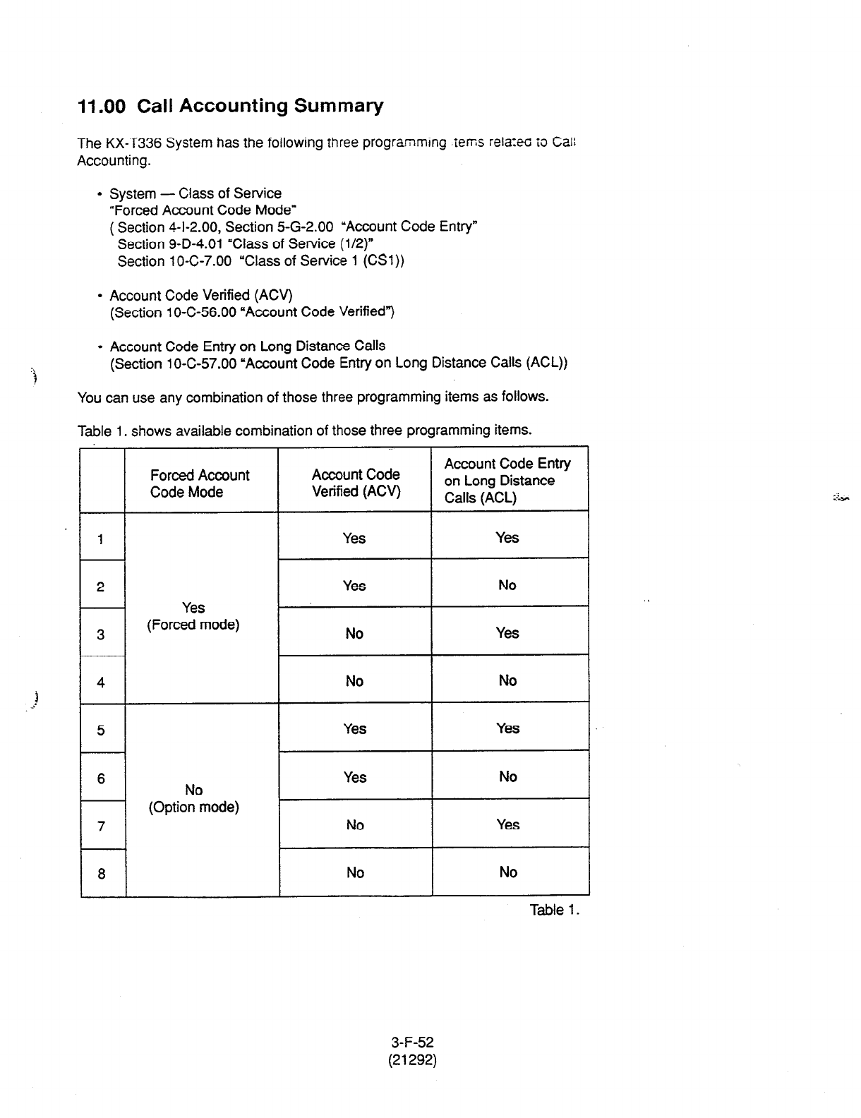
11 .OO Call Accounting Summary
The KX-T336 System has the following three programming .tems rela:eo to Call
Accounting.
l
System - Class of Service
“Forced Account Code Mode”
( Section 4-I-2.00, Section 5-G-2.00 ‘Account Code Entry”
Section 9-D-4.01 “Class of Service (l/2)”
Section 10-C-7.00 “Class of Service 1 (CSl))
l
Account Code Verified (ACV)
(Section 1 O-C-56.00 “Account Code Verified”)
“i
l
Account Code Entry on Long Distance Calls
(Section 1 O-C-57.00 “Account Code Entry on Long Distance Calls (ACL))
You can use any combination of those three programming items as follows.
Table 1. shows available combination of those three programming items.
Forced Account
Code Mode
-.
Account Code
Verified (ACV)
Account Code Entry
on Long Distance
Calls (ACL)
1 Yes Yes
2 Yes No .
Yes
3 (Forced mode) No Yes
4 No No
5 Yes Yes
6 Yes No
(0ptioNn”mode)
7 No Yes
8 No No
Table 1.
3-F-52
(21292)
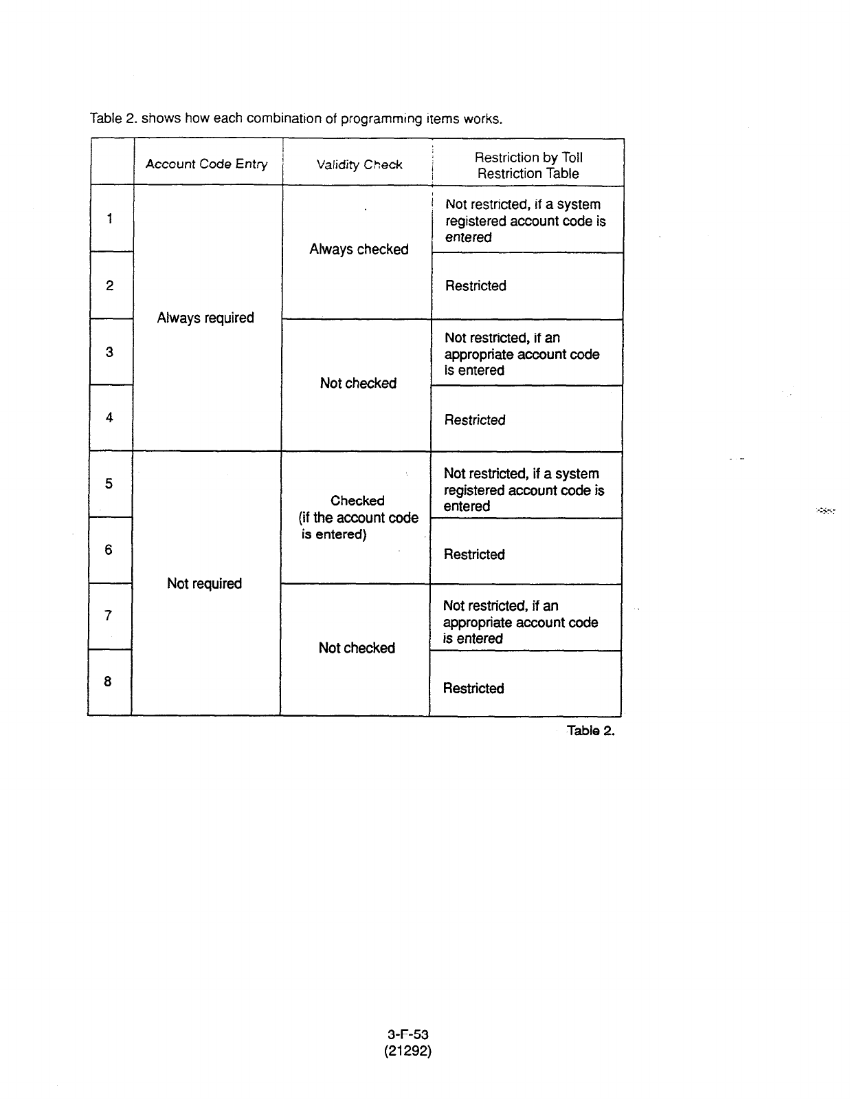
Table
2.
shows how each combination of programming items works.
3
4 Restricted
5
6
7
8
Account Code Entry
Always required
Not required
Validity Check j
/
Restriction by Toll
Restriction Table
! Not restricted, if a system
registered account code is
entered
Always checked
Restricted
Not checked
Not restricted, if an
appropriate account code
is entered
Checked
(if the account code
is entered)
Not restricted, if a system
registered account code is
entered
Restricted
Not restricted, if an
appropriate account code
Not checked is entered
Restricted
Table 2.
3-F-53
(21292)
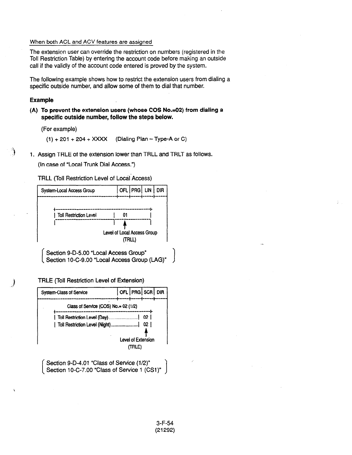
When both ACL and ACV features are assigned
The extension user can override the restriction on numbers (registered in the
Toll Restriction Table) by entering the account code before making an outside
call if the validly of the account code entered is proved by the system.
The following example shows how to restrict the extension users from dialing a
specific outside number, and allow some of them to dial that number.
Example
(A) To prevent the extension users (whose COS NO&~) from dialing a
specific outside number, follow the steps below.
(For example)
(1) + 201 + 204 + XXXX (Dialing Plan -Type-A or C)
1. Assign TRLE of the extension lower than TRLL and TRLT as follows.
(In case of “Local Trunk Dial Access.“)
TRLL (Toll Restriction Level of Loctil-Access)
System-Local Access Group 1 OFLlPRGl LIN 1 DIR
.I- I--------- - ---- ---+--+-+ ---- b --I.
+-----------------------------~
1 Toll Restrktion Level I 01
-------------I- --------------
I I + I
Level of Local Access Group
0-W
f
Section 9-D-5.00 “Local Access Group”
I Section 1 O-C-9.00 “Local Access Group (LAG)” )
TRLE (Toll Restriction Level of Extension)
System-Class of Service (OFLIPRGISCRI DIR
--_-------- t-+--i---t
class of Selvice (COS, No.= 02 (l/2)
t--- ---_-e-----------
1 Toll Resbi&n Level (by) . . . . . . . . . . . . . . . . . . . . . . . . . I 02 1
I Toll Restriction Level (Night) . . . . . . . . . . . . . . . . . . . . . . . I 02 I
+
Level of Extension
(TRW
Section 9-D-4.01 “Class of Service (l/2)”
Section 10-C-7.00 “Class of Service 1 (CSl)”
3-F-54
(21292)

,(ln case of “Individual Trunk Group Dial Access” and “Direct Trunk Access.“)
TRLT (Toll Restriction Level of Trunk Group) of a specific trunk groclp
Group -Trunk Group 1 OFLIP%/ SCR] SEL
_________----_______------------- -t----+----t----~----
Trunk Group No.= 02 (l/2)
+ _______________---------------------- ---I
1 Type . . . . . . . . . . . . . . . . . . . . . . . . . . . . . . 1 DDD I
I Name . . . . . . . . . . . . . . . . . . . . . . . .
I
I
/ - 9
I Intercept Routing (Night)1 En5002 (Typedo.) I
1 Toll Restriction Level......I 01
I
t
Level of Trunk Group
U-W
Section 9-E-l .Ol ‘Trunk Group (l/2)’
Section 1 O-C-l 4.00 “Trunk Group 1 (TGl) 1
TRLE (Toll Restriction Level of Extension)
System-Class of Service IOFLIPRGISCRI DIR
.----------------------I--------+-+---f-----~---
Class of Service (COS) No.= 02 (l/2)
+-------------------------------------~
1 Toll F&diction Level (Day) . . . .._................... i 02 I
I Toil Restriction Level (Night) ’ 02 1
. . . . . . . . . . . . . . . . . . . . . . . 1
t
Level of Extension
(TRE)
Section 9-D-4.01 “Class of Service (l/2)”
Section 1 O-C-7.00 “Class of Service 1 (CSl )” 1
3-F-55
(21292)
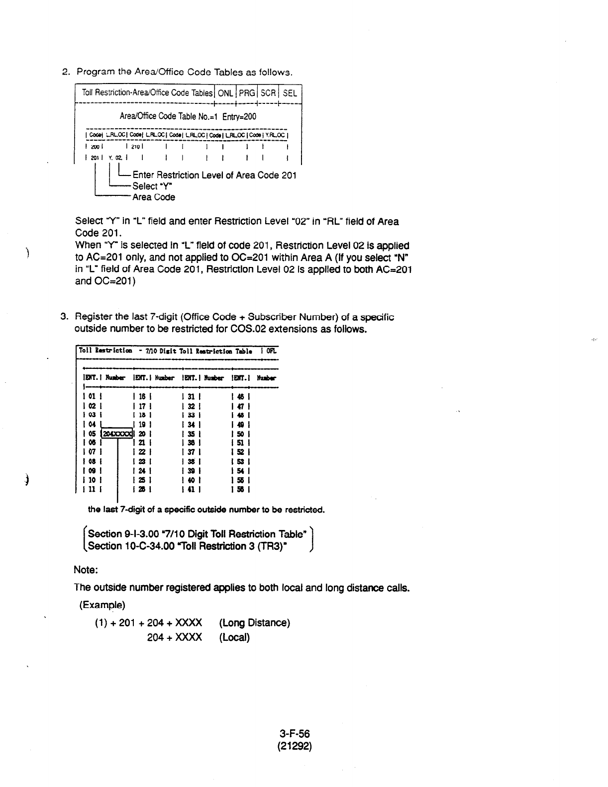
2. Program the Area/Office Code Tables as follows.
Toll Restriction-AreaiOce Code
Tables ONL PRG SCR SEL
----------------------------------~--+---
Area0ftice Code Table
No.=1 Entry=200
___------------------_____-__________------------
lcw LRL~l~lLfeocl~lLRLoc(~~LRLocIcodel~.RLocl
-----------------_______----------------------
I ml I2101 I I I I I I I
la11 Y.021 I I I I I I I I
Enter Restriction Level of Area Code 201
Select ‘Y
Area Code
Select Y” in “L” field
and enter Restriction Level “02” in “RL” field of Area
Code 201.
When ‘Y” is selected in I” field of code 201, Restriction Level 02 is applied
to AC=201 only, and not applied to OC=201 within Area A (If you select ‘N
in “L” field of Area Code 201, Restriction Level 02 is applied to both AC=201
and OC=201)
3. Register the last 7-digit (Office Code + Subscriber Number) of a spacific
outside number to be restricted for COS.02 extensions as follows.
Toll PatrietIm - 7no Dish Toll PdMrictim Tabl* I OR
-
mT.l iambor lElrr.Indor lenT.Ilhl&r
I :
I 01 I I 16 I 1311
ID31 I 17 I
1321
I
03
I I 1s I 1331
~ ID4 I 19 I
l34i
I I 05
e
1201 I351
~ lo61 I2ll 1381
~ 1071 lrrl I371
1081 1231 I 38 I
IOSI I241 I391
I
10
I IZJI I401
I 11
I lasl I
41
I
IMT.I WIubr
.+ :
1451
1471
l4al
1491
I501
Ial
1621
1631
1541
1561
ISal
the la& 7dgit of a specific outside number to be restricted.
Section 9-I-3.00 “7/l 0 Digit Toll Restriction Table”
Section 10-C-34.00 “Toll Restriction 3 (TR3)” 1
Note:
The
outside
number registered applies to both local and long distance calls.
(1) + 201 + 204 + XXXX (Long Distance)
204
+ XXXX (Local)
3-F-56
(21292)
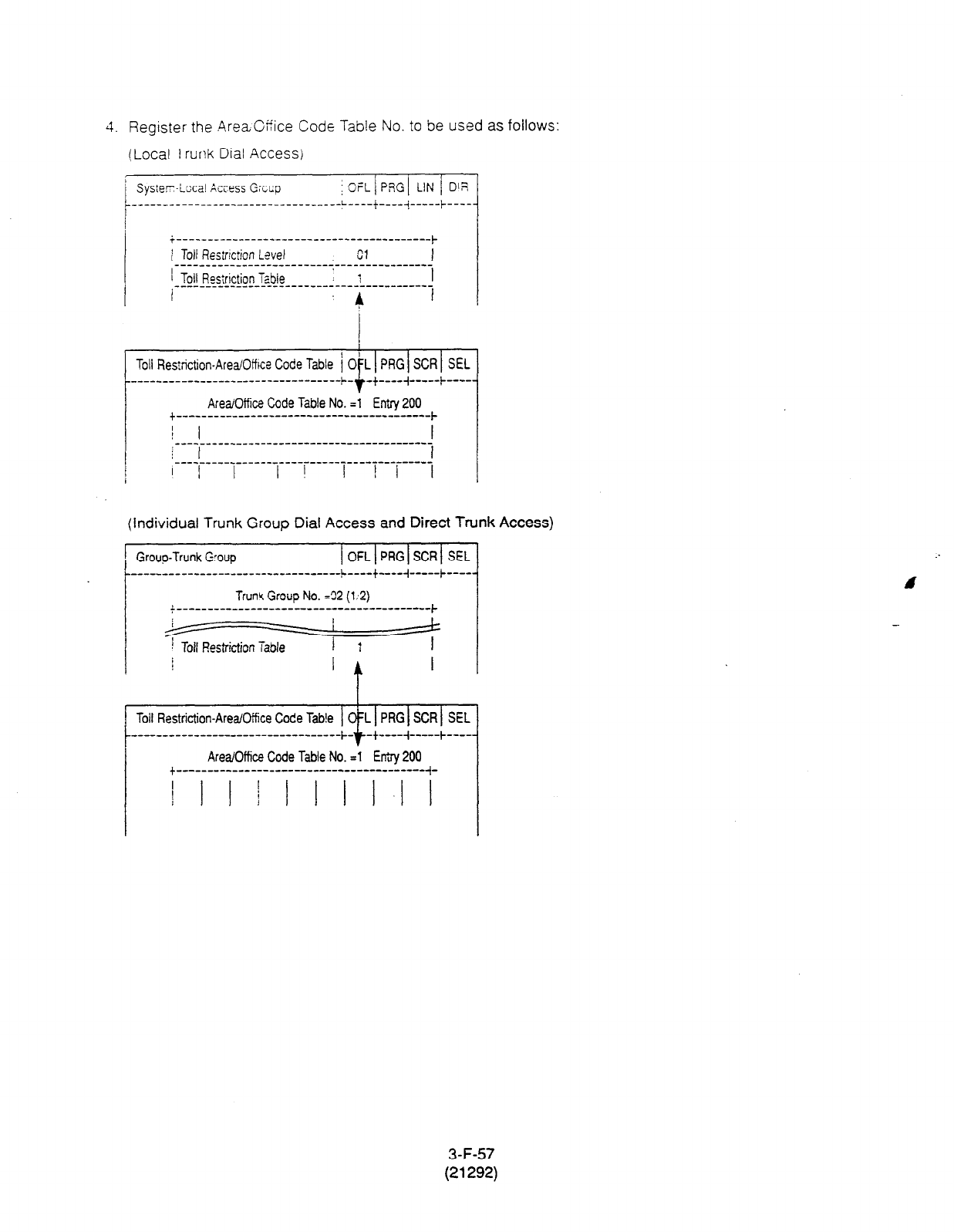
5. Register the .4reaCffice Code Table No. to be used as follows:
(Local Trurlk Dial Access)
1 Syster-Local Azess Gxcp
~ OFL j PRGl LIN 1 DIR
i-----------------------------------------~
j Toll Reztrrction Level Cl I
________-___-_______----------------------
1 Toll Rns’riction T-ble : i I
______=-L-__-_-9____----------------------
I ’
Toll Restriction-Area/Office Code Table i OIL 1 PRG 1 SCR 1 SEL
__-____--____-______-------
------- ++ -_-- i --__- + ----
Area/Office Code Table No. =l Entry 200
+-----------------------------------------~
__________-__----------------------- j
_---_____-__-_______----------------------
j ‘I I I! III II
(Individual Trunk Group Dial Access and Direct Trunk Access)
1 Group-Trunk
G:oup
t
1 OFL(PRGISCRI SEL
----------------------------------L----+----
Trum Group No. =32 (1;2)
f-----------------------------------------~
Toil Restriction-Area/Office Code Tab!e OfL PRG SCR SEL
t ____________________-------------- ++ ---- 4 --___ + --__ j
Area/Office Code Table No. -1 Eniry 200
f----------------------------------------,-
! I II I I II.1 I
3-F-57
(21292)
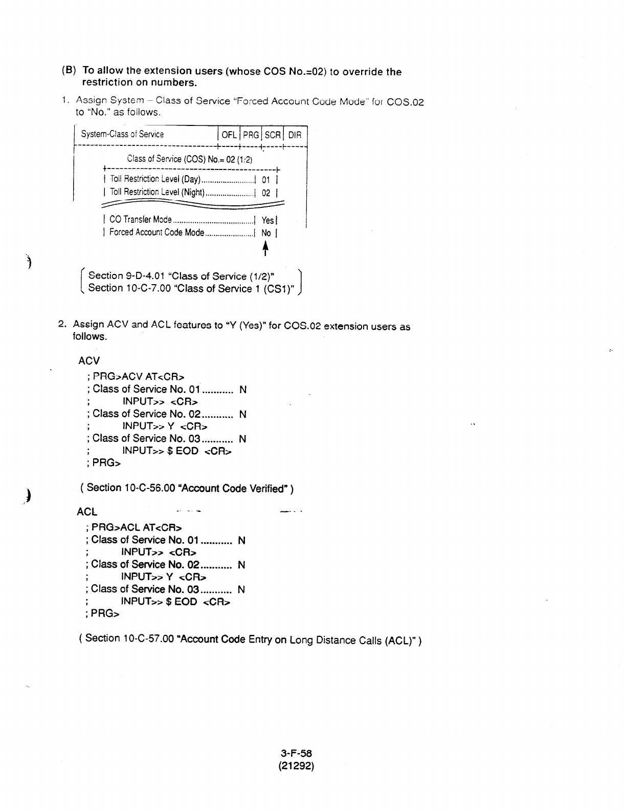
(B) To allow the extension users (whose COS No.=02) to override the
restriction on numbers.
1. Assign System - Class of Service “Forced Account Code Mode” for COS.02
to “No.” as follows.
Toll Res!rictior! Level (Day) . . . . . . . . . . . . . . . . . . . . . . . . . I
I
( Toll Restriction Level (Night) . . . . . . . . . . . . . . . . . . ..(_ i 02 I
6 -
I CO Transfer
Mode . . . . . . . . . . . . . . . . . . . . . . . . . . . . . . . . . . . . . . I Yes I
I Forced Account Code Mode . . . . . . . . . . .._.......... I ’ No I
t
Section 9-D-4.01 “Class of Service (l/2)”
Section
1
O-C-7.00 “Class of Service 1 (CSl)” 1
2. Assign ACV and ACL features to “Y (Yes)” for COS.02 extension users as
follows.
ACV
; PRG>ACV AT<CR>
; Class of Service No. 01 . . . . . . . . . . . N
INPUT>> <CR>
I Class of Service No. 02 . . . . . . . . . . . N
INPUT>> Y <CR>
I Class of Service No. 03 . . . . . . . . . . . N
; PRG> INPUT>> $ EOD <CR>
( Section
1
O-C-56.00 “Account Code Verified” )
ACL _. - ._ -.. .
; PRG>ACL ATcCR>
; Class of Service No. 01 . . . . . . . . . . . N
INPUT>> <CR>
I Class of Service No. 02 . . . . . . . . . . . N
INPUT>> Y <CR>
I Class of Service No. 03 . . . . . . . . . . . N
; PRG> INPUT>> $ EOD <CR>
( Section 10-C-57.00
“Account Code Entry on
Long Distance Calls (ACL)” )
3-F-58
(21292)

3. To register the System Account Codes, first divide the System Speed Dialing
area into two areas by entering the SPB command as follows.
To assign 80
Speed
Dialing Codes
and 120 System Account Codes in the
Speed Dialing Screen, enter as follows.
; PRG>SPB AT&R>
; Speed Dial Boundary . . . . . . . . . . . . . . . 200
INPUT>> 080 <CR>
; Speed Dial Boundary . . . . . . . . . . . . . . . 080 *
: PRG> INPUT>> $ EOD <CR>
( Section 1 O-C-56.00 “Account Code Verified” )
Then you can register the System Account Codes into the System Speed
Dialing Codes from No.081 to 200 as follows.
bsta - Swd Dialis - Smtu
I On I PEG 1 SX I DII
---- - : --c--c-
Smtca SF& Dial Ik. = odl
.
l atpa>
I no. I Tm I Did I 00:llcwu
h8lI#m234
I 01:Prtrictia Lnel-01
I
02:Putrictim Lad-D2
1062 IO1 I5678
I
Ds:Rutrictim
Led-03
lo83lOlI I 04:lsrtrktim LeeI-D4
lD84lOll I Qb:trtrictfml Led-(15
l085l01l I o6:btrietim Lwel-06
loss IO2 I I UMutrlctim tevel-U?
lo67 IO2 I
I CWutrictiaa Level-l
lca8 IO2 I I og:tatrictim Lad-00
ID69 ID2 I I 1o:wictim Level-10
IO90 loo I I
ll:xrtrictim Lad-11
lo9I IO9 I I
P:Pu~ietia Level-l2
loIlL IO9 I
I l3:htrictim Level-11
IOOI IO9 I I 14:BmMeticP M-14
IO94 I 16 I
I
lwartrictim
Led- I5
*- + Y:PesWtti011 Level- 16
I
~aaonllllllla B I I gmlDwY# I
Section 9-D-8.00 ‘Speed Dialing - System”
Section 1 O-C-l 2.OQ3peed Dialing - S.ptem (SPD)” j
3-F-59
(21292)

When the prog-zmming procedures from 1 to 5 have already been done, the
treatment of an outside call made by an extension user (whose COS.No. is
02) depends or rhe operation as follows.
(In case of “Local Trunk Dial Access.“)
PITS
Operation Result
1 cl
9
+ [( 1 j -
201+] 204xxxx i The outside number dialed
i is Restricted by “Toll
Restricted. , Restriction Table.”
(Call is not :
&-nplet&.) i The account code
; entered is “Not valid.”
3 OrI
9 i- iWD/DND + 1234# + [(l) i- 201+] 204xxxx Restriction on number is overridden.
(Call is completed.)
SLT c
1
-
2
-
3
Operation
-
pJ + [(l) + 201+] 204xXxX
psJ+ E q
+34!56#+ [(1)+201+]204xxxx
pJ+ q
fg +1234#+ [(1)+201+]204xxxx
Result
: The outside number dialed
Restricted. i is Restricted by “Toll
, Restriction Table.”
(Cell is not i
completed.) : The a-unt code
f entered is “Not valid.”
Restriction on number is overridden.
(Call is completed.)
(In case of ‘Individual Trunk Group Dial Access” and “Direct Trunk Access.“)
Individual Trunk Group Dial Access
When making an outside call by specifying the trunk group 02.
PITS
Operation
Result
1 pq-qm+ [(1)+201+]204xxxx
i The outside number dialed
Restricted. i is Restricted by 7011
, Restriction Table.”
3 q unn
8 1 2
+ FW’/DN’ + 1234# + ((1) +
‘O’+] 204~
(call is completed )
Restriction on number is overridden.
3-P-60
(21292)
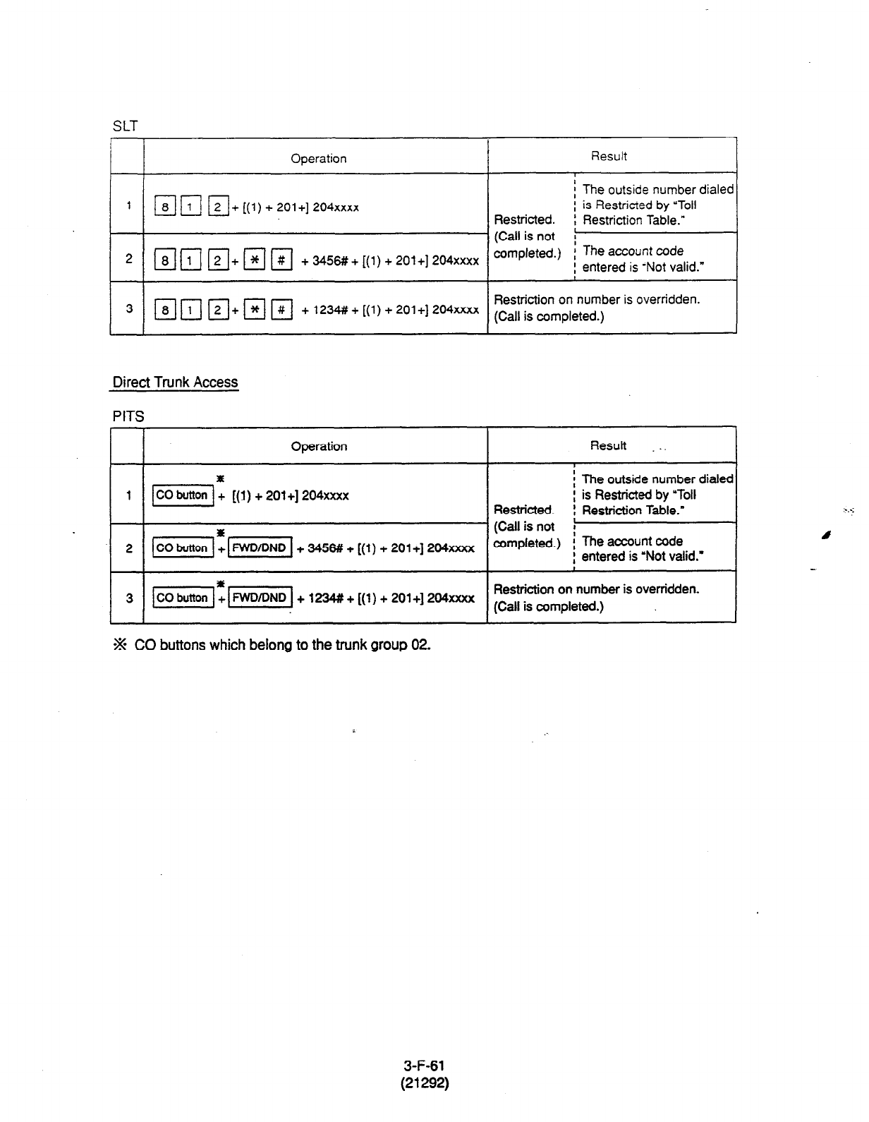
SLT
Operation
1 mr;l ~+[(1)+201+]204xxxx
2 mr;? r;;l+mm +3456#+[(1)+201+]204xxxx
3 T [-i-&-j •+~]~j +1234#+[(1)+201+]204xxxx
Direct Trunk Access
PITS
Result
f The outside number dialer
i is Restricted by ‘Toll
Restricted. , Restriction Table.”
(Call is not j
amp/&&.) ;
The account code
; entered is -Not valid.”
Restriction on number is overridden.
(Call is completed.)
I 7
I I
Operation
I I
1 -1: [(I) + 201+] 204xxxx
2 + 3456#! + [(l) + 201+] 2D4xxxx
Result _.
-~-I-- ~
i The outside number dialec
; is Restricted by ‘Toll
Restricted. : Restriction
Table.”
(Call is not i
completed.) ; The account coda
: entered is ‘Not valid.”
Restriction on number is overridden.
(Call is completed.)
j
% CO buttons which belong to the trunk group 02.
3-F-61
(21292)
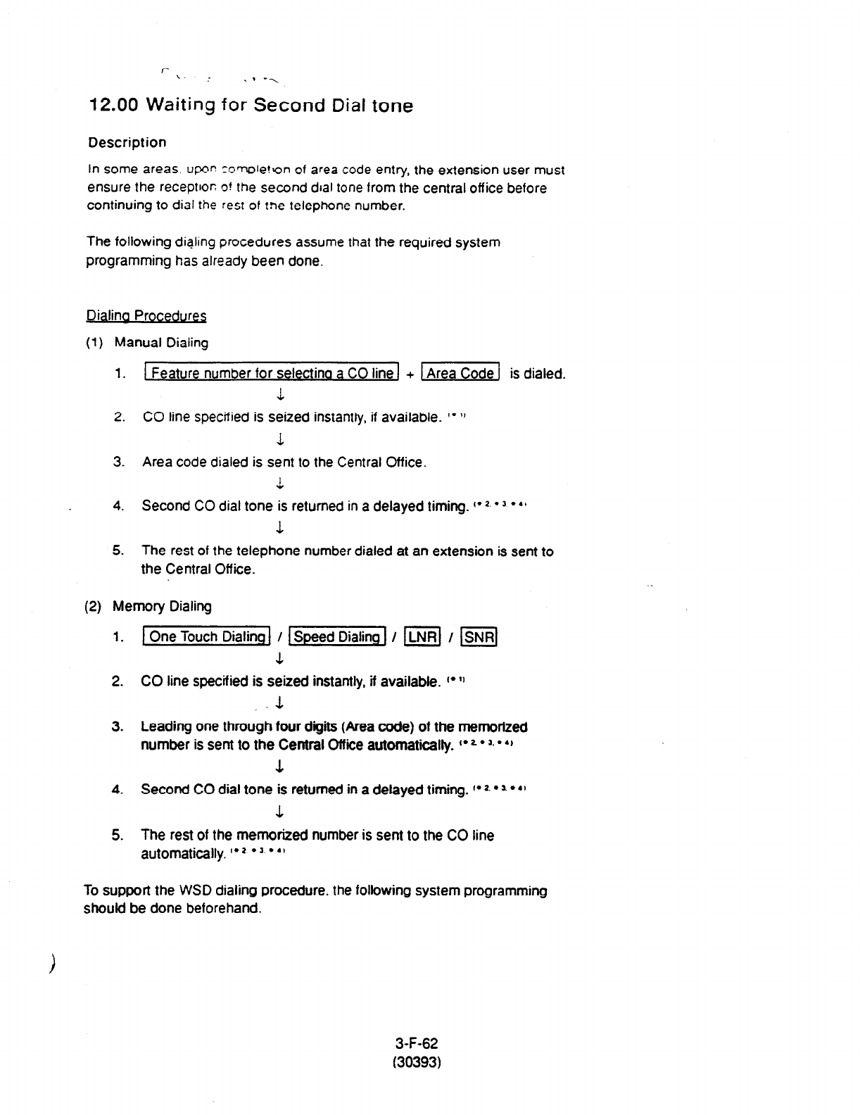
I- \. . . . --..
12.00 Waiting for Second Dial tone
Description
In some areas. upor: zcmore!Y)n
of
area code entry, the extension user must
ensure the receptkor; o! the second dial tone from the central office before
continuing to
dial the rest of tne
telephone number.
The following dialing procedures assume that the required system
programming has already been done.
Dialina Procedures
(1)
Manual Dialing
1. 1 Feature number for selectinq a CO line 1 + 1 Area Code 1 is dialed.
1
2. CO line specified is seized instantly, if available. I* ‘1
L
3. Area code dialed is sent to the Central Office.
1
4.
Second CO dial tone is returned in a delayed timing. I* *.
l
3
l
‘I
1
5. The rest of the telephone number dialed at an extension is sent to
the Central Off ice.
(2) Memory Dialing
1. 1 One Touch Dialing] / -1 I m] I m]
1
2. CO line specified is seized instantly, if available. ~~~~
-1
3. Leading one through four digits (Area code) of the memorized
number is sent to the Central Office automatically. I* 2
l
3.
l
4,
3.
4.
Second CO dial tone is returned in a debyed timing. I* *.
l
a
l
.I
1
5. The rest of the memorized number is sent to the CO line
automatically. I* *
l
’
l
4’
To support the WSD dialing procedure,
the
following system programming
should be done beforehand.
3-F-62
(30393)
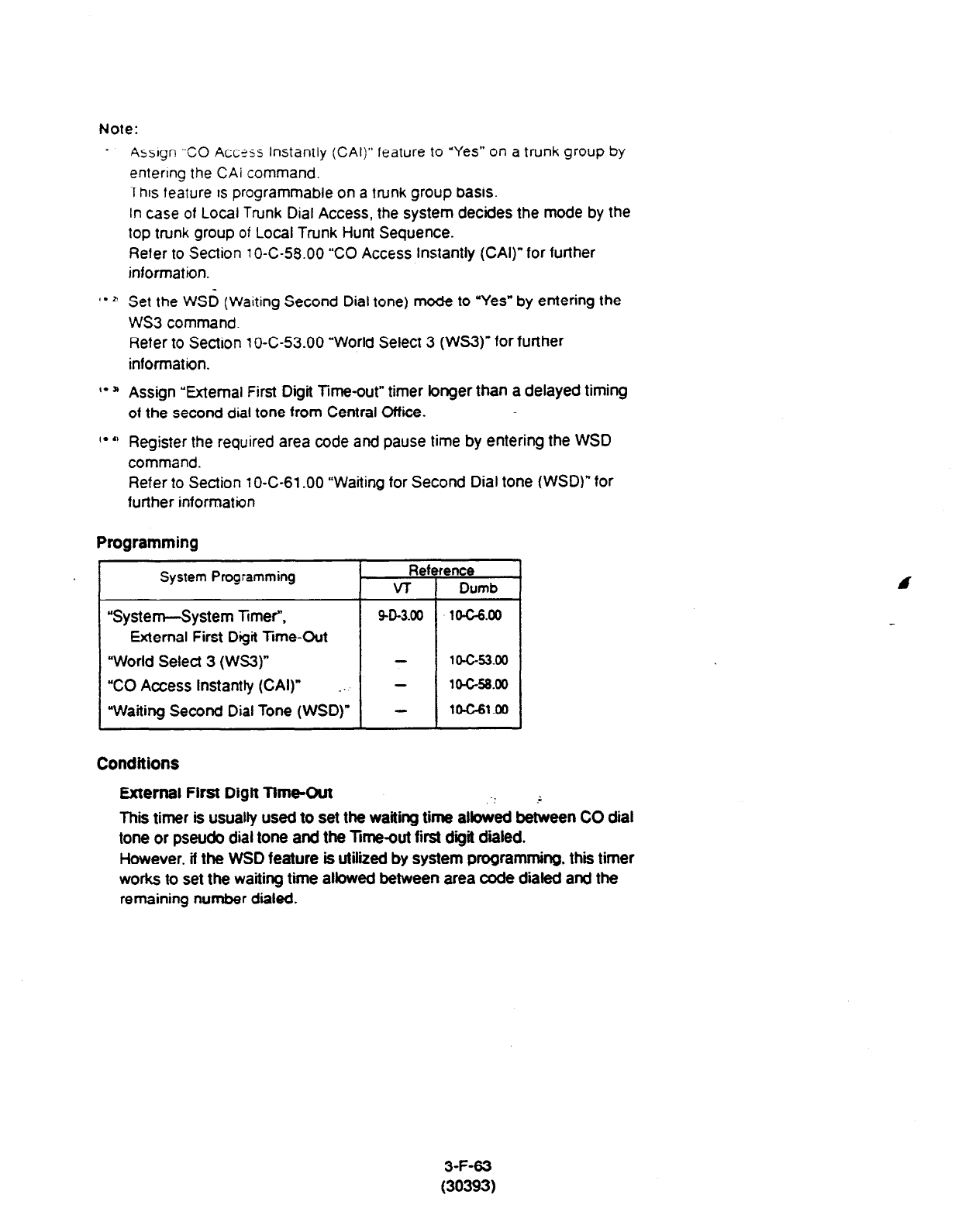
Note:
.
Assrgn “CO Accxs Instantly (CAI)” feature to “Yes” on a trunk group by
entering the
CAI
command.
This feature is programmable on
a
rrunk group
basis.
In case of Local Trunk Dial Access, the system decides the mode by the
top trunk group of Local Trunk Hunt Sequence.
Refer to Section 1 O-C-58.00 “CO Access instantly (CAI)” for further
information.
‘* *
Set
the
WSO
(Waiting
Second Dial tone) mode to “Yes” by entering the
WS3 command.
Refer to Section I O-C-53.00 “World Select 3 (WS3)” for further
information.
I- a Assign “External First Digit Time-out” timer longer than a delayed timing
of the second dial tone from Central Office.
I* ti Register the required area code and pause time by entering the WSD
command.
Refer to
Section
1
O-C-61 .OO “Waiting for Second Dial tone (WSD)” for
further information
Programming
System Programming
“System--System Ttmef,
External First Digit Time-Out
“World Selecf 3 (WS3)”
“CO Access Instantly (CAI)” _.
“Waiting Second Dial Tone (WSD)”
Conditions
External First Digit Time-Out
This timer is usually used to set the waiting time albwed between CO dial
tone or pseudo dial tone and the lime-out first digit dialed.
However, if the WSD feature is utilized by system programming, this timer
works to set the waiting time atbwed between area code dialed and the
remaining number dialed.
3-F-63
(30393)
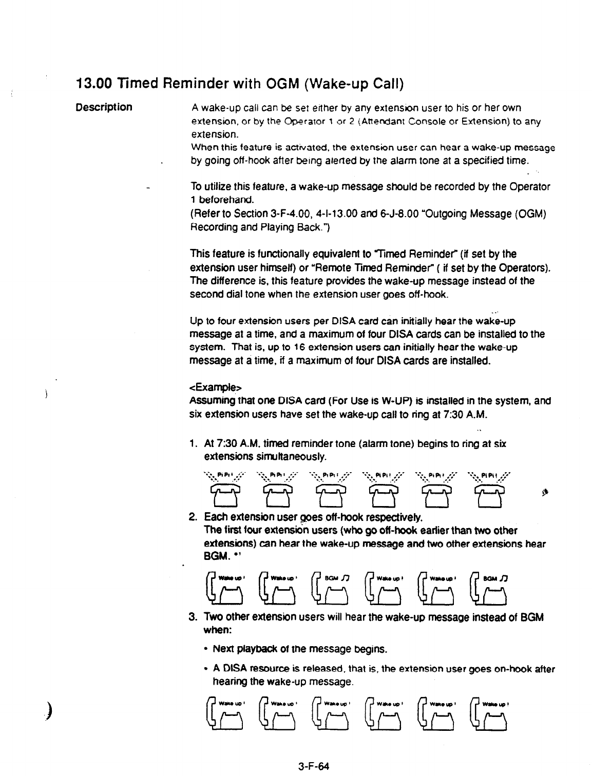
13.00 Timed Reminder with OGM (Wake-up Call)
Description
A wake-up call can be set erther by any extenson user to his or her own
extension, or by the Optraror 1 3r 2 (Attendant Console or Extension) to any
extension.
When this feature is activated, the extension user can hear
a
wake-up message
by
going off-hook after being alerted by
the
alarm tone at a specified time.
To utilize this feature, a wake-up message should be recorded by the Operator
1 beforehand.
(Refer to Section 3-F-4.00, 4-I-13.00 and 6-J-8.00 “Outgoing Message (OGM)
Recording and Playing Back.“)
This feature is functionally equivalent to %ned Reminder” (if set by the
extension user himself) or ‘Remote Timed Reminder” ( if set by the Operators).
The difference is, this feature provides the wake-up message instead of the
second dial tone when the extension user goes off-hook.
Up to four extension users per DISA card can initially hear the wake-up
message at a time, and a maximum of four DISA cards can be installed to the
system. That is, up to 16 extension users can initially hear the wake-up
message at a time, if a maximum of four DISA cards are installed.
<Example>
Assuming that one DISA card (For Use is W-UP) is installed in the system, and
six extension users have set the wake-up call to ring at 7:30 A.M.
1.
2.
3.
. .
At 7:30 A-M, timed reminder tone (alarm tone) begins to ring at six
extensions simuttaneously.
‘q.*Pl PI
) .*:*-
~ ‘.:wg.- ..-.g ..:;dwg . .:..g : .::g.. $
Each extension user goes off-hook respectively.
The first four extensi& users (who go off-hook earlier than two other
extensions) can hear the wake-up message and two other extensions hear
BGM.
l
’
Two other extension users will hear the wake-up message instead of BGM
when:
l
Next playback of the message begins.
l
A DiSA resource is released, that is, the extension user goes on-hook after
hearing the wake-up message.
3-F-64
(40993)
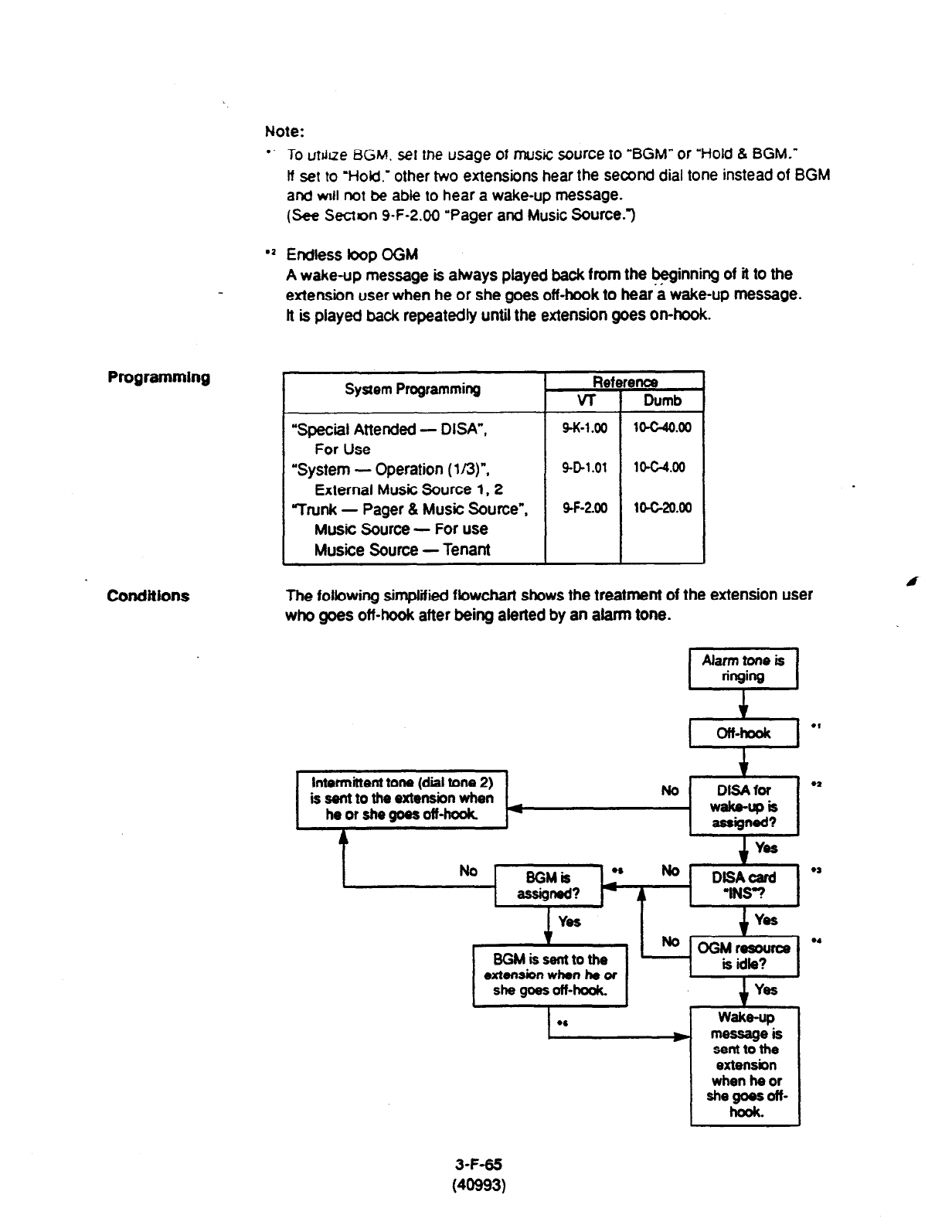
Note:
Programming
l
- To urdue BGM. set the usage of music source to “BGM” or “Hold 8 BGM.”
If set to ‘Hold.’ other two extensions hear the second dial tone instead of BGM
and vnll not be able to hear a wake-up message.
(See Secton 9-F-2.00 “Pager and Music Source.“)
l
a Endless bop OGM
A wake-up message is abays played back from the beginning of it to the
extension user when he or she goes off-hook to hear a wake-up message.
It is played back repeatedly until the extension goes on-hook.
System Programming Reference
VT 1 Dumb
“Special Attended - DISA”,
For Use
‘System - Operation (113)“.
External Music Source I, 2
Trunk - Pager 8 Music Source”,
Music Source - For use
Musice
Source - Tenant
9-K-l .oo
1O-C-4O.00
9-D-1.01
1o-G4.00
SF-200 104-20.00
conditions
The following simpfified fbwchart shows the treatment of the extension user
who goes off-hook after being alerted by an afann tone.
t
Intermittent tone (dial tone 2)
is sent to the extension when No DlSAfor
l
’
he or she goes off-hook wake-upis
4 assigned?
Yes
No -
9GMis l ’ Ia
- assigned? * 4 DtSAcerd
l
’
‘INS-?
YeS
-
BGM is sent to the
extension when he of
she goes off-hook.
YOS
No OGMresouroe m
is idle?
Yes
wake-up
messageis
sent to the
extension
when he or
she goes off-
hook.
3-F-65
(40993)
Note:
l
’ This feature works if the extension user goes off-hook while the alarm tone IS
ringing for 2 minutes.
‘2 Tenant Service
If the tenant service is employed, each tenant (1
and 2) can have its unique
wake-up message respectively.
In this case, afflications of the wake-up message and the extension should be
the same tenant.
l S Operating Status
Refer to Section 14-C-2.00 “Definition of Operating Status.”
l ’ OGM busy
Up to four extensions per DISA card can initially receive a wake-up message at
a time.
To utilize BGM, set the usage of music source to “BGM” or “Hold & BGM.”
(Refer to Section 9-F-2.00 “Pager and Music Source.“)
l ’ From BGM to a wake-up m&sage
The extension who currently hears BGM will hear the wake-up message instead
of BGM when:
l Next playback of the message begins.
l A DISA resource is released, that is, the extension user goes on-hook after
hearing the message.
3-F-66
(40993)
Section
4
Station Features and Operation
Proprietary Integrated Telephone System (PITS)
: Section 4)
Station Features and Operation
Proprietary Integrated Telephone System (PITS)
Contents
A Preparation Page
. . . . . . . . . . . . . . . . . . . . . . . . . . . . . . . . . . . . . .
. . . . . . ..-......-................................................ 4-A-l
1 .oo
2.00
3.00
4.00
Outline ..___.
..-.....................................................................
Configuration . . . . . . . . . .._..._. ._ . . . . . . . . . . . . . . . . . . . . . 4-A- 1
. . ..-.................................................................
2.01 Location of Feature Buttons 4-A-l
2.02 Controls . . . . . . . . . ..f............................................ 4-A-2
. . . . ..-.......-........................................................................
LED Indication Patterns 4-A-l 5
Display-LCD .-...-......-............................................................ 4-A-l 9
. . . . ..-......................--.....-......................................................
4.01 Trne and Date Display 4-A-20
4.02 Dialed Number Display . . . . . . . . . . . . . . . . . . . . . . . . . . . . . . . . . . . . . . . . . . . . . . . . . . . . . . . . . . . . . . . . 4-A-20
. . . . . ..-........................................................
4.03 Duration Trne of Call Display 4-A-21
4.04 Incoming Call Source Display . . . . . . . . . . . . . . . . . . . . . . . . . . . . . . . . . . . . . . . . . . . . . . . . . . . . . . 4-A-21
. . . . . . .
. . . . . . . . . . . . . . . . . . . . . . . . . . . . . . . . . . . . . . . . . . . . . . .
4.05 Station Programmed Data Display 4-A-22
4.06 Station Name Display . . . . . . . . . . . . . . . . . . . . . . . . . . . . . . . . . . . . . . . . . . . . . . 4-A-22
. . . . . . . . . . . . . . . . . . . . . . . . . . . . . . . . . . . . . . . . . . . . . . . . . . . . . . . . . . . . . . . . . . 4-A-23
B Feature Buttons .... . ......................................................... ................................. 4-B-l
Fixed Feature Buttons ........................................
1 .oo
2.00
3.00
Assignable Feature Buttons . . . . . . . . . . . . . . . . . . . . . . . . .
...................................
...........................................
............
Line Access Buttons
3.01 PDN Button ..............................................................................
................................................
3.02
SDN Button ..................................
...................................................
3.03 ICM Button ...............................
...................................................................................
3.04
PC0 Button ................................................
3.05 SC0 Button .................................
................................................
3.06 GCO Button .................................
.................................................................................
4-B-l
4-B-4
&‘B-6
4-B-6
4-B-7
4-B-7
4-B-8
4-B-9
4-B-10
; ,
C
Outgoing Call Features . . ..-...--.......................................................................... 4-C-l
1 .oo
2.00
3.00
Line Selection-Calling . . . . . . . . . . . . . . . . . . . . . . . . . . . . . . . . . . . . . . . . . . . . . . . . . . . . . . . .
1 .Ol Prime Line Preference-Calling . . . . . . . . . . . . . . . . . . . . . . . . . . . . . . . . . . . . . . . .
1.02 Idle tine Preference-Calling
. . . . . . . . . . . . .
. . . . . . . . . . . . . . . . . . . . . . . . . . . . .
1.03 No tine Preference-Calling
............................
On-Hook Dialing . . . . . . . . . . . . . . . . . . . . . . . . . . . . . . . . . . . . .
....................
. . . . . . . . . . . . . . . . . . . . . . . . . . . . . . . . . . . . . . . . . . . . . . . . . . . . . . . . . . . . . . . . . . . . . . . . . . . . . .
Making Outside Calls . . . . . . . . . . . . . . . . . . . . . . . . . . . . . . . . . . . . . . . . . . . . . . . . . . . . . . . . .
3.01 Local Think Dial Access
. . . . . . . . . . . . . . . . . . . .
3.02 . . . . . . . . . . . . . . . . . . . . . . . . . . . . . . . . . . . . . . . . . . . .._....
Individual Trunk Group Dial Access . .
............
...........................................
3.03 Individual Virtual Trunk Group Dial Access
3.04 Direct Trunk Access . . . . . . . . . . . . . . . . . . . . . . . . . . . . . . . . .
.-..............................................,
. . . . . . ..-...........
4-c-i
4-C-2
4-c-3
4-c-4
4-c-4
4-C-6
4-C-6
4-c-7
4-C-8
4-c-9
4-1
Page
4-c-10
4-c-10
4-c-11
4-c-14
4-c-1
5
4-C-1
6
4-c-17
4-c-l
7
4-c-l
8
4-c-19
4-C-20
4-C-21
4-C-22
4-C-22
4-C-24
4-C-25
4-C-26
4-C-27
4-C-28
4.00
5.00
6.00
7.00
8.00
9.00
10.00
Automatic Dialing.. .................................................................................
4.01 One Touch Dialing .......................................................................
4.02 Speed Dialing-System.. ...............................................................
4.03 Last Number Redial (LNR) ..........................................................
4.04 Automatic Redial .........................................................................
4.05 Saved Number Redial (SNR) ......................................................
Making Internal Calls .............................................................................
5.01 Inter Office Calling .......................................................................
5.02 Intercom Calling.. .........................................................................
5.03 Intercom-Voice Calling..
...............................................................
5.04 Intercom-Busy Station Signaling
(BSS)
.......................................
5.05 Intercom Oft-Hook Call Announcement (OHCA) ....................... .
.
Automatic Callback.. ..............................................................................
6.01 Automatic Callback-Trunk ...........................................................
6.02 Automatic Callback-Station .........................................................
Executive Busy Override .......................................................................
Do Not Disturb (DND) Override ........... . .................................................
Walking COS (Class of Service). ...........................................................
Operator Call .........................................................................................
D Receiving Features .......................................................................................... 4-0-l
- . .
1.00 Line Selection-Answering ...................................................................... 4-0-l
1.01 Ringing Line Preference-Answering.. .......................................... 4-D-l
1.02 Prime Line Preference-Answering ............................................... 4-o-2
1.03 No Line Preference-Answering.. .................................................. 4-O-3
1.04 Direct Answering (Pre-selection) 4-O-3 ”
.................................................
2.00 Intercom Answer .................................................................................... 4-D-4
2.01 Intercom Hands-Free Answerback .............................................. 4-D-4
2.02 Intercom Answer Voice Calling Deny .......................................... 4-D-5
2.03 Intercom Answer BSSIOHCA Deny.. ........................................... 4-D-6
3.00 Call Pickup ............................................................................................. 4-D-7
3.01 Dial Call Pickup ........................................................................... 4-D-7
3.02 Directed Call Pickup .................................................................... 4-D-6
3.03 Call Pickup Deny ......................................................................... 4-D-9
4.00 Trunk Answer From Any Station (TAFAS)-Day Service.. ....................... 4-O-10
5.00 Executive Busy Override Deny .............................................................. 4-D-11
6.00 Do Not Disturb (DND) .............................. ............................................. 4-D-l 2
7.00 Call Waiting ............................................................................................ 4-D-15
8.00 Uniform Call Distribution (UCD)-Log Out.. ............................................. 4-D-l 7
4-2
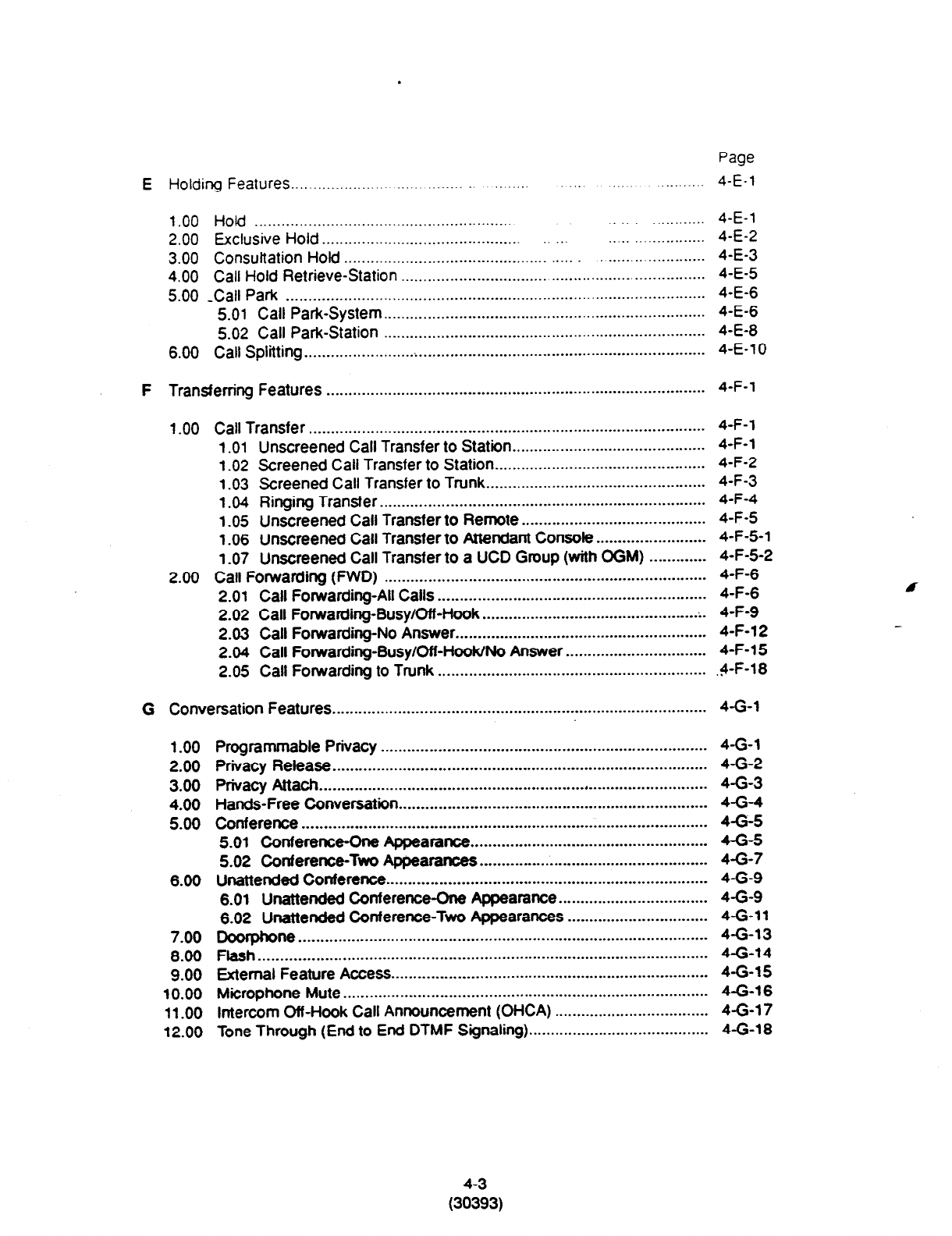
.
Page
E Holding Features _.......__...___._.... ._... .._.. 4-E-1
1 .OO Hold .............................................................. ............ 4-E-l
2.00
Exclusive Hold .......................................................................
4-E-2
3.00 Consultation Hold ........................................................................... 4-E-3
4.00 Call Hold Retrieve-Station .................................................................... 4-E-S
5.00 -Call Park ............................................................................................... 4-E-6
5.01 Call Park-System.. ....................................................................... 4-E-6
5.02 Call Park-Station ......................................................................... 4-E-8
6.00 Call Splitting ....................... ..i............................_ .................................... 4-E-l 0
F
Transferring Features . . . . . . . . . . . . . . . . . . . . . . . . .._......_......................-............................. 4-F-l
1 .OO Call Transfer .......................................................................................... 4-F-l
1 .Ol Unscreened Call Transfer to Station.. .......................................... 4-F-l
1.02 Screened Call Transfer to Station ................................................ 4-F-2
1.03 Screened Call Transfer to Trunk .................................................. 4-F-3
1.04 Ringing Transfer. ......................................................................... 4-F-4
1.05 Unscreened Call Transfer to Remote .......................................... 4-F-5
1.06 Unscreened Call Transfer to Attendant Consob.. ....................... 4-F-5-l
1.07 Unscreened Call Transfer to a UCD Group (with OGM) ............. 4-F-5-2
2.00 Call Forwarding (FWD) .........................................................................
4-F-6
2.01 Call Forwarding-All Calls ............................................................. 4-F-6
2.02 Call Forwarding-Busy/Off-Hook ................................................. .
. 4-F-9
2.03 Call Forwarding-No Answer ......................................................... 4-F-12
2.04 Call Forwarding-Busy/Off-HooWNo Answer ................................ 4-F-l 5
2.05 Call Forwarding to Trunk ............................................................. 4-F-l 8
. .
G Conversation Features . . . . . . . . . . . . . . . . . . . . . . . . . . . . . . . . . . . . . . . . . . . . . . . . . . . . . . . . . . . . . . . . . . . . . . . . . . . . . . . . . . . . . 4-G-l
1 .oo
2.00
3.00
4.00
5.00
6.00
7.00
8.00
9.00
10.00
11 .oo
12.00
Programmable Privacy.. ........................................................................ 4-G-l
Privacy Release .....................................................................................
4-G-2
privacy Attach ........................................................................................
4-G-3
Hands-Free Conversation ......................................................................
4-G-4
Conference ............................................................................................
4-G-5
5.01 Conference-One Appearance ......................................................
4-e-5
5.02 Conference-Two Appearances ....................................................
4-G-7
Unattended Conference ......................................................................... 4-G-9
6.01 Unattended Conference-One Appearance.. ................................ 4-G-9
6.02
Unattended Conference-Two Appearances ................................
4-G-11
Doorphone .............................................................................................
4-G-13
Flash ......................................................................................................
4-G-14
External
Feature Access.. ...................................................................... 4-G-15
Microphone Mute ...................................................................................
4-G-16
Intercom Off-Hook Call Announcement (OHCA) ...................................
4-G-1 7
Tone Through (End to End DTMF Signaling). ........................................
4-G-18
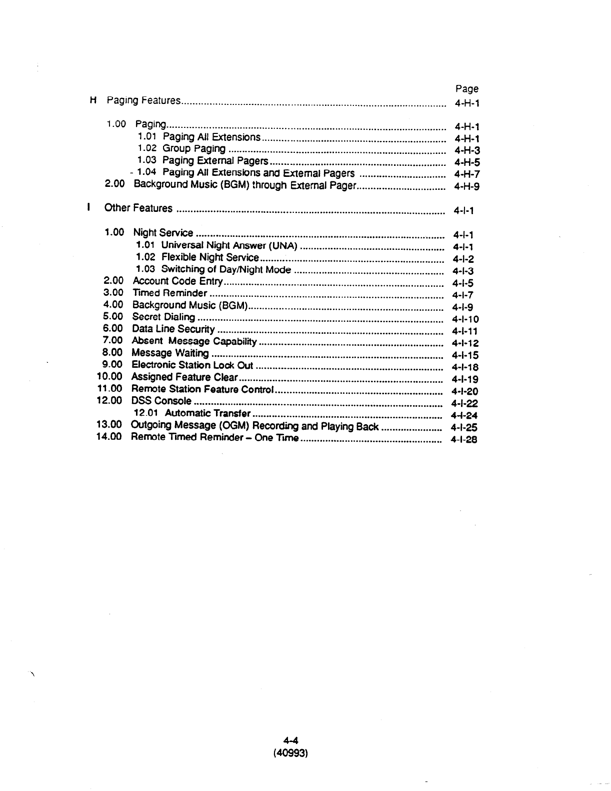
Page
H Paging
Features ............................................................................................... 4-H-l
1
.OO Paging..
..................................................................................................
4-H-l
1
.Ol
Paging All Extensions.. ........... .....................................................
4-H-l
1.02
Group Paging .............................................................................. 4-H-3
1.03 Paging External Pagers.. ............................................................. 4-H-5
- 1.04 Paging All Extensions and External Pagers ............................... 4-H-7
2.00 Background Music (BGM) !hrough External Pager..
.............................. 4-H-9
I Other Features ................................................................................................ 4-l-l
1.00
2.00
3.00
4.00
5.00
6.00
7.00
8.00
9.00
10.00
11.00
12.00
13.00
14.00
Night Service ......................................................................................... 4-l-l
1
.Ol
Universal Night Answer (UNA) .................................................... 4-l-l
1.02 Flexible Night Service..
................................................................ 4-l-2
1.03 Switching of Day/Night Mode ...................................................... 4-l-3
Account Code Entry ............................................................................... 4-l-5
Timed Reminder .................................................................................... 4-l-7
Background Music (BGM)
...................................................................... 4-l-9
Secret Dialing ........................................................................................ 4-l-l 0
Data Line Security ................................................................................. 4-I-l 1
Absent Message Capability
Message Waiting .................................................................. 4-l-l 2
................................................................................... 4-l-15
Electronic Station Lock Cut ................................................................... 4-l-l 8
Assigned Feature Clear ......................................................................... 4-l-19
Remote Station Feature Control ............................................................ 4-I-20
DSS Console ......................................................................................... 4-l-22
12.01 Automatic Transfer .................................................................... 4-l-24
Outgoing Message @GM) Recording and Playing Back ...................... 4-l-25
Remote limed Reminder - One
Ti
................................................... 4-l-28
(23)
A. Preparation
1 .OO Outline
Panasonic EMSS PITS (Proprietary Integrated
Telephone System) telephones are provided to
utilize the various features of the
KX-T336
system, in addition to supporting
basic telephone
service (making and answering calls).
This section describes special features and
required
operatigm of PITS telephones.
4-A-1
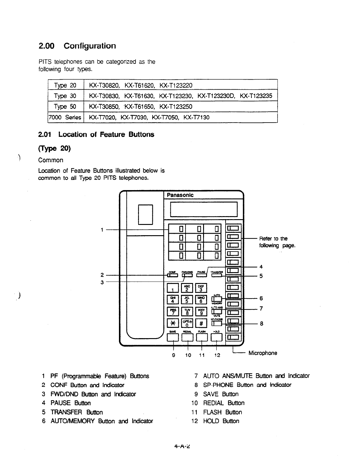
2.00 Configuration
PITS telephones can be categorized as the
following four types.
Type 20 KX-T30820, KX-T61620, KX-T123220
1 Type 30 KX-T30830,
KX-T61630, KX-T123230, KX-T1232300, KX-T123235
Type 50
KX-T30860, WC-T61 650, KX-T123250
7000 Series KX-l7020, KX-l7030,
KX-77050, KX-T/130
2.01 Location of Feature Buttons
crype 20)
!
Common
Location of Feature Buttons illustrated below is
common to all Type 20 PITS telephones.
1
2
3
1 PF (Programmable Feature) Buttons
2 CONF Button and Indicator
3 FVVDIDND Button and lrtckator
4 PAUSE Button
5 TRANSFER Button
6 AUTO/MEMORY Button and indicator
- Refer to the
following page.
-4
-5
-6
-7
-6
I I I I L-L-
9 IO 11 12 Microphone
7 AUTO ANSMUTE Button and Indicator
8 SP-PHONE Button and ~hdiior
9 SAVE Button
10 REDIAL Button
11 FLASH Button
12 HOLD Button
4-A-2
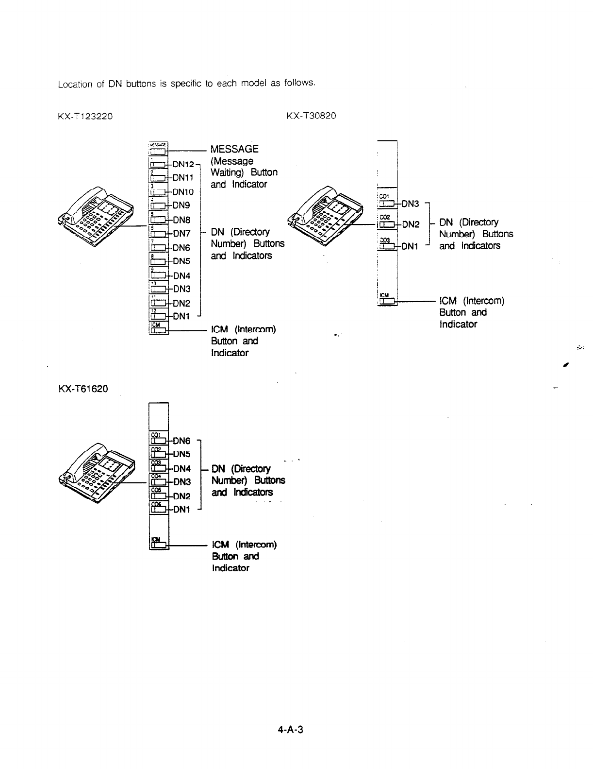
Location of DN buttons is specific to each model as follows.
KX-T123220 KX-T30820
MESSAGE
(Message
Waiting) Button
and Indicator
DN (Directory
Number) Buttons
and Indicators
ICM (Intercom)
Button and
Indicator
KX-T61620
Number) Buttons
and lndlcators
DN3
DN2
DNl
DN (Directory
Number) Buttons
and Indicators
ICM (Intercom)
Button and
Indicator
ICM (lnterwm)
Buttonand
indicator
4-A-3
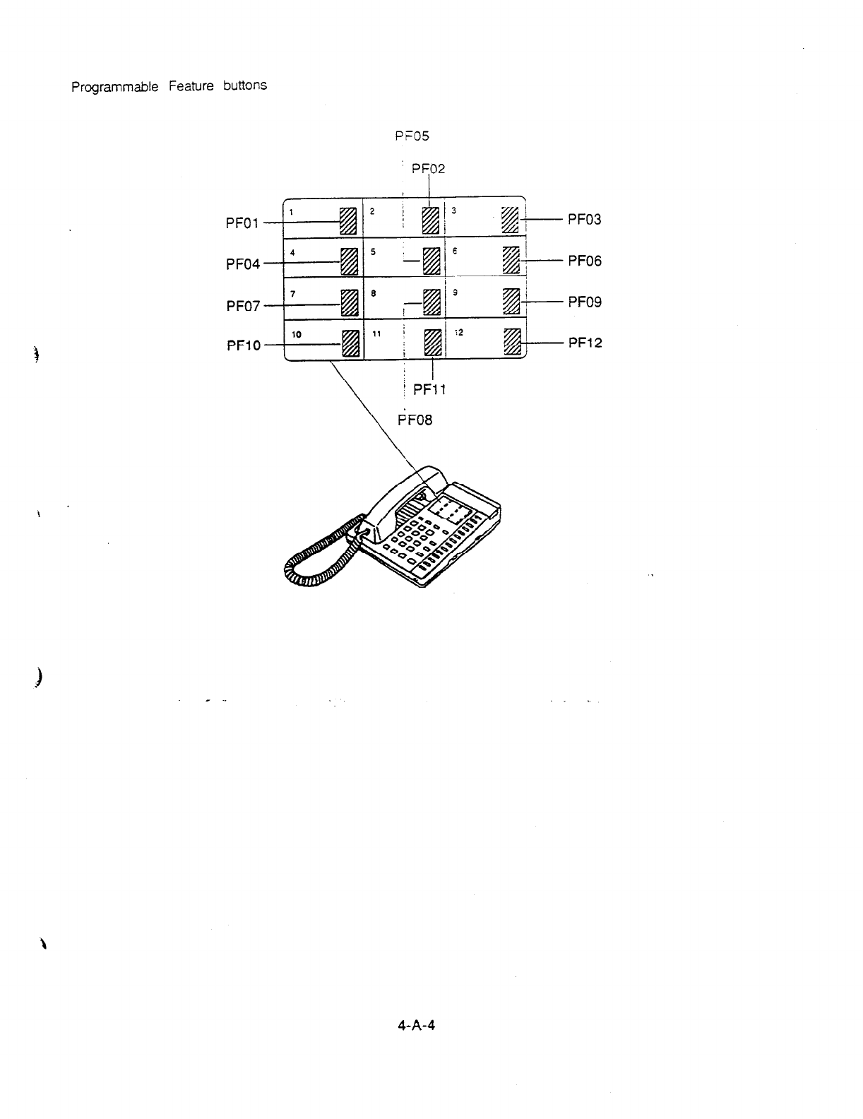
Programmable Feature buttons
PFO5
PFO2
/ -Y
2 i I
PFOl ’ t Ii& j3 f&- PF03
1
PF04 4 kzi
5
Et8
E 74
- &- PFO6
I
PF07 ’ ia
8
B’
3
i % +---- PFO9
PFlO lo
L El ” i I@
:2
PF12
/
_
4-A-4
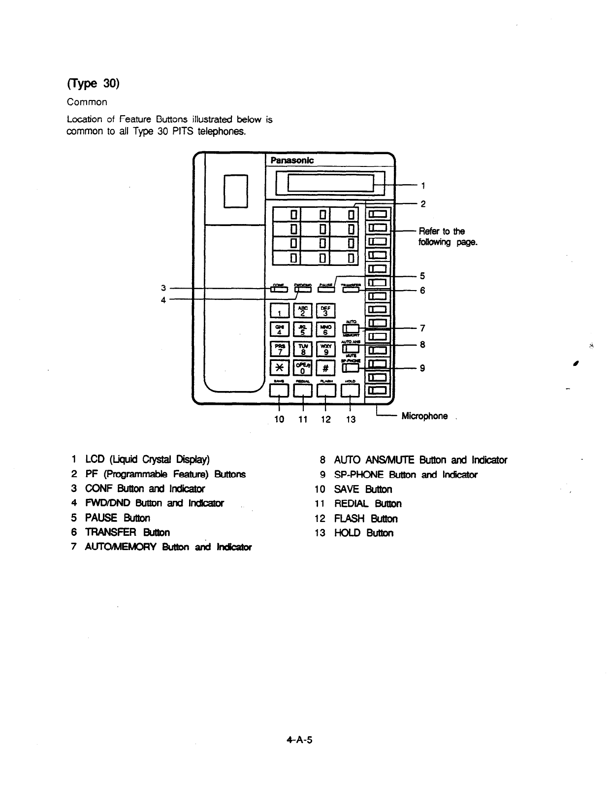
Common
Location of Feature Buttons illustrated below is
common to all Type 30 PITS telephones.
3-.
1 LCD (Liquid Crystal Display)
2 PF (ProgrammabIe Feature) Butms
3 CONFButtonandhdicaw
4 WD/DNDBut!onandI~
5 PAUSE Button
6TRANSFERButton
7 AlJTOmAEhdORY Button a& Indkaor
Microphone
the
page-
8 AUTO ANSMUTE Button and Indiior
9 SP-PHONE Button and lndicabr
1osAvEButton
11
REDIAL Button
12 FLASHButton
13 HOLDButton
4-A-5
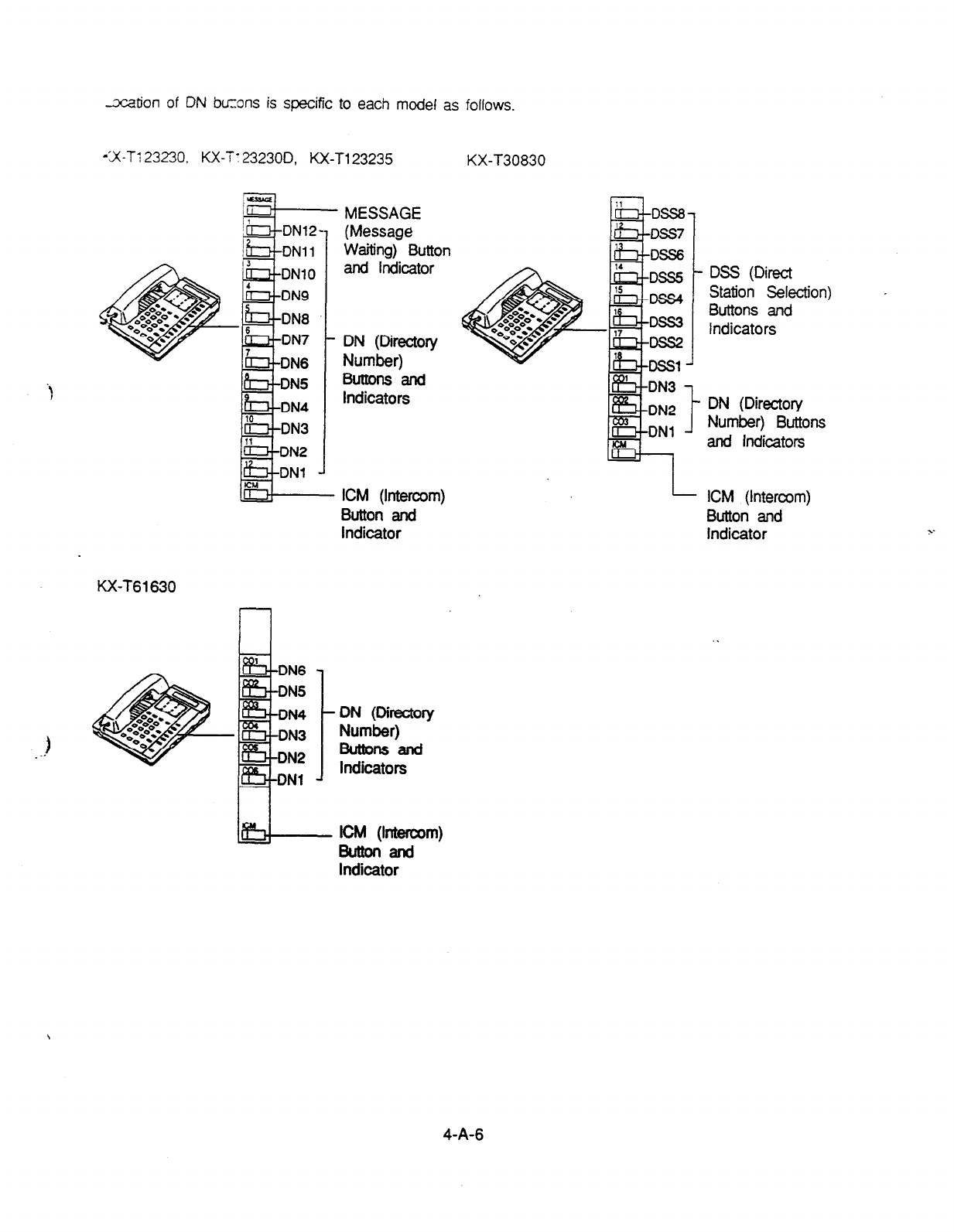
-xation of DN buzons is specific to each model as follows.
-‘X-T1 23230, KX-T: 232300, KX-Tl23235 KX-130830
-
and Indicator
. DN (Directory
Number)
Buttons and
Indicators
MESSAGE
I -- (Message
Waiting) Button
ICM (Intercom) I- ICM (Intercom)
Button and Button and
Indicator Indicator
KX-T61630
DN6
DN5
DN4
ON (Dlrectow
J
Number) a
Buttonsand
Indicators
iLDNI J
DSS (Direct
Station Selection)
Buttons and
Indicators
DN (Directory
Number) Buttons
and indicators
Indicator
4-A-6
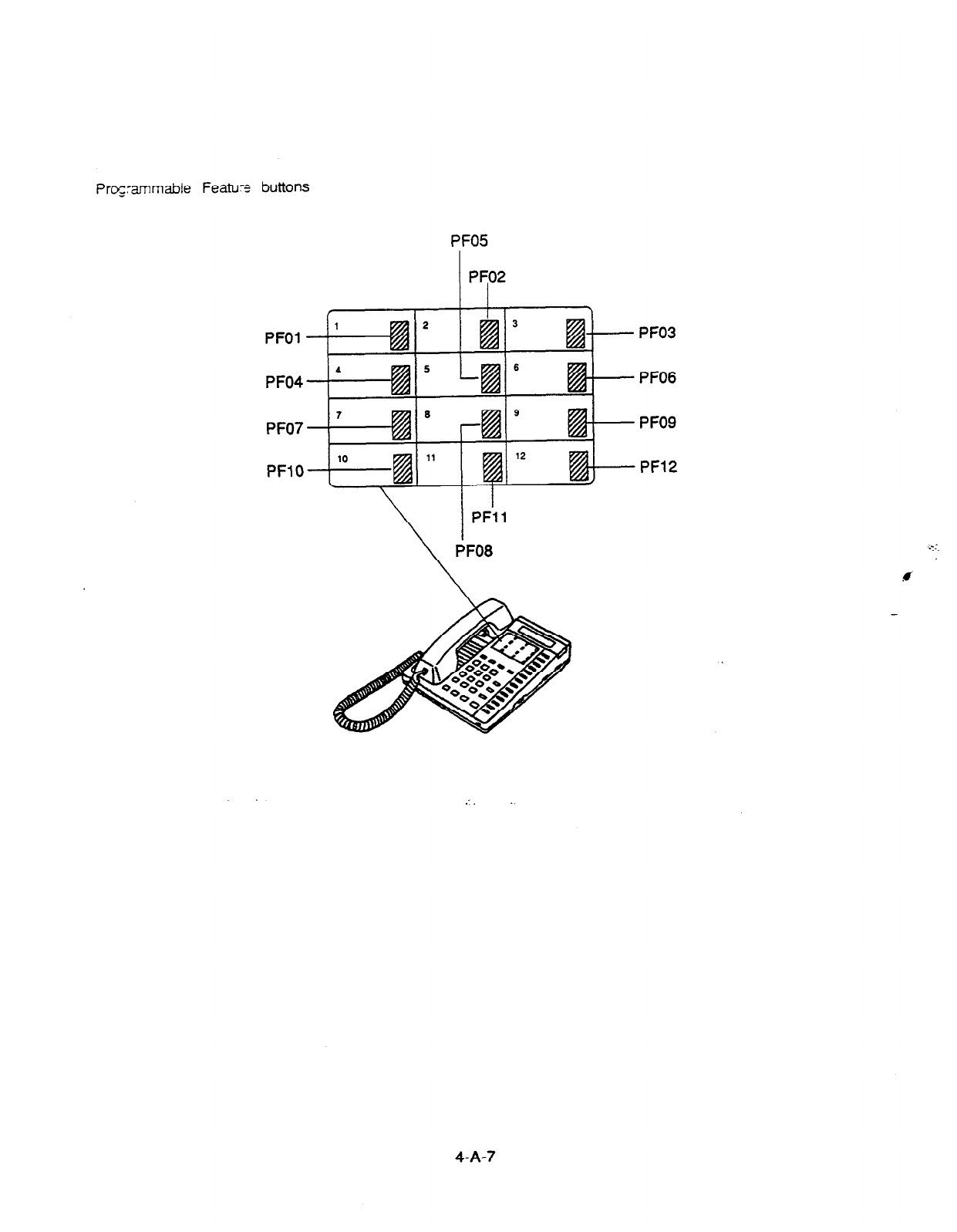
Proprnmable Featux buttons
PF05
PFOl
PF04
PF07
PFlO
PF03
PFO6
PFO9
PF12
I
\
PFi 1
PFO8
4-A-7
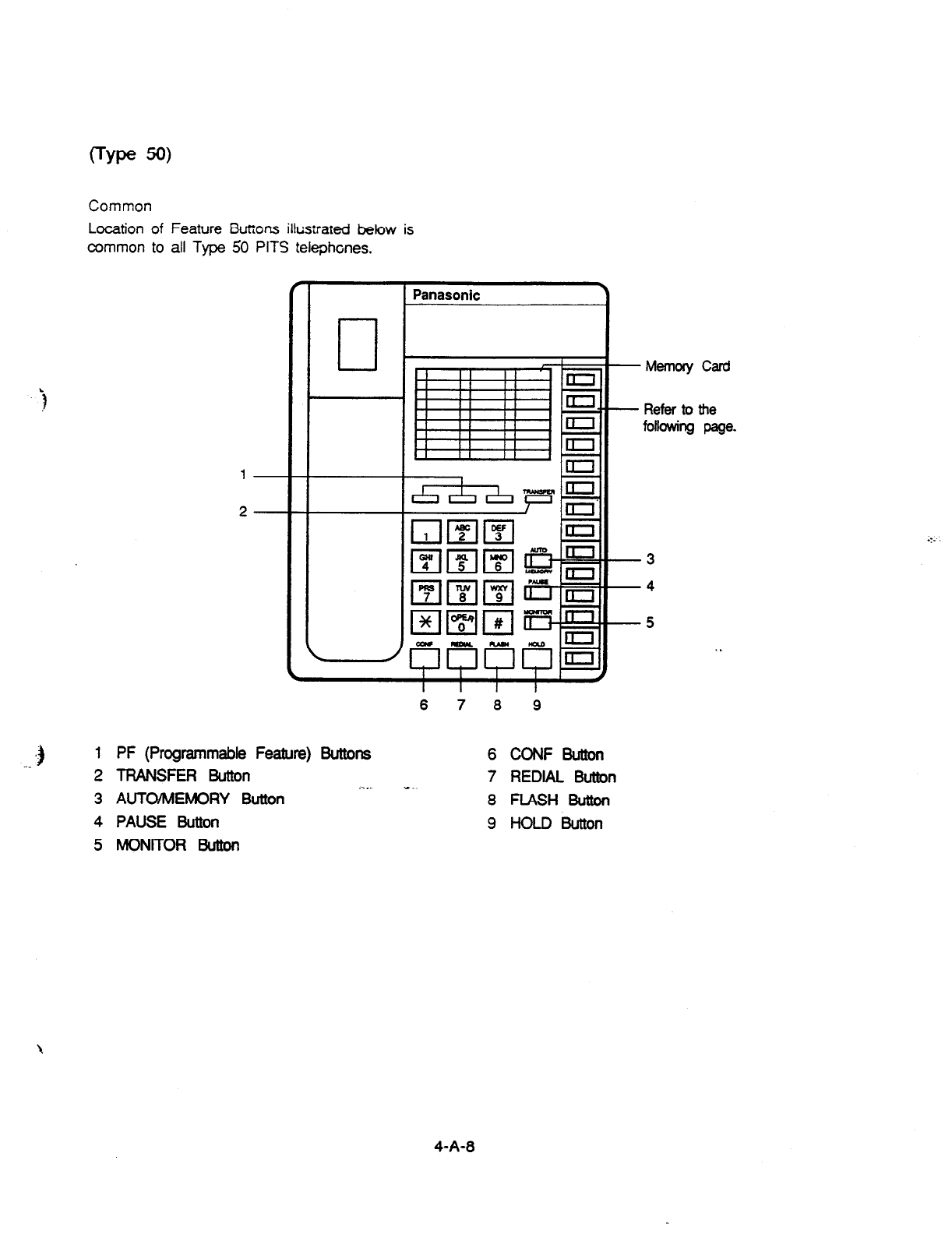
i
Common
Location of Feature Bucons kstrared below is
common to all Type 50 PITS telephones.
0
Panasonic
.)
1 PF (Programmable Feature) Buttons
2 TRANSFER Button . .._ --
3 AUTO/MEMORY Button
4 PAUSE Button
5 MONITOR Button
I I I I
6 7 a 9
6 CONFButton
7 REDIAL Button
8 FLASH Button
9 HOLD Button
Memory Card
Refer to the
following page.
.:.
4-A-8
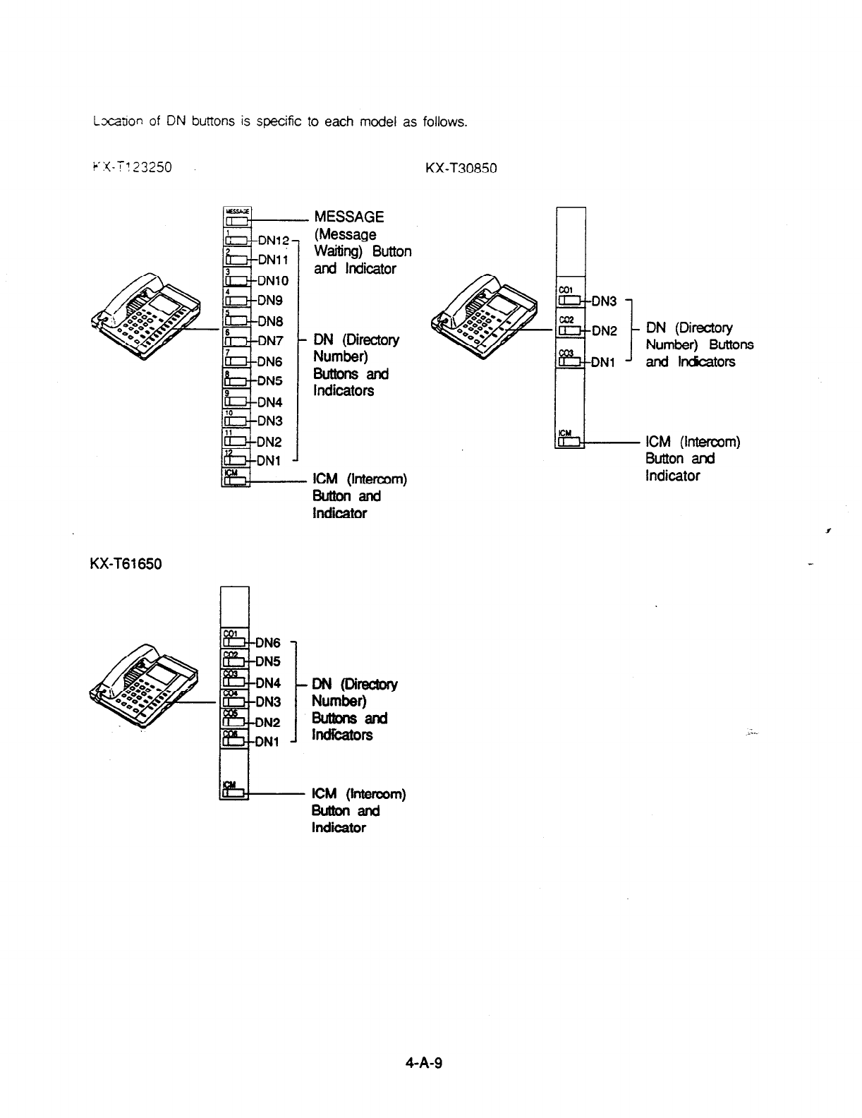
Lxx~on of DN buttons is specific to each model as follows.
k-x-T? 33250
I*
KX-T30850
DN (Directory
Number) Buttons
and ln&atoE
Buttonand
Indicator
ICM (Intercom)
Button and
Indicator
I
KX-T61650
~@i=w
Number)
Butkmsand
IMibtOrS
ICM (htercom)
Buttonand
Indicator
4-A-9

. .
f
Programmable Feawe x%ns
4-A- 10

(7000 Series)
Preliminary Remarks:
Some x. -tons orovided for the KX-T7020, KX-T7030, KX-17050 and KX-T7130 are
caikd 2, names sther ?han the ones described in this manual.
If yol: ZSP these Todels, please press the equivalent buttons shown below instead of
the buttons described in this manual.
1 Description here ) Equivalent button 1
KX-T7020
3
4
Panasonic 7
‘0
HYBRID SYSTEM
-2
1; ’
-7
-a
-9
-10” .; .;:
-11
1 PF (Programmable Feature) Buttons
2 DN (Directory Number) Buttons and
Indicators
3 INTERCOM Button and Indicator
4 CONF Button and Indicator
5 FWD/DND Button and Indicator
6 MESSAGE Button and Indicator
7 TRANSFER Button
8 PAUSE Button
9 AUTO DIAL/STORE Button and Indicator
10 AUTO ANSWER/MUTE Button and
Indicator
11 SP-PHONE Button and Indicator
12 REDIAL Button
13
FLASH Button
14
HOLD Button
4-A-l 1
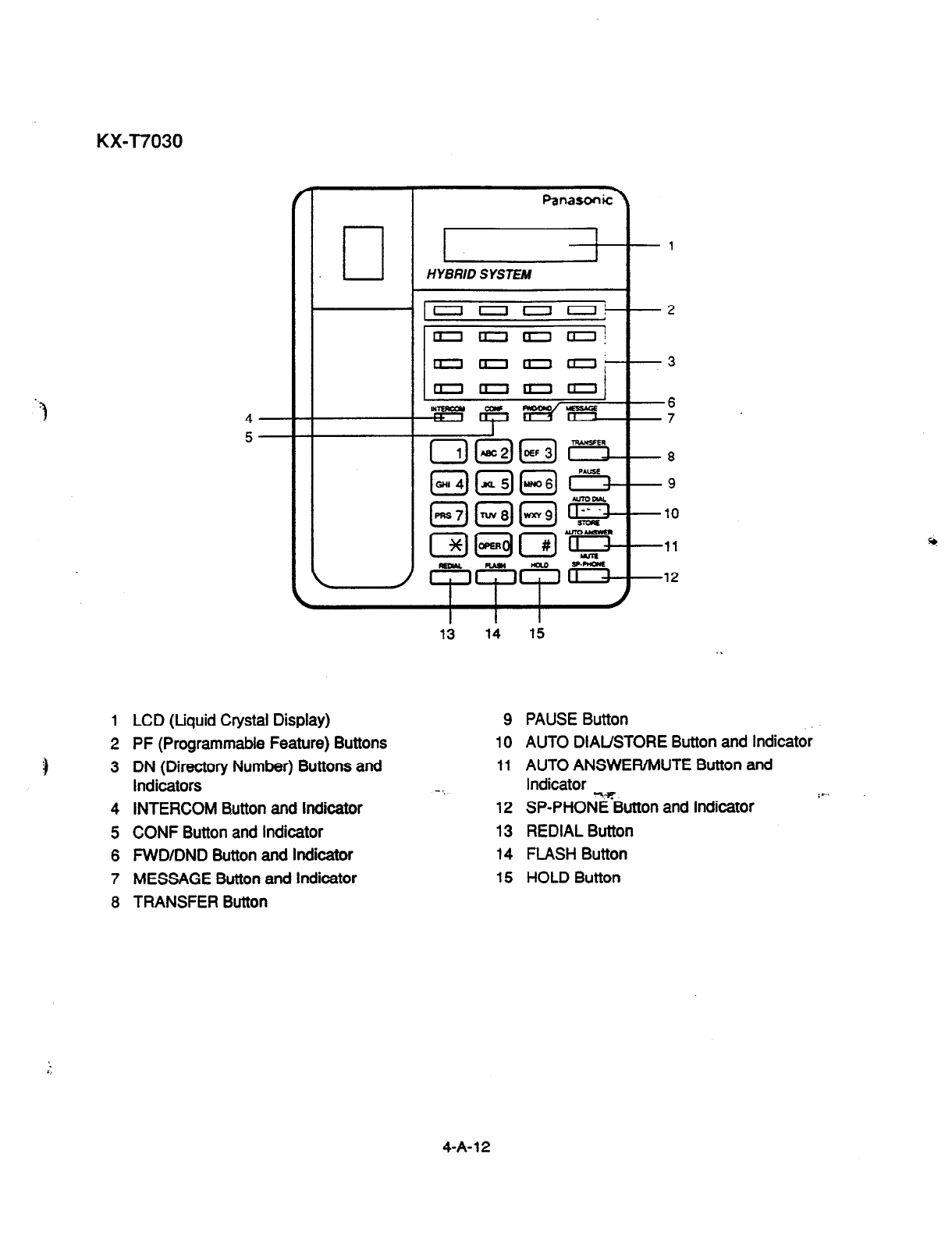
KX-T7030
1
LCD (Liquid Crystal Display)
2 PF (Programmable Feature) Buttons
3 DN (Directory Number) Buttons and
Indicators
4 INTERCOM Button and indicator
5. CONF Button and indicator
6 FWD/DND Button and Indicator
7 MESSAGE Button and Indicator
8 TRANSFER Button
v1
HYBRID SYSTEM
4
5
13 14
9
10
11
- . .
12
13
14
15
PAUSE Button
AUTO DIAL/STORE Button and Indicator
AUTO ANSWER/MUTE Button and
Indicator
SP-PHOsButton and Indicator ‘*’
REDIAL Button
FLASH Button
HOLD Button
4-A- 12
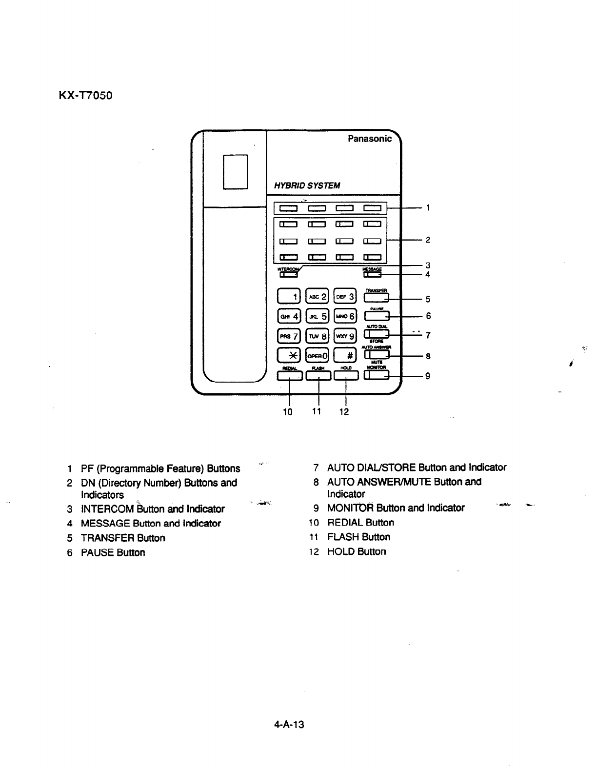
KX-T7050
r
I I
Panasonic.
0
HYBRID SYSTEM
1 PF (Programmable Feature) Buttons
2 DN (Directory Number) Buttons and
indicators k
3 INTERCOM Button and Indicator
4 MESSAGE Button and indicator
5 TRANSFER Button
6 PAUSE Button
...
_ .4!
-1
-2
-3
-4
-5
-6
"7
-8
-9
7 AUTO DIAL/STORE Button and indicator
8 AUTO ANSWER/MUTE Button and
indicator
9 MONImd Button and Indicator
10 REDIAL Button
11
FLASH Button
12 HOLD Button
4-A-l 3
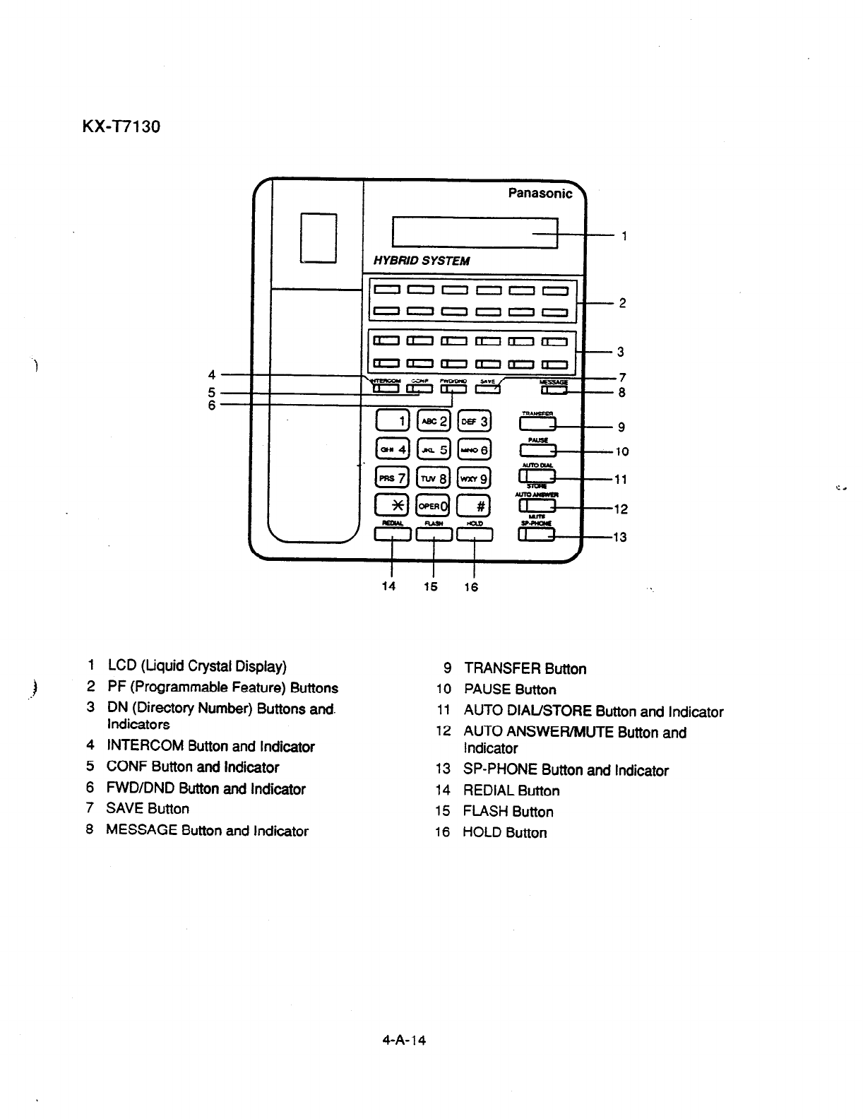
KX-l7130
HYBRID SYSTEM
‘000000
000000
nooaII0
1
LCD (Liquid Crystal Display)
2 PF (Programmable Feature) Buttons
3 DN (Directory Number) Buttons and.
Indicators
4
INTERCOM Button and Indicator
5 CONF Button and Indicator
6 FWD/DND Button and Indicator
7 SAVE Button
8 MESSAGE Button and Indicator
14 15 16 .
9 TRANSFER Button
10 PAUSE Button
11
AUTO DIAL/STORE Button and Indicator
12 AUTO ANSWER/MUTE Button and
Indicator
13 SP-PHONE Button and Indicator
14
REDIAL Button
15 FLASH Button
16 HOLD Button
4-A-l 4
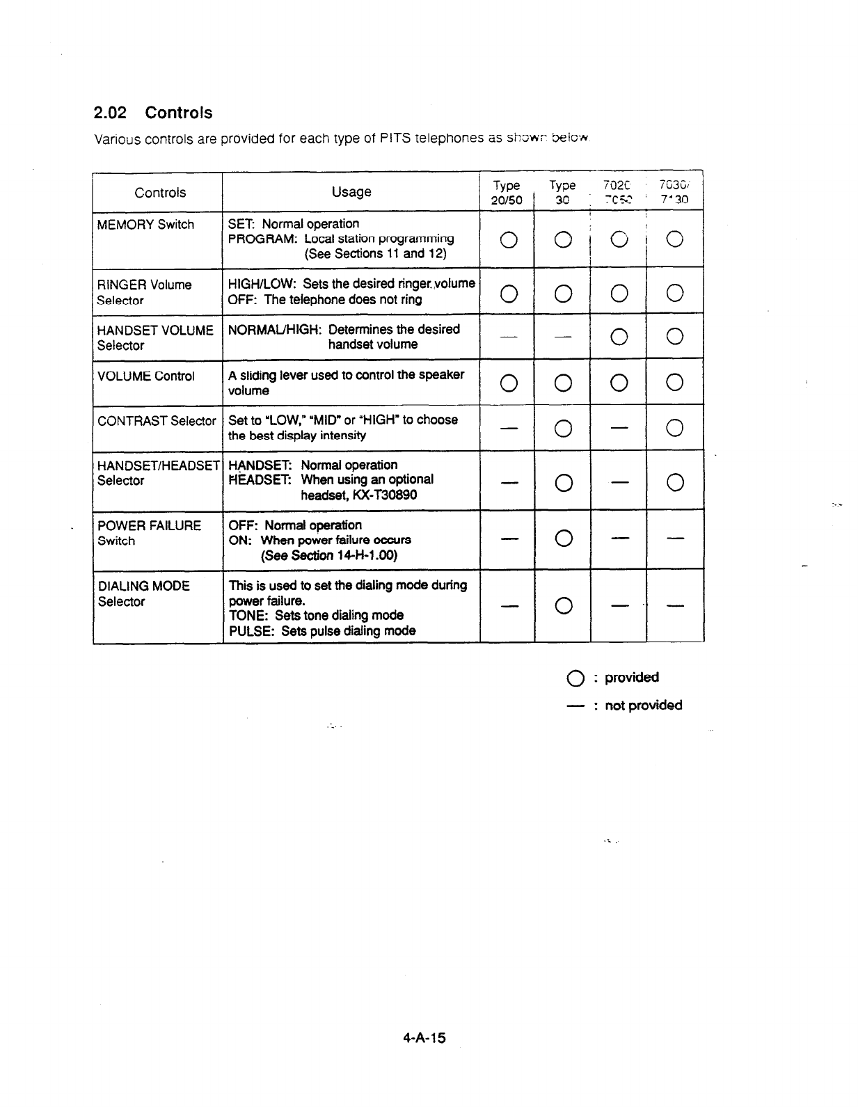
2.02 Controls
Various controls are provided for each type of PITS telephones as sh3wr Seiow
Controls Usage Type Type 702c 7C3G
20/50 30 ] x5: 7’ 30
MEMORY Switch SET Normal operation
PROGRAM: Local station programming
(See Sections 11 and 12) 0 opio
RINGER Volume HIGH/LOW: Sets the desired ringervolume
Selector OFF: The telephone does not ring 0 0 0 0
HANDSET VOLUME NORMAUHIGH: Determines the desired - -
Selector handset volume 0 0
VOLUME Control A sliding lever used to control the speaker
volume 0 0 0 0
CONTRAST Selector Set to “LOW,” “MID” or ‘HIGH” to choose -
the best display intensity 0 - 0
HANDSET/HEADSET HANDSET: Normal operation
Selector HEADSET: When using an optional -
headset, KX-T30890 0 - 0
POWER FAILURE OFF: Normal operation
Switch ON: When power failure occurs - 0 - -
(See
Section 14-H-l 40)
DIALING MODE This is used to set the dialing mode during
Selector power failure. -
TONE: Sets tone dialing mode 0 -‘)-
PULSE: Sets pulse dialing mode
0 : provided
- : not provided
:-‘
4-A-l 5
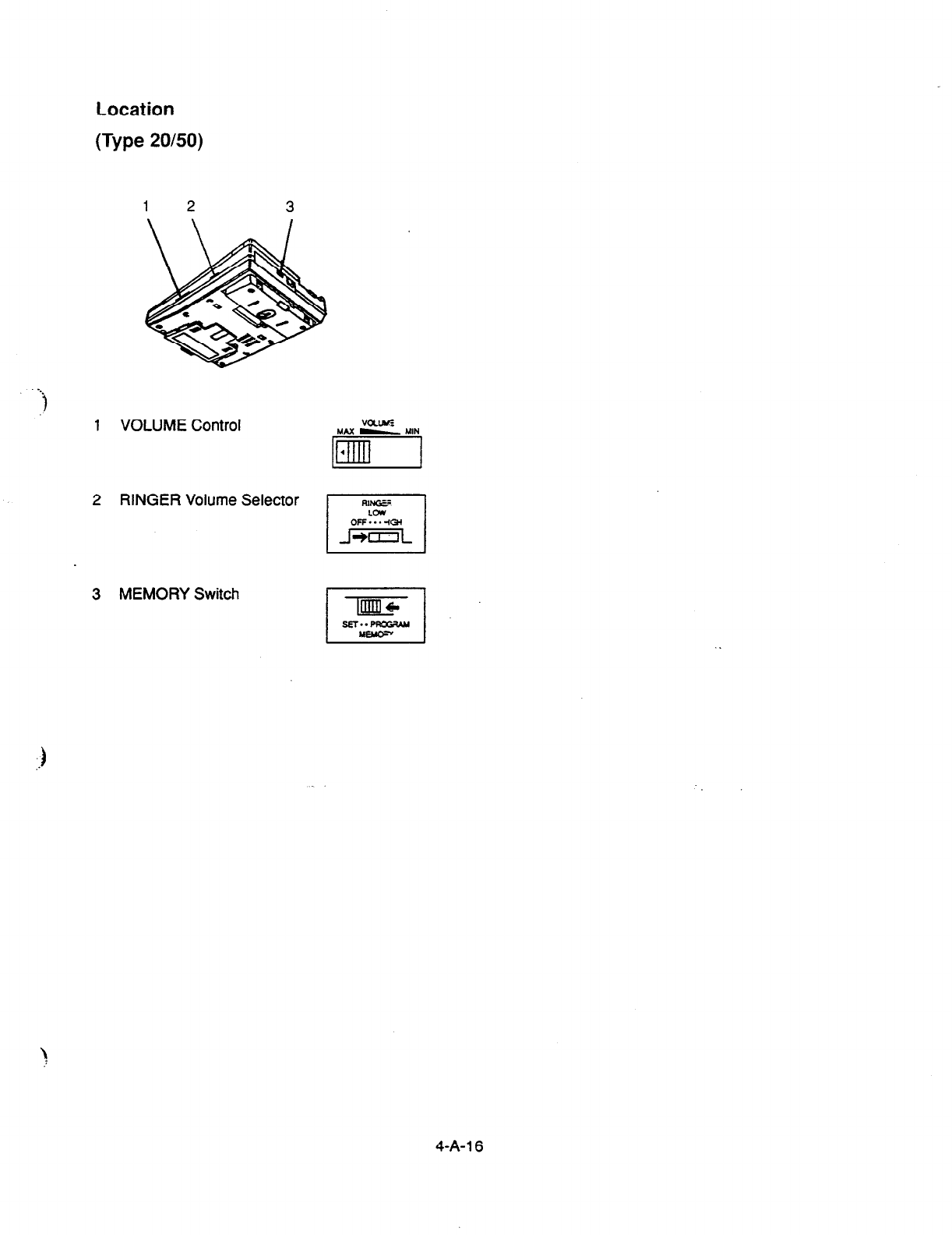
Location
(Type 20/50)
1 VOLUME Control
2 RINGER Volume Selector
3 MEMORY Switch
.sEl..PRo3Ak4
4-A- 16
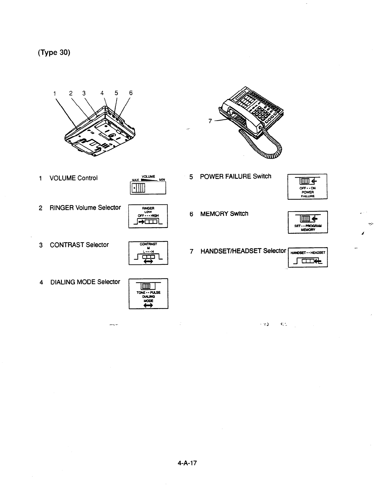
(Type
30)
123 456
7
.,.
1 VOLUME Control
2 RINGER Volume Selector
3 CONTRAST Selector
4 DIALING MODE Selector
vauts
MAX - YIN
5 POWER FAILURE Switch
6 MEMORY Switch
7 HANDSET/HEADSET Selector
-lml-
El
TUUE..FlLSE
is
4-A-l 7
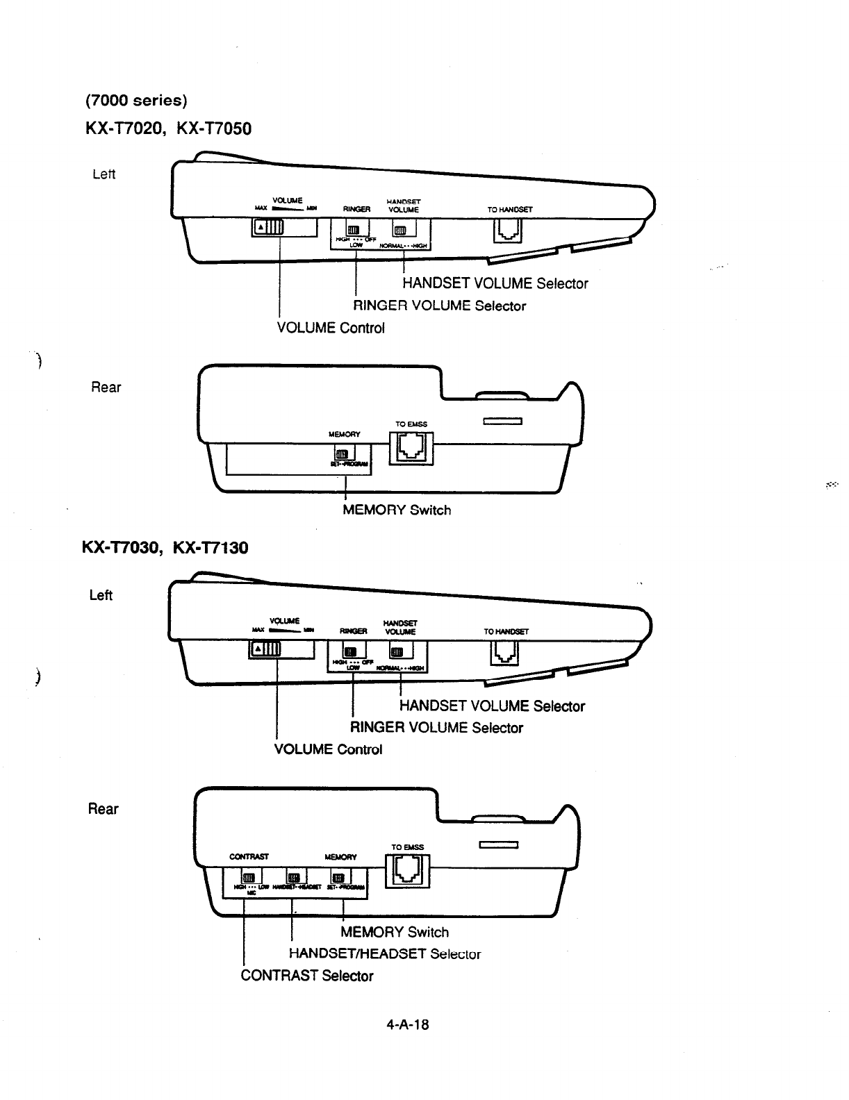
(7000
series)
KX-T7020, KX-T7050
Left
HANDSET VOLUME Selector
RINGER VOLUME Selector
VOLUME Control
)
Rear
MEMORY Switch
KXJ7030, KX-T7130
Left
Rear
I
HANDSET VOLUME Selector
RINGER VOLUME Selector
VOLUME Control
MEMORY Switch
HANDSET/HEADSET Selector
CONTRAST Selector
4-A-l
a
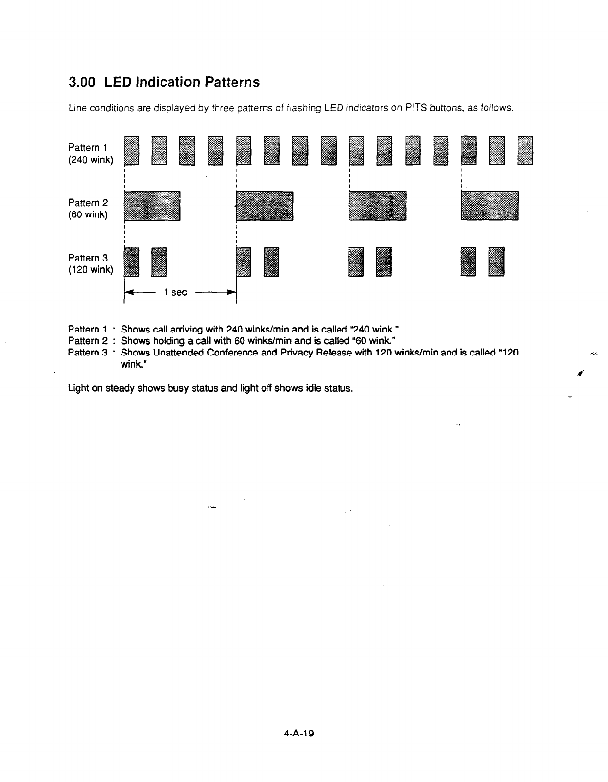
3.00 LED Indication Patterns
Line conditions are displayed by three patterns of flashing LED indicators on PITS buttons, as follows.
I I
I I I
0 I
Pattern 2
(60 wink)
I
Pattern 3
(120 wink)
Pattern 1 : Shows call arriving with 240 winks/min and is called 240 wink.”
Pattern 2 : Shows holding a call with 60 winks/min and is called “60 wink.”
Pattern 3 : Shows Unattended Conference and Privacy Release with 120 winks/min and is called “120
wink.”
Light on steady shows busy status and light off shows idle status.
4-A-l 9

4.00 Display-LCD
4.01 Time and Date Display
Description
This is a function for a PITS provided with the
display to offer a display either of the present
time or of the date and the day of the week. It is
indicated on the display when the PITS is on-
hook and the SP-PHONE is off.
Two display modes are available: the time
display mode and the date display mode. For
instance, the displays for “January 1, Friday, 12:
00 a.m., 1999” in each mode are as follows:
$ In the time display mode:
1 Jan 1 12:00 AM 1
In the date display mode:
” Jan 1.1999 FRI
To alternate the modes, dial U*” while on-hook
and SP-PHONE off.
$
::
Setting the time and date is executed by “Date &
Time Set Up Screen” and “Change Date & Time.”
Extensions assigned to a “Class of Service” in
which Maintenance Capability is set to “Yes” can
also set the time and date. Refer to Section ll-
C-2.00 “Setting Date and Time.”
Programming
~1
“System-Class of Service (l/2)., 94-4~01 10-i-7.00
PITS System Programming Reference
Setting Date
and
Time
11-c-2.00
Operation
Changing the time display mode to the dare
display mode
Be sure the telephone set is on-hook and the SP-
PHONE is off.
In1
1. Dial “*.n
l
The message on the display of
PITS changes to the daie
display mode.
Changing the date display mode to the time
display mode.
•l
1.
Dial ‘*.”
*
l
The message on the display
changes to the time display
mode.
Conditions
None
\
4-A-20
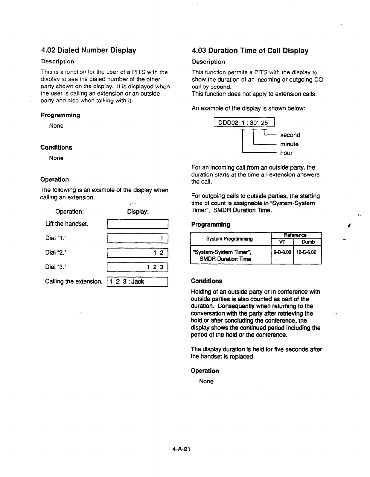
This is a function for the user of
a PITS
with the
display to see the dialed
number of the other
party shown on the display. It is displayed when
the user is
calling an extension or an outside
party
and also when talking with it.
4.02 Dialed Number
Display
4.03 Duration Time of
Call Display
Description Description
This function permits a PITS with the display to
show the
duration of an incoming or outgoing CO
call by second.
This function does not apply to extension calls.
Programming
None
Conditions
None
Operation
The following is an example of the display when
calling an extension. . .
Operation: Display:
Lift the handset. I
Dial “1 .n I 1 I
Dial “2.”
Dial “3.”
12
I 1231
Callina the extension. 1 1 2 3 : Jack I
An example of the display is shown below:
1 DDD02 1:30’25 ]
lc second
minute
hour
For an incoming call from an outside party, the
duration starts at the time an extension answers
the call.
For outgoing calls to outside patties, the starting
time of count is assignable in “System-System
Timer”, SMDR Duration Time. .-..
Programming
System Programming Reference
VT
I
Dumb
‘System-System TmW.
SMDR Duration Time 9-D-3.00 1o-G6.00
.
Conditions
Holding of an outside party or in conference with
outside parties is also counted as part of the
duration. Consequently when returning to the
conversation with the party after retrieving the
hold or after concluding the conference, the
display shows the continued period including the
period of the hold or the conference.
The display duration is held for five seconds after
the handset is replaced.
Operation
None
4-A-21
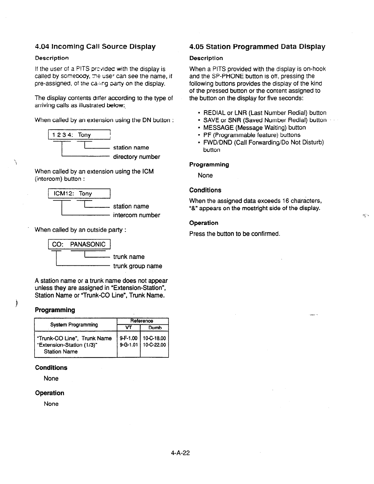
4.04 Incoming Call Source Display
Description
If the user of a PITS prc\/lded with the display is
called by somebody, :?e use7 can see the name, if
pre-assigned, of me ca:;tr.g oarty on the display.
The display contents defier according to the type of
arriving calls as illustrated below:.
When called by an extension using the DN button :
1 23 4: Tony i
:
l-l-
I
station name
directory number
When called by an extension using the ICM
(intercom) button :
KM1 2: Tony 1
?_15_ ~~~~nmuember
When called by an outside party :
1 CO: PANASONIC 1
-lLIEi ~~~~~~ name
A station name or a trunk name does not appear
unless they are assigned in ‘Extension-Station”,
Station Name or “Trunk-CO tine”, Trunk Name.
3
Programming
System Programming Reference
VT 1 Dumb
I
“Trunk-CO tine”, Trunk Name
‘Extension-Station (l/3)”
Station Name
4.05 Station
Programmed Data Display
Description
When a PITS provided with the display is on-hook
and the SP-PHONE button is off? pressing the
following buttons provides the display of the kind
of the pressed button or the content assigned to
the button on the display for five seconds:
REDIAL or LNR (Last Number Redial) button
SAVE or SNR (Saved Number Redial) button
MESSAGE (Message Waiting) button
PF (Programmable feature) buttons
FWD/DND (Call Forwarding/Do Not Disturb)
button
Programming
None
Conditions
When the assigned data exceeds 16 characters,
.&” appears on the mostright side of the display.
Operation
Press the button to be confirmed.
Conditions
None
Operation
None
4-A-22
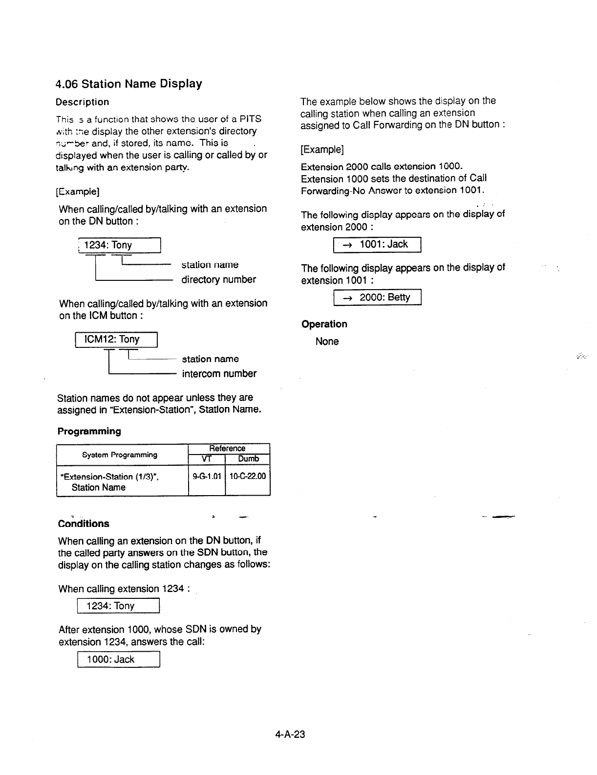
4.06 Station Name Display
Description
This s a func:ion that shows the user of a PITS
.Cth :ne display the other
extension’s directory
~7%’ and, if
stored, its name. This is .
displayed
when the user is calling or called by or
takng with an extension
party.
[Example]
When calling/called by/talking with an extension
on the DN button :
When calling/called by/talking with an extension
on the ICM button :
ICM12: Tony
-Lb Fzizzzlber
Station names do not appear unless they are
assigned in “Extension-Station”, Station Name.
Programming
Cohditions 2 -
When calling an extension on the DN button, if
the called party answers on the SDN button, the
display on the calling station changes as follows:
When calling extension 1234 :
1 1234: Tony
After extension 1000, whose SDN is owned by
extension 1234, answers the call:
[I
The example below shows the display on the
calling station when calling an extension
assigned
to
Call Forwarding on the DN button :
[Example]
Extension 2000 calls extension 1000.
Extension 1000 sets the destination of Call
Forwarding-No Answer to extension 1001.
The following display appears on the dis$ay of
extension 2000 :
] + 1001: Jack 1
The following display appears on the display of
extension 1001 :
1 + 2000: Betty 1
Operation
None
4-A-23

B. Feature Buttons
1.00 Fixed Feature Buttons
Description
Feature Buttons, like features, are either fixed or assrgnable.
Fixed Feature Buttons, (for example m ,) have specific :JCIIO~S permanently
associated with them.
The following table shows all Fixed Feature Buttons provided on the PITS telephone
by each type.
_’
Feature Button Type 20/30 I Type 50 7020/7030 I 7050 I 7130 I
‘t
SP-PHONE * 0 OS’ 0 0 “’
0
AUTO/MEMORY *
-------------------------
AUTO DIAUSTORE *
PAUSE * 0 0 0 0
0
$
I
REDIAL (LNR)
lololololol
I
SAVE (SNR) 1 0 None *2 I - None ‘2 I
None
“2 j
0
I
ICM *
-------------------------
INTERCOM *
AUTO ANSIMUTE *
-------------------------
AUTO ANSWER/MUTE *
I
HOLD
I
TRANSFER
lololololol
I
FWDIDND * j 0 1 Nonei3~T 0 None *3 171
I
CONF *
lololololol
FLASH *
lololololol
MESSAGE *
I 0 *4 I 0 *4 I 0 I 0 I 0 I
[Note]
In the above list, Feature Buttons marked * have an LED indicator.
33’ The MONITOR button is provided instead of the SP-PHONE button.
‘2 The SAVE button can be assigned to the PFl button.
*3 The FWD/DND button can be assigned to the PF 3 button.
4-B-i
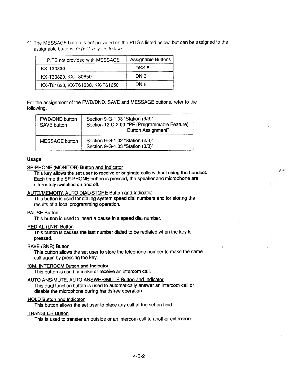
g4 The MESSAGE button is not provided on rhe PITS’s listed below, but can be assigned to the
assignable burl-tons respxrively. as !oilcws
I
PITS not providea with MESSAGE 1 Assignable Buttons 1
KX-T30830 DSS 8
KX-T30820, KX-T30850 DN3
I- __~
KX-T61620, KX-T61630, KX-T61650 DN6 I
For the assignment of the
FWD/DND: SAVE and MESSAGE buttons, refer to the
following.
FVVD/DND button Section 9-G-l .03 “Station (3/3)”
SAVE button Section 12-C-2.00 “PF (Programmable Feature)
Button Assignment”
MESSAGE button Section 9-G-l .02 “Station (U3)”
Section 9-G-l -03 “Station (313)”
Usage
SP-PHONE (MONITOR) Button and Indicator
This key allows the set user to receive or originate calls without using the handset.
Each time the SP-PHONE button is pressed, the speaker and microphone are
alternately switched on and off.
AUTO/MEMORY. AUTO DIAUSTORE Button and Indicator
This button is used for dialing system speed dial numbers and for storing the
results of a local programming operation.
PAUSE Button
This button is used to insert a pause in a speed dial number.
REDIAL (LNR) Button
This button is causes the last number dialed to be redialed when the key is
pressed.
SAVE (SNR) Button
This button allows the set user to store the telephone number to make the same
call again by pressing the key.
ICM, INTERCOM Button and Indicator
This button is used to make or receive an intercom call.
AUTO ANS/MUTE. AUTO ANSWER/MUTE Button and Indicator
This dual function button is used to automatically answer an intercom call or
disable the microphone during handsfree operation.
HOLD Button and Indicator
This button allows
the set
user to place any call at the set on hold.
TRANSFER Button
This is used to transfer an outside or an intercom call to another extension.
4-B-2

FWD/DND Button
This button can be used for setting or canceling the Call Forwarding or Do Not
Disturb feature.
CONF Button and Indicator
Allows the user to perform a three party conference.
FLASH Button
This button causes a flash signal to be sent’to the Central Office.
MFSSAGF mton and Indicabx
This button can be used for Message Waiting feature.
4-B-3
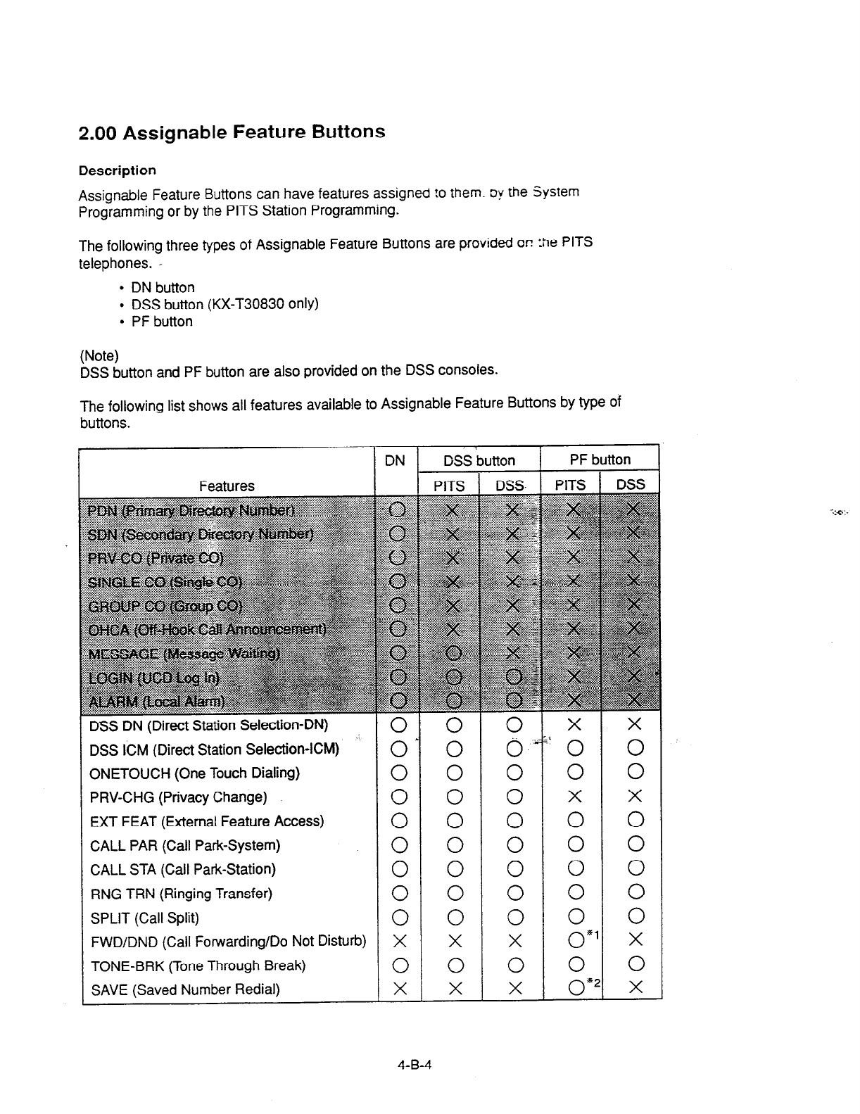
2.00 Assignable Feature Buttons
Description
Assignable Feature Buttons can have features assigned !o them. oy the System
Programming or by the PITS Station Programming.
The following three types of Assignable Feature Buttons are provided on :tie PITS
telephones. -
l
DN button
l
DSS button (KX-T30830 only)
l
PF button
(Note)
DSS button and PF button are also provided on the DSS consoles.
The following list shows all features available to Assignable Feature Buttons by type of
buttons.
DSS DN (Direct Station Selection-DN)
DSS ICM (Direct Station Selection-ICM) o* 0 0 &’ 0 0
ONETOUCH
(One Touch Dialing) 0 0 0 0 0
PRV-CHG (Privacy Change) 0 0 0 x EXT FEAT (External Feature Access) 0 0 0 0 E
CALL
PAR (Call Park-System) 0 0 0 0 0
CALL
STA (Call Park-Station) 0 0 0 0 0
RNG TRN (Ringing Transfer) 0 0 0 0 0
SPLIT (Call Split) 0 0 0 0 0
FWD/DND
(Call Forwarding/Do Not Disturb) X x x OS’ x
TONE-BRK
(Tone Through Break) 0 0 0 0 0
SAVE
(Saved Number Redial) x x x OS2 x
4-B-4
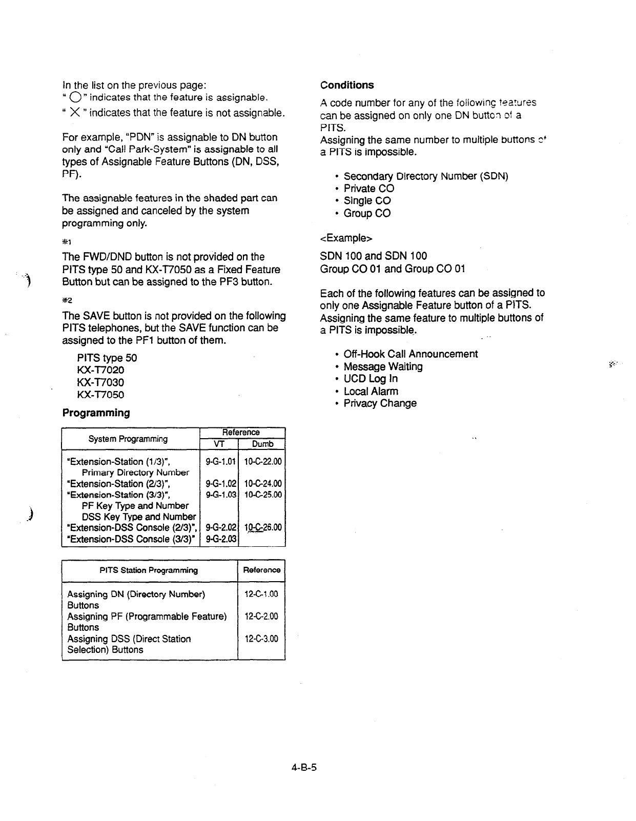
In the list on the previous page:
u On indicates that
the
feature is assignable.
I‘
X
” indicates that
the
feature is not assignable.
For example, “PDN” is assignable to DN button
only and “Call Park-System” is assignable to all
types of Assignable Feature Buttons (DN, DSS,
PF).
The assignable features in the shaded part can
be assigned and canceled by the system
programming only.
l
Secondary Directory Number (SDN)
l
Private CO
l
Single CO
l
Group CO
%l <Example>
The FWD/DND button is not provided on the
PITS type 50 and KX-T7050 as a Fixed Feature
Button but can be assigned to the PF3 button.
352
SDN 100 and SDN 100
Group CO 01 and Group CO 01
The SAVE button is not provided on the following
PITS telephones, but the SAVE function can be
assigned to the PFl button of them.
PITS type 50
KX-l7020
KX-T7030
KX-T7050
Each of the following features can be assigned to
only one Assignable Feature button of a PITS.
Assigning the same feature to multiple buttons of
a PITS is impossible.
Programming
l
Off-Hook Call Announcement
l
Message Waiting
l
UCD Log In
l
Local Alarm
l
Privacy Change
System Programming Reference
VT 1 Dumb
“Extension-Station
(l/3)“,
Primary Directory Number
“Extension-Station (2/3)“,
“Extension-Station (3/3)“,
PF Key Type and
Number
DSS Key Type
and
Number
‘Extension-DSS Console
(2/3)“,
‘Extension-DSS Console (3/3)”
9-G-l .Ol 10-C-22.00
9-G-l .02 1 OC24.00
9-G-l .03 10-G25.00
9-G-2.02 lgQ6.00
9-G-2.03
PITS Station Programming Reference
Assigning DN (Directory Number)
Buttons
Assigning PF (Programmable Feature)
Buttons
Assigning DSS
(Direct Station
Selection)
Buttons
12Cl .oo
12-C-2.00
12-C-3.00
Conditions
A code number for any of the iollowing
foarxes
can be assigned on only one DN buttcn
of a
PITS.
Assigning the same number to multiple buttons o+
a PITS is impossible.
4-B-5
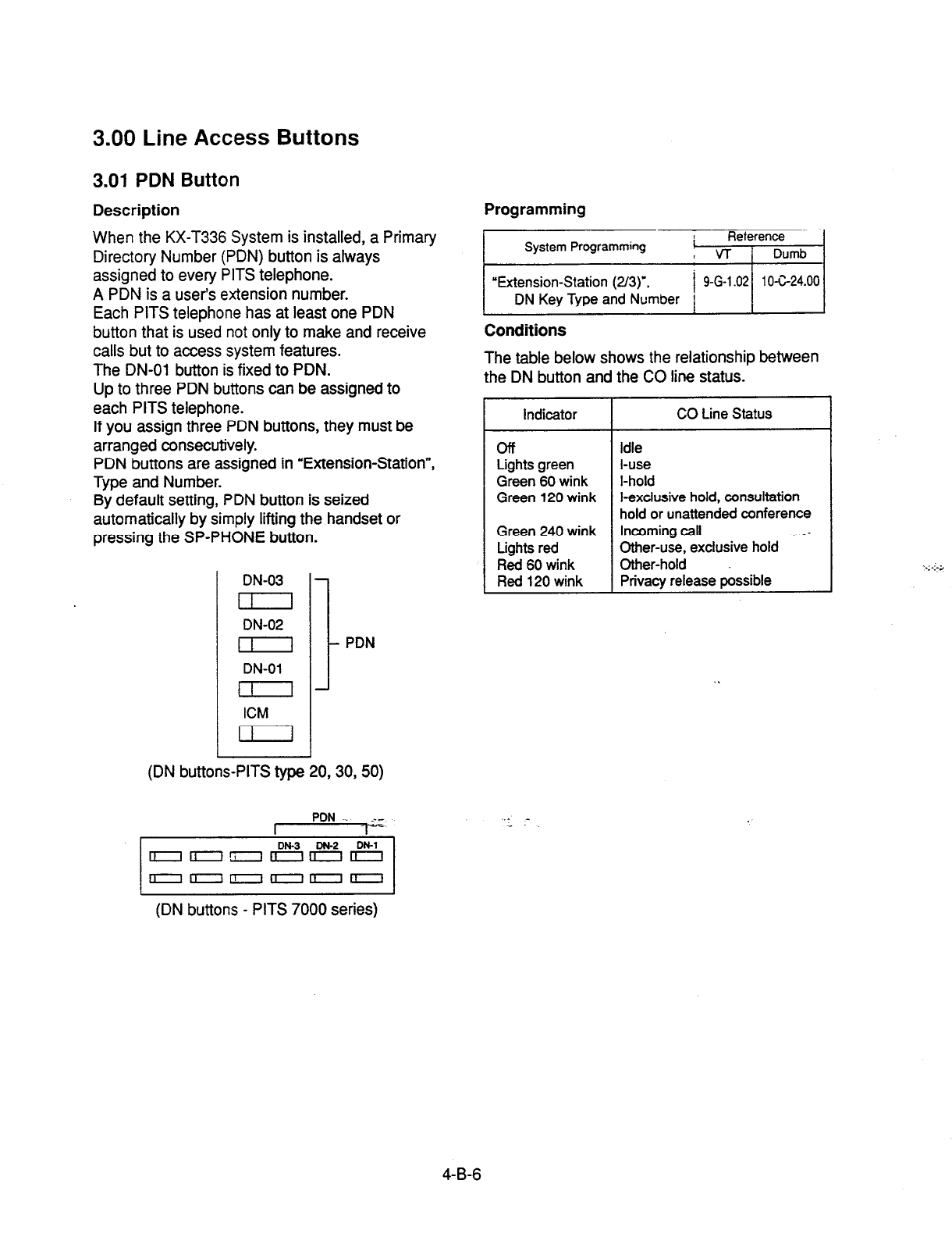
3.00 Line Access Buttons
3.01 PDN Button
Description
When the KX-T336 System is installed, a Primary
Directory Number (PDN) button is always
assigned to every PITS telephone.
A PDN is a user’s extension number.
Each PITS telephone has at least one PDN
button that is used not only to make and receive
calls but to access system features.
The DN-01 button is fixed to PDN.
Up to three PDN buttons can be assigned to
each PITS telephone.
If you assign three PDN buttons, they must be
arranged consecutively.
PDN buttons are assigned in “Extension-Station”,
Type and Number.
By default setting, PDN button is seized
automatically by simply lifting the handset or
pressing the SP-PHONE button.
DN-03
I I I
DN-02
I I
DN-01
1
ICM
11 I
I
PDN
(DN buttons-PITS type 20,30,50)
PDN-. .--
-1
(DN buttons - PITS 7000 series)
Programming
System Programming Reterence
i vT i Dumb
I I
“Extension-Station (2/3)‘. 9 G
1 02 10-C-24.00
DN
Key Type and
Number I --. 1
1
Conditions
The table below shows the relationship between
the DN button and the CO line status.
Indicator CO Line Status
off Idle
Lights green l-use
Green 60 wink l-hold
Green 120 wink l-exclusive hold, consultation
hold or unattended conference
Green 240 wink Incoming call
Lights red Other-use, exdusive hold - -
Red 60 wink Other-hold
Red 120 wink Privacy release possible
-
4-B-6
3.02 SDN Button
Description
Allows an extension user to assign PDN buttons
of other extensions on DN buttons of PITS. This
assigned DN buttons are called SDN buttons.
The assignment of SDN buttons make it easier to
transfer or answer other
extensions.
SDN buttons are assigned in “Extension-Station”,
Type and Number.
3.03 ICM Button
Description
Allows an extension user to make/receive an
intercom call within an ICM (Intercom) group.
Programming
Conditions
The table below shows the relationship betieen
the DN button and
the CO line status.
. 1 Indicator
I
CO Line Status I
Off
Lights green
Green
60
wink
Green
120
wink
Red 240 wink
idle
l-use
I-hold
l-exclusive hold, consultation
hold or unattended conference
Other-use, exclusive hold
Other-hold
Privacy release possible
Incoming call
3
Preferential order of SDN indicators is as follows:
1. l-use, hold, exclusive hold, consultation
hold, unattended
conference : Lights green,
Green
60 wink, Green 120 wink
2. Incoming call : Red 240 wink
3. Other-hold : Red 60 wink
4. Privacy Release : Red 120 wink
5. Busy : Lights red
6. Idle : Off
Programming
System Programming Reference
VT
I
Dumb
“Extension-Station (l/3)“,
Intercom Number
Conditions
The table below shows the relationship between
the indicator and the intercom status.
I
Indicator I Intercom Status I
off I
Idle
tights green l-use, Off-Hook Call Announcement
(OHCA)
Green
240 wink Incoming call
4-B-7
3.04 PC0 Button
Description Conditions
It is possible to connect a CO line as if it were
connected directly to a DN button on a PITS.
This operation
is
called Private CO.
ft is then no longer possible to place outgoing
calls from other extensions using this CO line.
Also, an incoming call from the CO line will arrive
only at this PITS.
A Private CO button lights up red at the times
below.
1) When the Private CO line is not In Service.
2) When the Private CO line has been set to
Busy-Out.
3) When access using the Trunk Verify
function is made by the Attendant Console.
To program a Private CO line, set “Group-Trunk
Group”, Type to PVL and program the CO line to
the Private trunk group in “Trunk-CO Line”, Trunk
Group.
Also, program the DN button on the PITS to
PRV-CO using “Extension-Station (2/3)“, Type
and assign the physical number of the Private
CO line under Number.
Programming
System Programming Reference
VT
I
Dumb
“Group-Trunk Group (l/Z)“,
Type
9-E-l .Ol 10-C-14.00
“Trunk-CO Line”, Trunk Group 9-F-l .OO 1 O-C-1 8.00
“Extension-Station (2/3)“, 9-G-l .02 1 O-C-24.00
Tvoe and Number
A call held on a Private CO button can not be
retrieved by other extensions, however, an
incoming call to a Private CO button can be
transferred.
When an incoming call arrives, ringing occurs
instantly. Delayed ringing is not available.
4-B-8
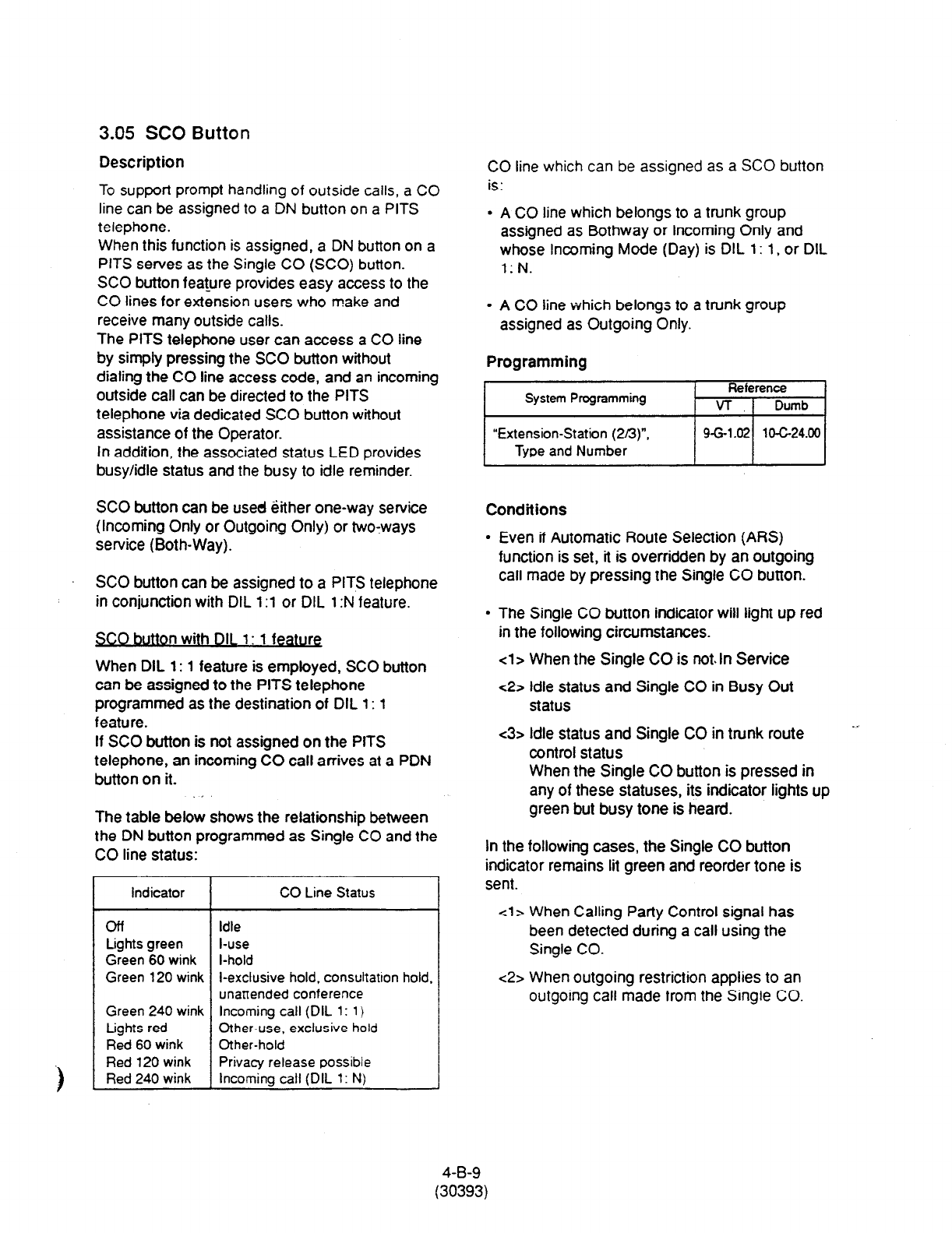
3.05 SC0 Button
Description
To support prompt handling of outside calls, a CO
line can be assigned to a DN button on a PITS
telephone.
When this function is assigned, a DN button on a
PITS serves as the Single CO (SCO) button.
SC0 button feat_ure provides easy access to the
CO lines for extension users who make and
receive many outside calls.
The PITS telephone user can access a CO iine
by simply pressing the SC0 button without
dialing the CO line access code, and an incoming
outside call can be directed to the PITS
telephone via dedicated SC0 button without
assistance of the Operator.
In addition, the associated status LED provides
busy/idle status and the busy to idle reminder.
SC0 button can be used Qither one-way service
(Incoming Only or Outgoing Only) or two-ways
service (Both-Way).
SC0 button can be assigned to a PITS telephone
in conjunction with DIL 1:l or DIL 1 :N feature.
idle
I-use
Green 60 wink I-hold
Green 120 wink I-exclusive hold, consultation hold.
unattended conference
Green 240 wink Incoming call (DIL 1:
1)
Lights red Other-use, exclusive hold
Red 60 wink Other-hold
Red 120 wink Privacy release possible
Incoming call (DIL 1: N)
1 Red 240 wink
SC0 button with DIL
1: 1
feature
When DIL 1: 1 feature is employed, SC0 button
can be assigned to the PITS telephone
programmed as the destination of DIL
1: 1
feature.
If SC0 button is not assigned on the PITS
telephone, an incoming CO call arrives at a PDN
button on it. j
The table below shows the relationship between
the DN button programmed as Single CO and the
CO line status:
CO Line Status
CO line which can be assigned as a SC0 button
is:
A CO line which belongs to a trunk group
assigned as Bothway or Incoming Only and
whose Incoming Mode (Day) is DIL 1: 1, or DIL
l:N.
A CO iine which belongs to a trunk group
assigned as Outgoing Only.
Programming
hi
Conditions
Even if Automatic Route Selection (ARS)
function is set, it is overridden by an outgoing
call made by pressing the Single CO button.
The Single CO button indicator will light up red
in the following circumstances.
cl
> When the Single CO is not. In Service
c2> idle status and Single CO in Busy Out
status
<3> idle status and Single CO in trunk route
control status
When the Single CO button is pressed in
any of these statuses, its indicator lights up
green but busy tone is heard.
In the following cases, the Single CO button
indicator remains lit green and reorder tone is
sent.
cl> When Calling Patty Control signal has
been detected during a call using the
Single CO.
c2> When outgoing restriction applies to an
outgoing call made from the Single CO.
4-B-9
(30393)
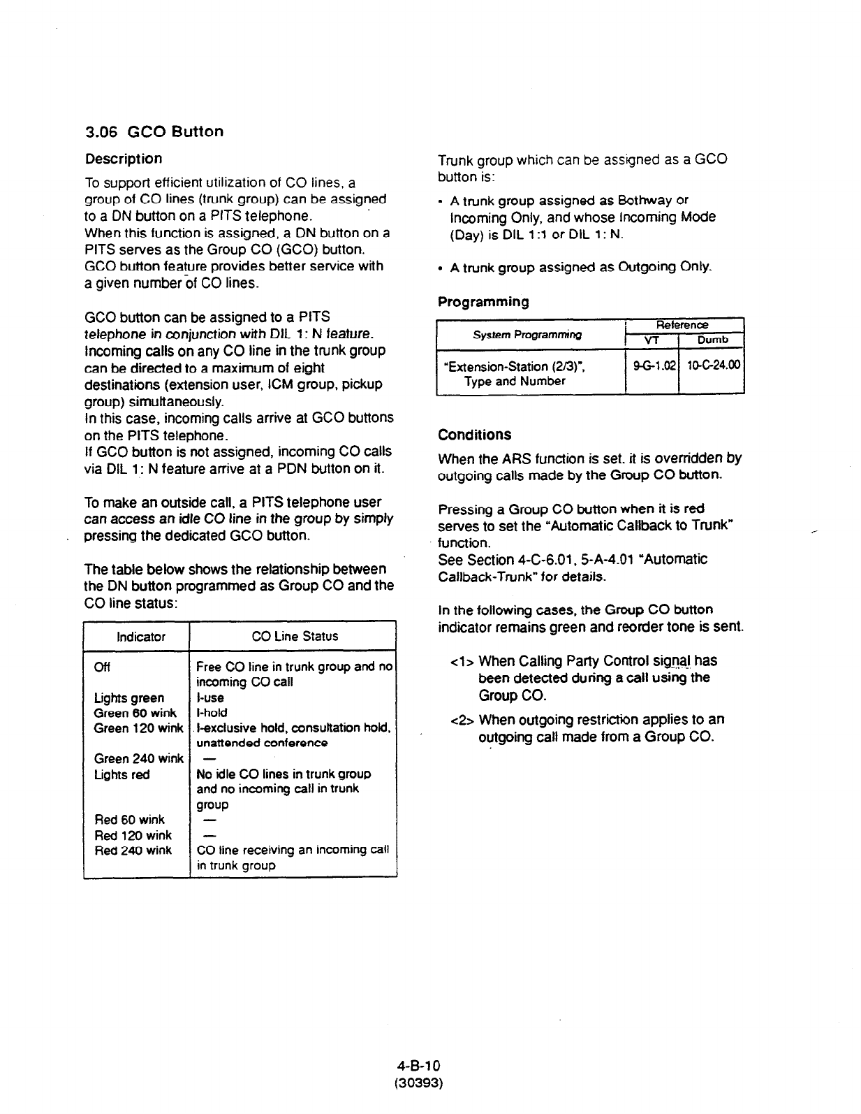
3.06 GCO Button
Description
To support efficient utilization of CO lines, a
group of CO lines (trunk group) can be assigned
to a ON button on a PITS telephone. ’
When this function is assigned, a DN button on a
PITS serves as the Group CO (GCO) button.
GCO button feature provides better service with
a given number if CO lines.
GCO button can be assigned to a PITS
telephone in conjunction with DIl 1: N feature.
Incoming calls on any CO line in the trunk group
can be directed to a maximum of eight
destinations (extension user, ICM group, pickup
group) simultaneously.
In this case, incoming calls arrive at GCO buttons
on the PITS telephone.
If GCO button is not assigned, incoming CO calls
via DIL 1: N feature arrive at a PDN button on it.
To make an outside call, a PITS telephone user
can access an idle CO line in the group by simply
pressing the dedicated GCO button.
The table below shows the relationship between
the DN button programmed as Group CO and the
CO line status:
I~ ~
Indicator
off
Lights green
Green 60 wink
Green 120 wink
Green 240 wink
tights red
Red 60 wink
Red 120 wink
Red 240 wink
CO Line Status
Free CO tine in trunk group and no
incoming CO
call
l-use
I-ho@
l-exclusive hold, consultation hold,
unattended conference
-
No idle CO lines in trunk group
and no incoming call in trunk
group
-
-
CO line receiving an incoming call
1 in trunk group
Trunk group which
can be assigned as a GCO
button is:
l
A trunk group assigned as Bothway or
Incoming Only, and whose Incoming Mode
(Day) is DIL 13 or DIL 1: N.
l
A trunk group assigned as Outgoing Only.
Programming
Conditions
When the ARS function is set. it is overridden by
outgoing calls made by the Group CO button.
Pressing a Group CO button when it is red
serves to set the “Automatic Callback to Trunk”
function.
See Section 4-C-6.01.5-A-4.01 “Automatic
Callback-Trunk” for details.
In the following cases, the Group CO button
indicator remains green and reorder tone is sent.
<l> When Calling Party Comrol sig+l has
been detected during a call using the
Group CO.
~2s When outgoing restriction applies to an
outgoing call made from a Group CO.
4-B-l 0
(30393)

C. Outgoing Call Features
1 .OO Line Selection-Calling
Description
PITS telephones may have many line access
buttons and the set user can access a desired line
either directly by pressing the button or by
employing automatic line selection feature.
This Line Selection-Calling feature offers the
following three line-preferen&and the user can
select only one preference for his or her PITS set:
l
Prime Line Preference-Calling (default)
l
Idle Line Preference-Calling
l
No Line Preference-Calling
If Prime Line Preference or Idle tine Preference is
selected, the user can get the programmed line
automatically for making a call by simply lifting the
handset or pressing the SP-PHONE button (On-
Hook Dialing).
If No Line Preference is selected, no line is
accessed until the user directly presses the
desired button.
Every PITS telephone is assigned to Prime tine
Preference on PDN button by default setting. This
can be changed on a PITS telephone basis using
PITS station programming.
Refer
to Section 12-C
4.00 “Automatic Line Hunting (Calling).”
Line Preference-Calling feature newly assigned on
a PITS telephone overrides the previous
assignment.
!.dQ&
Line access buttons that are available for a PITS
telephone are:
l
DN buttons... Primary Directory Number
(PDN) buttons
Secondary Directory Number
(SDN) buttons
(Refer to Section 4-B-3.01
through 3.02.)
l
CO buttons... Private CO (PCO), Single CO
(SCO), Group CO (GCO)
(Refer to Section 4-B-3.04
through 3.06.)
l
ICM (Intercom) button
(Refer to Section 4-B-3.03.)
4-c-1
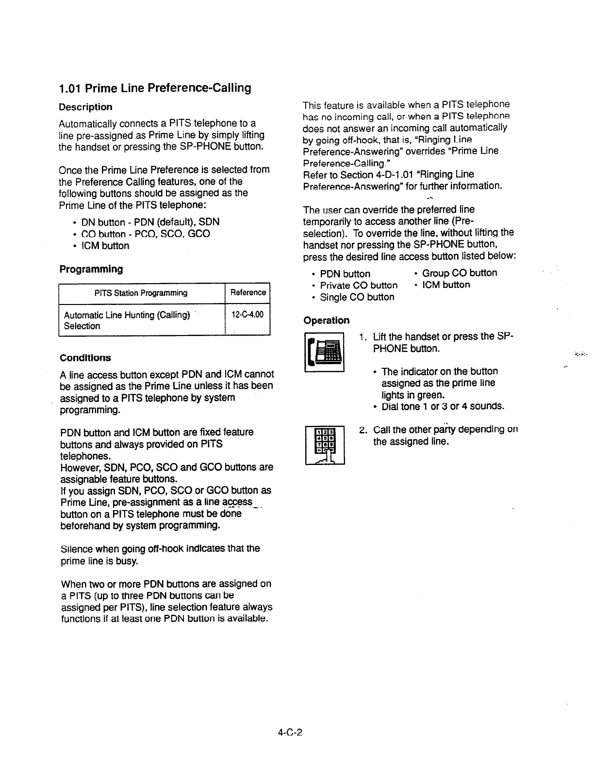
1 .Ol Prime Line Preference-Calling
Description
Automatically connects a PITS telephone to a
line pre-assigned as Prime Line by simply lifting
the handset or pressing the SP-PHONE button.
Once the Prime tine Preference is selected from
the Preference Calling features, one of the
following buttons should be assigned as the
Prime tine of the PITS telephone:
l
DN button - PDN (default), SDN
l
CO button - PCO, SCO, GCO
l
KM button
Programming
Conditions
A line access button except PDN and ICM cannot
be assigned as the Prime tine unless it has been
assigned to a PITS telephone by system
programming.
PDN button and ICM button are fixed feature
buttons and always provided on PITS
telephones.
However, SDN, PCO, SC0 and GCO buttons are
assignable feature buttons.
If you assign SDN, PCO, SC0 or GCO button as
Prime tine, pre-assignment as a line access- _
button on a PITS telephone must be dbne
beforehand by system programming.
Silence when going off-hook indicates that the
prime line is busy.
This feature is available when a PITS
telephone
has no incoming call, or when a PITS telephone
does not answer an incoming call automatically
by going off-hook, that is, “Ringing Line
Preference-Answering” overrides “Prime Line
Preference-Calling.”
Refer to Section 4-D-l .Ol “Ringing tine
Preference-Answering” for further information.
_..
The user can override the preferred line
temporarily to access another line (Pre-
selection). To override the line, without lifting the
handset nor pressing the SP-PHONE button,
press the desired line access button .listed below:
. PDN button
l
Group CO button
l
Private CO button
l
ICM button
l
Single CO button
Operation
1. Lift the handset or press the SP-
PHONE button.
I
l
The indicator on the button
assigned as the prime line
lights in green.
l
Dial tone 1 or 3 or 4 sounds.
2. Call the other p&ty depending on
the assigned line.
When two or more PDN buttons are assigned on
a PITS (up to three PDN buttons can be
assigned per PITS), line selection feature always
functions if at least one PDN button is available.
4-C-2
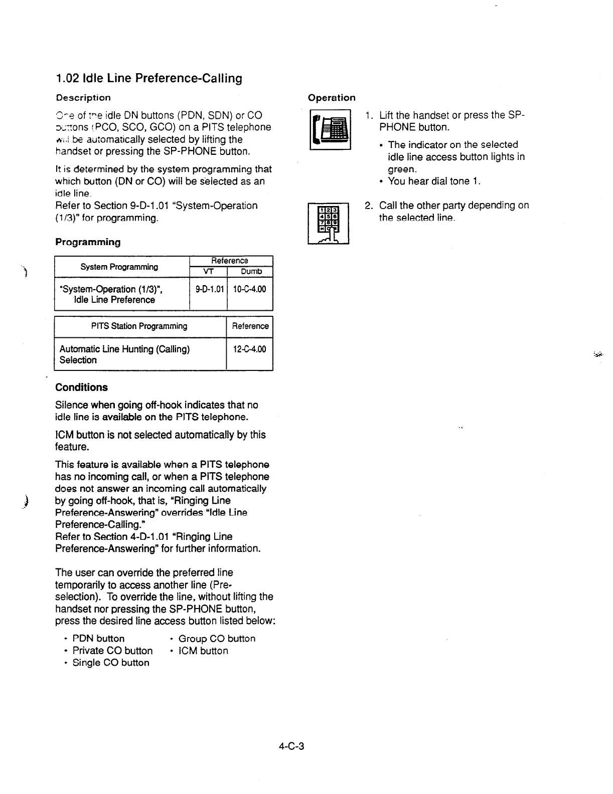
1.02 Idle Line Preference-Calling
Oescription
S-s of :ne idle DN buttons (PDN, SDN) or CO
x:ons !PCO, SCO, GCO) on a PITS telephone
*i.j & automatically selected by lifting the
handset or pressing the SP-PHONE button.
It
is determined by the system programming that
which button (DN or CO) will be selected as an
idle line.
Refer to Section 9-D-l .Ol “System-Operation
(l/3)” for programming.
Operation
1. Lift the handset or press the SP-
PHONE button.
l
The indicator on the selected
idle line access button lights in
green.
l
You hear dial tone 1.
Programming
.“r )I
PITS Station Programming Reference
2. Call the other party depending on
the selected line.
Automatic tine Hunting (Calling)
12c4.00
Selection
I I
Conditions
Silence when going off-hook indicates that no
idle line is available on the PITS telephone.
ICM button is not selected automatically by this
feature.
This feature is available when a PITS telephone
has no incoming call, or when a PITS telephone
does not answer an incoming call automatically
by going off-hook, that is, “Ringing tine
Preference-Answering” overrides “Idle tine
Preference-Calling.”
Refer to Section 4-D-l .Ol “Ringing tine
Preference-Answering” for further information.
The user can override the preferred line
temporarily to access another line (Pre-
selection). To override the line, without lifting the
handset nor pressing the SP-PHONE button,
press the desired line access button listed below:
l
PDN button
l
Group CO button
l
Private CO button
l
ICM button
l
Single CO button
4-c-3
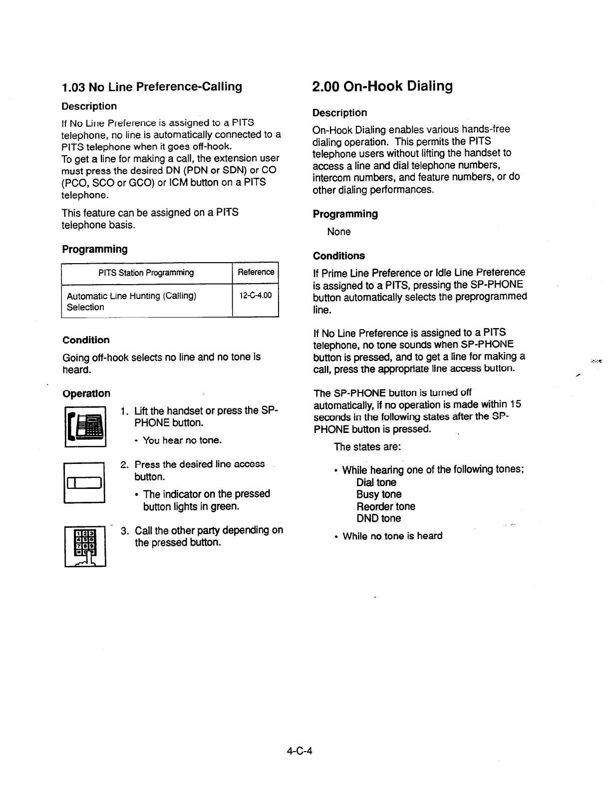
1.03 No Line Preference-Calling
Description
If No Line Preference is assigned to a PITS
telephone, no line is automatically connected to a
PITS telephone when it goes off-hook.
To get a line for making a call, the extension user
must press the desired DN (PDN or SDN) or CO
(PCO, SC0 or GCO) or ICM button on a PITS
telephone.
This feature can be assigned on a PITS
telephone basis.
Programming
I
PITS Station Programming Reference I
Automatic Line Hunting (Calling)
I I
12-c-4.00
Selection
Condition
Going off-hook selects no line and no tone is
heard.
Operation
1. Lift the handset or press the SP-
PHONE button.
l
You hear no tone.
2. Press the desired line access
button.
l
The indicator on the pressed
button lights in green.
3. Call the other party depending on
the pressed button.
2.00 On-Hook Dialing
Description
On-Hook Dialing enables various hands-free
dialing operation. This permits the PITS
telephone users without lifting the handset to
access a line and dial telephone numbers,
intercom numbers, and feature numbers, or do
other dialing performances.
Programming
None
Conditions
If Prime tine Preference or Idle Line Preference
is assigned to a PITS, pressing the SP-PHONE
button automatically selects the preprogrammed
line.
If No tine Preference is assigned to a PITS
telephone, no tone sounds when SP-PHONE
button is pressed, and to get a line for making a
call, press the appropriate line access button.
The SP-PHONE button is turned off
automatically, if no operation is made within 15
seconds in the following states after the SP-
PHONE button is pressed. I
The states are:
l
While hearing one of the following tones;
Dial tone
Busy tone
Reorder tone
DND tone . . .
l
While no tone is heard
4-c-4
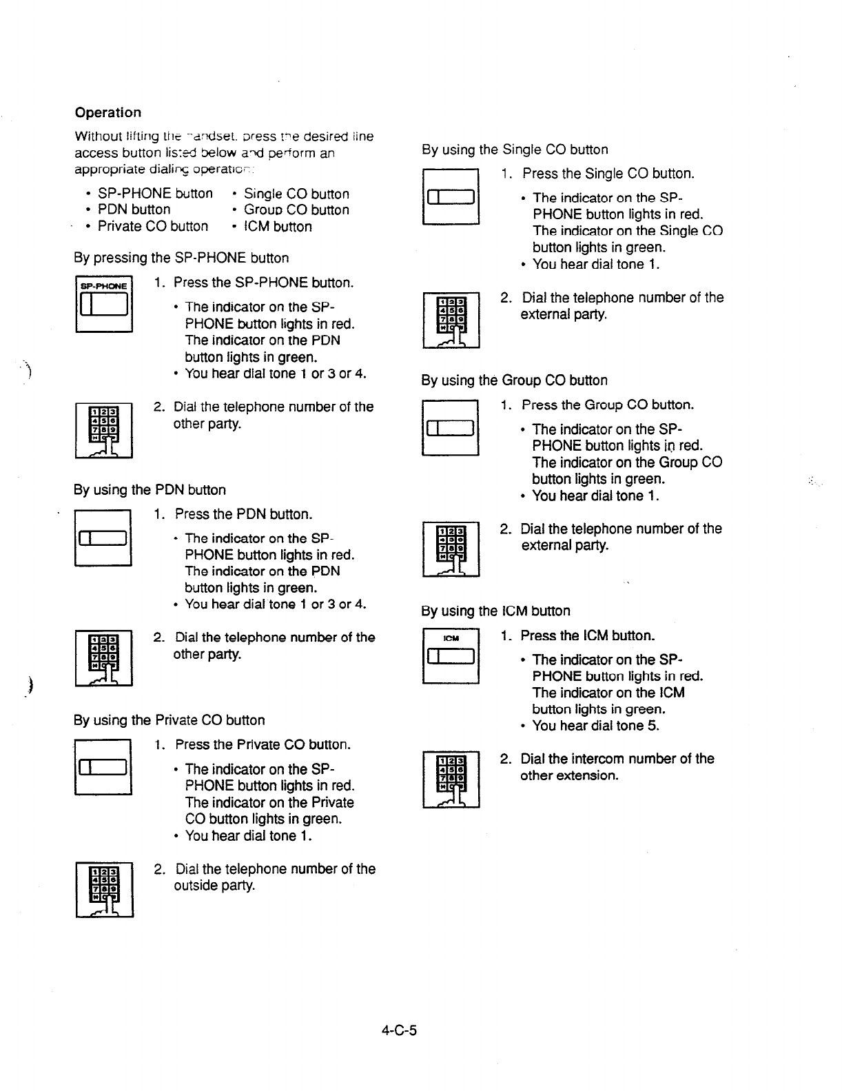
Operation
Without lifting the -aodset. Dress Fe desired
iine
access button iis:ti below axt
pedorm an
appropriate dialing operatw-
l
SP-PHONE button
l
Single CO button
l
PDN button
l
Grow CO button
l
Private CO button = ICM button
By pressing the SP-PHONE button
IjyEq
1. Press the SP-PHONE button.
l
The indicator on the SP-
PHONE button lights in red.
The indicator on the PDN
button lights in green.
l
You hear dial tone 1 or 3 or 4.
2. Dial the telephone number of the
other party.
By using the PDN button
1. Press the PDN button.
l
The indicator on the SP-
PHONE button lights in red.
The indicator on the PDN
button lights in green.
l
You hear dial tone 1 or 3 or 4.
2. Dial the telephone number of the
other party.
By using the Private CO button
q
1. Press the Private CO button.
l
The indicator on the SP-
PHONE button lights in red.
The indicator on the Private
CO button lights in green.
l
You hear dial tone 1.
By using the Single CO button
I 1 1. Press the Single CO button.
/
II l
.
The indicator on the SP-
PHONE button lights in red.
The indicator on the Single CO
button lights in green.
You hear dial tone 1.
2. Dial the telephone number of the
external party.
By using the Group CO button
El 1.
Press the Group CO button.
l
The indicator on the SP-
PHONE button lights in red.
The indicator on the Group CO
button lights in green.
l
You hear dial tone 1.
Dial the telephone number of the
external party.
By using the ICM button
n
1. Press the ICM button.
,F-, .
.
The indicator on the SP-
PHONE button lights in red.
The indicator on the ICM
button lights in green.
You hear dial tone 5.
2. Dial the intercom number of the
other extension.
2. Dial the telephone number of the
outside party.
4-c-5

3.00 Making Outside Calls
3.01 Local Trunk
Dial Access
Description
Allows
extension users to make outgoing CO
calls by automatic selection of an idle CO line.
Dialing the feature number for ARSILocal CO
Line Access” enables you to execute this
function.
To
activate this feature, set “System-Operation”,
Automatic Route Selection to “No.” If set to
‘Yes,’ ARS feature is activated instead of this
feature.
Refer to Section 3-C-2.00 “Automatic Route
Selection (ARS)” for further information.
Programming
System Programming
“System-Operation (l/3)“,
Automatic Route
Selection
“System-Local Access Group”,
Hunt Sequence
“System-Numbering Plan (2/9)
APB/Local CO Line Access
Reference
-y
9-D-l .Ol 10-C-4.00
I
9-D-5.00 1 o-c-9.00
9-O-6.02 10-ClO.oC
Conditions
An idle CO fine available and hunting sequence
is determined by the system programming
“System-Local Access Group”, Hunt Sequence.
If an extension user hears busy tone, there is no
idle CO line available.
If an extension user hears reorder tone, the user
is restricted from accessing this feature.
Refer to Section 3-C-l .Ol “Toll Restriction for
Local Trunk Dial Access,” for further information.
If tenant service is employed, accessible trunk
groups are limited to the trunk groups within the
same tenant.
Operation
1. Lift the handset or press the SP-
PHONE button.
l
You hear dial tone 1 or 3 or 4.
2. Dial the feature number for ‘.“’
“ARS/Local CO Line Access.”
1 .A4 I
l
You hear dial tone 1.”
3. Dial the telephone number of the
outside party.
The dialing plan followed is that of the trunk
group in hunt sequence 01 in ‘System-Local
Access Group.”
4-C-6
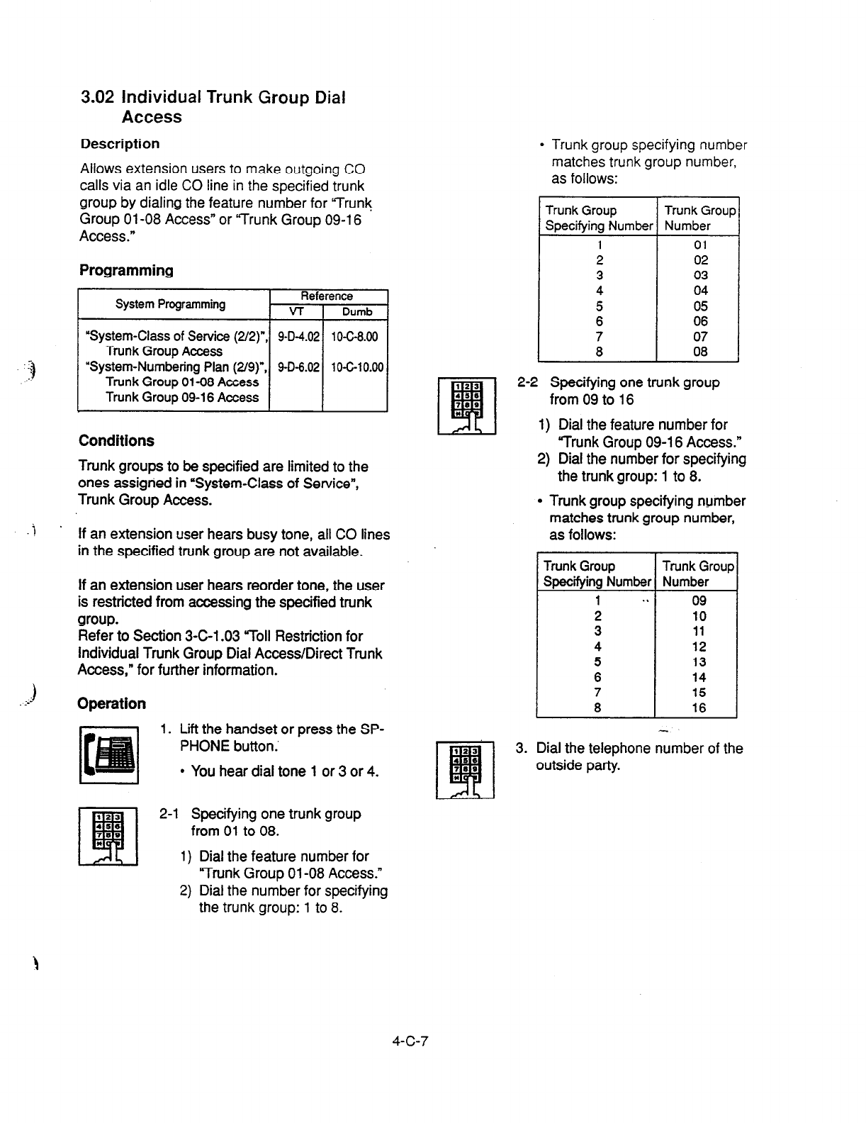
3.02 individual Trunk Group Dial
Access
Description
Allows extension users to make outgoing CO
calls via an idle CO line in the specified trunk
group by dialing the feature number for Yrunl(
Group 01-08 Access” or Yrunk Group 09-l 6
Access.”
Programming
System Programming Reference
VT i Dumb
10-C-8.00
Conditions
Trunk groups to be specified are limited to the
ones assigried in ‘System-Class of Service”,
Trunk Group Access.
.j .
If an extension user hears busy tone, all CO lines
in the specified trunk group are not available.
If an extension user hears reorder tone, the user
is restricted from accessing the specified trunk
group.
Refer to Section 3-C-l .03 roll Restriction for
individual Trunk Group Dial Access/Direct Trunk
Access,” for further information.
Operation
1. Lift the handset or press the SP-
PHONE button.’
l
You hear dial tone 1 or 3 or 4.
l
Trunk group specifying number
matches trunk group number,
-
as follows:
Trunk Group
TrunkGroup
Specifying Number Number
1 01
2 02
3 03
4 04
5 05
6 06
7 07
8 08
2-2 Specifying one trunk group
from 09 to 16
11 Dial the feature number for
I
“Trunk Group 09-l 6 Access.”
2) Dial the number for specifying
the trunk group: 1 to 8.
l
Trunk group specifying number
matches trunk group number,
J
1
!
I
as follows:
1
drunk Group
specifying Number
1 . .
2
3
4
5
6
7
8
Trunk Group
Number
09
10
11
12
13
14
15
16
3. Dial the telephone number of the
outside party.
123
q
2-l Specifying one trunk group
456
,(I0 from 01 to 08.
*
1)
Dial the feature number for
“Trunk Group 01-08 Access.”
2) Dial the number for specifying
the
trunk group: 1 to 8.
4-c-7

3.03 Individual Virtual Trunk Group
Dial Access
Description
Allows extension users to make outgoing CO
calls using Special Carrier Facilities by simply
dialing the feature number for “Trunk Group 17-
24 Access.”
Detailed data, such as access codes and
authorization codes, required to Special Carder
Access must be programmed beforehand in
“Special Carrier Access” screen.
Trunk groups available for Special Carder
Access is also defined in the same screen.
Special carriers available for each extension user
is defined in “System-Class of Service (2/2)
Special Carrier Access.
It is programmable to restrict Special Carrier
Access on system-wide basis.
Refer to Section 1 O-C-52.00 “World Select 2-
ECWOCC Access Assignment” for further
information.
Programming
System Programming
‘System-Class of Service (2/2)“,
Special Carrier Access
“System-Numbering Plan (2/g)“,
Trunk Group
17-24 Access
“Special Canier Access-Equal
Access/OCC Access”
World Select 2”
Condition
None
Reference
Operation
1. Lift the handset or press the SP-
PHONE button.
t-
I
l
You hear dial tone 1 or 3 or 4.
2. Dial the feature number for
“Trunk Group 17-24 Access.”
3. Dial the number for specifying
the virtual trunk group: 1 to 8.
l
Virtual trunk group number
matches virtual trunk group
specifying number and digit
modification table number
(Equal access table number 1
to 4, OCC access table number
1 to 4 which should be
assigned beforehand), as
follows:
virtual Trunk Virtual Trunk Digit Modiition
Group Number
~~ro~e~pecffying Table Number
17
18
19
20 21
22
23
24
1
Equal access I
2 table number 2
3 3
4 J 5 OCCaccess ;’
6
7
8 .*..
A, 2.
4. Dial the telephone number of the
outside party.
4-C-8
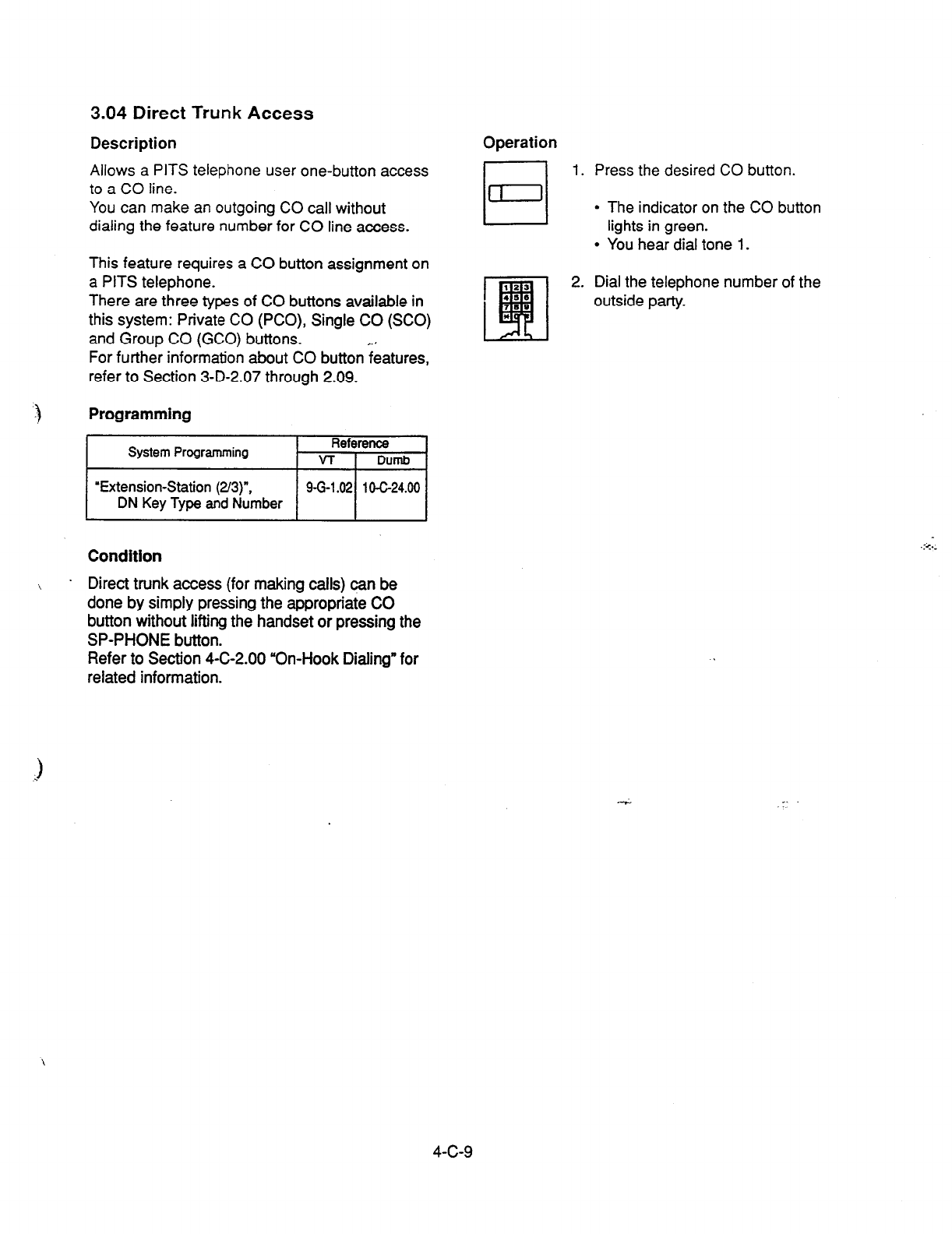
3.04 Direct Trunk Access
Description Operation
Allows a PITS telephone
user one-button access
to a CO line.
You can make an outgoing CO call without
dialing the feature number for CO line access.
This feature requires a CO button assignment on
a PITS telephone.
There are three types of CO buttons available in
this system: Private CO (PCO), Single CO (SCO)
and Group CO (GCO) buttons. r. :
For further information about CO button features,
refer to Section 3-D-2.07 through 2.09.
Programming
System Programming Reference
VT 1 Dumb
‘Extension-Station
(2/3)“.
DN Key Type and Number
/ 961.02/ lo-G24.00 /
Condition
1. Press the desired CO button.
l
The indicator on the CO button
lights in green.
l
You hear dial tone 1.
2. Dial the telephone number of the
outside party.
.:<..
.
\
Direct trunk access (for making calls) can be
done by simply pressing the appropriate CO
button without lifting the handset or pressing the
SP-PHONE button.
Refer to Section 4-C-2.00 “On-Hook Dialing” for
related information.
4-c-9

4.00 Automatic Dialing
4.01 One Touch Dialing
Description
Extension users can program frequently dialed
telephone numbers (of bolh extensions and
outside parties) or feature numbers into memory
on the following PITS telephone’s Assignable
Feature buttons.
l
PF buttons
l
DN buttons
l
DSS buttons (KX-T30830 only)
To dial a number stored in an assignable feature
button, the extension user just press the button
and the PITS telephone automatically dials the
number.
This feature can be programmed by either
system programming and PITS station
programming.
Programming
System Programming
‘Extension-Station (2/3)“,
DN Key Type, Number
‘Extension-Station (3/3)“,
PF Key Type, Number
DSS Key Type, Number
‘Extension-DSS Console (l/3)“,
DSS Key Type, Number
‘Extension-DSS Console Q/3)“,
PF Key Type, Number
Reference
9-G-2.01
9-G-2.02
1 O-c-25.00
1 O-C-26.00
1 O-C-24.00
1 o-c-25.00
PITS StaMn Programming
DN (Directory
Number) Button
Assignme’nt .
PF (Programmable Feature)
Button
Assignment
DSS (Direct Station
Selection) Button
Assignment
Reference I
Conditions
Each stored number can have up to 16 digits
including CO line access code. “0 to 9,” %,’ “#,”
“PAUSE,” ‘FLASH,” y-” and “SECRET” can be
registered.
For employing One Touch Dialing for calling an
outside party, stored number must include a
feature number for selecting a CO line as leading
digits.
<Example>
For calling an outside party automatically:
AFWLocal CO Line Access - telephone number
The feature numbers for selecting a CO line are:
l
ARS/Local CO tine Access
l
Trunk Group 01-08 Access
l
Trunk Group 09-l 6 Access
l
Trunk Group 17-24 Access
Operation
Making a call using One Touch Dialing
1. Lift the handset or press the
SP-PHONE button.
l
You hear dial tone 1 or 3 or 4.
El
2. Press the One Touch button.
1” ..
l
Stored number is sent.
(Supplement)
In step 2, dialing a feature number for selecting a
CO line before pressing the One Touch button
ignores the stored feature number and seizes the
CO line selected by manual operation.
instead of the operation in step 1, pressing the
Private CO, the Single CO, or the Group CO
button ignores the stored feature number for
selecting a CO line and seizes the CO line of the
pressed button. . .._
ea..
One Touch Dialing, Speed Dialing, La% iz%ber
Redial, Saved Number Redial and manual dialing
can be used in combination.
<Example>
An extension user can store a number consisting
of 17 digits or more by dividing it and storing it in
two assignable feature buttons.
In this case, feature number for selecting a CO
line should not be stored on the second button.
To dial the number, first press the first One Touch
button, and then press the second One Touch
button.
4-c-1 0
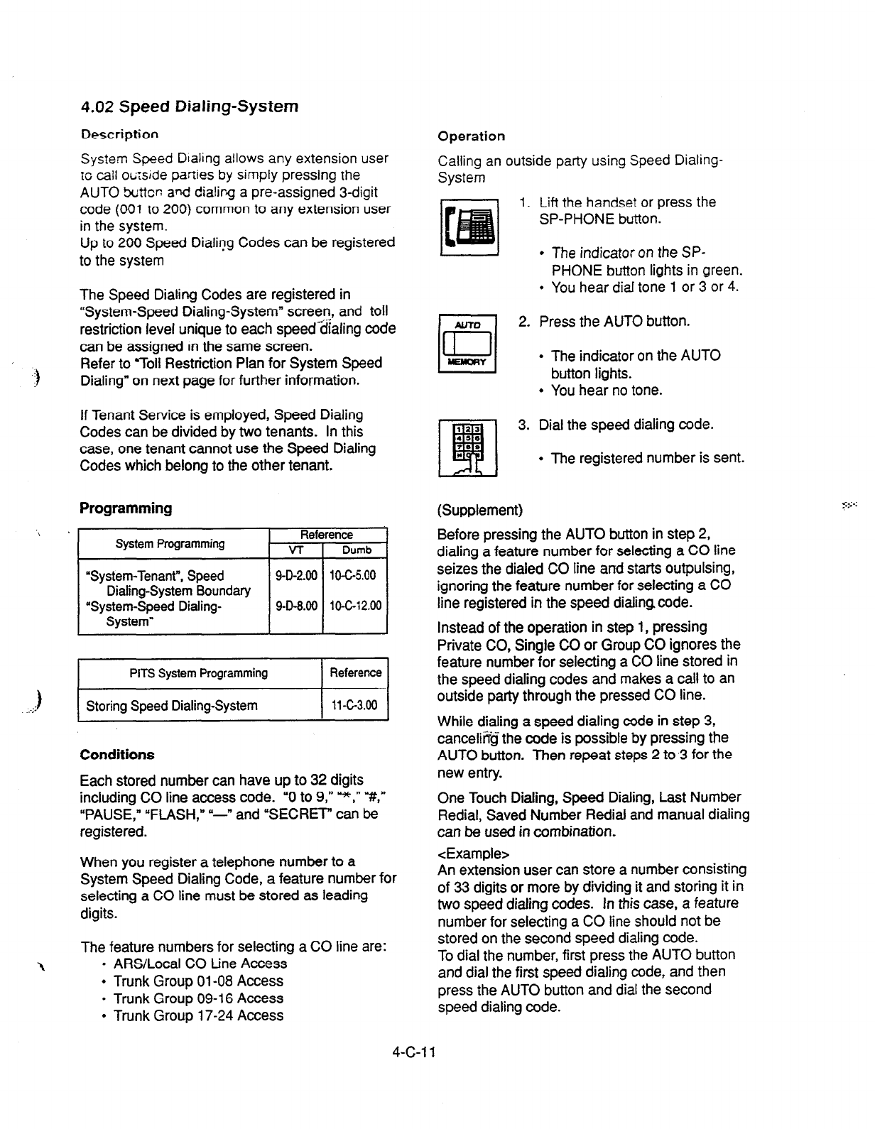
4.02 Speed Dialing-System
Description
System Speed Dialing allows any extension user
ro call oti:s;de paflies by simply
pressing the
AUTO buttor: and dialirg a pre-assigned 3-digit
code
(001
to 200) common
to any extension user
in the system.
Up to
200 Speed Dialing Codes can be registered
to the system
The Speed Dialing Codes
are registered in
“System-Speed Dialing-System” screen, and toll
restriction level unique to each speed-dialing code
can be assigned In the same screen.
Refer to 7011 Restriction Plan for System Speed
Dialing” on next page for further information.
If Tenant Service is employed, Speed Dialing
Codes can be divided by two tenants. In this
case, one tenant cannot use the Speed Dialing
Codes which belong to the other tenant.
Programming
‘i .
System Programming Reference
VT Dumb
“System-Tenant”, Speed
9-D-2.00 1 O-c-5.00
Dialing-System Boundary
‘System-Speed Dialing- 9-D-9.00 1
O-C-l 2.00
System”
. ...:)
PITS System Programming Reference
Storing Speed Dialing-System
11-c-3.00
Conditions
Each stored number can have up to 32 digits
including CO line access code. “0 to 9,” =*,- Y,,
“PAUSE,” “FLASH,” Y-n and “SECRET” can be
registered.
When you register a telephone number to a
System Speed Dialing Code, a feature number for
selecting a CO line must be stored as leading
digits.
The
feature numbers for selecting a CO line are:
1
l
ARS/Local CO tine Access
l
Trunk Group 01-08 Access
l
Trunk Group 09-l 6 Access
l
Trunk Group 17-24 Access
Operation
Calling an outside party using Speed Dialing-
System
1. Lift the handset
or press
the
SP-PHONE button.
l
The indicator on the SP-
PHONE button lights in green.
l
You hear dial tone 1 or 3 or 4.
2. Press the AUTO button.
l
The indicator on the AUTO
button lights.
l
You hear no tone.
3. Dial the speed dialing code.
l
The registered number is sent.
I 44 I
(Supplement)
Before pressing the AUTO button in step 2,
dialing a feature number for selecting a CO line
seizes the dialed CO line and starts outpulsing,
ignoring the feature number for selecting a CO
line registered in the speed dialing code.
Instead of the operation in step 1, pressing
Private CO, Single CO or Group CO ignores the
feature number for selecting a CO line stored in
the speed dialing codes and makes a call to an
outside party through the pressed CO line.
While dialing a speed dialing code in step 3,
cancelit@ the code is possible by pressing the
AUTO button. Then repeat steps 2 to 3 for the
new entry.
One Touch Dialing, Speed Dialing, Last Number
Redial, Saved Number Redial and manual dialing
can be used in combination.
<Example>
An extension user can store a number consisting
of 33 digits or more by dividing it and storing it in
two speed dialing codes. In this case, a feature
number for selecting a CO line should not be
stored on the second speed dialing code.
To dial the number, first press the AUTO button
and dial the first speed dialing code, and then
press the
AUTO button and dial the second
speed dialing code.
4-C-l 1
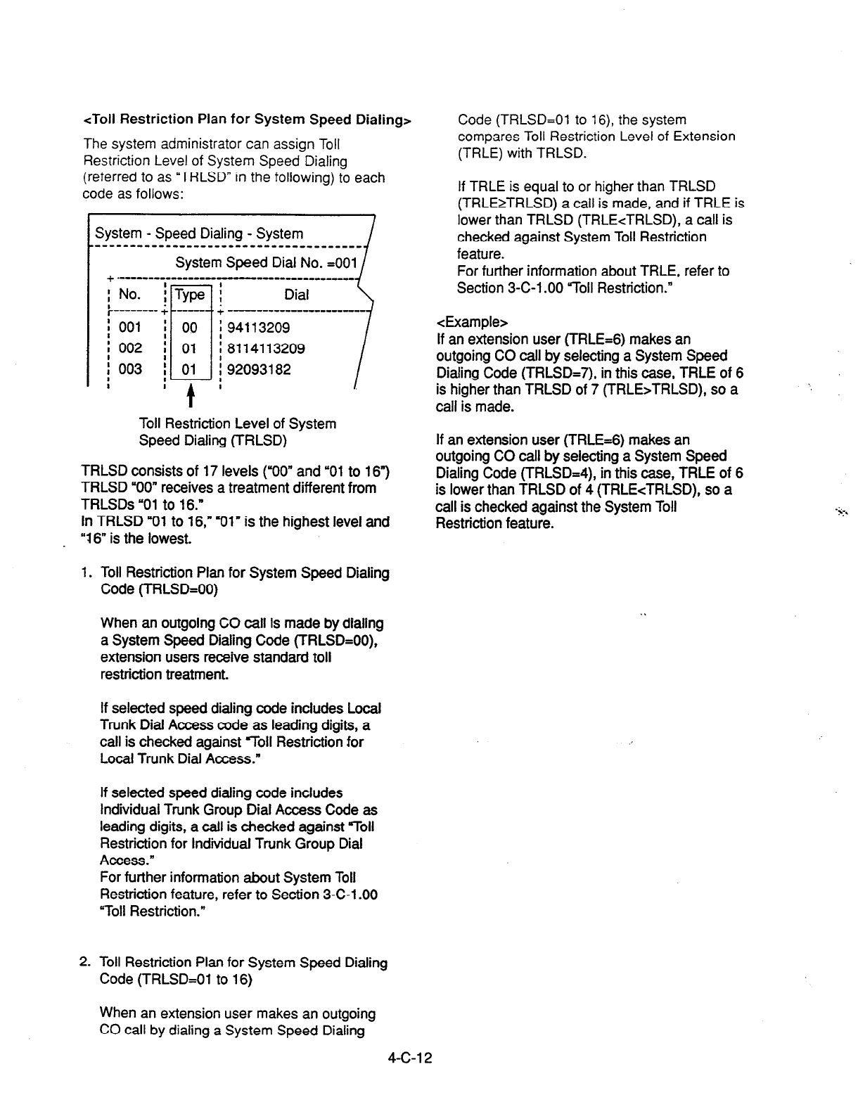
<Toll
Restriction Plan for System Speed Dialing>
The system administrator can assign Toll
Restriction Level of System Speed Dialing
(referred to as “TRLSD” in the
following)
to each
code as follows:
System - Speed Dialing - System
----------------_---------------------
System Speed Dial No.
=OOl
+ .-em- ---w--m--- -- -I------------- i'
:No. i
; -------. 4
:001 I
i 002 ;
; 003 :
8 :
Toll Restriction Level of System
Speed Dialing (TRLSD)
TRLSD consists of 17 levels (YOO” and “01 to 16”)
TRLSD “00” receives a treatment different from
TRLSDs “01 to 16.”
In TRLSD “01 to 16,” Iy)l“ is the highest level and
“16” is the lowest.
1. Toll Restriction Plan for System Speed Dialing
Code (TRLSD=OO)
When an outgoing CO call is made by dialing
a System Speed Dialing Code (TRLSD=OO),
extension users receive standard toll
restriction treatment.
If selected speed dialing code includes Looal
Trunk Dial Access code as leading digits, a
call is checked against 7011 Restriction for
Local Trunk Dial Access.”
If selected speed dialing code includes
Individual Trunk Group Dial Access Code as
leading digits, a call is checked against “Toll
Restriction for Individual Trunk Group Dial
Access.”
For further information about System Toll
Restriction feature, refer to Section 3-C-l .OO
“Toll Restriction.”
2. Toll Restriction Plan for System Speed Dialing
Code (TRLSD=Ol to 16)
Code
(TRLSD=Ol to
16), the system
compares Toll Restriction Level of Extension
(TRLE) with TRLSD.
If TRLE is equal to or higher than TRLSD
(TRLE2TRLSD) a call is made, and if TRLE is
lower than TRLSD (TRLEcTRLSD), a call is
checked against System Toll Restriction
feature.
For further information about TRLE, refer to
Section 3-C-l .OO “Toll Restriction.”
<Example>
If an extension user (TRLE=6) makes an
outgoing CO call by selecting a System Speed
Dialing Code (TRLSD=7), in this case, TRLE of 6
is higher than TRLSD of 7 (TRLE>TRLSD), so a
call is made.
If an extension user (TRLE=6) makes an
outgoing CO call by selecting a System Speed
Dialing Code (TRLSD=4), in this case, TRLE of 6
is lower than TRLSD of 4 (TRLEcTRLSD), so a
call is checked against the System Toll
Restriction feature.
When an extension user makes an outgoing
CO call by dialing a System Speed Dialing
4-c-1 2
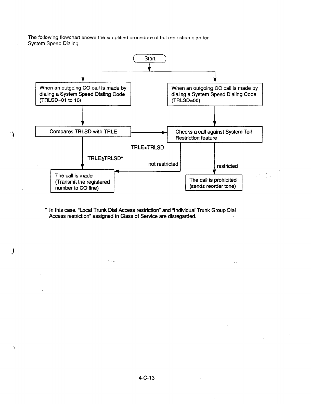
The following flowchart shows rhe simplified procedure of toll restriction plan for
System Speed Diaikg.
Start
I i I
le f
When an outgoing CO cari is, made by When an outgoing CO call is made by
dialing a System Speed Dialing Code dialing a System Speed Dialing Code
(TRLSD=Ol to 16) (TRLSD*OO)
)‘ ‘I
Compares TRLSD with TRLE .-+ Checks a call against System Toll
Restriction feature
TRLEcTRLSD
TRLEzTRLSD’
v
The call is made
(Transmit the registered
number to CO line)
not restricted restricted
* In this case, ‘Local Trunk Dial Access restriction” and ‘Individual Trunk Group Dial
Access restriction” assigned in Class of Service are disregarded. . .
4-c-13
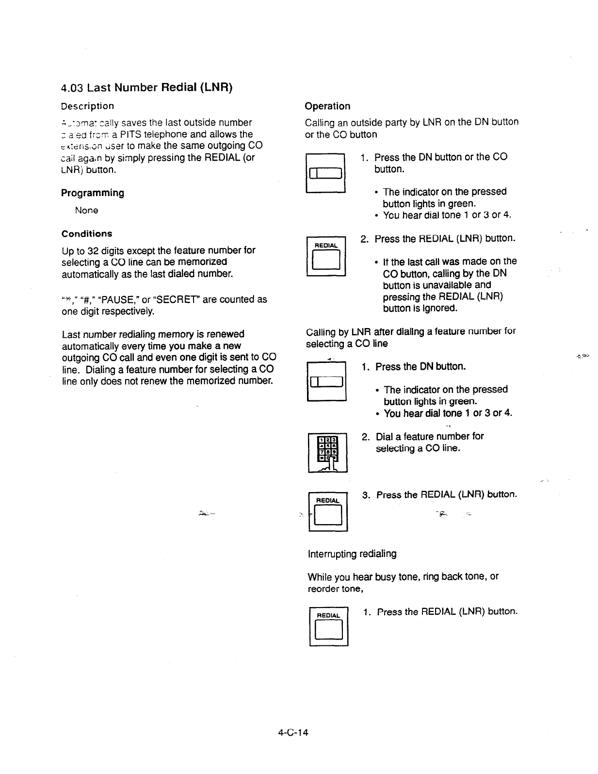
4.03 Last Number Rediai (LNR)
Description
:,:~ma: :a!ly saves the last outside number
3 2
sd
frs~ a PITS telephone and allows the
-h:tiris.;n &er to make the same outgoing CO
tail aga$n by simply pressing the REDIAL (or
LNR j
button.
Programming
None
Conditions
Up to 32 digits except the feature number for
selecting a CO line can be memorized
automatically as the last dialed number.
“+ ” “#,” “PAUSE,” or “SECRET” are counted as
on’e digit respectively.
Last number redialing memory is renewed
automatically every time you make a new
outgoing CO call and even one digit is sent to CO
line. Dialing a feature number for selecting a CO
line only does not renew the memorized number.
Operation
Calling an outside party by LNR on the DN button
or the CO button
1. Press the DN button or the CO
button.
l
The indicator on the pressed
button lights in green.
l
You hear dial tone 1 or 3 or 4.
2. Press the REDIAL (LNR) button.
l
If the last call was made on the
CO button, calling by the DN
button is unavailable and
pressing the REDIAL (LNR)
button is ignored.
Calling by LNR after dialing a feature number for
selecting a CO line
5 1. Press the DN button.
l
The indicator on the pressed
button lights in green.
l
You hear dial tone 1 or 3 or 4.
. .
2. Dial a feature number for
selecting a CO line.
3. Press the REDIAL (LNR) button.
Interrupting redialing
While you hear busy tone, ring back tone, or
reorder tone,
RENAL
n
1. Press the REDIAL (LNR) button.
cl
4-c-14
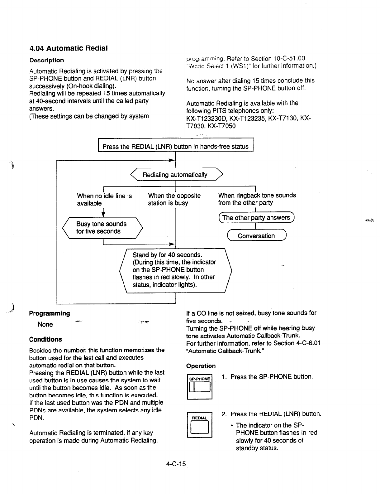
4.04 Automatic Redial
Description
Automatic Redialing is activated by pressing the
SP-PHONE button and REDIAL (LNR) button
successively (On-hook dialing).
Redialing will be repeated 15 times automatically
at 40-second intervals until the called party
answers.
(These settings can be changed by system
I
pq;am=~ng.
Refer
to Section 1 O-C-51 .OO
-;Vc:id Select 1 (WSl)” for further information.)
F*io answer after dialing 15 times conclude this
function, turning the SP-PHONE button off.
Automatic Redialing is available with the
following PITS telephones only:
KX-T123230D, KX-T123235, KX-T7130, KX-
T7030, KX-T7050
, .- I
Press the REDIAL (LNR) button in hands-free status
I
Redialing automatically
I
I I
When no idle line is When the opposite
available station is busy When ringbaLk tone sounds
from the other party
Busy tone sounds
for five seconds
The other party answers
I
c
Conversation 1
i
Stand by for 40 seconds.
(During this time, the indicator
on the SP-PHONE button
:
. .
flashes in red slowly. In other
status, indicator lights).
.:)
I I
Programming
None -L
Conditions
Besides the number, this function memorizes the
button used for the last call and executes
automatic redial on that button.
Pressing the REDIAL (LNR) button while the last
used button is in use causes the system to wait
until the button becomes idle. As soon as the
button becomes idle, this function is executed.
If the last used button was the PDN and multiple
PDNs are available, the system selects any idle
PDN.
Automatic Redialing is terminated, if any key
operation is made during Automatic Redialing.
If a CO line is not seized, busy tone sounds for
five seconds. a .
Turning the SP-PHONE off while hearing busy
tone activates Automatic Callback-Trunk.
For further information, refer to Section 4-C-6.01
“Automatic Callback-Trunk.”
Operation
1. Press the SP-PHONE button.
2. Press the REDIAL (LNR) button.
l
The indicator on the SP-
PHONE button flashes in red
slowly for 40 seconds of
standby status.
4-c-1 5
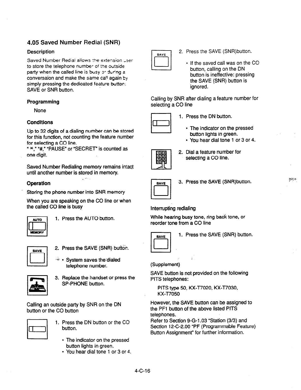
4.05 Saved Number Redial (SNR)
Description
Saved Number Rediar allows rhe exte-sion zxr
to store the
telephone
numbe- ot me ourside
party when the called line is sC;sy 3’ -ftkng a
conversaion and make the same ca!l again by
simply pressing the dedicated feature buttor::
SAVE or SNR button.
Programming
None
Conditions
Up to 32 digits of a dialing number can be stored
for this function, not counting the feature number
for selecting a CO line.
y *,” “#,* “PAUSE” or “SECRET” is counted as
one digit.
Saved Number Redialing memory remains intact
until another number is stored in memory.
. ..’
Operation
Storing the phone number into SNR memory
When you are speaking on the CO line or when
the called CO line is busy
r-l
1. Press the AUTO button.
In
WNORY
2. Press the SAVE (SNR) but%%.
+&
l
System saves the:dialed
telephone number.
rl
,z,
3. Replace the handset or press the
SP-PHONE button.
I I
Calling an outside party by SNR on the DN
button or the CO button
1.
Press the DN button or the CO
button.
I I
l
The indicator on the pressed
button lights in green.
l
You hear dial tone 1 or 3 or 4.
PITS type 50, KX-l7020, KX-T7030,
KX-T7050
However, the SAVE button can be assigned to
the PFl button of the above listed PITS
telephones.
4-C-l 6
Refer to Section 9-G-l .03 “Station (3/3) and
Section 12-C-2.00 “PF (Programmable Feature)
Button Assignment” for further information.
2. Press the SAVE (SNR)button.
l
If the saved call was on the
CO
button, calling on the DN
button is ineffective: pressing
the SAVE (SNR) button is
ignored.
Calling by SNR after dialing a feature number for
selecting a CO line
1. Press the DN button.
l
The indicator on the pressed
button lights in green.
l
You hear dial tone 1 or 3 or 4.
2. Dial a feature number for
selecting a CO line.
3. Press the SAVE (SNR)button.
Interrupting redialing
While hearing busy tone, ring back tone, or
reorder tone from a CO line
1. Press the SAVE (SNR) button.
(Supplement)
SAVE button is not provided on the following
PITS telephones:
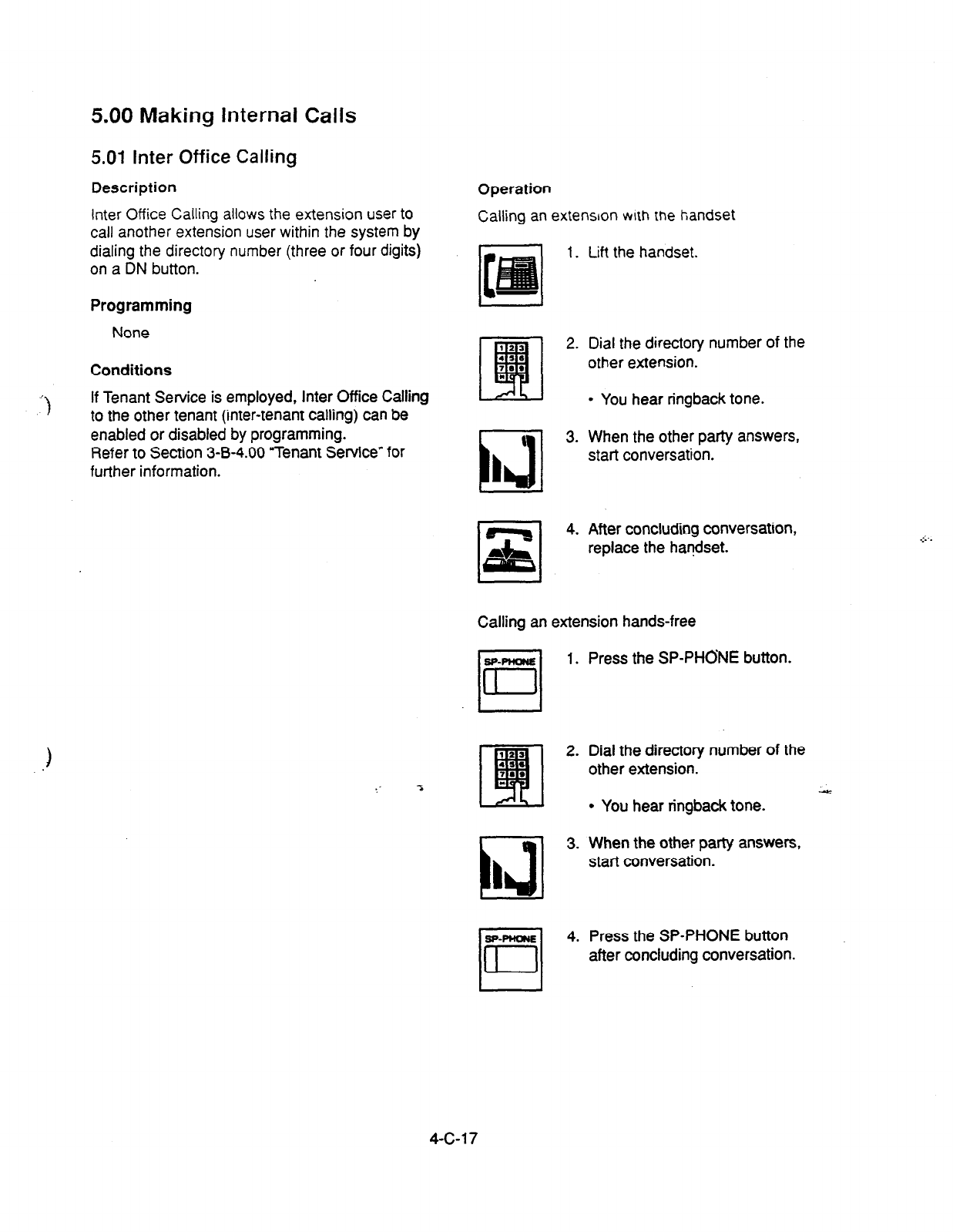
5.00 Making Internal Calls
5.01 Inter Office Calling
Description
Inter Office Calling allows the
extension user to
call another extension user within the system by
dialing the directory number (three or four digits)
on a DN button.
Programming
None
Conditions
If Tenant Service is employed, Inter Office Calling
to the other tenant (inter-tenant calling) can be
enabled or disabled by programming.
Refer to Section 3-B-4.00 =Tenant Service” for
further information.
)
Operation
Calling an extension
mth the
handset
1.
Lift the handset.
t 3.
La
I
Dial the directory number of the
other extension.
l
You hear ringback tone.
When the other party answers,
start conversation.
After concluding conversation,
replace the handset.
Calling an extension hands-free
SP-PlmNe
0
1.
In
Ll
3.
I
SP-PHONE
0
4.
El
Press the SP-PHONE button.
Dial the directory number of the
other extension.
l
You hear ringback tone.
When the other party answers,
start conversation.
Press the SP-PHONE button
after concluding conversation.
4-C-l 7
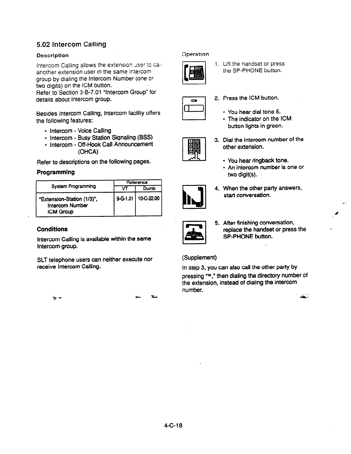
5.02 Intercom Calling
Description
Intercom Calling allows the extension Jspr to ca.l
another extension user in the same ktercom
group by dialing the
intercom Number
(one or
two digits) on the ICt,vl button.
Refer to Section 3-B-7.01 “Intercom Group” for
details about Intercom group.
Besides Intercom Calling, Intercom facility offers
the following features:
l
Intercom - Voice Calling
l
Intercom -
Busy
Station Signaling (BSS)
l
Intercom - Off-Hook Call Announcement
(OHCA)
Refer to descriptions on the following pages.
Programming
Reference
System Programming VT
I
Dumb
‘Bxtension-8tetion
(l/3)",
Intercom Number
ICM Group
9-G-l .Ol 104-22.00
Conditions
Intercom Calling is available within the same
Intercom group.
SLT telephone users can neither execute nor
receive Intercom Calling.
--m .-
.- -
Dperation
1.
ICY
El
2.
1431
4.
I
Lift the handset or press
the SP-PHONE button.
Press the ICM button.
l
You hear dial tone 5.
l
The indicator on the ICM
button lights in green.
Dial the intercom number of the
other extension.
l
You hear ringback tone.
l
An intercom number is one or
two digit(s).
When the other party answers,
start conversation.
0
After finishing conversation,
replace the handset or press the
SP-PHONE
button.
(Supplement)
In step 3, you can also call the other party by
pressing “*,” then dialing the directory number of
the extension, instead of dialing the intercom
number. .I_
*
4-C-18
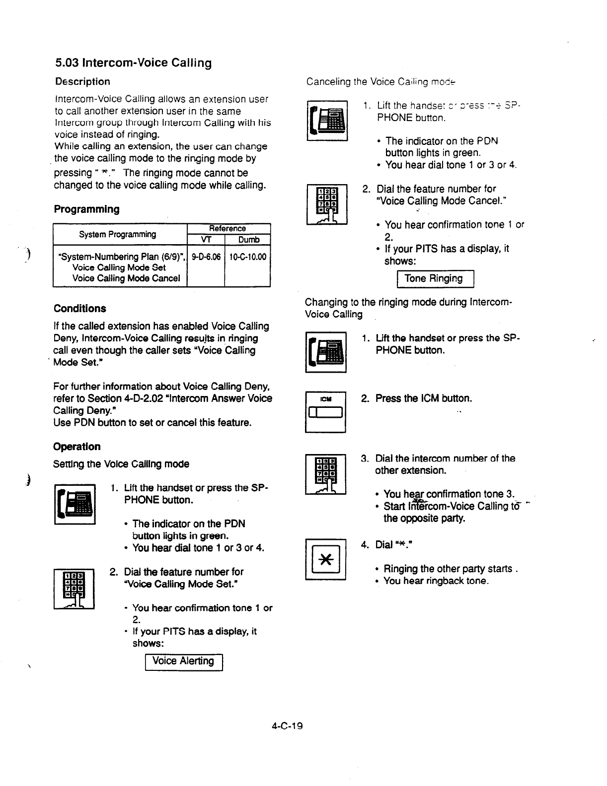
5.03 Intercom-Voice Calling
Description Canceling the Voice Cailing mo&
Intercom-Voice Calling allows an extension user
to call another extension user in the same
Intercom group through intercom Calling with his
voice instead of ringing.
While
calling an extension, the
user can change
the voice calling mode to the ringing mode by
pressing “ *.” The ringing mode cannot be
changed to the voice caliing mode while calling.
1.
Lift the handse: CT z-zss 1-e SF’-
PHONE button.
l
The indicator on the PDN
button lights in green.
l
You hear dial tone 1 or 3 or 4.
2. Dial the feature number for
“Voice Calling Mode Cancel.”
-’
Programming
System Programming Reference
VT
I
Dumb
r)
‘System-Numbering
Plan (6/9)n, 9-D-6.06 10-C-10.00
Voice Calling Mode Set
Voice Calling Mode Cancel I
Conditions
If the called extension has enabled Voice Calling
Deny, Intercom-Voice Calling resujts in ringing
call even though the caller sets “Voice Calling
. Mode Set.”
For further information about Voice Calling Deny,
refer to Section 4-D-2.02 ‘Intercom Answer Voice
Calling Deny.”
Use PDN button to set or cancel this feature.
Operation
Setting the Voice Calling mode
) 1. Lift the handset or press the SP-
PHONE button.
l
The indicator on the PDN
button lights in green.
l
You hear dial tone 7 or 3 or 4.
2. Dial the feature number for
‘voice Calling Mode Set.”
l
You hear confirmation tone 1 or
2.
l
If your PITS has a display, it
shows:
1 Tone Ringing 1
Changing to the ringing mode during Intercom-
Voice Calling
1.
Lift the handset or press the SP-
PHONE button.
/o/
4.
*
Press the ICM button.
Dial the intercom number of the
other extension.
l
You hear confirmation tone 3.
l
Start Ini%$rcom-Voice Calling t6 -
the opposite party.
Dial *.”
l
Ringing the other party starts .
l
You hear ringback tone.
l
You hear confirmation tone 1 or
2.
l
If your PITS has a display, it
shows:
1 Voice Alerting ]
4-c-1 9

5.04 Intercom-Busy Station Signaling
Description
When
the called extension user is busy talking on
a DN or CO button, and the ICM button is idle,
Intercom-Busy Station Signaling informs the
other extension user that he or she is called by
another extension through Intercom Calling with
the flashing ICM button.
The called extension user’s telephone must be
off -hook.
To activate this function, assign “System-Class of
Service”, BSS/OHCA to “Yes.’
If the called extension user’s telephone is PITS
KX-T1232300, KX-T123235 or KX-l7130, Busy
Station Signaling turns into Intercom Off-Hook
Call Announcement (OHCA).
Refer to the next page for further information.
BSS feature is available between the extension
users in the same Intercom group.
.~,
‘System-Class of Sentice (l/2)-, 9-D-4.01 10-C-7.00
Conditions
Intercom-Busy Station Signaling is effective if the
called extension is
preset
to either of the
following functions:
-.
l
‘System-Class~~f Service*, BSSJOHCA
Y
Deny is set to y/es.
l
‘System-Class of Service-, Call
Forwardin@
Do Not Disturb is
set
to Yes.”
Operation
Calling an
extension
1.
Lift the handset or press
the SP-PHONE button.
3. Dial the IntercOrn number of the
c!her extension.
l
You hear ringback
tone.
l
The indicator on the ICM
button of the other station
flashes in 240 wink.
(Supplement)
If the ICM button of the other station is occupied,
the caller hears busy tone.
Answering the call
The indicator on the ICM button flashes in 240
wink and you hear call waiting tone.
Talking to the second caller by disconnecting the
fira Party
1. Press the ICM button.
l
Talktothesecond party.
l
The indicator on the ICM
button lights;
Talking to the second caller by holding the
. .
first
r-l
r=l
1. Press the HOLD button.
H
l
The first party is placed on
hold.
2.
Pre&?6 ICM button. -
l
Speak to the second party.
l
The indicator on the ICM
button lights.
3. Press the button that is flashing
in 60 wink to talk to the first party
again.
l
The second party is
disconnected. Talk to the first
Party.
2. Press the ICM button.
4-C-20

5.05 Intercom Off-Hook Call
Announcement (OHCA)
Description
When the called extension is busy talking on a
DN or CO button, and the ICM button is idle,
OHCA allows the calling extension user to inform
the called party that another call is waiting,
through the built-in speaker of the called party’s
PITS telephone.
OHCA works under the following conditions:
l
The ICM buttons on both the calling
extension’s telephone and the called
extension’s telephone are idle.
l
The called extension’s telephone is PITS
KX-T1232300, KX-T123235 or KX-l7130.
l
The called extension’s handset is off the .
hook.
To activate this function, install T-SW OHCA card
(KX-T336105) in the Basic Slot 02, and OHCA
card (KX-T96136) on the PLC or HLC card.
Refer to Section 2-C-3.02 “T-SW OHCA Card
(KX-T336105)” and Section 2-C-3.03 ‘OHCA
Card (KX-T96136)’ for further information.
In the system programming, assign ‘System-
Class of Service (l/2)“, BSS/OHCA to “Yes” at
calling extension, and assign
‘Extension-Station
(l/3)“, OHCA Circuit to “Yes” at the called
extension.
Programming
.)
System Programming
Reference
-L_ L_. VT 1 Dumb
1 I
‘System-Class of Service (l/2)“, 9-D-4.01 10-C-7.00
SSS/OHCA
‘Extension-Station (l/3)“, 9-G-l .Ol 1 o-c-22.00
OHCA Circuit
Conditions
OHCA does not work if the called extension is
under one of the following conditions:
l
The ICM button is not idle.
l
Talking in the speaker phone mode.
l
“System-Class of Service”, BSSOHCA
Deny is set to “‘Yes.”
l
“System-Class of Service”, Call
Forwarding/Do Not Disturb is set to “Yes.”
Operation
Executing OHCA
1. Lift the handset or press the SP-
PHONE button.
2. Press the ICM button.
3. Dial the intercom number of the
extension. .
l
When the extension is off-
hook, you hear confirmation
tone 3.
q
4. Talk to the other party.
L A-
4-C-21

6.00 Automatic Callback
6.01 Automatic Callback-Trunk
Description
if no idle
CO
line is
available when dialing a
feature number
for selecting a CO line and the
telephone number of
an
outside party, the caller
hears special busy tone.
On-hook while hearing the special busy tone
calls back the caller as soon as a CO line
becomes idle: call-back ringing. Off-hook or
pressing the SP-PHONE button catches the CO
line automatically, and sends the last dialed
telephone number to the CO line.
Off-hook prior to the start of callback ringing
cancels this function.
Also no answer in four ringings (within 10
seconds) after the start of callback ringing
cancels this function.
To activate “Automatic Callback-Trunk,” assign
“Extension-Station”, Automatic Callback-Trunk to
“Yes.”
This setting is assignable on an extension basis.
Programming
System Programming
1
Reference
VT 1 Dumb
I
Operation
Setting Automatic Callback-Trunk (1)
1.
122
EI
2.
4ss
TO*
*
(22
E!tl
3.
4SS
72*
*
“Extension-Station (l/3)“,
Automatic &&a&Trunk
(Supplement)
Conditions
Multiple.exiensions are able to set this function to
one or more CO lines at the same time.
A maximum of 64 Automatic Callback-Trunk can
be active in the system.
If 64 extensions already set this function to one
or more CO lines, another caller’s
attempt to
execute this setting is rejected by normal busy
tone, not by special busy tone.
Even if an extension user sets Call Forwarding-
No Answer or Do Not Disturb, he or she can set
Automatic Callback-Trunk: callback ringing is
effective to the extension.
Lift the handset or press
the SP-PHONE button.
l
You hear dial tone 1 or 3 or 4.
l
The indicator on the PDN
button lights in green.
Dial the feature number for
selecting a CO line.
l
You hear dial tone 1.
Dial the telephone number of the
outside party.
l
You hear busy tone 3.
Replace the handset or press the
SP-PHONE button.
l
If your PITS has a display, it
shows: . .
1 Trunk Queuing 1
The following four feature numbers are available
for selecting a CO line:
l
AF?S/Local CO tine Access
l
Trunk Group 01-08 Access
l
Trunk Group 09-l 6 Access
l
Trunk Group 17-24 Access
Automatic Callback-Trunk cannot be set by the
extension which has a consultation hold call.
4-C-22
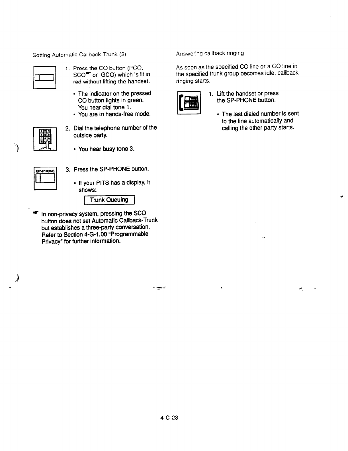
Setting Automatic Callback-Trunk (2)
El
1.
121
E!ll
2.
.99
799
.-.
‘) *
BP-PHONE
r-l
3.
II
Press the CO button (PCO,
SCO* or GCO) which is lit in
red without lifting the handset.
l
The indicator on the pressed
CO button lights in green.
You hear dial tone 1.
l
You are in hands-free mode.
Dial the telephone number of the
outside party.
l
You hear busy tone 3.
Press the SP-PHONE button.
l
If your PITS has a display, it
shows:
1 TrunkQueuing 1
* In non-privacy system, pressing the SC0
button does not set Automatic Callback-Trunk
but establishes a three-party conversation.
Refer to Section 4-G-l .OO “Programmable
Privacy” for further information.
Answering callback ringing
As soon as the specified CO line or a CO line in
the specified trunk group becomes idle, callback
ringing starts.
1.
Lift the handset or press
the SP-PHONE button.
I- I
l
The last dialed number is sent
to the line automatically and
calling the other party starts.
4-C-23
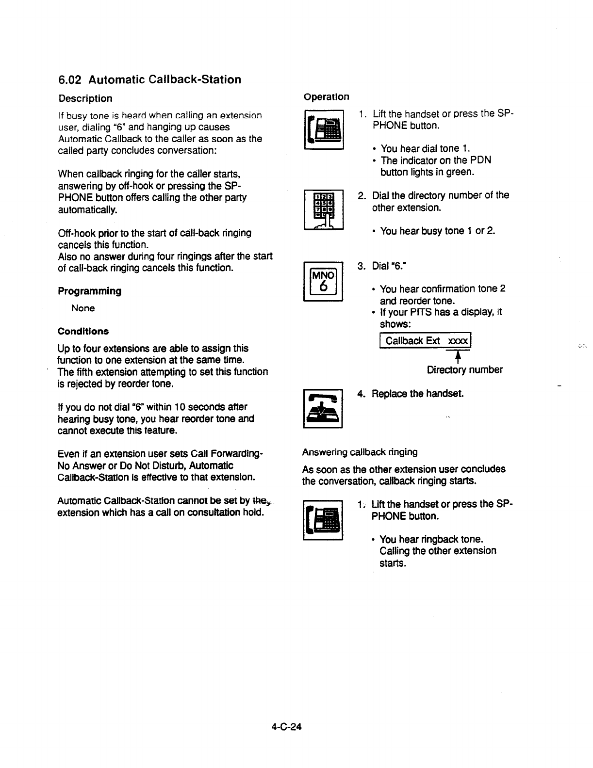
6.02 Automatic Callback-Station
Description Operation
If busy tone is
heard when calling an extension
user, dialing “6”
and hanging up causes
Automatic Callback to the caller as soon as the
called party concludes conversation:
I
l
You hear dial tone 1.
l
The indicator on the PDN
button lights in green.
When callback ringing for the caller starts,
answering by off-hook or pressing the SP-
PHONE button offers calling the other party
automatically.
Off-hook prior to the start of till-back ringing
cancels this function.
Also no answer during four ringings after the start
of call-back ringing cancels this function.
Programming
None
Conditions
Up to four extensions are able to assign this
function to one extension at the same time.
. The fifth extension attempting to set this function
is rejected by reorder tone.
If you do not dial “6” within 10 seconds after
hearing busy tone, you hear reorder tone and
cannot execute this feature.
Even if an extension user sets Call Forwarding-
No Answer or Do Not Disturb, Automatic
Callback-Station is effective to that extension.
Automatic Callback-Station cannot be set by tRe,.,
extension which has a call on consultation hold.
1. Lift
the
handset or press the SP-
PHONE button.
2. Dial the directory number of the
other extension.
l
You hear busy tone 1 or 2.
m
3. Dial “6.”
l
You hear confirmation tone 2
and reorder tone.
l
If your PITS has a display, it
shows:
1 Callback Ext xxxx 1
Direct&y number
4. Replace the handset.
. .
Answering callback ringing
As soon as the other extension user concludes
the conversation, callback ringing starts.
1, Lift the handset or press the SP-
PHONE button.
l
You hear ringback tone.
Calling the other extension
starts.
4-C-24
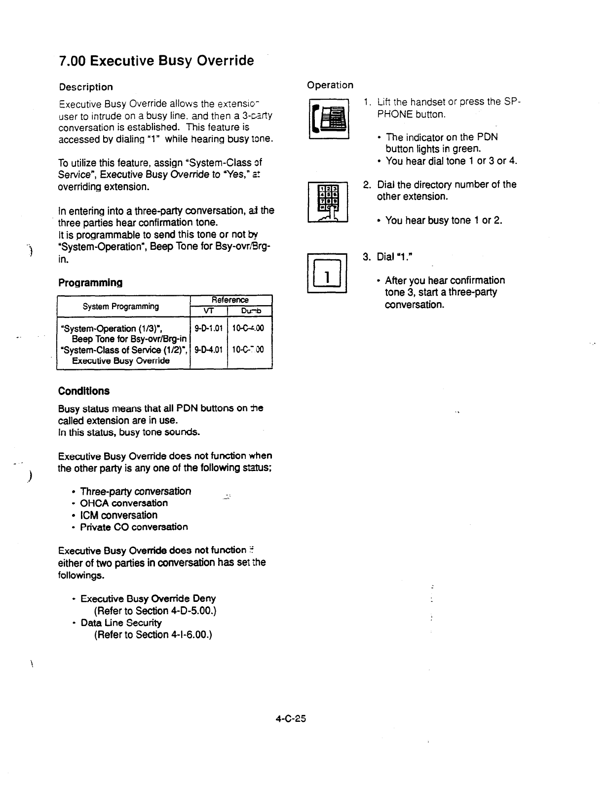
7.00 Executive Busy Override
Description
Executive Busy Override allows the etiensio-
user to intrude on a busy line. and then a 3-&zfty
conversation is established. This feature is
accessed by dialing “1” while hearing busy tone.
Operation
To utilize this feature, assign ‘System-Class 3f
Service”, Executive Busy Override to ‘Yes,” =t
overriding extension.
In entering into a three-party conversation, aJ the
three parties
hear confirmation tone.
It is programmable to send this tone
or
not &
‘System-Operation”, Beep Tone for Bsy-ovr/Srg-
in.
Programming
System
Programming
Reference
VT t DC&I
-- .~‘“‘”
“System-Class of Service (l/2)‘,
9-D-4.01 10-G: 90
Conditions
Busy status means that all PDN buttons on he
called extension are in use.
In this status, busy tone sounds.
Executive Busy Override does not function when
- 1
1 the other patty is any one of the following status;
l
Three-party conversation __
l
OHCA conversation -:
l
ICM conversation
l
Private CO conversation
Executive Busy Override does not function ?
either of two parties in conversation has set
the
followings.
1.
Lift the handset or press the SP-
PHONE button.
l
The indicator on the
PDN
button lights in green.
l
You hear dial tone 1 or 3 or 4.
2. Dial the directory number of the
other extension.
I AL I
l
You hear busy tone 1 or 2.
•l
3. Dial ‘1.”
1
l
After you hear confirmation
tone 3, start a three-patty
conversation.
l
Executive Busy Override Deny
(Refer to Section 4-D-5.00.)
l
Data tine Security
(Refer to Section 4-I-6.00.)
4-C-25
8.00 Do Not Disturb (DND)
Overt ide
Description
Do Not Disturb Override allows an extension to
call another extension which has set Do Not
Disturb.
Dialing “1” after hearing DND tone provides
calling the extension.
Refer to Section 4-D-6.00 ‘Do Not Disturb
(DND)” for further information about DND feature.
To activate this function, assign “System-Class of
Service”, Do Not Disturb Override to “Yes.”
Programming
System !hgramming Reference
VT 1 Dumb
I
‘System-Class
of
Service
(l/2)‘, 9-D-4.01 1067.00
Do Not Distuti Override I I I
Operation
1. Lift the handset or press the SP-
PHONE button.
l
The indicator on the PDN
button lights in green.
l
You hear dial tone 1 or 3 or 4.
2. Dial the directory number of the
other extension.
l
if the other extension sets DND
(Do Not Disturb), you hear
DND tone.
m
3. Dial ‘1 .II
l
You hear ringback tone.
l
Calling the other party starts.
Conditions
When dialing ‘1; if the other extension is busy,
the caller hears busy tone. In this case, it is
possible to assign Automatic Callback-Station,
etc.,.
For Automatic Callback-Station, refer to Section
4-C-6.02 UAutomatic Callback-Station.”
::a..
‘
If “System-Class of Service,” Do Not Disturb
Override is set to ‘No,” the caller hears reorder
tone after dialing ‘1” and cannot call the other
party.
4-C-26
9.00 Walking COS (Class Of
Service)
Description
Allows an ex:er,slo:: user 10
call
an outside party
from another extension preset to a lower COS
(Class of Servvlce) by using a higher COS of his
or her own extension temporarily.
This
is generally
used for making .toll calls from a
toll
restricted extension.
After conclusion of one call to an outside party,
Class of Setvce of the employed station returns
to the original class automatically.
Each tenant has a four digit Walking COS
Password programmed in system program.
The password allows a user to set Walking COS.
‘System-Operation (3/3)“,
Walking COS Password
“System-Tenant”,
Walking COS Password
(Tenant 2)
“System-Numbering Plan (719)‘)
Walking COS Set
Walking COS Cancel
Programming
I
System Programming Reference
VT Dumb
Conditions
g-D-1.03
w-2.00
~ 9-D-6.07
1 O-C-S.00
10-GS.W
1fl-G10.00
Use the PDN button to set and cancel Walking
cos. x?z -**.?I
Operation
Setting Walking COS
From a lower COS telephone,
1.
Lift the handset or press the SP-
l
COS returns to the original
PHONE button. grade.
3. Dial the four-digit Walking COS
Password.
123
q
4. Dial the extension number of
42s
12, your own station.
l
l
You hear confirmation tone 2.
l
If your PITS has a displtiy, it
shows:
t Set COS of Exxxx 1
3L
Directory number
I
5. Call an outside party by using a
higher COS of your own station.
Canceling Walking COS
It is possible to cancel Walking COS without
making any call to an outside party as follows:
1. Lift the handset ot,press the SP-
PHONE button.
2. Dial the feature number for
Waking COS Cancel.”
l
You he.& confirmation tone 2.
l
If your PITS has a display, it
shows:
I Restored COS I
2. Dial the feature
number for
‘Walking COS Set.”
4-C-27
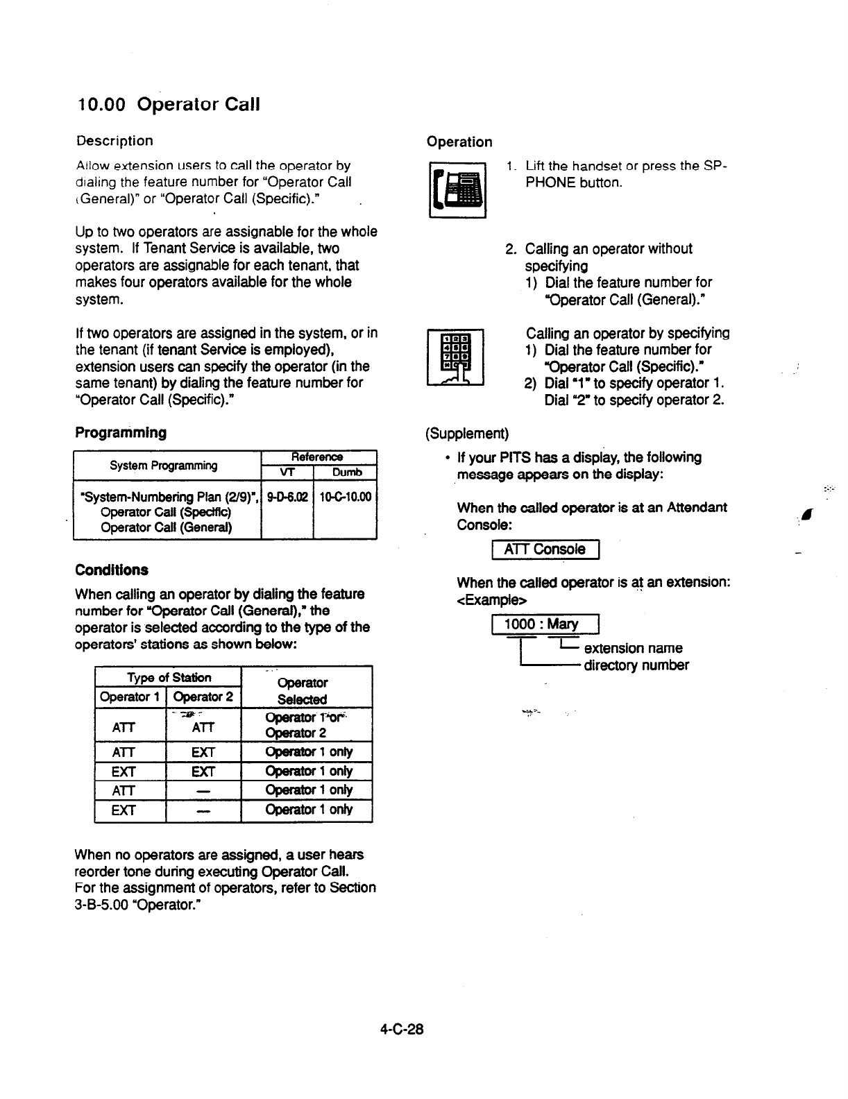
10.00 Operator Call
Description
Allow extension users to call the operator by
dialing the feature number for “Operator Call
cGen&al)” or “Operator
Call (Specific).”
Operation
1.
Up to two operators are assignable for the whole
system. If Tenant Service is available, two
operators are assignable for each tenant, that
makes four operators available for the whole
system.
If two operators are assigned in the system, or in
the
tenant (if tenant Service is employed),
extension users can specify the operator (in the
same tenant) by dialing the feature number for
“Operator Call (Specific).”
Programming
System Programming Reference
r VT 1 Dumb
I
‘System-Numbering Plan (2/g)‘, 94-6.02
1O-G10.00
Operator Call (Specific)
Operator Call (General)
Conditions
When calling an operator by dialing the feature
number for “Operator Call (General),” the
operator is selected according to the type of the
operators’ stations as shown below:
Type of Station
Operator
1 Operator 2
-TzF-
ATT
ATT
ATT
EXT
Al-T -
EXT -
- bperator
8elected
s: T”
-1 onfy
operalorf only
operator1 on&
Operator 1 only
2.
I22
4‘.
L!fl
7.2
*
(Supplement)
Lift the handset or press the SP-
PHONE
button.
Calling an operator without
specifying
1)
Dial
the feature number for
“Operator Call (General).”
Calling an operator by specifying
1) Dial the feature number for
Qperator
Call (Specific).”
2) Dial ‘1 I to specify operator 1.
Dial ‘2’ to specify operator 2.
.
If your PITS has a display, the following
message appears on the display: :::-
When the called operator is at an Attendant
Console:
1 AlTConsole 1
.,I
When the called operator is at an extension:
&le>
1 1000:Mary J
T-z extension name
directory number
When no operators are assigned, a user hears
reorder tone during executing Operator Call.
For the assignment of operators, refer to Section
3-B-5.00 “Operator.”
4-C-28

D.
Receiving Features
1 .OO Line Selection-Answering
Description Description
Line Selection-Answering feature
allows a
PITS
telephone user to answer an incoming call on it
by simply lifting the handset or pressing the SP-
PHONE button.
Air:~maxally connects a
PITS telephone user to
an incoming call ringing at PITS telephone by
simply
lifting
the handset.
Line access buttons that can be selected by this
feature include PDN, SDN, ICM, PCO, SC0 and
GCO buttons.
One of the following three Line Selection-
Answering features can be assigned to a PITS
telephone individually.
l
Ringing Line Preference - Answering
l
Prime tine Preference - Answering
l
No Line Preference - Answering
Ringing Line Preference-Answering is assigned
to all PITS telephones by default.
This assignment can be changed on a PITS
telephone basis in PITS station programming
mode.
To prevent a PITS telephone from automatically *
answering an incoming call by simply going off-
hook, assign No Line Preference-Answering
feature to the PITS telephone.
If No Line Preference-Answering is assigned,
press the appropriate button on a PITS telephone
to answer a call.
tine Selection-Answering feature newly assigned
on a PITS overrides the pre-assigned tine
Selection-Answering feature.
1 .Ol Ringing Line
Preference-Answering
Programming
I
PITS Station Programming I Reference
I
I
Automatic Answering
Selection 1 12-c-5.00 1
Conditions
It two or more line on a PITS are ringing
simultaneously, a PITS telephone user is
connectedto
the first line to start ringing.
If a PITS telephone user wishes to answer a line
other than the first rfnging line, the desired line
access button must be pressed prior to going off-
hook (Refer to Section 4-D-l .04 “Direct
Answering (Pm-selection).?
This feature functions only for incoming calls
ringing at a PITS telephone. ..
Consequently, if an incoming call arrives at a line
access button on which delayed ringing is
assigned, that is, no rlnging occurs while the
indicator flashes in 240 wink, in this case
extension user must press the appropriate line
access button to answer the incoming call.
Refer to Section 3-D-3.02 “Flexible Ringing
Assignment-Delayed Ringing” for further
information about delayed ringing.
Operation
An incoming call is ringing at your telephone.
Also the indicator light on the call-receiving button
flashes in 240 wink, showing the arrfval of the call.
1. Lift the handset or press the SP-
PHONE button.
l
You can automatically answer
the incoming call ringing, and
the indicator on the button
lights in green.
l
Talk to the caller.
4-D-l
1.02 Prime Line Preference-Answering
Description Operation
Automatically connects a
PITS
Wmhore :s
answer an incoming call assigned as “P%e Line
(Answering)” on a
PITS
telephone.
Line access buttons that
can be selected by this
feature include
PDN, SDN, ICM, PCO, SC0
and
GCO buttons.
A call arrives at the assigned prime line and your
telephone is ringing. The indicator on the line
access button assigned as Prime line flashes in
240 wink.
Even if two or more lines on
a PITS
are ringing
simultaneously, PITS telephone is automatically
connected to an incoming call on a line assigned
as Prime Line-Answering by simply lifting the
handset or pressing the SP-PHONE button.
Programming
I
PITS
Station Programming I
Reference I
I
Automatic Answering Selection I
12-GWO I
Conditions
. When a call or calls are coming on a line or lines
other than the prime line, lifting the handset or
pressing the SP-PHONE button is considered as
a calling operation. If you wish to answer the call
at the time, press the desired line access button.
Refer to Section 4-C-i .Ol ‘Prime tine
Preference-calling” for related information.
It is possible to answer desired incoming call by
pressing the appropriate DN or CO button
directly
without lifting the handset or pressing the
SP-PHONE button (Direct Answering).
Refer to Sectft~&D-1.04 “Direct Ar%wexing
(Pre-selection)” for further information.
1. Lift the handset or press the SP-
PHONE button.
I
l
The indicator on the call-
receiving button lights in green.
l
Talk to the caller.
k
4-D-2
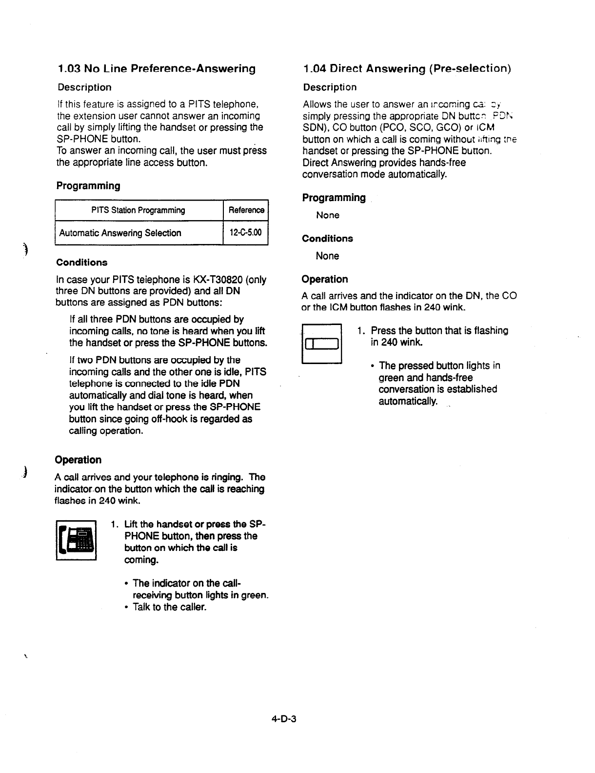
1.03 No Line Preference-Answering 1.04 Direct Answering (Pre-selection)
Description Description
if this feature is assigned to a PITS telephone,
the extension user cannot answer an incoming
call by simply lifting the handset or pressing the
SP-PHONE button.
To answer an incoming call, the user must pr&s
the appropriate line access button.
Allows the user to answer an ircoming cz: zJ
simply pressing the appropriate DN butte- .PDp;
SDN), CO button (PCO, SCO, GCO) or rCM
button on which a call is coming without ilfting :ne
handset or pressing the SP-PHONE button.
Direct Answering provides hands-free
conversation mode automatically.
Programming
I
PITS Station Programming I Reference
I
Automatic Answering Selection I 12-Gs.00 I
Conditions
In case your PITS teiephone is KX-T30820
(only
three DN buttons are provided) and all DN
buttons are assigned as PDN
buttons:
If all three PDN buttons are occupied by
incoming calls, no tone is heard when you lift
the handset or press the SP-PHONE buttons.
If two PDN buttons are occupied by the
incoming calls and the other one is idle, PITS
telephone is connected to the idle PDN
automatically and dial tone is heard, when
you lift the handset or press the SP-PHONE
button since going off-hook is regarded as
calling operation.
Operation
3
A call arrives and your telephone is ringing. The
indicator:on the button which the call is reaching
flashes in 240 wink.
1. Lift the handset
or
press the SP-
PHONE button, then press the
button on which the call is
coming.
Programming
None
Conditions
None
Operation
A call arrives and the indicator on the DN, the CO
or the ICM
button flashes in 240 wink.
1. Press the button that is flashing
in 240 wink.
l
The pressed button lights
in
green and hands-free
conversation is established
automatically. ,.
l
The indicator on the call-
receiving button lights in green.
l
Talk to the caller.
4-D-3
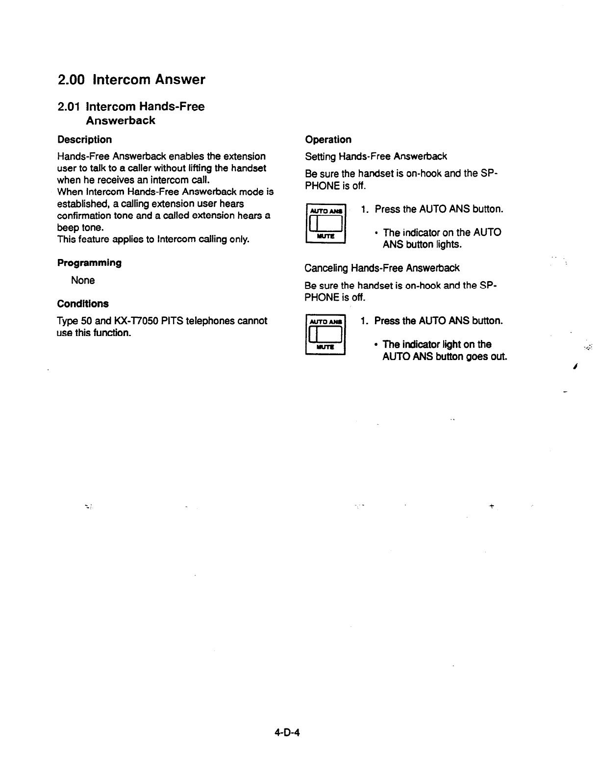
2.00 Intercom Answer
2.01 Intercom Hands-Free
Answerback
Description
Hands-Free Answerback enables the extension
user to talk to a caller without lifting the handset
when he receives an intercom call.
When Intercom Hands-Free Answerback mode is
established, a calling extension user hears
confirmation tone and a called extension hears a
beep tone.
This feature applies to Intercom calling only.
Programming
None
Conditions
Type 50 and KX-l7050 PITS telephones cannot
use this function.
Operation
Setting Hands-Free Answerback
Be sure the handset is on-hook and the SP-
PHONE is off.
*vTO*w
cl
1. Press the AUTO ANS button.
[I
l
The indicator on the AUTO
ANS button lights.
Canceling Hands-Free Answerback
Be sure the handset is on-hook and the SP-
PHONE is off.
1. Press the AUTO ANS button.
l
The indicator liiht on the
AUTO ANS button goes out.
4-D-4
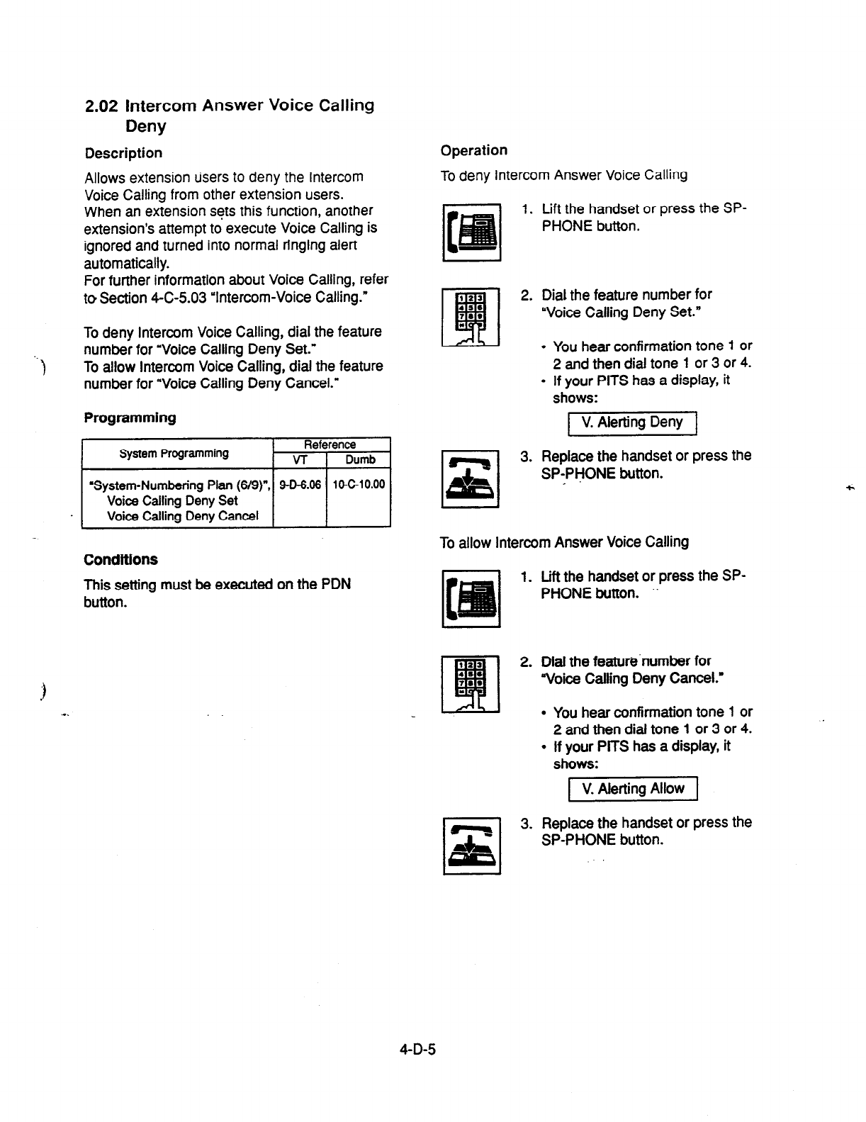
2.02 Intercom Answer Voice Calling
Deny
Description
Allows extension Users to deny the intercom
Voice Calling from other extension users.
When an extension sets this function, another
extension’s attempt to execute Voice Calling is
ignored and turned into normal ringing alert
automatically.
For further information about Voice Calling, refer
to Section 4-C-5.03 ‘Intercom-Voice Calling.”
To deny Intercom Voice Calling, dial the feature
number for “Voice Calling Deny Set.”
To allow Intercom Voice Calling, dial the feature
number for “Voice Calling Deny Cancel.”
Programming
System Programming Reference
VT 1 Dumb
I
-System-Numbering Plan (s/s)“, 9-D-6.06 IO-C-10.00
Voice Calling Deny Set
Voice Calling Deny Cancel
Conditions
This setting must be executed on the PDN
button.
Operation
To deny Intercom Answer Voice Calling
1. Lift the handset or press the SP-
PHONE button.
El
s,
3.
Dial the feature number for
“Voice Calling Deny Set.”
l
You hear confirmation tone 1 or
2 and then dial tone 1 or 3 or 4.
l
If your PITS has a display, it
shows:
pKi%ipq
Replace the handset or press the
SPYPHONE button.
To allow Intercom Answer Voice Calling
1. Lift the handset or press the SP-
PHONE button. ”
2. Dial the feature’number for
Voice Calling Deny Cancel.”
.
.
You hear confirmation tone 1 or
2 and then dial tone 1 or 3 or 4.
If your PITS has a display, it
shows:
3. Replace the handset or press the
SP-PHONE button.
4-D-5
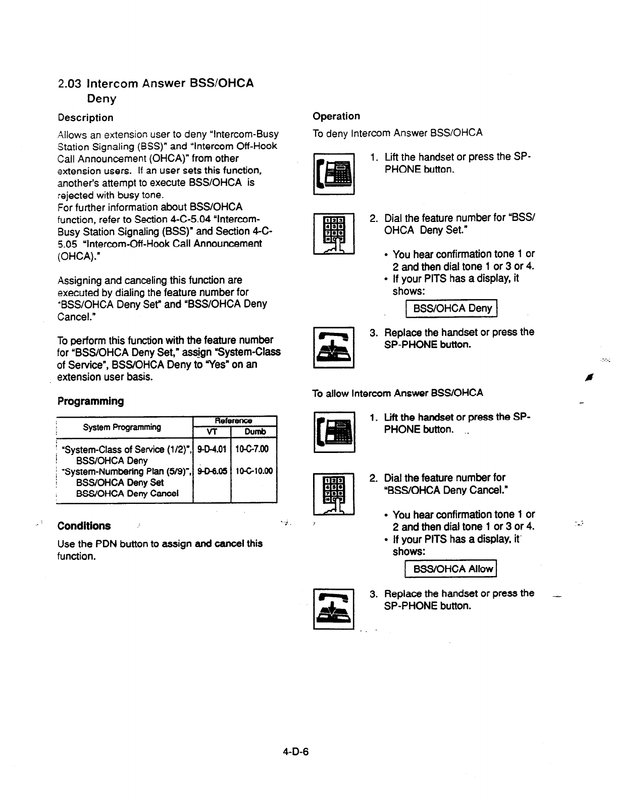
2.03 Intercom Answer
BSS/OHCA
Deny
Description Operation
To deny Intercom Answer BSS/OHCA Allows an extension user to deny “Intercom-Busy
Station Signaling (BSS)” and “Intercom Off-Hook
Call Announcement (OHCA)” from other
extension users. If an user sets this function,
another’s attempt to execute BSSIOHCA is
rejected with busy tone.
For further information about BSS/OHCA
function, refer to Section 4-C-5.04 “Intercom-
Busy Station Signaling (BSS)” and Section 4-C-
5.05 “Intercom-Off-Hook Call Announcement
(OHCA).”
1. Lift the handset or press the SP-
PHONE button.
2. Dial the feature number for “BSS/
OHCA Deny Set.”
l
You hear confirmation tone 1 or
2 and then dial tone 1 or 3 or 4.
l
If your PITS has a display, it
shows:
Assigning and canceling this function are
executed by dialing the feature number for
‘BSSIOHCA Deny Set” and ‘BSS/OHCA Deny
Cancel.”
To perform this function with the feature number
for “BSS/OHCA Deny Set,” assjgn “System-Class
of Service”, BSS/OHCA Deny to yes” on an
extension user basis.
Programming
System Prqamming Reference
VT Dumb
j “System-Class of Service (l/2)‘, 9-D-4.01
10-C-7.00
BSSIOHCA Deny
i “System-Numbering Plan (5/g)“, &O-6.05 10-C-10.00
BSS/OHCA Deny Set
BSS/OHCA Deny Cancel
3. Replace the handset or press the
SP-PHONE button. I.‘..
To allow Intercom Answer BSSlOHCA
Conditions .: . I
Use the PDN button to assign and cancel this
function.
Lift the handset or press the SP-
PHONE button. ,
Dial the feature number for
“BSS/OHCA Deny Cancel.”
l
You hear confirmation tone 1 or
2 and then dial tone 1 or 3 or 4.
l
If
your
PITS
has
a display, it’
shows:
Replace the handset or press the ._
SP-PHONE button.
4-D-6
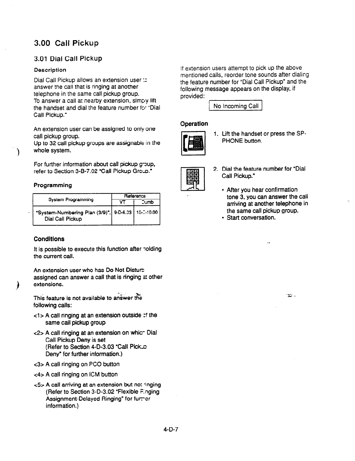
3.00 Call Pickup
3.01 Dial Call Pickup
Description
Dial Call Pickup allows an extension user 13
answer !he call that is ringing at another
telephone in the same call pickup group.
To answer a call at nearby extension, simpy lift
the handset and dial the feature number fcl- “Dial
Call Pickup.”
An extension user can be assigned to only one
call pickup group.
Up to 32 call pickup groups are assignable in the
-I whole system.
For further information about call pickup gnup,
refer to Section 3-B-7.02 “Call Pickup Grola.’
Programming
System Programming Referen=
VT 1 Zumb
I
. “System-Numbering Plan (3/g)“, 9-D-6.-33
l@--1-iO.00
Dial Call Pickup I I
Conditions
It is possible to execute this function after Tolding
the current call.
An extension user who has Do Not Distuti
assigned can answer a call that is ringing zt other
extensions.
This feature is not available to &ver t&
following calls:
cl > A call ringing at an extension outside :f the
same call pickup group
c2>
A call ringing at an extension on whit- Dial
Call Pickup Deny is set
(Refer to Section 4-D-3.03 “Call Piti
Deny” for further information.)
c3>
A call ringing on PC0 button
c4>
A call ringing on ICM button
~5
A call arriving at an extension but nor inging
(Refer to Section 3-D-3.02 “Flexible Enging
Assignment-Delayed Ringing” for furer
information.)
If extension users attempt to pick up the above
mentioned calls, reorder tone sounds after dialing
the feature number for “Dial Call Pickup” and the
following message appears on the display, if
provided:
No Incoming Call
Operation
1. Lift the handset or press the SP-
PHONE button.
2. Dial the feature number for “Dial
Call Pickup.”
l
After you hear confirmation
tone 3, you can answer the call
arriving at another telephone in
the same call pickup group.
l
Start conversation.
. .
4-D-7
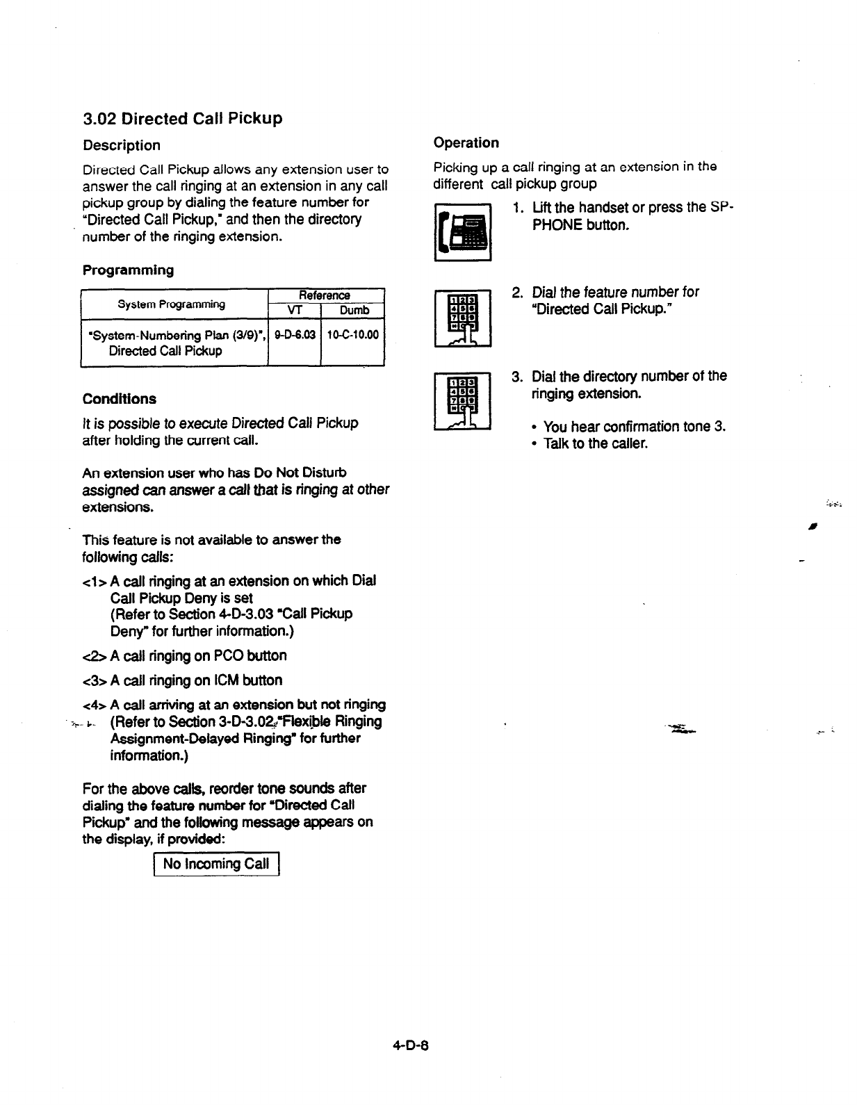
3.02 Directed Call Pickup
Description Operation
Directed Call Pickup allows any extension user to
answer the call ringing at an extension in any call
pickup
group by dialing the feature number for
“Directed Call Pickup,’ and then the directory
number of the ringing extension.
Picking up a call ringing at an extension in the
different call pickup group
1. Lift the handset or press the SP-
PHONE button.
Programming
System
Programming
Reference
VT
I
Dumb
‘System-Numbering Plan (3/g)”
Directed Call Pickup
Conditions
It is possible to execute Directed Call Pickup
after holding the current call.
An extension user who has Do Not Disturb
assigned can answer a call that is ringing at other
extensions.
This feature is not available to answer the
following calls:
cl> A call ringing at an extension on which Dial
Call Pickup Deny is set
(Refer to Section 4-D-3.03 %afl Pickup
Deny” for further information.)
& A call ringing on PC0 button
<3> A call ringing on ICM button
<4> A call arriving at an extension but not ringing
+ L (Refer to Section 3-D-3.O~Flexipie Ringing
Assignment-Delayed Ringing’ for further
information.)
For the above calls, reorder tone sounds after
dialing the feature number for “Directed Call
Pickup” and the following message appears on
the display, if provided:
2. Dial the feature number for
“Directed Call Pickup.”
3. Dial the directory number of the
ringing extension.
l
You hear confirmation tone 3.
l
Talk to the caller.
No Incoming Call
4-D-8
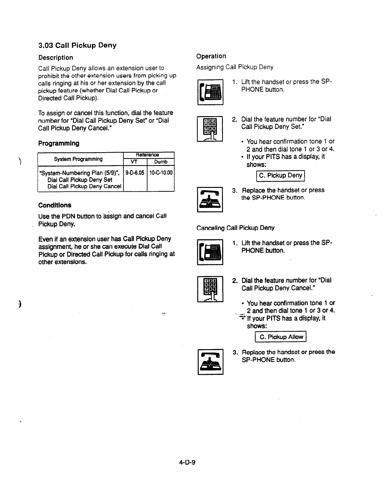
3.03 Call Pickup Deny
Description
Call Pickup Deny allows an extension user to
prohibit the other extension users from picking up
calls ringing at his or her extension by the call
pickup feature (whether Dial Call Pickup or
Directed Call Pickup).
Operation
To assign or cancel this function; dial the feature
number for “Dial Call Pickup Deny Set” or “Dial
Call Pickup Deny Cancel.”
Programming
Conditions
Use the PDN button to assign and cancel Call
Pickup Deny.
Even if an extension user has Call Pickup Deny
assignment, he or she can execute Dial Call
Pickup or Directed
Call
Pickup for calls ringing at
other extensions.
z-*
Assigning Call Pickup Deny
1. Lift the handset or press the SP-
PHONE button.
2. Dial the feature number for “Dial
Call Pickup Deny Set.”
l
You hear confirmation tone 1 or
2 and then dial tone 1 or 3 or 4.
l
If your PITS has a display, it
shows:
3. Replace the handset or press
the SP-PHONE button.
Canceling Call Pickup Deny
1. Lift the handset or press the SP-
PHONE button.
2. Dial the feature number for “Dial
Call Pickup Deny Cancel.”
l
You hear confirmation tone 1 or
2 and then dial tone 1 or 3 or 4.
=%f your PITS has a dispfay, it
shows:
1 C. Pikuo Allow 1
3. Replace the handset or press the
SP-PHONE button.
4-D-9

4.00 Trunk Answer From Any
Station (TAFAS)-Day
Service
Description
Incoming CO calls programmed for TAFAS will
ring the external pager and any extension user in
the system can answer the calls by dialing the
feature number for “Night Answer 1” (when a call
is ringing at external pager 1) or “Night Answer 2
(when a call is ringing at external pager 2).
To activate this feature. assign “Group-Trunk
Group”, Incoming Mode (Day) to TAFAS 1 or
TAFAS 2, and “Trunk-CO tine” Trunk Group to ‘1
to 16” (Trunk Group Number whose Incoming
Mode (Day) is assigned as TAFAS 1 or 2).
To utiiize the external pager, assign ‘System-
Operation”, External Paging
1, 2”
to ‘Yes.’
Up to two external pagers can be connected to
this system. TAFAS 1 is associated with external
pager 1 and TAFAS 2 is associated with external
pager 2.
Call handling in TAFAS is identical to UNA. The
difference is that TAFAS is available in day mode
and UNA is available in night mode.
For further information about UNA, refer to
Section 4-l-l .Ol ‘Universal Night Answer (UNA).”
System Programming Reference - .
VT Dumb
‘System-Operation
(l/3)‘. .9-D-1.01 lO-c-4xM
External
Paging
1,2
‘System-Numbeting Plan (3/g)“, W-8.03 10-C-10.00
Night Answer 1
Night Answer 2
%roup-Trunk-Group (l/2)“, 9-E-1.01 10-G14.00
Incoming Mode (Day)
Trunk-CO tine”, SF-l.00
10678.00
Trunk Group
Trunk-Pager & Music Source”, 9-F-2.00 1 O-C-1 9.00
External Pager-Tenan?
Conditions
If tenant service is employed :
The affiliation of each external pager is
determined by the system programming in
“Trunk-Pager & Music Source”, External Pager-
Tenant.
Extension users cannot answer the TAFAS call
ringing at an external pager in the different
tenant.
Operation
Answering incoming CO calls programmed for
TAFAS
An incoming CO call is ringing at an
external pager.
.l . Lift the handset or press the SP- I
PHONE button.
l
You hear dial tone 1 or 3 or 4.
2. If a call is ringing at external
pager 1: Dial the feature number
for “Night Answer 1 .*
If a call is ringing at external
pager 2: Dial the feature number
for “Night Answer 2.”
“Y 7 I
3. Talk to the caller.
4-D-l 0
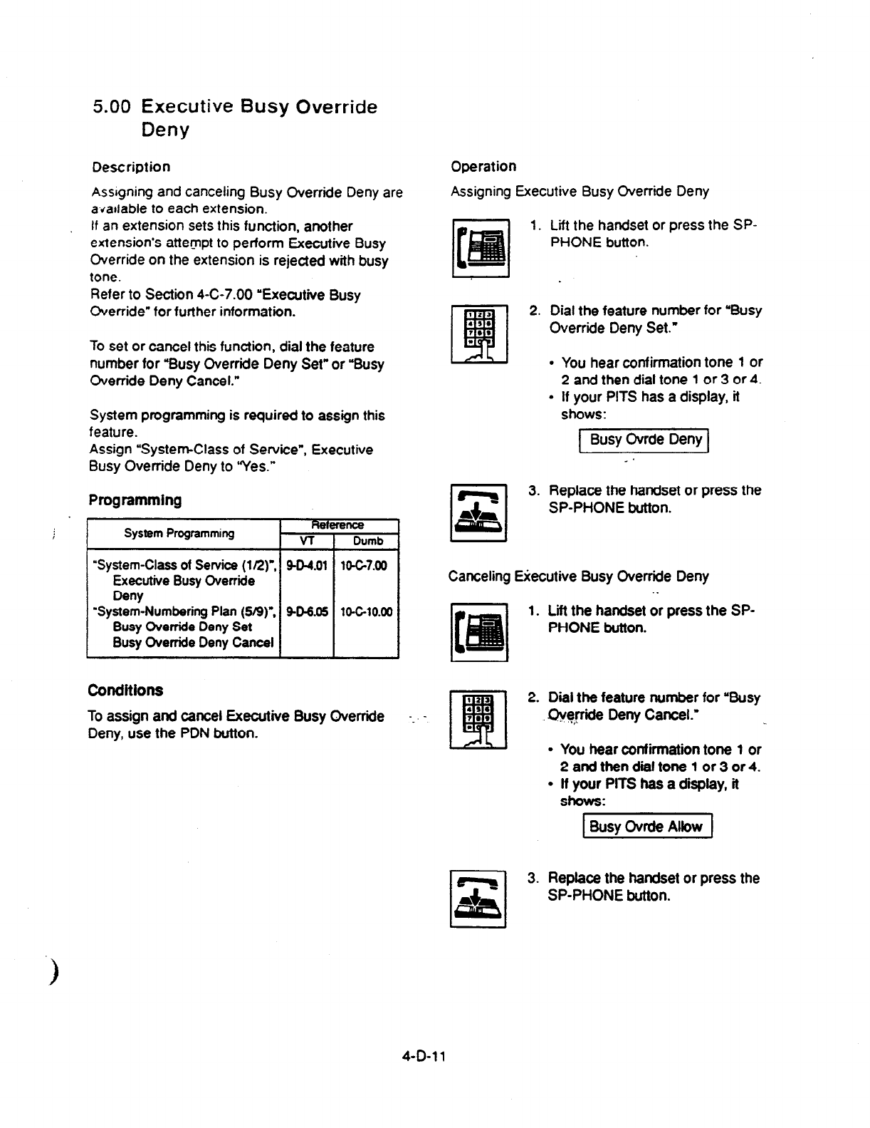
5.00 Executive Busy Override
Deny
Description
Assigning and canceling Busy Override Deny are
a,dallable to each extension.
If an extension sets this function, another
extension’s attempt to perform Executive Busy
Override on the extension is rejected with busy
tone.
Refer to Section 4-C-7.00 “Executive Busy
Override” for further information.
To set or cancel this function, dial the feature
number for “Busy Override Deny Set” or “Busy
Override Deny Cancel.”
System programming is required to assign this
feature.
Assign “System-Class of Service”, Executive
Busy Override Deny to ‘Yes.”
Programming
System Programming Refemlce
vi
Dumb
“System-Class of
Senrice
(la)“, W-4.01 10-C-7.00
Executive Busy Override
Deny
“System-Numbering Plan (5B)“. W-6.05 10440.00
Busy Override Deny Set
Busy Override Deny Cancel
conditions
To assign and cancel Executive Busy Override
Deny, use the PDN button.
-
Operation
Assigning
Executive Busy Override Deny
1. Lift the handset or press the SP-
PHONE button.
2. Dial the feature number for “Busy
Override Deny Set.”
l
You hear confirmation tone 1 or
2 and then dial tone 1 or 3 or 4.
l
If your PITS has a display, it
shows:
1 Busy Ovrde Deny 1
rl
x
- .
3. Replace the handset or press the
SP-PHONE button.
Canceling Ekutive Busy Override Deny
. .
1. Lii the handset or press the SP-
PHONE button.
(21
q
2. Dial the feature number for ‘Busy
.,‘
1.. Ch@cte Deny Cancel.” _,
.
l
You hear confirmation tone 1 or
2andthendialtonel or3or4.
l
If your PITS has a display, it
shows:
t Busv Ovrde Albw 1
3. Replace the handset or press the
SP-PHONE button.
4-D-1 I
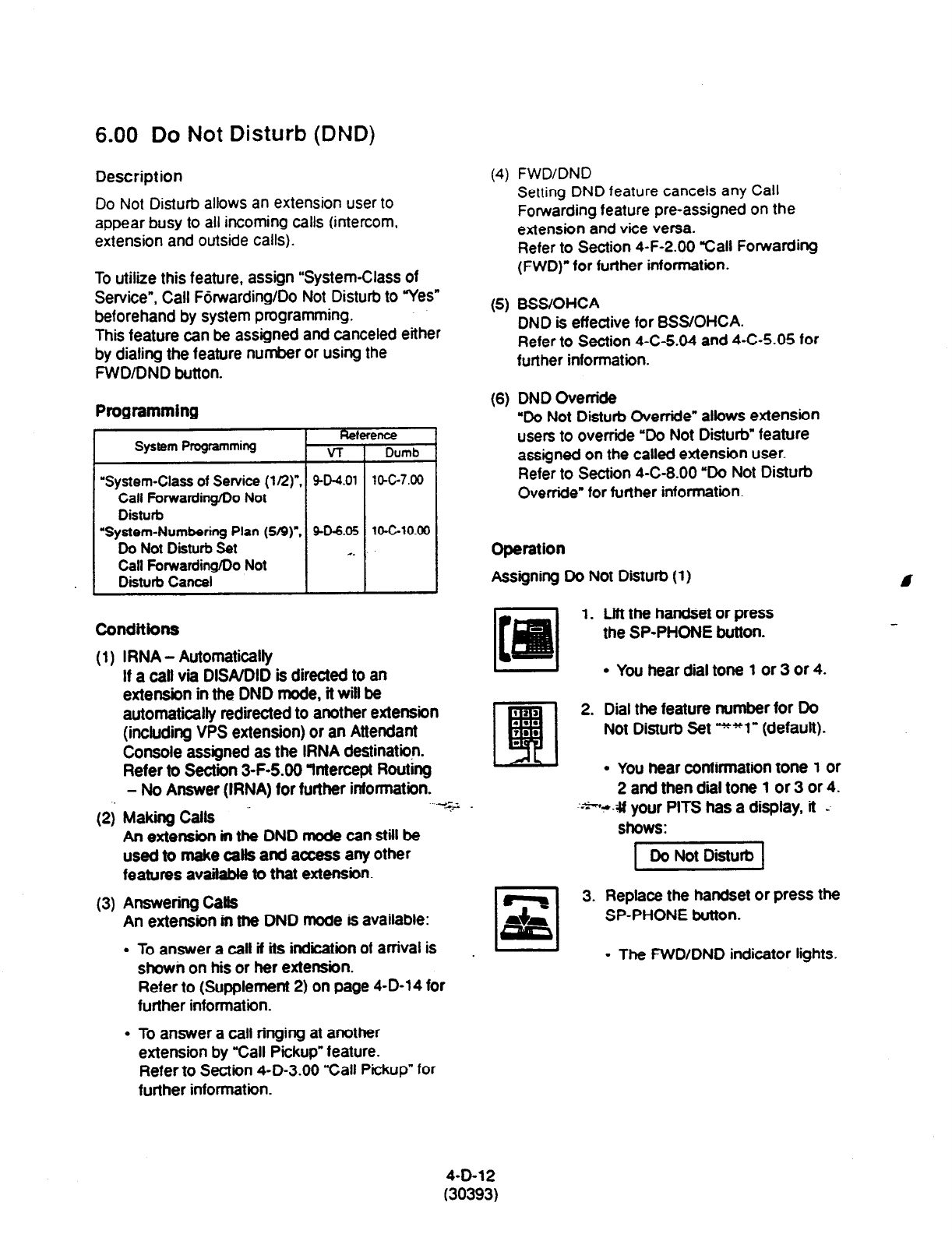
6.00 Do Not Disturb (DND)
Description
Do Not Disturb allows an extension user to
appear busy to all incoming calls (intercom,
extension and
outside calls).
To utilize this
feature,
assign “System-Class of
Service”, Call Forwarding/Do Not Disturb to “Yes”
beforehand by system programming.
This feature can be assigned and canceled either
by dialing the feature number or using the
FWDIDND button.
Programming
Fkterence
System Programming v-r Dumb
“System-Class of Service (l/2)“.
SW.01 lW-7.00
Call Forwarding/Do Not
Disturb
“System-Numbering Plan (S/9)‘. 9-D-6.05
10-C-10.00
Do Not Disturb Set . .
Call
Forwarding/Do Not
Disturb Cancel
Conditions
(1)
(2)
(3)
IRNA
- Automatically
If a catl via DWUDID is directed
to an
extension in the DND mode, it will be
automatically redirected to another extension
(including VPS extension) or an Attendant
Console assigned as the IRNA destination.
Refer to Section 3-F-5.00 “fntercept Routrng
- No Answer (IRNA) for further information.
Making Calls
.-t&2
An extension in the DND mode can still be
used to make calls
and access
any other
features available to
that
extension.
Answering Calts
An extension in the DND mode is available:
l
To answer a call if its indiiion of arrival is
showi, on his or her extension.
Refer to (Supplement 2) on page 4-D-14 for
further information.
l
To answer a call ringing at another
extension by “Call Pickup” feature.
Refer to Section 4-D-3.00 “Call Pickup” for
further information.
(4)
FWD/DND
Setting DND feature cancels any Call
Fowarding feature pre-assigned on the
extension and vice versa.
Refer to Section 4-F-2.00 “Call Forwarding
(FWD)” for further information.
(5)
BSS/OHCA
DND is effective for BSSIOHCA.
Refer to Section 4-C-5.04 and 4-C-5.05 for
further information.
(6)
DND Override
“Do Not Disturb Overrfde” allows extension
users to override ‘Do Not Disturb” feature
assigned on the called extension user.
Refer to Section 4-C-8.00 ‘Do Not Disturb
Override” for further information.
Operation
Assigning Do Not Disturb (1) I
1. Lift
the handset or press
the
SP-PHONE button.
l
You hear dial tone 1 or 3 or 4.
2. Dial the feature number for Do
Not Disturb Set yy*l” (default).
l
You hear confirmation tone 1 or
2 and then dial tone 1 or 3 or 4.
~--+*e-# your PITS
has a
display, it -
shows:
1 Do Not Disturb 1
3. Replace the handset or press the
SP-PHONE button.
I J
l
The FWD/DND indicator lights.
4-D-12
(30393)
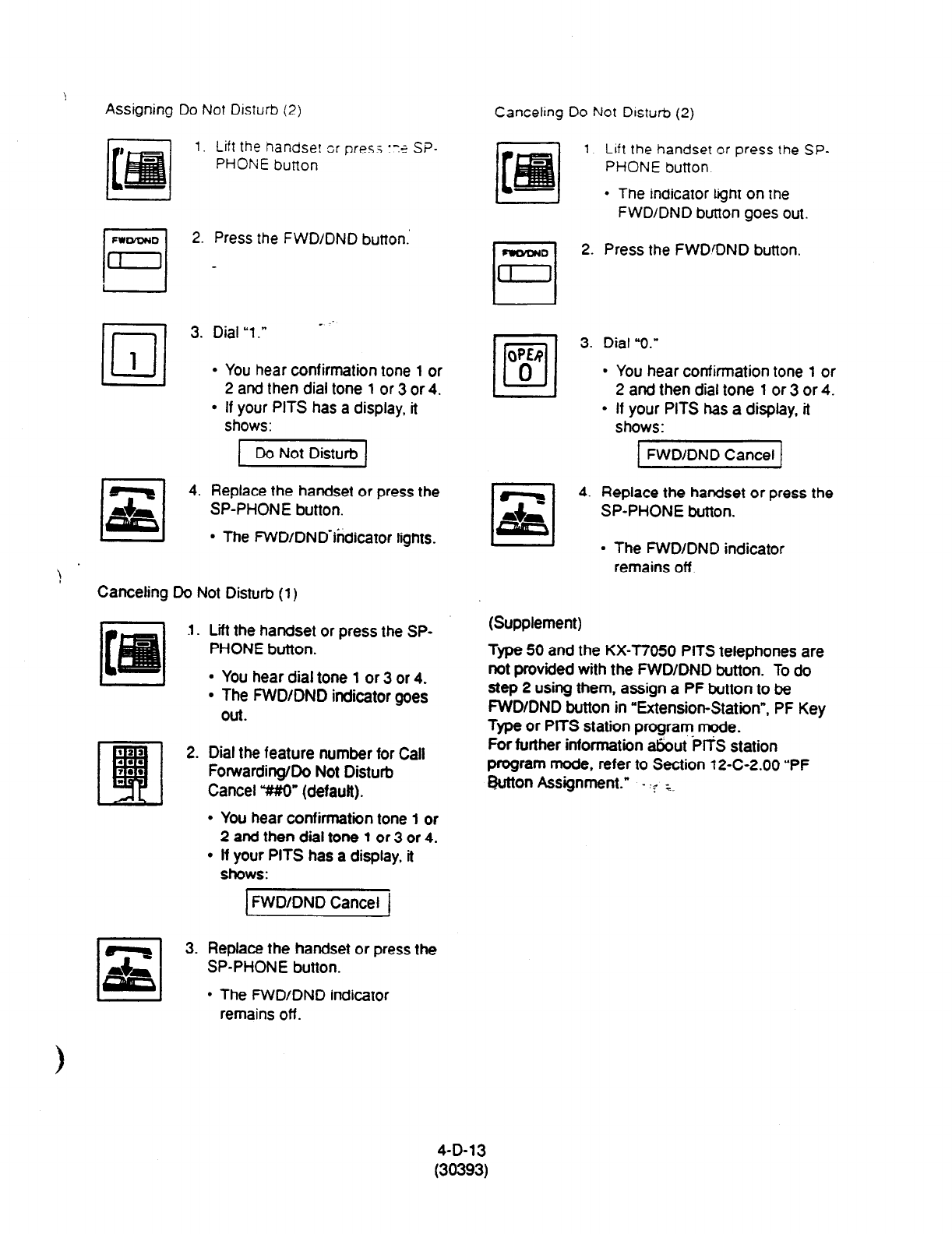
Assigning Do Not Disturb (2)
1. Lift the handse: or press ‘79 SP-
PHONE button
FWWDND
rl
2.
Press the
FWD/DND button.’
[1 -
1-1 3. Dial “1.” - ‘.
l
You
hear
confirmation tone
1 or
2 and then dial tone
1
or 3 or 4.
l
If your PITS has a display, it
shows:
4. Replace the handset or press the
SP-PHONE button.
l
The FWD/DND-indicator lights.
Canceling Do Not Disturb (1)
I. Lift the handset or press the SP-
PHONE button.
l
You hear dial tone 1 or 3 or 4.
l
The FWDIDND indicator goes
Out.
2. Dial the feature number for Call
Forwarding/Do Not Disturb
Cancel Y#O” (default).
l
You hear confirmation tone 1 or
2 and then dial tone
1
or 3 or 4.
l
If your PITS has a display, it
shows:
3. Replace the handset or press the
SP-PHONE button.
l
The FWD/DND indicator
Canceling Do Not Disturb (2)
1. Lift the handset or press the SP-
PHONE button.
l
The indicator light on the
FWDIDND button goes out.
2. Press the FWDaND button.
OW
•l
3. Dial “0.”
0
9 You hear confirmation tone 1 or
2 and then dial tone 1 or 3 or 4.
l
If your PITS has a display, it
shows:
1 FWD/DND Cancel f
4. Replace the handset or press the
SP-PHONE button.
I I l
The FWD/DND indicator
remains off.
(Supplement)
Type 50 and the KX-T7050 PITS telephones are
not provided with the FWD/DND button.
To do
step 2 using them, assign a PF button to be
FWDIDND button in “Extension-Station”, PF Key
Type or PITS station program mode.
For further information atkut Pll% station
program mode. refer to Section 12-C-2.00 “PF
Button Assignment.” - .? ;.
remains off.
4-D-13
(30393)
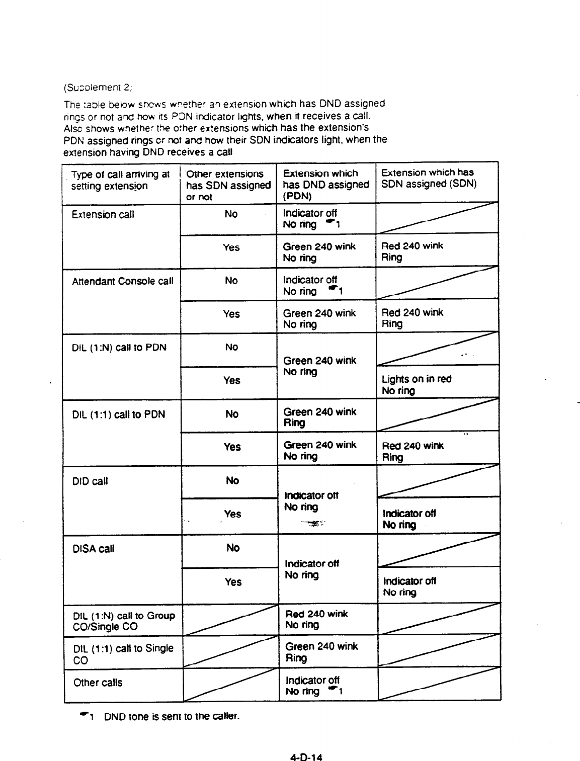
(Su;olement 2:
The :a3le bebw sncws w?o!her an extension which has DND assigned
rirgs or not and how its P3N indicator Ights, when it receives a call.
Alsc shows whethe: the o:her extensions which has
the
extension’s
PDt4 assigned rings cr not and how their SON
indicators light, when
the
extension having DND receives a call
Type
of call arriving at 1 Other extensions Extension which Extension
which has
setting extension
has SDN assigned has DND assigned SDN assigned (SDN)
or not PW
Extension call No
indicator off
Noring *1
Attendant Console call
Yes
No
Green 240 wink
No ring
Indicator off
No ring *l
Red 240 wink
Ring
DIL
(1 :N) call to
PDN
Yes
No
Green 240 wink
No ring
Green 240 wink
Red 240 wink
Ring
Yes No ring Lights on in red
No ring
DIL (1:l) call to
PDN No
Yes
Green 240 wink
Ring
Green 240 wink
Norillg
. .
Red 240 wink
DID call
DISA call
No
Yes
No
Yes
1 lndiiator off
Noring
--+rr.-
lndiior off
No ring
lndlcator off
Noring
Indicator off
No ring
DIL (1
:N) call to Group
CO/Single CO
DIL
(1 :l) Call to Single
co
Other calls
Red
240
wink
No ring
Green 240 wink
Ring
Indicator off
No ring -1
-1
DND tone is sent to the caller.
4-D-l
4
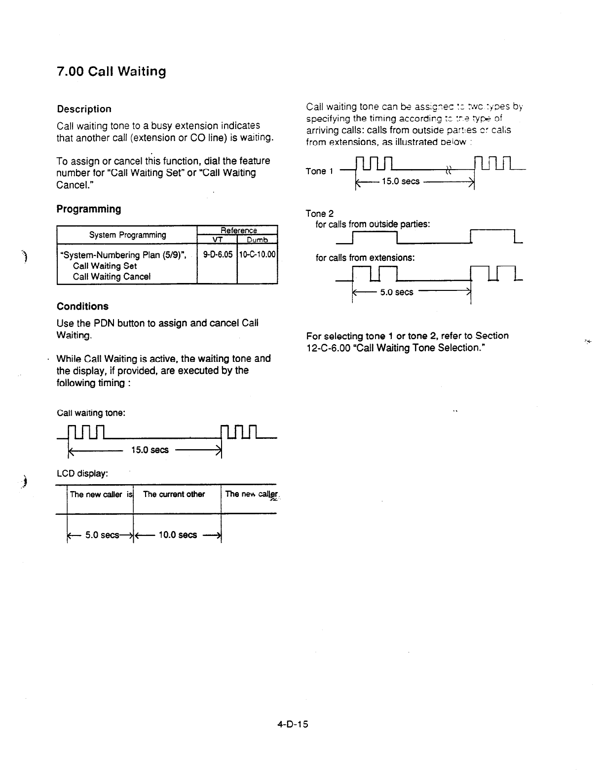
7.00 Call Waiting
Description
Call waiting tone to a busy extension indicates
that another call (extension or CO line) is waiting.
To assign or cancel this function, dial
the feature
number for “Call Waiting Set” or “Call Waiting
Cancel.”
Programming
System Programming
Reference
VT 1 Dumb
I I
“System-Numbering Plan (5/g)“,
Call Waiting Set
Call Waiting Cancel
j 9-D-6.05 ~CGlO.00~
Conditions
Use the PDN
button to assign and cancel
Call
Waiting.
. While Call Waiting is active, the waiting
tone and
the
display, if provided, are executed
by the
following timing :
Call waiting tone:
l-l
<
15.0 sets )
Call waiting tone can k ass;g;es :c ?:/c :joes bb
specifying the timing according ;c :r.? vw of
arriving
Call.% Calls
from outside parr:es cr cdl&
from extensions, as illustrated oeiow :
Tone 1 - l-l ,,
CL YLiLii
+- 15.0 sets >
Tone 2
for
calls from outside parties:
L
for calls from extensions:
For selecting tone 1 or tone 2, refer to Section
12-C-6.00 “Call Waiting Tone Selection.”
4-D-l 5
Operation
Setting Call Waiting
1. Lift the handset or press
the SP-PHONE button.
2. Dial
the
feature ‘number for “Call
Waiting Set.”
l
You hear confirmation tone 1 or
2 and then dial tone 1 or 3.
3. Replace the handset.
Canceling Call Waiting
1. Lift the handset or press
the SP-PHONE button.
2. Dial the feature number for “call
waiting Cancel.”
l
You hear confirmation tone 1 or
2
and then dial tone 1 or 3 or 4.
3.
Replace the handset.
A.7.srver-c Call LVairing
A cdl f-z- an extension or an outside party arrives
while l2.q a zxversation.
l
The mdiitor
on
the DN or the CO button
f!asnes irr 240 wink.
. You Qear call waiting tone.
Talking
to the
new
caller by concluding the current
call
D
1.
Press the flashing DN or CO
button.
l
The current call is diinnected.
l
Talk to the new caller on the
pressed DN or CO button.
Talking to the new
caller
by holding the
current call
HOLO
0
cl
q
1. Press the HOLD button to hold
the current party.
_.
l
You hear no tbne.
2.
Press the DN or CO button flashing
in 240 wink
l
Talk to the new ‘caller.
l
To condude the new call and talk
to the held party again, press the
DN or CO button flashing in 60
wink.
EJ. L. .:-
4-D-l 6
8.00 Uniform Call Distribution
(UCD)-Log Out
Description
UCD group members may leave the group
temporarily by dialing the feature number for
“UCD Log Out” or using the programmable UCD
Log In button to prevent UCD calls being sent to
their extensions.
Refer to Section 3-D-2.05 “Uniform Call
Distribution (UCD)-without OGM” and Section
3-D-2.06 “Uniform Call Distribution (UCD)-with
OGM.”
Programming
System Ptcgrammirg
“System-Numbering Plan p/9)“,
UCD Leg In
UCD Log Cut
“Extension-Station (2/3)“,
DN Key Type,
“Extension-Station (3n)“,
DSS Key Type
Conditicm
To set or cancel UCD Log Out, use the PDN
button.
RE
VT
9-o-6.09
9-G-l .oz
9-G-l .03
When an extension of the UCD group set for Log
Out goes off-hook, dial tone 4 below can be
J heard.
(sewnd) 0 1 - 2 3 4 p-;‘
Operation
Setting UCD Log Out
(1)
1. Lift the handset or press the SP-
PHONE button.
l
You hear dial tone
1
or 3 or
4.
2. Dial the feature number for “UCD
Log Out.”
l
You hear confmation tone 1 or
2.
l
If your PITS has a display, it
shows:
t UCD Losoa 1
3.
%place the handset or press the
SP-PHONE button.
Setting UCD Log Out (2)
u
iii
1. Lift the handset or press the SP-
PHONE button.
l
You hear dial tone 1 or 3 or 4.
2.
Press the UCD Log In button.
l
You hear conknation tone 1 or
2.
The indicator
on the UCD Log
In button lights in red.
l
If your PITS has a display, it
shows:
3.
Rep&e the handset or press the
SP-PHONE button.
.:.
4-D-l 7

Canceling UCD Log Out (1)
1. Lift the handset or press the SP-
PHONE button.
l
You
hear
dial tone 1 or 3 or 4.
2. Dial the feature number for “UCD
Log In.”
You hear confirmation tone 1 or
2.
If your PITS has a display, it
shows:
3. Replace the handset or press the
SP-PHONE button.
Canceling UCD Log Out (2)
I_ Ly f+ “are- ;r ;iess ::e SP-
P%NE b&
l You hear
dk x-32 * of 3 or 4.
-1 2. Press the UCD Lq In button.
111 .
.
You hear wcfirmation tone 1 or
2.
The indicator iight on the UCD
Loglnbuttongoesout.
If your PITS has a display, it
shows: ,
1 UCD Login /
3.
Replace the handset or press the
SP-PHONE button.
4-D-18
E. Holding Features
1.00 Hold
Description
Allows an extension user to hold the current call
and either call or answer another extension or
outside party.
To place
a
call on hold, press the
HOLD
button.
To retrieve a held call, simply press the flashing
line
access button on which a call is held.
A call placed on hold can be retrieved at the
extension that put
the
call on hold or at
an
extension that shares the held line.
A PITS telephone user can place as many calls
on hold as it has line access button (PCO, GCO,
SCO, PDN,
SDN).
Programming
None
Conditions
. The extension users can not hold the following
calls.
l
A call on ICM button
l
A call with Attendant Console
l
A call with Doorphone
l
Paging Announcement through built-in
speaker of PITS
A call held on PC0 button can not be retrieved
from the other extensions.
If a held calf has not been an-d more than a
preassigned time, a warning tone may sound at
extension which placed a call on hold.
Refer to Section 3-E-2.00 “Held Call Reminder”
for further information.
If a held call is not answered more than 30
minutes, it will be disconnected automatically.
Music on Hold will be sent to the held party if
available. For sending Music on Hold, prior
assignment is necessary. Refer to Section
3-E-l .OO ‘Music on Hold” for further information.
Operation
Placing a Call on Hold
In conversation on the DN, SCO, GCO or PC0
button
1. Press
the
HOLD
button.
.
.
.
If
the
call is on the DN or SC0
or
GCO button, the indicator on
the button flashes in green 60
wink. If the call is on the PC0
button, the indicator on the
button flashes in green 120
wink. You hear confirmation
tone 2 and then no tone.
The other party is placed on
Hold.
You can hang up without
loosing a held call.
Retrieving a Held Call
From the holding extension
1. Press the green button that is
flashing in 60 wink or 120 wink.
. .
l
The indicator on the pressed
button lights in green.
l
Talk to the other party again.
From another extension that shares the held line
I 1. Press the red button that is
+a2
t t
slowly flashirS$ in 6o‘wink
I \ .
.
The indicator on the pressed
button lights in green.
Start conversation with the
retrieved party.
(Supplement)
Any extension user can retrieve the call held at
another extension by dialing the feature number
for “Hold Extension Retrieve.”
For further information, refer to Section 4-E-4.00
“Call Hold Retrieve-Station.”
4-E-l
2.00 Exclusive Hold
Description
Allows an extension user to place a call on hold
exclusively and either make or answer another
extension or outside @I.
A call held by “Exclusive Hold” can not be
retrieved from any other extension.
To place a call on exclusive hold, press the
HOLD button twice.
To retrieve a call placed on exclusive hold, simply
press the flashing line access button (PCO,
GCO, SCO, PDN, SDN) on which a call is held.
A call on exclusive hold can be retrieved only at
the extension that put a call on exclusive hold.
A PITS telephone user can place as many calls
on exclusive hold as it has line access buttons.
Programming
None
Conditions
The extension users can not place the following
calls on exclusive hold.
l
A call on ICM button
l
A call with Attendant Console
l
A call with Doorphone
l
Paging Announcement through built-in
speaker of PITS
A call held on PC0
button
is always treated as
exclusive hold and therefore it can not be
retrieved from any other exter&&-
If a held call has not been answered within the
pre-assigned time, a warning tone may sound at
extension which placed a call on hold.
Refer to Section 3-E-2.00 ‘Held Call Reminder”
for further information.
If a held call is not answered within 30 minutes, it
will be disconnected automatically.
Music on Hold will be sent to the held patty if
available. For sending Music on Hold, prior
assignment is necessary. Refer to Section
3-E-l .OO “Music on Hold” for further information.
Operation
Placing a Call on Exclusive Hold
During a conversation with the other party
1. Press the HOLD button.
l
The indicator on the button in
use flashes in green 60 wink.
. You hear confirmation tone 2
and then no tone.
I
2. Press the HOLD button again.
l
The flashing indicator changes
to green 120 wink.
l
The other party is held
exclusively.
Retrieving a Call on Exclusive Hold
1. Press the green button that is
flashing in 120 wink.
l
The indiitor on the pressed
button lights in green.
l
The held party is retrieved.
l
Talk to the other party again.
(Supplement)
To change ‘Exclusive Hold’ to ‘Hold, press the
HOLD button again.
Exclusive
Hold and Hold
alternate with each pressing of the HOLD button.
:: ?
4-E-2
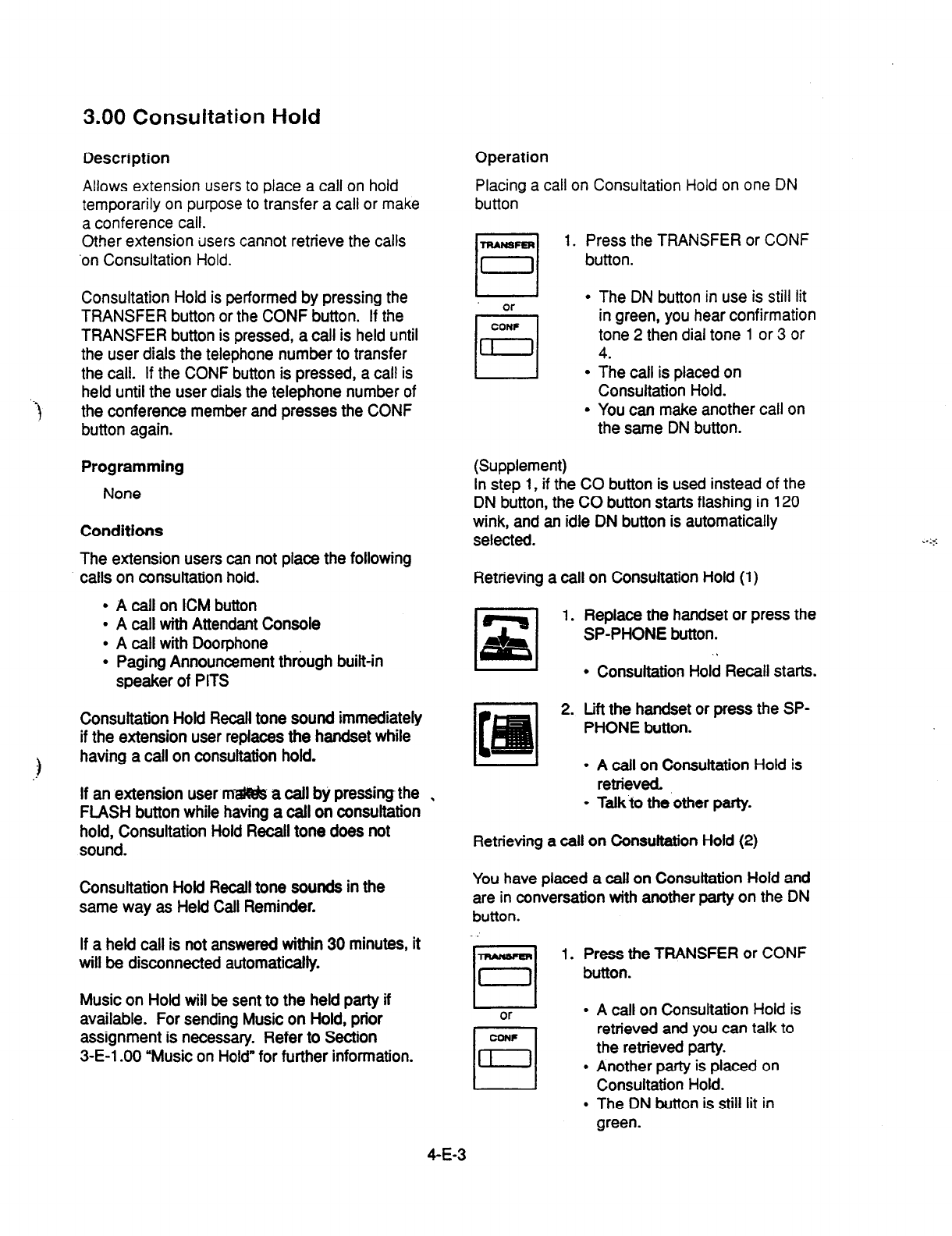
3.00 Consultation Hold
Description
Allows extension users to place a call on hold
temporarily on purpose to transfer a call or make
a conference call.
Other
extension
users
cannot retrieve the calls
‘on Consultation
Hold.
‘t
Consultation Hold is performed by pressing the
TRANSFER
button or the CONF button. If the
TRANSFER button is pressed, a call is held until
the user dials the telephone number to transfer
the call. If the CONF button is pressed, a call is
held until the user dials the telephone number of
the conference member and presses the CONF
button again.
Programming
None
Conditions
The extension users can not place the following
. calls on consultation hold.
l
A call on ICM button
l
A call with Attendant Console
l
A call with Doorphone
l
Paging Announcement through built-in
speaker of PITS
Consultation Hold Recall tone sound immediately
if the extension user replaces the handset while
having a call on consultation hold.
If an extension user mzl@& a call b,’ pressing the
FLASH button while having a call on consultation
hold, Consultation Hold Recall tone does not
sound.
Consultation Hoki Recall tone sounds in the
same way as Held Call Reminder.
If a held call is not answered within 30 minutes, it
will be disconnected automatically.
Music on Hold will be sent to the held party if
available. For sending Music on Hold, prior
assignment is necessary. Refer to Section
3-E-l .OO “Music on Hold” for further information.
Operation
Placing a call on Consultation Hold on one DN
button
TRANSFER
D
1.
Press the TRANSFER or CONF
button.
l
The DN button in use is still lit
or
CONF
q
in
green, you hear confirmation
tone 2 then dial tone 1 or 3 or
= 4.
l
The call is placed on
Consultation Hold.
l
You can make another call on
the same DN button.
(Supplement)
In step 1, if the CO button is used instead of the
DN button, the CO button starts flashing in 120
wink, and an idle DN button is automatically
selected.
Retrieving a call on Consultation Hold (1)
Replace the handset or press the
SP-PHONE button.
l
Consultation Hold Recall starts.
Lift the handset or press the SP-
PHONE button.
l
A call on Consultation Hold is
retrieved.
l
Talk to the other party.
Retrieving a call on Consultation Hold (2)
You have placed a call on Consultation Hold and
are in conversation with another party on the DN
button.
1. Press the TRANSFER or CONF
button.
or
. A call on Consultation Hold is
retrieved and you can talk to
the retrieved party.
l
Another party is placed on
Consultation Hold.
l
The DN button is still lit in
green.
4-E-3
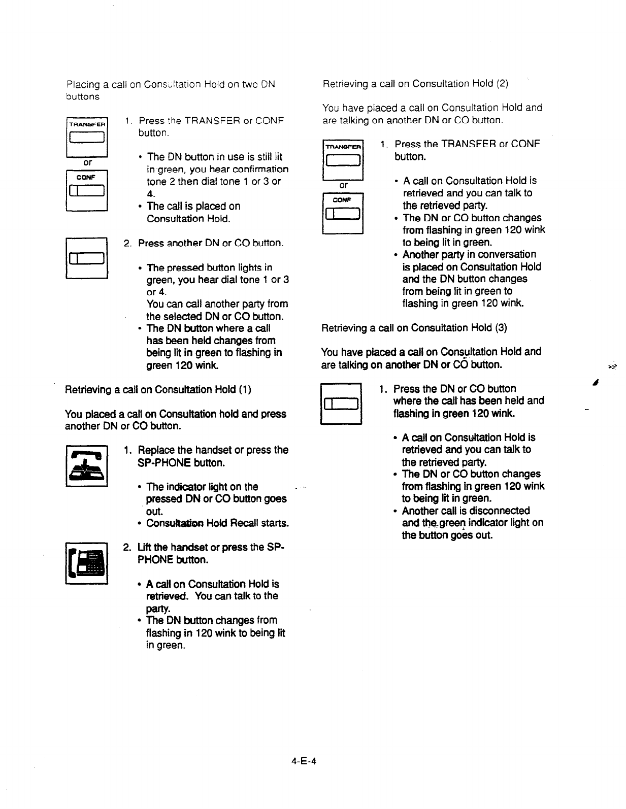
Placing a call on Consuitation Hold on twc DN
buttons
1.
Press the TRANSFER or CONF
button.
I
or
l
The DN button in use is still lit
CCNF
El
in green, you hear confirmation
tone 2 then dial
tone 1 or 3 or
n 4.
l
The call is placed on
Consultation Hold.
El
2. Press another DN or CO button.
l
The pressed button lights in
green, you hear dial tone 1 or 3
or 4.
You can call another party from
the seleoted DN or CO button.
l
The DN button where a call
has been held changes from
being lit in green to flashing in
green 120 wink.
Retrieving a call on Consuttation Hold (1)
You placed a call on Consultation hold and press
another DN or CO button.
1. Replace the handset or press the
SP-PHONE button.
l
The indicator light on the
pressed DN or?0 button goes
Out.
l
Consul&&en Hold Recall starts.
2.
Lift the handset or press the SP-
PHONE button.
Retrieving a call on Consultation Hold (2)
You have placed a call on Consultation Hold and
are talking on another
DN or
CO button.
-mAreFER
q
1. Press the TRANSFER or CONF
button.
or
l
A call on Consultation Hold is
0
63
retrieved and you can talk to
the retrieved pa;ty.
l
The DN or CO button changes
from flashing in green 120 wink
to being lit in green.
l
Another party in conversation
is placed on Consultation Hold
and the DN button changes
from being lit in green to
flashing in green 120 wink.
Retrieving a call on Consultation Hold (3)
You have placed a call on Consukation Hold and
are talking on another DN or CO button.
1. Press the DN or CO button
where the call has been held and
flashing in green 120 wink.
A call on Consultation Hold is
retrieved and you can talk to
the retrieved party.
The DN or CO button changes
from flashing in green 120 wink
to being lit in green.
Another call is disconnected
and the,green indicator light on
the button goes out.
I- I
l A
call on Consultation Hold is
retrieved You can talk to the
Party
l
The DN button changes from
flashing in 120 wink to being lit
in green.
4-E-4

4.00 Call Hold Retrieve-Station
Description
kilows an extension user to talk to the other
par;y
oy remeving a call held by another extension.
This function is performed by dialing the feature
number for “Hold Extension Retrieve” and
extension number on which a call is placed on
hold (directory number: three or four digits).
Programming
Conditions
Even if the other extension has held multiple
calls, there is no preferential order for retrieving
calls.
In case of a failure to retrieve a call (the other
extension holds no call), reorder tone is returned
and the following message appears on the
display, if provided:
1 No Hold Call 1
The following calls cannot be retrieved from other
extensions.
l
A call held on PC0 button
l
A call placed on Exclusive Hold
l
A call place on Consultation Hold
Operation
1. Lift the handset or
press
the
SP-PHONE button.
Dial the feature number for
“Hold Extension Retrieve.”
Dial the directory number of the
holding extension : three or four
digits.
. After hearing confirmation tone
3, start conversation with the
retrieved party.
.:.
4-E-5
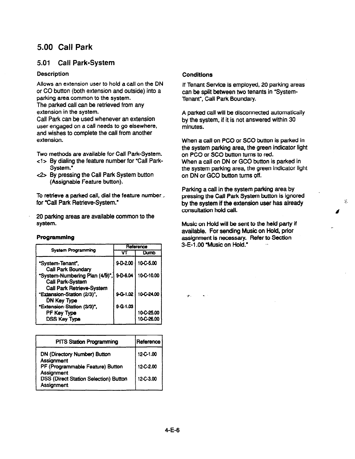
5.00 Call Park
5.01 Call Park-System
Description
Allows an extension user to hold a call on the DN
or CO button (both extension and outside) into a
parking area common to the system.
The parked call can be retrieved from any
extension in the system.
Call Park can be used whenever an extension
user engaged on a call needs to go elsewhere,
and wishes to complete the call from another
extension.
Two methods are available for Call Park-System.
cl
> By dialing the feature number for “Call Park-
System.”
<2> By pressing the Call Park System button
(Assignable Feature button).
To retrieve a larked call, dial the feature number .-
for %all Park Retrieve-System.”
20 parking areas are available common to the
system.
Programming
System Programming Rel
VT
‘System-Ten&,
Call Park 6olJndary
‘System-Numbering Plan (4&)
Call Park-System
Call Perk Retrieve6ystem
‘+ension-Station (2M)“.
DN Key Type
‘Extension-Station (3/3)l,
PF Key Type
DSS Key Type
9-o-2.00
9-o-6.04
9-Gl.02
9-G-1.03
I
PITS Statkm Pmgramming
DN (Directory Number) Button
Assignment
PF (Programmable Feature) Button
Assignment
DSS (Direct Station Selection) Button
Assignment
Parking a call in the system parking area by
pressing the Call Park System button is ignored
by the system if the extension user has already
consultation hold call.
Music on Hold will be sent to the held party if
available. For sending Music on Hold, prior
assignment is necessary. Refer to Section
3-E-l .OO ‘Music on Hold.’ .%
lO-G24.00
7. -
10625.00
1 o-c-26.00
Reference
12-c-1.00
12-c-2.00
12c-3.00
Conditions
If Tenant Service is employed, 20 parking areas
can be split between two tenants in ‘System-
Tenant”, Call Park Boundary.
A parked call will be disconnected automatically
by the system, if it is not answered within 30
minutes.
When a call on PC0 or SC0 button is parked in
the system parking area, the green indicator light
on PC0 or SC0 button turns to red.
When a call on DN or GCO button is parked in
the system parking area, the green indicator light
on DN or GCO button
turns off.
.
4-E-6
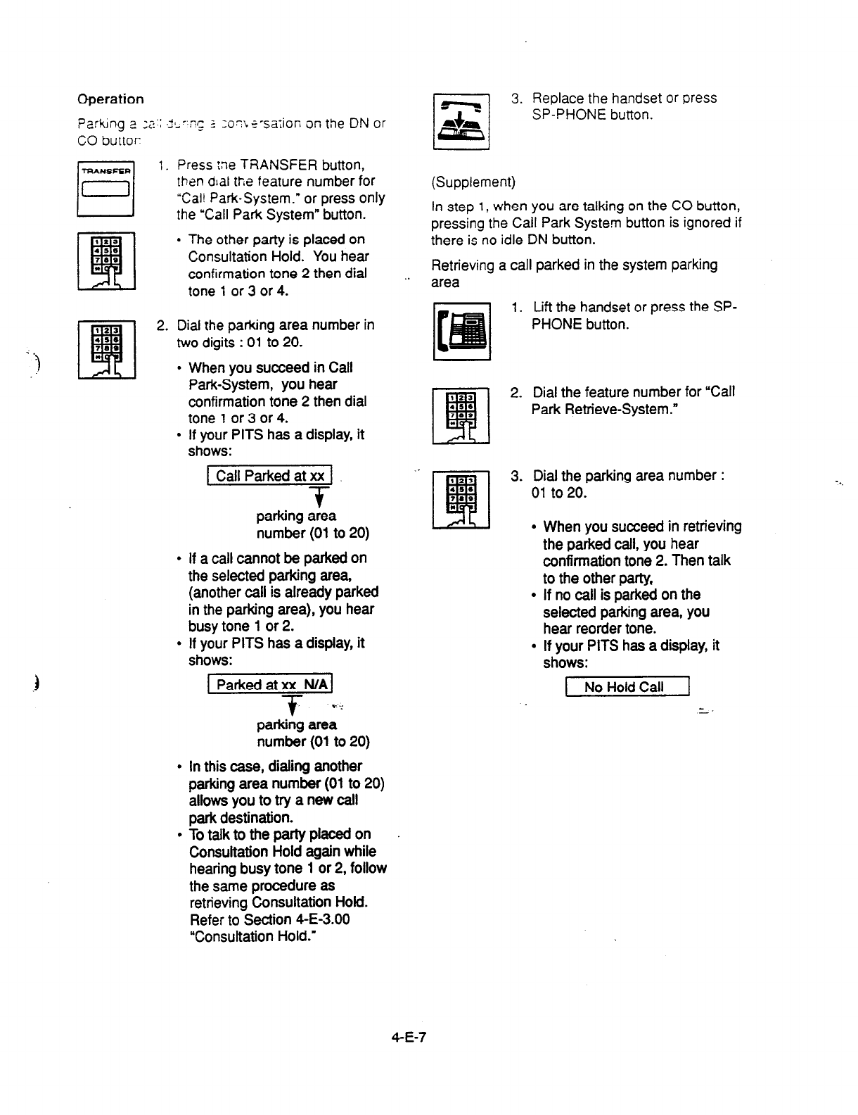
Operation
Parking 2 2: .d,-:ns 2
:o7\~-sa;ion on the DN or
CO buttor
TRANSFER
El
1. Press :ne TRANSFER button,
then alal the feature number for
“Cal! Park-System.” or press only
the “Call Park System” button.
l
The other party is placed on
Consultation Hold. You hear
confirmation tone 2 then dial
tone 1 or 3 or 4.
3 P,
2l
2. Dial the parking area number in
two digits : 01 to 20.
*
l
When you succeed in Call
Park-System, you hear
confirmation tone 2 then dial
tone 1 or 3 or 4.
l
If your PITS has a display, it
shows:
[ Call Parked at xx 1
+
parking area
number (01 to 20)
l
If a call cannot be parked on
the selected parking area,
(another call is already parked
in the parking area), you hear
busy tone 1 or 2.
l
If your PITS has a display, it
shows:
1 Parked at xx N/AI
+ v :’
parking area
number (01 to 20)
l
In this case, dialing another
parking area number (01 to 20)
allows you to try a new call
park destination.
l
To talk to the party placed on
Consultation Hold again while
hearing busy tone 1 or 2, follow
the same procedure as
retrieving Consultation Hold.
Refer to Section 4-E-3.00
“Consultation Hold.”
3. Replace the handset or press
SP-PHONE button.
(Supplement)
In step 1, when you are talking on the CO button,
pressing the Call Park System button is ignored if
there is no idle DN button.
Retrieving a call parked in the system parking
. . area
1. Lift the handset or press the SP-
PHONE button.
2. Dial the feature number for “Call
Park Retrieve-System.”
3. Dial the parking area number :
01 to 20.
l
When you succeed in retrieving
the parked call, you hear
confirmation tone 2. Then talk
to the other party,
l
If no call is parked on the
selected parking area, you
hear reorder tone.
l
If your PITS has a display, it
shows:
1 No Hold Call 1
4-E-7
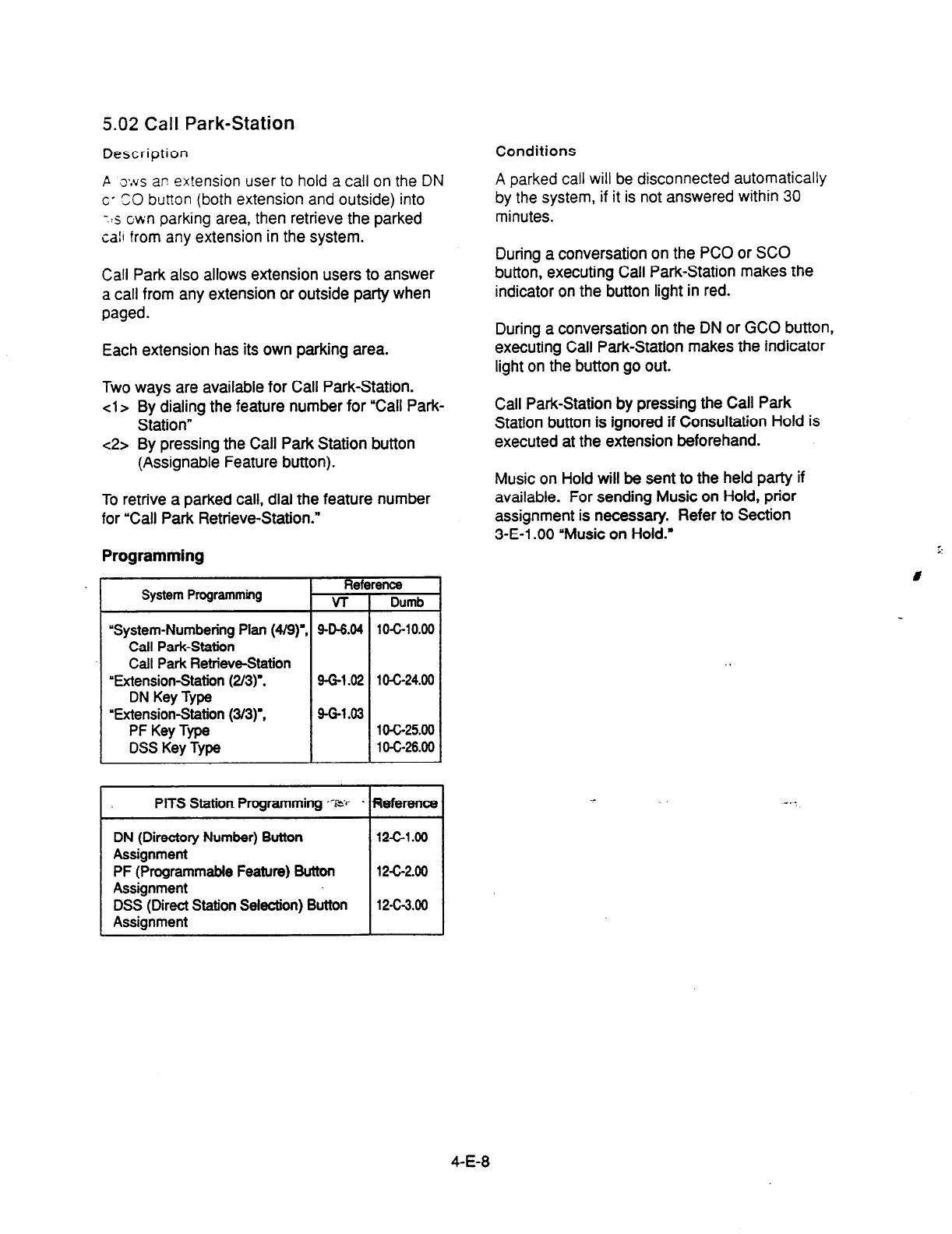
5.02
Call
Park-Station
Description
P o*.us ar: extension user to hold a call on the DN
c- SO button (both extension and outside) into
-.!s own parking
area, then retrieve the parked
call from any extension in the system.
Call Park also allows extension users to answer
a call from any extension or outside party when
paged.
Each extension has its own parking area.
Two ways are available for Call Park-Station.
<la
By dialing the feature number for “Call Park-
Station”
~2, By pressing the Call Park Station button
(Assignable Feature button).
To retrive a parked call, dial the feature number
for “Call Park Retrieve-Station.”
Programming
-r
I,
System Programming
“System-Numbering Plan (4/9)
Call Park-Station
Call Park Retrieve-Station
“Extension-Station (2/3)‘,
DN Key Type
“Extension-Station (3/3)‘,
PF Key Type
DSS Key Type
T
Reference
1
v-r
9-D-6.04
9-G-1.02
9-G-l .03
PITS
Station
Programming “5;
DN (Directory Number) Button
Assignment
PF (Programmable Feature) Button
Assignment
DSS (Direct Station Selection) Button
Assignment
Dumb
10-C-10.00
1 O-C-24.00
1 O-c-25.00
1 O-C-26.00
Reference
12-c-1.00
12-c-2.00
12-C-3.00
-I
Conditions
A parked call will be disconnected automatically
by the system, if
it is not answered within 30
minutes.
During a conversation on the PC0 or SC0
button, executing Call Park-Station makes the
indicator on the button light in red.
During a conversation on the DN or GCO button,
executing Call Park-Station makes the indicator
light on the button go out.
Call Park-Station by pressing the Call Park
Station button is ignored if Consultation Hold is
executed at the extension beforehand.
Music on Hold will be sent to the held party if
available. For sending Music on Hold, prior
assignment is necessary.
Refer to
Section
3-E-l .OO ‘Music on Hold.”
4-E-8
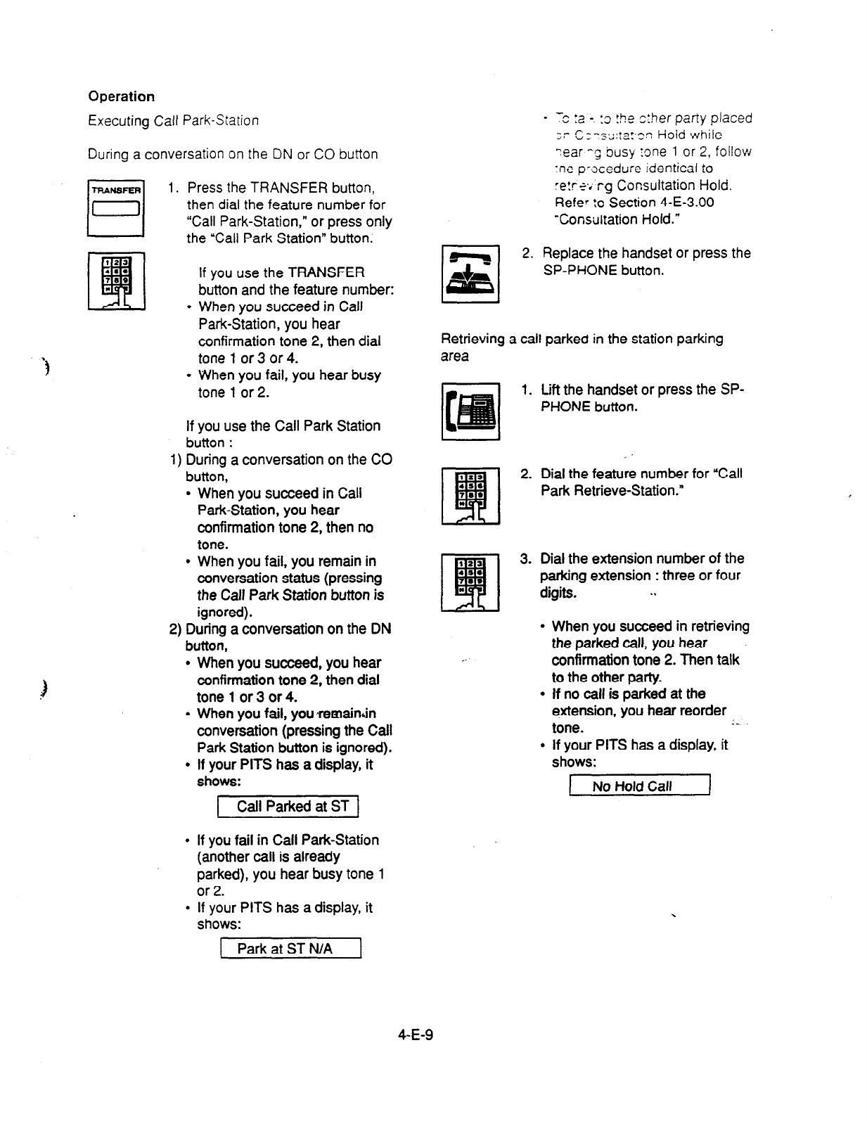
Operation
Executing Call Park-Station
During
a conversation on
the DN
or CO button
1.
Press the TRANSFER
button,
then dial the feature number for
“Call Park-Station,” or press only
the “Call Park Station” button.
if you use the TRANSFER
button and the feature number:
l
When you succeed in Call
Park-Station, you hear
confirmation tone 2, then dial
tone 1 or 3 or 4.
l
When you fail, you hear busy
tone 1 or 2.
If you use the Call Park Station
button :
1) During a conversation on the CO
button,
l
When you succeed in Call
Park-Station, you hear
confirmation tone 2, then no
tone.
l
When you fail, you remain in
conversation status (pressing
the Call Park Station button is
ignored).
2) During a conversation on the DN
button,
l
When you succeed, you hear
confirmation tone 2, then dial
tone 1 or 3 or 4.
l
When you fail, you remainlin
conversation (pressing the Call
Park Station button is ignored).
l
If your PITS has a display, it
shows:
( Call Parked at ST 1
l
If you fail in Call Park-Station
(another call is already
parked), you hear busy tone 1
or 2.
l
If your PITS has a display, it
shows:
1 Park at ST N/A
- -c :a -. :3 !he ether party placed
;r- CI-r;l;::a:,cn HaId while
Year -9 busy me 1 or 2, follow
‘ne p’-scedure identical to
re!re~.‘rg Consultation Hold.
RefeV :o Section 4-E-3.00
‘Consultation Hold.”
2. Replace the handset or press the
SP-PHONE button.
Retrieving a call parked in the station parking
area
1. Lift the handset or press the SP-
PHONE button.
2. Dial the feature number for “Call
Park Retrieve-Station.”
3. Dial the extension number of the
parking extension : three or four
digits. . .
I AL I
,.
l
When you succeed in retrieving
the parked call, you hear
confirmation tone 2. Then talk
to the other party.
l
If no call is parked at the
extension, you hear reorder
tone. I..
l
If your PITS has a display, it
shows:
1 No Hold Call I
4-E-9
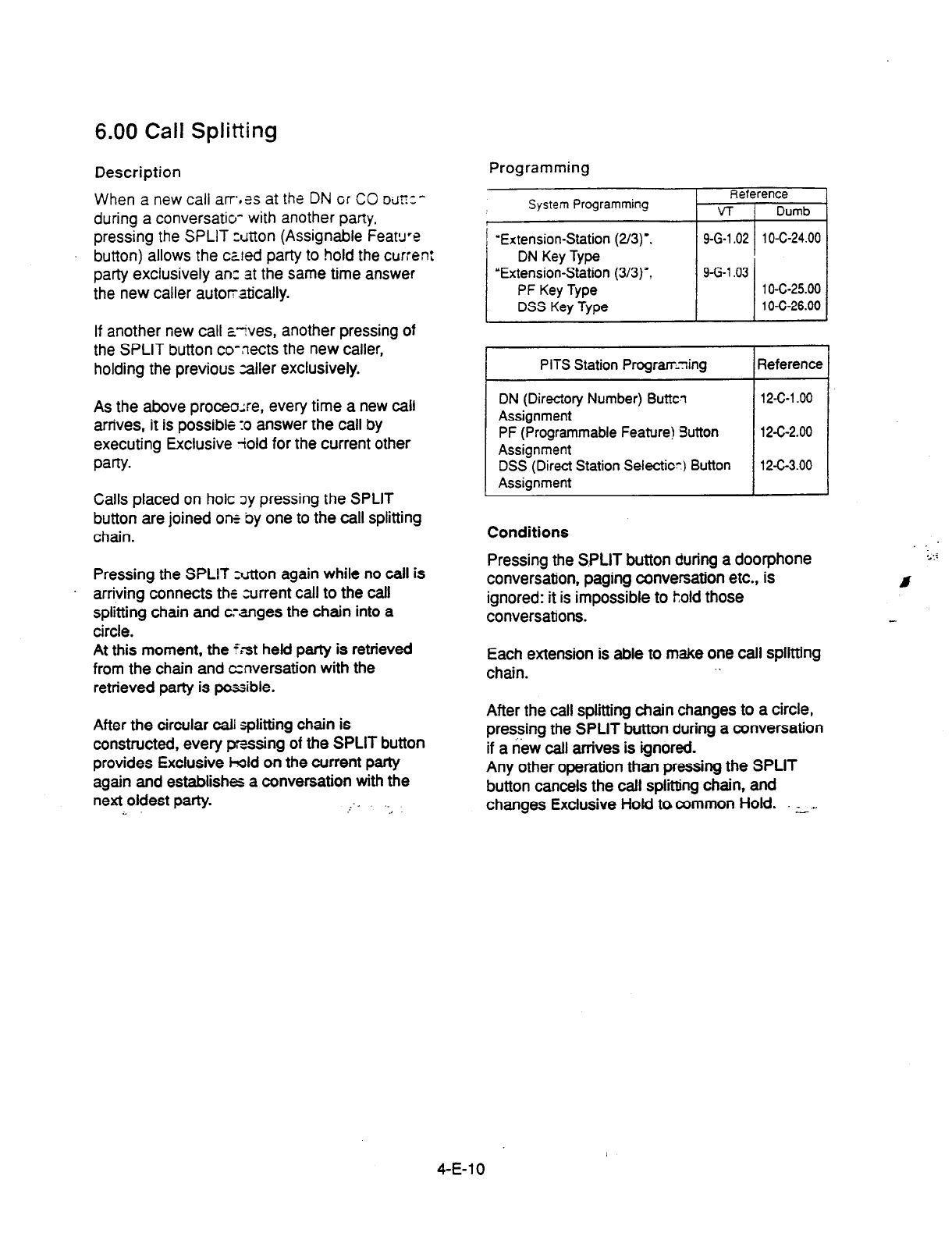
6.00 Call Splitting
Description Programming
When a new call at-r-*% at the DN
GT
CO DJ~:’
during a conversatio- with another party.
pressing the SPLIT z&ton
(Assignable FeaWe
button) allows the caled party to hold the current
party exclusively ant at the same
time answer
the new caller automatically.
System Programming
‘Extension-Station (2/3)‘.
DN
Key Type
‘Extension-Station (3/3)‘,
PF
Key Type
DSS
Key Type
If another new call ayves, another pressing of
the SPLIT button co-nects the new caller,
holding the previous zaller exclusively.
As the above proceo;re, every time a new call
arrives, it is possible :o answer the call by
executing Exclusive iold for the current other
party.
Calls placed on hoic by pressing the SPLIT
button are joined one
by
one to the call splitting
chain.
Pressing the SPLIT Ntton again while no call is
arriving connects the current call to the call
splitting chain and cranges the chain into a
circle.
At this moment, the ?;st held party is retrieved
from the chain and conversation with the
retrieved party is possible.
After the circular
call
splitting chain is
constructed, every pmssing of the SPLIT button
provides Exclusive l-old on the current party
again and establishes a conversation with the
next oldest party. I
-. .
.,
Reference
VT 1 Dumb
9-G-l .02 1 O-C-24.00
I
9-G-l .03 1 o-c-25.00
1 O-C-26.00
PITS Station Program-ning Reference
Conditions
Pressing the S.PLIT button during a doorphone
conversation, paging conversation etc., is
ignored: it is impossible to hold those
conversations.
Each extension is able to make one call splitting
chain. I
After the call splitting chain changes to a circle,
pressing the SPLIT button during a conversation
if a new call arrives is ignored.
Any other operation than pressing the SPLIT
button cancels the call spliing chain, and
changes Exclusive Hold to common Hold. :- . .
4-E-l 0

Operation
Call Splitting operaticn
During a conversation, another call arrives at the
DN or CO button.
El
1. Press
the
SPLIT button.
l
The current
call is placed on
Exclusive
Hold ‘and connected
to
rhe
call splitting chain.
l
Start
conversation with the new
caller.
Another call arrives again.
2. Press the SPLIT button.
l
The current call is placed on
Exclusive Hold and chained to
the call splitting chain.
l
Start conversation with the new
caller.
3. During a conversation, press the
SPLIT button every time a new
call arrives. Then press the
SPLIT button again while no call
is arriving.
l
The current party is joined to
the call splitting chain, that
completes a circular chain.
l
Start
conversation with the first
held party.
4; .-Fress the SPLIT button.
l
Every pressing of the SPLIT
button connects the current call
to the call spliing chain again.
l
Start conversation with a held
call in the chained order.
_c
4-E-l 1

F. Transferring Features
1 .OO Call Transfer
1 .Ol Unscreened Call Transfer to
Station
Description
Transfer is convenient to redirect a call to another
extension user.
Attendant assistance is not required and the caller
does not have to redial.
Unscreened Call Transfer allows an extension user
to transfer calls placed on the DN or CO button to
another extension without announcement.
Programming
None
Conditions
If transferred call is not answered by the
destination party, it will receive one of the following
treatments.
Status of Destination opefatjon Resulted
Able to receive the Performs the call to the destination for
call aspecifwzperiod. Inoaseofno
(sending rtngbaok answer, interrupts ringing and Stark
tone) ringing to the originator of transfer. -1
For detail. refer to Section 3-E-3.00
Transfer Recall.”
Busy Assoonasthedestinationgoeson-
(sending busy tone) hook, starts calling the destination
(Camp-on Transfer).
If the destination party remains busy 01
doesnotanswertheoallwithina
specitied period, starts calling back the
originator of transfer. *l
For detail, refer to Seotion 3-E-3.00
?ansfer Recall.’
Setting Do Not ’ Unscreened Call Transfer to extension
Disturb is ineffective.
(sending DND tone) Transferred party is treated simply as a
partyp&edonConsultationHold.
Harglng up causes the Consultation
HoIdRecaHtotheo@natoroftransfer
4 When the originator of transfer answers the call,
conversation between the originator and the
transferred party starts.
The extension users can not transfer the following
calls.
l
A call on ICM button
l
A call with Attendant Console
l
A call with Doorphone
l
Paging Announcement through built-in
speaker of PITS
If
Music or
%!d ‘s a.;ailable from the start of the
transferring operation until the destination party
answers,
the
system sends Music on Hold to
the
transferred party.
For further detail, refer to Section 3-E-l .OO
“Music on Hold.”
Operation
During a conversation with an extension or an
outside party on the DN or CO button
1. Press the TRANSFER butt&.
l
The other party is placed on
Consultation Hold.
l
You hear confirmation tone 2
and then dial tone 1 or 3 or 4.
l
If your PITS has a display, it
shows:
Transfer to ]
2. Dial the directory number of the
destination extension: three or
four digits. I
.
3. Replace the handset or press the
SP-PHONE button.
1 J
l
Calling the desired extension
starts and if the extension
ms, ccinvers@ion
between the held party a’nd’&e
extension is established.
(Supplement)
After step 2, if you want to restore the
conversation with the transferred party, (1) if the
destination has already answered, press the
FLASH button and then TRANSFER button. (2)
if the destination has not answered yet, press the
TRANSFER button only.
To change the destination of transfer after
executing step 2, press the FLASH button while
hearing ringback tone, busy tone, or DND tone.
Then after hearing dial tone, dial the extension
number of the new destination.
4-F-l
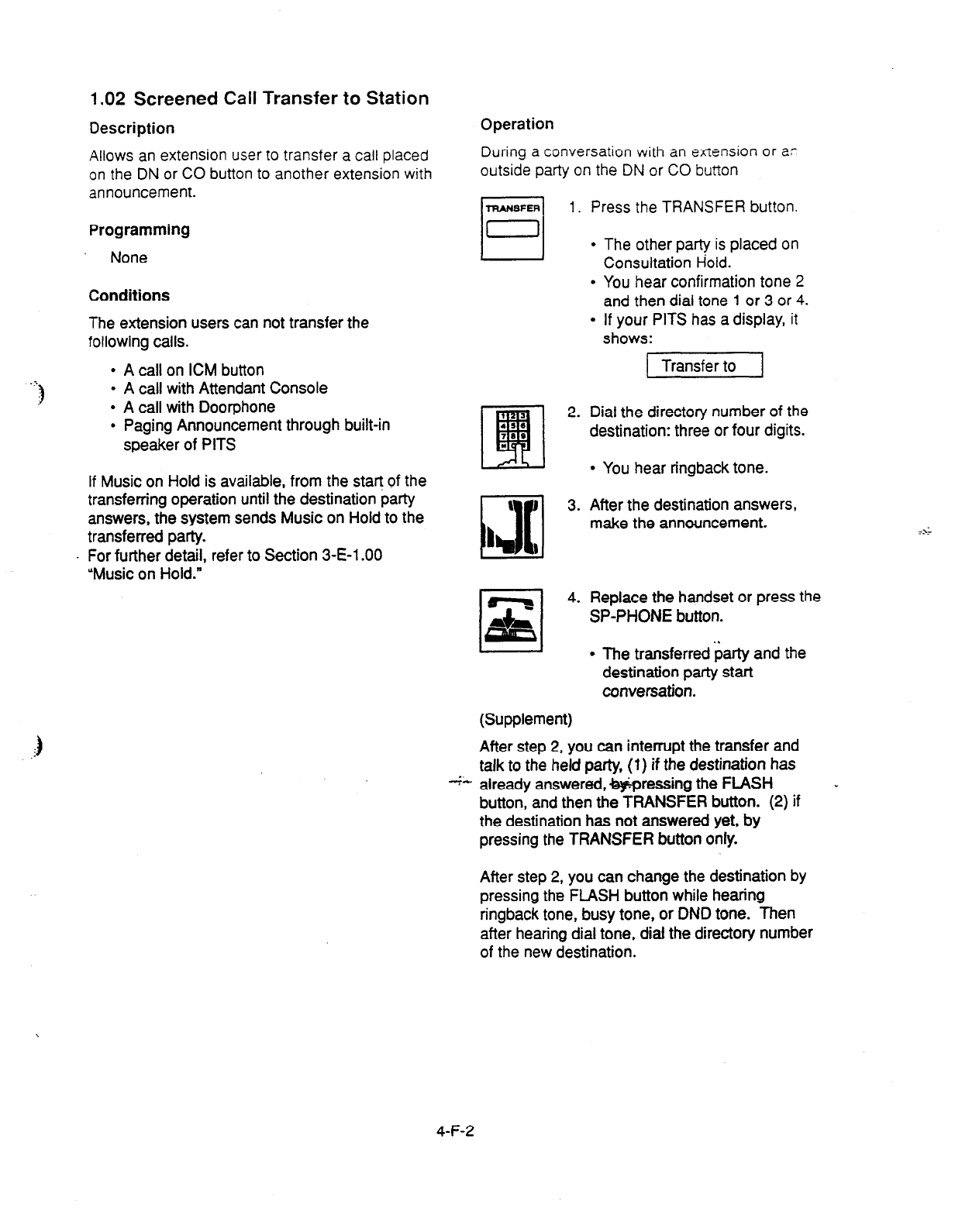
1.02 Screened Call Transfer to Station
Description
Allows an extension user to transfer a call placed
on the DN or CO button to another extension with
announcement.
Programming
None
Conditions
The
extension users can not transfer the
following calls.
l
A call on ICM button
l
A call with Attendant Console
l
A call with Doorphone
l
Paging Announcement through built-in
speaker of PITS
If Music on Hold is available, from the start of the
transferring operation until the destination party
answers, the system sends Music on Hold to the
transferred party.
For further detail, refer to Section 3-E-l .OO
‘Music on Hold.”
Operation
During a conversation with an exiension or ar
outside party on the DN or CO button
TRANSFER
Ll
1.
Press the TRANSFER button.
l
The other party
is
placed on
Consultation Hold.
l
You hear confirmation tone 2
and then dial tone 1 or 3 or 4.
l
If your PITS has a display,
it
shows:
q
z 4*
(Supplement)
1 Transfer to 1
Dial the directory number of the
destination: three or four digits.
l
You hear ringback tone.
After the destination answers,
make the announcement.
Replace the handset or press the
SP-PHONE button.
l
The transferred Garty and the
destination party
start
conversation.
After step 2, you can interrupt the transfer and
talk to the held party, (1) if the destination has
+- already answered, wressing the FLASH
button, and then the TRANSFER button. (2) if
the destination has not answered yet, by
pressing the TRANSFER button only.
-
After step 2, you can change the destination by
pressing the FLASH button while hearing
ringback tone, busy tone, or DND tone. Then
after hearing dial tone, dial the directory number
of
the
new destination.
4-F-2
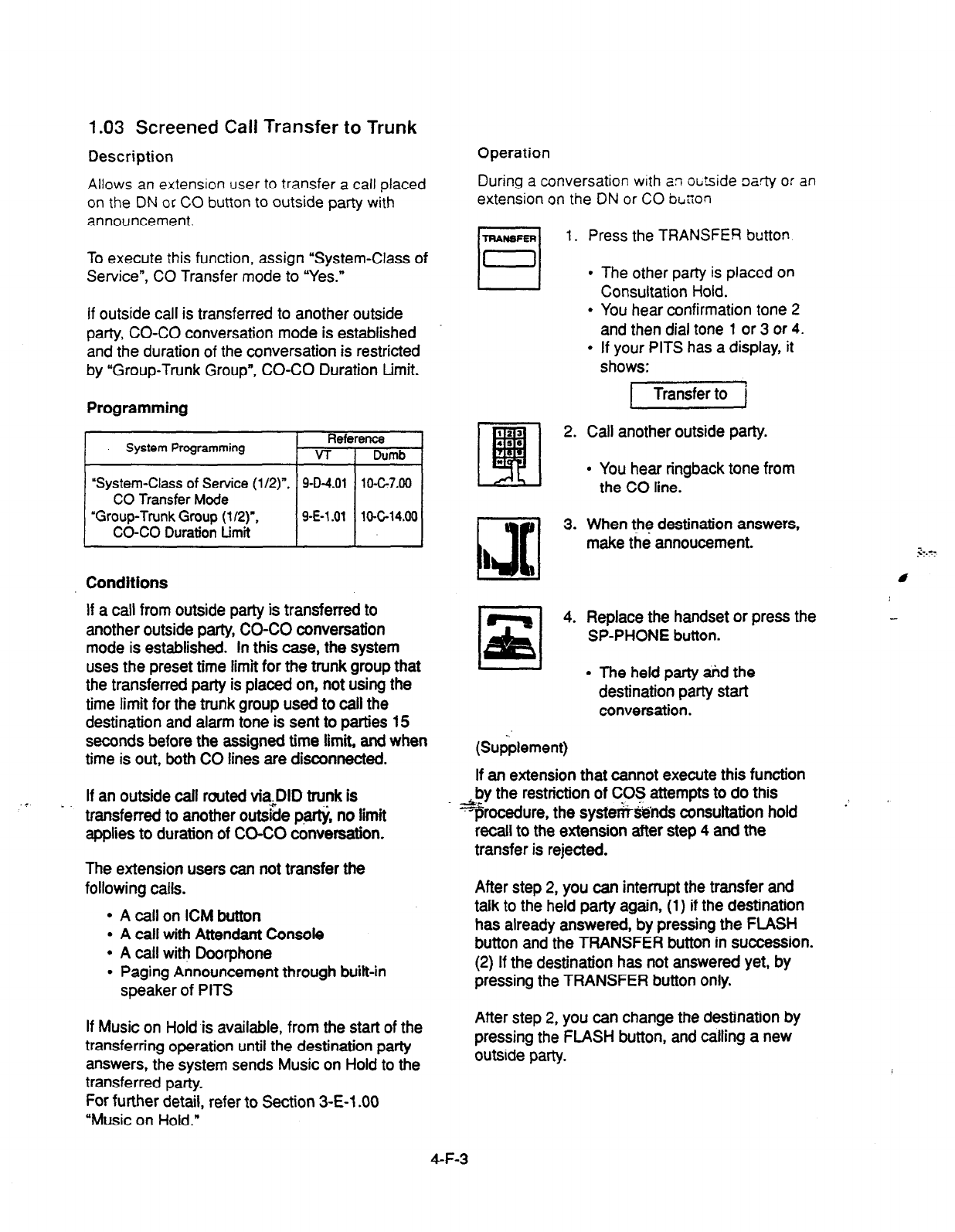
1.03 Screened Call Transfer to Trunk
Description Operation
During
a conversation
with an ot,tside oarty or an
extension on the ON or CO boon
Allows an extension user to transfer a call placed
on the DN or CO button to outside party with
announcement.
To execute this function, assign “System-Class of
Service”, CO Transfer mode to “Yes.”
If outside call is transferred to another outside
party, CO-CO conversation mode is established
and the duration of the conversation is restricted
by “Group-Trunk Group”, CO-CO Duration Limit.
Programming
System Programming Reference
VT 1 Dumb
Conditions
If a call from outside party is transferred to
another outside party, CO-CO conversation
mode is established. In this case, the system
uses the preset time limit for the trunk group that
the transferred party is placed on, not using the
time limit for the trunk group used to call the
destination and alarm tone is sent to parties 15
seconds before the assigned time limit, and when
time is out, both CO lines are disconnected.
If an outside call routed via.DID trunk is
. . _. transferred to another out&e partji, no limit
applies to duration of CO-CO
conversation.
The extension users can not transfer the
following calls.
l
A call on ICM button
l
A call with Attendant Console
l
A call with Doorphone
l
Paging Announcement through built-in
speaker of PITS
If Music on Hold is available, from the start of the
transferring operation until the destination party
answers, the system sends Music on Hold to the
transferred party.
For further detail, refer to Section 3-E-l .OO
“Music on Hold.”
1.
Press the TRANSFER button
l
The other party is placed on
Consultation Hold.
l
You hear confirmation tone 2
and then dial tone 1 or 3 or
4.
l
If your PITS has a display, it
shows:
(23
•I
2. Call another outside party.
416
73.
*
l
You hear ringback tone from
the CO line.
3. When the destination answers,
make the annoucement.
4. Replace the handset or press the
SP-PHONE button.
I I
l
The held party tid the
destination party start
conversation.
(Supplement)
If an extension that cannot execute this function
&ty the restriction of COS attempts to do this
“jsrocedure, the syst&&nds consultation hold
recall to the extension after step 4 and the
transfer is rejected.
After step 2, you can interrupt the transfer and
talk to the held party again, (1) if the destination
has already answered, by pressing the FLASH
button and the TRANSFER button in succession.
(2) If the destination has not answered yet, by
pressing the TRANSFER button only.
After step 2, you can change the destination by
pressing the FLASH button, and calling a new
outside party.
4-F-3
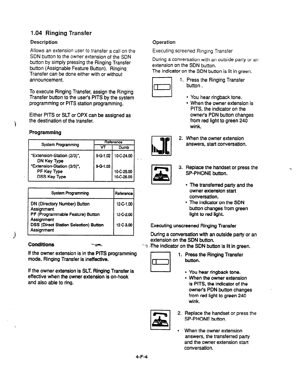
1.04 Ringing Transfer
Description Operation
Allows an extension user to transfer a call on the
SDN button to the owner extension
of the
SDN
button by simply pressing the Ringing Transfer
button (Assignable Feature Button). Ringing,
Transfer can be done either with or without
announcement.
Executing screened Ringing Transfer
During a conversation with an outside party or an
extension on the SDN button.
The indicator on the SDN button is lit in green.
El 1.
To execute Ringing Transfer, assign the Ringing
Transfer button to the user’s PITS by the system
programming or PITS station programming.
Either PITS or SLT or OPX can be assigned as
the destination of the transfer.
Programming
System Programming Reference
VT 1 Dumb
“Extension-Station (2/a)“,
DN Key Type
“Extension-Station
p/3)“,
PF Key Type
DSS Key Type
9-G-1.02
g-G-1.03
1 O-C-24.00
1 O-C-25.00
1 O-C-26.00
System Programming I
Reference I
DN (Directory Number) Button
Assignment
PF (Programmable Feature)
Button
Assignment
DSS (Direct Station Selection) Button
Assignment
1 I I
Conditions -z%L
12c1.00
1262.00
12-c-3.00
If the owner extension is in the PITS programming
mode, Ringing Transfer is ineffective.
If the owner extension is SLT, Ringing Transfer is
effective when the owner extension is on-hook
and also able to ring.
:.
13[1
2.
I
3.
Press the Ringing Transfer
button.
.
.
You hear ringback tone.
When the owner extension is
PITS, the indicator on the
owners PDN button changes
from red light to green 240
wink.
When the owner extension
answers, start conversation.
Replace the handset or press the
SP-PHONE button.
The transferred party and the
owner extension start
conversation.
The indicator on the SDN
button changes from green
light to red light.
Executing unscreened Ringing Transfer
During a conversation with an outside party or an
extension on the SDN button.
? Xhe indicator on the SDN button is lit in green.
1. Press the Ringing Transfer
button.
l
You hear nngback tone.
l
When the owner extension
is PITS, the indicator of the
owner’s PDN button changes
from red light to green 240
wink.
2. Replace the handset or press the
SP-PHONE button.
l
When the owner extension
answers, the transferred party
and the owner extension start
conversation.
4-F-4
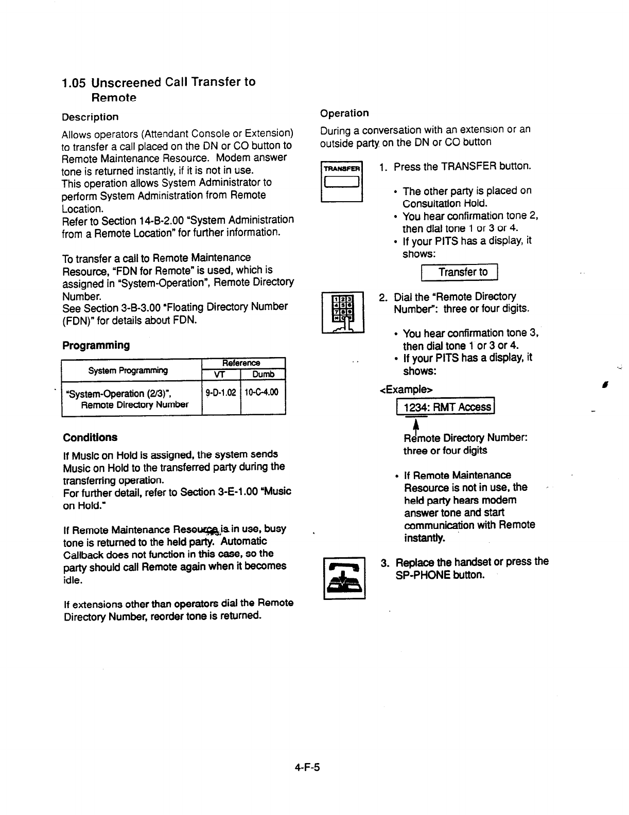
1.05 Unscreened Call Transfer to
Remote
Description
Allows operators (Attendant Console or Extension)
to transfer a call placed on the DN or CO button to
Remote Maintenance Resource. Modem answer
tone is returned instantly, if it is not in use.
This operation allows System Administrator to
perform System Administration from Remote
Location.
Refer to Section 14-B-2.00 “System Administration
from a Remote Location” for further information.
To transfer a call to Remote Maintenance
Resource, “FDN for Remote” is used, which is
assigned in “Systembperation”, Remote Directory
Number.
See Section 3-B-3.00 ‘Floating Directory Number
(FDN)” for details about FDN.
Programming
Conditions
If Music on Hold is assigned, the system sends
Music on Hold to the transferred party during the
transferring operation.
For further detail, refer to
Section
3-E-l .OO ‘Music
on Hold.”
If Remote Maintenance Resouq&isin use, busy
tone is returned to the held party. Automatic
Callback does not function in this case, so the
party should call Remote again when it becomes
idle.
If extensions other than operators dial the Remote
Directory Number, reorder tone is returned.
Operation
During a conversation with an extension or an
outside party on the DN or CO button
-1 1. Press the TRANSFER button.
The other party is placed on
Consultation Hold.
You hear confirmation tone 2,
then dial tone 1 or 3 or 4.
If your PITS has a display, it
shows:
2. Dial the “Remote Directory
Number”: three or four digits.
.
l
You hear confirmation tone 3,
then dial tone 1 or 3 or 4.
. If your PITS has a display, it
shows:
<ExamDIe>
1 1234: RMT Access 1
.
t
Remote Directory Number:
three or four digits
If Remote Maintenance
Resource is not in use, the
held party hears modem
answer tone and
start
communication with Remote
instantly.
3. Replace the handset or press the
SP-PHONE button.
4-F-5

1.06 Unscreened Call Transfer
-to Attendant Console
Description
Allows an extenson user to transfer a call (both
extenson and outsde) to an Attendant Console
without announcement.
Programming _
None
Conditions
1) Transfer Recall
2)
i
3)
4)
5)
A call transferred by this feature will not ring
back at the extension who transferred the call
even
if the Attendant Console does not
answer the call after the transfer recall timer
has been elapsed.
Intercept Routing No Answer (IRNA)
A call transferred to an Attendant Console will
not be transferred to another extension by
IRNA feature even if the Attendant Console
does not answer the call after the IRNA timer
has been elapsed.
What if ail six Loop keys on the Attendant
Console are not
idle?
A call is put in the call waiting queue of the
Attendant Console.
What if the Attendant Console is in ATT-FWD
mode?
This feature does not function.
A call is simpiy put on Consultation Hoid, that
is, a call will ring back at the extension who
tries to transfer the call as soon as he or she
goes on-hook.
Music on Hold
tf Music on Hoid is avaiiabie. the system
sends Music on Hoid to the transferred party,
from the start of the transferring operation till
the destination party answers.
Operation
During
a conversation with an extension or an
outside party.
1 Press the TRANSFER button.
l
The
other
party is put on
Consuttation Hoid.
l
You hear confirmation tone 2
and then dial tone 1 or 3 or 4.
l
If your PITS has a display. it
shows:
1 Transfer to 1
1
Jl
2 Make
a call
to an
Attendant
,
1 Console.
l
You hear ringback tone.
l
Calling an Attendant Console
starts.
3 Replace the handset or press the
SP-PHONE button.
l
At an Attendant Console:
The call is displayed as a
transfer recall.
(Supplement)
The feature numbers and DN’s for making a call
to an Attendant Console are:
l
Operator Call (General)
l
Operator Call (Specifii)
l
FDN for General Operator Call
l
DN for ATT1 and ATT2
4-F-5-1
(21292)

1.07
Unscreened Call Transfer
-to a UCD Group (with OGM)
Description
Allows any extension user to transfer an outside
call to a UCD Group from
01
to
04
(with OGM
type).
Feature References
Uniform Call Distribution (UCD)-with /without
O-GM (Section 3-D-2.06)
From version 8.xX, not only the operators but
any extension user can transfer an outside call to
a UCD group (with OGM).
Programming
conattons
lf all group members are not available to answer
the call, il will be redirected to the Overflow
destination. In thii case, the call will be
. disconnected if not answered by the Overflow
destination withii 60 seconds.
See page 3-D-l 3 for further information.
Operation
During a conversation with an outside party.
r===l
1 Press the TRANSFER button.
I
0 ’
.
.
Theotherpaftyisputon
Consultation Hold.
You hear confiib~ tone 2
andthendialtona 1 or3or4.
If your PlTS has
a display, it
2
OhI the FDN for UCD group (01
tOO4).
l
You hear confirmation tone 3 *
and then diil tone 1 or 3 or 4.
3 Rep&e the handset or press the
SP-PHON E button.
4-F-5-2
(40993)

2.00 Call Forwarding (FWD)
2.01 Call Forwarding-All Calls
Description
Call Forwarding-All Calls allows extension users
who are away from their phones to receive
incoming calls (both extension and CO) at
another extension.
Incoming calls can be forwarded to extension
users, Voice Mail ports, or operators (Attendant
Console or Extension).
‘FDN for General Operator Call” can be used to
assign operators as the destination of Call
Forwarding.
Refer to Section 9-D-l .Ol “Operation (l/3)” for
further information.
The following incoming calls do not receive Call
Forwarding treatment.
l
A call appearing on ICM button
l
A call from doorphone
l
A call appearing on PC0 button
7
l
A call routed via DIL 1: N feature
&4
l
A call directed to a UCD group
To execute Call Fonvarding-All Calls, assign
‘System-Class of Service”, Call Forwarding/Do
Not Disturb to “Yes.”
To set or cancel this function, the following two
methods are available:
cl> By pressing the FWD/DND button.
c2>
By dialing the feature number for
“Call Forwarding-All Calls Ser and
“Call Forwarding-Do Not Disturb Cancel.”
Programming
System Programming
“System-Class of Service (l/2)=,
Call Forwarding& Not
Disturb
‘System-Numbering Plan (4/g)“,
Call Forwarding-All Call Set
‘System-Numbering Plan (5/9)“,
Call ForwardinglDo Not
Disturb Cancel
Rei
VT
9-O-4.01
9-0-6.04
9-O-6.05
13c7.00
10-6-10.00
10-c-10.00
Conditions
To set or cancel this function, use the PDN
button.
An extension user may have only one type of
Call Forwarding/Do Not Disturb feature in effect
at any time. If a second type is assigned, the
previously assigned type is canceled.
Call Forwarding-All Calls feature functions even if
the extension is in the PITS programming mode.
If the extension to which calls are to be
forwarded itself is in a call forward mode, a call is
not forwarded furthermore. The call rings at the
first forwarded extension. In case of an outside
call, if not answered in a specified time period,
the call will be routed to another destination, if
available, based on the ‘Intercept Routing-No
Answer” feature.
If Tenant Service is employed and ‘Inter Tenant
Calling” is assigned to ‘Yes” by programming,
this function is ineffective for the calls from
another tenant if the destination of Call
Forwarding-All Calls is set to an Attendant
Console.
Calls from any VM extension will not be
forwarded, if forwarding destination is another
VM extension.
An extension user is rejected with reorder tone if
he or she attempts:
l
To set the destination to an extension in the
other tenant when Tenant Service is employed.
l
To set the destination to another extension that
presets its own destination to the users
extension.
l
To call another extension that presets its
destination to the user’s extension.
The Operators (Attendant Console or Extension)
can cancel the Call Forwarding/Do Not Disturb
feature assigned to the extension users. Refer to
Section 4-1~11 .OO Remote Station Feature
Control.”
4-F-6
(21292)

The following table shows the results of the calls arriving at an extension setting
this function depending on the conditions of the preset destination.
Type of Call Arriving Condition of Destination Forwarding
at Setting Extension Execution Result
Extension call Idle status
0
Call is forwarded
to
destination.
Busy status
0
Busy tone is sent from destination.
Assigned to DND
0
DND tone is sent from destination.
PITS programming mode
0
Busy tone is sent from destination.
Conditions except In Service * )( Call is placed on setting extension.
DIL (1:l) or DISA call Idle status
0
Call is forwarded to destination.
Busy status
0
Call is forwarded and kept waiting
at destination.
Assigned to DND
0
Same as call reaching DND. See
Section 4-D-6.00 “Do Not Disturb
(DND).”
PITS programming mode
0
Call is forwarded and kept waiting
at destination.
DID call
-‘z
4 ^
Conditions except In Service *
Idle status
Busy status
Assigned to DND
PITS programming mode
Conditions except In Service *
X Call is placed on setting extension.
0
Call is forwarded to destination.
0
Busy tone is sent from destination
0
Same as call reaching DND. See
Section 4-D-6.00 “Do Not Distu$
(DND).”
0
Busy tone is sent from desti‘nation
X
Call is placed on destination.
0:
Forwarding possible
X : Forwarding impossible
t Conditions are Qut of Service,”
‘Fault” and ‘Pre-Installed.” See
Section 14-C-2.02 ‘Port” for details.
‘Ii
4-F-7
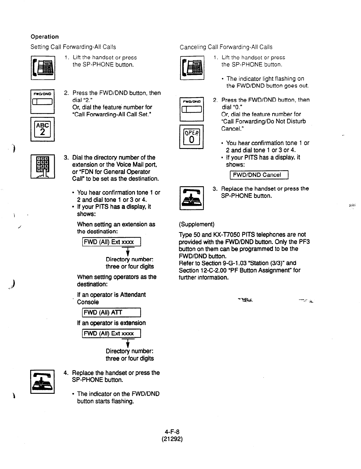
-)
i .
/
.)
. .-
Operation
Setting Call Forwarding-All Calls
1. Lift the handset or press
the SP-PHONE
button.
2.
Press the FWD/DND
button, then
dial “2.”
Or, dial the feature number for
“Call Forwarding-All Call Set.”
Dial the directory number of the
extension or the Voice Mail port,
or “FDN for General Operator
Call” to be set as the destination.
l
You hear confirmation tone 1 or
2 and dial tone 1 or 3 or 4.
l
If your PITS has a display, it
shows:
When setting an extension as
the destination:
MD (All) Ext xxxx 1
-
t
Directory number:
three or four digits
When setting operators as the
destination:
If an operator is Attendant
Console
1 FWD (All) AT-T I
If an operator is extension
IFWD (All) Ext xxxx 1
-?-
Directory number:
three or four digits
Replace the handset or press the
SP-PHONE button.
l
The indicator on the FWDIDND
button starts flashing.
Canceling Call Forwarding-All Calls
1.
0
FrEl
2.
OW
/o/
0
cl
,z,
3.
Lift the handset or press
the SP-PHONE button.
l
The indicator light flashing on
the FWD/DND button goes out.
Press the FWD/DND button, then
dial “0.”
Or, dial the feature number for
“Call Forwarding/Do Not
Disturb
Cancel.”
l
You hear confirmation tone 1 or
2 and dial tone 1 or 3 or 4.
e if your PITS has a display, it
shows:
[ FWD/DND Cancel 1
L 1
Replace the handset or press the
SP-PHONE button.
(Supplement)
Type 50 and KX-l7050 PITS telephones are not
provided with the FWD/DND button. Only the PF3
button on them can be programmed to be the
FWDIDND button.
Refer
to
Section 9-G-l -03 “Station (3/3)” and
Section 12-C-2.00 “PF Button Assignment” for
further information.
_- -
*. .*
4-F-8
(21292)

2.02 Call Forwarding-Busy/Off-Hook
Description Conditions
Call Forwarding-Busy/Off-Hook provides
automatic call transfer to a preset destination
when the user’s extension is busy.
Busy status means all PDNs are used, or off-hook
status (including hands-free status) or in the PITS
programming mode.
To set or cancel this function, use the PDN
button.
Incoming calls can be forwarded to extension
users, Voice Mail ports, or operators.
“FDN for General Operator Call’ is used to assign
operators as the destination of Call Forwarding.
Refer to Section 9-D-l .Ol “Operation (l/3)’ for
further information.
An extension user may have only one type of
Call Forwarding/Do Not Disturb feature in effect
at any time. If a second type is assigned, the
previously assigned type is canceled.
The following incoming calls do not receive Call
Forwarding treatment.
l
A call appearing on ICM button
l
A call from doorphone
l
A call appearing on PC0 button
l
A call routed via DK 1: N feature
l
A call directed to a UCD group
If the extension to which calls are to be - ..
forwarded itself is in a call forward mode, a call is
not forwarded furthermore. The call rings at the
first forwarded extension. In case of an outside
call, if not answered in a specified time period,
the call will be routed to another destination, if
available, based on the “Intercept Routing-No
Answer feature.
To set this function, assign “System-Class of
Service”, Call Forwarding/Do Not Disturb to ‘Yes.”
If Tenant Service is employed and ‘Inter Tenant
Calling” is assigned to Yes’ by programming,
this function is ineffective for the calls from
.another tenant if the destination of C&II
Forwarding-Busy/Off-t-look is set to an Attendant
Console.
Calls from any VM extension will’not be
forwarded, if forwarding destination is another
VM extension.
For setting and canceling this function, two
methods are available:
cl
> By pressing the FWD/DND button.
<2> By dialing the feature number for
“Call Fonnrarding-Busy Ser and
“Call Forwarding/Do Not Disturb Cancel.”
Programming
Q-m prosrammins Reterence
VT Dumb
%ystem-Class of Service (l/2)‘, 9-D-4.01 lOG7.00
Call ForwardingKb Not
Disturb
“System-Numbering Pian (WY, 9-D-6.04 10420.00
Call Forwarding-Busy Set
‘System-Numbering Plan (5/g)“, 9-D-6.05 104-10.00
Call Forwarding/Do Not
Disturb Cancel
An extension user is rejected with reorder tone if
he or she attempts:
l
To set the destination to an extension in the
other tenant when Tenant Setice is employed.
l
To set the destination to another extension that
presets its own
destination to the user’s
extension.
l
To
call
another extension that presets its
destination to the user’s extension.
The Operators (Attendant Console or Extension)
can cancel the Call Forwarding/Do Not Disturb
feature assigned to the extension users. Refer to
Section
4-l-11
90 “Remote Station Feature
Control.”
4-F-9
(21292)
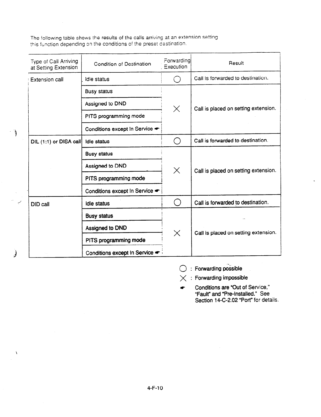
The followmg table shows the results of the calls arriving at an extension setting
this function depending on the conditions of the preset destination.
Type of Call Arriving
at Setting Extension
j I Extension call
DIL
(1 :I) or
DISA cal
DID call
I
Condition of Destination forwardins
Execution
Idle status
j 0
Busy
status I
Assigned to DND I
PITS programming mode j x
/
Conditions except In Service * /
Idle status 1 0
Busy
status
I
Assigned to DND
PITS programming mode j x
t
Conditions except In Sewice * i
Idle status i
0
/
Busy status L
Assigned to DND
PITS programming mode i x
r
Conditions except In Service * :
0
Forwarding possible
X : Forwarding impossible
Result
Call is forwarded to destination.
Call is placed on setting extension.
Call is forwarded to destination.
Call is placed on setting extension.
Call is forwarded to destination.
-.
J
Call is placed on setting extension.
m- Conditions are Wut of
Service,”
“Fault” and ‘Pre-Installed.” See
Section
14-C-2.02
“Port”
for details.
4-F-l 0
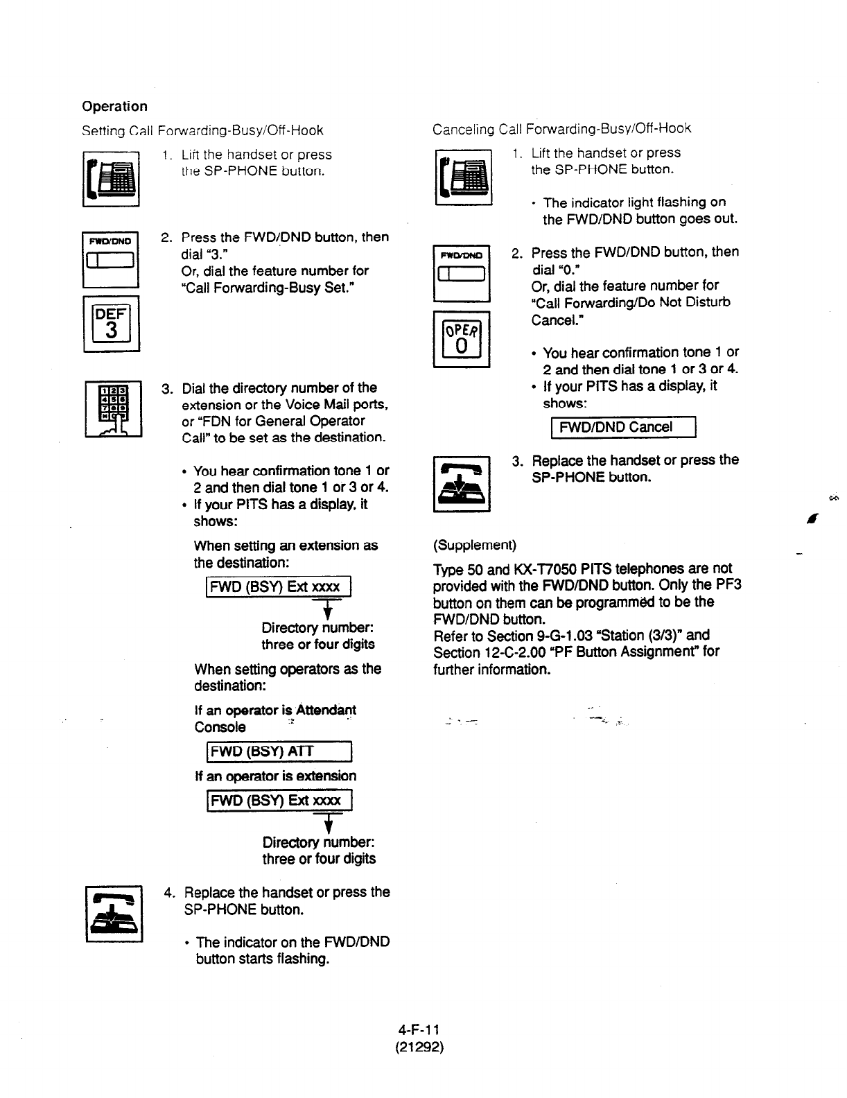
Operation
Setting Call Forwarding-Busy/Off-Hook
1. Lift the handset or press
the SP-PHONE button.
2.
rl
s,
4.
Press the FWD!DND button, then
dial “3.”
Or, dial the feature number for
“Call Forwarding-Busy Set.”
Dial the directory number of the
extension or the Voice Mail ports,
or “FDN for General Operator
Call” to be set as the destination.
l
You hear confirmation tone 1 or
2 and then dial tone 1 or 3 or 4.
l
If your PITS has a display, it
shows:
When setting an extension as
the destination:
IFWD(BSY) Ext= 1
T-
Directory number:
three or four digits
When setting operators as the
destination:
If an operator is Attendant
Console 2
IFWD (BSY) A-IT 1
lf an operator is extension
pwD(BsY)Extxxxx 1
- $
Directory number:
three or four digits
Replace the handset or press the
SP-PHONE button.
l
The indicator on the FWD/DND
button starts flashing.
Canceling Call
I.
0
iii2
3.
(Supplement)
Forwarding-Busy/Off -Hook
Lift the handset or press
the SP-PHONE button.
l
The indicator light flashing on
the FWD/DND button goes out.
Press the FWD/DND button, then
dial “0.”
Or, dial the feature number for
“Call Forwarding/Do Not Disturb
Cancel.”
l
You hear confirmation tone 1 or
2 and then dial tone 1 or 3 or 4.
l
If your PITS has a display, it
shows:
FWD/DND Cancel
Replace the handset or press the
SP-PHONE button.
Type 50 and KX-T7050 PITS telephones are not
provided with the FWD/DND button. Only the PF3
button on them can be programmed to be the
FWD/DND button.
Refer to Section 9-G-l .03 ‘Station (3/3)” and
Section 12-C-2.00 ‘PF Button Assignment” for
further information.
4-F-l 1
(21292)
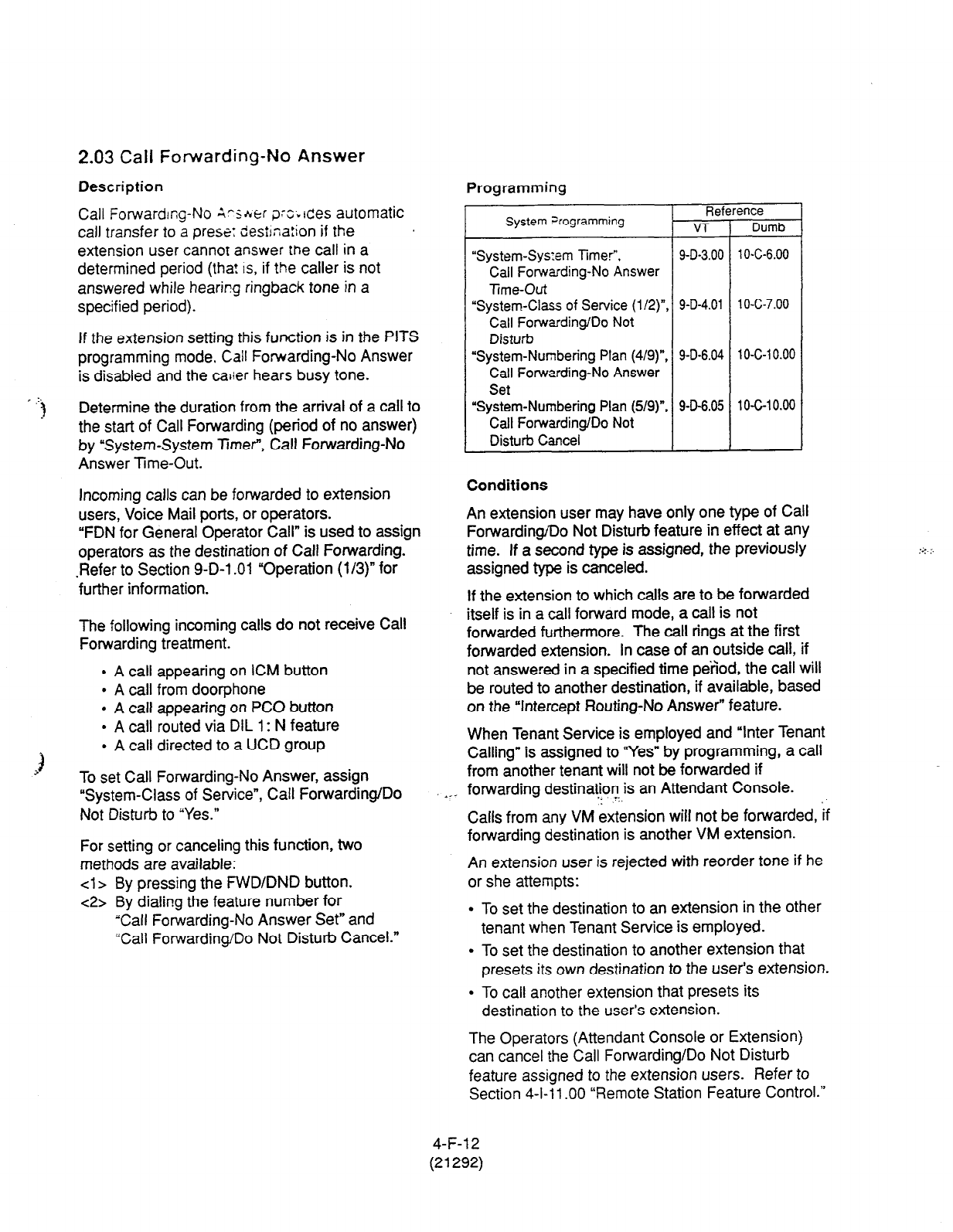
2.03 Call Forwarding-No Answer
Description
Call Forwarding-No ?~srer orc~~~!es automatic
call transfer to a prese: desiina:ion if the
extension user cannof answer
the
call in a
determined period (tha! IS, if the caller is not
answered while hearing ringback tone in a
specified period).
If the extension setting this function is in the PITS
programming mode. Call Forwarding-No Answer
is disabled and the calier hears busy tone.
, .:.
I Determine the duration from the arrival of a call to
the start of Call Forwarding (period of no answer)
by “System-System Timer”, Call Forwarding-No
Answer lime-Out.
Incoming calls can be forwarded to extension
users, Voice Mail ports, or operators.
“FDN for General Operator Call” is used to assign
operators as the destination of Call Forwarding.
.Refer to Section 9-D-l .Ol “Operation (l/3)” for
further information.
The following incoming calls do not receive Call
Forwarding treatment.
l
A call appearing on ICM button
l
A call from doorphone
l
A call appearing on PC0 button
. A call routed via DIL 1: N feature
l
A call directed to a UCD group
To set Call Forwarding-No Answer, assign
“System-Class of Service”, Call Forwarding/Do
Not Disturb to “Yes.”
For setting or canceling this function, two
methods are available:
cl > By pressing the FWD/DND button.
c2> By dialing the feature number for
“Call Forwarding-No Answer Set” and
“Call Forwarding/Do Not Disturb Cancel.”
*_-
Programming
System Frogramming Reference
VT Dumb
“System-Sys:em Timer”, 9-D-3.00 1 O-C-6.00
Call Forwarding-No Answer
Time-Out
“System-Class of Service (l/2)“, 9-D-4.01 1 O-C-7.00
Call Forwarding/Do Not
Disturb
“System-Numbering Plan (4/g)“, 9-D-6.04 1 O-C-1 0.00
Call Forwarding-No Answer
Set
“System-Numbering Plan (5/g)“, 9-D-6.05 10-C-10.00
Call Forwarding/Do Not
Disturb Cancel
Conditions
An extension user may have only one type of Call
Forwarding/Do Not Disturb feature in effect at any
time. If a second type is assigned, the previously
assigned type is canceled.
If the extension to which calls are to be forwarded
itself is in a call forward mode, a call is not
forwarded furthermore. The call rings at the first
forwarded extension. In case of an outside call, if
not answered in a specified time period, the call will
be routed to another destination, if available, based
on the “Intercept Flouting-No Answer” feature.
When Tenant Service is employed and “Inter Tenant
Calling” is assigned to “Yes” by programming, a call
from another tenant will not be forwarded if
forwarding destinatJon is an Attendant Console.
Calls from any VM extension will not be forwarded, if
forwarding destination is another VM extension.
An extension user is rejected with reorder tone if he
or she attempts:
l
To set the destination to an extension in the other
tenant when Tenant Service is employed.
l
To set the destination to another extension that
presets its own destination to the user’s extension.
l
To call another extension that presets its
destination to the user’s extension.
The Operators (Attendant Console or Extension)
can cancel the Call Forwarding/Do Not Disturb
feature assigned to the extension users. Refer to
Section 4-l-11 .OO “Remote Station Feature Control.”
4-F-l 2
(21292)

The following table shows the results of the calls arriving at an extension setting
;-is function depencing on the conditions of the preset destination.
T@+z of Call Arriving
3r Setting Extension Condition of Destination Forwardin!
Execution
Extension call Idle status
4
0
Busy status
Assigned
to DND
X
PITS programming mode
Conditions except In Service *
DIL (1
:l)
or DISA call Idle status
0
Busy status
Assigned to DND
PITS programming mode
X
Conditions except In Service *
DID call Idle status
Busy status
0
Assigned to DND
X
PITS programming mode
Conditions except In Service *
-
3
c
Result
Call is forwarded to destination.
Call is placed on setting extension.
Call is forwarded to destination.
Call is placed on setting extension.
Call is forwarded to destination.
Call is placed on setting extension.
0:
Forwarding possible
X : Forwarding impossible
u Conditions are “Out of Service,”
“Fault” and “Pre-Installed.” See
Section 14-C-2.02 “Port” for details.
4-F-l
3
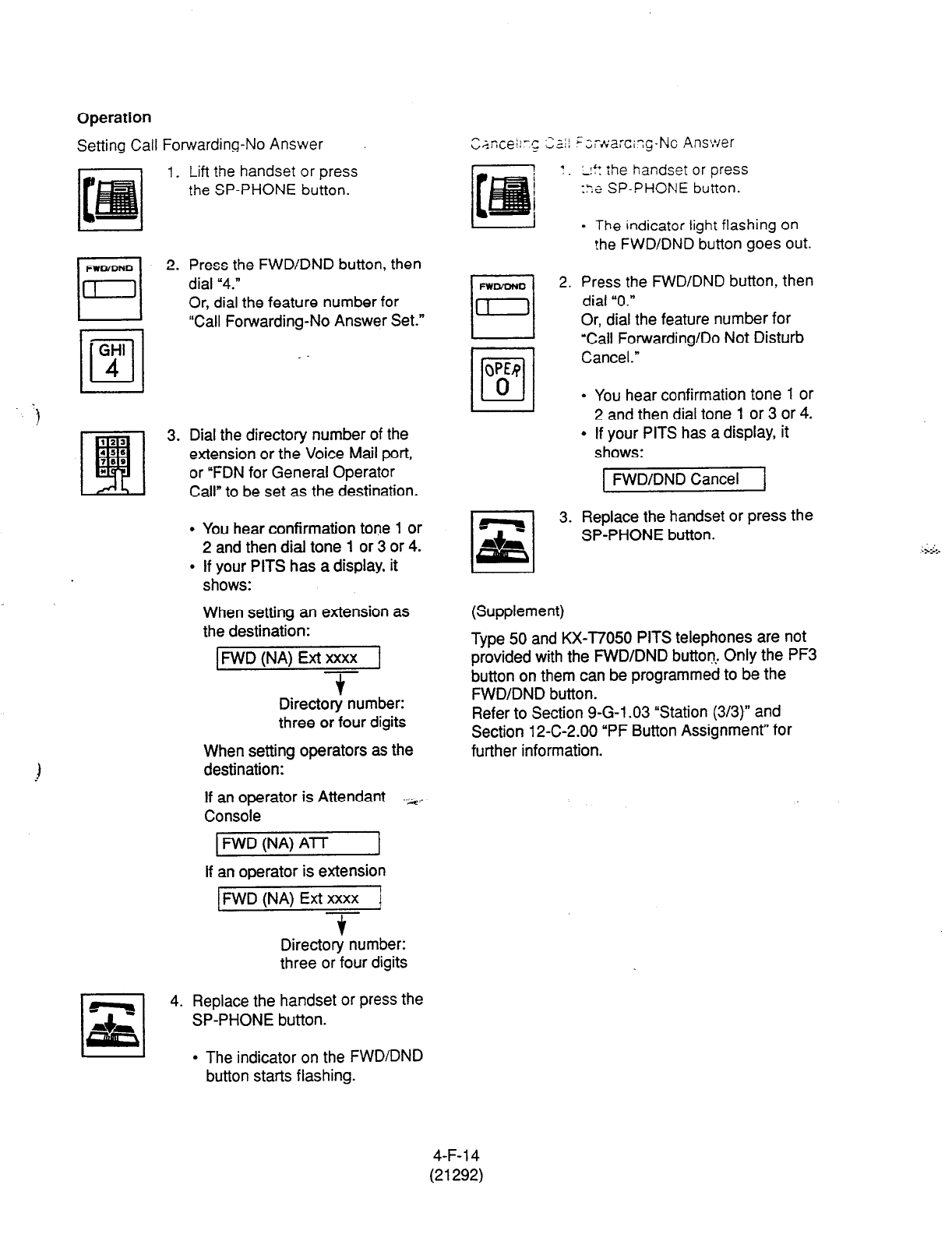
Operation
Setting Call Forwarding-No Answer
1.
Lift the handset or press
the SP-PHONE button.
WOiDNO
n
2.
GHI
•l
4
3.
Press the FWD/DND button, then
dial “4.”
Or, dial the feature number for
“Call Forwarding-No Answer Set.”
Dial the directory number of the
extension or the Voice Mail port,
or “FDN for General Operator
Call” to be set as the destination.
You hear confirmation tone 1 or
2 and then dial tone 1 or 3 or 4.
If your PITS has a display, it
shows:
When setting an extension as
the destination:
FWD (NA) Ext xxxx
-T
Directory number:
three or four digits
When setting operators as the
destination:
If an operator is Attendant -.>+
Console
1 FWD (NA) ATT I
If an operator is extension
FWD (NA) Ext xxxx 1
3-
Directory number:
three or four digits
rl
,x,
4. Replace the handset or press the
SP-PHONE button.
l
The indicator on the FWD/DND
button starts flashing.
FWODNO
El
2.
QW
/o/
0
l-l
qq
3.
I‘* :he handset or press
-. .
::e SP-PHONE button.
- The indicator light flashing on
!he
FWD/DND button goes out.
Press the FWDIDND button, then
dial “0.”
Or, dial the feature number for
‘Call Forwarding/Do Not Disturb
Cancel.”
. You hear confirmation tone 1 or
2 and then dial tone 1 or 3 or 4.
l
If your PITS has a display, it
shows:
FWD/DND Cancel
Replace the handset or press the
SP-PHONE button.
I I
(Supplement)
Type 50 and KX-T7050 PITS telephones are not
provided with the FWD/DND button.. Only the PF3
button on them can be programmed to be the
FWD/DND button.
Refer to Section 9-G-l .03 “Station (3/3)” and
Section 12-C-2.00 “PF Button Assignment” for
further information.
1 I
4-F-l 4
(21292)
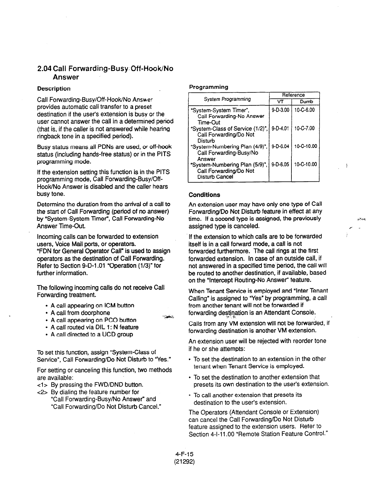
2.04 Call Forwarding-Busy. Off-Hook/No
Answer
Description
Call Forwarding-Busy/Off-Hook/No Answer
provides automatic call transfer to a preset
destination if the user’s extension is busy or the
user cannot answer the call in a determined period
(that is, if the caller is not answered while hearing
ringback tone in a specified period).
Busy status means .all PDNs are used, or off-hook
status (including hands-free status) or in
the PITS
programming mode.
Determine the duration from the arrival of a call to
the start of Call Forwarding (period of no answer)
by ‘System-System Timer”, Call Forwarding-No
Answer Time-Out.
If the extension setting this function is in the PITS
programming mode, Call Forwarding-Busy/Off-
HooWNo Answer is disabled and the caller hears
busy tone.
Incoming calls can be forwarded to extension
users, Voice Mail ports, or operators.
“FDN for General Operator Call” is used to assign
operators as the destination of Call Forwarding.
Refer to Section 9-D-l .Ol “Operation (l/3)” for
further information.
The following incoming calls do not receive Call
Forwarding treatment.
0 A call appearing on ICM button
l
A call from doorphone
l
A call appearing on PC0 button
l
A call routed via DIL 1: N feature
l
A call directed to a UCD group
To set this function, assign “System-Class of
Service”, Call Forwarding/Do Not Disturb to “Yes.”
For setting or canceling this function, two methods
are available:
cl
> By pressing the FWD/DND button.
c2>
By dialing the feature number for
“Call Forwarding-Busy/No Answer and
“Call Forwarding/Do Not Disturb Cancel.”
Programming
I-
System
Programming v-r
“System-System Timer, 9-D-3.00
Call Forwarding-No Answer
lime-Out
‘System-Class of Service (l/2)‘, 9-D-4.01
Call Forwarding/Do Not
Disturb
“System-Numbering Plan (4/g)“, 9-D-6.04
Call Forwarding-Busy/No
Answer
“System-Numbering Plan (5/g)“, 9-D-6.05
Call Forwarding/Do Not
Disturb Cancel
ence
Dumb
1 O-C-6.00
1 o-c-7.00
1 O-c-1 0.00
1 O-C-1 0.00
Conditions
An extension user may have only one type of Call
Forwarding/Do Not Disturb feature in effect at any
If the extension to which calls are to be forwarded
time. If a second type is assigned, the previously
itself is in a call forward mode, a call is not
forwarded furthermore. The call rings at the first
assigned type is canceled.
forwarded extension. In case of an outside call, if
not answered in a specified time’period, the call will
be routed to another destination, if available, based
on the “Intercept Routing-No Answer” feature.
When Tenant Service is employed and “Inter Tenant
Calling” is assigned to “Yes” by programming, a call
from another tenant will not be forwarded if
forwarding destination is an Attendant Console.
1’ h
Calls from any VM extension will not be forwarded, if
forwarding destination is another VM extension.
An extension user will be rejected with reorder tone
if he or she attempts:
l
To set the destination to an extension in the other
tenant when Tenant Service is employed.
l
To set the destination to another extension that
presets its own destination to the user’s extension.
l
To call another extension that presets its
destination to the user’s extension.
The Operators (Attendant Console or Extension)
can cancel the Call Forwarding/Do Not Disturb
feature assigned to the extension users. Refer to
Section 4-l-11 .OO “Remote Station Feature Control.”
4-F-l 5
(21292)
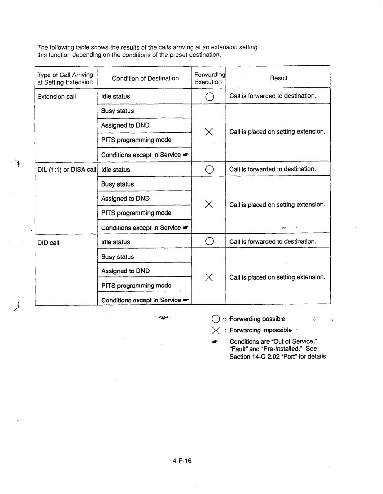
The following table shows the results of the calls arriving at an extension setting
this function depending on the conditions of the preset destination.
Type of Call Arriving Condition of Destination Forwarding
at Setting Extension Execution Result /
1
Extension call Idle status
Busy status
0
Call is forwarded to destination.
Assigned to DND
PITS programming mode
X
Call is placed on setting extension.
Conditions except In Service *
DIL (1 :I) or DISA call Idle status
0
Call is forwarded to destination.
Busy status
Assigned to DND
PITS programming mode
X
Call is placed on setting extension.
DID call
Conditions except In Service *
Idle status
Busy status
Assigned to DND
PITS programming mode
Conditions except In Service *
C,’
0
Call is forwarded to destination.
. .
X
Call is placed on setting extension.
0 -:- .Forwarding possible
X : Forwarding impossible
f Conditions are “Out of Service,”
“Fault” and “Pre-Installed.” See
Section 14-C-2.02 “Port” for details.
4-F-l 6
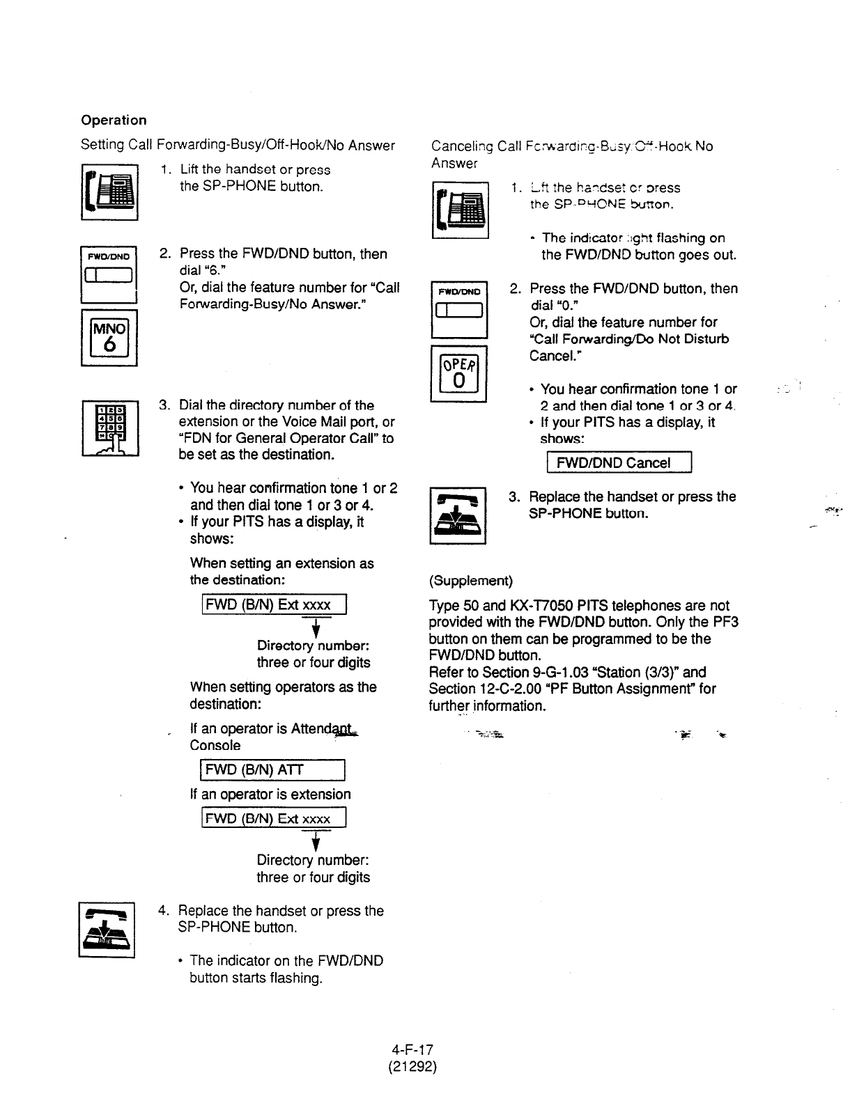
Operation
Setting Call Forwarding-Busy/Off-HooWNo Answer
I. Lift the handset or press
the
SP-PHONE button.
2. Press the FWDIDND button,
then
dial “6.”
Or, dial the feature number for “Call
Forwarding-Busy/No Answer.”
3. Dial the directory number of the
extension or the Voice Mail port, or
“FDN for General Operator Call” to
be set as the destination.
l
You hear confirmation tone 1 or 2
and then dial tone 1 or 3 or 4.
l
If your PITS has a display, it
shows:
When setting an extension as
the destination:
kWD (B/N) Ext xxxx 1
T
Directory number:
three or four digits
When setting operators as the
destination:
_ If an operator is Atten-
Console
1 FWD (B/N) A-f-l- I
If an operator is extension
FWD (B/N) Ext xxxx
f
Directory number:
three or four digits
4. Replace the handset or press the
SP-PHONE button.
Canceling Call Fcrwardirg-Btisy. E-Hook No
Answer
1. Lft the handset cr Dress
the SP-WCNE burron.
l
The indicator :ght flashing
on
the FWD/DND button goes out.
2. Press the FWD/DND button, then
dial “0.”
Or, dial the feature number for
“Call Forwarding/Do Not Disturb
Cancel.’
l
You hear confirmation tone 1 or
2 and then dial tone 1 or 3 or 4.
l
If your PITS has a display, it
shows:
1 FWD/DND Cancel 1
3. Replace the handset or press the
SP-PHONE button.
(Supplement)
Type 50 and KX-T7050 PITS telephones are not
provided with the FWD/DND button. Only the PF3
button on them can be programmed to be the
FWD/DND button.
Refer to Section 9-G-l .03 “Station (3/3)” and
Section 12-C-2.00 “PF Button Assignmenr for
further information.
. ‘iE -*
I 1 l
The indicator on the FWD/DND
button starts flashing.
4-F-l 7
(21292)
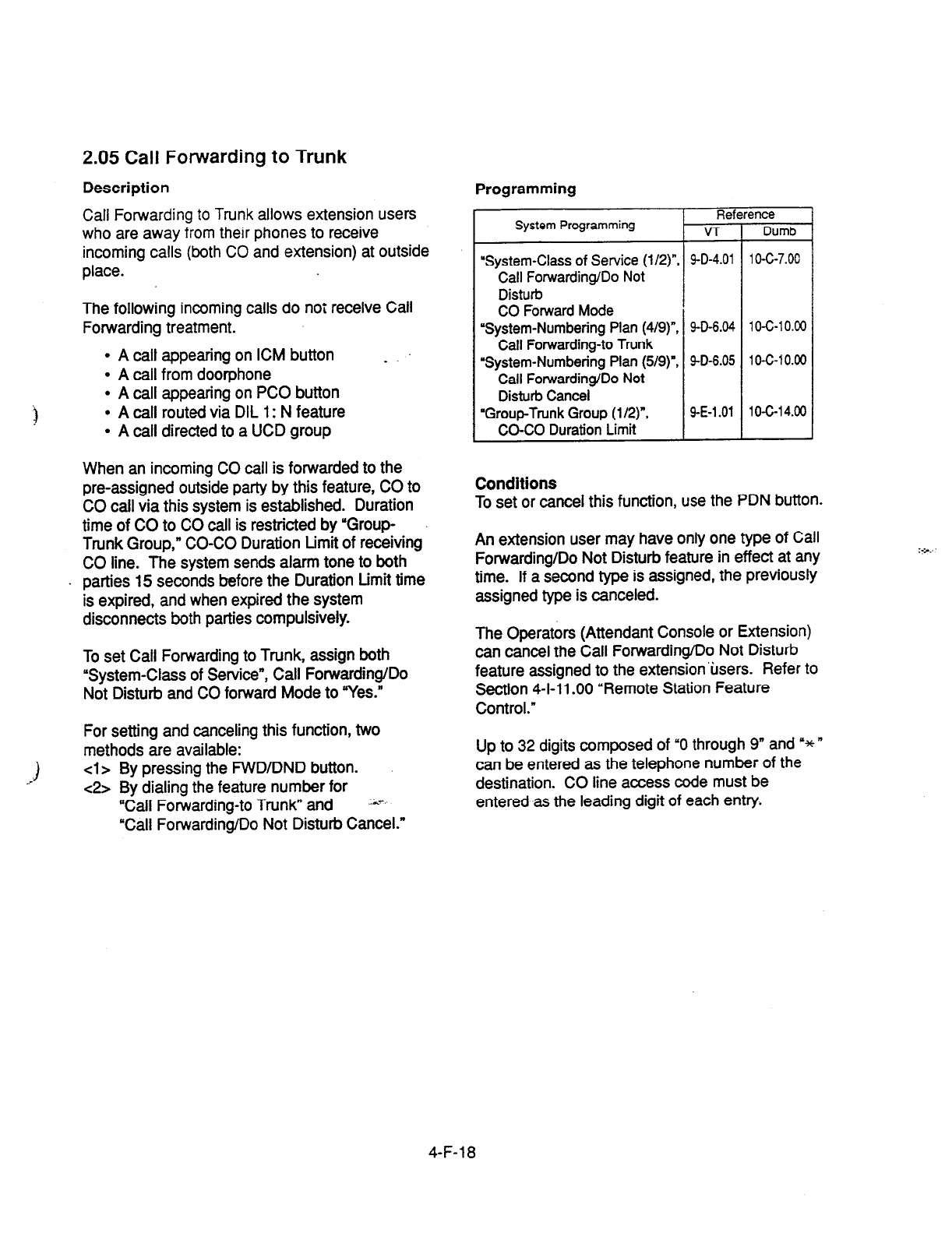
2.05 Call Forwarding to Trunk
Description Programming
Call Forwarding to Trunk
allows extension users
who
are away from their phones to receive
incoming
calls (both
CO and extension) at outside
place.
The following incoming calls do not receive Call
Forwarding treatment.
l
A call appearing on ICM button
l
A call from doorphone
l
A call appearing on PC0 button
l
A call routed via DIL 1: N feature
l
A tail directed to a UCD group
_
Reference
System Programming VT Dumb
“System-Class of Service (l/2)“, 9-D-4.01 10-C-7.00
Call Forwarding/Do Not
Disturb
CO Forward Mode
“System-Numbering Plan (4/g)“, SD-6.04 10-C-10.00
Call Forwarding-to Trunk
“System-Numbering Plan (5/g)“, 9-D-6.05 10-C-10.00
Call Forwarding/Do Not
Disturb Cancel
‘Group-Trunk Group
(l/2)“, 9-E-l .Ol 1 O-C-1 4.00
CO-CO Duration Limit
When an incoming CO call is forwarded to the
pre-assigned outside party by this feature, CO to
CO call via this system is established. Duration
time of CO to CO call is restricted by ‘Group-
Trunk Group,” CO-CO Duration Limit of receiving
CO line. The system sends alarm tone to both
Conditions
To set or cancel this function, use the PDN button.
. parties 15 seconds before the Duration Limit time
is expired, and when expired the system
disconnects both parties compulsively.
An extension user may have only one type of Call
Forwarding/Do Not Disturb feature in effect at any
time. If a second type is assigned, the previously
assigned type is canceled.
To set Call Forwarding to Trunk, assign both
“System-Class of Service”, Call Forwarding/Do
Not Disturb and CO forward Mode to “Yes.”
The Operators (Attendant Console or Extension)
can cancel the Call Forwarding/Do Not Disturb
feature assigned to the extension’tisers. Refer to
Section 4-l-l 1 .OO “Remote Station Feature
Control.”
For setting and canceling this function, two
methods are available:
cl> By pressing the FWD/DND button.
~2s.
By dialing the feature number for
“Call Forwarding-to Trunk” and 1s.T.
*Call Forwarding/Do Not Disturb Cancel.”
Up to 32 digits composed of “0 through 9” and ‘* ”
can be entered as the telephone number of the
destination. CO line access code must be
entered as the leading digit of each entry.
4-F-18
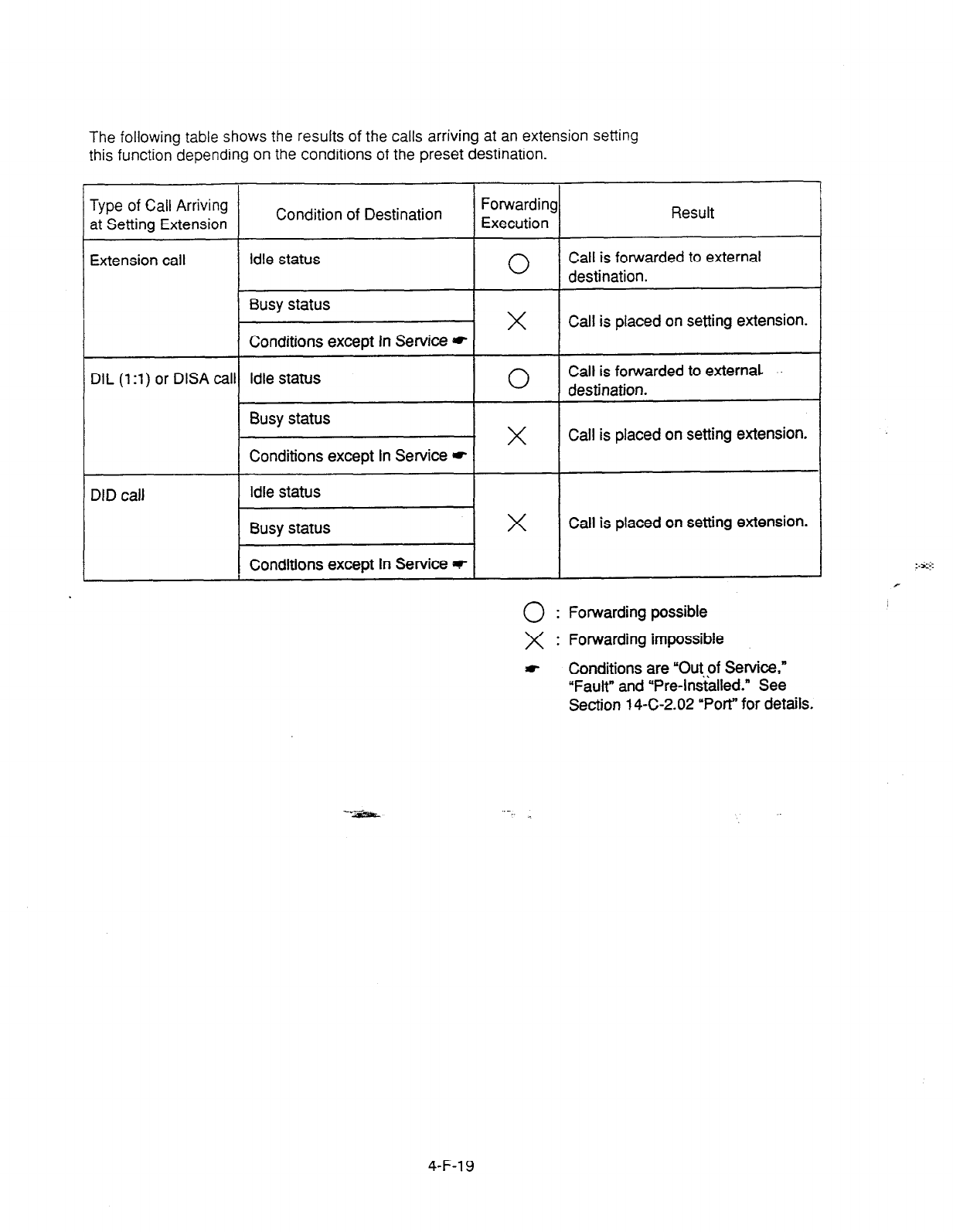
The following table shows the results of the calls arriving at an extension setting
this function depending on the conditions of the preset destination.
Type of Call Arriving
at Setting Extension Condition of Destination
I I
I
Extension
call I idle
status
I I
I
1 Busy status
I Conditions except in Service *
1 DIL (1 :l) or DISA calll Idle status
I I
I
Busy status
I I
Conditions except In Service *
DID call
*
I I
I
Conditions except In Service o
Forwarding
Execution
Result
0
Call is forwarded to external
destination.
X
Call is placed on setting extension.
0
Call is forwarded to external
destination.
X I
Call is placed on setting extension.
X
Call is placed on setting extension.
0
: Forwarding possible
X : Forwarding impossible
c
Conditions are “Out of Service,”
“Fault” and “Pre-lns’t’alled.” See
Section 14-C-2.02 “Port” for details.
4-F-l 9
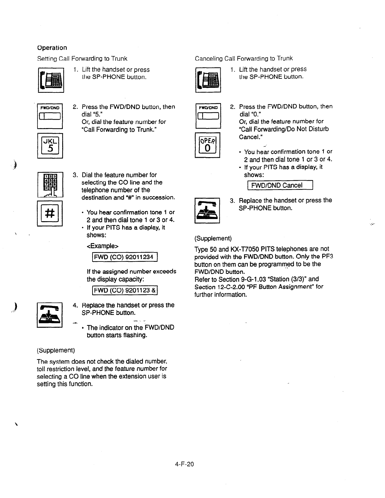
Operation
Setting Call Forwarding to Trunk Canceling Call Forwarding to Trunk
1. Lift the handset or press
the SP-PHONE button.
2. Press the FWD/DND button, then
dial “5.”
Or, dial the feature number for
“Call Forwarding to Trunk.”
3. Dial the feature number for
selecting the CO line and the
telephone number of the
destination and “#” in succession.
l
You hear confirmation tone 1 or
2 and then dial tone 1 or 3 or 4.
I I
l
If your PITS has a display, it
\ . shows:
<Example>
IFWD (CO) 92011234 1
If the assigned number exceeds
the display capacity:
IFWD (CO) 9201123 &I
1
:: 4. Replace the handset or press the
SP-PHONE button.
-.. -
l
The indicator on the FWD/DND
button starts flashing.
(Supplement)
The system does not check the dialed number,
toll restriction level, and the feature number for
selecting a CO line when the extension user is
setting this function.
1. Lift the handset or press
the SP-PHONE button.
2. Press the FWD/DND button, then
dial “0.”
Or, dial the feature number for
“Call Forwarding/Do Not Disturb
Cancel.”
l
You hear confirmation tone 1 or
2 and then dial tone 1 or 3 or 4.
l
If your PITS has a display, it
shows:
1 FWD/DND Cancel ]
3. Replace the handset or press the
SP-PHONE button.
(Supplement)
Type 50 and KX-T7050 PITS telephones are not
provided with the FWD/DND button. Only the PF3
button on them can be programmed to be the
FWD/DND button.
Refer to Section Q-G-1.03 ‘Station (3/3)” and
Section 12-C-2.00 “PF Button Assignment” for
further information.
4-F-20
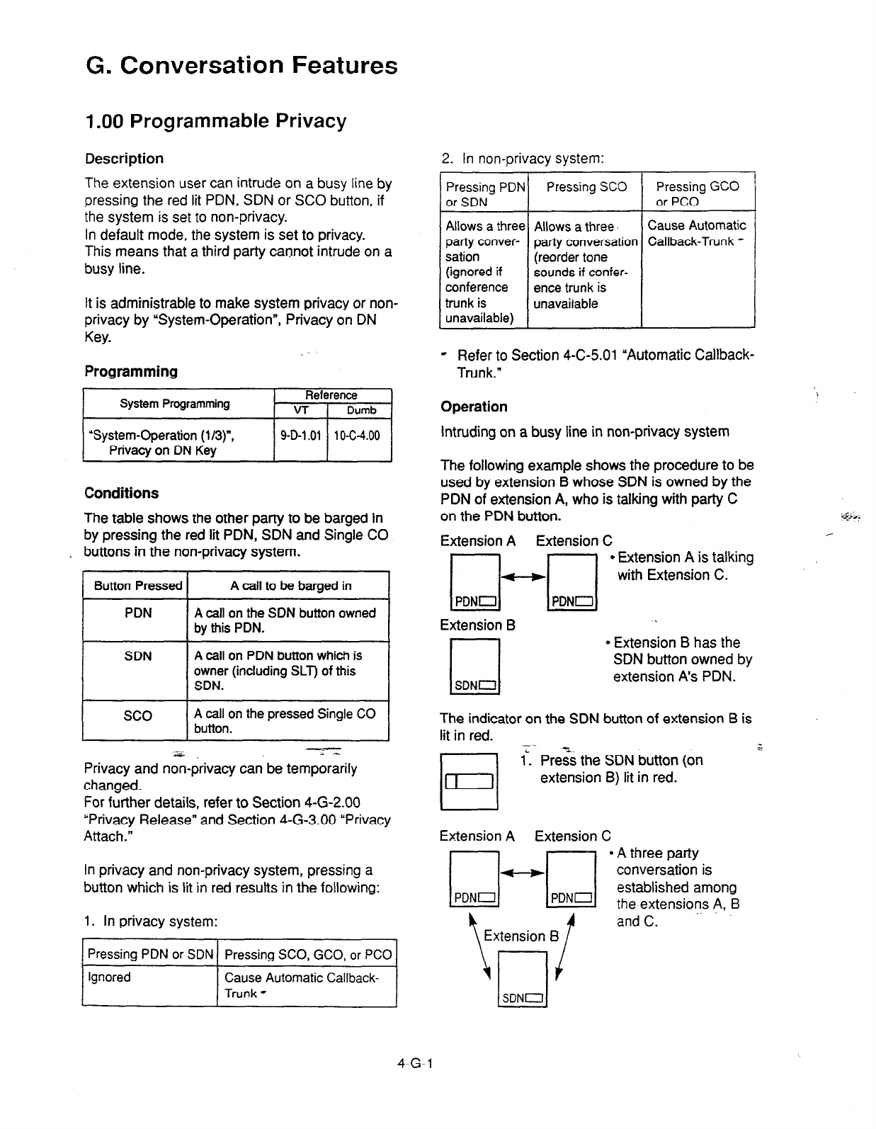
G. Conversation Features
1 .OO Programmable Privacy
Description
2. In non-privacy system:
The extension user can intrude on a busy line by
pressing the red lit PDN, SDN or SC0 button, if
the system is set to non-privacy.
In default mode, the system is set to privacy.
This means that a third party cannot intrude on a
busy line.
It is administrable to make system privacy or non-
privacy by “System-Operation”, Privacy on DN
Key.
Pressing PDN Pressing SC0 Pressing GCO
or SDN or PC0
Allows a three Allows a three. Cause Automatic
party conver- patty conversation Callback-Trunk *
sation (reorder tone
(ignored if sounds if confer-
conference ence trunk is
trunk is unavailable
unavailable)
Programming
hi
Conditions
e Refer to Section 4-C-5.01 ‘Automatic Callback-
Trunk.”
Operation
Intruding on a busy line in non-privacy system
The table shows the other party to be barged in
by pressing the red lit PDN, SDN and Single CO
. buttons in the non-privacy system.
Button Pressed
A call
to be barged in
PDN A call on the SDN button owned
by
this PDN.
The following example shows the procedure to be
used by extension B whose SDN is owned by the
PDN of extension
A,
who is talking with party C
on the PDN button.
Extension
A
Extension C
SDN A
call on PDN button which is
owner (including SLT) of this
SDN.
Extension B
I-J
SDNCJ
.
0 Extension B has the
SDN button owned by
extension A’s PDN.
SC0 A call on the pressed Single CO
button. The indicator on the SDN button of extension B is
lit in red.
2.z ; >..
Privacy and non-privacy can be temporarily
changed.
For further details, refer to Section 4-G-2.00
“Privacy Release” and Section 4-G-3.00 “Privacy
Attach.”
1”. Prezi the SDN button (on
extension B) lit in red.
Extension A Extension C
In privacy and non-privacy system, pressing a
button which is lit in red results in the following:
1. In privacy system:
Pressing PDN or SDN Pressing SCO, GCO, or PC0
4-G-l
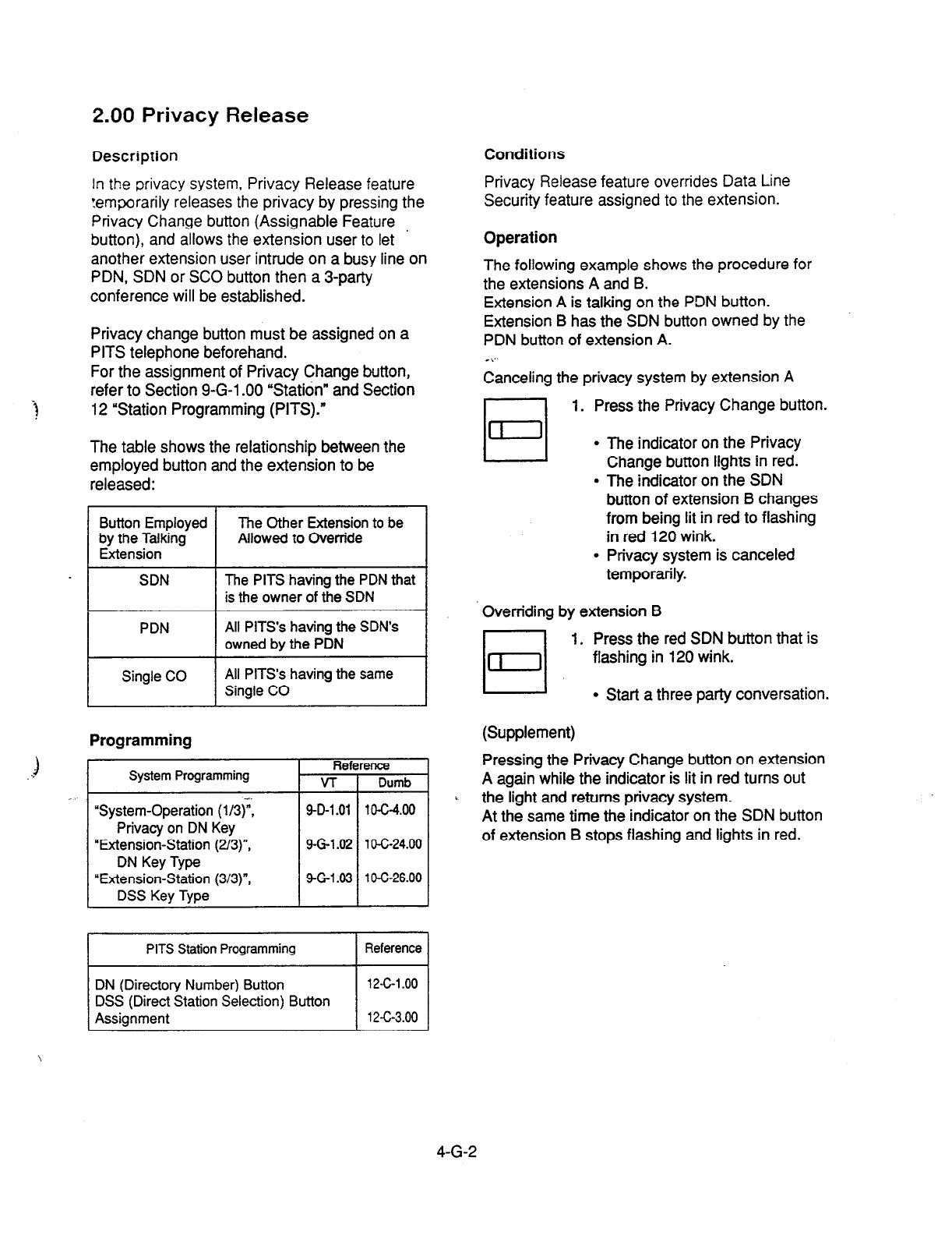
2.00 Privacy Release
Description
Conditions
In the privacy system, Privacy Release feature
temwrarily releases the privacy by pressing the
Privacy Change button (Assignable Feature
button), and allows the extension user to let
another extension user intrude on a busy line on
PDN, SDN or SC0 button then a 3-party
conference will be established.
Privacy Release feature overrides Data Line
Security feature assigned to the extension.
Operation
The following example shows the procedure for
the extensions A and B.
Extension A is talking on the PDN button.
Extension B has the SDN button owned by the
PDN button of extension A.
es..
Privacy change button must be assigned on a
PITS telephone beforehand.
For the assignment of Privacy Change button,
refer to Section 9-G-l .OO “Station” and Section
12 “Station Programming (PITS).*
The table shows the relationship between the
employed button and the extension to be
released:
Button Employed
by the Talking
Extension
The Other Extension
to
be
Allowed to Override
SDN The PITS having the PDN that
is the owner of the SDN
PDN All PITS’s having the SDN’s
owned by the PDN
Single CO All PITS’s having the same
Single CO
Programming
System Programming
“System-Operation (l/3)“;
Privacy on DN Key
“Extension-Station (2/3)“,
DN Key Type
“Extension-Station (3/3)“,
DSS Key Type
Reference
VT
Dumb
9-D-l .Ol 1 C-C-4.00
9-G-l 62 1 O-C-24.00
9-G-l 93 1 O-C-26.00
I
PITS Station Programming I
Reference
I
DN (Directory Number) Button
DSS (Direct Station Selection) Button
Assignment
12-c-l .oo
12-C-3.00
Canceling the privacy system by extension A
El
1. Press the Privacy Change button.
l
The indicator on the Privacy
Change button lights in red.
l
The indicator on the SDN
button of extension B changes
from being lit in red to flashing
in red 120 wink.
l
Privacy system is canceled
temporarily.
Overriding by extension B
El
1. Press the red SDN button that is
flashing in 120 wink.
l
Start a three party conversation.
(Supplement)
Pressing the Privacy Change button on extension
A again while the indicator is lit in red turns out
the light and returns privacy system.
At the same time the indicator on the SDN button
of extension B stops flashing and lights in red.
4-G-2
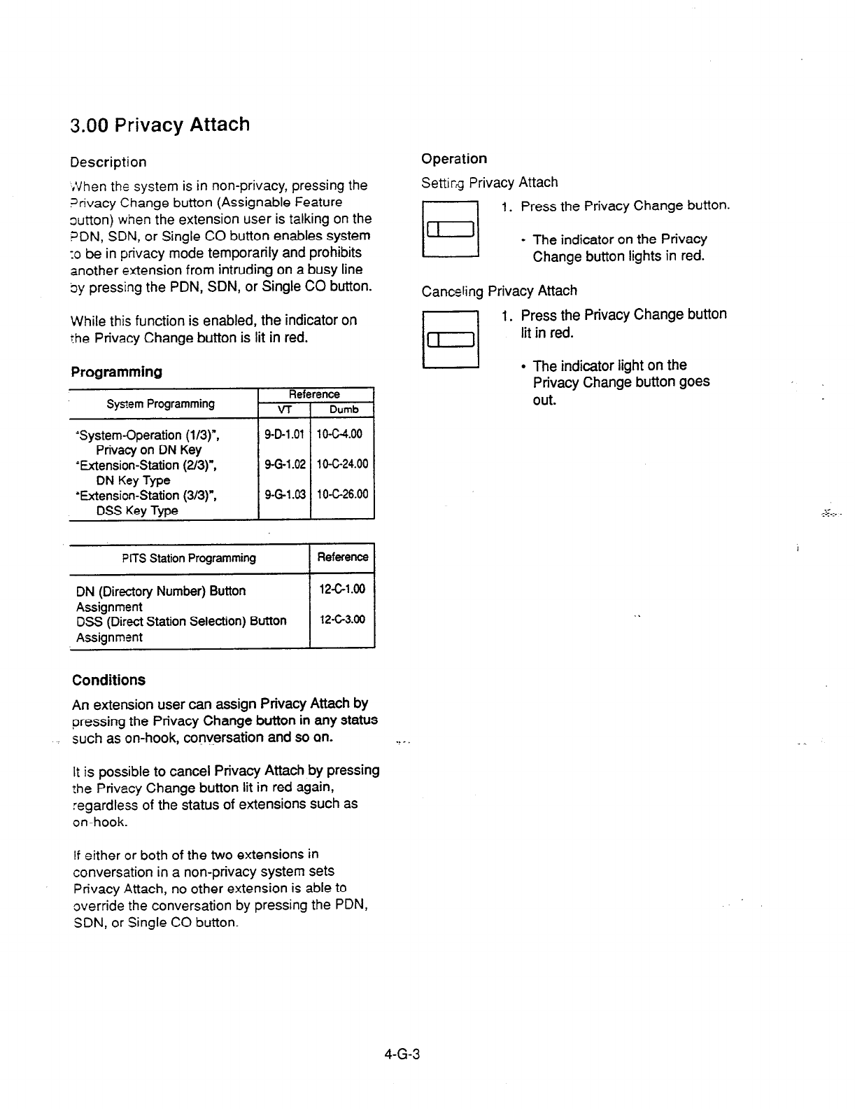
3.00 Privacy Attach
Description Operation
,,Vhen the system is in non-privacy, pressing the
?rivacy Change button (Assignable Feature
out-ton) when the extension user is talking on the
?DN, SDN, or Single CO button enables system
10 be in privacy mode temporarily and prohibits
another extension from intruding on a busy line
oy pressing the PDN, SDN, or Single CO button.
Setti rg Privacy Attach
1. Press the Privacy Change button.
Canceling Privacy Attach
1. Press the Privacy Change button
lit in red.
l
The indicator on the Privacy
Change button lights in red.
While this function is enabled, the indicator on
the Privacy Change button is lit in red.
Programming
Sys?em
Programming
Reference
VT 1 Dumb
‘System-Operation
(l/3)“,
Privacy on DN Key
‘Extension-Station (2/3)“,
DN Key Type
‘Extension-Station (3/3)“,
DSS Key Type
PITS Station Programming
DN
(Directory Number) Button
Assignment
DSS (Direct Station Selection) Button
Assignment
Reference
12c1.00
12-G3.00
Conditions
An extension user can assign Privacy Attach by
pressing the Privacy Change button in any status
such as on-hook, conversation and so an.
It is possible to cancel Privacy Attach by pressing
the Privacy Change button lit in red again,
regardless of the status of extensions such as
on-hook.
if either or both of the two extensions in
conversation in a non-privacy system sets
Privacy Attach, no other extension is able to
override the conversation by pressing the PDN,
SDN, or Single CO button.
l
The indicator light on the
Privacy Change button goes
out.
. . _ .
4-G-3
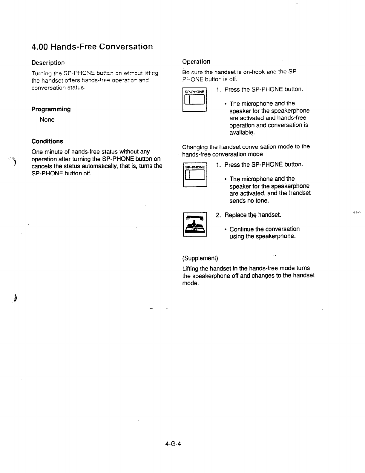
4.00 Hands-Free Conversation
Description
Turning
the BP-PHC’JE buttcc :P wj:-:;t lirting
the handset offers hands-free ooeWcn a’ld
conversation status.
Programming
None
Conditions
One minute of hands-free status without any
operation after turning the SP-PHDNE button on
cancels the status automatically, that is, turns the
SP-PHONE button off.
Operation
Be sure the handset is on-hook and the SP-
PHONE button is off.
1. Press the SP-PHONE button.
l
The microphone and the
speaker for the speakerphone
are activated and hands-free
operation and conversation is
available
:
Changing the handset conversation mode to the
hands-free conversation mode
-1
1. Press the SP-PHONE button.
l
The microphone and the
speaker for the speakerphone
are activated, and the handset
sends no tone.
2. Replace the handset.
l
Continue the conversation
using the speakerphone.
(Supplement) . .
Lifting the handset in the hands-free mode turns
the speakerphone off and changes to the handset
mode.
4-G-4
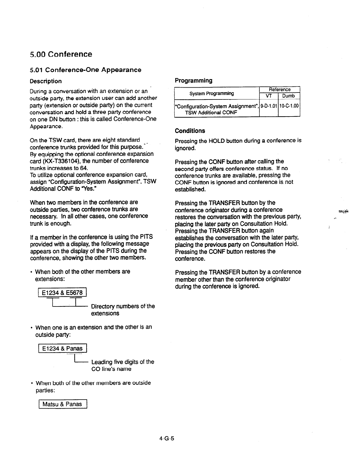
5.00 Conference
5.01
Conference-One Appearance
Description
During a conversation with an extension or an ’
outside party, the extension user can add another
party (extensicn or outside party) on the current
conversation and hold a three party conference
on one DN button : this is called Conference-One
Appearance.
On the TSW card, there are eight standard
conference trunks provided for this purpose.- ’
By equipping the optional conference expansion
card (KX-T336104), the number of conference
trunks increases to 64.
To utilize optional conference expansion card,
assign “Configuration-System Assignment”, TSW
Additional CONF to “Yes.”
When two members in the conference are
outside parties, two conference trunks are
necessary. In all other cases, one conference
trunk is enough.
If a member in the conference is using the PITS
provided with a display, the following message
appears on the display of the PITS during the
conference, showing the other two members.
. When both of the other members are
extensions:
1 El234 & E5678 1
-1
u Directory numbers of the
extensions
l
When one is an extension and the other is an
outside party:
El 234 & Panas
I
- Leading five digits of the
CO line’s name
l
When both of the other members are outside
parties:
Programming
Conditions
Pressing the HOLD button during a conference is
ignored.
Pressing the CONF button after calling the
second party offers conference status. If no
conference trunks are available, pressing the
CONF button is ignored and conference is. not
established.
Pressing the TRANSFER button by the
conference originator during a conference
restores the conversation with the previous party,
placing the later party on Consultation Hold.
Pressing the TRANSFER button again
establishes the conversation with the later party,
placing the previous party on Consultation Hold.
Pressing the CONF button restores the
conference.
Pressing the TRANSFER button by a conference
member other than the conference originator
during the conference is ignored.
Matsu & Panas
4-G-5
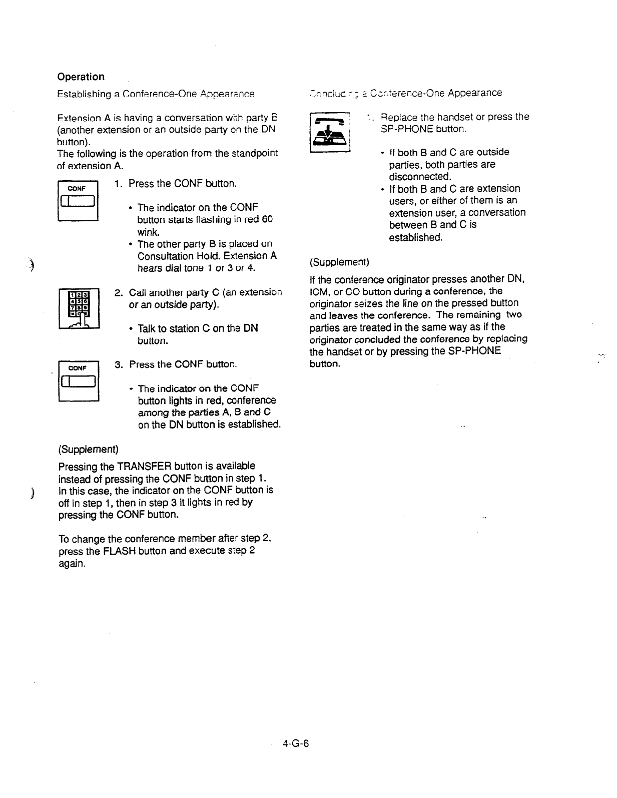
Operation
Establishing a
Conference-One Appeamce
Extension A is having a conversation
with party E
(another extension or an outside party on the DN
button).
The following is the operation from the standpoint
of extension A.
II 1. Press the CONF button.
I-J
= .
.
The indicator on the CONF
button starts flashing in red 60
wink
The other patty B is placed on
Consultation Hold. Extension A
hears dial tone 1 or 3 or 4.
2. Call another party C (an extension
or an outside party).
l
Talk to station C on the DN
button.
3. Press the CONF button.
l
The indicator on the CONF
button lights in red, conference
among the parties A, B and C
on the DN button is established.
(Supplement)
Pressing the TRANSFER button is available
instead of pressing the CONF button in step 1.
1 In this case, the indicator on the CONF button is
off in step 1, then in step 3 it lights in red by
pressing the CONF button.
>;~“ciilc -3 _
2 Cz=r:farence-One Appearance
Fieplace the handset or
press the
SP-PHONE button.
- If
both B
and C are outside
parties, both parties are
disconnected.
l
If both B and C are extension
users, or either of them is an
extension user, a conversation
between B and C is
established.
(Supplement)
If the conference originator presses another DN,
ICM, or CO button during a conference, the
originator seizes the line on the pressed button
and leaves the conference. The remaining two
parties are treated in the same way as if the
originator concluded the conference by replacing
the handset or by pressing the SP-PHONE
button.
To change the conference member after step 2,
press the FLASH button and execute slep 2
again.
4-G-6
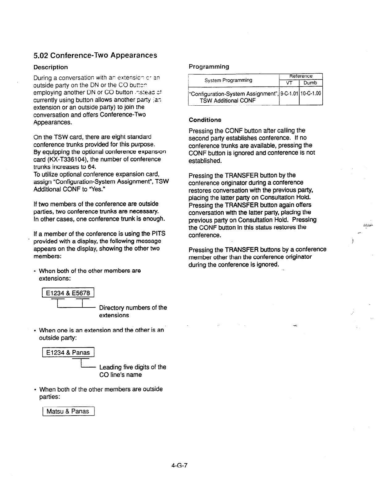
5.02 Conference-Two Appearances
Description Programming
During a conversation with ar exrensic- CT zn
outside party on the DN or the CO bu;rzr
employing another DN or CO button .-s:eac z!
currently using button allows another party :a:
extension or an outside party) to join the
conversation and
offers Conference-Two
Appearances.
Conditions
On the
TSW
card, there
are eight standard
conference trunks provided for this purpose.
By equipping the optional conference expanson
card (KX-T336104), the number of conference
trunks increases to 64.
To utilize optional conference expansion card,
assign “Configuration-System Assignment”, TSW
Additional CONF to “Yes.”
If two members of the conference are outside
parties, two conference trunks are necessary.
In other cases, one conference trunk is enough.
If a member of the conference is using the PITS
. provided with a display, the following message
appears on the display, showing the other two
members:
l
When both of the other members are
extensions:
1 El234 & E5678 1
-l--l-
- Directory numbers of the
extensions
l
When one is an extension and the other is an
outside party:
1 El234 & Panas 1
I
I Leading five digits of the
CO line’s name
l
When both of the other members are outside
parties:
Pressing the CONF button after calling the
second party establishes conference. If no
conference trunks are available, pressing the
CONF button is ignored and conference is not
established.
Pressing the TRANSFER button by the
conference
originator during a conference
restores conversation with the previous party,
placing the latter party on Consultation Hold.
Pressing the TRANSFER button again offers
conversation with the latter party, placing the
previous party on Consultation Hold. Pressing
the CONF button in this status restores the
conference.
Pressing the TRANSFER buttons by a conference
member other than the conference originator
during the conference is ignored.
1 Matsu & Panas 1
4-G-7
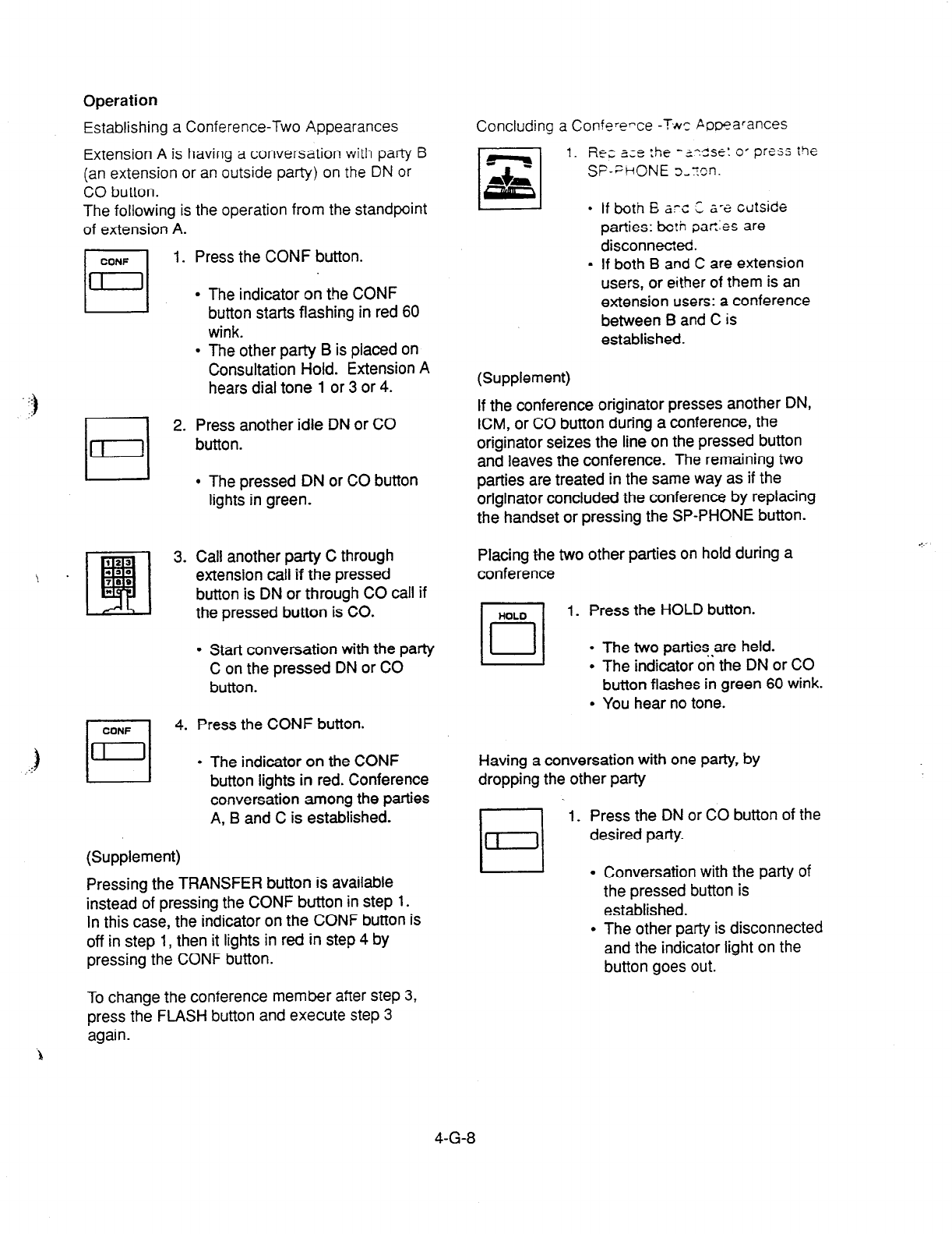
Operation
Establishing a Conference-Two Appearances Concluding a Confererce -T&c Pooearances
Extension A is having a conversation with party B
(an extension or an outside party) on the DN or
CO button.
The following is the operation from the standpoint
of extension A.
1. Rcc 3;e 5-e
-~-zsE: 0’ press the
SF-PHONE
D-Ton.
If both
B XC C z-a cutside
parties: bcth
oar,:es are
disconnected.
If both B and C are extension
users, or either of them is an
extension users: a conference
between B and C is
established.
CONF
El
-_
j D
.:
1. Press the CONF button.
l
The indicator on the CONF
button starts flashing in red 60
wink.
l
The other party B is placed on
Consultation Hold. Extension A
hears dial tone 1 or 3 or 4.
2. Press another idle DN or CO
button.
l
The pressed DN or CO button
lights in green.
3. Call another party C through
extension call if the pressed
button is DN or through CO call if
the pressed button is CO.
l
Start conversation with the party
C on the pressed DN or CO
button.
4. Press the CONF button.
l
The indicator on the CONF
button lights in red. Conference
conversation among the parties
A, B and C is established.
(Supplement)
Pressing the TRANSFER button is available
instead of pressing the CONF button in step 1.
In this case, the indicator on the CONF button is
off in step 1, then it lights in red in step 4 by
pressing the CONF button.
(Supplement)
If the conference originator presses another DN,
ICM, or CO button during a conference, the
originator seizes the line on the pressed button
and leaves the conference. The remaining two
parties are treated in the same way as if the
originator concluded the conference by replacing
the handset or pressing the SP-PHONE button.
Placing the two other parties on hold during a
conference
1. Press the HOLD button.
l
The two parties,are held.
l
The indicator on the DN or CO
button flashes in green 60 wink.
l
You hear no tone.
Having a conversation with one party, by
dropping the other party
L--l
1. Press the DN or CO button of the
desired party.
L-l .
Conversation with the party of
the pressed button is
established.
The other party is disconnected
and the indicator light on the
button goes out.
To change the conference member after step 3,
press the FLASH button and execute step 3
again.
4-G-8
6.00 Unattended Conference
6.01 Unattended Conference-One
Appearance
Description
When an extension is in a conference with two
outside parties on one DN button, the extension
can leave the conference and establishes the
CO-to-CO call between other two parties by
pressing the CONF button: this is called
Unattended Conference-One Appearance.
During an unattended conference between the
two outside parties, the indicator on the DN
button flashes in 120 wink.
To execute this function, assign “System-Class of
Service”, CO Transfer Mode to “Yes.”
The duration of the Unattended Conference is
limited by “Group-Trunk Group”, CO-CO Duration
Limit.
Programming
System Programming
“System-Class
of Service (l/2)“,
CO Transfer Mode
“Group-Trunk Group (l/2)“,
CO-CO Duration Limit
Conditions
If
rhe
extension is not allowed to execute this
function in Class of Service, or either or both of
the other parties are not outside ones, pressing
the CONF button during the conference is
ignored.
When the two occupied CO lines belong to
different trunk groups, the following time limits
apply to each case:
In the case one parry is an outgoing CO
call, the other is an incoming CO call; The
duration limit follows to the trunk group of
the incoming CO call.
If both are outgoing CO calls or both are
incoming CO calls; The longest duration
limit assigned to one of the two trunk
groups is used.
In the above cases, if an incoming call via DID
line is included in a conference, no limit applies to
the duration of the conference. .*
Unattended Conference Recall starts 50 seconds
before the time limit.
30 seconds of no answer after the start of the
Unattended Conference Recall causes Intercept
Routing-No Answer.
For further details, refer to Section%F-5.00
“Intercept Routing-No Answer (IRNA).”
Warning tone is sent to both outside parties 15
seconds before the time limit. When CO-CO
Duration Limit applied is expired, both outside
parties are disconnected.
4-G-9

Operation
Establishing an Unattended Conference-One
Appearance
During a conference with two outside parties on
one
DN
button
1. Press the CONF button.
l
The indicator on the DN button
flashes in green 120 wink.
l
You leave the conference.
CO-to-CO call between the
other two parties is
established.
l
The indicator light on the
CONF button goes out.
Returning to a conference
1. Press the green DN button that is
flashing in 120 wink.
l
You join the conference again.
l
The indicator on the DN button
lights in green.
l
The indicator on the CONF
button lights in red.
,-
Answering Unattended Conference Retail
If on-hook, Unattended Conference Rem.. S:ZX:
If off-hook, call waiting tone sounds.
1. Press the green DN button that 1s
flashing in 120 wink.
l
You return to the conference.
l
The indicator on the
DN
button
lights in green.
(Supplement)
If no conference trunks are available at the time,
returning to the conference and answering
Unattended Conference Recall results in
conversation with the first party, placing the other
party on Consultation Hold.
Pressing the TRANSFER button offers alternate
conversation with the two parties.
Pressing the CONF button again restores the
Unattended Conference.
4-G-l 0
6.02 Unattended Conference-Two
Appearances
Description
When an extension is in a Conference-Two
Appearances with two outside parties, the
extension can leave the conference and
establishes the CO-to-CO call between other two
parties by pressing the CONF button: this is
called Unattended Conference Two
Appearances.
During an unattended conference between the
two outside parties, the indicators on both ^
buttons (both are DNs, or one is DN and the
other is CO, or both are COs) flash in 120 wink.
To execute this function, assign “System-Class of
Service”, CO Transfer Mode to “Yes.”
The duration of the Unattended Conference is
restricted by “Group-Trunk Group”, CO-CO
Duration Limit.
. Programming
System Programming Reference
VT Dumb
‘System-Class
of Service (l/2)“, 9-D-4.01 10-C-7.00
CO Transfer Mode
“Group-Trunk Group (l/2)“, 9-E-l .Ol 1 O-C-1 4.00
CO-CO Duration Limit
1;
parties are disconnected.
Alarm tone is sent to both outside parties 15
seconds before the time limit. When CO-CO
Duration Limit applied is expired, both outside
Conditions
If the extension is not arioweo tc execute rnis
function in Class of Service, Oi anther or
Dorh 0:
the other parties are not otitside ones. Dressing
the CONF button is ignored.
When the two occupied CO lines belong to
different trunk groups, the following time limits
apply to each case:
If one party is an outgoing CO call and the
other is an incoming CO call; The duration
limit follows the trunk group of the incoming
CO call.
If both are outgoing CO calls or both are
incoming CO calls; The longest duration
limit assigned to one of the two trunks is
used.
In the above cases, if an incoming call via DID
line is included in a conference, no limit applies to
the duration of the conference.
Unattended Conference Recall starts 50 seconds
before the time limit.
30 seconds of no answer after the start of the
Unattended Conference Recall causes Intercept
Routing-No Answer.
For the further detail, refer to Section 3-F-5.00
“Intercept Routing-No Answer (IRNA).”
4-G-l 1
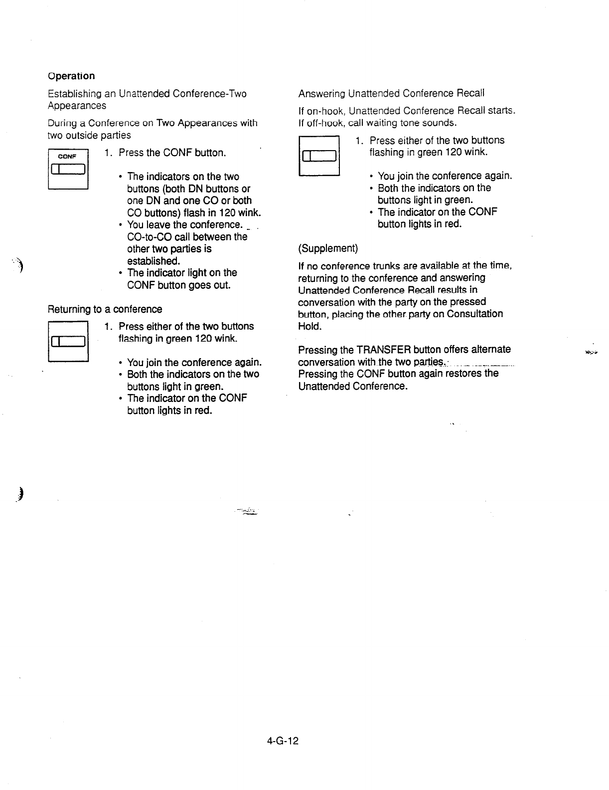
Operation
Establishing an Unattended Conference-Two
Appearances
During a Conference on Two Appearances with
two outside parties
CONF
El
1. Press the
CONF button.
l
The indicators on the two
buttons (both DN buttons or
one DN and one CO or both
CO buttons) flash in 120 wink.
l
You leave the conference. -
CO-to-CO call between the
other two parties is
established.
l
The indicator light on the
CONF button goes out.
Returning to a conference
1. Press either of the two buttons
flashing in green 120 wink.
l
You join the conference again.
l
Both the indicators on the two
buttons light in
green.
l
The indicator on the CONF
button
lights in red.
Answering
If on-hook,
If off-hook,
Unattended Conference Recall
Unattended Conference Recall stat%.
call waiting tone sounds.
1. Press either of the two buttons
flashing in green 120 wink.
l
You join the conference again.
l
Both the indicators on the
buttons light in green.
l
The indicator on the CONF
button lights in red.
(Supplement)
If no conference trunks are available at the time,
returning to the conference and answering
Unattended Conference Recall results in
conversation with the party on the pressed
button, placing the other party on Consultation
Hold.
Pressing the TRANSFER button offers alternate x%-i
conversation with the two p+?ies,:, ________ _ ,_-._.
Pressing the CONF button again restores the
Unattended Conference.
4-G-l 2
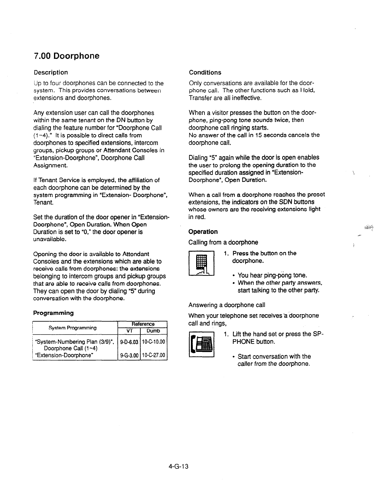
7.00 Doorphone
Description
Up to
four
doorphones can be connected to the
system. This provides conversations between
extensions and doorphones.
Conditions
Only conversations are available for the door-
phone call. The other functions such as Hold,
Transfer are all ineffective.
Any extension user can call the doorphones
within the same tenant on the DN button by
dialing the feature number for “Doorphone Call
(l-4).” It is possible to direct calls from
doorphones to specified extensions, intercom
groups, pickup groups or Attendant Consoles in
“Extension-Doorphone”, Doorphone Call
Assignment.
If
Tenant Service is employed, the affiliation of
each doorphone can be determined by the
system programming in “Extension- Doorphone”,
Tenant.
Set the duration of the door opener in “Extension-
Door-phone”, Open Duration. When Open
Duration is set to “0,” the door opener is
unavailable.
Opening the door is available to Attendant
Consoles and the extensions which are able to
receive calls from doorphones: the extensions
belonging to intercom groups and pickup groups
that are able to receive calls from doorphones.
They can open the door by dialing “5” during
conversation with the doorphone.
Programming
i
I
System Programming Reference
v-r Dumb
i “System-Numbering Plan (3/g)“, 9-D-6.03 1 O-C-1 0.00
Dootphone Call (l-4)
\ “Extension-Doorphone” 9-G-3.00 1 O-C-27.00
When a visitor presses the button on the door-
phone, ping-pong tone sounds twice, then
doorphone call ringing starts.
No answer of the call in 15 seconds cancels the
doorphone call.
Dialing “5” again while the door is open enables
the user to prolong the opening duration to the
specified duration assigned in ‘Extension-
Doorphone”, Open Duration.
When a call from a doorphone reaches the preset
extensions, the indicators on the SDN buttons
whose owners are the receiving extensions light
in red.
Operation
Calling from a doorphone
1. Press the button on the
doorphone.
l
You hear ping-pang tone.
l
When the other party answers,
start talking to the other party.
Answering a doorphone call
When your telephone set receivesadoorphone
call and rings,
1. Lift the hand set or press the SP-
PHONE button.
. Start conversation with the
calter
from the doorphone.
:::::s:
4-G-l 3
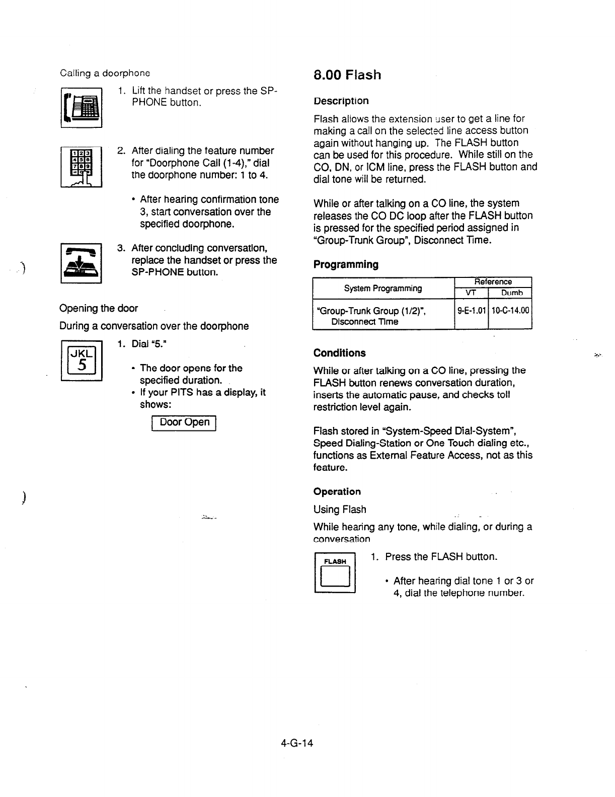
Calling a doorphone
Lift the handset or press the SP-
PHONE button.
.i 0
z 3.
After dialing the
feature number
for “Doorphone
Call (l-4),” dial
the doorphone number: 1 to 4.
l
After hearing confirmation tone
3,
start
conversation over the
specified doorphone.
After concluding conversation,
replace the handset or press the
SP-PHONE button.
Opening the door
During a conversation over the doorphone
•l
1. Dial “5.”
JKL
5
l
The door opens for the
specified duration.
l
If your PITS has a display, it
shows:
8.00 Flash
Description
Flash aliows the extension user to get a line for
making a call on the selected line access button
again without hanging up. The FLASH button
can be used for this procedure. While still on the
CO,
DN,
or ICM line, press the FLASH button and
dial tone will be returned.
While or
after
talking on a CO line, the system
releases the CO DC loop after the FLASH button
is pressed for the specified period assigned in
“Group-Trunk Group”, Disconnect Time.
Programming
System Programming Reference
VT
I
Dumb
“Group-Trunk Group
(l/2)“,
Disconnect Time
ISE-1.011 l&C-14.001
Conditions
While or after talking on a CO line, pressing the
FLASH button renews conversation duration,
inserts the automatic pause, and checks toll
restriction level again.
Flash stored in “System-Speed Dial-System”,
Speed Dialing-Station or One Touch dialing etc.,
functions as External Feature Access, not as this
feature.
Operation
Using Flash .” -
While hearing any tone, while dialing, or during a
conversation
1. Press the FLASH button.
l
After hearing dial tone 1 or 3 or
4, dial the telephone number.
4-G-l 4
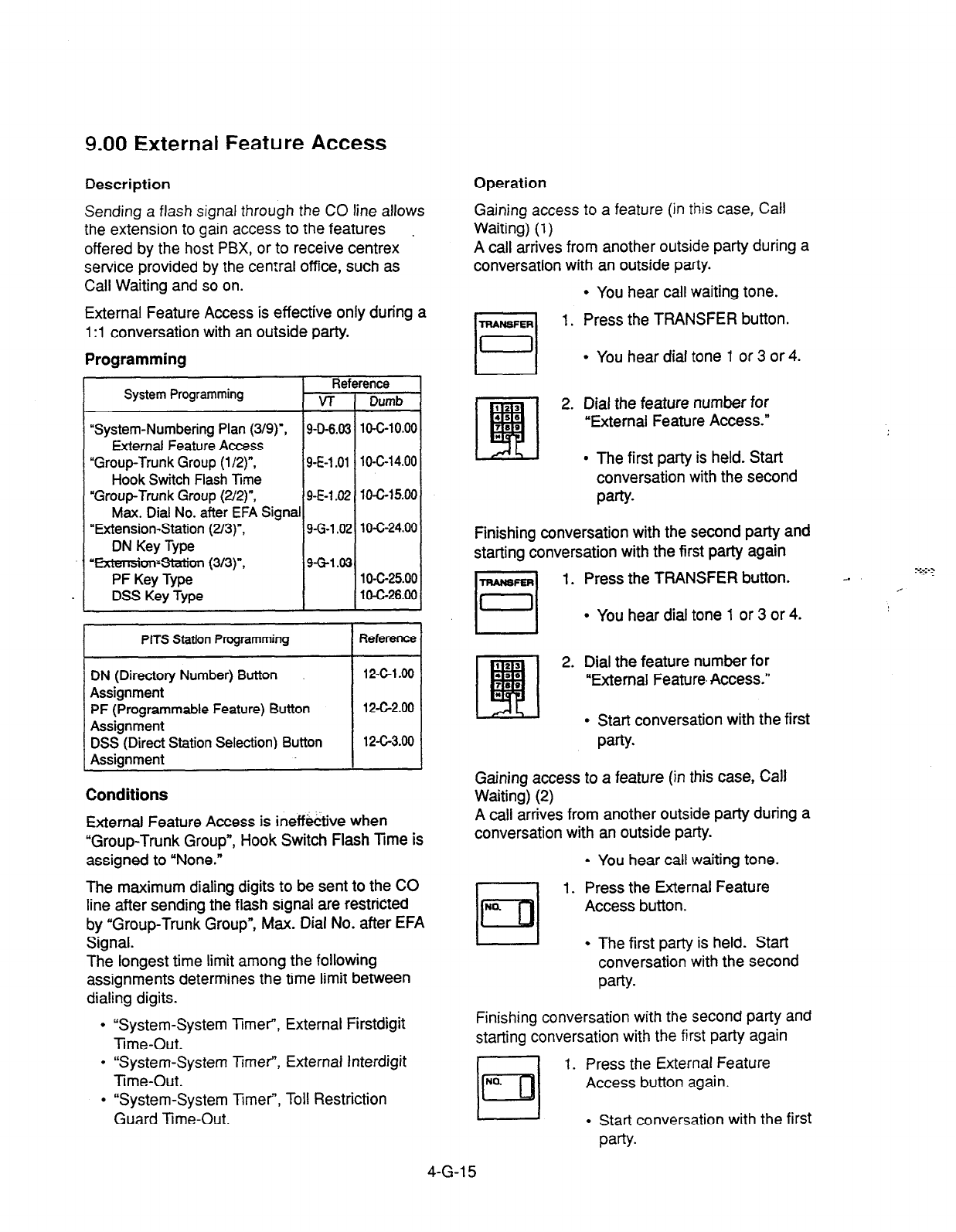
9.00 External Feature Access
Description Operation
Gaining access to a feature (in
this
case, Call
Waiting) (1)
Sending a flash signal through the CO line allows
the extension to gain access to the features
offered by the host PBX, or to receive centrex
service provided by the central office, such as
Call Waiting and so on.
External Feature Access is effective only during a
1 :l conversation with an outside party.
A call arrives from another outside party during a
conversation with an outside party.
l
You hear call waiting tone.
1. Press the TRANSFER button.
Programming
l
You hear dial tone 1 or 3 or 4.
System Programming Reference
v-f Dumb
“System-Numbering
Plan (3/g)‘, 9-D-6.03 10-C-10.00
External Feature Access
“Group-Trunk Group (l/2)“,
9-E-1 .Ol 1 O-C-l 4.00
Hook Switch Flash Time
“Group-Trunk Group (2/2)“, 9-E-1.02 10-C-15.00
Max. Dial No. after EFA Signal
“Extension-Station (2/3)“,
g-G-1.02 10-C-24.00
DN Key Type
tat
E!a
2. Dial the feature number for
4tie
780 “External Feature Access.”
*
l
The first party is held. Start
conversation with the second
party.
'Extension=statioTI (3/3)".
PF Key Type
DSS Key Type
9-G-l .03 1 o-c-25.00
1 O-C-26.00
Finishing conversation with the second party and
starting conversation with the first party again
1. Press the TRANSFER button.
l
You hear dial tone 1 or 3 or 4.
PITS Station Programming Reference
DN (Directory Number) Button
Assignment 12-c-l 90 2. Dial the feature number for
“External Feature. Access.”
PF (Programmable Feature) Button
Assignment
DSS (Direct Station Selection) Button
Assignment
12-c-2.00
12-G3.00
0 Start conversation with the first
party.
Conditions Gaining access to a feature (in this case, Call
Waiting) (2)
External Feature Access is ineffective when
“Group-Trunk Group”, Hook Switch Flash lime is
assigned to “None.”
The maximum dialing digits to be sent to the CO
line after sending the flash signal are restricted
by “Group-Trunk Group”, Max. Dial No. after EFA
Signal.
The longest time limit among the following
assignments determines the time limit between
dialing digits.
A call arrives from another outside party during a
conversation with an outside party.
. You hear call waiting tone.
1. Press the External Feature
Access button.
l
The first party is held. Start
conversation with the second
PW.
l
“System-System 3mer”, External Firstdigit
Time-Out.
l
“System-System Timer, External Interdigit
Time-Out.
Finishing conversation with the second party and
starting conversation with the first party again
I. Press the External Feature
Access button again.
l
“System-System Timer”, Toll Restriction
Guard Time-Out.
l
Start conversation with the first
PaW.
-
4-G-l 5

10.00 Microphone
Mute
Description Operation
Microphcrs b.!,~~ 5.. ~‘6 ar ex:;ens;on user to
disable the
mcrcf’
o-e of !“e speakerphone.
This is useful w/x? the user needs to speak
privately with
soF+cne in :he
office while on an
inside, an outside. or a door-phone call.
If the user presses the AUTO ANSIMUTE button
during a hands-free conversation with
speakerphone on. the other party cannot hear the
user until he or sie presses the button again.
Setting Microphone Mute
During a hands-free conversation
1. Press the AUTO ANSMUTE
button.
Programming
None
Conditions
Microphone Mute does not disable the
microphones in
t3e
handsets.
Setting and canceling this function is available
only when the SP-PHONE is on. Pressing the
AUTO ANSMUTE button when the SP-PHONE
. is off sets Hands-Free Answer-back.
Refer to Section 1-D-2.01 “Intercom Hands-Free
Answerback.”
While Microphone Mute is set, the indicator on
the AUTO ANSMUTE button flashes in 60 wink.
l
The indicator on the AUTO
ANS/ MUTE button flashes in
60 wink.
l
The microphone of the SP-
PHONE becomes mute status.
Canceling Microphone Mute
1. Press the flashing AUTO
ANS/MUTE button again.
l
The indicator light on the AUTO
ANS/MUTE button goes out.
l
Microphone Mute is canceled.
t
4-G-l 6

11 .OO intercom Off-Hook Call
Announcement (OHCA)
Description
During a conversation using the handset by PITS
:eiephone KX-T7130, KX-Ti 23235 or KX-
T123230D, the extension user can receive
another call from intercom
Calling or
from
Attendant Console, unless the current call is
made by Intercom Calling.
To execute this function, optional T-SW OHCA
Expansion card (KX-T336105) and OHCA card
;KX-T96136) are
necessary.
Programming
Conditions
OHCA can be received only with the PITS KX-
T7130, KX-T123235, and KX-T123230D
telephones.
OHCA does not work if the receiving extension is
in the following situations:
Operation
Answering OHCA
You are having a conversation using the handset.
1. When the indicator on the ICM
button lights in green, you hear
two beeps. At the same time the
microphone and the speaker for
hands-free turn on automatically.
Talk to the caller over the
speaker.
Finishing the original call during a conversation by
OHCA
You are having conversations with the original
caller and the OHCA caller.
1. Replace the handset.
l
The original call is finished. The
OHCA call changes to hands-
free mode.
SP+l#?lE
rl
2. After finishing conversation, press
In the SP-PHONE button.
l
Talking in speaker phone mode.
l
Do Not Disturb is set.
l
ICM button is not idle.
l
“System-Class of Service”,
BSSIOHCA Deny is set to yes.”
4-G-l 7
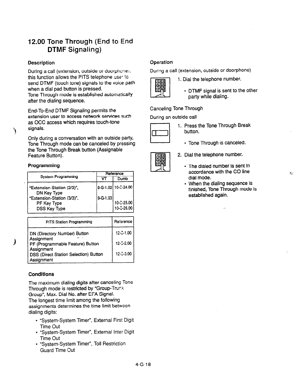
12.00 Tone Through (End to End
DTMF Signaling)
Description
During a call (extension, outside or doorphcne,,
this function allows the PITS telephone use- :c
send DTMF (touch tone) signals to the voice path
when a dial pad button is pressed.
Tone Through mode is established automatically
after the dialing sequence.
End-To-End DTMF Signaling permits the
extension user to access network services suet,
as OCC access which requires touch-tone
signals.
Only during a conversation with an outside party,
Tone Through mode can be canceled by pressing
the Tone Through Break button (Assignable
Feature Button).
Programming
System Programming
“Extension-Station (2/a)“,
DN Key Type
“Extension-Station (3/3)“,
PF
Key Type
DSS Key Type
Reference
VT Dumb
9-G-l .02 10-c-24.00
9-G-l 43 1 o-c-25.00
1 O-C-26.00
PITS Station Programming
DN (Directory Number) Button
Assignment a
PF (Programmable Feature) Button
Assignment
DSS (Direct Station Selection) Button
Assignment
Rekfence
12-C-l .oo
12-Z-2.00
12-Z-3.00
Conditions
The maximum dialing digits after canceling Tone
Through mode is restricted by ‘Group-Trur7i
Group”, Max. Dial No. after EFA Signal.
The longest time limit among the following
assignments determines the time limit between
dialing digits:
l
“System-System TimeT, External First Digit
Time Out
l
“System-System Timef, External Inter Digit
lime Out
l
“System-System Timer”, Toll Restriction
Guard Time Out
Operation
During a call (extension, outside or doorphone)
1. Dial the telephone number.
I dh I
l
DTMF signal is sent to the other
party while dialing.
Canceling Tone Through
During an outside call
1. Press the Tone Through Break
button.
l
Tone Through is canceled.
1 3
2. Dial the telephone number.
15s
EKI
789
*
l
The dialed number is sent in
accordance with the CO line
dial mode.
l
When the dialing sequence is
finished, Tone Through mode is
established again.
4-G-i 8

H. Paging Features
1.00 Paging
1.01 Paging All Extensions
Description Conditions
Paging
Ai!
Ex:ezs,c,zs allows any extension -ser
to perform paging on !he DN button to the a!
PITS telephone users at the same time through
the built-in speakers of PITS telephones.
Single Line Telephones (SLT’s) cannot be paged.
If all of the extensions assigned to be paged are
being paged by another page, busy tone is
returned to the new paging performer.
If any of the extensions is not being paged,
paging is executed.
The Class of Service of the user’s extensior
determines the extensions that can receive
paging. They are assigned to be paged by
“System-Class of Service”, Station Paging
Access and also if they belong to the same
tenant as the performer.
See Section 3-B-7.04 “Paging Group’ for de-u’ls
of paging groups.
To perform Paging All Extensions, dial the feature
number for “Station Paging” and “0.” To answer
paging, dial the feature number for “Station
Paging Answer.”
Programming
System Programming Reference
VT 1 Dumb
If you hear busy tone when attempting to page,
you cannot set Automatic Callback function.
Refer to Section 4-C-6.02 “Automatic Callback-
Station” for further information.
When there is no paging group assigned to “Yes”
in “System-Class of Service”, Station Paging
Access within the same tenant, the performer
hears reorder tone.
Paging is broadcast over idle speakers in
SP-
PHONES of on-hook PITS telephones.
4-H-l
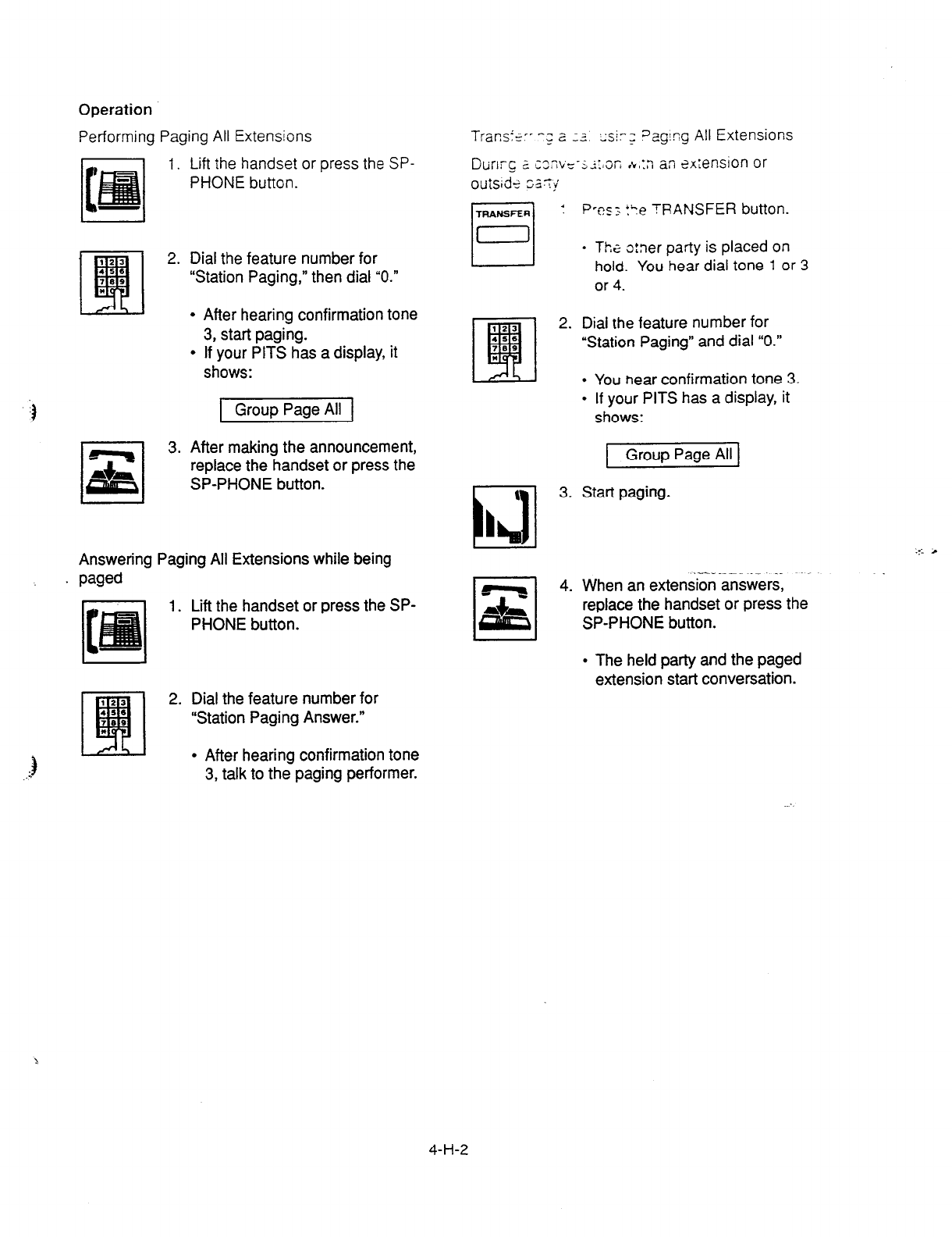
Operation
Performing Paging All Extensions
1. Lift the handset or press the SP-
PHONE button.
123
q
2. Dial the feature number for
456
789 “Station Paging,” then dial “0.”
*
l
After hearing confirmation tone
3, start paging.
l
If your PITS has a display, it
shows:
1 Group Page All 1
3. After making the announcement,
replace the handset or press the
SP-PHONE button.
Answering Paging All Extensions while being
. paged
1. Lift the handset or press the SP-
PHONE button.
2. Dial the feature number for
“Station Paging Answer.”
l
After hearing confirmation tone
3, talk to the paging performer.
Transipr -; a -3 ~sir; Dag!?g All Extensions
Durlrc 2 XXJE-S;:~ 0~ ,k,:n an 2xrension or
outside SZT~
1 Pw; t?e TRANSFER button.
l
T/X
c:ner party is placed on
hold. You hear dial tone 1 or 3
or 4.
2. Dial the feature number for
“Station Paging” and dial “0.”
l
You near confirmation tone 3.
l
If your PITS has a display, it
shows:
1 Group Page All 1
\
I3
3. Start paging.
h ha
--- _----“1. __. --, -..-
4. When an extension answers,
replace the handset or press the
SP-PHONE button.
l
The held party and the paged
extension start conversation.
4-H-2
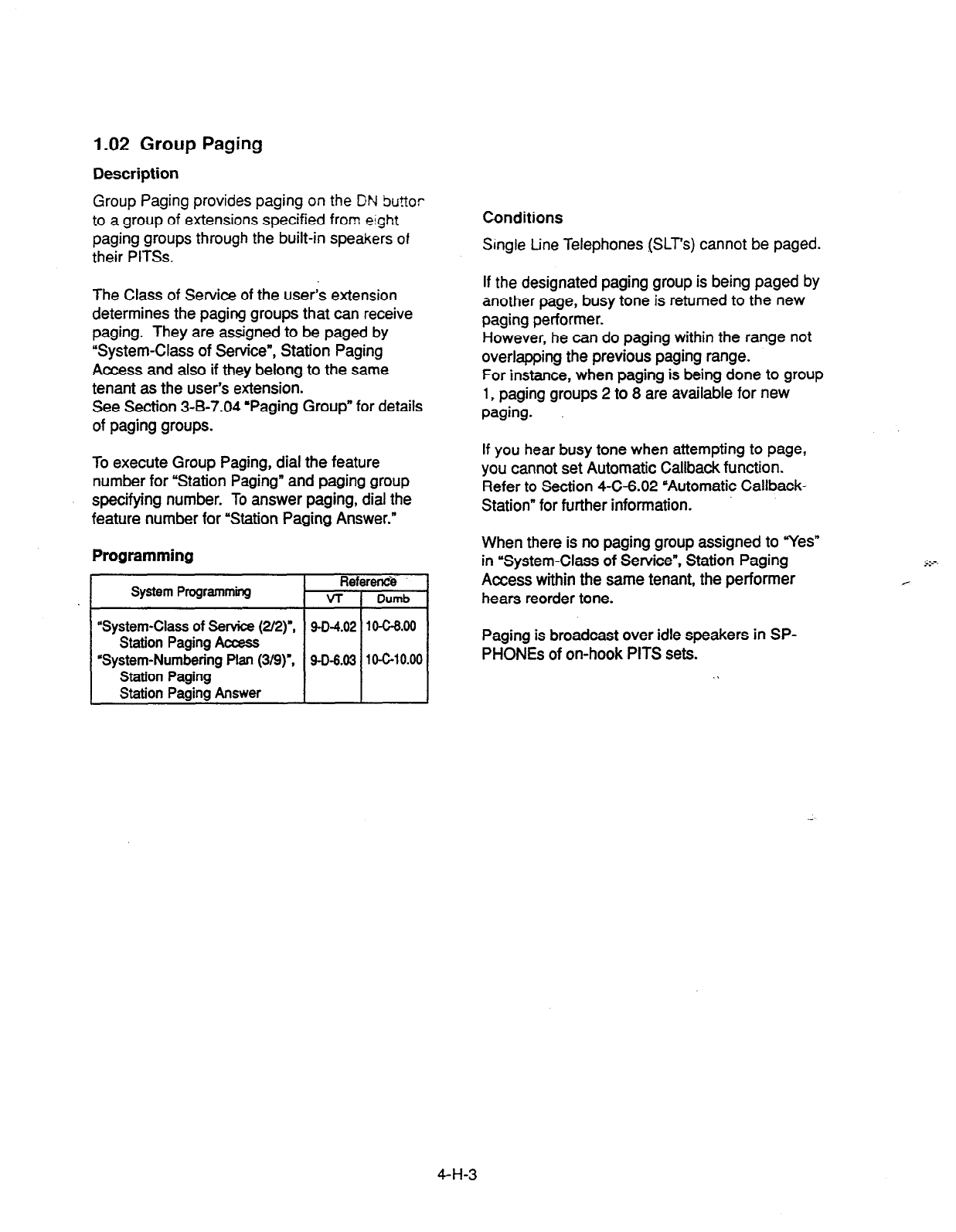
1.02 Group Paging
Description
Group Paging provides paging on the DN Su?tor
to a group of extensions specified from eight
paging groups through the built-in speakers of
their PITSs.
The Class of Service of the user’s extension
determines the paging groups that can receive
paging. They are assigned to be paged by
“System-Class of Service”, Station Paging
Access and also if they belong to the same
tenant as the user’s extension.
See Section 3-B-7.04 ‘Paging Group” for details
of paging groups.
To execute Group Paging, dial the feature
number for “Station Paging” and paging group
specifying number. To answer paging, dial the
feature number for “Station Paging Answer.”
Programming
System Programming
“System-Class
of Service (2/2)“,
Station Paging Access
‘System-Numbering Plan (3/g)‘,
Station Paging
Station Paging Answer
Re
VT
9-o-4.02
9-D-6.03
Conditions
Srngle tine Telephones (SLT’s) cannot be paged.
If the designated paging group is being paged by
another page, busy tone is returned to the new
paging performer.
However, he can do paging within the range not
overlapping the previous paging range.
For instance, when paging is being done to group
1,
paging groups 2 to 8 are available for new
paging.
If you hear busy tone when attempting to page,
you cannot set Automatic Callback function.
Refer to Section 4-C-6.02 “Automatic Callback-
Station” for further information.
When there is no paging group assigned to “Yes”
in ‘System-Class of Service”, Station Paging
Access within the same tenant, the performer
hears reorder tone.
Paging is broadcast over idle speakers in SP-
PHONES of on-hook PITS sets. .\
4-H-3
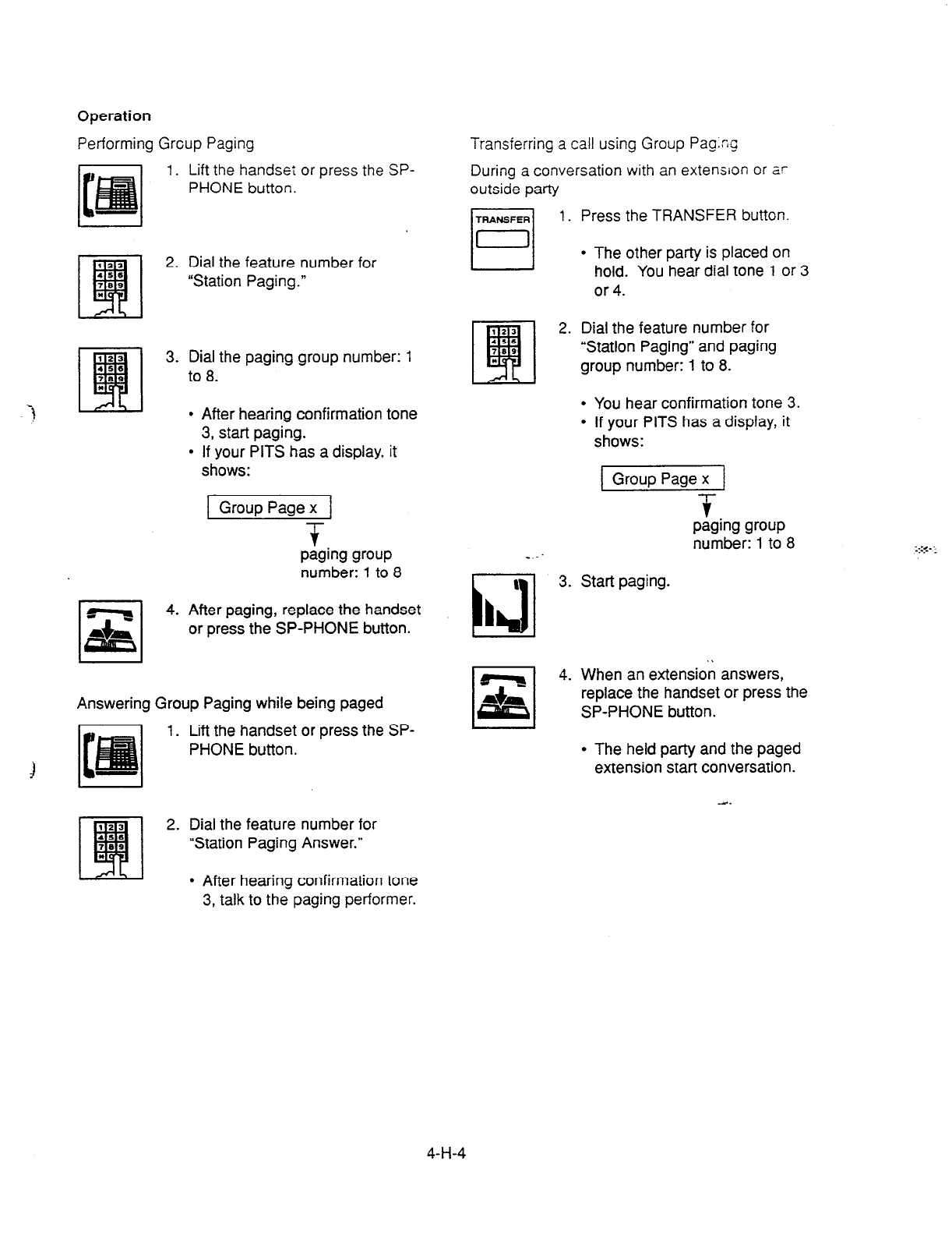
Operation
Performing Grcup Paging
1. Lift the handset or press the SP-
PHONE button.
2. Dial the feature number for
“Station Paging.”
3. Dial the paging group number: 1
to 8.
.
After hearing confirmation tone
3, start paging.
If your PITS has a display, it
shows:
1 Group Page x 1
-
$
paging group
number: 1 to 8
Transferring a call using Group Pag.ng
During a conversation with an extension or ar
outside party
1. Press the TRANSFER button
4. After paging, replace the handset
or press the SP-PHONE button.
Answering Group Paging while being paged
1. Lift the handset or press the SP-
PHONE button.
jl
l
The other party is placed on
hold. You hear dial tone 1 or 3
or 4.
Dial the feature number for
“Station Paging” and paging
group number: 1 to 8.
.
.
You hear confirmation tone 3.
If your PITS has a display, it
shows:
lGroupPagexj
T
paging group
number: 1 to 8
Start paging.
When an extension answers,
replace the handset or press the
SP-PHONE button.
l
The held party and the paged
extension start conversation.
2. Dial the feature number for
“Station Paging Answer.”
l
After hearing confirmation tone
3, talk to the paging performer.
:.:<- -.
. . _
4-H-4
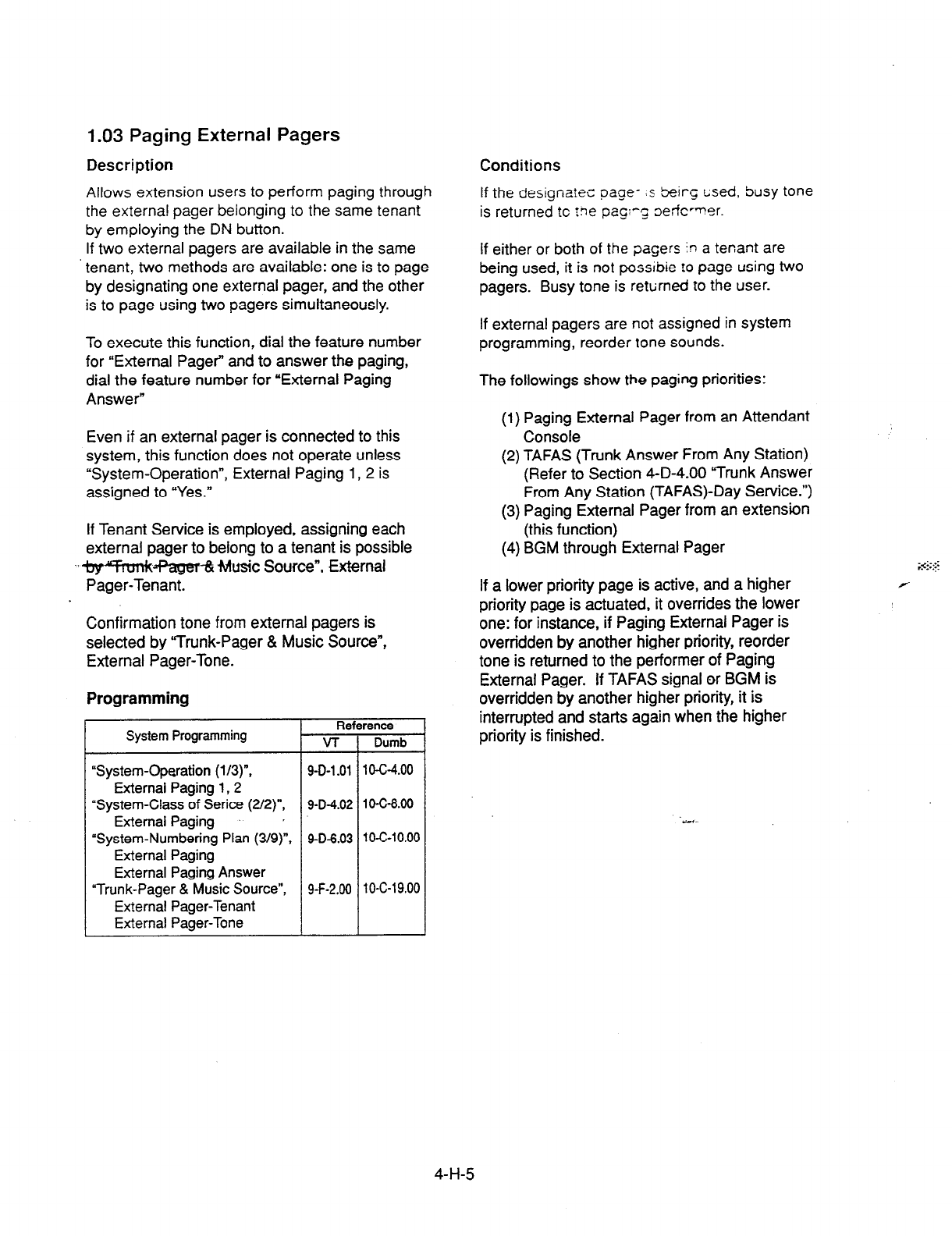
1.03 Paging External Pagers
Description Conditions
Allows
extension users to perform paging through
the external pager belonging to the same tenant
by employing the DN button.
If two external pagers are available in the same
tenant, two methods are available: one is to page
by designating one external pager, and the other
is to page using two pagers simultaneously.
If the designalec page- :s beirc tised, busy
tone
is returned
tc ?ne pagq ~effc~~!er.
If either or
both of the pagers in a tenant are
being used, it is not possibie !o page using two
pagers. Busy tone is rettirned to the user.
To execute this function, dial the feature number
for “External Pager” and to answer the paging,
dial the feature number for “External Paging
Answer”
If external pagers are not assigned in system
programming, reorder tone sounds.
The followings show the paging priorities:
Even if an external pager is connected to this
system, this function does not operate unless
“System-Operation”, External Paging 1, 2 is
assigned to “Yes.”
(1) Paging External Pager from an Attendant
Console
If Tenant Service is employed, assigning each
external pager to belong to a tenant is possible
-~lq+fnmk~ fvlusic Source”, External
Pager-Tenant.
(2) TAFAS (Trunk Answer From Any Station)
(Refer to Section 4-D-4.00 Yrunk Answer
From Any Station (TAFAS)-Day Service.“)
(3) Paging External Pager from an extension
(this function)
(4) BGM through External Pager
If a lower priority page is active, and a higher
priority page is actuated, it overrides the lower
one: for instance, if Paging External Pager is
overridden by another higher priority, reorder
tone is returned to the performer of Paging
External Pager. If TAFAS signal or BGM is
overridden by another higher priority, it is
interrupted and starts again when the higher
priority is finished.
Confirmation tone from external pagers is
selected by “Trunk-Pager & Music Source”,
External Pager-Tone.
Programming
System Programming Rei
v-r
“System-Operation (l/3)“, 9-D-l .Ol
External Paging I,2
“System-Class of Serice (2/2)“, 9-D-4.02
External Paging p
“System-Numbering Plan (3/g)“, 9-D-6.03
External Paging
External Paging Answer
“Trunk-Pager & Music Source”, 9-F-2.00
External Pager-Tenant
External Pager-Tone
rence
Dumb
1 O-c-4.00
1 O-C-8.00
lo-c-10.00
10-C-l 9.00
4-H-5
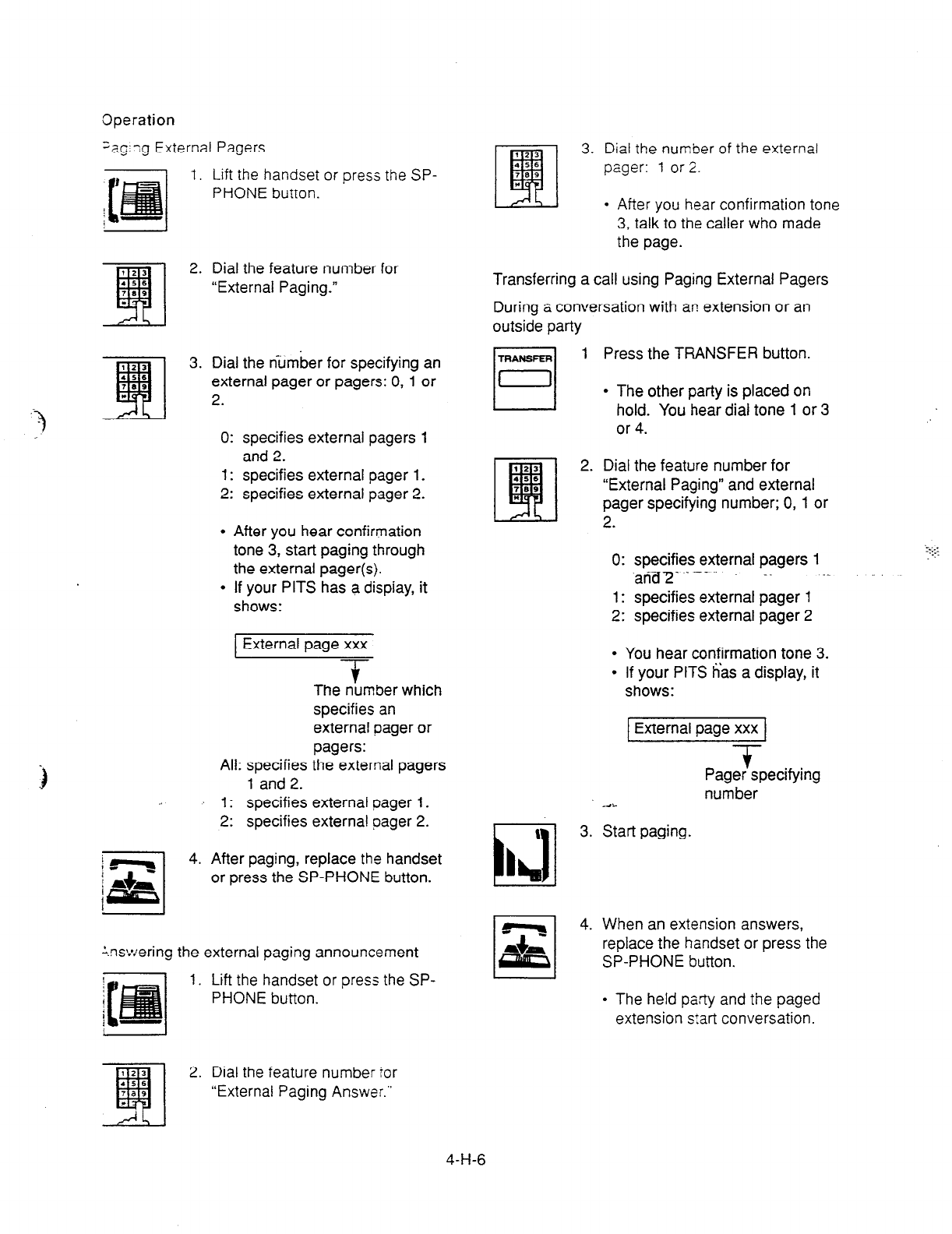
Operation
;ag;;g External Pagers
1. Lift the handset or press the SP-
PHONE button.
2. Dial the feature number for
“External Paging.”
3. Dial the number for specifying an
external pager or pagers: 0, 1 or
2.
0: specifies external pagers 1
and 2.
1: specifies external pager 1.
2: specifies external pager 2.
l
After you hear confirmation
tone 3, start paging through
the external pager(s).
l
If your PITS has a dispiay, it
shows:
External page xxx
-T
The number which
specifies an
external pager or
pagers:
All: specifies the external pagers
1 and 2.
1: specifies external pager 1.
2: specifies external pager 2.
j *T
1
4. After paging, replace the handset
j +
{+gs{ or press the SP-PHONE button.
‘I
:.nswering the external paging announcement
1. Lift the handset or press the SP-
PHONE button.
3. Dial the number of the external
pager:
1
or 2.
l
After you hear confirmation tone
3, talk to the caller who made
the page.
Transferring a call using Paging External Pagers
During a conversation with an extension or an
outside party
1
i 3.
a
L h!
q
,q 4.
Press the TRANSFER button.
l
The other party is placed on
hold. You hear dial tone 1 or 3
or 4.
Dial the feature number for
“External Paging” and external
pager specifying number; 0, 1 or
2.
0: specifies external pagers 1
and2 _. .-._... -.
1: specifies external pager 1
2: specifies external pager 2
l
You hear confirmation tone 3.
l
If your PITS has a display, it
shows:
External page xxx
-T
Pager specifying
number
“a..
Start paging.
When an extension answers,
replace the handset or press the
SP-PHONE button.
l
The held party and the paged
extension s:art conversation.
2. Dial the feature number for
“External Paging Answer.”
4-H-6
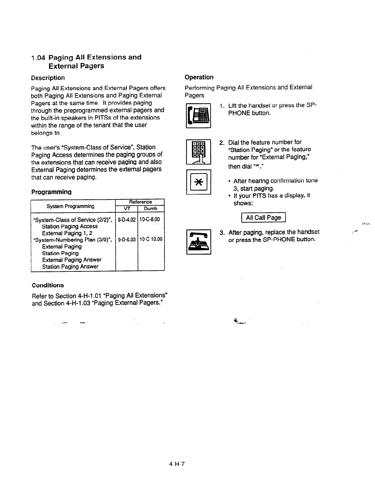
1.04
Paging All Extensions and
External Pagers
Description
Paging All Extensions and External Pagers offers
both Paging All Extensions and Paging Externai
Pagers at the same time. It provides paging
through the preprogrammed external pagers and
the built-in speakers in PlTSs of the extensions
within the range of the tenant that the user
belongs to.
The user’s “System-Class of Service”, Station
Paging Access determines the paging groups of
the
extensions that can receive paging and also
External Paging determines the external pagers
that can receive paging.
Programming
Reference
System Programming v-r Dumb
‘System-Class of Service (2/Z)“. 9-D-4.02 10-C-8.00
Station Paging Access
External Paging
1,2
‘System-Numbering Plan (3/g)“, 9-D-6.03 10-C-10.00
External Paging
Station Paging
External Paging Answer
Station Paging Answer
Conditions
Refer to Section 4-H-l .Ol “Paging All Extensions”
and Section 4-H-l .03 “Paging External Pagers.”
Operation
Performing Paging All Extensions and External
Pagers
1. Lift the handset or press the SP-
PHONE button.
2. Dial the feature number for
“Station Paging” or the feature
number for “External Paging,”
then dial =*.”
l
After hearing confirmation tone
3, start paging.
l
If your PITS has a display, it
shows:
1 All Call Page 1
3. After paging, replace the handset
or press the SP-PHONE button.
.- -
‘5,:
4-H-7
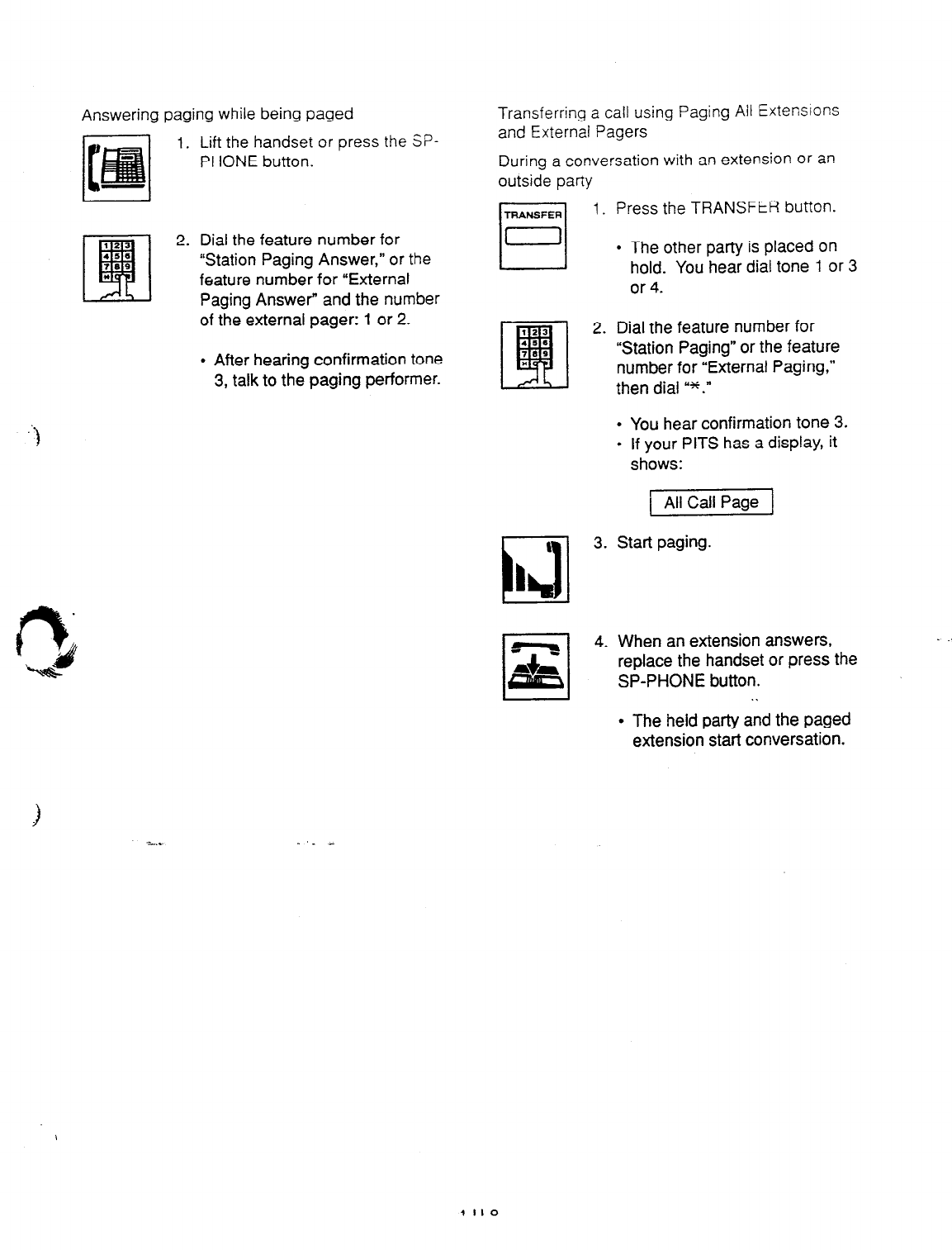
Answering paging while being
paged Transferring a call using Paging Ail Extensions
Lift the handset or
press the SP-
PHONE button.
Dial the feature number for
“Station Paging Answer,” or
the
feature number for “External
Paging Answer” and the number
of the external pager: 1 or 2.
l
After hearing confirmation tone
3, talk to the paging performer.
and External Pagers
During a conversation with an extension or an
outside party
1. Press the TRANSFER button.
l
The other party is placed on
hold. You hear dial tone 1 or 3
or 4.
2. Dial the feature number for
“Station Paging” or the feature
number for “External Paging,”
then dial ‘*.”
l
You hear confirmation tone 3.
l
If your PITS has a display, it
shows:
All Call Page 1
\
i
3. Start paging.
I h6
4. When an extension answers,
replace the handset or press the
SP-PHONE button.
. .
l
The held party and the paged
extension start conversation.
.
.
.
4-H-8
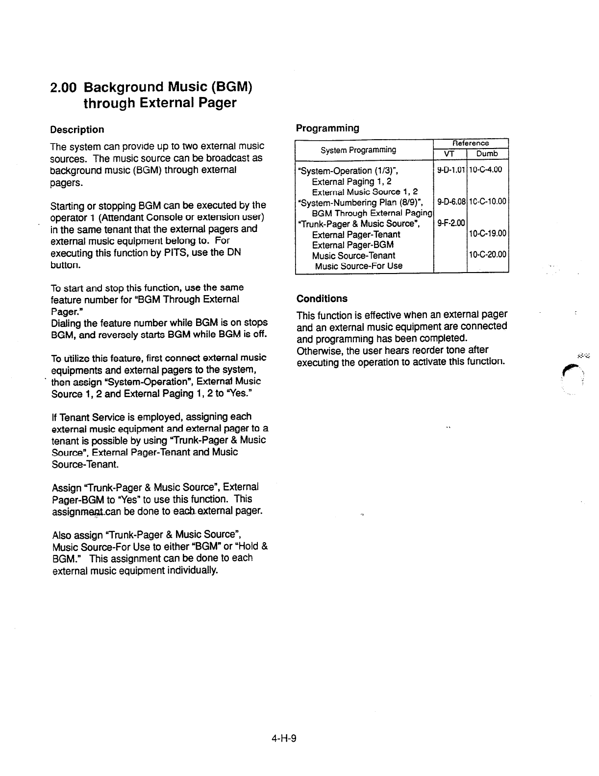
2.00 Background Music (BGM)
through External Pager
Description
The system can provide up to two external music
sources. The music source can be broadcast as
background music (BGM) through external
pagers.
Starting or stopping BGM can be executed by the
operator 1 (Attendant Console or extension user)
in the same tenant that the external pagers and
external music equipment belong to. For
executing this function by PITS, use the DN
button.
To start and stop this function, use the same
feature number for “BGM Through External
Pager.”
Dialing the feature number while BGM is on stops
BGM, and reversely starts BGM while BGM is off.
To utilize this feature, first connect external music
equipments and external pagers to the system,
’ then assign “System-Operation”, External Music
Source 1,2 and External Paging 1,2 to “Yes.”
If Tenant Service is employed, assigning each
external music equipment and external pager to a
tenant is possible by using Trunk-Pager & Music
Source”, External Pager-Tenant and Music
Source-Tenant.
Assign “Trunk-Pager & Music Source”, External
Pager-BGM to “Yes” to use this function. This
assignmeptcan be done to eacb.external pager.
Programming
Reference
System Programming VT Dumb
“System-Operation (l/3)“, 9-D-l .Ol 10-C-4.00
External Paging 1,2
External Music Source 1,2
“System-Numbering Plan (8/g)“, 9-D-6.08 1 C-C-l 0.00
BGM Through External Paging
“Trunk-Pager & Music Source”, 9-F-2.00
External Pager-Tenant 1 O-c-l 9.00
External Pager-BGM
Music Source-Tenant 10-c-20.00
Music Source-For Use
Conditions
This function is effective when an external pager
and an external music equipment are connected
and programming has been completed.
Otherwise, the user hears reorder tone after
executing the operation to activate this function.
Also assign “Trunk-Pager & Music Source”,
Music Source-For Use to either “BGM” or “Hold &
BGM.” This assignment can be done to each
external music equipment individually.
4-H-9
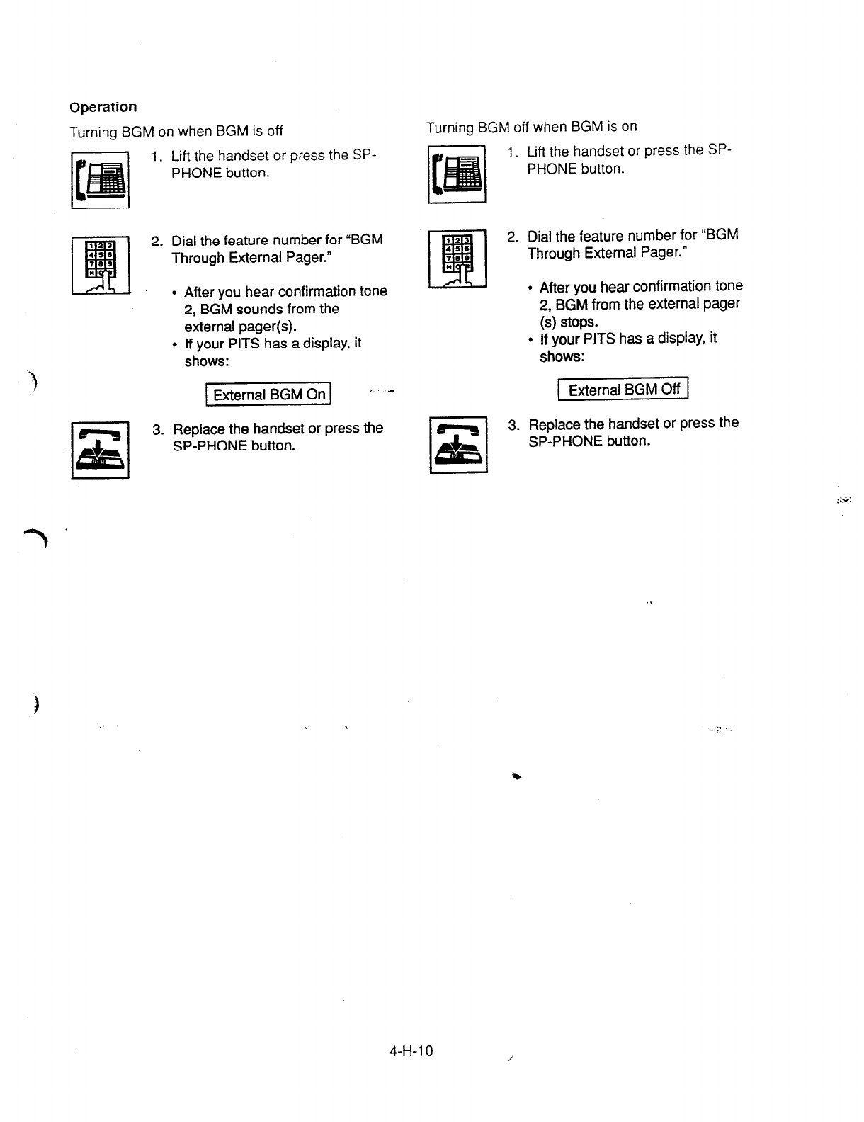
Operation
Turning BGM on when BGM is off
1. Lift the handset or press the SP-
PHONE button.
2. Dial the feature number for “BGM
Through External Pager.”
After you hear confirmation tone
2, BGM sounds from the
external pager(s).
If your PITS has a display, it
shows:
1 External BGM On 1 ’ ‘- External BGM Off
Turning BGM off when BGM is on
I.
Lif-t the handset or press the
SP-
PHONE
button.
2. Dial the feature number for “BGM
Through External Pager.”
After you hear confirmation tone
2, BGM from the external pager
(s) stops.
If your PITS has a display, it
shows:
3. Replace the handset or press the
SP-PHONE button.
Replace the handset or press the
SP-PHONE button.
7.
4-H-l 0
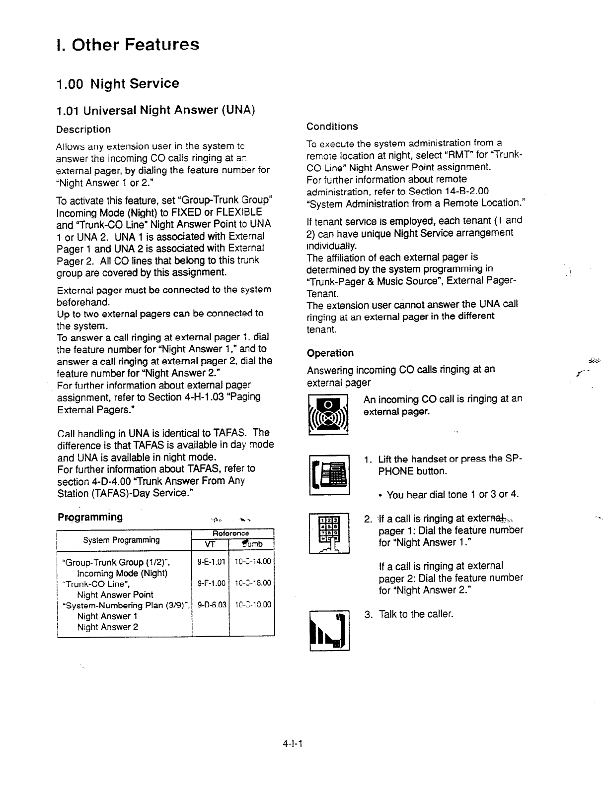
I. Other Features
1 .OO Night Service
1
.Ol Universal Night Answer (UNA)
Description Conditions
Allows any extension user in the system
tc
answer the incoming CO calls ringing at ar.
external pager, by dialing the feature number for
“Night Answer 1 or 2.”
To activate this feature, set “Group-Trunk Group”
Incoming Mode (Night) to FIXED or FLEXIBLE
and “Trunk-CO Line” Night Answer Point to UNA
1 or UNA 2. UNA 1 is associated with External
Pager 1 and UNA 2 is associated with External
Pager 2. All CO lines that belong to this trtink
group are covered by this assignment.
External pager must be connected to the system
beforehand.
Up to two external pagers can be connected to
the system.
To answer a call ringing at external pager 1, dial
the feature number for “Night Answer I ,” and to
answer a call ringing at external pager 2, dial the
feature number for “Night Answer 2.”
For further information about external pager
assignment, refer to Section 4-H-l .03 “Paging
External Pagers.”
To execute the system administration from a
remote location at night, select “RMT” for “Trunk-
CO tine” Night Answer Point assignment.
For further information about remote
administration, refer to Section 14-B-2.00
“System Administration from a Remote Location.”
If tenant service is employed, each tenant (1 and
2) can have unique Night Service arrangement
individually.
The affiliation of each external pager is
determined by the system programming in
“Trunk-Pager & Music Source”, External Pager-
Tenant.
The extension user cannot answer the UNA call
ringing at an external pager in the different
tenant.
Operation
Answering incoming CO calls ringing at an
external pager
Call handling in UNA is identical to TAFAS. The
difference is that TAFAS is available in day mode
and UNA is available in night mode.
For further information about TAFAS, refer to
section 4-D-4.00 “Trunk Answer From Any
Station (TAFAS)-Day Service.”
Prsgramming ;% t k .
Referents
System Programming VT %mb
‘Group-Trunk Group (l/Z)“, 9-E-l .Ol 1 K-1 4.00
Incoming Mode (Night)
j ‘Trunk-CO Line”, 9-F-l .OO 1 C-3-: 8.00
I Night Answer Point
1 ‘System-Numbering Plan (3/g)‘, 9-O-6.03 lC-Z-10.00
Night Answer 1
/ Night Answer 2
An incoming CO call is ringing at an
external pager.
1. Lift the handset or press the SP-
PHONE button.
l
You hear dial tone 1 or 3 or 4.
2. ..lf a call is ringing at exterr+a&+
pager 1: Dial the feature number
for “Night Answer 1.”
If a call is ringing at external
pager 2: Dial the feature number
for “Night Answer 2.”
I
c
3. Talk to the caller.
I hl
4-l-l
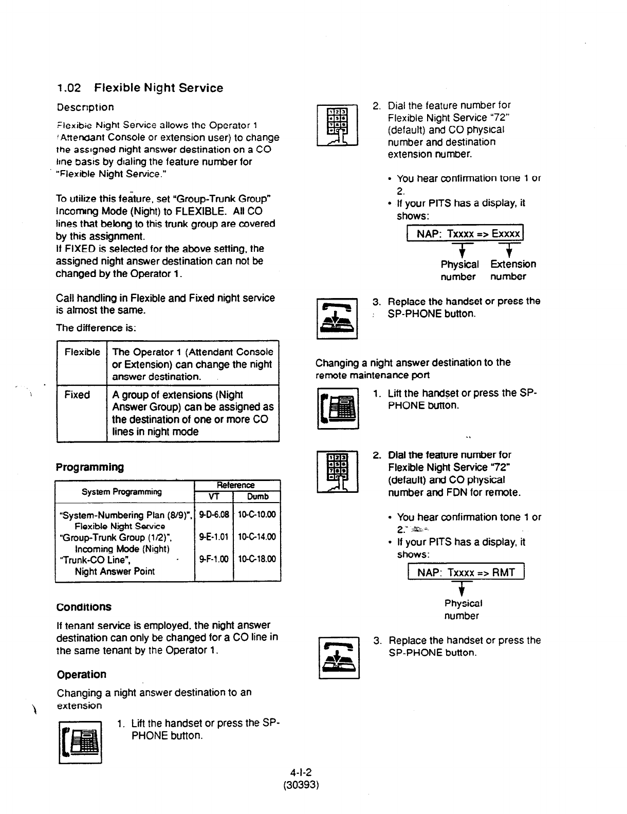
1.02 Flexible Night Service
Description
Flexibie Night Service allows the Operator
1
‘A!tenc~nt Console or extension user) to change
the assgned night answer destination on a CO
lme basis by dialing the feature number for
“Flexible Night Set-vice.”
To utilize this feature, set “Group-Trunk Group”
lncomng Mode (Night) to FLEXIBLE. Ail CO
lines that belong to this trunk group are covered
by this assignment.
If FIXED is selected for the above setting, the
assigned night answer destination can not be
changed by the Operator 1.
Call handling in Flexible and Fixed night service
is almost the same.
The difference is:
-. .
Flexible The Operator 1 (Attendant Console
or Extension) can change the night
answer destination.
Fixed A group of extensions (Night
Answer Group) can be assigned as
the destination of one or more CO
lines in night mode
Programming
System Programming Reference
VT 1 Dumb
Plan (8/g)“. 9-D-8.08 10-C-10.00
Flexible NQht Smite
“Group-Trunk Group
(1 Q)",
9-E-1 .Ol lo-G14.00
incoming Mode (Night)
“Trunk-CO Line”, 9-F-l .OO lO-Gl8.00
Ni9ht Answer Point
Conditions
If tenant service is employed, the night answer
destination can only be changed for a CO line in
the same tenant by the Operator 1.
Operation
Changing a night answer destination to an
\ extension
2. Dial the feature number for
Flexible Night Service “72”
(default) and CO physical
number and destination
extension number.
. You hear confirmation tone 1 or
2.
l
If your PITS has a display, it
shows:
NAP: Txxxx => Exxxx
T- T
Physical Extension
number number
Replace the handset or press the
SP-PHONE button.
Changing a night answer destination to the
remote maintenance port
1. Lift the handSet or press the SP-
PHONE button.
.I
92s
q
2. Dial the feature number for
.s.
7.. Flexible Night Service 72”
. (default) and CO physical
number and FDN for remote.
l
You hear confirmation tone 1 or
2-u
7&;.
l
If your PITS has a display, it
shows:
NAP: Txxxx => RMT
T
Physical
number
3. Replace the handset or press the
SP-PHONE button.
1. Lift the handset or press the SP-
PHONE button.
4-l-2
(30393)
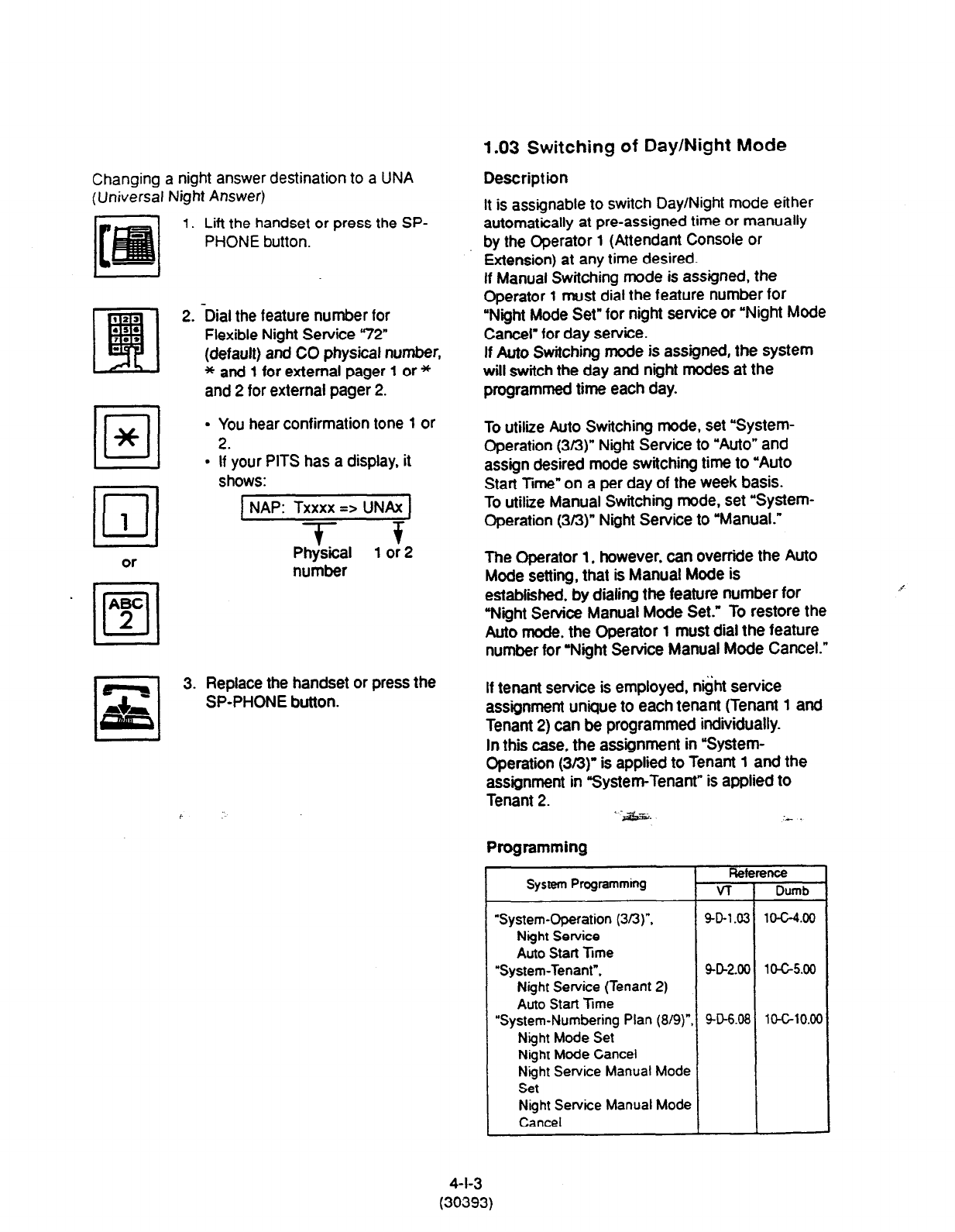
Changing a night answer destination to a UNA
(Universal
Night Answer)
1. Lift the handset or press the
SP-
PHONE button.
2. -Dial the feature number for
Flexible Night Service “72
(default) and CO physical number,
* and 1 for external pager 1 or *
and 2 for external pager 2.
Dl
*
l
You hear confirmation tone 1 or
2.
l
If your PITS has a display, it
shows:
L!J
1
or
NAP: Txxxx => UNAx
-?-- +
Physical 1 or 2
number
3. Replace the handset or press the
SP-PHONE button.
1.03 Switching of Day/Night Mode
Description
It is assignable to switch Day/Night mode either
automatically at pre-assigned time or manually
by the Operator
1
(Attendant Console or
Extension) at any time desired.
If Manual Switching mode is assigned, the
Operator 1 must dial the feature number for
“Night Mode Set” for night service or “Night Mode
Cancel’ for day service.
If Auto Switching mode is assigned, the system
will switch the day and night modes at the
programmed time each day.
To utiliie Auto Switching mode, set “System-
Operation (s/3)” Night Service to “Auto” and
assign desired mode switching time to “Auto
Start Time” on a per day of the week basis.
To utiliie Manual Switching mode, set “System-
Operation (s/3)” Night Service to “Manual.”
The Operator 1, however, can overrfde the Auto
Mode setting, that is Manual Mode is
established. by dialing the feature number
for
“Night Service Manual Mode Set.” To restore the
Auto mode. the Operator 1 must dial the feature
number for “Night Service Manual Mode Cancel.”
If tenant service is employed, night service
assignment unique to each tenant (Tenant 1 and
Tenant 2) can be programmed individually.
In this case, the assignment in “Sysfem-
Operation (363)” is applied to Tenant 1 and the
assignment in “System-Tenant” is applied to
Tenant 2. * -&x&. I- .
Programming
Reference
System Programming VT
Dumb
“System-Operation (3/3)“.
9-0-1.03 10-C-4.00
Night Service
Auto Start Tme
“System-Tenant”,
Q-D-2.00 10-G5.00
Night Service
(Tenant 2)
Auto Start Time
“System-Numbering Plan (8/g)“, SD6.08
lWlO.OC
Night Mode Set
Night Mode Cancel
Night Service
Manual
Mode
Set
Night Service
Manual Mode
Cancel
4-l-3
(30393)

Conditions
If Auto Start Time on a cerar:: da. s -c:
assigned, the current moae IS COT: xsc ~1. 2
new start time is encountered.
If the Start Time for Day mode and Night -ccc
on the
same
day are set identically, the current
mode is continued.
If Auto Start Time assignment is not programmed
at all, the current mode is continued. In other
words if the current mode is Day then Day Mode
is continued, and if the current mode is Night
then Night Mode is continued.
‘3
Operation
Switching Day mode to Night mode
1. Lift the handset or press the SP-
PHONE button.
Dial the feature number for
“Night Mode Set.”
l
You hear confirmation tone 1 or
2.
l
If your PITS has a display, it
shows:
0
z
3.
1 Night Mode 1
l
You hear confirmation tone 1 or
2.
Replace the handset or press the
SP-PHONE button.
l
If your PITS has a display, it
shows:
Switching Night mode to Day mode
y 1. Wft the handset or press the SP-
PHONE button.
2. Dial the feature number for
“Night Mode Cancel.”
.
You hear confirmation tone 1 or
2.
.
If
your
PITS has a display, it
shows:
[Day
Swlrching Auto mode to Manuzl mode
1. Lift the handset or press the SP-
PHONE button.
Dial
the feature number for “Night
Service Manual Mode Set.”
l
You hear confirmation tone I or
2.
l
If your PITS
has a display, it
shows:
1 Day/Night : Man 1
Replace the handset or press the
SP-PHONE button.
Switching Manual mode to Auto mode
1. Lift the handset or press the SP-
PHONE button.
2. Dial the feature number for “Night
Service Manual Mode Cancel.”
Day/Night : Auto
3. Replace the handset or press the
Sf?GWONE
button. :. -
3. Replace the handset or press the
SP-PHONE button.
4-l-4
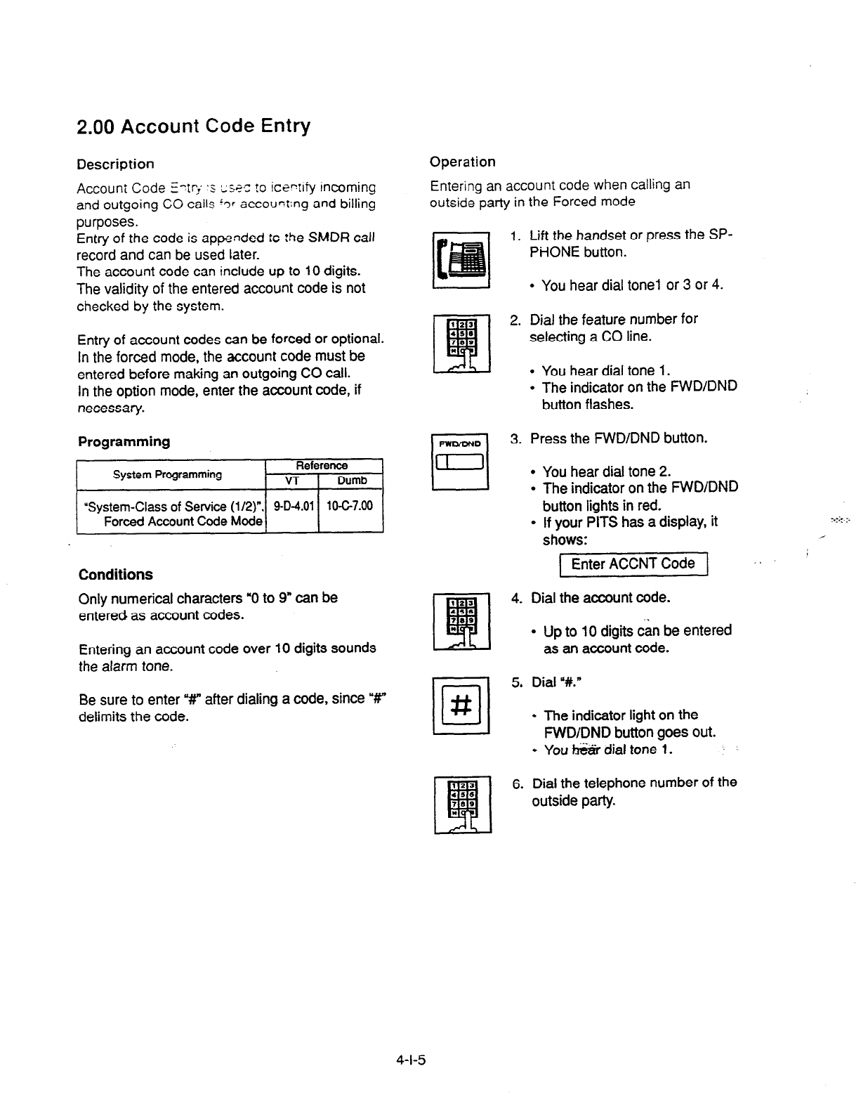
2.00 Account Code Entry
Description Operation
Entering an account code
when calling an
outside party
in the Forced mode
Account Code f?ri ‘5 cwc: !o icewfy incoming
and outgoing CO calls ‘3: account:ng and billing
purposes.
Entry of the code is appended to :he SMDR call
record and can be used later.
The account code can include up to 10 digits.
The validity of the entered account code is not
checked by the system.
Entry of account codes can be forced or optional.
In the forced mode, the account code must be
entered before making an outgoing CO call.
In the option mode, enter the account code, if
necessary.
1. Lift the handset or press the SP-
PHONE button.
l
You hear dial tone1 or 3 or 4.
2. Dial the feature number for
selecting a CO line.
l
You hear dial tone 1.
l
The indicator on the FWD/DND
button flashes.
Programming I[ 3. Press the FWD/DND button.
l-l
= .
.
.
You hear dial tone 2.
Conditions
The indicator on the FWD/DND
button lights in red.
If your PITS has a display, it
shows:
Enter ACCNT Code
Only numerical characters “0 to 9” can be
entered as account codes. 4. Dial the account code.
Entering an account code over 10 digits sounds
the alarm tone.
l
Up to 10 digits can be entered
as an account code.
Be sure to enter ‘W after dialing a code, since “#”
delimits the code.
•l
5. Dial “#.”
#
l
The indicator light on the
FWDIDND button goes out.
l
Youh&rdial tone 1.
6. Dial the telephone number of the
outside party.
4-l-5
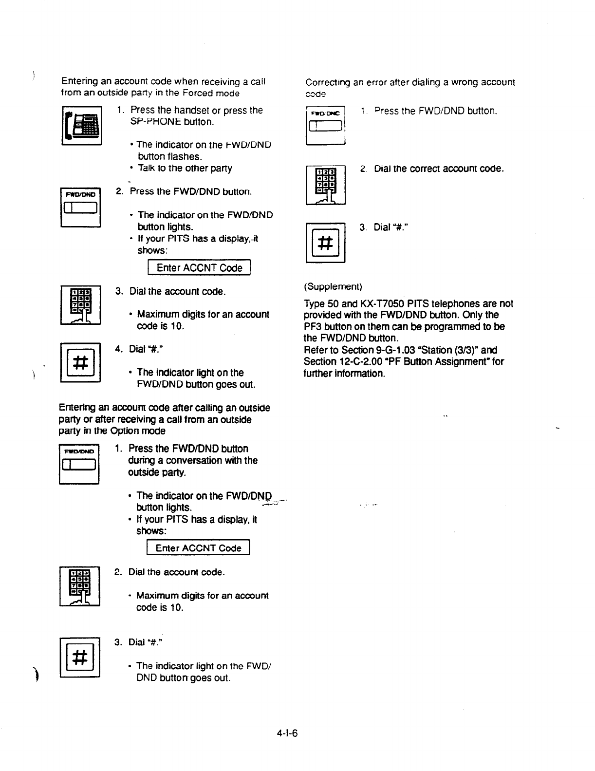
Entering an account
code when receiving a call
from an outside
party in the
Forced
mode
1. Press the handset or press the
SP-PHONE button.
l
The indicator on the FWD/DND
button flashes.
l
Talk to the other party
Press the FWD/DND button.
The indicator on the FWD/DND
button lights.
If your PITS has a display,-it
shows:
1 Enter ACCNT Code 1
3. Dial the account code.
l
Maximum digits for an account
code is 10.
•l
4. Dial “#I.”
#
l
The indicator light on the
FWD/DND button goes out.
Entering an account code after calling an outside
party or after receiving a call from an outside
party in the Option mode
1.
Press the
FWD/DND button
during a conversation with the
outside party.
.
The indicator on the FWD/DND
.-__*
button lights. C.-w:
If your PITS has a display, it
shows:
Enter ACCNT Code
2. Dial the account code.
l
Maximum digits for an account
code is 10.
Correctrng an error after dialing a wrong account
code
1 Press the FWD/DND button.
2. Dial the conect account code.
3. Dial “#.”
(Supplement)
Type 50 and KX-T7050 PITS telephones are not
provided with the FWD/DND button. Only the
PF3 button on them can be programmed to be
the FWDIDND button.
Refer to Section 9-G-l .03 “Station (3/3)” and
Section 12-C-2.00 “PF Button Assignment” for
further information.
. .
.I
3. Dial 3.”
l
The indicator light on
the
FWD/
DND button goes out.
4-l-6

3.00 Timed Reminder (Alarm Clock)
Description
The extension user can use his or her PITS
telephone as an alarm clock.
When this feature is set, alarm tone will ring for 2
minutes at the programmed time from the built-m
speaker of your PITS telephone.
By going off-hook, the extension user can hear
the wake-up message, if it has been recorded
beforehand.
The extension user may hear BGM or intermittent
tone (dial tone 2) instead of the wake-up
message.
(See Section 3-F-13.00 “Trmed Reminder with
OGM (wake-up call).7
This feature can be set to operate only once or
everyday at a specitied time.
Programming
I
System Pmgfamming Reference
VT I Dumb
conclltlons
(1) What if the extension is busy or off-hook at the
programmed time?
Alarm tone will ring after the extension goes
on-hook.
(2) What if a call comes in when alarm tone is
ringing?
The call comes in on an extension (call
irukation is shown)’ but does not ring.
lt will ring after alarm tone stops to ring.
l
The caller hears busy tone if the call is
coming to a PDN button and the extension
has only one PDN.
(3) Remote limed Reminder
This feature can also be set by the Operator 1
or 2 to any extension.
(See Section 4-I-14.00 and Section
6-J-13.00.)
(4)
Newly programmed time overrides the old one.
Only the latest setting is valid at a single
extension whether it was set by the extension
itsetf or by the operator.
(5) Tone
Pattern
Alarm tone sounds in the following manner:
Operation
Setting the alarm time
1. Lift the handset or press the SP-
PHONE button.
2.
3.
4.
5.
6.
Dial the feature number for Timed
Reminder set r* 51” (default).
Dial %our” with two digits: 01 to
12.
Dial 9ninute” with two digits: 00 to
59.
Dial ‘0” for a.m. or dial ‘1” for p.m..
Dial “0” for limed Reminderone
time, or diil ‘1” Trmed Reminder-
every day.
l You
hear confirmation tone 1 or
2 and then dial tone 1 or 3 or 4.
l
lf your PlTS has a display, it
shows:
4-l-7
(40993)
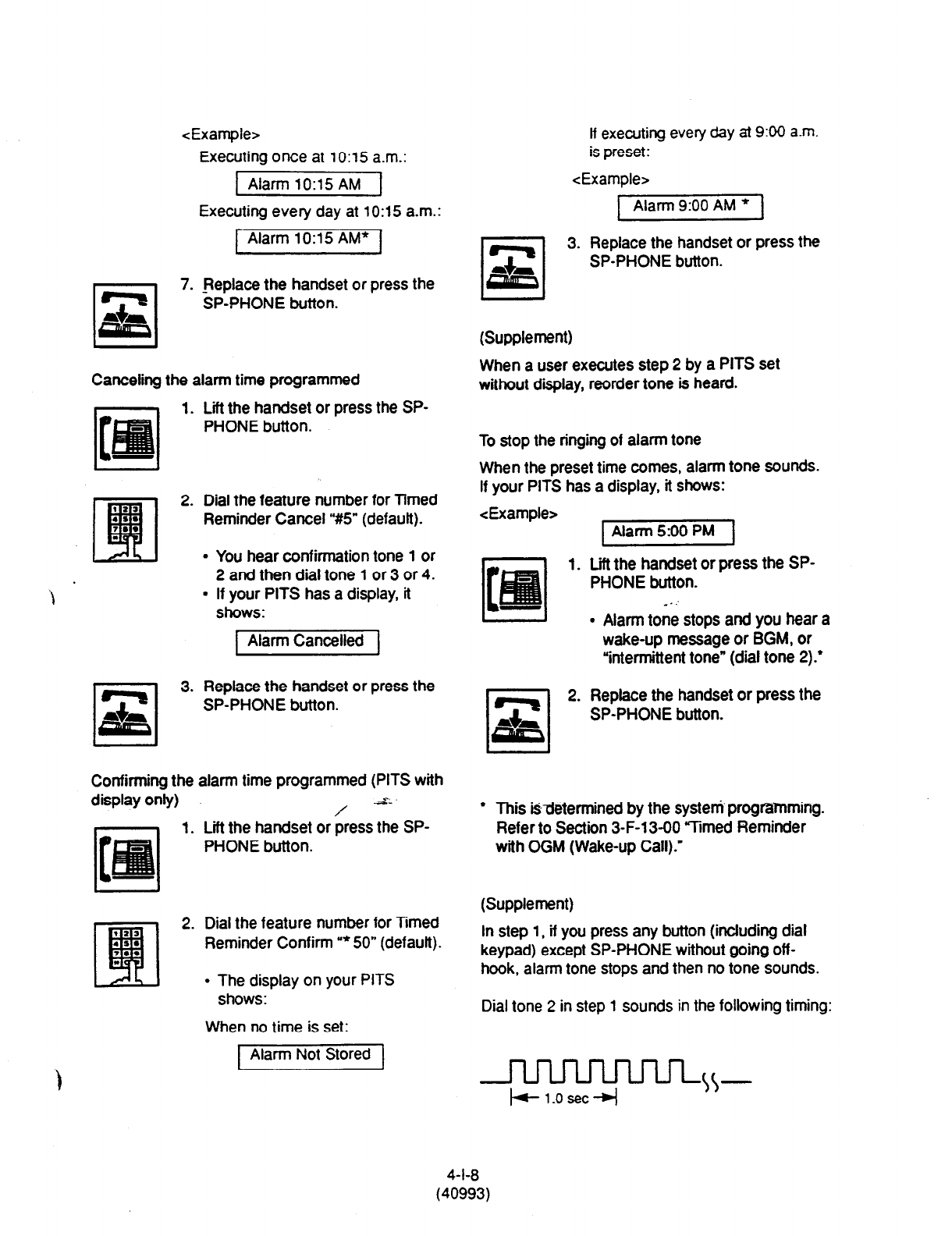
<Example>
Executing once at lo:15 a.m.:
Alarm lo:15 AM
Executing every day at lo:15 a.m.:
r-l 7.
p&
[ Alarm 10:X AM* 1
Replace the handset or press the
SP-PHONE button.
Canceling the alarm time programmed
1. Lift the handset or press the SP-
PHONE button.
rl
s
3.
Dial the feature number for Timed
Reminder Cancel ‘#5” (default).
l
You hear confirmation tone 1 or
2 and then dial tone 1 or 3 or 4.
l
If your PITS has a display, it
shows:
Alarm Cancelled
Replace the handset or press the
SP-PHONE button.
Confirming the alarm time programmed (PITS with
display or&)
.-
=*
Lii the handset or press the SP-
PHONE button.
1.
Dial the feature number for Timed
Reminder Confirm “*50” (defauft).
l
The display on your PITS
shows:
When no time is set:
[ Alarm Not Stored 1
It executing every day at 9:00 a.m.
is preset:
<Example>
Alarm 9:00 AM *
3. Replace the handset or press the
SP-PHONE button.
(Supplement)
When a user executes step 2 by a PITS set
without display, reorder tone is heard.
To stop the ringing of alarm tone
When the preset time comes, alarm tone sounds.
If your PITS has a display, it shows:
<Example> piii%sq
1. Lift the handset or press the SP-
PHONE button.
_ . :
. Alarm tone stops and you hear a
wake-up message or BGM, or
“intermittent tone” (dial tone 2):
2. Replace the handset or press the
SP-PHONE button.
.
This @determined by the system programming.
Refer to Section 3-F-13-00 “Timed Reminder
with OGM (Wake-up Call).’
(Supplement)
In step 1, if you press any button (including dial
keypad) except SP-PHONE without going off-
hook, alarm tone stops and then no tone sounds.
Dial tone 2 in step 1 sounds in the following timing:
-nnn-
+l.osec~
4-l-8
(40993)
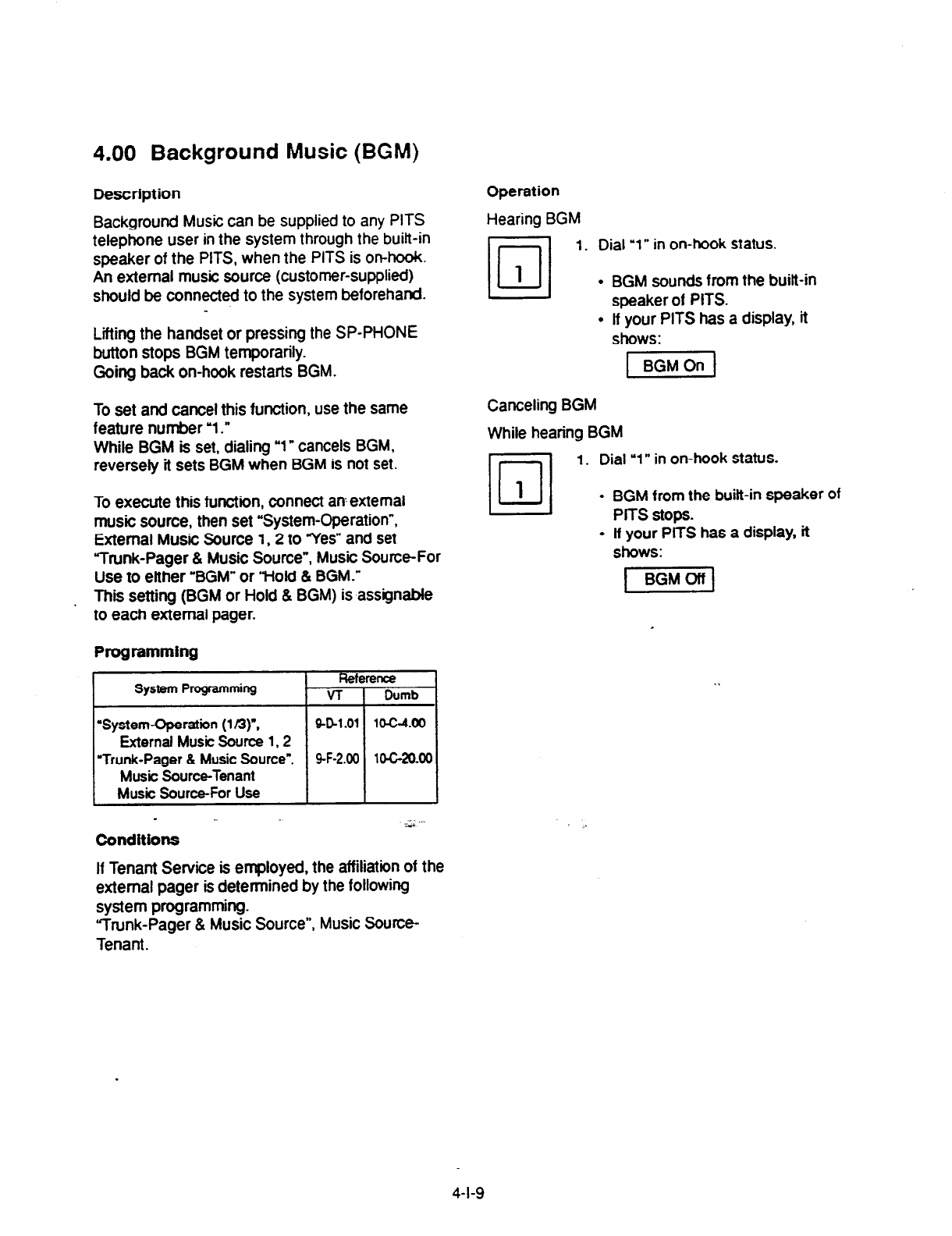
4.00 Background Music (BGM)
Description
Background Music can be supplied to any PITS
teiephone user in the system through the built-in
speaker of the PITS, when the PITS is on-hook.
An external music source (customer-supplied)
should be connected to the system beforehand.
Liiing the handset or pressing the SP-PHONE
button stops BGM temporarily.
Going back on-hook restarts BGM.
Operation
Hearing BGM
Dl
1. Dial
‘1”
in on-hook status.
1
l
BGM sounds from the built-in
speaker of PITS.
l
lf your PITS has a display, it
shows:
To set and cancel this function, use the same
feature number ‘1.”
While BGM is set, dialing “1” cancels BGM.
reversely it sets BGM when BGM is not set.
To execute this function, connect an external
music source, then set “System-Operation”,
External Music Source 1,2 to “Yes” and set
Vunk-Pager & Music Source”, Music Source-For
Use to either ‘BGM” or “Hold & BGM.”
This setting (BGM or Hold 8 BGM) is assignable
to each external pager.
Programming
System Programming Fkference
v-r Dumb
‘System-Operation (1/3y,
901.01 1o-c-4.00
External Music Source 1,2
“Trunk-Pager 8 Music Source”, 9-F-2.00 lO-C-20oO
Music Source-Tenant
Music Source-For Use
* -,i --
conditions
If Tenant Service is employed, the affiliation of the
external pager is determined by the following
system programming.
“Trunk-Pager & Music Source”, Music Source-
Tenant.
t BGMOn 1
Canceling BGM
While hearing BGM
Dl
1. Dial “1” in on-hook status.
1
l
BGM from the built-in speaker of
PlTS stops.
l
lf your PlTS has a display, it
shows:
4-l-9
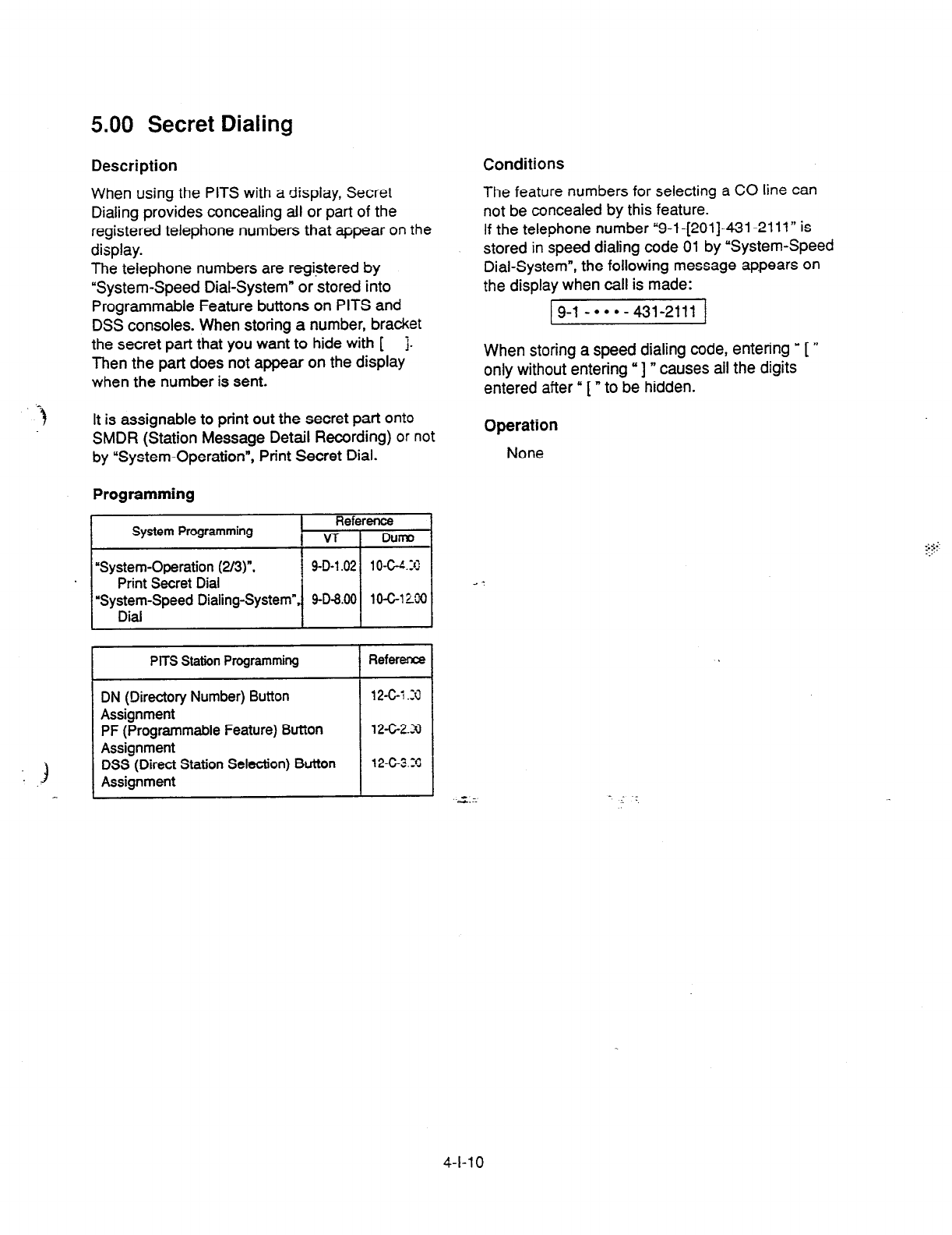
5.00 Secret Dialing
Description Conditions
When using the PITS with a display, Secret
Dialing provides concealing all or part of the
registered telephone numbers that appear on the
display.
The telephone numbers are registered by
“System-Speed Dial-System” or stored into
Programmable Feature buttons on PITS and
DSS consoles. When storing a number, bracket
the secret part that you want to hide with [ j.
Then the part does not appear on the display
when the number is sent.
The feature numbers for selecting a CO line can
not be concealed by this feature.
If the telephone number “9-l -[201]-431-2111” is
stored in speed dialing code 01 by “System-Speed
Dial-System”, the following message appears on
the display when call is made:
9-l
-***-431-2111
When storing a speed dialing code, entering y [ ”
only without entering “I n causes ail the digits
entered after” [“to be hidden.
It is assignable to print out the secret part onto
SMDR (Station Message Detail Recording) or not
by “System-Operation”, Print Secret Dial.
Programming
System Programming I Reference
I v-r DuFIp
“System-Operation (2/3)“, 9-D-l .02 1 O-W.31
Print Secret Dial
“System-Speed Dialing-System”, 9-D-8.00 10-C-l MO
Dial
r--
PITS Station Programming Refer- I
DN (Directory Number) Button
Assignment
PF (Programmable Feature) Button
Assignment
DSS (Direct Station Selection) Button
Assignment
12-c-i .4
12-G2.N
12-c-3.3
Operation
None
--
4-l-l 0
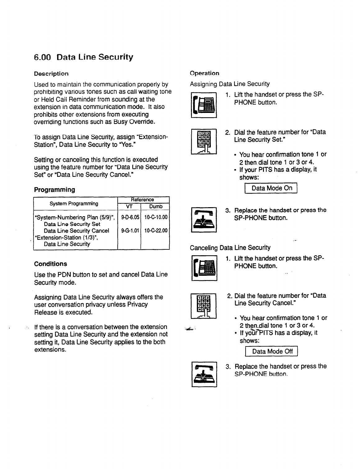
6.00 Data Line Security
Description
Used to
maintain the communication properly by
prohibiting various tones such as call waiting
tone
or
Held Call Reminder from sounding at the
extension in data communication mode. It also
prohibits other extensions from executing
overriding functions such as Busy Override.
To assign Data Line Security, assign “Extension-
Station”, Data tine Security to “Yes.”
Setting or canceling this function is executed
using the feature number for “Data tine Security
Set” or “Data tine Security Cancel.”
Programming
System Programming Reference
VT 1 Dumb
Conditions
Use the PDN button to set and cancel Data Line
Security mode.
Assigning Data Line Security always offers the
user conversation privacy unless Privacy
Release is executed.
. . If there is a conversation between the extension
setting Data tine Security and the extension not
setting it, Data Line Security applies to the both
extensions.
Operation
Assigning Data Line Security
1. Lift the handset or press the SP-
PHONE button.
2. Dial the feature number for “Data
tine Security Set.”
l
You hear confirmation tone 1 or
2 then dial tone 1 or 3 or 4.
l
if your PITS has a display, it
shows:
3. Replace the handset or press the
SP-PHONE button.
Canceling Data Line Security
1. Lift the handset or press the SP-
PHONE button. . .
2. Dial the feature number for “Data
tine Security Cancel.”
l
You hear confirmation tone 1 or
2
thendial tone 1 or 3 or 4.
l
If yo%r”PITS has a display, it ’
shows:
p2iiGzq
3. Replace the handset or press the
SP-PHONE button.
4-l-l
1
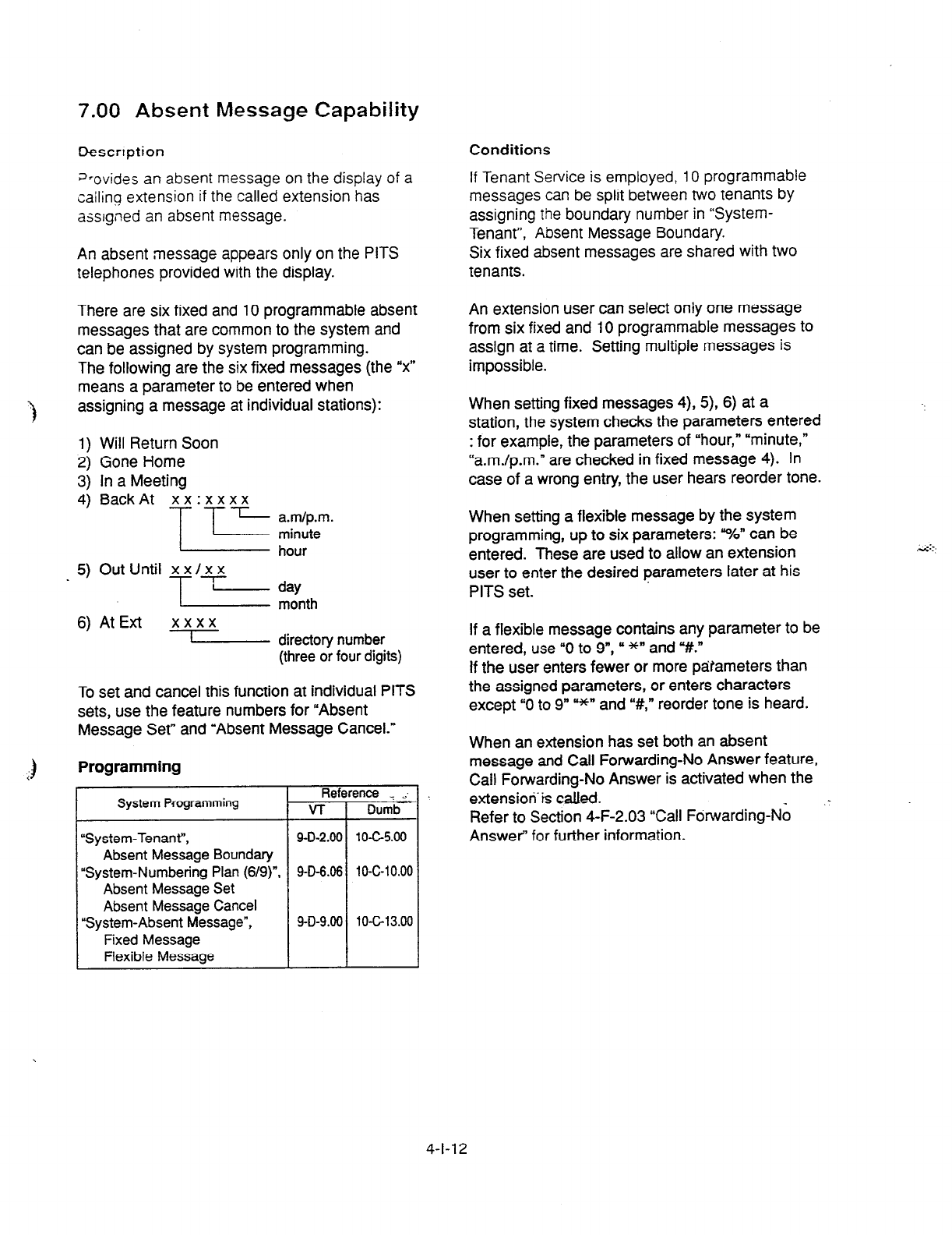
7.00 Absent Message Capability
Descrrption Conditions
J-ovides an absent message on the display of a
cailinq extension if the called extension has
assigned an absent message.
An absent message appears only on the PITS
telephones provided with the display.
If Tenant Service is employed, 10 programmable
messages can be split between two tenants by
assigning the boundary number in “System-
Tenant”, Absent Message Boundary.
Six fixed absent messages are shared with two
tenants.
There are six fixed and 10 programmable absent
messages that are common to the system and
can be assigned by system programming.
The
following are the six fixed messages (the “x”
means a parameter to be entered when
3
assigning a message at individual stations):
1) Will Return Soon
2)
Gone Home
3) In a Meeting
4, BackAt “i:‘“- m/;.
_ 5) Out Until x x/x x
= fzlltlth
6) At Ext xxxx
1 directory number
(three or four digits)
An extension user can select oniy one message
from six fixed and 10 programmable messages to
assign at a time. Setting multiple messages is
impossible.
When setting fixed messages 4), 5), 6) at a
station, the system checks the parameters entered
: for example, the parameters of “hour,” “minute,”
“a.m./p.m.” are checked in fixed message 4). In
case of a wrong entry, the user hears reorder tone.
When setting a flexible message by the system
programming, up to six parameters: “%” can be
entered. These are used to allow an extension
user
to enter
the desired parameters later at his
PITS set.
To set and cancel this function at individual PITS
sets, use the feature numbers for “Absent
Message Set” and “Absent Message Cancel.”
If a
flexible
message contains any parameter to be
entered, use “0 to 9”, cI *” and “#.”
If the user enters fewer or more parameters than
the assigned parameters, or enters characters
except “0 to 9
” =*’ and “#,” reorder tone is heard.
When an extension has set both an absent
message and Call Forwarding-No Answer feature,
Call Forwarding-No Answer is activated when the
extension’& called.
Programming
System Programming Refl
VT
“System-Tenant”, 9-D-2.00
Absent Message Boundary
“System-Numbering Plan (6/g)“, 9-D-6.06
Absent Message Set
Absent Message Cancel
“System-Absent Message”, 9-D-9.00
Fixed Message
Flexible Message
ence _i . .
Dumb
1 o-c-5.00
10-c-10.00
10-c-13.00
Refer to Section 4-F-2.03 “Call Forwarding-No
Answer” for further information.
4-l-l 2
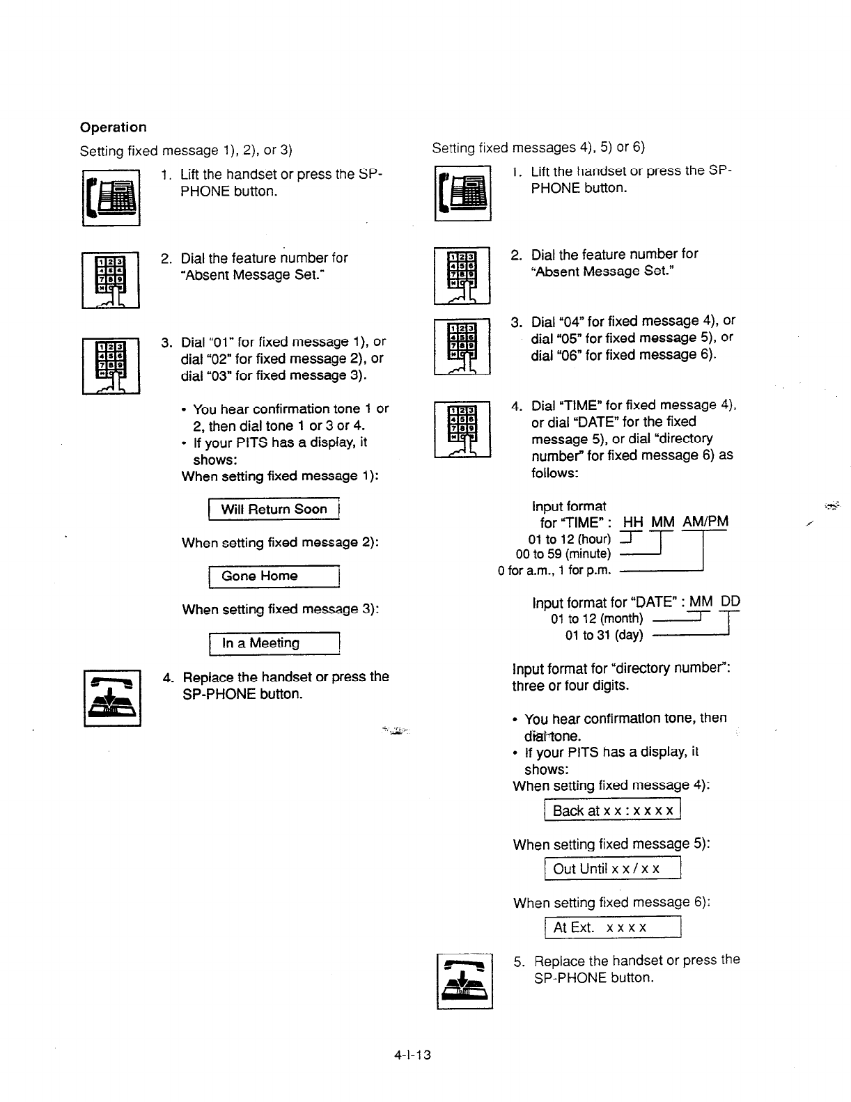
Operation
Setting fixed message l), Z), or 3)
1. Lift the handset or press the SP-
PHONE button.
2. Dial the feature number
for
“Absent Message Set.”
3. Dial “01” for fixed message l), or
dial “02” for fixed message 2), or
dial ‘03” for fixed message 3).
l
You hear confirmation tone 1 or
2, then dial tone 1 or 3 or 4.
l
If your PITS has a display, it
shows:
When setting fixed message 1):
I Will Return Soon i
When setting fixed message 2):
Gone Home I
When setting fixed message 3):
In a Meeting 1
4. Replace the handset or press the
SP-PHONE button.
Setting fixed messages 4), 5) or 6)
1. Lift the handset or press the SP-
PHONE button.
2. Dial the feature number for
“Absent Message Set.”
3. Dial “04” for fixed message 4), or
dial “05” for fixed message 5), or
dial “06” for fixed message 6).
4. Dial “TIME” for fixed message 4),
or dial “DATE” for the fixed
message 5), or dial “directory
number” for fixed message 6) as
follows:
Input format .&
for “TIME” : HH MM AM/PM
0 for a.m., 1 for p.m.
Input format for “DATE” : MM DD
--
01 to 12 (month) -
01 to 31 (day)
Input format for “directory number”:
three or four digits.
l
You hear confirmation tone, then
di&one.
l
If your PlTS has a display, it
shows:
When setting fixed message 4):
1 Backatxx:xxxx 1
When setting fixed message 5):
Out Until x x /x x
When setting fixed message 6):
At Ext. x x x x I
5. Replace the handset or press the
SP-PHONE button.
4-l-l 3

Setting a flexible nwssage Canceling the assigned message
7. L$ ?he handset or press the SF-
P+ONE button.
I. Lift the handset or
press
the
SP-
PHONE button.
2. Dral
the feature
number for
‘Absent Message Set.”
2. Dial the feature number for
“Absent Message Cancel.”
l
You hear confirmation tone 1 or
2 then dial tone 1 or 3 or 4.
3.
Dial the two digit message
number 07 to 16.
If the message requires any
parameters, enter all the
parameters.
.
l
You hear confirmation tone 1 or
2, then dial tone 1 or 3 or 4.
l
If your PITS has a display. it
shows the entered message.
4. Replace the handset or press the
SP-PHONE button.
--a;>
_. --
3. Replace the handset or press the
SP-PHONE button.
1’. *
4-l-14

8.00 Message Waiting
Description
Allows an extension user to indicate to another
exiensmn that a message is waiting for him or her,
by
turning on the MESSAGE indicator (button) on
the
called extension.
The extension user who received the message
waiting indication can call back the message
sender by simply going off-hook and pressing the
red lit MESSAGE indicator (button).
This feature is useful when the calied extension is
busy or does not answer the call.
Up to 500 message waiting indications can be set
for the whole system.
Programming
System Programming
“System-Tenant’,
Message Waiting Boundary
“System-Numbering
Plan (7/9)“.
Message Cancel
“Extension-Station (Z/3)“.
DN Key Type
“Extension-Station (3/3)-,
DSS Key
Type
Conditions
1. Suitable Telephones:
(1) Message Sender _
(1) Receiver’s extension is:
l
A
PITS telephone without a MESSAGE
button.
l
A Single Line Telephone without
MESSAGE lamp.
(2) The maximum number of message wafting
indications available for the system or
tenant l/2 has been assigned.
If your PITS has a display, it shows:
MW Not Accepted
3. Tenant Service
The maximum number of message waiting
indications available for Tenant
1
and 2 is
determined by “System-Tenant” Message
Waiting Boundary.
4. Setting of the multiple message waiting
indications
(1) More than one message sender can leave
message waiting indications to the same
extension at the same time.
(2) Even if the same message sender sets
message waiting indications to the same
extension more than once, this leaves only
one message on the called extension.
.-
5. The MESSAGE indicator on the message
receiver’s extension will be turned off when:
- .Anendant Conso@% ‘” .‘i ‘a;
l
A PITS telephone with a MESSAGE (1) The message receiver c% back the
button.’ message sender by pressing the red lit
l
Any Single Line Telephone MESSAGE button, and it was answered by
(2)
Message Receiver
l
A PITS telephone with a MESSAGE
the message sender (or by another
extension using Call Pickup or an SDN
button).
l
1
button:
l
A Single Line Telephone with
MESSAGE lamp.
* Refer to <Supplement> on page
4-l-17 for
further information.
(2) Message waiting indication is canceled by
the message sender.
l
’
(3) Message waiting indications are canceled
by the message receiver.’ *
2. Reorder Tone
A caller who attempts to leave message waiting
l
’ The indicator may not be turned off, if there are
other message waiting indications sent by other
extensions.
indication may hear the reorder tone in the
following cases:
l
7 All message waiting indications are canceled at
once.
4-l-l
5
(30393)

Operation by Caller
(At message sender’s extension)
Setting the Message Waiting Indication
1. Lift the handset or press the
SP-
PHONE button.
2. Dial the extension number of the
other party.
l
You hear ringback tone, or
busy tone 1 or 2, or DND tone.
-1 3. Press the MESSAGE button.
I
= .
.
You hear confirmation tone 2
and then dial tone 1 or 3 or 4.
The MESSAGE indicator of the
other extension lights.
4. Replace the handset or press the
SP-PHONE button.
Canceling the Message Wafting Indication on
receiver’s extension set by a caller
1. Lii the handset or press the SP-
PHONE button.
2. Dial the feature number for
%&sage Cancel Y#9” j&fault)
and the extension number of the
message receiver successively.
l
You hear confirmation tone 2
and then dial tone
1
or 3 or 4.
l
If the other extension received
only one message, the
MESSAGE indicator of the
other
extension goes out.
3. Replace the handset or press the
SP-PHONE button.
Operation by Receiver
(A’ message recetvsrs extension;
Cahng back
the message sender
1. Lift the handset or press the
SP-
PHONE button.
2. Press the MESSAGE button that
is lit.
l
You hear ringback tone. When
the message sender answers,
start conversation.
l
If you received multiple
messages, catfing back the first
message sender is performed.
At the conclusion of the
conversation, the first message
is canceled.
l
At the conclusion of the
conversations with all the
message senders, the
MESSAGE indicator goes out.
Canceling all Message Waiting tndications on
your extension
1. Lift the handset or press the SP-
PHONE button.
2. Dial the ieature number for
f@essa$+e.Cancel?V9” (default)
and your own extension number
in succession.
l
You hear confirmation tone 2
and then dial tone 1 or 3 or 4.
l
The MESSAGE indicator on
receiver’s extension goes out.
3. Replace the handset or press the
SP-PHONE buttoh.
4-l-l 6
(30393)
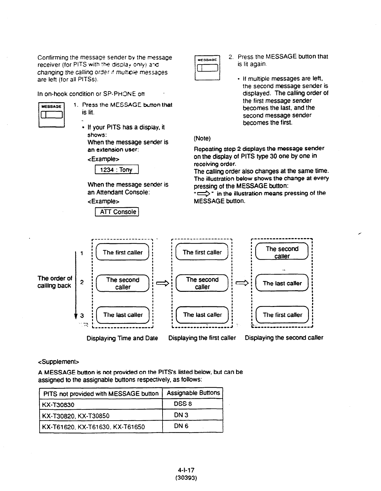
Confirming the message sender by the rxssage
receiver (for PITS with the disolaf oniy) arc
changing the calling o:der ,! munxxe messages
are left (for all PITSs).
In on-hook condition or SP-PH3NE on
MEGGAGE
1. Press the MESSAGE br;tton that
El -
is lit.
l
If your PITS has a dispfay. it
shows:
When the message sender is
an extension user:
<Example>
[WI
When the message sender is
an Attendant Console:
<Example>
2. Press the MESSAGE button that
is lit again.
- If multiple messages are left,
the second message
Sender
iS
displayed. The calling order of
the first message sender
becomes the last, and the
second message sender
becomes
the first.
(Note)
Repeating step 2 displays the message sender
on the display of PITS type 30 one by one in
receiving order.
The calling order also changes at the same time.
The illustration below shows the change at every
pressing of the MESSAGE button:
“e * in the illustration means pressing of the
MESSAGE button.
The order of
calling back 2
C------------------J
Displaying Time and Date Displaying the first caller Displaying the second caller
<Supplement>
A MESSAGE button is not provided on the PITS’s listed below, but can be
assigned to the assignable buttons respectively, as follows:
PITS not provided with MESSAGE button Assignable
ButtOns
KX-T30830 ! DSS 8
I
KX-T30820, KX-T30850 I DN3 I
I
KX-T61620, KX-T61630. KX-T61650 I
DN 6 I
4-l-17
(30393)

-I
9.00 Electronic Station Lock Out
Description
Electronic Station Lock Out
allows an extension,
user to
prohibit other extension users from
making
outgoing CO calls from his or her extension.
Any three-digit number (000 to 999) can be used
as a lock code.
To execute this function, assign “System-Class of
Service”, Station Lock to “Yes.”
Programming
System Programming Reference
VT f Dun-b
‘System-Class of Service (i/2)“,
9-O-4.01 IO-C-T.X
Station Lock
‘System-Numbering Plan (7/g)“, 9-D-6.07
lO-G;O.oC
Station Lock Set
Station Lock Cancel
Conditions
Both Operator 1 and 2 (extension user or
Attendant Console) can also set and cancel this
function.
Once the operator locks an extension, the
extension user cannot unlock it.
See Section 4-i-l 1 .OO “Remote Station Feature
Control” for the details.
Set and cancel Electronic Station Lock Out on the
I) PDN button.
Operation
Setting Electronic S:axn Lx3 CA
1. Lift the hanase: 3’ yess tt?e SP-
PHONE button.
rl
z 5.
Dial the feature number for
“Station Lock Set.”
Dial the lock code: 000 to 999.
Dial the same lock code again.
l
You hear confirmation tone 2.
l
If your PITS has a display, it
shows:
Locked No. : xxx
T
lock code
Replace the handset.
.I
Canceling Electronic Station Lock Out
1. Lift the handset or press the SP-
PHONE button.
2. Dial the feature number for
‘Station Lock Cancel.”
3. Dial the lock code.
l
You hear confirmation tone 2.
l
If your PITS
has
a display, it
shows:
1 Unlocked 1
4. Replace the handset.
4-l-l 8
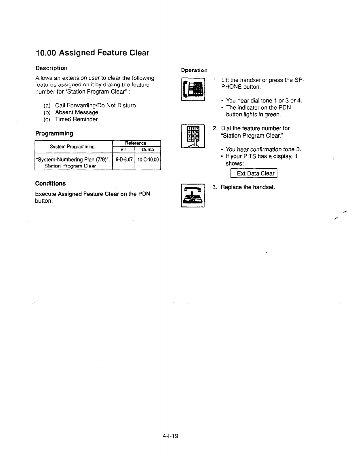
10.00 Assigned Feature Clear
Description
Allows an extension user to clear the following
features assigned on it by dialing the feature
number for “Station Program Clear” :
(a) Call Forwarding/Do Not Disturb
(b) Absent Message
(c) Timed Reminder
Programming
System Programming Reference
VT 1 Dumb
I
Operation
- Lift the handset or press the SP-
PHONE button.
l
You hear dial tone 1 or 3 or 4.
l
The indicator on the PDN
button lights in green.
2. Dial the feature number for
“Station Program Clear.”
l
You hear confirmation tone 3.
l
If your PITS has a display, it
shows:
1 Ext Data Clear 1
I I
-
3. Replace the handset.
I
“System-Numbering Plan (7/g)“,
Station Program Clear
1 9-D-6.071 lOC10.00 1
Conditions
Execute Assigned Feature Clear on the PDN
button.
4-l-l 9

11 .OO Remote Station Feature
Control
Description
Allows
the
Operator
1
and 2 (extension user or
Attendant Console) to cancel or set the following
features assigned to each extension:
Features to be canceled:
l
DND (Do Not Disturb)
l
Electronic Station Lock Out
l
FWD (Call Forwarding)
(It is also possible to cancel FWD temporarily.)
Features to be set:
l
DND (Do Not Disturb)
l
Electronic Station Lock Out
Programming
I
I
System Programming Reference
VT
I
Dumb
I
“System-Numbering Plan (8/g)“, 9-D-6,
Remote Station Lock Set
Remote Station Lock Card
Remote DND Set
Remote DND Cancel
Remote FWD Cancel
Remote FWD Cancel-OneTime
1 O-c-l 0.00
Conditions
When an extension is locked by the operator,
unlocking by the locked extension itself is
$ impossible.
_.
. 1 I- i.
Operation
Setting/canceling Do
Not Disturb to/from an
extension
1. Lift the handset or press the SP-
PHONE button.
2. Setting : Dial the feature number
for ‘Remote DND Set.”
Canceling : Dial the feature
number for “Remote
DND Cancel.”
3. Dial the directory number of the
extension.
l
Confirmation tone
1
or 2 sounds.
l
If your PITS has a display, it
shows:
When setting:
DND Set: E xxxx
.I 3-
Extension Number
When canceling:
DND Cancel: E xxxx
T-
Extension Number
/
x-u+:-
.-
4. Replace the handset or press the
SP-PHONE button.
4-I-20

Setting/canceling Electronic Station Lock Out
to/from an extension
1. Lift the handset or press the SP-
PHONE button.
I I
2.
2. Setting : Dial the feature number
for “Remote Station Lock
Set.”
Canceling : Dial the feature
number for “Remote
Station Lock Cancel.”
3. Dial the directory number of the
extension.
.
You hear confirmation tone 1 or
2.
If your PITS has a display, it
shows:
When setting:
/-Tzzzq
T
Extension number
When canceling:
Unlocked: E xxxx
-T
Extension number
4. Replace the handset or press the
SP-PHONE button.
‘+. c-
123
EFI
3.
456
709
*
rl
S\
4.
Canceling Call
temporarily
1.
(23
Etl
2.
4se
700
*
Dial the teaWe w=%’ ‘or
“Remote FWC “,ar.c;.
Dial the directory number of the
extension.
. You hear confirmation
tone 1 Or
2.
. If your PITS has a display, it
shows:
FWD cancel: E xxxx
3-
Extension number
Replace the handset or press the
SP-PHONE button.
Forwarding from an extension
Lift the handset or press the SP-
PHONE button.
.:;.,.
-a.-
Dial the feature number for
“Remote FWD Canc&-Qne Time.”
Dial the directory number of the
extension.
l
Call
Forwarding is canceled
temporarily.
. Calling the extension starts.
4-l-21

12.00 DSS Console
Description
The DSS Console is used to monitor the
busy/idle status of the extension users in the
system, and make a call to an extension user by
simply pressing the associated DSS (Direct
Station Selection) button.
The DSS Console provides a convenient way to
transfer an incoming CO call to an extension user
by simply pressing the associated DN*DSS
button instead of pressing the TRANSFER button
and dialing the extension number.
(See 4-l-l 2.01 “Automatic Transfer.” )
The DSS Console can also be used to make an
outgoing CO call and to access certain
programmable feature (e.g. Call Park-System).
Up to 16 DSS Consoles (one per extension port)
can be connected to the system in conjunction
with a PITS telephone.
Place the DSS Console.and the paired PITS
telephone side by side on your desk.
We provide three types of DSS Console as
illustrated below:
DSS buttons (16) PF buttons (16)
KX-I61640
DSS buttons (32) PF buttons (16)
I I I 1
KX-T123240
DSS buttons (32) PF buttons (16)
KX-T7040
The DSS Console has an array of 32 DSS
buttons” plus 16 PF (Programmable Feature)
buttons.
‘* The KX-T61640 has only 16 DSS buttons.
4-l-22

Any extension directory number can be
programmed to each DSS button, and the
associated LED indicator for each button
provides a busy,‘idle indication of the
programmed extension. Various features can be
programmed to the DSS and PF buttons.
The assignment for the DSS buttons and PF
buttons are programmed and changed either by
the system programming or PITS station
programming.
Programming
ti
PITS Station Programming
PF (Programmable Feature) Button
Assignment
DSS (Direct Station Selection) Button
Assignment
Reference
12-c-2.00
12-C-3.00
Conditions
None . .
i ,L
-
4-l-23
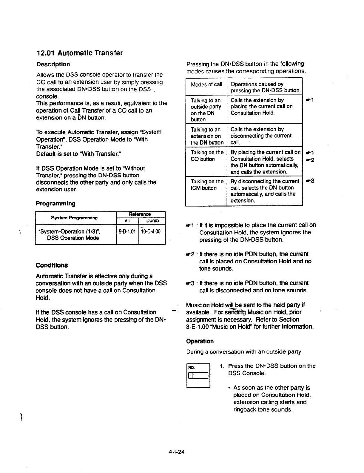
12.01 Automatic Transfer
Description
Allows
the
DSS console
operator to
transfer the
CO call to an extension
user by simply pressing
the associated DN*DSS button on the DSS
console.
This performance is, as a result, equivalent to the
operation of Call Transfer of a CO call to an
extension on a DN button.
To execute Automatic Transfer, assign ‘System-
Operation”, DSS Operation Mode to ‘With
Transfer.”
Defauft is set to With Transfer.”
If DSS Operation Mode is set to “Without
Transfer,” pressing the DN-DSS button
disconnects the other party and only calls the
extension user.
Programming
I
System Programming Reference
VT I
Dumb
“System-Operation (l/3)“,
DSS Operation Mode / 40-1.01 j
i(FG& /
Conditions
Automatic Transfer is effective only durfng a
conversation with an outside party when the
DSS
console does not have
a call on Consultation
Hold.
If the
DSS
console has a call on Consultation -
Hold, the system ignores the pressing of the DN*
DSS button.
Pressing the DN*DSS button in the following
modes causes the corresponding operations.
Modes
of call Operations caused by
pressing the DN*DSS button.
Talking to an Calls the extension by
outside party placing the current call on
on the DN Consultation Hold.
button
Talking to an Calls the extension by
extension on disconnecting the current
the DN button call.
Talking on the By placing the current call on
CO button Consuftation Hold, selects
the DN button automatically,
and calls the extension.
Talking on the By disconnecting the current
ICM button call. selects the
DN
button
automatically, and calls the
extension.
*l
-1
*2
*3
rl
: If it is impossible to place the arrrent call on
Consultation Hold, the system ignores the
pressing of the DN=DSS button.
r2
: If there is no idle PDN button, the current
call is placed on Consultation Hold
and no
tone sounds.
-3 : lf there is no idle PDN button, the current
call is disconnected and no tone sounds.
Music on Hold will be sent to the held party if
available. For s.e%ffhg Music on Hold, prior a
assignment is necessary. Refer to Section
3-E-l .OO “Music on Hold” for further information.
Operation
During a conversation with an outside party
1. Press the DN=DSS button on the
DSS Console.
l
As soon as
the
other party is
placed on Consultation Hold,
extension calling starts and
ringback tone sounds.
4-l-24
13.00 Outgoing Message (OGM)
Recording and Playing Back
Deacrfptlon
Up to four OGM’s can be recorded by the Operator
1 (Attendant Console or PlTS user) so that
different messages can be used for different
situations. _
The following four types of OGM can be recorded
respedively:
DISA, UCDl , UCD2 and W-UP (Wake-up)
OGM for outside parties
OGM for DISA is played to the outside party who
called the system via DISA feature.
(See Section 3-D-2.02 ‘Direct Inward System
Access (DISA) .3
OGM for UCD 1 and UCD 2 are played to the
outside party in conjunction with UCD feature.
(See Section 3-D-2.06 ‘Uniform Call Distribution
(UCD)-with CGM.“)
OGM for extension users
CGM for W-UP (Wake-up) can be used as a wake-
up message for the extension user.
(See Section 3-F-13.00 Timed Reminder
with
OGM (Wake-up Call).“)
Each OGM can be up to 30 seconds long.
A DISA card is required to record OGM and up to
four DISA cards can be- installed to the system. .;r
Usage of each DISA card is determined by the
system programming.
(See Section 9-K-l .OO “Special Attended-DISA.“)
Programming
I
System Programming Reference
VT Icvnb
Conditions
(1) Tenant Service
lf tenant service is employed, the affiliation of
each DISA card is determined by the system
programming “Special Attendant-DISA” tenant.
The Cperator 1 of each tenant can record and
play back the CGM within the same tenant.
(2) Recording of CGM
l
OGM recording is executed by selecting an
CXN type (usage of DISA card) from the
following four types:
1. ffiM1 for UCD with CGM
2. CGM2 for UCD with CGM
3. CGM for DISA
4. CGM for W-UP (Wake-up)
l
If the type of multiple DISA cards are the
same in a tenant, the same message is
recorded for them at a time.
(3) Playing back of CGM
l
The following two ways are available:
A. By selecting an OGM m
B. By designating the logical number of
each DISA card directly.
l
If there are multiple DISA cards of the same
type in the system or a tenant and the OGM
type is selected to play back, playback starts
from the lowest DISA card physical number,-
(4)
Others
Call Waiting tone and so on are prohibited
during OGM recording and playing.
‘System-Numbering Plan (g/9)‘. 9-D-6.09 lO&lO.OO
OGM Record
OGM Playback
“Special Attended-DISA”. For Use 9-K-1.00 lOGiO.00
4-l-25
(40993)
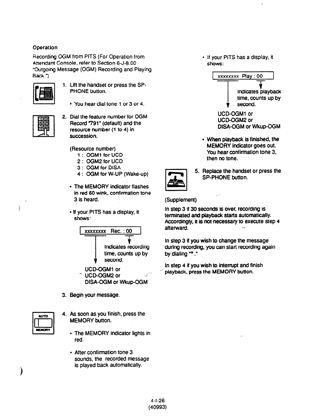
Operation
Recording OGM from PITS (For Operation from
Attendant Console. refer to Section 6-J-8.00
Wgoing Message (OGM) Recording and Playing
Back.-)
1.
3.
rl
4.
lrl
YYQII
Lff the handset or press the SP-
PHONE button.
5 You hear dial tone 1 or 3 or 4.
Dial the feature number for OGM
Record 791” (default) and the
resource number (1 to 4) in
succession.
(Resource number)
1 : OGMl for UCD
2 : OGM2 for UCD
3 : OGM for DISA
4 : OGM for W-UP (Wake-up)
l
The MEMORY indicator flashes
in red 60 wink, confirmation tone
3 is heard.
l
ff your PITS has a display, it
shows:
xxxxxxxx Rec. : 00
I 7
t
Indicates recording
time, counts up by
second.
UCD-OGMl or
^ UCD-OGM2 or .z’-
DISA-OGM or WkupOGM
Begin your message.
As soon as you finish, press the
MEMORY button.
l
The MEMORY indicator lights in
red.
l
After confirmation tone 3
sounds, the recorded message
is played back automatically.
r-l
+z,
If your PITS has a display, it
shows:
xxxxxxxx Play : 00 I
T +
Indicates playback
time, counts up by
second.
UCD-OGMl or
UCD-OGMP or
DISA-OGM or Wkup-OGM
When playback is finished, the
MEMORY indicator goes out.
You hear confirmation tone 3,
then no tone.
5. Replace the handset or press the
SP-PHONE button.
L I
(Supplement) -
In step 3 ff 30 seconds is over, recording is
terminated and piayback starts automatically.
Accordingly, it is not necessary to execute step 4
aftenrvard. . .
In step 3 if you wish to change the message
during recording, you can start recording again
by dialing * .”
In sfep 4 if you wish to interrupt and finish
playback, press the MEMORY button.
4-l-26
(40993)
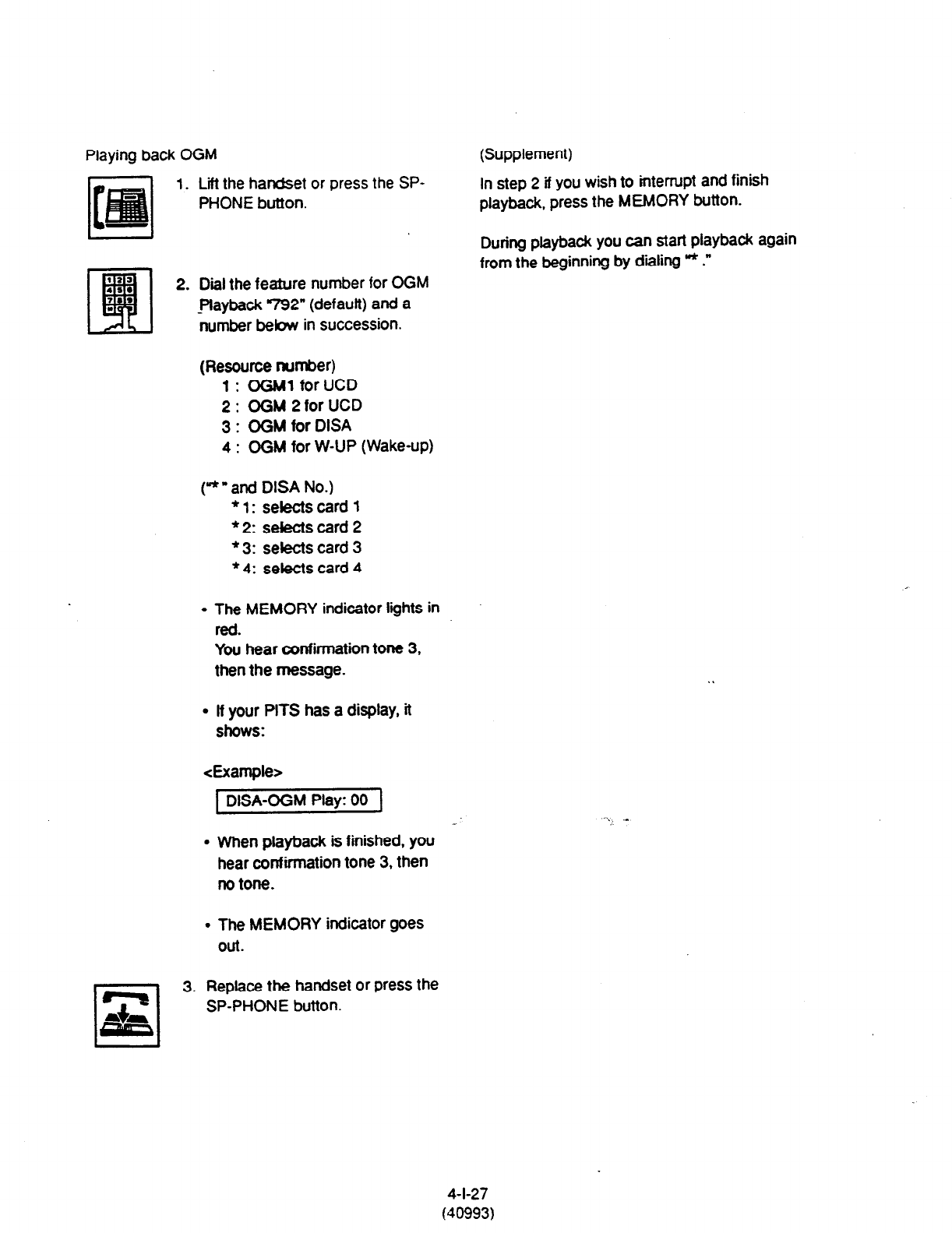
Playing back OGM
1. Lift the handset or press the SP-
PHONE button.
183
48.
EFI
2. Diil the feature number for OGM
?8*
I -playback 792” (default) and a
number below in succession.
(Supplement)
In
step 2
if you wish to interrupt and finish
playback, press the MEMORY button.
During playback you can start playback again
from the beginning by dialing v* .”
(Resource number)
1: OGMl for UCD
2: OGM2forUCD
3 : OGM for DISA
4 : OGM for W-UP (Wake-up)
(*” and DISA No.)
l
l: sebectscard 1
l
2: selects card 2
* 3: selects card 3
l
4: selects card 4
l
The MEMORY indicator lights in
red.
You hear confirmation tone 3,
then the message.
. If your PITS has a display, it
shows:
<Example>
1 DISA-OGM
Play:
00 i
. When playback is finished, you
hear confirmation tone 3, then
no tone.
l
The MEMORY indicator goes
Out.
3. Replace the handset or press the
SP-PHONE button.
4-l-27
(40993)

14.00 Remote Timed Reminder
-One Time
Description Operation
Allows the Operator 1 or 2 (Attendant Console or
PITS with display) to set “Timed Reminder’
feature to any extension.
(Refer to Section 4-1-3.00,5-G-3.00 “Ttmed
Reminder.“)
Setting Xmed Renrnder SC another extension
If Timed Reminder with OGM is programmed
beforehand, the extension user (on which
Remote Timed Reminder is set) hears a wake-up
message.
(Refer to Section 3-F-l 3.00 “Timed Reminder
with OGM (Wake-up Call).“)
Programming
System Programming
1
Reference
VT 1 Dumb
I
“System-Numbering Plan (9/9)^,
Remote limed Reminder
Confirm
Remote Timed Reminder
Set
Remote Timed Reminder
Cancel
9-D-6.09
104-10.00
Conditions
(1) The difference between “limed Reminder”
and “Remote Timed Reminder” is:
Remote by extenison
limed itself
Reminder
;Valiiity of the
setting -
Once or
everyday at the
programmed
time
Once
1. Lift the handset or press the SP-
PHONE button.
2. Dii the feature number for
Remote Tmed Reminder Set
7*1’ (default) and the extension
number to be set Timed Reminder
in succession.
3. Dial “hour with two digits: 01 to 12.
4. Dial ‘minute” with two digits: 00 to
59.
5. Dial “0” for a.m. or diil r” for p.m..
. You hear confirmation tone 1 or 2
and then diil tone l or 3 or 4.
l
If your PlTS has a display, it
shows:
1 El00 11:ll AM 1
-i
L
Extension number
1
6. Replace the handset or press the
SP-PHONE button.
(2) At a single extension, only the latest setting is
valid whether it was set by the extension itself
1
(Timed Reminder) or by the Operator 1 or 2
(Remote Timed Reminder).
4-l-28
(40993)
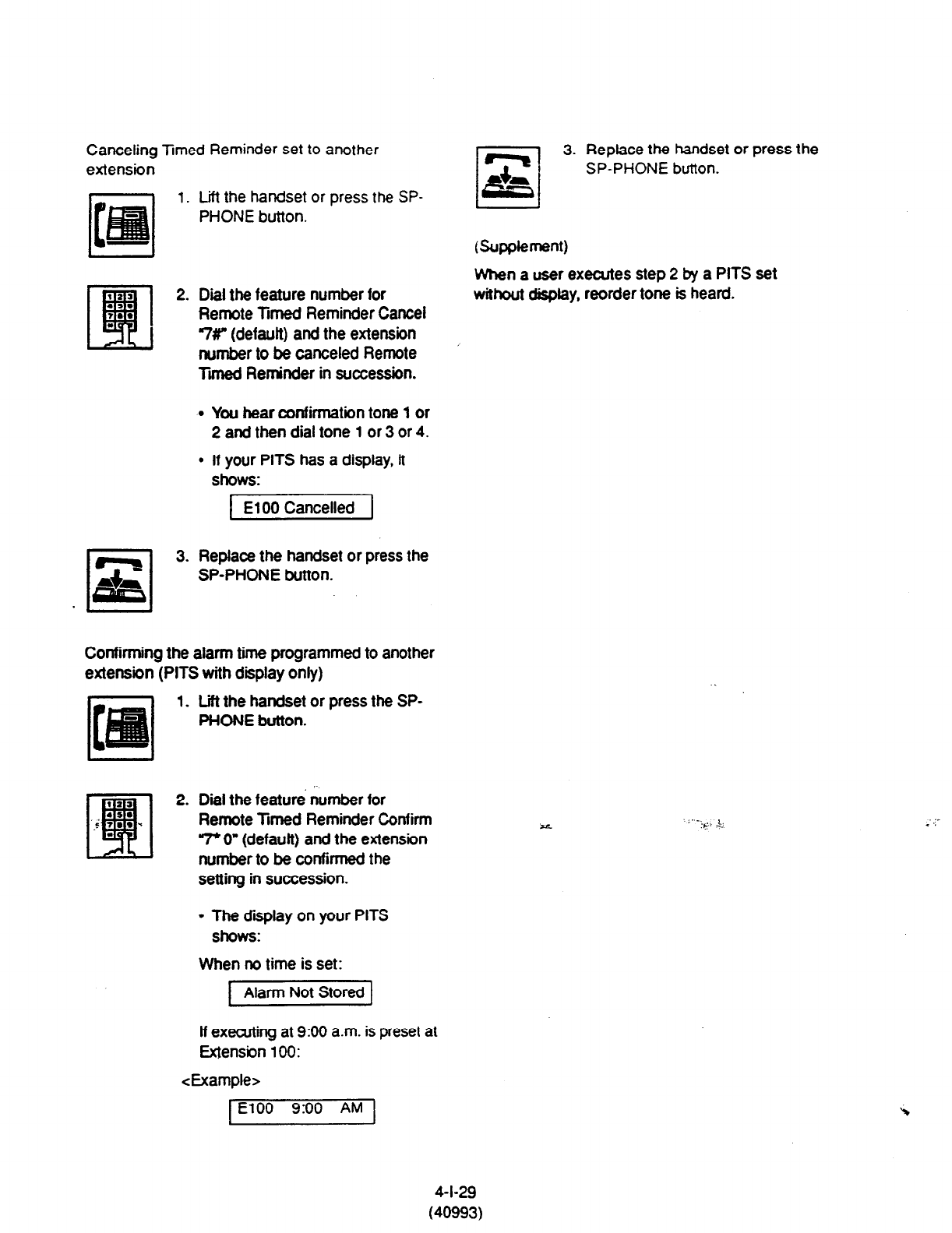
Canceling Xmed Reminder set to another
extension
1. Lift the handset or press the SP-
PHONE button.
3. Replace the handset or press the
SP-PHONE button.
(Supplement)
2. Diil the feature number for
Remote Timed Reminder Cancel
7r (default) and the extension
number to be canceled Remote
Tii Reminder in succession.
When a user executes step 2 by a PITS set
without display, reorder tone is heard.
l
You hear confirmation tone 1 or
2 and then dial tone 1 or 3 or 4.
l
If your PITS has a display, it
ShOWC
1 El00 Cancelled 1
3. Replace the handset or press the
SP-PHONE button.
Confirming the alarm time programmed to another
extension (PITS with display only)
1. Lift the handset or press the SP-
PHONE button.
2. Dial the feature number for
Remote Timed Reminder Confirm
“7+ 0” (default) and the extension
number to be confirmed the
setting in succession.
l
The display on your PITS
shows:
When no time is set:
Alarm Not Stored
If executing at 9:00 a.m. is preset at
Extension 100:
<Example>
1 El00 9:00 AM 1
4-l-29
(40993)

Section 5
Station Features and Operation
Single Line Telephone (SLT)

(Section 5)
Station Features and Operation
Single Line Telephone (SLT)
Contents
Page
A Outgoing Ca!l Features . . . . . . . . . .._......................
. . . . . . . . . . . . . . . . . . . . . . . . . . . . . . . . . . . . . . . . . . . . . . . . . . 5-A-1
1 .oo
2.00
3.00
4.00
5.00
6.00
7.00
8.00
Making Outside Calls.. ........................................................................... 5-A- 1
1 .Ol Local Trunk Dial Access .............................................................. 5-A-l
1 .02 Individual Trunk Group Dial Access ............................................ 5-A-2
1.03 Individual Virtual Trunk Group Dial Access ................................. 5-A-3
Automatic Dialing ................................................................................... 5-A-4
2.01 Speed Dialing-Station .................................................................. 5-A-4
2.02 Speed Dialing-System ................................................................. 5-A-6
2.03 Last Number Redial (LNR) .......................................................... 5-A-9
2.04 Pickup Dialing.. ............................................................................ 5-A-9
Making Internal Calls.. ........................................................................... 5-A-11
3.01 Inter Office Calling ....................................................................... 5-A- 11
Automatic Callback ................................................................................ 5-A-1 2
4.01 Automatic Callback-Trunk ........................................................... 5-A-l 2
4.02 Automatic Callback-Station ......................................................... 5-A-13
Executive Busy Override ....................................................................... 5-A- 14
Do Not Disturb (DtiD) Override ............................................................. 5-A-l 5
Walking COS (Class of Service) ............................................................ 5-A- 16
Operator Call ......................................................................................... 5,A-17
B Receiving Features . . . . . . . . . . . . . . . . . . . . . . . . . . . . . . . . . . . . . . . . . . . . . . . . . . . . . . . . . . . . . . . . . . . . . . . . . . . . . . . . . . . . . . . . . . 5-B-l
1 .OO Call Pickup.. ...........................................................................................
1 .Ol Dial Call Pickup ...........................................................................
1.02 Directed Call Pickup ....................................................................
1.03 Call Pickup Deny .........................................................................
2.00 Truiik Answer From Any %tion (TAFAS)-Day Service.. ......
“:.
.......
z..
....
3.00 Executive Busy Override Deny ..............................................................
4.00 Do Not Disturb (DND) ...........................................................................
5.00 Call Waiting ............................................................................................
6.00 Uniform Call Distribution (UCD)-Log Out.. .............................................
C Holding Features . . . . . . . . . . . . . . . . .
. . . . . . . . . . . . . . .._........._.................................................. 5-c-1
1 .OO Hold ...................................................................................................... 5-c-1
2.00 Consultation Hold ..................................................................................
5-c-2
3.00 Call Hold Retrieve-Station .....................................................................
5-c-3
4.00 Call Park ...............................................................................................
5-c-4
4.01 Call Park-System ......................................................................... 5-c-4
4.02 Call Park-Station ......................................................................... 5-c-5
5-B-l
5-B-l
5-B-2
5-B-3
5-B-4
5-B-5
5-B-6
5-B-8
5-B-l 0
5-l
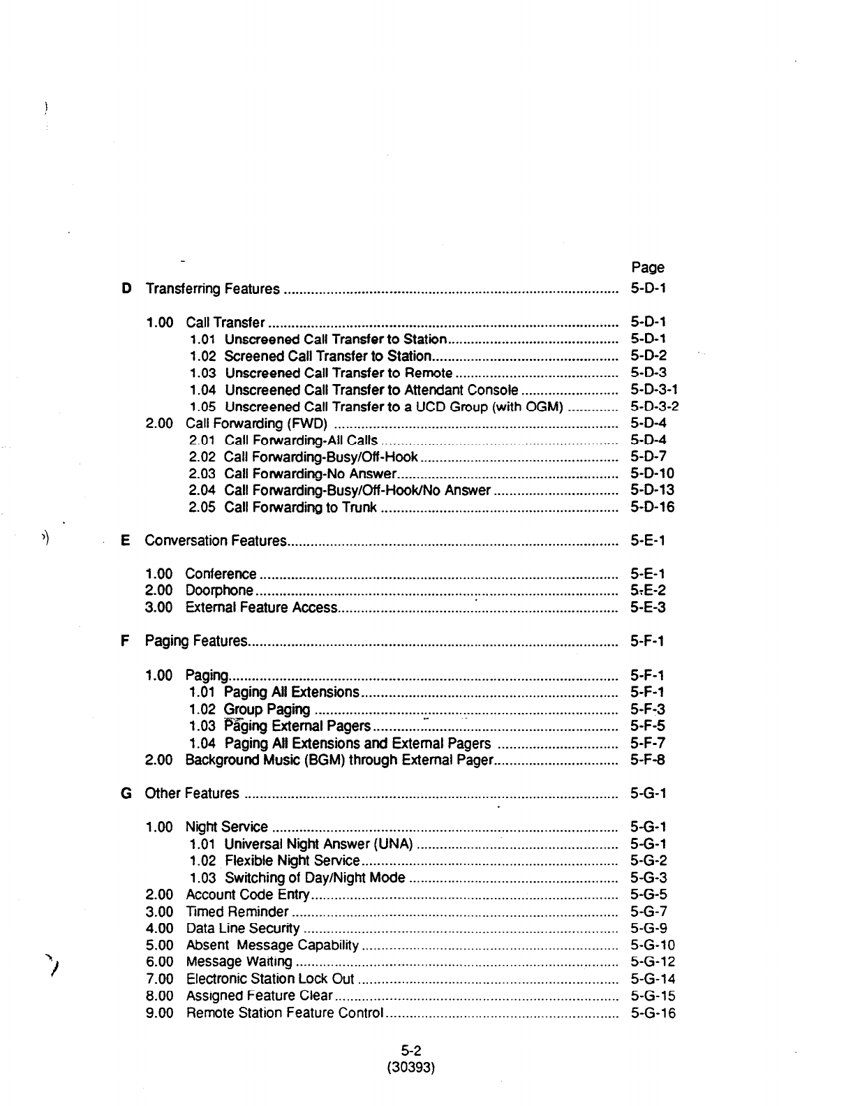
Page
D Transferring Features . . . . . . . . . . . . . . . . . . . . . . . . . ..-.........................................................- 5-D-l
1 .OO Call Transfer .......................................................................................... 5-D-l
1 .Ol Unscreened Call Transfer to Station.. .......................................... 5-D-l
1.02 Screened Call Transfer to Station.. .............................................. 5-D-2
1.03 Unscreened Call Transfer to Remote .......................................... 5-D-3
1.04 Unscreened Call Transfer to Attendant Console ......................... 5-D-3-l
1.05 Unscreened Call Transfer to a UCD Group (with OGM) ............. 5-D-3-2
2.00 Call Forwarding (FWD) ......................................................................... 5-D-4
2.01 Call Forwarding-All Calls ............................................................. 5-D-4
2.02 Call Forwarding-Busy/Off -Hook ................................................... 5-D-7
2.03 Call Forwarding-No Answer ......................................................... 5-D-l 0
2.04 Call Forwarding-Busy/Off-Hook/No Answer.. .............................. 5-D-l 3
2.05 Call Forwarding to Trunk ............................................................. 5-D-l 6
4
E Conversation Features . . . . . . .._......._._...._....._....._..........____.._....___.........................
5-E-l
1.00 Conference ............................................................................................ 5-E-l
2.00 Doorphone.. ........................................................................................... STE-2
3.00 External Feature Access.. ................................ .: .................................... 5-E-3
F Paging Features . . . . . . . . . . . . . . . . . . . . . . . . . . . . . . . . . . . . . . . . . . . . . . . . . . . . . . . . . . . . . . . . . . . . . .._....................... 5-F-l
1.00 Paging.. .................................................................................................. 5-F-l
1.01 Paging All Extensions.. ................................................................ 5-F-l
1.02 Group Paging .............................................................................. 5-F-3
1.03 i%ging External Pagers.. ........... y.. ....... [. ...................................... 5-F-5
1.04 Paging All Extensions and External Pagers ............................... 5-F-7
2.00 Background Music (BGM) through External Pager.. .............................. 5-F-8
G Other Features . . . . . . . . ..__...._ _ ______....._........._ _ ._.._._..__.____.._..._..._........_..__....._.._.__.._
5-G-l
1.00
2.00
3.00
4.00
5.00
6.00
7.00
8.00
9.00
Night Service .........................................................................................
1 .Ol Universal Night Answer (UNA) ....................................................
1.02 Flexible Night Service.. ................................................................
1.03 Switching of Day/Night Mode ......................................................
Account Code Entry. ..............................................................................
Timed Reminder ....................................................................................
Data Line Security .................................................................................
Absent Message Capability ..................................................................
Message Waiting ...................................................................................
Electronic Station Lock Out ...................................................................
Assigned Feature Clear .........................................................................
Remote Station Feature Control.. ..........................................................
5-G-l
5-G-l
5-G-2
5-G-3
5-G-5
5-G-7
5-G-9
5-G-l 0
5-G-l 2
5-G-14
5-G-15
5-G-l 6
5-2
(30393)
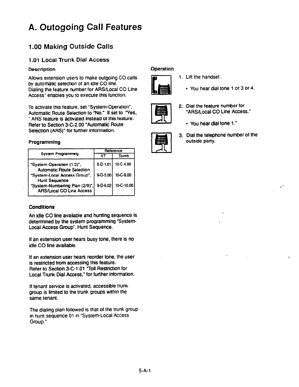
A. Outogoing Call Features
1.00 Making Outside Calls
1 .Ol Local Trunk Dial Access
Description
Allows extension users to make outgoing CO calls
by automatic selection of an idle CO line.
Dialing the feature number for ARS/Local CO Line
Access” enables you to execute this function.
Operation
1. Lift the handset .
l
You hear dial tone 1 or 3 or 4.
To activate this feature, set “System-Operation”,
Automatic Route Selection to “No.” If set to “Yes,
” ARS feature is activated instead of this feature.
Refer to Section 3-C-2.00 “Automatic Route
Selection (ARS)” for further information.
Programmfng
Reference
System Pfogrammng VT Dumb
“System-Operation (1 n)“.
9-D-l .Ol 10-c-4.00
Automatic Route Selection
2. Dial the feature number for
“ARSRocal CO Line Access.”
l
You hear dial tone 1.”
3. Dial the telephone number of the
outside party.
“System-Local Access Group”. SD5.00
10-C-9.00
Hunt Sequence
“System-Numbering
Pfan (2/g)“, SD6.02 lCG10.00
ARSlLocal CO Line Access
Conditions
An idle CO line available and hunting sequence is
determined by the system programming “System-
Local Access Group’, Hunt Sequence.
If an extension user hears busy tone, there is no
idle CO line available.
If an extension user hears reorder tone, the user
is restricted from accessing this feature.
Refer to Section 3-C-l .Ol “Toll Restriction for
Local Trunk Dial Access,” for further infomration.
If tenant service is activated, accessible trunk
group is limited to the trunk groups within the
same tenant.
,’
The dialing plan followed is that of the trunk group
in hunt sequence 01 in “System-Local Access
Group.”
5-A-l
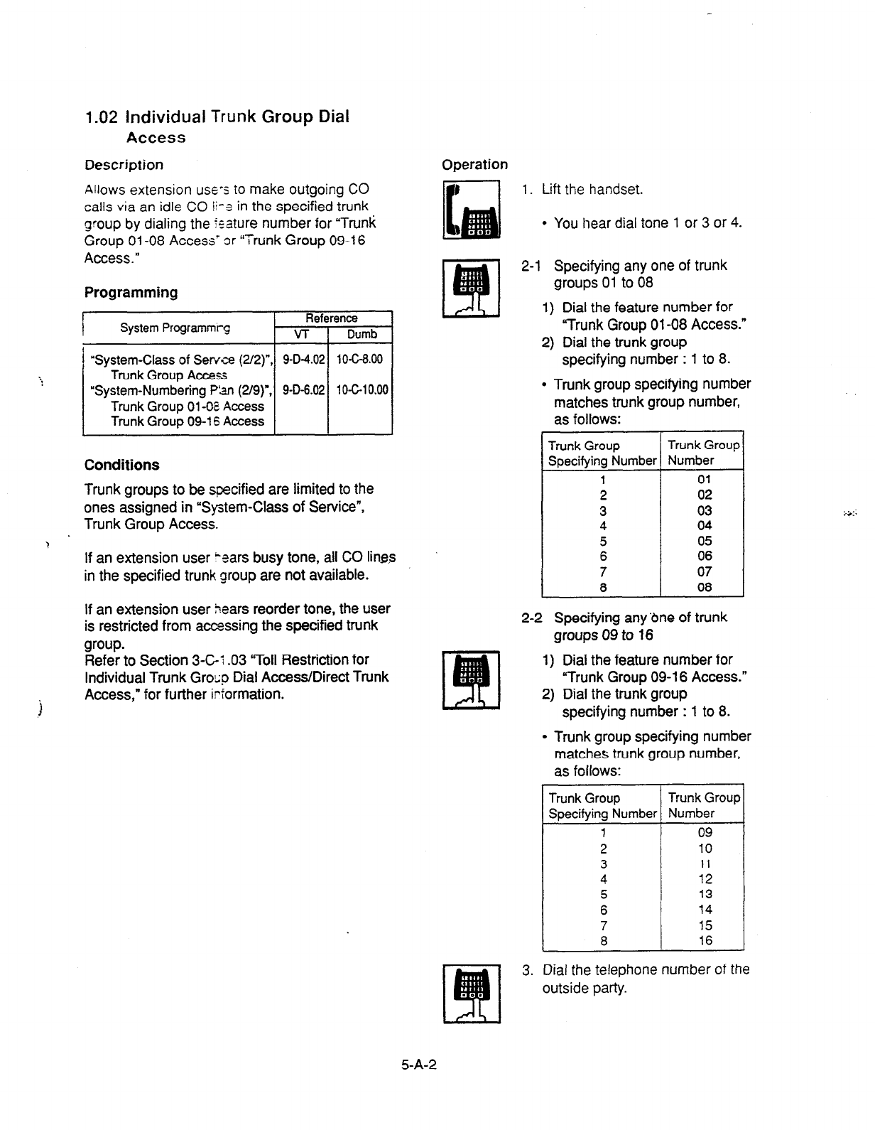
1.02 Individual Trunk Group Dial
Access
Description Operation
Allows extension use-s to make outgoing CO
calls via an idle CO ii-? in the specified trunk
group by dialing the %ature number for “Trunk
Group 01-08 Access’ 3r “Trunk Group 09-l 6
Access.”
Programming
System Programmrg Reference
VT I Dumb
“System-Class of Serve (2/2)“,
Trunk Group Access
“System-Numbering F%n (2/g)‘,
Trunk Group Ol-OE Access
Trunk Group 09-l 6 Access
Conditions
Trunk groups to be specified are limited to the
ones assigned in “System-Class of Service”,
Trunk Group Access.
If an extension user ‘ears busy tone, all CO lines
in the specified trunk group are not available.
If an extension user bears reorder tone, the user
is restricted from accessing the specified trunk
group.
Refer to Section 3-C-t .03 ‘7011 Restriction for
Individual Trunk Grocp Dial Access/Direct Trunk
j Access,” for further irformation.
1. Lift the handset.
l
You hear dial tone 1 or 3 or 4.
2-l Specifying any one of trunk
groups 01 to 08
1) Dial the feature number for
“Trunk Group 01-08 Access.”
2) Dial the trunk group
specifying number : 1 to 8.
l
Trunk group specifying number
matches trunk group number,
as follows:
Trunk Group Trunk Group
Specifying Number Number
1 01
2 02
3 03
4 04
5 05
6 06
7 07
a 08
2-2 Specifying any’dne of trunk
groups 09 to 16
1) Dial the feature number for
“Trunk Group 09-l 6 Access.”
2) Dial the trunk group
specifying number : 1 to 8.
l
Trunk group specifying number
matches trunk group number,
as follows:
Specifying Number
i
Trunk Group
Number
09
10
11
12
13
14
15
16
3. Dial the telephone number of the
outside party.
5-A-2
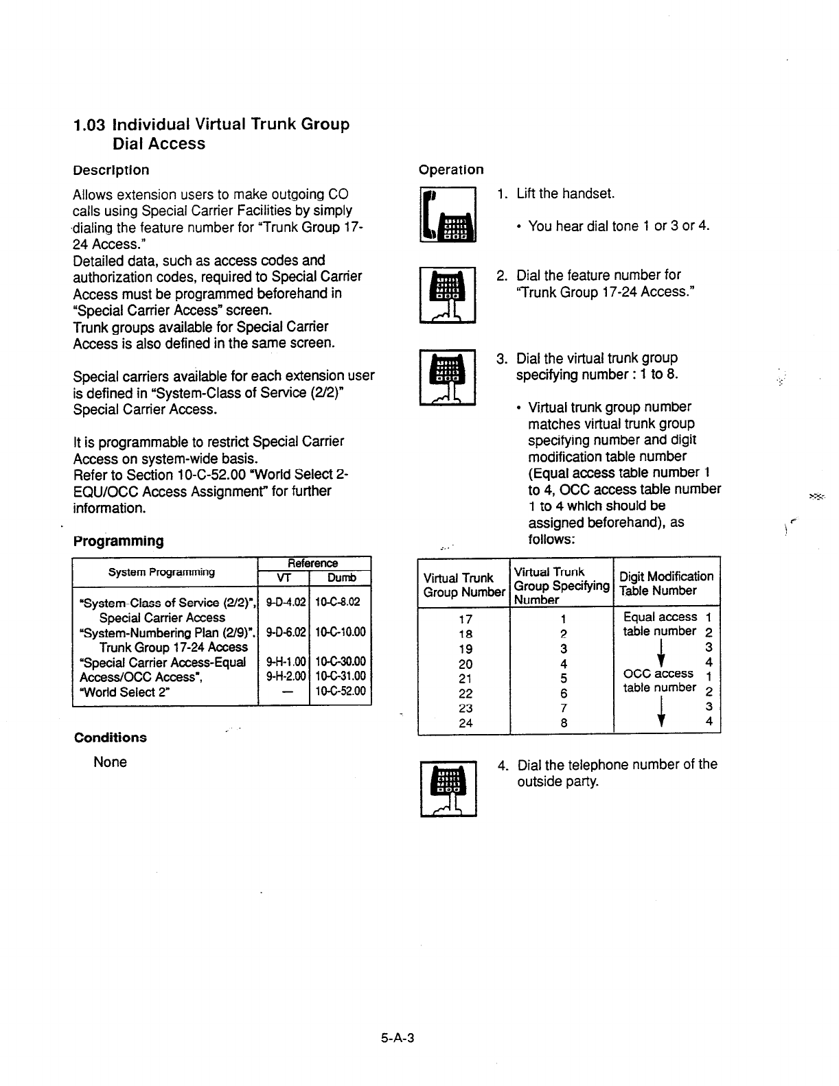
1.03 individual Virtual Trunk
Group
Dial Access
Description Operation
Allows extension users to make outgoing CO
calls using Special Carrier Facilities by
simply
.dialing the feature number for “Trunk
Group 17-
24 Access.”
Detailed data, such as access codes and
authorization codes, required to Special Carrier
Access must be programmed beforehand in
“Special Carrier Access” screen.
Trunk groups available for Special Carrier
Access is also defined in the same screen.
Special carriers available for each extension user
is defined in “System-Class of Service (2/2)”
Special Carrier Access.
It is programmable to restrict Special Carrier
Access on system-wide basis.
Refer to Section 1 O-C-52.00 “World Select 2-
EQU/OCC Access Assignmenr for further
information.
Programming
Reference
System Programming VT DlJmb
“System-Class of Service (2/2)“, 9-O-4.02 10-C-8.02
Special
Carrier Access
“System-Numbering Plan (2/g)“, 9-O-6.02 10-6-10.00
Trunk Group 17-24 Access
‘Special Carrier Access-Equal 9-H-l .oO 1 O-C-30.00
AccessIOCC Access’, 9-H-2.00 1 O-C-31 .OO
“World Select 2” - 1 O-c-52.00
Conditions
None
1. Lift the handset.
l
You hear dial tone 1 or 3 or 4.
2. Dial the feature number for
‘Trunk Group 17-24 Access.”
3. Dial the virtual trunk group
specifying number : 1 to 8.
l
Virtual trunk group number
matches virtual trunk group
specifying number and digit
modification table number
(Equal access table number 1
to 4, OCC access table number
1 to 4 which should be
assigned beforehand), as
follows:
Virtual Trunk Virtual Trunk Digit Modification
Group Number iruouEeTpecifyin9 Table Number
17 1 Equal access I
18 2 table number 2
19 3 3
20 4 1 21 5 OCCaccess y
22 6 table number
+
2
23 7 3
24 8 4
4. Dial the telephone number of the
outside party.
5-A-3
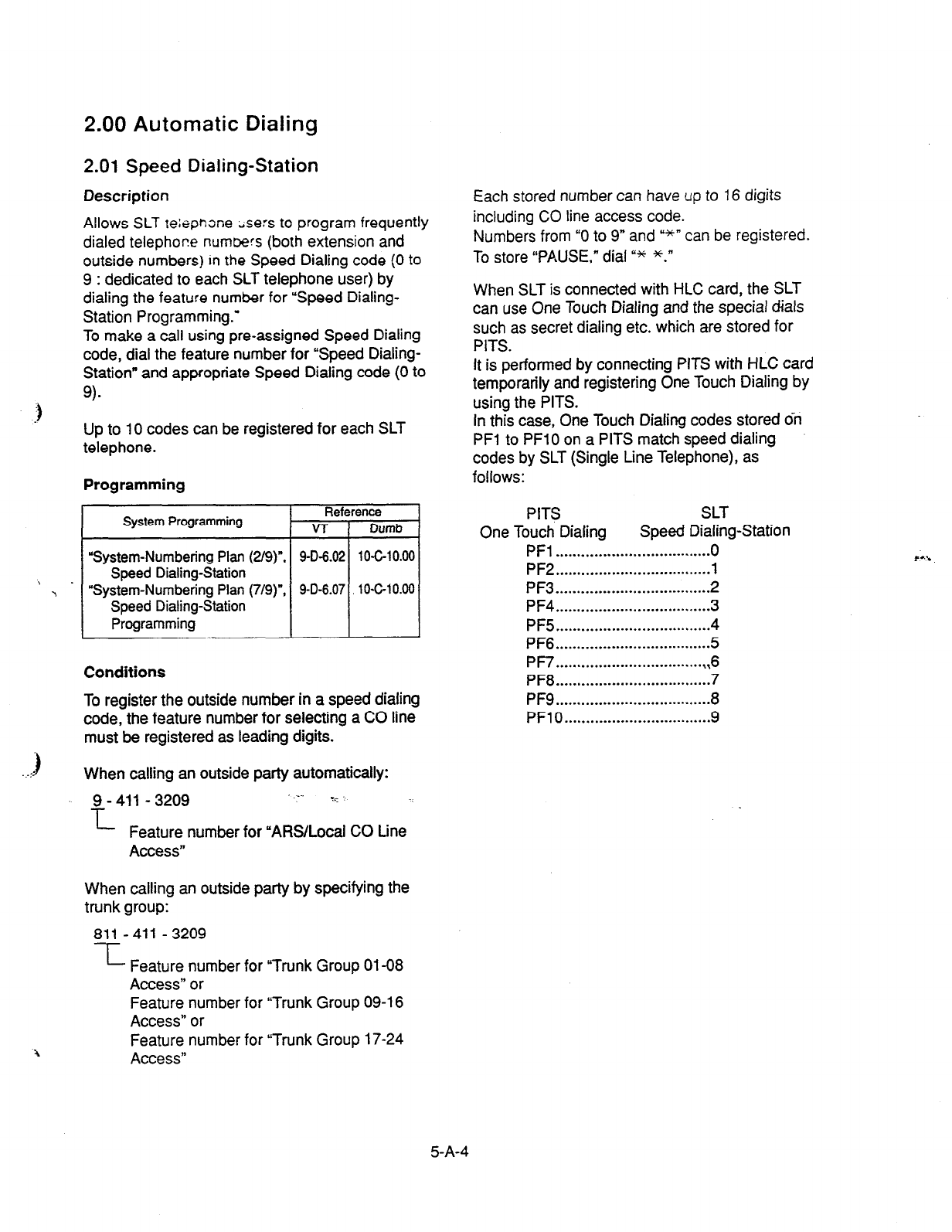
2.00 Automatic Dialing
2.01 Speed Dialing-Station
Description
Allows SLT teiepnone ;se:s to program frequently
dialed telephor?e numbers (both extension and
outside numbers) In the Speed Dialing code (0 to
9 : dedicated to each SLT telephone user) by
dialing the feature number for “Speed Dialing-
Station Programming.’
To make a call using pre-assigned Speed Dialing
code, dial the feature number for “Speed Dialing-
Station” and appropriate Speed Dialing code (0 to
9).
\ .
\
a
Up to 10 codes can be registered for each SLT
telephone.
Programming
System Programming Reference
VT
Dumb
“System-Numbering Plan (2/9)n, 9-D-6.02 10-C-10.00
Speed Dialing-Station
“System-Numbering Plan (7/g)“, 9-O-6.07 10-C-10.00
Speed Dialing-Station
Programming
Conditions
To register the outside number in a speed dialing
code, the feature number for selecting a CO line
must be registered as leading digits.
When calling an outside party automatically:
9 - 411 - 3209 .-- T.-
L
Feature number for “ARS/Locai CO Line
Access”
When calling an outside party by specifying the
trunk group:
811 -411 - 3209
--L Feature number for “Trunk Group 01-08
Access” or
Feature number for “Trunk Group 09-l 6
Access” or
Feature number for “Trunk Group 17-24
Access”
Each stored number can have up to 16 digits
including
CO
line access code.
Numbers from “0 to 9” and &*” can be registered.
To store “PAUSE,” dial y* *.”
When SLT is connected with HLC card, the SLT
can use One Touch Dialing and the special dials
such as secret dialing etc. which are stored for
PITS.
It is performed by connecting PITS with HLC card
temporarily and registering One Touch Dialing by
using the PITS.
In this case, One Touch Dialing codes stored o?i
PFl to PFlO on a PITS match speed dialing
codes by SLT (Single Line Telephone), as
follows:
PITS SLT
One Touch Dialing Speed Dialing-Station
PFl . . . . . . . . . . . . . . . . . . . . . . . . . . . . . . . . . . . . 0
PF2
. . . . . . . . . . . . . . . . . . . . . . . . . . . . . . . . . . . .
1
PF3
. . . . . . . . . . . . . . . . . . . . . . . . . . . . . . . . . . . .
2
PF4
. . . . . . . . . . . . . . . . . . . . . . . . . . . . . . . . . . . .
3
PF5
. . . . . . . . . . . . . . . . . . . . . . . . . . . . . . . . . . . .
4
PF6 . . . . . . . . . . . . . . . . . . . . . . . . . . . . . . . . . . . . 5
PF7 . . . . . . . . . . . . . . . . . . . . . . . . . . . . . . . . . . . ,6
PF8 . . . . . . . . . . . . . . . . . . . . . . . . . . . . . . . . . . . . 7
PF9
. . . . . . . . . . . . . . . . . . ..-...............
8
PFlO . . . . . . . . . . . . . . . . . . . . . . . . . . . . . . . . . . 9
5-A-4
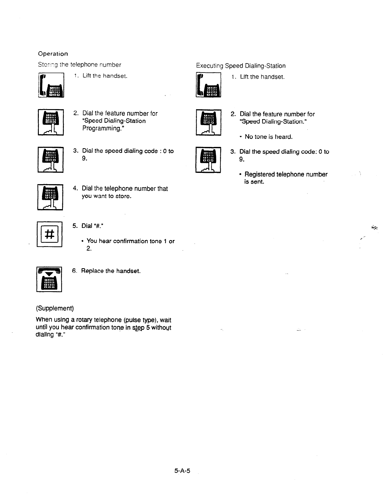
Operation
Stcri:g the telephone number
Executing Speed Dialing-Station
1. Lift the handset.
2. Dial the feature number for
“Speed Dialing-Station
Programming.”
1.
Lift the handset.
2.
3. Dial the speed dialing code : 0 to
9.
4. Dial the telephone number that
you want to store.
5. Dial “#.”
l
You hear confirmation tone 1 or
6. Replace the handset.
(Supplement)
When using a rotary telephone (pulse type), wait
until you hear confirmation tone in s&p 5 withoyt
dialing “#.”
Dial the feature number for
“Speed Dialing-Station.”
l
No tone is heard.
Dial the speed dialing code: 0 to
9.
l
Registered telephone number
is sent.
S-A-S
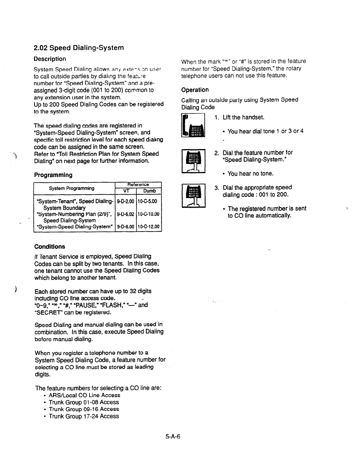
2.02 Speed Dialing-System
Description
System Speed Dialing allows
any e&-s x user
to call outside parties by dialing me
fe&re
number for “Speed Dialing-System”
and a pre-
assigned 3-digit code (001 to 200) common to
any extension user in the system.
Up to 200 Speed Dialing Codes can be registered
to the system.
The speed dialing codes are registered in
“System-Speed Dialing-System” screen, and
specific toll restriction level for each speed diahng
code can be assigned in the same screen.
Refer to “Toll Restriction Plan for System Speed
Dialing” on next page for further information.
Programming
System Programming Reference
VT 1 Dumb
“System-Tenant”, Speed Dialing-
9-D-2.00 1 O-C-5.00
System Boundary
“System-Numbering Plan (2/g)“,
9-D-6.02
10-6-10.00
II Speed Dialing-System
“System-Speed Dialing-System” 9-D-8.00
10-C-12.00
Conditions
If Tenant Service is employed, Speed Dialing
Codes can be split by two tenants. In this case,
one tenant cannot use the Speed Dialing Codes
which belong to another tenant.
Each stored number can have up to 32 digits
including CO line access code.
“O-9 ” YJC,” “#,” “PAUSE,” “FLASH,” “-” &d
“SECRET” can be registered.
Speed Dialing and manual dialing can be used in
combination. In this case, execute Speed Dialing
before manual dialing.
When you register a telephone number to a
System Speed Dialing Code, a feature number for
selecting a CO line must be stored as leading
digits.
The feature numbers for selecting a CO line are:
l
ARS/Local CO Line Access
l
Trunk Group 01-08 Access
l
Trunk Group 09-l 6 Access
l
Trunk Group 17-24 Access
When the mark “*” or “#” is stored in the feature
number for “Speed Dialing-System,” the rotary
telephone users
can
not use this feature.
Operation
Calling an outside party using System Speed
Dialing Code
1. Lift the handset.
2.
3.
l
You hear dial tone 1 or 3 or 4
Dial the feature number for
“Speed Dialing-System.”
l
You hear no tone.
Dial the appropriate speed
dialing code : 001 to 200.
l
The registered number is sent
to CO line automatically.
5-A-6

<Toll Restrictton Plan for System Speed Dialing>
‘be ;‘,s:?r” a.:- y.s+Lrz:“’ car; assign Toll
Ees:-: -f:-” i-e. 2
-..- of S:isrem S.oeed Dialing
t,re!e--26
tc 25 -'=iiSf-
:n the tollowing) to each
code as :olio*s
System - Speed Dlalrng - System
_--_-----------------------------------
System Speed Dial No. =OOl
f.-------------------------‘---‘-”’--”
Toll Restriction Level of System
Speed Dialing (TRLSD)
TRLSD consists of 17 levels (YOO” and “01 to 16”)
TRLSD “00” receives a treatment different from
TRLSDs “01 to 16.”
. In TRLSD “01 to 16,” “01” is the highest level and
“16” is the lowest.
1. Toll Restriction Plan for System Speed Dialing
Code (TRLSD=OO)
When an outgoing CO call is made by dialing
a System Speed Dialing Code (TRLSD=OO),
extension users receive standard toll
restriction treatment.
If selected speed dialing code includes Local
Trunk Dial Access code as leading digits, a
call is checked against “Toll Restriction for
Local Trunk Dial Access.”
If selected speed dialing code includes
Individual Trunk Group Dial Access Code as
leading digits, a call is checked against “Toll
Restriction for Individual Trunk Group Dial
Access.”
For further information about System Toll
Restriction feature, refer to Section 3-C-l .OO
“Toll Restriction.”
2. Toll Restriction Plan for System Speed Dialing
Code (TRLSD=Ol to 16)
Code (TRLSD=Ol to 16j. the system
compares Toll Restriction Level of Extension
(TRLE) with TRLSD.
If TRLE is equal to or higher than TRLSD
(TRLEzTRLSD) a call is made, and if TRLE is
lower than TRLSD (TRLEcTRLSD), a call is
checked against System Toll Restriction
feature.
For further information about TRLE, refer to
Section 3-C-l .OO “Toll Restriction.”
<Example>
If an extension user (TRLE=6) makes an
outgoing CO call by selecting a System Speed
Dialing Code (TRLSD=7), in this case, TRLE of 6
is higher than TRLSD of 7 (TRLEsTRLSD), so a
call is made.
If an extension user (TRLE=6) makes an
outgoing CO call by selecting a System Speed
Dialing Code (TRLSD=4), in this case, TRLE of 6
is lower than TRLSD of 4 (TRLEcTRLSD), so a
call is checked against the System Toll ’
Restriction feature.
When an extension user makes an outgoing
CO call by dialing a System Speed Dialing
5-A-7
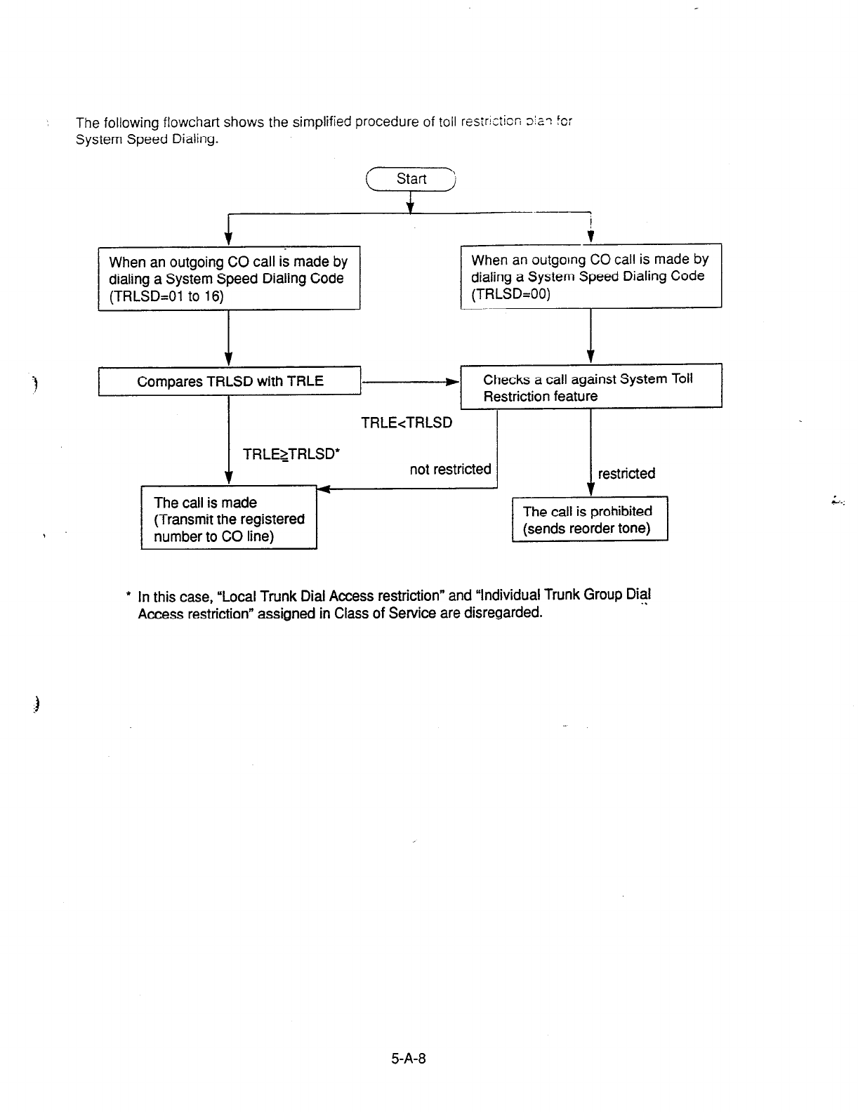
The following flowchart shows the simplified procedure of toll resIr!cticr, 5z-1 for
System Speed Dialing.
When an outgoing CO call is made by When an outgoing CO call is made by
dialing a System Speed Dialing Code dialing a System Speed Dialing Code
(TRLSD=Ol
to 16)
(TRLSD=OO)
1 1
c Compares TRLSD with TRLE e Checks a call against System Toll
Restriction feature
TRLE<TRLSD
TRLEZTRLSD’
1
The call is made
(Transmit the registered
number to CO line)
not restricted restricted
l
In this case, “Local Trunk Dial Access restriction” and “Individual Trunk Group Dial
Access restriction” assigned in Class of Service are disregarded.
5-A-8
2.03 Last Number Redial (LNR) 2.04 Pickup Dialing
Description
Automatically saves the last number
d,ar& ‘rc-
an
extension and allows the user to
make FE
outgoing CO call again by simply dialing rhe
feature number for “Redial.”
Programming
Conditions
Up to 32 digits except the feature number for
selecting a CO line can be memorized as the last
dialed number.
u*,n “#,” “PAUSE.” or “SECRET” are counted as
one digit respectively.
The memorized telephone number is replaced
automatically by a new one every time you make
a new outgoing CO call and even one digit is
sent to a CO line. That is, dialing a feature
number for selecting a CO line only does not
renew the memorized number.
Operation
Executing LNR
1. Lift the handset.
l
You hear dial tone 1 or 3 or 4. -- - .-
2. Dial the feature number for
“Redial.”
Description
Pickuc Dialing
allows SLT telephone users to
Take calls automatically by simply lifting
the
‘iandset.
To program the desired number for this feature,
dial the feature number for “Pickup Dialing
Programming.”
To activate this feature, dial the feature number
for “Pickup Dialing Set.”
To cancel this feature, dial the feature number for
“Pickup Dialing Cancel.”
This feature works only when an extension user
goes off-hook from on-hook status. Petiod from
off-hook to Pickup Dialing is assigned in
‘System-System Timer”, Pickup Dial Waiting.
Programming
Reference
System
Programming VT
Dumb
“System-System Timer”, 9-D-3.00 t O-C-6.00
Pickup Dial Waiting _
‘Syste-m:Numbering Plan (6/g)“, 9-D-6.06 1 O-C-10.00
Pickup Dialing Programming
Pickup Dialing Set
Pickup Dialing Cancel . .
Conditions
It is available to override this feature temporarily
by dialing another telephone number before
“System-System Timer”, Pickup Dial Waiting
timer expires.
This feature does not function when a call is
arriving or the user has a call on Consultation
Hold.
UP to 32 digits can be stored as a telephone
number including “0 through 9,” and “*.-
To
store
“PAUSE,” use “* *.”
5-A-9
Operation
Storing the telephone number for Pickup Dialing
1.
2.
3.
i
4.
Lift the handset.
Dial the feature number for “Pickup
Dialing Programming.”
Dial the telephone number that
you want to store.
l
You hear confirmation tone 1 or
2 then dial tone 1 or 3 or 4.
Replace the handset.
Setting or canceling Pickup Dialing
1. Lift the handset.
2-l Setting : Dial the feature number
for ‘Pickup Dialing Set.”
2-2 Canceling : Dial the feature
number for “Pickup
Dialing Cancel.”
- You hear confirmation tone 1 or
2 then dial tone 1 or 3 or 4.
Executing Pickup Dialing
1. Lift the hands?:
l
You hear dial tone 1 cr 3 or d
2. Wait until the
time preprogrammed
in “System-System Timer’, Pickup
Dial Waiting is over.
l
The system sends the stored
telephone number automatically.
Canceling Pickup Dialing temporarily
1.
2.
Lift the handset.
l
You hear dial tone 1 or 3 or 4.
Dial a telephone number before
the time preprogrammed in
“System-System Timer”, Pickup
Dial Waking is over.
l
The system sends the dialed
telephone number.
3. Replace the handset.
S-A- 10

3.00 Making Internal Calls
3.01 Inter Office Calling
Description
inter Office Calling allows the extension user to
call another extension user within the system by
dialing the directory number of extensions (three
or four digits).
Programming
None
Conditions
If Tenant Service is employed, Inter Office Calling
to the extension users in the other tenant (inter-
tenant calling) can be enabled by programming.
Refer to Section 3-B-4.00 7enant Service” for
further information.
Operation
! : ,* ?qe haRdset.
. -.....
2. Dial the directory number of the
other extension.
l
You hear tingback tone.
l
A directory number consists of
three or four digits from 0 to 9.
\
idl
3. When the other extension
L
answers, start conversation.
4. After concluding conversation,
replace the handset.
5-A- 11

4.00 Automatic Callback
4.01 Automatic Callback-Trunk
Description
When no idle CO line is available after dialing a
feature number for selecting a CO line and the
telephone number of an outside party, the caller
hears special busy tone, if this feature is
assigned.
On-hook while hearing the special busy tone
calls back the caller as soon as a CO line
becomes idle: call-back ringing. Off-hook
catches the CO line automatically, and sends the
.3 last dialed telephone number to the CO line.
Off-hook prior to the start of callback ringing
cancels this feature.
Also no answer in four ringing tones (within 10
seconds) after the start of callback ringing
cancels this feature.
To execute this feature, assign “Extension-
Station”, Automatic Callback-Trunk to “Yes” on an
. extension user basis.
Programming
~1
Conditions
Multipfe extensions are able to set this function to
. . . _.
one or more CO lines at the same time.
A maximum of 64 Automatic Callback-Trunk can
be active in the system.
If 64 extensions already set this function to one
or more CO lines another caller’s attempt to
execute this setting is rejected by normal busy
tone, not by special busy tone.
Even if Call Forwarding-No Answer or Do Not
Disturb is assigned on the extension, the
extension user can set Automatic Callback-
Trunk: callback ringing starts on the extension.
\ Automatic Callback-Trunk cannot be set by the
extension which has a call on Consultation Hold.
Operation
Setting Automatic Callback-Trunk
1.
2.
3.
4. Replace the handset
Lift the handset.
l
You hear dial tone 1 or 3 or 4.
Dial the feature number for
selecting a CO line.
l
You hear dial tone 1.
Dial the telephone number of the
outside party.
l
You hear busy tone 3.
(Supplement)
The following four feature numbers are available
for selecting a CO line:
l
ARS/Local CO tine Access
l
Trunk Group 01-08 Access
l
Trunk Group 09-l 6 Access
l
Trunk Group 17-24 Access
Answering callback ringing
As soon as a CO line in the specified trunk group
becomes idle, callback ringing starts.
1. Lift the handset.
l
The last dialed number is sent
to the line automatically and
calling the other party starts.
-..
-.
5-A-l 2
4.02 Automatic Callback-Station
Description
If busy tone is heard when calling an extension,
dialing “6” and hanging up causes Automatic
Callback to the caller as soon as the called party
concludes conversation.
When callback ringing for the caller starts,
answering by off-hook offers calling the other
party automatically.
Off-hook prior to the start of callback ringing
cancels this function.
Also no answer during four ring tones after the
start of callback ringing cancels this function.
Programming
None
Conditions
Up to four extensions are able to assign this
function to one extension at the same time.
The fifth extension attempting to set this function
. is rejected by reorder tone.
If you do not dial “6” within 10 seconds after
hearing busy tone, you hear reorder tone and
cannot execute this feature.
Even if Call Forwarding-No Answer or Do Not
Disturb is assigned to the extension, the
extension user can set Automatic Callback-
Station: callback starts on the extension.
Operation
Setting Automatic Callback-Sxior
IF--l 1. Lift the hardset.
l
You hear dial
tone 1
or 3 or 4.
2. Dial the directory number of the
other extension.
l
You hear busy tone 1 or 2.
3. Dial “6.”
. You hear confirmation tone 2,
I J
then reorder tone.
4. Replace the handset.
Answering callback ringing
As soon as the other party concludes the
conversation, callback ringing starts.
.I
F-l
1. Lift the handset.
. You hear ringback tone.
Calling the other extension
starts.
Automatic Callback-Station cannot be set by the
extension which has a call on consultation hold.
5-A-l 3
5.00 Executive Busy Override
Operation
‘3
Description
Executive Busy Override allows an extension
user to intrude on a busy line, and then a 3-party
conversation is established. This feature is
accessed by dialing “1” while hearing busy tone.
To utilize this feature, assign ‘Sy.&m-Class of
Service”, Executive Busy Override to “Yes,” at
overriding extension.
Setting can be made by system. programming
“System-Operation”, Beep Tone for Bsy-ovr/Brg-
in to determine whether the overriding tone is be
sent or not when entering into a three-person
conversation.
Programming
System Programming
‘System-Operation (l/3)“, 9-D-l .Ol 1 O-C4.00
Beep Tone for Bsy-ovr/Brg-in
‘System-Class of Service (l/2)“, 9-D-4.01 10-C-7.00
Executive Busy Override
Conditions
Executive Busy Override does not function when
the other party is in the following status.
l
Three-party conversation status
l
OHCA conversation status
l
ICM conversation status
l
Priv@e CO conversation status
Executive Busy Override does not function if any
of two parties in conversation has set the
followings.
l
Executive Busy Override Deny
(Refer to Section 4-D-5.00.)
l
Data tine Security
(Refer to Section 4-I-6.00.)
1. Lift the handset.
l
You hear dial tone 1 or 3 or 4.
2. Dial the directory number of the
other extension.
l
You hear busy tone 1 or 2.
•l
3. Dial “1 .n
1
l
After you hear confirmation
tone 3, start a three party
conversation.
If you do not dial “I” within 10 seconds after
hearing busy tone, you cannot execute this
function.
5-A-l 4
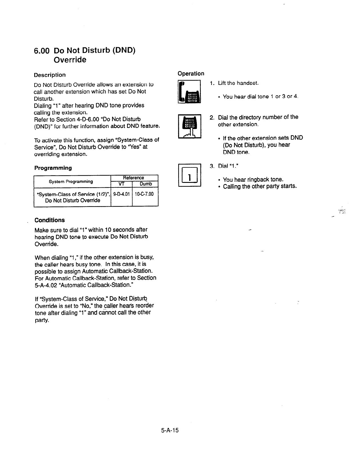
6.00 Do Not Disturb (DND)
Override
Description
Do Not Disturb Override allows an extension to
call another extension which has set Do Not
Disturb.
Dialing “1” after hearing DND tone provides
calling the extension.
Refer to Section 4-D-6.00 “Do Not Disturb
(DND)” for further information about DND feature.
To activate this function, assign “System-Class of
Service”, Do Not Disturb Override to “Yes” at
overriding extension.
Programming
$1
‘System-Class of Service (l/2) , 9-O-4.01 1 O-C-7.00
Conditions
Make sure to dial “1 n within 10 seconds after
hearing DND tone to execute Do Not Disturb
Override.
When dialing “1,” if the other extension is busy,
the caller hears busy tone. In this case, it is
possible to assign Automatic Callback-Station.
For Automatic Callback-Station, refer to Section
5-A-4.02 “Automatic Callback-Station.”
If “System-Class of Service,” Do Not Disturb
Override is set to “No,” the caller heafs reorder
tone after dialing “1” and cannot call the other
PaW
Operation
1.
2,
III
3.
1
Lift the handset.
l
You hear dial tone 1 or 3 or 4.
Dial the directory number of the
other extension.
l
If the other extension sets DND
(Do Not Disturb), you hear
DND tone.
Dial “1.”
l
You hear ringback tone.
l
Calling the other party starts.
5-A- 15
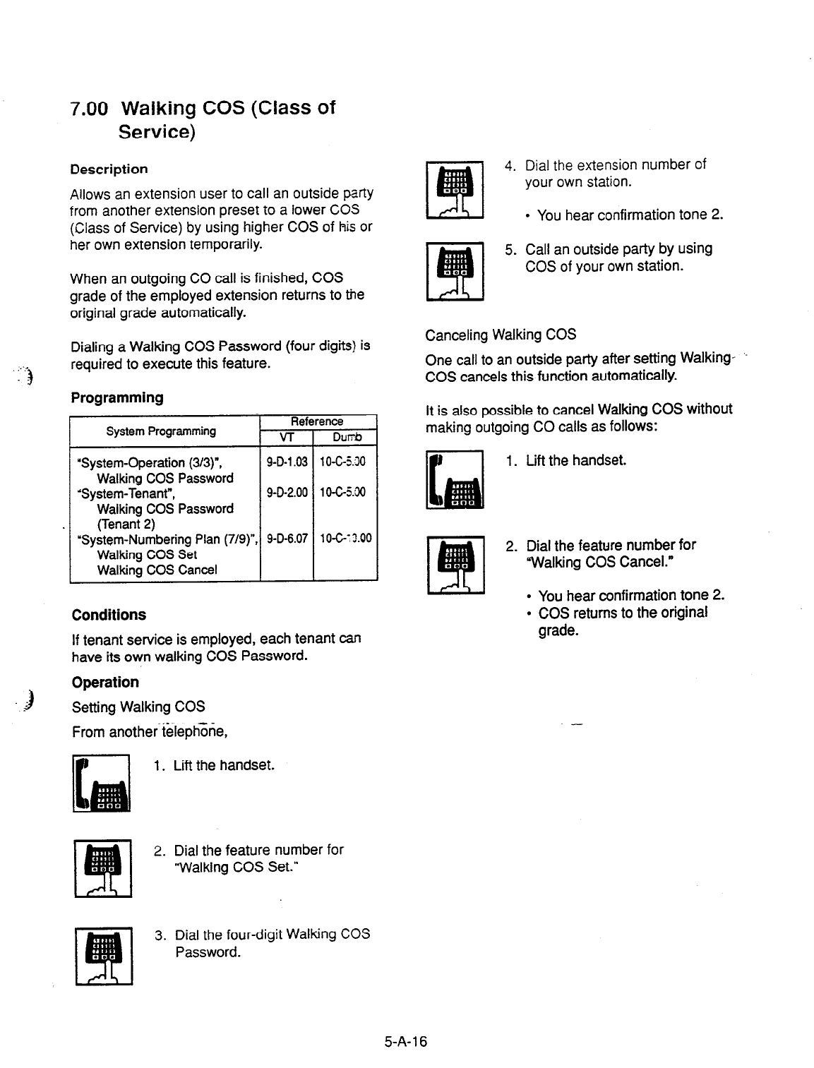
7.00 Walking COS (Class of
Service)
Description
Allows an extension user to call an outside party
from another extension preset to a lower CO5
(Class of Service) by using higher COS of his or
her own extension temporarily.
When an outgoing CO call is finished, COS
grade of the employed extension returns to the
original grade automatically.
:-.-
1
Dialing a Walking COS Password (four digits) is
required to execute this feature.
Programming
Reference
System Programming VT DlJl?b
“System-Operation
(3/3)“, 9-D-l .03 1 O-C-5.30
Walking COS Password
‘System-Tenant”,
9-D-2.00 1 O-C-j:XI
Walking COS Password
(Tenant 2)
“System-Numbering Plan (7/g)“, 9-D-6.07 10-G:X00
Walking COS Set
Walking COS Cancel
Conditions
If tenant service is employed, each tenant can
have its own walking COS Password.
1
--
Operation
Setting Walking COS
From another teleph;ne,
1. Lift the handset.
2. Dial the feature number for
“Walking COS Set.”
4. Dial the extension number of
your own station.
I
l
You hear confirmation tone 2.
5. Call an outside party by using
COS of your own station.
Canceling Walking COS
One call to an outside party after setting Walking- ‘-
COS cancels this function automatically.
It is also possible to cancel Walking COS without
making outgoing CO calls as follows:
1. Lift the handset.
2. Dial the feature number for
“Walking COS Cancel.”
l
You hear confirmation tone 2.
l
COS returns to the original
grade.
-
3. Dial the four-digit Walking COS
Password.
5-A-l 6

8.00 Operator Call
Description
Allows the extension users to call the
operaior by
dialing the feature number for ‘Operator Call
(General)” or “Operator Call (Specific).”
Operation
Calling an operator
Up to two operators are assignable for the whole
system. If Tenant Service is available, two
operators are assignable for each tenant, that
makes four operators available for the whole
system.
If two operators are assigned in the system, or in
a tenant (if tenant Service is employed),
extension users can specify the operator (in the
same tenant) by dialing the feature number for
“Operator Call (Specific).”
Programming
Operator Call iSpecific) I I I
Conditions
When calling an operator by dialing the feature
number for “Operator Call (General),” the
operator is selected according to the type of the
operator’s stations as shown below:
EXT
ATT
Ex-r
-
Operator 1 on?
Operator 1 or,?j
I I
EXT - Operator 1 on,y
1. Lift the handset.
2. Calling an operator without
specifying
1) Dial the feature number for
“Operator Call (General).”
Calling an operator by specifying
1) Dial the feature number for
“Operator Call (Specific).”
2) Dial “1” to specify operator 1.
Dial “2” to specify operator 2.
When no operators are assigned, a user hears
reorder tone during executing Operator Call.
For the assignment of operators, refer to Section
3-B-5.00 “Operator.”
5-A-l 7
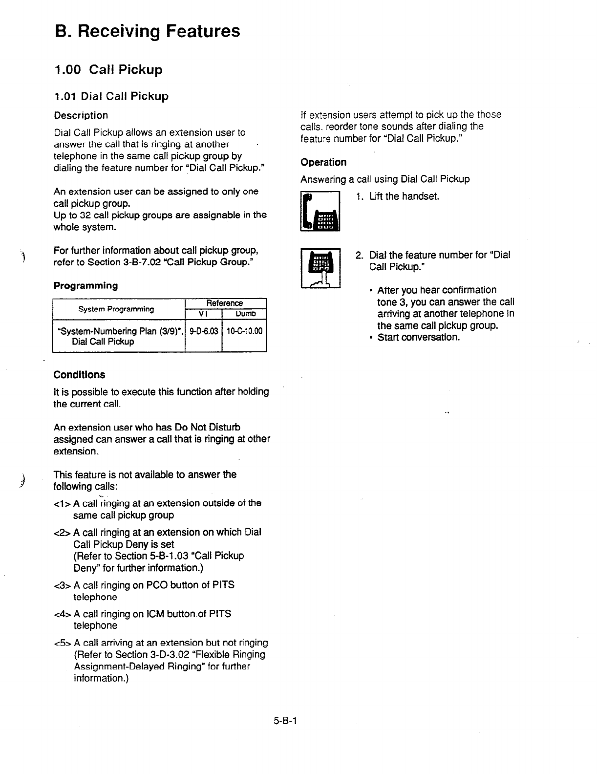
B. Receiving Features
1.00
Call Pickup
1.01 Dial Call Pickup
Description
Dial Call Pickup
allows an exlension user to
answer the call that is ringing at another
telephone in the same call pickup group by
dialing the feature number for ‘Dial Call Pickup.”
An extension user can be assigned to only one
call pickup group.
Up to 32 call pickup groups are assignable in the
whole system.
For further information about call pickup group,
refer to Section 3-B-7.02 “Call Pickup Group.”
Programming
System Programming Reference
VT 1 Dumb
I
“System-Numbering Plan (3/g)‘. 9-D-6.03
lO-G~O.00
Dial Call Pickup I I
Conditions
It is possible to execute this function after holding
the current call.
An extension user who has Do Not Disturb
assigned can answer a call that is ringing at other
extension.
)
This feature is not available to answer the
following calls:
cl> A call ;inging at an extension outside of the
same call pickup group
<2> A call ringing at an extension on which Dial
Call Pickup Deny is set
(Refer to Section 5-B-l .03 “Call Pickup
Deny” for further information.)
c3> A call ringing on PC0 button of PITS
telephone
c4> A call ringing on ICM button.of PITS
telephone
c5> A call arriving at an extension but not ringing
(Refer to Section 3-D-3.02 “Flexible Ringing
Assignment-Delayed Ringing” for further
information.)
If ex%nsion users attempt to pick up the those
calls. reorder tone sounds after dialing the
feature
number for ‘Dial Call Pickup.”
Operation
Answering a call using Dial Call Pickup
1.
2.
Lift the handset.
Dial the feature number for “Dial
Call Pickup.”
After
you hear confirmation
tone
3, you can answer the call
arriving at another telephone in
the same call pickup group.
Start conversation.
5-B-l
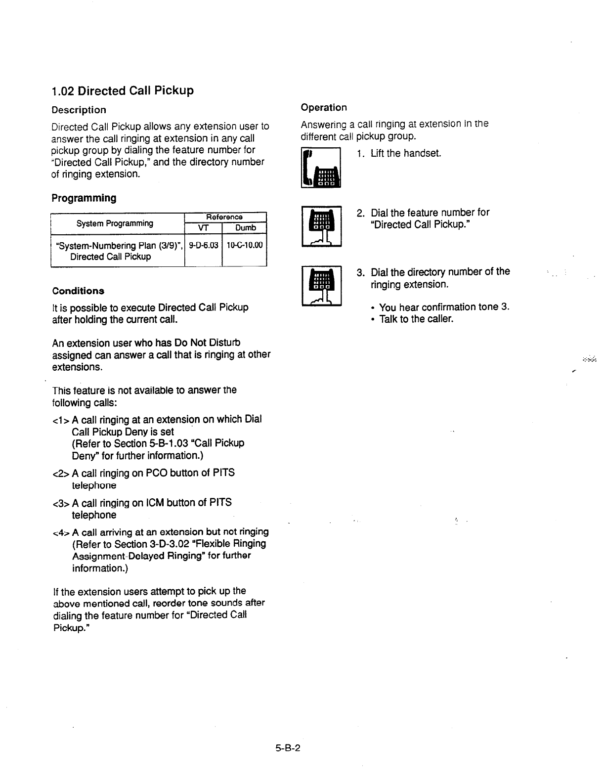
1.02
Directed Call Pickup
Description
Directed Call Pickup allows any extension user to
answer the call ringing at extension in any call
pickup group by dialing the feature number for
‘Directed Call Pickup,” and the directory number
of ringing extension.
Programming
111
“System-Numbering Plan (3/g)“, 9-O-6.03 104-10.00
Conditions
It is possible to execute Directed Call Pickup
after holding the current call.
An extension user who has Do Not Disturb
assigned can answer a call that is ringing at other
extensions.
This feature is not available to answer the
following calls:
cl > A call ringing at an extension on which Dial
Call Pickup Deny is set
(Refer to Section 5-B-l .03 “Call Pickup
Deny” for
further information.)
<2> A call ringing on PC0 button of PITS
telephone
<3> A call ringing on ICM button of PITS
telephone
c4> A call arriving at an extension but not ringing
(Refer to Section 3-D-3.02 “Flexible Ringing
Assignment-Delayed Ringing” for further
information.)
If the extension users attempt to pick up the
above mentioned call, reorder tone sounds after
dialing the feature number for “Directed
Call
Pickup.”
Operation
Answering a call ringing at extension in the
different call pickup group.
1. Lift the handset.
2. Dial the feature number for
“Directed Call Pickup.”
3. Dial the directory number of the
ringing extension.
l
You hear confirmation tone 3.
l
Talk to the caller.
5-B-2
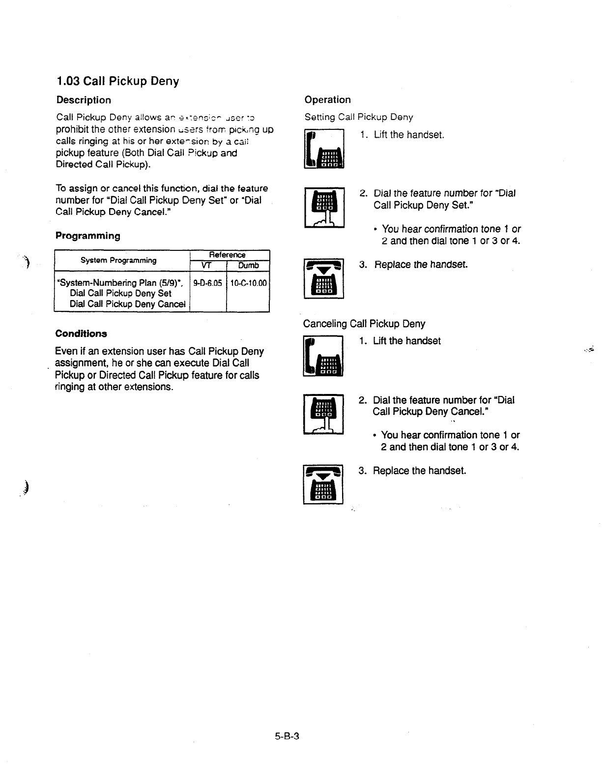
1.03
Call Pickup Deny
Description
Call Pickup Deny &lows a? SXT~WC~ user :3
prohibit
the other extension i;strs tram pccicq up
calls ringing
at his or her exte-sior! by a caii
pickup feature (Both Dial Call Pickup
and
Directed Call Pickup).
To assign or cancel this function, dial the feature
number for ‘Dial Call Pickup Deny Set” or ‘Dial
Call Pickup Deny Cancel.”
Programming
System Programming Reference
VT 1 Dumb
“System-Numbering Plan (5/g)“.
Dial Call
Pickup Deny Set
Dial Call
Pickup Dew Cancel
Conditions
Even if an extension user has Call Pickup Deny
assignment, he or she can execute Dial Call
Pickup or Directed Call Pickup feature for calls
ringing at other extensions.
Operation
Setting Call Pickup Deny
1. Lift the handset.
2. Dial the feature number for “Dial
Call Pickup Deny Set.”
I
9 You hear confirmation tone 1 or
2 and then dial tone 1 or 3 or 4.
3. Replace the handset.
Canceling Call Pickup Deny
1. Lift the handset
2. Dial the feature number for “Dial
Call Pickup Deny Cancel.”
. .
l
You hear confirmation tone 1 or
2 and then dial tone 1 or 3 or 4.
3. Replace the handset.
5-B-3

2.00 Trunk Answer From Any
Station (TAFAS)-Day
Service
Description
Incorn?; CO ra!‘s programmed for TAFAS will
ring the external oager and any extension user in
the system can answer the calls by dialing the
feature number for “Night Answer 1” (when a call
is ringing at external pager 1) or “Night Answer 2”
(when a call is ringing at external pager 2).
To activate this feature, assign “Group-Trunk
Group”, Incoming Mode (Day) to TAFAS 1 or
TAFAS 2, and ‘Trunk-CO Line” Trunk Group to “1
to 16” (Trunk Group Number whose Incoming
Mode (Day) is assigned as TAFAS 1 or 2).
To utilize the external pager, assign “System-
Operation”, External Paging 1, 2” to “Yes.”
Up to two external pagers can be connected to
this system. TAFAS
1
is associated with external
pager 1 and TAFAS 2 is associated with external
pager 2.
Call handling in TAFAS is identical to UNA. The
difference is that TAFAS is available in day mode
and UNA is available in night mode.
For further information about UNA, refer to
section 5-G-l .Ol “Universal Night Answer (UNA).”
Programming
System Programming Reference
v-r Dumb
“System-Operation
(l/3)“, 9-D-l .Ol 10-C-4.00
External Paging 1, 2
“System-Numbering Plan (3/g)“, 9-D-6.03 10-C-10.00
Night Answer 1
Night Answer 2
“Group-Trunk-Group (l/2)“, 9-E-1 .ol 1 O-C-1 4.00
Incoming Mode (Day)
“Trunk-CO Line”, 9-F-1 .OO 1 O-C-l 8.00
Trunk Group
“Trunk-Pager & Music Source”, 9-F-2.00 10-C-19.00
External Pager-Tenant
Conditions
If tenant service is employed :
The affiliation of each external pager is
determined by the system programming in
“Trunk-Pager & Music Source”, External Pager-
Tenant.
Extension users cannot answer the TAFAS call
ringing at an external pager in the different
tenant.
Operation
Answering incoming CO calls programmed for
TAFAS
An incoming CO call is ringing at an
external pager.
1. Lift the handset.
l
You hear dial tone 1 or 3 or 4.
2-1 If a call is ringirig at external
pager 1: Dial the feature
number for ‘Night Answer 1.”
2-2 If a call is ringing at external
pager 2: Dial the feature
number for ‘Night Answer 2.”
q
3. Talk to the caller.
h
5-B-4

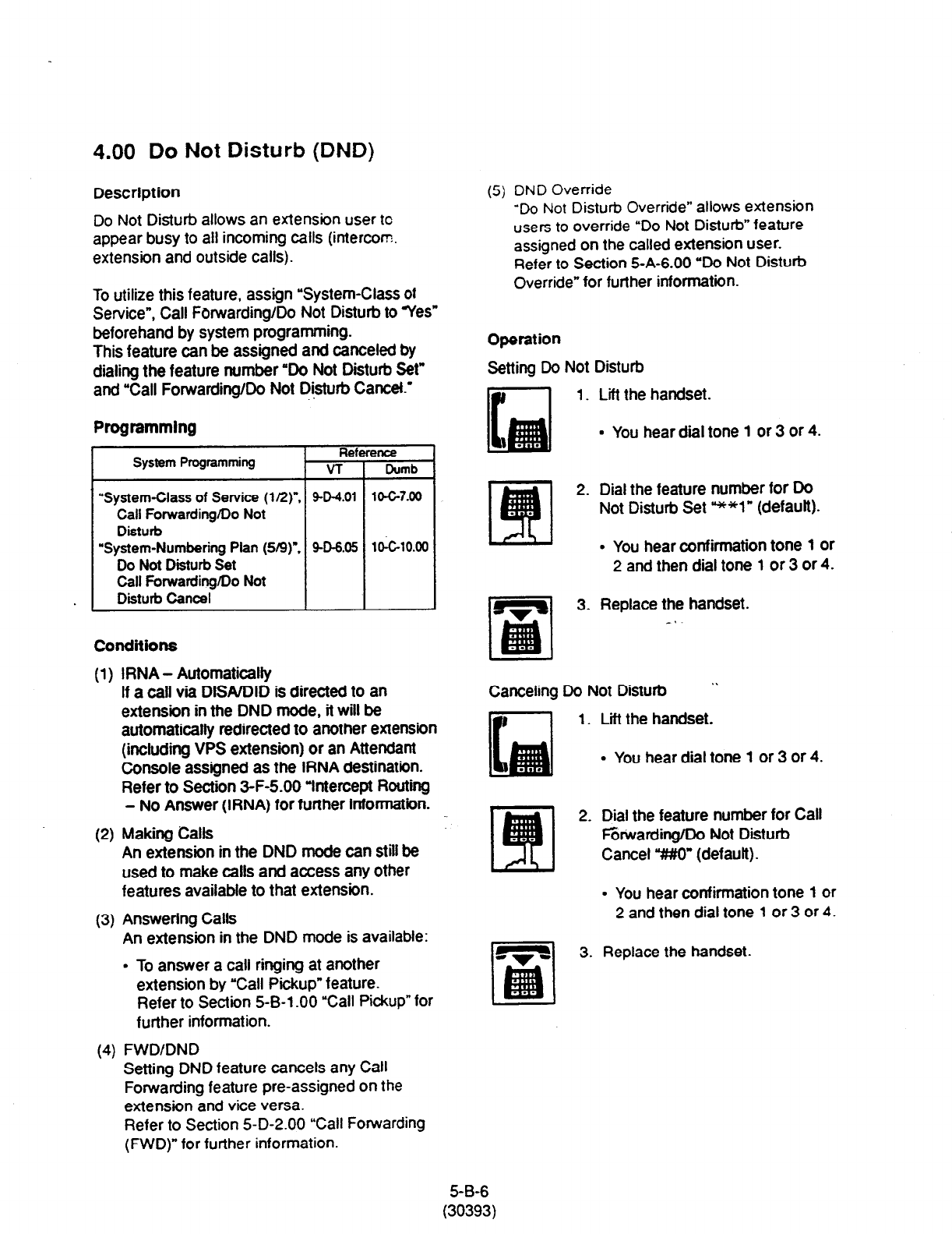
4.00 Do Not Disturb (DND)
Description
(5) DND Override
Do Not Disturb allows an extension user to
appear busy to all incoming calls (intercom.
extension and outside calls).
To utilize this feature, assign “System-Class ot
Service”, Call Forwarding/Do Not Disturb to yes”
beforehand by system programming.
This feature can be assigned and canceled by
dialing the feature number “Do Not Disturb Set”
and ‘Call Forwarding/Do Not D&turb Cancet.’
‘Do Not
Disturb Override” allows extension
users to override “Do Not Disturb” feature
assigned on the called extension user.
Refer to Section 5-A-6.00 “Do Not Disturb
Override” for further information.
Operation
Setting Do Not Disturb
1. Lii the handset.
Programmlng
Reference
System Programming VT Dumb
“System-Class of Service (1/2r,
9-D-4.01 lOG7.00
Call Forwarding/Do Not
Disturb
“System-Numbering Pfan (519): 9-D-6.05
1OklO.W
Do Not Disturb Set
Call Forwarding/Do Not
Disturb Cancel
l
You hear dial tone 1 or 3 or 4.
2. Dial the feature number for Do
Not Disturb Set **l” (default).
l
You hear confirmation tone 1 or
2 and then dial tone 1 or 3 or 4.
3. Replace the handset.
_.
COllditiOIlS
(1)
(2)
(3)
(4)
IRNA - Automatically
If a call via DISAIDID is directed to an
extension in the DND mode, it will be
automatically redirected to another extension
(including VPS extension) or an Attendant
Console assigned as the IRNA destination.
Refer to Section 3-F-5.00 Wntercept Routing
- No Answer (IRNA) for further information.
Making Calls
An extension in the DND mode can still be
used to make calls and access any other
features available to that extension.
Answering Calls
An extension in the DND mode is available:
l
To answer a call ringing at another
extension by “Call Pickup” feature.
Refer to Section 5-B-l .OO “Call Pickup” for
further information.
FWD/DND
Setting DND feature cancels any Call
Forwarding feature pre-assigned on the
extension and vice versa.
Refer to Section 5-D-2.00 “Call Forwarding
(FWD)” for further information.
Canceling Do Not Disturb
1.
2.
3.
Lii the handset.
l
You hear dial tone 1 or 3 or 4.
Dial the feature number for Call
F&Warding/Do Not Disturb
Cancel “MO” (default).
l
You hear confirmation tone 1 or
2 and then dial tone 1 or 3 or 4.
Replace the handset
5-B-6
(30393)
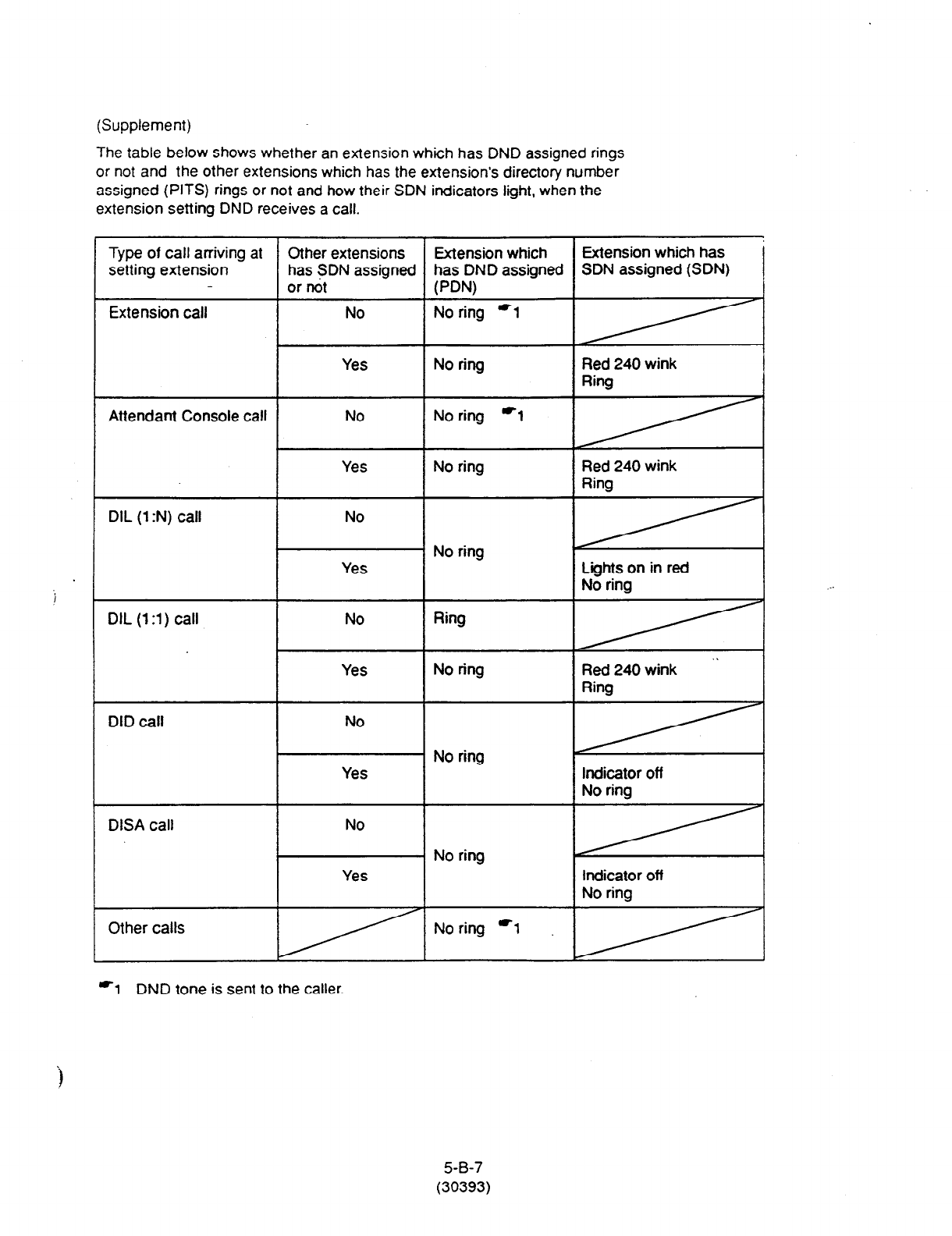
(Supplement)
The table below shows whether an extension which has DND assigned rings
or not and the other extensions which has the extension’s directory number
assigned (PITS) rings or not and how their SDN indicators light, when the
extension setting DND receives a call.
Type of call arriving at
setting extension
Extension call
Attendant Console call
DIL (1 :N) call
DIL (13) call
DID call
DISA call
Other calls
Other extensions Extension which
has SDN assigned has DND assigner
or not PDN)
I
No ring -1
No ring *l
Yes
No ring
No Ring
No
No
Yes 1 No ring
Extension which has
SDN assigned (SDN) !
Red 240 wink
Ring
Red 240 wink
Ring
Lights on in red
No ring
” Red 240 wink
indicator off
Indicator off
No ring
i
‘1 DND tone is sent to the caller.
5-B-7
(30393)
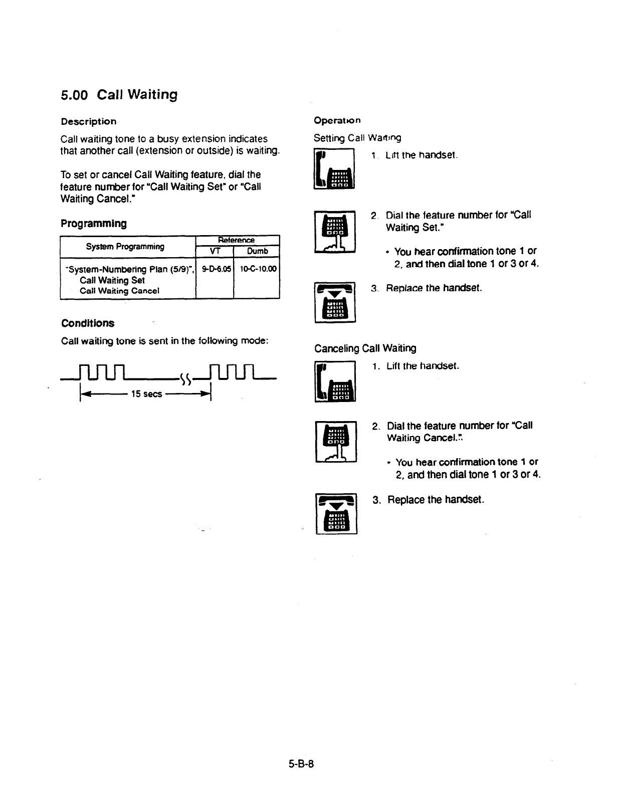
5.00 Call Waiting
Description
Call waiting tone to a busy extension indicates
that another call (extension or outside) is waiting.
To set or cancel Call Waiting feature, dial the
feature number for “Call Waiting Set” or “Call
Waiting Cancel.”
Programming
System Programming Reference
VT I Dumb
“System-Numbering Plan (5/g)“, SD-6.05 10-C-10.00
Call Waiting Set
Call Waitina Cancel I I I
Conditions
Call waiting tone is sent in the foliowing mode:
Operanon
Setting Call Wanq
1
Litt the handset.
2. Dial the feature number for “Call
Waiting Set.”
- You near confirmation tone 1 or
2,
and
then dial tone 1 or 3 or 4.
3.
Replace the handset.
Canceling Call Waiting
1. Lift the handset.
2. Dial the feature number for “Call
Waiting Cancel.:
l
You hear confirmation tone 1 or
2, and then
dial tone 1 or 3 or 4.
3. Replace the handset.
5-B-8
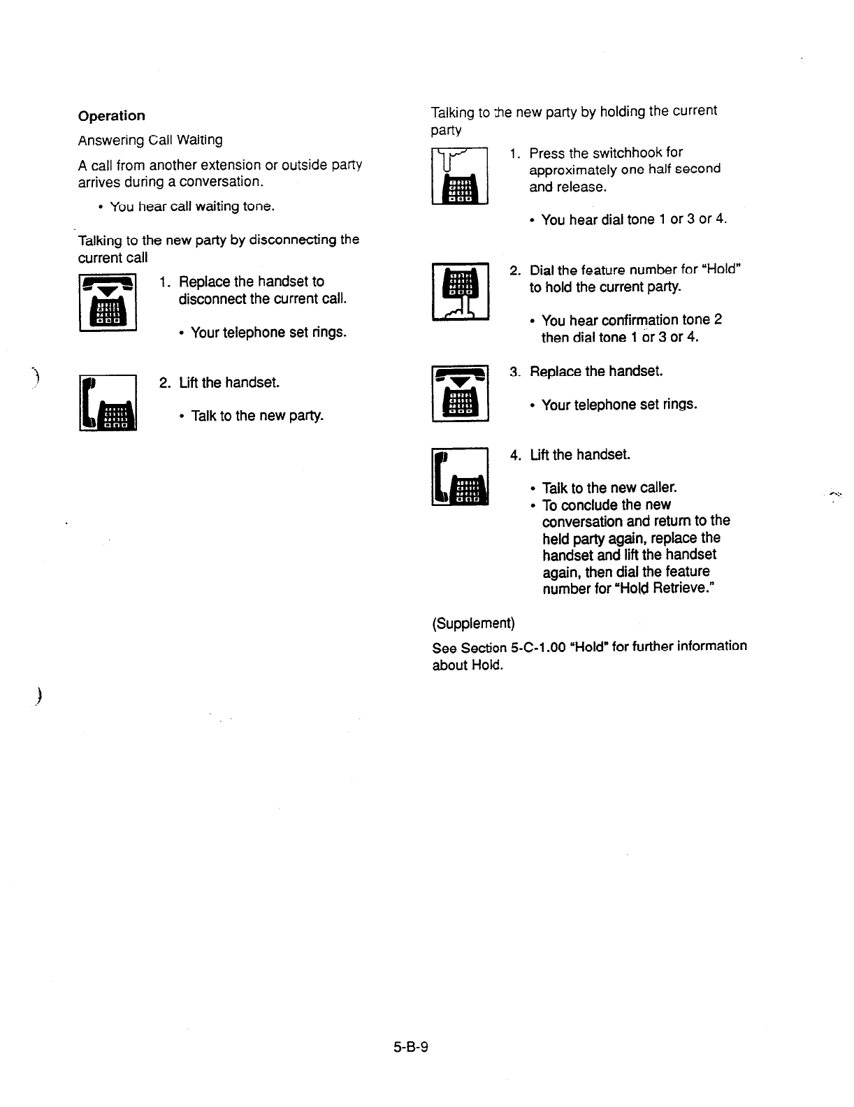
Operation
Answering Call Waiting
A call from another extension or outside party
arrives during a conversation.
l
You hear call waiting tone.
Talking to the new party by disconnecting the
current call
1. Replace the handset to
disconnect the current call.
l
Your telephone set rings.
2. Lift the handset.
. Talk to the new party.
Talking to tie new party by holding the current
paW
1. Press the switchhook for
approximately one half second
and release.
l
You hear dial tone 1 or 3 or 4.
2. Dial the feature number for “Hold”
to hold the current party.
I
l
You hear confirmation tone 2
then dial tone 1 or 3 or 4.
3. Replace the handset.
l
Your telephone set rings.
4. Lift the handset.
l
Talk to the new caller.
l
To conclude the new
conversation and return to the
held party again, replace the
handset and lift the handset
again, then dial the feature
number for “Hold Retrieve.”
(Supplement)
See Section 5-C-l .OO “Hold” for further information
about Hold.
5-B-9

6.00 Uniform Call Distribution
(UCD j-Log Out
Description
UCD group members may leave the group
temporarily by dialing the feature number for
“UCD Log Out” to avoid UCD calls being sent to
their extensions.
Refer to Section 3-D-2.05 “Uniform Call
Distribution (UCD)-without OGM” and Section
3-D-2.06 “Uniform Call Distribution (UCD)-with
OGM” for further information about UCD call.,
Programming
~1
Conditions
. When an extension of the UCD group set for
Log Out goes off-hook, dial tone 4 below can be
heard.
(second) 0 1 2 3 4 5
Operation
Setting UCD Log Out (Leaving a UCD group)
1.
2.
3.
Lift the handset.
l
You hear dial tone 4.
Dial the feature number for “UCD
Log Out.”
l
You hear confirmation tone 1 or
2.
Replace the handset.
Canceling UCD Log Out (Returning to a UCD
group)
1. Lift the handset.
l
You hear dial tone 4.
2. Dial the feature number for “UCD
Log In.”
3. Replace the handset.
5-B-l 0
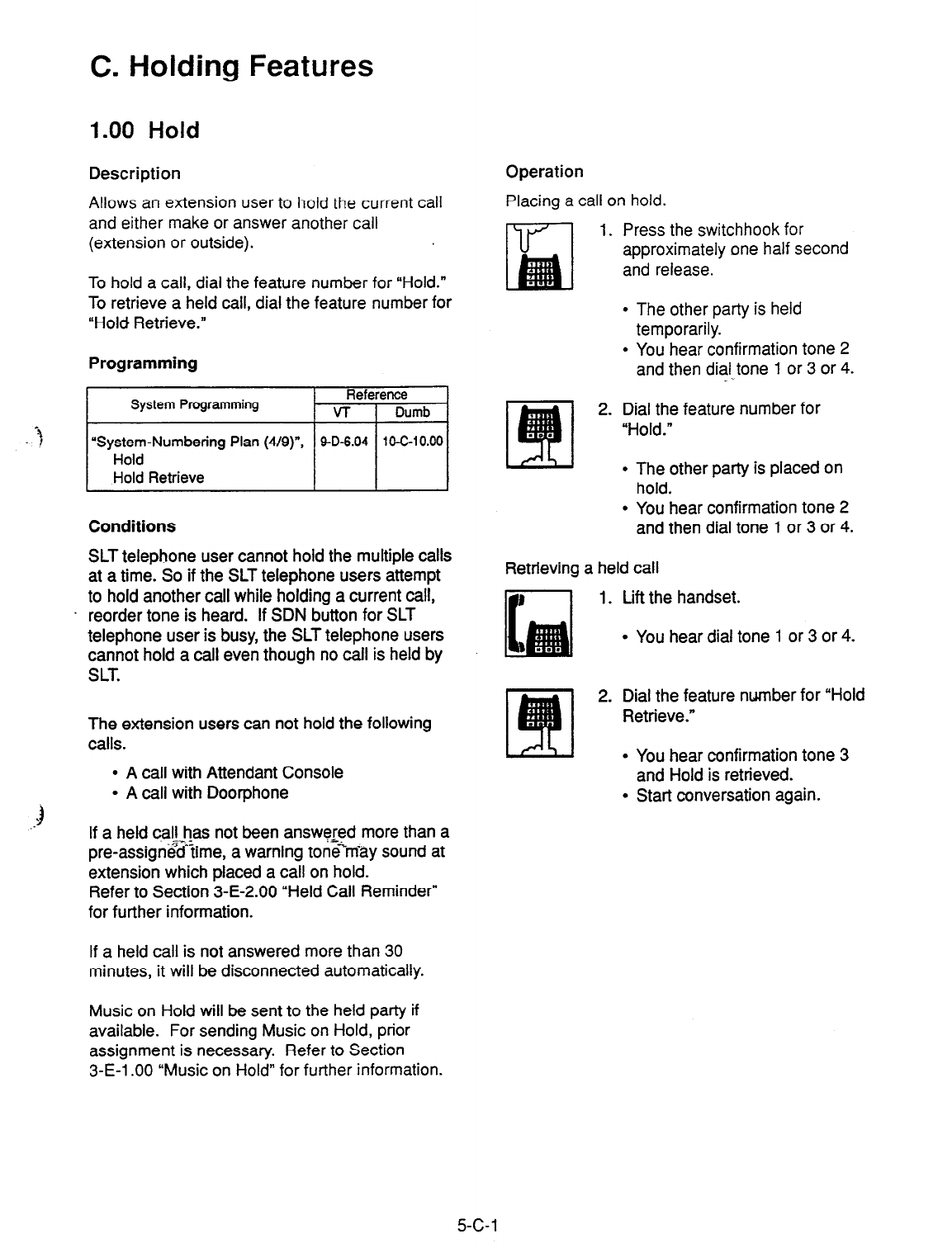
C. Holding Features
1.00 Hold
Description
Allows an extension user to hold the current call
and either make or answer another call
(extension or outside).
Operation
‘f
To hold a call, dial the feature number for “Hold.”
To retrieve a held call, dial the feature number for
“Hold Retrieve.”
Programming
System Programming Reference
VT I Dumb
“System-Numbering Plan (4/g)“, 9-D-6.04 10-C-10.00
Hold
Hold
Retrieve
Conditions
SLT telephone user cannot hold the multiple calls
at a time. So if the SLT telephone users attempt
to hold another call while holding a current call,
reorder tone is heard. If SDN button for SLT
telephone user is busy, the SLT telephone users
cannot hold a call even though no call is held by
SLT.
The extension users can not hold the following
calls.
l
A call with Attendant Console
l
A call with Doorphone
If a held call has not been answq$d more than a
pre-assig$&ime, a warning ton<rriay sound at
extension which placed a call on hold.
Refer to Section 3-E-2.00 “Held Call Reminder”
for further information.
If a held call is not answered more than 30
minutes, it will be disconnected automatically.
Placing a call on hold.
1. Press the switchhook for
approximately one half second
and release.
l
The other party is held
temporarily.
l
You hear confirmation tone 2
and then dial tone 1 or 3 or 4.
2. Dial the feature number for
“Hold.”
l
The other party is placed on
hold.
l
You hear confirmation tone 2
and then dial tone 1 or 3 or 4.
Retrieving a held call
1. Lift the handset.
l
You hear dial tone 1 or 3 or 4.
2. Dial the feature number for “Hold
Retrieve.”
l
You hear confirmation tone 3
and Hold is retrieved.
l
Stat-f conversation again.
Music on Hold will be sent to the held party if
available. For sending Music on Hold, prior
assignment is necessary. Refer to Section
3-E-l .OO “Music on Hold” for further information.
5-c-1

2.00 Consultation Hold
Description
Allows the extension user to hold the current call
temporarily on purpose to transfer it or establish
a conference. Other extensions cannot retrieve
‘the call during Consultation Hold.
Programming
None
Conditions
The extension users can not place the following
calls on consuftation hold.
l
A call with Attendant Console
l
A call with Doorphone
Consultation Hold Recall tone sound immediately
if the extension user replaces the handset while
having a call on consultation hold.
Consultation Hold Recatl tone sounds in the
same way as Held Call Reminder. _ i
If a held call is not answered more than 30
minutes, it will be disconnected automatically.
When you have a call on Consultation Hold and
are talking to another party, pressing the
switchhook for approximately one half second
and releasing it enables you to have conference
if a conference trunk is available. If there is no
conference trunk available, the party in
conversation is placed on Consultation Hold and
you can talk to the retrieved party.
For further information about conference, refer to
Section 5-E-l .OO “Conference.”
Music on Hold will be sent to the held party if
available. For sending Music on Hold, prior
assignment is necessary. Refer to Section
3-E-l -00 ‘Music on Hold” for further information.
Operation
Placing a call on Consultation Hold
1. Press the switchhook for
approximately one half second
and release.
l
The call is placed on
Consultation Hold, and you
hear confirmation tone 2 then
dial tone 1 or 3 or 4.
l
You can call another party.
Retrieving a call on Consultation Hold
You have placed a call on Consultation Hold and
are not in conversation.
ITF’l 1. Press the switchhook for
approximately one half second
and release.
l
The call is retrieved and you
can talk to the party.
5-C-2
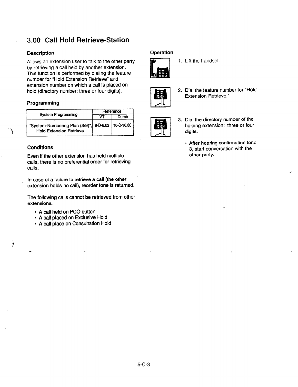
3.00 Call Hold Retrieve-Station
Description
k:lows an extension user to talk to the other party
oy retrievmg a call held by another extension.
This function is performed by dialing the feature
number for “Hold Extension Retrieve” and
extension number on which a call is placed on
hold (directory number: three or four digits).
Programming
I
Reference
I System Programming VT 1 Dumb
System-Numbering Plan (3/g)“, 906.03 10C10.00
Hold Extension Retrieve I I
Conditions
Even if the other extension has held multiple
calls, there is no preferential order for retrieving
calls.
Operation
1. Lift
the handset.
2. Dial the feature number for “Hold
Extension Retrieve.”
3. Dial the directory number of the
holding extension: three or four
digits.
. After hearing confirmation tone
3, start conversation with the
other party.
..,
In case of a failure to retrieve a call (the other _ extension holds no call), reorder tone is returned.
The following calls cannot be retrieved from other
extensions.
l
A call held on PC0 button
l
A call placed on Exclusive Hold
l
A call place on Consultation Hold
5-c-3
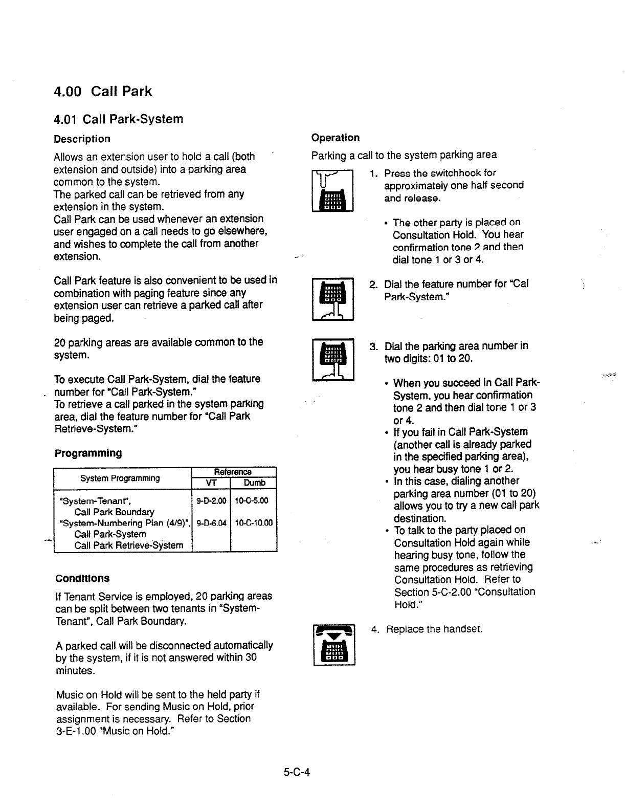
4.00 Call Park
4.01 Call Park-System
Description
Allows an extension user to hold a call (both
extension and outside) into a parking area
common to the system.
The parked call can be retrieved from any
extension in the system.
Call Park can be used whenever an extension
user engaged on a call needs to go elsewhere,
and wishes to complete the call from another
extension.
Call Park feature is also convenient to be used in
combination with paging feature since any
extension user can retrieve a parked call after
being paged.
20 parking areas are available common to the
system.
To execute Call Park-System, dial the feature
. number for “Call Park-System.”
To retrieve a call parked in the system parking
area, dial the feature number for “Call Park
Retrieve-System.”
Programming
System Programming Refc
VT
“System-Tenant”,
9-D-2.00
Call Park Boundary
“System-Numbering Plan (4/g)“, SD-6.04
Call Park-System
Call Park R&eveSystem
Conditions
If Tenant Service is employed, 20 parking areas
can be split between two tenants in “System-
Tenant”, Call Park Boundary.
A parked call will be disconnected automatically
by the system, if it is not answered within 30
minutes.
Operation
Parking a call to the system parking area
ri7’l 1. Press the switchhook for
approximately one half second
and release.
l
The other patty is placed on
Consultation Hold. You hear
confirmation tone 2 and then
dial tone
1
or 3 or 4.
2. Dial the feature number for “Cal
Park-System.”
3. Dial the parking area number in
two digits: 01 to 20.
l
When you succeed in Call Park-
System, you hear confirmation
tone 2 and then dial tone 1 or 3
or 4.
l
If you fail in Call Park-System
(another call is already parked
in the specified parking area),
you hear busy tone 1 or 2.
l
In this case, dialing another
parking area number (01 to 20)
allows you to try a new call park
destination.
l
To talk to the party placed on
Consultation Hotd again while
hearing busy tone, follow the
same procedures as retrieving
Consultation Hold. Refer to
Section 5-C-2.00 “Consultation
Hold.”
4. Replace the handset.
Music on Hold will be sent to the held party if
available. For sending Music on Hold, prior
assignment is necessary. Refer to Section
3-E-l .OO “Music on Hold.”
5-c-4

4.02 Call Park-Station
Description
Allc~vs an extension user to hold a call (both
extension and outside) into the parking area
ded:cated to each
extension.
The parked call can be retrieved from any
extension in the system.
2. Dial the feature number for “Call
Park Retrieve-System.”
3. Dial the parking area number: 01
to 20.
.
.
When you succeed in retrieving
the parked call, you hear
confirmation tone 2. Start
conversation with the retrieved
party.
If you fail, you hear reorder
tone.
Call Park feature can be used whenever an
extension user engaged on a call needs to go
elsewhere, and wishes to complete the call from
another extension.
Call
Park feature is also convenient to be used in
combination with
paging feature since any
extension user can retrieve a parked call after
being paged.
Any extension user can park only one call to the
parking area dedicated to each. extension.
Programming
System Programming Reference
VT 1 Dumb
I
I
“System-Numbering Plan (4/g)”
Call
Park-Station
L
Call
Park Retrieve-Station 1
Conditions
A parked call will be disconnectedautomatically
by the system, if it is not answered within 30
minutes.
Music on Hold will be sent to the held party if
available. For sending Music on Hold, prior
assignment is necessary. Refer to Section
3-E-l .OO “Music on Hold.”
..-..;
. .._..

Operations
Ex==, tin3 Za!l Pa-r%-Station
u-v..
1.
Press the switchhook for
approximately one half second
and release.
.
The
current call is p!aced on
Consultation Hold. You
hear
confirmation tone 2 and then
dial tone 1 or 3 or 4.
2. Dial the feature number for “Call
Park-Station.”
l
When you succeed in Call
Park-Station, you hear
confirmation tone 2 and then
dial tone 1 or 3 or 4.
l
When you cannot park a call
(another call is already
parked), you hear busy tone 1
or 2.
l
To talk to the party placed on
Consultation Hold again while
hearing busy tone 1 or 2, follow
the same procedures as
retrieving Consultation Hokf.
Refer to Section 5-C-2.00
‘Consultation Hold.”
Retrieving Call Park-Station
1. Lift the handset.
2. Dial the feature number for “Call
Park Retrieve-Station.”
3. Dial the directory number of the
parking extension : three or four
digits.
l
When you succeed in retrieving
Call Park-Station, you hear
confirmation tone 2. Then start
conversation with the retrieved
Party.
l
If no call is parked at the
extension, you hear reorder
tone.
3. Replace the handset.
5-C-6

D. Transferring Features
1 .OO Call Transfer
1.01 Unscreened Call Transfer to
Station
Description
Transfer is convenient to redirect a call to another
extension user.
If Music on Hold is ;. z:ztL ‘-17 tt.e start of the
transferring operatic?. L;ntil ?e zestina:ion party
answers, the system sends f,!,sic on Hold to the
transferred party.
Attendant assistance is not required and the caller
does not have to redial. For further detail, refer to Sec::on 3-E-l .OO
“Music on Hold.”
Unscreened Call Transfer allows an extension user
to transfer calls (both extension and CO) to
another extension without announcement. Operation
During a conversation with ar extension or an
outside party
Programming
) None
Conditions
If transferred call is not answered by the
destination party, it will receive one of the following
treatments.
Status of Destination Operation Resulted
Able to receive the
call
(sending ringback
tone)
Busv
Performs the call to the destination for
a specific period. In case of no
answer, interrupts ringing and starts
ringing to the originator of transfer. *l
For detail, refer to Section 3-E-3.00
I
“Transfer Recall.”
1 As soon as the destination goes on-
(sending busy tone) hook, starts caking the destination
(Camp-on Transfer).
If the destination party remains busy 01
does not answer the call within a
specified period, starts calling back the
originator of transfer. -1
For detail. refer to Section 3-E-3.00
“Transfer Recall.”
_
Setting Do Not Unscreened Call Transfer to extension
Disturb is ineffective.
(sending DND tone) Transferred party is treated simply as i
party placed on Consuttation Hold.
Hanging up causes the Consultation
Hold Recall to the originator of transfer
*l When the originator
of transfer answers the call,
conversation between the originator
and the
transferred party starts.
The extension users can not transfer the following
calls.
l
A call with Attendant Console
- A call with Doorphone
1. Press the switchhook for
approximately one half second
and release.
l
The other party is placed on
Consultation Hold.
l
You hear confirmation tone 2
and then dial tone 1 or 3 or 4.
2. Dial the directory number of the
destination: three or four digits.
m
3. Replace the handset.
l
Calling the destination starts
and when the destination
answers, conversation
between the held party and the
destination is established.
(Supplement)
After step 2, you can interrupt the transfer and
talk to the held party by pressing the switchhook
for approximately one half second and releasing.
5-D-l
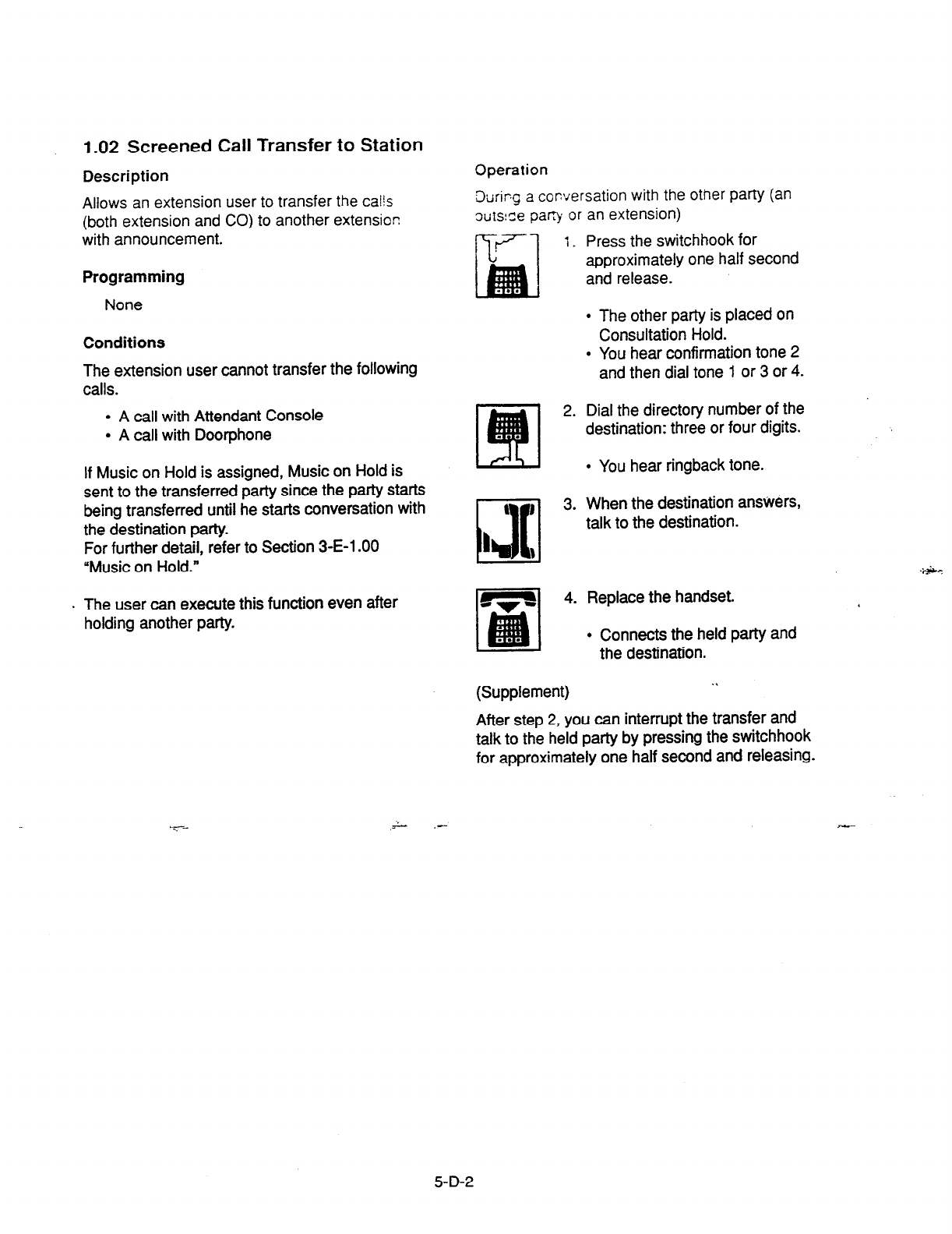
1.02 Screened Call Transfer to Station
Description
Allows an extension user to transfer the calls
(both extension and CO) to another extension
with announcement.
Programming
None
Conditions
The extension
user cannot transfer the following
calls.
l
A call with
Attendant Console
l
A call with Doorphone
If
Music
on Hold is assigned, Music on Hold is
sent to the transferred party since the party starts
being transferred until he starts conversation with
the destination party.
For further detail, refer to Section 3-E-l .OO
“Music on Hold.”
. The user can execute this function even after
holding another party.
Operation
&ring a conversation with the other party (an
3uts:Se pany or an extension)
1. Press the switchhook for
approximately one half second
and release.
l
The other party is placed on
Consultation Hold.
l
You hear confirmation tone 2
and then dial tone 1 or 3 or 4.
2. Dial the directory number of the
destination: three or four digits.
l
You hear ringback tone.
3. When the destination answers,
talk to the destination.
4. Replace the handset.
l
Connects the held party and
the destination.
(Supplement) . .
After step 2, you can interrupt the transfer and
talk to the held party by pressing the switchhook
for awroximatelv one half second and releasing.
5-D-2
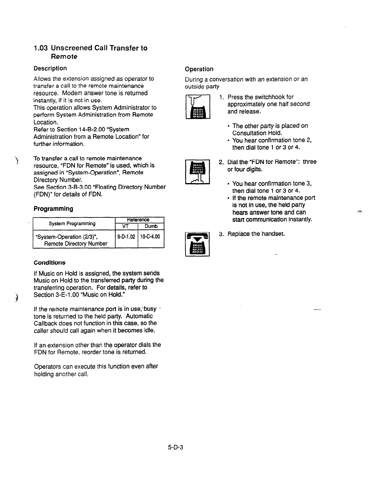
1.03 Unscreened Call Transfer to
Remote
Description Operation
During a conversation with an extension or an
outside party
Allows the extension assigned as operator to
transfer a caii to the remote maintenance
resource. Modem answer tone is returned
‘instantly, if it is not in use.
This operation allows System Administrator to
perform System Administration from Remote
Location.
Refer to Section 14-B-2.00 “System
Administration from a Remote Location” for
further information.
1. Press the switchhook for
approximately one half second
and release.
l
The other
party is placed on
Consultation Hold.
. You hear confirmation tone 2,
then dial tone 1 or 3 or 4.
‘3
To transfer a call to remote maintenance
resource, “FDN for Remote” is used, which is
assigned in “System-Operation”, Remote
Directory Number.
See Section 3-B-3.00 “Floating Directory Number
(FDN)” for details of FDN.
Programming
System Programming Reference
VT I Dumb
“System-Operation (2/3)“,
Remote Directory Number 9-D-l 42 10-C-4.00
Conditions
If Music on Hold is assigned, the system sends
Music on Hold to the transferred party during the
transferring operation. For details, refer to
Section 3-E-l .OO “Music on Hold.”
If the reinote maintenance port is in use,-busy -
tone is returned to the held party. Automatic
Callback does not function in this case, so the
caller should
call again when it becomes idle.
If an extension other than the operator dials the
FDN for Remote, reorder tone is returned.
2. Dial the “FDN for Remote”: three
or four digits.
l
You hear confirmation- tone 3,
then dial tone 1 or 3 or 4.
l
If the remote maintenance port
is not in use, the held party
hears answer tone and can
start communication instantly.
3. Replace the handset.
. .
--.
Operators can execute this function even after
holding another call.
5-D-3
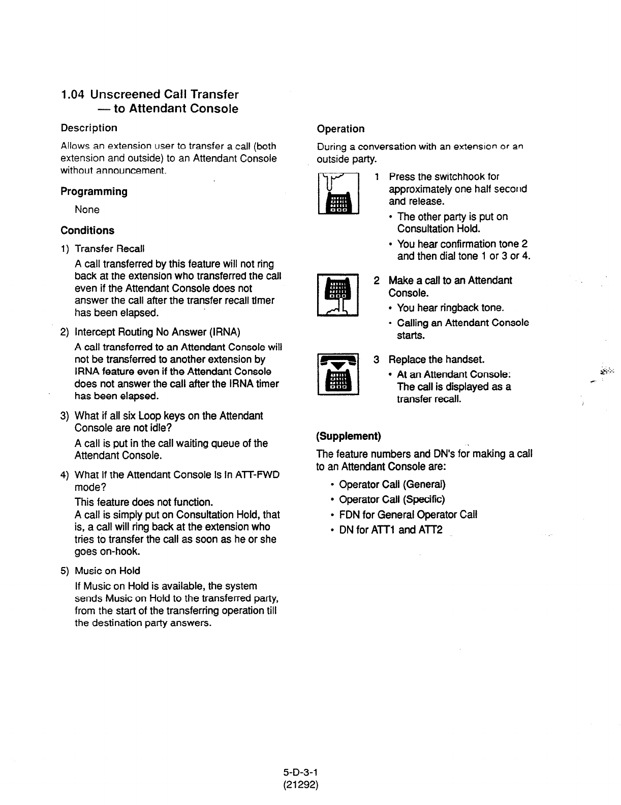
1.04 Unscreened Call Transfer
- to Attendant Console
Description
Allows an extension user to transfer a call (both
extension and outside) to an Attendant Console
without announcement,
Programming
None
Conditions
1)
2)
3)
4)
5)
Transfer Recall
A call transferred by this feature will not ring
back at the extension who transferred the call
even if the Attendant Console does not
answer the call after the transfer recall timer
has been elapsed.
Intercept Routing No Answer (IRNA)
A call transferred to an Attendant Console will
not be transferred to another extension by
IRNA feature even if the Attendant Console
does not answer the call after the IRNA timer
has been elapsed.
What if all six Loop keys on the Attendant
Console are not idle?
A call is put in the call waiting queue of the
Attendant Console.
What if the Attendant Console is in ATT-FWD
mode?
This feature does not function.
A call is simply put on Consultation Hold, that
is, a call will ring back at the extension who
tries to transfer the call as soon as he or she
goes on-hook.
Music on Hold
If Music on Hold is available, the system
sends Music on Hold to the transferred party,
from the start of the transferring operation till
the destination party answers-
Operation
During a conversation with an extension or an
outside party.
1 Press the switchhook for
approximately one half second
and release.
l
The other party is put on
Consultation Hold.
l
You hear confirmation tone 2
and then dial tone 1 or 3 or 4.
2 Make a call to an Attendant
Console.
l
You hear ringback tone.
l
Calling an Attendant Console
starts.
1 3 Replace the handset.
l
At an Attendant Console:
The call is displayed as a
transfer recall.
(Supplement)
The feature numbers and DN’s for making a call
to an Attendant Console are:
l
Operator Call (General)
l
Operator Call (Specific)
l
FDN for General Operator Call
l
DN for ATT1 and ATT2
5-D-3-l
(21292)

1.05 Unscreened Call Transfer
-to a UCD Group (with OGM)
Description
Allows any extension user to transfer an outside
call to a UCD Group from
01
to 04 (with OGM
type).
From version 8.xX. not only the operators but
any ‘extension user can transfer an outside call to
a UCD group (with CGM).
Programming
I .
System Programming Reference
VT
I
Dumb
1 “Special Attended-UCD
(l/2)” 1 g-K-3.01 110-C-44.00 I
Conditions
If all group members are not available to answer
the call, it will be redirected to the Overflow
. destination. In this case, the call wilt be
! disconnected if not answered by the Overflow
destination within 60 seconds.
See page 3-D-13 for further information.
Operation
During a conversation with an outside party.
Press the switchhook for
approximately one half second
and release.
. The other party is put on
Consultation Hold.
l
You hear confirmation tone 2
and then dial tone 1 or 3 or 4.
Dial the FDN for UCD group (01
to 04).
. You hear confirmation tone 3
and then dial tone 1 or 3 or 4.
Replace the handset.
)
Feature References
Uniform Call Distribution (UCD)-with/without
OGM (Section 3-D-2.06)
5-D-3-2

2.00 Call Forwarding (FWD)
2.01 Call Forwarding-All Calls
Description
Call Forwarding-All Calls allows extension users
who are away from their phones to receive
incoming calls (both extension and CO) to them
at another extension.
Incoming calls can be forwarded either to
extension users, Voice Mail port, or operators
(Attendant Console or Extension).
“FDN for General Operator Call” can be used to
assign operators as the destination of Call
Forwarding.
Refer to Section 9-D-l .Ol “Operation (l/3)” for
further information.
The following incoming calls do not receive Call
Forwarding treatment.
l
A call from doorphone
l
A call routed via DIL 1: N feature
l
A call directed to a UCD group
To execute Call Forwarding-All Calls, assign
“System-Class of Service”, Call Forwarding/Do
Not Disturb” to “Yes.”
To set and cancel this function, dial the feature
number for “Call Forwarding-All Calls Set” and
“Call Forwarding-Do Not Disturb Cancel.”
Programming
System Proga&ming Reference
VT Dumb
“System-Class of Service
(l/Z)“, 9-D-4.01 10-C7.00
Call Forwarding/Do Not
Disturb
“System-Numbering Plan (419)“. 4D-6.04 lC-C-10.00
Call Forwarding-All Call Set
“System-Numbering Plan (5/g)“, 9D-6.05 10-C-10.00
Call Forwarding/Do Not
Disturb Cancel
Conditions
An extension user may have only one type of
Call Forwarding/Do Not Disturb feature in effect
at any time. If a second type is assigned, the
previously assigned type is canceled.
If the extension to which calls are to be
forwarded itself is in a call forward mode, a call is
not forwarded furthemx>re. The call rings at the
first forwarded extension. In case of an outside
call, if not answered in a specified time period,
the call will be routed to another destination, if
available, based on the “Intercept Routing-No
Answer” feature.
If Tenant Service is employed and ‘Inter Tenant
Calling” is assigned to “Yes” by programming,
this function is ineffective for the calls from
another tenant if the destination of Call
Forwarding-All Calls is set to an Attendant
Console.
Calls from any VM extension will not be
forwarded, if forwarding destination is another
VM extension. .*
The following attempt will be rejected with
reorder tone.
l
If Tenant Service is employed, the user cannot
set the destination to an extension in the other
tenant.
l
The extension user cannot set the destination
to another extension that presets its own
destination to the user’s extension.
l
The extension user cannot call another
extension that presets its destination to the
users extension.
The Operators (Attendant Console or Extension)
can cancel the Call Forwarding/Do Not Disturb
feature assigned to the extension users. Refer to
Section 5-G-9.00 “Remote Station Feature
Control.”
S-D-4
(21292)

The following table shows the results of the calls arriving at an extension setting
this function depending on the conditions of the preset destination.
.>
.I
.
Type of Call Arriving Condition of Destination Forwarding
8 Setting Extension
Execution Result
Extension call
idle status
0
Call is forwarded to destination.
Busy status
0
Busy tone is sent from destination.
Assigned to DND
0
DND tone is sent from destination.
PITS programming mode
0
Busy tone is sent from destination.
Conditions except In Service * X Call is placed on setting extension.
IL (1 :l) or DISA call Idle status
0
Call is forwarded to destination.
Busy status
0
Call is forwarded and kept waiting
at destination.
Assigned to DND
0
Same as call reaching DND. See
Section 5-B-4.00 “Do Not Disturb
(DND).”
PITS programming mode
0
Call is forwarded and kept waiting
at destination.
IID call
Conditions except In Service *
Idle status
Busy status
Assigned to DND
PITS programming mode
Conditions except ln Service *
X Call is placed on setting extension.
0
Call is forwarded to d&nation.
0
Busy tone is sent from destination
0
Same as call reaching DND. See
Section 5-B-4.00 “Do Not Disturb
(DND).” .,
0
Busy tone is sent from destination
X
Call is placed on destination.
0:
Forwarding possible
X : Forwarding impossible
ic Conditions are “Out of Service,”
“Fault” and “Pre-Installed.” See
Section 14-C-2.02 “Port” for details
5-D-5
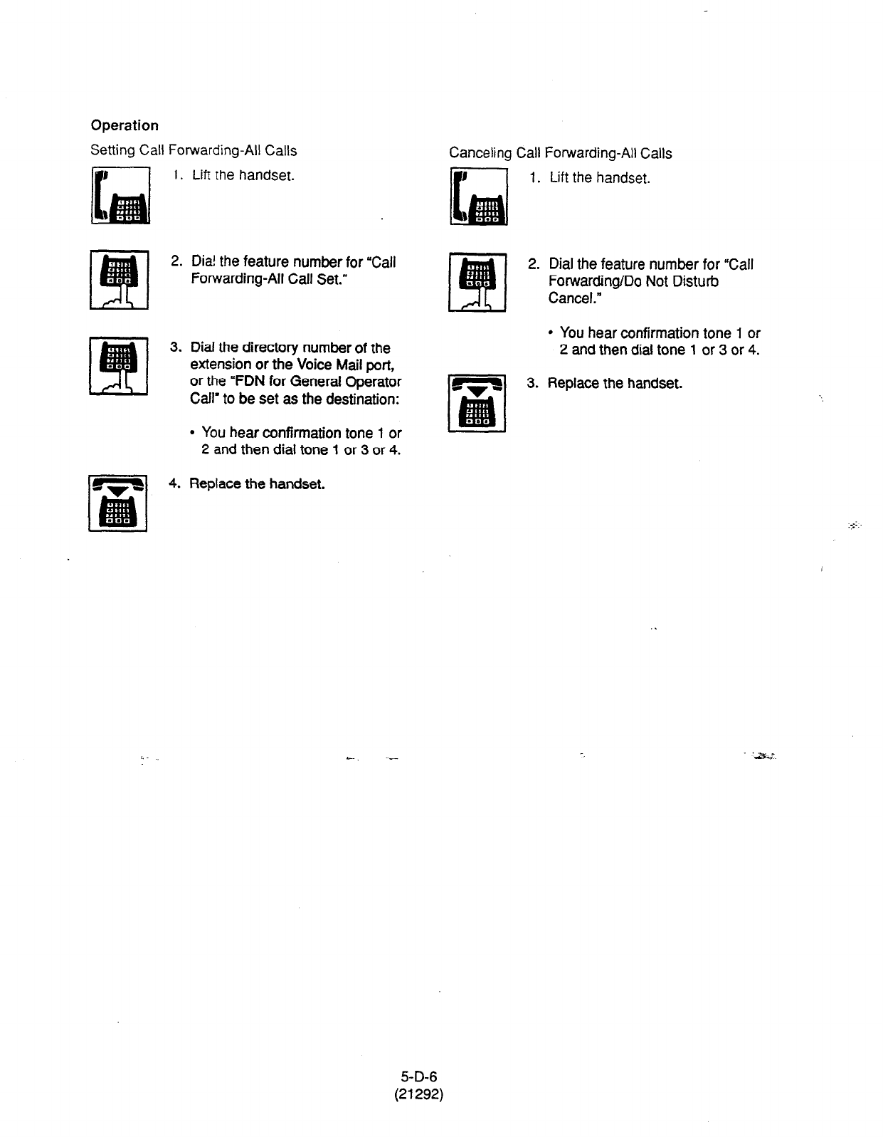
Operation
Setting Call Forwarding-All Calls
1.
2.
3.
4.
Lift the handset.
Dia’ the feature number for “Call
Forwarding-All Call Set.”
Dial the directory number of the
extension or the Voice Mail port,
or the “FDN for General Operator
Call’ to be set as the destination:
l
You hear confirmation tone 1 or
2 and then dial tone 1 or 3 or 4.
Replace the handset.
Canceling Call Forwarding-All Calls
1.
2.
3.
Lift the handset.
Dial the feature number for
“Call
Forwarding/Do Not Disturb
Cancel.”
l
You hear confirmation tone 1 or
2 and then dial tone 1 or 3 or 4.
Replace the handset.
5-D-6
(21292)

2.02 Call Forwarding-Busy/Off-Hook
Description
Cal; Forwardlrg-Busy.Off-Hook
provides
atiiomatic c&t
irW&er
to a preset destination
when the “ser’s eztension is busy or off-hook.
Incoming caiis can be forwarded to extension
users, Voice tv?ail ports, or operators.
“FDN for General Operator Call” is used to assign
operators as the destination of Call Forwarding.
Refer to Section 9-D-l .Ol Operation (l/3)” for
further information.
The following incoming calls do not receive Call
Forwarding treatment.
l
A call from doorphone
l
A call routed via DIL 1: N feature
l
A call directed to a UCD group
To set Call Forwarding-Busy/Off-Hook, assign
“System-Class of Service”, “Call Forwarding/Do
Not Disturb” to “Yes.”
To set and cancel this function, dial the feature Calls from any VM extension will not be
number for “Call Forwarding-Busy Set,” and forwarded, if forwarding destination is another
“Call Forwarding/Do Not Disturb Cancel.” VM extension.
Programming
System Programming Reference
t VT 1 Dumb
“System-Class of Service (l/2)“,
Call Forwarding/Do Not
Disturb
! “System-Numbering Plan (4/g)“,
Call Forwarding-Busy Set
“System-Numbering Plan (5/g)‘,
Call Forwarding/Do Not
Disturb Cancel
~ 9-D-4.01
9-o-6.04
9-O-6.05
1 o-c-7.00
104-10.00
10-c-10.00
Conditions
An extension user
may have only one type of
Call
Forwarding/Do Not Disturb feature in effect
at any time. If a second type is assigned, the
previously assigned type is canceled.
If the extension to which calls are to be
forwarded itself is in a call forward mode, a call is
not forwarded furthermore. The call rings at the
first forwarded extension. In case of an outside
call, if not answered in a specified time period,
the call will be routed to another destination, if
available, based on the “Intercept Routing-No
Answer” feature.
If Tenant Service is employed and “Inter Tenant
Calling” is assigned to ‘Yes” by programming,
this function is ineffective for the calls from
another tenant if the destination of Call
Forwarding-Busy/Off-Hook is set to an Attendant
Console.
The following attempt will be rejected with
reorder tone. .
l
If Tenant Service is employed, the user cannot
set the destination to an extension in the other
tenant.
l
The extension user cannot set the destination
to another extension that presets&own
destination to the user’s extension.
l
The extension user cannot call another
extension that presets its destination to the
user’s extension.
The Operators (Attendant Console or Extension)
can cancel the Call Forwarding/Do Not Disturb
feature assigned to the extension users. Refer to
Section 5-G-9.00 “Remote Station Feature
Control.”
5-D-7
(21292)

The following table shows the results of the calls arriving at an extension setting
!3is function depending on the conditions of the preset destination.
Type of Call Arriving
at Setting Extension
Ex:ension call
DIL (1 A) or DISA cal
DID call
-
I
Condition of Destination Forwarding
Execution
Idle status
Busy status I
Assigned to DND
X
PITS programming mode
Conditions except In Service *
Idle
status
Busy status
0
Assigned to DND
PITS programming mode
X
Conditions except In Service *
Idle status
Busy status
0
Assigned to DND
PITS programming mode
X
Conditions except In Service * 1
Result
Call is forwarded to destination.
Call is placed on setting extension.
Call is forwarded to destination.
Call is placed on setting extension.
Call is forwarded to destination.
. .
Call is placed on setting extension.
0:
Forwarding possible =-
X : Forwarding impossible
;c Conditions are “Out of Service,”
“Fault” and “Pre-Installed.” See
Section 14-C-2.02 “Port” for details.
5-D-8

Operation
Setting Call Forwarding-Busy..Off-Hcc%
1.
2.
3.
)
4.
Lift the handset.
Canceling Call Forwarding-Busy/Off-Hook
Lift the handset.
Dial the feature number for “Calf
Forwarding-Busy Set.”
Dial the directory number of the
extension or the Voice Mail ports,
or the ‘FDN for General Operator
Call” to be set as the destination.
l
You hear confirmation tone 1 or
2 and then dial tone 1 or 3 or 4.
Dial the feature number for “Call
Forwarding/Do Not Disturb
Cancel.”
l
You hear confirmation tone 1 or
2 and then dial tone
1
or 3 or 4.
Replace the handset.
Replace the handset.
3
5-D-9
(21292)
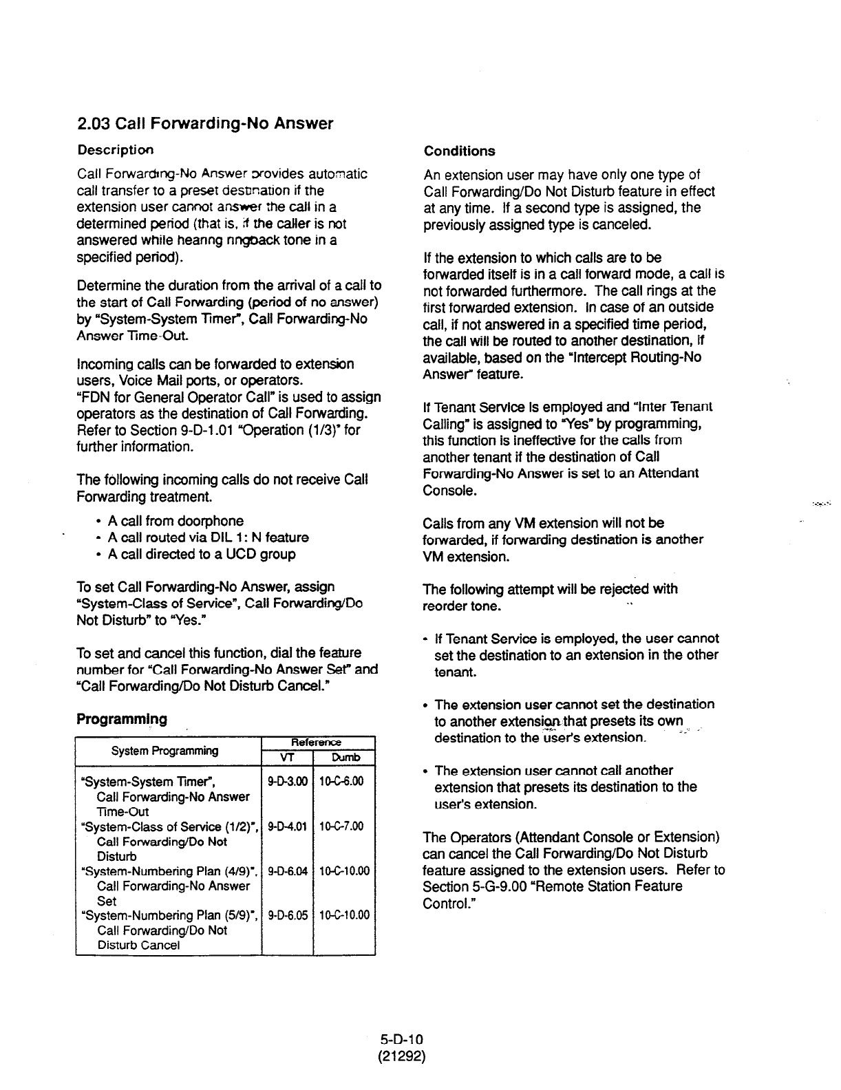
2.03 Call Forwarding-No Answer
Description
Call Forwating-No Answer wovides automatic
call transfer to a preset desbnation if the
extension user cannot answer :he call in a
determined period (that is, ti the caller is not
answered while heanng ringback tone in a
specified perfod).
Determine the duration from the arrival of a call to
the start of Call Forwarding (period of no answer)
by “System-System Timer”, Call Forwarding-No
Answer Time-Out.
Incoming calls can be forwarded to extension
users, Voice Mail ports, or operators.
“FDN for General Operator Call” is used to assign
operators as the destination of Call Forwarding.
Refer to Section 9-O-1.01 “Operation (113)‘for
further information.
The following incoming calls do not receive Call
Forwarding treatment.
l
A call from doorphone
l
A call routed via DIL 1: N feature
l
A call directed to a UCD group
To set Call Forwarding-No Answer, assign
“System-Class
of Service”, Call Forwarding/Do
Not Disturb” to ‘Yes.”
To set and cancel this function, dial the feature
number for “Call Forwarding-No Answer Ser and
‘Call Forwarding/Do Not Disturb Cancel.”
Programming
System Programming Reference
VT Dumb
‘System-System Timer”,
9-O-3.00 104-6.00
Call Forwarding-No
Answer
Time-Out
“System-Class of Service (l/2)‘, 9-D-4.01 I O-C-7.00
Call Forwarding/Do Not
Disturb
“System-Numbering Plan (4/g)‘. 9-O-6.04 lO-GlO.00
Call Forwarding-No Answer
Set
“System-Numbering Plan (5/g)‘, 9-D-6.06 lO-GiO.00
Call Forwarding/Do Not
Disturb Cancel
Conditions
An extension user may have only one type of
Call Forwarding/Do Not Disturb feature in effect
at any time. If a second type is assigned, the
previously assigned type is canceled.
If the extension to which calls are to be
forwarded itself is in a call forward mode, a call is
not forwarded furthermore. The call rings at the
first forwarded extension. In case of an outside
call, if not answered in a specified time period,
the call will be routed to another destination, if
available, based on the ‘Intercept Routing-No
Answer” feature.
If Tenant Service is employed and ‘Inter Tenant
Calling” is assigned to Yes” by programming,
this function is ineffective for the calls from
another tenant if the destination of Call
Forwarding-No Answer is set to an Attendant
Console.
Calls from any VM extension will not be
forwarded, if forwarding destination is another
VM extension.
The following attempt will be rejected with
reorder tone. . .
l
If Tenant Service is employed, the user cannot
set the destination to an extension in the other
tenant.
l
The extension user cannot set the destination
to another extens@ that presets its own
destination to the users extension. -- -
l
The extension user cannot call another
extension that presets its destination to the
user’s extension.
The Operators (Attendant Console or Extension)
can cancel the Call Forwarding/Do Not Disturb
feature assigned to the extension users. Refer to
Section 5-G-9.00 “Remote Station Feature
Control.”
5-D-l 0
(21292)
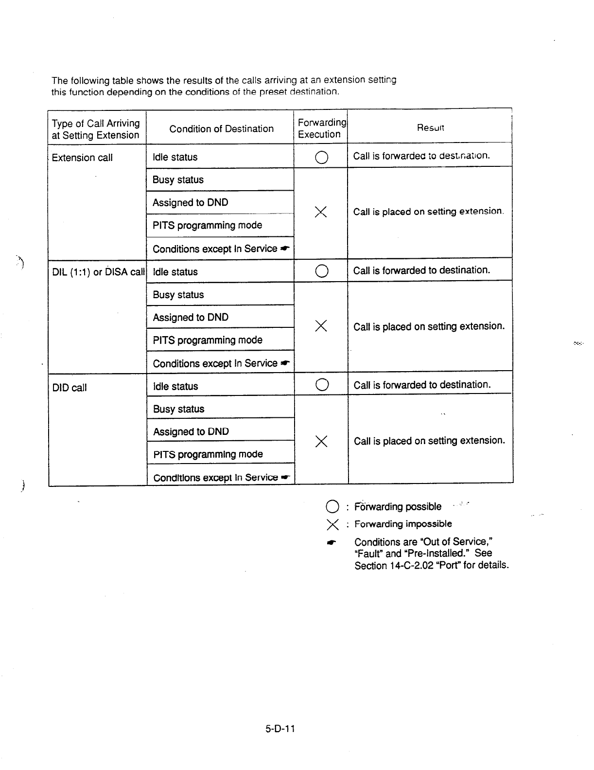
The following table shows the results
of
the calls arriving at an extension setting
this function depending on the conditions of the preset destination.
Type of Call Arriving
at Setting Extension
Extension call
DIL
(1 :l)
or l&A call
DID call
Condition of Destination
Rescrr;
Idle status I 0 I Call is forwarded
iO
desmation.
Busy status I I
I I
31 x
Call is placed on setting extension.
Idle status
Busy status
0
Call is forwarded to destination.
Assigned to DND
PITS programming mode
X
Call is placed on setting extension.
Conditions except In Service *
Idle status
Busy status
Assigned to DND
PITS programming mode
Conditions except In Service *
0
Call is forwarded to destination.
. .
X
Call is placed on setting extension.
0 : f&warding possible ’ r
X : Forwarding impossible
t Conditions are “Out of Service,”
“Fault” and “Pre-Installed.” See
Section 14-C-2.02 “Port” for details.
5-D-l 1

Operation
Setting Call Forwarding-No Answer
1. Lift the handset. .
2. Dial the feature number for “Call
Forwarding-No Answer Set.”
3. Dial the directory number of the
extension or the Voice Mail port,
or the “FDN for General Operator
I’-‘!
Call” of the destination.
l
You hear confirmation tone 1 or
2 and then dial tone 1 or 3 or 4.
4. Replace the handset.
3. Replace the handset.
Fomxding-No Answer
Liti me handset.
Dia! the feature number for “Call
Forwarding/Do Not Disturb
Cancel.”
l
You hear confirmation tone 1 or
2 and then dial tone 1 or 3 or 4.
5-D-l 2
(21292)
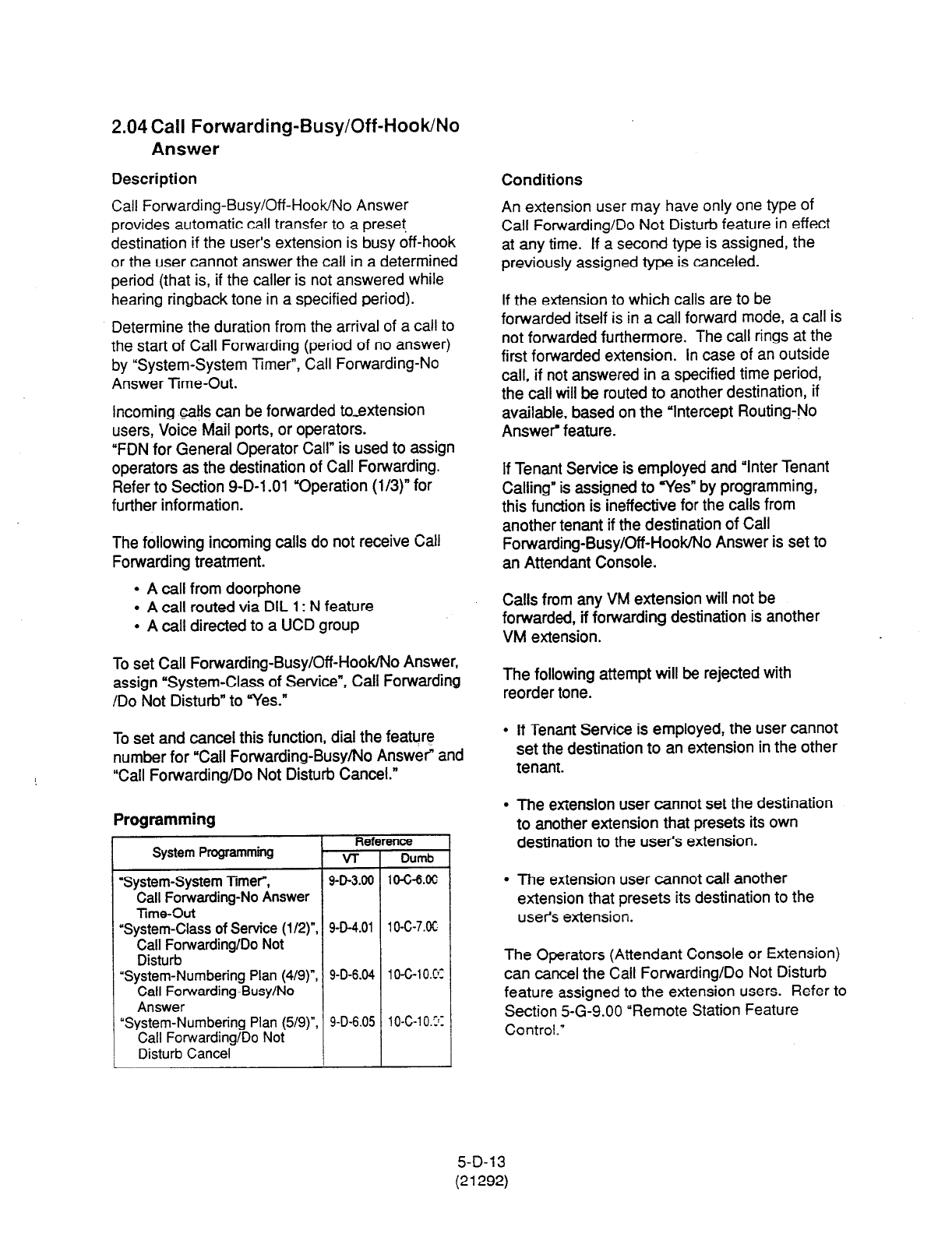
2.04 Call Forwarding-Busy/Off-Hook/No
Answer
Description
Call Forwarding-Busy/Off-Hook/No Answer
provides automatic call transfer to a preset
destination if the user’s extension is busy off-hook
or the user cannot answer the call in a determined
period (that is, if the caller is not answered while
hearing ringback tone in a specified period).
Determine the duration from the arrival of a call to
the start of Call Forwarding (period of no answer)
by “System-System Timer”, Call Forwarding-No
Answer Time-Out.
Incoming calls can be forwarded to-extension
users, Voice Mail ports, or operators.
“FDN for General Operator Call” is used to assign
operators as the destination of Call Forwarding.
Refer to Section 9-D-l .Ol “Operation (l/3)” for
further information.
The following incoming calls do not receive Call
Forwarding treatment.
l
A call from door-phone
l
A call routed via DIL 1: N feature
l
A call directed to a UCD group
To set Call Forwarding-Busy/Off-HookMo Answer,
assign “System-Class of Service”, Call Forwarding
/Do Not Disturb” to ‘Yes.”
To set and cancel this function, dial the feature
number for “Call Forwarding-Busy/No Answer” and
“Call Forwarding/Do Not Disturb Cancel.”
Programming
Reference
System Programming VT Dumb
‘System-System Timer”, 9-D-3.00 1 o-c-6.00
Call Forwarding-No Answer
Time-Out
“System-Class of Service (l/2)“, 9-D-4.01 lo-C-7.K
Call Forwarding/Do Not
Disturb
“System-Numbering Plan (4/g)“, 9-D-6.04 10-G10.C~:
Call Forwarding-Busy/No
Answer
“System-Numbering Plan (5/g)“, 9-D-6.05 10-C-l O.Ir
Call Forwarding/Do Not
Disturb Cancel
Conditions
An extension user may have only one type of
Call Forwarding/Do Not Disturb feature in effect
at any time. If a second type is assigned, the
previously assigned type is canceled.
If the extension to which calls are to be
forwarded itself is in a call forward mode, a call is
not forwarded furthermore. The call rings at the
first forwarded extension. In case of an outside
call, if not answered in a specified time period,
the call will be routed to another destination, if
available, based on the “Intercept Routing-No
Answe? feature.
If Tenant Service is employed and “Inter Tenant
Calling” is assigned to ‘Yes” by programming,
this function is ineffective for the calls from
another tenant if the destination of Call
Forwarding-Busy/Off-HooWNo Answer is set to
an Attendant Console.
Calls from any VM extension will not be
forwarded, if forwarding destination is another
VM extension.
The following attempt will be rejected with
reorder tone.
l
If Tenant Service is employed, the user cannot
set the destination to an extension in the other
tenant.
l
The extension user cannot set the destination
to another extension that presets its own
destination to the user’s extension.
l
The extension user cannot call another
extension that presets its destination to the
user’s extension.
The Operators (Attendant Console or Extension)
can cancel the Call Forwarding/Do Not Disturb
feature assigned to the extension users. Refer to
Section 5-G-9.00 “Remote Station Feature
Control.’
5-D-l 3
(21292)
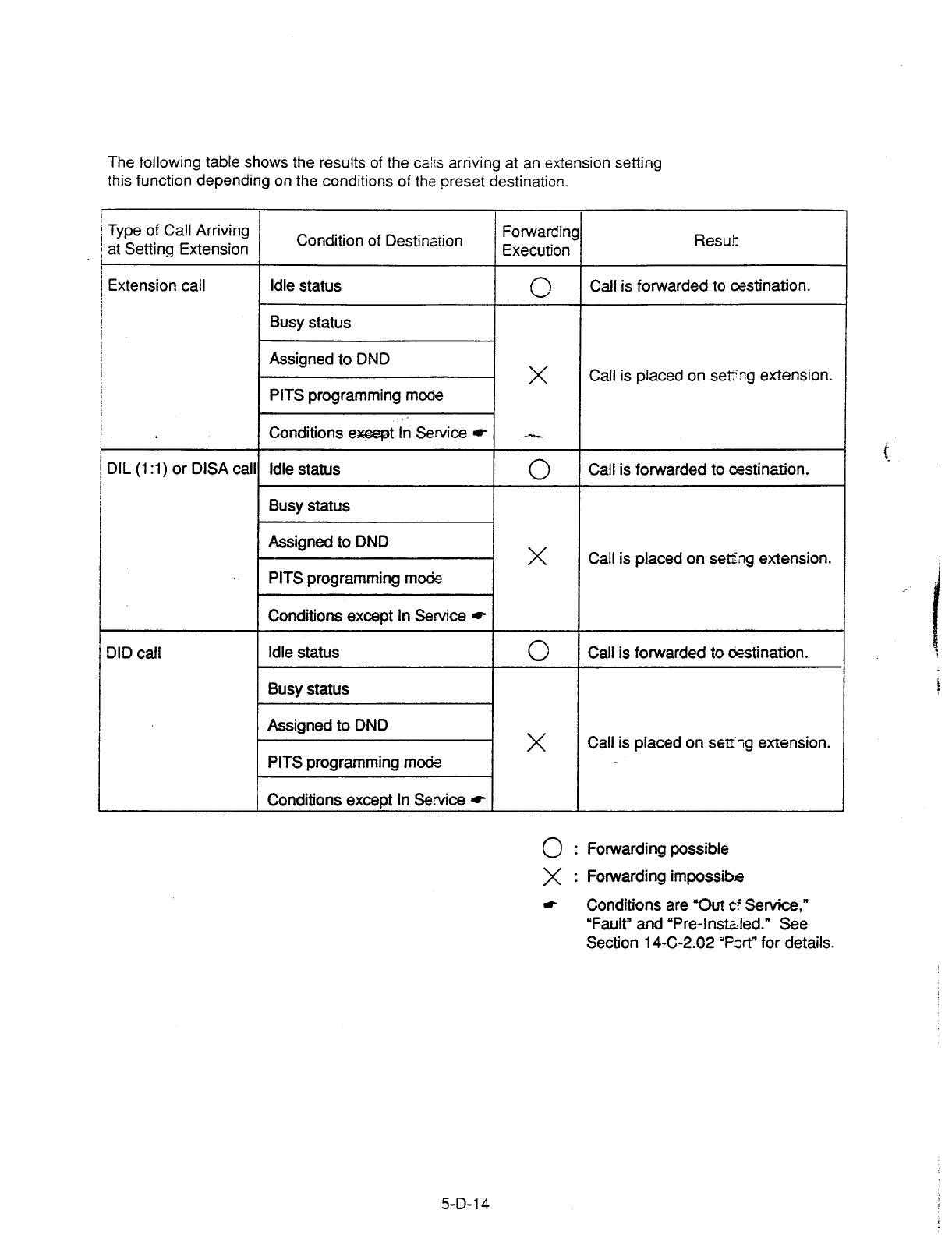

2.04 Call Forwarding-Busy/Off-Hook/No
Answer
Description
Call Forwarding-Busy/Off-HooWNo Answer
provides automatic call transfer to a preset
destination if the user’s extension is busy off-hook
or the user cannot answer the call in a determined
period (that is, if the caller is not answered while
hearing ringback tone in a specified period).
Determine the duration from the arrival of a call to
the start of Call Forwarding (period of no answer)
by ‘System-System Timer”, Call Forwarding-No
Answer Time-Out.
Incoming calls can be forwarded to extension
users, Voice Mail ports, or operators.
“FDN for General Operator Call” is used to assign
operators as the destination of Call Forwarding.
Refer to Section 9-D-l .Ol “Operation (l/3)” for
further information.
The following incoming calls do not receive Call
Forwarding treatment.
l
A call from doorphone
l
A call routed via DIL 1: N feature
l
A call directed to a UCD group
To set Call Forwarding-Busy/Off-Hook/No Answer,
assign “System-Class of Service”, Call Forwarding
/Do Not Disturb” to “Yes.”
To set and cancel this function, dial the feature
number for “Call Forwarding-Busy/No Answer” and
1 “Call Forwarding/Do Not Disturb Cancel.”
Programming
Refi
System Programming VT
‘System-System Timer, 9-D-3.00
Call Forwarding-No Answer
Time-Out
‘System-Class of Service (l/2)“,
9-D-4.01
Call Forwarding/Do Not
Disturb
“System-Numbering Plan (4/S)“, 9-D-6.04
Call Forwarding-Busy/No
Answer
“System-Numbering Plan (5/g)“, 9-D-6.05
Call Forwarding/Do Not
Disturb Cancel
ence
Dumb
1 O-c-6.00
1 o-c-7.00
1 o-c-1 0.00
10-C-l 0.00
Conditions
An extension user may have only one type of
Call Forwarding/Do Not Disturb feature in effect
at any time. If a second type is assigned, the
previously assigned type is canceled.
If the extension to which calls are to be
forwarded itself is in a call forward mode, a call is
not forwarded furthermore. The call rings at the
first forwarded extension. In case of an outside
call, if not answered in a specified time period,
the call will be routed to another destination, if
available, based on the “Intercept Routing-No
Answer” feature.
If Tenant Service is employed and “Inter Tenant
Calling” is assigned to “Yes” by programming,
this function is ineffective for the calls from
another tenant if the destination of Call
Forwarding-Busy/Off-Hook/No Answer is set to
an Attendant Console.
Calls from any VM extension will not be
forwarded, if forwarding destination is another
VM extension.
The following attempt will be rejected with
reorder tone.
l
If Tenant Service is employed, the user cannot
set the destination to an extension in the other
tenant.
l
The extension user cannot set the destination
to another extension that presets its own
destination to the user’s extension.
l
The extension user cannot call another
extension that presets its destination to the
user’s extension.
The Operators (Attendant Console or Extension)
can cancel the Call Forwarding/Do Not Disturb
feature assigned to the extension users. Refer to
Section 5-G-9.00 “Remote Station Feature
Control.”
5-D-l 3
(21292)

The following table shows the results of the calls arriving at an extension setting
this function depending on the conditions of the preset destination.
Extension call Idle status
Busy
status
0
Assigned to DND
PITS programming mode
X
I
Conditions except In Service * I
DIL (1 :l) or DISA
calll Idle status I 0
1 Busy status I
Type of Call Arriving
at Setting Extension
Condition of Destination
Result
Assigned to DND
X
1 PITS programming mode I
I Conditions except tn Service * I
DID call I Idle status I 0
I
Busy status I
Assigned to DND
X
PITS programming mode
_ .
I Conditions except In Service *
Call is fowarded to destination.
Call is placed on setting extension.
Call is forwarded to destination.
Call is placed on setting extension.
Call is forwarded to destination.
Call is placed on setting extension.
0:
Forwarding possible
X : Forwarding impossible
t Conditions are “Out of Service,”
“Fault” and “Pre-Installed.” See
Section
14-C-2.02
“Port” for details.
5-D-l 4
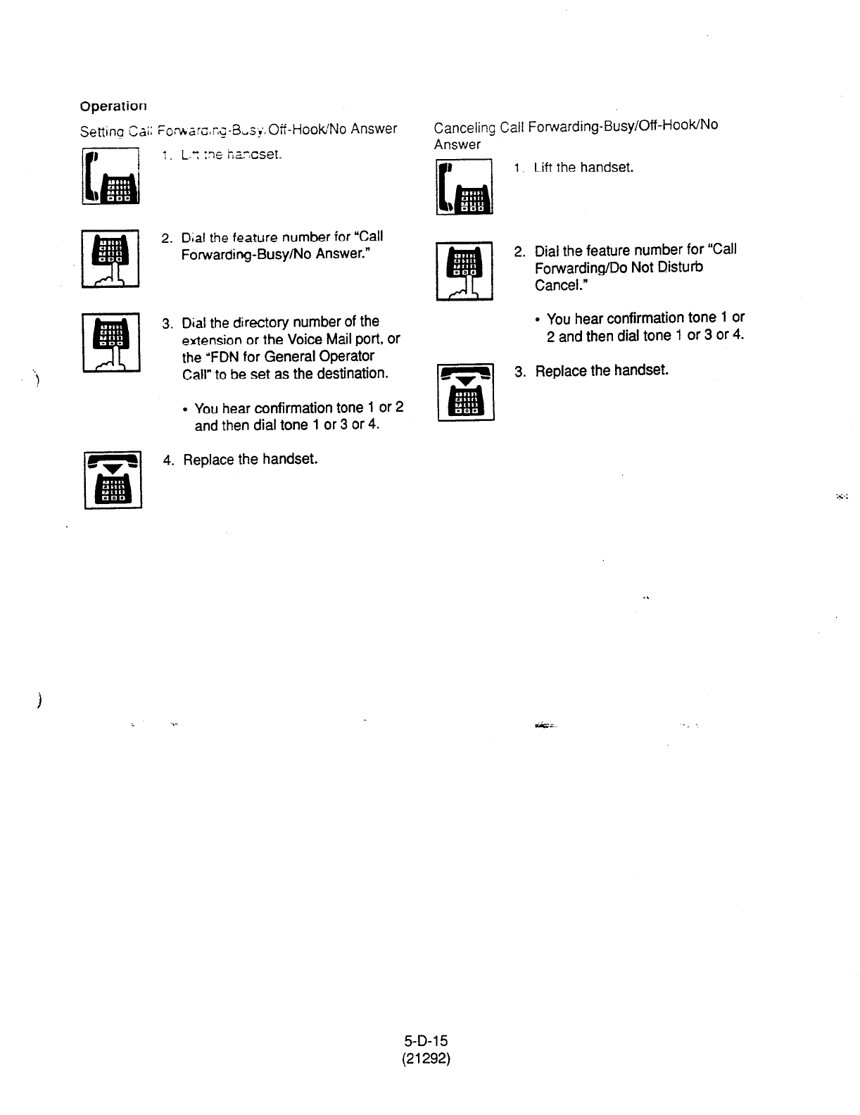
Operation
I .
2.
3.
t
4.
Dial the feature number for “Call
Forwarding-Busy/No Answer.”
Dial
the directory number of the
extension or the Voice Mail port, or
the ‘FDN for General Operator
Call” to be set as the destination.
l
You hear confirmation tone 1 or 2
and then dial tone 1 or 3 or 4.
Replace the handset.
Canceling Call Forwarding-Busy/Off-HooWNo
Answer
1.
Lift
the
handset.
2.
3.
Dial the feature number for ‘Call
Forwarding/Do Not Disturb
Cancel.”
l
You hear confirmation tone 1 or
2 and then dial tone 1 or 3 or 4.
Replace the handset.
5-D-l 5
(21292)
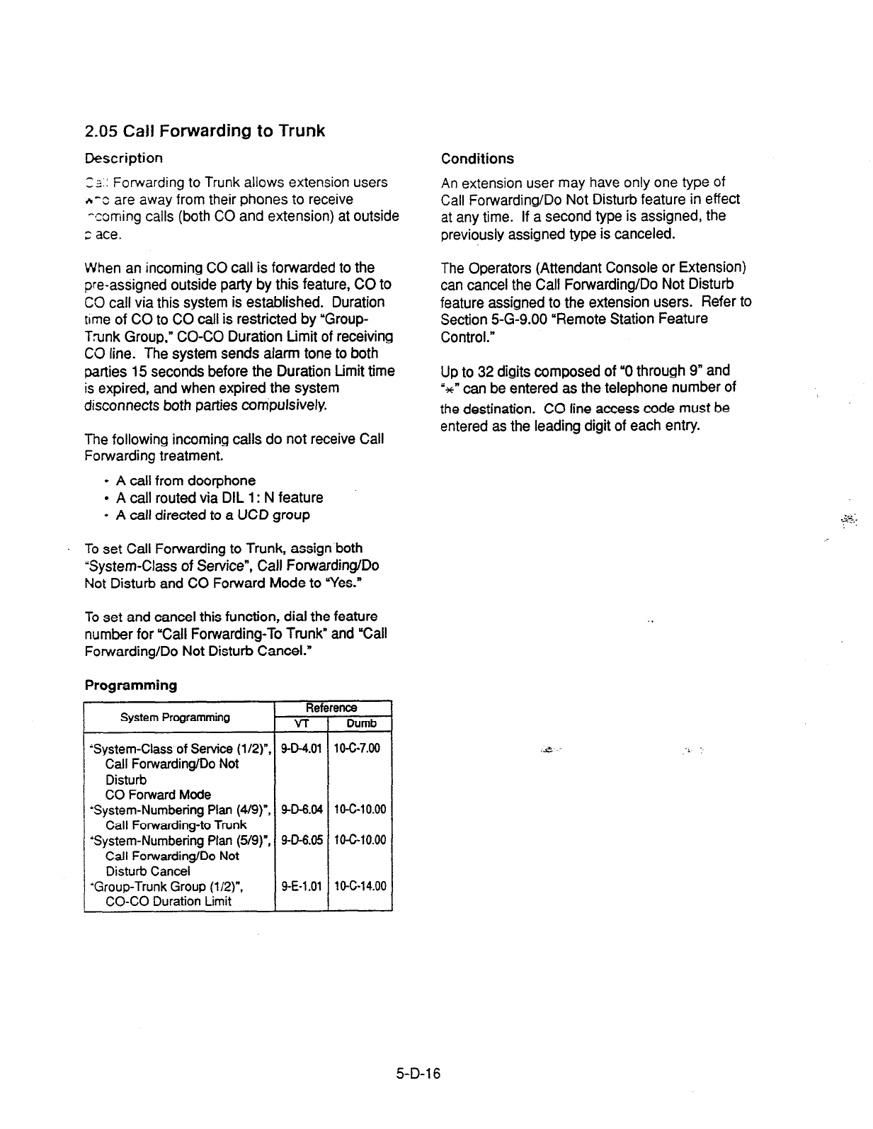
2.05 Call Forwarding to Trunk
Description
-2.. ^ - Forwarding to Trunk allows extension users
n-c are away from their phones to receive
-coming calls (both CO and extension) at outside
;: ace.
When an incoming CO call is forwarded to the
pre-assigned outside party by this feature, CO to
CO call via this system is established. Duration
time of CO to CO call is restricted by ‘Group-
Trunk Group,” CO-CO Duration Limit of receiving
CO line. The system sends alarm tone to both
parties 15 seconds before the Duration Limit time
is expired, and when expired the system
disconnects both parties compulsively.
The following incoming calls do not receive Call
Forwarding treatment.
l
A call from doorphone
l
A call routed via DIL 1: N feature
l
A call directed to a UCD group
. To set Call Forwarding to Trunk, assign both
System-Class of Service”, Call Forwarding/Do
Not Disturb and CO Forward Mode to Yes.”
To set and cancel this function, dial the feature
number for “Call Forwarding-To Trunk” and I%all
Forwarding/Do Not Disturb Cancel.”
Programming
System Programming
‘System-Class of Service (l/2)“.
Call Forwarding/Do Not
Disturb
CO Forward
Mode
-System-Numbering Plan (4/9)“,
Call Forwarding-to Trunk
‘System-Numbering Plan (5/g)“,
Call Forwarding/Do Not
Disturb Cancel
-Group-Trunk Group (l/2)“,
CO-CO Duration Limit
Ref
v-r
9-D-4.01
9-D-6.04
9-D-6.05
9-E-l .Ol
9nce
Dumb
10-c-7.00
lo-c-10.00
1 o-c-10.00
10-c-14.00
Conditions
An extension user may have only one type of
Call Forwarding/Do Not Disturb feature in effect
at any time. If a second type is assigned, the
previously assigned type is canceled.
The Operators (Attendant Console or Extension)
can cancel the Call Forwarding/Do Not Disturb
feature assigned to the extension users. Refer to
Section 5-G-9.00 “Remote Station Feature
Control.”
Up to 32 digits composed of “0 through 9” and
;sCn can be entered as the telephone number of
the destination. CO line access code must be
entered as the leading digit of each entry.
5-D-l 6
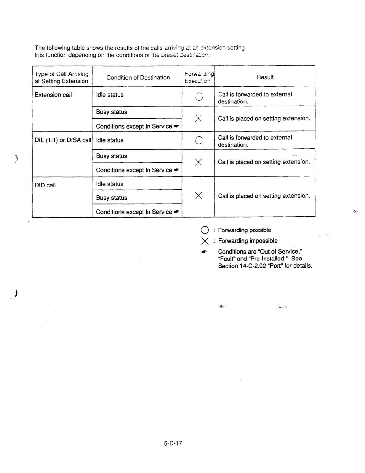
-3
The following
table
shows
the results
of the calls arriving zt a- ?x:ension setting
this
function depending on the conditions of the ore%:
zestirz:z.
Type of Call Arriving
at Setting Extension
I
Condition of Destination Eor*~-J,Gg’
; Exec-TO” /
Result
Extension call Idle status Call is forwarded to external
w destination.
Busy status x Calf is placed on setting extension.
Conditions except In Service *
DIL (1 :l) or DISA call Idle status 1 ’ 1 destination.
Call is forwarded to external
II x -”
Call is placed on setting extension.
DID call Idle status I I
I
Busy status I x I Call is placed on setting extension. I
I I I
1 Conditions except In Service * 1 I I
0:
Forwarding possible . .
X : Forwarding impossible
t
Conditions are “Out .of Service,”
“Fault” and “Pre-Installed.” See
Section 14-C-2.02 “Port” for details.
3
.*...
.L. ‘5
5-D-l 7

Operation
Setting Call Forwarding to Tnxic
1. Lift the handse:.
2.
3.
4. Replace the handset.
Dial the feature number for “Call
Forwarding to Trunk.”
Dial the feature number for
selecting the CO line and the
telephone number of the
destination and “#” in succession.
l
You hear confirmation tone
1
or
2 and then dial tone 1 or 3 or 4.
(Supplement)
The system does not check the dialed number,
toll restriction level, and the feature number for
selecting a CO line at the time of setting this
function.
Canceling Call Forwarding to Trunk
1.
2.
3.
Lift the handset.
Dial the feature number for “Call
Forwarding/Do Not Disturb
Cancel.”
l
You hear confirmation tone 1 or
2 and then dial tone 1 or 3 or 4.
Replace the handset.
5-D-l
a
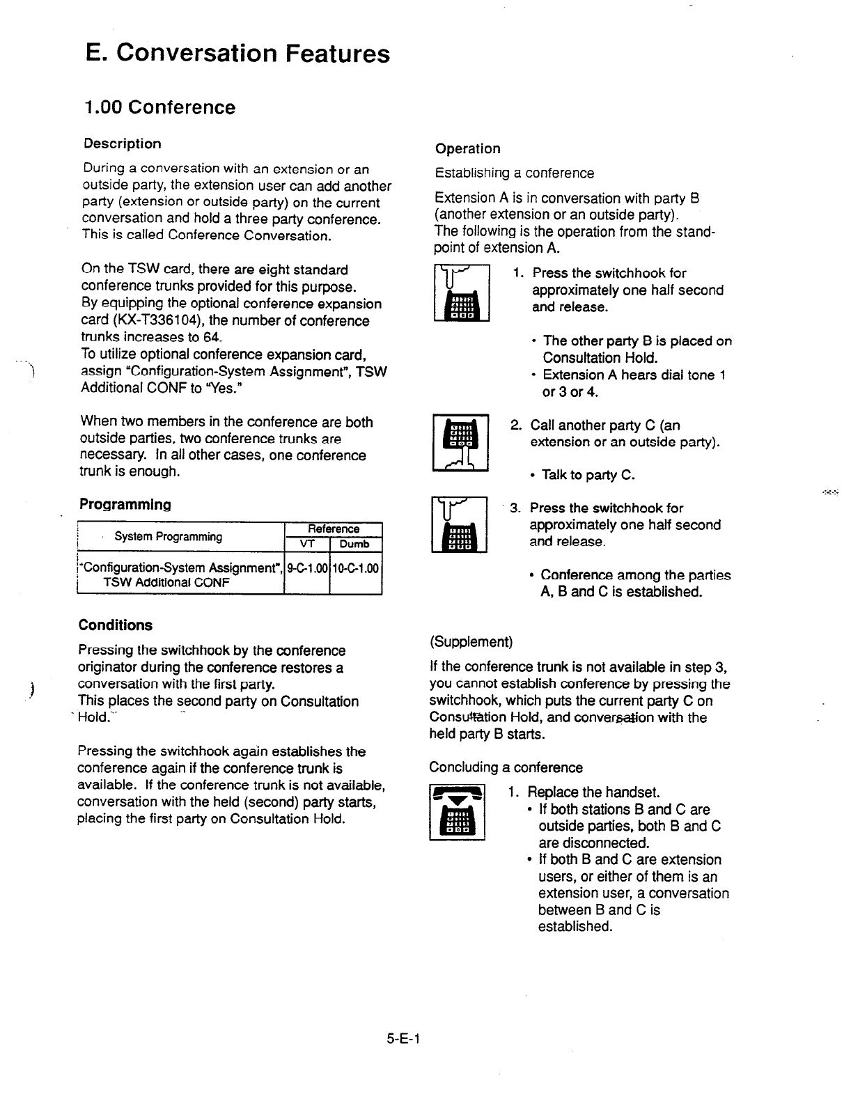
E. Conversation Features
1 .OO Conference
Description
During a conversation with an extension or an
outside party, the extension user can add another
party (extension or outside party) on the current
conversation and hold a three party conference.
This is called Conference Conversation.
On the TSW card, there are eight standard
conference trunks provided for this purpose.
By equipping the optional conference expansion
card (KX-T336104), the number of conference
trunks increases to 64.
To utilize optional conference expansion card,
f assign “Configuration-System Assignment”, TSW
Additional CONF to “Yes.”
When two members in the conference are both
outside parties, two conference trunks are
necessary. In all other cases, one conference
trunk is enough.
Programming
kl
j’Configuratron-System Assignment”, 9-C-l .@I
10-C-l .OO
Conditions
Pressing the switchhook by the conference
originator during the conference restores a
1 conversation with the first party.
This places the second party on Consultation
. Hold.‘- -.
Pressing the switchhook again establishes the
conference again if the conference trunk is
available. If the conference trunk is not available,
conversation with the held (second) party starts,
placing the first party on Consultation Hold.
Operation
Establishing a conference
Extension A is in conversation with party B
(another extension or an outside party).
The following is the operation from the stand-
point of extension A.
1.
2.
3.
Press the switchhook for
approximately one half second
and release.
l
The other party B is placed on
Consultation Hold.
l
Extension A hears dial tone 1
or3or4.
Call another party C (an
extension or an outside party).
l
Talk to party C.
Press the switchhook for
approximately one half second
and release.
l
Conference among the parties
A, B and C is established.
(Supplement)
If the conference trunk is not available in step 3,
you cannot establish conference by pressing the
switchhook, which puts the current party C on
Consu%tion Hold, and convar@on with the
held party B starts.
Concluding a conference
1. Replace the handset.
l
If both stations B and C are
outside parties, both B and C
are disconnected.
.:a:.:.
l
If both B and C are extension
users, or either of them is an
extension user, a conversation
between B and C is
established.
5-E-l
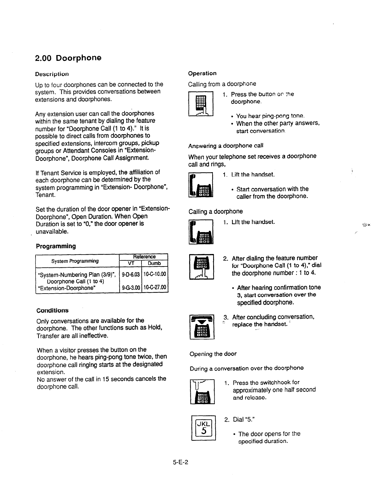
2.00 Doorphone
Description
Up to four doorphones can be connected to the
system. This provides conversations between
extensions and door-phones.
Any extension user can call the do&phones
within the same tenant by dialing the feature
number for “Doorphone Call (1 to 4).’ It is
possible to direct calls from doorphones to
specified extensions, intercom groups, pickup
groups or Attendant Consoles in “Extension-
Doorphone”, Doorphone Call Assignment.
If Tenant Service is employed, the affiliation of
each doorphone can be determined by the
system programming in “Extension- DoorphoneS
Tenant.
Set the duration of the door opener in “Extension-
Doorphone”, Open Duration. When Open
Duration is set to “0,” the door opener is
. unavailable.
Programming
Operation
Calling from a doorphone
1. Press the bunon or :he
doorphone.
l
You hear ping-pong tone.
. When the other party answers.
start conversation.
Answering a door-phone call
When your telephone set receives a doorphone
call and rings,
1. Lift the handset.
l
Start conversation with the
caller from the doorphone.
Calling a dootphone
1. Lift the handset.
. .
2. After dialing the feature number
for “Doorphone Call (1 to 4),” dial
the doorphone number : 1 to 4.
l
After hearing confirmation tone
3, start conversation over the
specified doorphone.
Conditions
Only conversations are available for the
doorphone. The other functions such as Hold,
Transfer are all ineffective.
3. After concluding conversation,
’ replace the handset. ’
_
When a visitor presses the button on the
doorphone, he hears ping-pong tone twice, then
doorphone call ringing starts at the designated
extension.
No answer of the call in 15 seconds cancels the
doorphone call.
Opening the door
During a conversation over the doorphone
1. Press the switchhook for
approximately one half second
and release.
1
2. Dial “5.”
l
The door opens for the
specified duration.
5-E-2
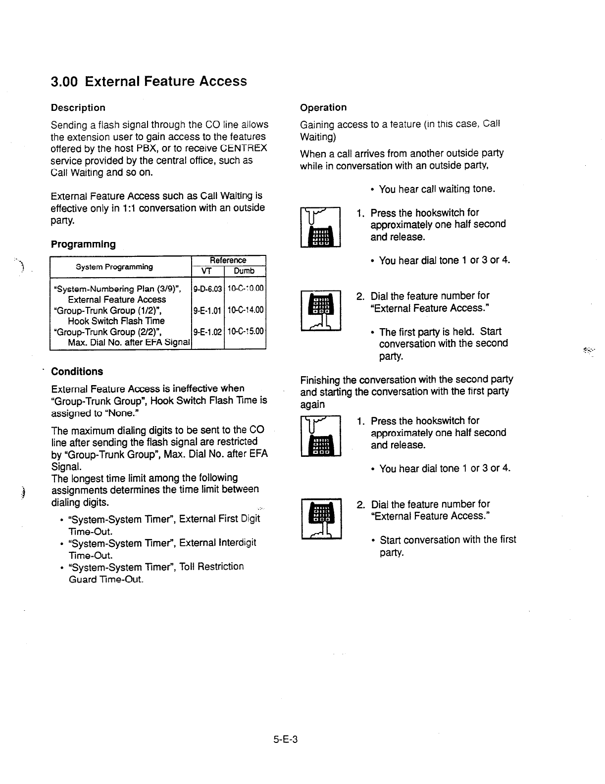
3.00 External Feature Access
.-
-?I
Sending a flash signal through the CO line allows
the extension user to gain access to the features
offered by the host PBX, or to receive CENTREX
service provided by the central office, such as
Call Waiting and so on.
Description Operation
Gaining access to a feature
(in this case, Call
Waiting)
When a call arrives from another outside party
while in conversation with an outside party,
External Feature Access such as Call Waiting is
effective only in 1 :l conversation with an outside
pafly.
l
You hear call waiting tone.
Programming
1. Press the hookswitch for
approximately one half second
and release.
System Programming
“System-Numbering Plan (3/g)“,
External Feature Access
“Group-Trunk Group (l/2)“,
Hook Switch flash Time
“Group-Trunk Group (2/2)‘,
Max. Dial
No. after EFA Signa
g-D-6.03 1 O-c-: 0.00
9-E-1 .Ol 10-C-t 4.00
g-E-1.02 1 O-C-? 5.00
. Conditions
External Feature Access is ineffective when
“Group-Trunk Group”, Hook Switch Flash hme is
assigned to “None.”
The maximum dialing digits to be sent to the CO
line after sending the flash signal are restricted
by “Group-Trunk Group”, Max. Dial No. after EFA
Signal.
The longest time limit among the following
assignments determines the time limit between
dialing digits. .i_
l
“System-System Timer”, External First Digit
Time-Out.
l
“System-System Timer”, External Interdigit
Time-Out.
l
“System-System Timer”, Toll Restriction
Guard Tme-Out.
l
You hear dial tone 1 or 3 or 4.
2. Dial the feature number for
“External Feature Access.”
l
The first party is held. Start
conversation with the second
party.
Finishing the conversation with the second party
and starting the conversation with the first party
again
1. Press the hookswitch for
approximately one half second
and release.
l
You hear dial tone 1 or 3 or 4.
2. Dial the feature number for
“External Feature Access.”
I
l
Start conversation with the first
party.
5-E-3
F. Paging Features
1 .OO Paging
1.01 Paging All Extensions
Description
Paging All Extensions allows any extension user
to perform paging through the built-in speakers of
all PITS telephones that can receive paging.
The Class of Service of the user’s extension
determines the extensions that can receive
paging. They are assigned to be paged by
“System-Class of Service”, Station Paging
Access and also if they belong to the same
tenant as the user’s extension.
See Section 3-B-7.04 “Paging Group” for further
information about paging groups.
To page all extensions, dial the feature number When there is no paging group assigned to “Yes”
for “Station Paging” and “0.” in “System-Class of Service”, Station Paging
To answer paging, dial the feature number for Access within the same tenant, the performer
“Station Paging Answer.” hears reorder tone.
Programming
System Programming Reference
VT Dumb
“System-Class of Service (2/2)“, 9-D-4.02 lOhI
Station Paging Access
“System-Numbering Plan (319)“. 9-D-6.03 10-C-10.00
Station Paging
Station Paging Answer
Conditions
Single Line telephone (SLT’s) cannot be paged.
If all of the extensions assigned to be paged are
being paged by another page, busy tone is
returned to the new paging performer. If any of
the extensions is not being paged, paging is
executed.
Automatic Callback feature does not function
during paging operation.
Refer to Section 5-A-4.01 “Automatic Callback-
Trunk” for further information.
Paging is broadcast over idle speakers in SP-
PHONES of on-hook PITS sets.
The PlTSs actuated by paging send confirmation
tone and are ready to be paged.
5-F-l
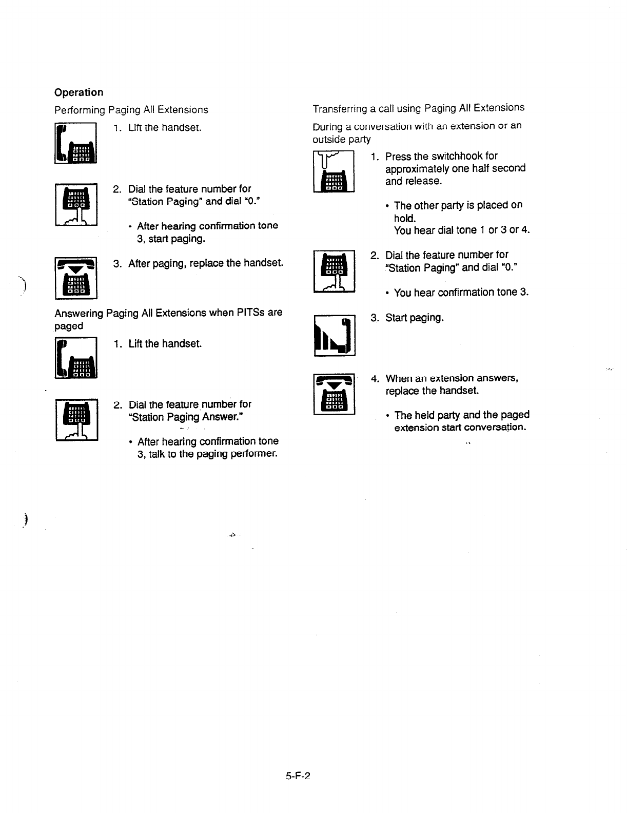
Operation
Performing Paging All Extensions
1. Lift the handset.
2. Dial the feature number for
“Station Paging” and dial “0.”
l
After hearing confirmation tone
3, start paging.
3. After paging, replace the handset.
Answering Paging All Extensions when PlTSs are
paged
1.
Lift the handset.
2. Dial the feature,number for
“Station Paging Answer.”
k!u -.’
l
After hearing confirmation tone
3, talk to the paging performer.
Transferring a call using Paging All Extensions
During a conversation with an extension or an
outside party
I
1. Press the switchhook for
approximately one half second
and release.
l
The other party is placed on
hold.
You hear dial tone 1 or 3 or 4.
2. Dial the feature number for
‘Station Paging” and dial “0.”
l
You hear confirmation tone 3.
1
idi
3. Start paging.
I
4. When an extension answers,
replace the handset.
l
The held party and the paged
extension start conversation.
. .
.._
5-F-2

1.02 Group Paging
Description
Group Paging provides paging to a group of
extensions specified from eight paging groups
through the built-in speakers of their PITSs.
The Class of Service of the user’s extension
determines the paging groups that can receive
paging. They are assigned to be paged by
“System-Class of Service”, Station Paging
Access and also if they belong to the same
tenant as the user’s extension.
To execute Group Paging, dial the feature
number for “Station Paging” and paging group
specifying number.
To answer paging, dial the feature number for
“Station Paging Answer.”
Programming
System Programming Re
v-r
“System-Class of Service (2/2)“,
9-D-4.02
Station Paging Access
“System-Numbering Plan (3/g)“,
9-O-6.03
Station Paging
Station Paging Answer
Conditions
Single Line Telephones (SLT’s) cannot be paged.
If the designated paging group is being paged by
another page, busy tone is returned to the new
paging performer.
However, he can page within the range not
overlapping the preset paging range.
For instance, when paging is being done to group
1, paging groups 2 to 8 are available for new
paging.
Automatic Callback feature does not function
during paging operation.
When there is no paging group allowed to
receive paging in “System-Class of Service”,
Station Paging Access, the performer hears
reorder tone.
Paging is broadcast over idle speakers in SP-
PHONES of on-hook PITS sets.
The PlTSs actuated by paging send confirmation
tone and then are ready to be paged. . .
. .
5-F-3
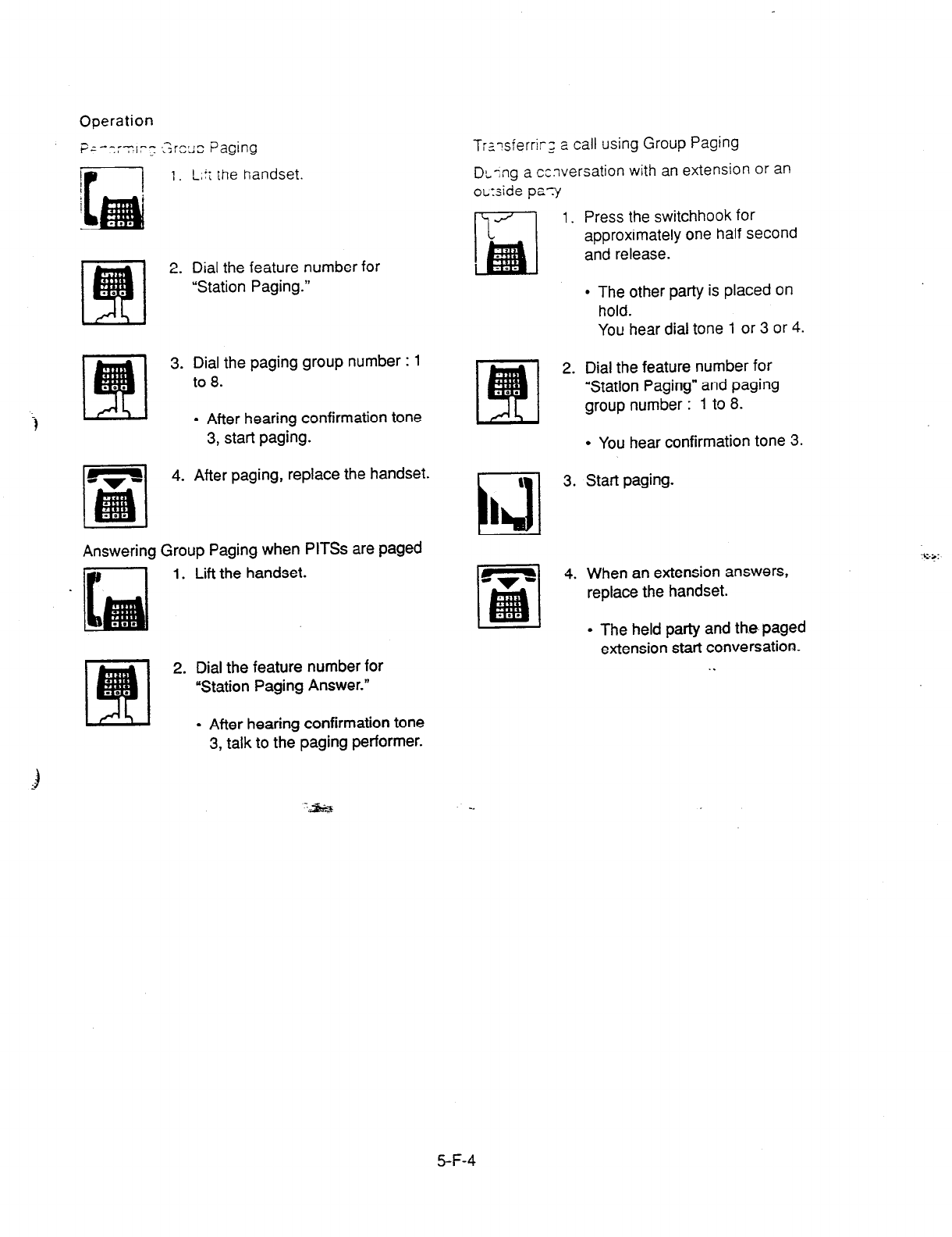
Operation
pf--:;~l:;
,srcsJ::
Paging
F-l ‘. L,t; the handset.
2. Dial the feature number for
“Station Paging.”
3. Dial the paging group number : 1
to 8.
. After hearing confirmation tone
3, start paging.
4. After paging, replace the handset.
Answering Group Paging when PIT% are paged
1. Lift the handset.
2. Dial the feature number for
“Station Paging Answer.”
l
After hearing confirmation tone
3, talk to the paging performer.
T:s-sierrir_= 2 call using Group Paging
DL;ng a conversation with an extension or an
oL:side pay
m 1. Press the switchhook for
approximately one half second
and release.
l
The other party is placed on
hold.
You hear dial tone 1 or 3 or 4.
Dial the feature number for
“Station Paging” and paging
group number : 1 to 8.
l
You hear confirmation tone 3.
Start paging.
When an extension answers,
replace the handset.
. The held party and the paged
extension start conversation.
. .
3
5-F-4

1.03 Paging External Pagers
Description
Allows
the extension users to perform paging
through
the external pager(s)
belonging to the
same tenant.
If two external pagers are available in the same
tenant, two methods are available: one is to page
by designating one external pager, and the other
is to page using two pagers.
To execute this function, dial the feature number
for “External Pager” and to answer the paging,
dial the feature number for ‘External Paging
Answer.”
Even if an external pager is connected to the
system, Paging External Pagers does not
operate unless ‘System-Operation”, External
Paging 1, 2 is assigned to “Yes”.
If Tenant Service is available, it is possible to
attach each external pager to a tenant in “lrunk-
Pager & Music Source”, External Pager-Tenant.
Confirmation tone from external pagers is
selected by “Trunk-Pager & Music Source”,
External Pager-Tone.
Programming
System Programming Reference
VT Dumb
*System-Operation (l/S)“, 9-D-l .Ol 1 O-C-4.00
External Paging 1.2
‘System-Class of -rice (2/2)“,
9-D-4.02 104-8.00
External Paging
‘System-Numbering Plan (SB)“, ~&343+X 10-G10.00
External Paging
External Paging Answer
‘Trunk-Pager
& Music Source”,
9-F-2.00 1 O-C-1 9.00
External Pager-Tenant
External Pager-Tone
Conditions
If the designated pager is being used, busy tone
is returned to the paging performer.
If either or both of the pagers in a tenant are
being used, it is not possible to page using two
pagers. Busy tone is returned to the user.
If external pagers are not assigned by system
programming, reorder tone sounds when paging.
The followings show the paging priorities:
(1) Paging External Pager from an Attendant
Console
(2) TAFAS (Trunk Answer from Any Station )
(Refer to Section 5-B-2.00 “Trunk Answer
From Any Station (TAFAS)-Day Service.” )
(3) Paging External Pagers from an extension
(this function)
(4) BGM through External Pager
If a lower priority page is active, and a higher
priority page is actuated, it overrides the lower
one: for instance, if Paging External Pager is
overridden by another higher priority, reorder
tone is returned to the performer of Paging
External Pager. If TAFAS signal or BGM is
overridden by another higher priority, it is
interrupted and starts again when the higher
priority is finished.
5-F-5

Operation
Performing Paging External
Pagers
1.
Lift the handset
2. Dial the feature number for
“External Paging.”
3. Dial the number for specifying an
external pager or pagers: 0, 1 or
2.
0: specifies external pagers 1
and 2
1: specifies external pager 1
2: specifies external pager 2
l
After you hear confirmation tone
3, start paging through the
external pager(s).
4. After paging, replace the
handset.
Answering during external paging
1. Lift the handset.
2. Dial the feature number for
“External Paging Answer.”
3. Dial the number of the external
pager: 1 or 2.
. After you hear confirmation tone
3, talk to the caller who made
._
the page.
-‘a”s’f’; ng a call using Paging External Pagers
3urinc 3 conversation with an extension or an
o;ltsi& party
1.
2.
Press the switchhook for
approximately one half second
and release.
l
The other party is placed on
hold.
You hear dial tone 1 or 3 or 4.
Dial the feature number for
“External Paging” and external
pager specifying number : 0, 1
or 2.
0: specifies external pagers 1
and 2
1: specifies external pager 1
2: specifies external pager 2
. You hear confirmation tone 3.
Start paging.
When an extension answers,
replace the handset.
l
The held party and the paged
extension start conversation.
5-F-6

1.04 Paging All Extensions
and
External Pagers
Description
Paging All Extensior: 2-c Ev?nal Pagers offers
both Paging All Extensions and Paging External
Pagers at the same tire It provides paging
through the preprogrammed external pagers and
the built-in speakers in PlTSs of the extensions
within the range of the tenant that the user
belongs to.
The user’s “System-Class of Service”, Station
Paging Access” determines the paging groups of
the extensions that can receive paging and also
External Paging determines the external pagers
that can receive paging.
Programming
System Programming
“System-Class of Service (2/2)“,
Station Paging ACXXSS
External Paging 1,2
‘System-Numbering Plan (3/g)“,
External Paging
Station Paging
External Paging Answer
Station Paging Answer
v-r
9-D-4.02
9-D-6.03
Conditions
Refer to Section 5-F-l .Ol “Paging All Extensions”
and Section 5-F-l .03 “Paging External Pagers.”
l
The other party is placed
on
hold.
Operation You hear dial tone 1 or 3 or 4.
Performing Paging All Extensi@@and External
Pagers 2. Dial the feature number for
“Station Paging” or the feature
number for “External Paging,”
then dial U*.”
1. Lift the handset.
2. Dial the feature number for
“Station Paging” or the feature
number for “External Paging,”
then dial “*.”
l
After hearing confirmation tone
3. start paging.
3. After paging, replace the handset.
Answering Paging All Extensions and External
1. Lift the handset.
2. Dial the feature number for
“Station Paging Answer,” or the ‘.
: -
I feature number for “External
Paging Answer” and the number
of the external pager : 1 or 2.
l
After hearing confirmation tone
3, talk to the paging performer. :i,
Transferring a call using Paging All Extensions
and External Pagers
During a conversation with an extension or an
outside party
1. Press the switchhook for
approximately one half second
and release.
l
You hear confirmation tone 3.
a
3. Start paging.
L
4. When an extension answers,
replace the handset. .
l
The held party and the paged
extension start conversation.
:::
5-F-7
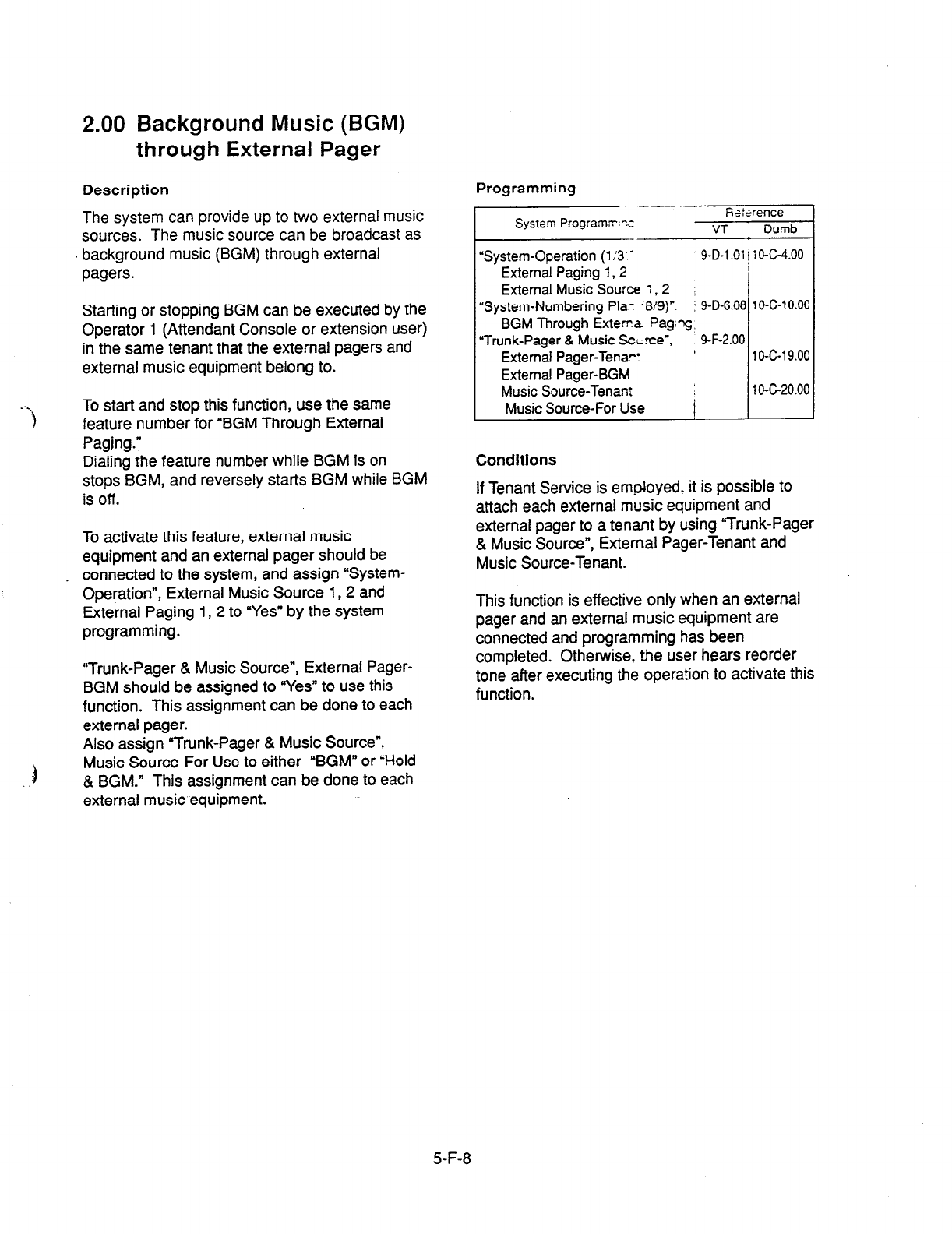
2.00 Background Music (BGM)
through External Pager
Description
The system can provide up to two external music
sources. The music source can be broadcast as
background music (BGM) through external
pagers.
Starting or stopping BGM can be executed by the
Operator 1 (Attendant Console or extension user)
in the same tenant that the external pagers and
external music equipment belong to.
To start and stop this function, use the same
feature number for “BGM Through External
Paging.”
Dialing the feature number while BGM is on
stops BGM, and reversely starts BGM while BGM
is off.
To activate this feature, external music
equipment and an external pager should be
. connected to the system, and
assign
“System-
Operation”, External Music Source 1, 2 and
External Paging 1, 2 to “Yes” by the system
programming.
“Trunk-Pager & Music Source”, External Pager-
BGM should be assigned to “Yes” to use this
function. This assignment can be done to each
external pager.
Also assign “Trunk-Pager & Music Source”,
Music Source-For Use to either “BGM” or “Hold
& BGM.” This assignment can be done to each
external musicequipment.
Programming
System Programs:-c --,,“““‘z,/
“System-Operation (1!3’ -
External Paging
1.2
9-D-l .Ol [ 1 O-C-4.00
External
Music Source : ,2 I
“System-Numbering Plar ‘8/g)“. : 9-D-6.08 10-C-10.00
BGM
Through Exten?a
Pag,T,
“Trunk-Pager 8 Music ScLrce”, 9-F-2.00
External Pager-Tenart ’ 10-c-19.00
External Pager-BGM
Music Source-Tenant 1 1 O-c-20.00
Music Source-For Use I
Conditions
If Tenant Service is employed, it is possible to
attach each external music equipment and
external pager to a tenant by using “Trunk-Pager
& Music Source”, External Pager-Tenant and
Music Source-Tenant.
This function is effective only when an external
pager and an external music equipment are
connected and programming has been
completed. Otherwise, the user hears reorder
tone after executing the operation to activate this
function.
5-F-8
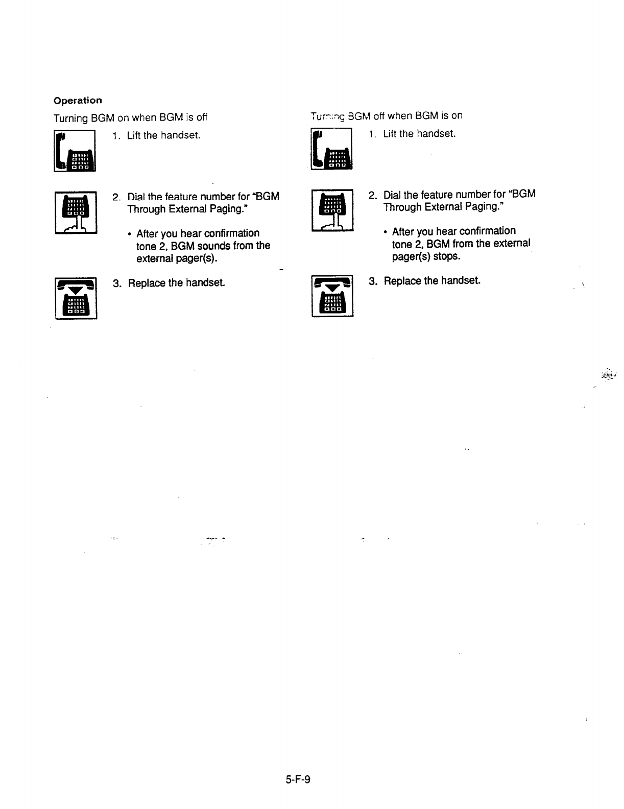
Operation
Turning BGM on when BGM is off
1. Lift the handset.
2. Dial the feature number for ‘BGM
Through External Paging.”
l
After you hear confirmation
tone 2, BGM sounds from the
external pager(s).
2. Dial the feature number for “BGM
Through External Paging.”
l
After you hear confirmation
tone 2, BGM from the external
pager(s) stops.
3. Replace the handset. 3. Replace the handset.
5-F-9
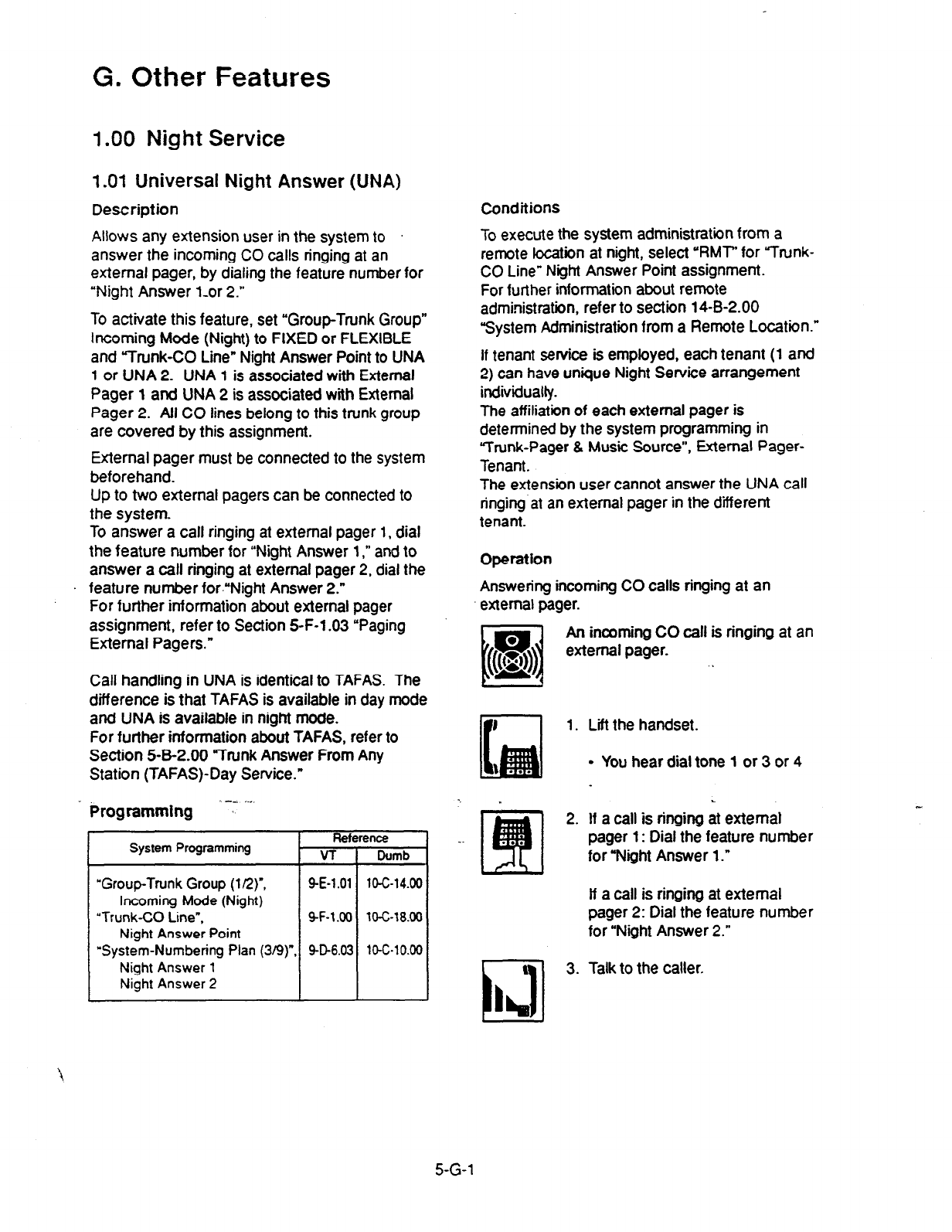
G. Other Features
1 .OO Night Service
1.01 Universal Night Answer (UNA)
Description Conditions
Allows any extension user in the system to
answer the incoming CO calls ringing at an
external pager, by dialing the feature number for
“Night Answer l-or 2.”
To activate this feature, set “Group-Trunk Group”
Incoming Mode (Night) to FIXED or FLEXIBLE
and Trunk-CO Line” Night Answer Point to UNA
1
or UNA 2. UNA 1 is associated with External
Pager 1 and UNA 2 is associated with External
Pager 2. AtI CO lines belong to this trunk group
are covered by this assignment.
To execute the system administration from a
remote location at night, select ‘MT’ for Yrunk-
CO Line” Night Answer Point assignment.
For further information about remote
administration, refer to section 14-B-2.00
System Administration from a Remote Location.”
External pager must be connected to the system
beforehand.
Up to two external pagers can be connected to
the system.
To answer a call ringing at external pager 1, dial
the feature number for “Night Answer 1,” and to
answer a call ringing at external pager 2, dial the
. feature number for.“Night Answer 2.”
For further information about external pager
assignment, refer to Section 5-F-l .03 “Paging
External Pagers.”
if tenant service is employed, each tenant (1 and
2) can have unique Night Service arrangement
individually.
The affiliation of each external pager is
determined by the system programming in
Trunk-Pager & Music Source”, External Pager-
Tenant.
The extension user cannot answer the UNA call
ringing at an external pager in the diierent
tenant.
Operation
Answering incoming CO calls ringing at an
external pager.
Call handling in UNA is identical to TAFAS. The
difference is that TAFAS is available in day mode
and UNA is available in night mode.
For further information about TAFAS, refer to
Section 5-B-2.00 “Trunk Answer From Any
Station (TAFAS)-Day Service.”
u
m
An incoming CO call is ringing at an
I 8
& external pager. ,
Ilr
1. Lift the handset.
Programming ‘-: ~.
System Programming
“Group-Trunk Group
(l/2)“,
Incoming Mode (Night)
‘Trunk-CO Line”,
Night Answer Point
“System-Numbering Plan (3/9)
Night Answer 1
Night Answer 2
l
You hear dial tone 1 or 3 or 4
L
2. If a call is ringing at external
pager 1: Dial the feature number
for “Night Answer 1.”
if a call is ringing at external
pager 2: Dial the feature number
for “Night Answer 2.”
3. Talk to the caller.
5-G-1

1.02 Flexible Night Service
Description
Flexible Night Service allows the Operator 1
(Attendant Console or extension user) to change
the assigned night answer destination on a CO
4ine basis by dialing the feature number for
“Flexible Night Service.”
To utilize this feature, set “Group-Trunk Group”
Incoming Mode (Night) to FLEXIBLE. All CO
lines belong to this trunk group are covered by
this assignment.
If FIXED is selected for above setting, the
assigned night answer destination can not be
changed by the Operator 1.
Call handling in Flexible and Fixed night service
is almost the same.
The difference is:
Flexible The Operator 1 (Attendant Console
or Extension) can change the night
answer destination.
FiXed
A group of extensions (Night
Answer Group) can be assigned as
the destination of one or more CO
lines in night mode
Programmlng
System Prosramming
i..,:. “Group-Trunk Group (l/2)“,
Incoming MC& (Night)
“Trunk-CO tine”,
Night Answer Point
Reference
VT Dumb
SE-l.01 10-C-14.00
9-F-1.00
lOG18.00
‘System-Numbering Plan (8/9)‘, 9-D-6.08
10-C-10.00
Flexible Night Service
Conditions
If tenant service is employed, the night answer
destination can only be changed for a CO line in
the same tenant by the Operator 1.
Operation
Changing a night answer desznation to an
extension
1. Lift the handset.
2.
3. Replace the handset.
Dial the feature number for
Flexible Night Service 72”
(default) and CO physical number
and destination extension number.
l
You hear confirmation tone 1 or
2.
Changing a night answer destination to the remote
maintenance port
1. Lift the handset.
. .
2. Dial the feature number for
Flexible Night Service 72”
(default) and CO physical number
and FDN for remote.
l
You hear confirmation tone 1 or
2. :.
3. Replace the handset.
5-G-2
(30393)
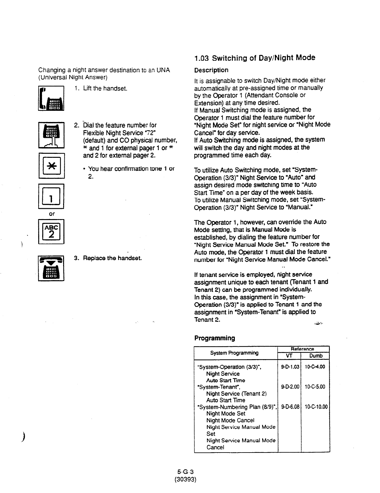
Changing a night answer
destination to tn UNA
(Universal Night Answer)
1. Lift the handset.
2. -Dial the feature number for
Flexible Night Service 72”
(default) and CO physical number,
* and 1 for external pager 1 or *
and 2 for external pager 2.
1.03 Switching of Day/Night Mode
Description
It is assignable to switch Day/Night mode either
automatically at pre-assigned time or manually
by the Operator 1 (Attendant Console or
Extension) at any time desired.
If Manual Switching mode is assigned, the
Operator 1 must dial the feature
number for
“Night Mode Set” for night service or “Night Mode
Cancel” for day service.
If Auto Switching mode is assigned, the system
will switch the day and night modes at the
programmed time each day.
l
You hear confirmation tone 1 or
2.
3. Replace the handset.
To utilize Auto Switching mode, set “System-
Operation (313)” Night Service to ‘Auto’ and
assign desired mode switching time to ‘Auto
Start Ttme” on a per day of the week basis.
To utilize Manual Switching mode, set ‘System-
Operation (3/3)” Night Service to “Manual.”
The Operator 1, however, can override the Auto
Mode setting, that is Manual Mode is
established, by dialing the feature number for
“Night Service Manual Mode Set.” To restore the
Auto mode, the Operator 1 must dial the feature
number for “Night Service Manual Mode Cancel.”
If tenant service is employed, night se&e
assignment unique to each tenant (Tenant 1 and
Tenant 2) can be programmed individually.
In this case, the assignment in ‘System-
Operation (3/3)” is applied to Tenant 1 and the
assignment in ‘System-Tenant” is applied to
Tenant 2.
Programming
Reference
System Rogramming VT DlJllIb
‘System-Operation (a/3)‘,
9-D-l .03 1 O-G4.00
Night Service
Auto Start Time
‘System-Tenant”.
9-D-2.00 1 W-5.00
Night Service (Tenant 2)
Auto Start Time
‘System-Numbering Plan (&9)“, 9-D-6.08 10-C-10.00
Night Mode Set
Night Mode Cancel
Night Service Manual Mode
Set
Night Service Manual Mode
ChllCel
5-G-3
(30393)
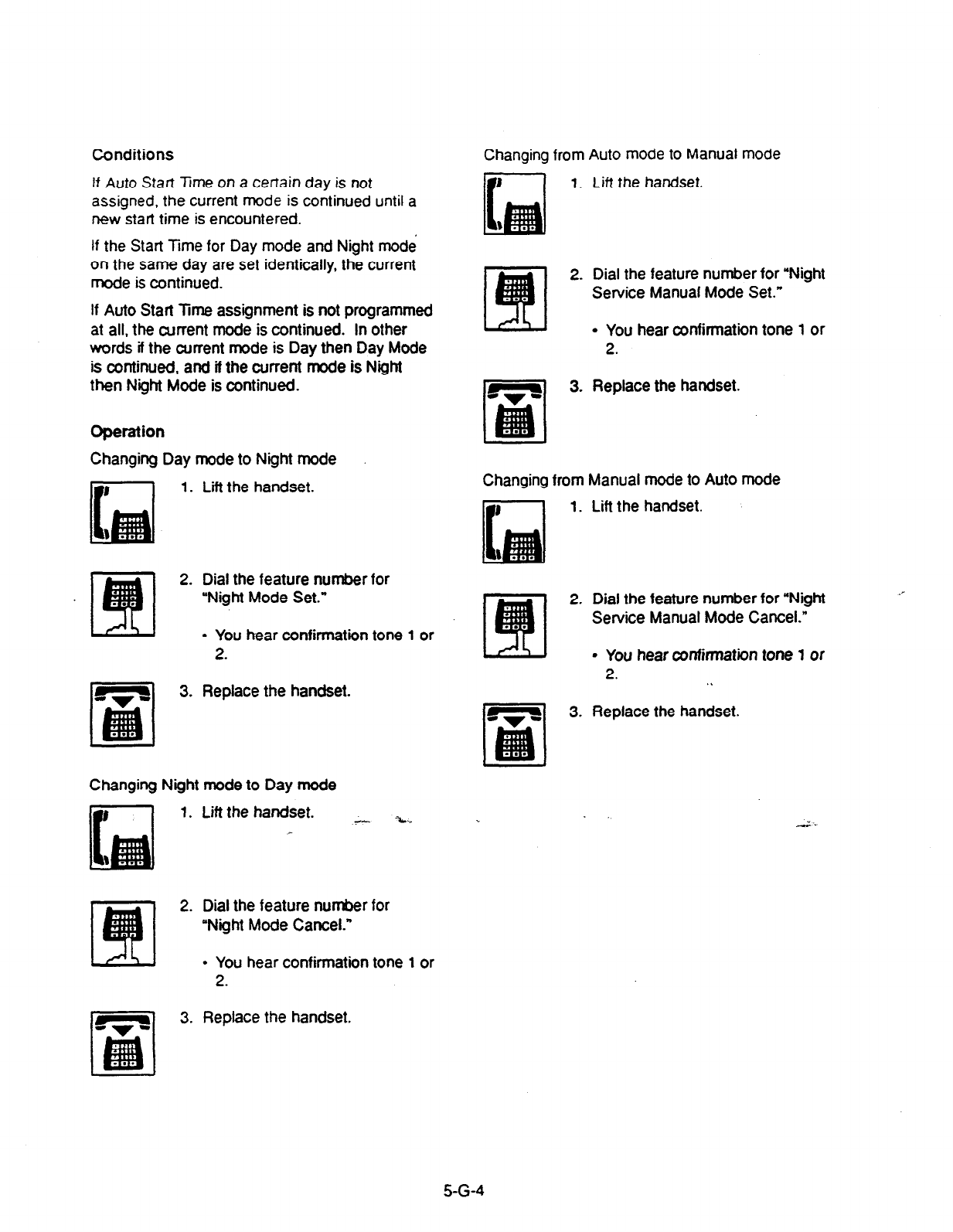
Conditions
If Auto Stati Time on a certain day is not
assigned, the current mode is continued until a
new start time is encountered.
If the Start lime for Day mode and Night mode
on the same day are set identically, the current
mode is continued.
If Auto Start Time assignment is not programmed
at all. the current mode is continued. In other
words if the current mode is Day then Day Mode
is continued, and if the current mode is Night
then Night Mode is continued.
Operation
Changing Day mode to Night mode
1.
2.
3.
Lii the handset.
Dial the feature number for
“Night Mode Set.”
l
You hear confirmation tone 1 or
2.
Replace the handset.
Changing Night mode to Day mode
Lift the handset. .Y-- %..
Dial the feature number for
“Night Mode Cancel.”
l
You hear confirmation tone 1 or
2.
Replace the handset.
Changing from Auto mode to Manual mode
1. lift the handset.
2. Dial the feature number for “Night
Service Manual Mode Set.”
l
You hear confirmation tone 1 or
2.
3. Replace the handset.
Changing from Manual mode to Auto mode
1.
2.
3.
Lift the handset.
Dial the feature number for “Night
Service Manual Mode Cancel.”
l
You hear confirmation tone 1 or
2. .L
Replace the handset.
5-G-4
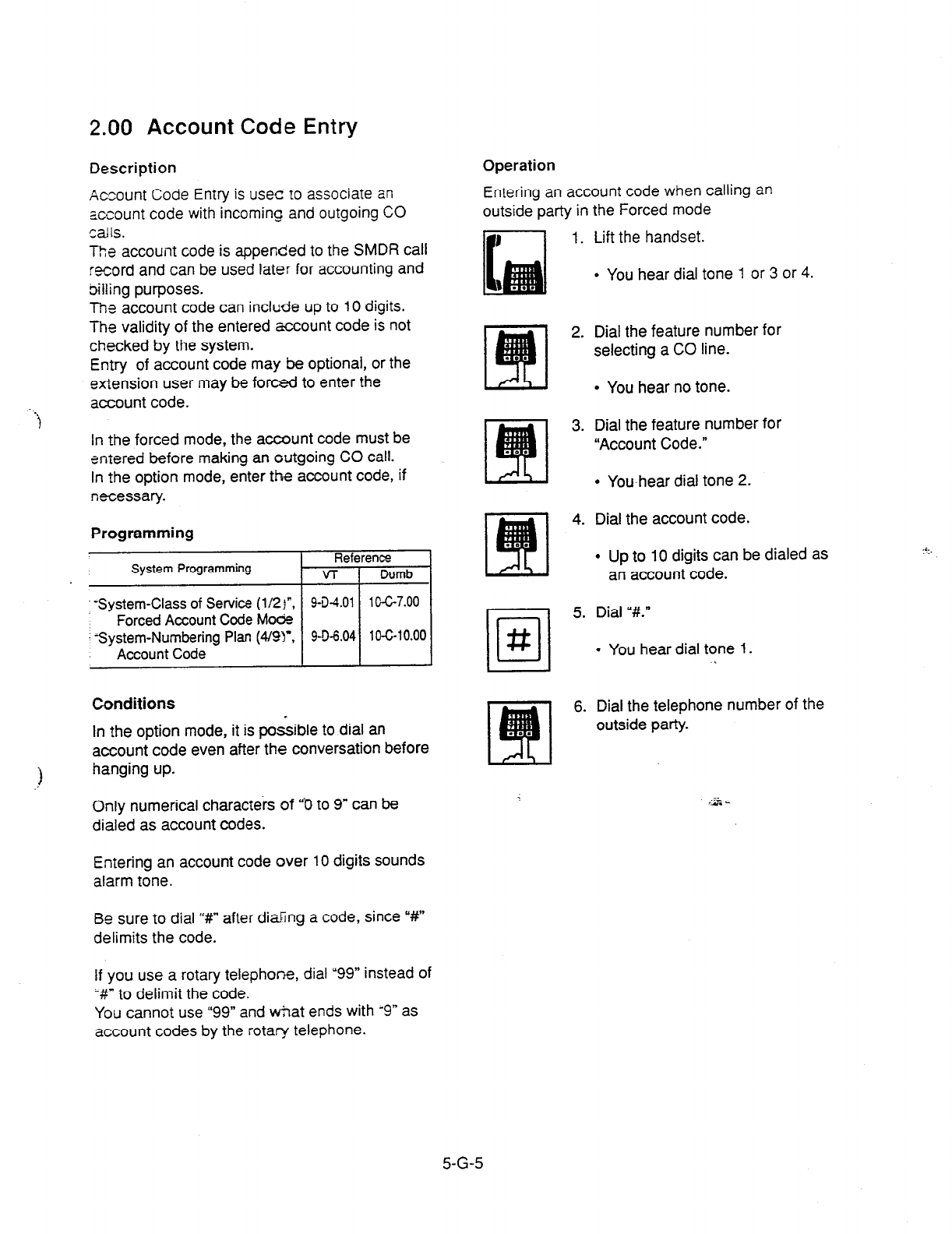
2.00
Account Code Entry
Description
Operation
Entering an account code when calling an
outside party in the Forced mode
Acsount Code Entry is usec to associate an
account code with incoming and outgoing CO
Saik.
The account code is appended to the SMDR call
record and can be used later for accounting and
billing purposes.
The account code can include up to 10 digits.
The validity of the entered account code is not
checked by the system.
Entry of account code may be optional, or the
extension user may be forced to enter the
account code.
1. Lift the handset.
l
You hear dial tone 1 or 3 or 4.
2.
Dial the feature number for
selecting a CO line.
l
You hear no tone.
-i
In the forced mode, the account code must be
entered before making an outgoing CO call.
In the option mode, enter the account code, if
necessary.
Programming
System Programming Reference
VT 1 Dumb
I
Conditions
.?
In the option mode, it is possible to dial an
account code even after the conversation before
hanging up.
Only numerical characters of “0 to 9” can be
dialed as account codes.
Entering an account code over 10 digits sounds
alarm tone.
Be sure to dial I‘#” after dialing a code, since “#I”
delimits the code.
•l
#
3.
4.
5.
6.
Dial the feature number for
“Account Code.”
l
Youhear dial tone 2.
Dial the account code.
l
Up to 10 digits can be dialed as
an account code.
Dial ,#.”
l
You hear dial tone 1.
.
Dial the telephone number of the
outside party.
If you use a rotary telephone, dial “99” instead of
W to delimit the code.
You cannot use “99” and tiat ends with ‘9” as
account codes by the rotary telephone.
5-G-5

Entering an account code when receiving a call
from an outside party in the Forced mode
1. Lift the handset.
l
Talk to the other party.
2. Press the switchhook for
approximately one half second
and release.
l
You hear dial tone 1 or 3 or 4.
3. Dial the feature number for
“Account Code.”
l
You hear dial tone 2.
4. Dial the account code.
l
Maximum digits for an account
code is 10.
5. Dial “#.”
l
Start conversation again.
Entering an account code after calling an outside
party or atier receiving a call from an outside
party in the Option mode
While having a conversation
I
1. Press the switchhook for
approximately one half second
and release.
l
You hear dial tone 1 or 3 or 4.
2. Dial the feature number for
“Account Code.”
l
You hear dial tone 2.
3. Dial the account code.
l
Maximum digits for an account
code is 10.
4. Dial ,#..
l
Start conversation again.
Correcting an error after dialing a wrong account
code (not available with rotary type SLT
telephones)
1. Dial “*.”
l
You hear dial tone 2.
2. Dial the correct account code.
‘*
3. Dial “#.”
5-G-6
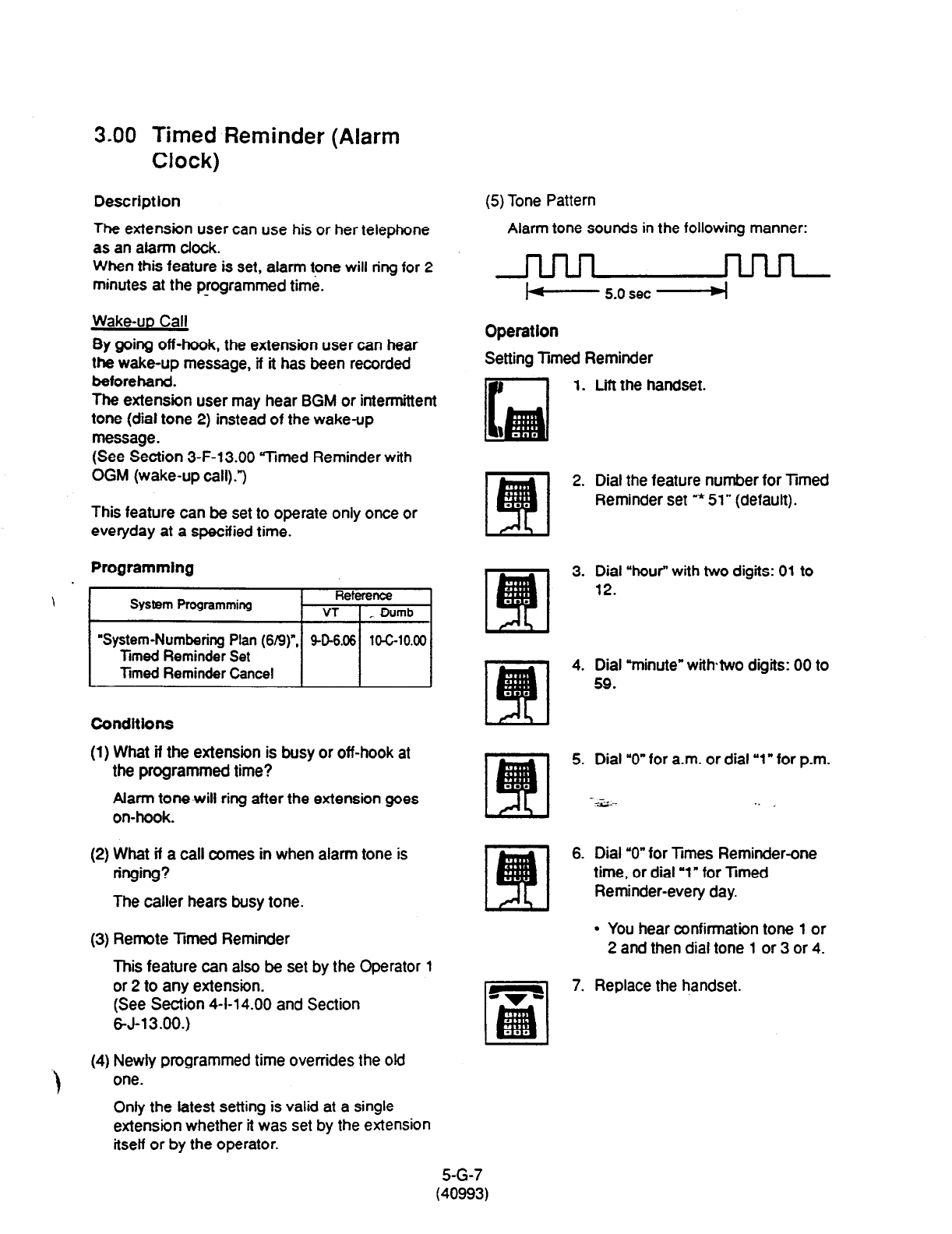
3.00 Timed Reminder (Alarm
Clock)
Description
The extension user can use his or her telephone
as an atarm clock.
When this feature is set, alarm tone will ring for 2
minutes at the programmed time.
Wake-up Call
By going off-hook, the extension user can hear
the wake-up message, lf it has been recorded
beforehand.
The extension user may hear BGM or intermittent
tone (dial tone 2) instead of the wake-up
message.
(See Section 3-F-13.00 “Timed Reminder with
OGM (wake-up call).“)
This feature can be set to operate only once or
everyday at a specified time.
Programming
’ ~1
System-Numbering Plan (619) , 9-D-6.06
10-G10.00
Conditions
(1) What if the extension is busy or off-hook at
the programmed time?
Alarm tone will ring after the extension goes
on-hook.
(2) What if a call comes in when alarm tone is
ringing?
The caller hears busy tone.
(3) Remote limed Reminder
This feature can also be set by the Operator 1
or 2 to any extension.
(See Section 4-I-14.00 and Section
6-J-13.00.)
(4) Newly programmed time overrides the aid
one.
Only the latest setting is valid at a single
extension whether it was set by the extension
itself or by the operator.
(5) Tone Pattern
Alarm tone sounds in the following manner:
+ 5.0 set W
Operation
Setting limed Reminder
1. Lift the handset.
2. Dial the feature number for limed
Reminder set * 51” (default).
3. Dial “hour” with two digits: 01 to
12.
4. Dial “minute” withtwo digits: 00 to
59.
5. Dial ‘0” for a.m. or dial “1” for p.m.
.- _
-4 ,... . .
6. Dial “0” for iimes Reminder-one
time, or dial ‘1” for Ttmed
Reminder-every day.
I’ ‘I
9 You hear confirmation tone 1 or
2 and then dial tone 1 or 3 or 4.
7. Replace the handset.
5-G-7
(40993)
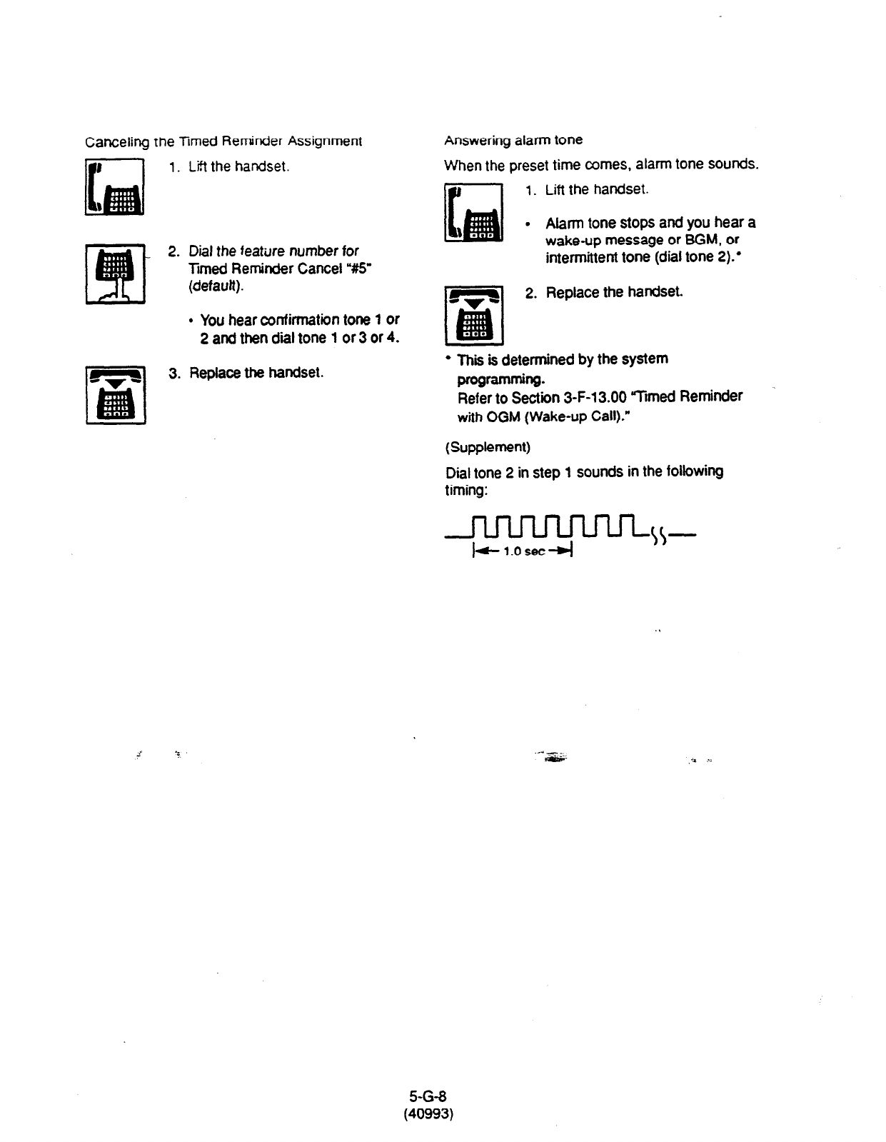
Canceling the limed Reminder Assignment
Lift the handset.
Answering alarm tone
1.
2.
3.
When the preset time comes, alarm tone sounds.
1.
.
Dial
the
feature number for
Tmed Reminder Cancel Y6’
(default).
l
You hear confirmation tone 1 or
2 and then diil tone 1 or 3 or 4.
Lift the handset.
Alarm tone stops and you hear a
wake-up message or BGM, or
intermittent tone (dial tone 2):
Replace the handset.
Replace the handset.
l
Thii is determined by the system
programming.
Refer to Section 3-F-13.00 “Jimed Reminder
with OGM (Wake-up Call).”
(Supplement)
Dial tone 2 in step 1 sounds in the following
timing:
-w-
I+ 1.osec-j
5-G-8
(40993)

4.00 Data Line Security
Description
Used to maintain Ihe co.mm~n~~a:.~r. ore-r:,- by
prohibiting various tones such as ‘3a*!
Ww13
tone or Held Call Reminder from sounding at the
extension in data communication mode. I: aiso
prohibits other extensions
from
executing
overriding functions such as Busy Override.
To assign Data Line Security, assign “Extension-
Station” Data Line Security to “Yes.”
You can set and cancel this function by
dialing
the feature numbers for “Data Line
Security Set”
and “Data Line Security Cancel.”
Programming
System Programming
“System-Numbering Plan (5/g)“,
Data Line Security Set
Data Line Security Cancel
“Extension-Station (l/3)”
Data Line Security
Reference
VT Dumb
9-D-6.05 10-C-10.00
9-G-1.01 10-C-22.00
Conditions
Assigning this function always offers the
extension user Privacy mode unless Privacy
Release is executed.
If there is a conversation between the
extension
setting
Data Line Security and the
extension not
setting
it, Data Line Security is applied to the
both extensions.
Operation
Setting Data Line Security
1. Lift the handset.
2. Dial the feature number for “Data
Line Security Set.”
I
l
You hear confirmation tone 1 or
2 then dial tone 1 or 3 or 4.
3. Replace the handset.
Canceling Data Line Security
1. Lift the handset.
2. Dial the feature number
for “Data
Line Security Cancel.”
l
You hear confirmation tone 1 or
2 then dial tone 1 or 3 or 4.
3. Replace the handset.
5-G-9
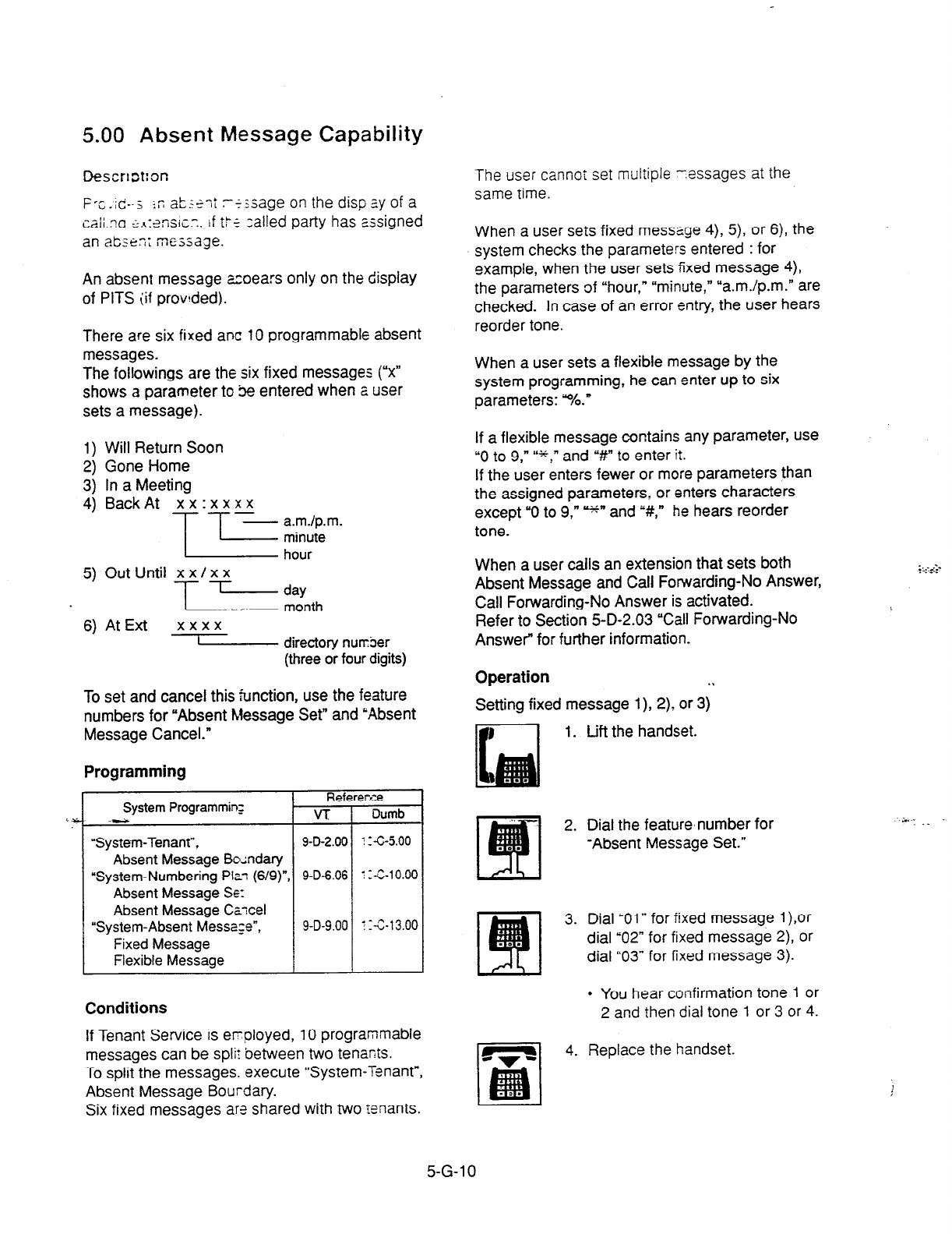
5.00 Absent Message Capability
Descrt=t:or:
F -c-id--5 ic &.?Z ii I
L- - --’ -*<sage on the disp ?.y of a
Cali ?a E;.q:?TiSiC.Y. i
f t:k zalled party has assigned
an a&en: message.
An absent message acoears only on the display
of PITS (if provded).
There are six fixed ant 10 programmable absent
messages.
The followings are the six fixed messages (“x”
shows
a
parameter to je entered when a user
sets a message).
1) Will Return Soon
2) Gone Home
3) In a Meeting
4) Back At xx :x x xx
T T--%;:“-
5) Out Until xx/xx
=%th
6) At Ext xxxx
s directory nurrber
(three or four digits)
To set and cancel this function, use the feature
numbers for “Absent Message Set” and ‘Absent
Message Cancel.”
Programming
Referee.ze
System Programmin;
.- VT Dumb
“System-Tenant”, 9-D-2.00 ::6-5.00
Absent
Message
Boundary
“System-Numbering Plot (6/g)“, 9-D-6.06 ! Z-G10.00
Absent Message SE:
Absent Message Czcel
“System-Absent Message”, 9-D-9.00 I :-&13.00
Fixed Message
Flexible Message
Conditions
If Tenant Service is eqloyed, 10 programmable
messages can be split between two tenarts.
To split the messages. execute “System-Tenant”,
Absent Message Bourdary.
Six fixed messages are shared with two tenants.
The user cannoi set multiple -.essages at the
same time.
When a user sets fixed message 4), 5), or 6), the
system checks the parameters entered : for
example, when the user sets fixed message 4),
the parameters of “hour,” “minute,” “a.m./p.m.” are
checked. In case of an error entry, the user hears
reorder tone.
When a user sets a flexible message by the
system programming, he can enter up to six
parameters: %.”
If a flexible message contains any parameter, use
“0 to 9,” “*,” and “#” to enter it.
If the user enters fewer or more parameters than
the assigned parameters, or enters characters
except “0 to 9,
” =+” and ,#,” he hears reorder
tone.
When a user calls an extension that sets both
Absent Message and Call Forwarding-No Answer,
Call Forwarding-No Answer is activated.
Refer to Section 5-D-2.03 “Call Forwarding-No
Answer” for further information.
Operation . .
Setting fixed message l), 2) or 3)
1. Lift the handset.
2. Dial the feature,number for
-Absent Message Set.”
3. Dial “Oln for fixed message l),or
dial “02” for fixed message 2), or
dial “03” for fixed message 3).
l
You hear confirmation tone 1 or
2 and then dial tone 1 or 3 or 4.
4. Replace the handset.
.:;..i‘-r
. . --.
..;m- . . .
5-G-l 0
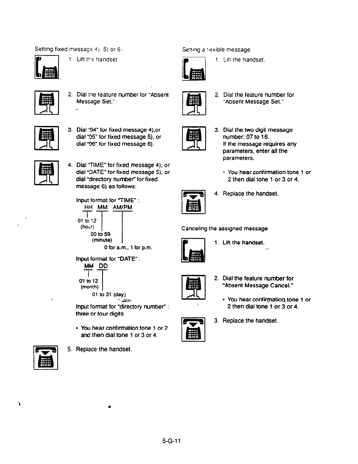
Setting fixed message
4).
5) or 61
i
Lift tc? handset
Dial tne feature number for ‘Absent
Message Set.”
Dial 94” for fixed message 4),or
dial ‘95” for fixed message 5), or
dial “06” for fixed message 6).
Dial &TIME” for fixed message
4),
or
dial ‘DATE” for fixed message 5), or
dial “directory number for fixed
message 6) as follows:
Input format for ‘WVIE” :
HH
MM AM/PM
(hoi:) 1
00 to 59
(minute)
0 for a.m.. 1 for p.m.
input format for ‘DATE’ :
MM DD
T
01 to12
T
(month)
01 to 31 (day)
‘.-c-s-
Input format for “directory number” :
three or four digits
l
You hear confirmation tone
1
or
2
and then dial tone
1
or 3 or
4.
Serr~ng a flsxible message
1. Lifr the handset.
2. Dial the feature number for
“Absent Message Set.”
3. Dial the two digit message
number: 07 to 16.
lf the message requires any
parameters, enter alI the
parameters.
l
You hear confirmation tone 1 or
2 then dial tone 1 or 3 or 4.
4.
Replace the handset.
Canceling the assigned message
1. Lift the handset. .I
2. Dial the feature number for
“Absent Message Cancel.”
l
You hear confivatiogtone 1 or
2 then dial tone 1 or 3 or 4.
3. Replace the handset.
5.
Replace the handset.
5-G 11
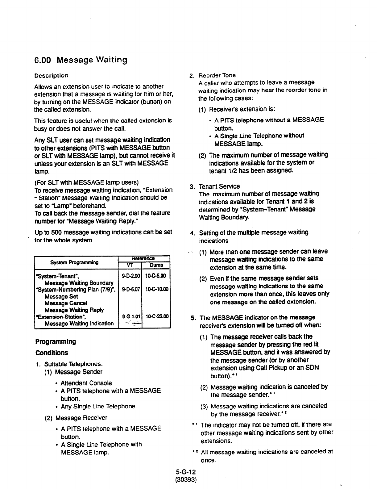
6.00 Message Waiting
Description
Allows an extension user to
rndicate to another
extension that a message ts waiting tar nim or her,
by turning on the MESSAGE indicator (button) on
the called extension.
This feature is useful when the called extension is
busy or does not answer the call.
Any SLT user can set message waiting indiition
to other extensions (PITS with MESSAGE button
or SLT with MESSAGE lamp), but cannot receive it
unless your extension is an SLT with MESSAGE
lamp.
(For SLT with MESSAGE lamp users)
To receive message waiting indication, “Extension
- Station” Message Waiting Indication should be
set to ‘Lamp’ beforehand.
To call back the message sender, dial the feature
number for ‘Message Waiting Reply.”
Up to 500 message waiting indications can be set
. for the whole system.
System Pqramming
‘System-Tenant,,
Message Wafting Boundary
‘System-Numbering
Plan (719)‘.
Message Set
Message Cancel
Message Wafting Reply
‘Extension-Statiin-,
Message Waiting Indication
Refc
VT
SD260
SD6.07
Programming
Conditions
1. Suitable Telephones:
(1) Message Sender
l
Attendant Console
. A PITS telephone with a MESSAGE
button.
l
Any Single Line Telephone.
(2) Message Receiver
l
A PITS telephone with a MESSAGE
button.
l
A Single Line Telephone with
MESSAGE lamp.
2. Reorder Tone
A
caller who attempts to leave a message
waiting indication may hear the reorder tone in
the following cases:
(1) Receiver’s extension is:
l
A PITS telephone without a MESSAGE
button.
l
A Single Line Telephone without
MESSAGE lamp.
(2) The maximum number of message waiting
indications available for the system or
tenant l/2 has been assigned.
3. Tenant Service
The maximum number of message waiting
indications available for Tenant 1 and 2 is
determined by “Systen+Tenant” Message
Waiting Boundary.
4. Setting of the multiple message waiting
indications
_ ., (1) More than one message sender can leave
message waiting indications to the same
extension at the same time.
(2) Even if the same message sender sets
message waiting indications to the same
extension more than once, this leaves only
one message on the called extension.
5. The MESSAGE indicator on the message
receiver’s extension will be turned off when:
(1) The message receiver calls back the
message sender by pressing the red tit
MESSAGE button, and it was answered by
the message sender (or by another
extension using Call Pickup or an SDN
button).’ ’
(2) Message waiting indication is canceled by
the message sender.’ ’
(3) Message waiting indications are canceled
by the message receiver.* z
* ’ The indicator may not be turned off, if there are
other message waiting indications sent by other
extensions.
l
* All message waiting indications are canceled at
once.
5-G-l 2
30393)
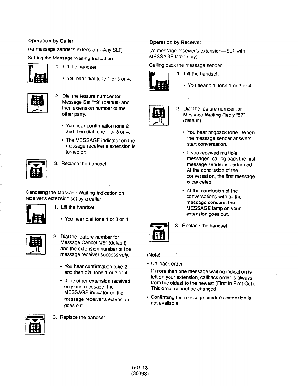
Operation by Caller
(At message sender’s extension-Any SLT)
Setting the Message Waiting Indication
1. Lift the handset.
l
You hear dial tone 1 or 3 or 4.
2. Dial the feature number for
Message Set ‘*9” (default) and
then extension number of the
other party.
l
You hear confirmation tone 2
and then dial tone 1 or 3 or 4.
l
The MESSAGE indicator on the
message receiver’s extension is
turned on.
3. Replace the handset.
Canceling the Message Waiting indication on
receiver’s extension set by a caller
II’
1. Lift the handset.
l
You hear dial tone 1 or 3 or 4.
2. Dial the feature number for
Message Cancel V9” (default)
and the extension number of the
message receiver successivelyI
l
You hear confirmation tone 2
and then dial tone 1 or 3 or 4.
l
If the other extension received
only one message, the
MESSAGE indicator on the
message receiver’s extension
goes out.
Operation by Receiver
(At message receiver’s extensior+SLT with
MESSAGE lamp only)
Calling back the message sender
F----l 1. Lift the handset.
l
You hear dial tone 1 or 3 or 4.
2. Dial the feature number for
Message Waiting Reply “57”
(defautt).
. You hear ringback tone. When
the message sender answers,
start conversation.
l
If you received multiple
messages, calling back the first
message sender is performed.
At the conclusion of the
conversation, the first message
is canceled.
. At the conclusion of the
conversations with all the
message senders, the
MESSAGE lamp on your
extension goes out.
3. Replace the handset.
(Note)
l
Callback order
If more than one message waiting indication is
left on your extension, callback order is always
from the oldest to the newest (First In First Out).
This order cannot be changed.
l
Confirming the message sendets extension is
not available.
3. Replace the handset.
5-G-13
(30393)
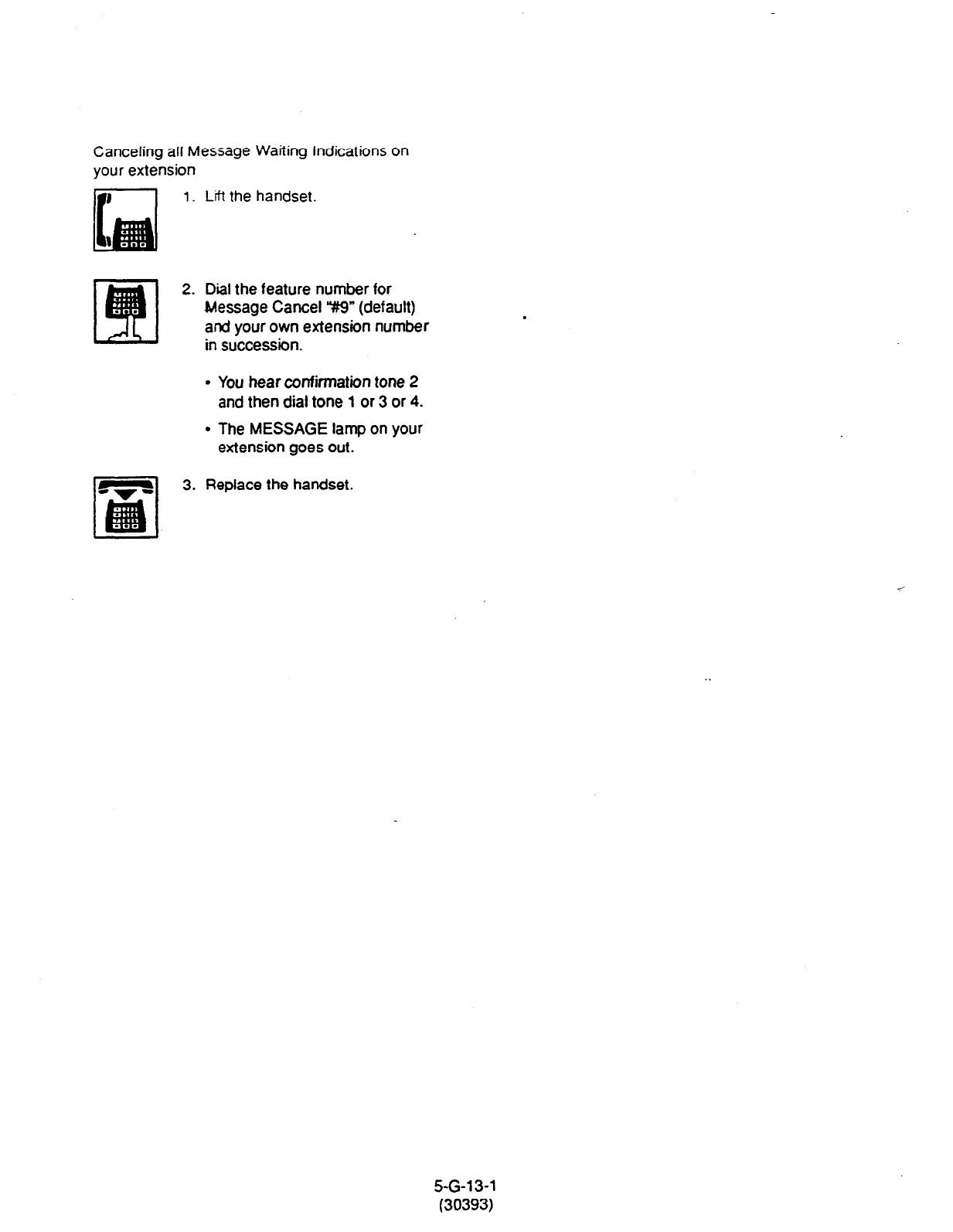
Canceling all Message Waiting Indications on
your extension
1.
Lift the handset.
2. Dial the feature number for
Message Cancel “#9” (default)
and your own extension number
in succession.
l
You hear confirmation tone 2
and then dial tone 1 or 3 or 4.
l
The MESSAGE lamp on your
extension goes out.
3. Replace the handset.
5-G-l 3-1
(30393)
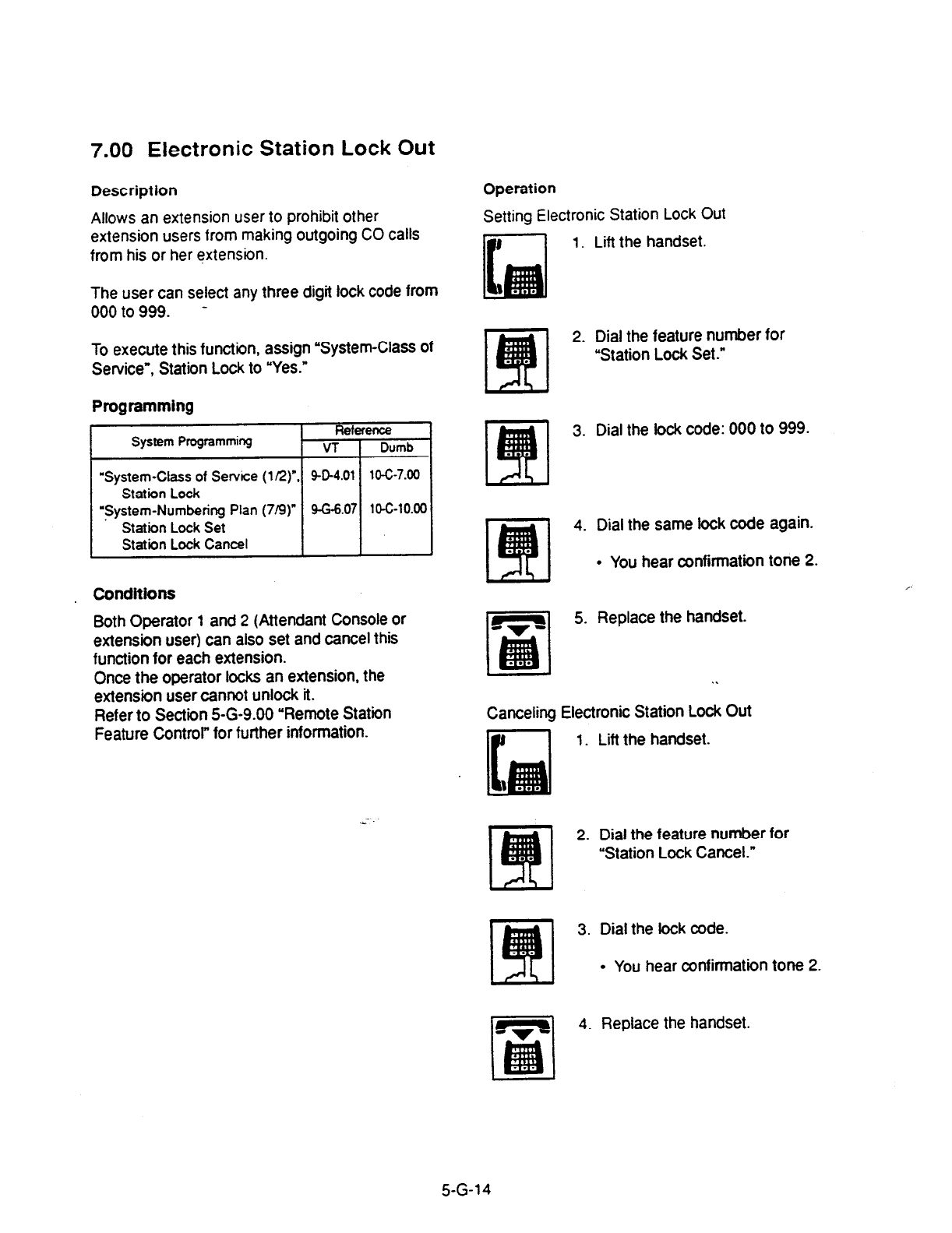
7.00
Electronic Station Lock Out
Description
Allows an extension user to prohibit other
extension users from making outgoing CO calls
from his or her extension.
The user can select any three digit lock code from
000 to 999. -
To execute this function, assign “System-Class of
Service”, Station Lock to “Yes.”
Programming
System Programming
“System-Class of Service (l/2)”
Station Lock
‘System-Numbering Plan (719)
Station Lock Set
Station Lock Cancel
Conditions
Both Operator 1 and 2 (Attendant Console or
extension user) can also set and cancel this
function for each extension.
Once the operator locks an extension, the
extension user cannot unlock it.
Refer to Section 5-G-9.00 “Remote Station
Feature Control” for further information.
Operation
Setting Electronic Station Lock
Out
1.
Lift the handset.
2. Dial the feature number for
“Station Lock Set.”
3. Dial the lock code: 000 to 999.
4. Dial the same lock code again.
l
You hear confirmation tone 2.
5. Replace the handset.
. .
Canceling Electronic Station Lock Out
1. Lift the handset.
2. Dial the feature number for
“Station Lock Cancel.”
3. Dial the iock code.
l
You hear confirmation tone 2.
m
4. Replace the handset.
5-G-14
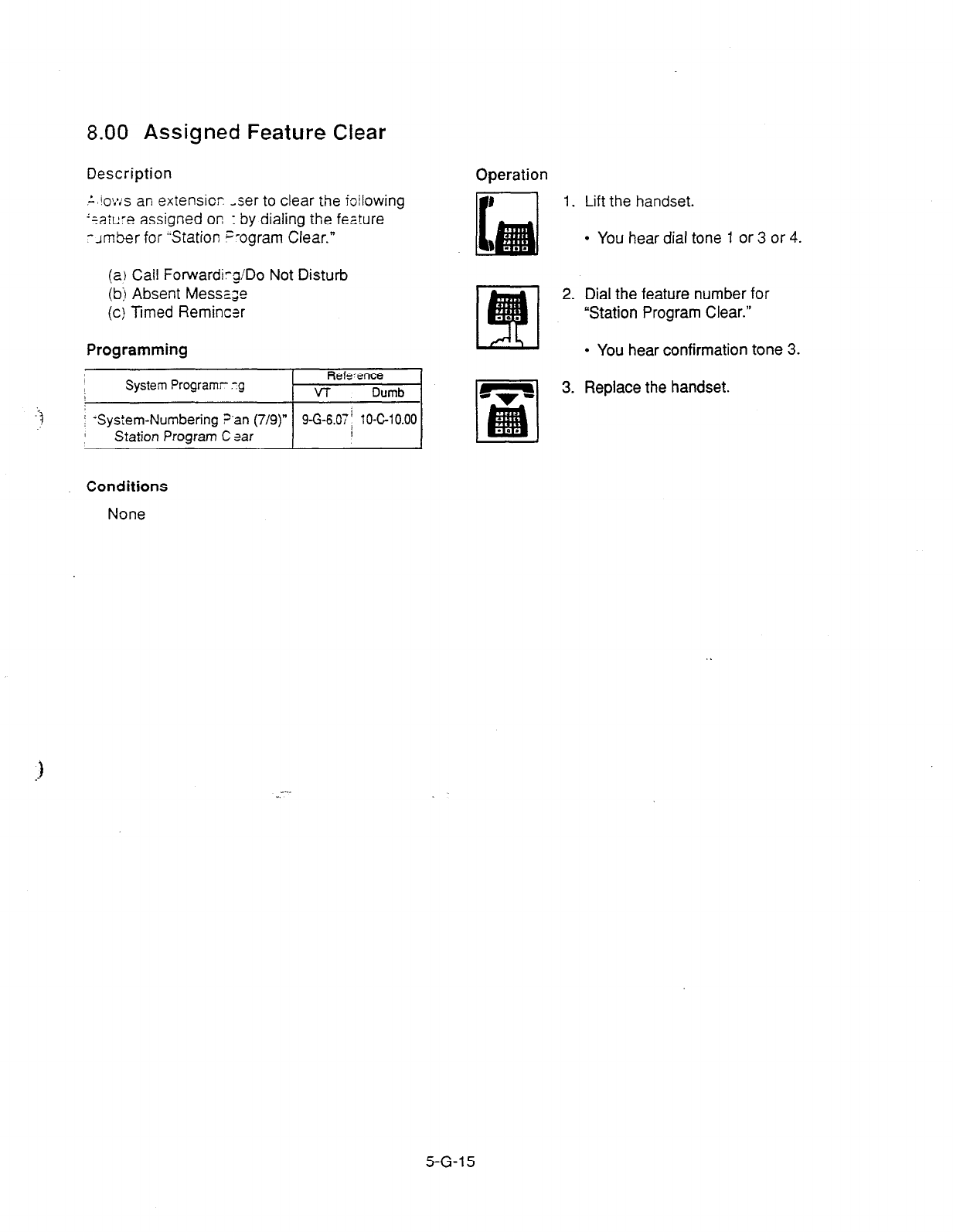
8.00 Assigned Feature Clear
Description
Operation
-
’ io?*:s an exiensior -ser to clear the Wowing
‘eaiure
assigned on : by dialing the feature
-Jmber for “Station s-ogram Clear.”
1. Lift the handset.
l
You hear dial tone 1 or 3 or 4.
(a) Call Forwardirg/Do Not Disturb
(b) Absent Messa.;e
(c) Ttmed Remincer
Programming
2. Dial the feature number for
“Station Program Clear.”
l
You hear confirmation tone 3.
3. Replace the handset.
Conditions
None
..-
5-G-l 5
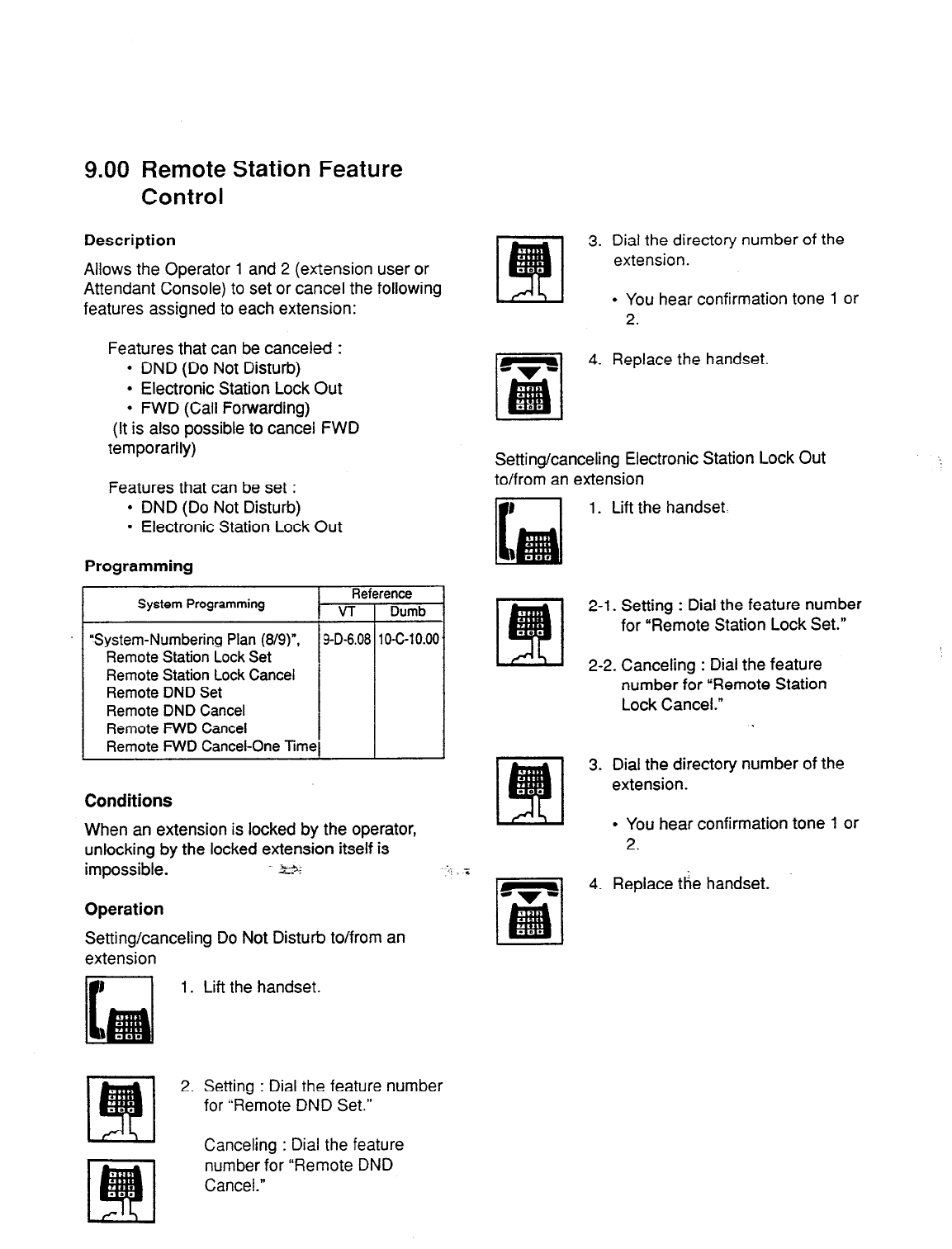
9.00 Remote
Control
Description
Station Feature
Allows the Operator
1
and 2 (extension user or
Attendant Console) to set or cancel the following
features assigned to each extension:
Features that can be canceled :
l
DND (Do Not Disturb)
l
Electronic Station Lock Out
l
FWD (Call Forwarding)
(it is also possible to cancel FWD
temporarily)
Features that can be set :
l
DND (Do Not Disturb)
l
Electronic Station Lock Out
Programming
System Programming Reference
VT Dumb
“System-Numbering Plan (8/g)“, g-D-6.08 1 O-C-I 0.00
Remote Station Lock Set
Remote Station Lock
Cancel
Remote DND Set
Remote DND Cancel
Remote FWD Cancel
Remote FWD Cancel-One Time
Conditions
When an extension is locked by the operator,
unlocking by the locked extension itself is
impossible. %..3.
cc --:: ‘s
Operation
Setting/canceling Do Not Disturb to/from an
extension
1. Lift the handset.
2. Setting : Dial the feature number
for “Remote DND Set.”
Canceling : Dial the feature
number for “Remote DND
Cancel.”
3. Dial the directory number of the
extension.
l
You hear confirmation tone 1 or
2.
4. Replace the handset.
Setting/canceling Electronic Station Lock Out
to/from an extension
1. Lift the handset.
2-l. Setting : Dial the feature number
for “Remote Station Lock Set.”
I
2-2. Canceling : Dial the feature
number for “Remote Station
Lock Cancel.”
3. Dial the directory number of the
extension.
l
You hear confirmation tone 1 or
2.
4. Replace tie handset.
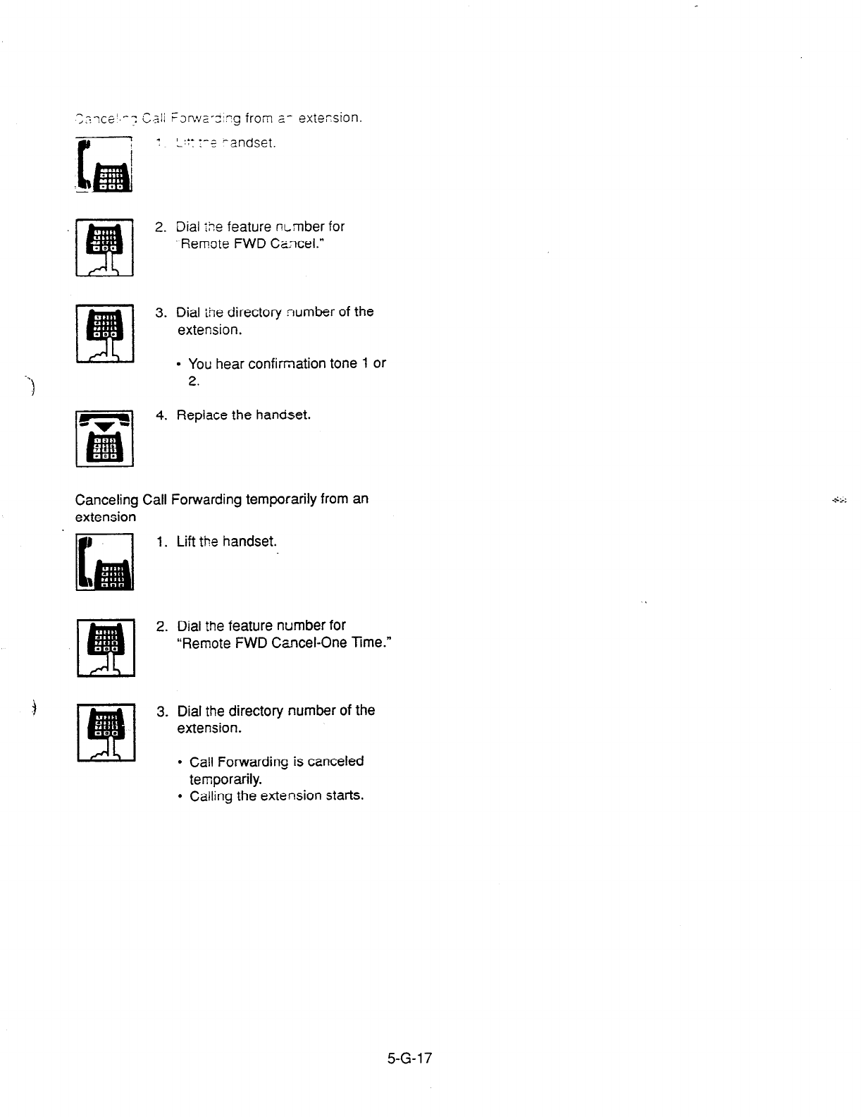
1
I *
/
-
2.
3.
-$
4.
Dial ;5e feature wrnber for
-Remote
FWD Cancel.”
Dial the directory number of the
extension.
l
You hear confirmation tone 1 or
2.
Replace the handset.
Canceling Call Forwarding temporarily from an
extension
3
1. Lift the handset.
2. Dial the feature number for
“Remote FWD Cancel-One Time.”
3. Dial the directory number of the
extension.
l
Cali
Forwarding is canceled
temporarily.
l
Cailing the extension starts.
5-G-l 7
Section 6
Station Features and Operation
Attendant Console (ATT)
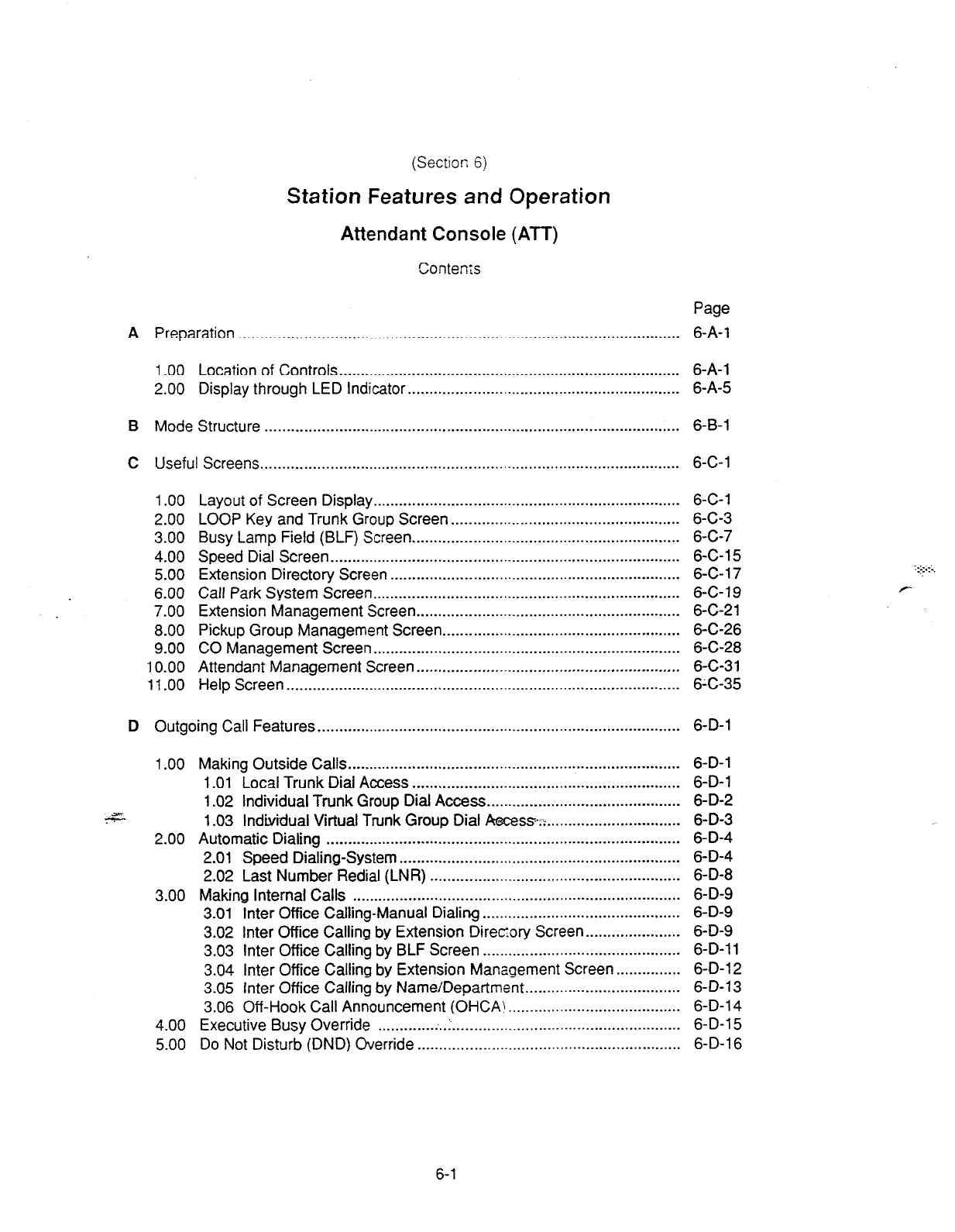
(Section; 6)
Station Features and Operation
Attendant Console (ATT)
Contenrs
Page
A Preparation .,......_. . . . . . . . . . . . . . . . . . . . . . . . . . . . . . . . . . . . . . . . . . . . . . . . . . ..__.._.................................... 6-A-l
1 .OO Location of Controls.. ............................................................................. 6-A-l
2.00 Display through LED Indicator.. ............................................................. 6-A-5
B Mode Structure . . . . . . . . . . . . . . . . . . . . . . . . . . . . . . . . . . . . . . . . . . . . . . . . . . . . . . . . . . . . . . . . . . . . . . . . . . . . . . . . . . . . . . . . . . . . . . . . 6-B-l
C Useful Screens . . . . . . . . . . . . . . . . . . . . . . . . .._..............................._...................................... 6-C-l
1 .oo Layout of Screen Display. ...................................................................... 6-C-l
2.00 LOOP Key and Trunk Group Screen ..................................................... 6-C-3
3.00 Busy Lamp Field (BLF) Screen .............................................................. 6-C-7
4.00 Speed Dial Screen ................................................................................. 6-C-l 5
5.00 Extension Directory Screen ................................................................... 6-C-l 7
6.00 Call Park System Screen.. ..................................................................... 6-C-l 9
7.00 Extension Management Screen ............................................................. 6-C-21
8.00 Pickup Group Management Screen.. ..................................................... 6-C-26
9.00 CO Management Screen.. ..................................................................... 6-C-28
10.00 Attendant Management Screen.. ........................................................... 6-C-31
11.00 Help Screen.. ......................................................................................... 6X-35
D Outgoing Call Features . . . . . . . . . . . . . . . . . . . . . . . . . . . . . . . . . . . . . . . . . . . . . . . . . . . . . . . . . . . . . . . . . . . . . . . . . . . . ..I..... 6-D-l
1 .OO Making Outside Calls.. ...........................................................................
1 .Ol Local Trunk Dial Access ..............................................................
1.02 Individual Trunk Group Dial Access.. ...........................................
&=- 1.03 Individual Virtual Trunk Group Dial Aece~a;~. ..............................
2.00 Automatic Dialing ..................................................................................
2.01 Speed Dialing-System .................................................................
2.02 Last Number Redial (LNR) ..........................................................
3.00 Making Internal Calls ............................................................................
3.01 Inter Office Calling-Manual Dialing. .............................................
3.02 Inter Office Calling by Extension Direcory Screen.. ....................
3.03 Inter Office Calling by BLF Screen ..............................................
3.04 Inter Office Calling by Extension Management Screen.. .............
3.05 Inter Office Calling by Name/Department ....................................
3.06 Off-Hook Call Announcement (OHCA\ ........................................
4.00 Executive Busy Override ............. ;..1....
.................................................
5.00 Do Not Disturb (DND) Override .............................................................
6-D-l
6-D-l
6-D-2
6-D-3
6-D-4
6-D-4
6-D-8
6-D-9
6-D-9
6-D-9
6-D-l 1
6-D-l 2
6-D-13
6-D-l 4
6-D-l 5
6-D-l 6
6-l
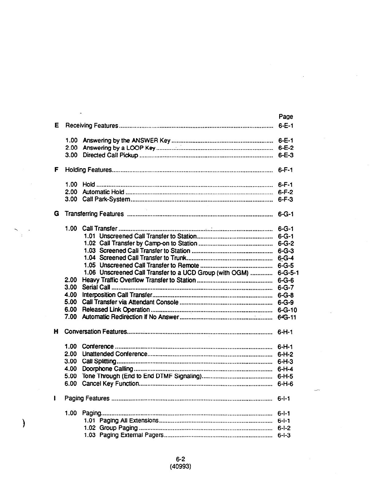
E
F
G
Page
Receiving Features.. ........................................................................................ 6-E-l
1.00 Answering by the ANSWER Key.. ......................................................... 6-E-i
2.00
Answering by a LOOP Key.. ........ .; ..:.
.................................................... 6-E-2
3.00 Directed Call Pickup .............................................................................. 6-E-3
Holding Features
.............................................................................................. 6-F-l
1 .OO Hold ....................................................................................................... 6-F-l
2.00
Automatic Hold ...................................................................................... 6-F-2
3.00 Call Park-System.. ................................................................................. 6-F-3
Transferring Features ..................................................................................... 6-G-l
1 .OO Call Transfer.. ................................................. . ..:. .................................. 6-G-l
1 .Ol Unscreened Call Transfer to Station ............................................ 6-G-l
1.02 Call Transfer by Camp-on to Station ........................................... 6-G-2
1.03 Screened Call Transfer to Station ...............................................
6-G-3
1.04 Screened Call Transfer to Trunk..
................................................ 69-4
1.05 Unscreened Call Transfer to Remote .......................................... 6-G-5
1.06 Unscreened Call Transfer to a UCD Group (with CGM) ............. 6-G-5-l
2.00 Heavy Traffii Overflow Transfer to Station.. .......................................... 6-G-6
3.00
Serial Call .............................................................................................. 6-G-7
4.00 lnterpositiin Call Transfer.. .................................................................... 6-G-8
5.00 Call Transfer via Attendant Console ...................................................... 6-G-9
6.00 Released Link Operation.. ..................................................................... 6-G-10
7.00 Automatic Redirection ff No Answer.. ......................................... .
.......... e-11
Conversation Features.. ................................................................................... 6-H-l
1 .OO Conference ............................................................................................ 6-H-1
2.00
Unattended Conference..
....................................................................... 6-H-2
3.00
Call Splitting ........................................................................................... 6-H-3
4.00 Doorphone Calling ................................................................................. 6-H-4
5.00 Tone Through (End to End DTMF Signaling). ........................................ 6-H-5
6.00 Cancel Key Function..
............................................................................ 6-H-6 ...
Paging Features .............................................................................................. 6-l-l
1 .OO Paging.. .................................................................................................. 6-l-l
1.01 Paging All Extensions..
................................................................ 6-l-l
1.02 Group Paging .............................................................................. 6-l-2
1.03 Paging External Pagers.. ............................................................. 6-l-3
(4E3)
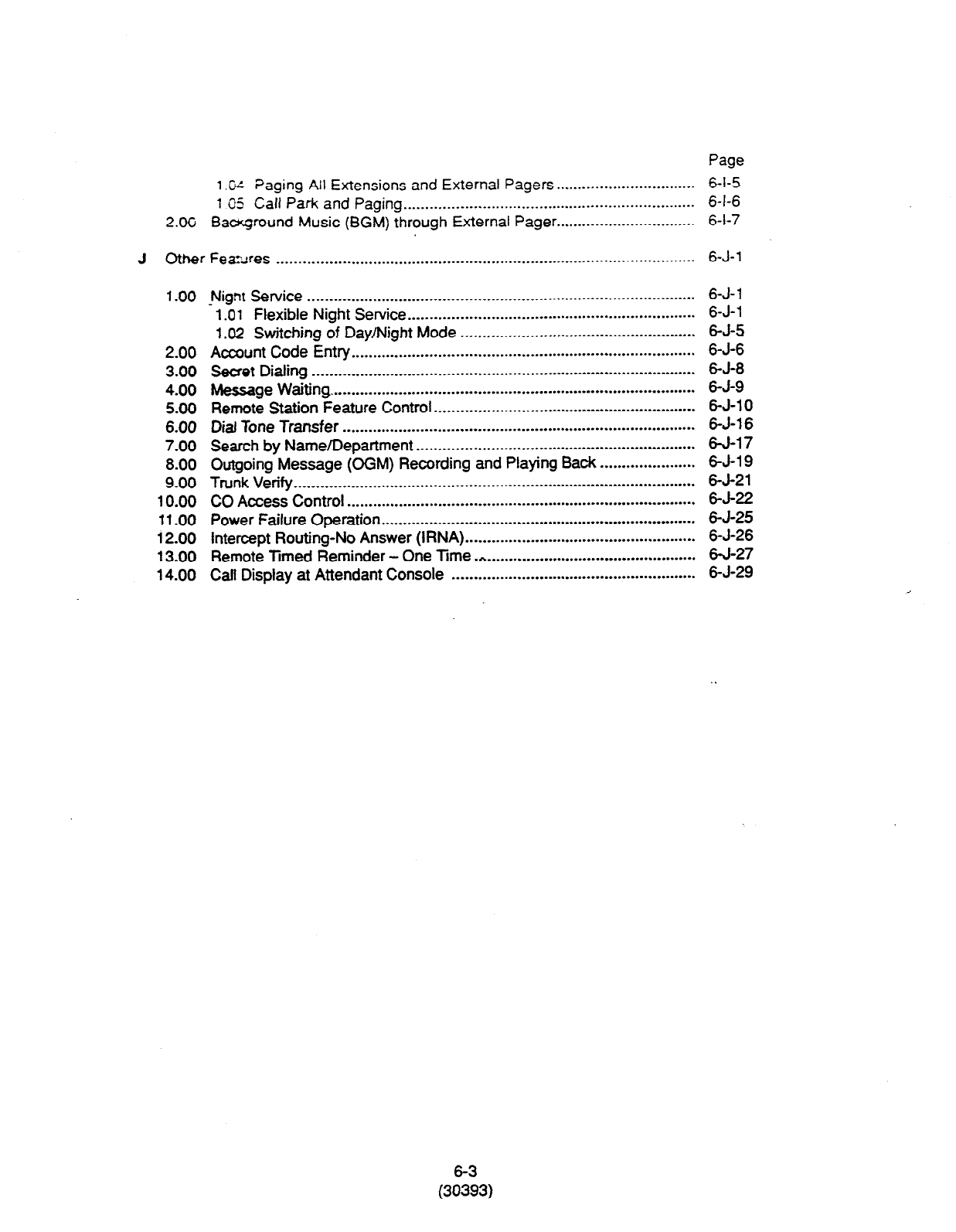
Page
1
.W ?aging All Extensions and External Pagers.. .............................. 6-I-5
1 05
Call Park
and Paging.. ................................................................. 6-I-6
2.OC Bacqmund Music (BGM) through External Pager.. .............................. 6-l-7
J Other
FezAres . . . . . . . . . .._............................-.................................-.....-.........-...-.
6-J-l
1.00
2.00
3.00
4.00
5.00
6.00
7.00
8.00
9.00
10.00
11.00
12.00
13.00
14.00
Nignt Service .........................................................................................
.
1.01
Flexible Night Service.. ................................................................
1.02 Switching of Day/Night Mode ......................................................
Account Code Entry ...............................................................................
Secret Dialing ........................................................................................
Message Waiting. ...................................................................................
Remote Station Feature Control ............................................................
Dial Tone Transfer .................................................................................
Search by Name/Department ................................................................
Outgoing Message (OGM) Recording and Playing Back ......................
Trunk Verify ............................................................................................
CO Access Control ................................................................................
Power Failure Operation ........................................................................
intercept Routing-No Answer (IRNA) .....................................................
Remote Timed Reminder - One Time .*..- .............................................
Call Display at Attendant Console ........................................................
6-J- 1
6-J-l
6-J-5
6-J-6
6-J-8
6-J-9
6-J-l 0
6-J-l 6
w-17
6-J-l 9
6-J-21
6-J-22
6-J-25
6-J-26
6-J-27
6-J-29
(3E3)
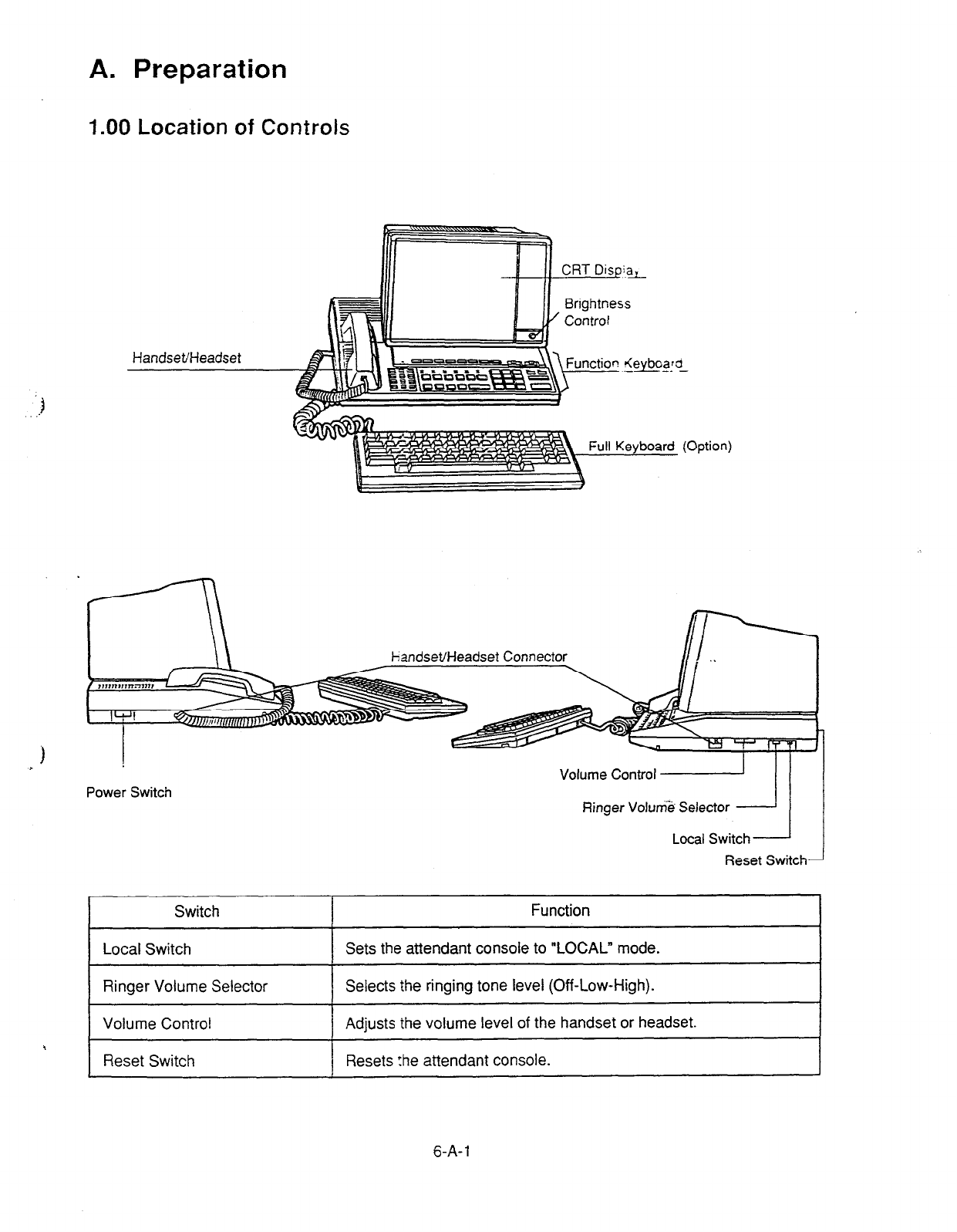
A. Preparation
1.00 Location of Controls
1
r
Volume Control
Power Switch Ringer Volum3 Selector
Switch Function
Local Switch Sets the attendant console to “LOCAL” mode.
Ringer Volume Selector Selects the ringing tone level (Off-Low-High).
Volume Control Adjusts the volume level of the handset or headset.
4 Reset Switch Resets :he attendant console.
6-A-l
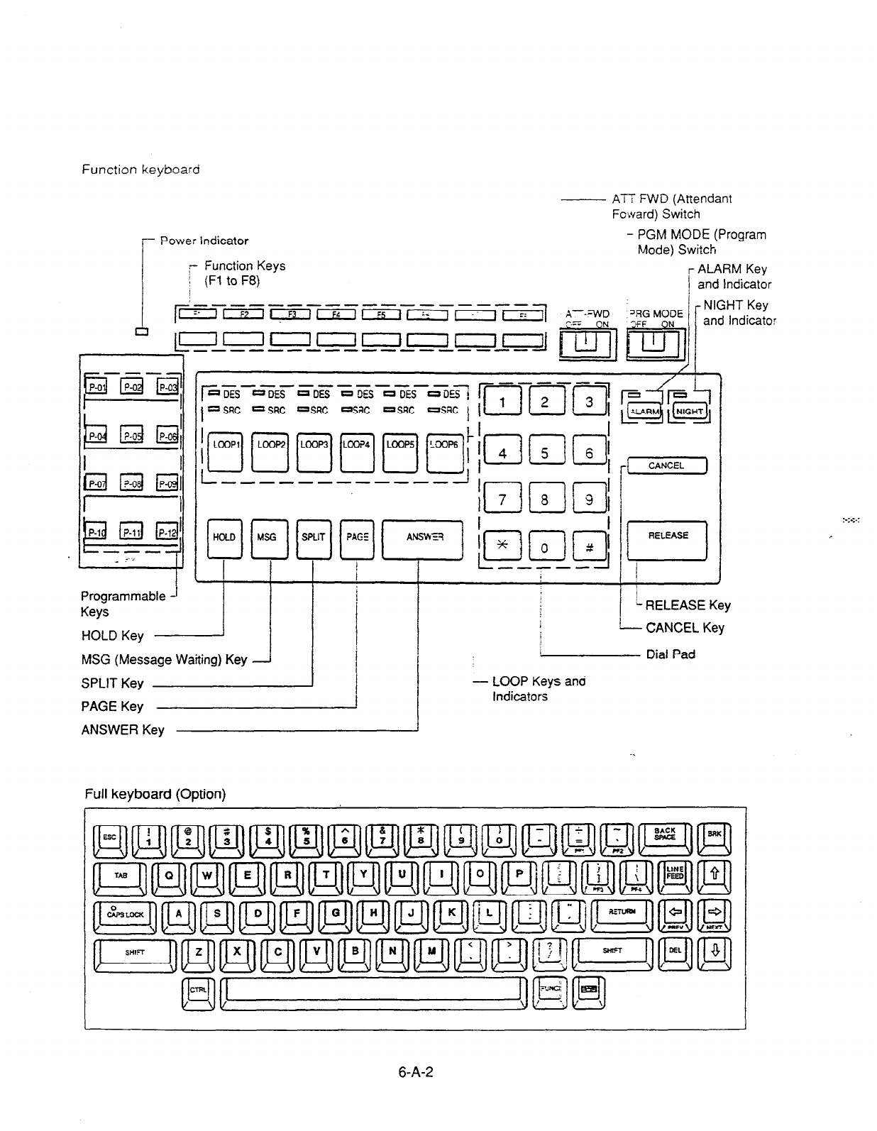
Function keyboard
- ATT FWD (Attendant
Fc:vard) Switch
r
Power indicator PGM MODE (Program
Mode) Switch
r Function Keys
( (Fi to F8)
I
r ALARM Key
and Indicator
‘RG MODE
- NIGHT Key
and Indicator
HOLD Key I
MSG (Message Waiting) Key -J
SPLIT Key
PAGE Key I
ANSWER Key
RELEASE
p
I
- RELEASE Key
- CANCEL Key
Dial Pad
- LOOP Keys and
Indicators
Full keyboard (Option)
l-
6-A-2
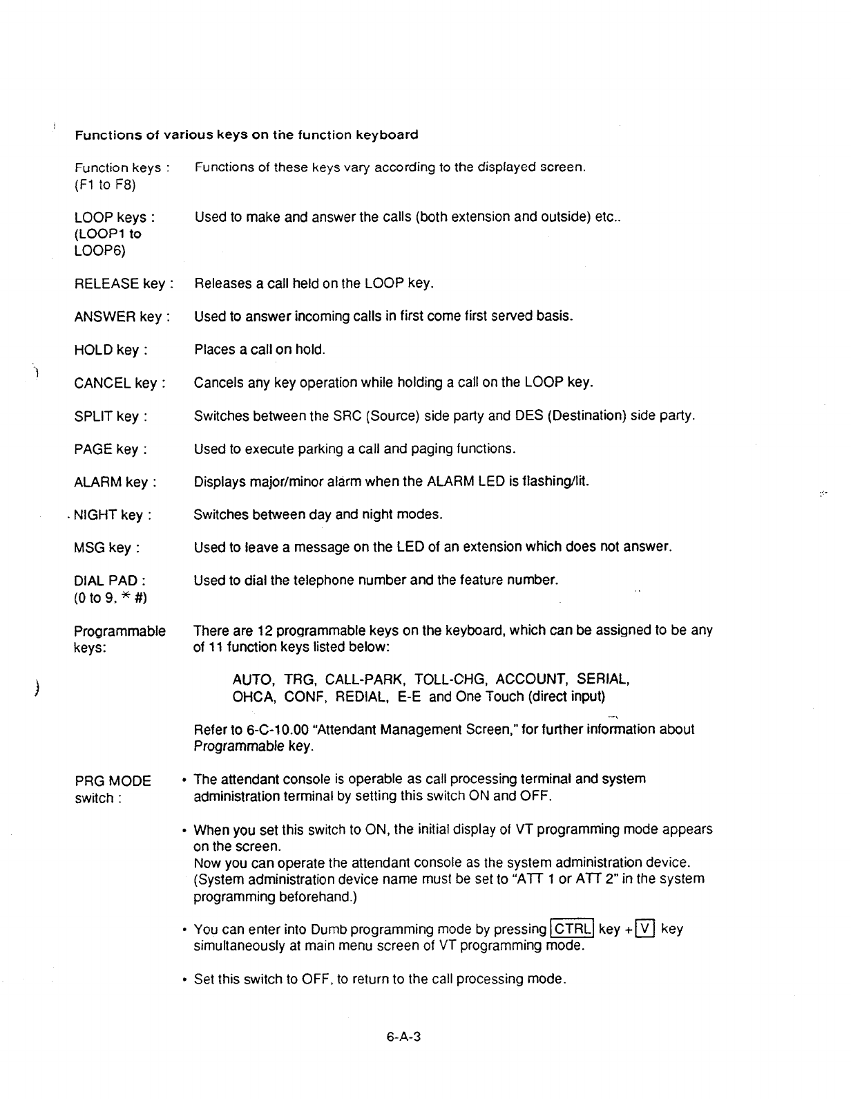
Functions of various keys on the function keyboard
Function keys :
(Fl to F8)
LOOP keys :
(LOOP1 to
LOOP6)
RELEASE key :
ANSWER key :
HOLD key :
CANCEL key :
SPLIT key :
PAGE key :
ALARM key :
NIGHT key :
MSG key :
DIAL PAD :
(0 to 9, * #)
Programmable There are 12 programmable keys on the keyboard, which can be assigned to be any
keys: of 11 function keys listed below:
Functions of these keys vary according to the displayed screen.
Used to make and answer the calls (both extension and outside) etc..
Releases a call held on the LOOP key.
Used to answer incoming calls in first come first served basis.
Places a call on hold.
Cancels any key operation while holding a call on the LOOP key.
Switches between the SRC (Source) side party and DES (Destination) side party.
Used to execute parking a call and paging functions.
Displays major/minor alarm when the ALARM LED is flashing/lit.
Switches between day and night modes.
Used to leave a message on the LED of an extension which does not answer.
Used to dial the telephone number and the feature number.
AUTO, TRG, CALL-PARK, TOLL-CHG, ACCOUNT, SERIAL,
OHCA, CONF, REDIAL, E-E and One Touch (direct input)
Refer to 6-C-10.00 “Attendant Management Screen,” for further information about
Programmable key.
PRG MODE
switch :
l
The attendant console is operable as call processing terminal and system
administration terminal by setting this switch ON and OFF.
l
When you set this switch to ON, the initial display of VT programming mode appears
on the screen.
Now you can operate the attendant console as the system administration device.
(System administration device name must be set to “ATT 1 or ATT 2” in the system
programming beforehand.)
. You can enter into Dumb programming mode by pressing I=] key +
q
key
simultaneously at main menu screen of VT programming mode.
l
Set this switch to OFF, to return to the call processing mode.
6-A-3
ATT-FWD
switch :
* Turning the ATT-FWD switch ON stops the arrival of all CO e:d exz-sior 3~ 5 ? 1 zt;.:
recall) to the attendant cor;sole temporarily and provides for r-an.+; ci thE L- --..-.- :.
calls to the extension programmed in system programming “Zrters :“-A:::- : -. T :*
sole-Busy-Out Extension” in advance.
It is available to make calls in this mode.
l
CO calls arrived at the attendant console before this switch is set to ON acd ‘fTalT!-z ,n
the queue are transferred to another attendant console, if it belongs to the ~a-2
ter? *
If there is no other attendant console belonging to the same tenant: the calls a-e trans
ferred to the above mentioned extension preset in system programming.
6-A-4

2.00 Display through LED Indicator
l
SRC, DES indicators of LOOP key
Line conditions are displayed by three patterns of flashing LED indicators as follows.
Pattern 1
(240 wink) uoouuullu~nooono I
t ,
-_
Pattern 2
(60 wink) :
Pattern 3
(120 wink)
PU
It-
1 set
I
rlu ml ml
-I
.::+
Pattern 1: Shows call arriving with 240 winks/min and is called “240 wink.”
Pattern 2: Shows holding a call with 60 winks/min and is called “60 wink.”
Pattern 3: Shows Unattended Conference with 120 winks/min and is called “120 wink.” . .
Light on steady shows busy status and light off shows idle status.
l
ALARM indicator
1 ALARM indicator shows the following conditions.
Lit steadily : Indicates minor trouble.
Blinking : Indicates major trouble.
Not lit : Indicates the system is in normal
operation.
Pressing the ALARM key while ALARM indicator
lights or flashes displays the detail of the trouble
on the message line of the CRT screen and the
ALARM indicator light goes out.
Pressing the ALARM key again causes the
trouble message disappear.
l
NIGHT Indicator
Not lit indicates Day mode and lit indicates
Night mode.
l
POWER Indicator .-em
Not lit indicates POWER switch-is turned OFF.
and lit indicates POWER switch is turned ON.
* This POWER switch is used to turn on and off
the CRT display.
The attendant console is operable during power
failure, if it is connected to the main unit.
(For details, refer to Section 6-J-l 1 .OO “Power
Failure Operation.“)
6-A-5
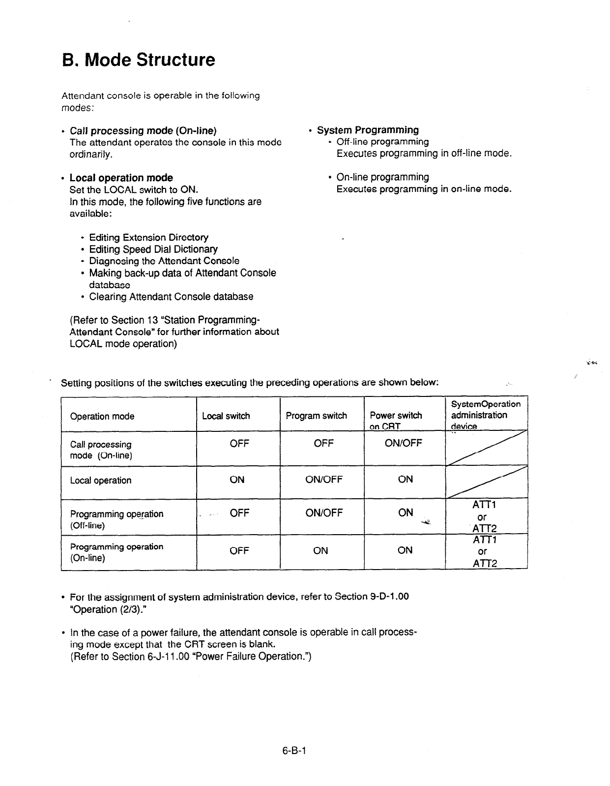
B. Mode Structure
Attendant console is operable in the following
modes:
9 Call processing mode (On-line)
l
System Programming
The attendant operates the console in this mode . Off-line programming
ordinarily. Executes programming in off-line mode.
l
Local operation mode
Set the LOCAL switch to ON.
In this mode, the following five functions are
available:
l
On-line programming
Executes programming in on-line mode.
l
Editing Extension Directory
l
Editing Speed Dial Dictionary
l
Diagnosing the Attendant Console
l
Making back-up data of Attendant Console
database
l
Clearing Attendant Console database
(Refer to Section 13 “Station Programming-
Attendant Console” for further information about
LOCAL mode operation)
. Setting positions of the switches executing the preceding operations are shown below: :
SystemOperation
Operation mode Local switch Program switch Power switch administration
on CRT device
Call processing OFF OFF
mode (On-line)
Local operation
Programming operation
(Off-line)
Programming operation
(On-line)
.
ON ON/OFF
ATT1
OFF ON/OFF ON .4. A0A2
AT-U
OFF ON ON A0A2
l
For the assignment of system administration device, refer to Section 9-D-l .OO
“Operation (2/3).”
l
In the case of a power failure, the attendant console is operable in call process-
ing mode except that the CRT screen is blank.
(Refer to Section 6-J-l 1 .OO “Power Failure Operation.“)
6-B-l
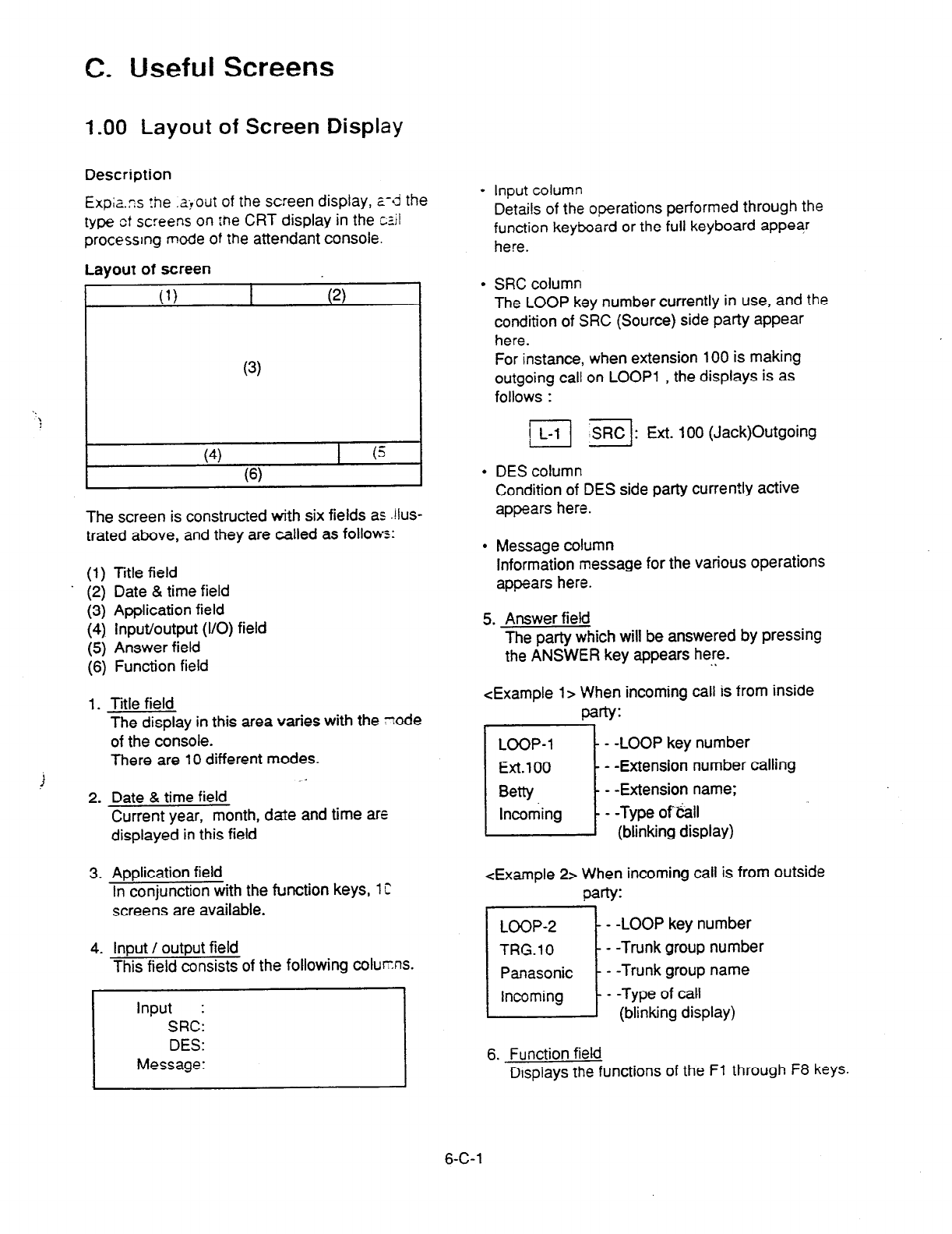
C. Useful Screens
1.00 Layout of Screen Display
Description
Expizs rhe .a+out of the screen display, a-sd the
type ct screens on :ne CRT display in the cz.il
processing mode of the attendant console.
Layout of screen
c
(4) I (5
(6)
The screen is constructed with six fields as .!lus-
trated above, and they are called as follows:
(1) Title field
. (2) Date & time field
(3) Application field
(4) Input/output (I/O) field
(5) Answer field
(6) Function field
1. Title field
f
The display in this area varies with the zode
of the console.
There are 10 different modes.
-
2. Date & time field
Current year, month, date and time are
displayed in this field
3. Application field
In conjunction with the function keys, 1 C
screens are available.
4. Input / output field
This field consists of the following coturns.
1
Input :
SRC:
DES:
Message:
l
Input column
Details of the operations performed through the
function keyboard or the full keyboard appear
here.
l
SRC column
The LOOP key number currently in use, and the
condition of SRC (Source) side party appear
here.
For instance, when extension 100 is making
outgoing call on LOOP1 , the displays is as
follows :
j] =I: Ext. 100 (Jack)Outgoing
l
DES column
Condition of DES side party currently active
appears here.
l
Message column
Information message for the various operations
appears here.
5. Answer field
The party which will be answered by pressing
the ANSWER key appears here.
. .
<Example l> When incoming call is from inside
party:
LOOP-l
i
- -LOOP key number
Ext.100 - -Extension number calling
Betty - -Extension name;
Incoming - -Type of%all
(blinking display)
<Example 2> When incoming call is from outside
party:
- -LOOP key number
- -Trunk group number
- -Trunk group name
- -Type of call
(blinking display)
6. Function field
Displays the functions of the Fl through F8 keys.
6-C-l
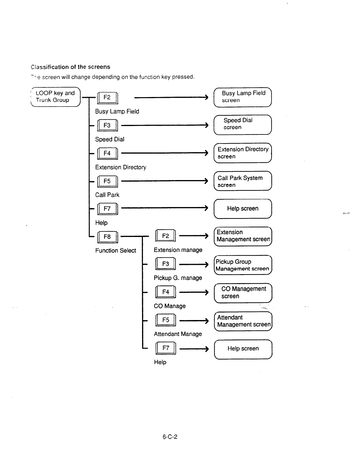
Classification of the screens
--e screen will change depending on the function key pressed.
(’ LOOP key and
LTrunk
Group ]T[T[ -
Busy Lamp Field
t-n
F3 -
I
Speed Dial
t=
F4 -
I
Extension Directory
t n
F5 -
Call Park
t-n\
F7 -
Help
n F8 -
Function Select Extension manage
. n F3 +
Pickup G. manage
. n F4 ~->
CO Manage
. n F5 lllj
Attendant Manage
. n I=7 +
Help
Busy Lamp Field
screen
f
Speed Dial
screen
(E$;;ion Directory)
I
Call Park System
screen I
I
Help screen I
[ Help screen )
6-C-2
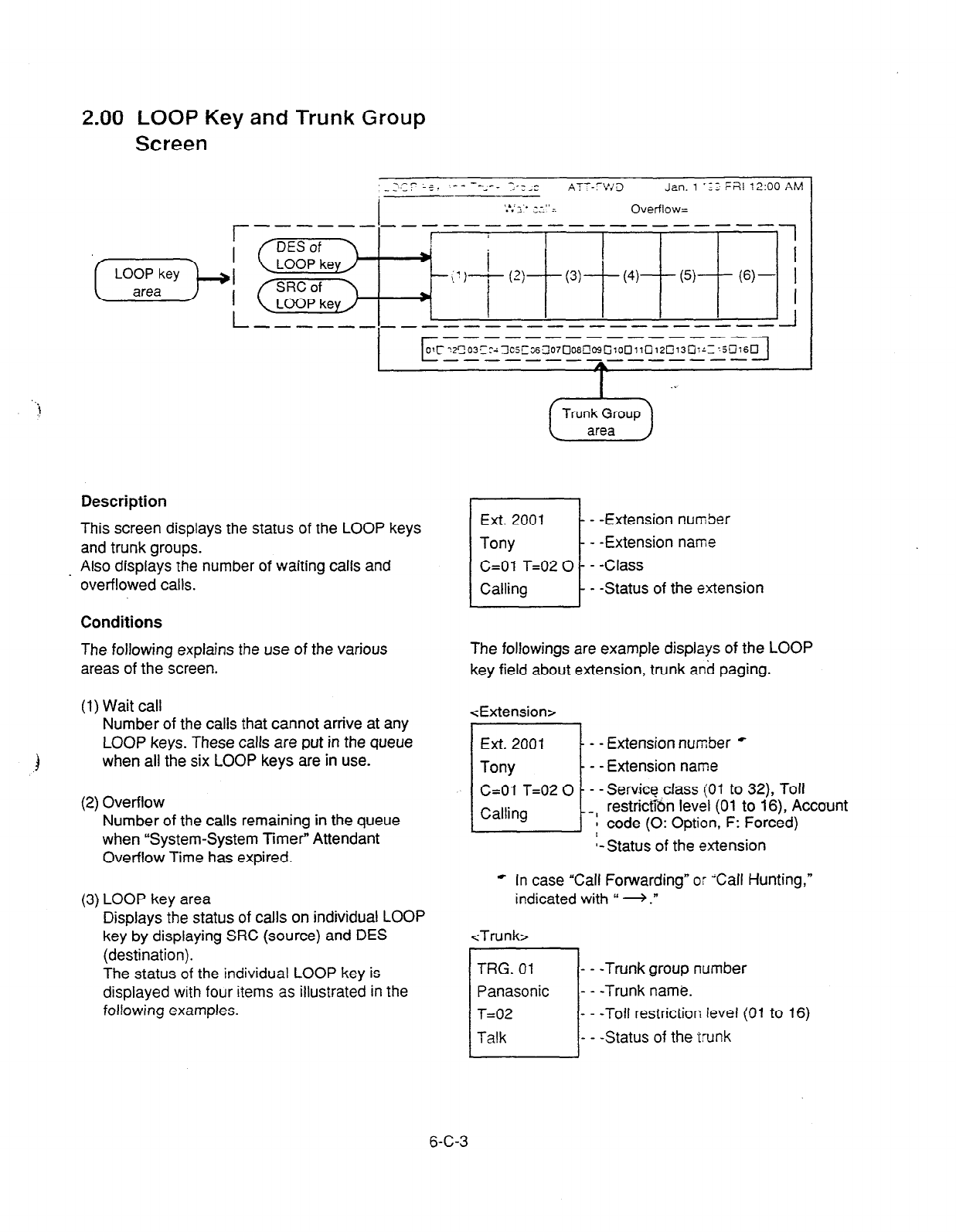
2.00 LOOP Key and Trunk Group
Screen
r
. .
!
,,,_,_I,_------------- ----A
c
_---_-------- --
C1~~2~03~~c-:3C5~~~07~06@~~10~11~12~13~:~~~jCi16~
------------- -- 7
A
I _.
Description
This screen displays the status of the LOOP keys
and trunk groups.
. Also displays the number of waiting calls and
overflowed calls.
Conditions
The following explains the use of the various
areas of the screen.
(1) Wait call
Number of the calls that cannot arrive at any
LOOP keys. These calls are put in the queue
) when all the six LOOP keys are in use.
(2) Overflow
Number of the calls remaining in the queue
when “System-System Timer” Attendant
Overflow Time has expired.
(3) LOOP key area
Displays the status of calls on individual LOOP
key by displaying SRC (source) and DES
(destination).
The status of the individual LOOP key is
displayed with four items as illustrated in the
following examples.
6-C-3
- -Extension number
- -Extension name
- -Status of the extension
The followings are example displays of the LOOP
key field about extension, trunk and paging.
<Extension>
Ext. 2001
-7
- -Extension number *
Tony - - Extension name
&Of T=02 0 - -Servfcg,cfass (01 to 32), Toll
Calling restrictTon level (01 to 16), Account
-[ code (0: Option, F: Forced)
t-Status of the extension
* In case “Call Forwarding” or “Calf Hunting,”
indicated with “ * .”
<Trunk>
- - -Trunk group number
- - -Trunk name.
- - -Toll restriction level (01 to 16)
- - -Status of the trunk

<Paging>
G. Page 1 - - -Type z: aaging *
Paging - - -Status
* G. page x
-& to8
: Grouo paging
G. page All : Group paging all
E. page x
-II. : External paging
1 or2
E. page All : External paging all
All page : Group paging all
and External paging all
<Attendant console>
AI-l-1 - -Attendant console number
Talk - -Status of attendant console
<Doorphone>
- - - Doorphone number
- - - Status of doorphone
l
The LOOP key number currently in use is dis-
played in reverse-video.
<Example>
(4) Trunk Group area
Trunk group number, trunk group name (Up to
10 a!phanumeric characters) and trunk group
status are displayed in the trunk group area.
Dispiay for trunk group status is as follows.
I:
An idle trunk is available in the
displayed trunk group.
m: All trunks are busy in the displayed
trunk group.
-- : The trunk is not used.
(5) When the ATT-FWD switch is set to
ON,
the
ATT-FWD indicator flashes.
The ATT-FWD indicator is not lit when the
switch is set to OFF.
6-C-4
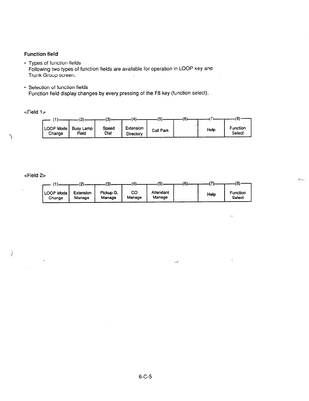
Function field
l
Types of function fields
Following two types of function fields are available for operation in LOOP key am
Trunk Group screen.
l
Selection of function fields
Function field display changes by every pressing of the F8 key (function select).
<Field l>
- (1)
(2)
LOOP Mode Busy Lamp
Change Field
(3) (4)
Speed Extension
Dial Directory
(5)
Call Park
(6) (7:
Help
@I---
Function
Select
<Field 2>
y.-....
- (1) (2)
(3) (4) (5) (6) II\
\. I !8)
LOOP Mode Extension Pickup G. co Attendant Function
Change Manage Manage Manage Manage Help Select
i
/
6-C-5
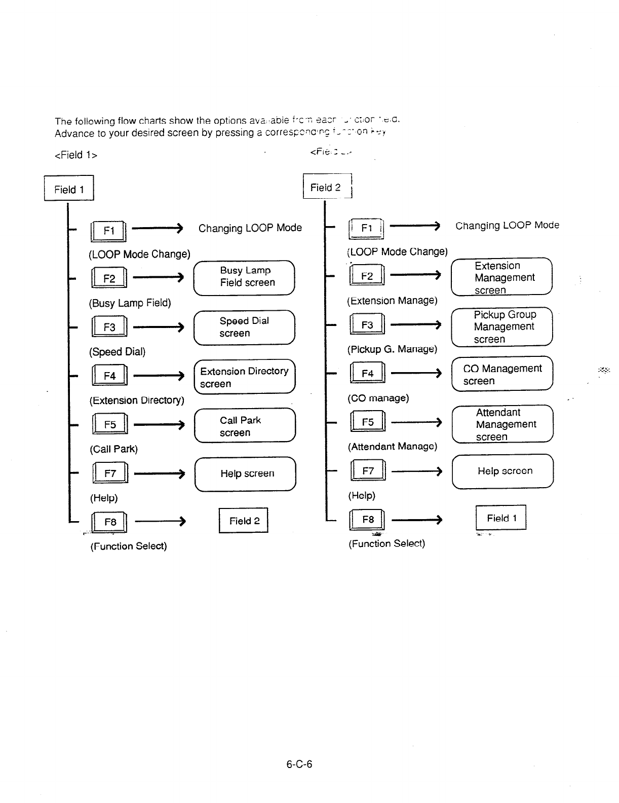
The following flow charts show the options a\z..,abie i-c.n sazr _. c;)or . cmc.
Advance to your desired screen by pressing a correqzcx’~~ ;_ - c- or, L YY
<Field I> <Fie. 3 __I
n
Fl -> Changing LOOP Mode
(LOOP Mode Change)
(Busy Lamp Field)
n F3 +
(Speed Dial)
(Extension Directory)
n F5 lllj
(Call Park)
n
F7 +
(Help)
(Function Select)
Speed Dial
screen
@zG)
(F)
I
Help screen I
I
Field 2
Changing LOOP Mode
(LOOP Mode Change)
.
n
F2 ---+
(Extension Manage)
n F3 -
(Pickup G. Manage)
n F4 +
(CO manage)
n F5 lllj
(Attendant Manage)
n F7 +
(Help)
n
I=8
+
-a
(Function Select)
(Helpscreen)
6-C-6
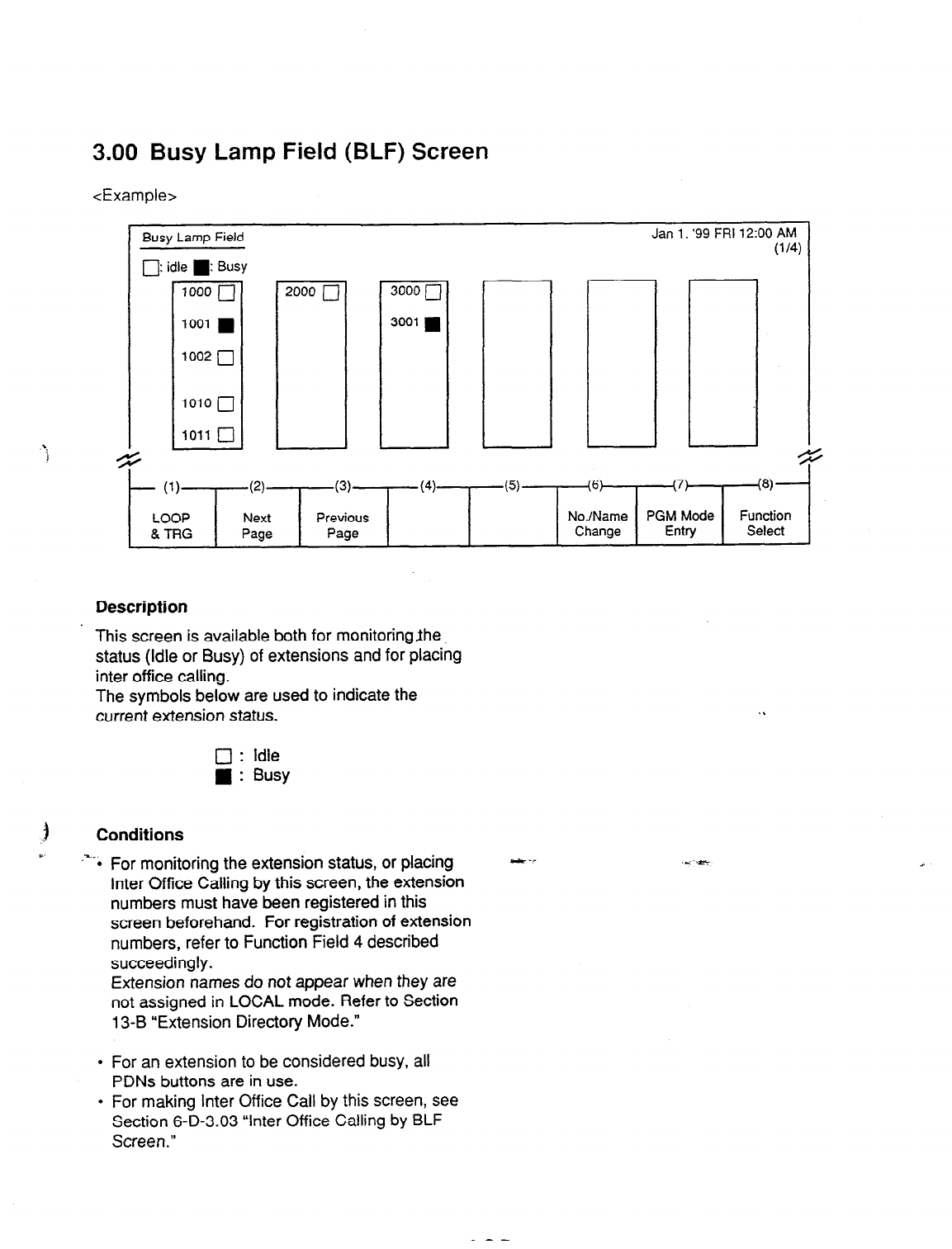
3.00 Busy Lamp Field (BLF) Screen
<Example>
Jan 1. ‘99 FRI 12:00 Ah,
Busy Lamp Field
0: idle
n
: Busy
1000 /--J
1001
n
I
1002 j-J
1010
q
1011
q
i
(lb
1
- (1)
LOOP
& TRG
(2)
Next
Page
(3)
Previous
Page
(4) (5) (6) (7)
W-
No./Name PGM Mode Function
Change Entry Select
Description
This screen is available both for monitoringJhe
status (idle or Busy) of extensions and for placing
inter office calling.
The symbols below are used to indicate the
current extension status.
0 : Idle
n
: Busy
Conditions
.%.* For monitoring the extension status, or placing
Inter Office Calling by this screen, the extension
numbers must have been registered in this
screen beforehand. For registration of extension
numbers, refer to Function Field 4 described
succeedingly.
a
t .-
Extension names do not appear when they are
not assigned in LOCAL mode. Refer to Section
13-B “Extension Directory Mode.”
. . .*
il
1)
I
1
l
For an extension to be considered busy, all
PDNs buttons are in use.
l
For making Inter Office Call by this screen, see
Section 6-D-3.03 “Inter Office Calling by BLF
Screen.”
6-C-7
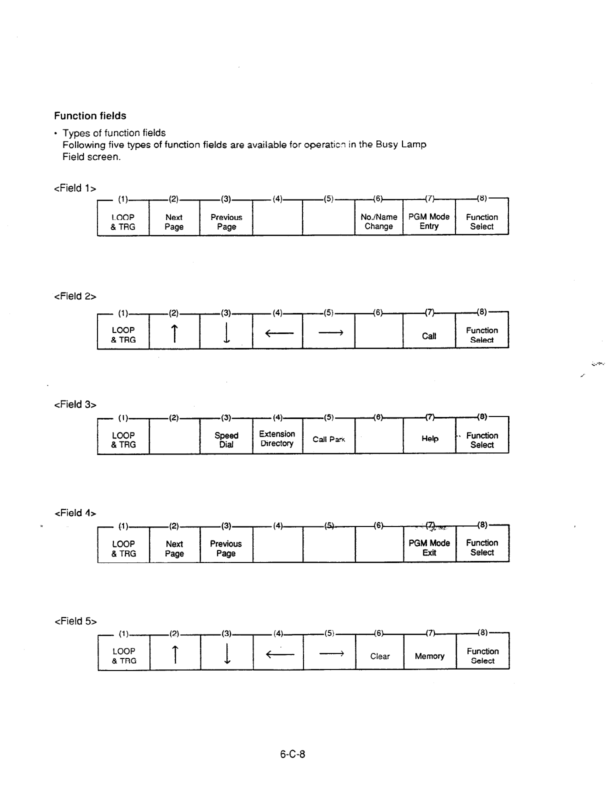
Function fields
l
Types of function fields
Following five types of function fields are avaiiable for operatic? in the Busy Lamp
Field screen.
<Field l>
- (1)
LOOP
& TRG
(2)
(3)
Next Previous
Page Page
(41 (5) (6) (7)
No./Name PGM Mode
Change Entry
!8)
Function
Select
<Field 2>
- (1)
LOOP
& TRG
(2)
(3) (4) (5) (6) (7)
3)
T f--- -
Function
Call S&Ct
<Field 3>
- (1)
LOOP
& TRG
63
(3)
Speed
Dial
(4)
Extension
Directory
(5)
Call P&
(6) (7) !8)
Help .. Function
Select
<Field 4>
- 41)
LOOP
& TRG
(2)
Next
Page
(3)
Previous
Page
(4) /c\ (6) @, *:.
!a)
PGM Mode Function
Exit Select
<Field 5>
- (1)
LOOP
& TRG
(2)
T
(4) (5) (6) (7)
!8)
e -
Clear Function
Memory Select
6-C-8
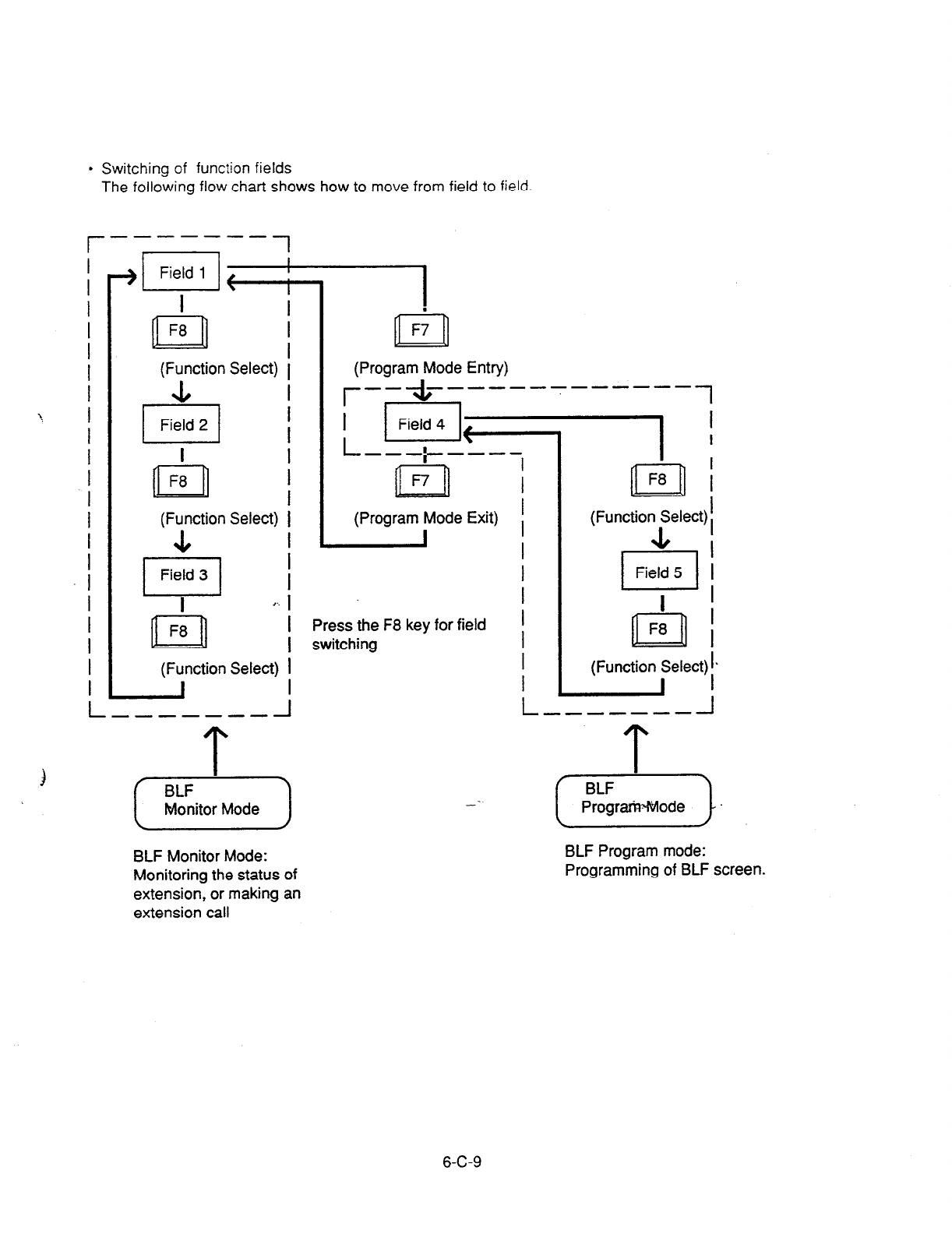
I
I
I
I
I
I
I
1 I
I
I
I
I
I
I
I
I
I
I
I
I
I
l
Switching of
function fields
The following flow chart shows how to move from field to field.
r _------
1
I
n
F8
(Function Select)
4
El Field 2
I
I
n
F8
I
I
(Function Select)
&
I r.
n F8
(Function Select)
L ----A---
n
F;
(Program Mode Entry)
l- ---;-----
m
n
F7
(Program Mode Exit)
Press the F8 key for field
switching
BLF Monitor Mode:
Monitoring the status of
extension, or making an
extension call
-1 I
I I
n I
F8 I
I
(Function ISelect) i
(Function Select) !*
- I
BLF Program mode:
Programming of BLF screen.
6-C-9
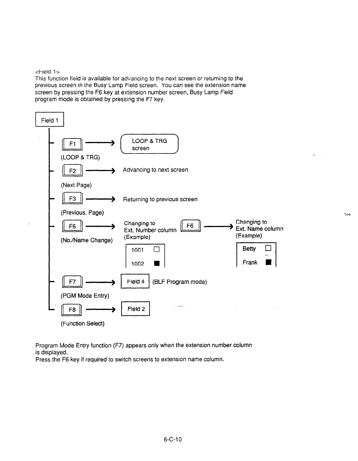
<Field l>
This function field is available for advancing to the next screen or returning to the
previous screen in the Busy Lamp Field screen. You can see the extension name
screen by pressing the F6 key at extension number screen, Busy Lamp Field
program mode is obtained by pressing the F7 key.
;q- (,,,,,,,)
(LOOP & TRG)
n
F2 -> Advancing to next screen
(Next Page)
n F3 -> Returning to previous screen
(Previous. Page)
n
F6
_I__j
(NoJName Change)
Ext. Name column
n
-- El
Field 4 (BLF Program mode)
(PGM Mode Entry)
-._.
(Function Select)
Program Mode Entry function (F7) appears only when the extension number column
is displayed.
Press the F6 key if required to switch screens to extension name column.
6-C-l 0
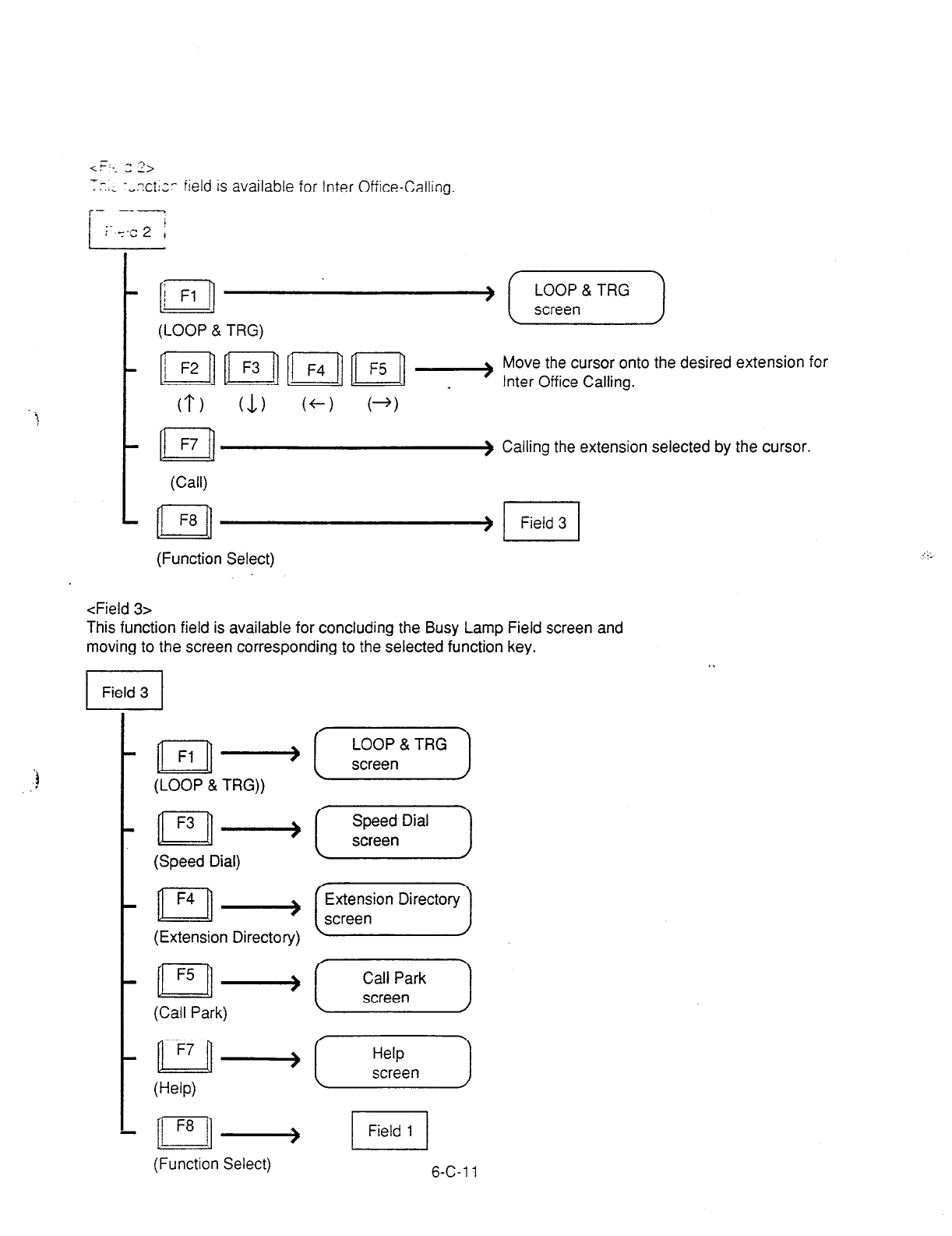
- ^I?
cv:-. _ L>
-- ,.; ‘,.Xtl,’
field is available for Inter Office-Calling.
i
- --- !
i-,c2 ,
IIn
i Fl
(LOOP & TRG)
Move the cursor onto the desired extension for
Inter Office Calling.
(Call)
n F8
(Function Select)
) Calling the extension selected by the cursor.
<Field 3>
This function field is available for concluding the Busy Lamp Field screen and
moving to the screen corresponding to the selected function key.
yp-,- (,,,,,,I
(LOOP & TRG))
m ,-a [ ;E;Dial ]
(Speed Dial)
pJ-(y-j
(Extension Directory)
~-(-XL--)
V-W
(Function Select)
1 Field 1 1
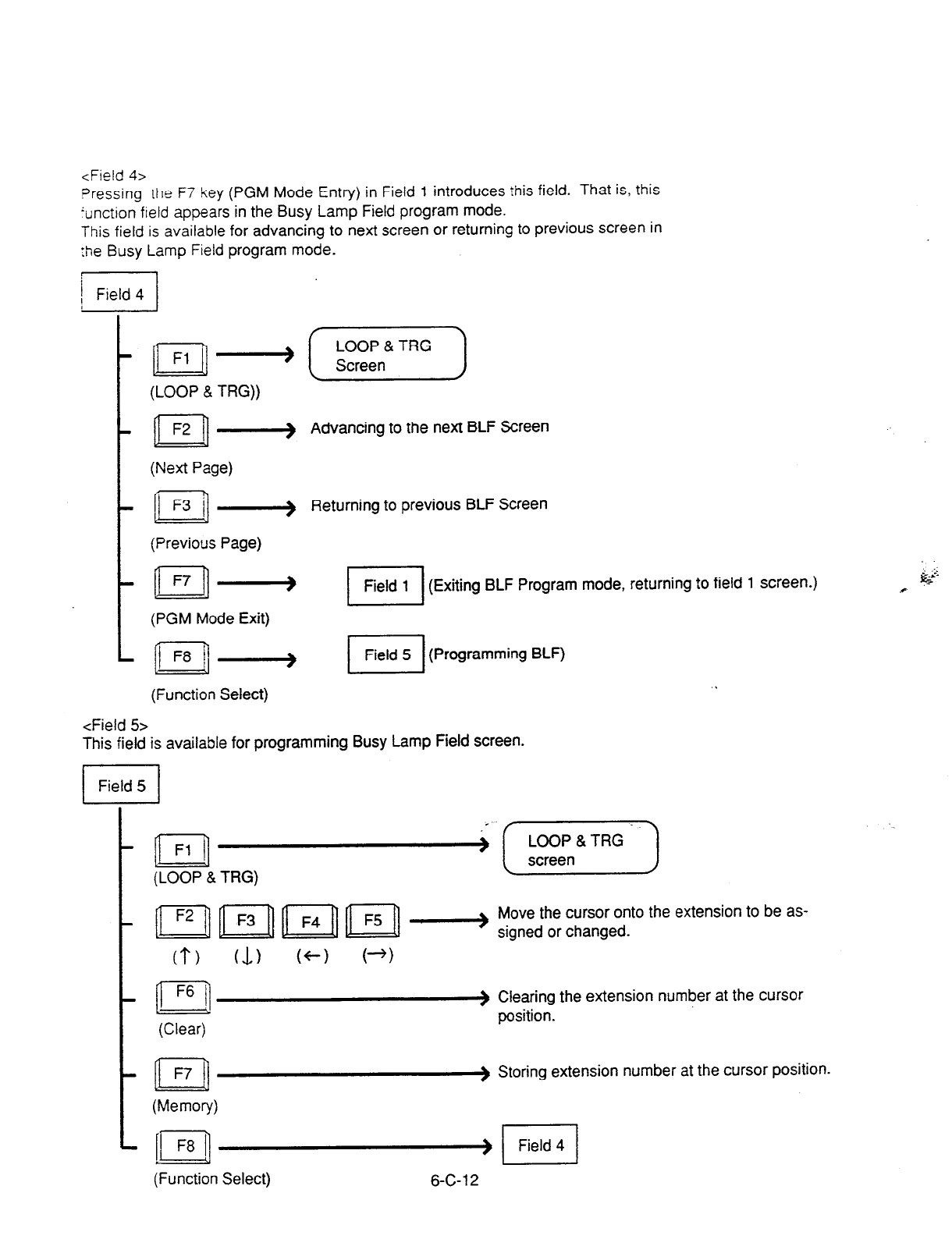
<Field 4>
Pressing the F7 key
(PGM Mode Entry) in Field 1 introduces this field. That is, this
iunction field appears in the Busy Lamp Field
program mode.
This field is available for advancing to next screen or returning to previous screen in
the Busy
Lamp Field
program mode.
j
r Field 4
i
n
Fl +
(LOOP & TRG))
n f=2 -
(Next Page)
(Previous Page)
n F7 -
(PGM Mode
Exit)
c
f F8 / __llj
(Function Select)
i
Advancing to the next BLF Screen
Returning to previous BLF Screen
(Exiting BLF Program mode, returning to field 1 screen.)
El
Field 5 (Programming BLF)
<Field 5
This field is available for programming Busy Lamp Field screen.
I
Field 5 I
t n
Fl
(LOOP & TRG)
Move the cursor onto the extension to be as-
- n n n n - signed or changed.
(?) (I) (+-I (+)
F6
-n
(Clear)
) Clearing the extension number at the cursor
position.
-n
F7
(Memory)
) Storing extension number at the cursor position.
L [pq cl Field 4
(Function Select) 6-C-l 2

l
Procedure ior sic- -; zkanc: -.g Bus; La?“:
Field screen
1. Press the F7 key I PGM Mote En:rY I rn
rhe
function field 1. field 1
l
Function field 4 appears or
the screen.
2. Obtain appropria:e extension screen by
pressing the F2 key (Next page) or the F3 key
(Previous page). field 4
3. Press the F8 key (Function Select)
l
Function field 5 appears on the screen. field 4
)
4. Move the cursor onto the extension to be
stored / changed.
5. Enter the extension number to be stored i
changed through the numeric keypad on the
function keyboard.
For correcting errors, or changing current
data, reenter data after pressing the F6 key
(clear).
(8)
Function
u
Select .
6-C-l 3

--
6. i;-Fs<,,-” ..._: - ” -...
ve-,?ry) stc-es E7tered
data. field 5
-
7. Repeat steps 2 to 6 to store or change other
extensions if necessary.
8. After storing or changing, press the F8 key
(function select).
l
Function field 5 appears on the screen.
field 5
cd
n r3 i] . .
9. Press the F7 key (PGM mode exit).
l
Exiting BLF PGM mode? changes to BLF
Monitor mode. field 4
6-C-l 4
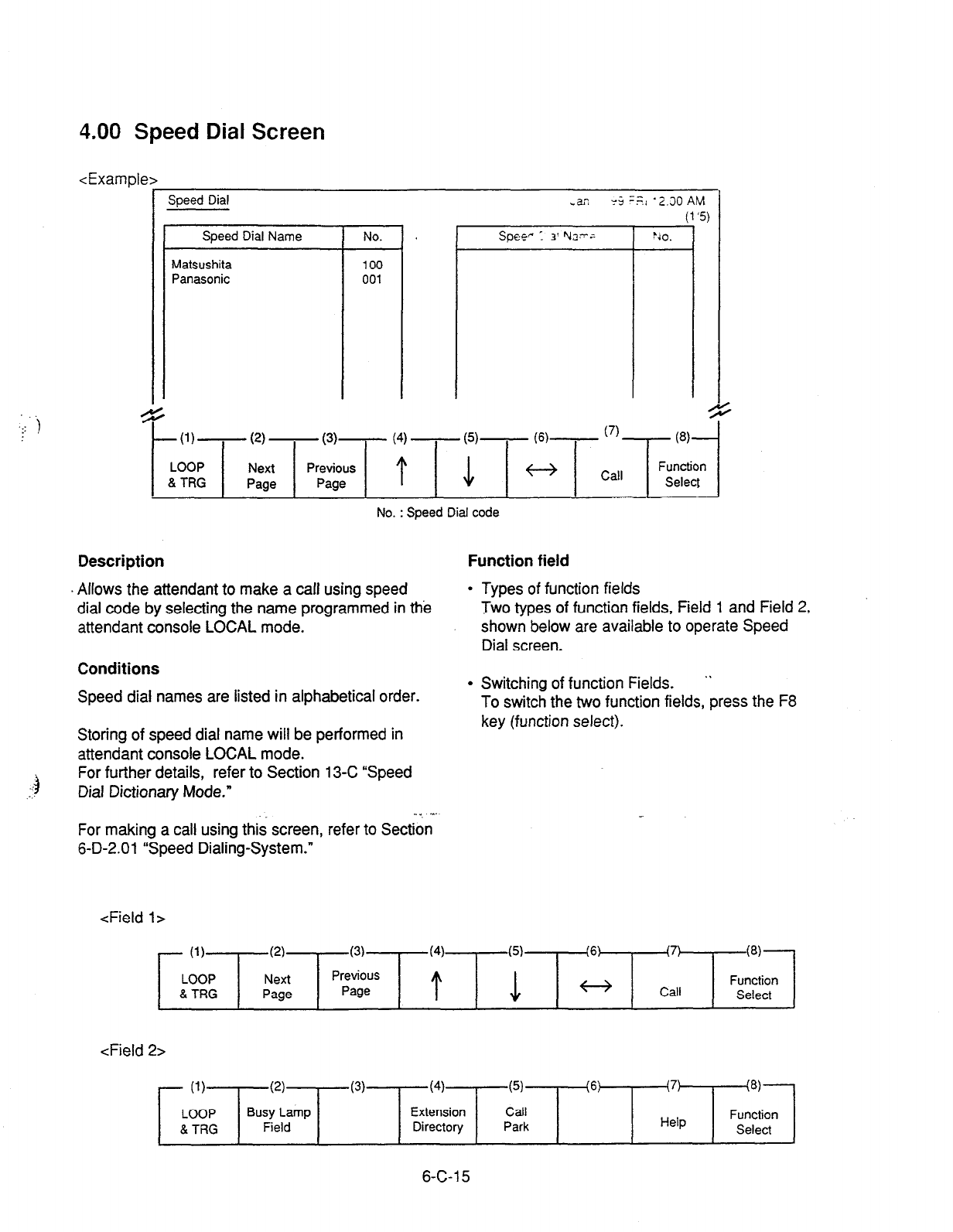
.: t
. .
-4
::
4.00 Speed Dial Screen
<Example>
F
Speed Dial
Speed Dial Name
Matsushita
Panasonic
+
t
U)-
(2)
- (3)- (4) - cd-
- m-
LOOP Next
& TRG Page
No. : Speed Dial code
Description Function field
Allows the attendant to make a call using speed
dial code by selecting the name programmed in the
attendant console LOCAL mode.
Conditions
Speed dial names are listed in alphabetical order.
l
Types of function fields
Two types of functian fields, Field 1 and Field 2,
shown below are available to operate Speed
Dial screen.
l
Switching of function Fields. ”
To switch the two function fields, press the F8
Storing of speed dial name will be performed in
attendant console LOCAL mode.
For further details, refer to Section 13-C “Speed
Dial Dictionary Mode.”
key (function select).
-4. ‘~’
For making a call using this screen, refer to Section
6-D-2.01 “Speed Dialing-System.”
<Field l>
- (1)
LOOP
8. TRG
c-4
Next
Page
(3)
Previous
Page
(4)
t
(6) (7)
Call
W-
Function
Select
<Field 2>
- (1)
LOOP
& TRG
(2)
Busy Lamp
Field
(3) (4)
Extension
Directory
(5)
Call
Park
(6: (7)
Help
(‘3)
Function
Select
6-C-l 5
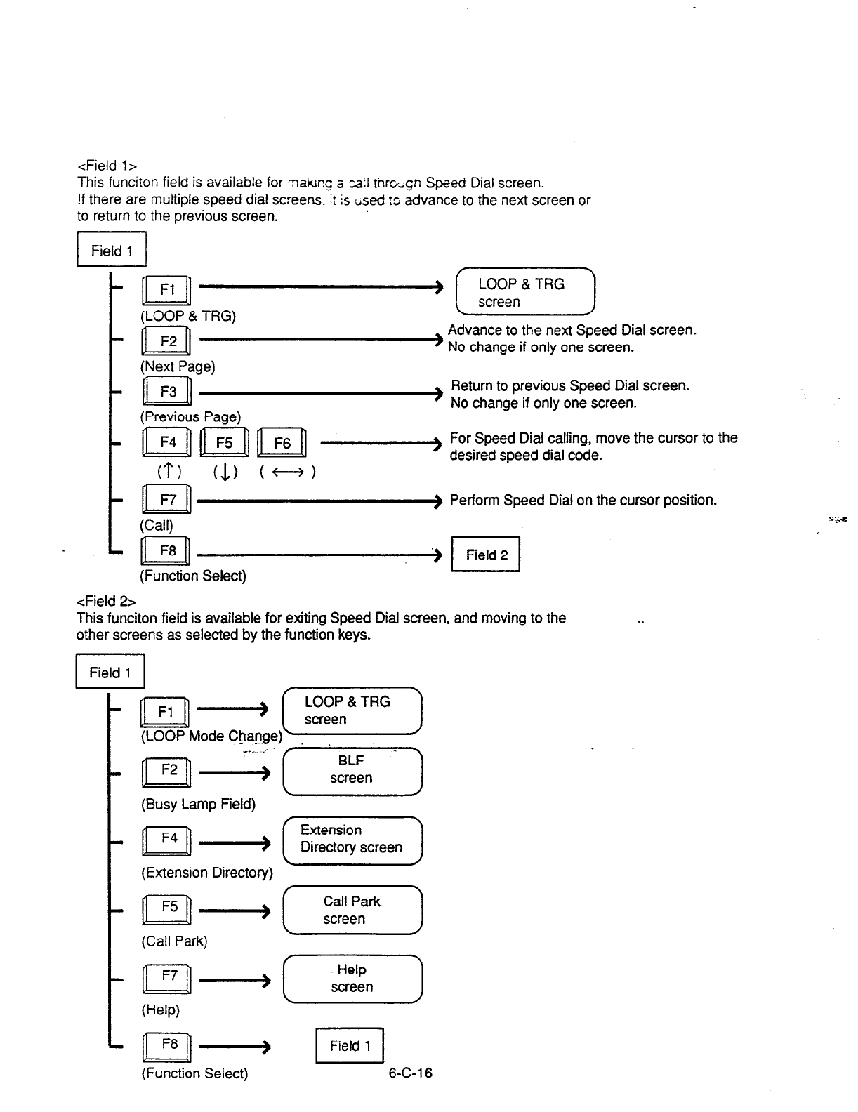
<Field 1>
This funciton field is available for making a za:I thrcign Speed Dial screen.
!f there are multiple speed dial screens. :t Is tised !s
advance to the next screen or
to return to the previous screen.
1 Field 1 1
(LOOP & TRG)
(Next Page)
’ (-EF--)
Advance to the next Speed Dial screen.
) No change if only one screen.
Return to previous Speed Dial screen.
(Previous Page)
’ No change if only one screen.
#-a For Speed Dial calling, move the cursor to the
cl-) (1) (+-+)
desired speed dial code.
) Perform Speed Dial on the cursor position.
(Call)
(Function Select)
<Field 2>
This funciton field is available for exiting Speed Dial screen, and moving to the
other screens as selected by the function keys. . .
(Busy Lamp Field)
(Extension Directory)
(Help)
(Function Select)
1 Field 1 1
6-C-l 6
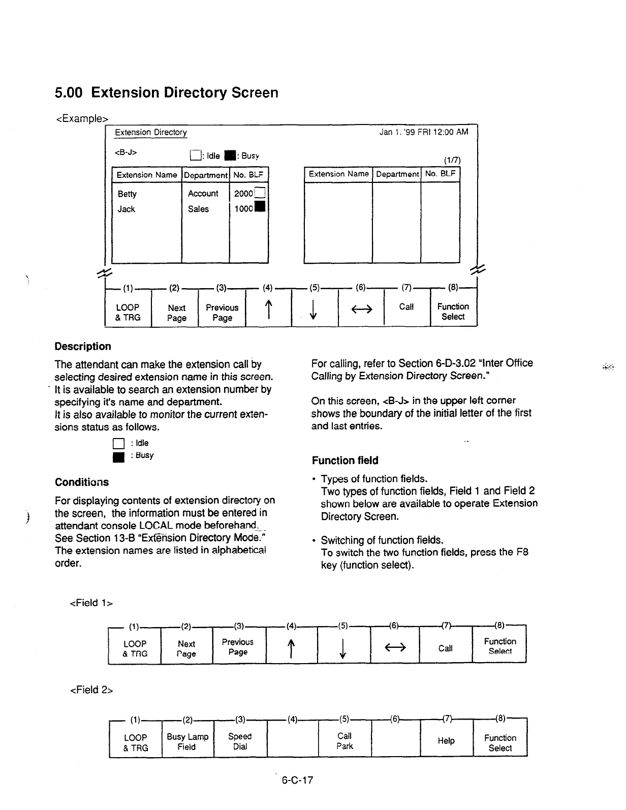
5.00 Extension Directory Screen
<Example>
Extension Directory Jan 1. ‘99 FRI 12:00 AM
<B-J> 0: Idle II: Busy (lfl)
Extension Name Department No. Bti Extension Name Department No. BLF
Betty Account 2000 g
Jack Sales 1000=
9 .
.
t
(1)-
(2)
-
(3)- (4) - (5)- (6)- (7) @I-
LOOP Next Function
& TRG Page Select
Description
The attendant can make the extension call by
selecting desired extension name in this screen.
. It is available to search an extension number by
specifying it’s name and department.
It
is also available to monitor the current exten-
sions status as follows.
q
: Idle
W : Busy
Conditions
For displaying contents of extension directory on
the screen, the information must be entered in
attendant console LOCAL mode beforehand.
See Section 13-8 “Extension Directory Mode.”
The extension names are listed in alphabetical
order.
:
For calling, refer to Section 6-D-3.02 “Inter Office
Calling by Extension Directory Screen.”
On this screen, <B-J> in the upper left corner
shows the boundary of the initial letter of the first
and last entries.
Function field
l
Types of function fields.
Two types of function fields, Field 1 and Field 2
shown below are available to operate Extension
Directory Screen.
l
Switching of function fields.
To switch the two function fields, press the F8
key (function select).
<Field
l>
- (1)
LOOP
& TRG
(2)
Next
Page
(3)
Previous
Page
(4)
t
(6) (7)
Call
(8)
Function
Select
<Field 2~
7 (1)
(2)
LOOP Busy Lamp
8. TRG Field
(3)
Speed
Dial
(4) (5)
Call
Park
(6: (7)
Help
(8)
Function
Select
6-C-17
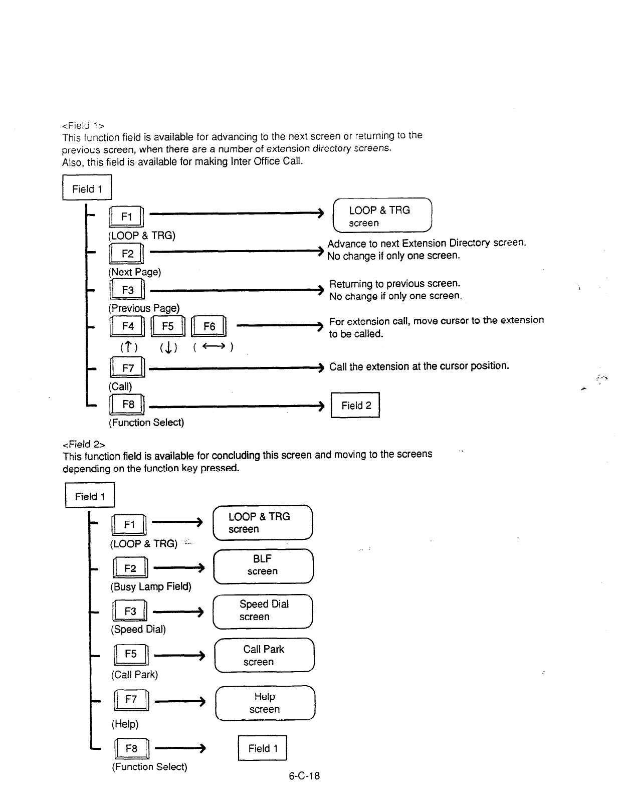
<Field I>
This function field is available for advancing to the next screen or returning to the
previous screen, when there are a number of extension directory screens.
Also, this field is available for making Inter Office Call.
I I
1 Field 1 1
n Fl
(LOOP & TRG)
n F2
) (-EF--)
Advance to next Extension Directory screen.
) No change if only one screen.
c
(Next Page)
n F3 Returning to previous screen.
’ No change if only one screen.
t
(Previous Page)
For extension call, move cursor to the extension
- to be called.
0) (1) C-J
. t II
F7 ) Call the extension at the cursor position.
(Call)
n F8 4rl Field 2
(Function Select)
<Field 2s
This function field is available for concluding this screen and moving to the screens ‘.
depending on the function key pressed.
El
Field 1
111)
n
Fl lllj
(LOOP & TRG) -I..
n I=2
llllj
(Busy Lamp Field)
n F3 -
(Speed Dial)
n I=5 -
(Call Park)
n F7 4
0-W
(Function Select)
(-Es=--)
[-G-J .‘.-
I
Field 1
6-C-l 8
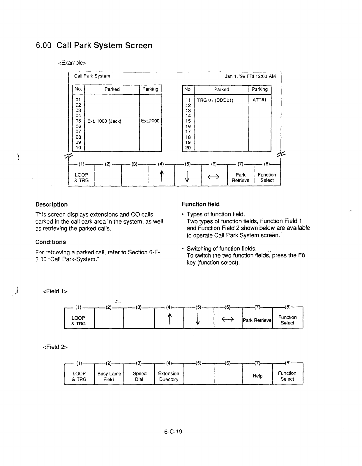
6.00 Call Park System Screen
<Example>
c II FZ?k
Svstem
No. Parked
01
02
03
04
05 Ext. 1000 (Jack)
06
07
08
09
10
Jan 1. ‘99 FRI 12:OO AM
I
No. Parked
11 TRG 01 (DDDOl)
32
13
14
15
16
17
18
19
20
Parking
ATT#l
(2)
-
(3)-
Description
T+is screen displays extensions and CO calls
. pzrked in the call park area in the system, as well
2s retrieving the parked calls.
Conditions
Function field
l
Types of function field.
Two types of function fields, Function Field 1
and Function Field 2 shown below are available
to operate Call Park System screbn. _
Fzr retrieving a parked call, refer to Section 6-F-
3.30 -Call Park-System.”
* Switching of function fields.
To switch the two function field& press the .F8
key (function select).
1
.-.
<Field l>
- (1)
LOOP
& TRG
(4
----I
(3) I \
6
I \
’ (8).
* Park Retrieve Fgicl
<Field 21
- (1)
(2)
(3) (4) (5) (6) (7)
(8)
LOOP Busy Lamp Speed Extension Function
& TRG Field Dial Directory Help Select
c
6-C-l 9
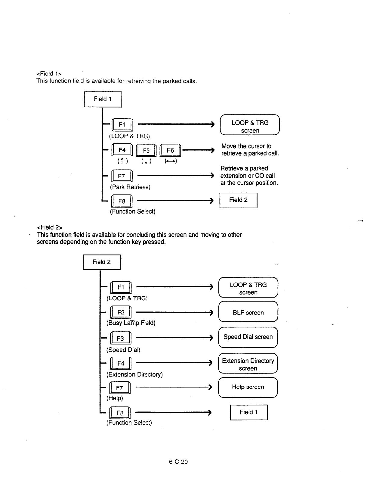
<Field
l>
This function field is available for retreivi-g the parked
calls.
/I
c n Fl -
t
(LOOP & TRG)
(f) (v) k-4
tm-
I (Park Retrieve)
(Function Se!act)
LOOP & TRG
screen
Move the cursor to
retrieve a parked call.
Retrieve a parked
extension or CO call
at the cursor position.
1 Field 2 ]
<Field 2>
This function field is available for concluding this screen and moving to other
screens depending on the function key pressed.
-
(LOOP & TRGi
-
(Busy L&i?ip Field)
-
(Speed Dial)
-
(Extension Directory)
-
Wp)
-
(Function Select)
I
BLF screen I
1 Speed Dial screen 1
t
Extension Directory
\
I
screen
J
I
Help screen I
6-C-20
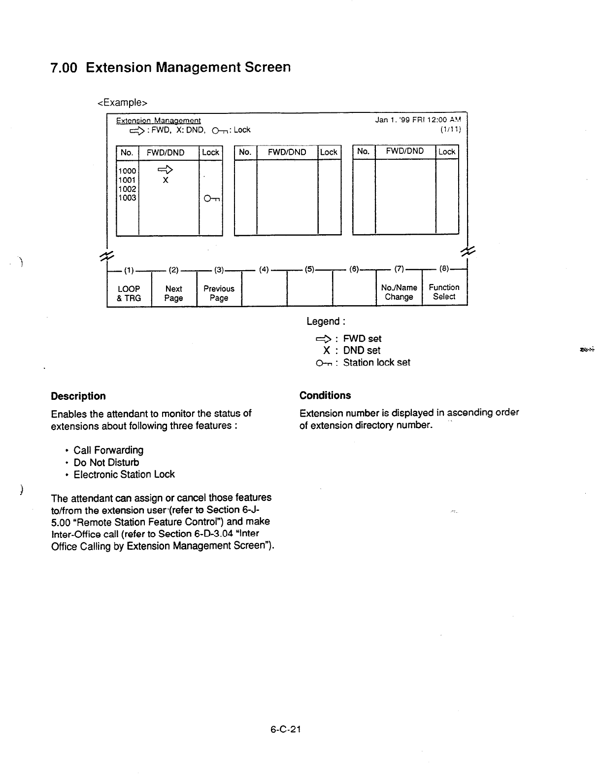
7.00 Extension Management Screen
<Example>
4 ,
Extension Manaaemen
4 : FWD, 2: DN;, &-,: Lock
.
Jan 1. ‘99 FRI 1200 A!:!
(l/l 1)
4
I
-(l)- (2) -
(3) (4) - (5)- (6) (7)
@I-
LOOP Next Previous NoJName Function
& TRG Page Page Change Select
:
Legend :
Q : FWD set
X : DND set
h : Station lock set
Description
Enables the attendant to monitor the status of
extensions about following three features :
Conditions
Extension number is displayed in ascending order
of extension directory number. .
l
Call Forwarding
l
Do Not Disturb
l
Electronic Station Lock
The attendant can assign or cancel those features
to/from the extension userjrefer to Section 6-J-
5.00 “Remote Station Feature Control”) and make
Inter-Office call (refer to Section 6-D-3.04 “Inter
Office Calling by Extension Management Screen”).
6-C-21

Function field
l
Types of function fields
Following four types of function fields are available for operation in Extension
Management screen.
l
Switching of function fields
For switching between the four function fields, press the F8 (Function Select) key.
<Field l>
- (1)
LOOP
8 TRG
(2)
(3)
Next Previous
Page Page
<Field 2>
- (1)
LOOP
& TRG
(2)
t
(6)
Select
(7)
Memory
(8)
Function
Select
<Field 3s
- (1)
LOOP
& TRG
(2)
t
(6: (7)
03)
Cdl Function
Select
.
<Field 4>
- (1)
LOOP
8 TRG
(2)
(3)
Pickup G.
Manage
(4)
co
Manage
(5)
Attendant
Manage
(6) (7)
Help
$9
Function
Select
6-C-22

<Field l>
This function field is available for advancing to the next screen or returning to the
previous screen when there are multiple extension management screens, and
changing the display from extension number to extension name.
(LOOP & TRG)
I
II
F2 -a Move to the next Extension Management screen.
(Next Page) No change if only one screen.
I
n
F3 _~_j Returning to the previous Extension Management
screen.
(Previous Page) No change if only one screen.
.
n
F7 - ~~?r~~?rkrnber
(No-/Name Change) (Example)
I
n
F8 llllj
(Function Select)
n
F7 + Changing to
Extension Name
(Example)
6-C-23
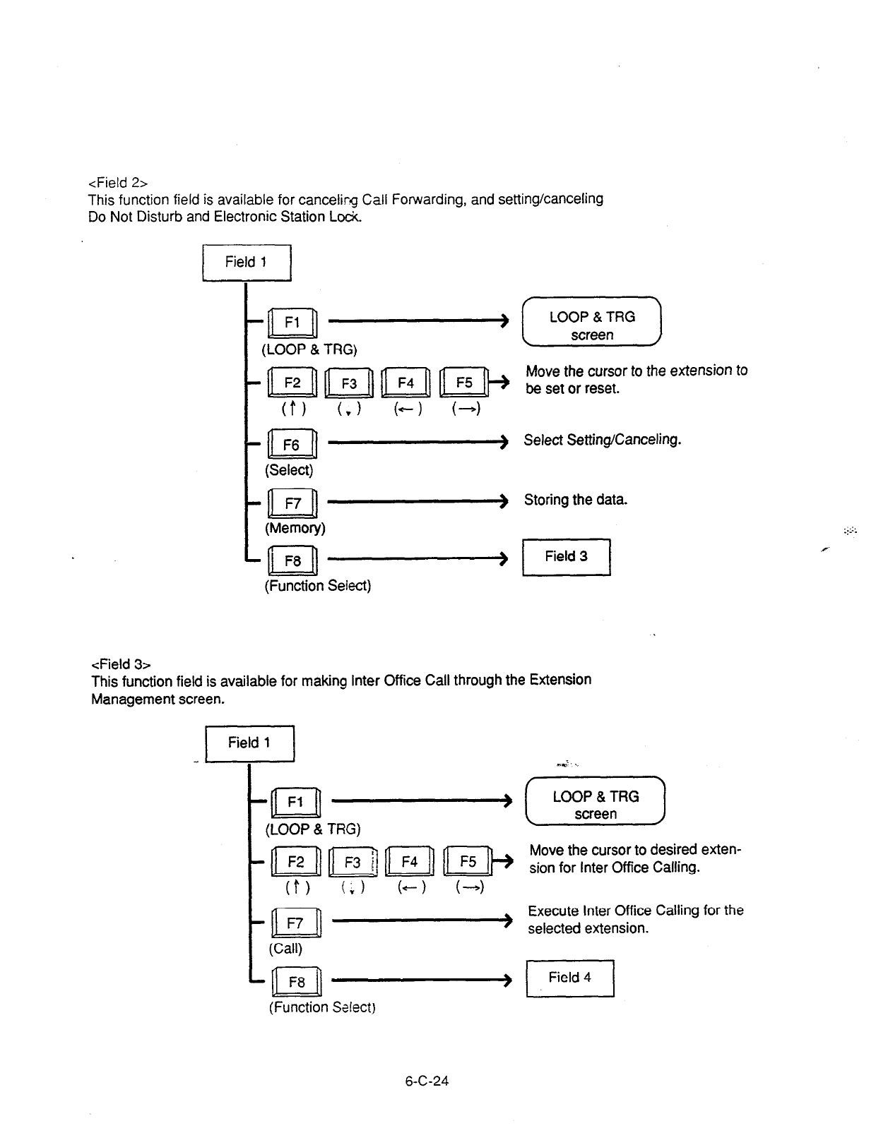
<Field 2>
This function field is available for cancelirg Call Forwarding, and setting/canceling
Do Not Disturb and Electronic Station Lock
<Field 3>
-n
Fl w
(LOOP & TRG)
-al
F6 w
(Select)
-al F7-
(Memory)
-n
F8 -
(Function Select)
[TEj-)
Move the cursor to the extension to
be set or reset.
Select Setting/Canceling.
Storing the data.
This function field
is available
for making inter Office Call through the Extension
Management screen.
1 Field 1 1
t
m.n’ . .
n Fl -[F)
(LOOP & TRG)
0) (; 1 b--1 l-4
n
n Execute Inter Office Calling for the
- selected extension.
(Call)
(Function Seiect!
6-C-24
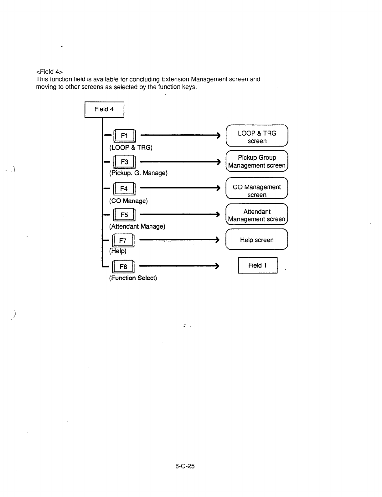
<Field 4~
This function field is available for concluding Extension Management screen and
moving to other screens as selected by the function keys.
- Fl
n - [ L”;;rfe;“” )
(LOOP & TRG) / b
-
(Pickup. G. Manage)
-
(CO Manage)
-
(Attendant Manage)
_ >
(Help)
-
(Function Select)
Pickup Group
Management screen 1
f Help screen
pq ,.
6-C-25
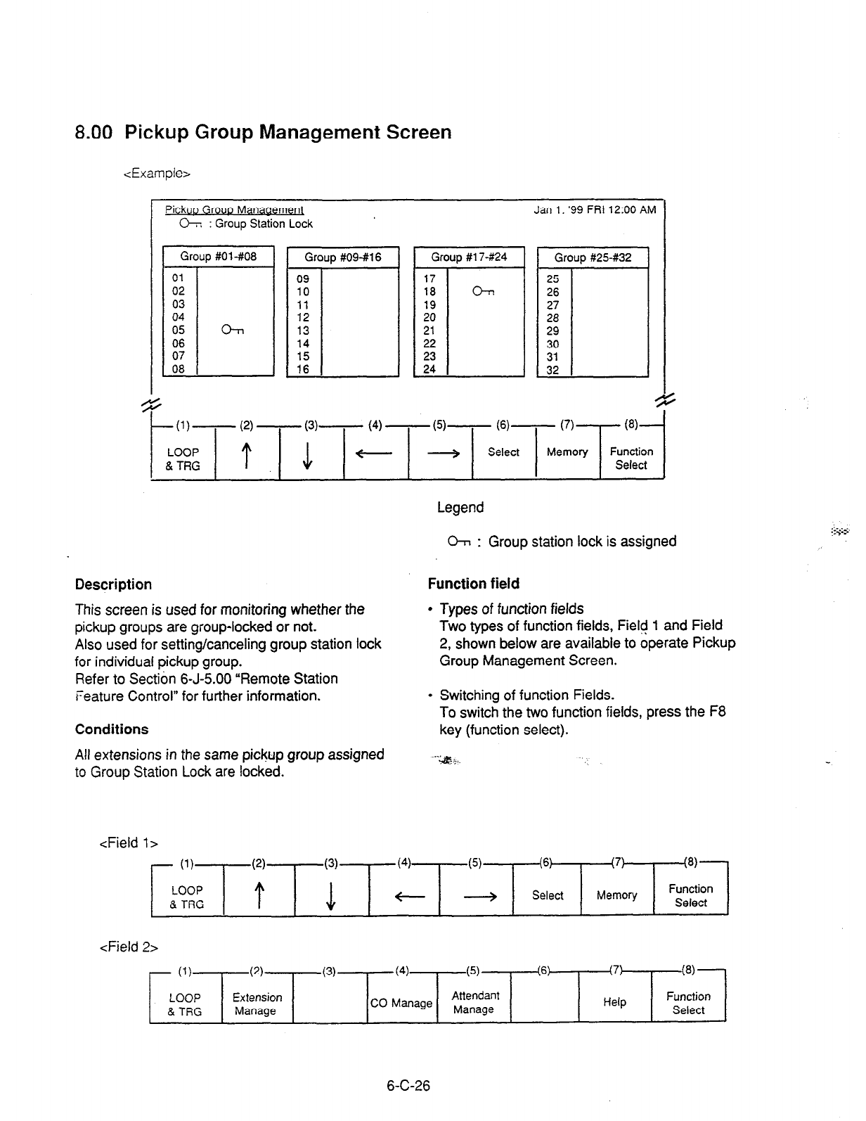
8.00 Pickup Group Management Screen
<Example>
Pick
CT :rGroup StatioTLock
~~~~~
4
.
-VI- (2) - (3)- (4) - (5)-
N-
(7)
@I-
Select Memory Function
Select
Legend
:
O-r, : Group station lock is assigned
Description
This screen is used for monitoring whether the
pickup groups are group-locked or not.
Also used for setting/canceling group station lock
for individual pickup group.
Refer to Section 6-J-5.00 “Remote Station
Feature Control” for further information.
Function field
l
Types of function fields
Two types of function fields, Field 1 and Field
2, shown below are available to operate Pickup
Group Management Screen.
l
Switching of function Fields.
To switch the two function fields, press the F8
Conditions
Ail extensions in the same pickup group assigned
to
Group Station Lock are locked.
key (function select).
--*;+a.
<Field
l>
- (‘)T
(2)
LOOP
t & TRG
(6) (7)
Select Memory
-la)-
Function
Select
<Field 2>
- (1)
LOOP
& TUG
(2)
Extension
Manage
(3) (4) (5) (6) (7)
(8)
CO Manage Attendant Function
Manage Help Select I
6-C-26
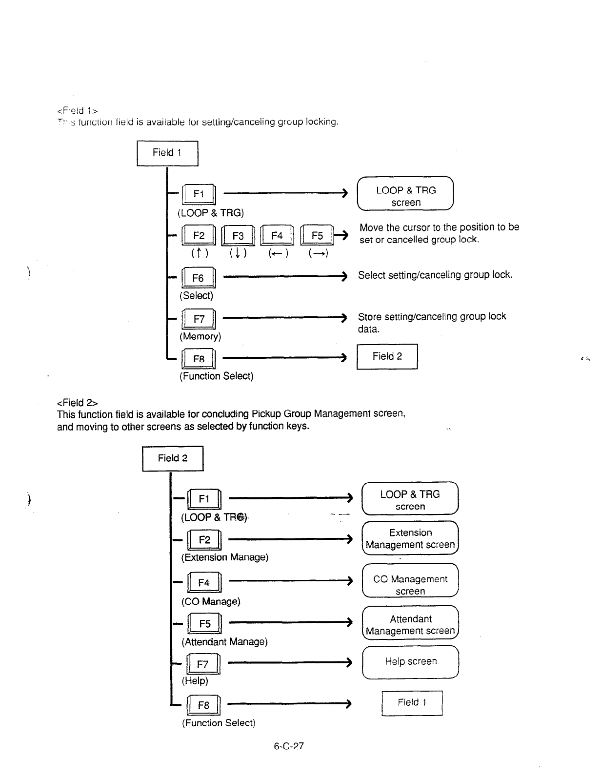
Y- s function field is available for setting/canceling group locking.
<Field 2>
I
Field 1 I
-E!l
Fi -
(LOOP & TRG)
-al
F6 -
(Select)
-II F7-
(Memory)
-al
F8 -
(Function Select)
LOOP & TRG
screen
Move the cursor to the position to be
set or cancelled group lock.
Select setting/canceling group lock.
Store setting/canceling group lock
data.
This function field is available for concluding Pickup Group Management screen,
and moving to other screens as selected by function keys.
piq
. .
- Fl
n --__-)(T)
(LOOP & TFN3))-
-n F2 -(EJ
(Extension Manage)
-al F4 -[G)
(CO Manage)
--aI F5 -&iiEicJ
(Attendant Manage)
--n F7 -> (-1
P-W)
L
(Function Select)
6-C-27

9.00 CO Management Screen
<Example>
CO Management
r
0: Idle,
n
: 63s~. * : Ringing, X : OUS/Fault Jan 1. ‘99 FR’ ‘2:OO AM
Ic
0 ID b BLF 1 TRG No. 8 CO Name 1 CO Status I Night Answer
lOI! 3
1012
n
1013 *
1014
q
1013 X
01 : BBBB
01 : ccccccc
01 : DDDDD
01 : AAA
01 : zz1234.5
CO busy out
CO access ctrl
UNA 1
UNA 2
Ext. 1000
I I I I I I
s +
t
(I)- (2)
- (3)- (4) - (5)-
W-
(7) w-
LOOP Next Previous Function
& TRG Page Page Select
Legend :
CO ID : Physical number of CO line
BLF : Busy Lamp Field
0: Idle
n
: Busy
*: Ringing
X : OUS/Fault
TRG No. : Trunk group number (01 to 16)
CO Name : Name of trunk (Up to 10 alphanumeric characters)
CO Status : Assigns status of CO access control or CO
busy out
Night Answer : Assigns call arrival destination of CO line in the night service mode
(UNA 1, UNA 2, Extension or RMT)
CO ID 8 BLF
TRG No. & CO
Name CO Stat& Night Answer
1OllO 01 BBBB CO busy out
Description
This screen is available for setting/canceling the
following functions.
Conditions
CO IDS are listed in ascending order.
l co busy out
l CO
access control
l
Night answer point
For details about CO busy out and CO access
control, refer to Section 6-J-l 0.00 “CO Access
Control.”
This screen also allows the attendant to confirm
the current CO line status.
For details about Night Answer, refer to Section
6-J-l .Ol “Flexible Night Service.”
6-C-28
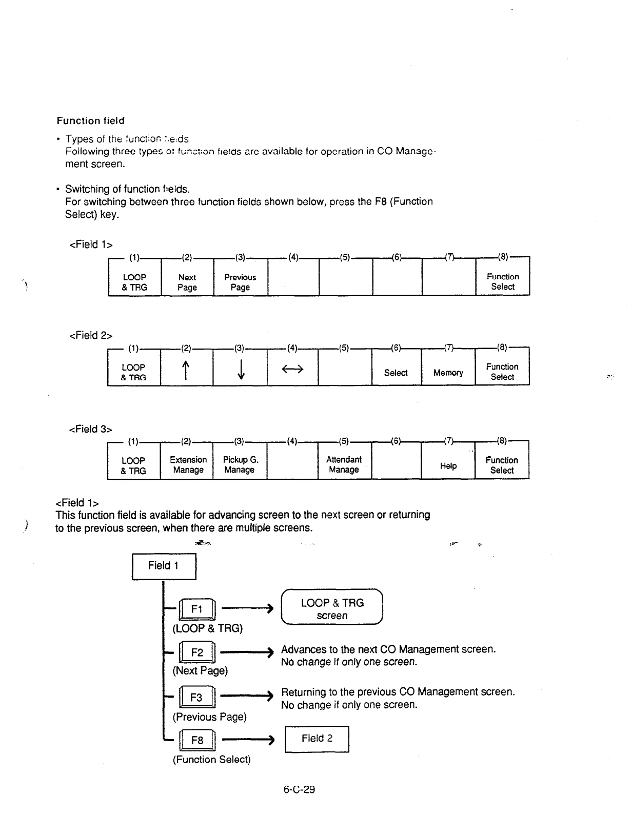
Function field
l
Types
of the
tunctioC
:.e:ds
Following three types o: func:;on ftelds are available for operation in CO Manage-
ment screen.
l
Switching of function fields.
For switching between three function fields shown below, press the F8 (Function
Select) key.
<Field l>
- (1)
LOOP
& TRG
(4
(3)
Next Previous
Page Page
(4) (5) (6)
m (8)
Function
Select
<Field 2>
- (1)
LOOP
& TRG
(5) (6:
Select
,7!
8’ I
Memory
W-
Function
Select
<Field 3>
<Field 1>
This function field is available for advancing screen to the next screen or returning
to the previous screen, when there are multiple screens.
,-> Advances to the next CO Management screen.
No change if only one screen.
t n
F3 ) Returning to the previous CO Management screen.
No change if only one screen.
(Previous Page)
6-C-29
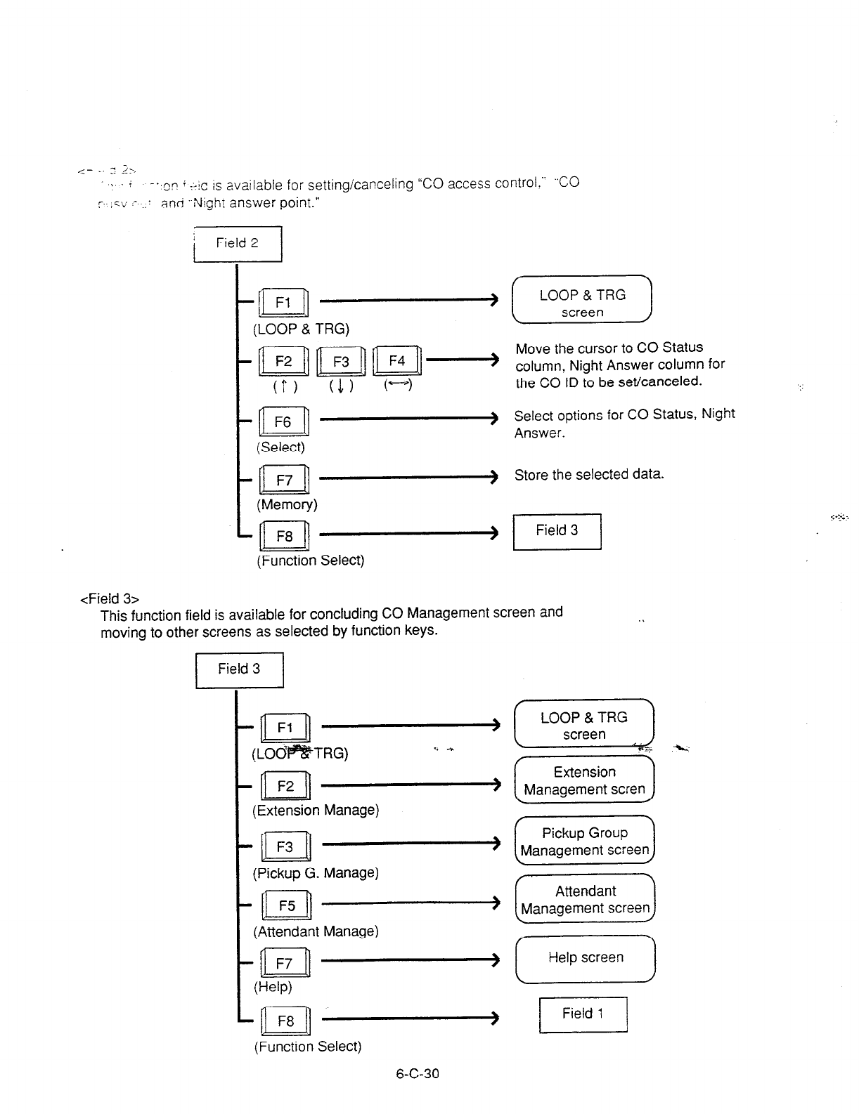
<- _. 0 2;.
,.f -.
,or~ i +!c IS available for setting/canceling “CO access control.” ‘CO
v. , c ,.*, .- . 1 anri .-Nigh1 answer point.”
j Field 2 /
I
(Function Select)
LOOP & TRG
screen
Move the cursor to CO Status
column, Night Answer column for
the CO ID to be set/canceled.
Select options for CO Status, Night
Answer.
Store the selected data.
1 Field 3 ]
<Field 3>
This function field is available for concluding CO Management screen and
moving to other screens as selected by function keys.
/I
(Extension Manage)
t n
F3 (
(Pickup G. Manage)
t
-
(Attendant Manage)
t n
F7 -
U-W)
n F8 I
(Function Select)
6-C-30
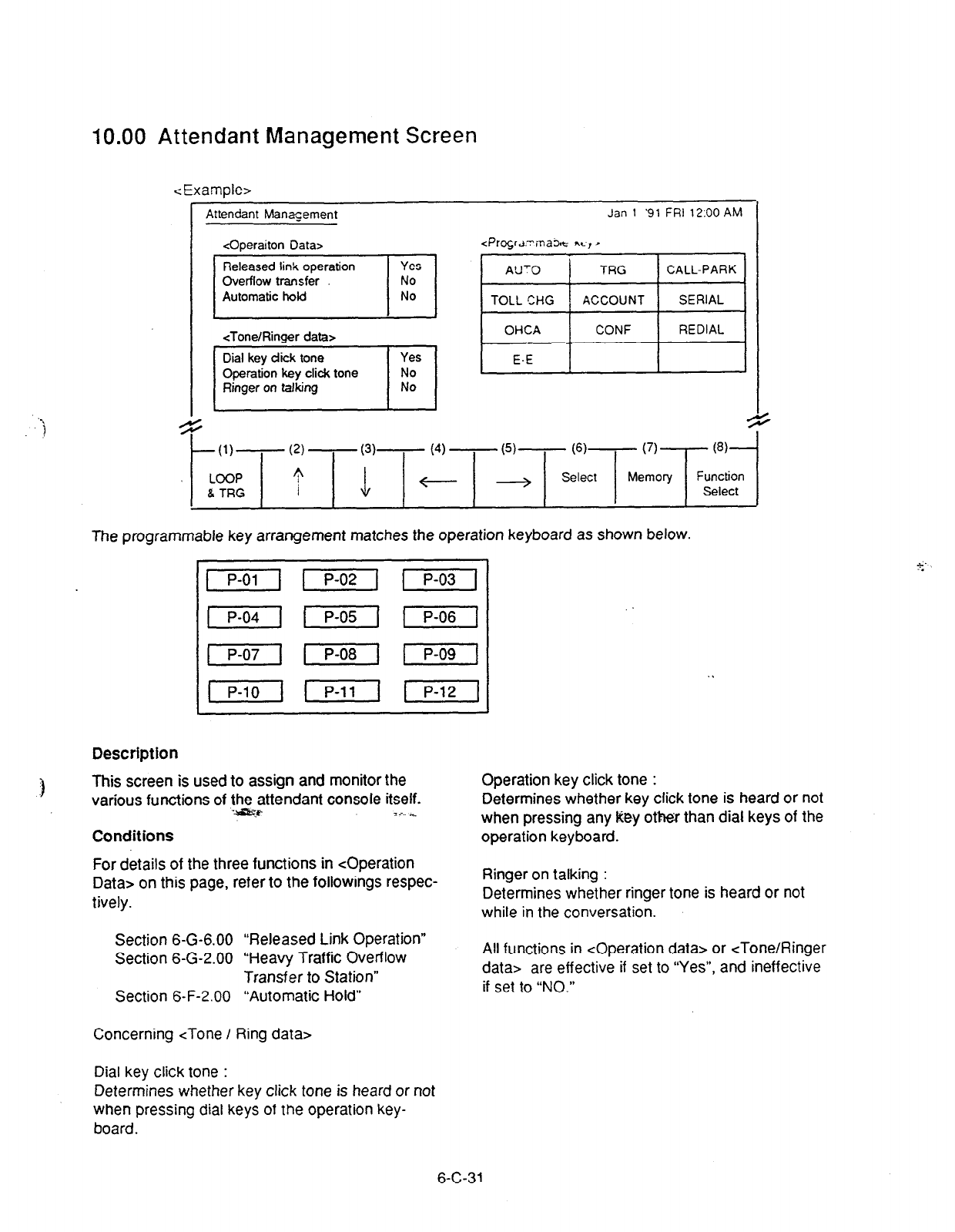
10.00 Attendant Management Screen
<Example>
Attendant Manqement Jan 1 ‘91 FRI 1200 AM
coperaiton Data> -zPrgr~.~ma* &L, )
<Tone/Ringer data> OHCA CONF REDIAL
;I ’ E-E
G c
d
t
(I)------- (2) - (3)- (4) - PI-----
(6)-
(7)
PI-
LOOP T
I w + Select Memory Function
8 TRG Select
The programmable key arrangement matches the operation keyboard as shown below.
Description
I
This screen is used to assign and monitor the Operation key click tone :
I
various functions of thefttendant console itself.
7:. *_
Conditions
For details of the three functions in <Operation
Data> on this page, refer to the followings respec-
tively.
Section 6-G-6.00 “Released Link Operation”
Section 6-G-2.00 “Heavy Traffic Overflow
Transfer to Station”
Section 6-F-2.00 “Automatic Hold”
Concerning <Tone / Ring data>
5
Determines whether key click tone is heard or not
when pressing any key other than dial keys of the
operation keyboard.
Ringer on talking :
Determines whether ringer tone is heard or not
while in the conversation.
All functions in <Operation data> or <Tone/Ringer
data> are effective if set to “Yes”, and ineffective
if set to “NO.”
Dial key click tone :
Determines whether key click tone is heard or not
when pressing dial keys of the operation key-
board.
6-C-31
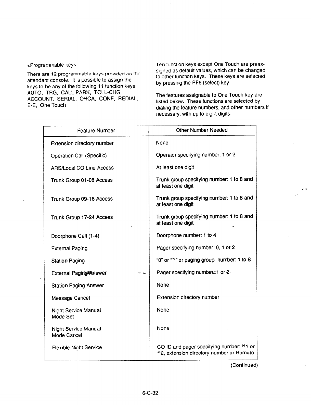
CProarammable key> Ten function keys except One Touch are preas-
There are 12 programmable keys provided on the
attendant console. It is possible to assgn me
keys to be any of the following 11 function keys:
AUTO. TRG, CALL-PARK, TOLL-CHG.
ACCOUNT, SERIAL, OHCA, CONF, REDIAL,
E-E, One Touch
signed as default values, which can be changed
to other function keys. These keys are selected
by pressing the PF6 (select) key.
The features assignable to One Touch key are
listed below. These functions are selected by
dialing the feature numbers, and other numbers if
necessary, with up to eight digits.
Feature Number
Extension directory number
Operation Call (Specific)
ARSILocal CO Line Access
Trunk Group 01-08 Access
Trunk Group 09-l 6 Access
Trunk Group 17-24 Access
Doorphone Call (l-4)
External Paging
Station Paging
External Pagiri@%nswer
Station Paging Answer
Message Cancel
Night Service Manual
Mode Set
Night Service Manual
Mode Cancel
Flexible Night Service
Other Number Needed
None
Operator specifying number: 1 or 2
At least one digit
Trunk group specifying number: 1 to 8 and
at least one digit
Trunk group specifying number: 1 to 8 and
at least one digit
Trunk group specifying number: 1 to 8 and
at least one digit . .
Doorphone number: 1 to 4
Pager specifying number: 0, 1 or 2
“0” or “*” or paging group number: 1 to 8
Pager specifying numberzl or 2..
None
Extension directory number
None
None
CO ID and pager specifying number: “1 or
*2, extension directory number or Remote
(Continued)
6-C-32

L
Feature Number
Remote Station Lock Set
Remote Station Lock Cancel
Remote DND Set
Remote DND Cancel
Remote FWD Cancel
Remote FWD Cancel-One Time
BGM through External Pager
Busy Out Trunk
Unbusy Trunk
OGM Record
OGM Playback
-
,
T
-
Function field
. .
l
Types of function fields
Following two types of function fields are
available for operation in Attendant Manage-
ment screen.
l
Switchino of function fields
For switching between the function fields shown
below, press the F8 (Function Select) key.
Other Number Needeo
Extension directory number
Extension directory number
Extension directory number
Extension directory number
Extension directory number
Extension directory number
None
Trunk port physical number
Trunk port physical number I
Resource number: 1 to 3
Resource number: 1 to 3, %l to *4
-G-y
- (1)
LOOP
& TRG
(51.‘ “- (6?
Select
(7)
Memory
(811
Function
Select
T*
<Field 2>
/ (1)
LOOP
& TRG
(2)
Extension
Manage
(3) (4) (5) (6) (7) i8jj
Pickup G. Function
Manage CO Manage Help Select
6-C-33
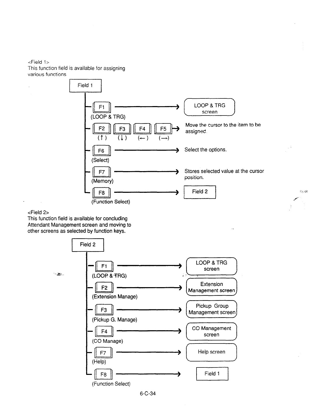
<Field 1~
This function field is available for assigning
various functions
n
F6 -
(Select)
n F7 -
(Memory)
n F8 -
(Function Select)
<Field 2>
This function field is available for concluding
Attendant Management screen and moving to
other screens as selected by function keys.
LOOP & TRG
screen
Move the cursor to the item to be
assigned.
Select the options.
Stores selected value at the cursor
position.
..a, . (LOOP &‘TRG)
(Pickup G. Manage)
_ F4 ( (““)
n
(CO Manage)
-n F7
U-W)
(Function Select)
6-C-34
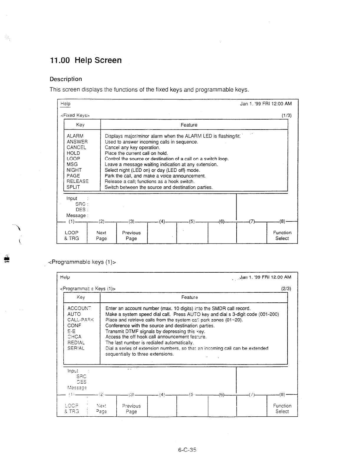
11 .OO Help Screen
Description
This screen displays the functions of the fixed keys and programmable keys.
Help Jan 1. ‘99 FRl 12:OO AM
<Fixed Keys>
(1
/31
ALARM
ANSWER
CANCEL
HOLD
LOOP
MSG
NIGHT
PAGE
RELEASE
SPLIT
Feature
Displays major/minor alarm when the ALARM LED is flashing/lit
Used to answer incoming calls in sequence.
Cancel any key operation.
Place the current call on hold.
Control the source or destination of a call on a switch loop.
Leave a message waiting indication at any extension.
Select night (LED on) or day (LED off) mode.
Park the call, and make a voice announcement.
Release a call: functions as a hook switch.
Switch between the source and destination parties.
Input
SRC I
DES.
Message :
- (1)
(2)
(3) (4)
(5)+6)
(7) w---
LOOP Next Previous Function
8. TRG Page Page Select
<Programmable keys (1 )>
Help . J.an 1. ‘99 FRI 12:00 AM
<Programma: 5 Keys (1)~
I
Feature
(2
Enter an account number (max. 10 digits) into the SMDR call record.
Make a system speed dial call. Press AUTO key and dial s 3-digit code (001-200)
Place and retrieve calls from the system &I park zones (01-20).
Conference with the source and destination parties.
Transmit DTMF signals by depressing this %ey.
Access the off hook call announcement fes:ure.
The last number is redialed automaticaily.
Dial a series of extension numbers, so tha: an incoming call can be extended
sequentially to three extensions. 1
‘/3)
_ ;j:
:2,
(3) (4! (5 (6) ’ (7)
M---
I r,r;
-vi.
&Ts’:3 i
rer:
Previous Function
3a;s Page Select
6-C-35
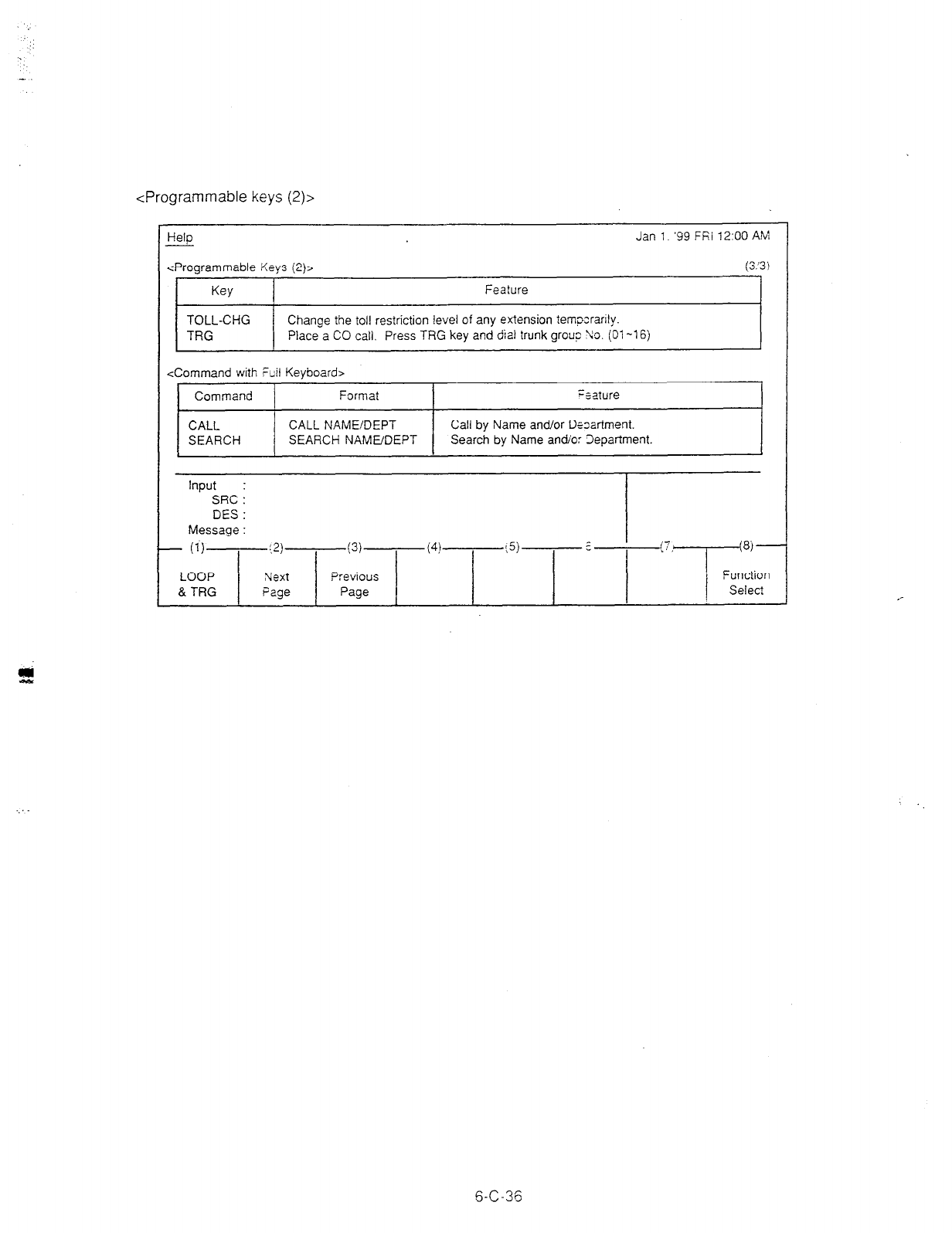
<Programmable keys (2)>
Help Jan 1. ‘99 Ffii 12:OO AM
<Programmable Keys (2)> (3.‘3)
Key Feature
TOLL-CHG Change the toll restriction level of any extension tempzranly.
TRG Place a CO call. Press TRG key and dial trunk group 90. (01-l 6)
<Command with Ftiil Keyboa:d>
Command Format ;=lture _^
CALL CALL NAME!DEPT Call by Name and/or Dfzartment.
SEARCH SEARCH NAMUDEPT Search by Name an&o: 3epartment.
Input SRC i
DES :
Message :
- (1)
:a
(3) (4) :5) : (7
I ‘--I-+
8j-
LOOP Next Previous Function
& TRG Page Page Select
5-C-36
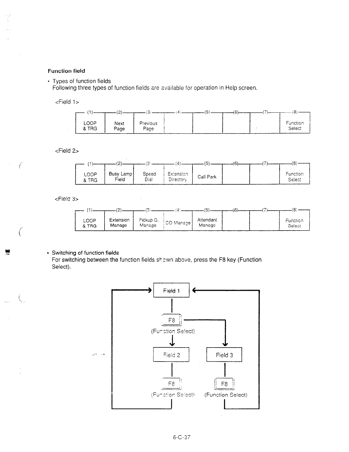
Function field
l
Types of function fields
Following three types of function fields are available for operation in Help screen.
<Field 1~
- (1)
T
i2)
LOOP Next
& TRG Page
(31
Previoiis
Pace
(5) (7)
(a;---
Fsnctio:!
Select
<Field 2>
- il!
LOOP
& TRG
!2)
Busy Lamp
Field
(3’
I (4! (5) (6) (7) (8)
Speed / Exiensiz? Functio::
D;zi j 3i:eCtg’b Call Park Selec:
I
<Fie!d 3>
1 (1)
LOOP
E TRG
P!
Extension
Manage
(31. .k
,- (5) (6) (7: (8; 7
I
Attendant Functlc:!
7ickw G. i mo hlanale
Xanage ; v Manage Select
l
Switching of function fields
For switching between the function fields shown above, press the F8 key (Function
Select).
<LB
(Fcrziion Se!ect)
6-C-37 6-C-37
I I
I
p-----7
1’ F8 :;
(Function Select)
I

<Field I>
This function field is available for switching Help screen to next or previous
we.
t n
F1 -
(LOOP & TRG)
tn >
I
(Next Page)
-
(Previous Page)
Advancing to the next Help screen.
<Field 2>
This function field is available for concluding this screen and switching to
another screen as selected by the corresponding function key.
Returning to the previous Help
screen.
-nFI-
(LE TRG)
-
(Busy Lamp Field)
-n
F3 -
(Speed Dial)
-n F4 -
(Extension Directory)
-
(Call Park)
-li F8 -
(Function Select)
LOOP & TRG
screen
I
BLF screen I
Field 1
6-C-38
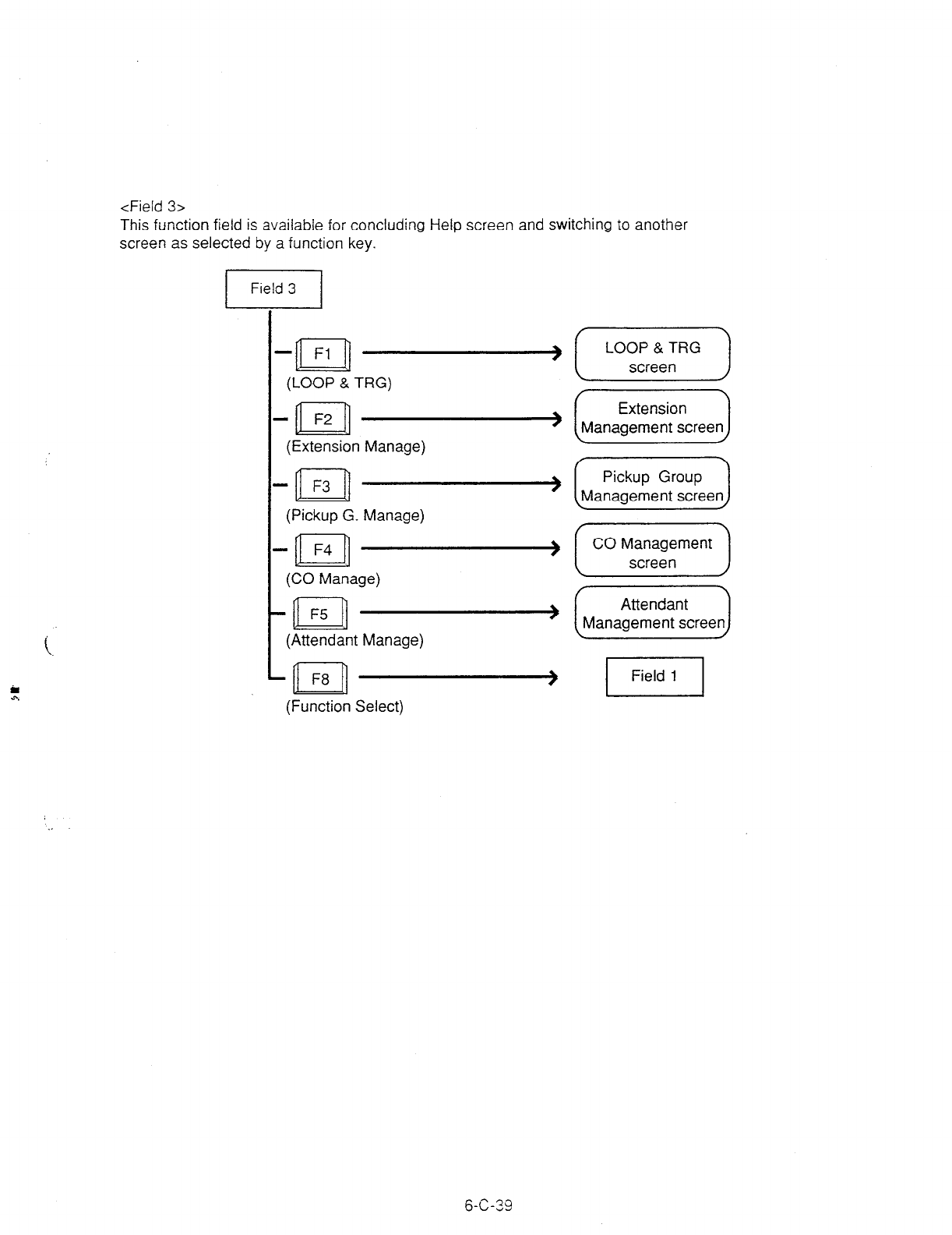
<Field 3>
This function field is available for concluding Help screen and switching to another
screen as selected by a function key.
-n Fl -(-=p--)
(LOOP & TRG)
-ml F2. - &YiiizLJ
(Extension Manage)
-al F3 - [M-d
(Pickup G. Manage)
- F4 -(I,,-)
n
(CO Manage)
-n F5 - (XJ
(Attendant Manage)
-Ial FfJ ( m
(Function Select)
6-C-39

D. Outgoing Call Features
1.00 Making Outside Calls
1.01 Local Trunk Dial Access
Description
Allows the attendant to make outgoing CO calls
using automatically selected idle CO line by
dialing the feature number for “AFWLocal CO
Line Access.”
To activate this feature, set “System-Operation”,
Automatic Route Selection to “No.” If set to
“Yes,” ARS feature is activated instead of this
feature.
Refer to Section 3-C-2.00 “Automatic Route
Selection (ARS)” for further information.
Programming
System
Programming Reference
VT 1 Dumb
“System-Operation (l/3)“. 9-D-l .Cl 10-c-4.00
Automatic Route Selection
“System-Local Access Group”, 9-D-5.00 1 O-C-9.00
Hunt Sequence
“System-Numbering Plan (US)“, 9-D-6.02 10-C-10.00
ARSILocal CO Line Access
Conditions
An idle CO line available and hunting sequence
is determined by the sysiem programming
“System-Local Access Group”, Hunt Sequence.
If busy tone is heard, there is no idle CO line
available.
If tenant service is employed, accessible trunk
group is limi?ed to the trunk groups within the
same tenant.
Operation
Dial tone
sounds.
(For instance. an
idle LOOP j,ly is pressed and
the SRC
indicator is lit
and d z.! tone sounds.:l
i. Dial the featLye number for
“ARS!Local C3 Line Access.”
l
You hear d:z! tone.
2. Dia! the
!eles;zne number of the
outside party.
The dialing plan followed is that of the trunk
group in hunt sequence 01 in “System-Local
Access Group.”
6-D-l
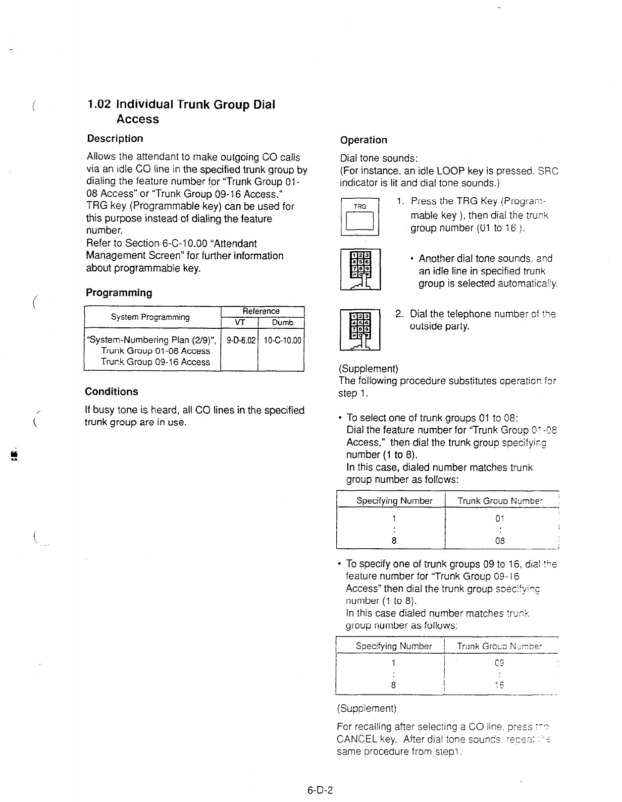
1.02 individual Trunk Group Dial
Access
Description
Allows the attendant to make outgoing CO calls
via an idle CO line in the specified trunk group by
dialing the feature number fpr “Trunk Group Ol-
08 Access” or “Trunk Group 09-l 6 Access.”
TRG key (Programmable key) can be used for
this purpose instead of dialing the feature
number.
Refer to Section 6-C-l 0.00 “Attendant
Management Screen” for further information
about programmable key.
Programming
System Programming Reference
VT 1 Dumb
I
“System-Numbering Plan (2/g)", 9-D-6.02 10-C-10.00
Trunk Group 01-08 Access
Truck Group 09- 16 Access
Conditions
i
If busy tone is heard, all CO lines in the specified
trunk group are in use.
Operation
Dial tone sounds:
(For instance, an idle LOOP key is pressed. SRC
indicator is lit and dial tone sounds.)
1. Press the TRG Key (Program-
mable key ), then dial the trunk
group number (01 to 16 ).
l
Another dial tone sounds. and
an idle line in specified trunk
group is selected automat&/y.
2. Dial the telephone number of tie
outside party.
(Supplement)
The following procedure substitutes operation for
step 1.
l
To select one of trunk groups 01 to 08:
Dial the feature number for “Trunk Group O? 48
Access,” then dial the trunk group specifyiq
number (1 to 8).
In this case, dialed number matches trunk
group number as follows:
i Specify in; Number 1 Trunk Gr; Namber
l
To specify one of trunk groups 09 to 16: dial Ihe
feature number for “Trunk Group 09-l 6
Access” then dial the trunk group soecify’?C
number (1 to 8).
In this case dialed number matches trr;n%
group number as follows:
!
I
Specifying Number -1 Trunk Gross N~nSer
(Supplement)
For recalling after selecting a CO line. press Y-?
CANCEL key. After dial tone sounds. rec)cz: ~5
same procedure from
siep!
6-D-2

1.03 Individual Virtual Trunk Group
Dial Access
Description
Allows the attendant to make outgoing CO calls
using Special Carrier Facilities by simply dialing
the feature number for “Trunk Group 17-24
Access.”
TRG key (Programmable key) can be used for
this purpose instead of dialing the feature
number.
Detailed data, such as access codes and
authorization codes, required to Special Carrier
Access must be programmed beforehand in
“Special Carrier Access” screen.
Trunk groups available for Special Carrier
Access is also defined in the same screen.
It is programmable to restrict Special Carrier
Access on system-wide basis.
Refer to Section 1 O-C-52.00 “World Select 2-
EQU/OCC Access Assignment” for further
information.
Programming
System Programming Reference
VT 1 Dumb
“System-Numbering Plan (2/g)“, 9-D-6.02 10-C-10.00
Trunk Group 17-24 Access
“Special Carrier Access-Equal
9-H-l .OO 1 O-C-30.00
AccessIOCC Access” 9-H-2.00 1 O-C-31 .OO
I I I I
I
Attendant Management I I
Reference
TRG (Trunk Group) key 1 6-C-10.00 1
Conditions
None
Operation
Dial tone sounds:
(For instance, an idle LOOP key is pressed and
the SRC indicator is lit, and dial tone sounds.)
1. Press the TRG Key (Program-
mable key ), then dial the virtual
trunk group number: 17 to24.
?I
1
l
Another dial tone sounds, an
idle trunk in the specified virtual
trunk group is selected
automatically.
2. Dial the telephone number of the
outside party.
(Supplement)
The following procedure substitutes operation for
step 1.
l
Dial the feature number for “Trunk Group 17-24
Access” then dial the virtual trunk group
specifying number: 1 to 8.
l
Virtual trunk group number matches virtual
trunk group specifying number and digit
modification table number (Equal access table
number 1 to 4, OCC access table number 1 to
4 which should be assigned beforehand), as
follows:
Virtual Trunk Virtual Trunk Digit Modification
Group Number Group ‘pecifying Table Number
Number
17 1
18 2
19 3
20 4
21 5
22 6
23 7
24 8
Equal access 1
table number 2
3
i 4
OCC access 1
table number 2
3
4
6-D-3
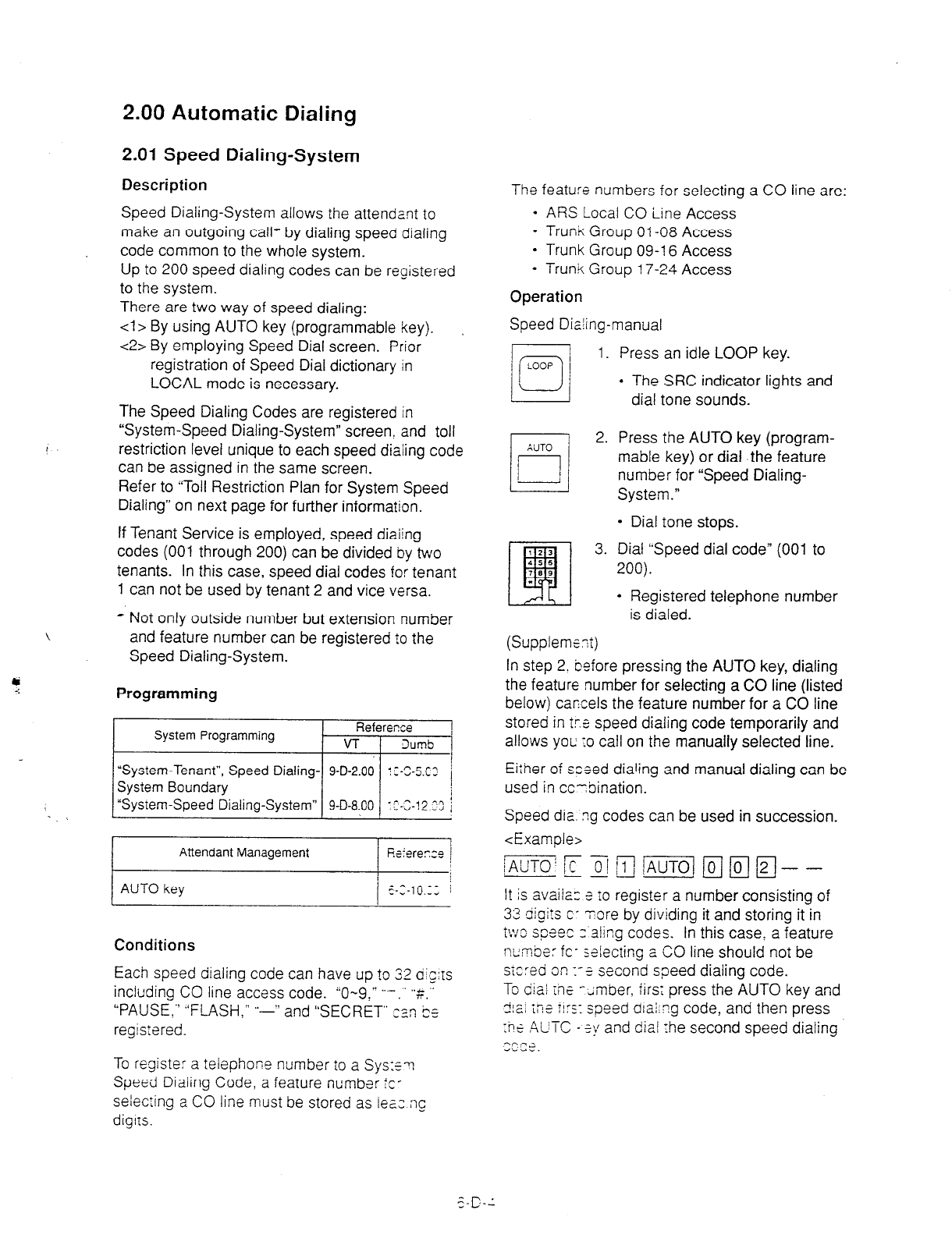
2.00 Automatic Dialing
2.01 Speed Dialing-System
Description
,
Speed Dialing-System allows the attendant to
make an outgoing call- by dialing speed dialing
code common to the whole system.
Up to 200 speed dialing codes can be registered
to the system.
There are two way of speed dialing:
<I > By using AUTO key (programmable key).
<2> By employing Speed Dial screen. Prior
registration of Speed Dial dictionary in
LOCAL mode is necessary.
The Speed Dialing Codes are registered in
“System-Speed Dialing-System” screen, and toll
restriction level unique to each speed dialing code
can be assigned in the same screen.
Refer to “Toll Restriction Plan for System Speed
Dialing” on next page for further information.
If Tenant Service is employed, speed diaiing
codes (001 through 200) can be divided by two
tenants. In this case, speed dial codes for tenant
1 can not be used by tenant 2 and vice versa.
* Not only outside number but extension number
\ and feature number can be registered to the
Speed Dialing-System.
7 Programming
System Programming Reference ,
VT 1 3umS
I
“System-Tenant”, Speed Dialing- 9-D-2.00 ::-X.C3 1
System Boundary
I “System-Speed Dialing-System” 9-D-8.00 I^-‘-13.‘” ’
-” --Ji
Attendant Management
AUTO key
Conditions
Each speed dialing code can have up to 32 dlc:rs
including CO line access code. “O-9:” ‘.- ” “rr’.”
“PAUSE,” “FLASH.” ‘.-” and “SECRET” csn Cs
registered.
The feature numbers for selecting a CO line are:
l
ARS Local CO iine Access
* Trunk Group 01-08 Access
* Trunk Group 09-l 6 Access
l
Trunk Group 17-24 Access
Operation
Speed Diaiing-manual
LOOP
q
i
1.
2.
3.
Press an idle LOOP key.
l
The SRC indicator lights and
dial tone sounds.
Press the AUTO key (program-
mable key) or dial the feature
number for “Speed Dialing-
System.”
l
Dial tone stops.
Dial “Speed dial code” (001 to
200).
l
Registered telephone number
is dialed.
(Supplemzt)
In step 2. before pressing the AUTO key, dialing
the feature number for selecting a CO line (listed
below) car:cels the feature number for a CO line
stored in tra speed dialing code temporarily and
allows you; :o call on the manually selected line.
Eiiher of steed dialing and manual dialing can be
used in cc-bination.
Speed dia. ?g codes can be used in succession.
<Example>
It is availa:: 3 to register a number consisting of
33 digi!s c- Tore by dividing it and storing it in
W3 spaec 2 sling codes. In this case: a feature
r~:mbe: fc- selecting a CO line should not be
sic:ed o:! 1-3 second speed dialing code.
To diai ihc - dmber, firs; press the AUTO key and
I;,.: *in .’
-151 Li != :!:s: speed dial;?g code, and then press
:iiz AUTC * ?y and dial fhe second speed dialing
--CF.2
ri.u-.
To register a telephofie number to a Sys:~7i
Speed Dialing Code, a feature number ic-
selecting a CO line must be stored as iez ng
diglrs.
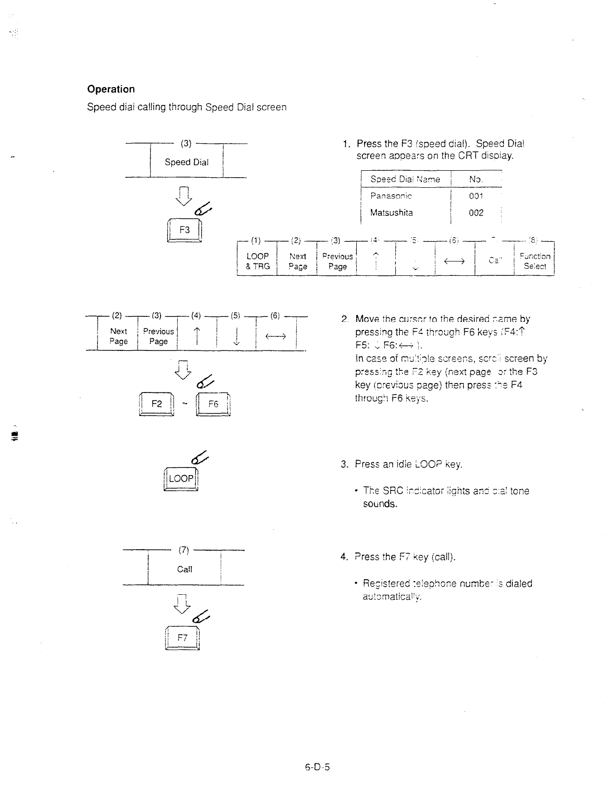
_ ::
Operation
Speed dial calling through Speed Dial screen
,,,a:‘DT
1. Press the F3 (speed dial). Speed Dial
screen appears on the CRT disoiay.
(7) I
/
Carl i
/
j
4
/
jj !I
Ii
3. Press an idie LOOP key.
- The SRC ic.3icator Zgh:s a% -;:z! tone
socrnds.
4. ?ress the F-7 iey (call).
l
RecistPred ‘c!aGhone numte- s dialed
= -..d ” .-I”,
autmatiral’y.
6-D-5
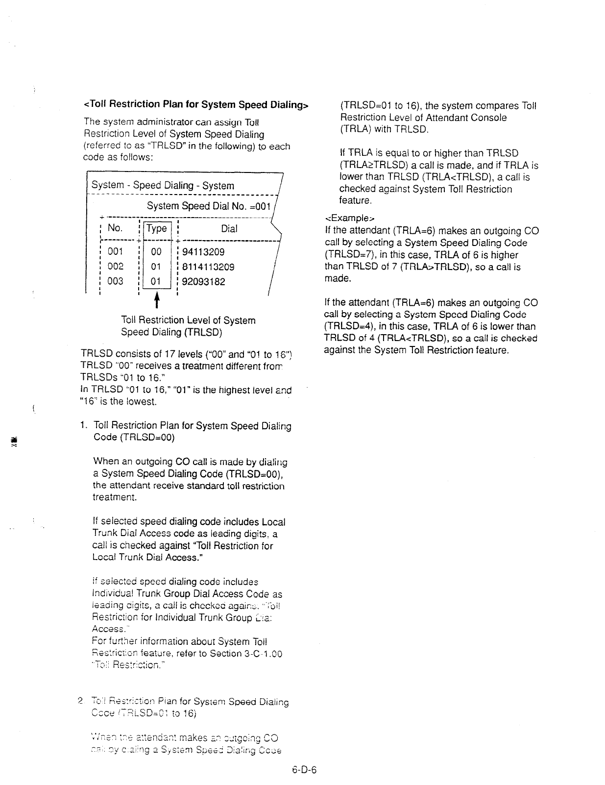
<Toll Restriction Plan for System Speed Dialing>
The system administrator can assign Toll
Restriction Level of System Speed Dialing
(referred to as “TRLSD” in the following) to each
code as follows:
t
System - Speed Dialing - System
--------------------------------------
System Speed Dial No. =OOl
I +.-----------------------------------------
I .
:
No. :T
! Dial
I
r-l.
yw i \
i------v- +I------$+ ------------------------~
: 001
i 002
Toll Restriction Level of System
Speed Dialing (TRLSD)
TRLSD consists of 17 levels (“00” and “01 to 16”)
TRLSD “00” receives a treatment different fron-
TRLSDs “01 to 16.”
In TRLSD ;Ol to 16,” “01” is the highest level and
“16“ is the lowest.
1. Toll Restriction Plan for System Speed Dialing
Code (TRLSD=OO)
When an outgoing CO call is made by dialing
a System Speed Dialing Code (TRLSD=OO),
the attendant receive standard toll restriction
treatmeni.
If selected speed dialing code includes Local
Trunk Dial Access code as leading digits, a
call is checked against “Toll Restriction for
Local Trunk Dial Access.”
if seiected speed dialing code includes
Individual Trunk Group Dial Access Code as
leading cigiis, a tail is checkec again:.. ,,~;:;i!
Resrriciion for Individual Trunk Group L:a:
Access..’
For further information abour System Toil
Res:riaicn featilre, refer to Section 3-C-l .OO
Tc, ; j Res:ris:icn.”
3
-.
Tc:i F;es::istion Plan for System Speed Diaiing
cccl IT’;liSDzO: to 16)
(TRLSD=Ol to 16) the system compares Toll
Restriction Level of Attendant Console
(TRLA) with TRLSD.
If TRLA is equal to or higher than TRLSD
(TRLAkTRLSD) a call is made, and if TRLA is
lower than TRLSD (TRLA<TRLSD), a call is
checked against System Toll Restriction
feature.
<Example>
If the attendant (TRL4=6) makes an outgoing CO
call by selecting a System Speed Dialing Code
(TRLSD=7), in this case, TRLA of 6 is higher
than TRLSD of 7 (TRLA>TRLSD), so a call is
made.
If the attendant (TRtA=6) makes an outgoing CO
call by selecting a System Speed Dialing Code
(TRLSD=4), in this case, TRLA of 6 is lower than
TRLSD of 4 (TRLAcTRLSD), so a call is checked
against the System Toll Restriction feature.
6-D-6
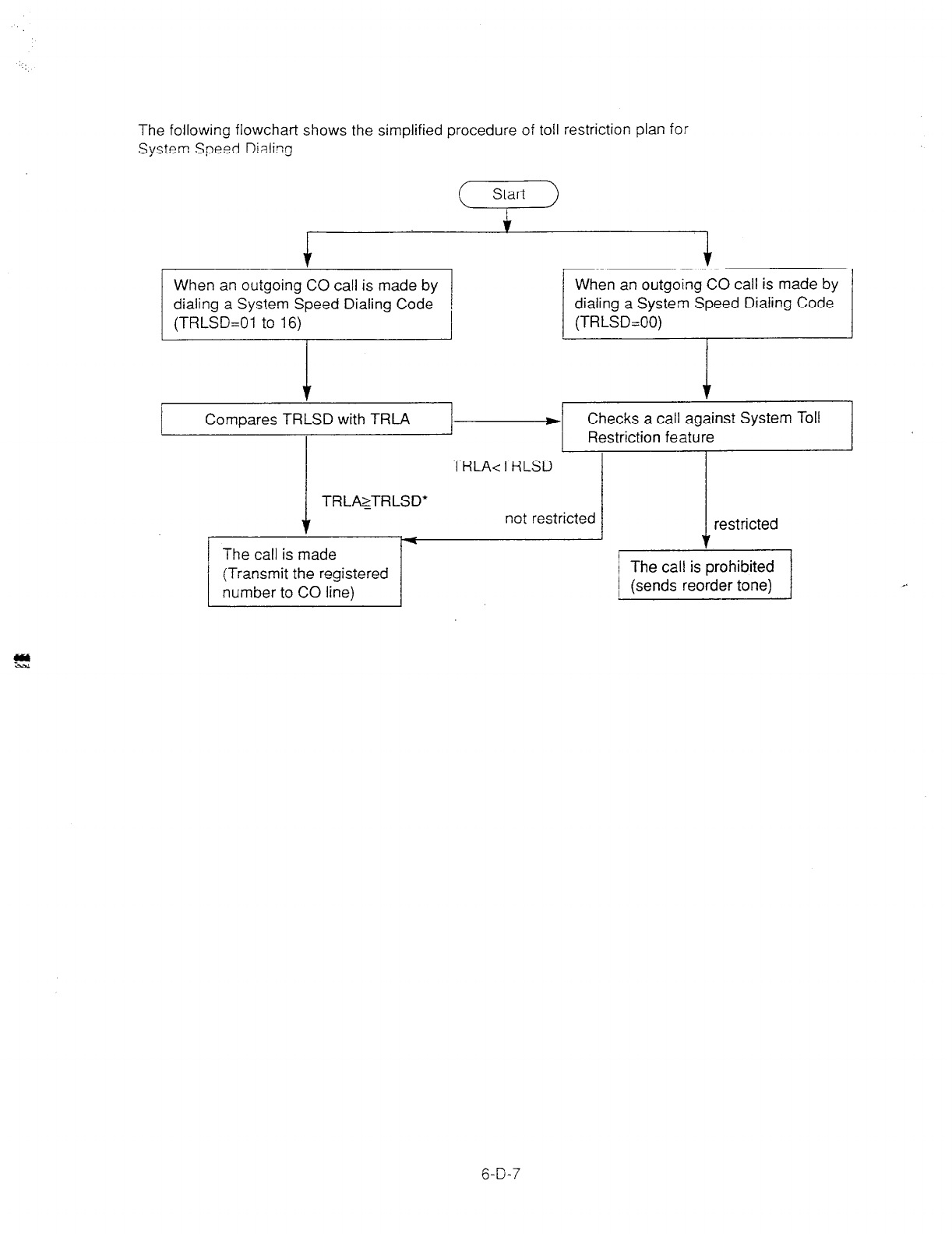
The following flowchart shows the simplified procedure of toll restriction plan for
System Speed Dialing.
( Start )
I
i- i-
I I I
When an outgoing CO call is made by
1 (TRLSD=OI to 16). 1 (TRLSD=OO) 1
When an outgoing CO call is made by
dialing a System Speed Dialing Code dialing a System Speed Dialing Code
Compares TRLSD with TRLA - Checks a call against System Toll
I Restriction feature
The call is made
( not rest2
(Transmit the registered
number to CO line)
I
TRLA<TRLSD
TRLAzTRLSD*
6-D-7

2.02 Last Number Redial (LNR)
Description Operation
Last Number Redial feature automatically saves
the last dialed telephone number of the outside
party and allows the attendant to make the call to
the same destination again by simply pressing
the REDIAL key (programmable key).
Assign REDIAL key to programmable key in
advance.
Programming
Attendant Management
REDIAL key
Reference
6-C-l
0.00
Conditions
Up to 32 digits except the feature number for
selecting a CO line can be memorized
automatically as the last dialed number.
“* ” “#,” “PAUSE,” or “SECRET”
one digit respectively.
are counted as
Last number redialing memory is renewed
automatically every time a new outgoing CO call
is made (including when ringback tone, DND
tone or busy tone is returned) and even one digit
is sent to CO line. Dialing a feature number for
selecting a CO line only does not renew the
memorized number.
1. Press an idle LOOP
key.
l
The SRC indicator lights and
dial tone sounds.
2. Press the REDIAL key
(programmable key).
l
After dial tone, ringback tone
sounds.
l
When the called party answers
start the conversation.
6-D-8
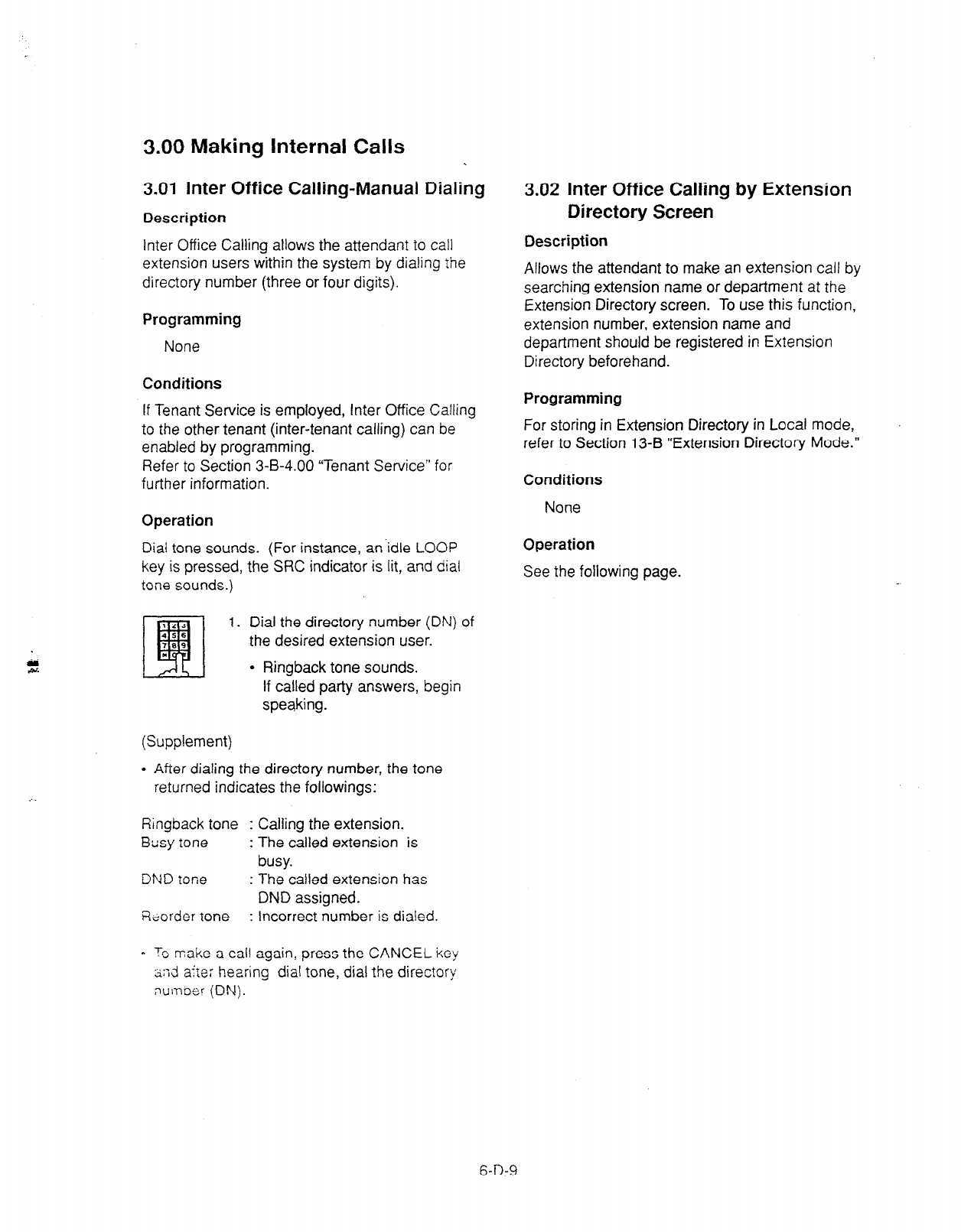
3.00 Making Internal Calls
3.01 Inter Office Calling-Manual Dialing
Description
Inter Office Calling allows the attendant to call
extension users within the system by dialing the
directory number (three or four digits).
Programming
None
Conditions
If Tenant Service is employed, Inter Office Calling
to the other tenant (inter-tenant calling) can be
enabled by programming.
Refer to Section 3-B-4.00 “Tenant Service” for
further information.
Operation
Dial tone sounds. (For instance, an.idle LOOP
key is pressed, the SRC indicator is lit, and dial
tone sounds.)
121
q 1. Dial the directory number (DN) of
456
789 the desired extension user.
*
l
Ringback tone sounds.
If called party answers, begin
speaking.
(Supplement)
l
After dialing the directory number, the tone
returned indicates the followings:
Ringback tone : Calling the extension.
Busy tone : The called extension is
busy.
DND tone : The called extension has
DND assigned.
&order tone : Incorrect number is dialed.
3.02 Inter Office Calling by Extension
Directory Screen
Description
Allows the attendant to make an extension call by
searching extension name or department at the
Extension Directory screen. To use this function,
extension number, extension name and
department should be registered in Extension
Directory beforehand.
Programming
For storing in Extension Directory in Local mode,
refer to Section 13-B “Extension Directory Mode.”
Conditions
None
Operation
See the following page.
0 Tc make a call again, press the CANCEL key
a;;d aite: hearing dial tone, dial the directory
number (DN).
6-D-9
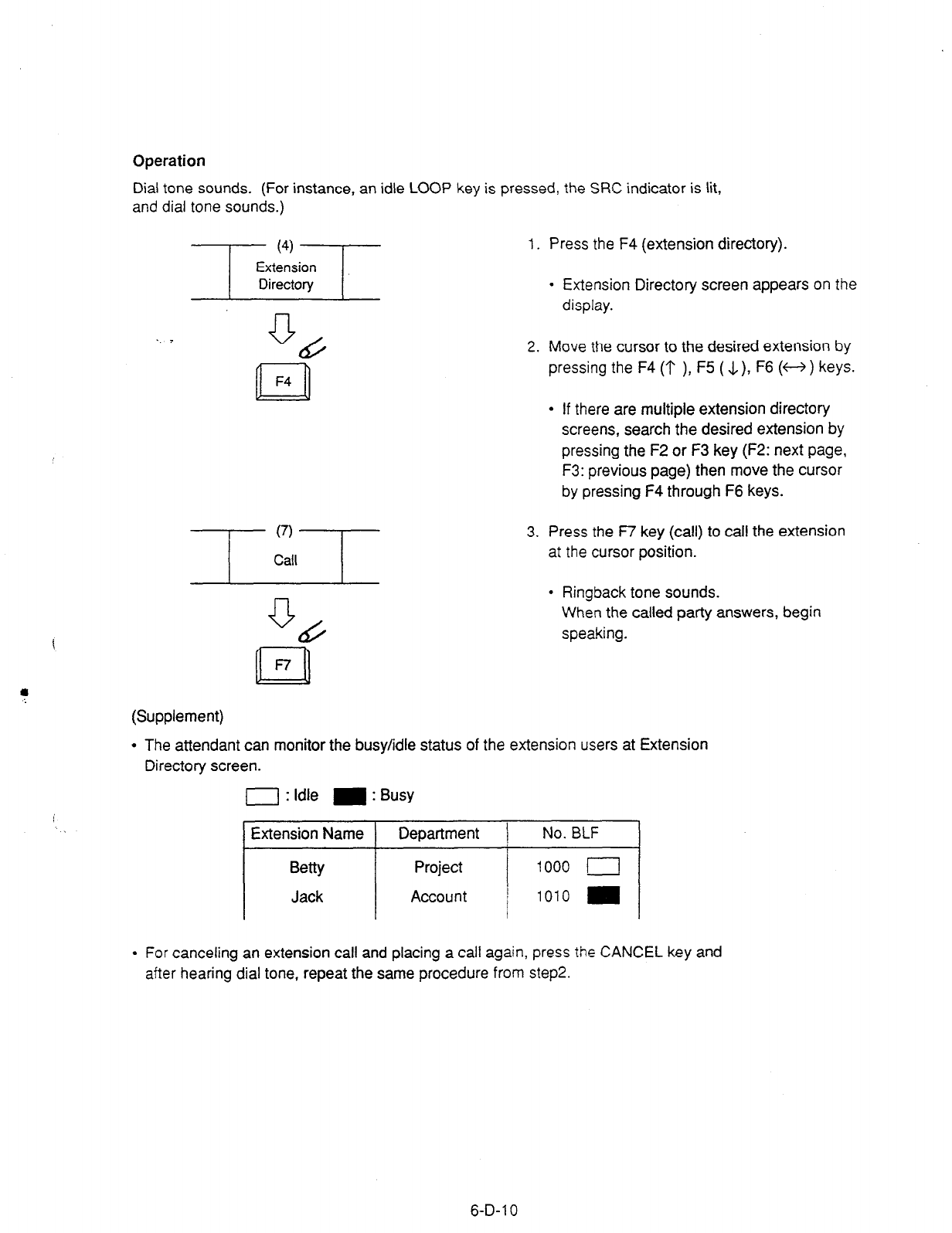
Operation
Dial tone sounds. (For instance, an idle LOOP key is pressed, the SRC indicator is lit,
and dial tone sounds.)
1. Press the F4 (extension directory).
a t55
n F4
l
Extension Directory screen appears on the
display.
2. Move the cursor to the desired extension by
pressing the F4 (‘I’ ), F5 (.l,), F6 (w ) keys.
l
If there are multiple extension directory
screens, search the desired extension by
pressing the F2 or F3 key (F2: next page,
F3: previous page) then move the cursor
by pressing F4 through F6 keys.
3. Press the R key (call) to call the extension
at the cursor position.
l
Ringback tone sounds.
When the called party answers, begin
speaking.
(Supplement)
l
The attendant can monitor the busy/idle status of the extension users at Extension
Directory screen.
0 : Idle m : Busy
Extension Name Department / No. BLF I
Betty
Jack
Project i 1000 (
Account j 1010 I
I
l
For canceling an extension call and placing a call again, press the CANCEL key and
after hearing dial tone, repeat the same procedure from step2.
6-D-l 0
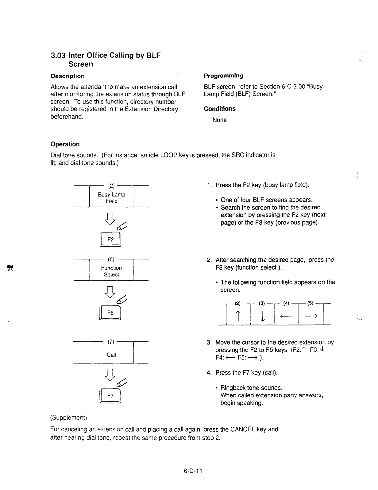
3.03 inter Office Calling by BLF
Screen
Description
Allows the attendant to make an extension call
after monitoring the extension status through BLF
screen. To use this function, directory number
should be registered in the Extension Directory
beforehand.
Programming
BLF screen: refer to Section 6-C-3.00 “Busy
Lamp Field (BLF) Screen.”
Conditions
None
Operation
Dial tone sounds. (For instance, an idle LOOP key is pressed, the WC indicator is
lit, and dial tone sounds.)
1. Press the F2 key (busy lamp field).
0 (L
n F2
l
One of four BLF screens appears.
l
Search the screen to find the desired
extension by pressing the F2 key (next
page) or the F3 key (previous page).
2. After searching the desired page, press the
F8 key (function select ).
l
The following function field appears on the
screen.
-
(2)
-
(3) (4)
-6)
T L+d :..
3. Move the cursor to the desired extension by
pressing the F2 to F5 keys (F2:1‘ F3: J
F4: c F5: -+ ).
n
F7 ))
4. Press the F7 key (call).
l
Ringback tone sounds.
When called extension pap answers,
begin speaking.
(Supplement)
For canceling an extension call and placing a call again, press the CANCEL key and
after hearing dial tone, repeat the same procedure from step 2.
6-D-l 1

3.04 Inter Office Calling by Extension
Management Screen
Description
Allows the attendant to make an extension call
through Extension Management screen. Before
the operation, directory number should be
registered in the Extension Directory screen.
Programming
Refer to Section 6-C-i.;; -Exter.s.on
Management Screen.”
Conditions
None
!-I.
Operation
Dial tone sounds. (For instance, an idle LOOP key is pressed. the SRC indicator is
lit, and dial tone sounds.)
0
cd
n
F2
1. Press the F2 key (extension manage).
l
One of Extension Management screens
appears.
l
Search the screen to find the desired
extension by pressing the F2 key (next
page) or the F3 key (previous page).
0 b
n F8
2. After searching the desired page, press the
F8 key (function select ). ..
l
The following function field appears on the
screen.
-
(2)
-
(3) (4)
(5)
T b+--
3. Move the cursor to the desired extension by
pressing the F2 to F5 keys (F2:? F3: \1
F4: t- F5: + ).
Q &
n F7
4. Press the F7 key (call).
l
Ringback tone sounds.
When called party answers, begin
speaking.
(Supplement)
For canceling an extension call and placing a call again, press the CANCEL key and
after hearing dial tone, repeat the same procedure from step 2.
6-D-l 2
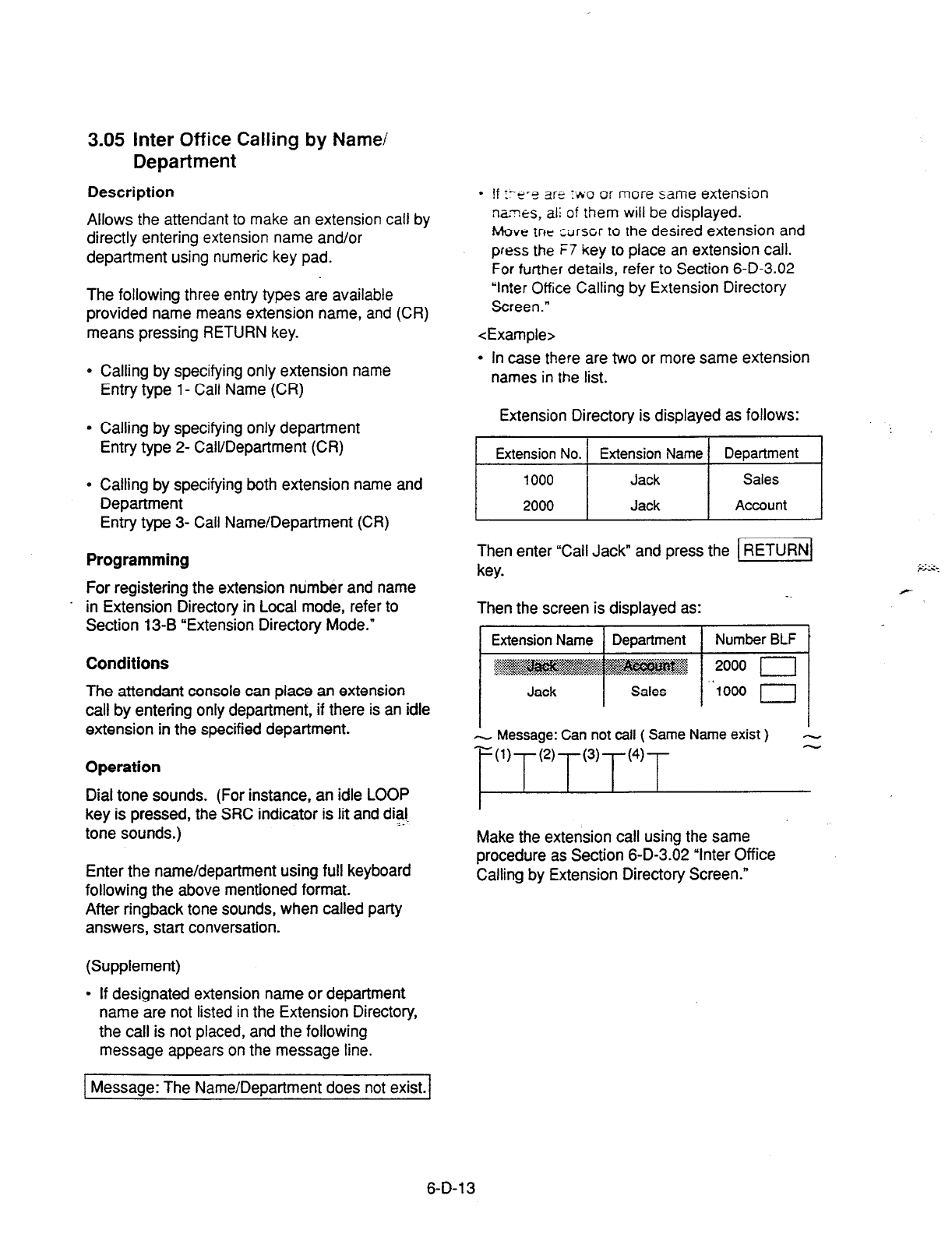
3.05 Inter Office Calling by Name/
Department
Description
Allows the attendant to make an extension call by
directly entering extension name and/or
department using numeric key pad.
The following three entry types are available
provided name means extension name, and (CR)
means pressing RETURN key.
* Calling by specifying only extension name
Entry type l- Call Name (CR)
l
Calling by specifying only department
Entry type 2- Call/Department (CR)
l
Calling by specifying both extension name and
Department
Entry type 3- Call Name/Department (CR)
Programming
For registering the extension number and name
. in Extension Directory in Local mode, refer to
Section 13-B “Extension Directory Mode.”
Conditions
The attendant console can place an extension
call by entering only department, if there is an idle
extension in the specified department.
Operation
Dial tone sounds. (For instance, an idle LOOP
key is pressed, the SRC indicator is lit and dial
= .
tone sounds.)
Enter the name/department using full keyboard
following the above mentioned format.
After ringback tone sounds, when called party
answers, start conversation.
(Supplement)
l
If designated extension name or department
name are not listed in the Extension Directory,
the call is not placed, and the following
message appears on the message line.
. If y-“‘3 2’I
_ _ _ e :fio of more same extension
names, al! of them will be displayed.
Move
tnV cdrscr to the desired extension and
press the i7 key to place an extension call.
For turther details, refer to Section 6-D-3.02
“Inter Office Calling by Extension Directory
Screen.”
<Example>
l
In case there are two or more same extension
names in the list.
Extension Directory is displayed as follows:
1 ExteinsNo.1 EtiensisiNamei DE!nt 1
Then enter “Call Jack” and press the 1 RETURN/
key.
Then the screen is displayed as:
Message: Can not call ( Same Name exist ) -
~U’T”‘T’“~‘“T
-
Make the extension call using the same
procedure as Section 6-D-3.02 “Inter Office
Calling by Extension Directory Screen.”
Message: The Name/Department does not exist.
6-D-l 3
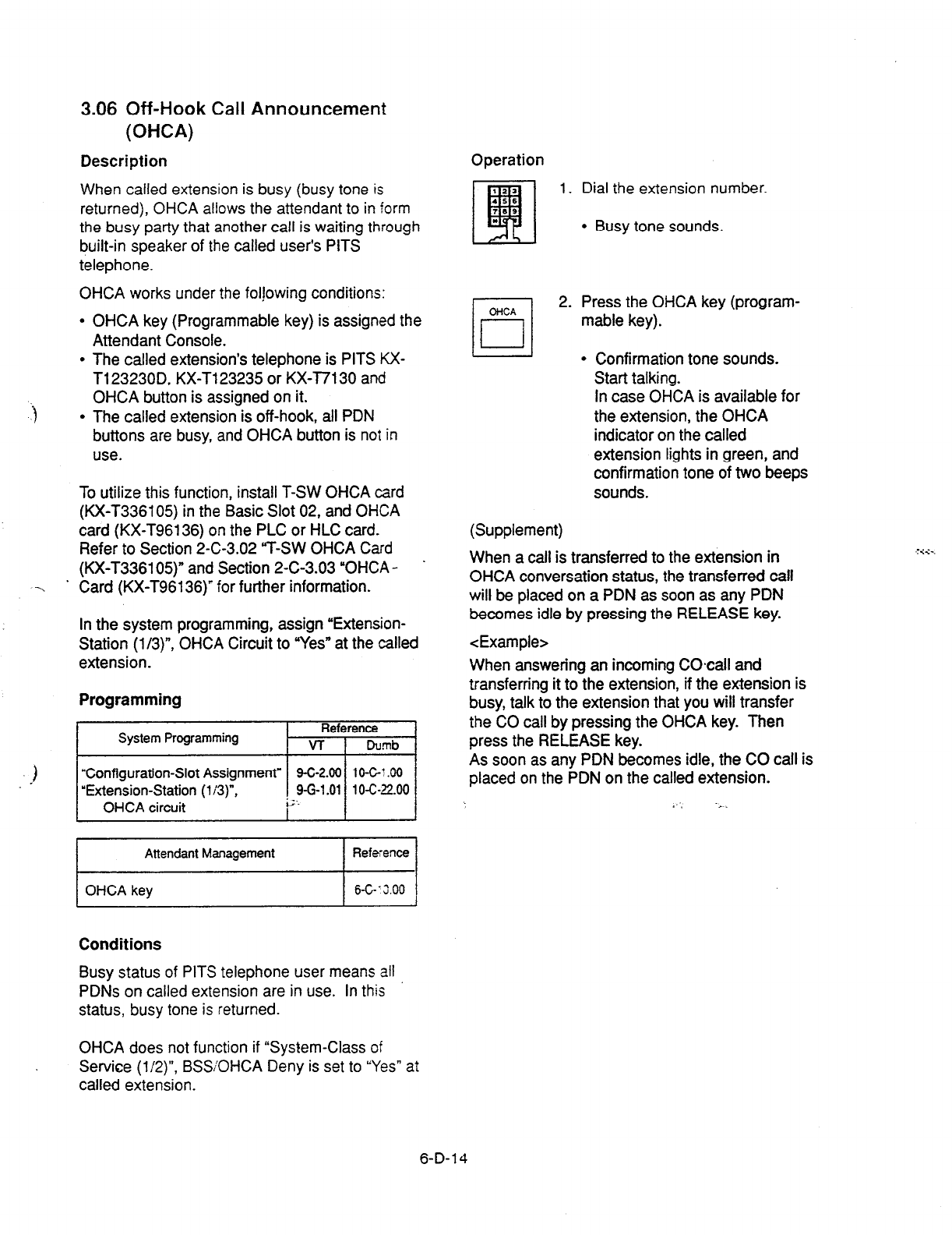
3.06 Off-Hook Call Announcement
(OHCA)
Description Operation
When called extension is busy (busy tone is
returned), OHCA allows the attendant to in form
the busy party that another call is waiting through
built-in speaker of the called user’s PITS
telephone.
OHCA works under the folfowing conditions:
l
OHCA key (Programmable key) is assigned the
Attendant Console.
l
The called extension’s telephone is PITS KX-
T123230D, KX-T123235 or KX-I7130 and
OHCA button is assigned on it.
l
The called extension is off-hook, all PDN
buttons are busy, and OHCA button is not in
use.
CiiCA
cl
i
To utilize this function, install T-SW OHCA card
(KX-T336105) in the Basic Slot 02, and OHCA
card (KX-T96136) on the PLC or HLC card.
Refer to Section 2-C-3.02 “T-SW OHCA Card
(KX-T336105)” and Section 2-C-3.03 “OHCA -
-. ’ Card (KX-T96136)’ for further information.
In the system programming, assign “Extension-
Station (l/3)“, OHCA Circuit to “Yes” at the called
extension.
When a call is transferred to the extension in
OHCA conversation status, the transferred call
will be placed on a PDN as soon as any PDN
becomes idle by pressing the RELEASE key.
<Example>
Programming
System Programming Reference
VT i Dumb
1
“Configuration-Slot Assignment” 9-C-2.00 IO-C-~ .OO
“Extension-Station (l/3)“, 9-G-l .Ol 1 o-c-z2.00
OHCA circuit L; ‘.
I
. . . . -,
Attendant Management
Reference
) OHCA key 1 6-G’3.00
Conditions
Busy status of PITS telephone user means all
PDNs on called extension are in use. In this
status,
busy tone is returned.
6-D-l 4
OHCA does not function if “System-Class of
Service (l/Z)“, BSSOHCA Deny is set to “Yes” at
called extension.
1.
Dial the extension number.
l
Busy tone sounds.
2.
(Supplement)
Press the OHCA key (program-
mable key).
l
Confirmation tone sounds.
Start talking.
In case OHCA is available for
the extension, the OHCA
indicator on the called
extension lights in green, and
confirmation tone of two beeps
sounds.
When answering an incoming COcall and
transferring it to the extension, if the extension is
busy, talk to the extension that you will transfer
the CO call by pressing the OHCA key. Then
press the RELEASE key.
As soon as any PDN becomes idle, the CO call is
placed on the PDN on the called extension.
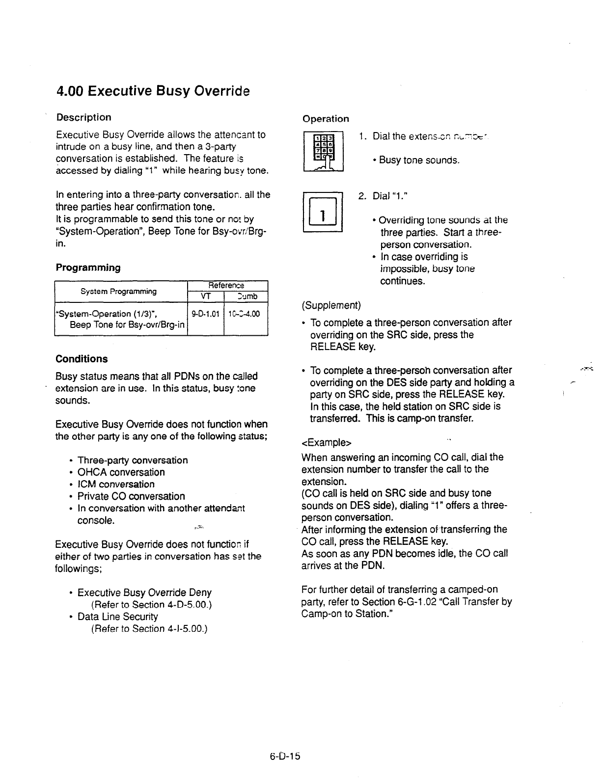
4.00 Executive Busy Override
Description
Executive Busy Override allows the attencant to
intrude on a busy line, and then a 3-party
conversation is established. The feature is
accessed by dialing “1” while hearing bus:/ tone.
In entering into a three-party conversation. ail the
three parties hear confirmation tone.
It is programmable to send this tone or nor by
“System-Operation”, Beep Tone for Bsy-ovriBrg-
in.
Programming
~1
Conditions
Busy status means that all PDNs on the cslled
extension are in use. In this status, busy tone
sounds.
Executive Busy Override does not function when
the other party is any one of the following status;
l
Three-party conversation
l
OHCA conversation
l
ICM conversation
l
Private CO conversation
l
In conversation with another attendant
console. _ .x..
Executive Busy Override does not function if
either of two parties in conversation has set the
followings;
l
Executive Busy Override Deny
(Refer to Section 4-D-5.00.)
l
Data Line Security
(Refer to Section 4-I-5.00.)
Operation
1. Dial the extensor. ~~7%~
l
Busy tone sounds.
hi-l
2. Dial “1.”
III
1 .
I I
.
(Supplement)
Overriding tone sounds at the
three parties. Start a three-
person conversation.
In case overriding is
impossible, busy tone
continues.
. To complete a three-person conversation after
overriding on the SRC side, press the
RELEASE key.
l
To complete a three-persoh conversation after
overriding on the DES side party and holding a
party on SRC side, press the RELEASE key.
In this case, the held station on SRC side is
transferred. This is camp-on transfer.
<Example> . .
When answering an incoming CO call, dial the
extension number to transfer the call to the
extension.
(CO call is held on SRC side and busy tone
sounds on DES side), dialing “1” offers a three-
person conversation.
After informing the extension of-transferring the
CO call, press the RELEASE key.
As soon as any PDN becomes idle, the CO call
arrives at the PDN.
For further detail of transferring a camped-on
party, refer to Section 6-G-l .02 “Call Transfer by
Camp-on to Station.”
6-D-l 5
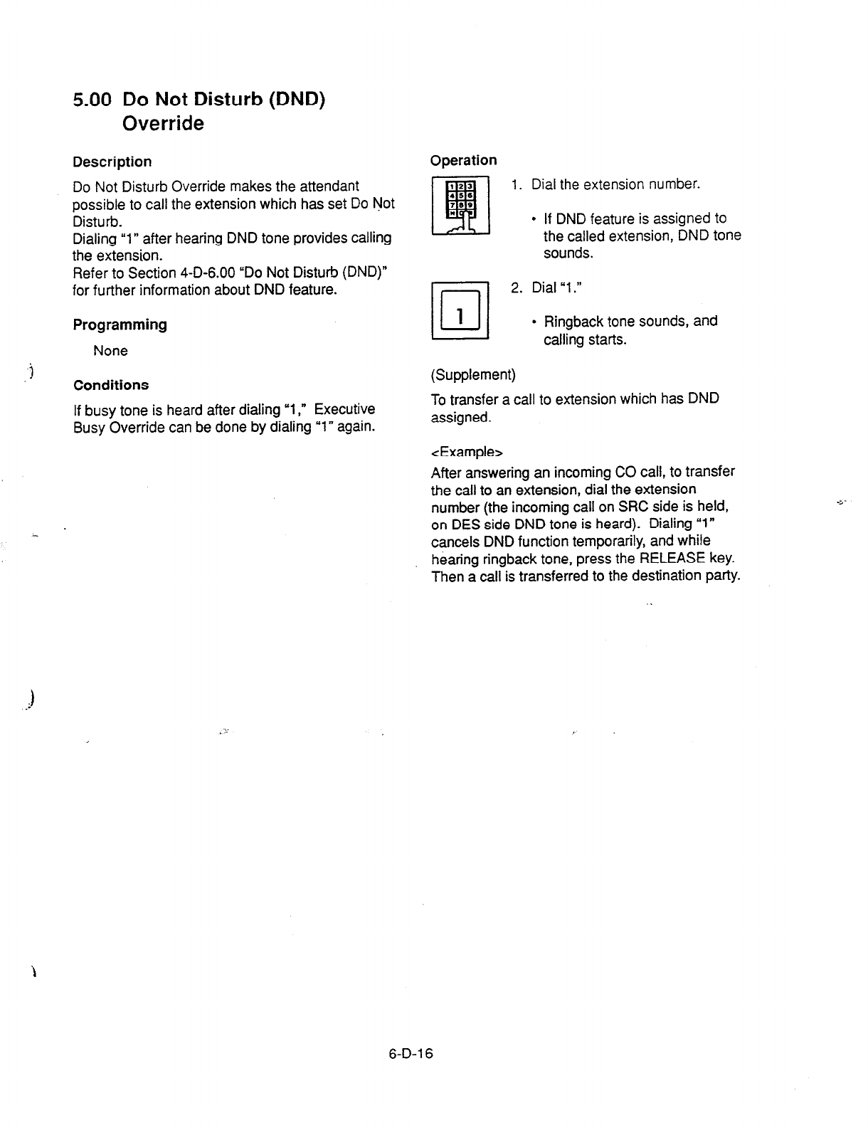
5.00 Do Not Disturb (DND)
Override
Description
Do Not Disturb Override makes the attendant
possible to call the extension which has set Do rlJot
Disturb.
Dialing “1” after hearing DND tone provides calling
the extension.
Refer to Section 4-D-6.00 “Do Not Disturb (DND)”
for further information about DND feature.
Programming
None
Conditions
If busy tone is heard after dialing “1,” Executive
Busy Override can be done by dialing “1” again.
Operation
1. Dial the extension number.
l
If DND feature is assigned to
the called extension, DND tone
sounds.
•l
2. Dial “1.”
1
l
Ringback tone sounds, and
calling starts.
(Supplement)
To transfer a call to extension which has DND
assigned.
<Example>
After answering an incoming CO call, to transfer
the call to an extension, dial the extension
number (the incoming call on SRC side is held,
on DES side DND tone is heard). Dialing “1”
cancels DND function temporarily, and while
hearing ringback tone, press the RELEASE key.
Then a call is transferred to the destination party.
6-D-l 6
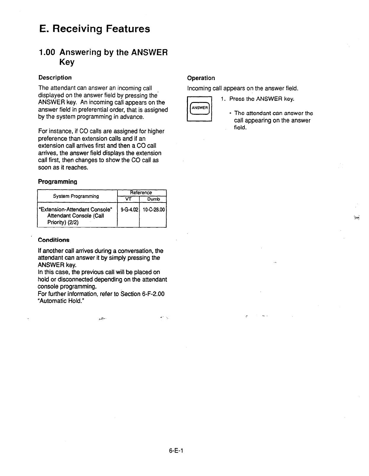
E. Receiving Features
1.00 Answering by the ANSWER
Key
Description Operation
The attendant can answer an incoming call
displayed on the answer field by pressing the’
ANSWER key. An incoming call appears on the
answer field in preferential order, that is assigned
by the system programming in advance.
Incoming call appears on the answer field.
1. Press the ANSWER key.
For instance, if CO calls are assigned for higher
preference than extension calls and if an
extension call arrives first and then a CO call
arrives, the answer field displays the extension
call first, then changes to show the CO call as
soon as it reaches.
Programming
System Programming Reference
VT
I
Dumb
l
The attendant can answer the
call appearing on the answer
field.
‘Extension-Attendant Console”
9-G-4.02 10-c-28.00
Attendant Console (Call
Priority) (2/2)
Conditions
If another call arrives during a conversation, the
attendant can answer it by simply pressing the
ANSWER key.
In this case, the previous call will be placed on
hold or disconnected depending on the attendant
console programming.
For further information, refer to Section 6-F-2.00
“Automatic Hold.”
;r= .e
i- c
6-E-l

2.00 Answering by a LOOP Key
Description
If there are multiple incoming calls,
the
attendant
can answer a desired call by pressing a LOOP
key associated with it.
For instance, when there are two incoming
extension calls, you can confirm the callers on
the screen below and answer a desired call by
pressing a LOOP key associated with
it.
In the example below, pressing the ANSWER key
automatically connects a call from Jack. Press
the LOOP 2 key to answer the call from Manager.
LOOP Key and Trunk Group Jan. 199 FRI 12:00 AM
Wait Call = 0 overlbw=o
- (1)
(2)
(3) (4) (5)
(6)
-
Ex-rloo
EXT. 200
Jack Manager
GO1 T=OS 0 C=Ol T=Ol 0
Incoming Incoming
010 020 030 040 050 060 070 060 090 100 110 120 130 140 150 160
Input SRC i
DES :
Message :
LOOP-1
EXT. 100
Jack ‘*
Incoming
Programming
None
ii-
Conditions
During a conversation, the attendant can answer
another incoming call by pressing a LOOP key
associated
with it.
In this case, the previous call will be placed on
hold or disconnected depending on the attendant
console programming.
For further information, refer to Section 6-F-2.00
“Automatic Hold.”
Operation
rl
0 DES
1. Multiple incoming calls are
r_l SRC arriving
at
LOOP keys.
I
l
Multiple SRC indicators start to
flash
in
240 winks.
ml
LOOP
2. Press the desired LOOP key.
l
The SRC indicator of the
pressed LOOP key lights. Talk
to the caller.
6-E-2

3.00 Directed Call Pickup
Description
Directed Call Pickup allows the attendant to
answer the call ringing at any extension by
dialing the feature number for “Directed Call
Pickup,” and then the directory number of the
ringing extension.
Operation
Picking up a call ringing at an extension
1. Press an idle LOOP key.
l
The SRC indicator lights and
dial tone sounds.
Programming -
I
System Programming Reference
VT I
lhmb
I
“System-Numbering Plan (3B)’
Directed Call
Pickup _ I
Conditions
It is possible to execute Directed Call Pickup
after holding the cunent call.
This feature is not available to answer the
following calls:
cl> A call ringing at an extension on which Dial
Call Pickup Deny is set
(Refer to Section 4-D-3.03 “Call Pickup
Deny” for further information.)
~2>
A call ringing on PC0 button
<3>
A call ringing on ICM button
<4>
A call arriving at an extension but not ringing
(Refer to Section 3-D-3.02 ‘Flexible Ringing
Assignment-Delayed Ringing” for further
information.)
For thti above calls, reorder tone sounds after
dialing the feature number for uDiiected Call
Pickup” and the diiectory number of the ringing
extension and the following message appears on
the Message line.
2. Dial the feature number for
Directed Call Pickup. “48”
(default).
3. Dial the directory number of the
ringing extension.
l
You hear confirmation tone 3.
l
Talk to the caller.
1 Message: No Incoming Call 1
6-E-3
(40993)
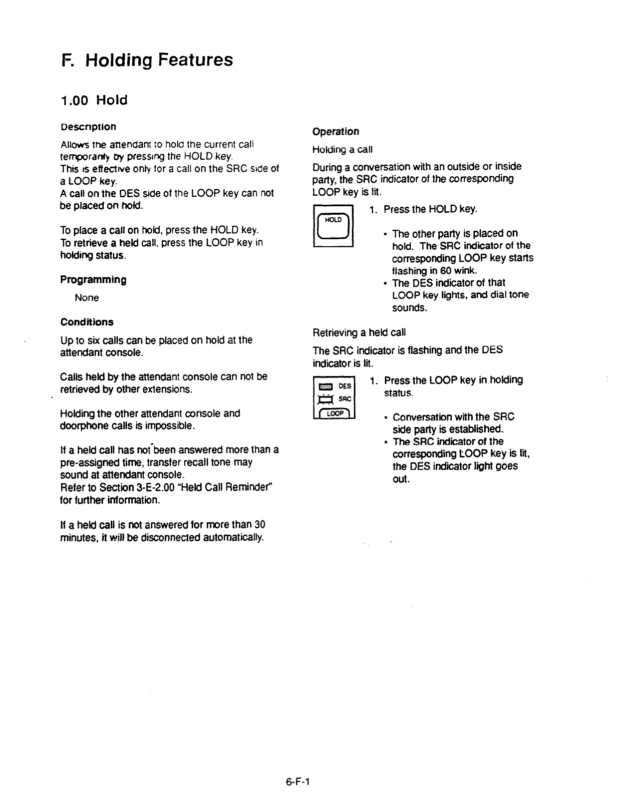
F. Holding Features
1 .OO Hold
Description
AlI~ws me attendam :o hold the current call
teTranIy &y pressing the HOLD key.
This rs effectrve only for a call on the SRC side of
a LOOP key.
A call on the DES side of the LOOP key can not
be placed on hold.
To place a call on hold, press the HOLD key.
To retrieve a held call. press the LOOP key in
holding status.
Programming
None
Conditions
Up to six calls can be placed on hold at the
attendant console.
Calls held by the attendant console can not be
retrieved by other extensions.
Holding the other attendant console and
doorphone calls is impossible.
If a held call has nofbeen answered more than a
pre-assigned time, transfer recall tone may
sound at attendant console.
Refer to Section 3-E-2.00 “Held Call Reminder’
for further information.
If a held call is not answered for more than 30
minutes, it will be disconnected automatically.
Operation
Holding a call
During a conversation with an outside or inside
patty, the SRC indicator of the corresponding
LOOP key is lit.
UOLO
El
0
1. Press the HOLD key.
l
The other party is placed on
hold. The SRC indicator of the
corresponding LOOP key starts
flashing in 60 wink.
l
The DES indicator of that
LOOP key lights, and dial tone
sounds.
Retrieving a held call
The SRC indicator is flashing and the DES
indicator is iii.
m DES
rl
1. Press the LOOP key in holding
m SRC status.
LEZU .
.
Conversation with the SRC
side party is established.
The SRC indicator of the
corresponding LOOP key is lii,
the DES indicator light goes
Out.
6-F-l
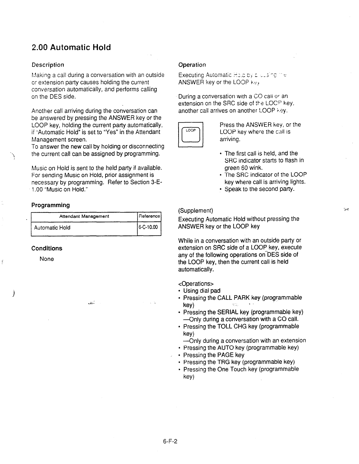
2.00 Automatic Hold
i
Description
b.laking a call during a conversation with an outside
or extension party causes holding the current
conversation automatically, and performs calling
on the DES side.
Another call arriving during the conversation can
be answered by pressing the ANSWER key or the
LOOP key, holding the current party automatically,
if -Automatic Hold” is set to “Yes” in the Attendant
Management screen.
To answer the new call by holding or disconnecting
the current call can be assigned by programming.
Music on Hold is sent to the held party if available.
For sending Music on Hold, prior assignment is
necessary by programming. Refer to Section 3-E-
l
.OO “Music on Hold.”
Programming
/-
Attendant Management 1 Reference1
I
Automatic
Hold
I&c-10.00 1
Conditions
None
Operation
Executing Auioinatic +;.c C! ; --; “: .’ L
ANSWER key or the LOCI? b.:,.
During a conversation with a CO
cati ‘3’
an
extension on the SRC side of ;I-a
LOC? key,
another call arrives on another LOOP +.ey.
LOOP
cl
0
Press the ANSWER key, or the
LOOP key where the call is
arriving.
l
The first call is held, and the
SRC indicator starts to flash in
green 60 wink.
l
The SRC indicator of the LOOP
key where call is arriving lights.
l
Speak to the second party.
(Supplement)
Executing Automatic Hold without pressing the
ANSWER key or the LOOP key
While in a conversation with an outside party or
extension on SRC side of a LOOP key, execute
any of the following operations on’DES side of
the LOOP key, then the current call is held
automatically.
<Operations>
l
Using dial pad
l
Pressing the CALL PARK key (programmable
key)
l
Pressing the SERIAL key (programmable key)
-Only during a conversation with a CO call.
l
Pressing the TOLL CHG key (programmable
key)
-Only during a conversation with an extension
l
Pressing the AUTO key (programmable key)
l
Pressing the PAGE key
l
Pressing the TRG key (programmable key)
l
Pressing the One Touch key (programmable
key)
6-F-2
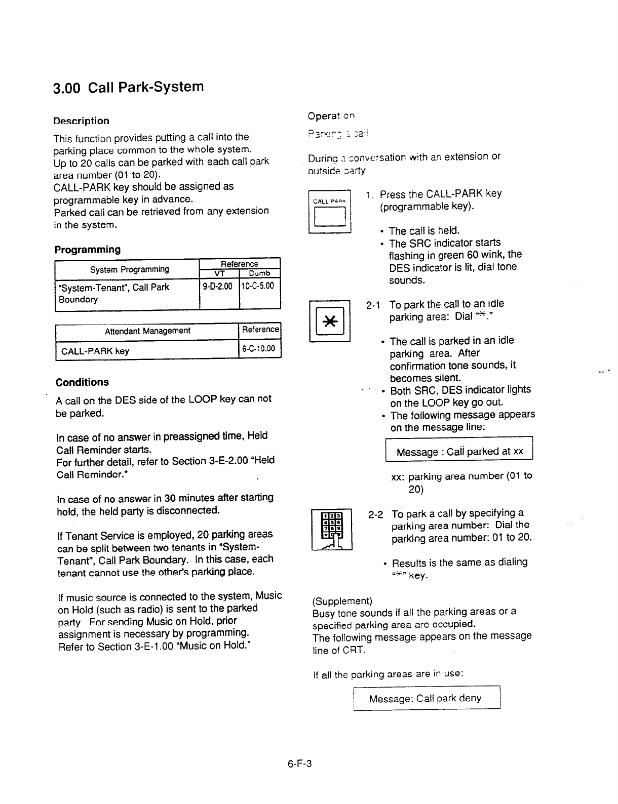
3.00 Call Park-System
Description
This function provides putting a call into the
parking place common to the whole system.
Up to 20 calls can be parked with each call park
area number (01 to 20).
CALL-PARK key should be assigned as
programmable key in advance.
Parked cali can be retrieved from any extension
in the system.
Programming
Attendant Management Ref+fence
CALL-PARK key 6-GT0.00
Conditions
. A call on the DES side of the LOOP key can not
be parked.
In case of no answer in preassigned time, Held
Call Reminder starts.
For further detail, refer to Section 3-E-2.00 “Held
Call Reminder.”
In case of no answer in 30 minutes after starting
hold, the held party is disconnected.
If Tenant Service is employed, 20 parking areas
can be split between two tenants in ‘System-
Tenant”, Call Park Boundary. In this case, each
tenant cannot use the other’s parking place.
If music source is connected to the system, Music
on Hold (such as radio) is sent to the parked
party. For sending Music on Hold, prior
assignment is necessary by programming.
Refer to Section 3-E-l .OO “Music on Hold.”
Opera? cn
pzyr-_ f ,ai!
During t :onvc:satior;
with an extension or
outside ;arty
rl
1. Press tine CALL-PARK key
CALL P&a.
l-l
(programmable key).
L!-lJ l
.
Dl
2-l
*
.
-’ .
.
The call is held.
The SRC indicator starts
flashing in green 60 wink, the
DES indicator is lit, dial tone
sounds.
To park the call to an idle
parking area: Dial I*.”
The call is parked in an idle
parking area. After
confirmation tone sounds, it
becomes silent.
Both SRC, DES indicator lights
on the LOOP key go out.
The following message appears
on the message line:
I
Message : Caii Darked at xx
xx: parking area number (01 to
20)
2-2 To park a call by specifying a
parking area number: Dial the
parking area number: 01 to 20.
l
Resutts is the same as dialing
P*-R key.
(Supplement)
Busy tone sounds if att Ihe parking areas or a
specified parking area are occupied.
The following message appears on the message
tine of CRT.
If all the parking areas are in use:
I
I Message: Call park deny
I
6-F-3

If the specified parking area is occupied:
Message : Call park at xx deny
xx: parking area number
To start conversation again, press the LOOP key.
Retrieving a parked call
There are two ways to retrieve a parked call.
i
!
Retrieving a parked call by pressing the CALL
PARK key (programmable key)
m
1. Press an idle LOOP key.
l
The SRC indicator of the LOOP
key is lit.
Dial tone sounds.
2. Press the CALL PARK key.
l
No tone is heard.
Retrieving a parked call employing Call Park
System screen
1. Press the F5 key (call park).
l
Call Park System screen appears
on the screen.
2. Move the cursor to the desired
number to be retrieved by pressing
the F4, F5, F6 keys (T ,J ,H).
LOOP
0
0
3. Press an idle LOOP key.
l
The SRC indicator of the LOOP
key is lit and dial tone sounds.
4. Press the F7 key (park retrieve).
- After hearing confirmation tone,
speak with the parked party.
l
The following message appears _
on the message line of CRT: -
3. Dial the call park area number
(01 to 20).
l
After you hear confirmation
tone, speak with a parked
caller.
. The following message appears
on the message line on CRT
screen:
Message : Call park retrieve from xx.
xx : parking area number
Message : Call park retrieve from xx I
xx: call park area number (01 to 20)
(Supplement)
If no call is parked in a specified parking area,
reorder tone sounds and the following message
appears on the message line:
Message : Call park retrieve deny
6-F-4
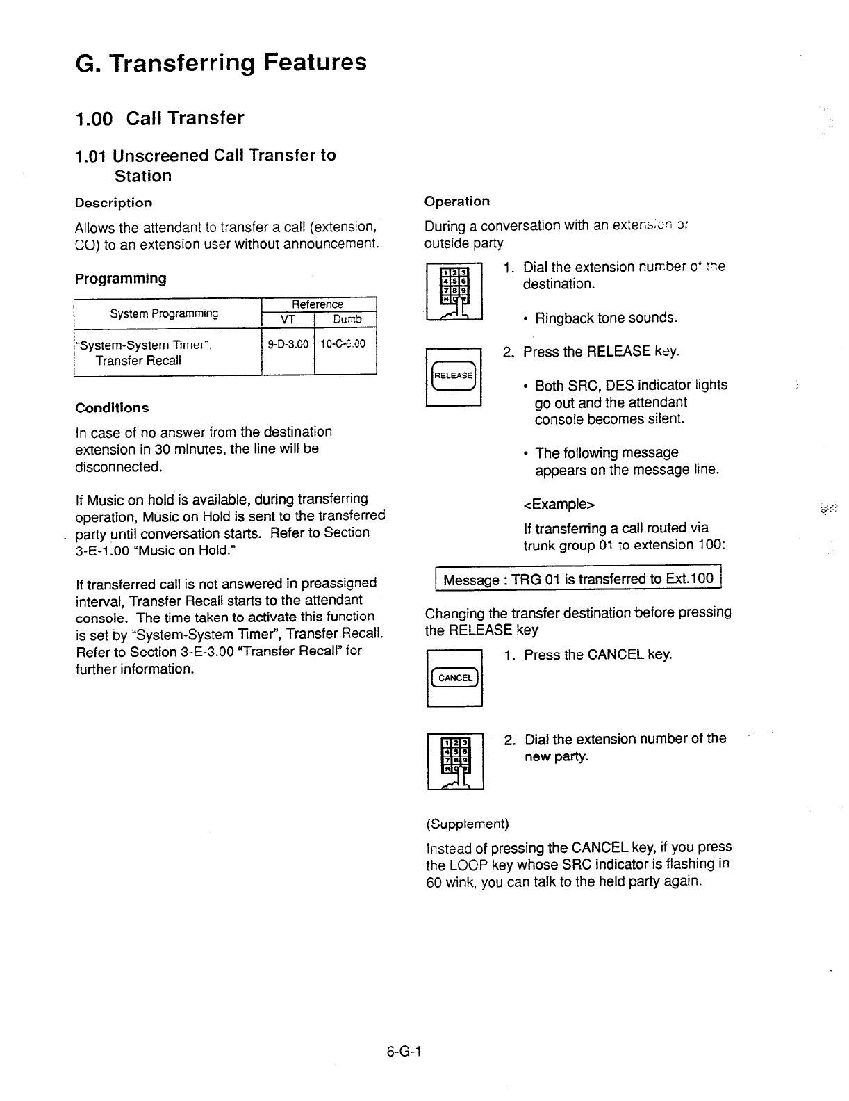
G. Transferring Features
1.00 Call Transfer
1 .Ol Unscreened Call Transfer to
Station
Allows the attendant to transfer a call (extension,
CO) to an extension user without announcement.
Description Operation
During a conversation with an extenszn or
outside party
Programming
Dial the extension number o: :ne
destination.
System Programming Reference
VT t Dud
l
Ringback tone sounds.
“System-System Timer-.
Transfer Recall / 9-D-3.00 / lO-C-E.00 /
Conditions
In case of no answer from the destination
extension in 30 minutes, the line will be
disconnected.
If Music on hold is available, during transferring
operation, Music on Hold is sent to the transferred
party until conversation starts. Refer to Section
3-E-1 -00 “Music on Hold.”
If transferred call is not answered in preassigned
interval, Transfer Recall starts to the attendant
console. The time taken to activate this function
is set by “System-System Timer”, Transfer Recall.
Refer to Section 3-E-3.00 “Transfer Recall” for
further information.
2. Press the RELEASE kdy.
l
Both SRC, DES indicator lights
go out and the attendant
console becomes silent.
l
The following message
appears on the message line.
<Example>
If transferring a call routed via
trunk group 01 to extension 100:
Message : TRG 01 is transferred to Ext.1 00 1
Changing the transfer destination before pressing
the RELEASE key
1. Press the CANCEL key.
2. Dial the extension number of the
new party.
(Supplement)
Instead of pressing the
CANCEL
key, if you press
the LOCP key whose SRC indicator is flashing in
60 wink, you can talk to the held party again.
6-G-l

1.02 Call Transfer by Camp-on to
Station
Description
Allows the attendant to transfer a call to busy
extension.
Transferred call will ring the busy extensior
automatically when it becomes idle.
Programming
Conditions
Busy status of PITS telephone means all
PDNs
on the destination extension are in use.
If Camp-on Transfer cannot be set (for example,
the destination extension is in program mode),
the following message appears on the message
. line on the screen:
1 Message: Camp-on deny. ]
If camped on call is not answered in preassigned
interval, transfer recall starts at the attendat
console.
The time taken to activate transfer recall is set by
“System-System Timer”, Transfer Recall.
Operation
During a conversation with an outside party or
extension. The SW indicator is lit.
1. Press the HOLD key.
l
The SRC indicator starts to
flash in 60 wink, and the DES
indicator lights.
2. Dial the extension number of the
destination.
l
Busy tone sounds on DES side
of the LOOP key.
I 1 3. Press the RELEASE key.
.
Both SRC and DES indicator
lights go out and the attendant
console becomes silent.
Transferred party is placed on
hold until the destination
extension answers.
Ringing starts at the
destination extension, as soon
as it becomes idle.
If the destination answers,
conversation with the
transferred party starts.
6-G-2
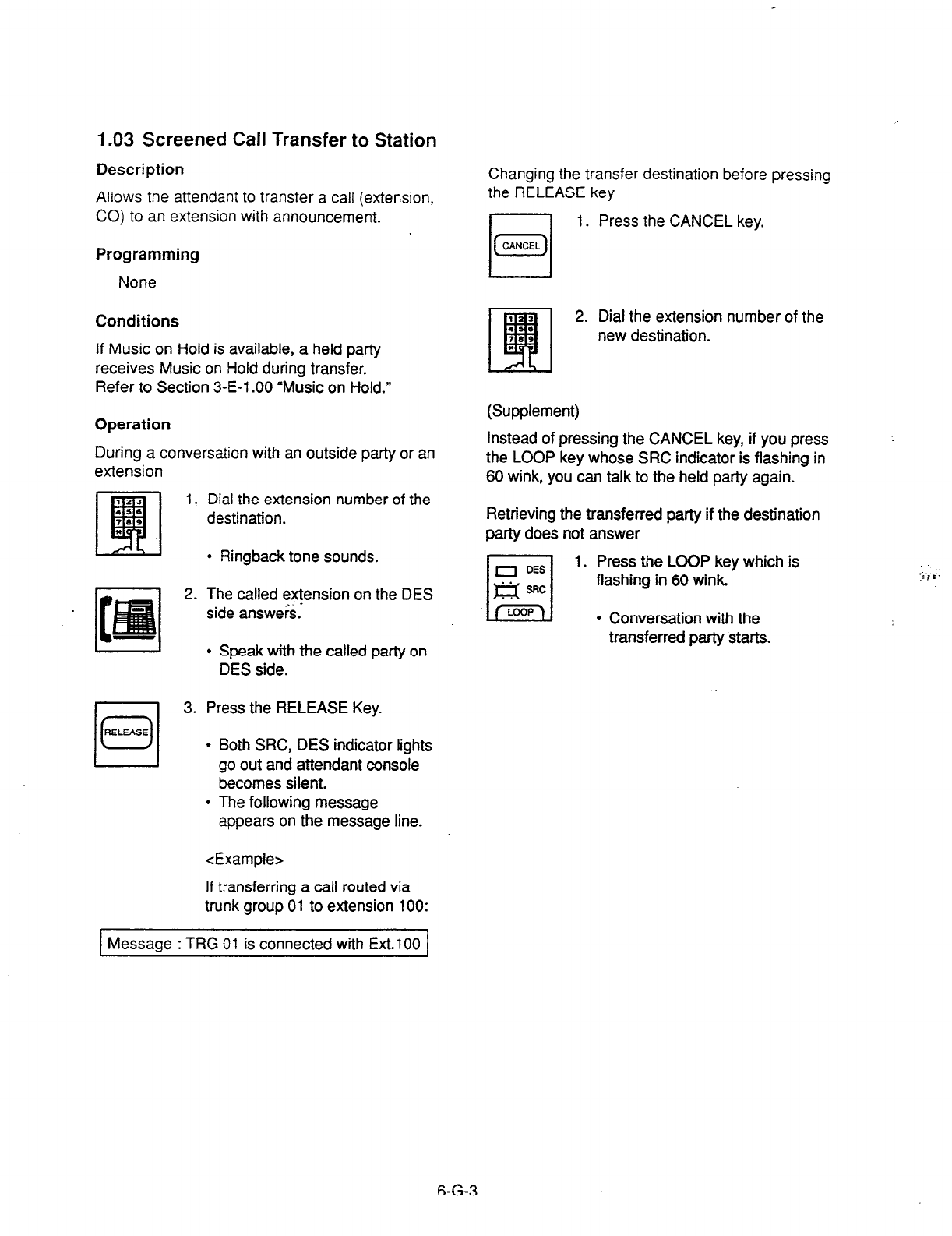
1.03 Screened Call Transfer to Station
Description
Allows the attendant to transfer a call (extension,
CO) to an extension with announcement.
Programming
None
Conditions
If Music
on
Hold is available,
a held party
receives
Music on Hold
during transfer.
Refer to Section 3-E-l .OO “Music on Hold.”
Operation
During a conversation with an outside party or an
extension
2.
rl
3.
0
RELEASE
I I
Dial the
extension number of the
destination.
l
Ringback tone sounds.
The called extension on the DES
side answers.*
l
Speak with the called party on
DES side.
Press the RELEASE Key.
l
Both SRC, DES indicator lights
go out and attendant console
becomes silent.
l
The following message
appears on the message line.
<Example>
If transferring a call routed via
trunk group
01 to extension 100:
Changing the transfer destination before
the RELEASE key
1.
Press the CANCEL key.
pressing
2. Dial the extension number of the
new destination.
(Supplement)
Instead of pressing the CANCEL key, if you press
the LOOP key whose SRC indicator is flashing in
60 wink, you can talk to the held party again.
Retrieving the transferred party if the destination
party does not answer
l-l
0 DES
1. Press the LOOP key which is
Es sRc flashing in 60 wink.
l
Conversation with the
transferred party starts.
Message : TRG 01 is connected with Ext.100
6-G-3

1.04 Screened Call Transfer to Trunk
Description
Allows the attendant to transfer a call (extension,
CO) to an outside patty with announcement.
Programming
None
Conditions
A call placed on hold during call transfer receives
Music on Hold, if available.
Refer to Section 3-E-i .OO “Music on Hold”
for
further information
Operation
During a conversation with an extension or
outside party
1. Select a CO line.
l
After selecting the CO line on
DES side of the LOOP key, dial
tone sounds.
2. Dial the telephone number of the
outside party.
l
Ringback tone sounds from the
CO line. When the called party
answers, make the announce-
ment.
3. Press the RELEASE key.
l
Held call is connected with the
I 1
outside destination party, and
the attendant console becomes
silent.
l
The following message
appears on the message line
on the screen.
<Example> ”
If transferring extension 100 via
CO line in the trunk group 01:
1 Message: Ext.100 is connected with TRG 01 1
(Supplement )
If busy tone sounds after selecting the CO line,
rl
1. Press the CANCEL key, then
(GZZ) repeat the pre-described
operation from step1 .
If busy tone or reorder tone sounds after calling
an outside party,
n
1. Press the CANCEL key, then
(GL) repeat the pre-described
operation from step
1.
6-G-4
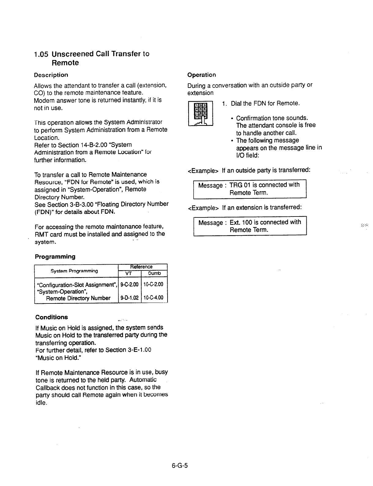
1.05 Unscreened Call Transfer
to
Remote
Description
Allows the attendant to transfer a call (extension,
CO) to the remote maintenance feature.
Modem answer tone is returned instantly, if it is
not in use.
This operation allows the System Administrator
to perform System Administration from a Remote
Location.
Refer to Section 14-B-2.00 “System
Administration from a Remote Location” for
further information.
To transfer a call to Remote Maintenance
Resource, “FDN for Remote” is used, which is
assigned in “System-Operation”, Remote
Directory Number.
See Section 3-B-3.00 “Floating Directory Number
(FDN)” for details about FDN.
For accessing the remote maintenance feature,
RMT card must be installed and assigned to the
system.
Programming
~1
Conftguratlon-Slot Assignment ,
Conditions . . .
If Music on Hold is assigned, the system sends
Music on Hold to the transferred party during the
transferring operation.
For further detail, refer to Section 3-E-l .OO
“Music on Hold.”
Operation
During a conversation with an outside party or
extension
1.
Dial the FDN for Remote.
l
Confirmation tone sounds.
The attendant console is free
to handle another call.
l
The following message
appears on the message line in
I/O field:
<Example> If an outside party is transferred:
Message : TRG 01 is connected with
Remote Term.
<Example> If an extension is transferred:
Message : Ext. 100 is connected with
Remote Term.
If Remote Maintenance Resource is in use, busy
tone is returned to the held party. Automatic
Callback does not function in this case, so the
party should call Remote again when it becomes
idle.
6-G-5
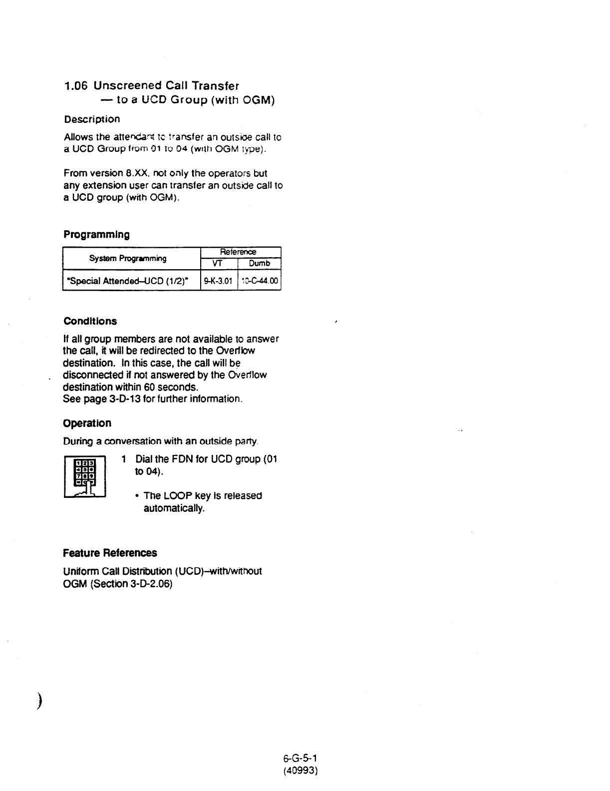
1.06 Unscreened Call Transfer
-to a UCD Group
(with
OGM)
Description
Allows the attendant tc transfer an out&e call to
a UCD
Group
from 01 To 04 (wtth OGM tfle).
From version 8.Xx. not only the operators but
any extension user can transfer an outside call to
a UCD group (with OGM).
Programming
System Programming Reference
VT Dumb
“Special Attended-UCD (l/2)
9-K-3.01 :X-44.00
Conditions
If all group members are not available to answer
the call, it will be redirected to the Overfbw
destination. In this case, the call will be
I
_ disconnected if not answered by the Overflow
destination within 60 seconds.
See
page
3-D-13 for further information.
Operation
During a conversation with an outside party.
1 Dial the FDN for UCD group
(01
to
04).
l
The LOOP key is released
automatically.
Feature References
Uniform Call
Distribution (UCD)-with/without
OGM (Section 3-D-2.06)
6-G-5-l
(40993)
2.00 Heavy Traffic Overflow
Transfer to Station
Descrlotlon
Conditions
CF; 1; _ ,, 33: I ;;;- z*-: e at the attendant console
at the same I’-e
If six tails hare arrived and other calls arrive, the
number c;f the other calls is displayed in the “wait
call” or “LOOP key and Trunk Gioup” screen.
If a call in the queue cannot be transferred to the
preassigned destination, it is called an
overflowed call.
The number of overflowed calls is displayed in
“Over flow = ” of “LOOP key and Trunk Group”
screen.
Calls cannot be transferred in the following
cases: .
If the waiting calls remain in the “wait call” for a
specified duration programmed in “System-
System Timer- Attendant Overflow Time, they will
be transferred automatically to the specified
! extension assigned by “Extension-Attendant
Console”, Overflow.
To transfer those calls, set “Overflow transfer” to
“Yes” in the Attendant Management screen.
Programming
System Programming Refeience
VT 1 Dumb
I
‘“System-System Timer”, 9-D-3.00 1 O-C-6.00
Attendant Overflow Time
/’ \ “Extension-Attendant Console”, 9-G-4.01 10-C-28.00
Overflow
Attendant Management Reference
l
The transfer destination is not assigned.
l
The destination extension is busy.
l
The destination extension has DND assigned.
Operation
None
cc
Overflow transfer 1 6-C-10.00 1
6-G-6
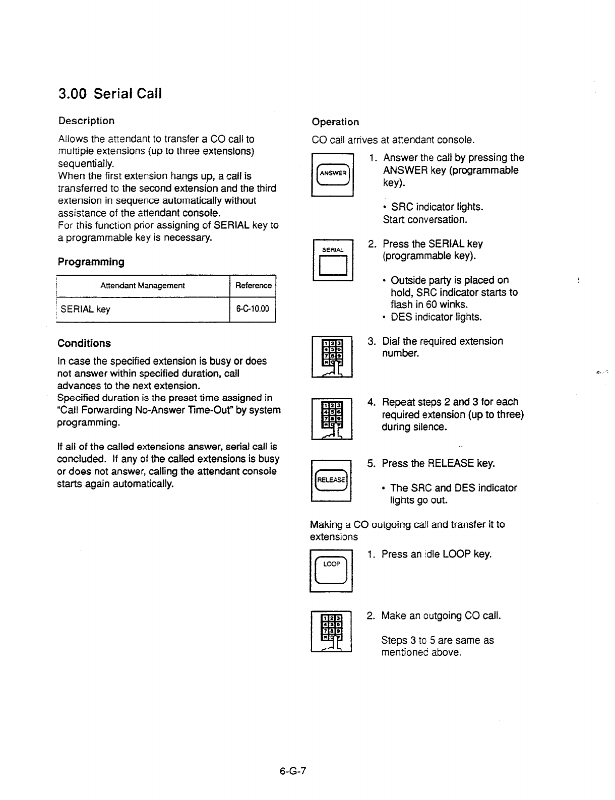
3.00 Serial Call
Description
Allows the attendant to transfer a CO call to
muttjpie extensions (up to three extensions)
sequentially.
When the first extension hangs up, a call is
transferred to the second extension and the third
extension in sequence automatically without
assistance of the attendant console.
For this function prior assigning of SERIAL key to
a programmable key is necessary.
Operation
CO call arrives at attendant console.
1. Answer the call by pressing the
ANSWER key (programmable
key).
l
SRC indicator lights.
Start conversation.
Programming
iii
Conditions
In case the specified extension is busy or does
not answer within specified duration, call
advances to the next extension.
Specified duration is the preset time assigned in
“Call Forwarding No-Answer Time-Out” by system
programming.
If all of the called extensions answer, serial call is
concluded. If any of the called extensions is busy
or does not answer, calling the attendant console
starts again automatically.
SERIAL
II
2. Press the SERIAL key
(programmable key).
11--11
l
Outside party is placed on
hold, SRC indicator starts to
flash in 60 winks.
l
DES indicator lights.
3. Dial the required extension
number.
4. Repeat steps 2 and 3 for each
required extension (up to three)
during silence.
I
5. Press the RELEASE key.
l
The SRC and DES indicator
lights go out.
Making a CO outgoing call and transfer it to
extensions
1. Press an idle LOOP key.
2. Make an outgoing CO call.
Steps 3 to 5 are same as
I fik I mentioned above.
6-G-7
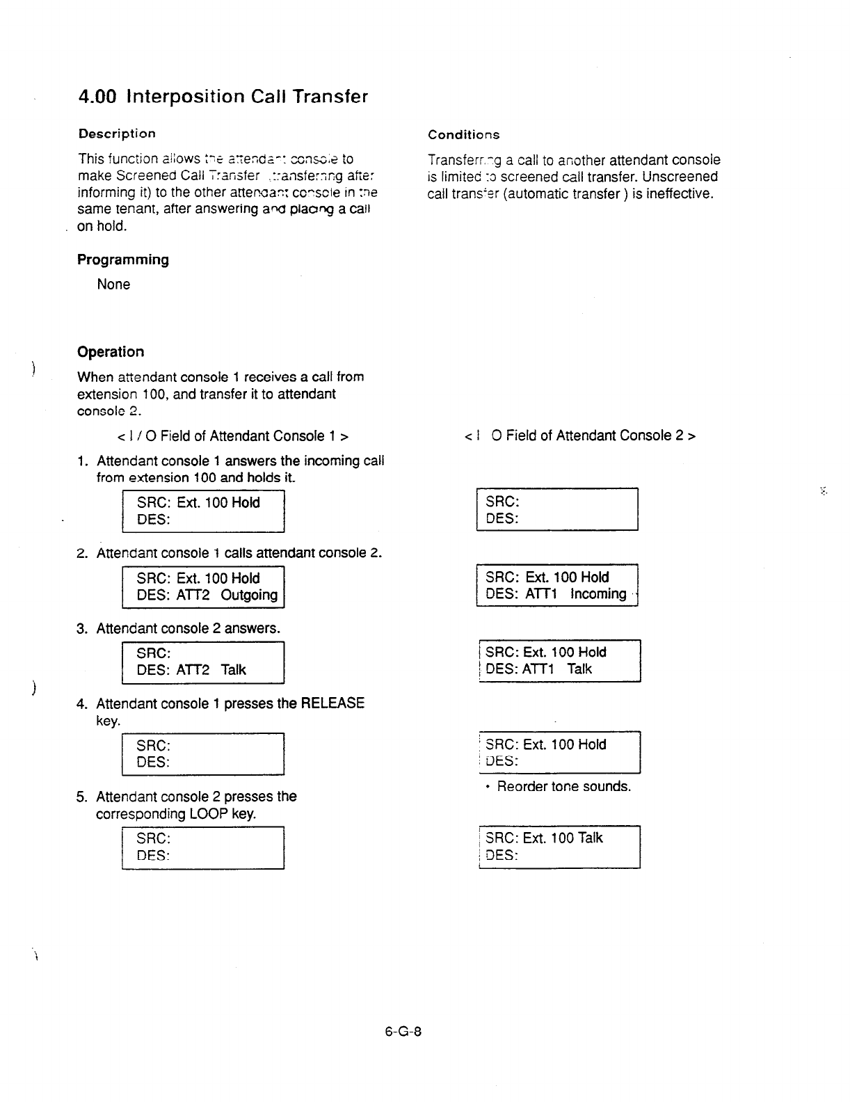
4.00 Interposition Call Transfer
Description
This
function allows ?z a.r;enda-: ccsnsz,e to
make Screened Call T:ansfer .:ransfe:;r;g atie:
informing it) to the other atteman: co?scle in :ne
same tenant, after answering ad
plaong a call
on hold.
Programming
None
Operation
) When
attendant console 1 receives
a
call from
extension 100, and transfer it to attendant
console 2.
c I / 0 Field of Attendant Console 1 >
1. Attendant console 1
answers the
incoming call
from extension
100 and holds it.
/I
2. Attendant console 1 calls
attendant console 2.
3. Attendant console
2 answers.
)
/I
4. Attendant console 1 presses the RELEASE
key.
5. Attendant console 2 presses the
corresponding LOOP key.
Conditions
Transferr.:g a call to another attendant console
is limited XI screened call transfer. Unscreened
call trans’lr (automatic transfer ) is ineffective.
c I 0 Field of
Attendant Console 2 >
SRC:
DES:
SIX: Ext. 100 Hold
DES: AlTl Incoming t
1 SRC: Ext. 100 Hold
1 DES: ATT1 Talk
+;;;Ext.lOOHold j
l
Reorder
tone sounds.
i SRC: Ext. 100 Talk
1 DES: I
SRti:
DES:
. .
i
6-G-8

5.00 Call Transfer via Attendant
Console
Description
The a~r,~a~; car tranjier an outside call held by
an extarsion :o another extension.
Operation
An extension which has held an outside party
calls the attendant console.
The SRC indicator starts flashing in 60 wink, the
Programming DES indicator starts flashing in 240 wink.
None
Conditions
None
0
1.
0
ANSWER
0
2.
[GZZ)
0
4.
0
RELEASE
Press the ANSWER key .
l
The DES indicator lights. Start
conversation with the DES side
party.
l
The SRC indicator remains
flashing in 60 wink.
Press the CANCEL key.
l
Dial tone sounds from DES
side, and calling starts.
l
The SRC indicator is flashing in
60 wink.
Dial the telephone number of the
destination.
l
Ringback tone sounds.
Press the RELEASE key.
l
The held call is transferred
automatically and the called
party answers it.
l
Both SRC and DES indicator
lights go out and the attendant
console becomes silent.
6-G-9
6.00 Released Link Operation
Description
Allows
the attendant to transfer a call bj s.qz~Iy
dialing the extension number of the c¶es::-.arOn
without pressing the RELEASE key.
ff any PDN button on the destination extensron IS
idle, the call is released from the console ano call
ringing starts at the destination party.
Set “Released link operation” to “Yes” in Attendant
Management screen beforehand.
Programming
31
Conditions
If the destination is busy or has DND assigned,
transferring is ineffective .
. )n the former case, pressing the RELEASE key
provides Camp-on Transfer.
Operation
During a conversation with an outside or inside
party
1. Dial the extension number of the
destination party.
l
The first party is placed on
hold, and if the destination
party is idle, call ringing starts.
l
Both SRC, DES indicator lights
on the LOOP key go out.
6-G-l 0
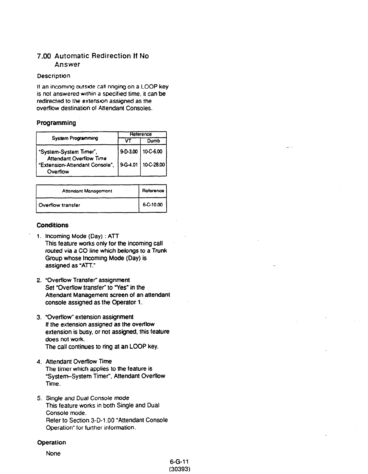
7.00 Automatic Redirection If No
Answer
Description
If an incomtng oufsde call ringing on a LOOP key
is not answered wrthin a specified time, it can&?
redirected to the exten9on assigned as the
overflow destination of Attendant Consoles.
Programming -
system Programmkg Reference
VT Dumb
“System-System Timer’. SD3.00
10-c-6.00
Attendant Overflow Ttme
“Extension-Attendant Console”. 9-G-4.01 10-C-28.00
Overflow
Conditions
1. Incoming Mode (Day) : ATT
This feature works only for the incoming call
routed via a CO line which belcmgs to a Trunk
Group whose Incoming Mode (Day) is
assigned as “ATT-”
2. “Overflow Transfer” assignment
Set “Overflow transfer” to “Yes” in the
Attendant Management screen of an attendant
console assigned as the Operator 1.
3. “Overflow” extension assignment
If the extension assigned as the overflow
extension is busy, or not assigned, this feature
does not work.
The call continues to ring at an LOOP key.
4. Attendant Overflow Time
The timer which applies to the feature is
“System-System Timer”, Attendant Overflow
Time.
5. Single and Dual Console mode
This feature works in both Single and Dual
Console mode.
Refer to Section 3-D-l .OO “Attendant Console
Operation” for further information.
Operation
None
6-G-l 1
(30393)

H. Conversation Features
1 .OO Conference
Description Operation
The attendant can set up a three-person
conference that includes inside party as well as
outside party by adding a new party to the
established call.
Durirq
a conversation with an outside or inside
wm
v ,
El
l-R%
I Place a new call while holding
. s.
J
1.9
the current party.
.
l
If the called party answers,
begin speaking.
The CONF key (programmable key) must be
assigned to the attendant console in advance.
On the TSW card, there are eight standard
conference trunks provided for this purpose.
By equipping the optional conference expansion
card (KX-T336104). the number of conference
trunks increases to 64.
To utilize optional conference expansion card,
assign “Configuration-System Assignment”, TSW
Additional CONF to ‘Yes.”
When two members in the conference are outside
parties, two conference trunks are necessary. In
all other cases, one conference trunk is enough.
If there are no -die conference trunks, pressing
the CONF key does not function.
Programming
System
Programming
Fleference
VT
I
Dumb
“Configuration System Assignment”. SG1.00
lO-Gl.00
TSW Additional CONF
I
Attendant Management P-4
CONF key 6-GlO.00
Conditions
Conference call is available in the following
combinations.
l
Two outside patties and an attendant
console
l
An outside party, an inside party and an
attendant console
l
Two inside parties and an attendant console
Conference call including another attendant
console is unavailable.
2. Press the CONF key
(programmable key).
l
Both SRC and DES indicators
light. Start a conference.
Finishing the conference
cl
0
RELESE
1. Press the RELEASE key.
l
Both SRC. DES indicator lights
go out.
l
If both B and C are outside
parties, both parties are
disconnected.
l
If both B and C are extension
users, or either of them is an
extension user, a conversation
between B and C is
established. .’
The following message appears on the message
line:
<Example>
1 Message: Ext.100 is connected with TRG (01) 1
.-
Changing from conference to conversation with
DES side party by holding SRC side party
I
1.
Press the corresponding LOOP
w
l
The SRC side party is placed
on hold, speak with the DES
side party.
(Supplement)
To change from conference to conversation with
the SRC side party by holding the DES side
party, press the SPLIT key (call splitting function).
For further information, refer to Section 6-H-3.00
“Call Splitting.”
6-H-l
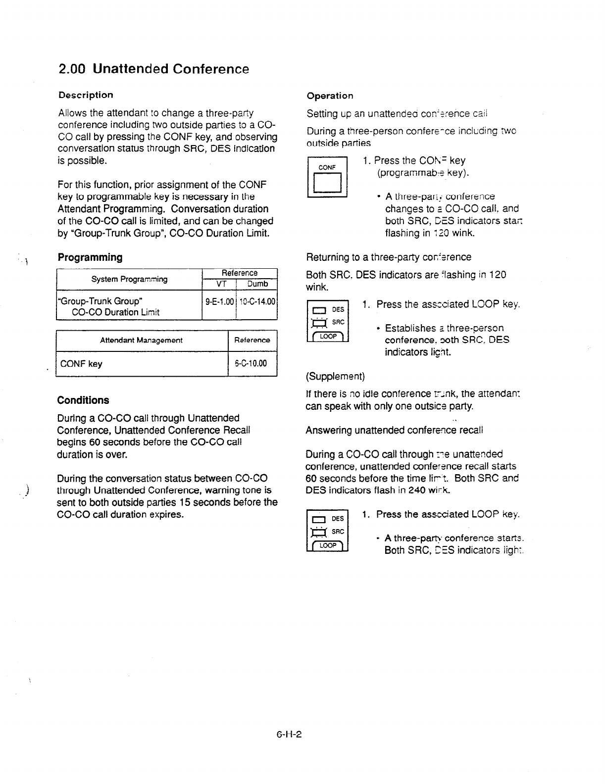
2.00 Unattended Conference
Description
Allows
the attendant IO change a three-party
conference including two outside parties to a CO-
CO call by pressing the CONF key, and observing
conversation status through SRC, DES indication
is possible.
For this function, prior assignment of the CONF
key to programmable key is necessary in the
Attendant Programming. Conversation duration
of the CO-CO call is limited, and can be changed
by “Group-Trunk Group”, CO-CO Duration Limit.
1 Programming
~~
m-l
Conditions
During a CO-CO call through Unattended
Conference, Unattended Conference Recall
begins 60 seconds before the CO-CO call
duration is over.
i
:
During the conversation status between CO-CO
through Unattended Conference, warning tone is
sent to both outside parties 15 seconds before the
CO-CO call duration expires.
Operation
Setting up an unattendeo con’zence tail
During a three-person confere-ce including twc
outside parties
1. Press the COh= key
(pr0grammab.r key).
l
A three-pan! conference
changes to z CO-CO call. and
both SRC, DES indicators star
flashing in : 23 wink.
Returning to a three-party con’srence
Both SRC. DES indicators are ‘lashing in 120
wink.
L-4 1. Press the associated LOOP key.
l
Establishes a three-person
conference. coth SRC, DES
indicators light.
(Supplement)
If there is no idle conference t-ink, the attendan:
can speak with only one outsict party.
Answering unattended conference recall
During
a CO-CO call through r-e unattended
conference, unattended conference recall starts
60 seconds before the time lirt. Both SRC and
DES indicators flash in 240 witk.
I
1. Press the associated LOOP key.
l
A three-par& conference starts.
Both SRC , DES indicators iight.
6-H-2
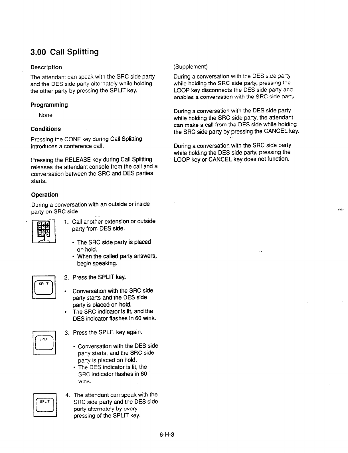
3.00 Call Splitting
Description
The attendant can speak with the SRC side party
and the DES side party alternately while holding
the other party by pressing the SPLIT key.
Programming
None
Conditions
Pressing the CONF key during Call Splitting
introduces a conference call.
Pressing the RELEASE key during Call Splitting
releases the attendant console from the call and a
conversation between the SRC and DES parties
starts.
Operation
During a conversation with an outside or inside
party on SRC side
SPLIT
c
0
SPLIT
q
0 4.
. -
Call another extension or outside
party from DES side.
l
The SRC side party is placed
on hold.
l
When the called party answers,
begin speaking.
Press the SPLIT key.
Conversation with the SRC side
party starts and the DES side
party is placed on hold.
The SRC indicator is lit, and the
DES indicator flashes in 60 wink.
Press the SPLIT key again.
Conversation with the DES side
party starts, and the SRC side
party is placed on hold.
The DES indicator is lit, the
SRC indicator flashes in 60
wink.
The attendant can speak with the
SRC side party and the DES side
party alternately by every
pressing
of the SPLIT key.
(Supplement)
During a conversation with the DES s:ce pa!rtj
while holding the SRC side party, pressing the
LOOP key disconnects the DES side party
and
enables a conversation with the SRC side par7
During a conversation with the DES side party
while holding the SRC side party, the attendant
can make a call from the DES side while holding
the SRC side party by pressing the CANCEL key.
During a conversation with the SRC side party
while holding the DES side party, pressing the
LOOP key or CANCEL key does not function.
6-H-3
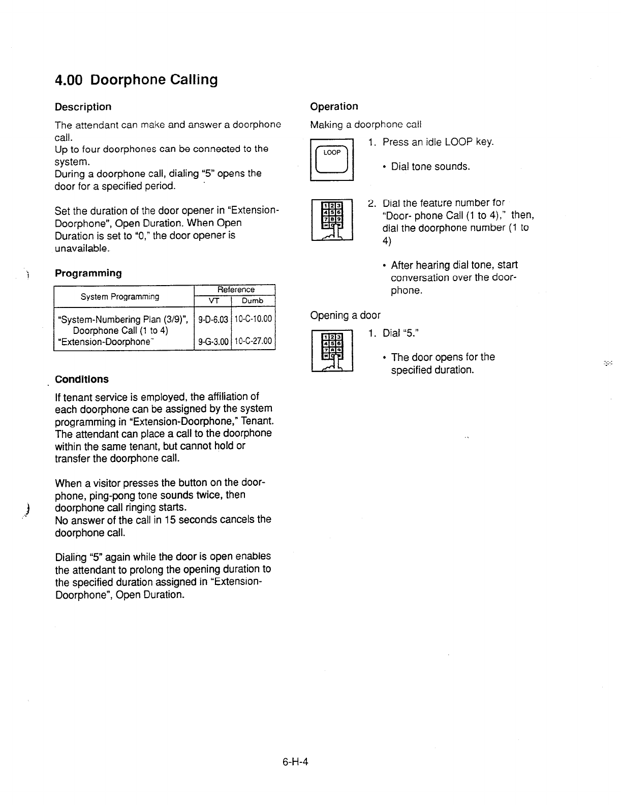
4.00 Doorphone Calling
Description Operation
The attendant can make
and answer a doorphone
call.
Up to four doorphones can be connected
to the
system.
During a doorphone call, dialing “5” opens the
door for a specified period.
Making a doorphone call
1. Press an idle LOOP key.
l
Dial tone sounds.
Set the duration of the door opener in “Extension-
Doorphone”, Open Duration. When Open
Duration is set to “0,” the door opener is
unavailable.
Conditions
If tenant service is employed, the affiliation of
each doorphone can be assigned by the system
programming in “Extension-Doorphone,” Tenant.
The attendant can place a call to the doorphone
within the same tenant, but cannot hold or
transfer the doorphone call.
When a visitor presses the button on the door-
phone, ping-pong tone sounds twice, then
doorphone call ringing starts.
No answer of the call in 15 seconds cancels the
doorphone call.
2. Dial the feature number for
“Door- phone Call (1 to 4):” then,
dial the doorphone number (1 to
4)
l
After hearing dial tone, start
conversation over the door-
phone.
Opening a door
1 . Dial 5”
l
The door opens for the
specified duration.
Dialing “5” again while the door is open enables
the attendant to prolong the opening duration to
the specified duration assigned in “Extension-
Doorphone”, Open Duration.
6-H-4
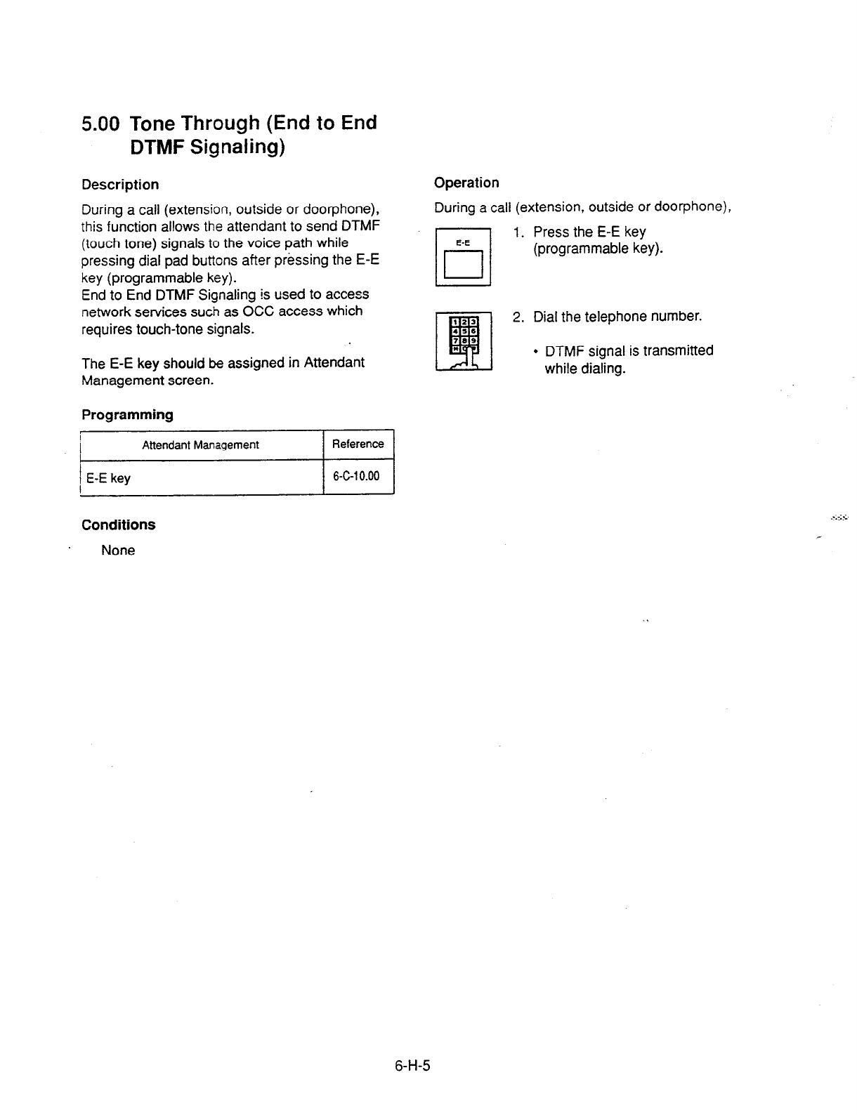
5.00 Tone Through (End to End
DTMF Signaling)
Description
During a call (extension, outside or doorphone),
this function allows the attendant to send DTMF
(touch tone) signals to the voice path while
pressing dial pad buttons after pressing the E-E
key (programmable key).
End to End DTMF Signaling is used to access
network services such as OCC access which
requires touch-tone signals.
The E-E key should be assigned in Attendant
Management screen.
Programming
Operation
During a call (extension, outside or doorphone),
E-E
rl
1. Press the E-E key
r-l
(programmable key).
I
2. Dial the telephone number.
l
DTMF signal is transmitted
while dialing.
Conditions
None
6-H-5
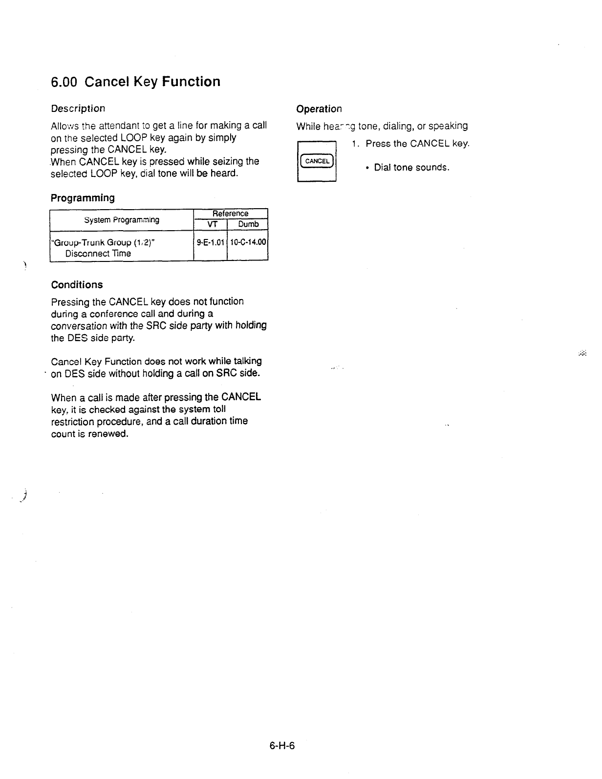
6.00 Cancel Key Function
Description
Operation
Allo:vs ?he attendant :o get a line for making a call
on the selected LOOP key again by simply
pressing the CANCEL key.
.When CANCEL key is pressed while seizing the
selected LOOP key, dial tone will be heard.
While hear?g tone, dialing, or speaking
1. Press the CANCEL key.
l
Dial tone sounds.
Programming
i *I
Conditions
Pressing the CANCEL key does not function
during a conference call and during a
conversation with the SRC side party with holding
the DES side party.
Cancel Key Function does not work while talking
. on DES side without holding a call on SRC side.
When a call is made after pressing the CANCEL
key, it is checked against the system toll
restriction procedure, and a call duration time
count is renewed.
,.
6-H-6

I. Paging Features
1 .OO Paging
1.01 Paging All Extensions
Description
Allows the attendam ::: make paging
announcement thrash built-in speakers of all
FITS telephones by c’aling the feature number
for “Station Paging” a:d -0.”
Programming
System Programs;. -?
“System-Numbering F z.$ (3 9)“,
Station Paging
Conditions
/ 9-D-6.03 110-0-10.00 1
Single line telephones (SLT’s) can not be paged.
If Tenant Service is employed, paging is only
available within the same tenant as the attendant
console.
If an extension is off-hook or its SP-PHONE is
active, paging is una::ailable for the extension.
Current call is parked and paging all extensions
through built-in spearer of all PITS telephones
can be carried out by pressing the PAGE key
during a conversation.
For further informaticnt refer to Section 6-l-l .05
“Call Park and Paging.”
Operation
1. Press an idle LOOP key and dial
the feature number for “Station
Paging” and “0” in succession.
l
After confirmation tone sounds,
all extension paging through
built-in speakers is possible.
2. Perform paging.
3. An extension answers the page.
n
0
4. Press the RELEASE key.
RELEASE
Transferring a call using Paging All Extensions
During a conversation with an extension or
outside party.
9 23
q
1. Dial the feature number for
45s
789 “Station Paging” and “0” in
x succession.
-; .- _
l
After confirmation tone sounds,
extension paging starts.
l
The first party is placed on
hold.
2. Perform paging.
q
3. After an extension answers the
0
RELEASE
page, press the RELEASE key.
. Conversation between the held
party and the paged party
starts. Attendant console
becomes silent.
6-l-l

1.02 Group Paging
Description
1 .CNS tlY* a.I?QrlCa”’ . to make paging
3’“3UXC
-&I
tr-zsgh
built-in speakers of PITS
:eiepho;-5 sy LXC ‘j ng ;he desired Paging
Group.
Up
to eight paging groups can be assigned to the
system.
Programming
pi
‘System-Numbering Plan (3/9) ,
-1
Conditions
Single line telephones (SLT’s) can not be paged.
If Tenant Service is employed, paging is only
available within the tenant where the attendant
console belongs.
If the designated paging group is being paged by
another page, busy tone is heard.
However, group paging can be done within the
range not overlapping the previous paging range.
For instance, when paging is being done to group
1, paging groups 2 to 8 are available for new
paging.
1 If an extension is off-hook or its SP-PHONE is
active, paging is unavailable for the extension.
Current call is parked and Group Paging through
built-in speaker of PITS telephones can be
carried out by pressing the PAGE key during a
conversation.
For further details, refer to Section 6-l-l -05 “Call
Park and Paging.”
Operation
/i
1
LOOP
Press an idle LOOP key and dial
the feature number for “Station
Paging” and paging group
number (1 to 8) in succession.
l
Confirmation tone sounds.
The specified paging group
gets ready to be paged.
2. Perform paging.
3. An extension answers the page.
4. Press the RELEASE key.
l
The call is released from the
I I
attendant console.
Transferring a call using Group Paging
During a conversation,
1. Dial the feature number for
“Station Paging” and desired
paging group number (1 to 8) in
succession.
l
Confirmation tone sounds.
The specified paging group
gets ready to be paged.
l
The call is held.
2. Perform paging.
3. An extension answers the page.
4. Press the RELEASE key.
l
The call is released from the
console.
l
Conversation between the held
party and the paged party
starts.
6-l-2
1.03 Paging External Pagers
Description
Conditions
:,lows the attendant tc Take paging
announcement through rhe
external pagers by
dialing the feature numoer for “External Paging’.”
Up
to two external pagers can be equipped with
this system.
If Tenant Service is employed, paging is available
only in the same tenant.
External paging originated by the attendant can
override external paging from an extension. The
extension will hear reorder tone.
Employing two externa pagers or selecting one
pager will be assigned oy “System-Operation”,
External Pager 1, 2.
External paging is effeaive when an external
pager or pagers are connected and assigned for
use by “System-Opera2on”, External Pager
1,2.
Confirmation tone from external pagers is
selected by “Trunk-Pa,;er & Music Source”,
External Pager-Tone.
Programming
System Programming
“System-Operation (l/3)‘.
External Paging 1,2
‘System-Numbering Plar (3/g)‘,
External Paging
“Trunk-Pager & Music Source”,
External Pager-Tone
Reference
VT Dumb
9-D-l .Ol 1 o-c-4.00
~ 9-D-6.03
10-c-10.00
g-F-2.00 1 O-C-1 9.00
The followings show the paging priorities:
(1) Paging External Pager from an Attendant
Console
(2) TAFAS (Trunk Answer From Any Station)
(Refer to Section 4-D-4.00 “Trunk Answer
From Any Station (TAFAS)-Day Service.“)
(3) Paging External Pager from an extension
(this function)
(4) BGM through External Pager
If a lower priority page is
active,
and a higher
priority page is actuated, it overrides the lower
one: for instance, if Paging External Pager from
extension is overridden by Paging External Pager
from an Attendant Console, reorder tone is
returned to the extension who initiates the Paging
External Pager. If TAFAS call or BGM is
overridden by another higher prfority, it is
interrupted and starts again when’the higher
priority is finished.
6-l-3
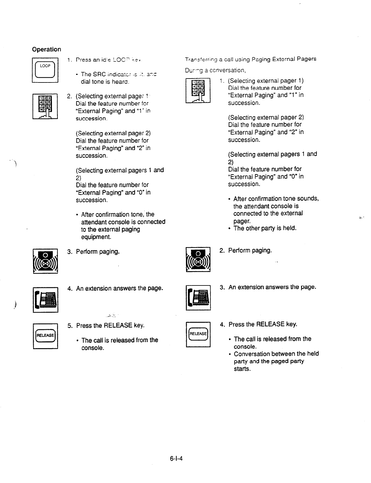
Operation
101
RELEASE
1. Press an idie LOG” i.e. Transterrlr,C a call using Paging External Pagers
l
The SRC
indicate: :s ..:. 3:~
Dur,-g a ccnversation,
dial tone is heara.
2. (Selecting external pagei !
Dial the feature number for
“External Paging” and ‘1” in
succession.
1. (Selecting external pager 1)
Dial the feature number for
“External Paging” and “1” in
succession.
(Selecting external pager 2)
Dial the feature number for
“External Paging” and ‘2” in
succession.
(Selecting external pager 2)
Dial the feature number for
“External Paging” and “2” in
succession.
(Selecting external pagers 1 and
2)
Dial the feature number for
“External Paging” and “0” in
succession.
(Selecting external pagers 1 and
2)
Dial the feature number for
“External Paging” and “0” in
succession.
l
After confirmation tone sounds,
the attendant console is
connected to the external
pager.
l
The other patty is held.
. After confirmation tone,. the
attendant console is connected
to the external paging
equipment.
3. Perform paging.
4. An extension answers the page.
5. Press the RELEASE key.
l
The call is released from the
console.
II
El 2. Perform paging.
(( 8
& .
3. An extension answers the page.
I
4. Press the RELEASE key.
RELEASE
/u/
l
The call is released from the
console.
l
Conversation between the held
party and the paged party
starts.
6-l-4
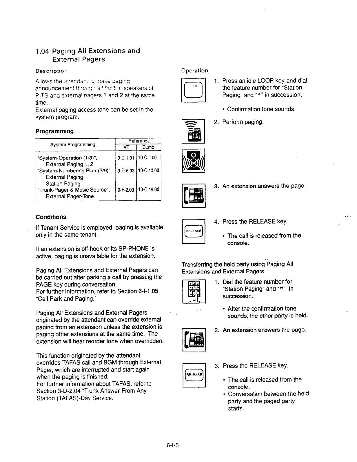
1.04 Paging Ail Extensions and
External Pagers
Description Operation
Allov:s the z~erdar: ‘; T&C:
edging
announcement th’c.:l;” $1 ?I:~‘? in: sxakers of
PITS and external pagers ? and 2 at the same
time.
External paging access tone can be set in the
system program.
Programming
System Programmipg Re
v-r
“System-Operation (113)‘.
External Paging
1.2
“System-Numbering Plan
(3/g)“,
External Paging
Station Paging
“Trunk-Pager & Music Source”,
External Pager-Tone
9-D-l .Ol
9-D-6.03
9-F-2.00
rents
Dcmb
I o-w.00
1 o-c-: 0.00
I 0-c-r 9.00
Conditions
If Tenant Service is employed, paging is available
only in the same tenant.
If an extension is off-hook or its SP-PHONE is
active, paging is unavailable for the extension.
Paging All Extensions and External Pagers can
be carried out after parking a call by pressing the
PAGE key during conversation.
For further information, refer to Section 6-l-l -05
“Call Park and Paging.”
Paging All Extensions and External Pagers
originated by the attendant can override external
paging from an extension unless the extension is
paging other extensions at the same time. The
extension will hear reorder tone when overridden.
This function originated by the attendant
overrides TAFAS call and BGM through External
Pager, which are interrupted and start again
when the paging is finished.
For further information about TAFAS, refer to
Section 3-D-2.04 “Trunk Answer From Any
Station (TAFAS)-Day Service.”
1. Press an idle LOOP key and dial
the feature number for “Station
Paging” and I‘*n in succession.
l
Confirmation tone sounds.
2. Perform paging.
3. An extension answers the page.
4. Press the RELEASE key.
l
The call is released from the
I I console.
Transferring the held party using’baging All
Extensions and External Pagers
1 _ Dial the feature number for
“Station Paging” and u*n in
succession.
_ ‘.
l
After the confirmation tone
sounds, the other party is held.
2. An extension answers the page.
3. Press the RELEASE key.
l
The call is released from the
I
console.
l
Conversation between the held
party and the paged party
starts.
6-l-5
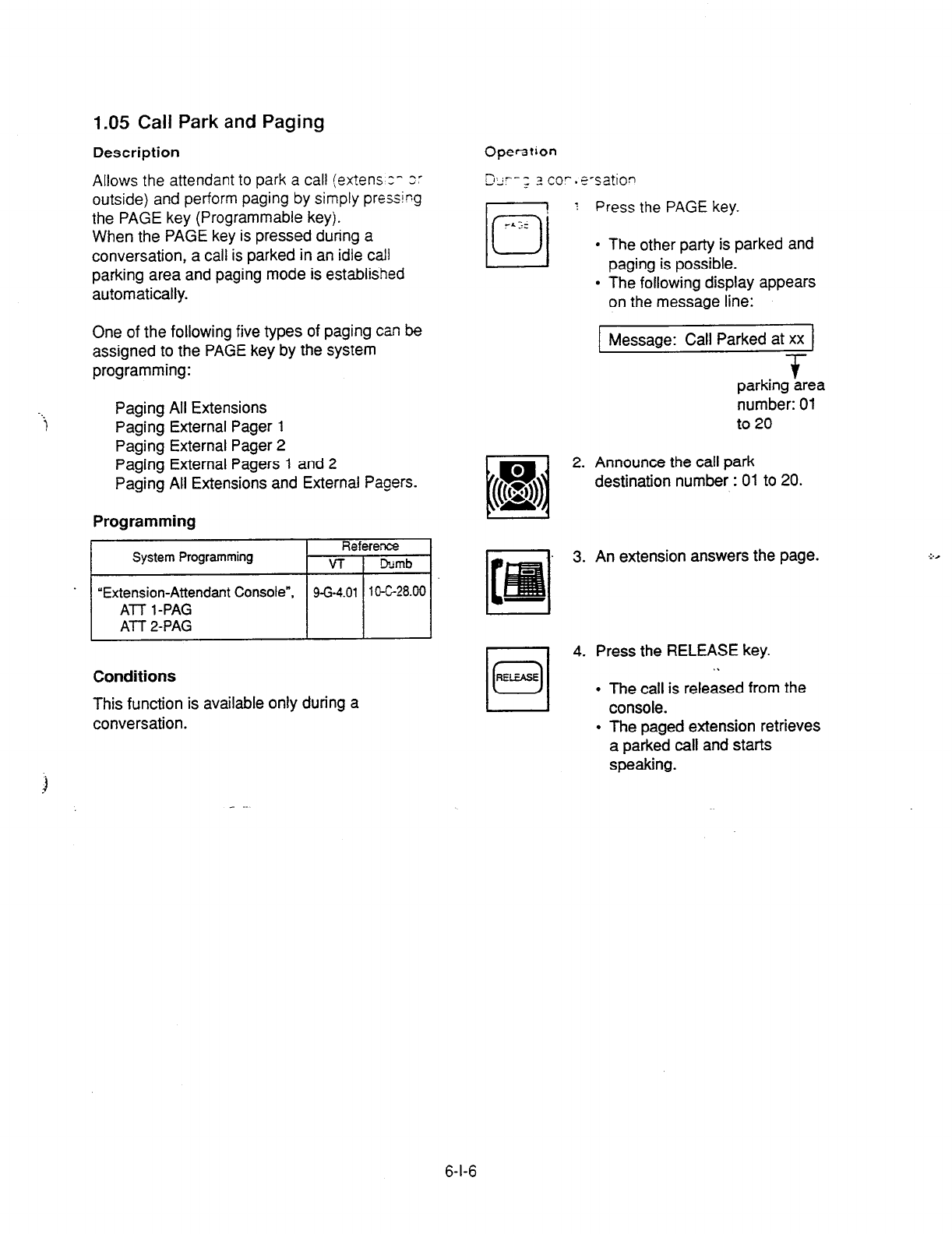
1.05 Call Park and Paging
Description
Allows the attendant to park a call (extens z- 2:
outside) and perform paging by simply pressing
the PAGE key (Programmable key).
When the PAGE key is pressed during a
conversation, a call is parked in an idle call
parking area and paging mode is established
automatically.
One of the following five types of paging can be
assigned to the PAGE key by the system
programming:
Paging All Extensions
Paging External Pager 1
Paging External Pager 2
Paging External Pagers 1 and 2
Paging All Extensions and External Pagers.
Programming
.Hi
Conditions
This function is available only during a
conversation.
b
Opef3tion
5, i--s 3 CO’. E-S&ion
- 4.
l
The other party is parked and
paging is possible.
l
The following display appears
on the message line:
1 Message: Call Parked at xx 1
+
parking area
number: 01
to 20
2. Announce the call park
destination number : 01 to 20.
. 3. An extension answers the page.
4. Press the RELEASE key.
.\
l
The call is released from the
console.
l
The paged extension retrieves
a parked call and starts
speaking.
:.,
6-l-6
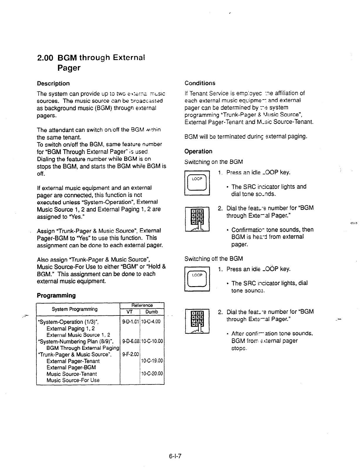
2.00 BGM through External
Pager
Description Conditions
The system can provide up to twc SI:.ZX ;T.LSIC
sources. The music source can be Sroaccastzd
as background music (BGM) througn external
pagers.
If
Tenant Service is emp:oyec :ne affiliation of
each
external music equipme-: and external
pager can lze determined by 1-15 system
programming ‘Trunk-Pager & Music Source”,
External Pager-Tenant and M-sic Source-Tenant.
The attendant can switch on;off the BGM til!hin
the same tenant.
To switch on/off the BGM, same feature number
for “BGM Through External Pager” is used
Dialing the feature number while BGM is on
stops the BGM, and starts the BGM while BGM is
Off.
If external music equipment and an external
pager are connected, this function is not
executed unless “System-Operation”, External
Music Source 1,2 and External Paging I, 2 are
assigned to “Yes.”
. Assign “Trunk-Pager & Music Source”, External
Pager-BGM to “Yes” to use this function. This
assignment can be done to each external pager.
Also assign “Trunk-Pager & Music Source”,
Music Source-For Use to either “BGM” or “Hold &
BGM.” This assignment can be done to each
external music equipment.
Programming
System Programming Reference
VT Dumb
.z?--
“System-Operation
(l/3)“, 9-D-l .Ol 1 O-C-4.00
External Paging
1,2
External
Music Source
1,2
‘System-Numbering Plan (819)“.
BGM Through External Paging
9-D-6.08/ 1 O-C-l 0.00
“Trunk-Pager & Music Source”, 9-F-2.00 j
External Pager-Tenant I 10-c-19.00
External Pager-BGM
Music Source-Tenant
Music Source-For Use
j 10-C-20.00
BGM will be terminated during &ernal paging.
Operation
Switching on the BGM
1. Press an idle -0OP key.
l
The SRC inzicator lights and
dial tone so-nds.
2. Dial the feati-2 number for “BGM
through Exteral Pager.”
l
Confirmatio- tone sounds, then
BGM is hez-3 from external
pager.
Switching off the BGM
jo/
1. Press an idle -0bP key.
LC-3
l
The SRC ircicator lights, dial
tone sounc;.
2. Dial the feat--z number for
“BGM
through Exte-al Pager.” _-
. After confiration tone sounds,
BGM from *bernal pager
stops.
6-l-7

J. Other Features
1 .OO Night Service
1 .Ol Flexible Night
Service
Description
Flexible Night Service allows the Operator
1
(Attendant Console or extension user) to change
the assigned night answer destination on a CO
line basis. -
The attendant assigned as Operator 1 can
change
the
night answer destination by
employing one of the following two ways.
cl
> By dialing the feature number for “Flexible
Night Service.”
<2> By employing the CO Management Screen
of the attendant console.
To utilize this feature, set “Group-Trunk Group”
incoming Mode (Night) to FLEXIBLE. All CO
lines belong to this trunk group are covered by
this assignment.
If FIXED is selected for above setting,
the
assigned night answer destination can not be
changed by the Operator 1.
Call handling in Flexible and Fixed night service
is almost the same.
The difference is:
Flexible The Operator 1 (Attendant Console
or Extension) can change the night
answer destination.
Fixed A group of extensions (Night
Answer Group) can be assigned as
the destination of one or more CO
lines in night mode
Programming
System Programming
Fief’
VT
‘Group-Trunk Group
(ln)“,
9-E-1.01
Incoming Mode (Night)
“Trunk-CO Line”.
9-F-1 .OO
Night Answer Point
“System-Numbering Plan (819)‘. 9-D-6.08
Flexible Night Service
i
Conditions
Operation
Changing Night Answer Point by dialing me
feature number
1. Press an idle LOOP key.
l
The SRC indicator lights and
dial tone sounds.
2. Dial the feature number for
Flexible Night Service “72”
(default) and “CO ID (physical
number).”
•l
3-l (Setting night answer point to
* external pager 1)
Dial “Y.”
Dl 1
l
Confirmation tone sounds, and
the LOOP key is released
automatically.
l
The following display appears
on the message line:
[ Message : Flexible Night Service Set-UNAl 1
3-2 (Setting night answer point to
external pager 2)
III
Dial
“*2.”
. .
ABC
2
l
Confirmation tone sounds, and
the LOOP key is released
automatically.
l
The following display appears
on the message line:
Message : Flexible Night Service Set-UNA2
If tenant service is employed, the night
answer
destination can only be changed for a CO line in
the same tenant by the Operator 1.
6-J-1
(30393)
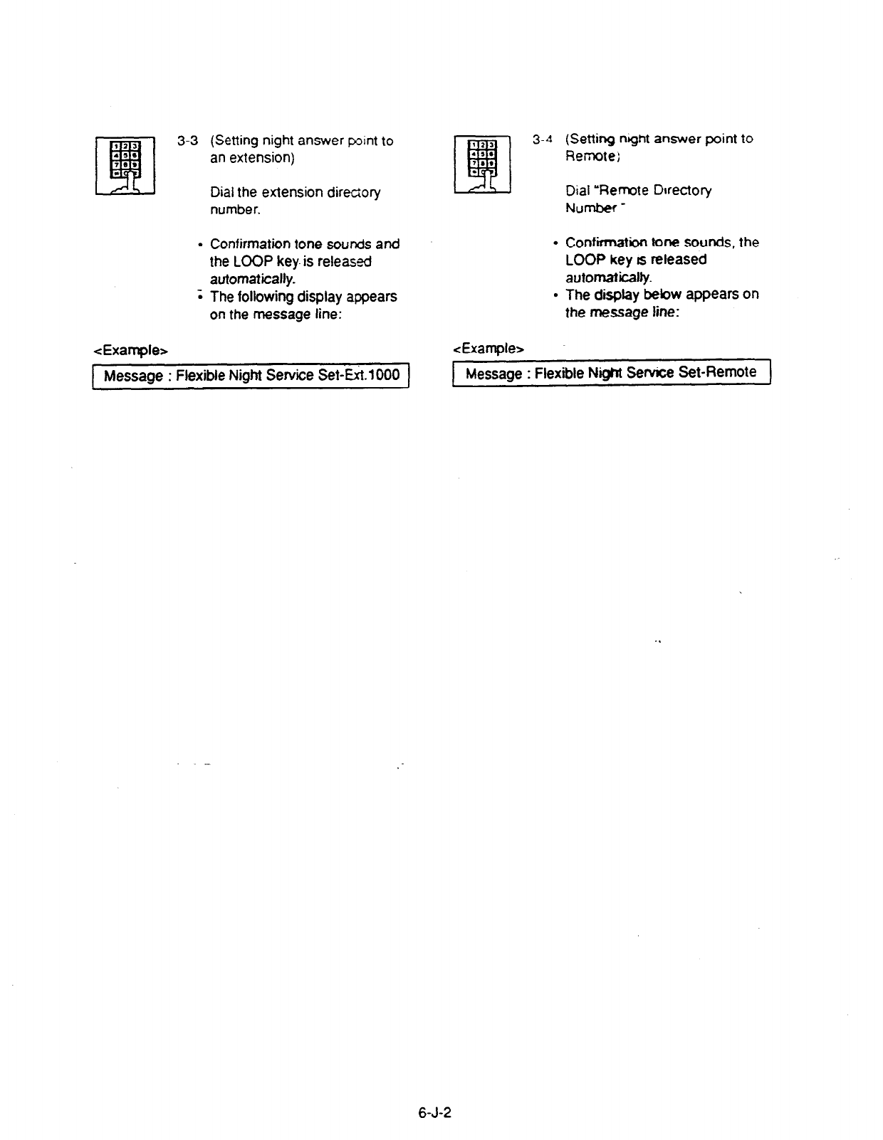
.
.
(Setting night answer point to
an extension)
Dial the extension directory
number.
Confirmation tone sounds and
the LOOP key- is released
automatically.
The following display appears
on the message line:
<Example> &tample>
(Setting night answer point to
Remote;
Dial ‘Remote Directory
Number -
Confiibn tone sounds, the
LOOP key rs released
automaticalfy.
The display bebw appears on
the message line:
Message : Flexible Night Service Set-&.1000 Message : Flexible Night Service Set-Remote
6-J-2

Operation
Changing Night Answer point by employing CO Management screen
1. Press the F4 key (CO rnanagei.
l
CO Management screen appears on the
OISP:Z~
CO ID TRG No.& CO Name CO Status :qhi ;.r.: hd
1011 16 : DDDOl
1012 01 : DDD02 UNA :
--w -.d
-..d .-.-.
_ .-
- (1) -
(2)
(3) (4) -6) (6) - ‘) - (8) -
LOOP Next Previous F,nction
& TRG Page Page Select
-(.a
T
(C -
Next Prevaus
Page Page
2. Press the F2 key (next page), or the F3 key (previous page).
l
Obtain the desired screen.
3. Press the F8 key (function select).
l
The following
function field appears.
-(l)-(2)
(3) - (4) - (51
(6)
-
ii%: T 1 -
Select
4. Move the cursor to Night
Answer field by pressing the F4 key
r- )-
I
CO Status Night Answer
-
UNA 1
6-J-3

-w
-
1.3,
-
6. Select “UNAl ,- “UNA2” -Ext.” or “Remote- by pressing the F6
key (select).
UNA 1 : External Pager 1
UNA 2 : External Pager 2
Ext. : Extension *
Remote : Remote maintenance port
* If “EXT.” is selected, the extension directory number must
be entered successively.
7.
?ress the F7 key (memory).
6-J-4

1.02 Switching of Day/Night Mode
Description
It is assignable to switch Day/Night mode either
automatically at pre-assigned time or manually
by the Operator
1
(Attendant Console or
Extension) at any time desired.
If Manual Switching mode is selected, the
attendant assigned as Operator 1 can switch day
mode to night and vice versa by pressing the
NIGHT key.
To utilize Manual Switching mode, set “System-
Operation (3/3)” Night Service to “Manual.”
Operation
Changing DAY mode to NIGHT mode
While the NIGHT key indicator is off,
1. Press the NIGHT key for more
than one second.
l
The indicator on the NIGHT key
lights.
l
The system is now in NIGHT
mode.
The attendant assigned as Operator
1,
however,
can override the Auto Mode setting, that is
Manual Mode is established, by dialing the
feature number for “Night Service Manual Mode
Set.” To restore the Auto mode, dial the feature
number for “Night Service Manual Mode Cancel.”
Programming
System Programming
Reference
VT
Dumb
“System-Operation (3/3)“, 9-D-i
.03 10-C-4.00
Night Service
Auto Start Time
‘System-Tenant”, 9-D-2.00 1 O-C-5.00
Night Service (Tenant 2)
Auto Start Time
“System-Numbering Plan (8/g)“, 9-D-6.08 iO-C-10.00
Night Mode Set
Night Mode Cancel
Night Service Manual Mode
Set
Night Service Manual Mode
Cancel
Conditions
If tenant service is employed, night service
assignment unique to each tenant (Tenant
1
and
Tenant 2) can be programmed individually.
In this case, the assignment in “System-
Operation (3/3)” is applied to Tenant 1 and the
assignment in “System-Tenant” is applied to
Tenant 2.
Changing NIGHT mode to DAY mode
While the NIGHT key indicator is lit in green,
rl
K)
1. Press the NIGHT key for more
than one second.
I I
l
The indicator light on the
NIGHT key goes out.
l
The system is now in,DAY
mode.
Changing to “Manual” mode from “Auto” mode
/o/
1.
Press an idle LOOP key.
LOOP
I I .a
2. Dial the feature number for “Night
Service Manual Mode Set.”
l
The following message appears
on the message line:
1 Messaae: Niaht Service Manual Mode Set 1
Changing to “Auto” mode from “Manual” mode
/o/
1. Press an idle LOOP key.
LOOP
I 8
2. Dial the feature number for “Night
Service Manual Mode Cancel.”
l
The following message appears
on the message line:
Message:
Night Service Manual Mode Cancel
6-J-5
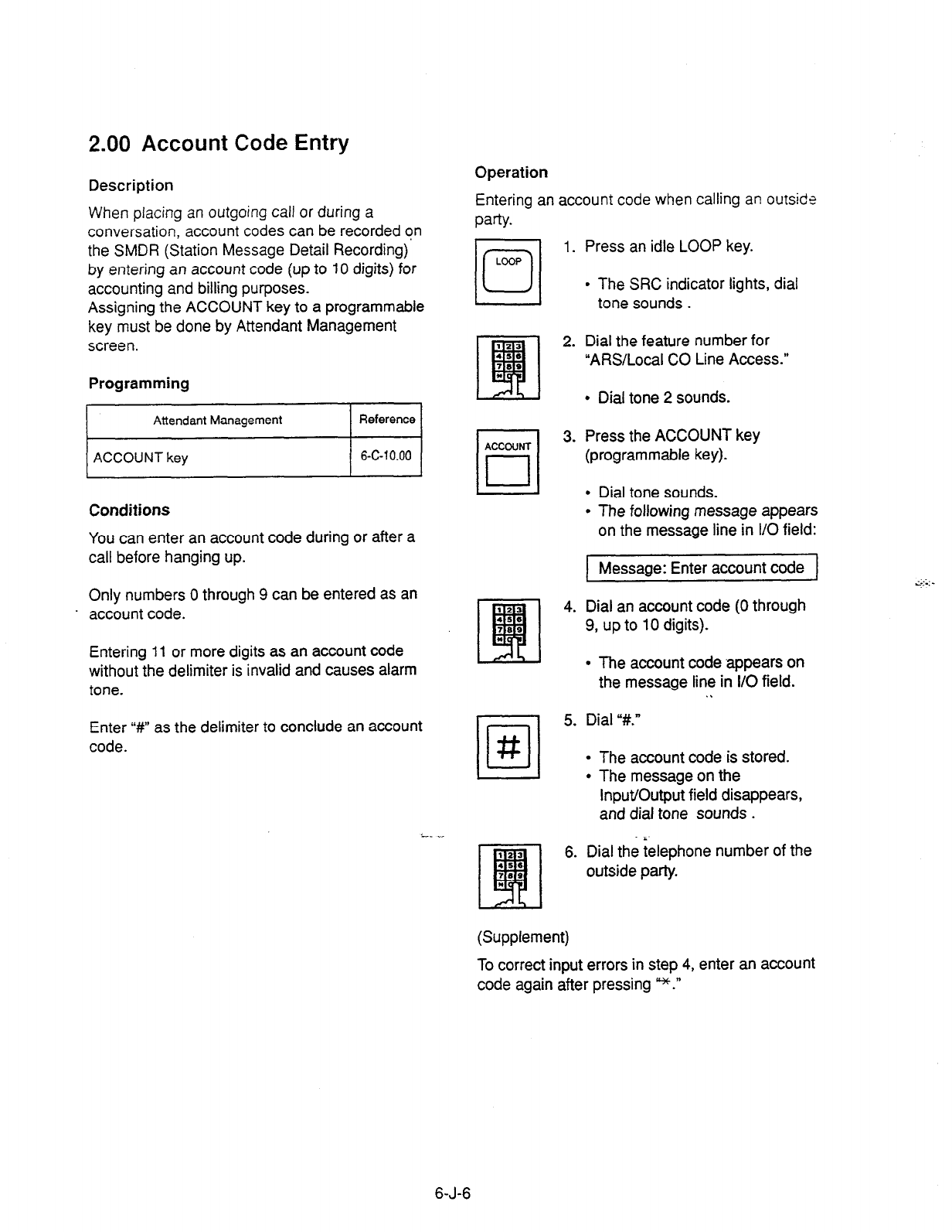
2.00 Account Code Entry
Description
When placing an
outgoing call
or during a
conversation, account codes can be recorded on
the SMDR (Station Message Detail Recording)
by entering an account code (up to IO digits) for
accounting and billing purposes.
Assigning the ACCOUNT key to a programmable
key must be done by Attendant Management
screen.
Programming
Conditions
You can enter an account code during or after a
call before hanging up.
Only numbers 0 through 9 can be entered as an
. account code.
Entering 11 or more digits as an account code
without the delimiter is invalid and causes alarm
tone.
Enter “#” as the delimiter to conclude an account
code.
Operation
Entering an account code when calling an
outsids
w-b.
101
1.
LOOP
3.
/[?I 5.
#
2_ __
6.
Press an idle LOOP key.
l
The SRC indicator lights, dial
tone sounds .
Dial the feature number for
“ARS/Local CO Line Access.”
l
Dial tone 2 sounds.
Press the ACCOUNT key
(programmable key).
l
Dial tone sounds.
l
The following message appears
on the message line in I/O field:
Message: Enter account code
Dial an account code (0 through
9, up to 10 digits).
l
The account code appears on
the message line in I/O field.
.\
Dial “#.”
l
The account code is stored.
l
The message on the
Input/Output field disappears,
and dial tone sounds .
Dial the ielephone number of the
outside party.
(Supplement)
To correct input errors in step 4, enter an account
code again after pressing *.”
6-J-6
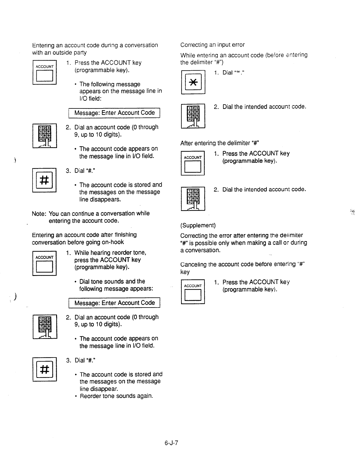
Entering an account code during a conversation
with an outside party
1.
Press the ACCOUNT key
(programmable key).
l
The following message
appears on the message line in
l/O field:
Message: Enter Account Code
2. Dial an account code (0 through
9, up to 10 digits).
.i
l
The account code appears on
the message line in I/O field.
•l
3. Dial “#.I’
#
l
The account code is stored and
the messages on the message
line disappears.
Note: You can continue a conversation while
entering the account code.
Entering an account code after finishing
conversation before going on-hook
1. While hearing reorder tone,
press the ACCOUNT key
(programmable key).
.
l
Dial tone sounds and the
following message appears:
Message: Enter Account Code
2. Dial an account code (0 through
9, up to 10 digits).
l
The account code appears on
the message line in I/O field.
3. Dial “#.”
l
The account code is stored and
Correcting
an
input error
While entering an account code (before rntering
the delimiter “#I’)
-1 1. Dial “*.”
/u/
*
2. Dial the intended accoun? code.
After entering the delimiter “#”
1. Press the ACCOUNT key
(programmable key).
2. Dial the intended account code.
(Supplement)
Correcting the error after entering the deiimiter
“w’ is possible only when making a call or during
a conversation.
Canceling the account code before entering ‘%’
key
1. Press the ACCOUNT key
(programmable key).
I I
the messages on the message
line disappear.
l
Reorder tone sounds again.
6-J-7

3.00 Secret Dialing il
Description
During speed dialing or calling by Extension
Directory, all or part of the telephone numbers that
appear
on the CRT screen can be concealed. The
secret portion appears with * m .”
Conditions
When storing a speed dialing code, entering “[”
only without entering “I”, causes all the digits
entered after “[” to be hidden.
Operation
The dialing numbers are registered by “System-
Speed Dial-System.” When
storing a number,
bracket the secret part that yoti want to hide with
[ 1. Then the part does not appear on the CRT
screen.
None
It is assignable to print out the secret part onto
SMDR (Station Message Detail Recording)
by
assigning “System-Operation”. Print Secret
Dial to
Yes.
Programming
6-J-8
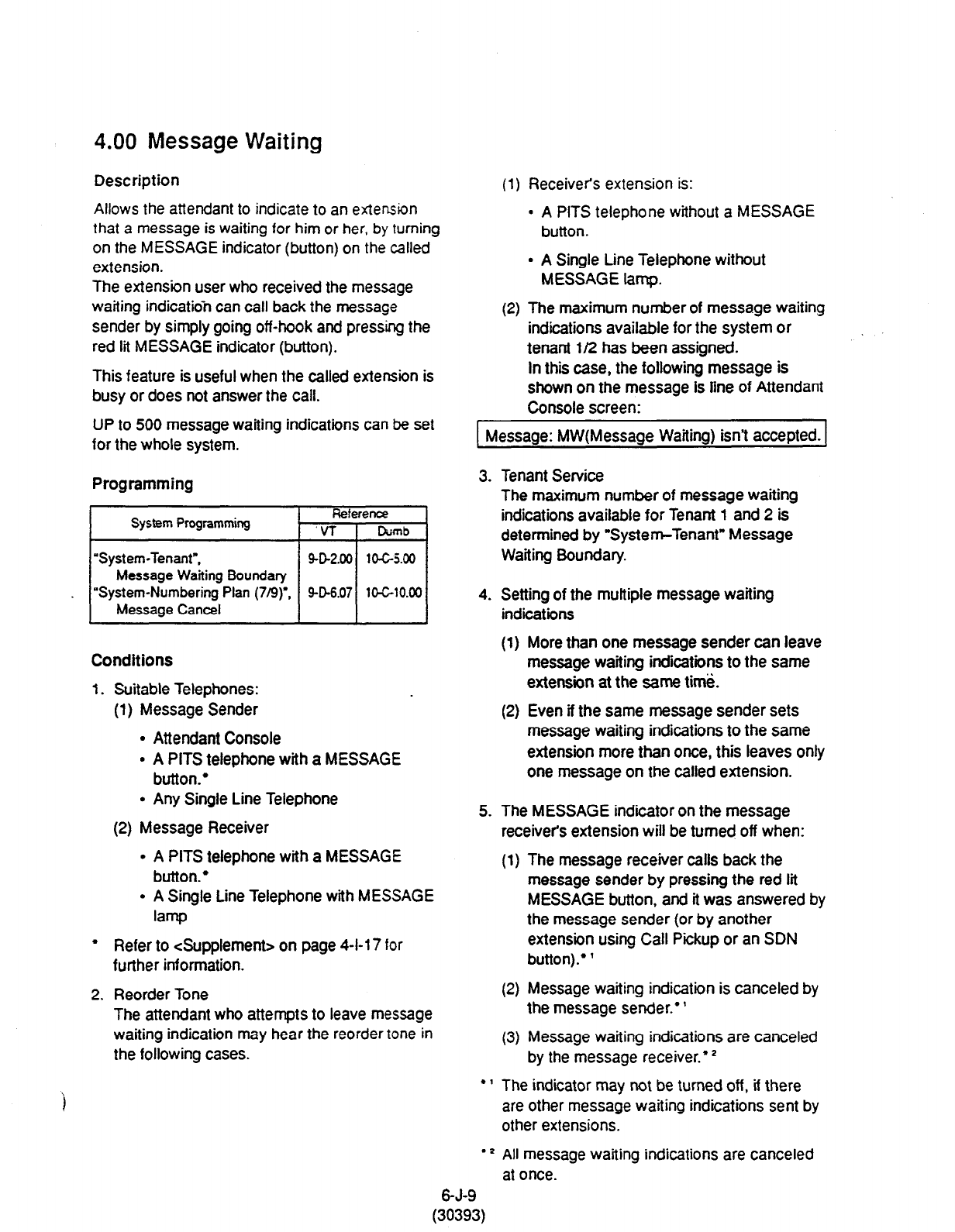
4.00
Message Waiting
Description
Allows
the attendant to indicate to an extension
that
a
message
is
waiting for him or her. by turning
on the MESSAGE indicator (button) on the called
extension.
The extension user who received the message
waiting indicahkin can call back the message
sender by simply going off-hook and pressing the
red lit MESSAGE indicator (button).
This feature is useful when the called extension is
busy or does not answer the call.
UP to 500 message waiting indications can be set
for the whole system.
Programming
System Programming Reference
‘VT Cwnb
‘System-Tenant”,
902.00 104-5.00
Message Waiting Boundary
. “System-Numbering Plan (7/9)“, SD6.07
10-G10.00
Message Cancel
Conditions
1. Suitable Telephones:
(1) Message Sender
l
Attendant Console
l
A PITS telephone with a MESSAGE
button.’
l
Any Single Line Telephone
(2) Message Receiver
l
A PITS telephone with a MESSAGE
button.’
l
A Single Line Telephone with MESSAGE
Iamp
l
Refer to <Supplement> on page 4-l-l 7 for
further information.
2. Reorder Tone
The attendant who attempts to leave message
waiting indication may hear the reorder tone in
the following cases.
(1) Receiver’s extension is:
. A PITS
telephone
without a MESSAGE
button.
l
A Single Line Telephone without
MESSAGE lamp.
(2) The maximum number of message waiting
indications available for the system or
tenant l/2 has been assigned.
In this case, the following message is
shown on the message is line of Attendant
Console screen:
r I
1 Message: MW(Message Wafting) isn’t accepted. 1
3.
4.
5.
.1
.Z
Tenant Service
The maximum number of message waiting
indications available for Tenant 1 and 2 is
determined by “System-Tenant” Message
Waiting Boundary.
Setting of the multiple message waiting
indications
(1)
(2)
More than one message sender can leave
message waiting indications to the same
extension at the same time.
Even if the same message sender sets
message waiting indications to the same
extension more than once, this leaves only
one message on the called extension.
The MESSAGE indicator on the message
receivers extension will be turned off when:
(1) The message receiver calls back the
message sender by pressing the red lit
MESSAGE button, and it was answered by
the message sender (or by another
extension using Call Pickup or an SDN
button).* ’
(2) Message waiting indication is canceled by
the message sender.’ ’
(3) Message waiting indications are canceled
by the message receiver.* ’
The indicator may not be turned off, if there
are other message waiting indications sent by
other extensions.
All message waiting indications are canceled
at once.
6-J-9
(30393)

Operation
Setting the Message Waiting indication of
another extension
123
iBl
1. Dial the extension number.
4,e
7.9
t
l
Ringback tone, busy tone or
DND tone sounds.
2. Press the MSG key.
l
After confirmation tone sounds,
the following message is
shown on the message line.
<Example>
1 Message: MW(Message Waiting) at EXr. 100 1
Canceling the Message Waiting Indication left on
the extension
101
1. Press an idle LOOP key.
LOOP
2. Dial the feature number for
Message Cancel %9” (default)
and the extension number of the
message receiver in succession.
6-J-9-l
(30393)
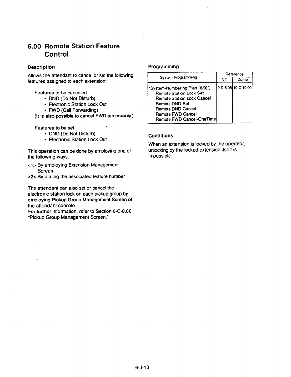
5.00
Remote Station Feature
Control
Description Programming
Allows the attendant to cancel or set the following
features assigned to each extension:
System Programming
Features to b_e canceled:
l
DND (Do Not Disturb)
l
Electronic Station Lock Out
l
FWD (Call Fowarding)
(It is also possible to cancel FWD temporarily.)
Reference
VT 1 Dumb
“System-Numbering Plan (8/g)“,
Remote Station Lock Set
Remote Station Lock Cancel
Remote DND Set
Remote DND Cancel
Remote FWD Cancel
Remote
FWD Cancel-OneTim~
9-D-6
Features to be set:
l
DND (Do Not Disturb)
l
Electronic Station Lock Out
This operation can be done by employing one of
the following ways.
<l> By employing Extension Management
Screen
<2> By dialing the associated feature number
Conditions
When an extension is locked by the operator,
unlocking
by
the locked extension itself is
impossible.
The attendant can also set or cancel the
electronic station lock on each pickup group by
employing Pickup Group Management Screen of
the attendant console.
For further information, refer to Section 6-C-8.00
“Pickup Group Management Screen.”
6-J-10
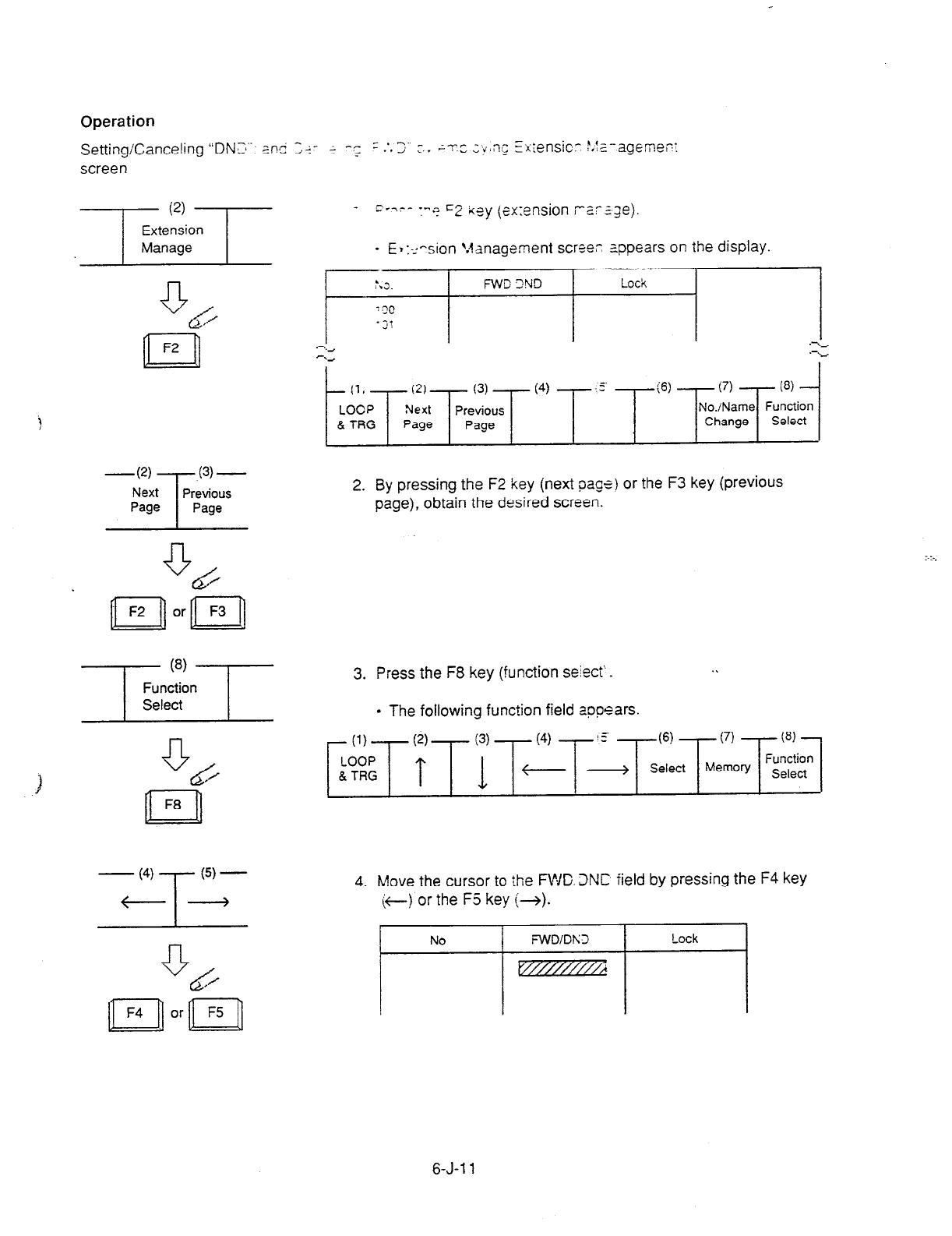
Operation
Setting/Canceling “DNZ~~~. z.n@ ;+- + -.; r .‘,3 c.. ;r~ ;tmnL; Ei;:ensic.- P,f;_-ageme,?:
screen
i
3
BP:: appears on the display.
‘.J.
FWD 3ND Lock
($5
r;Q
. ;!
-w
T
(3) -
Next Previous
Page Page
2. By pressing the F2 key (next page) or the F3 key (previous
page), obtain the desired screen.
3. Press the F8 key (function se&t‘.
l
The following function field appears.
4. Move the cursor to the FWC. 3NC field by pressing the F4 key
(:t) or the F5 key (+).
6-J-l 1
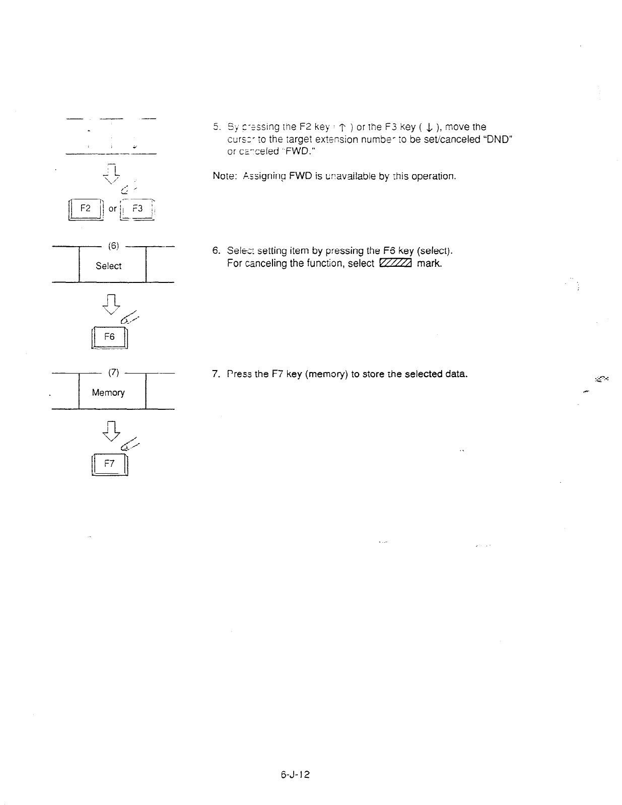
5. 5~ z-tssing the F2 key T ) or the F3 key ( & ), move the
curs:’ to the target ex?%sion numbe- TO be set/canceled “DND”
or cz-ceded ‘,FWD.”
Note: F-.rrigning FWD is c?available by this operation.
6. Self: setting item by pressing the F6 key (select).
For canceling the function, select m mark.
7. Press the F7 key (memory) to store tie selected data.
6-J-l 2
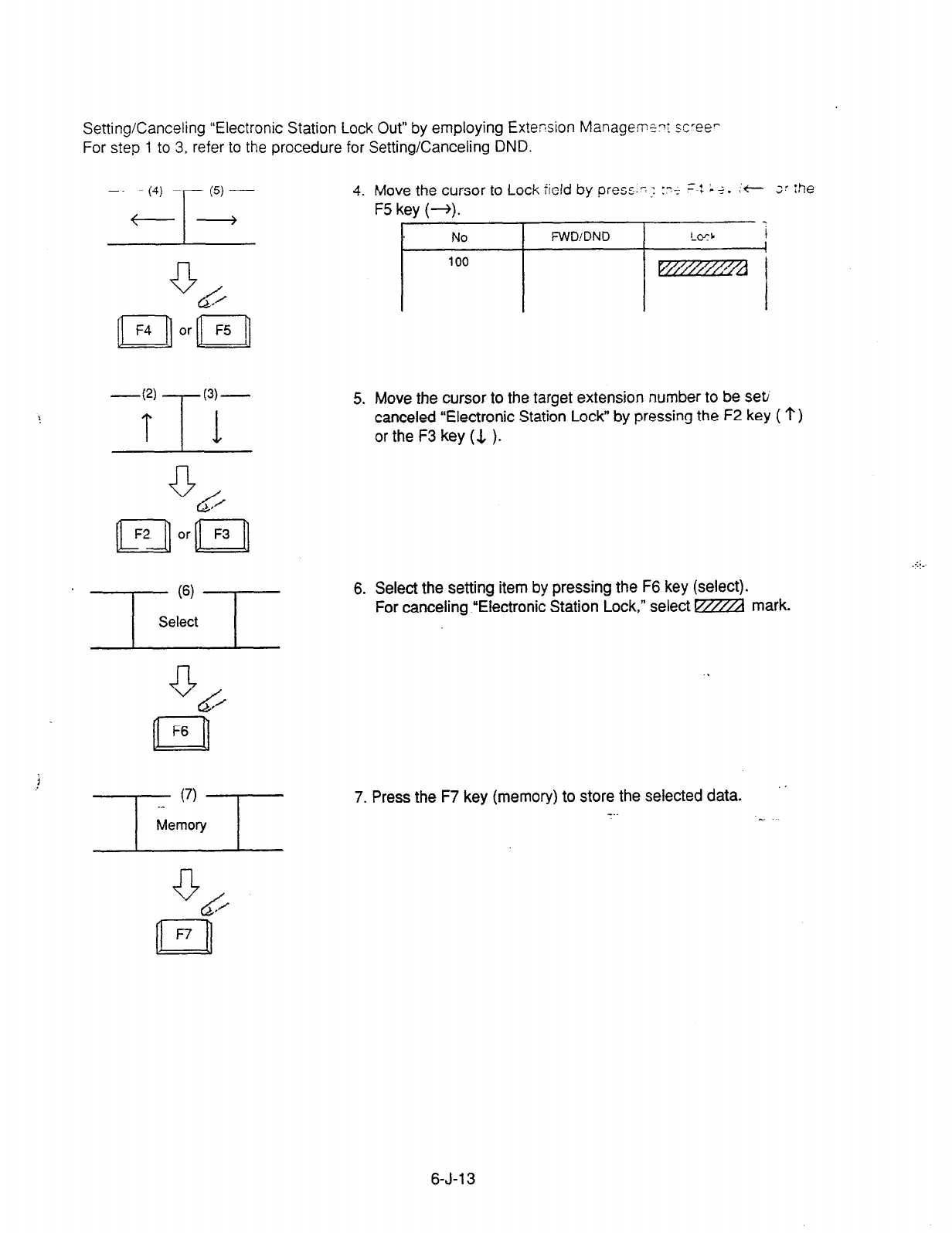
Setting/Canceling “Electronic Station Lock Out” by employing Extension Manageme? sc’ee-
For step 1 to 3, refer to the procedure for Setting/Canceling
DND.
4. Move the cursor to Lock field by press.?; 17~ -4 ; +. :t ;’
ihe
-m
5. Move the cursor to the
target
extension number to be seti
canceled “Electronic Station Lock” by pressing the F2 key ( ‘?)
or the F3 key (& ).
6. Select the setting item by pressing the F6 key (select).
For canceling .“Electronic Station Lock,” select m mark.
7. Press the F7 key (memory) to store the selected data.
-..
6-J-l 3
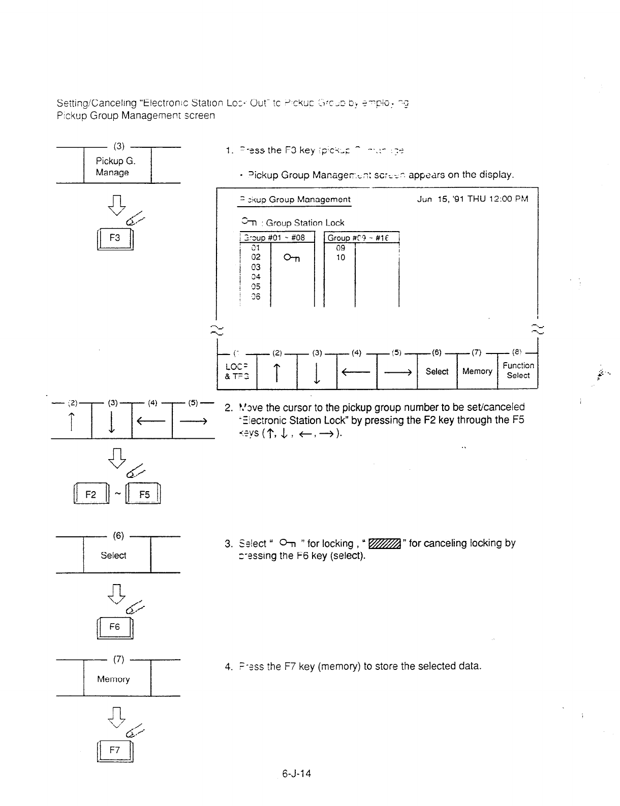
Setting/Canceling “Electronic Station Lo:- Out” ic 3~rkx S:c -3 5: ?-‘pi~, 1~2
Pickup Group
Managemenr
screen
1. =-ISS the F3 key ;?I+-; ^ -..:- .;+
l
?ckup Group Managec:zn: SC:K: appears on the display
, I
I
= skup Group Management Jun
15, '91
THU 12:00 PM
En : Group Station Lock
-
-7 774 i'j' ,
2. !.‘we the cursor to the pickup group number to be set/canceled
-fiectronic Station Lock” by pressing the F2 key through the F5
ys(1‘, -L, t,+). . .
3.
%!ect ”
07, ” for locking , ” m” for canceling locking by
z-essing the F6 key (select).
4. =-?ss
the F7 key
(memory) to store the selected data.
6-J-l 4
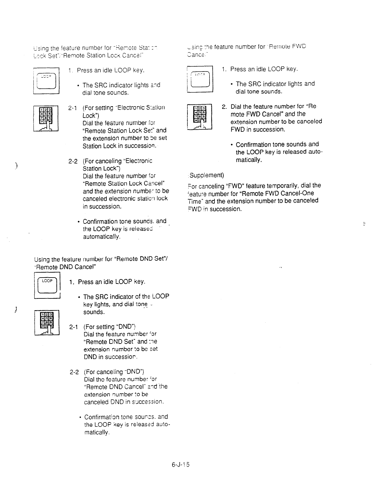
ssing the feature number for ‘Re;lote Sta: :- Lsi~g :le feature number for “Remote FWC
L,zck Set”.“Remote Station Locrc, Cancsi” Zancz.”
1. Press an idle LOO? key.
. The SRC indicator lights 2nd
dial tone sounds.
2-2
(For setting -Electronic Sxiion
Lock”)
Dial the feature number fcr
“Remote Station Lock Se:- and
the extension number to 5s set
Station Lock in successic-?.
(For canceling “Electronic
Station Lock*)
Dial the feature number i~r
“Remote Station Lock Cancel”
and the extension numbe- to be
canceled electronic static? lock
in succession.
Confirmation tone sounds. and - the LOOP key is reieasei .
automatically.
Losing the feature number for ‘Remote DND Set”/
,.Remote DND Cancel”
1. Press an idle LOOP key.
l
The SRC indicator of the LOOP
key lights, and dial tone .,
sounds.
2-1 (For setting “DND’)
Dial the feature number ‘or
“Remote DND Set- and :le
extension number :o be set
DND in succession.
2-2 (For canceiing .,DND”)
Dial the feature number ‘or
“Remote DND Cancel” a’7d the
extension number lo be
canceled DND in sxcession.
&q
1. Press an idle LOOP key.
l
The SRC indicator lights and
dial tone sounds.
2. Dial the feature number for “Re-
mote FWD Cancel” and the
extension number to be canceled
FWD in succession.
l
Confirmation tone sounds and
the LOOP key is released auto-
matically.
Suppiement)
For canceling “FWD” feature temporarily, dial the
‘eature number for “Remote FWD Cancel-One
Time- and the extension number to be canceled
FWD in successron.
l
Confirmation tone sourxs. and
the LOOP key is releassd auto-
matically.
6-J-1 5
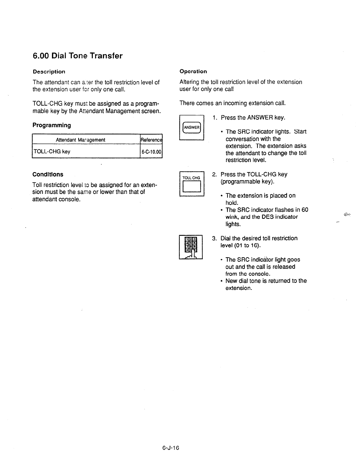
6.00 Dial Tone Transfer
The attendant can arer the toll restriction level of
the extension user fcr only
one call.
Description Operation
Altering the toll restriction level of the extension
user for only one call
TOLL-CHG key must be assigned as a program-
mable key by the Attendant Management screen.
There comes an incoming extension call.
1.
2.
3.
Press the ANSWER key.
Programming
l
The SRC indicator lights. Start
conversation with the
extension. The extension asks
the attendant to change the toil
restriction level.
Attendant Mxagement
TOLL-CHG key
Reference
6-C-l 0.00
Conditions
Toll restriction level tc be assigned for an exten-
sion must be the saine or lower than that of
attendant console.
Press the TOLL-CHG key
(programmable key).
l
The extension is placed on
hold.
l
The SRC indicator flashes in 60
wink, and the DES indicator
lights.
Dial the desired toll restriction
level (01 to 16).
l
The SRC indicator light goes
out and the call is released
from
the console.
l
New dial tone is returned to the
extension.
6-J-l 6

7.00 Search by Name/Department
Description
The attendant can search the
desired extension
number by entering the name
and department of
the extension in the Extension
Directory screen.
The following three basic entry patterns are avail-
able for seaching, assuming that number means
extension number, name means extension name,
and (CR) means pressing the RETURN key.
l
Search Name (CR) - Seaching by specifying
extension name only.
l
Search/Department (CR) - Searching by
specifying department only.
l
Search Name/Department (CR) - Searching by
specifying extension name and department.
Programming
Refer to Section 13-B “Extension Directory
Mode .”
Conditions
The attendant can make an extension call after
searching.
“*n can be entered as a wild card for searching
extension names and departments.
l
For displaying all contents of Extension Direc-
tory.
SEARCH * (CR)
SEARCH /if (CR)
SEARCH *c/* (CR)
This procedure assumes the following exten-
sions
are in the Extension Directory.
Execute: SEARCH Ja * (CR).
Extension name of “Jack” and “James” will be
listed.
l
For searching by specifying a part of extension
name. SEARCH 0- - -0 ++
Input a part of extension name
l
For searching by specifying a part of depart-
ment name.
SEARCH I
M”
input a part of Department Name
l
For searching by speciying a part of extension
name and department name:
SEARCH OO++ /&I++
6-J-l 7

Operation (Supplement)
Searching by specifying extension name and In case several extensions match the search
department name. criteria, all subjects appear.
This procedure
assumes
the following extensions
are in the Extension Directory.
~~
1. Enter “SEARCH.”
l
The following message appears on the Input
line:
Input: SEARCH
2. Press the space key once, then enter the
extension name “Jack.”
l
The following message appears on the Input
line:
Input: SEARCH Jack
3. Enter 7 and the department name “account.”
l
The following message appears on the Input
line:
1 Inhut: SEARCH Jack/account 1
4. Press the RETURN key.
l
The corresponding extensions will be
searched and displayed on the Extension
Directory screen.
In case no extension match the search criteria,
the following message appears on the message
line.
Message: Cannot search by Name/Department!
For calling the searched extension, refer to
Section 6-D-3.02 “Inter Office Calling by Exten-
sion Directory Screen.”
6-J-l 8
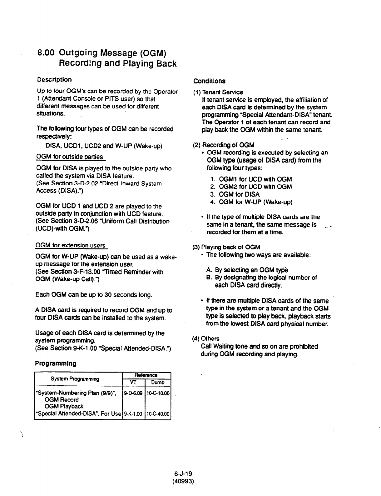
8.00 Outgoing Message (OGM)
Recording and Playing Back
Descrfptlon Condltlons
Up to four OGM’s can be recorded by the Operator
1 (Attendant Console or PITS user) so that
different messages can be used for different
situations. _
(1) Tenant Service
lf tenant service is employed, the affiliation of
each DISA card is determined by the system
programming Special Attendant-DISA” tenant.
The operator 1 of each tenant can record and
play back the OGM within the same tenant.
-- ’
The folbwing four types of OGM can be recorded
respectively:
DISA, UCDl , UCDP and W-UP (Wake-up)
OGM for outside parties
OGM for DISA is played to the outside party who
called the system via DISA feature.
(See Section 3-D-2.02 “Direct inward System
Access (DISA).“)
OGM for UCD 1 and UCD 2 are played to the
outside party in conjunction with UCD feature.
(See Section 3-D-2.06 “Uniform Call Distribution
(UCD)-with OGM-)
OGM for extension users
OGM for W-UP (Wake-up) can be used as a wake-
up message for the extension user.
(See
Section
3-F-13.00 Vmed Reminder with
OGM (Wake-up Call).3
Each OGM can be up to 30 seconds long.
A DISA card is required to record’OGM and up to
four DISA cards can be installed to the system.
Usage of each DISA card is determined by the
system programming.
(See Section 9-K-l .OO “Special Attended-DISA.“)
Programming
System Programming Reference
VT 1 Dumb
(2)
Recording of CGM
l
OGM recording is executed by selecting an
OGM type (usage of DISA card) from the
following four types:
1. OGMl for UCD with OGM
2. OGM2
for UCD with OGM
3. OGM for DISA
4.
OGM for W-UP (Wake-up)
l
If the type of muftiile DISA cards are the
same in a tenant, the same message is . . *.
recorded for them at a time.
(3) Playing back of OGM
l
The following two ways are available:
A. By selecting an OGM type
B. By designating the logical number of
each DlSA card directly.
l
If there are multiple DISA cards of the same
type in the system or a tenant and the OGM
type is selected to
play
back, playback starts
from the lowest DISA card physical number.
(4)
Others
Call Waiting tone and so on are prohibited
during OGM recording and playing.
‘System-Numbering Plan (g/9)“, 9-D-6.09
10-G10.00
OGM Record
OGM
Playback
“Special Attended-DfSA”. For Use
9-K-1.00 10-C-40.00
6-J-19
(40993)

Operation
Recording OGM
10/
1. Press an idle LOOP key.
LOW
- The SRC indicator lights and
dial tone sounds.
(23
L!!zl
2. Dial the feature number for OGM
.s.
7.. Record 791” (default) and the
. resource number (1 to 4) in
succession.
(Resource number)
1 : OGMl for UCD
2 : OGM2 for UCD
3 : OGM for DISA
4 : OGM for W-UP (Wake-up)
l
The following message appears
on the screen and confirmation
tone sounds.
Message: xxxxxxxx recording: 00 set
I
L UCD-OGMl or
UCD-OGM2 or
DISA-OGM or
Wake Up OGM
3.
Dl
4.
#
Begin your message.
Dial Y#” to conclude recording.
l
Playback starts automatically
through the handset or headset,
the following message appears
on the screen.
Message: xxxxxxxx playing: 00 set
l
After playback finishes, the
SRC indicator remains lit, and
no tone sounds.
(Supplement)
In step 3 if 30 seconds is over, recording is
terminated and playback starts automatically.
Accordingly, it is not necessary to execute step 4
afterward.
In step 3, if you wish to change the message
during recording, you can start recording again by
dialing rt .”
In Step 4, if you wish to interrupt and finish
playback, dial 3.”
6-J-20
(40993)
Playing back OGM
ioi
1. Press an idle LOOP key.
LOW
l
The SRC indicator lights and
dial tone sounds.
*1,
EFI
2. Dial the feature number for OGM
4s.
1.. Playback 792” (defautt) and a
. number below in succession.
. . (Resource number)
1 : OGMl for UCD
2 : OGM2 for UCD
3 : OGM for DISA
4 : OGM for W-UP (Wake-up)
(*” and DISA No.)
l
l : selectsCard
*2: selectsCard
l
3: setectsCard3
l
4 : selects Card 4
.
The following message
appears on the screen. After
confirmation tone sounds,
playback starts.
1 Message: xxxxxxxx playing: 00 set 1
I
- UCD-OGMl or
UCD-OGM2 or
DISA-OGM or
Wake Up OGM
l
After playback finishes, the
SRC indicator remains lit,
and
no tone sounds.
(Supplement)
In step 2, if you wish to interrupt and finish
playback, press “I#.”
During playback you can start playback again
from the beginning by dialing * .”

9.00 Trunk Verify
Description
Allows the attendant to verify :he c:::us oi
specified trunk.
The TRG key (programmabie key; “7ust be
assigned to the atiendant co-sole.
Programming
System Prcgramming
“System-Operation’, PITS
Programming Pass:vord
1
Attendant
I&?agement Ey+rt.-,=s
I
TRG key I S-I-- 1 11:
Conditions
The attendant can place a c&l by specifyin,; 2
trunk but cannot hold or trar;s-ier it.
When specified !runk is bus?. bus) lone so,-‘3s.
Verifying a trunk can be dona only when a :.z:; is
placed from SRC side.
9pc”ztion
Dl
3.
,*
P,ess an idle LOOP key.
l
The SRC indicator lights arc dia
ione sounds.
Press the TRG key (programrabie
key).
Dial “;t.”
Dial the four-digit password
(PITS programming password!. *-
Dial the desired trunk port physica
number (four digits) -2
l
Another dial tone sounds. and ?“t
specified trunk is seized.
rl The PITS programming
password is used for PJTS
programming and Trunk Verify
r2 Refer to Section 14-F-4.00
“Testing the Ports” for details
about trunk port physical
number.
6-J-21
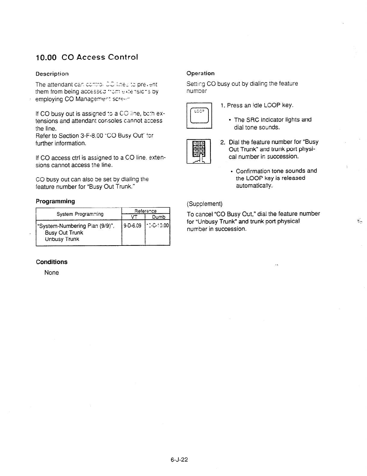
10.00 CO Access Control
Description
The attendant cz. c;.-z:o: L.Z :.x.. :z pre.,nt
them from being accesscz *-;c: t’ <:E WC-: oy
employing CO Manageme-: SW+-‘.
If CO busy out is assigned fo a CC line, bzh ex-
tensions and attendant consoles cannot access
the line.
Refer to Section 3-F-8.00 “CO Busy Out” for
further information.
If CO access ctrl is assigned to a CO line. %-ten-
sions cannot access tne line.
CO busy out can also be set by dialing the
feature number for “Busy Out Trunk.’
Programming
I
System Program5ng I 3efewce
/ VT 1 Dumb
“System-Numbering Pian (9/g)“, 9-D-&09 -:-c-t j.00
Busy Out Trunk
Unbusy Trunk
Operation
Sett!cg CO busy out by dialing the feature
numoer
(Supplement)
To cancel “CO Busy Out,” diai the feature number
for Wnbusy Trunk” and trunk port physical
number in succession.
Press an idle LOOP key.
l
The SRC indicator lights and
dial tone sounds.
Dial the feature number for “Busy
Out Trunk” and trunk port physi-
cal number in succession.
l
Confirmation tone sounds and
the LOOP key is released
automaticafly.
Conditions
None
6-J-22

Operation
CO access control by employing CO Management screen
‘--l-i.“IJ--
1. Press the F4 key (CO manage).
l
CO Management screen appears on the display.
CO ID & BLF TRG No.& CZ Name CO StaLS Night ri?r. .-,.:I i
111: 0 01 : DDDOS UN> 1
1112 m 02 : EEE03 /
.-
-L. .-
*L .- ._
- (1) - (2) - (3) - :4) -is!
LOOP Next Previous
& TRG Page Page
(7) 1 w
Function
i
Select
-(2)
T
(3) -
Next Previous
Page Page
2. By pressing the F2 key (next page) or the F3 key (previous
page), obtain the desired screen.
n
F4
3. Press the F8 key (function select).
l
The following function field appears.
4. By pressing the F4 key (H ): move the cursor to the CO status
field.
I
CO Status 1 N.ght Answer 1
-4
UNA 1
6-J-23
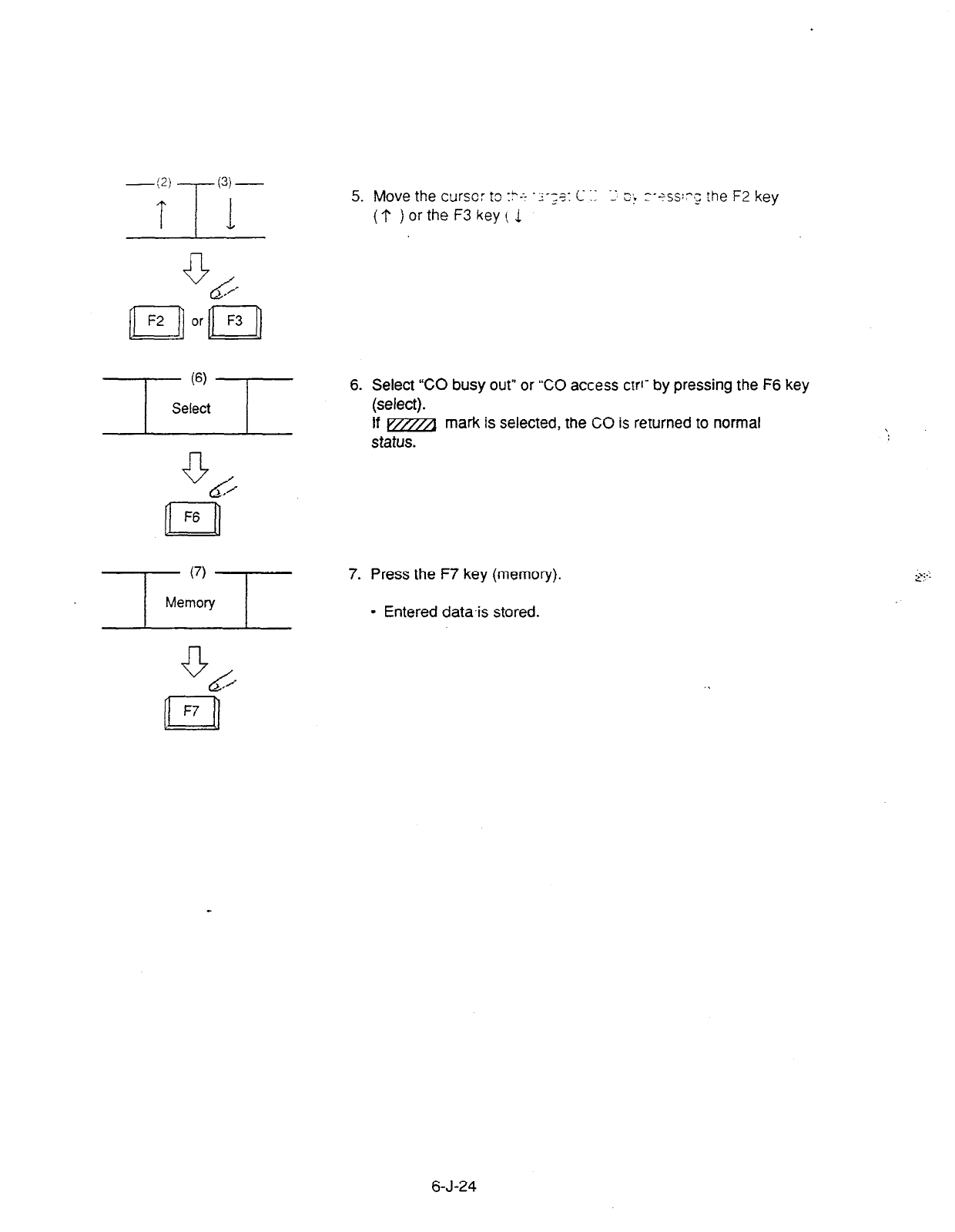
-<2) -7 (3) -
5. Move the curse: to I?.-- --;?I C 7 3 ek :--?ss:?,; :he
F2 key
(?)ortheF3key(1
6. Select “CO busy out” or “CO access cW by pressing the F6 key
(select).
If m~ mark is selected, the CO is returned to normal
status.
7. Press the F7 key (memory).
l
Entered data.is stored.
CG
n
F7
6-J-24
11 .OO Power Failure Operation
Description
At the
time
of power failure, power is supplied to
the attendant console from backup battery of the
system.
During power failure, the attendant console can
execute any other operations than the operations
below:
l
Operation using CRT display
l
Operation using function keys (Fl through
F8).
l
Operation using full keyboard.
Programming
None
Conditions
When the backup battery is not provided, the
attendant console is not operable.
Call processing is not interrupted when power is
failed and when power is restored.
6-J-25
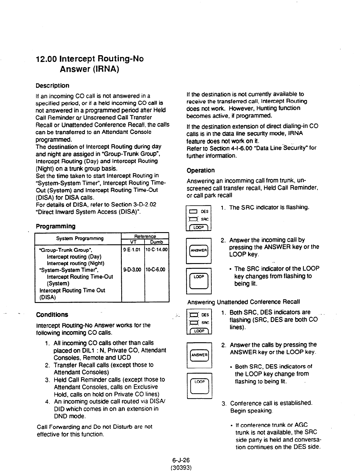
I
2.00 Intercept Routing-No
Answer (IRNA)
Description
If an incoming CO call is not answered in a
specified period, or if a held incoming CO call is
not answered in a programmed period after Held
Call Reminder or Unscreened Call Transfer
Recall or Unattended Conference Recall. the cal!s
can be transferred to an Attendant Console
programmed.
The destination of Intercept Routing during day
and night are assiged in “Group-Trunk Group”,
Intercept Routing (Day) and Intercept Routing
(Night) on a trunk group basis.
Set the time taken to start Intercept Routing in
“System-System Timer”, Intercept Routing Time-
Out (System) and Intercept Routing Time-Out
(DISA) for DISA calls.
For details of DISA, refer to Section 3-D-2.02
“Direct Inward System Access (DISA)“.
Programming
System Programmmg
“Group-Trunk
Group”,
Intercept routing (Day)
Intercept routing (Night)
“System-System Timer”,
Intercept Routing Time-Out
(System)
Intercept Routing lime Out
(DISA)
Conditions
Intercept Routing-No Answer works for the
following incoming CO calls.
1. All incoming CO calls other than calls
placed on ‘DILl : N, Private CO, Attendant
Consoles, Remote and UCD
2. Transfer Recall calls (except those to
Attendant Consoles)
3. Held Call Reminder calls (except those to
Attendant Consoles, calls on Exclusive
Hold, calls on hold on Private CO lines)
4. An incoming outside call routed via DISA/
DID which comes in on an extension in
DND mode.
Call Forwarding and Do not Disturb are not
effective for this function.
If the destination is not currently available to
receive the transferred call, Intercept Routing
does not work. However, Hunting function
becomes active, if programmed.
If the destination extension of direct dialing-in CO
calls is in the data line security mode, IRNA
feature &es not work on it. ,,.
Refer to Section 4-I-6.00 ‘Data Line Security” for
further information.
Operation
Answering an incomming call from trunk, un-
screened call transfer recall, Held Call Reminder,
or call park recall
1. The SRC indicator is flashing.
r-l
2. Answer the incoming call by
0
ANSWER pressing the ANSWER key or the
LOOP key.
. .
l
The SRC indicator of the LOOP
key changes from flashing to
Answering Unattended Conference Recall
1. Both SRC, DES indicators are _
flashing (SRC, DES are both
CO
lines).
cl
2. Answer the calls by pressing the
0
ANSWER
ANSWER key or the LOOP key.
l
Both SRC, DES indicators of
the LOOP key change from
flashing to being tit.
3. Conference call is established.
Begin speaking.
l
If conference trunk or AGC
trunk is not available, the SRC
side party is held and conversa-
tion continues on the DES side.
6-J-26
(30393)

13.00 Remote Timed Reminder
- One Time
Description Operation
Allows the Operator 1 or 2 (Attendant Console or
PITS with display) to set rimed Reminder”
feature to any extension.
(Refer to
Section 4-1-3.00,5-G-3.00 “Timed
Reminder.“)
Setting Iimed Reminder to an extension
LOOP
101
If Timed Reminder with OGM is programmed
beforehand, the extension user can hear
the
wake-up message.
~ (Refer to Section 3-F-l 3.00 “limed Reminder
with OGM (Wake-up Call).“)
Programming
System Programming neterence
VT 1 Dumb
I I
“System-Numbering Plan
(919)
Remote limed Reminder
Confirm
Remote limed Reminder
Set
Remote Timed Reminder
Cancel
/ SD-6.09 lo-c-1o.w
Conditions
(1) The difference between “Timed Reminder”
and “Remote Timed Reminder” is:
Setting Validity of the
setting
?imed by extenison Once’ti?
Reminder itself everyday at the
programmed
time
Remote by Operator Once
Timed
1
or2
Reminder
1. Press an idle LOOP key.
l
The SRC indicator
lights and dial
tone sounds.
2. Dial the feature number for
Remote Timed Reminder Set
7*1” (default) and the extension
number to be set Timed Reminder
in succession.
3. Dial “hour” with two digits:
01 to 12.
4.
Dial “minute” with two digits: 00 to
59.
5. Dial “0” for a.m. or dial “1” for p.m..
l
The LOOP key is released
automatically and the following
message appears on the
Message line.
Message: Atann Ext. 100 1O:OO AM
(2) At a single extension, only the latest setting is
valid whether it was set by the extension itself
(Timed Reminder) or by the Operator
1
or 2
(Remote l7med Reminder).
6-J-27
(40993)
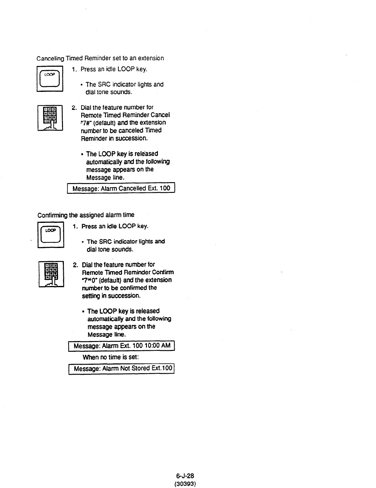
Canceling limed Reminder set to an extension
jo/
1. Press an idle LOOP key.
LOW
l
The SRC indicator lights and
dial tone sounds.
2. Dial the feature number for
Remote Timed Reminder Cancel
-“7#” (default) and the extension
number to be canceled Trmed
Reminder in succession.
9 The LOOP key is released
automatically and the following
message appears on the
Message line.
Message: Alarm Cancelled Ext. 100
Confirming the assigned alarm time
LOOP
ml 1.
*Pa
q
2.
.,.
I..
l
Press an idle LOOP key.
. The SRC indicator IigMs and
dial tone sounds.
Dial the feature number for
Remote Timed Reminder Confirm
7*0’ (defauft) and the extension
number to be confirmed the
setting in succession.
. The LOOP key is released
automatically and the following
message appears on the
Message line.
Message: Alarm Ext. 100 1030 AM
When no time is set:
Message: Alarm Not Stored Ext. 100
6-J-28
(30393)
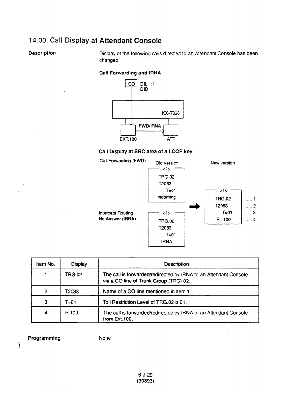
14.00 Call Display at Attendant Console
Description Display of the following calls dir-em3 to an Attendant Console has been
changed.
Call Forwarding and IRNA
EXT. 100 Al7
Call Display at SRC area of a LOOP key
Call Forwarding (WD) Old versm New version
Cl>
L
r 7
lRG.02 . . . . . . . 1
T2083 . . . . . . . 2
intercept Routing
No Answer (IRNA)
- <l> -
TRG.02
T2083
T=O’
IRNA
- - j R ::$ 1::::::::
a
I Item No. I Display 1 Descrption I
I I
1 TRG.02 The call is forwarded/redirected by IRNA to an Attendant Console
via a CO line of Trunk Group (TRG) 02.
I 2 1 T2083 I Name of a CO line mentioned in Item 1. I
I 3 I T=Ot I Toll Restriction Level of TRG.02 ts
01. I
1 4 1 R’lOO / from Ext.lOO.
The call is forwarded/redirected by IRNA to an Attendant Console
Programming None
)
6-J-29
(30393)
