310 430A Parker GS 07R01Y01 E
User Manual: 310-430A
Open the PDF directly: View PDF ![]() .
.
Page Count: 12

Manifolds With DPHarp
EJA and EJX
Pressure and Differential Transmitters
Manifold Construction
• 316 Stainless Steel (code S)
• 4/16” UNF zinc plated carbon steel or
stainless steel (/SSB option) bolts
• NACE compliant (/NC option)
• Oxygen clean service (/OXY option)
• Optional mounting brackets
• 3.1.b. material certificate always included
• Assembly of transmitter including 6 bar
pressure test
• Other materials on request:
Monel (code M)
Duplex (code D1)
Super Duplex (code D2)
Hastelloy (code HC)
Carbon Steel (code C)
Titanium (code T)
Manifold Rating
• Direct mount manifolds are rated up to
6000 psig (414 barg)
• Remote mount manifolds are rated up
to 6000 psig (414barg) and 10 000 psig
(689 barg)
Manifold Marking
• All manifold are permanently marked with
line diagram showing manifold capability
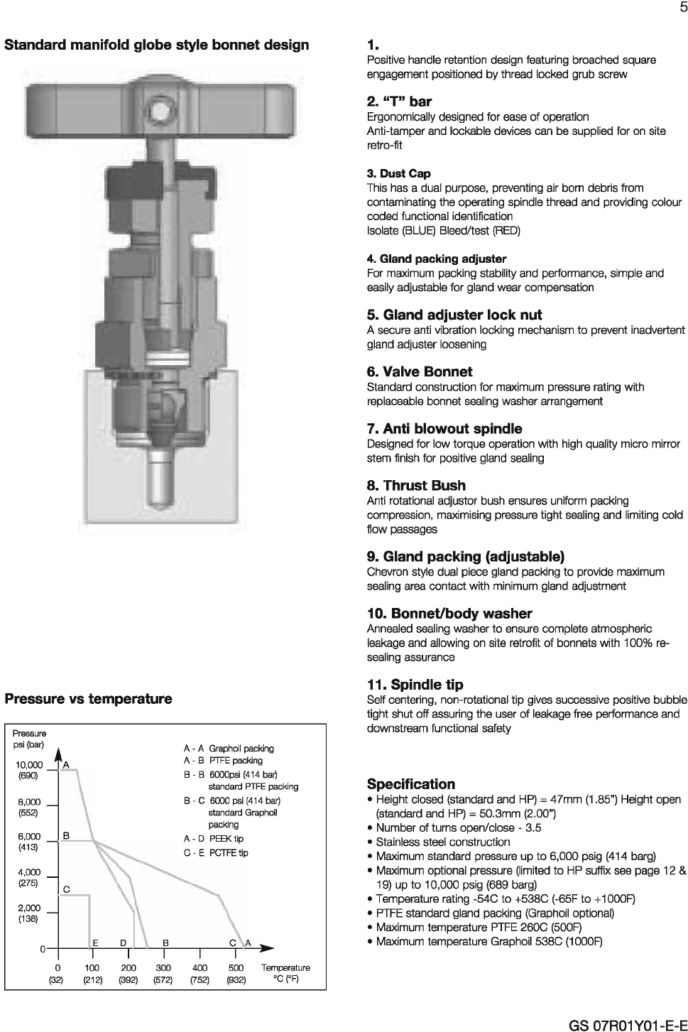
General
Specifications
Yokogawa Europe bv has included Parker Hannifin manifolds
in his DPHarp pressure and differential pressure transmitters
portfolio to suit all types of installations, specifications and
installations.
Enclosures (in Glass fibre Reinforced Polyester) suitable for one,
two or three process instruments, with manifold and tubing
connections for pressure, flow, temperature or other common
process variable instruments, and any accessories required,
as electrical heating element (or steam heat tubing, are also
available.
Contact your nearest Yokogawa office for quotations
Model Code Description
HBSN2FM
HBSN2FF 2 valve Block and Bleed Manifold for DPHarp EJA/EJX 510A/530A series
HBSN2MM
HBSN2MF
HLS2V 2 valve Remote Mount Block and Bleed Manifold DPHarp EJA/EJX 510A/530A series
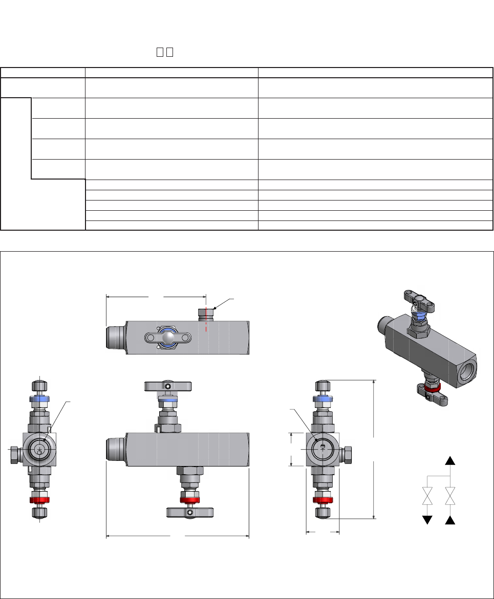
HDS2HLH 2 valve Direct Mount Block and Bleed Manifold for DPHarp EJA/EJX 510A/530A series
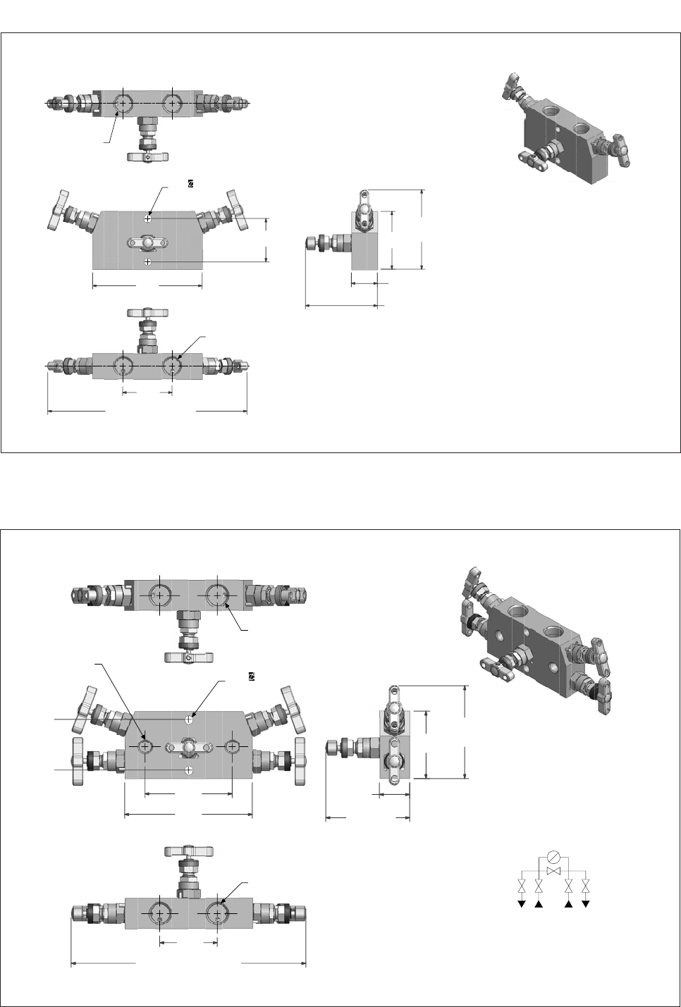
HDS3M 3 valve Direct Mount Block and Bleed Manifold for DPHarp EJA/EJX 310/430A series
HDS5M 5 valve Direct Mount Block and Bleed Manifold for DPHarp EJA/EJX 110A/120A/130A series
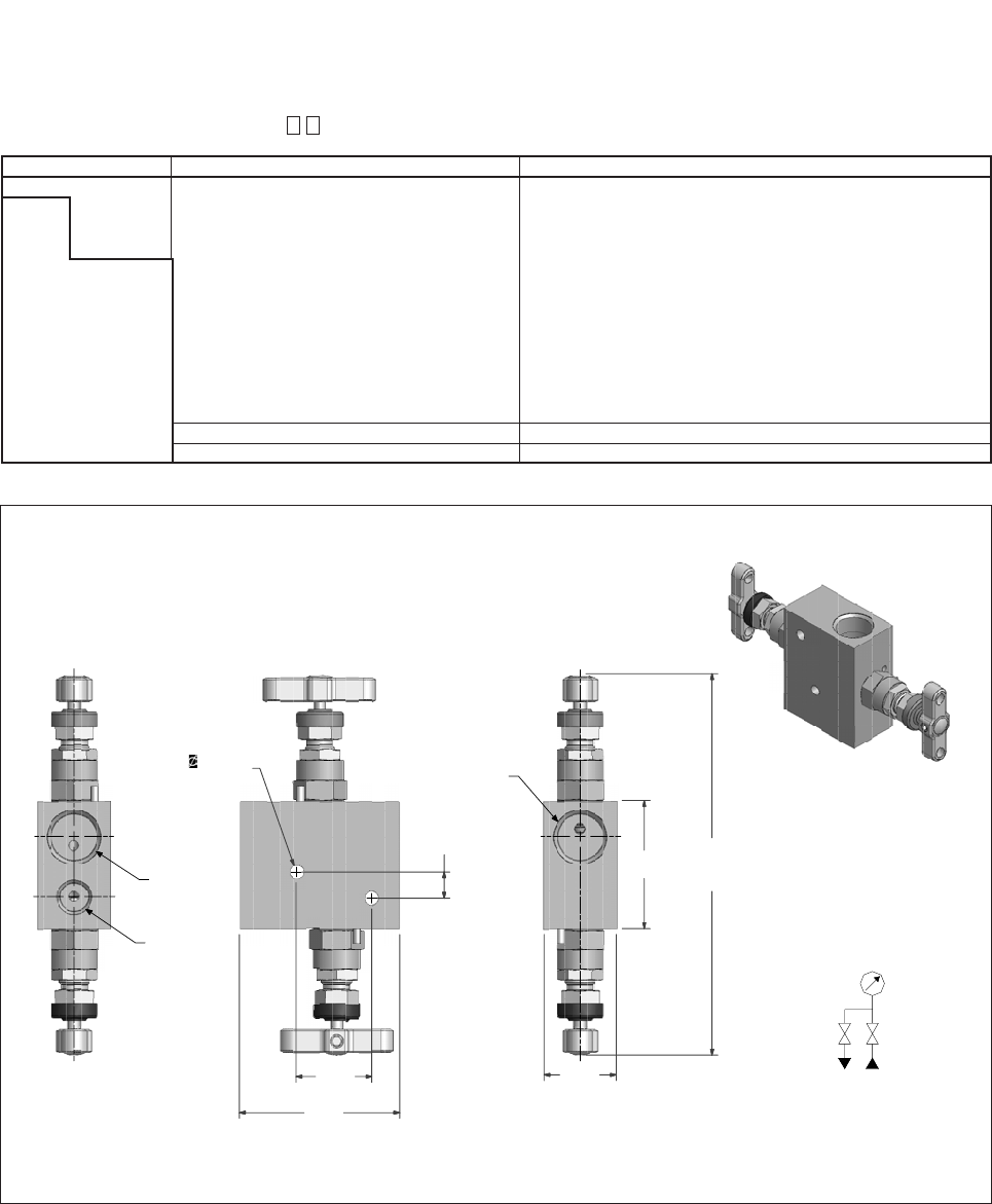
HLS3M 3 valve Remote Mount Block and Bleed Manifold for DPHarp EJA/EJX 110A/120A/130A series
HLS5M 5 valve Remote Mount Block and Bleed Manifold for DPHarp EJA/EJX 110A/120A/130A series
GS 07R01Y01-E-E
1st Edition
Test/Drain Equalize Test/Drain
IsolateIsolate
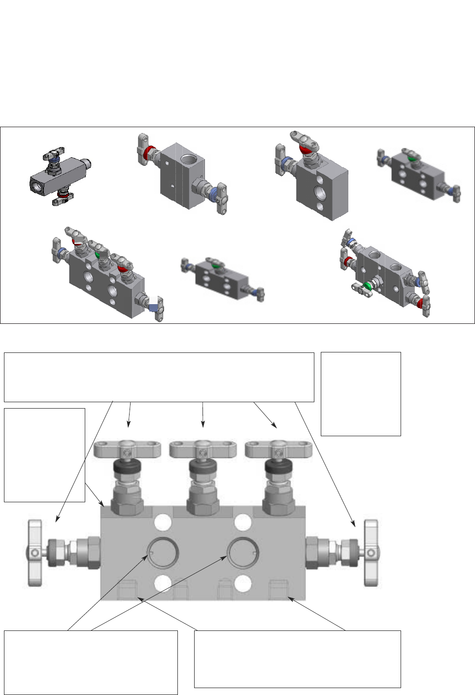
Manifold body:
this is standard
compact bar stock
style suitable for
enclosure
installation.
Extruded forms
are also available
as standard.
Process inlet connections positioned on
front face 1/2” NPT female threads or kidney
flange/oval/futbol are standard. Alternative
thread forms, socket or butt weld and
PTFree connections are available.
Standard connections are on 2.125"/54mm.
Drain/bleed connections the position depends upon
manifold design but are generally on the bottom face
of the manifold. Other optional positions are available.
On 3 valve manifold systems test and purge ports are
optional choices.
Bonnet assemblies: are all functionally colour coded, 3 valve manifolds are
provided with 2 IS and 1 EQ. 5 valve manifolds are provided with 2 IS,2 DR and 1
EQ (as illustrated here). Alternatively 5 valve manifolds for custody transfer/fiscal
metering are fitted with 2 IS,1DR and 2 EQ. For extruded style manifold blocks
straight through flow rising plug style valves can be fitted.
Functional colour
coding:
RED =
Drain/vent/test
BLUE =
Isolate/block
GREEN =
Equalize
316SS
Part No: HDS5M
PTFE: 260 Deg C (500 F) max.
Model: A1........1/2NPT/1/4NPT www.parker.com 414 BAR (6000 PSI) MAX
Test/Drain Equalize Test/Drain
IsolateIsolate
Manifold body:
this is standard
compact bar stock
style suitable for
enclosure
installation.
Extruded forms
are also available
as standard.
Process inlet connections positioned on
front face 1/2” NPT female threads or kidney
flange/oval/futbol are standard. Alternative
thread forms, socket or butt weld and
PTFree connections are available.
Standard connections are on 2.125"/54mm.
Drain/bleed connections the position depends upon
manifold design but are generally on the bottom face
of the manifold. Other optional positions are available.
On 3 valve manifold systems test and purge ports are
optional choices.
Bonnet assemblies: are all functionally colour coded, 3 valve manifolds are
provided with 2 IS and 1 EQ. 5 valve manifolds are provided with 2 IS,2 DR and 1
EQ (as illustrated here). Alternatively 5 valve manifolds for custody transfer/fiscal
metering are fitted with 2 IS,1DR and 2 EQ. For extruded style manifold blocks
straight through flow rising plug style valves can be fitted.
Functional colour
coding:
RED =
Drain/vent/test
BLUE =
Isolate/block
GREEN =
Equalize
316SS
Part No: HDS5M
PTFE: 260 Deg C (500 F) max.
Model: A1........1/2NPT/1/4NPT www.parker.com 414 BAR (6000 PSI) MAX
2
Functional Specifications
(Common for DPHarp EJA and EJX Pressure
Transmitters)
* Refer to specific General Specification for Accuracy
specifications
Output:
Two wire 4 to 20mA DC output with digital communications,
linear or square root programmable. BRAIN or HART FSK
protocol are superimposed on the 4 to 20mA signal.
Output limits conforming to NAMUR NE43 can be pre-set by
option code C2 or C3.
Digital Communication, via Foundation Fieldbus or Profibus PA
protocol, is also available.
Zero Adjustment Limits:
Zero can be fully elevated or suppressed, within the lower and
upper range limits of the capsule.
External Zero Adjustment:
External Zero is continuously adjustable with 0.01%
incremental resolution of span. Re-range can be done locally
using the digital indicator with range-setting switch.
Ambient Temperature Limits:
(Optional features or approval codes may affect limits.)
-40 to 85 ºC (-40 to 185 ºF)
-30 to 80 ºC (-22 to 176 ºF) with LCD display.
Process temperature Limits:
Dependent on seal type and fill fluid selection.
Transmitter Capsule temperature Limits:
(Optional features or approval codes may affect limits.)
-40 to 120 ºC (-40 to 248 ºF)
Ambient Humidity Limits:
0 to 100% RH (EJX)
5 to 100% RH (EJA)
EMC Conformity Standard:
EN 61326, AS/NZS CISPR11
Supply Voltage:
10.5 to 42 VDC for general use and flameproof type
10.5 to 32 VDC for lightning protector (option code /A).
10.5 to 30VDC for intrinsically safe, type n or non-incendive
Minimum voltage limited at 16.6 VDC (EJX) and 16.4 VDC
(EJA) for digital communication, BRAIN and HART
Span and Range Limits:
DPHarp EJX110A Differential Pressure Transmitter
DPHarp EJX910A Multivariable Transmitter
DPHarp EJX430A Gauge Pressure Transmitter
DPHarp EJX510A, 530A Absolute or Gauge Pressure
Transmitter
DPHarp EJA110A Differential Pressure Transmitter
DPHarp EJA310A Absolute Pressure Transmitter
DPHarp EJA430A Gauge Pressure Transmitter
DPHarp EJA510A, 530A Absolute or Gauge Pressure
Transmitter
General
Specifications
<<Contents>> <<Index>>
EJX110A
Differential Pressure Transmitter
Yokogawa Electric Corporation
2-9-32 Nakacho, Musashino-shi, Tokyo, 180-8750 Japan
Phone: 81-422-52-5690 Fax.: 81-422-52-2018
GS 01C25B01-01E
GS 01C25B01-01E
©Copyright Feb. 2004
6th Edition Aug. 2005
The high performance differential pressure transmitter
EJX110A features single crystal silicon resonant
sensor and is suitable to measure liquid, gas, or
steam flow as well as liquid level, density and pres-
sure. EJX110A outputs a 4 to 20 mA DC signal
corresponding to the measured differential pressure.
Its highly accurate and stable sensor can also mea-
sure the static pressure which can be shown on the
integral indicator or remotely monitored via BRAIN or
HART communications. Other key features include
quick response, remote set-up using communications,
self-diagnostics and optional status output for pressure
high/low alarm. FOUNDATION Fieldbus protocol type
is also available. All EJX series models in their
standard configuration, with the exception of the
Fieldbus type, are certified by TÜV as complying with
SIL 2 for safety requirement.
STANDARD SPECIFICATIONS
Refer to GS 01C25T02-01E for Fieldbus communica-
tion type marked with “.”
SPAN AND RANGE LIMITS
Measurement
Span/Range
L
M
H
0.1 to 10
–100 to 100
–5 to 5 kgf/cm2
Span
Span
Span
Range
Range
Range
kPa
0.4 to 40
–40 to 40
–400 to 400
2 to 400
–10 to 10
0.5 to 100
2.5 to 500
–500 to 500
inH2O(/D1)
10 to 2000
–2000 to 2000
mbar(/D3)
1 to 100
–1000 to 1000
–100 to 100
5 to 1000
25 to 5000
–5000 to 5000
mmH2O(/D4)
10 to 1000
–1000 to 1000
50 to 10000
–10000 to 10000
0.025 to 5 kgf/cm2
T01E.EPS
PERFORMANCE SPECIFICATIONS
Zero-based calibrated span, linear output, wetted
parts material code S and silicone oil, unless other-
wise mentioned.
For Fieldbus communication type, use calibrated
range instead of span in the following specifications.
Specification Conformance
EJX series ensures specification conformance to at
least 3.
Reference Accuracy of Calibrated Span
(includes terminal-based linearity, hysteresis, and
repeatability)
Measurement span
Reference
accuracy
0.04% of Span
(0.0050.0049 URL/span)% of Span
T08E.EPS
X
X span
X span
URL (upper range limit)
H
70 kPa (280 inH
2
O)
500 kPa (2000 inH
2
O)
Measurement span
Reference
accuracy
0.04% of Span
(0.0050.0035 URL/span)% of Span
M
T02E.EPS
X
X span
X span
URL (upper range limit)
10 kPa (40 inH
2
O)
100 kPa (400 inH
2
O)
Measurement span
Reference
accuracy
0.04% of Span
(0.0150.005 URL/span)% of Span
L
T03E.EPS
X
X span
Xspan
URL (upper range limit)
2 kPa (8 inH
2
O)
10 kPa (40 inH
2
O)
Square Root Output Accuracy
The square root accuracy is a percent of flow span.
Output Accuracy
50% or Greater Same as reference accuracy
50% to Dropout point
T03E.EPS
Reference accuracy50
Square root output (%)
Ambient Temperature Effects per 28˚C (50˚F)
Change
Capsule Effect
H(0.04% Span0.0125% URL)
M(0.04% Span0.009% URL)
L(0.055% Span0.09% URL)
Static Pressure Effects per 6.9 MPa (1000 psi)
Change
Span Effects
L, M and H capsules
0.075% of span
Effect on Zero
Capsule Effect
H0.028% URL
M0.02% URL
L0.05% URL
Overpressure Effects
Overpressure condition: up to maximum working
pressure
M and H capsules
0.03% of URL
[Style: S2]
General
Specifications
<<Contents>> <<Index>>
EJX430A
Gauge Pressure Transmitter
Yokogawa Electric Corporation
2-9-32 Nakacho, Musashino-shi, Tokyo, 180-8750 Japan
Phone: 81-422-52-5690 Fax.: 81-422-52-2018
GS 01C25E01-01E
GS 01C25E01-01E
©Copyright Feb. 2004
6th Edition Aug. 2005
The high performance gauge pressure transmitter
EJX430A features single crystal silicon resonant
sensor and is suitable to measure liquid, gas, or
steam pressure. The EJX430A outputs a 4 to 20 mA
DC signal corresponding to the measured pressure. It
also features quick response, remote setup and
monitoring via BRAIN or HART communications, and
self-diagnostics. FOUNDATION Fieldbus protocol type
is also available.
All EJX series models in their standard configuration,
with the exception of the Fieldbus type, are certified by
TÜV as complying with SIL 2 for safety requirement.
STANDARD SPECIFICATIONS
Refer to GS 01C25T02-01E for Fieldbus communica-
tion type marked with “.”
SPAN AND RANGE LIMITS
Measurement
Span/Range
H
A
B
2.5 to 500 kPa
– 0.1 to 3.5
–1 to 160
Span
Span
Span
Range
Range
Range
MPa
10 to 2000 inH2O
–400 to 2000 inH2O
–14.5 to 500
2.5 to 500
–100 to 500 kPa
0.0175 to 3.5
0.08 to 16
– 0.1 to 16
psi (/D1)
12 to 2300
–14.5 to 2300
bar(/D3)
0.025 to 5
–1 to 35
–1 to 5
0.175 to 35
0.8 to 160
–1 to 160
kgf/cm2(/D4)
0.025 to 5
–1 to 5
0.175 to 35
–1 to 35
0.8 to
1
60
T01E.EPS
PERFORMANCE SPECIFICATIONS
Zero-based calibrated span, linear output, wetted
parts material code ʻSʼ and silicone oil, unless
otherwise mentioned.
For Fieldbus communication type, use calibrated
range instead of span in the following specifications.
Specification Conformance
EJX series ensures specification conformance to at
least 3.
Reference Accuracy of Calibrated Span
(includes the effects of terminal-based linearity,
hysteresis, and repeatability)
Measurement span
Reference
accuracy
0.04% of Span
(0.0050.0049 URL/Span)% of Span
H
T03E.EPS
X
X span
X span
URL (upper range limit)
70 kPa (280inH2O)
500 kPa (2000inH2O)
Measurement span
Reference
accuracy
0.04% of Span
(0.0050.0035 URL/Span)% of Span
T02E.EPS
X
X span
X span
URL (upper range limit)
A
0.35 MPa
(50 psi) 1.6 MPa
(230 psi)
3.5 MPa
(500 psi) 16 MPa
(2300 psi)
B
Ambient Temperature Effects per 28˚C (50˚F)
Change
Capsule Effect
H(0.04% Span0.0125% URL)
A, B (0.04% Span0.009% URL)
Stability (All normal operating condition)
0.1% of URL per 10 years
Power Supply Effects (Output signal code D and E)
0.005% per Volt (from 21.6 to 32 V DC, 350 )
Vibration Effects
Amplifier housing code 1:
Less than 0.1% of URL when tested per the require-
ments of IEC60770-1 field or pipeline with high
vibration level (10-60 Hz, 0.21 mm peak to peak
displacement/60-2000 Hz 3 g)
Amplifier housing code 2:
Less than ±0.1% of URL when tested per the
requirements of IEC60770-1 field with general
application or pipeline with low vibration level (10-60
Hz 0.15mm peak to peak displacement /60-500 Hz
2g)
Mounting Position Effects
Rotation in diaphragm plane has no effect. Tilting up
to 90 degree will cause zero shift up to 0.4 kPa (1.6
inH2O) which can be corrected by the zero adjust-
ment.
Response Time (All capsules) “”
90 msec
When software damping is set to zero and including
dead time of 45 msec (nominal)
FUNCTIONAL SPECIFICATIONS
Output “”
Two wire 4 to 20 mA DC output with digital communi-
cations, linear or square root programmable. BRAIN
or HART FSK protocol are superimposed on the 4 to
20 mA signal.
General
Specifications
<<Contents>> <<Index>>
EJX510A and EJX530A
Absolute and Gauge Pressure
Transmitter
Yokogawa Electric Corporation
2-9-32 Nakacho, Musashino-shi, Tokyo, 180-8750 Japan
Phone: 81-422-52-5690 Fax.: 81-422-52-2018
GS 01C25F01-01E
GS 01C25F01-01E
©Copyright Jun. 2004
6th Edition Aug. 2005
The high performance absolute and gauge pressure
transmitter EJX510A and EJX530A feature single
crystal silicon resonant sensor and are suitable to
measure liquid, gas, or steam pressure. EJX510A and
EJX530A output a 4 to 20 mA DC signal correspond-
ing to the measured pressure. It also features quick
response, remote setup and monitoring via BRAIN or
HART communications, self-diagnostics, and optional
status output for pressure high/low alarm. FOUNDA-
TION Fieldbus protocol type is also available.
All EJX series models in their standard configuration,
with the exception of the Fieldbus type, are certified by
TÜV as complying with SIL 2 for safety requirement.
STANDARD SPECIFICATIONS
Refer to GS 01C25T02-01E for Fieldbus communica-
tion type marked with “.”
SPAN AND RANGE LIMITS
(For EJX510A, values are in absolute and lower
range limits are 0.)
T01E.EPS
Span
Span
Range
Range
Range
Range
Span
–1 to 20
1 to 50
–1 to 100
2 to 100
0.4 to 20
145 to 7200 10 to 500
8 to 200 kPa
–0.1 to 10
–0.1 to 2
0.04 to 2
–100 to 200 kPa
–14.5 to 1450
0.2 to 10
1.16 to 29
–14.5 to 29
5.8 to 290
–14.5 to 290
29 to 1450
Span
–1 to 2
10 to 500
–1 to 500–14.5 to 7200–0.1 to 50 –1 to 500
2 to 100
–1 to 2
kgf/cm2 (/D4)
0.08 to 2
0.4 to 20
–1 to 20
–1 to 100
MPa
Measurement
Span/Range psi (/D1)
A
D
0.08 to 2
bar (/D3)
C
B
PERFORMANCE SPECIFICATIONS
Zero-based calibrated span, linear output, wetted
parts material code ʻSʼ and silicone oil, unless
otherwise mentioned.
For Fieldbus communication type, use calibrated
range instead of span in the following specifications.
Specification Conformance
EJX series ensures specification conformance to at
least 3.
Reference Accuracy of Calibrated Span
(includes the effects of terminal-based linearity,
hysteresis, and repeatability)
20 kPa
(2.9 psi)
1 MPa
(145 psi)
0.1% of Span
0.2 MPa
(29 psi)
D
Span X
Span X
Reference
accuracy
10 MPa
(1450 psi)
2 MPa
(290 psi)
C
200 kPa
(29 psi)
(0.01+0.009 URL/Span) % of Span
5 MPa
(720 psi)
50 MPa
(7200 psi)
A
URL
(Upper range limit)
Measurement span B
X
T02E.EPS
Ambient Temperature Effects per 28˚C (50˚F)
Change
(0.15% of Span + 0.15% of URL)
Stability (All normal operating condition)
0.1% of URL per 1 year
Power Supply Effects
0.005% per Volt (from 21.6 to 32 V DC, 350 )
Vibration Effects
Amplifier housing code 1:
Less than 0.1% of URL when tested per the require-
ments of IEC60770-1 field or pipeline with high
vibration level (10-60 Hz, 0.21 mm peak to peak
displacement/60-2000 Hz 3 g)
Amplifier housing code 2:
Less than ±0.1% of URL when tested per the
requirements of IEC60770-1 field with general
application or pipeline with low vibration level (10-60
Hz 0.15mm peak to peak displacement /60-500 Hz
2g)
Mounting Position Effects
Rotation in diaphragm plane has no effect. Tilting up
to 90 degree will cause zero shift up to 0.21 kPa
(0.84 inH2O) which can be corrected by the zero
adjustment.
Response Time (All capsules) “”
90 msec
When software damping is set to zero and including
dead time of 45 msec (nominal)
General
Specifications
<<Contents>> <<Index>>
Model EJA110A
Differential Pressure Transmitter
Yokogawa Electric Corporation
2-9-32 Nakacho, Musashino-shi, Tokyo, 180-8750 Japan
Phone: 81-422-52-5690 Fax.: 81-422-52-2018
GS 01C21B01-00E
GS 01C21B01-00E
©Copyright June 1997
20th Edition Jan. 2005
The high performance differential pressure transmitter
model EJA110A can be used to measure liquid, gas,
or steam flow as well as liquid level, density and
pressure. It outputs a 4 to 20 mA DC signal corre-
sponding to the measured differential pressure. Model
EJA110A also features remote setup and monitoring
through communications with the BRAIN™ terminal
and CENTUM CS™ or XL™ or HART
®
275 host.
STANDARD SPECIFICATIONS
Refer to GS 01C22T02-00E for Fieldbus communica-
tion type marked with “.”
PERFORMANCE SPECIFICATIONS
Zero-based calibrated span, linear output, wetted
parts material code ʻSʼ and silicone oil.
Reference Accuracy of Calibrated Span
(including the effects of zero-based linearity, hyster-
esis, and repeatability)
0.075 % of Span
For spans below X
[0.025 + 0.05 ] % of Span
X
Span
where X equals:
Capsule X kPa {inH2O}
L 3 {12}
M 10 {40}
H 100 {400}
V 1.4 MPa {200 psi}
Square Root Output Accuracy
The square root accuracy is a percent of flow span.
Output Accuracy
50 % or Greater same as reference
accuracy
50 % to Dropout point reference accuracy50
square root output (%)
T00E.EPS
Ambient Temperature Effects
Total Effects per 28 ˚C (50 ˚F) Change
Capsule Effect
L[0.08 % Span + 0.09 % URL]
M[0.07 % Span + 0.02 % URL]
H[0.07 % Span + 0.015 % URL]
V[0.07 % Span + 0.03 % URL]
Static Pressure Effects
Total Effects per Change
L capsule
[0.07 % Span+0.052 % URL] per 3.4 MPa {500 psi}
M, H and V capsules
[0.1% Span+0.028 % URL] per 6.9 MPa {1000 psi}
Effect on Zero (can be corrected at line pres-
sure)
L capsule
[0.02 % Span+0.052 % URL] per 3.4 MPa {500 psi}
M, H and V capsules
0.028 % of URL per 6.9 MPa {1000 psi}
Overpressure Effects (M, H and V capsules)
0.03 % of URL per 16 MPa {2300 psi}
Stability (M, H and V capsules)
0.1 % of URL per 60 months
Power Supply Effects “”
0.005 % per Volt (from 21.6 to 32 V DC, 350 )
FUNCTIONAL SPECIFICATIONS
Span & Range Limits
Measurement
Span/Range
L
M
H
0.5 to 10
-100 to 100
-5 to 5 kgf/cm2
Span
Span
Span
Range
Range
Range
kPa
2 to 40
-40 to 40
-400 to 400
4 to 400
-10 to 10
1 to 100
5 to 500
-500 to 500
inH2O(/D1)
20 to 2000
-2000 to 2000
mbar(/D3)
5 to 100
-1000 to 1000
-100 to 100
10 to 1000
50 to 5000
-5000 to 5000
mmH2O(/D4)
50 to 1000
-1000 to 1000
100 to 10000
-10000 to 10000
0.05 to 5 kgf/cm2
T01E.EPS
V*1Span
Range -5 to 140 kgf/cm2
0.14 to 14 MPa
-0.5 to 14 MPa
20 to 2000 psi
-71 to 2000 psi
1.4 to 140 bar
-5 to 140 bar
1.4 to 140 kgf/cm2
*1: For Wetted parts material code other than S, the
ranges are 0 to 14 MPa, 0 to 2000 psi, 0 to 140
bar, and 0 to 140 kgf/cm2.
URL is defined as the Upper Range Limit from the table
above.
Zero Adjustment Limits
Zero can be fully elevated or suppressed, within the
Lower and Upper Range Limits of the capsule.
External Zero Adjustment “”
External zero is continuously adjustable with 0.01 %
incremental resolution of span. Span may be
adjusted locally using the digital indicator with range
switch.
General
Specifications
<<Contents>> <<Index>>
The high performance gauge pressure transmitter
model EJA430A can be used to measure liquid, gas,
or steam pressure. It outputs a 4 to 20 mA DC signal
corresponding to the measured gauge pressure.
Model EJA430A also features remote setup and
monitoring through communications with the BRAIN™
terminal and CENTUM CS™ or XL™ or HART®275
host.
STANDARD SPECIFICATIONS
Refer to GS 01C22T02-00E for Fieldbus communica-
tion type marked with “.”
PERFORMANCE SPECIFICATIONS
Zero-based calibrated span, linear output, wetted
parts material code ʻSʼ and silicone oil.
Reference Accuracy of Calibrated Span
(including the effects of zero-based linearity, hyster-
esis, and repeatability)
0.075 % of Span
For spans below X,
[0.025 + 0.05 ] % of Span
X
Span
where X equals:
Capsule X MPa {psi}
A 0.3 {43}
B 1.4 {200}
Ambient Temperature Effects
Total Effects per 28C (50F) Change
[0.084 % Span + 0.017 % URL]
Stability
0.1 % of URL per 60 months
Power Supply Effects “”
0.005 % per Volt (from 21.6 to 32 V DC, 350 )
FUNCTIONAL SPECIFICATIONS
Span & Range Limits
A
B
Measurement
Span and Range
Span
Range
Span
Range
psi (/D1)
4.3 to 430
-15 to 430
20 to 2000
-15 to 2000
bar (/D3)
0.3 to 30
kgf/cm
2
(/D4)
0.3 to 30
-1 to 30
1.4 to 140
-1 to 140
-1 to 30
1.4 to 140
-1 to 140
MPa
0.03 to 3
-0.1 to 3
0.14 to 14
-0.1 to 14
T01E.EPS
URL is defined as the Upper Range Limit from the
table above.
Zero Adjustment Limits
Zero can be fully elevated or suppressed, within the
Lower and Upper Range Limits of the capsule.
External Zero Adjustment “”
External zero is continuously adjustable with 0.01 %
incremental resolution of span. Span may be
adjusted locally using the digital indicator with range
switch.
Mounting Position Effect
Rotation in diaphragm plane has no effect. Tilting up to
90 will cause zero shift up to 0.4 kPa {1.6 inH2O}
which can be corrected by the zero adjustment.
Output “”
Two wire 4 to 20 mA DC output with digital communi-
cations. BRAIN or HART FSK protocol are superim-
posed on the 4 to 20 mA signal.
Failure Alarm
Output status at CPU failure and hardware error;
Up-scale: 110%, 21.6 mA DC or more(standard)
Down-scale: -5%, 3.2 mA DC or less
Note: Applicable for Output signal code D and E
Damping Time Constant (1st order)
The sum of the amplifier and capsule damping time
constant must be used for the overall time constant.
Amp damping time constant is adjustable from 0.2 to
64 seconds.
Capsule (Silicone Oil) A B
Time Constant (approx. sec) 0.2 0.2
Ambient Temperature Limits
(approval codes may affect limits)
-40 to 85C (-40 to 185F)
-30 to 80C (-22 to 176F) with LCD Display
Model EJA430A
Gauge Pressure Transmitter
Yokogawa Electric Corporation
2-9-32 Nakacho, Musashino-shi, Tokyo, 180-8750 Japan
Phone: 81-422-52-5690 Fax.: 81-422-52-2018
GS 01C21E01-00E
GS 01C21E01-00E
©Copyright June 1997
18th Edition Jan. 2005
General
Specifications
<<Contents>> <<Index>>
The absolute and gauge pressure transmitter model
EJA510A and EJA530A can be used to measure
liquid, gas, or steam pressure. Both output a 4 to 20
mA DC signal corresponding to the measured pres-
sure, and also feature remote setup and monitoring
through communications with the BRAIN™ terminal
and CENTUM CS™ or µXL™ or HART®275 host.
STANDARD SPECIFICATIONS
Refer to GS 01C22T02-00E for Fieldbus
communication type marked with “”.
PERFORMANCE SPECIFICATIONS
Zero-based calibrated span, linear output, wetted
parts material code ʻSʼ and silicone oil.
Reference Accuracy of Calibrated Span
(including the effects of zero-based linearity, hyster-
esis, and repeatability, values are in absolute for
EJA510A)
0.2 % of Span
0.075 % of Span, when/ HAC is specified
(EJA530A: A, B and C capsule)
0.12 % of Span, when/ HAC is specified
(EJA530A: D capsule)
For spans below
X
,
[0.050.15 ] % of Span
[0.0250.05 ] % of span, when/ HAC is
specified (EJA530A: A, B and C capsule)
[0.030.09 ] % of span, when/ HAC is
specified (EJA530A: D capsule)
X
Span
X
Span
X
Span
Where
X
equals:
Capsule
X
MPa {psi}
A 20 kPa {2.9}
A with/ HAC 40 kPa {5.8}
B 0.2 {29}
C 1 {145}
D 8 {1160}
Ambient Temperature Effects
Total Effects per 28C (50F) Change
[0.15% Span 0.15% URL]
Stability
0.1% of URL per 12 months
Vibration Effects
0.1 % of URL
(5 to 15Hz; 4mm peak-to-peak constant displace-
ment, 15 to 150Hz; 2g, 150 to 2000Hz; 1g)
Model EJA510A and EJA530A
Absolute and Gauge Pressure
Transmitters
Yokogawa Electric Corporation
2-9-32, Nakacho, Musashino-shi, Tokyo, 180-8750 Japan
Phone: 81-422-52-5690 Fax.: 81-422-52-2018
GS 01C21F01-00E
GS 01C21F01-00E
©Copyright Apr. 1999
15th Edition Jan. 2005
Power Supply Effects “”
0.005 % per Volt (from 21.6 to 32 V DC, 350 )
FUNCTIONAL SPECIFICATIONS
Span & Range Limits
(Values are in absolute for EJA510A)
A
B
Measurement
Span and
Range
Span
Range
Span
Range
psi (/D1)
1.45 to 29
0 to 29
14.5 to 290
0 to 290
bar (/D3)
0.1 to 2
kgf/cm
2
(/D4)
0.1 to 2
0 to 2
1 to 20
0 to 20
0 to 2
1 to 20
0 to 20
MPa
10 to 200
kPa
0 to 200
kPa
0.1 to 2
0 to 2
72.5 to 1450
0.5 to 10
0 to 10
CSpan
Range 0 to 1450
5 to 100
0 to 100
5 to 100
0 to 100
720 to 7200
5 to 50
0 to 50
DSpan
Range 0 to 7200
50 to 500
0 to 500
50 to 500
0 to 500
T01E.EPS
URL is defined as the Upper Range Limit from the
table above.
Zero Adjustment Limits
Zero can be fully elevated or suppressed, within the
Lower and Upper Range Limits of the capsule.
External Zero Adjustment “”
External zero is continuously adjustable with 0.01 %
incremental resolution of span. Span may be
adjusted locally using the digital indicator with range
switch.
Mounting Position Effect
Rotation in diaphragm plane has no effect. Tilting up
to 90 will cause zero shift up to 0.27 kPa {1.1 inH2O}
which can be corrected by the zero adjustment.
Output “”
Two wire 4 to 20 mA DC output with digital communi-
cations. BRAIN or HART FSK protocol are superim-
posed on the 4 to 20 mA signal.
[Style: S2]
General
Specifications
<<Contents>> <<Index>>
The high performance gauge pressure transmitter
model EJA310A can be used to measure liquid, gas,
or steam pressure. It outputs a 4 to 20 mA DC signal
corresponding to the measured absolute pressure.
Model EJA310A also features remote setup and
monitoring through communications with the BRAIN™
terminal and CENTUM-CS™ or XL™ or HART®275
host.
STANDARD SPECIFICATIONS
Refer to GS 01C22T02-00E for Fieldbus communica-
tion type marked with “.”
PERFORMANCE SPECIFICATIONS
Zero-based calibrated span, linear output, wetted
parts material code ʻSʼ and silicone oil.
Reference Accuracy of Calibrated Span
(including the effects of zero-based linearity, hyster-
esis, and repeatability)
±0.15 % of Span or
±0.20 % of Span for L Capsule
±0.075 % of Span when /HAC is specified.
For spans below X,
[0.1 + 0.05 ] % of Span or
[0.15 + 0.05 ] % of Span for the L
Capsule
[0.025 + 0.05 ] % of Span when/HAC is
specified.
X
Span
X
Span
X
Span
where X equals:
Capsule X kPa {psi}
L 5.4 {22 inH2O}
M 21.8 {3.2}
A 250 {36}
Ambient Temperature Effects
Total Effects per 28 ˚C (50 ˚F) Change
Capsule Effect
L[0.095 % Span + 0.118 % URL]
M[0.084 % Span + 0.028 % URL]
A[0.080 % Span + 0.008 % URL]
Power Supply Effects “”
0.005 % per Volt (from 21.6 to 32 V DC, 350 )
FUNCTIONAL SPECIFICATIONS
Span & Range Limits
(Units are in absolute terms.)
L
M
A
Measurement
Span and Range
Span
Range
Span
Range
Span
Range
psi(/D1)
0.2 to 2.95 inHg
0 to 2.95 inHg
0.38 to 38 inHg
0 to 38 inHg
4.3 to 430
0 to 430
mbar(/D3)
6.7 to 100
mmHg(/D4)
5 to 75
0 to 100
13 to 1300
0 to 1300
0.3 to 30 bar
0 to 30 bar
0 to 75
9.6 to 960
0 to 960
0.3 to 30 kgf/cm
2
0 to 30 kgf/cm
2
MPa
0.67 to 10 kPa
0 to 10 kPa
1.3 to 130 kPa
0 to 130 kPa
0.03 to 3
0 to 3
T01E.EPS
URL is defined as the Upper Range Limit from the
table above.
Minimum Input Pressure at Calibration
L capsule: 130 Pa abs. {1 mmHg abs.}
M and A capsules: 2.7 kPa abs. {20 mmHg abs.}
At range calibrating testing, minimum input pressure
of 130 Pa abs. {1 mmHg abs.} is obtained by
selecting Optional code S1. Always select S1 for M
capsule with higher range value(HRV) not exceeding
3.4 kPa abs. {25 mmHg abs.}
Zero Adjustment Limits
Zero can be fully elevated or suppressed, within the
Lower and Upper Range Limits of the capsule.
External Zero Adjustment “”
External zero is continuously adjustable with 0.01 %
incremental resolution of span. Span may be
adjusted locally using the digital indicator with range
switch.
Mounting Position Effect
Rotation in diaphragm plane has no effect. Tilting up to
90 ˚ will cause zero shift up to 0.4 kPa {1.6 inH2O}
which can be corrected by the zero adjustment.
Model EJA310A
Absolute Pressure Transmitter
Yokogawa Electric Corporation
2-9-32 Nakacho, Musashino-shi, Tokyo, 180-8750 Japan
Phone: 81-422-52-5690 Fax: 81-422-52-2018
GS 01C21D01-00E
GS 01C21D01-00E
©Copyright June 1997
17th Edition Jan. 2005
GS 07R01Y01-E-E
General
Specifications
<<Contents>> <<Index>>
EJX910A
Multivariable Transmitter
Yokogawa Electric Corporation
2-9-32 Nakacho, Musashino-shi, Tokyo, 180-8750 Japan
Phone: 81-422-52-5690 Fax.: 81-422-52-2018
GS 01C25R01-01E
GS 01C25R01-01E
©Copyright Mar. 2005
6th Edition Aug. 2006
The high performance EJX910A multivariable transmit-
ter features a single-crystal silicon resonant sensor
and is suitable to measure liquid, gas, or steam mass
flow. The EJX910A outputs a 4 to 20 mA DC signal
corresponding to the measured differential pressure,
static pressure, process temperature, or dynamically
calculated and fully compensated mass flow.
FOUNDATION fieldbus protocol type is also available.
Key features:
•1.0% mass flow rate accuracy over 1:10 flow range
[HART protocol type]
•Siumultaneous dual output of 4 to 20mA and pulse
signals.
[FOUNDATION Fieldbus protocol type]
•Various function blocks available; 5 AIs, AR, IT, SC,
and IS as standard. PID as an optional feature.
•Software download function(option)
STANDARD SPECIFICATIONS
SPAN AND RANGE LIMITS
Differential Pressure (DP)
T01E.EPS
50 to 10000
–10000 to 10000
0.025 to 5 kgf/cm2
–5 to 5 kgf/cm2
5 to 1000
–1000 to 1000
25 to 5000
–5000 to 5000
2 to 400
–400 to 400
10 to 2000
–2000 to 2000
0.5 to 100
–100 to 100
2.5 to 500
–500 to 500
Span
Range
Span
Range
mmH2O(/D4)
mbar(/D3)
inH2O(/D1)
kPa
H
M
10 to 1000
–1000 to 1000
1 to 100
–100 to 100
0.4 to 40
–40 to 40
0.1 to 10
–10 to 10
Span
Range
L
Measurement
Span/Range
Static Pressure (SP)
Absolute Pressure
T02E.EPS
10 to 250
0 to 250
10 to 250
0 to 250
145 to 3600
0 to 3600
1 to 25
0 to 25
Span
Range
kgf/cm2 abs(D4)
bar abs(D3)
psia(/D1)
MPa abs
M
H
10 to 160
0 to 160
10 to 160
0 to 160
145 to 2300
0 to 2300
1 to 16
0 to 16
Span
Range
L
Measurement
Span/Range
Gauge Pressure (Sealed gauge)
T03E.EPS
10 to 250
–1 to 250
10 to 250
–1 to 250
145 to 3600
–14.5 to 3600
1 to 25
– 0.1 to 25
Span
Range
kgf/cm2(D4)
bar(/D3)
psi(/D1)
MPa
M
H
10 to 160
–1 to 160
10 to 160
–1 to 160
145 to 2300
–14.5 to 2300
1 to 16
– 0.1 to 16
Span
Range
L
Measurement
Span/Range
External Temperature (ET) (PT100 ohm)
T04E.EPS
10 to 1050
73 to 1123
0 to 2200
18 to 1890
–328 to 1562
–459 to 3500
10 to 1050
–200 to 850
–273 to 1927
L
M
H
Span
Range
Fixed Temperature
K
°F
°C
Measurement External
Temperature Span/Range
PERFORMANCE SPECIFICATION
Zero-based calibrated span output, wetted parts
material code S and silicone oil, unless otherwise
mentioned.
For Fieldbus communication type, use calibrated
range instead of span in the following specifications.
Specification Conformance
EJX series ensures specification conformance to at
least ±3m.
Mass Flow (For Measurement Function Code B)
Mass Flow Reference Accuracy
±1.0% of Mass Flow Rate over 10:1 flow range. (100
:1 DP range) for liquids and gases.
Totalized Mass Flow Reference Accuracy
1.0% of Total Mass Flow.
Note: Assume 100:1 DP range for liquids and gases.
Conditions for mass flow accuracy
(1) Auto compensation mode.
(2) Uncalibrated differential producer (Orifice)
installed based on the following standards. *1
(3) Uncertainties for discharge coefficient, primary
device bore, pipe diameter, and gas expansion
factor defined on following standards. *1
(4) Density uncertainty less than 0.1%.
(5) Differential pressure spanned at up to 1/10th full
scale with DP trimmed for optimum flow
accuracy/rangeability.
*1: Standards: ISO5167-1 1991, ISO5167-2 2003,
ASME, MFC-3M 1989, AGA No.3 1992
3
EJX110A GS01C25B01-01E
EJX910A GS01C25R01-01E
EJX430A GS01C25E01-01E
EJX510A, EJX530A GS01C25F01-01E
EJA110A GS01C21B01-00E
EJA120A GS01C21B03-00E
EJA130A GS01C21B03-00E
EJA310A GS01C21D01-00E
EJA430A GS01C21E01-00E
EJA440A GS01C21E02-00E
EJA510A, EJA530A GS01C21F01-00E
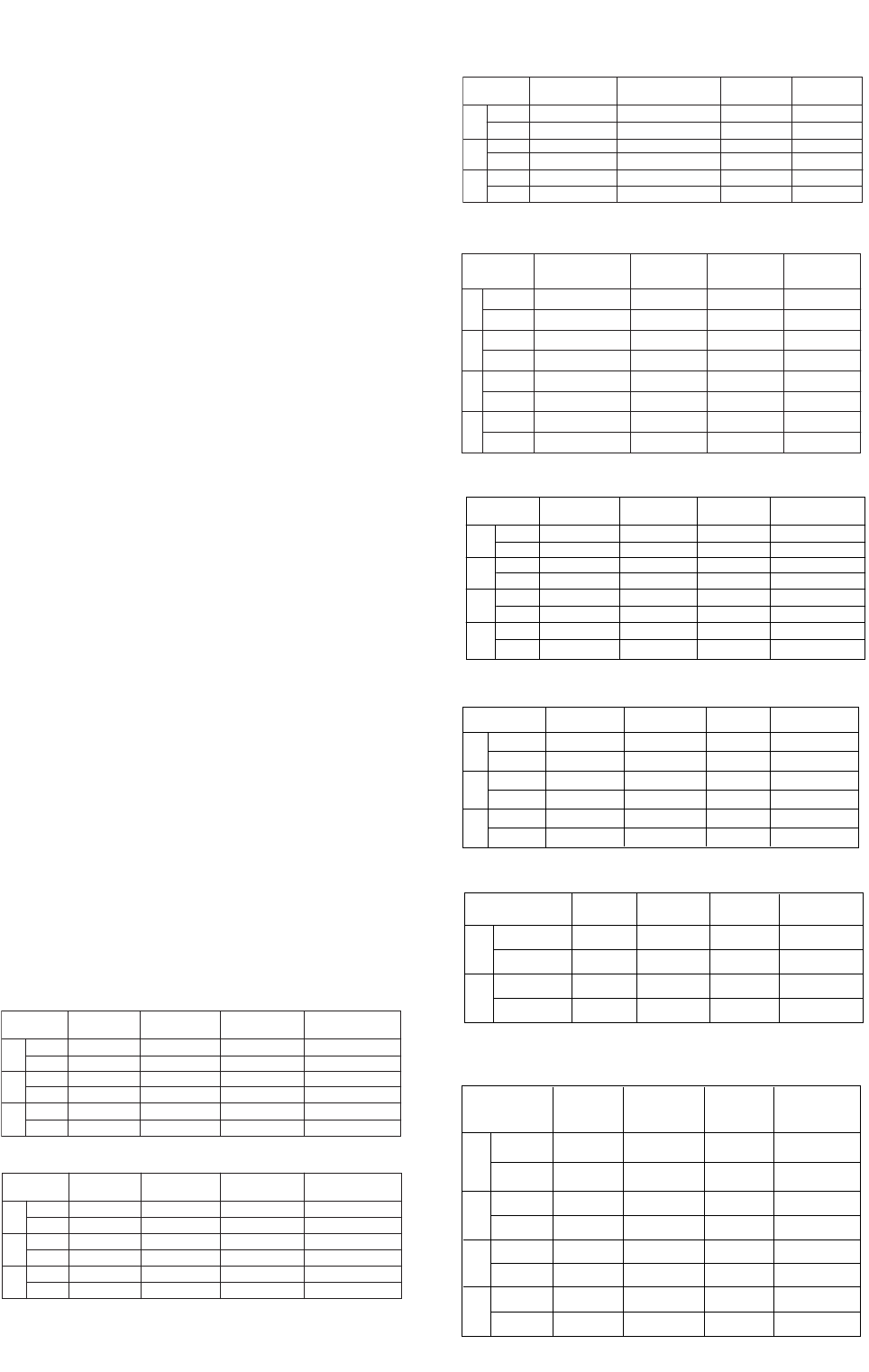
Manifold product overview
GS 07R01Y01-E-E
For details, please refer to the following GS for each product:
FOR MATERIAL AND PROCESS SPECIFICATIONS REFER TO GENRIC PROCESS CONTROL SHEET ESSF
FOR PART MARKING DETAILS REFER TO PART MARKING SPECIFICATION ESSF
THIS DRAWING CONTAINS INFORMA TION THAT IS CONFIDENTIAL AND PROPRIETRY TO PARKER HANNIFIN PLC. THIS DRAWING IS FURNISHED ON THE
UNDERSTANDING THAT THE DRAWI NG AND THE INFORMATION IT CONTAINS WILL NOT BE COPIED OR DISCLOSED TO OTHERS EXCEPT WITH THE
WRITTEN CONSENT OF PARKER HAN NIFIN.WILL NOT BE USED TO THE DETRIMENT OF PARKER HANNIFIN,AND WILL BE RETURNED UPON REQUEST
BY PARKER HANNIFIN.
ISSUE NO.
E.C.N NUMBER
DATE
DRAWN BY:
DATE DRAWN
SCALE PROPORTIONAL
ALL DIMENSIONS IN MM [INCHES] UNLESS OTHERWISE STATED
DRAWING TITLE :
DRAWING LOCATED IN PDM SYSTEM
REMOVE ALL SHARP EDGES AND BURRS
INCH METRIC ANGULAR
(.00") .015"
(.000") .005"
(.0)mm .3mm
(.00mm) 0.1mm
1/2
30
DO NOT SCALE IF IN DOUBT ASK
UNLESS STATED
3rd ANGLE
PROJECTION
CHECKED BY :
APPROVED BY:
Instrumentation
Parker Hannifin plc
Instrumentation Products Division
Riverside Road
Barnstaple.
Devon EX31 1NP
Approvals using electronic
ʼPDM WORKFLOWʼ (QSP05/25)
Approvals using electronic
ʼPDM WORKFLOWʼ (QSP05/25)
1
22/05/2002
NICK HOLTON
22/05/2002
N/A
N/A
HD*2HLH
CUST
2 VALVE MANIFOLD DIRECT MTG
PIPE TO FLANGE
1/2-14 NPT (FEM) INLET
1/4-18 NPT (FEM) VENT
BASE VENTED
6000 PSI RANGE
CUSTOMER ASSEMBLY DRAWING
2 VALVE MANIFOLD DIRECT MTG
INLET : 1/2-14 NPT (FEM)
VENT : 1/4-18 NPT (FEM)
MATERIAL OF CONSTRUCTION :
SEE ʼH-SERIES MATERIAL SPECʼ.
63.5
[2.500]
113.0
[4.449]
(OPEN REF.)
63.5
[2.500]
114.3 [4.500] (OPEN REF.)
111.3 [4.382] (CLOSED REF.)
28.6
[1.125]
M10 x 1.5p
MTG HOLES
2 OFF 12.0 [0.472]
MTG HOLES
M6 x 1.0p
MTG HOLES
1/4-18 NPT
(FEM) VENT
1/2-14 NPT
(FEM) INLET
41.3
[1.625]
24.0
[0.945]
8.3
[0.326]
FOR MATERIAL AND PROCESS SPECIFICATIONS REFER TO GENRIC PROCESS CONTROL SHEET ESSF
FOR PART MARKING DETAILS REFER TO PART MARKING SPECIFICATION ESSF
THIS DRAWING CONTAINS INFORMA TION THAT IS CONFIDENTIAL AND PROPRIETRY TO PARKER HANNIFIN PLC. THIS DRAWING IS FURNISHED ON THE
UNDERSTANDING THAT THE DRAWI NG AND THE INFORMATION IT CONTAINS WILL NOT BE COPIED OR DISCLOSED TO OTHERS EXCEPT WITH THE
WRITTEN CONSENT OF PARKER HAN NIFIN.WILL NOT BE USED TO THE DETRIMENT OF PARKER HANNIFIN,AND WILL BE RETURNED UPON REQUEST
BY PARKER HANNIFIN.
ISSUE NO.
E.C.N NUMBER
DATE
DRAWN BY:
DATE DRAWN
SCALE PROPORTIONAL
ALL DIMENSIONS IN MM [INCHES] UNLESS OTHERWISE STATED
DRAWING TITLE :
DRAWING LOCATED IN PDM SYSTEM
REMOVE ALL SHARP EDGES AND BURRS
INCH METRIC ANGULAR
(.00") .015"
(.000") .005"
(.0)mm .3mm
(.00mm) 0.1mm
1/2
30
DO NOT SCALE IF IN DOUBT ASK
UNLESS STATED
3rd ANGLE
PROJECTION
CHECKED BY :
APPROVED BY:
Instrumentation
Parker Hannifin plc
Instrumentation Products Division
Riverside Road
Barnstaple.
Devon EX31 1NP
Approvals using electronic
ʼPDM WORKFLOWʼ (QSP05/25)
Approvals using electronic
ʼPDM WORKFLOWʼ (QSP05/25)
1
22/05/2002
NICK HOLTON
22/05/2002
N/A
N/A
HD*5M
CUST
5 VALVE MANIFOLD DIRECT MTG
PIPE TO FLANGE
1/2-14 NPT (FEM) INLETS
1/4-18 NPT (FEM) VENTS
BASE VENTED
6000 PSI RANGE
CUSTOMER ASSEMBLY DRAWING
5 VALVE MANIFOLD DIRECT MTG
INLETS : 1/2-14 NPT (FEM)
VENTS : 1/4-18 NPT (FEM)
MATERIAL OF CONSTRUCTION :
SEE ʼH-SERIES MATERIAL SPECʼ.
239.6 [9.433] (OPEN REF.)
233.6 [9.197] (CLOSED REF.)
113.0
[4.449]
(OPEN REF.)
63.5
[2.500]
28.6
[1.125]
54.0
[2.125]
138.0
[5.433]
41.3
[1.625]
30.0
[1.181]
2 OFF 1/2-14 NPT
(FEM) INLETS 4 OFF 12.0 [0.472]
MTG. HOLES
2 OFF 1/4-18 NPT
(FEM) VENTS
2 OFF M10 x 1.5p
MTG. HOLES
102.0
[4.016]
FOR MATERIAL AND PROCESS SPECIFICATIONS REFER TO GENRIC PROCESS CONTROL SHEET ESSF
FOR PART MARKING DETAILS REFER TO PART MARKING SPECIFICATION ESSF
THIS DRAWING CONTAINS INFORMA TION THAT IS CONFIDENTIAL AND PROPRIETRY TO PARKER HANNIFIN PLC. THIS DRAWING IS FURNISHED ON THE
UNDERSTANDING THAT THE DRAWI NG AND THE INFORMATION IT CONTAINS WILL NOT BE COPIED OR DISCLOSED TO OTHERS EXCEPT WITH THE
WRITTEN CONSENT OF PARKER HAN NIFIN.WILL NOT BE USED TO THE DETRIMENT OF PARKER HANNIFIN,AND WILL BE RETURNED UPON REQUEST
BY PARKER HANNIFIN.
ISSUE NO.
E.C.N NUMBER
DATE
DRAWN BY:
DATE DRAWN
SCALE PROPORTIONAL
ALL DIMENSIONS IN MM [INCHES] UNLESS OTHERWISE STATED
DRAWING TITLE :
DRAWING LOCATED IN PDM SYSTEM
REMOVE ALL SHARP EDGES AND BURRS
INCH METRIC ANGULAR
(.00") .015"
(.000") .005"
(.0)mm .3mm
(.00mm) 0.1mm
1/2
30
DO NOT SCALE IF IN DOUBT ASK
UNLESS STATED
3rd ANGLE
PROJECTION
CHECKED BY :
APPROVED BY:
Instrumentation
Parker Hannifin plc
Instrumentation Products Division
Riverside Road
Barnstaple.
Devon EX31 1NP
Approvals using electronic
ʼPDM WORKFLOWʼ (QSP05/25)
Approvals using electronic
ʼPDM WORKFLOWʼ (QSP05/25)
1
22/05/2002
NICK HOLTON
22/05/2002
N/A
N/A
HL*2V
CUST
2 VALVE MANIFOLD REMOTE MTG
PIPE TO PIPE
1/2-14 NPT (FEM) INLET/OUTLET
1/4-18 NPT (FEM) VENT
6000 PSI RANGE
CUSTOMER ASSEMBLY DRAWING
2 VALVE MANIFOLD REMOTE MTG
INLET : 1/2-14 NPT (FEM)
OUTLET : 1/2-14 NPT (FEM)
VENT : 1/4-18 NPT (FEM)
MATERIAL OF CONSTRUCTION :
SEE ʼH-SERIES MATERIAL SPECʼ.
50.8
[2.000]
152.4 [6.000]
(OPEN REF.)
146.4 [5.764]
(CLOSED REF.)
63.5
[2.500]
28.6
[1.125]
2 OFF 5.5 [0.216]
MTG. HOLES 1/2-14 NPT
(FEM) OUTLET
1/2-14 NPT
(FEM) INLET
1/4-18 NPT
(FEM) VENT
30.0
[1.181]
10.4
[0.409]
FOR MATERIAL AND PROCESS SPECIFICATIONS REFER TO GENRIC PROCESS CONTROL SHEET ESSF
FOR PART MARKING DETAILS REFER TO PART MARKING SPECIFICATION ESSF
THIS DRAWING CONTAINS INFORMA TION THAT IS CONFIDENTIAL AND PROPRIETRY TO PARKER HANNIFIN PLC. THIS DRAWING IS FURNISHED ON THE
UNDERSTANDING THAT THE DRAWI NG AND THE INFORMATION IT CONTAINS WILL NOT BE COPIED OR DISCLOSED TO OTHERS EXCEPT WITH THE
WRITTEN CONSENT OF PARKER HAN NIFIN.WILL NOT BE USED TO THE DETRIMENT OF PARKER HANNIFIN,AND WILL BE RETURNED UPON REQUEST
BY PARKER HANNIFIN.
ISSUE NO.
E.C.N NUMBER
DATE
DRAWN BY:
DATE DRAWN
SCALE PROPORTIONAL
ALL DIMENSIONS IN MM [INCHES] UNLESS OTHERWISE STATED
DRAWING TITLE :
DRAWING LOCATED IN PDM SYSTEM
REMOVE ALL SHARP EDGES AND BURRS
INCH METRIC ANGULAR
(.00") .015"
(.000") .005"
(.0)mm .3mm
(.00mm) 0.1mm
1/2
30
DO NOT SCALE IF IN DOUBT ASK
UNLESS STATED
3rd ANGLE
PROJECTION
CHECKED BY :
APPROVED BY:
Instrumentation
Parker Hannifin plc
Instrumentation Products Division
Riverside Road
Barnstaple.
Devon EX31 1NP
Approvals using electronic
ʼPDM WORKFLOWʼ (QSP05/25)
Approvals using electronic
ʼPDM WORKFLOWʼ (QSP05/25)
1
22/05/2002
NICK HOLTON
22/05/2002
N/A
N/A
HL*5M
CUST
5 VALVE MANIFOLD REMOTE MTG
PIPE TO PIPE
1/2-14 NPT (FEM) INLET/OUTLET
1/4-18 NPT (FEM) VENT
6000 PSI RANGE
CUSTOMER ASSEMBLY DRAWING
5 VALVE MANIFOLD REMOTE MTG
INLETS : 1/2-14 NPT (FEM)
OUTLETS : 1/2-18 NPT (FEM)
VENTS : 1.4-18 NPT (FEM)
MATERIAL OF CONSTRUCTION :
SEE ʼH-SERIES MATERIAL SPECʼ.
63.5
[2.500]
28.6
[1.125]
79.0 [3.110]
(OPEN REF.)
221.6 [8.724] (OPEN REF.)
215.6 [8.488] (CLOSED REF.)
120.0
[4.724]
2 OFF 1/2-14 NPT
(FEM) INLETS
2 OFF 8.5 [0.335]
MTG. HOLES
2 OFF 1/4-18 NPT
(FEM) VENTS
2 OFF 1/2-14 NPT
(FEM) OUTLETS
54.0
[2.126]
47.6
[1.875]
88.0
[3.465]
(MAX REF.)
82.0
[3.228]
HBSN2FM HLS2V HDS2HLH HDS3M
HDS5M HLS3M HLS5M
Test/Drain Equalize Test/Drain
IsolateIsolate
Manifold body:
this is standard
compact bar stock
style suitable for
enclosure
installation.
Extruded forms
are also available
as standard.
Process inlet connections positioned on
front face 1/2” NPT female threads or kidney
flange/oval/futbol are standard. Alternative
thread forms, socket or butt weld and
PTFree connections are available.
Standard connections are on 2.125"/54mm.
Drain/bleed connections the position depends upon
manifold design but are generally on the bottom face
of the manifold. Other optional positions are available.
On 3 valve manifold systems test and purge ports are
optional choices.
Bonnet assemblies: are all functionally colour coded, 3 valve manifolds are
provided with 2 IS and 1 EQ. 5 valve manifolds are provided with 2 IS,2 DR and 1
EQ (as illustrated here). Alternatively 5 valve manifolds for custody transfer/fiscal
metering are fitted with 2 IS,1DR and 2 EQ. For extruded style manifold blocks
straight through flow rising plug style valves can be fitted.
Functional colour
coding:
RED =
Drain/vent/test
BLUE =
Isolate/block
GREEN =
Equalize
316SS
Part No: HDS5M
PTFE: 260 Deg C (500 F) max.
Model: A1........1/2NPT/1/4NPT www.parker.com 414 BAR (6000 PSI) MAX
Key features (example with a 5 valve manifold)
GS 07R01Y01-E-E
4
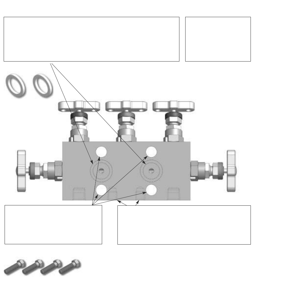
Test/Drain Equalize Test/Drain
IsolateIsolate
Instrument side, outlet, flange connections: are standard for direct
mount manifolds with machined grooves for PTFE seal rings. DIN sealing
groove arrangement is also available on request. Remote style manifolds are
provided as standard with 1/2” NPT female outlet connections (alternative
thread forms etc. are available). Flanged outlets are positioned on
54mm/2.125” centres. (56/57mm centres are available on request).
Pressure rating:
maximum standard rating
6000psig (414 barg).
Remote mount
10,000psig (689 barg) are
available
Manifold to transmitter mounting: all
direct mount manifolds are provided with
4 off 7/16 UNF x 1.625” high tensile zinc
plated carbon steel bolts. Bolt holes are
standard on 54mm/2.125” centres.
Optional St. St. bolts are available.
Manifold base/bracket mounting:
instrument allowing installation to take place without the
all manifolds are
provided with bracket mounting holes. This provides the
user with the opportunity to bracket mount the
instrument and to give full mounting support in the
event of Instrument removal.
Material: Products in this GS are
standard in stainless steel but can also be
produced in many other materials.
6
2 valve Manifold Block and Bleed HBSN2 for DPHarp EJA/EJX 510A/530A series
Model and Suffix codes HBSN2
Model Suffixcode Description
HBSN2 Instrument Block and Bleed Manifold
for DPHarp EJA/EJX 510A/530A series
FM HBSNVS28F8M4FHPP Manifold type 2 valves 316SS 1/2”NPT F inlet
(select EJA/X500 1/2”NPT M) 1/2” NPT M outlet
FF HBSNVS28F8F4FHPP Manifold type 2 valves 316SS 1/2”NPT F inlet
(select EJA/X500 1/2”NPT M) 1/2” NPT F outlet
MF HBSNVS28M8F4FHPP Manifold type 2 valves 316SS 1/2”NPT M inlet
(select EJA/X500 1/2”NPT F) 1/2” NPT F outlet
MM HBSNVS28M8M4FHPP Manifold type 2 valves 316SS 1/2”NPT M inlet
(select EJA/X500 1/2”NPT F) 1/2” NPT M outlet
Options /NC Sour Gas Service
/PP Plugged Vent Port
/MOUNTTF Assembly on Transmitter (free issue) with Teflon
/MOUNTLOC Assembly on Transmitter (free issue) with Loctite
/T Tested at 6 bar (dry air) during 1 min.
GS 07R01Y01-E-E
133.4 [5.25]
(OPEN REF.)
127.4 [5.02]
(CLOSED REF.)
2 VALVE MANIFOLD REMOTE MTG
INLET : 1/ 2- 14 NPT (MALE)
OUTLET : 1/ 2- 14 NPT (FEM)
VENT : 1/ 4- 18 NPT (FEM)
MATERIAL OF CONSTRUCTION :
SEE ʼH- SERIES MATERIAL SPECʼ.
95.4
[3.76]
136.7
[5.38]
31.8
[1.25]
31.8
[1.25]
1/2-14 (MALE)
INLET
1/4-18 NPT
PLUG
1/2-14 NPT (FEM)
OUTLET
Drawing HBSN2MF
7
Manifold Remote Mount for DPHarp EJA/EJX series
Model and Suffix codes HLS
Model Suffix Codes Description
HLS Manifold Remote Mount for DPHarp EJA/EJX series
2V 2 valves 316SS for DPHarp EJA/EJX510A - 530A
3M 3 valves 316SS for DPHarp EJA/EJX110A - 130A
5M 5 valves 316SS for DPHarp EJA/EJX110A - 130A
Options /NC Sour Gas Service
/MTG (always included) Tapped Mounting Holes
/BRKC Carbon steel Mounting Bracket
/BRKS Stainless steel Mounting Bracket
/SSB Stainless steel Mounting Bolts
/OXY Oxygen clean service
/PP Plugged Vent Port (for HLS2V manifold)
/MOUNTTF Assembly on EJA/EJX510A - 530A Transmitter with Teflon
/MOUNTLOC Assembly on EJA/EJX510A - 530A Transmitter with Loctite
/T Tested at 6 bar (dry air) during 1 min.
GS 07R01Y01-E-E
2 VALVE MANIFOLD REMOTE MTG
INLET : 1/2-14 NPT (FEM)
OUTLET : 1/2-14 NPT (FEM)
VENT : 1/4-18 NPT (FEM)
MATERIAL OF CONSTRUCTION :
SEE ʼH-SERIES MATERIAL SPECʼ.
50.8
[2.000]
152.4 [6.000]
(OPEN REF.)
146.4 [5.764]
(CLOSED REF.)
63.5
[2.500]
28.6
[1.125]
2 OFF 5.5 [0.216]
MTG. HOLES 1/2-14 NPT
(FEM) OUTLET
1/2-14 NPT
(FEM) INLET
1/4-18 NPT
(FEM) VENT
30.0
[1.181]
10.4
[0.409]
Drawing HLS2V
8
GS 07R01Y01-E-E
5 VALVE MANIFOLD REMOTE MTG
INLETS : 1/2-14 NPT (FEM)
OUTLETS : 1/2-18 NPT (FEM)
VENTS : 1.4-18 NPT (FEM)
MATERIAL OF CONSTRUCTION :
SEE ʼH-SERIES MATERIAL SPECʼ.
63.5
[2.500]
28.6
[1.125]
79.0 [3.110]
(OPEN REF.)
221.6 [8.724] (OPEN REF.)
215.6 [8.488] (CLOSED REF.)
120.0
[4.724]
2 OFF 1/2-14 NPT
(FEM) INLETS
2 OFF 8.5 [0.335]
MTG. HOLES
FF 1/4-18 NPT
(FEM) VENTS
2 OFF 1/2-14 NPT
(FEM) OUTLETS
54.0
[2.126]
47.6
875]
88.0
[3.465]
(MAX REF.)
82.0
[3.228]
120.0
[4.724]
63.5
[2.500]
28.6
[1.125]
88.0
[3.465]
(MAX REF.)
2 OFF 8.5 [0.335]
MTG HOLES
79.4 [3.126] (OPEN REF.)
76.4 [3.008] (CLOSED REF.)
2 OFF 1/2-14 NPT
(FEM) INLET
1/2-14 NPT
(FEM) OUTLET
2 OFF
220.0 [8.661] (OPEN REF.)
214.0 [8.425] (CLOSED REF.)
54.0
[2.126]
47.6
[1.875]
Drawing HLS3M
Drawing HLS5M

9
GS 07R01Y01-E-E
Manifold Direct Mount for DPHarp EJA/EJX series
Model and Suffix codes HDS
Model Suffix Codes Description
HDS Manifold Direct Mount for DPHarp EJA/EJX100 series
2HLH 2 valves 316SS for DPHarp EJA/EJX 310A - 430A
3M 3 valves 316SS for DPHarp EJA/EJX 110A - 130A
5M 5 valves 316SS for DPHarp EJA/EJX 110A - 130A
Options /NC Sour Gas Service
/MTG (always included) Tapped Mounting Holes
/BRKC Carbon steel Mounting Bracket
/BRKS Stainless steel Mounting Bracket
/SSB STSTL Mounting Bolts
/MOUNT Manifold Assembly - free issue EJA/EJX
/T Tested at 6 bar (dry air) during 1 min.
/OXY Oxygen clean service
/PP Plugged Vent Port (for HDS2HLH manifold)
2 VALVE MANIFOLD DIRECT MTG
INLET : 1/2-14 NPT (FEM)
VENT : 1/4-18 NPT (FEM)
MATERIAL OF CONSTRUCTION :
SEE ʼH-SERIES MATERIAL SPECʼ.
63.5
[2.500]
113.0
[4.449]
(OPEN REF.)
63.5
[2.500]
114.3 [4.500] (OPEN REF.)
111.3 [4.382] (CLOSED REF.)
28.6
[1.125]
M10 x 1.5p
MTG HOLES
2 OFF 12.0 [0.472]
MTG HOLES
M6 x 1.0p
MTG HOLES
1/4-18 NPT
(FEM) VENT
1/2-14 NPT
(FEM) INLET
41.3
[1.625]
24.0
[0.945]
8.3
[0.326]
Drawing HDS2HLH

10
GS 07R01Y01-E-E
FOR MATERIAL AND PROCESS SPECIFICATIONS REFER TO GENRIC PROCESS CONTROL SHEET ESSF
FOR PART MARKING DETAILS REFER TO PART MARKING SPECIFICATION ESSF
THIS DRAWING CONTAINS INFORMATION THAT IS CONFIDENTIAL AND PROPRIETRY TO PARKER HANNIFIN PLC. THIS DRAWING IS FURNISHED ON THE
UNDERSTANDING THAT THE DRAWING AND THE INFORMATION IT CONTAINS WILL NOT BE COPIED OR DISCLOSED TO OTHERS EXCEPT WITH THE
WRITTEN CONSENT OF PARKER HANNIFIN.WILL NOT BE USED TO THE DETRIMENT OF PARKER HANNIFIN,AND WILL BE RETURNED UPON REQUEST
BY PARKER HANNIFIN.
ISSUE NO.
E.C.N NUMBER
DATE
DRAWN BY:
DATE DRAWN
SCALE PROPORTIONAL
ALL DIMENSIONS IN MM [INCHES] UNLESS OTHERWISE STATED
DRAWING TITLE :
DRAWING LOCATED IN PDM SYSTEM
REMOVE ALL SHARP EDGES AND BURRS
INCH METRIC ANGULAR
(.00") .015"
(.000") .005 "
(.0)mm . 3mm
(.00mm) 0.1mm
1/2
30
DO NOT SCALE IF IN DOUBT ASK
UNLESS STATED
3rd ANGLE
PROJECTION
CHECKED BY :
APPROVED BY:
Instrumentation
Parker Hannifin plc
Instrumentation Products Division
Riverside Road
Barnstaple.
Devon EX31 1NP
Approvals using electronic
ʼPDM WORKFLOWʼ(QSP05/25)
Approvals using electronic
ʼPDM WORKFLOWʼ(QSP05/25)
1
22/05/2002
NICK HOLTON
22/05/2002
N/A
N/A
HD*3M
CUST
3 VALVE MANIFOLD DIRECT MTG.
PIPE TO FLANGE
1/2-14 NPT (FEM) INLETS
6000 PSI RANGE
CUSTOMER ASSEMBLY DRAWING
3 VALVE MANIFOLD DIRECT MTG.
INLETS : 1/2-14 NPT (FEM)
MATERIAL OF CONSTRUCTION :
SEE ʼH-SERIES MATERIAL SPECʼ.
28.6
[1.125]
110.0
[4.331]
211.6 [8.331] (OPEN REF.)
205.6 [8.094] (CLOSED REF.)
2 OFF M10 x 1.5p
MTG HOLES
4 OFF 12.0 [0.472]
MTG HOLES
54.0
[2.125]
41.3
[1.625]
113.0
[4.449]
(OPEN REF)
63.5
[2.500]
2 OFF 1/2-14 NPT
(FEM) INLET
30.0
[1.181]
5 VALVE MANIFOLD DIRECT MTG
INLETS : 1/2-14 NPT (FEM)
VENTS : 1/4-18 NPT (FEM)
MATERIAL OF CONSTRUCTION :
SEE ʼH-SERIES MATERIAL SPECʼ.
239.6 [9.433] (OPEN REF.)
233.6 [9.197] (CLOSED REF.)
113.0
[4.449]
(OPEN REF.)
63.5
[2.500]
28.6
[1.125]
54.0
[2.125]
138.0
[5.433]
41.3
[1.625]
30.0
[1.181]
2 OFF 1/2-14 NPT
(FEM) INLETS 4 OFF 12.0 [0.472]
MTG. HOLES
2 OFF 1/4-18 NPT
(FEM) VENTS
2 OFF M10 x 1.5p
MTG. HOLES
102.0
[4.016]
Drawing HDS5M
Drawing HDS3M
11
GS 07R01Y01-E-E
???????????????????
??????????
????
???????
????
???????
????
???????
?????
???????
????
???????
????
???????
????
???????
?????
???????
????
???????
????
???????
30.0
(1.18")
47.0
(1.85") 2-O Ø10.0
(0.41")
Mtg. holes
69.5
(2.74")
90.0
(3.54")
69.5
(2.74")
69.5
(2.74")
35.0
(1.38")
145.0
(5.71")
90.0
(3.54")
10.0
(0.39")
4-O Ø8.5
(0.34")
Mtg. holes
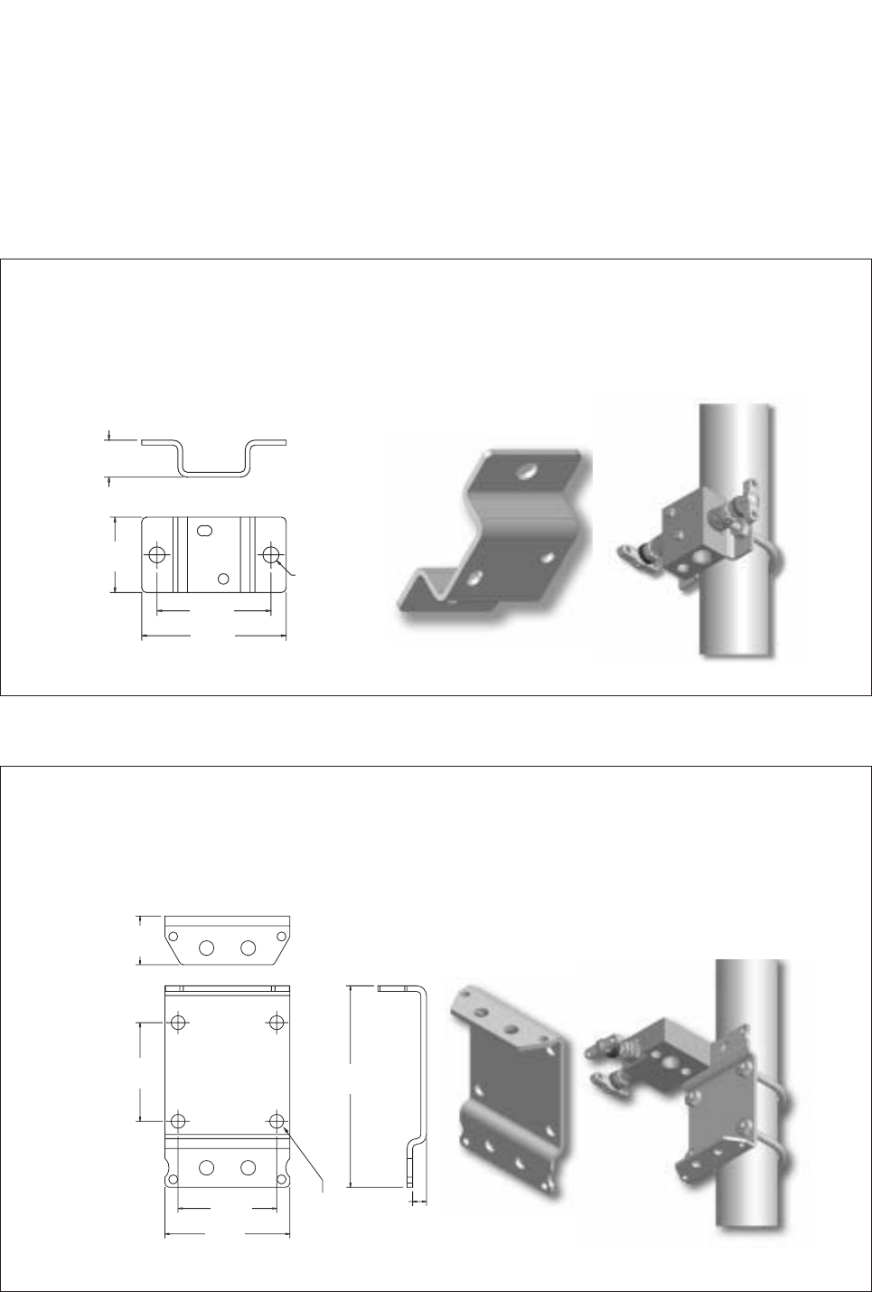
Mounting bracket for HLS2V model
Simple to install bracket for horizontal/vertical 2” standpipe, wall, panel or base mounting, bracket stand-off prevents handle
obstruction.
Mounting bracket for HDS2HLH model
Universal manifold mounting bracket suitable for all direct mount manifolds. This bracket design enables horizontal or vertical
instrument positioning.
Manifold bracket support
Purpose
It is essential to fully support impulse/pressure measurement tubing lines, manifolds and instruments. All manifolds are designed to
accommodate bracket mounting and support, a full range of brackets with additional U bolts are available.
Brackets are designed for panel and wall mounting and give full clearance for ease of handle operation. They are also suitable for vertical
and horizontal positioning on 2” pipe-stand.
Brackets are produced from 4mm thick carbon steel plate to provide maximum rigidity and support. For full corrosion protection the
brackets are shot blasted and zinc sprayed. Stainless Steel bracket are available in selecting Brks.
GS 07R01Y01-E-E
Subject to change without notice Printed in The Netherlands, 01-802 (A) I
Copyright©
YOKOGAWA
YOKOGAWA EUROPE B.V.
Databankweg 20
3821 AL AMERSFOORT
The Netherlands
Tel. +31-33-4641 611
Fax +31-33-4641 610
www.yokogawa.com/eu
Yokogawa has an extensive sales and
distribution network.
Please refer to the European website
(www.yokogawa.com/eu) to contact your
nearest representative.
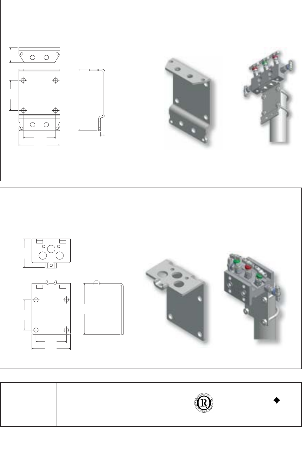
BKT3CS
BKT4CS
35.0
(1.38”)
71.0
(2.80”)
71.0
(2.80”)
90.0
(3.54”)
67.0
(2.64”)
120.0
(4.72”)
71.0
(2.80”)
71.0
(2.80”)
90.0
(3.54”)
85mm
(3.35")
145.0
(5.71”)
10.0
(0.39”)
Mounting bracket for HDS3M and HDS5M models
Simple to install bracket on horizontal or vertical 2” standpipe. Designed for horizontal or vertical mounting of manifold giving total
installation flexibility.
Mounting bracket for HLS3M and HLS5M models
Universal manifold mounting bracket suitable for all remote mount manifolds. This bracket allows 90 degree positioning enabling total
installation flexibility and prevents handle obstruction. Can be wall, standpipe or base mounted.
BKT3CS
BKT4CS
35.0
(1.38”)
71.0
(2.80”)
71.0
(2.80”)
90.0
(3.54”)
67.0
(2.64”)
120.0
(4.72”)
71.0
(2.80”)
71.0
(2.80”)
90.0
(3.54”)
85mm
(3.35")
145.0
(5.71”)
10.0
(0.39”)
