Jpyd023.tmp Partner Plus R3.0 System Planner Guide R3
Partner Plus R3 System Planner Partner Plus R3 System Planner
User Manual: Partner Plus R3.0 System Planner Guide Avaya Partner Plus
Open the PDF directly: View PDF ![]() .
.
Page Count: 25
- Table of Contents
- Introduction
- Form A Instructions: System Configuration
- Form B1 Instructions: System Extensions
- Form B2 Instructions: Customized Extension Settings
- Form C Instructions: Button Programming Templates
- Form D Instructions: Disallowed, Allowed and Emergency Telephone Numbers
- Form E Instructions: Speed Dial Numbers
- System Planner Worksheet
- Form A: System Configuration
- Form B1: System Extensions
- Form B2: Customized Extension Settings
- Form C1: Button Programming Template (MLS-34D)
- Form C2: Button Programming Template (MLS-18D)
- Form C3: Button Programming Template (MLS-12D/MLS-12)
- Form C4: Button Programming Template (MLS-6/MLC-6)
- Form D: Disallowed, AIlowed, and Emergency Telephone Numbers
- Form E: Speed Dial Numbers

AT&T
AT&T 518-455-214
(6-92)
PARTNER® PIus Communications System
Release
3
System Planner

Copyright © 1992 AT&T 518-455-214
All Rights Reserved
Issue 1
Printed In U.S.A. June 1992
Notice
Every effort was made to ensure that the information in this Planner was complete and accurate at the time of printing. However, information is subject to change.
Trademarks
PARTNER is a registered trademark of AT&T.
Call Assistant, MLS-34D, MLS-18D, MLS-12D, MLS-12, and MLS-6 are trademarks of AT&T.
Ordering Information
The order number for this Planner is 518-455-214. To order additional copies, call 1 800 432-6600 in the continental U.S. and 1800255-1242 in Canada. For
more information on how to order other system reference materials, see the PARTNER Plus Communicafion System Programming and Use guide.
Support Telephone Numbers
In the continental US., AT&T provides a toll-free customer helpline 24 hours a day. Call the AT&T
Helpline at 1 800 628-2886 if you need assistance when programming or using your system.
Outside the continental U.S., contact your local AT&T Authorized Dealer.
Contents
Introduction
Form A Instructions: System Configuration
Form B1 Instructions: System Extensions
Form B2 Instructions: Customized Extension Settings
Form C InstructIons: Button Programming Templates
Form D Instructions: Disallowed, Allowed, and Emergency Telephone Numbers
Form E Instructions: Speed Dial Numbers
System Planner Worksheet
Form A: System Conflguratlon
Form B1: System Extensions
Form B2: Customized Extension settings
Form C1: Button Programming Template (MLS-34D)
Form C2: Button Programming Template (MLS48D)
Form C3: Button Programming Template (MLS-12D/MLS42)
Form C4: Button Programming Template (MLS-8/MLC-8)
Form D: Disallowed, Allowed, and Emergency Telephone Numbers
Form E: Speed Dial Numbers
4
5
7
8
10
14
15
16
A-1
B-1
B-2
C-1
C-2
C-3
C-4
D-1
E-1
3
Introduction
Setup decisions for your PARTNER
®
Plus Communications System should be recorded on the forms in this Planner. The forms must be filled out before installa-
tion to provide guidance for the technicians who install and program the system. They should also be used to record changes after installation, so that you have an
ongoing record of the programming for your system. If programming is inadvertently erased (for example, in the event of an exteded power failure), the forms can
be used to reprogram your system
As part of the planning process, you should identify a person in your company to act as System Manager for your phone system. The System Manager is the
person who is responsible for your telephone system. The system Manager should work with your salesperson to fill out the forms in this guide, and should
participate (with an alternate) in the training for the system. The System Manager can then provide training, answer questions for telephone users, and perform
any additional programming for the system.
Filling Out Planning Forms
We suggest you complete the forms in pencil, as follows:
1
. When you purchase your system, your slaesperson will help you decide how to set it up. During this discussion, the salesperson should fill out the
System
Planner Worksheet,
to provide a quick overview of your basic setup decisions.
2. Your salesperson should fill out
Form A
(to describe your overall system configuration) and
Form B1
(to record basic information for each system extension).
If you want to customize extension settings for different user groups, your salesperson should also complete
Form B2.
NOTE:
For system options that require programming, the forms show the name of the procedure and the programming code in the form
{#NNN}
( for ex-
ample,
Line Assignment {#301}
); centralized programming procedures for individual extensions are identified by the letters
{CTP}
for “Centralized Telephone
Programming” ( for example,
Line Ringing {CTP}
).
3. Your salesperson should provide advice to help you fill out any additional forms needed for installation.
■
If you want button features programmed onto user telephones centrally (instead of letting users do it themselves), indicate the desired button programming
using the appropriate telephone templates in
Form C.
■
If you plan to use dialing restrictions, you can use
Form D
to specify a list of emergency telephone numbers that will override restrictions. You can also use
Form D
to specify lists of Disallowed and Allowed numbers, to fine tune the dialing capabilities for individual extensions.
■
If you want System Speed Dial numbers programmed that will be available to all system users, fill out the top portion of
Form E.
After filling out the forms, the salesperson will take a copy and leave you a copy of the filled-out forms.
Keep your copy In a safe place.
Training
■
AT&T rpresentative will provide training at your place of business when the system is installed and programmed. The representative will demonstrate how to
■
Handle calls and use system features
■
Program features and phone numbers onto phone buttons
■
Change the programming for the system and for individual telephones
■
Use the Quick Reference card and the Programming and Use guide.
To prepare for training, please. . .
■
Set aside 30–60 minutes of UNINTERRUPTED time for training on installation day, preferably in a quiet place away from distractions.
■
Designate one person (generally the System Manager) and an alternate to participate in the training. The persons you select will then train the rest of your staff.
This training will ensure that you take maximum advantage of your new AT&T system. Thank you for your cooperation.
4
Form A Instructions: System Configuration
Salesperson completes Items 1-11.
Sales Support Representative completes 12-14.
7. System Lines
Specify the number of telephone lines in the space provided, then enter infor-
mation about individual lines in the table. Be sure to list the lines assigned to all
extensions first, followed by personal or dedicated lines.
Number of Lines {#104}
Indicate the number of lines to be assigned to all extensions, as noted in Item
1c of the
System Planner Worksheet. Number of Lines {#104}
can be used
to assign that number of lines to all extensions. This procedure should be used
only for installation-using it later erases custom line settings for all extensions.
Telephone Number
Record the telephone number associated with each line.
Line Type {#201}
Enter TT for touch-tone lines or R for rotary lines.
Dial Mode {#201}
can be
used to Identify rotary lines to the system.
Subscription Services
If applicable, indicate any local telephone company subscription services (such
as Call Waiting or Caller ID) available on the line.
Line Owner {#301}
For a personal or dedicated line, indicate the user name or equipment descrip-
tion. (If another user provides backup call coverage on the line, note that user’s
name in parentheses.)
Line Assignment {#301}
can be used to assign per-
sonal or dedicated lines
(Form B2
records custom assignments).
8. System settings
Check boxes that apply to indicate settings that affect the entire system.
Transfer Return Rings {#105}
By default, a transferred call that is not answered within 4 rings returns to the
transfer return extension (see
Form B1).
To change the default, check this box
and indicate the preferred number of rings (0-9). For no return, enter 0.
Outside Conference Denial {#109}
To prevent all users from conferencing with more than one outside party, check this box.
Toll Call Prefix {#402) not required
If dialing a “0” or ”1” to make toll calls is NOT required, check this box.
System Password {#403}
If a System Password is desired, check this box and indicate the 4-digit pass-
word. Whoever knows the password can place any type of call at any time,
regardless of dialing restrictions.
NOTE:
If a System Password is programmed, it must be entered to turn Night
Service on and off. Also, users at Night Service Group extensions must enter
the password before placing outside calls--except Marked System Speed Dial
numbers and numbers on the Emergency Phone Number List.
Emergency Telephone Number List
If a list of emergency phone numbers (such as 911) is desired-to allow any
extension with access to an outside line to override dialing restrictions and dial
those numbers-check this box and list the numbers on
Form D.
Night Service Button {#503)
If Night Service is desired, check this box and identify extensions in the Night
Service Group using
Form B1.
A button must be programmed at extension 10
to turn Night Service on and off.
9. Auxiliary Equipment (System)
Check boxes that apply for any auxiliary equipment connected to the control
unit or to system wiring. Also, specify the following items as appropriate:
SMDR Record Type {#603}
If a call-reporting device (such as a printer or call accounting processor) will be
connected, indicate whether information should be collected for all calls or for
outgoing calls only.
Loudspeaker Paging
If a loudspeaker paging system to be connected to the control unit supports
multiple zones, indicate the number of zones.
Caller ID Devices
If you want to connect a Caller ID device (such as a PC to process Caller ID
information), check this box. Separate wiring runs will be required to connect
each device directly to the network interface jack for a line.
5
10. Auxiliary Equipment (Extensions)
Check boxes that apply for any auxilliary equipment connected to extensions,
indicating extension numbers as needed
(Form B1
shows all system extension
numbers).
Hotline {#603}
For any number of Hotline phones, specify the extension number of the Hotline
phone and single alert extension (for example, enter 15/10 for a HOtline at
extension 15 that alerts extension 10). If the loudspeaker paging system is to be
alerted, enter "70" as the alert extension. Do not connect a Hotline phone to
extension 10, 16, 22 , or 28.
Doorphone Extensions {#604/#605, #606}
For each doorphone (2 maximum), specify the extension number of the
doorphone and any number of alert extensions. Do not connect a doorphone to
extension 10, 11, 16, 17, 22, 23, 28, or 29.
11. Notes
Enter any additional information to communicate to the installer.
6
Form B1 Instructions: System Extensions
This form provides basic information for each system extension. To customize
line assignments or other extension settings, you must also use
Form B2.
Name/Description
Enter a user name or a description for auxiliary equipment (such as “Fax
Machine” or “Conference Room”) to be installed at the extension.
Item 10 on
Form A
identifies extensions where a Hotline phone or doorphone is
to be connected. For a Hotline extension, write “Hotline” in the Name/Descrip-
tion column of
Form B1
and write T for touch-tone or R for rotary in the Stan-
dard column (under Telephone) to indicate the type of phone. (A Hotline phone
extension should have a standard touch-tone or rotary phone; the alert exten-
sion can have any type of phone.) For a doorphone, write “Doorphone” in the
Name/Description column and write DP in the Other column (under Aux. Eq.).
Telephone
Check the appropriate box to indicate the type of phone to be connected. Also,
check the MLS-CA24 box if a Call Assistant™ Intercom Autodialer is to be
installed along with an MLS-34D™, MLS-18D™, or MLS-12D™ phone at
extensions 10 and 11.
For a standard phone, put T in the Standard column to indicate a touch-tone
phone, or R to indicate a rotary phone. Also enter a letter to identify the stan-
dard phone user group (from the
System Planner Worksheet)
in the User
Group ID column, and fill out the “Std. Phone” row on
Form B2.
If a system and standard phone are to be combined on an extension, place a
check mark in the two appropriate Telephone columns. If a phone and an
auxiliary device are to be combined on the extension, place a check mark in the
appropriate Telephone and Aux. Eq. columns.
AUX. Eq.
FAX {#601}
Check this box if a fax machine is connected to the extension.
AA/VMS {#607}
Check this box if a PARTNER Attendant (AA) or a voice messaging system
(VMS) is connected to the extension. (Do not connect an
AA or
VMS to exten-
sion 10, 16, 22, or 28.) Also use the Trans. Return Ext. {#306] column to
indicate a transfer return extension (such as
extension 10)
where unanswered
calls will be picked up by a human operator.
Other
Note any other equipment connected to an extension, as follows:
■
Answering Machines. Enter AM in this column.
■
Doorphones. Enter DP in this column.
■
Extra Alerts. Enter EX
in this column; in
the
Name/Description column, note
the alerted
area
(such as Warehouse) and the device (such as Bell or Light).
■
Modems. Enter MD in this column.
User Group ID
User Groups are extensions that use the same set of customized settings. Enter
the User Group ID (from the
System Planner Worksheet)
on
Form B1,
to
indicate the group to which the extension belongs. Then record the customized
settings on
Form B2.
Trans. Return Ext. {#306}
By default, a transferred call returns to the originating extension if the call is not
picked up. To specify a different transfer return extension, enter the extension
number in this column. If you checked the AA/VMS {#607) column for an
extension, indicate a transfer return extension with an actual person—usually
extension 10—to pick up calls that are transferred by the AA or VMS extension
but not answered.
Night Service {#504}
Check this box if the extension should be in the Night Service Group. When
Night Service is on, incoming calls on assigned lines ring immediately at the
extensions in the Night Service Group, even if Line Ringing for those extensions
is set for “delayed ring” or “no ring” during normal daytime use.
7
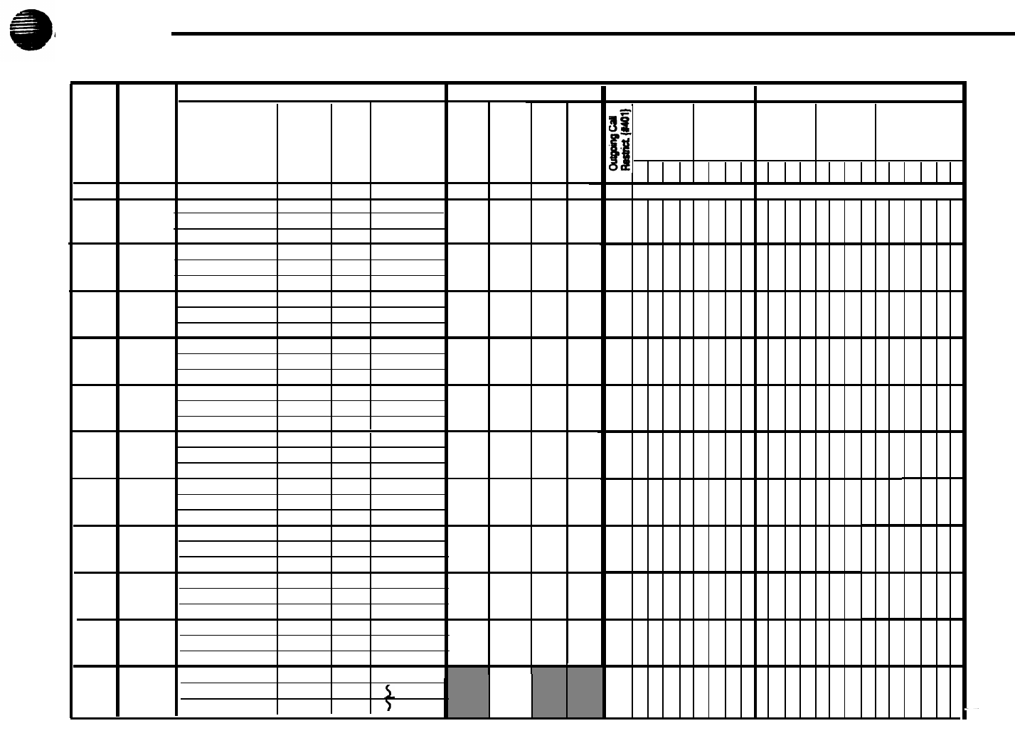
Form B2 Instructions: Customized Extension Settings
Each row on this form specifies settings—Including line assignments—that are
the same for all extensions om a User Group (such as "Managers" or "Fax
Extensions”). After programming one extension, those settings can be copied to
other extensions in the group using
Copy Settings {#399}.
Extensions with identical settings should belong to the same group; If a single
extension has unique settings, it should be put into a group by itself. (If you
need more groups, copy this form and fill out additional rows on the copy.)
Default settings are shown at the top of
Form B2.
Settings for Auxiliary Equipment
Assign each type of auxiliary equipment to its own User Group (or more than
one group if devlces of the same type are programmed differently). The follow-
ing settings may be useful for auxiliary equipment
■
For a dedicated line (such as a fax line), assign the line to the equipment
extension and remove it from other extensions.
■
To prevent other extensions from interrupting calls, enter “On” (Assigned) in
the Auto. Ext. Privacy {#304} column.
■
In general, do not assign auxiliary equipment extensions to a Pickup Group,
Calling Group, or Hunt Group, or to the Night Service (see
Form B1).
Settings for a Receptionist's Extension
If a receptionist is to answer calls, for either immediate or delayed call handling,
set up extension 10 as the receptionist’s extension. The line assignments and
line ringing for that extension should be coordinated with settings for other
extensions to determine how calls are handled in your company.
■
lf the receptionist answers all calls
(Immediate call handling),
assign all
lines to extension 10 with immediate ringing. Then assign lines to other
extensions as needed, with no ringing at those extensions. The receptionist
will answer all calls and transfer them to the appropriate extensions. If you
want another extension to answer calls that the receptionist cannot pick up
immediately, assign all ilnes to that extension with delayed ringing.
■
If the receptionist answers calls only when users do not pick up immediately
(delayed call handling), set lines to immediate ringing at user extensions
and to delayed ringing at extension 10.
User Group ID
Enter a letter in this column to identify a User Group-as defined in the
System
Planner Worksheet,
Item 3.
Exts. in Group
List the extensions in the User Group.
Line Settings
If different lines for a User Group should have different settings, specify restric-
tions and ringing for each group of lines as a block (we “Examples” below),
Line Assignment {#301}
Enter Number of Lines from
Form A,
Item 7, after the dash in the Default row
for Line Asssignment. For each User Group, indicate line numbers for all lines to
be assigned. Any personal or dedicated lines can be assigned using
Line
Assignment {#301}.
By default, lines are assigned in numerical order to the
buttons on an MLS- or MLC-model phone, starting with the bottom left button. If
buttons should be assigned in a different order, list the lines in the desired
order.
If unassigned lines are not restricted, they can be accessed using Direct Line
Pickup. To indicate restrictions on unassigned lines, enter “Remove” and the
line numbers in the Line Assignment column, then specify the desired restriction
in the
Line Access Restriction {#302}
column.
Line Access Restriction {#302}
Indicate any restrictions on the use of lines, as follows:
NR – No restrictions (default)
OUT – Outgoing calls only—can receive only transferred calls
IN – Incoming calls only—cannot place outside calls
NOA – No access—cannot place or receive outside calls (but if line is
assigned, button lights show calling activity)
Line Ringing {CTP}
Indicate when lines ring, as follows:
IMM -
Rings immediately (default)
DEL -
Rings after about a 20-second delay
NO
- Does not ring
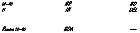
Examples
The following example shows how to assign lines 1-10 with no restrictions and
no ringing, while line 11 is assigned as incoming only with delayed ringing:
Line Assignment Line Access Restriction
Line Ringing
To block an extension from using outside lines, unassign and restrict the lines:
8

Automatic Line Selection {CTP}
Indicate the order in which a line is selected when a user lifts the handset or
presses
[Spkr]
to place a call, without first pressing a line button. For example, if
the order should be outside lines 2, 3, 4, and 1, followed by intercom, enter
“02-04,01,Int.” (Default line selection is outside lines 01– Number of Lines,
followed by the intercom.)
NOTE:
Set standard phones to select intercom first.
Extension Features
These features customize operation for the extensions in a User Group.
Display Lang. {#303} (for MLS-34D, MLS-18D, and MLS-12D phones only)
Indicate the language for display messages:
E-
English (default)
S- Spanish
F-
French
Auto. Ext. Privacy {#304}
By default, any user who shares a line can join calls at another extension
(privacy is Not Assigned). If all calls are to be private, write “On” (Assigned) in
this column. This feature should always be used for fax and modem extensions.
Abbr. Ring {#305}
(system phones only)
By default, a new call rings only once when the phone is in use (abbreviated
ringing is Active); the line button light flashes until the call is picked up or the
caller hangs up. To change the default so a new call rings repeatedly, write
“Off” (Not Active) in this column.
Forced Acct. Code Entry {#307}
(system phones only)
If a user should be required to enter an account code before placing outside
calls, write “On” (Assigned) in this column.
Restrictions/Permissions
These restrictions and permissions apply to
all
lines at an extension.
Outgoing Call Restriction {#401}
Write NR, IN, or LOC to indicate restrictions, as follows:
NR
- No restrictions (default)
IN
- User can only make intercom calls to other system extensions
LOC -
User can only make intercom and local outside calls (no toll calls)
Any available outside lines can still be used to dial numbers on an Allowed
Phone Number List assigned to the extension, numbers on the Emergency
Phone Number List, or Marked System Speed Dial numbers.
Disallowed Lists {#405}
Check one or more columns to assign a Disallowed Phone Number List (assign
any number of lists to each extension). Specify lists on
Form D;
after a list has
been created, it can be assigned using
Disallowed List Assignments {#405}).
Allowed Lists {#408}
Check one or more columns to assign an Allowed Phone Number list (assign
any number of lists to each extension). Specify lists on
Form D;
after a list has
been created, it can be assigned using
Allowed List Assignments {#408}).
Group Assignments
To assign extensions to any of the following groups (each extension can be in
any number of groups), place check marks in the appropriate columns.
Pickup Groups {#501}
Any extension can answer an outside call ringing at an extension in a Pickup
Group, without knowing which extension is ringing and without being in the
group. (Intercom or transferred calls cannot be picked up.)
Calling Groups {#502}
A user can ring or page (voice signal) all extensions in a Calling Group simulta-
neously. Once an extension answers, the ringing or paging stops at the other
extensions in the group. (Calls cannot be transferred to Calling Groups.)
NOTE:
When you voice signal an extension with an MLS-model phone, the
phone beeps and your voice is heard through its built-in speaker. MLS-model
phones are the only ones that can be voice signaled.
Hunt Groups {#505}
Calls can ring or be transferred to the first non-busy extension in a Hunt Group.
A call rings at an extension for 3 rings; if it is not answered, the call hunts to the
next available extension, continuing until someone answers or the caller hangs
up. (If you voice signal a Hunt Group, only the first extension is signaled; if that
extension does not answer, the call does not keep hunting.)
9
Form C Instructions: Button Programming Templates
Fill out these templates only if button features for users will be programmed
from extension 10 or 11. If multiple phones should have identical button pro-
gramming, fill out a template; then (below the template) list extensions that
should be programmed as shown. After assigning lines on
Form B2,
you can
use
Form C
to note line assignments and to indicate programming for buttons
that do not have lines assigned. Users can program additional features using
the instructions in their Quick Reference Cards.
The templates reproduce the labels for different phone types: MLS-34D, MLS-
18D, MLS-12D/MLS-12™, and MLS-6™/MLC-6 phones. Copy these templates
as needed. You can also fill out phone labels using these templates as a guide.
For your reference, example templates are shown following this page.
A telephone button can be programmed as a line button (to make and answer
calls on an outside line), an Auto Dial button (to dial an outside number, inter-
com number, or PBX/Centrex feature access code with one touch), or a dial-
code feature button (to access a dial-code feature with one touch). Line buttons
must have red and green status lights; some features also require buttons with
lights (see "Button Feature Summary").
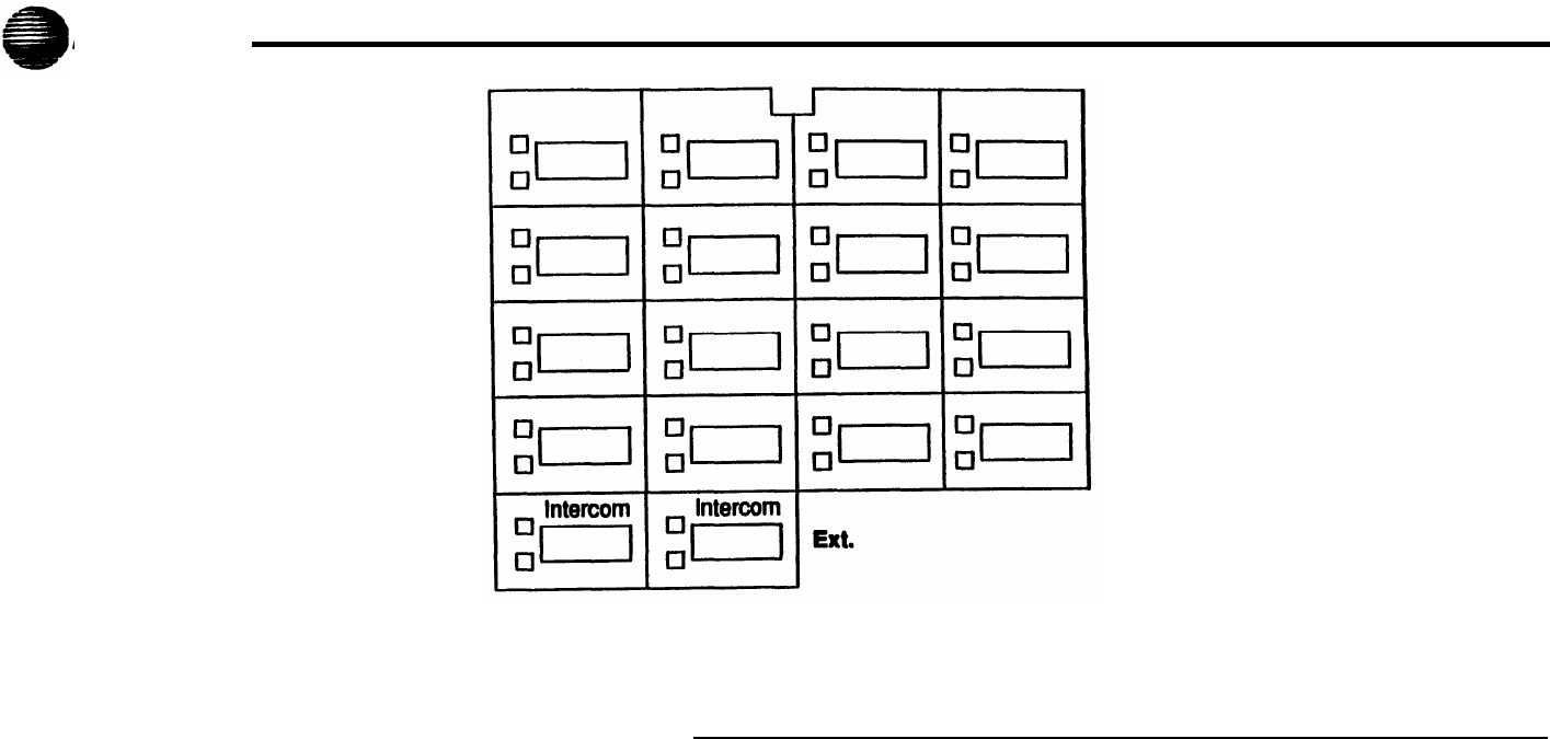
By default, lines are assigned to phone buttons in the following order:
MLS-34D
27
28 29
30
31
32
21
22 23
24 25 26
15
16
17 18 19 20
9
10
11 12 13 14
5678
123 4
MLS-18D, MLS/12D, and MLS-12
NOTE:
On the MLS-12D and MLS-12 phones, only buttons 1–10 are available
for lines and dial-code features that require lights.
13
14
15
16
910
11
12
5678
1234
MLS-6 and MLC-6
1234
The above order also applies to button features which can be assigned to the
first free button, such as a Night Service button.
Line Buttons
Lines are listed on
Form A;
assignments are specified on
Form B2.
On these
templates, note any line information that should appear on phone labels.
Line Assignment
Indicate line jack number for each line above the appropriate button.
Line Access Restriction
Indicate any line restrictions below the button: No Access, IN only, or OUT only
(for more information on restrictions, see
Form B2).
Auto Dial Buttons
Write the number or code to be programmed above the button. Also write the
name or description associated with the number below the button.
DiaI-Code Feature Buttons
Indicate the feature abbreviation (see “Button Feature Summary”), including
where appropriate an extension number—shown as -xx in the feature list—or a
group number—shown as -g. You can also include a description below the
button, as shown below:
Ext.
Record the extension jack number in this space. The extension jack number is
used to place intercom calls to the telephone's user, and is also required when
you program this extension centrally (from extension 10 or 11 ).
Additional Information
Below the label, each template shows summary information for the phone type.
At the bottom of each template, list the extensions that should be programmed
using the template.
10
Example Templates
These examples show an MLS-34D phone programmed for a receptionist, and an MLS-18D Programmed for a user. (The feature codes are explained in “Button
Feature Summary,” beginning on the next page.) The receptionist's phone i
S
for a system with 8 lines and 19 extensions; there are Intercom Calling buttons for
extensions 11–28, a Fax Management button for extension 29, and dial-code feature buttons on the top row of buttons. The user’s phone has only 6 lines as-
signed; buttons that are not used for lines are programmed for auto dialing and dial-code features.
MLS-34D
MLS-18D
11
Button Feature Summary
This section lists features in order by feature name. For each feature, the first
line shows the following information:
[Intercom]
xx
■
A feature abbreviation that can be entered on the
Form C
templates.
■
A symbol indicating whether a button with lights is required or recom-
mended
■
The name of the feature.
■
The entries required to program the feature on a button. Some features can
include a two-digit extension number (shown as xx) or a single-digit group
number (shown as g).
Extension 10 Features
A Night Service button can be assigned only to the telephone at extension 10.
Auto Dialing and dial-code features can also be used at extension 10; of
particular interest are the Intercom Calling features, which use button lights to
show extension calling activity.
NightSvc
Night Service Button
{Sys. Prog. #503}
Turns Night Service on and off. (When the feature is active, the button light is on.)
Phones In the Night Service Group ring immediately when the feature is in use,
regardless of normal ringing options. To use Night Service, the phone at extension 10
must be programmed with a Night Service button. Group extensions should be identified
on
Form B1 .
Auto Dialing Features
Auto Dial numbers can include the digits
[0]
–
[9], [*], [#],
and special functions that
you can include by pressing
[Hold]
(Pause),
[Mic]
(Stop),
[Spkr]
(Recall), and
[Transfer]
(Touch-Tone Enable). (To store an intercom number, you must also press the
left
[Intercom]
button before entering the extension number.) Only one Auto Dial
number for an extension can be stored on the buttons available at an extension
(on both the phone and Intercom Autodialer).
xxx-xxxx Auto Dialing (Outside Phone Number)
Places a call to an outside number. If a dial-out code is required to dial outside numbers
(for example, on PBX or Centrex lines), include it in the stored number.
xxx(NAME)
Auto Dialing (PBX/Centrex Feature Code)
Dials a PBX/Centrex feature code. On the template, write the feature code followed by
the name of the feature. To program the button so that you can access the feature while
on a call, write R on the template before the feature code, to have a Recall signal
Included on the Auto Dial button.
Fax- xx
Fax Management
Allows the user to transfer calls to the fax machine with one touch. (If on a button with
lights, the lights show when the fax is busy or when it is having trouble and not
anewerlng—for example, when it is out of paper.) On the template, indicate the
extension number for the fax. For example, if the fax is connected to extension 29, enter
Fax-29.
Ext- xx
Intercom Calling—Ring
[Intercom]
xx
Places a ringing intercom call to an extension. (If on a button with lights the lights show
calling activity at the extension.) On the template, indicate the extension number.
ExtVs-
xx
lntercom Calling—Voice Signal
[Intercom] [*]
xx
Places a voice-signaled intercom call to an extension's phone speaker. (If on a button
with lights, the lights show calling activity at the extension.) On the template, Indicate the
extension number.
Dial-Code Features
ACE
Account Code Entry
[Feature] [1] [2]
Allows a user to enter an account code for a call by pressing the button, entering up to
16 digits for the account code, and then pressing the button again. (If on a button with
lights, the lights show when the feature is in use.)
CF Call Forwarding
[Feature] [1] [1]
Forwards all calls to another extension. (If on a button with lights, the lights show when
the feature is in use.) Unless Do Not Disturb is on, phone beeps once each time a call is
forwarded.
Pickup- xx
Call Pickup
[Intercom] [6]
xx
Picks up a call ringing at a specific system extension. On the template, indicate the
number of the extension for which the button wiII pick up calls.
Drop Conference Drop
[Feature] [0] [6]
Drops the last outside party added to a conference call.
DLP Direct Line Pickup—Active Line
[Intercom] [6] [8]
Accesses a ringing, active, or held call on a line that is not assigned to the extension.
DLPI Direct Line Pickup—Idle Line
[Intercom] [8]
Accesses an Idle (non-busy) line that is not assigned to the extension.
DND
Do Not Disturb
[Feature] [0] [1]
Prevents calls from ringing at the extension. (When the feature Is active, the button light
is on.) Transferred calls return to sender, Intercom calls get a busy signal, and outside
callers hear ringing. Use only If someone else answers the extension’s outside calls.
12

ExHold Exclusive Hold
[Feature] [0] [2]
Places a call on hold and prevents other extensions with the line from picking it up.
[Intercom] [7] [0]
Gcall- g
Group Calling-Ring
[Intercom] [7]
g
Places a ringing intercom call to all extensions in a Calling Group. The caller is
connected to the first extension that answers. Indicate the group number (1–4) on the
template.
GCallP- g
Group Calllng-Page
[Intercom] [*] [7]
g
Places a voice-signaled intercom call to page all extensions in a Calling Group. The
caller is connected to the first extension that answers. Indicate the group number (1–4)
on the template.
Hunt- g
Group Hunting—Ring
[Intercom] [7] [7]
g
Rings the first available extension in a Hunt Group. indicate the group number (1–-6) on
the template.
HuntVS- g
Group Hunting—Voice Signal
[Intercom] [*] [7] [7]
g
Voice signals the first available extension in a Hunt Group. The caller is connected only if
that extension answers. Indicate the group number (1–6) on the template.
P/U Grp- g
Group Pickup
[Intercom] [6] [6]
g
Picks up an outside call ringing at any extension in a Pickup Group. Indicate the group
number (1–-4) on the template.
LNR
Last Number Redial
[Feature] [0] [5]
Automatically redials the last outside number dialed. (This feature can be used to redial
only the last outside number dialed.)
Loudspk
Loudspeaker Paging
Connects the user to the loudspeaker paging system, if one is connected to the system,
MsgOff Message Light Off
[Feature] [1] [0]
Turns off the message light on MLS- and MLC-model phones.
MsgOn Message Light On
[Feature] [0] [9]
Turns on the message light on MLS- and MLC-model phones.
Priv
Privacy
[Feature] [0] [7]
Prevents other people with the same line from joining calls being conducted at this
extension. (When the feature is active, the button light is on.)
Recall
Recall
[Feature] [0] [3]
“Recalls” a dial tone. A user can use this feature to access a PBX/Centrex feature while
on a call on a PBX/Centrex line (pressing Recall disconnects an intercom call).
SNR Save Number Radial
[Feature] [0] [4]
This feature can be programmed onto more than one button. Using this feature while on
an outside call saves the number dialed into temporary memory. The number stays in
memory until a different one is saved; this feature can be used again to redial the
number at anytime. (Unlike Last Number Redial, you must use this feature to save the
number as well as to redial it; Save Number Redial lets you make other outside calls
before redialing the saved number.)
TT-EN Touch-Tone Enable
[Feature] [0] [8]
Lets users with rotary lines access phone services that require touch-tone digits. For
example, after calling a bank-by-phone service and being prompted to enter touch-tone
digits, using this feature changes the digits dialed to touch tones for the rest of the call.
13
Form D Instructions: Disallowed, Allowed and Emergency Telephone Numbers
NOTE:
To restrict long-distance calling, the
Toll Call Prefix {#402}
(indicating
whether you must dial a 0 or 1 to place toll calls) must be set correctly.
Use this form to specify lists of Disallowed, and Emergency telephone
number. By combining restrictions and Disallowed number with selected
exceptions (including Allowed number, Marked System Speed Dial numbers,
and Emergency numbers), you can control outgoing call traffic and associated
costs without placing unreasonable constraints on you staff.
Creating Disallowed and Allowed Lists
You can create up to 4 lists each of Disallowed and Allowed telephone num-
bers. Each list can have up to 10 entries; each entry can be up to 12 digits long,
including the digits
[0]–[9]
and
[Hold]
(to represent any single digit).
1. Under the List number, write a name for the list (for example, "Suppliers").
2. Under “Telephone Number" write the entries for the list. You can specify
complete telephone numbers or categories of numbers.
■
To specify a complete number,
write it exactly as it would be dialed,
including (if needed) a dial-out code, toll call prefix, and area code.
■
To specify a category,
provide one or more entries to describe an entire
class of calls (such as an area code or local exchange). Preventing calls
to a category may require more than one entry, to allow for different ways
of dialing a number (see “Examples of Disallowed List Entries” below).
After a list has been created, it must be assigned to an extension. (List assign-
ments are specified on
Form B2.)
Disallowed Phone Number Lists {MM}
With Disallowed lists, you can prevent users from dialing specific telephone
numbers or categories )for example, calls to 976 exchanges for pre-recorded
messages such as horoscopes, and calls to 900 area code "chat lines").
Examples of Disallowed List Entries
Preventing Calls to 976 Numbers (Local Exchange)
In this example, !0! and !1! represent “any area code.”
Entries needed . . . if 0 of 1 is required if 0 or 1 is not required
976
976
0976
!0!976
1976
!1!976
0!1!976
0!0!976
1!1!976
1!0!976
Preventing Calls to 900 Area Code
Entries needed... if 0 or 1 is required
if 0 or 1 is not required
0900 900
1900
Preventing International (011) Calls
Entry needed...
011
Allowed Phone Number Lists {#407}
Allowed telephone numbers are exceptions to restrictions. For example, you
might put 976 numbers on a Disallowed list, but allow dialing of 978-1212 for
weather reports. Or you might restrict an extension to local dialing only, but
assign an Allowed list to permit the user to call specific customers or suppliers.
Emergency Phone Number List {#406]
You can create a single list of emergency numbers that can be dialed at any
time by any extension that has access to an outside line. The list can have up to
10 entries; each entry can be up to 12 digits long, including the digits
[0]–[9]
Emergency numbers override all other dialing restrictions, including Night
Service with a System Password.
NOTE:
Various factors influence the effectiveness of dialing restrictions. Avoid
putting 800 numbers in your Emergency Phone Number List. If you need to
allow restricted users to access 800 numbers, put those numbers in an Allowed
Phone Number List Instead.
Important Notices
■
Consult your local phone directory to determine the numbers for police, fire,
and ambulance service, because "911“ is not available everywhere.
■
When programming emergency numbers and/or making test calls to emer-
gency numbers:
1. Stay on the line and briefly explain to the dispatcher the reason for the call
before hanging up.
2. Perform such activities during off-peak hours, such as in the early rooming
or late evening.
Example Emergency List
911
611
(local phone company service)
555-2345
(Boss's home)
555-4567
(auto club)
555-1357
(company doctor)
14
Form E Instructions: Speed Dial Numbers
With Speed Dialing, a user can dial a stored number by pressing three buttons:
the
[Feature]
button (
[#]
on a standard phone) followed by a 2-digit code. Storing a
telephone number as a Speed Dial number lets users dial more quickly. You
can also store other kinds of numbers—such as account codes and other
dialing sequences-as Speed Dial numbers. The system allows up to 60
System Speed Dial numbers that everyone on the system can use, as well as
up to 20 Personal Speed Dial numbers for each extension (for the personal use
of the extension).
Please have the
System Speed Dial Numbers
Form filled out when the
technician arrives to install the system. After installation, photocopy this form
and distribute a copy to everyone using the system. Users should keep this
form near their phones for reference when placing calls.
System Speed Dial Numbers
Each System Speed Dial number is assigned a 2-digit code from 20–79. For
example, suppose your staff frequently calls Acme Supplies and you store
Acme’s telephone number for code 20. To call Acme, a user simply dials
[Feature]
[2] [0].
If Acme moves, or the phone number changes, you program the new
telephone number and users still dial
[Feature] [2] [0]
to reach them.
On the top of
Form E,
record the following information for each System Speed
Dial number.
Name/Company
Record the name of the person or company to which the number belongs. For
other types of numbers, such as account codes, enter a description of the
number.
*
Column (Marked Numbers)
If you want users to be able to call a particular System Speed Dial number,
regardless of any dialing restrictions placed on their extensions, “mark” the
number so it can be dialed at all times. Mark the number by placing a check
mark in this column, and by pressing
[*]
before the number when storing it.
For marked numbers, the stored number does not appear on a display phone
when a user dials the Speed Dial code. Account codes cannot be marked.
Number
Store the number exactly as it should be dialed. Numbers can be up to 20
digits, including the digits
[0]–[9], [*], [#],
and the special dialing functions dis-
cussed below. To store a telephone number, include the dial-out code, toll-call
prefix, and area code (if needed), along with the number.
Special Dialing Functions
Function
Key to Press Display
Pause
[Hold]
P
Recall
[Spkr]
R
Stop
[Mic]
S
Touch-Tone Enable
T
Personal Speed Dial Numbers
Description
Pauses for 1.5 seconds
before dialing the rest of the
stored number
Sends a timed switchhook
flash (useful for your
telephone company’s
custom calling features)
Interrupts the diailng
sequence until the code is
dialed again
Sends touch tones on a
rotary line
[Transfer]
In addition to System Speed Dial numbers, each user can have up to 20
Personal Speed Dial numbers (codes 80 to 99) at an extension for personal
use.
If Personal Speed Dial numbers will be programmed from extension 10 or 11,
copy
Form E
after System Speed Dial numbers have been filled in. Then
specify the extension number for which Personal Speed Dial numbers are to be
programmed and record the Personal Speed Dial numbers for that extension.
Personal Speed Dial numbers can be recorded like System Speed Dial num-
bers, except that they cannot be marked.
Alternatively, users can program their own Personal Speed Dial numbers.
15

System Planner Worksheet
This worksheet records basic setup decisions for the system.
2.
3.
1. Lines
a. How many lines (total) will be connected to the system?
b. How many lines will be assigned as personal/dedicated lines?
c. How many lines will be assigned to all extensions? (1a–1b=1c)
Call Handling
Who answers incoming calls for your business during normal business hours? (Check 2a or 2b)
a. Individual users (all extensions)
b. Central receptionist (extension 10)
Customizing Extension Settings
Your system is installed with default settings to support basic operation (see
Form B2);
however,
you can change settings to customize extensions for system users. In addition, you can simplify
extension programming by dividing users into groups-after programming one extension, simply
copy those settings to other extensions in the group.
■
■
■
In the User Group column below, use Rows C–J to identify User Groups-such as “Managers” or
“Sales”-for which customized extension settings are needed.
All members of a group should have the same type of phones (see
Form C
templates), calling
features, and dialing restrictions. If any of the settings on
Form B2
need to be different for one or
more extensions, put the affected extensions(s) in a separate group. (For example, if an exten-
sion will have a personal/dedicated line, assign that extension to its own group.)
If you need to define more groups than you can enter on Rows C–J, list the additional groups
below Row K or on the back of this page.
In the Number of Users column, indicate how many users fit into each group.
In the Phone Type column, note the type of phone (MLS-34D, MLS-18D, MLS-12D/MLS-12, or
MLS-6/MLC-6) to be installed for users in the group. For purposes of extension programming,
the MLS-6 and MLC-6 phones are identical. Likewise, theMLS-12D andMLS-12 are identical
except that the MLS-12D has a display.
User Group
A. Receptionist
B. Basic Users
C.
D.
E.
F.
G.
H.
L.
J.
K. Standard Phone Users
Number of Users Phone Type
Standard
1a
1b
1c
2a
2b
16
AT&T
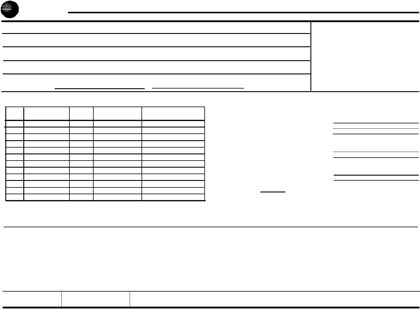
Form A: System Configuration
1. Customer Billing Name 6. Features Customer is Most Interested In
(most Important first)
2. Istallation Address
3. Contact Name
Phone
()-
4. Person to be Trained Phone Alternate Trainee's Name Phone
()-()-
5. Sold by
❑
AT&T Sales Force
Salesperson's Name Phone
❑
Dealer:
()-
7. System Lines
Number of Lines {104} ______
Line
Jack No.
Line Type Subscription Services
Telephone Number
{#201}
Line Owner {#301}
01
02
03
04
05
06
07
08
09
10
11
12
8.
9.
❑
❑
❑
❑
❑
❑
System Settings. Check if applicable:
Transfer Return Rings {#105}_____
10. Auxiliary Equipment (Extensions). Check if
applicable:
Outside Conference Denial {#109}
❑
Toll Call Prefix {#402} not required
System Password {#403}
__ __ __ __
Emergency Phone Number List (Form D)
Night Service Button {#503}
❑
Auxiliary Equipment (System). Cheek if
applicable:
❑
❑
❑
❑
❑
❑
❑
Music on Hold {#602}
❑
SMDR Record Type {#608}:
❑
All calls
❑
Outgoing calls only
Loudspeaker Paging
Number of zones
❑
IROB Protectors
EMI Filters
Uninterruptible Power Supply
Caller ID Devices
11. Notes
Hotline {#603}
List pairs of Hotline/alert extensions below:
Doorphone 1 Extension {#604}:______
To signal extensions {#606}:
Doorphone 2 Extension {#605):______
To signal extensions {#606}:
PARTNER Attendant {#607}
12. Installation Date 13. Order Nos.
14. Sales Support Representative's Name
Telephone
No.
A-1
Form B1: System Extensions
AT&T
Telephone Aux. Eq.
Ext.
Jack
No.
User
Name/Description
Group
ID
Other
Return
Ext.
{#306}
▲
▲
10
11
12
13
14
15
16
17
18
19
20
21
22
23
24
25
26
27
28
29
30
31
32
33
▲ Extension 10 is typically the receptionist's extension. Extension 11 is recommended as a second programming extension (typically the System Manager’s extension).
IMPORTANT: A system display phone (MLS-34D, MLS-18D, or MLS-12D) is required for programming at extension 10 or 11.
Auxiliary Equipment (Other)
AM Answering Machine
DP Doorphone
EX Extra Alert
MD Modem
B-1
AT&T
Form B2: Customized Extension Settings
Line Settings
Extension Features Restrictions/Permissions
Group Assignments
User
Group
ID
Exts. in
Group
Line
Assignment {#301}
Line
Access
Restriction
{#302}
Line
Ringing
{CTP}
Automatic Line
Selection
{CTP}
Display
Lang.
{#303}
Auto.
Ext.
Privacy
{#304}
Abbr.
Ring
{#305}
Forced
Acct.
Code
Entry
{#307}
Disallowed
Lists
{#405}
Allowed
Lists
{#408}
Pickup
Groups
{#501}
Calling
Groups
{#502}
Hunt
Groups
{#505}
1 2 3 4 1 2 3 4 1 2 3 4 1 2 3 4 1 2 3 4 5 6
Default 01-
NR IMM
01-Max., Int.
E Off On Off NR
Net Assigned Net Assigned
Int.,
Std.
Phone
B-2
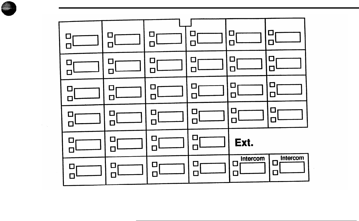
Form C1: Button Programming Template (MLS-34D)
AT&T
This phone provides
Up
to 12 lines 32 line/feature buttons with lights Display
Extensions programmed as shown above:
C-1
AT&T
Form C2: Button Programming Template (MLS-18D)
This phone provides
Up to 12 lines 16 line/feature buttons with lights Display
Extensions programmed as shown above:
C-2
AT&T
Form C3: Button Programming Template (MLS-12D/MLS-12)
This phone provides
Up to 10 lines 10 line/feature buttons with light; 6 additional feature buttons Display on MLS-12D only
Extensions programmed as shown above:
C-3

AT&T
Form C4: Button Programming Template (MLS-6/MLC-6)
This phone provides
Up to 4 lines 4 line/feature buttons with lights No display
Extensions programmed as shown above:
C-4
AT&T
Form D: Disallowed, AIlowed, and Emergency Telephone Numbers
Disallowed Telephone Numbers (#404)
List 1
List 2
List 3
List 4
Entry Telephone Number Entry Telephone Number Entry Telephone Number Entry Telephone Number
01 01
01
01
02 02 02 02
03 03 03 03
04
04
04 04
05 05 05 05
06 06 06 06
07
07
07 07
08 08 08 08
09 09 09 09
10 10 10 10
Entry Telephone Numbers
Allowed Telephone Numbers (Overrides) {#407}
List 1
List 2
List 3
List 4
01
02
03
04
05
06
07
08
09
10
Entry
Telephone Number Entry
Telephone Number
Entry Telephone Number Entry Telephone Number
01
01
01
01
02 02 02
02
03 03 03 03
04 04 04 04
05 05 05 05
06 06 06 06
07 07 07 07
08 08 08 08
09 09 09 09
10 10 10 10
Emergency Telephone Numbers (#406)
D-1
Form E: Speed Dial Numbers
AT&T
To Dial Speed Dial number: On system phones, press [Feature] + 2-digit code. On standard phones, press [#] + 2-digit code while receiving intercom dial tone
System Speed Dial Numbers
Code Name/Company * Number
Code Name/Company
*
Number
Code Name/Company
*
Number
20
21
22
23
24
25
26
27
28
29
30
31
32
33
34
35
36
37
38
39
40
41
42
43
44
45
46
47
48
49
50
51
52
53
54
55
56
57
58
59
60
61
62
63
64
65
66
67
68
69
70
71
72
73
74
75
76
77
78
79
*
You can dial System Speed Dial number that are marked with
*
at any time, regardless of dialing restrictions placed on your extension.
System Speed Dial numbers are programmed by the System Manager (report problems and suggested revisions to your System Manager).
Code
Number
Code
Name/Company
Personal Speed Dial Numbers (Ext.______)
Name/Company
80
81
82
83
84
85
86
87
88
89
To program Speed Dial numbers, see the Quick Reference card.
Number
90
91
92
93
94
95
96
97
98
99
E-1
