Lexmark C720 Color Laser (5024) Parts Catalog
User Manual: Parts Catalog La Biblioteca de los 8 bits
Open the PDF directly: View PDF ![]() .
.
Page Count: 33
- Table of Contents
- Notices and Safety Information
- Preface
- 1. General Information
- Maintenance Approach
- Tools Required for Service
- Serial Number
- Acronyms
- Standard Features
- Printer Identification
- Options Identification
- Printer Theory of Operation
- Printer Systems Description
- Details of the Print System
- Details of the Transfer System
- Details of the Optical System
- Details of the Paper Transportation System
- Control System Structure
- Lower Feed Unit Theory of Operation
- Duplex Theory of Operation
- 2. Diagnostic Information
- Start
- Service Error Codes
- Operator Messages
- Paper Jam Messages
- Symptom Tables
- Printer Service Checks
- 901—Yellow Developer Clutch Service Check
- 902—Magenta Developer Clutch Service Check
- 903—Cyan Developer Clutch Service Check
- 904—Black Developer Clutch Service Check
- 905—Yellow/Black Developer Solenoid Service Check
- 906—Magenta/Cyan Developer Solenoid Service Check
- 907—Toner Empty Sensor P.W.B. Board Service Check
- 910—Developer Motor (DM) Drive Service Check
- 911—Main Motor (MM) Service Check
- 915—Control Cooling Fan Service Check
- 916—Ozone Fan Service Check
- 917—Fuser Heater Fan Service Check
- 918—Erase Lamp Service Check
- 920, 922, 923—Fuser Unit Service Check
- 921—Fuser Thermistor Service Check
- 981—Duplex Motor (DPM1, DPM2) Service Check
- 982—Duplex Upper Solenoid (DSOL-U) Service Check
- 983— Duplex Fan (D-FAN) Service Check
- 984—Duplex Lower Solenoid (DSOL-L) Service Check
- 990—Transfer Drum Encoder Sensor (HPSEN) Service Check
- 991—Transfer Roller Cam Clutch (TRCM) Service Check
- 992—Drum Cleaner Brush Cam Clutch (FBCM) Service Check
- 993—Cleaner Clutch (FBCL) Service Check
- 994—Fuser Clutch (FUCL) Service Check
- 995—OPC Belt Cartridge, Belt Marker Sensor (PBS) Service Check
- 997—High Voltage Power Supply Unit (HVU) Service Check
- OPC Belt (Photo Developer) Cartridge Drive Service Check
- Operator Panel Service Check
- Options No Power Service Check
- Paper Discharge Service Check
- Printer No Power Service Check
- Toner Feed Service Check
- Waste Toner Feed Service Check
- Paper Feed Service Checks
- Print Quality Service Checks
- Background Service Check
- Back Stain Service Check
- Banding Service Check
- Black Line Service Check
- Color Misregistration Service Check
- Insufficient Fusing Service Check
- Insufficient Gloss Service Check
- Jitter Service Check
- Missing Image at Edge Service Check
- Mixed Color Image Service Check
- Mottle Service Check
- Residual Image Service Check
- Ribbing Service Check
- Toner Drop Service Check
- Vertical Line Service Check
- Vertical Staggering Image Service Check
- Vertical White Band Service Check
- White Band Service Check
- White Line I Service Check
- White Line II Service Check
- White Spot / Black Spot Service Check
- White Print Service Check
- Wrinkle / Image Migration Service Check
- Spacing Table
- 3. Diagnostic Aids
- 4. Repair Information
- Removal and Cleaning Precautions
- Handling the Printed Circuit Boards with MOS ICs
- Image Belt Cartridge/OPC
- Adjustments
- Printer Removal Procedures
- Printer Covers
- Upper Side Cover (L) Removal
- Side Cover (R) Removal
- Side Cover (L) Removal
- Side F Cover (L) Removal
- Top Cover Assembly Removal
- Paper Exit Cover / Paper Exit Front Cover / Paper Exit Cover (U) Removal
- Transfer Cover Removal
- Rear Cover Removal
- Rear Cover (U) Removal
- Base Cover (R) Removal
- Base Cover (L) Removal
- Cleaner Cover Removal
- Front Cover Removal
- Printer Board Removals
- Motor Removals
- Clutch and Solenoid Removals
- Sensor Removals
- Interlock Switch (Front) Removal
- Interlock Switch (Top) Removal
- Interlock Switch (Rear) Removal
- Paper Sensor (Paper Feeding Sensor PT1) Removal
- Paper Exit Sensor (PT2) Removal
- Paper Empty Sensor (PEU) / OHP Sensor (OHP) Removal
- Paper Size Sensor (PSU) Removal
- Drum Jam Sensor (DPJ) Removal
- Oil Sensor (OIL) Removal
- Drum Encoder Sensor (HPSEN) Removal
- Belt Sensor (PBS) Removal
- Waste Toner Sensor (TBLE/TBFL) (Waste Toner Holder Assembly) Removal
- Toner Sensor Assembly (TPD) / (TTR) Removal
- Cleaning Roller Sensor (FCS) Removal
- Paper Full Sensor (PFUL) Removal
- Toner Key Sensor (TNK) Removal
- Transfer Unit (Rollers and Drum) Removal
- Transfer Unit Removal
- Registration Roller Removal
- Transfer Drum Removal
- Paper Feed Roller / Separator Pad Removal
- Front Cover Unit Removal
- Paper Exit Unit / Paper Exit Roller Removal
- Discharger Brush Removal
- Waste Toner Feeder (U) (Stay 'A' Assembly) Removal
- Fuser Connector Removal
- Waste Toner Feeder (L) Removal
- Fuser Unit Removal
- Lower Feeder Unit (LFU) Removals
- Lower Feeder Unit Top Cover (R) Removal
- Lower Feeder Unit Top Cover (L) Removal
- Lower Feeder Unit Front Top Cover Removal
- Lower Feeder Unit Base Cover (R) Removal
- Lower Feeder Unit Base Cover (L) Removal
- Lower Feeder Unit Paper Sensor Removal
- Lower Feeder Unit Paper Size Sensor (SL-PS -A57 P.W.B. Assembly) Removal
- Lower Feeder Unit Paper Feed Clutch (PKCLL) / LF Clutch (DPKCL) Removal
- Lower Feeder Unit Paper Feeder Rolling / Separator Pad Removal
- Duplex Cover and Paper Guide Removals
- Duplex Side Cover Low (R) Removal
- Duplex Side Cover Low (L) Removal
- Duplex Cover Top (R) Removal
- Duplex Cover Top (L) Removal
- Duplex Cover Top (B) Assembly Removal
- Duplex Cover Top (C) Assembly Removal
- Duplex Cover Low (B) Assembly Removal
- Duplex Bottom Cover Assembly Removal
- Duplex Paper Guide RVS Unit Removal
- Duplex Paper Guide RVS IN Removal
- Duplex Paper Guide Bottom Removal
- Duplex Paper Top Assembly (D-Top Unit and D-Lower Unit) Removal
- Duplex Paper Guide Top Assembly Removal
- Duplex Print P.W.B. Removal
- Duplex Relay P.W.B. Removal
- Duplex Motor 1 Removal
- Duplex Motor 2 Removal
- Duplex Fan Motor Removal
- Duplex Solenoid (U) Assembly Removal
- Duplex Solenoid (L) Assembly Removal
- Duplex Interlock Switch (D-SW1, D-SW2) Removal
- Duplex Interlock Switch (D-SW3, D-SW4) Removal
- Duplex D Paper Sensor (PT5) Removal
- Duplex Paper Sensor Low (PT4) Removal
- 5. Locations
- Printer
- Options
- Electronic Components
- Sensor Locations
- Printer Circuit Board Locations
- Fan/Motor Locations
- Solenoid/Clutch Locations
- Symbol and Part Name Table
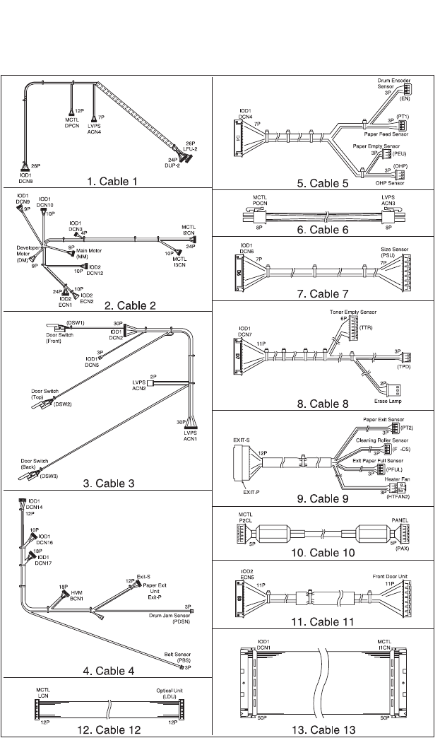
- Wiring Diagram / Cable Harness Reference
- Controller RIP Card
- Main Engine (MCTL P.W.B.) Board
- IOD1 P.W.B. Board
- IOD2 P.W.B. Board
- Low Voltage Power Supply (LVPS) Board
- High Voltage Unit (HVU) Board
- Fuser Unit (LVPS) Board
- Connector Locations for Options
- Connector Pin Assignments
- Location 1
- Location 2
- Location 3
- Location 4
- Location 5
- Location 6
- Location 7
- Location 8
- Location 9
- Location 10
- Location 11
- Location 12
- Location 13
- Location 14
- Location 15
- Location 16
- Location 17
- Location 18
- Location 19
- Location 20
- Location 21
- Location 22
- Location 23
- Location 24
- Location 25
- Location 26
- Location 27
- Location 28
- Location 29
- Location 30
- Location 31
- Location 32
- Location 33
- Location 34
- Location 35
- Location 36
- Location 37
- Location 38
- Location 39
- Location 40
- Location 41
- Location 42
- Printer Cables
- Cable 1 Connector Assignments
- Cable 2 Connector Assignments
- Cable 3 Connector Assignments
- Cable 4 Connector Assignments
- Cable 5 Connector Assignments
- Cable 6 Connector Assignments
- Cable 7 Connector Assignments
- Cable 8 Connector Assignments
- Cable 9 Connector Assignments
- Cable 10 Connector Assignments
- Cable 11 Connector Assignments
- Cable 12 Connector Assignments
- Cable 13 Connector Assignments
- 6. Preventive Maintenance
- 7. Parts Catalog
- Index

Lexmark C720
5024-001
Extracted From Service Manual
U.S.A. P/N: 12G3667
5024-001
Edition: March 2001
The following paragraph does not apply to any country where such provisions are
inconsistent with local law: LEXMARK INTERNATIONAL, INC. PROVIDES THIS
PUBLICATION “AS IS” WITHOUT WARRANTY OF ANY KIND, EITHER EXPRESS OR
IMPLIED, INCLUDING, BUT NOT LIMITED TO, THE IMPLIED WARRANTIES OF
MERCHANTABILITY OR FITNESS FOR A PARTICULAR PURPOSE. Some states do
not allow disclaimer of express or implied warranties in certain transactions; therefore,
this statement may not apply to you.
This publication could include technical inaccuracies or typographical errors. Changes
are periodically made to the information herein; these changes will be incorporated in
later editions. Improvements or changes in the products or the programs described may
be made at any time.
Comments may be addressed to Lexmark International, Inc., Department D22A/032-2,
740 West New Circle Road, Lexington, Kentucky 40550, U.S.A or e-mail at
ServiceInfoAndTraining@Lexmark.com. Lexmark may use or distribute any of the
information you supply in any way it believes appropriate without incurring any obligation
to you. You can purchase additional copies of publications related to this product by
calling 1-800-553-9727. In other countries, contact your point of purchase.
Lexmark, Lexmark with diamond design, MarkNet, and MarkVision are trademarks of
Lexmark International, Inc., registered in the United States and/or other countries.
PCL is a registered trademark of the Hewlett-Packard Company.
PostScript is a registered trademark of Adobe Systems Incorporated.
Other trademarks are the property of their respective owners.
© Copyright Lexmark International, Inc. 2001.
All rights reserved.
UNITED STATES GOVERNMENT RESTRICTED RIGHTS
This software and documentation are provided with RESTRICTED RIGHTS. Use,
duplication or disclosure by the Government is subject to restrictions as set forth in
subparagraph (c)(1)(ii) of the Rights in Technical Data and Computer Software clause at
DFARS 252.227-7013 and in applicable FAR provisions: Lexmark International, Inc.,
Lexington, KY 40550.

Parts Catalog 7-1
5024-001
7. Parts Catalog
How to Use this Parts Catalog
•SIMILAR ASSEMBLIES: If two assemblies contain a majority of
identical parts, they are shown on the same list. Common parts
are shown by one index number. Parts peculiar to one or the
other of the assemblies are listed separately and identified by
description.
•AR: (As Required) in the Units column indicates that the
quantity is not the same for all machines.
•NP: (Non-Procurable) in the Units column indicates that the part
is non-procurable and that the individual parts or the next higher
assembly should be ordered.
•NR: (Not Recommended) in the Units column indicates that the
part is procurable but not recommended for field replacement,
and that the next higher assembly should be ordered.
•R: (Restricted) in the Units column indicates that the part has a
restricted availability.
•NS: (Not Shown) in the Ref column indicates that the part is
procurable but is not pictured in the illustration.
•PP: (Parts Packet) in the Description column indicates that the
part is contained in a parts packet.
•A part reference within a circle indicates an assembly or a bill-
of-material. An assembly is complete. A bill-of-material contains
unassembled parts.
•NA: Not available/not referenced.
Parts Catalog 7-2
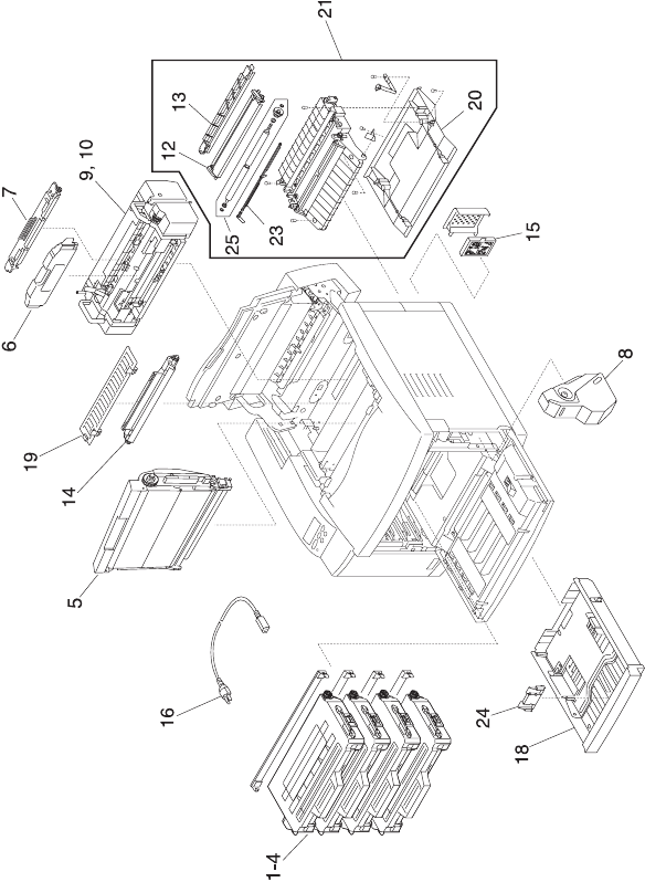
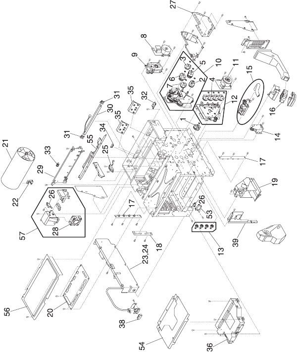
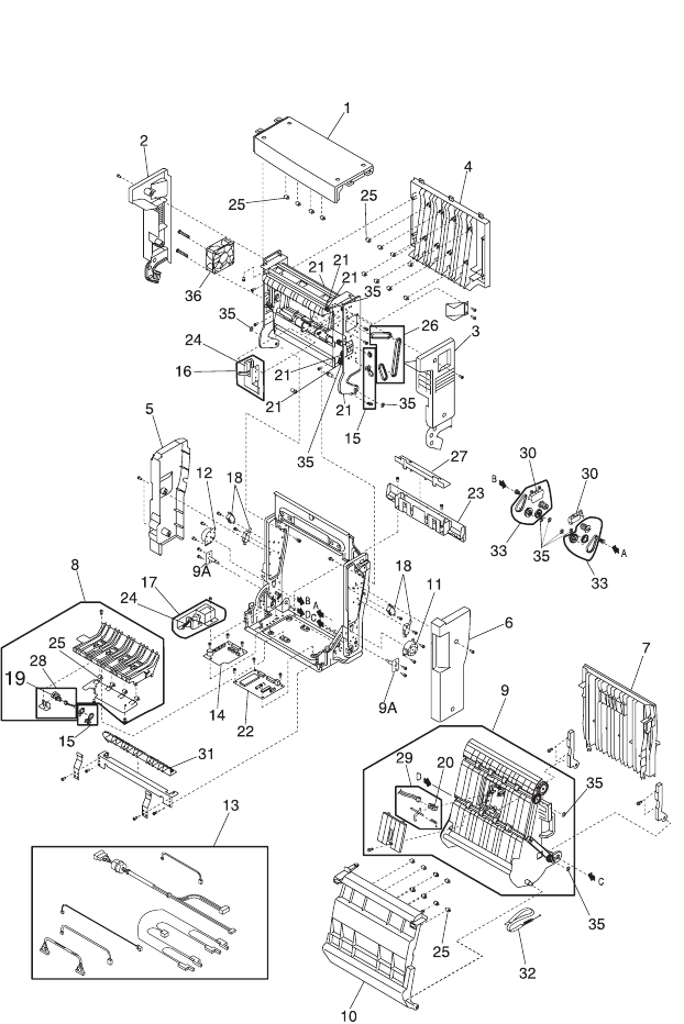
Assembly 1:

Parts Catalog 7-3
5024-001
Assembly 1:
Ref Part
Number Units Description
1 - 1 1 Toner Cartridge -Y
(Supply, customer order only)
21
Toner Cartridge -M
(Supply, customer order only)
31
Toner Cartridge -C
(Supply, customer order only)
41
Toner Cartridge -K
(Supply, customer order only)
51
OPC Belt Cartridge
(Supply, customer order only)
61
Fuser Oil Bottle
(Supply, customer order only)
71
Fuser Cleaner
(Supply, customer order only)
81
Waste Toner-P
(Supply, customer order only)
91
Fusing Unit (110V)
(Supply, customer order only)
10 1 Fusing Unit (220V)
(Supply, customer order only)
12 12G7004 1 Transfer Roller
13 12G7005 1 Paper Discharger
14 12G7006 1 Drum Cleaner
15 12G7007 1 Ozone Filter
16 12G7008 1 Power Cord (U.S.)
16 1339517 1
Power Cord, LV U.S., APG, Bolivia,
Canada, Columbia, Costa Rica, Ecuador,
EL Salvador, Guatemala, Honduras,
Mexico, Nicaragua, Panama, Peru,
Venezuela
16 1339518 1 Power Cord, HV, Argentina

Parts Catalog 7-4
Assembly 1 (cont.):

Parts Catalog 7-5
5024-001
Assembly 1 (cont.):
Note: Reference the foldout wiring diagram, in the back of this
manual, for cable replacement detailed information. Then go to
Assembly 6 for parts ordering information.
Ref Part
Number Units Description
1 - 16 1339520 1 Power Cord, HV, Brazil
16 1339524 1 Power Cord, HV, Chili
16 1339528 1 Power Cord, HV, UK, Ireland
16 1339529 1
Power Cord, HV, Austria, Belgium, EURO
English, Finland, France, Germany,
Greece, Netherlands, Norway, Poland,
Portugal, Russia, Slovakia/Czech/Hungary
Spain, Sweden, Turkey
16 1339530 1 Power Cord, HV, Israel
16 1339531 1 Power Cord, HV, Switzerland French,
Switzerland German, Switzerland Italian
16 1339532 1 Power Cord, HV, South Africa
16 1339533 1 Power Cord, HV, Italy
16 1339534 1 Power Cord, HV, Denmark
18 12G7010 1 Paper Cassette
18 12G7232 1 Paper Cassette (250 sheet legal)
19 12G7011 1 Cleaner Cover
20 12G7012 1 Transfer Unit Cover
21 12G7013 1 Transfer Unit (includes 12, 13, 20, 23, 25)
23 12G7014 1 PT1 Sensor Lever
24 12G7159 1 Paper Cassette Paper Stop
25 12G7160 1 Registration Roller Assembly
12G7341 1 Parts Packet, Screws
12G7340 1 Parts Packet, Cable Clamps, Retainers,
Miscellaneous
Parts Catalog 7-6
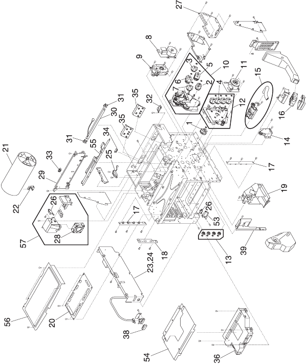
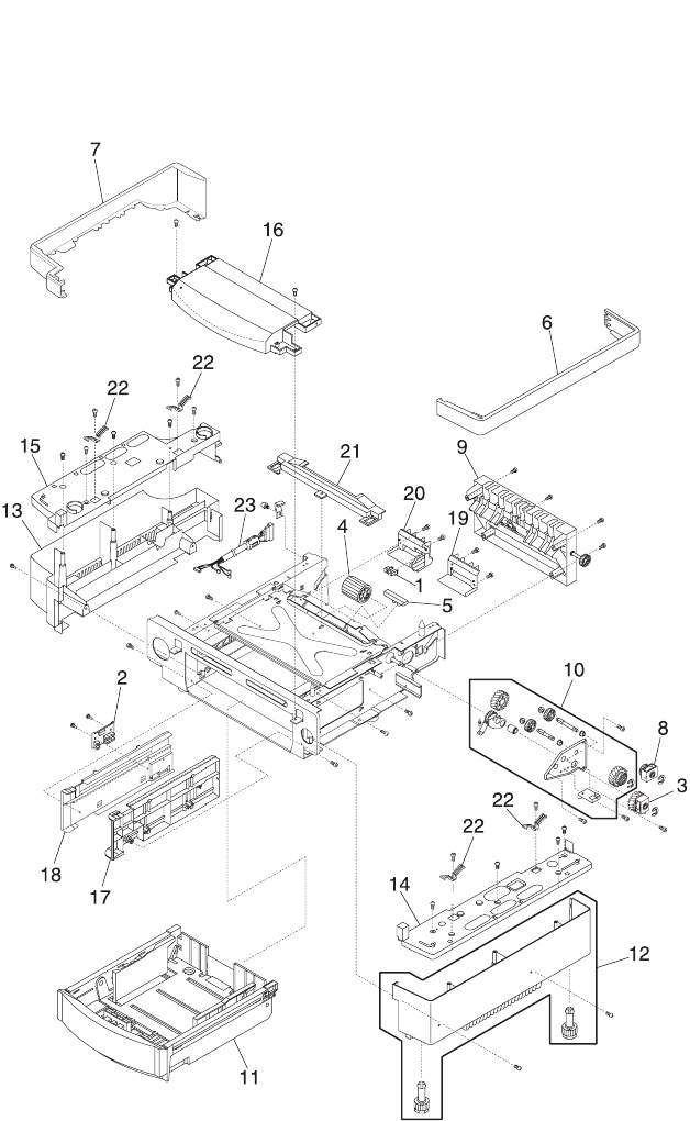
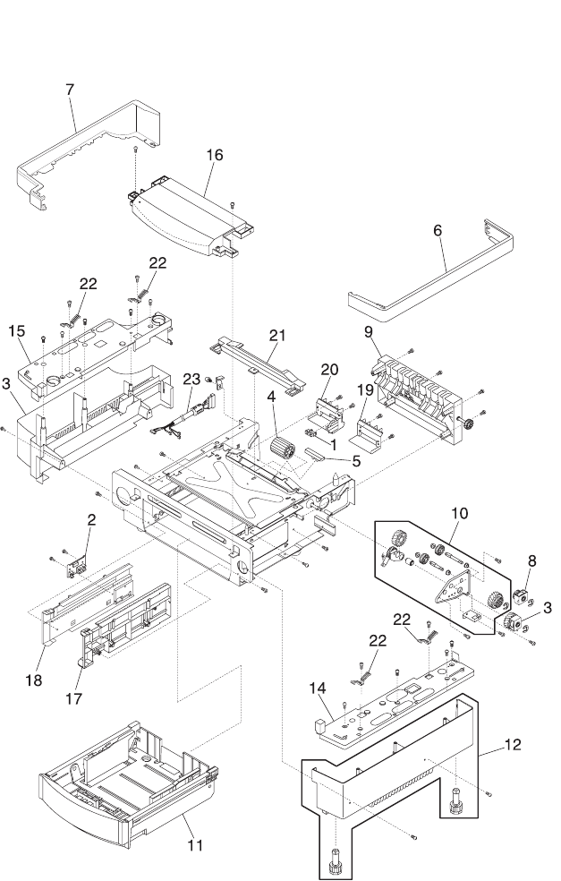
Assembly 2:

Parts Catalog 7-7
5024-001
Assembly 2:
Ref Part Number Units Description
2 - 1 12G7015 1 Top Cover Assembly (includes 35)
2 12G7016 1 Side Cover (R)
3 12G7017 1 Side Cover (L)
4 12G7018 1 Upper Side Cover (L)
5 12G7019 1 Front Cover
6 12G7020 1 Paper Exit Unit Cover (includes 13)
7 12G7021 1 Paper Exit Front Cover
8 12G7022 1 Base Cover (R)
9 12G7023 1 Base Cover (L)
10 12G7024 1 Rear Cover
11 12G7025 1 Rear Cover (U)
12 12G7026 1 Side F Cover (L)
13 12G7027 1 Paper Exit Upper Cover
14 12G7028 2 Rear Cover (U) Cap
15 12G7029 1 Front Cover Unit (includes 5, 45, 47)
16 12G7030 1 Main Engine (MCTL P.W.B.) Board
17 12G7031 1 High Voltage Unit
20 12G7032 1 Discharge Brush
21 12G7033 1 Cooling Fan (HFAN)
22 12G7034 1 Paper Exit Filter (with Case)
23 12G7035 1 Ozone Filter Cover
24 12G7036 1 Paper Sensor (PT2)
25 12G7037 1 Paper Sensor (FCL)
26 12G7038 1 Paper Exit Unit (includes 6, 7, 13, 20, 21,
22, 24, 25, 27, 28, 30, 31, 40, 42)
Parts Catalog 7-8
Assembly 2 (cont.):

Parts Catalog 7-9
5024-001
Assembly 2 (cont.):
Ref Part Number Units Description
2 - 27 12G7039 1 Paper Exit Roller
28 12G7037 1 Paper sensor (PFUL)
29 12G7360 1 Operator Panel Assembly
30 12G7041 1 Paper Exit Gear Z19
31 12G7042 1 FCS Cover Assembly
32 12G7043 1 Paper Size Sensor
33 12G7044 1 BC Terminal 2
34 12G7161 1 Control Panel Base
35 12G7162 1 Paper Exit Button
36 12G7163 1 Shield Cover B
37 12G7164 1 Shield Cover A
38 12G7165 1 Shield Case Assembly
39 12G7166 1 BC Lock Lever (set)
40 12G7167 1 Paper Exit Switch Guide
41 12G7168 1 Paper Exit Frame Assembly
(includes 7,10,24,25,27,28,30,31,40,42)
42 12G7169 1 Paper Exit Idle Roller Set
43 12G7170 1 Paper Exit Harness Cover
44 12G7171 1 IOD Harness Guide
45 12G7172 1 Front Cover Latch
46 12G7173 1 Front Cover/Door Arm Assembly
47 12G7174 1 DE Solenoid Assembly (also order 47A)
47A 12G7036 1 Cam Sensor, DE Solenoid GPH1, GPH2
48 12G7175 1 Front Paper Cassette Guide (L)
49 12G7176 1 Front Paper Cassette Guide (R)
Parts Catalog 7-10
Assembly 2 (cont.):

Parts Catalog 7-11
5024-001
Assembly 2 (cont.):
Note: Reference the foldout wiring diagram, in the back of this
manual, for cable replacement detailed information. Then go to
Assembly 6 for parts ordering information.
Ref Part Number Units Description
2 - 50 12G7177 1 DC Guide L
51 12G7019 1 DC Guide (R)
52 12G7179 1 Waste Toner U Spring
53 12G7180 1 TR Terminal Base Assembly
54 12G7070 1 Interlock Switch
12G7341 1 Parts Packet, Screws
12G7340 1 Parts Packet, Cable Clamps, Retainers,
Miscellaneous
Parts Catalog 7-12
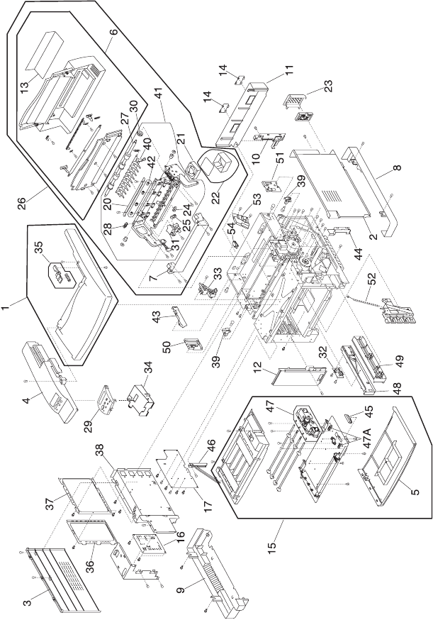
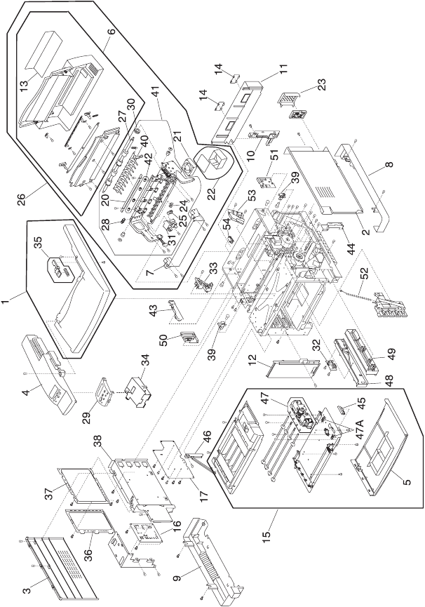
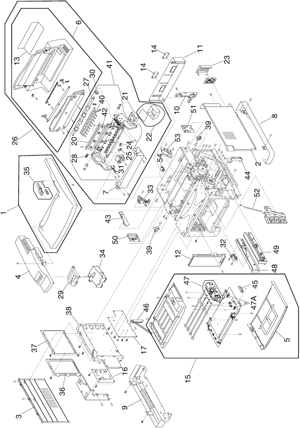
Assembly 3:

Parts Catalog 7-13
5024-001
Assembly 3:
Ref Part Number Units Description
3 - 1 12G7045 1 Paper Feeding Clutch (PCLU)
2 12G7046 1 Registration Clutch (RECL)
3 12G7047 1 Fuser Clutch (FUCL)
4 12G7048 4 Developer Clutch
5 12G7049 1 Transfer Cam Clutch (TRCM)
6 12G7049 1 Cleaner Cam Clutch (FBCM)
7 12G7051 1 Cleaner Clutch (FBCL)
8 12G7052 1 Main Motor (MM)
9 12G7053 1 BD Gear Assembly
10 12G7054 1 Main Gear Unit (includes 2, 3, 5, 6, 7)
11 12G7055 1 Developer Motor (DM)
12 12G7056 1 Developer Drive Unit (includes 4)
13 12G7057 1 Developer Drive Gear (Set)
14 12G7058 1 FP2 Gear Assembly (Front Developer
Solenoid Drive)
15 12G7059 1 Waste Toner Feeder (Lower)
16 12G7060 1 Cooling Fan (OZFAN)
17 12G7061 1 Toner Sensor (TPD, TTR)
18 12G7062 1 Toner Key Sensor (TNK)
19 12G7063 1 Waste Toner Holder Assembly
20 12G7064 1 IOD1 P.W.B.
21 12G7065 1 Transfer Drum
22 12G7037 5 Paper Sensor (Drum Encoder) (HPSEN)
23 12G7067 1 Power Supply Unit (U.S.) 110 V(LVPS)
24 12G7068 1 Power Supply Unit (WT) 220 V (LVPS)
Parts Catalog 7-14
Assembly 3 (cont.):

Parts Catalog 7-15
5024-001
Assembly 3 (cont.):
Note: Reference the foldout wiring diagram, in the back of this
manual, for cable replacement detailed information. Then go to
Assembly 6 for parts ordering information.
Ref Part Number Units Description
3 - 25 12G7069 1 Fuser Connector
26 12G7070 1 Interlock Switch, Front Door
27 12G7073 1 IOD2 P.W.B.
28 12G7074 1 Cooling Fan (CTFAN)
29 12G7075 1 Waste Toner Feeder Unit (Upper)
30 12G7076 1 Erase Lamp
31 12G7077 2 Erase Holder (2 pieces)
32 12G7078 1 Oil Sensor
33 12G7079 1 Belt Sensor (PBS)
34 12G7079 1 Drum Jam Sensor (DPJ)
35 12G7081 2 Paper Guide D (2 pieces)
36 12G7082 1 Optical Unit (Printhead)
38 12G7083 1 SW Button
39 12G7084 1 Cover (FR)
53 12G7181 1 SW Base Front
54 12G7182 1 Inner Cover C
55 12G7183 1 Oil Sensor Cover
56 12G7184 1 Shield Upper
57 12G7185 1 PS Fan Assembly (CTFAN) (includes 26,
28)
12G7341 1 Parts Packet, Screws
12G7340 1 Parts Packet, Cable Clamps, Retainers,
Miscellaneous
Parts Catalog 7-16
Assembly 4:

Parts Catalog 7-17
5024-001
Assembly 4:
Note: Reference the foldout wiring diagram, in the back of this
manual, for cable replacement detailed information. Then go to
Assembly 6 for parts ordering information.
Ref Part
Number Units Description
4 - 1 12G7098 1 Paper Feed Roller
2 12G7099 1 Separator Pad
3 12G7100 1 OHP Sensor
4 12G7037 1 Paper Sensor (PEU)
5 12G7037 1 Paper Sensor (PT1)
6 12G7103 1 Paper Guide (UL) Assembly
7 12G7104 1 Paper Guide (UR)
8 12G7186 1 Transfer Unit Rear Band
9 12G7187 1 Transfer Unit Hinge Support Bracket
10 12G7188 1 Paper Guide L
12G7341 1 Parts Packet, Screws
12G7340 1 Parts Packet, Cable Clamps, Retainers,
Miscellaneous
7-18 Service Manual
5024-001
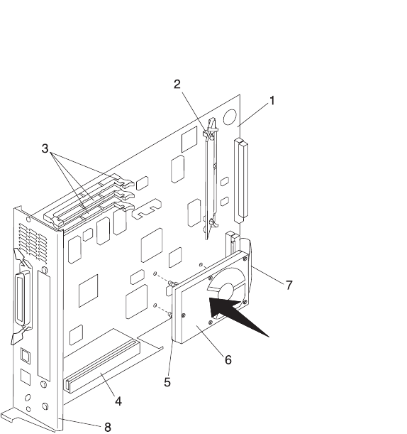
Assembly 5: Controller RIP Card

Parts Catalog 7-19
5024-001
Assembly 5: Controller RIP Card
Note: The standard and network models have listed memory. See
Assembly 7 for part number information.
Ref Part
Number Units Description
5 - 1 12G7226 1 Controller RIP Card Network
1 12G7227 1 Controller RIP Card
2 12G7228 1 SIMM Code
3 99A1752 1 4MB SDRAM DIMM
3 99A1755 1 32MB SDRAM DIMM
4 12G7229 1 Riser Card Assembly
5 12G7231 1 Hard Disk Mounting Bracket
6 99A0459 1 Hard Disk
7 11G0962 1 Hard Disk Cable
8 12G7230 1 Bracket, Controller RIP Card
7-20 Service Manual
5024-001
Assembly 6: Printer Cable Harness Sets

Parts Catalog 7-21
5024-001
Assembly 6: Printer Cable Harness Sets
Note: Reference the foldout wiring diagram, in the back of this
manual, for cable replacement detailed information.
Ref Part
Number Units Description
6 - 1 12G7342 1 Harness WH (A) Wiring Diagram #1
2 12G7343 1 Harness WH (B) Wiring Diagram #2
3 12G7344 1 Harness WH (C) Wiring Diagram #3
4 12G7345 1 Harness WH (D) Wiring Diagram #4
5 12G7346 1 Harness WH (I1/SEN) Wiring Diagram #5
6 12G7347 1 Harness WH (LPC) Wiring Diagram #6
7 12G7348 1 Harness WH (SIZE) Wiring Diagram #7
8 12G7349 1 Harness WH (I1/TO) Wiring Diagram #8
9 12G7350 1 Harness WH (PEX) Wiring Diagram #9
10 12G7351 1 Harness WH (LXPN) Wiring Diagram #10
11 12G7352 1 Harness WH (I2/FD) Wiring Diagram #11
12 12G7353 1 Harness WH (DUAL) Wiring Diagram #12
13 12G7354 1 Harness WH (MC/I1) Wiring Diagram #13

7-22 Service Manual
5024-001
Assembly 7: Miscellaneous
(No illustration)

Parts Catalog 7-23
5024-001
Assembly 7: Miscellaneous
Ref Part Number Units Description
NS 12G1704 1 Card Assembly, SIMM IPDS/SCS/TNE
NS 13A0297 1 Cable, Coax
NS 13A0296 1 Cable, Twinax
NS 99A0459 1 Hard Disk, 2.1GB
NS 99A0545 1 Adapter, Serial
NS 12G1696 1 MarkNet N2000t 4/16 Token Ring
NS 12G1697 1 MarkNet N2002e 10Base2/10BaseT
NS 99A1830 1 MarkNet N2001e 10/100 Ethernet
NS 99A1752 1 4MB SDRAM DIMM
NS 99A1753 1 8MB SDRAM DIMM
NS 99A1754 1 16MB SDRAM DIMM
NS 99A1755 1 32MB SDRAM DIMM
NS 99A1756 1 64MB SDRAM DIMM
NS 99A1773 1 128MB SDRAM DIMM
NS 99A1757 1 2MB Flash DIMM
NS 99A1758 1 4MB Flash DIMM
NS 99A1759 1 8MB Flash DIMM
NS 99A1774 1 16MB Flash DIMM
NS 99A0560 1 Tri-Port Adapter (Serial/LocalTalk and Infrared)
NS 99A0923 1 Board, USB/Parallel Port
NS 99A0467 1 Board, Parallel Port Adapter
NS Relocation Packaging
NS 7366394 1 - Base Printer
NS 7366417 1 - Lower Feed Unit
NS 7366413 1 - Duplex Unit
NS 7366409 1 - Base Printer / Duplex bundle
7-24 Service Manual
5024-001
Assembly 8: Lower Feed Unit

Parts Catalog 7-25
5024-001
Assembly 8: Lower Feed Unit
Ref Part
Number Units Description
8 - 1 12G7037 1 Paper Sensor (PEL)
2 12G7043 1 Paper Size Sensor (PSL)
3 12G7045 1 Paper Feed Clutch (PKCL)
4 12G7098 1 Paper Feed Roller
5 12G7099 1 Separator Pad (2)
6 12G7121 1 LF Side Cover R
7 12G7122 1 LF Side Cover L
8 12G7123 1 LF Clutch Drive, Transport Roller (DPKCL)
9 12G7124 1 LF Rear Cover Assembly (includes Transport
Roll)
10 12G7144 1 Drive Gear Assembly
11 12G7224 1 LF Paper Feed Cassette
12 12G7145 1 LF Base Cover (R) Assembly
13 12G7146 1 LF Base Cover (L)
14 12G7147 1 LF Top Cover (R)
15 12G7148 1 LF Top Cover (L)
16 12G7149 1 LF Front Top Cover
17 12G7150 1 LF Cassette Guide (R)
18 12G7151 1 LF Cassette Guide (L)
-19 12G7152 1 LF Paper Guide (UR)
20 12G7153 1 LF Paper Guide (UL)
21 12G7154 1 LF Rear Top Cover
22 12G7155 1 GND Contacts
23 12G7156 1 Cable Harness
12G7135 1 LFU / Duplex Parts Packet, Screws
7-26 Service Manual
5024-001
Assembly 8 (cont.): Lower Feed Unit (cont.)

Parts Catalog 7-27
5024-001
Assembly 8 (cont.): Lower Feed Unit (cont.)
Note: Reference the foldout wiring diagram, in the back of this
manual, for cable replacement detailed information. Then go to the
assembly for parts ordering information.
Ref Part
Number Units Description
12G7135 1 LFU / Duplex Parts Packet, Screws
12G7136 1 LFU / Duplex Parts Packet, Retainers
12G7137 1 LFU / Duplex Parts Packet, Cable Tie /
Guides
12G7139 1 LFU / Duplex Parts Packet, Springs
7-28 Service Manual
5024-001
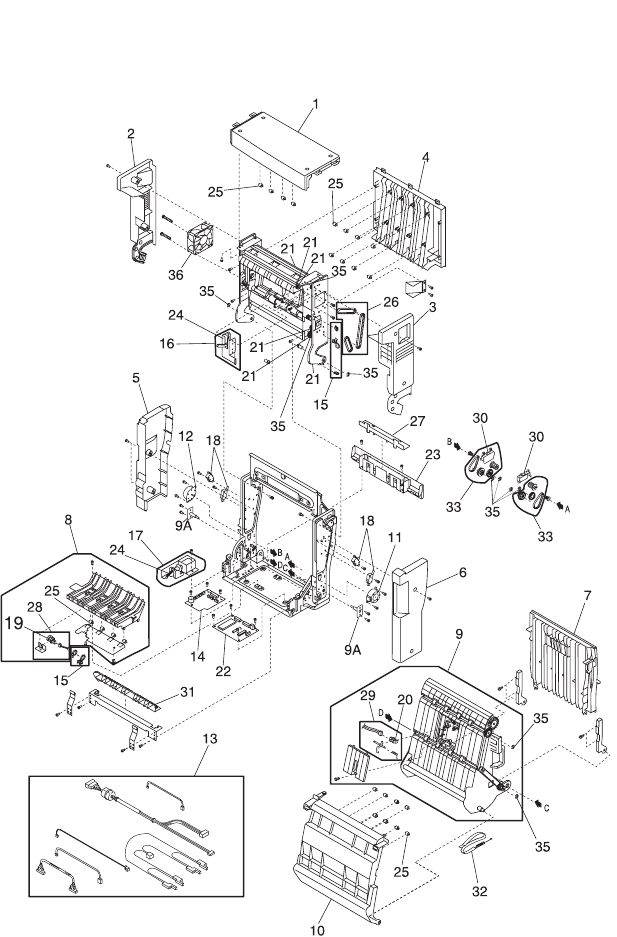
Assembly 9: Duplex Unit

Parts Catalog 7-29
5024-001
Assembly 9: Duplex Unit
Ref Part
Number Units Description
9 - 1 12G7105 1 Cover Top (C) Assembly
2 12G7106 1 Cover Top (L)
3 12G7107 1 Cover Top (R)
4 12G7108 1 Cover Top (B) Assembly
5 12G7109 1 Cover Low (L)
6 12G7110 1 Cover Low (R)
7 12G7111 1 Cover Low (B) Assembly
8 12G7112 1 Paper Guide Bottom Assembly (includes 19,
25, 28)
9 12G7113 1 Paper Guide RVS Assembly (includes 20,
29)
10 12G7114 1 Paper Guide Inner
11 12G7115 1 Motor 1(DPM1)
12 12G7116 1 Motor 2 (DPM2)
13 12G7138 1 4 Cable Bill of Material (Door, P.W.B.-
P.W.B.,I/F, Solenoid, PT4 P.W.B., Fan)
14 12G7117 1 Relay P.W.B.
16 12G7140 1 Solenoid (U) Assembly
17 12G7141 1 Solenoid (L) Assembly
18 12G7070 4 Interlock Switch (DSW1 - DSW4)
19 12G7143 1 D Sensor (PT4)
20 12G7125 1 D Sensor (PT5)
21 12G7118 1 Paper Guide U Assembly (includes printer
reference 26)
22 12G7119 1 DUP P.W.B.
7-30 Service Manual
5024-001
Assembly 9 (cont.): Duplex Unit (cont.)

Parts Catalog 7-31
5024-001
Assembly 9: Duplex Unit
Note: Reference the foldout wiring diagram, in the back of this
manual, for cable replacement detailed information. Then go to the
assembly for parts ordering information.
Ref Part
Number Units Description
9 - 23 12G7120 1 Cover Bottom
24 12G7139 1 Spring (contains 2 springs)
25 12G7126 1 D Roller (contains 20 rollers)
26 12G7127 1 3 Belts
27 12G7128 1 Lid-WH Bottom
28 12G7129 1 D Sensor Bottom Bill of Material
29 12G7130 1 D Sensor Middle Bill of Material
30 12G7131 2 D Gear Cover
31 12G7132 1 Gate Bottom
32 12G7133 1 Band-Spring Set
33 12G7134 2 3 Gears-Belt Set
35 12G7136 1 LFU / Duplex Screw Parts Pack
36 12G7138 1 Fan Motor (DFAN)
12G7135 1 LFU / Duplex Parts Packet, Screws
12G7136 1 LFU / Duplex Parts Packet, Retainers
12G7137 1 LFU / Duplex Parts Packet, Cable Tie /
Guides
12G7139 1 LFU / Duplex Parts Packet, Springs
