VGMII Pass Point Vista Gateway Module
User Manual: PassPoint Vista Gateway Module AlarmHow.net Library
Open the PDF directly: View PDF ![]() .
.
Page Count: 48
K3598 03/99
379*0
3DVV3RLQW9,67$*DWHZD\0RGXOH
,QVWDOODWLRQ6HWXS
$QG8VHU*XLGH
Central
Monitoring
Station
VISTA
Fire/Burglary
Alarm
System
PassPoint
ACS
VGM

ii
Table of Contents
•••••••••••••••••••••••••••••••••••••••••••
Conventions Used in This Manual ........................................................................................................iii
Section 1 - Introduction.........................................................................................................................1–1
General Information.............................................................................................................................1–1
VGM Compatibility...............................................................................................................................1–1
VGM as an Interface.............................................................................................................................1–2
Section 2 - Installing the VGM as an Interface.................................................................................2–1
Wiring VGM to PassPoint ACS and VISTA Panel as an Interface ....................................................2–1
Enrolling/Enabling the VGM ...............................................................................................................2–2
Enrolling the VGM into PassPoint................................................................................................ 2–2
Enabling the VGM in the VISTA FBS.......................................................................................... 2–5
Configuring the VGM ...........................................................................................................................2–6
Defining Test Report Schedules and VGM Interface................................................................... 2–7
Defining VISTA Zones ................................................................................................................... 2–8
Defining the Default VISTA FBS User Number ........................................................................ 2–11
Downloading the Configuration.........................................................................................................2–12
PassPoint ACS/VISTA FBS Event Actions........................................................................................2–13
PassPoint ACS/VISTA FBS Related Events......................................................................................2–14
PassPoint ACS Central Station Reports............................................................................................2–17
Modifying PassPoint Events Reported to Central Station......................................................... 2–18
Downloading the PassPoint Events Reported to Central Station Changes.............................. 2–20
Commonly Used Applications ............................................................................................................2–21
Controlling Access Points with VISTA FBS Keypads & RF Transmitters ............................... 2–21
Assigning VISTA FBS Relays to Access Points.......................................................................... 2–26
Arm VISTA FBS Partition on Access Point Card Swipe............................................................ 2–27
Disarm VISTA FBS Partition on Access Point Card Swipe....................................................... 2–28
Pulse a VISTA FBS Relay on an Access Point or any Access Point Denial............................... 2–29
Disarm a VISTA FBS Partition on an Access Grant.................................................................. 2–29
Lock/Protect an Access Point upon VISTA FBS Burglar Alarm/Restore.................................. 2–30
Synchronize Arming/Disarming of PassPoint ACS and VISTA FBS......................................... 2–31
Bypass/Protect Access Point upon VISTA FBS Fire Alarm/Restore.......................................... 2–33
PassPoint ACS MLB Supervision by the VISTA FBS................................................................ 2–34
Appendix A - Events Reported to Central Station..........................................................................A–1
PassPoint Events Reported to Central Station..................................................................................A–1
VISTA Gateway Module, Summary of Connections............................................Inside Rear Cover

iii
Conventions Used in This Manual
•••••••••••••••••••••••••••••••••••••••••••
Before you begin using this manual, it is important that you understand the meaning of the
following symbols:
ULThese notes include specific information that must be followed if you are installing this
system for a UL Listed application.
A checked note includes information you should be aware of before continuing with the
installation, and which, if not observed, could result in operational difficulties.
This symbol warns of conditions that could seriously affect the operation of the system, or
cause damage to the system. Please read each warning carefully. This symbol also
denotes warnings about physical harm to the user.
PRODUCT MODEL NUMBERS: Unless noted otherwise, references to specific model numbers
represent ADEMCO products.

iv

1–1
SECTION 1
Introduction
••••••••••••••••••••••••••••••••••••••••••••
In This Section
♦General Information
♦VGM Compatibility
♦VGM as an Interface
••••••••••••••••••••••••••••••••••••••••••••
General Information
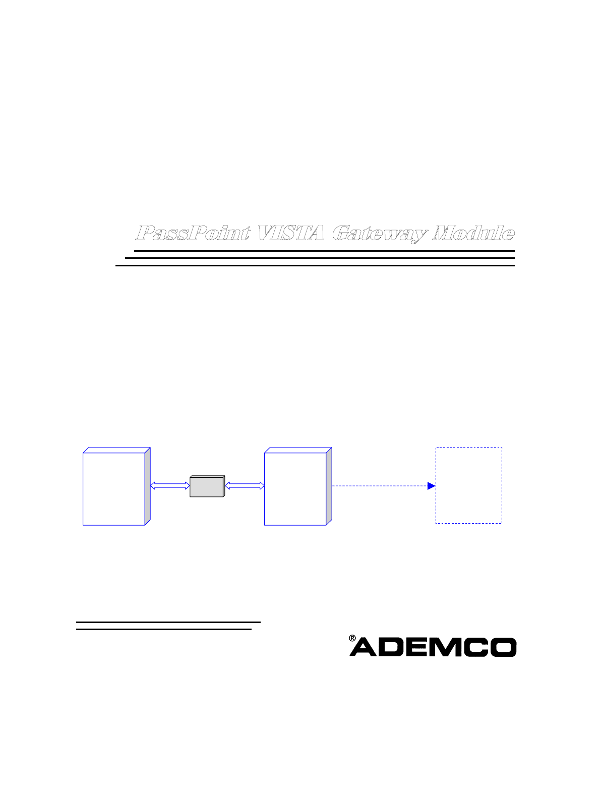
The VISTA Gateway Module (VGM) provides an interface between the ADEMCO
PassPoint Access Control System (PassPoint ACS) and ADEMCO VISTA
Fire/Burglary Alarm System (VISTA FBS). This document identifies some of the
features gained when the systems are interfaced, provides instructions for wiring the
interface, provides instructions for configuring the VGM as an interface, and contains
instructions for programming and using the interfaced systems.
VGM Compatibility
The VGM is compatible with all PassPoint Access Control Systems that have the
proper MLB revision and software version. To determine if your VISTA Fire/Burglary
Alarm System is compatible with the VGM, consult your Alarm System Manuals.
The VGM is compatible with PassPoint Express version 1.1 (or higher) software and a
PassPoint ACS with an MLB revision of 0.98 or higher. If you are not certain of your
PassPoint Express version or PassPoint ACS MLB revision, perform the following.
1. Connect your PassPoint computer to your PassPoint ACS,
2. Left-click your mouse on the Help button.
3. Left-click your mouse on About in the submenu. The About PassPoint Express screen
will be displayed.
4. On the About PassPoint Express screen, left-click on the MLB Info button and MLB
information will be displayed.
5. The MLB revision is listed under MLB Info as Rev. and the PassPoint Express Software
version is listed on the right half of the About PassPoint Express screen as Version.

VGM Installation, Setup, and User Guide
1–2
VGM as an Interface
When the VGM is used to link the PassPoint ACS and VISTA FBS, the VISTA FBS
provides a dialer function for the PassPoint ACS. Dialer events are sent through the
VGM to the VISTA FBS panel, which actually does the dialing. The VISTA FBS panel
supports all of the access control-related Contact ID event codes. In addition, linking
these two systems together allows the behavior of each subsystem to change based
upon status changes or occurring events. The following lists some of the features that
are available when using the VGM to interface between the PassPoint ACS and
VISTA FBS:
•VISTA FBS RF devices, such as RF button remotes, transmitters, wireless keypads,
and motion detectors can control access functions.
•The multitude of zones present in the VISTA FBS expands the capability of the
PassPoint ACS.
•Card users can be programmed to disarm or arm both systems.
•The access point modes of operation (PROTECT, BYPASS, or LOCKED) can be
controlled via the VISTA FBS keypad.
•A fire alarm detected in the VISTA FBS can be programmed via the PassPoint
system to cause the access points to be bypassed enabling fire department
personnel to enter the building.
•An access grant can be programmed to disarm both the VISTA FBS and PassPoint
systems while turning on the lights.
•An egress grant can be programmed to arm both the VISTA FBS and PassPoint
systems and turn off the lights.
•Systems already installed with a VISTA FBS system or PassPoint system can easily
be upgraded by installing the VGM.
Instructions for wiring, configuring the VGM, programming, and using the combined
PassPoint ACS and VISTA FBS are contained in Section 2 of this document.
2–1
SECTION 2
Installing the VGM as an Interface
••••••••••••••••••••••••••••••••••••••••••••
In This Section
♦Wiring VGM to PassPoint ACS and VISTA FBS as an Interface
♦Enrolling/Enabling the VGM
♦Configuring the VGM
♦Downloading the Configuration
♦PassPoint ACS/VISTA FBS Event Actions
♦PassPoint ACS/VISTA Related Events
♦PassPoint ACS Central Station Reports
♦Commonly Used Applications
••••••••••••••••••••••••••••••••••••••••••••
Wiring VGM to PassPoint ACS and VISTA Panel as an Interface
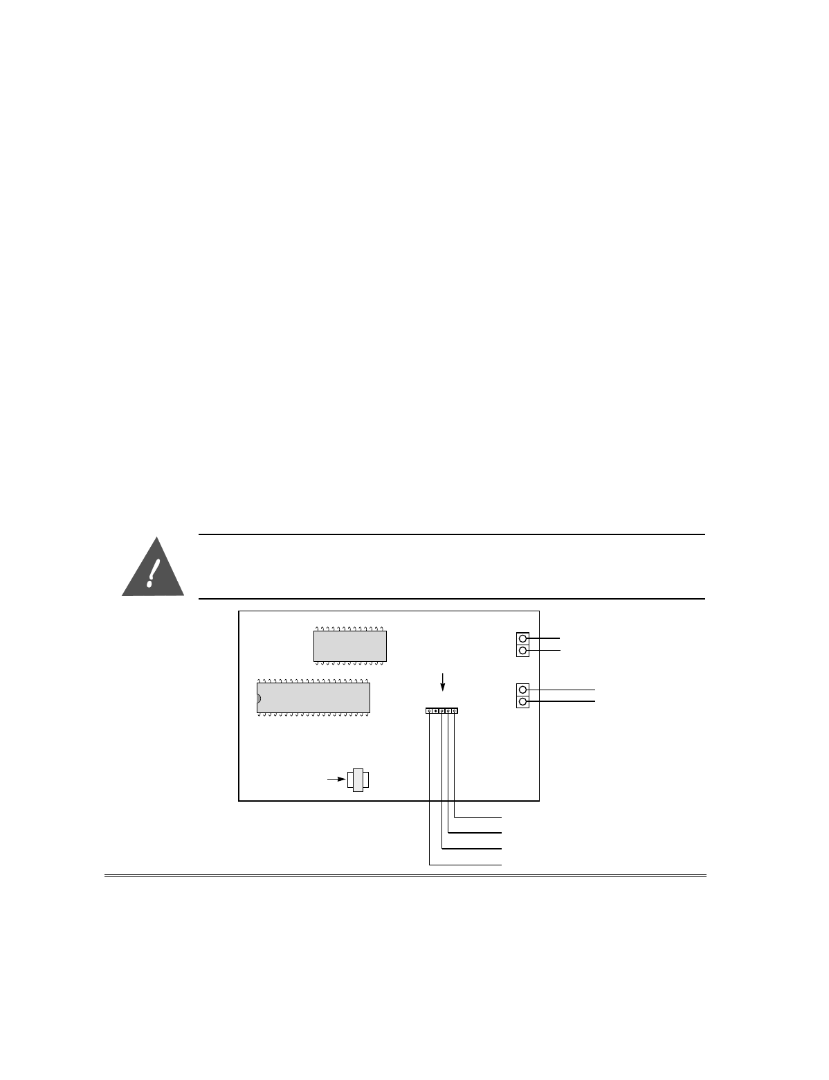
To use the VGM as an interface between the PassPoint ACS and VISTA FBS, wire the
VGM to the PassPoint ACS and VISTA FBS as shown in the illustration below.
Do not apply power to the system until all cables, including power connections, are
attached. Make sure that the component supplying power to the VGM, whether a separate
power supply or another module, is not powered while connecting to the VGM. After all
connections are complete, power may be applied to the system.
}
TO PASSPOINT ACS
MLB TERMINALS 15 & 16
OR OTHER MODULES
(TWISTED PAIR,
NETWORK CONNTECTION)
YELLOW
RED
BLACK
PROM C
TRANSFORMER
4-PIN
KEYPAD
PLUG
}
TO VISTA FSB
CONTROL PANEL
KEYPAD TERMINALS
(SEE NOTE)
GREEN
GROUND
+14VDC MAX
}
FROM
POWER
SUPPLY
(SEE NOTE)
J1 5
6
7
8
NOTE:
THE VGM DRAWS APPROXIMATELY 150MA. POWER CAN
BE SUPPLIED BY A POWER SUPPLY OR THE KEYPAD
TERMINALS ON THE VISTA FSB. IF A POWER SUPPLY IS
BEING USED, IT IS NOT NECESSARY TO CONNECT THE
RED AND BLACK WIRE TO THE VISTA FSB: HOWEVER,
THE GROUND OF THE POWER SUPPLY MUST BE
CONNECTED TO THE VISTA FSB - KEYPAD CONNECTION.
VGM Installation, Setup, and User Guide
2–2
Enrolling/Enabling the VGM
The VGM must be enrolled into the PassPoint ACS and enabled in the VISTA FBS to
have it perform as a PassPoint ACS/VISTA Interface. The following paragraphs
provide instructions for enrolling the VGM into the PassPoint ACS and enabling the
VGM in the VISTA FBS.
Enrolling the VGM into PassPoint
The VGM must be enrolled into the PassPoint system so the system will know that
the VGM is part of the system. To enroll the VGM, proceed as follows:
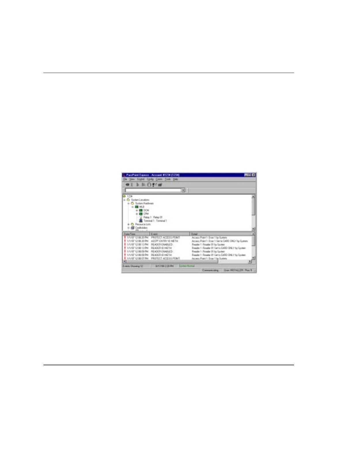
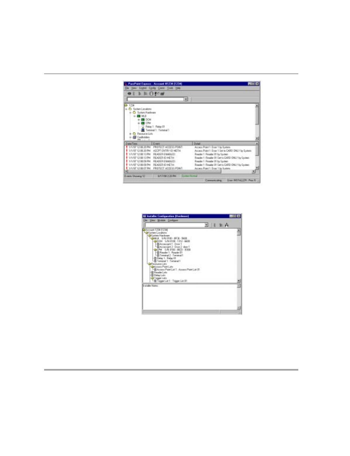
1. On the PassPoint computer, enter the Installer mode and connect to the PassPoint
ACS as defined in the PassPoint manuals. A screen similar to that shown below
will be displayed on your PassPoint computer.
2. Select Config on the Menu bar.
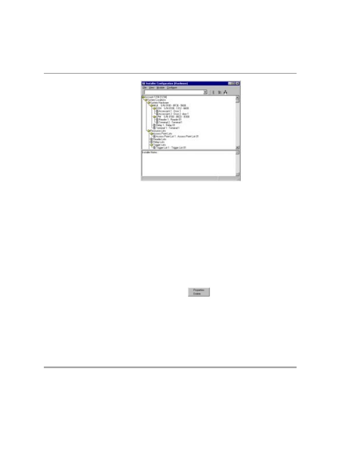
3. Select Hardware from the Config menu list. An Installer Configuration
(Hardware) screen similar to that shown below will be displayed.
Section 2 - VGM as an ACS/VISTA Interface
2–3
4. Select Module from the Installer Configuration menu bar.
5. Select Add VGM on the module menu list. The VGM will be added to the System
Hardware List in the Resource window of the PassPoint computer. The serial
number shown for the VGM will be all zeros.
6. Enter the serial number for the VGM into the PassPoint software. You may enter
the serial number in either of 2 ways. If you know the VGM serial number, follow
substep A below. If you don’t know the VGM serial number or choose to let the
PassPoint software determine the VGM serial number, use substep B below.
A. If you know the VGM serial number:
(1) Move the cursor to VGM in the System Hardware listing and left-click the
mouse to select it.
(2) Right-click the mouse. The following submenu will be displayed:
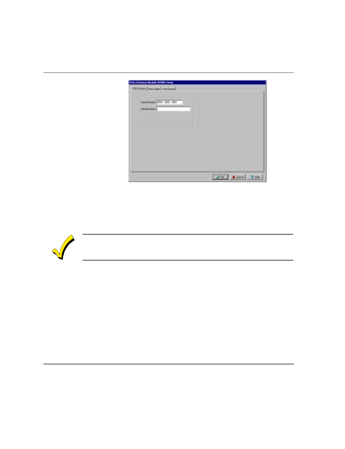
(3) Move the cursor to Properties on the submenu and right-click the mouse.
The VISTA Gateway Module (VGM) Setup screen shown below will be
displayed:
VGM Installation, Setup, and User Guide
2–4
(4) Move the cursor to the first position of the Serial Number box on the screen
and enter the VGM serial number.
(5) If desired, move to the Module Name box on the screen and enter a name
for the VGM.
(6) Select the OK button. The VGM serial number will be added to the VGM
listing in the Installer Configuration (Hardware) screen.
The VGM is now enrolled into the PassPoint software in the computer, but the information
has not yet been stored in the MLB of the PassPoint ACS. Downloading the information into
the MLB is described later in this section.
B. To let the PassPoint software determine the VGM Serial Number:
(1) Select Module from the Installer Configuration menu bar.
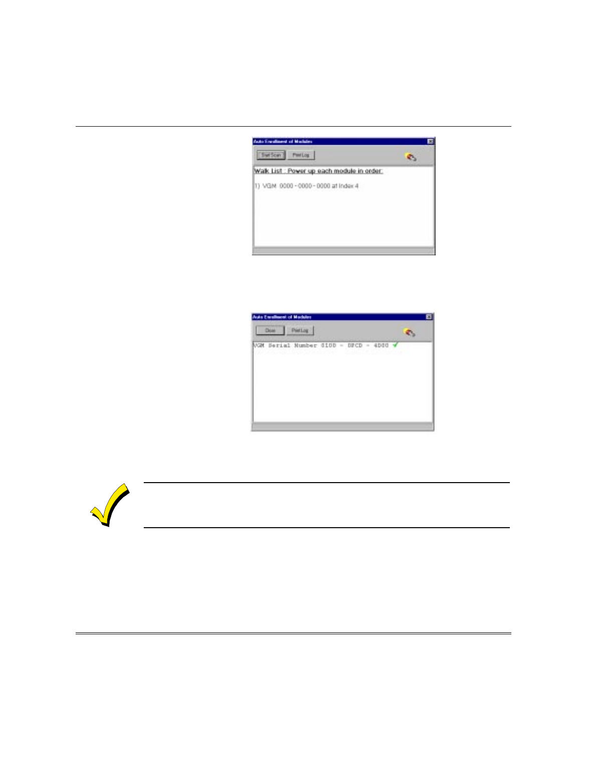
(2) Select Enroll on the Module menu list. The following Auto Enrollment of
Modules screen will be displayed:
Section 2 - VGM as an ACS/VISTA Interface
2–5
(3) Select the Start Scan button on the screen. The PassPoint software will
scan the system hardware and determine the VGM serial number. A screen
similar to that shown below will be displayed listing the VGM serial
number.
(4) Select the Close button to end the enrollment of the VGM. The VGM serial
number will be added to the VGM listing in the Installer Configuration
(Hardware) screen.
The VGM is now enrolled into the PassPoint software in the computer, but the information
has not yet been stored in the MLB of the PassPoint ACS. Downloading the information into
the MLB is described later in this section.
Enabling the VGM in the VISTA FBS
The VGM must be enabled as a connected device in the VISTA FBS so the system will
recognize that the VGM is part of the system. To enable the VGM, proceed as follows:
1. At the VISTA FBS Keypad, enter Device Programming in #93 Menu Mode. See the
VISTA FBS manuals for a detailed explanation of Device Programming in #93
Menu Mode.
VGM Installation, Setup, and User Guide
2–6
2. When the ENTER DEVICE ADDRESS message is displayed on the keypad,
enter a 2-digit device address followed by the asterisk (*). The address entered can
be any address within the range accepted by the VISTA FBS that is not used by
any other device. Note the device address entered. This number will be required
when the VGM is configured in the PassPoint ACS.
3. The DEVICE TYPE message will be displayed on the keypad. Enter 9* which
defines the device type as a VGM.
4. The VISTA PARTITION ONLY message will be displayed on the keypad. The
partition number defines which VISTA FBS (partition) account number will be
sent to the 685 receiver whenever a PassPoint ACS dialer message occurs.
5. Exit Device Programming.
Configuring the VGM
The VGM module must be configured after it is enrolled into the PassPoint software.
Configuration of the VGM consists of defining Test Report Schedules and setting the
VGM to act as an interface and defining controls for PassPoint Zones. To begin the
VGM configuration, proceed as follows:
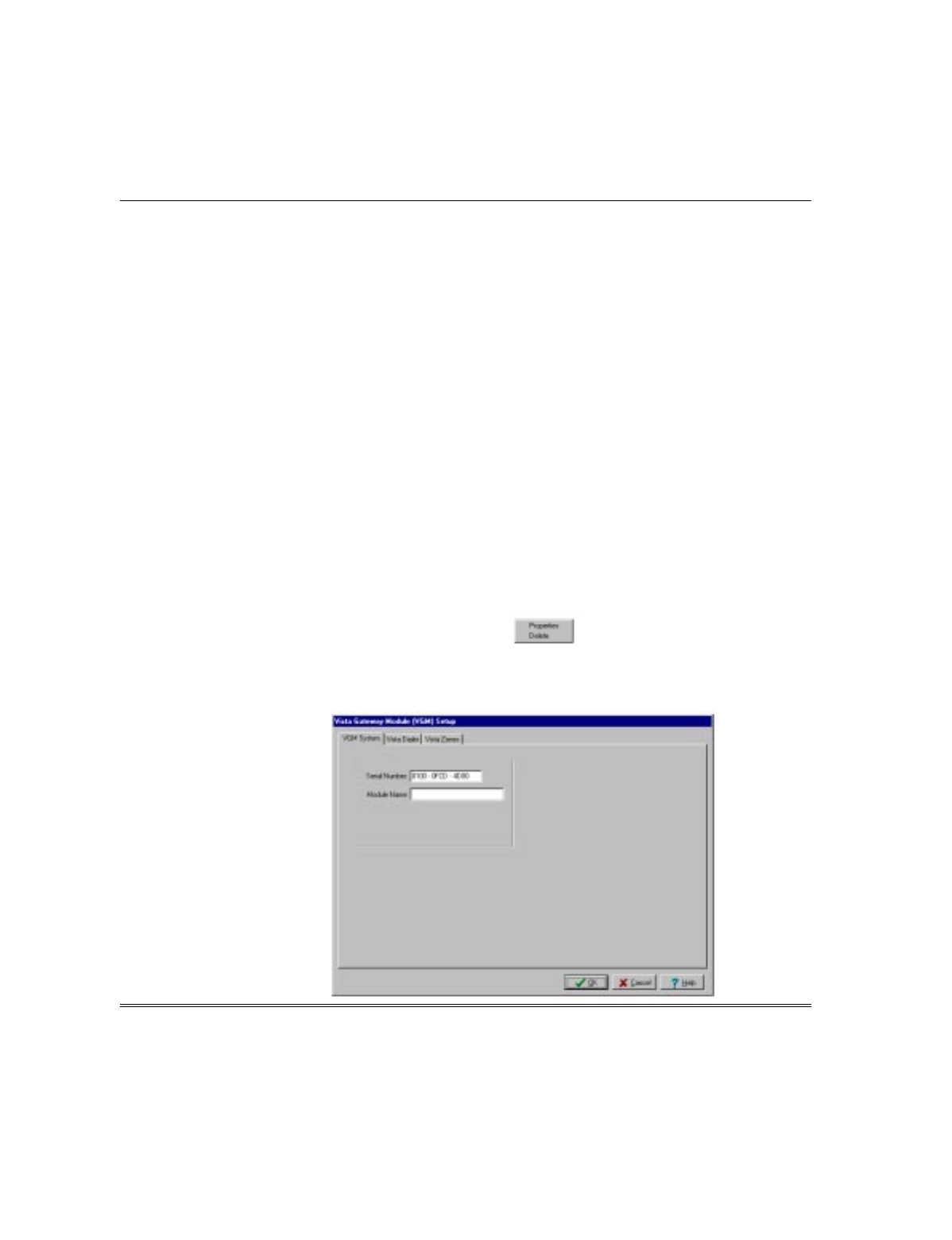
1. At the PassPoint ACS computer, move the cursor to VGM in the System Hardware
listing and left-click the mouse to select it.
2. Right-click the mouse. The following submenu will be displayed:
3. Move the cursor to Properties on the submenu and right-click the mouse. The
VISTA Gateway Module (VGM) Setup screen similar to that shown below will be
displayed.
Section 2 - VGM as an ACS/VISTA Interface
2–7
Defining Test Report Schedules and VGM Interface
To configure the Test Report Schedules and define the VGM as an interface between
the PassPoint ACS and VISTA FBS, proceed as follows:
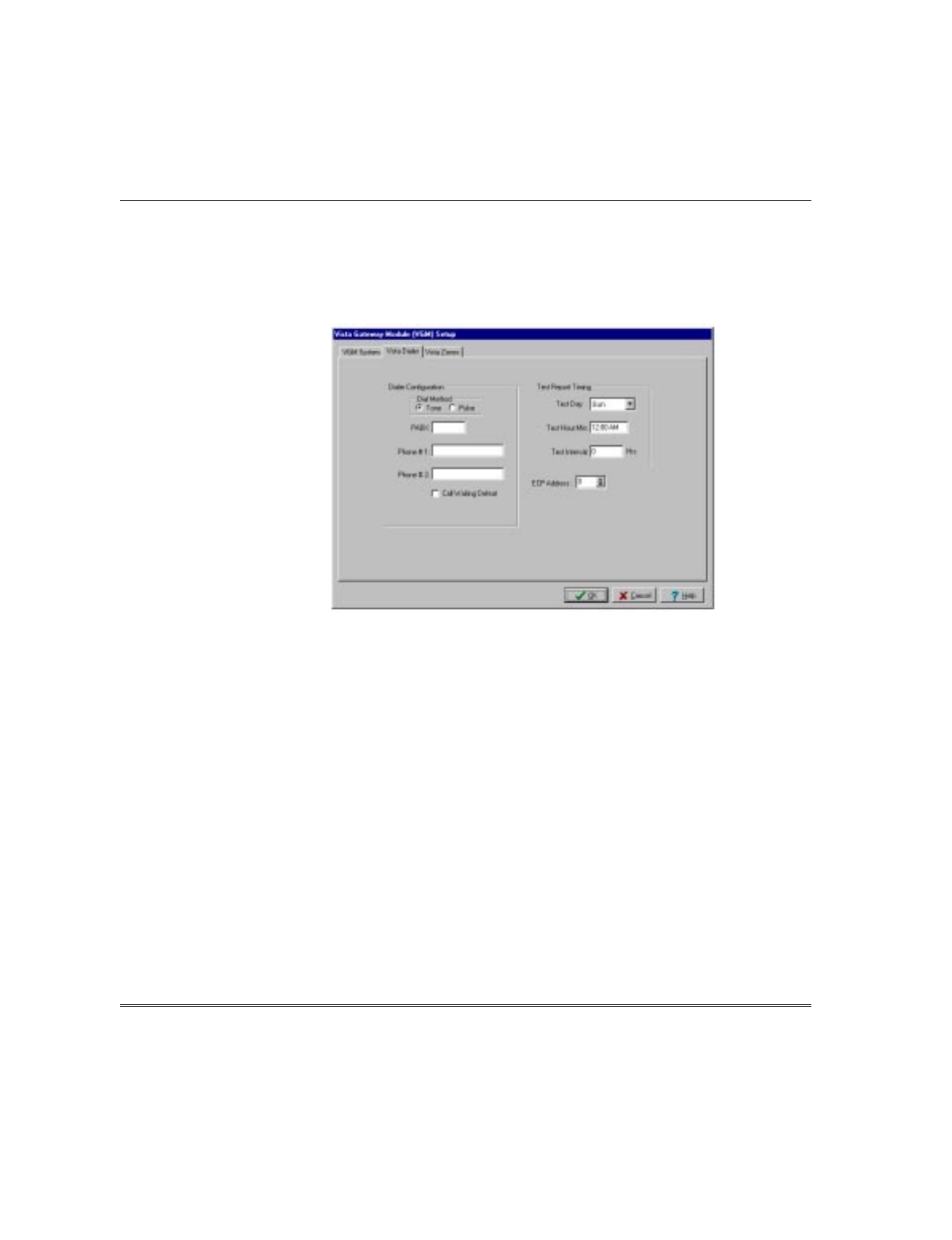
1. Select the Vista Dialer tab on the screen. The Dialer Configuration screen shown
below will be displayed:
2. Configure the VGM Test Report Schedules and set the VGM to act as an interface
between the PassPoint ACS and VISTA FBS by completing the entries on the
screen. The subfields on the screen allow definition of the configuration as follows:
Dialer Configuration - All subfields in this area (Dial Method, PABX, Phone # 1,
Phone # 2, and Call Waiting Defeat) may be left blank. Dialing functions will be
performed by the VISTA FBS.
Test Report Timing - This field controls when PassPoint test reports are sent to
the central station. The following subfields control test report timing:
Test Day - Select the day of the week to start sending test reports.
Test Hour:Min - Choose the time of day that is to be used to initiate the test-
reporting interval.
Test Interval - Enter the number of hours between test reports. Reports will not
be generated if this field is set to zero.
ECP Address - Set this field to match the device address assigned the VGM in the
VISTA FBS. The device address was assigned in the Enrolling/Enabling the VGM
procedures provided previously.
VGM Installation, Setup, and User Guide
2–8
The ECP address must be set to a non-zero value and match the address that was
programmed in the VISTA FBS.
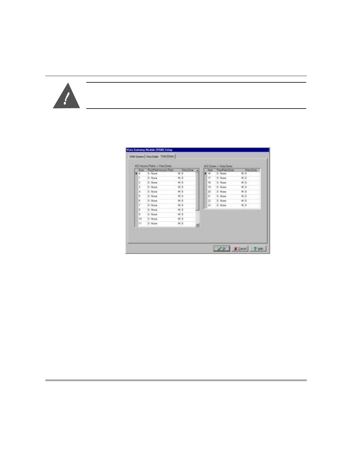
Defining VISTA Zones
Select the Vista Zones tab on the screen. The ACS Access Points to Vista Zones/ACS
Zones to Vista Zones Configuration screen shown below will be displayed:
Defining PassPoint ACS Access Points as VISTA FBS Zones
The state of up to 16 PassPoint ACS access points can be reported to the VISTA FBS
where they also can be treated as hardwired VISTA FBS zones. This allows a single
door contact to be installed, yet allow the PassPoint ACS door logic and a VISTA FBS
alarm zone to be configured at the door. The Access Point will be mirrored into the
VISTA FBS panel without having to run redundant wiring. When programmed,
PassPoint ACS access point door open alarms (and door open time alarms), restores,
and troubles are transmitted from the PassPoint ACS to the VISTA FBS. Note that
processing of events on both systems can still happen independently. You can still use
event/action relationships on PassPoint ACS for Access Point alarms and restores in
addition to causing alarms in the VISTA FBS based upon arming modes. Another
benefit of doing this is that just as a VISTA FBS alarm panel will prevent arming
with zone faults, a bypassed (unlatched) door that is propped open will prevent the
VISTA FBS panel from arming as well.
Section 2 - VGM as an ACS/VISTA Interface
2–9
Reports for Access Point status changes are sent to the VISTA FBS as listed below:
ACCESS POINT MODE
Status Lock, Protect, and Exit Only Bypassed
Fault Immediately on Forced
Immediately on Door Open Time-out Immediately on Door Opening
Fault Restore Immediately when Forced corrects
Immediately when Door Open Time-out
corrects Immediately on Door Closing
Trouble Immediately when it occurs Immediately when it occurs
Trouble Restore Immediately when it occurs Immediately when it occurs
Note that the above chart means that when a card is swiped at a Locked, Protected or
Exit Only Access Point or if a door opening is performed within the programmed door
timing parameters, the VISTA FBS never “sees” a fault and restore. If the door
operation results in a door forced alarm or a door open time-out alarm, the VISTA
FBS is notified of the fault. The zone reporting status for a Bypassed Access Point
allows a Bypassed Access Point that is propped open to prevent the VISTA FBS from
arming due to the fault condition.
Shunted Access Points or ACS Zones will NOT cause Fault, Fault Restore, Trouble, or
Trouble Restore status to be sent to the VISTA FBS causing a lack of protection.
To configure the VGM to report PassPoint ACS access points as VISTA FBS zones,
proceed as follows:
The access points being defined must already exist in PassPoint prior to performing the
following procedure. Refer to the PassPoint manuals for access point assignment
instructions.
1. In the ACS Access Point -> Vista Zones area of the screen, position the cursor on
the down (▼) button in the PassPoint Access Point column for the number (0-15)
being defined. Left-click the mouse, position the cursor on the desired access point
in the list that is displayed and left-click the mouse again.
2. Move the cursor to the Vista Zone area and enter the number of the zone in the
VISTA FBS that will be assigned to this PassPoint access point.
3. Repeat steps 1 and 2 for each access point (up to 16) that is to be reported to the
VISTA FBS.
4. Record the PassPoint Num column and corresponding VISTA FBS zone number.
This information will be required to program the VISTA FBS.

VGM Installation, Setup, and User Guide
2–10
At the VISTA FBS Keypad:
5. Enter Zone Programming in #93 Menu Mode. See the VISTA FBS manuals for a
detailed explanation of Zone Programming in #93 Menu Mode.
6. Program the first VISTA FBS zone that corresponds to the Vista Zone assignment
defined in the Vista Zone column of the VGM screen. Indicate the input type as
ACS (10).
7. Enter the VGM zone number from the Num column of the VGM screen (0-15).
8. Repeat steps 6 and 7 for each PassPoint zone being reported to the VISTA FBS.
9. Exit zone programming.
Defining PassPoint ACS Zones as VISTA FBS Zones
In order to obtain the wiring benefits of PassPoint’s Echelon Lonworks based network,
up to eight sensors that have been hardwired into a PassPoint module’s zones can be
mapped into the VISTA alarm panel’s zones. This allows a protective zone that may
be in close proximity to a PassPoint module to be treated as if it were a VISTA FBS
hardwired zone without having to run redundant wiring. In order to do this,
PassPoint needs to be configured to report zone status changes to the VGM on the
zones that need to be transferred to the VISTA panel. Zone faults, restores, and
troubles will be sent as they occur.
To configure the VGM to report PassPoint ACS zones as VISTA FBS zones, proceed as
follows:
The zones being defined must already be assigned in the MLB, DCM(s), or ZIM(s) prior to
performing the following procedure. Refer to the PassPoint manuals for zone assignment
instructions.
Shunted ACS Zones will NOT cause Fault, Fault Restore, Trouble, or Trouble Restore
status to be sent to the VISTA FBS causing a lack of protection.
ULBecause the VGM is not yet UL Listed, it is not recommended that a PassPoint ACS zone
be mapped into a VISTA FBS fire zone.
1. In the ACS Zones -> Vista Zones area of the screen, position the cursor on the
down (▼) button in the PassPoint Zone column for the number (16-23) being
defined. Left-click the mouse, position the cursor on the desired zone in the list
that is displayed and left-click the mouse again.

Section 2 - VGM as an ACS/VISTA Interface
2–11
2. Move the cursor to the Vista Zone area and enter the number of the zone in the
VISTA FBS that will be assigned to this PassPoint Zone.
The Vista Zone number must be a non-zero value for a properly mapped zone.
3. Repeat steps 1 and 2 for each zone (up to 8) that is to be reported to the VISTA
FBS.
4. Record the PassPoint Num column and corresponding VISTA FBS zone number.
This information will be required to program the VISTA FBS.
At the VISTA FBS Keypad:
5. Enter Zone Programming in #93 Menu Mode. See the VISTA FBS manuals for a
detailed explanation of Zone Programming in #93 Menu Mode.
6. Program the first VISTA FBS zone that corresponds to the VISTA Zone
assignment defined in the Vista Zone column of the VGM screen. Indicate the
input type as ACS (10).
7. Enter the VGM zone number from the Num column of the VGM screen (16-23).
8. Repeat steps 6 and 7 for each PassPoint zone being reported to the VISTA FBS.
9. Exit zone programming.
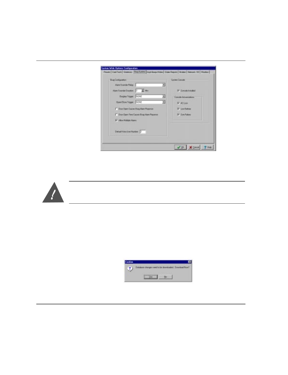
Defining the Default VISTA FBS User Number
All actions on a PassPoint ACS connected to a VISTA FBS alarm panel get logged to
the VISTA FBS event history log. Since all actions are logged, any action that the
PassPoint ACS system initiates on the VISTA FBS panel needs to map to a VISTA
FBS user number. The default VISTA user number defined in this field will be
associated with any VISTA action that is induced by the PassPoint ACS system. To
define the default VISTA FBS user number, proceed as follows:
1. Select Configure from the Installer Configuration menu bar.
2. Select System Wide Options from the Configure menu list and the system wide
options configuration screen will be displayed.
3. Select the Burg System tab and a screen similar to that shown below will be
displayed.
VGM Installation, Setup, and User Guide
2–12
4. The Default Vista User Number field will display a number 2 (default value) if the
field has never been modified. The number 2 may be left if it is acceptable or a new
number may be entered if desired. When the desired Default Vista User Number is
being displayed, click on the OK button.
The User Number defined in this screen must be enabled in the VISTA FBS for access to
the System/Partition/Zone the PassPoint ACS is reporting to. Additionally, if using the
PassPoint ACS to open or close a VISTA FBS partition, the User must have open/close
capability in the VISTA FBS.
Downloading the Configuration
After the VGM has been enrolled in the computer, test report schedules defined,
PassPoint zones defined, and the VGM has be configured to operate as an interface,
this information must be downloaded into the PassPoint ACS MLB. To download the
VGM information into the MLB proceed as follows.
1. Close the Installer Configuration (Hardware) screen on the computer. The following
message about downloading will be displayed:
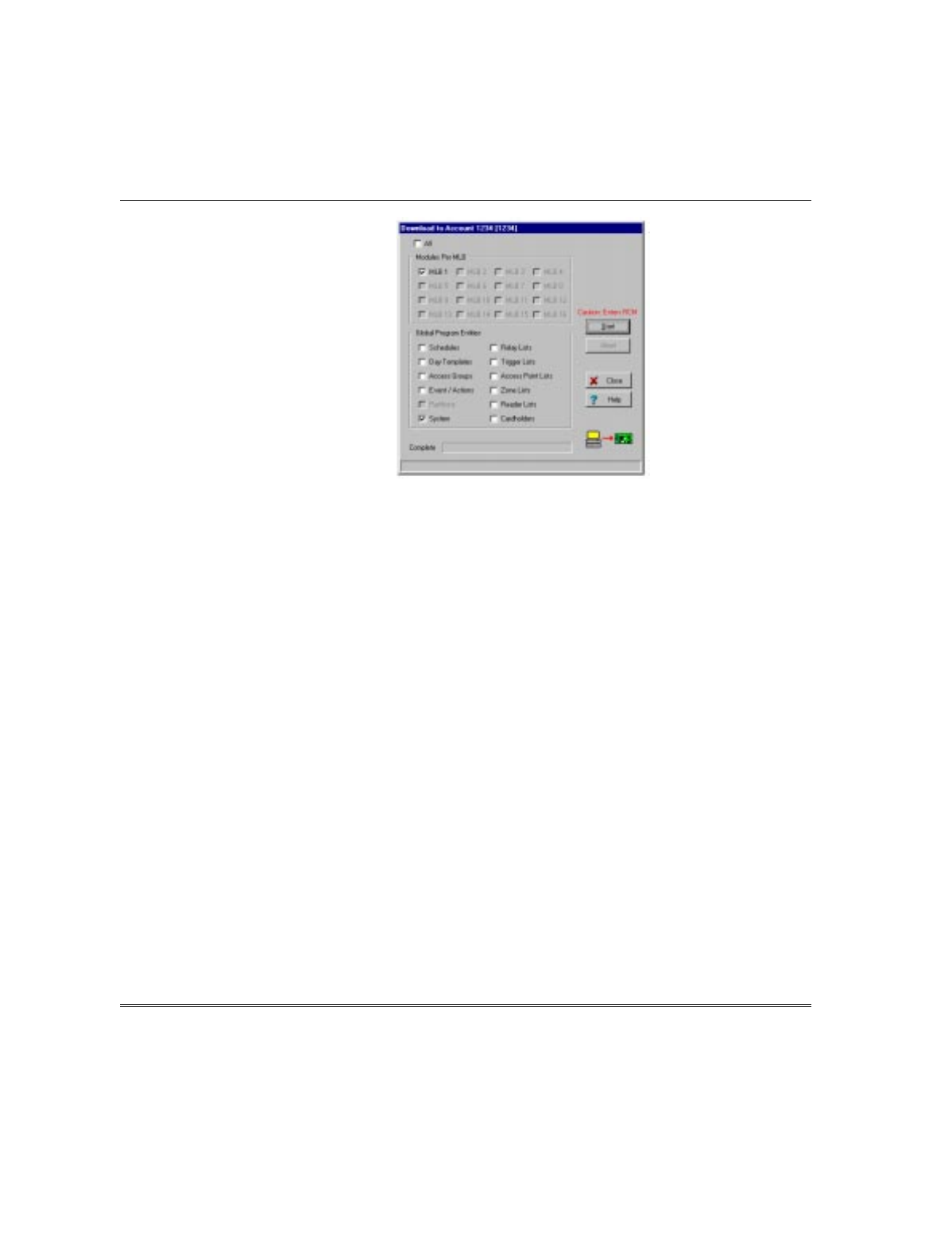
2. Select the Yes button. The Download to Account screen similar to that shown
below will be displayed.
Section 2 - VGM as an ACS/VISTA Interface
2–13
3. Select the Start button. The changes made in the computer to enroll the VGM,
test report definitions, PassPoint zone definitions, and VGM interface definition
will be downloaded in the PassPoint ACS MLB. When the download is complete,
the software will reset the PassPoint ACS. After the reset, the system will
automatically revert to the Ready state.
PassPoint ACS/VISTA FBS Event Actions
Triggers (events) can be initiated within the PassPoint ACS and sent via the VGM to
initiate an action in the VISTA FBS. Similarly, triggers can be initiated within the
VISTA FBS and sent via the VGM to cause an action in the PassPoint ACS. Refer to
the PassPoint ACS and VISTA FBS manuals for instructions on programming
event/actions.
The following action commands can be sent from the VISTA FBS to the PassPoint
ACS where the commands are received as Events.
Upon Vista Burg Sys Arming Away
Upon Vista Burg Sys Arming Stay
Upon Vista Burg Sys Arming Maximum
Upon Vista Burg Sys Arming Instant
Upon Vista Burg Sys Disarming
Upon Vista Burg Alarm in Ptn
Upon Vista Burg Alarm Rest in Ptn
Upon Vista Fire Alarm in Ptn
Upon Vista Fire Alarm Rest in Ptn
Upon Vista Panic/Duress Alarm in Ptn
Upon Vista Panic/Duress Al Rest in Ptn
Upon Vista Burg Sys Low Battery
Upon Vista Burg Sys Low Bat Restore
Upon Vista Burg Sys AC Loss
Upon Vista Burg Sys AC Restore
Upon Vista Dialer Comm Fail
Upon Vista Dialer Comm Restore
Upon Vista Connection Failure
Upon Vista Connection Restore
The following action commands can be sent from the PassPoint ACS to the VISTA
FBS where the commands are received as Events.

VGM Installation, Setup, and User Guide
2–14
Arm Vista Ptn Away
Arm Vista Ptn Stay
Disarm Vista Ptn
Force Arm Vista Ptn Away
Force Arm Vista Ptn Stay
Auto Bypass Vista Zone List
Auto Protect Vista Zone List
Enable Vista Ptn Opening
Disable Vista Ptn Opening
Enable Vista Ptn Closing
Disable Vista Ptn Closing
Enable Vista Access Wind
Disable Vista Access Wind
Vista Relay On
Vista Relay Off
Vista Relay Pulse
Vista Relay Pulse XX Min
Vista Relay Pulse YY Sec
Vista Relay Grp On
Vista Relay Grp Off
Vista Relay Grp Pulse
Vista Relay Grp Pulse XX Min
Vista Relay Grp Pulse YY Sec
PassPoint ACS/VISTA FBS Related Events
Table 2-1 lists events that will only occur and be displayed in the PassPoint ACS
event window if a VISTA FBS Alarm Panel has been connected to the PassPoint ACS
through a VGM Module.
Table 2-1. PassPoint ACS/VISTA FBS Related Events
Event Cause Default
Priority Logged
ZONE FAULT TO VISTA: This event indicates that a Zone fault was reported to a
connected VISTA FBS Alarm Panel. 0No
ZONE REST TO VISTA: This event indicates that a Zone restore was reported to a
connected VISTA FBS Alarm Panel. 0No
ZONE TRBL TO VISTA: This event indicates that a Zone trouble was reported to a
connected VISTA FBS Alarm Panel. 0No
ACCPT FAULT TO VISTA: This event indicates that an Access Point Door Status Monitor
Zone fault was reported to a connected VISTA FBS Alarm
Panel.
0No
ACCPT REST TO VISTA: This event indicates that an Access Point Door Status Monitor
Zone restore was reported to a connected VISTA FBS Alarm
Panel.
0No
ACCPT TRBL TO VISTA: This event indicates that an Access Point Door Status Monitor
Zone trouble was reported to a connected VISTA FBS Alarm
Panel.
0No
REQUEST VISTA STATUS: This event indicates that the Access Control System has
requested status information from a connected VISTA FBS
Alarm Panel.
0No
VISTA BURG ALARM: This event indicates that a burglary alarm condition has
occurred in the given VISTA FBS Burglary Partition. 3Yes
VISTA BURG ALARM REST: This event indicates that a burglary alarm condition has
restored (cleared) in the given VISTA FBS Burglary Partition. 3Yes
VISTA FIRE ALARM: This event indicates that a fire alarm condition has occurred in
the given VISTA FBS Partition. 3Yes
VISTA FIRE ALARM REST: This event indicates that a fire alarm condition has restored
(cleared) in the given VISTA FBS Partition. 3Yes

Section 2 - VGM as an ACS/VISTA Interface
2–15
Event Cause Default
Priority Logged
VISTA PANIC/DURESS
ALRM: This event indicates that a panic or duress alarm condition has
occurred in the given VISTA FBS Burglary Partition. 4Yes
VISTA PNC/DUR AL REST: This event indicates that a panic or duress alarm condition has
restored (cleared) in the given VISTA FBS Burglary Partition. 4Yes
VISTA ARMED AWAY: This event indicates that the given VISTA FBS Alarm Partition
was Armed Away. 3Yes
VISTA ARMED STAY: This event indicates that the given VISTA FBS Alarm Partition
was Armed Stay. 3Yes
VISTA ARMED MAXIMUM: This event indicates that the given VISTA FBS Alarm Partition
was Armed Maximum. 3Yes
VISTA ARMED INSTANT: This event indicates that the given VISTA FBS Alarm Partition
was Armed Instant. 3Yes
VISTA DISARMED: This event indicates that the given VISTA FBS Alarm Partition
was Disarmed. 3Yes
VISTA LOW BATTERY: This event indicates that the VISTA FBS Alarm Panel
connected to the Access Control System is experiencing a
Low Battery condition.
2Yes
VISTA LOW BATT REST: This event indicates that the VISTA FBS Alarm Panel’s Low
Battery condition has restored and that its battery is charged. 2Yes
VISTA AC PWR LOSS: This event indicates that the VISTA FBS Alarm Panel
connected to the Access Control System has lost its AC line
voltage.
2Yes
VISTA AC PWR RESTORE: This event indicates that the VISTA FBS Alarm Panel’s AC line
voltage has been turned back on. 2Yes
VISTA DLR COMM FAIL: This event indicates that the VISTA FBS Alarm Panel’s central
station communicator (dialer) has not been able to reach the
central station.
2Yes
VISTA DLR COMM REST: This event indicates that the VISTA FBS Alarm Panel’s central
station communicator (dialer) has been able to reach the
central station after a period of failure.
2Yes
VISTA CMD TO UNKN
ACCPT: This event indicates that the VISTA FBS Alarm Panel has
attempted to control an Access Point that is invalid. This event
may occur if the VISTA FBS Panel’s User Code or keypad
programming that maps to the Access Point is invalid.
2Yes
ACCESS REQ FR UNKN
VUSR: This event indicates that the VISTA FBS Alarm Panel has
requested access using a VISTA FBS User number that was
unknown to the Access Control System. This can occur if the
cardholder database in the Access Control System does not
contain an entry indicating this VISTA FBS User Number.
2Yes
EGRESS REQ FR UNKN
VUSR: This event indicates that the VISTA FBS Alarm Panel has
requested egress using a VISTA FBS User number that was
unknown to the Access Control System. This can occur if the
cardholder database in the Access Control System does not
contain an entry indicating this VISTA FBS User Number.
2Yes
VISTA CONNECTION FAIL: This event indicates that the Access Control System can not
communicate with its VISTA FBS Alarm Panel. 2Yes
VISTA CONNECTION REST: This event indicates that the Access Control System can once
again communicate with its VISTA FBS Alarm Panel after a
period of communication failure.
2Yes

VGM Installation, Setup, and User Guide
2–16
Event Cause Default
Priority Logged
BYP VISTA ZONE LIST: This event occurs when the Access Control System instructs
the VISTA FBS Alarm Panel to bypass a VISTA FBS Panel
Zone List.
1Yes
PROTECT VISTA ZONE
LIST: This event occurs when the Access Control System instructs
the VISTA FBS Alarm Panel to protect a VISTA FBS Panel
Zone List.
1Yes
VISTA PART OPEN ENABLE: This event occurs when the Access Control System instructs
the VISTA FBS Alarm Panel to enable openings (disarm
operations) within the indicated VISTA FBS Burglary Partition.
1Yes
VISTA PART OPEN
DISABLE: This event occurs when the Access Control System instructs
the VISTA FBS Alarm Panel to disable openings (disarm
operations) within the indicated VISTA FBS Burglary Partition.
1Yes
VISTA PART CLOSE
ENABLE: This event occurs when the Access Control System instructs
the VISTA FBS Alarm Panel to enable closings (arming
operations) within the indicated VISTA FBS Burglary Partition.
1Yes
VISTA PART CLOSE
DISABLE: This event occurs when the Access Control System instructs
the VISTA FBS Alarm Panel to disable closings (arming
operations) within the indicated VISTA FBS Burglary Partition.
1Yes
VISTA ACCESS GRP
ENABLE: This event occurs when the Access Control System instructs
the VISTA FBS Alarm Panel to enable a VISTA FBS Access
Group.
1Yes
VISTA ACCESS GRP
DISABLE: This event occurs when the Access Control System instructs
the VISTA FBS Alarm Panel to disable a VISTA FBS Access
Group.
1Yes
VISTA RELAY ON: This event indicates that the Access Control System has
instructed the VISTA FBS Alarm Panel to turn on one of the
VISTA FBS Output Relays.
1Yes
VISTA RELAY OFF: This event indicates that the Access Control System has
instructed the VISTA FBS Alarm Panel to turn on one of the
VISTA FBS Output Relays.
1Yes
VISTA RELAY PULSE: This event indicates that the Access Control System has
instructed the VISTA FBS Alarm Panel to pulse one of the
VISTA FBS Output Relays.
1Yes
VISTA RELAY PULSE
XXMIN: This event indicates that the Access Control System has
instructed the VISTA FBS Alarm Panel to pulse one of the
VISTA FBS Output Relays for the duration specified by the XX
minute timer as specified by the VISTA FBS Panel’s
programming options.
1Yes
VISTA RELAY PULSE
YYSEC: This event indicates that the Access Control System has
instructed the VISTA FBS Alarm Panel to pulse one of the
VISTA FBS Output Relays for the duration specified by the YY
seconds timer as specified by the VISTA FBS Panel’s
programming options.
1Yes
VISTA RELAY GRP ON: This event indicates that the Access Control System has
instructed the VISTA FBS Alarm Panel to turn on one of the
VISTA FBS Output Relay Groups.
1Yes
VISTA RELAY GRP OFF: This event indicates that the Access Control System has
instructed the VISTA FBS Alarm Panel to turn on one of the
VISTA FBS Output Relay Groups.
1Yes

Section 2 - VGM as an ACS/VISTA Interface
2–17
Event Cause Default
Priority Logged
VISTA RELAY GRP PULSE: This event indicates that the Access Control System has
instructed the VISTA FBS Alarm Panel to pulse one of the
VISTA FBS Output Relay Groups.
1Yes
VISTA RLY GRP PULSE
XXM: This event indicates that the Access Control System has
instructed the VISTA FBS Alarm Panel to pulse one of the
VISTA FBS Output Relay Groups for the duration specified by
the XX minute timer as specified by the VISTA FBS Panel’s
programming options.
1Yes
VISTA RLY GRP PULSE
YYS: This event indicates that the Access Control System has
instructed the VISTA FBS Alarm Panel to pulse one of the
VISTA FBS Output Relay Groups for the duration specified by
the YY seconds timer as specified by the VISTA FBS Panel’s
programming options.
1Yes
VISTA TEST START: This event occurs when the VISTA Alarm Panel enters a test
mode. Normal operation of the VISTA alarm functions may be
interrupted.
3Yes
VISTA TEST END: This event occurs when the VISTA Alarm Panel exits all test
modes. 3Yes
VISTA PROG START: This event occurs when the VISTA Alarm Panel enters
programming mode. Normal operation of the VISTA alarm
functions may be interrupted.
3Yes
VISTA PROG END: This event occurs when the VISTA Alarm Panel exits
programming mode. 3Yes
VISTA MDM DLD START: This event occurs when the VISTA Alarm Panel enters modem
downloading mode. Normal operation of the VISTA alarm
functions may be interrupted.
3Yes
VISTA MDM DLD END: This event occurs when the VISTA Alarm Panel exits modem
downloading mode. 3Yes
VISTA RESET: This event occurs when the VISTA Alarm Panel resets. Normal
operation of the VISTA alarm functions may have been
interrupted and may still occur for a short period of time while
the panel restarts.
3Yes
PassPoint ACS Central Station Reports
The procedures in this section have configured the PassPoint ACS and enrolled the
VGM as an interface. With these procedures completed, the PassPoint ACS will send
test reports to the central station at the intervals defined using the VISTA FBS as a
dialer. The PassPoint ACS will also initiate a call via the VISTA FBS to the central
station and report any of the events listed in Appendix A of this manual except those
modified in the Modifying PassPoint Events Reported to Central Station paragraph
that follows.
In the reports sent, a 3-digit point number will follow the Event Code where
applicable. The 3-digit number defines the actual resource for which the event code
pertains. These 3-digit point numbers are divided into the groups listed below.
Additionally, when reporting using the Contact ID format, the ACS will report as
partition 9.

VGM Installation, Setup, and User Guide
2–18
3-Digit
Group Definition
000 Unknown or Out Of Range VISTA FBS Zone
001-199 VISTA FBS zones 1 through 199
200 Unknown or Out of Range ACS Zone
201-399 ACS Uncommitted Zones 1 through 199
400 Unknown or out of Range ACS Uncommitted Reader
401-449 ACS Uncommitted Readers 1 through 49
450 Unknown or Out of Range ACS Access Point (Door)
451-600 Access Points 1 through 150
601-649 VISTA FBS Relays 1 through 49
650 Unknown or Out of Range ACS Uncommitted Trigger
651-699 ACS Uncommitted Triggers 1 through 49
700 Unknown or Out of Range ACS Uncommitted Relay
701-799 ACS Uncommitted Relays 1 through 99
800-849 VISTA FBS Modules
850 Unknown or Out of Range ACS Module
851-899 ACS Module 1 through 39
890 Unknown or Out of Range ACS RS232 Communications Port
891-899 ACS RS232 Communications Ports 1 through 9
The manner in which these group numbers are used is that the actual resource
number is added to the group base number to obtain the point number that is
reported. For example, if the event is in ACS Zone 5, 200 is added to 5 and the point
number reported is 205. As an additional example, if the event is for ACS Reader
number 10, 400 is added to 10 and the point number reported is 410.
Some event codes are new, as are the 3-digit point codes. As such, the text message
displayed by the VISTA FBS Event Log Reporter, VISTA FBS Event Log Printer, VISTA
FBS Pager, or Central Station may not match the text message displayed in the ACS
computer Event Window.
Modifying PassPoint Events Reported to Central Station
The PassPoint Events that are defaulted to report to the central station can be
modified by the Installer. To delete (or enable reported events previously deleted),
proceed as follows:
1. On the PassPoint computer, enter the Installer mode and connect to the PassPoint
ACS as defined in the PassPoint manuals. A screen similar to that shown below
will be displayed on your PassPoint computer.
Section 2 - VGM as an ACS/VISTA Interface
2–19
2. Select Config on the Menu bar.
3. Select Hardware from the Config menu list. An Installer Configuration
(Hardware) screen similar to that shown below will be displayed.
4. Select Configure from the Installer Configuration menu bar.
5. Select System Wide Options from the Configure menu list and the system wide
options configuration screen will be displayed.
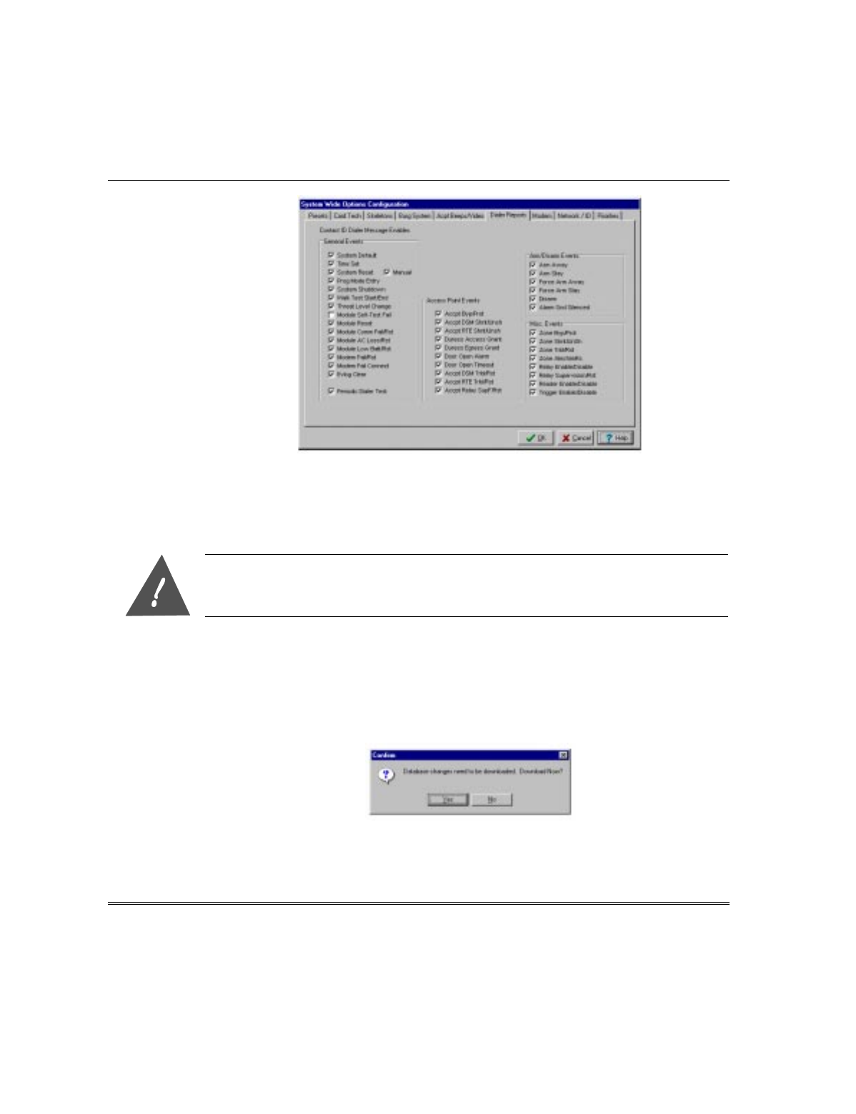
6. Select the Dialer Reports tab and a screen similar to that shown below will be
displayed.
VGM Installation, Setup, and User Guide
2–20
7. PassPoint Events that are reported to the central station are indicated by a check
mark. To disable or enable an event, position the cursor on the check mark or item
name and left-click the mouse. When all desired items have been modified, click on
the OK button. The system wide options screen will be closed. The changes must
now be downloaded.
If an event is checked but the priority of the event is set to zero, a report will not be sent.
Downloading the PassPoint Events Reported to Central Station Changes
After the PassPoint Events that are reported to the central station have been
modified, this information must be downloaded into the PassPoint ACS MLB. To
download the event information into the MLB proceed as follows.
1. Close the Installer Configuration (Hardware) screen on the computer. The following
message about downloading will be displayed:
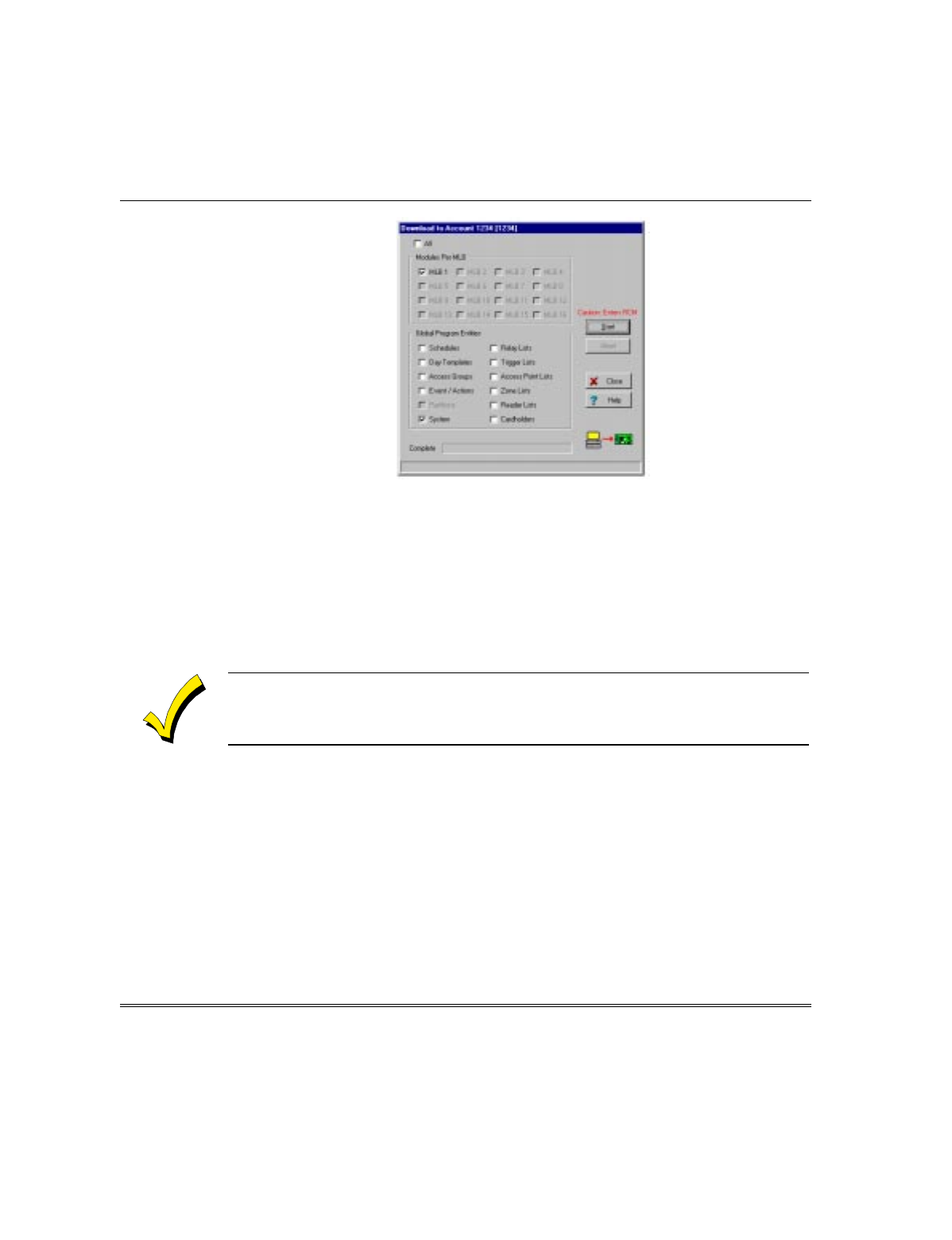
2. Select the Yes button. The Download to Account screen similar to that shown
below will be displayed.
Section 2 - VGM as an ACS/VISTA Interface
2–21
3. Select the Start button. The changes made in the computer for event reporting will
be downloaded into the PassPoint ACS MLB. When the download is complete, the
software will reset the PassPoint ACS. After the reset, the system will
automatically revert to the Ready state.
Commonly Used Applications
The following paragraphs contain instructions for setting up and using some
applications. Note that these paragraphs do not provide all possible applications, but
do provide a variety of the common ones.
Most of the following applications may be set up and used by the system user. Where an
application must be set up by the system installer, it will be noted.
Controlling Access Points with VISTA FBS Keypads & RF Transmitters
VISTA FBS alpha keypads and/or RF button type transmitters may be used to control
access points. To use keypads and/or RF button type transmitters to control access
points, perform the procedures below for the device(s) desired.
Controlling an Access Point with a VISTA FBS Keypad
A VISTA alpha keypad can be used to request access or egress through a PassPoint
access point. In addition, the VISTA keypad can be used to change the operational
mode of an access point, placing the access point in the bypassed or protected modes.

VGM Installation, Setup, and User Guide
2–22
ASSIGNING THE VISTA KEYPAD TO A PASSPOINT ACCESS POINT
Assigning the VISTA keypad to a PassPoint access point can only be performed by the
system installer. Once assigned, the application is available to the user of the system.
When a VISTA Keypad is assigned to a PassPoint Access Point, a keypad entry of
CODE+#73 will automatically perform an access or egress request at the associated
Access Point.
1. Enter the ZONE PROGRAMMING section in the #93 Menu Mode on the VISTA
FBS.
2. Select a zone to “attach” to the VISTA keypad.
3. Program this zone with a zone response type 27 (ACCESS POINT).
4. Enter the access point ID number of the access point to be controlled by this
keypad. Note: The access point ID number can be found in the PassPoint VGM
properties in the PassPoint VISTA Zones tab. First find the access point and then
read the value in the NUM column. This is the number that gets entered as the
access point ID number. For example, if the NUM column entry shows 0, enter a 0
in this field.
5. Indicate if this is going to be an Entry (0) or Exit (1) request.
6. Enter the partition number.
7. Enter the input type as 09 (CS or Console).
8. Enter the keypad ECP device address.
USING THE VISTA KEYPAD TO CONTROL A PASSPOINT ACCESS POINT
The VISTA Keypad may be used to control an access point as follows:
1. Entering CODE+#73 on a keypad will request access to the access point that is
assigned to that keypad
Note that user number whose code is used must be assigned to a PassPoint Access
Card in the PassPoint card deck. For example, if code “3219” is assigned to VISTA
user number 11, eleven must be entered into the PassPoint card screen in the
VISTA User field. Entering VISTA user numbers that are not represented by an
Access Card in the PassPoint card deck will not result in an Access Grant or
Egress Grant. Instead, an Access (or Egress) Grant from Unknown VISTA User
event will be logged in PassPoint, indicating the VISTA user number that
attempted access or egress.
2. Entering CODE+#74+<access_point>*+<entry(0)/exit(1)>* on the keypad will
request access of the access point entered.

Section 2 - VGM as an ACS/VISTA Interface
2–23
Using #74 allows the VISTA user to select an Access Point that differs from the
Access Point that is assigned to that Keypad. Note that user number whose code is
used must be assigned to a PassPoint Access Card in the PassPoint card deck. For
example, if code “3219” is assigned to VISTA user number 11, eleven must be
entered into the PassPoint card screen in the VISTA User field. Entering VISTA
user numbers that are not represented by an Access Card in the PassPoint card
deck will not result in an Access Grant or Egress Grant. Instead, an Access (or
Egress) Grant from Unknown VISTA User event will be logged in PassPoint,
indicating the VISTA user number that attempted access or egress.
3. Entering CODE+#75+<access_point>*+1* will perform a Manual Access Grant
at the access point specified.
The VISTA user number whose code is entered for this command does not need to
be entered in the PassPoint card deck as a VISTA user number. A Manual Access
Grant from the associated VISTA user number will be logged by PassPoint.
4. Entering CODE+#75+<access_point>*+2* will put the specified access point in
the Protect mode.
When in the Protect mode, an Access Point requires card &/or PIN entries or
VISTA requests in order to allow access or egress. The VISTA user number whose
code is entered for this command does not need to be entered in the PassPoint card
deck as a VISTA user number. An Access Point Protect from the associated VISTA
user number will be logged by PassPoint.
5. Entering CODE+#75+<access_point>*+3* will put the specified access point in
the Bypass mode.
When in the Bypass mode, the door of the Access Point is unlatched and people can
enter or exit freely though the door. The VISTA user number whose code is entered
for this command does not need to be entered in the PassPoint card deck as a
VISTA user number. An Access Point Bypass from the associated VISTA user
number will be logged by PassPoint.
Controlling 2 Access Points with 2 VISTA FBS Keypads
The system has capabilities of using 2 VISTA alpha keypads to request access through
2 different PassPoint access points. When 2 VISTA Keypads are assigned to 2
different PassPoint Access Points, a keypad entry of CODE+#73 will automatically
perform an access request at the Access Point associated with the keypad.
ASSIGNING 2 VISTA KEYPADS TO 2 PASSPOINT ACCESS POINTS
Assigning the 2 VISTA keypads to 2 PassPoint access points can only be performed by the
system installer. Once assigned, the application is available to the user of the system.

VGM Installation, Setup, and User Guide
2–24
Program each keypad as described in the Assigning the VISTA Keypad to a PassPoint
Access Point paragraphs above assigning one keypad to ECP address #1 and the
second keypad to ECP address # 2.
USING THE VISTA KEYPADS TO OBTAIN ACCESS TO PASSPOINT ACCESS POINTS
Entering CODE+#73 on the keypad will request access to the access point that is
assigned to that keypad
Note that user number whose code is used must be assigned to a PassPoint Access
Card in the PassPoint card deck. For example, if code “3219” is assigned to VISTA
user number 11, eleven must be entered into the PassPoint card screen in the VISTA
User field. Entering VISTA user numbers that are not represented by an Access Card
in the PassPoint card deck will not result in an Access Grant or Egress Grant.
Instead, an Access (or Egress) Grant from Unknown VISTA User event will be logged
in PassPoint, indicating the VISTA user number that attempted access or egress.
Controlling Access Point with Wireless Keypads
Wireless keypads (5827 & 5827BD) can provide another way of entering the premise.
They function the same as the alpha keypads, except when the CODE+#73 is entered.
When CODE+#73 is entered, it will allow access to ALL access points in the partition
the keypad is assigned.
PROGRAMMING WIRELESS KEYPADS TO CONTROL ACCESS POINTS
Programming wireless keypads to control access points can only be performed by the
system installer. Once assigned, the application is available to the user of the system.
To program the VISTA FBS for wireless keypad control of access points, observe the
following
1. Enter the Program Mode on the VISTA FBS.
2. Enter the partition the keypad is assigned to in the “Wireless Keypad Assignment”
field.
Controlling Access Point with an RF Transmitter Zone
VISTA 5800 wireless devices can be employed in order to enhance the VISTA
FBS/PassPoint ACS systems. These devices may be used as follows:
•An RF button type transmitter (5804) can be used to provide access at up to 4 doors.
Each button can be used to request access or egress through a specified access
point. In this manner, a 5804 can be used instead of an access card and access
control card reader at an access point.

Section 2 - VGM as an ACS/VISTA Interface
2–25
•The smoke detector (5808) can be used to provide egress in emergency situations.
Create an Event/Action that sets the appropriate doors in the Bypass mode upon a
Fire Alarm in the desired partition.
ULUsing the smoke detector to provide emergency egress is not a UL listed feature.
PROGRAMMING AN RF TRANSMITTER ZONE TO CONTROL AN ACCESS POINT
Programming an RF transmitter zone to control an access point can only be performed by
the system installer.
When an RF button type transmitter (5804) is assigned to a PassPoint Access Point, a
fault on that zone will automatically perform an access or egress request at the
associated access point. To program the VISTA FBS so that an RF button type
transmitter (5804) zone will control an access point, observe the following
1. Enter the ZONE PROGRAMMING section in the #93 Menu Mode on the VISTA
FBS.
2. Select a zone to assign to the RF transmitter.
3. Program this zone with a zone response type 27 (ACCESS POINT).
4. Enter the access point ID number of the access point to be controlled by this
keypad. Note: The access point ID number can be found in the PassPoint VGM
properties in the PassPoint VISTA Zones tab. First find the access point and then
read the value in the NUM column. This is the number that gets entered as the
access point ID number. For example, if the NUM column entry shows 0, enter a 0
in this field.
5. Indicate if this is going to be an Entry (0) or Exit (1) request.
6. Enter the partition number.
7. Enter the input type as 05 (button RF).
8. Enroll the RF transmitter serial number.
9. If enrolling a button type RF transmitter, repeat steps 1 though 8 for each button
on the transmitter.

VGM Installation, Setup, and User Guide
2–26
10.Enter the partition the keypad is assigned to in the “Wireless Keypad Assignment”
field.
NOTE: For an RF button type transmitter, after exiting the programming mode,
you must select a user code for the RF button. This is done by entering
code+8+uuu+rf_user_code. The console will query if the user has an RF button.
Answer YES and then enter the zone number in which one of the RF buttons was
“attached” to. This “attaches” a VISTA user number to this RF button. Make sure
there is a cardholder in the PassPoint database with this same VISTA user
number so that PassPoint will grant this RF button access.
Assigning VISTA FBS Relays to Access Points
Assigning VISTA FBS relays to access points can only be performed by the system
installer.
A relay can be assigned to an access point so that it can be energized when the VISTA
FBS requests access or egress through an Access Point.
1. Enter Relay Programming on the VISTA FBS.
2. At the “ENTER RELAY NO.” prompt, enter a number for the relay.
3. At the “RELAY ACTION” prompt, select the desired action (. i.e. close for 2 secs,
stay closed, toggle)
4. At the “START EVENT” prompt, select not used.
5. At the “START: ZN LIST” prompt, enter 0 for no list.
6. At the “START: ZN TYPE” prompt, enter 27 for access point.
7. At the “START: ACS PT” prompt, enter the number of the access point number
that will start the relay action. An access or egress grant request from an access
point device (RF button or keypad) will energize the relay.
8. At the “START PART” prompt, enter the partition number in which the event will
occur.
9. At the “STOP: ZN LIST” prompt, enter 0 for no list.
10.At the “STOP: ZN TYPE” prompt, enter 0 for no response. Note that if a 27
(ACCESS POINT) were entered here, then an access or egress grant request from
the STOP Access Point would de-energize the relay.
11.At the “STOP PART” prompt, enter 0.
12. At the “RELAY GROUP” prompt, enter a group number if applicable to the VISTA
FBS site.
13.At the “FIRE BELL?” prompt, enter 1 or 0. (Refer to your VISTA FBS manuals).
Section 2 - VGM as an ACS/VISTA Interface
2–27
14.At the “RESTRICTION” prompt, enter 1 or 0. (Refer to your VISTA FBS manuals).
15.At the “RELAY TYPE” prompt, enter 1.
16.Exit Relay Programming.
Arm VISTA FBS Partition on Access Point Card Swipe
The PassPoint ACS can be configured to arm a VISTA FBS partition on an access
point card swipe. Limiting who can arm a VISTA FBS partition can be used in
conjunction with the “Vista Partition Armed Away Restriction” field of PassPoint
Access Groups. Set the appropriate partitions as restricted while Armed Away, so that
cardholders in a group that does not have arming capability will be denied when
attempting to enter (or leave) an armed area, thus preventing false alarms.
1. In the card database of the PassPoint ACS, enroll a card or select an existing card
that is to be assigned as a VISTA user. (Refer to the PassPoint ACS manuals.)
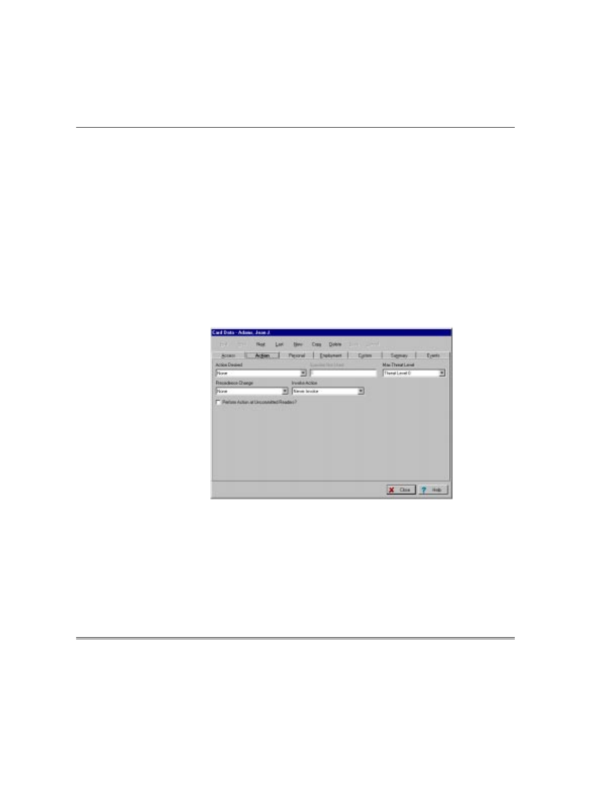
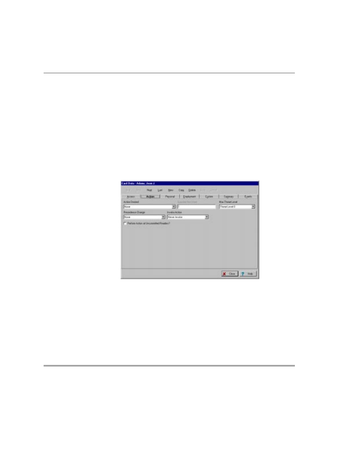
2. Select the Action tab for this card. A screen similar to the following will be
displayed.
3. In the Action Desired field, select “Arm Vista Ptn Away”.
4. In the Specifier = Vista Ptn # field, enter the VISTA FBS partition to be armed.
5. In the Invoke Action field, select “Egress Grant” as the action that will cause the
partition to be armed.
6. Select the Access tab and enter the default VISTA user number in the VISTA
User # field. This is needed since the PassPoint system maps all VISTA FBS users
to the default VISTA user number when commanding the VISTA FBS to arm or
disarm. (The default VISTA user number can be found in the System Wide
Options, Burg System tab.)
VGM Installation, Setup, and User Guide
2–28
7. Check that the default VISTA user number is valid in the VISTA FBS for the
partition that is being armed.
Disarm VISTA FBS Partition on Access Point Card Swipe
The PassPoint ACS can be configured to disarm a VISTA FBS partition on an access
point card swipe. Limiting who can disarm a VISTA FBS partition can be used in
conjunction with the “Vista Partition Armed Away Restriction” field of PassPoint
Access Groups. Set the appropriate partitions as restricted while Armed Away, so that
cardholders in a group that does not have disarming capability will be denied when
attempting to enter (or leave) an armed area, thus preventing false alarms.
1. In the card database of the PassPoint ACS, enroll a card or select an existing card
that is to be assigned as a VISTA user. (Refer to the PassPoint ACS manuals.)
2. Select the Action tab for this card. A screen similar to the following will be
displayed.
3. In the Action Desired field, select “Disarm Vista Ptn”.
4. In the Specifier = Vista Ptn # field, enter the VISTA FBS partition to be disarmed.
5. In the Invoke Action field, select “Access Grant” as the action that will cause the
partition to be disarmed.
6. Select the Access tab and enter the default VISTA user number in the VISTA
User # field. This is needed since the PassPoint system maps all VISTA FBS users
to the default VISTA user number when commanding the VISTA FBS to arm or
disarm. (The default VISTA user number can be found in the System Wide
Options, Burg System tab.)
Section 2 - VGM as an ACS/VISTA Interface
2–29
7. Check that the default VISTA user number is valid in the VISTA FBS for the
partition that is being disarmed.
Pulse a VISTA FBS Relay on an Access Point or any Access Point Denial
The PassPoint ACS can be configured to pulse a VISTA FBS relay on an access point
denial or on any access point denial.
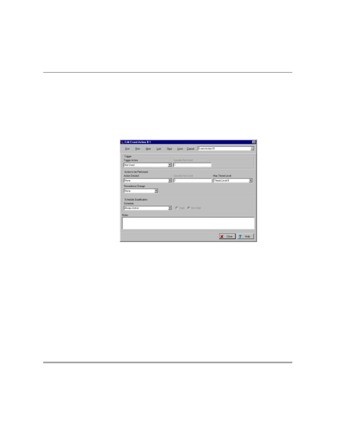
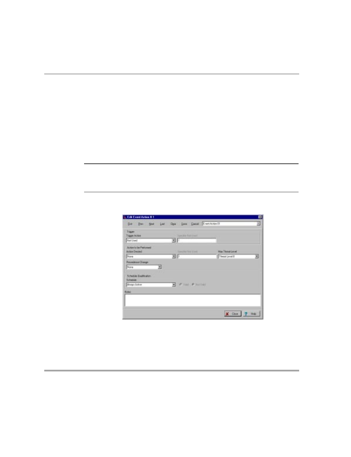
1. Go to the Event/Actions screen in the PassPoint ACS. A screen similar to the
following will be displayed. (Refer to the PassPoint ACS manuals.)
2. In the Trigger Action field, select “Upon an Access Denial” to select one access
point or select “Upon any Access Denial” to select all access points.
3. If “Upon an Access Denial” was selected above, in the Specifier = AccPT # field,
enter the access point number where the denial is to trigger the relay. Note that
this field is not shown if “Upon any Access Denial” was selected.
4. In the Action Desired field, select “Vista Relay Pulse” as the action to be performed
on the access denial.
5. In the Specifier = Vista Relay # field, enter the number of the VISTA FBS relay
that is to be pulsed.
When the defined access denial occurs, the VISTA FBS relay selected will pulse for
about 2 seconds.
Disarm a VISTA FBS Partition on an Access Grant
The PassPoint ACS can be configured so that an access grant at a particular access
point or access grant at any access point will disarm the a VISTA FBS partition.
VGM Installation, Setup, and User Guide
2–30
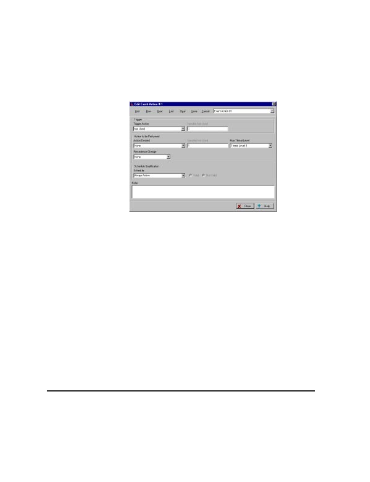
1. Go to the Event/Actions screen in the PassPoint ACS. A screen similar to the
following will be displayed. (Refer to the PassPoint ACS manuals.)
2. In the Trigger Action field, select “Upon an Access Grant” to select one access point
or select “Upon any Access Grant” to select all access points.
3. If “Upon an Access Grant” was selected above, in the Specifier = AccPT # field,
enter the access point number where the grant is to disarm a partition. Note that
this field is not shown if “Upon any Access Grant” was selected.
4. In the Action Desired field, select “Disarm Vista Ptn” as the action to be performed
on the access grant.
5. In the Specifier = Vista Ptn # field, enter the number of the VISTA FBS partition
that is to be disarmed.
Lock/Protect an Access Point upon VISTA FBS Burglar Alarm/Restore
The PassPoint ACS can be configured so that an access can be locked when a burglar
alarm occurs on the VISTA FBS and then the access point revert back to the protected
status when the burglar alarm is restored.
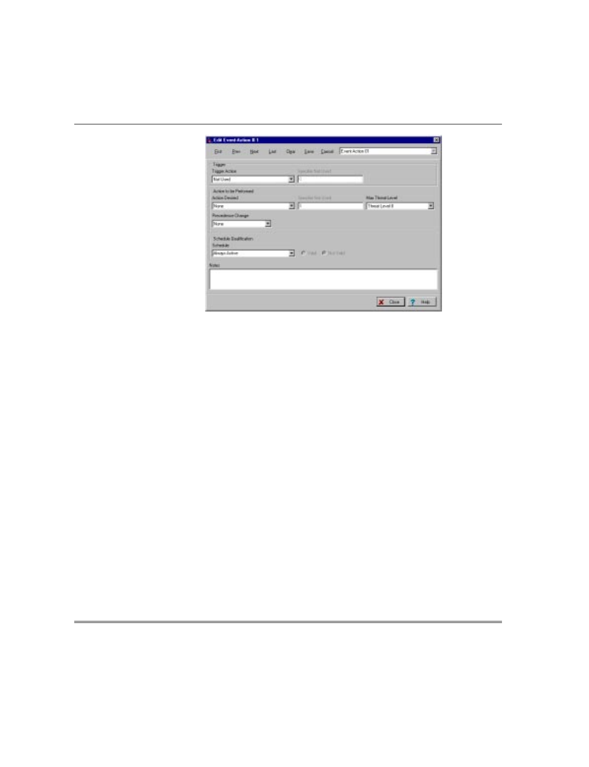
1. Go to the Event/Actions screen in the PassPoint ACS. A screen similar to the
following will be displayed. (Refer to the PassPoint ACS manuals.)

Section 2 - VGM as an ACS/VISTA Interface
2–31
2. In the Trigger Action field, select “Upon Vista Burg Alarm in Ptn”.
3. In the Specifier = Vista Ptn # field, enter the partition number where a burglar
alarm occurrence is to lock the access point.
4. In the Action Desired field, select “Lock Access Point” as the action to be performed
when the burglar alarm occurs.
5. In the Specifier = AccPt # field, enter the number of the access point that is to be
locked.
6. Select Save and then select Next. The Event/Action will be saved and the
PassPoint ACS will advance to the next Event/Action.
7. In the Trigger Action field, select “Upon Vista Burg Alarm Rest in Ptn”.
8. In the Specifier = Vista Ptn # field, enter the same partition number as the one
entered above.
9. In the Action Desired field, select “Protect Access Point” as the action to be
performed when the burglar alarm is restored.
10.In the Specifier = AccPt # field, enter the same access point number as the one
entered above.
Synchronize Arming/Disarming of PassPoint ACS and VISTA FBS
The PassPoint ACS/VISTA FBS can be configured so that when either system is
armed, the other system will be armed and when either system is disarmed, the other
system will be disarmed.
1. Go to the Event/Actions screen in the PassPoint ACS. A screen similar to the
following will be displayed. (Refer to the PassPoint ACS manuals.)
VGM Installation, Setup, and User Guide
2–32
2. In the Trigger Action field, select “Upon ACS Burg Sys Arming Away”.
3. In the Action Desired field, select “Arm Vista Ptn Away” as the action to be
performed when the ACS Burg System is armed.
4. In the Specifier = Vista Ptn # field, enter the number of the partition that is to be
armed.
5. Select Save and then select Next. The Event/Action will be saved and the
PassPoint ACS will advance to the next Event/Action.
6. Repeat steps 3 through 5 for each VISTA FBS partition to be synchronized.
7. In the Trigger Action field, select “Upon Vista Burg System Armed Away”.
8. In the Action Desired field, select “Arm ACS Burg System Away” as the action to
be performed when the VISTA FBS is armed.
9. Select Save and then select Next. The Event/Action will be saved and the
PassPoint ACS will advance to the next Event/Action.
10.In the Trigger Action field, select “Upon ACS Burg System Disarming”.
11.In the Action Desired field, select “Disarm Vista Partition” as the action to be
performed when the when the ACS Burg System is disarmed.
12.In the Specifier = Vista Ptn # field, enter the number of the partition that is to be
disarmed.
13.Select Save and then select Next. The Event/Action will be saved and the
PassPoint ACS will advance to the next Event/Action.
14.Repeat steps 10 through 13 for each VISTA FBS partition to be synchronized.
15.In the Trigger Action field, select “Upon Vista Burg System Disarming”.
Section 2 - VGM as an ACS/VISTA Interface
2–33
16.In the Action Desired field, select “Disarm ACS Burglary System” as the action to
be performed when the VISTA FBS is disarmed.
17.Select Save.
When the PassPoint ACS is armed or disarmed, the VISTA FBS will be armed or
disarmed. Also, when the VISTA FBS is armed or disarmed, the PassPoint ACS will
be armed or disarmed.
Bypass/Protect Access Point upon VISTA FBS Fire Alarm/Restore
The PassPoint ACS can be configured so that an access point can be bypassed when a
fire alarm occurs on the VISTA FBS and then the access point will revert back to the
protected status when the fire alarm is restored.
ULBypass/Protect Access Point upon VISTA FBS Fire Alarm/Restore is not a UL listed
feature.
1. Go to the Event/Actions screen in the PassPoint ACS. A screen similar to the
following will be displayed. (Refer to the PassPoint ACS manuals.)
2. In the Trigger Action field, select “Upon Vista Fire Alarm in Ptn”.
3. In the Specifier = Vista Ptn # field, enter the partition number where a fire alarm
occurrence is to bypass the access point.
4. In the Action Desired field, select “Bypass Access Point” as the action to be
performed when the fire alarm occurs.

VGM Installation, Setup, and User Guide
2–34
5. In the Specifier = AccPt # field, enter the number of the access point that is to be
bypassed.
6. Select Save and then select Next. The Event/Action will be saved and the
PassPoint ACS will advance to the next Event/Action.
7. In the Trigger Action field, select “Upon Vista Fire Alarm Rest in Ptn”.
8. In the Specifier = Vista Ptn # field, enter the same partition number as the one
entered above.
9. In the Action Desired field, select “Protect Access Point” as the action to be
performed when the fire alarm is restored.
10.In the Specifier = AccPt # field, enter the same access point number as the one
entered above.
PassPoint ACS MLB Supervision by the VISTA FBS
PassPoint ACS MLB Supervision by the VISTA FBS can only be enabled by the system
installer.
The VISTA FBS can be programmed to supervise the PassPoint ACS MLB and report
any failure that may occur.
1. Enter the ZONE PROGRAMMING section in the #93 Menu Mode on the VISTA
FBS.
2. Select a zone to assign to the MLB Supervision.
3. Program this zone with a zone response type 28 (MLB Supervision).
4. Enter the partition number.
5. Enter the desired report code.
6. Define if the zone should activate a bell or relay.
9. Define the input type as 00 (none).
The zone defined will provide supervision for the PassPoint ACS MLB and in the
event of a failure, perform the actions defined for activating a bell or relay and send
the defined report code.

A–1
APPENDIX A
Events Reported to Central Station
•••••••••••••••••••••••••••••••••••••••••••
PassPoint Events Reported to Central Station
All events are logged, and are defaulted to dial to the central station. The following
provides an example of the format of a typical message sent to the Central Station:
8888 - E140 - 09 - C206 GENERAL ALARM 206
ACCOUNT
NUMBER EVENT
TYPE PARTITION
(09 =ACS)
ZONE/CONTACT ID NUMBER,
USER NUMBER, OR
SYSTEM STATUS MESSAGE
Event Cause Default
Priority Contact ID
Code
Configuration Setting Changes
PROG MODE
ENTERED: The installer enters Programming mode. When changes are
made and downloaded, the system may enter the Reduced
Capability mode.
2 E429 ACS Prog
Mode Entry
PROG MODE EXIT: The installer exits Programming mode and the system returns
to normal operation. 2 E430 ACS Prog
Mode Exit
SYSTEM DEFAULTS
LOADED: The installer reprograms the system to its factory default
settings. 2 E306 Panel
Prog Change
SYSTEM TIME SET: A user alters the time setting of the system. 2 E625 Time Set
EVENT LOG
CLEARED: A user clears all event log contents. 2 E621 Event Log
Cleared
Access Point-Related Events
PROTECT ACCESS
POINT: An access point is set to its normal operation state. In Protect
mode, the access point will service entries and exits as
determined by the access point’s configuration.
1 R577 Access
Point Protect
BYPASS ACCESS
POINT: An access point has been set to Bypassed mode. This access
point no longer requires card swipes or RTE zone faults to
request entry or exit. The locking mechanism is disengaged,
and the door can swing freely.
1 E577 Access
Point Bypass
EXIT ONLY ACCESS
POINT: An access point is set to Exit-Only mode. The access point will
only accept requests to exit through the access point either via
an RTE zone or an exit reader.
1 R577 Access
Point Protect
TIMED BYP ACCPT
START: An access point has been set to Timed Bypassed mode. This
access point no longer requires card swipes or RTE zone faults
to request entry or exit. The locking mechanism is disengaged,
and the door can swing freely. The access point will
automatically return to the Protected mode at the expiration of
the given time period.
1 E577 Access
Point Bypass

VGM Installation, Setup, and User Guide
A–2
Event Cause Default
Priority Contact ID
Code
TIMED BYP->PROT
ACCPT: An access point is automatically set to its normal operation
state. In Protect mode, the access point will service entries and
exits as determined by the access point’s configuration.
1 R577 Access
Point Protect
LOCK ACCESS
POINT: An Access Point is set to the locked operational state. When
locked, the access point will not accept any entry or exit
requests.
1 R577 Access
Point Protect
SHUNT ACCPT DSM: An access point’s Door Status Monitor Zone is shunted. The
access point will operate as though it did not have a Door
Status Monitor Zone assigned and wired to it. This might have
been done by a user if the DSM Zone is awaiting repair.
1 E434 Access
Point DSM
Shunt
UNSHUNT ACCPT
DSM: An access point’s Door Status Monitor Zone is unshunted. The
access point will once again operate using the Door Status
Monitor Zone assigned and wired to it. This might have been
done by a user if the DSM Zone returns to normal operation
(i.e., it was repaired).
1 R434 Access
Point DSM
Unshunt
SHUNT ACCPT RTE: N/A in this revision. Occurs when an access point’s Request to
Exit Zone is shunted. The access point will operate as though it
did not have an RTE Zone assigned and wired to it. This might
have been done by a user if the RTE Zone is awaiting repair.
1 E433 Access
Point RTE
Shunt
UNSHUNT ACCPT
RTE: N/A in this revision. Occurs when an access point’s Request to
Exit Zone is unshunted. The access point will once again
operate using the RTE Zone assigned and wired to it. This
might have been done by a user if the RTE zone returns to
normal operation (i.e., it was repaired).
1 R433 Access
Point RTE
Unshunt
Relay-Related Events
RELAY DISABLED: An output relay is disabled. The output relay will remain in its
current state (on or off) until enabled. Relay On and Relay Off
commands will no longer be responded to for this output relay.
1 E520 Relay
Disable
RELAY ENABLED: An output relay is enabled. The output relay will return to a
commandable state. 1 R520 Relay
Enable
Trigger-Related Events
TRIGGER
DISABLED: An output trigger is disabled. The output trigger will remain in its
current state (on or off) until enabled. Trigger On and Trigger
Off commands will no longer be responded to for this output
trigger.
1 E520 Relay
Disabled
TRIGGER ENABLED: An output trigger is enabled. The output trigger will return to a
commandable state. 1 R520 Relay
Enabled
Reader-Related Events
READER DISABLED: An uncommitted reader is disabled. The reader will no longer
process card swipes. 1 E501 Reader
Disable
READER ENABLED: An uncommitted reader is enabled. The reader will process card
swipes. 1 R501 Reader
Enable
Zone-Related Events
BYPASS ZONE: An uncommitted zone is bypassed. This zone will no longer
cause an alarm. 1 E570 Zone
Bypass
PROTECT ZONE: An uncommitted zone is bypassed. This zone may cause an
alarm if the burglary system is armed appropriately for the
zone’s response type.
1 R570 Zone
Bypass Restore

Appendix A - Events Reported to Central Station
A–3
Event Cause Default
Priority Contact ID
Code
SHUNT ZONE: An uncommitted zone is shunted. This zone’s status will no
longer be monitored by the system. The zone can no longer
cause an alarm.
1 E576 Zone
Shunt
UNSHUNT ZONE: An uncommitted zone is unshunted. The system will once again
monitor the zone input. This zone may cause an alarm if the
burglary system is armed appropriately for the zone’s response
type.
1 R576 Zone
Unshunt
Access Control-Related Events
THREAT LEVEL
CHANGED: The operational threat level of the system is altered. 5 E431 Threat Lvl
Chg
DURESS ACCESS
EVENT: Duress PIN code was used at an entry reader of an access
point. The cardholder was granted access. 4 E124 Duress
Access Grant
DURESS EGRESS
EVENT: Duress PIN code was used at an exit reader of an access point.
The cardholder was granted egress. 4 E125 Duress
Egress Grant
ACCPT DOOR TIME: After granting access or egress, an access point door was held
open longer than the allotted door open time. The access point
will not accept card swipes until the door is closed properly.
This event can only occur if a Door Status Monitor Zone is
configured for the access point.
2 E426 Door Prop
Alarm
ACCPT DOOR TIME
REST: After granting access or egress, an access point door that was
held open longer than the allotted door open time has been
closed properly. The access point will now revert to normal
operation. This event can only occur if a Door Status Monitor
Zone is configured for the access point.
2 R426 Door
Prop Alarm
Restore
ACCPT DOOR OPEN
ALARM: An access point door was forced open without proper access or
egress being granted. The access point will not accept card
swipes until the door is closed properly. This event can only
occur if a Door Status Monitor Zone is configured for the access
point.
3 E423 Door
Force Alarm
ACCPT DOOR OPEN
REST: An access point door that was forced open without proper
access or egress being granted has been closed. The Access
Point will now revert to normal operation. This event can only
occur if a Door Status Monitor Zone is configured for the access
point.
3 R423 Door
Force Alarm
Restore
Remote Connection-Related Messages
These events will only occur if the ACS is administered remotely using modem communications.
MODEM ERROR: The ACS is experiencing trouble communicating with a modem. 2 E333 Module
Comm Fail
MODEM RESTORE: The ACS has successfully communicated with a modem after
experiencing a modem error. 2 R333 Module
Comm Fail Rest
CAN NOT
CONNECT: The ACS could not reach its PC host. 2 E354 Fail to
Comm
Diagnostic and Test Mode Events
ACCPT RTE ZNE
TRB: The Request to Exit Zone of an access point is experiencing a
wiring trouble condition. This event can only occur if a Request
to Exit Zone is configured for the access point.
2 E428 Access
Point RTE
Trouble

VGM Installation, Setup, and User Guide
A–4
Event Cause Default
Priority Contact ID
Code
ACCPT RTE TRB
REST: The Request to Exit Zone of an access point is no longer
experiencing a wiring trouble condition. This event can only
occur if a Request to Exit Zone is configured for the access
point.
2 R428 Access
Point RTE
Trouble Restore
ACCPT DSM ZNE
TRB: The Door Status Monitor Zone of an access point is
experiencing a wiring trouble condition. This event can only
occur if a Door Status Monitor Zone is configured for the access
point.
2 E427 Access
Point DSM
Trouble
ACCPT DSM TRB
REST: The Door Status Monitor Zone of an access point is no longer
experiencing a wiring trouble condition. This event can only
occur if a Door Status Monitor Zone is configured for the access
point.
2 R427 Access
Point DSM
Trouble Restore
ACCPT RELAY
SUPV FAIL: The Door Control Relay of an access point that operates the
door’s locking mechanism has detected that the locking
device’s power has failed. This event can only occur if the
access point’s door control relay was configured to monitor the
voltage of the locking device.
2 E432 Access
Point Relay
Supervision Fail
ACCPT RLY SUPV
REST: The door control relay of an access point that operates the
door’s locking mechanism has detected that the locking
device’s power has returned. This event can only occur if the
access point’s door control relay was configured to monitor the
voltage of the locking device.
2 R432 Access
Point Relay
Supervision
Restore
RELAY SUPV FAIL: The output relay has detected that its controlled device’s power
has failed. This event can only occur if the output relay was
configured to monitor the voltage of the controlled device.
2 E320 Relay
Supervision Fail
RELAY SUPV REST: The output relay detected that the power has returned to its
controlled device. This event can only occur if the output relay
was configured to monitor the voltage of the controlled device.
2 R320 Relay
Supervision
Restore
COMM FAIL: The MLB has experienced a communications failure with the
indicated module. 2 E333 Comm
Fail
COMM FAIL
RESTORE: The MLB has experienced a return of communications with the
indicated module. 2 R333 Comm
Fail Restore
LOW BATTERY: A module within the system is experiencing a low battery
condition. This event will only occur at modules that have been
programmed to monitor their battery condition.
2 E338 Module
Low Battery
LOW BATT
RESTORE: A module within the system that was experiencing a low battery
condition has detected that the battery has now been properly
charged. This event will only occur at modules that have been
programmed to monitor their battery condition.
2 R338 Module
Low Battery
Restore
AC PWR LOSS: A module within the system is experiencing an AC loss
condition. This event will only occur at modules that have been
programmed to monitor their AC power condition.
2 E342 Module
AC Loss
AC PWR RESTORE: A module within the system that was experiencing an AC loss
condition has detected that the AC line power has now been re-
applied. This event will only occur at modules that have been
programmed to monitor their AC power condition.
2 R342 Module
AC Restore
SYSTEM RESET: The system powers up or resets in response to a user request. 2 E305 System
Reset

Appendix A - Events Reported to Central Station
A–5
Event Cause Default
Priority Contact ID
Code
SYSTEM
SHUTDOWN: The system is shut down due to a user request or in response
to a power loss. 5 E308 System
Shutdown
WALK TEST START: A user starts VISTA Burglary System Walk Test. 1 E607 Burg
Walk Test Start
WALK TEST END: A user ends VISTA Burglary System Walk Test. 1 R607 Burg
Walk Test End
MANUAL SYS
RESET: A user deliberately reset the ACS. 1 E313
Engineer Reset
DIALER TEST: A periodic test report was sent to a monitoring central station. 2 E602 Periodic
Dialer Test
DIALER COMM FAIL: A monitoring central station could not be reached. (While this
event is intended to be dialed, it doesn’t actually reach central
station due to communication fail.)
2 E350 Centrl
Station Comm
Fail
DIALER COMM
REST: A monitoring central station could once again be reached. 2 R350 Centrl
Station Comm
Rest
MODULE RESET
OCCURRED: A module within the system experienced a reset condition. 1 E339 Module
Reset
MODULE WDRST
OCCURRED: A module within the system experienced a reset condition. 1 E339 Module
Reset
Uncommitted Zone-Related Events
ZONE TROUBLE: A wiring trouble condition has occurred at the indicated
uncommitted zone. 2 E380 Zone
Trouble
ZONE TRB REST: A wiring trouble condition has cleared at the indicated
uncommitted zone. 2 R380 Zone
Trouble Restore
ZONE ALARM: A zone alarm condition has occurred at the indicated
uncommitted zone. 3 E140 Zone
Alarm
ZONE ALM REST: A zone alarm condition has restored at the indicated
uncommitted zone. 3 R140 Zone
Alarm Restore
BURG SYS ARMED
AWAY: The burglary system of the access control panel is Armed Away 3 R401 Close
Away
BURG SYS ARMED
STAY: The burglary system of the access control panel is Armed Stay 3 R441 Close
Stay
BURG SYS
DISARMED: The burglary system of the access control panel is disarmed 3 E401 Open
BURG SYS FRC
ARMED AWAY: The burglary subsystem of the ACS was Armed Away,
automatically bypassing any zones that were faulted. 3 R401 Close
Away
BURG SYS FRC
ARMED STAY: The Burglary subsystem of the ACS was Armed Stay,
automatically bypassing any zones that were faulted. 3 R441 Close
Stay
ALARM SOUNDER
TIMEOUT: The Alarm Sounder Relay Output that has been assigned for
use as the Burglary Sounder was turned Off prior to the bell
timeout. The Normally open contacts of the Form-C Relay will
be disconnected, and the normally closed contacts of the Form-
C Relay will be connected.
1 E406 Cancel

VGM Installation, Setup, and User Guide
A–6
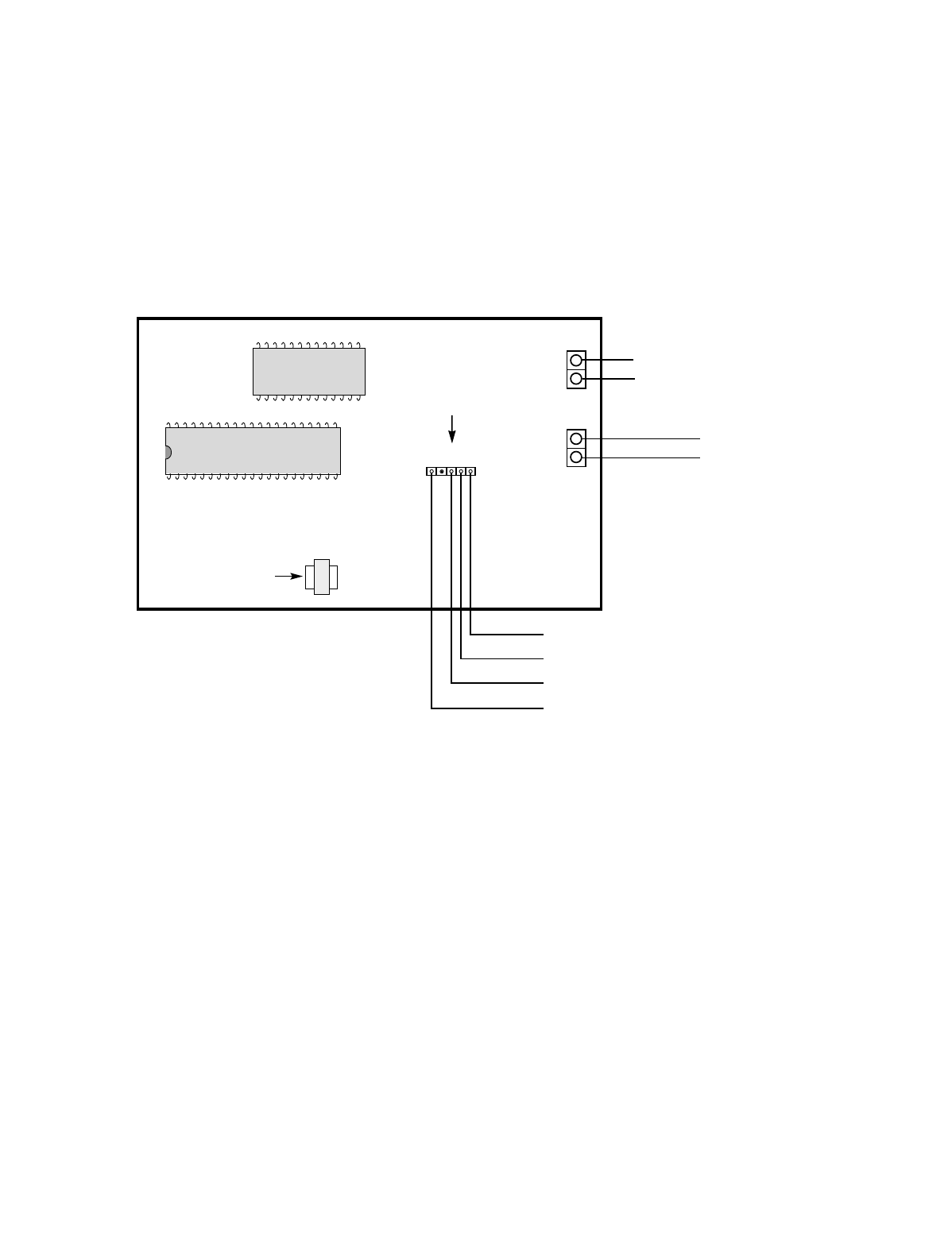
}
TO PASSPOINT ACS
MLB TERMINALS 15 & 16
OR OTHER MODULES
(TWISTED PAIR,
NETWORK CONNECTION)
YELLOW
RED
BLACK
PROM C
TRANSFORMER
}
GREEN
}
GROUND
+14VDC MAX.
VGM
5
6
7
8
4-PIN
KEYPAD
PLUG
J1
FROM
POWER
SUPPLY
(SEE NOTE)
TO VISTA FSB
CONTROL PANEL
KEYPAD TERMINALS
(SEE NOTE)
NOTE:
THE VGM DRAWS APPROXIMATELY 150MA. POWER CAN
BE SUPPLIED BY A POWER SUPPLY OR THE KEYPAD
TERMINALS ON THE VISTA FSB. IF A POWER SUPPLY IS
BEING USED, IT IS NOT NECESSARY TO CONNECT THE
RED AND BLACK WIRE TO THE VISTA FSB: HOWEVER,
THE GROUND OF THE POWER SUPPLY MUST BE
CONNECTED TO THE VISTA FSB - KEYPAD CONNECTION.
WARNING:
DO NOT APPLY POWER TO THE SYSTEM UNTIL ALL CABLES, INCLUDING POWER CONNECTIONS,
ARE ATTACHED. MAKE SURE THAT THE COMPONENT SUPPLYING POWER TO THE VGM, WHETHER A
SEPARATE POWER SUPPLY OR ANOTHER MODULE, IS NOT POWERED WHILE CONNECTING THE
VGM. AFTER ALL CONNECTIONS ARE COMPLETE, POWER MAY BE APPLIED TO THE SYSTEM.
VISTA Gateway Module, Summary of Connections

¬.;l
K3598 03/99
165 Eileen Way, Syosset, New York 11791
Copyright © 1999 PITTWAY CORPORATION
