EPHB Sec.01 98 Articulated Truck 725 Performance Handbook 416C
User Manual: Articulated Truck 725
Open the PDF directly: View PDF ![]() .
.
Page Count: 1014 [warning: Documents this large are best viewed by clicking the View PDF Link!]
- Performance Handbook
- Contents
- Track-Type Tractors
- Waste Disposal Track-Type Tractors
- Hydraulic Controls
- Rippers
- Winches
- Bulldozers
- Agricultural Tractors
- Motor Graders
- Excavators
- Specifications
- Shipping Dimensions
- General Dimensions
- Shipping Information
- Major Component Weights
- Range Dimensions
- Lifting Capacity (Definition)
- Lifting Capacity at Ground Level (Charts)
- Bucket Capacity (Definition)
- Curl and Crowd Forces
- Bucket Specifications
- Working Weights (Bucket & Payload)
- Equipping Excavators
- Cycle Time Estimating Charts
- Earthmoving Production
- Trenching Production
- 5000 Series
- Material Handling Arrangements
- Backhoe Loaders
- Wheel Skidders
- Track Skidders
- Pipelayers
- Wheel Tractor-Scrapers
- Features
- Specifications
- Tire Options, All Models
- Use of Rimpull-Speed-Gradeability Curves
- Use of Travel Time Charts
- Fixed Times for Scrapers
- Use of Retarder Curves
- Curves/Charts
- 613C Series II Rimpull, Travel Times
- 615C Series II Rimpull, Travel Times
- 621F Rimpull, Retarding, Travel Times
- 623F Rimpull, Retarding, Travel Times
- 627F Rimpull, Retarding, Travel Times
- 631E Series II Rimpull, Retarding, Travel Times
- 633E Series II Rimpull, Retarding, Travel Times
- 637E Series II Rimpull, Retarding, Travel Times
- 651E Rimpull, Retarding, Travel Times
- 657E Rimpull, Retarding, Travel Times
- Distance vs. Production Bm3 (BCY)/hr
- Hourly Production vs. Cycle Time
- Construction & Mining Trucks/Tractors
- Features
- Truck Specifications
- Tractor Specifications
- Tire Specifications
- Use of Brake Performance Curves
- Fixed Times for Hauling Units
- Mechanical Power Train Efficiencies
- Curves
- 769D Rimpull-Speed-Gradeability, Brake Performance, Travel Time
- 771D Rimpull-Speed-Gradeability, Brake Performance, Travel Time
- 773D Rimpull-Speed-Gradeability, Brake Performance, Travel Time
- 775D Rimpull-Speed-Gradeability, Brake Performance, Travel Time
- 776D,777D Rimpull-Speed-Gradeability, Brake Performance, Travel Time
- 784C,785C Rimpull-Speed-Gradeability, Brake Performance, Travel Time
- 789C Rimpull-Speed-Gradeability, Brake Performance, Travel Time
- 793C Rimpull-Speed-Gradeability, Brake Performance, Travel Time
- Articulated Trucks
- Features
- Specifications
- Special Arrangements
- Ground Pressure
- Curves: Brake/Retarder Performance
- D25D Curve, Rimpull, Travel Time (Loaded and Empty)
- D30D Curve, Rimpull, Travel Time (Loaded and Empty)
- D250E Curve, Rimpull, Travel Time (Loaded and Empty)
- D300E Curve, Rimpull, Travel Time (Loaded and Empty)
- D350E Curve, Rimpull, Travel Time (Loaded and Empty)
- D400E Curve, Rimpull, Travel Time (Loaded and Empty)
- Wheel Tractors and Soil/Landfill Compactors
- Wheel Loaders & Track Loaders
- Wheel Loaders
- Waste Handling Wheel Loaders
- Track Loaders
- Waste Disposal Track Loaders
- Integrated Toolcarriers
- Telescopic Handlers
- Paving Products
- Elphinstone Underground Machines
- Hydromechanical Work Tools
- Engines
- Former Models
- Track-Type Tractors
- Agricultural Tractors
- Motor Graders
- Hydraulic Excavators--Track
- Hydraulic Excavators--Wheel
- Logging and Forest Product Machines
- Wheel Skidders
- Backhoe Loaders
- Pipelayers
- Wheel Tractor-Scrapers
- Tractor-Towed Scrapers
- Construction & Mining Trucks/Tractors
- Articulated Trucks
- Wheel Tractors
- Compactors
- Wheel Loaders
- Track Loaders
- Integrated Toolcarriers
- Paving Products
- Underground Mining
- Estimating Owning & Operating Costs
- Estimating Form
- Explanation of Form:
- Estimating Owning Costs
- Guide for Selecting Ownership Period
- Agricultural Tractors Depreciation
- Delivered Price
- Residual Value at Replacement
- Value to be Recovered Through Work
- Interest
- Insurance
- Taxes
- Fuel Consumption Tables
- Lube Oils, Filters, Grease Tables
- Tires:
- Tire Life Estimator Curves
- Goodyear Life Estimating System
- Undercarriage
- Basic Factors and Conditions Multipliers
- Repair Reserve
- Cost Estimating Bar Graphs
- Special Wear Items
- Operator's Hourly Wage
- Estimating Owning Costs
- O & O Cost Examples
- Quick Estimators
- Tires
- Selection, Application, Maintenance
- Tire Construction
- Tire Types
- Tire Size Nomenclature
- Code Identification for Off-Highway Tires
- Manufacturers' Designations
- Mining and Earthmoving
- Logging and Forest Products
- Estimating wheel and Track Skidder Production
- Load Capacity Curves for Wheel Loaders and Integrated Toolcarriers
- Forestry Machines
- Log Loader Lift and Range Diagrams
- Heel Boom Grapples
- Woodchips Dozers & Scoops
- High Speed Disc Saws
- 320B Stroke Delimber
- Logging Forks for Wheel Loaders and Integrated Toolcarriers
- Log Volume Tables
- Weights of Commercially Important Woods
- Estimating Number of Trees
- Comparison of Log Rules
- Measurement Definitions
- Stockpile Coal Handling
- Land Clearing
- Waste Disposal
- Tables
- Index
Caterpillar
Performance
Handbook
Edition 29
®

1
TRACK-TYPE TRACTORS 1
AGRICULTURAL TRACTORS 2
MOTOR GRADERS 3
EXCAVATORS 4
BACKHOE LOADERS 5
SKIDDERS 6
PIPELAYERS 7
WHEEL TRACTOR-SCRAPERS 8
CONSTRUCTION & MINING TRUCKS/TRACTORS 9
ARTICULATED TRUCKS 10
WHEEL TRACTORS ●SOIL/LANDFILL COMPACTORS 11
WHEEL LOADERS 12
TRACK LOADERS 13
INTEGRATED TOOLCARRIERS 14
TELESCOPIC HANDLERS 15
PAVING PRODUCTS 16
ELPHINSTONE UNDERGROUND MINING MACHINES 17
HYDROMECHANICAL WORK TOOLS 18
CONTENTS
Page
Preface . . . . . . . . . . . . . . . . . . . . .4
Operator and
Machine Protection . . . . . . . . .5
Replacement Parts Warning . . . .7
Nomenclature . . . . . . . . . . . . . . .8


Machine performance must ultimately be meas-
ured in unit cost of material moved, a measure that
includes both production and costs. Factors bearing
directly on productivity include such things as
weight to horsepower ratio, capacity, type of trans-
mission, speeds and operating costs. The Perfor-
mance Handbook considers these factors in detail.
There are other less direct machine performance fac-
tors for which no tables, charts or graphs are pos-
sible. Serviceability, parts availability and operator
convenience are examples. In comparing machine
performance, all factors should be considered. This
Handbook is intended as an aid which, when coupled
with experience and a good knowledge of local
conditions, can assist in estimating true machine
performance.
Many sections of the Handbook include tables or
curves showing cycle times or hourly production fig-
ures for Caterpillar machines under certain con-
ditions. Statements of conditions always accompany
or precede the curves or tables. Before using any per-
formance information in this Handbook, a complete
understanding of the qualifying conditions is essential.
The data is based on field testing, computer analy-
sis, laboratory research and experience; and every
effort has been made to assure their correctness.
However, all such data is based upon 100% effi-
ciency in operation — a status which cannot be
achieved continuously even under ideal conditions.
Thus, in using such performance and production
data, it is necessary to correct the results indicated
in the handbook tables by appropriate factors. This
allows for the anticipated actual job efficiency, oper-
ator efficiency, material characteristics, haul road
conditions, altitude and other factors which may
reduce performance or production on a particular job.
Methods for estimating machine owning and oper-
ating costs vary widely, depending on locality, indus-
try practices, owner preferences and other factors.
One method is suggested in the Handbook section
on Owning and Operating Costs. When used with
good judgment, it has provided reasonably accurate
estimates in the past. Included in the Owning and
Operating Section are guidelines, based on working
conditions, to assist in estimating consumption of
fuel and lubricants, tire life and repair costs for
Caterpillar machines. However, what one Handbook
user regards as “excellent” conditions, another may
consider “severe” or “average”, depending on his own
experience and basis of comparison. Therefore, these
guidelines should be considered only approximations.
Caterpillar Inc. has made every effort to assure
that the information contained in this Handbook is
accurate and is a fair statement of the results to be
achieved in the circumstances indicated. However,
because of the many variables involved in estimat-
ing the production or performance of earthmoving
machinery, their consumption of fuel and lubricants,
tire life and repair costs, and the possibility of inad-
vertent errors or omissions in assembling this data,
Caterpillar cannot and does not imply that all data
in this book are complete nor that this level of per-
formance will be achieved on a given job.
Specifications shown in this Handbook were cur-
rent at time of printing. However, due to Caterpillar’s
many machine improvement programs, specifica-
tions and materials may change without notice. For
current specifications relating to a machine’s per-
formance, please refer to the most recent Caterpillar
product specification sheet.
Caterpillar Inc.
4
PREFACE

OPERATOR AND
MACHINE PROTECTION
A well trained operator, working under suitable
conditions, utilizing a modern, properly-equipped
machine provides a machine-operator team capable
of giving maximum production. These factors, along
with appropriate job site rules and communication
procedures, are essential to coordinate people and
machines working together. Appropriately protected
and maintained machines are less likely to suffer
premature component failure or damage, and give
operators the confidence and assurance they need
to carry out their work. Furthermore, training is
not complete until the operator reads, understands
and agrees to follow the instructions provided in the
Operation and Maintenance Manual included with
every Caterpillar machine.
Employers have a duty to provide a safe work place
for their employees. The purchaser of a Caterpillar
machine has a duty to review his/her particular appli-
cation and job site for the machine to identify poten-
tial hazards inherent to that application or job site.
Based on the results of this hazard analysis, the
appropriate operator and machine protection con-
figuration can be determined.
Caterpillar designs, builds, and tests its products
to ensure the safety of operators, maintenance per-
sons, service persons, and bystanders. Caterpillar pro-
vides as standard equipment the appropriate operator
and machine protection for most applications. How-
ever, particular applications may require additional
operator and/or machine protection. Caterpillar offers
related options for most such applications. However,
there may be very special applications where the
Caterpillar Dealer or the Purchaser may want to fab-
ricate, or request Caterpillar to provide, custom or
special guarding. Your Caterpillar Dealer can help
you with this hazard analysis and guarding config-
uration process.
I. Operator Training and Protection Practices
Remember that any kind of machine or mechanical
device can be hazardous if not kept in good condi-
tion, or if operated by careless or improperly trained
operators, or if operated in an irresponsible manner.
Listed below are some recommended basic steps
that can be broadly applied to most work environments:
●Train operators for the job they are assigned to
do. The length and type of training must comply
with governmental and local regulations wherever
they apply. As an example, machine operators in
mining activities must be trained in accordance with
Mine Safety and Health Administration (MSHA)
regulations. Where specific regulations do not apply,
no operator should be assigned to a job until he or
she meets the following minimum requirements:
– Completes proper training to operate the assigned
machine and understands that seat belts must be
worn whenever seated in operator’s compartment.
– Reads and understands the Operation & Main-
tenance manual for that machine, and knows
that a copy of that manual is stored in the oper-
ator’s compartment.
– Reads and understands the EMI (Equipment
Manufacturer’s Institute), CIMA (Construction
Industry Manufacturers Association), or any
other furnished manual related to rules for safe
machine operation and identification of hazards.
– Has appropriate personal safety equipment and
knows how to use it. This includes such things
as hard hat, gloves, safety glasses, hearing pro-
tection and safety shoes.
– Knows what the job requirements are, what
other machines are working in the area, and is
aware of any hazardous conditions that may
arise.
●Be sure operators are alert and in proper physi-
cal and mental condition to perform their work
assignments safely. No machine should be oper-
ated by a person who is drowsy, under the affect
of medicines or drugs, suffers blackouts, or is suf-
fering from any physical or mental distraction
that could contribute to unsafe operation.
5

●Maintain proper job conditions and working pro-
cedures. Check the job for possible hazards, both
above and below ground level. Look for all possi-
ble sources of danger to the operator and others
in the area. Pay particular attention to conditions
which may be hazardous or near the operating
limits of the machine: e.g., side slopes, steep grades,
potential overloads, etc. Examine the work site for
restricted traffic patterns, obstructed views, con-
gestion, etc. Hazardous work conditions should
be corrected wherever possible and adequate warn-
ings should be posted when applicable.
●Provide the correct machine to handle the job and
equip it properly for the job to provide the neces-
sary operator protection. Check for compliance
with all applicable governmental and local regu-
lations. It is the machine owner’s or employer’s
legal responsibility to see that his equipment com-
plies with, and is operated in accordance with, all
such requirements.
●Make sure the machine is properly maintained.
A walk-around inspection should be performed at
the beginning of each shift before the machine is
placed in operation. If this inspection reveals any
problems that could affect safety, the machine
must not be operated until these problems are cor-
rected. Some examples include:
– Loose, bent or missing grab irons, railings or
steps;
– Worn, cut or missing seat belts (any seat belt
over three (3) years old must be replaced regard-
less of condition);
– Damaged windows in the operator’s compartment;
– Worn, rubbing or abraded electrical insulation
and hoses;
– Any fluid leaks; and
– Missing or damaged guards.
It is the machine owner’s or employer’s responsi-
bility to ensure the machine is properly maintained.
Your Caterpillar Dealer will be glad to assist you
in selecting and equipping the machine best suited
for your job and in providing maintenance for your
machines.
II. Machine Modifications
Modifications must not be made to the machine
that:
– Interfere with operator visibility;
– Interfere with ingress, egress from the machine;
– Exceed the rated payload or gross combination
weight of the machine resulting in overloading
the braking and/or steering system or the roll-
over protective structure (ROPS) capacity rat-
ing (shown on a plate affixed to the ROPS); or
– Place objects in the cab that intrude into the oper-
ator’s space or that are not firmly fixed into place.
III. Operator-related Equipment Options
Each job presents unique conditions that must be
taken into account. Consider direct dangers to the
operator as well as all possible sources of distrac-
tion that could reduce operator efficiency and increase
the chances of costly and dangerous mistakes. Climate-
controlled, sound-suppressed cabs, and special exte-
rior lighting are options available from Caterpillar
that can address requirements of special working
environments.
“Flexible” machines include hydraulic excavators
(track-type, wheel-type, and compact), skid-steer
loaders, backhoe loaders and integrated tool-carri-
ers. Work tools or any tool used in hazardous appli-
cations like demolition and logging, can create a need
for special operator guarding. When flying debris
from impact, cutting, shearing or sweeping attach-
ments is present, additional protective devices such
as a front screen, Falling Object Guarding System
(FOGS, includes top & front guarding), thick poly-
carbonate windshields or a combination of these is
recommended by Caterpillar. Contact your Caterpillar
Dealer for operator guarding options on your machine.
IV. Machine Protection
Check the job for unusually demanding conditions
that could cause premature failure or excessive
wear of machine components. Additional protective
devices such as heavy-duty radiator guards, crankcase
guards, engine enclosures, track roller guards and/or
brake shields may be needed. Also, consider the use
of anti-vandalism devices, such as cap locks and instru-
ment panel guards. Contact your Caterpillar dealer
for machine-protection and vandalism-prevention
options for your machine.
V. Fire Prevention
Remember that most fluids on your machine are
flammable!
To minimize the risk of fire, Caterpillar recom-
mends following these basic steps:
– Remove trash (leaves, twigs, papers, etc.) that
may accumulate in the engine compartment.
– Do not operate a machine if leakage of flam-
mable fluids is noticed. Repair leaks before
resuming machine operation. Most fluids used
in Caterpillar machines should be considered
flammable.
– Keep access doors to major machine compart-
ments in working order to permit the use of fire
fighting equipment, should a fire occur.
– Avoid attaching electrical wiring to hoses and
tubes that contain flammable or combustible
fluids.
6

– Replace any rubbing, damaged, frayed, kinked
or leaking hydraulic hoses or fittings.
– Follow safe fueling practices as described in
Caterpillar Operation & Maintenance Manuals,
EMI or CIMA Safety Manuals, and local regu-
lations.
As an additional safety measure, keep a 10-pound
(4.5 kg) minimum fire extinguisher on the machine
in a location as specified in the Operator and Mainte-
nance Manual.
VI. Safety Regulations
Regulations vary from country to country and
often within country. Your Caterpillar dealer can
assist you in properly equipping your machine to
meet applicable requirements. Note: The general
summaries given below are not substitutes for
reading and being familiar with the appro-
priate local laws.
(a) United States (US)
With a few exceptions, all machine operations in
the United States are covered by federal and/or state
regulations. If the machine is used in mining activ-
ities, the regulations are administered by the Mine
Safety and Health Administration (MSHA). Other
activities, including construction, are under regu-
lations administered by the Occupational Safety
and Health Administration (OSHA). These agencies
require employers to provide a safe working envi-
ronment for employees. Caterpillar has the same
objective.
OSHA and MSHA have adopted criteria for ROPS,
Falling Object Protective Structures (FOPS), seat
belts, warning horns, back-up alarms, operator sound
levels, steering systems, and braking systems. Addi-
tional operator’s compartment protection may be
required for machines engaged in logging, demoli-
tion and other special applications.
(b) European Union (EU)
The EU Machinery Safety Directive applies to
Caterpillar machines and most work tools. It
requires that the “CE mark” be applied to the prod-
uct and that a manufacturer’s declaration be pro-
vided. The “CE mark” indicates that safety issues
have been addressed by applying the appropriate
safety standards in the design and manufacture of
the machine. The objective of the Safety Directive is
to protect operators, spectators and maintenance
personnel. Caterpillar fully supports this objective.
VII. Sound Suppression
Different marketing areas have different noise
emission requirements. Noise regulations usually
specify limits for operators and spectators.
(a) United States
OSHA and MSHA noise-control regulations set
permissible noise-exposure limits for machine oper-
ators and employees. Operator protection from
machine noise can be achieved by use of factory-
built cabs as offered in the Caterpillar Price List.
These cabs, when properly maintained and oper-
ated with the doors and windows closed, reduce the
operator sound level for an eight-hour operating
period to meet the OSHA and MSHA noise-exposure
limits in effect at the date of manufacture. Variables
that may be encountered on the job site, such as
other nearby noise sources or noise-reflecting sur-
faces, may reduce the allowable work hours. If this
occurs, ear protective devices may be required.
(b) European Union
Operator sound-exposure requirements for
machines in Europe are very similar to the OSHA
and MSHA regulations mentioned above. In addi-
tion to operator sound-exposure requirements, cer-
tain types of Caterpillar machines are subject to
European Commission regulations for exterior sound
levels. Caterpillar ensures its products sold in the
EU comply with the applicable noise regulations.
VIII. Replacement Parts for your
Caterpillar Machine
WARNING
!
7
When replacement parts are required for this product,
Caterpillar recommends using Caterpillar replacement parts or
parts with equivalent specifications including, but not limited
to, physical dimensions, type, strength and material.
Failure to heed this warning can lead to premature failures,
product damage, personal injury or death.
8
Nomenclature
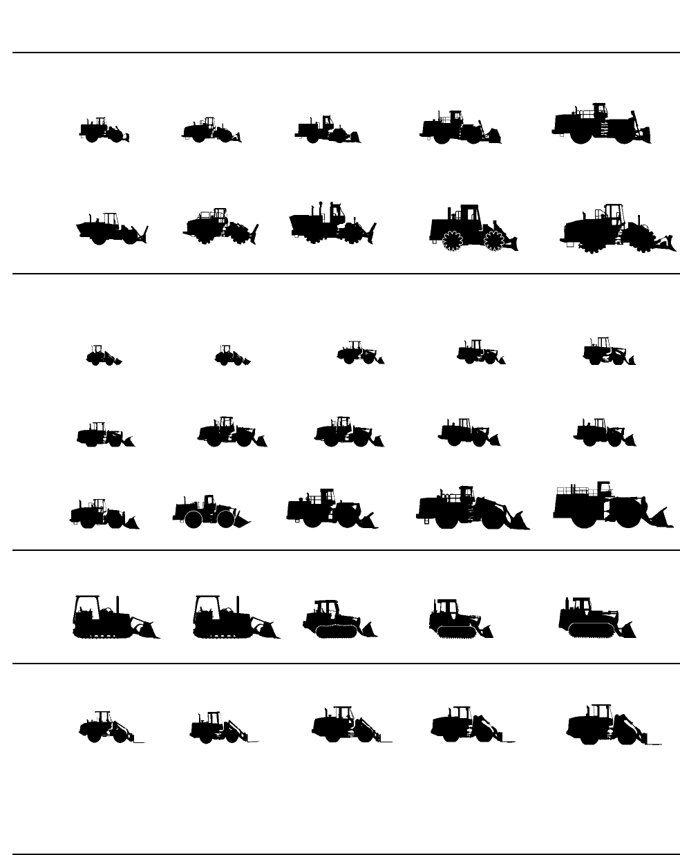
THE CATERPILLAR PRODUCT LINE
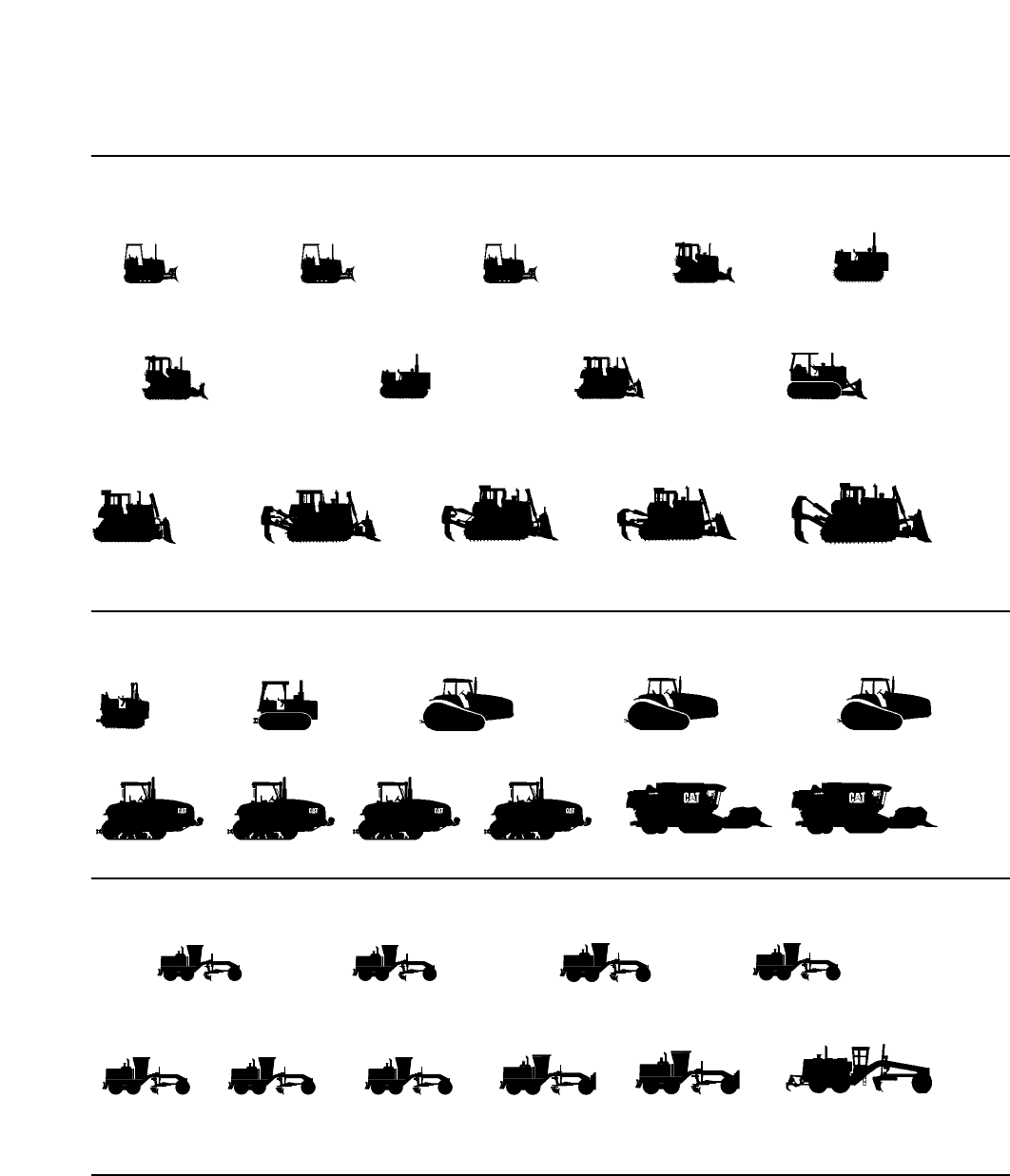
TRACK-TYPE TRACTORS
Flywheel power 52 to 634 kW (70 to 850 hp)
§Brazilian Domestic Only
D3C Series III**
D3C XL Series III**
D3C LGP Series III**
D5C Series III**
D5C XL Series III**
D5C LGP Series III**
D5M XL
D5M LGP D5E§
D6R*
D6R XL
D6R XR
D6R LGP
D6M XL
D6M LGP D6G D7G
D7R*
D7R XR
D7R LGP
D8R*
D8R LGP
D4E SR* D6G SR* Challenger 35 Challenger 45
D9R* D10R* D11R
*Waste Handling Arrangements (WHA)
**available for sanitary landfill applications
**Also available with hydrostatic power train.
AGRICULTURAL EQUIPMENT
*Variable Horsepower arrangements available
(SR) Super Rural
Challenger 75E Challenger 85E*Challenger 65E
Challenger 55
Challenger 95E LEXION 460/465 LEXION 480/485
MOTOR GRADERS
Flywheel power 104 to 373 kW (140 to 500 hp)
120H
120H NA
120H ES
135H
135H NA 12H
12H NA
12H ES
140H
140H NA
140H ES
163H NA* 14H 16H160H
160H NA
160H ES
143H NA*
D4C Series III**
D4C XL Series III**
D4C LGP Series III**
*All Wheel Drive
24H
9
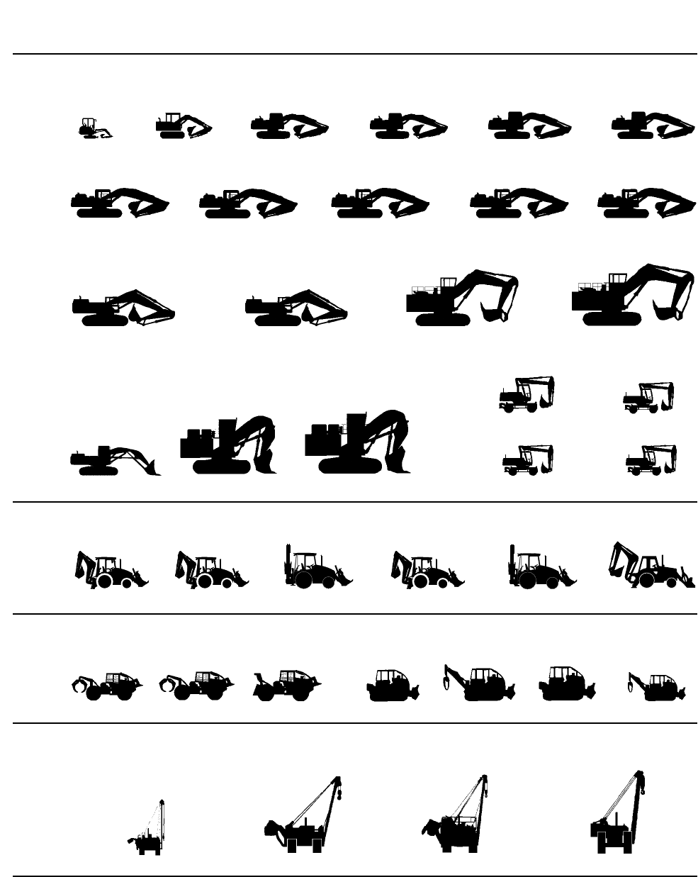
HYDRAULIC EXCAVATORS
Operating Weight 6700 to 316 600 kg (14,770 to 698,000 lb)
Track Models
307B
307B SB 311B 312B
312B L 315B
315B L
320B
320B L
320B N
320B LN
320B S
330B
330B L
330B LN
345B
345B L – FIX
345B L – VG
350
350 L 5130B
322B
322B L
322B LN
325B
325B L
325B LN
301.5
5230
Wheel Models
Front Shovels
Operating Weight 83 800 to 318 500 kg (184,600 to 702,000 lb)
M315
M3185080 5130B 5230
BACKHOE LOADERS
Digging depth 4420 to 6528 mm (14'6" to 21'5")
WHEEL SKIDDERS
Flywheel power 104 to 145 kW (140 to 195 hp) TRACK SKIDDERS
Flywheel power 89 to 112 kW (120 to 150 hp)
PIPELAYERS
Lifting capacity 18 145 to 104 330 kg (40,000 to 230,000 lb)
416C
561M 572R 583R 589
515 525 528B
426C 428C 436C 438C 446B
M312
M320
517 Grapple 527 Cable 527 Grapple517 Cable
375
375 L
318B L
318B LN
10
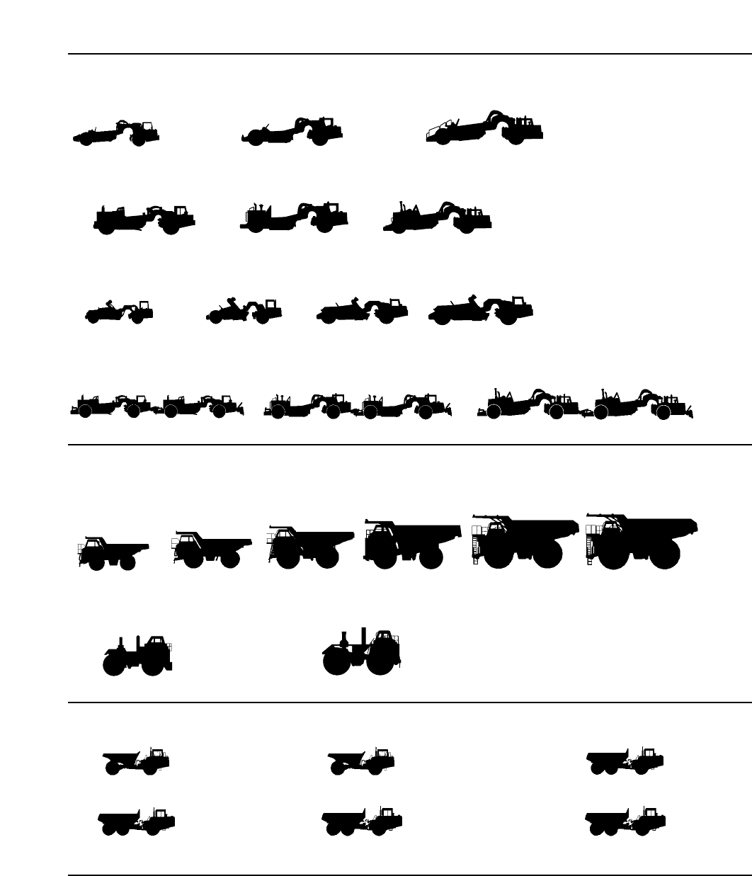
WHEEL TRACTOR-SCRAPERS
CONSTRUCTION & MINING TRUCKS/TRACTORS
ARTICULATED TRUCKS
Capacity 22.7 to 36.3 metric tons (25 to 40 U.S. tons)
Standard Models
Heaped capacity 15.3 to 33.6 m3(20 to 44 yd3)
Elevating Scrapers
Heaped capacity 8.4 to 26 m3(11 to 34 yd3)
Tandem Powered Scrapers
Heaped capacity 15.3 to 33.6 m3(20 to 44 yd3)
Push-Pull Scrapers
Heaped capacity 15.3 to 33.6 m3(20 to 44 yd3)
Construction & Mining Trucks
Capacity 36.8 to 218 metric ton — 40.6 to 240 U.S. tons
Construction & Mining Tractors
Flywheel power 699 to 962 kW (938 to 1290 hp)
621F* 631E Series II* 651E*
613C Series II 615C Series II 623F 633E Series II
627F*
769D
771D Quarry Truck 773D
775D Quarry Truck 777D 785C 789C 793C
D25D D30D
776D 784C
627F
637E Series II*
637E Series II
657E*
657E
D250E Series II
D300E Series II D350E D400E
*Available in auger scraper version
11
WHEEL TRACTORS
Flywheel power 164 to 597 kW (220 to 800 hp)
LANDFILL COMPACTORS
Flywheel power 164 to 353 kW (220 to 473 hp) SOIL COMPACTORS
Flywheel power 164 to 235 kW (220 to 315 hp)
WHEEL LOADERS
Bucket Capacity (Heaped) 1.2 to 30 m3(1.6 to 40 yd3)
* High lift arrangement available.
TRACK LOADERS
Bucket Capacity (Heaped)** 1.0 to 3.6 m3(1.3 to 4.2 yd3)
**Wide track arrangements available.
**General Purpose Bucket.
INTEGRATED TOOLCARRIERS
Bucket Capacity (Heaped)* 1.3 to 3.1 m3(1.7 to 4.0 yd3)
*General Purpose Bucket.
814F 824G 834B
815F 825G
816F 826G 836
844 854G
914G 924F 928G
938G* 950G 962G 966F Series II* 970F
980G* 988F Series II* 990 Series II 992G 994*
933C* 939C 953C* 963B* 973*
IT14G IT24F IT28G IT38G IT62G
906902
12
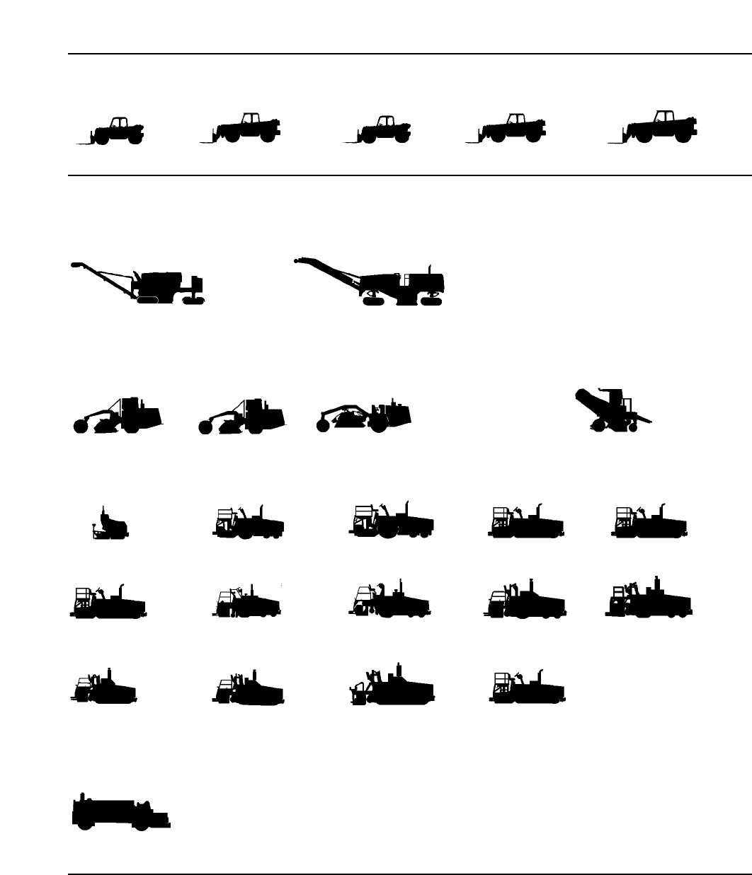
PAVING PRODUCTS
Cold Planers
Cutting widths 1905 & 2100 mm (6'3" & 6'11")
Flywheel Power 343 & 466 kW (460 & 625 hp)
PM-465
RR-250B SS-250B RM-350B BG-650
PM-565B
Reclaimer Mixers/Stabilizer Mixers
Flywheel power 250-321 kW (335-430 hp)
Cutting width 2438 mm (8'0")
Asphalt Pavers
Paving width 914 to 9754 mm (3 to 32 ft)
Road Wideners
Laydown width to 3048 mm (to 10'0")
Windrow Elevators
Operating weight 5897 kg (13,000 lb)
AP-200B AP-800C AP-1000B AP-1050B
BG-210B BG-260C
BG-730
BG-225C BG-245C BG-265B
BG-230 BG-240B
AP-650B
BG-2455C
TH62 TH63 TH82 TH83
TELESCOPIC HANDLERS
TH103
AP-1055B
13
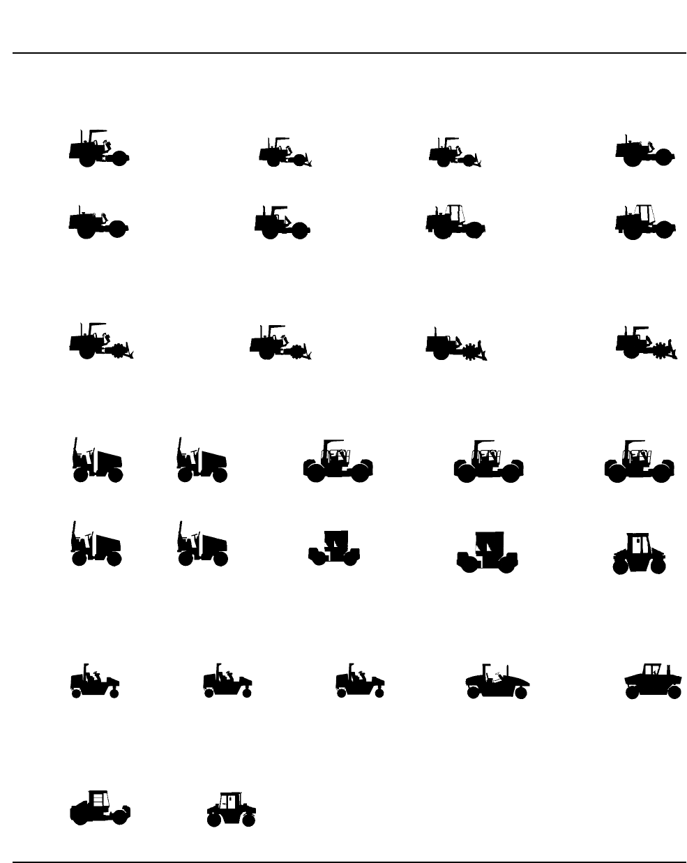
Smooth Drum Vibratory Soil Compactors
Drum width 1270 mm to 2130 mm (4'2" to 7'0")
CS-323C CS-431C CS-433C
CS-533C CS-563C CS-573C CS-583C
CS-531C
PAVING PRODUCTS (Continued)
Padded Drum Vibratory Soil Compactors
Drum width 1270 to 2130 mm (4'2" to 7'0")
Dual Drum Vibratory Asphalt Compactors
Drum width 1000 to 2130 mm (3'3.4" to 7'0")
Pneumatic Tire Asphalt Compactors
Wheel loads 1134 to 5000 kg (2500 to 11,020 lb)
Combination Vibratory Compactor
Drum Width 1700 mm (5'7")
CP-323C
CB-214C
PS-150B PF-300B PS-300B PS-500
CB-535B CB-545
PS-200B PS-360B
CB-224C CB-434C CB-534C CB-634C
CP-433C CP-533C CP-563C
CB-214C CB-224C CB-434B CB-534C CB-544
14
ENGINES
Application configurations
include: On and off highway
trucks, stationary and mobile
industrial, marine, electrical
power generation and petro-
leum. Spark-ignited (SI) avail-
able as noted. Generator set
kW shown is 60 Hertz.
1.1 L Family
• 104 to 224 kW (140 to 300 hp)
Diesel Engine
3200 Family
• 93 to 317 kW (125 to 425 hp)
Diesel Engine
• 160 to 200 kW Diesel
Generator Sets
3500 Family
• 448 to 1641 kW (600 to 2200 hp)
Diesel Engine
• 715 to 2000 kW Diesel
Generator Sets
• 392 to 858 kW (525 to 1150 hp)
SI Engine
• 360 to 800 kW SI Generator Sets
3300 Family
• 64 to 265 kW (85 to 355 hp)
Diesel Engine
• 65 to 250 kW Diesel Generator Sets
• 62 to 164 kW (83 to 220 hp)
SI Engine
• 85 to 150 kW SI Generator Sets
3400 Family
• 186 to 746 kW (250 to 1000 hp)
Diesel Engine
• 210 to 800 kW Diesel
Generator Sets
• 336 kW (450 hp) SI Engine
• 270 to 470 kW SI Generator Sets
3600 Family
• 1560 to 5420 kW (2090 to 7270 hp)
Diesel Engine
• 1375 to 4910 kW Diesel
Generator Sets
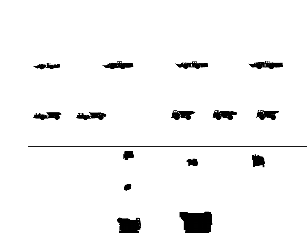
UNDERGROUND MINING (ELPHINSTONE)
Load-Haul-Dump
Bucket sizes 2.4-8.8 m3(3-12 yd3)
AD40 Series II AE40 Series II 69D Dump
Articulated Trucks Rigid Frame Trucks
69D Ejector 73D
R1300 R1600 R2900R1700 Series II
40 t (44 T) capacity 38 t (42 T) 36.2 t (40 T) 52.2 t (58 T)

CONTENTS
TRACK-TYPE TRACTORS
Features . . . . . . . . . . . . . . . . . . . . . . . . . . . . . . .1-2
Specifications . . . . . . . . . . . . . . . . . . . . . . . . . . .1-3
Power shift drawbar pull vs.
ground speed curves . . . . . . . . . . . . . . . . . . .1-13
Power shift travel speeds . . . . . . . . . . . . . . . . .1-20
Direct drive travel speeds and
drawbar pull . . . . . . . . . . . . . . . . . . . . . . . . .1-21
Ground pressures . . . . . . . . . . . . . . . . . . . . . . .1-23
Extreme slope operation . . . . . . . . . . . . . . . . . .1-24
WASTE HANDLING TRACK-TYPE TRACTORS
Features . . . . . . . . . . . . . . . . . . . . . . . . . . . . . .1-25
Specifications . . . . . . . . . . . . . . . . . . . . . . . . . .1-26
Bulldozer specifications . . . . . . . . . . . . . . . . . .1-28
HYDRAULIC CONTROLS
Features . . . . . . . . . . . . . . . . . . . . . . . . . . . . . .1-31
Specifications . . . . . . . . . . . . . . . . . . . . . . . . . .1-32
BULLDOZERS
Features . . . . . . . . . . . . . . . . . . . . . . . . . . . . . .1-35
Summary of blade options . . . . . . . . . . . . . . . .1-36
Blade selection . . . . . . . . . . . . . . . . . . . . . . . . .1-37
General dimensions (Tractor and Blade) . . . . .1-40
Blade specifications . . . . . . . . . . . . . . . . . . . . .1-41
Estimating bulldozer production off-the-job . .1-49
Job condition correction factors . . . . . . . . . . . .1-53
Measuring bulldozer production on-the-job . . .1-54
Special attachments . . . . . . . . . . . . . . . . . . . . .1-54
RIPPERS
Features . . . . . . . . . . . . . . . . . . . . . . . . . . . . . .1-57
Ripper Dimension Drawings
Adjustable Parallelogram Ripper . . . . . . . . .1-58
Radial Ripper . . . . . . . . . . . . . . . . . . . . . . . .1-60
Fixed Parallelogram Ripper . . . . . . . . . . . . .1-60
Specifications
Track-Type Tractors . . . . . . . . . . . . . . . . . . .1-61
Tip selection . . . . . . . . . . . . . . . . . . . . . . . . . . .1-67
Estimating ripping production . . . . . . . . . . . . .1-68
Seismic wave velocity charts . . . . . . . . . . . . . .1-69
Estimating ripper production graphs . . . . . . .1-75
WINCHES
Features . . . . . . . . . . . . . . . . . . . . . . . . . . . . . .1-77
Physical specifications . . . . . . . . . . . . . . . . . . .1-78
Operating specifications . . . . . . . . . . . . . . . . . .1-81
TOWED SCRAPERS
Estimated production . . . . . . . . . . . . . . . . . . . .1-83
TRACK-TYPE TRACTORS
WASTE HANDLING TRACK-TYPE TRACTORS
Hydraulic Controls
Bulldozers
Rippers & Winches
Towed Scrapers
1-1
1

TRACK-TYPE TRACTORS
Features:
●Cat Diesel Engines provide power, high torque
rise, reliability and performance you can depend on.
●Hydraulic Electronic Unit Injection on D9R
and D10R increases fuel efficiency, reduces smoke,
improves cold starting and enhances diagnostic
capabilities.
●Electronic Unit Injection (EUI) on D11R. The
Electronic Control Module (ECM) performs much
like a mechanical governor, but has no moving
parts. The ECM signals the injectors regulating
the fuel supply thus controlling engine speed and
power. EUI provides: Reduced exhaust smoke,
automatic altitude compensation and cold start
protection.
●Oil cooled steering clutches and brakes stan-
dard on all models except the D8R. Improves reli-
ability and component life. Oil disc brakes on
D5M XL and up. Oil cooled contracting band type
used on D3C Series III, D4C Series III and D5C
Series III power shift models.
●Finger Tip Controls (FTC) of transmission,
steering clutches and brakes available on D5M,
D6M, D6R, D7R, D10R and D11R.
●Differential steering allows infinitely variable
turning radius. Standard on the D8R and optional
on the D6R, D7R and D9R, allows the tractor to
make a “power turn” keeping both tracks working
for more traction and higher performance.
●Hydrostatic Power Train System available on
D3C Series III thru D5C Series III allows full
power turns, stepless speed range, smooth mod-
ulation, dynamic hydrostatic braking, superior
maneuverability and excellent controllability.
●Combined hand lever steering located left of
operator provides easier operation on D5M XL,
D6M XL and D9R. Combined pedal steering stan-
dard on the D3C Series III, D4C Series III and D5C
Series III. Optional combined hand lever clutch
and brake for D3C Series III, D4C Series III and
D5C Series III.
●Standard Tractors designed for heavy dozing
and general grading.
●XL Tractors offer higher horsepower and longer
roller frames for increased finish grading capa-
bility, flotation and productivity. Wider gauge
available on D6R XL through Caterpillar Custom
Products.
●Sealed and Lubricated Track reduces pin and
bushing wear for lower undercarriage repair costs.
Heavy duty track chain available on D5M, D6M,
D6R and D7R improves wear life and reduces pin/
bore stretching and cracking.
●Elevated sprockets on D5M XL and up eliminate
final drive stress induced by roller frame move-
ment and ground impact loads. Final drives pull
chain only. Seals moved up out of dirt, sand and
water for longer life. Blade visibility improved
because operator sits higher.
●Resilient mounted bogie undercarriage on
D8R, D9R, D10R and D11R reduces shock trans-
mitted to tractor.
●Solid mounted undercarriage standard on
D3C Series III through D7R and optional on the
D8R provides stable platform for low impact, high
abrasion applications like finish grading and
stockpiling.
●Accessible modular design on D5M XL and up
greatly reduces drive train removal and installa-
tion time resulting in reduced repair costs.
●Tag link on D7R and up; L-shaped push arms on
D6M through D6R. Both designs allow closer
mounting of dozer blades. This reduces total trac-
tor length, improves maneuverability, balance,
blade penetration and pryout.
1-2
Track-Type Tractors Features
D3C D3C Series III D3C XL D3C XL Series III
MODEL Series III Hystat Series III Hystat
Flywheel Power 52 kW 70 hp 52 kW 70 hp 52 kW 70 hp 52 kW 70 hp
Operating Weight*
(Power Shift) 7039 kg 15,518 lb 7112 kg 15,680 lb 7231 kg 15,941 lb 7304 kg 16,103 lb
Engine Model 3046 3046 3046 3046
Rated Engine RPM 2400 2400 2400 2400
No. of Cylinders 6666
Bore 94 mm 3.7" 94 mm 3.7" 94 mm 3.7" 94 mm 3.7"
Stroke 120 mm 4.7" 120 mm 4.7" 120 mm 4.7" 120 mm 4.7"
Displacement 5.0 L 305 in35.0 L 305 in35.0 L 305 in35.0 L 305 in3
Track Rollers (Each Side) 5566
Width of Standard Track Shoe 406 mm 16" 406 mm 16" 406 mm 16" 406 mm 16"
Length of Track on Ground 1899 mm 6'2.8" 1899 mm 6'2.8" 2055 mm 6'8.9" 2055 mm 6'8.9"
Ground Contact Area
(W/Std. Shoe) 1.55 m22390 in21.55 m22390 in21.67 m22586 in21.67 m22586 in2
Track Gauge 1422 mm 4'8" 1448 mm 4'9" 1448 mm 4'9" 1448 mm 4'9"
GENERAL DIMENSIONS:
Height (Stripped Top)** 1.70 m 5'7" 1.70 m 5'7" 1.70 m 5'7" 1.70 m 5'7"
Height (To Top of ROPS) 2.66 m 8'9" 2.73 m 8'11" 2.66 m 8'9" 2.73 m 8'11"
Overall Length (With P Blade) 3.77 m 12'5" 3.98 m 13'1" 4.02 m 13'2" 3.98 m 13'1"
(Without Blade) 2.93 m 9'7" 2.96 m 9'8" 2.98 m 9'9" 2.96 m 9'8"
Width (Over Trunnion) ————
Width (W/O Trunnion —
Std. Shoe) 1.83 m 6'0" 1.85 m 6'1" 1.83 m 6'0" 1.85 m 6'1"
Ground Clearance 322 mm 12.7" 374 mm 14.7" 374 mm 14.7" 374 mm 14.7"
Blade Types and Widths:
Straight ————
Angle ————
Angle Straight ————
Universal ————
Semi-U ————
“P” Straight 2.55 m 8'4" 2.55 m 8'4" 2.55 m 8'4" 2.55 m 8'4"
“P” Angled 2.31 m 7'6" 2.31 m 7'6" 2.31 m 7'6" 2.31 m 7'6"
Fuel Tank Refill Capacity 122 L 32.2 165 L 43.6 165 L 43.6 165 L 43.6
U.S. gal U.S. gal U.S. gal U.S. gal
**Operating Weight includes ROPS canopy, operator, lubricants, coolant, full fuel tank, hydraulic controls and fluids, back-up alarm, seat belts, lights, rigid drawbar, front
pull device and standard service crankcase guard.
**Height (stripped top) — without ROPS, exhaust, seat back or other easily removed encumbrances.
1-3
1
Track-Type TractorsSpecifications
D3C LGP D4C
D3C LGP Series III D4C Series III
MODEL Series III Hystat Series III Hystat
Flywheel Power 52 kW 70 hp 52 kW 70 hp 60 kW 80 hp 60 kW 80 hp
Operating Weight*
(Power Shift) 7640 kg 16,842 lb 7713 kg 17,004 lb 7266 kg 16,019 lb 7326 kg 16,150 lb
Engine Model 3046 3046 3046 3046
Rated Engine RPM 2400 2400 2400 2400
No. of Cylinders 6666
Bore 94 mm 3.7" 94 mm 3.7" 94 mm 3.7" 94 mm 3.7"
Stroke 120 mm 4.7" 120 mm 4.7" 120 mm 4.7" 120 mm 4.7"
Displacement 5.0 L 305 in35.0 L 305 in35.0 L 305 in35.0 L 305 in3
Track Rollers (Each Side) 6666
Width of Standard Track Shoe 635 mm 2'1" 635 mm 2'1" 406 mm 16" 406 mm 16"
Length of Track on Ground 2055 mm 6'8.9" 2055 mm 6'8.9" 2055 mm 6'8.9" 2055 mm 6'8.9"
Ground Contact Area
(W/Std. Shoe) 2.61 m24045 in22.61 m24045 in21.67 m22586 in21.67 m22586 in2
Track Gauge 1676 mm 5'6" 1676 mm 5'6" 1499 mm 4'11" 1499 mm 4'11"
GENERAL DIMENSIONS:
Height (Stripped Top)** 1.70 m 5'7" 1.70 m 5'7" 1.75 m 5'9" 1.75 m 5'9"
Height (To Top of ROPS) 2.66 m 8'9" 2.73 m 8'11" 2.73 m 8'11" 2.73 m 8'11"
Overall Length (With P Blade) 3.99 m 13'1" 3.95 m 13'0" 3.99 m 13'1" 3.99 m 13'1"
(Without Blade) 2.98 m 9'9" 2.96 m 9'8" 2.96 m 9'8" 2.96 m 9'8"
Width (Over Trunnion) ————
Width (W/O Trunnion —
Std. Shoe) 2.29 m 7'6" 2.31 m 7'7" 1.91 m 6'3" 1.91 m 6'3"
Ground Clearance 374 mm 14.7" 374 mm 14.7" 374 mm 14.7" 374 mm 14.7"
Blade Types and Widths:
Straight 2.80 m 9'2" — — —
Angle ————
Angle Straight ————
Universal ————
Semi-U ————
“P” Straight 3.19 m 10'6" 3.19 m 10'6" 2.74 m 9'0" 2.74 m 9'0"
“P” Angled 2.90 m 9'5" 2.90 m 9'5" 2.49 m 8'2" 2.49 m 8'2"
Fuel Tank Refill Capacity 165 L 43.6 165 L 43.6 157 L 41.4 157 L 41.4
U.S. gal U.S. gal U.S. gal U.S. gal
**Operating Weight includes ROPS canopy, operator, lubricants, coolant, full fuel tank, hydraulic controls and fluids, back-up alarm, seat belts, lights, rigid drawbar, front
pull device and standard service crankcase guard.
**Height (stripped top) — without ROPS, exhaust, seat back or other easily removed encumbrances.
1-4
Track-Type Tractors Specifications
1-5
1
Track-Type TractorsSpecifications
D4C XL D4C LGP
D4C XL Series III D4C LGP Series III
MODEL Series III Hystat Series III Hystat
Flywheel Power 60 kW 80 hp 60 kW 80 hp 60 kW 80 hp 60 kW 80 hp
Operating Weight*
(Power Shift) 7458 kg 16,442 lb 7518 kg 16,573 lb 7726 kg 17,032 lb 7785 kg 17,163 lb
Engine Model 3046 3046 3046 3046
Rated Engine RPM 2400 2400 2400 2400
No. of Cylinders 6666
Bore 94 mm 3.7" 94 mm 3.7" 94 mm 3.7" 94 mm 3.7"
Stroke 120 mm 4.7" 120 mm 4.7" 120 mm 4.7" 120 mm 4.7"
Displacement 5.0 L 305 in35.0 L 305 in35.0 L 305 in35.0 L 305 in3
Track Rollers (Each Side) 7766
Width of Standard Track Shoe 457 mm 18" 457 mm 18" 635 mm 2'1" 635 mm 2'1"
Length of Track on Ground 2210 mm 7'3" 2210 mm 7'3" 2055 mm 6'8.9" 2055 mm 6'8.9"
Ground Contact Area
(W/Std. Shoe) 2.02 m23131 in22.02 m23131 in22.61 m24045 in22.61 m24045 in2
Track Gauge 1499 mm 4'11" 1499 mm 4'11" 1676 mm 5'6" 1676 mm 5'6"
GENERAL DIMENSIONS:
Height (Stripped Top)** 1.75 m 5'9" 1.75 m 5'9" 1.75 m 5'9" 1.75 m 5'9"
Height (To Top of ROPS) 2.73 m 8'11" 2.73 m 8'11" 2.73 m 9'0" 2.73 m 8'11"
Overall Length (With P Blade) 3.99 m 13'1" 3.99 m 13'1" 3.99 m 13'1" 3.99 m 13'1"
(Without Blade) 3.04 m 10'0" 3.04 m 10'0" 2.96 m 9'8" 2.96 m 9'8"
Width (Over Trunnion) ————
Width (W/O Trunnion —
Std. Shoe) 1.96 m 6'5" 1.96 m 6'5" 2.31 m 7'6" 2.31 mm 7'6"
Ground Clearance 374 mm 14.7" 374 mm 14.7" 374 mm 14.7" 374 mm 14.7"
Blade Types and Widths:
Straight ————
Angle ————
Angle Straight ————
Universal ————
Semi-U ————
“P” Straight 2.74 m 9'0" 2.74 m 9'0" 3.34 m 10'11" 3.34 m 10'11"
“P” Angled 2.49 m 8'2" 2.49 m 8'2" 3.03 m 9'11" 3.03 m 9'11"
Fuel Tank Refill Capacity 157 L 41.4 U.S. gal 157 L 41.4 U.S. gal 157 L 41.4 U.S. gal 157 L 41.4 U.S. gal
**Operating Weight includes ROPS canopy, operator, lubricants, coolant, full fuel tank, hydraulic controls and fluids, back-up alarm, seat belts, lights, rigid drawbar, front
pull device and standard service crankcase guard.
**Height (stripped top) — without ROPS, exhaust, seat back or other easily removed encumbrances.
1-6
Track-Type Tractors Specifications
D5C D5C XL
D5C Series III D5C XL Series III
MODEL Series III Hystat Series III Hystat
Flywheel Power: Power Shift 67.1 kW 90 hp 67.1 kW 90 hp 67.1 kW 90 hp 67.1 kW 90 hp
Operating Weight*
(Power Shift) 8428 kg 18,580 lb 8487 kg 18,711 lb 8762 kg 19,316 lb 8821 kg 19,447 lb
Engine Model 3046 3046 3046 3046
Rated Engine RPM 2400 2400 2400 2400
No. of Cylinders 6666
Bore 94 mm 3.7" 94 mm 3.7" 94 mm 3.7" 94 mm 3.7"
Stroke 120 mm 4.7" 120 mm 4.7" 120 mm 4.7" 120 mm 4.7"
Displacement 5.0 L 305 in35.0 L 305 in35.0 L 305 in35.0 L 305 in3
Track Rollers (Each Side) 6677
Width of Standard Track Shoe 457 mm 18" 457 mm 18" 508 mm 1'8" 508 mm 1'8"
Length of Track on Ground 2145 mm 7'0" 2145 mm 7'0.4" 2320 mm 7'7" 2316 mm 7'7.2"
Ground Contact Area (W/Std. Shoe) 1.96 m23039 in21.96 m23039 in22.35 m23547 in22.35 m23547 in2
Track Gauge 1549 mm 5'1" 1549 mm 5'1" 1549 mm 5'1" 1549 mm 5'1"
GENERAL DIMENSIONS:
Height (Stripped Top)** 1.75 m 5'9" 1.75 m 5'9" 1.75 m 5'9" 1.75 m 5'9"
Height (To Top of ROPS) 2.74 m 9'0" 2.74 m 9'0" 2.74 m 9'0" 2.74 m 9'0"
Overall Length (With P Blade)*** 4.07 m 13'4" 4.07 m 13'4" 4.32 m 14'2" 4.32 m 14'2"
(Without Blade) 3.00 m 9'10" 3.00 m 9'10" 3.18 m 10'5" 3.18 m 10'5"
Width (W/O Trunnion —
Std. Shoe) 2.00 m 6'7" 2.00 m 6'7" 2.06 m 6'9" 2.06 m 6'9"
Ground Clearance 384 mm 15.1" 384 mm 15.1" 384 mm 15.1" 384 mm 15.1"
Blade Types and Widths:
Straight ————
Angle ————
“P” Straight 2.75 m 9'0" 2.75 m 9'0" 2.69 m 8'10" 2.69 m 8'10"
“P” Angled 2.50 m 8'2" 2.50 m 8'2" 2.50 m 8'2" 2.50 m 8'2"
Fuel Tank Refill Capacity 157 L 41.4 U.S. gal 157 L 41.4 U.S. gal 157 L 41.4 U.S. gal 157 L 41.4 U.S. gal
***Operating Weight includes ROPS canopy, operator, lubricants, coolant, full fuel tank, hydraulic controls and fluids, P blade, rigid drawbar, front towing device, standard
service crankcase guards, engine enclosures and suspension seat.
***Height (stripped top) — without ROPS canopy, exhaust, pre-cleaner, seat back or other easily removed encumbrances.
***D5M XL, D5M LGP with UPAT blade.
D5C LGP
D5C LGP Series III
MODEL Series III Hystat D5M XL D5M LGP
Flywheel Power: Power Shift 67.1 kW 90 hp 67.1 kW 90 hp 82 kW 110 hp 82 kW 110 hp
Direct Drive ———78 kW 105 hp
Operating Weight:* Power Shift 8913 kg 19,649 lb 8972 kg 19,780 lb 11 700 kg 25,800 lb 12 600 kg 27,800 lb
Direct Drive ———12 050 kg 26,600 lb
Engine Model 3046 3046 3116T 3116T
Rated Engine RPM 2400 2400 2100 2100
No. of Cylinders 6666
Bore 94 mm 3.7" 94 mm 3.7" 105 mm 4.1" 105 mm 4.1"
Stroke 120 mm 4.7" 120 mm 4.7" 127 mm 5" 127 mm 5"
Displacement 5.0 L 305 in35.0 L 305 in36.6 L 403 in36.6 L 403 in3
Track Rollers (Each Side) 6677
Width of Standard Track Shoe 660 mm 2'2" 660 mm 2'2" 560 mm 1'10" 760 mm 2'6"
Length of Track on Ground 2145 mm 7'0.4" 2145 mm 7'0.4" 2390 mm 7'10" 2600 mm 8'7"
Ground Contact Area (W/Std. Shoe) 2.83 m24389 in22.83 m24389 in22.67 m24144 in23.96 m26133 in2
Track Gauge 1727 mm 5'8" 1727 mm 5'8" 1770 mm 5'10" 2000 mm 6'7"
GENERAL DIMENSIONS:
Height (Stripped Top)** 1.75 m 5'9" 1.75 m 5'9" 2.22 m 7'3" 2.26 m 7'5"
Height (To Top of ROPS Canopy) 2.74 m 9'0" 2.74 m 9'0" 3.00 m 9'10" 3.04 m 10'0"
Height (To Top of ROPS Cab) ——3.00 m 9'10" 3.05 m 10'0"
Overall Length (With P Blade)*** 4.07 m 13'4" 4.07 m 13'4" 4.56 m 14'11" 5.13 m 16'10"
(Without Blade) 3.00 m 9'10" 3.00 m 9'10" 3.54 m 11'8" 3.73 m 12'3"
Width (W/O Trunnion —
Std. Shoe) 2.38 m 7'10" 2.39 m 7'10" 2.33 m 7'8" 2.76 m 9'1"
Ground Clearance 384 mm 15.1" 384 mm 15.1" 385 mm 15.2" 437 mm 17.2"
Blade Types and Widths:
Straight ————
Angle ————
“P” Straight 3.30 m 10'10" 3.30 m 10'10" — —
“P” Angled 3.00 m 9'10" 3.00 m 9'10" — —
UPAT ——3.08 m 10'1" 3.36 m 11'0"
Fuel Tank Refill Capacity 157 L 41.4 U.S. gal 157 L 41.4 U.S. gal 218 L 57.5 U.S. gal 218 L 57.5 U.S. gal
***Operating Weight includes ROPS canopy, operator, lubricants, coolant, full fuel tank, hydraulic controls and fluids, P blade, rigid drawbar, front towing device, standard
service crankcase guards, engine enclosures and suspension seat.
***Height (stripped top) — without ROPS canopy, exhaust, pre-cleaner, seat back or other easily removed encumbrances.
***D5M XL, D5M LGP with UPAT blade.
1-7
1
Track-Type TractorsSpecifications
1-8
Track-Type Tractors Specifications
MODEL D5E©D6M XL D6M LGP D6G
Flywheel Power: Power Shift 78 kW 105 hp 104 kW 140 hp 104 kW 140 hp 116 kW 155 hp
Operating Weight:* Power Shift —15 050 kg 33,200 lb 16 500 kg 36,400 lb 15 432 kg 34,028 lb
Direct Drive 11 702 kg 25,800 lb — — —
Engine Model 3306 3116T 3116T 3306T
Rated Engine RPM: Power Shift — 2200 2200 1900
Direct Drive 1750 — — —
No. of Cylinders 6666
Bore 121 mm 4.75" 105 mm 4.1" 105 mm 4.1" 121 mm 4.75"
Stroke 152 mm 6" 127 mm 5" 127 mm 5" 152 mm 6"
Displacement 10.5 L 638 in36.6 L 403 in36.6 L 403 in310.5 L 638 in3
Track Rollers (Each Side) 6787
Width of Standard Track Shoe 457 mm 18" 600 mm 2'0" 860 mm 2'10" 508 mm 1'8"
Length of Track on Ground 2.21 m 7'3" 2.55 m 8'4" 3.08 m 10'1" 2.67 m 8'9"
Ground Contact Area (W/Std. Shoe) 2.05 m23154 in23.06 m24743 in25.30 m28217 in22.72 m24216 in2
Track Gauge 1.52 m 5'0" 1.89 m 6'2" 2.16 m 7'1" 1.88 m 6'2"
GENERAL DIMENSIONS:
Height (Stripped Top)** 1.90 m 6'6" 2.30 m 7'6.5" 2.41 m 7'11" 2.10 m 6'11"
Height (To Top of ROPS Canopy) —3.02 m 9'11" 3.14 m 10'4" —
Height (To Top of ROPS) 2.95 m 9'8" — — 3.20 m 10'5"
Height (To Top of Cab ROPS) —3.08 m 10'1" 3.19 m 10'6" —
Overall Length (With P Blade)*** —4.80 m 15'9" 5.37 m 17'8" —
(Without Blade) —3.74 m 12'3" 4.15 m 13'7" —
Overall Length (With S Blade) —4.92 m 16'2" — 5.00 m 16'4"
(Without Blade) 3.88 m 12'8" 3.74 m 12'3" 4.15 m 13'7" 3.94 m 12'9"
Width (Over Trunnion) —3.19 m 10'6" — —
Width (W/O Trunnion —
Std. Shoe) 2.03 m 6'8" 2.49 m 8'2" 3.02 m 9'11" 2.39 m 7'10"
Ground Clearance 277 mm 10.9" 424 mm 16.7" 538 mm 1'9.2" 310 mm 12.2"
Blade Types and Widths:
Straight ———3.20 m 10'6"
Angle 3.34 m 10'11" — — 3.90 m 12'9"
Semi-U —3.17 m 10'6" — 3.20 m 10'6"
“P” Straight ————
Power Angle & Tilt —3.27 m†10'9" 4.08 m†13'5" —
Fuel Tank Refill Capacity 295 L 78 U.S. gal 311 L 82.2 U.S. gal 311 L 82.2 U.S. gal 300 L 80 U.S. gal
*** Operating Weight includes ROPS canopy, operator, lubricants, coolant, full fuel tank, hydraulic controls and fluids, straight dozer with tilt (UPAT on D5M LGP and D6M)
rigid drawbar, front towing device, engine enclosures and suspension seat.
*** Height (stripped top) — without ROPS canopy, exhaust, pre-cleaner, seat back or other easily removed encumbrances.
*** UPAT blade on D5M LGP and D6M.
† SU blade on D6M.
©Brazilian Domestic only.
1-9
1
Track-Type TractorsSpecifications
MODEL D6R D6R XL D6R XL (IG)©D6R XR
Flywheel Power 123 kW 165 hp 130 kW 175 hp 138 kW 185 hp 130 kW 175 hp
Operating Weight:*
Power Shift 18 000 kg 39,700 lb 19 000 kg 41,900 lb 19 780 kg 43,600 lb 18 780 kg 41,400 lb
Direct Drive 18 053 kg** 39,800 lb — — —
Power Shift Differential Steer 18 200 kg 40,000 lb 19 200 kg 42,300 lb 19 960 kg 44,000 lb 18 910 kg 41,700 lb
Engine Model 3306T 3306T 3306T 3306T
Rated Engine RPM 1900 1900 1900 1900
No. of Cylinders 6666
Bore 121 mm 4.75" 121 mm 4.75" 121 mm 4.75" 121 mm 4.75"
Stroke 152 mm 6" 152 mm 6" 152 mm 6" 152 mm 6"
Displacement 10.5 L 638 in310.5 L 638 in310.5 L 638 in310.5 L 638 in3
Track Rollers (Each Side) 6777
Width of Standard Track Shoe 560 mm 1'10" 560 mm 1'10" 762 mm 2'6" 560 mm 1'10"
Length of Track on Ground 2.61 m 8'7" 2.82 m 9'3" 2.82 m 9'3" 2.75 m 9'0"
Ground Contact Area (W/Std. Shoe) 2.92 m24523 in23.16 m24888 in24.3 m26661 in23.08 m24771 in2
Track Gauge 1.88 m 6'2" 1.88 m 6'2" 2.03 m 6'8" 1.88 m 6'2"
GENERAL DIMENSIONS:
Height (Stripped Top)*** 2.38 m 7'5" 2.38 m 7'5" 2.38 m 7'5" 2.38 m 7'5"
Height (To Top of ROPS) 3.19 m 10'5" 3.19 m 10'5" 3.19 m 10'5" 3.19 m 10'5"
Height (To Top of Cab ROPS) 3.19 m 10'5" 3.19 m 10'5" 3.19 m 10'5" 3.19 m 10'5"
Height (To Top of ROPS Canopy) ————
Overall Length (With S Blade) 5.11 m 16'9" — — 5.26 m 17'3"
(Without Blade) 4.08 m 13'4" 4.08 m 13'4" — 4.22 m 13'10"
Width (Over Trunnion) 2.64 m 8'8" 2.64 m 8'8" 2.95 m 9'8" 2.64 m 8'8"
Width (W/O Trunnion —
Std. Shoe) 2.44 m 8'0" 2.44 m 8'0" 2.74 m 9'0" 2.44 m 8'0"
Ground Clearance 383 mm 14.8" 383 mm 14.8" 383 mm 14.8" 383 mm 14.8"
Blade Types and Widths:
Straight 3.35 m 11'0" — — 3.36 m 11'0"
Angle ————
Angle Straight 4.16 m 13'7.8" 4.16 m 13'8" — 4.16 m 13'8"
Full Angle 3.78 m 12'4.7" 3.78 m 12'5" — 3.78 m 12'5"
Universal ————
Semi-U 3.26 m 10'8" 3.26 m 10'8" 3.56 m 11'8" 3.26 m 10'8"
Fuel Tank Refill Capacity 383 L 101 U.S. gal 383 L 101 U.S. gal 383 L 101 U.S. gal 383 L 101 U.S. gal
***Operating Weight includes ROPS canopy, operator, lubricants, coolant, full fuel tank, hydraulic controls and fluid, straight dozer with tilt, horn, back-up alarm, retrieval
hitch and front pull hook.
***Japan only.
***Height (stripped top) — without ROPS canopy, exhaust, seat back or other easily removed encumbrances.
©Intermediate Gauge offered as custom product.

1-10
Track-Type Tractors Specifications
MODEL D6R LGP D7G D7R D7R XR
Flywheel Power 138 kW 185 hp 149 kW 200 hp 171 kW 230 hp 171 kW 230 hp
Operating Weight:*
Power Shift 20 500 kg 45,200 lb 20 094 kg 44,300 lb 24 778 kg 54,600 lb 25 193 kg 55,600 lb
Direct Drive —20 502 kg 45,200 lb — —
Power Shift Differential Steer 20 680 kg 45,600 lb — 25 077 kg 55,300 lb 25 492 kg 56,200 lb
Engine Model 3306T 3306T 3306T 3306T
Rated Engine RPM 1900 2000 2100 2100
No. of Cylinders 6666
Bore 121 mm 4.75" 121 mm 4.75" 121 mm 4.75" 121 mm 4.75"
Stroke 152 mm 6" 152 mm 6" 152 mm 6" 152 mm 6"
Displacement 10.5 L 638 in310.5 L 638 in310.5 L 638 in310.5 L 638 in3
Track Rollers (Each Side) 8678
Width of Standard Track Shoe 915 mm 3'0" 508 mm 1'8" 560 mm 1'10" 610 mm 2'0"
Length of Track on Ground 3.25 m 10'8" 2.72 m 8'11" 2.89 m 9'6" 3.05 m 10'0"
Ground Contact Area (W/Std. Shoe) 5.93 m29254 in22.76 m24280 in23.24 m25016 in23.72 m25760 in2
Track Gauge 2.23 m 7'3" 1.98 m 6'6" 1.98 m 6'6" 1.98 m 6'6"
GENERAL DIMENSIONS:
Height (Stripped Top)** 2.43 m 7'7" 2.27 m 7'5" 2.56 m 8'5" 2.56 m 8'5"
Height (To Top of ROPS) 3.24 m 10'5" 3.20 m 10'6" 3.35 m 10'11" 3.35 m 10'11"
Height (To Top of Cab ROPS) 3.24 m 10'5" — 3.43 m 11'2" 3.43 m 11'2"
Height (To Top of ROPS Canopy) 3.24 m 10'5" ———
Overall Length (With S Blade) —5.28 m 17'4" 5.69 m 18'8" 5.81 mm 19'1"
(Without Blade) —4.19 m 13'9" 4.67 m 15'4" 4.67 m 15'4"
Width (Over Trunnion) 3.43 m 11'3" — 2.87 m 9'5" 2.87 m 9'5"
Width (W/O Trunnion —
Std. Shoe) 3.14 m 10'3.6" 2.55 m 8'5" 2.54 m 8'4" 2.59 m 8'6"
Ground Clearance 433 mm 17" 347 mm 13.7" 416 mm 16.4" 416 mm 16.4"
Blade Types and Widths:
Straight 3.99 m 13'1" 3.66 m 12'0" 3.52 m 11'7" 3.32 m 11'7"
Angle —4.27 m 14'0" 4.50 m 14'9" 4.50 m 14'9"
Angle Straight ————
Full Angle ————
Universal ——3.98 m 13'1" 3.98 m 13'1"
Semi-U ——3.69 m 12'2" 3.69 m 12'2"
Fuel Tank Refill Capacity 383 L 101 U.S. gal 435 L 115 U.S. gal 479 L 127 U.S. gal 479 L 127 U.S. gal
**Operating Weight includes ROPS canopy, operator, lubricants, coolant, full fuel tank, hydraulic controls and fluid, straight dozer with tilt, horn, back-up alarm, retrieval
hitch and front pull hook.
**— D7G includes end track guiding guards.
**Height (stripped top) — without ROPS canopy, exhaust, seat back or other easily removed encumbrances.
1-11
1
Track-Type TractorsSpecifications
MODEL D7R LGP D8R D8R LGP D9R
Flywheel Power 179 kW 240 hp 228 kW 305 hp 228 kW 305 hp 302 kW 405 hp
Operating Weight:*
Power Shift 27 065 kg 59,700 lb — — 47 910 kg 105,630 lb
Power Shift Differential Steer 27 364 kg 60,300 lb 37 580 kg 82,850 lb 33 730 kg 74,360 lb 48 310 kg 106,500 lb
Engine Model 3306T 3406CTA 3406CTA 3408ETA
Rated Engine RPM 2100 2100 2100 1900
No. of Cylinders 6668
Bore 121 mm 4.75" 137 mm 5.4" 137 mm 5.4" 137 mm 5.4"
Stroke 152 mm 6" 165 mm 6.5" 165 mm 6.5" 152 mm 6"
Displacement 10.5 L 638 in314.6 L 893 in314.6 L 893 in318 L 1099 in3
Track Rollers (Each Side) 7888
Width of Standard Track Shoe 914 mm 3'0" 560 mm 1'10" 965 mm 3'2" 610 mm 2'0"
Length of Track on Ground 3.16 m 10'5" 3.21 m 10'6" 3.20 m 10'6" 3.47 m 11'5"
Ground Contact Area (W/Std. Shoe) 5.78 m28960 in23.57 m25544 in26.2 m29576 in24.24 m26569 in2
Track Gauge 2.24 m 7'4" 2.08 m 6'10" 2.34 m 7'8" 2.25 m 7'5"
GENERAL DIMENSIONS:
Height (Stripped Top)** 2.74 m 9'0" 2.67 m 8'9" 2.67 m 8'9" 3.00 m 9'10"
Height (To Top of ROPS) 3.43 m 11'3" 3.51 m 11'6" 3.51 m 11'6" 3.99 m 13'1"
Height (To Top of ROPS Canopy) 3.52 m 11'6" 3.51 m 11'6" 3.51 m 11'6" 3.99 m 13'1"
Height (To Top of Cab ROPS) 3.58 m 11'9" 3.45 m 11'3" 3.45 m 11'3" —
Overall Length (With SU Blade)*** —6.39 m 21'0" 6.39 m 21'0" 6.84 m 22'5"
(Without Blade) —4.93 m 16'2" 4.93 m 16'2" 5.18 m 17'0"
Overall Length (With S Blade) 5.78 m 19'0" ———
(Without Blade) 4.67 m 15'4" ———
Width (Over Trunnions) 3.37 m 11'1" 3.05 m 10'0" 3.55 m 11'7" 3.30 m 10'10"
Width (W/O Trunnions —
Std. Shoe) 3.15 m 10'4" 2.7 m 8'8" — 2.93 m 9'8"
Width (With Standard Shoe) ——3.37 m 10'10" —
Ground Clearance 496 mm 1'7.5" 606 mm 1'11" 574 mm 1'10.6" 591 mm 1'11"m
Blade Types and Widths:
Straight 4.50 m 14'9" — — —
Angle Straight —4.99 m 16'4" — —
Universal —4.26 m 14'0" 3.94 m 12'11" 4.65 m 15'3"
Semi-U —3.94 m 12'11" 4.52 m 14'10" 4.32 m 14'2"
Fuel Tank Refill Capacity 479 L 127 U.S. gal 625 L 165 U.S. gal 625 L 165 U.S. gal 818 L 216 U.S. gal
***Operating Weight includes ROPS canopy, operator, lubricants, coolant, full fuel tank, hydraulic controls and fluids, semi universal blade with tilt, back-up alarm, seat
belts, lights, rigid drawbar and front towing device.
**— D8R and D9R equipped with track guides, ROPS/FOPS cab, single shank ripper and SU blade.
***Height (stripped top) — without ROPS canopy, exhaust, seat back or other easily removed encumbrances.
***Includes drawbar.
mSAE J1234
1-12
Track-Type Tractors Specifications
MODEL D10R D11R D11R C.D.
Flywheel Power 425 kW 570 hp 634 kW 850 hp 634 kW 850 hp
Operating Weight* 66 090 kg 145,690 lb 102 287 kg 225,500 lb 111 590 kg 246,000 lb
Engine Model 3412TA 3508BTA 3508BTA
Rated Engine RPM 1900 1800 1800
No. of Cylinders 12 8 8
Bore 137 mm 5.4" 170 mm 6.7" 170 mm 6.7"
Stroke 152 mm 6" 190 mm 7.5" 190 mm 7.5"
Displacement 27 L 1649 in334.5 L 2105 in334.5 L 2105 in3
Track Rollers (Each Side) 888
Width of Standard Track Shoe 610 mm 2'0" 710 mm 2'4" 914 mm 3'0"
Length of Track on Ground 3.88 m 12'9" 4.44 m 14'7" 4.44 m 14'7"
Ground Contact Area (W/Std. Shoe) 4.7 m27326 in26.31 m29781 in28.11 m212,276 in2
Track Gauge 2.55 m 8'4" 2.89 m 9'6" 2.89 m 9'6"
GENERAL DIMENSIONS:
Height (Stripped Top)** 3.267 m 10'6" 3.61 m 11'10" 3.61 m 11'10"
Height (To Top of ROPS Canopy) ———
Height (To Top of ROPS) 4.36 m 14'3" 4.66 m 15'3" 4.66 m 15'3"
Overall Length (With SU Blade) 7.50 m 24'7" 8.38 m 27'6" 8.34 m 26'8"
(Without Blade) 5.33 m 17'6" 6.16 m 20'3" 6.16 m 20'3"
Width (Over Trunnions) 3.72 m 12'2" 4.37 m 14'4" 4.37 m 14'4"
Width (W/O Trunnions — Std. Shoe) 3.16 m 10'4" 3.60 m 11'10" 3.60 m 11'10"
Ground Clearance 615 mm 2'0.2"m623 mm 2'0.5"m623 mm 2'0.5"m
Blade Types and Widths:
Straight ——6.71 m 22'0"
Angle Straight/Angled ———
Universal 5.26 m 17'3" 6.35 m 20'10" —
Semi-U 4.86 m 15'11" 5.60 m 18'4" —
“P” Straight/Angled ———
Fuel Tank Refill Capacity 1109 L 293 U.S. gal 1471 L 388 U.S. gal 1471 L 388 U.S. gal
***Operating Weight includes operator, lubricants, coolant, full fuel tank, hydraulic controls and fluids, SU blade with tilt, back-up alarm, seat belts, lights, rigid drawbar and
front towing device.
**— D10R includes single shank ripper and ROPS cab.
**— D11R includes 11U Dual Tilt Bulldozer, single shank ripper with pin puller, ROPS cab, fast fuel fill and engine doors.
**— D11R C.D. includes 11D Dual Tilt Bulldozer, single shank ripper with pin puller, ROPS cab, fast fuel fill and engine doors.
***Height (stripped top) — without ROPS canopy, exhaust, seat back or other easily removed encumbrances.
mSAE J1234
1-13
1
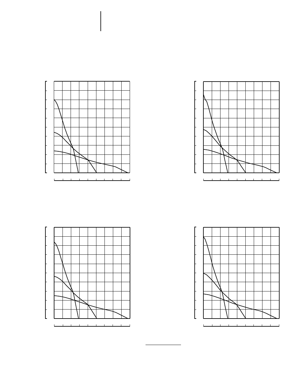
Track-Type TractorsDrawbar Pull vs. Ground Speed
●Power Shift
D3C Series III
D3C XL Series III
D3C LGP Series III
D4C Series III
D4C XL Series III
D4C LGP Series III
SPEED (Forward) SPEED (Forward)
DRAWBAR PULL
DRAWBAR PULL
kg 3
1000 lb 3
1000
mph
km/h
kg 3
1000 lb 3
1000
mph
km/h
D5C Series III
D5C XL Series III
D5C LGP Series III
SPEED (Forward)
DRAWBAR PULL
kg 3
1000 lb 3
1000
mph
km/h
kN
KEY
1 — 1st Gear
2 — 2nd Gear
3 — 3rd Gear
NOTE: Usable pull will depend upon weight
and traction of equipped tractor.
1-14
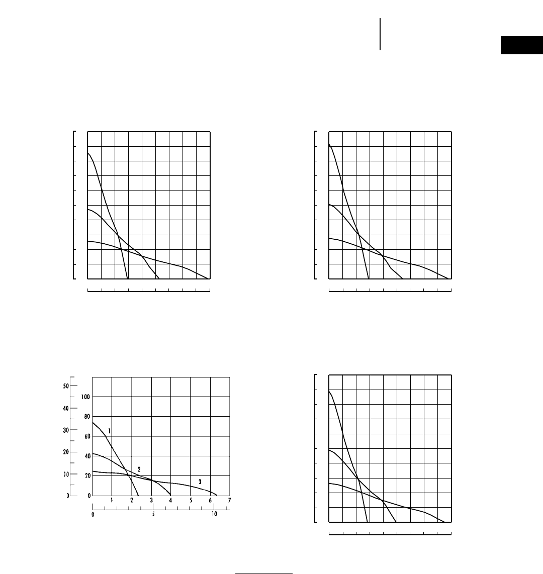
Track-Type Tractors Drawbar Pull vs. Ground Speed
●Hydrostatic Drive
B
1.2 2.5 3.70 5.0 6.2
20.3
15.8
11.3
6.8
2.3
100
80
60
40
20
0
A
B
A
1357
9
D3C Series III
D3C XL Series III
D3C LGP Series III
D4C Series III
D4C XL Series III
D4C LGP Series III
SPEED
DRAWBAR PULL
lb N
km/h
mph
D5C Series III
D5C XL Series III
D5C LGP Series III
KEY
A — Lo Speed
B — Hi Speed
NOTE: Usable pull will depend upon weight
and traction of equipped tractor.
B
1.2 2.5 3.70 5.0 6.2
24.8
20.3
15.8
11.3
6.8
2.3
120
100
80
60
40
20
A
B
A
1357
9
0
SPEED
DRAWBAR PULL
lb N
km/h
mph
B
1.2 2.5 3.70 5.0 6.2
24.8
20.3
15.8
11.3
6.8
2.3
A
B
A
1357
9
120
100
80
60
40
20
0
SPEED
DRAWBAR PULL
lb N
km/h
mph
1-15
1
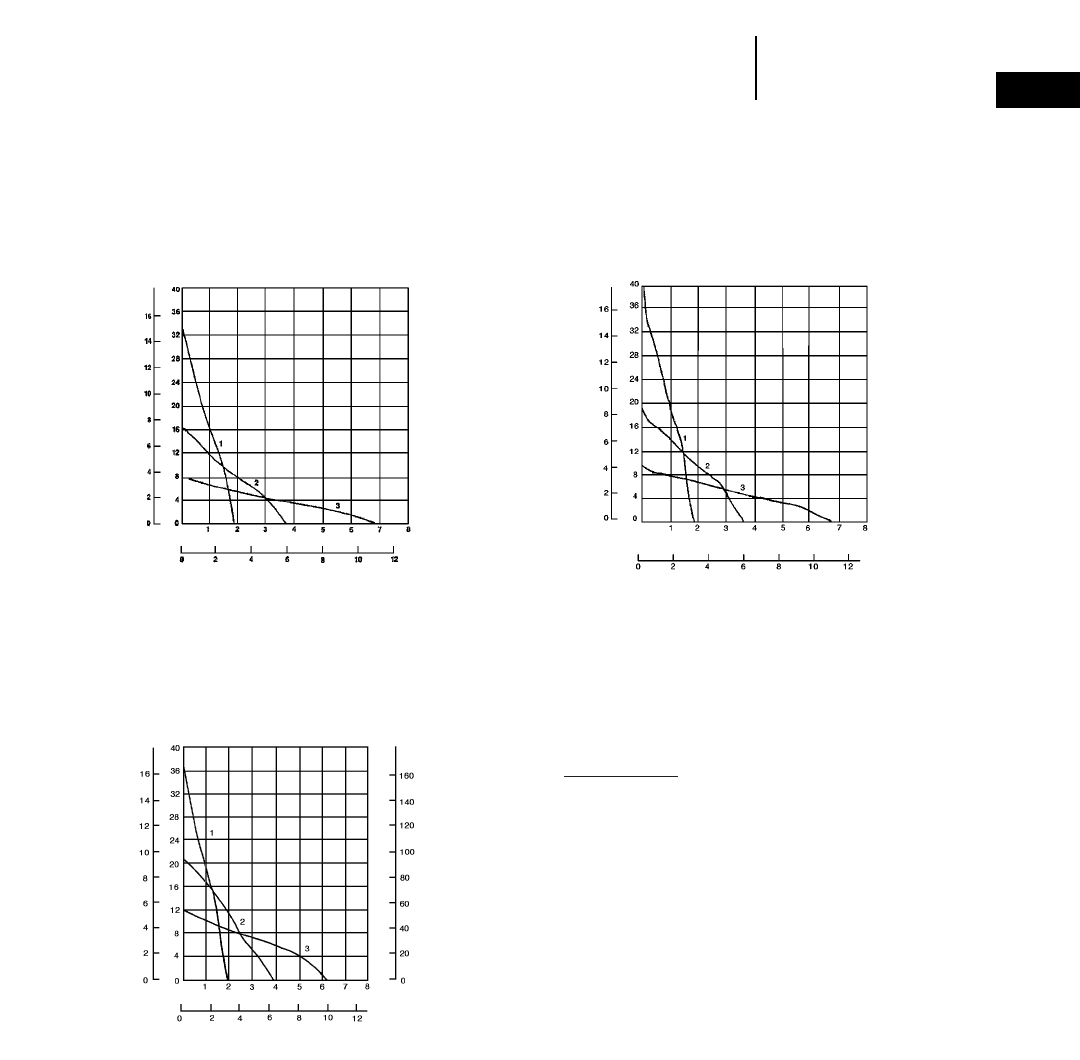
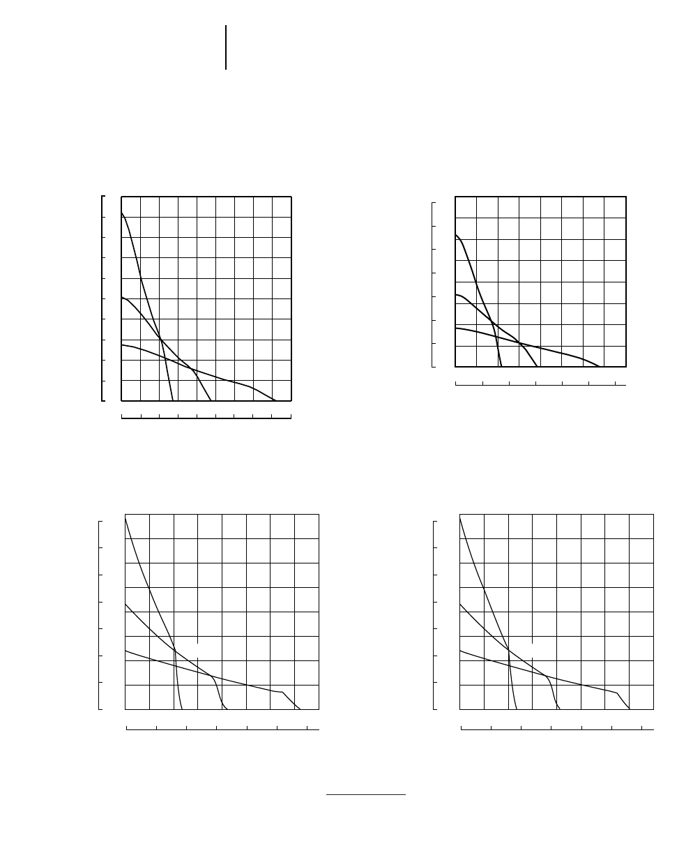
Track-Type TractorsDrawbar Pull vs. Ground Speed
●Power Shift
2468100 12
1
2
3
27
24
21
18
15
12
9
6
5
0012345678
0
5
10
15
20
25
30
35
40
45
50
55
60
D6G
SPEED
DRAWBAR PULL
kg 3
1000 lb 3
1000
mph
km/h
1.3 2.6 3.9 5.2 6.4 7.7 9.00 10.3
1
2
11.6
3
27.2
24.5
21.8
19.1
16.3
13.6
10.9
8.2
5.4
2.7
00.0 0.8 1.6 2.4 3.2 4.0 4.8 5.6 6.4 7.2
0
6
12
18
24
30
36
42
48
54
60
D5M XL
D5M LGP
SPEED
DRAWBAR PULL
kg 3
1000 lb 3
1000
mph
km/h
1.3 2.6 3.9 5.2 6.4 7.7 9.00 10.3
1
2
11.6
3
36.4
32.7
29.0
25.4
21.8
18.1
14.5
10.9
7.3
3.6
00.0 0.8 1.6 2.4 3.2 4.0 4.8 5.6 6.4 7.2
0
8
16
24
32
40
48
56
64
72
80
D6M XL
D6M LGP
SPEED
DRAWBAR PULL
kg 3
1000 lb 3
1000
mph
km/h
1.3 2.6 3.9 5.2 6.4 7.7 9.00 10.3
1
2
11.6
3
18.1
16.3
14.5
12.7
10.9
9.1
7.3
5.4
3.6
1.8
00.0 0.8 1.6 2.4 3.2 4.0 4.8 5.6 6.4 7.2
0
4
8
12
16
20
24
28
32
36
40
D5M LGP PSDD
SPEED
DRAWBAR PULL
kg 3
1000 lb 3
1000
mph
km/h
KEY
1 — 1st Gear
2 — 2nd Gear
3 — 3rd Gear
NOTE: Usable pull will depend upon weight and traction
of equipped tractor.
1-16
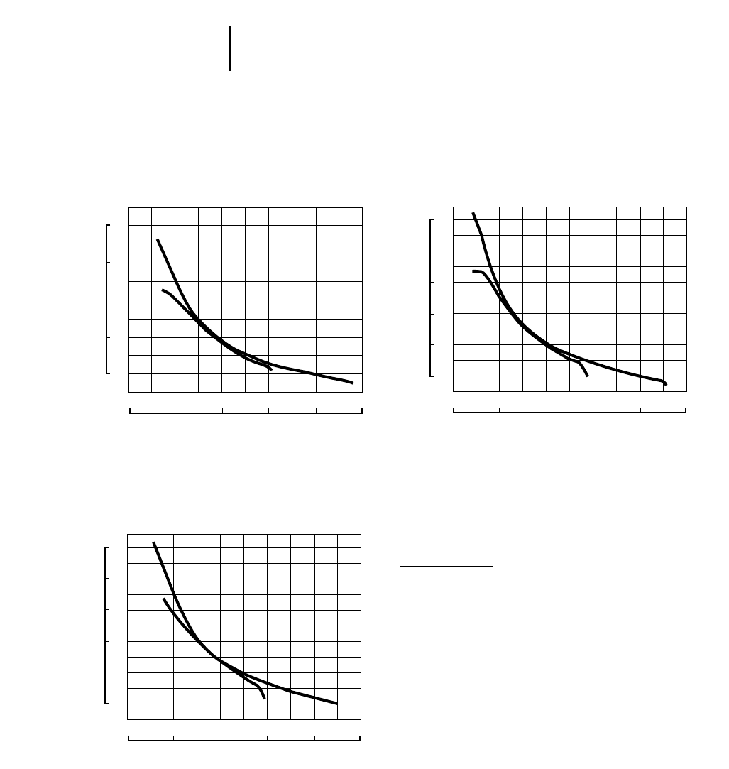
Track-Type Tractors Drawbar Pull vs. Ground Speed
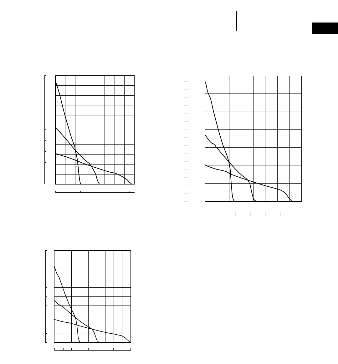
●Power Shift
1.3 2.6 3.9 5.2 6.4 7.7 9.00 10.3
1
2
11.6
3
36.4
32.7
29.0
25.4
21.8
18.1
14.5
10.9
7.3
3.6
00.0 0.8 1.6 2.4 3.2 4.0 4.8 5.6 6.4 7.2
0
8
16
24
32
40
48
56
64
72
80
D6R Standard
Steering Clutches & Brakes (FTC)
SPEED
DRAWBAR PULL
kg 3
1000 lb 3
1000
mph
km/h
1.3 2.6 3.9 5.2 6.4 7.7 9.00 10.3
1
2
11.6
3
36.4
32.7
29.0
25.4
21.8
18.1
14.5
10.9
7.3
3.6
00.0 0.8 1.6 2.4 3.2 4.0 4.8 5.6 6.4 7.2
0
8
16
24
32
40
48
56
64
72
80
D6R XL/XR/IG
Steering Clutches & Brakes (FTC)
SPEED
DRAWBAR PULL
kg 3
1000 lb 3
1000
mph
km/h
1.3 2.6 3.9 5.2 6.4 7.7 9.00 10.3
1
2
11.6
3
36.4
32.7
29.0
25.4
21.8
18.1
14.5
10.9
7.3
3.6
00.0 0.8 1.6 2.4 3.2 4.0 4.8 5.6 6.4 7.2
0
8
16
24
32
40
48
56
64
72
80
D6R XL/XR/IG
Differential Steering
SPEED
DRAWBAR PULL
kg 3
1000 lb 3
1000
mph
km/h
1.3 2.6 3.9 5.2 6.4 7.7 9.00 10.3
1
2
11.6
3
36.4
32.7
29.0
25.4
21.8
18.1
14.5
10.9
7.3
3.6
00.0 0.8 1.6 2.4 3.2 4.0 4.8 5.6 6.4 7.2
0
8
16
24
32
40
48
56
64
72
80
D6R Standard
Differential Steering
SPEED
DRAWBAR PULL
kg 3
1000 lb 3
1000
mph
km/h
KEY
1 — 1st Gear
2 — 2nd Gear
3 — 3rd Gear
NOTE: Usable pull will depend upon weight and traction
of equipped tractor.
1-17
1
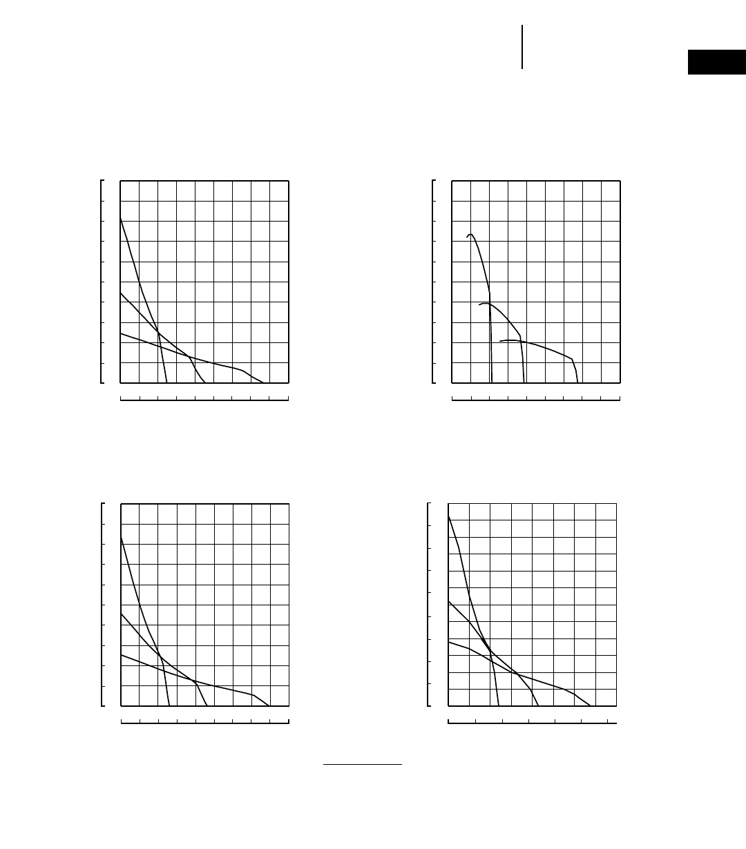
Track-Type TractorsDrawbar Pull vs. Ground Speed
●Power Shift
D7G
SPEED
DRAWBAR PULL
kN
lb 3
1000
mph
km/h
KEY
1 — 1st Gear
2 — 2nd Gear
3 — 3rd Gear
NOTE: Usable pull will depend upon weight and
traction of equipped tractor.
1.3 2.6 3.9 5.2 6.4 7.7 9.00 10.3
1
2
11.6
3
36.4
32.7
29.0
25.4
21.8
18.1
14.5
10.9
7.3
3.6
00.0 0.8 1.6 2.4 3.2 4.0 4.8 5.6 6.4 7.2
0
8
16
24
32
40
48
56
64
72
80
D6R LGP
Steering Clutches & Brakes (FTC)
SPEED
DRAWBAR PULL
kg 3
1000 lb 3
1000
mph
km/h
1.3 2.6 3.9 5.2 6.4 7.7 9.00 10.3
1
2
11.6
3
36.4
32.7
29.0
25.4
21.8
18.1
14.5
10.9
7.3
3.6
00.0 0.8 1.6 2.4 3.2 4.0 4.8 5.6 6.4 7.2
0
8
16
24
32
40
48
56
64
72
80
D6R LGP
Differential Steering
SPEED
DRAWBAR PULL
kg 3
1000 lb 3
1000
mph
km/h
1.3 2.6 3.9 5.2 6.4 7.7 9.00 10.3
1
2
11.6
3
50.0
45.0
40.0
35.0
30.0
20.0
14.5
15.0
10.0
5.0
00.0 0.8 1.6 2.4 3.2 4.0 4.8 5.6 6.4 7.2
0
11
22
33
44
55
66
77
88
99
110
D7R Standard/XR/LGP (FTC)
SPEED
DRAWBAR PULL
kg 3
1000 lb 3
1000
mph
km/h
1-18
Track-Type Tractors Drawbar Pull vs. Ground Speed
●Power Shift
70
60
50
40
30
20
10
0
160
140
120
100
80
60
40
20
0
024681012
012345678
1
2
3
D9R Power Shift with
Steering Clutches & Brakes
SPEED
DRAWBAR PULL
kg 3
1000 lb 3
1000
mph
km/h
70
60
50
40
30
20
10
0
160
140
120
100
80
60
40
20
0
024681012
012345678
1
2
3
D9R Differential Steering
SPEED
DRAWBAR PULL
kg 3
1000 lb 3
1000
mph
km/h
NOTE: Usable pull will depend upon weight and
traction of equipped tractor.
KEY
1 — 1st Gear
2 — 2nd Gear
3 — 3rd Gear
1.3 2.6 3.9 5.2 6.4 7.7 9.00 10.3
1
2
11.6
3
50.0
45.0
40.0
35.0
30.0
20.0
14.5
15.0
10.0
5.0
00.0 0.8 1.6 2.4 3.2 4.0 4.8 5.6 6.4 7.2
0
11
22
33
44
55
66
77
88
99
110
D7R Standard/XR/LGP Differential
Steering
SPEED
DRAWBAR PULL
kg 3
1000 lb 3
1000
mph
km/h
70
60
50
40
30
20
10
0
160
140
120
100
80
60
40
20
0
024681012
012345678
1
2
3
D8R
D8R LGP
SPEED
DRAWBAR PULL
kg 3
1000 lb 3
1000
mph
km/h
1-19
1
Track-Type TractorsDrawbar Pull vs. Ground Speed
●Power Shift
NOTE: Usable pull will depend upon weight and trac-
tion of equipped tractor. Tractors with sus-
pended undercarriage can provide up to 15%
more tractive effort than tractors with non-sus-
pended undercarriage.
KEY
1 — 1st Gear
2 — 2nd Gear
3 — 3rd Gear
350
300
250
200
150
100
50
00123 45 6 78
0
10
20
30
40
50
60
70
80
90
100
110
120
130
140
150
024681012
1
2
3
D11R
SPEED
DRAWBAR PULL
kg 3
1000 lb 3
1000
mph
km/h
70
80
90
100
60
50
40
30
20
10
0
200
140
160
180
120
100
80
60
40
20
0
220
024681012
012345678
1
2
3
D10R
SPEED
DRAWBAR PULL
kg 3
1000 lb 3
1000
mph
km/h
1.3 2.6 3.9 5.2 6.4 7.7 9.00 10.3
1
2
11.6
3
18.1
16.3
14.5
12.7
10.9
9.1
7.3
5.4
3.6
1.8
00.0 0.8 1.6 2.4 3.2 4.0 4.8 5.6 6.4 7.0
0
4
8
12
16
20
24
28
32
36
40
D11R C.D.
SPEED
DRAWBAR PULL
kg 3
1000 lb 3
1000
mph
km/h

1-20
Track-Type Tractors Travel Speed
TRAVEL SPEED
POWER D3C D4C D5C
SHIFT Series III Series III Series III D5M LGP*
MODEL All Models All Models All Models D5M XL D5M LGP PS DD D6M XL
FORWARD km/h mph km/h mph km/h mph km/h mph km/h mph km/h mph km/h mph
1 3.1 1.9 3.2 2.0 3.5 2.2 3.1 1.9 3.1 1.9 2.8 1.7 3.4 2.1
2 5.9 3.7 5.9 3.7 6.3 3.9 5.6 3.5 5.6 3.5 5.0 3.1 6.0 3.7
3 10.8 6.7 11.1 6.9 10.0 6.2 9.7 6.1 9.7 6.1 8.7 5.4 10.2 6.4
REVERSE
1 3.2 2.0 3.4 2.1 4.2 2.6 4.0 2.5 4.0 2.5 4.2 2.6
2 6.3 3.9 6.4 4.0 7.6 4.7 7.1 4.4 7.1 4.4 ** 7.5 4.6
3 11.4 7.1 11.9 7.4 11.9 7.4 12.1 7.5 12.1 7.5 12.8 7.9
HYDROSTATIC 0-9.0 0-5.6 0-9.0 0-5.6 0-9.0 0-5.6 ————————
FORWARD/
REVERSE
POWER Differential Steer Differential Steer
SHIFT D6R (FTC) D6R D7R (FTC) D7R
MODEL D6M LGP D6E All Models All Models D7G All Models All Models
FORWARD km/h mph km/h mph km/h mph km/h mph km/h mph km/h mph km/h mph
1 3.4 2.1 4.0 2.5 4.0 2.5 3.9 2.4 3.7 2.3 3.7 2.3 3.7 2.3
2 6.0 3.7 6.9 4.3 7.1 4.4 6.8 4.2 6.6 4.1 6.9 4.3 6.9 4.3
3 10.2 6.4 10.8 6.7 12.4 7.7 11.9 7.6 10.0 6.2 11.1 6.9 11.1 6.9
REVERSE
1 4.2 2.6 4.8 3.0 5.2 3.2 4.8 3.0 4.5 2.8 4.8 3.0 4.8 3.0
2 7.5 4.6 8.4 5.2 9.0 5.6 8.7 5.4 7.9 4.9 8.3 5.2 8.3 5.2
3 12.8 7.9 12.9 8.0 16.1 10.0 15.3 9.5 12.2 7.6 14.2 8.8 14.2 8.8
POWER
SHIFT D8R
MODEL D8R LGP D9R D10R D11R D11R C.D.
FORWARD km/h mph km/h mph km/h mph km/h mph km/h mph
1 3.5 2.2 3.9 2.4 4.0 2.5 3.9 2.4 3.9 2.4
2 6.2 3.9 6.8 4.2 7.1 4.4 6.8 4.2 6.8 4.2
3 10.8 6.7 11.8 7.3 12.5 7.7 11.8 7.3 11.7 7.3
REVERSE
1 4.7 2.9 4.8 3.0 5.0 3.1 4.7 2.9 4.7 2.9
2 8.1 5.0 8.4 5.2 8.9 5.5 8.2 5.1 8.2 5.1
3 13.9 8.6 14.7 9.1 15.6 9.7 14.0 8.7 14.0 8.7
**Power Shift direct drive transmission available for Japan domestic market only.
**Not available at time of printing.
1-21
1
Track-Type TractorsTravel Speed and Drawbar Pull Forward
●Direct Drive
TRAVEL SPEED
DIRECT
DRIVE D5E D6R
MODEL Std. Trans. Std. Trans.
FORWARD km/h mph km/h mph
1 2.7 1.7 2.7 1.7
2 4.2 2.6 3.5 2.2
3 5.8 3.6 4.6 2.9
4 8.0 5.0 5.8 3.6
5 11.1 6.9 7.6 4.7
6—10.0 6.2
REVERSE
1 3.4 2.1 3.3 2.1
2 5.3 3.3 4.3 2.7
3 7.4 4.6 5.6 3.5
4 10.1 6.3 7.1 4.4
5—9.2 5.7
6—12.2 7.6
DRAWBAR PULL FORWARD*
At Rated RPM At Rated RPM
FORWARD kN kg lb kN kg lb
1 86.1 8770 19,340 122.5 12 500 27,530
2 54.0 5500 12,130 93.2 9520 20,960
3 36.8 3750 8270 70.0 7140 15,740
4 24.9 2540 5600 53.3 5440 11,990
5 16.3 1660 3660 39.3 4010 8830
6—27.6 2820 6210
Max. at Lug Max. at Lug
1 109.2 11 130 24,540 159.0 16 220 35,750
2 69.1 7040 15,525 121.6 12 410 27,340
3 47.6 4850 10,695 91.9 9370 20,650
4 32.9 3350 7385 70.5 7200 15,860
5 22.1 2250 4960 52.5 5360 11,810
6—37.6 3840 8460
*Specified pull is based on nominal engine performance derated for transmission lube, control and optional implement hydraulic pumps, with corrections made for drive-
line mechanical efficiency and rolling resistance on firm level ground. Usable pull will depend on particular attachments, weight and traction of equipped tractor.
NOTE: For Variable Horsepower Tractor Information, see the Agricultural Tractor section in this handbook.

1-22
Track-Type Tractors Travel Speed and Drawbar Pull Forward
●Direct Drive
TRAVEL SPEED
DIRECT
DRIVE D6R LGP D7G D7G
MODEL Std. Trans. Std. Trans. Opt. Trans.
FORWARD km/h mph km/h mph km/h mph
1 2.7 1.7 2.6 1.6 3.5 2.2
2 3.5 2.2 3.7 2.3 4.8 3.0
3 4.6 2.9 5.3 3.3 5.6 3.5
4 5.8 3.6 7.9 4.9 6.4 4.0
5 7.6 4.7 10.3 6.4 7.2 4.5
6 10.0 6.2 — 8.2 5.1
REVERSE
1 3.3 2.1 3.1 1.9 4.0 2.5
2 4.3 2.7 4.3 2.7 5.6 3.5
3 5.6 3.5 6.3 3.9 6.8 4.2
4 7.1 4.4 9.3 5.8 7.6 4.7
5 9.2 5.7 — —
6 12.2 7.6 — —
DRAWBAR PULL FORWARD*
At Rated RPM At Rated RPM At Rated RPM
FORWARD kN kg lb kN kg lb kN kg lb
1 126.9 12 930 28,520 163.0 16 610 36,630 118.4 12 560 27,680
2 96.7 9850 21,730 109.9 11 200 24,690 83.5 8700 19,190
3 72.7 7410 16,330 73.4 7480 16,500 69.1 7110 15,680
4 55.4 5650 12,460 46.9 4780 10,540 60.5 6170 13,600
5 40.9 4170 9190 34.5 3510 7750 51.7 5190 11,450
6 28.8 2940 6480 — 45.1 4460 9840
Max. at Lug Max. at Lug Max. at Lug
1 168.8 17 200 37,930 209.8 21 390 47,150 153.0 16 080 35,440
2 129.2 13 170 29,030 142.2 14 500 31,960 108.7 11 260 24,830
3 97.7 9960 21,960 95.9 9770 21,550 90.4 9270 20,440
4 95.1 7660 16,880 62.1 6330 13,950 79.5 8040 17,840
5 56.1 5710 12,600 46.3 4710 10,400 68.3 6870 15,150
6 40.3 4100 9050 — 59.9 5960 13,130
*Specified pull is based on nominal engine performance derated for transmission lube, control and optional implement hydraulic pumps, with corrections made for drive-
line mechanical efficiency and rolling resistance on firm level ground. Usable pull will depend on particular attachments, weight and traction of equipped tractor.
NOTE: For Variable Horsepower Tractor Information, see the Agricultural Tractor section in this handbook.
1-23
1
Track-Type TractorsGround Pressures
GROUND PRESSURES
Pressures computed from operating weights given ear-
lier in this section in the specifications tables.
SHOE CONTACT GROUND
MODEL WIDTH AREA PRESSURE
mm in m2in2kPa psi
D3C Series III 406 16 1.54 2390 44.7 6.49
D3C Hystat 406 16 1.54 2390 45.2 6.56
D3C XL Series III 406 16 1.67 2586 42.5 6.16
D3C XL Hystat 406 16 1.67 2586 42.9 6.23
D3C LGP
Series III 635 25 2.61 4045 28.7 4.16
D3C LGP Hystat 635 25 2.61 4045 29.0 4.20
D4C Series III 406 16 1.67 2586 42.7 6.19
D4C Hystat 406 16 1.67 2586 43.0 6.25
D4C XL Series III 457 18 2.02 3131 36.2 5.25
D4C XL Hystat 457 18 2.02 3131 36.5 5.29
D4C LGP
Series III 635 25 2.61 4045 29.0 4.21
D4C LGP Hystat 635 25 2.61 4045 29.2 4.24
D5C Series III 457 18 1.96 3039 42.1 6.11
D5C Hystat 457 18 1.96 3039 42.4 6.16
D5C XL Series III 508 20 2.35 3547 36.5 5.30
D5C XL Hystat 508 20 2.35 3547 36.7 5.33
D5C LGP
Series III 660 26 2.83 4389 30.8 4.48
D5C LGP Hystat 660 26 2.83 4389 31.1 4.51
D5M XL §510 20 2.44 3775 48 6.83
560 22 2.67 4146 44 6.22
D5M LGP 610 24 3.18 4922 40 5.64
§760 30 3.96 6133 32 4.53
770 30 4.01 6213 31 4.47
D5E 406 16 1.77 2745 62 9.00
§457 18 1.99 3085 55 7.98
D6M XL 560 22 2.89 4427 52 7.49
§600 24 3.06 4743 48 6.99
D6M LGP 710 28 4.38 6783 37 5.36
§860 34 5.30 8217 31 4.43
865 34 5.33 8264 30 4.40
D6G 457 18 2.43 3766 60 8.70
§508 20 2.71 4200 54 7.83
560 22 2.98 4619 49 7.10
610 24 3.25 5040 45 6.54
D6R §560 22 2.92 4518 61 8.82
610 24 3.18 4930 56 8.14
§Standard Shoe.
SHOE CONTACT GROUND
MODEL WIDTH AREA PRESSURE
mm in m2in2kPa psi
D6R XL §560 22 3.16 4888 60 8.60
610 24 3.44 5332 55 7.93
D6R XL (IG) 762 30 4.30 6696 44 6.50
D6R XR §560 22 3.08 4770 60 8.68
610 24 3.36 5203 56 8.01
D6R LGP 760 30 4.93 7662 41 5.80
§915 36 5.93 9194 35 4.94
1000 39 6.49 9961 32 4.55
D7G §508 20 2.76 4280 73 10.60
§559 22 3.04 4708 66 9.60
610 24 3.31 5136 60 8.80
D7R 510 20 2.94 4560 82 11.71
§560 22 3.24 5016 75 10.69
610 24 3.53 5472 69 9.87
660 26 3.82 5928 64 9.17
D7R XR 560 22 3.43 5315 71.5 10.16
§610 24 3.75 5808 65.9 9.37
660 26 4.06 6282 61.2 8.70
D7R LGP 760 30 4.80 7504 54 7.74
915 36 5.82 9029 46 6.55
D8R §560 22 3.59 5565 101.1 14.67
610 24 3.91 6062 92.8 13.47
660 26 4.23 6559 85.9 12.47
710 28 4.55 7056 79.7 11.57
D8R LGP 965 38 6.20 9576 58.6 8.50
D9R 560 22 3.86 6009 121.1 17.58
§610 24 4.24 6569 110.8 16.08
685 27 4.74 7374 98.7 14.32
760 30 5.26 8194 88.8 12.89
D10R §610 24 4.73 7326 136.4 19.79
710 28 5.50 8527 117.1 17.00
860 31.5 6.66 10,328 96.7 14.04
D11R §710 28 6.31 9781 158.8 23.05
810 32 7.20 11,159 139.2 20.21
915 36 8.13 12,605 123.2 17.89
§Standard shoe.
NOTE: Ground contact area = width of track shoe
3 length of track on ground 3 2.
Ground pressure = operating weight
ground contact area
1-24
Track-Type Tractors Extreme Slope Operation
EXTREME SLOPE OPERATION
The following table gives the MAXIMUM fore and
aft slope on which each tractor will have proper
lubrication. Consult Operation & Maintenance
Manual (if applicable) for POWER TRAIN fluid
level overfill requirements for operation on extreme
slopes. Extreme slope operation is anytime the slope
exceeds 25° (47%).
The ENGINE should never be overfilled with oil.
This may lead to rapid overheating. For extreme
slope operation, engine oil should be maintained at
the full mark.
NOTE: Both ENGINE and POWER TRAIN fluid
levels should be checked on level ground
before working sidehills and slopes.
D5C
Tractor D3C Series III D4C Series III Series III D5M D5E & D6M
Percent Grade 100 100 100 100 100
or
Degrees Slope 45 45 45 45 45
D11R/
Tractor D6G & D6R D7G & D7R D8R D9R D10R D11R C.D.
Percent Grade 100 100 100 100 100 100
or
Degrees Slope 45 45* 45 45 45 45
When working sidehills and slopes, consideration
should be given to the following important points:
●Speed of travel — At higher speeds, inertia forces
tend to make the tractor less stable.
●Roughness of terrain or surface — Ample allow-
ance should be made where the terrain or surface
is uneven.
●Mounted equipment — Bulldozers, sidebooms,
winches, and other mounted equipment cause the
tractor to balance differently.
●Nature of surface — New earthen fills may give
way with the weight of the tractor. Rocky surfaces
may promote side slipping of tractor.
●Track slippage due to excessive loads — This may
cause downhill track to “dig in,” increasing angle
of tractor.
●Implements hitched to the drawbar — This may
decrease weight on uphill track, e.g., logging arch,
two-wheel wagon.
●Height of hitch on tractor — When a high draw-
bar is used the tractor is less stable than with the
standard drawbar.
●Width of shoes — Wide track shoes tend to decrease
“digging in”, hence tractor is more stable.
●Operated equipment — Be aware of the stability
and other performance features of the equipment
operated by the tractor.
●Keep all attachments or pulled loads low to the
ground for optimum stability.
*The D7G requires a 23 L (6 gal) transmission overfill for acceptable operation on
slopes above 25° (47%).
NOTE: Safe operation on steep slopes may require special machine main-
tenance as well as excellent operator skill and proper equipment
for the specific application. Consult Operation & Maintenance
Manual (if applicable) for proper fluid level requirements.

CONTENTS
Features . . . . . . . . . . . . . . . . . . . . . . . . . . . . . .1-25
Specifications . . . . . . . . . . . . . . . . . . . . . . . . . .1-26
Bulldozer specifications . . . . . . . . . . . . . . . . . .1-28
Features:
●Hinged heavy duty radiator doors are guarded
to prevent excessive trash build-up. Quick release
handles allow easy access for cleaning.
●Final drive, pivot shaft, and idler seal guard-
ing helps prevent wire, cable and similar material
from winding around components and damaging
seals.
●Striker bars for front, rear and ripper (all
optional) keep trash from damaging fenders, fuel
and hydraulic tanks or other sheet metal.
●Lighting protection. Front lights are mounted
on top of bulldozer lift cylinders. Rear lights are
ROPS mounted.
●AMOCS Waste Handling Arrangement radi-
ator with 6 fins/inch (optional on D6R thru D9R).
●Flexxaire fan is recommended option for D6R
thru D9R.
●Elevated sprocket removes final drives from
wear environment and eliminates impact loading
for extended power train life.
●Sheet metal guarding near track and on dozer
tilt hoses.
●Heavy duty steps and grab handles resist
damage from landfill debris.
●Trapezoidal-shaped center hole track shoes
(optional) help keep track clean during machine
operation.
●Blade trash racks (optional) prevent blade spill-
over and damage to cylinders or radiator guard.
●75 amp alternator available on D6R, D7R,
D8R, D9R, 100 amp on D10R insures adequate
current is available to maintain battery and oper-
ate accessories.
●Elevated prescreener to remove engine air inlet
from debris environment. Larger surface area to
resist plugging. Turbine precleaner is optional.
●ROPS mounted air conditioning (optional
on D8R and D9R) helps prevent condensor core
plugging. Provides full utilization of jacket water
cooling system by avoiding additional heat load
from radiator mounted condensor.
●Chassis Guards.
●Sealed belly guards on D10R.
●Perforated engine enclosures standard on D10R
and required attachments on D6R thru D9R.
●Carrier rollers not recommended.
WASTE HANDLING TRACK-TYPE TRACTORS
1-25
1
MODEL D6R WHA D7R WHA
Flywheel Power 123 kW 165 hp 171 kW 230 hp
Operating Weight (PS)* 20 600 kg 45,370 lb 27 920 kg 61,500 lb
Engine Model 3306 3306
Rated Engine RPM 1800 2100
No. of Cylinders 66
Bore 121 mm 4.75" 121 mm 4.75"
Stroke 152 mm 6" 152 mm 6"
Displacement 10.5 L 638 in310.5 L 638 in3
Track Rollers (Each Side) 67
Width of Standard Track Shoe 560 mm 1'10" 560 mm 1'10"
Length of Track on Ground 2.62 m 8'7.5" 2.88 m 9'5"
Ground Contact Area (W/Std. Shoe) 2.94 m24564 in23.22 m24996 in2
Track Gauge 1.88 m 6'2" 1.98 m 6'5"
GENERAL DIMENSIONS:
Height (Stripped Top)** 2.26 m 7'5" 2.56 m 8'5"
Height (To Top of Cab ROPS) 3.12 m 10'3" 3.50 m 11'6"
Overall Length (S Blade) 5.11 m 16'9" 5.82 m 19'1"
Overall Length (W/O Blade) — —
Width (Over Trunnion) 2.64 m 8'8" 2.87 m 9'5"
Width (W/O Trunnion) — 2.54 m 8'4"
Ground Clearance 376 mm 14.8" 414 mm 16"
Blade Types and Widths:
Straight 3.35 m 11'0" 3.90 m 12'10"
Semi-Universal 3.26 m 10'8" 3.69 m 12'1"
Universal — 3.98 m 13'0"
Fuel Tank Refill Capacity 383 L 101 U.S. gal 488 L 129 U.S. gal
**D6R Operating Weight includes lubricants, coolant, full fuel tank, hydraulic controls, 6SU/tilt, 610 mm (2'0") trash rack, 560 mm (1'10") shoes, ROPS canopy, engine
enclosure, extreme service crankcase guard, fuel tank guard, hydraulic cooler, prescreener, six lights, hinged HD radiator guard, lower radiator guarding, final drive seal
guards, idler seal guards, engine compartment guarding, tilt cylinder guards. WHA also available for D6R XL, XR, XL (IG) and LGP models.
**D7R Operating Weight includes lubricants, coolant, full fuel tank, hydraulic controls, 7SU/tilt, 610 mm (2'0") trash rack, 560 mm (1'10") shoes, ROPS canopy, engine
enclosure, extreme service crankcase guard, fuel tank guard, hydraulic cooler, prescreener, six lights, hinged HD radiator guard, lower radiator guarding, final drive seal
guards, idler seal guards, engine compartment guarding, tilt cylinder guards. WHA also available for D7R XR and D7R LGP.
**Height with ROPS canopy, exhaust pipe, seat or all easily removed encumbrances. Add 71.1 mm (2.8") for grouser tips on D7R.
1-26
Waste Handling
Track-Type Tractors Specifications
MODEL D8R WHA D9R WHA D10R WHA
Flywheel Power 228 kW 305 hp 302 kW 405 hp 425 kW 570 hp
Operating Weight (PS)* 37 594 kg 82,880 lb 47 913 kg 105, 630 lb 65 764 kg 144,986 lb
Engine Model 3406C 3408E 3412
Rated Engine RPM 2100 1900 1900
No. of Cylinders 6812
Bore 137 mm 5.4" 137 mm 5.4" 137 mm 5.4"
Stroke 165 mm 6.5" 152 mm 6" 152 mm 6"
Displacement 14.6 L 893 in318 L 1099 in327 L 1649 in3
Track Rollers (Each Side) 888
Width of Standard Track Shoe 560 mm 1'10" 610 mm 2'0" 610 mm 2'0"
Length of Track on Ground 3.21 m 10'6.5" 3.47 m 11'5" 3.88 m 12'9"
Ground Contact Area (W/Std. Shoe) 3.58 m25544 in24.24 m26569 in24.70 m27326 in2
Track Gauge 2.08 m 6'10" 2.25 m 7'5" 2.55 m 8'4"
GENERAL DIMENSIONS:
Height (Stripped Top)** 2.67 m 8'9" 3.00 m 9'10" 3.27 m 10'9"
Height (To Top of Cab ROPS) 3.51 m 11'6" 3.99 m 13'1" 4.36 m 14'3"
Overall Length (Blade) 6.39 m 21'0" 6.84 m 22'5" 7.76 m 25'5"
(W/O Blade) 4.88 m 16'2" 5.18 m 17'0" 5.59 m 18'4"
Width (Over Trunnion) 3.05 m 10'0" 3.30 m 10'10" 3.72 m 12'2"
Width (W/O Trunnion) 2.70 m 8'8" 2.93 m 9'8" 3.16 m 10'4"
Ground Clearance 585 mm 1'11" 585 mm 1'11" 615 mm 2'0.2"
Blade Types and Widths:
Semi-Universal 3.94 m 12'11" 4.31 m 14'2" —
Universal 4.26 m 14'0" 4.66 m 15'3.4" 5.26 m 17'3"
Fuel Tank Refill Capacity 625 L 165 U.S. gal 818 L 216 U.S. gal 1109 L 293 U.S. gal
**Operating Weight includes lubricants, coolant, full fuel tank, hydraulic controls, and ROPS — FOPS canopy. Also included are special radiator core and ejector fan, draw-
bar, engine enclosures, fuel tank guard, extreme service crankcase guard, HD hinged radiator guard, higher prescreener, front & rear striker bars and operator.
**— D8R 8S blade with 762 mm (2'6") trash rack and 660 mm (2'2") track shoes
**— D9R 9SU blade with 914 mm (3'0") trash rack and 685 mm (2'3") track shoes
**— D10R 10SU blade with 1107 mm (3'8") trash rack and 610 mm (2'0") track shoes.
**Height with ROPS canopy, exhaust pipe, seat or all easily removed encumbrances.
1-27
1
Waste Handling
Track-Type Tractors
Specifications

MODEL D6R WHA
Type 6S 6SU
Blade Capacities* 8.6 m311.2 yd311.2 m314.6 yd3
Dozer Weight** 2881 kg 6338 lb 3026 kg 6657 lb
Tractor & Dozer
Dimensions
Length Blade Straight 5.11 m 16'9" 5.30 m 17'5"
Length Blade Angled — —
Width Blade Angled — —
Width C Frame Only — —
Blade Dimensions
Width including
std. end bits 3355 mm 11'0" 3262 mm 10'8"
Height 1866 mm 6'1" 2019 mm 6'7"
Maximum Dig Depth 473 mm 18.6" 473 mm 18.6"
Ground Clearance at
full raise 1104 mm 3'7.5" 1104 mm 3'7.5"
Maximum Manual Tilt — —
Maximum Pitch — —
Maximum Hydraulic Tilt 765 mm 2'6.1" 744 mm 2'5.3"
Blade Angle — —
MODEL D7R WHA
Type 7S 7SU 7U
Blade Capacities* 10.9 m314.2 yd314.0 m318.4 yd316.8 m322.0 yd3
Dozer Weight** 4028 kg 8861 lb 4083 kg 8982 lb 4402 kg 9684 lb
Tractor & Dozer
Dimensions
Length Blade Straight 5813 mm 19'1" 6036 mm 19'10" 6278 mm 20'7"
Length Blade Angled — — —
Width Blade Angled — — —
Width C Frame Only — — —
Blade Dimensions
Width including
std. end bits 3904 mm 12'10" 3690 mm 12'1" 3980 mm 13'1"
Height 1971 mm 6'6" 2133 mm 7'0" 2162 mm 7'1"
Maximum Dig Depth 527 mm 1'8.7" 527 mm 1'8.7" 527 mm 1'8.7"
Ground Clearance at
full raise 1145 mm 3'9.1" 1145 mm 3'9.1" 1145 mm 3'9.1"
Maximum Manual Tilt — — —
Maximum Pitch — — —
Maximum Hydraulic Tilt 845 mm 2'9.3" 861 mm 2'9.9" 799 mm 2'7.5"
Blade Angle — — —
**Blade capacities, weights and heights include 610 mm (2'0") trash rack on D6R blades and D7R blades.
**Total bulldozer arrangement includes blade with trash rack, pusharms, braces, cylinders, lines, trunnions and lift cylinder mountings.
1-28
Waste Handling
Track-Type Tractors Bulldozer Specifications
MODEL D8R WHA
Type 8SU 8U
Blade Capacities* 20.0 m326.1 yd324.8 m332.4 yd3
Dozer Weight** 5466 kg 12,025 lb 6313 kg 13,888 lb
Tractor & Dozer
Dimensions
Length Blade Straight 6.39 m 21'0" 6.79 m 22'3"
Length Blade Angled — —
Width Blade Angled — —
Width C Frame Only — —
Blade Dimensions
Width including
std. end bits 3942 mm 12'11" 4262 mm 14'0"
Height 2464 mm 8'1" 2515 mm 8'3"
Maximum Dig Depth 582 mm 1'10.9" 582 mm 1'10.9"
Ground Clearance at
full raise 1231 mm 4'0.5" 1231 mm 4'0.5"
Maximum Manual Tilt — —
Maximum Pitch — —
Maximum Hydraulic Tilt 951 mm 3'1.4" 1028 mm 3'4.5"
Blade Angle — —
MODEL D9R WHA D10R WHA
Type 9SU 9U 10U
Blade Capacities* 28.8 m337.6 yd333.5 m343.8 yd348.9 m363.9 yd3
Dozer Weight** 6964 kg 15,353 lb 7662 kg 16,891 lb —
Tractor & Dozer
Dimensions
Length Blade Straight 6.84 m 22'5" 7.18 m 23'7" 8.01 m 26'3"
Length Blade Angled — — —
Width Blade Angled — — —
Width C Frame Only — — —
Blade Dimensions
Width including
std. end bits 4314 mm 14'2" 4645 mm 15'3" 5260 mm 17'3"
Height 2845 mm 9'4" 2845 mm 9'4" 3174 mm 10'5"
Maximum Dig Depth 606 mm 1'11.9" 606 mm 1'11.9" 679 mm 2'2.5"
Ground Clearance at
full raise 1422 mm 4'8" 1422 mm 4'8" 1497 mm 4'10.9"
Maximum Manual Tilt — — —
Maximum Pitch — — —
Maximum Hydraulic Tilt 940 mm 3'1" 1014 mm 3'3.9" 1074 mm 3'6.3"
Blade Angle — — —
**Blade capacities, weights and heights include 762 mm (2'6") trash rack on D8R blades, 914 mm (3'0") trash rack on D9R blades, and 1067 mm (3'6") trash rack on D10R blades.
**Total bulldozer arrangement includes blade with trash rack, pusharms, braces, cylinders, lines, trunnions and lift cylinder mountings.
1-29
1
Waste Handling
Track-Type Tractors
Bulldozer Specifications

CONTENTS
Features . . . . . . . . . . . . . . . . . . . . . . . . . . . . . .1-31
Specifications . . . . . . . . . . . . . . . . . . . . . . . . . .1-32
Features:
●Designed and built for specific vehicle appli-
cations. Valves and components sized for exacting
quality and performance.
●Job requirements matched through various
arrangements.
●Pressure compensated control valves for ease
of operation on D6R thru D9R. Pilot operated on
D10R and D11R tractors except for dozer lift
which is pressure compensated and manually
operated.
●Full flow filters*… all oil completely filtered.
●Dual tilt — standard on D11R, optional on D9R
and D10R.
*Exception — D8R 2-pump
HYDRAULIC CONTROLS
1-31
1

D3C Series III D4C Series III D5C Series III
MODEL and Hystat and Hystat and Hystat
Mounting Point Fender Fender Fender
Number of Valves 3 or 4 3 or 4 3 or 4
Flow at 6890 kPa
(1000 psi) 66.6 L/min 17.6 gpm 66.6 L/min 17.6 gpm 66.6 L/min 17.6 gpm
@ 2400 RPM @ 2400 RPM @ 2400 RPM
Tank Capacity (Oil) 57 L 15 U.S. gal 57 L 15 U.S. gal 57 L 15 U.S. gal
Lift Relief Valve
Setting 17 241 kPa 2500 psi 17 241 kPa 2500 psi 17 241 kPa 2500 psi
Weight Installed 16 kg 36 lb* 16 kg 36 lb* 16 kg 36 lb*
(Four Valves)
MODEL D5M D6M
Mounting Point Right Rear Fender Right Rear Fender
Number of Valves 3 or 4 3 or 4
Flow at 6890 kPa
(1000 psi) 95 L/min 25 gpm 119 L/min 31.5 gpm
@ 2200 RPM @ 2200 RPM
Tank Capacity (Oil) 32 L 8.5 U.S. gal 29 L 7.5 U.S. gal
Lift Relief Valve
Setting
XL & LGP 20 700 kPa 3000 psi 24 800 kPa 3600 psi
Weight Installed 216 kg 440 lb 295 kg 650 lb
(Four Valves) (Four Valves)
D6R
MODEL D6G D6R (Differential Steer)
Mounting Point Dash Under Operators Platform Under Operators Platform
Number of Valves 1, 2 or 3 2 or 3 2 or 3
Flow at 6890 kPa
(1000 psi) 167 L/min 44 gpm 193 L/min 51 gpm 196 L/min 51.8 gpm
@ 1900 RPM @ 1900 RPM @ 2000 RPM
Tank Capacity (Oil) 49 L 13 U.S. gal 47.3 L 12.5 U.S. gal 45.4 L 12 U.S. gal
Lift Relief Valve
Setting 15 500 kPa 2250 psi 19 305 kPa 2800 psi 19 305 kPa 2800 psi
Weight Installed 318 kg 700 lb 311 kg 685 lb 311 kg 686 lb
(Two Valves) (Four Valves) (Two Valves)
D7G D7R
MODEL (173B) D7R (Differential Steer)
Mounting Point Fender Under Operators Platform Under Operators Platform
Number of Valves 1, 2 or 3 2 or 3 2 or 3
Flow at 6890 kPa
(1000 psi) 227 L/min 60 gpm 175 L/min 46.2 gpm 275 L/min 72.7 gpm
@ 2080 RPM @ 2100 RPM (ENG.) @ 2100 RPM (ENG.)
Tank Capacity (Oil) 91 L 24 U.S. gal 66.2 L 17.5 U.S. gal 54 L 14.3 U.S. gal
Lift Relief Valve
Setting 15 500 kPa 2250 psi 22 750 kPa 3300 psi 22 750 kPa 3300 psi
Weight Installed 458 kg 1010 lb 358 kg 789 lb 273.2 kg 602.5 lb
(Two Valves) (Two Valves) (Two Valves)
*Hydraulic tank not included.
NOTE: Weight installed, two valves, includes pump, tank with filters, valves, lines, linkage, oil cooler and control levers. D3C Series II weight does not include hydraulic tank.
1-32
Hydraulic Controls Specifications

MODEL D8R D9R D10R
Mounting Point Under Operators Under Operators Under Operators
Platform Platform Platform
Number of Valves 342
Ripper§+ Dual Tilt (Attach.) At Rear Under
Requires optional Radiator Guard Fuel Tank
electronic diverter 2§
+ Dual Tilt (Attach.)
Radiator Guard
Flow at 6890 kPa
(1000 psi) 239 L/min 63 gpm 235 L/min 62.1 gpm 408 L/min 107.8 gpm
@ 2100 RPM @ 1900 RPM @ 1900 RPM
Tank Capacity (Oil) 72 L 19 U.S. gal 77.2 L 20.4 U.S. gal 108 L 28.6 U.S. gal
Lift Relief Valve
Setting 24 100 kPa 3500 psi 26 200 kPa 3800 psi 18 616 kPa 2700 psi
Weight Installed Included in Std.Tractor Included in Std.Tractor Included in Std.Tractor
(Two Valves)
MODEL D11R D11R C.D.
Mounting Point Under Operators Under Operators
Platform Platform
Number of Valves 22
At Rear Under At Rear Under
Seat Seat
2§2§
+ Dual Tilt (Attach.) Dual Tilt Standard
Radiator Guard Quick Dump Valve Standard
Both on Radiator Guard
Flow at 6890 kPa
(1000 psi) 620 L/min 164 gpm 620 L/min 164 gpm
@ 1890 RPM @ 1890 RPM
Tank Capacity (Oil) 205 L 54 U.S. gal 205 L 54 U.S. gal
Lift Relief Valve
Setting 22 750 kPa 3300 psi 24 115 kPa 3500 psi
Weight Installed Included in Std.Tractor Included in Std.Tractor
(Two Valves)
§Ripper valve.
NOTE: Weight installed, two valves, includes pump, tank with filters, valves, lines, linkage, oil cooler and control levers.
1-33
1
Hydraulic ControlsSpecifications

CONTENTS
Features . . . . . . . . . . . . . . . . . . . . . . . . . . . . . .1-35
Summary of blade options . . . . . . . . . . . . . . . .1-36
Blade selection/SAE definition . . . . . . . . . . . . .1-37
General dimensions (Tractor and Blade) . . . . .1-40
Blade specifications . . . . . . . . . . . . . . . . . . . . .1-41
Estimating bulldozer production
off-the-job . . . . . . . . . . . . . . . . . . . . . . . . . . . .1-49
Job condition correction factors . . . . . . . . . . . .1-53
Measuring production on-the-job . . . . . . . . . . .1-54
Special attachments . . . . . . . . . . . . . . . . . . . . .1-54
Features:
●Straight Bulldozers — adjustable pitch angle
controls blade penetration.
●Power Angle and Tilt blades for D3C Series III,
D4C Series III and D5C Series III. D5M and D6M
are designed for finish grading, backfilling
ditches, cutting V ditches, windrowing, fill spread-
ing, landscaping, medium duty land clearing and
heavy dozing.
●Variable cutting edge Power Angle and Tilt
(VPAT) — blade is available on the D5M and
D6M. The blade can be mechanically tipped for-
ward for improved penetration or back for more
productivity and easier finish grading.
●Angling Bulldozers — 25° right/left angling;
C-frame allows mounting other tools.
●Universal Bulldozers — 25° wings provide
increased capacity, less spillage.
●Semi-Universal Bulldozers — combines pene-
tration ability of straight blade with increased
load capacity provided by short 25° wings.
●Wheel Dozer blades are straight design, with
hydraulic pitch and tilt control.
●Box-section construction on blades adds rigidity
and strength.
●Cutting edges are heat treated and reversible
for extra life.
BULLDOZERS
1-35
1

SPECIAL ATTACHMENTS
HU LF TW CU CPB CB VR WCB CS WCS W
v
v
v
v
v
v
v
v
v
v
v
v
vvv v
v
vv
v
vv v
vvv v
vv v
vvvvv v
vv vvvv
vvvvv
vvvv
v
vvv
vv
vvv
vv
vv
vv
CATERPILLAR BLADES
MODEL S U SU A FS LFS P RC WC CL
D3C Series III v
D4C Series III v
D3C LGP
Series III v
D4C LGP
Series III v
D4E SR v
D5C Series III v
D5C LGP
Series III v
D5M XL v
D5M LGP v
D5E v
D6M XL vv
D6M LGP v
D6R vvv vvv
D6R XL vv
D6R LGP vvv
D6R IG vv
D6G vv v
D7R vvvv vv
D7R LGP v
D7G vv v vv
D8R vvv vvv
D8R LGP
D9R vv vv
D10R vv vvv
D11R vv v v
814F vvv
815F v
816F v
824G vvv
825G v
826G v
834B vv vv
836
CATERPILLAR SUPPLIED
S — Straight
U — Universal
SU — Semi-Universal
A — Angling
FS — Fill Spreading
LFS — Landfill Spreading
P — Power Angle Tilt
SPECIAL ATTACHMENTS SUPPLIED
RC — Reclamation U TW — Two-Way Dozer
WC — Woodchips CU — Cushion Dozer
CL — Coal CPB — Cushion Push Block
HU — Heavy U CB — Coal Bowldozer
LF — Landfill VR — Variable Radius
WCB — Wood Chip Bowldozer
CS — Coal Scoop
WCS — Wood Chip Scoop
W — W-Blade
1-36
Bulldozers Summary
Blade Options for Caterpillar Built Machines
NOTE: This chart suggests a range of blade options for Caterpillar built machines. It is not totally inclusive of all blades available. For additional information consult
Caterpillar Attachment Products and Services.
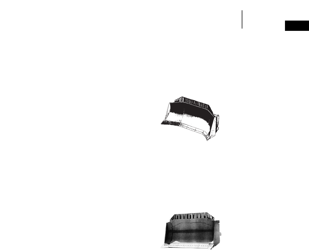
1-37
1
BulldozersBlade Selection
●Production Dozing Tools
BLADE SELECTION
Properly matching tractor and dozer is a basic
requirement for maximizing production. First con-
sider the kind of work the tractor will be doing most
of its life. Then evaluate:
●Material to be moved.
●Tractor limitations.
Materials to be moved.
Most materials are dozeable. However, dozer
performance will vary with material characteristics
such as:
Particle Size & Shape — The larger the individual
particle size, the harder it is for a cutting edge to
penetrate. Particles with sharp edges resist the nat-
ural rolling action of a dozer blade. These particles
require more horsepower to move than a similar vol-
ume of material with rounded edges.
Voids — Few voids or the absence of voids means
the individual particles have most or all of their sur-
face area in contact with other particles. This forms
a bond which must be broken. A well graded mate-
rial, which lacks voids, is generally heavy, and will
be hard to remove from the bank state.
Water Content — In most materials the lack of mois-
ture increases the bond between particles and
makes the material difficult to remove from the
bank state. A high moisture content makes dozing
difficult because the material is heavy and requires
more force to move. Optimum moisture reduces dust
and offers the best condition for dozing ease and
operator comfort.
The effect of freezing depends on the moisture
content. When frozen, the material’s bond strength-
ens as moisture content increases and temperature
decreases. However, freezing a completely dry mate-
rial does not change its characteristics.
An indication of a blade’s ability to penetrate and
obtain a blade load is kW per meter (or horsepower
per foot) of cutting edge. The higher the kW/meter
(HP/foot), the more aggressive the blade. Kilowatt
per Lm3(horsepower per loose cubic yard) indicates
a blade’s ability to push material. The higher the
kW/Lm3(HP/LCY), the greater the blade’s potential
capability for carrying material at a greater speed.
Tractor Limitations
The weight and horsepower of the machine deter-
mines its ability to push. No tractor can exert more
pounds push than the machine itself weighs and its
power train can develop. Various terrain and under-
foot conditions on the job limit the tractor’s ability
to use its weight and horsepower. The “approximate
coefficient of traction factors” chart in the Tables
Section presents these traction factors for common
materials. To use the chart, take the total tractor
weight (with attachments) times the factor to arrive
at the maximum usable push the dozer can exert.
Production Dozing Tools
“U” — Universal blade
— the large wings on
this blade include one
end bit and at least one
section of cutting edge
which make it efficient
for moving big loads over
long distances as in land
reclamation, stockpile
work, charging hoppers and trapping for loaders.
As this blade has a lower kW/meter (HP/foot) of cut-
ting edge than an “S” or “SU”, penetration should not
be a prime objective. With a lower kW/Lm3(HP/LCY)
than an “S” or “SU”, this blade is best for lighter or
relatively easily dozed material. If equipped with
tilt cylinder(s), it has some of the versatility of the
S-blade. Tilt cylinder(s) improve its ability to ditch,
pry out, and level. This extends its use to many util-
ity tasks.
“SU” — The Semi-U
blade combines the
desirable characteristics
of S and U-blades into
one package. It has
increased capacity by the
addition of short wings
which include only the dozer end bits. The wings pro-
vide improved load retention capabilities while
maintaining the blade’s ability to penetrate and load
quickly in tightly packed materials and to handle a
wide variety of materials in production oriented
applications. Tilt cylinder(s) increase both the pro-
ductivity and versatility of this dozer. Equipped
with a push plate, it is effectively used for push load-
ing scrapers.
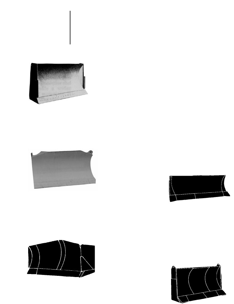
General Purpose Dozing Tools
“S” — The Straight blade
provides excellent versa-
tility. Since it is physically
smaller than the SU or
U-blade, it is easier to
maneuver and can handle
a wider range of materi-
als. It has a higher kW/
meter (HP/foot) of cutting edge than the SU or
U-blade; consequently, the “S” is more aggressive in
penetrating and obtaining a blade load. A tilt cylin-
der increases both the productivity and versatility
of this dozer. With a high kW/Lm3 (HP/LCY), the
S-blade can handle heavy material easily.
Power Angle and Tilt
blade — Versatility is
its key feature with its
ability to perform a
variety of site develop-
ment to general dozing
work as well as heavy-
duty applications. Angle and tilt control is with
2 levers on some machines, 1 lever on others.
Variable Power Angle and Tilt (VPAT) blade can
be mechanically tipped forward for improved pene-
tration or shedding sticky material and backward
for finish grading and improved productivity.
Balderson “VR Blades” (Variable Radius)
The Balderson Variable
Radius Semi-U-Blade
combines the benefits
of a semi-U-blade such
as “cutting” ability and
ground penetration with
U-blade characteristics
of better load retention and less side spill.
This is achieved with the variable radius moldboard.
The variable radius moldboard causes dirt to move
to the center of the blade creating more rolling
action. The extended side plates retain the load and
increase capacities.
The variable radius semi-U-blade is an excellent
tool for land improvement, soil conservation, site
development, or general construction.
Special Application Dozing Tools
Caterpillar and other blade manufacturers pro-
vide specialty bulldozers for specific applications.
The blades are designed to increase production
while performing certain tasks. However, special-
ization may reduce the blade versatility. Following
are the most popular special applications blades.
“A” — Or Angling blade
can be positioned straight
or angled 25 degrees to
either side. It is designed
for side-casting, pioneer-
ing roads, backfilling, cutting ditches and other sim-
ilar tasks. It can reduce the amount of maneuvering
required to do these jobs. Its “C” frame can be used
for attachments such as pushing, land clearing, or
snow removal tools. A-blades are not recommended
for rock or severe applications.
“C” — The Balderson
Cushion blade is used for
on-the-go push-loading.
Rubber cushions allow the
dozer to absorb the impact
of contacting a scraper push
block. When not push-load-
ing, the dozer can be used
for cut maintenance and other general dozing jobs.
The narrow width of the C-blade increases machine
maneuverability in congested cuts and reduces the
possibility of cutting tires associated with SU and
U-blades.
1-38
Bulldozers Blade Selection
●General Purpose Dozing Tools
●Special Attachments “VR Blades”
●Special Application Dozing Tools
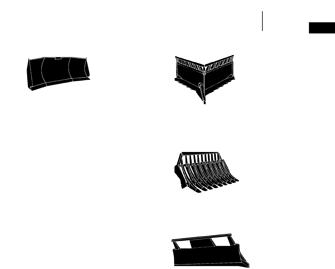
1-39
1
BulldozersBlade Selection
●Special Application Dozing Tools
“U-Blades” — Balderson
offers a variety of U-blades
for use in a wide range of
applications. They pro-
vide high volume move-
ment of light non-cohesive
materials such as coal and woodchips. Heavier
U-blades are also offered for production dozing and
reclamation work.
“Landfill” — Caterpillar and Balderson offer ver-
sions of the landfill or fill spreading dozer. Designed
to handle refuse and cover material. Open trash
screen on top of blade allows good visibility and pro-
tects radiator. Curved moldboard keeps cover mate-
rial rolling evenly.
“Two-Way Dozer” — Designed for use inside ship
holds to move cargo such as grain, salt, iron ore, coal
and chips. These blades can scrape material off
walls and doze to center of hold. They can doze
material forward or pull material.
“V-Tree Cutter” — Rimco
and Rome offer this clear-
ing blade for shearing
trees, stumps and brush
at ground level. A sharp
angle or “V”, formed by
two cutting blades, utilizes
tractor weight and horse-
power through the center-
line of the cutter. Utilization of tractor force allows
most growth to be cut at a steady pace and cast to the
sides.
“Rakes” — Balderson,
Rimco and Rome offer a
variety of rakes for use
in land clearing appli-
cations. They handle
vegetation up to tree
size, and offer good soil penetration for removal of
small stumps, rocks and roots. In most cases rake
tines are replaceable.
“K/G” — Offered by
Rimco and Rome,
the K/G-blade is used
in many land clear-
ing applications. In
addition to cutting trees this versatile blade can pile
vegetation, cut v-type drainage ditches and build
woods roads and firebreaks. Weldco-Beales offers a
blade of similar design called the One-Way Brush
Cutter.
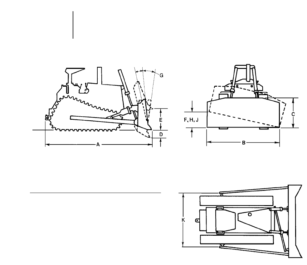
KEY
ALength (Blade Straight)
Blade:
BWidth (including standard end bits)
CHeight
DMaximum Digging Depth
EGround Clearance @ Full Lift
FMaximum Tilt (Manual)
GMaximum Pitch Adjustment
HMaximum Hydraulic Tilt
JHydraulic Tilt (manual brace centered)
KPusharm Trunnion Width (to Ball Centers)
Blade capacities on the following pages are as deter-
mined by SAE recommended practice J1265. Capac-
ities are defined as:
Vs = 0.8 WH2.
Vu = Vs + ZH (W-Z) tan X.
Where: Vs = Capacity of straight or angling blade.
Vu = Capacity of semi-U or full U-blade.
W = Blade width exclusive of end bits.
H = Effective blade height considering
tapered top corners, etc.
Z = Wing length measured parallel to
blade width @ ground line of
cutting edges.
X = Wing angle.
1-40
Bulldozers General Dimensions Key
●Tractor and Blade
●SAE Blade Capacity Definition
1-41
1
BulldozersBlade Specifications
●D3C Series III — All Models & Hydrostatics
●D4C Series III — All Models & Hydrostatics
●D5C Series III — All Models & Hydrostatics
D3C Series III, D3C LGP Series III & Hydrostatic
MODEL 3P 3P Hystat 3P LGP
Type Power Angling Power Angling Power Angling
and Tilt and Tilt and Tilt
Blade Capacities* 1.26 m31.64 yd31.26 m31.64 yd31.31 m31.70 yd3
Weight Shipping** 1126 kg 2482 lb 1126 kg 2482 lb 1213 kg 2674 lb
(Dozer)
Tractor & Dozer Dimensions:
ALength (Blade Straight) 3.86 m 12'8" 3.98 m 13'1" 3.95 m 13'0"
Length (Blade Angled) 4.26 m 14'0" 4.26 m 14'0" 4.63 m 15'2"
Width (Blade Angled) 2.31 m 7'7" 2.31 m 7'7" 2.90 m 9'6"
Width (with C-Frame only) ———
Blade Dimensions: (inside mounted) (inside mounted) (inside mounted)
BWidth (including std.
end bits) 2.55 m 8'4" 2.55 m 8'4" 3.19 m 10'6"
CHeight 836 mm 2'8.9" 836 mm 2'8.9" 746 mm 2'5.4"
DMax. Digging Depth 410 mm 16.2" 418 mm 16.5" 398 mm 15.7"
EGround Clearance @
Full Lift 773 mm 2'6.4" 761 mm 2'6" 761 mm 2'6"
GPitch Adjustment 50°–55° 50°–55° 50°–55°
JHydraulic Tilt 356 mm 14" 356 mm 14" 490 mm 1'7.3"
Blade Angle 25° 25° 25°
D4C Series III, D4C LGP Series III & Hydrostatic
D5C Series III, D5C LGP Series III & Hydrostatic
MODEL 4P 4P LGP 5P 5P LGP
Type Power Angling Power Angling Power Angling Power Angling
and Tilt and Tilt and Tilt and Tilt
Blade Capacities* 1.68 m32.18 yd31.70 m32.21 yd31.93 m32.51 yd32.06 m32.70 yd3
Weight Shipping** 1202 kg 2650 lb 1284 kg 2831 lb 1355 kg 2987 lb 1376 kg 3027 lb
(Dozer)
Tractor & Dozer Dimensions:
ALength (Blade Straight) 3.99 m 13'1" 3.99 m 13'1" 4.07 m 13'4" 4.07 m 13'4"
Length (Blade Angled) 4.42 m 14'6" 4.54 m 14'11" 4.51 m 14'10" 4.631 m 15'2"
Width (Blade Angled) 2.49 m 8'2" 3.03 m 9'11" 2.50 m 8'2" 3.00 m 9'10"
Width (with C-Frame only) ————
Blade Dimensions: (inside mounted) (inside mounted) (inside mounted) (inside mounted)
BWidth (including std.
end bits) 2.70 m 10'10" 3.34 m 10'11" 2.75 m 9'0" 3.30 m 10'10"
CHeight 928 mm 3'0.5" 837 mm 2'9" 999 mm 3'3.3" 929 mm 3'0.6"
DMax. Digging Depth 448 mm 17.6" 443 mm 17.4" 479 mm 18.9" 452 mm 17.8"
EGround Clearance @
Full Lift 775 mm 2'6.5" 775 mm 2'6.5" 809 mm 2'7.9" 835 mm 2'8.9"
GPitch Adjustment 50°–55° 50°–55° 50°–55° 50°–55°
JHydraulic Tilt 406 mm 16" 495 mm 1'7.5" 412 mm 16.2" 490 mm 1'7.3"
Blade Angle 25° 25° 25° 25°
**Blade capacities as determined by SAE J1265.
**Shipping Weight — Total Bulldozer Arrangement includes: Blade, push arms or C-frame, braces, cylinders, lines, trunnions and lift cylinder mountings.
D5M XL D5M LGP D6M XL
MODEL 5P 5P LGP 6SU 6P
Type Power Angling Power Angling
and Tilt and Tilt Semi-U
Blade Capacities* 2.59 m33.39 yd32.03 m32.66 yd34.28 m35.60 yd33.18 m34.14 yd3
Weight, Shipping** 1932 kg 4250 lb 2000 kg 4400 lb 2427 kg 5351 lb 2372 kg 5229 lb
(Dozer)
Tractor & Dozer Dimensions:
ALength (Blade Straight) 4.56 m 14'8" 5.13 m 16'10" 4.92 m 16'2" 4.80 m 15'9"
Length (Blade Angled) 5.24 m 16'10" 5.80 m 19'0" — 5.44 m 17'10"
Width (Blade Angled) 2.79 m 9'2" 3.04 m 10'0" — 2.96 m 9'9"
Width (with C-Frame only) ————
Blade Dimensions: (inside mounted) (inside mounted) (outside mounted) (inside mounted)
BWidth (including std.
end bits) 3.08 m 10'1" 3.36 m 11'0" 3.14 m 10'4" 3.27 m 10'9"
CHeight 1109 mm 3'7.6" 910 mm 2'11.8" 1244 mm 4'1" 1195 mm 3'11"
DMax. Digging Depth 441 mm 17.4" 491 mm 1'7.3" 520 mm 1'8.5" 444 mm 17.5"
EGround Clearance @
Full Lift 916 mm 3'0.1" 923 mm 3'0.3" 983 mm 3'2.7" 925 mm 3'0.4"
GMax. Pitch +2°–6° +2°–6° ±5° +2°–6°
HMax. Hydraulic Tilt — — 665 mm 2'2.2" —
JHydraulic Tilt 460 mm 18.1" 491 mm 1'7.3" 372 mm 14.6" 497 mm 1'7.6"
Blade Angle 25° 25° —25°
**Blade capacities as determined by SAEJ1265.
**Shipping Weight — Total bulldozer arrangement includes: Blade, push arms or C-frame, braces, cylinders, lines, trunnions and lift cylinder mountings.
D6M LGP
MODEL LGP
Type Power Angling
and Tilt
Blade Capacities* 3.16 m34.11 yd3
Weight, Shipping** 2819 kg 6215 lb
(Dozer)
Tractor & Dozer Dimensions:
ALength (Blade Straight) 5.39 m 17'8"
Length (Blade Angled) 6.20 m 20'4"
Width (Blade Angled) 3.70 m 12'2"
Width (with C-Frame only) —
Blade Dimensions: (inside mounted)
BWidth (including std.
end bits) 4.08 m 13'5"
CHeight 1025 mm 3'4.4"
DMax. Digging Depth 433 mm 17.0"
EGround Clearance @
Full Lift 1024 mm 3'4.3"
GMax. Pitch +2°–6°
HMax. Hydraulic Tilt —
JHydraulic Tilt 598 mm 1'11.5"
Blade Angle 25°
**Blade capacities as determined by SAE J1265.
**Notice that the capacity of the U-blade is the volume carried by a straight blade of the same dimensions plus the volume included
in the “cup” of the U-blade. It is intended for relative comparisons of dozer sizes, and not for predicting capacities or produc-
tivities in actual field conditions.
**Shipping Weight — Total Bulldozer Arrangement includes: Blade, push arms or C-frame, braces, cylinders, lines, trunnions and
lift cylinder mountings.
1-42
Bulldozers Blade Specifications
●D5M XL ●D5M LGP
●D6M XL ●D6M LGP
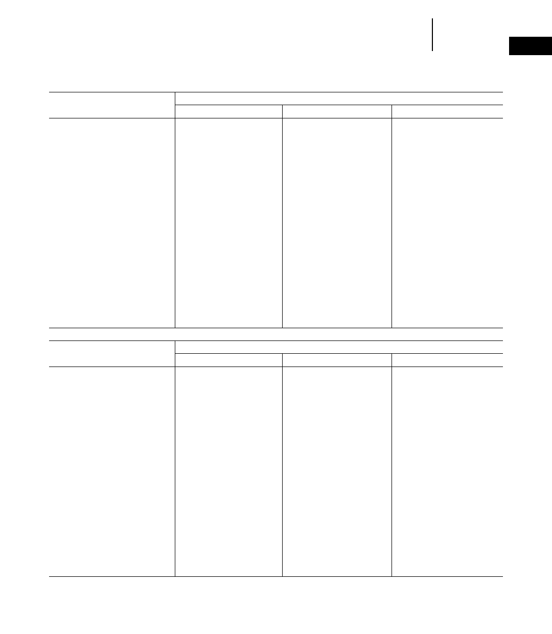
1-43
1
BulldozersBlade Specifications
●D6R ●D6R XL ●D6R LGP
D6R, D6R XL & D6R LGP
MODEL 6A 6A Heavy Duty 6A XL
Type Angling Angling Angling
Blade Capacities* 3.18 m34.16 yd33.93 m35.14 yd33.93 m35.14 yd3
Weight, Shipping** 2727 kg 5999 lb 3218 kg 7079 lb 3109 kg 6839 lb
(Dozer)
Tractor & Dozer Dimensions:
ALength (Blade Straight) 5.22 m 17'1" 5.22 m 17'1" 5.43 m 17'10"
Length (Blade Angled) 6.05 m 19'10" 6.05 m 19'10" 6.26 m 20'6"
Width (Blade Angled) 3.78 m 12'5" 3.78 m 12'5" 3.78 m 12'5"
Width (with C-Frame only) 2.91 m 9'7" 2.91 m 9'7" 2.98 m 9'10"
Blade Dimensions:
BWidth (including std.
end bits) 4.16 m 13'8" 4.16 m 13'8" 4.16 m 13'8"
CHeight 1033 mm 3'4.7" 1155 mm 3'9.5" 1155 mm 3'9.5"
DMax. Digging Depth 506 mm 1'7.9" 506 mm 1'7.9" 524 mm 1'8.6"
EGround Clearance @
Full Lift 1141 mm 3'8.9" 1141 mm 3'8.9" 1205 mm 3'11.4"
FManual Tilt 408 mm 16.1" 408 mm 16.1" 408 mm 16.1"
GMax. Pitch — — —
HMax. Hydraulic Tilt 408 mm 16.1"§408 mm 16.1"§408 mm 16.1"
Blade Angle 25° 25° 25°
JHydraulic Tilt — — —
(Manual Brace Centered)
D6R, D6R XL & D6R LGP
MODEL 6S 6SU 6SU XL
Type Straight Semi Universal Semi Universal
Blade Capacities* 3.89 m35.09 yd35.61 m37.34 yd35.61 m37.34 yd3
Weight, Shipping** 2599 kg 5717 lb 2699 kg 5937 lb 2973 kg 6540 lb
(Dozer)
Tractor & Dozer Dimensions:
ALength (Blade Straight) 5.12 m 16'9" 5.31 m 17'5" 5.55 m 18'2"
Length (Blade Angled) — — —
Width (Blade Angled) — — —
Width (with C-Frame only) — — —
Blade Dimensions:
BWidth (including std.
end bits) 3.36 m 11'0" 3.26 m 10'8" 3.26 m 10'8"
CHeight 1257 mm 4'1.5" 1411 mm 4'7.6" 1411 mm 4'7.6"
DMax. Digging Depth 473 mm 18.6" 473 mm 18.6" 459 mm 18.1"
EGround Clearance @
Full Lift 1104 mm 3'7.5" 1104 mm 3'7.5" 1195 mm 3'11.1"
FManual Tilt 689 mm 2'3.1" 670 mm 2'2.4" 670 mm 2'2.4"
GMax. Pitch +5.3°–4.8° +5.3°–4.8° +5.3°–4.8°
HMax. Hydraulic Tilt 764 mm 2'6.1" 743 mm 2'5.3" 743 mm 2'5.3"
Blade Angle — — —
JHydraulic Tilt 420 mm 16.5" 408 mm 16.1" 408 mm 16.1"
(Manual Brace Centered)
**Blade capacities as determined by SAE J1265.
**Notice that the capacity of the U-blade is the volume carried by a straight blade of the same dimensions plus the volume included in the “cup” of the U-blade. It is intended
for relative comparisons of dozer sizes, and not for predicting capacities or productivities in actual field conditions.
**Shipping Weight — Total Bulldozer Arrangement includes: Blade, push arms or C-frame, braces, cylinders, lines, trunnions and lift cylinder mountings.
§Attachment includes two cylinders.
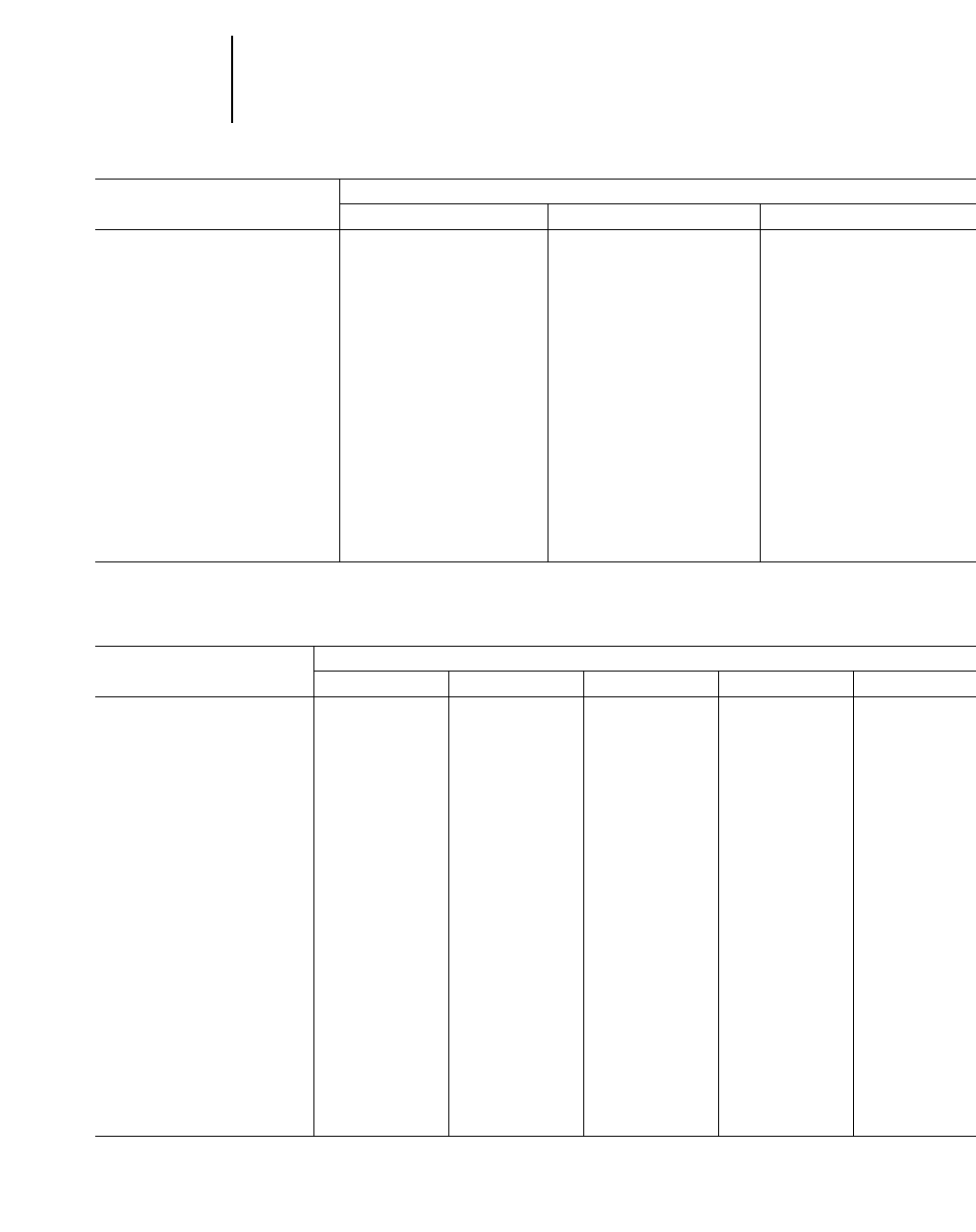
1-44
Bulldozers Blade Specifications
●D6R ●D6R XL ●D6R LGP
●D7R ●D7R LGP
D6R, D6R XL & D6R LGP
MODEL 6S LGP 6A (IG) 6SU (IG)
Type Straight Angling Semi Universal
Blade Capacities* 3.70 m34.83 yd34.3 m35.63 yd35.62 m37.4 yd3
Weight, Shipping** 2801 kg 6162 lb 3260 kg 7180 lb 2950 kg 6500 lb
(Dozer)
Tractor & Dozer Dimensions:
ALength (Blade Straight) 5.71 m 18'9" — —
Blade Dimensions:
BWidth (including std.
end bits) 3.99 m 13'1" 4.20 m 13'9" 3.56 m 11'8"
CHeight 1101 mm 3'7.3" 1169 mm 3'10" 1412 mm 4'8"
DMax. Digging Depth 655 mm 2'1.2" 500 mm 1'7.7" 459 mm 18.1"
EGround Clearance @
Full Lift 1083 mm 3'6.6" 1242 mm 4'1" 1195 mm 3'11"
FManual Tilt 632 mm 2'0.9" 408 mm 16.1" 670 mm 2'2.4"
GMax. Pitch +5.3°–4.8° +5.3°–4.8° +5.3°–4.8°
HMax. Hydraulic Tilt 701 mm 2'3.6" 408 mm 16.1" 743 mm 2'5.3"
JHydraulic Tilt 385 mm 15.2" 408 mm 16.1" 743 mm 2'5.3"
(Manual Brace Centered)
**Blade capacities as determined by SAE J1265.
Notice that the capacity of the U-blade is the volume carried by a straight blade of the same dimensions plus the volume included in the “cup” of the U-blade. It is intended
for relative comparisons of dozer sizes, and not for predicting capacities or productivities in actual field conditions.
**Shipping Weight — Total Bulldozer Arrangement includes: Blade, push arms or C-frame, braces, cylinders, lines, trunnions and lift cylinder mountings.
D7R & D7R LGP
MODEL 7A 7S 7SU 7U 7S LGP
Semi
Type Angling Straight Universal Universal Straight
Blade Capacities* 3.89 m35.08 yd35.16 m36.75 yd36.86 m38.98 yd38.34 m310.91 yd35.89 m37.7 yd3
Weight, Shipping** 3527 kg 7750 lb 3500 kg 7716 lb 3593 kg 7904 lb 3920 kg 8624 lb 3732 kg 8210 lb
(Dozer)
General Dimensions
(Tractor & Dozer)
ALength (Blade Straight) 6.10 m 20'0" 5.81 m 19'1" 6.03 m 19'9" 6.27 m 20'7" 5.81 m 19'1"
Length (Blade Angled) 6.98 m 22'11" ————
Width (Blade Angled) 4.12 m 13'6" ————
Width (with C-Frame only) 3.09 m 10'1" ————
Blade Dimensions:
BWidth (including std.
end bits) 4.50 m 14'9" 3.90 m 12'10" 3.69 m 12'1" 3.98 m 13'1" 4.50 m 14'9"
CHeight 1111 mm 3'7.7" 1363 mm 4'5.7" 1524 mm 5'0" 1553 mm 5'1.1" 1343 mm 4'4.9"
DMax. Digging Depth 669 mm 2'2.3" 527 mm 1'8.7" 527 mm 1'8.7" 527 mm 1'8.7" 668 mm 2'2.3"
EGround Clearance
@ Full Lift 1115 mm 3'7.9" 1145 mm 3'9.1" 1145 mm 3'9.1" 1145 mm 3'9.1" 1153 mm 3'9.4"
FManual Tilt 466 mm 18.3" ————
GMax. Pitch Adjustment — +3.1°–3.9° +3.1°–3.9° +3.1°–3.9° +3.0°–3.9°
Blade Angle (either side) 25° ————
HMax. Hydraulic Tilt 627 mm 2'0.7"§845 mm 2'9.3" 799 mm 2'7.4" 861 mm 2'9.9" 686 mm 2'3"
JHydraulic Tilt — 501 mm 1'7.7" 474 mm 18.6" 511 mm 1'8.1" 426 mm 16.8"
(Manual Brace Centered)
**Blade capacities as determined by SAE J1265.
**Notice that the capacity of the U-blade is the volume carried by a straight blade of the same dimensions plus the volume included in the “cup” of the U-blade. It is intended
for relative comparisons of dozer sizes, and not for predicting capacities or productivities in actual field conditions.
**Shipping Weight — Total Bulldozer Arrangement includes: Blade, push arms or C-frame, braces, cylinders, lines, trunnions and lift cylinder mountings.
§Attachment includes two cylinders.

1-45
1
BulldozersBlade Specifications
●D8R ●D9R
D8R D9R
MODEL 8A 8SU 8U 9SU 9U
Type Angling Semi-U Universal Semi-U Universal
Blade Capacities* 4.66 m36.09 yd38.68 m311.4 yd311.70 m315.3 yd313.5 m317.7 yd316.4 m321.4 yd3
Weight, Shipping** 5459 kg 12,009 lb 4930 kg 10,846 lb 5495 kg 12,089 lb 6543 kg 14,425 lb 7134 kg 15,727 lb
(Dozer)
General Dimensions
(Tractor & Dozer)
ALength (Blade Straight) 6.57 m 21'7" 6.39 m 21'0" 6.79 m 22'3" 6.84 m 22'5" 7.18 m 23'7"
Length (Blade Angled) 7.62 m 25'0" ————
Width (Blade Angled) 4.52 m 14'10" ————
Width (with C-Frame only) 3.38 m 11'1" ————
Blade Dimensions:
BWidth (including std.
end bits) 4.99 m 16'4" 3.94 m 12'11" 4.26 m 14'0" 4.31 m 14'2" 4.65 m 15'3"
CHeight 1174 mm 3'10.2" 1690 mm 5'6.5" 1740 mm 5'8.5" 1934 mm 6'4.1" 1934 mm 6'4.1"
DMax. Digging Depth 628 mm 2'0.7" 582 mm 1'10.9" 582 mm 1'10.9" 606 mm 1'11.9" 606 mm 1'11.9"
EGround Clearance
@ Full Lift 1308 mm 4'3.5" 1231 mm 4'0.5" 1231 mm 4'0.5" 1422 mm 4'8" 1422 mm 4'8"
GMax. Pitch Adjustment — +3.0°–2.9° +3.0°–2.9° +3.4°–2.9° +3.4°–2.9°
Blade Angle (either side) 25° ————
HMax. Hydraulic Tilt 729 mm 2'4.7"§951 mm 3'1.4" 1028 mm 3'4.5" 940 mm 3'1" 1014 mm 3'3.9"
JHydraulic Tilt — 650 mm 2'1.6" 703 mm 2'3.7" 570 mm 1'10.4" 616 mm 2'0.3"
(Manual Brace Centered)
KPusharm Trunnion Width
(to Ball Centers) 2.98 m 9'9" 2.98 m 9'9" 2.98 m 9'9" 3.17 m 10'3" 3.17 m 10'3"
Maximum Track Width
Permitted 712 mm 2'4" 711 mm 2'4" 711 mm 2'4" 762 mm 2'6" 762 mm 2'6"
Dual Tilt Option
GDual Pitch Adj. — — — +4.8°–5.2° +4.8°–4.9°
HDual Max. Hyd. Tilt — — — 1139 mm 3'8.8" 1231 mm 4'0.5"
**Blade capacities as determined by SAE J1265.
**Notice that the capacity of the U-blade is the volume carried by a straight blade of the same dimensions plus the volume included in the “cup” of the U-blade. It is intended
for relative comparisons of dozer sizes, and not for predicting capacities or productivities in actual field conditions.
**Shipping Weight — Total Bulldozer Arrangement includes: Blade, push arms or C-frame, braces, cylinders, lines, trunnions and lift cylinder mountings.
§Attachment includes two cylinders.
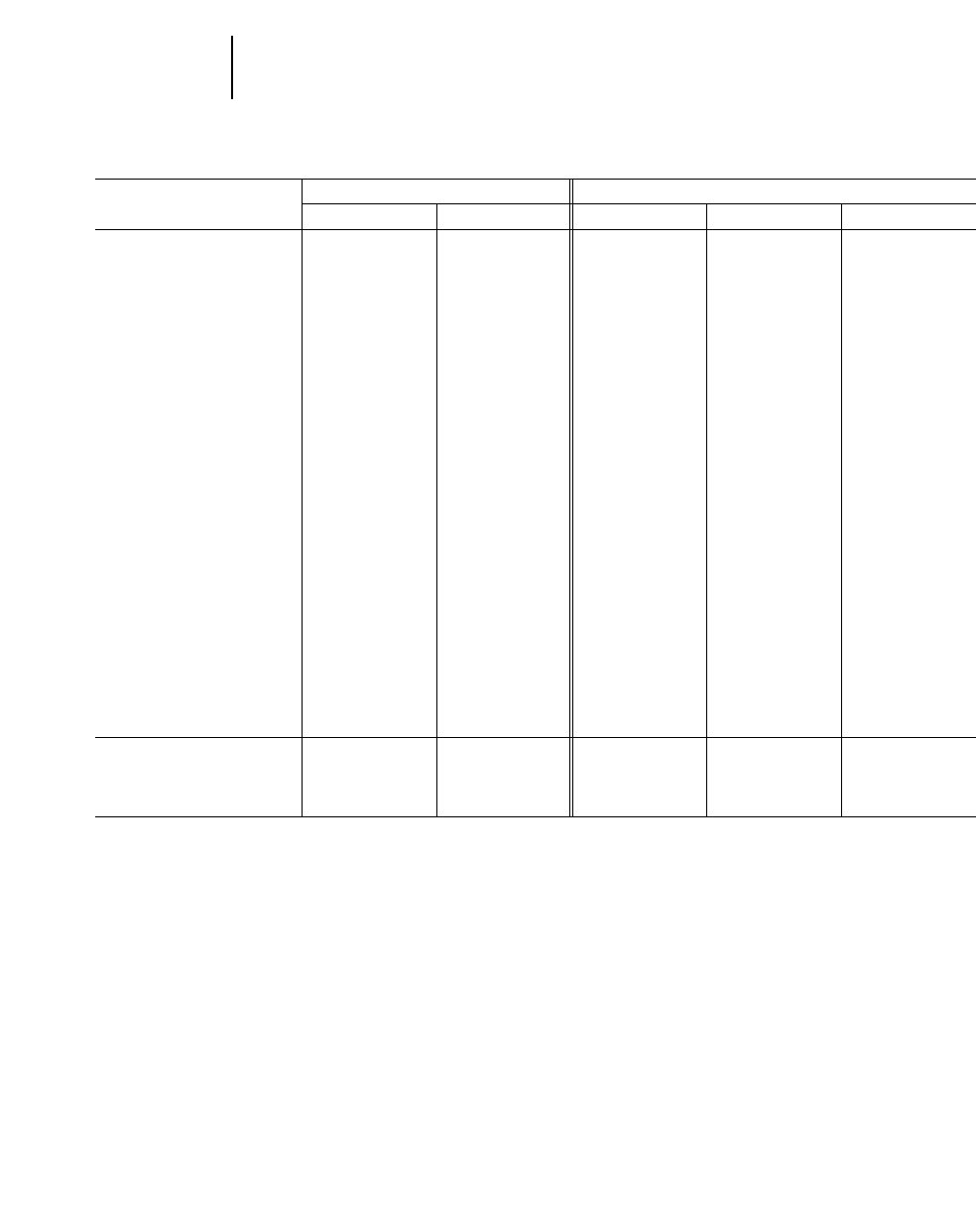
1-46
Bulldozers Blade Specifications
●D10R ●D11R
D10R D11R
MODEL 10SU 10U 11SU 11U 11 C.D.
Type Semi-U Universal Semi-U Universal Universal
Blade Capacities* 18.5 m324.2 yd322.0 m328.7 yd327.2 m335.5 yd334.4 m345.0 yd343.6 m357.0 yd3
Weight, Shipping**
Standard Dozer 10 229 22,550 10 784 23,775 14 813 32,658 17 296 38,131 21 678 47,800
kg lb kg lb kg lb kg lb kg lb
Abrasion Dozer 11 069 24,403 12 413 27,366 16 192 35,698 18 823 41,498 —
kg lb kg lb kg lb kg lb
General Dimensions
(Tractor & Dozer)
ALength 7.76 m 25'5" 8.01 m 26'3" 8.38 m 27'6" 8.83 m 28'11" 8.34 m 26'8"
Width 4.86 m 15'11" 5.26 m 17'3" 5.60 m 18'4" 6.35 m 20'10" 6.71 m 22'0"
Blade Dimensions:
BWidth
(including std. end bits) 4.86 m 15'11" 5.26 m 17'3" 5.60 m 18'4" 6.35 m 20'10" 6.71 m 22'0"
CHeight 2.12 m 6'11" 2.12 m 6'11" 2.37 m 7'9" 2.37 m 7'9" 3.26 m 10'8"
DMax. Digging Depth 674 mm 2'2.5" 674 mm 2'2.5" 766 mm 2'6.2" 766 mm 2'6.2" 766 mm 2'6.2"
EGround Clearance
@ Full Lift 1497 mm 4'10.9" 1497 mm 4'10.9" 1533 mm 5'0.4" 1533 mm 5'0.4" 1533 mm 5'0.4"
GMax. Pitch
Adjustment +1.7°–2.3° +1.7°–2.3° +2.1°–2.2° +2.1°–2.2° —
HMax. Hydraulic Tilt 993 mm 3'3.1" 1074 mm 3'6.3" 1184 mm 3'10.6" 1344 mm 4'4.9" 1344 mm 4'4.9"
JHydraulic Tilt (Manual 722 mm 2'4.4" 782 mm 2'6.8" 886 mm 2'10.9" 1006 mm 3'3.6" —
Brace Centered)
KPusharm Trunnion Width
(to Ball Centers) 3.60 m 11'10" 3.60 m 11'10" 4.18 m 13'9" 4.18 m 13'9" 4.18 m 13'9"
Maximum Track
Width Permitted 762 mm 2'6" 762 mm 2'6" 914 mm 3'0" 914 mm 3'0" 914 mm 3'0"
Dual Tilt Option +7.5°–7.6° +7.5°–7.6° —
or or
GDual Pitch Adj. +5.2°–5.5° +5.2°–5.5° +0°–13° +0°–13° —
HDual Max. Hyd. Tilt 1441 mm 4'8.7" 1560 mm 5'1.4" 1706 mm 5'7.2" 1938 mm 6'4.3" —
**Blade capacities as determined by SAE J1265.
**Notice that the capacity of the U-blade is the volume carried by a straight blade of the same dimensions plus the volume included in the “cup” of the U-blade. It is intended
for relative comparisons of dozer sizes, and not for predicting capacities or productivities in actual field conditions.
**Shipping Weight — Total Bulldozer Arrangement includes: Blade, push arms or C-frame, braces, cylinders, lines, trunnions and lift cylinder mountings.
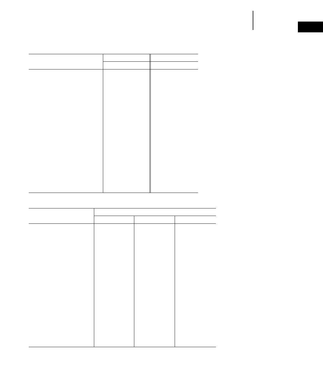
1-47
1
BulldozersBlade Specifications
●D4E SR ●D5E ●D6G
D4E SR D5E
MODEL 4A 5A
Type Angling Angling
Blade Capacities 1.28 m31.65 yd31.95 m32.55 yd3
Weight, Shipping* 1395 kg 3075 lb 1543 kg 3402 lb
(Dozer)
General Dimensions
(Tractor & Dozer)
ALength (Blade Straight) 3.87 m 12'9" 4.60 m 15'1"
Length (Blade Angled) 4.50 m 14'9" 5.26 m 17'3"
Width (Blade Angled) 2.84 m 9'4" 2.95 m 9'8"
Width (with C-frame only) 2.39 m 7'10" 2.36 m 7'9"
Blade Dimensions:
BWidth (including
std. end bits) 3.12 m 10'3" 3.41 m 11'2"
CHeight 706 mm 2'3.8" 859 mm 2'9.8"
DMax. Digging Depth 371 mm 14.6" 457 mm 18"
EGround Clearance
@ Full Lift 811 mm 2'7.9" 937 mm 3'0.9"
FManual Tilt 475 mm 18.7" 338 mm 13.3"
GMax. Pitch Adjustment — —
Blade Angle (either side) 25° 25°
HMax. Hydraulic Tilt 330 mm 13" —
JHydraulic Tilt (Manual — —
Brace Centered)
D6G
MODEL 6A 6S 6SU ©
Type Angling Straight Semi-U
Blade Capacities 2.40 m33.14 yd33.07 m34.02 yd33.80 m34.96 yd3
Weight, Shipping* 2325 kg 5126 lb 1998 kg 4405 lb 2460 kg 5423 lb
(Dozer)
General Dimensions
(Tractor & Dozer)
ALength (Blade Straight) 5.15 m 16'11" 5.07 m 16'8" 5.13 m 16'10"
Length (Blade Angled) 5.91 m 19'5" ——
Width (Blade Angled) 3.52 m 11'6" ——
Width (with C-frame only) 2.85 m 9'4" ——
Blade Dimensions:
BWidth (including
std. end bits) 3.88 m 12'9" 3.23 m 10'7" 3.20 m 10'6"
CHeight 924 mm 3'0.4" 1126 mm 3'8.3" 1235 mm 4'0.6"
DMax. Digging Depth 605 mm 1'11.8" 474 mm 18.7" 472 mm 18.6"
EGround Clearance
@Full Lift 945 mm 3'1.2" 907 mm 2'11.7" 915 mm 3'0"
FManual Tilt 367 mm 14.4" 679 mm 2'2.7" 680 mm 2'2.8"
GMax. Pitch Adjustment — — —
Blade Angle (either side) 25° ——
HMax. Hydraulic Tilt — 810 mm 2'8" 810 mm 2'7.9"
JHydraulic Tilt (Manual — 467 mm 18.4" 465 mm 18.3"
Brace Centered)
*Shipping Weight — Total Bulldozer Arrangement includes: Blade, push arms or C-frame, braces, cylinders, lines, trunnions and lift cylinder mountings.
*Notice that the capacity of the SU-blade is the volume carried by a straight blade of the same dimensions plus the volume included in the “cup” of the SU-blade.It is intended
for relative comparisons of dozer sizes, and not for predicting capacities or productivities in actual field conditions.
©Caterpillar Custom Product.
1-48
Bulldozers Blade Specifications
●D7G
D7G
MODEL 7A 7S
Type Angling Straight
Blade Capacities* 2.9 m33.8 yd34.2 m35.5 yd3
Weight, Shipping** 3227 kg 7115 lb 3475 kg 7660 lb
(Dozer)
General Dimensions
(Tractor & Dozer)
ALength (Blade Straight) 5.49 m 18'0" 5.30 m 17'5"
Length (Blade Angled) 6.35 m 20'10" —
Width (Blade Angled) 3.86 m 12'8" —
Width (with C-Frame only) 3.12 m 10'3" —
Blade Dimensions:
BWidth (including std. end bits) 4.26 m 14'0" 3.65 m 12'0"
CHeight 960 mm 3'1.8" 1274 mm 4'2.1"
DMax. Digging Depth 468 mm 18.4" 438 mm 17.2"
EGround Clearance
@ Full Lift 1206 mm 3'11.5" 1188 mm 3'10.8"
FManual Tilt — —
GMax. Pitch Adjustment — +5.2°–3.0°
Blade Angle (either side) 25° —
HMax. Hydraulic Tilt 300 mm 11.8"§721 mm 2'4.4"
JHydraulic Tilt (Manual — 505 mm 1'7.9"
Brace Centered)
**Blade capacities as determined by SAE J1265.
**Shipping Weight — Total Bulldozer Arrangement includes: Blade, push arms or C-frame, braces, cylinders, lines, trunnions and
lift cylinder mountings.
§Attachment includes two cylinders.

1-49
1
BulldozersEstimating Production Off-The-Job
BULLDOZER PRODUCTION OFF-THE-JOB
You can estimate bulldozer production using the
production curves that follow and the correction fac-
tors that are applicable. Use this formula:
Production (Lm3/hr) Maximum 3Correction
(LCY/hr) =production factors
The bulldozer production curves give maximum
uncorrected production for universal, semi-univer-
sal, and straight blades and are based on the fol-
lowing conditions:
1. 100% efficiency (60 minute hour — level cycle).
2. Power shift machines with 0.05 min. fixed
times.
3. Machine cuts for 15 m (50 feet), then drifts
blade load to dump over a high wall. (Dump
time — 0 sec.)
4. Soil density of 1370 kg/Lm3(2300 lb/LCY).
5. Coefficient of traction:
a. Track machines — 0.5 or better
b. Wheel machines — 0.4 or better
6. Hydraulic controlled blades used.
7. Dig 1F**
Carry 2F**
Return 2R**
To obtain estimated production in bank cubic
meters or bank cubic yards, appropriate load factor
from the Tables section should be applied to the cor-
rected production as calculated above.
Production Bm3/hr =Lm3/hr 3LF
(BCY/h) (LCY/h) 3LF
*Coefficient of traction assumed to be at least 0.4. While
poor traction affects both track and wheel vehicles, caus-
ing them to take smaller blade loads, wheeled units are
affected more severely and production falls much more
rapidly. While no fixed rules can predict this production
loss, a rough rule of thumb is that wheel dozer production
falls off 4% for each one-hundredth decrease in coefficient
of traction below 0.40. If, for example, coefficient of trac-
tion is 0.30, the difference is ten-hundredths (0.10), and
production is 60% (10 34% = 40% decrease).
**This gear sequence is based on level to downhill terrain,
light to medium density material, and no blade extensions
such as spill plates, rock guards, etc. Exceeding these con-
ditions may require carry in 1F, but productivity should
equal or exceed “standard conditions” due to the larger
loads that can be carried in 1F.
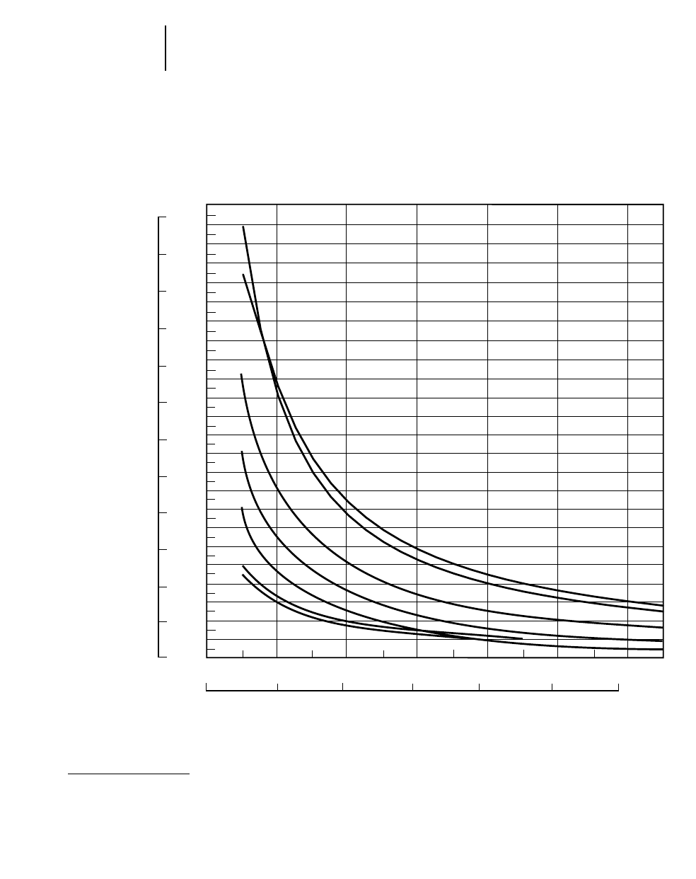
1-50
Bulldozers Estimating Production Off-The-Job
●U-Blades
0
200
400
600
800
1000
1200
1400
1600
1800
2000
2200
2400
2600
2800
3000
3200
3400
3600
3800
4000
4200
4400
4600
4800
0
300
600
900
1200
1500
1800
2100
2400
2700
3000
3300
3600
2000 100 500300 400 600
600 30 15090 120 180
A
B
C
D
E
F
E
D
C
B
A
F
G
G
Meters
KEY
A — D11R-11U
B — D11R C.D.
C — D10R-10U
D — D9R-9U
E — D8R-8U
F — D7R-7U
G — D7G-7U
NOTE: This chart is based on numer-
ous field studies made under varying
job conditions. Refer to correction
factors following these charts.
Lm3/hr LCY/hr
AVERAGE DOZING DISTANCE
Feet
EST. DOZING PRODUCTION
ESTIMATED DOZING PRODUCTION ●Universal Blades ●D7G through D11R
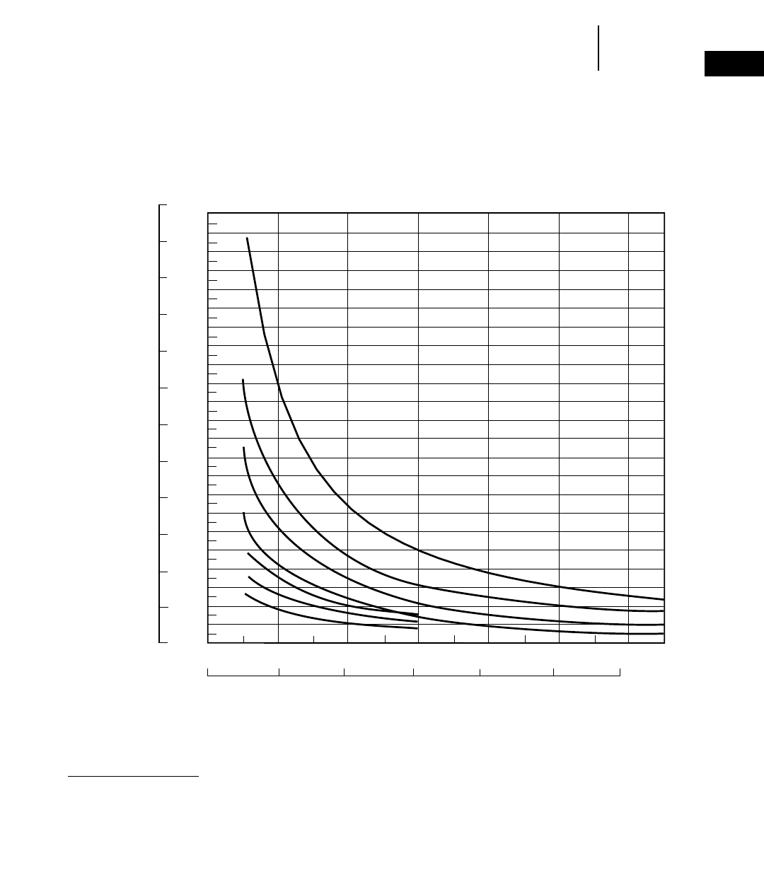
1-51
1
BulldozersEstimating Production Off-The-Job
●SU-Blades
KEY
A — D11R-11SU
B — D10R-10SU
C — D9R-9SU
D — D8R-8SU
E — D7R-7SU
F — D6R-6SU
G — D6M-6SU
NOTE: This chart is based on numer-
ous field studies made under varying
job conditions. Refer to correction
factors following these charts.
0
200
400
600
800
1000
1200
1400
1600
1800
2000
2200
2400
2600
2800
3000
3200
3400
3600
3800
4000
4200
4400
4600
0
300
600
900
1200
1500
1800
2100
2400
2700
3000
3300
3600
2000 100 500300 400 600
600 30 15090 120 180
A
E
E
D
C
B
A
F
F
G
G
B
C
D
Meters
Lm3/hr LCY/hr
AVERAGE DOZING DISTANCE
Feet
EST. DOZING PRODUCTION
ESTIMATED DOZING PRODUCTION ●Semi-Universal Blades ●D6M through D11R
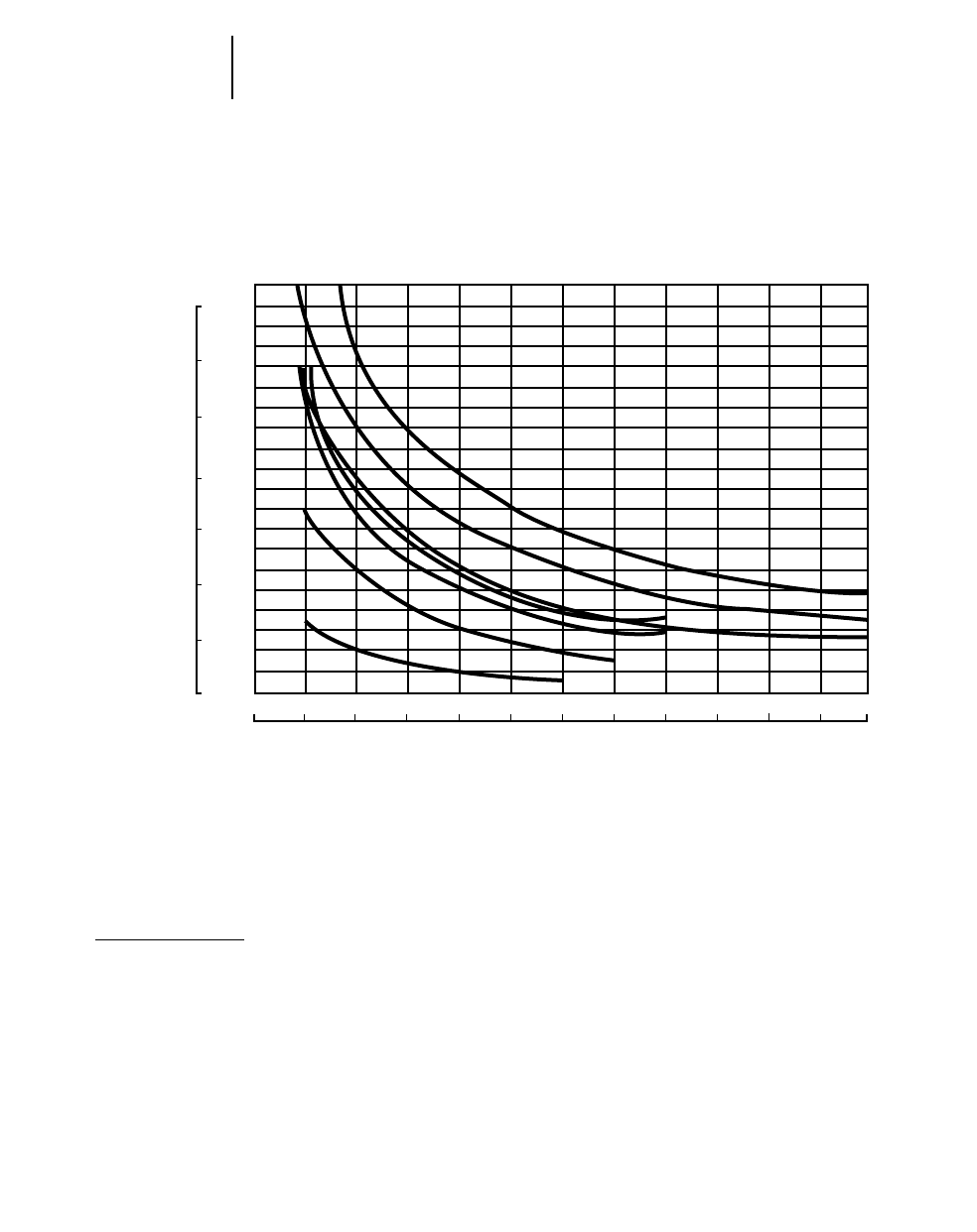
1-52
Bulldozers Estimating Production Off-The-Job
●S-Blades
ESTIMATED DOZING PRODUCTION
Straight Blades ●D3, D6, D7, 814, 824, 834
B
B
A
A
C
C
D
DE
E
F
G
F
G
1000
900
800
700
600
500
400
300
200
100
0
700
600
500
400
300
200
100
0
15 30 45060
75
100 200 300 400 500 600
90 15 120 135 150 165 180
Meters
KEY
A — 824-S
B — 834-S
C — D7G-7S
D — D7R-7S
E — 814-S
F — D6R-6S
G — D3C LGP
NOTE: This chart is based on numerous field studies made under varying job conditions. Refer to correction factors on the next page.
*The 3S represented is for the D3C LGP Series II.
Estimated production of the 834B with U-blade can be found in the Coal Handling section of this handbook.
Lm3/hr LCY/hr
AVERAGE DOZING DISTANCE
Feet
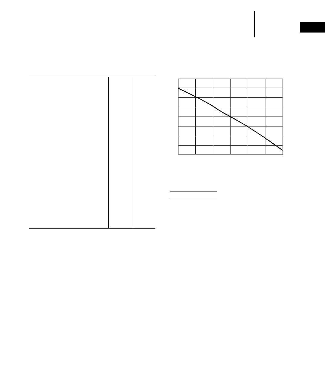
1-53
1
BulldozersJob Factors
Estimating Production Off-The-Job
●Example Problem
JOB CONDITION CORRECTION FACTORS
TRACK- WHEEL-
TYPE TYPE
TRACTOR TRACTOR
OPERATOR —
Excellent 1.00 1.00
Average 0.75 0.60
Poor 0.60 0.50
MATERIAL —
Loose stockpile 1.20 1.20
Hard to cut; frozen —
with tilt cylinder 0.80 0.75
without tilt cylinder 0.70 —
cable controlled blade 0.60 —
Hard to drift; “dead” (dry,
non-cohesive material) or
very sticky material 0.80 0.80
Rock, ripped or blasted 0.60-0.80 —
SLOT DOZING 1.20 1.20
SIDE BY SIDE DOZING 1.15-1.25 1.15-1.25
VISIBILITY —
Dust, rain, snow, fog or darkness 0.80 0.70
JOB EFFICIENCY —
50 min/hr 0.83 0.83
40 min/hr 0.67 0.67
BULLDOZER*
Adjust based on SAE capacity
relative to the base blade
used in the Estimated Dozing
Production graphs.
GRADES — See following graph.
*NOTE: Angling blades and cushion blades are not considered production dozing
tools. Depending on job conditions, the A-blade and C-blade will average
50-75% of straight blade production.
% Grade vs. Dozing Factor
(–) Downhill
(+) Uphill
1.8
1.6
1.4
1.2
1.0
.8
.6
.4
.2
–30 –20 –10 0 +10 +20 +30
ESTIMATING DOZER PRODUCTION
OFF-THE-JOB
Example problem:
Determine average hourly production of a D8R/8SU
(with tilt cylinder) moving hard-packed clay an aver-
age distance of 45 m (150 feet) down a 15% grade,
using a slot dozing technique.
Estimated material weight is 1600 kg/Lm3
(2650 lb/LCY). Operator is average. Job efficiency
is estimated at 50 min/hr.
Uncorrected Maximum Production — 458 Lm3/h
(600 LCY/hr) (example only)
Applicable Correction Factors:
Hard-packed clay is “hard to cut” material –0.80
Grade correction (from graph) . . . . . . . . . .–1.30
Slot dozing . . . . . . . . . . . . . . . . . . . . . . . . . .–1.20
Average operator . . . . . . . . . . . . . . . . . . . . .–0.75
Job efficiency (50 min/hr) . . . . . . . . . . . . . .–0.83
Weight correction . . . . . . . . . . .(2300/2650)–0.87
Production = Maximum Production 3Correction
Factors
= (600 LCY/hr) (0.80) (1.30) (1.20)
(0.75) (0.83) (0.87)
= 405.5 LCY/hr
To obtain production in metric units, the same
procedure is used substituting maximum uncor-
rected production in Lm3.
= 458 Lm3/h 3Factors
= 309.6 Lm3/h
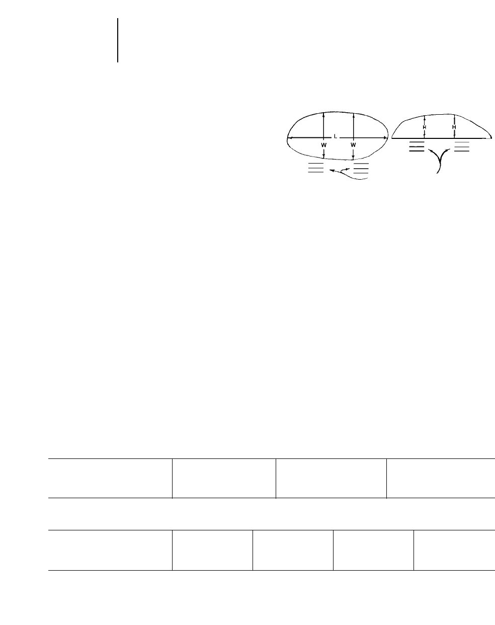
1-54
Bulldozers Measuring Production
On-The-Job
●Special Attachments
MEASURING PRODUCTION ON-THE-JOB
Three generally accepted methods of measuring
bulldozer production are listed below. The third
method is empirical, but is the simplest to conduct.
1. Employing Surveying Techniques
a. Conduct time study and then cross-section
the cut to determine the volume of material
removed. (Production in Bm3or BCY per unit
of time)
b. Conduct time study and then cross-section the
fill to determine the volume of fill material.
(Production in Lm3or LCY per unit of time)
2. Weighing Blade Loads
Conduct time study and weigh material
moved by bulldozer by weighing the loader
bucket loads.
3. Measuring Blade Loads
a. Dozer operation
(1) Pick up and carry load onto a level area
and stop.
(2) Raise the blade directly over the pile
pulling forward slightly as blade comes up,
leaving a nearly symmetrical pile.
(3) Reverse to clear the pile.
b. Measurements
(1) The average height (H) of the pile in feet.
Hold the tape vertically at the inside edge
of each grouser mark. Sight along top of
the pile to obtain the correct measurement.
(2) The average width (W) of the pile in feet.
Hold the tape horizontally over the pile
and sight at the inside edge of each grouser
mark and the corresponding opposite side
of the pile.
(3) The greatest length (L) of the pile in feet.
Hold the tape horizontally over the pile
and sight at each end of the pile.
c. With the above measurements, now compute
the blade load.
(1) Average the height measurement (H)
(2) Average the width measurement (W)
(3) Load (Lm3or LCY) = 0.0138 3(HWL)
(4) Load (Bm3or BCY) = Lm3or LCY 3LF
d. Combine the calculated blade load with time
study to figure production.
BALDERSON
VARIABLE RADIUS (VR)
SEMI-U BLADES D6R D7R D8R
Capacity 5.81 m37.6 yd37.84 m310.25 yd311.28 m314.75 yd3
Width 3349 mm 11'0" 3861 mm 12'8" 4521 mm 14'10"
Height 1473 mm 4'10" 1626 mm 5'4" 1778 mm 5'10"
Weight 1360 kg 3000 lb 1860 kg 4100 lb 2995 kg 6600 lb
BALDERSON
LANDFILL BLADES D6R D7R D8R D9R
Capacity 12.5 m316.4 yd318.1 m323.7 yd324.4 m332 yd338.5 m350.3 yd3
Width 3886 mm 12'9" 4267 mm 14'0" 4928 mm 16'2" 5442 mm 17'10"
Height 1796 mm 5'10.7" 2184 mm 7'2" 2286 mm 7'6" 2178 mm 7'1.75"
Weight 1450 kg 3200 lb 2567 kg 5660 lb 3310 kg 7300 lb 4900 kg 10,800 lb
This list is not all inclusive. Contact Balderson for special attachment needs.
TOP VIEW SIDE VIEW
GROUSER MARKS
SPECIAL ATTACHMENTS

1-55
1
BulldozersSpecial Attachments
●Balderson Cushion Dozers ●Balderson Coal U-Blades
●Balderson Slope Boards ●Balderson Woodchip Dozers
●Balderson Reclamation U-Blades
BALDERSON
COAL U-BLADES D6R D7R D8R D9R
Capacity 9.7 m312.63 yd316.1 m321.0 yd321.4 m328 yd335.8 m346.8 yd3
Width 4267 mm 14'0" 4953 mm 16'3" 5537 mm 18'2" 5940 mm 18'10"
Height 1473 mm 4'10" 1829 mm 6'0" 1980 mm 6'6" 2540 mm 8'4"
Weight 1495 kg 3300 lb 2405 kg 5300 lb 3200 kg 7050 lb 5080 kg 11,200 lb
BALDERSON
COAL U-BLADES D10R D11R
Capacity 45.9 m360 yd374.9 m398.0 yd3
Width 6191 mm 20'1" 7416 mm 24'4"
Height 2794 mm 9'2" 3530 mm 11'7"
Weight 6330 kg 14,400 lb 11 340 kg 25,000 lb
BALDERSON
WOODCHIP
DOZERS D6M D6R D7R D8R D9R D10R
Capacity 11.5 m315 yd315.3 m320 yd320.3 m326.6 yd328.3 m337 yd345.9 m360.0 yd372.6 m395 yd3
Width 3657 mm 12'0" 4267 mm 14'0" 4826 mm 15'10" 5486 mm 18'0" 5486 mm 18'0" 6401 mm 21'0"
Height 1829 mm 6'0" 1880 mm 6'2" 2083 mm 6'10" 2337 mm 7'8" 3086 mm 10'1.5" 3480 mm 11'5"
Weight 1542 kg 3400 lb 1905 kg 4200 lb 2765 kg 6100 lb 2925 kg 6450 lb 4900 kg 10,800 lb 8165 kg 18,000 lb
BALDERSON
RECLAMATION U-BLADES D8R D9R D10R D11R
Capacity 16.4 m321.5 yd330.6 m340 yd345.9 m360.0 yd3
Width 4877 mm 16'0" *5791 mm 19'0" 7010 mm 23'0"
Height 1880 mm 6'2" 2413 mm 7'11" 2590 mm 8'6"
Weight 3810 kg 8400 lb 6575 kg 14,500 lb 9525 kg 21,000 lb
BALDERSON
CUSHION
DOZERS D8R D9R D10R D11R
Width 2889 mm 9'5.75" 3048 mm 10'0" 3499 mm 11'5.75"
Height 1499 mm 4'11" 1575 mm 5'2" 1753 mm 5'9" *
Weight 3185 kg 7020 lb 4275 kg 9420 lb 6115 kg 13,480 lb
Balderson
Rear Cushion
Push Block *2175 kg 4800 lb 3105 kg 6850 lb *
*Available upon request.
This list is not all inclusive. Contact Caterpillar Attachment Products and Services.

CONTENTS
Features . . . . . . . . . . . . . . . . . . . . . . . . . . . . . .1-57
Ripper Specification Diagrams
Adjustable Parallelogram Ripper . . . . . . . . .1-58
Radial Ripper . . . . . . . . . . . . . . . . . . . . . . . .1-60
Fixed Parallelogram Ripper . . . . . . . . . . . . .1-60
Specifications
Track-Type Tractors . . . . . . . . . . . . . . . . . . .1-61
Tip selection . . . . . . . . . . . . . . . . . . . . . . . . . . .1-67
Estimating ripping production . . . . . . . . . . . . .1-68
Seismic wave velocity charts . . . . . . . . . . . . . .1-69
Estimating ripper production graphs . . . . . . .1-75
Features:
●Parallelogram linkage with hydraulically
variable pitch on D8R, D9R, D10R and D11R.
Operator can adjust angle of ripper tip to the
material for penetration at all ripping depths to
increase production.
●Fixed Parallelogram linkage design used on
D5E, D6M, D6G, D6R, D7G, D6R XR, D6R XL,
D7R and D7R XR. This design holds tooth angle
constant at all ripping depths.
●Fixed Radial rippers are Multishank with wide
beam coverage for utility ripping close to walls,
footings and embankments. Ripper tooth angle
changes as ripper is raised or lowered. Five shanks
available on the D3C Series III, D4C Series III,
D5C Series III. Three shanks available for the
D5M.
●Adjustable Single shank arrangements avail-
able for D8R, D9R, D10R and D11R for tough rip-
ping applications and deep ripping requirements.
●Hydraulically Variable Pitch Multishank
arrangements available in all ripper models,
including D8R, D9R, D10R and D11R allow wide-
beam coverage in easier-to-rip materials.
RIPPERS
1-57
1
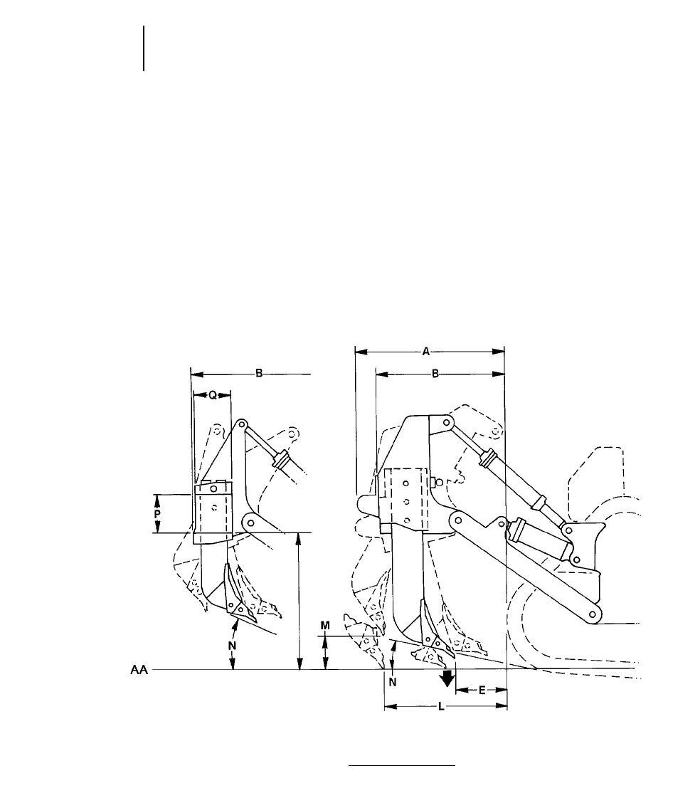
“Pryout,” (Breakout) newtons (and pounds) — the
maximum sustained upward force, generated by the
lift cylinders measured at the ripper tip. Breakout
force is measured with the shank in the top hole,
shank vertical and ripper full down. Breakout force
may be hydraulically or balance limited.
“Penetration force,” kilonewtons (and pounds) —
the maximum sustained downward force, generated
by the ripper lift cylinders measured at the ripper
tip, which is required to raise the back end of the
vehicle with the tip on ground and the shank
(pinned in the top hole) vertical.
1-58
Rippers Specification Diagrams
●Adjustable Parallelogram Ripper
DEFINITION OF FORCES SHOWN IN TABLES THAT FOLLOW
Adjustable Parallelogram Ripper
NOTE: Letters correspond to ripper specifications on pages that follow.
KEY
AA — Ground Line
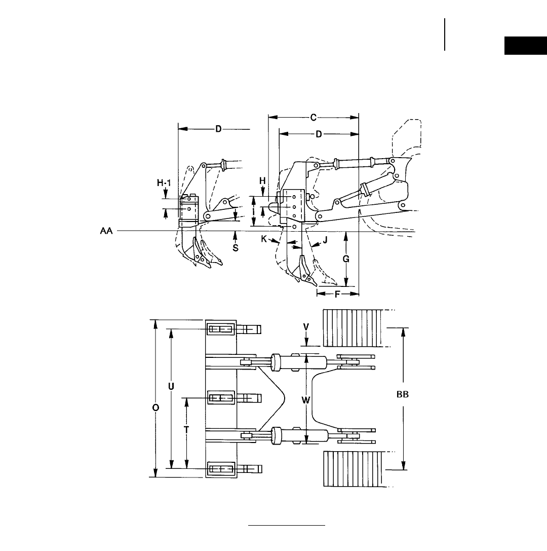
Adjustable Parallelogram Ripper
1-59
1
RippersSpecification Diagrams
●Adjustable Parallelogram Ripper
NOTE: Letters correspond to ripper specifications on pages that follow.
KEY
AA — Ground Line
BB — Track Gauge
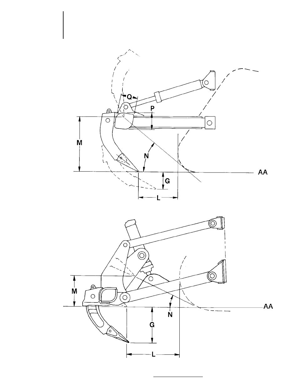
1-60
Rippers Specification Diagrams
●Radial Ripper
●Fixed Parallelogram Ripper
NOTE: Letters correspond to ripper specifications on pages that follow.
KEY
AA — Ground Line
* — Tip Standard
Radial Ripper*
Fixed Parallelogram Ripper

D3C D4C D5C
Series III Series III Series III
TRACTOR/RIPPER & Hydrostatic & Hydrostatic & Hydrostatic D5M XL**
Ripper Type Radial Radial Radial Radial
Dimensions:
Ripper Shank
GMaximum digging depth 284 mm 11.2" 231 mm 9.1" 220 mm 8.7" 350 mm 13.8"
LMaximum reach at
ground line 702 mm 2'3.6" 543 mm 1'9.4" 527 mm 1'8.7" 668 mm 2'2.3"
MMaximum ground
clearance under tip
(shank pinned in
bottom hole) 513 mm 1'8.2" 567 mm 1'10.3" 577 mm 1'10.7" 482 mm 1'7"
NMaximum ramp angle,
ripper up (shank
pinned in bottom
hole) 25° 30.5° 31° 25.2°
Shank section 36 376 mm 36 376 mm 58 3139 mm
(1.4" 33") (1.4" 33") (2.3" 35.5")
Ripper Beam
OOverall width 1.58 m 5'2" 1.58 m 5'2" 1.58 m 5'2" 1.95 m 6'5"
PHeight 130 mm 5.1" 130 mm 5.1" 130 mm 5.1" 165 mm 6.5"
QLength 140 mm 5.5" 140 mm 5.5" 140 mm 5.5" 211 mm 8.3"
Number of Pockets 5553
TPocket Spacing 356 mm 14" 356 mm 14" 356 mm 14" 896 mm 2'11.3"
UShank Gauge 1.42 m 4'8" 1.42 m 4'8" 1.42 m 4'8" 1.79 m 5'10"
VTrack clearance with
standard shoe 151 mm 5.9" 151 mm 5.9" 151 mm 5.9" 108 mm 4.3"
Installed weights:
Ripper with standard
shank 250 kg 550 lb 250 kg 550 lb 250 kg 550 lb 758 kg 1671 lb
Each additional shank 11 kg 24 lb 11 kg 24 lb 34 kg 74 lb
Ripper Forces:*
Penetration Force 2460 kg 5424 lb 2735 kg 6031 lb 3025 kg 6670 lb 4010 kg 8840 lb
Pryout Force 5265 kg 11,610 lb 5265 kg 11,610 lb 5265 kg 11,600 lb 19 126 kg 42,165 lb
**This value may vary slightly with various vehicle configurations.
**D5M XL and LGP Penetration and pryout forces are for machines equipped with UPAT-Blade and Power Shift Transmission
NOTE: Letters correspond to ripper dimension drawings.
1-61
1
RippersSpecifications
●D3C Series III ●D4C Series III
●D5C Series III ●D5M XL

TRACTOR/RIPPER D5M LGP D6M XL D6M LGP
Ripper Type Radial Parallelogram Parallelogram
Dimensions:
Ripper Shank
GMaximum digging depth 298 mm 11.7" 474 mm 18.6" 360 mm 14.2"
LMaximum reach at ground line 696 mm 2'3.4" 516 mm 1'8.3" 453 mm 17.8"
MMaximum ground clearance
under tip (shank pinned in
bottom hole) 536 mm 1'9.1" 392 mm 15.4" 506 mm 1'7.3"
NMaximum ramp angle,
ripper up (shank pinned
in bottom hole) 25.9° 34.4° 49.5°
Shank section 58 3139 mm 73 3176 mm 73 3176 mm
(2.3" 35.5") (2.9" 36.9") (2.9" 36.9")
Ripper Beam
OOverall width 1.95 m 6'5" 2.20 m 7'3" 2.20 m 7'3"
PHeight 165 mm 6.5" 216 mm 8.5" 216 mm 8.5"
QLength 211 mm 8.3" 254 mm 10" 254 mm 10"
Number of Pockets 333
TPocket Spacing 896 mm 2'11.3" 1000 mm 3'3.4" 1000 mm 3'3.4"
UShank Gauge 1.79 m 5'10" 2 m 6'7" 2 m 6'7"
VTrack clearance with
standard shoe 124 mm 4.9" 99 mm 3.9" 104 mm 4.1"
Installed weights:
Ripper with standard shank 758 kg 1671 lb 1406 kg 3100 lb 1406 kg 3100 lb
Each additional shank 34 kg 74 lb 78 kg 172 lb 78 kg 172 lb
Ripper Forces:*
Penetration Force 4669 kg 10,293 lb 6023 kg 13,278 lb 7198 kg 15,869 lb
Pryout Force 19 260 kg 42,461 lb 12 600 kg 27,778 lb 12 600 kg 27,778 lb
*This value may vary slightly with various vehicle configurations. D5M LGP equipped with UPAT-blade and Power Shift Transmission.
NOTE: Letters correspond to ripper dimension drawings.
1-62
Rippers Specifications
●D5M LGP
●D6M XL ●D6M LGP

TRACTOR/RIPPER D6R D6R XL D7R
Ripper Type Parallelogram Parallelogram Parallelogram
Dimensions:
Ripper Shank
GMaximum digging depth 500 mm 1'7.7" 500 mm 1'7.7" 748 mm 2'5.4"
LMaximum reach at ground line 729 mm 2'4.7" 729 mm 2'4.7" 1.07 m 3'6.1"
MMaximum ground clearance
under tip (shank pinned in
bottom hole) 520 mm 1'8.5" 520 mm 1'8.5" 638 mm 2'1.1"
NMaximum ramp angle, ripper
up (shank pinned
in bottom hole) 26° 26° 26.6°
Shank section 74 3175 mm 74 3175 mm 72 3228 mm
(2.9" 36.9") (2.9" 36.9") (2.8" 36.9")
Ripper Beam
OOverall width 2.20 m 7'3" 2.20 m 7'3" 2.21 m 7'3"
PHeight 216 mm 8.5" 216 mm 8.5" 279 mm 11"
QLength 254 mm 10" 254 mm 10" 343 mm 13.5"
Number of Pockets 333
TPocket Spacing 1000 mm 3'3.4" 1000 mm 3'3.4" 991 mm 3'3"
UShank Gauge 2 m 6'7" 2 m 6'7" 1.98 m 6'6"
VTrack clearance with
standard shoe 120 mm 4.7" 120 mm 4.7" 95 mm 3.7"
Installed weights:
Ripper with standard shank 1456 kg 3203 lb 1456 kg 3203 lb 3277 kg 7225 lb
Each additional shank 70 kg 154 lb 70 kg 154 lb 138 kg 305 lb
Ripper Forces:*
Penetration Force 6558 kg 14,428 lb 7485 kg 16,505 lb 8664 kg 19,104 lb
Pryout Force 9155 kg 20,140 lb 9155 kg 20,140 lb 18 007 kg 39,705 lb
*Tractor equipped with ripper, OROPS, SU dozer and heavy duty track.Values may vary slightly with various configurations.
NOTE: Letters correspond to ripper dimension drawings.
1-63
1
RippersSpecifications
●D6R ●D6R XL ●D7R

TRACTOR/RIPPER D8R D9R
Adjustable Parallelogram Adjustable Parallelogram
Ripper Type Single Shank Multishank Single Shank Multishank
Dimensions:
Ripper to Track
Ripper length behind track, shank
vertical, ripper up
AWith Pushblock NA NA NA NA
BWithout Pushblock 1.58 m 5'2" 1.46 m 4'9" 1.57 m 5'2" 1.33 m 4'4"
Ripper length behind track,
shank vertical, ripper down
CWith Pushblock NA NA NA NA
DWithout Pushblock 1.84 m 6'0" 1.71 m 5'7" 1.88 m 6'2" 1.71 m 5'7"
Tip to track distance, shank vertical
ERipper Up 694 mm 2'3.3" 640 mm 2'1.2" 689 mm 2'3.2" 510 mm 1'8.1"
FRipper Down 950 mm 3'1.4" 899 mm 2'11.4" 944 mm 3'1.2" 890 mm 2'11"
Ripper Shank*
GMaximum digging depth 1130 mm 3'8.5" 780 mm 2'6.7" 1231 mm 4'0.6" 798 mm 2'7.6"
HDig adjustment per hole 305 mm 12" 250 mm 10" 295 mm 12" 250 mm 10"
ITotal dig adjustment 610 mm 2'0" 250 mm 10" 590 mm 1'11.2" 250 mm 10"
Pitch Adjustment, ripper down:
JForward 15° 14.9° 10.57° 10°
KBackward 9.9° 10° 15.17° 15.10°
LMaximum reach at ground line 1.32 m 4'3" 1.17 m 3'10" 1.25 m 4'1" 1.16 m 3'10"
MMaximum ground clearance
under tooth (shank pinned
in bottom hole) 636 mm 2'1" 593 mm 1'11.3" 882 mm 2'10.9" 885 mm 2'10.7"
NMaximum ramp angle, ripper up
(shank pinned in bottom hole) 28.2° 28.4° 36.89° 37.5°
Shank Section 75 3333 mm 75 3333 mm 90 3355 mm 75 3333 mm
2.9" 313.1" 2.9" 313.1" 3.5" 314" 2.9" 313.1"
Ripper Beam
OOverall width NA 2.46 m 8'1" NA 2.64 m 8'8"
PHeight NA 334 mm 13.1" NA 380 mm 15"
QLength NA 457 mm 18" NA 457 mm 18"
Clearance under beam,
shank vertical
RRipper Up NA 1.55 m 5'1" NA 1.77 m 5'10"
SRipper Down NA 449 mm 17.7" NA 378 mm 14.9"
Number of Pockets 1313
TPocket Spacing NA 1092 mm 3'7" NA 1180 mm 3'10.4"
UShank Gauge NA 2.17 m 7'1" NA 2.35 m 7'8"
VTrack Clearance with standard shoe 76 mm 3" 76 mm 3" 71 mm 2.8" 71 mm 2.8"
WWidth across widest part
of lift cylinders 1.37 m 4'5" 1.37 m 4'5" 1.50 m 4'11" 1.50 m 4'11"
Installed Weights:
Ripper with standard shank 4085 kg 9005 lb 4213 kg 9287 lb 4854 kg 10,700 lb 4885 kg 10,770 lb
Each additional tooth group NA 332 kg 730 lb NA 332 kg 733 lb
Ripper Forces:**
Penetration Force, shank vertical 127 400 N 28,620 lb 124 200 N 27,920 lb 153 885 N 34,581 lb 147 958 N 33,249 lb
Pryout Force, shank vertical 222 800 N 50,070 lb 227 900 N 51,230 lb 320 511 N 72,025 lb 324 680 N 74,639 lb
**Deep Ripping Shank is available for D8R and D9R single shank rippers. D8R Deep Ripping Arrangement maximum digging depth is 1.57 m (5'2").
Hydraulic pin puller is standard with deep ripping shank. D9R Deep Ripping Arrangement maximum digging depth is 1.66 m (5'5").
**Forces are for a ripper on a tractor equipped with EROPS, U-Dozer and performance track. Forces will vary slightly with other vehicle configurations.
NOTE: Letters correspond to ripper dimension drawings.
NA — Not Applicable.
1-64
Rippers Specifications
●D8R ●D9R

TRACTOR/RIPPER D10R D11R D11R C.D.
Adjustable Parallelogram Adjustable Parallelogram
Ripper Type Single Shank Multishank Single Shank Multishank Single Shank
Dimensions:
Ripper to Track
Ripper length behind track, shank
vertical, ripper up (A)
AWith Pushblock 2.08 m 6'10" NA 2.19 m 7'2" NA NA
BWithout Pushblock 1.76 m 5'9" 1.56 m 5'1" 1.85 m 6'1" 1.92 m 6'4" 2.04 m 6'8"
Ripper length behind track,
shank vertical, ripper down (A)
CWith Pushblock 2.48 m 8'2" NA 2.59 m 8'6" NA NA
DWithout Pushblock 2.16 m 7'1" 1.96 m 6'5" 2.29 m 7'6" 1.92 m 6'4" 2.48 m 8'2"
Tip to track distance, shank
vertical (A)
ERipper Up 730 mm 2'4.7" 651 mm 2'1.6" 622 mm 2'0.5" 651 mm 2'1.6" 622 mm 2'0.5"
FRipper Down 1130 mm 3'8.5" 1050 mm 3'5.3" 1041 mm 3'5" 1030 mm 3'4.6" 1041 mm 3'5"
Ripper Shank*
GMaximum digging depth 1370 mm 4'5.9" 941 mm 3'1" 1612 mm 5'3.5" 1070 mm 3'6.1" 1612 mm 5'3.5"
HDig adjustment per hole 355 mm 14" 250 mm 10" 280 mm 11" 280 mm 11" 280 mm 11"
ITotal dig adjustment 710 mm 2'4" 250 mm 10" 840 mm 2'9.1" 280 mm 11" 840 mm 2'9.1"
Pitch Adjustment, ripper down:
JForward 18° 18° 15° 15° 15°
KBackward 19.7° 19.7° 18.3° 18.5° 18.3°
LMaximum reach at ground line 1.50 m 4'11" 1.36 m 4'6" 1.73 m 5'8" 1.57 m 5'2" 1.73 m 5'8"
MMaximum ground clearance
under tooth (shank pinned
in bottom hole) 1070 mm 3'6.1" 1070 mm 3'6.1" 1115 mm 3'7.9" 1137 mm 3'8.8" 1115 mm 3'7.9"
NMaximum ramp angle, ripper up
(shank pinned in bottom hole) 36.9° 37.5° 33.9° 37.1° 33.9°
Shank Section 100 3400 mm 90 3355 mm 110 3450 mm 100 3400 mm 110 3450 mm
4" 315.75" 3.5" 314" 4.3" 317.7" 3.9" 315.7" 4.3" 317.7"
Ripper Beam
OOverall width NA 2.92 m 9'7" NA 3.33 m 10'11" NA
PHeight NA 460 mm 18.1" NA 560 mm 1'10" NA
QLength NA 485 mm 1'7.1" NA 560 mm 1'10" NA
Clearance under beam,
shank vertical
RRipper Up NA 2.03 m 6'8" NA 2.06 m 6'9" NA
SRipper Down NA 380 mm 15" NA 282 mm 11.1" NA
Number of Pockets 13131
TPocket Spacing NA 1320 mm 4'4" NA 1500 mm 5'9" NA
UShank Gauge NA 2.63 m 8'8" NA 2.99 m 9'10" NA
VTrack Clearance with standard shoe 97 mm 4" 97 mm 4" 141 mm 5.6" 166 mm 5.6" 141 mm 5.6"
WWidth across widest part
of lift cylinders 1.75 m 5'9" 1.75 m 5'9" 1.90 m 6'3" 1.90 m 6'3" 1.90 m 6'3"
Installed Weights:
Ripper with standard shank 7117 kg 15,690 lb 6919 kg 15,253 lb 9643 kg 21,215 lb 9698 kg 21,335 lb 13 584 kg 29,885 lb
Each additional tooth group NA 524 kg 1155 lb NA 671 kg 1489 lb NA
Ripper Forces:**
Penetration Force, 205 000 45,980 205 000 45,980 279 865 62,890 265 265 59,610 318 440 71,560
shank vertical N lb Nlb Nlb Nlb Nlb
Pryout Force, shank vertical 429 000 96,360 429 000 96,360 657 845 147,830 643 895 144,695 619 260 139,160
Nlb Nlb Nlb Nlb Nlb
**Deep Ripping Shank is available for D10R & D11R single shank rippers. Hydraulic pin puller is standard with deep ripping shank. Deep Ripping Arrangement maximum
digging depth is 1.86 m (6'3") for D10R and 2.18 m (7'2") for D11R.
**Forces are for a ripper on a tractor equipped with an EROPS, U-Dozer and performance track. Forces will vary slightly with other vehicle configurations.
NA — Not Applicable.
1-65
1
RippersSpecifications
●D10R ●D11R ●D11R C.D.

TRACTOR/RIPPER D4E SR/No. 4 D5E/No. 5 D6G/No. 6 D7G/No. 7
Ripper Type Parallelogram Parallelogram Parallelogram Parallelogram
Dimensions:
Ripper Shank
GMaximum digging depth 400 mm 16" 478 mm 1'7" 530 mm 1'8.9" 737 mm 2'5"
LMaximum reach at
ground line 640 mm 2'1" 640 mm 2'1" 551 mm 1'9.7" 994 mm 3'3.1"
MMaximum ground clearance
under tip (shank pinned
in bottom hole) 297 mm 12" 297 mm 12" 218 mm 8.6" 462 mm 18.2"
NMaximum ramp angle, ripper
up (shank pinned in
bottom hole) 20° 20° 16° 21°
Shank Section 61 3140 mm 61 3140 mm 76 3178 mm 72 3228 mm
2.4" 35.5" 2.4" 35.5" 3" 37" 2.8" 39"
Ripper Beam
OOverall width 1.98 m 6'6" 2.34 m 7'8" 2.34 m 7'8" 2.21 m 7'3"
PHeight 140 mm 5.5" 140 mm 5.5" 214 mm 8.4" 279 mm 11"
QLength 171 mm 7" 171 mm 7" 254 mm 10" 343 mm 13.5"
Number of Pockets 5553
TPocket Spacing 432 mm 17" 432 mm 17" 536 mm 1'9.1" 991 mm 3'3"
UShank Gauge 1.74 m 5'8" 1.74 m 5'8" 2.15 m 7'1" 1.98 m 6'6"
VTrack clearance with
standard shoe 60 mm 2" 60 mm 2" 213 mm 8.4" 185 mm 7.3"
Installed weights:
Ripper with standard shank 1080 kg 2376 lb 1380 kg 3036 lb 1500 kg 3300 lb 2429 kg 5344 lb
Each additional shank 31 kg 68 lb 64 kg 141 lb 64 kg 141 lb 155 kg 341 lb
NOTE: Letters correspond to ripper dimension drawings.
1-66
Rippers Specifications
●D4E SR ●D5E ●D6G ●D7G

TIP SELECTION FOR THE D8R, D9R, D10R
AND D11R RIPPERS
Three tip configurations (short, intermediate and
long) in two styles (centerline and penetration) are
available for economical operation in a variety of
conditions.
RECOMMENDED TIP USAGE
Short — Use in high impact conditions where break-
age problems occur. The shorter the tip,
the more it resists breakage.
Intermediate — Most effective in moderate impact
conditions where abrasion is not
excessive.
Long — Use in loose, abrasive materials where break-
age is not a problem. Generally offers the
most wear material.
Centerline vs Penetration
The materials being ripped and the tractor doing
the ripping will both have an effect on which tip will
do the best job. High density material requires a
“penetration” tip. High impact material requires a
“centerline” tip. The following is a general guide to
tip application.
Tips to use
D8R/
Ripping Condition D9R D10R D11R
Tandem Tractors . . . . . . . Short Short Short
Single Shank &
Multi-Shank
Extreme Duty . . . . . . . . Int. Short Short
Medium Duty . . . . . . . . Long Int. Int.
Abrasive Duty . . . . . . . . Long Long Long
Always use the longest tip that will wear without
excessive breakage. Different tips should be tried
to determine the most economical.
ESTIMATING RIPPING PRODUCTION
Ripping costs must be compared to other methods
of loosening the material — usually drilling and
blasting — on a cost per ton or bank cubic yard basis.
Thus, an accurate estimation of ripper production is
needed to determine unit ripping costs.
There are three general methods of estimating
ripping production:
1. The best method is to record the time spent rip-
ping, then remove (using scrapers or loaders
and trucks) and weigh the ripped material. The
total weight divided by the time spent will give
hourly production. If the contractor is paid by
volume, then a density must be used and the
accuracy is only as good as the density used.
For payment by volume removed, method 2
may be desirable. Some care will be needed to
assure that only ripped material is removed.
2. Another method is to cross-section the area
and then record the time spent ripping. After
the material has been removed, cross-section
the area again to determine the volume of rock
removed. The volume divided by the time
spent ripping gives the ripping rate per minute
or hour.
3. Timing the ripper over a measured distance
is the least accurate method, but valuable for
quick estimating on the job. An average cycle
time should be determined from a number of
timed cycles. Turn-around or back-up time
must be included. Measure the average rip
distance, rip spacing and depth of penetration.
This data will give the volume per cycle from
which the production in bank cubic yards can
be calculated. Experience has shown results
obtained from this method are about 10 to 20%
higher than the more accurate method of
cross-sectioning.
An example of the measured distance method for
calculating ripper production is:
Data — D10R — No. 10 with one shank.
910 mm (36 in) between passes.
1.6 km/h (1 mph) average speed (including slip-
page and stalls).
Every 91 m (300 ft) requires 0.25 min to raise, pivot,
turn, and lower again: 91 m (300 ft) = 1 pass.
610 mm (24 in) penetration.
Full time ripping (no pushing or dozing assignment).
1-67
1
RippersTip Selection
Estimating Production

Estimating Production
Example of Estimating Production (Metric)
Time per pass:
1.6 km/h = 26.7 m/min. Then 91 m = 3.41 min;
26.7 m/min
3.41 min + 0.25 min (turn time) = 3.66 min/pass.
If the operator works an average of 45 min per h,
it is possible to make = 45 = 12.3 passes per h
3.66
Volume ripped: 91 m 30.9 m 30.6 m = 49.1 BCM
per pass
Production = 49.1 312.3 = 604 BCM per h
Remember the results from this method are usu-
ally 10 to 20 per cent higher than the actual pro-
duction that can be expected on the job.
● ● ●
Example of Estimating Production (English)
Time per pass:
MPH = 88 fpm. Then 300 ft = 3.41 min;
88 fpm
3.41 min + 0.25 min. (turn time) = 3.66 min/pass.
If the operator works an average of 45 min per hr,
it is possible to make 45 = 12.3 passes per hr
3.66
Volume ripped: 300 33 32= 66.7 BCY per pass
27
Production = 66.7 312.3 = 820 BCY per hr
● ● ●
NOTE: The demands of heavy ripping will increase
the normal owning and operating costs of the
tractor.
These costs should be increased no less than 30-
40% in heavy ripping applications to estimate rock
loosening costs.
There is no ready answer or rule-of-thumb solu-
tion to predict ripping production. Even if every-
thing is known about the seismic velocity of the
material, its composition, job conditions, equipment
and operator, only a “guesstimate” can be given. The
final answer must come from a production study
obtained on the job site.
Sample problem (Metric)
Determine the loosening costs in the following
situation:
Machine — D10R Tractor with No. 10
Single Shank Ripper
Rip Spacing — 915 mm
Ripper Penetration — 610 mm
Rip Distance — 91 m
Rip Time — 3.41 minutes
Maneuver Time — 0.25 minutes
Seismic Velocity — 1830 meters per second
Assume 60 min. hour
Solution:
1. Total Cycle Time = 3.41 + 0.25 = 3.66 min
Cycles/hour = 60 min/hr = 16.4
3.66 min/cycle
2. Production per cycle = 91 m 3 0.9 m 3 0.6 m =
49.1 BCM/cycle
3. Production = 49.1 BCM/cycle 3 16.4 cycles/h
= 805 BCM/h
4. Remember results of this method are usually
10 to 20% high.
Actual Production = 80% of 805 BCM/h
= 644 BCM/h
Or 90% of 805 BCM/h = 725 BCM/h
5. Owning and Operating Costs
A D10R (ripping only) could have a $115.00/h
O & O costs including $30/h operator.
6. Loosening Costs
$115.00/hr 4644 BCM/h = $0.179/BCM
$115.00/hr 4725 BCM/h = $0.159/BCM
The loosening cost should range from 15.9¢
to 17.9¢/BCM
● ● ●
Sample problem (English)
Determine the loosening costs in the following
situation:
Machine — D10R Tractor with No. 10
Single Shank Ripper
Rip Spacing — 3 feet
Ripper Penetration — 2 feet
Rip Distance — 300 feet
Rip Time — 3.41 minutes
Maneuver Time — 0.25 minutes
Seismic Velocity — 6,000 feet per second
Assume 60 min. hour
1-68
Rippers

Solution:
1. Total Cycle Time = 3.41 + 0.25 = 3.66 min
Cycles/hour = 60 min/hr = 16.4
3.66 min/cycle
2. Production per cycle = 300 33 32= 66.7
BCY/cycle 27
3. Production = 66.7 BCY/cycle 3 16.4 cycles/hr
= 1094 BCY/hour
4. Remember results of this method are usually
10 to 20% high.
Actual Production = 80% 31094
= 875 BCY/hr
or 90% 31094 = 984 BCY/hr
5. Owning and Operating Costs
A D10R (ripping only) could have a $115.00/hr
O & O cost including $30/hr operator
6. Loosening Costs
$115.00/hr 4875 BCY/hr = $0.131/BCY
$115.00/hr 4984 BCY/hr = $0.117/BCY
The loosening cost should range from 11.7¢ to
13.1¢/BCY
● ● ●
USE OF SEISMIC VELOCITY CHARTS
The charts of ripper performance estimated by
seismic wave velocities have been developed from
field tests conducted in a variety of materials. Con-
sidering the extreme variations among materials
and even among rocks of a specific classification,
the charts must be recognized as being at best only
one indicator of rippability.
Accordingly, consider the following precautions
when evaluating the feasibility of ripping a given
formation:
— Tooth penetration is often the key to ripping
success, regardless of seismic velocity. This is
particularly true in homogeneous materials
such as mudstones and claystones and the
fine-grained caliches. It is also true in tightly
cemented formations such as conglomerates,
some glacial tills and caliches containing rock
fragments.
— Low seismic velocities of sedimentaries can
indicate probable rippability. However, if the
fractures and bedding joints do not allow tooth
penetration, the material may not be ripped
effectively.
— Pre-blasting or “popping” may induce sufficient
fracturing to permit tooth entry, particularly
in the caliches, conglomerates and some other
rocks; but the economics should be checked
carefully when considering popping in the
higher grades of sandstones, limestones and
granites.
Ripping is still more art than science, and much
will depend on operator skill and experience. Rip-
ping for scraper loading may call for different tech-
niques than if the same material is to be dozed
away. Cross-ripping requires a change in approach.
The number of shanks used, length and depth of
shank, tooth angle, direction, throttle position — all
must be adjusted according to field conditions.
Ripping success may well depend on the operator
finding the proper combination for those conditions.
NOTE: Field Seismic Information shown in the fol-
lowing charts is the best single indication
of rippability. However, Caterpillar does
not rely on any single parameter to select
the best machine for your particular opera-
tion and rock type. Field Seismic Information
is just one aspect of a complete rippability
analysis that can be obtained through your
Caterpillar dealer. A Caterpillar rippabil-
ity analysis includes a geological site sur-
vey, field seismic velocity measurements,
laboratory analysis of rock properties and
an equipment investment analysis. Contact
your Caterpillar dealer for a complete rip-
pability analysis.
1-69
1
RippersEstimating Production
Using Seismic Charts
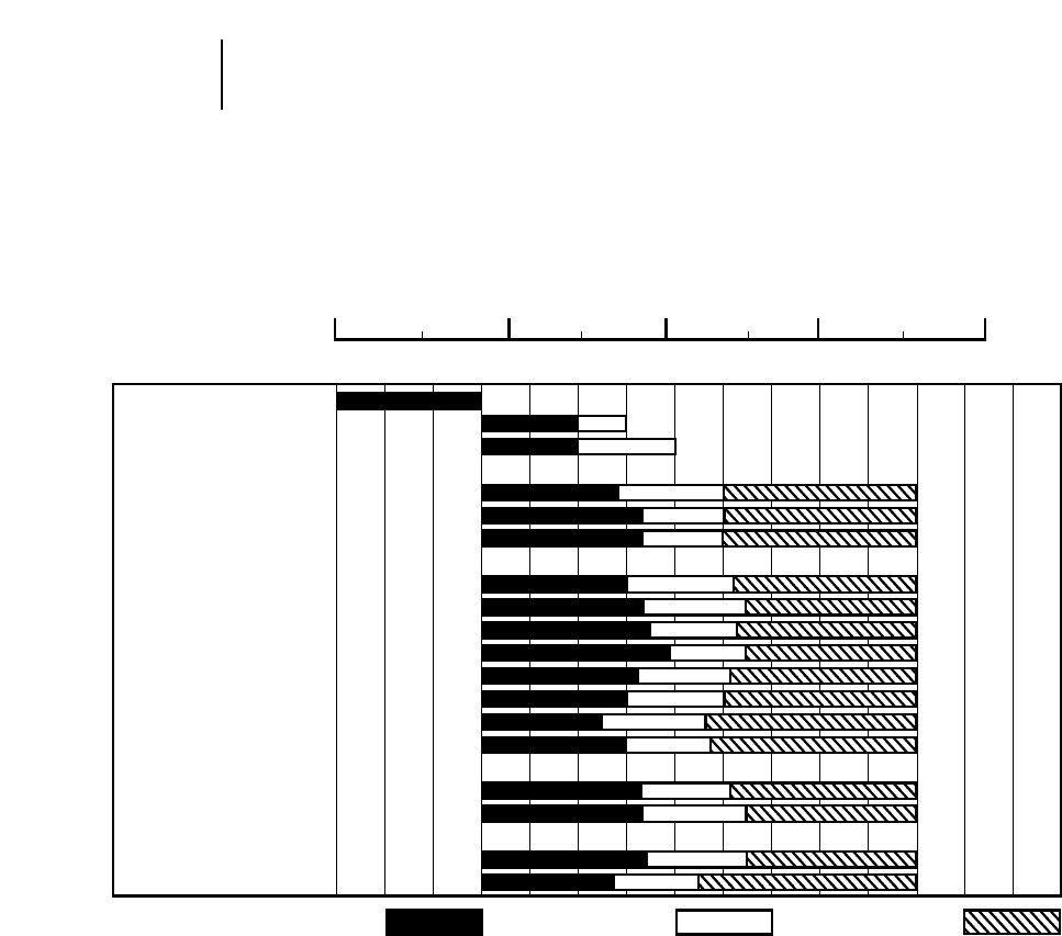
D8R
●Multi or Single Shank No. 8 Ripper
●Estimated by Seismic Wave Velocities
1-70
Rippers Ripper Performance
●D8R
111115161234 789101112131415
23410
TOPSOIL
CLAY
GLACIAL TILL
IGNEOUS ROCKS
GRANITE
BASALT
TRAP ROCK
SEDIMENTARY ROCKS
SHALE
SANDSTONE
SILTSTONE
CLAYSTONE
CONGLOMERATE
BRECCIA
CALICHE
LIMESTONE
METAMORPHIC ROCKS
SCHIST
SLATE
MINERALS & ORES
COAL
IRON ORE
Seismic Velocity
Meters Per Second 31000
Feet Per Second 31000
RIPPABLE MARGINAL NON-RIPPABLE
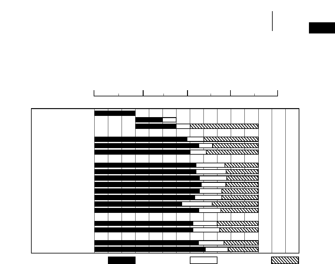
D9R
●Multi or Single Shank No. 9 Ripper
●Estimated by Seismic Wave Velocities
1-71
1
RippersRipper Performance
●D9R
111115161234 789101112131415
23410
TOPSOIL
CLAY
GLACIAL TILL
IGNEOUS ROCKS
GRANITE
BASALT
TRAP ROCK
SEDIMENTARY ROCKS
SHALE
SANDSTONE
SILTSTONE
CLAYSTONE
CONGLOMERATE
BRECCIA
CALICHE
LIMESTONE
METAMORPHIC ROCKS
SCHIST
SLATE
MINERALS & ORES
COAL
IRON ORE
RIPPABLE MARGINAL NON-RIPPABLE
Seismic Velocity
Meters Per Second 31000
Feet Per Second 31000
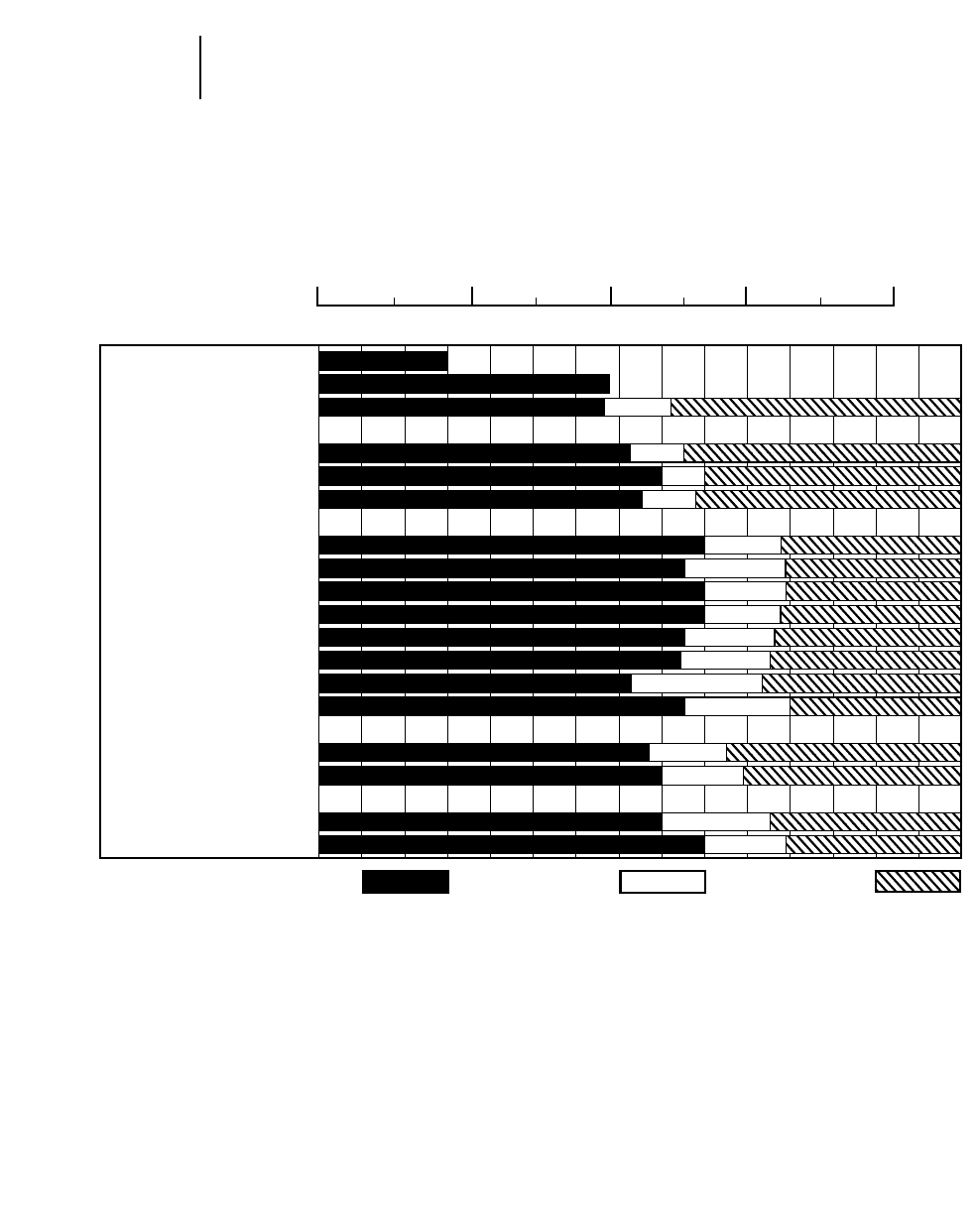
1-72
Rippers Ripper Performance
●D10R
D10R
●Multi or Single Shank No. 10 Ripper
●Estimated by Seismic Wave Velocities
111115161234 789101112131415
23410
TOPSOIL
CLAY
GLACIAL TILL
IGNEOUS ROCKS
GRANITE
BASALT
TRAP ROCK
SEDIMENTARY ROCKS
SHALE
SANDSTONE
SILTSTONE
CLAYSTONE
CONGLOMERATE
BRECCIA
CALICHE
LIMESTONE
METAMORPHIC ROCKS
SCHIST
SLATE
MINERALS & ORES
COAL
IRON ORE
Seismic Velocity
Meters Per Second 31000
Feet Per Second 31000
RIPPABLE MARGINAL NON-RIPPABLE
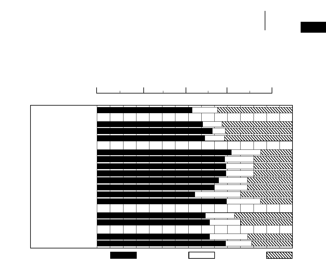
1-73
1
RippersRipper Performance
●D11R
D11R
●Multi or Single Shank No. 11 Ripper
●Estimated by Seismic Wave Velocities
111115161234 789101112131415
23410
GLACIAL TILL
IGNEOUS ROCKS
GRANITE
BASALT
TRAP ROCK
SEDIMENTARY
SHALE
SANDSTONE
SILTSTONE
CLAYSTONE
CONGLOMERATE
BRECCIA
CALICHE
LIMESTONE
METAMORPHIC
SCHIST
SLATE
MINERALS & ORES
COAL
IRON ORE
Seismic Velocity
Meters Per Second 31000
Feet Per Second 31000
RIPPABLE MARGINAL NON-RIPPABLE
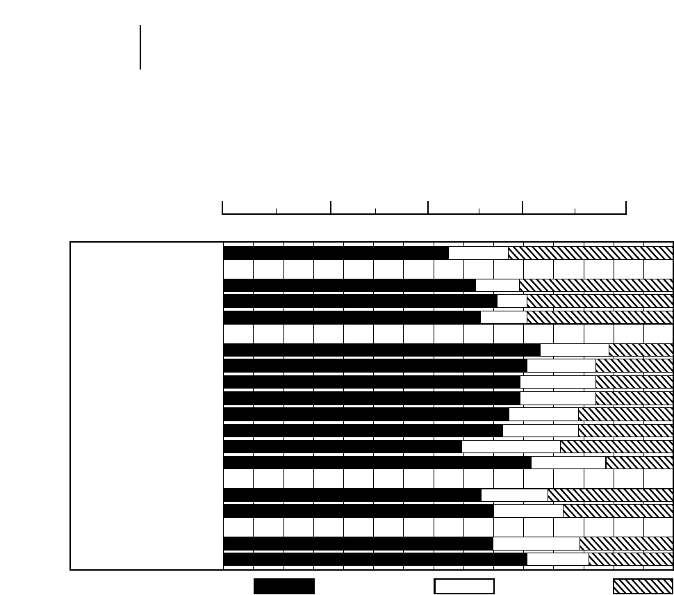
1-74
Rippers Ripper Performance
●D11R C.D.
D11R C.D.
●Single Shank No. 11 Ripper
●Estimated by Seismic Wave Velocities
111115161234 789101112131415
23410
GLACIAL TILL
IGNEOUS ROCKS
GRANITE
BASALT
TRAP ROCK
SEDIMENTARY
SHALE
SANDSTONE
SILTSTONE
CLAYSTONE
CONGLOMERATE
BRECCIA
CALICHE
LIMESTONE
METAMORPHIC
SCHIST
SLATE
MINERALS & ORES
COAL
IRON ORE
Seismic Velocity
Meters Per Second 31000
Feet Per Second 31000
RIPPABLE MARGINAL NON-RIPPABLE
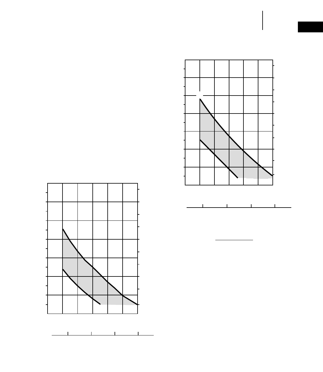
1-75
1
RippersEstimated Ripper Production Graphs
●D8R ●D9R
CONSIDERATIONS FOR USING
PRODUCTION ESTIMATED GRAPHS:
●Machine rips full-time — no dozing.
●Power shift tractors with single shank rippers.
●100% efficiency (60 min hour).
●Charts are for all classes of material.
●In igneous rock with seismic velocity of 8000 fps
or higher for the D11R, and 6000 fps or higher for
the D10R, D9R and D8R, the production figures
shown should be reduced by 25%.
●Upper limit of charts reflect ripping under ideal
conditions only. If conditions such as thick lami-
nation, vertical lamination or any factor which
would adversely affect production are present, the
lower limit should be used.
B
A
2345678
250
500
750
1000
1250
1500
1750
2000
2250
2500
2750
3000
3250
12
250
500
750
1000
1250
1500
1750
2000
2250
2500
B
2345678
250
500
750
1000
1250
1500
1750
2000
2250
2500
2750
3000
3250
250
500
750
1000
1250
1500
1750
2000
2250
2500
12
A
SEISMIC VELOCITY (in meters per second)
KEY
A — IDEAL
B — ADVERSE
SEISMIC VELOCITY (in feet per second x 1000)
D9R WITH SINGLE SHANK
PRODUCTION (BCY/hour)
PRODUCTION (Bm3/hour)
SEISMIC VELOCITY (in meters per second)
SEISMIC VELOCITY (in feet per second x 1000)
D8R WITH SINGLE SHANK
PRODUCTION (BCY/hour)
PRODUCTION (Bm3/hour)
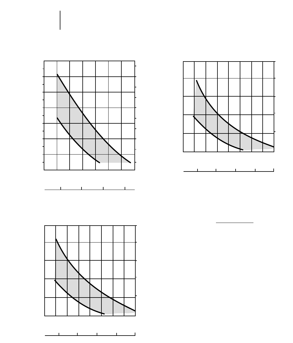
1-76
Rippers Estimated Ripper Production Graphs
●D10R ●D11R ●D11R C.D.
B
A
234 567 98
250
500
750
1000
1250
1500
1750
2000
2250
2500
2750
3000
3250
12
250
500
750
1000
1250
1500
1750
2000
2250
2500
SEISMIC VELOCITY (in meters per second)
SEISMIC VELOCITY (in feet per second x 1000)
D10R WITH SINGLE SHANK
PRODUCTION (BCY/hour)
PRODUCTION (Bm3/hour)
A
B
23 67 1094 85
1000
2000
3000
4000
5000
12 3
750
1500
2250
3000
3750
SEISMIC VELOCITY (in meters per second)
SEISMIC VELOCITY (in feet per second x 1000)
D11R WITH SINGLE SHANK
PRODUCTION (BCY/hour)
PRODUCTION (Bm3/hour)
KEY
A — IDEAL
B — ADVERSE
A
B
23 67 1094 85
1000
2000
3000
4000
5000
12 3
750
1500
2250
3000
3750
SEISMIC VELOCITY (in meters per second)
SEISMIC VELOCITY (in feet per second x 1000)
D11R C.D. WITH SINGLE SHANK
PRODUCTION (BCY/hour)
PRODUCTION (Bm3/hour)

CONTENTS
Features . . . . . . . . . . . . . . . . . . . . . . . . . . . . . .1-77
Physical specifications . . . . . . . . . . . . . . . . . . .1-78
Operating specifications . . . . . . . . . . . . . . . . . .1-81
PA55 & PA56 Standard Features:
●Rigid cast ductile case with integral fairlead
mounting lugs and heavy duty drawbar provides
durable construction for long life and maximum
resale value.
●Internal Hydraulic System with gear pump
and maintenance free spring type accumulator
for easy installation and maintenance.
●Equal speed gearing in forward and reverse to
provide smooth and predictable performance.
●Single lever control, electronic on PA56 or cable
control on PA55 for hydraulically actuated mul-
tiple disc clutches, brake, and freespool for ease of
operation.
●Freespool with drag adjustment so the oper-
ator can easily pull wire rope from the drum by
hand, permitting fast one man operation.
PA57G & Cat 59 Standard Features:
●Adjust-free oil-disc clutches in winch assure
reliable performance day-in, day-out.
●Input clutch reduces parasitic horsepower loss
for improved fuel efficiency.
●Single-lever actuation of both clutch and brake
functions … automatic synchronization of input
and directional clutch engagement for smooth
control.
●Equal speed gearing in reel-in and reel-out to
provide smooth and predictable performance.
PA57VS, PA58VS & PA59VS Standard Features:
●Variable line pull and line speed.
●Hydraulically driven winch for precise load
control in reel-in or reel-out.
●Inching control through modulation of variable
displacement pump and motor.
●Dual braking system provides a static brake with
a sprag clutch to eliminate fall back and a brake
valve for dynamic braking.
●Single lever joy stick control for ease of oper-
ation and reliable performance with no cable nor
linkage adjustments.
●Three roller fairlead is standard for improved
wire rope life during side pulls.
WINCHES
1-77
1
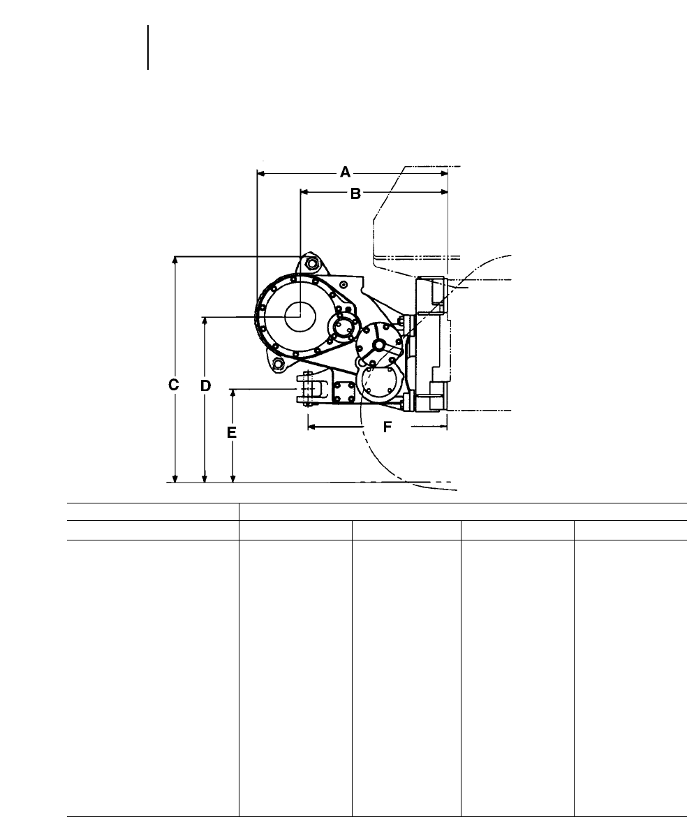
WINCH MODEL PA55
TRACTOR MODEL D5M XL D5M LGP D6M XL D6M LGP
Transmission PS PS & DD
ATractor to rear of winch 1120 mm 3'8.1" 1120 mm 3'8.1" 1120 mm 3'8.1" 1120 mm 3'8.1"
BTractor to drum centerline 866 mm 2'10.1" 866 mm 2'10.1" 866 mm 2'10.1" 866 mm 2'10.1"
CGround to top of winch 1328 mm 4'4.3" 1380 mm 4'6.3" 1396 mm 4'7" 1511 mm 4'11.5"
DGround to drum centerline 960 mm 3'1.8" 1012 mm 3'3.8" 1028 mm 3'4.5" 1142 mm 3'9"
EGround to center of hitch 526 mm 1'8.7" 578 mm 1'10.7" 594 mm 1'11.4" 708 mm 2'3.9"
FTractor to pin centerline 818 mm 2'8.2" 818 mm 2'8.2" 818 mm 2'8.2" 818 mm 2'8.2"
Overall width (not shown) 1080 mm 3'6.5" 1080 mm 3'6.5" 1080 mm 3'6.5" 1080 mm 3'6.5"
Drum diameter (not shown) 254 mm 10" 254 mm 10" 254 mm 10" 254 mm 10"
Weight* 1276 kg 2810 lb 1276 kg 2810 lb 1276 kg 2814 lb 1276 kg 2814 lb
Oil refill capacity 74 L 19.5 74 L 19.5 74 L 19.55 74 L 19.55
U.S. gal U.S. gal U.S. gal U.S. gal
Wire rope diameter:
Recommended 16 mm 0.63" 16 mm 0.63" 19 mm 0.75" 19 mm 0.75"
Optional 19 mm 0.75" 19 mm 0.75" 22 mm 0.87" 22 mm 0.87"
Drum capacity:
Recommended rope 177 m 581' 177 m 581' 122 m 400' 122 m 400'
Optional rope 122 m 400' 122 m 400' 88 m 289' 88 m 289'
Wire rope ferrule size 54 32.13 354 32.13 354 32.13 354 32.13 3
(OD 3length) 65 mm 2.56" 65 mm 2.56" 65 mm 2.56" 65 mm 2.56"
*Includes pump, operator controls, oil, mounting brackets, spacers and wire rope.
1-78
Winches Physical Specifications
●PA55 & PA56
PA55 & PA56
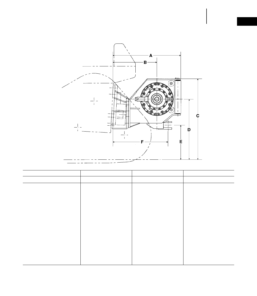
1-79
1
WinchesPhysical Specifications
●PA56 ●PA57G ●PA57VS
WINCH MODEL PA56 PA57G PA57VS
TRACTOR MODEL D6R D7G D7R
ATractor to rear of winch 1200 mm 3'11.2" 973 mm 3'2.3" 1435 mm 4'8.5"
BTractor to drum centerline 945 mm 3'1.2" 693 mm 2'3.3" 940 mm 3'1"
CGround to top of winch 1475 mm 4'10.1" 1570 mm 5'1.7" 1570 mm 5'1.8"
DGround to drum centerline 1110 mm 3'7.6" 1176 mm 3'10.3" 1130 mm 3'8.5"
EGround to center of hitch 680 mm 2'2.7" 610 mm 2'0" 579 mm 1'10.8"
FTractor to pin centerline 915 mm 3'0" 752 mm 2'5.6" 1216 mm 3'11.9"
Overall width (not shown) 975 mm 3'2.3" 1148 mm 3'9.2" 1158 mm 3'9.6"
Drum diameter (not shown) 254 mm 10" 305 mm 12" 318 mm 12.5"
Weight* 1135 kg 2503 lb 1727 kg 3800 lb 1790 kg 3950 lb
Oil refill capacity 67 L 17.75 U.S. gal 81 L 21.5 U.S. gal 15 L 4 U.S. gal
Wire rope diameter:
Recommended 22 mm 0.88" 25 mm 1" 29 mm 1.13"
Optional 25 mm 1" 29 mm 1.13" 32 mm 1.25"
Drum capacity:
Recommended rope 88 m 290'0" 73 m 239'0" 84 m 276'0"
Optional rope 67 m 220'0" 58 m 190'0" 59 m 193'0"
Wire rope ferrule size (OD 3length) 54 367 mm 2.10 32.63" 60 370 mm 2.38 32.75" 60 370 mm 2.38 32.75"
*Operating weight includes pump and operator controls.
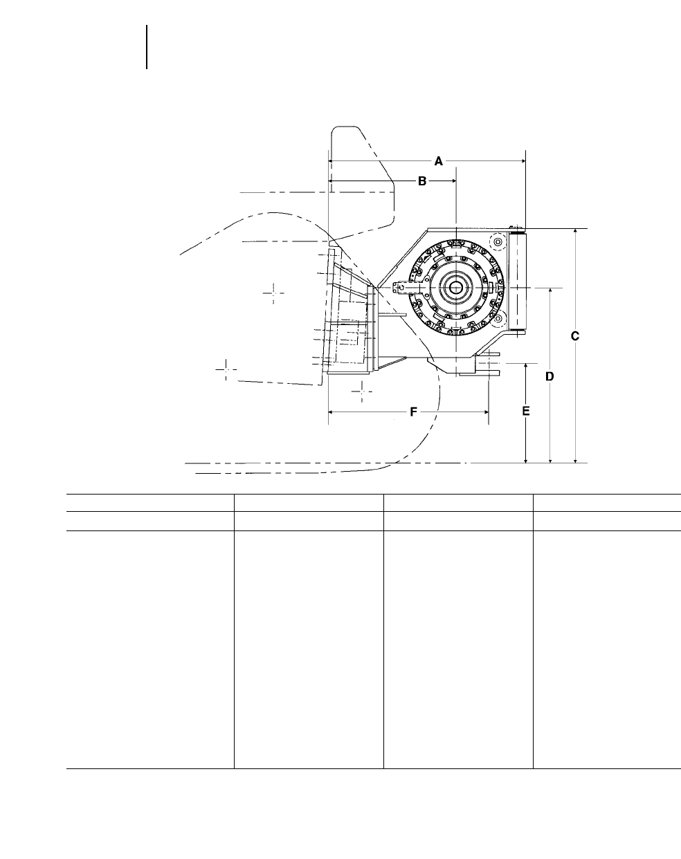
1-80
Winches Physical Specifications
●PA58VS ●PA59VS ●59
WINCH MODEL PA58VS PA59VS 59
TRACTOR MODEL D8R D9R D10R
ATractor to rear of winch 1435 mm 4'8.5" 1552 mm 5'1.1" 1247 mm 4'1.1"
BTractor to drum centerline 940 mm 3'1" 1041 mm 3'5" 942 mm 3'1.1"
CGround to top of winch 1712 mm 5'7.4" 1738 mm 5'8.4" 1787 mm 5'10.4"
DGround to drum centerline 1273 mm 4'2.1" 1298 mm 4'3.1" 1480 mm 4'10.3"
EGround to center of hitch 721 mm 2'4.4" 747 mm 2'5.4" 892 mm 2'11.1"
FTractor to pin centerline 1216 mm 3'11.9" 1282 mm 4'2.5" 1000 mm 3'3.4"
Overall width (not shown) 1158 mm 3'9.6" 1158 mm 3'9.6" 1564 mm 5'1.6"
Drum diameter (not shown) 318 mm 12.5" 318 mm 12.5" 330 mm 13"
Weight* 1790 kg 3950 lb 1860 kg 4100 lb 2184 kg 4805 lb
Oil refill capacity 15 L 4 U.S. gal 15 L 4 U.S. gal 70 L 18.5 U.S. gal
Wire rope diameter:
Recommended 29 mm 1.13" 29 mm 1.13" 29 mm 1.13"
Optional 32 mm 1.25" 32 mm 1.25" 32 mm 1.25"
Drum capacity:
Recommended rope 84 m 276'0" 84 m 276' 69 m 226'
Optional rope 59 m 193'0" 59 m 193' 55 m 180'
Wire rope ferrule size (OD 3 length) 60 3 70 mm 2.38 3 2.75" 60 370 mm 2.38 3 2.75" 60 3 70 mm 2.38 3 2.75"
*Operating weight includes pump and operator controls.
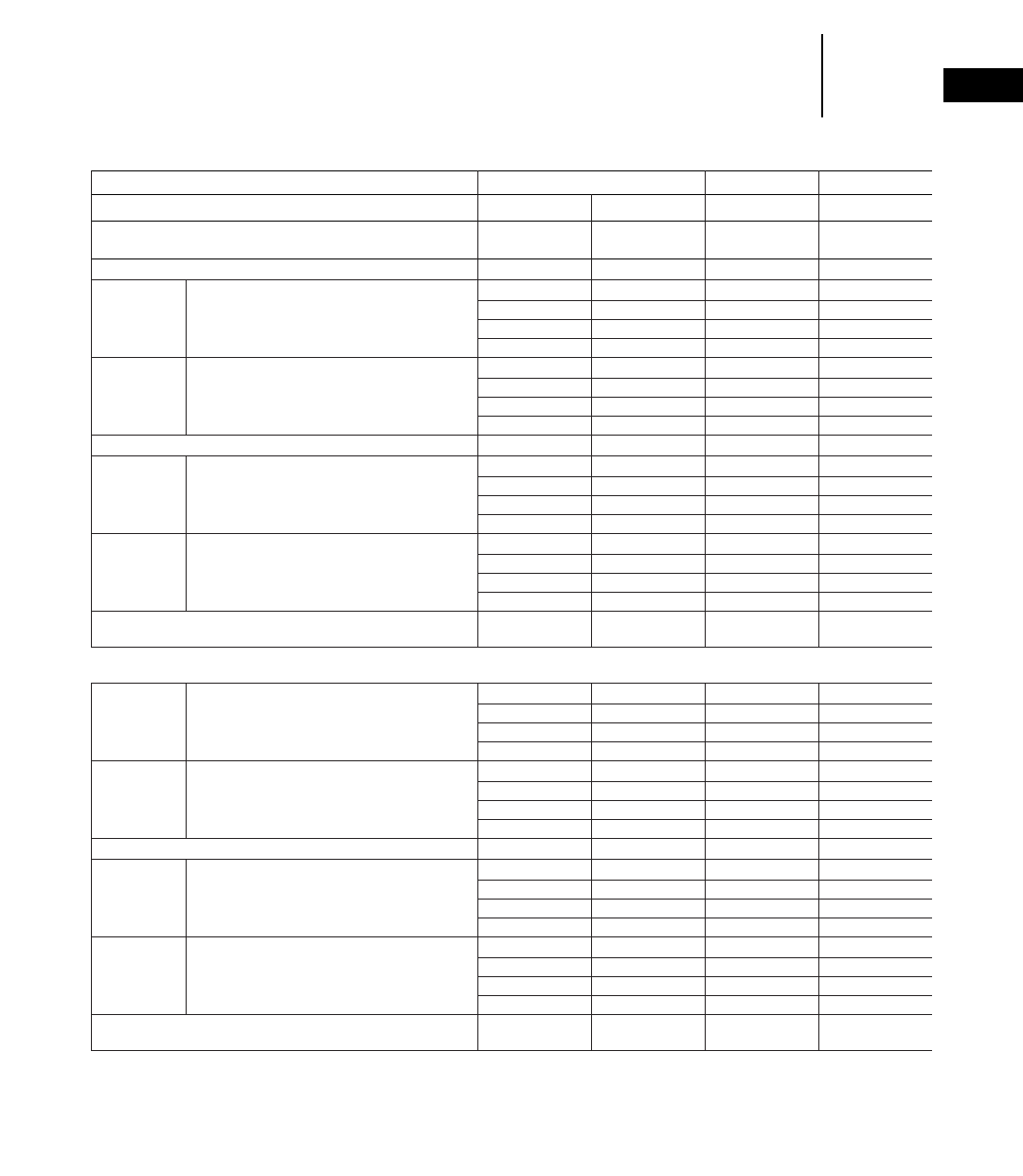
1-81
1
WinchesOperating Specifications
●British Units of Measure
●Metric Units of Measure
WINCH MODEL PA55 PA56 PA57G
TRACTOR MODEL D5M D6M D6R D7G
British Units of Measure
Standard speed gearing
Winch Drive . . . . . . . . . . . . . . . . . . . . . . . . . . . . . . . . . . . . . . PTO PTO PTO PTO
Rated Linepull . . . . . . . . . . . . . . . . . . . . . .lbs 26,730 37,510 54,180 53,939
Maximum linepull* . . . . . . . . . . . . . . . . . . .lbs 51,200 69,200 89,800 103,794
Bare Drum Rated linespeed . . . . . . . . . . . . . . . . . . .fpm 97 94 78 89
Maximum linespeed . . . . . . . . . . . . . . . . .fpm 151 143 122 159
Rated linepull . . . . . . . . . . . . . . . . . . . . . .lbs 15,020 21,080 31,570 33,712
Maximum linepull . . . . . . . . . . . . . . . . . . .lbs 36,760 53,590 64,970 64,871
Full Drum Rated linespeed . . . . . . . . . . . . . . . . . . .fpm 173 168 134 143
Maximum linespeed . . . . . . . . . . . . . . . . .fpm 269 254 209 254
Slow/Low speed gearing
Rated linepull* . . . . . . . . . . . . . . . . . . . . . .lbs 51,200 69,200 89,800 113,000
Maximum linepull* . . . . . . . . . . . . . . . . . . .lbs 51,200 69,200 89,800 113,000
Bare Drum Rated linespeed . . . . . . . . . . . . . . . . . . .fpm 41 39 35 37
Maximum linespeed . . . . . . . . . . . . . . . . .fpm 63 60 55 66
Rated linepull . . . . . . . . . . . . . . . . . . . . . .lbs 36,020 50,570 69,340 81,429
Maximum linepull* . . . . . . . . . . . . . . . . . . .lbs 51,200 69,200 89,800 113,000
Full Drum Rated linespeed . . . . . . . . . . . . . . . . . . .fpm 72 70 61 59
Maximum linespeed . . . . . . . . . . . . . . . . .fpm 112 106 95 105
Tractor rating . . . . . . . . . . . . . . . . . . . . . . . . . . . . . . . . . . . . . . 110 hp @ 140 hp @ 165 hp @ 200 hp @
2100 rpm 2200 rpm 1800 rpm 2000 rpm
Metric Units of Measure
Standard speed gearing
Rated Linepull . . . . . . . . . . . . . . . . . . . . . .kg 12 120 17 014 24 576 24 446
Maximum linepull* . . . . . . . . . . . . . . . . . . .kg 23 245 31 417 40 733 47 080
Bare Drum Rated linespeed . . . . . . . . . . . . . . . . . .mpm 30 29 24 27
Maximum linespeed . . . . . . . . . . . . . . . .mpm 46 44 37 48
Rated linepull . . . . . . . . . . . . . . . . . . . . . . .kg 6813 9562 14 320 15 292
Maximum linepull . . . . . . . . . . . . . . . . . . . .kg 16 674 24 471 29 470 29 425
Full Drum Rated linespeed . . . . . . . . . . . . . . . . . .mpm 53 51 41 44
Maximum linespeed . . . . . . . . . . . . . . . .mpm 82 77 64 77
Slow/Low speed gearing
Rated linepull* . . . . . . . . . . . . . . . . . . . . . .kg 23 245 31 417 40 733 51 256
Maximum linepull* . . . . . . . . . . . . . . . . . . .kg 23 245 31 417 40 733 51 256
Bare Drum Rated linespeed . . . . . . . . . . . . . . . . . .mpm 12 12 11 11
Maximum linespeed . . . . . . . . . . . . . . . .mpm 19 18 17 20
Rated linepull . . . . . . . . . . . . . . . . . . . . . . .kg 16 338 22 938 31 453 36 935
Maximum linepull* . . . . . . . . . . . . . . . . . . .kg 23 245 31 417 40 733 51 256
Full Drum Rated linespeed . . . . . . . . . . . . . . . . . .mpm 22 21 19 18
Maximum linespeed . . . . . . . . . . . . . . . .mpm 34 32 29 32
Tractor rating . . . . . . . . . . . . . . . . . . . . . . . . . . . . . . . . . . . . . . 82 kW @ 104 kW @ 123 kW @ 149 kW @
2100 rpm 2200 rpm 1800 rpm 2000 rpm
*Maximum linepull limited by breaking strength of the optional (larger diameter) wire rope.
Winch linepull and linespeed ratings are based on gear train mechanical efficiency of 90%.

1-82
Winches Operating Specifications
●British Units of Measure
●Metric Units of Measure
WINCH MODEL PA57VS PA58VS PA59VS 59
D7R D7R
TRACTOR MODEL Diff. Steer Power Shift D8R D9R D10
British Units of Measure
Standard speed gearing
Winch Drive . . . . . . . . . . . . . . . . . . . . . . . . HYD HYD HYD HYD PTO
Rated linepull . . . . . . . . .lbs 35,960 — — – 122,110
Maximum linepull . . . . . .lbs 109,657 — — – 139,000*
Bare Drum Rated linespeed . . . . . . .fpm 132 — — – 116
Maximum linespeed . . . .fpm 167 — — – 149
Rated linepull . . . . . . . . .lbs 22,820 — — – 82,620
Maximum linepull . . . . . .lbs 69,587 — — – 139,000*
Full Drum Rated linespeed . . . . . . .fpm 208 — — – 171
Maximum linespeed . . . .fpm 264 — — – 221
Slow/Low speed gearing
Rated linepull . . . . . . . . .lbs 107,800 101,200 109,700 120,200 139,000*
Maximum linepull . . . . . .lbs 107,800 101,200 109,700 120,200 139,000*
Bare Drum Rated linespeed . . . . . . .fpm 32 22 30 33 63
Maximum linespeed . . . .fpm 95 63 61 62 81
Rated linepull . . . . . . . . .lbs 69,700 65,500 71,000 72,400 139,000*
Maximum linepull . . . . . .lbs 69,700 65,500 71,000 72,400 139,000*
Full Drum Rated linespeed . . . . . . .fpm 49 35 46 55 97
Maximum linespeed . . . .fpm 147 79 95 104 121
Tractor rating . . . . . . . . . . . . . . . . . . . . . . . . 240 hp @ 240 hp @ 305 hp @ 405 hp @ 570 hp @
2100 rpm 2100 rpm 2100 rpm 1900 rpm 1900 rpm
Metric Units of Measure
Standard speed gearing
Rated linepull . . . . . . . . . .kg 16 326 — — – 55 389*
Maximum linepull . . . . . . .kg 49 784 — — – 63 106*
Bare Drum Rated linespeed . . . . . .mpm 40 — — – 35
Maximum linespeed . . .mpm 51 — — – 46
Rated linepull . . . . . . . . . .kg 10 360 — — – 37 476*
Maximum linepull . . . . . . .kg 31 592 — — – 63 106*
Full Drum Rated linespeed . . . . . .mpm 63 — — – 52
Maximum linespeed . . .mpm 81 — — – 67
Slow/Low speed gearing
Rated linepull . . . . . . . . . .kg 48 941*45 945 49 804 54 571 63 106*
Maximum linepull . . . . . . .kg 48 941 45 945 49 804 54 571 63 106*
Bare Drum Rated linespeed . . . . . .mpm 10 7 9 10 19
Maximum linespeed . . .mpm 29 16 19 19 25
Rated linepull . . . . . . . . . .kg 31 644 29 737 32 234 32 870 63 106*
Maximum linepull . . . . . . .kg 31 644 29 737 32 234 32 870 63 106*
Full Drum Rated linespeed . . . . . .mpm 15 11 14 17 30
Maximum linespeed . . .mpm 45 24 29 32 37
Tractor rating . . . . . . . . . . . . . . . . . . . . . . . . 179 kW @ 197 kW @ 228 kW @ 302 kW @ 425 kW @
2100 rpm 2100 rpm 2100 rpm 1900 rpm 1900 rpm
*Maximum linepull limited by breaking strength of the optional (larger diameter) wire rope.
Winch linepull and linespeed ratings are based on gear train mechanical efficiency of 90%.
1-83
1
PRODUCTION BASIS FOR ALL
TABLES IN THIS SECTION:
●Material 1780 kg/m3(3000 lb/yd3).
●60 minute hour.
●Total resistance 100 kg/metric ton ;(200 lb/U.S. ton).
●Scraper load per trip estimated at rated struck capacity.
Struck Haul Haul Haul Haul
SCRAPER & TRACTOR Capacity 120 m 400' 180 m 600' 250 m 800' 300 m 1000'
Push Loaded Estimated Hourly Production
R56H m3yd3m3yd3m3yd3m3yd3m3yd3
D6M (Power Shift) 6.9 9.0 107 140 88 115 75 98 66 86
D6M (Direct Drive) 6.9 9.0 101 132 83 109 71 93 61 80
D5B (Power Shift) 6.9 9.0 105 138 86 113 74 96 63 83
D5B (Direct Drive) 6.9 9.0 104 136 87 114 75 98 65 85
D6R (Power Shift) 6.9 9.0 125 164 102 133 86 113 75 98
D6R (Direct Drive) 6.9 9.0 128 168 108 141 93 121 82 107
D6D (Power Shift) 6.9 9.0 123 161 99 130 84 110 73 95
D6D (Direct Drive) 6.9 9.0 125 163 104 136 89 116 78 102
Self Loaded
D6M (Power Shift) 6.9 9.0 95 124 80 104 69 90 61 80
D6M (Direct Drive) 6.9 9.0 89 117 75 98 64 84 57 75
D5B (Power Shift) 6.9 9.0 93 122 78 102 67 88 59 77
D5B (Direct Drive) 6.9 9.0 92 121 79 103 68 89 60 79
D6R (Power Shift) 6.9 9.0 112 147 93 122 80 105 70 92
D6R (Direct Drive) 6.9 9.0 114 149 98 128 85 111 76 100
D6D (Power Shift) 6.9 9.0 110 144 91 119 78 102 68 89
D6D (Direct Drive) 6.9 9.0 111 145 94 123 82 107 73 95
Load time (average): Dump and turn time: D5 1.2 min
Push Loaded Self Loaded D6 1.0 min
D5 1.0 min 1.5 min Shift time: P.S. 0.0 min
D6 0.8 min 1.2 min D.D. 0.2 min
TOWED SCRAPERS
●All hydraulic
●Manufactured by
Rome Industries
1-84
Towed Scrapers Estimated Production
Struck Haul Haul Haul Haul
SCRAPER & TRACTOR Capacity 120 m 400' 180 m 600' 250 m 800' 300 m 1000'
Push Loaded Estimated Hourly Production
R67H m3yd3m3yd3m3yd3m3yd3m3yd3
D6R (Power Shift) 9.2 12 161 210 130 170 109 142 93 121
D6R (Direct Drive) 9.2 12 144 188 119 156 102 133 86 113
D6D (Power Shift) 9.2 12 152 200 122 160 100 132 85 112
D6D (Direct Drive) 9.2 12 140 183 114 150 97 127 82 108
D7R (Power Shift) 9.2 12 208 272 169 221 140 183 118 154
D7R (Direct Drive) 9.2 12 206 270 172 225 145 190 126 165
D7G (Power Shift) 9.2 12 198 260 159 208 131 172 110 144
D7G (Power Shift) 10.7 14 222 291 177 232 151 198 126 165
D7G (Direct Drive) 10.7 14 215 281 168 221 146 191 123 162
D8R (Power Shift) 10.7 14 238 312 191 250 159 208 137 180
D8K (Power Shift) 10.7 14 238 312 191 250 159 208 137 180
D8K (Direct Drive) 10.7 14 228 298 181 238 152 200 132 173
R89H
D7R (Power Shift) 13.8 18 257 336 206 269 170 222 147 192
D7R (Direct Drive) 13.8 18 240 314 194 254 160 209 141 185
D7G (Power Shift) 13.8 18 245 320 193 253 158 207 136 178
D7G (Direct Drive) 13.8 18 229 299 184 240 150 196 131 171
D8R (Power Shift) 13.8 18 275 360 213 278 176 230 151 198
D8K (Power Shift) 13.8 18 275 360 213 278 176 230 151 198
D8K (Direct Drive) 13.8 18 257 336 203 266 170 222 145 190
D8L (Power Shift) 13.8 18 325 425 155 328 207 271 179 234
Load time (average): Dump and turn time: D6 — 1.0 min
Push Self Push Self All others — 0.8 min
R67H Loaded Loaded R89H Loaded Loaded Shift time: Power Shift — 0.0 min
D6 0.8 min 1.2 min D7 0.8 min 1.2 min Direct Drive — 0.2 min
D7 0.6 min 1.0 min D8 0.6 min 1.0 min
D8 0.5 min 0.8 min D8 0.5 min 0.8 min
1-85
1
Towed ScrapersEstimated Production
Struck Haul Haul Haul Haul
SCRAPER & TRACTOR Capacity 120 m 400' 180 m 600' 250 m 800' 300 m 1000'
Self Loaded Estimated Hourly Production
R67H m3yd3m3yd3m3yd3m3yd3m3yd3
D6R (Power Shift) 9.2 12 143 187 119 156 101 132 88 115
D6R (Direct Drive) 9.2 12 134 175 112 147 95 124 82 107
D6D (Power Shift) 9.2 12 136 178 112 147 94 123 81 107
D6D (Direct Drive) 9.2 12 129 170 107 141 90 118 77 102
D7R (Power Shift) 9.2 12 187 244 151 197 128 168 109 142
D7R (Direct Drive) 9.2 12 174 227 136 178 113 148 97 129
D7G (Power Shift) 9.2 12 177 232 142 186 120 158 100 132
D7G (Direct Drive) 9.2 12 174 228 137 180 114 150 99 130
D7G (Power Shift) 10.7 14 194 255 160 210 137 180 116 152
D7G (Direct Drive) 10.7 14 189 248 156 205 133 175 113 149
D8R (Power Shift) 10.7 14 214 280 175 230 147 193 128 168
D8K (Power Shift) 10.7 14 214 280 175 230 147 193 128 168
D8K (Direct Drive) 10.7 14 206 270 168 220 143 180 123 162
R89H
D7R (Power Shift) 13.8 18 229 299 189 247 156 204 129 169
D7R (Direct Drive) 13.8 18 216 283 179 234 151 198 128 168
D7G (Power Shift) 13.8 18 218 285 178 232 145 190 129 169
D7G (Direct Drive) 13.8 18 206 270 169 221 141 185 119 156
D8R (Power Shift) 13.8 18 238 312 192 251 162 212 141 184
D8K (Power Shift) 13.8 18 238 312 192 251 162 212 141 184
D8K (Direct Drive) 13.8 18 229 300 184 241 157 206 136 178
D8L (Power Shift) 13.8 18 281 368 226 296 191 250 166 217
Load time (average): Dump and turn time: D6 — 1.0 min
Push Self Push Self All others — 0.8 min
R67H Loaded Loaded R89H Loaded Loaded Shift time: Power Shift — 0.0 min
D6 0.8 min 1.2 min D7 0.8 min 1.2 min Direct Drive — 0.2 min
D7 0.6 min 1.0 min D8 0.6 min 1.0 min
D8 0.5 min 0.8 min D8 0.5 min 0.8 min
Struck Haul Haul Haul Haul
SCRAPER & TRACTOR Capacity 100 m 330' 200 m 650' 300 m 1000' 400 m 1300'
Estimated Hourly Production
Agricultural m3yd3m3yd3m3yd3m3yd3m3yd3
2 3 6C + D4E DD 4.6 6160 209 110 144 90 118 80 105
2 3 14C + D6D DD 10.7 14 380 497 270 353 210 275 175 229
Industrial
1 3 R89H + D8L 27.5 36 325 425 251 328 207 271 179 234

CONTENTS
Features
Challenger Tractors . . . . . . . . . . . . . . . . . . . .2-1
Versatile Flotation System . . . . . . . . . . . . . . .2-4
LEXION Combines . . . . . . . . . . . . . . . . . . . . .2-4
Super Rural Tractors . . . . . . . . . . . . . . . . . . .2-5
Specifications
Challenger Tractors . . . . . . . . . . . . . . . . . . . .2-6
Versatile Flotation System . . . . . . . . . . . . . . .2-8
LEXION Combines . . . . . . . . . . . . . . . . . . . . .2-9
Super Rural Tractors . . . . . . . . . . . . . . . . . .2-10
Horsepower Ratings
Challenger Tractors . . . . . . . . . . . . . . . . . . .2-11
Super Rural Tractors . . . . . . . . . . . . . . . . . .2-11
Travel Speeds
Challenger Tractors . . . . . . . . . . . . . . . . . . .2-12
Super Rural Tractors . . . . . . . . . . . . . . . . . .2-12
Drawbar Pull
Challenger Tractors . . . . . . . . . . . . . . . . . . .2-13
Super Rural Tractors . . . . . . . . . . . . . . . . . .2-13
Row-Crop Gauge (Track) Spacing Guide . . . . .2-15
Angle Blade Specifications . . . . . . . . . . . . . . . .2-16
Drawbar Power and Tillage . . . . . . . . . . . . . . .2-17
Estimated Draft or Drawbar Pull . . . . . . . . . .2-18
CHALLENGER TRACTORS
Challenger Mid-Size Tractors
The Challenger 35, 45 and 55 tractors signal a
new direction in row-crop versatility, with row spac-
ing and horsepower to match most every cultivation,
planting and tillage requirement.
Patented Mobil-trac™ Undercarriage:
●Exclusive Cat track design is industry’s most
advanced.
●Weight is spread across five axles, improving trac-
tion, flotation and lowering compaction.
●Translates more power to the ground for added
performance, improved efficiency.
●Designed as an integral part of the Challenger trac-
tor, not an “add-on.”
●Hardbar elastomerically mounted for reduced
vibration and smooth ride.
●Two locations allow convenient chemical tank
mounting.
Exclusive Belt Design:
●Widest belt choice available: five widths — 406 to
813 mm (16"-32") — two tread-bar styles.
●Inside, patented arrangement of heavy-duty steel
cables delivers maximum lateral resistance.
●Belt components are vulcanized, not molded, for
excellent durability.
AGRICULTURAL EQUIPMENT
Challenger Tractors
Versatile Flotation System Trailers
LEXION Combines
Super Rural Tractors (SR)
2-1
2

Gauge (Track) Spacing:
●Choice of two chassis (standard and wide-track)
for maximum flexibility.
●Standard is adjustable from 1524 to 2286 mm
(60"-90"); wide-track from 2032 to 3048 mm
(80"-120").
●Adjustable in even, two-inch increments with
solid, exacting settings and 100% true alignment.
●Track spacing changes made on-farm in a few
hours and no special tools required.
Engines:
●Challenger 35, 45 feature Cat 3116 engine: 6.6 L
(403 in3) displacement.
●Challenger 55 features Cat 3126 engine: 7.2 L
(442 in3) displacement.
●Best-in-the-industry torque rise minimizes down-
shifting:
— Challenger 35, 68% torque rise.
— Challenger 45, 57% torque rise.
— Challenger 55, 46% torque rise.
●Engine iso-mounted to tractor mainframe for sim-
plified service.
16x9 Powershift Transmission:
●Programmable electronic powershift includes
sequential shift, shuttle shift, auto-shift, pro-
grammable downshift/upshift, speed matching.
●Speed range from zero to 31.37 km/h (19.5 mph).
●Optional creeper gears allow for ultra slow-speed
applications.
●Final drives feature inboard planetaries.
Patented Differential Steering:
●Hydraulic/mechanical design delivers smooth,
reliable steering.
●Stronger and more durable than conventional
electronic systems.
●Turning under load exceeds wheel tractor’s abil-
ity, particularly at 3048 mm (120") setting.
Responsive Hydraulics:
●Ample hydraulic flow at couplers of 118 L/min
(31.2 gpm).
●Hydraulic flow levers give comforting feeling of
control.
●In-cab flow controls allow convenient fine-tuning.
Comfortable Cab:
●Excellent visibility all-around.
●Eight-way adjustable air-ride suspension seat for
comfort.
●Patented rubber isolation mounts reduce shock
loads, smooth operator ride and reduce noise levels.
●Movable control console allows adjustment for
individual comfort.
Challenger High-Horsepower Tractors
The Challenger E-Series tractors take performance
in the high-horsepower category to new levels. Worthy
successors to the rugged Caterpillar D-Series, and
the fifth generation to the original Challenger 65
introduced 12 years ago, the E-Series tractors are
truly pulling the entire industry forward.
Patented Mobil-trac™ Undercarriage:
●Exclusive Cat track design is industry’s most
advanced.
●Weight is spread across six axles, improving trac-
tion, flotation and lowering compaction.
●Translates more power to the ground for added
performance and improved efficiency.
●Designed as an integral part of the Challenger
tractor, not an “add-on.”
●Bogie undercarriage system absorbs shock loads,
follows ground contours and smoothes ride.
●Choice of two drive wheels (chevron or heavy-duty
slotted cast-iron).
2-2
Agricultural Equipment Features

Exclusive Belt Design:
●Widest belt choice available: four belt widths —
635, 762 and 889 mm (25", 30", 35") — in stan-
dard, special application, reinforced and side-hill
versions.
●Inside, patented arrangement of heavy-duty steel
cables delivers maximum lateral resistance.
●Belt components are vulcanized, not molded, for
excellent durability.
Gauge (Track) Spacing:
●Standard 2286 mm (90") spacing provides improved
debris rejection and stability.
Engines:
●Challenger 65E, 75E: Cat 3176C engine: 10.3 L
(629 in3) displacement.
●Challenger 85E, 95E: Cat 3196 engine: 12 L (732 in3)
displacement.
●Excellent torque rise minimizes downshifting:
— Challenger 65E, 37% torque rise.
— Challenger 75E, 41% torque rise.
— Challenger 85E, 42% torque rise.
— Challenger 95E, 43% torque rise.
●Power reserve of 10% at 1900 rpm on 95E allows
exceptional pull-through in tough spots.
●Engine iso-mounted to tractor mainframe for sim-
plified service.
10x2 Full Powershift Transmission:
●Dependable and proven; single in-line lever pro-
vides smooth on-the-go shifting in all gears.
●Speed range from zero to 31.7 km/h (19.7 mph).
●Inching pedal permits tight-quarter maneuvers;
no need for high-maintenance master clutch.
●Fully hydraulic brake control reduces pedal effort.
Patented Differential Steering:
●Hydraulic/mechanical design delivers smooth,
reliable steering.
●Effortless full-power turns under load.
●Mechanical system assures reliable steering under
all conditions.
●“Straight-line” tracking allows straight forward
pulling with minimal operator input.
Responsive Hydraulics:
●Ample hydraulic flow at couplers of 114 L/min
(30 gpm).
●Power-beyond valve (standard) allows flow directly
to implement orbital motors or fans.
●Remote, lever-actuated hydraulic couplers for easy
connections.
●In-cab flow controls allow convenient fine-tuning.
●Hydraulic levers on the cab console positioned for
easy control.
Comfortable Cab:
●Excellent visibility all-around — roomier, brighter,
quieter cab improves productivity.
●Eight-way adjustable air-ride suspension seat.
●Fully padded trainer seat with retractable seat-
belt.
●Isolation mounts absorb shock loads for smoother
ride.
●Exclusive Caterpillar Information Display (optional)
provides on-going log of maintenance data and
field totals.
2-3
2
Agricultural EquipmentFeatures

VERSATILE FLOTATION SYSTEM (VFS)
The heavy-duty VFS trailer system offers an
extremely flexible hauling and spreading platform
for grain wagons, spray tanks and other equipment.
Certainly the most durable trailer system — track
or wheel — available in the industry.
Solid Construction:
●Six axles per track roller frame spread out axle
loads, lower rolling resistance.
●VFS 50 — four pressed high-strength low-alloy
(HSLA) steel midwheels, two steel idlers.
●VFS 70 — ductile-iron midwheels; an additional
layer of steel on idlers’ outer diameter increases
strength and load-carrying capacity.
●Dual tapered roller bearings on idlers and mid-
wheels improve performance.
●Air-spring tensioning system allows recoil for
material flow between belt and idler.
●Exclusive 762 mm (30") belts feature 96 tread
bars and a 40-degree tread-bar pattern for trac-
tion, low vibration.
Adaptable:
●VFS 50 and 70 available in three configurations:
hitch and frame, wide axle, or narrow axle.
●VFS 70 wide- and narrow-axle configurations
include bracket-mounting location for weight scale.
●Each roller assembly oscillates up to 17 degrees,
independent of the other, for a smooth ride.
●No lubrication required: special seals eliminate
need for periodic greasing of midwheel and idler
bearings.
Applications:
●Include but are not limited to the following:
— Grain transport.
— Sugar cane, vegetable or sugar beets hauling.
— Lime spreading.
— Anhydrous ammonia injection.
— Sludge hauling.
— Herbicide spreading.
— Side-dump carts.
— Air seeding.
— Manure spreading.
— Construction uses include rear dump boxes
and waste haulers.
LEXION COMBINES
After years of research, development and field
testing, Caterpillar is pleased to offer the LEXION
line of combines. This line represents the most sig-
nificant advancement in combine technology and
performance in more than two decades.
Headers:
●Auto-Contour automatically adjusts header height
and tilt when traveling over uneven terrain.
●Automatic reel control synchronizes reel speed to
travel speed and reel height to crop height.
●Auto-Pilot guidance system on corn heads offers
“hands-free” steering control by sensing row location.
●Retractable fingers across the full length of the
auger ensures that crop flows evenly into the
feederhouse.
●Hydraulic header reverser for positive high-
torque back-up of header and feederhouse to clear
blockages.
●Multi-Link connector provides quick and simple
hydraulic and electrical hook-up with just one
connection point.
2-4
Agricultural Equipment Features

Threshing:
●Exclusive Accelerated Pre-Separation (APS) sys-
tem separates out up to 30% of the grain before it
moves to the threshing cylinder.
●At 1706 mm (67") the threshing cylinder is the
widest in the industry.
Separation:
●LEXION 460 and 465 combines have six high-per-
formance straw walkers (most competitive com-
bines have only five).
●LEXION 480 and 485 combines use dual-rotor
separation — a gentle, centrifugal-force system
that produces high quality grain.
Cleaning:
●The long preparation pan, dual ventilation, and
remote electric adjustment of the upper chaffer
and lower sieve are exclusive to the LEXION.
●The optional 3-D sieve system compensates for
slopes of up to 20%.
●Turbine fans are sectional, providing even air flow
across the entire width of the cleaning area.
Engines:
●LEXION 460 and 465 combines feature the Cat
3126 engine — a 7.2 liter (439 cu. in.) engine pro-
ducing 216 kW (290 hp). Power reserve of 222 kW
(298 hp) is available at 2000 rpm.
●LEXION 480 and 485 combines are powered by
the Cat 3176C engine — a 10.3 liter (629 cu. in.)
engine producing 272 kW (365 hp). Power reserve
of 280 kW (375 hp) is available at 2000 rpm.
Tracks and Tires:
●LEXION 465 and 485 combines feature Caterpillar’s
exclusive Mobil-trac™ undercarriage that provides
greater flotation, sidehill stability and reduced
soil compaction.
●LEXION 460 and 480 combines are available with a
number of different tire options to fit all applications.
●A powered rear axle is available on all four combines.
SUPER RURAL TRACTORS
●Cat diesel Engines with large piston displace-
ment and individual adjustment-free fuel pumps
and valves. High drawbar power for all day hard
work, season after season.
●Sealed and Lubricated Track greatly reduces
internal pin and bushing wear for lower under-
carriage maintenance costs.
●Direct drive transmission helps deliver maxi-
mum engine power to the drawbar. Closely spaced
speeds match implement requirements.
●Excellent balance with weight forward and low
center of gravity.
●Easy maintenance with spin-on fuel filter, two-
piece master link, hydraulic track adjusters.
Power train oil dipstick and filler spout are within
easy reach from ground level.
●Variable horsepower arrangements are avail-
able for increased production in high speed tillage
operations.
2-5
2
Agricultural EquipmentFeatures
2-6
Agricultural Equipment Specifications
●Challenger Tractors
MODEL Challenger 35 Challenger 45 Challenger 55
Gross Horsepower 165 kW 221 hp 181 kW 243 hp 213 kW 285 hp
PTO Horsepower 131 kW 175 hp 149 kW 200 hp 168 kW 225 hp
Drawbar Horsepower 112 kW 150 hp 127 kW 170 hp 142 kW 191 hp
Operating Weight Range* 10 047- 22,150- 10 070- 22,200- 10 070- 22,200-
12 018 kg 26,500 lb 12 018 kg 26,500 lb 12 018 kg 26,500 lb
Engine Model 3116 3116 3126
Rated Engine RPM 2100 2100 2100
No. of Cylinders/Aspiration 6 ATAAC 6 ATAAC 6 ATAAC
Bore 105 mm 4.13" 105 mm 4.13" 110 mm 4.33"
Stroke 127 mm 5" 127 mm 5" 127 mm 5"
Displacement 6.6 L 403 in36.6 L 403 in37.2 L 442 in3
Max. Torque Rise (standard) 68%** 57%** 46%**
Track Rollers (each side) 333
Width of Standard Track Belt¶457 mm 18" 457 mm 18" 457 mm 18"
Length of Track on Ground 2.18 m 7'2" 2.18 m 7'2" 2.18 m 7'2"
Ground Contact Area (with std. belt) 2 m23096 in22 m23096 in22 m23096 in2
Grouser Height (std. belt)Ä63.5 mm 2.5" 63.5 mm 2.5" 63.5 mm 2.5"
Track Gauge:
1.52 m (60") base 1.47 m 60" 1.47 m 60" 1.47 m 60"
2.03 m (80") base 2.03 m 80" 2.03 m 80" 2.03 m 80"
GENERAL DIMENSIONS:
Wheelbase 2184 mm 7'2" 2184 mm 7'2" 2184 mm 7'2"
Height (to top of ROPS) 3.05 m 10'0" 3.05 m 10'0" 3.05 m 10'0"
Overall Length 5.36 m 17'7" 5.36 m 17'7" 5.36 m 17'7"
Width with Standard Belt:
1.52 m (60") base 2.31 m 7'7" 2.31 m 7'7" 2.31 m 7'7"
2.03 m (80") base 2.82 m 9'3" 2.82 m 9'3" 2.82 m 9'3"
Ground Clearance 480 mm 18.9" 480 mm 18.9" 480 mm 18.9"
Drawbar Height 508 mm 1'8" 508 mm 1'8" 508 mm 1'8"
Fuel Tank Refill Capacity 322 L 85 U.S. gal 473 L 125 U.S. gal 473 L 125 U.S. gal
**Operating Weight includes lubricants, coolants, standard belt, ROPS cab, full fuel tank and operator.
**Maximum PTO torque rise.
¶Optional Belt Widths: 457 mm (18"), 508 mm (20"), 624 mm (25"), 762 mm (30"), 813 mm (32").
ÄHeavy Duty 38 mm (1.5") extra wide Grousers available for all belts.
2-7
2
Agricultural EquipmentSpecifications
●Challenger Tractors
MODEL Challenger 65E Challenger 75E Challenger 85E Challenger 95E
Gross Horsepower 231 kW 310 hp 254 kW 340 hp 280 kW 375 hp 306 kW 410 hp
Power Reserve 9% 8% 7% 10%
PTO Horsepower 206 kW 277 hp**** 224 kW 301 hp**** 253 kW 339 hp**** 279 kW 375 hp****
Drawbar Horsepower
(firm ground) 175 kW 235 hp 198 kW 266 hp 217 kW 291 hp 236 kW 317 hp
Operating Weight* 15 186 kW 33,480 lb 15 186 kg 33,480 lb 15 413 kg 33,980 lb 15 413 kg 33,980 lb
Engine Model 3176C 3176C 3196 3196
Rated Engine RPM 2100 2100 2100 2100
No. of Cylinders/Aspiration 6 ATAAC 6 ATAAC 6 ATAAC 6 ATAAC
Bore 125 mm 4.92" 125 mm 4.92" 130 mm 5.1" 130 mm 5.1"
Stroke 140 mm 5.5" 140 mm 5.5" 150 mm 5.9" 150 mm 5.9"
Displacement 10.3 L 629 in310.3 L 629 in312.0 L 732 in312.0 L 732 in3
Max. Torque Rise (standard) 37%**** 41%**** 42% in high hp**** 43% in high hp****
Midwheels (each side) 4444
Width of Standard Track Belt** 635 mm 25" 635 mm 25" 635 mm 25" 635 mm 25"
Length of Track on Ground 2.72 m 8'11" 2.72 m 8'11" 2.72 m 8'11" 2.72 m 8'11"
Ground Contact Area
(w/std. belt) 3.45 m25355 in23.45 m25355 in23.45 m25355 in23.45 m25355 in2
Grouser Height (std. belt)*** 63.5 mm 2.5" 63.5 mm 2.5" 63.5 mm 2.5" 63.5 mm 2.5"
Track Gauge 2.29 m 90" 2.29 m 90" 2.29 m 90" 2.29 m 90"
GENERAL DIMENSIONS:
Wheel Base 2721 mm 8'11" 2721 mm 8'11" 2721 mm 8'11" 2721 mm 8'11"
Height (to top of ROPS) 3.40 m 11'2" 3.40 m 11'2" 3.40 m 11'2" 3.40 m 11'2"
Overall Length 5.94 m 19'6" 5.94 m 19'6" 5.94 m 19'6" 5.94 m 19'6"
Width with Standard Belt 2.92 m 9'7" 2.92 m 9'7" 2.92 m 9'7" 2.92 m 9'7"
Ground Clearance 394 mm 15.5" 394 mm 15.5" 394 mm 15.5" 394 mm 15.5"
Drawbar Height 457 mm 18" 457 mm 18" 457 mm 18" 457 mm 18"
Fuel Tank Refill Capacity 1060 L 280 U.S. gal 1060 L 280 U.S. gal 1060 L 280 U.S. gal 1060 L 280 U.S. gal
****Operating weight includes lubricants, coolants, standard belt, ROPS cab, full fuel tank and operator.
****Optional belt widths: 635 mm (25") std., 762 mm (30"), 889 mm (35").
****Heavy Duty 38 mm (1.5") extra wide grousers available for all belt widths.
****Measured at University of Nebraska tractor test lab.
MODEL VFS50 VFS70
GENERAL DIMENSIONS:
Track Gauge
Wide Axle 3175 mm 10'5" 3175 mm 10'5"
Narrow Axle 2692 mm 8'10" 2692 mm 8'10"
Hitch and Frame 2260 mm 7'5" 2260 mm 7'5"
Track Length CL to CL 3023 mm 9'11" 3023 mm 9'11"
Track Height 940 mm 3'1" 940 mm 3'1"
Overall Length 6261 mm 20'7" 6261 mm 20'7"
Hitch and Frame
Frame Length 4597 mm 15'1" 4597 mm 15'1"
Frame Width 864 mm 2'10" 864 mm 2'10"
Ground Clearance 462 mm 18" 462 mm 18"
Hitch Height 368 mm 15" 368 mm 15"
Hitch to Undercarriage Pivot 4115 mm 13'6" 4115 mm 13'6"
Front of frame to Undercarriage Pivot 2438 mm 8'0" 2438 mm 8'0"
Weight
Undercarriage with Hitch and Frame 4589 kg 10,118 lb 5121 kg 11,290 lb
Narrow Axle 3689 kg 8132 lb 4283 kg 9442 lb
Wide Axle 3741 kg 8248 lb 4350 kg 9590 lb
Maximum Gross Weight 27 269 kg 60,118 lb 36 873 kg 81,290 lb
Travel Speed up to 32 km/h up to 20 mph up to 32 km/h up to 20 mph
Axles 66
Oscillation 17 deg up, 17 deg down 17 deg up, 17 deg down
Belt Tension 2449 kg 5400 lb 2449 kg 5400 lb
Belt Width 762 mm 30" 762 mm 30"
Crop Clearance 439 mm 17.3" 439 mm 17.3"
VFS GROUND PRESSURE
VFS Weight with Load
9072 kg 13 608 kg 18 144 kg 22 680 kg 27 216 kg 31 750 kg
20,000 lb 30,000 lb 40,000 lb 50,000 lb 60,000 lb 70,000 lb
Belt Width Contact Area Ground pressure
mm in m2in2kPa psi kPa psi kPa psi kPa psi kPa psi kPa psi
762 30 4.61 7140 19.3 2.8 28.9 4.2 38.6 5.6 48.2 7.0 57.9 8.4 67.5 9.8
2-8
Agricultural Equipment Specifications
●Versatile Flotation System
2-9
2
Agricultural EquipmentSpecifications
●LEXION Combines
MODEL LEXION 460/465 LEXION 480/485
PRE-SEPARATION:
Type APS system APS system
THRESHING:
Cylinder diameter 600 mm 23.5" 600 mm 23.5"
Cylinder width 1700 mm 5'7" 1700 mm 5'7"
Speed
Single range 362 to 1050 rpm 362 to 1050 rpm
Dual range (low) 158 to 457 rpm 158 to 457 rpm
Dual range (high) 362 to 1050 rpm 362 to 1050 rpm
Concave type Bar and wire Bar and wire
Concave area
Pre-concave 0.64 m2993 in20.64 m2993 in2
Main concave 1.29 m21992 in21.29 m21992 in2
Concave grate extension 0.32 m2501 in2NA
Total concave area 2.25 m23486 in21.93 m22985 in2
Concave adjustment Electric over hydraulic Electric over hydraulic
Concave overload protection Hydraulic Hydraulic
Dump rock trap Yes Yes
SEPARATION:
Straw walkers
Number of straw walkers 6NA
Length 4367 mm 14'4" NA
Crank shaft throw 100 mm 3.9" NA
Separation area
Straw walkers 7.42 m211,507 in2NA
With intensive separation 9.85 m215,520 in2NA
Rotary
Number of rotors NA 2
Diameter NA 444 mm 17.5"
Length NA 4200 mm 13'9"
Separation area NA 6.34 m29826 in2
CLEANING SYSTEM:
Total cleaning area 5.99 m29286 in25.99 m29286 in2
Cleaning fan 6 turbine fans 6 turbine fans
Electric sieve adjustment Optional Optional
3-D sieve Optional Optional
ENGINE:
Caterpillar 3126 ATAAC 3176C ATAAC
Number of cylinders 66
Displacement 7.2 L 439 in310.3 L 629 in3
Rated speed 2100 rpm 2100 rpm
Horsepower 216 kW 290 hp 272 kW 365 hp
Transmission
Type Hydrostatic Hydrostatic
variable 3-speed variable 3-speed
DIMENSIONS/CAPACITIES:
Fuel tank 650 L 170 U.S. gal 650 L 170 U.S. gal
Unloading speed 89 L/sec 2.5 bu/sec 89 L/sec 2.5 bu/sec
Chassis length 8.83 m 29'0" 8.83 m 29'0"
Transport width 460: 3.57 m 11'9"* 480: 3.57 m 11'9"*
465: 4.25 m 13'11.5" 485: 4.25 m 13'11.5"
Transport height 3.99 m 13'1" 3.99 m 13'1"
Weight 460: 13 381 kg 29,500 lb 480: 14 515 kg 32,000 lb
465: 16 874 kg 37,200 lb 485: 18 008 kg 39,700 lb
CAB INSTRUMENTATION:
Sound level 76 bD(A) 76 dB(A)
On-board computer system IMO std., CEBIS optional IMO std., CEBIS optional
Yield monitor Optional Optional
GPS yield mapping Optional Optional
TRACKS/WHEELS:
Mobil-trac system 465 and 485 — with 893 mm (35") Caterpillar belts
Front tires 460 and 480 — Variety of sizes and tread types
Rear tires Variety of sizes and treads; optional power rear axle available
HEADERS Corn, 762 mm (30") row spacing — 6, 8 and 12 row;
Rigid, 7.6 m (25'0") and 9.1 m (30'0"); Flexible, 7.6 m (25'0") and 9.1 m (30'0");
Pickup, 4 m (13'0")
*With 20.8R-42 tires.
2-10
Agricultural Equipment Specifications
●Super Rural Tractors
MODEL D4E SR D6G SR
Flywheel Power* 93 kW 125 hp 161 kW 216 hp
Operating Weight** 9400 kg 20,730 lb 14 960 kg 32,987 lb
Engine Model 3304 3306
Rated Engine RPM 2200 1900
No. of Cylinders 46
Bore 121 mm 4.75" 121 mm 4.75"
Stroke 152 mm 6" 152 mm 6"
Displacement 7 L 425 in310.5 L 638 in3
Max. Torque Rise
(standard) 30% 24%
(variable horsepower) 30% 21%
Track Rollers (each side) 57
Width of Standard Track Shoe 406 mm 16" 508 mm 1'8"
Length of Track on Ground 1.89 m 6'2" 2.667 m 8'9"
Ground Contact Area (with std. shoe) 1.53 m22380 in22.72 m24212 in2
Grouser Height 48 mm 1.88" —
Track Gauge 1.52 m 5'0" 1.88 m 6'2"
GENERAL DIMENSIONS:
Height (without ROPS or exhaust) 1.93 m 6'4" 2.03 m 6'8"
Height (to top of ROPS) 2.71 m 8'11" 3.06 m 10'0"
Overall Length 3.37 m 11'0" 3.73 m 12'3"
Width with Standard Shoe 1.98 m 6'6" —
Ground Clearance 360 mm 14" 310 mm 12.2"
Fuel Tank Refill Capacity 295 L 78 U.S. gal 435 L 115 U.S. gal
**For variable horsepower ratings see the power ratings on adjacent page.
**Operating Weight includes lubricants, coolants, standard track shoes, ROPS canopy, full fuel tank and operator.
2-11
2
Agricultural EquipmentHorsepower Ratings
●Challenger Tractors
●SR Tractors
HORSEPOWER RATINGS
Drawbar** Drawbar*
Gross Concrete Firm Soil PTO
MODEL kW hp kW hp kW hp kW hp
Challenger 35 165 221 137 185 112 150 131 175
Challenger 45 181 243 158 211 127 170 149 200
Challenger 55 213 285 176 236 142 191 168 225
Challenger 65E 231 310 207 ** 278 175 235 207 ** 277
Challenger 75E 254 340 220 ** 295 198 266 224 ** 301
VARIABLE HORSEPOWER RATINGS
Drawbar Drawbar
Gross Concrete Firm Soil PTO
MODEL kW hp kW hp kW hp kW hp
D4E SR VHP
Gears 1-2 66 89 59 80 47 64 —
Gears 3-5 103 138 92 125 76 104 —
D6G SR VHP
Gears 1-2-6 128 172 116 155 162 121 —
Gears 3-4-5 174 234 162 216 228 170 —
Challenger 85E
Gears 1-2 254 340 208 ** 279 ——226 303
Gears 3-10 280 375 244 ** 327 217 291 253 339
Challenger 95E
Gears 1-2 254 340 213 ** 285 ——227 305
Gears3 280 375 244 ** 327 ——253 339
Gears 4-10 306 410 272 ** 365 236 317 280 375
**Estimated drawbar power based on firm soil conditions with standard machine configuration.
**University of Nebraska Tractor Test Lab results.
TRAVEL SPEEDS
MODEL D4E SR VHP D6G SR VHP
FORWARD
GEAR* km/h mph km/h mph
1 3.2 2.0 3.0 1.9
2 4.6 2.9 4.3 2.7
3 5.6 3.5 5.8 3.6
4 6.4 4.0 6.8 4.3
5 7.2 4.5 7.7 4.8
6—9.3 5.8
REVERSE
GEAR
1 3.8 2.4 4.1 2.5
2 5.4 3.4 5.8 3.6
3 6.6 4.1 7.9 4.9
4 7.5 4.7 9.1 5.7
5 8.6 5.3 10.5 6.6
6——
2-12
Agricultural Equipment Travel Speeds
●Challenger Tractors
●SR Tractors
TRAVEL SPEEDS
MODEL Challenger 35 Challenger 45 Challenger 55
GEAR km/h mph km/h mph km/h mph
1 2.62 1.6 2.62 1.6 2.62 1.6
2 3.11 1.9 3.11 1.9 3.11 1.9
3 3.64 2.3 3.64 2.3 3.64 2.3
4 4.17 2.6 4.17 2.6 4.17 2.6
5 4.93 3.1 4.93 3.1 4.93 3.1
6 5.76 3.6 5.76 3.6 5.76 3.6
7 6.79 4.2 6.79 4.2 6.79 4.2
8 8.02 5.0 8.02 5.0 8.02 5.0
9 9.39 5.8 9.39 5.8 9.39 5.8
10 11.11 6.9 11.11 6.9 11.11 6.9
11 12.70 7.9 12.70 7.9 12.70 7.9
12 15.04 9.3 15.04 9.3 15.04 9.3
13 17.60 10.9 17.60 10.9 17.60 10.9
14 20.70 12.9 20.70 12.9 20.70 12.9
15 24.49 15.2 24.49 15.2 24.49 15.2
16 28.64 17.8 28.64 17.8 28.64 17.8
TRAVEL SPEEDS
MODEL Challenger 65E Challenger 75E Challenger 85E Challenger 95E
FORWARD
GEAR km/h mph km/h mph km/h mph km/h mph
1 4.3 2.7 4.5 2.8 4.5 2.8 4.5 2.8
2 6.4 4.0 6.4 4.0 6.4 4.0 6.4 4.0
3 7.6 4.7 7.9 4.9 7.9 4.9 7.9 4.9
4 8.7 5.4 9.0 5.6 9.0 5.6 9.0 5.6
5 10.0 6.2 10.3 6.4 10.3 6.4 10.3 6.4
6 11.3 7.0 11.3 7.0 11.3 7.0 11.3 7.0
7 12.9 8.0 12.9 8.0 12.9 8.0 12.9 8.0
8 14.8 9.2 14.8 9.2 14.8 9.2 14.8 9.2
9 19.3 12.0 20.1 12.5 20.1 12.5 20.1 12.5
10 29.0 18.0 29.0 18.0 29.0 18.0 29.0 18.0
REVERSE
GEAR
1 3.2 2.0 3.2 2.0 3.2 2.0 3.2 2.0
2 7.3 4.5 7.6 4.7 7.6 4.7 7.6 4.7
2-13
2
Agricultural EquipmentDrawbar Pull Forward
●Challenger Tractors
●SR Tractors
DRAWBAR PULL
MODEL D4E SR VHP D6G SR VHP
FORWARD At Rated RPM At Rated RPM
GEAR kN kg lb kN kg lb
1 53.4 5450 12,012 110 11 308 24,878
2 36.7 3744 1,8252 77 7771 17,097
3 49.7 5068 11,170 79 8130 17,887
4 43.2 4408 1,9715 67 6866 15,105
5 37.5 3832 1,8448 58 5926 13,037
6———31 3135 1,6987
Max. at Lug Max. at Lug
1 57.5 5868 12,933 144 14 770 32,496
2 50.5 5148 11,349 100 10 221 22,487
3 57.2 5831 12,859 100 10 190 22,420
4 48.1 5002 11,207 84 8634 18,996
5 43.5 4433 1,9773 73 7477 16,450
6———42 4258 1,9368
DRAWBAR PULL FORWARD*
GEAR Challenger 35 Challenger 45 Challenger 55
kN kg lb kN kg lb kN kg lb
1 84.4 8604 18,968 85.1 8675 19,125 85.1 8675 19,125
2 83.4 8499 18,737 85.1 8675 19,125 85.1 8675 19,125
3 81.6 8314 18,329 85.1 8675 19,125 85.1 8675 19,125
4 77.0 7851 17,307 81.0 8255 18,199 85.1 8675 19,125
5 70.3 7161 15,787 75.6 7710 16,997 81.0 8255 18,200
6 65.7 6694 14,757 71.8 7318 16,134 76.5 7802 17,200
7 58.4 5949 13,116 66.3 6757 14,897 70.5 7188 15,848
8 50.5 5147 11,348 57.8 5891 12,987 64.7 6593 14,535
9 43.5 4436 1,9779 49.7 5063 11,162 55.6 5663 12,484
10 36.7 3740 1,8244 40.9 4170 1,9193 45.9 4676 10,310
11 31.1 3171 1,6991 34.8 3547 1,7821 39.1 3990 1,8796
12 25.5 2601 1,5735 28.7 2920 1,6438 32.3 3295 1,7264
13 21.1 2154 1,4749 23.8 2427 1,5351 26.9 2747 1,6056
14 17.4 1771 1,3904 19.7 2003 1,4416 22.3 2275 1,5015
15 14.2 1449 1,3194 16.1 1646 1,3629 18.4 1876 1,4135
16 11.7 1196 1,2637 13.4 1365 1,3010 15.3 1562 1,3443
DRAWBAR PULL FORWARD
Ballasted @ Max. Power
GEAR Challenger 35 Challenger 45 Challenger 55
kN kg lb kN kg lb kN kg lb
1 122.5 12 503 27,540 125.19 12 780 28,150 129.24 13 193 29,060
2 122.42 12 494 27,520 126.02 12 862 28,330 130.64 13 334 29,370
3 121.17 12 367 27,240 121.7 12 421 27,360 131.21 13 393 29,500
4 118.89 12 135 26,730 124.95 12 753 28,090 130.82 13 352 29,410
5 118.14 12 058 26,560 122.17 12 471 27,470 129.27 13 193 29,060
6 100.52 10 260 22,600 116.48 11 890 26,190 114.38 11 672 25,710
7 85.89 8767 19,310 94.68 9666 21,290 97.89 9993 22,010
8 74.34 7586 16,710 85.87 8762 19,300 83.5 8522 18,770
9 62.37 6365 14,020 72.09 7359 16,210 70.57 7205 15,870
10 51.52 5257 11,580 59.55 6079 13,390 58.18 5938 13,080
11 43.5 4440 9779 50.2 5191 11,435 53.5 5463 12,034
12 36.7 3743 8244 42.6 4407 9708 45.5 4644 10,229
13 31.1 3174 6991 35.49 3673 8090 38.2 3901 8592
14 25.5 2604 5735 29.3 3030 6674 32.1 3277 7217
15 21.1 2156 4749 24.2 2500 5506 26.9 2752 6062
16 17.4 1772 3904 19.8 2050 4515 22.3 2284 5031
*Specified pull is based on nominal engine performance derated for transmission lube, control and optional implement hydraulic pumps, with corrections made for drive-
line mechanical efficiency and rolling resistance on firm level ground. Usable pull will depend on particular attachments, and weight and traction of equipped tractor.
2-14
Agricultural Equipment Drawbar Pull Forward
●Challenger Tractors
DRAWBAR PULL FORWARD*
MODEL Challenger 65E Challenger 75E Challenger 85E Challenger 95E
FORWARD At Rated RPM At Rated RPM At Rated RPM At Rated RPM
GEAR kN kg lb kN kg lb kN kg lb kN kg lb
1 148.05 15 098 33,284 148.80 15 174 33,452 151.55 15 454 34,070 156.59 15 968 35,202
2 105.99 10 808 23,827 114.70 11 696 25,785 113.52 11 576 25,520 112.83 11 506 25,366
3 90.85 9265 20,425 92.20 9402 20,728 103.61 10 566 23,294 103.02 10 505 23,159
4 79.39 8096 17,849 79.97 8155 17,979 90.00 9177 20,232 98.90 10 085 22,234
5 68.29 6964 15,352 68.80 7015 15,466 78.42 7997 17,629 85.60 8729 19,244
6 59.01 6017 13,265 62.87 6412 14,135 71.27 7268 16,022 77.50 7903 17,423
7 51.45 5247 11,567 54.36 5543 12,221 62.01 6323 13,940 67.32 6865 15,134
8 43.83 4469 9853 47.05 4798 10,578 53.12 5417 11,942 57.87 5901 13,009
** 9** 33.31 3396 7488 34.35 3502 7722 38.78 3954 8718 42.22 4308 9497
**10** 22.35 2279 5025 23.99 2447 5395 38.78 2763 6090 29.51 3010 6635
At Max. Power At Max. Power At Max. Power At Max. Power
1 147.22 15 012 33,096 148.12 15 104 33,299 150.15 15 312 33,756 156.20 15 928 35,115
2 130.29 13 286 29,291 131.88 13 448 29,648 136.79 13 949 30,751 138.40 14 113 31,113
3 111.96 11 417 25,169 112.65 11 487 25,325 126.11 12 860 28,351 127.39 12 991 28,639
4 97.46 9938 21,910 98.26 11 020 22,089 109.95 11 212 24,718 122.54 12 496 27,548
5 85.29 8698 19,175 86.51 8822 19,448 95.59 9747 21,489 106.29 10 839 23,896
6 73.67 7513 16,562 78.47 8002 17,641 86.69 8840 19,488 96.21 9811 21,629
7 64.44 6572 14,488 68.15 6949 15,320 75.75 7724 17,029 83.96 8561 18,874
8 55.34 5644 12,442 59.12 6029 13,292 64.97 6625 14,605 73.11 7455 16,436
** 9** 42.06 4289 9456 43.16 4401 9703 47.43 4836 10,662 53.37 5442 11,998
**10** 28.22 2878 6345 30.15 3075 6779 33.13 3379 7449 32.29 3802 8382
**Numbers from Nebraska test on concrete.
**Tests were not conducted in these gear settings, data is estimated.
Row-Crop
Spacer
Gauge (Track) Quantity Spacer
Spacing (per side) Size
1524 mm (60") Base Tractor No spacers
1575 mm (62") 1 25.4 mm (1")
[max. belt width
457 mm (18")]
1626 mm (64") 1 50.8 mm (2")
[max. belt width
508 mm (1'8")]
1676 mm (66") 1 76.2 mm (3")
[max. belt width
508 mm (1'8")]
1727 mm (68") 1 101.6 mm (4")
[max. belt width
635 mm (2'1")]
1778 mm (70") 1 plus 101.6 mm (4")
[max. belt width
635 mm (2'1")]
1 25.4 mm (1")
1829 mm (72") 1 152.4 mm (6")
[max. belt width
635 mm (2'1")]
1880 mm (74") 1 plus 152.4 mm (6")
1 25.4 mm (1")
1930 mm (76") 1 203.2 mm (8")
1981 mm (78") 1 plus 203.2 mm (8")
1 25.4 mm (1")
2032 mm (80") 1 254 mm (10")
2083 mm (82") 1 plus 254 mm (10")
1 25.4 mm (1")
2134 mm (84") 1 plus 254 mm (10")
1 50.8 mm (2")
2184 mm (86") 1 plus 254 mm (10")
1 76.2 mm (3")
2235 mm (88") 1 355.6 mm (14")
2286 mm (90") 1 plus 355.6 mm (14")
1 25.4 mm (1")
Spacer
Gauge (Track) Quantity Spacer
Spacing (per side) Size
2032 mm (80") Base Tractor No spacers
2083 mm (82") 1 25.4 mm (1")
2134 mm (84") 1 50.8 mm (2")
2184 mm (86") 1 76.2 mm (3")
2235 mm (88") 1 101.6 mm (4")
2286 mm (90") 1 plus 101.6 mm (4")
1 25.4 mm (1")
2337 mm (92") 1 152.4 mm (6")
2389 mm (94") 1 plus 152.4 mm (6")
1 25.4 mm (1")
2438 mm (96") 1 203.2 mm (8")
2489 mm (98") 1 plus 203.2 mm (8")
1 25.4 mm (1")
2540 mm (100") 1 254 mm (10")
2591 mm (102") 1 plus 254 mm (10")
1 25.4 mm (1")
2642 mm (104") 1 plus 254 mm (10")
1 50.8 mm (2")
2692 mm (106") 1 plus 254 mm (10")
1 76.2 mm (3")
2743 mm (108") 1 355.6 mm (14")
2794 mm (110") 1 plus 355.6 mm (14")
2845 mm (112") 1 plus 355.6 mm (14")
1 50.8 mm (2")
2896 mm (114") 1 plus 355.6 mm (14")
1 76.2 mm (3")
2946 mm (116") 1 plus 355.6 mm (14")
1 101.6 mm (4")
2997 mm (118") 1 plus 355.6 mm (14")
1 plus 25.4 mm (1")
1 101.6 mm (4")
3048 mm (120") 1 508 mm (1'8")
NOTE: The chart reflects the recommended spacer combinations, although others
are possible.
2-15
2
Agricultural EquipmentGauge (Track) Spacing Guide
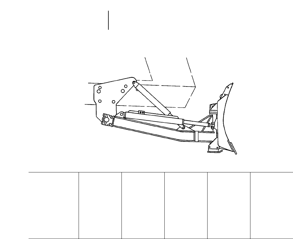
2-16
Agricultural Equipment Angle Blade Specifications
●Challenger 65E, 75E, 85E, 95E
Balderson Blades Specifications
Challenger 65E, 75E, 85E, 95E
Model B95/65A-14P B95/65A-12'6P B95/65A-12'6 B95/65A-12P B95/65A-12
Challenger Track Width 889 mm 2'11" 762 mm 2'6" 762 mm 2'6" 624 mm 2'1" 624 mm 2'1"
Capacity 4.8 m35.3 yd34.3 m34.7 yd34.3 m34.7 yd34.1 m34.5 yd34.1 m34.5 yd3
Blade Type PAT PAT Hyd. Angle PAT Hyd. Angle
Width — Straight 4216 mm 13'10" 3785 mm 12'5" 3785 mm 12'5" 3683 mm 12'1" 3683 mm 12'1"
Width — Angled 3810 mm 12'6" 3429 mm 11'3" 3424 mm 11'3" 3277 mm 10'9" 3277 mm 10'9"
Height 1118 mm 3'8" 1118 mm 3'8" 1118 mm 3'8" 1118 mm 3'8" 1118 mm 3'8"
Max. Dig Depth 610 mm 2'0" 610 mm 2'0" 610 mm 2'0" 610 mm 2'0" 610 mm 2'0"
Max. Height 762 mm 2'6" 762 mm 2'6" 762 mm 2'6" 762 mm 2'6" 762 mm 2'6"
Blade Angle (degrees) 25 25 25 25 25
Weight (approx.) 1800 kg 3970 lbs 1720 kg 3790 lbs 1720 kg 3790 lbs 1542 kg 3400 lbs 1490 kg 3280 lbs

DRAWBAR POWER AND TILLAGE
Tillage work ability, or rate, is measurable in draw-
bar power, either kilowatts or horsepower. If the
quantity of work done is being emphasized, then a
unit of time is also included. The common terminol-
ogy is Kilowatt hours or horsepower hours.
Work rate is a combination of load (or force) times
distance, divided by time or simply load times speed.
For example a 5000 kg (11,000 lb) load pulled at
5 km/h (3.1 mph) is equivalent work to a 2000 kg
(4400 lb) load pulled at 12.5 km/h (7.8 mph).
A Pullmeter is used most frequently to measure
implement loads. The Towner Pullmeter is a hydrau-
lic cylinder with a head machined precisely to 10
square inches. Gauges are used to read pounds per
square inch thus 10 times the gauge reading gives
drawbar pounds pull (DBPP) in thousands of pounds
exerted by the implement pulled. Similar pullmeters
are available with gauges reading in Kilograms pull.
Formulas providing either Metric or English units
of work rate are:
Metric: kg Drawbar pull 2km/h
Drawbar Kilowatts =_______________________
(DBkW) 367
kg Drawbar pull 2km/h
Drawbar Power = _______________________
274
English: lb Drawbar pull 2mph
Drawbar Horsepower = _______________________
375
Example (Metric)
A 6 m implement imposes 5000 kg draft at 5 km/h
requires how many drawbar kilowatts to pull it?
5000 kg 25 km/h
Solution: _________________ = 68.1 DBkW
367
● ● ●
Example (English)
A 20 ft wide implement imposing 11,000 DBPP at
3 mph requires how many drawbar horsepower to
pull it?
11,000 DBPP 23.0 mph
Solution: _______________________ = 88.0 DBHP
375
● ● ●
TILLAGE PRODUCTION
Tillage production is most commonly measured in
area covered per hour, i.e. hectares per hour or acres
per hour. Production can be determined by field mea-
surement of tractor speed and implement width. If
implement width is known and drawbar pull can be
estimated, reference to tractor drawbar pull/speed
graphs will give estimated speeds for each gear, and
use of standard formulas will provide reasonable
estimates of tillage production. Drawbar pull is a
function of: 1) speed of tractor, 2) implement width
and, 3) tillage depth.
Formulas
A. At 100% efficiency (not attainable)
Metric: Width (m) 2Speed (km/h)
Hectares/hr = ________________________
10
English: Width (ft) 2Speed (mph)
Acres/hr = ________________________
8.25
B. At 82.5% efficiency (average for tillage —
includes turns)
Metric:
Hectares/hr = meters 2km/h 20.0825
English: feet 2mph
Acres/hr = ___________
10
Example problem
Calculate normal tillage production of a D6E SR
with a 6 m (20 ft) cut width disc plowing harrow
pulled at a measured speed of 6 km/h (3.7 mph).
Solution:
Hectares/hr
= 6 m 26 km/h 20.0825 = 3 Hectares/hr
20 ft 23.7 mph
Acres/hr = _______________ = 7.4 Acres/hr
10
● ● ●
2-17
2
Agricultural EquipmentDrawbar Power and Tillage
Tillage Production
ESTIMATED DRAFT OR DRAWBAR PULL REQUIRED PER M (FT) OF IMPLEMENT WIDTH OF CUT
Soil Type
Heavy Moderate Average Moderate Light
Gumbo Heavy Silty Silty Light Sandy Sandy or
Speed Depth Clay Loam Clay Loam Loam Loam Coarse
Moldboard plow 5.6-9.6 km/h 178-229 mm 1860-2382 kg 1414-1713 kg 1115-1266 kg 745-968 kg 522-669 kg
3.5-6 mph 7-9" 1250-1600 lb 950-1150 lb 750-850 lb 500-650 lb 350-480 lb
Heavy disc plow
965 mm (3'2") 4.8-8.0 km/h 254-457 mm 2677 kg 2382 kg 2083 kg 1489 kg 1489 kg
3-5 mph 10-18" 1800 lb 1600 lb 1400 lb 1000 lb 1000 lb
1270 mm (4'2") 3.7-6.4 km/h 203-305 mm 3573 kg 3274 kg 2976 kg 2677 kg 2382 kg
2.3-4 mph 8-12" 2400 lb 2200 lb 2000 lb 1800 lb 1600 lb
Heavy offset disc harrow 4.8-8.0 km/h 102-203 mm 1785 kg 1637 kg 1489 kg 1339 kg 1191 kg
915 mm (3'0") 3-5 mph 4-8" 1200 lb 1100 lb 1000 lb 900 lb 800 lb
(stubble or breaking)
Heavy tandem or med. 4.8-9.6 km/h 102-203 mm 1191 kg 1043 kg 892 kg 775 kg 594 kg
offset disc harrow 3-6 mph 4-8" 800 lb 700 lb 600 lb 500 lb 400 lb
660-813 mm (2'2"-2'8")
Finishing or seedbed 6.4-11.2 km/h 51-102 mm 446 kg 410 kg 335 kg 335 kg 148 kg
disc harrow 4-7 mph 2-4" 300 lb 275 lb 225 lb 225 lb 100 lb
508-610 mm (1'8"-2'0")
Disc plow 6.4-9.6 km/h 76-152 mm 558 kg 482 kg 410 kg 335 kg 259 kg
(stubble mulch) 4-6 mph 3-6" 375 lb 324 lb 275 lb 225 lb 175 lb
Chisel plow 5.6-10.5 km/h 203-305 mm 1191 kg 968 kg 775 kg 522 kg 299 kg
3.5-6.5 mph 8-12" 800 lb 650 lb 500 lb 350 lb 200 lb
Field cultivation or 6.4-11.2 km/h 76-102 mm 775 kg 558 kg 371 kg 299 kg 223 kg
springtooth 4-7 mph 3-4" 500 lb 375 lb 250 lb 200 lb 150 lb
Rod weeder (add to 6.4-11.2 km/h 76-102 mm 177 kg 157 kg 135 kg 112 kg 89 kg
FC or springtooth) 4-7 mph 3-4" 120 lb 105 lb 90 lb 75 lb 60 lb
Adjust estimates of varying moisture content.
Use a pullmeter for more accurate measurements.
Draft or DBPP/Shank
Depth Heavy Medium Light
Lister 363 kg 800 lb 272 kg 600 lb 181 kg 400 lb
406 mm 16" 1162 kg 2560 lb 871 kg 1920 lb 653 kg 1440 lb
V. chisel 457 mm 18" 1306 kg 2880 lb 980 kg 2160 lb 735 kg 1620 lb
(parabolic shank) 508 mm 1'8" 1452 kg 3200 lb 1089 kg 2400 lb 816 kg 1800 lb
559 mm 1'10" 1597 kg 3520 lb 1198 kg 2640 lb 898 kg 1980 lb
508 mm 1'8" 1633 kg 3600 lb 1270 kg 2800 lb 907 kg 2000 lb
559 mm 1'10" 1814 kg 4000 lb 1406 kg 3100 lb 998 kg 2200 lb
Subsoilers 610 mm 2'0" 1950 kg 4300 lb 1542 kg 3400 lb 1089 kg 2400 lb
660 mm 2'2" 2132 kg 4700 lb 1633 kg 3600 lb 1179 kg 2600 lb
2-18
Agricultural Equipment Estimated Draft or Drawbar Pull

3-1
CONTENTS
Features . . . . . . . . . . . . . . . . . . . . . . . . . . . . . . .3-1
Specifications: Standard Versions . . . . . . . . . . .3-4
Specifications: NA Versions . . . . . . . . . . . . . . . .3-6
Specifications: Global Versions . . . . . . . . . . . . .3-8
Specifications: ES Versions . . . . . . . . . . . . . . . .3-9
Travel speeds . . . . . . . . . . . . . . . . . . . . . . . . . . .3-10
All Wheel Drive (AWD) . . . . . . . . . . . . . . . . . . .3-10
Front Mounted Scarifiers . . . . . . . . . . . . . . . . .3-10
Rippers/Scarifiers . . . . . . . . . . . . . . . . . . . . . . .3-11
Special attachments . . . . . . . . . . . . . . . . . . . . .3-12
Features, H-Series Motor Graders:
●Geographic Versions — The H-Series was specif-
ically designed to meet the needs of different geo-
graphic regions. NA, Standard, ES and Global
Versions are available with an assortment of stan-
dard features and optional equipment. All motor
graders feature advanced Caterpillar engines,
power train components, hydraulics and machine
structures. The 24H was designed to meet the pro-
ductivity and durability expectations of Caterpillar
mining customers.
●Power to the Ground — Proven Caterpillar
designed and manufactured components are care-
fully matched to maximize productivity and effi-
ciency. Caterpillar H-Series engines have excellent
lugging performance and fuel economy. Variable
Horsepower (VHP) (NA Versions only — standard
on models 143H and 163H, optional on models
120H, 135H, 140H and 160H) provides more power
in gears 4F-8F and 3R-6R to increase productivity
and improve gradeability when roading. Engine
Power Management (standard on all ES and Stan-
dard Versions) delivers full rated power in gears
4F-8F and 3R-6R. In lower gears, where traction
is limited, engine horsepower is automatically
reduced, lowering fuel consumption and reducing
tire slippage. All models have Caterpillar trans-
missions that provide on-the-go, full-power shift-
ing and inching capability. Auto-shift is standard
equipment on the 24H and optional on certain NA
and ES models. In addition, the 24H is equipped
with a lockup clutch torque converter which allows
the machine to operate in direct drive at high out-
put speeds.
●Blade Positioning — The H-Series provides a
broad range of extended blade positions particu-
larly beneficial in mid-range bank sloping, ditch
cutting and ditch cleaning. Along wheel base allows
for an aggressive blade angle permitting material
to roll more freely, reducing power requirements.
3
MOTOR GRADERS

●Brakes — Caterpillar designs and builds multi-
disc brakes that are completely sealed, oil-bathed,
adjustment-free and offer unmatched reliability
and durability. They are located at each tandem
wheel to eliminate braking loads on the power
train and to speed up servicing. The large brake
surface provides dependable braking capability
and long life. The 24H brakes are oil-actuated and
all other models are air-actuated.
●Visibility — Ample glass area and carefully placed
components provide excellent visibility to enhance
operator confidence and productivity in all motor
grader applications. The H-Series gives the oper-
ator an exceptional view forward to the blade toe,
working surface and front tires. Rearward visi-
bility to the ripper and tandem tires and sideways
to the blade heel and front tandem tires is maxi-
mized. The slanted rear window and optional sun-
shade reduce glare.
●Controllability — The H-Series features motor
grader-specific hydraulic controls providing
smooth, predictable response every time a lever
is moved. The machines can perform multiple,
hydraulic-control operations with little effect on
the engine or implement speeds. The result is
more production in almost any application. The
Proportional, Priority, Pressure-Compensated
(PPPC) Hydraulic System is load-sensing and pro-
vides hydraulic power on demand, consuming
horsepower only when needed. The system pro-
vides proportionate flow to each circuit when the
system demand exceeds the available flow. Lock
valves, built into all control valves, maintain
exact cylinder positioning. The implement valves
provide superior modulation, system response
and predictability.
●Operator Comfort — The H-Series provides a
comfortable environment to keep the operator
alert and focused. Conveniently located, low-effort
controls reduce fatigue. The interior noise level is
maintained between 75 and 80 dBA with the
doors and windows closed. Other standard and
optional operator-comfort features may include
(availability dependent on model):
– key engine start-stop switch
– pressurized cab
– air conditioning and heating
– fully adjustable Caterpillar Contour Series Seat
– adjustable steering and implement control console
– easy-to-see gauges
– provisions for entertainment and communica-
tion radios
– lunch box location
– coat hook
– sweepout cab floor
– suspended pedals
– cigarette lighter and ashtray
– cupholder
– 12 volt power port
– lower-opening front windows
– sliding side windows
●Environmental Design — The H-Series responds
to important environmental concerns such as
noise and air pollution. Designed with low exte-
rior sound levels and low-emissions engines
(except on Standard Version models 12H, 140H
and 160H), Caterpillar motor graders are quiet
and clean. Low exterior sound levels range from
80 to 84 dBA due to slower engine speeds, under-
hood mufflers, rubber-mounted engines, trans-
missions and slower fans. R134a refrigerant is
used in the air conditioner. To minimize oil leaks
and withstand high working pressures and temper-
atures, Caterpillar designed, heavy-duty XT hose
and O-ring face seals are used.
3-2
Motor Graders Features

●Serviceability — H-Series motor graders are
designed for fast, easy servicing. Easy access to
service areas allows for quick maintenance and
ensures that routine service is performed on time.
Features promoting easy servicing include:
– Electronic Monitoring System (EMS) to alert
the operator to potential problems (EMSII on
the 24H)
– easily replaceable wear inserts to keep the draw-
bar, circle and blade tight and prevent damage
to expensive components
– large, hinged, engine side doors to provide ample
access to the engine and transmission service
points (optional on Standard Versions)
– air cleaner located above the engine, accessible
from left side
– hydraulic oil level sight gauge
– tandem oil level sight gauge (24H)
– oil sampling capability from engine and hydraulics
– oil sampling capability from tandem and power
train systems (24H)
– clustered lube points located at the bolster, draw-
bar, articulation joint and ripper for ground-
level service (24H)
– auto-lube option available (24H)
– diagnostic connectors for Electronic Technician
(ET) (excluding 14H and 16H)
– modular wiring harness
– engine disconnect switch
– fuse panel located inside the cab
●143H and 163H All Wheel Drive Motor Graders
— All Wheel Drive (AWD) improves tractive per-
formance in poor underfoot conditions such as
snow, mud and sand. This feature also provides
excellent steering and sidedraft control. AWD is
available in gears 1F-7F and 1R-5R, making it
effective in both low-speed and high-speed appli-
cations. VHP is standard on AWD models and
delivers maximum power in all gears when AWD
is engaged. Three operating modes are available:
automatic, manual or off.
●24H Motor Grader — To meet the specialized
needs of Caterpillar’s large mining customers, the
24H is sized to maintain haul roads for large min-
ing-truck fleets. The Caterpillar 3412E Hydraulic
Electronic Unit Injector (HEUI) engine, power
train components and machine structures are
designed to meet the rigors of this application.
●Best Product Support — Caterpillar motor
grader users are assured the best product support
anywhere in the world. With industry-best parts
availability, training and an offering of inspection,
maintenance and repair, Caterpillar dealers can
provide the support needed to keep the machines
productive.
3-3
3
Motor GradersFeatures
3-4
Motor Graders
Standard Versions Specifications
MODEL 120H 135H 12H
Net Flywheel Power: Gears 4-8 104 kW 140 hp 116 kW 155 hp 104 kW 140 hp
Net Flywheel Power: Gears 1-3¶93 kW 125 hp 101 kW 135 hp 104 kW 140 hp
Operating Weight* 11 358 kg 25,040 lb 11 788 kg 25,990 lb 13 077 kg 28,830 lb
Engine Model 3116 DITA 3116 DITA 3306 DINA
Rated Engine RPM 2000 2000 2000
No. of Cylinders 666
Displacement 6.6 L 403 in36.6 L 403 in310.45 L 638 in3
Max. Torque Rise 30% 30% 30.5%
No. of Speeds Forward/Reverse 8/6 8/6 8/6
Top Speed Forward 42.6 km/h 26.5 mph 41.9 km/h 26.0 mph 41.7 km/h 25.9 mph
Top Speed Reverse 33.7 km/h 20.9 mph 33.1 km/h 20.6 mph 32.9 km/h 20.4 mph
Std. Tires — Front & Rear 13.00-24 (10 PR) (G-2) 13.00-24 (10 PR) (G-2) 13.00-24 (10 PR) (G-2)
Front Axle/Steering:
Oscillation Angle 32° 32° 32°
Wheel Lean Angle 18° 18° 18°
Steering Angle 50° 50° 50°
Articulation Angle 20° 20° 20°
Minimum Turning Radius** 7.2 m 23'8" 7.2 m 23'8" 7.4 m 24'3"
Front Frame Section Modulus:
Min. 1619 cm399 in31619 cm399 in32083 cm3127 in3
Max. 3681 cm3225 in33681 cm3225 in34785 cm3291 in3
No. Circle Support Shoes 446
Hydraulics: Pump Type Axial Piston Axial Piston Axial Piston
Max. Pump Flow 148 L/min 39 gpm 148 L/min 39 gpm 148 L/min 39 gpm
System Capacity 61 L 16 U.S. gal 61 L 16 U.S. gal 73 L 19 U.S. gal
Implement Pressure: Max. 24 150 kPa 3500 psi 24 150 kPa 3500 psi 24 150 kPa 3500 psi
Implement Pressure: Min. 3100 kPa 450 psi 3100 kPa 450 psi 3100 kPa 450 psi
Electrical:
System Size 24V 24V 24V
Std. Battery CCA @ 0° F 750 750 750
Std. Alternator 35 amp 35 amp 35 amp
GENERAL DIMENSIONS:
Height (to top of ROPS) 3.11 m 10'2" 3.11 m 10'2" 3.11 m 10'2"
Height (stripped top)*** 2.91 m 9'7" 2.91 m 9'7" 3.04 m 10'0"
Overall Length 8.14 m 26'9" 8.14 m 26'9" 8.45 m 27'9"
With Ripper & Pushplate 9.64 m 31'8" 9.64 m 31'8" 10.01 m 32'10"
Wheelbase 5.87 m 19'3" 5.87 m 19'3" 6.09 m 20'0"
Blade Base 2.60 m 8'6" 2.60 m 8'6" 2.57 m 8'5"
Overall Width 2.44 m 8'0" 2.44 m 8'0" 2.44 m 8'0"
(at top of front tires)
Standard Blade: Length 3.66 m 12'0" 3.66 m 12'0" 3.66 m 12'0"
Standard Blade: Height 610 mm 2'0" 610 mm 2'0" 610 mm 2'0"
Standard Blade: Thickness 22 mm 0.87" 22 mm 0.87" 22 mm 0.87"
Lift Above Ground 410 mm 16.1" 410 mm 16.1" 452 mm 18.9"
Max. Shoulder Reach:§
Frame Straight 1.84 m 6'0" 1.84 m 6'0" 1.85 m 6'1"
Articulated Position 2.78 m 9'1" 2.78 m 9'1" 2.96 m 9'2"
Fuel Tank Capacity 284 L 75 U.S. gal 284 L 75 U.S. gal 284 L 75 U.S. gal
***Operating Weight — based on standard machine configuration, full fuel tank, coolant, lubricants and operator.
***Minimum Turning Radius — combining the use of articulated frame steering, front wheel steer and unlocked differential.
***Height (stripped top) — without ROPS, exhaust, or other easily removed encumbrances.
§Applicable for the standard blade with hydraulic sideshift and tip control. Maximum shoulder reach is obtainable to the right.
¶Engine Power Management automatically reduces power in gears 1F-3F and 1R-2R.
3-5
3
Motor Graders
Standard Versions
Specifications
MODEL 140H 160H
Net Flywheel Power: Gears 4-8 138 kW 185 hp 149 kW 200 hp
Net Flywheel Power: Gears 1-3¶123 kW 165 hp 134 kW 180 hp
Operating Weight* 13 552 kg 29,880 lb 14 416 kg 31,780 lb
Engine Model 3306 DIT 3306 DIT
Rated Engine RPM 1900 1900
No. of Cylinders 66
Displacement 10.45 L 638 in310.45 L 638 in3
Max. Torque Rise 30% 30%
No. of Speeds Forward/Reverse 8/6 8/6
Top Speed Forward 41.1 km/h 25.5 mph 40.7 km/h 25.3 mph
Top Speed Reverse 32.4 km/h 20.2 mph 32.1 km/h 20.0 mph
Std. Tires — Front & Rear 14.00-24 (10 PR) (G-2) 14.00-24 (10 PR) (G-2)
Front Axle/Steering:
Oscillation Angle 32° 32°
Wheel Lean Angle 18° 18°
Steering Angle 50° 50°
Articulation Angle 20° 20°
Minimum Turning Radius** 7.4 m 24'3" 7.4 m 24'3"
Front Frame Section Modulus:
Min. 2083 cm3127 in32083 cm3127 in3
Max. 4785 cm3291 in34785 cm3291 in3
No. Circle Support Shoes 66
Hydraulics: Pump Type Axial Piston Axial Piston
Max. Pump Flow 155 L/min 40.9 gpm 155 L/min 40.9 gpm
System Capacity 73 L 19 U.S. gal 73 L 19 U.S. gal
Implement Pressure: Max. 24 150 kPa 3500 psi 24 150 kPa 3500 psi
Implement Pressure: Min. 3100 kPa 450 psi 3100 kPa 450 psi
Electrical:
System Size 24V 24V
Std. Battery CCA @ 0° F 750 750
Std. Alternator 35 amp 35 amp
GENERAL DIMENSIONS:
Height (to top of ROPS) 3.12 m 10'3" 3.12 m 10'3"
Height (stripped top)*** 3.04 m 10'0" 3.04 m 10'0"
Overall Length 8.49 m 27'10" 8.49 m 27'10"
With Ripper & Pushplate 10.01 m 32'10" 10.01 m 32'10"
Wheelbase 6.09 m 20'0" 6.09 m 20'0"
Blade Base 2.57 m 8'5" 2.52 m 8'3"
Overall Width 2.46 m 8'1" 2.46 m 8'1"
(at top of front tires)
Standard Blade: Length 3.66 m 12'0" 4.27 m 14'0"
Standard Blade: Height 610 mm 2'0" 686 mm 2'3"
Standard Blade: Thickness 22 mm 0.87" 25 mm 1"
Lift Above Ground 452 mm 17.8" 452 mm 17.8"
Max. Shoulder Reach:§
Frame Straight 1.85 m 6'1" 1.85 m 6'1"
Articulated Position 2.96 m 9'2" 2.96 m 9'2"
Fuel Tank Capacity 284 L 75 U.S. gal 341 L 90 U.S. gal
***Operating Weight — based on standard machine configuration with full fuel tank, coolant, lubricants and operator.
***Minimum Turning Radius — combining the use of articulated frame steering, front wheel steer and unlocked differential.
***Height (stripped top) — without ROPS, exhaust, or other easily removed encumbrances.
§Applicable for the standard blade with hydraulic sideshift and tip control. Maximum shoulder reach is obtainable to the right.
¶Engine Power Management automatically reduces power in gears 1F-3F and 1R-2R.
3-6
Motor Graders
NA Versions Specifications
MODEL 120H 135H 12H
Net Flywheel Power 93 kW 125 hp 101 kW 135 hp 104 kW 140 hp
Variable horsepower: Gears 4-8¶104 kW 140 hp 116 kW 155 hp —
Operating Weight* 12 519 kg 27,600 lb 12 950 kg 28,550 lb 14 247 kg 31,410 lb
Engine Model 3116 DIT 3116 DIT 3306 DIT
Rated Engine RPM 2000 2000 1900
No. of Cylinders 666
Displacement 6.6 L 403 in36.6 L 403 in310.45 L 638 in3
Max. Torque Rise 30% 30% 30%
No. of Speeds Forward/Reverse 8/6 8/6 8/6
Top Speed: Forward 42.6 km/h 26.5 mph 41.9 km/h 26.0 mph 39.7 km/h 24.7 mph
Top Speed: Reverse 33.7 km/h 20.9 mph 33.1 km/h 20.6 mph 31.3 km/h 19.5 mph
Std. Tires — Front & Rear 13.00-24 (10 PR) (G-2) 13.00-24 (10 PR) (G-2) 13.00-24 (10 PR) (G-2)
Front Axle/Steering:
Oscillation Angle 32° 32° 32°
Wheel Lean Angle 18° 18° 18°
Steering Angle 50° 50° 50°
Articulation Angle 20° 20° 20°
Minimum Turning Radius** 7.2 m 23'8" 7.2 m 23'8" 7.4 m 24'3"
Front Frame Section Modulus:
Min. 1619 cm399 in31619 cm399 in32083 cm3127 in3
Max. 3681 cm3225 in33681 cm3225 in34785 cm3291 in3
No. Circle Support Shoes 446
Hydraulics: Pump Type Axial Piston Axial Piston Axial Piston
Max. Pump Flow 148 L/min 39 gpm 148 L/min 39 gpm 196 L/min 51.9 gpm
System Capacity 68 L 17.7 U.S. gal 68 L 17.7 U.S. gal 80 L 20.8 U.S. gal
Implement Pressure: Max. 24 150 kPa 3500 psi 24 150 kPa 3500 psi 24 150 kPa 3500 psi
Implement Pressure: Min. 3100 kPa 450 psi 3100 kPa 450 psi 3100 kPa 450 psi
Interior Sound Level*** 75 dBA 75 dBA 75 dBA
Electrical:
System Size 24V 24V 24V
Std. Battery CCA @ 0° F 750 750 750
Std. Alternator 35 amp 35 amp 35 amp
GENERAL DIMENSIONS:
Height (to top of ROPS) 3.11 m 10'2" 3.11 m 10'2" 3.11 m 10'2"
Height (stripped top)**** 2.91 m 9'7" 2.91 m 9'7" 3.04 m 10'0"
Overall Length 8.26 m 27'1" 8.26 m 27'1" 8.57 m 28'1"
With Pushplate 8.50 m 27'10" 8.50 m 27'10" 10.01 m 32'10"
Wheelbase 5.87 m 19'3" 5.87 m 19'3" 6.09 m 20'0"
Blade Base 2.60 m 8'6" 2.60 m 8'6" 2.57 m 8'5"
Overall Width (at top of front tires) 2.44 m 8'0" 2.44 m 8'0" 2.44 m 8'0"
Standard Blade: Length 3.66 m 12'0" 3.66 m 12'0" 3.66 m 12'0"
Standard Blade: Height 610 mm 2'0" 610 mm 2'0" 610 mm 2'0"
Standard Blade: Thickness 22 mm 0.87" 22 mm 0.87" 22 mm 0.87"
Lift Above Ground 410 mm 16.1" 410 mm 16.1" 480 mm 18.9"
Max. Shoulder Reach:§
Frame Straight 1.91 m 6'3" 1.91 m 6'3" 1.97 m 6'6"
Articulated Position 2.85 m 9'4" 2.85 m 9'4" 2.91 m 9'7"
Fuel Tank Capacity 284 L 75 U.S. gal 284 L 75 U.S. gal 284 L 75 U.S. gal
****Operating Weight — based on standard machine configuration with full fuel tank, coolant, lubricants and operator.
****Minimum Turning Radius — combining the use of articulated frame steering, front wheel steer and unlocked differential.
****SAE J919.
****Height (stripped top) — without ROPS, exhaust, seat back or other easily removed encumbrances.
*§Applicable for the standard blade with hydraulic sideshift and tip control. Maximum shoulder reach is obtainable to the right.
*¶Power is automatically increased in gears 4F-8F and 3R-6R.
3-7
3
Motor Graders
NA Versions
Specifications
MODEL 140H 143H 160H 163H
Net Flywheel Power 123 kW 165 hp 123 kW 165 hp 134 kW 180 hp 134 kW 180 hp
Variable horsepower: Gears 4-8¶138 kW 185 hp 138 kW 185 hp 149 kW 200 hp 149 kW 200 hp
Operating Weight* 14 724 kg 32,460 lb 15 023 kg 33,120 lb 15 586 kg 34,360 lb 16 538 kg 36,460 lb
Engine Model 3306 DIT 3306 DIT 3306 DIT 3306 DITA
Rated Engine RPM 1900 1900 1900 1900
No. of Cylinders 6666
Displacement 10.45 L 638 in310.45 L 638 in310.45 L 638 in310.45 L 638 in3
Max. Torque Rise 30% 30% 30% 33.5%
No. of Speeds Forward/Reverse 8/6 8/6 8/6 8/6
Top Speed Forward 41.1 km/h 25.5 mph 41.1 km/h 25.5 mph 40.7 km/h 25.3 mph 40.7 km/h 25.3 mph
Top Speed Reverse 32.4 km/h 20.2 mph 32.4 km/h 20.2 mph 32.1 km/h 20.0 mph 32.1 km/h 20.0 mph
Std. Tires — Front & Rear 14.00-24 (10 PR) (G-2) 14.00-24 (10 PR) (G-2) 14.00-24 (12 PR) (G-2) 14.00-24 (12 PR) (G-2)
Front Axle/Steering:
Oscillation Angle 32° 32° 32° 32°
Wheel Lean Angle 18° 18° 18° 18°
Steering Angle 50° 50° 50° 50°
Articulation Angle 20° 20° 20° 20°
Minimum Turning Radius** 7.4 m 24'3" 7.4 m 24'3" 7.4 m 24'3" 7.4 m 24'3"
Front Frame Section Modulus:
Min. 2083 cm3127 in32083 cm3127 in32083 cm3127 in32083 cm3127 in3
Max. 4785 cm3291 in34785 cm3291 in34785 cm3291 in34785 cm3291 in3
No. Circle Support Shoes 6666
Hydraulics: Pump Type Axial Piston Axial Piston Axial Piston Axial Piston
Max. Pump Flow 206 L/min 54.4 gpm 206 L/min 54.4 gpm 206 L/min 54.4 gpm 206 L/min 54.4 gpm
System Capacity 80 L 20.8 U.S. gal 98 L 25.5 U.S. gal 80 L 20.8 U.S. gal 98 L 25.5 U.S. gal
Implement Pressure: Max. 24 150 kPa 3500 psi 24 150 kPa 3500 psi 24 150 kPa 3500 psi 24 150 kPa 3500 psi
Implement Pressure: Min. 3100 kPa 450 psi 3100 kPa 450 psi 3100 kPa 450 psi 3100 kPa 450 psi
Interior Sound Level*** 75 dBA 77 dBA 75 dBA 77 dBA
Electrical:
System Size 24V 24V 24V 24V
Std. Battery CCA @ 0° F 750 950 750 950
Std. Alternator 50 amp 50 amp 50 amp 50 amp
GENERAL DIMENSIONS:
Height (to top of ROPS) 3.12 m 10'3" 3.12 m 10'3" 3.12 m 10'3" 3.12 m 10'3"
Height (stripped top)**** 3.04 m 10'0" 3.04 m 10'0" 3.04 m 10'0" 3.04 m 10'0"
Overall Length 8.60 m 28'3" 8.60 m 28'3" 8.60 m 28'3" 8.60 m 28'3"
With Ripper & Pushplate 10.01 m 32'10" 10.01 m 32'10" 10.01 m 32'10" 10.01 m 32'10"
Wheelbase 6.09 m 20'0" 6.09 m 20'0" 6.09 m 20'0" 6.09 m 20'0"
Blade Base 2.57 m 8'5" 2.57 m 8'5" 2.52 m 8'3" 2.52 m 8'3"
Overall Width (at top of front tires) 2.46 m 8'1" 2.55 m 8'6" 2.48 m 8'2" 2.55 m 8'6"
Standard Blade: Length 3.66 m 12'0" 3.66 m 12'0" 4.27 m 14'0" 4.27 m 14'0"
Standard Blade: Height 610 mm 2'0" 610 mm 2'0" 686 mm 2'3" 686 mm 2'3"
Standard Blade: Thickness 22 mm 0.87" 22 mm 0.87" 25 mm 1" 25 mm 1"
Lift Above Ground 480 mm 18.9" 480 mm 18.9" 452 mm 17.8" 452 mm 17.8"
Max. Shoulder Reach:§
Frame Straight 1.97 m 6'6" 1.97 m 6'6" 1.96 m 6'5" 1.96 m 6'5"
Articulated Position 2.91 m 9'7" 2.91 m 9'7" 2.90 m 9'6" 2.90 m 9'6"
Fuel Tank Capacity 341 L 90 U.S. gal 341 L 90 U.S. gal 341 L 90 U.S. gal 341 L 90 U.S. gal
****Operating Weight — based on standard machine configuration with full fuel tank, coolant, lubricants and operator.
****Minimum Turning Radius — combining the use of articulated frame steering, front wheel steer and unlocked differential.
****SAE J919.
****Height (stripped top) — without ROPS, exhaust, seat back or other easily removed encumbrances.
§Applicable for the standard blade with hydraulic sideshift and tip control. Maximum shoulder reach is obtainable to the right.
¶Power is automatically increased in gears 4F-8F and 3R-6R.
3-8
Motor Graders
Global Versions Specifications
MODEL 14H 16H 24H
Net Flywheel Power 160 kW 215 hp 205 kW 275 hp 373 kW 500 hp
Operating Weight* 18 784 kg 41,410 lb 24 748 kg 54,560 lb 61 950 kg 136,600 lb
Engine Model 3306 DITA 3406 DITA 3412E HEUI
Rated Engine RPM 1850 1850 2000
No. of Cylinders 6612
Displacement 10.45 L 638 in314.6 L 893 in327.0 L 1647 in3
Max. Torque Rise 30% 30% 30%
No. of Speeds Forward/Reverse 8/8 8/8 6/3
Top Speed Forward 42.7 km/h 26.5 mph 44.5 km/h 27.7 mph 37.7 km/h 23.4 mph
Top Speed Reverse 47.3 km/h 29.4 mph 42.3 km/h 26.3 mph 36.1 km/h 22.4 mph
Std. Tires — Front & Rear 16.00-24 (12 PR) (G-2) 18.00-25 (12 PR) (E-2) 29.5-29
Front Axle/Steering:
Oscillation Angle 32° 32° 32°
Wheel Lean Angle 18° 18° 18°
Steering Angle 50° 50° 50°
Articulation Angle 20° 20° 25°
Minimum Turning Radius** 7.9 m 25'11" 8.2 m 27'0" 12.0 m 39'11"
Front Frame Section Modulus:
Min. 2649 cm3162 in33746 cm3228 in39655 cm3589 in3
Max. 5091 cm3310 in38057 cm3491 in322 490 cm31372 in3
No. Circle Support Shoes 668
Hydraulics: Pump Type Axial Piston Axial Piston Axial Piston
Max. Pump Flow 243 L/min 64.1 gpm 243 L/min 64.1 gpm 445 L/min 116 gpm
System Capacity 125 L 32.5 U.S. gal 130 L 33.8 U.S. gal 250 L 65 U.S. gal
Implement Pressure: Max. 24 150 kPa 3500 psi 24 150 kPa 3500 psi 24 150 kPa 3500 psi
Implement Pressure: Min. 3100 kPa 450 psi 3100 kPa 450 psi 3100 kPa 450 psi
Interior Sound Level*** 80 dBA 80 dBA 75 dBA
Electrical:
System Size 24V 24V 24V
Std. Battery CCA @ 0° F 950 1300 1300
Std. Alternator 50 amp 50 amp 100 amp
GENERAL DIMENSIONS:
Height (to top of ROPS) 3.34 m 10'11" 3.52 m 11'7" 4.35 m 14'3"
Height (stripped top)**** 2.85 m 9'4" 3.11 m 10'2" —
Overall Length 9.21 m 30'2" 9.99 m 32'9" 14.16 m 46'6"
With Ripper & Pushplate 10.67 m 35'10" 11.62 m 38'2" 15.80 m 51'10"
Wheelbase 6.46 m 21'2" 6.96 m 22'10" 10.23 m 33'7"
Blade Base 2.86 m 9'5" 3.07 m 10'1" 4.08 m 13'4"
Overall Width (at top of front tires) 2.82 m 9'3" 3.08 m 10'1" 3.94 m 12'11"
Standard Blade: Length 4.27 m 14'0" 4.88 m 16'0" 7.32 m 24'0"
Standard Blade: Height 686 mm 2'3" 787 mm 2'7" 1067 mm 3'6"
Standard Blade: Thickness 25 mm 1" 25 mm 1" 50 mm 2"
Lift Above Ground 419 mm 16.5" 419 mm 16.5" 634 mm 2'1"
Max. Shoulder Reach:§
Frame Straight 2.08 m 6'10" 2.31 m 7'7" 3.22 m 10'7"
Articulated Position 3.07 m 10'1" 3.37 m 11'1" 5.05 m 16'7"
Fuel Tank Capacity 379 L 100 U.S. gal 492 L 130 U.S. gal 1207 L 319 U.S. gal
****Operating Weight — based on standard machine configuration with full fuel tank, coolant, lubricants and operator. 24H includes ripper.
****Minimum Turning Radius — combining the use of articulated frame steering, front wheel steer and unlocked differential.
****SAE J919.
****Height (stripped top) — without ROPS, exhaust, seat back or other easily removed encumbrances.
§Applicable for the standard blade with hydraulic sideshift and tip control. Maximum shoulder reach is obtainable to the right on 14H, both sides on 16H.
3-9
3
Motor Graders
ES Versions
Specifications
MODEL 120H 12H 140H 160H
Net Flywheel Power: Gears 4-8 104 kW 140 hp 104 kW 140 hp 138 kW 185 hp 149 kW 200 hp
Net Flywheel Power: Gears 1-3¶93 kW 125 hp ——123 kW 165 hp 134 kW 180 hp
Operating Weight* 12 519 kg 27,600 lb 14 248 kg 31,410 lb 14 724 kg 32,460 lb 15 586 kg 34,360 lb
Engine Model 3116 DITA 3306 DIT 3306 DIT 3306 DITA
Rated Engine RPM 2000 1900 1900 1900
No. of Cylinders 6666
Displacement 6.6 L 403 in310.45 L 638 in310.45 L 638 in310.45 L 638 in3
Max. Torque Rise 30% 30% 30% 30%
No. of Speeds Forward/Reverse 8/6 8/6 8/6 8/6
Top Speed Forward 42.6 km/h 26.5 mph 39.7 km/h 24.7 mph 41.1 km/h 25.5 mph 40.7 km/h 25.3 mph
Top Speed Reverse 33.7 km/h 20.9 mph 31.3 km/h 19.5 mph 32.4 km/h 20.2 mph 32.1 km/h 20.0 mph
Std. Tires — Front & Rear 13.00-24 (10 PR) (G-2) 13.00-24 (10 PR) (G-2) 14.00-24 (10 PR) (G-2) 14.00-24 (12 PR) (G-2)
Front Axle/Steering:
Oscillation Angle 32° 32° 32° 32°
Wheel Lean Angle 18° 18° 18° 18°
Steering Angle 50° 50° 50° 50°
Articulation Angle 20° 20° 20° 20°
Minimum Turning Radius** 7.2 m 23'8" 7.4 m 24'3" 7.4 m 24'3" 7.4 m 24'3"
Front Frame Section Modulus:
Min. 1619 cm399 in32083 cm3127 in32083 cm3127 in32083 cm3127 in3
Max. 3681 cm3225 in34785 cm3291 in34785 cm3291 in34785 cm3291 in3
No. Circle Support Shoes 4666
Hydraulics: Pump Type Axial Piston Axial Piston Axial Piston Axial Piston
Max. Pump Flow 148 L/min 39 gpm 206 L/min 54.4 gpm 206 L/min 54.4 gpm 206 L/min 54.4 gpm
System Capacity 68 L 17.7 U.S. gal 80 L 20.8 U.S. gal 80 L 20.8 U.S. gal 80 L 20.8 U.S. gal
Implement Pressure: Max. 24 150 kPa 3500 psi 24 150 kPa 3500 psi 24 150 kPa 3500 psi 24 150 kPa 3500 psi
Implement Pressure: Min. 3100 kPa 450 psi 3100 kPa 450 psi 3100 kPa 450 psi 3100 kPa 450 psi
Interior Sound Level*** 77 dBA 77 dBA 77 dBA 77 dBA
Electrical:
System Size 24V 24V 24V 24V
Std. Battery CCA @ 0° F 950 950 950 950
Std. Alternator 50 amp 50 amp 50 amp 50 amp
GENERAL DIMENSIONS:
Height (to top of ROPS) 3.11 m 10'2" 3.11 m 10'2" 3.12 m 10'3" 3.12 m 10'3"
Height (stripped top)**** 2.91 m 9'7" 3.04 m 10'0" 3.04 m 10'0" 3.04 m 10'0"
Overall Length 8.26 m 27'1" 8.57 m 28'1" 8.60 m 28'3" 8.60 m 28'3"
With Ripper & Pushplate 9.76 m 32'0" 10.01 m 32'10" 10.01 m 32'10" 10.01 m 32'10"
Wheelbase 5.87 m 19'3" 6.09 m 20'0" 6.09 m 20'0" 6.09 m 20'0"
Blade Base 2.60 m 8'6" 2.57 m 8'5" 2.57 m 8'5" 2.52 m 8'3"
Overall Width (at top of front tires) 2.44 m 8'0" 2.44 m 8'0" 2.46 m 8'1" 2.48 m 8'2"
Standard Blade: Length 3.66 m 12'0" 3.66 m 12'0" 3.66 m 12'0" 4.27 m 14'0"
Standard Blade: Height 610 mm 2'0" 610 mm 2'0" 610 mm 2'0" 686 mm 2'3"
Standard Blade: Thickness 22 mm 0.87" 22 mm 0.87" 22 mm 0.87" 25 mm 1"
Lift Above Ground 410 mm 16.1" 480 mm 18.9" 480 mm 18.9" 452 mm 17.8"
Max. Shoulder Reach:§
Frame Straight 1.91 m 6'3" 1.97 m 6'6" 1.97 m 6'6" 1.96 m 6'5"
Articulated Position 2.85 m 9'4" 2.91 m 9'7" 2.91 m 9'7" 2.90 m 9'6"
Fuel Tank Capacity 284 L 75 U.S. gal 284 L 75 U.S. gal 284 L 75 U.S. gal 341 L 90 U.S. gal
*Operating Weight — based on standard machine configuration with full fuel tank, coolant, lubricants and operator.
** Minimum turning radius — combined use of frame articulation, front wheel steer and unlocked differential.
*** ISO 6394.
****Height (stripped top) — without ROPS, exhaust, seat back or other easily removed encumbrances.
§Applicable for the standard blade with hydraulic sideshift and tip control. Maximum shoulder reach is obtainable to the right.
¶Engine Power Management automatically reduces power in gears 1F-3F and 1R-2R.
3-10
Motor Graders ●Travel Speeds (All Versions)
●All Wheel Drive
●M10 Scarifiers
TRAVEL SPEEDS @ RATED RPM WITH STD.TIRES (ALL VERSIONS)
Gear 12345678
km/h mph km/h mph km/h mph km/h mph km/h mph km/h mph km/h mph km/h mph
120H Forward 3.6 2.3 5.0 3.1 7.2 4.5 9.9 6.2 15.6 9.7 21.3 13.2 29.3 18.2 42.6 26.5
Reverse 2.9 1.8 5.4 3.4 7.8 4.9 12.3 7.7 23.1 14.4 33.7 20.9 ————
135H Forward 3.6 2.3 4.9 3.1 7.2 4.5 9.9 6.2 15.4 9.6 20.9 13.0 28.8 17.9 41.9 26.0
Reverse 2.9 1.8 5.4 3.3 7.8 4.9 12.2 7.6 23.0 14.3 33.1 20.6 ————
12H* Forward 3.4 2.1 4.6 2.9 6.7 4.2 9.2 5.7 14.6 9.0 19.8 12.3 27.3 17.0 39.7 24.7
Reverse 2.7 1.7 5.0 3.1 7.3 4.5 11.5 7.2 21.6 13.4 31.3 19.5 ————
140H Forward 3.5 2.2 4.8 3.0 7.0 4.3 9.6 6.0 15.1 9.4 20.5 12.8 28.3 17.6 41.1 25.5
Reverse 2.8 1.7 5.2 3.2 7.6 4.7 11.9 7.4 22.3 13.9 32.4 20.2 ————
143H Forward 3.5 2.2 4.8 3.0 7.0 4.3 9.6 6.0 15.1 9.4 20.5 12.8 28.3 17.6 41.1 25.5
Reverse 2.8 1.7 5.2 3.2 7.6 4.7 11.9 7.4 22.3 13.9 32.4 20.2 ————
160H Forward 3.5 2.2 4.8 3.0 7.0 4.3 9.6 6.0 15.0 9.3 20.3 12.6 28.0 17.4 40.7 25.3
Reverse 2.8 1.7 5.2 3.2 7.6 4.7 11.8 7.3 22.3 13.9 32.1 20.0 ————
163H Forward 3.5 2.2 4.8 3.0 7.0 4.3 9.6 6.0 15.0 9.3 20.3 12.6 28.0 17.4 40.7 25.3
Reverse 2.8 1.7 5.2 3.2 7.6 4.7 11.8 7.3 22.3 13.9 32.1 20.0 ————
14H Forward 3.7 2.3 5.3 3.3 7.1 4.4 10.3 6.4 15.5 9.6 21.8 13.5 29.5 18.3 42.7 26.5
Reverse 4.1 2.6 5.8 3.6 7.9 4.9 11.4 7.1 17.7 10.7 24.1 15.0 32.7 20.3 47.3 29.4
16H Forward 3.9 2.4 5.5 3.4 7.4 4.6 10.7 6.7 16.2 10.1 22.7 14.1 30.8 19.1 44.5 27.7
Reverse 3.7 2.3 5.2 3.2 7.0 4.4 10.2 6.3 15.4 9.6 21.6 13.4 29.2 18.2 42.3 26.3
24H Wide-
based tires
Forward 3.2 2.0 4.9 3.1 8.5 5.3 13.1 8.1 24.3 15.1 37.7 23.4 ————
Reverse 4.7 2.9 12.6 7.8 36.1 22.4 ——————————
*For 12H Standard Version travel speeds, multiply by 1.05.
ALL WHEEL DRIVE (AWD) 143H 163H
Power with AWD engaged 138 kW 185 hp 149 kW 200 hp
Working Range:
Forward Gears 1-7 1-7
Reverse Gears 1-5 1-5
Pump Type Axial Piston Axial Piston
System Capacity 175 L/min 46.2 gpm 175 L/min 46.2 gpm
Operating Pressure: Max. 35 000 kPa 5080 psi 35 000 kPa 5080 psi
Operating Pressure: Min. 5500 kPa 800 psi 5500 kPa 800 psi
M10 — MOUNTED SCARIFIERS 120H, 135H, 12H, 140H, 143H, 160H, 163H
Type V Straight*
Working Width 1184 mm 46.6" 1800 mm 71"
Depth (Max.) 292 mm 11.5" 317 mm 12.5"
Number of Shank Holders 11 17
Spacing 116 mm 4.6" 111 mm 4.38"
*Available on NA Versions only.
3-11
3
Motor GradersRippers/Scarifiers
MOTOR
GRADER/ 12H/140H/143H/
RIPPER 120H/135H† 160H/163H 14H 16H 24H
Parallelogram —
Rear Mounted Ripper Ripper/Scarifier Ripper Ripper Ripper
Tire Size (std.)
Front & Rear 13.00-24 14.00-24*** 16.00-24 18.00-25 29.5-29
Dimensions:
Scarifier
Maximum digging depth —411 mm 16.2" — — —
Number of pockets — 9 ———
Spacing —267 mm 10.5" — — —
Ripper Shank
Maximum digging depth 262 mm 10.3" 462 mm 18.2" 401 mm 15.8" 452 mm 17.8" 490 mm 1'7.3"
Maximum reach at
ground line* 1034 mm 3'4.7" 1168 mm 3'10" 1380 mm 4'6.3" 1500 mm 4'11" 1165 mm 3'9.9"
Maximum ground
clearance under tip
(shank pinned in
bottom hole) 652 mm 2'1.6" 521 mm 1'8.5" 663 mm 2'2.1" 673 mm 2'2.5" 739 mm 2'5.1"
Maximum ramp angle,
ripper up (shank
pinned in
bottom hole) 23° 23° 21° 21° 20°
Shank Section 36 x 76 mm 61 x 140 mm 61 x 140 mm 76 x 178 mm 78 x 178 mm
1.4" x 3.0" 2.4" x 5.5" 2.4" x 5.5" 3" x 7" 3" x 7"
Ripper Beam
Overall Width 2.30 m 7'7" 2.30 m 7'7" 2.60 m 8'6" 2.98 m 9'9" 3.91 m 12'10"
Height 152 mm 6" 152 mm 6" 165 mm 6.5" 214 mm 8.4" 216 mm 8.5"
Length 182 mm 7.2" 229 mm 9" 211 mm 8.3" 254 mm 10" 254 mm 10"
Number of Pockets 55777
Pocket Spacing:
Inside 533 mm 1'9" 533 mm 1'9" 472 mm 1'7" 500 mm 1'8" 593 mm 1'11.4"
Middle 533 mm 1'9" 533 mm 1'9" 373 mm 15" 445 mm 17.5" 604 mm 1'11.8"
Outside 533 mm 1'9" 533 mm 1'9" 373 mm 15" 445 mm 17.5" 604 mm 1'11.8"
Shank Gauge 2.13 m 7'0" 2.13 m 7'0" 2.44 m 8'0" — —
Installed weights:
Ripper with
standard shank 613 kg 1350 lb 1060.5 kg 2336 lb 1542 kg 3399 lb 2177 kg 4799 lb 2812 kg 6186 lb
Each additional
shank 11 kg 24 lb 31 kg 68 lb 31 kg 68 lb 68 kg 150 lb 68 kg 150 lb
Ripper Forces§
Penetration Force §4343 kg 9566 lb 8047 kg** 17,740 lb** 10 676 kg 23,541 lb 10 163 kg 22,410 lb 117 720 N 39,987 lb
Pryout Force 2279 kg 5020 lb 9281 kg 20,460 lb 11 804 kg 26,028 lb 15 323 kg 33,788 lb 263 880 N 59,373 lb
*Measured from mounting face on frame.
**Applies to 12H, 140H and 143H. Penetration force for 160H and 163H is 8518 kg (18,780 lb).
***12H std. tire is 13.00-24.
†Available on Standard and ES Versions only.
NOTE: See Section 1 for Ripper Tips.
§This value may vary slightly with various vehicle configurations.

BALDERSON WORK TOOLS
Work Tools 120H 135H 12H 140H 143H 160H 163H 14H 16H
Lift Group XXXXXXXXX
V-Plow XXXXXXXX
One Way Plow XXXXXXXX
Manual Reversible Plow XXXXXXXX
Hydraulic Reversible Plow XXXXXXXX
Snow Wing XXXXXXXX
Scarifier XXXXXXXXX
Manual Angle Blade XXXXXXXX
Hydraulic Angle Blade XXXXXXXX
Straight Blade XXXXXXXXX
This list is not all inclusive. Contact Balderson for special attachment needs.
NOTE: Balderson Attachments for Cat H-Series Motor Graders require additional hydraulics. All front-
mounted attachments require a Balderson Quick Attach-Detach Parallel Lift Group. Contact
Balderson for details.
3-12
Motor Graders Special Attachments

CONTENTS
EXCAVATORS
Specifications . . . . . . . . . . . . . . . . . . . . . . . . . . .4-2
Shipping Dimensions . . . . . . . . . . . . . . . . . . . .4-16
General Dimensions . . . . . . . . . . . . . . . . . . . . .4-27
Shipping Information . . . . . . . . . . . . . . . . . . . .4-28
Major Component Weights . . . . . . . . . . . . . . . .4-29
Range Dimensions:
One-piece Boom . . . . . . . . . . . . . . . . . . . . . . .4-34
Variable Adjustable Boom . . . . . . . . . . . . . . .4-53
Hydraulic Adjustable Boom . . . . . . . . . . . . .4-54
Lifting Capacity (definition) . . . . . . . . . . . . . . .4-58
Lifting Capacity at Ground Level (charts) . . .4-60
Bucket Capacity (definition) . . . . . . . . . . . . . .4-91
Curl and Crowd Forces . . . . . . . . . . . . . . . . . . .4-91
Bucket Specifications . . . . . . . . . . . . . . . . . . .4-102
Working Weights (bucket & payload) . . . . . .4-120
Equipping Excavators:
Long Reach . . . . . . . . . . . . . . . . . . . . . . . . .4-123
Ditch Cleaning . . . . . . . . . . . . . . . . . . . . . . .4-125
Demolition Arrangements . . . . . . . . . . . . .4-127
Machine Selection (tracks vs. wheels) . . . .4-134
Stick/Bucket Combinations . . . . . . . . . . . .4-135
Shoe Selection and Ground Pressure . . . . .4-137
Quick Coupler Systems . . . . . . . . . . . . . . . .4-140
Major Attachment Summary . . . . . . . . . . .4-141
Special Attachments . . . . . . . . . . . . . . . . . .4-146
Cycle Time Estimating Charts . . . . . . . . . . . .4-147
Earthmoving Production . . . . . . . . . . . . . . . .4-150
Production Estimating Tables . . . . . . . . . .4-152
Trenching Production . . . . . . . . . . . . . . . . . . .4-153
5000 SERIES
Features . . . . . . . . . . . . . . . . . . . . . . . . . . . . .4-161
Specifications . . . . . . . . . . . . . . . . . . . . . . . . .4-162
Digging Envelopes . . . . . . . . . . . . . . . . . . . . .4-168
Shipping Information . . . . . . . . . . . . . . . . . . .4-170
General Dimensions . . . . . . . . . . . . . . . . . . . .4-172
Shoe Selection . . . . . . . . . . . . . . . . . . . . . . . . .4-173
Curl and Crowd Forces . . . . . . . . . . . . . . . . . .4-173
Bucket Selection . . . . . . . . . . . . . . . . . . . . . . .4-174
Vital Information Management System
(VIMS) . . . . . . . . . . . . . . . . . . . . . . . . . . . . .4-174
Estimating Cycle Time . . . . . . . . . . . . . . . . . .4-175
Production Tables . . . . . . . . . . . . . . . . . . . . . .4-177
MATERIAL HANDLING ARRANGEMENTS
Range Dimensions & Capacities . . . . . . . . . .4-182
EXCAVATORS
4-1
4
MODEL 301.5 307B 307B SB 307
Sourcing Japan Japan France
Flywheel Power 13 kW 17.4 hp 40 kW 54 hp 40 kW 54 hp 40 kW 54 hp
Operating Weight* 1673 kg 3690 lb 6500 kg 14,320 lb 7400 kg 16,310 lb 7600 kg 16,760 lb
Bucket Capacity 0.018- 0.023- 0.14- 0.18- 0.14- 0.18- 0.09- 0.12-
Range (heaped) 0.056 m30.073 yd30.28 m30.37 yd30.28 m30.37 yd30.35 m30.46 yd3
Engine Model 3003 4M40E1 4M40E1 3054
Rated Engine RPM 2300 2100 2100 1800
No. of Cylinders 3444
Bore 75 mm 2.95" 95 mm 3.7" 95 mm 3.7" 100 mm 3.9"
Stroke 72 mm 2.83" 100 mm 3.9" 100 mm 3.9" 127 mm 5"
Displacement 0.95 L 58.2 in32.84 L 173 in32.84 L 173 in33.99 L 243 in3
Max. Implement
Hydraulic Pump 2 216/ 2 24.2/
Output at Rated 1 217 1 24.5 2 264 2 217 2 264 2 217 2 267 2 218
RPM L/min gpm L/min gpm L/min gpm L/min gpm
Relief Valve Settings:
Implement Circuits 18 600 kPa 2700 psi 27 460 kPa 3980 psi 27 460 kPa 3980 psi 27 460 kPa 3980 psi
Travel Circuits 18 600 kPa 2700 psi 31 380 kPa 4550 psi 31 380 kPa 4550 psi 31 380 kPa 4550 psi
Swing Circuits 17 200 kPa 2500 psi 22 060 kPa 3200 psi 24 030 kPa 3480 psi 20 590 kPa 2990 psi
Pilot Circuits —3930 kPa 570 psi 3930 kPa 570 psi 3000 kPa 440 psi
Maximum Drawbar
Pull 13.6 kN 3060 lb 55 kN 12,130 lb 55 kN 12,130 lb 48 kN 10,800 lb
Maximum Travel Two Speed Travel Two Speed Travel Two Speed Travel
Speed at Lo: 2.2 km/h 1.4 mph Lo: 3.5 km/h 2.2 mph Lo: 3.5 km/h 2.2 mph 4.1 km/h 2.5 mph
Rated RPM Hi: 4.4 km/h 2.7 mph Hi: 5 km/h 3.1 mph Hi: 5 km/h 3.1 mph
Width of Standard
Track Shoe 230 mm 9" 450 mm 18" 450 mm 18" 450 mm 18"
Overall Track Length 1390 mm 4'7" 2760 mm 9'1" 2760 mm 9'1" 2660 mm 8'9"
Ground Contact Area
with Std. Shoe 0.64 m2990 in22.11 m23271 in22.11 m23271 in22.04 m23160 in2
Track Gauge 750 mm 2'6" 1750 mm 5'9" 1750 mm 5'9" 1750 mm 5'9"
Fuel Tank Refill
Capacity 22 L 5.8 U.S. gal 135 L 36 U.S. gal 135 L 36 U.S. gal 110 L 29 U.S. gal
Hydraulic System
(includes tank) 37 L 9.8 U.S. gal 94 L 25 U.S. gal 105 L 28 U.S. gal 105 L 28 U.S. gal
*Operating weight includes coolant, lubricants, full fuel tank, cab, standard shoes, bucket, medium stick, and operator 75 kg (165 lb).
NOTE: Certain models may not be available in all Sales areas.
Specifications may also vary by Sales area.
Contact your Caterpillar District Office for details.
4-2
Excavators Specifications
4-3
4
ExcavatorsSpecifications
MODEL 311B 312B 312B 312B L
Sourcing Japan Japan France Japan
Flywheel Power 59 kW 79 hp 63 kW 84 hp 66 kW 88 hp 63 kW 84 hp
Operating Weight* 11 125 kg 24,550 lb 12 435 kg 27,410 lb 13 000 kg 28,665 lb 12 935 kg 28,520 lb
Bucket Capacity 0.35- 0.46- 0.35- 0.46- 0.24- 0.31- 0.35- 0.46-
Range (heaped) 0.78 m31.02 yd30.78 m31.02 yd30.75 m30.98 yd30.78 m31.02 yd3
Engine Model 3064T 3064T 3054T 3064T
Rated Engine RPM 1800 1900 1900 1900
No. of Cylinders 4444
Bore 102 mm 4" 102 mm 4" 100 mm 3.9" 102 mm 4"
Stroke 130 mm 5.1" 130 mm 5.1" 127 mm 5" 130 mm 5.1"
Displacement 4.25 L 259 in34.25 L 259 in34 L 244 in34.25 L 259 in3
Max. Implement
Hydraulic Pump
Output at Rated 2 2108 2 229 2 2120 2 232 2 2120 2 232 2 2120 2 232
RPM L/min gpm L/min gpm L/min gpm L/min gpm
Relief Valve Settings:
Implement Circuits 29 900 kPa 4340 psi 29 900 kPa 4340 psi 30 000 kPa 4350 psi 29 900 kPa 4340 psi
Travel Circuits 34 300 kPa 4980 psi 34 300 kPa 4980 psi 34 300 kPa 4973 psi 34 300 kPa 4980 psi
Swing Circuits 23 050 kPa 3340 psi 23 050 kPa 3340 psi 25 000 kPa 3625 psi 23 050 kPa 3340 psi
Pilot Circuits 3930 kPa 570 psi 3930 kPa 570 psi 4000 kPa 580 psi 3930 kPa 570 psi
Maximum Drawbar
Pull 95 kN 21,360 lb 106 kN 23,835 lb 104 kN 23,400 lb 106 kN 23,835 lb
Maximum Travel Two Speed Travel Two Speed Travel Two Speed Travel Two Speed Travel
Speed at Lo: 3.8 km/h 2.4 mph Lo: 3.8 km/h 2.4 mph Lo: 3.6 km/h 2.2 mph Lo: 3.8 km/h 2.4 mph
Rated RPM Hi: 5.5 km/h 3.4 mph Hi: 5.5 km/h 3.4 mph Hi: 5.5 km/h 3.4 mph Hi: 5.5 km/h 3.4 mph
Width of Standard
Track Shoe 500 mm 1'8" 500 mm 1'8" 500 mm 1'8" 600 mm 2'0"
Overall Track Length 3320 mm 10'11" 3490 mm 11'5" 3490 mm 11'5" 3750 mm 12'4"
Ground Contact Area
with Std. Shoe 2.86 m24430 in23.03 m24700 in22.78 m24309 in23.95 m25925 in2
Track Gauge 1990 mm 6'6" 1990 mm 6'6" 1990 mm 6'6" 1990 mm 6'6"
Fuel Tank Refill
Capacity 250 L 66 U.S. gal 250 L 66 U.S. gal 250 L 66 U.S. gal 250 L 66 U.S. gal
Hydraulic System
(includes tank) 157 L 41 U.S. gal 162 L 43 U.S. gal 151 L 40 U.S. gal 162 L 43 U.S. gal
*Operating weight includes coolant, lubricants, full fuel tank, standard shoes, bucket, medium stick, and operator 75 kg (165 lb).
NOTE: Certain models may not be available in all Sales areas.
Specifications may also vary by Sales area.
Contact your Caterpillar District Office for details.
4-4
Excavators Specifications
MODEL 312B L 315B 315B L 315B L
Sourcing France Japan Japan France
Flywheel Power 66 kw 88 hp 74 kW 99 hp 74 kW 99 hp 80 kW 107 hp
Operating Weight* 13 270 kg 29,260 lb 15 800 kg 34,800 lb 16 400 kg 36,200 lb 16 200 kg 35,721 lb
Bucket Capacity 0.24- 0.31- 0.37- 0.5- 0.37- 0.5- 0.35- 0.45-
Range (heaped) 0.75 m30.98 yd30.84 m31.1 yd30.84 m31.1 yd30.9 m31.17 yd3
Engine Model 3054T 3046T 3046T 3054TA
Rated Engine RPM 1900 2100 2100 2100
No. of Cylinders 4664
Bore 100 mm 3.9" 94 mm 3.7" 94 mm 3.7" 100 mm 3.9"
Stroke 127 mm 5" 120 mm 4.7" 120 mm 4.7" 127 mm 5"
Displacement 4 L 244 in35 L 305 in35 L 305 in34 L 244 in3
Max. Implement
Hydraulic Pump
Output at Rated 2 2120 2 232 2 2132 2 235 2 2132 2 235 2 2132 2 235
RPM L/min gpm L/min gpm L/min gpm L/min gpm
Relief Valve Settings:
Implement Circuits 30 000 kPa 4350 psi 34 300 kPa 4980 psi 34 320 kPa 4980 psi 35 000 kPa 5075 psi
Travel Circuits 34 300 kPa 4970 psi 34 300 kPa 4980 psi 34 320 kPa 4980 psi 34 300 kPa 4973 psi
Swing Circuits 25 000 kPa 3625 psi 23 050 kPa 3340 psi 23 050 kPa 3340 psi 26 500 kPa 3842 psi
Pilot Circuits 4000 kPa 580 psi 3930 kPa 570 psi 3930 kPa 570 psi 4000 kPa 580 psi
Maximum Drawbar
Pull 118 kN 26,550 lb 131 kN 29,540 lb 131 kN 29,540 lb 132 kN 29,700 lb
Maximum Travel Two Speed Travel Two Speed Travel Two Speed Travel Two Speed Travel
Speed at Lo: 3.2 km/h 1.9 mph Lo: 3.3 km/h 2.1 mph Lo: 3.3 km/h 2.1 mph Lo: 3.2 km/h 1.9 mph
Rated RPM Hi: 5.5 km/h 3.4 mph Hi: 5.5 km/h 3.4 mph Hi: 5.5 km/h 3.4 mph Hi: 5.5 km/h 3.4 mph
Width of Standard
Track Shoe 600 mm 2'0" 500 mm 1'8" 600 mm 2'0" 500 mm 1'8"
Overall Track Length 3750 mm 12'4" 3685 mm 12'1" 3970 mm 13'0" 3960 mm 12'6"
Ground Contact Area
with Std. Shoe 3.65 m25654 in23.16 m24898 in24.14 m26420 in23.16 m24907 in2
Track Gauge 1990 mm 6'6" 1990 mm 6'6" 1990 mm 6'6" 1990 mm 6'6"
Fuel Tank Refill
Capacity 250 L 66 U.S. gal 280 L 74 U.S. gal 280 L 74 U.S. gal 280 L 74 U.S. gal
Hydraulic System
(includes tank) 151 L 40 U.S. gal 188 L 49.7 U.S. gal 188 L 49.7 U.S. gal 188 L 49.7 U.S. gal
*Operating weight includes coolant, lubricants, full fuel tank, standard shoes, bucket, medium stick, and operator 75 kg (165 lb).
NOTE: Certain models may not be available in all Sales areas.
Specifications may also vary by Sales area.
Contact your Caterpillar District Office for details.
4-5
4
ExcavatorsSpecifications
MODEL 318B L 318B L 318B LN 318B LN
Sourcing Japan France Japan France
Flywheel Power 86 kW 115 hp 86 kW 115 hp 86 kW 115 hp 86 kW 115 hp
Operating Weight* 18 410 kg 40,590 lb 17 700 kg 39,028 lb 18 020 kg 39,730 lb 17 160 kg 37,838 lb
Bucket Capacity 0.45- 0.59- 0.41- 0.53- 0.45- 0.59- 0.41- 0.53-
Range (heaped) 0.8 m31.05 yd31.35 m31.75 yd30.8 m31.05 yd31.35 m31.75 yd3
Engine Model 3046T 3046T 3046T 3046T
Rated Engine RPM 2100 2100 2100 2100
No. of Cylinders 6666
Bore 94 mm 3.7" 94 mm 3.7" 94 mm 3.7" 94 mm 3.7"
Stroke 120 mm 4.7" 120 mm 4.7" 120 mm 4.7" 120 mm 4.7"
Displacement 5 L 305 in35 L 305 in35 L 305 in35 L 305 in3
Max. Implement
Hydraulic Pump
Output at Rated 2 2150 2 240 2 2150 2 240 2 2150 2 240 2 2150 2 240
RPM L/min gpm L/min gpm L/min gpm L/min gpm
Relief Valve Settings:
Implement Circuits 34 320 kPa 4980 psi 35 000 kPa 5075 psi 34 320 kPa 4980 psi 35 000 kPa 5075 psi
Travel Circuits 34 320 kPa 4980 psi 34 300 kPa 4973 psi 34 320 kPa 4980 psi 34 300 kPa 4973 psi
Swing Circuits 23 050 kPa 3340 psi 26 500 kPa 3842 psi 23 050 kPa 3340 psi 26 500 kPa 3842 psi
Pilot Circuits 3930 kPa 570 psi 4000 kPa 580 psi 3930 kPa 570 psi 4000 kPa 580 psi
Maximum Drawbar
Pull 176 kN 39,550 lb 154 kN 34,650 lb 176 kN 39,550 lb 154 kN 34,650 lb
Maximum Travel Two Speed Travel Two Speed Travel Two Speed Travel Two Speed Travel
Speed at Lo: 2.5 km/h 1.6 mph Lo: 2.8 km/h 1.7 mph Lo: 2.5 km/h 1.6 mph Lo: 2.8 km/h 1.7 mph
Rated RPM Hi: 3.9 km/h 2.4 mph Hi: 5.5 km/h 3.4 mph Hi: 3.9 km/h 2.4 mph Hi: 5.5 km/h 3.4 mph
Width of Standard
Track Shoe 600 mm 2'0" 600 mm 2'0" 500 mm 1'8" 500 mm 1'8"
Overall Track Length 4075 mm 13'4" 4075 mm 13'4" 4075 mm 13'4" 4075 mm 13'4"
Ground Contact Area
with Std. Shoe 4.26 m26600 in23.92 m26073 in23.55 m25500 in23.26 m25061 in2
Track Gauge 2200 mm 7'3" 2200 mm 7'3" 1990 mm 6'6" 1995 mm 6'6.5"
Fuel Tank Refill
Capacity 280 L 74 U.S. gal 280 L 74 U.S. gal 280 L 74 U.S. gal 280 L 74 U.S. gal
Hydraulic System
(includes tank) 188 L 49.7 U.S. gal 188 L 49.7 U.S. gal 188 L 49.7 U.S. gal 188 L 49.7 U.S. gal
*Operating weight includes coolant, lubricants, full fuel tank, standard shoes, bucket, medium stick, and operator 75 kg (165 lb).
NOTE: Certain models may not be available in all Sales areas.
Specifications may also vary by Sales area.
Contact your Caterpillar District Office for details.
4-6
Excavators Specifications
MODEL M312 M315 M318 M320
Flywheel Power 85.1 kW 114 hp 92.4 kW 124 hp 104.4 kW 140 hp 104.4 kW 140 hp
Operating Weight* 13 810 kg 30,450 lb 15 730 kg 34,685 lb 17 910 kg 39,490 lb 19 410 kg 20,640 lb
Bucket Capacity 0.24- 0.31- 0.24- 0.31- 0.4- 0.52- 0.41- 0.54-
Range (heaped) 0.86 m31.12 yd30.86 m31.12 yd31.05 m31.37 yd31.35 m31.77 yd3
Engine Model 3054TA 3054TA 3116T 3116T
Rated Engine RPM 2000 2300 2000 2000
No. of Cylinders 4466
Bore 100 mm 3.9" 100 mm 3.9" 102 mm 4" 102 mm 4"
Stroke 127 mm 5" 127 mm 5" 130 mm 5.1" 130 mm 5.1"
Displacement 3.99 L 243 in33.99 L 243 in36.6 L 402.6 in36.6 L 402.6 in3
Max. Implement
Hydraulic Pump
Output at 190+80 50+21 220+80 58+21 260+112 69+30 320+112 85+30
Rated RPM L/min gpm L/min gpm L/min gpm L/min gpm
Relief Valve Setting 33 000 kPa 4785 psi 33 000 kPa 4785 psi 33 000 kPa 4785 psi 33 000 kPa 4785 psi
Tires — standard Dual 10.00-20 16PR Dual 10.00-20 16PR Dual 10.00-20 16PR Dual 11.00-20 16PR
Tires — optional Dual 10.00-20 14PR Dual 10.00-20 14PR Dual 10.00-20 14PR Dual 10.00-20 Solid
Dual 11.00-20 16PR Dual 11.00-20 16PR Dual 11.00-20 16PR Single 18R-19.5 XF
Single 18R-19.5 XF Single 18R-19.5 XF Single 18R-19.5 XF Single 18R-22.5 XF
Single 18R-22.5 XF Single 18R-22.5 XF —
Max. Travel Speed 34 km/h 21 mph 34 km/h 21 mph 34 km/h 21 mph 20 km/h 12 mph
Tread Width** 1913 mm 6'3" 1913 mm 6'3" 1913 mm 6'3" 1913 mm 6'3"
Wheel Base 2500 mm 8'2" 2500 mm 8'2" 2600 mm 8'6" 2750 mm 9'0"
Width Over Tires** 2500 mm 8'2" 2500 mm 8'2" 2500 mm 8'2" 2950 mm 9'8"
Ground Clearance** 375 mm 14.8" 375 mm 14.8" 375 mm 14.8" 360 mm 14.1"
Fuel Tank Refill
Capacity 230 L 60.8 U.S. gal 240 L 63.4 U.S. gal 320 L 84.5 U.S. gal 370 L 98 U.S. gal
Hydraulic System
(includes tank) 180 L 47.6 U.S. gal 210 L 55.5 U.S. gal 220 L 58.1 U.S. gal 300 L 79 U.S. gal
**Operating weight includes full fuel tank, operator 75 kg (165 lb), one-piece boom, mid-size stick and bucket, and two sets of outriggers.
**With standard tires.
NOTE: Standard cold inflation pressure for all tires is 650 kPa (94 psi).
NOTE: Certain models may not be available in all Sales areas.
Specifications may also vary by Sales area.
Contact your Caterpillar District Office for details.

4-7
4
ExcavatorsSpecifications
MODEL 320B 320B 320B L 320B L
Sourcing Japan, Brazil Belgium Japan, Brazil Belgium
Flywheel Power 96 kW 128 hp 96 kW 128 hp 96 kW 128 hp 96 kW 128 hp
Operating Weight* 19 400 kg 42,770 lb 20 520 kg 45,250 lb 20 720 kg 45,690 lb 21 380 kg 47,140 lb
Bucket Capacity 0.45- 0.59- 0.41- 0.5- 0.45- 0.59- 0.41- 0.5-
Range (heaped) 1.5 m31.96 yd31.5 m31.9 yd31.5 m31.96 yd31.5 m31.9 yd3
Engine Model 3066T 3116T 3066T 3116T
Rated Engine RPM 1800 1800 1800 1800
No. of Cylinders 6666
Bore 102 mm 4" 105 mm 4.1" 102 mm 4" 105 mm 4.1"
Stroke 130 mm 5.1" 127 mm 5" 130 mm 5.1" 127 mm 5"
Displacement 6.4 L 389 in36.6 L 403 in36.4 L 389 in36.6 L 403 in3
Max. Implement 2 2185 2 249 2 2185 2 249 2 2185 2 249 2 2185 2 249
Hydraulic Pump L/min gpm L/min gpm L/min gpm L/min gpm
at Rated RPM
Relief Valve Settings:
Implement Circuits 34 300 kPa 4980 psi 34 300 kPa 4980 psi 34 300 kPa 4980 psi 34 300 kPa 4980 psi
Travel Circuits 34 300 kPa 4980 psi 34 300 kPa 4980 psi 34 300 kPa 4980 psi 34 300 kPa 4980 psi
Swing Circuits 23 000 kPa 3340 psi 23 000 kPa 3340 psi 23 000 kPa 3340 psi 23 000 kPa 3340 psi
Pilot Circuits 4140 kPa 600 psi 4140 kPa 600 psi 4140 kPa 600 psi 4140 kPa 600 psi
Two Speed Travel Two Speed Travel Two Speed Travel Two Speed Travel
Maximum Drawbar Lo: 177 kN 39,800 lb Lo: 177 kN 39,800 lb Lo: 177 kN 39,800 lb Lo: 177 kN 39,800 lb
Pull Hi: 106 kN 23,810 lb Hi: 106 kN 23,810 lb Hi: 106 kN 23,810 lb Hi: 107 kN 23,810 lb
Maximum Travel
Speed at Lo: 3.4 km/h 2.1 mph Lo: 3.4 km/h 2.1 mph Lo: 3.4 km/h 2.1 mph Lo: 3.4 km/h 2.1 mph
Rated RPM Hi: 5.5 km/h 3.4 mph Hi: 5.5 km/h 3.4 mph Hi: 5.5 km/h 3.4 mph Hi: 5.5 km/h 3.4 mph
Width of Standard
Track Shoe 600 mm 2'0" 600 mm 2'0" 800 mm 2'8" 550 mm 1'10"
Overall Track Length 4075 mm 13'4" 4075 mm 13'4.4" 4455 mm 14'7" 4360 mm 14'4"
Ground Contact Area
with Std. Shoe 4.26 m26600 in24.26 m26600 in26.29 m29750 in24.15 m26433 in2
Track Gauge 2200 mm 7'3" 2200 mm 7'2.6" 2380 mm 7'10" 1895 mm 6'3"
Fuel Tank Refill
Capacity 340 L 90 U.S. gal 290 L 77 U.S. gal 340 L 90 U.S. gal 290 L 77 U.S. gal
*Operating weight includes coolant, lubricants, full fuel tank, standard shoes, bucket and operator 75 kg (165 lb).
NOTE: Certain models may not be available in all Sales areas.
Specifications may also vary by Sales area.
Contact your Caterpillar District Office for details.
4-8
Excavators Specifications
MODEL 320B N 320B LN 320B S 322B
Sourcing Japan Belgium Belgium Japan
Flywheel Power 96 kW 128 hp 96 kW 128 hp 96 kW 128 hp 114 kW 153 hp
Operating Weight* 19 930 kg 43,940 lb 20 810 kg 45,900 lb 22 530 kg 49,680 lb 22 760 kg 50,180 lb
Bucket Capacity 0.45- 0.59- 0.41- 0.5- 0.41- 0.5- 0.45- 0.6-
Range (heaped) 1.5 m31.96 yd31.5 m31.9 yd31.5 m31.9 yd31.8 m32.4 yd3
Engine Model 3066T 3116T 3116T 3116T
Rated Engine RPM 1800 1800 1800 1950
No. of Cylinders 6666
Bore 102 mm 4" 105 mm 4.1" 105 mm 4.1" 105 mm 4.1"
Stroke 130 mm 5.1" 127 mm 5" 127 mm 5" 127 mm 5"
Displacement 6.4 L 389 in36.6 L 403 in36.6 L 403 in36.6 L 403 in3
Max. Implement 2 2185 2 249 2 2185 2 249 2 2185 2 249 2 2205 2 254
Hydraulic Pump L/min gpm L/min gpm L/min gpm L/min gpm
at Rated RPM
Relief Valve Settings:
Implement Circuits 34 300 kPa 4980 psi 34 300 kPa 4980 psi 34 300 kPa 4980 psi 34 300 kPa 4980 psi
Travel Circuits 34 300 kPa 4980 psi 34 300 kPa 4980 psi 34 300 kPa 4980 psi 34 300 kPa 4980 psi
Swing Circuits 23 050 kPa 3340 psi 23 050 kPa 3340 psi 23 050 kPa 3340 psi 27 500 kPa 3980 psi
Pilot Circuits 4140 kPa 600 psi 4140 kPa 600 psi 4140 kPa 600 psi 4140 kPa 600 psi
Two Speed Travel Two Speed Travel Two Speed Travel Two Speed Travel
Maximum Drawbar Lo: 177 kN 39,800 lb Lo: 177 kN 39,800 lb Lo: 177 kN 39,800 lb Lo: 194 kN 43,650 lb
Pull Hi: 106 kN 23,810 lb Hi: 106 kN 23,810 lb Hi: 106 kN 23,810 lb Hi: 108 kN 24,500 lb
Maximum Travel
Speed at Lo: 3.4 km/h 2.1 mph Lo: 3.4 km/h 2.1 mph Lo: 3.4 km/h 2.1 mph Lo: 3.4 km/h 2.1 mph
Rated RPM Hi: 5.5 km/h 3.4 mph Hi: 5.5 km/h 3.4 mph Hi: 5.5 km/h 3.4 mph Hi: 5.5 km/h 3.4 mph
Width of Standard
Track Shoe 500 mm 1'8" 500 mm 1'8" 550 mm 1'9" 600 mm 2'0"
Overall Track Length 4075 mm 13'4" 4460 mm 14'8" 4358 mm 14'4" 4260 mm 14'0"
Ground Contact Area
with Std. Shoe 3.55 m25500 in23.9 m26045 in24.15 m26433 in24.48 m26940 in2
Track Gauge 2200 mm 7'3" 1995 mm 6'6.5" 1895 mm 6'3" 2390 mm 7'10"
Fuel Tank Refill
Capacity 340 L 90 U.S. gal 290 L 77 U.S. gal 290 L 77 U.S. gal 340 L 90 U.S. gal
*Operating weight includes coolant, lubricants, full fuel tank, standard shoes, bucket and operator 75 kg (165 lb).
NOTE: Certain models may not be available in all Sales areas.
Specifications may also vary by Sales area.
Contact your Caterpillar District Office for details.
4-9
4
ExcavatorsSpecifications
MODEL 322B L 322B L 322B LN
Sourcing Japan, U.S. Belgium Belgium
Flywheel Power 114 kW 153 hp 114 kW 153 hp 114 kW 153 hp
Operating Weight* 23 990 kg 52,890 lb 24 590 kg 54,220 lb 23 810 kg 52,500 lb
Bucket Capacity
Range (heaped) 0.45-1.9 m30.6-2.5 yd30.63-1.9 m30.82-2.5 yd30.63-1.9 m30.82-2.5 yd3
Engine Model 3116TA 3116TA 3116TA
Rated Engine RPM 1950 1950 1950
No. of Cylinders 666
Bore 105 mm 4.1" 105 mm 4.1" 105 mm 4.1"
Stroke 127 mm 5" 127 mm 5" 127 mm 5"
Displacement 6.6 L 403 in36.6 L 403 in36.6 L 403 in3
Max. Implement 2 2205 2 254 2 2205 2 254.2 2 2205 2 254
Hydraulic Pump L/min gpm L/min gpm L/min gpm
at Rated RPM
Relief Valve Settings:
Implement Circuits 34 300 kPa 4980 psi 34 300 kPa 4980 psi 34 300 kPa 4980 psi
Travel Circuits 34 300 kPa 4980 psi 34 300 kPa 4980 psi 34 300 kPa 4980 psi
Swing Circuits 27 500 kPa 3980 psi 27 500 kPa 3980 psi 27 500 kPa 3980 psi
Pilot Circuits 4140 kPa 600 psi 4140 kPa 600 psi 4140 kPa 600 psi
Two Speed Travel Two Speed Travel Two Speed Travel
Maximum Drawbar Lo: 194 kN 43,650 lb Lo: 194 kN 43,650 lb Lo: 194 kN 43,650 lb
Pull Hi: 108 kN 24,500 lb Hi: 108 kN 24,500 lb Hi: 108 kN 24,500 lb
Maximum Travel
Speed at Lo: 3.4 km/h 2.1 mph Lo: 3.4 km/h 2.1 mph Lo: 3.4 km/h 2.1 mph
Rated RPM Hi: 5.5 km/h 3.4 mph Hi: 5.5 km/h 3.4 mph Hi: 5.5 km/h 3.4 mph
Width of Standard
Track Shoe 800 mm 2'8" 800 mm 2'8" 600 mm 2'0"
Overall Track Length 4630 mm 15'2" 4640 mm 15'3" 4640 mm 15'3"
Ground Contact Area
with Std. Shoe 6.58 m210,200 in26.58 m210,200 in24.94 m27650 in2
Track Gauge 2590 mm 8'6" 2590 mm 8'6" 2590 mm 8'6"
Fuel Tank Refill
Capacity 340 L 90 U.S. gal 340 L 90 U.S. gal 340 L 90 U.S. gal
*Operating weight includes coolant, lubricants, full fuel tank, standard shoes, bucket and operator 75 kg (165 lb).
NOTE: Certain models may not be available in all Sales areas.
Specifications may also vary by Sales area.
Contact your Caterpillar District Office for details.

4-10
Excavators Specifications
MODEL 325B 325B L 325B L 325B LN
Sourcing Japan Japan, U.S. Belgium Belgium
Flywheel Power 125 kW 168 hp 125 kW 168 hp 125 kW 168 hp 125 kW 168 hp
Operating Weight* 25 900 kg 57,100 lb 27 530 kg 60,700 lb 28 590 kg 63,040 lb 27 070 kg 59,690 lb
Bucket Capacity 0.7- 0.92- 0.7- 0.92- 0.63- 0.82- 0.63- 0.82-
Range (heaped) 2.2 m32.88 yd32.2 m32.88 yd31.9 m32.5 yd31.9 m32.5 yd3
Engine Model 3116TA 3116TA 3116TA 3116TA
Rated Engine RPM 2000 2000 2000 2000
No. of Cylinders 6666
Bore 105 mm 4.1" 105 mm 4.1" 105 mm 4.1" 105 mm 4.1"
Stroke 127 mm 5" 127 mm 5" 127 mm 5" 127 mm 5"
Displacement 6.6 L 403 in36.6 L 403 in36.6 L 403 in36.6 L 403 in3
Max. Implement 2 2210 2 255.5 2 2214 2 256.5 2 2210 2 255 2 2210 2 255
Hydraulic Pump L/min gpm L/min gpm L/min gpm L/min gpm
at Rated RPM
Relief Valve Settings:
Implement Circuits 34 300 kPa 4980 psi 34 300 kPa 4980 psi 34 300 kPa 4980 psi 34 300 kPa 4980 psi
Travel Circuits 34 300 kPa 4980 psi 34 300 kPa 4980 psi 34 300 kPa 4980 psi 34 300 kPa 4980 psi
Swing Circuits 27 500 kPa 3980 psi 29 400 kPa 4250 psi 27 500 kPa 3980 psi 27 500 kPa 3980 psi
Pilot Circuits 4140 kPa 600 psi 4100 kPa 595 psi 4140 kPa 600 psi 4140 kPa 600 psi
Two Speed Travel Two Speed Travel Two Speed Travel Two Speed Travel
Maximum Drawbar Lo: 215 kN 48,350 lb Lo: 215 kN 48,350 lb Lo: 215 kN 48,350 lb Lo: 215 kN 48,350 lb
Pull Hi: 131 kN 29,540 lb Hi: 131 kN 29,540 lb Hi: 131 kN 29,540 lb Hi: 131 kN 29,540 lb
Maximum Travel
Speed at Lo: 3.1 km/h 1.9 mph Lo: 3.1 km/h 1.9 mph Lo: 3.1 km/h 1.9 mph Lo: 3.1 km/h 1.9 mph
Rated RPM Hi: 5 km/h 3.1 mph Hi: 5 km/h 3.1 mph Hi: 5 km/h 3.1 mph Hi: 5 km/h 3.1 mph
Width of Standard
Track Shoe 600 mm 2'0" 800 mm 2'8" 800 mm 2'8" 600 mm 2'0"
Overall Track Length 4360 mm 14'4" 4660 mm 15'3" 4660 mm 15'3" 4660 mm 15'3"
Ground Contact Area
with Std. Shoe 4.55 m27050 in26.56 m210,200 in26.56 m210,200 in24.92 m27630 in2
Track Gauge 2390 mm 7'10" 2590 mm 8'6" 2590 mm 8'6" 2390 mm 7'10"
Fuel Tank Refill
Capacity 420 L 111 U.S. gal 420 L 111 U.S. gal 420 L 111 U.S. gal 420 L 111 U.S. gal
*Operating weight includes coolant, lubricants, full fuel tank, standard shoes, bucket and operator 75 kg (165 lb).
NOTE: Certain models may not be available in all Sales areas.
Specifications may also vary by Sales area.
Contact your Caterpillar District Office for details.
4-11
4
ExcavatorsSpecifications
MODEL 330B 330B L 330B L 330B LN
Sourcing Japan Japan, U.S. Belgium Belgium
Flywheel Power 165 kW 222 hp 165 kW 222 hp 165 kW 222 hp 165 kW 222 hp
Operating Weight* 32 420 kg 71,470 lb 33 730 kg 74,360 lb 34 180 kg 75,370 lb 33 730 kg 74,380 lb
Bucket Capacity 0.7- 0.92- 0.7- 0.92- 0.66- 0.86- 0.66- 0.86-
Range (heaped) 2.2 m32.88 yd32.2 m32.88 yd32.1 m32.75 yd32.1 m32.75 yd3
Engine Model 3306TA 3306TA 3306TA 3306TA
Rated Engine RPM 1800 1800 1800 1800
No. of Cylinders 6666
Bore 121 mm 4.75" 121 mm 4.75" 121 mm 4.75" 121 mm 4.75"
Stroke 152 mm 6" 152 mm 6" 152 mm 6" 152 mm 6"
Displacement 10.5 L 638 in310.5 L 638 in310.5 L 640 in310.5 L 638 in3
Max. Implement 2 2240 2 263 2 2240 2 263 2 2240 2 263 2 2240 2 263
Hydraulic Pump L/min gpm L/min gpm L/min gpm L/min gpm
at Rated RPM
Relief Valve Settings:
Implement Circuits 34 300 kPa 4980 psi 34 300 kPa 4980 psi 34 300 kPa 4980 psi 34 300 kPa 4980 psi
Travel Circuits 34 300 kPa 4980 psi 34 300 kPa 4980 psi 34 300 kPa 4980 psi 34 300 kPa 4980 psi
Swing Circuits 27 500 kPa 3980 psi 27 500 kPa 3980 psi 27 500 kPa 3980 psi 27 500 kPa 3980 psi
Pilot Circuits 4140 kPa 600 psi 4140 kPa 600 psi 4140 kPa 600 psi 4140 kPa 600 psi
Two Speed Travel Two Speed Travel Two Speed Travel Two Speed Travel
Maximum Drawbar Lo: 268 kN 60,250 lb Lo: 268 kN 60,250 lb Lo: 268 kN 60,250 lb Lo: 268 kN 60,250 lb
Pull Hi: 148 kN 33,300 lb Hi: 148 kN 33,300 lb Hi: 148 kN 33,300 lb Hi: 148 kN 33,300 lb
Maximum Travel
Speed at Lo: 2.7 km/h 1.7 mph Lo: 2.7 km/h 1.7 mph Lo: 2.7 km/h 1.7 mph Lo: 2.7 km/h 1.7 mph
Rated RPM Hi: 4.6 km/h 2.9 mph Hi: 4.6 km/h 2.9 mph Hi: 4.6 km/h 2.9 mph Hi: 4.6 km/h 2.9 mph
Width of Standard
Track Shoe 600 mm 2'0" 750 mm 2'6" 750 mm 2'5.5" 600 mm 2'0"
Overall Track Length 4.58 m 15'0" 5.02 m 16'6" 5.02 m 16'6" 5.02 m 16'6"
Ground Contact Area
with Std. Shoe 4.74 m27350 in26.58 m210,200 in26.58 m210,200 in25.26 m28150 in2
Track Gauge 2.59 m 8'6" 2.59 m 8'6" 2.59 m 8'6" 2.39 m 7'10"
Fuel Tank Refill
Capacity 560 L 148 U.S. gal 560 L 148 U.S. gal 560 L 148 U.S. gal 560 L 148 U.S. gal
*Operating weight includes coolant, lubricants, full fuel tank, standard shoes, bucket and operator 75 kg (165 lb).
NOTE: Certain models may not be available in all Sales areas.
Specifications may also vary by Sales area.
Contact your Caterpillar District Office for details.

4-12
Excavators Specifications
MODEL 345B 345B L – FIX 345B L – VG 345B L – VG
Sourcing Japan Japan, U.S. U.S. Belgium
Flywheel Power 216 kW 290 hp 216 kW 290 hp 216 kW 290 hp 216 kW 290 hp
Operating Weight* 43 000 kg 94,800 lb 44 900 kg 98,990 lb 46 900 kg 103,400 lb 47 615 kg 105,000 lb
Bucket Capacity 1.3- 1.7- 1.3- 1.7- 1.3- 1.7- 1.8- 2.3-
Range (heaped) 2.6 m33.4 yd32.6 m33.4 yd32.6 m33.4 yd33.5 m34.6 yd3
Engine Model 3176CATAAC 3176CATAAC 3176CATAAC 3176CATAAC
Rated Engine RPM 2000 2000 2000 2000
No. of Cylinders 6666
Bore 125 mm 4.92" 125 mm 4.92" 125 mm 4.92" 125 mm 4.92"
Stroke 140 mm 5.51" 140 mm 5.51" 140 mm 5.51" 140 mm 5.51"
Displacement 10.3 L 628.5 in310.3 L 628.5 in310.3 L 628.5 in310.3 L 628.5 in3
Max. Implement 2 2320 2 285 2 2320 2 285 2 2320 2 285 2 2320 2 285
Hydraulic Pump L/min gpm L/min gpm L/min gpm L/min gpm
at Rated RPM
Relief Valve Settings:
Implement Circuits 34 300 kPa 4980 psi 34 300 kPa 4980 psi 34 300 kPa 4980 psi 34 300 kPa 4980 psi
Travel Circuits 34 300 kPa 4980 psi 34 300 kPa 4980 psi 34 300 kPa 4980 psi 34 300 kPa 4980 psi
Swing Circuits 28 400 kPa 4125 psi 28 400 kPa 4125 psi 28 400 kPa 4125 psi 28 400 kPa 4125 psi
Pilot Circuits 3930 kPa 570 psi 3930 kPa 570 psi 3930 kPa 570 psi 3930 kPa 570 psi
Maximum Drawbar
Pull 322 kN 72,400 lb 322 kN 72,400 lb 322 kN 72,400 lb 322 kN 72,400 lb
Maximum Travel Two Speed Travel Two Speed Travel Two Speed Travel Two Speed Travel
Speed at Lo: 3.2 km/h 2 mph Lo: 3.2 km/h 2 mph Lo: 3.2 km/h 2 mph Lo: 3.2 km/h 2 mph
Rated RPM Hi: 4.4 km/h 2.7 mph Hi: 4.4 km/h 2.7 mph Hi: 4.4 km/h 2.7 mph Hi: 4.4 km/h 2.7 mph
Width of Standard
Track Shoe 600 mm 2'0" 750 mm 2'6" 750 mm 2'6" 600 mm 2'0"
Overall Track Length 5.03 m 16'6" 5.36 m 17'7" 5.34 m 17'6" 5.34 m 17'6"
Ground Contact Area
with Std. Shoe 5.26 m28150 in27.07 m210,960 in25.63 m28730 in25.63 m28727 in2
Track Gauge 2.74 m 9'0" 2.74 m 9'0" 2.74 m 9'0" 2.74 m 9'0"
Extended ——2.89 m 9'6" 2.89 m 9'6"
Fuel Tank Refill
Capacity 600 L 159 U.S. gal 600 L 159 U.S. gal 600 L 159 U.S. gal 600 L 159 U.S. gal
*Operating weight includes coolant, lubricants, full fuel tank, standard shoes, bucket and operator 75 kg (165 lb).
NOTE: Certain models may not be available in all Sales areas.
Specifications may also vary by Sales area.
Contact your Caterpillar District Office for details.

4-13
4
ExcavatorsSpecifications
MODEL 350 350 L 375 375
Sourcing Japan Japan Japan, U.S. Belgium
Flywheel Power 213 kW 286 hp 213 kW 286 hp 319 kW 428 hp 319 kW 428 hp
Operating Weight* 48 040 kg 105,930 lb 49 010 kg 108,070 lb 75 770 kg 167,070 lb 79 160 kg** 174,550 lb**
Bucket Capacity 1.3- 1.7- 0.9- 1.2- 1.5- 1.96- 3.6- 4.7-
Range (heaped) 2.6 m33.4 yd32.6 m33.4 yd34.4 m35.75 yd35.6 m37.3 yd3
Engine Model 3306ATAAC 3306ATAAC 3406CATAAC 3406CATAAC
Rated Engine RPM 2000 2000 1800 1800
No. of Cylinders 6666
Bore 121 mm 4.75" 121 mm 4.75" 137 mm 5.4" 137 mm 5.4"
Stroke 152 mm 6" 152 mm 6" 165 mm 6.5" 165 mm 6.5"
Displacement 10.5 L 638 in310.5 L 638 in314.6 L 893 in314.6 L 891 in3
Max. Implement 2 2335 2 289 2 2335 2 289 2 2430 2 2114 2 2435 2 2115
Hydraulic Pump L/min gpm L/min gpm L/min gpm L/min gpm
at Rated RPM
Relief Valve Settings:
Implement Circuits 31 400 kPa 4550 psi 31 400 kPa 4550 psi 31 400 kPa 4550 psi 31 400 kPa 4550 psi
Travel Circuits 34 300 kPa 4980 psi 34 300 kPa 4980 psi 34 300 kPa 4980 psi 34 300 kPa 4980 psi
Swing Circuits 27 000 kPa 3910 psi 27 000 kPa 3910 psi 27 500 kPa 3980 psi —
Pilot Circuits 3430 kPa 500 psi 3500 kPa 508 psi 3500 kPa 508 psi 3480 kPa 505 psi
Two Speed Travel
Maximum Drawbar 336 kN 75,600 lb 336 kN 75,600 lb 546 kN 122,800 lb Lo: 546 kN 122,795 lb
Pull Hi: 278 kN 62,390 lb
Maximum Travel Two Speed Travel Two Speed Travel Two Speed Travel
Speed at Lo: 3.3 km/h 2 mph Lo: 3.3 km/h 2 mph Lo: 2.7 km/h 1.7 mph Lo: 2.7 km/h 1.7 mph
Rated RPM Hi: 4.6 km/h 2.9 mph Hi: 4.6 km/h 2.9 mph Hi: 9.4 km/h 2.7 mph Hi: 4.5 km/h 2.8 mph
Width of Standard
Track Shoe 600 mm 2'0" 750 mm 2'6" 610 mm 2'0" 610 mm 2'0"
Overall Track Length 5.11 m 16'9" 5.57 m 18'3" 5.84 m 19'2" 5840 m 19'1.9"
Ground Contact Area
with Std. Shoe 5.30 m28220 in27.30 m211,320 in26.14 m29520 in26.14 m29520 in2
Track Gauge 2.55 m 8'4" 2.55 m 8'4" 2.75 m 9'0" 2.75 m 9'4"
Extended 3 m 9'10" 3 m 9'10" 3.51 m 11'6" 3.51 m 11'6"
Fuel Tank Refill
Capacity 700 L 185 U.S. gal 700 L 185 U.S. gal 990 L 262 U.S. gal 990 L 262 U.S. gal
**Operating weight includes coolant, lubricants, full fuel tank, one-piece boom, long stick, small profile bucket, operator 75 kg (165 lb) and wide shoes.
**Operating weight includes coolant, lubricants, fuel fuel tank, reach boom, medium stick configuration, bucket and operator 75 kg (165 lb).
NOTE: Certain models may not be available in all Sales areas.
Specifications may also vary by Sales area.
Contact your Caterpillar District Office for details.
4-14
Excavators Specifications
MODEL 375 L 375 L
Sourcing Japan, U.S. Belgium
Flywheel Power 319 kW 428 hp 319 kW 428 hp
Operating Weight* 78 870 kg 173,910 lb 80 700 kg** 177,940 lb**
Bucket Capacity Range (heaped) 1.5-4.4 m31.96-5.75 yd32.7-5.6 m33.5-7.3 yd3
Engine Model 3406CATTAC 3406CATAAC
Rated Engine RPM 1800 1800
No. of Cylinders 66
Bore 137 mm 5.4" 137 mm 5.4"
Stroke 165 mm 6.5" 165 mm 6.5"
Displacement 14.6 L 893 in314.6 L 891 in3
Max. Implement Hydraulic Pump 2 2430 2 2114 2 2435 2 2115
Output at Rated RPM L/min gpm L/min gpm
Relief Valve Settings:
Implement Circuits 31 400 kPa 4550 psi 31 400 kPa 4550 psi
Travel Circuits 34 300 kPa 4980 psi 34 300 kPa 4980 psi
Swing Circuits 27 500 kPa 3980 psi —
Pilot Circuits 3500 kPa 508 psi 3480 kPa 505 psi
Two Speed Travel
Maximum Drawbar Pull 546 kN 122,800 lb Lo: 546 kN 122,795 lb
Hi: 278 kN 62,390 lb
Two Speed Travel
Maximum Travel Speed at Lo: 2.7 km/h 1.7 mph Lo: 2.7 km/h 1.7 mph
Rated RPM Hi: 4.4 km/h 2.7 mph Hi: 4.5 km/h 2.8 mph
Width of Standard Track Shoe 750 mm 2'6" 610 mm 2'0"
Overall Track Length 6.36 m 20'10" 6360 mm 20'10.4"
Ground Contact Area with Std. Shoe 8.33 m212,910 in26.77 m210,500 in2
Track Gauge 2.75 m 9'0" 2.75 m 9'4"
Extended 3.51 m 11'6" 3.51 m 11'6"
Fuel Tank Refill Capacity 990 L 262 U.S. gal 990 L 262 U.S. gal
**Operating weight includes coolant, lubricants, full fuel tank, one-piece boom, long stick, small profile bucket, operator 75 kg (165 lb) and wide shoes.
**Operating weight includes coolant, lubricants, full fuel tank, reach boom, medium stick configuration, bucket and operator 75 kg (165 lb).
NOTE: Certain models may not be available in all Sales areas.
Specifications may also vary by Sales area.
Contact your Caterpillar District Office for details.
4-15
4
ExcavatorsSpecifications
MODEL 5130B ME 5230 ME
Sourcing U.S. U.S.
Flywheel Power 597 kW 800 hp 1095 kW 1470 hp
Operating Weight* 182 000 kg 401,000 lb 316 600 kg 698,000 lb
Bucket Capacity Range (heaped) 8.5-18.3 m311-24 yd313-27.5 m317-36 yd3
Engine Model 3508B EUI 3516 EUI
Rated Engine RPM 1750 1750
No. of Cylinders 816
Bore 170 mm 6.7" 170 mm 6.7"
Stroke 190 mm 7.5" 190 mm 7.5"
Displacement 34.5 L 2105 in369 L 4210 in3
Max. Hydraulic Pump Output at Rated RPM: Implement 4 2372 L/min 4 299 gpm 6 2372 L/min 6 299 gpm
Swing 1 2464 L/min 1 2123 gpm 2 2464 L/min 2 2123 gpm
Relief Valve Settings:
Implement Circuits 31 000 kPa 4550 psi 31 000 kPa 4550 psi
Travel Circuits 35 000 kPa 5080 psi 35 000 kPa 5080 psi
Swing Circuits: Accelerate 35 000 kPa 5080 psi 35 000 kPa 5080 psi
Swing Circuits: Decelerate 25 000 kPa 3620 psi 25 000 kPa 3620 psi
Pilot Circuits 4000 kPa 580 psi 4000 kPa 580 psi
Maximum Drawbar Pull 872 kN 196,000 lb 1545 kN 340,875 lb
Maximum Travel Speed at Rated RPM 3.3 km/h 2.1 mph 2.5 km/h 1.6 mph
Overall Track Length 5.55 m** 18'3"** 6.26 m** 20'6"**
Width of Standard Track Shoe 800 mm 2'8" 1300 mm 4'4"
Ground Contact Area with Std. Shoe 9.8 m215,200 in218 m227,900 in2
Track Gauge 4.72 m 15'6" 5.2 m 17'
Fuel Tank Refill Capacity 2600 L 687 U.S. gal 5330 L 1386 U.S. gal
* Operating weight includes coolant, lubricants, full fuel tank, one-piece boom, medium stick, bucket, standard counterweight and operator 75 kg (165 lb).
** Measured from center of driver to center of idler.
NOTE: Certain models may not be available in all Sales areas.
Specifications may also vary by Sales area.
Contact your Caterpillar District Office for details.

SHIPPING DIMENSIONS KEYS
307 through 5230
A Cab height
B House width, without mirrors
C Track width, standard shoe
D Ground clearance, frame
E Ground clearance, counterweight
F Tail swing radius
G Overall track length
(grouser bar to grouser bar)
H Overall transport length
J Shipping height
K Length of track on ground
L Track gauge
SHIPPING DIMENSIONS KEYS
M312 through M320
A Cab height
B Transport width
C Overall tire width
D Ground clearance, frame
E House height
F Exhaust stack height
G Overall length
(outrigger to outrigger)
H Overall transport length
J Transport height
K Ground clearance, counterweight
L Transport length without boom
M Cab swing radius
N Tail swing radius
O Wheelbase length
P Overall width
(outrigger to outrigger)
4-16
Excavators Shipping Dimensions
●Keys
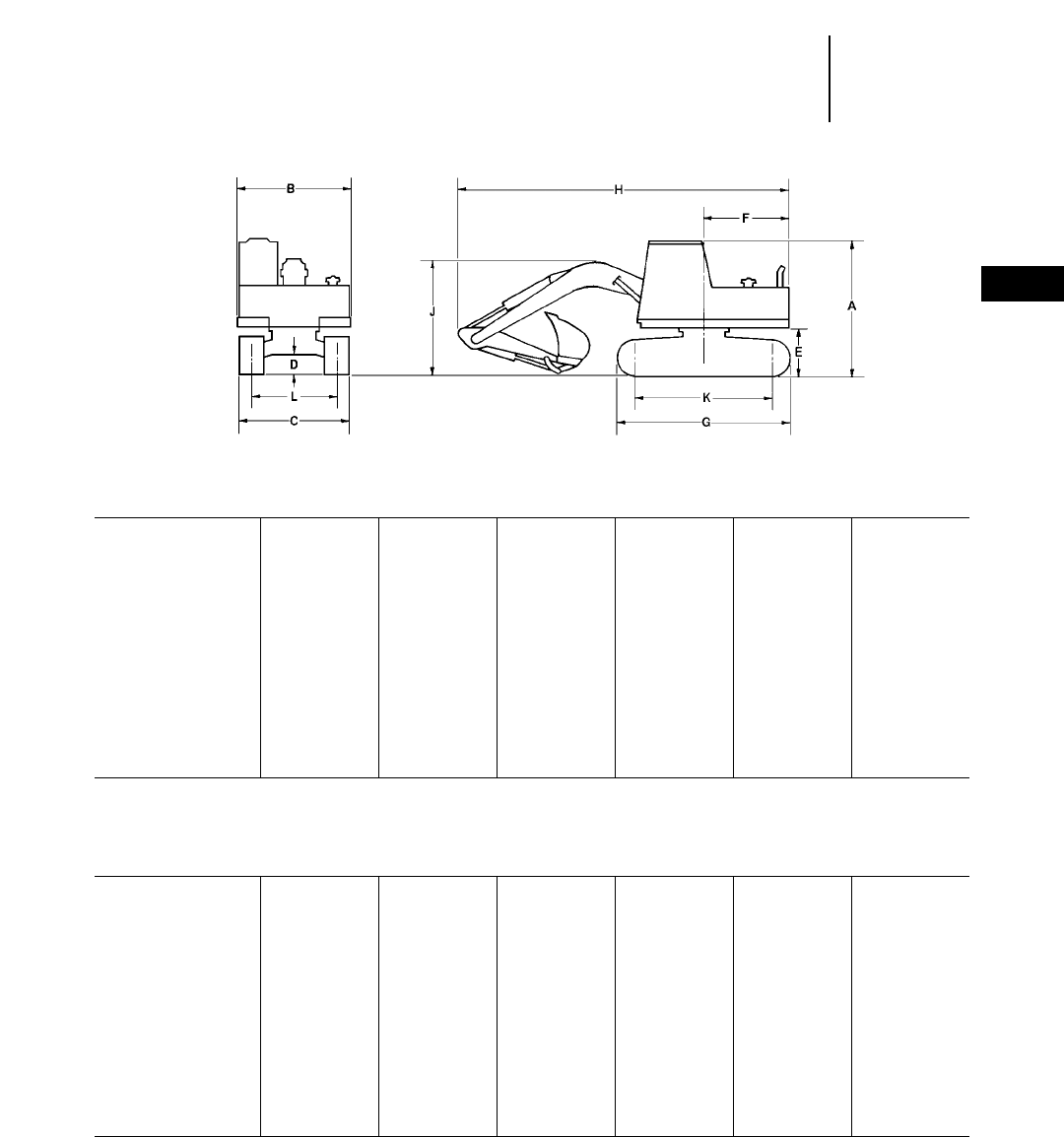
4-17
4
ExcavatorsShipping Dimensions
●301.5 ●307B ●307B SB ●307 ●311B
●312B ●312B L ●315B ●315B L
301.5 307B 307B SB 307 311B 312B
Sourcing —Japan Japan France Japan Japan
mm ft mm ft mm ft mm ft mm ft mm ft
A2190 7'2" 2630 8'8" 2640 8'8" 2660 8'9" 2760 9'1" 2760 9'1"
B980 3'3" 2280 7'6" 2280 7'6" 2280 7'6" 2495 8'2" 2495 8'2"
C980 3'3" 2200 7'3" 2200 7'3" 2200 7'3" 2490 8'2" 2490 8'2"
D220 8.7" 380 15" 380 15" 365 14" 455 18" 455 18"
E460 18" 785 2'7" 785 2'7" 700 2'6" 920 3'0" 920 3'0"
F1070 3'6" 1750 5'9" 1750 5'9" 1750 5'9" 2130 7'0" 2130 7'0"
G1390 4'7" 2760 9'1" 2760 9'1" 2660 8'9" 3320 10'11" 3490 11'5"
H3690 12'1" 6080 19'11" 6730 22'1" 6310 20'8" 7250 23'9" 7595 24'11"
J* —2630 8'8" 2640 8'8" 2750 9'0" 2760 9'1" 2760 9'1"
K1020 3'4" 2120 6'11" 2120 6'11" 2050 6'9" 2610 8'7" 2780 9'1"
L—1750 5'9" 1750 5'9" 1750 5'9" 1990 6'6" 1990 6'6"
312B 312B L 312B L 315B 315B L 315B L
Sourcing France Japan France Japan Japan France
mm ft mm ft mm ft mm ft mm ft mm ft
A2910 9'6" 2760 9'1" 2760 9'1" 2880 9'5" 2880 9'5" 3000 9'11"
B2480 8'2" 2595 8'6" 2480 8'2" 2490 8'2" 2490 8'2" 2480 8'2"
C2490 8'2" 2590 8'6" 2590 8'6" 2490 8'2" 2590 8'6" 2490 8'2"
D435 17" 455 18" 435 17" 460 18" 460 18" 462 18"
E900 2'11" 920 3'0" 900 2'11" 1030 3'5" 1030 3'5" 1022 3'4"
F2090 6'10" 2130 7'0" 2090 6'10" 2450 8'0" 2450 8'0" 2430 8'0"
G3490 11'5" 3750 12'4" 3750 12'4" 3690 12'1" 3970 13'0" 3965 13'0"
H7590 24'10" 7595 24'11" 7590 24'10" 8500 28'0" 8500 28'0" 8475 27'9"
J* 2660 8'9" 2760 9'1" 2660 8'9" 2880 9'5" 2880 9'5" 2870 9'5"
K2780 9'1" 3040 12'0" 3040 12'0" 2880 9'5" 3170 10'5" 3166 10'4"
L1990 6'6" 1990 6'6" 1990 6'6" 1990 6'6" 1990 6'6" 1990 6'6"
*Varies with stick length.
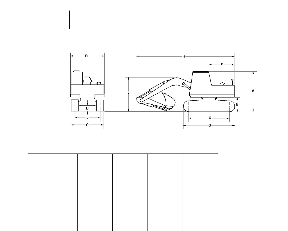
4-18
Excavators Shipping Dimensions
●318B L ●318B LN
318B L 318B L 318B LN 318B LN
Sourcing Japan France Japan France
mm ft mm ft mm ft mm ft
A2930 9'7" 3020 9'10" 2930 9'7" 3020 9'10"
B2800 9'2" 2490 8'2" 2800 9'2" 2490 8'2"
C2800 9'2" 2800 9'2" 2490 8'2" 2495 8'2"
D475 1'7" 470 18" 475 1'7" 470 18"
E1045 3'5" 1030 3'4" 1045 3'5" 1030 3'4"
F2450 8'0" 2350 7'8" 2450 8'0" 2350 7'8"
G4075 13'4" 4075 13'4" 4075 13'4" 4075 13'4"
H8720 28'7" 8687 28'6" 8720 28'7" 8687 28'6"
J* 3050 10'0" 2830 9'3" 3050 10'0" 2830 9'3"
K3265 10'9" 3265 10'8" 3265 10'9" 3265 10'8"
L2200 7'3" 2200 7'3" 1990 6'6" 1995 6'7"
*Varies with stick length.
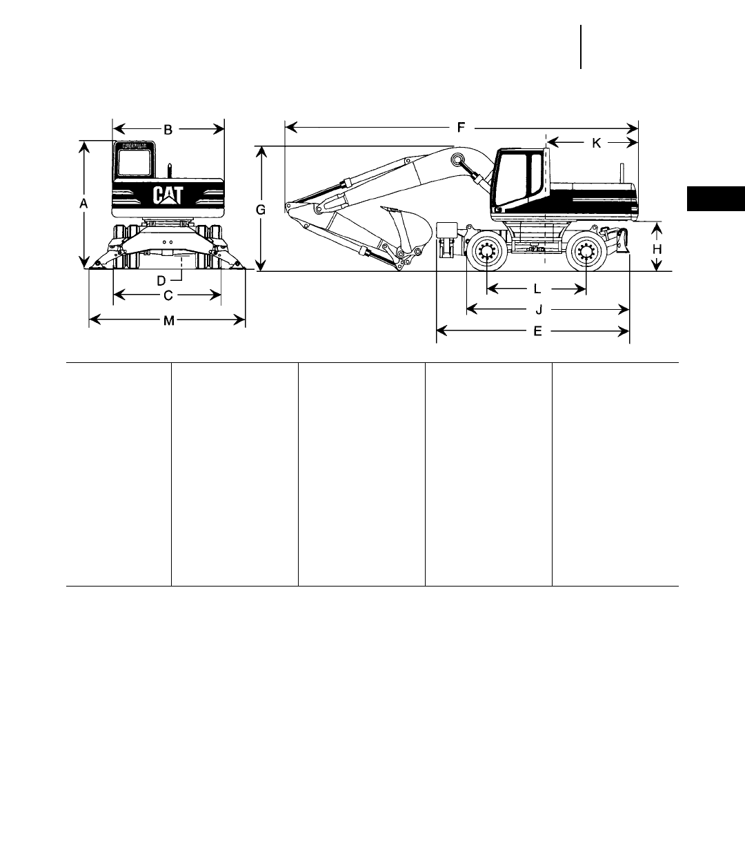
4-19
4
Excavators
M312 M315 M318 M320
mm ft mm ft mm ft mm ft
A3070 10'1" 3080 10'1" 3100 10'2" 3145 10'4"
B2500 8'2" 2500 8'2" 2500 8'2" 2650 8'8"
C* 2500 8'2" 2500 8'2" 2500 8'2" 2750 9'0"
Dozer width 2500 8'2" 2500 8'2" 2500 8'2" 2750 9'0"
D375 14.7" 375 14.7" 375 14.7" 360 14.2"
E14900 16'1" 5000 16'5" 5000 16'5" 5175 17'0"
E24660 15'3" 4930 16'2" 5030 16'5" 5205 17'1"
E34140 13'6" 4140 13'6" 4240 13'9" 4405 14'5"
F**8620** 28'3" **8840** 29'0" 8970 29'5" 9660 31'8"
G3070 10'1" 3080 10'1" 3100 10'2" 3145 10'4"
H1262 4'2" 1262 4'2" 1280 4'2" 1310 4'4"
J4140 13'7" 4140 13'7" 4240 13'11" 4405 14'5"
K1990 6'5" 2150 7'1" 2450 8'0" 2700 8'10"
L2500 8'2" 2500 8'2" 2600 8'6" 2750 9'0"
M3835 12'7" 3835 12'7" 3835 12'7" 3900 12'9"
E12 Sets Outriggers.
E2Outriggers/Dozer.
E3Dozer only.
**10 220 Dual Tires.
**Linkage over dozer.
NOTE: Shipping dimensions above are for standard machine equipped with one-piece boom and medium stick.
Shipping Dimensions
●M312 ●M315 ●M318 ●M320
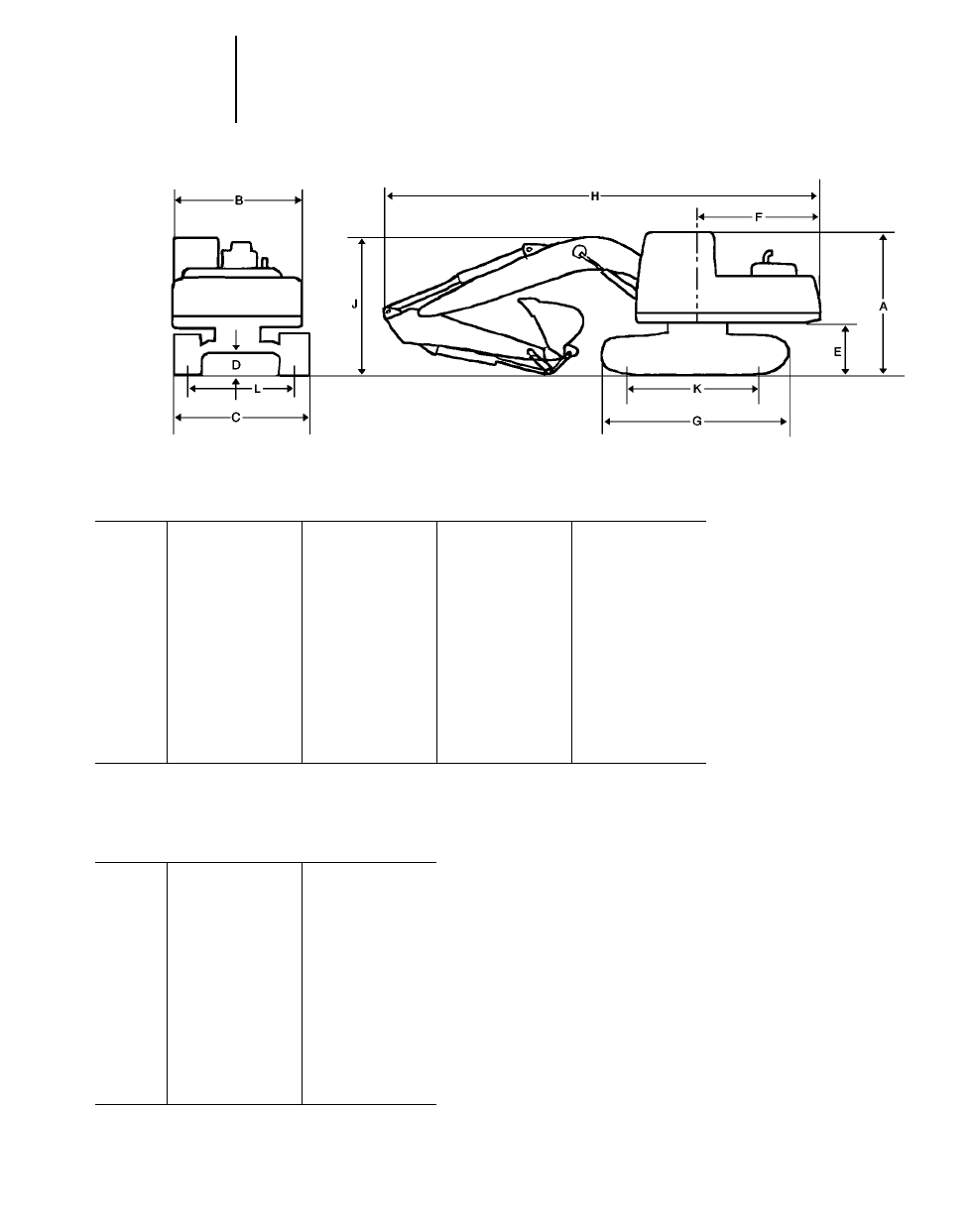
4-20
Excavators
320B Reach 320B Mass 320B L Reach 320B L Mass
mm ft mm ft mm ft mm ft
A2940 9'8" 2940 9'8" 2940 9'8" 2940 9'8"
B2650 8'8" 2650 8'8" 2650 8'8" 2650 8'8"
C2800 9'2" 2800 9'2" 3180 10'5" 3180 10'5"
D475 1'7" 475 1'7" 475 1'7" 475 1'7"
E1045 3'5" 1045 3'5" 1045 3'5" 1045 3'5"
F2750 9'0" 2750 9'0" 2750 9'0" 2750 9'0"
G4075 13'4" 4075 13'4" 4455 14'7" 4455 14'7"
H9440 31'0" 9000 29'6" 9440 31'0" 9000 29'6"
J* 2940 9'8" 3050 10'0" 2940 9'8" 3050 10'0"
K3265 10'9" 3265 10'9" 3650 12'0" 3650 12'0"
L2200 7'3" 2200 7'3" 2380 7'10" 2380 7'10"
320B N Reach 320B N Mass
mm ft mm ft
A2940 9'8" 2940 9'8"
B2470 8'1" 2470 8'1"
C2500 8'2" 2500 8'2"
D475 1'7" 475 1'7"
E1045 3'5" 1045 3'5"
F2750 9'0" 2750 9'0"
G4075 13'4" 4075 13'4"
H10 230 33'7" 9000 29'6"
J* 2940 9'8" 3050 10'0"
K3265 10'9" 3265 10'9"
L2200 7'3" 2200 7'3"
*Varies with stick length.
Shipping Dimensions
●320B, 320B L, 320B N
●Japan Sourced
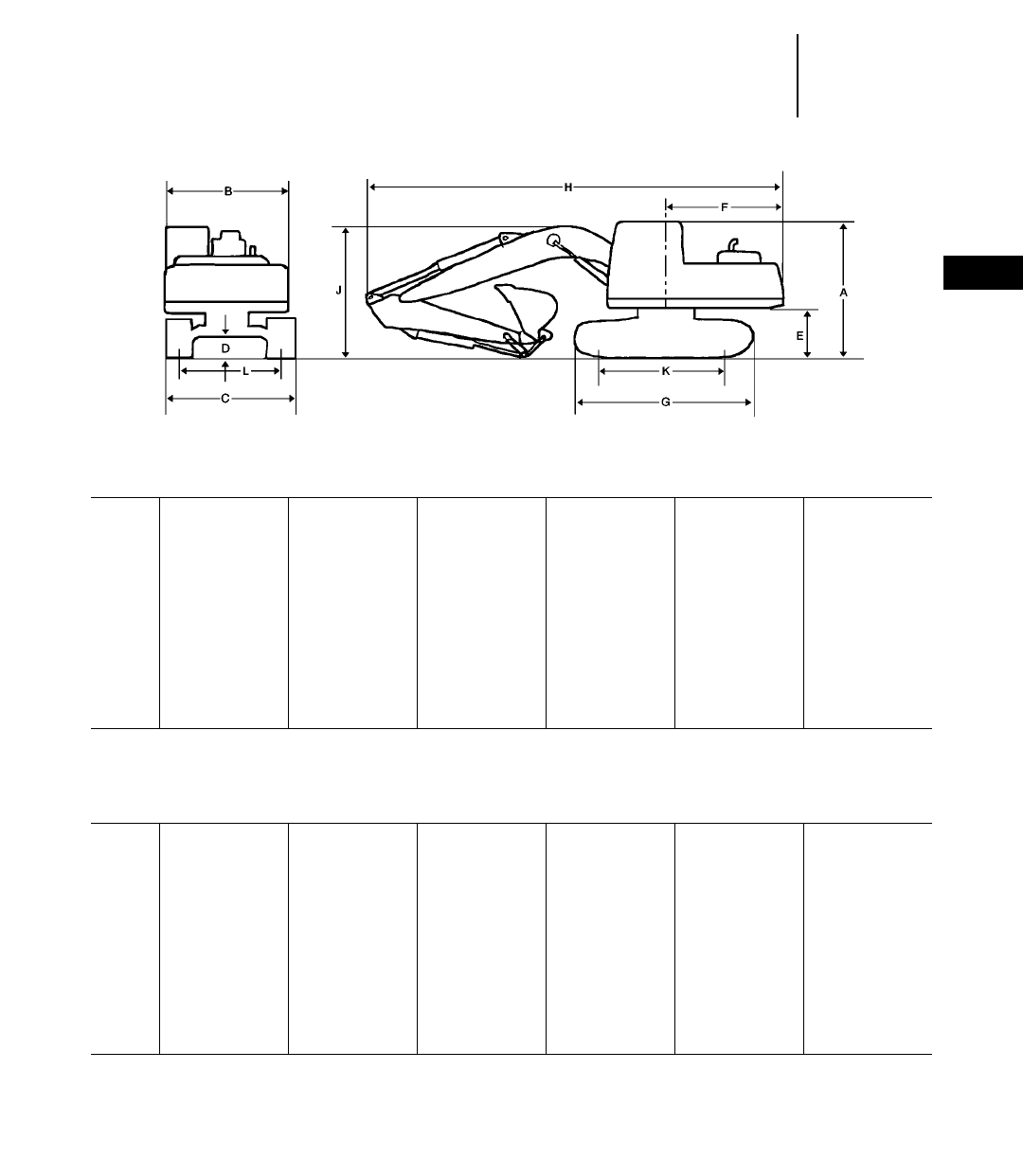
4-21
4
ExcavatorsShipping Dimensions
●320B, 320B L, 320B LN, 320B S
●Belgium Sourced
320B Reach 320B Mass 320B VA 320B L Reach 320B L Mass 320B L VA
mm ft mm ft mm ft mm ft mm ft mm ft
A3030 9'11" 3030 9'11" 3030 9'11" 3030 9'11" 3030 9'11" 3030 9'11"
B2490 8'2" 2490 8'2" 2490 8'2" 2490 8'2" 2490 8'2" 2490 8'2"
C2800 9'2" 2800 9'2" 2800 9'2" 2980 9'9" 2980 9'9" 2980 9'9"
D470 18" 470 18" 470 18" 470 18" 470 18" 470 18"
E1020 3'4" 1020 3'4" 1020 3'4" 1020 3'4" 1020 3'4" 1020 3'4"
F2750 9'0" 2750 9'0" 2750 9'0" 2750 9'0" 2750 9'0" 2750 9'0"
G4075 13'4" 4075 13'4" 4075 13'4" 4455 14'7" 4455 14'7" 4455 14'7"
H9360 30'8" 8890 29'2" 9250 30'4" 9360 30'8" 8890 29'2" 9250 30'4"
J* 2910 9'7" 2870 9'5" 2980 9'9" 2910 9'7" 2870 9'5" 2980 9'9"
K3265 10'8" 3265 10'8" 3265 10'8" 3650 12'0" 3650 12'0" 3650 12'0"
L2200 7'3" 2200 7'3" 2200 7'3" 2380 7'10" 2380 7'10" 2380 7'10"
320B LN Reach 320B LN Mass 320B LN VA 320B S Reach 320B S Mass 320B S VA
mm ft mm ft mm ft mm ft mm ft mm ft
A3030 9'11" 3030 9'11" 3030 9'11" 3100 10'2" 3100 10'2" 3100 10'2"
B2490 8'2" 2490 8'2" 2490 8'2" 2490 8'2" 2490 8'2" 2490 8'2"
C2595 8'6" 2595 8'6" 2595 8'6" 2495 8'2" 2495 8'2" 2495 8'2"
D470 18" 470 18" 470 18" 490 1'7" 490 1'7" 490 1'7"
E1000 3'3" 1000 3'3" 1000 3'3" 1080 3'7" 1080 3'7" 1080 3'7"
F2750 9'0" 2750 9'0" 2750 9'0" 2750 9'0" 2750 9'0" 2750 9'0"
G4460 14'8" 4460 14'8" 4460 14'8" 4360 14'4" 4360 14'4" 4360 14'4"
H9360 30'8" 8890 29'2" 9250 30'4" 9360 30'8" 8890 29'2" 9250 30'4"
J* 3225 10'7" 3225 10'7" 3225 10'7" 3245 10'8" 3245 10'8" 3245 10'8"
K3650 12'0" 3650 12'0" 3650 12'0" 3490 11'5" 3490 11'5" 3490 11'5"
L1995 6'7" 1995 6'7" 1995 6'7" 1895 6'3" 1895 6'3" 1895 6'3"
*Varies with stick length.
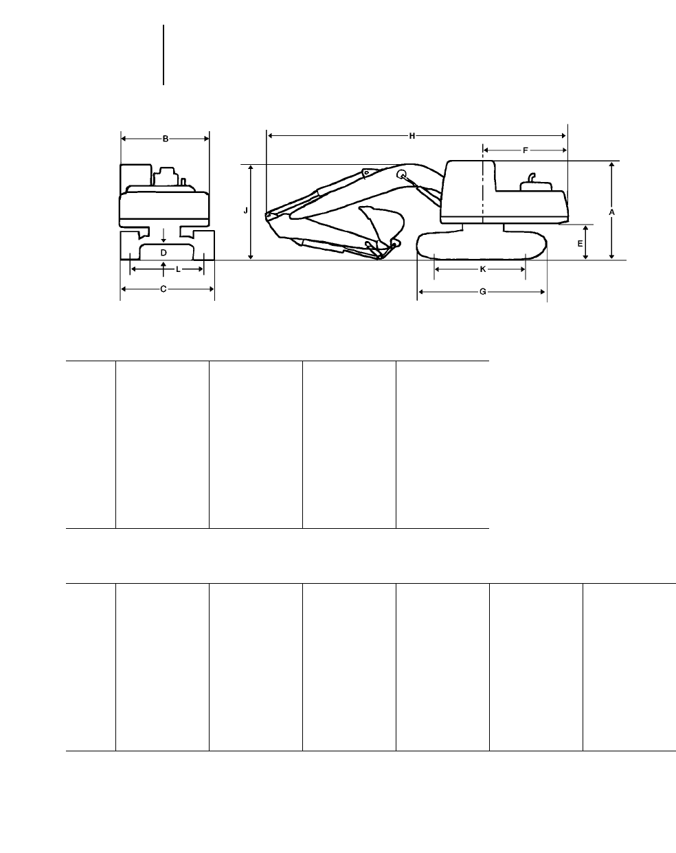
4-22
Excavators
Japan/U.S. Sourced
322B Reach 322B Mass 322B L Reach 322B L Mass
mm ft mm ft mm ft mm ft
A2980 9'9" 2980 9'9" 2980 9'9" 2980 9'9"
B2740 9'0" 2740 9'0" 2740 9'0" 2740 9'0"
C2990 9'10" 2990 9'10" 3390 11'1" 3390 11'1"
D445 18" 445 18" 445 18" 445 18"
E1060 3'6" 1060 3'6" 1060 3'6" 1060 3'6"
F2900 9'6" 2900 9'6" 2900 9'6" 2900 9'6"
G4260 14'0" 4260 14'0" 4640 15'3" 4640 15'3"
H9960 32'8" 9490 31'2" 9960 32'8" 9490 31'2"
J* 3120 10'3" 3450 11'4" 3120 10'3" 3450 11'4"
K3450 11'4" 3450 11'4" 3830 12'7" 3830 12'7"
L2390 7'10" 2390 7'10" 2590 8'6" 2590 8'6"
Belgium Sourced
322B L Reach 322B L Mass 322B L VA 322B LN Reach 322B LN Mass 322B LN VA
mm ft mm ft mm ft mm ft mm ft mm ft
A2980 9'9" 2980 9'9" 2980 9'9" 2980 9'9" 2980 9'9" 2980 9'9"
B2740 9'0" 2740 9'0" 2740 9'0" 2740 9'0" 2740 9'0" 2740 9'0"
C3390 11'2" 3390 11'2" 3390 11'2" 2990 9'10" 2990 9'10" 2990 9'10"
D470 1'7" 470 1'7" 470 1'7" 470 1'7" 470 1'7" 470 1'7"
E1080 3'7" 1080 3'7" 1080 3'7" 1080 3'7" 1080 3'7" 1080 3'7"
F2855 9'4" 2855 9'4" 2855 9'4" 2855 9'4" 2855 9'4" 2855 9'4"
G4630 15'2" 4630 15'2" 4630 15'2" 4630 15'2" 4630 15'2" 4630 15'2"
H10 000 32'10" 9480 31'1" 9700 31'10" 10 000 32'10" 9480 31'1" 9700 31'10"
J* 3280 10'9" 3320 10'11" 3300 10'10" 3280 10'9" 3320 10'11" 3300 10'10"
K3830 12'7" 3830 12'7" 3830 12'7" 3830 12'7" 3830 12'7" 3830 12'7"
L2590 8'6" 2590 8'6" 2590 8'6" 2390 7'10" 2390 7'10" 2390 7'10"
*Varies with stick length.
Shipping Dimensions
●322B, 322B L — Japan/U.S. Sourced
●322B L, 322B LN — Belgium Sourced
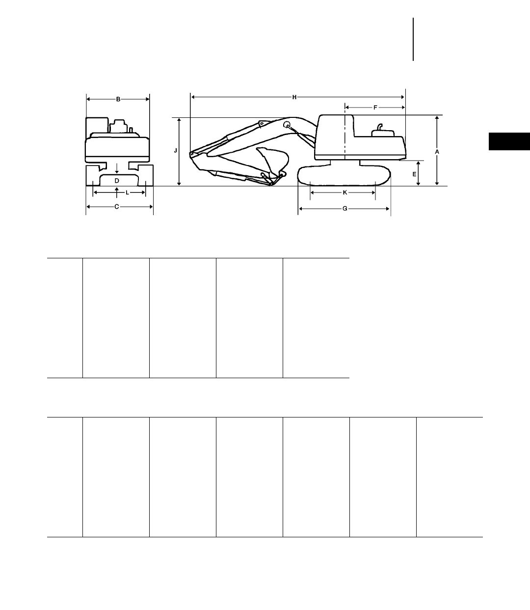
4-23
4
ExcavatorsShipping Dimensions
●325B, 325B L — Japan/U.S. Sourced
●325B L, 325B LN — Belgium Sourced
Japan/U.S. Sourced
325B Reach 325B Mass 325B L Reach 325B L Mass
mm ft mm ft mm ft mm ft
A3090 10'2" 3090 10'2" 3090 10'2" 3090 10'2"
B2900 9'6" 2900 9'6" 2900 9'6" 2900 9'6"
C2990 9'10" 2990 9'10" 3390 11'1" 3390 11'1"
D510 1'8" 510 1'8" 510 1'8" 510 1'8"
E1140 3'9" 1140 3'9" 1140 3'9" 1140 3'9"
F3050 10'0" 3050 10'0" 3050 10'0" 3050 10'0"
G4360 14'4" 4360 14'4" 4660 15'3" 4660 15'3"
H10 290 33'10" 9710 31'10" 10 290 33'10" 9710 31'10"
J* 3270 10'9" 3460 11'4" 3270 10'9" 3460 11'4"
K3490 11'5" 3490 11'5" 3795 12'5" 3795 12'5"
L2390 7'10" 2390 7'10" 2590 8'6" 2590 8'6"
Belgium Sourced
325B L Reach 325B L Mass 325B L VA 325B LN Reach 325B LN Mass 325B LN VA
mm ft mm ft mm ft mm ft mm ft mm ft
A3140 10'4" 3140 10'4" 3140 10'4" 3140 10'4" 3140 10'4" 3140 10'4"
B2900 9'6" 2900 9'6" 2900 9'6" 2900 9'6" 2900 9'6" 2900 9'6"
C3390 11'2" 3390 11'2" 3390 11'2" 2990 9'10" 2990 9'10" 2990 9'10"
D480 1'7" 480 1'7" 480 1'7" 480 1'7" 480 1'7" 480 1'7"
E1130 3'9" 1130 3'9" 1130 3'9" 1130 3'9" 1130 3'9" 1130 3'9"
F3050 10'0" 3050 10'0" 3050 10'0" 3050 10'0" 3050 10'0" 3050 10'0"
G4660 15'4" 4660 15'4" 4660 15'4" 4660 15'3" 4660 15'3" 4660 15'3"
H10 350 33'11" 9890 32'5" 10 090 33'1" 10 350 33'11" 9890 32'5" 10 090 33'1"
J* 3210 10'6" 3330 10'11" 3150 10'4" 3210 10'6" 3330 10'11" 3150 10'4"
K3800 12'6" 3800 12'6" 3800 12'6" 3800 12'6" 3800 12'6" 3800 12'6"
L2590 8'6" 2590 8'6" 2590 8'6" 2390 7'10" 2390 7'10" 2390 7'10"
*Varies with stick length.
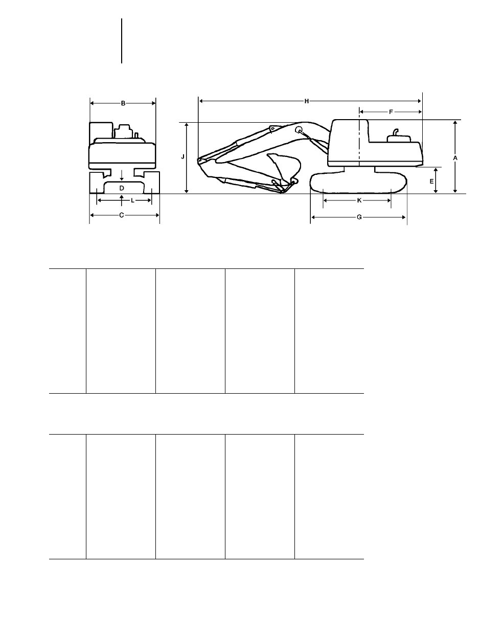
4-24
Excavators
Japan/U.S. Sourced
330B Reach 330B Mass 330B L Reach 330B L Mass
mm ft mm ft mm ft mm ft
A3150 10'4" 3150 10'4" 3150 10'4" 3150 10'4"
B2990 9'10" 2990 9'10" 2990 9'10" 2990 9'10"
C3190 10'6" 3190 10'6" 3340 10'11" 3340 10'11"
D480 1'7" 480 1'7" 480 1'7" 480 1'7"
E1230 4'0" 1230 4'0" 1230 4'0" 1230 4'0"
F3500 11'6" 3500 11'6" 3500 11'6" 3500 11'6"
G4580 15'0" 4580 15'0" 5020 16'6" 5020 16'6"
H11 010 36'2" 10 760 35'4" 11 010 36'2" 10 760 35'4"
J* 3290 10'10" 3560 11'8" 3290 10'10" 3560 11'8"
K3610 11'10" 3610 11'10" 4040 13'3" 4040 13'3"
L2590 8'6" 2590 8'6" 2590 8'6" 2590 8'6"
Belgium Sourced
330B L Reach 330B L Mass 330B LN Reach 330B LN Mass
mm ft mm ft mm ft mm ft
A3250 10'8" 3250 10'8" 3250 10'8" 3250 10'8"
B3000 9'10" 3000 9'10" 3000 9'10" 3000 9'10"
C3340 11'0" 3340 11'0" 2990 9'10" 2990 9'10"
D510 1'8" 510 1'8" 510 1'8" 510 1'8"
E1260 4'2" 1260 4'2" 1260 4'2" 1260 4'2"
F3500 11'6" 3500 11'6" 3500 11'6" 3500 11'6"
G5020 16'6" 5020 16'6" 5020 16'6" 5020 16'6"
H11 150 36'7" 10 810 35'6" 11 150 36'7" 10 810 35'6"
J* 3560 11'8" 3580 11'9" 3560 11'8" 3580 11'9"
K4040 13'3" 4040 13'3" 4040 13'3" 4040 13'3"
L2590 8'6" 2590 8'6" 2390 7'10" 2390 7'10"
*Varies with stick length.
Shipping Dimensions
●330B, 330B L — Japan/U.S. Sourced
●330B L, 330B LN — Belgium Sourced
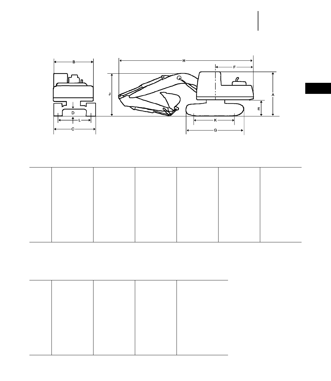
4-25
4
ExcavatorsShipping Dimensions
●345B, 345B L, 350, 350 L
345B L – FIX 345B L – FIX 345B L – VG 345B L – VG
345B Reach 345B Mass Reach Mass Reach Mass
mm ft mm ft mm ft mm ft mm ft mm ft
A3245 10'8" 3245 10'8" 3245 10'8" 3245 10'8" 3405 11'2" 3405 11'2"
B2995 9'10" 2995 9'10" 2995 9'10" 2995 9'10" 2995 9'10" 2995 9'10"
C3340 10'11" 3340 10'11" 3490 11'5" 3490 11'5" 2990 9'10" 2990 9'10"
D510 1'8" 510 1'8" 510 1'8" 510 1'8" 740 2'5" 740 2'5"
E1290 4'3" 1290 4'3" 1290 4'3" 1290 4'3" 1460 4'9" 1460 4'9"
F3610 11'10" 3610 11'10" 3610 11'10" 3610 11'10" 3610 11'10" 3610 11'10"
G5030 16'6" 5030 16'6" 5360 17'7" 5360 17'7" 5330 17'6" 5330 17'6"
H11 730 38'6" 11 380 37'4" 11 770 38'7" 11 380 37'4" 11 740 38'6" 11 380 37'4"
J* 3480 11'5" 3680 12'1" 3660 12'0" 3690 12'1" 3680 12'1" 3850 12'8"
K4030 13'3" 4030 13'3" 4360 14'4" 4360 14'4" 4340 14'3" 4340 14'3"
L2740 9'0" 2740 9'0" 2740 9'0" 2740 9'0" **2390 7'10" **2390 7'10"
**Varies with stick length.
**Transport position.
NOTE: 600 mm shoes are available for 345B.
750 mm shoes are available for 345B L.
Medium stick is available all models.
Undercarriage is retracted.
350 Reach 350 Mass 350 L Reach 350 L Mass
mm ft mm ft mm ft mm ft
A3500 11'6" 3500 11'6" 3500 11'6" 3500 11'6"
B3170 10'5" 3170 10'5" 3170 10'5" 3170 10'5"
C3200 10'6" 3200 10'6" 3300 10'10" 3300 10'10"
D730 2'5" 730 2'5" 730 2'5" 730 2'5"
E1420 4'8" 1420 4'8" 1420 4'8" 1420 4'8"
F3580 11'9" 3580 11'9" 3580 11'9" 3580 11'9"
G5110 16'9" 5110 16'9" 5570 18'3" 5570 18'3"
H12 200 40'0" 11 750 38'7" 12 200 40'0" 11 750 38'7"
J* 3750 12'4" 3980 13'1" 3750 12'4" 3980 13'1"
K4040 13'3" 4040 13'3" 4490 14'9" 4490 14'9"
L2550 8'4" 2550 8'4" 2550 8'4" 2550 8'4"
*Varies with stick length.
NOTE: 600 mm shoes are available for 350.
750 mm shoes are available for 350 L.
Medium stick is available all models.
Undercarriage is retracted.
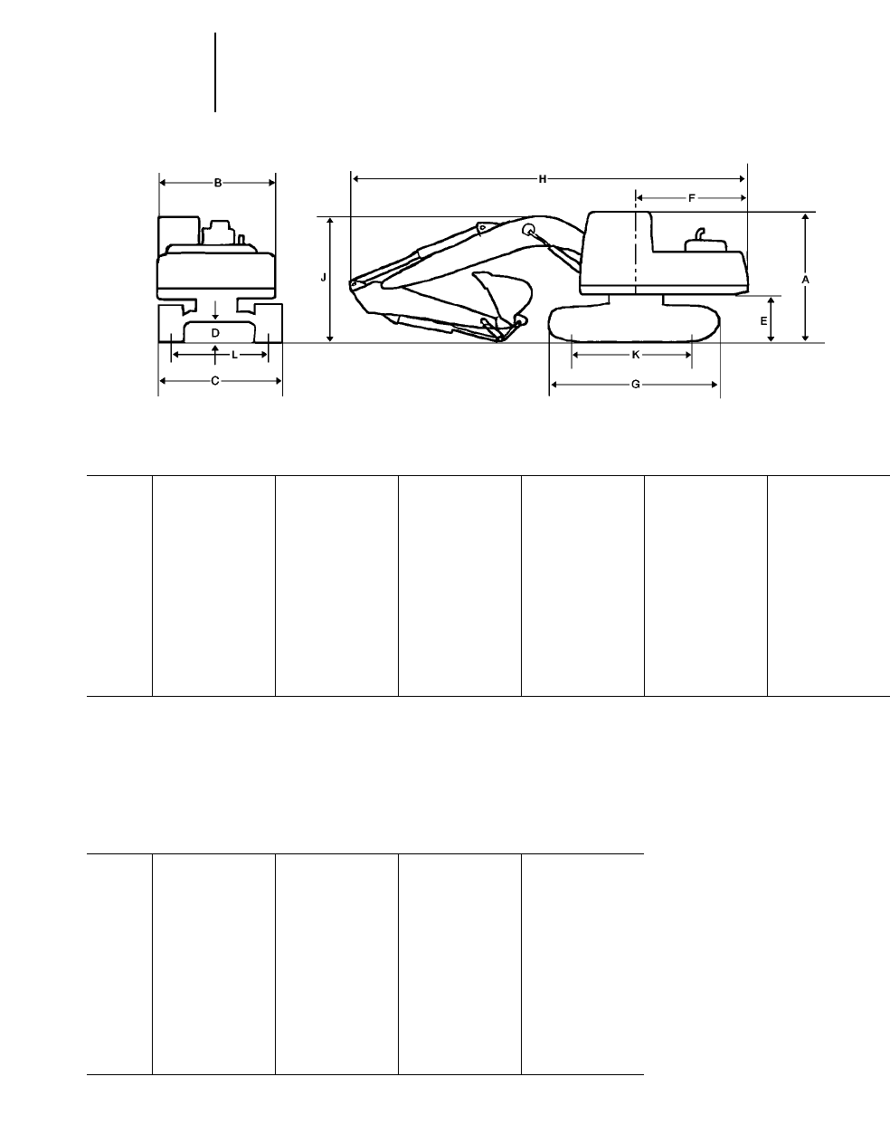
4-26
Excavators Shipping Dimensions
●375, 375 L
●Japan/U.S. Sourced ●Belgium Sourced
Japan/U.S. Sourced
375 Reach 375 GP 375 Mass 375 L Reach 375 L GP 375 L Mass
mm ft mm ft mm ft mm ft mm ft mm ft
A3650 12'0" 3650 12'0" 3650 12'0" 3650 12'0" 3650 12'0" 3650 12'0"
B3470 11'5" 3470 11'5" 3470 11'5" 3470 11'5" 3470 11'5" 3470 11'5"
C3480 11'5" 3480 11'5" 3480 11'5" 3500 11'6" 3500 11'6" 3500 11'6"
D890 2'11" 890 2'11" 890 2'11" 890 2'11" 890 2'11" 890 2'11"
E1600 5'3" 1600 5'3" 1600 5'3" 1600 5'3" 1600 5'3" 1600 5'3"
F4200 13'9" 4200 13'9" 4200 13'9" 4200 13'9" 4200 13'9" 4200 13'9"
G5840 19'2" 5840 19'2" 5840 19'2" 6360 20'10" 6360 20'10" 6360 20'10"
H14 710 48'3" 14 290 46'11" 13 140 43'1" 14 710 48'3" 14 290 46'11" 13 140 43'1"
J4690 15'5" 5240 17'2" 4890 16'1" 4690 15'5" 5240 17'2" 4890 16'1"
K4600 15'1" 4600 15'1" 4600 15'1" 5120 16'10" 5120 16'10" 5120 16'10"
L2750 9'0" 2750 9'0" 2750 9'0" 2750 9'0" 2750 9'0" 2750 9'0"
NOTE: 610 mm shoes are available for 375.
750 mm shoes are available for 375 L.
Medium stick is available all Reach & Mass.
3.4 m short stick is available for GP.
Undercarriage is retracted.
Belgium Sourced
375 Reach 375 Mass 375 L Reach 375 L Mass
mm ft mm ft mm ft mm ft
A3650 12'0" 3650 12'0" 3650 12'0" 3650 12'0"
B3470 11'5" 3470 11'5" 3470 11'5" 3470 11'5"
C3480 11'5" 3480 11'5" 3480 11'5" 3480 11'5"
D890 2'11" 890 2'11" 890 2'11" 890 2'11"
E1600 5'3" 1600 5'3" 1600 5'3" 1600 5'3"
F4200 13'9" 4200 13'9" 4200 13'9" 4200 13'9"
G5840 19'2" 5840 19'2" 6360 20'10" 6360 20'10"
H13 140 43'1" 13 140 43'1" 14 290 46'11" 13 140 43'1"
J5240 17'2" 4890 16'1" 5240 17'2" 4890 16'1"
K4600 15'1" 4600 15'1" 5120 16'10" 5120 16'10"
L2750 9'0" 2750 9'0" 2750 9'0" 2750 9'0"
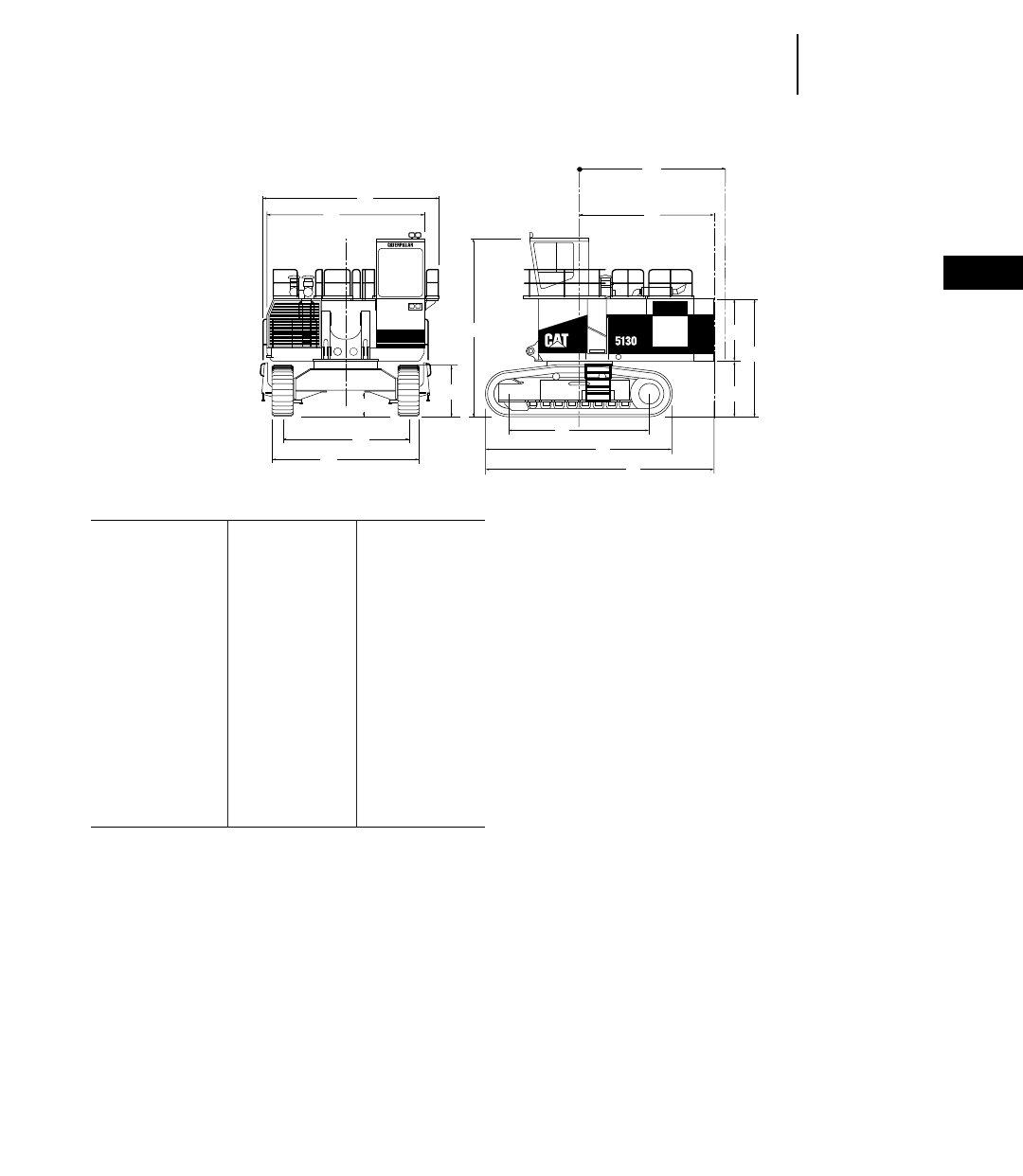
4-27
4
ExcavatorsGeneral Dimensions
●5130B ME ●5230 ME
5130B ME 5230 ME
mm ft mm ft
A6620 21'9" 7510 24'7"
B5900 19'4" 6960 22'11"
C4720 15'6" 5196 17'0"
D5370 17'7" 6296 20'8"
E960 3'2" 1108 3'8"
F1890 6'3" 2260 7'5"
G Swing radius 5250 17'3" 6450 21'2"
H5140 16'11" 6280 20'7"
J5552 18'3" 6260 20'6"
K7270 23'10" 8174 26'10"
L8775 28'9" 10 325 33'10"
M6550 21'5" 7455 24'5"
N2350 7'9" 2850 9'4"
O2045 6'9" 2450 8'0"
P4395 14'5" 5300 17'5"
A
B
E
C
D
F
M
J
K
L
O
N
P
H
G

●5130B ME
Weight Length Width Height
kg lb mm ft mm ft mm ft
Carbody 15 800 34,820 3560 11'8" 4110 13'6" 1520 5'0"
Swing Frame 22 830 50,340 7060 23'2" 2460 8'1" 2440 8'0"
Track Roller Frame (each)
650 mm (2'2") Shoes 23 610 52,060 7140 23'5" 1500 4'11" 1910 6'3"
800 mm (2'7") Shoes 24 640 54,320 7140 23'5" 1500 4'11" 1910 6'3"
1000 mm (3'3") Shoes 25 770 56,820 7140 23'5" 1500 4'11" 1910 6'3"
Left Module 8090 17,830 5770 18'11" 2340 7'8" 2620 8'7"
Boom Cylinders 3000 6620 3840 12'7" 910 3'0" 690 2'3"
Stick Cylinders 1100 2430 3840 12'7" 910 3'0" 690 2'3"
Bucket Cylinders 1100 2430 3840 12'7" 910 3'0" 690 2'3"
Ladders 2070 4570 2240 7'4" 1090 3'7" 1190 3'11"
Parts Box 2100 4620 2240 7'4" 1090 3'7" 990 3'3"
Handrails 1150 2540 3990 13'1" 2290 7'6" 1120 3'8"
Right Module 13 810 30,440 5660 18'7" 2440 8'0" 3050 10'0"
Cab 2050 4510 2360 7'9" 2060 6'9" 3100 10'2"
Boom 20 530 45,260 8560 28'1" 1980 6'6" 3400 11'2"
Counterweight 20 970 46,220 6250 20'6" 1170 3'10" 2510 8'3"
Stick 6220 13,710 5260 17'3" 1020 3'4" 2290 7'6"
Brackets 1550 3420 1520 5'0" 1450 4'9" 790 2'7"
Bucket 9700 21,380 2900 9'6" 3200 10'6" 2820 9'3"
●5230 ME
Weight Length Width Height
kg lb mm ft mm ft mm ft
Carbody 24 770 54,610 4470 14'8" 3840 12'7" 1980 6'6"
Swing Frame 40 590 89,490 8890 29'2" 3330 10'11" 3480 11'5"
Track Roller Frame (each)
1100 mm (3'7") Shoes 45 400 100,080 8030 26'4" 1830 6'0" 2360 7'9"
1300 mm (4'3") Shoes 46 560 102,640 8030 26'4" 1830 6'0" 2360 7'9"
1500 mm (4'11") Shoes 48 080 106,000 8030 26'4" 1830 6'0" 2360 7'9"
Left Module 12 310 27,140 7190 23'7" 2510 8'3" 3230 10'7"
Cylinder Skid 3130 6900 4170 13'8" 610 2'0" 810 2'8"
Cylinder Skid 3130 6900 4170 13'8" 610 2'0" 810 2'8"
Cylinder Skid 4350 9580 4880 16'0" 910 3'0" 740 2'5"
Cylinder Skid 3290 7260 4170 13'8" 910 3'0" 740 2'5"
Parts Box 2220 4890 2240 7'4" 1090 3'7" 990 3'3"
Parts Box 2170 4780 2240 7'4" 1090 3'7" 990 3'3"
Parts Box 2220 4900 2240 7'4" 1090 3'7" 990 3'3"
Handrails 1350 2980 3990 13'1" 2290 7'6" 1120 3'8"
Right Module 20 880 46,040 7570 24'10" 2510 8'3" 3580 11'9"
Cab 2380 5240 2360 7'9" 2060 6'9" 3050 10'0"
Boom 28 340 62,480 10 030 32'11" 3960 13'0" 2490 8'2"
Counterweight 41 390 91,240 7320 24'0" 1220 4'0" 3050 10'0"
Stick 11 030 24,320 6250 20'6" 1350 4'5" 2570 8'5"
Brackets 2590 5720 1780 5'10" 1680 5'6" 890 2'11"
Guards 940 2080 2080 6'10" 1700 5'7" 840 2'9"
Bucket 16 380 36,110 4010 13'2" 3250 10'8" 3100 10'2"
4-28
Excavators Shipping Information
●5130B ME ●5230 ME
4-29
4
ExcavatorsMajor Component Weights
●301.5 ●307B ●307B SB ●311B
●312B ●315B ●315B L ●318B L
301.5† 307B 307B SB 311B 312B
Buckets:
(see data in bucket section) kg lb kg lb kg lb kg lb kg lb
Sticks:*
Short Stick — ———515 1140 560 1240
Medium Stick 245 540 150 330 500 1105 540 1200
Long Stick 325 720 230 510 600 1330 620 1370
Extra Long Stick — ———————
Booms:**
One-piece 635 1400 590 1300 1135 2500 1230 2710
Parallel-Offset 1115 2460 ——————
VA (France sourced only) — —————1720 3790
Other:
Upperstructure (complete w/o ctwt) 2550 5620 3150 6940 3870 8530 3875 8540
Standard undercarriage (std shoe) 2120 4670 2120 4670 3700 8155 3835 8455
Long undercarriage (std shoe) — —————4335 9555
Counterweight 750 1650 1150 2540 1450 3200 2450 5400
***Stick weights include stick, stick lines, bucket cylinder, bucket cylinder pins and bucket linkage.
***Boom weights include boom, boom lines, boom cylinders and rod end pins, stick cylinder and head end pin.
†Information unavailable.
315B 315B L 318B L 318B L
Source — France Japan France
Buckets:
(see data in bucket section) kg lb kg lb kg lb kg lb
Sticks:*
Short Stick 650 1,1430 830 1,1830 820 1,1810 868 1,1913
Medium Stick 580 1,1280 760 1,1676 810 1,1790 878 1,1935
Long Stick 630 1,1390 810 1,1786 860 1,1900 876 1,1931
Extra Long Stick 700 1,1540 890 1,1962 980 1,2160 946 1,2085
Booms:**
One-piece 1600 1,3500 1610 1,3550 1900 1,4190 1825 1,4025
Parallel-Offset — ———————
VA (France sourced only) — —2310 1,5095 ————
Other:
Upperstructure (complete w/o ctwt) 4600 10,200 4600 10,200 4550 10,030 5100 11,245
Standard undercarriage (std shoe) 5300 11,600 ——————
Long undercarriage (std shoe) 5900 12,900 5900 12,900 6650 14,650 6470 14,260
Narrow undercarriage (std shoe) — ———6360 14,030 6190 13,650
Counterweight 3000 1,6600 3300 1,7276 3610 1,7960 3600 1,7940
***Stick weights include stick, stick lines, bucket cylinder, bucket cylinder pins and bucket linkage.
***Boom weights include boom, boom lines, boom cylinders and rod end pins, stick cylinder and head end pin.

M312 M315 M318 M320
Buckets:
(see data in bucket section) kg lb kg lb kg lb kg lb
Sticks:*
Short Stick 522 1,1151 588 1,1297 743 1,1638 936 1,2064
Medium Short Stick 509 1,1122 604 1,1332 795 1,1753 991 1,2185
Medium Stick 541 1,1193 633 1,1396 837 1,1846 1081 1,2384
Long Stick 596 1,1314 652 1,1438 1025 1,2260 1253 1,2763
Extra Long Stick 614 1,1354 761 1,1678 ————
Industrial Stick 508 1,1120 606 1,1336 737 1,1625 ——
Booms:**
One-piece Boom 1208 1,2664 1371 1,3023 1737 1,3830 2165 1,4774
VA Stub Boom 867 1,1912 997 1,2198 1173 1,2586 1409 1,3107
VA Fore Boom 748 1,1649 885 1,1951 1059 1,2335 1329 1,2930
Other:
Upperstructure
(with swing bearing, no boom) 6350 14,002 7473 16,478 8590 18,941 9282 20,467
Undercarriage
(with standard tires) 3390 1,7475 3700 1,8159 4070 1,8974 4917 10,842
Outriggers (each set, with
cylinders and linkage) 800 1,1764 1040 1,2293 1070 1,2359 1275 1,2811
Dozer Blade (with cylinders
and linkage) 650 1,1433 700 1,1544 700 1,1544 900 1,1985
**Stick weight includes stick, stick lines, bucket cylinder, bucket cylinder pins, bucket linkage and bucket linkage pins.
**One-piece boom weight includes boom, boom lines, boom cylinders, boom cylinder rod end pin, stick cylinder, stick cylinder head end pin and boom nose pin.
— VA stub boom weight includes stub boom, stub boom lines, boom cylinders, VA cylinder, VA cylinder head end pin and stub/fore boom pin.
— VA fore boom weight includes fore boom, fore boom lines, stick cylinder, stick cylinder head end pin, VA cylinder rod end pin and fore boom nose pin.
4-30
Excavators Major Component Weights
●M312 ●M315 ●M318 ●M320

4-31
4
ExcavatorsMajor Component Weights
●320B ●322B ●325B ●330B ●345B
●Japan/U.S. Sourced
320B 322B 325B 330B 345B
Source Japan Japan, U.S. Japan, U.S. Japan, U.S. Japan, U.S.
Buckets:
(see data in bucket section) kg lb kg lb kg lb kg lb kg lb
Booms:**
One-piece Reach 2020 4,4450 2480 4,5470 2745 4,6050 1 3830 4,8445 1 4700 10,360
Sticks:* (for Reach Boom)
Short 750 4,1650 760 4,1680 895 4,1980 1 1090 4,2400 1 1285 4,2830
* 675 4,1490 785 4,1730 825 4,1820 1 1130 4,2490 1 1585 4,3490
* 650 4,1430 985 4,2170 905 4,2000 1 1220 4,2690 1 1665 4,3670
* 750 4,1650 ——903 4,1990 1 1350 4,2980 ——
Long — —————————
Booms:**
One-piece Mass 2060 4,4540 2540 4,5600 2820 4,6220 1 3755 4,8280 1 4740 10,450
VA Boom — —————————
Sticks:* (for Mass Boom & VA Boom)
Short 750 4,1650 880 4,1940 895 4,1980 1 1090 4,2400 1 1700 4,3750
* 780 4,1720 935 4,2060 995 4,2200 1 1180 4,2600 1 1720 4,3790
Long — —————1 1300 4,2870 ——
Upperstructure (complete w/o ctwt) 5600 12,350 6445 14,210 7020 15,480 1 8830 19,470 11 310 24,930
Reinforced Frame — —————————
Undercarriage — Standard (600) (600) (600) 1 (600) 1 (600)
6470 14,260 7380 16,270 8680 19,140 10 915 24,060 13 980 30,820
(700) (700) (700) 1 (750) 1 (750)
6800 14,990 7640 16,845 8980 19,800 11 410 25,150 15 020 33,115
(800) (800) (800) 1 (850) 1 (900)
7090 15,630 7950 17,530 9615 21,200 12 100 26,680 15 740 34,700
( ) Shoe width — Long (FIX) (600) (600) (600) 1 (600) 1 (600)
7210 15,900 7960 17,550 9280 20,460 11 680 25,750 15 010 33,090
(700) (700) (700) 1 (750) 1 (750)
7410 16,340 8250 18,180 9600 21,170 12 220 26,940 16 110 35,515
(800) (800) (800) 1 (850) 1 (900)
7690 16,950 8580 18,920 10 270 22,640 12 980 28,620 16 870 37,190
— Long (VG) 1 (600)
————————16 680 36,770
1 (750)
————————17 780 39,200
1 (900)
————————18 640 41,095
— Narrow (500)
6190 13,650 ————————
(600) 1 (600)
6425 14,160 ————11 560 25,490 ——
— Long Narrow (600) (600) 1 (750)
——7950 17,530 9215 20,320 12 100 26,680 ——
Counterweight — Standard 3860 4,8510 4460 4,9835 5220 11,500 1 5920 13,050 1 8500 18,740
— Extra — ———————1 9500 20,940
— Super Long Reach — —————————
— Super Long Demo. — —————————
— Material Handling — —————————
— Ditch Cleaning — —————————
***Stick weights include stick and stick lines.
***Boom weights include boom, boom lines, boom cylinders and rod end pins, stick cylinder and head end pin.

4-32
Excavators Major Component Weights
●320B ●322B ●325B ●330B ●345B
●Belgium Sourced
320B 322B 325B 330B 345B
Buckets:
(see data in bucket section) kg lb kg lb kg lb kg lb kg lb
Booms:**
One-piece Reach 2060 1,4540 2480 1,5470 0 2480 1,5470 0 3400 1,7500 0 4610 10,165
Sticks:* (for Reach Boom)
Short 720 1,1590 730 1,1610 0 840 1,1850 0 1020 1,2250 0 1670 1,3680
Medium 620 1,1370 760 1,1680 0 800 1,1760 0 1080 1,2380 0 1655 1,3650
Long 670 1,1480 ——0 870 1,1920 0 1170 1,2580 ——
Extra Long — —————————
Booms:**
One-piece Mass 2085 1,4600 2550 1,5620 0 2915 1,6430 0 3610 1,7960 0 5130 11,310
VA Boom 2660 1,5865 ——0 3540 1,7805 ————
Sticks:* (for Mass Boom)
Short 610 1,1345 840 1,1850 0 840 1,1850 0 1020 1,2250 0 1700 1,3750
Medium 750 1,1650 890 1,1960 0 950 1,2095 0 1110 1,2450 0 1675 1,3690
Upperstructure (complete w/o ctwt) 5560 12,260 6230 13,740 0 7320 16,140 0 9804 21,620 10 150 22,380
Undercarriage — Standard 6470 14,270 ————————
— L 7330 16,160 8580 18,920 10 685 23,560 12 300 27,120 18 780 41,410
— LN 6750 14,880 7910 17,440 0 9625 21,220 11 500 25,360 ——
— S 7990 17,620 ————————
Counterweight — Standard 4410 1,9725 ————————
— L 4410 1,9725 4860 10,730 0 5210 11,490 0 6120 13,490 0 9300 20,510
— LN 4710 10,385 4860 10,730 0 5210 11,490 0 6620 14,600 ——
— S 4710 10,385 ————————
**Stick weights include stick and stick lines.
**Boom weights include boom, boom lines, boom cylinders and rod end pins, stick cylinder and head end pin.
NOTE: Heavy duty track shoes available.

4-33
4
ExcavatorsMajor Component Weights
●350 ●375
350 375 375
Buckets: (see data in bucket section) kg lb kg lb kg lb
Sourcing Japan Japan/U.S. Belgium
Booms:*
One-piece Reach 0 5060 11,155 0 6740 14,859 10 500 23,150
Sticks:** (for Reach Boom)
Short 0 1510 1,3330 0 2780 1,6129 0 4540 10,010
•0 1580 1,3480 0 2870 1,6330 0 4130 1,9110
*——0 2930 1,6460 ——
Long 0 2000 1,4410 0 3100 1,6834 0 4300 1,9480
Booms:*
One-piece General Purpose — —0 6545 14,396 ——
Sticks:** (for General Purpose Boom)
Short — —————
•——0 2870 1,6330 ——
•——0 2930 1,6460 ——
Long — —0 3100 1,6834 ——
Booms:*
One-piece Mass 0 5080 11,199 0 6780 14,947 10 650 23,480
Sticks:** (for Mass Boom)
Short 0 1600 1,3530 0 2870 1,6327 0 4470 1,9860
•0 1660 1,3660 0 2940 1,6480 0 4540 10,010
•——————
Long 0 1860 1,4100 0 3180 1,7011 0 4850 10,690
Upperstructure (complete w/o ctwt) 13 680 30,160 19 200 42,300 31 700 69,900
Undercarriage — Std (600) 18 350 40,455 (610) 28 140 62,038 28 140 62,050
( ) Shoe width — Long (750) 20 000 44,090 (750) 31 540 69,534 30 800 67,910
Counterweight — Std 0 6200 13,670 11 600 25,550 11 790 26,030
— Long — ———0 4860 10,720
— Removal C/W 0 6620 14,600 12 090 26,680 ——
***Boom weights include
— 350-boom, boom lines, cylinders, rod end pins, stick cylinder and head end pin.
— 375-boom, boom lines and rod end pins.
***Stick weight includes stick and stick lines.
NOTE: Heavy duty track shoes available.
NOTE: Major component weights for 5130B ME and 5230 ME are listed in shipping dimensions in this section.
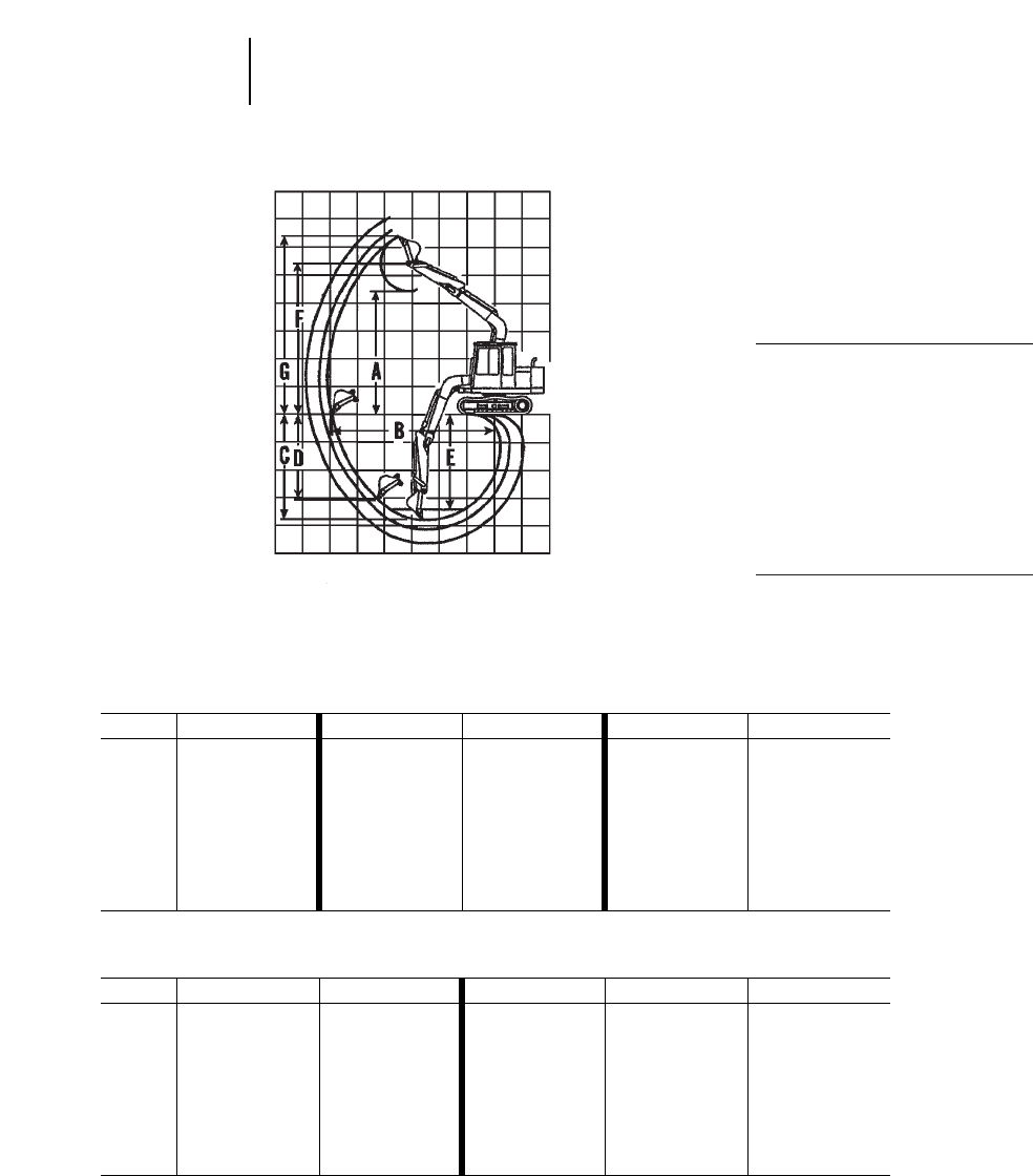
4-34
Excavators
One-Piece Boom
Digging Envelope
●Standard shoes and
undercarriage
●Lug height not included
KEY:
AMaximum loading height of bucket
with teeth
BMaximum reach at ground level
CMaximum digging depth
DMaximum vertical wall
EMaximum depth of cut for 2.44 m
(8'0") level bottom (straight clean up)
FMaximum bucket hinge pin height
GMaximum height, to bucket teeth at
highest arc
301.5 307B 307B SB
Stick 890 mm 2'11" 1.67 m 5'6" 2.21 m 7'3" 1.67 m 5'6" 2.21 m 7'3"
mft mft mft mft mft
A2.36 7'9" 5.15 16'11" 5.56 18'3" 4.16 13'8" 4.45 14'7"
B3.70 12'2" 6.20 20'4" 6.72 22'1" 6.89 22'7" 7.42 24'4"
C2.13 7'0" 4.11 13'5" 4.65 15'3" 4.16 13'8" 4.70 15'5"
D1.62 5'4" 3.64 11'11" 4.16 13'8" 3.00 9'10" 3.58 11'9"
E——3.77 12'4" 4.35 14'3" 3.76 12'4" 4.34 14'3"
F——6.24 20'6" 6.65 21'10" 5.25 17'3" 5.54 18'2"
G3.32 10'11" 7.29 23'11" 7.69 25'3" 6.18 20'3" 6.49 21'4"
307 311B
Stick 1.67 m 5'6" 2.21 m 7'3" 1.95 m 6'5" 2.25 m 7'5" 2.8 m 9'2"
mft mft mft mft mft
A5.17 17'0" 5.57 18'3" 5.30 17'5" 5.45 17'11" 5.78 19'0"
B6.20 20'4" 6.72 22'1" 7.29 23'11" 7.57 24'10" 8.10 26'7"
C4.10 13'5" 4.64 15'3" 4.74 15'7" 5.04 16'6" 5.59 18'4"
D3.62 11'11" 4.14 13'7" 4.15 13'7" 4.37 14'4" 4.88 16'0"
E3.23 10'7" 4.33 14'2" 4.42 14'6" 4.73 15'6" 5.30 17'5"
F6.25 20'6" 6.64 21'9" 6.51 21'4" 6.66 21'10" 6.99 22'11"
G7.30 23'11" 7.71 25'4" 7.66 25'2" 7.81 25'7" 8.13 26'8"
Range Dimensions
●301.5 ●307B ●307B SB ●307 ●311B
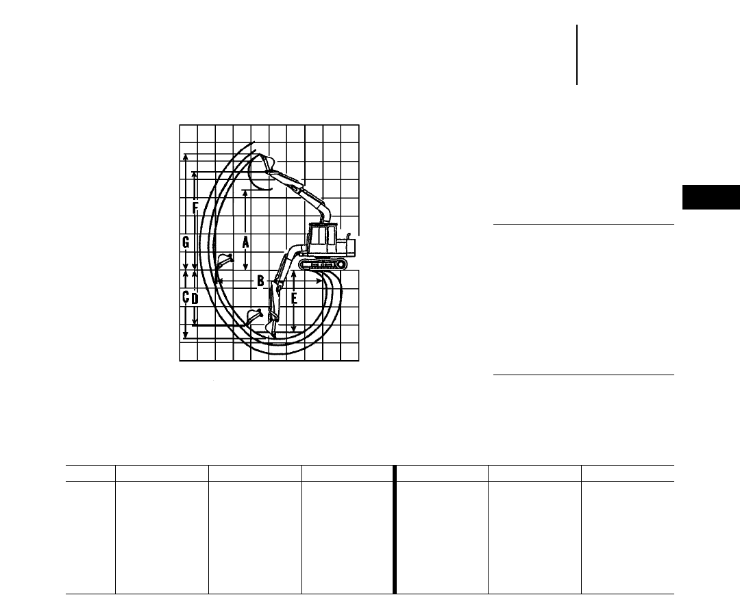
4-35
4
ExcavatorsRange Dimensions
●312B ●312B L
●Japan Sourced ●France Sourced
Japan Sourced 312B, 312B L France Sourced 312B, 312B L
Stick 2.1 m 6'11" 2.5 m 8'2" 3 m 9'10" 2.1 m 6'11" 2.5 m 8'2" 3 m 9'10"
mft mft mft mft mft mft
A5.86 19'3" 6.11 20'1" 6.34 20'10" 5.83 19'1" 6.03 19'9" 6.31 20'8"
B7.79 25'7" 8.17 26'10" 8.62 28'3" 7.81 25'7" 8.19 26'10" 8.64 28'4"
C5.13 16'10" 5.53 18'2" 6.03 19'9" 5.15 16'11" 5.55 18'2" 6.05 19'10"
D4.43 14'6" 4.89 16'1" 5.25 17'3" 4.62 15'2" 5.01 16'5" 5.52 18'1"
E4.83 15'10" 5.24 17'2" 5.75 18'10" 4.91 16'1" 5.34 17'6" 5.87 19'3"
F7.07 23'2" 7.32 24'0" 7.55 24'9" 7.07 23'2" 7.32 24'0" 7.56 24'9"
G8.23 27'0" 8.48 27'10" 8.70 28'6" 8.27 27'1" 8.52 27'11" 8.75 28'8"
One-Piece Boom
Digging Envelope
●Standard shoes and
undercarriage
●Lug height not included
KEY:
AMaximum loading height of bucket
with teeth
BMaximum reach at ground level
CMaximum digging depth
DMaximum vertical wall
EMaximum depth of cut for 2.44 m
(8'0") level bottom (straight clean up)
FMaximum bucket hinge pin height
GMaximum height, to bucket teeth at
highest arc
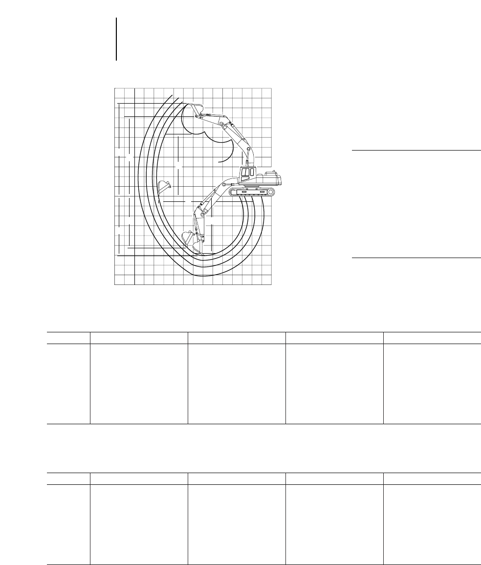
4-36
Excavators Range Dimensions
●315B ●315B L
●Japan Sourced ●France Sourced
Japan Sourced 315B, 315B L
Stick 1.85 m 6'1" 2.25 m 7'5" 2.6 m 8'6" 3.1 m 10'2"
mftmftmftmft
A5.93 19'6" 6.15 20'2" 6.32 20'9" 6.41 21'0"
B8.04 26'5" 8.42 27'7" 8.74 28'8" 9.14 30'0"
C5.31 17'5" 5.71 18'9" 6.06 19'10" 6.56 21'6"
D4.40 14'5" 4.93 16'2" 5.34 17'6" 5.57 18'3"
E5.02 16'5" 5.46 17'11" 5.83 19'1" 6.33 20'9"
F7.27 23'10" 7.49 24'7" 7.66 25'1" 7.75 25'5"
G8.50 27'10" 8.74 28'8" 8.91 29'3" 8.97 29'5"
France Sourced 315B L
Stick 1.85 m 6'1" 2.25 m 7'5" 2.6 m 8'6" 3.1 m 10'2"
mftmftmftmft
A6.05 19'11" 6.07 19'11" 6.43 21'1" 6.27 20'7"
B7.92 25'11" 8.21 26'11" 8.62 28'3" 8.90 29'2"
C5.18 17'0" 5.58 18'3" 5.93 19'5" 6.43 21'1"
D3.89 12'9" 4.03 13'3" 4.86 15'11" 4.68 15'4"
E4.87 16'0" 5.27 17'3" 5.69 18'8" 6.13 20'1"
F7.28 23'11" 7.30 23'11" 7.66 25'1" 7.50 24'7"
G8.49 27'10" 8.51 27'11" 8.89 29'2" 8.69 28'6"
One-Piece Boom
Digging Envelope
●Standard shoes and
undercarriage
KEY:
AMaximum loading height of bucket
with teeth
BMaximum reach at ground level
CMaximum digging depth
DMaximum vertical wall
EMaximum depth of cut for 2.44 m
(8'0") level bottom (straight clean up)
FMaximum bucket hinge pin height
GMaximum height, to bucket teeth at
highest arc
➤
➤
G
➤
➤
D
➤
➤
A
➤
➤
➤
➤
F
0
➤
➤
C
B
➤
➤
E
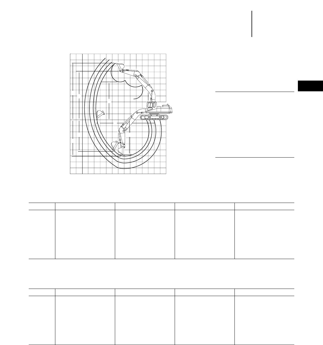
4-37
4
ExcavatorsRange Dimensions
●318B L ●318B LN
●Japan Sourced ●France Sourced
Japan Sourced 318B L, 318B LN
Stick 1.8 m 5'11" 2.25 m 7'5" 2.7 m 8'10" 3.2 m 10'6"
mftmftmftmft
A5.94 19'6" 6.20 20'4" 6.50 21'4" 6.85 22'6"
B8.27 27'2" 8.71 28'7" 9.17 30'1" 9.70 31'10"
C5.53 18'2" 5.98 19'7" 6.44 21'1" 6.93 22'9"
D3.95 13'0" 4.96 16'3" 5.59 18'4" 6.13 20'1"
E5.16 16'11" 5.63 18'6" 6.10 20'0" 6.76 22'2"
F7.29 23'11" 7.57 24'10" 7.87 25'10" 8.27 27'2"
G8.59 28'2" 8.94 29'4" 9.27 30'5" 9.68 31'9"
France Sourced 318B L, 318B LN
Stick 1.8 m 5'11" 2.25 m 7'5" 2.7 m 8'10" 3.2 m 10'6"
mftmftmftmft
A5.82 19'1" 6.09 20'0" 6.39 20'4" 6.33 20'9"
B8.27 27'2" 8.71 28'7" 9.16 30'1" 9.27 30'5"
C5.54 18'2" 5.99 19'8" 6.44 21'1" 6.83 22'5"
D3.79 12'5" 4.81 15'9" 5.48 18'0" 3.43 11'3"
E5.23 17'2" 5.73 18'10" 6.22 20'5" 6.52 21'5"
F7.29 23'11" 7.57 24'10" 7.87 25'10" 7.81 25'7"
G8.58 28'1" 8.93 29'3" 9.26 30'4" 8.86 29'1"
One-Piece Boom
Digging Envelope
●Standard shoes and
undercarriage
KEY:
AMaximum loading height of bucket
with teeth
BMaximum reach at ground level
CMaximum digging depth
DMaximum vertical wall
EMaximum depth of cut for 2.44 m
(8'0") level bottom (straight clean up)
FMaximum bucket hinge pin height
GMaximum height, to bucket teeth at
highest arc
➤
➤
G
➤
➤
D
➤
➤
A
➤
➤
➤
➤
F
0
➤
➤
C
B
➤
➤
E
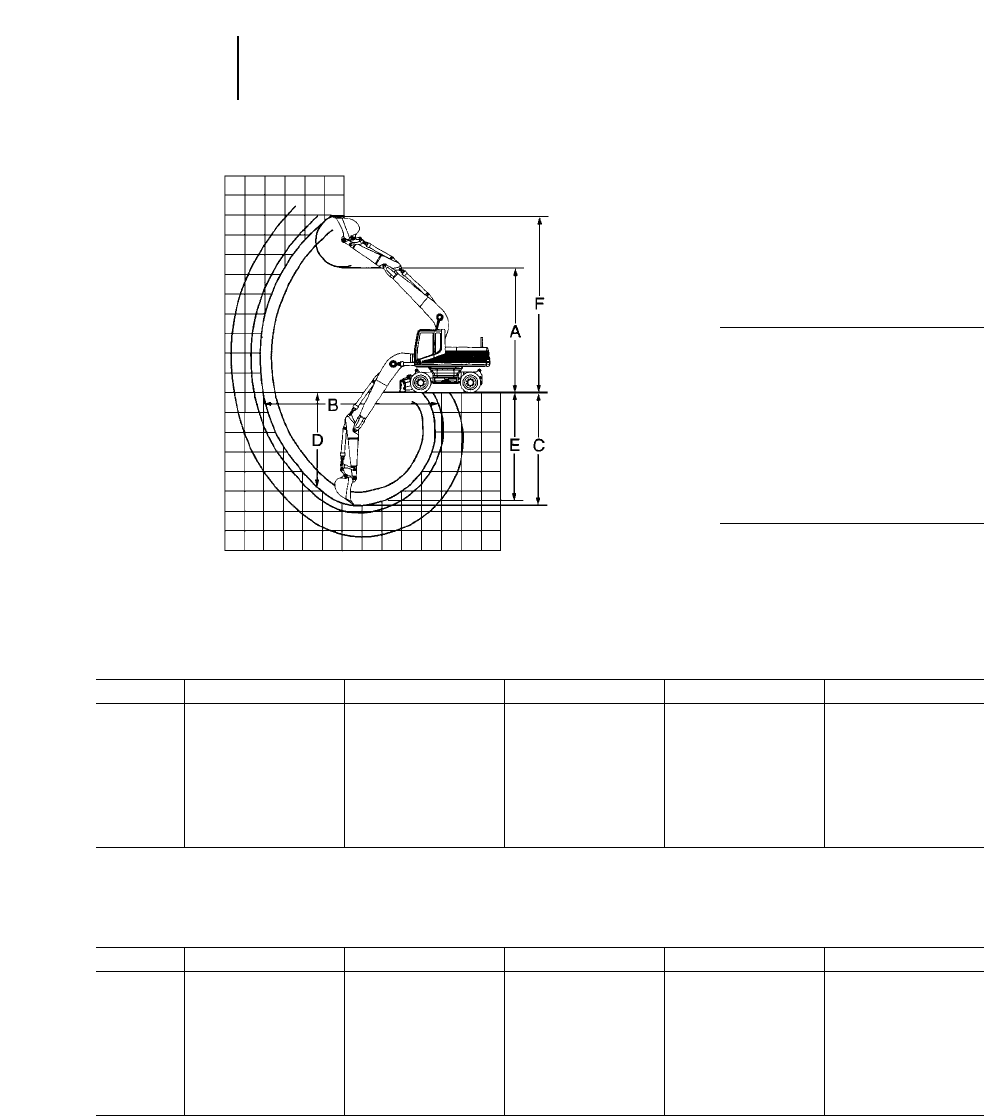
4-38
Excavators Range Dimensions
●M312 ●M315
M312
Stick 1.6 m 5'3" 2 m 6'6" 2.3 m 7'5" 2.6 m 8'5" 3 m 9'9"
mftmftmftmftmft
A5.64 18'5" 5.86 19'2" 6.03 19'8" 6.19 20'3" 6.20 20'3"
B7.62 25'0" 8.01 26'3" 8.30 27'2" 8.59 28'2" 8.90 29'2"
C4.42 14'5" 4.82 15'8" 5.12 16'8" 5.42 17'8" 5.82 19'1"
D2.39 7'8" 3.75 12'3" 4.03 13'2" 4.30 14'1" 4.39 14'4"
E4.10 13'5" 4.57 15'0" 4.89 16'0" 5.21 17'1" 5.63 18'5"
F7.88 25'5" 8.21 26'9" 8.38 27'5" 8.55 28'1" 8.52 28'0"
M315
Stick 1.7 m 5'7" 2.1 m 6'9" 2.4 m 7'9" 2.6 m 8'5" 3.1 m 10'1"
mftmftmftmftmft
A5.94 19'6" 6.16 20'3" 6.33 20'9" 6.44 21'1" 6.59 21'7"
B7.95 26'1" 8.34 27'4" 8.63 28'4" 8.82 28'9" 9.26 30'5"
C4.65 15'3" 5.05 16'7" 5.35 17'7" 5.55 18'2" 6.05 19'10"
D2.51 8'3" 4.00 13'1" 4.27 14'0" 4.48 14'8" 4.76 15'7"
E4.37 14'4" 4.81 15'9" 5.13 16'10" 5.34 17'6" 5.87 19'3"
F8.18 26'10" 8.52 27'11" 8.69 28'6" 8.80 28'10" 8.93 29'4"
One-Piece Boom
Digging Envelope
●Standard 10 220 tires and
undercarriage
●General purpose bucket
KEY:
AMaximum loading height of bucket
with teeth
BMaximum reach at ground level
CMaximum digging depth
DMaximum vertical wall
EMaximum depth of cut for 2.44 m
(8'0") level bottom (straight clean up)
FMaximum height, to bucket teeth at
highest arc
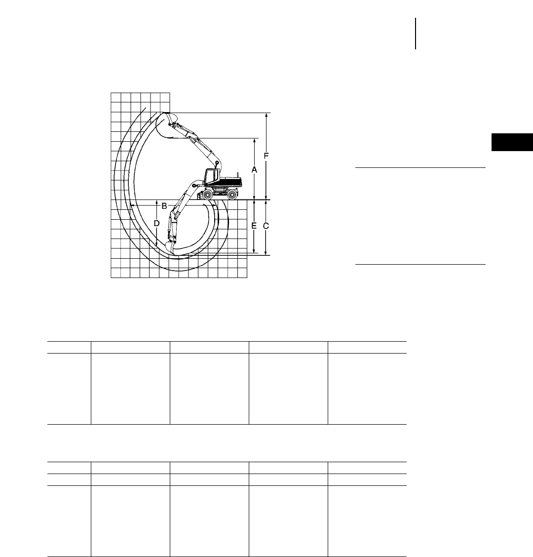
4-39
4
ExcavatorsRange Dimensions
●M318 ●M320
One-Piece Boom
Digging Envelope
●Standard 10 220 tires and
undercarriage
●General purpose bucket
KEY:
AMaximum loading height of bucket
with teeth
BMaximum reach at ground level
CMaximum digging depth
DMaximum vertical wall
EMaximum depth of cut for 2.44 m
(8'0") level bottom (straight clean up)
FMaximum height, to bucket teeth at
highest arc
M318
Stick 1.8 m 5'11" 2.4 m 7'9" 2.8 m 9'2" 4 m 13'1"
mftmftmftmft
A6.08 19'11" 6.33 20'9" 6.42 21'1" 6.73 22'1"
B8.49 27'10" 9.04 29'8" 9.38 30'9" 10.55 34'7"
C5.09 16'8" 5.69 18'8" 6.09 20'0" 7.37 24'2"
D2.93 9'7" 4.36 14'4" 4.56 15'0" 5.47 17'11"
E4.82 15'10" 5.47 17'11" 5.89 19'4" 7.22 23'8"
F8.53 28'0" 8.89 29'2" 8.95 29'4" 9.45 31'0"
M320
Stick 1.9 m 6'3" 2.5 m 8'2" 2.9 m 9'6" 4.2 m 13'9"
Bucket 1.05 m31.37 yd30.9 m31.18 yd30.81 m31.06 yd30.55 m30.72 yd3
mftmftmftmft
A6.06 19'11" 6.30 20'8" 6.21 20'4" 6.84 22'5"
B9.05 29'8" 9.61 31'6" 9.90 32'6" 11.18 36'8"
C5.19 17'0" 5.79 19'0" 6.19 20'4" 7.47 24'6"
D2.46 8'1" 3.91 12'10" 3.67 12'0" 5.34 17'6"
E4.94 16'2" 5.58 18'4" 6.00 19'8" 7.35 24'1"
F8.62 28'3" 8.97 29'5" 8.80 28'10" 9.50 31'2"
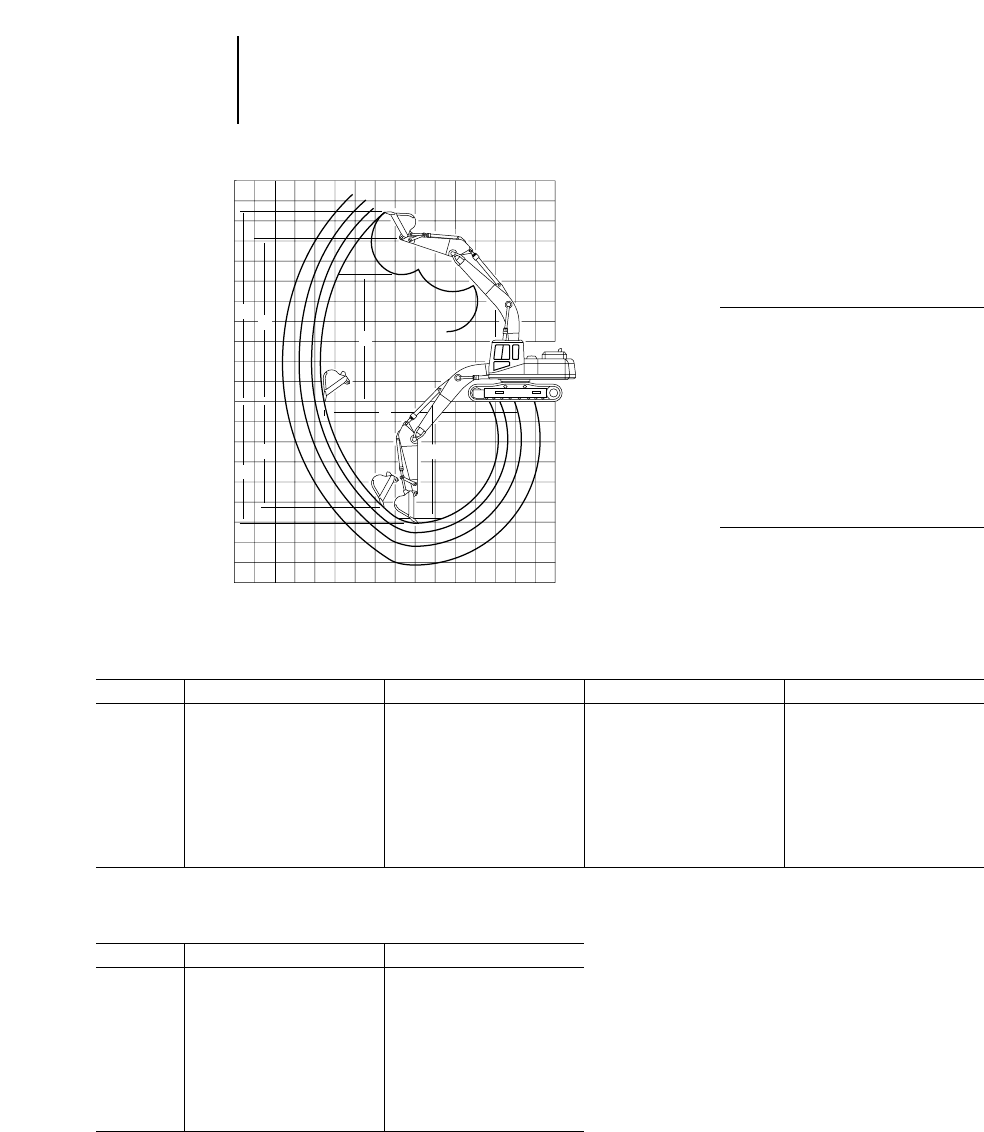
4-40
Excavators Range Dimensions
●320B ●320B L ●320B N
●Japan Sourced
320B, 320B L, 320B N with Reach Boom
Stick 3.86 m 12'8" 2.92 m 9'7" 2.5 m 8'2" 1.9 m 6'3"
mftmftmftmft
A6.93 22'9" 6.57 21'5" 6.46 21'2" 5.96 19'7"
B10.63 34'11" 9.78 32'1" 9.31 30'7" 8.76 28'9"
C7.58 24'10" 6.64 21'9" 6.15 20'2" 5.63 12'6"
D6.80 22'4" 6.04 19'10" 5.33 17'6" 4.68 15'4"
E7.25 23'9" 6.38 20'11" 5.85 19'2" 5.31 17'5"
F8.41 27'7" 8.06 26'5" 7.87 25'10" 7.45 24'5"
G9.73 31'11" 9.47 31'1" 9.16 30'1" 8.78 28'10"
One-Piece Boom
Digging Envelope
●Standard shoes and
undercarriage
KEY:
AMaximum loading height of bucket
with teeth
BMaximum reach at ground level
CMaximum digging depth
DMaximum vertical wall
EMaximum depth of cut for 2.44 m
(8'0") level bottom (straight clean up)
FMaximum bucket hinge pin height
GMaximum height, to bucket teeth at
highest arc
➤
➤
G
➤
➤
D
➤
➤
A
➤
➤
➤
➤
F
0
➤
➤
C
B
➤
➤
E
320B, 320B L, 320B N with Mass Boom
Stick 2.4 m 7'10" 1.9 m 6'3"
mftmft
A5.92 19'5" 5.69 18'8"
B8.76 28'9" 8.30 27'3"
C5.70 18'8" 5.20 17'1"
D4.91 16'1" 4.43 14'6"
E5.39 17'8" 4.88 16'0"
F7.42 24'4" 7.18 23'7"
G8.77 28'9" 8.54 28'0"
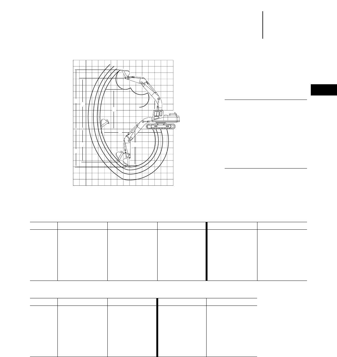
4-41
4
ExcavatorsRange Dimensions
●320B ●320B L ●320B N ●320B LN ●320B S
●Belgium Sourced
320B, 320B L, 320B N 320B, 320B L, 320B N
with Reach Boom with Mass Boom
Stick 2.92 m 9'7" 2.5 m 8'2" 1.9 m 6'3" 2.4 m 7'10" 1.9 m 6'3"
mftmftmftmftmft
A6.66 21'10" 6.46 21'2" 5.89 19'4" 5.85 19'2" 5.63 18'6"
B9.69 31'9" 9.29 30'6" 8.82 28'11" 8.82 28'11" 8.35 27'5"
C6.65 21'10" 6.14 20'2" 5.68 18'8" 5.75 18'10" 5.25 17'3"
D5.45 17'11" 5.15 16'11" 3.57 12'1" 3.87 12'8" 3.43 11'3"
E6.37 20'11" 5.94 19'6" 5.42 17'9" 8.84 29'0" 5.01 16'5"
F——————————
G9.39 30'10" 9.20 30'2" 8.76 28'9" 8.52 27'11" 8.75 28'8"
One-Piece Boom
Digging Envelope
●Standard shoes and
undercarriage
KEY:
AMaximum loading height of bucket
with teeth
BMaximum reach at ground level
CMaximum digging depth
DMaximum vertical wall
EMaximum depth of cut for 2.44 m
(8'0") level bottom (straight clean up)
FMaximum bucket hinge pin height
GMaximum height, to bucket teeth at
highest arc
➤
➤
G
➤
➤
D
➤
➤
A
➤
➤
➤
➤
F
0
➤
➤
C
B
➤
➤
E
320B, 320B L, 320B LN with VA Boom 320B S with Mass Boom
Stick 2.4 m 7'10" 1.9 m 6'3" 2.4 m 7'10" 1.9 m 6'3"
mftmftmftmft
A7.50 24'7" 7.10 23'4" 5.94 19'6" 5.70 18'8"
B9.19 30'2" 8.74 28'8" 8.80 28'10" 8.34 27'4"
C5.69 18'8" 5.19 17'0" 5.68 18'8" 5.18 17'0"
D3.95 13'0" 3.50 11'6" 3.80 12'6" 3.35 11'0"
E5.58 18'4" 5.06 16'7" 5.47 17'11" 4.93 16'2"
F————————
G8.75 28'8" 8.53 28'0" 8.83 29'0" 8.60 28'3"
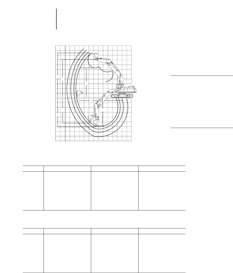
320B S with
Belgium Sourced 5.675 m (18'7") Reach Boom
Stick 2.92 m 9'7" 2.5 m 8'2" 1.9 m 6'3"
mftmftmft
A6.74 22'1" 6.54 21'2" 5.97 19'7"
B9.68 31'9" 9.28 30'5" 8.80 28'10"
C6.49 21'4" 6.06 19'7" 5.61 18'5"
D5.48 18'0" 5.08 16'8" 3.50 11'6"
E6.30 20'8" 5.86 19'3" 5.35 17'7"
F——————
G9.47 31'1" 9.28 30'5" 8.84 29'0"
4-42
Excavators Range Dimensions
●320B S ●322B ●322B L
●Belgium Sourced ●Japan/U.S. Sourced
One-Piece Boom
Digging Envelope
●Standard shoes and
undercarriage
KEY:
AMaximum loading height of bucket
with teeth
BMaximum reach at ground level
CMaximum digging depth
DMaximum vertical wall
EMaximum depth of cut for 2.44 m
(8'0") level bottom (straight clean up)
FMaximum bucket hinge pin height
GMaximum height, to bucket teeth at
highest arc
➤
➤
G
➤
➤
D
➤
➤
A
➤
➤
➤
➤
F
0
➤
➤
C
B
➤
➤
E
322B, 322B L
Japan/U.S. Sourced with Reach Boom
Stick 3.6 m 11'10" 2.95 m 9'8" 2.5 m 8'2"
mftmftmft
A7.10 23'4" 6.73 22'1" 6.54 21'5"
B10.47 34'4" 10.01 32'10" 9.59 31'6"
C7.22 23'8" 6.71 22'0" 6.26 20'6"
D6.33 20'9" 5.70 18'8" 5.26 17'3"
E6.91 22'8" 6.40 21'0" 5.95 19'6"
F8.56 28'1" 8.28 27'2" 8.08 26'6"
G9.83 32'3" 9.68 31'9" 9.48 31'1"
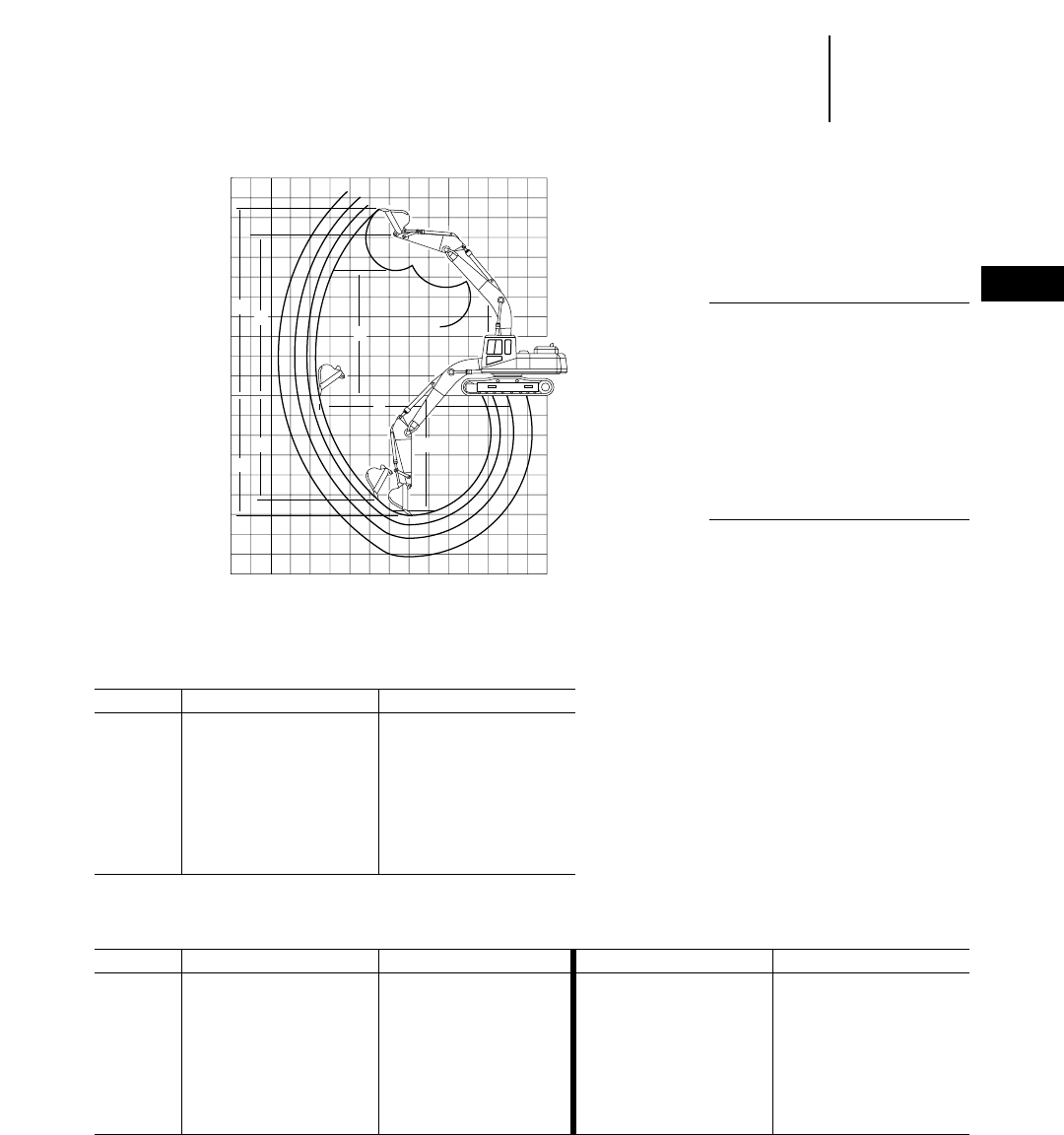
4-43
4
ExcavatorsRange Dimensions
●322B ●322B L ●322B LN
●Japan/U.S. Sourced ●Belgium Sourced
One-Piece Boom
Digging Envelope
●Standard shoes and
undercarriage
KEY:
AMaximum loading height of bucket
with teeth
BMaximum reach at ground level
CMaximum digging depth
DMaximum vertical wall
EMaximum depth of cut for 2.44 m
(8'0") level bottom (straight clean up)
FMaximum bucket hinge pin height
GMaximum height, to bucket teeth at
highest arc
➤
➤
G
➤
➤
D
➤
➤
A
➤
➤
➤
➤
F
0
➤
➤
C
B
➤
➤
E
322B, 322B L
Japan/U.S. Sourced with Mass Boom
Stick 2.5 m 8'2" 2 m 6'7"
mftmft
A5.98 19'7" 5.75 18'10"
B9.12 29'11" 8.65 28'5"
C5.91 19'5" 5.41 17'9"
D5.18 17'0" 4.70 15'5"
E5.57 18'3" 5.06 16'7"
F7.63 25'0" 7.41 24'4"
G9.16 30'1" 8.93 29'4"
322B L, 322B LN with 322B L, 322B LN with
Belgium Sourced 5.9 m (19'4") Reach Boom 5.3 m (17'5") Mass Boom
Stick 2.95 m 9'8" 2.5 m 8'2" 2.5 m 8'2" 2 m 6'7"
mftmftmftmft
A6.75 22'2" 6.55 21'6" 5.96 19'7" 5.74 18'10"
B10.00 32'10" 9.59 31'6" 9.12 29'11" 8.65 28'5"
C6.69 21'11" 6.24 20'6" 5.92 19'5" 5.42 17'9"
D4.43 14'6" 4.02 13'2" 4.09 13'5" 3.65 12'0"
E6.50 21'4" 6.03 19'9" 5.72 18'9" 5.19 17'0"
F————————
G9.62 31'7" 9.42 30'11" 9.08 29'9" 8.86 29'1"
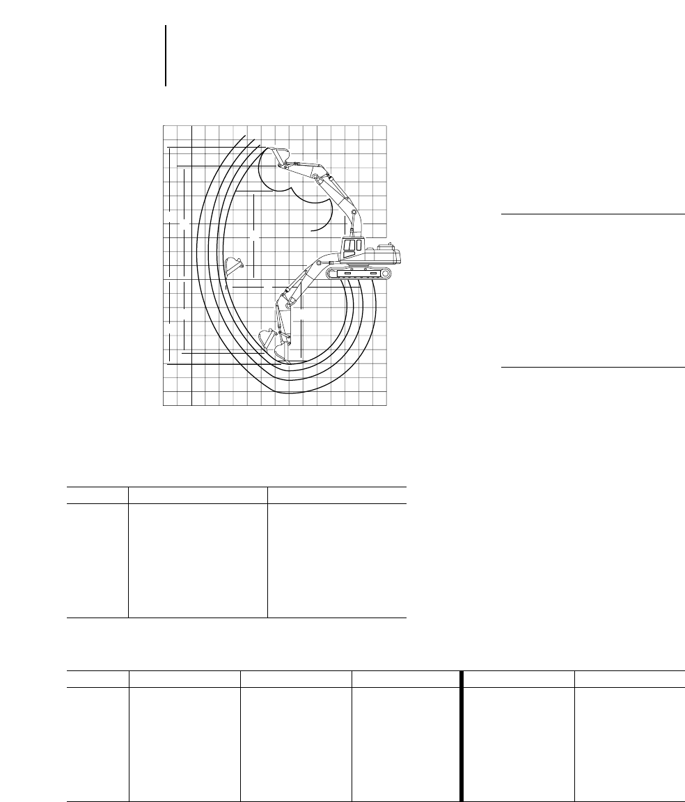
4-44
Excavators Range Dimensions
●322B L ●322B LN ●325B ●325B L
●Belgium Sourced ●Japan/U.S. Sourced
One-Piece Boom
Digging Envelope
●Standard shoes and
undercarriage
KEY:
AMaximum loading height of bucket
with teeth
BMaximum reach at ground level
CMaximum digging depth
DMaximum vertical wall
EMaximum depth of cut for 2.44 m
(8'0") level bottom (straight clean up)
FMaximum bucket hinge pin height
GMaximum height, to bucket teeth at
highest arc
➤
➤
G
➤
➤
D
➤
➤
A
➤
➤
➤
➤
F
0
➤
➤
C
B
➤
➤
E
322B L, 322B LN with
Belgium Sourced 5.66 m (18'7") VA Boom
Stick 2.5 m 8'2" 2 m 6'7"
mftmft
A7.81 25'7" 7.40 24'3"
B9.60 31'6" 9.13 29'11"
C5.89 19'4" 5.40 17'9"
D4.20 13'9" 3.74 12'3"
E5.78 19'0" 5.28 17'4"
F————
G11.10 36'5" 10.69 35'1"
325B, 325B L 325B, 325B L
Japan/U.S. Sourced with Reach Boom with Mass Boom
Stick 3.2 m 10'6" 2.65 m 8'8" 2 m 6'7" 2.5 m 8'2" 2 m 6'7"
mftmftmftmftmft
A7.11 23'4" 6.90 22'8" 6.31 20'8" 6.10 20'0" 5.89 19'4"
B10.52 34'6" 10.01 32'10" 9.52 31'3" 9.35 30'8" 8.89 29'2"
C7.09 23'3" 6.54 21'5" 6.06 19'11" 6.01 19'9" 5.51 18'1"
D6.38 20'11" 5.86 19'3" 5.27 17'3" 5.21 17'1" 4.05 13'3"
E6.92 22'8" 6.35 20'10" 5.83 19'2" 5.81 19'1" 5.28 17'4"
F8.60 28'3" 8.38 27'6" 7.97 26'2" 7.76 25'6" 7.55 24'9"
G9.96 32'8" 9.75 32'0" 9.46 31'0" 9.24 30'4" 8.93 29'4"
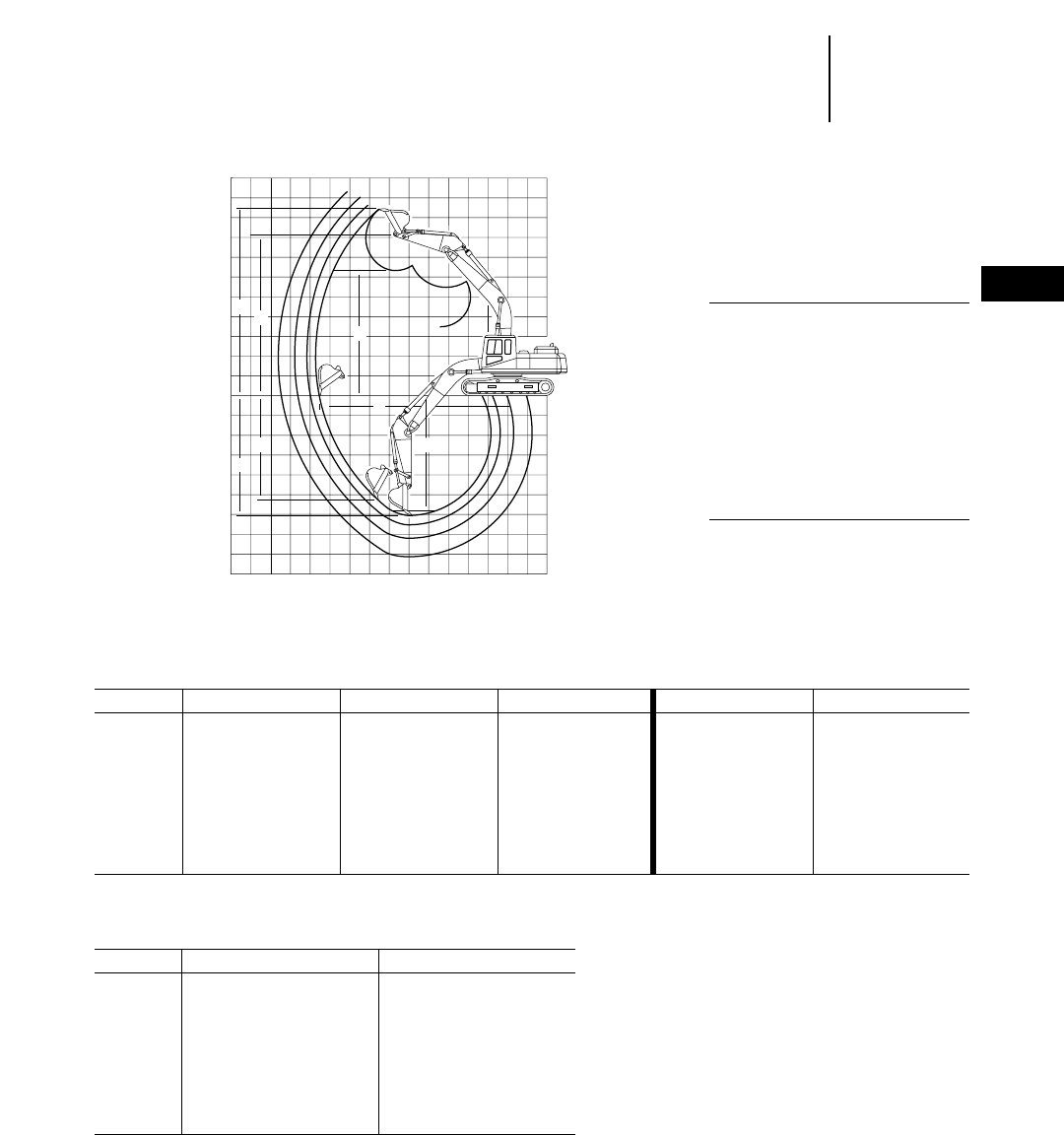
4-45
4
ExcavatorsRange Dimensions
●325B L ●325B LN
●Belgium Sourced
One-Piece Boom
Digging Envelope
●Standard shoes and
undercarriage
KEY:
AMaximum loading height of bucket
with teeth
BMaximum reach at ground level
CMaximum digging depth
DMaximum vertical wall
EMaximum depth of cut for 2.44 m
(8'0") level bottom (straight clean up)
FMaximum bucket hinge pin height
GMaximum height, to bucket teeth at
highest arc
➤
➤
G
➤
➤
D
➤
➤
A
➤
➤
➤
➤
F
0
➤
➤
C
B
➤
➤
E
325B L, 325B LN with 325B L, 325B LN with
6.15 m (20'2") Reach Boom 5.55 m (18'3") Mass Boom
Stick 3.2 m 10'6" 2.65 m 8'8" 2 m 6'7" 2.5 m 8'2" 2 m 6'7"
mftmftmftmftmft
A7.05 23'2" 6.84 22'5" 6.31 20'8" 6.09 20'0" 5.89 19'4"
B10.57 34'8" 10.07 33'0" 9.53 31'3" 9.35 30'8" 8.89 29'2"
C7.15 23'5" 6.59 21'7" 6.06 19'11" 6.02 19'9" 5.52 18'1"
D5.18 17'0" 4.78 15'8" 4.13 13'7" 4.11 15'6" 3.65 12'0"
E6.98 22'11" 6.40 21'1" 5.83 19'2" 5.82 19'1" 5.29 17'4"
F——————————
G9.95 32'8" 9.75 32'0" 9.39 30'10" 9.17 30'1" 8.97 29'5"
325B L, 325B LN with
5.66 m (18'7") VA Boom
Stick 2.5 m 8'2" 2 m 6'7"
mftmft
A7.89 25'11" 7.51 24'8"
B9.75 32'0" 9.28 30'5"
C5.89 19'4" 5.40 17'9"
D4.13 13'7" 3.67 12'0"
E5.78 19'0" 5.28 17'4"
F————
G11.21 36'9" 10.83 35'6"
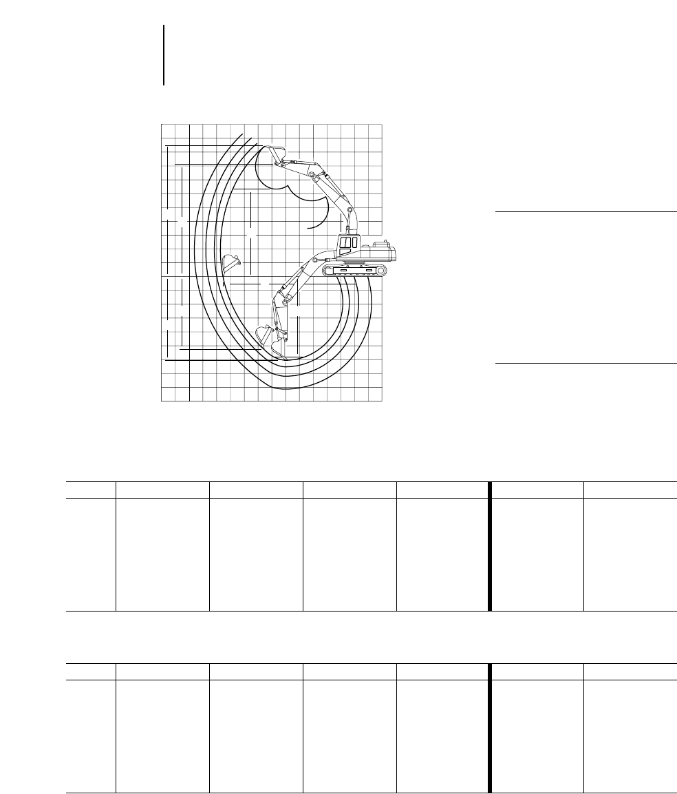
4-46
Excavators Range Dimensions
●330B ●330B L ●330B LN
●Japan/U.S. Sourced ●Belgium Sourced
One-Piece Boom
Digging Envelope
●Standard shoes and
undercarriage
KEY:
AMaximum loading height of bucket
with teeth
BMaximum reach at ground level
CMaximum digging depth
DMaximum vertical wall
EMaximum depth of cut for 2.44 m
(8'0") level bottom (straight clean up)
FMaximum bucket hinge pin height
GMaximum height, to bucket teeth at
highest arc
➤
➤
G
➤
➤
D
➤
➤
A
➤
➤
➤
➤
F
0
➤
➤
C
B
➤
➤
E
330B, 330B L 330B, 330B L
Japan/U.S. Sourced with Reach Boom with Mass Boom
Stick 3.99 m 12'10" 3.3 m 10'10" 2.8 m 9'2" 2.15 m 7'1" 2.55 m 8'4" 2.15 m 7'1"
mft mft mft mft mft mft
A7.60 24'11" 7.29 23'11" 7.12 23'4" 6.50 21'4" 6.68 21'11" 6.25 20'6"
B11.62 38'1" 11.03 36'2" 10.58 34'9" 10.09 33'1" 10.21 33'6" 9.71 31'10"
C8.08 26'6" 7.49 24'7" 6.99 22'11" 6.52 21'5" 6.59 21'7" 6.19 20'4"
D7.23 23'9" 6.54 22'5" 6.12 20'1" 5.14 16'10" 5.89 19'4" 4.75 15'7"
E7.75 25'5" 7.15 23'5" 6.65 21'10" 6.13 20'1" 6.20 20'4" 5.80 19'0"
F9.29 30'6" 8.98 29'5" 8.80 28'10" 8.37 27'6" 8.54 27'9" 8.12 26'8"
G10.77 35'4" 10.44 34'3" 10.27 33'8" 9.90 32'6" 10.17 33'4" 9.65 31'8"
330B L, 330B LN 330B L, 330B LN
Belgium Sourced with Reach Boom with Mass Boom
Stick 3.9 m 12'10" 3.3 m 10'10" 2.8 m 9'2" 2.2 m 7'3" 2.6 m 8'6" 2.2 m 7'3"
mft mft mft mft mft mft
A7.63 25'0" 7.31 24'0" 7.13 23'5" 6.59 21'7" 6.76 22'2" 6.34 20'10"
B11.62 38'1" 11.03 36'2" 10.57 34'8" 10.01 32'10" 10.14 33'3" 9.64 31'8"
C8.06 25'7" 7.46 24'6" 6.96 22'10" 6.42 21'1" 6.50 21'4" 6.10 20'0"
D6.02 19'9" 5.36 17'7" 4.98 16'4" 4.82 15'10" 5.38 17'8" 4.38 14'4"
E7.96 26'1" 7.32 24'0" 6.77 22'3" 6.19 20'3" 6.32 20'9" 5.86 19'3"
F————————————
G10.73 35'2" 10.40 34'1" 10.23 33'7" 9.91 32'6" 10.17 33'4" 9.64 31'8"
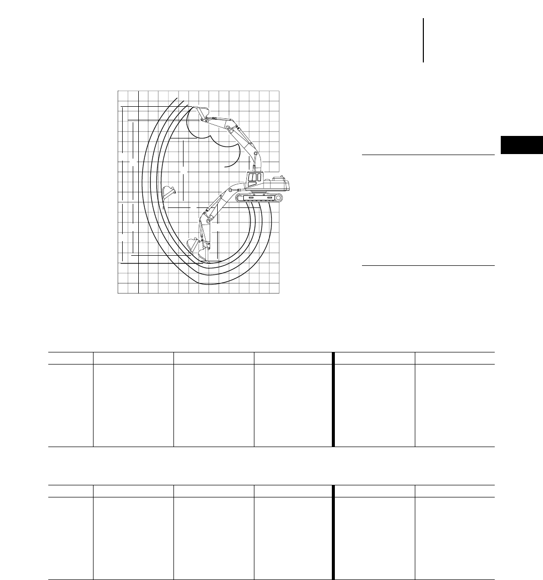
4-47
4
ExcavatorsRange Dimensions
●345B — Japan Sourced
●345B L – FIX — Japan/U.S. Sourced
One-Piece Boom
Digging Envelope
●Standard shoes and
undercarriage
KEY:
AMaximum loading height of bucket
with teeth
BMaximum reach at ground level
CMaximum digging depth
DMaximum vertical wall
EMaximum depth of cut for 2.44 m
(8'0") level bottom (straight clean up)
FMaximum bucket hinge pin height
GMaximum height, to bucket teeth at
highest arc
➤
➤
G
➤
➤
D
➤
➤
A
➤
➤
➤
➤
F
0
➤
➤
C
B
➤
➤
E
Japan Sourced 345B with Reach Boom 345B with Mass Boom
Stick 3.9 m 12'10" 3.35 m 11'0" 2.9 m 9'6" 3 m 9'11" 2.5 m 8'2"
mftmftmftmftmft
A2.12 6'11" 2.78 9'1" 3.18 10'5" 2.79 9'2" 3.19 10'6"
B12.20 40'1" 11.66 38'3" 11.29 37'0" 11.02 36'2" 10.66 35'0"
C8.28 27'2" 7.63 25'0" 7.23 23'9" 7.08 23'2" 6.68 21'11"
D6.52 21'5" 6.56 21'6" 5.73 18'10" 5.63 18'6" 4.99 16'4"
E7.88 25'10" 7.22 23'8" 6.83 22'5" 6.63 21'9" 6.25 20'6"
F9.28 30'5" 9.24 30'4" 9.07 29'9" 8.81 28'11" 8.62 28'3"
G10.82 35'6" 10.78 35'4" 10.60 34'9" 10.27 33'8" 10.16 33'4"
345B L – FIX 345B L – FIX
Japan/U.S. Sourced with Reach Boom with Mass Boom
Stick 3.9 m 12'10" 3.35 m 11'0" 2.9 m 9'6" 3 m 9'11" 2.5 m 8'2"
mftmftmftmftmft
A7.35 24'1" 7.37 24'2" 7.20 23'7" 6.95 22'10" 6.66 21'10"
B12.20 40'0" 11.71 38'5" 11.29 37'0" 11.02 36'2" 10.66 35'0"
C8.28 27'2" 7.68 25'2" 7.23 23'9" 7.08 23'3" 6.68 21'11"
D6.52 21'5" 6.18 20'3" 5.73 18'10" 5.63 18'6" 4.99 16'4"
E7.88 25'10" 7.28 23'11" 6.83 22'5" 6.63 21'9" 6.25 20'6"
F9.28 30'5" 9.24 30'4" 9.07 29'9" 8.81 28'11" 8.62 28'3"
G10.82 35'6" 10.78 35'4" 10.60 34'9" 10.27 33'8" 10.16 33'4"
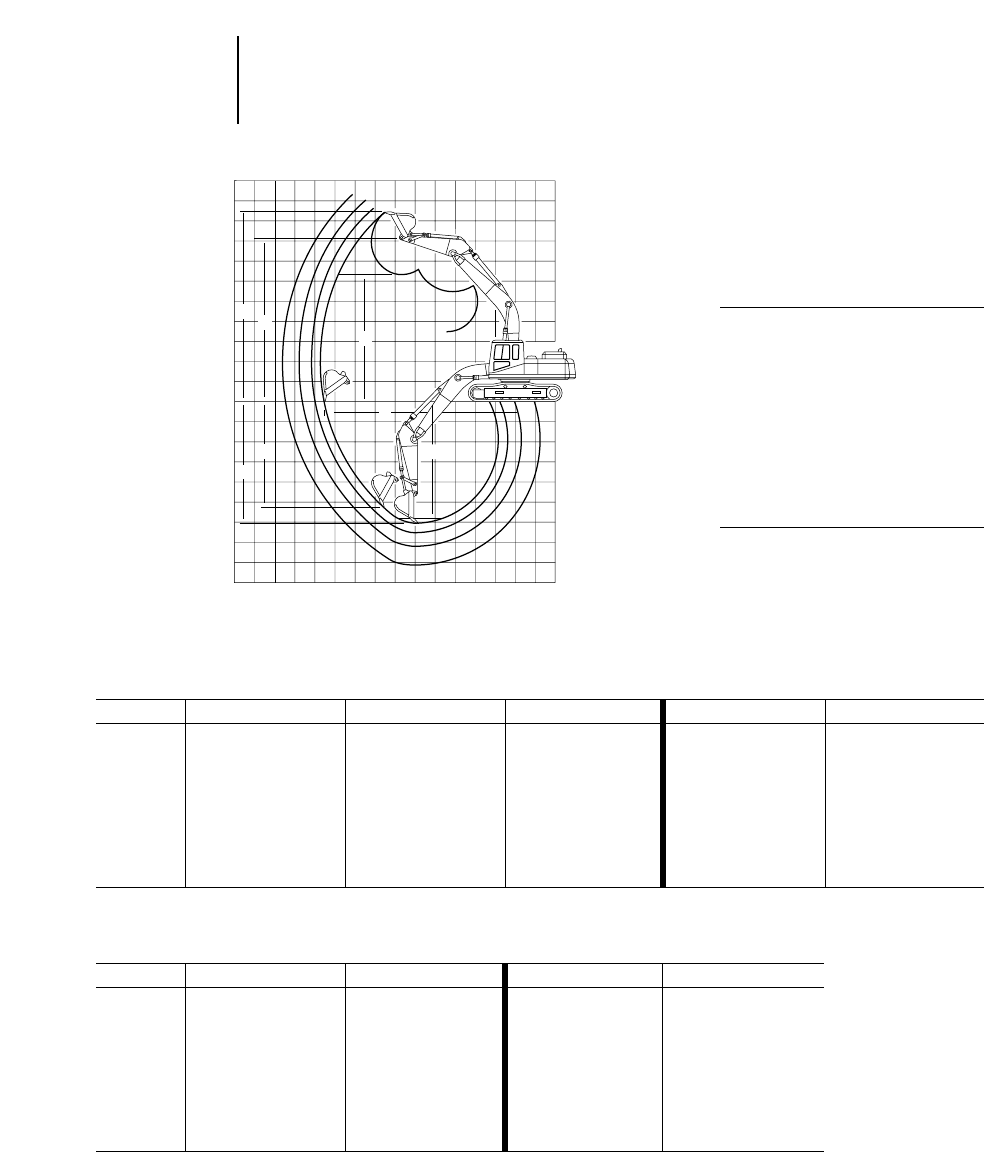
4-48
Excavators Range Dimensions
●345B L – VG ●345B – VG
●U.S. Sourced ●Belgium Sourced
345B L – VG 345B L – VG
U.S. Sourced with Reach Boom with Mass Boom
Stick 3.9 m 12'10" 3.35 m 11'0" 2.9 m 9'6" 3 m 9'11" 2.5 m 8'2"
mftmftmftmftmft
A7.51 24'8" 7.54 24'9" 7.36 24'2" 7.01 23'0" 6.82 22'5"
B12.17 39'11" 11.68 38'4" 11.26 36'11" 11.09 36'5" 11.62 38'1"
C8.12 26'8" 7.51 24'8" 7.06 23'2" 7.02 23'0" 6.52 21'5"
D6.36 20'10" 6.02 19'9" 5.56 18'3" 5.29 17'4" 4.07 13'4"
E7.72 25'4" 7.12 23'4" 6.67 21'11" 6.59 21'7" 6.09 20'0"
F9.44 31'0" 9.41 30'10" 9.23 30'3" 8.97 29'5" 8.78 28'10"
G10.98 36'0" 10.94 35'11" 10.76 35'4" 10.51 34'6" 10.18 33'5"
345B – VG 345B – VG
Belgium Sourced with Reach Boom with Mass Boom
Stick 3.35 m 11'0" 2.9 m 9'6" 3 m 9'11" 2.5 m 8'2"
mftmftmftmft
A7.54 24'9" 7.37 24'2" 6.98 22'11" 6.79 22'3"
B11.67 38'3" 11.25 36'11" 11.12 36'6" 10.66 35'0"
C7.50 24'7" 7.05 23'2" 7.05 23'2" 6.55 21'6"
D6.15 20'2" 5.70 18'8" 4.95 16'3" 4.52 14'10"
E7.34 24'1" 6.89 22'7" 6.90 22'8" 6.37 20'11"
F————————
G11.04 36'3" 10.87 35'8" 10.51 34'6" 10.18 33'5"
One-Piece Boom
Digging Envelope
●Standard shoes and
undercarriage
KEY:
AMaximum loading height of bucket
with teeth
BMaximum reach at ground level
CMaximum digging depth
DMaximum vertical wall
EMaximum depth of cut for 2.44 m
(8'0") level bottom (straight clean up)
FMaximum bucket hinge pin height
GMaximum height, to bucket teeth at
highest arc
➤
➤
G
➤
➤
D
➤
➤
A
➤
➤
➤
➤
F
0
➤
➤
C
B
➤
➤
E
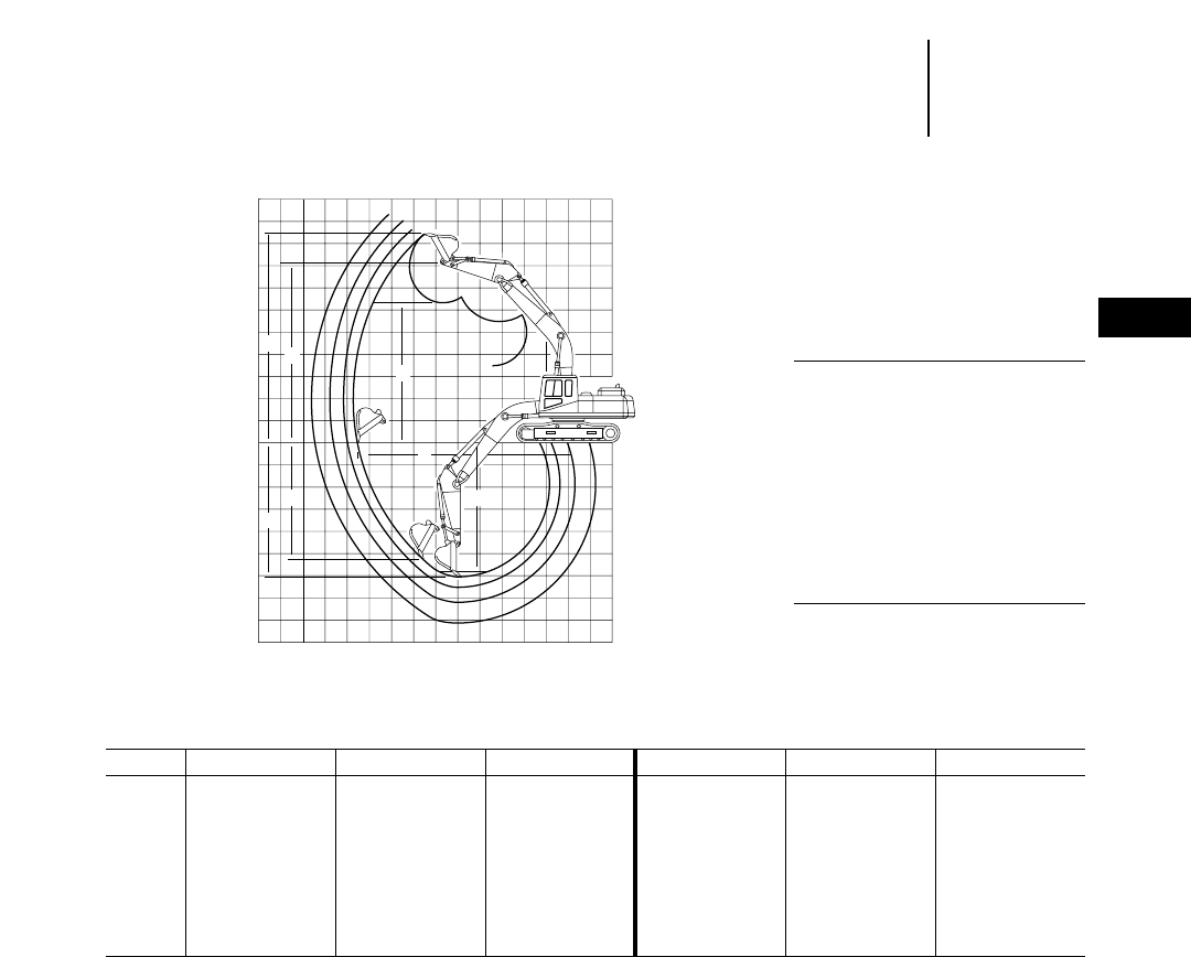
4-49
4
ExcavatorsRange Dimensions
●350 ●350 L
●Japan Sourced
350, 350 L with Reach Boom 350, 350 L with Mass Boom
Stick 4.8 m 15'9" 3.6 m 11'10" 3.1 m 10'2" 3.7 m 12'2" 2.95 m 9'8" 2.4 m 7'10"
mft mft mft mft mft mft
A8.45 27'9" 7.99 26'3" 7.85 25'9" 7.96 26'1" 7.40 24'3" 7.06 23'2"
B13.45 44'2" 12.33 40'5" 11.81 38'9" 11.93 39'2" 11.25 36'11" 10.68 35'0"
C9.57 31'5" 8.37 27'6" 7.82 25'8" 7.96 26'1" 7.30 23'11" 6.75 22'2"
D8.20 26'11" 7.11 23'4" 6.67 21'11" 6.99 22'11" 6.19 20'4" 5.42 17'9"
E9.18 30'1" 7.98 26'2" 7.42 24'4" 7.57 24'10" 6.87 22'6" 6.32 20'9"
F10.38 34'1" 9.92 32'7" 9.72 31'11" 9.83 32'3" 9.35 30'8" 9.01 29'7"
G12.07 39'7" 11.62 38'1" 11.38 37'4" 11.52 37'10" 11.08 36'4" 10.70 35'1"
One-Piece Boom
Digging Envelope
●Standard shoes and
undercarriage
●Lug height not included
KEY:
AMaximum loading height of bucket
with teeth
BMaximum reach at ground level
CMaximum digging depth
DMaximum vertical wall
EMaximum depth of cut for 2.44 m
(8'0") level bottom (straight clean up)
FMaximum bucket hinge pin height
GMaximum height, to bucket teeth at
highest arc
➤
➤
G
➤
➤
D
➤
➤
A
➤
➤
➤
➤
F
0
➤
➤
C
B
➤
➤
E
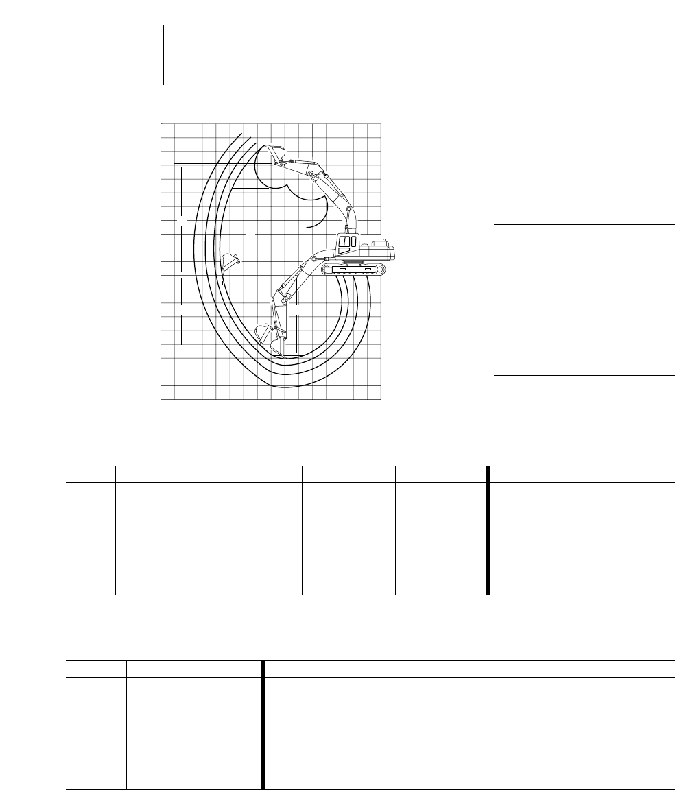
4-50
Excavators Range Dimensions
●375 ●375 L
●Japan/U.S. Sourced
375, 375 L with Reach Boom 375, 375 L with GP Boom
Stick 5.5 m 18'1" 4.4 m 14'5" 3.4 m 11'2" 2.9 m 9'6" 5.5 m 18'1" 4.4 m 14'5"
mft mft mft mft mft mft
A10.35 33'11" 9.66 31'8" 9.44 31'0" 9.28 30'5" 10.31 33'10" 9.55 31'4"
B15.96 52'4" 14.66 48'1" 14.02 46'0" 13.59 44'7" 15.67 51'5" 14.37 47'2"
C10.84 35'7" 9.63 31'7" 8.77 28'9" 8.29 27'2" 10.58 34'9" 9.37 30'9"
D9.81 32'2" 8.26 27'1" 7.70 25'3" 7.32 24'0" 9.55 31'4" 8.39 27'6"
E10.36 34'0" 9.16 30'1" 8.24 27'0" 7.77 25'6" 10.09 33'1" 8.90 29'2"
F12.56 41'2" 11.76 38'7" 11.68 38'4" 11.51 37'9" 12.52 41'1" 11.65 38'3"
G14.50 47'2" 13.52 44'4" 13.58 44'7" 13.43 44'1" 14.52 47'8" 13.48 44'3"
One-Piece Boom
Digging Envelope
●Standard shoes and
undercarriage
●Lug height not included
KEY:
AMaximum loading height of bucket
with teeth
BMaximum reach at ground level
CMaximum digging depth
DMaximum vertical wall
EMaximum depth of cut for 2.44 m
(8'0") level bottom (straight clean up)
FMaximum bucket hinge pin height
GMaximum height, to bucket teeth at
highest arc
➤
➤
G
➤
➤
D
➤
➤
A
➤
➤
➤
➤
F
0
➤
➤
C
B
➤
➤
E
375, 375 L
with GP Boom 375, 375 L with Mass Boom
Stick 3.4 m 11'2" 4.1 m 13'5" 3.4 m 11'2" 2.9 m 9'6"
mftmftmftmft
A9.27 30'5" 8.76 28'9" 8.43 27'8" 8.26 27'1"
B13.69 44'11" 13.08 42'11" 12.42 40'9" 12.00 39'4"
C8.50 27'11" 8.11 26'7" 7.41 24'4" 6.94 22'9"
D7.55 24'9" 7.13 23'5" 6.46 21'2" 5.52 18'1"
E7.98 26'2" 7.59 24'11" 6.89 22'7" 6.41 21'1"
F11.51 37'9" 11.00 36'1" 10.67 35'8" 10.49 34'5"
G13.48 44'3" 12.95 42'6" 12.61 41'4" 12.34 40'6"
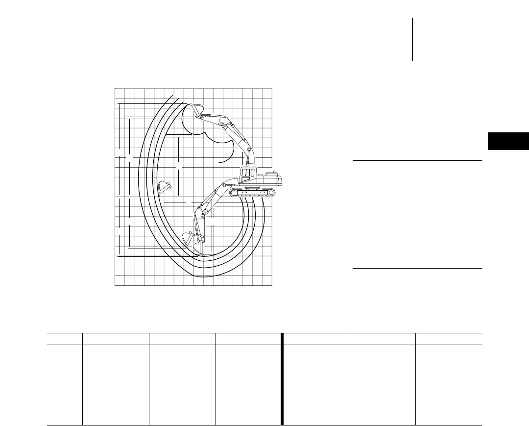
4-51
4
ExcavatorsRange Dimensions
●375 ●375 L
●Belgium Sourced
375, 375 L with GP Boom 375, 375 L with Mass Boom
Stick 5.5 m 18'1" 4.4 m 14'5" 3.4 m 11'2" 4.1 m 13'5" 3.4 m 11'2" 2.9 m 9'6"
mft mft mft mft mft mft
A10.31 33'10" 9.55 31'4" 9.27 30'5" 8.76 28'8" 8.43 27'8" 8.26 27'1"
B15.67 51'5" 14.37 47'1" 13.69 44'11" 13.08 42'11" 12.42 40'8" 12.00 39'5"
C10.58 34'8" 9.37 30'8" 8.50 27'11" 8.11 26'7" 7.41 24'4" 6.94 22'10"
D9.55 31'4" 8.39 27'6" 7.55 24'10" 7.13 23'5" 6.46 21'2" 5.52 18'1"
E10.09 33'1" 8.90 29'2" 7.98 26'2" 7.59 24'11" 6.89 22'7" 6.41 21'0"
F12.52 41'1" 11.65 38'2" 11.51 37'10" 11.00 36'1" 10.67 35'0" 10.49 34'5"
G14.52 47'7" 13.48 44'2" 13.48 44'2" 12.95 42'6" 12.61 41'5" 12.34 40'6"
One-Piece Boom
Digging Envelope
●Standard shoes and
undercarriage
●Lug height not included
KEY:
AMaximum loading height of bucket
with teeth
BMaximum reach at ground level
CMaximum digging depth
DMaximum vertical wall
EMaximum depth of cut for 2.44 m
(8'0") level bottom (straight clean up)
FMaximum bucket hinge pin height
GMaximum height, to bucket teeth at
highest arc
➤
➤
G
➤
➤
D
➤
➤
A
➤
➤
➤
➤
F
0
➤
➤
C
B
➤
➤
E
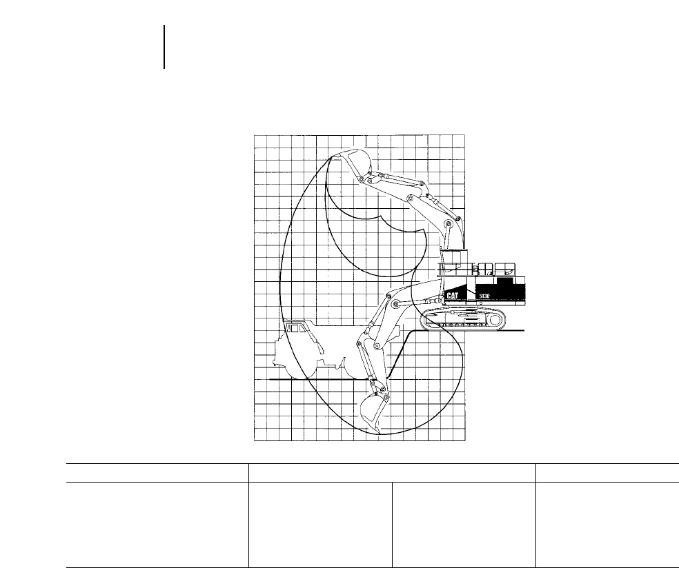
4-52
Excavators Range Dimensions
●5130B ME ●5230 ME
MODEL 5130B ME 5230 ME
mftmftmft
Boom 8.0 26'3" 8.0 26'3" —
Stick 3.8 12'5" 5.2 17'1" —
Max. Loading Height 9.1 29'8" 9.7 31'8" 9.8 32'2"
Max. Reach 14.9 48'11" 16.1 52'8" 17.7 58'0"
Max. Digging Depth 8.4 27'7" 9.7 31'8" 9.4 30'11"
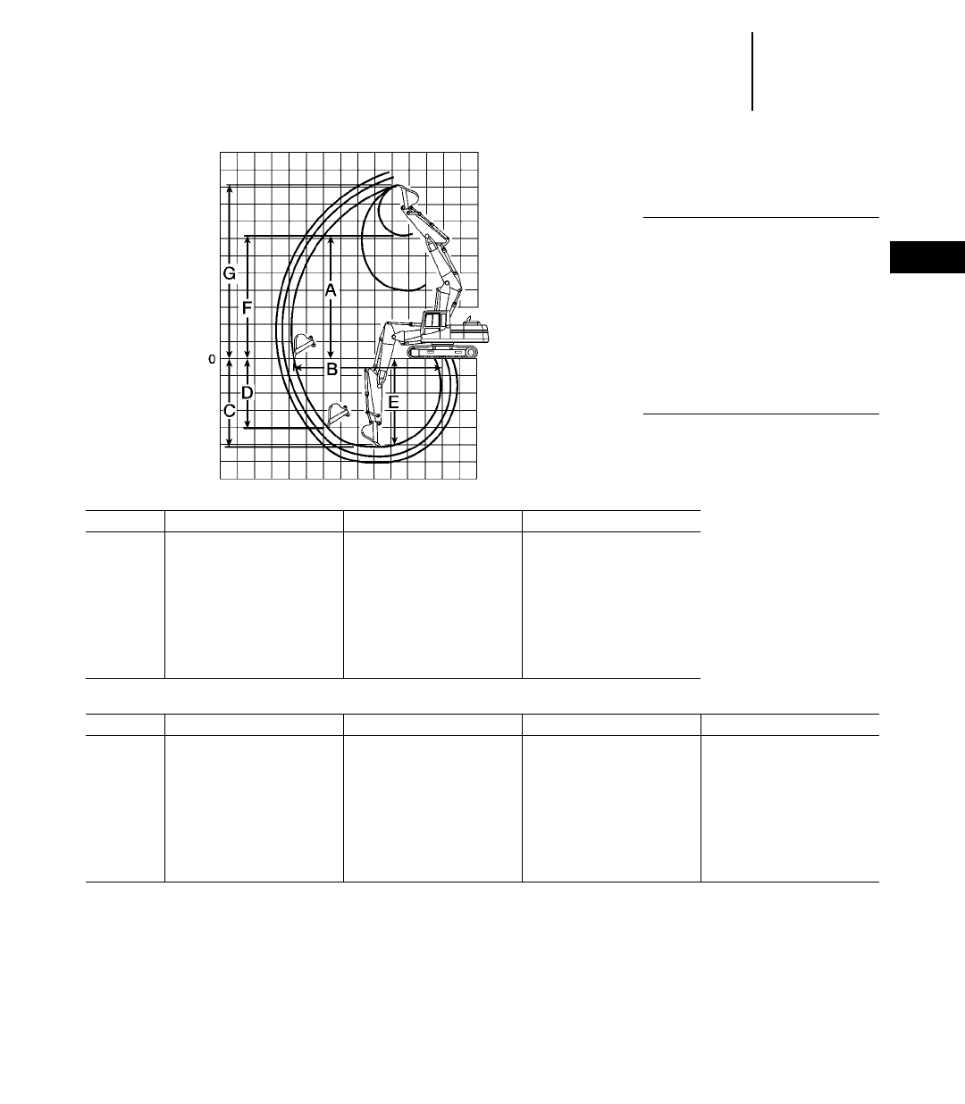
4-53
4
ExcavatorsRange Dimensions
●312B L ●315B L
●France Sourced
Variable Adjustable Boom
Digging Envelope
KEY:
AMaximum loading height of bucket
with teeth
BMaximum reach at ground level
CMaximum digging depth
DMaximum vertical wall
EMaximum depth of cut for 2.44 m
(8'0") level bottom (straight clean up)
FMaximum bucket hinge pin height
GMaximum height, to bucket teeth at
highest arc
312B L
Stick 3 m 9'10" 2.5 m 8'2" 2.1 m 6'11"
mftmftmft
A7.57 24'10" 7.18 23'7" 6.82 22'5"
B8.80 28'10" 8.34 27'4" 7.96 26'1"
C5.73 18'10" 5.24 17'2" 4.84 15'11"
D3.63 11'11" 3.18 10'5" 2.88 9'5"
E5.61 18'5" 5.12 16'9" 4.71 15'5"
F8.81 28'11" 8.41 27'7" 8.05 26'5"
G10.04 32'11" 9.64 31'7" 9.28 30'5"
315B L
Stick 3.1 m 10'2" 2.6 m 8'6" 2.25 m 7'5" 1.85 m 6'1"
mftmftmftmft
A7.75 25'5" 7.71 25'3" 7.24 23'9" 7.11 23'4"
B8.92 29'3" 8.61 28'3" 8.20 26'11" 7.90 25'11"
C3.15 10'4" 2.23 7'4" 2.72 8'11" 2.14 7'0"
D4.18 13'8" 3.71 12'2" 3.35 11'0" 2.97 9'9"
E5.68 18'7" 5.26 17'3" 4.87 16'0" 4.51 14'9"
F8.95 29'4" 8.82 28'11" 8.41 27'7" 8.21 26'11"
G10.16 33'4" 9.99 32'9" 9.62 31'7" 9.38 30'9"
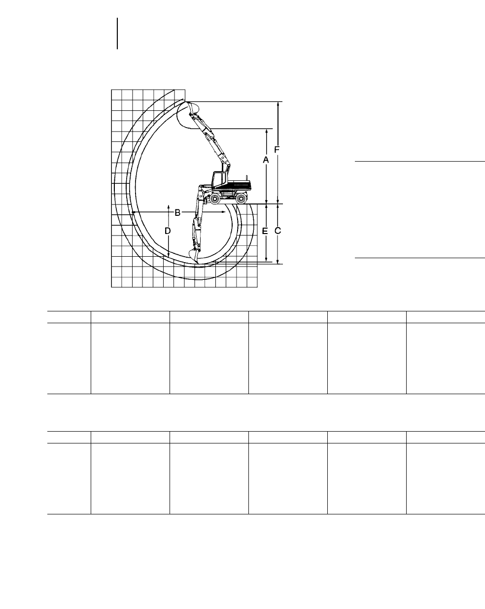
4-54
Excavators Range Dimensions
●M312 ●M315
Hydraulic Adjustable Boom
Digging Envelope
●Standard 10 220 tires and
undercarriage
●General purpose bucket
KEY:
AMaximum loading height of bucket
with teeth
BMaximum reach at ground level
CMaximum digging depth
DMaximum vertical wall
EMaximum depth of cut for 2.44 m
(8'0") level bottom
FMaximum height, to bucket teeth at
highest arc
M312
Stick 1.6 m 5'3" 2 m 6'6" 2.3 m 7'5" 2.6 m 8'5" 3 m 9'9"
mftmftmftmftmft
A6.76 22'2" 7.05 23'1" 7.29 23'9" 7.54 24'7" 7.70 25'3"
B7.90 25'9" 8.30 27'2" 8.59 28'2" 8.89 29'2" 9.22 30'3"
C4.62 15'2" 5.02 16'5" 5.32 17'5" 5.62 18'4" 6.00 19'7"
D2.85 9'3" 3.84 12'6" 4.11 13'5" 4.39 14'4" 4.62 15'2"
E4.49 14'7" 4.90 16'1" 5.21 17'1" 5.51 18'1" 5.90 19'4"
F9.13 29'10" 9.49 31'3" 9.73 31'9" 9.97 32'7" 10.13 33'2"
M315
Stick 1.7 m 5'7" 2.1 m 6'9" 2.4 m 7'9" 2.6 m 8'5" 3.1 m 10'1"
mftmftmftmftmft
A7.03 23'1" 7.32 24'0" 7.56 24'10" 7.72 25'4" 8.04 26'5"
B8.19 26'10" 8.59 28'2" 8.80 28'10" 9.08 29'9" 9.53 31'3"
C4.80 13'5" 5.28 17'4" 5.58 18'4" 5.78 19'0" 6.27 20'7"
D2.96 9'9" 4.05 13'3" 4.34 14'3" 4.53 14'10" 4.91 16'1"
E4.77 15'8" 5.17 17'0" 5.48 18'0" 5.68 18'8" 6.17 20'3"
F9.40 30'10" 9.76 32'0" 10.00 32'10" 10.16 33.4" 10.47 34'4"
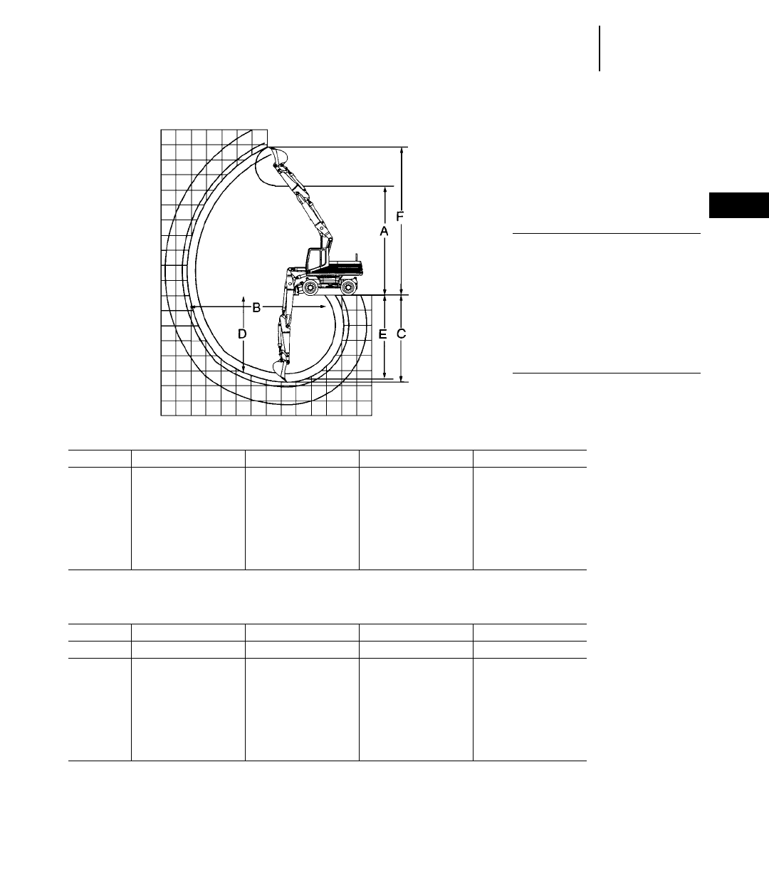
4-55
4
ExcavatorsRange Dimensions
●M318 ●M320
Hydraulic Adjustable Boom
Digging Envelope
●Standard 10 220 tires and
undercarriage
●General purpose bucket
KEY:
AMaximum loading height of bucket
with teeth
BMaximum reach at ground level
CMaximum digging depth
DMaximum vertical wall
EMaximum depth of cut for 2.44 m
(8'0") level bottom
FMaximum height, to bucket teeth at
highest arc
M318
Stick 1.8 m 5'11" 2.4 m 7'9" 2.8 m 9'2" 4 m 13'1"
mftmftmftmft
A6.78 22'3" 7.18 23'7" 7.38 24'3" 7.99 26'3"
B8.43 27'8" 9.00 29'6" 9.35 30'8" 10.55 34'7"
C5.20 17'1" 5.79 19'0" 6.18 20'3" 7.44 24'5"
D3.17 10'5" 4.43 14'6" 4.73 15'6" 5.72 18'9"
E5.08 16'8" 5.69 18'8" 6.15 20'2" 7.14 23'5"
F9.38 30'9" 9.84 32'3" 10.02 32'10" 10.79 35'5"
M320
Stick 1.9 m 6'3" 2.5 m 8'2" 2.9 m 9'6" 4.2 m 13'9"
Bucket 1.05 m31.37 yd30.9 m31.18 yd30.81 m31.06 yd30.55 m30.72 yd3
mftmftmftmft
A6.66 21'10" 7.04 23'1" 7.10 23'4" 7.90 25'11"
B8.82 28'11" 9.38 30'9" 9.67 31'9" 10.96 35'11"
C5.42 17'9" 6.01 19'9" 6.38 20'11" 7.68 25'2"
D2.46 8'1" 3.85 12'8" 3.64 11'11" 5.28 17'4"
E5.00 16'5" 5.62 18'5" 6.00 19'8" 7.36 24'2"
F9.37 30'9" 9.79 32'1" 9.74 31'11" 10.63 34'11"
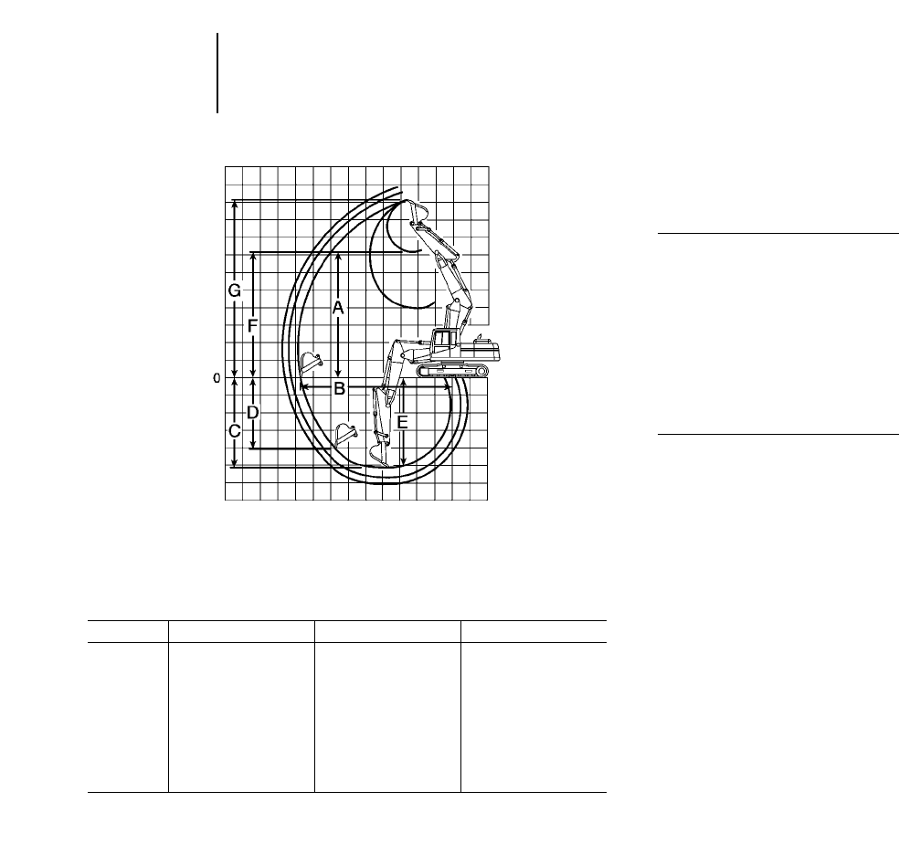
4-56
Excavators Range Dimensions
●320B ●320B L ●320B N ●320B LN
●Belgium Sourced
Variable Adjustable Boom
Digging Envelope
KEY:
AMaximum loading height of bucket
with teeth
BMaximum reach at ground level
CMaximum digging depth
DMaximum vertical wall
EMaximum depth of cut for 2.44 m
(8'0") level bottom (straight clean up)
FMaximum bucket hinge pin height
GMaximum height, to bucket teeth at
highest arc
320B, 320B L, 320B N, 320B LN
Stick 2.92 m 9'7" 2.4 m 7'10" 1.9 m 6'3"
mftmftmft
A8.07 26'6" 7.50 24'7" 7.16 23'6"
B9.55 31'4" 9.19 30'2" 8.65 28'5"
C6.06 19'11" 5.69 18'8" 5.14 16'11"
D5.03 16'6" 4.58 15'0" 4.07 13'5"
E5.95 19'6" 5.58 18'4" 5.01 16'5"
F9.48 31'1" 9.05 29'8" 8.65 28'5"
G10.88 35'8" 10.59 34'8" 10.13 33'2"
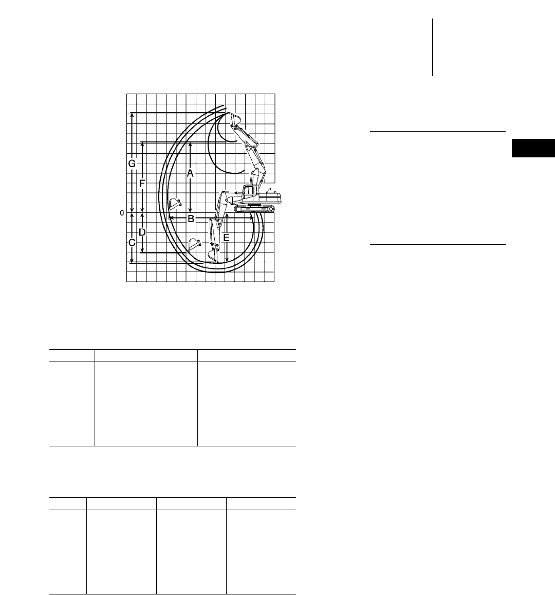
4-57
4
ExcavatorsRange Dimensions
●322B L ●322B N ●322B LN
●325B L ●325B LN
●Belgium Sourced
Variable Adjustable Boom
Digging Envelope
KEY:
AMaximum loading height of bucket
with teeth
BMaximum reach at ground level
CMaximum digging depth
DMaximum vertical wall
EMaximum depth of cut for 2.44 m
(8'0") level bottom (straight clean up)
FMaximum bucket hinge pin height
GMaximum height, to bucket teeth at
highest arc
322B L, 322B N, 322B LN with VA Boom
Stick 2.5 m 8'2" 2 m 6'7"
mftmft
A6.99 22'11" 7.40 24'4"
B9.60 31'6" 9.13 30'0"
C5.89 19'4" 5.40 17'8"
D3.18 10'5" 2.80 9'2"
E5.78 19'0" 5.28 17'4"
F9.46 31'0" 9.05 29'8"
G11.10 36'5" 10.69 35'1"
325B L, 325B LN with VA Boom
Stick 3.2 m 10'6" 2.5 m 8'2" 2 m 6'7"
mft mft mft
A8.59 28'2" 7.89 25'11" 7.51 24'7"
B10.24 33'7" 9.75 32'0" 9.28 30'5"
C6.40 21'0" 5.89 19'4" 5.40 17'8"
D5.28 17'4" 4.71 15'6" 3.94 12'11"
E6.30 20'8" 5.78 19'0" 5.28 17'4"
F10.08 33'1" 9.55 31'4" 9.17 30'1"
G11.57 38'0" 11.21 36'10" 10.83 35'6"
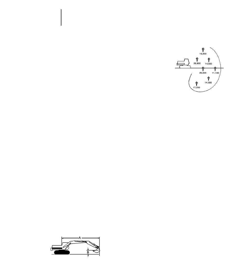
EXCAVATOR LIFTING CAPACITY
On many sewer jobs an excavator must lift and
swing heavy pipe and manboxes in and out of the
trench, place manholes and unload material from
trucks. In some situations the excavator’s lift require-
ments may be so critical that they determine the
size excavator selected.
An excavator’s lift capacity depends on its weight,
center of gravity, the lift point position (see sketches)
and its hydraulic capability. An excavator’s lifting
capability for any given lift position is limited by its
tipping stability or hydraulic capacity.
Changes in boom, stick and bucket position affect
attachment geometry and can drastically change a
machine’s hydraulic lifting capacity. Caterpillar
defines excavator lifting capabilities using the fol-
lowing SAE guidelines.
Tipping Conditions — An excavator is considered
to be at the tipping point when the weight in the
bucket acting at the center of gravity causes the rear
rollers to lift clear of the track rails. Suspended
loads are considered to be hung from the back of the
excavator’s bucket or bucket linkage by a sling or
chain. Weights of attachments, slings or auxiliary
lifting devices are considered part of the suspended
load.
Thus, the tipping load is defined as the load pro-
ducing a tipping condition at a specified radius. The
load radius shall be measured as the horizontal dis-
tance from the axis of upper structure rotation (before
loading) to the center of vertical load line with load
applied (dimension A, below). The rating height is
based on the vertical distance of the bucket lift point
to the ground (dimension B).
A. Radius from swing centerline
B. Bucket lift point height
HYPOTHETICAL MACHINE
Rated Hoist Load — The rated load is established
using the vertical distance of the lifting point to the
ground and the radius of load. Ratings for the abil-
ity of a specific machine attachment to lift a load
slung from the designated bucket are defined as
follows:
a. The rated load will not exceed 75% of the tip-
ping load.
b. The rated load will not exceed 87% of the excava-
tor’s hydraulic capacity. This means the machine
should be able to lift 115% of the rated load.
c. The rated load will not exceed the machine’s
structural capability.
4-58
Excavators Lifting Capacity
●Definition
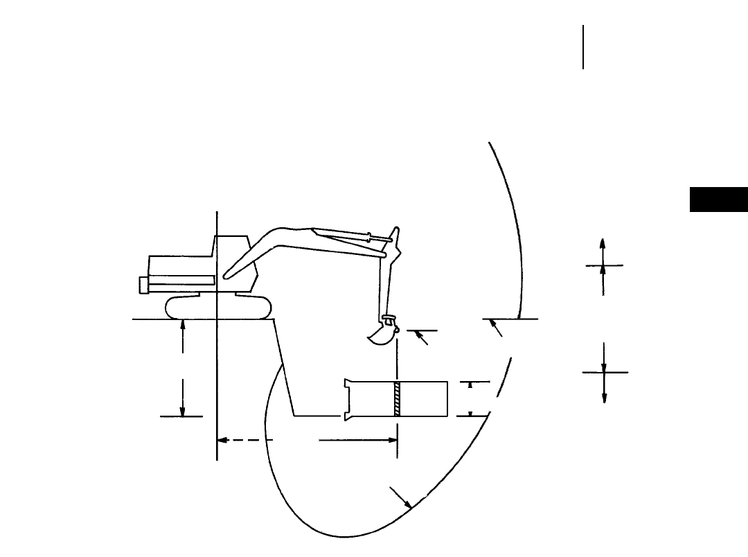
4-59
4
ExcavatorsLifting Capacity
●Definition
This drawing shows how an excavator’s lifting
capacity can vary with load position:
HYPOTHETICAL
MACHINE
Tips for Lifting Above Ground:
Get the load as close to the excavator as possible.
Use a cable short enough and position the excava-
tor so as to put the load lift point in the “optimum
lifting range” (see sketch).
Problem: Long reach cable — Can’t lift.
Solution: Shorten reach and cable — Can lift.
GROUND LEVEL LIFTING CAPACITIES
The lifting capacities that are shown on the fol-
lowing pages are with the lifting point at ground level.
These capacities are rated according to SAE Std.
No. J1097.
(For lifting capacities at other heights or with other
tools, refer to current Specification Sheets.)
Tips for Lifting Below Grade:
Use a cable for sufficient length to position the load
lift point in the “optimum lifting range”.
Problem: Short cable, deep trench — Can’t lift.
Solution: Lengthen cable to locate bucket hinge pin
in optimum lifting area — Can lift.
Trench
Depth
Digging Envelope Boundary
Load Lift Point
Pipe
Diameter
Ground
Line
Lifting
Decreases
Optimum
Lifting
Range
Lifting
Decreases
Load
Radius

4-60
Excavators Lifting Capacity At Ground Level
●301.5 ●307B ●307B SB ●307 ●311B
301.5 ●Bucket Teeth ●Rubber Track ●Canopy ●Blade Raised
1.5 m 2 m 2.5 m 3 m 3.5 m
5'0" 6'6" 8'0" 10'0" 11'6" At Max. Reach
Stick Bucket Front Side Front Side Front Side Front Side Front Side Front Side
890 mm 400 mm kg 620 420 410 280 300 210 230 160 ——
190 140
2'11" 16" lb 1360 920 900 610 660 460 500 350 410 300
301.5 ●Bucket Teeth ●Rubber Track ●Canopy ●Blade Lowered
1.5 m 2 m 2.5 m 3 m 3.5 m
5'0" 6'6" 8'0" 10'0" 11'6" At Max. Reach
Stick Bucket Front Side Front Side Front Side Front Side Front Side Front Side
890 mm 400 mm kg 680* 490 690* 330 490* 240 390* 190 ——
310* 150
2'11" 16" lb 1490* 1080 1520* 720 1080* 520 850* 410 680* 330
307B ●450 mm (18") Track Shoes
3 m 4.5 m 6 m
10'0" 15'0" 20'0" At Max. Reach
Stick Bucket Front Side Front Side Front Side Front Side
1665 mm 800 mm kg 2550 2050 1350 1100 ——
700* 700*
5'6" 2'7" lb 5450 4350 2900 2350 1500* 1500*
2210 mm 600 mm kg 2550 2050 1350 1100 ——
750* 650
7'3" 2'0" lb 5450 4350 2900 2350 1650* 1350
307B SB ●450 mm (18") Track Shoes ●Swing Boom
3 m 4.5 m 6 m
10'0" 15'0" 20'0" At Max. Reach
Stick Bucket Front Side Front Side Front Side Front Side
1665 mm 800 mm kg 2700 2150 1500 1200 ——
850 700
5'6" 2'7" lb 5800 4600 3150 1550 1900 1500
2210 mm 600 mm kg 2700 2100 1450 1150 950 750 750 600
7'3" 2'0" lb 5800 4450 3100 2500 2000 1600 1600 1250
307 ●450 mm (18") Track Shoes
3 m 4.5 m 6 m
10'0" 15'0" 20'0" At Max. Reach
Stick Bucket Front Side Front Side Front Side Front Side
1665 mm 800 mm kg 2550 2150 1350 1150 ——
700* 700*
5'6" 2'7" lb 5400 4600 2850 2450 1500* 1500*
2210 mm 600 mm kg 2550 2150 1350 1150 ——
750* 650*
7'3" 2'0" lb 5400 4550 2900 2450 1650* 1450*
311B ●500 mm (1'8") Track Shoes
3 m 4.5 m 6 m 7.5 m
10'0" 15'0" 20'0" 25'0" At Max. Reach
Stick Bucket Front Side Front Side Front Side Front Side Front Side
1950 mm 925 mm kg 6030 4160 3060 2210 1930 1390 ——
1180* 1130
6'5" 3'0" lb 12,910 8940 6570 4750 4130 2980 2590* 2490
2250 mm 775 mm kg 6130 4250 3110 2260 1960 1420 ——
1210* 1080
7'5" 2'6" lb 13,120 9130 6670 4850 4200 3050 2660* 2380
2800 mm 625 mm kg 6200 4310 3130 2270 1950 1410 ——
950* 930
9'2" 2'0" lb 13,260 9250 6690 4870 4180 3030 2090* 2050
*Load limited by hydraulic capacity rather than tipping.
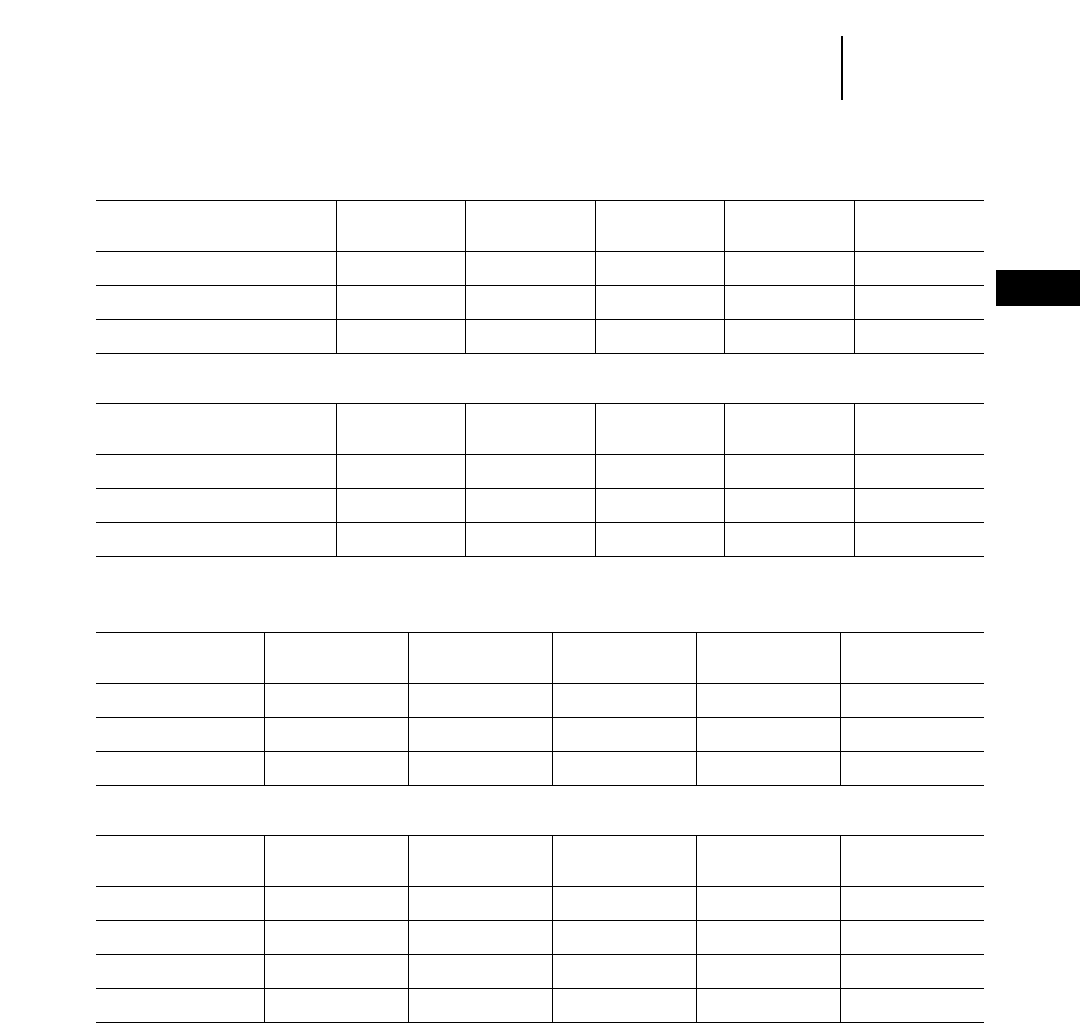
312B ●500 mm (1'8") Track Shoes
3 m 4.5 m 6 m 7.5 m
10'0" 15'0" 20'0" 25'0" At Max. Reach
Stick Bucket Front Side Front Side Front Side Front Side Front Side
2100 mm 1075 mm kg 6160* 5080 4070 2730 2580 1750 ——
1770* 1270
6'11" 3'6" lb 14,320* 10,290 8740 5870 5550 3760 3910* 2790
2500 mm 925 mm kg 6730* 5220 4150 2810 2630 1800 ——
1500* 1190
8'2" 3'0" lb 15,630* 11,220 8910 6040 5660 3870 3300* 2630
3000 mm 775 mm kg 7810* 5280 4170 2830 2640 1810 1830 1230 1400* 1080
9'10" 2'6" lb 17,900* 11,350 8960 6080 5670 3880 4040 2710 3080* 2370
312B L ●600 mm (2'0") Track Shoes
3 m 4.5 m 6 m 7.5 m
10'0" 15'0" 20'0" 25'0" At Max. Reach
Stick Bucket Front Side Front Side Front Side Front Side Front Side
2100 mm 1075 mm kg 6160* 5290 4850 2850 3060 1830 ——
1770* 1330
6'11" 3'6" lb 14,320* 11,360 10,400 6130 6570 3930 3910* 2930
2500 mm 925 mm kg 6730* 5430 4930 2920 3110 1880 ——
1500* 1250
8'2" 3'0" lb 15,630* 11,670 10,580 6290 6680 4040 3300* 2760
3000 mm 925 mm kg 7760* 5460 4930 2920 3090 1860 2090 1270 1360* 1100
9'10" 3'0" lb 18,060* 11,740 10,590 6280 6640 3990 4600 2790 3000* 2420
312B L France Sourced ●500 mm (1'8") Track Shoes — 2100/2500 (6'11"/8'2") Stick
●920 mm (3'0") Bucket ●600 mm (2'0") Track Shoes — 3000 mm (9'10") Stick
3 m 4.5 m 6 m 7.5 m
10'0" 15'0" 20'0" 25'0" At Max. Reach
Stick Front Side Front Side Front Side Front Side Front Side
2100 mm kg 6250 5080 4660 2760 2970 1800 ——
1770 1290
6'11" lb 2840 2310 2120 1250 1350 820 800 590
2500 mm kg 6810 5220 4740 2820 3000 1830 ——
1490 1200
8'2" lb 3100 2370 2150 1280 1360 830 680 540
3000 mm kg 7480 5450 4940 2930 3110 1880 2160 1300 1360 1110
9'10" lb 3400 2480 2240 1330 1410 850 980 590 620 500
315B ●500 mm (1'8") Track Shoes
3 m 4.5 m 6 m 7.5 m
10'0" 15'0" 20'0" 25'0" At Max. Reach
Stick Bucket Front Side Front Side Front Side Front Side Front Side
1850 mm 1220 mm kg ——
5300 3400 3400 2200 ——
2400 1550
6'1" 4'0" lb 11,350 7350 7250 4750 5250 3400
2250 mm 1070 mm kg 5500* 5500* 5450 3600 3500 2300 ——
2250* 1500
7'5" 3'6" lb 12,700* 12,700* 11,750 7700 7500 4950 5000* 3250
2600 mm 1070 mm kg 5900* 5900* 5500 3600 3500 2300 2400 1600 1950* 1350
8'6" 3'6" lb 13,600* 13,600* 11,750 7700 7450 4950 5300 3500 4250* 3000
3100 mm 770 mm kg 7000* 6700 5500 3600 3500 2350 2450 1600 1800* 1300
10'2" 2'6" lb 16,100* 14,400 11,850 7750 7500 5000 5250 3450 3950* 2800
*Load limited by hydraulic capacity rather than tipping.
4-61
4
ExcavatorsLifting Capacity At Ground Level
●312B ●312B L ●315B

315B L ●1070 mm (3'6") Bucket ●600 mm (2'0") Track Shoes
3 m 4.5 m 6 m 7.5 m
10'0" 15'0" 20'0" 25'0" At Max. Reach
Stick Bucket Front Side Front Side Front Side Front Side Front Side
1850 mm 1220 mm kg ——
6250 3500 3950 2300 ——
2700* 1600
6'1" 4'0" lb 13,450 7500 8500 4850 5950* 3500
2250 mm 1070 mm kg 5500* 5500* 6550 3700 4150 2400 ——
2250* 1550
7'5" 3'6" lb 12,700* 12,700* 14,050 8000 8850 5200 5000* 3450
2600 mm 1070 mm kg 5900* 5900* 6550 3750 4150 2400 2900 1650 1950* 1450
8'6" 3'6" lb 13,600* 13,600* 14,050 8000 8850 5150 6350 3650 4250* 3150
3100 mm 770 mm kg 7000* 6950 6600 3750 4150 2450 2900 1700 1800* 1350
10'2" 2'6" lb 16,100* 14,950 14,150 8100 8900 5200 6250 3600 3950* 2950
France Sourced
315B L ●0.93 m3(1.22 yd3) Bucket ●600 mm (2'0") Track Shoes
3 m 4.5 m 6 m 7.5 m
10'0" 15'0" 20'0" 25'0" At Max. Reach
Stick Front Side Front Side Front Side Front Side Front Side
1850 mm kg ——
6570 4080 4150 2640 ——
2550* 1840
6'1" lb 14,480 8990 9150 5820 5620* 4050
2250 mm kg ——
6760 4260 4250 2740 ——
2760 1770
7'5" lb 14,900 9390 9370 6040 6080 3900
2600 mm kg 5290* 5290* 6780 4270 4240 2730 2940 1880 1830* 1600
8'6" lb 11,660 11,660 14,950 9410 9340 6020 6480 4140 4030* 3520
3100 mm kg 6340* 6340* 6800 4280 4230 2720 2920 1860 1620* 1430
10'2" lb 13,980* 13,980* 14,990 9430 9320 5990 6430 4100 3570* 3150
Japan Sourced
318B L ●600 mm (2'0") Track Shoes
3 m 4.5 m 6 m 7.5 m
10'0" 15'0" 20'0" 25'0" At Max. Reach
Stick Bucket Front Side Front Side Front Side Front Side Front Side
3200 mm 625 mm kg 5600* 5600* 7700 4600 4800 2900 3300 2000 2200* 1400
10'6" 2'0" lb 19,900* 12,900* 16,450 9800 10,250 6250 7050 4250 4800* 3050
2700 mm 775 mm kg 6550* 6550* 7500 4450 4700 2850 3250 1950 2550* 1500
8'10" 2'6" lb 14,350* 14,350* 16,100 9500 10,050 6050 6950 4150 5600* 3300
2250 mm 775 mm kg ——
7450 4350 4650 2800 ——
2850 1650
7'5" 2'6" lb 15,950 9350 9950 5950 6200 3650
1800 mm 932 mm kg ——
7400 4300 4650 2750 ——
3100 1850
5'11" 3'0" lb 15,850 9250 9900 5950 6800 4000
*Load limited by hydraulic capacity rather than tipping.
4-62
Excavators Lifting Capacity At Ground Level
●315B L ●318B L

4-63
4
ExcavatorsLifting Capacity At Ground Level
●318B L ●318B LN
France Sourced
318B L ●0.8 m3(1.05 yd3) Bucket ●600 mm (2'0") Track Shoes
3 m 4.5 m 6 m 7.5 m
10'0" 15'0" 20'0" 25'0" At Max. Reach
Stick Bucket Front Side Front Side Front Side Front Side Front Side
1800 mm kg ——
8920* 5030 5700 3260 ——
3820 2200
5'11" lb 19,660* 11,090 12,560 7180 8420 4850
2250 mm kg ——
8830* 5070 5700 3260 ——
3190* 1980
7'5" lb 19,470* 11,170 12,560 7180 7030* 4360
2700 mm kg 5380* 5380* 8630* 5100 5700 3260 3950 2250 2240* 1770
8'10" lb 11,860* 11,860* 19,020* 11,240 12,560 7180 8710 4960 4930* 3900
3200 mm kg 6850* 6850* 8440* 5040 5570 3200 3840 2200 2440* 1620
10'6" lb 15,100* 15,100* 18,610* 11,110 12,280 7050 8460 4850 5380 3570
Japan Sourced
318B LN ●500 mm (1'8") Track Shoes
3 m 4.5 m 6 m 7.5 m
10'0" 15'0" 20'0" 25'0" At Max. Reach
Stick Bucket Front Side Front Side Front Side Front Side Front Side
3200 mm 625 mm kg 5600* 5600* 7550 3950 4700 2500 3250 1700 2200* 1150
10'6" 2'0" lb 12,900* 12,900* 16,200 8500 10,050 5350 6950 3600 4800* 2550
2700 mm 775 mm kg 5550* 5550* 7500 3900 4700 2500 3250 1700 2600 1350
8'10" 2'6" lb 12,850* 12,850* 16,050 8400 10,050 5350 6950 3650 5700 2900
2250 mm 775 mm kg ——
7300 4000 4550 1400 ——
2750 1400
7'5" 2'6" lb 16,300 8550 9750 5100 6100 3050
1800 mm 775 mm kg ——
7150 3600 4500 2300 ——
3000 1500
5'11" 2'6" lb 15,350 7750 9600 4950 6550 3250
France Sourced
318B LN ●0.8 m3(1.05 yd3) Bucket ●500 mm (1'8") Track Shoes
3 m 4.5 m 6 m 7.5 m
10'0" 15'0" 20'0" 25'0" At Max. Reach
Stick Bucket Front Side Front Side Front Side Front Side Front Side
1800 mm kg ——
7420 3860 4680 2510 ——
3150 1680
5'11" lb 16,360 8510 10,310 5530 6940 3700
2250 mm kg ——
7490 3910 4700 2520 ——
2870 1510
7'5" lb 16,510 8620 10,360 5550 6320 3320
2700 mm kg 5410* 5410* 7560 3970 4730 2550 3290 1740 2610* 1360
8'10" lb 11,920* 11,920* 16,660 8750 10,420 5620 7250 3830 5750* 2990
3200 mm kg 6850* 6850* 7590 3980 4720 2540 3270 1720 2440* 1250
10'6" lb 15,100* 15,100* 16,730 8770 10,400 5600 7210 3870 5380* 2750
*Load limited by hydraulic capacity rather than tipping.

4-64
Excavators Lifting Capacity At Ground Level
●M312
M312 ●4-Point Outriggers Down ●1000 mm (3'3") Bucket ●One-Piece Boom
3 m 4.5 m 6 m 7.5 m
10'0" 15'0" 20'0" 25'0" At Max. Reach
Stick Front Side Front Side Front Side Front Side Front Side
1600 mm kg ——
5500* 5250 3950* 3350 ——
2350* 2350
5'3" lb 12,120* 11,580 8710* 7390 5180* 5180
2000 mm kg ——
5500* 5300 3900* 3300 ——
1500* 1500*
6'6" lb 12,130* 11,690 8600* 7280 3310* 3310*
2300 mm kg 2700* 2700* 5500* 5300 3900* 3300 ——
1260* 1260*
7'5" lb 5950* 5950* 12,120* 11,680 8590* 7270 2780* 2780*
2600 mm kg 2900* 2900* 5400* 5300 3900* 3330 2100* 2100* 1100* 1100*
8'5" lb 6390* 6390* 11,900* 11,680 8590* 7340 4630* 4630* 2420* 2420*
3000 mm kg 3600* 3600* 5360* 5300 3800 3360 2600* 2300 1000* 1000
9'9" lb 7930* 7930* 11,810* 11,680 8370 7400 5730* 5070 2200* 2200
M312 ●Free On Wheels ●1000 mm (3'3") Bucket ●One-Piece Boom
3 m 4.5 m 6 m 7.5 m
10'0" 15'0" 20'0" 25'0" At Max. Reach
Stick Front Side Front Side Front Side Front Side Front Side
1600 mm kg ——
3900 2100 2500 1400 ——
1800 900
5'3" lb 8590 4630 5510 3080 2860 1980
2000 mm kg ——
4000 2200 2500 1400 ——
1500* 900
6'6" lb 8820 4850 5510 3090 3310* 1980
2300 mm kg 2700* 2700* 4000 2200 2600 1400 ——
1300* 800
7'5" lb 5950* 5950* 8820 4850 5730 3080 2860* 1760
2600 mm kg 2300* 2300* 4000 2100 2500 1960 1800 300 1160* 700
8'5" lb 5070* 5070* 8820 4630 5510 4320 3960 660 2550* 1540
3000 mm kg 3600* 3600* 4000 2100 2500 1400 1800 360 1000* 740
9'9" lb 7930* 7930* 8820 4630 5510 3080 3960 790 2200* 1630
M312 ●4-Point Outriggers Down ●1000 mm (3'3") Bucket ●VA Boom
3 m 4.5 m 6 m 7.5 m
10'0" 15'0" 20'0" 25'0" At Max. Reach
Stick Front Side Front Side Front Side Front Side Front Side
1600 mm kg 7900* 7900* 5400* 5300 3800* 3400 ——
2300* 2200
5'3" lb 17,410* 17,410* 11,900* 11,680 8370* 7500 5070* 4850
2000 mm kg 7900* 7900* 5400* 5300* 3900* 3500 ——
1500* 1500*
6'6" lb 17,420* 17,420* 11,910* 11,690* 8600* 7720 3310* 3310*
2300 mm kg 7600* 7600* 5900* 5300 3900* 3500 2400* 2400* 1300* 1300
7'5" lb 16,750* 16,750* 13,000* 11,680 8590* 3300 5290* 5290* 2860* 2860
2600 mm kg 7100* 7100* 5300* 5300 3860* 3560 2300* 2400 1100* 1100*
8'5" lb 15,650* 15,650* 11,680 11,680 8510* 7840 5070* 5290 2420* 2420*
3000 mm kg 7100* 7100* 5200* 5200 3740* 3440* 2900* 2400 1040* 1040*
9'9" lb 15,650* 15,650* 11,460* 11,460 8240* 7580* 6390* 5290 2290* 2290*
M312 ●Free On Wheels ●1000 mm (3'3") Bucket ●VA Boom
3 m 4.5 m 6 m 7.5 m
10'0" 15'0" 20'0" 25'0" At Max. Reach
Stick Front Side Front Side Front Side Front Side Front Side
1600 mm kg 7900* 4700 4400 2500 2600 1400 ——
1600 800
5'3" lb 17,410* 10,360 9700 5510 5730 3080 3520 1760
2000 mm kg 7900* 4800 4400 2600 2700 1500 ——
1500* 800
6'6" lb 17,420* 10,580 9700 5730 5950 3310 3310* 1760
2300 mm kg 7600* 4900 4300 2600 2800 1600 1800 900 1300* 800
7'5" lb 16,750* 10,800 9480 5730 6170 3520 3960 1980 2860* 1760
2600 mm kg 7100* 4800 4300 2700 2800 1600 1800 900 1100* 700
8'5" lb 15,650* 10,580 9480 5950 6170 3520 3960 1980 2420* 1100
3000 mm kg 7100* 4900* 4300 2600 2800 1700 1800 1000 1060* 700
9'9" lb 15,650* 10,800* 9480 5730 6170 3740 3960 2200 2330* 1100
*Load limited by hydraulic capacity rather than tipping.

4-65
4
ExcavatorsLifting Capacity At Ground Level
●M315
M315 ●4-Point Outriggers Down ●1100 mm (3'7") Bucket ●One-Piece Boom
3 m 4.5 m 6 m 7.5 m
10'0" 15'0" 20'0" 25'0" At Max. Reach
Stick Front Side Front Side Front Side Front Side Front Side
1700 mm kg ——
6700* 6400 4800* 4100 ——
2600* 2600*
5'10" lb 14,770* 14,110 10,580* 9040 5730* 5730*
2100 mm kg ——
6700* 6500 4800* 4100 ——
1700* 1700*
6'11" lb 14,770* 14,330 10,580* 9040 3740* 3740*
2400 mm kg 2500* 2500* 6700* 6500 4800* 4100 2900* 2900* 1500* 1500*
7'10" lb 5510* 5510* 14,770* 14,330 10,580* 9040 6390* 6390* 3300* 3300*
2600 mm kg 2700* 2700* 6700* 6500 4800* 4100 3300* 2900* 1300* 1300*
8'6" lb 5950* 5950* 14,770* 14,330 10,580* 9040 7270* 6390* 2860* 2860*
M315 ●Free On Wheels ●1100 mm (3'7") Bucket ●One-Piece Boom
3 m 4.5 m 6 m 7.5 m
10'0" 15'0" 20'0" 25'0" At Max. Reach
Stick Front Side Front Side Front Side Front Side Front Side
1700 mm kg ——
4700 2600 3100 1700 ——
2000 1100
5'10" lb 10,360 5730 6830 3740 4410 2420
2100 mm kg ——
4800 2700 3100 1700 ——
1700* 1000
6'11" lb 10,580 5950 6830 3740 3740* 2200
2400 mm kg 2500* 2500* 4800 2700 3100 1700 2200 1200 1500* 1000
7'10" lb 5510* 5510* 10,580 5950 6830 3740 4850 2640 3300* 2200
2600 mm kg 2700* 2700* 4800 2700 3100 1700 2200 1200 1300* 900
8'6" lb 5950* 5950* 10,580 5950 6830 3740 4850 2640 2860* 1980
M315 ●4-Point Outriggers Down ●1100 mm (3'7") Bucket ●VA Boom
3 m 4.5 m 6 m 7.5 m
10'0" 15'0" 20'0" 25'0" At Max. Reach
Stick Front Side Front Side Front Side Front Side Front Side
1700 mm kg 9500* 9500* 6600* 6600* 4700* 4300 ——
2400* 2400*
5'10" lb 20,940* 20,940* 14,550* 14,550* 10,360* 9430 5290* 5290*
2100 mm kg 8900* 8900* 6600* 6500 4700* 4300 3000* 2900 1600* 1600*
6'11" lb 19,620* 19,620* 14,550* 14,330 10,360* 9480 6610* 6390 3520* 3520*
2400 mm kg 8300* 8300* 6500* 6500* 4700* 4300 3000* 2900 1400* 1400*
7'10" lb 18,300* 18,300* 14,330* 14,330 10,360* 9480 6610* 6390 3080* 3080*
2600 mm kg 8500* 8500* 6500* 6500* 4600* 4200 3000* 2900 1300* 1300*
8'6" lb 18,740* 18,740* 14,330* 14,330* 10,140* 9260 6610* 6390 2860* 2860*
M315 ●Free On Wheel ●1100 mm (3'7") Bucket ●VA Boom
3 m 4.5 m 6 m 7.5 m
10'0" 15'0" 20'0" 25'0" At Max. Reach
Stick Front Side Front Side Front Side Front Side Front Side
1700 mm kg 9500* 5800 5200 3200 3200 1800 ——
1900 1000
5'10" lb 20,940* 12,780 11,460 7050 7050 3960 4180 2200
2100 mm kg 8900* 5900 5200 3200 3300 2000 2200 1200 1600* 1000
6'11" lb 19,620* 13,000 11,460 7050 7270 4410 4850 2640 3520* 2200
2400 mm kg 8300* 6000 5200 3200 3400 2000 2200 1200 1400* 900
7'10" lb 18,300* 13,230 11,460 7050 7490 4410 4850 2640 3080* 1980
2600 mm kg 8500* 5800 5200 3300 3400 2000 2200 1200 1300* 900
8'6" lb 18,740* 12,780 11,460 7270 7490 4410 4850 2640 2860* 1980
*Load limited by hydraulic capacity rather than tipping.

4-66
Excavators Lifting Capacity At Ground Level
●M318
M318 ●4-Point Outriggers Down ●1200 mm (3'11") Bucket ●One-Piece Boom
3 m 4.5 m 6 m 7.5 m
10'0" 15'0" 20'0" 25'0" At Max. Reach
Stick Front Side Front Side Front Side Front Side Front Side
1800 mm kg ——
7700* 7200 5500* 4600 ——
3100* 2700
5'11" lb 16,970* 15,870 12,120* 10,140 6830* 5950
2400 mm kg ——
7700* 7300 5500* 4600 4200* 3200 1800* 1800*
7'10" lb 16,970* 16,090 12,120* 10,140 9260* 7050 3960* 3960*
2800 mm kg 3800* 3800* 7600* 7400 5400* 4600 4200* 3200 1600* 1600*
9'2" lb 8370* 8370* 16,750* 16,310 11,900* 10,140 9260* 7050 3520* 3520*
4000 mm kg 5100* 5100* 6900* 6900* 4900 4600 3800* 3200 900* 900*
13'2" lb 11,240* 11,240* 15,210* 15,210* 10,800 10,140 8370* 7050 1980* 1980*
M318 ●Free On Wheels ●1200 mm (3'11") Bucket ●One-Piece Boom
3 m 4.5 m 6 m 7.5 m
10'0" 15'0" 20'0" 25'0" At Max. Reach
Stick Front Side Front Side Front Side Front Side Front Side
1800 mm kg ——
5900 2900 3700 1900 ——
2200 1100
5'11" lb 13,000 6390 8150 4180 4850 2420
2400 mm kg ——
5900 3000 3800 1900 2600 1300 1800* 1000
7'10" lb 13,000 6610 8370 4180 5730 2860 3960* 2200
2800 mm kg 3800* 3800* 5900 3000 3800 1900 2600 1300 1600* 900
9'2" lb 8370* 8370* 13,000 6610 8370 4180 5730 2860 3520* 1980
4000 mm kg 5100* 5100* 6000 3100 3800 1900 2600 1300 900 600
13'2" lb 11,240* 11,240* 13,230 6830 8370 4180 5730 2860 1980 1320
M318 ●4-Point Outriggers Down ●1200 mm (3'11") Bucket ●VA Boom
3 m 4.5 m 6 m 7.5 m
10'0" 15'0" 20'0" 25'0" At Max. Reach
Stick Front Side Front Side Front Side Front Side Front Side
1800 mm kg 10 800* 10 800* 7600* 7400* 5400* 4900 ——
2900* 2800
5'11" lb 23,810* 23,810* 16,750* 16,310* 11,900* 10,800 6390* 6170
2400 mm kg 10 200* 10 200* 7500* 7400* 5300* 4800 4100* 3300 1600* 1600*
7'10" lb 22,490* 22,490* 16,530* 16,310* 11,680* 10,580 9040* 7270 3520* 3520*
2800 mm kg 10 200* 10 200* 7400* 7400* 5200* 4800 4100* 3300 1400* 1400*
9'2" lb 22,490* 22,490* 16,310* 16,310* 11,460* 10,580 9040* 7270 3080* 3080*
4000 mm kg 6500* 6500* 4600* 4600* 3600* 3300 2300* 2300* 800 800
13'2" lb 14,330* 14,330* 10,140* 10,140* 7930* 7270 5070* 5070* 1760 1760
M318 ●Free On Wheels ●1200 mm (3'11") Bucket ●VA Boom
3 m 4.5 m 6 m 7.5 m
10'0" 15'0" 20'0" 25'0" At Max. Reach
Stick Front Side Front Side Front Side Front Side Front Side
1800 mm kg 10 800* 6800 6400 3700 4100 2200 ——
2200 1100
5'11" lb 23,810* 14,990 14,110 8150 9040 4850 4850 2420
2400 mm kg 10 200* 6900 6400 3800 4200 2300 2700 1400 1600 1000
7'10" lb 22,490* 15,210 14,110 8370 9260 5070 5950 3080 3520 2200
2800 mm kg 10 200* 6900 6300 3800 4100 2400 2800 1400 1400* 900
9'2" lb 22,490* 15,210 13,890 8370 9040 5290 6170 3080 2200* 1980
4000 mm kg ——
6100 3600 4000 2400 2800 1600 800* 600
13'2" lb 13,450 7930 8820 5290 6170 3520 1760* 1320
*Load limited by hydraulic capacity rather than tipping.
4-67
4
ExcavatorsLifting Capacity At Ground Level
●M320
M320 ●Rear Dozer Up ●One-Piece 5.65 m (18'6") Boom
3 m 4.5 m 6 m 7.5 m 9 m
10'0" 15'0" 20'0" 25'0" 30'0" At Max. Reach
Stick Bucket Front Side Front Side Front Side Front Side Front Side Front Side
1900 mm 1.05 m3kg ——
6600 3500 4800 2300 2900 1500 ——
2200 1100
6'3" 1.37 yd3lb 14,550 7700 10,580 5070 6350 3300 4850 2400
2500 mm 0.9 m3kg ——
6700 3600 4200 2300 3000 1600 ——
1300* 1000
8'2" 1.17 yd3lb 14,750 7930 9250 5050 6600 3500 2850 2200
2900 mm 0.81 m3kg ——
6700 3600 4200 2300 3000 1600 ——
1100* 900
9'6" 1.06 yd3lb 14,750 7900 9250 5050 6600 3500 2400 1950
4200 mm 0.55 m3kg ——
6900 3700 4300 2400 3000 1600 2200 1100 600* 600*
13'9" 0.72 yd3lb 15,200 8150 9450 5250 6600 3500 4850 2400 1300 1300
M320 ●Rear Dozer Down ●One-Piece 5.65 m (18'6") Boom
3 m 4.5 m 6 m 7.5 m 9 m
10'0" 15'0" 20'0" 25'0" 30'0" At Max. Reach
Stick Bucket Front Side Front Side Front Side Front Side Front Side Front Side
1900 mm 1.05 m3kg ——
9000* 4200 6400* 2700 4800* 1900 ——
3000* 1400
6'3" 1.37 yd3lb 19,800* 9250 14,100* 5950 10,550* 4150 6600* 3050
2500 mm 0.9 m3kg ——
9000* 4300 6300* 2800 4900* 1900 ——
1300* 1300
8'2" 1.17 yd3lb 19,800* 9450 13,850* 6150 10,800* 4150 2850* 2850
2900 mm 0.81 m3kg ——
8900* 4300 6200* 2800 4800* 1900 ——
1100* 1100*
9'6" 1.06 yd3lb 19,600* 9450 13,650* 6150 10,550* 4150 2400* 2400*
4200 mm 0.55 m3kg ——
8100* 4500 5600* 2900 4400* 1900 3600* 1400 600* 600
13'9" 0.72 yd3lb 17,850* 9900 12,300* 6350 9700* 4150 7900* 3050 1300* 1300*
M320 ●Rear Stabilizer Down ●One-Piece 5.65 m (18'6") Boom
3 m 4.5 m 6 m 7.5 m 9 m
10'0" 15'0" 20'0" 25'0" 30'0" At Max. Reach
Stick Bucket Front Rear Front Rear Front Rear Front Rear Front Rear Front Rear
1900 mm 1.05 m3kg ——
9000* 5400 6200 3500 4300 2400 ——
3000* 1800
6'3" 1.37 yd3lb 19,800* 11,900 13,650 7700 9450 5250 6600* 3960
2500 mm 0.9 m3kg ——
9000* 5500 6300 3500 4300 2400 ——
1300* 1300*
8'2" 1.17 yd3lb 19,800* 12,100 13,850 7700 9450 5250 2850* 2850*
2900 mm 0.81 m3kg ——
8900* 5500 6200* 3500 4300 2500 ——
1100* 1100*
9'6" 1.06 yd3lb 19,600* 12,100 13,650* 7700 9450 5500 2400* 2400*
4200 mm 0.55 m3kg ——
8100* 5700 5600* 3600 4400 2500 3200 1800 600* 600*
13'9" 0.72 yd3lb 17,850* 12,550 12,300* 7900 9700 5500 7050 3950 1300* 1300*
M320 ●4-Point Stabilizers Down ●One-Piece 5.65 m (18'6") Boom
3 m 4.5 m 6 m 7.5 m 9 m
10'0" 15'0" 20'0" 25'0" 30'0" At Max. Reach
Stick Bucket Front Side Front Side Front Side Front Side Front Side Front Side
1900 mm 1.05 m3kg ——
9000* 9000* 6400* 5600 4800* 3900 ——
3000* 3000
6'3" 1.37 yd3lb 19,800* 19,800* 14,100* 12,300 10,550* 8550 6600* 6600
2500 mm 0.9 m3kg ——
9000* 9000* 6300* 5700 4900* 4000 ——
1300* 1300*
8'2" 1.17 yd3lb 19,800* 19,800* 13,850 12,550 10,800* 8800 2850* 2850*
2900 mm 0.81 m3kg ——
8900* 8900* 6200* 5700 4800* 4000 ——
1100* 1100*
9'6" 1.06 yd3lb 19,600* 19,600* 13,650* 12,550 10,550* 8800 2400* 2400*
4200 mm 0.55 m3kg ——
8100* 8100* 5600* 5600* 4400* 4000 3600* 3000 600* 600*
13'9" 0.72 yd3lb 17,850* 17,850* 12,300* 12,300* 9700* 8800 7900* 6600 1300* 1300*
M320 ●Dozer and Stabilizer Down ●One-Piece 5.65 m (18'6") Boom
3 m 4.5 m 6 m 7.5 m 9 m
10'0" 15'0" 20'0" 25'0" 30'0" At Max. Reach
Stick Bucket Front Side Front Side Front Side Front Side Front Side Front Side
1900 mm 1.05 m3kg ——
9000* 7200 6400* 4600 4800* 3200 ——
3000* 2400
6'3" 1.37 yd3lb 19,800* 15,850 14,100* 10,100 10,550* 7050 6600* 5250
2500 mm 0.9 m3kg ——
9000* 7300 6300* 4600 4900* 3300 ——
1300* 1300*
8'2" 1.17 yd3lb 19,800* 16,050 13,850* 10,100 10,800* 7250 2850* 2850*
2900 mm 0.81 m3kg ——
8900* 7300 6200* 4600 4800* 3200 ——
1100* 1100*
9'6" 1.06 yd3lb 19,600* 16,050 13,650* 10,100 10,550* 7050 2400* 2400*
4200 mm 0.55 m3kg ——
8100* 7500 5600* 4700 4400* 3300 3600* 2400 600* 600*
13'9" 0.72 yd3lb 19,600* 16,500 12,300* 10,350 9700* 7250 7900* 5250 1300* 1300*
*Load limited by hydraulic capacity rather than tipping.

4-68
Excavators Lifting Capacity At Ground Level
●M320
M320 ●Rear Dozer Up ●VA Boom @ 5.41 m (17'9") Max.
3 m 4.5 m 6 m 7.5 m 9 m
10'0" 15'0" 20'0" 25'0" 30'0" At Max. Reach
Stick Bucket Front Side Front Side Front Side Front Side Front Side Front Side
1900 mm 1.05 m3kg 12 800* 8300 7400 4500 4800 2700 3000 1600 ——
2400 1200
6'3" 1.37 yd3lb 28,200* 18,300 16,300 9900 10,550 5950 6600 3500 5250 2600
2500 mm 0.9 m3kg 12 400* 8600 7300 4600 4700 2900 3200 1700 ——
1400* 1100
8'2" 1.17 yd3lb 27,300* 18,950 16,050 10,100 10,350 6350 7050 3700 3050* 2400
2900 mm 0.81 m3kg 12 100* 8400 7200* 4500 4700 2900 3200 1800 ——
1200* 1000
9'6" 1.06 yd3lb 26,650* 18,500 15,850* 9900 10,350 6350 7050 3950 2600* 2200
4200 mm 0.55 m3kg 10 800* 8300 7100* 4400 4600 2900 3300 2000 2300 1200 600* 600*
13'9" 0.72 yd3lb 23,800* 18,300 15,650* 9700 10,100 6350 7250 4400 5050 2600 1300* 1300*
M320 ●Rear Dozer Down ●VA Boom @ 5.41 m (17'9") Max.
3 m 4.5 m 6 m 7.5 m 9 m
10'0" 15'0" 20'0" 25'0" 30'0" At Max. Reach
Stick Bucket Front Side Front Side Front Side Front Side Front Side Front Side
1900 mm 1.05 m3kg 12 800* 10 100 8900* 5300 6300* 3200 4800* 1900 ——
3000* 1500
6'3" 1.37 yd3lb 28,200* 22,250 19,600* 11,650 13,850* 7050 10,550* 4150 6600* 3300
2500 mm 0.9 m3kg 12 400* 10 000 8800* 5300 6200* 3400 4800* 2100 ——
1400* 1400
8'2" 1.17 yd3lb 27,300* 22,050 19,400* 11,650 13,650* 7450 10,550* 4600 3050* 3050
2900 mm 0.81 m3kg 12 100* 9900 8600* 5200 6000* 3400 4700* 2100 ——
1200* 1200
9'6" 1.06 yd3lb 26,650* 21,800 18,950* 11,450 13,200* 7450 10,350* 4600 2600* 2600
4200 mm 0.55 m3kg 10 800* 9700* 7600* 5100 5300* 3300 4200* 2400 3400* 1500 600* 600*
13'9" 0.72 yd3lb 23,800* 21,350* 16,750* 11,200 11,650* 7250 9250* 5250 7450* 3300 1300* 1300*
M320 ●Rear Stabilizer Down ●VA Boom @ 5.41 m (17'9") Max.
3 m 4.5 m 6 m 7.5 m 9 m
10'0" 15'0" 20'0" 25'0" 30'0" At Max. Reach
Stick Bucket Front Side Front Side Front Side Front Side Front Side Front Side
1900 mm 1.05 m3kg 12 800* 12 400 8900* 6400 6300* 4000 4400 2500 ——
3000* 1900
6'3" 1.37 yd3lb 28,200* 27,300 19,600* 14,100 13,850* 8800 9700 5500 6600* 4150
2500 mm 0.9 m3kg 12 400* 12 300 8800* 6300 6200* 4200* 4500 2600 ——
1400* 1400*
8'2" 1.17 yd3lb 27,300* 27,100 19,400* 13,850 13,650* 9250* 9900 5700 3050* 3050*
2900 mm 0.81 m3kg 12 100* 12 100* 8600* 6200 6000* 4100 4500* 2700 ——
1200* 1200*
9'6" 1.06 yd3lb 26,650* 26,650* 18,950* 13,650 13,200 9000 9900* 5950 2600* 2600*
4200 mm 0.55 m3kg 10 800* 10 800* 7600* 6100 5300* 4000 4200* 2800 3300 1900 600* 600*
13'9" 0.72 yd3lb 23,800 23,800* 16,750 13,450 11,650* 8800 9250* 6150 7250 4150 1300* 1300*
M320 ●4-Point Stabilizers Down ●VA Boom @ 5.41 m (17'9") Max.
3 m 4.5 m 6 m 7.5 m 9 m
10'0" 15'0" 20'0" 25'0" 30'0" At Max. Reach
Stick Bucket Front Side Front Side Front Side Front Side Front Side Front Side
1900 mm 1.05 m3kg 12 800* 12 800* 8900* 8900* 6300* 6000 4800* 4000 ——
3000* 3000*
6'3" 1.37 yd3lb 28,200* 28,200* 19,600* 19,600* 13,850* 13,200 10,550* 8800 6600* 6600*
2500 mm 0.9 m3kg 12 400* 12 400* 8800* 8800* 6200* 5900 4800* 4200 ——
1400* 1400*
8'2" 1.17 yd3lb 27,300* 27,300* 19,400* 19,400* 13,650* 13,000 10,550* 9250 3050* 3050*
2900 mm 0.81 m3kg 12 100* 12 100* 8600* 8600* 6000* 5800* 4700* 4200 ——
1200* 1200*
9'6" 1.06 yd3lb 26,650* 26,650* 18,950* 18,950* 13,200* 12,750* 10,350* 9250 2600* 2600*
4200 mm 0.55 m3kg 10 800* 10 800* 7600* 7600* 5300* 5300* 4200* 4100 3400* 3000 600* 600*
13'9" 0.72 yd3lb 23,800* 23,800* 16,750* 16,750* 11,650* 11,650* 9250* 9000 7450* 6600 1300* 1300*
M320 ●Dozer and Stabilizer Down ●VA Boom @ 5.41 m (17'9") Max.
3 m 4.5 m 6 m 7.5 m 9 m
10'0" 15'0" 20'0" 25'0" 30'0" At Max. Reach
Stick Bucket Front Side Front Side Front Side Front Side Front Side Front Side
1900 mm 1.05 m3kg 12 800* 12 800* 8900* 7900* 6300* 4900 4800* 3300 ——
3000* 2600
6'3" 1.37 yd3lb 28,200* 28,200* 19,600* 17,400* 13,850* 10,800 10,550* 7250 6600* 5700
2500 mm 0.9 m3kg 12 400* 12 400* 8800* 7800 6200* 5100 4800* 3400 ——
1400* 1400*
8'2" 1.17 yd3lb 27,300* 27,300* 19,400* 17,150 13,650* 11,200 10,550* 7450 3050* 3050*
2900 mm 0.81 m3kg 12 100* 12 100* 8600* 7700 6000* 5000 4700* 3500 ——
1200* 1200*
9'6" 1.06 yd3lb 26,650* 26,650* 18,950* 16,950 13,200* 11,000 10,350* 7700 2600* 2600*
4200 mm 0.55 m3kg 10 800* 10 800* 7600* 7600* 5300* 4900 4200* 3500 3400* 2500 600* 600*
13'9" 0.72 yd3lb 23,800* 23,800* 16,750* 16,750* 11,650* 10,800 9250* 7700 3050* 5500 1300* 1300*
*Load limited by hydraulic capacity rather than tipping.
4-69
4
ExcavatorsLifting Capacity At Ground Level
●320B ●320B L
Japan Sourced
320B ●Reach Boom ●600 mm (2'0") Track Shoes
3 m 4.5 m 6 m 7.5 m 9 m
10'0" 15'0" 20'0" 25'0" 30'0" At Max. Reach
Stick Bucket Front Side Front Side Front Side Front Side Front Side Front Side
1900 mm C1370X kg ——
7950 4650 4950 2950 ————
3000 1750
6'3" 4'6" lb 17,050 10,000 10,600 6300 6550 3800
2500 mm B1260X kg ——
8350 5050 5300 3300 3700 2300 ——
2900 1750
8'2" 4'2" lb 17,950 10,850 11,350 7050 7950 4900 6350 3900
2920 mm B1130X kg 5450* 5450* 8450 5150 5350 3350 3800 2350 ——
2400* 1700
9'7" 3'8" lb 12,500* 12,500* 18,150 11,050 11,500 7200 8100 5050 5300* 3700
3860 mm B1130X kg 6850* 6850* 8600 5250 5450 3400 3800 2400 2850 1750 2050* 1450
12'8" 3'8" lb 15,750* 15,750* 18,450 11,300 11,650 7350 8200 5150 6100 3700 4450* 3150
320B ●Mass Boom ●600 mm (2'0") Track Shoes
3 m 4.5 m 6 m 7.5 m 9 m
10'0" 15'0" 20'0" 25'0" 30'0" At Max. Reach
Stick Bucket Front Side Front Side Front Side Front Side Front Side Front Side
1900 mm C1470X kg ——
8100 4750 5000 3000 ————
3350 1950
6'3" 4'10" lb 17,350 10,200 10,750 6400 7300 4300
2400 mm C1370X kg 7600* 7600* 8150 4800 5050 3050 ————
3000 1750
7'10" 4'6" lb 17,600* 17,600* 17,500 10,350 10,800 6500 6600 3850
320B L ●Reach Boom ●800 mm (2'8") Track Shoes
3 m 4.5 m 6 m 7.5 m 9 m
10'0" 15'0" 20'0" 25'0" 30'0" At Max. Reach
Stick Bucket Front Side Front Side Front Side Front Side Front Side Front Side
1900 mm C1470X kg ——
9600* 5550 6250 3500 ————
3800 2100
6'3" 4'10" lb 20,800* 11,850 13,400 7550 8300 4600
2500 mm B1370X kg ——
9900* 5950 6600 3850 4600 2700 ——
2950* 2050
8'2" 4'6" lb 21,450* 12,750 14,150 8250 9900 5800 6500* 4550
2920 mm B1260X kg 5350* 5350* 9750* 6000 6650 3900 4650 2750 ——
2400* 1950
9'7" 4'2" lb 12,350* 12,350* 21,100* 12,850 14,250 8350 9950 5050 5200* 4300
3860 mm B1130X kg 6850* 6850* 9200* 6150 6650 4000 4750 2800 3550 2100 2050* 1700
12'8" 3'8" lb 15,700* 15,700* 19,900* 13,200 14,350 8550 10,150 6050 7550 4450 4450* 3750
320B L ●Mass Boom ●800 mm (2'8") Track Shoes
3 m 4.5 m 6 m 7.5 m 9 m
10'0" 15'0" 20'0" 25'0" 30'0" At Max. Reach
Stick Bucket Front Side Front Side Front Side Front Side Front Side Front Side
1900 mm C1440MX kg ——
9700* 5650 6350 3550 ————
4200 2350
6'3" 4'6" lb 20,950* 12,100 13,550 7650 9250 5150
2400 mm C1470X kg 7600* 7600* 9600* 5700 6350 3600 ————
3800 2150
7'10" 4'10" lb 17,550* 17,550* 20,750* 12,250 13,650 7700 8350 4650
*Load limited by hydraulic capacity rather than tipping.

Japan Sourced
320B N ●Reach Boom ●500 mm (1'8") Track Shoes
3 m 4.5 m 6 m 7.5 m 9 m
10'0" 15'0" 20'0" 25'0" 30'0" At Max. Reach
Stick Bucket Front Side Front Side Front Side Front Side Front Side Front Side
1900 mm C1370X kg ——
8500 4450 5300 2850 ————
3200 1700
6'3" 4'6" lb 18,200 9550 11,350 6100 7050 3700
2500 mm B1260X kg ——
8900 4850 5600 3200 3950 2250 ——
3100* 1750
8'2" 4'2" lb 19,050 10,400 12,050 6800 8500 4800 6850* 3800
2920 mm B1130X kg 5450* 5450* 9000 4950 5700 3250 4050 2300 ——
2400* 1650
9'7" 3'8" lb 12,500* 12,500* 19,300 10,600 12,250 6950 8650 4900 5300* 3600
3860 mm B1130X kg 6850* 6850* 9100 5050 5750 3300 4050 2350 3050 1700 2050* 1400
12'8" 3'8" lb 15,750* 15,750* 19,550 10,800 12,350 7100 8700 4950 6500 3600 4450* 3050
320B N ●Mass Boom ●500 mm (1'8") Track Shoes
3 m 4.5 m 6 m 7.5 m 9 m
10'0" 15'0" 20'0" 25'0" 30'0" At Max. Reach
Stick Bucket Front Side Front Side Front Side Front Side Front Side Front Side
1900 mm C1470X kg ——
8600 4550 5350 2900 ————
3600 1900
6'3" 4'10" lb 18,450 9800 11,450 6200 7850 4150
2400 mm C1370X kg 7600* 7600* 8700 4600 5400 2950 ————
3250 1700
7'10" 4'6" lb 17,600* 17,600* 18,600 9900 11,550 6250 7150 3750
Belgium Sourced
320B ●Reach Boom ●600 mm (2'0") Track Shoes
3 m 4.5 m 6 m 7.5 m 9 m
10'0" 15'0" 20'0" 25'0" 30'0" At Max. Reach
Stick Bucket Front Side Front Side Front Side Front Side Front Side Front Side
1.9 m 1.15 m3kg ——
8480 5020 5330 3240 ————
2180 1910
6'3" 1.5 yd3lb 18,690 11,060 11,750 7140 4800 4210
2.5 m 1.05 m3kg ——
8910 5430 5620 3530 3950 2480 ——
2960* 1880
8'2" 1.37 yd3lb 19,640 11,970 12,390 7780 8700 5460 6520* 4140
2.9 m 0.8 m3kg 5300* 5300* 9000 5500 5670 3570 3980 2510 ——
2290* 1170
9'6" 1.04 yd3lb 11,680* 11,680* 19,840 12,120 12,500 7870 8770 5530 5040* 3900
320B ●Mass Boom ●600 mm (2'0") Track Shoes
3 m 4.5 m 6 m 7.5 m 9 m
10'0" 15'0" 20'0" 25'0" 30'0" At Max. Reach
Stick Bucket Front Side Front Side Front Side Front Side Front Side Front Side
1.9 m 1.25 m3kg ——
8740 5240 5470 3360 ————
3580 2190
6'3" 1.63 yd3lb 19,270 11,550 12,060 7400 7890 4820
2.4 m 1.15 m3kg 7660* 7660* 8810 5300 5500 3390 3810 2330 ——
3250 1980
7'10" 1.5 yd3lb 16,890* 16,890* 19,420 11,680 12,120 7470 8400 5130 7160 4360
320B ●VA Boom ●600 mm (2'0") Track Shoes
3 m 4.5 m 6 m 7.5 m 9 m
10'0" 15'0" 20'0" 25'0" 30'0" At Max. Reach
Stick Bucket Front Side Front Side Front Side Front Side Front Side Front Side
1.9 m 1.15 m3kg ——
8530* 4480 5460 2900 ————
3250* 1760
6'3" 1.5 yd3lb 18,800* 9870 12,030 6390 7160* 3880
2.4 m 0.95 m3kg ——
8810 4590 5540 2970 3870 2050 ——
3090 1620
7'10" 1.24 yd3lb 19,430 10,120 12,210 6540 8530 4520 6810 3570
**Load limited by hydraulic capacity rather than tipping.
4-70
Excavators Lifting Capacity At Ground Level
●320B N ●320B Belgium Sourced

4-71
4
ExcavatorsLifting Capacity At Ground Level
●320B L ●320B LN
Belgium Sourced
320B L ●Reach Boom ●600 mm (2'0") Track Shoes
3 m 4.5 m 6 m 7.5 m 9 m
10'0" 15'0" 20'0" 25'0" 30'0" At Max. Reach
Stick Bucket Front Side Front Side Front Side Front Side Front Side Front Side
1.9 m 1.15 m3kg ——
9500* 5840 6580 3770 ————
3920 2250
6'3" 1.5 yd3lb 20,940 12,870 14,500 8310 8640 4960
2.5 m 1.05 m3kg ——
9810* 6250 6870 4060 4820 2860 ——
2960* 2190
8'2" 1.37 yd3lb 21,630* 13,780 15,140 8950 10,620 6300 6520* 4820
2.9 m 0.8 m3kg 5300* 5300* 9680* 6330 6920* 4100 4850 2900 ——
2290* 2060
9'6" 1.04 yd3lb 11,680* 11,680* 21,340* 13,950 15,250 9040 10,690 6390 5040* 4540
320B L ●Mass Boom ●600 mm (2'0") Track Shoes
3 m 4.5 m 6 m 7.5 m 9 m
10'0" 15'0" 20'0" 25'0" 30'0" At Max. Reach
Stick Bucket Front Side Front Side Front Side Front Side Front Side Front Side
1.9 m 1.25 m3kg ——
9680* 6070 6730 3900 ————
4390 2560
6'3" 1.63 yd3lb 21,340* 13,380 14,830 8590 9670 5640
2.4 m 1.15 m3kg 7660* 7660* 9590* 6130 6760 3920 4680 2720 ——
3810* 2310
7'10" 1.5 yd3lb 16,890* 16,890* 21,140* 13,510 14,900 8640 10,310 5990 8400* 5090
320B L ●VA Boom ●600 mm (2'0") Track Shoes
3 m 4.5 m 6 m 7.5 m 9 m
10'0" 15'0" 20'0" 25'0" 30'0" At Max. Reach
Stick Bucket Front Side Front Side Front Side Front Side Front Side Front Side
1.9 m 1.15 m3kg ——
8530* 5000 5370 3220 ————
3250* 1960
6'3" 1.5 yd3lb 18,800* 11,020 11,840 7100 7160* 4320
2.4 m 0.95 m3kg ——
8670 5100 5440 3290 3800 2280 ——
3030 1800
7'10" 1.24 yd3lb 19,110 11,240 11,990 7250 8370 5020 6680 3960
320B LN** ●Reach Boom ●500 mm (1'8") Track Shoes
3 m 4.5 m 6 m 7.5 m 9 m
10'0" 15'0" 20'0" 25'0" 30'0" At Max. Reach
Stick Bucket Front Side Front Side Front Side Front Side Front Side Front Side
1.9 m 1.15 m3kg
6'3" 1.5 yd3lb
2.5 m 1.05 m3kg
8'2" 1.37 yd3lb
2.9 m 0.8 m3kg
9'6" 1.04 yd3lb
320B LN** ●Mass Boom ●500 mm (1'8") Track Shoes
3 m 4.5 m 6 m 7.5 m 9 m
10'0" 15'0" 20'0" 25'0" 30'0" At Max. Reach
Stick Bucket Front Side Front Side Front Side Front Side Front Side Front Side
1.9 m 1.25 m3kg
6'3" 1.63 yd3lb
2.4 m 1.15 m3kg
7'10" 1.5 yd3lb
**Load limited by hydraulic capacity rather than tipping.
**Information unavailable.

4-72
Excavators
Belgium Sourced
320B LN** ●VA Boom ●500 mm (1'8") Track Shoes
3 m 4.5 m 6 m 7.5 m 9 m
10'0" 15'0" 20'0" 25'0" 30'0" At Max. Reach
Stick Bucket Front Side Front Side Front Side Front Side Front Side Front Side
1.9 m 1.15 m3kg
6'3" 1.5 yd3lb
2.4 m 0.95 m3kg
7'10" 1.24 yd3lb
320B S ●Reach Boom ●550 mm (1'10") Track Shoes
3 m 4.5 m 6 m 7.5 m 9 m
10'0" 15'0" 20'0" 25'0" 30'0" At Max. Reach
Stick Bucket Front Side Front Side Front Side Front Side Front Side Front Side
1.9 m 1.15 m3kg ——
9490* 4760 6560 3110 ————
3960 1860
6'3" 1.5 yd3lb 20,920 10,490 14,460 6850 8730 4100
2.5 m 1.05 m3kg ——
9820* 5160 6850 3390 4830 2400 ——
2980* 1840
8'2" 1.37 yd3lb 21,650* 11,370 15,100 7470 10,650 5290 6570* 4050
2.9 m 0.8 m3kg 5450* 5450* 9710* 5230 6900 3440 4860 2430 ——
2300 1730
9'6" 1.04 yd3lb 12,010* 12,010* 21,410* 11,530 15,210 7580 10,710 5350 5070 3810
320B S ●Mass Boom ●550 mm (1'10") Track Shoes
3 m 4.5 m 6 m 7.5 m 9 m
10'0" 15'0" 20'0" 25'0" 30'0" At Max. Reach
Stick Bucket Front Side Front Side Front Side Front Side Front Side Front Side
1.9 m 1.25 m3kg ——
9670* 4970 6700 3230 ————
4440 2130
6'3" 1.63 yd3lb 2130* 10,950 14,770 7120 9790 4690
2.4 m 1.15 m3kg 7890* 7890* 9610* 5020 6730 3250 ————
3840 1920
7'10" 1.5 yd3lb 17,390* 17,390* 21,190* 11,060 14,830 7160 8460 4230
320B S ●VA Boom ●550 mm (1'10") Track Shoes
3 m 4.5 m 6 m 7.5 m 9 m
10'0" 15'0" 20'0" 25'0" 30'0" At Max. Reach
Stick Bucket Front Side Front Side Front Side Front Side Front Side Front Side
1.9 m 1.15 m3kg ——
8470* 4680 6250* 3050 ————
3210* 1880
6'3" 1.5 yd3lb 18,670* 10,310 13,780* 6720 7070* 4140
2.4 m 0.95 m3kg ——
8990* 4780 6550* 3110 4680* 2170 ——
3220* 1730
7'10" 1.24 yd3lb 19,820* 10,530 14,440* 6850 10,310* 4780 7100* 3810
**Load limited by hydraulic capacity rather than tipping.
**Information unavailable.
Lifting Capacity At Ground Level
●320B LN ●320B S
4-73
4
ExcavatorsLifting Capacity At Ground Level
●322B ●322B L
Japan/U.S. Sourced
322B ●Reach Boom ●600 mm (2'0") Track Shoes
3 m 4.5 m 6 m 7.5 m 9 m
10'0" 15'0" 20'0" 25'0" 30'0" At Max. Reach
Stick Bucket Front Side Front Side Front Side Front Side Front Side Front Side
2500 mm S1355X kg ——
10 500 6500 6550 4200 4600 2950 ——
3450 2200
8'2" 4'5" lb 22,450 13,950 14,050 9000 9850 6350 7550 4800
2950 mm S1225X kg 5200* 5200* 10 600 6600 6600 4250 4650 3000 ——
3200 2050
9'8" 4'0" lb 11,950* 11,950* 22,700 14,150 14,200 9150 9950 6400 7050 4450
3600 mm B1260X kg 6050* 6050* 10 650 6600 6650 4250 4650 3000 3450 2150 2900 1800
11'10" 4'2" lb 13,800* 13,800* 22,800 14,200 14,250 9150 9950 6400 7350 4600 6400 4000
322B ●Mass Boom ●600 mm (2'0") Track Shoes
3 m 4.5 m 6 m 7.5 m 9 m
10'0" 15'0" 20'0" 25'0" 30'0" At Max. Reach
Stick Bucket Front Side Front Side Front Side Front Side Front Side Front Side
2000 mm D1345X kg ——
10 200 6150 6250 3900 ————
3900 2400
6'7" 4'5" lb 21,850 13,250 13,400 8350 8600 5250
2500 mm D1345X kg ——
10 250 6200 6250 3900 4300 2600 ——
3500 2100
8'2" 4'5" lb 21,950 13,300 13,400 8300 9150 5500 7700 4650
322B L ●Reach Boom ●800 mm (2'8") Track Shoes
3 m 4.5 m 6 m 7.5 m 9 m
10'0" 15'0" 20'0" 25'0" 30'0" At Max. Reach
Stick Bucket Front Side Front Side Front Side Front Side Front Side Front Side
2500 mm S1315X kg ——
12,150* 7650 8100 4950 5650 3500 ——
4200 2600
8'2" 4'4" lb 26,250* 16,400 17,350 10,550 12,100 7450 9300 5650
2950 mm S1355X kg 5150* 5150* 12 000* 7700 8150 4950 5650 3500 ——
3700 2400
9'8" 4'5" lb 11,850* 11,850* 25,950* 16,550 17,450 10,650 12,150 7500 8150 5250
3600 mm B1260X kg 6050* 6050* 11 600* 7750 8150 5000 5700 3500 4250 2600 3150 2200
11'10" 4'2" lb 13,800* 13,800* 25,050* 16,700 17,550 10,700 12,200 7500 9050 5500 6850 4800
322B L ●Mass Boom ●800 mm (2'8") Track Shoes
3 m 4.5 m 6 m 7.5 m 9 m
10'0" 15'0" 20'0" 25'0" 30'0" At Max. Reach
Stick Bucket Front Side Front Side Front Side Front Side Front Side Front Side
2000 mm D1500X kg ——
11 750 7300 7750 4600 ————
4800 2850
6'7" 4'11" lb 25,350 15,600 16,650 9800 10,600 6250
2500 mm D1430X kg ——
11 550 7250 7750 4550 5300 3100 ——
4350 2550
8'2" 4'8" lb 24,950 15,550 16,550 9750 11,350 6600 9550 5600
Belgium Sourced
322B L ●Reach Boom ●800 mm (2'8") Track Shoes
3 m 4.5 m 6 m 7.5 m 9 m
10'0" 15'0" 20'0" 25'0" 30'0" At Max. Reach
Stick Bucket Front Side Front Side Front Side Front Side Front Side Front Side
2500 mm 1.25 m3kg ——
11 980* 8040 8430 5180 5880 3650 ——
4310 2670
8'2" 1.63 yd3lb 26,410* 17,720 18,580 11,420 12,960 8040 9500 5880
2950 mm 1.15 m3kg 5050* 5050* 11 850* 8130 8430* 5220 5910 3680 ——
3560* 2480
9'8" 1.5 yd3lb 11,130* 11,130* 26,120* 17,920 18,580* 11,510 13,030 8110 7840* 5460
**Load limited by hydraulic capacity rather than tipping.

4-74
Excavators Lifting Capacity At Ground Level
●322B L ●322B LN ●325B
Belgium Sourced
322B L ●Mass Boom ●800 mm (2'8") Track Shoes
3 m (10'0") 4.5 m (15'0") 6 m (20'0") 7.5 m (25'0") 9 m (30'0") At Max. Reach
Stick Bucket Front Side Front Side Front Side Front Side Front Side Front Side
2000 mm 1.5 m3kg ——
11 660* 7770 8190 4910 ————
4950* 2970
6'7" 1.96 yd3lb 25,710* 17,130 18,050 10,820 10,910* 6540
2500 mm 1.45 m3kg ——
11 580* 7860 8230 4940 5630 3380 ——
4100* 2690
8'2" 1.9 yd3lb 25,530* 17,330 18,140 10,890 12,410 7450 9040* 5930
322B L ●VA Boom ●800 mm (2'8") Track Shoes
3 m (10'0") 4.5 m (15'0") 6 m (20'0") 7.5 m (25'0") 9 m (30'0") At Max. Reach
Stick Bucket Front Side Front Side Front Side Front Side Front Side Front Side
2 m 1.5 m3kg ——
10 170* 7430 7590* 4720 5260* 3260 ——
3540* 2590
6'7" 1.96 yd3lb 22,420* 16,380 16,730* 10,400 11,590* 7180 7800* 5710
2.5 m 1.45 m3kg ——
10 810* 7520 7880* 4750 5570 3270 ——
3500* 2340
8'2" 1.9 yd3lb 23,830* 16,580 17,370* 10,470 12,280 7210 7710* 5150
322B LN ●Reach Boom ●600 mm (2'0") Track Shoes
3 m (10'0") 4.5 m (15'0") 6 m (20'0") 7.5 m (25'0") 9 m (30'0") At Max. Reach
Stick Bucket Front Side Front Side Front Side Front Side Front Side Front Side
2.5 m 1.15 m3kg ——
12 000* 7030 8190 4550 5710 3210 ——
4190 2340
8'2" 1.5 yd3lb 26,460* 15,500 18,050 10,030 12,590 7070 9230 5150
2.95 m 0.95 m3kg 5130* 5130* 11 920 7160 8290 4640 5790 3280 ——
3620* 2210
12'8" 1.24 yd3lb 11,310* 11,310* 26,280 15,780 18,270 10,230 12,760 7230 7980* 4870
322B LN ●Mass Boom ●600 mm (2'0") Track Shoes
3 m (10'0") 4.5 m (15'0") 6 m (20'0") 7.5 m (25'0") 9 m (30'0") At Max. Reach
Stick Bucket Front Side Front Side Front Side Front Side Front Side Front Side
2 m 1.45 m3kg ——
11 710* 6780 7970 4300 ————
4830 2600
6'7" 1.9 yd3lb 25,820* 14,940 17,570 9480 10,650 5730
2.5 m 1.3 m3kg ——
11 600* 6840 7990 4320 5470 2940 ——
4120* 2330
8'2" 1.7 yd3lb 25,570* 15,080 17,610 9520 12,060 6480 9080* 5130
322B LN ●VA Boom ●600 mm (2'0") Track Shoes
3 m (10'0") 4.5 m (15'0") 6 m (20'0") 7.5 m (25'0") 9 m (30'0") At Max. Reach
Stick Bucket Front Side Front Side Front Side Front Side Front Side Front Side
2 m 1.45 m3kg ——
10 230* 6440 7640* 4110 5310* 2830 ——
3600* 2250
6'7" 1.9 yd3lb 22,550* 14,200 16,840* 9060 11,700* 6240 7930* 4960
2.5 m 1.3 m3kg ——
10 830* 6500 7860 4120 5400 2820 ——
3530* 2000
8'2" 1.7 yd3lb 23,880* 14,330 17,330 9080 11,900 6210 7780* 4410
Japan/U.S. Sourced
325B ●Reach Boom ●600 mm (2'0") Track Shoes
3 m 4.5 m 6 m 7.5 m 9 m
10'0" 15'0" 20'0" 25'0" 30'0" At Max. Reach
Stick Bucket Front Side Front Side Front Side Front Side Front Side Front Side
2000 mm D1430X kg ——
11 850 7150 7400 4650 5200 3250 ——
3950 2450
6'7" 4'8" lb 25,400 15,350 15,900 9950 11,150 6950 8700 5400
2650 mm C1470X kg ——
12 400 7650 7750 5000 5450 3550 ——
3800 2450
8'8" 4'10" lb 26,500 16,500 16,650 10,700 11,750 7600 8350 5300
3200 mm C1370X kg 4300* 4300* 12 450 7750 7800 5000 5500 3550 4100 2600 3300* 2200
10'6" 4'6" lb 9850* 9850* 26,700 16,600 16,750 10,800 11,750 7600 8750 5550 7200* 4800
325B ●Mass Boom ●600 mm (2'0") Track Shoes
3 m 4.5 m 6 m 7.5 m 9 m
10'0" 15'0" 20'0" 25'0" 30'0" At Max. Reach
Stick Bucket Front Side Front Side Front Side Front Side Front Side Front Side
2000 mm D1520MX kg ——
12 300 7500 7650 4850 ————
4600 2900
6'7" 5'0" lb 26,300 16,150 16,400 10,400 10,100 6350
2500 mm D1500X kg ——
12 350 7550 7650 4850 5300 3550 ——
4150 2600
8'2" 4'11" lb 26,450 16,250 16,350 10,350 11,300 7100 9100 5650
**Load limited by hydraulic capacity rather than tipping.
4-75
4
ExcavatorsLifting Capacity At Ground Level
●325B L
Japan/U.S. Sourced
325B L ●Reach Boom ●800 mm (2'8") Track Shoes
3 m 4.5 m 6 m 7.5 m 9 m
10'0" 15'0" 20'0" 25'0" 30'0" At Max. Reach
Stick Bucket Front Side Front Side Front Side Front Side Front Side Front Side
2000 mm D1520MX kg ——
14 100 8500 8950 5500 6250 3850 ——
4750 2950
6'7" 5'0" lb 31,100 18,300 19,150 11,800 13,400 8300 10,450 6450
2650 mm C1440MX kg ——
15 100 9050 9300 5850 6550 4150 ——
4100* 2900
8'8" 4'9" lb 32,350 19,450 20,000 12,600 14,050 8950 9050* 6300
3200 mm C1470X kg 4250* 4250* 15 200 9100 9350 5900 6550 4150 4900 3100 3250* 2600
10'6" 4'10" lb 9800* 9800* 32,500 19,550 20,050 12,650 14,050 8950 10,450 6600 7150* 5750
325B L ●Mass Boom ●800 mm (2'8") Track Shoes
3 m 4.5 m 6 m 7.5 m 9 m
10'0" 15'0" 20'0" 25'0" 30'0" At Max. Reach
Stick Bucket Front Side Front Side Front Side Front Side Front Side Front Side
2000 mm D1700MX kg ——
15 000 8850 9150 5650 ————
5450 3400
6'7" 5'7" lb 32,050 19,000 19,600 72,150 12,000 7450
2500 mm D1520MX kg ——
15 100 8950 9200 5700 6350 3950 ——
4700* 3100
8'2" 5'0" lb 32,300 19,200 19,700 12,200 13,600 8450 10,300* 6750
Belgium Sourced
325B L ●Reach Boom ●800 mm (2'8") Track Shoes
3 m 4.5 m 6 m 7.5 m 9 m
10'0" 15'0" 20'0" 25'0" 30'0" At Max. Reach
Stick Bucket Front Side Front Side Front Side Front Side Front Side Front Side
2 m 1.45 m3kg ——
14 070* 8730 9160 5630 6410 3970 ——
4790 2960
6'7" 1.89 yd3lb 31,020* 19,240 20,190 12,410 14,130 8750 10,560 6520
2.65 m 1.45 m3kg ——
15 080* 9270 9530 6000 6690 4260 ——
3930* 2890
8'8" 1.9 yd3lb 33,250* 20,440 21,010 13,230 14,750 9390 8660* 6370
3.2 m 1.15 m3kg 4180* 4180* 15 460* 9320 9560 6020 6700 4260 5000 3160 3130* 2630
10'6" 1.5 yd3lb 9210* 9210* 34,080* 20,550 21,070 13,270 14,770 9390 11,020 6960 6900* 5790
325B L ●Mass Boom ●800 mm (2'8") Track Shoes
3 m 4.5 m 6 m 7.5 m 9 m
10'0" 15'0" 20'0" 25'0" 30'0" At Max. Reach
Stick Bucket Front Side Front Side Front Side Front Side Front Side Front Side
2 m 1.7 m3kg ——
15 290 9030 9340 5770 ————
5460 3390
6'7" 2.22 yd3lb 33,710 19,910 20,590 12,720 12,030 7470
2.5 m 1.5 m3kg ——
15 400 9120 9360 5790 6470 4010 ——
4450* 3070
8'2" 1.96 yd3lb 33,950 20,100 20,630 12,760 14,260 8840 9810* 6760
325B L ●VA Boom ●800 mm (2'8") Track Shoes
3 m 4.5 m 6 m 7.5 m 9 m
10'0" 15'0" 20'0" 25'0" 30'0" At Max. Reach
Stick Bucket Front Side Front Side Front Side Front Side Front Side Front Side
2 m 1.7 m3kg ——
13 040* 8500 9040 5440 6290 3800 ——
4800* 2950
6'7" 2.22 yd3lb 28,750* 18,740 19,930 11,990 13,860 8370 10,580* 6500
2.5 m 1.45 m3kg ——
14 000* 8610 9100 5490 6310 3820 ——
4240* 2700
8'2" 1.89 yd3lb 30,870* 18,980 20,060 12,100 13,910 8420 9340* 5950
**Load limited by hydraulic capacity rather than tipping.
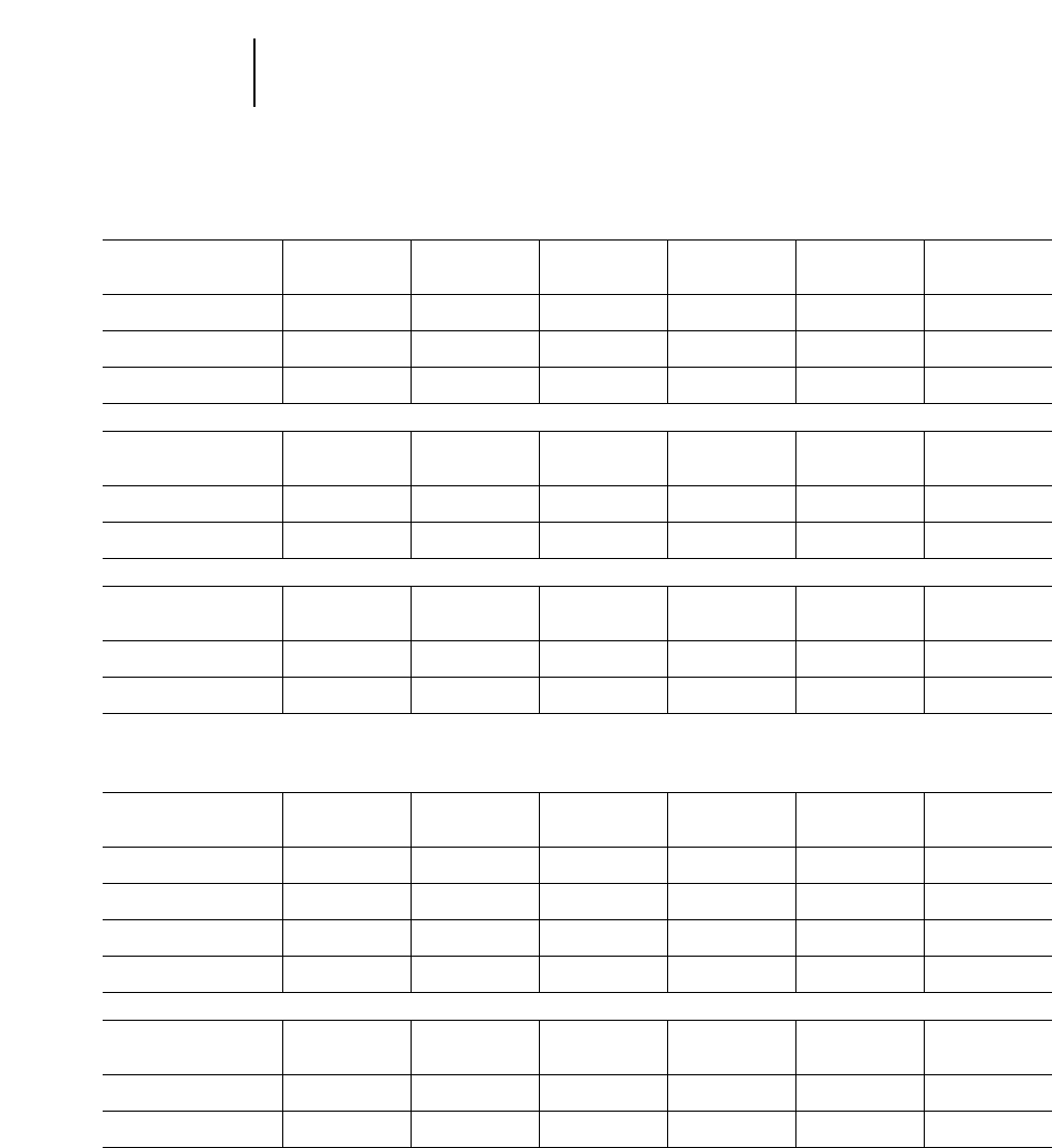
4-76
Excavators Lifting Capacity At Ground Level
●325B LN ●330B
Belgium Sourced
325B LN ●Reach Boom ●800 mm (2'8") Track Shoes
3 m 4.5 m 6 m 7.5 m 9 m
10'0" 15'0" 20'0" 25'0" 30'0" At Max. Reach
Stick Bucket Front Side Front Side Front Side Front Side Front Side Front Side
2 m 1.45 m3kg ——
14 070* 7470 8790 4840 6140 3400 ——
4580 2510
6'7" 1.89 yd3lb 31,020* 16,470 19,380 10,670 13,530 7490 10,090 5530
2.65 m 1.15 m3kg ——
14 920 8020 9180 5220 6440 3700 ——
3950* 2500
8'8" 1.5 yd3lb 32,890 17,680 20,240 11,510 14,200 8150 8700* 5510
3.2 m 0.95 m3kg 4260* 4260* 15 030 8120 9250 5290 6490 3750 4850 2770 3200* 2310
10'6" 1.24 yd3lb 9390* 9390* 33,140 17,900 20,390 11,660 14,310 8260 10,690 6100 7050* 5090
325B LN ●Mass Boom ●600 mm (2'0") Track Shoes
3 m 4.5 m 6 m 7.5 m 9 m
10'0" 15'0" 20'0" 25'0" 30'0" At Max. Reach
Stick Bucket Front Side Front Side Front Side Front Side Front Side Front Side
2 m 1.5 m3kg ——
14 770 7820 9030 5030 ————
5290 2950
6'7" 1.96 yd3lb 32,560 17,240 19,910 11,090 11,660 6500
2.5 m 1.45 m3kg ——
14 860 7880 9030 5030 6240 3480 ——
4500* 2650
8'2" 1.89 yd3lb 32,760 17,370 19,910 11,090 13,750 7670 9920* 5840
325B LN ●VA Boom ●600 mm (2'0") Track Shoes
3 m 4.5 m 6 m 7.5 m 9 m
10'0" 15'0" 20'0" 25'0" 30'0" At Max. Reach
Stick Bucket Front Side Front Side Front Side Front Side Front Side Front Side
2 m 1.7 m3kg ——
13 040* 7220 8680 4630 6020 3210 ——
4700* 2480
6'7" 2.22 yd3lb 28,750* 15,920 19,130 10,200 13,270 7070 10,360* 5460
2.5 m 1.45 m3kg ——
14 000* 7340 8730 4690 6040 3240 ——
4240* 2260
8'2" 1.89 yd3lb 30,870* 16,180 19,240 10,340 13,310 7140 9340* 4980
Japan/U.S. Sourced
330B ●Reach Boom ●600 mm (2'0") Track Shoes
3 m 4.5 m 6 m 7.5 m 9 m
10'0" 15'0" 20'0" 25'0" 30'0" At Max. Reach
Stick Bucket Front Side Front Side Front Side Front Side Front Side Front Side
2150 mm E1470X kg ——
15 600 10 150 9700 6500 6800 4600 ——
4750 3200
7'1" 4'10" lb 33,450 21,750 20,800 14,000 14,600 9850 10,450 6950
2800 mm D1500X kg ——
16 200 10 700 10 100 6900 7100 4900 5300 3600 4650 3150
9'2" 4'11" lb 34,750 22,450 21,650 14,850 15,250 10,500 11,550 7900 10,200 6900
3300 mm D1430X kg 7000* 7000* 16 300 10 750 10 100 6950 7100 4900 5300 3600 4050* 2850
10'10" 4'8" lb 15,900* 15,900* 34,900 23,050 21,750 14,350 15,250 10,500 11,650 7700 8850* 6250
3900 mm D1345X kg 7550* 7550* 16 400 10 850 10 200 7000 7150 4900 5300 3600 3250* 2500
12'10" 4'5" lb 17,200* 17,200* 35,200 23,300 21,900 15,000 15,300 10,550 11,350 7700 7200* 5550
330B ●Mass Boom ●600 mm (2'0") Track Shoes
3 m 4.5 m 6 m 7.5 m 9 m
10'0" 15'0" 20'0" 25'0" 30'0" At Max. Reach
Stick Bucket Front Side Front Side Front Side Front Side Front Side Front Side
2150 mm E1600X kg ——
16 000 10 450 9900 6700 6900 4700 ——
5200 3500
7'1" 5'3" lb 34,250 22,450 21,250 14,400 14,850 10,100 11,400 7700
2550 mm E1470X kg ——
16 100 10 550 9950 6750 6900 4700 ——
4700 3150
8'4" 4'10" lb 34,500 22,650 21,300 14,450 14,800 10,050 10,350 6900
*Load limited by hydraulic capacity rather than tipping.

4-77
4
ExcavatorsLifting Capacity At Ground Level
●330B L
Japan/U.S. Sourced
330B L ●Reach Boom ●750 mm (2'6") Track Shoes
3 m 4.5 m 6 m 7.5 m 9 m
10'0" 15'0" 20'0" 25'0" 30'0" At Max. Reach
Stick Bucket Front Side Front Side Front Side Front Side Front Side Front Side
2150 mm E1470X kg ——
16 900* 10 600 12 100 6800 8450 4800 ——
5900 3350
7'1" 4'10" lb 36,600* 22,700 25,950 14,650 18,100 10,350 13,000 7350
2800 mm D1520MX kg ——
17 500* 11 100 12 450 7200 8700 5100 6500 3750 5600 3250
9'2" 5'0" lb 37,900* 23,850 26,750 15,400 18,650 10,900 13,900 8050 12,350 7150
3300 mm D1500X kg 6950* 6950* 17 350* 11 150 12 350* 7200 8700 5100 6500 3800 4100* 3000
10'10" 4'11" lb 15,900* 15,900* 37,550* 24,000 26,700* 15,500 18,700 10,900 13,900 8050 9000* 6600
3900 mm D1345X kg 7550* 7550* 16 950* 11 300 12 000* 7300 8750 5150 6500 3800 3250* 2650
12'10" 4'5" lb 17,200* 17,200* 36,600* 24,250 25,950* 15,650 18,800 11,050 13,950 8100 7200* 5850
330B L ●Mass Boom ●750 mm (2'6") Track Shoes
3 m 4.5 m 6 m 7.5 m 9 m
10'0" 15'0" 20'0" 25'0" 30'0" At Max. Reach
Stick Bucket Front Side Front Side Front Side Front Side Front Side Front Side
2150 mm E1735MX kg ——
17 100 10 800 12 250 6950 8500 4850 ——
6350 3600
7'1" 5'8" lb 37,100 23,250 26,250 14,900 18,200 10,400 13,950 7900
2550 mm E1600X kg ——
17 250 10 950 12 300 7000 8500 4850 ——
5650* 3250
8'4" 5'3" lb 37,350 23,450 26,350 15,000 18,200 10,450 12,400* 7150
Belgium Sourced
330B L ●Reach Boom ●750 mm (2'6") Track Shoes
3 m 4.5 m 6 m 7.5 m 9 m
10'0" 15'0" 20'0" 25'0" 30'0" At Max. Reach
Stick Bucket Front Side Front Side Front Side Front Side Front Side Front Side
2.2 m 1.7 m3kg ——
17 110* 12 120 12 530* 7800 8920 5540 ——
6210 3840
7'3" 2.2 yd3lb 37,720* 26,720 27,620* 17,190 19,660 12,210 13,690 8460
2.8 m 1.5 m3kg ——
17 620* 12 490 12 660* 8050 9110 5730 6810 4270 5470* 3590
9'2" 1.96 yd3lb 38,850* 27,540 27,910* 17,750 20,080 12,630 15,010 9410 12,060* 7910
3.3 m 1.45 m3kg 6660* 6660* 17 510* 12 570 12 460* 8100 9140 5750 6820 4280 3800* 3320
10'10" 1.89 yd3lb 14,680* 14,680* 38,600* 27,710 27,470* 17,860 20,150 12,670 15,030 9430 8370* 7320
3.9 m 1.3 m3kg 7280* 7280* 17 070* 12 660 12 080* 8140 9150 5760 6810 4270 3160* 2980
12'9" 1.7 yd3lb 16,050* 16,050* 37,630* 27,910 26,630* 17,940 20,170 12,700 15,010 9410 6960* 6570
330B L ●Mass Boom ●750 mm (2'6") Track Shoes
3 m 4.5 m 6 m 7.5 m 9 m
10'0" 15'0" 20'0" 25'0" 30'0" At Max. Reach
Stick Bucket Front Side Front Side Front Side Front Side Front Side Front Side
2.2 m 1.9 m3kg ——
17 460* 12 490 12 720* 8010 9050 5650 ——
6740 4200
7'3" 2.4 yd3lb 38,490* 27,540 28,040* 17,660 19,950 12,450 14,860 9260
2.6 m 1.7 m3kg ——
17 600* 12 560 12 650* 8030 9050 5650 ——
5570* 3820
8'6" 2.2 yd3lb 38,800* 27,690 27,890* 17,700 19,950 12,450 12,280* 8420
*Load limited by hydraulic capacity rather than tipping.
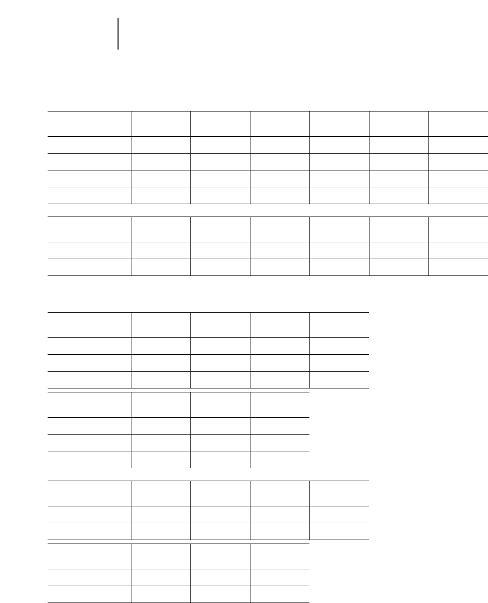
Belgium Sourced
330B LN ●Reach Boom ●600 mm (2'0") Track Shoes
3 m 4.5 m 6 m 7.5 m 9 m
10'0" 15'0" 20'0" 25'0" 30'0" At Max. Reach
Stick Bucket Front Side Front Side Front Side Front Side Front Side Front Side
2.2 m 1.7 m3kg ——
17 110* 11 240 12 530* 7300 9080 5190 ——
6330 3600
7'3" 2.2 yd3lb 37,720* 24,780 27,620* 16,090 20,020 11,440 13,950 7930
2.8 m 1.5 m3kg ——
17 620* 11 600 12 660* 7540 9270 5380 6930 4010 5470* 3370
9'2" 1.96 yd3lb 38,850* 25,570 27,910* 16,620 20,440 11,860 15,280 8840 12,060* 7430
3.3 m 1.45 m3kg 6660* 6660* 17 510* 11 670 12 460* 7590 9290 5400 6940 4020 3800* 3110
10'10" 1.89 yd3lb 14,680* 14,680* 38,600* 25,730 27,470* 16,730 20,480 11,900 15,300 8860 8370* 6850
3.9 m 1.3 m3kg 7280* 7280* 17 070* 11 760 12 080* 7620 9310 5410 6930 4010 3160* 2790
12'9" 1.7 yd3lb 16,050* 16,050* 37,630* 25,930 26,630* 16,800 20,520 11,920 10,870 8840 6960* 6150
330B LN ●Mass Boom ●600 mm (2'0") Track Shoes
3 m 4.5 m 6 m 7.5 m 9 m
10'0" 15'0" 20'0" 25'0" 30'0" At Max. Reach
Stick Bucket Front Side Front Side Front Side Front Side Front Side Front Side
2.2 m 1.9 m3kg ——
17 460* 11 590 12 720* 7500 9210 5310 ——
6860 3940
7'3" 2.4 yd3lb 38,490* 25,550 28,040* 16,530 20,300 11,700 15,120 8680
2.6 m 1.7 m3kg ——
17 600* 11 660 12 650* 7520 9210 5310 ——
5570* 3590
8'6" 2.2 yd3lb 38,800* 25,700 27,390* 16,580 20,300 11,700 12,280* 7910
Japan Sourced
345B ●Reach Boom ●600 mm (2'0") Track Shoes
3 m 4.5 m 6 m 7.5 m
10'0" 15'0" 20'0" 25'0"
Stick Bucket Front Side Front Side Front Side Front Side
2900 mm F1590X kg ——
18 100* 15 150 15 650* 9700 11 050 6900
9'6" 5'3" lb 42,150* 32,500 33,650* 20,900 23,650 14,750
3350 mm T1580X kg ——
19 250* 15 350 15 650* 9850 11 100 7000
10'0" 5'3" lb 44,700* 33,000 33,800* 21,200 23,850 14,950
3900 mm F1218T kg 7750* 7750* 21 600* 15 800 15 600* 10 150 11 350 7200
12'10" 4'0" lb 17,600* 17,600* 47,700* 33,950 33,700* 21,850 24,350 15,400
9 m 10.5 m
30'0" 35'0" At Max. Reach
Stick Bucket Front Side Front Side Front Side
2900 mm F1590X kg 8200 5100 ——
5650* 3850
9'6" 5'3" lb 17,600 10,900 12,400* 8500
3350 mm T1580X kg 8250 5150 ——
4900* 3650
10'0" 5'3" lb 17,750 11,050 10,750* 8000
3900 mm F1218T kg 8450 5300 6500 4000 4800* 3450
12'10" 4'0" lb 18,100 11,400 14,150 8850 10,500* 7600
345B ●Mass Boom ●600 mm (2'0") Track Shoes
3 m 4.5 m 6 m 7.5 m
10'0" 15'0" 20'0" 25'0"
Stick Bucket Front Side Front Side Front Side Front Side
2500 mm G1770X kg ——
20 750* 14 600 15 100* 9300 10650 6450
8'2" 5'10" lb 42,150* 32,500 33,650* 20,900 23,650 14,750
3000 mm U1830V kg ——
20 950* 14 650 14 900* 9250 10 600 6400
9'10" 5'9" lb 45,350* 31,400 32,200* 19,850 22,650 13,650
9 m 10.5 m
30'0" 35'0" At Max. Reach
Stick Bucket Front Side Front Side Front Side
2500 mm G1770X kg ————
6700 3950
8'2" 5'10" lb 14,750 8650
3000 mm U1830V kg 7700 4550 ——
5600* 3550
9'10" 5'9" lb 16,500 9700 12,300* 7750
*Load limited by hydraulic capacity rather than tipping.
4-78
Excavators Lifting Capacity At Ground Level
●330B LN ●345B

Japan/U.S. Sourced
345B L – FIX ●Reach Boom ●750 mm (2'6") Track Shoes
3 m 4.5 m 6 m 7.5 m
10'0" 15'0" 20'0" 25'0"
Stick Bucket Front Side Front Side Front Side Front Side
2900 mm F1735X kg ——
18 000* 15 700 15 600* 10 100 11 950* 7150
9'6" 5'8" lb 41,900* 33,750 33,700* 21,650 25,800* 15,300
3350 mm F1590X kg ——
19 200* 15 950 15 600* 10 250 11 950* 7250
11'0" 5'3" lb 44,600* 34,300 33,700* 22,050 25,800* 15,600
3900 mm F1218T kg 7750* 7750* 21 600* 16 450 15 600* 10 600 11 950* 7500
12'10" 4'0" lb 17,600* 17,600* 47,700* 35,300 33,700* 22,750 25,850* 16,100
9 m 10.5 m
30'0" 35'0" At Max. Reach
Stick Bucket Front Side Front Side Front Side
2900 mm F1735X kg 9550 5300 ——
5500* 4000
9'6" 5'8" lb 20,450 11,300 12,200* 8800
3350 mm F1590X kg 9600* 5350 ——
4800* 3800
11'0" 5'3" lb 20,650 11,500 10,500* 8300
3900 mm F1218T kg 9700* 5550 7050* 4250 4800* 3650
12'10" 4'0" lb 20,900* 11,950 15,300* 9300 10,500* 8000
345B L – FIX ●Mass Boom ●750 mm (2'6") Track Shoes
3 m 4.5 m 6 m 7.5 m
10'0" 15'0" 20'0" 25'0"
Stick Bucket Front Side Front Side Front Side Front Side
2500 mm G1770X kg ——
20 750* 15 250 15 100* 9700 11 500* 6800
8'2" 5'10" lb 45,050* 32,750 32,650* 20,850 24,850* 14,550
3000 mm U1830V kg ——
20 950* 15 250 14 900* 9650 11 350* 6700
9'10" 6'0" lb 45,350* 32,800 32,200* 20,750 24,450* 14,350
9 m 10.5 m
30'0" 35'0" At Max. Reach
Stick Bucket Front Side Front Side Front Side
2500 mm G1770X kg ————
7100* 4150
8'2" 5'10" lb 15,650* 9150
3000 mm U1830V kg 8950* 4800 ——
5600* 3750
9'10" 6'0" lb 19,200* 10,250 12,300* 8250
*Load limited by hydraulic capacity rather than tipping.
4-79
4
ExcavatorsLifting Capacity At Ground Level
●345B L – FIX

U.S. Sourced
345B L – VG ●Reach Boom ●600 mm (2'0") Track Shoes
3 m 4.5 m 6 m 7.5 m
10'0" 15'0" 20'0" 25'0"
Stick Bucket Front Side Front Side Front Side Front Side
2900 mm F1735X kg ——
18 600* 18 600* 15 600* 12 050 11 950* 8600
9'6" 5'8" lb 43,200* 40,550 33,750* 25,950 25,800* 18,450
3350 mm F1590X kg ——
19 550* 19 150 15 650* 12 250 12 000* 8700
11'0" 5'3" lb 45,350* 41,100 33,800* 26,350 25,900* 18,700
3900 mm F1410T kg 8050* 8050* 21 500* 19 450 15 500* 12 450 11 850* 8850
12'10" 4'8" lb 18,300* 18,300* 47,450* 41,800 33,550* 26,750 25,650* 18,950
9 m 10.5 m
30'0" 35'0" At Max. Reach
Stick Bucket Front Side Front Side Front Side
2900 mm F1735X kg 9550* 6450 ——
5650* 5000
9'6" 5'8" lb 20,550* 13,800 12,400* 11,000
3350 mm F1590X kg 9600* 6500 ——
4850* 4700
11'0" 5'3" lb 20,750* 13,950 10,650* 10,400
3900 mm F1410T kg 9550* 6600 6650* 5050 4700* 4400
12'10" 4'8" lb 20,650* 14,100 14,650* 11,100 10,350* 9650
345B L – VG ●Mass Boom ●600 mm (2'0") Track Shoes
3 m 4.5 m 6 m 7.5 m
10'0" 15'0" 20'0" 25'0"
Stick Bucket Front Side Front Side Front Side Front Side
2500 mm G1770X kg ——
21 000* 18 550 15 000* 11 750 11 400* 8200
8'2" 5'10" lb 45,450* 39,750 32,400* 25,200 24,600* 17,600
3000 mm G1895M kg ——
20 600* 18 400 15 000* 11 650 11 400* 8150
9'10" 6'0" lb 44,700* 39,450 32,400* 25,000 24,600* 17,500
9 m 10.5 m
30'0" 35'0" At Max. Reach
Stick Bucket Front Side Front Side Front Side
2500 mm G1770X kg 8950* 6000 ——
7100* 4150
8'2" 5'10" lb 19,250* 12,900 15,650* 9150
3000 mm G1895M kg ————
7150* 5200
9'10" 6'0" lb 15,750* 11,400
*Load limited by hydraulic capacity rather than tipping.
4-80
Excavators Lifting Capacity At Ground Level
●345B L – VG
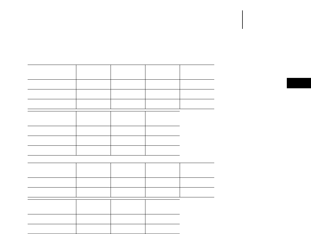
Belgium Sourced**
345B L – VG ●Reach Boom ●600 mm (2'0") Track Shoes
3 m 4.5 m 6 m 7.5 m
10'0" 15'0" 20'0" 25'0"
Stick Bucket Front Side Front Side Front Side Front Side
2900 mm F1735X kg
9'6" 5'8" lb
3350 mm F1590X kg
11'0" 5'3" lb
3900 mm F1410T kg
12'10" 4'8" lb
9 m 10.5 m
30'0" 35'0" At Max. Reach
Stick Bucket Front Side Front Side Front Side
2900 mm F1735X kg
9'6" 5'8" lb
3350 mm F1590X kg
11'0" 5'3" lb
3900 mm F1410T kg
12'10" 4'8" lb
345B L – VG ●Mass Boom ●600 mm (2'0") Track Shoes
3 m 4.5 m 6 m 7.5 m
10'0" 15'0" 20'0" 25'0"
Stick Bucket Front Side Front Side Front Side Front Side
2500 mm G1770X kg
8'2" 5'10" lb
3000 mm G1895M kg
9'10" 6'0" lb
9 m 10.5 m
30'0" 35'0" At Max. Reach
Stick Bucket Front Side Front Side Front Side
2500 mm G1770X kg
8'2" 5'10" lb
3000 mm G1895M kg
9'10" 6'0" lb
**Information unavailable.
4-81
4
ExcavatorsLifting Capacity At Ground Level
●345B L – VG

4-82
Excavators Lifting Capacity At Ground Level
●350
Japan Sourced
350 ●Reach Boom ●600 mm (2'0") Triple Grousers
3 m 4.5 m 6 m 7.5 m
10'0" 15'0" 20'0" 25'0"
Stick Bucket Front Side Front Side Front Side Front Side
4800 mm F1075T kg 5950* 5950* 16 600* 16 600* 14 250* 11 700 10 850* 8250
15'9" 3'6" lb 13,500* 13,500* 38,500* 38,500* 30,800* 25,100 23,450* 17,700
3600 mm F1410T kg ——
13 850* 13 850* 15 150* 11 450 11 550 8150
11'10" 4'8" lb 32,100* 32,100* 32,700* 24,650 24,750 17,450
3100 mm F1590X kg ——
12 500* 12 500* 15 300* 11 350 11 450 8050
10'2" 5'3" lb 29,200* 29,200* 33,050* 24,400 24,600 17,300
9 m 10.5 m
30'0" 35'0" At Max. Reach
Stick Bucket Front Side Front Side Front Side
4800 mm F1075T kg 8700 6150 6700 4700 2900* 2900*
15'9" 3'6" lb 18,650 13,150 14,400 10,000 6400* 6400*
3600 mm F1410T kg 8600 6050 6650 4650 3750* 3750*
11'10" 4'8" lb 18,450 13,000 12,250* 9900 8250* 8250*
3100 mm F1590X kg 8600 6050 ——
5300* 4250
10'2" 5'3" lb 18,400 12,900 11,700* 9350
350 ●Mass Boom ●600 mm (2'0") Triple Grousers
3 m 4.5 m 6 m 7.5 m
10'0" 15'0" 20'0" 25'0"
Stick Bucket Front Side Front Side Front Side Front Side
3700 mm F1590X kg 6950* 6950* 19 800* 18 350 15 050* 11 600 11 500* 8150
12'2" 5'3" lb 15,800* 15,800* 46,000* 39,350* 32,500* 24,850 24,800* 17,450
2950 mm G1655X kg ——
16 550* 17 850 15 050* 11 200 11 250 7850
9'8" 5'5" lb 43,250 38,300 32,550* 24,100 24,200 16,850
2400 mm G1770X kg ——
18 300* 17 550 15 000* 11 050 11 200 7750
7'10" 5'10" lb 42,800* 37,650 32,450* 23,700 24,000 16,700
9 m 10.5 m
30'0" 35'0" At Max. Reach
Stick Bucket Front Side Front Side Front Side
3700 mm F1590X kg 8600 6000 ——
2800* 2800*
12'2" 5'3" lb 18,400 12,850 6200* 6200*
2950 mm G1655X kg 8350 5750 ——
4450* 4450
9'8" 5'5" lb 17,850 12,350 9800* 9750
2400 mm G1770X kg ————
6500* 4900
7'10" 5'10" lb 14,350* 10,800*
*Load limited by hydraulic capacity rather than tipping.

Japan Sourced
350 Heavy Lift ●Reach Boom ●600 mm (2'0") Triple Grousers
3 m 4.5 m 6 m 7.5 m
10'0" 15'0" 20'0" 25'0"
Stick Bucket Front Side Front Side Front Side Front Side
4800 mm F1075T kg 6450* 6450* 17 750* 17 750* 16 150* 11 700 11 650 8250
15'9" 3'6" lb 14,650* 14,650* 41,250* 39,450* 34,900* 25,100 25,050 17,700
3600 mm F1410T kg ——
14 850* 14 850* 16 500 11 450 11 550 8150
11'10" 4'8" lb 34,400* 34,400* 35,350 24,650 24,750 17,450
3100 mm F1590X kg ——
13 450* 13 450* 16 350 11 350 11 450 8050
10'2" 5'3" lb 31,300* 31,300* 35,050 24,400 24,600 17,300
9 m 10.5 m
30'0" 35'0" At Max. Reach
Stick Bucket Front Side Front Side Front Side
4800 mm F1075T kg 8700 6150 6700 4700 3350* 3300
15'9" 3'6" lb 18,650 13,150 14,400 10,000 7400* 7200
3600 mm F1410T kg 8600 6050* 6650 4650 4300* 3900
11'10" 4'8" lb 18,450 13,000 13,800* 9900 9400* 8600
3100 mm F1590X kg 8600 6050 ——
6000* 4250
10'2" 5'3" lb 18,400 12,900 13,200* 9350
350 Heavy Lift ●Mass Boom ●600 mm (2'0") Triple Grousers
3 m 4.5 m 6 m 7.5 m
10'0" 15'0" 20'0" 25'0"
Stick Bucket Front Side Front Side Front Side Front Side
3700 mm F1590X kg 7550* 7550* 21 200* 18 350 16 600 11 600 11 550 8150
12'2" 5'3" lb 17,100* 17,100* 49,250* 39,350 35,650 24,850 24,800 17,450
2950 mm G1655X kg ——
19 900* 17 850 16 250 11 200 11 250 7850
9'8" 5'5" lb 46,350* 38,300 34,650 24,100 24,200 16,850
2400 mm G1770X kg ——
19 600* 17 550 16 050 11 050 11 200 7750
7'10" 5'10" lb 45,800* 37,650 34,450 23,700 24,000 16,700
9 m 10.5 m
30'0" 35'0" At Max. Reach
Stick Bucket Front Side Front Side Front Side
3700 mm F1590X kg 8600 6000 ——
3300* 3300*
12'2" 5'3" lb 18,400 12,850 7200* 7200*
2950 mm G1655X kg 8350 5750 ——
5100* 4450
9'8" 5'5" lb 17,850 12,350 11,150* 9750
2400 mm G1770X kg ————
7150 4900
7'10" 5'10" lb 15,700 10,800
*Load limited by hydraulic capacity rather than tipping.
4-83
4
ExcavatorsLifting Capacity At Ground Level
●350

Japan Sourced
350 L ●Reach Boom ●750 mm (2'6") Triple Grousers
3 m 4.5 m 6 m 7.5 m
10'0" 15'0" 20'0" 25'0"
Stick Bucket Front Side Front Side Front Side Front Side
4800 mm F1218T kg 5850* 5850* 16 500* 16 500* 14 200* 12 100 10 800* 8550
15'9" 4'0" lb 13,250* 13,250* 38,250* 38,250* 30,600* 25,950 23,300* 18,300
3600 mm F1410T kg ——
13 850* 13 850* 15 150* 11 950 11 550* 8450
11'10" 4'8" lb 32,100* 32,100* 32,700* 25,650 24,900* 18,200
3100 mm F1735X kg ——
12 450* 12 450* 15 250* 11 750 11 650* 8350
10'2" 5'3" lb 29,000* 29,000* 32,950* 25,300 25,150* 17,950
9 m 10.5 m
30'0" 35'0" At Max. Reach
Stick Bucket Front Side Front Side Front Side
4800 mm F1218T kg 8700* 6350 7350* 4850 2850* 2850*
15'9" 4'0" lb 18,850* 13,550 15,900* 10,300 6200* 6200*
3600 mm F1410T kg 9300* 6350 7250* 4850 3750* 3750*
11'10" 4'8" lb 20,050* 13,550 12,250* 10,400 8250* 8250*
3100 mm F1735X kg 9350* 6250 ——
5250* 4400
10'2" 5'3" lb 20,200* 13,400 11,550* 9700
350 L ●Mass Boom ●750 mm (2'6") Triple Grousers
3 m 4.5 m 6 m 7.5 m
10'0" 15'0" 20'0" 25'0"
Stick Bucket Front Side Front Side Front Side Front Side
3700 mm F1735X kg 6900* 6900* 19 700* 19 000 15 000* 12 000 11 450* 8450
12'2" 5'8" lb 15,650* 15,650* 45,800* 40,750* 32,400* 25,750 24,700* 18,100
2950 mm G1770X kg ——
18 450* 18 450 14 950 11 600 11 350* 8100
9'8" 5'10" lb 43,050* 39,550 32,300* 24,900 24,550* 17,400
2400 mm G1895M kg ——
18 050* 18 050* 14 900* 11 450 11 400* 8050
7'10" 6'3" lb 42,250* 39,050* 32,250* 24,600 24,550* 17,250
9 m 10.5 m
30'0" 35'0" At Max. Reach
Stick Bucket Front Side Front Side Front Side
3700 mm F1735X kg 9200* 6250 ——
2750* 2750*
12'2" 5'8" lb 19,900* 13,350 6050* 6050*
2950 mm G1770X kg 9000* 5950 ——
4350* 4350*
9'8" 5'10" lb 19,450* 12,750 9600* 9600*
2400 mm G1895M kg ————
6450* 5050
7'10" 6'3" lb 14,150* 11,150
*Load limited by hydraulic capacity rather than tipping.
4-84
Excavators Lifting Capacity At Ground Level
●350 L
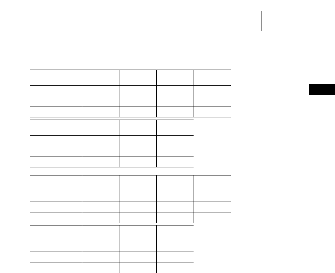
4-85
4
ExcavatorsLifting Capacity At Ground Level
●350 L
Japan Sourced
350 L Heavy Lift ●Reach Boom ●750 mm (2'6") Triple Grousers
3 m 4.5 m 6 m 7.5 m
10'0" 15'0" 20'0" 25'0"
Stick Bucket Front Side Front Side Front Side Front Side
4800 mm F1218T kg 6350* 6350* 17 650* 17 650* 16 050* 12 100 12 300* 8550
15'9" 4'0" lb 14,400* 14,400* 41,000* 40,800* 34,700* 25,950 26,550* 18,300
3600 mm F1410T kg ——
14 850* 14 850* 17 150* 11 950 13 100* 8450
11'10" 4'8" lb 34,400* 34,400* 37,050 25,650 28,350* 18,200
3100 mm F1735X kg ——
13 350* 13 350* 17 250* 11 750 13 200* 8350
10'2" 5'3" lb 31,150* 31,150* 37,300* 25,300 28,600* 17,950
9 m 10.5 m
30'0" 35'0" At Max. Reach
Stick Bucket Front Side Front Side Front Side
4800 mm F1218T kg 10 000* 6350 8150 4850 3300* 3300*
15'9" 4'0" lb 21,600* 13,550 17,500 10,300 7200* 7200*
3600 mm F1410T kg 10 550 6350 8100* 4850 4300* 4100
11'10" 4'8" lb 22,600 13,550 13,800* 10,400 9400* 9050
3100 mm F1735X kg 10 450 6250 ——
5950* 4400
10'2" 5'3" lb 22,450 13,400 13,050* 9700
350 L Heavy Lift ●Mass Boom ●750 mm (2'6") Triple Grousers
3 m 4.5 m 6 m 7.5 m
10'0" 15'0" 20'0" 25'0"
Stick Bucket Front Side Front Side Front Side Front Side
3700 mm F1735X kg 7450* 7450* 21 100* 19 000 16 950* 12 000 13 000* 8450
12'2" 5'8" lb 16,950* 16,950* 49,050* 40,750 36,660* 25,750 28,100* 18,100
2950 mm G1770X kg ——
19 800 18 450 16 950* 11 600 12 950* 8100
9'8" 5'10" lb 46,100* 39,550 36,700* 24,900 28,000* 17,400
2400 mm G1895M kg ——
19 350* 18 200 16 950* 11 450 13 000* 8050
7'10" 6'3" lb 45,250* 39,050 36,650* 24,600 28,050* 17,250
9 m 10.5 m
30'0" 35'0" At Max. Reach
Stick Bucket Front Side Front Side Front Side
3700 mm F1735X kg 10 450 6250 ——
3200* 3200*
12'2" 5'8" lb 22,450 13,350 7050* 7050*
2950 mm G1770X kg 10 200 5950 ——
5000* 4600
9'8" 5'10" lb 21,850 12,750 10,950* 10,050
2400 mm G1895M kg ————
7250* 5050
7'10" 6'3" lb 15,950* 11,150
*Load limited by hydraulic capacity rather than tipping.

4-86
Excavators Lifting Capacity At Ground Level
●375
Japan/U.S. Sourced
375 ●Reach Boom ●610 mm (2'0") Double Grousers
4.5 m 6 m 7.5 m 9 m
15'0" 20'0" 25'0" 30'0"
Stick Bucket Front Side Front Side Front Side Front Side
5500 mm H1380T kg 10 400* 10 400* 27 400* 23 650 20 850* 16 800 16 650* 12 650
18'1" 4'6" lb 24,050* 24,050* 59,200* 50,850 45,000* 36,100 36,000* 27,150
4400 mm H1800X kg 9600* 9600* 25 900* 22 850 21 050* 16 200 16 900* 12 250
14'5" 5'10" lb 22,250* 22,250* 59,200* 49,100 45,500* 34,850 36,450* 26,300
3400 mm J1780X kg ——
20 050* 20 050* 20 350* 15 350 16 300* 11 500
11'2" 5'10" lb 47,650* 46,700 43,950* 32,950 35,000 24,750
2900 mm J1865X kg ——
17 600* 17 600* 20 150* 15 200 16 200 11 400
9'6" 6'1" lb 42,450* 42,450* 43,550* 32,650 34,800 24,500
10.5 m 12 m 13.5 m
35'0" 40'0" 45'0" At Max. Reach
Stick Bucket Front Side Front Side Front Side Front Side
5500 mm H1380T kg 13 650 9850 10 950 7800 8900 6250 5200* 5100
18'1" 4'6" lb 29,300 21,100 23,450 16,700 19,050 13,350 11,450* 11,250
4400 mm H1800X kg 13 350 9550 10 700 7600 ——
8050* 5900
14'5" 5'10" lb 28,600 20,500 22,950 16,200 17,750* 12,950
3400 mm J1780X kg 12 700 8950 10 150 7050 ——
8750 6000
11'2" 5'10" lb 27,250 19,150 22,350 15,500 19,300 13,250
2900 mm J1865X kg 12 650 8850 ————
9250 6350
9'6" 6'1" lb 27,100 18,950 20,350 14,000
375 ●GP Boom ●610 mm (2'0") Double Grousers
4.5 m 6 m 7.5 m 9 m
15'0" 20'0" 25'0" 30'0"
Stick Bucket Front Side Front Side Front Side Front Side
5500 mm H1380T kg 13 700* 13 700* 27 700* 24 350 21 100* 17 200 16 900* 12 950
18'1" 4'6" lb 31,600* 31,600* 59,800* 52,300 45,500* 37,050 36,600* 27,800
4400 mm H1800X kg 13 100* 13 100* 27 900* 23 500 21 400* 16 650 17 200* 12 550
14'5" 5'10" lb 30,250* 30,250* 60,350* 50,550 46,300* 35,850 37,150* 27,000
3400 mm J1780X kg ——
26 700* 22 450 20 800* 15 800 16 650* 11 850
11'2" 5'10" lb 57,900* 48,200 44,950* 33,950 35,750 25,450
10.5 m 12 m 13.5 m
35'0" 40'0" 45'0" At Max. Reach
Stick Bucket Front Side Front Side Front Side Front Side
5500 mm H1380T kg 13 850 10 100 11 100 8000 7800* 6400 4150* 4150*
18'1" 4'6" lb 29,750 21,600 23,800 17,100 12,800* 12,800* 9100* 9100*
4400 mm H1800X kg 13 550 9800 10 900 7750 ——
6750* 6300
14'5" 5'10" lb 29,150 21,000 23,350 16,600 14,850* 13,900
3400 mm J1780X kg 12 950 9200 ————
7850* 6550
11'2" 5'10" lb 27,800 19,650 17,250* 14,350
375 ●Mass Boom ●610 mm (2'0") Double Grousers
4.5 m 6 m 7.5 m 9 m 10.5
15'0" 20'0" 25'0" 30'0" 35'0" At Max. Reach
Stick Bucket Front Side Front Side Front Side Front Side Front Side Front Side
4100 mm J2040X kg 23 650* 23 650* 27 950* 22 650 21 350* 15 700 16 300 11 550 12 500 8750 7050* 6650
13'5" 6'8" lb 54,750* 54,750* 60,400* 48,600 46,100* 33,700 34,950 24,750 26,700 18,650 15,500* 14,700
3400 mm J2210X kg 22 450* 22 450* 27 750* 22 350 21 350* 15 550 16 250 11 500 ——
8900* 7500
11'2" 7'3" lb 52,050* 52,050* 60,050* 47,950 46,150* 33,400 34,800 24,600 19,550* 16,500
2900 mm J2390MX kg 20 850* 20 850* 27 100* 21 900* 20 950* 15 250 15 950 11 250 ——
9400* 7850
9'6" 7'10" lb 48,450* 48,450* 58,650* 47,000 45,200* 32,700 34,250 24,050 20,750* 17,300
**Load limited by hydraulic capacity rather than tipping.
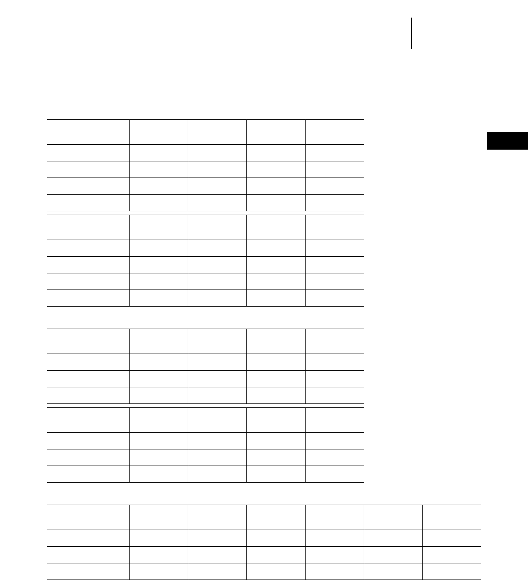
4-87
4
ExcavatorsLifting Capacity At Ground Level
●375
Japan/U.S. Sourced
375 Heavy Lift ●Reach Boom ●750 mm (2'6") Double Grousers
●11.6 t (25,600 lb) Counterweight with C/W removal
4.5 m 6 m 7.5 m 9 m
15'0" 20'0" 25'0" 30'0"
Stick Bucket Front Side Front Side Front Side Front Side
5500 mm H1380T kg 11 300 11 300 29 600 24 500 22 700 17 400 18 050 13 150
18'1" 4'6" lb 26,050 26,050 64,400 52,700 49,100 37,450 38,800 28,250
4400 mm H1800X kg 10 400 10 400 27 750 23 700 23 000 16 850 17 650 12 750
14'5" 5'10" lb 24,150 24,150 64,500 50,950 49,700 36,200 37,900 27,350
3400 mm J1780X kg ——
21 550 21 550 22 250 15 950 16 900 12 000
11'2" 5'10" lb 51,150 48,550 48,150 34,300 36,300 25,800
2900 mm J1865X kg ——
18 950 18 950 22 050 15 850 16 800 11 900
9'6" 6'1" lb 45,650 45,650 47,750 34,000 36,050 25,600
10.5 m 12 m 13.5 m
35'0" 40'0" 45'0" At Max. Reach
Stick Bucket Front Side Front Side Front Side Front Side
5500 mm H1380T kg 14 100 10 250 11 350 8150 9250 6550 5700* 5350
18'1" 4'6" lb 30,300 22,000 24,300 17,450 19,850 14,000 12,600* 11,800
4400 mm H1800X kg 13 800 9950 11 100 7950 ——
8750* 6200
14'5" 5'10" lb 29,650 21,350 23,800 17,000 19,250* 13,600
3400 mm J1780X kg 13 200 9350 10 550 7400 ——
9150 6350
11'2" 5'10" lb 28,300 20,000 23,250 16,250 20,100 13,950
2900 mm J1865X kg 13 100 9250 ————
9650 6700
9'6" 6'1" lb 28,150 19,850 21,200 14,750
375 Heavy Lift ●GP Boom ●750 mm (2'6") Double Grousers
●11.6 t (25,600 lb) Counterweight with C/W removal
4.5 m 6 m 7.5 m 9 m
15'0" 20'0" 25'0" 30'0"
Stick Bucket Front Side Front Side Front Side Front Side
5500 mm H1380T kg 14 800 14 800 30 050 25 200 22 950 17 850 18 350 13 450
18'1" 4'6" lb 34,050 34,050 64,950 54,150 49,600 38,400 39,450 28,900
4400 mm H1800X kg 14 150 14 150 30 300 24 350 23 350 17 300 17 950 13 050
14'5" 5'10" lb 32,600 32,600 65,600 52,400 50,450 37,200 38,600 28,050
3400 mm J1780X kg ——
29 150 23 300 22 700 16 450 17 250 12 350
11'2" 5'10" lb 63,150 50,000 49,150 35,350 37,050 26,500
10.5 m 12 m 13.5 m
35'0" 40'0" 45'0" At Max. Reach
Stick Bucket Front Side Front Side Front Side Front Side
5500 mm H1380T kg 14 350 10 500 11 500 8350 8500 6700 4600* 4600*
18'1" 4'6" lb 30,800 22,500 24,700 17,850 14,050 14,050 10,050* 10,050*
4400 mm H1800X kg 14 050 10 200 11 300 8100 ——
7350* 6600
14'5" 5'10" lb 30,200 21,850 24,200 17,350 16,200* 14,550
3400 mm J1780X kg 13 450 9600 ————
8550* 6850
11'2" 5'10" lb 28,850 20,550 18,800* 15,050
375 Heavy Lift ●Mass Boom ●750 mm (2'6") Double Grousers
●11.6 t (25,600 lb) Counterweight with C/W removal
4.5 m 6 m 7.5 m 9 m 10.5
15'0" 20'0" 25'0" 30'0" 35'0" At Max. Reach
Stick Bucket Front Side Front Side Front Side Front Side Front Side Front Side
4100 mm J2040X kg 25 450 25 450 30 350 24 950 23 250 17 400 17 850 12 850 13 750 9850 7700* 7600
13'5" 6'8" lb 58,800 58,800 65,700 53,550 50,300 37,350 38,250 27,600 29,400 21,000 16,950* 16,700
3400 mm J2210X kg 24 150 24 150 30 200 24 600 23 300 17 250 17 750 12 800 ——
9650* 8500
11'2" 7'3" lb 55,900 55,900 65,350 52,850 50,350 37,000 38,150 27,500 21,300* 18,650
2900 mm J2390MX kg 22 400 22 400 29 500 24 200 22 850 16 900 17 500 12 550 ——
10 250* 8900
9'6" 7'10" lb 52,100 52,100 63,900 51,950 49,400 36,350 37,550 26,900 22,550* 19,550
**Load limited by hydraulic capacity rather than tipping.

Belgium Sourced
375 ●GP Boom ●610 mm (2'0") Track Shoes
4.5 m 6 m 7.5 m 9 m
15'0" 20'0" 25'0" 30'0"
Stick Bucket Front Side Front Side Front Side Front Side
3.4 m 3.6 m3kg ——
26 120* 22 200 20 270* 15 600 16 180* 11 660
11'2" 4.7 yd3lb 57,590* 48,950 44,690* 34,390 35,670* 25,710
4.4 m 3.2 m3kg 12 880* 12 880* 27 500* 23 510 21 080* 16 640 16 890* 12 510
14'5" 4.1 yd3lb 28,400* 28,400* 60,630* 51,830 46,480* 36,690 37,240* 27,580
5.5 m 2.8 m3kg 13 390* 13 390* 27 090* 24 130 20 560* 17 010 16 440* 12 730
18'1" 3.6 yd3lb 29,520* 29,520* 59,730* 53,200 45,330* 37,500 36,250* 28,060
10.5 m 12 m 13.5 m
35'0" 40'0" 45'0" At Max. Reach
Stick Bucket Front Side Front Side Front Side Front Side
3.4 m 3.6 m3kg 12 760 8970 ————
7520* 6240
11'2" 4.7 yd3lb 28,130 19,770 16,580* 13,750
4.4 m 3.2 m3kg 13 510* 9720 10 800 7680 ——
6590* 6160
14'5" 4.1 yd3lb 29,780* 21,430 23,800 16,930 14,530* 13,580
5.5 m 2.8 m3kg 13 640* 9840 10 870 7740 7630* 6150 3930* 3930
18'1" 3.6 yd3lb 30,070* 21,690 23,960 17,060 16,820* 13,560 8660* 8660
375 ●Mass Boom ●610 mm (2'0") Track Shoes
4.5 m 6 m 7.5 m 9 m 10.5 m
15'0" 20'0" 25'0" 30'0" 35'0" At Max. Reach
Stick Bucket Front Side Front Side Front Side Front Side Front Side Front Side
2.9 m 4.4 m3kg 20 590* 20 590* 26 750* 23 340 20 650* 16 290 16 250* 12 050 ——
9250* 8390
9'6" 5.75 yd3lb 45,400* 45,400* 58,980* 51,460 45,530* 35,910 35,830* 26,570 20,390* 18,490
3.4 m 4.4 m3kg 21 910* 21 910* 27 100* 23 520 20 770* 16 350 16 390* 12 050 12 720* 9130 8480* 7740
11'2" 5.75 yd3lb 48,310* 48,310* 59,750* 51,860 45,790* 36,050 36,130* 26,570 28,040* 20,130 18,690* 17,060
4.1 m 3.6 m3kg 23 620* 23 620* 27 600* 24 090 21 060* 16 770 16 740* 12 370 13 230* 9410 6930* 6930*
13'5" 4.7 yd3lb 52,080* 52,080* 60,850* 53,110 46,430* 36,970 36,910* 27,270 29,170* 20,740 15,280* 15,280*
Japan/U.S. Sourced
375 ●Reach Boom ●750 mm (2'6") Double Grousers
4.5 m 6 m 7.5 m 9 m
15'0" 20'0" 25'0" 30'0"
Stick Bucket Front Side Front Side Front Side Front Side
5500 mm H1380T kg 10 450* 10 450* 27 400* 24 900 20 850* 17 700 16 700* 13 350
18'1" 4'6" lb 24,100* 24,100* 59,200* 53,500 45,000* 38,050 36,050* 28,700
4400 mm H1800X kg 9650* 9650* 25 900* 24 100 21 050* 17 150 16 900* 12 950
14'5" 5'11" lb 22,350* 22,350* 59,200* 51,750 45,500* 36,850 36,450* 27,850
3400 mm J1780X kg ——
20 100* 20 100* 20 350* 16 250 16 300* 12 250
11'2" 5'10" lb 47,750* 47,750* 43,950* 34,950 35,200* 26,300
2900 mm J1865X kg ——
17 700* 17 700* 20 150* 16 100 16 200* 12 150
9'6" 6'1" lb 42,650* 42,650* 43,550* 34,650 35,000* 26,050
10.5 m 12 m 13.5 m
35'0" 40'0" 45'0" At Max. Reach
Stick Bucket Front Side Front Side Front Side Front Side
5500 mm H1380T kg 13 850* 10 450 11 750 8300 10 100* 6700 5200* 5200*
18'1" 4'6" lb 29,900* 22,400 25,400 17,800 20,650* 14,300 11,450* 11,450*
4400 mm H1800X kg 13 950* 10 150 11 750* 8100 ——
8050* 6300
14'5" 5'11" lb 30,150* 21,750 25,250* 17,300 17,750* 13,900
3400 mm J1780X kg 13 350* 9500 10 900* 7550 ——
9200* 6500
11'2" 5'10" lb 28,800* 20,400 24,000* 16,600 20,250* 14,250
2900 mm J1865X kg 13 250* 9450 ————
9450* 6850
9'6" 6'1" lb 28,500* 20,250 20,750* 15,100
**Load limited by hydraulic capacity rather than tipping.
4-88
Excavators Lifting Capacity At Ground Level
●375
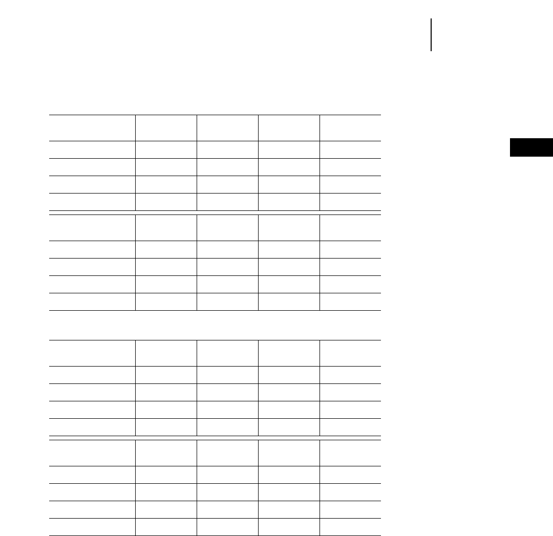
4-89
4
ExcavatorsLifting Capacity At Ground Level
●375 L
Japan/U.S. Sourced
375 L ●GP Boom ●750 mm (2'6") Double Grousers
4.5 m 6 m 7.5 m 9 m
15'0" 20'0" 25'0" 30'0"
Stick Bucket Front Side Front Side Front Side Front Side
5500 mm H1380T kg 13 700* 13 700* 27 700* 25 550 21 100* 18 150 16 950* 13 650
18'1" 4'6" lb 31,650* 31,650* 59,850* 54,950 45,550* 39,000 36,600* 29,350
4400 mm H1800X kg 13 150* 13 150* 27 900* 24 750 21 400* 17 600 17 200* 13 300
14'5" 5'10" lb 30,350* 30,350* 60,350* 53,200 46,300* 37,800 37,150* 28,550
3400 mm J1865X kg ——
26 600* 23 550 20 650* 16 600 16 550* 12 500
11'2" 6'1 lb 57,600* 50,600 44,700* 35,700 35,700* 26,800
2900 mm J1865X kg ——
25 850* 23 500 20 650* 16 600 16 550* 12 500
9'6" 6'1" lb 56,750* 50,500 44,600* 35,650 35,750* 26,800
10.5 m 12 m 13.5 m
35'0" 40'0" 45'0" At Max. Reach
Stick Bucket Front Side Front Side Front Side Front Side
5500 mm H1380T kg 14 100* 10 650 12 000* 8500 7800* 6850 4150* 4150*
18'1" 4'6" lb 30,500* 22,900 25,950* 18,200 12,750* 12,750* 9100* 9100*
4400 mm H1800X kg 14 250* 10 400 11 950* 8300 ——
6750* 6750
14'5" 5'10" lb 30,750* 22,250 25,650* 17,700 14,900* 14,850
3400 mm J1865X kg 13 550* 9700 ————
7750* 6900
11'2" 6'1" lb 29,150* 20,750 17,100* 15,200
2900 mm J1865X kg 13 450* 9700 ————
8250* 7400
9'6" 6'1" lb 28,950* 20,800 18,150* 16,350
375 L Heavy Lift ●GP Boom ●750 mm (2'6") Double Grousers
●11.6 t (25,600 lb) Counterweight with C/W removal
4.5 m 6 m 7.5 m 9 m
15'0" 20'0" 25'0" 30'0"
Stick Bucket Front Side Front Side Front Side Front Side
5500 mm H1380T kg 11 300 11 300 29 550 25 450 22 700 18 100 18 250 13 700
18'1" 4'6" lb 26,100 26,100 64,400 54,700 49,100 38,900 39,400 29,400
4400 mm H1800X kg 10 450 10 450 27 750 24 650 23 000 17 550 18 450 13 300
14'5" 5'10" lb 24,250 24,250 64,500 52,950 49,700 37,700 39,900 28,550
3400 mm J1865X kg ——
21 600 21 600 22 250 16 650 17 900 12 550
11'2" 6'1 lb 51,300 50,600 48,150 35,800 38,700 26,950
2900 mm J1865X kg ——
19 050 19 050 22 050 16 500 17 800 12 450
9'6" 6'1" lb 45,650 45,850 47,750 35,500 38,450 26,750
10.5 m 12 m 13.5 m
35'0" 40'0" 45'0" At Max. Reach
Stick Bucket Front Side Front Side Front Side Front Side
5500 mm H1380T kg 15 200 10 700 12 950 8550 11 150 6900 5700* 5650
18'1" 4'6" lb 32,800 22,950 28,000 18,300 22,400 14,750 12,600* 12,450
4400 mm H1800X kg 15 300 10 400 12 950 8300 ——
8750* 6500
14'5" 5'10" lb 33,100 22,300 27,850 17,800 19,300* 14,300
3400 mm J1865X kg 14 750 9800 12 100 7750 ——
10 150* 6700
11'2" 6'1" lb 31,800 20,950 26,650 17,100 22,300* 14,700
2900 mm J1865X kg 14 600 9700 ————
10 500* 7050
9'6" 6'1" lb 31,500 20,800 23,150* 15,550
*Load limited by hydraulic capacity rather than tipping.

4-90
Excavators
Japan/U.S. Sourced
375 L Heavy Lift ●GP Boom ●750 mm (2'6") Double Grousers
●11.6 t (25,600 lb) Counterweight with C/W removal
4.5 m 6 m 7.5 m 9 m
15'0" 20'0" 25'0" 30'0"
Stick Bucket Front Side Front Side Front Side Front Side
5500 mm H1380T kg 14 800 14 800 30 050 26 100 22 950 18 550 18 500 14 000
18'1" 4'6" lb 34,100 34,100 65,000 56,150 49,600 39,850 39,950 30,050
4400 mm H1800X kg 14 200 14 200 30 350 25 300 23 350 18 000 18 800 13 600
14'5" 5'10" lb 32,700 32,700 65,600 54,400 50,450 38,650 40,600 29,200
3400 mm J1865X kg ——
29 150 24 200 22 700 17 100 18 250 12 900
11'2" 6'1 lb 63,150 52,050 49,150 36,800 39,450 27,700
2900 mm J1865X kg ——
27 750 24 050 22 550 17 000 18 150 12 800
9'6" 6'1" lb 61,950 51,700 48,800 36,500 39,250 27,500
10.5 m 12 m 13.5 m
35'0" 40'0" 45'0" At Max. Reach
Stick Bucket Front Side Front Side Front Side Front Side
5500 mm H1380T kg 15 450 10 950 13 200 8700 8500 7050 4600* 4600*
18'1" 4'6" lb 33,400 23,450 28,550 18,650 14,000 14,000 10,100* 10,100*
4400 mm H1800X kg 15 600 10 650 13 150 8500 ——
7400* 6950
14'5" 5'10" lb 33,700 22,850 28,250 18,200 16,250* 15,250
3400 mm J1865X kg 15 000 10 050 ————
8550* 7200
11'2" 6'1" lb 32,350 21,500 18,800* 15,850
2900 mm J1865X kg 14 850 9950 ————
8950* 7650
9'6" 6'1" lb 31,900 21,350 19,750* 16,800
Belgium Sourced
375 L ●GP Boom ●610 mm (2'0") Track Shoes
4.5 m 6 m 7.5 m 9 m
15'0" 20'0" 25'0" 30'0"
Stick Bucket Front Side Front Side Front Side Front Side
3.4 m 3.6 m3kg ——
26 120* 23 130 20 270* 16 280 16 180* 12 190
11'2" 4.7 yd3lb 57,590* 51,000 44,690* 35,890 35,670* 26,870
4.4 m 3.2 m3kg 12 880* 12 880* 27 500* 24 430 21 080* 17 310 16 890* 13 040
14'5" 4.1 yd3lb 28,400* 28,400* 60,630* 53,860 46,480* 38,160 37,240* 28,750
5.5 m 2.8 m3kg 13 390* 13 390* 27 090* 25 060 20 560* 17 690 16 440* 13 260
18'1" 3.6 yd3lb 29,520* 29,520* 59,730* 55,250 45,330* 39,000 36,250* 29,230
10.5 m 12 m 13.5 m
35'0" 40'0" 45'0" At Max. Reach
Stick Bucket Front Side Front Side Front Side Front Side
3.4 m 3.6 m3kg 13 190* 9410 ————
7520* 6590
11'2" 4.7 yd3lb 29,080* 20,740 16,580* 14,530
4.4 m 3.2 m3kg 13 950* 10 160 11 670* 8060 ——
6590* 6480
14'5" 4.1 yd3lb 30,750* 22,400 25,730* 17,770 14,530* 14,280
5.5 m 2.8 m3kg 13 640* 10 280 11 570* 8120 7630* 6480 3930* 3930*
18'1" 3.6 yd3lb 30,070* 22,660 25,510* 17,900 16,820* 14,280 8660* 8660*
375 L ●Mass Boom ●610 mm (2'0") Track Shoes
4.5 m 6 m 7.5 m 9 m 10.5 m
15'0" 20'0" 25'0" 30'0" 35'0" At Max. Reach
Stick Bucket Front Side Front Side Front Side Front Side Front Side Front Side
2.9 m 4.4 m3kg 20 590* 20 590* 26 750* 24 260 20 650* 16 960 16 250* 12 580 ——
9250* 8800
9'6" 5.75 yd3lb 45,400* 45,400* 58,980* 53,490 45,530* 37,390 35,830* 27,730 20,390* 19,400
3.4 m 4.4 m3kg 21 910* 21 900* 27 100* 24 440 20 770* 17 030 16 390* 12 580 12 720* 9570 8480* 8140
11'2" 5.75 yd3lb 48,310* 48,310* 59,750* 53,890 45,790* 37,550 36,130* 27,730 28,040* 21,100 18,690* 17,940
4.1 m 3.6 m3kg 23 620* 23 620* 27 600* 25 010 21 060* 17 440 16 740* 12 900 13 490* 9850 6930* 6930*
13'5" 4.7 yd3lb 52,080* 52,080* 60,850* 55,140 46,430* 38,450 36,910* 28,440 29,740* 21,710 15,280* 15,280*
*Load limited by hydraulic capacity rather than tipping.
Lifting Capacity At Ground Level
●375 L
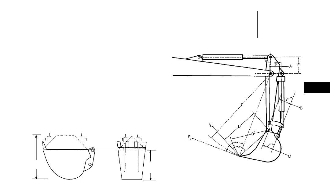
4-91
4
Excavators
EXCAVATOR BUCKET CAPACITIES
Caterpillar rates excavator buckets to conform
with both PCSA standard No. 3 and SAE standard
J-296. Buckets are rated on both their struck and
heaped capacities as follows:
Struck Capacity
Volume actually enclosed inside the outline of the
sideplates and rear and front bucket enclosures
without any consideration for any material sup-
ported or carried by the spillplate or bucket teeth.
Heaped Capacity
Volume in the bucket under the strike off plane
plus the volume of the heaped material above the
strike off plane, having an angle of repose of 1:1 with-
out any consideration for any material supported or
carried by the spillplate or bucket teeth.
The Committee on European Construction Equip-
ment (CECE) rates heaped bucket pay loads on a 2:1
angle of repose for material above the strike off
plane.
CURL AND CROWD FORCES
Bucket penetration into a material is achieved by
the bucket curling force (FB) and stick crowd force
(FS). Rated digging forces are the digging forces that
can be exerted at the outermost cutting point. These
forces can be calculated by applying working relief
hydraulic pressure to the cylinder(s) providing the
digging force. The digging forces listed on next page
conform with SAE Standard J1179 and PCSA Stan-
dard No. 3. The values may not be directly compar-
able to forces for machines rated by other methods
than those described below.
FB= Radial tooth force due to bucket cylinder
FB=Bucket cylinder force Arm A 2Arm C
___________________ _______________
Arm D length (Arm B )
Cylinder force = (Pressure) 2
(End area of cylinder head)
Arm D = Bucket tip radius
Maximum radial tooth force due to bucket cylinder
(bucket curling force) is the digging force generated
by the bucket cylinder(s) and tangent to the arc of
radius D1. The bucket shall be positioned to obtain
maximum output moment from the bucket cylin-
der(s) and connecting linkages. When calculating,
maximum FBoccurs when the factor — Arm A times
Arm C divided by Arm B — becomes the maximum.
FS= Radial tooth force due to stick cylinder
FX=(Stick cylinder force) 2(Arm E length)
____________________________________
(Arm F length)
Arm F = Bucket tip radius + stick length
Maximum radial tooth force due to stick cylinder
(stick crowd force) is the digging force generated by
the stick cylinder(s) and tangent to the arc of radius F.
The stick shall be positioned to obtain the maximum
output moment from the arm cylinder and the bucket
positioned as described in the bucket force rating.
When calculating, maximum FSoccurs when the axis
in the stick cylinder working direction is at a right
angle to the line connecting the stick cylinder pin and
the boom nose pin.
Bucket Capacity
●Definition
Curl and Crowd Forces
Heaped
Capacity Struck
Capacity
Strike
Off
Plane
Excavator Bucket Rating
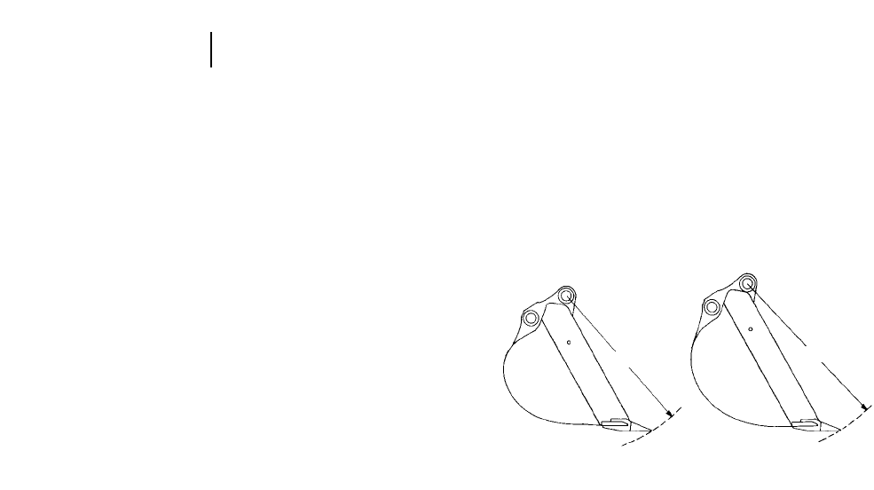
4-92
Excavators
Bucket Selection Considering
Bucket Curl and Stick Crowd Forces
The combination of the excavator’s stick crowd
force and bucket curling force give this machine con-
figuration more effective bucket penetration force
per mm (inch) of bucket cutting edge than is avail-
able with other machine types such as wheel and
track loaders.
As a result of high penetration force, an excavator
bucket is comparatively easy to load. Also, the higher
unit breakout forces allow the excavator’s economic
application range to be extended farther into the
tougher soils (coral, caliche, shale, limestone) before
blasting or ripping is required.
To take full advantage of an excavator’s high pene-
tration forces, buckets should be selected so they are
well matched to soil conditions that are encountered.
The two important things to consider are bucket
width and bucket tip radius.
As a general rule, wide buckets are used in easily
dug soil and narrow buckets in harder material. In
hard rocky soils, tip radius also has to be considered
in bucket selection. Because the shorter tip radius
buckets provide more total bucket curling force than
the long tip radius buckets, they are generally the
easiest to load. A good rule of thumb when select-
ing a Caterpillar bucket for hard material is to choose
the narrowest bucket that has a short tip radius.
Other factors such as trench bottom width specifi-
cations, manbox size, or the desire to conserve bed-
ding material may also influence excavator bucket
selection.
NOTE: See the following pages for listing of
Caterpillar buckets by tip radius and
cutting edge width.
Curl and Crowd Forces
SHORTER
TIP RADIUS
LONGER
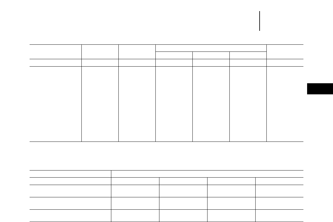
Curl and Crowd Forces
●318B L
4-93
4
Excavators
Bucket Bucket Curling Stick Crowd Forces
Model Source Tip Radius Forces Short Medium Long Extra Long
mm ft kN lb kN lb kN lb kN lb kN lb
301.5 — 500 1'8" 12.6 2840 ——8.8 1980 ————
307B Japan 1070 3'6" 44 9890 ——35 7870 31 6970 ——
307B SB Japan 1070 3'6" 44 9890 ——35 7870 31 6970 ——
307 France 1070 3'6" 49 11,020 ——36 7940 32 7050 ——
311B Japan 1220 4'0" 80 17,980 62 13,930 58 13,030 50 11,240 ——
312B Japan 1220 4'0" 84 18,880 65 14,610 63 14,160 57 12,810 ——
312B France 1220 4'0" 94 21,190 73 16,310 64 14,460 58 12,920 ——
312B L France 1220 4'0" 84 18,880 71 15,970 63 14,160 57 12,810 ——
315B Japan 1340 4'5" 99 22,250 95 21,350 84 18,880 76 17,080 68 15,280
315B L France 1310 4'4" *****
318B L France 1410 4'7.5" *****
318B LN France 1410 4'7.5" *****
*Information unavailable at time of printing.
318B L
Boom 1-Piece Boom
Stick Short Medium Long Extra Long
Bucket Tip Radius mm 1563 1563 1563 1563
ft 5'1.5" 5'1.5" 5'1.5" 5'1.5"
Bucket Curling Forces kN 126 125 106 107
lb 28,310 28,090 23,830 24,050
Stick Crowd Forces kN 117 101 87 78
lb 26,290 22,700 19,560 17,530

M312
Boom 1-Piece/VA Boom
Stick 1600 mm 5'3" 2000 mm 6'6" 2300 mm 7'5" 2600 mm 8'5" 3000 mm 9'9"
Bucket Tip Radius mm 1240/1518 1100 1000 1000 900
ft 4'1"/5'0" 3'7" 3'3" 3'3" 2'11"
Bucket Curling Forces kN 88 80 80 80 80
lb 22,440 20,400 20,400 20,400 20,400
Stick Crowd Forces kN 72 57 52 48 44
lb 18,360 14,535 13,260 12,240 11,220
M315
Boom 1-Piece/VA Boom
Stick 1700 mm 5'7" 2100 mm 6'11" 2400 mm 7'10" 2600 mm 8'6"
Bucket Tip Radius mm 1220/1290 1220 1220 1220
ft 4'0"/4'3" 4'0" 4'0" 4'0"
Bucket Curling Forces kN 108 99 99 99
lb 24,300 22,200 22,200 22,200
Stick Crowd Forces kN 84 67 67 58
lb 18,900 15,000 15,000 13,000
M318
Boom 1-Piece/VA Boom
Stick 1800 mm 5'11" 2400 mm 7'10" 2800 mm 9'2" 4000 mm 13'1"
Bucket Tip Radius mm 1340/1420 1340 1340 1340
ft 4'5"/4'8" 4'5" 4'5" 4'5"
Bucket Curling Forces kN 122 114 114 107
lb 27,400 25,600 25,600 24,000
Stick Crowd Forces kN 108 83 75 57
lb 24,300 18,600 16,800 12,800
M320
Boom 1-Piece/VA Boom
Stick 1900 mm 6'3" 2500 mm 8'2" 2900 mm 9'6" 4200 mm 13'9"
Bucket Tip Radius mm 1423 1423 1423 1423
ft 4'8" 4'8" 4'8" 4'8"
Bucket Curling Forces kN 137 127 127 127
lb 30,800 28,500 28,500 28,500
Stick Crowd Forces kN 130 99 90 69
lb 29,200 22,200 20,200 15,500
4-94
Excavators Curl and Crowd Forces
●M312 ●M315 ●M318 ●M320
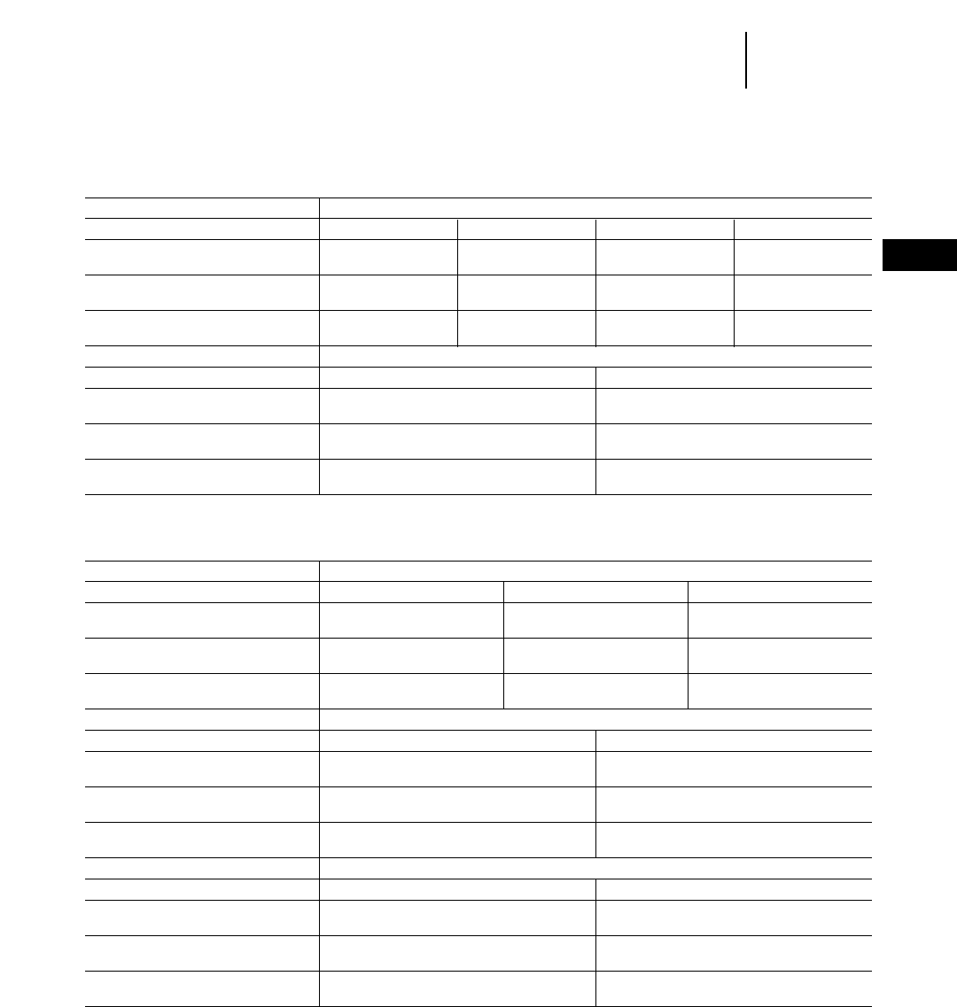
4-95
4
ExcavatorsCurl and Crowd Forces
●320B
Japan Sourced
320B
Boom Reach Boom
Stick R1.9C R2.5B R2.9B R3.9B
Bucket Tip Radius mm 1487 1409 1480 1480
ft 4'10.5" 4'7" 4'10.2" 4'10.2"
Bucket Curling Forces kN 159 132 125 125
lb 35,750 29,700 28,100 28,100
Stick Crowd Forces kN 144 113 98 83
lb 32,400 25,400 22,050 18,650
Boom Mass Boom
Stick M1.9C M2.4C
Bucket Tip Radius mm 1487 1487
ft 4'10.5" 4'10.5"
Bucket Curling Forces kN 159 160
lb 35,750 36,000
Stick Crowd Forces kN 144 126
lb 32,400 28,300
Belgium Sourced
320B
Boom Reach Boom
Stick R1.9C R2.5B R2.9B
Bucket Tip Radius mm 1550 1410 1410
ft 5'1" 4'7.5" 4'7.5"
Bucket Curling Forces kN 153 132 132
lb 34,400 29,700 29,700
Stick Crowd Forces kN 144 113 99
lb 32,400 25,400 22,200
Boom Mass Boom
Stick M1.9C M2.4C
Bucket Tip Radius mm 1550 1550
ft 5'1" 5'1"
Bucket Curling Forces kN 153 154
lb 34,400 34,600
Stick Crowd Forces kN 144 125
lb 32,400 28,100
Boom VA Boom*
Stick M1.9C M2.4C
Bucket Tip Radius mm 1550 1550
ft 5'1" 5'1"
Bucket Curling Forces kN 153 132
lb 34,400 29,700
Stick Crowd Forces kN 144 113
lb 32,400 25,400
*Preliminary information.

Japan/U.S. Sourced
322B
Boom Reach Boom
Stick R2.5S R2.95S R3.6B
Bucket Tip Radius mm 1550 1550 1409
ft 5'1" 5'1" 4'7.5"
Bucket Curling Forces kN 151 151 131
lb 33,950 33,950 29,500
Stick Crowd Forces kN 136 116 104
lb 30,640 26,230 23,400
Boom Mass Boom
Stick M2.0D M2.5D
Bucket Tip Radius mm 1660 1660
ft 5'5.4" 5'5.4"
Bucket Curling Forces kN 189 189
lb 42,550 42,550
Stick Crowd Forces kN 151 133
lb 33,950 29,980
Belgium Sourced
322B
Boom Reach Boom
Stick R2.5S R2.95S
Bucket Tip Radius mm 1550 1550
ft 5'1" 5'1"
Bucket Curling Forces kN 149 149
lb 33,500 33,500
Stick Crowd Forces kN 141 121
lb 31,700 27,200
Boom Mass Boom
Stick M2.0D M2.5D
Bucket Tip Radius mm 1670 1670
ft 5'5.7" 5'5.7"
Bucket Curling Forces kN 187 187
lb 42,000 42,000
Stick Crowd Forces kN 155 136
lb 34,800 30,600
Boom VA Boom*
Stick M2.0D M2.5D
Bucket Tip Radius mm 1670 1670
ft 5'5.7" 5'5.7"
Bucket Curling Forces kN 187 187
lb 42,000 42,000
Stick Crowd Forces kN 155 136
lb 34,800 30,600
*Preliminary information.
4-96
Excavators Curl and Crowd Forces
●322B

4-97
4
ExcavatorsCurl and Crowd Forces
●325B
Japan/U.S. Sourced
325B
Boom Reach Boom
Stick R2.0D R2.7C R3.2C
Bucket Tip Radius mm 1660 1487 1487
ft 5'5.4" 4'10.5" 5'1"
Bucket Curling Forces kN 189 160 160
lb 42,470 35,960 35,960
Stick Crowd Forces kN 161 136 118
lb 36,180 30,560 26,520
Boom Mass Boom
Stick M2.0D M2.5D
Bucket Tip Radius mm 1660 1660
ft 5'5.4" 5'5.4"
Bucket Curling Forces kN 198 189
lb 44,490 42,470
Stick Crowd Forces kN 162 140
lb 36,400 31,460
Belgium Sourced
325B
Boom Reach Boom
Stick R2.0C R2.65C R3.2C
Bucket Tip Radius mm 1670 1550 1550
ft 5'5.7" 5'1" 5'1"
Bucket Curling Forces kN 188 152 151
lb 42,300 34,200 33,900
Stick Crowd Forces kN 166 137 120
lb 37,300 30,800 27,000
Boom Mass Boom
Stick M2.0D M2.5D
Bucket Tip Radius mm 1670 1670
ft 5'5.7" 5'5.7"
Bucket Curling Forces kN 188 188
lb 42,300 42,300
Stick Crowd Forces kN 165 144
lb 37,100 32,400
Boom VA Boom*
Stick M2.0D M2.5D
Bucket Tip Radius mm 1670 1670
ft 5'5.7" 5'5.7"
Bucket Curling Forces kN 188 188
lb 42,300 42,300
Stick Crowd Forces kN 165 144
lb 37,100 32,400
*Preliminary information.

Japan/U.S. Sourced
330B
Boom Reach Boom
Stick R2.2E R2.8D R3.3D R3.9D
Bucket Tip Radius mm 1845 1600 1600 1600
ft 6'0.1" 5'3" 5'3" 5'3"
Bucket Curling Forces kN 227 189 189 190
lb 51,000 42,470 42,470 42,670
Stick Crowd Forces kN 209 175 151 134
lb 46,970 39,330 33,930 30,110
Boom Mass Boom
Stick M2.2E M2.6E
Bucket Tip Radius mm 1845 1845
ft 6'0.1" 6'0.1"
Bucket Curling Forces kN 227 227
lb 51,000 51,000
Stick Crowd Forces kN 239 173
lb 53,700 38,880
Belgium Sourced
330B
Boom Reach Boom
Stick R2.2E R2.8D R3.3D R3.9D
Bucket Tip Radius mm 1730 1660 1660 1660
ft 5'8.1" 5'5.3" 5'5.3" 5'5.3"
Bucket Curling Forces kN 232 187 187 187
lb 52,200 42,000 42,000 42,000
Stick Crowd Forces kN 216 179 155 138
lb 48,600 40,200 34,800 42,300
Boom Mass Boom
Stick M2.15E M2.6E
Bucket Tip Radius mm 1780 1780
ft 5'8.1" 5'8.1"
Bucket Curling Forces kN 232 232
lb 52,200 52,200
Stick Crowd Forces kN 216 179
lb 48,600 40,200
4-98
Excavators Curl and Crowd Forces
●330B

4-99
4
ExcavatorsCurl and Crowd Forces
●345B ●350
345B
Boom Reach Boom
Stick R2.9F R3.35T R3.9F
Bucket Tip Radius mm 1870 1820 1925
ft 6'1.6" 5'11.7" 6'3.8"
Bucket Curling Forces kN 231 229 225
lb 51,900 51,460 50,560
Stick Crowd Forces kN 209 194 175
lb 46,970 43,600 39,330
Boom Mass Boom
Stick M2.5G M3.0V
Bucket Tip Radius mm 1958 1860
ft 6'5.1" 6'1.2"
Bucket Curling Forces kN 252 260
lb 56,630 58,430
Stick Crowd Forces kN 230 208
lb 51,690 46,740
350
Boom Reach Boom
Stick R3.1F R3.6F R4.8F
Bucket Tip Radius mm 1870 1925 1925
ft 6'1.6" 6'3.8" 6'3.8"
Bucket Curling Forces kN 219 213 213
lb 49,300 47,900 47,900
Stick Crowd Forces kN 195 169 142
lb 43,900 38,000 32,000
Boom Mass Boom
Stick M2.4G M3.0G M3.7F
Bucket Tip Radius mm 1958 1958 1870
ft 6'5.1" 6'5.1" 6'1.6"
Bucket Curling Forces kN 271 259 220
lb 61,000 58,300 49,500
Stick Crowd Forces kN 225 193 164
lb 50,600 43,400 37,000

Japan/U.S. Sourced
375
Boom Reach Boom*
Stick R2.9J R3.4J R4.4H R5.5H
Bucket Tip Radius mm 2235 2235 2100 2210
ft 7'4" 7'4" 6'10.7" 7'3"
Bucket Curling Forces kN 421 422 335 317
lb 94,500 94,800 75,400 71,400
Stick Crowd Forces kN 325 301 259 212
lb 73,100 67,600 58,200 47,600
Boom General Purpose Boom
Stick R2.9J* R3.4J R4.4H R5.5H
Bucket Tip Radius mm 2235 2235 2100 2210
ft 7'4" 7'4" 6'10.7" 7'3"
Bucket Curling Forces kN 421 422 335 317
lb 94,500 94,800 75,400 71,400
Stick Crowd Forces kN 325 301 259 212
lb 73,100 67,600 58,200 47,600
Boom Mass Boom
Stick M2.9J M3.4J M4.1J
Bucket Tip Radius mm 2235 2235 2235
ft 7'4" 7'4" 7'4"
Bucket Curling Forces kN 435 422 423
lb 97,600 94,800 95,000
Stick Crowd Forces kN 326 301 266
lb 73,100 67,600 59,700
*Not available in all sales areas.
4-100
Excavators Curl and Crowd Forces
●375
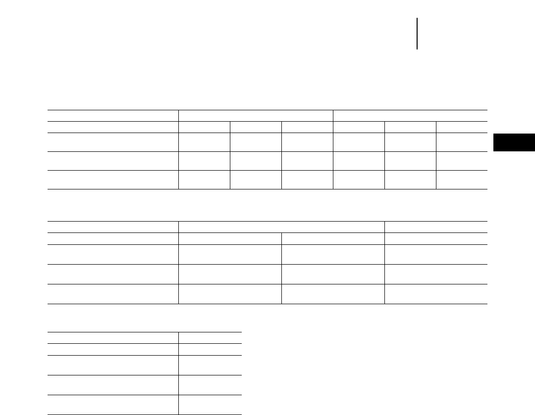
4-101
4
ExcavatorsCurl and Crowd Forces
●375 ●5130B ●5230
Belgium Sourced
375
Boom GP Boom Mass Boom
Stick R3.4J R4.4H R5.5H M2.9J M3.4J M4.1J
Bucket Tip Radius mm 2236 2100 2100 2236 2236 2236
ft 7'4" 6'10.7" 6'10.7" 7'4" 7'4" 7'4"
Bucket Curling Forces kN 371 309 297 383 384 372
lb 83,500 69,500 66,800 86,100 86,300 83,600
Stick Crowd Forces kN 291 251 209 313 291 258
lb 65,400 56,400 47,100 70,400 65,500 58,100
U.S. Sourced
5130B
Boom 8 m 26'3" 11 m 36'1"
Stick* 3.8 m 12'6" 5.2 m 17'1" 3.8 m 12'6"
Bucket Tip Radius mm 3038 3038 3038
ft 10'0" 10'0" 10'0"
Bucket Curling Force kN 672 666 672
lb 151,000 150,000 151,000
Rated Arm Force kN 624 542 624
lb 140,000 122,000 140,000
*11 m (36'1") and 5.2 m (17'1") or 6.6 m (21'8") sticks use smaller bucket linkage.
5230
Boom 9.5 m 31'2"
Stick 4.5 m 14'9"
Bucket Tip Radius mm 3254
ft 10'8"
Bucket Curling Force kN 873
lb 196,200
Rated Arm Force kN 874
lb 196,400

4-102
Excavators Bucket Specifications
Caterpillar offers a very comprehensive list of
high strength steel buckets. High strength steel
allows thinner components which helps keep the
weight down, maintains durability and improves
loadability. The wrong bucket can reduce production
30-40% or more. Caterpillar’s in-depth knowledge
of machine design, bucket design and application
experience allows offering machine matched pack-
ages that optimize performance.
Additional buckets may be available and the listed
buckets may not be available in all sales areas. Contact
your Caterpillar Dealer for your specific bucket needs.
Bucket Bucket Heaped Bucket Weight
Model Bucket Type Teeth Bite Width Tip Radius Capacity With Teeth
mm in mm in L yd3kg lb
301.5 Digging 0 230 9.1" 440 17.3" 18.3 0.024 25 55
3 230 9.1" 500 19.7" 18.3 0.024 29 64
0 300 11.8" 440 17.3" 22.2 0.029 27 60
3 300 11.8" 500 19.7" 22.2 0.029 31 68
0 400 15.7" 440 17.3" 32.9 0.043 32 70
3 400 15.7" 500 19.7" 32.9 0.043 35 77
0 500 19.7" 440 17.3" 45.1 0.059 36 79
4 500 19.7" 500 19.7" 45.1 0.059 41 90
0 600 23.6" 440 17.3" 55.8 0.073 41 90
4 600 23.6" 500 19.7" 55.8 0.073 45 99
Ditch Cleaning 0 800 31.5" 353 13.9" 44.3 0.058 40 88
0 1000 39.4" 353 13.9" 55.8 0.073 42 93
307B, General Purpose 500 20.0" 1070 42.0" 180 0.24 180 397
307B SB, 600 24.0" 1070 42.0" 230 0.30 195 430
307 610 *24.0"*1070 42.0" 230 0.30 200 440
700 28.0" 1070 42.0" 240 0.31 215 474
760 *30.0"*1070 42.0" 310 0.40 230 510
800 31.0" 1070 42.0" 280 0.37 225 496
915 *36.0"*1070 42.0" 370 0.45 250 550
Excavation 300 12.0" 1070 42.0" 90 0.12 122 270
450 18.0" 1070 42.0" 160 0.21 168 370
600 24.0" 1070 42.0" 230 0.30 191 420
750 30.0" 1070 42.0" 300 0.39 208 460
800 31.0" 1070 42.0" 325 0.42 215 470
850 33.0" 1070 42.0" 350 0.46 222 490
1000 39.0" 1070 42.0" 800 1.05 635 1400
Extreme Service Excavation 300 12.0" 1070 42.0" 90 0.12 133 290
450 18.0" 1070 42.0" 160 0.21 174 380
600 24.0" 1070 42.0" 230 0.30 197 430
750 30.0" 1070 42.0" 300 0.39 214 470
800 31.0" 1070 42.0" 325 0.42 228 500
311B General Purpose 625 24.0" 1220 48.0" 350 0.46 336 740
775 30.0" 1220 48.0" 460 0.60 372 820
925 36.0" 1220 48.0" 570 0.75 415 914
1075 42.0" 1220 48.0" 670 0.88 459 1011
1225 48.0" 1220 48.0" 780 1.02 495 1091
*Not available for 307.

4-103
4
ExcavatorsBucket Specifications
Bucket Bucket Heaped Bucket Weight
Model Bucket Type Bite Width Tip Radius Capacity With Teeth
mm in mm in L yd3kg lb
312B General Purpose 450 18.0" 1220 48.0" 235 0.31 250 550
600 24.0" 1220 48.0" 330 0.43 270 594
625 24.0" 1220 48.0" 350 0.46 336 740
700 28.0" 1220 48.0" 400 0.52 295 649
775 30.0" 1220 48.0" 460 0.60 372 820
900 35.0" 1220 48.0" 540 0.71 340 748
925 36.0" 1220 48.0" 570 0.75 415 914
1000 39.0" 1220 48.0" 610 0.79 358 787
1075 42.0" 1220 48.0" 670 0.88 459 1011
1100 43.0" 1220 48.0" 680 0.89 385 847
1200 47.0" 1220 48.0" 750 0.98 403 886
1225 48.0" 1220 48.0" 780 1.02 495 1091
Heavy Duty 450 17.7" 1220 48.0" 235 0.31 270 594
600 23.6" 1220 48.0" 330 0.43 300 660
700 27.6" 1220 48.0" 400 0.52 322 708
750 29.5" 1220 48.0" 400 0.52 338 743
900 35.4" 1220 48.0" 540 0.71 374 822
1000 39.4" 1220 48.0" 610 0.79 400 880
Excavation 450 18.0" 1220 48.0" 235 0.31 236 520
600 24.0" 1220 48.0" 330 0.43 263 580
700 28.0" 1220 48.0" 400 0.52 286 630
750 30.0" 1220 48.0" 440 0.58 321 710
900 35.0" 1220 48.0" 540 0.70 329 725
1000 39.0" 1220 48.0" 550 0.72 332 730
1000 39.0" 1220 48.0" 610 0.80 348 770
1100 43.0" 1220 48.0" 680 0.89 371 820
1200 47.0" 1220 48.0" 750 0.98 390 860
Extreme Service Excavation 450 18.0" 1220 48.0" 235 0.31 236 520
600 24.0" 1220 48.0" 330 0.43 263 580
700 28.0" 1220 48.0" 400 0.52 287 630
750 30.0" 1220 48.0" 440 0.58 330 730
900 35.0" 1220 48.0" 540 0.70 329 725
1000 39.0" 1220 48.0" 610 0.80 348 770
1100 43.0" 1220 48.0" 680 0.89 400 880
Ditch Cleaning 1500 59.0" N/S 400 0.52 340 750
1600 63.0" N/S 330 0.43 350 770
1800 71.0" N/S 370 0.48 380 840
2000 79.0" N/S 330 0.43 350 770
Utility 1200 47.0" N/S 395 0.52 400 880
1400 55.0" N/S 465 0.61 440 970
1600 63.0" N/S 530 0.69 480 1060
1800 71.0" N/S 605 0.79 530 1170
Utility Light 1200 47.0" N/S 395 0.52 300 660
1400 55.0" N/S 465 0.61 330 730
1600 63.0" N/S 530 0.69 360 790
1800 71.0" N/S 605 0.79 400 880
N/S = Not Significant for Utility, Utility Light and Ditch Cleaning Bucket.

4-104
Excavators Bucket Specifications
Bucket Bucket Heaped Bucket Weight
Model Bucket Type Bite Width Tip Radius Capacity With Teeth
mm in mm in L yd3kg lb
315B/315B L General Purpose 610 24.0" 1340 53.0" 380 0.50 419 924
760 30.0" 1340 53.0" 500 0.65 471 1038
914 36.0" 1340 53.0" 610 0.80 517 1140
1067 42.0" 1340 53.0" 690 0.90 566 1248
1219 48.0" 1340 53.0" 840 1.10 609 1343
Excavation 600 24.0" 1310 52.0" 350 0.46 365 800
600 24.0" 1310 52.0" 350 0.46 390 860
750 30.0" 1310 52.0" 470 0.61 417 920
750 30.0" 1310 52.0" 470 0.61 435 960
850 33.0" 1310 52.0" 560 0.73 455 1000
850 33.0" 1310 52.0" 560 0.73 495 1090
1000 39.0" 1310 52.0" 680 0.89 502 1100
1000 39.0" 1310 52.0" 680 0.89 544 1200
1100 43.0" 1310 52.0" 770 1.01 540 1190
1100 43.0" 1310 52.0" 770 1.01 542 1195
1200 47.0" 1310 52.0" 860 1.12 570 1260
1200 47.0" 1310 52.0" 860 1.12 590 1300
1300 51.0" 1310 52.0" 930 1.22 609 1340
1300 51.0" 1310 52.0" 930 1.22 620 1370
1300 51.0" 1310 52.0" 1000 1.31 647 1430
1300 51.0" 1310 52.0" 1000 1.31 695 1530
Extreme Service Excavation 600 24.0" 1310 52.0" 350 0.46 373 820
600 24.0" 1310 52.0" 350 0.46 400 880
750 30.0" 1310 52.0" 470 0.61 425 940
750 30.0" 1310 52.0" 470 0.61 445 980
850 33.0" 1310 52.0" 560 0.73 464 1020
850 33.0" 1310 52.0" 560 0.73 495 1090
1000 39.0" 1310 52.0" 680 0.89 510 1120
1000 39.0" 1310 52.0" 680 0.89 555 1220
1100 43.0" 1310 52.0" 770 1.01 548 1210
1200 47.0" 1310 52.0" 860 1.12 579 1280
1200 47.0" 1310 52.0" 860 1.12 630 1390
Ditch Cleaning 1600 63.0" 1310 52.0" 330 0.43 360 790
1800 71.0" N/S 370 0.48 380 840
1800 71.0" 1310 52.0" 370 0.48 390 860
2000 79.0" N/S 410 0.54 410 910
2000 79.0" 1310 52.0" 410 0.54 450 990
Utility 1200 47.0" N/S 395 0.52 410 900
1400 55.0" N/S 465 0.61 450 990
1600 63.0" N/S 535 0.70 490 1080
1800 71.0" N/S 605 0.79 540 1190
Trapezoidal 500 20.0" Slope:1/1.0 380 0.50 345 760
500 20.0" Slope:1/1.5 510 0.67 405 890
2400 94.5" 1310 52.0" 380 0.50 360 790
3350 131.0" 1310 52.0" 510 0.67 420 930
Weed Cutting 4000 157.0" ——————
N/S = Not Significant for Utility, Utility Light and Ditch Cleaning Bucket.

4-105
4
ExcavatorsBucket Specifications
Bucket Bucket Bucket Heaped Bucket Weight
Model Bucket Type Family Bite Width Tip Radius Capacity With Teeth
mm in mm in L yd3kg lb
318B L, Heavy Duty B 625 24.0" 1563 61.5" 450 0.59 600 1320
318B LN B 775 30.0" 1563 61.5" 560 0.73 685 1510
B 932 36.0" 1563 61.5" 800 1.05 785 1730
B 1082 42.0" 1563 61.5" 1000 1.31 850 1870
B 1230 48.0" 1551 61.0" 1200 1.57 955 2100
Excavation and 600 24.0" 1410 55.5" 410 0.54 473 1043
Excavation Quick Coupling 750 30.0" 1410 55.5" 550 0.72 525 1158
1000 39.0" 1410 55.5" 800 1.05 654 1442
1250 49.0" 1410 55.5" 1050 1.37 753 1660
1400 55.0" 1410 55.5" 1200 1.57 833 1837
1500 59.1" 1410 55.5" 1350 1.77 872 1923
Extreme Excavation and 600 24.0" 1410 55.5" 410 0.54 519 1144
Extreme Excavation 750 30.0" 1410 55.5" 550 0.72 562 1239
Quick Coupling 1000 39.0" 1410 55.5" 800 1.05 702 1548
1250 49.0" 1410 55.5" 1050 1.37 819 1806
1400 55.0" 1410 55.5" 1200 1.57 878 1936
Utility and Utility Light 1400 55.0" 1410 55.5" 605 0.79 620 1367
1600 63.0" 1410 55.5" 700 0.92 680 1499
1800 71.0" 1410 55.5" 790 1.03 740 1632
2000 79.0" 1410 55.5" 880 1.15 800 1764
Ditch Cleaning 1800 71.0" 1410 55.5" 490 0.64 545 1202
2000 79.0" 1410 55.5" 550 0.72 585 1290
Rock and 600 24.0" 1410 55.5" 410 0.54 547 1206
Rock Quick Coupling 750 30.0" 1410 55.5" 550 0.72 645 1422
1000 39.0" 1410 55.5" 810 1.06 751 1656
1250 49.0" 1410 55.5" 1050 1.37 875 1929

4-106
Excavators Bucket Specifications
Bucket Bucket Bucket Heaped Bucket Weight
Model Bucket Type Family Bite Width Tip Radius Capacity With Teeth
mm in mm in L yd3kg lb
M312/ Excavation 450 17.7" 1240 48.8" 240 0.31 271 600
M315 600 23.6" 1240 48.8" 330 0.43 304 800
700 27.6" 1240 48.8" 400 0.52 340 750
750 29.5" 1318 51.9" 470 0.61 430 950
850 33.5" 1318 51.9" 560 0.73 473 1040
900 35.4" 1240 48.8" 540 0.71 366 810
1000 39.4" 1318 51.9" 610 0.80 410 900
1100 43.3" 1240 48.8" 680 0.89 438 970
1200 47.2" 1318 51.9" 860 1.12 458 1010
Extreme Service Excavation 1100 43.3" 1240 48.8" 680 0.89 472 1040
1200 47.2" 1240 48.8" 750 0.98 493 1090
M318 Excavation 600 23.6" 1419 55.9" 400 0.52 540 1190
750 29.5" 1419 55.9" 550 0.72 560 1235
1000 39.4" 1340 52.7" 700 0.92 600 1320
1000 39.4" 1419 55.9" 800 1.05 650 1430
1100 43.3" 1340 52.7" 800 1.05 640 1410
1200 47.2" 1340 52.7" 900 1.18 660 1455
1250 49.2" 1419 55.9" 1050 1.37 740 1630
Extreme Service Excavation 1200 47.2" 1340 52.7" 900 1.18 710 1570
Excavation B 600 24.0" 1410 55.5" 410 0.54 524 1155
B 750 30.0" 1410 55.5" 550 0.72 550 1210
B 1000 39.0" 1410 55.5" 800 1.05 635 1400
B 1250 49.0" 1410 55.5" 1050 1.37 716 1580
B 1400 55.0" 1410 55.5" 1200 1.57 752 1660
B 1500 59.0" 1410 55.5" 1350 1.77 770 1700
Extreme Service Excavation B 600 24.0" 1410 55.5" 410 0.54 552 1220
B 750 30.0" 1410 55.5" 550 0.72 606 1340
B 1000 39.0" 1410 55.5" 800 1.05 697 1540
B 1250 49.0" 1410 55.5" 1050 1.37 772 1700
B 1400 55.0" 1410 55.5" 1200 1.57 818 1800
Rock B 600 24.0" 1410 55.5" 410 0.54 565 1245
B 750 30.0" 1410 55.5" 550 0.72 625 1380
B 1000 39.0" 1410 55.5" 800 1.05 775 1710
B 1250 49.0" 1410 55.5" 1050 1.37 898 1980
Ditch Cleaning B 1800 71.0" 1250 49.2" 480 0.63 477 1050
B 2000 79.0" 1400 55.1" 580 0.76 680 1500
B 2200 87.0" 1250 49.2" 620 0.81 563 1240
Utility B 1400 55.0" N/S 605 0.79 620 1370
B 1600 63.0" N/S 700 0.92 680 1500
B 1800 71.0" N/S 790 1.03 740 1630
B 2000 79.0" N/S 880 1.15 800 1760
Utility Light B 1400 55.0" N/S 605 0.79 470 1040
B 1600 63.0" N/S 700 0.92 510 1125
B 1800 71.0" N/S 790 1.03 550 1210
B 2000 79.0" N/S 880 1.15 600 1320
N/S = Not Significant for Utility, Utility Light and Ditch Cleaning Bucket.

4-107
4
ExcavatorsBucket Specifications
Bucket Bucket Bucket Heaped Bucket Weight
Model Bucket Type Family Bite Width Tip Radius Capacity With Teeth
mm in mm in L yd3kg lb
M320 General Purpose 600 23.6" 1423 56.0" 410 0.54 540 1190
750 29.5" 1423 56.0" 550 0.72 560 1230
1000 39.4" 1423 56.0" 810 1.06 600 1320
1100 43.3" 1423 56.0" 900 1.18 685 1510
1250 49.2" 1423 56.0" 1050 1.37 740 1630
1400 55.1" 1423 56.0" 1200 1.57 780 1920
1500 59.0" 1423 56.0" 1350 1.77 810 1790
Extreme Service 1200 47.2" 1340 52.8" 900 1.18 710 1565
1250 49.2" 1423 56.0" 1050 1.37 750 1650
Ditch Cleaning 1800 70.9" 1244 49.0" 480 0.63 477 1050
2000 78.7" 1300 51.2" 580 0.76 680 1500
2000 78.7" 1400 55.1" 700 0.92 720 1590
2300 90.6" 1244 49.0" 620 0.81 570 1260
2000 78.7" 896 35.3" 700 0.92 640 1410
320B General Purpose B 775 30.0" 1626 64.0" 700 0.88 665 1466
B 932 36.0" 1626 64.0" 900 1.12 741 1634
B 1082 42.0" 1626 64.0" 1100 1.50 777 1713
B 1230 48.0" 1626 64.0" 1300 1.75 906 1998
C 775 30.0" 1778 70.0" 800 1.12 807 1779
C 948 36.0" 1778 70.0" 1100 1.50 909 2004
C 1098 42.0" 1778 70.0" 1300 1.75 966 2130
C 1248 48.0" 1778 70.0" 1600 2.12 1052 2320
C 1395 54.0" 1778 70.0" 1900 2.50 1138 2509
Excavation B 1130 44.0" 1480 58.2" 800 1.05 640 1410
B 1260 50.0" 1409 55.4" 900 1.18 760 1680
B 1370 54.0" 1409 55.4" 1000 1.31 795 1750
B 600 23.6" 1410 55.5" 410 0.54 524 1155
B 750 29.5" 1410 55.5" 550 0.72 550 1210
B 1000 39.4" 1410 55.5" 800 1.05 635 1400
B 1250 49.2" 1410 55.5" 1050 1.37 716 1580
B 1400 55.1" 1410 55.5" 1200 1.57 752 1660
B 1500 59.1" 1410 55.5" 1350 1.77 770 1700
C 1370 54.0" 1487 58.5" 1100 1.44 940 2070
C 1470 58.0" 1487 58.5" 1200 1.57 895 1970
C 750 29.5" 1550 61.0" 630 0.82 694 1530
C 1000 39.4" 1550 61.0" 950 1.24 780 1720
C 1150 45.3" 1550 61.0" 1150 1.50 874 1930
C 1250 49.2" 1550 61.0" 1250 1.63 903 1990
C 1350 53.1" 1550 61.0" 1400 1.83 940 2070
C 1450 57.1" 1550 61.0" 1500 1.96 990 2180
C 1600 63.0" 1550 61.0" 1700 2.22 1045 2300

4-108
Excavators Bucket Specifications
Bucket Bucket Bucket Heaped Bucket Weight
Model Bucket Type Family Bite Width Tip Radius Capacity With Teeth
mm in mm in L yd3kg lb
320B Extreme Service Excavation B 600 23.6" 1410 55.5" 410 0.54 552 1220
(cont’d) B 750 29.5" 1410 55.5" 550 0.72 606 1340
B 1000 39.4" 1410 55.5" 800 1.05 697 1540
B 1100 43.0" 1409 55.4" 800 1.05 760 1670
B 1250 49.2" 1410 55.5" 1050 1.37 772 1700
B 1400 55.1" 1410 55.5" 1200 1.57 818 1800
C 750 29.5" 1550 61.0" 630 0.82 722 1590
C 1000 39.4" 1550 61.0" 950 1.24 863 1900
C 1150 45.3" 1550 61.0" 1150 1.50 940 2070
C 1250 49.2" 1550 61.0" 1250 1.63 980 2160
C 1350 53.1" 1550 61.0" 1400 1.83 1025 2260
C 1450 57.1" 1550 61.0" 1500 1.96 1085 2390
C 1600 63.0" 1550 61.0" 1700 2.22 1154 2545
Heavy Duty B 625 24.0" 1563 61.5" 450 0.59 600 1320
B 775 30.0" 1563 61.5" 560 0.73 685 1510
B 932 36.0" 1563 61.5" 800 1.05 785 1730
B 1082 42.0" 1563 61.5" 1000 1.31 850 1870
B 1230 48.0" 1551 61.0" 1200 1.57 955 2100
B 1377 54.0" 1551 61.0" 1400 1.83 1020 2250
B 1507 60.0" 1551 61.0" 1500 1.96 1075 2370
B 1725 68.0" 1203 47.3" 1200 1.60 *715* 1580
C 775 30.0" 1638 64.5" 700 0.88 792 1720
C 948 36.0" 1638 64.4" 900 1.18 950 2100
C 1098 42.0" 1638 64.4" 1100 1.44 1060 2340
C 1248 48.0" 1638 64.4" 1300 1.70 1140 2510
C 1378 54.0" 1518 60.0" 1200 1.50 1088 2400
C 1395 54.0" 1638 64.4" 1500 1.96 1240 2730
C 1522 60.0" 1638 64.5" 1700 2.25 1119 2620
C 1680 66.0" 1638 64.5" 1900 2.50 1195 2825
Mass Excavation C 1440 57.0" 1487 58.5" 1300 1.70 940 2060
Rock B 600 23.6" 1410 55.5" 410 0.54 565 1245
B 750 29.5" 1410 55.5" 550 0.72 625 1380
B 1000 39.4" 1410 55.5" 800 1.05 775 1710
B 1250 49.2" 1410 55.5" 1050 1.37 898 1980
C 750 29.5" 1550 61.0" 630 0.82 764 1685
C 1000 39.4" 1550 61.0" 950 1.24 552 1220
C 1350 53.1" 1550 61.0" 1400 1.83 1076 2370
Heavy Duty Rock B 775 30.0" 1563 61.5" 600 0.75 759 1670
B 932 36.0" 1563 61.5" 800 1.00 863 1900
B 1082 42.0" 1563 61.5" 1000 1.25 949 2095
C 948 36.0" 1638 64.5" 900 1.25 988 2180
C 1098 42.0" 1638 64.5" 1100 1.50 1084 2390
C 1248 48.0" 1638 64.5" 1300 1.75 1165 2570
Rock Ripping C 850 33.0" 1660 65.0" 600 0.75 1084 2385
*Weight without teeth.

4-109
4
ExcavatorsBucket Specifications
Bucket Bucket Bucket Heaped Bucket Weight
Model Bucket Type Family Bite Width Tip Radius Capacity With Teeth
mm in mm in L yd3kg lb
320B Ditch Cleaning B 1800 70.9" N/S 490 0.64 545 1200
(cont’d) B 2000 78.7" N/S 550 0.72 585 1290
B 2200 86.6" N/S 610 0.80 625 1380
C 2000 78.7" N/S 730 0.95 820 1810
C 2200 86.6" N/S 805 1.05 880 1940
C 2400 94.5" N/S 880 1.15 980 2160
B 1422 60.0" 1143 45.0" 900 1.12 681 1500
B 1727 72.0" 1143 45.0" 1100 1.50 786 1733
C 1676 66.0" 1130 44.5" 1100 1.50 739 1629
C 1829 72.0" 1130 44.5" 1200 1.62 857 1890
Utility B 1400 55.1" N/S 605 0.79 620 1370
B 1600 63.0" N/S 700 0.92 680 1500
B 1800 70.9" N/S 790 1.03 740 1630
B 2000 78.7" N/S 880 1.15 800 1760
C 1600 63.0" N/S 940 1.23 970 2140
C 1800 70.9" N/S 1065 1.39 1060 2340
C 2000 78.7" N/S 1190 1.56 1140 2510
C 2200 86.6" N/S 1315 1.72 1220 2690
Utility Light B 1400 55.1" N/S 605 0.79 470 1040
B 1600 63.0" N/S 700 0.92 510 1125
B 1800 70.9" N/S 790 1.03 550 1210
B 2000 78.7" N/S 880 1.15 600 1320
C 1600 63.0" N/S 940 1.23 730 1610
C 1800 70.9" N/S 1065 1.39 800 1760
C 2000 78.7" N/S 1190 1.56 860 1900
C 2200 86.6" N/S 1315 1.72 920 2030
322B General Purpose B 775 30.0" 1626 64.0" 700 0.88 665 1466
B 932 36.0" 1626 64.0" 900 1.12 741 1634
B 1082 42.0" 1626 64.0" 1100 1.50 777 1713
B 1230 48.0" 1626 64.0" 1300 1.75 906 1998
S 625 24.0" 1778 70.0" 600 0.75 691 1524
S 775 30.0" 1778 70.0" 800 1.12 807 1779
S 948 36.0" 1778 70.0" 1100 1.50 909 2004
S 1098 42.0" 1778 70.0" 1300 1.75 966 2130
S 1248 48.0" 1778 70.0" 1600 2.12 1052 2320
S 1395 54.0" 1778 70.0" 1900 2.50 1138 2509
D 775 30.0" 1854 73.0" 800 1.12 953 2101
D 925 36.0" 1854 73.0" 1100 1.50 1043 2300
D 1098 42.0" 1854 73.0" 1400 1.88 1122 2474
D 1246 48.0" 1854 73.0" 1700 2.25 1202 2650
D 1400 55.0" 1854 73.0" 2000 2.62 1315 2900
D 1540 60.0" 1854 73.0" 2200 3.00 1400 3087
N/S = Not Significant for Utility, Utility Light and Ditch Cleaning Bucket.

4-110
Excavators Bucket Specifications
Bucket Bucket Bucket Heaped Bucket Weight
Model Bucket Type Family Bite Width Tip Radius Capacity With Teeth
mm in mm in L yd3kg lb
322B Excavation B 1260 50.0" 1409 55.4" 900 1.18 760 1680
(cont’d) S 1225 48.0" 1550 61.0" 1000 1.30 780 1720
S 1355 53.0" 1550 61.0" 1100 1.40 850 1870
S 1315 52.0" 1550 61.0" 1200 1.60 870 1920
S 750 29.5" 1550 61.0" 630 0.82 694 1530
S 1000 39.4" 1550 61.0" 950 1.24 780 1720
S 1150 45.3" 1550 61.0" 1150 1.50 874 1930
S 1250 49.2" 1550 61.0" 1250 1.64 903 1990
S 1350 53.1" 1550 61.0" 1400 1.83 940 2070
S 1600 63.0" 1550 61.0" 1700 2.22 1120 2470
D 1345 53.0" 1660 65.4" 1300 1.70 1115 2460
D 1430 56.0" 1660 65.4" 1400 1.80 1180 2600
D 1500 59.0" 1660 65.4" 1500 2.00 1190 2630
D 750 29.5" 1660 65.4" 660 0.86 924 2040
D 1000 39.4" 1660 65.4" 1000 1.31 1015 2240
D 1150 45.3" 1660 65.4" 1300 1.70 1120 2470
D 1300 51.2" 1660 65.4" 1450 1.90 1150 2540
D 1350 53.1" 1660 65.4" 1500 1.96 1214 2680
D 1500 59.1" 1660 65.4" 1700 2.22 1307 2880
D 1650 65.0" 1660 65.4" 1900 2.49 1390 3065
Extreme Service Excavation S 750 29.5" 1550 61.0" 630 0.82 722 1590
S 1000 39.4" 1550 61.0" 950 1.24 865 1910
S 1150 45.3" 1550 61.0" 1150 1.50 940 2070
S 1250 49.2" 1550 61.0" 1250 1.64 980 2160
S 1350 53.1" 1550 61.0" 1400 1.83 1025 2260
S 1450 57.1" 1550 61.0" 1500 1.96 1085 2390
S 1600 63.0" 1550 61.0" 1700 2.22 1150 2535
D 750 29.5" 1660 65.4" 660 0.86 924 2040
D 1000 39.4" 1660 65.4" 1000 1.31 1108 2440
D 1150 45.3" 1660 65.4" 1300 1.70 1260 2780
D 1250 49.2" 1660 65.4" 1500 1.96 1370 3020
D 1500 59.1" 1660 65.4" 1700 2.22 1480 3260
D 1650 65.0" 1660 65.4" 1900 2.49 1571 3460
Heavy Duty B 625 24.0" 1563 61.5" 500 0.62 578 1274
B 775 30.0" 1563 61.5" 600 0.75 656 1446
B 932 36.0" 1563 61.5" 800 1.00 785 1730
B 1082 42.0" 1563 61.5" 1000 1.30 850 1870
B 1230 48.0" 1551 61.0" 1200 1.60 955 2100
B 1377 54.0" 1551 61.0" 1400 1.80 1020 2250
B 1507 60.0" 1551 61.0" 1500 2.00 1075 2370
B 1725 68.0" 1203 47.3" 1200 1.60 *715* 1580
*Weight without teeth.
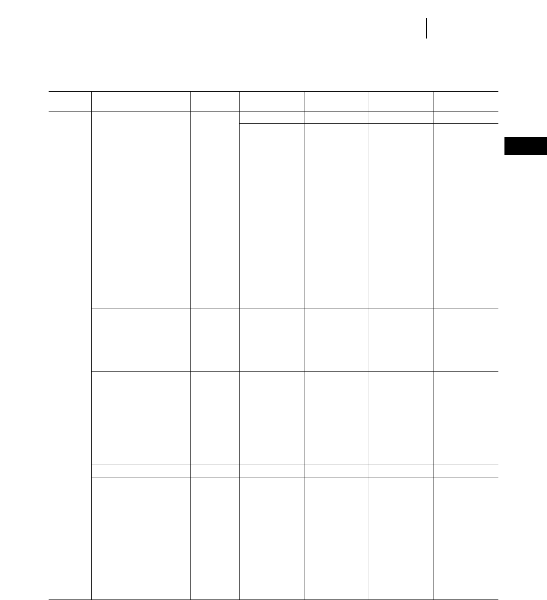
4-111
4
ExcavatorsBucket Specifications
Bucket Bucket Bucket Heaped Bucket Weight
Model Bucket Type Family Bite Width Tip Radius Capacity With Teeth
mm in mm in L yd3kg lb
322B Heavy Duty S 625 24.0" 1551 61.0" 500 0.62 609 1343
(cont’d) S 625 24.0" 1551 61.0" 500 0.62 630 1390
S 775 30.0" 1638 64.4" 700 0.90 840 1850
S 948 36.0" 1638 64.4" 900 1.20 955 2100
S 1098 42.0" 1638 64.4" 1100 1.40 1055 2330
S 1248 48.0" 1638 64.4" 1300 1.70 1135 2500
S 1378 54.0" 1518 60.0" 1200 1.50 1088 2399
S 1395 54.0" 1638 64.4" 1500 2.00 1235 2720
S 1522 60.0" 1638 64.4" 1700 2.20 1330 2930
D 775 30.0" 1764 69.4" 700 1.00 875 1929
D 925 36.0" 1764 69.4" 900 1.25 968 2134
D 1098 42.0" 1764 69.4" 1200 1.60 1150 2530
D 1246 49.0" 1764 69.4" 1400 1.80 1290 2840
D 1400 55.0" 1764 69.4" 1600 2.10 1435 3170
D 1440 57.0" 1695 66.7" 1500 2.00 1368 3016
D 1540 60.0" 1764 69.4" 1800 2.40 1565 3450
D 1695 66.0" 1764 69.4" 2000 2.75 1493 3292
D 1820 72.0" 1764 69.4" 2200 3.00 1620 3572
Rock S 750 29.5" 1550 61.0" 630 0.82 764 1685
S 1000 39.4" 1550 61.0" 950 1.24 904 1990
S 1350 53.1" 1550 61.0" 1400 1.83 1076 2370
D 750 29.5" 1660 65.4" 660 0.86 974 2150
D 1000 39.4" 1660 65.4" 1000 1.31 1160 2560
D 1650 65.0" 1660 65.4" 1900 2.49 1632 3600
Heavy Duty Rock B 775 30.0" 1563 61.5" 600 0.75 759 1674
B 932 36.0" 1563 61.5" 800 1.00 863 1903
B 1082 42.0" 1563 61.5" 1000 1.25 949 2093
S 948 36.0" 1638 64.5" 900 1.25 988 2179
S 1098 42.0" 1638 64.5" 1100 1.50 1084 2390
S 1248 48.0" 1638 64.5" 1300 1.75 1165 2569
D 1098 42.0" 1764 69.4" 1200 1.50 1293 2851
D 1246 48.0" 1764 69.4" 1400 1.88 1436 3166
D 1400 55.0" 1764 69.4" 1600 2.12 1552 3422
Rock Ripping D 900 35.0" 1746 69.0" 700 0.88 1123 2471
Ditch Cleaning S 2000 78.7" N/S 730 0.95 820 1810
S 2200 86.6" N/S 805 1.05 880 1940
S 2400 94.5" N/S 880 1.15 980 2160
D 2200 86.6" N/S 1080 1.41 1210 2670
D 2400 94.5" N/S 1180 1.54 1290 2840
D 2600 102.4" N/S 1280 1.67 1370 3020
B 1422 60.0" 1143 45.0" 900 1.12 681 1502
B 1727 72.0" 1143 45.0" 1100 1.50 786 1733
S 1575 60.0" 1130 44.5" 1000 1.38 739 1629
S 1829 72.0" 1130 44.5" 1200 1.62 857 1890
D 1676 66.0" 1410 55.5" 1700 2.25 1188 2620
D 1829 72.0" 1410 55.5" 1800 2.38 1247 2750
N/S = Not Significant for Utility, Utility Light and Ditch Cleaning Bucket.

4-112
Excavators Bucket Specifications
Bucket Bucket Bucket Heaped Bucket Weight
Model Bucket Type Family Bite Width Tip Radius Capacity With Teeth
mm in mm in L yd3kg lb
322B Utility S 1600 63.0" N/S 940 1.23 970 2140
(cont’d) S 1800 70.9" N/S 1065 1.39 1060 2340
S 2000 78.7" N/S 1190 1.56 1140 2510
S 2200 86.6" N/S 1315 1.72 1220 2690
D 1800 70.9" N/S 1385 1.81 1490 3285
D 2100 82.7" N/S 1630 2.13 1600 3530
D 2400 94.5" N/S 1875 2.45 1840 4060
D 2700 106.3" N/S 2120 2.77 2020 4450
Utility Light S 1600 63.0" N/S 940 1.23 730 1610
S 1800 70.9" N/S 1065 1.39 800 1760
S 2000 78.7" N/S 1190 1.56 860 1900
S 2200 86.6" N/S 1315 1.72 920 2030
D 1800 70.9" N/S 1385 1.81 1120 2470
D 2100 82.7" N/S 1630 2.13 1250 2760
D 2400 94.5" N/S 1875 2.45 1380 3040
D 2700 106.3" N/S 2120 2.77 1510 3330
325B General Purpose C 775 30.0" 1778 70.0" 800 1.12 803 1767
C 948 36.0" 1778 70.0" 1100 1.50 890 1958
C 1098 42.0" 1778 70.0" 1300 1.75 951 2092
C 1248 48.0" 1778 70.0" 1600 2.12 1046 2301
C 1395 54.0" 1778 70.0" 1900 2.50 1116 2455
D 775 30.0" 1854 73.0" 800 1.12 947 2083
D 925 36.0" 1854 73.0" 1100 1.50 1024 2253
D 1098 42.0" 1854 73.0" 1400 1.88 1116 2455
D 1246 48.0" 1854 73.0" 1700 2.25 1146 2521
D 1400 55.0" 1854 73.0" 1900 2.50 1192 2622
D 1540 60.0" 1854 73.0" 2200 3.00 1400 3080
Excavation C 750 29.5" 1550 61.0" 630 0.82 694 1530
C 1000 39.4" 1550 61.0" 950 1.24 780 1720
C 1150 45.3" 1550 61.0" 1150 1.50 874 1930
C 1250 49.2" 1550 61.0" 1250 1.64 903 1990
C 1350 53.1" 1550 61.0" 1400 1.83 940 2070
C 1370 54.0" 1487 58.5" 1100 1.44 940 2070
C 1450 57.1" 1550 61.0" 1500 1.96 990 2180
C 1470 58.0" 1487 58.5" 1200 1.57 895 1970
C 1600 63.0" 1550 61.0" 1700 2.22 1045 2300
D 750 29.5" 1660 65.3" 660 0.86 924 2040
D 1000 39.4" 1660 65.3" 1000 1.31 1015 2240
D 1150 45.3" 1660 65.3" 1300 1.70 1120 2470
D 1300 51.2" 1660 65.3" 1450 1.90 1150 2540
D 1350 53.1" 1660 65.3" 1500 1.96 1214 2680
D 1430 56.0" 1660 65.4" 1400 1.83 1195 2640
D 1500 59.0" 1660 65.4" 1500 1.96 1160 2560
D 1500 59.1" 1660 65.3" 1700 2.22 1307 2880
D 1650 65.0" 1660 65.3" 1900 2.49 1390 3060
N/S = Not Significant for Utility, Utility Light and Ditch Cleaning Bucket.
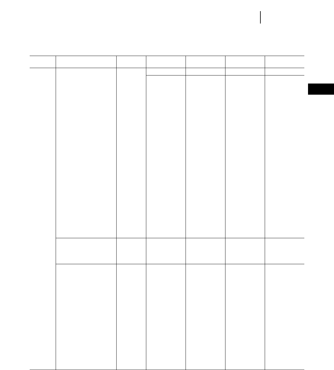
Bucket Bucket Bucket Heaped Bucket Weight
Model Bucket Type Family Bite Width Tip Radius Capacity With Teeth
mm in mm in L yd3kg lb
325B Extreme Service Excavation C 775 30.0" 1638 64.4" 700 0.92 850 1880
(cont’d) C 948 36.0" 1638 64.4" 900 1.18 970 2130
C 1098 42.0" 1638 64.4" 1100 1.44 1060 2340
C 1248 48.0" 1638 64.4" 1300 1.70 1140 2510
C 1395 54.0" 1638 64.4" 1500 1.96 1240 2730
C 1522 60.0" 1638 64.4" 1700 2.22 1335 2940
C 1680 66.0" 1638 64.4" 1900 2.49 1470 3240
C 750 29.5" 1550 61.0" 630 0.82 722 1590
C 1000 39.4" 1550 61.0" 950 1.24 863 1900
C 1150 45.3" 1550 61.0" 1150 1.50 940 2070
C 1250 49.2" 1550 61.0" 1250 1.64 980 2160
C 1350 53.1" 1550 61.0" 1400 1.83 1025 2260
C 1450 57.1" 1550 61.0" 1500 1.96 1085 2390
C 1600 63.0" 1550 61.0" 1700 2.22 1154 2540
D 1098 42.0" 1764 69.4" 1200 1.50 1150 2530
D 1246 48.0" 1764 69.4" 1400 1.88 1290 2840
D 1400 55.0" 1764 69.4" 1600 2.12 1390 3060
D 1540 60.0" 1764 69.4" 1800 2.50 1500 3310
D 1695 66.0" 1764 69.4" 2000 2.62 1650 3640
D 1820 72.0" 1764 69.4" 2200 2.88 1800 3970
D 750 29.5" 1660 65.3" 660 0.86 924 2040
D 1000 39.4" 1660 65.3" 1000 1.31 1108 2440
D 1150 45.3" 1660 65.3" 1300 1.70 1260 2780
D 1250 49.2" 1660 65.3" 1500 1.96 1370 3020
D 1500 59.1" 1660 65.3" 1700 2.22 1480 3260
D 1650 65.0" 1660 65.3" 1900 2.49 1571 3460
Mass Excavation C 1440 57.0" 1487 58.5" 1300 1.70 940 2060
C 1530 60.0" 1487 58.5" 1500 1.96 1050 2310
D 1520 60.0" 1660 65.4" 1600 2.09 1330 2930
D 1700 67.0" 1660 65.4" 1900 2.49 1325 2920
Heavy Duty C 775 30.0" 1638 64.5" 700 0.88 792 1742
C 948 36.0" 1638 64.5" 900 1.25 888 1954
C 1098 42.0" 1638 64.5" 1100 1.50 962 2116
C 1378 54.0" 1518 60.0" 1200 1.50 1082 2380
C 1248 48.0" 1638 64.5" 1300 1.75 1037 2281
C 1395 54.0" 1638 64.5" 1500 2.00 1119 2462
C 1522 60.0" 1638 64.5" 1700 2.25 1195 2629
C 1680 66.0" 1638 64.5" 1900 2.50 1281 2818
D 775 30.0" 1764 69.0" 700 1.00 875 1925
D 925 36.0" 1764 69.0" 900 1.25 968 2130
D 1098 42.0" 1764 69.0" 1200 1.50 1079 2374
D 1246 48.0" 1764 69.0" 1400 1.88 1206 2653
D 1440 57.0" 1695 67.0" 1500 2.00 1330 2926
D 1400 55.0" 1764 69.0" 1600 2.12 1306 2873
D 1540 60.0" 1764 69.0" 1800 2.50 1407 3095
D 1695 66.0" 1764 69.0" 2000 2.75 1493 3285
D 1820 72.0" 1764 69.0" 2200 3.00 1620 3564
4-113
4
ExcavatorsBucket Specifications

Bucket Bucket Bucket Heaped Bucket Weight
Model Bucket Type Family Bite Width Tip Radius Capacity With Teeth
mm in mm in L yd3kg lb
325B Trenching C 1075 42.0" 1550 61.0" 1000 1.31 800 1760
(cont’d) D 1225 48.0" 1730 68.1" 1400 1.83 1165 2560
D 1400 55.1" 1730 68.1" 1600 2.09 1120 2470
Rock C 750 29.5" 1550 61.0" 630 0.82 764 1680
C 1000 39.4" 1550 61.0" 950 1.24 552 1220
C 1350 53.1" 1550 61.0" 1400 1.83 1076 2370
D 750 29.5" 1660 65.3" 660 0.86 974 2150
D 1000 39.4" 1660 65.3" 1000 1.31 1160 2560
D 1650 65.0" 1660 65.3" 1900 2.49 1632 3600
Heavy Duty Rock C 948 36.0" 1638 64.5" 900 1.25 1000 2200
C 1098 42.0" 1638 64.5" 1100 1.50 1084 2385
C 1248 48.0" 1638 64.5" 1300 1.75 1168 2570
D 1098 42.0" 1764 69.0" 1200 1.50 1294 2847
D 1246 48.0" 1764 69.0" 1400 1.88 1437 3161
D 1400 55.0" 1764 69.0" 1600 2.12 1553 2417
Rock Ripping C 850 33.0" 1660 65.0" 600 0.75 1084 2385
D 900 35.0" 1746 69.0" 700 0.88 1123 2471
Ditch Cleaning C 2000 78.7" N/S 730 0.95 820 1810
C 2200 86.6" N/S 805 1.05 880 1940
C 2400 94.5" N/S 880 1.15 980 2160
C 1676 66.0" 1132 45.0" 1100 1.50 813 1789
C 1829 72.0" 1132 45.0" 1200 1.62 860 1892
D 2200 86.6" N/S 1080 1.41 1210 2670
D 2400 94.5" N/S 1180 1.54 1290 2840
D 2600 102.4" N/S 1280 1.67 1370 3020
D 1676 66.0" 1424 56.0" 1700 2.25 1192 2622
D 1829 72.0" 1424 56.0" 1800 2.50 1239 2726
Utility C 1600 63.0" N/S 940 1.23 970 2140
C 1800 70.9" N/S 1065 1.39 1060 2340
C 2000 78.7" N/S 1190 1.56 1140 2510
C 2200 86.6" N/S 1315 1.72 1220 2690
D 1800 70.9" N/S 1385 1.81 1490 3285
D 2100 82.7" N/S 1630 2.13 1600 3530
D 2400 94.5" N/S 1875 2.45 1840 4060
D 2700 106.3" N/S 2120 2.77 2020 4450
Utility Light C 1600 63.0" N/S 940 1.23 730 1610
C 1800 70.9" N/S 1065 1.39 800 1760
C 2000 78.7" N/S 1190 1.56 860 1900
C 2200 86.6" N/S 1315 1.72 920 2030
D 1800 70.9" N/S 1385 1.81 1120 2470
D 2100 82.7" N/S 1630 2.13 1250 2760
D 2400 94.5" N/S 1875 2.43 1380 3040
D 2700 106.3" N/S 2120 2.77 1510 3330
N/S = Not Significant for Utility, Utility Light and Ditch Cleaning Bucket.
4-114
Excavators Bucket Specifications

Bucket Bucket Bucket Heaped Bucket Weight
Model Bucket Type Family Bite Width Tip Radius Capacity With Teeth
mm in mm in L yd3kg lb
330B General Purpose D 775 30.0" 1854 73.0" 800 1.12 947 2083
D 925 36.0" 1854 73.0" 1100 1.50 1024 2253
D 1098 42.0" 1854 73.0" 1400 1.88 1116 2455
D 1246 48.0" 1854 73.0" 1700 2.25 1146 2521
D 1400 55.0" 1854 73.0" 2000 2.62 1192 2622
D 1540 60.0" 1854 73.0" 2200 3.00 1400 3080
Excavation D 1345 53.0" 1660 65.4" 1300 1.70 1115 2460
D 1430 56.0" 1660 65.4" 1400 1.83 1195 2640
D 1500 59.0" 1660 65.4" 1500 1.96 1160 2560
D 750 29.5" 1660 65.4" 660 0.86 924 2040
D 1000 39.4" 1660 65.4" 1000 1.31 1015 2240
D 1150 45.3" 1660 65.4" 1300 1.70 1120 2470
D 1300 51.2" 1660 65.4" 1450 1.90 1150 2540
D 1350 53.1" 1660 65.4" 1500 1.96 1214 2680
D 1500 59.1" 1660 65.4" 1700 2.22 1307 2880
D 1650 65.0" 1660 65.4" 1900 2.49 1390 3065
E 1470 58.0" 1845 72.1" 1700 2.22 1470 3240
E 1600 63.0" 1845 72.1" 1900 2.49 1545 3410
E 1400 55.1" 1780 70.0" 1700 2.22 1490 3285
E 1500 59.1" 1780 70.0" 1900 2.49 1590 3505
E 1650 65.0" 1780 70.0" 2100 2.75 1730 3815
Extreme Service Excavation D 775 30.0" 1764 69.4" 700 1.00 955 2100
D 925 36.0" 1764 69.4" 900 1.25 1045 2310
D 1098 42.0" 1764 69.4" 1200 1.50 1185 2610
D 1246 48.0" 1764 69.4" 1400 1.88 1335 2950
D 1400 55.0" 1764 69.4" 1600 2.12 1435 3170
D 1540 60.0" 1764 69.4" 1800 2.50 1565 3450
D 1695 66.0" 1764 69.4" 2000 2.62 1650 3640
D 1820 72.0" 1764 69.4" 2200 2.88 1800 3970
D 750 29.5" 1660 65.4" 660 0.86 924 2040
D 1000 39.4" 1660 65.4" 1000 1.31 1108 2440
D 1150 45.3" 1660 65.4" 1300 1.70 1260 2780
D 1250 49.2" 1660 65.4" 1500 1.96 1370 3020
D 1500 59.1" 1660 65.4" 1700 2.22 1480 3260
D 1650 65.0" 1660 65.4" 1900 2.49 1571 3460
E 1400 55.1" 1780 70.0" 1700 2.22 1490 3285
E 1500 59.1" 1780 70.0" 1900 2.49 1590 3505
E 1650 65.0" 1780 70.0" 2100 2.75 1730 3815
Mass Excavation D 1520 60.0" 1660 65.4" 1600 2.09 1330 2930
D 1700 67.0" 1660 65.4" 1900 2.49 1325 2920
E 1735 68.0" 1845 72.1" 2100 2.75 1710 3770
4-115
4
ExcavatorsBucket Specifications

Bucket Bucket Bucket Heaped Bucket Weight
Model Bucket Type Family Bite Width Tip Radius Capacity With Teeth
mm in mm in L yd3kg lb
330B Heavy Duty D 775 30.0" 1764 69.0" 700 1.00 875 1925
(cont’d) D 925 36.0" 1764 69.0" 900 1.25 968 2130
D 1098 42.0" 1764 69.0" 1200 1.50 1079 2374
D 1246 48.0" 1764 69.0" 1400 1.88 1206 2653
D 1440 57.0" 1695 67.0" 1500 2.00 1330 2926
D 1440 55.0" 1764 69.0" 1600 2.12 1306 2873
D 1540 60.0" 1764 69.0" 1800 2.50 1407 3095
D 1695 66.0" 1764 69.0" 2000 2.75 1493 3285
D 1820 72.0" 1764 69.0" 2200 2.88 1620 3564
E 1695 66.0" 1764 69.0" 2400 3.14 2119 4660
E 1820 72.0" 1764 69.0" 2600 3.40 2246 4940
Trenching D 1400 55.0" 1730 68.1" 1600 2.09 1120 2470
Rock D 750 29.5" 1660 65.4" 660 0.86 974 2150
D 1000 39.4" 1660 65.4" 1000 1.31 1160 2560
D 1650 65.0" 1660 65.4" 1900 2.49 1632 3600
E 1500 59.1" 1780 70.0" 1900 2.49 1690 3730
Heavy Duty Rock D 1098 42.0" 1764 69.0" 1200 1.50 1294 2847
D 1246 48.0" 1764 69.0" 1400 1.88 1437 3161
D 1400 55.0" 1764 69.0" 1600 2.12 1552 3414
Rock Ripping D 900 35.0" 1764 69.0" 700 0.88 1123 2471
Ditch Cleaning D 2200 86.6" N/S 1080 1.41 1210 2670
D 2400 94.5" N/S 1180 1.54 1290 2840
D 2600 102.4" N/S 1280 1.67 1370 3020
D 1676 66.0" 1424 56.0"
D 1829 72.0" 1424 56.0"
Utility D 1800 70.9" N/S 1385 1.81 1490 3285
D 2100 82.7" N/S 1630 2.13 1600 3530
D 2400 94.5" N/S 1875 2.45 1840 4060
D 2700 106.3" N/S 2120 2.77 2020 4450
Utility Light D 1800 70.9" N/S 1385 1.81 1120 2470
D 2100 82.7" N/S 1630 2.13 1250 2760
D 2400 94.5" N/S 1875 2.45 1380 3040
D 2700 106.3" N/S 2120 2.77 1510 3330
345B Trenching F 1075 42.0" 1925 75.8" 1300 1.70 1475 3250
F 1218 48.0" 1925 75.8" 1600 2.09 1563 3450
F 1410 56.0" 1925 75.8" 1900 2.49 1756 3870
Excavation T 1580 62.0" 1820 71.7" 1900 2.49 1728 3810
U 1650 65.0" 1860 73.2" 2100 2.75 2212 4880
F 1590 63.0" 1870 73.6" 2000 2.62 1814 4000
F 1735 68.0" 1870 73.6" 2200 2.88 1921 4240
G 1655 65.0" 1958 77.1" 2200 2.88 2172 4790
G 1770 70.0" 1958 77.1" 2400 3.14 2292 5050
Mass Excavation G 1895 75.0" 1958 77.1" 2600 3.40 2434 5370
N/S = Not Significant for Utility, Utility Light and Ditch Cleaning Bucket.
4-116
Excavators Bucket Specifications
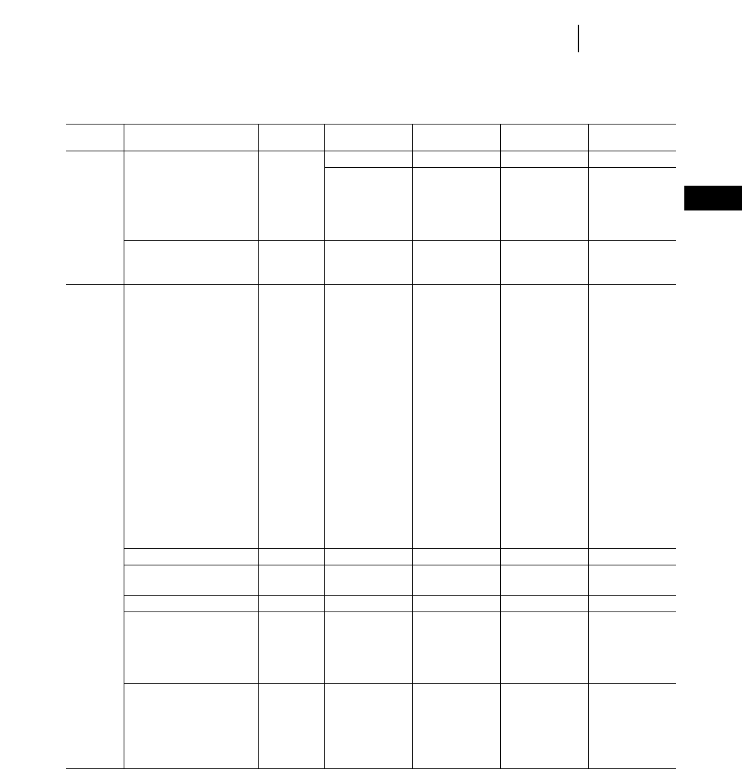
Bucket Bucket Bucket Heaped Bucket Weight
Model Bucket Type Family Bite Width Tip Radius Capacity With Teeth
mm in mm in L yd3kg lb
345B Extreme Service Excavation T 1560 61.0" 1862 73.3" 1900 2.49 1950 4300
(cont’d) T 1605 63.0" 1862 73.3" 2000 2.62 2091 4610
T 1665 66.0" 1862 73.3" 2100 2.75 2138 4710
F 1600 63.0" 1870 73.6" 2000 2.62 1988 4380
F 1600 63.0" 1925 75.8" 2100 2.75 2027 4470
V-Type Excavation U 1830 72.0" 1860 73.2" 2100 2.75 2394 5280
G 1750 69.0" 1972 77.6" 2200 2.89 2519 5550
G 1880 74.0" 1972 77.6" 2400 3.14 2630 5800
350 Excavation F 925 36.4" 2011 79.2" 1100 1.38 1636 3607
F 1075 42.3" 2011 79.2" 1400 1.75 1724 3800
F 1225 48.2" 1965 77.4" 1700 2.25 1701 3750
F 1250 49.2" 1900 74.8" 1800 2.35 1650 3640
F 1350 53.1" 1900 74.8" 2000 2.62 1750 3860
F 1375 54.1" 1965 77.4" 2000 2.63 1837 4050
F 1450 57.1" 1900 74.8" 2200 2.88 1995 4400
F 1525 60.0" 1965 77.4" 2300 3.00 1953 4306
F 1590 62.6" 1870 73.6" 2000 2.62 1842 4060
F 1600 63.0" 1900 74.8" 2500 3.27 2175 4800
F 1700 67.0" 1900 74.8" 2700 3.53 2190 4830
F 1735 68.3" 1870 73.6" 2200 2.88 1954 4310
F 1800 70.9" 1900 74.8" 2700 3.53 2310 5090
G 1450 57.1" 2000 78.7" 2400 3.14 2090 4610
G 1550 61.0" 2000 78.7" 2600 3.40 2145 4730
G 1650 65.0" 2000 78.7" 2800 3.66 2270 5005
G 1655 65.2" 1958 77.1" 2200 2.88 2224 4900
G 1770 69.7" 1958 77.1" 2400 3.14 2237 4930
G 1800 70.9" 2000 78.7" 3100 4.05 2410 5310
Extreme Service Excavation G 1800 70.9" 2000 78.7" 3100 4.05 2405 5300
V-Type Excavation G 1750 68.9" 1958 77.1" 2200 2.88 2503 5520
G 1880 74.0" 1958 77.1" 2400 3.14 2606 5750
Mass Excavation G 1895 74.6" 1958 77.1" 2600 3.50 2479 5470
Trenching F 1075 42.3" 1925 75.8" 1300 1.75 1507 3320
F 1218 48.0" 1925 75.8" 1600 2.12 1601 3530
F 1410 55.5" 1925 75.8" 1900 2.50 1789 3940
F 1225 48.2" 1965 77.4" 1700 2.25 1571 3456
F 1375 54.1" 1965 77.4" 2000 2.63 1707 3755
Extreme Service Trenching F 925 36.4" 2011 79.0" 1100 1.38 1534 3375
F 1075 42.3" 2011 79.0" 1400 1.75 1622 3568
F 1259 49.6" 2011 79.0" 1700 2.25 1857 4094
F 1525 60.0" 2011 79.0" 2300 3.00 2101 4622
F 1600 63.0" 1870 73.6" 2000 2.63 1963 4330
F 1600 63.0" 1925 75.8" 2100 2.75 2015 4440
4-117
4
ExcavatorsBucket Specifications

Bucket Bucket Bucket Heaped Bucket Weight
Model Bucket Type Family Bite Width Tip Radius Capacity With Teeth
mm in mm in L yd3kg lb
350 Rock F 953 37.5" 1870 73.6" 900 1.25 2190 4829
(cont’d) F 1350 53.1" 1900 74.8" 2000 2.62 2100 4630
F 1450 57.1" 1900 74.8" 2200 2.88 2205 4860
F 1600 63.0" 1900 74.8" 2500 3.27 2370 5225
G 1750 68.9" 2050 80.7" 2800 3.66 2770 6110
G 1750 68.9" 2050 80.7" 2800 3.66 2810 6200
G 1800 70.9" 2050 80.7" 3100 4.05 2962 6530
375 Excavation H 1800 70.9" 2100 82.7" 2800 3.66 2490 5490
H 1990 78.3" 2100 82.7" 3200 4.25 2667 5880
H 1990 78.3" 2210 87.0" 3800 5.00 2975 6559
H 1750 68.9" 2100 82.7" 3200 4.19 3280 7232
H 1900 74.8" 2100 82.7" 3600 4.71 3430 7563
H 1800 70.9" 2300 90.5" 4200 5.49 3720 8203
J 1750 68.9" 2235 88.0" 3000 3.92 2602 5780
J 1865 73.4" 2235 88.0" 3200 4.19 3026 6670
J 2040 80.3" 2235 88.0" 3600 4.75 3223 7110
J 2210 87.0" 2235 88.0" 4000 5.25 3403 7500
J 2200 86.6" 2200 86.6" 4400 5.76 4030 8886
J 2140 84.3" 2200 86.6" 5100 6.67 4120 9085
J 2300 90.6" 2200 86.6" 5600 7.32 4350 9592
Extreme Service Excavation J 2380 93.7" 2200 86.6" 4500 5.89 4420 9746
J 2380 93.7" 2200 86.6" 5200 6.80 4150 9151
J 2380 93.7" 2200 86.6" 5200 6.80 4790 10,562
J 2400 94.5" 2200 86.6" 5200 6.80 4450 9812
V-Type Excavation J 2080 81.9" 2235 88.0" 3600 4.75 3879 8550
Mass Excavation *J* 1744 68.7" 2234 88.0" 3000 4.00 3524 7771
*J* 2064 81.3" 2234 88.0" 3800 5.00 4006 8833
J 2390 94.1" 2235 88.0" 4400 5.75 3818 8420
*J* 2390 94.1" 2234 88.0" 4400 6.00 4531 9991
*J* 2390 94.1" 2234 88.0" 5400 7.00 4835 10,661
V-Type Mass Excavation J 2260 89.0" 2235 88.0" 4000 5.25 4065 8960
Trenching H 1380 54.3" 2210 87.0" 2300 3.25 2218 4890
*H* 1535 60.4" 2210 87.0" 2800 3.75 2576 5680
H 1560 61.4" 2210 87.0" 2700 3.53 2348 5180
*J* 1530 60.2" 2350 92.5" 2800 3.75 2954 6514
*J* 1680 66.1" 2350 92.5" 3200 4.25 3103 6842
Extreme Service Trenching *H* 1075 42.3" 2309 90.9" 1600 2.13 2096 4611
*H* 1225 48.2" 2309 90.9" 2000 2.63 2251 4952
Rock H 1190 46.9" 2137 84.1" 1600 2.00 3254 6589
H 1220 48.0" 2046 80.6" 1500 1.96 3131 6900
J 1850 72.8" 2350 92.5" 4200 5.49 3900 8600
J 1950 76.8" 2350 92.5" 4000 5.23 4420 9746
J 2000 78.7" 2350 92.5" 4300 5.62 4830 10,650
J 2380 93.7" 2350 92.5" 5200 6.80 5220 11,510
J 2380 93.7" 2350 92.5" 5200 6.80 5300 11,687
Heavy Duty Rock J 2380 93.7" 2350 92.5" 5200 6.80 6032 13,301
*Available only from U.S.A.
4-118
Excavators Bucket Specifications

4-119
4
ExcavatorsBucket Specifications
Bucket Bucket Bucket Heaped Bucket Weight
Model Bucket Type Family Bite Width Tip Radius Capacity With Teeth
mm in mm in m3yd3kg lb
5130B High Density 2810 111.0" 3038 120.0" 8.5 11.0 8340 18,380
Rock 2810 111.0" 3038 120.0" 10.5 13.7 10 250 22,600
Excavation 2810 111.0" 3038 120.0" 10.5 13.7 8940 19,700
Coal 3500 138.0" 3225 127.0" 13.6 17.8 8760 19,320
Coal 3680 145.0" 3225 127.0" 18.3 24.0 9430 20,800
5230 Rock 3940 156.0" 3250 128.0" 16.0 21.0 17 140 37,785
Light Material 3940 156.0" 3250 128.0" 18.0 23.5 19 040 41,975
Coal 4350 171.0" 3400 134.0" 27.5 36.0 15 420 34,000
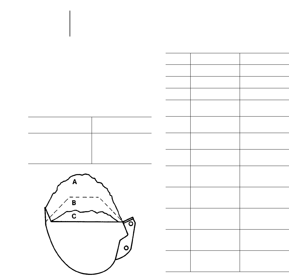
BUCKET PAYLOAD
An excavator’s bucket payload (actual amount of
material in the bucket on each digging cycle) is
dependent on bucket size, shape, curl force, and cer-
tain soil characteristics, i.e., the fill factor for that
soil. Fill factors for several types of material are
listed below.
Average Bucket Payload =
(Heaped Bucket Capacity) 2(Bucket Fill Factor)
Fill Factor Range
Material (Percent of heaped
bucket capacity)
Moist Loam or Sandy Clay A— 100-110%
Sand and Gravel B— 95-110%
Hard, Tough Clay C— 80-90%
Rock — Well Blasted 60-75%
Rock — Poorly Blasted 40-50%
Working Weights — Bucket & Payload
The following tables give maximum “bucket plus
payload” weights to assist in selecting the correct
bucket for a specific application. These weights are
based on actual job conditions. In better than aver-
age conditions the excavator may be able to achieve
rated lift capacities listed in this section.
NOTE: Bucket sizes are suitable for a maximum
material density of 1800 kg/m3(3035 lb/yd3).
Payloads shown are calculated at 1500 kg/m3
(2530 lb/yd3).
Stick Length
Model mm ft kg lb
307B 1665 5'6" 1050 2310
2210 7'3" 860 1900
307B SB 1665 5'6" 1030 2270
2210 7'3" 750 1650
307 1665 5'6" 1090 2400
2210 7'3" 880 1940
311B 1950 6'5" 1560 3440
2250 7'5" 1470 3240
2800 9'2" 1230 2710
312B 2100 6'11" 1580 3480
2500 8'2" 1460 3220
3000 9'10" 1280 2820
312B L 2100 6'11" 1770 3900
2500 8'2" 1640 3620
3000 9'10" 1450 3200
312B L* 2100 6'11" 1740 3830
2500 8'2" 1595 3510
3000 9'10" 1450 3190
315B 1850 6'1" 2070 4570
2250 7'5" 1980 4360
2600 8'6" 1810 4000
3100 10'2" 1630 3590
315B L 1850 6'1" 2160 4760
2250 7'5" 2060 4540
2600 8'6" 1890 4170
3100 10'2" 1700 3750
318B L 1800 5'11" 2600 5730
2250 7'5" 2380 5250
2700 8'10" 2210 4870
3200 10'6" 1910 4210
318B LN 1800 5'11" 2230 4920
2250 7'5" 2030 4480
2700 8'10" 1900 4190
3200 10'6" 1630 3590
318B L*/ 1800 5'11" 2440 5380
318B LN* 2250 7'5" 2250 4960
2700 8'10" 2160 4760
3200 10'6" 1810 3990
*France sourced.
4-120
Excavators Working Weights
●Bucket Fill Factors
●Bucket & Payload

4-121
4
ExcavatorsWorking Weights
●Buckets & Payload
Working Weights†
Stick Length Buckets & Payload
Model Boom m ft kg lb
320B Reach 1.90 6'3" 2380 5250
2.50 8'2" 2330 5140
2.92 9'7" 2150 4740
3.86 12'8" 1850 4080
Mass 1.90 6'3" 2690 5930
2.40 7'10" 2430 5360
VA 1.90 6'3" 2870 6330
2.40 7'10" 2620 5780
2.92 9'7" 2460 5420
320B L Reach 1.90 6'3" 2850 6290
2.50 8'2" 2750 6070
2.92 9'7" 2560 5650
3.86 12'8" 2200 4850
Mass 1.90 6'3" 3210 7080
2.40 7'10" 2910 6420
VA 1.90 6'3" 3260 7190
2.40 7'10" 2990 6590
2.92 9'7" 2790 6150
320B N Reach 1.90 6'3" 2300 5070
2.50 8'2" 2270 5000
2.92 9'7" 2090 4610
3.86 12'8" 1800 3970
Mass 1.90 6'3" 2600 5730
2.40 7'10" 2350 5180
VA 1.90 6'3" 2640 5820
2.40 7'10" 2410 5310
2.92 9'7" 2280 5030
322B Reach 2.50 8'2" 2910 6420
2.95 9'8" 2690 5930
3.60 11'10" 2320 5120
Mass 2.00 6'7" 3390 7480
2.50 8'2" 3030 6680
322B L Reach 2.50 8'2" 3410 7520
2.95 9'8" 3160 6970
3.60 11'10" 2760 6090
Mass 2.00 6'7" 4010 8840
2.50 8'2" 3630 8010
VA 2.00 6'7" 3750 8270
2.50 8'2" 3390 7470
Working Weights†
Stick Length Buckets & Payload
Model Boom m ft kg lb
322B N Reach 2.50 8'2" 2610 5760
2.95 9'8" 2410 5320
3.60 11'10" 2070 4570
Mass 2.00 6'7" 3010 6640
2.50 8'2" 2690 5930
VA 2.00 6'7" 2830 6240
2.50 8'2" 2540 5600
322B LN Reach 2.00 6'7" 3240 7140
2.50 8'2" 3150 6940
2.95 9'8" 2910 6420
3.60 11'10" 2710 5970
Mass 2.00 6'7" 3850 8490
2.50 8'2" 3430 7560
VA 2.00 6'7" 3260 7190
2.50 8'2" 2950 6500
325B Reach 2.00 6'7" 3450 7610
2.65 8'8" 3140 6930
3.20 10'6" 2840 6270
Mass 2.00 6'7" 4090 9020
2.50 8'2" 3650 8050
VA 2.00 6'7" 3430 7560
2.50 8'2" 3130 6900
3.20 10'6" 2820 6220
325B L Reach 2.00 6'7" 4060 8950
2.65 8'8" 3680 8120
3.20 10'6" 3360 7410
Mass 2.00 6'7" 4810 10,610
2.50 8'2" 4290 9460
VA 2.00 6'7" 4090 9020
2.50 8'2" 3740 8250
3.20 10'6" 3360 7410
325B LN Reach 2.00 6'7" 3530 7790
2.65 8'8" 3210 7080
3.20 10'6" 2910 6420
Mass 2.00 6'7" 4180 9220
2.50 8'2" 3730 8230
VA 2.00 6'7" 3490 7690
2.50 8'2" 3190 7030
3.20 10'6" 2870 6330
†Working weights may vary depending on machine configuration.
Contact your Caterpillar Dealer for specific information.

4-122
Excavators Working Weights
●Buckets & Payload
Working Weights†
Stick Length Buckets & Payload
Model Boom m ft kg lb
330B Reach 2.15 7'1" 4500 9920
2.80 9'2" 4000 8820
3.30 10'10" 3690 8140
3.90 12'10" 3250 7170
Mass 2.15 7'1" 5030 11,090
2.55 8'4" 4440 9790
330B L Reach 2.15 7'1" 4700 10,360
2.80 9'2" 4160 9170
3.30 10'10" 3830 8440
3.90 12'10" 3240 7540
Mass 2.15 7'1" 5210 11,490
2.55 8'4" 4640 10,230
330B LN Reach 2.15 7'1" 4150 9150
2.80 9'2" 3700 8160
3.30 10'10" 3410 7520
3.90 12'10" 3000 6610
Mass 2.15 7'1" 4660 10,270
2.55 8'4" 4100 9040
3.50 11'6" 3530 7780
345B Reach 2.90 9'6" 5780 12,740
3.35 11'0" 5210 11,490
3.90 12'10" 4790 10,560
Mass 2.50 8'2" 6190 13,650
3.00 9'10" 5670 12,500
345B L Reach 2.90 9'6" 6360 14,020
– FIX 3.35 11'0" 5710 12,590
3.90 12'1" 5320 11,730
Mass 2.50 8'2" 6780 14,950
3.00 9'10" 6230 13,730
345B L Reach 2.90 9'6" 7110 15,670
– VG 3.35 11'0" 6410 14,130
3.90 12'10" 5990 13,210
Mass 2.50 8'2" 7650 16,870
3.00 9'10" 7150 15,760
350 Reach 3.10 10'2" 5800 12,790
3.60 11'10" 5380 11,860
4.80 15'9" 4320 9520
Mass 2.40 7'10" 7110 15,670
2.95 9'8" 6350 14,000
3.70 12'2" 5610 12,370
350 L Reach 3.10 10'2" 6060 13,360
3.60 11'10" 5610 12,370
4.80 15'9" 4520 9960
Mass 2.40 7'10" 7300 16,090
2.95 9'8" 6640 14,640
3.70 12'2" 5860 12,920
Working Weights†
Stick Length Buckets & Payload
Model Boom m ft kg lb
375 Reach 2.90 9'6" 8450 18,630
3.40 11'2" 7930 17,480
4.40 14'5" 7570 16,690
5.50 18'1" 6360 14,020
General 3.40 11'2" 8550 18,850
Purpose 4.40 14'5" 8080 17,810
5.50 18'1" 6770 14,930
Mass 2.90 9'6" 11 120 24,520
3.40 11'2" 10 430 22,990
4.10 13'5" 9220 20,330
375 L Reach 2.90 9'6" 8860 19,530
3.40 11'2" 8330 18,360
4.40 14'5" 7930 17,480
5.50 18'1" 6680 14,730
General 3.40 11'2" 8970 19,780
Purpose 4.40 14'5" 8450 18,630
5.50 18'1" 7100 15,650
Mass 2.90 9'6" 11 610 25,600
3.40 11'2" 10 890 24,010
4.10 13'5" 9650 21,270
5130B ME Mass 3.80 12'6" 28 500 62,800
5230 ME Mass 4.50 14'9" 44 500 98,100
†Working weights may vary depending on machine configuration.
Contact your Caterpillar dealer for specific information.
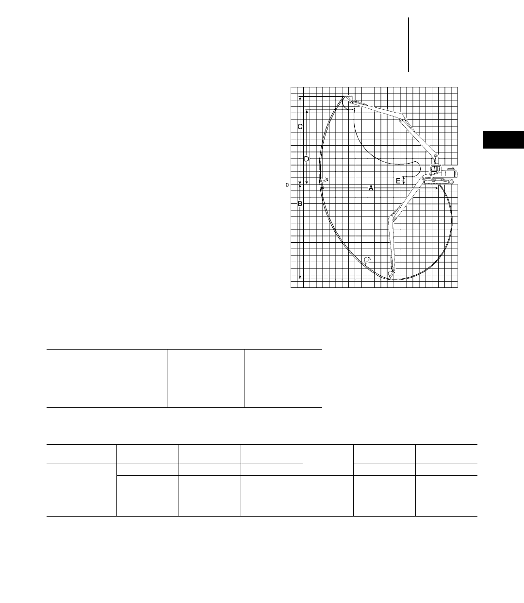
INTRODUCTION
Long reach excavators are designed purposely for
light duty digging that requires reach capability
well above that of normal digging machines. To be
able to have high enough digging forces together
with an acceptable size bucket, the long reach excava-
tors have a smaller digging envelope than the ditch
cleaning machines. Long reach excavators are ideally
suited for deep digging in gravel or sand pits then
feeding directly into a hopper.
Caterpillar’s long reach hydraulic excavators use
purpose-built booms and sticks designed by Caterpillar
for maximum performance and durability in light
duty applications.
Long Reach Excavation Fronts include: boom,
stick, linkage cylinders (boom, stick, and bucket),
hydraulic lines, additional counterweight for sta-
bility over the side and heavy duty wide undercar-
riage. Dimensions include light excavation bucket.
4-123
4
ExcavatorsLong Reach
●Introduction
●Range Dimensions
●Bucket Information
325B L 330B L
Long Reach Model mftmft
AMaximum Reach at
Ground Level 16.07 52'9" 17.91 58'9"
BMaximum Digging Depth 11.34 37'2" 12.62 41'5"
CMaximum Cutting Height 13.88 45'6" 16.01 52'6"
DMaximum Dumping Height 11.20 36'9" 13.42 44'0"
EMinimum Loading Height 3.15 10'4" 3.55 11'8"
325B L/330B L • Long Reach
Bucket Bucket SAE Bucket Bucket Stick
Type Width Heaped Cap. Weight No. of Curl Force Crowd Force
mm ft L yd3kg lb Teeth kN lb kN lb
Excavation 1500 4'11" 1350 1.77 820 1810 6 54.1 12,170 ——
Ditch Cleaning 1800 5'11" 450 0.59 550 1210 0————
Ditch Cleaning 2000 6'7" 550 0.72 590 1300 0————
Ditch Cleaning 2200 7'3" 610 0.80 630 1390 0————
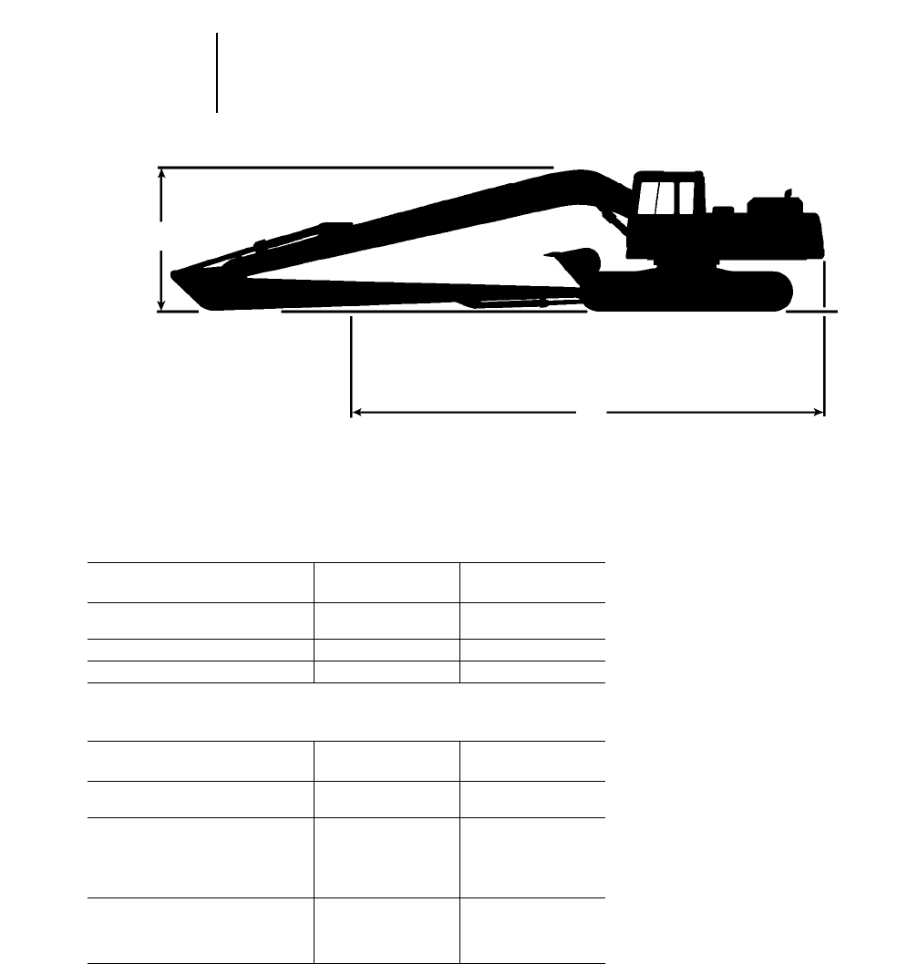
LONG REACH ATTACHMENT
SHIPPING DIMENSIONS
325B L 330B L
Model m ft m ft
AOverall Transport Length
(Front Folded) 13.59 44'7" 15.45 50'8"
BOverall Height (To Top of Boom) 3.44 11'3" 3.75 12'4"
Overall Width (To Widest Point) 3.72 12'2" 3.72 12'2"
NOTE: For other base machine dimensions, see section on machines with GP attachments.
LONG REACH ATTACHMENT COMPONENT WEIGHTS
325B L 330B L
Model kg lb kg lb
Total Counterweight: 7700 16,980 8300 18,300
Includes Additional over Standard 1272 2800 1510 3330
Long Reach Boom:
Includes boom, stick cylinder,
hydraulic lines, and pins for
stick, stick cylinder, and
boom rod end 3400 7500 4500 9920
Long Reach Stick:
Includes stick, bucket linkage
and pins, bucket cylinder and
pin, and hydraulic lines 1940 4280 2300 5070
4-124
Excavators Long Reach
●Shipping Dimensions
●Major Component Weights
B
A
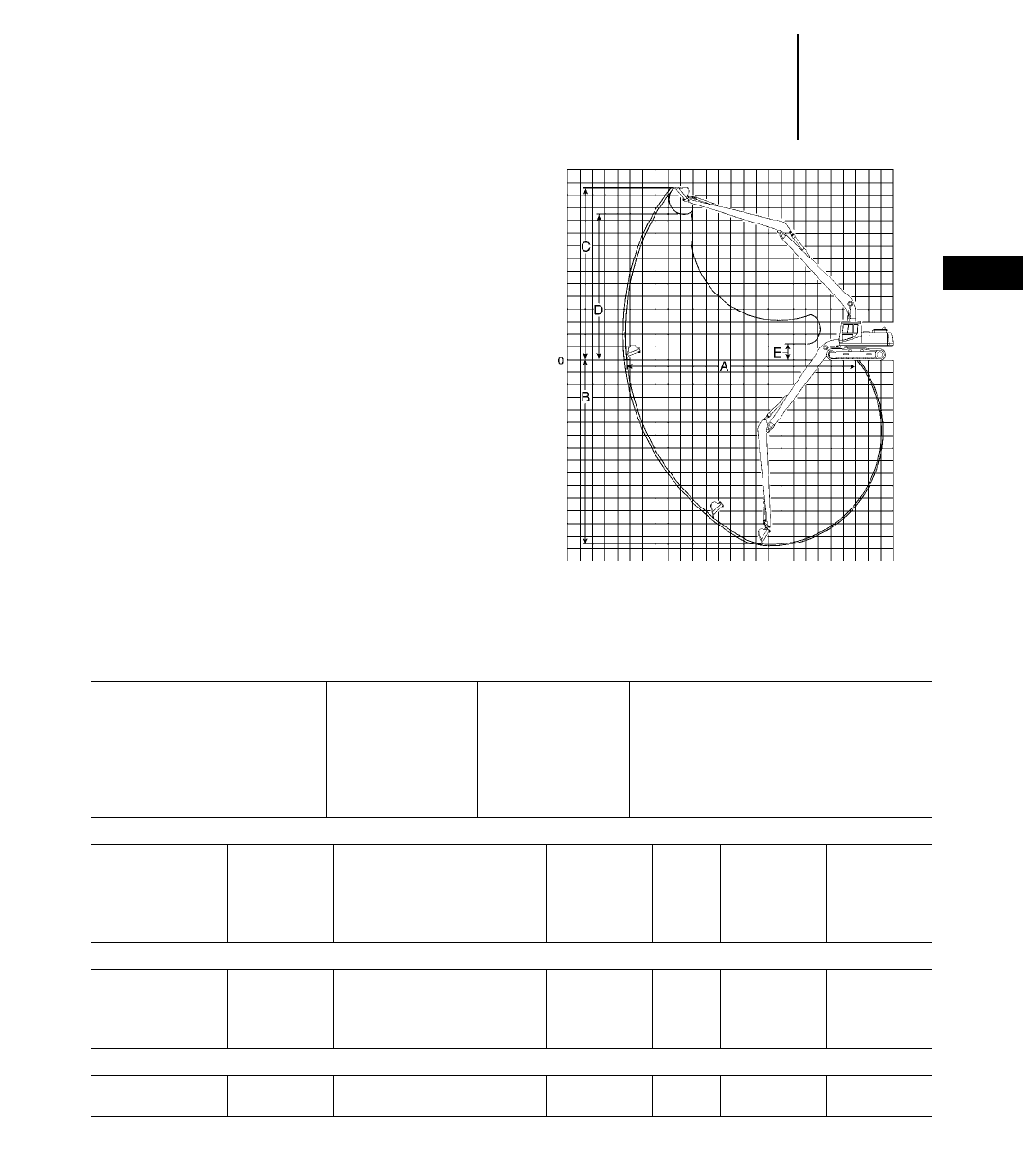
INTRODUCTION
Ditch cleaning excavators are designed specifically
for those jobs requiring maximum reach well beyond
the range of normal excavators. Those machines are
designed to drag a small bucket at about 90 degrees
over the side of the tracks towards the excavator;
they are not suited for digging work. Caterpillar offers
the Long Reach excavators for light digging applica-
tions with a much larger digging envelope than normal
excavators. Ditch cleaning excavators are suited for
ditch cleaning, slope finishing, river conservation
and other work formerly reserved to draglines.
Caterpillar’s ditch cleaning hydraulic excavators
use purpose-built booms and sticks designed by
Caterpillar for maximum performance and dura-
bility in dragging applications.
Ditch Cleaning Fronts include: boom, stick, link-
age cylinders (boom, stick, and bucket), hydraulic
lines and additional counterweight for stability
while working over the side. Dimensions include
ditch cleaning bucket.
4-125
4
ExcavatorsDitch Cleaning
●Introduction
●Range Dimensions
●Bucket Information
320B L 320B L 322B L 325B L
Long Reach Model mftmftmftmft
Source Japan Belgium Japan Belgium
AMaximum Reach at
Ground Level 15.60 51'2" 15.59 51'2" 18.30 60'0" 18.30 60'0"
BMaximum Digging Depth 11.75 38'7" 11.75 38'7" 14.60 47'11" 15.60 51'2"
CMaximum Cutting Height 13.24 43'5" 13.32 43'8" 14.19 46'7" 13.60 44'7"
DMaximum Dumping Height 11.14 36'7" 11.14 36'7" 12.14 39'10" 11.60 38'1"
EMinimum Loading Height 2.10 6'10" 2.09 6'10" 1.49 4'11" 1.32 4'4"
320B L • Ditch Cleaning • Japan/U.S. Sourced
Bucket Bucket Tip SAE Bucket Bucket Stick
Type Width Radius Heaped Cap. Weight No. of Curl Force Crowd Force
mm ft/in mm ft/in L yd3kg lb Teeth kN lb kN lb
General Purpose 810 2'8" 1220 4'0" 450 0.59 340 750 5 60.5 13,600 46.0 10,340
Ditch Cleaning 1140 3'9" 1090 3'7" 600 0.78 290 640 0 54.1 12,170 46.6 10,470
322B L • Ditch Cleaning • Japan/U.S. Sourced
General Purpose 700 2'4" 1220 4'0" 380 0.50 335 740 4 54.1 12,170 50.1 11,270
General Purpose 810 2'8" 1220 4'0" 450 0.59 340 750 5 54.1 12,170 50.1 11,270
Ditch Cleaning 965 3'2" 1090 3'7" 480 0.63 265 580 0 60.5 13,600 50.6 11,380
Ditch Cleaning 1140 3'9" 1090 3'7" 600 0.78 290 640 0 60.5 13,600 50.6 11,380
320 L/325 L • Ditch Cleaning • Belgium Sourced
810 2'8" ——450 0.59 350 770 —————
1800 5'11" ——600 0.78 400 880 —————

4-126
Excavators Ditch Cleaning
●Shipping Dimensions
●Major Component Weights
DITCH CLEANING ATTACHMENT
SHIPPING DIMENSIONS
320B L 320B L 322B L 325B L* 330B L*
Model m ft m ft m ft m ft m ft
Source Japan Belgium Japan Belgium Japan
AOverall Transport Length
(Front Folded) 12.65 41'6" 12.80 42'0" 14.24 46'9" 14.60 47'11" 16.62 54'6"
BOverall Height (To Top of Boom) 3.21 10'6" 3.20 10'6" 3.17 10'5" 3.30 10'10" 3.59 11'9"
Overall Width (To Widest Point) 3.18 10'5" 3.00 9'10" 3.39 11'1" 3.38 11'1" 3.34 10'11"
NOTE: For other base machine dimensions, see section on machines with GP attachments.
DITCH CLEANING ATTACHMENT COMPONENT WEIGHTS
320B L 320B L 322B L 325B L* 330B L*
Model kg lb kg lb kg lb kg lb kg lb
Total Counterweight: 4810 10,600 4810 10,600 5900 13,010 7700 16,980 7390 16,290
Includes Additional over Standard 950 2090 950 2090 1440 3180 1272 2800 ——
Long Reach Boom:
Includes boom, stick cylinder,
hydraulic lines, and pins for
stick, stick cylinder, and
boom rod end 2185 4820 2185 4820 3130 6900 3400 7500 4190 9240
Long Reach Stick:
Includes stick, bucket linkage
and pins, bucket cylinder and
pin, and hydraulic lines 1260 2780 1260 2780 1570 3460 1940 4280 2130 4700
*Custom Product.
B
A
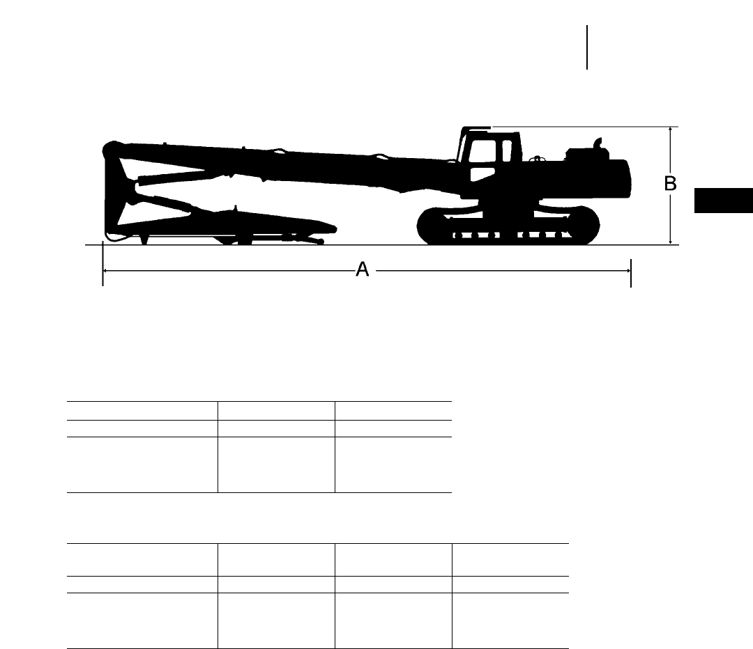
4-127
4
ExcavatorsUltra High Demolition Arrangements
●Shipping Dimensions
Model 325B L 330B L
mftmft
AOverall Transport Length 12.56 41'2" 14.90 48'11"
BTransport Height 3.33 10'11" 3.34 10'11"
Transport Width with
600 mm (2'0") Shoe 3.19 10'6" 3.19 10'6"
330B LN 345B LN
Model Hydraulic Gauge 345B L Hydraulic Gauge
mftmftmft
AOverall Transport Length 14.90 48'11" 16.25 53'4" 16.25 53'4"
BTransport Height 3.34 10'11" 3.67 12'0" 3.67 12'0"
Transport Width with
600 mm (2'0") Shoe 2.99 9'10" 2.99 9'10" 2.99 9'10"
**Not available in all sales areas.
**Includes wide gauge undercarriage and 2-piece boom.
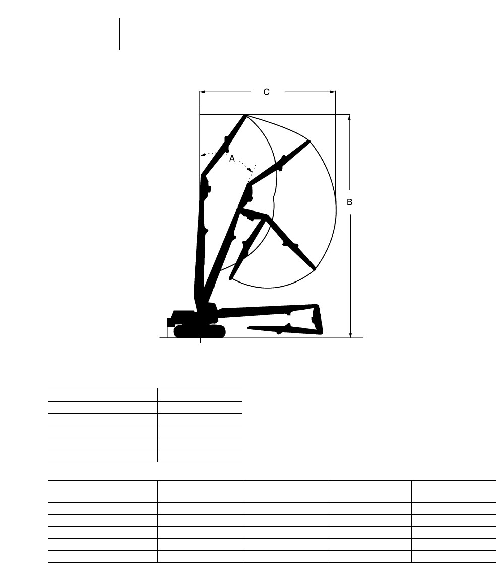
Model 325B L
AMax. Boom Angle 25°
mft
BMax. Height 17.10 56'1"
CMax. Reach 11.10 36'5"
Max. Tool Weight 2300 kg 5070 lb
330B LN 345B LN
Model 330B L Variable Gauge 345B L Variable Gauge
ABoom Angle 25° 25° 25° 25°
mftmftmftmft
BMax. Height 20.90 68'7" 20.90 68'7" 22.80 74'10" 22.80 74'10"
CMax. Reach 13.80 45'3" 13.80 45'3" 15.30 50'2" 15.30 50'2"
Max. Tool Weight 2300 kg 5070 lb 3000 kg 6610 lb 2300 kg 5070 lb 3000 kg 6610 lb
4-128
Excavators Ultra High Demolition Arrangements
●Range Dimensions
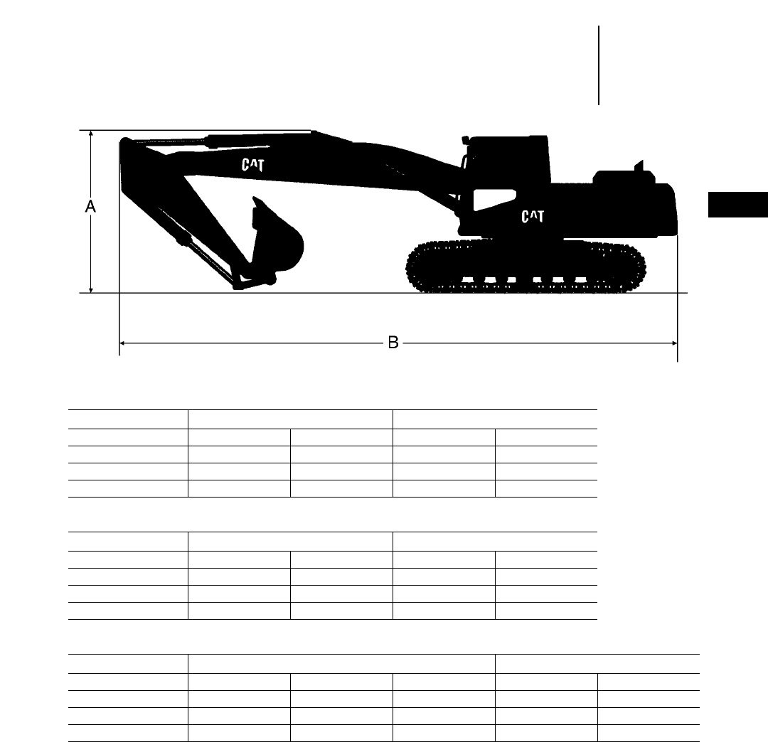
4-129
4
ExcavatorsDemolition Arrangements
●Straight Boom
●Shipping Dimensions
●Belgium Sourced
Model 320B 322B
mftmftmftmft
Stick 2.50 8'2" 2.90 9'6" 2.50 8'2" 2.95 9'8"
AShipping Height 3.07 10'1" 3.07 10'1" 3.10 10'2" 3.13 10'3"
BShipping Length 9.70 31'10" 9.70 31'10" 10.42 34'2" 10.36 34'0"
Model 325B 330B
mftmftmftmft
Stick 2.65 8'8" 3.20 10'6" 3.30 10'10" 3.90 12'10"
AShipping Height 3.15 10'4" 3.15 10'4" 3.60 11'10" 3.60 11'10"
BShipping Length 10.30 33'10" 10.30 33'10" 10.50 34'5" 10.70 35'1"
Model 345B L 375 L
mftmftmftmftmft
Stick 2.90 9'6" 3.40 11'2" 4.00 13'1" 2.90 9'6" 3.40 11'2"
AShipping Height 3.35 11'0" 3.50 11'6" 3.75 12'4" 4.35 14'3" 4.60 15'1"
BShipping Length 12.10 39'8" 12.05 39'6" 12.00 39'4" 14.80 48'7" 14.55 47'9"
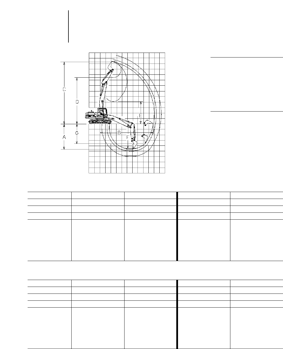
4-130
Excavators Demolition Arrangements
●Straight Booms
●Range Dimensions
●Belgium Sourced
Model 320B L 322B
mftmftmftmft
Boom 6.02 19'9" 6.02 19'9" 6.20 20'4" 6.20 20'4"
Stick 2.50 8'2" 2.92 9'6" 2.50 8'2" 2.95 9'8"
Bucket Tip radius 1.50 4'11" 1.50 4'11" 1.55 5'1" 1.55 5'1"
A4.64 15'3" 5.06 16'7" 4.50 14'9" 4.94 16'2"
B9.77 32'1" 10.18 33'5" 10.02 32'10" 10.47 34'4"
C11.36 37'3" 11.72 38'5" 11.62 38'1" 12.00 39'4"
D8.45 27'9" 8.81 28'11" 8.54 28'0" 8.92 29'3"
E4.07 13'4" 3.59 11'9" 4.42 14'6" 3.83 12'7"
F4.44 14'7" 4.88 16'0" 4.30 14'1" 4.74 15'7"
G3.60 11'10" 3.93 12'11 3.40 11'2" 3.80 12'6"
KEY:
AMaximum digging depth
BMaximum reach @ ground line
CMaximum cutting height
DMaximum loading height
EMinimum loading height
FMaximum depth at 2.44 m (8'0")
level bottom
GMaximum vertical wall depth
Model 325B 330B
mftmftmftmft
Boom 6.48 21'3" 6.48 21'3" 6.87 22'6" 6.87 22'6"
Stick 2.65 8'8" 3.20 10'6" 3.30 10'10" 3.90 12'10"
Bucket Tip radius 1.60 5'3" 1.60 5'3" 1.85 6'1" 1.85 6'1"
A5.54 18'2" 6.09 20'0" 6.06 19'11" 6.66 21'10"
B10.48 34'5" 11.01 36'1" 11.54 37'10" 12.13 39'10"
C11.84 38'10" 12.24 40'2" 13.15 43'2" 13.67 44'10"
D8.63 28'4" 9.03 29'8" 9.70 31'10" 10.23 33'7"
E4.05 13'3" 3.47 11'5" 3.87 12'8" 3.35 11'0"
F5.36 17'7" 5.93 19'5" 5.91 19'5" 6.53 21'5"
G4.76 15'7" 5.24 17'2" 5.04 16'6" 5.52 18'1"
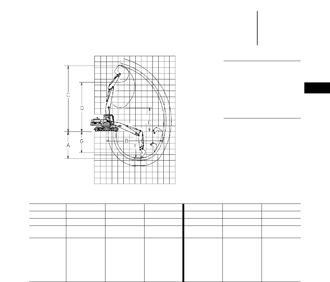
4-131
4
ExcavatorsDemolition Arrangements
●Straight Booms
●Range Dimensions
●Belgium Sourced
KEY:
AMaximum digging depth
BMaximum reach @ ground line
CMaximum cutting height
DMaximum loading height
EMinimum loading height
FMaximum depth at 2.44 m (8'0")
level bottom
GMaximum vertical wall depth
Model 345B L 375 L
mftmftmftmftmftmft
Boom 7.20 23'7" 7.20 23'7" 7.20 23'7" 8.80 28'10" 8.80 28'10" 8.80 28'10"
Stick 2.90 9'6" 3.40 11'2" 4.00 13'1" 2.92 9'7" 3.40 11'2" 4.10 13'5"
Bucket
Tip radius 1.90 6'3" 1.90 6'3" 1.90 6'3" 2.23 7'4" 2.23 7'4" 2.23 7'4"
A5.20 17'1" 5.65 18'6" 6.30 20'8" 6.52 21'5" 6.98 22'11" 7.69 25'3"
B11.80 38'9" 12.25 40'2" 12.90 42'4" 13.85 45'5" 14.30 46'11" 15.00 49'3"
C13.55 44'5" 13.95 45'9" 14.50 47'7" 15.79 51'10" 16.13 54'11" 16.72 54'10"
D9.80 32'2" 10.20 33'6" 10.70 35'1" 11.34 37'2" 11.68 38'4" 12.27 40'3"
E4.75 15'7" 4.35 14'3" 3.75 12'4" 9.29 30'6" 8.86 29'1" 8.23 27'0"
F5.00 16'5" 5.45 17'11" 6.10 20'0" 6.37 20'11" 6.85 22'6" 7.57 24'10"
G4.90 16'1" 5.20 17'1" 5.70 18'8" 4.85 15'11" 5.37 17'7" 5.81 19'1"

320B L
●Straight Boom ●600 mm (2'0") Track Shoes ●0.8 m3(1.05 yd3) Bucket
3 m 4.5 m 6 m 7.5 m 9 m
10'0" 15'0" 20'0" 25'0" 30'0" At Max. Reach
Stick Front Side Front Side Front Side Front Side Front Side Front Side
2.50 m kg ——
9320* 6340 6980* 4160 4960 2970 ——
2740* 2070
8'2" lb 20,550* 13,990 15,390* 9180 10,930 6550 6040* 4560
2.92 m kg ——
9600* 6350 7000 4140 4920 2930 3040* 2165 2050* 1880
9'7" lb 21,170* 14,010 15,440 9130 10,850 6470 6710* 4770 4530* 4150
322B LN
●Straight Boom ●600 mm (2'0") Track Shoes ●1.25 m3(1.64 yd3) Bucket
3 m 4.5 m 6 m 7.5 m 9 m
10'0" 15'0" 20'0" 25'0" 30'0" At Max. Reach
Stick Front Side Front Side Front Side Front Side Front Side Front Side
2.50 m kg ——
10 680* 6800 8000 4390 5570 3070 ——
3600* 2040
8'2" lb 23,550* 15,000 17,650 9680 12,290 6780 7940* 4500
2.95 m kg ——
11 480* 6840 8020 4400 5570 3070 4130 2230 3130* 1860
9'8" lb 25,320* 15,090 17,700 9700 12,300 6780 9110 4930 6910* 4100
325B LN
●Straight Boom ●600 mm (2'0") Track Shoes ●1.2 m3(1.57 yd3) Bucket
3 m 4.5 m 6 m 7.5 m 9 m
10'0" 15'0" 20'0" 25'0" 30'0" At Max. Reach
Stick Front Side Front Side Front Side Front Side Front Side Front Side
2.65 m kg ——
8510* 7400 8650 4790 6060 3390 4520 2490 3760* 2110
8'8" lb 18,770* 16,330 19,070 10,570 13,360 7470 9970 5490 8300* 4660
3.20 m kg ——
10 040* 7400 8650 4780 6040 3360 4490 2450 2960* 1870
10'6" lb 22,150* 16,330 19,070 10,550 13,320 7420 9900 5420 6530* 4140
*Load limited by hydraulic capacity rather than tipping.
4-132
Excavators Demolition Arrangements
●Belgium Sourced
●Lift Capacity at Ground Line

4-133
4
ExcavatorsDemolition Arrangement
●Belgium Sourced
●Lift Capacity at Ground Line
330B LN
●Straight Boom ●600 mm (2'0") Track Shoes ●1.2 m3(1.57 yd3) Bucket
4.5 m 6 m 7.5 m 9 m 10.5 m
15'0" 20'0" 25'0" 30'0" 35'0" At Max. Reach
Stick Front Side Front Side Front Side Front Side Front Side Front Side
2.80 m kg ——
12 290* 6810 8630 4870 6470 3630 ——
5000 2770
9'2" lb 27,110* 15,020 19,040 10,750 14,270 8020 11,040 6110
3.30 m kg 11 870* 10 460 12 330 6810 8620 4850 6440 3600 ——
3520* 2500
10'10" lb 26,170* 23,060 27,180 15,020 19,010 10,700 14,200 7940 7770* 5530
3.90 m kg 12 750* 10 510 12 580* 6830 8610 4840 6410 3570 4650 2680 2920* 2200
12'10" lb 28,130* 23,170 27,740* 15,060 19,000 10,670 14,140 7870 10,250 5910 6450* 4860
345B L
●Straight Boom ●600 mm (2'0") Track Shoes ●2.0 m3(2.62 yd3) Bucket
4.5 m 6 m 7.5 m 9 m 10.5 m
15'0" 20'0" 25'0" 30'0" 35'0" At Max. Reach
Stick Front Side Front Side Front Side Front Side Front Side Front Side
2.90 m kg ——
13 480* 10 780 10 450* 7510 7900* 5530 ——
4240* 4050
9'6" lb 29,720* 23,760 23,040* 16,550 17,410* 12,190 9340* 8930
3.40 m kg 10 790* 10 790* 14 060* 10 780 10 780* 7550 8240* 5530 5660* 4180 4140* 3720
11'2" lb 23,790* 23,790* 31,000* 23,760 23,760* 16,640 18,160* 12,190 12,480* 9210 9120* 8200
4.00 m kg 12 000* 12 000* 14 410* 10 790 10 930* 7460 8410* 5410 6270* 4020 3180* 3180*
13'1" lb 26,460* 26,460* 31,770* 23,790 24,100* 16,440 18,540* 11,920 13,820* 8860 7010* 7010*
*Load limited by hydraulic capacity rather than tipping.
EXCAVATOR SELECTION:
TRACKS VERSUS WHEELS
Features:
Tracks Wheels
●Flotation ●Mobility and speed
●Traction ●No pavement damage
●Maneuverability ●Better stability with
●Severe underfoot outriggers or dozers
●Faster machine ●Leveling machine with
repositioning outriggers
●Dozing capability
307–375
Unless the application calls for a lot of travel to,
from, and around the job sites, a track-type excava-
tor could be the better choice. Track-type excavators
provide good traction and flotation in almost all
kinds of underfoot conditions. Consistently good
drawbar power provides excellent maneuverability.
The tracked undercarriage also provides good over-
all stability. If the job calls for frequent machine
repositioning, a track-type excavator will provide
better operating efficiency — where raising and low-
ering outriggers would take extra time.
Wheels (M312 and M320)
Looking for a highly versatile machine? A machine
that can do more than mass excavation and trench-
ing. Consider a Wheel Excavator.
A Wheel Excavator combines traditional excava-
tor features such as 360° swing, long reach, deep
digging depth, high loading height, high digging
forces and high lift capacities, with the mobility of
a wheeled undercarriage. The rubber tires allow the
excavator to travel paved roads, work in shopping
malls, squares, parking lots and other paved areas
without damaging the pavement. It’s mobility allows
fast independent travel between jobsites as well as
on the jobsite giving you more job planning flexibil-
ity. The Wheel Excavator is the ideal tool for truck
loading in tight quarters, undercutting concrete or
asphalt, patching, shoulder work, curb and gutter
repair, landscaping, spreading top soil, fine grading,
laying pipe, placing manholes or ditch cleaning.
A Wheel Excavator is also an ideal machine in
material handling. It can load or unload trucks and
carry loads around the job site. Stabilizers and a dozer
blade can be pinned to the undercarriage increas-
ing the machines stability during lifting.
Equip the Wheel Excavator with dedicated spe-
cial attachments such as cab riser, material handling
stick and boom. Add the additional hydraulic circuit
option and your ready for a complete range of special
tools. Ditch cleaning bucket, clamshell, grapples,
hammers to name a few.
Caterpillar Wheel Excavators offer a load inde-
pendent, load-sensing, flow distribution hydraulic
system that gives the operator absolute precision
and control no matter what the application.
Machine weight is the key to selecting a Wheel
Excavator. Following are some additional factors
that need to be considered.
Choose the proper boom and stick for your reach,
digging depth and lifting requirements. Stability
can be greatly enhanced by adding outriggers and/or
a dozer blade. Additional hydraulic circuits can be
added depending on your application and stick end
attachments.
4-134
Excavators
Acceptable Bucket/Stick Combinations
The following charts identify the acceptable bucket and stick
combinations for Caterpillar Wheel Excavators and are based
on stability. Minimum stability occurs with the linkage oriented
over the side and positioned as shown in the visual. Dozer and/or
stabilizers (if equipped) are raised and the bucket contains a
full load. The longest stick is shown that has acceptable stabil-
ity for each bucket. That stability is 1.1 moment ratio or better.
Once this stability factor is established, all shorter sticks are
then acceptable with the listed bucket.
Machine Selection
●Track vs. Wheels
●Stick/Bucket Combinations
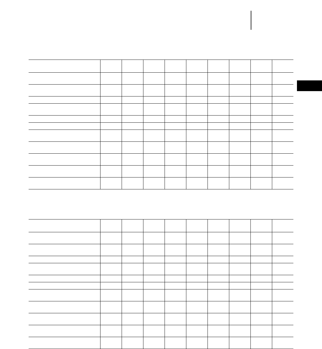
FOR USE WITH 1-PIECE BOOM — UNIQUE M312/M315 BUCKETS
Bucket Bite Width mm 450 600 700 900 1000 1100 1100 1200 1200*
ft/in 17.7" 1'11.6" 2'3.6" 2'11.4" 3'3.4" 3'7.3" 3'7.3" 3'11.2" 3'11.2"
ISO Bucket Capacity m30.24 0.33 0.40 0.54 0.61 0.68 0.68 0.75 0.86
yd30.31 0.43 0.52 0.70 0.79 0.88 0.88 0.98 1.12
Bucket Tip Radius mm 1240 1240 1240 1240 1240 1240 1220 1220 1318
ft/in 4'0.8" 4'0.8" 4'0.8" 4'0.8" 4'0.8" 4'0.8" 4'0" 4'0" 4'3.9"
Number of Tips 334556665
Weight with Tips kg 271 304 340 365 410 438 472 458 592
lb 596 669 748 803 902 964 1038 1008 1305
Bucket Type1TTTXXXEXXEX
Longest Acceptable Stick:
Dozer Only — Up m3.1 3.1 3.1 3.1 3.1 2.6 2.6 2.4 2.4
(FOW2)ft/in 10'2" 10'2" 10'2" 10'2" 10'2" 8'6" 8'6" 7'11" 7'11"
Dozer Only — Down m3.1 3.1 3.1 3.1 3.1 3.1 3.1 2.6 2.6
ft/in 10'2" 10'2" 10'2" 10'2" 10'2" 10'2" 10'2" 8'6" 8'6"
Rear Outriggers — Down m3.1 3.1 3.1 3.1 3.1 3.1 3.1 3.1 3.1
ft/in 10'2" 10'2" 10'2" 10'2" 10'2" 10'2" 10'2" 10'2" 10'2"
2 Sets Outriggers — Down m3.1 3.1 3.1 3.1 3.1 3.1 3.1 3.1 3.1
ft/in 10'2" 10'2" 10'2" 10'2" 10'2" 10'2" 10'2" 10'2" 10'2"
Dozer/Outriggers — Down m3.1 3.1 3.1 3.1 3.1 3.1 3.1 3.1 3.1
ft/in 10'2" 10'2" 10'2" 10'2" 10'2" 10'2" 10'2" 10'2" 10'2"
FOR USE WITH VA BOOM — UNIQUE M312/M315 BUCKETS
Bucket Bite Width mm 450 600 700 900 1000 1100 1100 1200 1200*
ft/in 17.7" 1'11.6" 2'3.6" 2'11.4" 3'3.4" 3'7.3" 3'7.3" 3'11.2" 3'11.2"
ISO Bucket Capacity m30.24 0.33 0.40 0.54 0.61 0.68 0.68 0.75 0.86
yd30.31 0.43 0.52 0.70 0.79 0.88 0.88 0.98 1.12
Bucket Tip Radius mm 1220 1220 1220 1220 1220 1220 1220 1220 1318
ft/in 4'0" 4'0" 4'0" 4'0" 4'0" 4'0" 4'0" 4'0" 4'3.9"
Number of Tips 334556665
Weight with Tips kg 271 304 340 365 410 438 472 458 592
lb 596 669 748 803 902 964 1038 1008 1305
Bucket Type1TTTXXXEXXEX
Longest Acceptable Stick:
Dozer Only — Up m3.1 3.1 3.1 3.1 2.6 2.4 2.4 2.1 1.7
(FOW2)ft/in 10'2" 10'2" 10'2" 10'2" 8'6" 7'11" 7'11" 6'11" 5'7"
Dozer Only — Down m3.1 3.1 3.1 3.1 3.1 3.1 2.6 2.6 2.6
ft/in 10'2" 10'2" 10'2" 10'2" 10'2" 10'2" 8'6" 8'6" 8'6"
Rear Outriggers — Down m3.1 3.1 3.1 3.1 3.1 3.1 3.1 3.1 3.1
ft/in 10'2" 10'2" 10'2" 10'2" 10'2" 10'2" 10'2" 10'2" 10'2"
2 Sets Outriggers — Down m3.1 3.1 3.1 3.1 3.1 3.1 3.1 3.1 3.1
ft/in 10'2" 10'2" 10'2" 10'2" 10'2" 10'2" 10'2" 10'2" 10'2"
Dozer/Outriggers — Down m3.1 3.1 3.1 3.1 3.1 3.1 3.1 3.1 3.1
ft/in 10'2" 10'2" 10'2" 10'2" 10'2" 10'2" 10'2" 10'2" 10'2"
*Requires J300 tips. All other buckets require J250 tips.
1T = Trenching X = Excavation EX = Extreme Service Excavation
2Free on wheels
4-135
4
ExcavatorsStick/Bucket Combinations
●M312 ●M315

4-136
Excavators
FOR USE WITH 1-PIECE & VA BOOMS — UNIQUE M318 BUCKETS
Bucket Bite Width 1000 mm 3'3" 1100 mm 3'7" 1200 mm 3'11" 1200 mm 3'11"
ISO Bucket Capacity 0.70 m30.92 yd30.80 m31.05 yd30.90 m31.18 yd30.90 m31.18 yd3
Bucket Tip Radius 1340 mm 4'5" 1340 mm 4'5" 1340 mm 4'5" 1340 mm 4'5"
Number of Tips 5555
Weight with Tips 600 kg 1323 lb 640 kg 1411 lb 660 kg 1455 lb 713 kg 1569 lb
Bucket Type1XXXX
Longest Acceptable Stick:
Dozer Only — Up (FOW2) 2.8 m 9'2" 2.4 m 7'10" 1.8 m 5'11" 1.8 m 5'11"
Dozer Only — Down 4.0 m 13'1" 2.8 m 9'2" 2.4 m 7'10" 2.4 m 7'10"
Rear Outriggers — Down 4.0 m 13'1" 2.8 m 9'2" 2.4 m 7'10" 2.4 m 7'10"
2 Sets Outriggers — Down 4.0 m 13'1" 4.0 m 13'1" 4.0 m 13'1" 4.0 m 13'1"
Dozer/Outriggers — Down 4.0 m 13'1" 4.0 m 13'1" 4.0 m 13'1" 4.0 m 13'1"
1T = Trenching X = Excavation EX = Extreme Service Excavation
2Free on wheels
FOR USE WITH 1-PIECE & VA BOOMS — UNIQUE M320 BUCKETS
Bucket Bite Width 600 mm 2'0" 750 mm 2'6" 1000 mm 3'3" 1100 mm 3'7" 1250 mm 4'1"
ISO Bucket Capacity 0.41 m30.54 yd30.55 m30.72 yd30.81 m31.06 yd30.90 m31.18 yd31.05 m31.37 yd3
Bucket Tip Radius 1423 mm 4'8" 1423 mm 4'8" 1423 mm 4'8" 1423 mm 4'8" 1423 mm 4'8"
Number of Tips 33455
Weight with Tips 540 kg 1190 lb 560 kg 1230 lb 600 kg 1320 lb 685 kg 1510 lb 740 kg 1630 lb
Bucket Type GP GP GP GP GP
Bucket Bite Width 1400 mm 4'7" 1500 mm 4'11" 1200 mm 3'11" 1250 mm 4'1" 1800 mm 5'11"
ISO Bucket Capacity 1.20 m31.57 yd31.35 m31.77 yd30.90 m31.18 yd31.05 m31.37 yd30.48 m30.63 yd3
Bucket Tip Radius 1423 mm 4'8" 1423 mm 4'8" 1340 mm 4'4" 1423 mm 4'8" 1244 mm 4'1"
Number of Tips 6655—
Weight with Tips 780 kg 1720 lb 810 kg 1785 lb 710 kg 1565 lb 750 kg 1655 lb 477 kg* 1050 lb*
Bucket Type GP GP ES ES DC
Bucket Bite Width 2000 mm 6'7" 2000 mm 6'7" 2300 mm 7'7" 2000 mm 6'7"
ISO Bucket Capacity 0.58 m30.76 yd30.70 m30.92 yd30.62 m30.81 yd30.70 m30.92 yd3
Bucket Tip Radius 1300 mm 4'3" 1400 mm 4'7" 1244 mm 4'1" 896 mm 2'11"
Number of Tips ————
Weight with Tips 680 kg* 1500 lb* 720 kg* 1590 lb* 569 kg* 1255 lb* 640 kg 1410 lb
Bucket Type DC DC DC DC
*Not including adapter and cylinders.
*GP = General Purpose DC = Ditch Cleaning ES = Extreme Service
Stick/Bucket Combinations
●M318 ●M320

EXCAVATOR SHOE SELECTION
Undercarriage life can be extended by equipping
the machine properly for the application.
Many excavators work on pavement or flat, soft
ground and experience few undercarriage problems.
But if those same machines (usually equipped with
wide track pads) were placed in severe underfoot
conditions, undercarriage destruction could occur
very rapidly.
The rule, used for other track-type machines —
“Whenever possible use the narrowest shoes avail-
able” — is even more valid for excavators.
The best general purpose track shoe is the triple
grouser. It has a good section modulus and offers
the best compromise between traction and mini-
mum disturbance to paved surface.
The double grouser shoe has a better section modu-
lus and is more aggressive than the triple grouser
section. Single grouser shoes are offered for maxi-
mum traction. Some users like single grousers for
added mobility in hilly terrain.
The following table lists ground pressures for var-
ious width shoes (reach boom, medium stick and
bucket):
4-137
4
ExcavatorsShoe Selection
Ground Pressure
Shoe Width Pressure
Model ShoeType mm in kPa psi
301.5 Double 230 9"
Rubber Belt 230 9"
307B Triple 450 18" 30.0 4.35
Triple 600 24" 23.0 3.34
Segment Rubber 450 18" 30.0 4.35
307B SB Triple 450 18" 34.0 4.93
Triple 600 24" 26.0 3.77
Segment Rubber 450 18" 34.0 4.93
307 Triple 450 18" 32.3 4.68
Triple 600 24" 25.3 3.67
Apex* 600 24" NA NA
Flat* 450 18" NA NA
Rubber 450 18" 32.3 4.68
311B Triple 500 20" 38.0 5.51
Triple 600 24" 32.0 4.64
Triple 700 28" 28.0 4.06
Triple 770 30" 26.0 3.77
Segment Rubber 500 20" 38.2 5.54
312B Triple 500 20" 39.0 5.66
Triple 600 24" 33.0 4.79
Triple 700 28" 29.0 4.21
Triple 770 30" 26.0 3.77
Segment Rubber 500 20" 40.2 5.83
312B L Triple 500 20" 38.0 5.51
Triple 600 24" 32.0 4.64
Triple 700 28" 28.0 4.10
Triple 770 30" 26.0 3.77
Triple 850 34" 24.0 3.60
Segment Rubber 500 20" 40.2 5.83
*Custom product.

Shoe Width Pressure
Model ShoeType mm in kPa psi
315B Triple 500 20" 48.0 6.96
Triple 600 24" 41.0 5.95
Triple 700 28" 35.0 5.08
315B L Triple 500 20" 46.0 6.67
Triple 600 24" 39.0 5.67
Triple 700 28" 33.0 4.79
318B L Triple 500 20" 44.0 6.39
Triple 600 24" 42.4 6.15
Triple 600 24" 38.0 5.54
Triple 700 28" 36.5 5.30
Triple 700 28" 32.0 4.69
Triple 800 32" 32.8 4.75
318B LN Triple 500 20" 50.0 7.25
Triple 500 20" 49.0 7.10
Triple 600 24" 44.0 6.39
Triple 600 24" 42.3 6.13
Triple 700 28" 38.0 5.54
Triple 700 28" 36.7 5.30
320B* Triple 600 24" 44.7 6.36
Triple 700 28" 39.0 5.55
Triple 800 32" 34.5 4.91
320B L* Triple 600 24" 41.8 5.95
Triple 700 28" 36.4 5.18
Triple 800 32" 32.3 4.59
320B N Triple 500 20" 55.4 7.88
Triple 600 24" 46.7 6.64
322B Triple 600 24" 49.8 7.22
Triple 700 28" 43.4 6.29
Triple 800 32" 38.3 5.55
322B L Triple 600 24" 46.4 6.73
Triple 700 28" 40.3 5.85
Triple 800 32" 35.8 5.19
322B LN Triple 600 24" 46.3 6.72
325B Triple 600 24" 55.8 8.09
Triple 700 28" 48.4 7.02
Triple 800 32" 43.3 6.29
325B L Triple 600 24" 52.9 7.67
Triple 700 28" 45.9 6.66
Triple 800 32" 41.1 5.96
325B LN Triple 600 24" 52.7 7.64
330B Triple 600 24" 67.0 9.70
Triple 750 30" 54.0 7.80
Triple 850 33" 49.0 7.10
*3066T Engine.
NOTE: Belgium sourced excavators have different ground pressures. See Technical Data Sheets.
4-138
Excavators Shoe Selection
Ground Pressure

4-139
4
ExcavatorsShoe Selection
Ground Pressure
Shoe Width Pressure
Model ShoeType mm in kPa psi
330B L Triple 600 24" 62.0 9.0
Triple 750 30" 50.0 7.3
Triple 850 33" 45.0 6.5
330B LN Triple 600 24" 62.0 9.0
345B Triple 600 24" 80.3 11.6
Triple 750 30" 65.8 9.5
Triple 900 35" 55.7 8.1
345B L – FIX Triple 600 24" 76.0 11.0
Triple 750 30" 62.3 9.0
Triple 900 35" 52.8 7.7
345B L – VG Triple 600 24" 81.8 11.9
Triple 750 30" 67.0 9.7
Triple 900 35" 56.7 8.2
350 Triple 600 24" 87.6 12.7
Triple 750 30" 70.3 10.2
Triple 900 35" 60.0 8.7
Double 600 24" 87.6 12.7
Double 750 30" 71.7 10.4
350 L Triple 600 24" 80.7 11.7
Triple 750 30" 64.8 9.4
Triple 900 35" 55.9 8.1
Double 600 24" 80.7 11.7
Double 750 30" 65.5 9.5
375 Double 610 24" 120.7 17.5
Double 750 30" 99.3 14.4
Double 900 35" 83.4 12.1
Single 610 24" 122.1 17.7
375 L Double 610 24" 113.1 16.4
Double 750 30" 93.1 13.5
Double 900 35" 78.6 11.4
Single 610 24" 113.1 16.4
5130B ME Double 650 26" 179.0 26.0
Double 800 32" 218.0 31.6
Double 1000 39" 145.0 21.0
5230 ME Double 1100 43" 151.0 21.9
Double 1300 51" 172.0 25.0
Double 1500 59" 202.0 29.4
NOTE: Belgium sourced excavators have different ground pressures. See Technical Data Sheets.
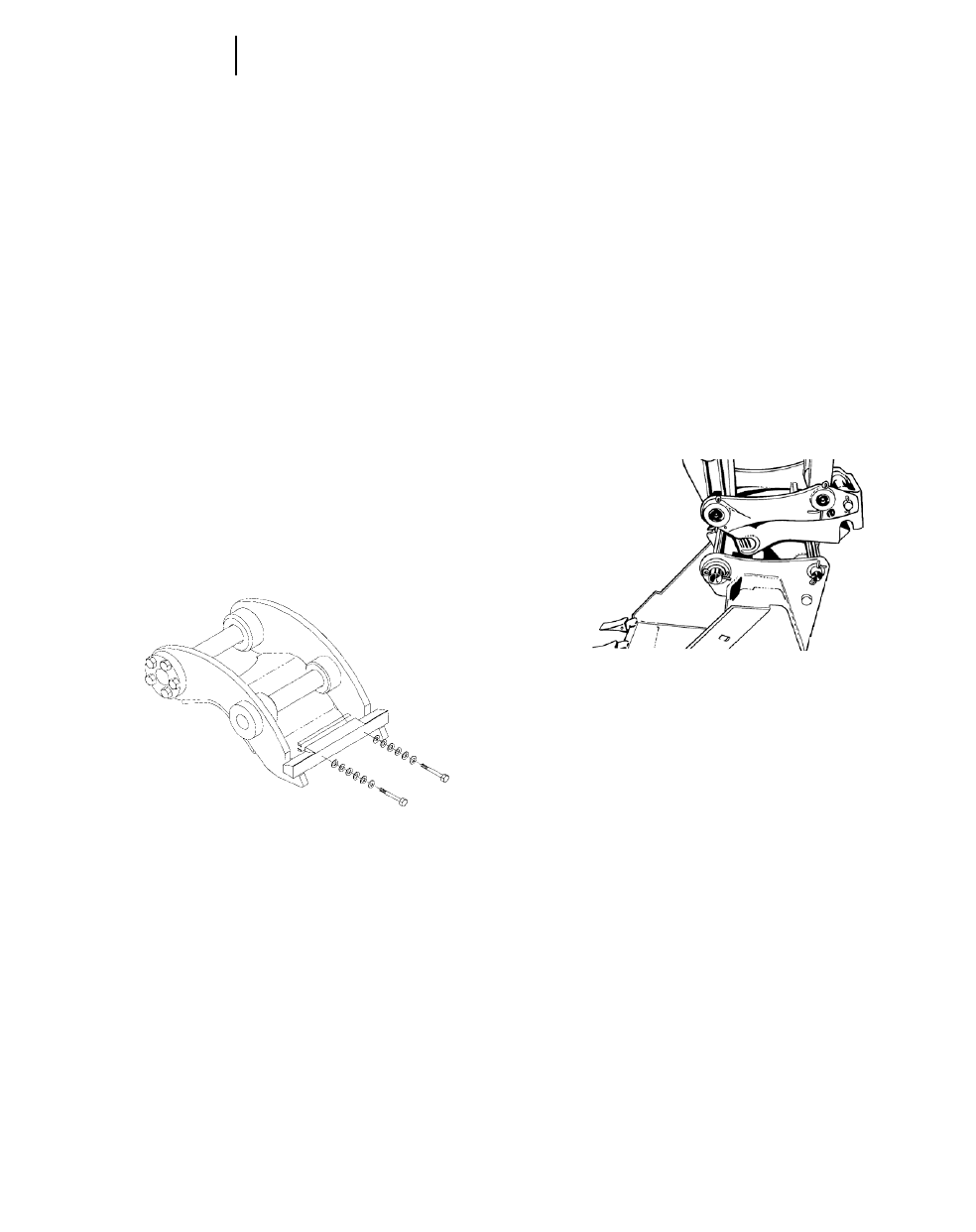
4-140
Excavators Quick Coupler
QUICK COUPLER SYSTEMS
Quick couplers can greatly increase a machine’s
versatility and productivity. They make it much eas-
ier to switch attachments which can increase uti-
lization. Quick couplers also encourage changing
buckets when the application changes, rather than
continue to use a less efficient bucket. Example: An
application that is predominately dirt with occa-
sional pockets or seams of rock. Without a quick cou-
pler the owner may choose to live with a rock bucket
but, rock buckets are normally smaller and heavier
which reduces performance in a dirt application. A
quick coupler allows the use of the rock bucket in
the rock and a GP bucket in the dirt.
There are two types of quick couplers. The first
is a dedicated type. A typical system substitutes
hooks on the bucket for the pin-on hinges used with
conventional buckets. The mating portion is pinned
on the stick and bucket linkage. It slips into the
hooks to secure the bucket or other attachment.
Advantages:
Bucket tip radius (distance from the bucket pivot
point to the bucket tip) does not increase. Increased
tip radius reduces curl and stick forces which can
reduce the loadability of the bucket. The hook type
coupler also does not add appreciable weight at the
end of the stick. Keeping the tip radius and weight
the same ensure no compromise in performance.
The machine portion of the hook type coupler can
be designed to allow more than one machine to use
the same buckets.
Disadvantages:
The hook type system requires special buckets.
Conventional pin-on buckets cannot be used. The
ability to use buckets on more than one machine
requires careful application analysis. Larger ma-
chines generate forces that can destroy the wrong
buckets. Smaller machines with the wrong bucket
may develop loads in excess of the machine’s capabil-
ity. Even if the machine can handle the loads, the
tip radius may be too large to allow the bucket to load
properly. With the flexibility of a quick coupler comes
the responsibility to make sure the bucket or other
attachments are properly sized for each application.
The second type of quick coupler is the pin grab-
ber type. This device pins on the stick and bucket
linkage and grabs the bucket pins on standard pin-
on buckets.
Advantages:
The advantage of the pin grabber is that it will
pick up standard pin-on buckets. No need to pur-
chase new attachments that will fit the system.
Disadvantages:
The pin grabber is mounted between the stick and
the bucket which significantly increases the tip
radius. This can compromise performance. It is an
additional assembly between a standard bucket and
stick. This means it adds more weight and reduces
the excavator’s payload capability.
Pin grabbers are required to mate up with exist-
ing bucket pins. Because different machines require
different pin spreads, they offer very limited abil-
ity to match with buckets from other machines.
Both types of quick couplers offer two types of
actuation. Mechanical … which requires manual
activity to release and engage the attachment. This
process can take from one to five minutes depend-
ing on the coupler design. The other type is cab acti-
vated … this type can usually allow an attachment
change in 30 seconds or less.
Dedicated
Hook-type
Pin Grabber

4-141
ExcavatorsSummary of Major Attachments
●301.5 ●307B ●307B SB ●307
EQUIPMENT
FOR … 301.5 307B 307B SB 307
Undercarriage:
Standard ●●●●
Booms:
One-Piece Reach ●●—●
Swing ——●—
Sticks: mm ft mm ft mm ft
Short ●1670 5'6" 1670 5'6" 1665 5'6"
●—2212 7'3" 2210 7'3" 2210 7'3"
Booms:
Parallel offset —●—●
Sticks: mm ft mm ft
Short ●1670 5'6" — 1665 5'6"
Buckets (No. of) 12334
Teeth:
Long (G.P.) ●●●●
Short (Rock) —●●●
Side Cutters:
One-Piece Blade —●●●
Track Shoes: Double Triple Triple Triple
Grouser Grouser Grouser Grouser
230 mm 450, 600 mm 450, 600 mm 450, 600 mm
(9") (18", 24") (18", 24") (18", 24")
Rubber Belt Rubber Pads Rubber Pads Rubber Pads
230 mm (9") 450 mm (18") 450 mm (18") 450 mm (18")
NOTE: Number of buckets includes Gen. Purpose, Trenching and Rock. Other types of buckets have not been included.
All attachments may not be available in all sales areas.
4

4-142
Excavators Summary of Major Attachments
●311B ●312B ●315B ●318B L ●318B LN
EQUIPMENT 312B 315B 318B L
FOR … 311B 312B L 315B L 318B LN
Undercarriage:
Standard ●●●—
Long (L) —●●●
Narrow (N) ———●
Booms:
One-Piece Reach ●●●●
Sticks: mm ft mm ft mm ft mm ft
Short 1950 6'5" 2100 6'11" 1850 6'1" 1800 5'11"
●2250 7'5" 2500 8'2" 2250 7'5" 2250 7'5"
●2800 9'2" 3000 9'10" 2600 8'6" 2700 8'10"
Long ——3100 10'2" 3200 10'6"
Booms:
One-Piece Mass ————
Two-Piece VA —●●●
Parallel offset ————
Sticks: mm ft mm ft
Short —2100 6'11" 1850 6'1" —
●—2500 8'2" 2250 7'5" —
●—3000 9'10" 2600 8'6" —
Long ——3100 10'2" —
Bucket Family — — — B
Buckets (No. of) 5 685540
Teeth:
Abrasion ●●●●
Long (G.P.) ●●●●
Short (Rock) ●●●●
Penetration ●●●●
Wide (Spade) ●●●●
Sharp ●●●●
Side Cutters:
One-Piece Blade ●●●●
Track Shoes: Triple Triple Triple Triple
Grouser Grouser Grouser Grouser
500, 600, 700, 770 mm 500, 600, 700, 770, 500, 600, 700, 900 mm 600, 700, 800, 900 mm
(20", 24", 28", 30") 850, 900, 1400 mm (20", 24", 28", 36") (24", 28", 32", 36")
(20", 24", 28", 30",
34", 36", 56")
Rubber Pads Rubber Pads Rubber Pads Rubber Pads
500 mm (20") 500 mm (20") 500, 600 mm (20", 24") 500, 600 mm (20", 24")
NOTE: Number of buckets includes Gen. Purpose, Trenching and Rock. Other types of buckets have not been included.
All attachments may not be available in all sales areas.

4-143
4
ExcavatorsSummary of Major Attachments
●320B ●322B ●325B ●330B ●345B
320B 322B 325B 330B
EQUIPMENT 320B L 322B L 325B L 330B L 345B
FOR … 320B LN 322B LN 325B LN 330B LN 345B L
Undercarriage:
Standard ●●●●●
Long (L) ●●●●●
Narrow (N) ●————
Long Narrow (LN)* —*●**●**●*—
Booms:
One-Piece Reach ●●●●●
Sticks: mm ft mm ft mm ft mm ft mm ft
Short 1900 6'3" — 2000 6'7" 2150 7'1" —
●2500 8'2" 2500 8'2" 2650 8'8" 2800 9'2" 2900 9'6"
●2920 9'7" 2950 9'8" 3200 10'6" 3300 10'10" 3350 11'0"
●—3600 11'10" 4200 13'9" 3900 12'10" 3900 12'10"
Long 3860 12'8" ————
Booms:
One-Piece Mass ●●●●●
Two-Piece VA ●●———
Sticks: mm ft mm ft mm ft mm ft mm ft
Short 1900 6'3" 2000 6'7" 2000 6'7" 2150 7'1" 2500 8'2"
●2400 7'10" 2500 8'2" 2500 8'2" 2550 8'4" 3000 9'10"
●2920 9'7" — 3200 10'6" — —
Bucket Family B, C B, S, D B, C, D D, E F, G, T, U
Buckets (No. of) 19 24 24 17 15
Teeth:
Abrasion ●●●●●
Long (G.P.) ●●●●●
Short (Rock) ●●●●●
Penetration ●●●●●
Wide (Spade) ●●●●●
Sharp ●●●●●
Side Cutters:
One-Piece Blade ●●●●●
Track Shoes: Triple Triple Triple Triple Triple
Grouser Grouser Grouser Grouser Grouser
500, 600, 700 600, 700, 800 mm 600, 700, 800 mm 600, 750, 850 mm 600, 750, 900 mm
800 mm (24", 28", 32") (24", 28", 32") (24", 30", 34") (24", 30", 35")
(20", 24", 28", 30")
Apex Double Grouser Double Grouser Double Grouser
800 mm (32") 600, 700 mm 700 mm (28") 600, 750 mm
(24", 28") (24", 30")
Quick Coupler —****
*All attachments may not be available in all sales areas.
NOTE: Number of buckets includes Gen. Purpose, Trenching and Rock. Other types of buckets have not been included.

EQUIPMENT 350 375
FOR … 350 L 375 L 5130B ME 5230 ME
Undercarriage:
Standard ●●●●
Long (L) ●●——
Booms:
One-Piece Reach ●●N/A N/A
One-Piece GP —●N/A N/A
Sticks: mm ft mm ft
Short 3100 10'2" *2900* 9'6" N/A N/A
●3600 11'10" *3400* 11'2" N/A N/A
●4050 13'3" 4400 14'5" N/A N/A
●4800 15'9" 5500 18'1" N/A N/A
Booms:
One-Piece Mass ●●●●
Sticks: mm ft mm ft
Short 2400 7'10" 2900 9'6" N/A N/A
●2950 9'8" 3400 11'2" N/A N/A
Long 3700 12'2" 4100 13'5" N/A N/A
Bucket Family F, G H, J ——
Sticks — — ME & LR ME & LR
Buckets (No. of) 24 23 5 3
Teeth:
Abrasion ●●●—
Long (G.P.) ●●●●
Short (Rock) ●●●●
Penetration ●●●—
Wide (Spade) ●●——
Sharp ●●——
Side Cutters:
One-Piece Blade ●●●●
Track Shoes: Triple Double Double Double
Grouser Grouser Grouser Grouser
600, 750, 900 mm 610, 750, 900 mm 650, 800, 1000 mm 1100, 1300, 1500 mm
(24", 30", 36") (24", 30", 36") (26", 32", 39") (43", 52", 60")
Double Single
Grouser Grouser
600, 750 mm 610 mm
(24", 30") (24")
*All attachments may not be available in all sales areas.
NOTE: Number of buckets includes Gen. Purpose, Trenching and Rock. Other types of buckets have not been included.
4-144
Excavators Summary of Major Attachments
●350 ●375 ●5130B ME ●5230 ME
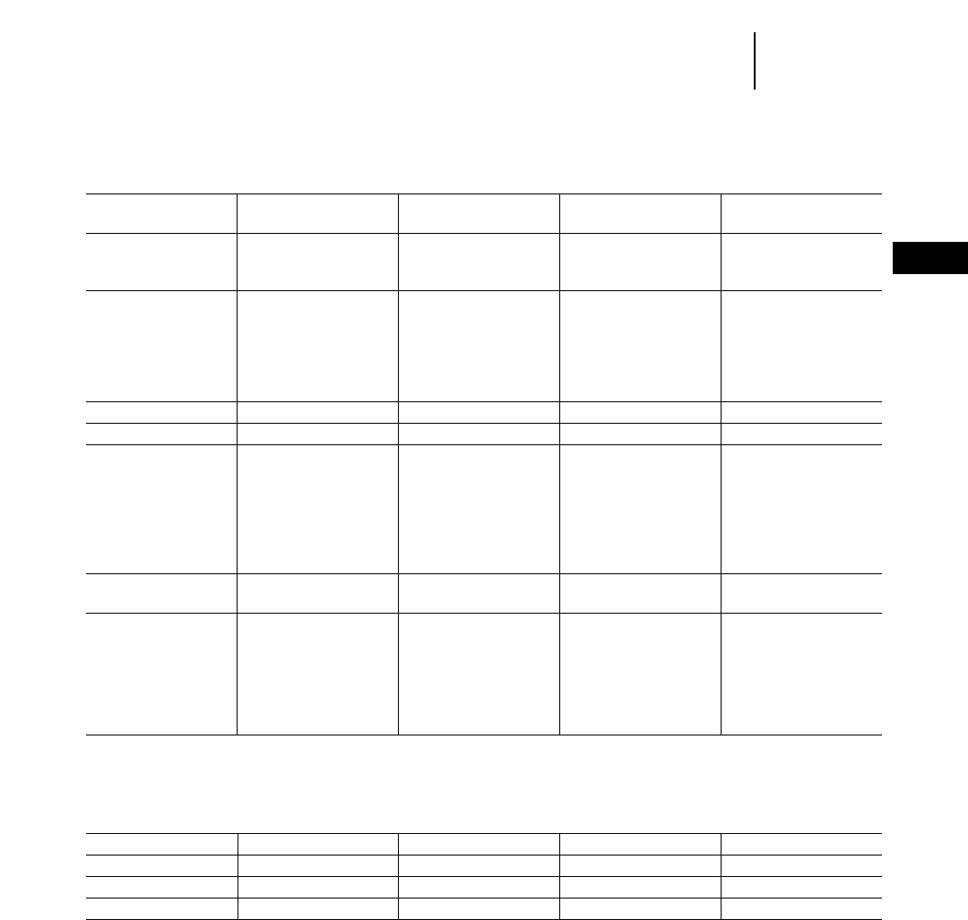
4-145
4
ExcavatorsSummary of Major Attachments
●M312 ●M315 ●M318 ●M320
EQUIPMENT
FOR … M312 M315 M318 M320
Undercarriage:
Wheeled ●●●●
Booms:
One-piece ●●●●
VA ●●●●
Backhoe Sticks: mm ft mm ft mm ft mm ft
Short 1600 5'3" 1700 5'7" 1800 5'11" 1900 6'3"
Medium 2000 6'6" 2100 6'9" 2400 7'9" 2500 8'2"
Medium Long 2300 7'5" 2400 7'9" — —
Long 2600 8'5" 2600 8'5" 2800 9'2" 2900 9'6"
Extra Long 3000 9'9" 3100 10'1" 4000 13'1" 4200 13'9"
Material Handling Stick — — 3200 10'6" —
Buckets (No. of) 13 13 8 14
Teeth:
Abrasion ●●●●
Long (G.P.) ●●●●
Short (Rock) ●●●●
Penetration ●●●●
Wide ———●
Sharp ———●
Side Cutters:
One-Piece Blade ●●●—
Tires: Tires: Tires: Tires: Tires:
Duals Duals Duals Duals
10.00-20 10.00-20 10.00-20 11.00-20
11.00-20 11.00-20 11.00-20 10.00-20 Solid
__________ __________ __________ __________
Singles Singles Singles Singles
18-19.5 18-19.5 18-19.5 18R-19.5XF
18R-22.5XF 18-22.5 18R-22.5XF
NOTE: Number of buckets shown includes general purpose, rock and trenching. Not included are ditch cleaning, ditch grading and trapezoidal ditching.
Work Tools M312 M315 M318 M320
Clamshell* X X X
Ditch Cleaning Bucket XXXX
Grapples* X X X
Hammer Installation Kit X X X
*With hydraulic rotator.

4-146
Excavators Special Attachments
345B/ 318B L/ ,311B,
Work Tools 375 350 330B 325B 322B 320B 318B LN 315B 312B L 307B
Quick Coupler XXXXXXXXX
Ditch Cleaning XXXXXXXXX
General Purpose XXXXXXXXXX
Rock XXXXXXXXXX
Tilt Bucket XXXXXXXX
Thumb XXXXXXXXXX
Construction Grapple XXXXXXXX
Medium Grapple XXXXXXXX
Trash Grapple XXXXXXXX
Hydraulic Hammer XXXXXXXXXX
Vibratory Plate Compactor XXXXXXX
Shear XXXXXX
Crusher XXXXX
Pulverizer XXXXXX
Rock Drill XX
NOTE: Other attachments available upon request. Contact Caterpillar Attachment Products and Services.
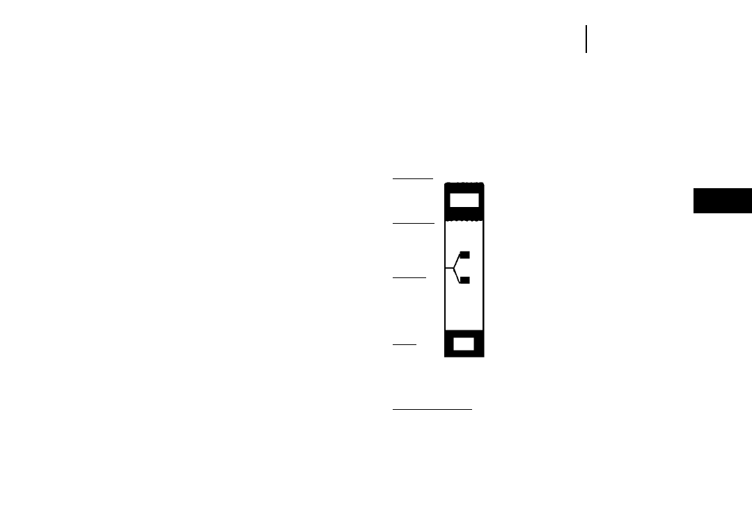
4-147
4
ExcavatorsCycle Time Estimating Charts
CYCLE TIME ESTIMATING CHARTS
The digging cycle of the excavator is composed of
four segments:
1. Load Bucket 3. Dump Bucket
2. Swing Loaded 4. Swing Empty
Total excavator cycle time is dependent on machine
size (small machines can cycle faster than large
machines) and job conditions. With excellent job con-
ditions the excavator can cycle fast. As job conditions
become more severe (tougher digging, deeper trench,
more obstacles, etc.), the excavator slows down
accordingly. As the soil gets harder to dig, it takes
longer to fill the bucket. As the trench gets deeper
and the spoil pile larger, the bucket has to travel
farther and the upper structure has to swing farther
on each digging cycle.
Spoil pile or truck location also affects cycle time.
If a truck is located on the floor of the excavation
beside material being moved, 10 to 17 second cycles
are practical. The other extreme would be a truck or
spoil pile located above the excavator 180° from the
excavation.
In sewer construction work the operator may not
be able to work at full speed because he has to dig
around existing utilities, load the bucket inside a
trench shield, or avoid people working in the area.
The Cycle Time Estimating Chart outlines the range
of total cycle time that can be expected as job condi-
tions range from excellent to severe. Many variables
affect how fast the excavator is able to work. The
chart defines the range of cycle times frequently
experienced with a machine and provides a guide
to what is an “easy” or a “hard” job. The estimator
can then evaluate the conditions of his job and use
the Cycle Time Estimating Chart to select the appro-
priate working range. A practical method of further
calibrating the Cycle Time Estimating Chart is to
observe excavators working in the field and corre-
late measured cycle times to job conditions, opera-
tor ability, etc.
The following table breaks down what experience
has shown to be typical Caterpillar excavator cycle
times with
— no obstruction in the right of way
— above average job conditions
— an operator of average ability and
— 60°-90° swing angle.
These times would decrease as job conditions or
operator ability improved and would get slower as
conditions become less favorable.
CYCLE TIME -vs- JOB CONDITION
DESCRIPTION
— Easy digging (unpacked earth, sand
gravel, ditch cleaning, etc.). Digging
to less than 40% of machine’s maxi-
mum depth capability. Swing angle
less than 30°. Dump onto spoil pile or
truck in excavation. No obstructions.
Good operator.
— Medium digging (packed earth, tough
dry clay, soil with less than 25% rock
content). Depth to 50% of machine’s
maximum capability. Swing angle to 60°.
Large dump target. Few obstructions.
— Medium to hard digging (hard packed
soil with up to 50% rock content). Depth
to 70% of machine’s maximum capabil-
ity. Swing angle to 90°. Loading trucks
with truck spotted close to excavator.
— Hard digging (shot rock or tough soil
with up to 75% rock content). Depth
to 90% of machine’s maximum capa-
bility. Swing angle to 120°. Shored
trench. Small dump target. Working
over pipe crew.
— Toughest digging (sandstone, caliche,
shale, certain limestones, hard frost).
Over 90% of machine’s maximum depth
capability. Swing over 120°. Loading
bucket in man box. Dump into small
target requiring maximum excavator
reach. People and obstructions in the
work area.
Fastest
Possible
Fastest
Practical
Typical
Range
Slow
A
B
C
D
E
KEY
A — Excellent
B — Above
Average
C — Average
D — Below
Average
E—Severe
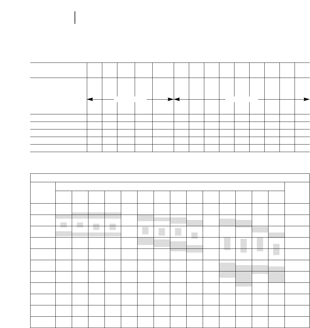
4-148
Excavators Cycle Time Estimating Charts
Cycle Time Estimating Chart
312B, 315B, 318B L*, 5130 5230
Model 307 311B 312B L 315B L 318B LN 320B 322B 325B 330B 345B* 350 375 ME ME
Bucket Size
L280 450 520 520 800 1000 1100 1400 1900 2800 10 m315.5 m3
(yd3) 0.37 0.59 0.68 0.68 1.05 1.31 1.44 1.83 2.5 3.66 13 20.3
Soil Type
Digging Depth (m) 1.5 1.5 1.8 3.0 2.3 3.2 3.2 3.4 4.2 5.2 4.0 5.0
(ft) 5 5 6 10 8 10 10 11 14 17 13 16
Load Bucket (min) 0.08 0.07 0.07 0.10 0.09 0.09 0.09 0.09 0.10 0.11 0.12 0.12
Swing Loaded (min) 0.05 0.06 0.06 0.04 0.06 0.06 0.06 0.07 0.09 0.10 0.13 0.14
Dump Bucket (min) 0.03 0.03 0.03 0.02 0.03 0.04 0.04 0.04 0.04 0.04 0.04 0.04
Swing Empty (min) 0.06 0.05 0.05 0.05 0.05 0.06 0.06 0.07 0.07 0.09 0.13 0.14
Total Cycle Time (min) 0.22 0.21 0.21 0.21 0.23 0.25 0.25 0.27 0.30 0.34 0.42 0.44
*Information not available at time of printing.
CYCLE TIME ESTIMATING CHART
MACHINE SIZE CLASS
CYCLE
5130B 5230
CYCLE
TIME
307 311B 312B 315B 318B L* 320B 322B 325B 330B 345B* 350 375 ME ME
TIME
10 SEC. 0.17 min.
15 SEC. 0.25 min.
20 SEC. 0.33 min.
25 SEC. 0.42 min.
30 SEC. 0.50 min.
35 SEC. 0.58 min.
40 SEC. 0.67 min.
45 SEC. 0.75 min.
50 SEC. 0.83 min.
55 SEC. 0.92 min.
60 SEC. 1.0 min.
Packed Earth Hard Clay
*Information not available at time of printing.
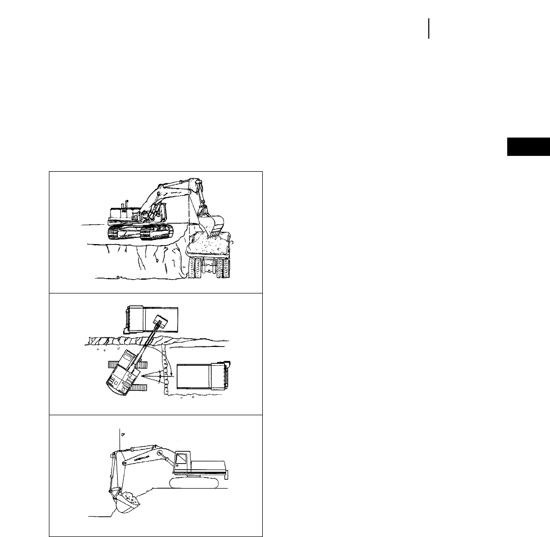
4-149
4
ExcavatorsMachine Operation
Caterpillar 300 Series Mass Excavation booms and buckets coupled with the proper stick will help you
move material faster and more efficiently in production excavation and loading applications. With the largest
bucket, shortest stick and long undercarriage your excavator can often do the work of a larger machine. A
longer stick and standard undercarriage make it ideal for loading on-highway trucks and general construc-
tion jobs.
MAXIMIZING PRODUCTION WITH A MASS EXCAVATOR
Ideal Bench Height and Truck Distance — For
stable or consolidated materials, bench height
should be about equal to stick length. For unstable
materials it should be less. The most useful truck
position is when the inside truck body rail is below
the boomstick hinge pin.
Optimum Work Zone and Swing Angle — For
maximum production, the work zone should be
limited to 15° either side of machine center or about
equal to undercarriage width. Trucks should be posi-
tioned as close as possible to machine centerline.
Two alternatives shown here.
Best Distance from the Edge — The machine
should be positioned so that the stick is vertical
when the bucket reaches full load. If the unit is far-
ther back, breakout force is reduced. If it is closer to
the edge, undercutting may occur and time is wasted
bringing the stick back out. Also, the operator should
begin boom-up when the bucket is 75% of the way
through the curl cycle. This should be as the stick
nears the vertical position.
This example reflects the ideal situation. Not all
points are usable on each job, but incorporation of
as many of these points as possible will positively
affect production.

EARTHMOVING PRODUCTION
As with any other piece of material handling
equipment, excavator earthmoving production is
dependent on average bucket payload, average cycle
time and job efficiency. If an estimator can accurately
predict excavator cycle time and bucket payload, a
machine’s earthmoving production can be derived
from the following formula.
m3(yd3)/60 min hr = Cycles/60 min hr 2Avg.
Bucket Payload in m3
(yd3)
m3(yd3)/60 min hr =
60 min/hr
___________________ 2Avg. Bucket Payload
Cycle Time – min in m3(yd3)
Avg. Bucket Payload = Heaped Bucket Capacity
2 Bucket Fill Factor
Actual m3(yd3)/hr = m3(yd3)/60 min hr 2
Job Efficiency Factor
The Production Estimating Tables (next page) will
provide theoretical earthmoving production in cubic
meters (yards) per hour if bucket size and cycle time
can be estimated. The use of an average cycle time
allows adjusting the estimated production for spe-
cific job sites and applications. For instance, estimat-
ing truck loading applications should include truck
exchange times which extends the average cycle
time and reduces production potential. The values
in the table are based on a 60 minute work hour or
100% efficiency (a condition that is never achieved
in reality). The estimator should apply a job effi-
ciency factor to the figures in the table based on his
judgment or knowledge of actual job conditions.
Areas outlined on the Production Estimating Table
define the work ranges of excavators in the size
classes of Caterpillar 307 through 5230 ME Excava-
tors. The upper limit on each area corresponds to
the “fastest practical” cycle time for the machines.
The width of each area corresponds to the range of
bucket payload sizes the machine can handle. An
unshaded box has been provided in each machine
area to provide a guide indicating that the upper
limit of earthmoving production is being approached.
When working beyond the values in the white area,
the estimator should be certain that excellent job
conditions will be encountered (easy digging, shallow
trench, good operator, etc.).
The Production Estimating Table can also serve
as a guide when selecting the proper size machine
to do a job, as is shown in the following example.
Example problem (Metric)
Contractor has a job to move 15 300 Bm3(19 100 Lm3
considering 25% swell factor) of wet sandy loam
material in rear dump on-highway trucks which will
be loaded by an excavator. Average face depth will
be 2.4 m with 60-90 degree average swing angle.
Ten days are available to do the work. Contractor
plans to work 10 hrs/day and estimates a 50 min.
work hour (83% job efficiency). He has two excava-
tors that could be made available to do the work —
a 320 with 1.0 m3bucket or a 330 with 1.9 m3bucket.
Experience has shown that either machine can get
its rated capacity in the sandy loam soil. Could this
job be done with either machine or will the 330 have
to be used?
Solution: The excavator must produce 1900 Lm3/
Day (19 100 Lm3÷ 10 Days) which means the required
average hourly rate will be 190 Lm3/60 Min. Hr.
(1900 Lm3/Day ÷ 10 hrs/day). Further considering
the 83% job efficiency, the excavator’s capability will
have to be 230 Lm3/50 min hr.
4-150
Excavators Earthmoving Production
●Example Problem

4-151
4
ExcavatorsEarthmoving Production
●Example Problem
The production estimating table shows that the
320 with a 1.0 m3bucket would have to achieve a
17.1 sec. average cycle time to produce the required
190 Lm3/60 min. hr. With job efficiency applied a
15.0 second average cycle time is required to pro-
duce the 230 Lm3/50 min. hr. The 330 with a 1.9 m3
bucket could obtain the same 60 min. hr. production
level with a 35 second average cycle, or 30 second
cycles to meet the 50 min. hr. production require-
ment. The cycle times estimating chart shows that
the 320 would be working near its maximum capa-
bility to meet the production requirement, whereas,
the 330 could handle the job easily. This informa-
tion can then be weighed against what else is known
about the job (reach requirements, job conditions,
operator ability, etc.) to decide whether or not the
larger machine is needed.
Example problem (English)
Substitute these English values in the preceding
problem:
Job — 20,000 BCY (25,000 LCY considering 25%
swell).
Average face depth — 8-12 ft
320 L with 1.25 yd3bucket or 330 with 2.5 yd3
bucket.
Solution: The excavator must produce 2500 LCY/
Day, which means the required average hourly rate
will be 250 LCY/60 min hr. Further considering the
83% job efficiency the excavator’s capability will
have to be 300 LCY/50 min hr.
The same concluding comments regarding the
Production Estimating Table apply here as in the
Metric example.
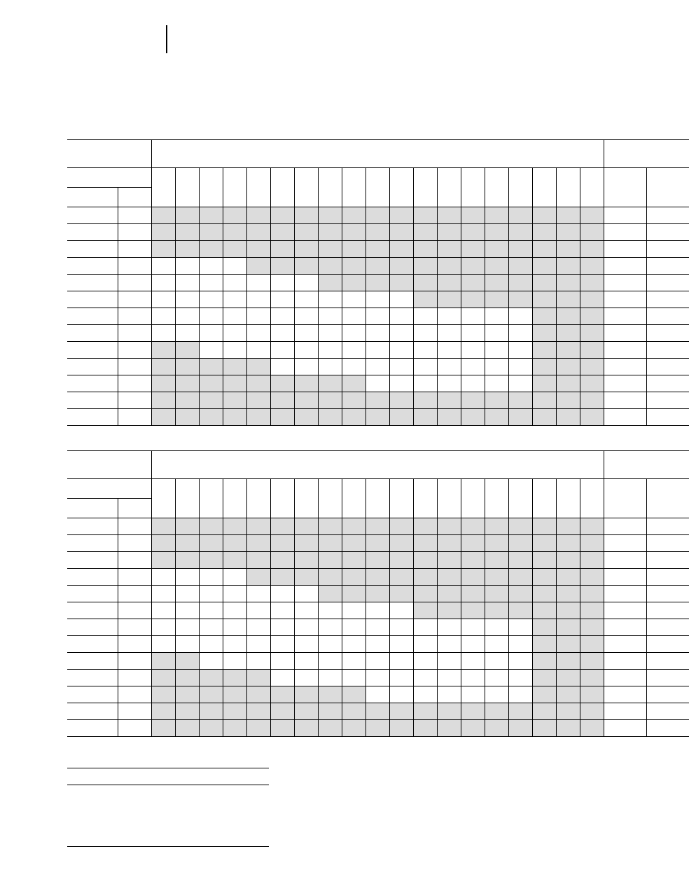
4-152
Excavators Production Estimating Tables
Cubic Meters per 60 Minute Hour*
ESTIMATED ESTIMATED BUCKET PAYLOAD** — LOOSE CUBIC METERS ESTIMATED
CYCLE TIMES CYCLE TIMES
Cycle Time Cycles Cycles
Per Per
Seconds Min. Min. Hr.
10.0 0.17 6.0 360
11.0 0.18 5.5 330
12.0 0.20 5.0 300
13.3 0.22 4.5 270
15.0 0.25 4.0 240
17.1 0.29 3.5 210
20.0 0.33 3.0 180
24.0 0.40 2.5 150
30.0 0.50 2.0 120
35.0 0.58 1.7 102
40.0 0.67 1.5 90
45.0 0.75 1.3 78
50.0 0.83 1.2 72
3.5
945
840
735
630
525
420
357
315
273
4.0
1080
960
840
720
600
480
408
360
312
3.3
891
792
693
544
495
396
337
297
257
3.1
837
744
651
558
465
372
316
279
242
2.9
783
696
609
522
435
348
296
261
226
2.7
729
648
567
486
405
324
275
243
211
2.5
675
600
525
450
375
300
255
225
195
2.3
621
552
483
414
345
276
235
207
179
2.1
567
504
441
378
315
252
214
189
164
1.9
513
456
399
342
285
228
194
171
148
1.7
459
408
357
306
255
204
173
153
133
1.5
405
360
315
270
225
180
153
135
1.3
351
312
273
234
195
156
133
177
1.1
297
264
231
198
165
132
112
99
0.9
270
243
216
189
162
135
108
92
81
0.7
210
189
168
147
126
105
84
71
0.5
150
135
120
105
90
75
60
51
0.3
90
81
72
63
54
45
36
31
0.2
60
54
48
42
36
30
24
20
Cubic Yards per 60 Minute Hour*
ESTIMATED ESTIMATED BUCKET PAYLOAD** — LOOSE CUBIC YARDS ESTIMATED
CYCLE TIMES CYCLE TIMES
Cycle Time Cycles Cycles
Per Per
Seconds Min. Min. Hr.
10.0 0.17 6.0 360
11.0 0.18 5.5 330
12.0 0.20 5.0 300
13.3 0.22 4.5 270
15.0 0.25 4.0 240
17.1 0.29 3.5 210
20.0 0.33 3.0 180
24.0 0.40 2.5 150
30.0 0.50 2.0 120
35.0 0.58 1.7 102
40.0 0.67 1.5 90
45.0 0.75 1.3 78
50.0 0.83 1.2 72
5.00
1350
1200
1050
900
750
600
513
450
400
5.25
1417
1260
1102
945
787
630
535
472
409
4.50
1215
1080
945
810
675
510
462
405
360
4.00
1080
960
840
720
600
480
410
360
320
3.75
1012
900
787
675
562
450
385
337
300
3.50
945
840
735
630
525
420
360
315
280
3.25
877
780
682
585
487
390
333
292
260
3.00
810
720
630
540
450
360
08
270
240
2.75
742
660
577
495
412
330
282
247
220
2.50
675
600
525
450
375
300
256
225
200
2.25
607
540
472
405
337
270
231
202
180
2.00
540
480
420
360
300
240
205
180
1.75
472
420
367
315
262
210
180
157
1.50
404
360
315
270
225
180
154
135
1.25
375
337
300
262
225
187
150
128
112
1.00
300
270
240
210
180
150
120
102
0.75
225
202
180
157
135
112
90
77
0.50
150
135
120
105
90
75
60
51
0.25
75
67
60
52
45
37
30
36
Job Efficiency Estimator
Work Time/Hour Efficiency
60 Min 100%
55 Min 91%
50 Min 83%
45 Min 75%
40 Min 67%
**Actual hourly production = (60 min. hr. production) 2(Job Efficiency Factor)
**Estimated Bucket Payload = (Amount of Material in the Bucket)
= (Heaped Bucket Capacity) 2(Bucket Fill Factor)
**Unshaded area indicates average production.
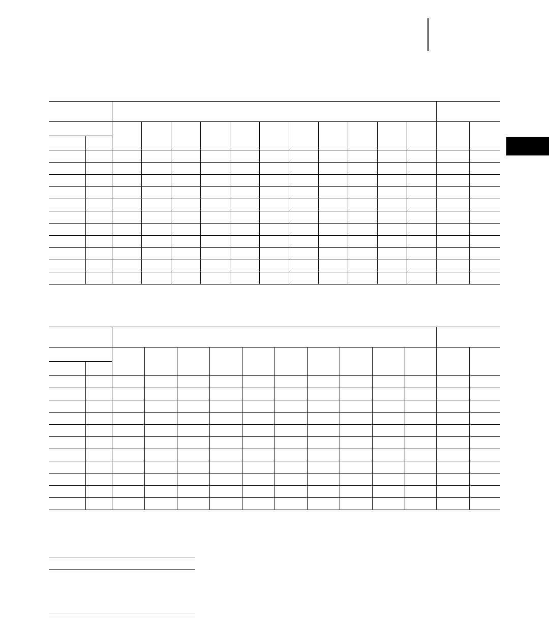
4-153
4
ExcavatorsProduction Estimating Tables
●Trenching Production
Cubic Meters/Yards per 60 Minute Hour*
ESTIMATED ESTIMATED BUCKET PAYLOAD** — LOOSE CUBIC METERS/YARDS ESTIMATED
CYCLE TIMES CYCLE TIMES
Cycle Time Cycles Cycles
Per Per
Seconds Min. Min. Hr.
15.0 0.25 4.0 240
17.1 0.29 3.5 210
20.0 0.33 3.0 180
24.0 0.40 2.5 150
30.0 0.50 2.0 120
35.0 0.58 1.7 102
40.0 0.67 1.5 90
45.0 0.75 1.3 78
50.0 0.83 1.2 72
55.0 0.92 1.1 66
60.0 1.00 1.0 60
5.0
1200
1050
900
750
600
510
450
390
360
330
300
6.0
1440
1260
1080
900
720
612
540
468
432
396
360
7.0
1680
1470
1260
1050
840
714
630
546
504
462
420
8.0
1920
1680
1440
1200
960
816
720
624
576
528
480
9.0
2160
1890
1620
1350
1080
918
810
702
648
594
540
10.0
2400
2100
1800
1500
1200
1020
900
780
720
660
600
11.0
2640
2310
1980
1650
1320
1122
990
858
792
726
660
12.0
2880
2520
2160
1800
1440
1224
1080
936
864
792
720
13.0
3120
2730
2340
1950
1560
1326
1170
1014
936
858
780
14.0
3360
2940
2520
2100
1680
1428
1260
1092
1008
924
840
15.0
3600
3150
2700
2250
1800
1530
1350
1170
1080
990
900
Cubic Meters/Yards per 60 Minute Hour*
ESTIMATED ESTIMATED BUCKET PAYLOAD** — LOOSE CUBIC METERS/YARDS ESTIMATED
CYCLE TIMES CYCLE TIMES
Cycle Time Cycles Cycles
Per Per
Seconds Min. Min. Hr.
15.0 0.25 4.0 240
17.1 0.29 3.5 210
20.0 0.33 3.0 180
24.0 0.40 2.5 150
30.0 0.50 2.0 120
35.0 0.58 1.7 102
40.0 0.67 1.5 90
45.0 0.75 1.3 78
50.0 0.83 1.2 72
55.0 0.92 1.1 66
60.0 1.00 1.0 60
16.0
3840
3360
2880
2400
1920
1632
1440
1248
1152
1056
960
17.0
4080
3570
3060
2550
2040
1734
1530
1326
1224
1122
1020
18.0
4320
3780
3240
2700
2160
1836
1620
1404
1296
1188
1080
19.0
4560
3990
3420
2850
2280
1938
1710
1482
1368
1254
1140
20.0
4800
4200
3600
3000
2400
2040
1800
1560
1440
1320
1200
21.0
5040
4410
3780
3150
2520
2142
1890
1638
1512
1386
1260
22.0
5280
4620
3960
3300
2640
2244
1980
1716
1584
1452
1320
23.0
5520
4830
4140
3450
2760
2346
2070
1794
1656
1518
1380
24.0
5760
5040
4320
3600
2880
2448
2160
1872
1728
1584
1440
25.0
6000
5250
4500
3750
3000
2550
2250
1950
1800
1650
1500
Job Efficiency Estimator
Work Time/Hour Efficiency
60 Min 100%
55 Min 91%
50 Min 83%
45 Min 75%
40 Min 67%
**Actual hourly production = (60 min. hr. production) 2(Job Efficiency Factor)
**Estimated Bucket Payload = (Amount of Material in the Bucket)
= (Heaped Bucket Capacity) 2(Bucket Fill Factor)
NOTE: For estimating truck loading production include approximately 0.7 minutes for truck exchange time.

4-154
Excavators Trenching Production
●Example Problems
EXCAVATOR TRENCHING PRODUCTION
When an excavator is used for trenching applica-
tions, a meaningful expression of work produced is
the machine’s trenching rate expressed in meters
or lineal feet per hour or per day. Trenching rate
depends on the earthmoving production of the exca-
vator being used and the size of the trench being
excavated. Earthmoving production converts to
trenching production as follows:
Lineal Meters of Trench per Hour =
Cubic Meters Excavated per Hour
_____________________________________
Cubic Meters per Lineal Meter of Trench
Lineal Meters of Trench per day = (Lineal Meters
per Hour) 2(Trenching Hours per Day)
Lineal Feet of Trench per Hour =
Yd3Excavated Per Hour
____________________________
Yd3Per Lineal Foot of Trench
Lineal Feet of Trench Per Day = (Lineal Ft Per Hour)
2 (Trenching Hours Per Day)
For machines that work in trenching applications
where they dig all of the time, the Trenching Con-
version Chart provides easy conversion from m3(yd3)
per hour to m (lineal feet) per hour, if the excavating
rate m3/hr (yd3/hr) and trench volume m3/m (yd3/ft)
are known. The following examples demonstrate
how the Trenching Conversion Chart can be used.
Example problem (Metric)
Contractor estimates that the 325 Excavator will
produce 200 Lm3/hour. Trench survey shows that
the trench contains 2.5 Lm3/meter. What trenching
rate will the 325 produce?
Solution: Enter the horizontal axis of the Trenching
Conversion Chart at 200 m3/Hour and move up to
the 2.5 m3/m diagonal line. Then move left to the
vertical axis of chart and read answer of 80 m/hour.
● ● ●
Example problem 2 (Metric)
Contractor knows he must produce 1000 meters of
trench in every 10 hour work day. Survey shows that
trench contains 1.5 Bm3per lineal meter and soil
swell factor is estimated at 30%. How much earth-
moving production will the excavator have to pro-
vide in order to get the job done on time assuming
a 50 min work hour? What Caterpillar excavator
will provide needed production at 6 meter maximum
depth in sandy loam soil?
Solution: Determine trenching requirement 1000 me-
ters in 10 hrs = 100 m/h. Convert Bm3to Lm3(excava-
tor handles Lm3) 1.5 Bm3/m 21.30 = 2.0 Lm3/m. Enter
vertical axis of trenching conversion chart at m/h
and travel horizontally to diagonal line representing
2.0 m3/m. Next move down to horizontal axis and
read answer to 200 Lm3/50 min hr. Convert 200 Lm3/
50 min hr to Lm3/60 min hr = 200 = 241 Lm3/60 min hr.
Production estimating tables in this section show
that 241 Lm3/60 min hr is within the capability of a
325 Excavator. Job should then be checked for reach
and lifting requirements to make sure that the 325
could handle these aspects of the work.
● ● ●
Example problem (English)
Contractor estimates that a 325 Excavator will
produce 250 LCY/Hour. Trench survey shows that
the trench contains 2.5 LCY/Foot. What trenching
rate will the 325 produce?
Solution: Enter the horizontal axis of the Trenching
Conversion Chart at 250 yd3/hr. Then move to the
vertical axis of chart and read answer of 100 ft/hr.
The Trenching Conversion Chart can also be used
to determine the required excavating rate if the con-
tractor can define his trenching production require-
ment and the trench volume per lineal foot.
● ● ●
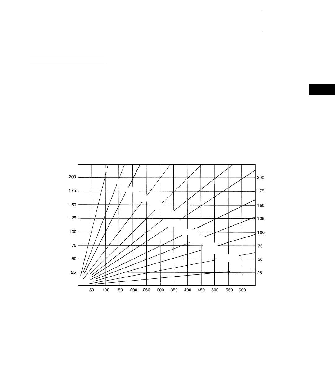
4-155
4
ExcavatorsTrenching Production
●Conversion Chart
Example problem 2 (English)
Contractor knows he must produce 1000 ft of
trench in every 10 hr work day. Survey shows that
trench contains 1.6 BCY per lineal ft and soil swell
factor is estimated at 25%. How much earthmoving
production will excavator have to provide in order to
get the job done on time assuming 50 min work
hour? What Caterpillar model will provide needed
production at 8 ft depth in sandy loam soil?
Solution: Determine trenching requirement —
1000 ft in 10 Hrs. = 100 ft/hr
Convert BCY to LCY — 1.6 BCY/ft 21.25 =
2.0 LCY/ft
Enter vertical axis of trenching conversion chart
at 100 ft/hr and travel over to diagonal line repre-
senting 2.0 yd3/ft. Next move down to horizontal axis
and read answer of 200 LCY/50 min hr.
Convert 200 LCY/50 min hr to LCY/60 min hr =
200
____ = 241 LCY/60 min hr
0.83
Production estimating tables in this section show
that 241 LCY/60 min. hr. is within capability of a
325 Excavator. Job should then be checked for reach
and lifting requirements to make sure that the 325
could handle these aspects of the work.
● ● ●
TRENCHING CONVERSION CHART — CUBIC METERS (yd3) PER HOUR TO METER (ft) PER HOUR
Values in m3/m or yd3/ft
If excavating rate has been calculated in Bm3/h use Bm3/m for Trench Volume/m.
" " """ " "Lm
3/h use Lm3/m for Trench Volume/m.
" " " " " " " BCY/Hr use BCY/ft for Trench Volume/ft.
" " " " " " " LCY/Hr use LCY/ft for Trench Volume/ft.
0.5 m3/(yd3)
0.75 m3/(yd3)
1.0 m3/(yd3)
1.5 m3/(yd3)
2.0 m3/(yd3)
2.5 m3/(yd3)
3.0 m3/(yd3)
4.0 m3/(yd3)
5.0 m3/(yd3)
7.5 m3/(yd3)
10.0 m3/(yd3)
20.0 m3/(yd3)
m (ft.) = m3/(yd3)Hr.
Hr. = m3/(yd3)m (ft.)
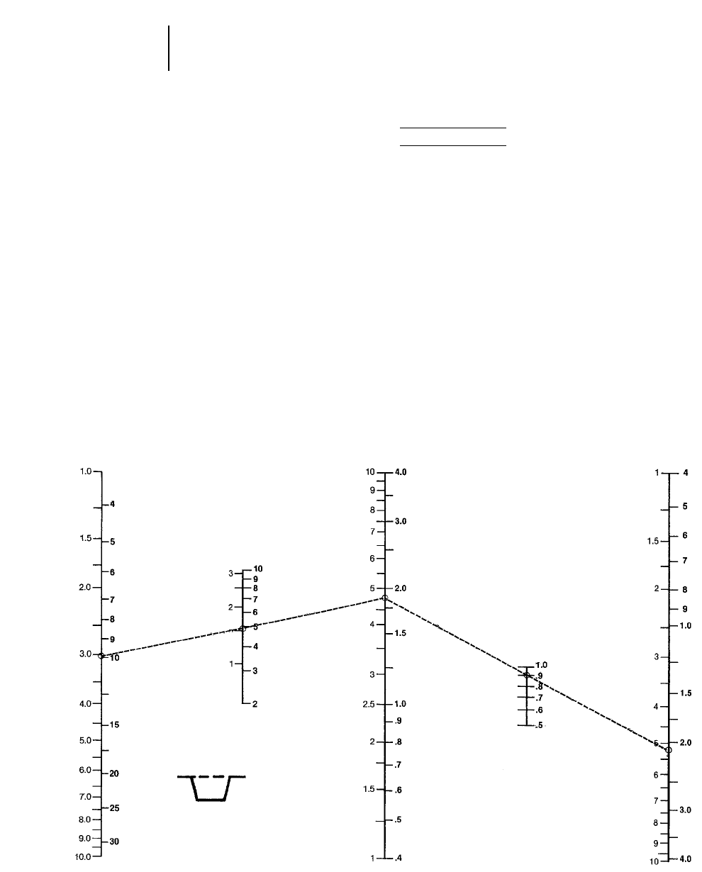
4-156
Excavators Trenching Production
●Estimating Bucket Size
Estimating Bucket Size
In addition to the trenching calculations on the
previous pages, an alternative method of figuring
trenching production is the nomograph. Shown on
the following pages, this particular nomograph can
be used for estimating bucket size when given trench
dimensions and linear production rate. The nomo-
graph is quicker and easier than the preceding exam-
ple because it does not require as many calculations,
yet the accuracy is about the same within the nor-
mal limits of input data.
Be careful when entering and reading data from
the nomographs because some scales increase from
bottom to top, while others are the reverse. Do not
be overly concerned with the precision as affected
by pencil line width or reading to the hundredth of
a m3(yd3). Remember that bucket fill factor, mate-
rial density and cycle time are at best close estimates.
Example problem:
A sewer contractor owns a 325 with 2 piece boom
and short stick. He wants to bid a contract for a
3.1 m (10') deep trench which measures 1.8 m (6')
at the top and 1.2 m (4') at the bottom. He must dig
9 m/hr (30 ft/hr) to finish on time. The material is
sand and gravel with a load factor of 0.90 and 100%
bucket fill factor. He works 54 minutes per hour,
half the time digging and half setting pipe. Cycle
time is estimated at 23 seconds which includes a
90° swing angle.
1) Enter trench depth 3.1 m (10') on scale A and
average trench width 1.5 m (5') on scale B.
2) Connect A and B and extend to scale C for bank
volume per m (ft).
3) Enter estimated load factor (0.90) on scale D.
4) Connect C & D and extend to scale E for loose
volume per m (ft).
A
TRENCH
DEPTH
mft
C
BANK
VOLUME
D
LOAD
FACTOR
BCM/m BCY/ft
E
LOOSE
VOLUME
LCM/m LCY/ft
B
AVERAGE
TRENCH
WIDTH
mft
NOTE: average trench width =
X + Y
_____
2
x = 1.8 m (6')
y = 1.2 m (4') (continued next page)
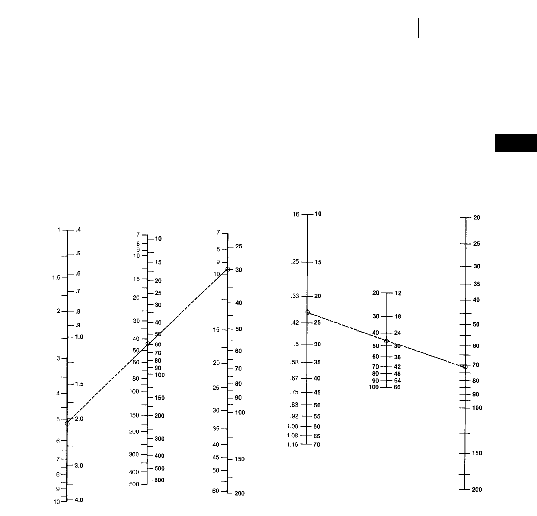
4-157
4
ExcavatorsTrenching Production
(get loose volume from scale E and enter on this page
scale E)
5) Enter required linear production rate 9 m/h
(30 t/hr) on scale G.
6) Connect E and G. Transfer hourly production
rate from scale F to scale K (next page).
7) Estimate cycle time (23 sec) based on anticipated
conditions and enter on scale H.
8) Estimate hourly digging time (27 min) and enter
on scale I.
9) Connect H through I to scale J for cycles per hour.
E
LOOSE
VOLUME
LCM/m LCY/ft
F
HOURLY
PRODUCTION
LCM/m LCY/ft
G
LINEAR
PRODUCTION
m/h ft/hr
H
CYCLE
TIME
100’s
of min Sec
I
DIGGING
TIME/HR.
J
CYCLES
PER
HOUR
% of
Hour
%
Digging
time/hr
min
Cycles/hr
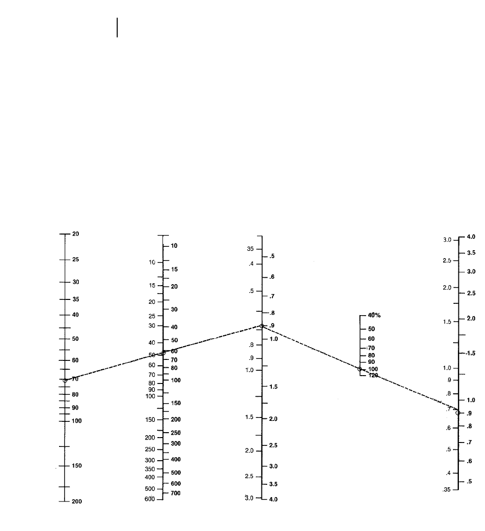
4-158
Excavators Trenching Production
(get cycles per hour from scale J and enter on this
page scale J)
10) Connect J through K to scale L for required vol-
ume per cycle.
11) Enter estimated bucket fill factor (100%) on
scale M.
12) Connect L through M to scale N for required
bucket size.
NOTE: Ensure bucket width does not exceed min-
imum trench width and also that weight of
bucket and payload does not exceed machine
working weight capacity (see lift capacity
charts in this section).
J
CYCLES
PER
HOUR
K
HOURLY
PRODUCTION
LCM/m LCY/hr
L
REQUIRED
VOLUME
M
BUCKET
FILL FACTOR
m3yd3
N
REQUIRED
BUCKET
m3yd3
Cycles/hr
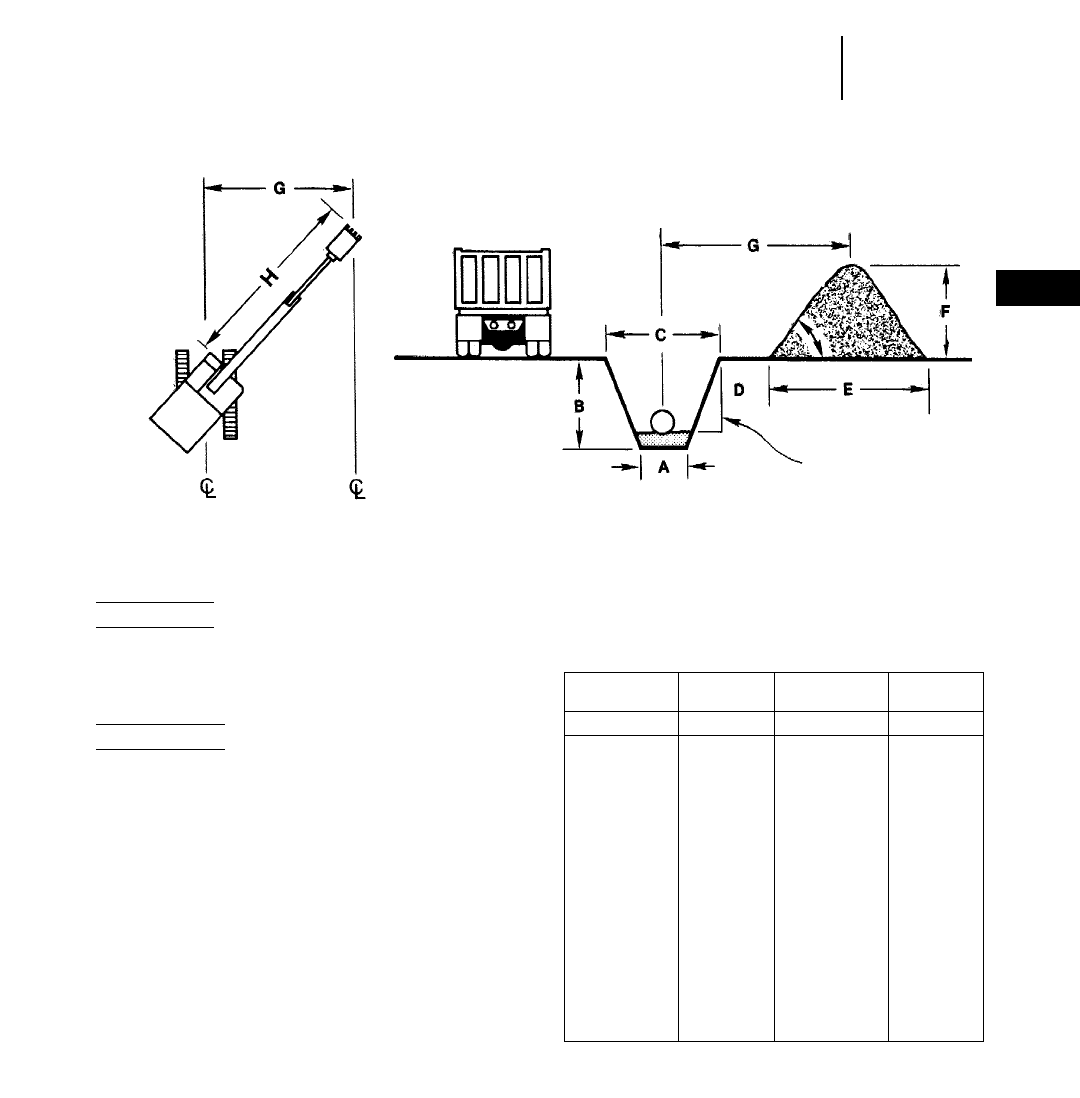
4-159
4
ExcavatorsTrenching Production
●Excavation Volumes
Metric version
Bank m3/meter = (Trench end area m2) 2(one m)
Trench volume (Bm3/m) = 1⁄2(A + C) 2B
Spoil pile volume (Lm3/m) = (Bm3/m) 2
(1.00 + % Swell)
English version
Bank yd3/foot = (Trench end area ft2) 2(one ft)
____________________________
27
Trench volume (BCY/ft) =
1⁄2(A + C) 2B
_____________
27
Spoil pile volume (LCY/ft) =
(BCY/ft) 2(1.00 + % Swell)
The following table provides a general guide to
trench bottom width for various outside diameters
of pipe.
Swing
Angle Angle of
Repose
H = max. reach at
spoil pile ht. Side Slope
Trench Spoil Pile
Excavation Volumes Per Meter or Foot of Trench Length
Pipe Trench Pipe Trench
Diameter Width Diameter Width
mm ft/in m ft mm ft m ft
102 4" 0.49 1'7" 1524 5'0" 2.59 8'6"
152 6" 0.55 1'10" 1676 5'6" 2.80 9'2"
203 8" 0.61 2'0" 1829 6'0" 3.05 10'0"
254 10" 0.70 2'4" 1981 6'6" 3.26 10'8"
305 12" 0.76 2'6" 2134 7'0" 3.47 11'5"
381 15" 0.91 3'0" 2286 7'6" 3.69 12'1"
457 18" 1.03 3'5" 2438 8'0" 3.93 12'11"
533 1'9" 1.16 3'10" 2591 8'6" 4.15 13'7"
610 2'0" 1.25 4'1" 2743 9'0" 4.36 14'4"
686 2'3" 1.37 4'6" 2896 9'6" 4.54 14'11"
838 2'9" 1.58 5'2" 3048 10'0" 4.75 15'7"
914 3'0" 1.70 5'7" 3200 10'6" 4.99 16'5"
1067 3'6" 1.92 6'4" 3353 11'0" 5.21 17'1"
1219 4'0" 2.13 7'0" 3505 11'6" 5.43 17'10"
1372 4'6" 2.38 7'10" 3658 16'2" 5.64 18'6"
NOTE: Trench widths based on 1.25 Bc + 1.0 where Bc is the outside diameter
of the pipe in feet.
Table courtesy of American Concrete Pipe Association
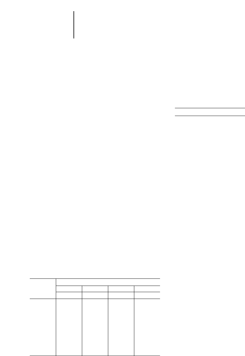
4-160
Excavators Trenching Production
●Trenching Rate With Pipesetting
●Pipesetting Example Problem
Trenching Production with Pipesetting
On many sewer construction jobs the excavator
does more than just dig the trench. Other tasks
include handling the shoring system, placing bed-
ding material, and lowering the pipe. The normal
work procedure is to open a section of trench and
then stop and make a pipe installation before going
on to dig the next section of trench. At that point
the key to trenching production is the total amount
of time required to install each section of pipe. Pipe
installation time can be broken down as follows:
Digging time + other time = Total pipe installation
time
Total Pipe Installation Time Pipe Installed Per Hour
_______________________ ____________________
60 min 1 Pipe/hr
30 min 2 Pipe/hr
15 min 4 Pipe/hr
10 min 6 Pipe/hr
Digging Time can be calculated once the trench-
ing rate has been calculated using the methods
described earlier in this section. Once Digging Time
has been calculated, it can be added to an estimate
of “Other Time” to determine Total Pipe Installation
Time. “Other Time” can be estimated based on a
contractor’s judgment, experience, or actual meas-
urement on a job. The following formula and table
relate the trenching rate of the excavator to the time
required to open a section of trench for pipe of var-
ious lengths.
Pipe Length (ft)
Digging Time (Min.) = ____________________
Trenching Rate (ft/hr)
260 (Min/hr)
Trenching
Rate Time Required to Dig for Pipe of Various Lengths
Ft. Per 8 ft Pipe 12 ft Pipe 16 ft Pipe 20 ft Pipe
Hour Hours Min. Hours Min. Hours Min. Hours Min.
20 ft/hr 0.400 24.00 0.600 36.00 0.800 48.00 1.000 60.00
40 ft/hr 0.200 12.00 0.300 18.00 0.400 24.00 0.500 30.00
60 ft/hr 0.130 8.00 0.200 12.00 0.260 16.00 0.333 20.00
80 ft/hr 0.100 6.00 0.150 9.00 0.200 12.00 0.250 15.00
100 ft/hr 0.080 4.80 0.120 7.20 0.160 9.60 0.200 12.00
120 ft/hr 0.060 4.00 0.100 6.00 0.120 7.20 0.167 10.00
140 ft/hr 0.057 3.43 0.086 5.14 0.114 6.86 0.143 8.57
160 ft/hr 0.050 3.00 0.075 4.50 0.100 6.00 0.125 7.50
180 ft/hr 0.044 2.66 0.067 4.00 0.089 5.33 0.111 6.67
200 ft/hr 0.040 2.40 0.060 3.60 0.080 4.80 0.100 6.00
This table can be used to show how an excavator
that is capable of more trenching production will pro-
vide significant advantages even on jobs where the
machine does not dig all of the time. Consider 12,000'
job with 12' sections of pipe (1000 pipe to be installed).
Excavator “A” can work at 60 ft/hr while Excavator
“B” is capable of producing 120 ft/hr. Table shows
that Excavator “B” will only take 0.10 hr to do the
same work. This means that over the course of install-
ing the 1000 pipe the more productive machine will
save 0.10 hr/pipe or 100 hours of working time.
Example problem (English)
The following example shows how trenching pro-
duction can be calculated on a job where the exca-
vator is also required to set pipe. This example is
based on the assumption that the excavator’s earth-
moving rate and the pipe installation time have
already been estimated by the contractor.
Problem: Contractor estimates that the 350 Exca-
vator will be able to produce 500 LCY/60 min. hr.
Survey shows that an average cross section trench
contains 3.2 BCY/ft and swell factor for sandy clay
soil is estimated at 25%. How much trenching pro-
duction can a contractor expect; assuming it takes
10.0 min. to install each 20 ft length of pipe after
trench has been opened. Also assume 83% job effi-
ciency — 50 min. work hour and 8 work hours out
of a 9 hour shift. (0.5 hours for lunch and two 15
minute breaks.)
Solution:
Convert trench volume to LCY/ft:
1.25 (3.2 BCY/ft) = 4.0 LCY/ft
Convert Earthmoving rate to Trenching rate:
500 LCY/hr
___________ = 125 ft/hr
4.0 LCY/ft
Calculate digging time for each pipe:
20 ft/pipe
_________ = 0.16 hr/pipe = 9.6 min
125 ft/hr
Calculate pipe installation time:
Digging time = 9.6 min
Other time = 10.0 min
________
Pipe Installation time = 19.6 min
Calculate pipe installations/hour:
60 min/hr
____________ = 3.06 pipe/hr
19.6 min/pipe
Calculate max. pipe installations/day:
8 hrs (3.06 pipe/hr) = 24.48 pipe/day
Actual pipe/day:
0.83 (24.48 pipe/day) = 20.3 – 20 pipe/day
Actual feet/day:
(20 pipe/day) 2(20 ft/pipe) = 400 ft/day

CONTENTS
Features . . . . . . . . . . . . . . . . . . . . . . . . . . . . .4-161
Specifications . . . . . . . . . . . . . . . . . . . . . . . . .4-162
Digging envelopes . . . . . . . . . . . . . . . . . . . . . .4-168
Shipping information . . . . . . . . . . . . . . . . . . .4-170
General dimensions . . . . . . . . . . . . . . . . . . . .4-172
Shoe selection . . . . . . . . . . . . . . . . . . . . . . . . .4-173
Curl and Crowd forces . . . . . . . . . . . . . . . . . .4-173
Bucket selection . . . . . . . . . . . . . . . . . . . . . . .4-174
Vital Information Management
System (VIMS) . . . . . . . . . . . . . . . . . . . . . .4-174
Estimating cycle time . . . . . . . . . . . . . . . . . . .4-175
Production tables . . . . . . . . . . . . . . . . . . . . . .4-177
Features:
●Modular design on the 5130B/5230 provides
enhanced service access, isolated cooling systems
for improved efficiency, superior stability through
lower center of gravity and simplified assem-
bly/disassembly process. Modules mount to the
main frame on vertical shear ledges. The Right
Hand (RH) or Power module includes the engine,
pump drive, pumps, filters and engine radiator.
A bulkhead separates the pump drive and engine
compartments. Space between the engine and
radiator allows the engine to be disconnected, slid
forward and lifted from the module. The Left
Hand (LH) or Cooler/Fluids module includes the
hydraulic tank and filters, hydraulic coolers, fuel
tank, autolube system, and cab riser. The cab
riser allows standup access to hydraulic pilot
lines, electrical components, VIMS Main module,
windshield washer reservoir, and cab air filters.
●Large castings in critical areas provide supe-
rior stress resistance eliminating welds in high
stress areas. Boom and stick castings provide
structure designs which improve visibility over
competitive designs. Large single floating pins
mount the boom to main frame, boom to stick and
stick to bucket. Single pins provide additional
strength to these critical areas. Caterpillar’s shovel
manufacturing facility uses the latest machining
and manufacturing processes. Large five plane
machining center performs the precision milling
required to mount the swing bearing to the car-
body eliminating the need for a swing bearing
collar assembly.
●Proportional Priority Pressure Compensa-
tion hydraulic system delivers excellent con-
trollability with efficient full-powered response.
The system uses a closed center design. Pressure
compensation senses implement loads/pressures
and meters pump flow according to implement
requirements. Pumps deliver only the flow neces-
sary to do the work. The 5130B/5230 hydraulics
have proportioning or flow modulation that senses
the implement loads. Implement valves adjust to
provide consistent and constant feel modulation.
PPPC valves deliver flow proportional to joy stick
deflection. The flow remains proportional even as
pressures change due to increased loads. Operation
is smooth and predictable with reduced effort
improving operator efficiency.
●Undercarriage track roller frames on the
5130B/5230 attach to the carbody on large preci-
sion machined surfaces with 32 dowels pressed
fit into the carbody. These dowels provide supe-
rior resistance to shear loads between the car-
body/upper structure and the track roller frames.
Automatic track tension eliminates manual adjust-
ments. Accumulators absorb shock loads caused
by debris passing through the undercarriage.
Sloped track roller frames resist material build
up improving component life. The 5000 U/C uses
solid track pins and positive pin retention. All
undercarriage components are lifetime lubricated
for reduced maintenance. A hunting tooth drive
sprocket alternates tooth-pin engagement result-
ing in extended undercarriage life. The 5230 uses
a patented shovel style single piece cast shoe/link
assembly. Two solid floating pins join the shoe/link
casting providing even pin wear. Four load bear-
ing surfaces increase undercarriage life and elim-
inate track walking.
5000 SERIES
EXCAVATORS AND SHOVELS
4-161
4
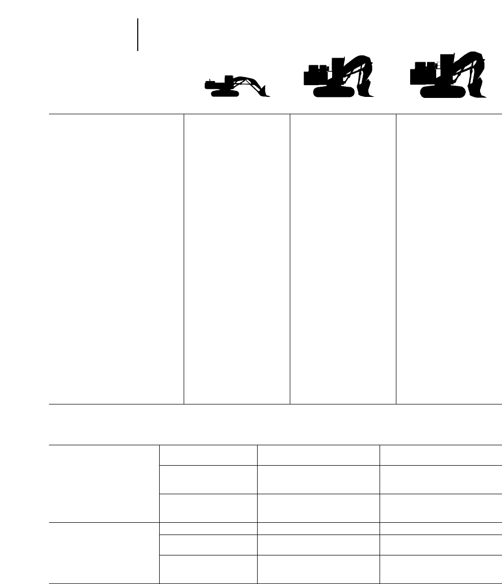
4-162
5000 Series —
Front Shovels Specifications
●Metric
MODEL 5080 5130B 5230
Sourcing U.S. U.S. U.S.
Flywheel Horsepower 319 kW 597 kW 1095 kW
Operating Weight* 83 800 kg 181 000 kg 318 500 kg
Bucket Capacity Range
(heaped) 5.2 m39-11 m312.5-17 m3
Engine Model 3406C 3508B EUI 3516 EUI
Rated Engine RPM 1800 1750 1750
No. of Cylinders 6 8 16
Bore 137 mm 170 mm 170 mm
Stroke 165 mm 190 mm 190 mm
Displacement 14.6 L 34.5 L 69.1 L
Max. Hydraulic Pump Output
at Rated RPM: Implement 2 2430 L/min 4 2372 L/min 6 2372 L/min
at Rated RPM: Swing 1 2340 L/min 1 2464 L/min 2 2464 L/min
Relief Valve Setting:
Implement Circuits 31 400 kPa 31 000 kPa 31 000 kPa
Travel Circuits 34 300 kPa 35 000 kPa 35 000 kPa
Swing Circuits: Accelerate 27 500 kPa 35 000 kPa 35 000 kPa
Swing Circuits: Decelerate 27 500 kPa 25 000 kPa 25 000 kPa
Pilot Circuits 3500 kPa 4000 kPa 4000 kPa
Maximum Drawbar Pull 546 kN 872 kN 1545 kN
Maximum Travel Speed Low: 2.7 km/h — —
at Rated RPM High: 4.4 km/h 3.3 km/h 2.5 km/h
Overall Track Length** 4.6 m 5.55 m 6.26 m
Track Gauge 3.51 m 4.72 m 5.12 m
Grouser Height 48 mm 29, 71 mm 15 mm
Track Shoe Widths 610, 750 mm 650, 800, 1000 mm 1100, 1300, 1500 mm
Ground Contact Areas 6.13, 7.55 m28.0, 9.8, 12.3 m215.2, 18.0, 20.8 m2
Ground Pressures 132, 107 kPa 217, 178, 144 kPa 205, 174, 153 kPa
Fuel Tank Refill Capacity 990 L 2600 L 5330 L
**Operating Weights include coolant, lubricants, full fuel tank, standard shoes, bucket, and operator.
**Track length measured from center of idler to center of sprocket.
Adjustments to Standard Operating Weight
Track 5080 610 mm Track 0 kg
750 mm Track +966 kg
5130B 650 mm Track 0 kg
800 mm Track +2050 kg
1000 mm Track +4320 kg
5230 1100 mm Track 0 kg
1300 mm Track +2320 kg
1500 mm Track +5370 kg
Buckets 5080 G.P. Rock Bucket (5.2 m3) 0 kg
5130B Rock Bucket (11.0 m3) 0 kg
High Density (9.0 m3) –225 kg
5230 Rock Bucket (17.0 m3) 0 kg
High Density (14.5 m3) –3050 kg
High Density (12.5 m3) –3750 kg
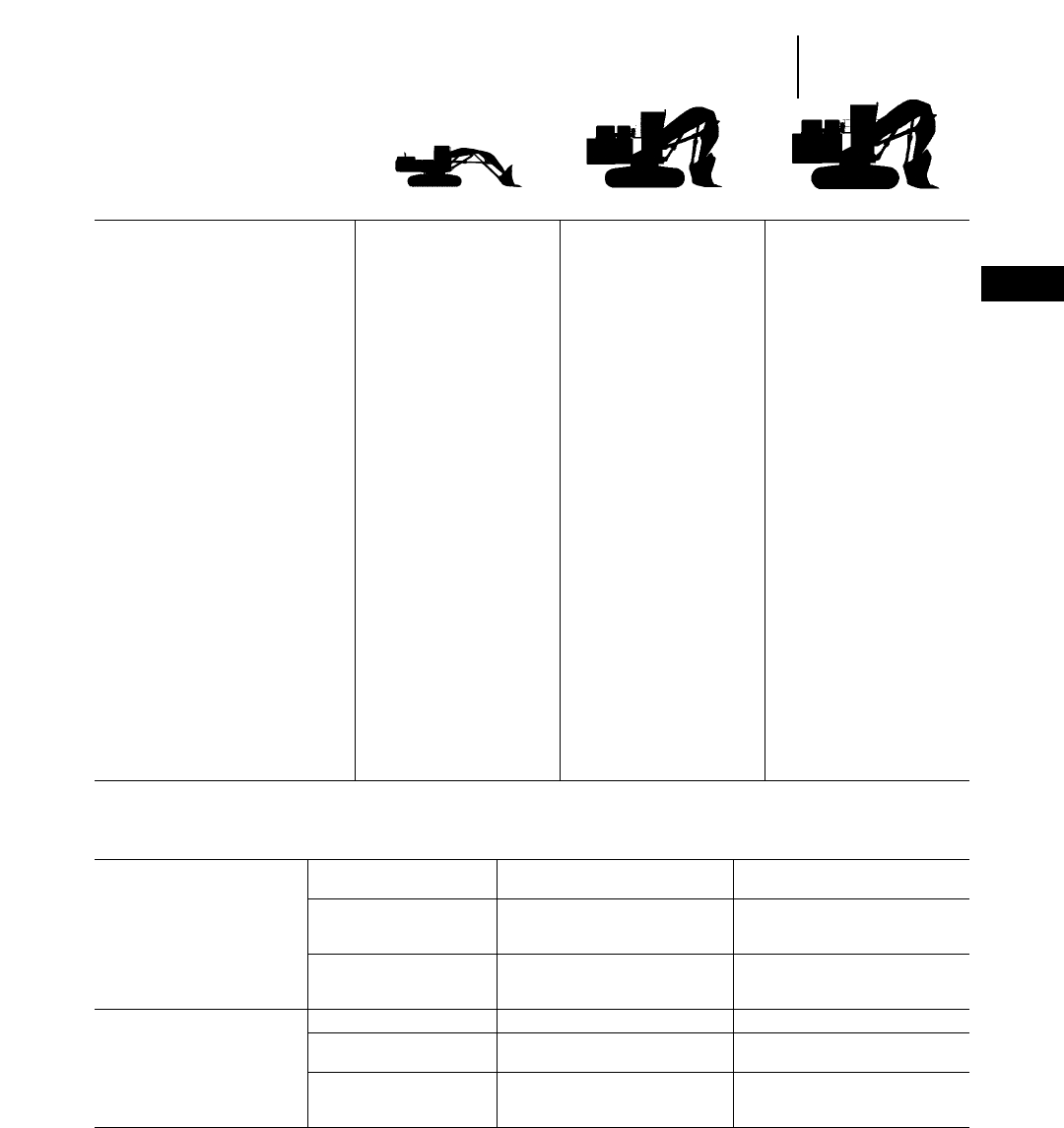
4-163
4
5000 Series —
Front Shovels
Specifications
●English
MODEL 5080 5130B 5230
Sourcing U.S. U.S. U.S.
Flywheel Horsepower 428 hp 800 hp 1470 hp
Operating Weight* 184,600 lb 399,000 lbs 702,000 lbs
Bucket Capacity Range
(heaped) 6.8 yd312.0-14.5 yd316.3-22.2 yd3
Engine Model 3406C ATAAC 3508B EUI 3516 EUI
Rated Engine RPM 1800 1750 1750
No. of Cylinders 6 8 16
Bore 5.4" 6.7" 6.7"
Stroke 6.5" 7.5" 7.5"
Displacement 891 in32105 in34211 in3
Max. Hydraulic Pump Output
at Rated RPM: Implement 2 2114 gpm 4 299 gpm 6 299 gpm
at Rated RPM: Swing 1 290 gpm 1 2123 gpm 2 2123 gpm
Relief Valve Setting:
Implement Circuits 4550 psi 4500 psi 4500 psi
Travel Circuits 4980 psi 5080 psi 5080 psi
Swing Circuits: Accelerate 3980 psi 5080 psi 5080 psi
Swing Circuits: Decelerate 3980 psi 3620 psi 3620 psi
Pilot Circuits 505 psi 580 psi 580 psi
Maximum Drawbar Pull 122,850 lb 196,000 lb 340,875 lb
Maximum Travel Speed Low: 1.7 mph — —
at Rated RPM High: 2.7 mph 2.1 mph 1.6 mph
Overall Track Length** 15'1" 18'3" 20'6"
Track Gauge 11'6" 15'6" 17'
Grouser Height 2" 1.1", 2.8" 0.6"
Track Shoe Widths 24", 30" 26", 32", 39" 43", 51", 59"
Ground Contact Areas 66, 81.3 ft286.1, 105.4 ft2163.6,193.7, 223.8 ft2
Ground Pressures 19.2, 16 psi 31.4, 25.8, 20.9 psi 29.7, 25.3, 22.2 psi
Fuel Tank Refill Capacity 262 U.S. gal 687 U.S. gal 1386 U.S. gal
**Operating Weights include coolant, lubricants, full fuel tank, standard shoes, bucket, and operator.
**Track length measured from center of idler to center of sprocket.
Adjustments to Standard Operating Weight
Track 5080 2'0" Track 0 lbs
2'6" Track +2125 lbs
5130B 2'2" Track 0 lbs
2'8" Track +4520 lbs
3'3" Track +9520 lbs
5230 3'7" Track 0 lbs
4'3" Track +5120 lbs
4'11" Track +11,840 lbs
Buckets 5080 G.P. Rock Bucket (6.8 yd3) 0 lbs
5130B Rock Bucket (14.4 yd3) 0 lbs
High Density (12.0 yd3) –500 lbs
5230 Rock Bucket (22.2 yd3) 0 lbs
High Density (19.0 yd3) –6700 lbs
High Density (16.3 yd3) –8300 lbs

4-164
5000 Series —
Excavators Specifications
●Metric
MODEL 5130B 5230
Sourcing U.S. U.S.
Flywheel Horsepower 597 kW 1095 kW
Operating Weight* 182 000 kg 316 600 kg
Bucket Capacity Range
(heaped) 8.5-18.3 m313-27.5 m3
Engine Model 3508B EUI 3516 EUI
Rated Engine RPM 1750 1750
No. of Cylinders 8 16
Bore 170 mm 170 mm
Stroke 190 mm 190 mm
Displacement 34.5 L 69.1 L
Max. Hydraulic Pump Output
at Rated RPM: Implement 4 2372 L/min 6 2372 L/min
at Rated RPM: Swing 1 2464 L/min 2 2464 L/min
Relief Valve Settings:
Implement Circuits 31 000 kPa 31 000 kPa
Travel Circuits 35 000 kPa 35 000 kPa
Swing Circuits: Accelerate 35 000 kPa 35 000 kPa
Swing Circuits: Decelerate 25 000 kPa 25 000 kPa
Pilot Circuits 4000 kPa 4000 kPa
Maximum Drawbar Pull 872 kN 1545 kN
Maximum Travel Speed — —
at Rated RPM 3.3 km/h 2.5 km/h
Overall Track Length** 5.55 m 6.26 m
Track Gauge 4.72 m 5.12 m
Grouser Height 29,71 mm 15 mm
Track Shoe Widths 650, 800 mm 1100, 1300, 1500 mm
Ground Contact Areas 8.0, 9.8 m215.2, 18.0, 20.8 m2
Ground Pressures 218, 179, 145 kPa 202, 172, 151 kPa
Fuel Tank Refill Capacity 2600 L 5330 L
**Operating Weights include coolant, lubricants, full fuel tank, standard shoes, bucket, and operator.
**Track length measured from center of idler to center of sprocket.
Working Weights
Stick Length Buckets & Payload
Model Boom m kg
5130B 8.0 m 3.8 m 28 500
5.2 m 23 900
11.0 m 3.8 m 18 250
5230 9.5 m 4.5 m 44 500

Adjustments to Standard Operating Weight
Track 5130B 650 mm Track –2050 kg
800 mm Track 0 kg
1000 mm Track +2270 kg
5230 1100 mm Track –2320 kg
1300 mm Track 0 kg
1500 mm Track +5370 kg
Buckets 5130B Rock (10.5 m3) 0 kg
High Density (8.5 m3) –1079 kg
Excavation (10.5 m3) –500 kg
Coal (13.6 m3) –800 kg
Coal (18.3 m3) –130 kg
5230 Rock (16.0 m3) 0 kg
High Density (13.0 m3) –2000 kg
Rock (18.0 m3) +1800 kg
Coal (27.5 m3) –1140 kg
4-165
4
5000 Series —
Excavators
Specifications
●Metric
MODEL 5130B 5230
Sourcing U.S. U.S.
Flywheel Horsepower 800 hp 1470 hp
Operating Weight* 401,000 lb 698,000 lb
Bucket Capacity Range
(heaped) 11.0-24.0 yd317-36 yd3
Engine Model 3508B EUI 3516 EUI
Rated Engine RPM 1750 1750
No. of Cylinders 8 16
Bore 6.7" 6.7"
Stroke 7.5" 7.5"
Displacement 2105 in34211 in3
Max. Hydraulic Pump Output
at Rated RPM: Implement 4 299 gpm 6 299 gpm
at Rated RPM: Swing 1 2123 gpm 2 2123 gpm
Relief Valve Settings:
Implement Circuits 4500 psi 4500 psi
Travel Circuits 5080 psi 5080 psi
Swing Circuits: Accelerate 5080 psi 5080 psi
Swing Circuits: Decelerate 3620 psi 3620 psi
Pilot Circuits 580 psi 580 psi
Maximum Drawbar Pull 196,000 lb 340,875 lb
Maximum Travel Speed
at Rated RPM 2.1 mph 1.6 mph
Overall Track Length** 18'3" 20'6"
Track Gauge 15'6" 17'
Grouser Height 1.1", 2.8" 0.6"
Track Shoe Widths 26", 32" 43", 51", 59"
Ground Contact Areas 86.1, 105.5 ft2163.6, 193.7, 346.6 ft2
Ground Pressures 31.6, 26.0, 21.0 psi 29.4, 25.0, 21.9 psi
Fuel Tank Refill Capacity 687 U.S. gal 1386 U.S. gal
**Operating Weights include coolant, lubricants, full fuel tank, standard shoes, bucket, and operator.
**Track length measured from center of idler to center of sprocket.
Working Weights
Stick Length Buckets & Payload
Model Boom ft lb
5130B 26'3" 12'6" 62,800
17'1" 52,700
36'1" 12'6" 35,800
5230 31'2" 14'9" 98,100
4-166
5000 Series —
Excavators Specifications
●English

4-167
4
5000 Series —
Excavators
Specifications
●English
Adjustments to Standard Operating Weight
Track 5130B 2'2" Track –4520 lbs
2'8" Track 0 lbs
3'3" Track +5000 lbs
5230 3'7" Track –5120 lbs
4'3" Track 0 lbs
4'11" Track +6720 lbs
Buckets 5130B Rock (13.7 yd3) 0 lbs
High Density (11.0 yd3) –2380 lbs
Excavation (13.7 yd3) –2080 lbs
Coal (17.8 yd3) –2760 lbs
Coal (24.6 yd3) –1280 lbs
5230 Rock (20.9 yd3) 0 lbs
High Density (17 yd3) –4400 lbs
Rock (24.2 yd3) +4000 lbs
Coal (36 yd3) –2500 lbs
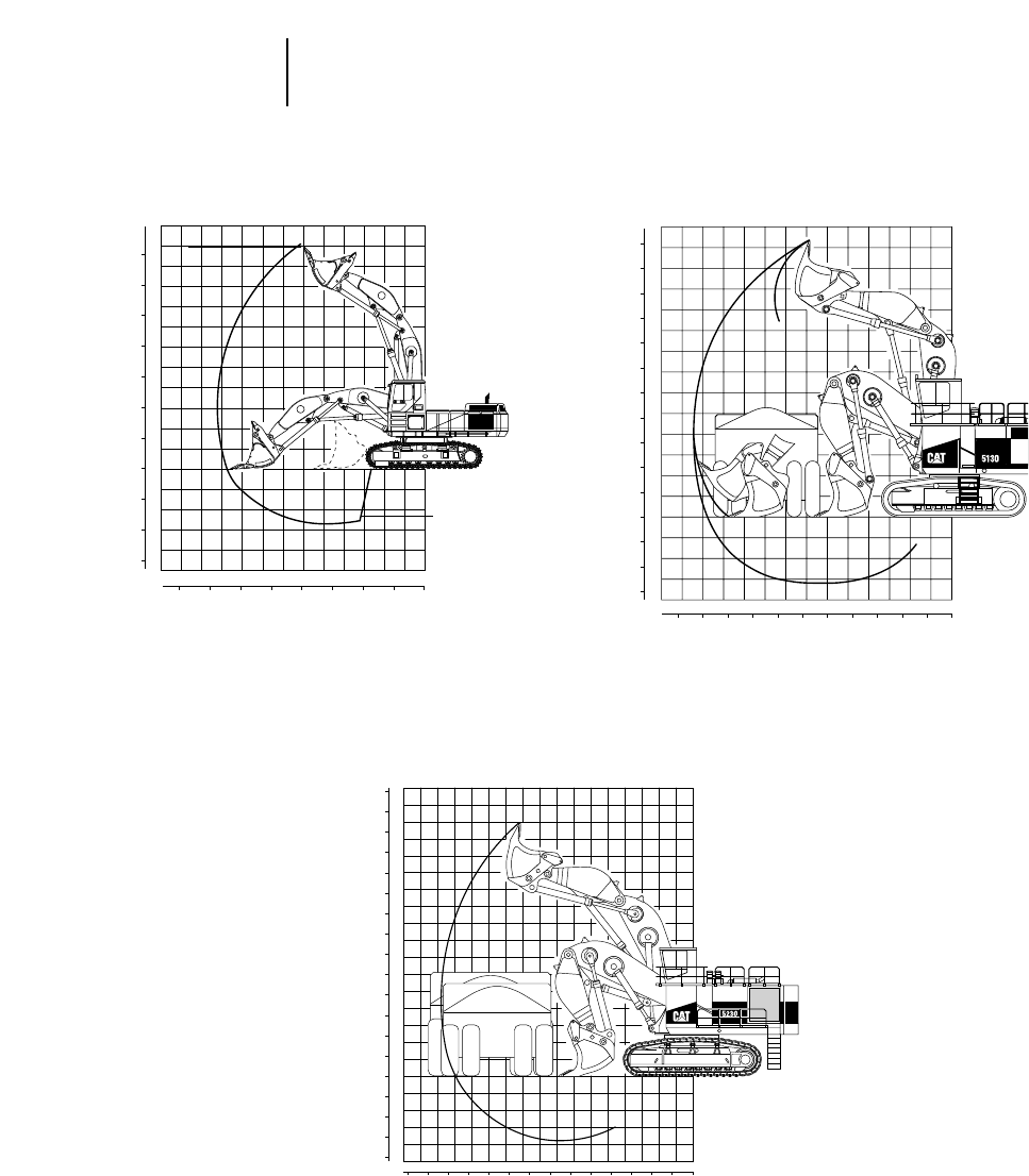
4-168
5000 Series —
Front Shovels Digging Envelopes
●5080 ●5130B ●5230
120
0
3456
789101112
5
101520253035
1
00
1
2
3
4
5
6
7
8
9
10
11
2
3
4
5
10
15
5
10
15
20
25
30
35
40
➤
5080
Feet Meters
Meters
Feet
General Purpose Rock
1
0
0
40 12
2
3
4
5
6
7
8
9
10
11
13
14
15
16
17
1
2
3
4
0
0
2345678910111213141516 1
4
8
12
16
20
24
28
32
36
44
48
52
56
4
8
12
16
48121620242832364044
48
5256
785
789
5230
Feet Meters
Meters
Feet
5130B
Feet Meters
Feet
Meters
1
0
0
40 12
2
3
4
5
6
7
8
9
10
11
13
14
1
2
3
40
0
2345678910111213 1
4
8
12
16
20
24
28
32
36
44
4
8
12
481216202428323640
44
777C
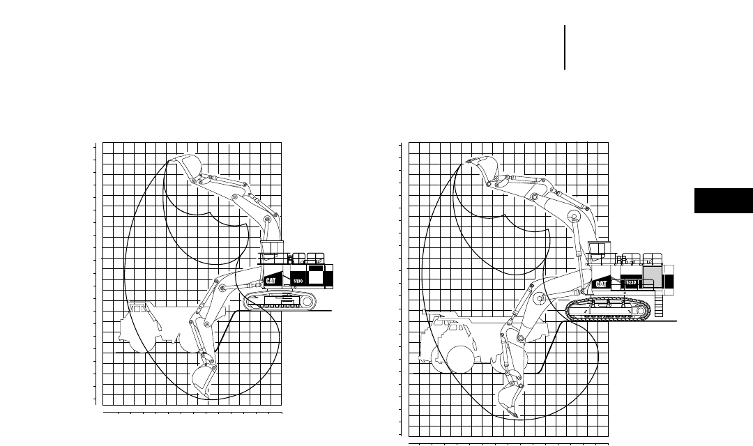
4-169
4
5000 Series —
Excavators
Digging Envelopes
●5130B ME ●5230 ME
1
785
789
0
0
40 12
2
3
4
5
6
7
8
9
10
11
13
14
15
16
17
1
2
3
4
5
6
7
8
9
10
0
0
23456789101112131415161718 1
4
8
12
16
20
24
28
32
36
44
48
52
56
4
8
12
16
20
24
28
32
36
48121620242832364044
48
525660
5230 ME
Feet Meters
Meters
Feet
1
0
0
40
44
48
52
12
2
3
4
5
6
7
8
9
10
11
13
14
15
16
1
2
3
4
5
6
7
8
0
0
2345678910111213141516 1
4
8
12
16
20
24
28
32
36
4
8
12
16
20
24
28
48121620242832364044
48
52
777C
5130B ME
Feet Meters
Feet
Meters

4-170
5000 Series Shipping Information
●5130B ME
●5130B ME
Weight Length Width Height
kg lb mm ft mm ft mm ft
Carbody 15 800 34,820 3560 11'8" 4110 13'6" 1520 5'0"
Swing Frame 22 830 50,340 7060 23'2" 2460 8'1" 2440 8'0"
Track Roller Frame (each)
650 mm (2'2") Shoes 23 610 52,060 7140 23'5" 1500 4'11" 1910 6'3"
800 mm (2'7") Shoes 24 640 54,320 7140 23'5" 1500 4'11" 1910 6'3"
1000 mm (3'3") Shoes 25 770 56,820 7140 23'5" 1500 4'11" 1910 6'3"
Left Module 8090 17,830 5770 18'11" 2340 7'8" 2620 8'7"
Boom Cylinders 3000 6620 3840 12'7" 910 3'0" 690 2'3"
Stick Cylinders 1100 2430 3840 12'7" 910 3'0" 690 2'3"
Bucket Cylinders 1100 2430 3840 12'7" 910 3'0" 690 2'3"
Ladders 2070 4570 2240 7'4" 1090 3'7" 1190 3'11"
Parts Box 2100 4620 2240 7'4" 1090 3'7" 990 3'3"
Handrails 1150 2540 3990 13'1" 2290 7'6" 1120 3'8"
Right Module 13 810 30,440 5660 18'7" 2440 8'0" 3050 10'0"
Cab 2050 4510 2360 7'9" 2060 6'9" 3100 10'2"
Boom 20 530 45,260 8560 28'1" 1980 6'6" 3400 11'2"
Counterweight 20 970 46,220 6250 20'6" 1170 3'10" 2510 8'3"
Stick 6220 13,710 5260 17'3" 1020 3'4" 2290 7'6"
Brackets 1550 3420 1520 5'0" 1450 4'9" 790 2'7"
Bucket 9700 21,380 2900 9'6" 3200 10'6" 2820 9'3"
●5230 ME
Weight Length Width Height
kg lb mm ft mm ft mm ft
Carbody 24 770 54,610 4470 14'8" 3840 12'7" 1980 6'6"
Swing Frame 40 590 89,490 8890 29'2" 3330 10'11" 3480 11'5"
Track Roller Frame (each)
1100 mm (3'7") Shoes 45 400 100,080 8030 26'4" 1830 6'0" 2360 7'9"
1300 mm (4'3") Shoes 46 560 102,640 8030 26'4" 1830 6'0" 2360 7'9"
1500 mm (4'11") Shoes 48 080 106,000 8030 26'4" 1830 6'0" 2360 7'9"
Left Module 12 310 27,140 7190 23'7" 2510 8'3" 3230 10'7"
Cylinder Skid 3130 6900 4170 13'8" 610 2'0" 810 2'8"
Cylinder Skid 3130 6900 4170 13'8" 610 2'0" 810 2'8"
Cylinder Skid 4350 9580 4880 16'0" 910 3'0" 740 2'5"
Cylinder Skid 3290 7260 4170 13'8" 910 3'0" 740 2'5"
Parts Box 2220 4890 2240 7'4" 1090 3'7" 990 3'3"
Parts Box 2170 4780 2240 7'4" 1090 3'7" 990 3'3"
Parts Box 2220 4900 2240 7'4" 1090 3'7" 990 3'3"
Handrails 1350 2980 3990 13'1" 2290 7'6" 1120 3'8"
Right Module 20 880 46,040 7570 24'10" 2510 8'3" 3580 11'9"
Cab 2380 5240 2360 7'9" 2060 6'9" 3050 10'0"
Boom 28 340 62,480 10 030 32'11" 3960 13'0" 2490 8'2"
Counterweight 41 390 91,240 7320 24'0" 1220 4'0" 3050 10'0"
Stick 11 030 24,320 6250 20'6" 1350 4'5" 2570 8'5"
Brackets 2590 5720 1780 5'10" 1680 5'6" 890 2'11"
Guards 940 2080 2080 6'10" 1700 5'7" 840 2'9"
Bucket 16 380 36,110 4010 13'2" 3250 10'8" 3100 10'2"
4-171
4
5000 SeriesShipping Information
●5230 ME
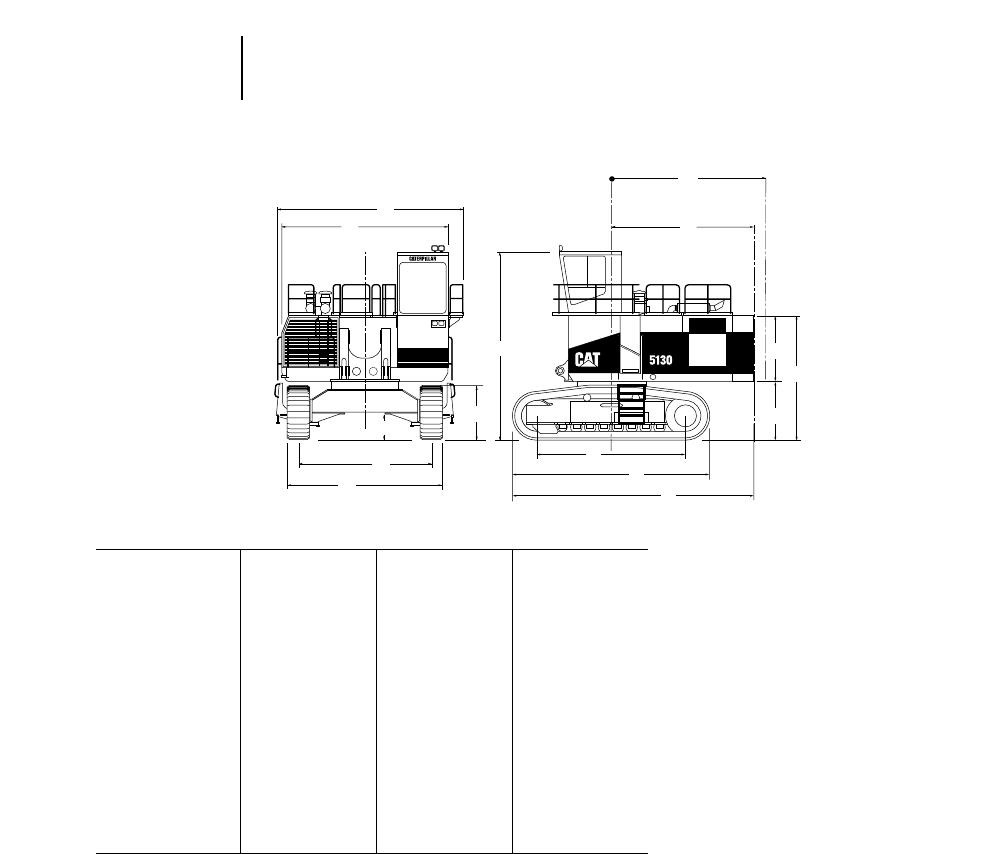
5080 5130B ME 5230 ME
A4400 mm 14'5" 6620 mm 21'9" 7510 mm 24'7"
B3470 mm 11'5" 5900 mm 19'4" 6960 mm 22'11"
C3510 mm 11'6" 4720 mm 15'6" 5196 mm 17'0"
D4120 mm 13'6" 5370 mm 17'7" 6296 mm 20'8"
E890 mm 2'11" 960 mm 3'2" 1108 mm 3'8"
F——1890 mm 6'3" 2260 mm 7'5"
G Swing radius 4200 mm 13'9" 5250 mm 17'3" 6450 mm 21'2"
H4200 mm 13'9" 5140 mm 16'11" 6280 mm 20'7"
J4600 mm 15'1" 5552 mm 18'3" 6260 mm 20'6"
K5840 mm 19'2" 7270 mm 23'10" 8174 mm 26'10"
L7120 mm 23'4" 8775 mm 28'9" 10 325 mm 33'10"
M4820 mm* 15'10" 6550 mm 21'5" 7455 mm 24'5"
N——2350 mm 7'9" 2850 mm 9'4"
O1620 mm 5'4" 2045 mm 6'9" 2450 mm 8'0"
P——4395 mm 14'5" 5300 mm 17'5"
*Euro cab with FOPS.
4-172
5000 Series General Dimensions
●5080 ●5130B ●5230
A
B
E
C
D
F
M
J
K
L
O
N
P
H
G
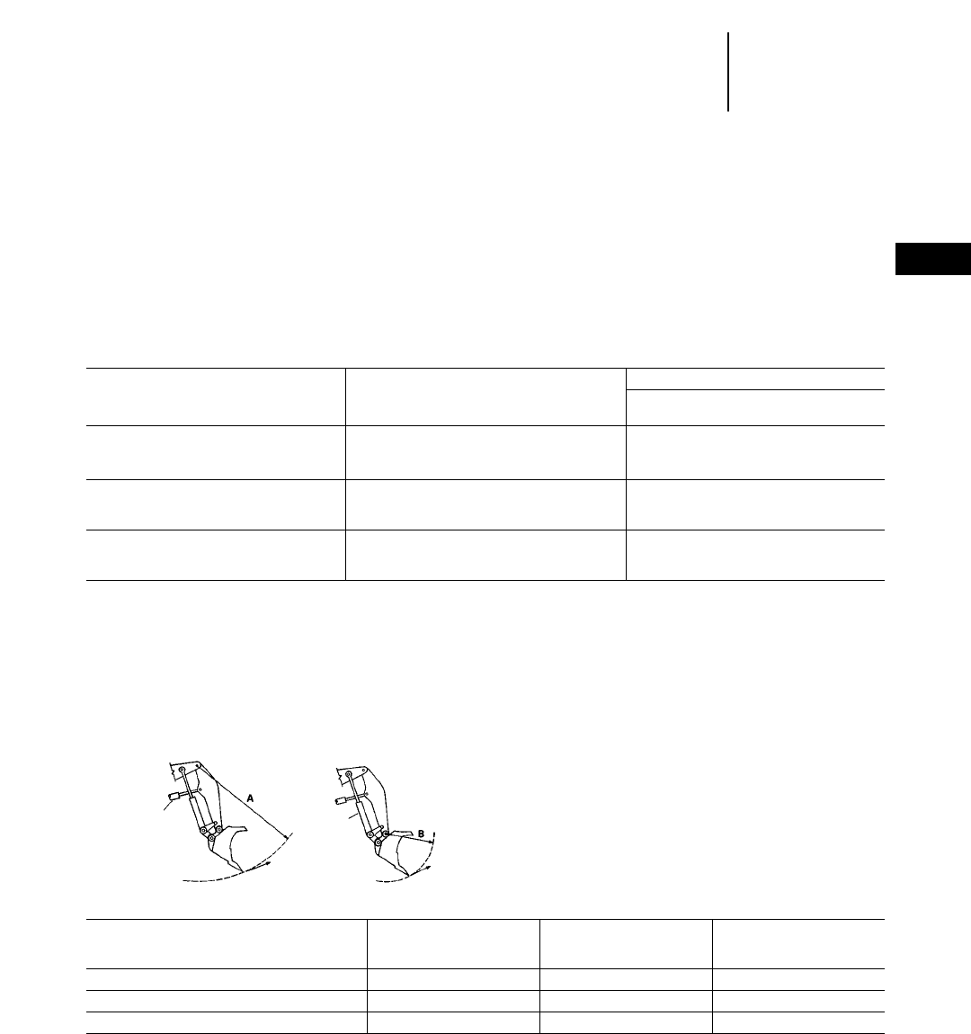
4-173
4
5000 Series —
Front Shovels
Shoe Selection
Ground Pressure
Curl and Crowd Forces
CHOOSING A TRACK SHOE
In severe underfoot conditions, narrow shoes
impose lower forces on other undercarriage compo-
nents, and normally result in improved overall track
life. Machines working in rock should be equipped
with the narrowest available shoe. Wider shoes will
improve flotation, but shoes wider than those shown
here should not be used. Track shoe width has lit-
tle effect on stability.
Double grouser shoes will provide adequate trac-
tion in most underfoot conditions, and are less dam-
aging to floor and road surfaces. For additional
traction in deep mud, or in rock applications which
allow some grouser penetration, single grouser
shoes are recommended. Hard, smooth quarry floors
that allow little or no grouser penetration are best
handled by the narrowest double grouser shoes.
Track Shoe Widths and Ground Pressures
GROUND PRESSURE
With Bottom
Model Shoe Dump Bucket
kPa psi
5080 Front Shovel 610 mm (2'0") double grouser 132 19.2
750 mm (2'6") double grouser 107 16.0
5130B Front Shovel 650 mm (2'2") 215 31.2
800 mm (2'8") 174 25.3
1000 mm (3'3") 144 20.9
5230 Front Shovel 1100 mm (3'7") 202 29.3
1300 mm (4'3") 171 24.8
1500 mm (4'11") 148 21.5
CURL AND CROWD FORCES
Rated digging forces are the forces that can be
exerted at the outermost cutting point. They are cal-
culated by applying working relief hydraulic pres-
sure to the cylinder(s) providing the digging force.
Weight of components and friction are excluded
from the calculations.
Rated Arm (Stick) Force — is generated by the
arm (stick) cylinder and is tangent to the arc of radius
“A”. The arm is positioned to obtain the maximum
output moment from the arm cylinder with the
bucket positioned as in figure 1.
Rated Bucket Tangential Force — is generated
by the bucket cylinders and is tangent to the arc of
radius “B”. The bucket is positioned to obtain the
maximum output moment from the bucket cylin-
ders and connecting linkage as in figure 2.
A — Crowd B — Bucket
Bucket Capacity Force Tangential Force
Model Bucket m3yd3kN lb kN lb
5080 Front Shovel Bottom Dump 5.2 6.8 434 97,600 451 101,500
5130B Front Shovel Bottom Dump 11.0 14.5 770 173,000 715 161,000
5230 Front Shovel Bottom Dump 17.0 22.2 1250 281,000 1125 253,000
Arm (stick)
cylinder Bucket
cylinder
Figure 1 Figure 2

4-174
5000 Series —
Front Shovels Bucket Selection
Vital Information Management System (VIMS)
MAJOR BOTTOM DUMP BUCKET
APPLICATION FEATURES:
●Controlled dumping action permits more accurate
loading of narrow trucks with less chance of spillage.
Closer bucket positioning over the truck, and meter-
ing the material flow on the first pass, lessens
impact on truck bodies increasing their life.
●The bottom-dump clamping action is ideal for
sorting in rock applications. Oversized material
can be segregated for secondary breakage. In
some cases, the operator can screen material as
he dumps by limiting the bucket opening.
●Sticky material is easier to dislodge, thus avoiding
material build-up which robs production. The bot-
tom-dump bucket bulldozer assembly is nearly
vertical when the bucket is fully open.
Bucket Selection
Heaped Struck
Capacity Capacity Weight Width
Model m3yd3m3yd3kg lb m ft
5080
General Purpose 5.2 6.8 4.1 5.4 8893 19,610 2.59 8'6"
5130B Front Shovel
General Purpose 11.0 14.5 NA NA 15 790 34,820 3.64 11'11"
Rock 11.0 14.5 NA NA 17 960 39,500 3.64 11'11"
Hi-density Rock 9.0 12.0 NA NA 17 700 39,000 3.06 10'0"
5230 Front Shovel
Rock 17.0 22.2 NA NA 29 820 65,740 4.36 14'4"
Hi-density Rock 15.5 20.2 NA NA 28 580 63,000 3.67 12'0"
VITAL INFORMATION MANAGEMENT
SYSTEM (VIMS):
VIMS is a Caterpillar exclusive advanced diag-
nostic and equipment management tool designed to
lower operating costs. Equipment utilization can be
improved through higher mechanical availability,
optimized component life, reduced risk of catastrophic
failures, faster diagnostics and improved service-
ability. VIMS includes both on-board hardware and
an off-board software package — VIMS-PC.
The VIMS system “coaches” the operator to improve
vehicle performance and productivity. On-board,
VIMS is designed to work with the operator and not
interfere with equipment operation. In-cab modules
provide meaningful messages, indicators, gauges
and warnings from sensors located throughout the
machine. VIMS provides the operator immediate
access to current machine information. VIMS data
can also be transmitted for in-office/remote machine
monitoring and analysis.
The CAT DATA LINK is the on-board network
allowing communication between VIMS and the many
machine mounted electronic control modules.
VIMS is like having a first rate mechanic riding in
the cab with all of his diagnostic tools connected to
the machine. Listening, watching, monitoring the
entire vehicle by converting data signals from various
sensors into meaningful information. VIMS displays
information in “real-time” and records and stores
information similar to a Flight Data Recorder on an
airplane.
VIMS works with four types of information: 1.
Internal (e.g.: service meter hours); 2. Sensed (e.g.:
Exhaust Temperature); 3. Communicated (e.g.: Tach
from ECM); 4. Calculated (e.g.: fuel consumption).
VIMS organizes and stores information into six
categories: 1. Event List; 2. Event Recorder; 3. Data
Logger; 4. Trends; 5. Cumulatives; 6. Histograms.
VIMS provides value to more than the operator.
Whether you’re in operations, maintenance, engi-
neering, planning or management — Caterpillar’s
VIMS is your best choice for maximizing availabil-
ity, productivity and reducing the risk of cata-
strophic failure while lowering overall cost.
4-175
4
5000 Series —
Front Shovels
Estimating Cycle Time
●Cycle Time Charts
ESTIMATING FRONT SHOVEL CYCLE TIME
The loading cycle of the front shovel is composed
of four segments:
1. Load bucket 3. Dump bucket
2. Swing loaded 4. Swing empty
Total shovel cycle time is dependent on machine
size and job conditions. As conditions become more
severe (tougher loading, more obstacles, etc.), the
shovel slows down accordingly.
The following table breaks down what experience
has shown to be typical Caterpillar Front Shovel
cycle times with above average job conditions and
an operator of average ability.
These times would decrease as job conditions or
operator ability improved and would become slower
as conditions become less favorable. For example:
Tough material . . . . . . . . . .Longer bucket fill and
dump time.
Greater swing angle . . . . . . . .Longer swing times.
Operator ability . . . . . . . . .Affects total cycle time.
Loading from the top down . . . . . . . .May improve
swing time.
MODEL 5080 5130B 5230
Bucket Size 5.2 m36.8 yd311.1 m314.5 yd317.0 m322.2 yd3
Soil Type Shot rock Shot rock Shot rock
Swing Angle 90° 90° 90°
Load Area No Obstructions No Obstructions No Obstructions
Operator Ability Average Average Average
Load Bucket 0.16 Min. 0.18 Min. 0.20 Min.
Swing Loaded 0.09 Min. 0.13 Min. 0.14 Min.
Dump Bucket 0.03 Min. 0.04 Min. 0.05 Min.
Swing Empty 0.09 Min. 0.10 Min. 0.10 Min.
Total Cycle Time 0.37 Min. 0.45 Min. 0.49 Min.
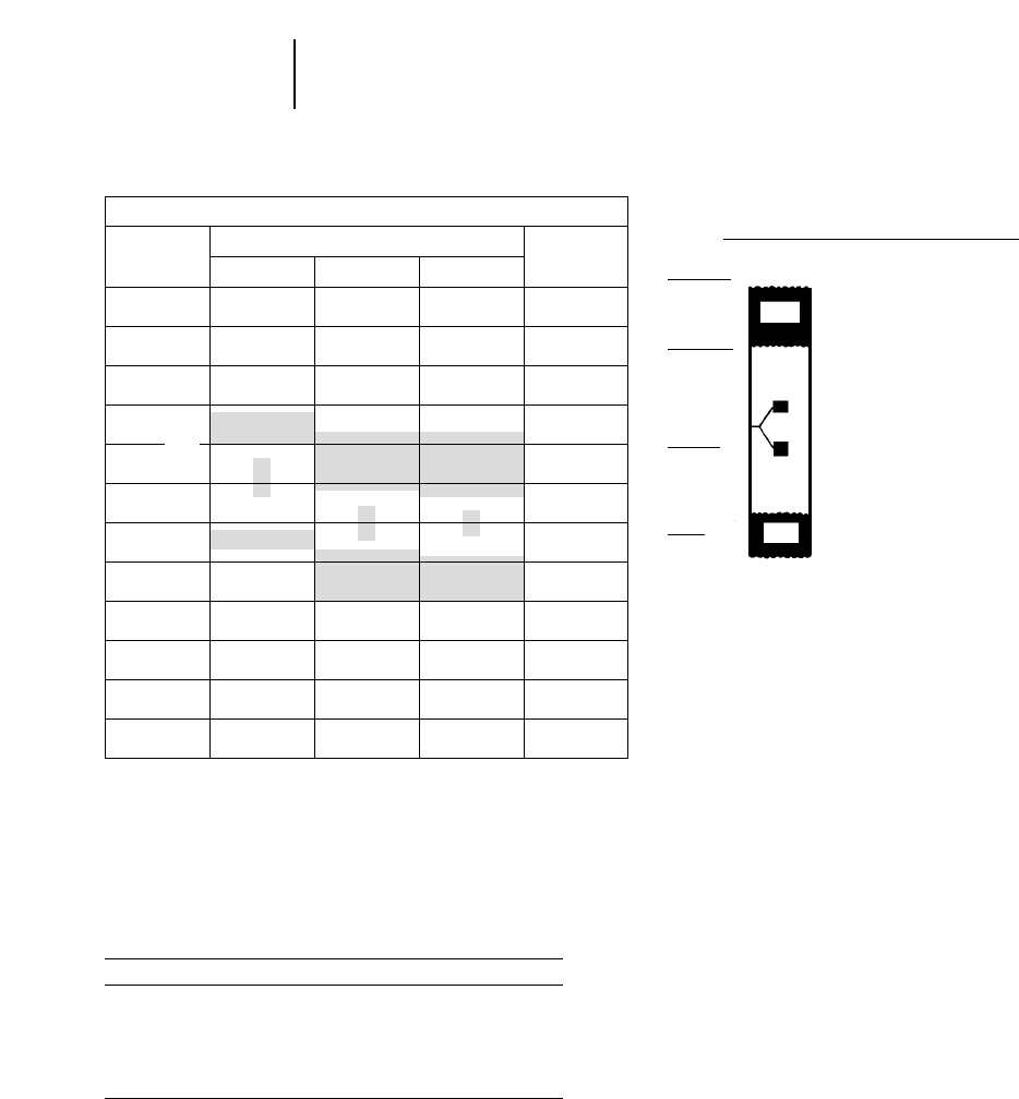
4-176
5000 Series —
Front Shovels Estimating Cycle Time Charts
Bucket Fill Factors
CYCLE TIME vs
JOB CONDITION DESCRIPTION
Good job set-up, tight swing.
Excellent operator.
Well fragmented material.
Typical job conditions.
Good operator.
60°–90° swing.
Oversized Material.
Undesirable set-up.
90°–120° swing.
Poorly shot material.
Bad floor conditions.
New operator.
120°–180° swing.
BOTTOM DUMP BUCKET
FILL FACTORS
Material Fill Factor*
Bank Clay; Earth 100%-105%
Rock-Earth Mixture 100%-105%
Rock — Poorly Blasted 85%-95%
Rock — Well Blasted 95%-105%
Shale, Sandstone — Standing Bank 85%-100%
*Percent of heaped bucket capacity.
CYCLE TIME ESTIMATING CHART
CYCLE MACHINE AND BUCKET CYCLE
TIME TIME
(MIN) 5080 5130B 5230 (SEC)
10
0.25 15
20
25
30
0.60 35
40
0.75 45
50
55
1.00 60
0.30
0.35
0.40
0.45
0.50
Fastest
Possible
Fastest
Practical
Typical
Range
Slow
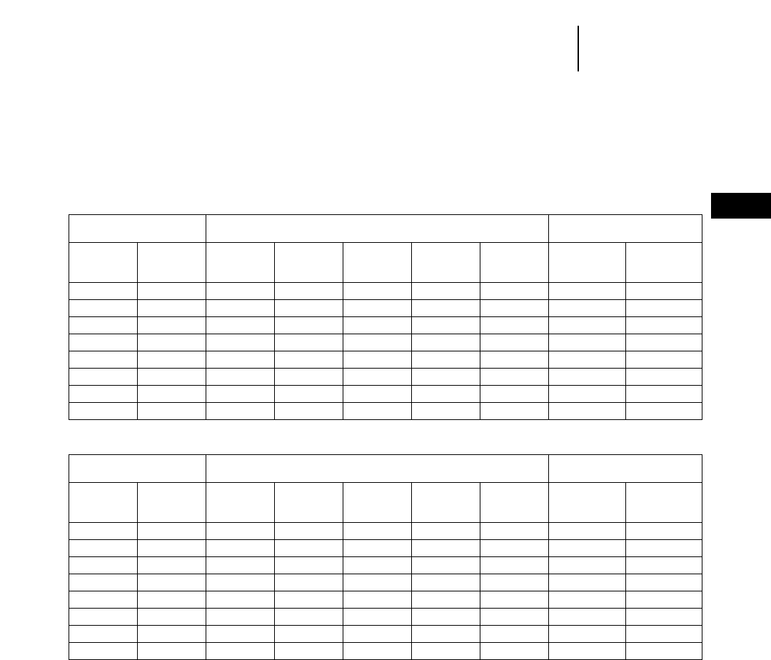
4-177
4
5000 Series —
Front Shovels
Rock Loading Production Tables
ROCK LOADING PRODUCTION TABLES
●Shot Rock
●Estimated Density — 1600 kg/Lm3or 2700 lb/LCY (1.35 ton/LCY)
METRIC TONS PER 60 MIN. HOUR*
U.S.TONS PER 60 MIN. HOUR*
**Actual Hourly Production = (60 Min. Hr. Production) 2(Job Efficiency Factor)
**Estimated Bucket Payload = (Heaped Bucket Capacity) 2(Bucket Fill Factor)
These tables are calculated using a 100% bucket fill factor.
See bucket fill factors prior to the rock loading production charts.
ESTIMATED ESTIMATED
CYCLE TIME ESTIMATED BUCKET PAYLOAD** — LOOSE CUBIC METER CYCLES
Cycle Cycle Cycles/ Cycles/
Time Time Minute Hour
(Sec) (Min) 2.6 m33.8 m37.5 m38.8 m312 m3
15 0.25 998 1459 2880 3379 4608 4.0 240
18 0.30 832 1216 2400 2816 3840 3.0 200
21 0.35 711 1040 2052 2408 3283 2.9 171
25 0.42 599 876 1728 2028 2765 2.5 144
32 0.53 470 687 1356 1591 2170 1.9 113
40 0.67 374 547 1080 1267 1728 1.5 90
45 0.75 333 486 960 1126 1536 1.3 80
50 0.83 300 438 864 1014 1382 1.2 72
ESTIMATED ESTIMATED
CYCLE TIME ESTIMATED BUCKET PAYLOAD** — LOOSE CUBIC YARD CYCLES
Cycle Cycle Cycles/ Cycles/
Time Time Minute Hour
(Sec) (Min) 3.4 yd35 yd39.75 yd311.5 yd315.75 yd3
15 0.25 1102 1620 3159 3726 5103 4.0 240
18 0.30 918 1350 2633 3105 4253 3.0 200
21 0.35 785 1154 2251 2655 3636 2.9 171
25 0.42 661 972 1895 2236 3062 2.5 144
32 0.53 519 763 1487 1754 2403 1.9 113
40 0.67 413 608 1185 1397 1914 1.5 90
45 0.75 367 540 1053 1242 1701 1.3 80
50 0.83 330 486 948 1118 1531 1.2 72
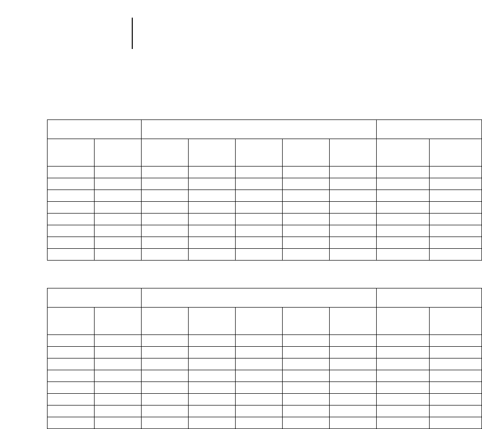
4-178
5000 Series —
Front Shovels Earth Loading Production Tables
EARTH LOADING PRODUCTION TABLES
METRIC Lm3PER 60 MIN. HOUR
U.S. LCY PER 60 MIN. HOUR
ESTIMATED ESTIMATED
CYCLE TIME ESTIMATED BUCKET PAYLOAD — LOOSE CUBIC METER CYCLES
Cycle Cycle Cycles/ Cycles/
Time Time Minute Hour
(Sec) (Min) 2.6 m33.8 m37.5 m38.8 m312 m3
15 0.25 624 912 1800 2112 3880 4.0 240
18 0.30 520 760 1500 1760 2400 3.0 200
21 0.35 445 650 1283 1505 2052 2.9 171
24 0.40 390 570 1125 1320 1800 2.5 150
27 0.45 346 505 998 1170 1596 2.2 133
30 0.50 312 456 900 1056 1440 2.0 120
33 0.55 283 414 818 959 1308 1.8 109
36 0.60 260 380 750 880 1200 1.7 100
ESTIMATED ESTIMATED
CYCLE TIME ESTIMATED BUCKET PAYLOAD** — LOOSE CUBIC YARD CYCLES
Cycle Cycle Cycles/ Cycles/
Time Time Minute Hour
(Sec) (Min) 3.4 yd35 yd39.75 yd311.5 yd315.75 yd3
15 0.25 816 1200 2340 2760 3780 4.0 240
18 0.30 680 1000 1950 2300 3150 3.0 200
21 0.35 581 855 1667 1967 2693 2.9 171
24 0.40 510 750 1463 1725 2363 2.5 150
27 0.45 452 665 1297 1530 2095 2.2 133
30 0.50 408 600 1170 1380 1890 2.0 120
33 0.55 370 545 1063 1254 1717 1.8 109
36 0.60 340 500 975 1150 1575 1.7 100
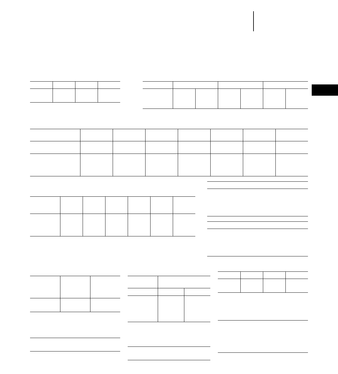
4-179
4
5000 Series —
Front Shovels
Owning & Operating Costs
NOTE: This page compiled from Owning and Operating Section for your convenience. All terms, conditions
etc. stated in the O & O Section also apply to this page.
APPROXIMATE HOURLY CONSUMPTION OF LUBRICANTS
Hydraulic Lubricant Grease
Crankcase Transmission* Final Drives** Control Coolant Changes Fittings
U.S. U.S. U.S. U.S. U.S.
Model liter gal liter gal liter gal liter gal liter gal
5130B FS 0.364 0.096 0.077 0.020 0.392 0.103 0.600 0.159 0.050 0.013 20 0
5130B ME 0.364 0.096 0.077 0.020 0.392 0.103 0.600 0.159 0.050 0.013 20 2800
5230 FS 0.760 0.200 0.090 0.024 0.499 0.131 0.830 0.169 0.083 0.022 22 0
5230 ME 0.760 0.200 0.090 0.024 0.499 0.131 0.830 0.169 0.083 0.022 22 2800
**Includes pump drives.
**Includes travel drives and swing drives.
†Plus auto lube (see auto lube).
Grease Auto lube Number Grease
Kg/hr lb/hr canister interval of canister
Model grease grease refills* (minutes) injectors size (lb)
5130B FS 0.34 0.75 13 10 48 120
5130B ME 0.27 0.60 10 10 36 120
5230 FS 0.47 1.04 5 10 48 400
5230 ME 0.33 0.73 4 10 38 400
NOTE: These figures are based on auto lube system as set from the factory.
*Total number of times you can expect to refill the auto lube grease canister in a 2000 hour period.
FUEL CONSUMPTION
Model Low Medium High
liter U.S. gal liter U.S. gal liter U.S. gal
5130B 91-95 24-25 110-114 29-30 129-132 34-35
5230 163-185 43-49 189-201 50-53 204-227 54-60
OWNERSHIP PERIOD
Model Zone A Zone B Zone C
5130B 60,000 hr 50,000 hr 40,000 hr
5230 60,000 hr 50,000 hr 40,000 hr
Factors used (labor)
— hourly labor rate of U.S. $50.00
— 30 minutes per lube oil change
— 15 minutes per auto lube grease canister refill
— 5 minutes per filter change
— 1 minute per grease fitting
Factors used (materials)
— Lube oils at U.S. 6.35 per U.S. gallon
— Long life coolant at U.S. $7.00 per U.S. gallon
— Filters at suggested U.S. consumer’s list prices.
— Grease at U.S. $.05 per fitting
— Auto lube grease at U.S. $3.68 per pound
GUIDE FOR ESTIMATING LOCAL
HOURLY COST OF FILTERS
Approx.
Hourly
Filter
Model Cost Filters
5130B 0.89 88
5230 1.49 140
UNDERCARRIAGE
BASIC FACTORS
B5130B 13.75
5230 19.00
QUICK ESTIMATOR TABLE
Lube Oils, Filters, Grease
Approx. Cost
Per Hour
Model Materials Labor
5130B FS 6.16 0.57
5130B ME 5.68 1.66
5230 FS 8.83 0.60
5230 ME 7.77 1.76
REPAIRS
Model Low Typical High
5130B 25.00 38.00 53.00
5230 34.00 52.00 73.00
LIFE ADJUSTMENT
MULTIPLIERS
0-10,000 hours 0.40
0-20,000 0.80
0-30,000 1.00
0-40,000 1.21
0-60,000 1.25
COST DISTRIBUTION
% parts 70
% labor 30
*Insufficient data.

CONTENTS
Range dimensions & capacities . . . . . . . . . . .4-182
(Scrap specifications and classifications can be
found in the Institute of Scrap Iron and Steel Inc.’s
“Handbook”. The common unit measure for the
scrap industry is the gross ton which is 2240 pounds.
However, short tons, net tons and metric tons may
also be used.)
The versatility of Caterpillar Excavators, plus
their ability to be equipped in any number of ways,
make them an effective, low cost way to handle scrap
and other materials.
NOTE: Contact your Caterpillar Dealer for addi-
tional information on equipping Caterpillar
Excavators for material handling.
MATERIAL HANDLING ARRANGEMENTS
4-181
4
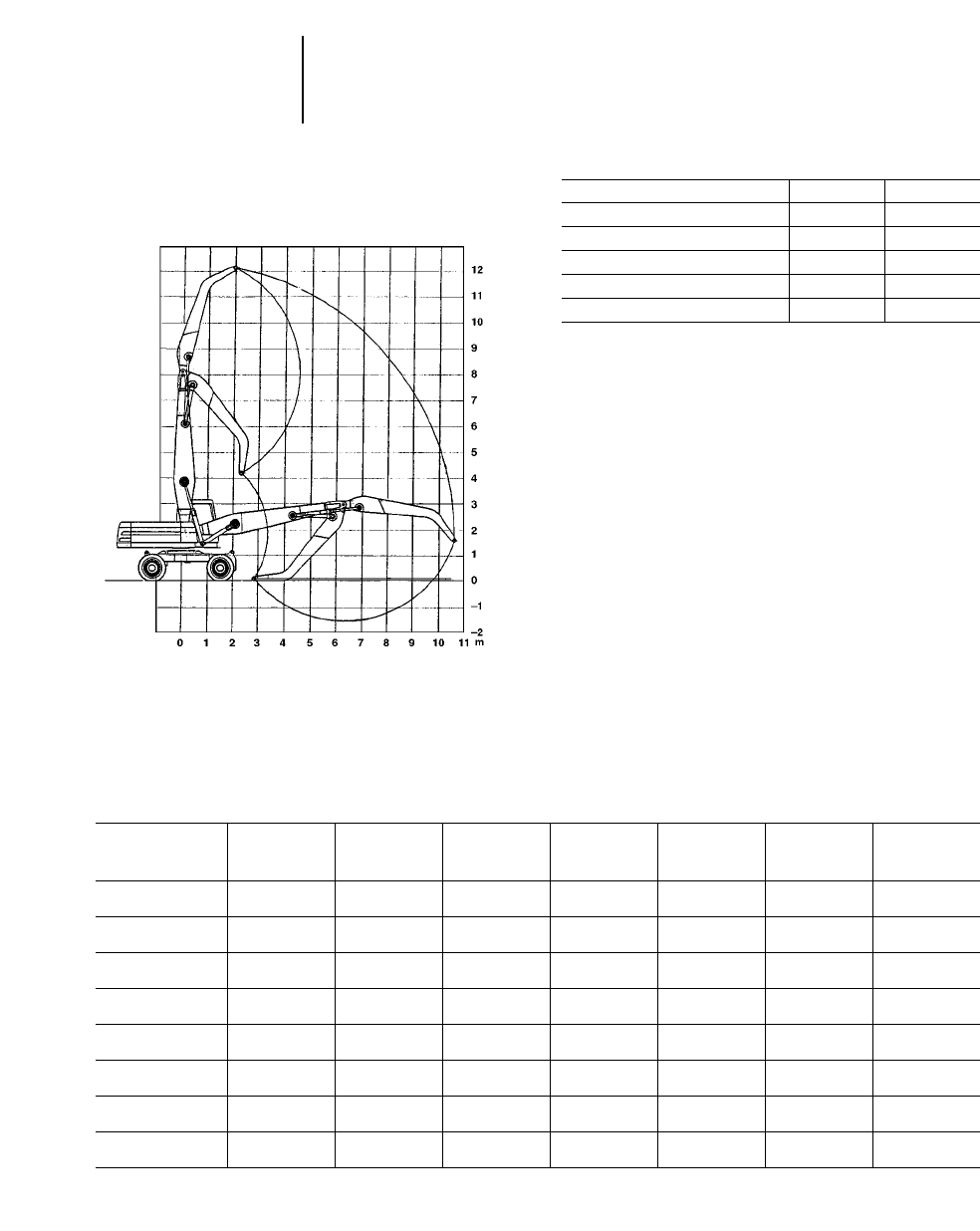
M318 MH/M320 MH Range Diagram
● Caterpillar Material Handling Boom and Stick Model M318 MH M320 MH
mftmft
Boom 6.20 20'4" 6.80 22'4"
Stick 4.50 14'9" 4.90 16'1"
Maximum Horizontal Reach 10.60 34'9" 11.60 38'1"
Maximum Vertical Pin Height 12.00 39'4" 12.70 41'8"
Lift Capacities
Equipped with Caterpillar material handling arrange-
ment.
Includes purpose built material handling boom and
stick complete with boom foot adapter, wiring and
connecting hydraulics, hydraulic cylinders (boom
cylinder — 120 mm (4.72") diameter, stick cylinder
— 100 mm (3.94") diameter).
Capacities are measured at the bare stick tip.
Capacities are based on level machine
equipped as follows:
●Total machine weight including base machine,
material handling front, 1.2 m fixed cabriser, wide
axles, 2 sets of outriggers, solid tires, 3350 kg
(7390 lb) counterweight, lubricants, full fuel tank
and operator.
M318 MH — 19 300-20 500 kg (42,550-45,200 lb)
M320 MH — 21 150-22 350 kg (46,630-49,230 lb)
4-182
Excavators —
Material Handling Range Dimensions
Lift Capacities
●M318 MH ●M320 MH
M318 MH
●Stabilizers Raised
3 m 4.5 m 6 m 7.5 m 9 m At Max. Max. Reach
10'0" 15'0" 20'0" 25'0" 30'0" Reach Radius
Height Front Side Front Side Front Side Front Side Front Side Front Side m ft
9.0 m kg ————
4300* 3700 3800* 2400 ——————
29'6" lb 9480* 8150 8370* 5290
7.5 m kg ————
5400 3800 3800 2600 ——
1700* 1700*
24'7" lb 11,900 8370 8370 5730 3740* 3740* 8.9 29'2"
6.0 m kg ——
7800* 5800 5300 3700 3700 2600 2700 1800 1600* 1600
19'8" lb 17,190* 12,780 11,680 8150 8150 5730 5950 3960 3520* 3520 9.7 31'10"
4.5 m kg 10 400* 10 400* 8200 5600 5100 3500 3600 2500 2700 1800 1600* 1400
14'10" lb 22,930* 22,930* 18,080 12,340 11,240 7710 7930 5510 5950 3960 3520* 3080 10.2 33'6"
3.0 m kg ——
7600 5000 4900 3300 3500 2300 2600 1800 1600* 1300
9'10" lb 16,750 11,020 10,800 7270 7710 5070 5730 3960 3520* 2860 10.5 34'5"
1.5 m kg ——
7000 4400 4600 3000 3300 2200 2500 1700 ————
4'11" lb 15,430 9700 10,140 6610 7270 4850 5510 3740
0 m kg 3700* 3700* 6600 4100 4400 2800 3200 2100 2500 1600 ————
0' lb 8150* 8150* 14,550 9040 9700 6170 7050 4630 5510 3520
–1.5 m kg ————
4100 2700 ————————
–4'11" lb 9040 5950
*Load limited by hydraulic capacity rather than tipping.

M318 MH
●Stabilizers Lowered
3 m 4.5 m 6 m 7.5 m 9 m At Max. Max. Reach
10'0" 15'0" 20'0" 25'0" 30'0" Reach Radius
Height Front Side Front Side Front Side Front Side Front Side Front Side m ft
9.0 m kg ————
4300* 4300* 2400* 2400* ——————
29'6" lb 9480* 9480* 5290* 5290*
7.5 m kg ————
6300* 6300* 5100* 4800* ——
1700* 1700*
24'7" lb 13,890* 13,890* 11,240* 10,580* 3740* 3740* 8.9 29'2"
6.0 m kg ——
7800* 7800* 6500* 6500* 5500* 4700* 4100* 3500 1600* 1600*
19'8" lb 17,190* 17,190* 14,330* 14,330* 12,120* 10,360* 9040* 7710 3520* 3520* 9.7 31'10"
4.5 m kg 8500* 8500* 8600* 8600* 6800* 6600 5700* 4600 4800* 3500 1600* 1600*
14'10" lb 18,740* 18,740* 18,960* 18,960* 14,990* 14,550 12,560* 10,140 10,580* 7710 3520* 3520* 10.2 33'6"
3.0 m kg ——
9500 9500 7200* 6300 5800* 4500 4800* 3400 1600* 1600*
9'10" lb 20,940 20,940 15,870* 13,890 12,780* 9920 10,580* 7490 3520* 3520* 10.5 34'5"
1.5 m kg ——
10 000* 9400 7400* 6000 5800* 4300 4700* 3300 ————
4'11" lb 22,050* 20,720 16,310* 13,230 12,780* 9480 10,360* 7270
0 m kg 3700* 3700* 9600* 9000 7200* 5800 5600* 4200 4300 3200 ————
0' lb 8150* 8150* 21,160* 19,840 15,870* 12,780 12,340* 9260 9480 7050
–1.5 m kg ————
6400* 5000 ————————
–4'11" lb 14,110* 11,020
*Load limited by hydraulic capacity rather than tipping.
4-183
4
Excavators —
Material Handling
Lift Capacities
●M318 MH

M320 MH
●Stabilizers Raised
4.5 m 6 m 7.5 m 9. m At Max. Max. Reach
15'0" 20'0" 25'0" 30'0" Reach Radius
Height Front Side Front Side Front Side Front Side Front Side m ft
7.5 m kg ——
6300 4500 4400 3100 3200 2200 2600 1800
24'7" lb 13,890 9920 9700 6830 7050 4850 5730 3960 10.10 33'2"
6.0 m kg ——
6200 4300 4300 3000 3200 2200 2300 1500
19'6" lb 13,670 9480 9480 6610 7050 4850 5070 3300 10.81 35'6"
4.5 m kg 9400 6300 5900 4100 4100 2900 3100 2100 2100 1400
14'9" lb 20,720 13,890 13,000 9040 9040 6390 6830 4630 4630 3080 11.28 37'0"
3.0 m kg 8600 5600 5500 3700 3900 2700 3000 2000 2000 1300
9'10" lb 18,960 12,340 12,120 8150 8590 5950 6610 4410 4410 2860 11.53 38'4"
1.5 m kg 7900 5000 5100 3400 3700 2500 2800 1900 ————
4'11" lb 17,410 11,020 11,240 7490 8150 5510 6170 4180
Ground kg 7400 4600 4900 3200 3600 2300 2800 1800 ————
Line lb 16,310 10,140 10,800 7050 7930 5070 6170 3960
–1.5 m kg ——
4700 3000 3500 2200 ——————
–4'11" lb 10,360 6610 7710 4850
M320 MH
●Stabilizers Lowered
4.5 m 6 m 7.5 m 9 m At Max. Max. Reach
15'0" 20'0" 25'0" 30'0" Reach Radius
Height Front Side Front Side Front Side Front Side Front Side m ft
7.5 m kg ——
7100* 7100* 6200* 6000 5400* 4500 2800* 2800*
24'7" lb 15,650* 15,650* 13,670* 13,230 11,900* 9920 6170* 6170* 10.10 33'2"
6.0 m kg ——
7400* 7400* 6300* 5900 5500* 4400 2800* 2800*
19'6" lb 16,310* 16,310* 13,890* 13,000 12,120* 9700 6170* 6170* 10.81 35'6"
4.5 m kg 10 100* 10 100* 7900* 7900* 6500* 5800 5500* 4300 2700* 2700*
14'9" lb 22,270* 22,270* 17,410* 17,410* 14,330* 12,780 12,120* 9480 5950* 5950* 11.28 37'0"
3.0 m kg 11 200* 11 200* 8400* 7900 6700* 5600 5600* 4200 2800* 2800*
9'10" lb 24,690* 24,690* 18,520* 17,410 14,770* 12,340 12,340* 9260 6170* 6170* 11.53 38'4"
1.5 m kg 11 800* 11 800* 8600* 7500 6800* 5300 5500* 4100 ————
4'11" lb 26,010* 26,010* 18,960* 16,530 14,990* 11,680 12,120* 9040
Ground kg 10 800* 10 800* 8400* 7200 6600* 5200 5200* 4000 ————
Line lb 23,810* 23,810* 18,520* 15,870 14,550* 11,460 11,460* 8820
–1.5 m kg ——
7500* 7000 5900* 5100 ——————
–4'11" lb 16,530* 15,430 13,000* 11,240
*Load limited by hydraulic capacity rather than tipping.
4-184
Excavators —
Material Handling Lift Capacities
●M320 MH
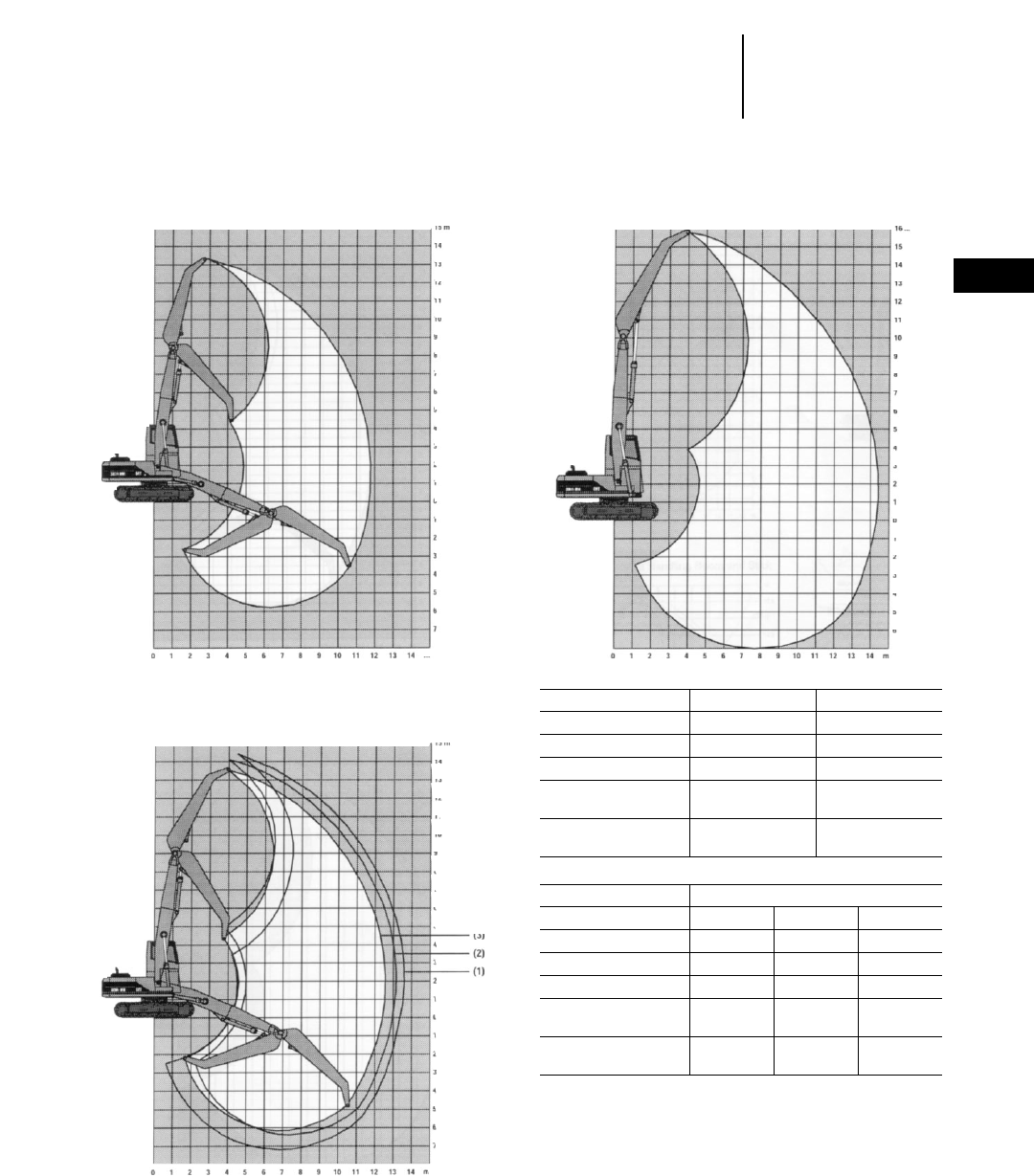
320B MH Range Diagram
● Caterpillar Material Handling Boom and Stick
325B MH Range Diagram
● Caterpillar Material Handling Boom and Stick
330B MH Range Diagram
● Caterpillar Material Handling Boom and Stick
Model 320B MH 330B MH
mftmft
Boom 6.65 21'10" 7.77 25'6"
Stick 5.40 17'9" 6.83 22'5"
Maximum
Horizontal Reach 12.40 40'3" 14.37 47'1"
Maximum Vertical
Pin Height 13.60 44'6" 15.78 51'9"
Model 325B MH
123
m ft m ft m ft
Boom 7.20 23'7" 7.80 25'7" 7.20 23'7"
Stick 6.35 20'10" 5.35 17'7" 5.35 17'7"
Maximum
Horizontal Reach 13.40 44'0" 12.90 42'4" 12.40 40'8"
Maximum Vertical
Pin Height 14.60 47'11" 14.00 45'11" 13.50 44'3"
NOTE: All Material Handling Arrangements require extra wide gage, reinforced
upper frame and additional counter weight.
4-185
4
Excavators —
Material Handling
Range Dimensions
●320B MH ●325B MH ●330B MH
●Belgium Sourced
4-186
Excavators —
Material Handling Lifting Capacities
●320B MH Belgium Sourced
Lift Capacities
Equipped with Caterpillar material handling arrange-
ment.
Includes purpose built material handling boom and
stick, wiring and connecting hydraulics, hydraulic
cylinders and heavier counterweight. Boom cylinder
— 140 mm (5.5") diameter stick cylinder — 150 mm
(5.9") diameter.
Capacities are measured at the bare stick tip, and
are expressed in kg.
Capacities are based on level machine
equipped as follows:
●Total machine weight including base machine,
material handling front, 1.2 m fixed cabriser, wide
gage undercarriage, counterweight, lubricants,
full fuel tank and operator.
●600 mm (2'0") triple grouser shoes.
●
320B MH — Heavy Duty Square Undercarriage configuration
Maximum reach, height and lift capacity (6.65 m boom and 5.4 m stick)
3 m 4.5 m 6 m 7.5 m Max. Reach
Height Front Side Front Side Front Side Front Side Radius
12.0 m kg ————6233* 6233* — — 6.46 m
10.5 m kg ————7627* 7627* 6161* 6161* 8.37 m
9.0 m kg ——————6979* 6531 9.69 m
7.5 m kg ——————6972* 6511 10.63 m
6.0 m kg ————8164* 8164* 7173* 6390 11.29 m
4.5 m kg — — 9215* 9215* 8848* 8848* 7070 6186 11.73 m
3.0 m kg — — 12 551* 12 551* 9652* 8390 6803 5927 11.96 m
1.5 m kg — — 13 903* 12 366 9166 7894 6524 5657 12.00 m
Ground kg — — 11 336* 11 336* 8746 7491 6285 5425 11.84 m
–1.5 m kg 3656* 3656* 8933* 8933* 8484 7239 6122 5266 11.49 m
–3.0 m kg 4990* 4990* 9408* 9408* 8375 7135 6047 5194 10.52 m
–4.5 m kg ————6295* 6295* 4887* 4887* 7.68 m
9 m 10.5 m At Max. Reach Max. Reach
Height Front Side Front Side Front Side Radius
12.0 m kg ————5124* 5124* 6.46 m
10.5 m kg ————4190* 4190* 8.37 m
9.0 m kg 5418 4755 — — 3741* 3741* 9.69 m
7.5 m kg 5451 4786 4043* 3612 3494* 3494* 10.63 m
6.0 m kg 5392 4728 4153 3626 3362* 3159 11.29 m
4.5 m kg 5274 4614 4101 3576 3308* 2939 11.73 m
3.0 m kg 5123 4466 4021 3497 3255 2818 11.96 m
1.5 m kg 4964 4311 3933 3411 3212 2778 12.00 m
Ground kg 4824 4175 3859 3338 3255 2813 11.84 m
–1.5 m kg 4728 4080 3816 3296 3195* 2934 11.49 m
–3.0 m kg 4692 4045 3326* 3308 3297* 3297* 10.52 m
–4.5 m kg ————4716* 4716* 7.68 m
*Limited by hydraulic rather than tipping load.
*The above loads are in compliance with hydraulic excavator lift capacity ratings standard ISO 10567, they do not exceed 87% of hydraulic lifting capacity or 75% of tipping
capacity. Weight of all lifting accessories must be deducted from the above lifting capacities.

320B MH — Heavy Duty High Undercarriage configuration
Maximum reach and height but less lift capacity (6.65 m boom and 5.4 m stick). To be used when shipping width is limited.
3 m 4.5 m 6 m 7.5 m Max. Reach
Height Front Side Front Side Front Side Front Side Radius
12.0 m kg ————6233* 6233* — — 6.46 m
10.5 m kg ————7627* 7627* 6161* 5248 8.37 m
9.0 m kg ——————6979* 5363 9.69 m
7.5 m kg ——————6972* 5344 10.63 m
6.0 m kg ————8164* 7520 7173* 5229 11.29 m
4.5 m kg — — 9215* 9215* 8848* 7182 7035 5034 11.73 m
3.0 m kg — — 12 551* 10 542* 9636 6735 6768 4786 11.96 m
1.5 m kg — — 13 903* 9570 9120 6268 6490 4528 12.00 m
Ground kg — — 11 336* 8875 8700 5889 6251 4307 11.84 m
–1.5 m kg 3656* 3656* 8933* 8528 8437 5651 6087 4155 11.49 m
–3.0 m kg 4990* 4990* 9408* 8433 8328 5553 6012 4086 10.52 m
–4.5 m kg ————6295* 5577 4887* 4104 7.68 m
9 m 10.5 m At Max. Reach Max. Reach
Height Front Side Front Side Front Side Radius
12.0 m kg ————5124* 5124* 6.46 m
10.5 m kg ————4190* 4190* 8.37 m
9.0 m kg 5391 3880 — — 3741* 3339 9.69 m
7.5 m kg 5424 3910 4043* 2915 3494* 2835 10.63 m
6.0 m kg 5365 3855 4131 2929 3362* 2530 11.29 m
4.5 m kg 5247 3744 4079 2880 3308* 2343 11.73 m
3.0 m kg 5096 3601 3999 2804 3236 2238 11.96 m
1.5 m kg 4936 3451 3912 2721 3193 2200 12.00 m
Ground kg 4797 3321 3837 2649 3236 2226 11.84 m
–1.5 m kg 4701 3230 3793 2608 3195* 2324 11.49 m
–3.0 m kg 4665 3195 3326* 2620 3297* 2615 10.52 m
–4.5 m kg ————4716* 3976 7.68 m
*Limited by hydraulic rather than tipping load.
*The above loads are in compliance with hydraulic excavator lift capacity ratings standard ISO 10567, they do not exceed 87% of hydraulic lifting capacity or 75% of tipping
capacity. Weight of all lifting accessories must be deducted from the above lifting capacities.
4-187
4
Excavators —
Material Handling
Lifting Capacities
●320B MH Belgium Sourced

Lift Capacities
Equipped with Caterpillar material handling arrange-
ment.
Includes purpose built material handling boom and
stick, wiring and connecting hydraulics, hydraulic
cylinders (boom cylinder — 140 mm (5.5") diameter,
stick cylinder — 170 mm (7") diameter).
Capacities are measured at the bare stick tip, and
are expressed in kg.
Capacities are based on level machine equipped
as follows:
●Total machine weight including base machine,
material handling front, 1.2 m fixed cabriser, wide
gage undercarriage, counterweight, lubricants,
full fuel tank and operator.
●800 mm (2'8") triple grouser shoes.
4-188
Excavators —
Material Handling Lifting Capacities
●325B MH Belgium Sourced
325B MH — Standard configuration (1)
Maximum reach, height and lift capacity (7.2 m boom and 6.35 m stick)
3 m 4.5 m 6 m 7.5 m Max. Reach
Height Front Side Front Side Front Side Front Side Radius
13.5 m kg ———————— 6.94 m
12.0 m kg ——————6751* 6751* 8.98 m
10.5 m kg ————————10.42 m
9.0 m kg ————————11.47 m
7.5 m kg ————————12.26 m
6.0 m kg ——————6771* 6771* 12.82 m
4.5 m kg ————8413* 8413* 7347* 7347* 13.18 m
3.0 m kg — — 12 309* 12 309* 9629* 9629* 8014* 7543 13.36 m
1.5 m kg — — 14 524* 14 524* 10 744* 9945 8617* 7196 13.37 m
Ground kg — — 12 855* 12 855* 11 420* 9434 8889 6894 13.21 m
–1.5 m kg 4204* 4204* 10 392* 10 392* 11 470* 9099 8658 6676 12.88 m
–3.0 m kg 6043* 6043* 11 133* 11 133* 10 847* 8934 8529 6554 12.35 m
–4.5 m kg 7956* 7956* 12 210* 12 210* 9533* 8908 7586* 6527 11.60 m
–6.0 m kg — — 9210* 9210* 7447* 7447* 5924* 5924* 10.23 m
9 m 10.5 m 12 m At Max. Reach Max. Reach
Height Front Side Front Side Front Side Front Side Radius
13.5 m kg ——————7823* 7823* 6.94 m
12.0 m kg ——————6536* 6078 8.98 m
10.5 m kg 6078* 6078* ————5894* 4820 10.42 m
9.0 m kg 5937* 5937* 5676* 4846 — — 5182 4115 11.47 m
7.5 m kg 5999* 5999* 5648* 4839 4830 3828 4647 3674 12.26 m
6.0 m kg 6217* 6117 5741* 4773 4817 3815 4302 3388 12.82 m
4.5 m kg 6544* 5946 5880 4670 4763 3762 4085 3207 13.18 m
3.0 m kg 6913* 5741 5750 4544 4689 3691 3966 3105 13.36 m
1.5 m kg 7038 5531 5615 4414 4611 3617 3930 3070 13.37 m
Ground kg 6843 5344 5495 4299 4545 3552 3975 3102 13.21 m
–1.5 m kg 6696 5204 5406 4214 4503 3512 4028* 3207 12.88 m
–3.0 m kg 6612 5124 5364 4173 4159* 3516 3672* 3403 12.35 m
–4.5 m kg 6037* 5113 4593* 4191 — — 3164* 3164* 11.60 m
–6.0 m kg 4466* 4466* ————3017* 3017* 10.23 m
*Limited by hydraulic rather than tipping load.
*The above loads are in compliance with hydraulic excavator lift capacity ratings standard ISO 10567, they do not exceed 87% of hydraulic lifting capacity or 75% of tipping
capacity. Weight of all lifting accessories must be deducted from the above lifting capacities.

4-189
4
Excavators —
Material Handling
Lifting Capacities
●325B MH Belgium Sourced
325B MH — Optional configuration (2)
More dump height close at machine with the same reach (7.8 m boom and 5.35 m stick)
3 m 4.5 m 6 m 7.5 m Max. Reach
Height Front Side Front Side Front Side Front Side Radius
13.5 m kg ————8952* 8952* — — 6.17 m
12.0 m kg ——————7291* 7291* 8.40 m
10.5 m kg ——————6934* 6934* 9.92 m
9.0 m kg ——————6902* 6902* 11.03 m
7.5 m kg ——————7110* 7110* 11.84 m
6.0 m kg ————8713* 8713* 7513* 7513* 12.42 m
4.5 m kg — — 12 440* 12 440* 9683* 9683* 8037* 7566 12.79 m
3.0 m kg ————10 667* 9961 8559* 7224 12.98 m
1.5 m kg ————11 324* 9408 8903 6906 12.99 m
Ground kg — — 5604* 5604* 11 404* 9030 8643 6661 12.83 m
–1.5 m kg — — 7022* 7022* 10 861* 8836 8485 6512 12.48 m
–3.0 m kg 5454* 5454* 9104* 9104* 9732* 8788 7885* 6456 11.93 m
–4.5 m kg — — 9516* 9516* 8024* 8024* 6606* 6488 11.16 m
–6.0 m kg ————5654* 5654* 4676* 4676* 8.94 m
9 m 10.5 m 12 m At Max. Reach Max. Reach
Height Front Side Front Side Front Side Front Side Radius
13.5 m kg ——————8870* 8870* 6.17 m
12.0 m kg ——————7067* 6663 8.40 m
10.5 m kg 6464* 6113 ————6276* 5141 9.92 m
9.0 m kg 6352* 6145 5925* 4740 — — 5458 4329 11.03 m
7.5 m kg 6435* 6079 5896* 4734 — — 4856 3836 11.84 m
6.0 m kg 6645* 5944 5877 4665 4743 3743 4475 3522 12.42 m
4.5 m kg 6926* 5762 5766 4560 4695 3696 4239 3324 12.79 m
3.0 m kg 7068 5558 5640 4437 4628 3631 4110 3215 12.98 m
1.5 m kg 6866 5364 5517 4320 4560 3567 4073 3180 12.99 m
Ground kg 6702 5208 5417 4223 4509 3517 4126 3218 12.83 m
–1.5 m kg 6595 5106 5355 4163 4491 3499 4015* 3337 12.48 m
–3.0 m kg 6415* 5067 5122* 4151 — — 3586* 3560 11.93 m
–4.5 m kg 5294* 5098 3881* 3881* — — 2970* 2970* 11.16 m
–6.0 m kg ——————3506* 3506* 8.94 m
*Limited by hydraulic rather than tipping load.
*The above loads are in compliance with hydraulic excavator lift capacity ratings standard ISO 10567, they do not exceed 87% of hydraulic lifting capacity or 75% of tipping
capacity. Weight of all lifting accessories must be deducted from the above lifting capacities.

4-190
Excavators —
Material Handling Lifting Capacities
●325B MH Belgium Sourced
325B MH — Optional configuration (3)
Allows more lift capacity but less maximum reach (7.2 m boom and 5.35 m stick)
3 m 4.5 m 6 m 7.5 m Max. Reach
Height Front Side Front Side Front Side Front Side Radius
13.5 m kg ———————— 4.77 m
12.0 m kg ———————— 7.45 m
10.5 m kg ——————7222* 7222* 9.13 m
9.0 m kg ——————7054* 7054* 10.32 m
7.5 m kg ——————7184* 7184* 11.19 m
6.0 m kg ————8548* 8548* 7551* 7551* 11.80 m
4.5 m kg — — 11 837* 11 837* 9532* 9532* 8082* 7722 12.19 m
3.0 m kg — — 14 086* 14 086* 10 621* 10 279 8652* 7424 12.39 m
1.5 m kg — — 14 966* 14 904 11 646* 9765 9094* 7136 12.40 m
Ground kg — — 9229* 9229* 11 749* 9390 8892 6906 12.23 m
–1.5 m kg 4309* 4309* 9810* 9810* 11 351* 9181 8738 6761 11.86 m
–3.0 m kg 6770* 6770* 11 753* 11 753* 10 258* 9117 8184* 6705 11.29 m
–4.5 m kg — — 10 348* 10 348* 8436* 8436* 6768* 6738 10.46 m
–6.0 m kg ———————— 7.08 m
9 m 10.5 m 12 m At Max. Reach Max. Reach
Height Front Side Front Side Front Side Front Side Radius
13.5 m kg ——————10 985* 10 985* 4.77 m
12.0 m kg ——————7922* 7922* 7.45 m
10.5 m kg 6898* 6050 ————6887* 5896 9.13 m
9.0 m kg 6611* 6150 ————6102 4865 10.32 m
7.5 m kg 6618* 6124 5976 4769 — — 5368 4269 11.19 m
6.0 m kg 6794* 6025 5937 4731 — — 4918 3899 11.80 m
4.5 m kg 7068* 5877 5854 4651 4764 3769 4644 3672 12.19 m
3.0 m kg 7211 5703 5751 4551 4719 3726 4499 3549 12.39 m
1.5 m kg 7032 5532 5647 4452 4672 3681 4461 3515 12.40 m
Ground kg 6884 5391 5562 4371 4641 3650 4527 3562 12.23 m
–1.5 m kg 6788 5299 5514 4323 — — 4400* 3707 11.86 m
–3.0 m kg 6551* 5268 5022* 4327 — — 3924* 3924* 11.29 m
–4.5 m kg 5213* 5213* ————3218* 3218* 10.46 m
–6.0 m kg ——————4858* 4858* 7.08 m
*Limited by hydraulic rather than tipping load.
*The above loads are in compliance with hydraulic excavator lift capacity ratings standard ISO 10567, they do not exceed 87% of hydraulic lifting capacity or 75% of tipping
capacity. Weight of all lifting accessories must be deducted from the above lifting capacities.
Lift Capacities
Equipped with Caterpillar material handling arrange-
ment.
Includes purpose built material handling boom and
stick , wiring and connecting hydraulics, hydraulic
cylinders (boom cylinder — 150 mm (5.9") diameter,
stick cylinder — 170 mm (6.7") diameter).
Capacities are measured at the bare stick tip, and
are expressed in kg.
Capacities are based on level machine equipped
as follows:
●Total machine weight including base machine,
material handling front, 1.2 m fixed cabriser, wide
gage undercarriage, counterweight, lubricants,
full fuel tank and operator.
●750 mm (2'6") triple grouser shoes.
4-191
4
Excavators —
Material Handling
Lifting Capacities
●330B MH Belgium Sourced
330B MH
Maximum reach, height and lift capacity (7.8 m boom and 6.8 m stick)
3 m 4.5 m 6 m 7.5 m 9 m Max. Reach
Height Front Side Front Side Front Side Front Side Front Side Radius
15.0 m kg ————9198* 9198* ———— 6.64 m
13.5 m kg ——————7676* 7676* — — 8.97 m
12.0 m kg ————————6765* 6765* 10.59 m
10.5 m kg ————————6543* 6543* 11.80 m
9.0 m kg ————————6533* 6533* 12.72 m
7.5 m kg ————————6698* 6698* 13.40 m
6.0 m kg ——————7733* 7733* 7006* 7006* 13.89 m
4.5 m kg ————9808* 9808* 8420* 8420* 7408* 7408* 14.21 m
3.0 m kg ————11 155* 11 155* 9167* 9167* 7834* 7589 14.36 m
1.5 m kg ————12 312* 12 312* 9808* 9456 8188* 7290 14.35 m
Ground kg — — 7670* 7670* 12 943* 12 355 10 178* 9042 8372* 7026 14.18 m
–1.5 m kg 2864* 2864* 7237* 7237* 12 901* 11 910 10 158* 8742 8298* 6826 13.85 m
–3.0 m kg 4569* 4569* 8312* 8312* 12 177* 11 684 9677* 8568 7884* 6703 13.34 m
–4.5 m kg 6320* 6320* 9933* 9933* 10 787* 10 787* 8679* 8511 7043* 6664 12.63 m
–6.0 m kg — — 10 626* 10 626* 8691* 8691* 7071* 7071* 5637* 5637* 11.43 m
10.5 m 12 m 13.5 m At Max. Reach Max. Reach
Height Front Side Front Side Front Side Front Side Radius
15.0 m kg ——————8224* 8224* 6.64 m
13.5 m kg ——————6690* 6690* 8.97 m
12.0 m kg 6171* 6171* ————5951* 5951* 10.59 m
10.5 m kg 6233* 6233* ————5527* 5298 11.80 m
9.0 m kg 6164* 6164* 5832* 5216 — — 5273* 4672 12.72 m
7.5 m kg 6234* 6234* 5816* 5204 — — 5130* 4258 13.40 m
6.0 m kg 6401* 6384 5879* 5138 5370* 4197 5068* 3980 13.89 m
4.5 m kg 6625* 6219 5978* 5037 5370 4152 4936 3801 14.21 m
3.0 m kg 6855* 6029 6070* 4919 5304 4088 4818 3699 14.36 m
1.5 m kg 7027* 5838 6109* 4798 5235 4021 4637* 3668 14.35 m
Ground kg 7073* 5667 6034* 4692 5030* 3967 4412* 3705 14.18 m
–1.5 m kg 6919* 5538 5773* 4615 4550* 3941 4137* 3817 13.85 m
–3.0 m kg 6482* 5460 5221* 4581 — — 3780* 3780* 13.34 m
–4.5 m kg 5644* 5448 4176* 4176* — — 3288* 3288* 12.63 m
–6.0 m kg 4186* 4186* ————3031* 3031* 11.43 m
*Limited by hydraulic rather than tipping load.
*The above loads are in compliance with hydraulic excavator lift capacity ratings standard ISO 10567, they do not exceed 87% of hydraulic lifting capacity or 75% of tipping
capacity. Weight of all lifting accessories must be deducted from the above lifting capacities.
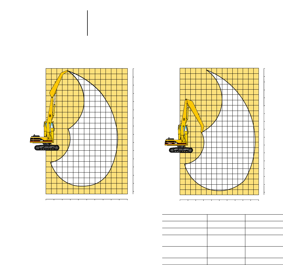
4-192
Excavators —
Material Handling Range Dimensions
●325B MH ●330B MH
●U.S. Sourced
325B MH Range Diagram 330B MH Range Diagram
Model 325B MH 330B MH
mftmft
MH Two-Piece Front 13.40 43'11" 14.40 47'3"
Maximum Reach @
1.5 m (5'0") 13.40 43'11" 14.40 47'3"
Maximum Height @
5.09 m (16'8") 14.80 48'7" 15.65 51'4"
Track Shoe 800 mm 2'8" 850 mm 2'10"
12345678910111213
14 15
0
1
0
1
2
3
6
7
2
3
4
5
6
7
4
5
8
9
10
11
12
13
14
15
16
0
5
10
15
20
25
5
10
15
20
25
30
35
40
45
50
05
10 15 20 25 30 35 40 45 50
12345678910111213
14 15
0
1
0
1
2
3
6
7
2
3
4
5
6
7
4
5
8
9
10
11
12
13
14
15
0
5
10
15
20
25
5
10
15
20
25
30
35
40
45
50
05
10 15 20 25 30 35 40 45 50
325B MH
m
m
ft
m
ft
ft mft

325B MH
Equipped with Cat two-piece, 13.4 m (43'11") Front, 800 mm (2'7.5") triple grouser shoes
1.5 m 3 m 4.5 m 6 m 7.5 m Max. Reach
5'0" 10'0" 15'0" 20'0" 25'0" Radius
Height Front Side Front Side Front Side Front Side Front Side m ft
15.0 m kg ————————— — — 21.43
45'0" lb 18,600* 18,600*
12.0 m kg ————————
6700* 6700* 8.96 28.68
40'0" lb 15,100* 15,100*
10.5 m kg ————————
6300* 6300* 10.40 33.67
35'0" lb 14,100* 14,100*
9.0 m kg ————————
6300* 6300* 11.46 37.32
30'0" lb 13,800* 13,800*
7.5 m kg ————————
6400* 6400* 12.25 40.02
25'0" lb 14,300* 14,300*
6.0 m kg ————————
6800* 6800* 12.81 41.94
20'0" lb 15,000* 15,000*
4.5 m kg ——————
8500* 8500* 7400* 7400* 13.18 43.19
15'0" lb 18,500* 18,500* 16,200* 16,200*
3.0 m kg ————
12 300* 12 300* 9700* 9700* 8100* 7700 13.37 43.84
10'0" lb 26,800* 26,800* 21,000* 21,000* 17,600* 16,700
1.5 m kg ——————10 800* 10 200* 8700* 7400 13.38 43.90
5'0" lb 31,700* 31,700* 23,500* 21,900 18,900* 15,900
0.0 m kg ————
12 700* 12 700* 11 500* 9700 9100* 7100 13.22 43.39
0' lb 30,400* 30,400* 25,000* 20,800 19,700* 15,300
–1.5 m kg ——
4100* 4100* 10 300* 10 300* 11 500* 9400 9000 6900 12.89 42.27
–5'0" lb 9600* 9600* 24,000* 24,000* 25,000* 20,100 19,500 14,800
–3.0 m kg — — 6000* 6000* 11 000* 11 000* 10 900* 9200 8600* 6800 12.36 40.50
–10'0" lb 9100* 9100* 13,700* 13,700* 25,400* 25,400* 23,800* 19,800 18,800* 14,600
–4.5 m kg ——
7900* 7900* 12 300* 12 300* 9600* 9200 7600* 6700 11.62 37.98
–15'0" lb 18,000* 18,000* 26,900* 26,900* 20,900* 19,700* 16,600* 14,500
–6.0 m kg ——————————
——
–20'0" lb 20,100* 20,100* 16,200* 16,200* 12,800* 12,800* 9500*
9 m 10.5 m 12 m At Max. Max. Reach
30'0" 35'0" 40'0" Reach Radius
Height Front Side Front Side Front Side Front Side m ft
15.0 m kg ————————
— 21.43
45'0" lb 18,300* 18,300*
12.0 m kg ——————
6600* 6200 8.96 28.68
40'0" lb 14,900* 14,300
10.5 m kg 6100* 6100* ————
5900* 5000 10.40 33.67
35'0" lb 13,600* 13,600* 13,400* 11,200
9.0 m kg 6000* 6000* 5700* 5000 ——
5400 4300 11.46 37.32
30'0" lb 13,500* 13,500* 12,800* 10,700 12,100 9500
7.5 m kg 6000* 6000* 5700* 5000 ——4900 3800 12.25 40.02
25'0" lb 13,400* 13,400* 12,600* 10,700 10,800 8500 10,800 8500
6.0 m kg 6300* 6300* 5800* 4900 5000 4000 4500 3500 12.81 41.94
20'0" lb 13,800* 13,500 12,800* 10,600 10,800 8500 10,000 7800
4.5 m kg 6600* 6100 6000* 4800 5000 3900 4300 3300 13.18 43.19
15'0" lb 14,400* 13,200 13,100* 10,400 10,700 8400 9500 7400
3.0 m kg 7000* 5900 6000 4700 4900 3800 4200 3200 13.37 43.84
10'0" lb 15,200* 12,700 12,900 10,100 10,600 8200 9200 7100
1.5 m kg 7300* 5700 5900 4600 4800 3800 4100 3200 13.38 43.90
5'0" lb 15,800 12,300 12,700 9800 10,400 8100 9100 7100
0.0 m kg 7200 5500 5800 4500 4800 3700 4200 3200 13.22 43.39
0' lb 15,400 11,900 12,400 9600 10,300 8000 9200 7100
–1.5 m kg 7000 5400 5700 4400 4700 3700 4100* 3300 12.89 42.27
–5'0" lb 15,100 11,600 12,200 9400 10,200 7900 9000* 7400
–3.0 m kg 6900 5300 5600 4300 4200* 3700 3700* 3500 12.36 40.50
–10'0" lb 14,900 11,400 12,100 9400 8800* 7900 8200* 7800
–4.5 m kg 6100* 5300 4600* 4400 ——
3200* 3200* 11.62 37.98
–15'0" lb 13,200* 11,400 9900* 9400 7100* 7100*
–6.0 m kg — —————————
–20'0" lb 9500*
*Indicates that the load is limited by hydraulic capacity rather than tipping capacity. Lift capacity ratings are based on SAE standard J1097. Rated loads do not exceed
87% of hydraulic lifting capacity or 75% of tipping capacity.
4-193
4
Excavators —
Material Handling
Lifting Capacities
●325B MH U.S. Sourced

4-194
Excavators —
Material Handling Lifting Capacities
●330B MH U.S. Sourced
330B MH
Equipped with Cat two-piece, 14.4 m (47'3") Front, 850 mm triple grouser shoes
3 m 4.5 m 6 m 7.5 m 9 m Max. Reach
10'0" 15'0" 20'0" 25'0" 30'0" Radius
Height Front Side Front Side Front Side Front Side Front Side m ft
13.5 m kg ——————
7600* 7600* ——8.93 26.37
46'0" lb 17,200* 17,200*
12.0 m kg ————————
6700* 6700* 10.56 34.05
40'0" lb 15,000* 15,000*
10.5 m kg ————————
6500* 6500* 11.78 38.25
35'0" lb 14,800* 14,800*
9.0 m kg ————————
6500* 6500* 12.70 41.41
30'0" lb 14,600* 14,600*
7.5 m kg ————————
6700* 6700* 13.39 43.76
25'0" lb 14,800* 14,800*
6.0 m kg ——————
7700* 7700* 7000* 7000* 13.89 45.47
20'0" lb 17,000* 17,000* 15,400* 15,400*
4.5 m kg ————
9800* 9800* 8400* 8400* 7400* 7400* 14.21 46.57
15'0" lb 21,300* 21,300* 18,400* 18,400* 16,200* 16,200*
3.0 m kg ————
11 200* 11 200* 9200* 9200* 7900* 7700 14.36 47.10
10'0" lb 24,300* 24,300* 20,000* 20,000* 17,100* 16,600
1.5 m kg ————
12 300* 12 300* 9800* 9600 8200* 7400 14.35 47.10
5'0" lb 26,800* 26,800* 21,400* 20,600 17,900* 16,000
0.0 m kg ——
7600* 7600* 13 000* 12 500 10 200* 9200 8400* 7100 14.19 46.55
0' lb 18,800* 18,800* 26,200* 26,800 22,200* 19,700 18,300* 15,400
–1.5 m kg 2900* 2900* 7200* 7200* 12 900* 12 000 10 200* 8900 8300* 6900 13.86 45.45
–5'0" lb 6800* 6800* 17,000* 17,000* 28,000* 25,900 22,100* 19,100 18,100* 15,000
–3.0 m kg 4600* 4600* 8300* 8300* 12 200* 11 800 9700* 8700 7900* 6800 13.35 43.75
–10'0" lb 10,600* 10,600* 19,200* 19,200* 26,300* 25,400 21,100* 18,700 17,200* 14,700
–4.5 m kg 6300* 6300* 9900* 9900* 10 800* 10 800* 8700* 8600 7100* 6800 12.65 41.37
–15'0" lb 14,400* 14,400* 22,700* 22,700* 23,600* 23,600* 18,900* 18,600 15,300* 14,600
–6.0 m kg ——
10 600* 10 600* 8700* 8700* 7100* 7100* 5600* 5600* ——
–20'0" lb 23,200* 23,200* 18,900* 18,900* 15,300* 15,300* 12,100* 12,100*
10.5 m 12 m 13.5 m At Max. Max. Reach
35'0" 40'0" 46'0" Reach Radius
Height Front Side Front Side Front Side Front Side m ft
13.5 m kg ——————
6600* 6600* 8.93 26.37
46'0" lb 15,200* 15,200*
12.0 m kg 6000* 6000* ————
5900* 5900* 10.56 34.05
40'0" lb —— 13,300* 13,300*
10.5 m kg 6200* 6200* ————
5500* 5400 11.78 38.25
35'0" lb 14,100* 14,100* 12,200* 12,100
9.0 m kg 6200* 6200* 5800* 5300 ——
5200* 4800 12.70 41.41
30'0" lb 13,700* 13,700* 13,000* 11,300 11,600* 10,600
7.5 m kg 6200* 6200* 5800* 5300 ——
5100* 4400 13.39 43.76
25'0" lb 13,800* 13,800* 12,900* 11,400 11,300* 9600
6.0 m kg 6400* 6400* 5900* 5200 5400* 4300 5000* 4100 13.89 45.47
20'0" lb 14,100* 13,900* 12,900* 11,200 11,800* 9200 11,100* 9000
4.5 m kg 6600* 6300 6000* 5100 5400* 4200 5000* 3900 14.21 46.57
15'0" lb 14,500* 13,600 13,100* 11,000 11,700* 9100 11,100* 8600
3.0 m kg 6900* 6100 6100* 5000 5400* 4200 4900* 3800 14.36 47.10
10'0" lb 15,000* 13,200 13,300 10,800 11,700* 9000 10,800* 8300
1.5 m kg 7100* 5900 6100* 4900 5300* 4100 4700* 3800 14.35 47.10
5'0" lb 15,400* 12,800 13,400* 10,500 11,400* 8800 10,400* 8300
0.0 m kg 7100* 5800 6100* 4800 5100* 4100 4400* 3800 14.19 46.55
0' lb 15,400* 12,400 13,200* 10,300 10,900* 8700 9900* 8400
–1.5 m kg 6900* 5600 5800* 4700 4600* 4000 4200* 3900 13.86 45.45
–5'0" lb 15,100* 12,200 12,500* 10,200 9600* 8700 9200* 8600
–3.0 m kg 6500* 5600 5200* 4700 ——
3800* 3800* 13.35 43.75
–10'0" lb 14,100* 12,000 11,200* 10,100 8400* 8400*
–4.5 m kg 5700* 5600 4200* 4200* ——
3300* 3300* 12.65 41.37
–15'0" lb 12,200* 12,000 8700* 8700* 7300* 7300*
–6.0 m kg 4200* 4200* ————————
–20'0" lb 8800* 8800*
*Indicates that the load is limited by hydraulic capacity rather than tipping capacity. Lift capacity ratings are based on SAE standard J1097. Rated loads do not exceed
87% of hydraulic lifting capacity or 75% of tipping capacity.

CONTENTS
Features . . . . . . . . . . . . . . . . . . . . . . . . . . . . . . .5-1
Specifications . . . . . . . . . . . . . . . . . . . . . . . . . . .5-2
Tires . . . . . . . . . . . . . . . . . . . . . . . . . . . . . . . . . . .5-4
Backhoe Loader Performance Data . . . . . . . . . .5-6
Backhoe Bucket Capacities . . . . . . . . . . . . . . .5-21
Backhoe Lifting Capacities . . . . . . . . . . . . . . .5-22
Machine Dimensions . . . . . . . . . . . . . . . . . . . .5-28
Special Attachments . . . . . . . . . . . . . . . . . . . . .5-29
Features:
●416C/426C/436C/446B — center pivot backhoe
design.
●428C/438C — side shift backhoe design.
●Standard single-tilt loader … features diver-
gent loader arms, a narrow loader tower and sin-
gle bucket tilt cylinder for improved visibility.
●Optional integrated toolcarrier (IT) loader
… offers maximum lift and breakout forces, diver-
gent loader arms, and parallel lift for efficient
loading and material handling.
– Hydraulic Quick Coupler … allows a wide
range of selected attachments, including those
available for Cat integrated toolcarriers.
●Excavator-style backhoe … provides enhanced
visibility even with narrow buckets, ability to reach
over obstacles, and faster, easier truck loading.
●Load-sensing hydraulic system … provides
full hydraulic power to implements at all engine
speeds, low fuel consumption, smooth control and
low lever efforts.
●All wheel steer … is available on the 426C,
436C, and 438C. Full hydrostatic steering with
three operator selected modes. Two wheel steer,
circle steer, and independent rear maneuvering
for the tightest turning circle in the industry.
●4F/4R fully synchronized gear box … provides
on-the-go shifting in all gears and on-the-go
engagement of optional all wheel drive.
●Power-Shift transmission standard on 446B
and available as an option on C-Series … for
operator comfort and efficiency.
●Brakes … are oil immersed, mutli-disc and self
adjusting for long service life. Hydraulic assist
allows low pedal effort.
●E-Stick wear pads … are field replaceable and
can be shimmed independently for reduced main-
tenance cost.
●XT-3 hose with O-ring face seals … provides a
dry, reliable machine.
●Cat 3054 engine … proven reliability, durable
gear- driven water pump, thermal starting aid,
parts commonality, and low cost per hour. Large
fuel tank for extended operation.
●Sloping, flip-open hood … allows excellent vis-
ibility to the loader working area and tilts up for
single location access to all daily service points.
●Stackable counterweights … allow easy adjust-
ment of machine weight distribution. Lockable
tool and battery boxes.
●Cat radial-seal air filter … is an air cleaner
and precleaner in a single unit, eliminates hood-
mounted precleaner.
●Operator compartment features:
Adjustable tilt steering is optional. Heating/air
conditioning system with vents in the front con-
sole. Rear, door and side windows can be fully
opened for enhanced visibility and cab roof is
extended to help keep operator dry. Four-post
Rollover Protective Structure (ROPS) for increased
protection. Lunch box storage, rear mounted hand
throttle, transmission disconnect switch on loader
lift lever and low effort levers all add up to more
precise control with a less fatigued operator.
●Stabilizer legs … on the 428C and 438C use
internal, self-lubricated, adjustable wear pads.
BACKHOE LOADERS
5-1
5
MODEL 416C 426C 436C
Flywheel Power (Gross) 59 kW 78 hp 63 kW 84 hp 66 kW 89 hp
Flywheel Power (Net) 56 kW 75 hp* 60 kW 80 hp 63 kW 85 hp
Operating Weight 6300 kg 13,890 lb 7010 kg 15,450 lb 7075 kg 15,600 lb
Engine Model 3054 DINA 3054 DIT 3054 DIT
Rated Engine RPM 2200 2200 2200
No. of Cylinders 444
Bore 100 mm 3.94 in 100 mm 3.94 in 100 mm 3.94 in
Stroke 127 mm 5 in 127 mm 5 in 127 mm 5 in
Displacement 4 L 243 in34 L 243 in34 L 243 in3
Speeds Forward km/h mph km/h mph km/h mph
1st 5.8 3.6 5.8 3.6 6.0 3.7
2nd 9.3 5.8 4.3 5.8 9.6 6.0
3rd 17.9 11.1 17.9 11.1 19.9 12.4
4th 34.0 21.1 34.0 21.1 33.7 20.9
Speeds Reverse
1st 5.8 3.6 5.8 3.6 6.0 3.7
2nd 9.3 5.8 9.3 5.8 9.6 6.0
3rd 17.9 11.1 17.9 11.1 19.9 12.3
4th 34.0 21.1 34.0 21.1 33.7 20.9
Turning Circle Wall to Wall 10 670 mm 35'0" 10 800 mm 35'5" 10 859 mm 35'7"
All Wheel Steer Wall to Wall
Two Wheel Steer —10 800 mm 35'5" 10 800 mm 35'5"
Circle Steer —10 400 mm 34'1" 10 400 mm 34'1"
Independent Rear —9500 mm 31'2" 9500 mm 31'2"
Tires, Single-Tilt, Front
Standard, 2WD 11LX16, 10 PR, F3 11LX16, 10 PR, F3 11L-16, 12 PR, F3
Standard, AWD 12.5/80-18, 10 PR, SG 12.5/80-18, 10 PR, SG 12.5/80-18, 10 PR, SG
Tires, Single-Tilt, Rear
Standard, 2WD 16.9X24, 8 PR, R4 16.9X24, 8 PR, R4 19.5L-24, 10 PR, IT525
Standard, AWD 19.5LX24, 8 PR, IT525 19.5L-24, 8 PR, IT525 19.5L-24, 10 PR, IT525
Standard, AWS — 19.5L-24, 10 PR, IT525 19.5L-24, 10 PR, IT525
Tire, Parallel Lift, Front
Standard, 2WD 11LX16, 12 PR, F3 11LX16, 12 PR, F3 11L-16, 12 PR, F3
Standard, AWD 12.5/80-18, 10 PR, SG 12.5/80-18, 10 PR, SG 12.5/80-18, 10 PR, SGI
Tires, Parallel Lift, Rear
Standard, 2WD 16.9X24, 8 PR, R4 16.9X24, 8 PR, R4 —
Standard, AWD 19.5L-24, 8 PR, IT525 19.5L-24, 8 PR, IT525 19.5L-24, 10 PR, IT525
Standard, AWS — 19.5L-24, 10 PR, IT525 19.5L-24, 10 PR, IT525
Hydraulic System, closed center LSPC LSPC LSPC
Pump capacity: 162 L/min @ 162 L/min @ 162 L/min @
2200 rpm @ 20 700 kPa 2200 rpm @ 20 700 kPa 2200 rpm @ 20 700 kPa
(43 gpm @ (43 gpm @ (43 gpm @
2200 rpm @ 3000 psi) 2200 rpm @ 3000 psi) 2200 rpm @ 3000 psi)
Fuel Tank Capacity 128 L 34 U.S. gal 128 L 34 U.S. gal 128 L 34 U.S. gal
*With turbocharger 60 kW (80 hp).
5-2
Backhoe Loaders Specifications
5-3
5
Backhoe LoadersSpecifications
MODEL 446B 428C 438C
Flywheel Power (Gross) 82 kW 110 hp 59 kW 78 hp 66 kW 89 hp
Flywheel Power (Net) 76 kW 102 hp 56 kW 75 hp* 63 kW 85 hp
Operating Weight 8890 kg 19,600 lb 7416 kg 16,350 lb 7560 kg 16,670 lb
Engine Model 3114 DIT 3054 DINA 3054 DIT
Rated Engine RPM 2200 2200 2200
No. of Cylinders 444
Bore 105 mm 4.13 in 100 mm 3.94 in 100 mm 3.94 in
Stroke 127 mm 5 in 127 mm 5 in 127 mm 5 in
Displacement 4.40 L 268 in34 L 243 in34 L 243 in3
Speeds Forward km/h mph km/h mph km/h mph
1st 6.6 4.1 5.7 3.5 5.8 3.6
2nd 12.1 7.5 9.1 5.6 9.3 5.8
3rd 21.7 13.5 18.7 11.6 19.2 11.9
4th 33.0 20.5 31.5 19.6 32.3 20.0
Speeds Reverse
1st 7.3 4.5 5.7 3.5 5.8 3.6
2nd 13.4 8.3 9.1 5.6 9.3 5.8
3rd 24.1 15.0 18.7 11.6 19.2 11.9
4th 36.5 22.7 31.5 19.6 32.3 20.0
Turning Circle Wall to Wall 11 357 mm 37'3" 10 800 mm 35'5" 10 800 mm 35'5"
All Wheel Steer Wall to Wall
Two Wheel Steer ——10 800 mm 35'5"
Circle Steer ——10 400 mm 34'1"
Independent Rear ——9500 mm 31'2"
Tires, Single-Tilt, Front
Standard, 2WD 14.5/75-16, 10 PR, F3 11L-16, 10 PR, F3 —
Standard, AWD 12.5-20, 10 PR, R4 10.5-20, 10 PR, ISG 12.5/80-18, 10 PR, SG
Tires, Single-Tilt, Rear
Standard, 2WD 21L-24, 12 PR, R4, IT525 16.9-28, 10 PR, R4, ISG —
Standard, AWD 21L-24, 12 PR, R4, IT525 16.9-28, 10 PR, R4, ISG 16.9-28, 10 PR, R4, ISG
Standard, AWS — — 16.9-28, 10 PR, R4, ISG
Tire, Parallel Lift, Front
Standard, 2WD — 11L-16, 12 PR, F3 —
Standard, AWD — 12.5/80-18, 10 PR, SG 12.5/80-18, 10 PR, SG
Standard, AWD — 12.5/80-18, 10 PR, SGI 12.5/80-18, 10 PR, SGI
Tires, Parallel Lift, Rear
Standard, 2WD — 16.9-28, 10 PR, R4, ISG —
Standard, AWD — — 16.9-28, 10 PR, R4, ISG
Standard, AWD — — **16.9-28, 12 PR, R4, ISG
Standard, AWS — — 16.9-28, 10 PR, R4, ISG
Hydraulic System, closed center LSPC LSPC LSPC
Pump capacity: 178 L/min @ 155 L/min @ 162 L/min @
2200 rpm @ 22 400 kPa 2200 rpm @ 20 700 kPa 2200 rpm @ 20 700 kPa
(47 gpm @ (41 gpm @ (43 gpm @
2200 rpm @ 3250 psi) 2200 rpm @ 3000 psi) 2200 rpm @ 3000 psi)
Fuel Tank Capacity 125 L 33 U.S. gal 128 L 34 U.S. gal 128 L 34 U.S. gal
**With turbocharger 60 kW (80 hp).
**For use with E-Stick.

5-4
Backhoe Loaders Tires
MODEL 416C 426C 436C
Tires, Single-Tilt, Front
Standard, 2WD 11L-16, 10 PR, F3 11L-16, 10 PR, F3 —
Standard, 2WD — — 11L-16, 12 PR, F3
Optional, 2WD 11L-16, 12 PR, F3 11L-16, 12 PR, F3 —
Optional, 2WD — 14.5/75-16, 10 PR, F3 14.5/75-16, 10 PR, F3
Standard, 4WD — — —
Standard, AWD 12.5/80-18, 10 PR, SG 12.5/80-18, 10 PR, SG 12.5/80-18, 10 PR, SG
Standard, AWD — — —
Optional, AWD — — —
Optional, AWD — — —
Optional, AWD — — —
Optional, AWD 340/80-R18, IT510 340/80-R18, IT510 340/80-R18, IT510
Tires, Single-Tilt, Rear
Standard, 2WD *16.9-24, 8 PR, R4 *16.9-24, 8 PR, R4 19.5L-24, 10 PR, IT525
Optional, 2WD **16.9-24, 10 PR, R4 **16.9-24, 10 PR, R4 19.5LR-24, IT510
Optional, 2WD 19.5L-24, 8 PR, IT525 19.5L-24, 8 PR, IT525 21L-24, 12 PR, IT525
Optional, 2WD 19.5L-24, 10 PR, IT525 19.5L-24, 10 PR, IT525 —
Optional, 2WD 19.5LR-24, IT510 19.5LR-24, IT510 —
Optional, 2WD — 21L-24, 12 PR, IT525 —
Optional, 2WD — — —
Standard, 4WD 19.5L-24, 8 PR, IT525 19.5L-24, 8 PR, IT525 —
Standard, AWD — — 19.5L-24, 10 PR, IT525
Optional, AWD 19.5L-24, 10 PR, IT525 19.5L-24, 10 PR, IT525 —
Optional, AWD 19.5LR-24, IT510 19.5LR-24, IT510 19.5LR-24, IT510
Optional, AWD — 21L-24, 12 PR, IT525 21L-24, 12 PR, IT525
Optional, AWD — — —
Optional, AWD — — —
Optional, AWD — — —
Standard, AWS — 19.5L-24, 10 PR, IT525 19.5L-24, 10 PR, IT525
Optional, AWS — 19.5LR-24, IT510 19.5LR-24, IT510
Optional, AWS — — —
Optional, AWS — — —
Tires, Parallel Lift, Front
Standard, 2WD 11L-16, 12 PR, F3 11L-16, 12 PR, F3 11L-16, 12 PR, F3
Optional, 2WD — 14.5/75-16, 10 PR, F3 14.5/75-16, 10 PR, F3
Standard, AWD 12.5/80-18, 10 PR, SG 12.5/80-18, 10 PR, SG 12.5/80-18, 10 PR, SG
Standard, AWD — — —
Optional, AWD — — —
Optional, AWD 340/80-R18, IT510 340/80-R18, IT510 340/80-R18, IT510
Tires, Parallel Life, Rear
Standard, 2WD *16.9-24, 8 PR, R4 *16.9-24, 8 PR, R4 —
Optional, 2WD **16.9-24, 10 PR, R4 **16.9-24, 10 PR, R4 —
Optional, 2WD 19.5L-24, 8 PR, IT525 19.5L-24, 8 PR, IT525 —
Optional, 2WD 19.5L-24, 10 PR, IT525 19.5L-24, 10 PR, IT525 19.5L-24, 10 PR, IT525
Optional, 2WD 19.5LR-24, IT510 19.5LR-24, IT510 19.5LR-24, IT510
Optional, 2WD — 21L-24, 12 PR, IT525 21L-24, 12 PR, IT525
Optional, 2WD — — —
Standard, AWD 19.5L-24, 8 PR, IT525 19.5L-24, 8 PR, IT525 19.5L-24, 10 PR, IT525
Standard, AWD — — —
Optional, AWD 19.5L-24, 10 PR, IT525 19.5L-24, 10 PR, IT525 19.5LR-24, IT510
Optional, AWD 19.5LR-24, IT510 19.5LR-24, IT510 21L-24, 12 PR, IT525
Optional, AWD — 21L-24, 12 PR, IT525 —
Optional, AWD — — —
Standard, AWS — 19.5L-24, 10 PR, IT525 19.5L-24, 10 PR, IT525
Optional, AWS — 19.5LR-24, IT510 19.5LR-24, IT510
Optional, AWS — — —
Optional, AWS — — —
**Not for use with E-Stick.
**For use with E-Stick.
MODEL 446B 428C 438C
Tires, Single-Tilt, Front
Standard, 2WD 14.5/75-16, 10 PR, F3 11L-16, 10 PR, F3 —
Standard, 2WD — — —
Optional, 2WD — 11L-16, 12 PR, F3 —
Optional, 2WD — 14.5/75-16, 10 PR, F3 —
Standard, 4WD 12.5-20, 10 PR, R4, IT525 10.5-20, 10 PR, ISG —
Standard, AWD — — 12.5/80-18, 10 PR, SG
Standard, AWD — — 12.5/80-18, 10 PR, SGI
Optional, AWD — 12.5/80-18, 10 PR, SG —
Optional, AWD — 12.5/80-18, 10 PR, SGI
Optional, AWD — 335/80R-18, MX27 335/80R-18, MX27
Optional, AWD — 340/80R-18, IT510 340/80R-18, IT510
Tires, Single-Tilt, Rear
Standard, 2WD 21L-24, 12 PR, R4, IT525 *16.9-28, 10 PR, R4, ISG —
Optional, 2WD — **16.9-28, 12 PR, R4, ISG —
Optional, 2WD — 16.9/14-28, 12 PR, R1 —
Optional, 2WD — 16.9R-28, MX27 —
Optional, 2WD — 16.9R-28, IT510 —
Optional, 2WD — 18.4/15-26, 12 PR, ISG —
Optional, 2WD — 18.4/15R-26, MX27 —
Standard, 4WD — *16.9-28, 10 PR, R4, ISG *16.9-28, 10 PR, R4, ISG
Standard, AWD — — —
Optional, AWD — **16.9-28, 12 PR, R4, ISG **16.9-28, 12 PR, R4, ISG
Optional, AWD 21L-24, 12 PR, R4, IT525 16.9/14-28, 12 PR, R1 —
Optional, AWD — 16.9R-28, MX27 16.9R-28, MX27
Optional, AWD — 16.9R-28, IT510 16.9R-28, IT510
Optional, AWD — 18.4/15-26, 12 PR, ISG 18.4/15-26, 12 PR, ISG
Optional, AWD — 18.4/15R-26, MX27 18.4/15R-26, MX27
Standard, AWS — — *16.9-28, 10 PR, R4, ISG
Optional, AWS — — *16.9-28, 12 PR, R4, ISG
Optional, AWS — — 16.9R-28, MX27
Optional, AWS — — 16.9R-28, IT510
Tires, Parallel Lift, Front
Standard, 2WD — 11L-16, 12 PR, F3 —
Optional, 2WD — 14.5/75-16, 10 PR, F3 —
Standard, AWD — 12.5/80-18, 10 PR, SG 12.5/80-18, 10 PR, SG
Standard, AWD — 12.5/80-18, 10 PR, SGI 12.5/80-18, 10 PR, SGI
Optional, AWD — 335/80R-18, MX27 335/80R-18, MX27
Optional, AWD — 340/80R-18, IT510 340/80R-18, IT510
Tires, Parallel Life, Rear
Standard, 2WD — *16.9-28, 10 PR, R4, ISG —
Optional, 2WD — *16.9-28, 12 PR, R4, ISG —
Optional, 2WD — 16.9/14-28, 12 PR, R1 —
Optional, 2WD — 16.9R-28, MX27 —
Optional, 2WD — 16.9R-28, IT510 —
Optional, 2WD — 18.4/15-26, 12 PR, ISG —
Optional, 2WD — 18.4/15R-26, MX27 —
Standard, AWD — — *16.9-28, 10 PR, R4, ISG
Standard, AWD — — **16.9-28, 12 PR, R4, ISG
Optional, AWD — — 16.9R-28, MX27
Optional, AWD — — 16.9R-28, IT510
Optional, AWD — — 18.4/15-26, 12 PR, ISG
Optional, AWD — — 18.4/15R-26, MX27
Standard, AWS — — *16.9-28, 10 PR, R4, ISG
Optional, AWS — — **16.9-28, 12 PR, R4, ISG
Optional, AWS — — 16.9R-28, MX27
Optional, AWS — — 16.9R-28, IT510
**Not for use with E-Stick.
**For use with E-Stick.
5-5
5
Backhoe LoadersTires
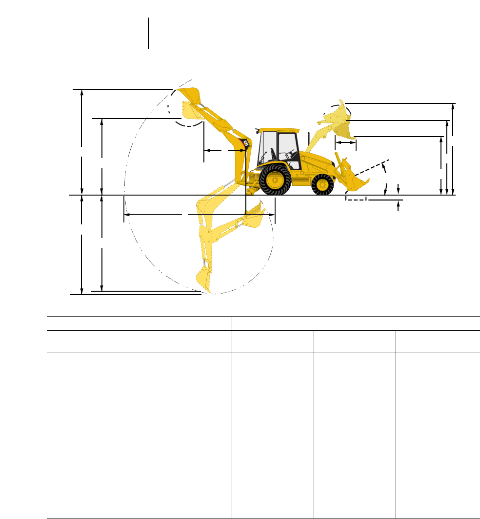
MODEL 416C*
Extendible Stick Extendible Stick
Backhoe Standard Stick Retracted Extended
A) Digging depth (SAE max.) 4420 mm 14'6" 4498 mm 14'9" 5545 mm 18'2"
B) 610 mm (2'0") flat bottom (SAE) 4379 mm 14'4" 4446 mm 14'7" 5498 mm 18'1"
C) Overall operating height — fully raised 5269 mm 17'3" 5240 mm 17'2" 5919 mm 19'5"
D) Loading height 3483 mm 11'5" 3654 mm 12'0" 4223 mm 13'10"
E) Overall reach from rear axle centerline 6729 mm 22'1" 6772 mm 22'3" 7770 mm 25'6"
Overall reach from swing pivot @ ground line 5639 mm 18'6" 5682 mm 18'8" 6680 mm 21'11"
F) Loading reach 1764 mm 5'10" 1804 mm 5'11" 2706 mm 8'11"
Swing arc 180° 180° 180°
Bucket rotation — Vertical wall position 170° 165° 165°
Bucket rotation — Truck loading position 170° 165° 165°
Stabilizer spread —
Operating position 3219 mm 10'7" 3219 mm 10'7" 3219 mm 10'7"
Transport position 2352 mm 7'9" 2352 mm 7'9" 2352 mm 7'9"
Digging force, bucket cylinder, SAE 52 kN 11,700 lb 53.7 kN 12,065 lb 53.7 kN 12,065 lb
Digging force, stick cylinder, SAE 34.3 kN 7704 lb 34.9 kN 7836 lb 25.1 kN 5635 lb
Leveling angle (maximum slope on which
backhoe will make vertical cut) 14° 14° 14°
*Equipped with 610 mm (2'0") standard duty bucket.
5-6
Backhoe Loaders Backhoe Performance Data
●416C
E
F
B
A
CDG
H
J
L
M
K
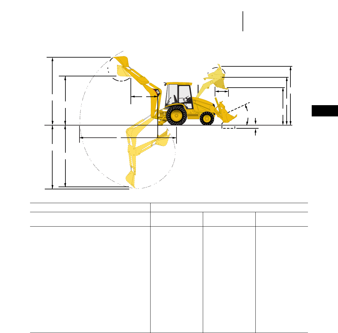
5-7
5
Backhoe LoadersBackhoe Performance Data
●426C
MODEL 426C*
Extendible Stick Extendible Stick
Backhoe Standard Stick Retracted Extended
A) Digging depth (SAE max.) 4721 mm 15'6" 4956 mm 16'3" 6169 mm 20'3"
B) 610 mm (2'0") flat bottom (SAE) 4696 mm 15'4" 4909 mm 16'1" 6129 mm 20'1"
C) Overall operating height — fully raised 5752 mm 18'11" 5832 mm 19'2" 6667 mm 21'11"
D) Loading height 3815 mm 12'6" 4096 mm 13'5" 4925 mm 16'2"
E) Overall reach from rear axle centerline 7146 mm 23'5" 7332 mm 24'1" 8485 mm 27'10"
Overall reach from swing pivot 6056 mm 19'10" 6242 mm 20'6" 7395 mm 24'3"
F) Loading reach 1711 mm 5'7" 1823 mm 6'0" 2717 mm 8'11"
Swing arc 180° 180° 180°
Bucket rotation — Vertical wall position 170° 165° 165°
Bucket rotation — Truck loading position 170° 165° 165°
Stabilizer spread —
Operating position 3219 mm 10'7" 3219 mm 10'7" 3219 mm 10'7"
Transport position 2352 mm 7'9" 2352 mm 7'9" 2352 mm 7'9"
Digging Force; Bucket cylinder, SAE 64.3 kN 14,440 lb 64.3 kN 14,440 lb 64.3 kN 14,440 lb
Digging Force; Stick cylinder, SAE 37.9 kN 8510 lb 39.1 kN 8790 lb 28.1 kN 6310 lb
Leveling angle (maximum slope on which
backhoe will make vertical cut) 14° 14° 14°
*Equipped with 610 mm (2'0") heavy duty bucket.
E
F
B
A
CDG
H
J
L
M
K

MODEL 436C*
Extendible Stick Extendible Stick
Backhoe Standard Stick Retracted Extended
A) Digging depth (SAE max.) 4953 mm 16'3" 4995 mm 16'5" 6202 mm 20'4"
B) 610 mm (2'0") flat bottom (SAE) 4926 mm 16'2" 4938 mm 16'2" 6160 mm 20'3"
C) Overall operating height — fully raised 5862 mm 19'3" 5664 mm 18'7" 6444 mm 21'2"
D) Loading height 3935 mm 12'11" 4003 mm 13'2" 4783 mm 15'8"
E) Overall reach from rear axle centerline 7358 mm 24'2" 7344 mm 24'1" 8496 mm 27'11"
Overall reach from swing pivot 6268 mm 20'7" 6254 mm 20'6" 7406 mm 24'4"
F) Loading reach 1917 mm 6'4" 2038 mm 6'8" 2717 mm 8'11"
Swing arc 180° 180° 180°
Bucket rotation — Vertical wall position 170° 165° 165°
Bucket rotation — Truck loading position 170° 165° 165°
Stabilizer spread —
Operating position 3219 mm 10'7" 3219 mm 10'7" 3219 mm 10'7"
Transport position 2352 mm 7'9" 2352 mm 7'9" 2352 mm 7'9"
Digging Force; Bucket cylinder, SAE 64.2 kN 14,440 lb 64.2 kN 14,440 lb 64.2 kN 14,440 lb
Digging Force; Stick cyilnder, SAE 38.7 kN 8685 lb 40.3 kN 9060 lb 29 kN 6529 lb
Leveling angle (maximum slope on which
backhoe will make vertical cut) 14° 14° 14°
*Equipped with 610 mm (2'0") heavy duty bucket.
E
F
B
A
CDG
H
J
L
M
K
5-8
Backhoe Loaders Backhoe Performance Data
●436C
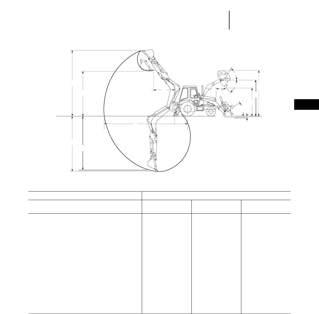
5-9
5
Backhoe LoadersBackhoe Performance Data
●446B
MODEL 446B*
Extendible Stick Extendible Stick
Backhoe Standard Stick Retracted Extended
A) Digging depth (SAE max.) 5219 mm 17'2" 5182 mm 17'0" 6528 mm 21'5"
B) 610 mm (2'0") flat bottom (SAE) 5173 mm 17'0" 5134 mm 16'10" 6479 mm 21'3"
C) Overall operating height — fully raised 6335 mm 20'9" 6298 mm 20'8" 7240 mm 23'9"
D) Loading height 4310 mm 14'2" 4205 mm 13'10" 4894 mm 16'1"
E) Overall reach from rear axle centerline 7866 mm 25'10" 7825 mm 25'8" 9130 mm 29'11"
Overall reach from swing pivot 6604 mm 21'8" 6563 mm 21'6" 7868 mm 25'9"
F) Loading reach 2027 mm 6'8" 2070 mm 6'9" 3261 mm 10'8"
Swing arc 180° 180° 180°
Bucket rotation — Vertical wall position 169° 163° 163°
Bucket rotation — Truck loading position 169° 163° 163°
Stabilizer spread —
Operating position 4084 mm 13'5" 4084 mm 13'5" 4084 mm 13'5"
Transport position 2405 mm 7'11" 2405 mm 7'11" 2405 mm 7'11"
Digging force, bucket cylinder, SAE 67.6 kN 15,200 lb 67.4 kN 15,150 lb 67.4 kN 15,150 lb
Digging force, stick cylinder, SAE 48 kN 10,800 lb 49.8 kN 11,200 lb 34.8 kN 7830 lb
Leveling angle (maximum slope on which
backhoe will make vertical cut) 13° 13° 13°
*Equipped with 610 mm (2'0") standard duty bucket.
60°
45°
A
C
DF
E
B
K
MG
H
J
L
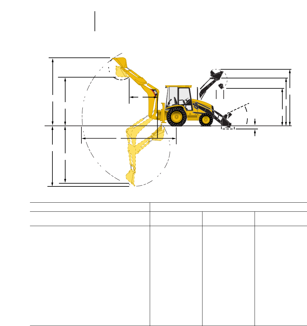
MODEL 428C*
Extendible Stick Extendible Stick
Backhoe Standard Stick Retracted Extended
A) Digging depth (SAE max.) 4153 mm 13'7" 4236 mm 13'11" 5290 mm 17'4"
B) 610 mm (2'0") flat bottom (SAE) 4120 mm 13'6" 4190 mm 13'9" 5246 mm 17'2"
C) Overall operating height — fully raised 5564 mm 18'3" 5541 mm 18'2" 6250 mm 20'6"
D) Loading height 3803 mm 12'5" 3845 mm 12'7" 4454 mm 14'7"
E) Overall reach from rear axle centerline 6903 mm 22'8" 6947 mm 22'10" 7950 mm 26'1"
Overall reach from swing pivot @ ground line 5727 mm 18'9" 5622 mm 18'5" 6625 mm 21'9"
F) Loading reach 1638 mm 5'4" 1677 mm 5'6" 2579 mm 8'6"
Swing arc 180° 180° 180°
Sideshift from machine centerline 630 mm 2'1" 630 mm 2'1" 630 mm 2'1"
Bucket rotation — Vertical wall position 170° 170° 170°
Bucket rotation — Truck loading position 170° 170° 170°
Stabilizer spread 2360 mm 7'9" 2360 mm 7'9" 2360 mm 7'9"
Digging Force; Bucket cylinder 52 kN 11,693 lb 53.6 kN 12,057 lb 53.6 kN 12,056 lb
Digging Force; Stick cylinder 34 kN 7631 lb 33.6 kN 7541 lb 23.8 kN 5356 lb
Leveling angle (maximum slope on which
backhoe will make vertical cut) 11° 11° 11°
*Equipped with 610 mm (2'0") heavy duty bucket.
E
F
B
A
CDG
H
J
L
M
K
5-10
Backhoe Loaders Backhoe Performance Data
●428C
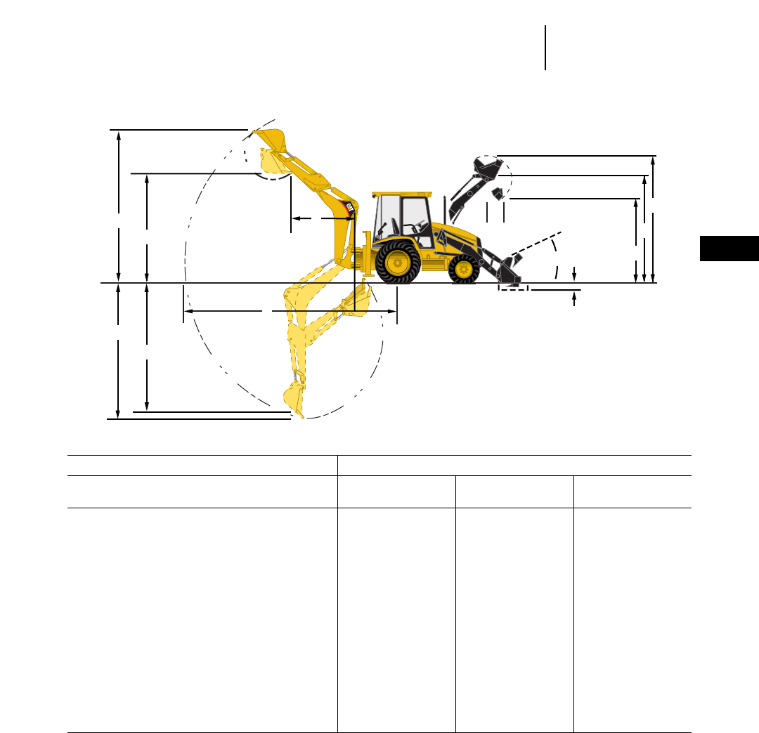
5-11
5
Backhoe LoadersBackhoe Performance Data
●438C
MODEL 438C*
Extendible Stick Extendible Stick
Backhoe Standard Stick Retracted Extended
A) Digging depth (SAE max.) 4326 mm 14'2" 4405 mm 14'5" 5455 mm 17'11"
B) 610 mm (2'0") flat bottom (SAE) 4288 mm 14'1" 4356 mm 14'3" 5409 mm 17'9"
C) Overall operating height — fully raised 5568 mm 18'3" 5532 mm 18'2" 6220 mm 20'5"
D) Loading height 3684 mm 12'1" 3766 mm 12'4" 4344 mm 14'3"
E) Overall reach from rear axle centerline 7036 mm 23'1" 7072 mm 23'3" 8081 mm 26'7"
Overall reach from swing pivot @ ground line 5711 mm 18'9" 5752 mm 18'10" 6756 mm 22'2"
F) Loading reach 1660 mm 5'5" 1699 mm 5'7" 2596 mm 8'6"
Swing arc 180° 180° 180°
Sideshift from machine centerline 630 mm 2'1" 630 mm 2'1" 630 mm 2'1"
Bucket rotation — Vertical wall position 170° 165° 165°
Bucket rotation — Truck loading position 170° 165° 165°
Stabilizer spread 2360 mm 7'9" 2360 mm 7'9" 2360 mm 7'9"
Digging Force; Bucket cylinder 54.2 kN 12,195 lb 53.6 kN 12,060 lb 53.6 kN 12,060 lb
Digging Force; Stick cylinder 33 kN 7427 lb 33.5 kN 7531 lb 23.8 kN 5350 lb
Leveling angle (maximum slope on which
backhoe will make vertical cut) 11° 11° 11°
*Equipped with 610 mm (2'0") heavy duty backhoe bucket.
E
F
B
A
CDG
H
J
L
M
K
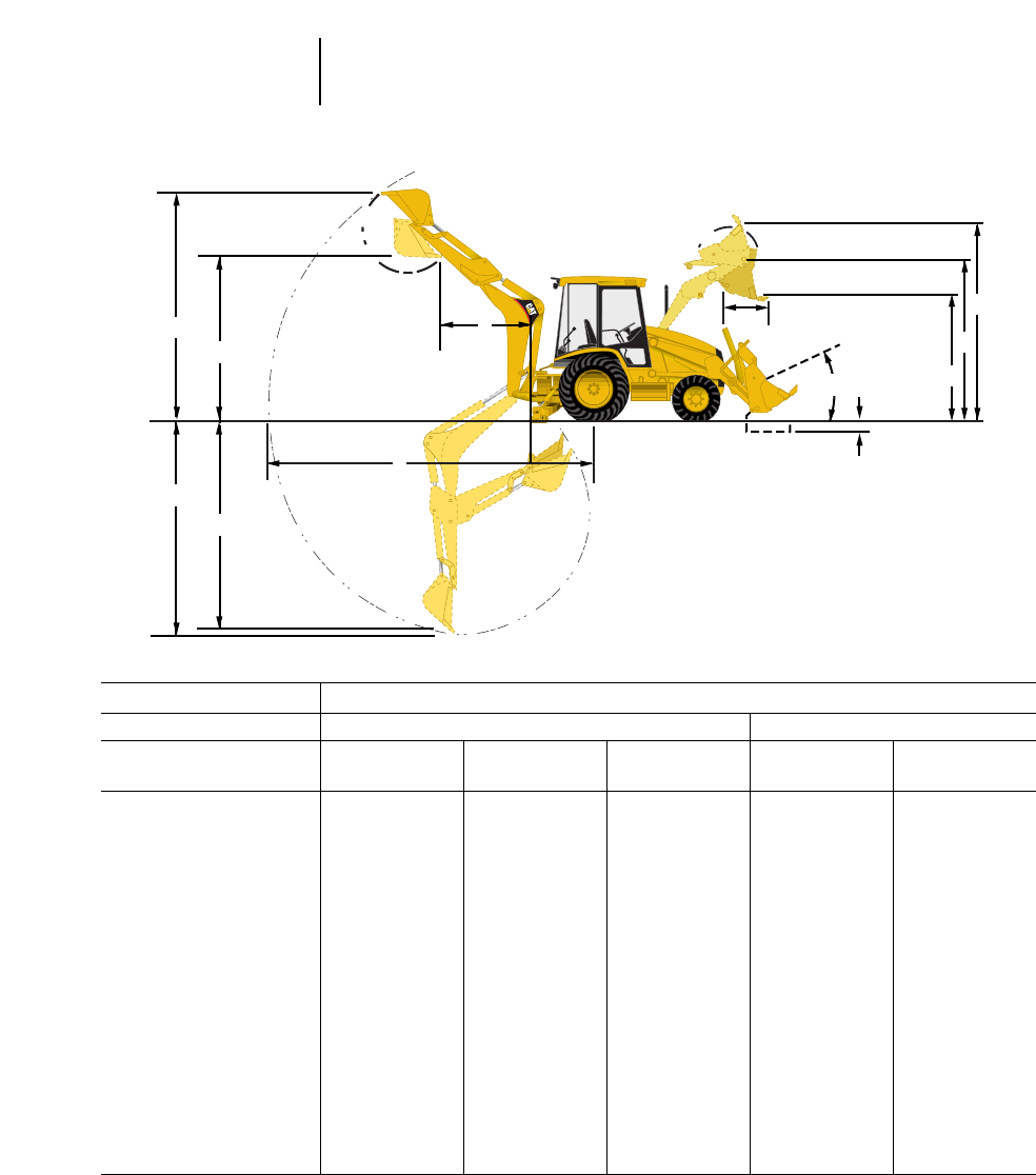
MODEL 416C
Loader Single Tilt IT Loader with QC
General General Multi- General Multi-
Bucket Purpose Purpose Purpose Purpose Purpose
Bucket capacity 0.76 m31 yd30.96 m31.25 yd30.96 m31.25 yd30.96 m31.25 yd30.96 m31.25 yd3
Width 2262 mm 7'5" 2262 mm 7'5" 2262 mm 7'5" 2262 mm 7'5" 2262 mm 7'5"
Lift capacity at max height 2622 kg 5780 lb 2486 kg 5480 lb 2368 kg 5220 lb 3250 kg 7166 lb 2981 kg 6570 lb
Breakout force 40 kN 9030 lb 38.3 kN 8606 lb 42 kN 9490 lb 47.1 kN 10,600 lb 46.6 kN 10,485 lb
G) Dump height @ max
dump angle 2650 mm 8'8" 2575 mm 8'5" 2640 mm 8'8" 2495 mm 8'2" 2560 mm 8'5"
H) Hinge pin height 3290 mm 10'10" 3290 mm 10'10" 3290 mm 10'10" 3290 mm 10'10" 3290 mm 10'10"
J) Max operating height 4020 mm 13'2" 4170 mm 13'8" 4200 mm 13'9" 4170 mm 13'8" 4200 mm 13'9"
K) Digging depth 105 mm 4" 105 mm 4" 105 mm 4" 105 mm 4" 135 mm 5"
Grading angle 110° 106° 110° 107° 111°
Width of dozer
cutting edge — ———2406 mm 7'11" ——2262 mm 7'11"
Clam opening —
maximum — ———790 mm 2'7" ——790 mm 2'7"
L) Reach @ full height
max dump angle 730 mm 2'5" 810 mm 2'8" 700 mm 2'4" 840 mm 2'9" 730 mm 2'5"
M) Maximum rollback
@ groundline 40° 40° 40° 40° 41°
Weight 380 kg 838 lb 428 kg 944 lb 659 kg 1453 lb 466 kg 983 lb 659 kg 1453 lb
E
F
B
A
CDG
H
J
L
M
K
5-12
Backhoe Loaders Loader Performance Data
●General/Multi-Purpose Buckets
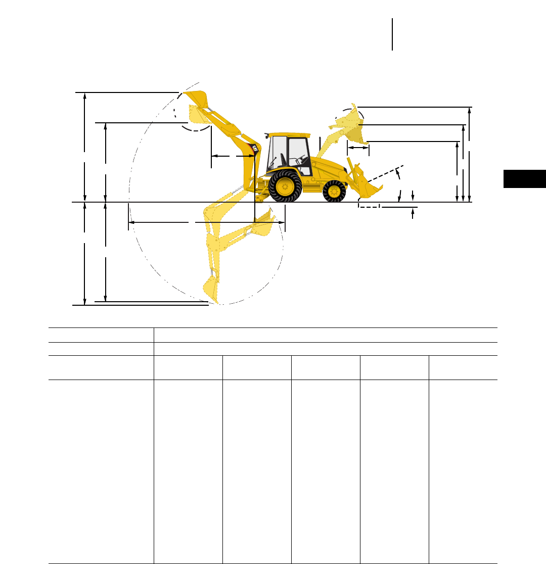
5-13
5
Backhoe LoadersLoader Performance Data
●General/Multi-Purpose Buckets
MODEL 426C
Loader Single Tilt
General General General Multi- Multi-
Bucket Purpose Purpose* Purpose Purpose Purpose*
Bucket capacity 0.96 m31.25 yd31 m31.31 yd31.07 m31.40 yd30.96 m31.25 yd31.03 m31.35 yd3
Width 2262 mm 7'5" 2406 mm 7'11" 2262 mm 7'5" 2262 mm 7'5" 2406 mm 7'11"
Lift capacity at full height 2826 kg 6230 lb 2930 kg 6460 lb 2876 kg 6340 lb 2771 kg 6110 lb 2750 kg 6064 lb
Breakout force 45.3 kN 10,181 lb 45.4 kN 10,204 lb 44.5 kN 10,000 lb 44.7 kN 10,035 lb 44.4 kN 9979 lb
G) Dump height @ max
dump angle 2575 mm 8'5" 2610 mm 8'7" 2555 mm 8'5" 2640 mm 8'8" 2640 mm 8'8"
H) Hinge pin height 3290 mm 10'10" 3290 mm 10'10" 3290 mm 10'10" 3290 mm 10'10" 3290 mm 10'10"
J) Max operating height 4170 mm 13'8" 4170 mm 13'8" 4215 mm 13'10" 4200 mm 13'9" 4200 mm 13'9"
K) Digging depth 105 mm 4" 105 mm 4" 145 mm 6" 135 mm 5" 135 mm 5"
Grading angle 106° 107° 107° 110° 110°
Width of dozer
cutting edge — —————2406 mm 7'11" 2406 mm 7'11"
Clam opening —
maximum — —————790 mm 2'7" 790 mm 2'7"
L) Reach @ full height
max dump angle 810 mm 2'8" 780 mm 2'7" 780 mm 2'7" 700 mm 2'3" 700 mm 2'4"
M) Maximum rollback
@ groundline 40° 40° 41° 41° 40°
Weight 428 kg 944 lb 440 kg 970 lb 437 kg 964 lb 659 kg 1453 lb 682 kg 1504 lb
*Recommended for use with All Wheel Steer option.
E
F
B
A
CDG
H
J
L
M
K
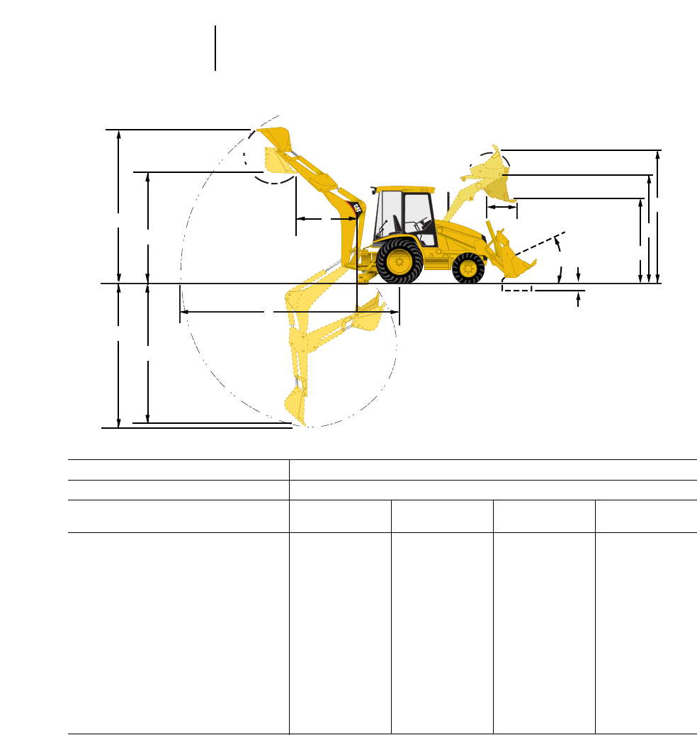
MODEL 426C
Loader IT Loader with QC
General General Multi- Multi-
Bucket Purpose Purpose* Purpose Purpose*
Bucket capacity 0.96 m31.25 yd31 m31.31 yd30.96 m31.25 yd31.03 m31.35 yd3
Width 2262 mm 7'5" 2406 mm 7'11" 2262 mm 7'5" 2406 mm 7'11"
Lift capacity at full height 3116 kg 6871 lb 3190 kg 7034 lb 2981 kg 6573 lb 2955 kg 6516 lb
Breakout force 45.8 kN 10,300 lb 46.9 kN 10,541 lb 45.4 kN 10,200 lb 46.5 kN 10,451 lb
G) Dump height @ max dump angle 2495 mm 8'2" 2530 mm 8'4" 2560 mm 8'5" 2560 mm 8'5"
H) Hinge pin height 3290 mm 10'10" 3290 mm 10'10" 3290 mm 10'10" 3290 mm 10'10"
J) Max operating height 4170 mm 13'8" 4170 mm 13'8" 4200 mm 13'9" 4200 mm 13'9"
K) Digging depth 105 mm 4" 105 mm 4" 135 mm 5" 135 mm 5"
Grading angle 107° 108° 111° 111°
Width of dozer cutting edge — ———2262 mm 7'5" 2262 mm 7'5"
Clam opening — maximum — ———790 mm 2'7" 790 mm 2'7"
L) Reach @ full height/max dump angle 840 mm 2'9" 810 mm 2'8" 730 mm 2'5" 730 mm 2'5"
M) Maximum rollback @ groundline 40° 40° 41° 41°
Weight 446 kg 983 lb 459 kg 1012 lb 659 kg 1453 lb 682 kg 1504 lb
*Recommended for use with All Wheel Steer option.
E
F
B
A
CDG
H
J
L
M
K
5-14
Backhoe Loaders Loader Performance Data
●General/Multi-Purpose Buckets

5-15
5
Backhoe LoadersLoader Performance Data
●General/Multi-Purpose Buckets
MODEL 436C
Loader Single Tilt
General General General Multi- Multi-
Bucket Purpose* Purpose Purpose* Purpose Purpose*
Bucket capacity 1 m31.31 yd31.07 m31.40 yd31.15 m31.50 yd30.96 m31.25 yd31.03 m31.35 yd3
Width 2406 mm 7'11" 2262 mm 7'5" 2406 mm 7'11" 2262 mm 7'5" 2406 mm 7'11"
Lift capacity at full height 3000 kg 6614 lb 2946 kg 6494 lb 2901 kg 6395 lb 2845 kg 6273 lb 2821 kg 6218 lb
Breakout force 45.7 kN 10,278 lb 44.9 kN 10,080 lb 44.4 kN 9990 lb 45 kN 10,125 lb 44.8 kN 10,069 lb
G) Dump height @ max
dump angle 2670 mm 8'9" 2620 mm 8'7" 2590 mm 8'6" 2705 mm 8'11" 2305 mm 7'7"
H) Hinge pin height 3350 mm 11'0" 3350 mm 11'0" 3350 mm 11'0" 3350 mm 11'0" 3350 mm 11'0"
J) Max operating height 4230 mm 13'11" 4270 mm 14'0" 4270 mm 14'0" 4260 mm 14'0" 4260 mm 14'0"
K) Digging depth 43 mm 2" 85 mm 3" 85 mm 3" 75 mm 3" 75 mm 3"
Grading angle 108° 108° 108° 111° 111°
Width of dozer
cutting edge — —————2262 mm 7'5" 2406 mm 7'11"
Clam opening —
maximum — —————790 mm 2'7" 790 mm 2'7"
L) Reach @ full height
max dump angle 750 mm 2'6" 750 mm 2'6" 750 mm 2'6" 670 mm 2'2" 670 mm 2'2"
M) Maximum rollback
@ groundline 39° 40° 40° 40° 40°
Weight 440 kg 970 lb 437 kg 964 lb 456 kg 1003 lb 659 kg 1453 lb 682 kg 1504 lb
*Recommended for use with All Wheel Steer option.
E
F
B
A
CDG
H
J
L
M
K

5-16
Backhoe Loaders Loader Performance Data
●General/Multi-Purpose Buckets
MODEL 436C
Loader IT Loader with QC
General General Multi- Multi-
Bucket Purpose* Purpose* Purpose Purpose*
Bucket capacity 1 m31.31 yd31.15 m31.50 yd30.96 m31.25 yd31.03 m31.35 yd3
Width 2406 mm 7'11" 2406 mm 7'11" 2262 mm 7'5" 2262 mm 7'5"
Lift capacity at full height 3264 kg 7196 lb 3211 kg 7080 lb 3056 kg 6739 lb 3031 kg 6681 lb
Breakout force 46.8 kN 10,518 lb 45.9 kN 10,316 lb 46.6 kN 10,462 lb 46.4 kN 10,429 lb
G) Dump height @ max dump angle 2590 mm 8'6" 2540 mm 8'4" 2630 mm 8'8" 2630 mm 8'8"
H) Hinge pin height 3350 mm 11'0" 3350 mm 11'0" 3350 mm 11'0" 3350 mm 11'0"
J) Max operating height 4290 mm 14'1" 4330 mm 14'3" 4320 mm 14'2" 4320 mm 14'2"
K) Digging depth 42 mm 2" 80 mm 3" 75 mm 3" 75 mm 3"
Grading angle 109° 109° 112° 112°
Width of dozer cutting edge — ———2262 mm 7'5" 2406 mm 7'11"
Clam opening — maximum — ———790 mm 2'7" 790 mm 2'7"
L) Reach @ full height/max dump angle 780 mm 2'7" 780 mm 2'7" 700 mm 2'4" 700 mm 2'4"
M) Maximum rollback @ groundline 39° 40° 40° 40°
Weight 459 kg 1012 lb 473 kg 1043 lb 659 kg 1453 lb 682 kg 1504 lb
*Recommended for use with All Wheel Steer option.
E
F
B
A
CDG
H
J
L
M
K
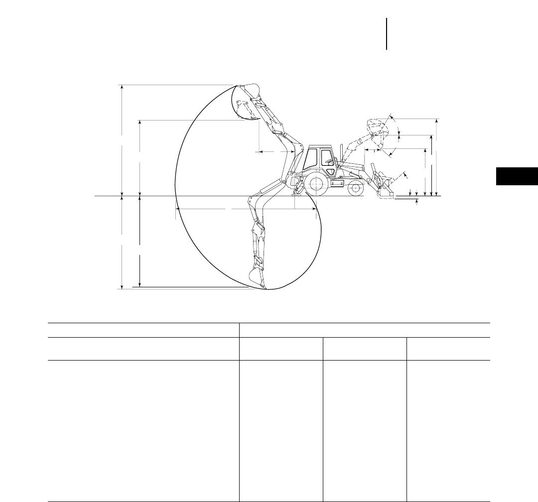
5-17
5
Backhoe LoadersLoader Performance Data
●General/Multi-Purpose Buckets
MODEL 446B
General General Multi-
Loader Purpose Purpose Purpose
Bucket capacity 1.1 m31.5 yd31.3 m31.75 yd31.05 m31.375 yd3
Width 2434 mm 8'0" 2434 mm 8'0" 2434 mm 8'0"
Lift capacity at full height 3970 kg 8760 lb 3905 kg 8610 lb 3790 kg 8350 lb
Breakout force 56 kN 12,600 lb 51.7 kN 11,610 lb 57.4 kN 12,900 lb
G) Dump height @ 45 degrees 2699 mm 8'10" 2657 mm 8'9" 2731 mm 9'0"
H) Hinge pin height 3490 mm 11'5" 3490 mm 11'5" 3490 mm 11'5"
J) Overall operating height — fully raised 4410 mm 14'3" 4198 mm 13'9" 4410 mm 14'6"
K) Digging depth 162 mm 6.4" 162 mm 6.4" 143 mm 5.6"
Grading angle 115° 115° 115°
Width of dozer cutting edge — —2434 mm 8'0" 2434 mm 8'0"
Clam opening — maximum — —965 mm 3'2" 1000 mm 3'3"
L) Reach @ full height/45 degrees 868 mm 2'10" 910 mm 3'0" 868 mm 2'10"
M) Maximum rollback @ groundline 40° 40° 40°
Weight 553 kg 1217 lb 608 kg 1338 lb 849 kg 1868 lb
NOTE: All 446B specifications are effective with S/N 5BL00500.
60°
45°
A
C
DF
E
B
K
MG
H
J
L
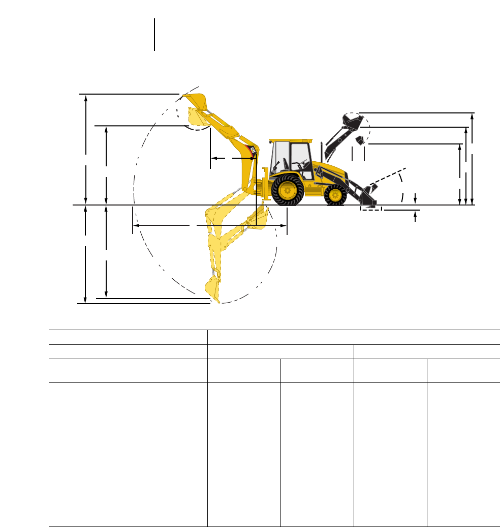
MODEL 428C
Loader Single Tilt Parallel Lift
General Multi- General Multi-
Bucket Purpose Purpose Purpose Purpose
Bucket capacity 1 m31.30 yd31.03 m31.35 yd31 m31.30 yd31.03 m31.35 yd3
Width 2396 mm 7'10" 2406 mm 7'11" 2396 mm 7'10" 2406 mm 7'11"
Lift capacity at full height 2340 kg 5158 lb 2145 kg 4728 lb 3295 kg 7265 lb 3060 kg 6747 lb
Breakout force 38.5 kN 8655 lb 41.1 kN 9239 lb 50.1 kN 11,262 lb 53.2 kN 11,959 lb
G) Dump height @ max dump angle 2570 mm 8'5" 2605 mm 8'6" 2565 mm 8'5" 2600 mm 8'6"
H) Hinge pin height 3270 mm 10'8" 3270 mm 10'8" 3270 mm 10'8" 3270 mm 10'8"
J) Max operating height 4150 mm 13'7" 4175 mm 13'8" 4150 mm 13'7" 4175 mm 13'8"
K) Digging depth 135 mm 5" 165 mm 7" 135 mm 5" 165 mm 7"
Grading angle 108° 111° 111° 114°
Width of dozer cutting edge — —2406 mm 7'11" ——2406 mm 7'11"
Clam opening — maximum — —927 mm 3'0" ——927 mm 3'0"
L) Reach @ full height/max dump angle 825 mm 2'8" 745 mm 2'5" 820 mm 2'8" 735 mm 2'5"
M) Maximum rollback @ groundline 39° 40° 40° 40°
Weight 445 kg 981 lb 700 kg 1543 lb 445 kg 981 lb 685 kg 1510 lb
5-18
Backhoe Loaders Loader Performance Data
●General/Multi-Purpose Buckets
E
F
B
A
CDG
H
J
L
M
K

5-19
5
Backhoe LoadersLoader Performance Data
●General/Multi-Purpose Buckets
MODEL 438C
Loader Single Tilt
General General Multi-
Bucket Purpose Purpose Purpose
Bucket capacity 1 m31.30 yd31.15 m31.50 yd31.03 m31.35 yd3
Width 2396 mm 7'10" 2396 mm 7'10" 2406 mm 7'11"
Lift capacity at full height 2390 kg 5269 lb 2300 kg 5070 lb 2200 kg 4850 lb
Breakout force 39.3 kN 8835 lb 38 kN 8543 lb 40.4 kN 9082 lb
G) Dump height @ max dump angle 2670 mm 8'9" 2615 mm 8'7" 2700 mm 8'10"
H) Hinge pin height 3360 mm 11'0" 3360 mm 11'0" 3360 mm 11'0"
J) Max operating height 4240 mm 13'11" 4285 mm 14'1" 4270 mm 14'0"
K) Digging depth 40 mm 2" 80 mm 3" 70 mm 3"
Grading angle 110° 110° 113°
Width of dozer cutting edge — ———2406 mm 7'11"
Clam opening — maximum — ———927 mm 3'1"
L) Reach @ full height/max dump angle 800 mm 2'7" 800 mm 2'7" 720 mm 2'4"
M) Maximum rollback @ groundline 38° 39° 38°
Weight 445 kg 981 lb 635 kg 1400 lb 700 kg 1543 lb
E
F
B
A
CDG
H
J
L
M
K
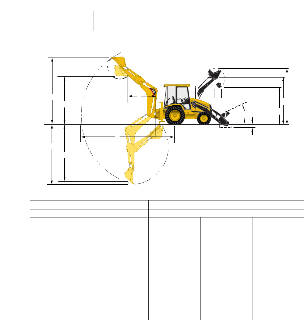
5-20
Backhoe Loaders Loader Performance Data
●General/Multi-Purpose Buckets
MODEL 438C
Loader Parallel Lift
General General Multi-
Bucket Purpose Purpose Purpose*
Bucket capacity 1 m31.30 yd31.15 m31.50 yd31.03 m31.35 yd3
Width 2396 mm 7'10" 2396 mm 7'10" 2406 mm 7'11"
Lift capacity at full height 3355 kg 7396 lb 3300 kg 7275 lb 3120 kg 6878 lb
Breakout force 50.4 kN 11,330 lb 49.4 kN 11,105 lb 53.4 kN 12,004 lb
G) Dump height @ max dump angle 2655 mm 8'9" 2600 mm 8'6" 2690 mm 8'10"
H) Hinge pin height 3360 mm 11'0" 3360 mm 11'0" 3360 mm 11'0"
J) Max operating height 4240 mm 13'11" 4285 mm 14'1" 4270 mm 14'0"
K) Digging depth 40 mm 2" 80 mm 3" 70 mm 3"
Grading angle 113° 113° 116°
Width of dozer cutting edge — ———2406 mm 7'11"
Clam opening — maximum — ———927 mm 3'1"
L) Reach @ full height/45 degrees 780 mm 2'7" 780 mm 2'7" 700 mm 2'3"
M) Maximum rollback @ groundline 38° 39° 39°
Weight 445 kg 981 lb 635 kg 1400 lb 685 kg 1510 lb
*Recommended for use with All Wheel Steer.
E
F
B
A
CDG
H
J
L
M
K
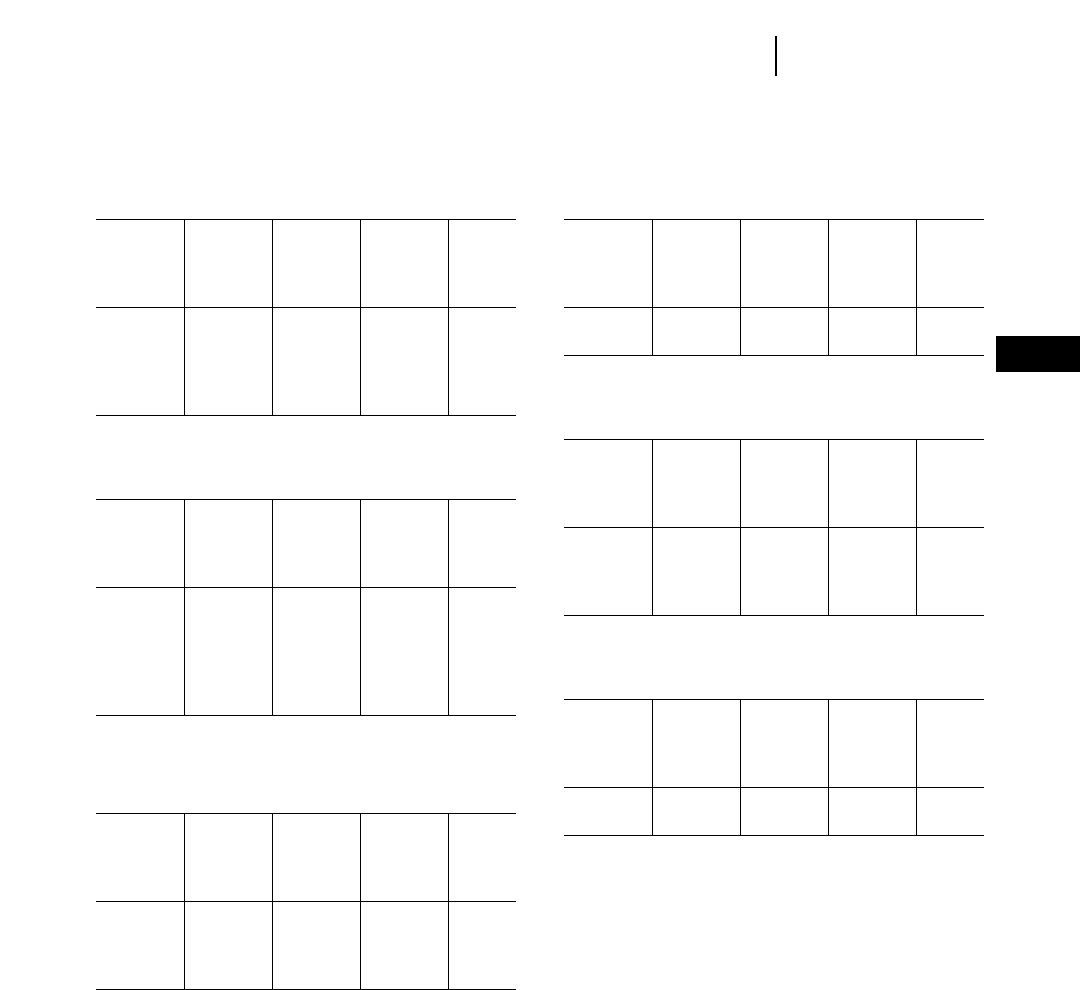
Standard Duty Buckets (SD)
416C, 428C, 438C
SAE SAE
Heaped Struck
Width Capacity Capacity Weight No. of
mm in L ft3Lft
3kg lb Teeth
305 12 70 2.5 60 2.0 110 243 3
457 18 127 4.5 99 3.5 130 287 4
610 24 198 7.0 156 5.5 150 331 5
762 30 255 9.5 198 7.0 165 364 5
914 36 311 11.5 227 8.0 180 397 6
Heavy Duty Buckets (HD)
416C, 426C, 436C, 428C, 438C
SAE SAE
Heaped Struck *
Width Capacity Capacity Weight No. of
mm in L ft3Lft
3kg lb Teeth
305 12 70 2.5 60 2.0 110 243 3
400 16 100 3.5 85 3.0 132 291 4
457 18 127 4.5 99 3.5 150 331 4
610 24 198 7.0 156 5.5 175 386 4
762 30 255 9.5 198 7.0 195 430 5
914 36 311 11.5 227 8.0 210 463 6
*Bolt-on teeth available.
High Capacity Buckets (HC)
416C, 426C, 436C, 428C, 438C
SAE SAE
Heaped Struck
Width Capacity Capacity Weight No. of
mm in L ft3Lft
3kg lb Teeth
457 18 184 6.5 127 4.5 155 342 4
610 24 225 9.0 184 6.5 180 397 4
762 30 311 11.0 227 8.0 200 441 5
914 36 396 14.0 283 10.0 215 474 6
Teeth Options:
Utility — Short
Penetration — Long
Abrasion
Extreme Service Buckets (ES)
416C, 426C, 436C, 428C, 438C
SAE SAE
Heaped Struck
Width Capacity Capacity Weight No. of
mm in L ft3Lft
3kg lb Teeth
457 18 99 4.0 83 3.0 145 320 4
610 24 156 6.0 140 5.0 165 364 4
Heavy Duty Buckets (HD)
446B
SAE SAE
Heaped Struck
Width Capacity Capacity Weight No. of
mm in L ft3Lft
3kg lb Teeth
457 18 190 6.5 170 5.9 178 392 3
610 24 280 10.0 240 8.4 216 476 4
762 30 380 13.0 300 10.5 237 523 5
914 36 480 17.0 380 13.0 267 589 6
Extreme Service Buckets (ES)
446B
SAE SAE
Heaped Struck
Width Capacity Capacity Weight No. of
mm in L ft3Lft
3kg lb Teeth
600 24 270 9.0 230 8.1 227 501 4
760 30 370 13.0 290 10.0 249 549 5
5-21
5
Backhoe LoadersBackhoe Bucket Capacities
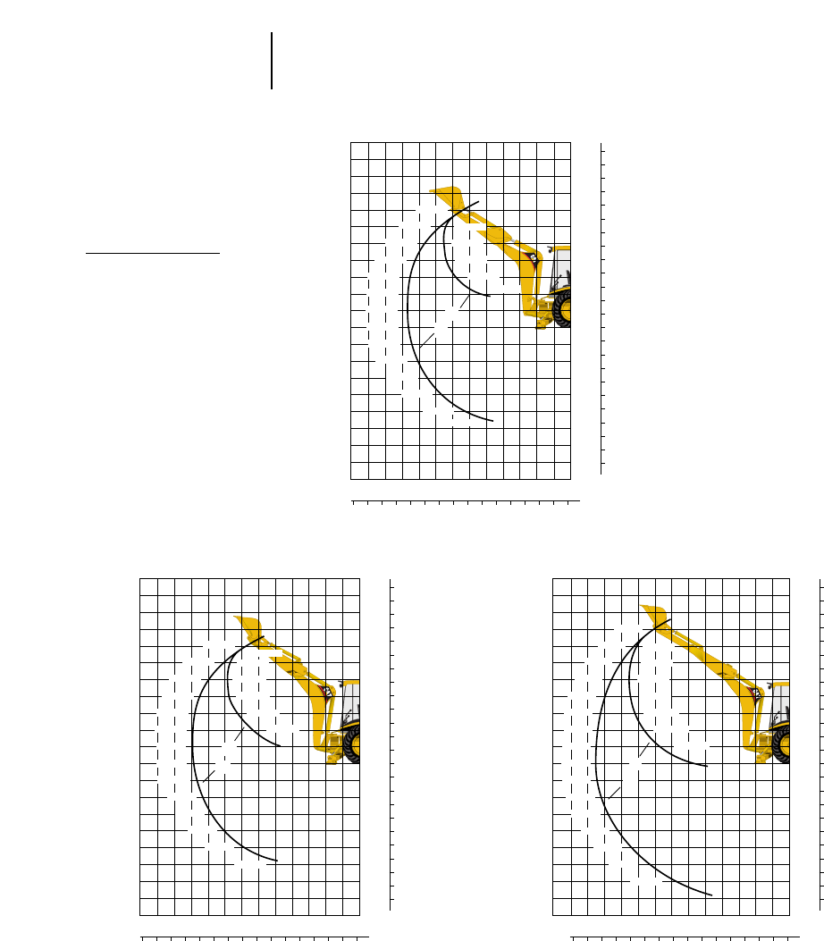
5-22
Backhoe Loaders Lifting Capacity
●416C
NOTE: Boom at 65°.
Machine configuration includes 16.9X24, 8PR, R4 rear and 11LX16, 10PR, F3 front tires, open ROPS,
two wheel drive, single tilt loader, 0.76 m3(1 yd3)GP bucket, 610 mm (2'0") standard duty bucket, base
counterweight 145 kg (320 lb).
KEY
A — Boom lift lb kg
B — Stick lift lb kg
Extendible Stick —
Extended
Extendible Stick —
Retracted
Standard Stick
22
20
18
16
14
12
10
8
6
4
2
0
-2
-4
-6
-8
-10
-12
-14
-16
-18
6
5
4
3
2
1
0
-1
-2
-3
-4
-5
FEET METERS
20
6543210-1
FEET
METERS
181614121086420-2
•
2830 1283
3100 1406
3100 1406
3030 1374
2940 1333
2840 1288
2750 1247
2660 1206
2580 1170
2520 1143
2470 1120
2460 1116
2550 115 7
2912 1321
4730 2145
4460 2023
4580 2077
5210 2363
7520 3411
B
A
©
©
22
20
18
16
14
12
10
8
6
4
2
0
-2
-4
-6
-8
-10
-12
-14
-16
-18
6
5
4
3
2
1
0
-1
-2
-3
-4
-5
FEET METERS
20
6543210-1
FEET
METERS
181614121086420-2
2750 1247
2780 1261
2780 1261
2710 1229
2620 1188
2520 1143
2490 1129
2340 1061
2260 1025
2200 998
2150 975
2120 961
2170 984
2561 1162
4244 1925
4360 1977
4120 1869
4210 1909
4750 2154
6960 3157
B
A
©
©
22
20
18
16
14
12
10
8
6
4
2
0
-2
-4
-6
-8
-10
-12
-14
-16
-18
6
5
4
3
2
1
0
-1
-2
-3
-4
-5
FEET METERS
2022
6543210-1
FEET
METERS
181614121086420-2
1570 712
1830 830
1930 875
1960 889
1950 884
1930 875
1900 862
1870 848
1840 834
1800 816
1780 807
1760 798
1760 798
1850 839
1930 875
2550 1021
2610 1148
2910 1320
2830 1283
2860 1297
3010 1365
3360 1524
4108 1896
B
A
©
©
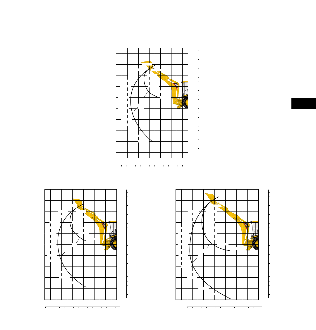
5-23
5
Backhoe LoadersLifting Capacity
●426C
NOTE: Boom at 65°.
Machine configuration includes 16.9X24, 8PR, R4 rear and 11LX16, 12PR, F3 front tires, open ROPS,
two wheel drive, single tilt loader, 0.96 m3(1.25 yd3)GP bucket, 610 mm (2'0") heavy duty bucket,
base counterweight 145 kg (320 lb) plus 1 add on 105 kg (231 lb).
Standard Stick
KEY
A — Boom lift lb kg
B — Stick lift lb kg
Extendible Stick —
Extended
Extendible Stick —
Retracted
22
20
18
16
14
12
10
8
6
4
2
0
-2
-4
-6
-8
-10
-12
-14
-16
-18
6
5
4
3
2
1
0
-1
-2
-3
-4
-5
FEET METERS
20
6543210-1
FEET
METERS
181614121086420-2
3340 1515
4090 1855
4130 1873
3750 1701*
3380 1533*
3150 1429*
3020 1370*
2960 1342*
2960 1342*
3040 1379*
3230 1465*
3160 1433
3120 1415
3120 1415
3480 1579
5650 2563
5020 2277
4910 2227
5120 2322
5890 2671
8100 3674
B
A
©
©
22
20
18
16
14
12
10
8
6
4
2
0
-2
-4
-6
-8
-10
-12
-14
-16
-18
6
5
4
3
2
1
0
-1
-2
-3
-4
-5
FEET METERS
20
6543210-1
FEET
METERS
181614121086420-2
3060 1388
3470 1574
3500 1587
3430 1556
3100 1406*
2890 1311*
2760 1252*
2700 1225*
2700 1225*
2810 1274
2720 1234
2660 1206
2610 1184
2600 1179
2730 1238
5150 2336
4660 2113
4560 2068
4730 2145
5280 2395
7140 3238
B
A
©
©
22
20
18
16
14
12
10
8
6
4
2
0
-2
-4
-6
-8
-10
-12
-14
-16
-18
6
5
4
3
2
1
0
-1
-2
-3
-4
-5
FEET METERS
2022
6543210-1
FEET
METERS
181614121086420-2
2260 1025
2380 1079
2430 1102
2430 1102
2330 1057
2210 1002*
2140 971*
2100 952*
2090 948*
2110 957
2180 989
2160 980
2150 975
2150 975
2190 993
2300 1043
2710 1229
2700 1225
3170 1438
3280 1488
3240 1469
3300 1497
3460 1569
3790 1719*
4460 2023*
6510 2952*
B
A
©
©
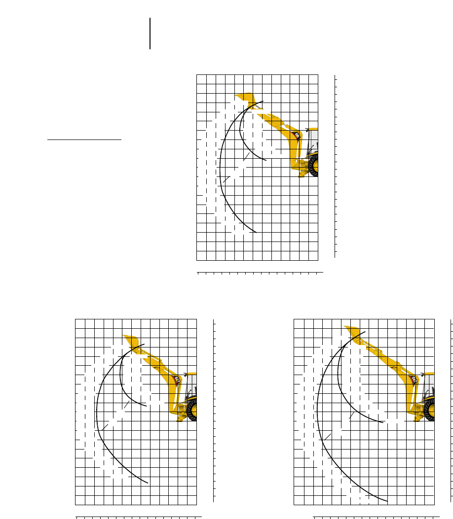
NOTE: Boom at 65°.
Machine configuration includes 11L-16, 12PR, F3 front and 19.5LX24, 10PR, IT525 rear tires, open
ROPS, two wheel drive, single tilt loader, 1.07 m3(1.4 yd3)GP bucket, 610 mm (2'0") high capacity
bucket, base counterweight 145 kg (320 lb) plus 1 add on 105 kg (231 lb).
*Indicates lift capacity is stability limited.
Standard Stick
KEY
A — Boom lift lb kg
B — Stick lift lb kg
Extendible Stick —
Extended
Extendible Stick —
Retracted
5-24
Backhoe Loaders Lifting Capacity
●436C
22
20
18
16
14
12
10
8
6
4
2
0
-2
-4
-6
-8
-10
-12
-14
-16
-18
6
5
4
3
2
1
0
-1
-2
-3
-4
-5
FEET METERS
20
6543210-1
FEET
METERS
181614121086420-2
3160 1435
3740 1695
3830 1735
3790 1720*
3450 1565*
3230 1465*
3100 1405*
3040 1380*
3040 1380*
3110 1410*
3200 1450
3150 1430
3120 1415
3150 1430
3350 1520
5430 2465
5010 2275*
4890 2220*
5050 2290*
5610 2545*
7550 3425*
B
A
©
©
22
20
18
16
14
12
10
8
6
4
2
0
-2
-4
-6
-8
-10
-12
-14
-16
-18
6
5
4
3
2
1
0
-1
-2
-3
-4
-5
FEET METERS
20
6543210-1
FEET
METERS
181614121086420-2
2830 1285
3390 1540
3480 1580
3450 1565
3370 1530
3280 1490
3180 1440
3090 1400
3000 1360
2910 1320
2840 1290
2790 1265
2750 1250
2770 1255
2940 1335
5100 2315
4970 2255
4830 2190
5010 2275
5650 2565
7870 3560
B
A
©
©
22
20
18
16
14
12
10
8
6
4
2
0
-2
-4
-6
-8
-10
-12
-14
-16
-18
6
5
4
3
2
1
0
-1
-2
-3
-4
-5
FEET METERS
202224
6543210-1
FEET
METERS
181614121086420-2
1840 835
2220 1005
2380 1080
2440 1105
2460 1115
2450 1110
2430 1100
2400 1090
2370 1075
2340 1060
2310 1050
2280 1035
2270 1030
2260 1025
2270 1030
2320 1050
2450 1110
2900 1315
3920 1780
2700 1225
3180 1440
3360 1525
3310 1500
3370 1530
3540 1605
3900 1770
4660 2115
7040 3195
B
A
©
©
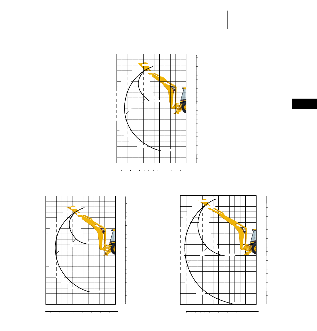
5-25
5
Backhoe LoadersLifting Capacity
●446B
NOTE: Boom at 65°.
**With 455 kg (1000 lb) counterweight.
**With 680 kg (1500 lb) counterweight.
0
2
4
6
8
10
12
14
16
18
20
22
-2
-4
-6
-8
-10
-12
-14
-16
-18
6
5
4
3
2
1
0
-1
-2
-3
-4
-5
6543 210-1
20 18 16 14 12 10 8 6 4 2 0 -2
3920 1775
3990 1810
3850 1745
3020 1370
4530 2055
5740 2600
6450 2925
6850 3105
7240 3285
8390 3810
13540 6145
3250 1475
3190 1445
3160 1430
3160 1435
3300 1500
4100 1860
4010 1815
3330 1510
3410 1550
3510 1590
3610 1635
3710 1685
3820 1730
B
RS
A
Standard Stick*
KEY
A — Boom lift lb kg
B — Stick lift lb kg
FEET METERS
FEET
METERS
0
2
4
6
8
10
12
14
16
18
20
22
-2
-4
-6
-8
-10
-12
-14
-16
-18
6
5
4
3
2
1
0
-1
-2
-3
-4
-5
6543 210-1
20 18 16 14 12 10 8 6 4 2 0 -2
1410 640
1790 810
2170 985
2730 1235
3150 1430
3440 1560
3670 1665
3890 1765
4180 1900
4600 2090
5370 2435
9940 4505
2390 1080
2210 1005
2460 1115
2470 1120
2190 990
2190 995
2220 1005
2310 1050
2580 1170
4920 2235
2460 1115
2400 1090
2440 1105
2370 1075
2330 1055
2290 1040
2250 1020
2220 1010
2200 995
ET
TERS
B
A
Extendible Stick** —
Extended
FEET METERS
FEET
METERS
0
2
4
6
8
10
12
14
16
18
20
22
-2
-4
-6
-8
-10
-12
-14
-16
-18
6
5
4
3
2
1
0
-1
-2
-3
-4
-5
6543 210-1
20 18 16 14 12 10 8 6 4 2 0 -2
3680 1670
3650 1655
3560 1615
3460 1565
3550 1610
3340 1515
3020 1370
2920 1325
2840 1285
2770 1255
3460 1570
4420 2005
5640 2560
6350 2880
6700 3040
7170 3250
8590 3895
13660 6195
2770 1255
2720 1235
2710 1230
2830 1285
3230 1465
3120 1415
B
A
Extendible Stick** —
Retracted
FEET METERS
FEET
METERS
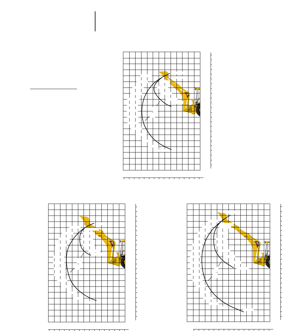
NOTE: Boom at 65°.
Machine configuration includes 11LX16 12PR, F-3 laborer front and 16.9X28, 10PR, R4 rear tires, cab,
two wheel drive, parallel lift loader, 1 m3(1.3 yd3)GP bucket, 610 mm (2'0") heavy duty bucket, base
counterweight 16 kg (35 lb).
Standard Stick
KEY
A — Boom lift lb kg
B — Stick lift lb kg
Extendible Stick —
Extended
Extendible Stick —
Retracted
5-26
Backhoe Loaders Lifting Capacity
●428C
22
20
18
16
14
12
10
8
6
4
2
0
-2
-4
-6
-8
-10
-12
-14
-16
-18
6
5
4
3
2
1
0
-1
-2
-3
-4
-5
FEET METERS
20
6543210-1
FEET
METERS
181614121086420-2
3159 1433
3168 1437
3083 1398
2977 1350
2868 1300
2762 1253
2665 1208
2575 1168
2495 1132
2426 1100
2372 1076
2346 1064
2419 1097
2521 1143
4562 2069
4453 2019
2700 1224
4370 1982
4546 2061
5172 2346
7756 3517
B
A
©
©
22
20
18
16
14
12
10
8
6
4
2
0
-2
-4
-6
-8
-10
-12
-14
-16
-18
6
5
4
3
2
1
0
-1
-2
-3
-4
-5
FEET METERS
20
6543210-1
FEET
METERS
181614121086420-2
2881 1307
2879 1306
2794 1267
2691 1220
2583 1171
2480 1124
2382 1080
2292 1040
2212 1003
2139 970
2080 943
2043 926
2072 940
2185 991
4244 1925
2451 1111
4326 1962
4218 1913
4429 2009
5211 2363
10631 4821
B
A
©
©
22
20
18
16
14
12
10
8
6
4
2
0
-2
-4
-6
-8
-10
-12
-14
-16
-18
6
5
4
3
2
1
0
-1
-2
-3
-4
-5
FEET METERS
20
6543210-1
FEET
METERS
181614121086420-2
1573 713
1945 882
2055 932
2078 943
2065 937
2035 932
1996 905
1954 886
1911 867
1871 849
1835 832
1804 818
1779 807
1768 802
1780 807
1850 839
2954 1022 2496 1132
2462 1117
2742 1244
3028 1373
2993 1357
3060 1388
3261 1479
3703 1679
4876 2211
11521 5225
B
A
©
©
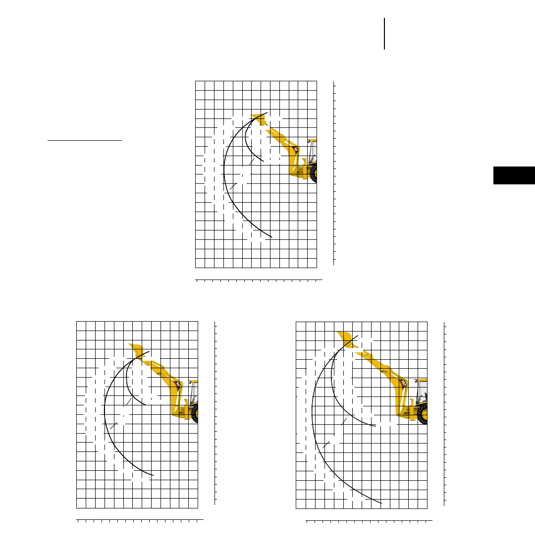
5-27
5
Backhoe LoadersLifting Capacity
●438C
NOTE: Boom at 65°.
Machine configuration includes 12.5/80X18 10PR, I-3 implement front and 18.4/15X26, 12PR, R4 rear
tires, cab, all wheel drive, parallel lift loader, 1 m3(1.3 yd3)GP bucket, 610 mm (2'0") heavy duty
bucket, base counterweight 16 kg (35 lb).
Standard Stick
KEY
A — Boom lift lb kg
B — Stick lift lb kg
Extendible Stick —
Extended
Extendible Stick —
Retracted
22
20
18
16
14
12
10
8
6
4
2
0
-2
-4
-6
-8
-10
-12
-14
-16
-18
6
5
4
3
2
1
0
-1
-2
-3
-4
-5
FEET METERS
20
6543210-1
FEET
METERS
181614121086420-2
2978 1351
3068 1391
2754 1249
3023 1371
2941 1334
2849 1292
2757 1250
2670 1211
2591 1175
2520 1143
2462 1117
2421 1098
2416 1096
2533 1149
4558 2067
4449 2018
4322 1960
4540 2059
5384 2441
10377 4706
B
A
©
©
22
20
18
16
14
12
10
8
6
4
2
0
-2
-4
-6
-8
-10
-12
-14
-16
-18
6
5
4
3
2
1
0
-1
-2
-3
-4
-5
FEET METERS
20
6543210-1
FEET
METERS
181614121086420-2
2714 1231
2782 1262
2736 1241
2650 1207
2565 1163
2473 1122
2387 1083
2306 1046
2235 1014
2173 986
2126 964
2108 956
2178 988
2416 1096
4240 1923
4130 1873
4011 1819
4195 1902
4898 2221
10134 4596
B
A
©
©
22
20
18
16
14
12
10
8
6
4
2
0
-2
-4
-6
-8
-10
-12
-14
-16
-18
6
5
4
3
2
1
0
-1
-2
-3
-4
-5
FEET METERS
20
6543210-1
FEET
METERS
181614121086420-2
1343 817
1958 888
2010 911
2016 914
1999 907
1971 894
1938 879
1904 864
1871 849
1842 835
1817 824
1801 817
1798 816
1822 826
1911 867
2348 1065
2877 1305
1343 609
2453 1113
2716 1232
2881 1307
2836 1286
2894 1313
3079 1396
3485 1581
4540 2059
10980 4980
B
A
©
©
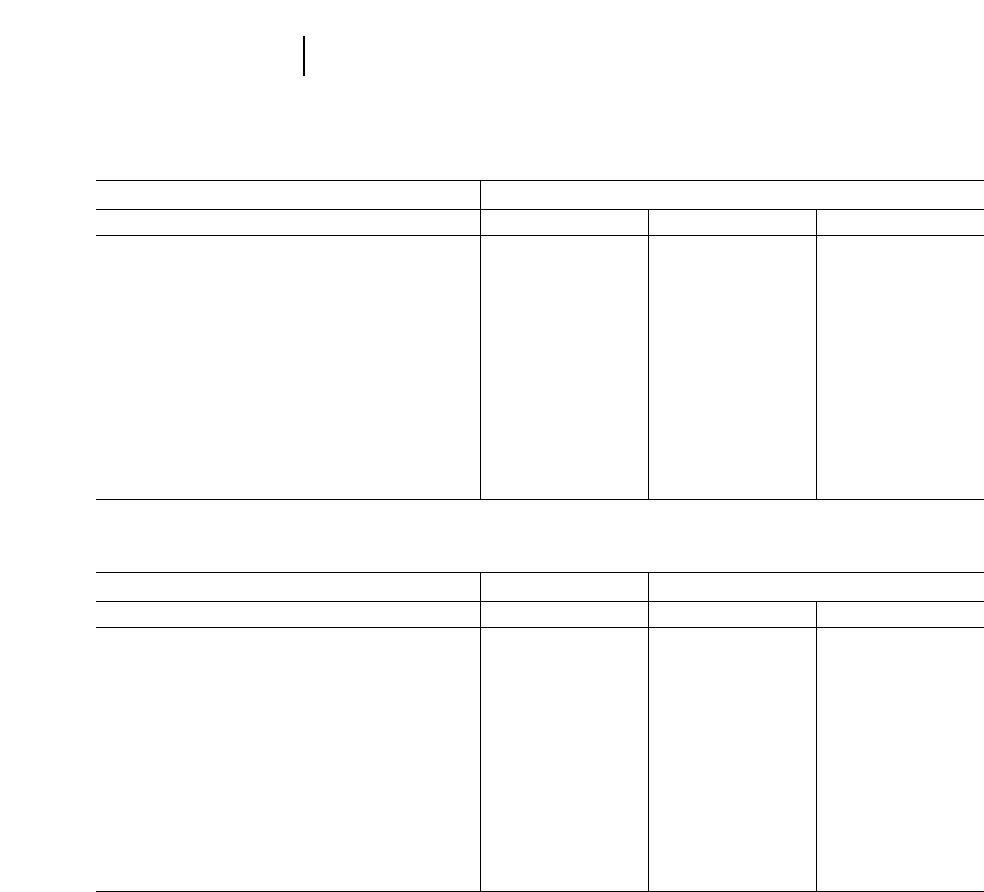
Centerpivot
Dimensions 416C 426C 436C
Overall transport length 6890 mm 22'7" 7260 mm 23'10" 7300 mm 23'11"
Overall length (loader on ground) 6870 mm 22'6" 7280 mm 23'11" 7295 mm 23'11"
Overall transport height 3585 mm 11'9" 3770 mm 12'4" 3750 mm 12'4"
Overall width, without bucket 2235 mm 7'4" 2235 mm 7'4" 2235 mm 7'4"
Height to top of cab 2850 mm 9'4" 2850 mm 9'4" 2870 mm 9'5"
Height to top of stack 2670 mm 8'9" 2670 mm 8'9" 2710 mm 8'11"
Height to top of steering wheel 1940 mm 6'4" 1940 mm 6'4" 1965 mm 6'5"
Ground clearance (minimum) 297 mm 12" 291 mm 12" 352 mm 14"
Rear axle centerline to front grill 2660 mm 8'9" 2660 mm 8'9" 2660 mm 8'9"
Front wheel tread 1780 mm 5'10" 1977 mm 6'4" 1828 mm 6'0"
Rear wheel tread 1714 mm 5'8" 1714 mm 5'8" 1714 mm 5'8"
Wheel base: (2WD) 2100 mm 6'11" 2100 mm 6'11" 2100 mm 6'11"
Wheel base: (4WD) 2100 mm 6'11" 2100 mm 6'11" 2100 mm 6'11"
Centerpivot Sideshift
Dimensions 446B 428C 438C
Overall transport length 7954 mm 26'1" 5760 mm 18'11" 5740 mm 18'10"
Overall length (loader on ground) 7922 mm 26'0" 5710 mm 18'9" 5665 mm 18'7"
Overall transport height 4193 mm 13'9" 3740 mm 12'3" 3765 mm 12'4"
Overall width, without bucket 2434 mm 8'0" 2392 mm 7'10" 2392 mm 7'10"
Height to top of cab 2864 mm 9'5" 2900 mm 9'6" 2900 mm 9'6"
Height to top of stack 2960 mm 9'9" 2700 mm 8'10" 2750 mm 9'0"
Height to top of steering wheel 2111 mm 6'11" 1940 mm 6'4" 1940 mm 6'4"
Ground clearance (machine main frame) 332 mm 13" 320 mm 13" 335 mm 13"
Rear axle centerline to front grill 2752 mm 9'0" 2613 mm 8'7" 2620 mm 8'7"
Front wheel tread 1970 mm 6'6" 1780 mm 5'10" 1780 mm 5'10"
Rear wheel tread 1800 mm 5'11" 1714 mm 5'7" 1714 mm 5'7"
Wheel base: (2WD) 2233 mm 7'4" 2100 mm 6'11" 2100 mm 6'11"
Wheel base: (4WD) 2233 mm 7'4" 2100 mm 6'11" 2100 mm 6'11"
5-28
Backhoe Loaders Machine Dimensions

5-29
5
Backhoe LoadersSpecial Attachments
Loader End Work Tools 446B 436C 428C 426C 416C
Quick coupler XXXXX
General purpose bucket XXXXX
Light material bucket XXXXX
Multi-purpose bucket XXXXX
Pallet fork XXXXX
Hydraulic angle blade XXXXX
Hydraulic broom XXXXX
Asphalt cutter XXXXX
Loader rake XXXXX
Side dump bucket XXXXX
Stick End Work Tools 446B 436C 428C 426C 416C
Ditch cleaning bucket XXXXX
Heavy duty bucket XXXXX
Extreme service bucket XXXXX
Hydraulic hammer XXXXX
Vibratory plate compactor XXXXX
This list is not all-inclusive. Contact Caterpillar Special Attachments for special attachment needs.

6-1
CONTENTS
WHEEL SKIDDERS
Features . . . . . . . . . . . . . . . . . . . . . . . . . . . . . . .6-1
Specifications . . . . . . . . . . . . . . . . . . . . . . . . . . .6-2
Rimpull and speed . . . . . . . . . . . . . . . . . . . . . . .6-3
Grapple Information:
SAE specification definition . . . . . . . . . . . . . .6-5
Single-function grapples . . . . . . . . . . . . . . . . .6-6
Dual-function grapples . . . . . . . . . . . . . . . . . .6-7
Swing-boom . . . . . . . . . . . . . . . . . . . . . . . . . . .6-8
TRACK SKIDDERS
Features . . . . . . . . . . . . . . . . . . . . . . . . . . . . . . .6-9
Specifications . . . . . . . . . . . . . . . . . . . . . . . . . .6-10
Drawbar pull and speeds . . . . . . . . . . . . . . . . .6-11
Grapples . . . . . . . . . . . . . . . . . . . . . . . . . . . . . .6-13
Swing-boom . . . . . . . . . . . . . . . . . . . . . . . . . .6-14
525/515 Features:
●Proven Cat 3304 diesel engine. 515 is turbo-
charged; 525 is turbocharged and aftercooled.
●4 speed powershift transmission … provides bet-
ter match of engine power to skidding requirements.
●Long wheelbase for stability with large grapple
loads and uphill skidding.
●Front Axle Cradle oscillation — helps improve
tractor stability with grapples and provides excel-
lent ride for operator.
●Enclosed oil disk brakes, sealed, adjustment
free, and fade resistant.
●Load Sensing Hydraulic System — variable
displacement pressure compensating hydraulic
system provides reduced power requirements
when there is no hydraulic demand, significantly
reduced heat generation.
●Single, dual-function arch, swing-boom (525)
and cable skidder options available to meet var-
ious logging requirements.
●Outstanding operator environment superior
visibility, logical control placement, and signifi-
cantly reduced hydraulic, steering and transmis-
sion control efforts. ROPS structures meets OSHA
regulations for roll-over and falling object.
●Easy servicing — minimal daily requirements,
grouped and accessible grease fittings, accessible
hydraulic oil sight gauges, engine oil dipstick and
fuel cap.
528B Features:
●Proven Cat 3306 Turbocharged diesel engine
provides power and outstanding durability and
reliability.
●Frame oscillation for excellent side hill stability.
●Caliper disk brakes — reliable and easy to service.
●Protection for operator and machine — ROPS
structures and guarding provide operator and
machine protection in the most severe logging
environments.
6
WHEEL SKIDDERS
TRACK SKIDDERS
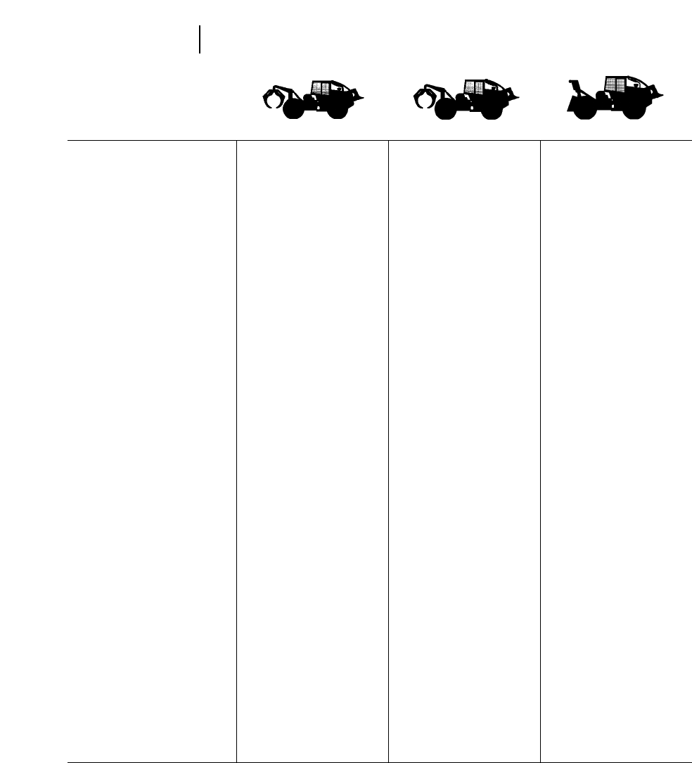
MODEL 515 525 528B
Flywheel Power 104 kW 140 hp 118 kW 160 hp 138/145 kW 185/195 hp
Operating Weight 12 700 kg 27,940 lb 15 200 kg 33,500 lb 15 550 kg 34,210 lb
Engine Model 3304 3304 3306
Rated Engine RPM 2200 2200 2200
No. Cylinders 446
Displacement 7 L 425 in37 L 425 in310.5 L 638 in3
Oscillation, Type front axle cradle front axle cradle frame (center hitch)
Oscillation, degrees ±15° ±15° ±14°
Tires, standard 23.1-26 23.1-26 24.5-32
Tires, optional 28L-26 28L-26 30.5-32
67/34-25 67/34-25
66/43-25 66/43-25
73/44-32
Turning Diameter
(outside rear wheel)* 5.532 m 36'6" 11.4 m 37'5" 11.86 m 38'10"
Heavy Duty Winch Line Pull,
max. at stall, bare drum 13 608 kg 30,000 lb 19 500 kg 43,000 lb 18 140 kg 40,000 lb
Line Speed at Rated Engine
RPM, full drum 97.5 m/min 300 fpm 101 m/min 333 fpm 113 m/min 370 fpm
Winch Weight 522 kg 1150 lb 522 kg 1150 lb 522 kg 1150 lb
Drum Capacity,
Standard — 5/8 (16 mm) 96 m 315'0" 96 m 315'0" 66 m 216'0"
DrOptional — 3/4 (19 mm) 66 m 216'0" 65 m 213'0" 96 m 315'0"
Flange Diameter 495 mm 1'7.5" 495 mm 1'7.5" 495 mm 1'7.5"
Drum Width 200 mm 7.88" 200 mm 7.88" 200 mm 7.88"
Drum Diameter 305 mm 12" 305 mm 12" 305 mm 12"
Fuel Tank Refill Capacity 185 L 48 U.S. gal 258 L 68 U.S. gal 208 L 55 U.S. gal
Hydraulic Retrieval Device
Line Pull, max at stall,
bare drum 88 kN 19,800 lb 88 kN 19,800 lb —
Line Speed at Rated Engine
RPM, bare drum 29.25 m/min 96 fpm 29.25 m/min 96 fpm —
HRD Weight 499 kg 1100 lb 499 kg 1100 lb —
Drum Capacity — 5/8 (16 mm) 67 m 18'4" 67 m 18'4" —
Drum Diameter 254 mm 10" 254 mm 10" —
Hydraulic System Refill Capacity 75 L 19.5 U.S. gal 74 L 19.5 U.S. gal 75 L 19.5 U.S. gal
GENERAL DIMENSIONS*
Length with Dozer @ ground 5.8 m 19'0" 6.00 m 19'8" 6.76 m 22'2"
Wheelbase 3.30 m 10'10" 3.50 m 11'6" 3.25 m 10'8"
Width over Tires* 2.72 m 9'0" 3.13 m 10'3" 2.96 m 9'9"
Height to Top of ROPS 3.03 m 9'11.5" 3.05 m 10'0" 3.07 m 10'1"
Height to Exhaust 3.07 m 10'1" 3.09 m 10'1.5" 3.13 m 10'3"
Ground Clearance* 457 mm 18" 527 mm 1'8.7" 610 mm 2'0"
Tread Width* 2.10 m 6'11" 2.39 m 7'10" 2.34 m 7'8"
Dozer Width 2.16 m 7'1" 2.16 m 7'1" 2.29 m 7'6"
*With standard tires.
6-2
Wheel Skidders Specifications
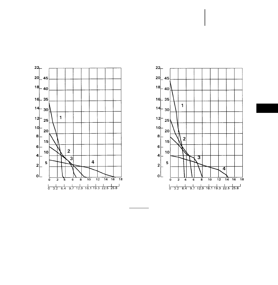
6-3
1st 2nd 3rd 4th
Forward, km/h . . . . . . . . . . . . . . . . . . 6.21 10.63 15.00 27.15
Forward, mph . . . . . . . . . . . . . . . . . . 3.86 6.61 9.32 16.87
Reverse, km/h . . . . . . . . . . . . . . . . . . 6.21 10.63 19.22 —
Reverse, mph . . . . . . . . . . . . . . . . . . 3.86 6.61 11.95 —
1st 2nd 3rd 4th
Forward, km/h . . . . . . . . . . . . . . . . . . 5.37 9.2012.97 23.5
Forward, mph . . . . . . . . . . . . . . . . . . 3.34 5.72 8.06 14.6
Reverse, km/h . . . . . . . . . . . . . . . . . . 5.37 9.2016.64 —
Reverse, mph . . . . . . . . . . . . . . . . . . 3.34 5.72 10.34 —
6
Wheel SkiddersRimpull vs Ground Speed
●515 ●525
515 Skidder
SPEED SPEED
525 Skidder
kg x
1000 lb x
1000
RIMPULL
RIMPULL
mph
km/h km/h
KEY
1 — 1st Gear
2 — 2nd Gear
3 — 3rd Gear
4 — 4th Gear
kg x
1000 lb x
1000
mph
Usable rimpull depends on traction, tire size and equipped weight of loaded machines. Grapple weights may vary.
NOTE: Rimpull shown with 28L-26 tires. Consult your Caterpillar Dealer for further information.
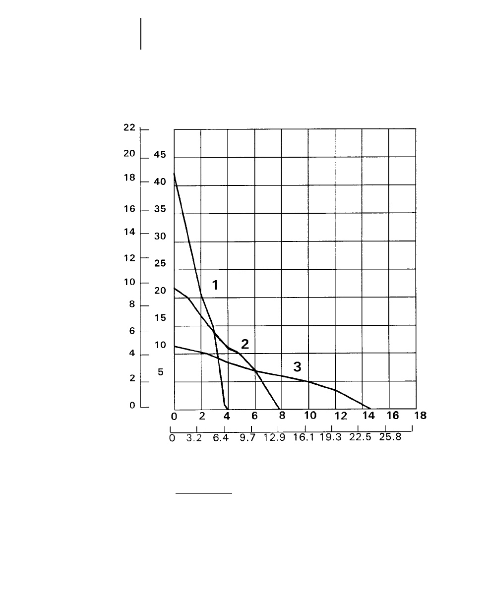
6-4
Wheel Skidders Power Shift Rimpull vs. Ground Speed
●528B
528B Skidder
kg 3
1000 lb 3
1000
mph
km/h
SPEED
RIMPULL
NOTE: Usable pull will depend upon weight and traction of equipped tractor.
KEY
1 — 1st Gear
2 — 2nd Gear
3 — 3rd Gear

GRAPPLES
Grapples for Cat 515 and 525 Skidders are built by
independent manufacturers of auxiliary equipment
(AEMS) to Caterpillar specifications. All fixed and
swing grapples are factory installed and supplied by
Caterpillar. The following pages contain informa-
tion on the available models, which are presented
here to suggest a range of grapple possibilities. The
specifications were supplied by the manufacturer
and follow the SAE definitions listed below.
SAE specification definition
Reach (A, B, C, D) — The horizontal distance from
the vertical center of the rear axle to the vertical
center of the grapple fore and aft pivot.
A) With the grapple in its highest farthest position
B) With the grapple in its lowest farthest position
C) With the grapple in its highest fully retracted
position
D) With the grapple in its lowest fully retracted
position
Lift (E, F, G, H) — The vertical distance from the hor-
izontal center of the rear axle to the horizontal cen-
ter of the grapple fore and aft pivot.
E) With the grapple in its highest farthest position
F) With the grapple in its lowest farthest position
G) With the grapple in its highest fully retracted
position
H) With the grapple in its lowest fully retracted
position
Loaded Tire Radius (J) — Vertical distance from
horizontal center of axle to horizontal reference
plane.
Maximum Grapple Opening (K) — The horizontal
distance between the tips of the grapple arms when
grapple is fully open.
Area of Opening (L) — The available area with
grapple in tips together position.
Minimum Log Size (M) — The smallest diameter
which the grapple can close on.
Grapple Length (N, O, P) — The distance from the
grapple fore and aft pivot to tips of grapple arms.
N) With grapple fully open
O) With grapple in tips together position
P) With grapple fully closed
6-5
6
Wheel Skidders515 and 525 Grapple Information
●SAE Specification Definition
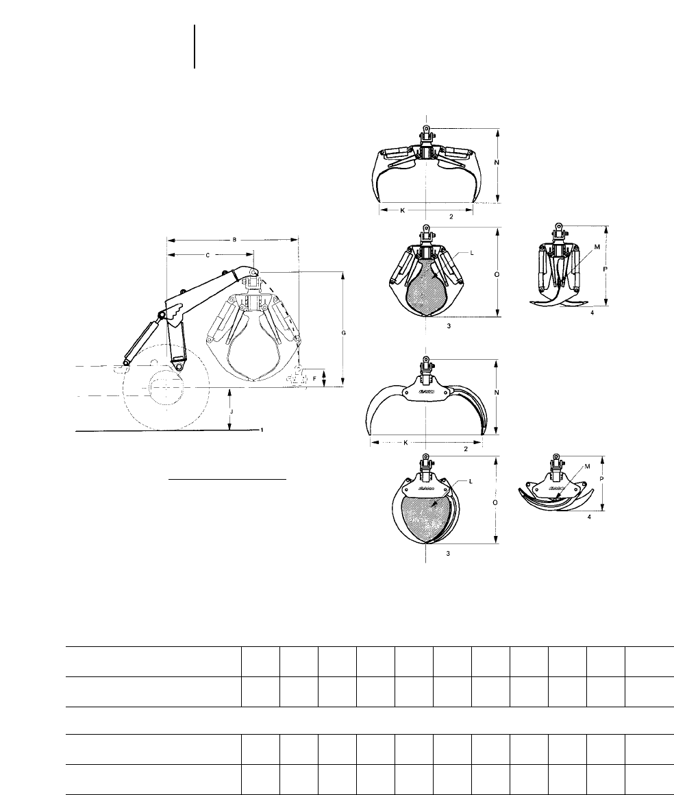
6-6
Wheel Skidders Grapples
●Single-function Arch
Grapples for 515 B C F G J K M N O P L
84" Sorting mm 2140 1323 515 223 724 2130 76 1680 1980 1740 0.74 m2
in 84.3 52.0 20 8 28.5 84 3 66 78 68.5 8 ft2
90" Bunching mm 2140 1323 515 223 724 2290 102 1640 1920 1310 0.74 m2
in 84.3 52.0 20 8 28.5 90 4 64 75 51 8 ft2
Grapples for 525 B C F G J K M N O P L
100" Sorting mm 2517.1 1662.2 342.9 2169.2 737 2540.0 76.2 1562.1 2044.7 1828.8 0.84 m2
in 99.1 65.4 13.5 85.4 29 100.0 3.0 61.5 80.5 72.0 9 ft2
110" Bunching mm 2517.1 1662.2 342.9 2169.2 737 2794.0 76.2 1879.6 2171.7 1358.9 1.04 m2
in 99.1 65.4 13.5 85.4 29 110.0 3.0 74.0 85.5 53.5 11.2 ft2
KEY
1 — Horizontal Reference Plane
2 — Fully Open
3 — Tip to Tip
4 — Fully Closed
Single-function arch
●Versatile attachment suitable for selection or
clear cut applications. Reach consists of one ver-
tical arc and typical application is short cycles
and/or larger diameter timber.
Sorting grapple is designed
to pick up individual or
several stems for quick
cycles of 305 mm (12")
or larger diameter trees.
Bunching grapple is
designed to gather bundled
stems and maximize grapple
loads of 305 mm (12") or
smaller diameter trees.
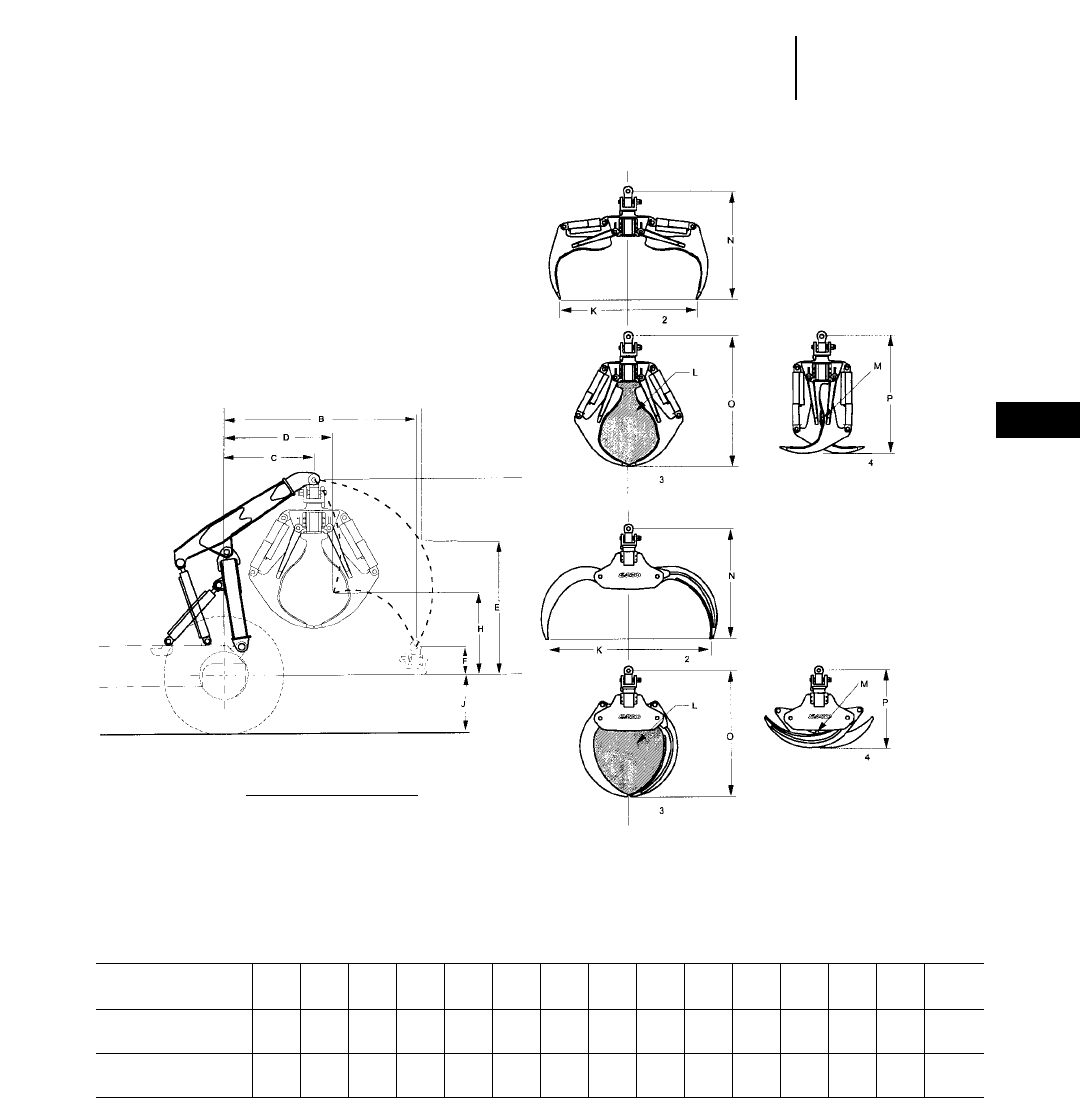
6-7
6
Wheel SkiddersGrapples
●Dual Function Arch
Grapples
for 525 ABCDEFGHJKMNOP L
100" Sorting mm 2725.4 2654.3 1242.1 1491.0 1828.8 378.5 2694.9 1125.2 731.5 2540.0 76.2 1562.1 2044.7 1828.8 0.84 m2
in 107.3 104.5 48.9 58.7 72.0 14.9 106.1 44.3 28.8 100.0 3.0 61.5 80.5 72.0 9 ft2
110" Bunching mm 2725.4 2654.3 1242.1 1491.0 1828.8 378.5 2694.9 1125.2 731.5 2794.0 76.2 1879.6 2171.7 1358.9 1.04 m2
in 107.3 104.5 48.9 58.7 72.0 14.9 106.1 44.3 28.8 110.0 3.0 74.0 85.5 53.5 11.2 ft2
120" Bunching mm 2725.4 2654.3 1242.1 1491.0 1828.8 378.5 2694.9 1125.2 731.5 3048.0 203.2 1778.0 2235.2 1574.8 1.16 m2
in 107.3 104.5 48.9 58.7 72.0 14.9 106.1 44.3 28.8 120.0 8.0 70.0 88.0 62.0 12.5 ft2
KEY
1 — Horizontal Reference Plane
2 — Fully Open
3 — Tip to Tip
4 — Fully Closed
Dual-function arch
●Extended range provides extra reach for grabbing
large bundles of feller bunched, small diameter logs.
●Ability to position load closer to tractor for improved
stability and traction.
●Typical applications include longer cycles and smaller
diameter bunched timber.
Sorting grapple is designed
to pick up individual or
several stems for quick
cycles of 305 mm (12")
or larger diameter trees.
Bunching grapple is
designed to gather bundled
stems and maximize grapple
loads of 305 mm (12") or
smaller diameter trees.
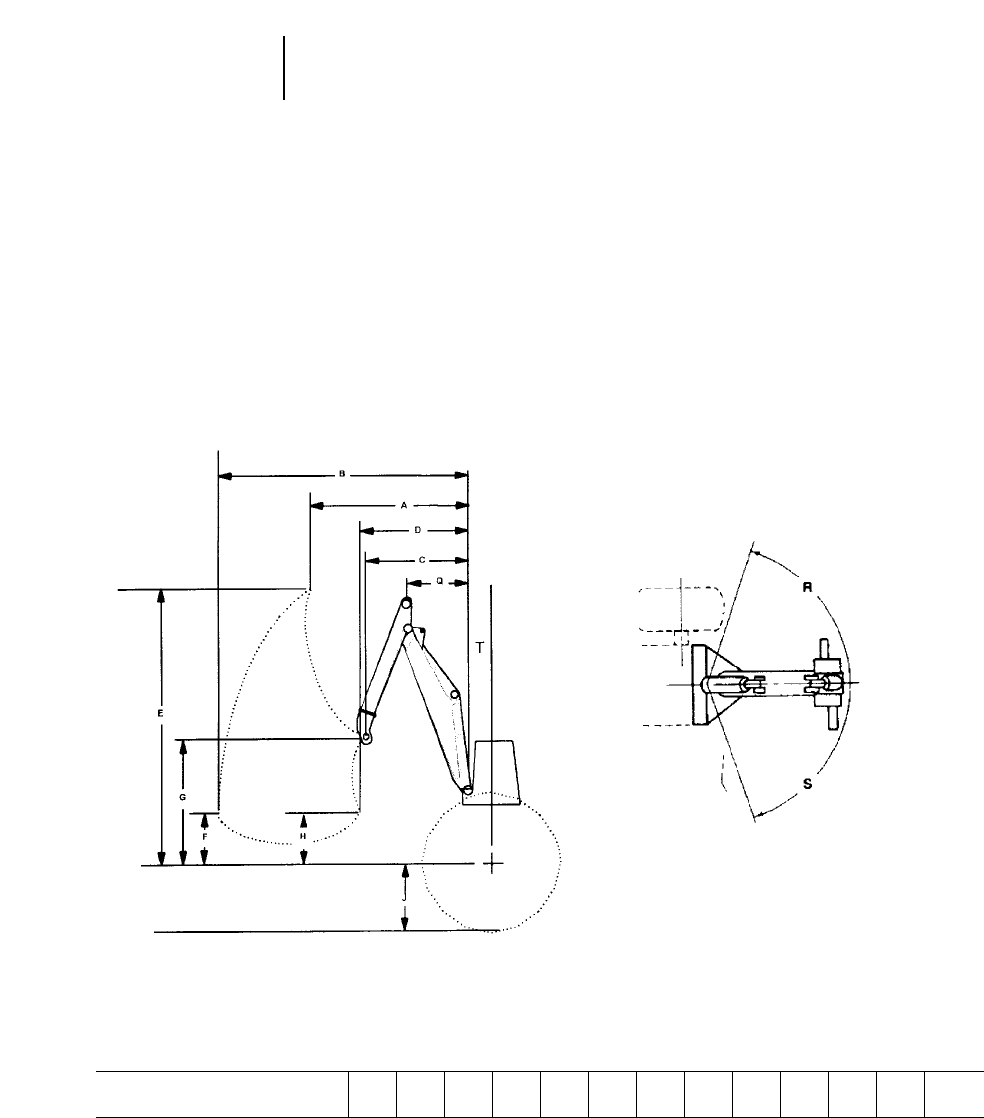
6-8
Wheel Skidders Grapples
●Swing-boom
Grapples for 525
with Swing-boom ABCDEFGHJQRS T
100" Sorting mm 2257 3705 1365 1410 3818 500 1671 127 737 904 70° 70° 207
in 89 146 54 56 150 20 66 5 29 35.6 8
Swing-boom
●Ability to reach and lift over the side to collect
scattered logs.
●Has decking and loading capability.
●Excellent reach to the rear and side for maximum
skidder versatility.
●Suitable for hard to reach timber on steep slopes,
soft ground, or selection harvest and thinning.
●Reduces cycle times by reducing the amount of
manuevering of the skidder to reach logs.

6-9
CONTENTS
Features . . . . . . . . . . . . . . . . . . . . . . . . . . . . . . .6-9
Specifications . . . . . . . . . . . . . . . . . . . . . . . . . .6-10
Power shift drawbar pull vs.
ground speed charts . . . . . . . . . . . . . . . . . . .6-11
Grapple information . . . . . . . . . . . . . . . . . . . . .6-13
Features 517 and 527:
●Exceptional balance — roller frames extended
to rear significantly improves traction capability
under heavy loads and uphill skidding applica-
tions.
●Excellent ground clearance — no diagonal
braces allow tractor to pass over stumps and debris,
reduces maneuvering for reduced cycle times and
minimizes soil impact. Smooth belly pans are also
less likely to hang up in mud or debris in soft
ground or swamp logging applications.
●Outstanding sidehill stability — wide gauge
and long track roller frames provide excellent
sidehill capability.
●Improved flotation — more track on ground dis-
tributes tractor weight and propulsion forces over
a much larger area than conventional track skid-
ders or wheel skidders. This improves flotation
capabilities, gradeability and significantly reduces
soil impact.
●Superior component durability — final drives
are raised above the work area, isolating the power-
train from ground impact shock loads and abrasive
materials.
●Outstanding reliability and durability — built
to handle the toughest logging conditions.
6
TRACK SKIDDERS
6-10
MODEL 517 Cable 517 Grapple 527 Cable 527 Grapple
Flywheel Power 89 kW 120 hp 89 kW 120 hp 112 kW 150 hp 112 kW 150 hp
Operating Weight* 17 330 kg 38,200 lb 18 350 kg 40,450 lb 17 236 kg 38,000 lb 21 380 kg 47,140 lb
Engine Model 3304 DIT 3304 DIT 3304 3304
Rated Engine RPM 2200 2200 2200 2200
No. of Cylinders 4444
Bore 121 mm 4.75" 121 mm 4.75" 121 mm 4.75" 121 mm 4.75"
Stroke 152 mm 6" 152 mm 6" 152 mm 6" 152 mm 6"
Displacement 7 L 425 in37 L 425 in37 L 425 in37 L 425 in3
Track Rollers (Each Side) 8877
Width of Standard Track Shoe 660 mm 2'2" 660 mm 2'2" 560 mm 1'10" 560 mm 1'10"
Length of Track on Ground 2.91 m 9'7" 2.91 m 9'7" 2.85 m 9'4" 2.85 m 9'4"
Ground Contact Area (W/Std. Shoe) 3.52 m25458 in23.52 m25458 in23.19 m24940 in23.19 m24940 in2
Track Gauge 2 m 6'7" 2 m 6'7" 2.16 m 7'1" 2.16 m 7'1"
GENERAL DIMENSIONS:
Height (To Top of ROPS) 2.48 m 8'1" 2.48 m 8'1" 3.30 m 10'10" 3.30 m 10'10"
Overall Length (With Blade) 4.97 m 16'4" 5.75 m 18'10" 4.94 m 16'3" 6.07 m 19'11"
Overall Length (Without Blade) 4.10 m 13'5" 4.87 m 16'0" 4.35 m 14'3" 5.6 m 18'5"
Width (W/O Trunnion) 2.91 m 9'7" 2.91 m 9'7" 2.72 m 8'11" 2.72 m 8'11"
Ground Clearance 635 mm 2'1" 635 mm 2'1" 531.8 mm 1'8.9" 531.8 mm 1'8.9"
PAT Blade Widths:
Straight 2.74 m 9'0" 2.74 m 9'0" 3.35 m 11'0" 3.17 m 10'5"
Angle 2.48 m 8'1" 2.48 m 8'1" 3.10 m 10'2" 2.92 m 9'7"
Fuel Tank Capacity 260 L 69 U.S. gal 260 L 69 U.S. gal 256 L 67 U.S. gal 256 L 67 U.S. gal
Winch
Line Pull, max at stall,
bare drum** 31 260 kg 68,780 lb 31 260 kg 68,780 lb 31 389 kg 69,200 lb 31 389 kg 69,200 lb
Line Speed at Rated Engine
RPM, bare drum** 40.5 m/min 133 fpm 40.5 m/min 133 fpm 44 m/min 143 fpm 44 m/min 143 fpm
Winch Weight 1500 kg 3300 lb 1500 kg 3300 lb 1500 kg 3300 lb 1500 kg 3300 lb
Drum Capacity: Recommended 122 m 400'0" 122 m 400'0" 122 m 400'0" 122 m 400'0"
Optional 88 m 290'0" 88 m 290'0" 88 m 290'0" 88 m 290'0"
Cable Size: Recommended 19 mm 0.75" 19 mm 0.75" 19 mm 0.75" 19 mm 0.75"
Optional 22 mm 0.88" 22 mm 0.88" 22 mm 0.88" 22 mm 0.88"
Drum Diameter 254 mm 10" 254 mm 10" 254 mm 10" 254 mm 10"
**All models include coolant, lubricants, full fuel tank, and operator.
517 Cable includes enclosed cab and 4PAT blade.
517 Grapple includes enclosed cab, 4PAT blade, swing boom, and 0.74 m2(8 ft2)grapple.
527 Cable includes lubricants, coolant, ROPS Canopy, 100% Fuel, operator, 5A blade, open cab, and towing winch.
**527 Grapple includes lubricants, coolant, ROPS Canopy, 100% Fuel, operator, 5P blade, track roller guard, 660 mm (2'2") tri-link track, Swing Grapple, 100" Sorting head,
and enclosed cab.
**With 22 mm (0.88") cable.
Track Skidders Specifications
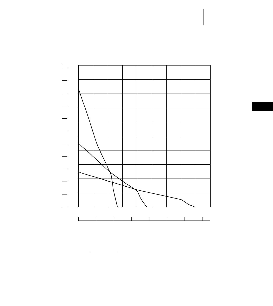
6-11
6
Track SkiddersPower Shift Drawbar Pull vs. Ground Speed
●517
22
20
18
16
14
12
10
8
6
4
2
0
50
45
40
35
30
25
20
15
10
5
0
02468101214
123456789
1
2
3
517 Skidder
kg 3
1000 lb 3
1000
mph
km/h
SPEED
DRAWBAR PULL
NOTE: Usable pull will depend upon weight and traction of equipped tractor.
KEY
1 — 1st Gear
2 — 2nd Gear
3 — 3rd Gear
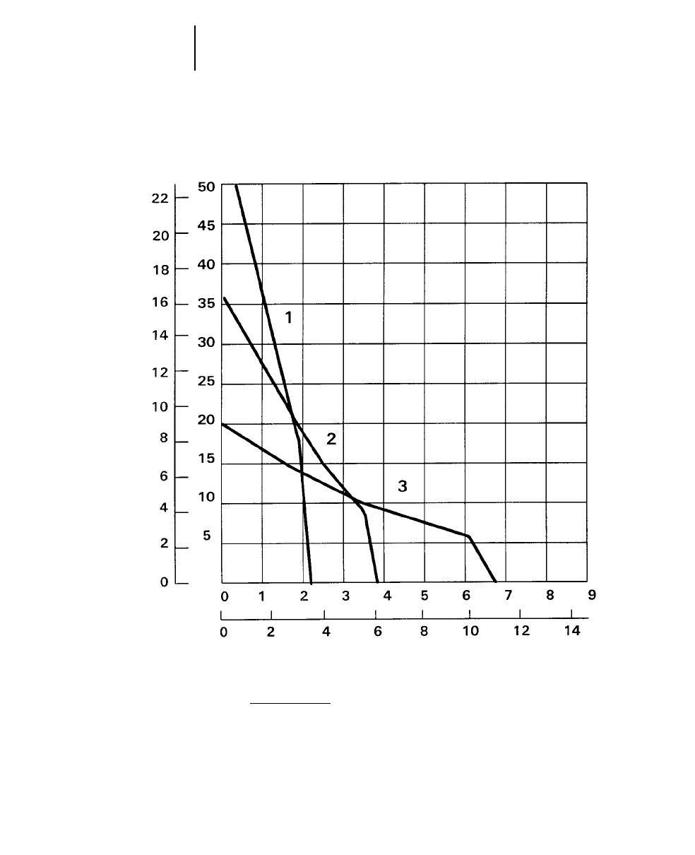
6-12
Track Skidders Power Shift Drawbar Pull vs. Ground Speed
●527
527 Skidder
kg 3
1000 lb 3
1000
mph
km/h
SPEED
DRAWBAR PULL
NOTE: Usable pull will depend upon weight and traction of equipped tractor.
KEY
1 — 1st Gear
2 — 2nd Gear
3 — 3rd Gear
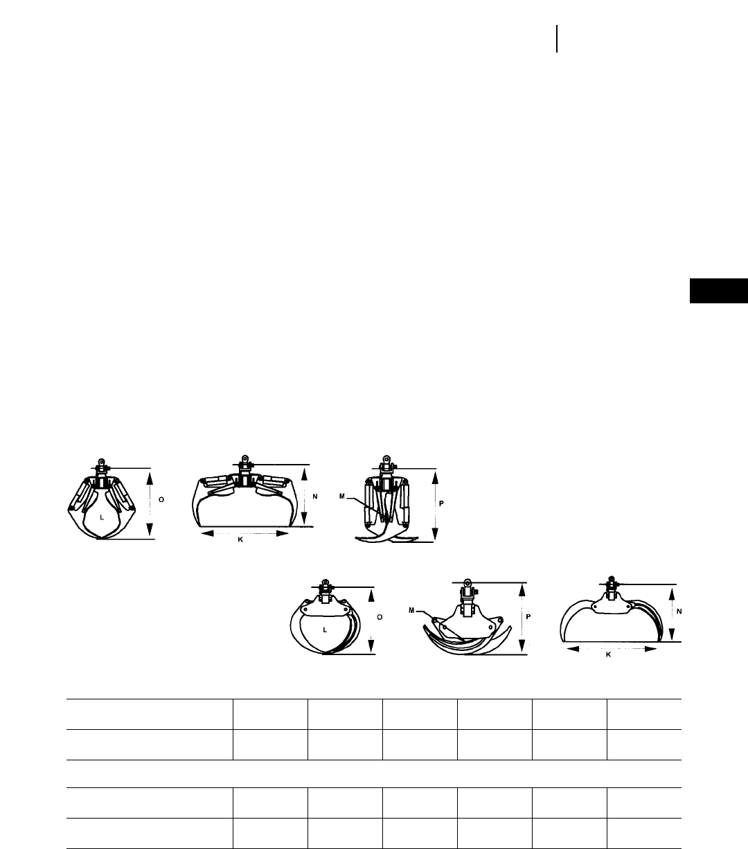
6-13
Grapples for 517 K M N O P L
84" Sorting mm 2130 76 1680 1980 1740 0.74 m2
in 84 3 66 78 68.5 8 ft2
90" Sorting mm 2290 102 1640 1920 1310 0.74 m2
in 90 4 64 75 51 8 ft2
Grapples for 527 K M N O P L
100" Sorting mm 2540 76 1560 2040 1830 0.84 m2
in 100 3 61.5 80.5 72 9 ft2
102" Bunching mm 2590 76 1780 2020 136 0.93 m2
in 102 3 70 79.5 53.5 10 ft2
6
Track SkiddersGrapples
GRAPPLES
Fixed boom Grapples for Cat 517 and 527 Skidders
are built and supplied by Caterpillar. Swing boom
grapples are built by independent manufacturers of
auxiliary equipment (AEMS) to Caterpillar specifi-
cations. The following contains information on some
of the available models, which are presented here
to suggest a range of grapple possibilities.
Reach (A, B) — The horizontal distance from the
vertical center of the rear idler to the vertical cen-
ter of the grapple fore and aft pivot.
A) With the grapple in its lowest fully extended
position.
B) With the grapple in its highest fully retracted
position.
Lift (C, E) — The vertical distance from the
ground to the center of the grapple fore and aft
pivot.
C) With the grapple in its lowest fully extended
position.
E) With the grapple in its highest fully retracted
position.
Maximum Grapple Opening (K) — The hori-
zontal distance between the tips of the grapple arms
when grapple is fully open.
Area of Opening (L) — The available area with
grapple in tips together position.
Minimum Log Size (M) — The smallest diam-
eter which the grapple can close.
Grapple Length (N, O, P) — The distance from
the grapple fore and aft pivot to tips of grapple arms.
N) With grapple fully open.
O) With grapple in tips together position.
P) With grapple fully closed.
Sorting Grapple
●Used for 305 mm (12") or larger
diameter trees.
●Designed to pick up individual or
several stems for quick cycles.
Bunching Grapple
●Used for 305 mm (12") or smaller
diameter trees.
●Designed to gather bundle of stems
and maximize grapple loads.
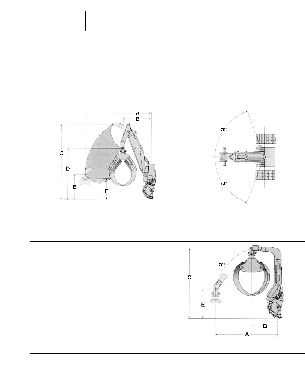
6-14
Swing-boom
●Ability to reach and lift over the side to collect
scattered logs.
●Has decking and loading capability.
●Excellent reach to the rear and side for maximum
skidder versatility.
●Suitable for hard to reach timber on steep slopes,
soft ground, or selection harvest and thinning.
●Reduces cycle times by reducing the amount of
manuevering of the skidder to reach logs.
Single-function arch
●Versatile attachment suitable for selection and
clear cut applications.
●Reach consists of one vertical arc.
●Typical application includes short cycles and/or
larger diameter timber.
Track Skidders Grapples
●Swing-boom
Swing-boom ABCDEF
517 mm 3269 1241 4092 2800 1366 1166
in 129 49 161 110 54 46
527 mm 3544 1515 4048 2792 1358 1158
in 139 60 160 110 53 46
Single-function ABCDEF
517 mm 2465 909 2974 — 1000 —
in 96 36 117 — 39 —
527 mm 2619 1105 2970 — 1231 —
in 103 44 117 — 49 —

7-1
CONTENTS
Features . . . . . . . . . . . . . . . . . . . . . . . . . . . . . . .7-1
Specifications . . . . . . . . . . . . . . . . . . . . . . . . . . .7-2
Lifting capacities . . . . . . . . . . . . . . . . . . . . . . . .7-3
Drawbar Pull Charts . . . . . . . . . . . . . . . . . . . . .7-5
Travel and hook speeds . . . . . . . . . . . . . . . . . . .7-6
Features:
●Planetary power shift transmission on all
models.
●Kick-out helps prevent boom bending as
boom approaches near-vertical.
●Sealed and Lubricated Track.
●Simplified Controls, two levers control all func-
tions including raise, lower, quick-drop and power
down, high and low range and speed adjustments.
●Modular design of major components and
accessory drive system for simplified repair.
●Separate, self-energizing brakes for boom and
hook winches.
●Positive track pin retention (572R, 583R and 589).
●Hydraulic Drawworks with two independently
driven hydraulic motors for boom and hook
winches.
●Suspended Undercarriage for improved ride
and greater operator comfort (583R and 589).
7
PIPELAYERS
MODEL 561M 572R 583R 589
Flywheel Power 82 kW 110 hp 171 kW 230 hp 228 kW 305 hp 313 kW 420 hp
Operating Weight 16 240 kg 35,800 lb 30 110 kg 66,250 lb 44 750 kg 98,650 lb 65 366 kg 151,212 lb
(with full fuel tank and operator)
Engine Model 3116T 3306TA 3406C TA 3408TA
Rated Engine RPM 2100 2100 2100 1900
No. of Cylinders 6 668
Displacement 6.6 L 403 in310.5 L 638 in314.6 L 893 in318 L 1099 in3
Lift Capacity at 1.22 m (4'0") 18 145 kg 40,000 lb 40 910 kg 90,000 lb 63 500 kg 140,000 lb 104 330 kg 230,000 lb
Overhang
Standard Boom Length 5.49 m 18'0" 6.1 m 20'0" 6.1 m 20'0" 8.8 m 28'10"
Width of Standard Shoe 510 mm 1'8" 660 mm 2'2" 710 mm 2'4" 914 mm 3'0"
Length of Track on Ground 2.619 m 8'7" 3.167 m 10'5" 3.586 m 11'9" 4.29 m 14'1"
Ground Contact Area 2.67 m24120 in24.18 m23250 in25.1 m27896 in26.96 m212,148 in2
(with standard shoes)
Track Gauge 2.0 m 6'7" 2.235 m 7'4" 2.34 m 7'8" 2.9 m 9'6"
Fuel Tank Refill Capacity 218 L 57.6 479 L 127 416 L 110 776 L 205
U.S. gal U.S. gal U.S. gal U.S. gal
GENERAL DIMENSIONS:
Height to Top of Stack 3.12 m 10'3" 3.45 m 11'4" 3.51 m 11'6" 3.92 m 12'10"
Height to Top of Counterweight 1.68 m 5'6" 2.90 m 9'6" 3.41 m 11'2" 2.88 m 9'5"
Width, Weights Retracted 3.19 m 10'5" 3.66 m 12'0" 3.63 m 11'11" 4.63 m 15'2"
Minimum Shipping Width 2.90 m 9'6" 3.0 m 9'10" 3.48 m 11'5" 3.55 m 11'8"
(both side frames removed)
Shipping Width 3.05 m 10'0" 3.66 m 12'0" 3.51 m* 11'6"* —
(left frame removed)
Overall Length 3.73 m 12'3" 4.74 m 15'6" 5.48 m 18'0" 5.94 m 19'6"
Ground Clearance 438 mm 17.2" 414 mm 16.3" 537 mm 1'9.1" 625 mm 2'0.6"
DRUMS and CABLES:
Drum Capacity Load 73 m 239' 80 m 263' 126 m 415' 152 m 500'
Boom 49.4 m 162' 52 m 170' 126 m 415' 93 m 305'
Cable Diameter Load 16 mm 0.62" 19 mm 0.75" 19 mm 0.75" 22 mm 0.88"
Boom 16 mm 0.62" 19 mm 0.75" 19 mm 0.75" 22 mm 0.88"
Drum Diameter Load 216 mm 8.5" 254 mm 10" 343 mm 13.5" 343 mm 13.5"
Boom 245 mm 9.63" 224 mm 8.5" 343 mm 13.5" 343 mm 13.5"
Adjustable Counterweights 14 @ 9 @ 2 @ 7 @
177 kg ea 391 lb ea 216 kg ea 475 lb ea 299 kg ea 658 lb ea 1315 kg ea 2900 lb ea
6 @
535 kg ea 1180 lb ea
5 @
432 kg ea 952 lb ea
Total Weight Extendable 3270 kg 7208 lb 4320 kg 9524 lb 9016 kg 19,880 lb 11 854 kg 26,134 lb
*Boom and counterweight only removed.
7-2
Pipelayers Specifications
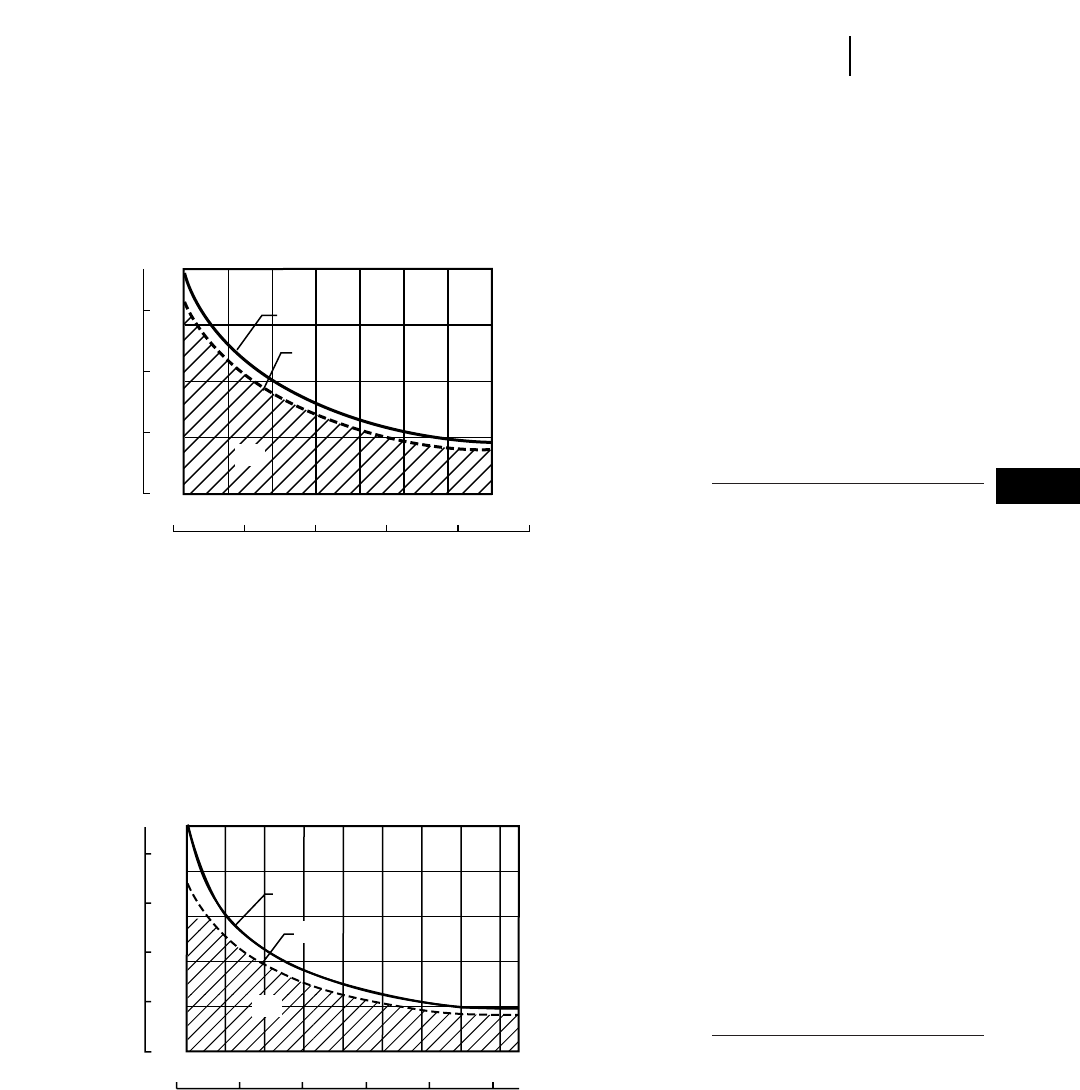
7-3
7
PipelayersLifting Capacities
15
10
5
0
123 456
40
30
20
10
064 8 10 12 14 16 18
(A)
(B)
(C)
561M
LIFTING CAPACITY* 5.49 m (18'0") BOOM
LOAD OVERHANG
kg x
1000 lb x
1000
feet
meters
LIFTING CAPACITY
*Specified Equipment:
●16 mm (5/8") diameter wire rope.
●18 688 kph (41,200 lb) minimum breaking strength.
●3 part load line.
●3 part boom line.
●3270 kg (7208 lb) counterweight extended.
●Total operating weight 16 240 kg (35,804 lb).
KEY
A — Max lift capacity per ANSI/SAE J743 MAR92
B — Rated load capacity per ANSI/ASME B30.14
C — Working range per ANSI/ASME B30.14
20
40
60
80
0
10
0
20
30
40
12345
4 6 8 101214161820
6
90
(C)
(A)
(B)
572R
LIFTING CAPACITY* 6.10 m (20'0") BOOM
LOAD OVERHANG
kg x
1000 lb x
1000
feet
meters
LIFTING CAPACITY
*Specified Equipment:
●19 mm (3/4") dia. wire rope 26 670 kg (58,800 lb) minimum
breaking strength.
●4 part load line.
●4 part boom line.
●4330 kg (9525 lb) of counterweights extended.
●6.10 m (20'0") Boom.
KEY
A — Max lift capacity per ANSI/SAE J743 MAR92
B — Rated load capacity per ANSI/ASME B30.14
C — Working range per ANSI/ASME B30.14
NOTE: SAE stands for the Society of Automotive
Engineers. ANSI stands for American
National Standard Institute.
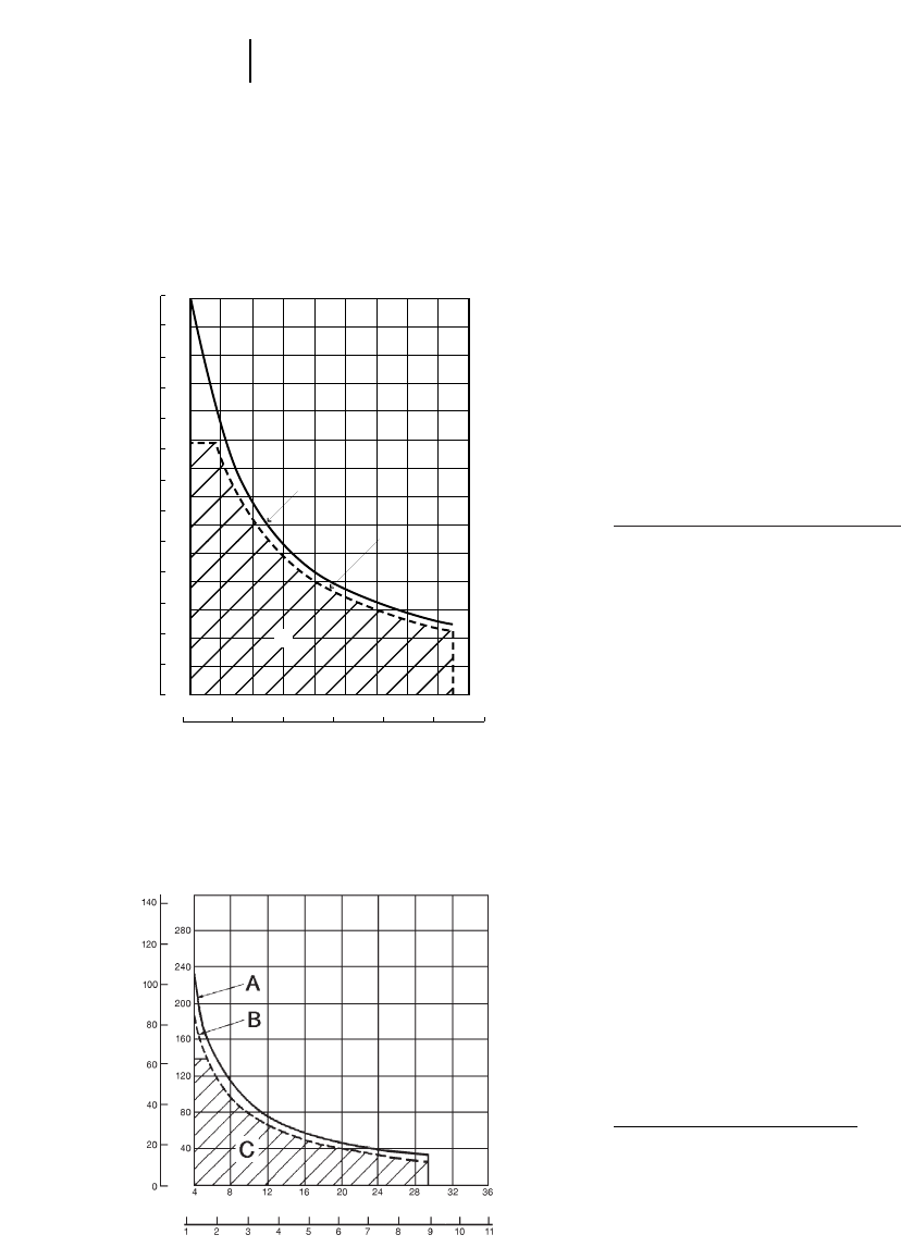
7-4
Pipelayers Lifting Capacities
15
2314567
4 6 8 10 12 14 16 18 20 22
0
5
10
20
25
30
35
40
50
55
60
65
45
40
50
60
70
80
90
100
30
20
10
0
110
120
130
140
A
B
C
583R
LIFTING CAPACITY* 6.10 m (20'0") BOOM
LOAD OVERHANG
kg x
1000 lb x
1000
feet
meters
LIFTING CAPACITY
*Specified Equipment:
●19 mm (3/4") diameter wire rope.
●26 672 kg (58,800 lb) minimum breaking strength.
●6 part load line.
●5 part boom line.
●9036 kg (19,920 lb) counterweight extended.
●boom 6.10 m (20 ft) standard.
●total operating weight 44 748 kg (98,650 lb).
KEY
A — Max lift capacity per SAE J743 MAR92
B — Rated load capacity per ANSI/ASME B30.14
C — Working range per ANSI/ASME B30.14
589
LIFTING CAPACITY* 8.53 m (28'0") BOOM
LOAD OVERHANG
kg x
1000 lb x
1000
feet
meters
LIFTING CAPACITY
*Specified Equipment:
●Load: 22 mm (7/8") dia. wire rope 31 389 kg (69,200 lb)
minimum breaking strength.
●Boom: 22 mm (7/8") dia. wire rope 31 389 kg (69,200 lb)
minimum breaking strength.
●8 part load line.
●8 part boom line.
●14 633 kg (32,260 lb) of counterweights extended.
●8.53 m (28'0") Boom.
KEY
A — Max lift capacity per SAE J743b
B — Max load capacity per ANSI B30.14
C — Working range per ANSI B30.14
NOTE: SAE stands for the Society of Automotive
Engineers. ANSI stands for American
National Standard Institute.
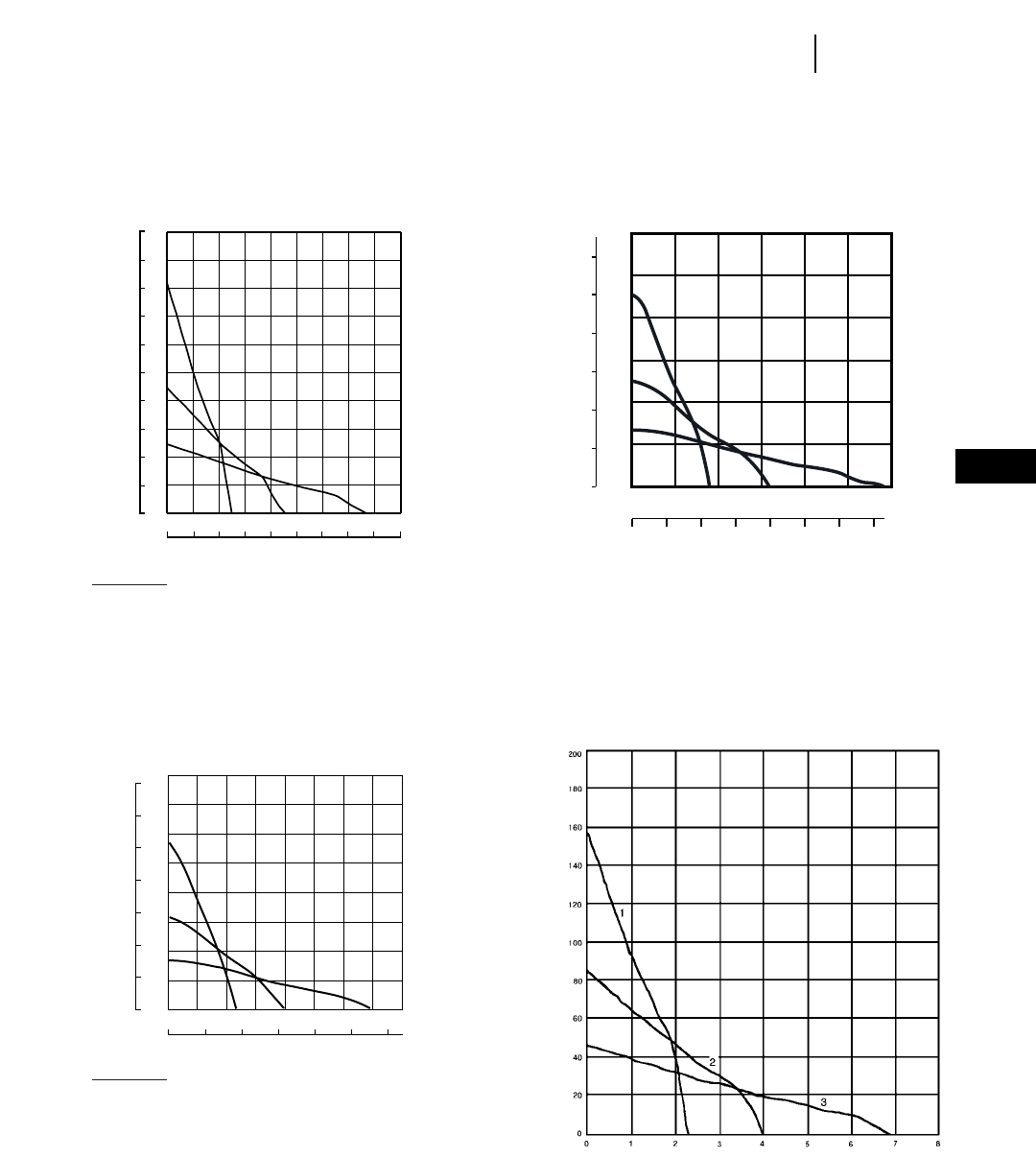
7-5
7
PipelayersDrawbar Pull vs Ground Speed
589
SPEED
DRAWBAR PULL
NOTE: Usable pull will depend upon weight and
traction of equipped tractor.
1.3 2.6 3.9 5.2 6.4 7.7 9.00 10.3
1
2
11.6
3
27.2
24.5
21.8
19.1
16.3
13.6
10.9
8.2
5.4
2.7
00.0 0.8 1.6 2.4 3.2 4.0 4.8 5.6 6.4 7.2
0
6
12
18
24
30
36
42
48
54
60
561M
SPEED
DRAWBAR PULL
kg 3
1000 lb 3
1000
mph
km/h
20
40
60
80
100
120
012 34567
8
64201012
20
10
30
40
50
0
0
60
1
23
572R
SPEED
DRAWBAR PULL
lb 3
1000 kg 3
1000
km/h
mph
KEY
1 — 1st Gear
2 — 2nd Gear
3 — 3rd Gear
70
60
50
40
30
20
10
0
160
140
120
100
80
60
40
20
0
024681012
012345678
1
2
3
583R
SPEED
DRAWBAR PULL
kg 3
1000 lb 3
1000
mph
km/h
KEY
1 — 1st Gear
2 — 2nd Gear
3 — 3rd Gear

MODEL 561M 572R
Travel Forward Reverse Forward Reverse
Speeds (at rated RPM) km/h mph km/h mph km/h mph km/h mph
1st Gear . . . . . . . . . . . . . . . . . . 3.27 2.03 4.01 2.49 3.5 2.3 4.7 2.9
2nd Gear . . . . . . . . . . . . . . . . . 5.81 3.61 7.09 4.41 6.4 4.0 8.1 5.0
3rd Gear . . . . . . . . . . . . . . . . . . 9.93 6.17 12.06 7.49 10.8 6.8 13.8 8.6
Pipelayer Hook Speeds per m/min ft/min m/min ft/min
minute, Bare drum at rated
engine RPM
First (Lo) . . . . . . . . . . . . . . . . . . (33) (108) (11) (37)
Second . . . . . . . . . . . . . . . . . . . — ———
Third (High) . . . . . . . . . . . . . . . (69.5) (228) (37) (75)
Lower . . . . . . . . . . . . . . . . . . . . — —16.3 53.4
Boom Line Speed . . . . . . . . . . . 46 151 73 241
MODEL 583R 589
Travel Forward Reverse Forward Reverse
Speeds (at rated RPM) km/h mph km/h mph km/h mph km/h mph
1st Gear . . . . . . . . . . . . . . . . . . 3.5 2.3 4.7 2.9 3.5 2.2 4.3 2.7
2nd Gear . . . . . . . . . . . . . . . . . 6.4 4.0 8.1 5.0 6.3 3.9 7.9 4.9
3rd Gear . . . . . . . . . . . . . . . . . . 10.8 6.8 13.8 8.6 10.9 6.8 13.7 8.5
Pipelayer Hook Speeds per m/min ft/min m/min ft/min
minute, Bare drum at rated
engine RPM
Low Raise . . . . . . . . . . . . . . . . . 7.5 24 5.8 19
High Raise . . . . . . . . . . . . . . . . 22.0 73 17.4 57
Lower (Powered) . . . . . . . . . . . 30.0 98 23.5 77
7-6
Pipelayers Travel Speeds
Hook Speeds

8-1
CONTENTS
Features . . . . . . . . . . . . . . . . . . . . . . . . . . . . . . .8-1
Specifications:
Standard Scrapers . . . . . . . . . . . . . . . . . . . . .8-2
Tandem Powered and Push-Pull Scrapers . . .8-3
Elevating Scrapers . . . . . . . . . . . . . . . . . . . . .8-4
Auger Scrapers . . . . . . . . . . . . . . . . . . . . . . . .8-5
Tire Options, all models . . . . . . . . . . . . . . . . . . .8-7
Use of Rimpull-Speed-Gradeability curves . . . .8-8
Use of Travel Time charts . . . . . . . . . . . . . . . .8-10
Fixed Times for Scrapers . . . . . . . . . . . . . . . . .8-11
Use of Retarder curves . . . . . . . . . . . . . . . . . . .8-11
Curves/charts:
613C Series II Rimpull, Travel Times . . . . .8-13
615C Series II Rimpull, Travel Times . . . . .8-16
621F Rimpull, Retarding, Travel Times . . .8-19
623F Rimpull, Retarding, Travel Times . . .8-25
627F Rimpull, Retarding, Travel Times . . .8-29
631E Series II Rimpull, Retarding,
Travel Times . . . . . . . . . . . . . . . . . . . . . . .8-35
633E Series II Rimpull, Retarding,
Travel Times . . . . . . . . . . . . . . . . . . . . . . .8-41
637E Series II Rimpull, Retarding,
Travel Times . . . . . . . . . . . . . . . . . . . . . . .8-45
651E Rimpull, Retarding, Travel Times . . .8-51
657E Rimpull, Retarding, Travel Times . . .8-55
Distance vs. Production Bm3(BCY)/hr,
All models . . . . . . . . . . . . . . . . . . . . . . . . . . .8-61
Hourly Production vs. Cycle Time
Bm3(BCY)/hr, All models . . . . . . . . . . . . . . .8-73
Features:
●Hydraulic Electronic Unit Injector (HEUI)
fuel system used in 631E Series II thru 657E.
●Semi-automatic power shift transmissions.
Eight speed used in 621F thru 657E.
●Power shift transmissions with six speeds used
in 613C Series II and 615C Series II.
●Differential lock ... operator controlled, rigidly
connects both tractor drive wheels for positive
traction.
●Cushion Hitch on 621F through 657E (optional
axle suspension on 615C Series II) absorbs haul
road shocks, stabilizes machine travel, substan-
tially increases usable working speeds.
●Double-acting hydraulics supply positive cut-
ting edge penetration, apron closure and material
ejection. Positive bulldozer-type ejection. Auto-
matic ejector return kickout.
●Quick-drop valves for pump loading (except
613C Series II, 615C Series II, 623F, 633E). Carry
check valves isolate bowl cylinders to carry load
rather than hydraulic lines.
●Hydraulic retarder standard on 651E/657E,
optional on 621F through 637E Series II. Not
available on 613C Series II or 615C Series II.
Tandem Powered:
●Push-Pull arrangement allows two 627F, 637E
Series II or 657E scrapers to assist one another
in loading eliminating the push tractor.
Elevating:
●Uninterrupted elevator reverse allows sticky
material to be ejected more easily.
●Two-speed elevator on 613C Series II and 615C
Series II allows operator to match elevator speed
to material conditions.
●Infinitely variable elevator speed on 623F
and 633E allows operator to match elevator speed
to material conditions.
Auger:
●Factory installed attachment provides self
loading capability in standard and tandem pow-
ered scrapers.
8
WHEEL TRACTOR-SCRAPERS

MODEL 621F 631E Series II 651E
Flywheel Power 246 kW 330 hp 335/365 kW 450/490 hp 410/452 kW 550/605 hp
Approx. Operating
Weight (Empty)§32 070 kg 70,700 lb 45 400 kg 100,000 lb 61 120 kg 134,760 lb
Scraper Capacity —
Struck 10.7 m314 yd316.1 m321 yd324.5 m332 yd3
Heaped 15.3 m320 yd323.7 m331 yd333.6 m344 yd3
Rated Load 21 775 kg 48,000 lb 34 020 kg 75,000 lb 47 175 kg 104,000 lb
Weight Distribution — Empty
Drive 68% 67% 66%
Rear 32% 33% 34%
Weight Distribution — Loaded
Drive 53% 53% 53%
Rear 47% 47% 47%
Engine Model 3406C 3408 3412
Rated Engine RPM 1900 2000 1900
Displacement 14.6 L 893 in318 L 1099 in327 L 1649 in3
Top Speed (Loaded) 51 km/h 32 mph 53 km/h 33 mph 53 km/h 33 mph
Non-Stop Turning Circle 10.9 m 35'8" 12.2 m 40'1" 13.6 m 44'7"
With ROPS Restriction ——14.5 m 47'7"
Tires — Tractor Drive 33.25R29★★E2/E3 37.25R35★★E2/E3 40.5/75R39
Scraper 33.25R29★★E2/E3 37.25R35★★E2/E3 40.5/75R39
Width of Cut 3.02 m 9'11" 3.49 m 11'6" 3.85 m 12'8"
Maximum Depth of Cut 333 mm 13.1" 437 mm 17.2" 470 mm 18.5"
Maximum Depth of Spread 522 mm 1'8.6" 480 mm 18.9" 533 mm 1'9"
Fuel Tank Refill Capacity 530 L 140 U.S. gal 806 L 213 U.S. gal 954 L 252 U.S. gal
GENERAL DIMENSIONS:
Height to Top of Scraper 3.71 m 12'2" 4.29 m 14'1" 4.71 m 15'5"
Wheelbase 7.72 m 25'4" 8.77 m 28'9" 9.97 m 32'9"
Overall Length 12.93 m 42'5" 14.56 m 47'9" 16.18 m 53'1"
Overall Width 3.47 m 11'4" 3.94 m 12'11" 4.35 m 14'4"
Shipping Width (Draft Arm
on Inside of Bowl) —3.64 m 11'11" 3.91 m 12'10"
Scraper Tread 2.18 m 7'2" 2.46 m 8'1" 2.81 m 9'3"
Tractor Tread 2.20 m 7'3" 2.46 m 8'1" 2.64 m 8'8"
§Operating weight includes standard machine, coolant, lubricants, full fuel tank, and operator.
8-2
Wheel Tractor-Scrapers Specifications
●Standard Scrapers
8-3
MODEL 627F 637E Series II 657E
Flywheel Power: Tractor 246.2 kW 330 hp 335/365 kW 450/490 hp 410/452 kW 550/605 hp
Flywheel Power: Scraper 168 kW 225 hp 187 kW 250 hp 298/328 kW 400/440 hp
Approx. Operating Weight (Empty)§37 060 kg 81,640 lb 50 990 kg 112,320 lb 70 670 kg 155,650 lb
Scraper Capacity: Struck 10.7 m314 yd316.1 m321 yd324.5 m332 yd3
Scraper Capacity: Heaped 15.3 m320 yd323.7 m331 yd333.6 m344 yd3
Rated Load 21 775 kg 48,000 lb 34 020 kg 75,000 lb 47 175 kg 104,000 lb
Weight Distribution — Empty: Front 60% 59% 60%
Weight Distribution — Empty: Rear 40% 41% 40%
Weight Distribution — Loaded: Front 49% 49% 51%
Weight Distribution — Loaded: Rear 51% 51% 49%
Engine Model: Tractor 3406C 3408 3412
Engine Model: Scraper 3306 3306 3408
Rated Engine RPM: Tractor 1900 2000 1900
Rated Engine RPM: Scraper 2200 2200 1900
Displacement: Tractor 14.6 L 893 in318 L 1099 in327 L 1649 in3
Displacement: Scraper 10.5 L 638 in310.5 L 638 in318 L 1099 in3
Top Speed (Loaded) 51.3 km/h 32 mph 53 km/h 33 mph 53 km/h 33 mph
Non-Stop Turning Circle 10.9 m 35'9" 12.2 m 40'1" 13.6 m 44'8"
With ROPS Restriction ——14.5 m 47'7"
Tires — Tractor Drive 33.25R29★★E2/E3 37.25R35★★E2/E3 40.5/75R39
Tires — Scraper 33.25R29★★E2/E3 37.25R35★★E2/E3 40.5/75R39
Width of Cut 3.02 m 9'11" 3.51 m 11'6" 3.85 m 12'8"
Maximum Depth of Cut 333 mm 13.1" 437 mm 17" 470 mm 18.5"
Maximum Depth of Spread 522 mm 1'8.6" 480 mm 18.9" 533 mm 1'9"
Fuel Tank Refill Capacity: Tractor ———
Fuel Tank Refill Capacity: Scraper 992 L 262 U.S. gal 1272 L 336 U.S. gal 1772 L 468 U.S. gal
GENERAL DIMENSIONS:
Height to Top of Scraper 3.81 m 12'2" 4.29 m 14'1" 4.71 m 15'5"
Wheelbase 7.72 m 25'4" 8.77 m 28'9" 9.97 m 32'9"
Overall Length 12.93 m 42'5" 14.56 m 47'9" 16.2 m 53'0"
Overall Width 3.47 m 11'4" 3.94 m 12'11" 4.35 m 14'4"
Shipping Width
(Draft Arm on Inside of Bowl) —3.64 m 11'11" 3.91 m 12'10"
Scraper Tread 2.18 m 7'2" 2.46 m 8'1" 2.81 m 9'3"
Tractor Tread 2.21 m 7'3" 2.46 m 8'1" 2.64 m 8'8"
PUSH-PULL GENERAL DIMENSIONS:
Operating Weight (Empty)§38 103 kg 84,000 lb 52 385 kg 115,490 lb 72 640 kg 160,140 lb
Overall Length 15.2 m 49'7" 16.49 m 54'1" 18.01 m 59'1"
Weight Distribution — Empty: Front 60% 60% 60%
Weight Distribution — Empty: Rear 40% 40% 40%
Weight Distribution — Loaded: Front 49% 50% 51%
Weight Distribution — Loaded: Rear 51% 50% 49%
§Operating weight includes standard machine, coolant, lubricants, full fuel tank, and operator.
8
Wheel Tractor-ScrapersSpecifications
●Tandem Powered
●Push-Pull
MODEL 613C Series II 615C Series II 623F 633E Series II
Flywheel Power 131 kW 175 hp 197.5 kW 265 hp 272 kW 365 hp 335/365 kW* 450/490 hp*
Approx. Operating Weight
(Empty)§15 264 kg 33,650 lb 25 605 kg 56,450 lb 35 290 kg 77,800 lb 51 110 kg 112,670 lb
Scraper Capacity — Heaped 8.4 m311 yd313 m317 yd317.6 m323 yd326 m334 yd3
Rated Load 11 975 kg 26,400 lb 18 506 kg 40,800 lb 24 950 kg 55,000 lb 37 200 kg 82,000 lb
Weight Distribution — Empty
Drive 63% 66% 65% 64%
Rear 37% 34% 35% 36%
Weight Distribution — Loaded
Drive 49% 51% 52% 51%
Rear 51% 49% 48% 49%
Engine Model 3116 3306 3406C 3408
Rated Engine RPM 2300 2200 1900 2000
Displacement 6.6 L 403 in310.5 L 638 in314.6 L 893 in318 L 1099 in3
Top Speed (Loaded) 35.1 km/h 21.8 mph 44.4 km/h 27.6 mph 48 km/h 30 mph 53 km/h 32.9 mph
Non-Stop Turning Circle 8.9 m 29'4" 9.63 m 31'7" 10.9 m 35'8" 13.16 m 43'2"
Tires — Standard
Tractor 23.5R25★29.5R25★33.25R29★★E2 37.25R35★★E2
Scraper 23.5R25★29.5R25★33.25R29★★E2 37.25R35★★E2
Width of Cut 2.35 m 7'8.5" 2.89 m 9'6" 3.5 m 11'6" 3.5 m 11'6"
Maximum Depth of Cut 160 mm 6.3" 414 mm 16.3" 330 mm 13" 431 mm 17"
Elevator Flight Spacing 419 mm 16.5" 419 mm 16.5" 520 mm 1'8.5" 610 mm 2'0"
Number of Flights 15 18 15 14
Maximum Floor Opening 1.14 m 3'9" 1.181 m 3'10.5" 1.53 m 5' 1.22 m 4'0"
Maximum Depth of Spread 370 mm 14.6" 399 mm 15.7" 390 mm 15.4" 578 mm 1'10.7"
Fuel Tank Refill Capacity 250 L 66 U.S. gal 399 L 105 U.S. gal 606 L 160 U.S. gal 807 L 213 U.S. gal
GENERAL DIMENSIONS:
Height to Top of Scraper 3.06 m 10'0" 3.589 m 11'9" 3.58 m 11'9" 4.24 m 13'11"
Wheelbase 6.26 m 20'6.5" 6.995 m 22'11" 7.98 m 26'2" 9.02 m 29'7"
Overall Length 10 m 32'9" 11.6 m 38'1" 13.21 m 43'4" 14.81 m 48'7"
Overall Width 2.44 m 8'0" 3.05 m 10'0" 3.55 m 11'8" 3.96 m 13'0"
Shipping Width (Draft Arm
on Inside of Bowl) 2.44 m 8'0" 3.05 m 10'0" 3.55 m 11'8" 3.64 m 11'11"
Scraper Tread 1.80 m 5'11" 2.12 m 6'9" 2.20 m 7'3" 2.5 m 8'1"
Tractor Tread 1.80 m 5'11" 2.12 m 6'9" 2.20 m 7'3" 2.5 m 8'1"
§Operating weight includes coolants, lubricants, ROPS canopy, full fuel tank and operator.
* Elevator on.
8-4
Wheel Tractor-Scrapers Specifications
●Elevating Scrapers
8-5
MODEL 621F 631E Series II 651E
Flywheel Power: Tractor 272 kW 365 hp 335/365 kW 450/490 hp 410/452 kW 550/605 hp
Approx. Operating Weight
(Empty)§37 762 kg 83,250 lb 45 980 kg 101,370 lb 66 575 kg 146,770 lb
Scraper Capacity (Heaped) 15.96 m321 yd323.7 m331 yd333.6 m344 yd3
Rated Load 21 775 kg 48,000 lb 34 020 kg 75,000 lb 47 175 kg 104,000 lb
Approx. Operating Weight
(Loaded) 57 950 kg 127,750 lb 80 000 kg 176,370 lb 113 750 kg 250,770 lb
AUGER ATTACHMENT
Auger Diameter 1320 mm 4'4" 1524 mm 5'0" 1676 mm 5'6"
Auger RPM Variable 55 to 35 RPM Variable 55 to 35 RPM Variable 55 to 35 RPM
Auger Power 149 kW 200 hp 201 kW 270 hp 354 kW 475 hp
Hydraulic Flow 273 L/min 72 gpm 378 L/min 100 gpm 549 L/min 145 gpm
Cooling Flow ————132 L/min 35 gpm
System Pressure 41 370 kPa 6000 psi 37 895 kPa 5500 psi 41 370 kPa 5700 psi
Auger Control electronic electronic electronic
§Operating weight includes standard machine, coolant, lubricants, full fuel tank and operator.
The auger scraper is a self-loading system that offers an alternative to conventional, push-pull or elevating scrapers. An
independent hydrostatic system powers the auger which is located near the center of the bowl.The rotating auger lifts and evenly
distributes over 50% of the material that flows over the scraper cutting edge.This action reduces the cutting edge resistance allow-
ing the wheel tractor-scraper to continue moving through the cut and quickly obtain full rated loads.
Advantages:
8
Wheel Tractor-ScrapersSpecifications
●Standard Auger
●Self-load in equal or less time
●Requires shorter cut distance
●Complete material ejection
(angled ejector pushes material)
●Significantly reduces dust problems
in dry material
●Increased tire life
●Broader material appetite
●Better material retention on haul road
(closed apron instead of open elevator)
MODEL 627F 637E Series II 657E
Flywheel Power: Tractor 246 kW 330 hp 335/365 kW 450/490 hp 410/452 kW 550/605 hp
Flywheel Power: Scraper 168 kW 225 hp 187 kW 250 hp 298 kW 400 hp
Approx. Operating Weight
(Empty)§42 230 kg 93,100 lb 54 540 kg 120,235 lb 75 875 kg 167,270 lb
Scraper Capacity (Heaped) 15.96 m321 yd323.7 m331 yd333.6 m344 yd3
Rated Load 21 775 kg 48,000 lb 34 020 kg 75,000 lb 47 175 kg 104,000 lb
Approx. Operating Weight
(Loaded) 62 160 kg 137,035 lb 88 560 kg 195,235 lb 123 050 kg 271,270 lb
AUGER ATTACHMENT
Auger Diameter 1320 mm 4'4" 1524 mm 5'0" 1676 mm 5'6"
Auger RPM Variable 55 to 35 RPM Variable 55 to 35 RPM Variable 55 to 35 RPM
Auger Power 149 kW 200 hp 201 kW 270 hp 354 kW 475 hp
Hydraulic Flow 273 L/min 72 gpm 378 L/min 100 gpm 549 L/min 145 gpm
Cooling Flow ————132 L/min 35 gpm
System Pressure 41 370 kPa 6000 psi 37 923 kPa 5500 psi 41 340 kPa 5700 psi
Auger Control electronic electronic electronic
§Operating weight includes standard machine, coolant, lubricants, full fuel tank and operator.
The auger scraper is a self-loading system that offers an alternative to conventional, push-pull or elevating scrapers. An
independent hydrostatic system powers the auger which is located near the center of the bowl.The rotating auger lifts and evenly
distributes over 50% of the material that flows over the scraper cutting edge.This action reduces the cutting edge resistance allow-
ing the wheel tractor-scraper to continue moving through the cut and quickly obtain full rated loads.
Advantages:
8-6
Wheel Tractor-Scrapers Specifications
●Tandem Powered Auger
●Self-load in equal or less time
●Requires shorter cut distance
●Complete material ejection
(angled ejector pushes material)
●Significantly reduces dust problems
in dry material
●Increased tire life
●Broader material appetite
●Better material retention on haul road
(closed apron instead of open elevator)

8-7
621F 631E Series II
613C 615C 623F 633E Series II 651E
TIRE Series II Series II 627F 637E Series II 657E
OPTIONS Tr. Sc. Tr. Sc. Tr. Sc. Tr. Sc. Tr. Sc.
23.5-25 20 PR E2 ●●
""E3●●
23.5R25 ★●1●
26.5R25 ★ ★ E2 ●●
29.5-25 28 PR E2 ●●
""E3 ●●
29.5R25 ★E2 ●2●
29.5-25 34 PR E3 ●●
29.5-29 34 PR E2 ●●
""E3 ●●
29.5R29 ★★ E2 ●●
""E3 ●●
33.25-29 32 PR E3 ●●
33.25R29 ★★ E2 ●3●
""E3 ●●
37.25-35 42 PR E3 ●●
37.25R35 ★★ E2/E3 ●4 & 5 ●
37.5-39 52 PR E3 ●●
37.5R39 ★★ E3 ●●
40.5/75R39 ★★ E3 ●6●
KEY
1. Standard on 613C Series II.
2. Standard on 615C Series II.
3. Standard on 621F, 623F and 627F.
4. Standard on 631E Series II and 637E Series II.
5. Standard on 633E Series II.
6. Standard on 651E and 657E.
8
Wheel Tractor-ScrapersTire Specifications
●All Models

USE OF RIMPULL-SPEED-
GRADEABILITY CURVES
The following explanation applies to Rimpull-Speed-
Gradeability curves for Wheel Tractor-Scrapers,
Construction & Mining Trucks/Tractors and Artic-
ulated Trucks.
Maximum speed attainable, gear range and avail-
able rimpull can be determined from curves on the
following pages when machine weight and total
effective grade (or total resistance) are known.
Rimpull is the force (in kg, lb or kN) available
between the tire and the ground to propel the
machine (limited by traction).
Weight is defined as Gross Machine Weight (kg or lb)
= Machine + Payload.
Total Effective Grade (or Total Resistance) is grade
resistance plus rolling resistance expressed as
percent grade.
Grade is measured or estimated.
Rolling resistance is estimated (see Tables section
for typical values.)
10 kg/metric ton (20 lb/U.S. ton) = 1% adverse grade.
Example
With a 6% grade and a rolling resistance of 40 kg/
metric ton (80 lb/U.S. ton), find total resistance.
Rolling resistance = 40 kg/t ÷ 10 = 4% Effective
Grade
(English: 80 lb ÷ 20 = 4%)
Total resistance = 4% rolling + 6% grade = 10%
Altitude Derating
Rimpull force and speed must be derated for alti-
tude similar to flywheel horsepower. The percent-
age loss in rimpull force approximately corresponds
to the percentage loss in flywheel horsepower. See
Tables Section for altitude derations.
Rimpull-Speed-Gradeability
To determine gradeability performance: Read
from gross weight down to the % of total resistance.
(Total resistance equals actual % grade plus 1% for
each 10 kg/metric ton (20 lb./U.S. ton) of rolling
resistance.) From this weight-resistance point, read
horizontally to the curve with the highest obtain-
able speed range, then down to the maximum speed.
Usable rimpull depends upon traction and weight
on drive wheels.
Example problem:
A 631E Series II with an estimated payload of
34 020 kg (75,000 lb) is operating on a total effec-
tive grade of 10%. Find the available rimpull and
maximum attainable speed.
Empty weight payload = Gross Weight
43 945 kg + 34 020 kg = 77 965 kg
(96,880 lb + 75,000 lb = 171,880 lb)
Solution: Using graph on the next page, read from
77 965 kg (171,880 lb) (point A) on top of gross
weight scale down the line to the intersection of the
10% total resistance line (point B).
Go across horizontally from B to the Rimpull
Scale on the left (point D). This gives the required
rimpull: 7756 kg (17,100 lb).
Where the line cuts the speed curve (point C),
read down vertically (point E) to obtain the maxi-
mum speed attainable for the 10% effective grade:
12.9 km/h (8 mph).
ANSWER: The machine will climb the 10% effec-
tive grade at a maximum speed of 12.9 km/h (8 mph)
in 4th gear. Available rimpull is 7756 kg (17,100 lb).
● ● ●
8-8
Wheel Tractor-Scrapers Rimpull-Speed-Gradeability Curves
●Example
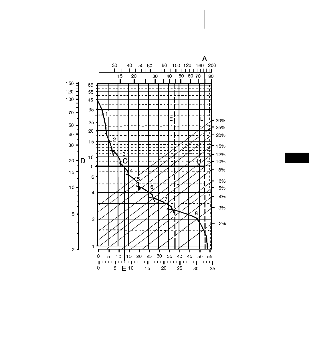
8-9
8
Wheel Tractor-ScrapersRimpull-Speed-Gradeability Curves
●Example
KEY
1 — 1st Gear Torque Converter Drive
2 — 2nd Gear Torque Converter Drive
3 — 3rd Gear Direct Drive
4 — 4th Gear Direct Drive
5 — 5th Gear Direct Drive
6 — 6th Gear Direct Drive
7 — 7th Gear Direct Drive
8 — 8th Gear Direct Drive
KEY
A — Loaded 77 965 kg (171,880 lb)
B — Intersection with 10% total resistance line
C — Intersection with rimpull curve (4th gear)
D — Required rimpull 7756 kg (17,100 lb)
E — Speed 12.9 km/h (8 mph)
GROSS WEIGHTGROSS WEIGHT
kg x 1000
lb x 1000
TOTAL RESISTANCE
(Grade plus Rolling Resistance)
SPEED
RIMPULL
km/h
mph
lb x
1000 kg x
1000
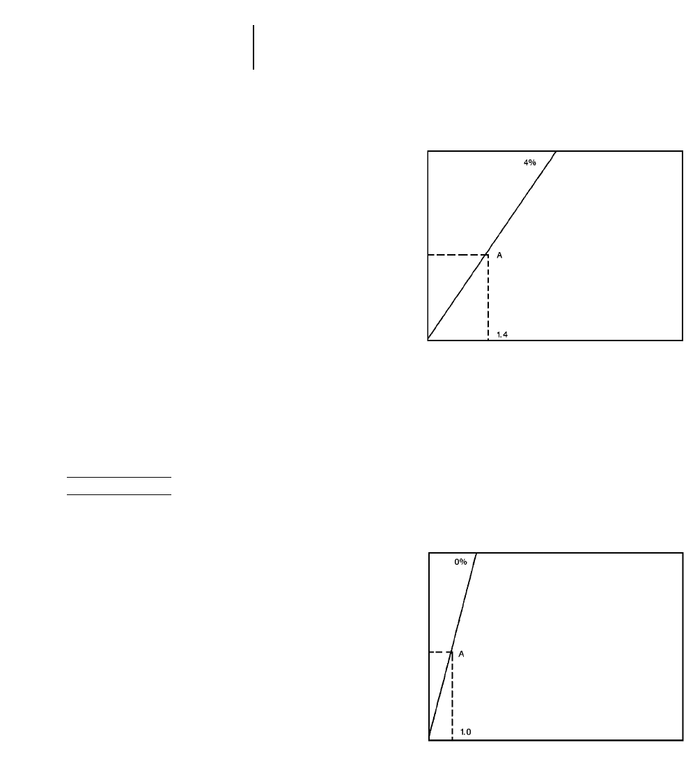
USE OF TRAVEL TIME CHARTS
The following explanation applies to travel time
charts for Wheel Tractor-Scrapers, Construction &
Mining Trucks and Articulated Trucks.
One-way travel time can be determined from
graphs on the following pages when one-way travel
distance and total resistance (expressed in percent)
are known. 10 kg/metric ton (20 lb/U.S. ton) equals
1% equivalent grade.
If total resistance is negative (grade assistance
greater than rolling resistance) machine may accel-
erate downhill requiring the use of retarder or
brakes. Travel time charts cannot be used in these
cases. Consult respective machine retarder curve to
establish maximum safe downhill speed.
Two graphs are given for each hauling unit: one
for the machine carrying its rated payload and one
for the empty machine.
Travel times were derived using Caterpillar Machine
Simulation Program and standard tire inputs.
Travel times for machines equipped with (larger)
optional tires vary slightly.
Example problem:
631E Series II hauls its rated payload 34 020 kg
— 19.1 bank cubic meters (75,000 lb — 25 bank
cubic yards) on a 4% road for 610 m (2000 feet) and
returns on a 0% road for 760 m (2500 feet). Find the
cycle time.
Haul —
Using the graph for the Loaded machine, read
from the Travel Distance (one way) scale at 610 m
(2000 feet) across to the 4% total resistance line
(point A). From (point A) read down to the Travel Time
(one way) scale to determine haul time = 1.4 minutes.
8-10
Wheel Tractor-Scrapers Travel Time Charts
●Example
Return —
Using the graph for the Empty machine, read
from the Travel Distance (one way) scale at 760 m
(2500 feet) across to the 0% total resistance line
(point A). From (point A) read down to the Travel Time
(one way) scale to determine return time = 1 min.
Loaded
Total Resistance
Travel Time One Way
Travel Distance One Way
2000 ft
(610 m)
Empty
Total Resistance
Travel Time One Way
Travel Distance One Way
2500 ft
(760 m)
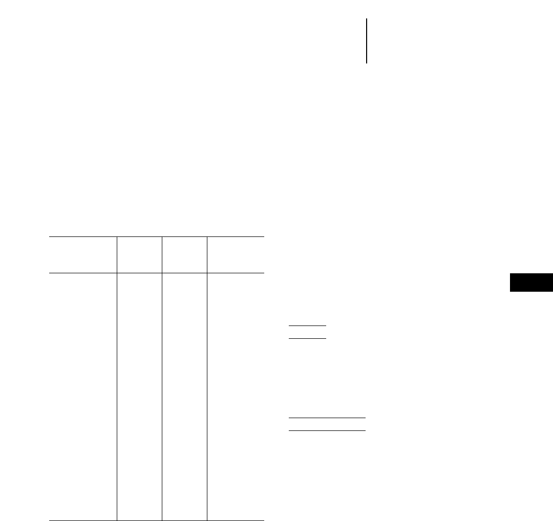
Cycle Time —
= load* + haul + maneuver & spread* + return
= 0.6 + 1.4 + 0.7 + 1.0
= 3.7 min.
*For fixed time (load, maneuver and spread)
see the table below.
When cycle time and payload are known, pro-
ductivity can be calculated. For a more complex
example see the Earthmoving Section.
● ● ●
TYPICAL FIXED TIMES FOR SCRAPERS
(Times may vary depending on job conditions)
Maneuver and
Spread or
Load Time Maneuver and
Model Loaded By (Min.) Dump (Min.)
613C Series II Self 0.9 0.7
615C Series II Self 0.9 0.7
623F Self 0.9 0.7
633E Series II Self 0.9 0.7
621F One D8R 0.5 0.7
627F One D8R 0.5 0.6
621F One D9R 0.4 0.7
627F One D9R 0.4 0.6
627F PP Self 0.9* 0.6
631E Series II One D9R 0.6 0.7
637E Series II One D9R 0.6 0.6
631E Series II One D10R 0.5 0.7
637E Series II One D10R 0.5 0.6
637E/PP Series II Self 1.0* 0.6
651E One D11R 0.6 0.7
657E One D11R 0.6 0.6
657E Push Pull 1.1* 0.6
Self
621F Auger 0.9 0.7
627F Auger 0.7 0.7
631E Series II Auger 0.9 0.7
637E Series II Auger 0.8 0.7
651E Auger 1.3 0.7
657E Auger 1.0 0.7
*Load time per pair, including transfer time.
NOTE: Empty Weights shown on the Wheel Tractor-
Scraper charts includes ROPS Canopy. The
travel times will remain within acceptable
limits when applied to a non-ROPS equipped
machine. When calculating TMPH loadings
any additional weight must be considered
in establishing mean tire loads.
USE OF RETARDER CURVES
The following explanation applies to retarder curves
for Wheel Tractor-Scrapers and Articulated Trucks.
The speed that can be maintained (without use
of service brake) when the machine is descending a
grade with retarder fully on can be determined from
the retarder curves in this section if gross machine
weight and total effective grade are known.
Total Effective Grade (or Total Resistance) is grade
assistance minus rolling resistance.
10 kg/metric ton (20 lb/U.S. ton) = 1% adverse
grade.
Example
15% favorable grade with 5% rolling resistance.
Find Total Effective Grade.
Total Effective Grade = 15% Grade Assistance —
5%
Rolling Resistance = 10% Total Effective Grade
Assistance.
Example problem:
A 651E with an estimated payload of 47 175 kg
(104,000 lb) descends a 10% total effective grade.
Find constant speed and gear range with maximum
retarder effort. Find travel time if the slope is 610 m
(2000 ft) long.
Empty Weight + Payload = Gross Weight
= 60 950 kg + 47 175 kg = 108 125 kg
(134,370 lb + 104,000 lb = 238,370 lb)
8-11
8
Wheel Tractor-ScrapersTravel Time Charts
Typical Fixed Times
Retarder Curves
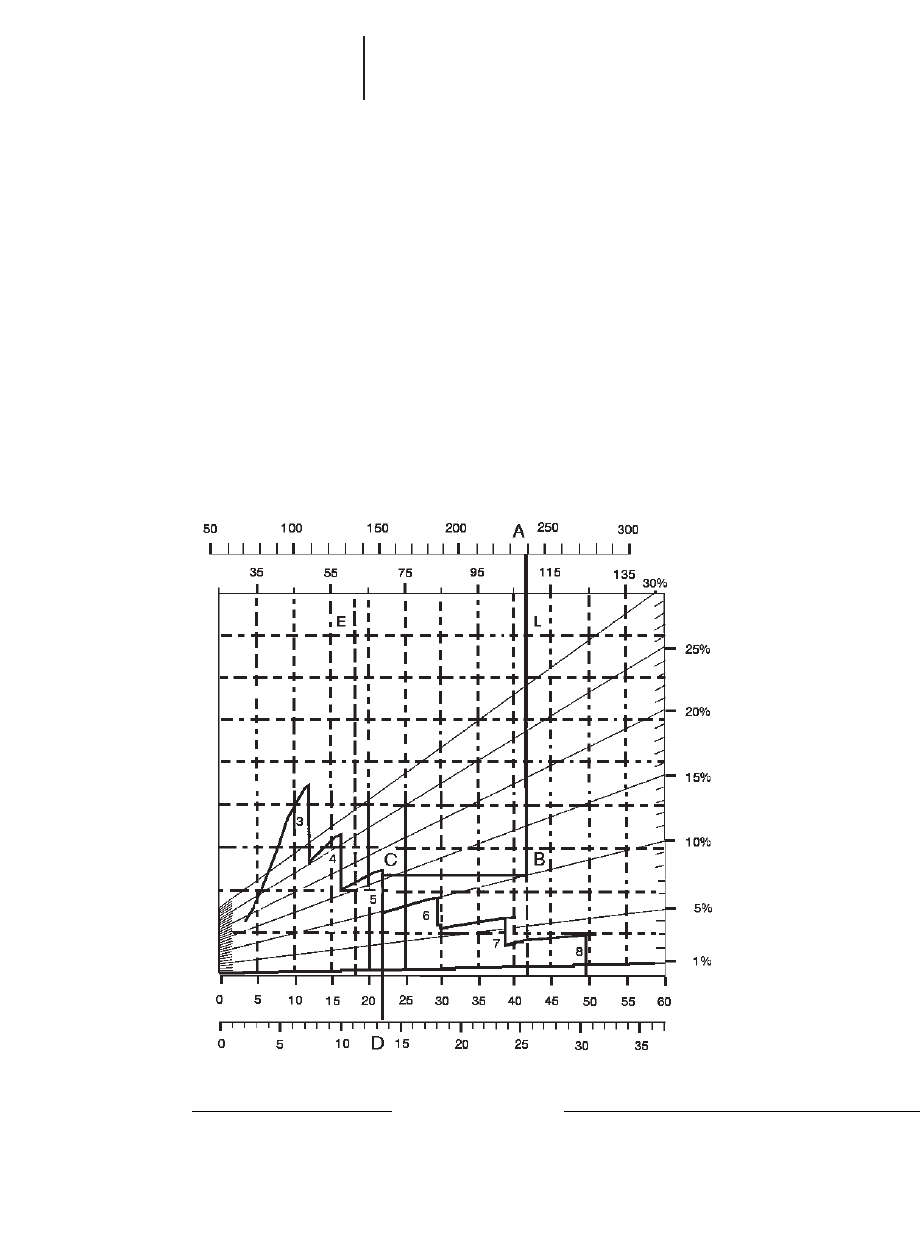
Solution: Using the retarder curve below, read from
108 125 kg (238,370 lb) (point A) on top of gross
weight scale down the line to the intersection of the
10% effective grade line (point B).
Go across horizontally from point B to the inter-
section of the retarder curve (point C). Point C inter-
sects at the 5 (5th gear) range.
Where point C intersects the retarder curve, read
down vertically to point D on the bottom scale to
obtain the constant speed: 21.7 km/h (13.5 mph).
ANSWER: The 651E will descend the slope at
21.7 km/h (13.5 mph) in 5th gear. Travel time is
1.68 minutes.
610 m
__________ = 1.68 min
363 m/min *(mph 3 88 = F.P.M.)
2000 ft
_______________ = 1.68 min
13.5 mph 388*
NOTE: The basic Distance-Speed-Time formula is
60 D ÷ S = T (or “60 D Street”), where 60 is
minutes, D is distance, S is speed and T is
time. In the above problem, 60 3610 m ÷
21.7 km/h 31000 = T.
60 3610
____________ = T = (1.68)
21.7 31000
8-12
Wheel Tractor-Scrapers Retarder Curves
●Example
KEY
3 — 3rd Gear Direct Drive
4 — 4th Gear Direct Drive
5 — 5th Gear Direct Drive
6 — 6th Gear Direct Drive
7 — 7th Gear Direct Drive
8 — 8th Gear Direct Drive
KEY
A — Loaded 108 125 kg (238,370 lb)
B — Intersection with 10% effective grade line
C — Intersection with retarder curve (5th gear)
D — Constant speed 21.7 km/h (13.5 mph)
GROSS WEIGHT
kg x 1000
lb x 1000
EFFECTIVE GRADE
(Grade minus Rolling Resistance)
SPEED
km/h
mph
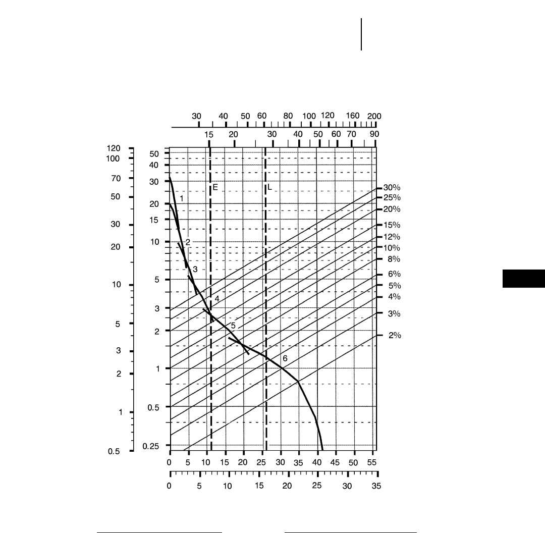
8-13
8
Wheel Tractor-Scrapers613C Series II Rimpull-Speed-Gradeability
●23.5R25 Tires
KEY
1 — 1st Torque Converter Drive
2 — 2nd Torque Converter Drive
3 — 3rd Torque Converter Drive
4 — 4th Torque Converter Drive
5 — 5th Torque Converter Drive
6 — 6th Torque Converter Drive
KEY
E — Empty 15 265 kg (33,650 lb)
L — Loaded 27 240 kg (60,050 lb)
kg x 1000
lb x 1000
TOTAL RESISTANCE
(Grade plus Rolling Resistance)
SPEED
RIMPULL
km/h
mph
lb x
1000 kg x
1000
GROSS WEIGHT
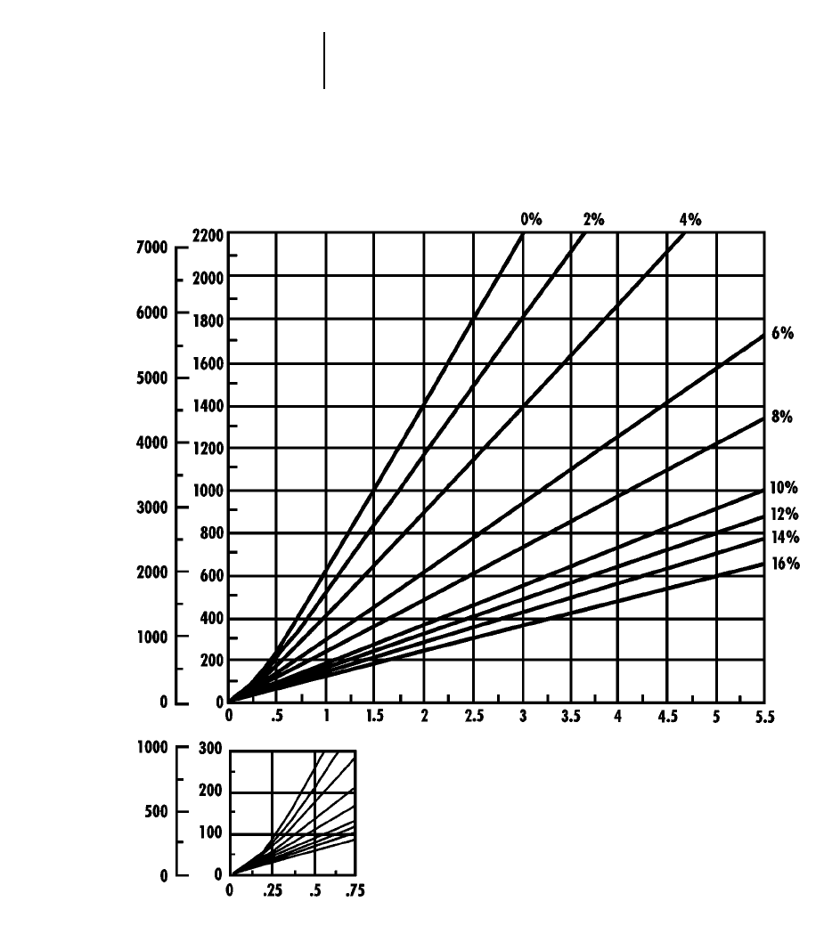
8-14
Wheel Tractor-Scrapers 613C Series II Travel Time — Loaded
●23.5R25 Tires
TOTAL RESISTANCE
(Grade plus Rolling)
feet meters
minutes
DISTANCE ONE WAY
TIME
TOTAL RESISTANCE
(Grade plus Rolling)
feet meters
LOADED
minutes
DISTANCE ONE WAY
TIME
Empty weight: 15 264 kg (33,650 lb)
Payload: 11 975 kg (26,400 lb)
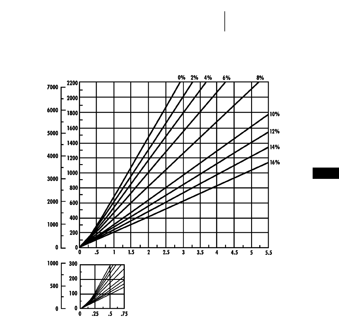
8-15
8
Wheel Tractor-Scrapers613C Series II Travel Time — Empty
●23.5R25 Tires
TOTAL RESISTANCE
(Grade plus Rolling)
feet meters
EMPTY
minutes
DISTANCE ONE WAY
TIME
Empty weight: 15 264 kg (33,650 lb)
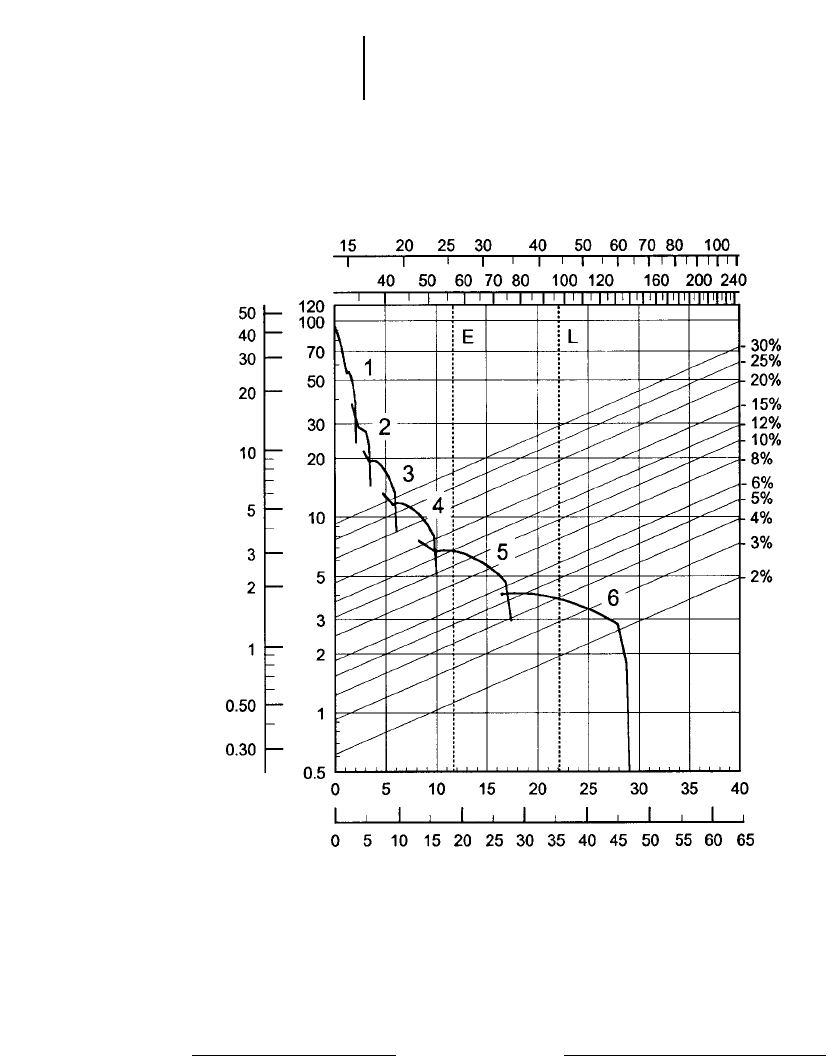
8-16
Wheel Tractor-Scrapers 615C Series II Rimpull-Speed-Gradeability
●29.5R25 Tires
GROSS WEIGHT
KEY
1 — 1st Gear Direct Drive
2 — 2nd Gear Direct Drive
3 — 3rd Gear Direct Drive
4 — 4th Gear Direct Drive
5 — 5th Gear Direct Drive
6 — 6th Gear Direct Drive
KEY
E — Empty 25 605 kg (56,450 lb)
L — Loaded 44 113 kg (97,250 lb)
lb x 1000
kg x 1000
TOTAL RESISTANCE
(Grade plus Rolling Resistance)
SPEED
RIMPULL
mph
km/h
kg x
1000 lb x
1000
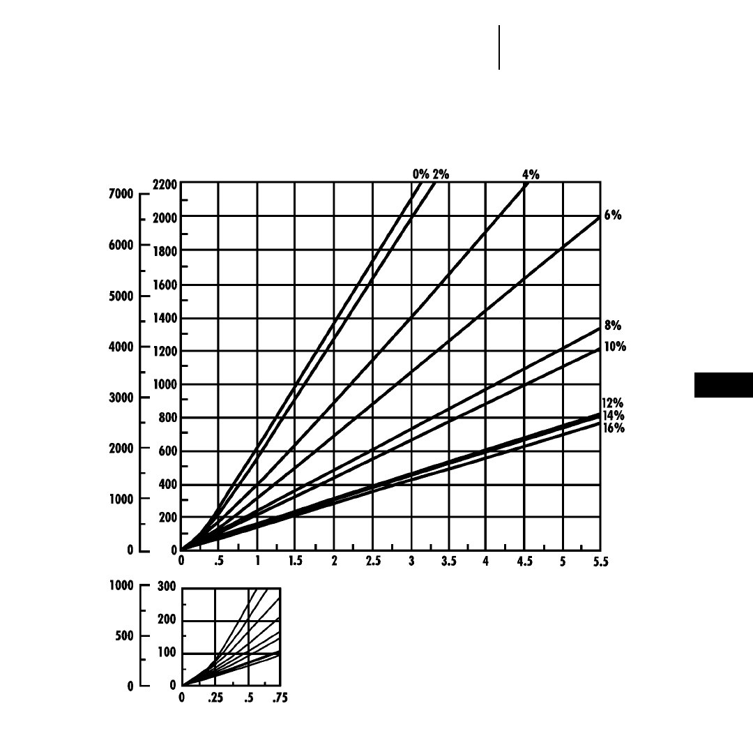
8-17
8
Wheel Tractor-Scrapers615C Series II Travel Time — Loaded
●29.5R25 Tires
TOTAL RESISTANCE
(Grade plus Rolling)
feet meters
LOADED
minutes
DISTANCE ONE WAY
TIME
Empty weight: 25 605 kg (56,450 lb)
Payload: 18 506 kg (40,800 lb)
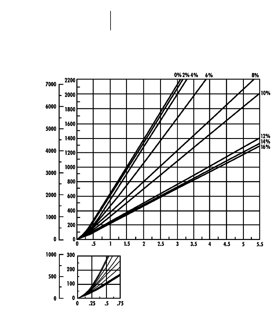
8-18
Wheel Tractor-Scrapers 615C Series II Travel Time — Empty
●29.5R25 Tires
TOTAL RESISTANCE
(Grade plus Rolling)
feet meters
EMPTY
minutes
DISTANCE ONE WAY
TIME
Empty weight: 25 605 kg (56,450 lb)
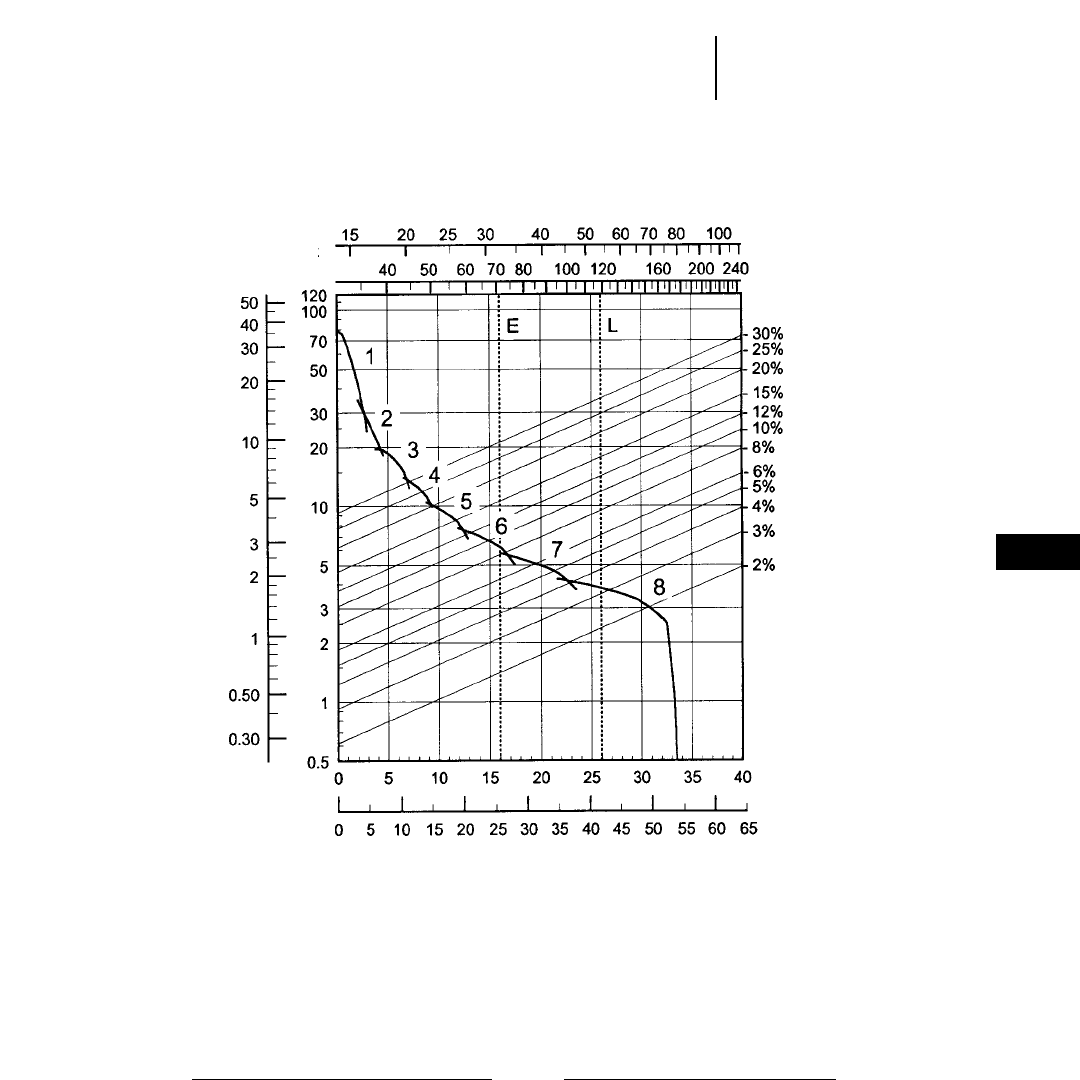
8-19
8
Wheel Tractor-Scrapers621F Rimpull-Speed-Gradeability
●33.25R29 Tires
GROSS WEIGHT
KEY
1 — 1st Gear Torque Converter Drive
2 — 2nd Gear Torque Converter Drive
3 — 3rd Gear Direct Drive
4 — 4th Gear Direct Drive
5 — 5th Gear Direct Drive
6 — 6th Gear Direct Drive
7 — 7th Gear Direct Drive
8 — 8th Gear Direct Drive
KEY
E — Empty 32 070 kg (70,700 lb)
L — Loaded 53 843 kg (118,700 lb)
lb x 1000
kg x 1000
TOTAL RESISTANCE
(Grade plus Rolling Resistance)
SPEED
RIMPULL
km/h
mph
kg x
1000 lb x
1000
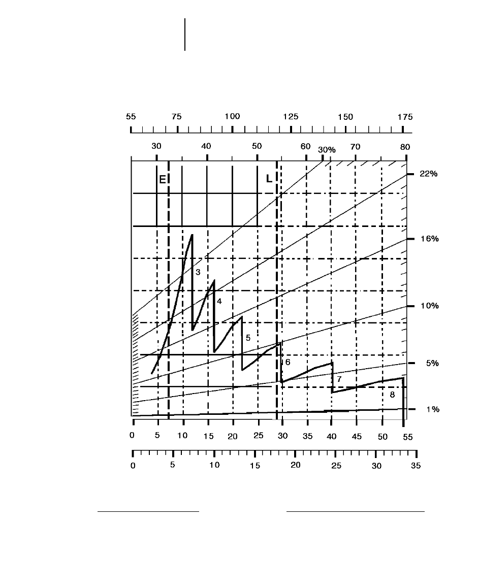
8-20
Wheel Tractor-Scrapers 621F Retarding
●33.25R29 Tires
GROSS WEIGHT
KEY
3 — 3rd Gear Direct Drive
4 — 4th Gear Direct Drive
5 — 5th Gear Direct Drive
6 — 6th Gear Direct Drive
7 — 7th Gear Direct Drive
8 — 8th Gear Direct Drive
KEY
E — Empty 32 070 kg (70,700 lb)
L — Loaded 53 843 kg (118,700 lb)
kg x 1000
lb x 1000
EFFECTIVE GRADE
(Grade minus Rolling Resistance)
SPEED
km/h
mph

8-21
8
Wheel Tractor-Scrapers621F Travel Time — Loaded
●33.25R29 Tires
TOTAL RESISTANCE
(Grade plus Rolling)
feet meters
LOADED
minutes
DISTANCE ONE WAY
TIME
Empty weight: 32 070 kg (70,700 lb)
Payload: 21 775 kg (48,000 lb)

8-22
Wheel Tractor-Scrapers 621F Travel Time — Empty
●33.25R29 Tires
TOTAL RESISTANCE
(Grade plus Rolling)
feet meters
EMPTY
minutes
DISTANCE ONE WAY
TIME
Empty weight: 32 070 kg (70,700 lb)
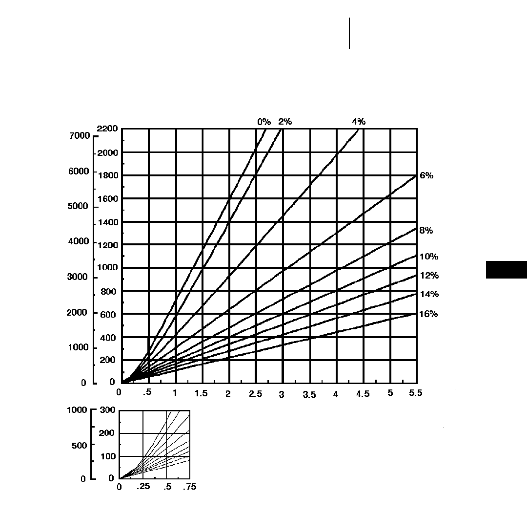
8-23
8
Wheel Tractor-Scrapers621F Auger Travel Time — Loaded
●33.25R29 Tires
TOTAL RESISTANCE
(Grade plus Rolling)
feet meters
LOADED
minutes
DISTANCE ONE WAY
TIME
Empty weight: 37 762 kg (83,250 lb)
Payload: 21 775 kg (48,000 lb)
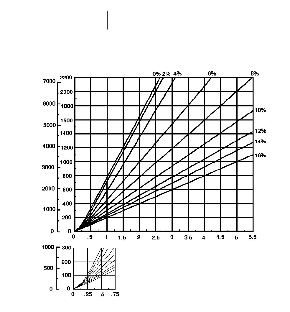
8-24
Wheel Tractor-Scrapers 621F Auger Travel Time — Empty
●33.25R29 Tires
TOTAL RESISTANCE
(Grade plus Rolling)
feet meters
EMPTY
minutes
DISTANCE ONE WAY
TIME
Empty weight: 37 762 kg (83,250 lb)
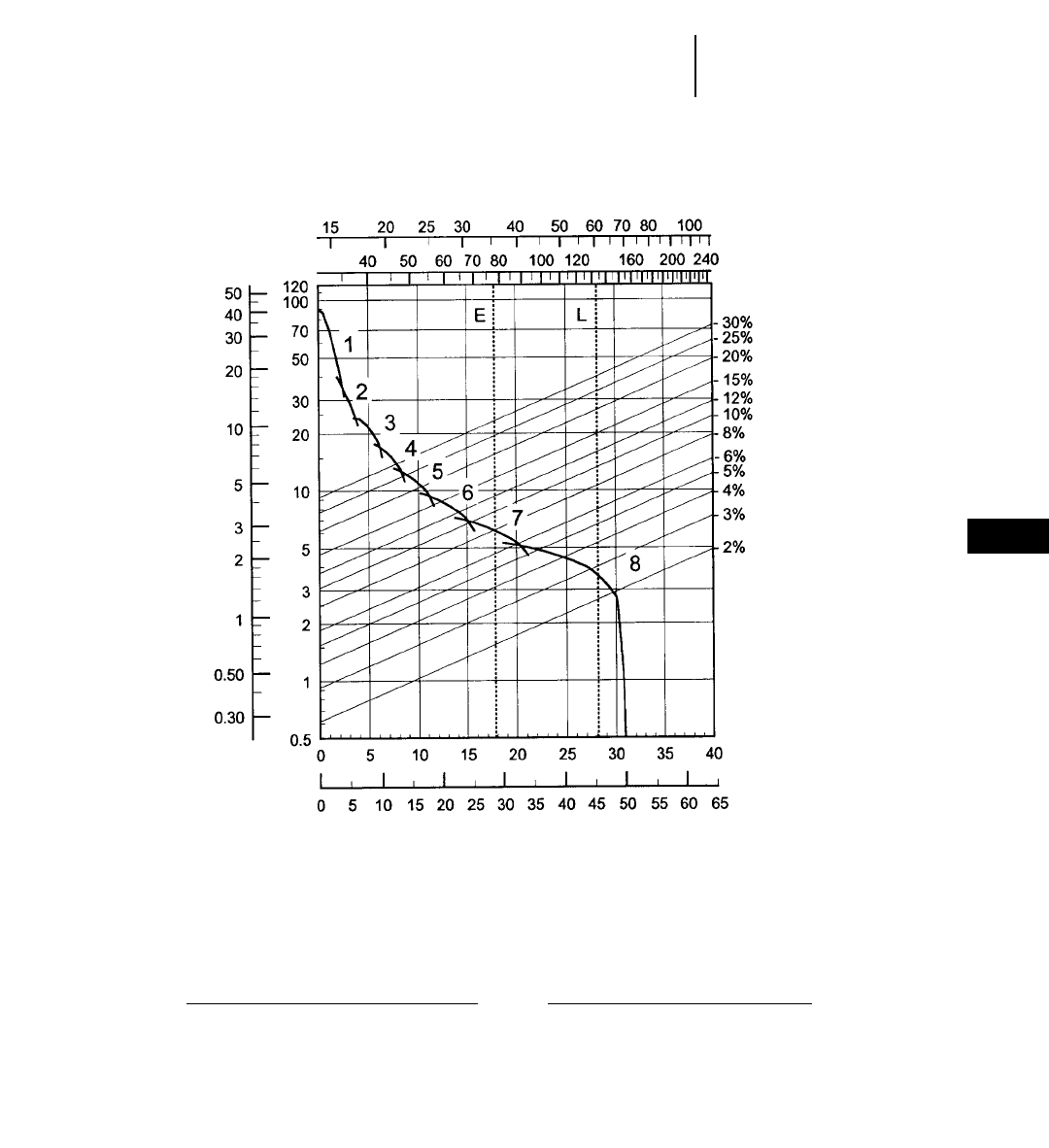
8-25
8
Wheel Tractor-Scrapers623F Rimpull-Speed-Gradeability
●33.25R29 Tires
GROSS WEIGHT
KEY
1 — 1st Gear Torque Converter Drive
2 — 2nd Gear Torque Converter Drive
3 — 3rd Gear Direct Drive
4 — 4th Gear Direct Drive
5 — 5th Gear Direct Drive
6 — 6th Gear Direct Drive
7 — 7th Gear Direct Drive
8 — 8th Gear Direct Drive
KEY
E — Empty 35 290 kg (77,800 lb)
L — Loaded 60 238 kg (132,800 lb)
lb x 1000
kg x 1000
TOTAL RESISTANCE
(Grade plus Rolling Resistance)
SPEED
RIMPULL
km/h
mph
kg x
1000 lb x
1000
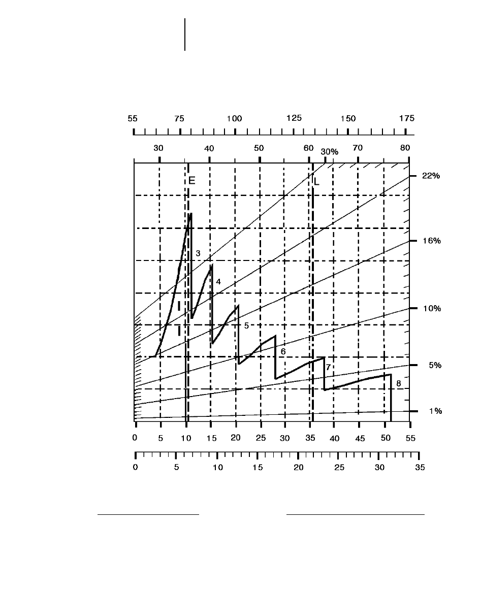
8-26
Wheel Tractor-Scrapers 623F Retarding
●33.25R29 Tires
GROSS WEIGHT
KEY
3 — 3rd Gear Direct Drive
4 — 4th Gear Direct Drive
5 — 5th Gear Direct Drive
6 — 6th Gear Direct Drive
7 — 7th Gear Direct Drive
8 — 8th Gear Direct Drive
KEY
E — Empty 35 290 kg (77,800 lb)
L — Loaded 60 238 kg (132,800 lb)
kg x 1000
lb x 1000
EFFECTIVE GRADE
(Grade minus Rolling Resistance)
SPEED
km/h
mph
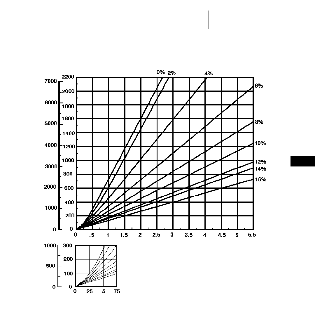
8-27
8
Wheel Tractor-Scrapers623F Travel Time — Loaded
●33.25R29 Tires
TOTAL RESISTANCE
(Grade plus Rolling)
feet meters
LOADED
minutes
DISTANCE ONE WAY
TIME
Empty weight: 32 070 kg (70,700 lb)
Payload: 21 775 kg (48,000 lb)
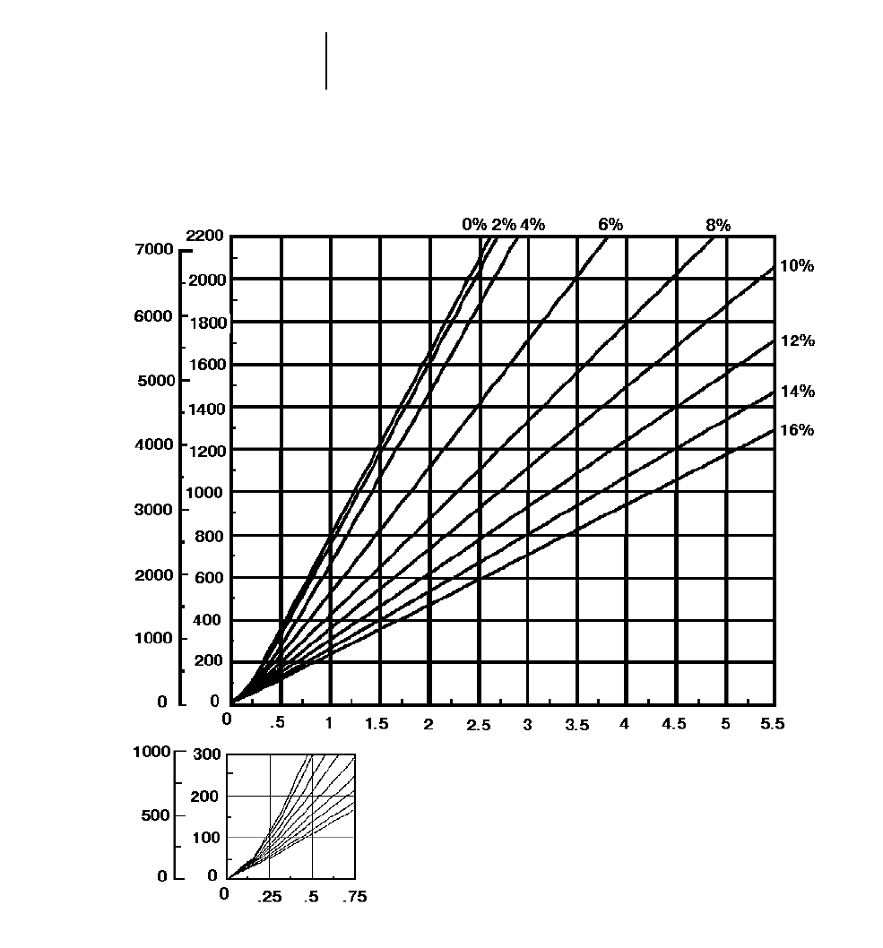
8-28
Wheel Tractor-Scrapers 623F Travel Time — Empty
●33.25R29 Tires
TOTAL RESISTANCE
(Grade plus Rolling)
feet meters
EMPTY
minutes
DISTANCE ONE WAY
TIME
Empty weight: 32 070 kg (70,700 lb)
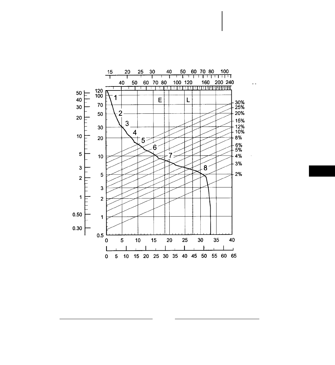
8-29
8
Wheel Tractor-Scrapers627F Rimpull-Speed-Gradeability
●33.25R29 Tires
GROSS WEIGHT
KEY
1 — 1st Gear Torque Converter Drive
2 — 2nd Gear Torque Converter Drive
3 — 3rd Gear Direct Drive
4 — 4th Gear Direct Drive
5 — 5th Gear Direct Drive
6 — 6th Gear Direct Drive
7 — 7th Gear Direct Drive
8 — 8th Gear Direct Drive
KEY
E — Empty 36 538 kg (80,550 lb)
L — Loaded 58 311 kg (128,550 lb)
lb x 1000
kg x 1000
TOTAL RESISTANCE
(Grade plus Rolling Resistance)
SPEED
RIMPULL
km/h
mph
kg x
1000 lb x
1000
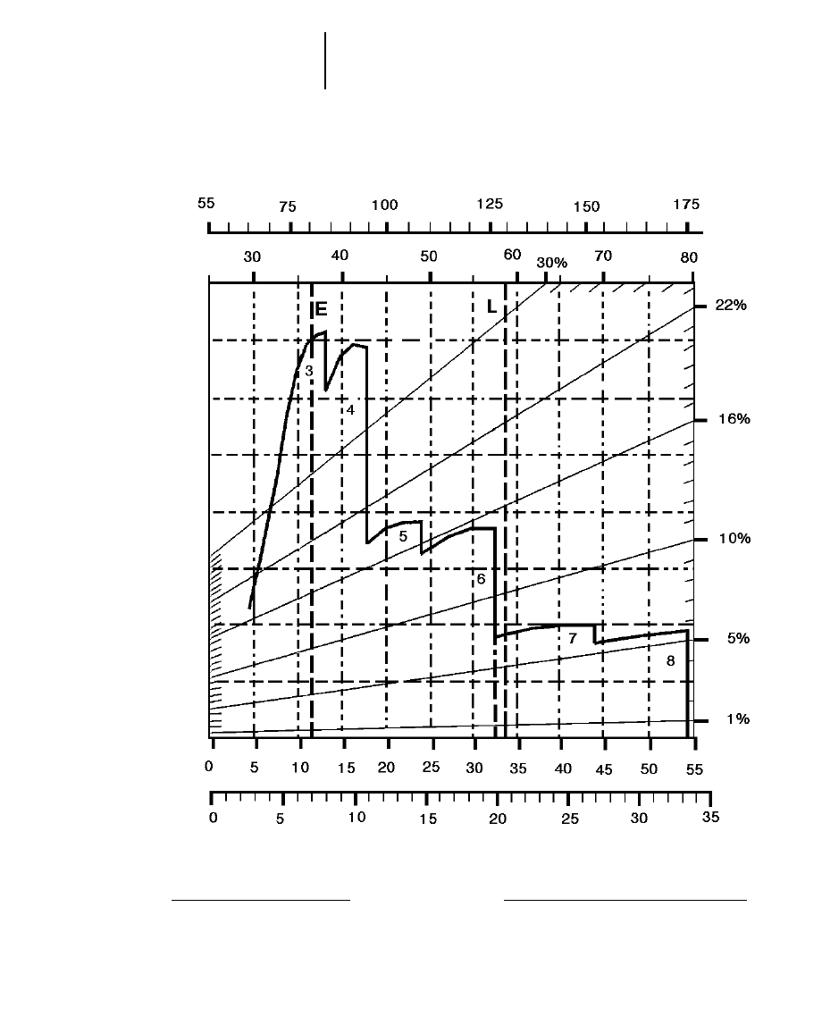
8-30
Wheel Tractor-Scrapers 627F Retarding
●33.25R29 Tires
GROSS WEIGHT
KEY
3 — 3rd Gear Direct Drive
4 — 4th Gear Direct Drive
5 — 5th Gear Direct Drive
6 — 6th Gear Direct Drive
7 — 7th Gear Direct Drive
8 — 8th Gear Direct Drive
KEY
E — Empty 36 538 kg (80,550 lb)
L — Loaded 58 311 kg (128,550 lb)
kg x 1000
lb x 1000
EFFECTIVE GRADE
(Grade minus Rolling Resistance)
SPEED
km/h
mph
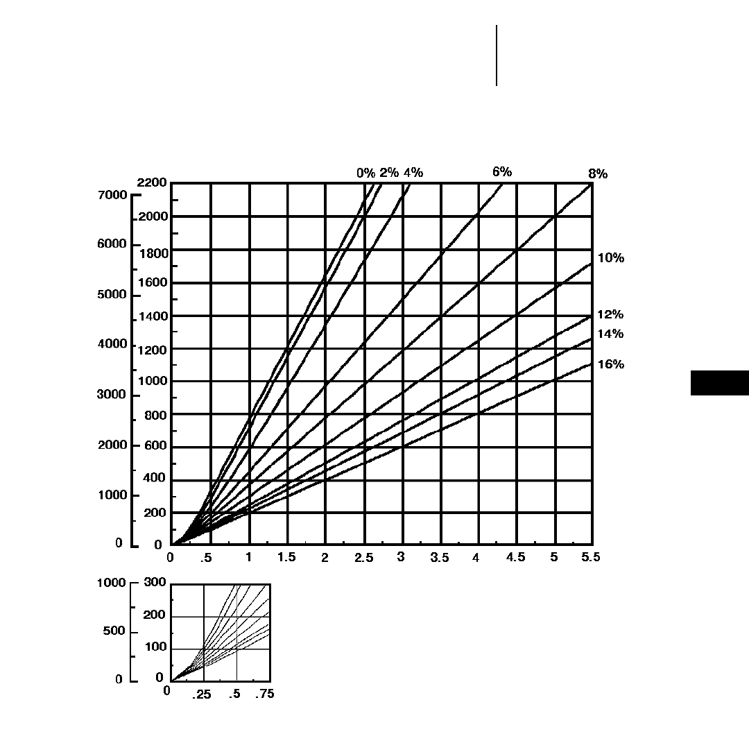
8-31
8
Wheel Tractor-Scrapers627F Travel Time — Loaded
●33.25R29 Tires
● Standard and Push-Pull
TOTAL RESISTANCE
(Grade plus Rolling)
feet meters
LOADED
minutes
DISTANCE ONE WAY
TIME
Empty weight: 36 538 kg (80,550 lb)
Payload: 21 775 kg (48,000 lb)
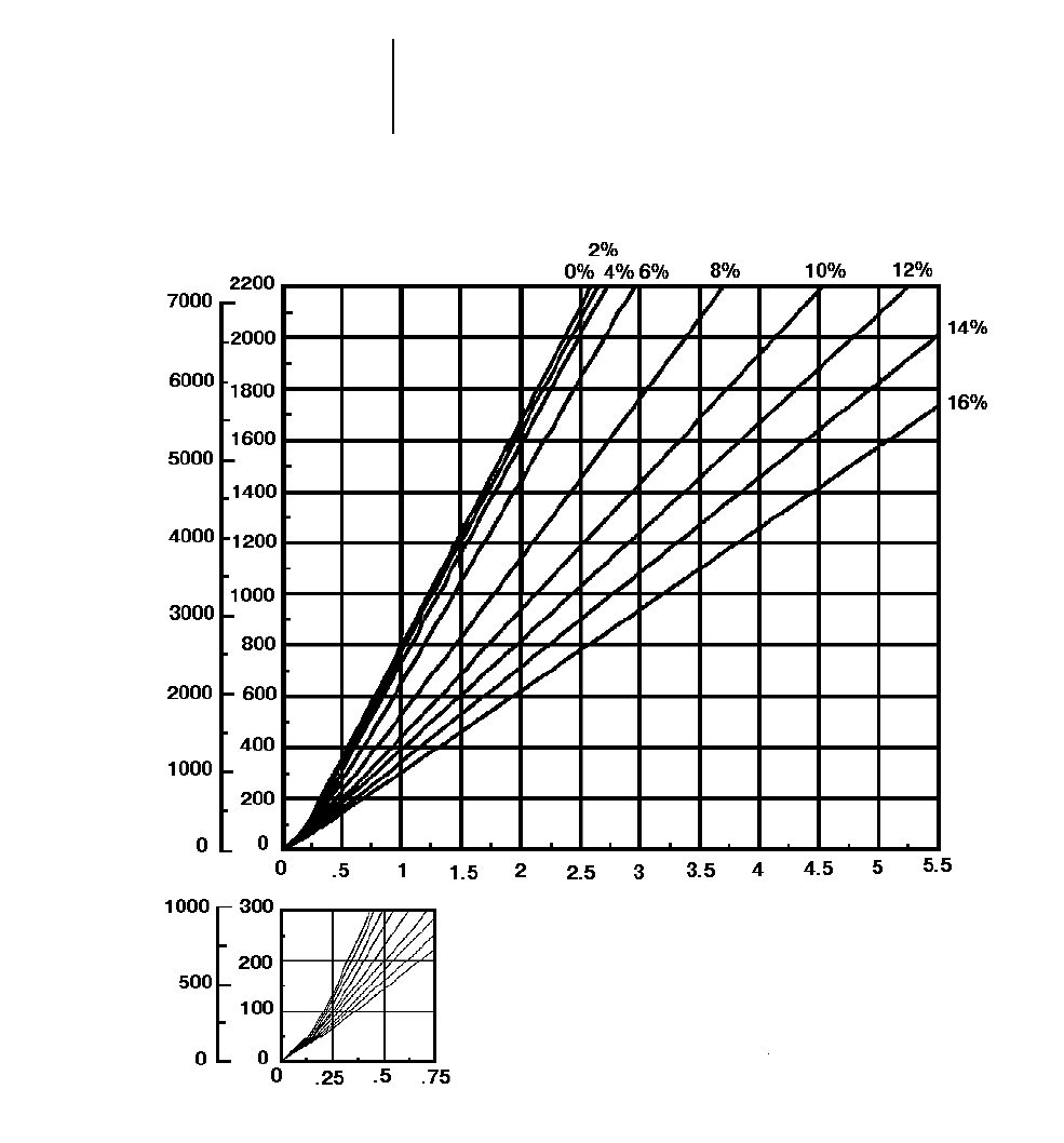
8-32
Wheel Tractor-Scrapers 627F Travel Time — Empty
●33.25R29 Tires
●Standard and Push-Pull
TOTAL RESISTANCE
(Grade plus Rolling)
feet meters
EMPTY
minutes
DISTANCE ONE WAY
TIME
Empty weight: 36 538 kg (80,550 lb)

8-33
8
Wheel Tractor-Scrapers627F Auger Travel Time — Loaded
●33.25R29 Tires
TOTAL RESISTANCE
(Grade plus Rolling)
feet meters
LOADED
minutes
DISTANCE ONE WAY
TIME
Empty weight: 42 230 kg (93,100 lb)
Payload: 21 775 kg (48,000 lb)
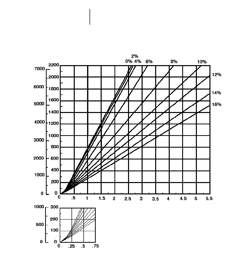
8-34
Wheel Tractor-Scrapers 627F Auger Travel Time — Empty
●33.25R29 Tires
TOTAL RESISTANCE
(Grade plus Rolling)
feet meters
EMPTY
minutes
DISTANCE ONE WAY
TIME
Empty weight: 42 230 kg (93,100 lb)
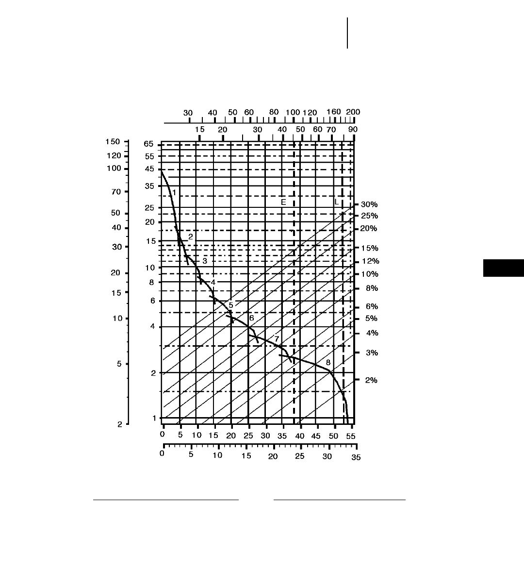
8-35
8
Wheel Tractor-Scrapers631E Series II Rimpull-Speed-Gradeability
●37.25R35 Tires
GROSS WEIGHT
KEY
1 — 1st Gear Torque Converter Drive
2 — 2nd Gear Torque Converter Drive
3 — 3rd Gear Direct Drive
4 — 4th Gear Direct Drive
5 — 5th Gear Direct Drive
6 — 6th Gear Direct Drive
7 — 7th Gear Direct Drive
8 — 8th Gear Direct Drive
KEY
E — Empty 45 400 kg (100,000 lb)
L — Loaded 79 420 kg (175,000 lb)
kg x 1000
lb x 1000
TOTAL RESISTANCE
(Grade plus Rolling Resistance)
SPEED
RIMPULL
km/h
mph
lb x
1000 kg x
1000
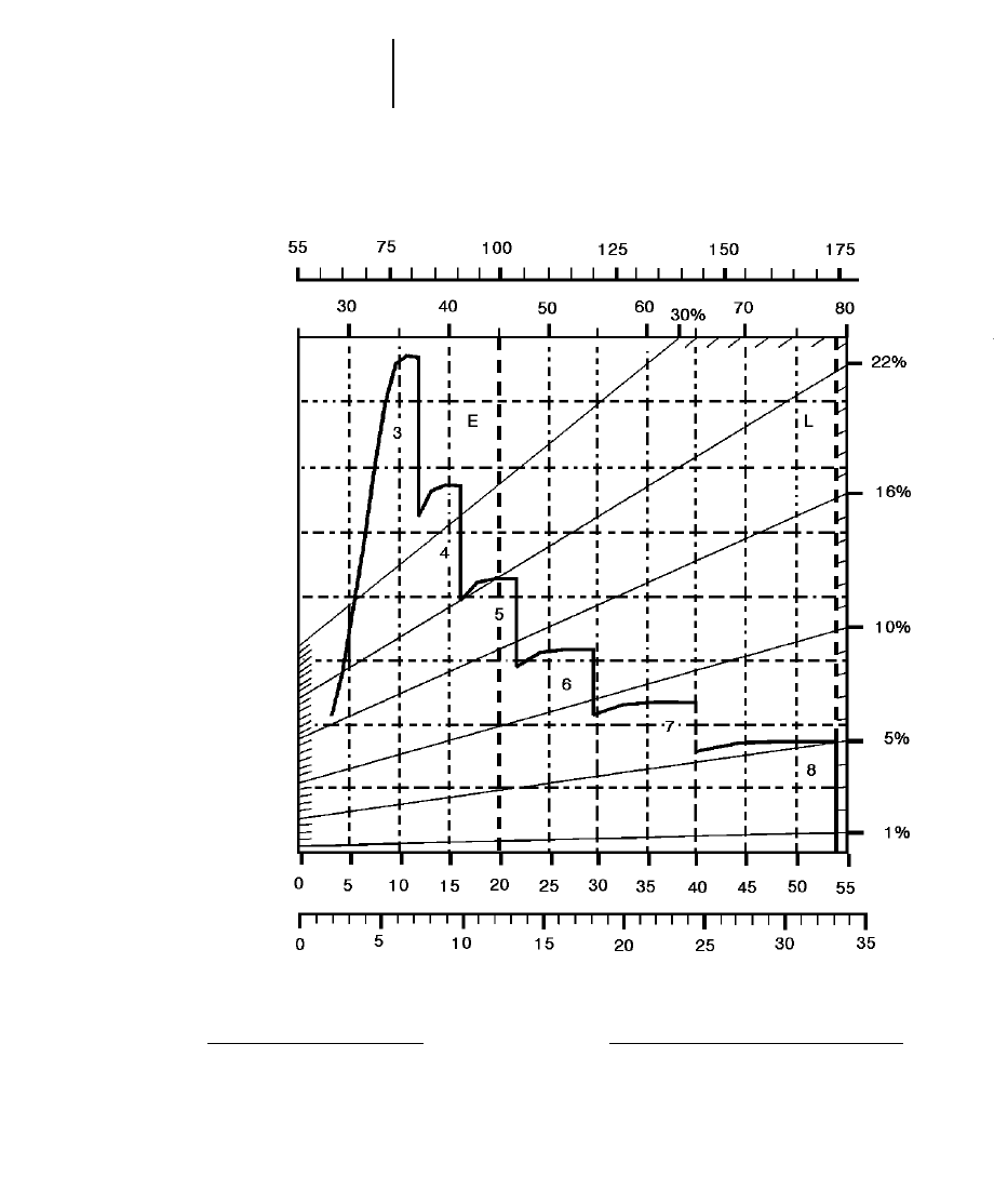
8-36
Wheel Tractor-Scrapers 631E Series II Retarding
●37.25R35 Tires
GROSS WEIGHT
KEY
3 — 3rd Gear Direct Drive
4 — 4th Gear Direct Drive
5 — 5th Gear Direct Drive
6 — 6th Gear Direct Drive
7 — 7th Gear Direct Drive
8 — 8th Gear Direct Drive
KEY
E — Empty 45 400 kg (100,000 lb)
L — Loaded 79 420 kg (175,000 lb)
kg x 1000
lb x 1000
EFFECTIVE GRADE
(Grade minus Rolling Resistance)
SPEED
km/h
mph
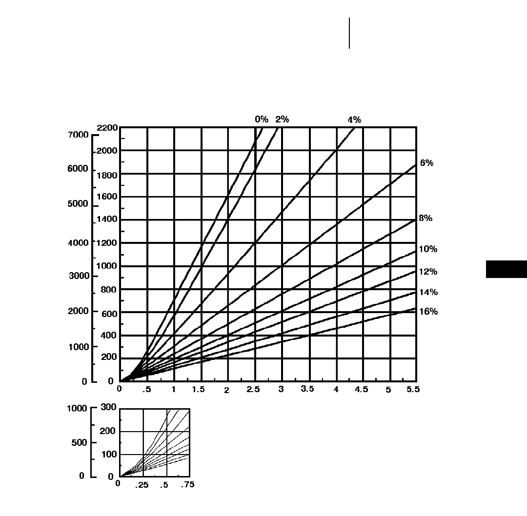
8-37
8
Wheel Tractor-Scrapers631E Series II Travel Time — Loaded
●37.25R35 Tires
TOTAL RESISTANCE
(Grade plus Rolling)
feet meters
LOADED
minutes
DISTANCE ONE WAY
TIME
Empty weight: 45 400 kg (100,000 lb)
Payload: 34 020 kg (75,000 lb)

8-38
Wheel Tractor-Scrapers 631E Series II Travel Time — Empty
●37.25R35 Tires
TOTAL RESISTANCE
(Grade plus Rolling)
feet meters
EMPTY
minutes
DISTANCE ONE WAY
TIME
Empty weight: 45 400 kg (100,000 lb)
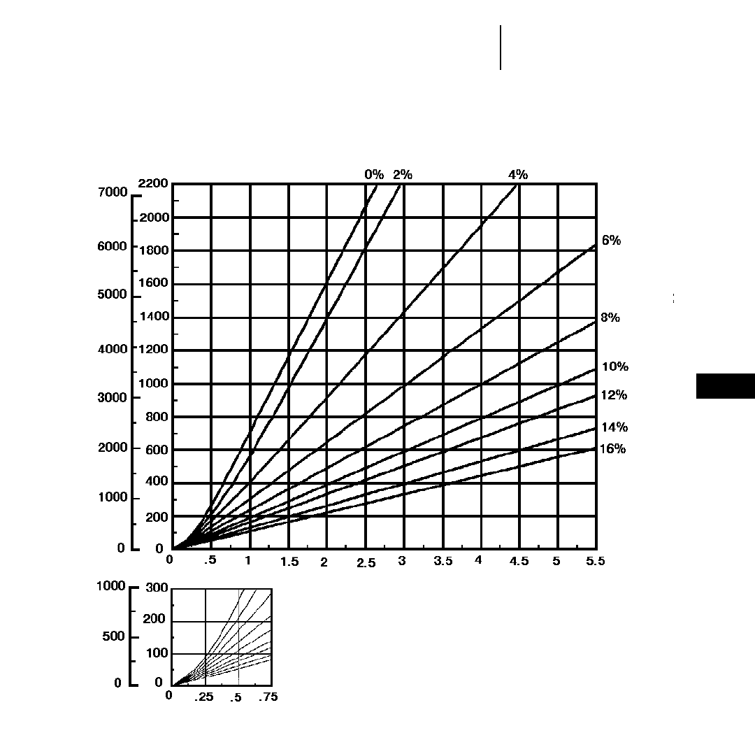
8-39
8
Wheel Tractor-Scrapers631E Series II Auger Travel Time — Loaded
●37.25R35 Tires
TOTAL RESISTANCE
(Grade plus Rolling)
feet meters
LOADED
minutes
DISTANCE ONE WAY
TIME
Empty weight: 45 980 kg (101,370 lb)
Payload: 34 020 kg (75,000 lb)
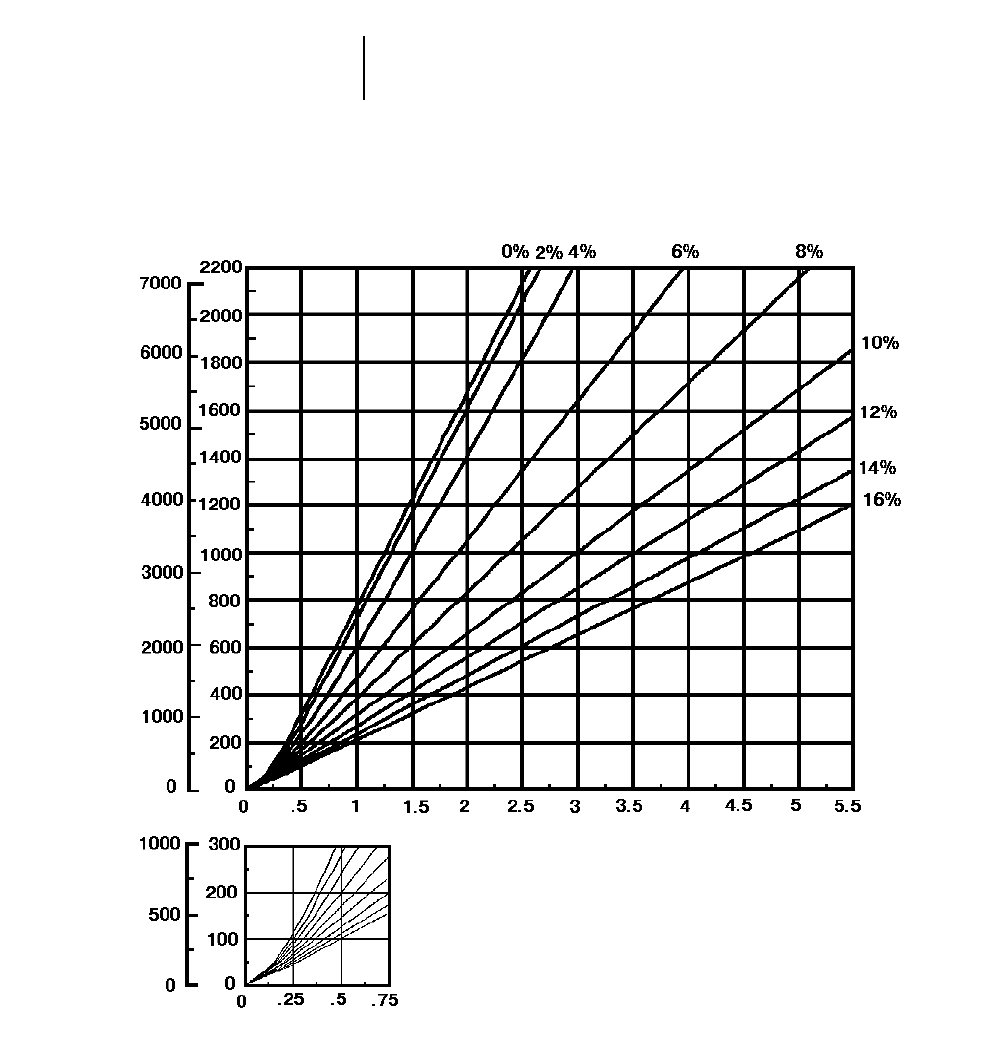
8-40
Wheel Tractor-Scrapers 631E Series II Auger Travel Time — Empty
●37.25R35 Tires
TOTAL RESISTANCE
(Grade plus Rolling)
feet meters
EMPTY
minutes
DISTANCE ONE WAY
TIME
Empty weight: 45 980 kg (101,370 lb)
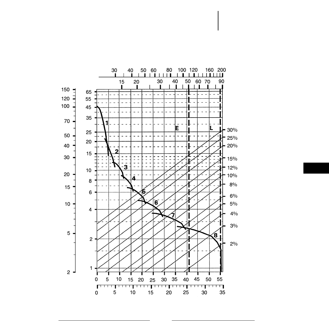
8-41
8
Wheel Tractor-Scrapers633E Series II Rimpull-Speed-Gradeability
●37.25R35 Tires
GROSS WEIGHT
KEY
1 — 1st Gear Torque Converter Drive
2 — 2nd Gear Torque Converter Drive
3 — 3rd Gear Direct Drive
4 — 4th Gear Direct Drive
5 — 5th Gear Direct Drive
6 — 6th Gear Direct Drive
7 — 7th Gear Direct Drive
8 — 8th Gear Direct Drive
KEY
E — Empty 51 100 kg (112,670 lb)
L — Loaded 88 300 kg (194,670 lb)
kg x 1000
lb x 1000
TOTAL RESISTANCE
(Grade plus Rolling Resistance)
SPEED
RIMPULL
km/h
mph
lb x
1000 kg x
1000
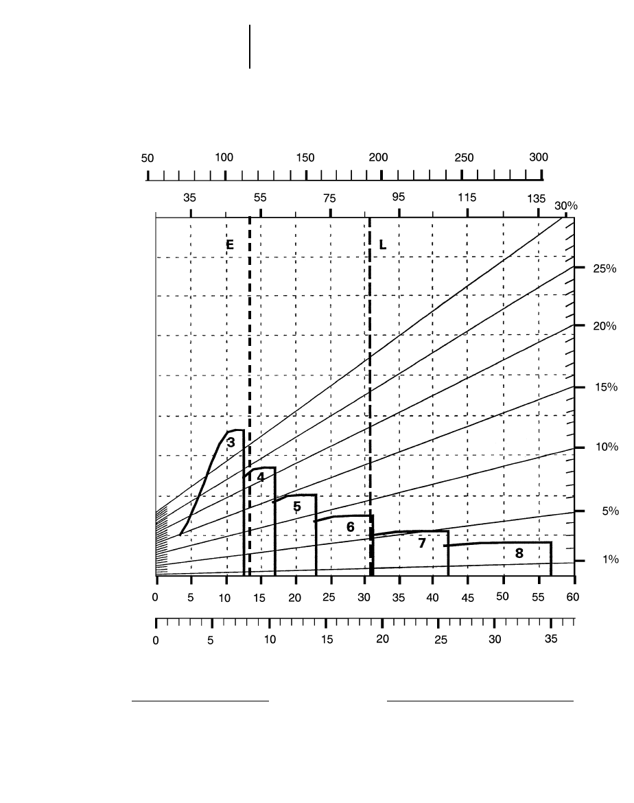
8-42
Wheel Tractor-Scrapers 633E Series II Retarding
●37.25R35 Tires
GROSS WEIGHT
KEY
3 — 3rd Gear Direct Drive
4 — 4th Gear Direct Drive
5 — 5th Gear Direct Drive
6 — 6th Gear Direct Drive
7 — 7th Gear Direct Drive
8 — 8th Gear Direct Drive
KEY
E — Empty 51 100 kg (112,670 lb)
L — Loaded 88 300 kg (194,670 lb)
kg x 1000
lb x 1000
EFFECTIVE GRADE
(Grade minus Rolling Resistance)
SPEED
km/h
mph
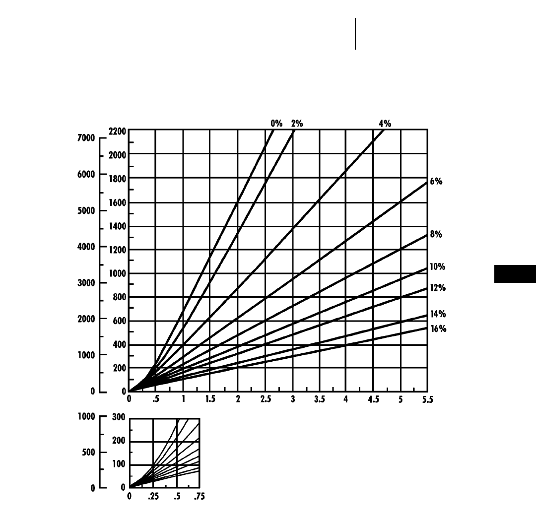
8-43
8
Wheel Tractor-Scrapers633E Series II Travel Time — Loaded
●37.25R35 Tires
TOTAL RESISTANCE
(Grade plus Rolling)
feet meters
LOADED
minutes
DISTANCE ONE WAY
TIME
Empty weight: 51 100 kg (112,670 lb)
Payload: 37 200 kg (82,000 lb)
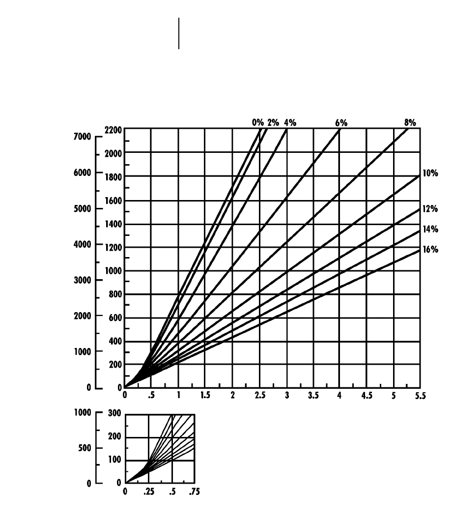
8-44
Wheel Tractor-Scrapers 633E Series II Travel Time — Empty
●37.25R35 Tires
TOTAL RESISTANCE
(Grade plus Rolling)
feet meters
EMPTY
minutes
DISTANCE ONE WAY
TIME
Empty weight: 51 100 kg (112,670 lb)
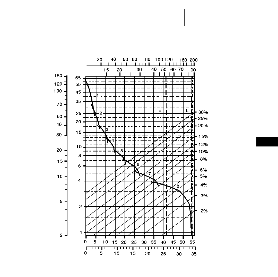
8-45
8
Wheel Tractor-Scrapers637E Series II Rimpull-Speed-Gradeability
●37.25R35 Tires
GROSS WEIGHT
KEY
1 — 1st Gear Torque Converter Drive
2 — 2nd Gear Torque Converter Drive
3 — 3rd Gear Direct Drive
4 — 4th Gear Direct Drive
5 — 5th Gear Direct Drive
6 — 6th Gear Direct Drive
7 — 7th Gear Direct Drive
8 — 8th Gear Direct Drive
KEY
E — Empty 51 000 kg (112,320 lb)
L — Loaded 85 020 kg (187,320 lb)
kg x 1000
lb x 1000
TOTAL RESISTANCE
(Grade plus Rolling Resistance)
SPEED
RIMPULL
km/h
mph
lb x
1000 kg x
1000
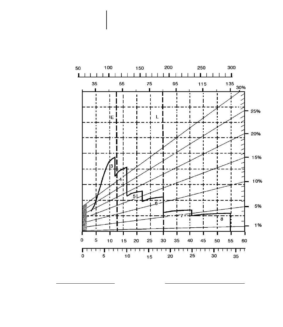
8-46
Wheel Tractor-Scrapers 637E Series II Retarding
●37.25R35 Tires
GROSS WEIGHT
KEY
3 — 3rd Gear Direct Drive
4 — 4th Gear Direct Drive
5 — 5th Gear Direct Drive
6 — 6th Gear Direct Drive
7 — 7th Gear Direct Drive
8 — 8th Gear Direct Drive
KEY
E — Empty 51 000 kg (112,320 lb)
L — Loaded 85 020 kg (187,320 lb)
kg x 1000
lb x 1000
EFFECTIVE GRADE
(Grade minus Rolling Resistance)
SPEED
km/h
mph
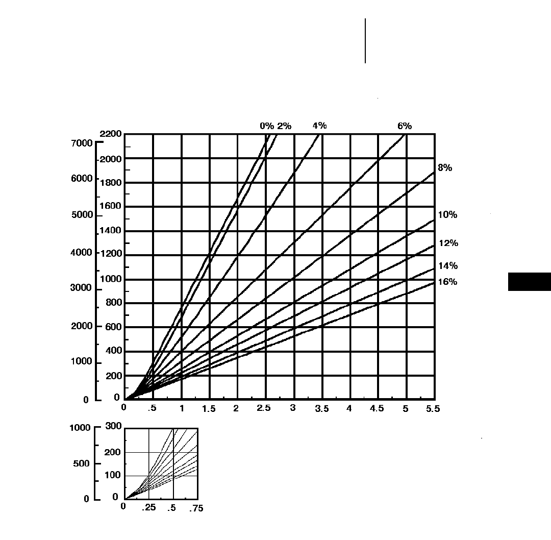
8-47
8
Wheel Tractor-Scrapers637E Series II Travel Time — Loaded
●37.25R35 Tires
●Standard and Push-Pull
TOTAL RESISTANCE
(Grade plus Rolling)
feet meters
LOADED
minutes
DISTANCE ONE WAY
TIME
Empty weight: 51 000 kg (112,320 lb)
Payload: 34 020 kg (75,000 lb)
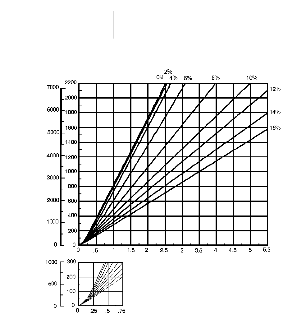
8-48
Wheel Tractor-Scrapers 637E Series II Travel Time — Empty
●37.25R35 Tires
●Standard and Push-Pull
TOTAL RESISTANCE
(Grade plus Rolling)
feet meters
EMPTY
minutes
DISTANCE ONE WAY
TIME
Empty weight: 51 000 kg (112,320 lb)
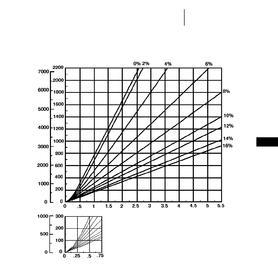
8-49
8
Wheel Tractor-Scrapers637E Series II Auger Travel Time — Loaded
●37.25R35 Tires
TOTAL RESISTANCE
(Grade plus Rolling)
feet meters
LOADED
minutes
DISTANCE ONE WAY
TIME
Empty weight: 54 540 kg (120,235 lb)
Payload: 34 020 kg (75,000 lb)
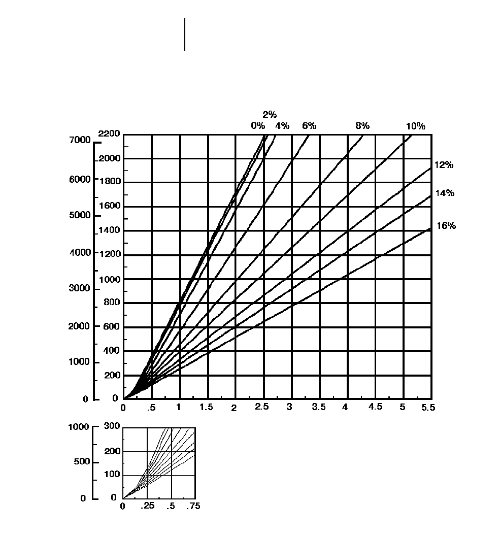
8-50
Wheel Tractor-Scrapers 637E Series II Auger Travel Time — Empty
●37.25R35 Tires
TOTAL RESISTANCE
(Grade plus Rolling)
feet meters
EMPTY
minutes
DISTANCE ONE WAY
TIME
Empty weight: 54 540 kg (120,235 lb)
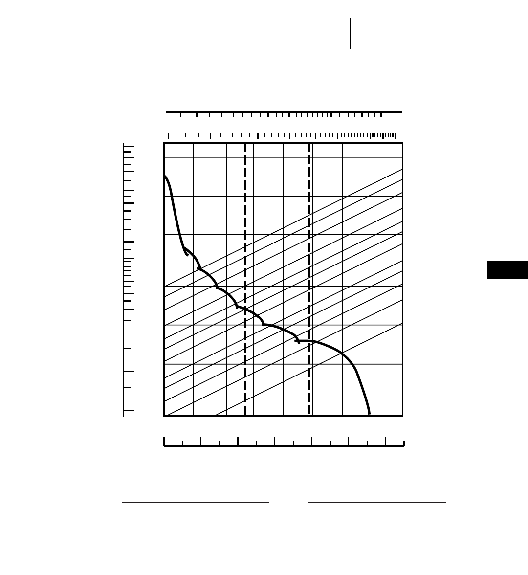
8-51
8
Wheel Tractor-Scrapers651E Rimpull-Speed-Gradeability
●40.5/75R39 Tires
70 100 150 200 250 300 400 500
40 50 60 80 100 120 150 200
0 5 10 15 20 25 30 35 40 45 50 55 60 65
110
90
70
50
40
30
20
15
10
8
6
4
2
12
5
10
20
50
100
200
250
0 5 10 15 20 25 30 35 40
30%
25%
20%
15%
12%
10%
8%
6%
5%
4%
3%
2%
EL
1
2345
67
8
GROSS WEIGHT
KEY
1 — 1st Gear Torque Converter Drive
2 — 2nd Gear Torque Converter Drive
3 — 3rd Gear Direct Drive
4 — 4th Gear Direct Drive
5 — 5th Gear Direct Drive
6 — 6th Gear Direct Drive
7 — 7th Gear Direct Drive
8 — 8th Gear Direct Drive
KEY
E — Empty 61 120 kg (134,760 lb)
L — Loaded 108 295 kg (238,760 lb)
lb x 1000
kg x 1000
TOTAL RESISTANCE
(Grade plus Rolling Resistance)
SPEED
RIMPULL
mph
km/h
kg x
1000 lb x
1000
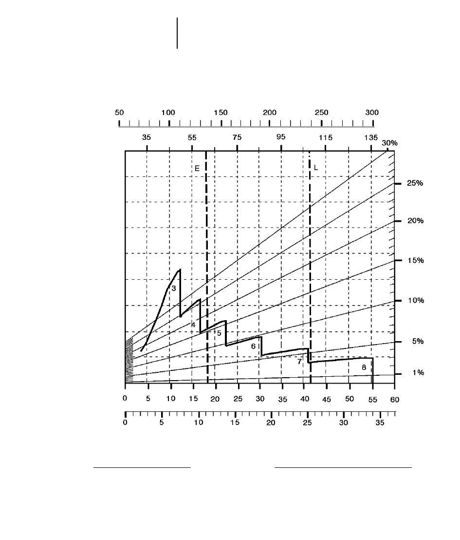
8-52
Wheel Tractor-Scrapers 651E Retarding
●40.5/75R39 Tires
GROSS WEIGHT
KEY
3 — 3rd Gear Direct Drive
4 — 4th Gear Direct Drive
5 — 5th Gear Direct Drive
6 — 6th Gear Direct Drive
7 — 7th Gear Direct Drive
8 — 8th Gear Direct Drive
KEY
E — Empty 61 120 kg (134,760 lb)
L — Loaded 108 295 kg (238,760 lb)
kg x 1000
lb x 1000
EFFECTIVE GRADE
(Grade minus Rolling Resistance)
SPEED
km/h
mph
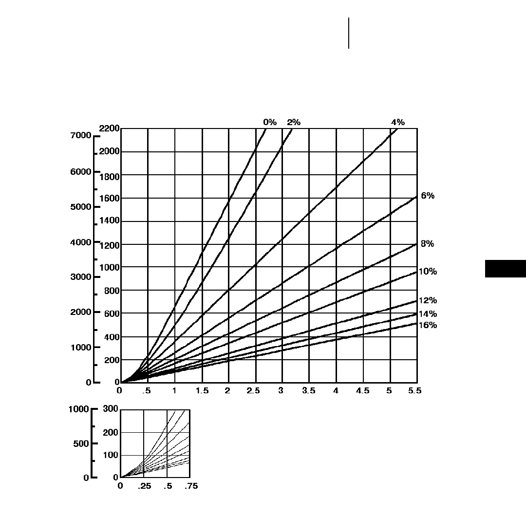
8-53
8
Wheel Tractor-Scrapers651E Auger Travel Time — Loaded
●40.5/75R39 Tires
TOTAL RESISTANCE
(Grade plus Rolling)
feet meters
LOADED
minutes
DISTANCE ONE WAY
TIME
Empty weight: 66 575 kg (146,770 lb)
Payload: 47 175 kg (104,000 lb)
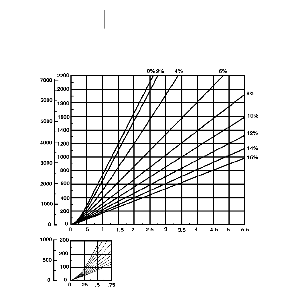
8-54
Wheel Tractor-Scrapers 651E Auger Travel Time — Empty
●40.5/75R39 Tires
TOTAL RESISTANCE
(Grade plus Rolling)
feet meters
EMPTY
minutes
DISTANCE ONE WAY
TIME
Empty weight: 66 575 kg (146,770 lb)
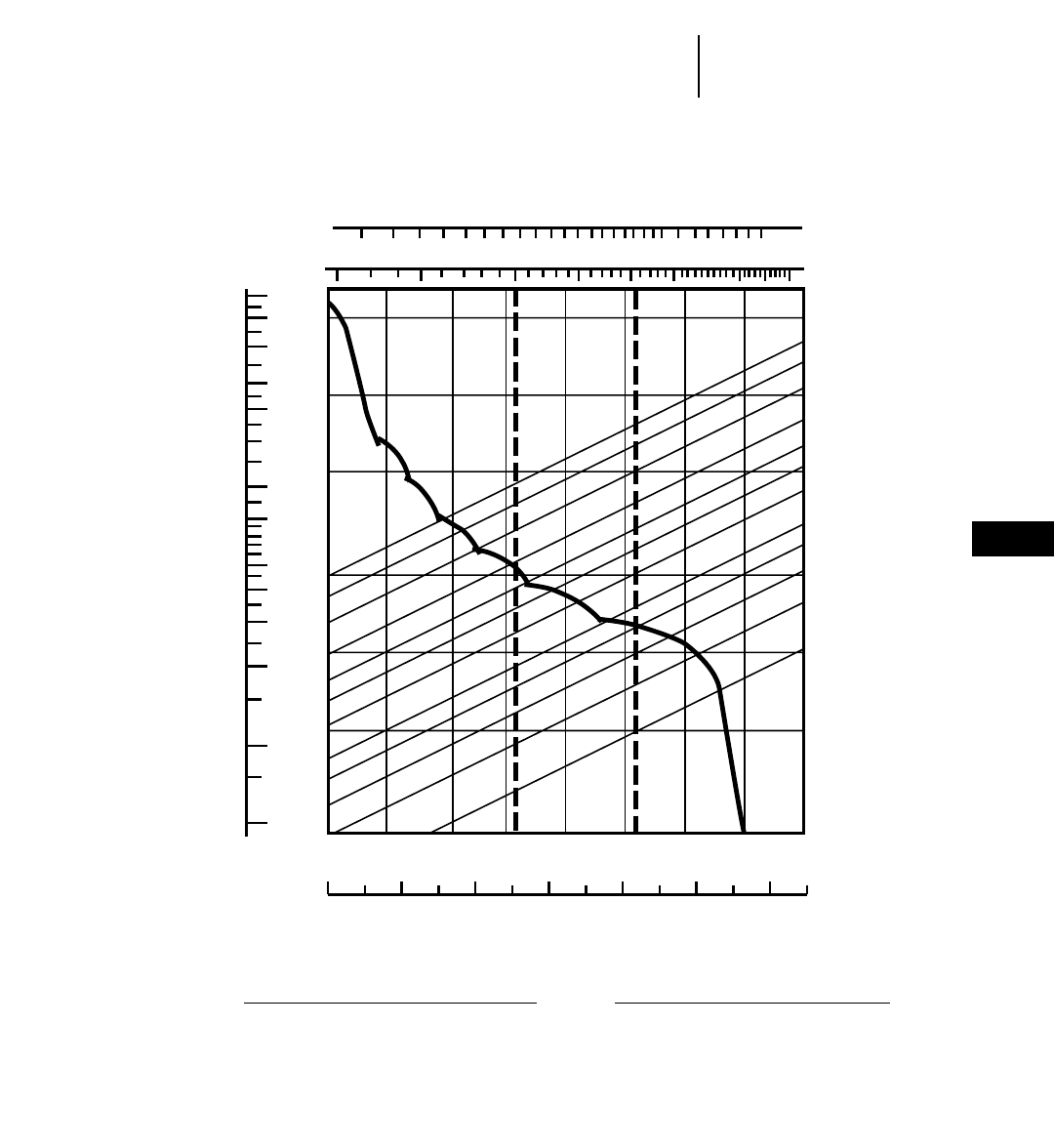
8-55
8
Wheel Tractor-Scrapers657E Rimpull-Speed-Gradeability
●40.5/75R39 Tires
70 100 150 200 250 300 400 500
40 50 60 80 100 120 150 200
0 5 10 15 20 25 30 35 40 45 50 55 60 65
110
90
70
50
40
30
20
15
10
8
6
4
2
12
5
10
20
50
100
200
250
0 5 10 15 20 25 30 35 40
30%
25%
20%
15%
12%
10%
8%
6%
5%
4%
3%
2%
EL
1
2
345
67
8
GROSS WEIGHT
KEY
1 — 1st Gear Torque Converter Drive
2 — 2nd Gear Torque Converter Drive
3 — 3rd Gear Direct Drive
4 — 4th Gear Direct Drive
5 — 5th Gear Direct Drive
6 — 6th Gear Direct Drive
7 — 7th Gear Direct Drive
8 — 8th Gear Direct Drive
KEY
E — Empty 69 080 kg (152,290 lb)
L — Loaded 116 250 kg (256,290 lb)
lb x 1000
kg x 1000
TOTAL RESISTANCE
(Grade plus Rolling Resistance)
SPEED
RIMPULL
mph
km/h
kg x
1000 lb x
1000
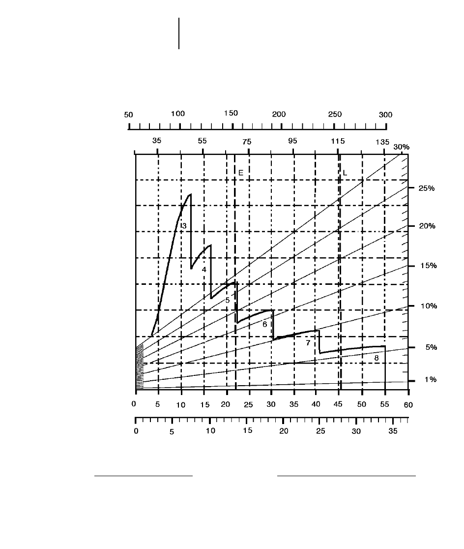
8-56
Wheel Tractor-Scrapers 657E Retarding
●40.5/75R39 Tires
GROSS WEIGHT
KEY
3 — 3rd Gear Direct Drive
4 — 4th Gear Direct Drive
5 — 5th Gear Direct Drive
6 — 6th Gear Direct Drive
7 — 7th Gear Direct Drive
8 — 8th Gear Direct Drive
KEY
E — Empty 70 670 kg (155,650 lb)
L — Loaded 117 935 kg (259,650 lb)
kg x 1000
lb x 1000
EFFECTIVE GRADE
(Grade minus Rolling Resistance)
SPEED
km/h
mph
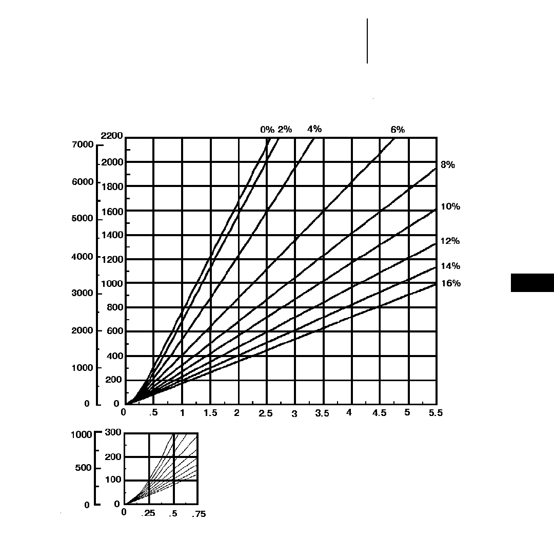
8-57
8
Wheel Tractor-Scrapers657E Travel Time — Loaded
●40.5/75R39 Tires
●Standard and Push-Pull
TOTAL RESISTANCE
(Grade plus Rolling)
feet meters
LOADED
minutes
DISTANCE ONE WAY
TIME
Empty weight: 70 670 kg (155,650 lb)
Payload: 47 175 kg (104,000 lb)
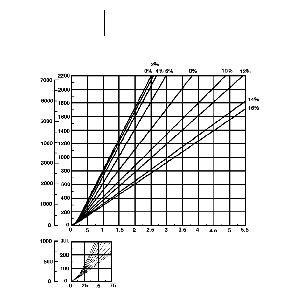
8-58
Wheel Tractor-Scrapers 657E Travel Time — Empty
●40.5/75R39 Tires
●Standard and Push-Pull
TOTAL RESISTANCE
(Grade plus Rolling)
feet meters
EMPTY
minutes
DISTANCE ONE WAY
TIME
Empty weight: 70 670 kg (155,650 lb)
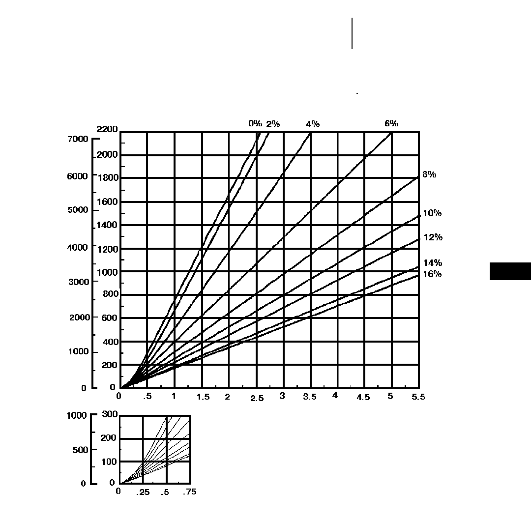
8-59
8
Wheel Tractor-Scrapers657E Auger Travel Time — Loaded
●40.5/75R39 Tires
TOTAL RESISTANCE
(Grade plus Rolling)
feet meters
LOADED
minutes
DISTANCE ONE WAY
TIME
Empty weight: 75 875 kg (167,270 lb)
Payload: 47 175 kg (104,000 lb)
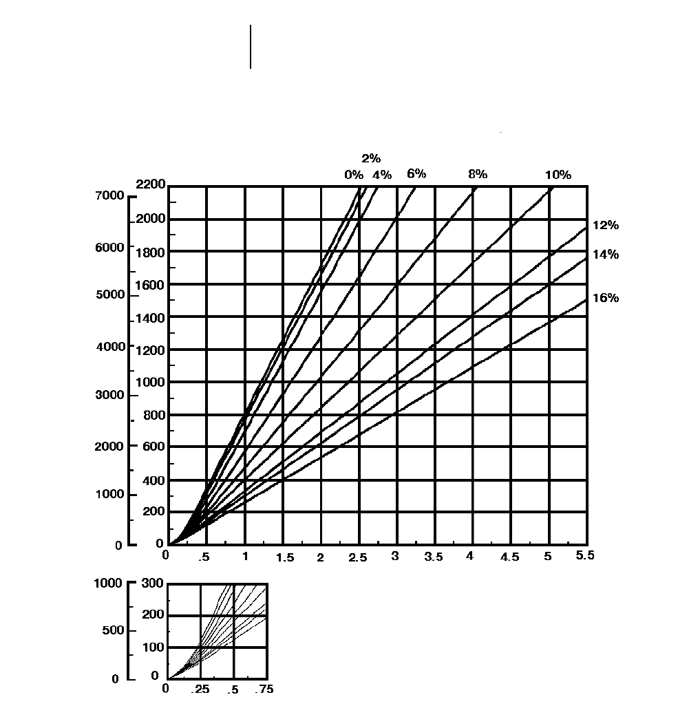
8-60
Wheel Tractor-Scrapers 657E Auger Travel Time — Empty
●40.5/75R39 Tires
TOTAL RESISTANCE
(Grade plus Rolling)
feet meters
EMPTY
minutes
DISTANCE ONE WAY
TIME
Empty weight: 75 875 kg (167,270 lb)
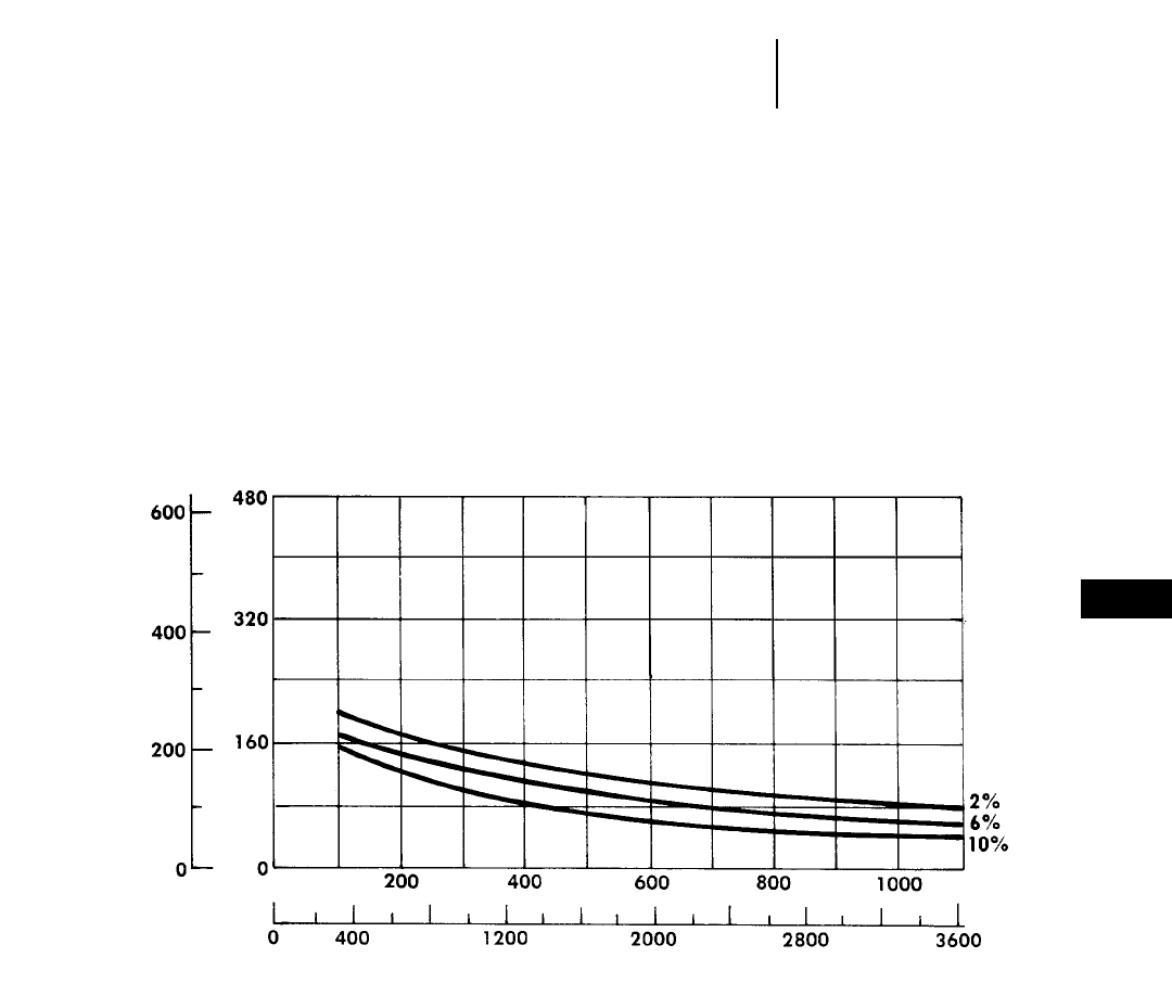
8-61
8
Wheel Tractor-Scrapers613C Series II Bm3(BCY)/hr
●23.5R25 Tires
DISTANCE vs. PRODUCTION
CONDITIONS: Flat haul. Percentages
shown are rolling resistance only.
100% efficiency (60 min hour).
●Material: 1780 kg/m3(3000 lb/yd3).
●Payload: 11 975 kg, 6.7 Bm3(26,400 lb, 8.8 BCY).
●Empty weight: 15 264 kg (33,650 lb).
●Fixed time: 1.6 min.
yd3m3
feet
BANK VOLUME/HR
DISTANCE ONE WAY
meters
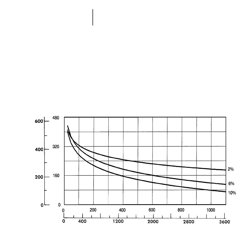
8-62
Wheel Tractor-Scrapers 615C Series II Bm3(BCY)/hr
●29.5R25 Tires
DISTANCE vs. PRODUCTION
CONDITIONS: Flat haul. Percentages
shown are rolling resistance only.
100% efficiency (60 min hour).
●Material: 1780 kg/m3(3000 lb/yd3).
●Payload: 18 506 kg, 10.4 Bm3(40,800 lb, 13.6 BCY).
●Empty weight: 44 113 kg (97,250 lb).
●Fixed time: 1.6 min.
yd3m3
feet
BANK VOLUME/HR
DISTANCE ONE WAY
meters
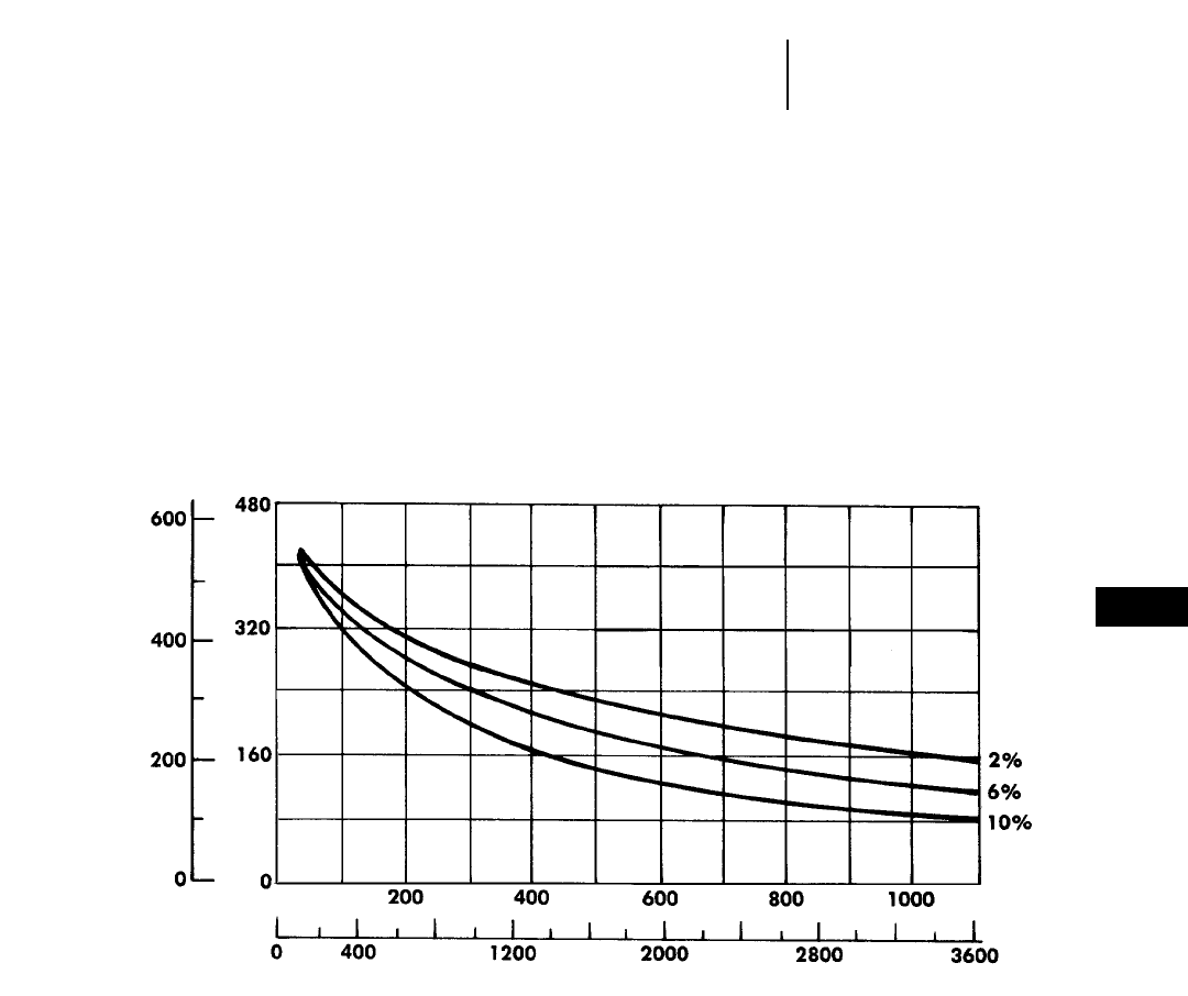
8-63
8
Wheel Tractor-Scrapers621F Bm3(BCY)/hr
●33.25R29 Tires
DISTANCE vs. PRODUCTION
CONDITIONS: Flat haul. Percentages
shown are rolling resistance only.
100% efficiency (60 min hour).
●Material: 1780 kg/m3(3000 lb/yd3).
●Payload: 21 770 kg, 12.2 Bm3(48,000 lb, 16 BCY).
●Empty weight: 32 070 kg (70,700 lb).
●Fixed time: 1.4 min.
yd3m3
feet
BANK VOLUME/HR
DISTANCE ONE WAY
meters
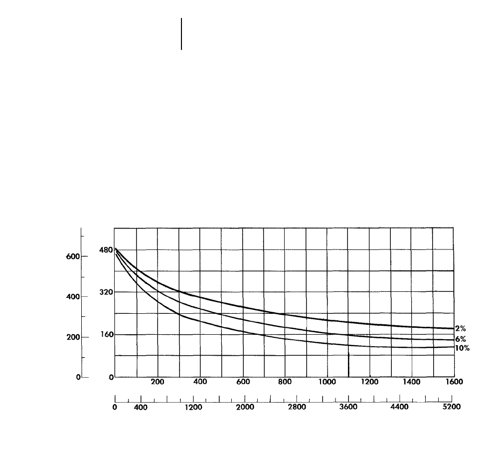
8-64
Wheel Tractor-Scrapers 623F Bm3(BCY)/hr
●33.25R29 Tires
DISTANCE vs. PRODUCTION
CONDITIONS: Flat haul. Percentages
shown are rolling resistance only.
100% efficiency (60 min hour).
●Material: 1780 kg/m3(3000 lb/yd3).
●Payload: 24 950 kg, 12.2 Bm3(55,000 lb, 16 BCY).
●Empty weight: 35 290 kg (77,800 lb).
●Fixed time: 1.6 min.
yd3m3
feet
BANK VOLUME/HR
DISTANCE ONE WAY
meters
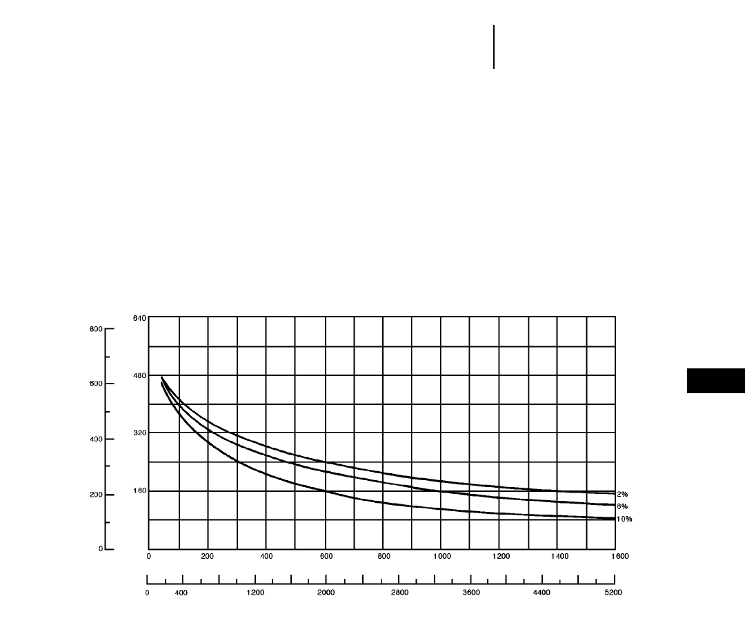
8-65
8
Wheel Tractor-Scrapers627F Bm3(BCY)/hr
●33.25R29 Tires
DISTANCE vs. PRODUCTION
CONDITIONS: Flat haul. Percentages
shown are rolling resistance only.
100% efficiency (60 min hour).
●Material: 1780 kg/m3(3000 lb/yd3).
●Payload: 21 770 kg, 12.2 Bm3(48,000 lb, 16 BCY).
●Empty weight: 37 060 kg (81,640 lb).
●Fixed time: 1.2 min.
yd3m3
feet
BANK VOLUME/HR
DISTANCE ONE WAY
meters
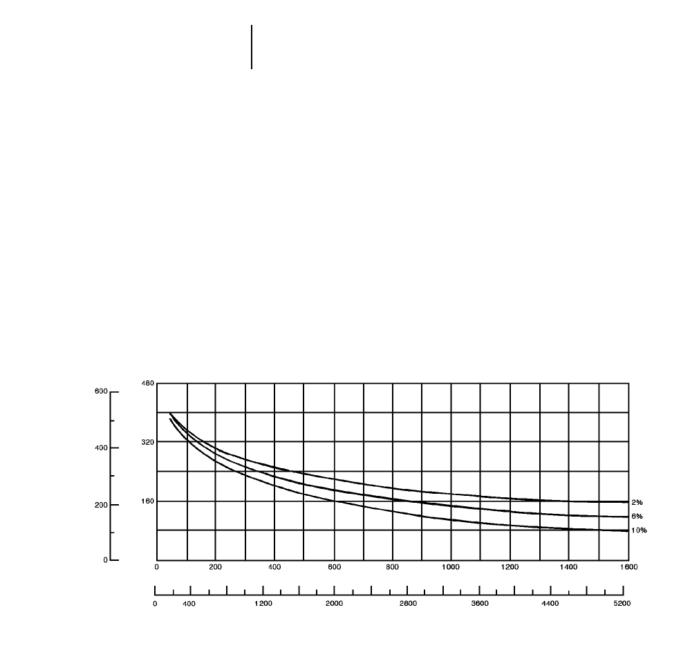
8-66
Wheel Tractor-Scrapers 627F Push-Pull Bm3(BCY)/hr
●33.25R29 Tires
DISTANCE vs. PRODUCTION
CONDITIONS: Flat haul. Percentages
shown are rolling resistance only.
100% efficiency (60 min hour).
●Material: 1780 kg/m3(3000 lb/yd3).
●Payload: 21 770 kg, 12.2 Bm3(48,000 lb, 16 BCY).
●Empty weight: 38 103 kg (84,000 lb).
●Fixed time: 1.5 min. (includes loading both units and
transfer time).
NOTE: Production estimates apply to one unit.
Double these figures for a push-pull pair.
yd3m3
feet
BANK VOLUME/HR
DISTANCE ONE WAY
meters
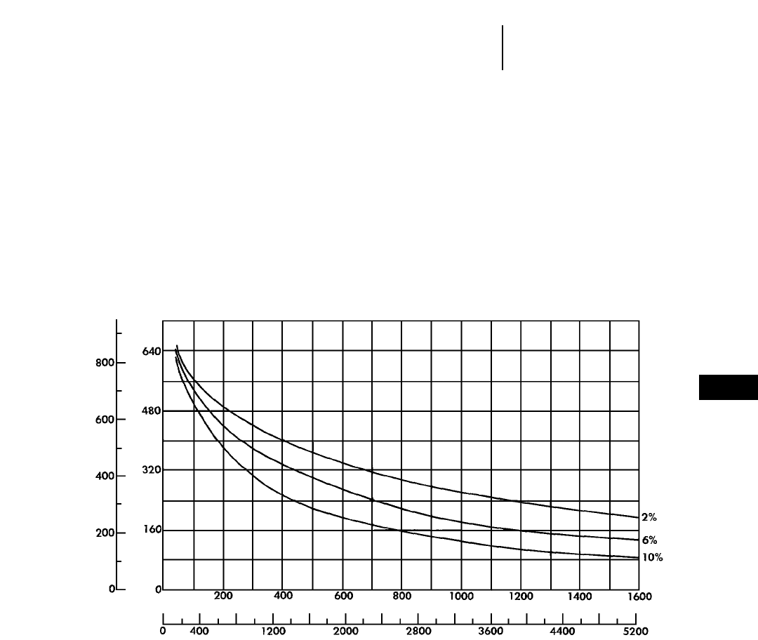
8-67
8
Wheel Tractor-Scrapers631E Series II Bm3(BCY)/hr
●37.25R35 Tires
DISTANCE vs. PRODUCTION
CONDITIONS: Flat haul. Percentages
shown are rolling resistance only.
100% efficiency (60 min hour).
●Material: 1780 kg/m3(3000 lb/yd3).
●Payload: 34 020 kg, 19.1 Bm3(75,000 lb, 25 BCY).
●Empty weight: 45 400 kg (100,000 lb).
●Fixed time: 1.3 min.
yd3m3
feet
BANK VOLUME/HR
DISTANCE ONE WAY
meters
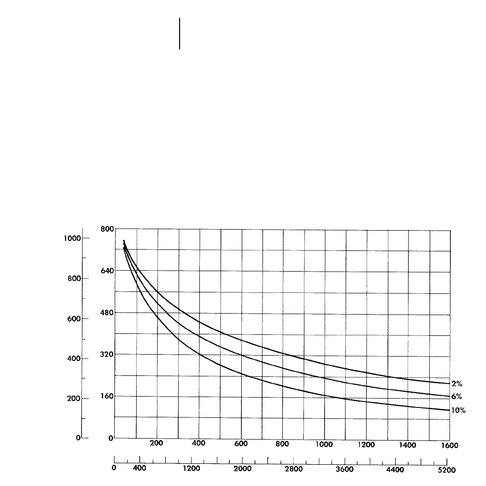
8-68
Wheel Tractor-Scrapers 637E Series II Bm3(BCY)/hr
●37.25R35 Tires
DISTANCE vs. PRODUCTION
CONDITIONS: Flat haul. Percentages
shown are rolling resistance only.
100% efficiency (60 min hour).
●Material: 1780 kg/m3(3000 lb/yd3).
●Payload: 34 020 kg, 19.1 Bm3(75,000 lb, 25 BCY).
●Empty weight: 50 990 kg (112,320 lb).
●Fixed time: 1.1 min.
yd3m3
feet
BANK VOLUME/HR
DISTANCE ONE WAY
meters
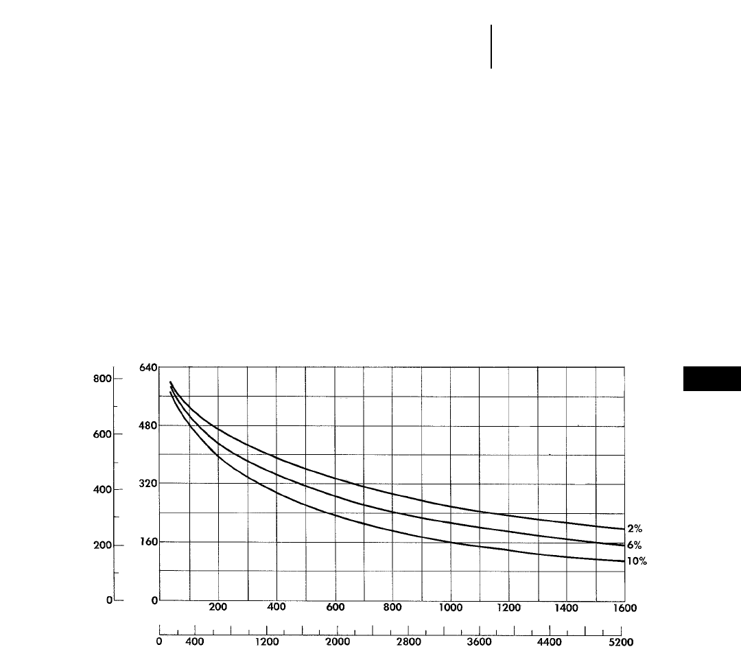
8-69
8
Wheel Tractor-Scrapers637E Series II Push-Pull Bm3(BCY)/hr
●37.25R35 Tires
DISTANCE vs. PRODUCTION
CONDITIONS: Flat haul. Percentages
shown are rolling resistance only.
100% efficiency (60 min hour).
●Material: 1780 kg/m3(3000 lb/yd3).
●Payload: 34 020 kg, 19.1 Bm3(75,000 lb, 25 BCY).
●Empty weight: 52 385 kg (115,490 lb).
●Fixed time: 1.6 min. (includes loading both units and
transfer time).
NOTE: Production estimates apply to one unit.
Double these figures for a push-pull pair.
yd3m3
feet
BANK VOLUME/HR
DISTANCE ONE WAY
meters
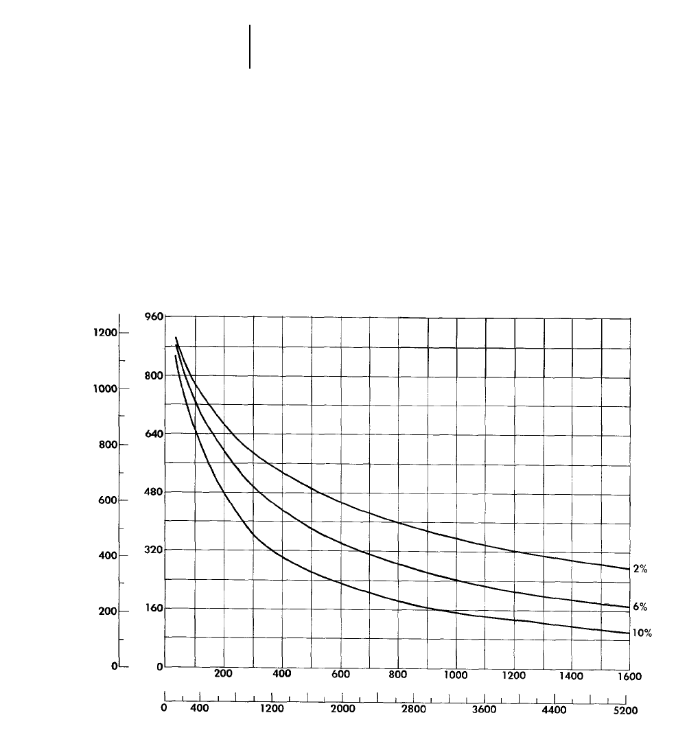
8-70
Wheel Tractor-Scrapers 651E Bm3(BCY)/hr
●40.5/75R39 Tires
DISTANCE vs. PRODUCTION
CONDITIONS: Flat haul. Percentages
shown are rolling resistance only.
100% efficiency (60 min hour).
●Material: 1780 kg/m3(3000 lb/yd3).
●Payload: 47 200 kg, 26.5 Bm3(104,056 lb, 34.6 BCY).
●Empty weight: 61 120 kg (134,760 lb).
●Fixed time: 1.3 min.
yd3m3
feet
BANK VOLUME/HR
DISTANCE ONE WAY
meters
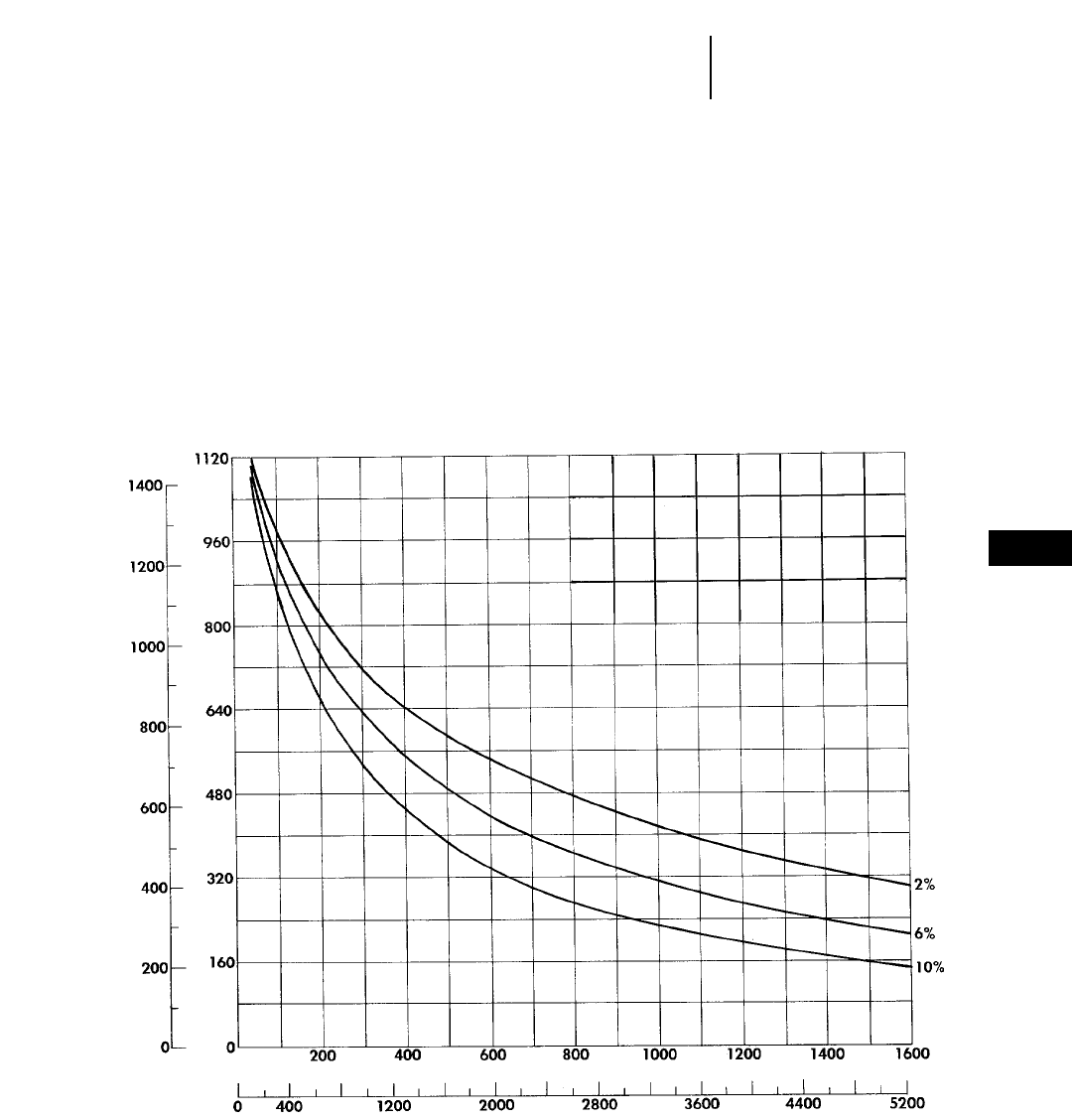
8-71
8
Wheel Tractor-Scrapers657E Bm3(BCY)/hr
●40.5/75R39 Tires
DISTANCE vs. PRODUCTION
CONDITIONS: Flat haul. Percentages
shown are rolling resistance only.
100% efficiency (60 min hour).
●Material: 1780 kg/m3(3000 lb/yd3).
●Payload: 47 200 kg, 26.5 Bm3(104,000 lb, 34.6 BCY).
●Empty weight: 70 670 kg (155,650 lb).
●Fixed time: 1 min.
yd3m3
feet
BANK VOLUME/HR
DISTANCE ONE WAY
meters
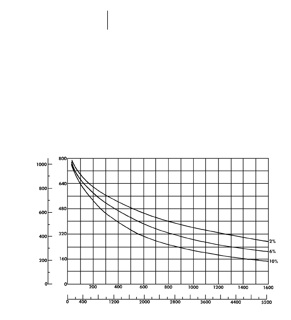
8-72
Wheel Tractor-Scrapers 657E Push-Pull Bm3(BCY)/hr
●40.5/75R39 Tires
DISTANCE vs. PRODUCTION
CONDITIONS: Flat haul. Percentages
shown are rolling resistance only.
100% efficiency (60 min hour).
●Material: 1780 kg/m3(3000 lb/yd3).
●Payload: 47 200 kg, 26.5 Bm3(104,000 lb, 34.6 BCY).
●Empty weight: 72 640 kg (160,140 lb).
●Fixed time: 1.7 min. (includes loading both units and
transfer time).
NOTE: Production estimates apply to one unit.
Double these figures for a push-pull pair.
yd3m3
feet
BANK VOLUME/HR
DISTANCE ONE WAY
meters
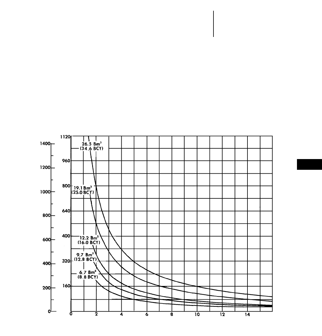
8-73
8
Wheel Tractor-ScrapersBm3(BCY)/hr
●All Models
●100% Efficiency
HOURLY PRODUCTION vs. CYCLE TIME
VEHICLE CAPACITY:
613C Series II @ 6.7 Bm3/trip (8.8 BCY)
615C Series II @ 9.7 Bm3/trip (12.8 BCY)
621F, 623F, 627F @ 12.2 Bm3/trip (16 BCY)
631E Series II, 633E Series II, 637E Series II @ 19.1 Bm3/trip (25 BCY)
651E, 657E @ 26.5 Bm3/trip (34.6 BCY)
yd3m3
BANK VOLUME/HR
CYCLE TIME
minutes

9-1
CONTENTS
Features . . . . . . . . . . . . . . . . . . . . . . . . . . . . . . .9-1
Truck Specifications . . . . . . . . . . . . . . . . . . . . . .9-2
Tractor Specifications . . . . . . . . . . . . . . . . . . . . .9-4
Tire Specifications . . . . . . . . . . . . . . . . . . . . . . .9-7
Use of Brake Performance curves . . . . . . . . . . .9-8
Fixed times for hauling units . . . . . . . . . . . . . . .9-8
Mechanical Power Train Efficiencies . . . . . . . . .9-9
Curves:
769D Rimpull-Speed-Gradeability,
Brake Performance, Travel Time . . . . . . .9-10
771D Rimpull-Speed-Gradeability,
Brake Performance, Travel Time . . . . . . .9-14
773D Rimpull-Speed-Gradeability,
Brake Performance, Travel Time . . . . . . .9-18
775D Rimpull-Speed-Gradeability,
Brake Performance, Travel Time . . . . . . .9-23
776D, 777D Rimpull-Speed-Gradeability,
Brake Performance, Travel Time . . . . . . .9-27
784C, 785C Rimpull-Speed-Gradeability,
Brake Performance, Travel Time . . . . . . .9-31
789C Rimpull-Speed-Gradeability,
Brake Performance, Travel Time . . . . . . .9-36
793C Rimpull-Speed-Gradeability,
Brake Performance, Travel Time . . . . . . .9-40
Features:
●Caterpillar four-stroke-cycle diesels … turbo-
charged, aftercooled, adjustment-free fuel system
(direct injection).
●Electronically-controlled automatic trans-
mission … speed sensing device automatically
shifts transmission between 1st and gear selected
by operator.
●Truck Production Management System
(TPMS) utilizes strut pressure sensors and an
on-board microprocessor to determine payload
weight, cycle segment times, delay times, actual
clock time and date of each cycle.
●Vital Information Management System (VIMS)
Monitors all vital machine functions. Keeps oper-
ator informed of current machine operating condi-
tions, helps reduce downtime and allows service
personnel easy access to data for fast accurate diag-
nosis. VIMS includes Production Management
System.
●Electronic Unit Injection (EUI) in the 776D-
793C and Hydraulic Electronic Unit Injection
(HEUI) on 769D-775D electronically maintains
fuel settings, provides automatic altitude and air
filter restriction compensation, automatic vari-
able timing, improved diagnostics and increased
fuel efficiency.
●Oil cooled disc brakes provide retarding, service,
parking, and secondary braking in one sealed,
fade-resistant, maintenance-free unit. 769D-777D
front brakes are caliper disc, can be switched out
of the service system when not needed but acti-
vate as part of the secondary system. (Front oil-
cooled brakes optional on 777D.) 784C-793C front
brakes are oil-cooled disc.
●Automatic Retarder Control (ARC) electroni-
cally controls braking on grade to maintain faster
downhill speeds and consistently higher engine
speed.
●Full hydraulic steering, with front suspension
cylinders serving as kingpins.
●Four independent, self-contained, oil-pneumatic
suspension cylinders absorb loading and road
shocks. Wide spacing for stability.
●Dual slope body has V-bottom for load balance
and retention. Low loading height and center of
gravity.
●Quarry trucks have single-slope flat floor for
smooth, metered dumping into crushers or hoppers.
Optional flat floor body available for 769D, 773D.
●Integral Roll Over Protective Structure (ROPS)
cab standard on all models.
●Separate hydraulic systems prevents cross
contamination.
Tractor Features:
●Yoke type hitch oscillates four ways to reduce
frame stresses. Rugged turn stops prevent exces-
sive wagon rotation either direction.
●Rear platform functions as a power train guard
and provides safe, stable work area. Fenders and
mud flaps protect from material thrown by tires.
NOTE: Listed features may be standard on some models. Optional on others.
Contact your Caterpillar Dealer for specific information.
9
CONSTRUCTION & MINING TRUCKS
CONSTRUCTION & MINING TRACTORS
9-2
Construction & Mining Trucks Specifications
MODEL 769D 769D 771D
Body Type Flat Floor Dual Slope Quarry
Gross Vehicle Weight 68 180 kg 150,000 lb 68 180 kg 150,000 lb 73 970 kg 163,100 lb
Chassis Weight* 22 950 kg 50,600 lb 22 950 kg 50,600 lb 22 950 kg 50,600 lb
Body Weight 7800 kg 17,200 lb 7330 kg 16,170 lb 10 350 kg 22,820 lb
Maximum Payload** 37 430 kg 82,533 lb 37 900 kg 83,570 lb 40 670 kg 89,680 lb
Standard Liner Weight 3300 kg 7280 lb 3160 kg 6970 lb —
Payload with Standard Liner 34 130 kg 75,250 lb 34 740 kg 76,600 lb —
Capacity:
Struck (SAE) 16.5 m321.6 yd317 m322.2 yd320.2 m326.4 yd3
Heaped (2:1) (SAE) 24.2 m331.7 yd324.2 m331.7 yd327.5 m336 yd3
Distribution Empty:
Front 49.7% 49.8% 46.3%
Rear 50.3% 50.2% 53.7%
Distribution Loaded:
Front 33.2% 33.3% 32.9%
Rear 66.8% 66.7% 67.1%
Engine Model 3408E 3408E 3408E
Number of Cylinders 888
Bore 137 mm 5.4" 137 mm 5.4" 137 mm 5.4"
Stroke 152 mm 6" 152 mm 6" 152 mm 6"
Displacement 18 L 1099 in318 L 1099 in318 L 1099 in3
Flywheel Power 362 kW 485 hp 362 kW 485 hp 362 kW 485 hp
Gross Power 380 kW 510 hp 380 kW 510 hp 380 kW 510 hp
Standard Tires 18.00R33(E-4) 18.00R33(E-4) 18.00R33(E-4)
Machine Clearance Turning Circle 19.8 m 65'0" 19.8 m 65'0" 19.8 m 65'0"
Fuel Tank Refill Capacity 530 L 140 U.S. gal 530 L 140 U.S. gal 530 L 140 U.S. gal
Top Speed (Loaded) 75 km/h 47 mph 75 km/h 47 mph 56 km/h 35 mph
GENERAL DIMENSIONS
(Empty):
Height to Canopy Rock Guard Rail 4.07 m 13'4" 4.03 m 13'3" 4.02 m 13'2"
Wheelbase 3.71 m 12'2" 3.71 m 12'2" 3.71 m 12'2"
Overall Length 8.73 m 28'7" 8.57 m 28'1" 8.73 m 28'7"
Loading Height (Empty) 3.19 m 10'6" 3.14 m 10'4" 3.40 m 11'2"
Height at Full Dump 7.75 m 25'5" 7.71 m 25'3" 7.74 m 25'5"
Body Length (Target Length) 5.43 m 17'10" 5.28 m 17'4" 5.52 m 18'1"
Width (Operating) 5.01 m 16'5" 5.01 m 16'5" 5.01 m 16'5"
Width (Shipping)*** 3.95 m 12'11" 3.95 m 12'11" 3.95 m 12'11"
Front Tire Tread 3.10 m 10'2" 3.10 m 10'2" 3.10 m 10'2"
***Weights include lubricants, coolants, and 10% fuel.
***Maximum rating requires selection of proper tires and is dependent on selection of optional equipment. Gross vehicle weight should not be exceeded.
***Disassembled.
9-3
MODEL 773D 773D 775D 775D
Body Type Flat Floor Dual Slope Quarry Lined Quarry
Gross Vehicle Weight 92 530 kg 204,000 lb 92 530 kg 204,000 lb 106 590 kg 235,000 lb 106 590 kg 235,000 lb
Chassis Weight* 30 165 kg 66,500 lb 30 165 kg 66,500 lb 30 390 kg 67,000 lb 30 390 kg 67,000 lb
Body Weight 9375 kg 20,670 lb 9030 kg 19,910 lb 12 830 kg 28,230 lb 14 140 kg 31,170 lb
Maximum Payload** 52 990 kg 116,840 lb 53 340 kg 117,610 lb 63 370 kg 139,730 lb 62 070 kg 136,860 lb
Standard Liner Weight 3981 kg 8778 lb 3920 kg 8640 lb — —
Payload with Standard Liner 49 010 kg 108,065 lb 49 420 kg 108,970 lb — 62 070 kg 136,860 lb
Capacity:
Struck (SAE) 26.6 m334.8 yd326.6 m334.8 yd331.4 m341.1 yd331.2 m340.8 yd3
Heaped (2:1) (SAE) 35.5 m346.4 yd335.2 m346 yd341.5 m354.3 yd341.2 m353.9 yd3
Distribution Empty:
Front 47.3% 47.3% 44.3% 44.3%
Rear 52.7% 52.7% 55.7% 55.7%
Distribution Loaded:
Front 33.3% 33.3% 31.2% 31.2%
Rear 66.7% 66.7% 68.8% 68.8%
Engine Model 3412E 3412E 3412E 3412E
Number of Cylinders 12 12 12 12
Bore 137 mm 5.4" 137 mm 5.4" 137 mm 5.4" 137 mm 5.4"
Stroke 152 mm 6" 152 m 6" 152 mm 6" 152 mm 6"
Displacement 27 L 1649 in327 L 1649 in327 L 1649 in327 L 1649 in3
Flywheel Power 485 kW 650 hp 485 kW 650 hp 517 kW 693 hp 517 kW 693 hp
Gross Power 509 kW 682 hp 509 kW 682 hp 541 kW 725 hp 541 kW 725 hp
Standard Tires 24.00R35(E-4) 24.00R35(E-4) 24.00R35(E-4) 24.00R35(E-4)
Machine Clearance
Turning Circle 24 m 78'9" 24 m 78'9" 24 m 78'9" 24 m 78'9"
Fuel Tank Refill Capacity 700 L 185 U.S. gal 700 L 185 U.S. gal 700 L 185 U.S. gal 700 L 185 U.S. gal
Top Speed (Loaded) 66 km/h 41 mph 66 km/h 41 mph 66 km/h 41 mph 66 km/h 41 mph
GENERAL DIMENSIONS
(Empty):
Height to Canopy Rock
Guard Rail 4.42 m 14'6" 4.39 m 14'5" 4.41 m 14'5" 4.41 m 14'5"
Wheelbase 4.19 m 13'9" 4.19 m 13'9" 4.19 m 13'9" 4.19 m 13'9"
Overall Length 9.70 m 31'10" 9.61 m 31'6" 9.70 m 31'10" 9.70 m 31'10"
Loading Height (Empty) 3.79 m 12'5" 3.77 m 12'5" 3.91 m 12'10" 3.91 m 12'10"
Height at Full Dump 8.82 m 28'11" 8.79 m 28'10" 8.80 m 28'10" 8.80 m 28'10"
Body Length (Target Length) 6.49 m 21'3" 6.40 m 21'0" 6.54 m 21'5" 6.51 m 21'4"
Width (Operating) 5.08 m 16'8" 5.08 m 16'8" 5.21 m 17'1" 5.21 m 17'1"
Width (Shipping)*** 3.97 m 13'0" 3.97 m 13'0" 3.97 m 13'0" 3.97 m 13'0"
Front Tire Tread 3.28 m 10'9" 3.28 m 10'9" 3.28 m 10'9" 3.28 m 10'9"
***Weights include lubricants, coolants, and 10% fuel.
***Maximum rating requires selection of proper tires and is dependent on selection of optional equipment. Gross vehicle weight should not be exceeded.
***Disassembled.
9
Construction & Mining TrucksSpecifications
9-4
Construction & Mining Trucks Specifications
MODEL 777D 777D 785C 785C
Body Type Flat Floor Dual Slope Flat Floor Dual Slope
Gross Vehicle Weight 161 030 kg 355,000 lb 161 030 kg 355,000 lb 249 480 kg 550,000 lb 249 480 kg 550,000 lb
Chassis Weight* 48 580 kg 107,100 lb 48 580 kg 107,100 lb 74 450 kg 164,170 lb 74 450 kg 164,170 lb
Body Weight 16 430 kg 36,185 lb 15 780 kg 34,785 lb 24 610 kg 54,200 lb 21 280 kg 46,870 lb
Maximum Payload** 96 020 kg 211,710 lb 96 670 kg 213,110 lb 150 560 kg 331,630 lb 153 890 kg 338,970 lb
Standard Liner Weight 5675 kg 12,500 lb 5460 kg 12,040 lb 1090 kg 2400 lb 7640 kg 16,840 lb
Payload with Standard Liner 90 340 kg 199,210 lb 91 210 kg 201,070 lb 149 470 kg 329,230 lb 146 250 kg 322,130 lb
Capacity:
Struck (SAE) 42.0 m354.6 yd342.1 m355 yd374 m396 yd357 m374 yd3
Heaped (2:1) (SAE) 60.5 m379.1 yd360.1 m378.6 yd391 m3119 yd378 m3102 yd3
Distribution Empty:
Front 47% 47% 47% 47%
Rear 53% 53% 53% 53%
Distribution Loaded:
Front 47% 33% 32% 33%
Rear 53% 67% 68% 67%
Engine Model 3508B 3508B 3512 3512
Number of Cylinders 8 8 12 12
Bore 170 mm 6.7" 170 mm 6.7" 170 mm 6.7" 170 mm 6.7"
Stroke 190 mm 7.5" 190 mm 7.5" 190 mm 7.5" 190 mm 7.5"
Displacement 34.5 L 2105 in334.5 L 2105 in351.8 L 3158 in351.8 L 3158 in3
Flywheel Power 699 kW 938 hp 699 kW 938 hp 962 kW 1290 hp 962 kW 1290 hp
Gross Power 746 kW 1000 hp 746 kW 1000 hp 1029 kW 1380 hp 1029 kW 1380 hp
Standard Tires 27.00R49 27.00R49 33.00R51 33.00R51
Machine Clearance
Turning Circle 26.1 m 85'6" 26.1 m 85'6" 30.2 m 99'2" 30.2 m 99'2"
Fuel Tank Refill Capacity 1137 L 300 U.S. gal 1137 L 300 U.S. gal 1893 L 500 U.S. gal 1893 L 500 U.S. gal
Top Speed (Loaded) 60 km/h 38 mph 60 km/h 38 mph 56 km/h 35 mph 56 km/h 35 mph
GENERAL DIMENSIONS
(Empty):
Height to Canopy Rock
Guard Rail 5.00 m 16'5" 4.95 m 16'3" 5.93 m 19'6" 5.77 m 18'11"
Wheelbase 4.57 m 15'0" 4.57 m 15'0" 5.18 m 17'0" 5.18 m 17'0"
Overall Length 9.78 m 32'1" 9.78 m 32'1" 11.02 m 36'2" 11.02 m 36'2"
Loading Height (Empty) 4.34 m 14'3" 4.29 m 14'1" 5.55 m 18'3" 4.98 m 16'4"
Height at Full Dump 9.97 m 32'9" 9.95 m 32'8" 11.12 m 36'6" 11.20 m 36'9"
Body Length (Target Length) 9.60 m 31'6" 6.95 m 22'10" 10.46 m 34'4" 7.65 m 25'1"
Width (Operating) 5.53 m 18'2" 6.10 m 20'0" 6.79 m 22'3" 6.64 m 21'9"
Width (Shipping)*** 3.51 m 11'6" 3.51 m 11'6" 3.84 m 12'6" 3.84 m 12'6"
Front Tire Tread 4.17 m 13'8" 4.17 m 13'8" 4.85 m 15'11" 4.85 m 15'11"
***Weights include lubricants, coolants, and 10% fuel.
***Maximum rating requires selection of proper tires and is dependent on selection of optional equipment. Gross vehicle weight should not be exceeded.
***Disassembled.
9-5
9
Construction & Mining TrucksSpecifications
MODEL 789C 789C 793C 793C
Body Type Flat Floor Dual Slope Flat Floor Dual Slope
Gross Vehicle Weight 317 520 kg 700,000 lb 317 520 kg 700,000 lb 376 820 kg 830,000 lb 376 820 kg 830,000 lb
Chassis Weight* 95 220 kg 209,930 lb 95 220 kg 209,930 lb 113 510 kg 250,250 lb 113 510 kg 250,250 lb
Body Weight 30 220 kg 66,570 lb 26 305 kg 57,940 lb 32 980 kg 72,650 lb 31 200 kg 68,800 lb
Maximum Payload** 192 270 kg 423,500 lb 196 190 kg 432,130 lb 230 320 kg 507,100 lb 232 105 kg 510,950 lb
Standard Liner Weight 1360 kg 3000 lb 9440 kg 20,790 lb 1360 kg 3000 lb 11 070 kg 24,420 lb
Payload with Standard Liner 190 910 kg 420,500 lb 186 750 kg 411,340 lb 228 860 kg 504,100 lb 221 030 kg 486,530 lb
Capacity:
Struck (SAE) 94 m3123 yd373 m396 yd3120 m3157 yd396 m3126 yd3
Heaped (2:1) (SAE) 121.5 m3158 yd3105 m3137 yd3147.5 m3193 yd3129 m3169 yd3
Distribution Empty:
Front 47% 47% 47% 47%
Rear 53% 53% 53% 53%
Distribution Loaded:
Front 32% 33% 32% 33%
Rear 68% 67% 68% 67%
Engine Model 3516 3516 3516B 3516B
Number of Cylinders 16 16 16 16
Bore 170 mm 6.7" 170 mm 6.7" 170 mm 6.7" 170 mm 6.7"
Stroke 190 mm 7.5" 190 mm 7.5" 190 mm 7.5" 190 mm 7.5"
Displacement 69 L 4211 in369 L 4211 in369 L 4211 in369 L 4211 in3
Flywheel Power 1272 kW 1705 hp 1272 kW 1705 hp 1616 kW 2166 hp 1616 kW 2166 hp
Gross Power 1342 kW 1800 hp 1342 kW 1800 hp 1716 kW 2300 hp 1716 kW 2300 hp
Standard Tires 37.00R57 37.00R57 40.00R57 40.00R57
Machine Clearance
Turning Circle 30.2 m 99'2" 30.2 m 99'2" 30.2 m 99'2" 30.2 m 99'2"
Fuel Tank Refill Capacity 3222 L 851 3222 L 851 3861 L 1020 3861 L 1020
U.S. gal U.S. gal U.S. gal U.S. gal
Top Speed (Loaded) 54 km/h 34 mph 54 km/h 34 mph 55 km/h 34 mph 55 km/h 34 mph
GENERAL DIMENSIONS
(Empty):
Height to Canopy Rock
Guard Rail 6.16 m 20'3" 6.15 m 20'2" 6.56 m 21'6" 6.43 m 21'1"
Wheelbase 5.70 m 18'8" 5.90 m 18'8" 5.90 m 19'4" 5.90 m 19'4"
Overall Length 12.13 m 39'9" 12.18 m 39'11" 13.23 m 43'4" 12.86 m 42'3"
Loading Height (Empty) 5.69 m 18'8" 5.21 m 17'1" 6.40 m 20'11" 5.86 m 19'3"
Height at Full Dump 11.93 m 39'2" 11.91 m 39'1" 13.14 m 43'1" 13.21 m 43'4"
Body Length (Target Length) 11.62 m 38'2" 8.15 m 26'9" 12.67 m 41'7" 8.94 m 29'4"
Width (Operating) 7.97 m 26'2" 7.67 m 25'2" 8.02 m 26'8" 7.42 m 24'4"
Width (Shipping)*** 3.84 m 12'6" 3.84 m 12'6" 3.84 m 12'6" 3.84 m 12'6"
Front Tire Tread 5.43 m 17'10" 5.43 m 17'10" 5.61 m 18'5" 5.61 m 18'5"
***Weights include lubricants, coolants, and 10% fuel.
***Maximum rating requires selection of proper tires and is dependent on selection of optional equipment. Gross vehicle weight should not be exceeded.
***Disassembled.
MODEL 776D 784C
Flywheel Power 699 kW 938 hp 962 kW 1290 hp
Gross Power 746 kW 1000 hp 1029 kW 1380 hp
Operating Weight* 55 480 kg 122,311 lb 89 280 kg 196,825 lb
Engine Model 3508B (EUI) 3512 (EUI)
No. Cylinders 812
Bore 170 mm 6.7" 170 mm 6.7"
Stroke 190 mm 7.5" 190 mm 7.5"
Displacement 34.5 L 2105 in351.8 L 3158 in3
Standard Tires,
Front & Dual Rear 27.00R49 (E-4) 36.00R51 (E-3)
Machine Clearance
Turning Circle 26.1 m 85'6" 33.5 m 109'10"
Fuel Tank Refill Capacity 1137 L 300 U.S. gal 3222 L 851 U.S. gal
GENERAL DIMENSIONS
(Empty):
Height to Top of Cab 4.57 m 15'0" 5468 mm 17'1"
Wheelbase 4.57 m 15'0" 5180 mm 17'
Overall Length 8.06 m 26'5.5" 9343 mm 30'8"
Ground Clearance 200 mm 2'4" 1027 mm 3'4"
Width, shipping
(Disassembled) 3.51 m 11'6" 3810 mm 12'6"
Height to Yoke Seat 3.40 m 11'2" 4048 mm 13'4"
Rear axle to Hitch Pin 762 mm 2'6" 850 mm 2'9"
Front Tire Tread 4.17 m 13'8" 4935 mm 16'2"
*Operating Weights include coolant, lubricants, hitch, full fuel tank and operator.
9-6
Construction & Mining Tractors Specifications

MODEL PLY RATING/
TIRE SIZE STAR RATING* TYPE
769D
18.00-33 32 E-4
18.00R33 ★★ E-3
18.00R33§★★ E-4
771D
18.00R33§★★ E-4
773D
24.00-35 36 E-4
24.00-35 42 E-4
24.00R35 ★★ E-3
24.00R35§★★ E-4
775D
24.00R35§★★ E-4
24.00R35 ★★ E-3
24.00-35 42 E-4
777D
27.00R49 ★★ E-3
27.00R49§★★ E-4
785C
33.00R51 ★★ E-3
33.00R51 ★★ E-4
MODEL PLY RATING/
TIRE SIZE STAR RATING* TYPE
789C
37.00R57 ★★ E-4
793C
40.00R57 ★★ E-4
776D
27.00R49 ★★ E-3
27.00R49§★★ E-4
784C
36.00R51 ★★ E-3
*Manufacturer uses star (★) rating system instead of ply rating.
§Standard Tire.
9-7
9
Construction & Mining Trucks
Construction & Mining Tractors
Tire Specifications

USE OF BRAKE PERFORMANCE CURVES
The speed that can be maintained when the
machine is descending a grade with retarder applied
can be determined from the retarder curves in this
section when gross machine weight and total effec-
tive grade are known.
Select appropriate grade distance chart that covers
total downhill haul; don’t break haul into individ-
ual segments.
To determine brake performance: Read from gross
weight down to the percent effective grade. (Effec-
tive grade equals actual % grade minus 1% for each
10 kg/metric ton (20 lb./U.S. ton) of rolling resis-
tance.) From this weight-effective grade point, read
horizontally to the curve with the highest obtainable
speed range, then down to maximum descent speed
brakes can safely handle without exceeding cooling
capacity. When braking, engine RPM should be
maintained at the highest possible level without
overspeeding. If cooling oil overheats, reduce ground
speed to allow transmission to shift to next lower
speed range.
USE OF RIMPULL-SPEED-
GRADEABILITY CURVES
(See Wheel Tractor Scraper Section)
Total Effective Grade (or Total Resistance) is grade
assistance minus rolling resistance.
10 kg/metric ton (20 lb/U.S. ton) = 1% adverse
grade.
Example —
With a favorable grade of 20% and rolling resis-
tance of 50 kg/metric ton (100 lb/U.S. ton), find Total
Effective Grade.
(50 kg/metric ton) = 50 ÷ 10 = 5% Effective Grade
(from Rolling Resistance)
100 lb/ton = 100 ÷ 20 = 5% Effective Grade
20% (grade) – 5% (resistance) =
15% Total Effective Grade
TYPICAL FIXED TIMES FOR HAULING UNITS
Wait time, delays and operator efficiency all impact
cycle time. Minimizing truck exchange time can
have a significant effect on productivity.
Fixed time for hauling units include:
1. Truck load time (various with loading tool)
2. Truck maneuver in load area (Truck exchange)
(Typically 0.6-0.8 min.)
3. Maneuver and dump time at dump point (Typi-
cally 1.0-1.2 min.)
Total cycle time is the combination of:
1. The above fixed time
2. Hauling time (Loaded)
3. Return time (Empty)
Example — assume load tool spots hauler with full
bucket
988F 5130B
cycle times . . . . . . . . . . . . .60 .45
First pass (dump time) . . . . . . . . . . . . .10 min. .05 min.
2 passes (full cycle) . . . . . . . . . . . . .70 .50
3 passes " . . . . . . . . . . . 1.30 .95
4 passes " . . . . . . . . . . . 1.90 1.40
5 passes " . . . . . . . . . . . 2.50 1.85
6 passes " . . . . . . . . . . . 3.10 2.30
7 passes " . . . . . . . . . . . 3.70 2.75
8 passes " . . . . . . . . . . . 4.30 3.20
9 passes " . . . . . . . . . . . 4.90 3.65
10 passes " . . . . . . . . . . . 5.40 4.10
NOTE: Other sizes of loading tools will have dif-
ferent cycle times. See Wheel Loader section
for average cycle times for truck loading.
9-8
Construction & Mining Trucks
Construction & Mining Tractors Brake Performance Curves
Fixed Times for Hauling Units
MECHANICAL POWER TRAIN EFFICIENCIES
In selling against electric drive trucks, power
train efficiency is an important consideration. To
better illustrate the advantages of mechanical drive
performance, grade horsepower, power train effi-
ciency, and retarding horsepower should be com-
pared to electric drive trucks.
Grade horsepower can be calculated by the fol-
lowing formula:
Metric
GMW (kg) 2TR 2Speed (km/h)
grade HP = ______________________________
273.75
English
GMW (lb) 2TR 2Speed (mph)
grade HP =______________________________
375
where TR
(total
resistance) = Rolling resistance + Grade resistance
(expressed as a decimal)
English example
700,000 lb GMW, 2% rolling resistance, +8% actual
grade at 8.2 mph would require 1530 HP
700,000 2(.02 + .08) 28.2
___________________________ = 1530 HP
375
Metric example
317 520 kg GMW, 2% rolling resistance, +8% actual
grade at 13.2 km/h would require 1530 HP
317 520 2(.02 + .08) 213.2
___________________________ = 1530 HP
273.75
We then calculate power train efficiency by divid-
ing grade horsepower by the gross horsepower pro-
duced by the engine. Most electric drive trucks run
at constant maximum horsepower while under load.
Mechanical drive trucks, however, lug the engine
and may produce somewhat less than maximum
horsepower. Engine power curves must be utilized
to determine exact horsepower produced.
Example
1530 grade horsepower
______________________ 2100 = 85% power train
1800 gross engine HP efficiency
This exercise illustrates the effect of an efficient
mechanical drive power train and should yield
results in the 80-85% efficiency range. The same
calculation for electric drive trucks would be lower
(70-78% range) with a maximum efficiency of about
78% for the most common systems.
Likewise, retarding horsepower being consumed
by the retarding system can be calculated by the fol-
lowing formula:
Metric
GMW (kg) 2TR 2Speed (km/h)
retarding =______________________________
HP 273.75
English
GMW (lb) 2TR 2Speed (mph)
retarding =______________________________
375
where TR
(total
resistance) = Rolling resistance + Grade resistance
(expressed as a decimal)
English example
700,000 lb GMW, 2% rolling resistance, –8% actual
grade at 14.7 mph would equate to –1646 HP
700,000 2(.02 – .08) 214.7
___________________________ = 1646 HP
375
Metric example
317 520 kg GMW, 2% rolling resistance, –8% actual
grade at 23.6 km/h would equate to –1646 HP
317 520 2(.02 – .08) 223.6
____________________________ = 1646 HP
273.75
This formula is intended for use in determining
horsepower being consumed in the field based on
field measurements. It is not intended to indicate
how fast trucks should be operated on grade. Only
job conditions, proper operating procedure, and good
judgement should determine safe operating speeds
during retarder use.
9-9
9
Construction & Mining TrucksMechanical Power Train Efficiencies
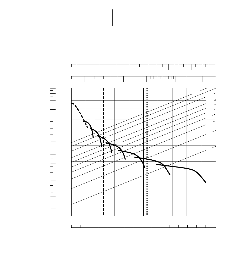
9-10
KEY
1A — 1st Gear (Torque Converter)
1B — 1st Gear
2 — 2nd Gear
3 — 3rd Gear
4 — 4th Gear
5 — 5th Gear
6 — 6th Gear
7 — 7th Gear
KEY
A — Empty 31 250 kg (68,900 lb)
B — Max GMW 68 182 kg (150,000 lb)
Construction & Mining Trucks 769D Rimpull-Speed-Gradeability
●18.00R33 Tires
GROSS WEIGHT
RIMPULL
TOTAL RESISTANCE
(Grade plus Rolling)
SPEED
mph
km/h
20
120
100
70
50
30
20
10
5
3
2
1
0.5 0
0 5 10 15 20 25 30 35 40 45 50 55 60 65 70 75 80
5 101520253035404550
0.30
0.50
1
2
3
5
10
20
30
40
50
50 100 150 200 250 300 400 500
30 40 50 60 80 100 150 200
1A
A B
1B
2
3
4
5
6
7
30% 20%
15%
12%
10%
8%
6%
4%
2%
kg x
1000 lb x
1000
lb x 1000
kg x 1000
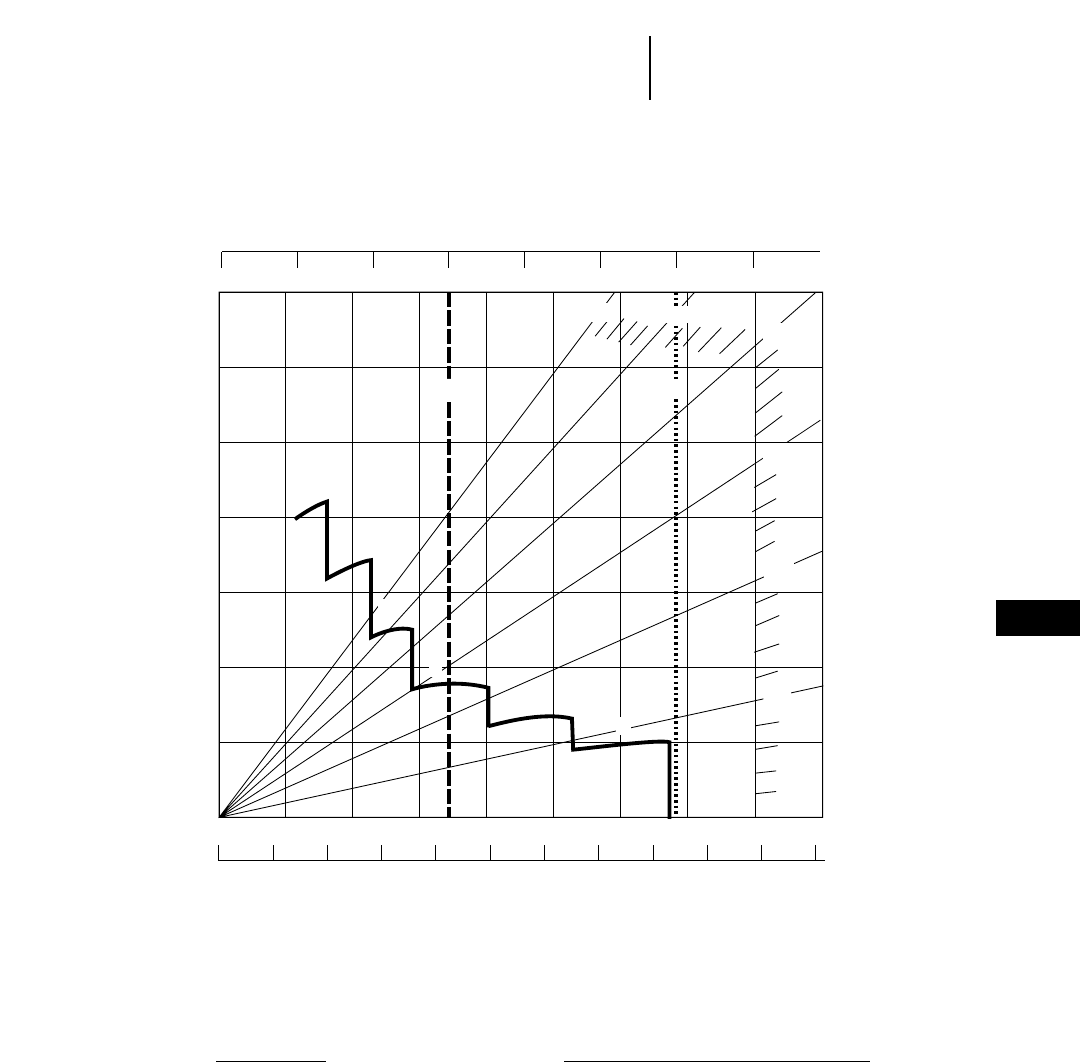
9-11
Construction & Mining Trucks769D Brake Performance
●Continuous grade retarding
KEY
2 — 2nd Gear
3 — 3rd Gear
4 — 4th Gear
5 — 5th Gear
6 — 6th Gear
7 — 7th Gear
KEY
A — Empty 31 250 kg (68,900 lb)
B — Max GMW 68 182 kg (150,000 lb)
GROSS WEIGHT
EFFECTIVE GRADE
(Favorable)
SPEED
CONTINUOUS GRADE LENGTH
km/h
mph
0 25 50 75 100 125 150
0102030 40506070
0 1020 30405060 7080
0 5 10 15 20 25 30 35 40 45 50
80
175
55
90
10%
5%
15%
20%
25%
30%
5
4
3
2
6
7
AB
kg x 1000
lb x 1000
9
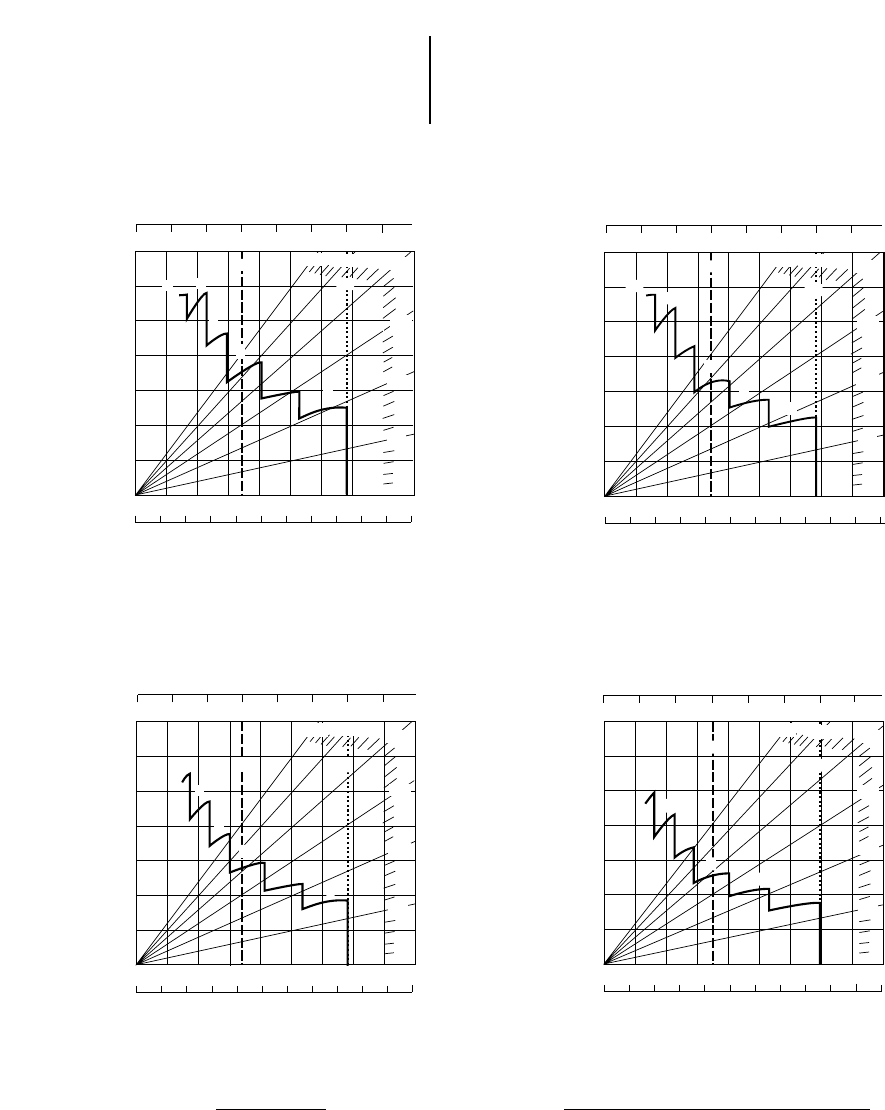
9-12
Construction & Mining Trucks 769D Brake Performance
●450 m (1500 ft) ●600 m (2000 ft)
●900 m (3000 ft) ●1500 m (5000 ft)
KEY
2 — 2nd Gear
3 — 3rd Gear
4 — 4th Gear
5 — 5th Gear
6 — 6th Gear
7 — 7th Gear
KEY
A — Empty 31 250 kg (68,900 lb)
B — Max GMW 68 182 kg (150,000 lb)
GROSS WEIGHT
EFFECTIVE GRADE
(Favorable)
SPEED
GRADE DISTANCE — 450 m (1500 ft)
km/h
mph
80
175
55
90
0 1020 30405060 7080
0 5 10 15 20 25 30 35 40 45 50
0 25 50 75 100 125 150
010203040506070
5
4
3
7
10%
5%
15%
25% 20%
6
30%
2
A
B
kg x 1000
lb x 1000
GROSS WEIGHT
EFFECTIVE GRADE
(Favorable)
SPEED
GRADE DISTANCE — 900 m (3000 ft)
km/h
mph
80
175
55
90
0 1020 30405060 7080
0 5 10 15 20 25 30 35 40 45 50
0 25 50 75 100 125 150
010203040506070
10%
5%
15%
20%
5
4
3
6
7
25%
30%
2B
A
kg x 1000
lb x 1000
GROSS WEIGHT
EFFECTIVE GRADE
(Favorable)
SPEED
GRADE DISTANCE — 1500 m (5000 ft)
km/h
mph
80
175
55
90
0 1020 30405060 7080
0 5 10 15 20 25 30 35 40 45 50
0 25 50 75 100 125 150
0102030 40506070
2
10%
5%
15%
20%
25%
30%
5
4
3
67
A
B
kg x 1000
lb x 1000
GROSS WEIGHT
EFFECTIVE GRADE
(Favorable)
SPEED
GRADE DISTANCE — 600 m (2000 ft)
km/h
mph
80
175
55
90
0 25 50 75 100 125 150
010203040506070
0 1020 30405060 7080
0 5 10 15 20 25 30 35 40 45 50
3a,
10%
5%
20%
25%
30%
5
4
6
7
3
15%
2
A
B
kg x 1000
lb x 1000
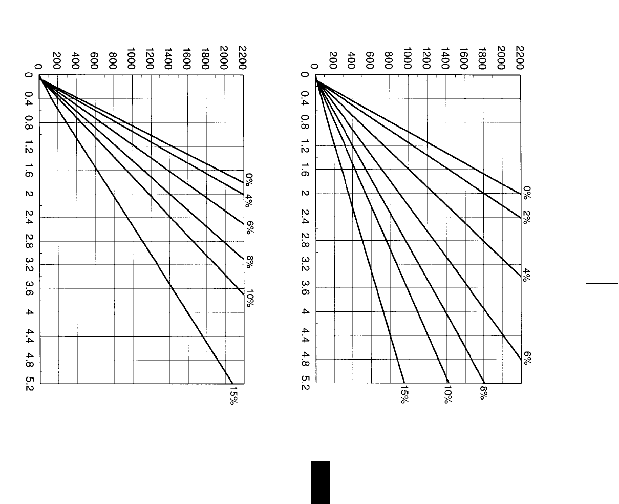
9-13
9
Construction & Mining Trucks769D Travel Time
●18.00R33 Tires
TOTAL RESISTANCE
(Grade plus Rolling)
LOADED
TOTAL RESISTANCE
(Grade plus Rolling)
EMPTY
DISTANCE ONE WAY (Meters)
TIME (Minutes)
DISTANCE ONE WAY (Meters)
TIME (Minutes)
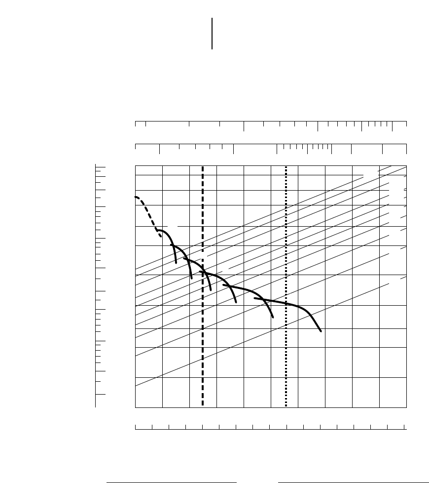
9-14
Construction & Mining Trucks 771D Rimpull-Speed-Gradeability
●18.00R33 Tires
KEY
1A — 1st Gear (Torque Converter)
1B — 1st Gear
2 — 2nd Gear
3 — 3rd Gear
4 — 4th Gear
5 — 5th Gear
6 — 6th Gear
KEY
A — Empty 33 975 kg (74,900 lb)
B — Max GMW 73 970 kg (163,100 lb)
GROSS WEIGHT
RIMPULL
TOTAL RESISTANCE
(Grade plus Rolling)
SPEED
mph
km/h
20
120
100
70
50
30
20
10
5
3
2
1
0.5 0
0 5 10 15 20 25 30 35 40 45 50 55 60 65 70 75 80
5 101520253035404550
0.30
0.50
1
2
3
5
10
20
30
40
50
50 100 150 200 250 300 400 500
30 40 50 60 80 100 150 200
1A
AB
1B
2
3
4
5
6
30% 20%
15%
12%
10%
8%
6%
4%
2%
kg x
1000 lb x
1000
lb x 1000
kg x 1000
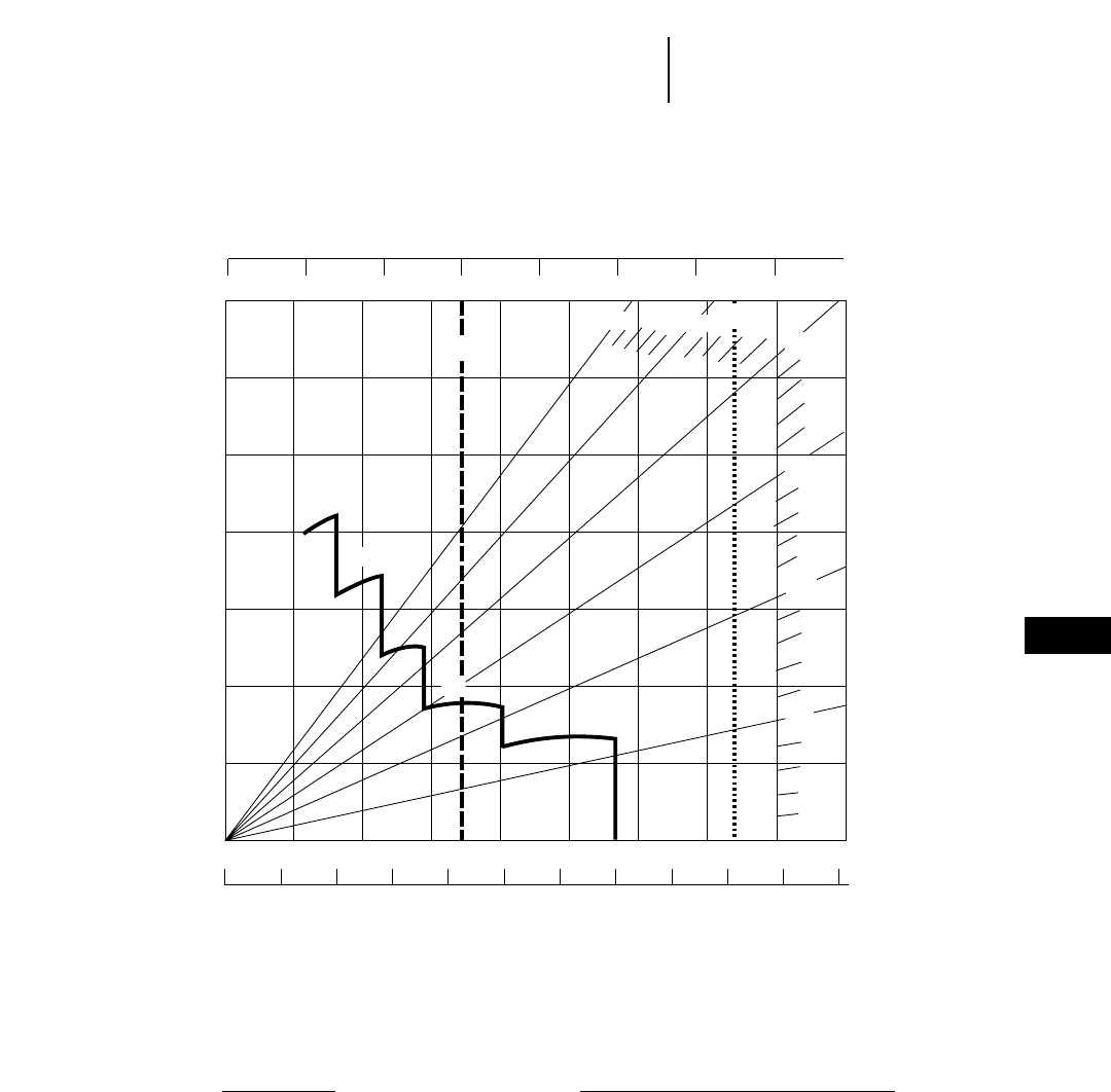
9-15
9
Construction & Mining Trucks771D Brake Performance
●Continuous grade retarding
KEY
2 — 2nd Gear
3 — 3rd Gear
4 — 4th Gear
5 — 5th Gear
6 — 6th Gear
KEY
A — Empty 33 975 kg (74,900 lb)
B — Max GMW 73 970 kg (163,100 lb)
GROSS WEIGHT
EFFECTIVE GRADE
(Favorable)
SPEED
CONTINUOUS GRADE LENGTH
km/h
mph
0 25 50 75 100 125 150
0102030 40506070
0 1020 30405060 7080
0 5 10 15 20 25 30 35 40 45 50
80
175
55
90
10%
5%
15%
20%
25%
30%
5
4
3
2
6
A
B
kg x 1000
lb x 1000
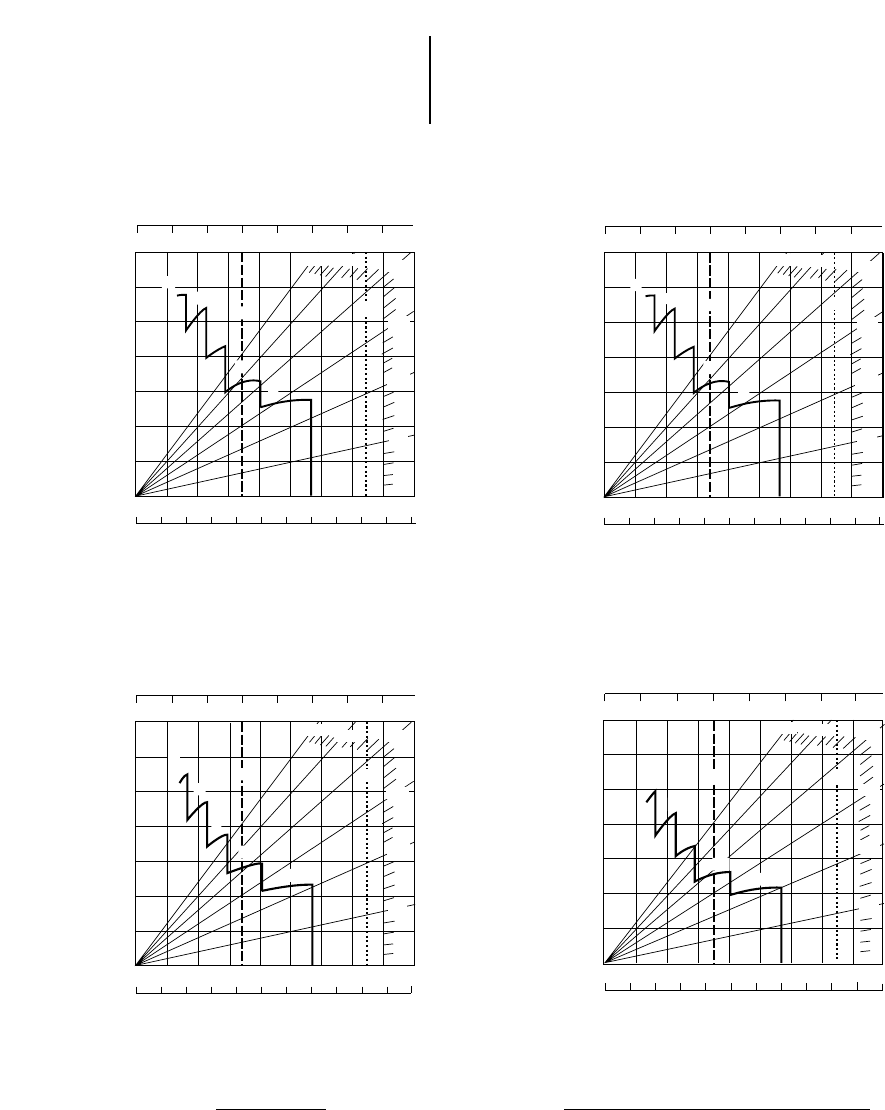
9-16
Construction & Mining Trucks 771D Brake Performance
●450 m (1500 ft) ●600 m (2000 ft)
●900 m (3000 ft) ●1500 m (5000 ft)
KEY
2 — 2nd Gear
3 — 3rd Gear
4 — 4th Gear
5 — 5th Gear
6 — 6th Gear
KEY
A — Empty 33 975 kg (74,900 lb)
B — Max GMW 73 970 kg (163,100 lb)
GROSS WEIGHT
EFFECTIVE GRADE
(Favorable)
SPEED
GRADE DISTANCE — 450 m (1500 ft)
km/h
mph
80
175
55
90
0 25 50 75 100 125 150
010203040506070
0 1020 30405060 7080
0 5 10 15 20 25 30 35 40 45 50
10%
5%
20%
25%
30%
5
4
2
15%
3
6
AB
kg x 1000
lb x 1000
GROSS WEIGHT
EFFECTIVE GRADE
(Favorable)
SPEED
GRADE DISTANCE — 900 m (3000 ft)
km/h
mph
80
175
55
90
0 1020 30405060 7080
0 5 10 15 20 25 30 35 40 45 50
0 25 50 75 100 125 150
010203040506070
10%
5%
20%
25%
30%
5
4
2
6
15%
3
AB
kg x 1000
lb x 1000
GROSS WEIGHT
EFFECTIVE GRADE
(Favorable)
SPEED
GRADE DISTANCE — 1500 m (5000 ft)
km/h
mph
80
175
55
90
0 1020 30405060 7080
0 5 10 15 20 25 30 35 40 45 50
0 25 50 75 100 125 150
0102030 40506070
2
10%
5%
15%
20%
25%
30%
5
4
3
6
A
B
kg x 1000
lb x 1000
GROSS WEIGHT
EFFECTIVE GRADE
(Favorable)
SPEED
GRADE DISTANCE — 600 m (2000 ft)
km/h
mph
80
175
55
90
0 25 50 75 100 125 150
010203040506070
0 1020 30405060 7080
0 5 10 15 20 25 30 35 40 45 50
3rd
10%
5%
20%
25%
30%
5
4
3
2
15%
6
AB
kg x 1000
lb x 1000
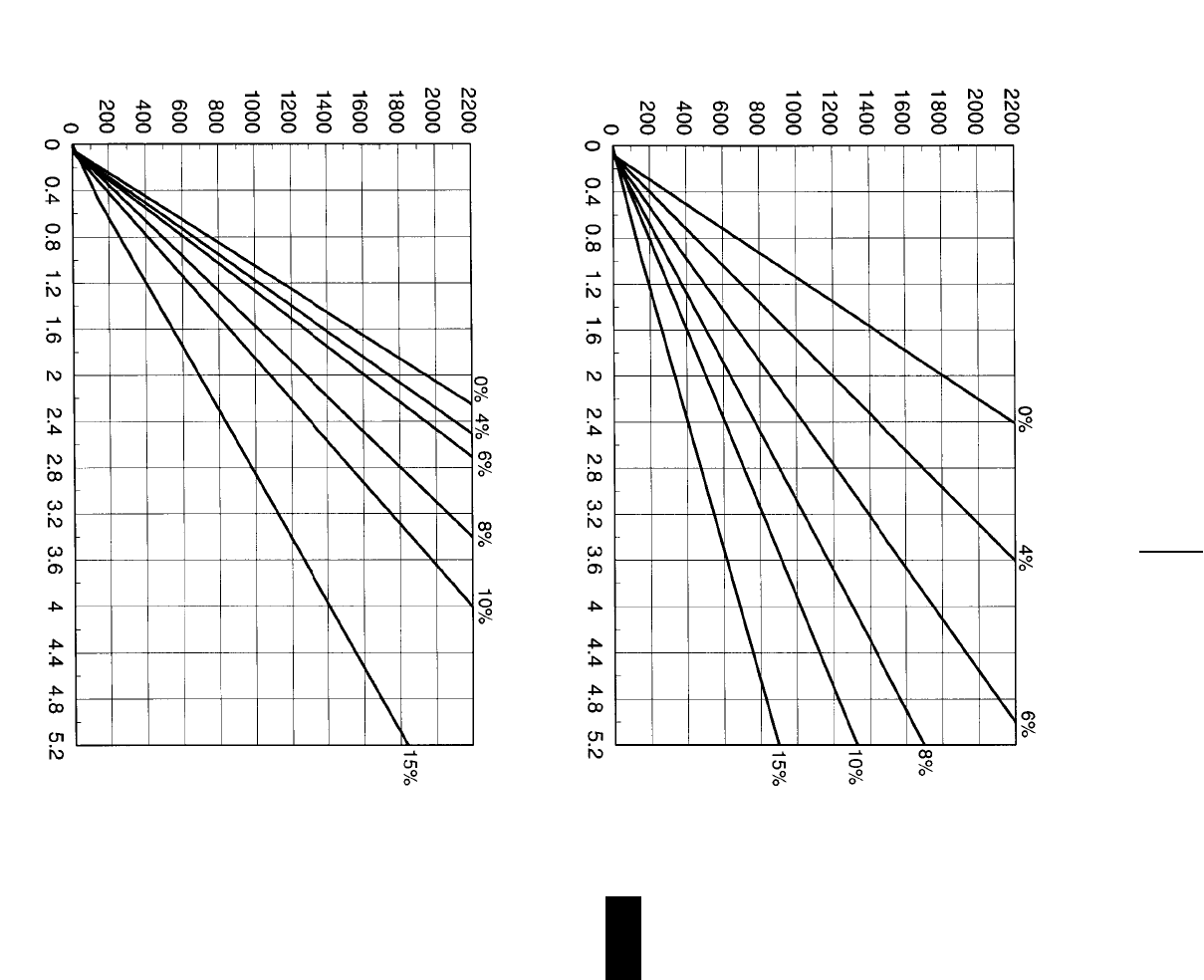
9-17
9
Construction & Mining Trucks771D Travel Time
●18.00R33 Tires
TOTAL RESISTANCE
(Grade plus Rolling)
LOADED
TOTAL RESISTANCE
(Grade plus Rolling)
EMPTY
DISTANCE ONE WAY (Meters)
TIME (Minutes)
DISTANCE ONE WAY (Meters)
TIME (Minutes)
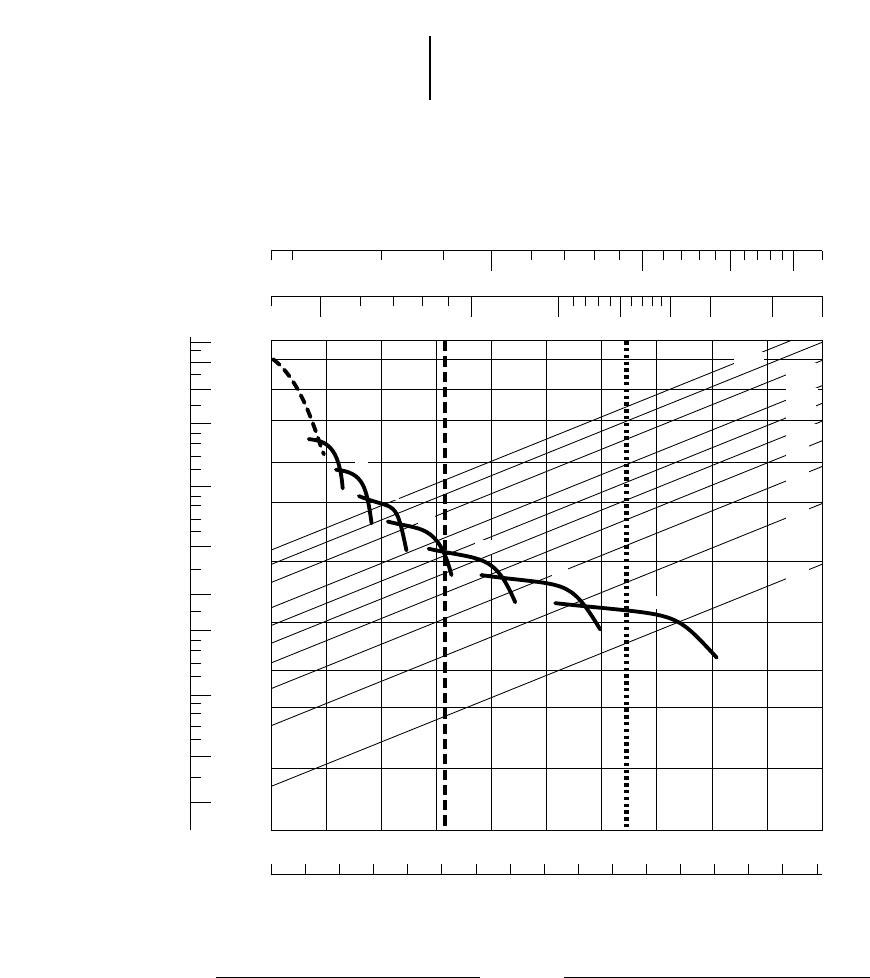
9-18
Construction & Mining Trucks 773D Rimpull-Speed-Gradeability
●24.00R35 Tires
KEY
1A — 1st Gear (Torque Converter)
1B — 1st Gear
2 — 2nd Gear
3 — 3rd Gear
4 — 4th Gear
5 — 5th Gear
6 — 6th Gear
7 — 7th Gear
KEY
A — Empty 40 188 kg (88,600 lb)
B — Max GMW 92 534 kg (204,000 lb)
GROSS WEIGHT
RIMPULL
TOTAL RESISTANCE
(Grade plus Rolling)
SPEED
mph
km/h
20
120
100
70
50
30
20
10
5
3
2
1
0.5 0
0 5 10 15 20 25 30 35 40 45 50 55 60 65 70 75 80
5 101520253035404550
0.30
0.50
1
2
3
5
10
20
30
40
50
50 100 150 200 250 300 400 500
30 40 50 60 80 100 150 200
1A
A B
1B
2
3
4
5
6
7
30% 20%
15%
12%
10%
8%
6%
4%
2%
kg x
1000 lb x
1000
lb x 1000
kg x 1000
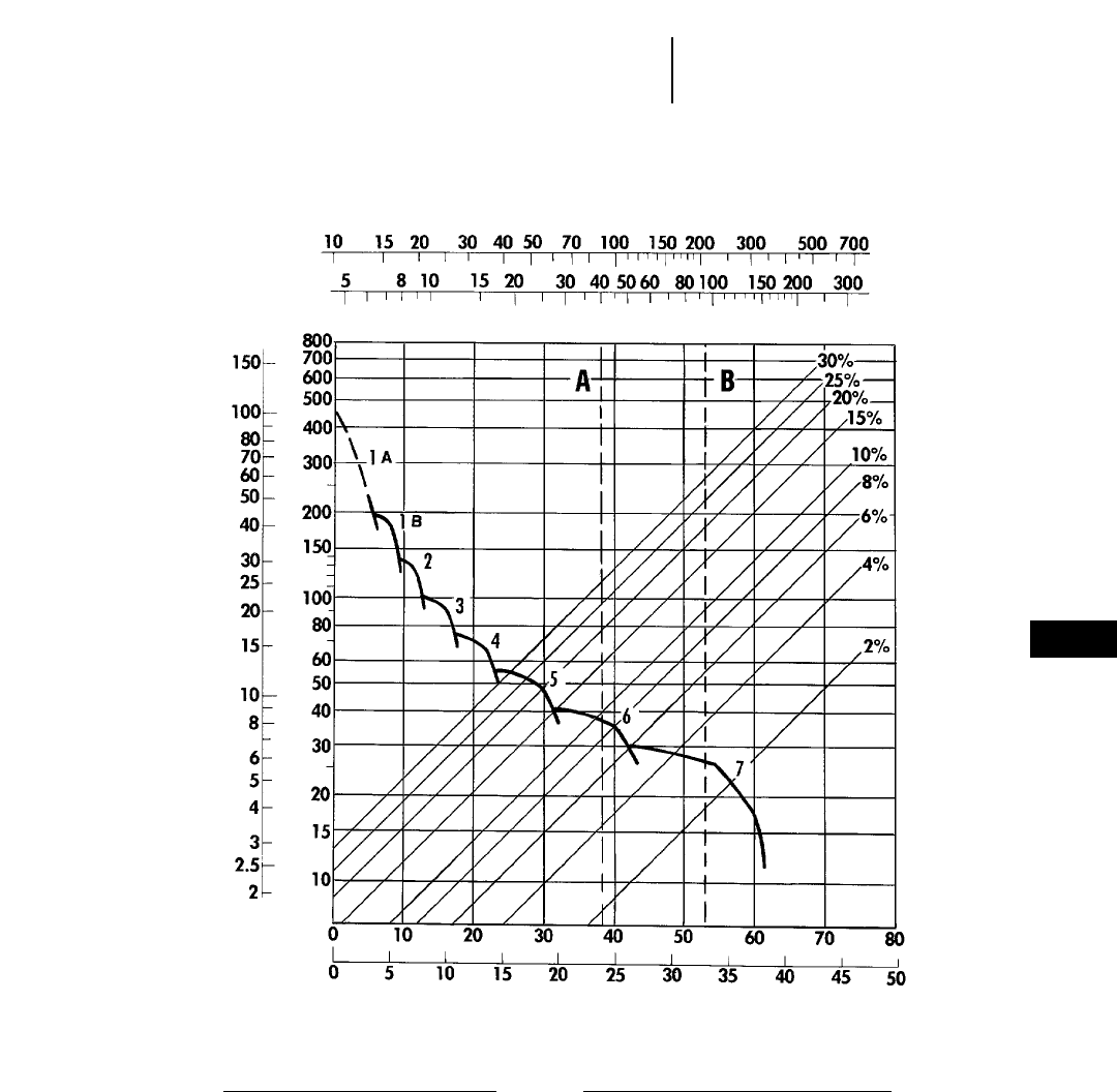
9-19
9
Construction & Mining Trucks773D Rimpull-Speed-Gradeability
●21.00R35 Tires (Optional)
KEY
1A— 1st Gear (Torque Converter)
1B— 1st Gear
2 — 2nd Gear
3 — 3rd Gear
4 — 4th Gear
5 — 5th Gear
6 — 6th Gear
7 — 7th Gear
KEY
A — Empty 40 188 kg (88,600 lb)
B — Max GMW 92 534 kg (204,000 lb)
GROSS WEIGHT
kg x 1000
lb x 1000
TOTAL RESISTANCE
(Grade plus Rolling)
SPEED
RIMPULL
kN
lb x
1000
km/h
mph
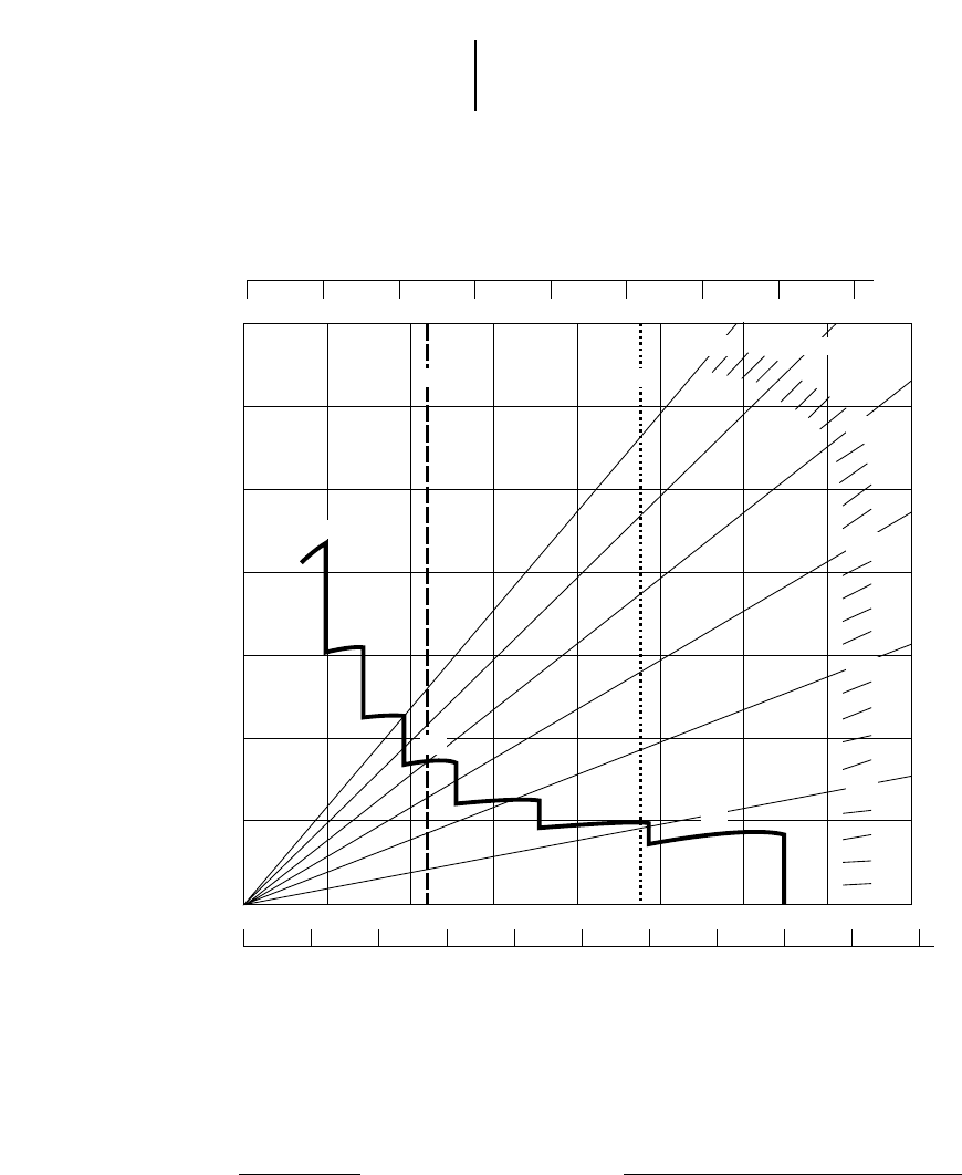
9-20
Construction & Mining Trucks 773D Brake Performance
●Continuous grade retarding
KEY
1 — 1st Gear
2 — 2nd Gear
3 — 3rd Gear
4 — 4th Gear
5 — 5th Gear
6 — 6th Gear
7 — 7th Gear
KEY
A — Empty 40 188 kg (88,600 lb)
B — Max GMW 92 534 kg (204,000 lb)
GROSS WEIGHT
EFFECTIVE GRADE
(Favorable)
SPEED
CONTINUOUS GRADE LENGTH
km/h
mph
0 40 80 120 160 200 240 280 320
0 20 40 60 80 100 120 140
0 1020 30405060 7080
0 5 10 15 20 25 30 35 40 45 50
10%
5%
15%
20%
25%
30%
5
3
2
1
6
4
7
AB
kg x 1000
lb x 1000
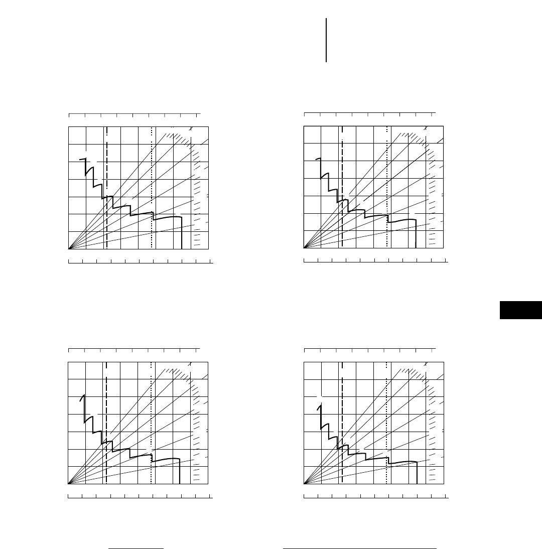
9-21
9
Construction & Mining Trucks773D Brake Performance
●450 m (1500 ft) ●600 m (2000 ft)
●900 m (3000 ft) ●1500 m (5000 ft)
KEY
1 — 1st Gear
2 — 2nd Gear
3 — 3rd Gear
4 — 4th Gear
5 — 5th Gear
6 — 6th Gear
7 — 7th Gear
KEY
A — Empty 40 188 kg (88,600 lb)
B — Max GMW 92 534 kg (204,000 lb)
GROSS WEIGHT
EFFECTIVE GRADE
(Favorable)
SPEED
GRADE DISTANCE — 450 m (1500 ft)
km/h
mph
0 40 80 120 160 200 240 280 320
0 20 40 60 80 100 120 140
0 1020 30405060 7080
0 5 10 15 20 25 30 35 40 45 50
10%
5%
15%
20%
25%
30%
4
3
2
1
6
5
7
AB
kg x 1000
lb x 1000
GROSS WEIGHT
EFFECTIVE GRADE
(Favorable)
SPEED
GRADE DISTANCE — 900 m (3000 ft)
km/h
mph
0 40 80 120 160 200 240 280 320
0 20 40 60 80 100 120 140
0 1020 30405060 7080
0 5 10 15 20 25 30 35 40 45 50
10%
5%
15%
20%
25%
30%
5
4
3
2
1
67
AB
kg x 1000
lb x 1000
GROSS WEIGHT
EFFECTIVE GRADE
(Favorable)
SPEED
GRADE DISTANCE — 1500 m (5000 ft)
km/h
mph
0 40 80 120 160 200 240 280 320
0 20 40 60 80 100 120 140
0 1020 30405060 7080
0 5 10 15 20 25 30 35 40 45 50
10%
5%
15%
20%
25%
30%
5
4
3
2
1
67
AB
kg x 1000
lb x 1000
GROSS WEIGHT
EFFECTIVE GRADE
(Favorable)
SPEED
GRADE DISTANCE — 600 m (2000 ft)
km/h
mph
0 40 80 120 160 200 240 280 320
0 20 40 60 80 100 120 140
0 1020 30405060 7080
0 5 10 15 20 25 30 35 40 45 50
10%
5%
15%
20%
25%
30%
5
4
3
2
1
67
AB
kg x 1000
lb x 1000
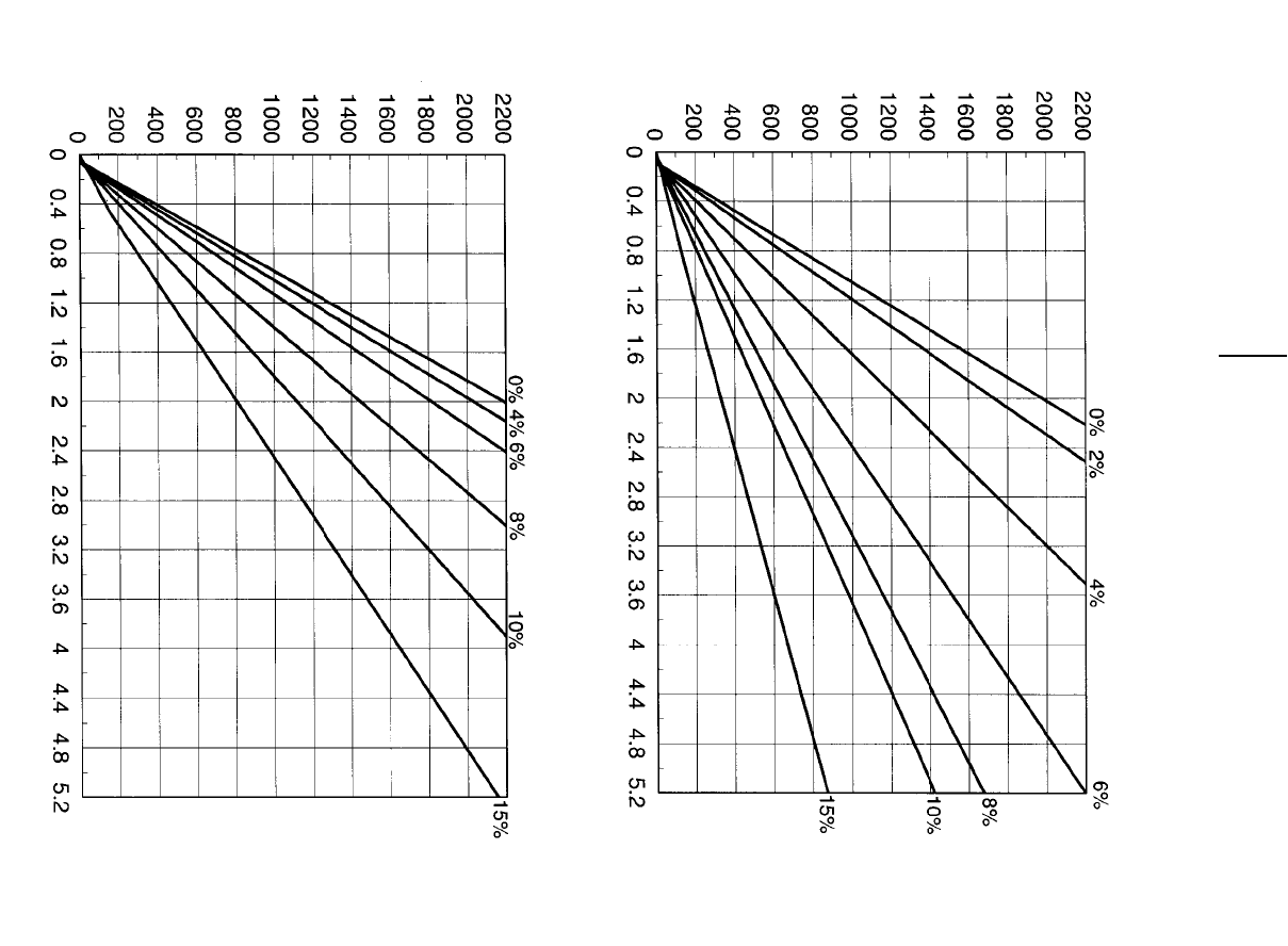
9-22
Construction & Mining Trucks 773D Travel Time
●24.00R35 Tires
TOTAL RESISTANCE
(Grade plus Rolling)
LOADED
TOTAL RESISTANCE
(Grade plus Rolling)
EMPTY
DISTANCE ONE WAY (Meters)
TIME (Minutes)
DISTANCE ONE WAY (Meters)
TIME (Minutes)
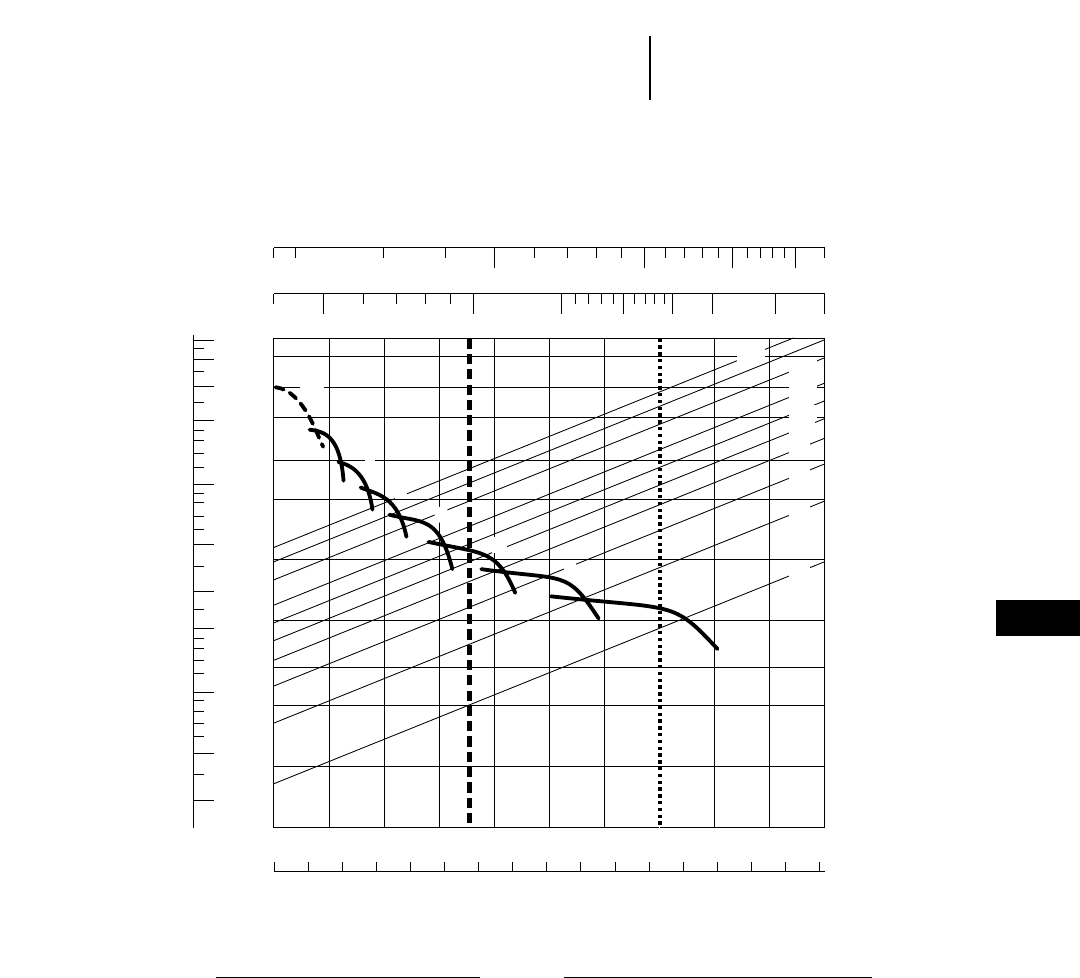
9-23
9
Construction & Mining Trucks775D Rimpull-Speed-Gradeability
●24.00R35 Tires
KEY
1A — 1st Gear (Torque Converter)
1B — 1st Gear
2 — 2nd Gear
3 — 3rd Gear
4 — 4th Gear
5 — 5th Gear
6 — 6th Gear
7 — 7th Gear
KEY
A — Empty 43 953 kg (96,900 lb)
B — Max GMW 106 594 kg (235,000 lb)
GROSS WEIGHT
RIMPULL
TOTAL RESISTANCE
(Grade plus Rolling)
SPEED
mph
km/h
20
120
100
70
50
30
20
10
5
3
2
1
0.5 0
0 5 10 15 20 25 30 35 40 45 50 55 60 65 70 75 80
5 101520253035404550
0.30
0.50
1
2
3
5
10
20
30
40
50
50 100 150 200 250 300 400 500
30 40 50 60 80 100 150 200
1A
A B
1B
2
3
4
5
6
7
30% 20%
15%
12%
10%
8%
6%
4%
2%
kg x
1000 lb x
1000
lb x 1000
kg x 1000
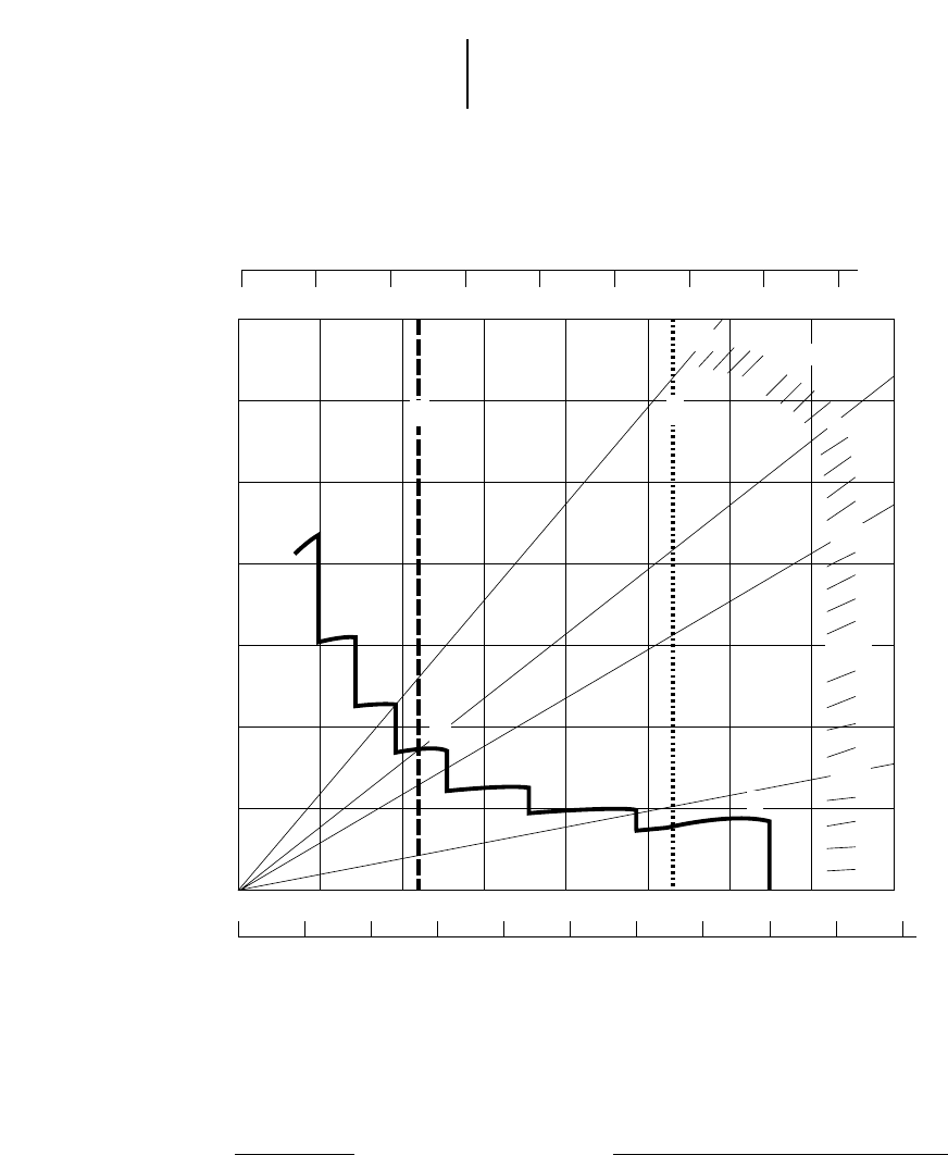
9-24
Construction & Mining Trucks 775D Brake Performance
●Continuous grade retarding
KEY
1 — 1st Gear
2 — 2nd Gear
3 — 3rd Gear
4 — 4th Gear
5 — 5th Gear
6 — 6th Gear
7 — 7th Gear
KEY
A — Empty 43 953 kg (96,900 lb)
B — Max GMW 106 594 kg (235,000 lb)
GROSS WEIGHT
EFFECTIVE GRADE
(Favorable)
SPEED
CONTINUOUS GRADE LENGTH
km/h
mph
0 40 80 120 160 200 240 280 320
0 20 40 60 80 100 120 140
0 1020 30405060 7080
0 5 10 15 20 25 30 35 40 45 50
10%
5%
15%
20%
25%
30%
5
4
3
2
1
67
B
A
kg x 1000
lb x 1000
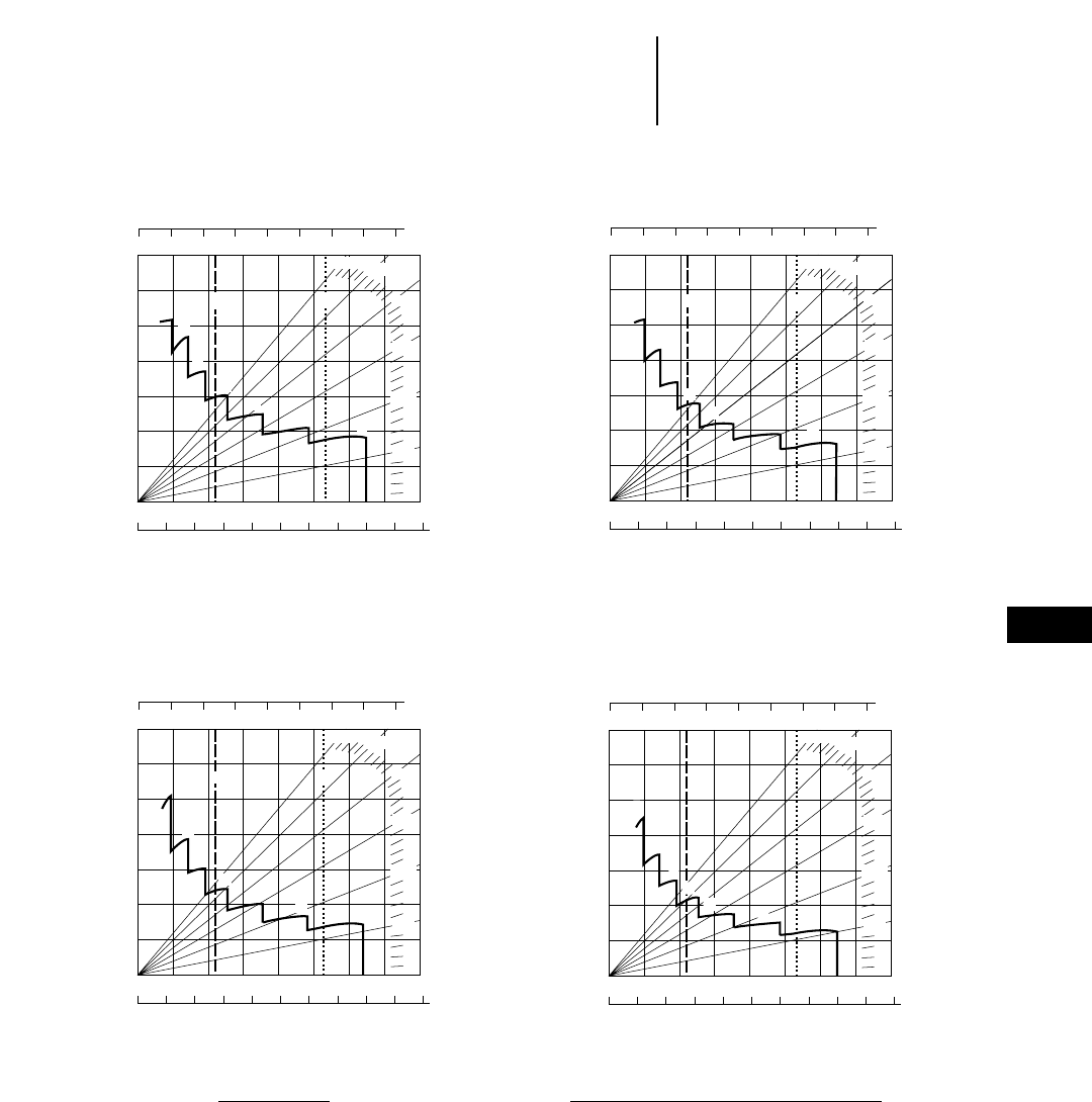
9-25
9
Construction & Mining Trucks775D Brake Performance
●450 m (1500 ft) ●600 m (2000 ft)
●900 m (3000 ft) ●1500 m (5000 ft)
KEY
1 — 1st Gear
2 — 2nd Gear
3 — 3rd Gear
4 — 4th Gear
5 — 5th Gear
6 — 6th Gear
7 — 7th Gear
KEY
A — Empty 43 953 kg (96,900 lb)
B — Max GMW 106 594 kg (235,000 lb)
GROSS WEIGHT
EFFECTIVE GRADE
(Favorable)
SPEED
GRADE DISTANCE — 450 m (1500 ft)
km/h
mph
0 40 80 120 160 200 240 280 320
0 20 40 60 80 100 120 140
0 1020 30405060 7080
0 5 10 15 20 25 30 35 40 45 50
10%
5%
15%
20%
25%
30%
4
3
2
1
6
5
7
AB
kg x 1000
lb x 1000
GROSS WEIGHT
EFFECTIVE GRADE
(Favorable)
SPEED
GRADE DISTANCE — 900 m (3000 ft)
km/h
mph
0 40 80 120 160 200 240 280 320
0 20 40 60 80 100 120 140
0 1020 30405060 7080
0 5 10 15 20 25 30 35 40 45 50
10%
5%
15%
20%
25%
30%
5
4
3
1
67
A B
2
kg x 1000
lb x 1000
GROSS WEIGHT
EFFECTIVE GRADE
(Favorable)
SPEED
GRADE DISTANCE — 1500 m (5000 ft)
km/h
mph
0 40 80 120 160 200 240 280 320
0 20 40 60 80 100 120 140
0 1020 30405060 7080
0 5 10 15 20 25 30 35 40 45 50
10%
5%
15%
20%
25%
30%
5
4
67
2
1
3
kg x 1000
lb x 1000
GROSS WEIGHT
EFFECTIVE GRADE
(Favorable)
SPEED
GRADE DISTANCE — 600 m (2000 ft)
km/h
mph
0 40 80 120 160 200 240 280 320
0 20 40 60 80 100 120 140
0 1020 30405060 7080
0 5 10 15 20 25 30 35 40 45 50
10%
5%
15%
20%
25%
30%
5
4
3
2
1
6
AB
7
kg x 1000
lb x 1000
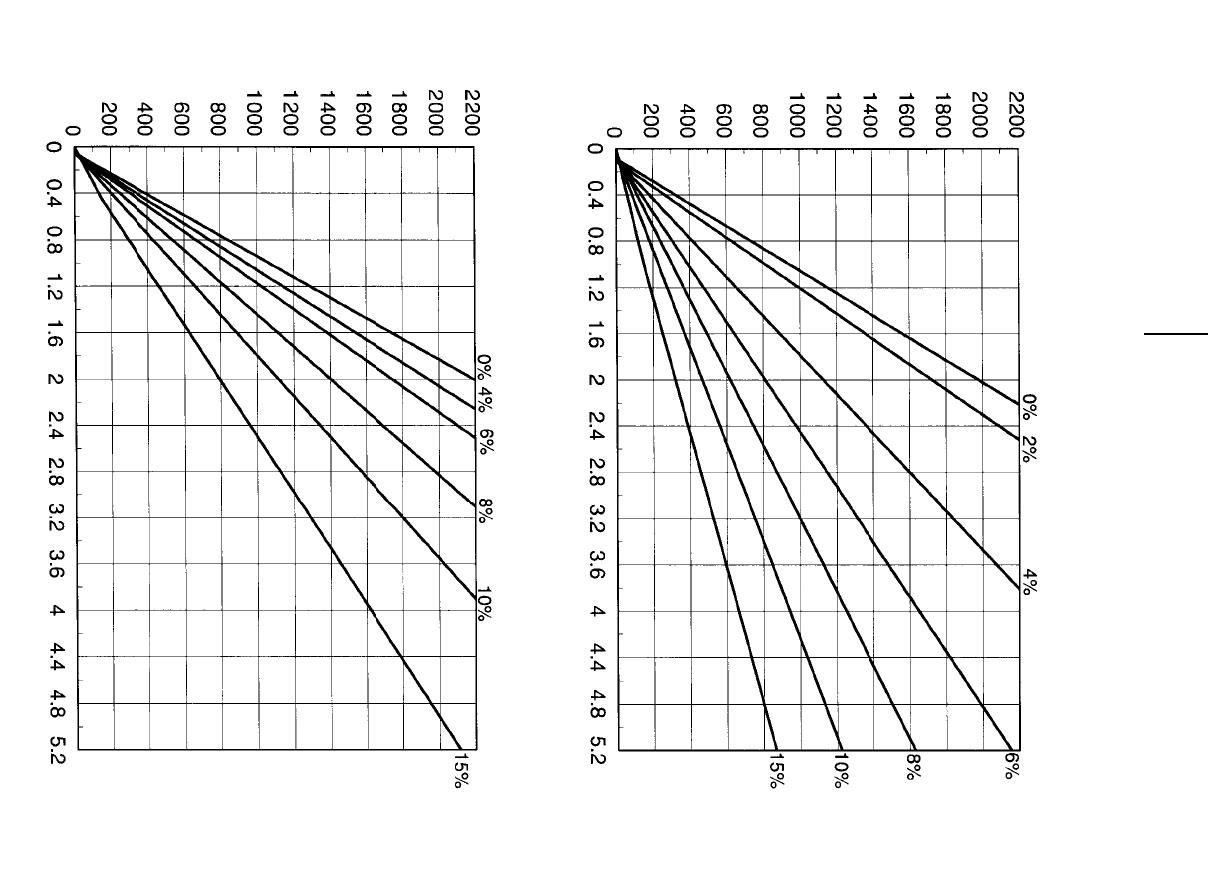
9-26
Construction & Mining Trucks 775D Travel Time
●24.00R35 Tires
TOTAL RESISTANCE
(Grade plus Rolling)
LOADED
TOTAL RESISTANCE
(Grade plus Rolling)
EMPTY
DISTANCE ONE WAY (Meters)
TIME (Minutes)
DISTANCE ONE WAY (Meters)
TIME (Minutes)
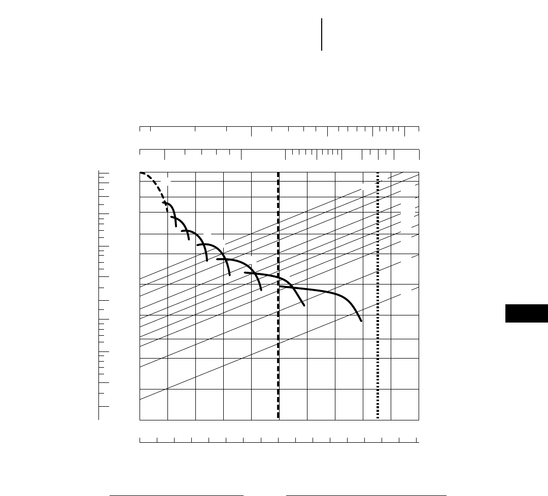
9-27
9
Construction & Mining Trucks
Construction & Mining Tractors
777D, 776D Rimpull-Speed-Gradeability
●27.00R49 Tires
KEY
1A — 1st Gear (Torque Converter)
1B — 1st Gear
2 — 2nd Gear
3 — 3rd Gear
4 — 4th Gear
5 — 5th Gear
6 — 6th Gear
7 — 7th Gear
KEY
A* — Empty 64 359 kg (141,889 lb)
B* — Max GMW 161 028 kg (355,000 lb)
GROSS WEIGHT
RIMPULL
TOTAL RESISTANCE
(Grade plus Rolling)
SPEED
mph
km/h
20
120
100
70
50
30
20
10
5
3
2
1
0.5 0
0 5 10 15 20 25 30 35 40 45 50 55 60 65 70 75 80
5 101520253035404550
0.30
0.50
1
2
3
5
10
20
30
40
50
50 100 150 200 250 300 400 500
30 40 50 60 80 100 150 200
A B
1B
2
4
5
6
7
30% 20%
15%
12%
10%
8%
6%
4%
2%
1A
3
kg x
1000 lb x
1000
lb x 1000
kg x 1000
*These two reference lines (A and B) apply only to 777D.
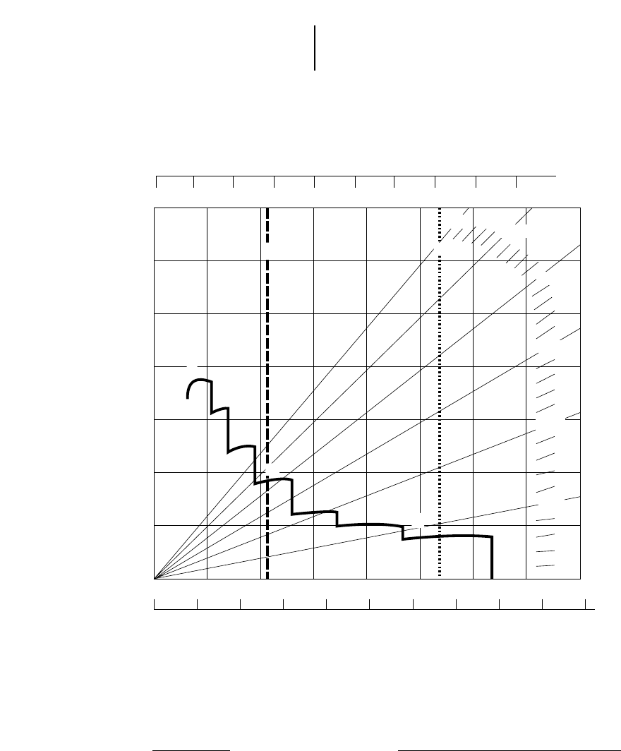
9-28
Construction & Mining Trucks
Construction & Mining Tractors 777D, 776D Brake Performance
●Continuous Grade Retarding
KEY
1 — 1st Gear
2 — 2nd Gear
3 — 3rd Gear
4 — 4th Gear
5 — 5th Gear
6 — 6th Gear
7 — 7th Gear
KEY
A* — Empty 64 359 kg (141,889 lb)
B* — Max GMW 161 028 kg (355,000 lb)
*These two reference lines (A and B) apply only to 777D. Brake performance
for the 776D will vary depending on trailer brake capability.
GROSS WEIGHT
EFFECTIVE GRADE
(Favorable)
SPEED
CONTINUOUS GRADE LENGTH
km/h
mph
0 50 100 150 200 300250 350 400 450
0 30 60 90 120 150 180 210
0 1020 30405060 7080
0 5 10 15 20 25 30 35 40 45 50
10%
5%
15%
20%
25%
30%
5
4
3
2
67
1
A B
kg x 1000
lb x 1000
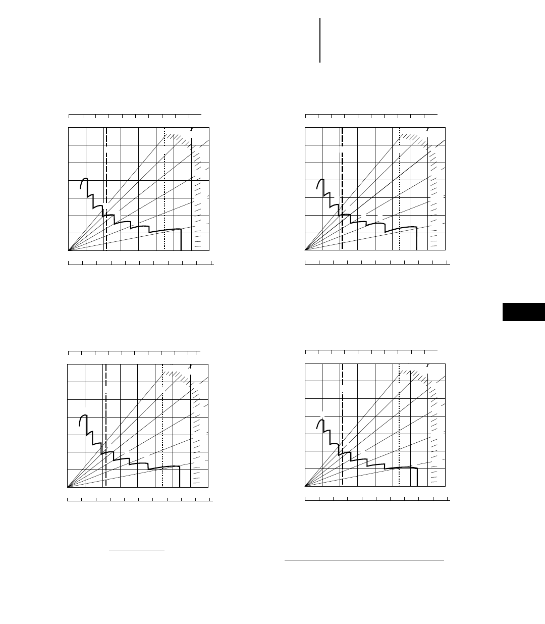
9-29
9
Construction & Mining Trucks
Construction & Mining Tractors
777D, 776D Brake Performance
●450 m (1500 ft) ●600 m (2000 ft)
●900 m (3000 ft) ●1500 m (5000 ft)
KEY
1 — 1st Gear
2 — 2nd Gear
3 — 3rd Gear
4 — 4th Gear
5 — 5th Gear
6 — 6th Gear
7 — 7th Gear
GROSS WEIGHT
EFFECTIVE GRADE
(Favorable)
SPEED
GRADE DISTANCE — 450 m (1500 ft)
km/h
mph
0 50 100 150 200 250 300 350 400 450
0 30 60 90 120 150 180 210
0 1020 30405060 7080
0 5 10 15 20 25 30 35 40 45 50
10%
5%
15%
20%
25%
30%
4
3
2
1
6
5
7
AB
kg x 1000
lb x 1000
GROSS WEIGHT
EFFECTIVE GRADE
(Favorable)
SPEED
GRADE DISTANCE — 900 m (3000 ft)
km/h
mph
0 50 100 150 200 250 300 350 400 450
0 30 60 90 120 150 180 210
0 1020 30405060 7080
0 5 10 15 20 25 30 35 40 45 50
10%
5%
15%
20%
25%
30%
5
4
2
67
1
3
A B
kg x 1000
lb x 1000
GROSS WEIGHT
EFFECTIVE GRADE
(Favorable)
SPEED
GRADE DISTANCE — 1500 m (5000 ft)
km/h
mph
0 50 100 150 200 300250 350 400 450
0 30 60 90 120 150 180 210
0 1020 30405060 7080
0 5 10 15 20 25 30 35 40 45 50
10%
5%
15%
20%
25%
30%
5
7
6
2
3
4
1
AB
kg x 1000
lb x 1000
GROSS WEIGHT
EFFECTIVE GRADE
(Favorable)
SPEED
GRADE DISTANCE — 600 m (2000 ft)
km/h
mph
0 50 100 150 200 250 300 350 400 450
0 30 60 90 120 150 180 210
0 1020 30405060 7080
0 5 10 15 20 25 30 35 40 45 50
10%
5%
15%
20%
25%
30%
5
4
2
1
67
3
AB
kg x 1000
lb x 1000
KEY
A* — Empty 64 359 kg (141,889 lb)
B* — Max GMW 161 028 kg (355,000 lb)
*These two reference lines (A and B) apply only to 777D. Brake performance
for the 776D will vary depending on trailer brake capability.
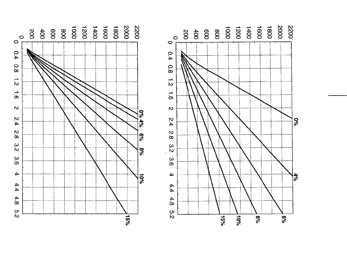
9-30
Construction & Mining Trucks 777D Travel Time
●27.00R49 Tires
TOTAL RESISTANCE
(Grade plus Rolling)
LOADED
TOTAL RESISTANCE
(Grade plus Rolling)
EMPTY
DISTANCE ONE WAY (Meters)
TIME (Minutes)
DISTANCE ONE WAY (Meters)
TIME (Minutes)
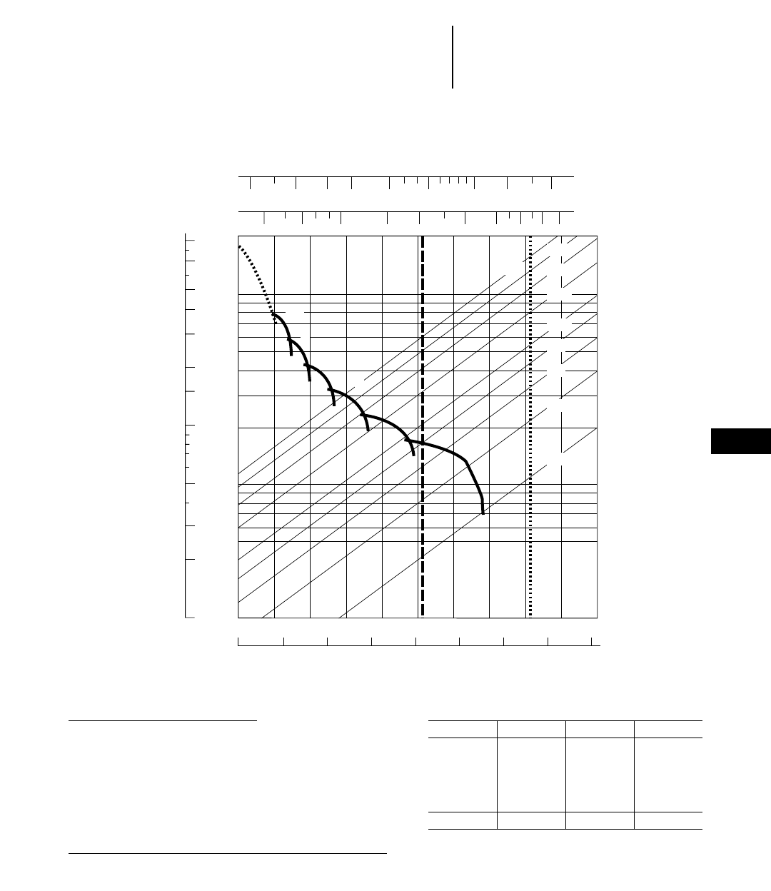
9-31
9
Construction & Mining Trucks
Construction & Mining Tractors
785C, 784C Rimpull-Speed-Gradeability
●33.00R51 Tires
●1433 mm (4'8.4") Tire Radius
90
70
50
40
30
20
15
10
5
3
2
1
200
100
50
20
10
5
20 5 10 15 20 25 30 35 40 45 50
01020304050607080
30%
25%
20%
15%
10%
8%
6%
4%
2%
50
4
5
6
3
2
AB
1B
1A
70 100 150 200 300 400 500 600
20 30 40 50 70 100 150 200 300
KEY
1A— 1st Gear (Torque Converter)
1B— 1st Gear
2 — 2nd Gear
3 — 3rd Gear
4 — 4th Gear
5 — 5th Gear
6 — 6th Gear
Maximum travel speeds
1900 rpm Gear km/h MPH
Forward 1 12.1 7.5
2 16.3 10.2
3 22.2 13.8
4 29.9 18.6
5 40.6 25.2
6 54.8 34.0
Reverse 11.0 6.8
KEY
A* — Est. Field Empty Weight 113 400 kg (250,000 lb)**
B* — Max GMW 249 433 kg (550,000 lb)
**These two reference lines (A and B) apply only to 785C.
**Truck equipped with sideboards and liners.
GROSS WEIGHT
lb x 1000
kg x 1000
TOTAL RESISTANCE
(Grade plus Rolling)
SPEED
mph
kph
RIMPULL
kg x
1000 lb x
1000
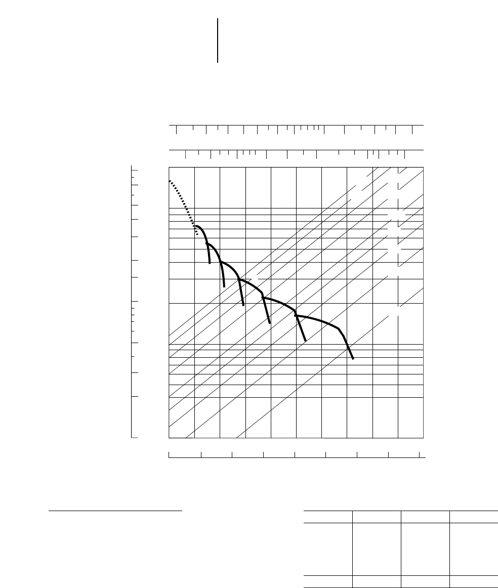
9-32
Construction & Mining Trucks 784C Rimpull-Speed-Gradeability
●36.00R51 Tires
●1524 mm (5'0") Tire Radius
90
70
50
40
30
20
15
10
5
3
2
1
200
100
50
20
10
5
20 5 10 15 20 25 30 35 40 45 50
01020304050607080
30%
25%
20%
15%
10%
8%
6%
4%
2%
50
4
5
6
3
2
1B
1A
70 100 150 200 300 1000600 700
20 30 40 50 60 80 100 150 200 300 500
KEY
1A— 1st Gear (Torque Converter)
1B— 1st Gear
2 — 2nd Gear
3 — 3rd Gear
4 — 4th Gear
5 — 5th Gear
6 — 6th Gear
Maximum travel speeds
1900 rpm Gear km/h MPH
Forward 1 12.9 8.0
2 17.4 10.8
3 23.5 14.6
4 31.9 19.8
5 43.3 26.8
6 58.4 36.2
Reverse 11.7 7.2
GROSS WEIGHT
lb x 1000
kg x 1000
TOTAL RESISTANCE
(Grade plus Rolling)
SPEED
mph
kph
RIMPULL
kg x
1000 lb x
1000
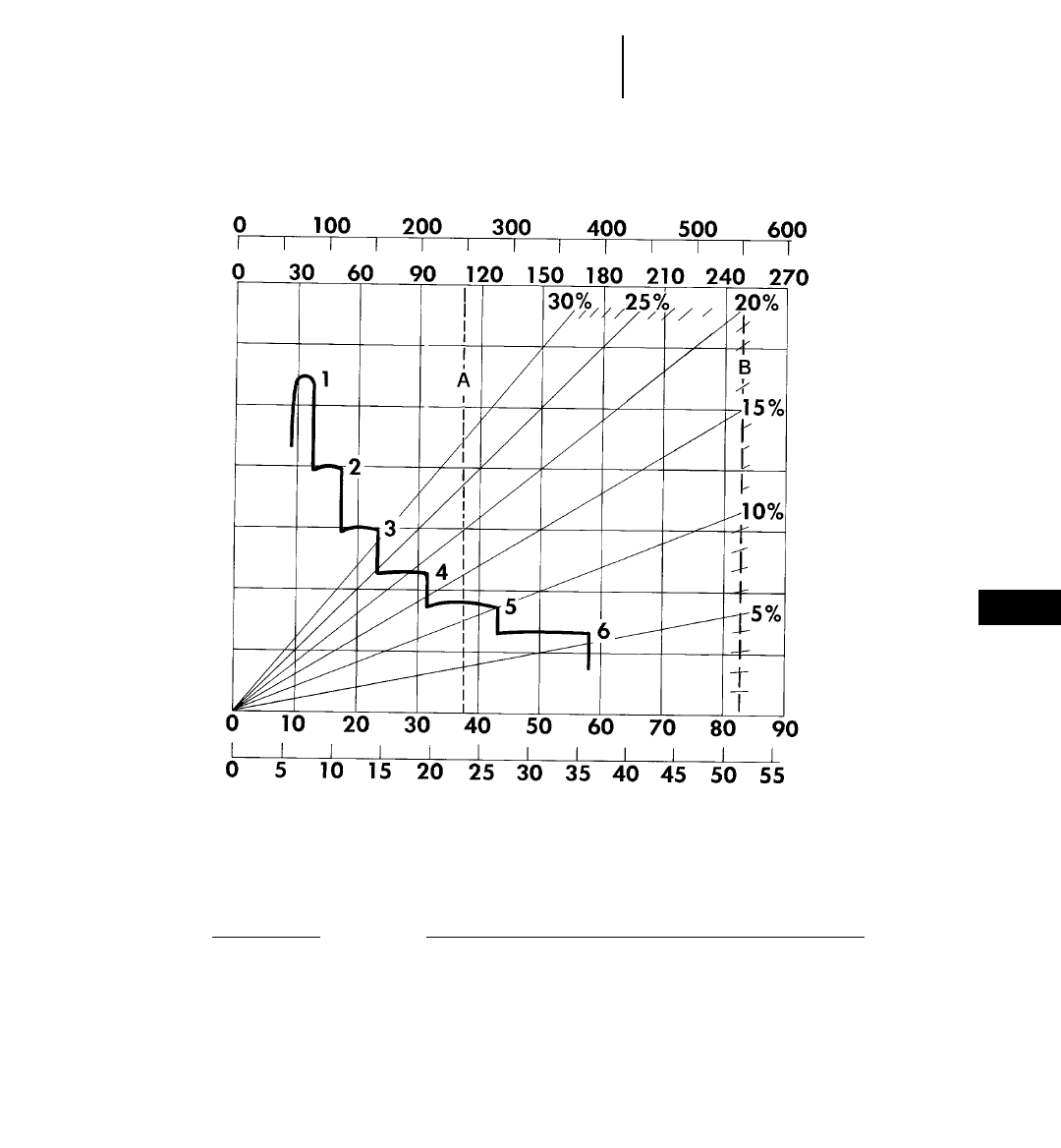
9-33
9
Construction & Mining Trucks
Construction & Mining Tractors
785C, 784C Brake Performance
●Continuous Grade Retarding
KEY
1 — 1st Gear
2 — 2nd Gear
3 — 3rd Gear
4 — 4th Gear
5 — 5th Gear
6 — 6th Gear
KEY
A* — Est. Field Empty Weight 113 400 kg (250,000 lb)**
B* — Max GMW 249 433 kg (550,000 lb)
**These two reference lines (A and B) apply only to 785C. Brake performance for 784C
will vary depending on trailer brake capability.
**Truck equipped with sideboards and liners.
GROSS WEIGHT
kg x 1000
lb x 1000
EFFECTIVE GRADE
(FAVORABLE)
SPEED
km/h
mph
CONTINUOUS GRADE LENGTH
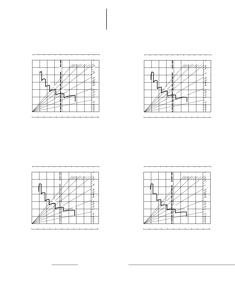
9-34
Construction & Mining Trucks
Construction & Mining Tractors 785C, 784C Brake Performance
●450 m (1500 ft) ●600 m (2000 ft)
●900 m (3000 ft) ●1500 m (5000 ft)
GROSS WEIGHT
EFFECTIVE GRADE
(Favorable)
SPEED
GRADE DISTANCE — 450 m (1500 ft)
km/h
mph
0102030405060708090
0 5 10 15 20 25 30 35 40 45 50 55
0 100 200 300 400
0 30 60 90 120 150 180 210 240 270
1
500 600
6
2
3
5%
15%
10%
20%
25%
30%
4
5
AB
kg x 1000
lb x 1000
GROSS WEIGHT
EFFECTIVE GRADE
(Favorable)
SPEED
GRADE DISTANCE — 900 m (3000 ft)
km/h
mph
0102030405060708090
0 5 10 15 20 25 30 35 40 45 50 55
0 100 200 300 400
0 30 60 90 120 150 180 210 240 270
1
500 600
6
2
3
5%
15%
10%
20%
25%
30%
4
5
AB
kg x 1000
lb x 1000
GROSS WEIGHT
EFFECTIVE GRADE
(Favorable)
SPEED
GRADE DISTANCE — 1500 m (5000 ft)
km/h
mph
0 102030405060708090
0 5 10 15 20 25 30 35 40 45 50 55
0 100 200 300 400
0 30 60 90 120 150 180 210 240 270
1
500 600
6
2
3
5%
15%
10%
20%
25%
30%
4
5
AB
kg x 1000
lb x 1000
GROSS WEIGHT
EFFECTIVE GRADE
(Favorable)
SPEED
GRADE DISTANCE — 600 m (2000 ft)
km/h
mph
0102030405060708090
0 5 10 15 20 25 30 35 40 45 50 55
0 100 200 300 400
0 30 60 90 120 150 180 210 240 270
1
500 600
6
2
3
5%
15%
10%
20%
25%
30%
4
5
AB
kg x 1000
lb x 1000
KEY
1 — 1st Gear
2 — 2nd Gear
3 — 3rd Gear
4 — 4th Gear
5 — 5th Gear
6 — 6th Gear
KEY
A* — Est. Field Empty Weight 113 400 kg (250,000 lb)**
B* — Max GMW 249 433 kg (550,000 lb)
**These two reference lines (A and B) apply only to 785C. Brake performance for 784C
will vary depending on trailer brake capability.
**Truck equipped with sideboards and liners.
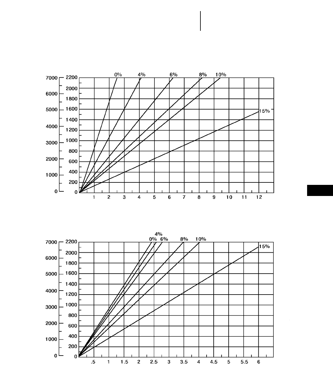
9-35
9
Construction & Mining Trucks785C Travel Time
●33.00R51 Tires
TOTAL RESISTANCE
(Grade plus Rolling)
feet meters
LOADED
TOTAL RESISTANCE
(Grade plus Rolling)
feet meters
EMPTY
DISTANCE ONE WAY
TIME (Minutes)
DISTANCE ONE WAY
TIME (Minutes)
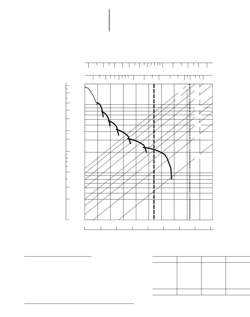
9-36
Construction & Mining Trucks 789C Rimpull-Speed-Gradeability
●37.00R57 Tires
●1593 mm (5'2.7") Tire Radius
90
70
50
40
30
20
15
10
5
3
2
1
200
100
50
20
10
5
20 5 10 15 20 25 30 35 40 45 50
01020304050607080
30%
A
25%
20%
15%
10%
8%
6%
4%
2%
50
4
5
6
3
2
1B
1A
70 100 150 200 300 1000600 700
20 30 40 50 60 80 100 150 200 300 500
B
KEY
1A— 1st Gear (Torque Converter)
1B— 1st Gear
2 — 2nd Gear
3 — 3rd Gear
4 — 4th Gear
5 — 5th Gear
6 — 6th Gear
Maximum travel speeds
1900 rpm Gear km/h MPH
Forward 1 12.0 7.5
2 16.3 10.1
3 22.0 13.7
4 29.8 18.5
5 40.4 25.0
6 54.5 33.8
Reverse 10.9 6.8
GROSS WEIGHT
lb x 1000
kg x 1000
TOTAL RESISTANCE
(Grade plus Rolling)
SPEED
mph
kph
RIMPULL
kg x
1000 lb x
1000
KEY
A — Est. Field Empty Weight 140 616 kg (310,000 lb)*
B — Max GMW 317 460 kg (700,000 lb)
*Truck equipped with sideboards and liners.
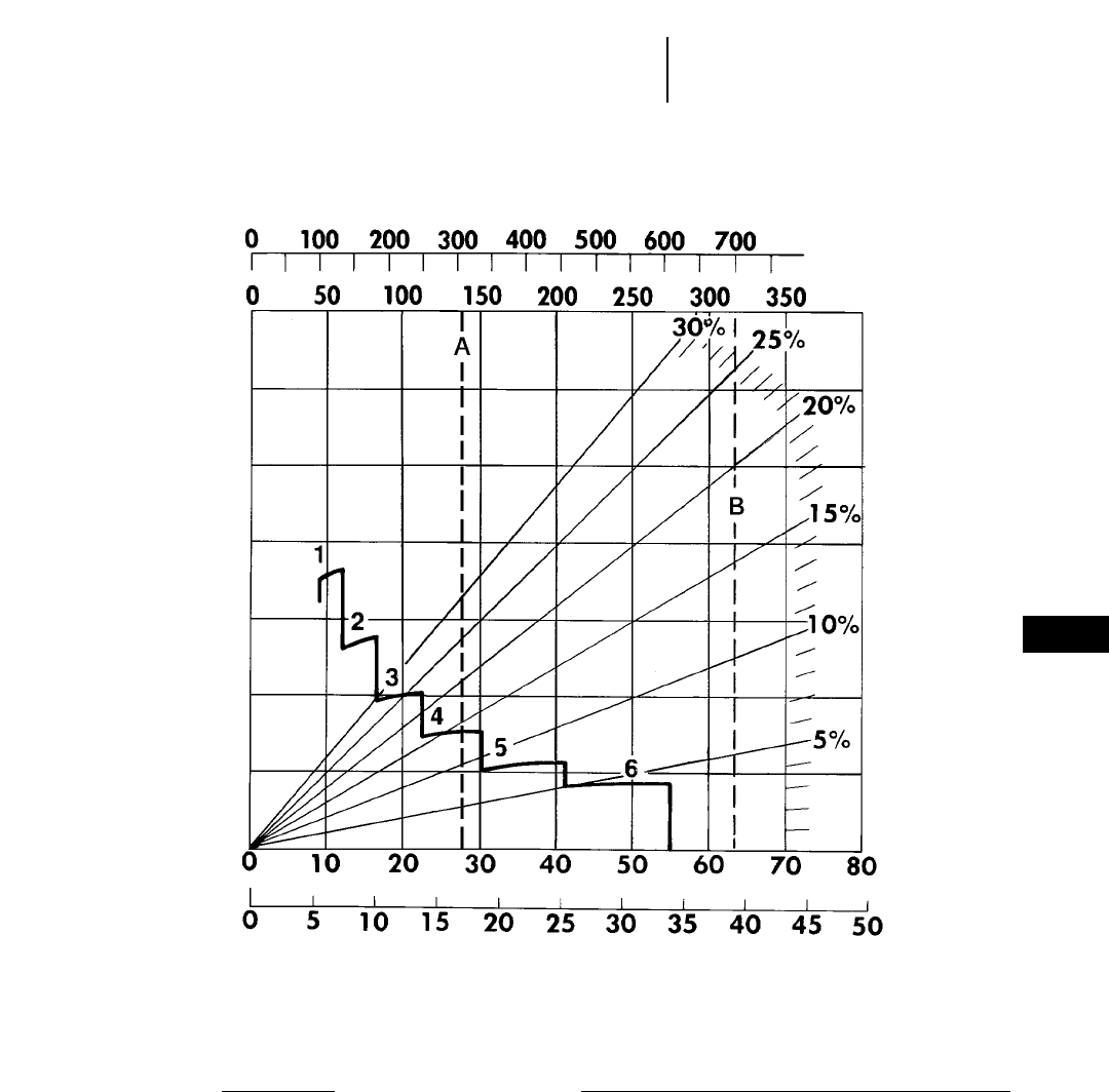
9-37
9
Construction & Mining Trucks789C Brake Performance
●Continuous Grade Retarding
KEY
1 — 1st Gear
2 — 2nd Gear
3 — 3rd Gear
4 — 4th Gear
5 — 5th Gear
6 — 6th Gear
KEY
A — Est. Field Empty Weight 140 616 kg (310,000 lb)*
B — Max GMW 317 460 kg (700,000 lb)
GROSS WEIGHT
kg x 1000
lb x 1000
EFFECTIVE GRADE
(FAVORABLE)
SPEED
km/h
mph
CONTINUOUS GRADE LENGTH
*Truck equipped with sideboards and liners.
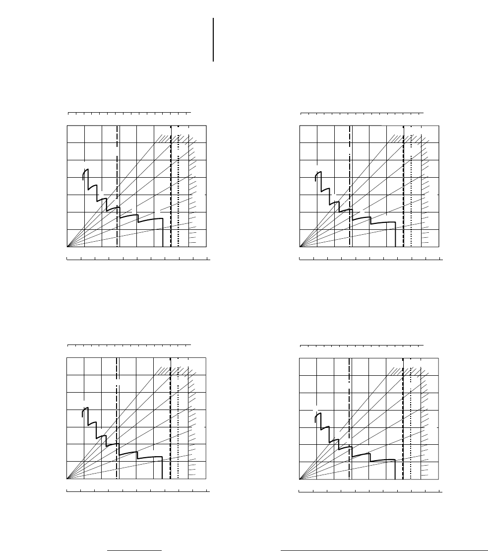
9-38
Construction & Mining Trucks 789C Brake Performance
●450 m (1500 ft) ●600 m (2000 ft)
●900 m (3000 ft) ●1500 m (5000 ft)
KEY
1 — 1st Gear
2 — 2nd Gear
3 — 3rd Gear
4 — 4th Gear
5 — 5th Gear
6 — 6th Gear
KEY
A — Est. Field Empty Weight 140 616 kg (310,000 lb)*
B — Max GMW 317 460 kg (700,000 lb)
*Truck equipped with sideboards and liners.
GROSS WEIGHT
EFFECTIVE GRADE
(Favorable)
SPEED
GRADE DISTANCE — 450 m (1500 ft)
km/h
mph
0 1020 304050607080
0 5 10 15 20 25 30 35 40 45 50
0 100 200 300 400
20%
0 50 100 150 200 250 300 350
1
500 600 700
2
3
4
56
30%
5%
10%
15%
25%
AB
kg x 1000
lb x 1000
GROSS WEIGHT
EFFECTIVE GRADE
(Favorable)
SPEED
GRADE DISTANCE — 900 m (3000 ft)
km/h
mph
01020304050607080
0 5 10 15 20 25 30 35 40 45 50
0 100 200 300 400
20%
0 50 100 150 200 250 300 350
1
500 600 700
2
3
4
56
30%
15%
10%
5%
25%
A B
kg x 1000
lb x 1000
GROSS WEIGHT
EFFECTIVE GRADE
(Favorable)
SPEED
GRADE DISTANCE — 1500 m (5000 ft)
km/h
mph
0 1020304050607080
0 5 10 15 20 25 30 35 40 45 50
0 100 200 300 400
20%
0 50 100 150 200 250 300 350
1
500 600 700
2
3
4
56
30%
15%
10%
5%
25%
A B
kg x 1000
lb x 1000
GROSS WEIGHT
EFFECTIVE GRADE
(Favorable)
SPEED
GRADE DISTANCE — 600 m (2000 ft)
km/h
mph
0 1020304050607080
0 5 10 15 20 25 30 35 40 45 50
0 100 200 300 400
20%
0 50 100 150 200 250 300 350
1
500 600 700
2
3
4
56
30%
15%
10%
5%
25%
AB
kg x 1000
lb x 1000
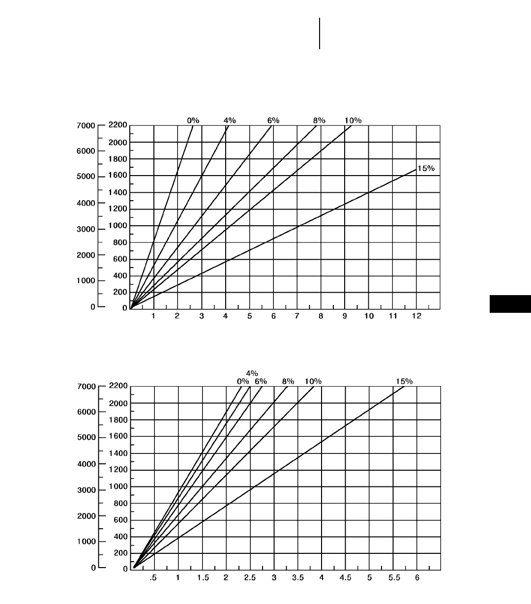
9-39
9
Construction & Mining Trucks789C Travel Time
●37.00R57 Tires
TOTAL RESISTANCE
(Grade plus Rolling)
feet meters
LOADED
TOTAL RESISTANCE
(Grade plus Rolling)
feet meters
EMPTY
DISTANCE ONE WAY
TIME (Minutes)
DISTANCE ONE WAY
TIME (Minutes)
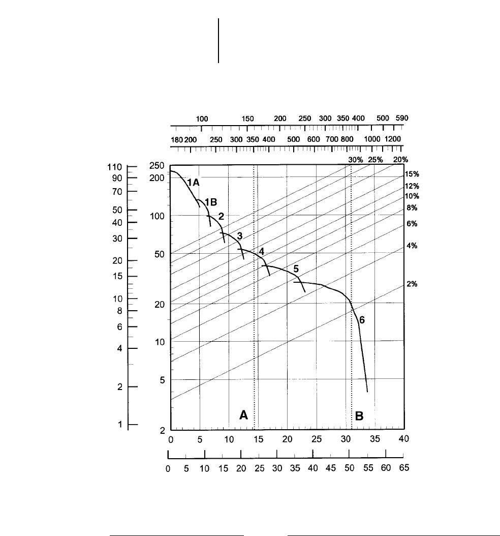
9-40
Construction & Mining Trucks 793C Rimpull-Speed-Gradeability
●40.00R57 Tires
●1778 mm (5'10") Tire Radius
KEY
1A— 1st Gear (Torque Converter)
1B— 1st Gear
2 — 2nd Gear
3 — 3rd Gear
4 — 4th Gear
5 — 5th Gear
6 — 6th Gear
KEY
A — Est. Field Empty Weight 158 760 kg (350,000 lb)*
B — Max GMW 376 488 kg (830,000 lb)
GROSS WEIGHT
lb x 1000
kg x 1000
TOTAL RESISTANCE
(Grade plus Rolling)
SPEED
km/h
mph
RIMPULL
kg x
1000 lb x
1000
*Truck equipped with sideboards and liners.
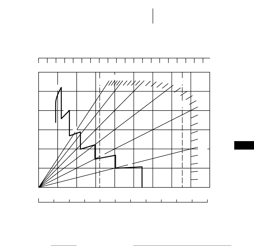
9-41
9
Construction & Mining Trucks793C Brake Performance
●Continuous Grade Retarding
0 100 200 300 400 500 600 700
0 50 100 150 200 250 300 350
0 1020304050607080
0 5 10 15 20 25 30 35 40 45 50
10%
B
A30%
1
2
3
4
5
6
400
800 900
90
55
25% 20% 15%
5%
KEY
1 — 1st Gear
2 — 2nd Gear
3 — 3rd Gear
4 — 4th Gear
5 — 5th Gear
6 — 6th Gear
KEY
A — Est. Field Empty Weight 158 760 kg (350,000 lb)*
B — Max GMW 376 488 kg (830,000 lb)
GROSS WEIGHT
EFFECTIVE GRADE
(FAVORABLE)
SPEED
km/h
mph
CONTINUOUS GRADE LENGTH
*Truck equipped with sideboards and liners.
kg x 1000
lb x 1000
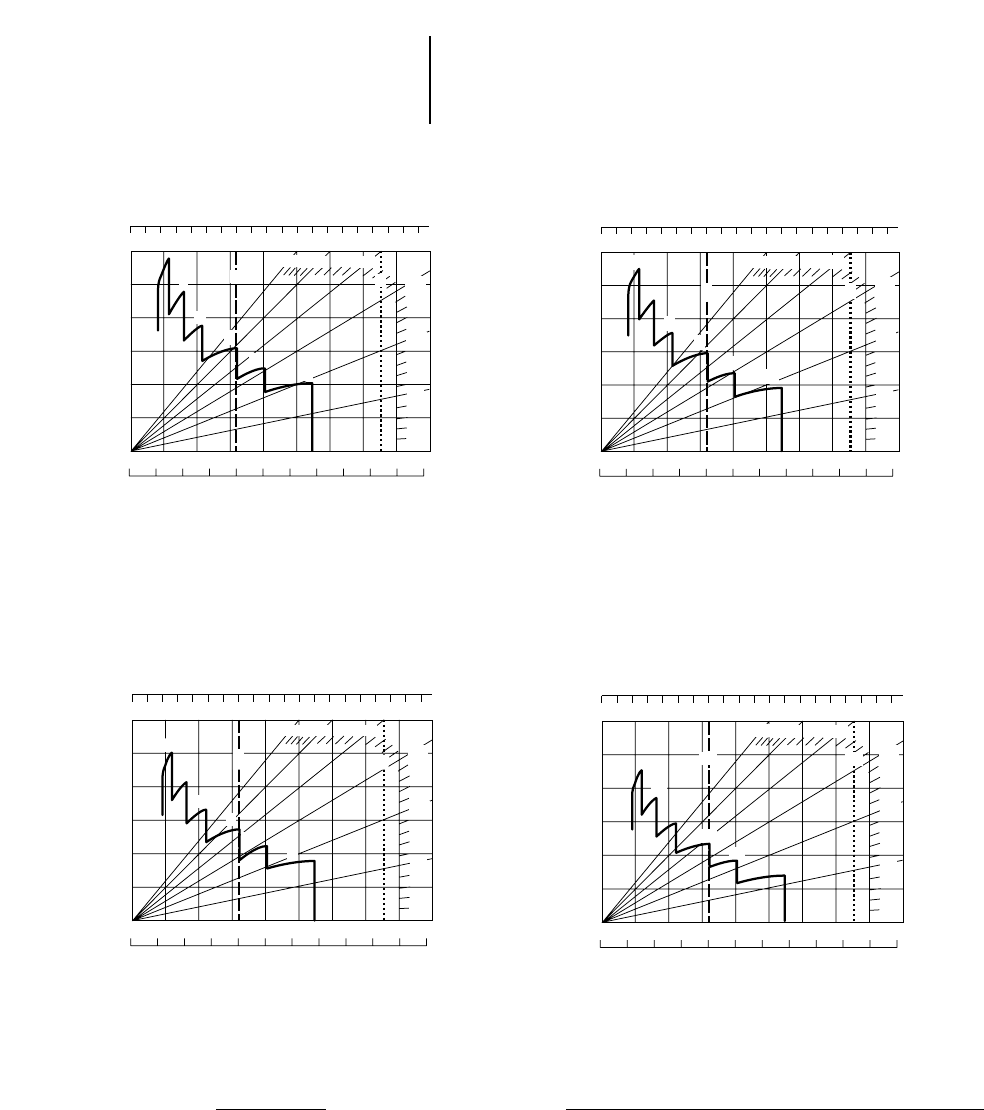
9-42
Construction & Mining Trucks 793C Brake Performance
●450 m (1500 ft) ●600 m (2000 ft)
●900 m (3000 ft) ●1500 m (5000 ft)
KEY
1 — 1st Gear
2 — 2nd Gear
3 — 3rd Gear
4 — 4th Gear
5 — 5th Gear
6 — 6th Gear
KEY
A — Est. Field Empty Weight 158 760 kg (350,000 lb)*
B — Max GMW 376 488 kg (830,000 lb)
*Truck equipped with sideboards and liners.
GROSS WEIGHT
EFFECTIVE GRADE
(Favorable)
SPEED
GRADE DISTANCE — 450 m (1500 ft)
km/h
mph
0 100 200 300 400 500 600 700 800 900
0 50 100 150 200 250 300 350 400
0 102030405060708090
0 5 10 15 20 25 30 35 40 45 50 55
1
2
3
4
56
30% 25% 20%
15%
10%
5%
AB
kg x 1000
lb x 1000
GROSS WEIGHT
EFFECTIVE GRADE
(Favorable)
SPEED
GRADE DISTANCE — 900 m (3000 ft)
km/h
mph
0 100 200 300 400 500 600 700 800 900
0 50 100 150 200 250 300 350 400
0102030405060708090
0 5 10 15 20 25 30 35 40 45 50 55
1
2
3
4
56
30% 25% 20%
15%
10%
5%
AB
kg x 1000
lb x 1000
GROSS WEIGHT
EFFECTIVE GRADE
(Favorable)
SPEED
GRADE DISTANCE — 1500 m (5000 ft)
km/h
mph
0 100 200 300 400 500 600 700 800 900
0 50 100 150 200 250 300 350 400
0102030405060708090
0 5 10 15 20 25 30 35 40 45 50 55
1
2
3
4
56
30% 25% 20%
15%
10%
5%
AB
kg x 1000
lb x 1000
GROSS WEIGHT
EFFECTIVE GRADE
(Favorable)
SPEED
GRADE DISTANCE — 600 m (2000 ft)
km/h
mph
0 100 200 300 400 500 600 700 800 900
0 50 100 150 200 250 300 350 400
0102030405060708090
0 5 10 15 20 25 30 35 40 45 50 55
1
2
3
4
56
30% 25% 20%
15%
10%
5%
A B
kg x 1000
lb x 1000
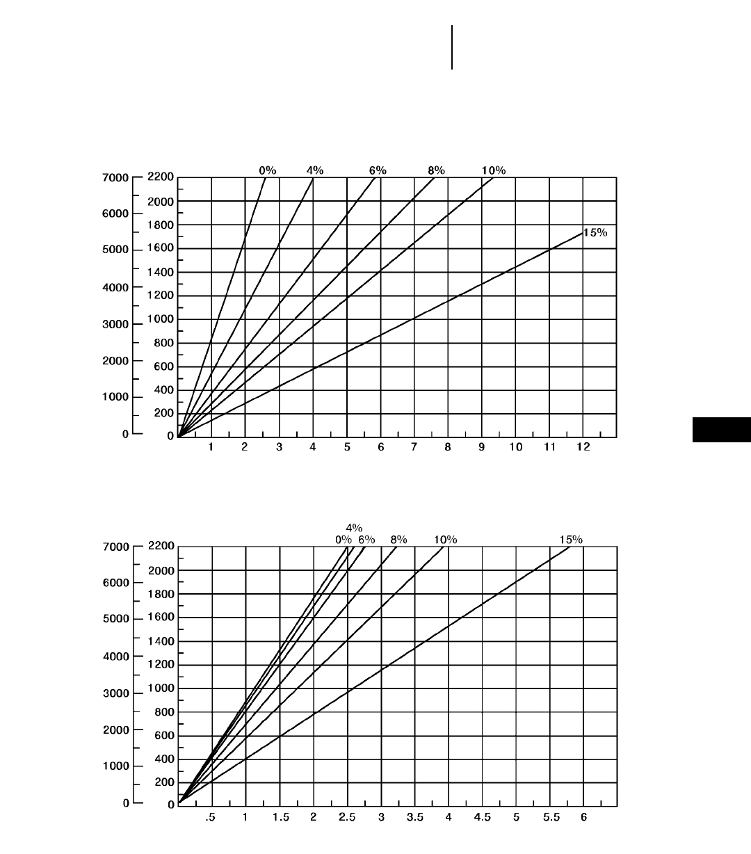
9-43
9
Construction & Mining Trucks793C Travel Time
●40.00R57 Tires
TOTAL RESISTANCE
(Grade plus Rolling)
feet meters
LOADED
TOTAL RESISTANCE
(Grade plus Rolling)
feet meters
EMPTY
DISTANCE ONE WAY
TIME (Minutes)
DISTANCE ONE WAY
TIME (Minutes)

10-1
CONTENTS
Features . . . . . . . . . . . . . . . . . . . . . . . . . . . . . .10-1
Specifications . . . . . . . . . . . . . . . . . . . . . . . . . .10-2
Special Arrangements . . . . . . . . . . . . . . . . . . .10-4
Ground Pressure . . . . . . . . . . . . . . . . . . . . . . . .10-5
Curves:
D25D Brake/Retarder Performance
Curve, Rimpull, Travel Time
(loaded and empty) . . . . . . . . . . . . . . . . . .10-8
D30D Brake/Retarder Performance
Curve, Rimpull, Travel Time
(loaded and empty) . . . . . . . . . . . . . . . . .10-11
D250E Series II Brake/Retarder
Performance Curve, Rimpull,
Travel Time (loaded and empty) . . . . . . .10-14
D300E Series II Brake/Retarder
Performance Curve, Rimpull,
Travel Time (loaded and empty) . . . . . . .10-17
D350E Retarding Performance
Curve, Rimpull, Travel Time
(loaded and empty) . . . . . . . . . . . . . . . . .10-23
D400E Brake/Retarder Performance
Curve, Rimpull, Travel Time
(loaded and empty) . . . . . . . . . . . . . . . . .10-26
Features:
●Caterpillar four-stroke-cycle diesels … turbo-
charged and aftercooled, automatic variable timing
… parallel porting … direct injection, adjustment-
free fuel system … meet all environment regula-
tions effective January 1, 1996.
●Electronically programmable transmission
control on “E” series models … speed sensing
device automatically shifts transmission between
1st and gear selected by operator. Control con-
stantly monitors transmission behavior for quick
and efficient troubleshooting.
●Articulating and fully oscillating hitch … links
torsion-free front and rear frames for exceptional
maneuverability and traction on uneven terrain.
Cast hitch head is robotically-welded to steel alloy
forged tube for unmatched strength and durability.
●Superior suspension systems … coupled with
oscillating hitch, provide smooth ride and excel-
lent traction for prime performance and operator
comfort.
●Wide, long, low dump body design … for
enhanced loadability, material retention and ejec-
tion, with excellent machine stability. Low load-
over-height allows versatile loader match.
●High capacity low pressure tires in single
formation … for superior traction and flotation
on poor underfoot conditions.
●High power-to-weight ratio and excellent
gradeability … for high-efficiency and versatile
performance.
●Standard ROPS/FOPS, low sound level cab
with tinted safety glass … for productive and
safe operation.
10
ARTICULATED TRUCKS
MODEL D25D D30D
Flywheel Power 194 kW 260 hp 213 kW 285 hp
Operating Weight (Empty)* 19 450 kg 42,880 lb 21 690 kg 47,320 lb
Top Speed (Loaded) 48 km/h 30 mph 52 km/h 32 mph
GMW — Gross Machine Weight 42 250 kg 93,145 lb 49 150 kg 108,360 lb
Distribution Empty:
Front 70% 66%
Rear 30% 34%
Distribution Loaded:
Front 48% 44%
Rear 52% 56%
Max. Capacity** 22.7 t 25 T 27.2 t 30 T
Struck (SAE) 10 m313 yd312.5 m316.4 yd3
Heaped (2:1) (SAE) 14 m318 yd316.5 m321.6 yd3
Engine Model 3306TA 3306TA
No. Cylinders 66
Bore 121 mm 4.75" 121 mm 4.75"
Stroke 152 mm 6" 152 mm 6"
Displacement 10.5 L 638 in310.5 L 638 in3
Tires, Front & Rear 26.5R25 Radials 29.5R25 Radials
Circular Clearance
Diameter 15.9 m 52'2" 16.4 m 53'9"
Fuel Tank Refill Capacity 450 L 120 U.S. gal 450 L 120 U.S. gal
GENERAL DIMENSIONS
(Empty):
Height to Cab Top 3.34 m 10'11" 3.40 m 11'2"
Wheel Base 4.93 m 16'2" 5.04 m 16'6"
Overall Length 8.79 m 28'10" 8.89 m 29'2"
Loading Height (Empty) 2.63 m 8'8" 2.83 m 9'3"
Height at Full Dump 5.19 m 17'0" 5.46 m 17'11"
Body Length 4.79 m 15'8" 4.90 m 16'1"
Width (Operating) 3.00 m 9'10" 3.30 m 10'10"
Front Tire Tread 2.32 m 7'7" 2.55 m 8'4"
**Includes coolant, lubricant and full fuel tank.
**Rating dependent on optional equipment. Maximum gross weight (empty weight plus payload) should not be exceeded.
10-2
Articulated Trucks Specifications
●Two-Axle Models
10-3
MODEL D250E Series II D300E Series II D350E D400E
Flywheel Power 201 kW 270 hp 213 kW 285 hp 253 kW 340 hp 302 kW 405 hp
Operating Weight (Empty)* 21 600 kg 47,630 lb 22 450 kg 49,500 lb 27 871 kg 61,455 lb 29 263 kg 64,510 lb
Top Speed (Loaded) 50.9 km/h 31.6 mph 49 km/h 30.5 mph 50.7 km/h 31.5 mph 55.4 km/h 34 mph
GMW — Gross Machine Weight 44 280 kg 97,640 lb 49 670 kg 109,520 lb 59 631 kg 131,486 lb 65 563 kg 144,500 lb
Distribution Empty:
Front 56% 54% 60% 60%
Center 23% 24% 20% 20%
Rear 21% 22% 20% 20%
Distribution Loaded:
Front 30% 30% 35% 34%
Center 35% 35% 33% 33%
Rear 35% 35% 32% 33%
Max. Capacity** 22.7 t 25 T 27.2 t 30 T 31.8 t 35 T 36.3 t 40 T
Struck (SAE) 10.5 m313.7 yd313 m317 yd314.6 m319.1 yd316.5 m321.6 yd3
Heaped (2:1) (SAE) 13.7 m318 yd316.5 m321.6 yd319.2 m325.1 yd322 m328.8 yd3
Engine Model 3306DITA 3306DITA 3406DITA 3406DITA
No. Cylinders 6666
Bore 121 mm 4.75" 121 mm 4.75" 137 mm 5.4" 137 mm 5.4"
Stroke 152 mm 6" 152 mm 6" 165 mm 6.5" 165 mm 6.5"
Displacement 10.5 L 638 in310.5 L 638 in314.6 L 893 in314.6 L 893 in3
Tires, Front, Center & Rear 23.5R25 Radials 23.5R25 Radials 26.5R25 Radials 29.5R25 Radials
30/65R25 Radials (Opt.)
Circle Clearance Diameter 14.9 m 48'10" 15.2 m 49'8" 16.42 m 53'10" 16.5 m 54'3"
Fuel Tank Refill Capacity 360 L 95 U.S. gal.360 L 95 U.S. gal.570 L 154 U.S. gal.570 L 154 U.S. gal.
GENERAL DIMENSIONS
(Empty):
Height to Cab Top 3.35 m 11'0" 3.35 m 11'0" 3.51 m 11'6" 3.58 m 11'9"
Wheel Base
(Front-Center of Bogie) 4.72 m 15'6" 4.72 m 15'6" 5.02 m 16'6" 5.12 m 16'10"
Overall Length 9.99 m 32'9" 9.99 m 32'9" 10.38 m 34'1" 10.52 m 34'6"
Loading Height (Empty) 2.75 m 9'0" 2.89 m 9'6" 2.94 m 9'8" 3.06 m 10'1"
Height at Full Dump 6.40 m 21'0" 6.44 m 21'2" 6.60 m 21'8" 6.58 m 21'7"
Body Length 5.80 m 19'0" 5.80 m 19'0" 6.01 m 19'9" 5.90 m 19'4"
Width (Operating) 2.88 m 9'5" 2.91 m 9'7" 3.26 m 10'8" 3.30 m 10'10"
Front Tire Tread 2.22 m 7'3" 2.30 m 7'7" 2.55 m 8'4" 2.55 m 8'4"
**Includes coolant, lubricant and full fuel tank.
**Rating dependent on optional equipment. Maximum gross weight (empty weight plus payload) should not be exceeded.
10
Articulated TrucksSpecifications
●Three-Axle Models

A variety of special arrangements are available
on a custom product basis. Below is a summary of
some of the most popular versions, which are attain-
able in different model sizes. Please contact your
Caterpillar dealer for details and availability.
Refuse Haulers — Very large capacity body arrange-
ments for transport of bulk solid waste, normally
used between a transfer station and the face of a
sanitary landfill. Arrangement includes large capac-
ity body, extended rear frame and scissors tailgate.
Hydraulically operated steel covers — Available
for certain refuse bodies. The covers improve light
material retention during transport.
Container Carriers — Allows transport and dump
of 6 m (20'0") ISO containers. Usual application is
handling containerized waste in landfills. Arrange-
ment includes an extended and reinforced rear
frame combined with a special tipping structure.
Transverse Steering — Improves maneuverabil-
ity in areas with limited space, like tunnels, under-
ground mines and industrial sites. This option allows
the truck to turn completely around in a space slightly
longer than the truck itself. Available for two axle
trucks only.
Heavy Duty Bodies — More robust bodies made
with thicker plates and incorporating rock deflec-
tors for tire protection. Increase the vehicle’s mate-
rial appetite and provide longer life in applications
involving highly abrasive materials and high impact
loading.
Extended Chassis/Water Wagons — Long wheel
base chassis, suitable for installation of low center
of gravity liquid tanks and other AEM accessories.
The extended rear frame permits use of low center
of gravity arrangements for added stability. Common
applications are haul road dust control and off-road
transport of water or fuel. Available for three axle
trucks only.
Coal Haulers — Machines configured with large
capacity body, extended rear frame and scissors tail-
gate, for transport of coal. The longer frame helps
maintain stability and gives loading height acces-
sible to many loading systems.
Sugar Cane Haulers — May be manufactured by
using extended rear frame chassis, adding a sub
frame and special tires.
10-4
Articulated Trucks Special Arrangements
Model D25D D30D D250E D300E D350E D400E
Refuse Haulers XXXX
Container Carriers X X
Transverse Steer X X
Heavy Duty Bodies X X
Extended Chassis XXXX
Coal Haulers XXX
Sugar Cane Haulers X

Use of Ground Pressure Charts
Articulated trucks are normally equipped with
wide base radial tires, for improved flotation in poor
underfoot conditions. Ground pressure is a function
of tire deflection and is also affected by tire pene-
tration. The charts in this section provide a means
to estimate ground pressure for 0 and 76 mm (3")
tire penetration, when gross vehicle weight, axle
load distribution and tire inflation pressure are
known. The ground pressure charts on the following
pages are based on Michelin XADN tire character-
istics. Results may differ for other tread patterns.
Tire load can be calculated by the following formula:
Heaviest Axle Load
Tire load = __________________
2
Example
Find the ground pressure generated by a D250E
fully loaded with zero and 76 mm (3") tire penetra-
tion. The machine is equipped with standard Michelin
23.5R25 tires, inflated to the recommended pressure.
43 680 kg 20.34
D250E Tire Load = ________________ = 7426 kg
2
96,300 lb 20.34
D250E Tire Load = ________________ = 16,371 lb
2
From the tire section in this book, inflation pres-
sure for the D250E is 325 kPa = 3.25 bar (47 psi).
From the ground pressure chart for 23.5R25 tires,
Ground pressure = 3.1 kg/cm2(44 psi) with zero tire
penetration.
Ground pressure = 1.4 kg/cm2(21 psi) with 76 mm
(3 in) tire penetration.
See the Wheel Tractor Scraper section for
explanation on using:
●Rimpull-Speed-Gradeability Curves
●Retarder Curves
●Travel Time Charts
See the Construction and Mining Trucks
section for Hauling Unit Fixed Times.
10-5
10
Articulated TrucksGround Pressure
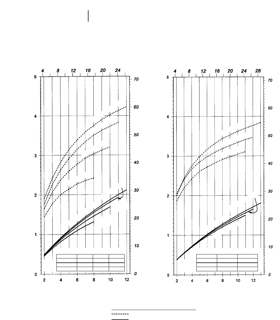
10-6
Articulated Trucks Ground Pressure
23.5R25 Tires*
Tire Load (lb x 1000)
Tire Load (kg x 1000)
Ground Pressure (kg/cm2)
Ground Pressure (psi)
30/65R25 Tires*
Tire Load (lb x 1000)
Tire Load (kg x 1000)
Ground Pressure (kg/cm2)
Ground Pressure (psi)
KEY
Zero Penetration (Flat Plate)
76 mm (3") Penetration
*Charts based on Michelin XADN tire characteristics. Results may differ for other tread patterns and/or brands. Charts are to be used to calculate ground pressure.To deter-
mine the inflation as a function of load and conditions or when loads exceed tire load limit, contact your tire manufacturer representative.
Cold Inflation Pressure
2.0 bar 3.0 4.0 4.5
29 psi 44 58 65
5650 kg 7100 8550 9250
12,460 lb 15,650 18,850 20,390
Tire
Load
Limit
Cold Inflation Pressure
3.0 bar 3.5 4.0
44 psi 51 58
7800 kg 8550 9250
17,200 lb 18,850 20,390
Tire
Load
Limit
4.5 bar (65 psi)
4 bar (58 psi)
3.5 bar (51 psi)
3 bar (44 psi)
3.5 bar (51 psi)
4 bar (58 psi)
3 bar (44 psi)
4 bar (58 psi)
3 bar (44 psi)
2 bar (29 psi)
4.5 bar (65 psi)
4 bar (58 psi)
3 bar
(44 psi)
2 bar
(29 psi)
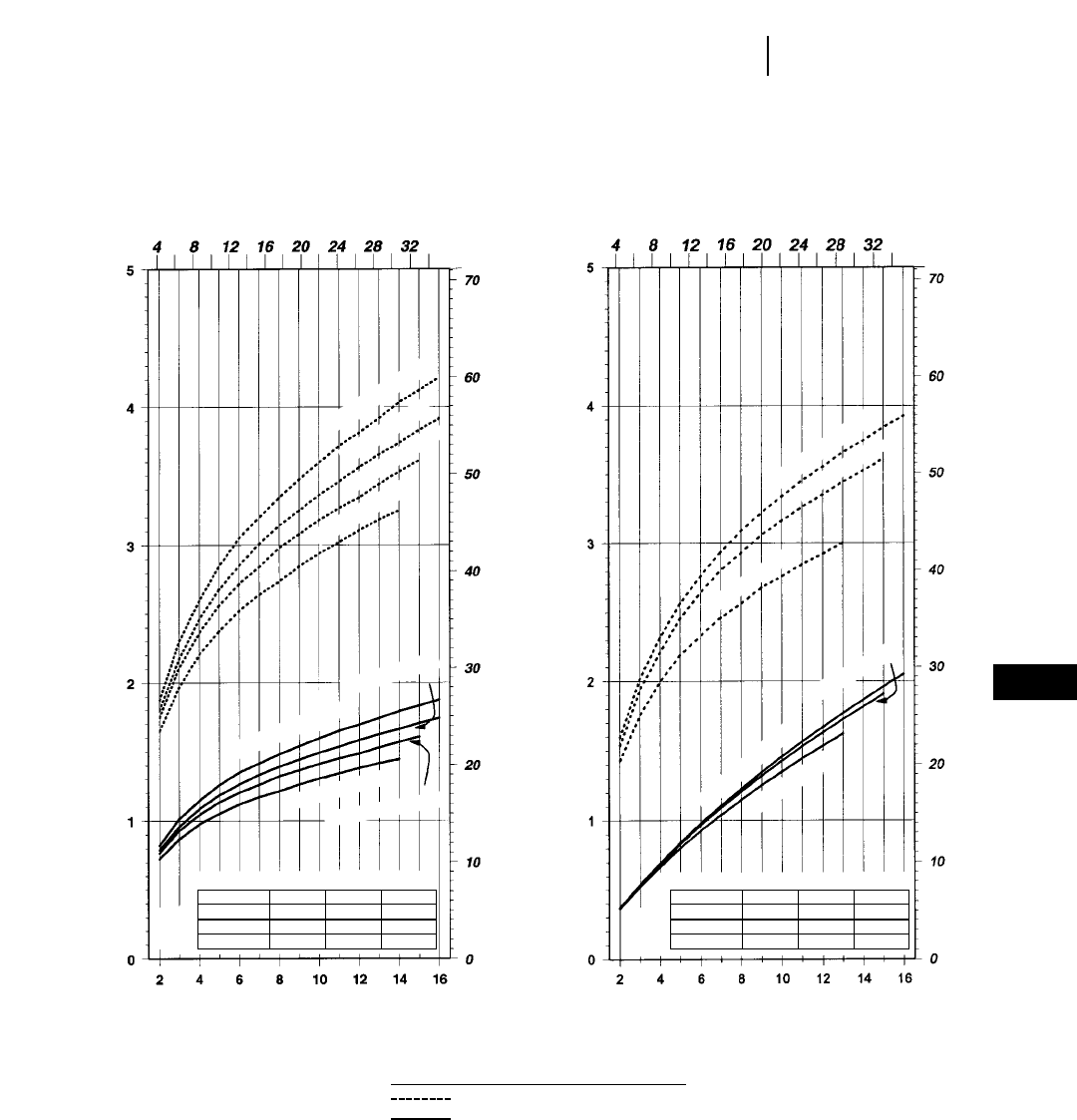
10-7
10
Articulated TrucksGround Pressure
Cold Inflation Pressure
3.0 bar 3.5 4.0 4.5
44 psi 51 58 65
10 300 kg 11 500 12 750 14 000
22,710 lb 25,350 28,110 30,860
Tire
Load
Limit
26.5R25 Tires* 29.5R25 Tires*
Tire Load (lb x 1000)
Tire Load (kg x 1000)
Ground Pressure (kg/cm2)
Ground Pressure (psi)
KEY
Zero Penetration (Flat Plate)
76 mm (3") Penetration
*Charts based on Michelin XADN tire characteristics. Results may differ for other tread patterns and/or brands. Charts are to be used to calculate ground pressure.To deter-
mine the inflation as a function of load and conditions or when loads exceed tire load limit, contact your tire manufacturer representative.
4.5 bar (65 psi)
4 bar (58 psi)
3 bar (44 psi)
4 bar (58 psi)
4.5 bar (65 psi)
3 bar (44 psi)
Tire Load (lb x 1000)
Tire Load (kg x 1000)
Ground Pressure (kg/cm2)
Ground Pressure (psi)
Cold Inflation Pressure
3.0 bar 3.5 4.0 4.5
44 psi 51 58 65
8500 kg 9500 10 500 11 500
18,739 lb 20,944 18,850 20,390
Tire
Load
Limit
4.5 bar (65 psi)
4 bar (58 psi)
3.5 bar (51 psi)
3 bar (44 psi)
4.5 bar (65 psi)
4 bar (58 psi)
3 bar (44 psi)
3.5 bar (51 psi)
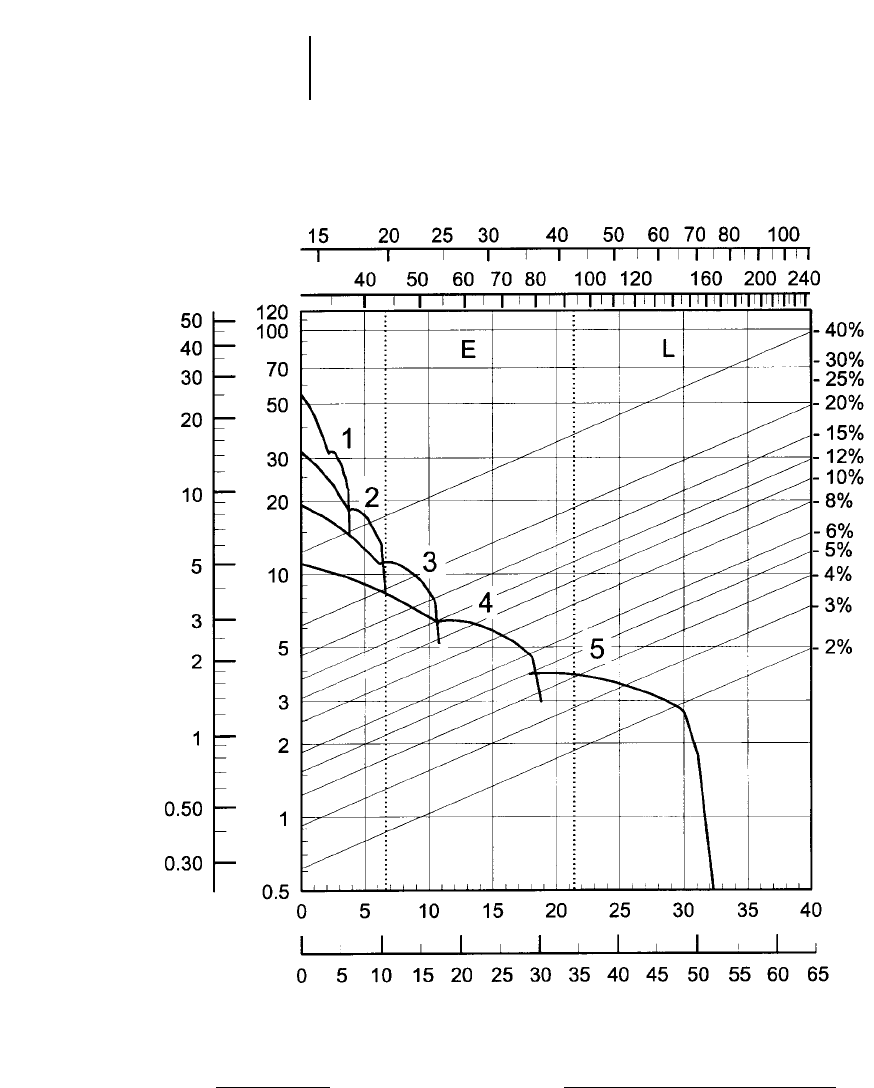
10-8
Articulated Trucks D25D Rimpull-Speed-Gradeability
●26.5R25 Tires
KEY
E — Empty 19 700 kg (43,428 lb)
L — Loaded 42 381 kg (93,428 lb)
KEY
1 — 1st Gear
2 — 2nd Gear
3 — 3rd Gear
4 — 4th Gear
5 — 5th Gear
GROSS WEIGHT
RIMPULL
kg x 1000
lb x 1000
kg x 1000
lb x 1000
TOTAL RESISTANCE
(Grade plus Rolling Resistance)
SPEED
mph
km/h
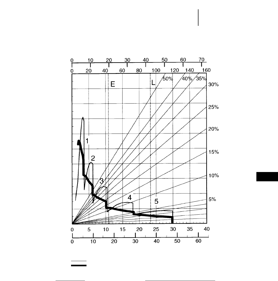
10-9
10
Articulated TrucksD25D Brake/Retarder Performance Curve
●26.5R25 Tires
KEY
1 — 1st Gear
2 — 2nd Gear
3 — 3rd Gear
4 — 4th Gear
5 — 5th Gear
KEY
E — Empty 19 700 kg (43,428 lb)
L — Loaded 42 381 kg (93,428 lb)
GROSS WEIGHT
EFFECTIVE GRADE (Favorable)
SPEED
200 m (660 ft) OR LESS GRADE LENGTH
CONTINUOUS
kg x 1000
lb x 1000
mph
km/h
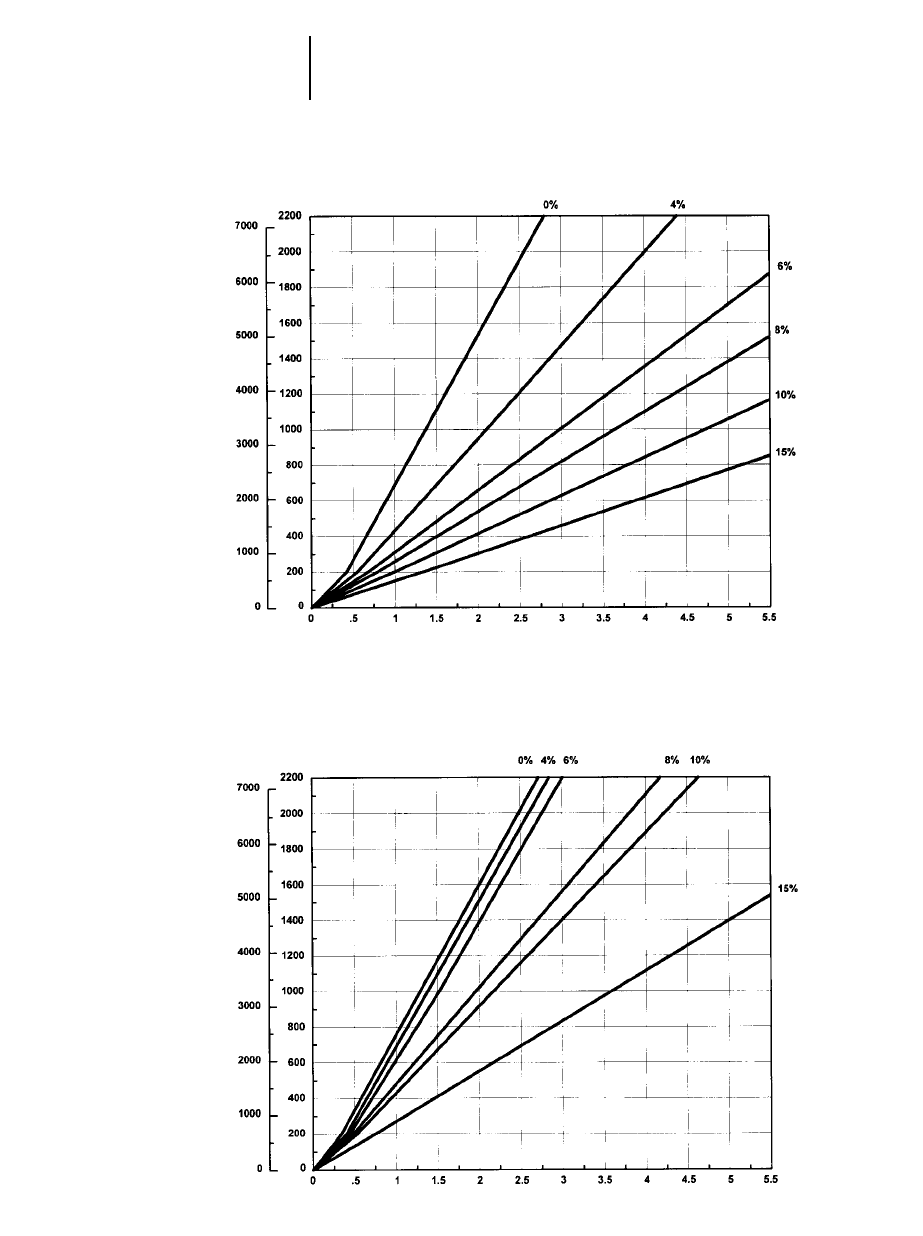
10-10
Articulated Trucks D25D Travel Time — Loaded/Empty
●26.5R25 Tires
LOADED
TIME
DISTANCE ONE WAY
TOTAL RESISTANCE
(Grade plus Rolling)
feet meters
minutes
EMPTY
TIME
DISTANCE ONE WAY
TOTAL RESISTANCE
(Grade plus Rolling)
feet meters
minutes
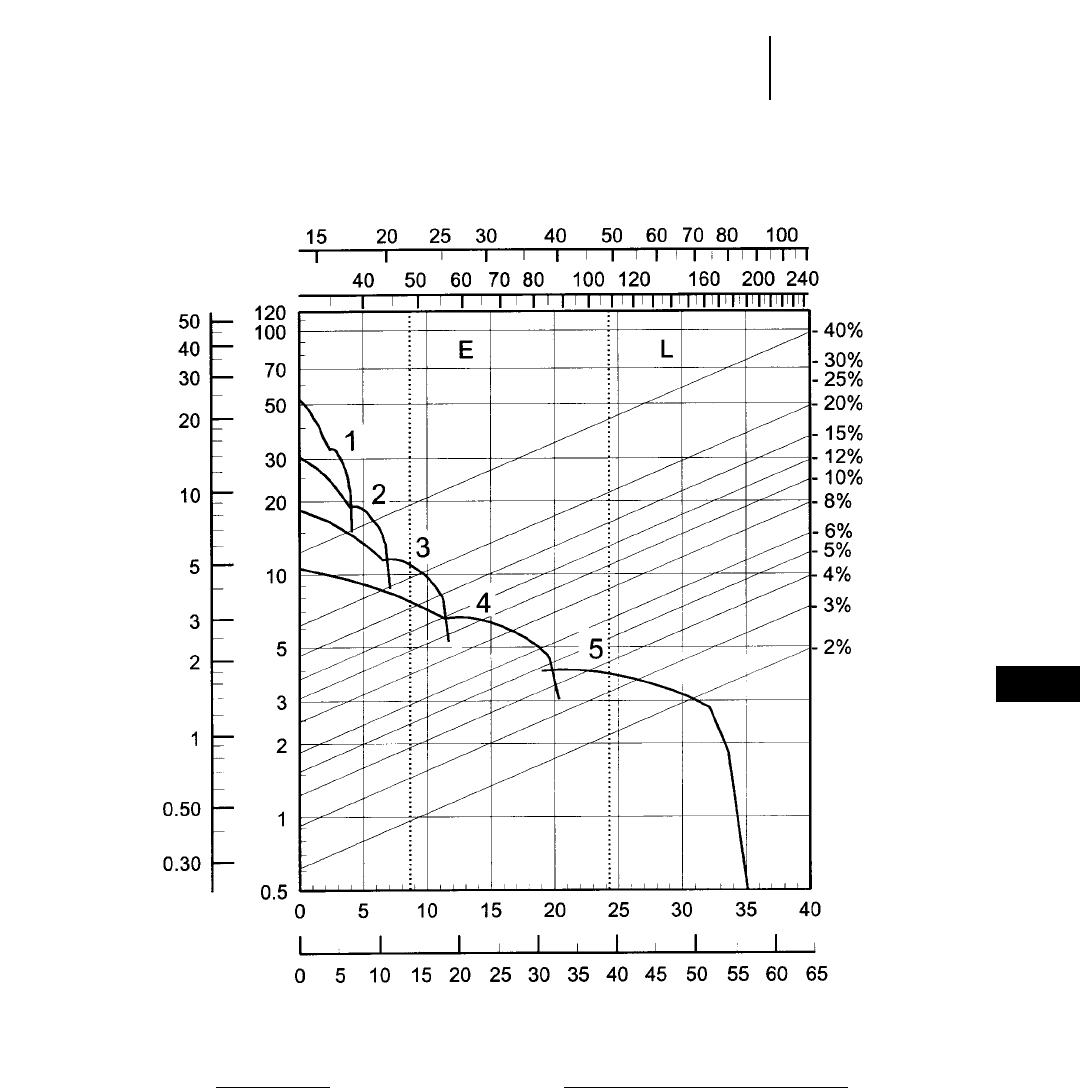
10-11
10
Articulated TrucksD30D Rimpull-Speed-Gradeability
●29.5R25 Tires
KEY
1 — 1st Gear
2 — 2nd Gear
3 — 3rd Gear
4 — 4th Gear
5 — 5th Gear
KEY
E — Empty 21 900 kg (48,278 lb)
L — Loaded 49 117 kg (108,278 lb)
GROSS WEIGHT
RIMPULL
kg x 1000
lb x 1000
kg x 1000
lb x 1000
TOTAL RESISTANCE
(Grade plus Rolling Resistance)
SPEED
mph
km/h
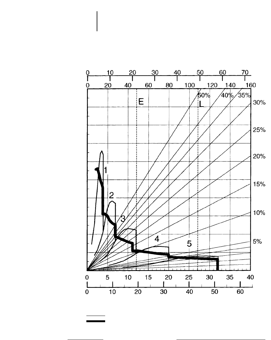
10-12
Articulated Trucks D30D Brake/Retarder Performance Curve
●29.5R25 Tires
KEY
E — Empty 21 900 kg (48,278 lb)
L — Loaded 49 117 kg (108,278 lb)
KEY
1 — 1st Gear
2 — 2nd Gear
3 — 3rd Gear
4 — 4th Gear
5 — 5th Gear
GROSS WEIGHT
EFFECTIVE GRADE (Favorable)
SPEED
200 m (660 ft) OR LESS GRADE LENGTH
CONTINUOUS
kg x 1000
lb x 1000
mph
km/h
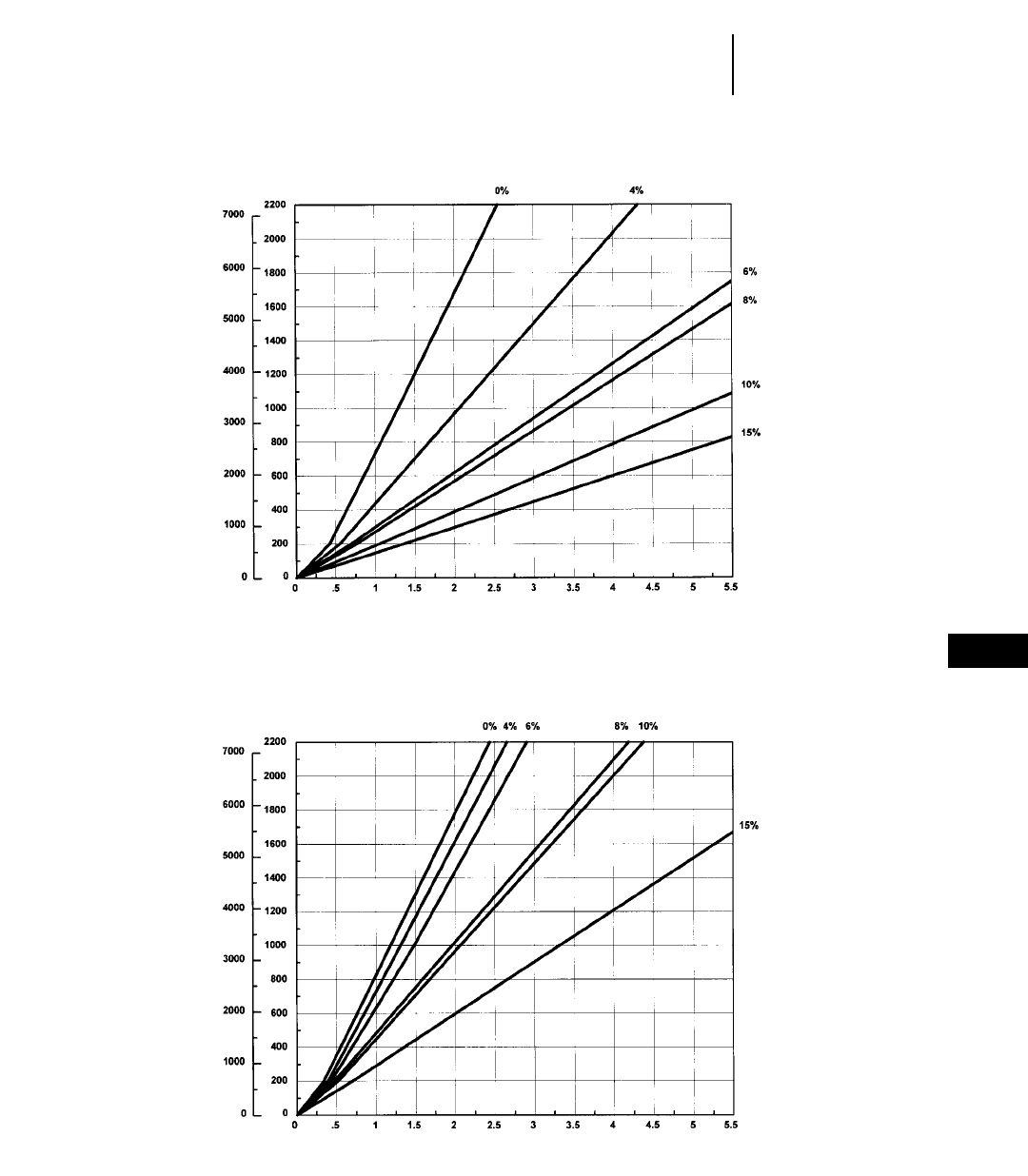
10-13
10
Articulated TrucksD30D Travel Time — Loaded/Empty
●29.5R25 Tires
LOADED
TIME
DISTANCE ONE WAY
TOTAL RESISTANCE
(Grade plus Rolling)
feet meters
minutes
EMPTY
TIME
DISTANCE ONE WAY
TOTAL RESISTANCE
(Grade plus Rolling)
feet meters
minutes
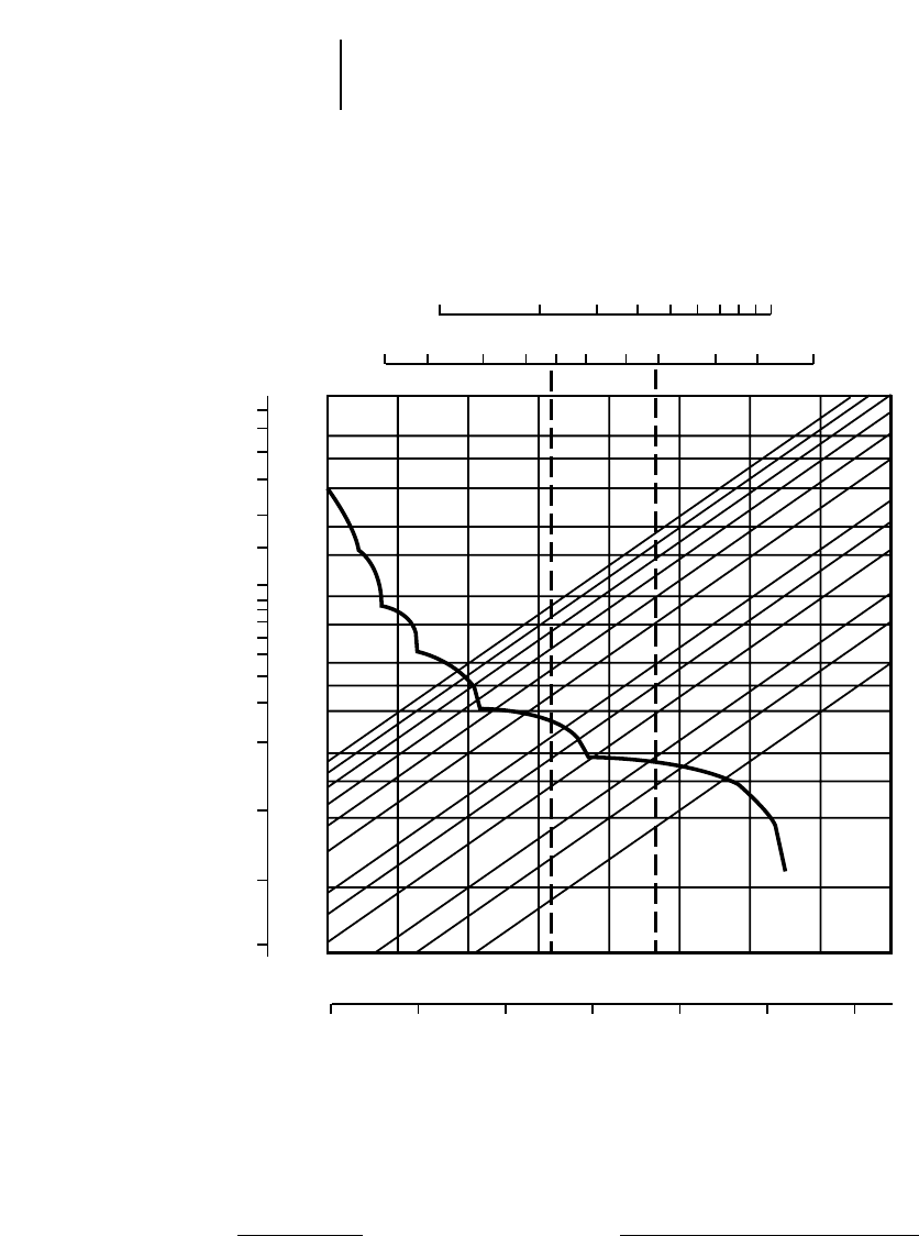
10-14
Articulated Trucks D250E Series II Rimpull-Speed-Gradeability
●23.5R25 Tires
KEY
1 — 1st Gear
2 — 2nd Gear
3 — 3rd Gear
4 — 4th Gear
5 — 5th Gear
KEY
E — Empty 21 700 kg (47,840 lb)
L — Loaded 44 380 kg (97,840 lb)
10 20 30 40 50 60 80 100
15 20 30 40 50 60 80 100 150 200 300
0 1020304050 60
0 5 10 15 20 25 30 35 40
60
50
40
30
20
15
10
5
7
4
3
2
1
.5
0.25
100
150
80
60
40
30
20
15
10
8
6
4
3
2
1
40% 30%
20%
15%
10%
8%
6%
4%
3%
2%
EL
GROSS WEIGHT
RIMPULL
kg x 1000
lb x 1000
lb x 1000
TOTAL RESISTANCE
(Grade plus Rolling Resistance)
SPEED
mph
km/h
kg x 1000
Preliminary Information
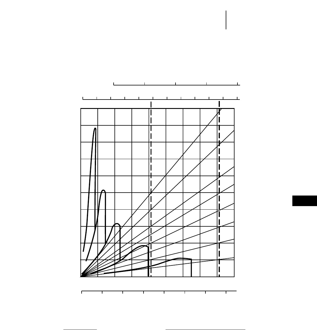
10-15
10
Articulated TrucksD250E Series II Brake/Retarder Performance Curve
●23.5R25 Tires
KEY
E — Empty 21 700 kg (47,840 lb)
L — Loaded 44 380 kg (97,840 lb)
KEY
1 — 1st Gear
2 — 2nd Gear
3 — 3rd Gear
4 — 4th Gear
5 — 5th Gear
10 20 30 40
10 20 30 40 50 60 80 10090
0 102030405060
0 5 10 15 20 25 30 35 45
50
40
30
20
10
20%
15%
5%
40
70
0
10%
25%
30%
40%
50%
EL
70
50
GROSS WEIGHT
EFFECTIVE GRADE (Favorable)
SPEED
kg x 1000
lb x 1000
mph
km/h
Preliminary Information
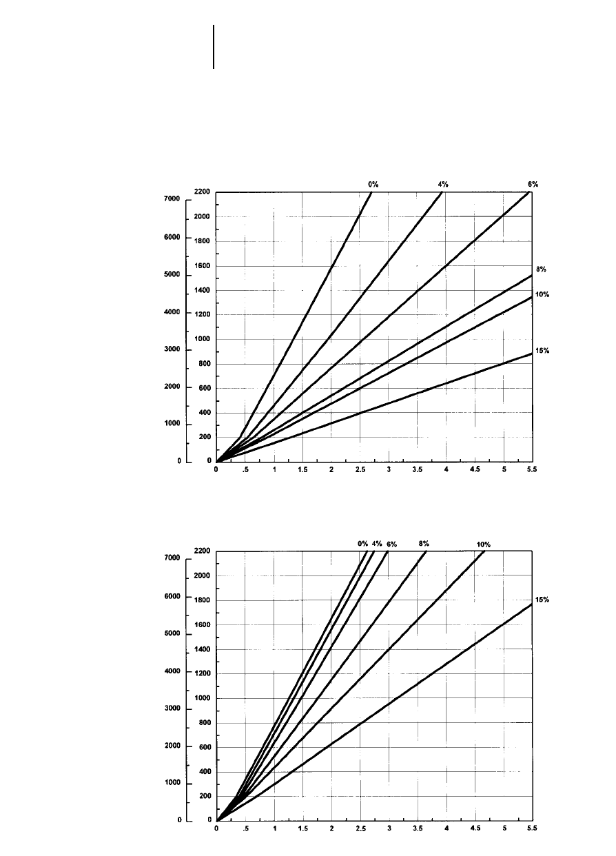
10-16
Articulated Trucks D250E Series II Travel Time — Loaded/Empty
●23.5R25 Tires
LOADED
TIME
DISTANCE ONE WAY
TOTAL RESISTANCE
(Grade plus Rolling)
feet meters
minutes
EMPTY
TIME
DISTANCE ONE WAY
TOTAL RESISTANCE
(Grade plus Rolling)
feet meters
minutes
Preliminary Information
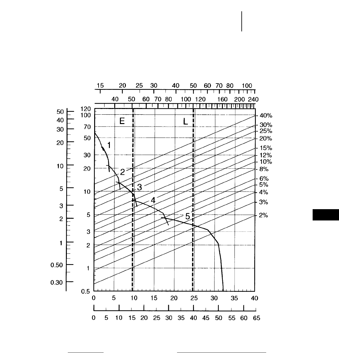
10-17
10
Articulated TrucksD300E Series II Rimpull-Speed-Gradeability
●23.5R25 Tires
KEY
1 — 1st Gear
2 — 2nd Gear
3 — 3rd Gear
4 — 4th Gear
5 — 5th Gear
KEY
E — Empty 22 890 kg (50,460 lb)
L — Loaded 50 100 kg (110,460 lb)
GROSS WEIGHT
RIMPULL
kg x 1000
lb x 1000
kg x 1000
lb x 1000
TOTAL RESISTANCE
(Grade plus Rolling Resistance)
SPEED
mph
km/h
Preliminary Information
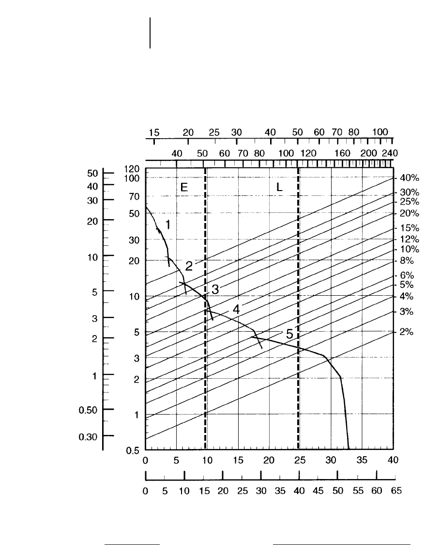
10-18
Articulated Trucks D300E Series II Rimpull-Speed-Gradeability
●30/65R25 Tires
KEY
1 — 1st Gear
2 — 2nd Gear
3 — 3rd Gear
4 — 4th Gear
5 — 5th Gear
KEY
E — Empty 22 890 kg (50,460 lb)
L — Loaded 50 100 kg (110,460 lb)
GROSS WEIGHT
Preliminary Information
RIMPULL
kg x 1000
lb x 1000
kg x 1000
lb x 1000
TOTAL RESISTANCE
(Grade plus Rolling Resistance)
SPEED
mph
km/h
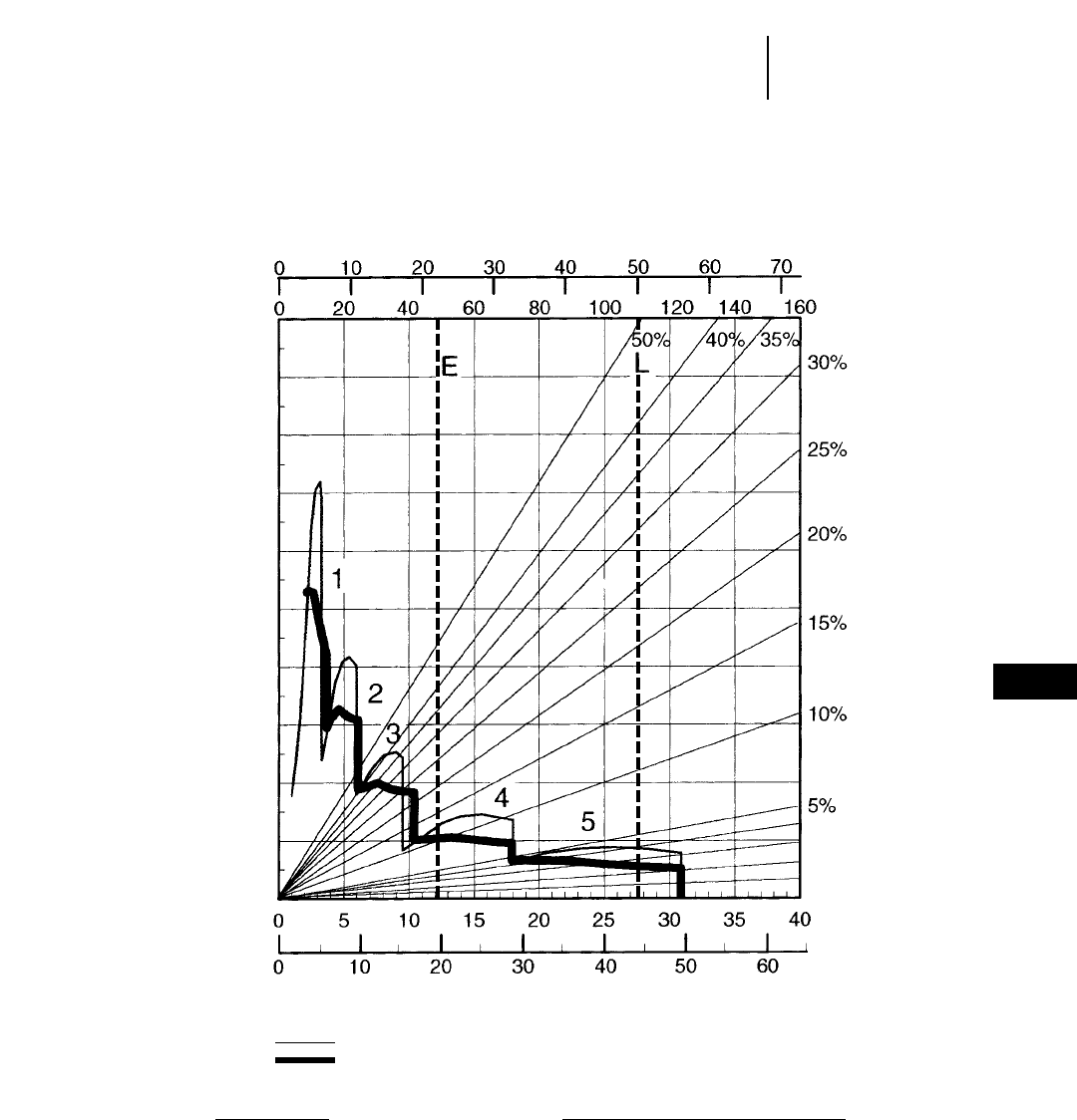
10-19
10
Articulated TrucksD300E Series II Brake/Retarder Performance
●23.5R25 Tires
KEY
E — Empty 22 890 kg (50,460 lb)
L — Loaded 50 100 kg (110,460 lb)
KEY
1 — 1st Gear
2 — 2nd Gear
3 — 3rd Gear
4 — 4th Gear
5 — 5th Gear
GROSS WEIGHT
Preliminary Information
EFFECTIVE GRADE (Favorable)
SPEED
200 m (660 ft) OR LESS GRADE LENGTH
CONTINUOUS
kg x 1000
lb x 1000
mph
km/h
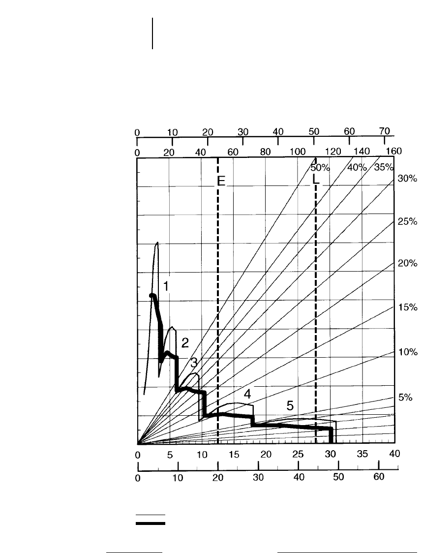
10-20
Articulated Trucks D300E Series II Brake/Retarder Performance
●30/65R25 Tires
KEY
E — Empty 22 890 kg (50,460 lb)
L — Loaded 50 100 kg (110,460 lb)
KEY
1 — 1st Gear
2 — 2nd Gear
3 — 3rd Gear
4 — 4th Gear
5 — 5th Gear
GROSS WEIGHT
Preliminary Information
EFFECTIVE GRADE (Favorable)
SPEED
200 m (660 ft) OR LESS GRADE LENGTH
CONTINUOUS
kg x 1000
lb x 1000
mph
km/h
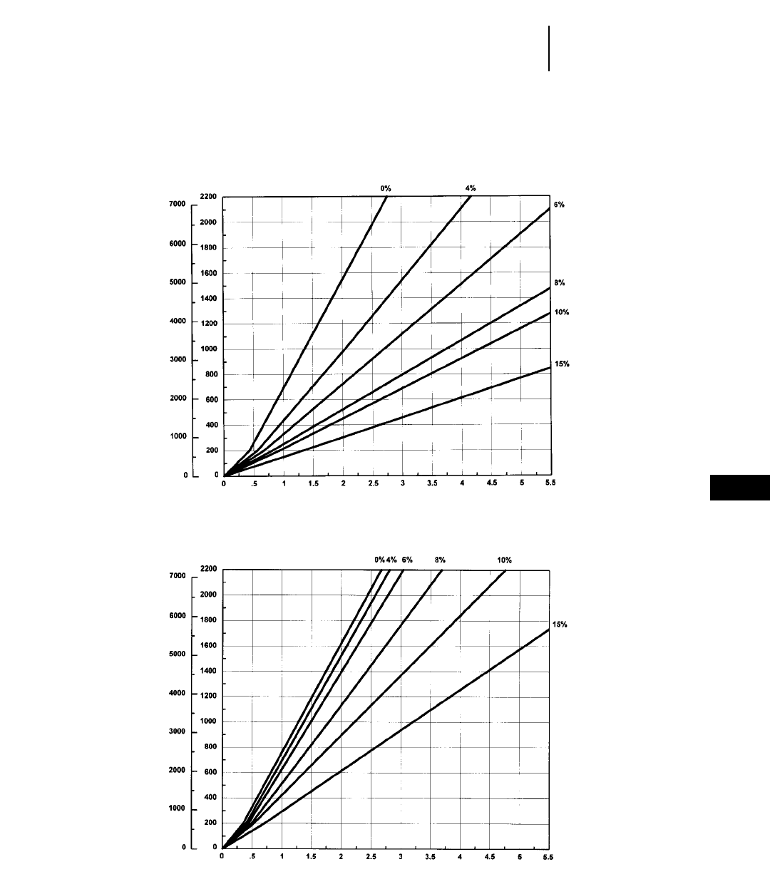
10-21
10
Articulated TrucksD300E Series II Travel Time — Loaded/Empty
●23.5R25 Tires
LOADED
Preliminary Information
TIME
DISTANCE ONE WAY
TOTAL RESISTANCE
(Grade plus Rolling)
feet meters
minutes
EMPTY
TIME
DISTANCE ONE WAY
TOTAL RESISTANCE
(Grade plus Rolling)
feet meters
minutes
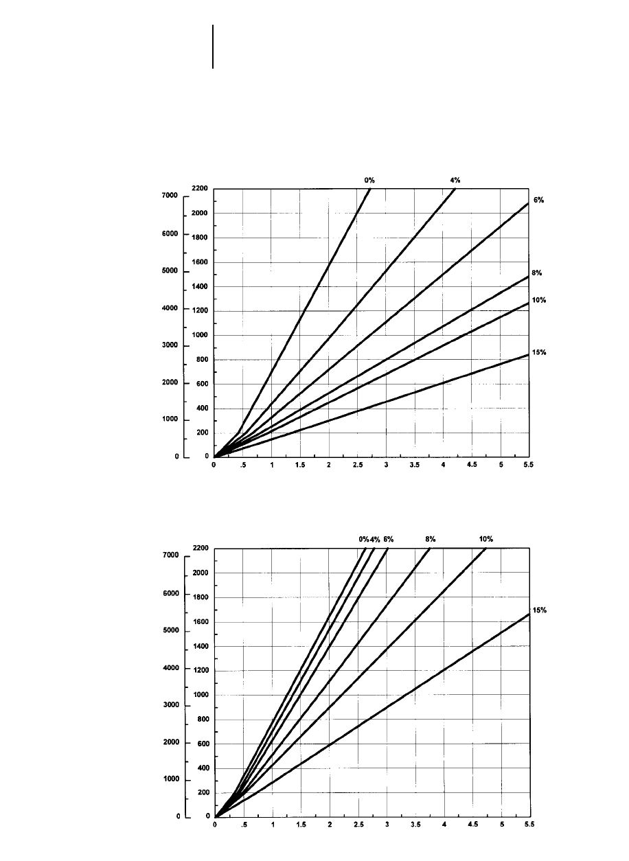
10-22
Articulated Trucks D300E Series II Travel Time — Loaded/Empty
●30/65R25 Tires
LOADED
Preliminary Information
TIME
DISTANCE ONE WAY
TOTAL RESISTANCE
(Grade plus Rolling)
feet meters
minutes
EMPTY
TIME
DISTANCE ONE WAY
TOTAL RESISTANCE
(Grade plus Rolling)
feet meters
minutes
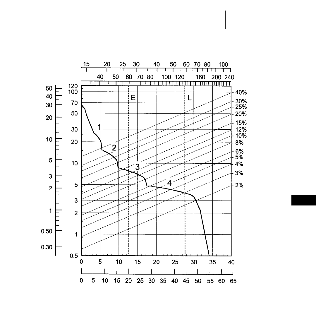
10-23
10
Articulated TrucksD350E Rimpull-Speed-Gradeability
●26.5R25 Tires
KEY
E — Empty 26 990 kg (59,500 lb)
L — Loaded 58 750 kg (129,520 lb)
KEY
1 — 1st Gear
2 — 2nd Gear
3 — 3rd Gear
4 — 4th Gear
GROSS WEIGHT
RIMPULL
kg x
1000 lb x
1000
kg x 1000
lb x 1000
TOTAL RESISTANCE %
(Grade + Rolling)
SPEED
mph
km/h
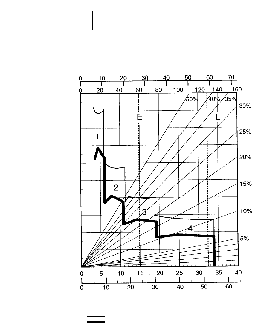
10-24
Articulated Trucks D350E Brake/Retarder Performance Curve
●26.5R25 Tires
KEY
1 — 1st Gear
2 — 2nd Gear
3 — 3rd Gear
4 — 4th Gear
KEY
E — Empty 26 990 kg (59,500 lb)
L — Loaded 58 750 kg (129,520 lb)
GROSS WEIGHT
EFFECTIVE GRADE (Favorable)
SPEED
kg x 1000
lb x 1000
mph
km/h
200 m (660 ft) OR LESS GRADE LENGTH
CONTINUOUS
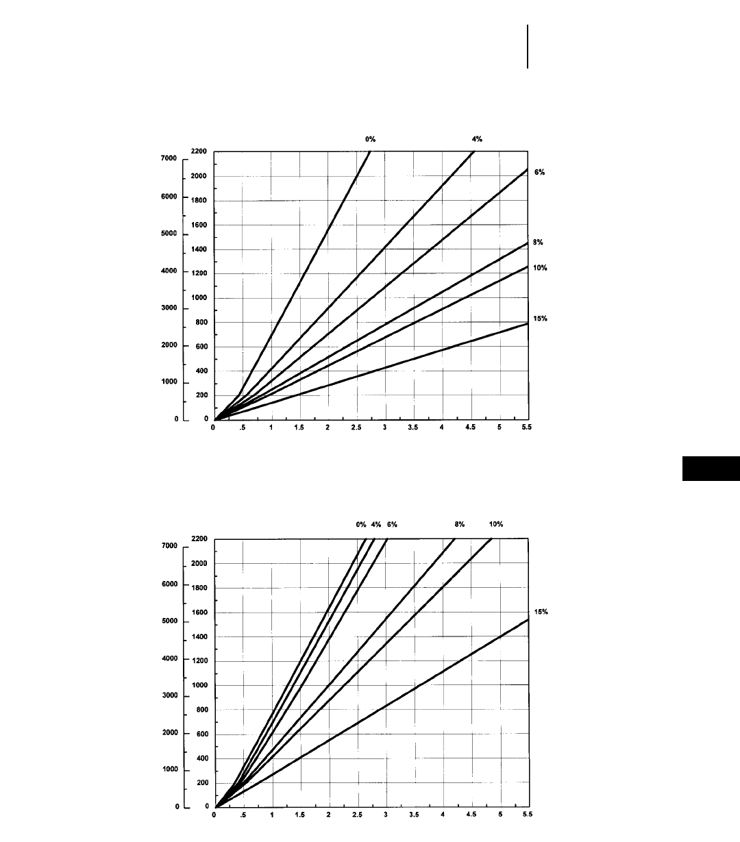
10-25
10
Articulated TrucksD350E Travel Time — Loaded/Empty
●26.5R25 Tires
LOADED
TIME
DISTANCE ONE WAY
TOTAL RESISTANCE
(Grade plus Rolling)
feet meters
minutes
EMPTY
TIME
DISTANCE ONE WAY
TOTAL RESISTANCE
(Grade plus Rolling)
feet meters
minutes
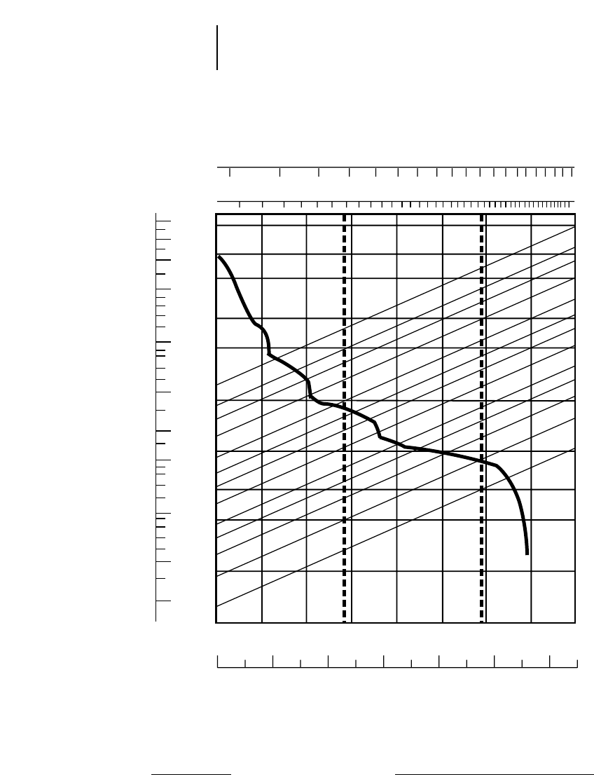
10-26
Articulated Trucks D400E Rimpull-Speed-Gradeability
●29.5R25 Tires
KEY
1 — 1st Gear
2 — 2nd Gear
3 — 3rd Gear
4 — 4th Gear
KEY
E — Empty 29 260 kg (64,510 lb)
L — Loaded 65 560 kg (144,500 lb)
0 5 10 15 20 25 30 35 40
0 5 10 15 20 25 30 35 40 45 50 55 60 65
40 50 60 70 80 100 120 150 200 240
15 20 25 30 40 50 60 70 80 100
40%
30%
25%
20%
15%
12%
10%
8%
6%
5%
4%
3%
2%
120
100
70
50
30
20
10
5
3
2
1
0.5
50
40
30
20
10
5
3
2
1
0.50
0.30
EL
1
2
3
4
GROSS WEIGHT
RIMPULL
kg x 1000
lb x 1000
kg x 1000
lb x 1000
TOTAL RESISTANCE
(Grade plus Rolling Resistance)
SPEED
mph
km/h
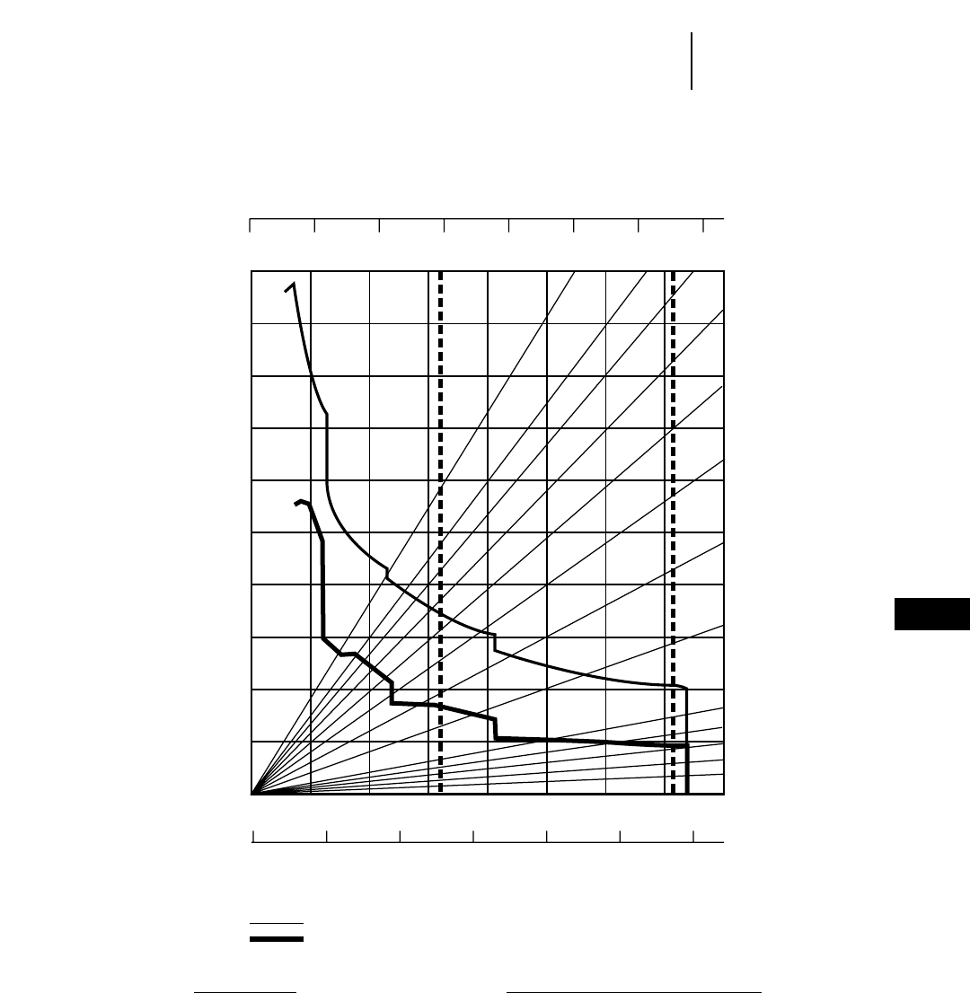
10-27
10
Articulated TrucksD400E Brake/Retarder Performance Curve
●29.5R25 Tires
KEY
E — Empty 29 260 kg (64,510 lb)
L — Loaded 65 560 kg (144,500 lb)
KEY
1 — 1st Gear
2 — 2nd Gear
3 — 3rd Gear
4 — 4th Gear
0 10203040506070
0 20 40 60 80 100 120 140 160
0 5 10 15 20 25 30 35 40
0 102030405060
5%
10%
15%
20%
25%
30%
35%
40%
50%
EL
1
2
3
4
GROSS WEIGHT
EFFECTIVE GRADE (Favorable)
SPEED
200 m (660 ft) OR LESS GRADE LENGTH
CONTINUOUS
kg x 1000
lb x 1000
mph
km/h
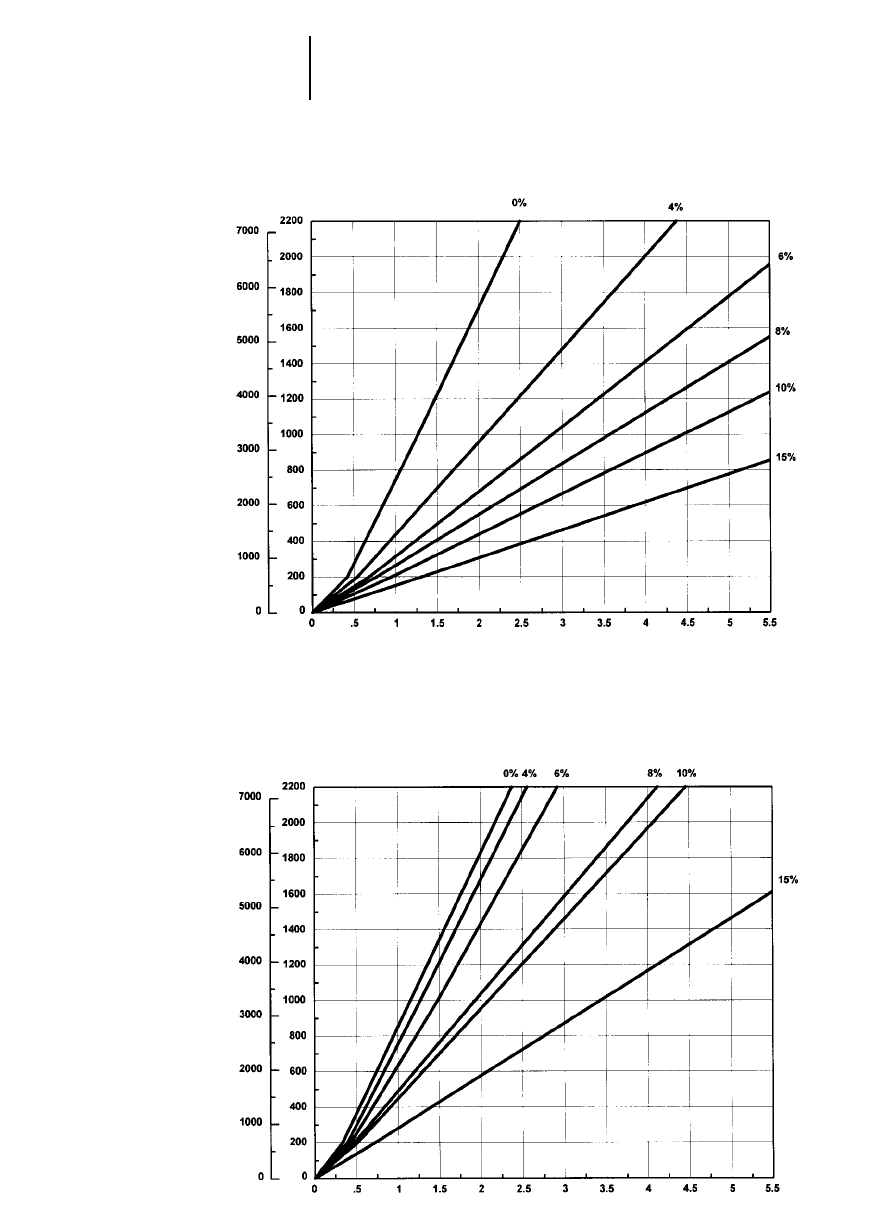
10-28
Articulated Trucks D400E Travel Time — Loaded/Empty
●29.5R25 Tires
LOADED
TIME
DISTANCE ONE WAY
TOTAL RESISTANCE
(Grade plus Rolling)
feet meters
minutes
EMPTY
TIME
DISTANCE ONE WAY
TOTAL RESISTANCE
(Grade plus Rolling)
feet meters
minutes

11-1
CONTENTS
WHEEL TRACTORS
Features . . . . . . . . . . . . . . . . . . . . . . . . . . . . . .11-1
Specifications . . . . . . . . . . . . . . . . . . . . . . . . . .11-2
Travel speeds . . . . . . . . . . . . . . . . . . . . . . . . . . .11-4
Rimpull . . . . . . . . . . . . . . . . . . . . . . . . . . . . . . .11-4
Machine selection . . . . . . . . . . . . . . . . . . . . . . .11-6
Counterweights and ballast . . . . . . . . . . . . . . .11-6
Tire selection and maintenance . . . . . . . . . . . .11-6
Bulldozer specifications . . . . . . . . . . . . . . . . . .11-8
Special attachments . . . . . . . . . . . . . . . . . . . . .11-9
SOIL COMPACTORS
Features . . . . . . . . . . . . . . . . . . . . . . . . . . . . .11-11
Specifications & Rimpull . . . . . . . . . . . . . . . .11-12
Compaction fundamentals . . . . . . . . . . . . . . .11-13
Compactor types and zones
of application . . . . . . . . . . . . . . . . . . . . . . . .11-14
Estimating production (example problem) . .11-15
Production table . . . . . . . . . . . . . . . . . . . . . . .11-16
Bulldozer specifications . . . . . . . . . . . . . . . . .11-16
LANDFILL COMPACTORS
Features . . . . . . . . . . . . . . . . . . . . . . . . . . . . .11-17
Specifications & Rimpull . . . . . . . . . . . . . . . .11-18
Compaction fundamentals . . . . . . . . . . . . . . .11-19
Blade specifications . . . . . . . . . . . . . . . . . . . .11-20
WHEEL TRACTORS
Features:
●Reliable Cat power train: four-stroke-cycle
diesel with adjustment-free fuel system … full
power shift with single lever on-the-go shifting.
●Articulated frame steering with hinge point
midway between front and rear axles … short
turning radius, long wheelbase … rear and front
wheels track at all times.
●Machine balance … equal weight distribution
on axles when blading.
●All dozer functions, including tip and tilt,
hydraulically controlled from operator’s seat.
11
WHEEL TRACTORS
SOIL COMPACTORS
LANDFILL COMPACTORS
MODEL 814F 824G 834B
Flywheel Power 164 kW 220 hp 235 kW 315 hp 336 kW 450 hp
Operating Weight* 18 611 kg 40,944 lb 26 620 kg 58,564 lb 46 355 kg 102,213 lb
Engine Model 3306 DITA (EMISSIONS) 3406C DITA (EMISSIONS) 3408E HEUI
Rated Engine RPM 2200 2100 2100
No. Cylinders 668
Displacement 10.5 L 638 in314.6 L 893 in318 L 1098 in3
Speeds:
Forward 444
Reverse 444
Top Speed Forward 29.9 km/h 18.6 mph 33.0 km/h 20.4 mph 34.1 km/h 21.2 mph
Turning Circle with Blade 12.5 m 41'0" 14.6 m 40'0" 17.2 m 56'6"
Standard Tire Size 23.5-25, 12 PR (L-2) 29.5-25, 16 PR (L-3) 35/65-33, 24 PR (L-4)
Fuel Tank Refill Capacity 462 L 122 U.S. gal 630 L 166.5 U.S. gal 595 L 157 U.S. gal
GENERAL DIMENSIONS:
Height (to top of ROPS) 3.368 m 11'1" 3.764 m 12'4" 4.102 m 13'5.5"
Height (stripped top)** 2.418 m 7'11" 2.676 m 8'9" 2.955 m 9'8"
Wheel Base 3.350 m 11'0" 3.700 m 12'2" 3.810 m 12'6"
Overall Length with Dozer 6.844 m 22'5" 8.020 m 26'4" 8.716 m 28'7"
Width (over standard tires) 2.865 m 9'5" 3.28 m 10'9" 3.556 m 11'8"
Ground Clearance 448 mm 17.6" 383 mm 15.1" 466 mm 18"
STRAIGHT BULLDOZER:
Width 3.650 m 12'0" 4.51 m 14'9" 4.623 m 15'2"
Height 1.004 m 3'4" 1.23 m 4'0" 1.448 m 4'9"
Capacity 2.91 LCM 3.8 LCY 4.67 LCM 6.11 LCY 7.27 LCM 9.5 LCY***
Ground Clearance Below
Skid Shoe 940 mm 3'1" 955 mm 3'1.6" 1118 mm 3'8"
Depth of Cut 460 mm 18.1" 430 mm 16.9" 441 mm 17"
Tilt Adjustment 747 mm 2'5.4" 1.18 m 3'11" 1.278 m 4'2"
Tip Adjustment 18° 23° 22°
Lift Speed 0.40 m/sec 1.3 ft/sec 0.46 m/sec 1.5 ft/sec 0.40 m/sec 1.3 ft/sec
***Operating Weight includes straight dozer, 75% CaCl2in all tires, lubricants, coolant, ROPS cab, full fuel tank and operator. 75% CaCl2in all tires adds the following weight
to each model: 814F — 1996 kg (4400 lb), 824G — 3881 kg (8556 lb), 834B — 5360 kg (11,816 lb).
***Height (stripped top) — without ROPS, exhaust, seat back or easily removed encumbrances.
***Capacity of 834B U-Blade is 10.48 LCM (13.7 LCY).
11-2
Wheel Tractors Specifications
11-3
11
Wheel TractorsSpecifications
MODEL 844 854G
Flywheel Power 466 kW 625 hp 597 kW 800 hp
Operating Weight* 73 830 kg 162,410 lb 96 470 kg 212,230 lb
Engine Model 3412E HEUI 3508B EUI
Rated Engine RPM 2000 1750
No. Cylinders 12 8
Displacement 27 L 1649 in334.5 L 2105 in3
Speeds:
Forward 33
Reverse 33
Top Speed Forward 22.5 km/h 14.0 mph 20.5 km/h 12.7 mph
Turning Circle with Blade
Standard Tire Size 45/65R39, PR (L-4) 45/65R45, L-4
Fuel Tank Refill Capacity 930 L 245 U.S. gal 1345 L 355 U.S. gal
GENERAL DIMENSIONS:
Height (to top of ROPS) 5.142 m 16'9" 5.50 m 18'3"
Height (stripped top)** 3.469 m 11'4" 3.984 m 13'1"
Wheel Base 4.60 m 15'1" 5.89 m 19'3"
Overall Length with Dozer 10.94 m 35'9" 13.405 m 44'0"
Width (over standard tires)
Ground Clearance 1197 mm 3'9" 1314 mm 4'3"
SEMI-U DOZER:
Width 5.278 m 17'4" 6.604 m 20'8"
Height 1.877 m 6'2" 2.124 m 6'11"
Capacity 16.1 m321.1 yd325.4 m333.1 yd3
Ground Clearance Below
Skid Shoe 1372 mm 4'5" 1539 mm 5'1"
Depth of Cut 466 mm 18" 398 mm 16"
Tilt Adjustment 830 mm 2'7" 1165 mm 3'8"
Tip Adjustment 13° 15°
Lift Speed 0.353 m/sec 1.2 ft/sec 0.385 m/sec 1.3 ft/sec
**Operating Weight includes straight dozer, 75% CaCl2in all tires, lubricants, coolant, ROPS cab, full fuel tank and operator.
**Height (stripped top) — without ROPS, exhaust, seat back or easily removed encumbrances.
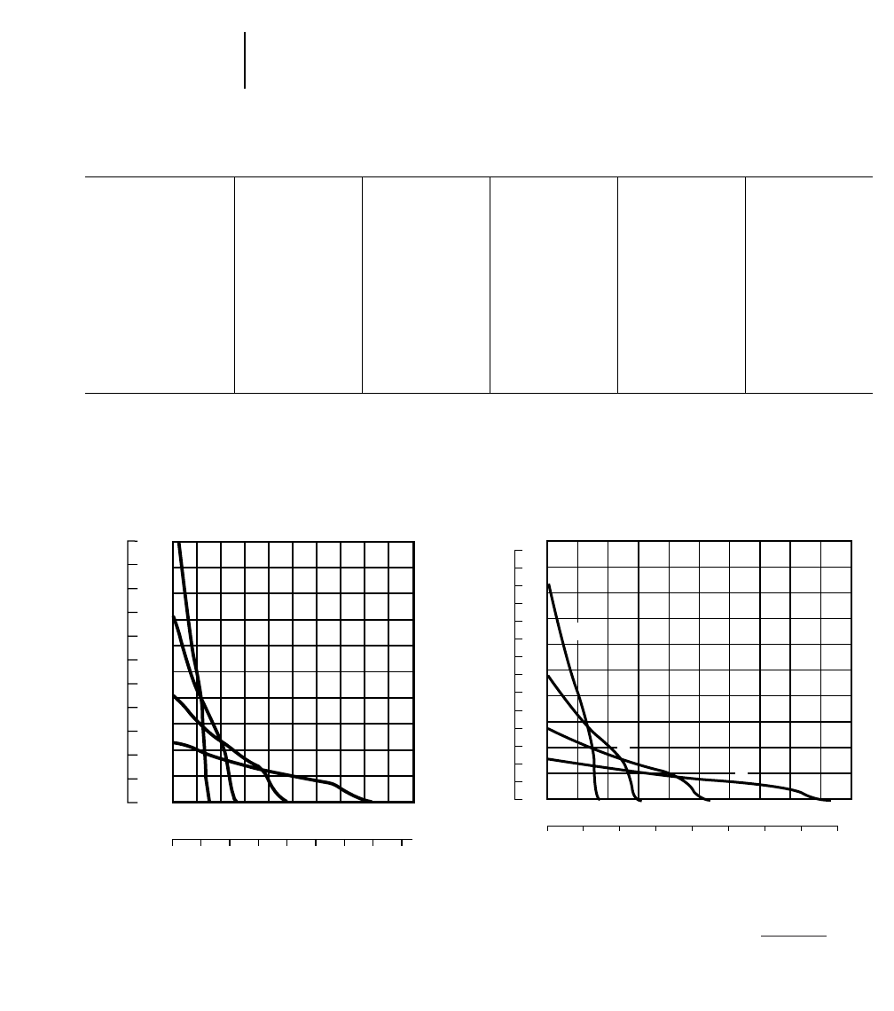
11-4
Wheel Tractors Travel Speeds
Rimpull
MODEL 814F 824G 834B 844 854G
FORWARD
GEAR km/h mph km/h mph km/h mph km/h mph km/h mph
1 5.6 3.5 5.9 3.6 6.3 3.9 7.2 4.5 6.9 4.3
2 9.8 6.1 10.5 6.5 11.3 7.0 12.9 8.0 12.0 7.4
3 17.2 10.7 18.6 11.5 19.8 12.3 22.5 14.0 20.5 12.7
4 29.9 18.6 33.0 20.4 34.1 21.2 — —
REVERSE
GEAR
1 6.3 3.9 6.8 4.2 7.9 4.9 8.2 5.0 7.7 4.8
2 11.3 7.0 12.0 7.4 14.0 8.7 14.2 8.8 13.3 8.3
3 19.6 12.2 21.3 13.2 24.5 15.2 25.0 15.5 22.7 14.1
4 34.1 21.1 37.8 23.5 41.8 25.9 — —
20
16
12
8
4
0
10
6
2
14
18
40
36
32
28
24
20
16
12
8
4
0
44
0481216202428
0 3 6 9 12 15 18
32 36 40
21 24
1
2
34
814F
RIMPULL
KEY
1 – 1st Gear
2 – 2nd Gear
3 – 3rd Gear
4 – 4th Gear
Usable rimpull depends upon traction and weight of tractor.
SPEED
mph
km/h
lbs x
1000 kg x
1000
04 81216202428
0 3 6 9 12 15 18
54
48
42
36
30
24
18
12
6
0
84
78
72
66
60
36
32
28
24
20
16
12
8
4
0
40
21
32 36
24
2
1
3
4
824G
km/h
SPEED
RIMPULL
mph
kg x
1000
lbs x
1000
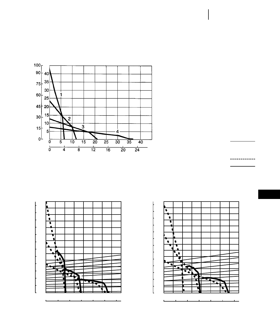
11-5
11
Wheel TractorsRimpull
KEY
1 – 1st Gear
2 – 2nd Gear
3 – 3rd Gear
4 – 4th Gear
Torque Converter
Direct Drive
834B
km/h
SPEED
RIMPULL
Usable rimpull depends upon traction and weight of tractor.
mph
kg x
1000
lbs x
1000
35
40
45
50
55
60
30
25
20
15
10
5
0
100
110
120
130
140
70
80
90
60
50
40
30
20
10
00
3
1
1
3
2
30
25
40
35
45
20
15
10
5
0 4 8 12 16 20 24
0246810121416
2
844
RIMPULL
GRADEABILITY-PERCENT
(Grade + Rolling Resist)
SPEED
km/h
mph
kg x
1000 lbs x
1000
0 4 8 12 16 20 24
0246810121416
35
40
45
50
55
60
65
30
25
20
15
10
5
0
30
25
20
15
10
5
0
100
110
120
130
140
70
80
90
60
50
40
30
20
10
0
150
3
1
2
3
2
854G
RIMPULL
GRADEABILITY-PERCENT
(Grade + Rolling Resist)
SPEED
km/h
mph
kg x
1000 lbs x
1000

CONSIDERATIONS IN MACHINE SELECTION
The following factors should be considered when
comparing wheels vs. tracks:
Traction
You can figure coefficient of traction, depending
on underfoot conditions, from the Table Section
in this book.
Wheels — up to 0.65 (in quarry pit with good
floor)
Track — up to 0.90 (in soils permitting grouser
penetration)
Usable Rimpull = Machine Weight 2Coefficient
of Traction
Speed
Wheels — travel speeds up to three times higher
than track.
Maneuverability
Articulated steering and good visibility give wheel
tractors high maneuverability.
Cost
See Owning and Operating Costs section. Tire vs
undercarriage costs can often be the deciding fac-
tor in selecting wheels or tracks.
Compaction
Ground Pressure:
Wheels — from 241 kPa (35 psi) to 310 kPa
(45 psi)
Tracks — from 82 kPa (12 psi) to 97 kPa (14 psi)
Application
Utility … mobility, maneuverability and good
speed suit wheel tractors for yard and stockpile
work and for clean-up around shovels. Lower
maintenance costs may be realized in certain soils
that can be highly abrasive to track-type under-
carriages.
Coal pile … recommend wheel tractors in this
application when following conditions are present:
— Long push distances
— Need for good material spread
— High degree of compaction desired
Production Dozing … a wheel tractor should be
considered in the following conditions:
— Long push distances
— Loose soils, little or no rock
— Level or downhill work
— Good underfoot conditions
Pushloading Scrapers … a wheel tractor should
be considered in the following conditions:
— Thin scraper cut
— Good underfoot conditions — no rock
— Higher push speeds
Chip and Coal Scoops … may adversely affect per-
formance andor reliability, particularly when
adverse grades are encountered.
COUNTERWEIGHTS AND BALLAST
For each specific application, there is a correct
machine weight for proper balancing of traction, flo-
tation, mobility and response.
●Low machine weight may increase tire slipping
and wear, but improves flotation, mobility and
machine response.
●High machine weight increases traction, but
decreases mobility and response.
The machine weight is optimum for the operating
conditions when wheel slipping barely occurs in the
gear being used. Weight distribution under operat-
ing conditions should then be approximately equal
between the wheels to balance power to each axle.
Application
Lower machine weight is usually required for typi-
cal second gear applications, such as fill spreading,
stockpiling, road maintenance, towing compactors
and shovel cleanup.
Higher machine weight is usually required for
such typical first gear applications as heavy dozing
and pushloading.
Tire Ballast
A solution of calcium chloride and water is recom-
mended for tire ballast. It has the advantage of low
cost with simple quick adjustment to suit working
conditions.
TIRE SELECTION & MAINTENANCE
Requirements of traction, flotation and tire life
are met by a choice of tire size, tread design and
inflation pressure.
Tire Width
For good conditions with little rolling resistance
on surfaces where flotation is no problem, a nar-
rower tire may be most economical. It may also be
considered in muddy conditions in which the mud
can be penetrated to reach firm earth underneath.
11-6
Wheel Tractors Machine Selection
Counterweights and Ballast
Tire Selection & Maintenance

Where flotation problems and increased rolling
resistance are encountered, wider tires are recom-
mended. The greater contact area and shallower
penetration increases flotation.
Tire Size
Larger optional tires will also improve flotation
in soft conditions. With larger diameter, rimpull will
be reduced which may be desirable to help control
wheel spin.
Traction Tread (L-2) tire’s penetration ability pro-
vides improved traction under some soil conditions.
Rock Tread (L-3) offers improved traction and a
more cut resistant rubber compound than the L-2.
It provides more rubber at the ground with the same
footprint and reduces tire penetration under abra-
sive conditions. Recommended on any hard smooth
surface such as rock, concrete or compacted earth.
Rock — Deep Tread (L-4) provides 50% more
tread depth, thicker undertread and sidewall with
increased tire life when compared to the L-3 tire.
Recommended in rock conditions where sharp frag-
ments cause high tire wear or sudden failures.
Rock — Extra Deep Tread (L-5) provides 150%
more tread depth when compared to the L-3 tire.
Intended for severe rock conditions with extreme
penetration hazards.
Chains should be considered in severe applications
where extra tread tires still give unsatisfactory life.
Operating costs vary greatly depending on applica-
tion, underfoot conditions, wheel spin and chain
maintenance. Under normal rock operating condi-
tions (short cycle, low average speed and minimum
wheel spin) the maximum estimated chain life is
about 2000 hours. Before installing chains, carefully
weigh their overall economics against known tire
costs. Chains are not recommended with new rock
extra tread tires but can extend the life of a used
tire. Always check clearance around tires before
using chains.
Major applications where chains can be considered
include:
— stripping rock or rocky soils
— clean-up work around rock loading shovels
— any application where underfoot conditions
cause excessive tire wear.
Inflation Pressure
In average operating conditions the recommended
inflation pressure prevents excessive deflection and
minimizes tire rollover on side slopes.
Over-inflation
Reduces amount of tread contact with ground and
provides less flotation. Over-inflation causes center
of tread to wear faster and increases the chance of
cuts and impact breaks.
Under-inflation
Can cause permanent tire damage in the form of
flex breaks, radial cracks, and tread or ply separa-
tion. On jobs where wrinkling and bead rollover are
not apparent, inflation pressure may be reduced to a
minimum of:
Bias Ply — 170 kPa (25 psi) on 35/65-33
170 kPa (25 psi) on 29.5-25
170 kPa (25 psi) on 26.5-25
170 kPa (25 psi) on 23.5-25
Radial — 310 kPa (45 psi) on 35/65R 33
310 kPa (45 psi) on 29.5R 25
205 kPa (30 psi) on 26.5R 25
240 kPa (35 psi) on 23.5R 25
Reduced pressure will:
Increase flotation and traction in sand.
Improve envelopment characteristics to reduce
sudden death failure on rock jobs.
Provide better tread wear by reducing contact
pressure between tire and ground.
11-7
11
Wheel TractorsTire Selection & Maintenance

MODEL 814F 824G 834B
Type Straight Straight Straight
Capacity** 2.89 m33.77 yd35.12 m36.70 yd37.26 m39.5 yd3
Weight, Dozer* 3740 kg 8245 lb 5136 kg 11,323 lb 4738 kg 10,443 lb
General Dimensions
(Tractor & Dozer)
Length 6.82 m 22'5" 8.29 m 27'2" 8.72 m 28'7"
Width 3.65 m 12'0" 4.51 m 14'9" 4.62 m 15'2"
Blade:
Width (including std. end bits) 3.65 m 12'0" 4.51 m 14'9" 4.62 m 15'2"
Height 1004 mm 3'3.5" 1220 mm 4'0" 1462 mm 4'9"
Max. Digging Depth 460 mm 18.1" 430 mm 16.9" 441 mm 17.4"
Ground Clearance @ Full
Lift Under Skid Plate 940 mm 3'1" 955 mm 3'1.6" 1118 mm 3'8"
Tilt Adjust. from
Horizontal 747 mm 2'5.4" 1184 mm 3'10.6" 1278 mm 4'2"
Total Tip Adjustment 18° 22.4° 22°
MODEL 834B 844 854G
Type U-Blade Semi-U Semi-U
Capacity** 10.5 m313.7 yd315.9 m320.7 yd325.4 m333.1 yd3
Weight, Dozer* 4803 kg 10,588 lb 15 670 kg 34,520 lb 21 910 kg 48,270 lb
General Dimensions
(Tractor & Dozer)
Length 9.40 m 30'10" 10.94 m 35'9" 13.405 m 44'0"
Width 4.85 m 15'11" 5.42 m 17'8" 6.321 m 20'7"
Blade:
Width (including std. end bits) 4.85 m 15'11" 5.42 m 17'8" 6.321 m 20'7"
Height 1448 mm 4'9" 1813 mm 5'9" 2179 mm 7'1"
Max. Digging Depth 442 mm 17.4" 466 mm 18.3" 398 mm 15.7"
Ground Clearance @ Full
Lift Under Skid Plate 1118 mm 3'8" 1372 mm 4'6" 1539 mm 5'0.6"
Tilt Adjust. from
Horizontal 1340 mm 4'5" 830 mm 2'8.7" 1165 mm 3'9.9"
Total Tip Adjustment 22° 13° 15°
**Total Bulldozer Arrangement.
**Blade capacities determined by SAE J1265.
11-8
Wheel Tractors Bulldozer
●Specifications
11-9
BALDERSON
COAL U-BLADE 814F 824G 834B
Balderson Models
Replaces “S” Blade BD814U-14 BD824U-15'9" BD834U-20
Blade:
Capacity 10.55 m313.8 yd316.1 m321.0 yd321.18 m327.7 yd3
Length (Cutting Width) 4318 mm 14'2" 4788 mm 15'8.5" 6198 mm 20'4"
Height, wing section
(tapered down) 1473 mm 4'10" 1783 mm 5'10" 1803 mm 5'11"
Wing Angle 25° 30° 30°
Weight, Installed
(Without Hydraulics) 1810 kg 3985 lb 3085 kg 6800 lb 3560 kg 7850 lb
BALDERSON
WOODCHIP U-BLADE 814F 824G 834B
Balderson Models
Replaces “S” Blade BD814US-14 BD824US-15'9" BD834US-20
Blade:
Capacity 16.7 m321.9 yd323.9 m331.4 yd329.8 m339.0 yd3
Length (Cutting Width) 4318 mm 14'2" 4775 mm 15'8" 6096 mm 20'0"
Height, wing section 1880 mm 6'2" 2253 mm 7'4.7" 2235 mm 7'4"
Wing Angle 30° 30° 30°
Weight 1975 kg 4350 lb 3630 kg 8000 lb 4295 kg 9470 lb
BALDERSON
COAL SCOOP WITH TILT 814F 824G 834B
Balderson Models
Replaces “S” Blade B14-15 B24-17 B34-26
Scoop:
Lift and Carrying
Capacity 11.5 m315.0 yd312.9 m317.0 yd319.9 m326.0 yd3
Dozing Capacity 19.1 m325.0 yd325.8 m334.0 yd337.5 m349.0 yd3
Width 3734 mm 12'3" 4013 mm 13'2" 5283 mm 17'4"
Height 1626 mm 5'4" ——2083 mm 6'10"
Depth 2083 mm 6'10" ——2540 mm 8'4"
Overall length 7.3 m 24'0" ——11.0 m 36'0"
Weight 5216 kg 11,500 lb 8400 kg 18,500 lb 8700 kg 19,180 lb
Dump Clearance 1041 mm 3'5" ——1448 mm 4'9"
BALDERSON
CHIP SCOOP WITH TILT 814F 824G 834B
Balderson Models
Replaces “S” Blade B14-20S B24-27S B34-40S
Scoop:
Capacity/Lift & Carry 15.3 m320.0 yd320.6 m327.0 yd330.2 m339.5 yd3
Capacity/Dozing 30.6 m340.0 yd341.3 m354.0 yd349.7 m365.0 yd3
Width 3734 mm 12'3" 4026 mm 13'2.5" 4826 mm 15'10"
Height 2286 mm 7'6" 2794 mm 9'2" 2248 mm 7'4.5"
Depth 2464 mm 8'1" 2946 mm 9'8" 3023 mm 9'11"
Weight 5390 kg 11,880 lb 11 420 kg 19,125 lb 11 105 kg 24,480 lb
11
Wheel TractorsSpecial Attachments
●Specifications

11-11
CONTENTS
Features . . . . . . . . . . . . . . . . . . . . . . . . . . . . .11-11
Specifications & Rimpull . . . . . . . . . . . . . . . .11-12
Compaction fundamentals . . . . . . . . . . . . . . .11-13
Compactor types and zones of application . . .11-14
Estimating production (example problem) . . .11-15
Production table . . . . . . . . . . . . . . . . . . . . . . .11-16
Bulldozer specifications . . . . . . . . . . . . . . . . .11-16
Features:
●Dozing, filling and compacting versatility.
●High speed operation with responsive Caterpillar
diesel Engine, single-lever planetary power shift
transmission, and all-wheel drive.
●Articulated frame makes maneuvering quick
and easy. Long wheel base for stability.
●Wheels with tamping foot design and chevron
pattern give traction, penetration and compaction
needed for high production. Foot pattern reversed on
trailing drums to prevent overprinting lead drums.
●Rear drums track front for double compactive
effort. Drum spacing covers mid-axle strip on return
pass.
●Rear axle oscillation keeps all drums on ground
for traction and stability.
●Cleaner bars keep drums free of carry over earth
regardless of rolling direction. Adjustable,
replaceable.
●Optional fill spreading dozer has single lever
control for raise, lower, hold and float. (Blade tilt
optional.)
11
SOIL COMPACTORS
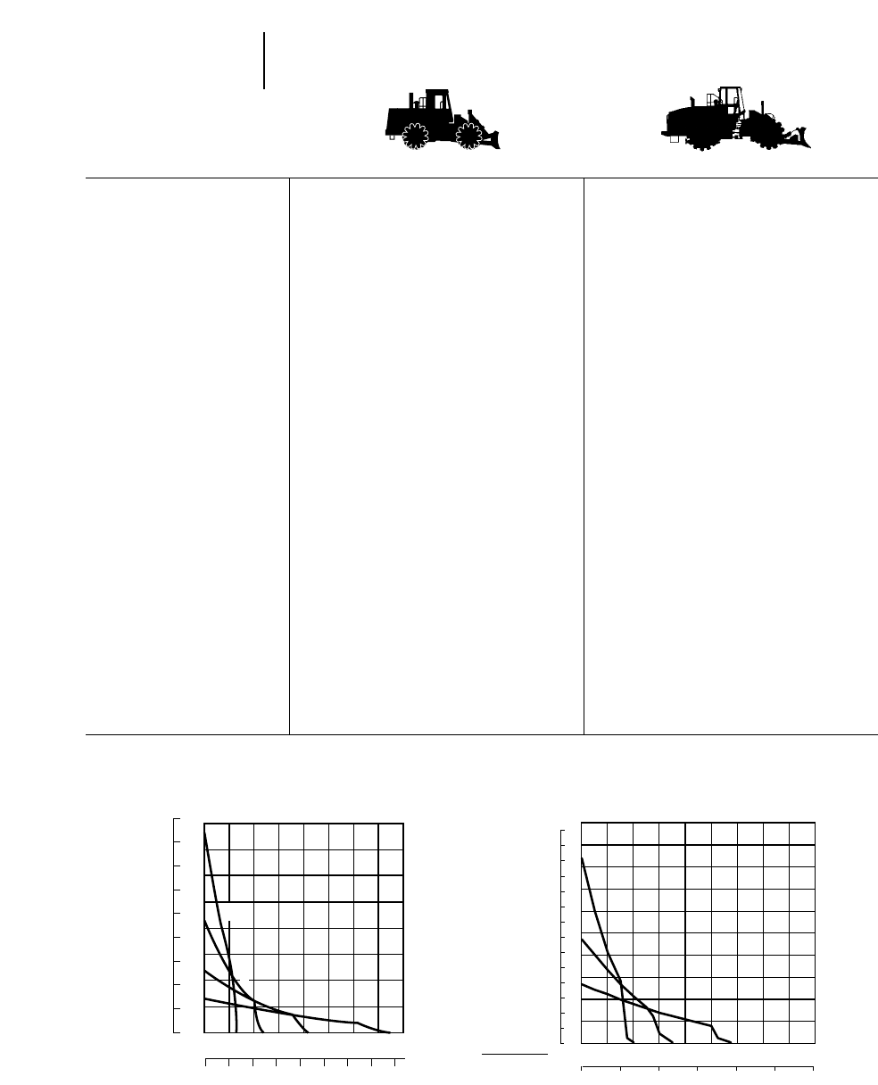
MODEL 815F 825G
Flywheel Power 164 kW 220 hp 235 kW 315 hp
Operating Weight* 20 879 kg 45,934 lb 31 740 kg 69,828 lb
Engine Model 3306 DITA 3406C DITA
Rated Engine RPM 2200 2100
No. Cylinders 66
Displacement 10.5 L 638 in314.6 L 893 in3
Speeds:
Forward 43
Reverse 43
Turning Circle with Blade 12.6 m 41'5" 14.6 m 48'0"
Fuel Tank Refill Capacity 464 L 122.6 U.S. gal 630 L 166.5 U.S. gal
TAMPING FOOT WHEELS:
Each Drum Width 978 mm 3'2.5" 1125 mm 3'8.3"
Diameters, over feet 1.42 m 4'7.9" 1.68 m 5'6"
Diameters, over drum 1.03 m 3'4.5" 1.29 m 4'3"
Feet per Wheel 60 65
Feet per Row 12 13
Rows of Feet 55
Foot Length 198 mm 7.8" 203 mm 8"
End Area Per Foot 116 cm218 in2183 cm228.4 in2
Width of Two Pass Coverage 4.35 m 14'3" 4.88 m 16'0"
GENERAL DIMENSIONS:
Height (top of ROPS) 3.34 m 11'0" 3.74 m 12'3"
Height (stripped top)** 2.39 m 7'10" 2.65 m 8'8"
Wheel Base 3.35 m 11'0" 3.70 m 12'2"
Overall Length with Dozer 6.82 m 22'5" 8.24 m 27'1"
Width over Drums 3.24 m 10'8" 3.65 m 12'0"
Ground Clearance 423 mm 17" 355 mm 14"
STRAIGHT BULLDOZER:
Width 3.76 m 12'4" 4.41 m 14'5"
Height 860 mm 2'10" 1.03 m 3'5"
**Operating Weight includes coolant, lubricants, bulldozer, hydraulics, ROPS canopy, full fuel tank and operator.
**Height (stripped top) — without ROPS, exhaust, seat back or other easily removed encumbrances.
11-12
Soil Compactors Specifications
●Rimpull
24
21
18
15
12
9
6
3
0
05 1015 20 2530 35 40
0 3 6 9 12 15 18 21 24
54
48
42
36
30
24
18
12
6
0
1
34
2
815F
km/h
SPEED
RIMPULL
mph
kg x
1000
lbs x
1000
02 4 68101214
0 5 10 15 20 25 30
27
24
21
18
15
12
9
6
3
0
1
2
3
42
39
36
33
30
90
80
70
60
50
40
30
20
10
0
100
16
825G
mph
SPEED
RIMPULL
km/h
lbs x
1000
kg x
1000
KEY
1 – 1st Gear
2 – 2nd Gear
3 – 3rd Gear
4 – 4th Gear
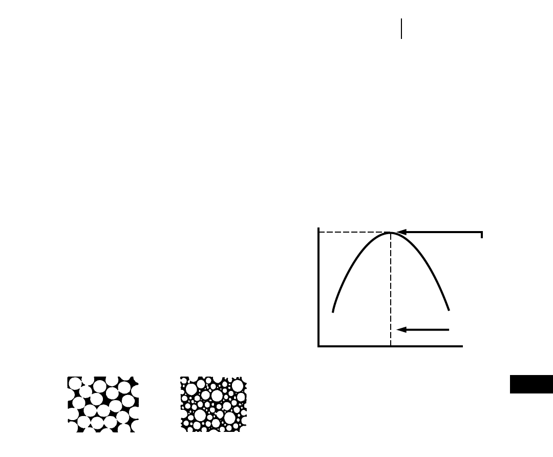
COMPACTION FUNDAMENTALS
The following discussion applies to soil com-
paction only. For information on refuse compaction,
see Waste Disposal section of this book.
Definition
Compaction is the process of physically densifying
or packing the soil … resulting in increased weight
per unit volume. It is generally accepted that the
strength of a soil can be increased by densification.
Three important factors affect compaction.
— Material gradation
— Moisture content
— Compactive effort
Material Gradation — refers to the distribution
(% by weight) of the different particle sizes within a
given soil sample. A sample is well-graded if it
contains a good, even distribution of particle sizes. A
sample composed of predominantly one size particle,
is said to be poorly-graded. In terms of compaction,
a well-graded soil will compact more easily than one
that is poorly-graded. In well-graded material the
smaller particles tend to fill the empty spaces
between the larger particles, leaving fewer voids after
compaction.
MATERIAL GRADATION
Moisture Content — or the amount of water
present in a soil, is very important to compaction.
Water lubricates soil particles thus helping them
slide into the most dense position. Water also creates
clay particle bonding, giving cohesive materials their
sticky qualities.
OPTIMUM MOISTURE
Heavy clay 17.5%
Silty clay 15.0%
Sandy clay 13.0%
Sand 10.0%
Gravel, sand, clay
mix (pit run) 7.0%
Experience has shown that it is very difficult, if not
impossible, to achieve proper compaction in materi-
als that are too dry or too wet. Soil experts have
determined that in practically every soil there is an
amount of water, called optimum moisture content,
at which it is possible to obtain maximum density
with a given amount of compactive effort. The curve
below shows this relationship between dry density
and moisture content. It is called a compaction curve,
moisture-density curve or Proctor curve.
Compactive Effort — refers to the method employed
by a compactor to impart energy into the soil to
achieve compaction. Compactors are designed to use
one or a combination of the following types of com-
pactive effort.
— Static weight (or pressure)
— Kneading action (or manipulation)
— Impact (or sharp blow)
— Vibration (or shaking)
11-13
11
Soil CompactorsCompaction Fundamentals
Poorly-graded Well-graded
Moisture Content ©
Maximum
Density
Optimum
Moisture
Dry Density ©
MOISTURE CONTENT
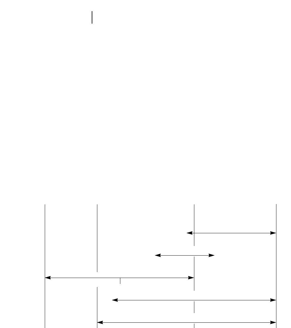
COMPACTOR TYPES
Compaction equipment can be grouped generally
into the following classifications:
sheepsfoot
vibratory
pneumatic
high speed tamping foot
chopper wheels (see Landfill Compactor section)
Combinations of these types are also available,
such as a vibrating smooth steel drum.
For ease of comparison, the compactors have been
placed on the Zones of Application Chart shown
below. This chart contains a range of material mois-
tures from 100% clay to 100% sand, plus a rock zone.
Each type has been positioned in what is considered
to be its most effective and economical zone of appli-
cation. However, it is not uncommon to find them
working out of their zones. Exact positioning of the
zones can vary with differing material conditions.
RANGES OF SOIL TYPES FOR
SOIL COMPACTION EQUIPMENT
11-14
Soil Compactors Types and Applications
CLAY
100%
ROCK SAND
100% SAND/CLAY
50%
SHEEPSFOOT
PNEUMATIC (50T & UP)
VIBRATORY
SMOOTH DRUM PADDED DRUM
HIGH SPEED TAMPING FOOT
CATERPILLAR TAMPING FOOT

COMPACTOR PRODUCTION
Compactor production is expressed in compacted
cubic meters (Cm3) or compacted cubic yards (CCY)
per hour. Material in its natural or bank state is
measured in bank cubic meters or yards (Bm3or BCY).
When it is removed or placed in a fill, it is measured
in loose cubic meters or yards (Lm3or LCY).
When the loose material is worked into a com-
pacted state, the relationship of compacted material
to bank material is shown as the shrinkage factor
(SF). Compacted cubic meters (Cm3)
SF = ____________________________
Bank cubic meters (Bm3)
Compacted cubic yards (CCY)
SF = ____________________________
Bank cubic yards (BCY)
The construction industry has developed the fol-
lowing formula for use in estimating compactor
production. This formula gives the material volume
a given machine can compact in a 60-minute hour.
Metric Method
W 2S 2L
Cm3=___________
P
W = Compacted width per pass, in meters. (For
Caterpillar Compactors it is recommended
that W = Twice the width of one wheel.)
S = Average speed, in kilometers per hour.
L = Compacted thickness of lift, in millimeters.
P = Number of machine passes to achieve com-
paction (can only be determined by
testing the compacted material den-
sity on-the-job).
English Method
W 2S 2L216.3
CCY/Hr = __________________
P
W = Compacted width per pass, in feet. (For
Caterpillar Compactors it is recommended
that W = Twice the width of one wheel.)
S = Average speed, in miles per hour.
L = Compacted thickness of lift, in inches.
16.3 = Conversion constant, equals 5280 feet ÷
12 inches ÷ 27 cubic feet
P = Number of machine passes to achieve
compaction (can only be determined
by testing the compacted material
density on-the-job).
Example problem (Metric)
Determine production for an 815F operating
under the following conditions:
P = 5, S = 10 km/h, L = 100 mm
Refer to 815F in the production table on the next
page. Read down the first column until reaching sec-
tion for 5 passes. Within this section in the second
column, find the speed closest to 10 km/h. Read
across this line to the 100 mm compacted lift. Read
the production figure given.
Answer: 377 Cm3/h. (Since the machine’s speed of
10 km/h is slightly faster than the 9.5 of the table,
production may be interpolated slightly higher — say
395 Cm3/h.)
Example problem (English)
Determine production for an 825G operating
under the following conditions:
P = 4, S = 8 mph, L = 6 inches
Refer to the production estimating table on the next
page. This table contains estimates for the 815F and
825G Compactors using various speeds, lift thick-
nesses and number of passes. These figures were
calculated using the formula discussed on this page.
The figures represent 100% efficiency. W = Twice
the width of one wheel.
In the 825 portion of this table, read down the
first column until reaching the section for four
passes. Within this section in the second column,
find the line for 8 mph. Read across this line to the
lift thickness column for 6 inches. Read the pro-
duction figure given.
Answer: 1444 CCY/hr.
● ● ●
11-15
11
Soil CompactorsEstimating Production
●Example Problems
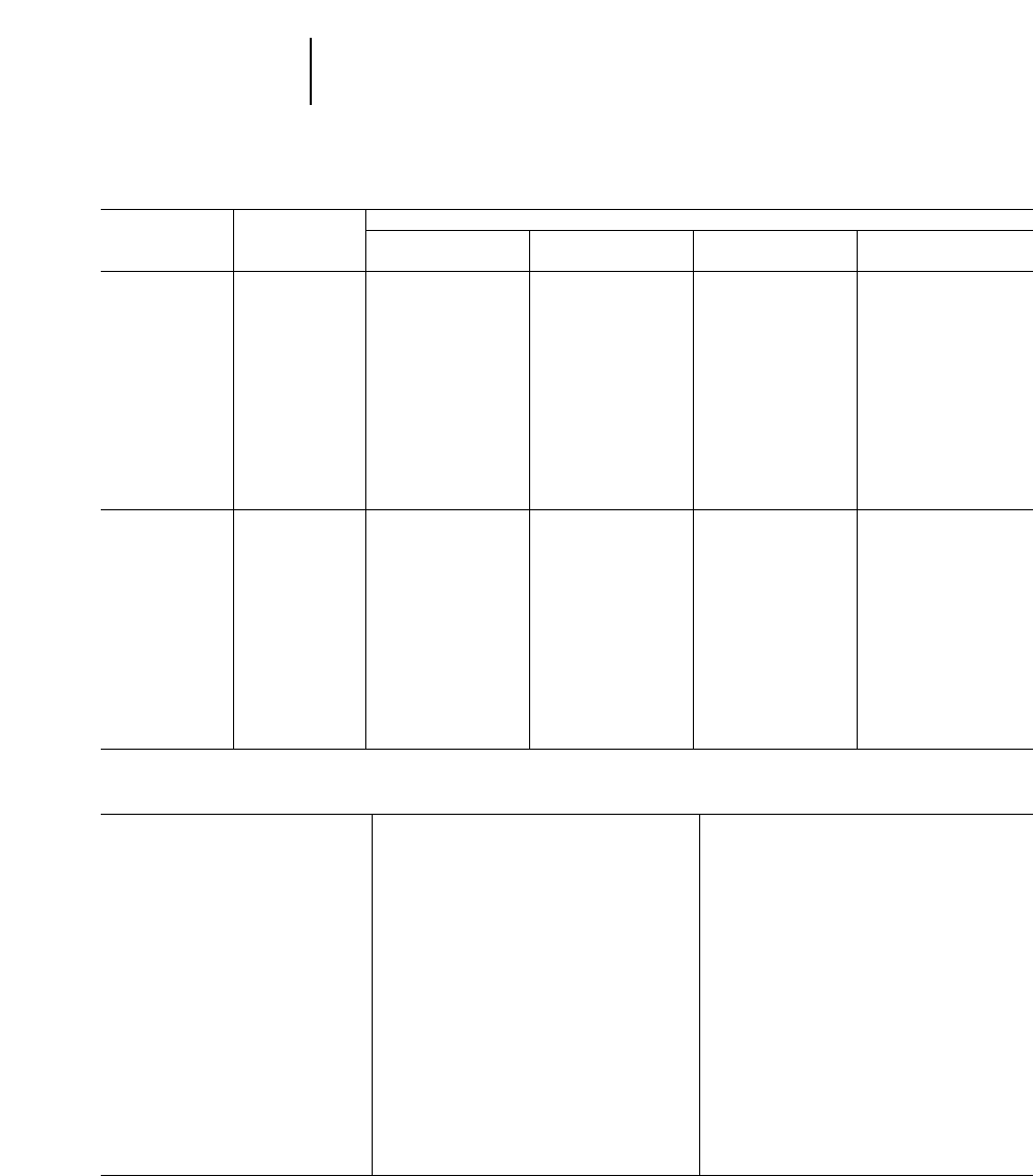
PRODUCTION TABLE
MODEL AND AVERAGE COMPACTED LIFT THICKNESS
MACHINE SPEED 100 mm 4 in 150 mm 6 in 200 mm 8 in 250 mm 10 in
PASSES* km/h mph m3/h yd3/hr m3/h yd3/hr m3/h yd3/hr m3/h yd3/hr
815F 3 6.5 4419 548 628 822 837 1095 —
9.5 6628 822 942 1232 1256 1643 —
13.0 8837 1095 1256 1643 1675 2191 —
4 6.5 4314 411 471 616 628 822 —
9.5 6471 616 706 924 942 1232 —
13.0 8628 822 942 1232 1256 1643 —
5 6.5 4251 329 377 493 502 657 —
9.5 6377 493 565 739 754 986 —
13.0 8502 657 754 986 1005 1314 —
6 6.5 4286 274 314 411 419 548 —
9.5 6314 411 471 616 628 822 —
13.0 8419 548 628 822 837 1095 —
825G 3 6.5 4488 642 731 962 975 1283 1219 1604
9.5 6713 962 1069 1444 1425 1925 1781 2406
13.0 8975 1283 1463 1925 1950 2566 2438 3208
4 6.5 4366 481 534 722 731 962 914 1203
9.5 6534 722 802 1083 1069 1444 1336 1804
13.0 8731 962 1097 1444 1463 1925 1828 2406
5 6.5 4293 385 439 577 585 770 731 962
9.5 6428 577 641 866 855 1155 1069 1444
13.0 8585 770 878 1155 1170 1540 1463 1925
6 6.5 4244 321 366 481 488 642 609 802
9.5 6356 481 534 722 713 962 891 1203
13.0 8488 642 731 962 975 1283 1219 1604
*The number of machine passes required is dependent on soil type, moisture content, desired compaction and machine weight.
MODEL 815F 825G
Type Fill Spreading Fill Spreading
Capacity**
Earth 2.16 m32.82 yd33.79 m34.95 yd3
Refuse — —
Weight, Dozer* 1460 kg 3220 lb 2831 kg 6241 lb
General Dimensions:
(Tractor & Dozer)
Length 6.82 m 22'5" 8.37 m 27'6"
Width 3.76 m 12'4" 4.61 m 15'2"
Blade Dimensions:
Width, End Bits 3.76 m 12'4" 4.41 m 14'5"
Height, Moldboard 860 mm 2'10" 1.03 m 3'4"
Height, Trash Rack — —
Max. Digging Depth 407 mm 16" 312 mm 12.3"
Ground Clearance
@ Full Lift 628 mm 2'0.7" 932 mm 3'0.7"
Tilt Adjust. from Horizontal 328 mm 12.9" 801 mm 2'7.5"
**Total Bulldozer Arrangement.
**Blade capacities determined by SAE recommended practice J1265.
11-16
Soil Compactors Production Table
●Bulldozer Specifications

11-17
CONTENTS
Features . . . . . . . . . . . . . . . . . . . . . . . . . . . . .11-17
Specifications & Rimpull . . . . . . . . . . . . . . . .11-18
Compaction fundamentals . . . . . . . . . . . . . . .11-19
Bulldozer specifications . . . . . . . . . . . . . . . . .11-20
Landfill Compactors Features:
●Choice of Chopper Blades or PLUS TIPS …
Chopper blades alternate in a staggered-chevron
design for maximum coverage and density. PLUS
TIPS are standard on 836 — optional on 816F
and 826G.
●Cat designed and manufactured power train
… for optimum match, performance and effi-
ciency. Responsive Cat diesel Engine. Single-lever
planetary power shift. All-wheel drive.
●Center-point articulation … excellent maneu-
verability. Front and rear drums track, so mate-
rial is chopped and compacted twice each pass.
●Protective guarding … helps keep trash from
damaging machine components.
●Caterpillar landfill blades spread refuse and
cover material … built strong to handle the wide
range of refuse encountered in landfills.
●Operator comfort and convenience … sound
suppressed cab with pressurized and filtered air
circulation system. Adjustable suspension seat.
Electronic Monitoring System and gauge package
is standard. Optional air conditioner available.
●Striker bars … standard on 826G, 836 and 816F,
prevents refuse from being carried over the rear
wheels.
11
LANDFILL COMPACTORS
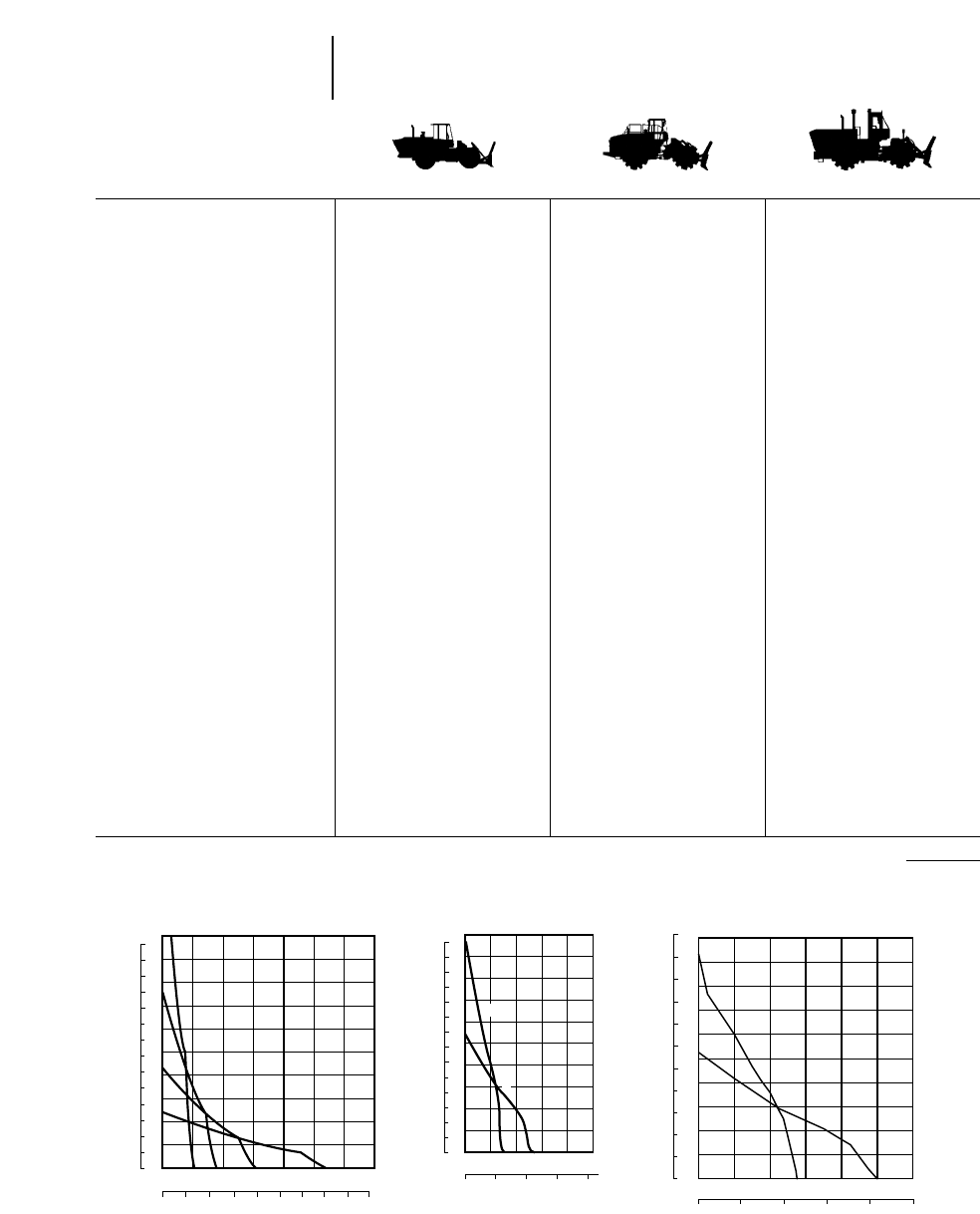
MODEL 816F 826G 836
Flywheel Power 164 kW 220 hp 235 kW 315 hp 353 kW 473 hp
Operating Weight* 22 780 kg 50,115 lb 33 350 kg 73,370 lb 44 135 kg 97,300 lb
Engine Model 3306 DITA 3406C DITA 3408
Rated Engine RPM 2200 2100 2100
No. Cylinders 668
Displacement 10.5 L 638 in314.6 L 893 in318.0 L 1098 in3
Speeds:
Forward 422
Reverse 422
Clearance Turning Circle with
Blade 12.8 m 42'2" 14.69 m 48'2" 18.59 m 61'0"
Fuel Tank Refill Capacity 446 L 117.8 U.S. gal 630 L 166.5 U.S. gal 890 L 235 U.S. gal
WHEELS: CHOPPER CHOPPER PLUS-TIPS
Each Drum Width 1.02 m 3'4" 1.20 m 3'11" 1.40 m 4'7"
Diameters, over Blade Tips 1.60 m 5'3" 1.83 m 6'0" 2.04 m 6'8"
Drum only 1.30 m 4'3" 1.53 m 5'0" 1.72 m 5'8"
Blade Tips per Wheel 20 24 28
Blade Length 348 mm 13.7" 419 mm 16.5" 294 mm 11.6"
Blade Height 152 mm 6" 152 mm 6" 165 mm 6.5"
Blade Thickness/Width 22 mm 0.87" 28.6 mm 1.125" 150 mm 5.9"
PLUS TIPS per Wheel 20 25 35
Width of Two Pass Coverage 4.5 m 14'9" 4.78 m 15'8" 5.67 m 18'7"
GENERAL DIMENSIONS:
Height (to top of ROPS) 3.45 m 11'4" 3.82 m 12'7" 4.57 m 15'0"
Height (stripped top)** 2.50 m 8'3" 2.74 m 9'0" 2.96 m 9'8"
Wheel Base 3.35 m 11'0" 3.70 m 12'2" 3.81 m 12'6"
Overall Length with Dozer 7.79 m 25'7" 8.42 m 27'7" 10.17 m 33'4"
Width over Drums 3.33 m 10'11" 3.80 m 12'6" 4.27 m 14'0"
Ground clearance 532 mm 1'9" 505 mm 1'8" 525 mm 1'8"
LANDFILL BULLDOZER:
Width 3.65 m 12'0" 4.50 m 14'9" 5.18 m 17'0"
Height*** 1.91 m 6'3" 1.90 m 6'3" 2.21 m 7'3"
***Operating Weight includes coolant, bulldozer, hydraulics, ROPS cab, full fuel tank, and operator.
***Height (stripped top) — without ROPS cab, exhaust, seat back or other easily removed encumbrances.
***To top of trash screen.
11-18
Landfill Compactors Specifications
●Rimpull
36
32
28
24
20
16
12
8
4
004 81216202428
0510152025303540
45
54
48
42
36
30
24
18
12
6
0
1
2
34
84
78
72
66
60
40
816F
mph
SPEED
RIMPULL
km/h
kg x
1000
lbs x
1000
KEY
1 – 1st Gear
2 – 2nd Gear
3 – 3rd Gear
4 – 4th Gear
04 8121620
03 6 912
54
48
42
36
30
24
18
12
6
0
84
78
72
66
60
36
32
28
24
20
16
12
8
4
0
40
2
1
826G
SPEED
RIMPULL
mph
kg x
1000
lbs x
1000
1
2
024681012
0
6
12
18
24
30
36
42
48
54
60
034.5 7.51.5 6
48
36
24
12
0
72
84
96
108
120
132
60
836
km/h
SPEED
RIMPULL
mph
kg x
1000
lbs x
1000
km/h
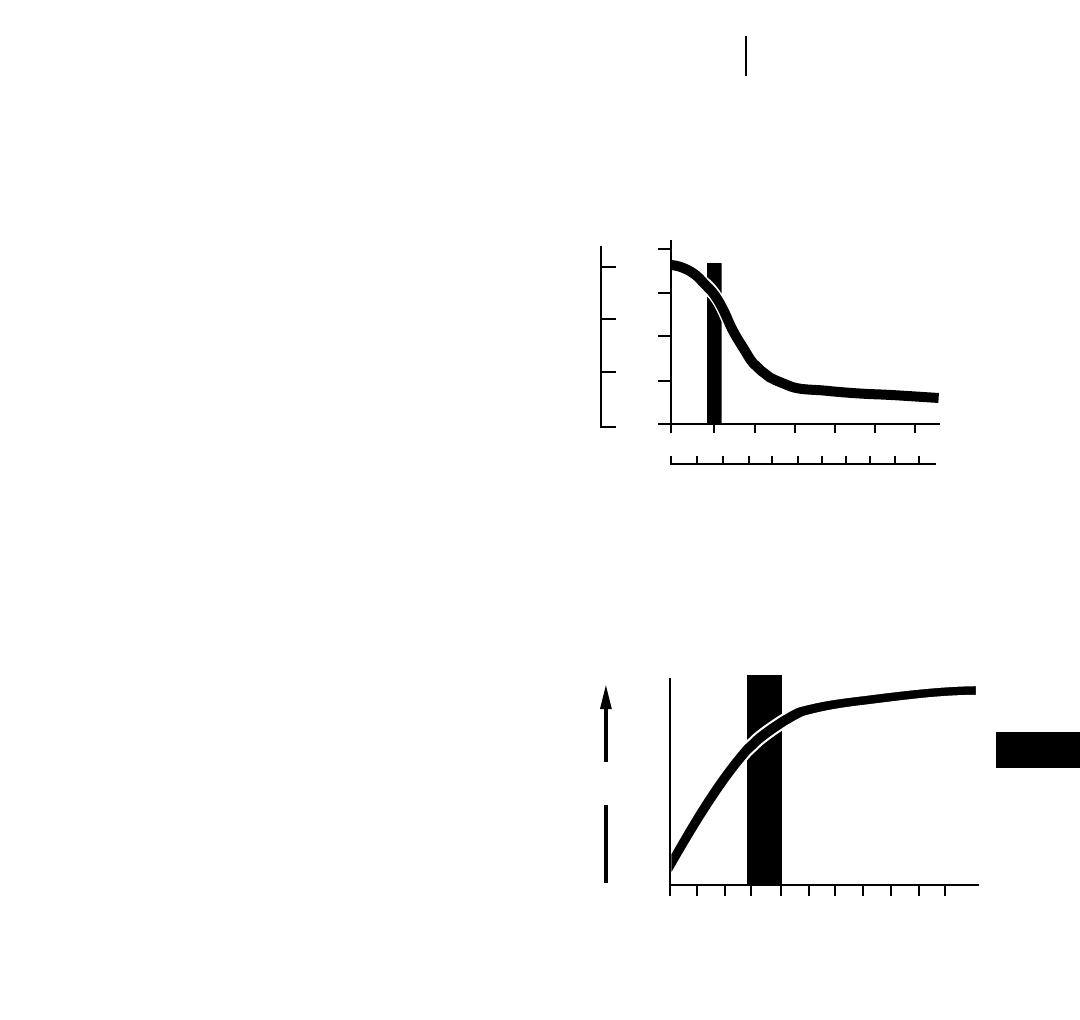
COMPACTION FUNDAMENTALS
To maximize compaction, the following guidelines
should be employed when possible:
1. Refuse Layer Thickness — The depth of each
com-pacted layer is perhaps the single most
important controllable factor influencing density.
To obtain maximum density efficiency, waste
should be spread and compacted in layers not
exceeding a depth of 609 mm (2'0"). Deeper
layers will reduce the density that a machine can
develop in a given number of passes. (See top
table at right.)
2. Number of Passes made over the refuse also affects
density. Regardless of what type of machine
used, the unit should make 3-4 passes to achieve
optimum density. The following graph illustrates
that more than five passes result in little addi-
tional compactive effort. The added expense of
additional passes is not justified by the incremen-
tal increase in density. (See bottom table at right).
3. Slope — To maximize compaction, a compactor
should be operated on as flat a slope as possible.
This is because the weight of the landfill compactor
is more efficiently utilized and concentrated when
working on a flat surface. Landfill compactors
should never operate on a slope steeper than 4:1.
(Note: Ballasting the wheels on Caterpillar Landfill
Compactors to increase machine weight and achieve
higher compaction densities is not recommended.
Landfills are high rimpull applications. Ballasting
the wheels will significantly increase machine weight
but decrease overall performance when traveling on
the fill. Also, wheels are not necessarily air tight or
leak proof. For more landfill discussion please see
Waste Disposal section of this handbook.)
11-19
11
Landfill CompactorsFundamentals
1500
1000
500
0
750
1000
500
250
00 .5 1.0 1.5 2.0 2.5 3.0
01 234 5678910
LAYER THICKNESS
lb/yd3
Meters
012345678910
Increasing
Density
Number of machine passes made with
each steel wheel, rubber tire or track.
kg/m3
Feet

MODEL 816F 826G 836
Type Land Fill Spreading Land Fill Spreading Land Fill Spreading
Capacity**
Earth 2.90 m33.79 yd33.68 m34.81 yd35.0 m36.56 yd3
Refuse 10.48 m313.70 yd312.74 m316.66 yd318.9 m324.66 yd3
Weight, Dozer* 2107 kg 4645 lb 2739 kg 6038 lb 3290 kg 7250 lb
General Dimensions:
(Tractor & Dozer)
Length 7.79 m 25'7" 8.38 m 27'6" 10.17 m 33'4"
Width 3.65 m 12'0" 4.50 m 14'9" 5.18 m 17'0"
Blade Dimensions:
Width, End Bits 3.65 m 12'0" 4.50 m 14'9" 5.18 m 17'0"
Height, Trash Rack 1915 mm 6'3" 1935 mm 6'4" 2210 mm 7'3"
**Total Bulldozer Arrangement.
**Blade capacities determined by SAE recommended practice J1265.
BALDERSON
U-BLADE 816F 826G 836
Balderson Model: BD816UL-12 BD826UL-14 BD836UL-17 BD836SUL-17
Type U-Blade U-Blade U-Blade Semi-U-Blade
Blade:
Capacity (Refuse) 11.9 m315.5 yd316.7 m321.9 yd325.2 m333 yd320.3 m326.5 yd3
Capacity (Earth) 8.3 m310.8 yd312.2 m316 yd37.74 m310.13 yd36.38 m38.34 yd3
Length (Cutting Width) 3658 mm 12'0" 4369 mm 14'4" 5182 mm 17'0" 5316 mm 17'5.31"
Height 1857 mm 6'1.1" 2007 mm 6'7" 2210 mm 7'3" 2210 mm 7'3"
Wing Angle 25° 25° 25° —
Max. lift above ground 889 mm 2'11" 864 mm 2'10" 864 mm 2'10" ——
Weight, Installed
(Without Hydraulics) 1680 kg 3700 lb 2100 kg 4625 lb 4310 kg 9500 lb 3355 kg 7400 lb
BALDERSON
W-BLADE 816F 826G 836
Balderson Model: BD816WL-12 BD826WL-14 BD836WL-17
Replaces “S” Blade
Blade:
Capacity (Refuse) 11.9 m315.5 yd316.8 m322.0 yd323.9 m331.3 yd3
Length (Cutting Width) 3658 mm 12'0" 4420 mm 14'6" 5207 mm 17'1"
Moldboard Height 1857 mm 6'1.1" 2057 mm 6'9" 2210 mm 7'3"
Weight, Installed
(Without Hydraulics) 2070 kg 4560 lb 2975 kg 6600 lb 4515 kg 9950 lb
BALDERSON
TILT STRAIGHT BLADE 816F 826G
Balderson Model: BDI816SL-12'T BDI826SL-14'8"T
Blade:
Capacity (Refuse) 10.7 m314.0 yd313.0 m317.0 yd3
Length (Cutting Width) 3647 mm 11'11.6" 4375 mm 14'4.3"
Weight, Installed 2225 kg 4500 lb 3530 kg 7780 lb
11-20
Landfill Compactors Blade Specifications
●Special Attachments

12-1
CONTENTS
WHEEL LOADERS
Features . . . . . . . . . . . . . . . . . . . . . . . . . . . . . .12-1
Specifications . . . . . . . . . . . . . . . . . . . . . . . . . .12-2
Performance data . . . . . . . . . . . . . . . . . . . . . . .12-6
Machine dimensions . . . . . . . . . . . . . . . . . . . .12-31
SAE loader ratings . . . . . . . . . . . . . . . . . . . . .12-37
Machine selection:
Cycle time factors . . . . . . . . . . . . . . . . . . . .12-39
Truck loading . . . . . . . . . . . . . . . . . . . . . . .12-40
Bucket fill factors . . . . . . . . . . . . . . . . . . . .12-40
Example problem . . . . . . . . . . . . . . . . . . . .12-41
Alternative method of selection . . . . . . . . .12-42
Nomographs . . . . . . . . . . . . . . . . . . . . . . . .12-43
Bucket selection . . . . . . . . . . . . . . . . . . . . . . .12-45
Estimated haul or return time charts . . . . . .12-49
Travel time charts . . . . . . . . . . . . . . . . . . . . .12-50
Production estimating tables:
Cubic meters and cubic yards . . . . . . . . . . .12-70
Metric tons and U.S. tons in shot rock . . . .12-71
Attachments . . . . . . . . . . . . . . . . . . . . . . . . . .12-73
Waste handling wheel loaders . . . . . . . . . . . .12-75
WHEEL LOADERS
Features:
●Caterpillar large displacement, heavy duty
diesel engine.
●Productive operator environment. Excellent
visibility.
●Automatic lift and bucket controls.
●Adjustable suspension seat and steering
column.
●Four wheel enclosed wet disc brakes.
●Automatic power shift transmissions. Allows
operator to select automatic or manual mode.
●Hydrostatic drive on 902, 906 and 914G.
●Transmission neutralizer switch.
●Centerpoint articulated frame steering.
●Computerized machine function monitoring.
●Variable capacity torque converter on 988F
Series II and 992G.
●Command control steering with integrated
transmission controls.
●Lock up clutch on 990 and 994 (optional on
988F).
●Impeller clutch on 994.
●Limited slip differentials.
●Traction control system…938G.
●Automatic Ride Control suspension system.
Operator select “on”, “off” or “automatic”.
●Payload control system.
Listed features may be standard on some models, optional or unavailable on
others. Contact your Caterpillar Dealer for specific information.
12
WHEEL LOADERS
WASTE HANDLING WHEEL LOADERS
MODEL 902 906 914G 924F
Flywheel Power: Net 34 kW 45 hp 45 kW 60 hp 67 kW 90 hp 78 kW 105 hp
Flywheel Power: Gross 36 kW 48 hp 47 kW 63 hp — —
Engine Model 3024 3034 3054T 3114T
Rated Engine RPM 2600 2600 2200 2400
Bore 84 mm 3.31" 97 mm 3.82" 100 mm 3.94"105 mm 4.13"
Stroke 100 mm 3.94" 100 mm 3.94" 127 mm 5" 127 mm 5"
No. Cylinders 4444
Displacement 2.2 L 135 in32.95 L 180 in34 L 243 in34.4 L 268 in3
Speeds Forward km/h mph km/h mph km/h mph km/h mph
1st 7 Lo 48Lo57 Lo**4.3 7.1 4.4
2nd 20 Hi 12 20 Hi 12 20 Lo** 12.4 13.1 8.2
3rd ——9 Hi** 5.6 23.6 14.8
4th ——35 Hi** 21.7 38.2 23.9
Speeds Reverse
1st 7 Lo 48Lo57 Lo**4.3 7.1 4.4
2nd 20 Hi 12 20 Hi 12 20 Lo** 12.4 13.1 8.2
3rd ——9 Hi** 5.6 23.6 14.8
4th ——35 Hi** 21.7 —
Hydraulic Cycle Time,
Rated Load in Bucket: Seconds Seconds Seconds Seconds
Raise 4.5 4.5 5.6 4.3
Dump 1.5 1.5 2.1 1.3
Lower (Empty, Float Down) 3.2 3.2 3.2 2.7
Total 9.2 9.2 10.9 8.3
Tread Width 1.35 m 4'5" 1.40 m 4'7" 1.80 m 5'11" 1.85 m 6'1"
Width Over Tires 1.70 m 5'7" 1.82 m 6'0" 2.26 m 7'5" 2.32 m 7'7.7"
Ground Clearance 385 mm 15" 420 mm 17" 456 mm 18" 318 mm 12.5"
Fuel Tank Capacity 74 L 19.6 U.S. gal 74 L 19.6 U.S. gal 150 L 39.6 U.S. gal 157 L 41.5 U.S. gal
Hydraulic Tank Capacity 49 L 13 U.S. gal 49 L 13 U.S. gal 70 L 18.5 U.S. gal 53 L 14 U.S. gal
Hydraulic System Capacity
(includes tank) 66 L 17.5 U.S. gal 66 L 17.5 U.S. gal 100 L 26.4 U.S. gal 77 L 20.3 U.S. gal
**Hydrostatic transmission standard speed version.
**Hydrostatic transmission high speed version.
12-2
Wheel Loaders Specifications
MODEL 928G 938G 950G 962G
Flywheel Power: Net 93 kW 125 hp 108 kW 145 hp 134 kW 180 hp 149 kW 200 hp
Flywheel Power: Gross —118 kW 158 hp 140 kW 185 hp 154 kW 207 hp
Engine Model 3116T 3126TA 3126TA 3126TA
Rated Engine RPM 2300 2200 2200 2200
Bore 105 mm 4.13" 110 mm 4.3" 110 mm 4.3" 110 mm 4.3"
Stroke 127 mm 5" 127 mm 5127 mm 5" 127 mm 5"
No. Cylinders 6666
Displacement 6.6 L 403 in37.2 L 439 in37.2 L 439 in37.2 L 439 in3
Speeds Forward km/h mph km/h mph km/h mph km/h mph
1st 7.6 4.7 74.3 6.9 4.3 6.9 4.3
2nd 12 7.5 12.7 7.9 12.7 7.9 12.7 7.9
3rd 24.6 15.3 21.9 13.6 22.3 13.9 22.3 13.9
4th 36.7 22.8 35.9 22.3 37 23 37 23.0
Speeds Reverse
1st 7.6 4.7 74.3 7.6 4.7 7.6 4.7
2nd 12 7.5 12.7 7.9 13.9 8.7 13.9 8.7
3rd 24.6 15.3 21.9 13.6 24.5 15.3 24.5 15.3
4th — —40.5 25.3 40.5 25.3
Hydraulic Cycle Time,
Rated Load in Bucket: Seconds Seconds Seconds Seconds
Raise 6.1 6 6.3 6.3
Dump 1.2 1.4 2.2 2.2
Lower (Empty, Float Down) 2.8 2.8 2.2 2.2
Total 10.1 10.2 10.7 10.7
Tread Width 1.82 m 6'1" 2.02 m 6'8" 2.14 m 7'0" 2.14 m 7'0"
Width Over Tires 2.44 m 8'0" 2.60 m 8'6" 2.89 m 9'6" 2.89 m 9'6"
Ground Clearance 408 mm 16" 400 mm 15.7" 400 mm 15.7" 400 mm 15.7"
Fuel Tank Capacity 230 L 60.8 U.S. gal 254 L 67 U.S. gal 295 L 78 U.S. gal 295 L 78 U.S. gal
Hydraulic Tank Capacity 70 L 18.5 U.S. gal 55 L 14.5 U.S. gal 88 L 23.2 U.S. gal 88 L 23.2 U.S. gal
Hydraulic System Capacity
(includes tank) 125 L 33 U.S. gal 90 L 23.8 U.S. gal 153 L 40.4 U.S. gal 153 L 40.4 U.S. gal
12-3
12
Wheel LoadersSpecifications
MODEL 966F Series II 970F 980G 988F Series II
Flywheel Power 164 kW 220 hp 187 kW 250 hp 224 kW 300 hp 321 kW 430 hp
Engine Model 3306TA 3306TA 3406TA 3408E TA
Rated Engine RPM 2200 2200 2100 2000
Bore 121 mm 4.75" 121 mm 4.75" 137 mm 5.4" 137 mm 5.4"
Stroke 152 mm 6" 152 mm 6" 165 mm 6.5" 152 mm 6"
No. Cylinders 6668
Displacement 10.5 L 638 in310.5 L 638 in314.6 L 893 in318 L 1099 in3
Speeds Forward km/h mph km/h mph km/h mph km/h mph
1st 7.3 4.5 7.2 4.5 74.3 6.9 4.3
2nd 13 8.1 12.6 7.8 12.3 7.7 12.1 7.5
3rd 22.5 14 21.7 13.5 21.6 13.4 20.7 12.8
4th 38.8 24.1 37.3 23.2 37.4 23.2 35.1 21.8
Speeds Reverse
1st 8.3 5.2 8.2 5.1 857.9 4.9
2nd 14.8 9.2 14.4 8.9 14 8.8 13.7 8.5
3rd 25.6 15.9 24.6 15.3 24.6 15.3 23.5 14.6
4th 43.9 27.3 42.7 26.5 42.8 26.6 —
Hydraulic Cycle Time,
Rated Load in Bucket: Seconds Seconds Seconds Seconds
Raise 7.1 6.1 6 7.9
Dump 2 1.3 2 3.3
Lower (Empty, Float Down) 2.4 2.1 3.4 4.0
Total 11.5 9.5 11.4 15.2
Tread Width 2.20 m 7'3" 2.20 m 7'3" 2.44 m 8'0" 2.59 m 8'6"
Width Over Tires 2.94 m 9'8" 2.94 m 9'8" 3.25 m 10'8" 3.52 m 11'7"
Ground Clearance 476 mm 18.7" 482 mm 1'7" 467 mm 18.4" 496 mm 1'7"
Fuel Tank Capacity 377 L 99.6 U.S. gal 377 L 99.6 U.S. gal 470 L 124 U.S. gal 659 L 174 U.S. gal
Hydraulic Tank Capacity 140 L 37 U.S. gal 140 L 37 U.S. gal 125 L 33 U.S. gal 235 L 62 U.S. gal
Hydraulic System Capacity
(includes tank) 205 L 54 U.S. gal 205 L 54 U.S. gal 208 L 55 U.S. gal 295 L 78 U.S. gal
12-4
Wheel Loaders Specifications
MODEL 990 Series II 992G 994
Flywheel Power 466 kW 625 hp 597 kW 800 hp 932 kW 1250 hp
Engine Model 3412E TA 3508B TA 3516TA
Rated Engine RPM 2000 1750 1600
Bore 137 mm 5.4" 170 mm 6.7" 170 mm 6.69"
Stroke 152 mm 6" 190 mm 7.5" 190 mm 7.48"
No. Cylinders 12 8 16
Displacement 27 L 1649 in334.5 L 2105 in369 L 4211 in3
Speeds Forward km/h mph km/h mph km/h mph
1st 7.2 4.5 6.7 4.2 6.8 4.2
2nd 12.9 811.9 7.3 12.2 7.6
3rd 22.5 14 20.2 12.5 21.2 13.2
Speeds Reverse
1st 8 57.4 4.6 7.6 4.7
2nd 14.2 8.8 12.6 7.8 14 8.7
3rd 25 15.5 22.7 14.1 24.3 15.1
Hydraulic Cycle Time,
Rated Load in Bucket: Seconds Seconds Seconds
Raise 9.2 9.12 12.5
Dump 2.9 3.26 3.4
Lower (Empty, Float Down) 3.8 3.47 4.2
Total 15.9 15.85 20.1
Tread Width 3.1 m 10'0" 3.30 m 10'10" 3.90 m 12'10"
Width Over Tires 4.1 m 13'6" 4.50 m 14'9" 5.20 m 17'0"
Ground Clearance 507 mm 20" 691 mm 27" 650 mm 25.6"
Fuel Tank Capacity 970 L 252 U.S. gal 1319 L 343 U.S. gal 4540 L 1200 U.S. gal
Hydraulic Tank Capacity 174 L** 45 U.S. gal 326 L✝84.8 U.S. gal 623 L* 165 U.S. gal
Hydraulic System Capacity
(includes tank) 435 L** 113 U.S. gal 646 L✝168 U.S. gal 723 L* 190 U.S. gal
*Separate steering system 265 L (70 U.S. gal). Brakes 42 L (11 U.S. gal).
**Also contains separate systems for steering and engine cooling fan 193 L (51 U.S. gal), tank only 129 L (34 U.S. gal).
✝Separate steering and fan system 227 L (60 U.S. gal). Tank only 156 L (41.3 U.S. gal).
12-5
12
Wheel LoadersSpecifications

Bucket Type General Purpose Multi-Purpose
Ground Engaging Type Bolt-on Bolt-on Weld-on Pin-on Bolt-on Bolt-on Weld-on
Bare Edge Teeth Edge Tips Bare Edge Teeth Edge
Rated bucket capacity (§) m30.6 0.6 0.6 0.7 0.6 0.6 0.6 0.6 0.7
yd30.78 0.78 0.78 0.78 0.78 0.78 0.78 0.78 0.78
Struck capacity (§) m30.5 0.5 0.5 0.5 0.5 0.5 0.5 0.5 0.5
yd30.65 0.65 0.65 0.65 0.65 0.65 0.65 0.65 0.65
Width mm 1780 1790 1780 1790 1780 1790 1790 1790 1790
ft/in 5'10" 5'10" 5'10" 5'10" 5'10" 5'10" 5'10" 5'10" 5'10"
Dump clearance at full lift mm 2341 2307 2341 2273 2341 2341 2307 2341 2273
and 43° discharge (§) ft/in 7'8" 7'7" 7'8" 7'5" 7'8" 7'8" 7'7" 7'8" 7'5"
Reach at full lift and mm 751 764 751 801 751 751 764 751 801
43° discharge (§) ft/in 2'6" 2'6" 2'6" 2'7" 2'6" 2'6" 2'6" 2'6" 2'7"
Reach at 45° discharge and mm 920 902 856 905 839 920 902 856 905
2130 mm (7'0") clearance (§) ft/in 3'0" 3'0" 2'10" 3'0" 2'9" 3'0" 3'0" 2'10" 3'0"
Reach with lift arms mm 1779 1811 1779 1862 1779 1779 1811 1779 1882
horizontal and bucket level ft/in 5'10" 5'11" 5'10" 6'1" 5'10" 5'10" 5'11" 5'10" 6'2"
Digging depth (§) mm 52 68 52 68 52 52 68 52 68
in 2" 2.7" 2" 2.7" 2" 2" 2.7" 2" 2.7"
Overall length mm 5155 5200 5155 5251 5155 5155 5200 5155 5251
ft/in 16'11" 17'1" 16'11" 17'3" 16'11" 16'11" 17'1" 16'11" 17'3"
Overall height with mm 3967 3967 3967 3967 3967 3944 3944 3944 3944
bucket at full raise (§) ft/in 13'0" 13'0" 13'0" 13'0" 13'0" 12'11" 12'11" 12'11" 12'11"
Loader clearance circle with mm 7724 7764 7724 7792 7724 7732 7792 7732 7804
bucket in carry position ft/in 25'4" 25'6" 25'4" 25'7" 25'4" 25'4" 25'7" 25'4" 25'7"
Static tipping load, kg 3040 2983 3022 2955 3012 2788 2732 2771 2706
straight* (§) lb 6700 6570 6660 6510 6640 6140 6020 6110 5960
Static tipping load, kg 2551 2496 2533 2472 2523 2308 2254 2289 2231
full 43° turn* (§) lb 5620 5500 5580 5450 5560 5080 4970 5040 4910
Breakout force (§) kN 36.4 34.7 36.3 32.1 36.2 35.6 33.6 35.4 31.4
lb 8190 7800 8160 7220 8140 8010 7560 7960 7060
Operating weight* kg 4452 4487 4467 4492 4475 4685 4720 4700 4721
lb 9820 9890 9850 4900 9870 10,330 10,410 10,360 10,410
*Static tipping load and operating weights shown are with implements, ROPS cab, 12.5-18 tires, full fuel tank and operator.
NOTE: Specifications and ratings conform to all applicable standards recommended by the Society of Automotive Engineers (SAE). SAE Standards J732 JUN92 and J742
FEB85 govern loader rating, denoted in the text by (§). Change in
Change in Articulated Static
Operating Weight Tipping Load
________________ _______________
kg lb kg lb
Limited slip rear axle . . . . . . . . . . . . . . . . . . . . . . . . . . . . . . . . . . . . . . . . . . . . . . . . . . . . . . 0 000
Enclosed ROPS (Comfort) . . . . . . . . . . . . . . . . . . . . . . . . . . . . . . . . . . . . . . . . . . . . . . . . . + 2 +4 +1 +2
Enclosed ROPS (Deluxe) . . . . . . . . . . . . . . . . . . . . . . . . . . . . . . . . . . . . . . . . . . . . . . . . . . + 5 +11 +4 +9
Boom with load check valves . . . . . . . . . . . . . . . . . . . . . . . . . . . . . . . . . . . . . . . . . . . . . . . + 12 +26 +2 +4
Third valve hydraulics . . . . . . . . . . . . . . . . . . . . . . . . . . . . . . . . . . . . . . . . . . . . . . . . . . . . .+11+24 –1 –2
Counterweight . . . . . . . . . . . . . . . . . . . . . . . . . . . . . . . . . . . . . . . . . . . . . . . . . . . . . . . . . . . + 110 + 243 + 113 + 249
Wheel chock . . . . . . . . . . . . . . . . . . . . . . . . . . . . . . . . . . . . . . . . . . . . . . . . . . . . . . . . . . . . + 5 +11 +2 +4
Tool roll . . . . . . . . . . . . . . . . . . . . . . . . . . . . . . . . . . . . . . . . . . . . . . . . . . . . . . . . . . . . . . . . + 4 +9 +4 +9
12-6
Wheel Loaders Performance Data
●902

12-7
12
Wheel LoadersPerformance Data
●902
Multi-
Bucket Type Purpose High Dump Light Material Stone Sieve
Pin-on Bolt-on Bolt-on Bolt-on Bolt-on Bolt-on
Ground Engaging Type Tips Bare Edge Teeth Bare Edge Bare Edge Teeth
Rated bucket capacity (§) m30.6 0.6 0.6 0.6 1 1 0.6 0.6 0.6
yd30.78 0.78 0.78 0.78 1.3 1.3 0.78 0.78 0.78
Struck capacity (§) m30.5 0.5 0.5 0.5 0.8 0.8 0.5 0.5 0.5
yd30.65 0.65 0.65 0.65 1.05 1.05 0.65 0.65 0.65
Width mm 1790 1887 1787 1787 1880 1890 1780 1780 1780
ft/in 5'10" 6'2" 5'10" 5'10" 6'2" 6'2" 5'10" 5'10" 5'10"
Dump clearance at full lift mm 2341 2341 2307 2341 2204 2170 2341 2307 2341
and 43° discharge (§) ft/in 7'8" 7'8" 7'7" 7'8" 7'3" 7'1" 7'8" 7'7" 7'8"
Reach at full lift and mm 844 717 728 788 856 867 717 728 788
43° discharge (§) ft/in 2'9" 2'4" 2'5" 2'7" 2'10" 2'10" 2'4" 2'5" 2'7"
Reach at 43° discharge and mm 929 920 902 928 929 904 920 902 928
2130 mm (7'0") clearance (§) ft/in 3'1" 3'0" 3'0" 3'1" 3'1" 3'0" 3'0" 3'0" 3'1"
Reach with lift arms mm 1906 1779 1811 1881 1979 2011 1779 1811 1881
horizontal and bucket level ft/in 6'3" 5'10" 5'11" 5'11" 6'6" 6'7" 5'10" 5'11" 6'2"
Digging depth (§) mm 52 52 68 52 52 69 52 68 52
in 2" 2" 2.7" 2" 2" 2.7" 2" 2.7" 2"
Overall length mm 5282 5155 5200 5257 5355 5400 5155 5200 5257
ft/in 17'4" 16'11" 17'1" 17'3" 17'7" 17'9" 16'11" 17'1" 17'3"
Overall height with mm 3944 3967 3967 3967 3944 3944 3816 3816 3816
bucket at full raise (§) ft/in 12'11" 13'0" 13'0" 13'0" 12'11" 12'11" 12'6" 12'6" 12'6"
Loader clearance circle with mm 7752 7724 7764 7724 7934 7974 7724 7764 7724
bucket in carry position ft/in 25'5" 25'4" 25'6" 25'4" 26'0" 26'2" 25'4" 25'6" 25'4"
Static tipping load, kg 2763 2788 2818 2859 2962 2900 2985 2924 2940
straight* (§) lb 6090 6140 6210 6300 6530 6390 6580 6440 6480
Static tipping load, kg 2282 2386 2329 2368 2473 2414 2498 2439 2452
full turn* (§) lb 5030 5260 5130 5220 5450 5320 5500 5370 5400
Breakout force (§) kN 35.3 35.3 33.3 35.1 27.5 23.6 36.3 34.3 35.8
lb 7940 7940 7490 7890 6180 5310 8160 7710 8050
Operating weight* kg 4704 4639 4674 4654 4531 4568 4509 4544 4552
lb 10,370 10,230 10,310 10,260 9990 10,070 9940 10,020 10,040
*Static tipping load and operating weights shown are with implements, ROPS cab, 12.5-18 tires, full fuel tank and operator.
NOTE: Specifications and ratings conform to all applicable standards recommended by the Society of Automotive Engineers (SAE). SAE Standards J732 JUN92 and J742
FEB85 govern loader rating, denoted in the text by (§). Change in
Change in Articulated Static
Operating Weight Tipping Load
________________ _______________
kg lb kg lb
Limited slip rear axle . . . . . . . . . . . . . . . . . . . . . . . . . . . . . . . . . . . . . . . . . . . . . . . . . . . . . . 0 000
Enclosed ROPS (Comfort) . . . . . . . . . . . . . . . . . . . . . . . . . . . . . . . . . . . . . . . . . . . . . . . . . + 2 +4 +1 +2
Enclosed ROPS (Deluxe) . . . . . . . . . . . . . . . . . . . . . . . . . . . . . . . . . . . . . . . . . . . . . . . . . . + 5 +11 +4 +9
Boom with load check valves . . . . . . . . . . . . . . . . . . . . . . . . . . . . . . . . . . . . . . . . . . . . . . . + 12 +26 +2 +4
Third valve hydraulics . . . . . . . . . . . . . . . . . . . . . . . . . . . . . . . . . . . . . . . . . . . . . . . . . . . . .+11+24 –1 –2
Counterweight . . . . . . . . . . . . . . . . . . . . . . . . . . . . . . . . . . . . . . . . . . . . . . . . . . . . . . . . . . . + 110 + 243 + 113 + 249
Wheel chock . . . . . . . . . . . . . . . . . . . . . . . . . . . . . . . . . . . . . . . . . . . . . . . . . . . . . . . . . . . . + 5 +11 +2 +4
Tool roll . . . . . . . . . . . . . . . . . . . . . . . . . . . . . . . . . . . . . . . . . . . . . . . . . . . . . . . . . . . . . . . . + 4 +9 +4 +9

12-8
Wheel Loaders Performance Data
●906
Bucket Type General Purpose Multi-Purpose
Bolt-on Bolt-on Weld-on Pin-on Bolt-on Bolt-on
Ground Engaging Type Bare Edge Teeth Edge Tips Bare Edge Teeth
Rated bucket capacity (§) m30.8 0.8 0.8 0.9 0.8 0.8 0.8 0.8
yd31.05 1.05 1.05 1.18 1.05 1.05 1.05 1.05
Struck capacity (§) m30.6 0.7 0.6 0.7 0.6 0.6 0.6 0.6
yd30.78 0.92 0.78 0.92 0.78 0.78 0.78 0.78
Width mm 1880 1890 1880 1890 1880 1890 1890 1890
ft/in 6'2" 6'2" 6'2" 6'2" 6'2" 6'2" 6'2" 6'2"
Dump clearance at full lift mm 2425 2391 2425 2356 2425 2425 2391 2425
and 43° discharge (§) ft/in 7'11" 7'11" 7'11" 7'9" 7'11" 7'11" 7'10" 7'11"
Reach at full lift and mm 829 842 901 879 922 829 842 904
43° discharge (§) ft/in 2'9" 2'9" 2'11" 2'11" 3'0" 2'9" 2'9" 3'0"
Reach at 43° discharge and mm 1070 982 1142 1118 1160 1071 1045 1143
2130 mm (7'0") clearance (§) ft/in 3'6" 3'3" 3'9" 3'8" 3'10" 3'7" 3'5" 3'9"
Reach with lift arms mm 1912 1945 2014 1995 2040 1912 1945 2014
horizontal and bucket level ft/in 6'3" 6'5" 6'7" 6'6" 6'8" 6'3" 6'5" 6'7"
Digging depth (§) mm 84 100 84 100 84 84 99 84
in 3.31 3.94 3.31 3.94 3.31 3.31 3.90 3.31
Overall length mm 5310 5355 5412 5405 5437 5309 5354 5411
ft/in 17'5" 17'7" 17'9" 17'9" 17'10" 17'5" 17'7" 17'9"
Overall height with mm 4170 4170 4170 4170 4170 4205 4205 4205
bucket at full raise (§) ft/in 13'8" 13'8" 13'8" 13'8" 13'8" 13'10" 13'10" 13'10"
Loader clearance circle with mm 8330 8368 8330 8394 8330 8330 8358 8330
bucket in carry position ft/in 27'4" 27'5" 27'4" 27'6" 27'4" 27'4" 27'5" 27'4"
Static tipping load, kg 3427 3382 3410 3374 3399 3234 3169 3215
straight* (§) lb 7550 7450 7510 7430 7490 7130 6980 7080
Static tipping load, kg 2962 2917 2944 2909 2934 2765 2702 2746
full turn* (§) lb 6530 6430 6490 6410 6460 6090 5950 6050
Breakout force (§) kN 45.4 43.2 45.3 40.4 45.2 44.5 42.3 44.3
lb 10,210 9720 10,190 9090 10,170 10,010 9510 9960
Operating weight* kg 5096 5131 5110 5138 5118 5343 5379 5357
lb 11,240 11,310 11,270 11,330 11,290 11,780 11,860 11,810
*Static tipping load and operating weights shown are with implements, ROPS cab, 12.5-20 tires, full fuel tank, operator and 80 kg (176 lb) counterweight.
NOTE: Specifications and ratings conform to all applicable standards recommended by the Society of Automotive Engineers (SAE). SAE Standards J732 JUN92 and J742
FEB85 govern loader rating, denoted in the text by (§). Change in
Change in Articulated Static
Operating Weight Tipping Load
________________ _______________
kg lb kg lb
Limited slip rear axle . . . . . . . . . . . . . . . . . . . . . . . . . . . . . . . . . . . . . . . . . . . . . . . . . . . . . . 0 000
Enclosed ROPS (Comfort) . . . . . . . . . . . . . . . . . . . . . . . . . . . . . . . . . . . . . . . . . . . . . . . . . + 2 +4 +1 +2
Enclosed ROPS (Deluxe) . . . . . . . . . . . . . . . . . . . . . . . . . . . . . . . . . . . . . . . . . . . . . . . . . . + 5 +11 +4 +9
Boom with load check valves . . . . . . . . . . . . . . . . . . . . . . . . . . . . . . . . . . . . . . . . . . . . . . . + 12 +26 +2 +4
Third valve hydraulics . . . . . . . . . . . . . . . . . . . . . . . . . . . . . . . . . . . . . . . . . . . . . . . . . . . . .+11+24 –1 –2
Counterweight (standard) removed . . . . . . . . . . . . . . . . . . . . . . . . . . . . . . . . . . . . . . . . . . . – 80 – 176 – 112 – 247
Counterweight 150 kg (330 lb) . . . . . . . . . . . . . . . . . . . . . . . . . . . . . . . . . . . . . . . . . . . . . . + 150 + 331 + 151 + 333
Wheel chock . . . . . . . . . . . . . . . . . . . . . . . . . . . . . . . . . . . . . . . . . . . . . . . . . . . . . . . . . . . . + 5 +11 +2 +4
Tool roll . . . . . . . . . . . . . . . . . . . . . . . . . . . . . . . . . . . . . . . . . . . . . . . . . . . . . . . . . . . . . . . . + 4 +9 +4 +9

12-9
12
Wheel LoadersPerformance Data
●906
Bucket Type Multi-Purpose High Dump Side Dump
Weld-on Pin-on Bolt-on Bolt-on Bolt-on Bolt-on
Ground Engaging Type Edge Tips Bare Edge Teeth Bare Edge Teeth
Rated bucket capacity (§) m30.8 0.8 0.7 0.7 0.7 0.7 0.7 0.7
yd31.05 1.05 0.92 0.92 0.92 0.92 0.92 0.92
Struck capacity (§) m30.7 0.6 0.6 0.6 0.6 0.5 0.6 0.5
yd30.92 0.78 0.78 0.78 0.78 0.65 0.78 0.65
Width mm 1890 1890 1887 1887 1887 1880 1880 1880
ft/in 6'2" 6'2" 6'2" 6'2" 6'2" 6'2" 6'2" 6'2"
Dump clearance at full lift mm 2357 2425 2425 2391 2425 2322 2288 2322
and 43° discharge (§) ft/in 7'9" 7'11" 7'11" 7'11" 7'11" 7'7" 7'6" 7'7"
Reach at full lift and mm 879 923 829 842 904 938 951 1013
43° discharge (§) ft/in 2'11" 3'0" 2'9" 2'9" 3'0" 3'1" 3'1" 3'4"
Reach at 43° discharge and mm 1061 1161 1070 1039 1082 1087 1067 1091
2130 mm (7'0") clearance (§) ft/in 3'6" 3'10" 3'6" 3'5" 3'7" 3'7" 3'6" 3'7"
Reach with lift arms mm 1995 2040 1912 1945 2015 2062 2095 2165
horizontal and bucket level ft/in 6'7" 6'8" 6'3" 6'4" 6'7" 6'9" 6'10" 7'1"
Digging depth (§) mm 99 84 84 100 84 84 100 84
in 3.90 3.31 3.31 3.94 3.31 3.31 3.94 3.31
Overall length mm 5405 5437 5310 5355 5412 5461 5505 5562
ft/in 17'9" 17'10" 17'5" 17'7" 17'9" 17'11" 18'1" 18'3"
Overall height with mm 4205 4205 4212 4212 4212 4211 4211 4211
bucket at full raise (§) ft/in 13'10" 13'10" 13'10" 13'10" 13'10" 13'10" 13'10" 13'10"
Loader clearance circle with mm 8386 8330 8366 8404 8366 8412 8442 8412
bucket in carry position ft/in 27'6" 27'4" 27'5" 27'7" 27'5" 27'7" 27'8" 27'7"
Static tipping load, kg 3147 3205 3252 3188 3234 3038 2979 3020
straight* (§) lb 6930 7060 7170 7020 7130 6690 6560 6650
Static tipping load, kg 2684 2736 2787 2725 2768 2598 2540 2580
full turn* (§) lb 5910 6030 6140 6000 6100 5720 5600 5680
Breakout force (§) kN 39.5 44.2 44.3 42 44.1 36.3 34.6 36.1
lb 8880 9940 9960 9450 9920 8160 7780 8120
Operating weight* kg 5380 5365 5279 5316 5294 5318 5355 5332
lb 11,860 11,830 11,640 11,720 11,670 11,730 11,810 11,760
*Static tipping load and operating weights shown are with implements, ROPS cab, 12.5-20 tires, full fuel tank, operator and 80 kg (176 lb) counterweight.
NOTE: Specifications and ratings conform to all applicable standards recommended by the Society of Automotive Engineers (SAE). SAE Standards J732 JUN92 and J742
FEB85 govern loader rating, denoted in the text by (§). Change in
Change in Articulated Static
Operating Weight Tipping Load
________________ _______________
kg lb kg lb
Limited slip rear axle . . . . . . . . . . . . . . . . . . . . . . . . . . . . . . . . . . . . . . . . . . . . . . . . . . . . . . 0 000
Enclosed ROPS (Comfort) . . . . . . . . . . . . . . . . . . . . . . . . . . . . . . . . . . . . . . . . . . . . . . . . . + 2 +4 +1 +2
Enclosed ROPS (Deluxe) . . . . . . . . . . . . . . . . . . . . . . . . . . . . . . . . . . . . . . . . . . . . . . . . . . + 5 +11 +4 +9
Boom with load check valves . . . . . . . . . . . . . . . . . . . . . . . . . . . . . . . . . . . . . . . . . . . . . . . + 12 +26 +2 +4
Third valve hydraulics . . . . . . . . . . . . . . . . . . . . . . . . . . . . . . . . . . . . . . . . . . . . . . . . . . . . .+11+24 –1 –2
Counterweight (standard) removed . . . . . . . . . . . . . . . . . . . . . . . . . . . . . . . . . . . . . . . . . . . – 80 – 176 – 112 – 247
Counterweight 150 kg (330 lb) . . . . . . . . . . . . . . . . . . . . . . . . . . . . . . . . . . . . . . . . . . . . . . + 150 + 331 + 151 + 333
Wheel chock . . . . . . . . . . . . . . . . . . . . . . . . . . . . . . . . . . . . . . . . . . . . . . . . . . . . . . . . . . . . + 5 +11 +2 +4
Tool roll . . . . . . . . . . . . . . . . . . . . . . . . . . . . . . . . . . . . . . . . . . . . . . . . . . . . . . . . . . . . . . . . + 4 +9 +4 +9

12-10
Wheel Loaders Performance Data
●906
Bucket Type Light Material Stone Sieve
Bolt-on Bolt-on Bolt-on
Ground Engaging Type Bare Edge Bare Edge Teeth
Rated bucket capacity (§) m31.2 1.2 0.7 0.7 0.7
yd31.57 1.57 0.92 0.92 0.92
Struck capacity (§) m31.0 1.0 0.5 0.6 0.5
yd31.31 1.31 0.65 0.78 0.65
Width mm 1950 1970 1880 1880 1880
ft/in 6'5" 6'6" 6'2" 6'2" 6'2"
Dump clearance at full lift mm 2281 2247 2425 2391 2425
and 43° discharge (§) ft/in 7'6" 7'4" 7'11" 7'10" 7'11"
Reach at full lift and mm 982 995 829 842 903
43° discharge (§) ft/in 3'3" 3'3" 2'9" 2'9" 3'0"
Reach at 43° discharge and mm 1090 1068 1070 1054 1082
2130 mm (7'0") clearance (§) ft/in 3'7" 3'6" 3'6" 3'5" 3'7"
Reach with lift arms mm 2122 2155 1912 1945 2014
horizontal and bucket level ft/in 7'0" 7'1" 6'3" 6'5" 6'7"
Digging depth (§) mm 84 100 84 100 84
in 3.31 3.94 3.31 3.94 3.31
Overall length mm 5520 5565 5310 5355 5412
ft/in 18'1" 18'3" 17'5" 17'7" 17'9"
Overall height with mm 4314 4314 4037 4037 4037
bucket at full raise (§) ft/in 14'2" 14'2" 13'3" 13'3" 13'3"
Loader clearance circle with mm 8506 8556 8328 8358 8328
bucket in carry position ft/in 27'11" 28'11" 27'4" 27'5" 27'4"
Static tipping load, kg 3327 3263 3353 3286 3335
straight* (§) lb 7330 7190 7390 7240 7350
Static tipping load, kg 2864 2802 2892 2828 2874
full turn* (§) lb 6310 6170 6370 6230 6330
Breakout force (§) kN 34.5 33 45.3 43 45.1
lb 7760 7420 10,190 9670 10,140
Operating weight* kg 5178 5216 5149 5188 5164
lb 11,420 11,500 11,350 11,440 11,390
*Static tipping load and operating weights shown are with implements, ROPS cab, 12.5-20 tires, full fuel tank, operator and 80 kg (176 lb) counterweight.
NOTE: Specifications and ratings conform to all applicable standards recommended by the Society of Automotive Engineers (SAE). SAE Standards J732 JUN92 and J742
FEB85 govern loader rating, denoted in the text by (§). Change in
Change in Articulated Static
Operating Weight Tipping Load
________________ _______________
kg lb kg lb
Limited slip rear axle . . . . . . . . . . . . . . . . . . . . . . . . . . . . . . . . . . . . . . . . . . . . . . . . . . . . . . 0 000
Enclosed ROPS (Comfort) . . . . . . . . . . . . . . . . . . . . . . . . . . . . . . . . . . . . . . . . . . . . . . . . . + 2 +4 +1 +2
Enclosed ROPS (Deluxe) . . . . . . . . . . . . . . . . . . . . . . . . . . . . . . . . . . . . . . . . . . . . . . . . . . + 5 +11 +4 +9
Boom with load check valves . . . . . . . . . . . . . . . . . . . . . . . . . . . . . . . . . . . . . . . . . . . . . . . + 12 +26 +2 +4
Third valve hydraulics . . . . . . . . . . . . . . . . . . . . . . . . . . . . . . . . . . . . . . . . . . . . . . . . . . . . .+11+24 –1 –2
Counterweight (standard) removed . . . . . . . . . . . . . . . . . . . . . . . . . . . . . . . . . . . . . . . . . . . – 80 – 176 – 112 – 247
Counterweight 150 kg (330 lb) . . . . . . . . . . . . . . . . . . . . . . . . . . . . . . . . . . . . . . . . . . . . . . + 150 + 331 + 151 + 333
Wheel chock . . . . . . . . . . . . . . . . . . . . . . . . . . . . . . . . . . . . . . . . . . . . . . . . . . . . . . . . . . . . + 5 +11 +2 +4
Tool roll . . . . . . . . . . . . . . . . . . . . . . . . . . . . . . . . . . . . . . . . . . . . . . . . . . . . . . . . . . . . . . . . + 4 +9 +4 +9

12-11
12
Wheel LoadersPerformance Data
●914G
Bucket Type General Purpose Penetration
Bolt-on Bolt-on Bolt-on Flush
Ground Engaging Type Cutting Edge Teeth & Segments Teeth Mounted Teeth
Rated bucket capacity (§) m31.3 1.4 1.3 1.4 1.2 1.3 1.3 1.4
yd31.7 1.8 1.7 1.8 1.6 1.7 1.7 1.8
Struck capacity (§) m31.1 1.2 1.1 1.2 1 1.1 1.1 1.2
yd31.4 1.5 1.4 1.5 1.3 1.5 1.5 1.5
Width mm 2401 2401 2424 2424 2424 2424 2434 2434
ft/in 7'10.5" 7'10.5" 7'11.4" 7'11.4" 7'11.4" 7'11.4" 7'11.8" 7'11.8"
Dump clearance at full lift mm 2658 2623 2658 2630 2714 2679 2679 2679
and 45° discharge (§) ft/in 8'9" 8'7" 8'9" 8'7" 8'11" 8'10" 8'10" 8'10"
Reach at full lift and 45° discharge (§) mm 973 1008 966 1001 943 979 979 979
ft/in 3'2" 3'4" 3'2" 3'3" 3'1" 3'3" 3'3" 3'3"
Reach at 45° discharge and mm 1330 1348 1282 1297 1259 1275 1287 1249
2130 mm (7'0") clearance (§) ft/in 4'4" 4'5" 4'2" 4'3" 4'2" 4'2" 4'3" 4'1"
Reach with lift arms mm 1980 2030 1970 2020 1920 1970 1970 1970
horizontal and bucket level ft/in 6'6" 6'8" 6'6" 6'8" 6'4" 6'6" 6'6" 6'6"
Digging depth (§) mm 89 89 89 89 70 70 70 70
in 3.5" 3.5" 3.5" 3.5" 2.8" 2.8" 2.8" 2.8"
Overall length mm 6229 6279 6328 6378 6310 6360 6358 6438
ft/in 20'5" 20'7" 20'9" 20'11" 20'8" 20'10" 20'10" 21'1"
Overall height with bucket at full raise (§) mm 4390 4442 4390 4442 4390 4442 4442 4442
ft/in 14'5" 14'7" 14'5" 14'7" 14'5" 14'7" 14'7" 14'7"
Loader clearance circle with m 10.34 10.37 10.42 10.45 10.42 10.45 10.44 10.49
bucket in carry position ft/in 33'11" 34'0" 34'2" 34'4" 34'2" 34'4" 34'3" 34'5"
Static tipping load, kg 5869 5840 5830 5800 5965 5935 5953 5774
straight* (§) lb 12,912 12,848 12,826 12,760 13,123 13,057 13,097 12,703
Static tipping load, kg 5123 5095 5084 5056 5213 5185 5203 5024
full 40° turn* (§) lb 11,270 11,209 11,185 11,123 11,468 11,407 11,447 11,053
Breakout force (§) kg 6367 5971 6415 6010 6930 6469 6484 6359
lb 14,007 13,136 14,113 13,222 15,246 14,232 14,265 13,983
Operating weight* kg 7198 7211 7230 7243 7157 7170 7156 7321
lb 15,836 15,864 15,906 15,935 15,745 15,744 15,743 16,106
*Static tipping load and operating weights shown are for high-speed version 914G and include lubricants, full fuel tank, ROPS cab, 80 kg (176 lb) operator and 17.5-R25
(L2 equivalent) tires.
NOTE: Specifications and ratings conform to all applicable standards recommended by the Society of Automotive Engineers (SAE). SAE Standards J732 JUN92 and J742
FEB85 govern loader rating, denoted in the text by (§). Change in
Change in Articulated Static
Operating Weight Tipping Load
________________ _______________
kg lb kg lb
Air conditioner . . . . . . . . . . . . . . . . . . . . . . . . . . . . . . . . . . . . . . . . . . . . . . . . . . . . . . . . . . . + +55 + 121 ++71 + 156
Canopy, ROPS (less cab) . . . . . . . . . . . . . . . . . . . . . . . . . . . . . . . . . . . . . . . . . . . . . . . . . . – 199 – 438 – 174 – 383
Counterweight, 150 kg (330 lb) . . . . . . . . . . . . . . . . . . . . . . . . . . . . . . . . . . . . . . . . . . . . . . + 152 + 334 + 287 + 631
Ride control . . . . . . . . . . . . . . . . . . . . . . . . . . . . . . . . . . . . . . . . . . . . . . . . . . . . . . . . . . . . . + 32 +70 +6 +13
Standard speed version machine . . . . . . . . . . . . . . . . . . . . . . . . . . . . . . . . . . . . . . . . . . . . – 70 – 154 –74 – 163
Supplemental steering . . . . . . . . . . . . . . . . . . . . . . . . . . . . . . . . . . . . . . . . . . . . . . . . . . . . . +30 +66 +44 +97
Tires & rims, 15.5-25, 12 PR (L-2) . . . . . . . . . . . . . . . . . . . . . . . . . . . . . . . . . . . . . . . . . . . – 127 – 280 –79 – 174
Tires & rims, 15.5-25, 12 PR (L-3) . . . . . . . . . . . . . . . . . . . . . . . . . . . . . . . . . . . . . . . . . . . – 78 – 172 –48 – 106
Tires & rims, 15.5-R25, radial (L-2 equivalent) . . . . . . . . . . . . . . . . . . . . . . . . . . . . . . . . . . – 84 – 185 –52 – 114
Tires & rims, 15.5-R25, radial (L-3 equivalent) . . . . . . . . . . . . . . . . . . . . . . . . . . . . . . . . . . – 36 –79 –23 –51
Tires & rims, 17.5-25, 12 PR (L-2) . . . . . . . . . . . . . . . . . . . . . . . . . . . . . . . . . . . . . . . . . . . – 126 – 277 –78 – 172
Tires & rims, 17.5-25, 12 PR (L-3) . . . . . . . . . . . . . . . . . . . . . . . . . . . . . . . . . . . . . . . . . . . + 12 +26 +7 +15
Tires & rims, 17.5-R25, radial (L-3 equivalent) . . . . . . . . . . . . . . . . . . . . . . . . . . . . . . . . . . + 156 + 343 +96 + 211
Tires & rims, 17.5-R25, radial (L-2/L-3 equivalent) . . . . . . . . . . . . . . . . . . . . . . . . . . . . . . . + 95 + 209 +58 + 128

12-12
Wheel Loaders Performance Data
●924F
Bucket Type Loose Material Excavating
Bolt-on Bolt-on Bolt-on Bolt-on
Cutting Teeth & Bolt-on Cutting Teeth & Bolt-on
Ground Engaging Type Edge Segments Teeth Edge Segments Teeth
Rated bucket capacity (§) m31.70 1.70 1.50 1.50 1.50 1.40
yd32.25 2.25 2.00 2.00 2.00 1.80
Struck capacity (§) m31.40 1.40 1.30 1.30 1.30 1.20
yd31.80 1.80 1.70 1.70 1.70 1.60
Width mm 2395 2431 2431 2395 2431 2431
ft/in 7'10" 7'11" 7'11" 7'10" 7'11" 7'11"
Dump clearance at full lift mm 2700 2592 2592 2700 2592 2592
and 45° discharge (§) ft/in 8'10" 8'6" 8'6" 8'10" 8'6" 8'6"
Reach at full lift and 45° discharge mm 855 956 956 855 956 956
ft/in 2'10" 3'2" 3'2" 2'10" 3'2" 3'2"
Reach at 45° discharge and mm 1296 1333 1333 1296 1333 1333
2130 mm (7'0") clearance ft/in 4'3" 4'4" 4'4" 4'3" 4'4" 4'4"
Reach with lift arms mm 2049 2196 2196 2049 2196 2196
horizontal and bucket level ft/in 6'9" 7'2" 7'2" 6'9" 7'2" 7'2"
Digging depth mm 93 108 108 93 108 108
in 3.6" 4.3" 4.3" 3.6" 4.3" 4.3"
Overall length mm 6524 6670 6649 6524 6670 6649
ft/in 21'5" 21'11" 21'8" 21'5" 21'11" 21'8"
Overall height with bucket at full raise mm 4682 4682 4682 4557 4557 4557
ft/in 15'4" 15'4" 15'4" 14'11" 14'11" 14'11"
Loader clearance circle with m 10.70 10.82 10.82 10.67 10.79 10.79
bucket in carry position ft/in 35'0" 35'6" 35'6" 35'0" 35'5" 35'5"
Static tipping load, kg 7203 7100 7257 7203 7101 7258
straight* lb 15,883 15,655 16,002 15,883 15,658 16,004
Static tipping load, kg 6297 6194 6342 6302 6200 6351
full 40° turn* lb 13,885 13,658 13,984 13,896 13,671 14,004
Breakout force kg 9553 9470 10 373 9593 9512 10 418
lb 21,067 20,881 22,872 21,153 20,974 22,972
Operating weight* kg 9025 9107 9040 8988 9069 9002
lb 19,900 20,081 19,933 19,819 19,997 19,849
*Static tipping and operating weights shown include lubricants, full fuel tank, ROPS cab, 257 kg (566 lb) counterweight, 80 kg (176 lb) operator and 17.5 x 25 12 PR (L2) tires.
NOTE: Specifications and ratings conform to all applicable standards recommended by the Society of Automotive Engineers (SAE). SAE Standards J732 JUN92 and J742
FEB85 govern loader rating, denoted in the text by (§). Change in
Change in Articulated Static
Operating Weight Tipping Load
________________ _______________
kg lb kg lb
15.5-25, 12 PR (L-2) tires & rims . . . . . . . . . . . . . . . . . . . . . . . . . . . . . . . . . . . . . . . . . . . . . –+62 – 137 –+40 –0088
15.5-25, 12 PR (L-3) tires & rims . . . . . . . . . . . . . . . . . . . . . . . . . . . . . . . . . . . . . . . . . . . . . – 13 –29 –9 –0020
15.5-25, Radial (L-2 equivalent) tires & rims . . . . . . . . . . . . . . . . . . . . . . . . . . . . . . . . . . . . – 31 –68 –20 –0044
15.5-25, Radial (L-3 equivalent) tires & rims . . . . . . . . . . . . . . . . . . . . . . . . . . . . . . . . . . . . + 62 + 137 +40 +0088
17.5-25, 12 PR (L-2) tires & rims . . . . . . . . . . . . . . . . . . . . . . . . . . . . . . . . . . . . . . . . . . . . . 0 000000
17.5-25, Radial (L-2 equivalent) tires & rims . . . . . . . . . . . . . . . . . . . . . . . . . . . . . . . . . . . . + 45 +99 +29 +0064
17.5-25, Radial (L-3 equivalent) tires & rims . . . . . . . . . . . . . . . . . . . . . . . . . . . . . . . . . . . . + 166 + 366 + 108 +0238
17.5-25, Radial (L-2/L-3 equivalent) tires & rims . . . . . . . . . . . . . . . . . . . . . . . . . . . . . . . . . + 160 + 353 + 103 +0227
Air conditioner . . . . . . . . . . . . . . . . . . . . . . . . . . . . . . . . . . . . . . . . . . . . . . . . . . . . . . . . . . . + 47 + 104 +50 +0110
Canopy, ROPS (less cab) . . . . . . . . . . . . . . . . . . . . . . . . . . . . . . . . . . . . . . . . . . . . . . . . . . – 210 – 463 – 199 –0439
Counterweight, 257 kg (566 lb) (removal) . . . . . . . . . . . . . . . . . . . . . . . . . . . . . . . . . . . . . . – 257 – 567 – 480 –1059
Counterweight, add second set, 257 kg (566 lb) . . . . . . . . . . . . . . . . . . . . . . . . . . . . . . . . + 257 + 567 + 480 +1059
Crankcase guard . . . . . . . . . . . . . . . . . . . . . . . . . . . . . . . . . . . . . . . . . . . . . . . . . . . . . . . . .+42+93 +66 +0146
Power train guard . . . . . . . . . . . . . . . . . . . . . . . . . . . . . . . . . . . . . . . . . . . . . . . . . . . . . . . .+74+ 163 +83 +0183

12-13
12
Wheel LoadersPerformance Data
●928G
Bucket Type General Purpose Penetration
Bolt-On Bolt-On Bolt-On Flush
Ground Engaging Type Cutting Edge Teeth & Segments* Teeth* Mounted Teeth*
Rated bucket capacity (§) m32 2.2 2 2.2 1.9 2.1 2.1
yd32.6 2.9 2.6 2.9 2.5 2.75 2.75
Struck capacity (§) m31.7 1.9 1.7 1.9 1.6 1.8 1.8
yd32.25 2.5 2.25 2.5 2.1 2.3 2.3
Bucket width mm 2549 2549 2549 2549 2549 2549 2594
ft/in 8'4" 8'4" 8'4" 8'4" 8'4" 8'4" 8'6"
Dump clearance at full lift mm 2879 2842 2766 2730 2766 2729 2748
and 45° discharge*** (§) ft/in 9'5" 9'4" 9'1" 8'11" 9'1" 8'11" 9'0"
Reach at full lift and mm 927 964 1021 1058 1021 1058 1074
45° discharge (§) ft/in 3'0" 3'2" 3'4" 3'6" 3'4" 3'6" 3'6"
Reach at 45° discharge and mm 1455 1474 1492 1509 1492 1509 1535
2130 mm (7'0") clearance (§) ft/in 4'9" 4'10" 4'11" 4'11" 4'11" 4'11" 5'0"
Reach with arms horizontal mm 2253 2305 2399 2451 2399 2451 2449
and bucket level ft/in 7'5" 7'7" 7'10" 8'0" 7'10" 8'0" 8'0"
Digging depth (§) mm 86 86 99 99 99 99 74
in 3.4 3.4 3.9 3.9 3.9 3.9 2.9
Overall length mm 7255 7307 7401 7453 7416 7433 7432
ft/in 23'10" 24'0" 24'3" 24'5" 24'4" 24'5" 24'5"
Overall height with bucket mm 4971 5070 4971 5070 4971 5070 5057
at full raise (§) ft/in 16'4" 16'8" 16'4" 16'8" 16'4" 16'8" 16'7"
Bucket floor angle at full
dump and maximum lift 47.5° 47.5° 47.5° 47.5° 47.5° 47.5° 47.5°
Loader clearance circle with m 11.56 11.59 11.69 11.72 11.69 11.72 11.70
bucket in carry position ft/in 38'0" 38'0" 38'4" 38'6" 38'4" 38'6" 38'4"
Static tipping load, kg 9231 9074 9062 8909 9150 9083 9074
straight* (§) lb 20,354 20,008 19,982 19,644 20,176 20,028 20,008
Static tipping load, kg 8020 7877 7850 7709 7941 7877 7868
full 40° turn* (§) lb 17,684 17,369 17,309 16,998 17,510 17,369 17,349
Breakout force** (§) kg 11 723 11 095 11 590 10 961 12 604 11 880 11 947
lb 25,849 24,464 25,556 24,169 27,792 26,195 26,343
Operating weight* kg 11 657 11 707 11 791 11 841 11 706 11 756 11 778
lb 25,704 25,814 25,999 26,109 25,812 25,922 25,970
Shipping weight kg 11 397 11 447 11 531 11 581 11 446 11 496 11 518
lb 25,131 25,241 25,426 25,536 25,239 25,349 25,397
***Static tipping load and operating weight are based on standard machine configuration with 20.5-25, 12 PR (L-2) tires, full fuel tank, coolant, lubricants, operator and
optional counterweight.
***Measured 102 mm (4") behind tip of cutting edge with bucket hinge pin as pivot point in accordance with SAE J732 JUN92.
***Dump clearance, reach and overall length dimensions for buckets equipped with teeth reflect actual dimensions. SAE J732 JUN92 allows dimensions for buckets with
teeth to reflect the dimension using the cutting edge. Caterpillar Inc. uses actual equipped bucket dimensions.
NOTE: Specifications and ratings conform to all applicable standards recommended by the Society of Automotive Engineers. SAE Standards J732 JUN92 and J742
FEB85 govern loader ratings, denoted in the text by (§). Change in Change in Articulated
Operating Weight Static Tipping Load
________________ __________________
kg lb kg lb
Air conditioner . . . . . . . . . . . . . . . . . . . . . . . . . . . . . . . . . . . . . . . . . . . . . . . . . . . . . . . . . . . . . . . . + 48 + 106 +56 + 123
Canopy, ROPS (less cab) . . . . . . . . . . . . . . . . . . . . . . . . . . . . . . . . . . . . . . . . . . . . . . . . . . . . . . – 198 – 437 – 182 – 401
Counterweight, 250 kg/550 lb (removal) . . . . . . . . . . . . . . . . . . . . . . . . . . . . . . . . . . . . . . . . . . . . – 252 – 556 – 421 – 928
Guard, crankcase . . . . . . . . . . . . . . . . . . . . . . . . . . . . . . . . . . . . . . . . . . . . . . . . . . . . . . . . . . . . . + 17 +37 +24 +53
Guard, power train . . . . . . . . . . . . . . . . . . . . . . . . . . . . . . . . . . . . . . . . . . . . . . . . . . . . . . . . . . . . + 58 + 128 +56 + 123
Ride control . . . . . . . . . . . . . . . . . . . . . . . . . . . . . . . . . . . . . . . . . . . . . . . . . . . . . . . . . . . . . . . . . + 41 +90 +20 +44
Secondary steering . . . . . . . . . . . . . . . . . . . . . . . . . . . . . . . . . . . . . . . . . . . . . . . . . . . . . . . . . . . . + 42 +93 +57 + 126
Tires & 1-piece rims, 17.5-25, 12PR (L-2) . . . . . . . . . . . . . . . . . . . . . . . . . . . . . . . . . . . . . . . . . . – 421 – 928 – 262 – 578
Tires & 1-piece rims, 17.5-25, 12PR (L-3) . . . . . . . . . . . . . . . . . . . . . . . . . . . . . . . . . . . . . . . . . . – 342 – 354 – 213 – 470
Tires & 1-piece rims, 17.5-25, 12PR (L-2/L-3) . . . . . . . . . . . . . . . . . . . . . . . . . . . . . . . . . . . . . . . – 279 – 615 – 174 – 384
Tires & 1-piece rims, 17.5-R25, radial (L-2) . . . . . . . . . . . . . . . . . . . . . . . . . . . . . . . . . . . . . . . . . – 374 – 825 – 232 – 512
Tires & 1-piece rims, 17.5-R25, radial (L-3) . . . . . . . . . . . . . . . . . . . . . . . . . . . . . . . . . . . . . . . . . – 218 – 481 – 136 – 300
Tires & 3-piece rims, 17.5-25, 12PR (L-2) . . . . . . . . . . . . . . . . . . . . . . . . . . . . . . . . . . . . . . . . . . – 289 – 367 – 180 – 370
Tires & 3-piece rims, 17.5-25, 12PR (L-3) . . . . . . . . . . . . . . . . . . . . . . . . . . . . . . . . . . . . . . . . . . – 217 – 478 – 147 – 324
Tires & 3-piece rims, 17.5-25, 12PR (L-2/L-3) . . . . . . . . . . . . . . . . . . . . . . . . . . . . . . . . . . . . . . . – 173 – 381 – 108 – 238
Tires & 3-piece rims, 17.5-R25, radial (L-2) . . . . . . . . . . . . . . . . . . . . . . . . . . . . . . . . . . . . . . . . . – 249 – 549 – 155 – 342
Tires & 3-piece rims, 17.5-R25, radial (L-3) . . . . . . . . . . . . . . . . . . . . . . . . . . . . . . . . . . . . . . . . . – 149 – 329 –93 – 205
Tires & 3-piece rims, 20.5-25, 12PR (L-3) . . . . . . . . . . . . . . . . . . . . . . . . . . . . . . . . . . . . . . . . . . + 204 + 450 + 126 + 278
Tires & 3-piece rims, 20.5-25, 12PR (L-2/L-3) . . . . . . . . . . . . . . . . . . . . . . . . . . . . . . . . . . . . . . . + 188 + 415 + 122 + 269
Tires & 3-piece rims, 20.5-R25, radial (L-2) . . . . . . . . . . . . . . . . . . . . . . . . . . . . . . . . . . . . . . . . . + 68 + 150 +42 +93
Tires & 3-piece rims, 20.5-R25, radial (L-3) . . . . . . . . . . . . . . . . . . . . . . . . . . . . . . . . . . . . . . . . . +240 + 529 + 148 + 326

12-14
Wheel Loaders Performance Data
●938G
High Lift
Bucket Type General Purpose Arrangement****
Bolt-on Bolt-on
Adapters Adapters
Bolt-on & Bolt-on Bolt-on &
Ground Engaging Type Edges Segments Adapters Edges Segments
Rated bucket capacity m32.8 2.6 2.5 Same
yd33.65 3.40 3.25 Same
Struck capacity m32.37 2.37 2.27 2.09 2.09 Same
yd33.10 3.10 2.99 2.74 2.74 Same
Width mm 2740 2740 2706 2740 2740 Same
ft/in 9'0" 9'0" 8'10.5" 9'0" 9'0" Same
Dump clearance at full lift mm 2786 2679 2679 2846 2739 +426.4
and 45° discharge** ft/in 9'1.5" 8'9.5" 8'9.5" 9'4" 9'0" +14.5"
Reach at full lift mm 1060 1162 1162 1004 1106 +67.7
and 45° discharge** ft/in 3'6" 3'10" 3'10" 3'3.5" 3'7.5" +2.7"
Reach with lift arms mm 2315 2462 2462 2235 2382 +374.5
horizontal and bucket level ft/in 7'7" 8'1" 8'1" 7'4" 7'10" +14.7"
Digging depth mm 48 48 23 48 48 +61.3
in 1.9" 1.9" 0.09" 1.90" 1.90" +2.4"
Overall length** mm 7315 7419 7419 7281 7389 +472.3
ft/in 24'0" 24'4" 24'4" 23'9" 24'3" +18.6"
Overall height with bucket mm 5185 5185 5185 5084 5084 +363.7
at full raise ft/in 17'0" 17'0" 17'0" 16'8" 16'8" +14.3"
Loader clearance circle with m 11.98 12.10 12.10 11.92 12.04 +430.0
bucket in carry position ft/in 39'3.5" 39'8.5" 39'8.5" 39'1" 39'6" +16.9"
Static tipping load, kg 10 572 10 474 10 659 10 707 10 608 –1373
straight* lb 23,307 23,091 23,499 23,604 23,386 –3027
Static tipping load, kg 9241 9143 9317 9371 9272 –1241
full 40° turn* lb 20,373 20,157 20,540 20,659 20,441 –2736
Breakout force*** kg 11 376 11 376 12 314 12 328 12 328 –558
lb 25,078 25,078 27,146 27,179 27,179 –1230
Operating weight* kg 13 154 13 234 13 151 13 062 13 142 +162
lb 28,999 29,175 28,992 28,796 28,973 +356
****Static tipping load and operating weight shown are based on standard machine configuration with sound-suppression cab and ROPS, 20.5-R25 XTLA (L-2) tires, full
fuel tank, coolant, lubricants and operator.
****Dump clearance, reach and overall length dimensions for bucket equipped with teeth reflect actual dimensions. SAE J732 JUN92 allows dimensions for bucket with
teeth to reflect the dimension using the cutting edge. Caterpillar Inc. uses actual equipped bucket dimensions.
****Measured 102 mm (4") behind tip of cutting edge with bucket hinge pin as pivot point in accordance with SAE J732 JUN92.
****All buckets shown can be used on the high lift arrangement. High lift column shows changes in specifications from standard lift to high lift. Add or subtract as indicated
to or from specifications given for appropriate bucket to calculate high lift specifications.
Change in Change in Articulated
Operating Weight Static Tipping Load
________________ __________________
kg lb kg lb
Remove cab only, ROPS . . . . . . . . . . . . . . . . . . . . . . . . . . . . . . . . . . . . . . . . . . . . . . . . . . –198 –437 –191 –421
20.5-25, 12 PR (L-2) . . . . . . . . . . . . . . . . . . . . . . . . . . . . . . . . . . . . . . . . . . . . . . . . . . . . . ––60 –132 –39 –86
20.5-25, 12 PR (L-3) . . . . . . . . . . . . . . . . . . . . . . . . . . . . . . . . . . . . . . . . . . . . . . . . . . . . . ++85 +187 +56 +123
20.5-R25, XTLA (L-2) . . . . . . . . . . . . . . . . . . . . . . . . . . . . . . . . . . . . . . . . . . . . . . . . . . . . — — — —
20.5-R25, GP-2B (L-2/L-3) . . . . . . . . . . . . . . . . . . . . . . . . . . . . . . . . . . . . . . . . . . . . . . . . +130 +287 +86 +190
20.5-R25, XHA (L-3) . . . . . . . . . . . . . . . . . . . . . . . . . . . . . . . . . . . . . . . . . . . . . . . . . . . . . +172 +379 +114 +251

12-15
12
Wheel LoadersPerformance Data
●938G
High Lift
Bucket Type General Purpose Penetration Arrangement****
Bolt-on
Adapters Flush-
Bolt-on & Bolt-on Bolt-on mounted
Ground Engaging Type Edges Segments Adapters Adapters Teeth
Rated bucket capacity m32.3 2.1 2.1 Same
yd33.00 2.75 2.75 Same
Struck capacity m31.93 1.93 1.99 1.83 1.81 Same
yd32.52 2.52 2.60 2.40 2.37 Same
Width mm 2740 2740 2706 2706 2773 Same
ft/in 9'0" 9'0" 8'10.5" 8'10.5" 9'1" Same
Dump clearance at full lift mm 2846 2739 2739 2739 2763 +426.4
and 45° discharge** ft/in 9'4" 9'0" 9'0" 9'0" 9'1" +14.5"
Reach at full lift mm 1004 1106 1106 1106 1192 +67.7
and 45° discharge** ft/in 3'3.5" 3'7.5" 3'7.5" 3'7.5" 3'11" +2.7"
Reach with lift arms mm 2235 2382 2382 2382 2379 +374.5
horizontal and bucket level ft/in 7'4" 7'10" 7'10" 7'10" 7'10" +14.7"
Digging depth mm 48 48 23 23 23 +61.3
in 1.90" 1.90" 0.90" 0.90" 0.90" +2.4"
Overall length** mm 7231 7389 7389 7389 7414 +472.3
ft/in 23'9" 24'3" 24'3" 24'3" 24'4" +18.6"
Overall height with bucket mm 4993 4993 5084 4993 4949 +363.7
at full raise ft/in 16'5" 16'5" 16'8" 16'5" 16'3" +14.3"
Loader clearance circle with m 11.02 12.04 12.04 12.04 12.06 +430.0
bucket in carry position ft/in 39'1" 39'6" 39'6" 39'6" 39'7" +16.9"
Static tipping load, kg 10 639 10 580 10 795 10 766 10 668 –1373
straight* lb 23,455 23,326 23,798 23,734 23,518 –3027
Static tipping load, kg 9347 9248 9448 9422 9332 –1241
full 40° turn* lb 20,606 20,388 20,829 20,772 20,573 –2736
Breakout force*** kg 12 328 12 328 13 291 13 291 13 291 –558
lb 27,179 27,179 29,301 29,301 29,301 –1230
Operating weight* kg 13 064 13 144 13 059 13 061 13 104 +162
lb 28,800 28,977 28,790 28,794 28,889 +356
****Static tipping load and operating weight shown are based on standard machine configuration with sound-suppression cab and ROPS, 20.5-R25 XTLA (L-2) tires, full
fuel tank, coolant, lubricants and operator.
****Dump clearance, reach and overall length dimensions for bucket equipped with teeth reflect actual dimensions. SAE J732 JUN92 allows dimensions for bucket with
teeth to reflect the dimension using the cutting edge. Caterpillar Inc. uses actual equipped bucket dimensions.
****Measured 102 mm (4") behind tip of cutting edge with bucket hinge pin as pivot point in accordance with SAE J732 JUN92.
****All buckets shown can be used on the high lift arrangement. High lift column shows changes in specifications from standard lift to high lift. Add or subtract as indicated
to or from specifications given for appropriate bucket to calculate high lift specifications.
Change in Change in Articulated
Operating Weight Static Tipping Load
________________ __________________
kg lb kg lb
Remove cab only, ROPS . . . . . . . . . . . . . . . . . . . . . . . . . . . . . . . . . . . . . . . . . . . . . . . . . . –198 –437 –191 –421
20.5-25, 12 PR (L-2) . . . . . . . . . . . . . . . . . . . . . . . . . . . . . . . . . . . . . . . . . . . . . . . . . . . . . ––60 –132 –39 –86
20.5-25, 12 PR (L-3) . . . . . . . . . . . . . . . . . . . . . . . . . . . . . . . . . . . . . . . . . . . . . . . . . . . . . ++85 +187 +56 +123
20.5-R25, XTLA (L-2) . . . . . . . . . . . . . . . . . . . . . . . . . . . . . . . . . . . . . . . . . . . . . . . . . . . . — — — —
20.5-R25, GP-2B (L-2/L-3) . . . . . . . . . . . . . . . . . . . . . . . . . . . . . . . . . . . . . . . . . . . . . . . . +130 +287 +86 +190
20.5-R25, XHA (L-3) . . . . . . . . . . . . . . . . . . . . . . . . . . . . . . . . . . . . . . . . . . . . . . . . . . . . . +172 +379 +114 +251

12-16
Wheel Loaders Performance Data
●950G
Bucket Type General Purpose High Lift†
Teeth & Teeth & Teeth & All Stand.
Bolt-on Seg- Bolt-on Seg- Bolt-on Seg- Buckets
Ground Engaging Type Edges ments* Teeth* Edges ments* Teeth* Edges ments* Teeth* Available
Rated capacity (§) m33.1 3.1 2.9 2.9 2.9 2.7 2.7 2.7 2.5 Same
yd34 4 3.75 3.75 3.75 3.5 3.5 3.5 3.25 Same
Struck capacity (§) m32.66 2.66 2.50 2.46 2.46 2.31 2.27 2.27 2.12 Same
yd33.46 3.46 3.25 3.2 3.2 3 2.95 2.95 2.76 Same
Width (§) mm 2843 2927 2927 2843 2927 2927 2843 2927 2927 Same
ft/in 9'3.9" 9'7.2" 9'7.2" 9'3.9" 9'7.2" 9'7.2" 9'3.9" 9'7.2" 9'7.2" Same
Dump clearance at full mm 2852.1 2748.7 2748.7 2898.4 2795.8 2795.8 2945.7 2844.2 2844.2 +558
lift and 45° discharge (§) ft/in 9'4.3" 9'0.2" 9'0.2" 9'6.1" 9'2.1" 9'2.1" 9'8" 9'4" 9'4" +1'10"
Reach at full lift mm 1286.6 1384.6 1384.6 1250.8 1349.7 1349.7 1216.7 1316.7 1316.7 +25
and 45° discharge (§) ft/in 4'2.7" 4'6.5" 4'6.5" 4'1.3" 4'5.1" 4'5.1" 3'11.9" 4'3.9" 4'3.9" +1.0"
Reach with lift arms mm 2597.2 2739 2739 2537.2 2679 2679 2477.2 2619 2619 +425
horizontal and bucket level ft/in 8'6.3" 8'11.8" 8'11.8" 8'3.9" 8'9.5" 8'9.5" 8'1.5" 8'7.1" 8'7.1" +16.7"
Digging depth (§) mm 101 101 101 101 101 101 101 101 101 +25
in 3.97 3.97 3.97 3.97 3.97 3.97 3.97 3.97 3.97 +1.0"
Overall length (§) mm 8048.2 8190 8190 7988.2 8130 8130 7928.2 8070 8070 +525
ft/in 26'4.9" 26'10.4" 26'10.4" 26'2.5" 26'8.1" 26'8.1" 26'0.1" 26'5.7" 26'5.7" +1'8.7"
Overall height with bucket mm 5256.5 5256.5 5256.5 5198.1 5198.1 5198.1 5140.3 5140.3 5140.3 +558
at full raise (§) ft/in 17'2.9" 17'2.9" 17'2.9" 17'0.6" 17'0.6" 17'0.6" 16'10.4" 16'10.4" 16'10.4" +1'10"
Loader clearance circle with m 13.29 13.43 13.43 13.25 13.39 13.97 13.22 13.36 13.36 +237
bucket in carry position (§) ft 43'7" 44'1" 44'1" 43'6" 43'11" 45'10" 43'4" 43'10" 43'10" +9.3"
Static tipping load, kg 11 850 11 741 12 047 11 965 11 856 12 166 12 082 11 974 12 287 –850
straight** (§) lb 26,117 25,877 26,552 26,371 26,131 26,814 26,629 26,391 27,081 –1874
Static tipping load, kg 10 410 10 301 10 591 10 518 10 410 10 703 10 629 10 521 10 817 –935
full 40° turn** (§) lb 22,944 22,703 23,343 23,182 22,944 23,589 23,426 23,188 23,841 –2062
Breakout force*** (§) kN 146.3 145.8 146.6 154.5 154 154.8 163.1 162.7 163.4 –878
lb 32,809.2 32,697.1 32,876.5 34,648.2 34,536 34,715.4 36,576 36,487.1 36,644.1 –1935
Operating weight** (§) kg 17 428 17 523 17 358 17 376 17 471 17 306 17 322 17 417 17 252 +210
lb 38,411 38,621 38,257 38,297 38,506 38,142 38,178 38,387 38,023 +463
*Dimensions are measured to the tip of the bucket teeth to provide accurate clearance data. SAE Standards specifies the cutting edge.
**Static tipping load and operating weight shown include standard machine with 23.5-R25, XHA (L-3) tires, full fuel tank, coolant, lubricants, operator, air conditioning,
crankcase and power train guards.
***Measured 102 mm (4") behind tip of cutting edge with bucket hinge pin as pivot point in accordance with SAE J732 JUN92.
†All buckets shown can be used on high lift arrangement. High lift column shows changes in specifications from standard lift to high lift. Add or subtract as indicated to
or from specifications given for appropriate bucket to calculate high lift specifications.
NOTE: Specifications and ratings conform to all applicable standards recommended by the Society of Automotive Engineers. SAE Standards J732 JUN92 and J742
FEB85 govern loader ratings and are denoted in the text by (§).
Change in
Change in Static Tipping Load
Operating Weight — Straight
________________ __________________
kg lb kg lb
23.5-25, 12 PR (L-2) . . . . . . . . . . . . . . . . . . . . . . . . . . . . . . . . . . . . . . . . . . . . . . . . . . . . . –408 –900 –300 –660
23.5-25, 16 PR (L-3) . . . . . . . . . . . . . . . . . . . . . . . . . . . . . . . . . . . . . . . . . . . . . . . . . . . . . –300 –660 –221 –487
23.5-R25, XHA (L-2) standard . . . . . . . . . . . . . . . . . . . . . . . . . . . . . . . . . . . . . . . . . . . . . . — ———
23.5-R25, XTLA (L-2) steel radial . . . . . . . . . . . . . . . . . . . . . . . . . . . . . . . . . . . . . . . . . . . –100 –220 –63 –139
23.5-R25, GP-2B (L-2/3) steel radial . . . . . . . . . . . . . . . . . . . . . . . . . . . . . . . . . . . . . . . . . – 76 –168 –60 –132

12-17
12
Wheel LoadersPerformance Data
●950G
Bucket Type Material Handling Rock High Lift†
Teeth & Teeth & Bottom All Stand.
Bolt-on Seg- Bolt-on Seg- Bolt-on Strap Buckets
Ground Engaging Type Edges ments* Teeth* Edges ments* Teeth* Edges Teeth Available
Rated capacity (§) m33.3 3.3 3.1 3.1 3.1 2.9 2.7 2.7 Same
yd34.25 4.25 4 4 4 3.75 3.5 3.5 Same
Struck capacity (§) m32.83 2.83 2.66 2.66 2.66 2.51 2.38 2.37 Same
yd33.68 3.68 3.46 3.46 3.46 3.26 3.09 3.08 Same
Width (§) mm 2843 2927 2927 2843 2927 2927 2984 2969 Same
ft/in 9'3.9" 9'7.2" 9'7.2" 9'3.9" 9'7.2" 9'7.2" 9'9.4" 9'8.9" Same
Dump clearance at full mm 2808.2 2698.3 2698.3 2843.6 2775.6 2733.6 2862.5 2807.3 +558
lift and 45° discharge (§) ft/in 9'2.6" 8'10.2" 8'10.2" 9'3.9" 9'1.2" 8'11.6" 9'4.7" 9'2.5" +1'10"
Reach at full lift mm 1196 1286.3 1286.3 1160.4 1250.9 1250.9 1316.7 1353.3 +25
and 45° discharge (§) ft/in 3'11.1" 4'2.6" 4'2.6" 3'9.7" 4'1.3" 4'1.3" 4'3.9" 4'5.3" +1.0"
Reach with lift arms mm 2582.2 2724 2724 2532.2 2674 2674 2607.2 2689 +425
horizontal and bucket level ft/in 8'5.7" 8'11.2" 8'11.2" 8'3.7" 8'9.3" 8'9.3" 8'6.6" 8'9.9" +16.7"
Digging depth (§) mm 101 101 101 101 101 101 101 120 +25
in 3.97 3.97 3.97 3.97 3.97 3.97 3.97 4.72 +1.0"
Overall length (§) mm 8033.2 8175 8175 7983.2 8125 8125 8058 8096 +525
ft/in 26'4.3" 26'9.9" 26'9.9" 26'2.3" 26'7.9" 26'7.9" 26'5.2" 26'6.7" +1'8.7"
Overall height with bucket mm 5245.9 5245.9 5245.9 5198.2 5198.2 5198.2 5330.1 5330.1 +558
at full raise (§) ft/in 17'2.5" 17'2.5" 17'2.5" 17'0.6" 17'0.6" 17'0.6" 17'5.8" 17'5.8" +1'10"
Loader clearance circle with m 13.28 13.42 13.42 13.25 13.39 13.39 13.36 13.38 +237
bucket in carry position (§) ft 43'7" 44'0" 44'0" 43'6" 43'11" 43'11" 43'10" 43'11" +9.3"
Static tipping load, kg 12 073 11 963 12 276 12 175 12 065 12 381 11 827 11 964 –850
straight** (§) lb 26,609 26,366 27,056 26,834 26,591 27,288 26,067 26,369 –1874
Static tipping load, kg 10 614 10 504 10 800 10 710 10 600 10 899 10 361 10 493 –935
full 40° turn** (§) lb 23,393 23,151 23,803 23,605 23,362 24,021 22,836 23,127 –2062
Breakout force*** (§) kN 148.1 147.6 148.4 155.3 154.8 155.6 141.3 149.3 –878
lb 33,212.9 33,100.8 33,280.2 34,827.6 34,715.4 34,894.9 31,687.9 33,482 –1935
Operating weight** (§) kg 17 357 17 452 17 287 17 316 17 411 17 246 17 656 17 573 +210
lb 38,255 38,464 38,101 38,164 38,374 38,010 38,914 38,731 +463
*Dimensions are measured to the tip of the bucket teeth to provide accurate clearance data. SAE Standards specifies the cutting edge.
**Static tipping load and operating weight shown include standard machine with 23.5-R25, XHA (L-3) tires, full fuel tank, coolant, lubricants, operator, air conditioning,
crankcase and power train guards.
***Measured 102 mm (4") behind tip of cutting edge with bucket hinge pin as pivot point in accordance with SAE J732 JUN92.
†All buckets shown can be used on high lift arrangement. High lift column shows changes in specifications from standard lift to high lift. Add or subtract as indicated to
or from specifications given for appropriate bucket to calculate high lift specifications.
NOTE: Specifications and ratings conform to all applicable standards recommended by the Society of Automotive Engineers. SAE Standards J732 JUN92 and J742
FEB85 govern loader ratings and are denoted in the text by (§).
Change in
Change in Static Tipping Load
Operating Weight — Straight
________________ __________________
kg lb kg lb
23.5-25, 12 PR (L-2) . . . . . . . . . . . . . . . . . . . . . . . . . . . . . . . . . . . . . . . . . . . . . . . . . . . . . –408 –900 –300 –660
23.5-25, 16 PR (L-3) . . . . . . . . . . . . . . . . . . . . . . . . . . . . . . . . . . . . . . . . . . . . . . . . . . . . . –300 –660 –221 –487
23.5-R25, XHA (L-2) standard . . . . . . . . . . . . . . . . . . . . . . . . . . . . . . . . . . . . . . . . . . . . . . — ———
23.5-R25, XTLA (L-2) steel radial . . . . . . . . . . . . . . . . . . . . . . . . . . . . . . . . . . . . . . . . . . . –100 –220 –63 –139
23.5-R25, GP-2B (L-2/3) steel radial . . . . . . . . . . . . . . . . . . . . . . . . . . . . . . . . . . . . . . . . . – 76 –168 –60 –132

12-18
Wheel Loaders Performance Data
●962G
Bucket Type General Purpose Material Handling
Teeth & Teeth & Teeth &
Bolt-on Seg- Bolt-on Seg- Bolt-on Seg-
Ground Engaging Type Edges ments* Teeth* Edges ments* Teeth* Edges ments* Teeth*
Rated capacity (§) m33.3 3.3 3.1 3.1 3.1 2.9 3.8 3.8 3.6
yd34.25 4.25 4 4 4 3.75 5 5 4.75
Struck capacity (§) m32.83 2.83 2.66 2.66 2.66 2.50 3.26 3.26 3.10
yd33.68 3.68 3.46 3.46 3.46 3.25 4.24 4.24 4
Width (§) mm 2927 2994 2994 2927 2994 2994 2927 2994 2994
ft/in 9'7.2" 9'9.9" 9'9.9" 9'7.2" 9'9.9" 9'9.9" 9'7.2" 9'9.9" 9'9.9"
Dump clearance at full mm 3029.8 2926.2 2962.2 3065 2961.8 2961.8 2915.8 2805.9 2805.9
lift and 45° discharge (§) ft/in 9'11.3" 9'7.2" 9'7.2" 10'0.7" 9'8.6" 9'8.6" 9'6.8" 9'2.5" 9'2.5"
Reach at full lift mm 1252.7 1350.4 1350.4 1218.4 1316.5 1316.5 1324.6 1324.6 1324.6
and 45° discharge (§) ft/in 4'1.3" 4'5.2" 4'5.2" 4'0" 4'3.8" 4'3.8" 4'4.1" 4'4.1" 4'4.1"
Reach with lift arms mm 2722.6 2864.4 2864.4 2672.6 2814.4 2814.4 2949.4 2949.4 2949.4
horizontal and bucket level ft/in 8'11.2" 9'4.8" 9'4.8" 8'9.2" 9'2.8" 9'2.8" 9'8.1" 9'8.1" 9'8.1"
Digging depth (§) mm 97.6 97.6 97.6 97.6 97.6 97.6 97.6 97.6 97.6
in 3.8 3.8 3.8 3.8 3.8 3.8 3.8 3.8 3.8
Overall length (§) mm 8200.7 8342.5 8342.5 8150.7 8292.5 8292.5 8285.7 8427.5 8427.5
ft/in 26'10.9" 27'4.4" 27'4.4" 26'8.9" 27'2.5" 27'2.5" 27'2.2" 27'7.8" 27'7.8"
Overall height with bucket mm 5479.3 5479.3 5479.3 5454.9 5454.9 5454.9 5563.6 5563.6 5563.6
at full raise (§) ft/in 17'11.7" 17'11.7" 17'11.7" 17'10.8" 17'10.8" 17'10.8" 18'3" 18'3" 18'3"
Loader clearance circle with m 13.47 13.59 13.59 13.44 13.56 13.56 13.51 13.63 13.63
bucket in carry position (§) ft 44'2" 44'7" 44'7" 44'1" 44'6" 44'6" 44'4" 44'9" 44'9"
Static tipping load, kg 12 515 12 484 12 712 12 627 12 518 12 828 12 595 12 484 12 788
straight** (§) lb 27,583 27,515 28,017 27,830 27,590 28,273 27,759 27,515 28,185
Static tipping load, kg 10 913 10 881 11 093 11 019 10 910 11 202 10 983 10 872 11 160
full 40° turn** (§) lb 24,052 23,982 24,449 24,286 24,046 24,689 24,207 23,962 24,597
Breakout force*** (§) kN 140.7 140.2 141 147.1 146.7 147.5 133.8 133.3 134.2
lb 31,553.5 31,441.4 31,620.8 32,988.8 32,899.1 33,078.5 30,006.1 29,894 30,095.8
Operating weight** (§) kg 18 324 18 419 18 254 18 259 18 354 18 189 18 295 18 390 18 225
lb 40,386 40,595 40,232 40,243 40,452 40,089 40,322 40,532 40,168
*Dimensions are measured to the tip of the bucket teeth to provide accurate clearance data. SAE Standards specifies the cutting edge.
**Static tipping load and operating weight shown include standard machine with 23.5-R25, XHA (L-3) tires, air conditioning, crankcase guard, power train guard, full fuel
tank, coolant, lubricants and operator.
***Measured 102 mm (4") behind tip of cutting edge with bucket hinge pin as pivot point in accordance with SAE J732 JUN92.
NOTE: Specifications and ratings conform to all applicable standards recommended by the Society of Automotive Engineers. SAE Standards J732 JUN92 and J742
FEB85 govern loader ratings and are denoted in the text by (§).
Change in
Change in Static Tipping Load
Operating Weight — Straight
________________ __________________
kg lb kg lb
23.5-25, 12 PR (L-2) . . . . . . . . . . . . . . . . . . . . . . . . . . . . . . . . . . . . . . . . . . . . . . . . . . . . . –408 –900 –300 –660
23.5-25, 16 PR (L-3) . . . . . . . . . . . . . . . . . . . . . . . . . . . . . . . . . . . . . . . . . . . . . . . . . . . . . –300 –660 –221 –487
23.5-R25, XHA (L-2) standard . . . . . . . . . . . . . . . . . . . . . . . . . . . . . . . . . . . . . . . . . . . . . . — ———
23.5-R25, XTLA (L-2) steel radial . . . . . . . . . . . . . . . . . . . . . . . . . . . . . . . . . . . . . . . . . . . –100 –220 –63 –139
23.5-R25, GP-2B (L-2/3) steel radial . . . . . . . . . . . . . . . . . . . . . . . . . . . . . . . . . . . . . . . . . – 76 –168 –60 –132

12-19
12
Wheel LoadersPerformance Data
●962G
Bucket Type Material Handling Rock
Teeth & Teeth & Bottom
Bolt-on Seg- Bolt-on Seg- Bolt-on Strap
Ground Engaging Type Edges ments* Teeth* Edges ments* Teeth* Edges Teeth
Rated capacity (§) m33.5 3.5 3.3 3.3 3.3 3.1 3.1 3.1
yd34.5 4.5 4.25 4.25 4.25 4 4 4
Struck capacity (§) m33.00 3.00 2.83 2.83 2.83 2.67 2.72 2.72
yd33.9 3.9 3.68 3.68 3.68 3.47 3.53 3.53
Width (§) mm 2927 2994 2994 2927 2994 2994 2984 2969
ft/in 9'7.2" 9'9.9" 9'9.9" 9'7.2" 9'9.9" 9'9.9" 9'9.5" 9'8.9"
Dump clearance at full mm 2968.9 2858.9 2858.9 3004.5 2894.5 2894.5 2994.5 2938.8
lift and 45° discharge (§) ft/in 9'8.9" 9'4.6" 9'4.6" 9'10.3" 9'6" 9'6" 9'9.9" 9'7.7"
Reach at full lift mm 1271.6 1271.6 1271.6 1236.6 1236.6 1236.6 1311.6 1347.2
and 45° discharge (§) ft/in 4'2.1" 4'2.1" 4'2.1" 4'0.7" 4'0.7" 4'0.7" 4'3.6" 4'5"
Reach with lift arms mm 2874.4 3016.2 3016.2 2824.4 2966.2 2966.2 2787.6 2869.4
horizontal and bucket level ft/in 9'10.7" 9'10.7" 9'10.7" 9'8.8" 9'8.8" 9'8.8" 9'1.7" 9'5"
Digging depth (§) mm 97.6 97.6 97.6 97.6 97.6 97.6 97.6 116.54
in 3.8 3.8 3.8 3.8 3.8 3.8 3.8 4.6
Overall length (§) mm 8210.7 8352.5 8352.5 8160.7 8302.5 8302.5 8265.7 8305.6
ft/in 27'4.8" 27'4.8" 27'4.8" 26'9.3" 27'2.9" 27'2.9" 27'1.4" 27'3"
Overall height with bucket mm 5492 5492 5492 5444.4 5444.4 5444.4 5608.8 5608.8
at full raise (§) ft/in 18'0.2" 18'0.2" 18'0.2" 17'10.3" 17'10.3" 17'10.3" 18'4.8" 18'4.8"
Loader clearance circle with m 13.46 13.58 13.58 13.43 13.55 13.55 13.54 13.65
bucket in carry position (§) ft 44'2" 44'7" 44'7" 44'1" 44'5" 44'5" 44'5" 44'9"
Static tipping load, kg 12 749 12 639 12 952 12 853 12 744 13 060 12 161 12 312
straight** (§) lb 28,099 27,856 28,546 28,328 28,088 28,784 26,803 27,136
Static tipping load, kg 11 127 11 017 11 313 11 224 11 115 11 413 10 534 10 681
full 40° turn** (§) lb 24,524 24,281 24,934 24,738 24,497 25,154 23,217 23,541
Breakout force*** (§) kN 142.5 142 142.8 148.9 148.5 149.2 131.6 137.8
lb 31,957.2 31,845.1 32,024.5 33,392.5 33,302.8 33,459.7 29,512.7 30,903.2
Operating weight** (§) kg 18 230 18 325 18 160 18 188 18 283 18 118 18 843 18 760
lb 40,179 40,388 40,025 40,086 40,296 39,932 41,530 41,347
*Dimensions are measured to the tip of the bucket teeth to provide accurate clearance data. SAE Standards specifies the cutting edge.
**Static tipping load and operating weight shown include standard machine with 23.5-R25, XHA (L-3) tires, air conditioning, crankcase guard, power train guard, full fuel
tank, coolant, lubricants and operator.
***Measured 102 mm (4") behind tip of cutting edge with bucket hinge pin as pivot point in accordance with SAE J732 JUN92.
NOTE: Specifications and ratings conform to all applicable standards recommended by the Society of Automotive Engineers. SAE Standards J732 JUN92 and J742
FEB85 govern loader ratings and are denoted in the text by (§).
Change in
Change in Static Tipping Load
Operating Weight — Straight
________________ __________________
kg lb kg lb
23.5-25, 12 PR (L-2) . . . . . . . . . . . . . . . . . . . . . . . . . . . . . . . . . . . . . . . . . . . . . . . . . . . . . –408 –900 –300 –660
23.5-25, 16 PR (L-3) . . . . . . . . . . . . . . . . . . . . . . . . . . . . . . . . . . . . . . . . . . . . . . . . . . . . . –300 –660 –221 –487
23.5-R25, XHA (L-2) standard . . . . . . . . . . . . . . . . . . . . . . . . . . . . . . . . . . . . . . . . . . . . . . — ———
23.5-R25, XTLA (L-2) steel radial . . . . . . . . . . . . . . . . . . . . . . . . . . . . . . . . . . . . . . . . . . . –100 –220 –63 –139
23.5-R25, GP-2B (L-2/3) steel radial . . . . . . . . . . . . . . . . . . . . . . . . . . . . . . . . . . . . . . . . . – 76 –168 –60 –132

Bucket Type General Purpose Penetration High Lift*
All Stand.
Bolt-on Teeth & Bolt-on Teeth & Buckets
Ground Engaging Tools Edges Segments Teeth Edges Segments Teeth Available
Capacity, rated (§) m33.8 3.8 3.6 3.6 3.6 3.6 Same
yd35 5 4.75 4.75 4.75 4.75 Same
Capacity, struck (§) m33.25 3.25 3.04 3.18 3.18 3.12 Same
yd34.26 4.26 3.95 4.17 4.17 4.09 Same
Width (§) mm 3059 3107 3107 3059 3107 3128 Same
ft/in 10'0" 10'2" 10'2" 10'0" 10'2" 10'3" Same
Dump clearance at full lift mm 2987 2851 2851 2987 2851 2775 +606
and 45° discharge (§) ft/in 9'9" 9'4" 9'4" 9'9" 9'4" 9'1" +1'11.6"
Reach at full lift and mm 1277 1400 1400 1277 1400 1320 +37
45° discharge ft/in 4'2" 4'7" 4'7" 4'2" 4'7" 4'4" +1.5"
Reach at 45° discharge and mm 1834 1894 1894 1834 1894 1776 +497
2130 mm (7'0") clearance (§) ft/in 6'0" 6'2" 6'2" 6'0" 6'2" 5'10" +1'7.6"
Reach with lift arm horizontal mm 2585 2766 2766 2585 2766 2788 +465
and bucket level ft/in 8'6" 9'1" 9'1" 8'6" 9'1" 9'2" +18.3"
Digging depth (§) mm 76 76 46 76 76 46 Same
in 3" 3" 1.8" 3" 3" 1.8" Same
Overall length (§) mm 8303 8506 8506 8213 8506 8491 +576
ft/in 27'3" 27'11" 27'11" 26'11" 27'11" 27'10" +1'10.7"
Overall height with bucket mm 5595 5595 5595 5595 5595 5595 +600
at full raise (§) ft/in 18'4" 18'4" 18'4" 18'4" 18'4" 18'4" +1'11.8"
Loader clearance circle with mm 14 722 14 876 14 876 14 722 14 876 14 880 +251
bucket in carry position (§) ft/in 48'4" 48'10" 48'10" 48'4" 48'10" 48'10" +9.9"
Static tipping load, kg 14 539 14 781 14 684 14 503 14 369 14 593 –468
straight** lb 32,044 32,577 32,364 31,965 31,669 32,163 –1030
Static tipping load, kg 13 230 13 433 13 363 13 184 13 060 13 274 –554
full 40° turn** lb 29,172 29,620 29,465 29,093 28,797 29,269 –1220
Breakout force*** (§) kN 201 200.2 215.5 201.1 201 215.1 –24.5
lb 45,187 45,007 48,446 45,209 45,187 48,356 –5511
Operating weight** (§) kg 21 293 21 466 21 312 21 286 21 459 21 371 +1202
lb 46,951 47,333 46,993 46,936 47,317 47,123 +2645
***All buckets shown can be used on high lift arrangement. High lift column shows changes in specifications from standard lift to high lift. Add or subtract as indicated to
or from specifications given for appropriate bucket to calculate high lift specifications.
***Static tipping load and operating weight shown include sound-suppressed cab and ROPS, 26.5-25 tires, full fuel tank, coolant, lubricants and operator.
***Measured 102 mm (4") behind tip of cutting edge with bucket hinge pin as pivot point in accordance with SAE J732 JUN92.
NOTE: Specifications and ratings conform to all applicable standards recommended by the Society of Automotive Engineers. SAE Standards J732 JUN92 and J742
FEB85 govern loader ratings and are denoted in the text by (§).
Change in Change in Articulated
Operating Weight Static Tipping Load
________________ __________________
kg lb kg lb
Remove cab only, ROPS remains . . . . . . . . . . . . . . . . . . . . . . . . . . . . . . . . . . . . . . . . . . . –177 – 390 – 150 – 331
26.5-25, 20 PR (L-3) . . . . . . . . . . . . . . . . . . . . . . . . . . . . . . . . . . . . . . . . . . . . . . . . . . . . . –211 – 465 – 142 – 313
26.5-R25, GP-2B, (L-2/3) radial . . . . . . . . . . . . . . . . . . . . . . . . . . . . . . . . . . . . . . . . . . . . . – 35 –77 –24 –53
26.5-25, 14 PR (L-2) . . . . . . . . . . . . . . . . . . . . . . . . . . . . . . . . . . . . . . . . . . . . . . . . . . . . . –561 –1237 – 376 – 829
23.5-25, 16 PR (L-2) . . . . . . . . . . . . . . . . . . . . . . . . . . . . . . . . . . . . . . . . . . . . . . . . . . . . . –980 –2161 – 657 –1449
23.5-25, 16 PR (L-3) . . . . . . . . . . . . . . . . . . . . . . . . . . . . . . . . . . . . . . . . . . . . . . . . . . . . . –818 –1804 – 548 –1208
23.5-25, 24 PR (L-3) . . . . . . . . . . . . . . . . . . . . . . . . . . . . . . . . . . . . . . . . . . . . . . . . . . . . . –691 –1524 – 464 –1023
23.5-R25, GP-2B (L-2/3) radial . . . . . . . . . . . . . . . . . . . . . . . . . . . . . . . . . . . . . . . . . . . . . –664 –1464 – 445 – 981
23.5-R25, XHA (L-3) radial . . . . . . . . . . . . . . . . . . . . . . . . . . . . . . . . . . . . . . . . . . . . . . . . –580 –1279 – 389 – 858
Tire ballast: 23.5-25 bias ply tires . . . . . . . . . . . . . . . . . . . . . . . . . . . . . . . . . . . . . . . . . . . +191 + 421 + 631 +1391
Tire ballast: 26.5-25 bias ply tires . . . . . . . . . . . . . . . . . . . . . . . . . . . . . . . . . . . . . . . . . . . +995 +2105 +1656 +3652
12-20
Wheel Loaders Performance Data
●966F Series II

Bucket Type General Purpose Rock High Lift*
Bottom All Stand.
With Bolt-on Teeth & No Strap Buckets
Ground Engaging Tools Teeth Edges Segments Teeth Teeth Teeth Available
Capacity, rated (§) m33.5 3.5 3.5 3.3 3.5 3.5 Same
yd34.5 4.5 4.5 4.25 4.5 4.5 Same
Capacity, struck (§) m32.76 2.91 2.91 2.76 2.94 2.94 Same
yd33.59 3.81 3.81 3.62 4.51 4.51 Same
Width (§) mm 3107 3059 3107 3107 3085 3085 Same
ft/in 10'2" 10'0" 10'2" 10'2" 10'1" 10'1" Same
Dump clearance at full lift mm 2851 3061 2927 2927 3022 2807 +600
and 45° discharge (§) ft/in 9'4" 10'0" 9'7" 9'7" 9'11" 9'2" +1'11.6"
Reach at full lift and mm 1400 1229 1354 1354 1360 1525 +37
45° discharge ft/in 4'7" 4'0" 4'5" 4'5" 4'5" 5'0" +1.5"
Reach at 45° discharge and mm 1894 1816 1885 1885 1932 1997 +497
2130 mm (7'0") clearance (§) ft/in 6'2" 5'11" 6'2" 6'2" 6'4" 6'6" +1'7.6"
Reach with lift arm horizontal mm 2766 2495 2676 2676 2618 2879 +465
and bucket level ft/in 9'1" 8'2" 8'9" 8'9" 8'7" 9'5" +18.3"
Digging depth (§) mm 46 76 76 46 46 46 Same
in 1.8" 3" 3" 1.8" 1.8" 1.8" Same
Overall length (§) mm 8506 8213 8416 8416 8311 8630 +576
ft/in 27'11" 26'11" 27'7" 27'7" 27'3" 28'4" +1'10.7"
Overall height with bucket mm 5595 5521 5521 5521 5616 5616 +600
at full raise (§) ft/in 18'4" 18'1" 18'1" 18'1" 18'5" 18'5" +1'11.8"
Loader clearance circle with mm 14 876 14 674 14 828 14 828 14 748 14 926 +251
bucket in carry position (§) ft/in 48'10" 48'2" 48'8" 48'8" 48'5" 49'0" +9.9"
Static tipping load, kg 14 702 14 658 14 465 14 842 14 786 14 712 –468
straight** lb 32,403 32,306 31,881 32,712 32,588 32,425 –1030
Static tipping load, kg 13 381 13 342 13 148 13 513 13 456 13 381 –554
full 40° turn** lb 29,505 29,419 28,981 29,796 29,670 29,505 –1220
Breakout force*** (§) kN 215.9 216.6 214.9 233.6 196.1 197 –24.5
lb 48,536 48,693 48,311 52,515 44,123 44,287 –5513
Operating weight** (§) kg 21 305 21 233 21 406 21 252 21 329 21 395 +1202
lb 46,778 46,819 47,200 46,861 47,030 47,176 +2645
***All buckets shown can be used on high lift arrangement. High lift column shows changes in specifications from standard lift to high lift. Add or subtract as indicated to
or from specifications given for appropriate bucket to calculate high lift specifications.
***Static tipping load and operating weight shown include sound-suppressed cab and ROPS, 26.5-25 tires, full fuel tank, coolant, lubricants and operator.
***Measured 102 mm (4") behind tip of cutting edge with bucket hinge pin as pivot point in accordance with SAE J732 JUN92.
NOTE: Specifications and ratings conform to all applicable standards recommended by the Society of Automotive Engineers. SAE Standards J732 JUN92 and J742
FEB85 govern loader ratings and are denoted in the text by (§).
Change in Change in Articulated
Operating Weight Static Tipping Load
________________ __________________
kg lb kg lb
Remove cab only, ROPS remains . . . . . . . . . . . . . . . . . . . . . . . . . . . . . . . . . . . . . . . . . . . –177 – 390 – 150 – 331
26.5-25, 20 PR (L-3) . . . . . . . . . . . . . . . . . . . . . . . . . . . . . . . . . . . . . . . . . . . . . . . . . . . . . –211 – 465 – 142 – 313
26.5-R25, GP-2B, (L-2/3) radial . . . . . . . . . . . . . . . . . . . . . . . . . . . . . . . . . . . . . . . . . . . . . – 35 –77 –24 –53
26.5-25, 14 PR (L-2) . . . . . . . . . . . . . . . . . . . . . . . . . . . . . . . . . . . . . . . . . . . . . . . . . . . . . –561 –1237 – 376 – 829
23.5-25, 16 PR (L-2) . . . . . . . . . . . . . . . . . . . . . . . . . . . . . . . . . . . . . . . . . . . . . . . . . . . . . –980 –2161 – 657 –1449
23.5-25, 16 PR (L-3) . . . . . . . . . . . . . . . . . . . . . . . . . . . . . . . . . . . . . . . . . . . . . . . . . . . . . –818 –1804 – 548 –1208
23.5-25, 24 PR (L-3) . . . . . . . . . . . . . . . . . . . . . . . . . . . . . . . . . . . . . . . . . . . . . . . . . . . . . –691 –1524 – 464 –1023
23.5-R25, GP-2B (L-2/3) radial . . . . . . . . . . . . . . . . . . . . . . . . . . . . . . . . . . . . . . . . . . . . . –664 –1464 – 445 – 981
23.5-R25, XHA (L-3) radial . . . . . . . . . . . . . . . . . . . . . . . . . . . . . . . . . . . . . . . . . . . . . . . . –580 –1279 – 389 – 858
Tire ballast: 23.5-25 bias ply tires . . . . . . . . . . . . . . . . . . . . . . . . . . . . . . . . . . . . . . . . . . . +191 + 421 + 631 +1391
Tire ballast: 26.5-25 bias ply tires . . . . . . . . . . . . . . . . . . . . . . . . . . . . . . . . . . . . . . . . . . . +995 +2105 +1656 +3652
12-21
12
Wheel LoadersPerformance Data
●966F Series II

12-22
Wheel Loaders Performance Data
●970F
Bucket Type Material Handling General Purpose
Bolt-on Teeth & Bolt-on Teeth & Bolt-on Teeth & Bolt-on Teeth &
Ground Engaging Tools Edges Segments Edges Segments Edges Segments Edges Segments
Capacity, heaped (§) m34.7 4.7 4.3 4.3 4 4 4.3 4.3
yd36 6 5.6 5.6 5.25 5.25 5.6 5.6
Struck capacity m33.91 3.91 3.67 3.67 3.44 3.44 3.57 3.57
yd35.11 5.11 4.80 4.80 4.50 4.50 4.67 4.67
Width mm 3220 3268 3220 3220 3059 3107 3220 3268
ft/in 10'7" 10'9" 10'7" 10'7" 10'0" 10'2" 10'7" 10'9"
Dump clearance at full lift mm 3225 3097 3225 3097 3323 3191 3323 3191
and 45° discharge* ft/in 10'6" 10'1" 10'6" 10'1" 10'10" 10'5" 10'10" 10'5"
Reach at full lift mm 1357 1469 1357 1469 1238 1348 1147 1272
and 45° discharge** ft/in 4'5" 4'10" 4'5" 4'10" 4'1" 4'5" 3'9" 4'2"
Reach at 45° discharge and mm 1887 1926 1887 1926 1834 1876 1981 2047
2130 mm (7'0") clearance ft/in 6'2" 6'4" 6'2" 6'4" 6'0" 6'2" 6'6" 6'9"
Reach with lift arms horizontal mm 2864 3045 2864 3045 2715 2896 2715 2896
and bucket level ft/in 9'5" 10'0" 9'5" 10'0" 8'11" 9'6" 8'11" 9'6"
Digging depth mm 76 76 76 76 76 76 76 76
in 3" 3" 3" 3" 3" 3" 3" 3"
Overall length** mm 8675 8856 8675 8856 8526 8707 8526 8707
ft/in 28'6" 29'1" 28'6" 29'1" 28'0" 28'7" 28'0" 28'7"
Overall height with bucket mm 5808 5808 5865 5865 5893 5893 5893 5893
at full raise ft/in 19'1" 19'1" 19'3" 19'3" 19'4" 19'4" 19'4" 19'4"
Loader clearance circle with mm 15 012 15 120 15 012 15 120 14 782 14 936 14 930 15 084
bucket in carry position ft/in 49'3" 49'7" 49'3" 49'7" 48'6" 49'0" 49'0" 49'6"
Static tipping load, kg 16 083 15 910 16 096 15 920 16 674 16 497 16 865 16 487
straight*** lb 35,447 35,066 35,476 35,088 36,749 36,359 37,170 36,337
Static tipping load, kg 14 435 14 279 14 470 14 295 15 026 14 849 15 214 14 836
full 35° turn*** lb 31,870 31,484 31,906 31,520 33,132 32,741 33,546 32,713
Breakout force**** kN 161.8 160.9 162.1 161.2 183.3 182.4 183.1 182.4
lb 36,405 36,202 36,473 36,270 41,243 41,040 41,175 40,995
Operating weight*** kg 23 693 23 866 23 639 23 812 23 310 23 483 23 328 23 501
lb 52,237 52,625 52,124 52,505 51,399 51,780 51,438 51,820
****Material handling buckets discharge at less than 45° as measured from the inside floor of the bucket at full lift, in accordance with SAE J732 JUN92.
****Reach at 45° discharge is measured at less than full lift for material handling buckets.
****Static tipping load and operating weight shown includes sound-suppressed cab and ROPS, 26.5-25, tires, full fuel tank, coolant, lubricants and operator.
****Measured 102 mm (4") behind tip of cutting edge with bucket hinge pin as pivot point in accordance with SAE J732 JUN92.
Change in Change in Articulated
Operating Weight Static Tipping Load
________________ __________________
kg lb kg lb
Remove cab only, ROPS remains . . . . . . . . . . . . . . . . . . . . . . . . . . . . . . . . . . . . . . . . . . . – 177 – 390 – 150 – 331
26.5-25, 20 PR (L-3) . . . . . . . . . . . . . . . . . . . . . . . . . . . . . . . . . . . . . . . . . . . . . . . . . . . . . – 211 – 465 – 130 – 286
26.5-R25, GP-2B, (L-2/3) radial . . . . . . . . . . . . . . . . . . . . . . . . . . . . . . . . . . . . . . . . . . . . . – 35 –77 –22 –47
23.5-25, 20 PR (L-3) . . . . . . . . . . . . . . . . . . . . . . . . . . . . . . . . . . . . . . . . . . . . . . . . . . . . . – 754 –1663 – 465 –1025
23.5-R25, GP-2B (L-2/3) radial . . . . . . . . . . . . . . . . . . . . . . . . . . . . . . . . . . . . . . . . . . . . . – 664 –1464 – 408 – 900
23.5-R25, XHA (L-3) radial . . . . . . . . . . . . . . . . . . . . . . . . . . . . . . . . . . . . . . . . . . . . . . . . – 580 –1279 – 357 – 786

12-23
12
Wheel LoadersPerformance Data
●970F
Bucket Type General Purpose
Bolt-on Teeth & Bolt-on Teeth &
Ground Engaging Tools Edges Segments Edges Segments Teeth
Rated bucket capacity m34 4 3.8 3.8 3.8
yd35.25 5.25 5 5 5
Struck capacity m33.39 3.39 3.25 3.25 3.23
yd34.43 4.43 4.25 4.25 4.22
Width mm 3059 3107 3059 3107 3107
ft/in 10'0" 10'2" 10'0" 10'2" 10'2"
Dump clearance at full lift mm 3323 3191 3323 3191 3191
and 45° discharge* ft/in 10'10" 10'5" 10'10" 10'5" 10'5"
Reach at full lift and mm 1147 1272 1147 1272 1272
45° discharge** ft/in 3'9" 4'2" 3'9" 4'2" 4'2"
Reach at 45° discharge and mm 1981 2047 1981 2047 2047
2130 mm (7'0") clearance ft/in 6'6" 6'9" 6'6" 6'9" 6'9"
Reach with lift arms horizontal mm 2715 2896 2715 2896 2896
and bucket level ft/in 8'11" 9'6" 8'11" 9'6" 9'6"
Digging depth mm 76 76 76 76 46
in 3" 3" 3" 3" 1.8"
Overall length** mm 8526 8707 8526 8707 8707
ft/in 28'0" 28'7" 28'0" 28'7" 28'7"
Overall height with bucket mm 5893 5893 5893 5893 5893
at full raise ft/in 19'4" 19'4" 19'4" 19'4" 19'4"
Loader clearance circle with mm 14 782 14 936 14 782 14 936 14 936
bucket in carry position ft/in 48'6" 49'0" 48'6" 49'0" 49'0"
Static tipping load, straight*** kg 16 770 16 595 16 850 16 674 16 897
lb 36,961 36,525 37,137 36,749 37,241
Static tipping load, full 35° turn*** kg 15 120 14 944 15 202 15 026 15 232
lb 33,339 32,951 33,520 33,132 33,586
Breakout force**** kN 183.5 182.7 184.2 183.3 195.7
lb 41,288 41,108 41,445 41,243 44,033
Operating weight*** kg 23 224 23 397 23 153 23 526 23 243
lb 51,209 51,590 51,052 51,434 51,251
****Material handling buckets discharge at less than 45° as measured from the inside floor of the bucket at full lift, in accordance with SAE J732 JUN92.
****Reach at 45° discharge is measured at less than full lift for material handling buckets.
****Static tipping load and operating weight shown includes sound-suppressed cab and ROPS, 26.5-25, tires, full fuel tank, coolant, lubricants and operator.
****Measured 102 mm (4") behind tip of cutting edge with bucket hinge pin as pivot point in accordance with SAE J732 JUN92.
Change in Change in Articulated
Operating Weight Static Tipping Load
________________ __________________
kg lb kg lb
Remove cab only, ROPS remains . . . . . . . . . . . . . . . . . . . . . . . . . . . . . . . . . . . . . . . . . . . – 177 – 390 – 150 – 331
26.5-25, 20 PR (L-3) . . . . . . . . . . . . . . . . . . . . . . . . . . . . . . . . . . . . . . . . . . . . . . . . . . . . . – 211 – 465 – 130 – 286
26.5-R25, GP-2B, (L-2/3) radial . . . . . . . . . . . . . . . . . . . . . . . . . . . . . . . . . . . . . . . . . . . . . – 35 –77 –22 –47
23.5-25, 20 PR (L-3) . . . . . . . . . . . . . . . . . . . . . . . . . . . . . . . . . . . . . . . . . . . . . . . . . . . . . – 754 –1663 – 465 –1025
23.5-R25, GP-2B (L-2/3) radial . . . . . . . . . . . . . . . . . . . . . . . . . . . . . . . . . . . . . . . . . . . . . – 664 –1464 – 408 – 900
23.5-R25, XHA (L-3) radial . . . . . . . . . . . . . . . . . . . . . . . . . . . . . . . . . . . . . . . . . . . . . . . . – 580 –1279 – 357 – 786

12-24
Wheel Loaders Performance Data
●980G
Bucket Type General Purpose
Bolt-on Teeth & Bolt-on Teeth & Bolt-on Teeth &
Ground Engaging Tools Edges Segments* Edges Teeth* Segments* Edges Teeth* Segments*
Rated capacity (§) m35.7 5.6 5.4 5.4 5.3 5 5 4.9
yd37.5 7.25 7 7 6.75 6.5 6.5 6.25
Struck capacity (§) m34.92 4.85 4.61 4.68 4.55 4.25 4.38 4.19
yd36.44 6.34 6.03 6.12 5.95 5.56 5.73 5.48
Width (§) mm 3447 3533 3447 3533 3533 3447 3533 3533
ft/in 11'4" 11'7" 11'4" 11'7" 11'7" 11'4" 11'7" 11'7"
Dump clearance at full lift mm 3271 3160 3311 3160 3201 3374 3201 3265
and 45° discharge (§) ft/in 10'9" 10'4" 10'10" 10'4" 10'6" 11'1" 10'6" 10'9"
Reach at full lift and mm 1545 1656 1516 1656 1627 1469 1627 1581
45° discharge (§) ft/in 5'1" 5'5" 5'0" 5'5" 5'4" 4'10" 5'4" 5'2"
Reach with lift arms horizontal mm 3021 3177 2971 3177 3127 2891 3127 3047
and bucket level ft/in 9'11" 10'5" 9'9" 10'5" 10'3" 9'6" 10'3" 10'0"
Digging depth (§) mm 138 133 138 103 133 138 103 133
in55545545
Overall length (§) mm 9465 9632 9415 9632 9582 9335 9582 9502
ft/in 31'1" 31'7" 30'11" 31'7" 31'5" 30'8" 31'5" 31'2"
Overall height with bucket mm 6205 6205 6135 6205 6135 6067 6135 6067
at full raise (§) ft/in 20'4" 20'4" 20'2" 20'4" 20'2" 19'11" 20'2" 19'11"
Loader clearance circle with mm 15 780 15 937 15 753 15 937 15 909 15 710 15 909 15 865
bucket in carry position (§) ft/in 51'9" 52'3" 51'8" 52'3" 52'2" 51'7" 52'2" 52'1"
Static tipping load, kg 20 306 20 274 20 648 20 646 20 600 20 886 21 008 20 837
straight** (§) lb 44,767 44,696 45,521 45,516 45,415 46,045 46,314 45,937
Static tipping load at kg 18 146 18 109 18 483 18 465 18 431 18 707 18 819 18 655
full 37° turn** (§) lb 40,005 39,923 40,748 40,708 40,633 41,241 41,488 41,127
Breakout force*** (§) kN 210 213 219 225 222 233 235 236
lb 47,277 47,836 49,255 50,736 49,868 52,391 52,978 53,104
Operating weight** (§) kg 29 773 29 831 29 519 29 666 29 576 29 426 29 411 29 484
lb 65,638 65,765 65,078 65,402 65,203 64,873 64,839 65,000
***Dimensions are measured to the tip of the bucket teeth to provide accurate clearance data. SAE Standards specifies the cutting edge.
***Static tipping load and operating weight shown are based on standard machine configuration with 29.5-R25 1-Star (L-3) tires, full fuel tank, coolant, lubricants and
operator.
***Measured 102 mm (4") behind tip of cutting edge with bucket hinge pin as pivot point in accordance with SAE J732 JUN92.
NOTE: Specifications and ratings conform to all applicable standards recommended by the Society of Automotive Engineers. SAE Standards J732 JUN92 govern loader rat-
ings and are denoted in the text by (§). Change in Operating
Weight Standard Change in Articulated Static Tipping Load
_________________________ ____________________________________
Standard High Lift
kg lb kg lb kg lb
29.5-25, 22 PR (L-3) . . . . . . . . . . . . . . . . . . . . . . . . . . . . –323 ––712 –255 ––562 –235 ––517
29.5-25, 22 PR (L-4) . . . . . . . . . . . . . . . . . . . . . . . . . . . . +337 +–743 +266 +–586 +245 +–540
29.5-25, 22 PR (L-5) . . . . . . . . . . . . . . . . . . . . . . . . . . . . +951 +2097 +751 +1655 +691 +1523
29.5-R25, 1-Star (L-2/L-3) . . . . . . . . . . . . . . . . . . . . . . . . ––82 ––181 ––65 ––143 ––60 ––131
29.5-R25, 1-Star (L-5) . . . . . . . . . . . . . . . . . . . . . . . . . . . +868 +1914 +685 +1510 +631 +1390

12-25
12
Wheel LoadersPerformance Data
●980G
Bucket Type General Purpose Rock
Spade Spade Spade Spade High Lift
Bolt-on Teeth & Teeth & With No With Change
Ground Engaging Tools Edges Teeth* Segments* Teeth* Segments* Teeth* Teeth Teeth* in Specs
Rated capacity (§) m34.7 4.7 4.5 4.2 4.5 4.2 4.2 3.8 —
yd36 6 5.75 5.5 5.75 5.5 5.5 5 —
Struck capacity (§) m33.87 4.03 3.81 3.66 3.73 3.53 3.53 3.53 —
yd35.06 5.27 4.98 4.79 4.88 4.62 4.62 4.25 —
Width (§) mm 3447 3533 3533 3533 3492 3492 3492 3492 —
ft/in 11'4" 11'7" 11'7" 11'7" 11'5" 11'5" 11'5" 11'5" —
Dump clearance at full
lift and 45° mm 3448 3265 3342 3342 3206 3206 3415 3271 221
discharge (§) ft/in 11'4" 10'9" 11'0" 11'0" 10'6" 10'6" 11'2" 10'9" 9"
Reach at full lift and mm 1419 1581 1534 1534 1798 1798 1580 1760 —
45° discharge (§) ft/in 4'8" 5'2" 5'0" 5'0" 5'11" 5'11" 5'2" 5'9" —
Reach with lift arms
horizontal mm 2801 3047 2957 2957 3243 3243 2940 3169 160
and bucket level ft/in 9'2" 10'0" 9'8" 9'8" 10'8" 10'8" 9'8" 10'5" 6"
Digging depth (§) mm 138 103 133 103 133 103 103 103 —
in54545444—
Overall length (§) mm 9245 9502 9412 9412 9687 9687 9357 9614 199
ft/in 30'4" 31'2" 30'11" 30'11" 31'9" 31'9" 30'8" 31'7" 8"
Overall height with
bucket at full mm 5994 6067 5994 5994 6360 6360 6360 6282 221
raise (§) ft/in 19'8" 19'11" 19'8" 19'8" 20'10" 20'10" 20'10" 20'7" 9"
Loader clearance
circle with bucket mm 15 662 15 865 15 815 15 815 15 757 15 757 15 563 15 718 225
in carry position (§) ft/in 51'5" 52'1" 51'11" 51'11" 51'8" 51'8" 51'1" 51'7" 9"
Static tipping load, kg 21 122 21 208 21 071 21 468 20 428 20 942 21 274 21 040 (1830)
straight** (§) lb 46,566 46,755 46,453 47,328 45,036 46,169 46,901 46,385 (4034)
Static tipping load, kg 18 932 19 010 18 878 19 256 18 256 18 753 19 086 18 848 (1680)
full 37° turn** (§) lb 41,737 41,909 41,618 42,452 40,247 41,343 42,077 41,552 (3704)
Breakout force*** (§) kN 251 251 254 272 207 224 228 233 —
lb 56,386 56,583 57,216 61,214 46,485 50,473 51,228 52,488 —
Operating weight** (§) kg 29 325 29 319 29 383 29 218 29 770 29 497 29 247 29 449 105
lb 64,650 64,637 64,778 64,414 65,631 65,029 64,478 64,923 231
***Dimensions are measured to the tip of the bucket teeth to provide accurate clearance data. SAE Standards specifies the cutting edge.
***Static tipping load and operating weight shown are based on standard machine configuration with 29.5-R25 1-Star (L-3) tires, full fuel tank, coolant, lubricants and
operator.
***Measured 102 mm (4") behind tip of cutting edge with bucket hinge pin as pivot point in accordance with SAE J732 JUN92.
NOTE: Specifications and ratings conform to all applicable standards recommended by the Society of Automotive Engineers. SAE Standards J732 JUN92 govern loader rat-
ings and are denoted in the text by (§). Change in Operating
Weight Standard Change in Articulated Static Tipping Load
_________________________ ____________________________________
Standard High Lift
kg lb kg lb kg lb
29.5-25, 22 PR (L-3) . . . . . . . . . . . . . . . . . . . . . . . . . . . . –323 ––712 –255 ––562 –235 ––517
29.5-25, 22 PR (L-4) . . . . . . . . . . . . . . . . . . . . . . . . . . . . +337 +–743 +266 +–586 +245 +–540
29.5-25, 22 PR (L-5) . . . . . . . . . . . . . . . . . . . . . . . . . . . . +951 +2097 +751 +1655 +691 +1523
29.5-R25, 1-Star (L-2/L-3) . . . . . . . . . . . . . . . . . . . . . . . . ––82 ––181 ––65 ––143 ––60 ––131
29.5-R25, 1-Star (L-5) . . . . . . . . . . . . . . . . . . . . . . . . . . . +868 +1914 +685 +1510 +631 +1390

12-26
Wheel Loaders Performance Data
●988F Series II
Standard High Lift
Spade-edge Straight-edge Spade-edge
With With DST With With With
Rock Buckets Teeth** Bare & BOS* BOCE* Modulok Quarry©DST & BOS* Teeth*
Capacity, heaped m36.1 6.1 6.3 6.1 6 6.9 6.1 5.6
yd38 8 8.25 8 8 9 8 7.25
Capacity, struck (§) m35.04 5.04 5.27 5.1 5.1 5.6 5.1 4.6
yd36.59 6.59 6.89 6.6 6.6 7.3 6.6 6
Width (§) mm 3772 3772 3772 3772 3776 3980 3772 3772
ft/in 12'5" 12'5" 12'5" 12'5" 12'5" 13'1" 12'5" 12'5"
Dump clearance at full lift mm 3209 3496 3176 3393 3240 3218 3434 3675
and 45° discharge (§) ft/in 10'7" 11'6" 10'5" 11'2" 10'8" 10'7" 11'3" 12'1"
Reach at full lift mm 1611 1611 1658 1658 1671 1688 1685 1684
and 45° discharge (§) ft/in 5'3" 5'3" 5'5" 5'5" 5'6" 5'6" 5'6" 5'6"
Reach at 45° dump and mm 2248 2340 2279 2356 2316 2326 2395 2600
2130 mm (7'0") height (§) ft/in 7'5" 7'8" 7'6" 7'9" 7'7" 7'7" 7'10" 8'6"
Reach with lift arms
horizontal and mm 3089 3089 3196 3196 3202 3239 3234 3382
bucket level ft/in 10'2" 10'2" 10'6" 10'6" 10'6" 10'8" 10'8" 11'1"
Digging depth (§) mm 82 82 123 123 111 123 123 135
in 3" 3" 5" 5" 4" 5" 5" 5"
Overall length (§) mm 10 928 10 589 11 000 10 728 10 938 10 961 10 655 11 314
ft/in 35'10" 34'9" 36'1" 35'2" 35'11" 36'0" 35'0" 37'1"
Overall height with bucket mm 6852 6852 6852 6852 6852 6890 6720 7236
at full raise (§) ft/in 22'6" 22'6" 22'6" 22'6" 22'6" 22'7" 22'0" 23'9"
Loader clearance circle
with bucket in carry mm 16 966 16 754 17 002 16 966 16 986 17 138 16 988 17 340
position (§) ft/in 55'8" 55'0" 55'9" 55'8" 55'9" 56'3" 55'9" 56'11"
Static tipping load, kg 30 794 30 967 29 875 30 371 29 996 30 090 30 692 26 365
straight† (§) lb 67,747 68,127 65,725 66,816 65,991 66,198 67,522 58,003
Static tipping load, kg 27 596 27 770 26 699 27 179 26 798 26 910 27 502 23 524
full 35° turn† (§) lb 60,711 61,094 58,738 59,794 58,956 59,202 60,504 51,753
Breakout force†† (§) kg 37 401 37 596 34 500 34 742 35 785 34 686 42 267 39 114
lb 82,282 82,652 75,900 76,432 78,727 76,309 92,987 86,051
Operating weight† kg 45 678 45 481 46 111 45 941 46 274 46 085 45 693 46 114
lb 100,492 100,267 101,655 101,070 101,803 101,387 100,525 101,451
* DST & BOS = Double Strap Teeth and Bolt-On Segments, BOCE = Bolt-On Cutting Edge.
** Dimensions measured to end of teeth and do not conform to SAE standards.
©Specification is with BOS and DST.
† Static tipping load and operating weight are based on standard machine configuration with 35/65-33, 30 PR (L-4) tires, full fuel tank, coolant, lubricants and operator.
†† Measured 102 mm (4") behind tip of cutting edge with bucket hinge pin as pivot point in accordance with SAE J732 JUN92.
NOTE: Specifications and ratings conform to all applicable standards recommended by the Society of Automotive Engineers. SAE Standard J732 JUN92 and J742 FEB85
govern loader ratings, denoted in the text by (§). Change in Articulated
Change in Operating Weight Static Tipping Load
________________________ __________________
Standard Standard High Lift
kg lb kg lb kg lb
Remove cab only . . . . . . . . . . . . . . . . . . . . . . . . . . . . . . . . ––480 –1058 ––487 –1074 ––438 ––966
Remove ROPS canopy and cab . . . . . . . . . . . . . . . . . . . . –2257 –4976 –2625 –5787 –2337 –5152
35/65-33, 24 PR (L-5) tires . . . . . . . . . . . . . . . . . . . . . . . . ++493 +1087 ++349 ++769 ++310 +–683
35/65 R33, (L-5) equivalent tires . . . . . . . . . . . . . . . . . . . . ––588 –1290 ––416 ––917 ––369 ––813

12-27
12
Wheel LoadersPerformance Data
●990 Series II
Spade-edge Straight-edge
With With DST With With With
Standard Rock Buckets Teeth** Bare & BOS* BOCE* Modulok Quarry DST & BOS* BOCE*
Capacity, heaped m38.4 8.4 8.6 8.6 8.6 9.2 8.6 8.6
yd311 11 11.2 11.2 11.2 12 11.2 11.2
Capacity, struck m36.9 6.9 7 7 7.2 7.5 7 7
yd39 9 9.1 9.1 9.4 9.8 9.1 9.1
Width (§) mm 4450 4450 4450 4500 4490 4610 4450 4500
ft/in 14'7" 14'7" 14'7" 14'9" 14'8" 15'2" 14'7" 14'9"
Dump clearance at full lift mm 4046 4367 4046 4254 4026 3989 4454 4641
and 45° discharge (§) ft/in 13'3" 14'4" 13'3" 13'11" 13'3" 13'1" 14'7" 15'3"
Reach at full lift mm 1986 1986 2042 2042 2049 2099 1956 1956
and 45° discharge (§) ft/in 6'6" 6'6" 6'8" 6'8" 6'8" 6'11" 6'5" 6'5"
Reach at 45° dump and mm 2965 3026 3022 3064 3024 3065 3009 3029
2130 mm (7'0") height (§) ft/in 9'9" 9'11" 9'11" 10'1" 9'11" 10'1" 9'10" 9'11"
Reach with lift arms
horizontal and mm 3822 3822 3942 3942 3947 4022 3582 3582
bucket level ft/in 12'6" 12'6" 12'11" 12'11" 12'11" 13'2" 11'9" 11'9"
Digging depth (§) mm 72 72 112 112 107 112 112 112
in 2.8" 2.8" 4.4" 4.4" 4.2" 4.4" 4.4" 4.4"
Overall length (§) mm 12 610 12 170 12 610 12 322 12 646 12 689 12 249 11 962
ft/in 41'4" 39'11" 41'4" 40'5" 41'6" 41'8" 40'2" 39'3"
Overall height with bucket mm 8130 8130 8130 8130 8130 8130 8130 8130
at full raise (§) ft/in 26'8" 26'8" 26'8" 26'8" 26'8" 26'8" 26'8" 26'8"
Loader clearance circle
with bucket in carry mm 20 578 20 496 20 578 20 624 20 608 20 726 20 606 20 652
position (§) ft/in 67'6" 67'3" 67'6" 67'8" 67'7" 68'0" 67'7" 67'9"
Static tipping load, kg 40 996 41 567 40 203 40 403 39 387 39 606 40 742 40 960
straight† (§) lb 90,191 91,447 88,447 88,887 86,651 87,133 89,632 90,112
Static tipping load, kg 37 139 37 709 36 356 36 556 35 561 35 778 36 903 37 120
full 35° turn† (§) lb 81,706 82,960 79,983 80,423 78,234 78,712 81,187 81,664
Breakout force†† (§) kg 63 106 63 523 58 772 58 937 58 213 56 162 72 917 73 113
lb 138,833 139,751 129,298 129,661 128,069 123,556 160,417 160,850
Operating weight† kg 73 453 73 023 73 971 73 825 74 454 74 315 73 520 73 357
lb 161,597 160,651 162,736 162,415 163,800 163,493 161,744 161,385
* DST & BOS = Double Strap Teeth and Bolt-On Segments, BOCE = Bolt-On Cutting Edge.
** Dimensions measured to end of teeth and do not conform to SAE standards.
† Static tipping load and operating weight are based on standard machine configuration with 41.25/70-39, 34 PR (L-5) tires, full fuel lubricants and operator.
†† Measured 102 mm (4") behind tip of cutting edge with bucket hinge pin as pivot point in accordance with SAE J732 JUN92.
NOTE: Specifications and ratings conform to all applicable standards recommended by the Society of Automotive Engineers. SAE Standard J732 JUN92 and J742 FEB85
govern loader ratings, denoted in the text by (§).

12-28
Wheel Loaders Performance Data
●992G
Standard Large Standard Light Aggregate
Spade Edge Spade Edge Spade Edge Heavy Duty Mining
Teeth & Segments Teeth & Segments Teeth & Segments Teeth
Rock Buckets Std. Hi-Lift Std. Hi-Lift Std. Hi-Lift Std. Hi-Lift
Rated capacity (§) m311.5 11.5 12.3 12.3 11.5 11.5 12 12
yd315 15 16 16 15 15 15.5 15.5
Struck capacity (§) m39.39 9.39 10.1 10.1 9.39 9.39 9.86 9.86
yd312.1 12.1 13.1 13.1 12.1 12.1 12.9 12.9
Width (§) mm 4824 4824 4824 4824 4824 4824 4840 4840
ft/in 15'10" 15'10" 15'10" 15'10" 15'10" 15'10" 15'11" 15'11"
Dump clearance at full lift
and 45° discharge (§) With teeth: mm 4636 5256 4636 5256 4695 5315 4623 5243
ft/in 15'3" 17'3" 15'3" 17'3" 15'5" 17'5" 15'2" 17'2"
Bare: mm 5003 5623 5003 5623 5009 5629 5003 5623
ft/in 16'5" 18'5" 16'5" 18'5" 16'5" 18'6" 16'5" 18'5"
Reach at full lift and 45°
discharge (§) With teeth: mm 2303 2299 2303 2299 2261 2256 2363 2358
ft/in 7'7" 7'6" 7'7" 7'6" 7'5" 7'5" 7'9" 7'9"
Bare: mm 1699 1694 1699 1694 1699 1694 1729 1725
ft/in 5'7" 5'7" 5'7" 5'7" 5'7" 5'7" 5'8" 5'8"
Reach with boom – horizontal
and bucket level With teeth: mm 5105 5585 5105 5585 5033 5513 5156 5636
ft/in 16'9" 18'4" 16'9" 18'4" 16'6" 18'1" 16'11" 18'6"
Bare: mm 4663 5143 4663 5143 4661 5141 4663 5143
ft/in 15'4" 16'10" 15'7" 16'10" 15'4" 16'10" 15'4" 16'10"
Digging depth (§) mm 140 144 140 144 140 144 149 149
in 5.5" 5.7" 5.5" 5.7" 5.5" 5.7" 5.9" 5.9"
Overall length (§) With teeth: mm 15 585 16 175 15 585 16 175 15 513 16 103 15 636 16 226
ft/in 51'2" 53'1" 51'2" 53'1" 50'11" 52'10" 51'4" 53'3"
Bare: mm 15 143 15 733 15 143 15 733 15 141 15 731 15 143 15 733
ft/in 49'8" 51'7" 49'8" 51'7" 49'8" 51'7" 49'8" 51'7"
Overall height with bucket at mm 9415 10 035 9415 10 035 9415 10 035 9415 10 035
full raise (§) ft/in 30'11" 32'11" 30'11" 32'11" 30'11" 32'11" 30'11" 32'11"
Loader clearance circle with bucket
in carry position (§) With teeth: mm 22 272 22 876 22 272 22 876 22 216 22 818 22 310 22 918
in 73'1" 75'1" 73'1" 75'1" 72'11" 74'10" 73'2" 75'2"
Bare: mm 21 882 22 464 21 882 22 464 21 882 22 464 21 942 22 512
in 71'9" 73'8" 71'9" 73'8" 71'9" 73'8" 72' 73'10"
Static tipping load, straight† kg 56 782 55 951 56 802 56 117 57 371 56 179 55 036 55 079
lb 124,920 123,092 124,964 123,457 126,216 123,594 121,079 121,174
Static tipping load, full 43° turn† kg 49 035 47 877 49 019 48 004 49 632 48 112 47 344 47 053
lb 107,877 105,329 107,842 105,609 109,190 105,846 104,157 103,517
Breakout force†† (§) kg 62 655 61 203 62 413 61 203 63 139 61 929 58 059 56 849
lb 137,841 134,647 137,309 134,647 138,906 136,244 127,730 125,068
Operating weight† (§) kg 91 810 94 921 92 045 95 156 91 171 94 281 93 141 96 251
lb 201,982 208,826 202,499 209,343 200,576 207,418 204,910 211,752
† Static tipping load and operating weight shown are based on standard machine configuration with 45/65-45, 46 PR (L-5) tires, full fuel tank, cooolant, lubricants and
operator.
†† Measured 102 mm (4") behind tip of segments with bucket hinge pin as pivot point not in accordance with SAE J732 JUN92.
NOTE: Specifications and ratings conform to all applicable standards recommended by the Society of Automotive Engineers. SAE Standards J732 JUN92 govern loader
ratings and are denoted in the text by (§). Dimensions are also measured to the tip of the bucket teeth to provide accurate clearance data. SAE Standards speci-
fies the cutting edge. Change in Articulated
Change in Operating Weight Static Tipping Load
________________________ __________________
Standard (for four tires) Standard High Lift
kg lb kg lb kg lb
45/65-45, 46 ply L-5 Firestone . . . . . . . . . . . . . . . . . . . . . . 0 00000
45/65-45, 46 ply L-5 General . . . . . . . . . . . . . . . . . . . . . . . ++427 ++940 ++284 ++625 +256 ++564
45/65-45, 46 ply L-5 Goodyear . . . . . . . . . . . . . . . . . . . . . –+162 ––356 –+108 ––238 –+97 ––214
45/65 R45 1-Star L-4 (XLDD1) Michelin . . . . . . . . . . . . . . –1942 –4272 –1290 –2838 –882 –1942
45/65 R45 1-Star L-5 (XLDD2) Michelin . . . . . . . . . . . . . . ––681 –1500 ––452 ––994 –409 ––900
45/65 R45 1-Star L-5 (XMINED2) Michelin . . . . . . . . . . . . +–752 +1656 +–523 +1151 +451 ++994
45/65-45, 50PR L-5 Firestone . . . . . . . . . . . . . . . . . . . . . . ––278 –612 ––167 –367 –167 ––367
45/65-45, 50PR L-5 Firestone . . . . . . . . . . . . . . . . . . . . . . +–441 ++972 +–265 ++583 +265 ++583

12-29
12
Wheel LoadersPerformance Data
●994 with 5650 mm (18'6") Bucket
Bucket Type Iron Ore*** Rock Coal High Lift Equipped w/
Spade Spade Straight All Stand. 53.5/85-57
Ground Engaging Tools With Teeth With Teeth w/Teeth Bkts. Avail. Tires
Capacity, rated (§) m310 12 14 16 18 20 30 Same Same
yd313 16 18 21 23 26 40 Same Same
Capacity, struck (§) m37.4 9.6 11.3 13 14.5 16.3 25.8 Same Same
yd39.8 12.6 14.8 17 18.9 21.3 33.8 Same Same
◆Width (§) mm 5650 5650 5650 5650 5650 5650 5650 Same Same
ft/in 18'6" 18'6" 18'6" 18'6" 18'6" 18'6" 18'6" Same Same
◆Dump clearance at full lift mm 6082 6082 5870 5508 5402 5658 5496 +340 +180
and 45° discharge (§) ft/in 19'11" 19'11" 19'3" 18'1" 17'9" 18'7" 18'0" +1'1" +7"
◆Reach at full lift and mm 1842 1842 2054 2310 2416 2266 2462 +561 –200
45° discharge ft/in 6'1" 6'1" 6'9" 7'7" 7'11" 7'5" 8'1" +1'10" –8"
◆Reach with lift arms mm 4487 4487 4787 5224 5374 5087 5340 +640 –200
horizontal, bucket level* ft/in 14'9" 14'9" 15'8" 17'2" 17'6" 16'8" 17'6" +2'1" –8"
◆Digging depth (§) mm 246 246 246 248 248 246 222 +14.1 –180
in 9.7" 9.7" 9.7" 9.8" 9.8" 9.7" 8.7" +0.6" –7"
◆Overall length (§) mm 16 047 16 047 16 347 16 839 16 989 16 647 16 882 +780 –130
ft/in 52'8" 52'8" 53'8" 55'3" 55'9" 54'7" 55'5" +2'7" –5.1"
Overall height mm 10 246 10 696 10 724 10 749 10 840 11 276 12 161 +340 +180
bucket at full lift (§) ft/in 33'7" 35'1" 35'2" 35'3" 35'7" 37'0" 39'11" +1'1" +7"
Loader clearance circle with m 25.19 25.19 25.30 25.5 25.6 25.50 25.70 +720 mm –40 mm
bucket in carry position ft/in 82'8" 82'8" 83'0" 83'8" 84'0" 83'8" 84'4" +2'4" –2"
◆Static tipping load, kg 120 910 122 050 119 780 118 620 116 090 130 340 117 670 0.82©1.02©
straight** (§) lb 266,600 269,100 264,100 261,500 255,400 287,400 259,400 0.82©1.02©
◆Static tipping load, kg 104 840 105 790 103 630 102 380 100 040 112 310 101 620 0.80©1.02©
full 40° turn** (§) lb 231,100 233,200 228,500 225,200 220,100 247,600 224,000 0.80©1.02©
Breakout force (§) kN 1370 1370 1165 1014 952 1010 900 0.96©1.00©
lb 308,000 308,000 262,000 228,000 214,000 228,000 202,000 0.96©1.00©
◆Operating weight** kg 174 600 174 800 175 500 177 000 178 000 177 900 177 100 +2500 +2600
lb 385,000 385,500 387,000 399,000 392,000 392,300 390,500 +5520 +5720
***Reach is measured to tooth tip when applicable, otherwise to cutting edge.
***Static tipping load and operating weight include sound-suppressed cab and ROPS, 49.5-57 (L-4) tires, full fuel tank, coolant, lubricants and operator.
***Iron ore buckets with 75 mm (3") reversible bolt on segments. All other buckets with 50 mm (2") segments.
©Multiply this factor to standard rating to obtain High Lift rating.
◆Varies with bucket tip, segment or wing configuration.
NOTE: Also available 30 m3(35 yd3) general purpose coal bucket spade with teeth and segments.
NOTE: Specifications and ratings conform to all applicable standards recommended by the Society of Automotive Engineers. SAE Standards J732 JUN92 and J742
FEB85 govern loader ratings, denoted in the text by (§).
Change in Change in Articulated
Operating Weight Static Tipping Load
________________ __________________
kg lb kg lb
Remove ROPS canopy & cab . . . . . . . . . . . . . . . . . . . . . . . . . . . . . . . . . . . . . . . . . . . . . . –3595 –7930 –2680 –5910
Remove cab only . . . . . . . . . . . . . . . . . . . . . . . . . . . . . . . . . . . . . . . . . . . . . . . . . . . . . . . . – 335 ––740 ––250 ––550
Remove ROPS canopy only . . . . . . . . . . . . . . . . . . . . . . . . . . . . . . . . . . . . . . . . . . . . . . . –3260 –7190 –2430 –5360

12-30
Wheel Loaders Performance Data
●994 with 6220 mm (20'5") Bucket
Bucket Type Iron Ore*** Rock Coal High Lift Equipped w/
Spade Spade Straight All Stand. 53.5/85-57
Ground Engaging Tools With Teeth With Teeth w/Teeth Bkts. Avail. Tires
Capacity, rated (§) m311 12 14 16 18 20 30 Same Same
yd314 16 18 21 23 26 40 Same Same
Capacity, struck (§) m38.4 9.3 11 12.8 14.3 16.3 25.6 Same Same
yd311 12.2 14.3 16.8 18.7 21.3 33.5 Same Same
◆Width (§) mm 6220 6220 6220 6220 6220 6220 6220 Same Same
ft/in 20'5" 20'5" 20'5" 20'5" 20'5" 20'5" 20'5" Same Same
◆Dump clearance at full lift mm 5994 5994 5782 5508 5402 5569 5496 +340 +180
and 45° discharge (§) ft/in 19'8" 19'8" 19'0" 18'1" 17'9" 18'3" 18'0" +1'1" +7"
◆Reach at full lift and mm 1930 1930 2142 2310 2416 2354 2462 +561 –200
45° discharge ft/in 6'4" 6'4" 7'0" 7'7" 7'11" 7'9" 8'1" +1'10" –8"
◆Reach with lift arms mm 4612 4612 4912 5224 5374 5212 5340 +640 –200
horizontal, bucket level* ft/in 15'2" 15'2" 16'1" 17'2" 17'6" 17'1" 17'6" +2'1" –8"
◆Digging depth (§) mm 246 246 246 248 248 246 222 +14.1 –180
in 9.7" 9.7" 9.7" 9.8" 9.8" 9.7" 8.7" +0.6" –7"
◆Overall length (§) mm 16 172 16 172 16 472 16 839 16 989 16 772 16 882 +780 –130
ft/in 53'1" 53'1" 54'1" 55'3" 55'9" 55'0" 55'5" +2'7" –5.1"
Overall height mm 10 246 10 406 10 388 10 507 10 598 10 990 11 770 +340 +180
bucket at full lift (§) ft/in 33'7" 33'7" 34'1" 34'6" 34'9" 36'1" 38'8" +1'1" +7"
Loader clearance circle with m 25.70 25.70 25.87 25.5 25.6 26.00 26.21 +720 mm –40 mm
bucket in carry position ft/in 84'4" 84'4" 84'10" 83'8" 84'0" 85'4" 86'0" +2'4" –2"
◆Static tipping load, kg 118 560 118 620 116 390 116 460 115 160 113 720 115 100 0.82©1.02©
straight** (§) lb 261,400 261,500 256,600 256,200 253,900 250,700 253,700 0.82©1.02©
◆Static tipping load, kg 102 510 102 520 100 400 100 340 98 940 97 700 99 160 0.80©1.02©
full 40° turn** (§) lb 226,000 226,000 221,300 220,700 217,700 215,400 218,600 0.80©1.02©
Breakout force (§) kN 1275 1275 1095 956 903 960 900 0.96©1.00©
lb 287,000 287,000 247,000 215,000 203,000 216,000 202,000 0.96©1.00©
◆Operating weight** kg 176 200 176 400 177 100 179 000 180 000 179 600 178 800 +2500 +2600
lb 388,500 389,000 390,500 393,000 396,000 395,900 394,100 +5520 +5720
***Reach is measured to tooth tip when applicable, otherwise to cutting edge.
***Static tipping load and operating weight include sound-suppressed cab and ROPS, 49.5-57 (L-4) tires, full fuel tank, coolant, lubricants and operator.
***Iron ore buckets with 75 mm (3") reversible bolt on segments. All other buckets with 50 mm (2") segments.
©Multiply this factor to standard rating to obtain High Lift rating.
◆Varies with bucket tip, segment or wing configuration.
NOTE: Also available 30 m3(35 yd3) general purpose coal bucket spade with teeth and segments.
NOTE: Specifications and ratings conform to all applicable standards recommended by the Society of Automotive Engineers. SAE Standards J732 JUN92 and J742
FEB85 govern loader ratings, denoted in the text by (§).
Change in Change in Articulated
Operating Weight Static Tipping Load
________________ __________________
kg lb kg lb
Remove ROPS canopy & cab . . . . . . . . . . . . . . . . . . . . . . . . . . . . . . . . . . . . . . . . . . . . . . –3595 –7930 –2680 –5910
Remove cab only . . . . . . . . . . . . . . . . . . . . . . . . . . . . . . . . . . . . . . . . . . . . . . . . . . . . . . . . – 335 – 740 – 250 – 550
Remove ROPS canopy only . . . . . . . . . . . . . . . . . . . . . . . . . . . . . . . . . . . . . . . . . . . . . . . –3260 –7190 –2430 –5360
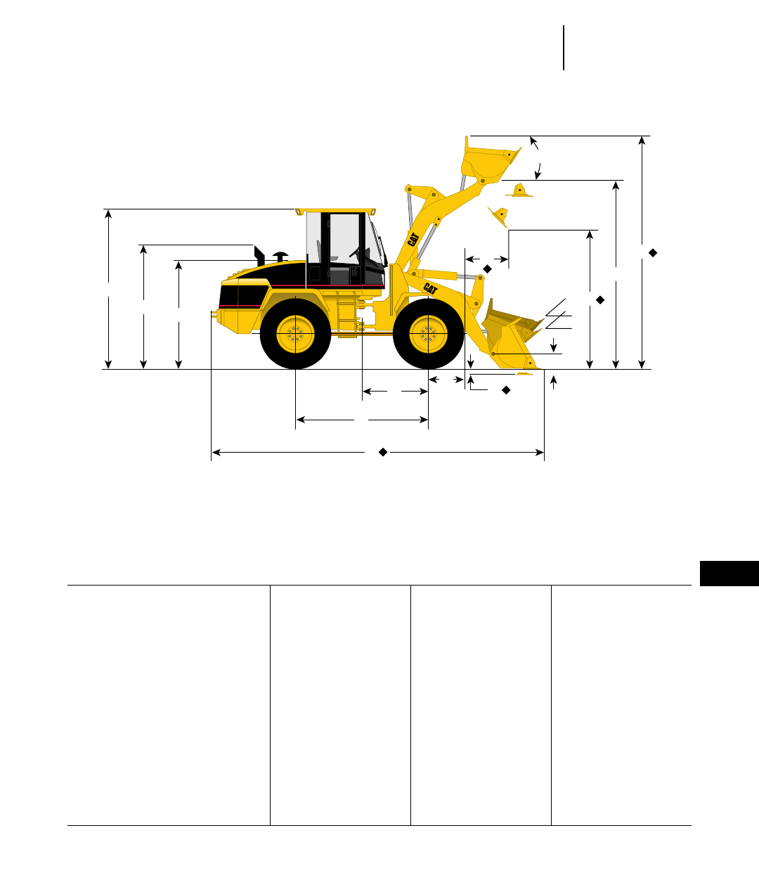
12-31
12
Wheel LoadersMachine Dimensions
●902-914G
Dimensions shown represent standard machine with General Purpose bucket (bolt-on cutting edge) and standard tires.
◆ Varies with Bucket Size and/or Bucket Configuration — Refer to Performance Data
902 906 914G
General Purpose General Purpose General Purpose
Bolt-on edge Bolt-on edge Bolt-on edge
MODEL: 0.6 m30.78 yd30.8 m31.05 yd31.3 m31.7 yd3
A Height to top of stack 2.69 m 8'10" 2.72 m 8'11" 2.26 m 7'5"
B Height to top of engine compartment 1.78 m 5'10" 1.82 m 6'0" 2.08 m 6'10"
C Height to top of ROPS 2.65 m 8'8" 2.68 m 8'10" 3.1 m 10'2"
D Hinge pin height at carry position 330 mm 13" 416 mm 16" 374 mm 15"
E Dump clearance at full lift and
45° discharge angle 2.31 m 7'7" 2.39 m 7'10" 2.66 m 8'9"
F Hinge pin height at full lift 3.02 m 9'11" 3.13 m 10'3" 3.44 m 11'3"
G Maximum overall height 3.97 m 13'0" 4.17 m 13'8" 4.39 m 14'5"
H Maximum digging depth 68 mm 2.7" 100 mm 3.9" 89 mm 3.5"
J Machine center point to axle 1.0 m 3'3" 1.0 m 3'3" 1.3 m 4'3"
K Wheelbase 2.0 m 6'7" 2.0 m 6'7" 2.6 m 8'6"
L Free radius of tire 440 mm 17" 475 mm 1'7" 670 mm 2'2"
M Maximum overall length 5.2 m 17'1" 5.36 m 17'7" 6.23 m 20'5"
N Reach at full lift 764 mm 2'6" 982 mm 3'3" 973 mm 3'2"
O Maximum rollback at maximum lift 63° 63° 60°
P Maximum rollback at carry height 50° 53° 46°
Q Maximum rollback at ground 44° 43° 41°
Ground clearance (std. tires) 282 mm 11.1" 317 mm 12.5" 456 mm 18"
Tread width (std. tires) 1.35 m 4'5" 1.4 m 4'7" 1.8 m 5'10.9"
Width over tires (std. tires) 1.7 m 4'3" 1.74 m 5'9" 2.26 m 7'4.9"
Tires used for measurements 12.5-18 12.5-20 17.5-R25 (L-2)
C
AB
K
J
N
O
L
E
F
G
M
H
D
P
Q
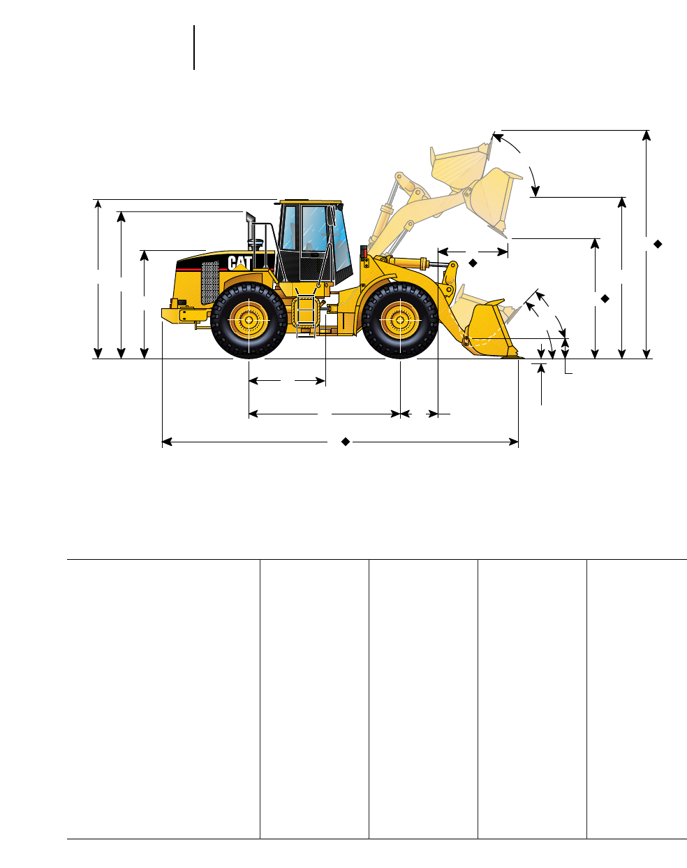
12-32
Wheel Loaders Machine Dimensions
●924F-950G
Dimensions shown represent standard machine with bucket, bolt-on cutting edge, and standard tires.
◆ Varies with Bucket Size and/or Bucket Configuration — Refer to Performance Data.
924F 928G 938G 950G
Loose Material General Purpose General Purpose General Purpose
Bolt-on edge Bolt-on edge Bolt-on edge Bolt-on edge
MODEL: 1.5 m32.00 yd32.2 m32.9 yd32.5m33.25 yd33.1 m34 yd3
A Height to top of stack 3.07 m 10'1" 3.11 m 10'2" 3.23 m 10'7" 3.22 m 10'7"
B Height to top of engine compartment 2.14 m 7'0" 2.16 m 7'1" 2.36 m 7'9" 2.25 m 7'5"
C Height to top of ROPS 3.14 m 10'4" 3.27 m 10'8" 3.3 m 10'10" 3.37 m 11'1"
D Hinge pin height at carry position 415 mm 16" 449 mm 18" 419 mm 16.5" 230 mm 9"
E Dump clearance at full lift and
45° discharge angle 2.70 m 8'10" 2.84 m 9'4" 2.85 m 9'4" 2.85 m 9'4"
F Hinge pin height at full lift 3.59 m 11'9" 3.87 m 12'8" 3.84 m 12'7" 3.98 m 13'1"
G Maximum overall height 4.68 m 15'4" 5.07 m 16'8" 5.08 m 16'8" 5.26 m 17'3"
H Maximum digging depth 93 mm 3.6" 86 mm 3.4" 48 mm 1.9" 101 mm 3.97"
J Machine center point to axle 1.35 m 4'5" 1.45 m 4'9" 1.510 m 4'11" 1.68 m 5'6"
K Wheelbase 2.70 m 8'10" 2.90 m 9'6" 3.020 m 9'11" 3.35 m 11'0"
L Radius of wheel 677 mm 2'3" 752 mm 2'6" 750 mm 2'6" 818 mm 2'8"
M Maximum overall length 6.52 m 21'5" 7.81 m 24'0" 7.28 m 23'9" 8.05 m 26'5"
N Reach at full lift 855 mm 2'10" 964 mm 3'2" 1004 mm 3'3.5" 1.29 m 4'3"
O Maximum rollback at maximum lift 58° 58° 65° 59°
P Maximum rollback at carry height 45° 47.8° 46° 45°
Q Maximum rollback at ground 40° 44° 41° 37.5°
Ground clearance (std. tires) 318 mm 12.5" 408 mm 16" 400 mm 15.7" 400 mm 16"
Tread width (std. tires) 1.85 m 6'1" 1.82 m 6'1" 2.02 m 5'8" 2.14 m 7'0"
Width over tires (std. tires) 2.33 m 7'8" 2.44 m 8'0" 2.61 m 8'6" 2.89 m 9'6"
Tires used for measurements 17.5-25 (L-2) 20.5-25 (L-2) 20.5-R25 (L-2) 23.5-R25,
XHA (L-3)
950G
CA
BE
F
G
J
KLH
D
O
N
O
P
M
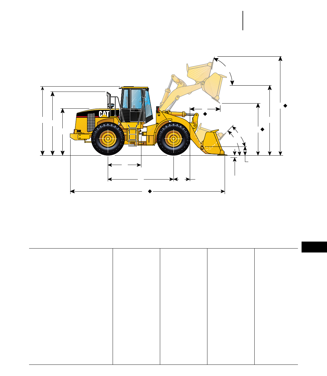
12-33
12
Wheel LoadersMachine Dimensions
●962G-980G
Dimensions shown represent standard machine with bucket, bolt-on cutting edge, and standard tires.
◆ Varies with Bucket Size and/or Bucket Configuration — Refer to Performance Data.
962G 966F Series II 970F 980G
Material General Material General
Handler Purpose Handling Purpose
Bolt-on edge Bolt-on edge Bolt-on edge Bolt-on edge
MODEL: 3.5 m34.5 yd33.8 m35 yd34.7 m36 yd35.7 m37.5 yd3
A Height to top of stack 3.22 m 10'7" 3.4 m 11'2" 3.4 m 11'3" 3.39 m 11'1"
B Height to top of engine compartment 2.25 m 7'5" 2.46 m 8'1" 2.48 m 8'1" 2.33 m 7'8"
C Height to top of ROPS 3.37 m 11'1" 3.43 m 11'3" 3.43 m 11'3" 3.75 m 12'4"
D Hinge pin height at carry position 230 mm 9" 470 mm 18.5" 470 mm 18.5" 453 mm 18"
E Dump clearance at full lift and
45° discharge angle 2.97 m 9'8" 2.98 m 9'9" 3.23 m 10'6" 3.27 m 10'9"
F Hinge pin height at full lift 4.17 m 13'8" 4.12 m 13'6" 4.43 m 14'7" 4.50 m 14'9"
G Maximum overall height 5.49 m 18'0" 5.59 m 18'4" 5.81 m 19'1" 6.20 m 20'4"
H Maximum digging depth 98 mm 3.8" 76 mm 3" 76 mm 3" 138 mm 5"
J Machine center point to axle 1.68 m 5'6" 1.675 m 5'6" 1.675 m 5'6" 1.85 m 6'1"
K Wheelbase 3.35 m 11'0" 3.350 m 11'0" 3.35 m 11'0" 3.70 m 12'2"
L Radius of wheel 818 mm 2'8" 864 mm 2'10" 864 mm 2'10" 928 mm 36.6"
M Maximum overall length 8.21 m 27'5" 8.30 m 27'4" 8.68 m 28'6" 9.46 m 31'1"
N Reach at full lift 1.27 m 4'2" 1275 mm 4'2" 1355 mm 4'5" 1.54 mm 5'1"
O Maximum rollback at maximum lift 60° 59° 54.3° 61°
P Maximum rollback at carry height 45° 48° 47° 46°
Q Maximum rollback at ground 37.5° 40° 43° 36°
Ground clearance (std. tires) 400 mm 16" 476 mm 18.7" 482 mm 19" 467 mm 18.4"
Tread width (std. tires) 2.14 m 7'0" 2.20 m 7'3" 2.20 m 7'3" 2.44 m 8'0"
Width over tires (std. tires) 2.89 m 9'6" 2.94 m 9'8" 2.94 m 9'8" 3.24 m 10'7"
Tires used for measurements 23.5-R25, XHA (L-3) 26.5-25 (L-3) 26.5-25 (L-3) 29.5-R25 (L-3)
950G
CA
BE
F
G
J
KLH
D
O
N
O
P
M
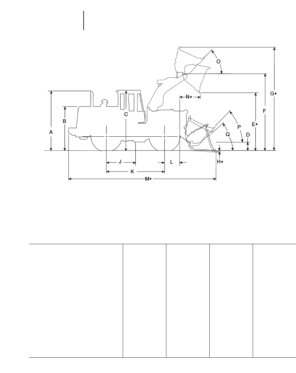
12-34
Wheel Loaders Machine Dimensions
●980G-990 Series II
Dimensions shown represent standard machine with spade edge rock bucket and standard tires.
◆ Varies with Bucket Size and/or Bucket Configuration — Refer to Performance Data
980G 988F 988F 990
General Series II Series II Series II
Purpose High Lift
High Lift Spade Edge Spade Edge Spade Edge
Bolt-on Rock With Rock With Rock With
edge Teeth Teeth Teeth
MODEL: 5.7 m37.5 yd36 m37.8 yd35.6 m37.25 yd38.4 m311 yd3
A Height to top of stack 3.39 m 11'1" 3.97 m 13'0" 3.97 m 13'0" 4.59 m 15'5"
B Height to top of engine compartment 2.33 m 7'8" 2.98 m 9'9" 2.98 m 9'9" 3.46 m 11'4"
C Height to top of ROPS 3.75 m 12'4" 4.13 m 13'6" 4.13 m 13'6" 5.13 m 16'10"
D Hinge pin height at carry position 453 mm 18" 650 mm 2'4" 780 mm 2'4" 816 mm 2'8"
E Dump clearance at full lift and
45° discharge angle 3.49 m 11'6" 3.21 m 10'6" 3.72 m 12'2" 4.05 m 13'3"
F Hinge pin height at full lift 4.73 m 15'6" 4.90 m 16'1" 5.36 m 17'7" 5.90 m 19'4"
G Maximum overall height 6.42 m 21'1" 6.85 m 22'6" 7.23 m 23'9" 8.13 m 26'8"
H Maximum digging depth 138 mm 5" 98 mm 4" 146 mm 6" 72 mm 2.8"
J Machine center point to axle 1.85 m 6'1" 1.90 m 6'3" 1.90 m 6'3" 2.30 m 7'7"
K Wheelbase 3.70 m 12'2" 3.81 m 12'6" 3.81 m 12'6" 4.60 m 15'1
L Radius of wheel 928 mm 36.6" 1.03 m 3'4" 1.03 m 3'4" 1.25 m 4'1"
M Maximum overall length 9.68 m 31'9" 10.99 m 36'1" 11.31 m 37'1" 12.61 m 41'4"
N Reach at full lift 1.54 mm 5'1" 1.61 m 5'3" 1.68 m 5'6" 1.99 m 6'6"
O Maximum rollback at maximum lift 61° 63.3° 63.3° 64°
P Maximum rollback at carry height 46° 50° 50° 48.4°
Q Maximum rollback at ground 36° 40° 40° 39.1°
Ground clearance (std. tires) 467 mm 18.4" 529 mm 1'9" 529 mm 1'9" 491 mm 1'7"
Tread width (std. tires) 2.44 m 8'0" 2.59 m 8'6" 2.59 m 8'6" 3.05 m 10'0"
Width over tires (std. tires) 3.25 m 10'8" 3.55 m 11'8" 3.55 m 11'8" 4.16 m 13'3"
Tires used for measurements 29.5-R25 (L-3) 35/65-33 (L-4) 35/65-33 (L-4) 41.25/70-39 (L-5)
FULL DUMP ◆
@ MAX. LIFT
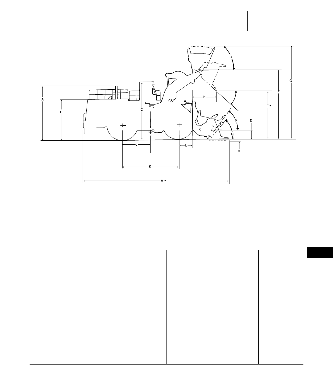
12-35
12
Wheel LoadersMachine Dimensions
●992G-994
Dimensions shown represent standard machine with spade edge rock bucket and standard tires.
◆ Varies with Bucket Size and/or Bucket Configuration — Refer to Performance Data
992G 992G 994 994
High Lift
High Lift 5640 mm (18'6") 5640 mm (18'6")
Spade Edge Spade Edge Spade-Edge Bucket Spade Edge Bucket
Rock With Rock With With Teeth With Teeth
Teeth Teeth And Segments And Segments
MODEL: 11.5 m315 yd311.5 m315 yd316 m321 yd316 m321 yd3
A Height to top of stack 5.23 m 17'2" 5.23 m 17'2" 6.30 m 20'8" 6.30 m 20'8"
B Height to top of engine compartment 3.98 m 13'0" 3.98 m 13'0" 4.66 m 15'3" 4.66 m 15'3"
C Height to top of ROPS 5.59 m 18'4" 5.59 m 18'4" 6.53 m 21'5" 6.53 m 21'5"
D Hinge pin height at carry position 960 mm 3'1.8" 1125 mm 3'8.3" 1030 mm 3'5" 1258 mm 4'2"
◆E Dump clearance at full lift and
45° discharge angle 4.63 m 15'3" 5.25 m 17'3" 5.51 m 18'1" 5.85 m 19'2"
◆F Hinge pin height at full lift 6.94 m 22'9" 7.55 m 24'10" 7.98 m 26'2" 8.32 m 27'3"
◆G Maximum overall height 9.41 m 30'11" 10.03 m 32'11" 10.75 m 35'3" 11.09 m 36'5"
◆H Maximum digging depth 140 mm 5.5" 144 mm 5.7" 248 mm 9" 262 mm 10"
J Machine center point to axle 2.94 m 9'8" 2.94 m 9'8" 3.20 m 10'6" 3.20 m 10'6"
K Wheelbase 5.89 m 19'4" 5.89 m 19'4" 6.40 m 21'0" 6.40 m 21'0"
L Radius of wheel 1.37 m 4'6" 1.37 m 4'6" 1.80 m 5'11" 1.80 m 5'11"
◆M Maximum overall length 15.58 m 49'8" 16.17 m 53'1" 16.84 m 55'3" 17.61 m 57'9"
◆N Reach at full lift 2.3 m 7'7" 2.29 m 7'7" 2.31 m 7'7" 2.87 m 9'5"
O Maximum rollback at maximum lift 65° 65° 64° 64°
P Maximum rollback at carry height 50° 50° 53° 58°
Q Maximum rollback at ground 42° 42° 40° 40°
Ground clearance (std. tires) 691 mm 2'3.2" 691 mm 2'3.2" 650 mm 2'2" 650 mm 2'2"
Tread width (std. tires) 3.30 m 10'10" 3.30 m 10'10" 3.90 m 12'10" 3.90 m 12'10"
Width over tires (std. tires) 4.50 m 14'9" 4.49 m 14'9" 5.20 m 17'1" 5.20 m 17'1"
Tires used for measurements 45/65-45 (L-5) 45/65-45 (L-5) 50/80-57 (L-4) 50/80-57 (L-4)
FULL DUMP ◆
@ MAX. LIFT
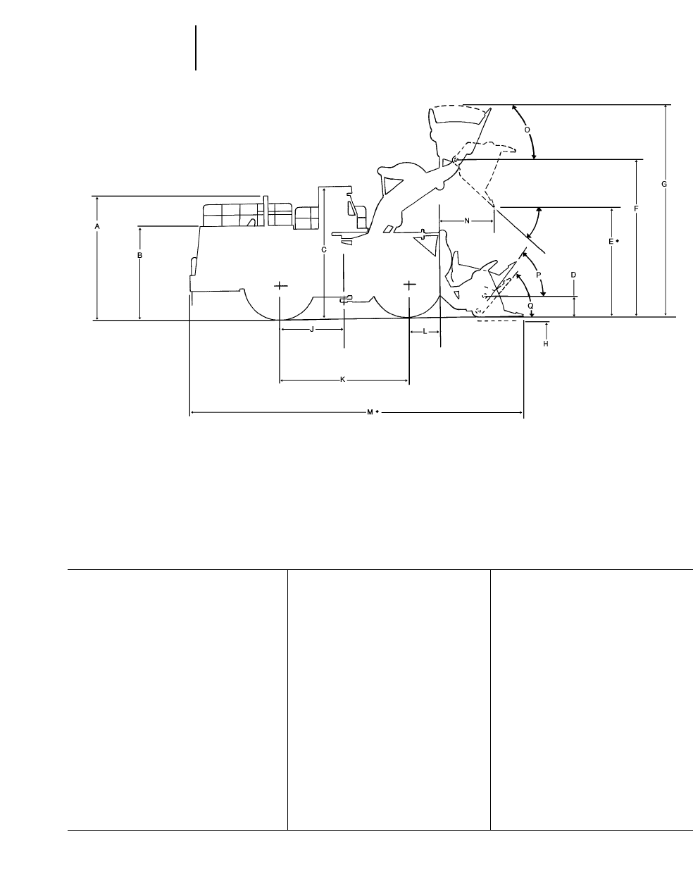
12-36
Wheel Loaders Machine Dimensions
●994
Dimensions shown represent standard machine with spade edge rock bucket and standard tires.
◆ Varies with Bucket Size and/or Bucket Configuration — Refer to Performance Data
994 994
High Lift
5640 mm (18'6") 5640 mm (18'6")
Spade Edge Bucket Spade Edge Bucket
With Teeth With Teeth
And Segments And Segments
MODEL: 18 m323 yd318 m323 yd3
A Height to top of stack 6.48 m 21'3" 6.48 m 21'3"
B Height to top of engine compartment 4.84 m 15'11" 4.84 m 15'11"
C Height to top of ROPS 6.71 m 22'0" 6.71 m 22'0"
D Hinge pin height at carry position 1030 mm 3'5" 1258 mm 4'2"
◆E Dump clearance at full lift and
45° discharge angle 5.58 m 18'4" 5.92 m 19'5"
◆F Hinge pin height at full lift 8.16 m 26'9" 8.50 m 27'11"
◆G Maximum overall height 11.02 m 36'2" 11.36 m 37'3"
◆H Maximum digging depth 68 mm 3" 82 mm 3"
J Machine center point to axle 3.20 m 10'6" 3.20 m 10'6"
K Wheelbase 6.40 m 21'0" 6.40 m 21'0"
L Radius of wheel 2.00 m 6'7" 2.00 m 6'7"
◆M Maximum overall length 16.86 m 55'4" 17.64 m 57'11"
◆N Reach at full lift 2.42 m 7'11" 2.98 m 9'9"
O Maximum rollback at maximum lift 64° 64°
P Maximum rollback at carry height 53° 58°
Q Maximum rollback at ground 40° 40°
Ground clearance (std. tires) 830 mm 2'9" 830 mm 2'9"
Tread width (std. tires) 4.00 m 13'1" 4.00 m 13'1"
Width over tires (std. tires) 5.35 m 17'7" 5.35 m 17'7"
Tires used for measurements 53.5/85-57 (L-5) 53.5/85-57 (L-5)
FULL DUMP ◆
@ MAX. LIFT
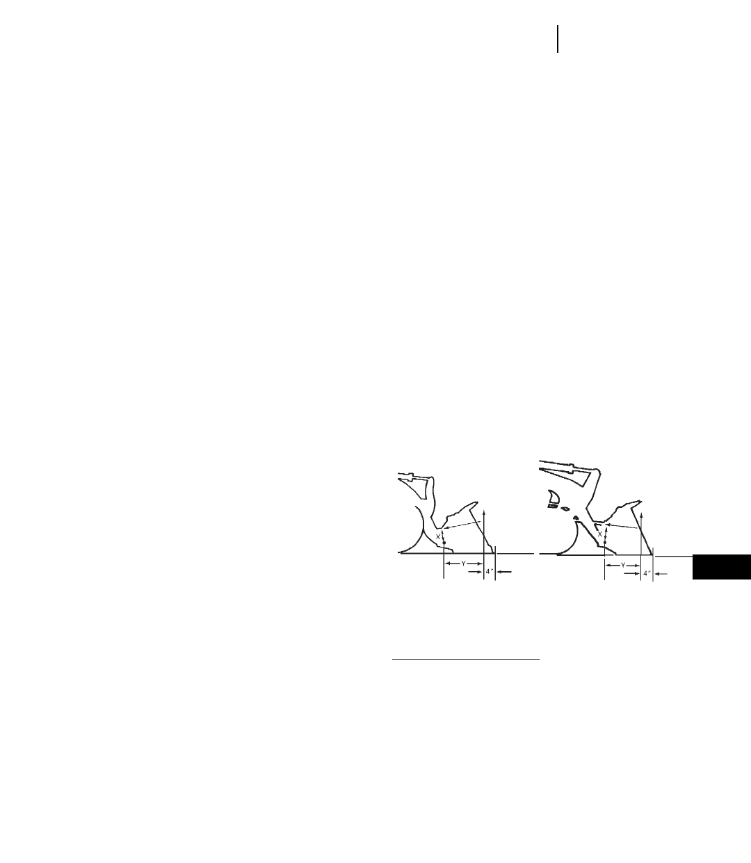
12-37
Wheel LoadersSAE Loader Ratings
SPECIFICATION DEFINITIONS FOR
FRONT END LOADERS
Caterpillar wheel and track loader specifications
conform to Society of Automotive Engineers (SAE)
definitions as expressed in standards J732 (JUN92),
as follows:
Description of Specification Machine
On wheel loaders the tire inflation pressure at
which specifications are taken must be described in
addition to the current written basic machine descrip-
tion. On track loaders the type of grouser must be
specified.
Hydraulic Cycle Times
a. “Raise Time’’ — Time in seconds required to raise
the bucket from level position on the ground.
b. “Lower Time’’ — Time in seconds required to
lower the empty bucket from the full height to
a level position on the ground.
c. “Dump Time’’ — Time in seconds required to
move the bucket at maximum height from the
maximum rollback position to full dump posi-
tion while dumping the SAE loose material oper-
ating load.
Breakout Force
“Breakout force,’’ pounds (and kilonewtons or kilo-
grams) — the maximum sustained vertical upward
force exerted 100 mm (4") behind the tip of the bucket
cutting edge and achieved through the ability to lift
and/or rollback about the specified pivot point under
the following conditions:
a. Loader on a hard level surface with transmis-
sion in neutral.
b. All brakes released.
c. Unit at standard operating weight — rear of
loader not tied down.
d. Bottom of cutting edge parallel to and not more
than 20 mm (0.75") above or below the ground
line.
e. When bucket circuit is used the pivot point must
be specified as the bucket hinge pin, and the unit
blocked under the bucket hinge pin pivot point
in order to minimize linkage movement.
f. When the lift circuit is used, the pivot point
must be specified as the lift arm hinge pin.
Wheel loaders shall have front axle blocked to
eliminate change in position of pivot pins due
to tire deflection.
g. If both circuits are used simultaneously, the
dominating pivot point listed in (e) or (f) must
be specified.
h. If the circuit used causes the rear of the vehi-
cle to leave the ground, then the vertical force
value required to raise the rear of the vehicle is
the breakout force.
i. For irregular shaped buckets, the tip of the
bucket cutting edge referred to above shall mean
the farther forward point of the cutting edge.
The following are illustrations used (according to
provisions of SAE J732 JUN92) to measure Caterpillar
Loader breakout forces.
a. Breakout force resulting from rackback:
(Tilt Force) 3 (Dist. “X’’) = (“Y’’ Dist.) 3
(Breakout Force)
(Tilt Force) 3 (Dist. “X’’) = Breakout Force
“Y’’ Dist.
TRACKWHEEL
BREAKOUT
FORCE BREAKOUT
FORCE
TILT
FORCE TILT
FORCE
12
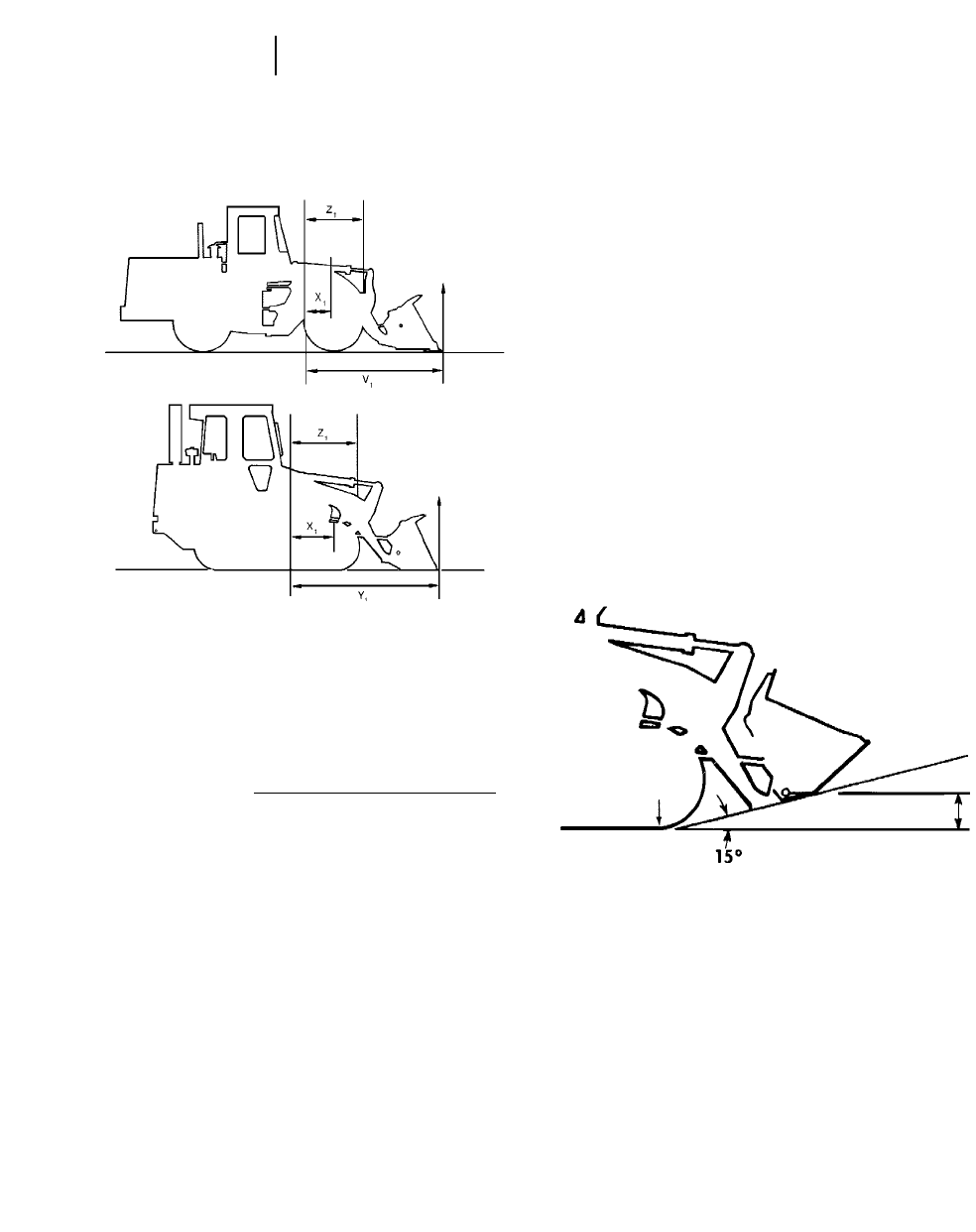
12-38
Wheel Loaders SAE Loader Ratings
b. Breakout force resulting from bucket lift:
(Lift Force) 3
(Dist. “X1’’) = (“Y1’’ Dist.) 3(Breakout Force)
+ (Linkage Wt.) 3(Dist. “Z1’’)
+ (Breakout Force)
3(Linkage Mechanical
Advantage) “V1’’
or
(Lift Force) 3(Dist. “X1’’) —
Breakout (Linkage Wt.) 3(Dist. “Z1’’)
Force = (Dist. “Y1’’) + (Dist. “V1’’) 3
(Linkage Mech. Advantage)
Static Tipping Load
The minimum weight at center of gravity of “SAE
Rated’’ load in bucket which will rotate rear of
machine to a point where, on track loaders, front
rollers are clear of the track and on wheel loaders,
rear wheels are clear of the ground under the fol-
lowing conditions:
a. Loader on hard level surface and stationary.
b. Unit at standard operating weight.
c. Bucket at maximum rollback position.
d. Load at maximum forward position during
raising cycle.
e. For articulated wheel loaders, the test will be
run both with frame straight (straight static
tipping load) and fully turned to a specific angle
(full turn static tipping load).
f. Unit with standard equipment as described in
specifications unless otherwise noted under the
heading.
Operating Load
In order to comply with SAE standard J818 MAY87,
the operating load of Wheel Loaders should not
exceed 50% of the full turn Static Tipping load of
the machine when equipped with attachments
needed for the job. (For track loaders, operating load
should not exceed 35% of the Static Tipping load
rating.) See “Performance Data’’ of each machine in
this handbook for increases to static tipping load by
adding cab, counterweights, ripper-scarifier, etc.
Carry Position
SAE defines carry positions as: “The vertical dis-
tance from the ground to the center line of the bucket
hinge pin, with the angle of approach at 15°.’’ The
sketch below illustrates this definition:
Loader Clearance Circle
SAE J732 JUN92 states that “minimum turning
radius (over tire)’’ and “loader clearance circle’’
should be given for wheel loaders. Both are given
on Caterpillar specification sheets, including loader
clearance circles for all available buckets for each
machine.
Digging Depth
J732 JUN92 specifies digging depth as “the verti-
cal distance in mm (inches) from the ground line to
the bottom of the bucket cutting edge at the lowest
position with the bucket cutting edge horizontal.’’
LINKAGE WT.
LINKAGE WT.
BREAKOUT
FORCE
BREAKOUT
FORCE
LIFT
FORCE
LIFT
FORCE
LAST POINT
OF WHEEL OR
TRACK CONTACT CARRY
HEIGHT
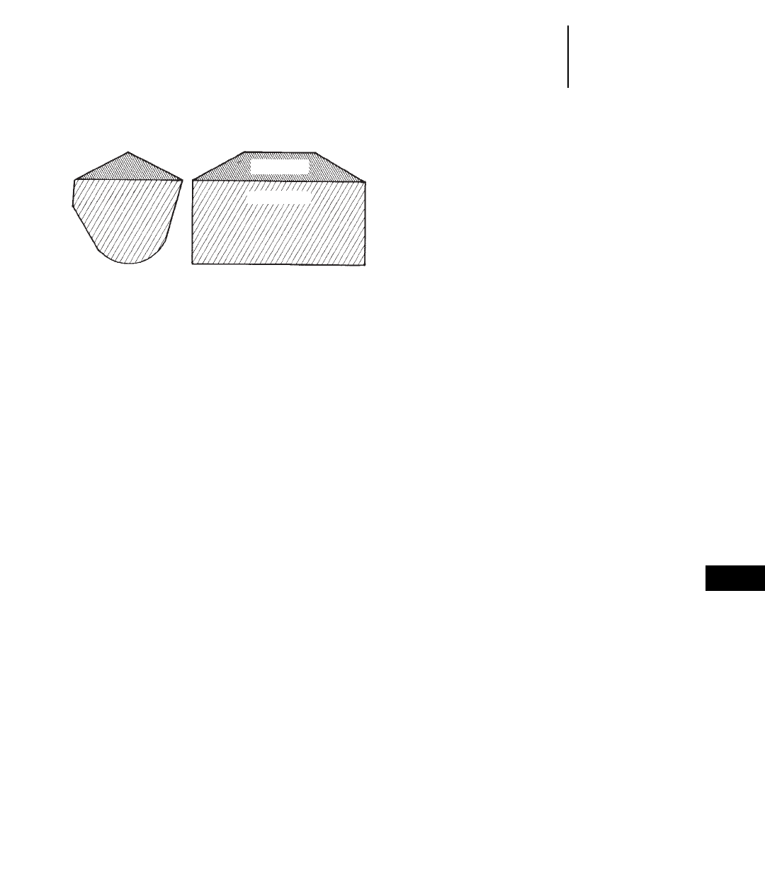
12-39
12
Wheel LoadersSAE Loader Ratings
Machine Selection
●Cycle Time Factors
SAE BUCKET RATING
SAE Bucket Capacities
Struck capacity is that volume contained in a
bucket after a load is leveled by drawing a straight
edge resting on the cutting edge and the back of the
bucket.
Heaped capacity is a struck capacity plus that
additional material that would heap on the struck
load at a 2:1 angle of repose with the struck line
parallel to the ground.
SAE J742 (FEB85) specifies that the addition of any
auxiliary spill guard to protect against spillage which
might injure the operator will not be included in bucket
capacity ratings. Buckets with irregular shaped cut-
ting edges (vee edge) the strike plane should be drawn
at one-third the distance of the protruding portion of
the cutting edge. Caterpillar rock buckets are built
with integral see-through rock guards. Caterpillar
light material buckets come standard with bolt-on
edges. These features which add to actual bucket
capacity are included in published ratings.
Dump Height
SAE J732 JUN92 specifies that dump height is
the vertical distance from the ground to the lowest
point of the cutting edge with the bucket hinge pin
at maximum height and the bucket at a 45° dump
angle. Dump angle is the angle in degrees that the
longest flat section of the inside bottom of the bucket
will rotate below horizontal.
SELECTING A MACHINE
Steps in selecting the proper size loader:
1. Determine production required or desired.
2. Determine loader cycle time and cycles per hour.
A machine size must be assumed to select a basic
cycle time.
3. Determine required payload per cycle in loose
cubic yards and pounds (meters and kilograms).
4. Determine bucket size needed.
5. Make machine selection using bucket size and pay-
load as criteria to meet production requirements.
6. Compare the loader cycle time used in calculations
to the cycle time of the machine selected. If there
is a difference, rework the process beginning at
step 2.
1. Production Required
The production required of a wheel or track loader
should be slightly greater than the production capa-
bility of the other critical units in the earth or mate-
rial moving system. For example, if a hopper can
handle 300 tons per hour, a loader capable of slightly
more than 300 tons should be used. Required pro-
duction should be carefully calculated so the proper
machine and bucket selections are made.
2. Loader Cycle Times
When hauling loose granular material on a hard
smooth operating surface, a .45-.55 minute basic
cycle time is considered reasonable for Caterpillar
articulated loaders with a competent operator. This
includes load, dump, four reversals of direction, full
cycle of hydraulics and minimum travel.
Material type, pile height, and other factors may
improve or reduce production, and should be added
to or subtracted from the basic cycle time when
applicable.
When hauls are involved, obtain the haul and return
portion of the cycle from the estimated travel chart (this
section). Add the haul and return times to the esti-
mated basic cycle time to obtain total cycle time.
CYCLE TIME FACTORS
A basic cycle time (Load, Dump, Maneuver) of
.45-.55 minutes is average for an articulated loader
[the basic cycle for large loaders, 3 m3(4 yd3) and
up, can be slightly longer], but variations can be
anticipated in the field. The following values for
many variable elements are based on normal oper-
ations. Adding or subtracting any of the variable
times will give the total basic cycle time.
STRUCK
HEAPED

12-40
Wheel Loaders Machine Selection
●Truck Loading
●Bucket Fill Factors
Minutes added (+)
or Subtracted (–)
From Basic Cycle
Machine
— Material handler . . . . . . . . . . . . . –.05
Materials
— Mixed. . . . . . . . . . . . . . . . . . . . . . . +.02
— Up to 3 mm (1/8 in). . . . . . . . . . . . +.02
— 3 mm (1/8 in) to 20 mm
(3/4 in) . . . . . . . . . . . . . . . . . . . . . . –.02
— 20 mm (3/4 in) to 150 mm
(6 in) . . . . . . . . . . . . . . . . . . . . . . . –.00
— 150 mm (6 in) and over. . . . . . . . . +.03 and Up
— Bank or broken . . . . . . . . . . . . . . . +.04 and Up
Pile
— Conveyor or Dozer piled 3 m
(10 ft) and up . . . . . . . . . . . . . . . . –.00
— Conveyor or Dozer piled 3 m
(10 ft) or less . . . . . . . . . . . . . . . . . +.01
— Dumped by truck . . . . . . . . . . . . . +.02
Miscellaneous
— Common ownership of trucks
and loaders . . . . . . . . . . . . . . . . . . Up to –.04
— Independently owned
trucks . . . . . . . . . . . . . . . . . . . . . . Up to +.04
— Constant operation. . . . . . . . . . . . Up to –.04
— Inconsistent operation . . . . . . . . . Up to +.04
— Small target . . . . . . . . . . . . . . . . . Up to +.04
— Fragile target . . . . . . . . . . . . . . . . Up to +.05
Using actual job conditions and the above factors,
total cycle time can be estimated. Convert total cycle
time to cycles per hour.
Cycles per hour at 60 min
100% Efficiency = Total Cycle Time
in Minutes
Job efficiency is an important factor in machine
selection. Efficiency is the actual number of min-
utes worked during an hour. Job efficiency accounts
for bathroom breaks and other work interruptions.
Cycles per hour
at 50 minutes Cycles per hour 50 min
per hour = at 100% 3actual work
(83% efficiency) efficiency time
60 min hour
TRUCK LOADING
Average loader cycle times
914G-962G . . . . . . . . . . . . . . . . . . . . . . . . 0.45-0.50
966F Series II-980G . . . . . . . . . . . . . . . . . 0.50-0.55
988F-990 . . . . . . . . . . . . . . . . . . . . . . . . . . 0.55-0.60
992G-994. . . . . . . . . . . . . . . . . . . . . . . . . . 0.60-0.70
3. Required Payload Per Cycle
Required payload per cycle is determined by divid-
ing required hourly production by the number of
cycles per hour.
4. Bucket Selection
After required payload per cycle has been calcu-
lated, the payload should be divided by the loose cubic
yard (meter) material weight to determine number
of loose cubic yards (meters) required per cycle.
The bulk of material handled does not weigh
1800 kg/m3(3000 lb/yd3), so a reasonable knowledge
of material weight is necessary for accurate pro-
duction estimates. The Tables Section has average
weight for certain materials when actual weights
are not known.
The percentage of rated capacity a bucket carries
in various materials is estimated below. The bucket
size required to handle the required volume per cycle
is found with the aid of the percentage of rated bucket
capacity called “Bucket Fill Factor.’’
The bucket size needed is determined by dividing
loose cubic meters (or yards) required per cycle by
the bucket fill factor.
Bucket size =Volume Required/Cycle
Bucket Fill Factor
BUCKET FILL FACTORS
The following indicates the approximate amounts
of material as a percent of rated bucket capacity
which will actually be delivered per bucket per cycle.
This is known as “Bucket Fill Factor.’’
Loose Material Fill factor
Mixed moist aggregates. . . . . . . . . . . . . 95-100%
Uniform aggregates up to 3 mm
(1/8 in). . . . . . . . . . . . . . . . . . . . . . . . . 95-100%
3 mm (1/8 in) to 9 mm (3/8 in). . . . . . . . 90-95%
12 mm (1/2 in) to 20 mm (3/4 in). . . . . . 85-90%
24 mm (1.0 in) and over. . . . . . . . . . . . . 85-90%

12-41
12
Wheel LoadersMachine Selection
●Bucket Fill Factors
●Example Problem
Blasted Rock
Well blasted . . . . . . . . . . . . . . . . . . . . . 80-950%
Average . . . . . . . . . . . . . . . . . . . . . . . . 75-900%
Poor . . . . . . . . . . . . . . . . . . . . . . . . . . . 60-750%
Other
Rock dirt mixtures. . . . . . . . . . . . . . . . 100-120%
Moist loam . . . . . . . . . . . . . . . . . . . . . . 100-110%
Soil, boulders, roots . . . . . . . . . . . . . . . 80-100%
Cemented materials . . . . . . . . . . . . . . 85-950%
NOTE: Fill factors on wheel loaders are affected by
bucket penetration, breakout force, rackback
angle, bucket profile and ground engaging
tools such as bucket teeth or bolt-on replace-
able cutting edges.
Example:
12 mm (1/2 in) material and 3 m3(4 yd3) bucket.
.90 33m
3= 2.75 Loose m3delivered per cycle.
.90 34yd
3= 3.6 Loose yd3delivered per cycle.
NOTE: Check the static tipping load on the specific
machine to determine if bucket load is in
fact a safe operating load.
Bucket Selection Tons Required/Hour
Tons Required/Cycle = CyclesHour
Kg (Pounds)
Required/Cycle = Tons Required/Cycle
3
907 kg (2000 lb)
Volume Required/Cycle = kg (Pounds)Cycle
Material Weight
kg/m3(lb/yd3)
Always select a machine with a greater capacity
than the calculated required operating capacity.
For most applications, payload above recommended
and excessive counterweight can hinder machine
performance and reduce dynamic stability and
machine life.
For optimum performance in fast cycling situations
such as truck loading, operating loads should not
exceed the recommended capacity. To provide extra
stability, calcium chloride (CaCl2) ballast may be
desired when operating at recommended operating
load, see SAE Loader rating pages in this section. For
specific stability data and optional tire sizes, see the
“Performance Data’’ pages in this section.
When selecting special application buckets, such as
multi-purpose and side dump the additional bucket
weight must be deducted from recommended capacity.
Specific circumstances may involve other conditions
which would also affect loader capacity. Because of
the greatly varied applications and conditions, your
Caterpillar dealer should be contacted for guidance.
Example problem:
JOB CONDITIONS
Application Truck loading
Production Required 450 metric ton (496 Tons)
per hour
Material 9 mm (3/8") gravel in 6 m
(20 ft) high stockpile
Density 1660 kg/m3(2800 lb/yd3)
Trucks are 6-9 m3(8-12 yd3) capacity and are owned
by three contractors. Loading is constant. Hard level
surface for loader maneuvering.
1. PRODUCTION REQUIRED: Given
2. CYCLE TIME: Assume loader size between 914G
and 962G for initial choice of basic cycle.
(Refer to Cycle Time Factors in this section)
Independent trucks .04 min
Basic Cycle .50 min
Material –.02 min
Independent trucks +.04 min
Constant operation –.02 min
Total Cycle .50 min
NOTE: Load and carry times not required in total
cycle.
Cycles/hr 50 min actual
at 83% = 120 cycles/hr 3work time
efficiency 60 min per hr
= 100 cycles/hr
3. VOLUME REQUIRED PER CYCLE
(Density in tons)
Density in this example was given. When not
given, refer to Tables Section to obtain an esti-
mated density for the material being handled.
1660 kg/m3
Metric: 1000 kg/ton = 1.66 ton/m3
2800 lb/yd3
English: 2000 lb/ton = 1.4 tons/yd3

12-42
Wheel Loaders Machine Selection
●Example Problem
●Alternative Method
Production Rate Required
450 tons/hr
Metric: 1.66 tons/m3= 271 m3/hr
496 tons/hr
English: 1.4 tons/yd3= 354 yd3/hr
Volume Required per Cycle
271 m3/hr
Metric: 100 cycles/hr= 2.71 m3/cycle
354 yd3/hr
English:100 cycles/hr= 3.54 yd3/cycle
4. DETERMINE BUCKET SIZE
BUCKET FILL FACTOR
The volume of material required per cycle has
been determined. Because of varying material fill
factors, buckets do not always carry their rated
load, a larger capacity bucket may be needed to
carry the volume required. For fill factors, refer
to Bucket Fill Factor Chart in this section.
Rated Bucket Capacity Required (Heaped)
2.71 m3/cycle = 2.85 m3
.95 fill factor
3.54 yd3/cycle = 3.73 yd3
.95 fill factor
A 2.9 m3(3.75 yd3) bucket would provide the
required capacity.
5. MACHINE SELECTION
The bucket size required and material density
lead to the choice of a 950G with a 2.9 m3(3.75 yd3)
General Purpose Bucket (see bucket selection
guide pages which follow.)
Finally, SAE payload criteria must be satis-
fied as follows:
The required operating capacity must not
exceed one-half of the full turn static tipping load
of the loader as equipped with a specific bucket.
The required operating capacity of the machine
is determined by the volume the machine will
carry per load times the density.
2.9 m331660 kg/m3= 4814 kg
(3.75 yd332800 lb/yd3= 10,500 lb)
One half of full turn static tipping load for the
950G with a 2.9 m3(3.75 yd3) General Purpose
Bucket is 5259 kg (11,591 lb). SAE criteria is
satisfied.
●●●
An Alternative Method
of Machine Selection
Another method of selecting the right Wheel
Loader and bucket to meet production requirements
is by use of the nomographs on the following pages.
The method is quicker and easier than the preced-
ing example because it does not require as many
calculations, yet the accuracy is about the same
within the normal limits of input data.
Be careful when entering and reading data from
the nomographs because some scales increase from
bottom to top, while others are the reverse. Do not be
overly concerned with the precision as affected by
pencil line width or reading to the hundredth of a m3
(yd3). Remember that bucket fill factor, material den-
sity and cycle time are at best close estimates.
Example problem:
A Wheel Loader must produce 230 m3(300 yd3)
per hour in a truck loading application. Estimated
cycle time is .6 minutes, working 45 minutes per
hour. Bucket fill factor is 95% and material density
is 1780 kg/m3(3000 lb/yd3).
Determine bucket size and machine model.
Solution:
At full efficiency, the Wheel Loader will cycle 100
times per hour. Since only an average of 45 minutes
are available, only 75 cycles will be completed.
Starting on Scale A at 75 cycles per hour draw a
straight line intersecting 230 m3/hr (300 yd3/hr) on
Scale B and extending it on to Scale C giving
3m
3/cycle (4 yd3/cycle) required payload. Follow
solution steps 1-10.
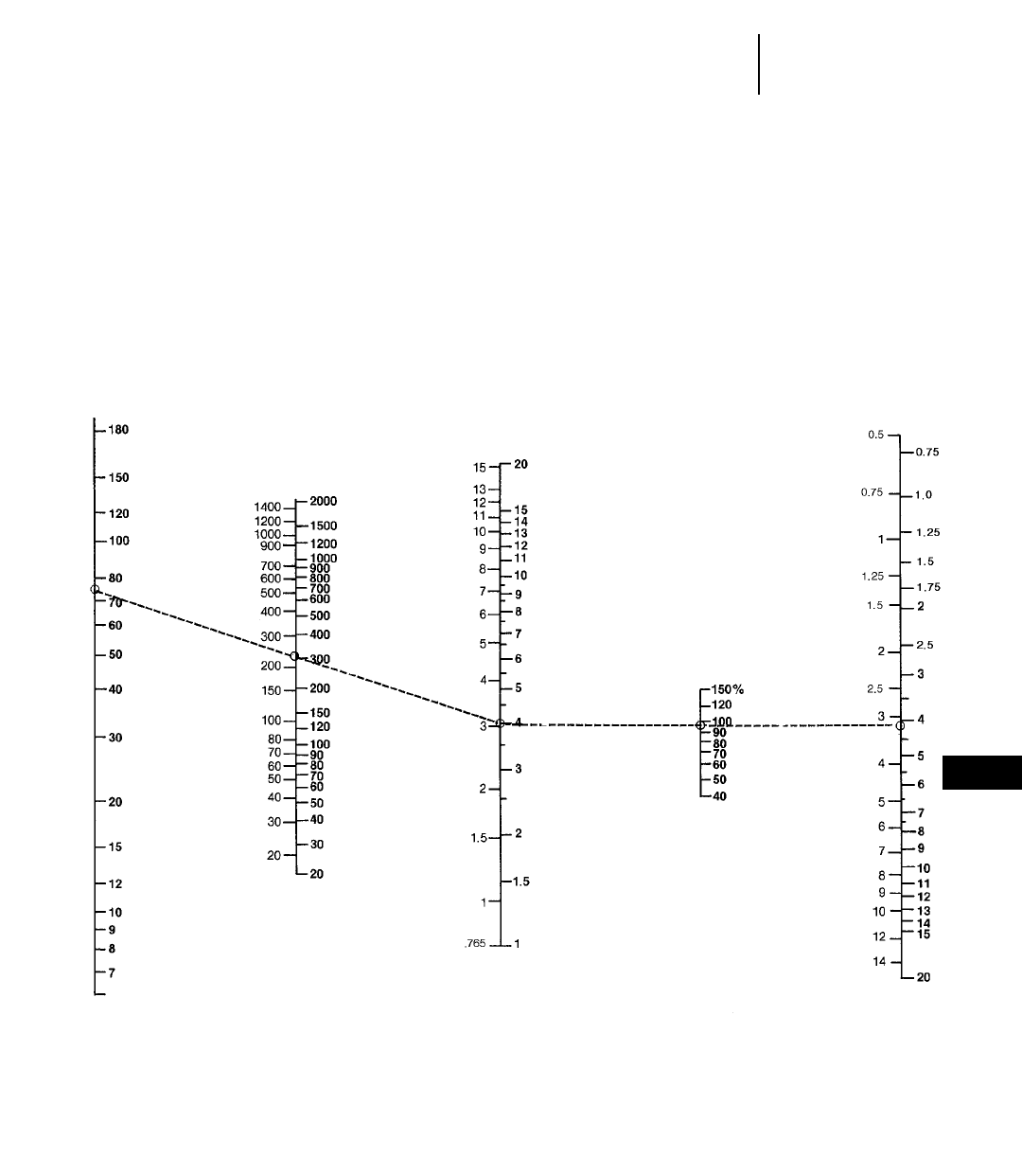
12-43
12
Wheel LoadersProduction and Machine Selection Nomograph
●To find payload weight and tons per hour
1. Enter required hourly production on Scale B
230 m3/hr (300 yd3/hr).
2. Enter cycles per hour on Scale A (60 ÷ .6 = 100
3.75 = 75 cycles/hr).
3. Connect A thru B to C. This shows a required
payload of 3 m3(4 yd3) per cycle.
4. Enter estimated bucket fill factor on Scale D
(0.95).
5. Connect C thru Scale D to E for required bucket
size 3 m3(4 yd3).
6. Transfer cycles per hour Scale A and required
payload Scale C to the following page.
m3/cycle yd3/cycle
m3/hr yd3/hr
m3yd3
AB C DE
Cycles Hourly Required Bucket Required
per hour Production Payload Fill Bucket
Volume Volume Factor
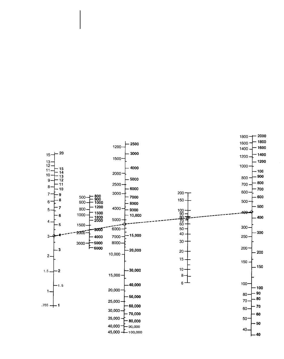
12-44
Wheel Loaders Production and Machine Selection Nomograph
●To find required bucket payload and bucket size
7. Enter material density on Scale F 1780 kg/m3
(3000 lb/yd3).
8. Connect C thru Scale F to Scale G to give pay-
load weight per cycle 5300 kg (11,500 lb).
9. Compare Scale G quantity 5300 kg (11,500 lb)
with recommended machine working range
listed on the following bucket selection pages.
Operating capacity for the 950G with 3.1 m3
(4 yd3) bucket is dependent on material density
and bucket capacity (see bucket selection pages
that follow).
10. For hourly tonnage, draw a straight line from
Scale G thru Scale A to Scale I 400 metric tons
(450 U.S. tons).
CFG A I
Required Material Bucket Cycles/hr Tons per
Payload Density Payload Hour
Volume Weight per
cycle
kg/cycle
Metric
Tons
lb/cycle
U.S.
Short Tons
m3/cycle yd3/cycle
kg/m3lb/yd3
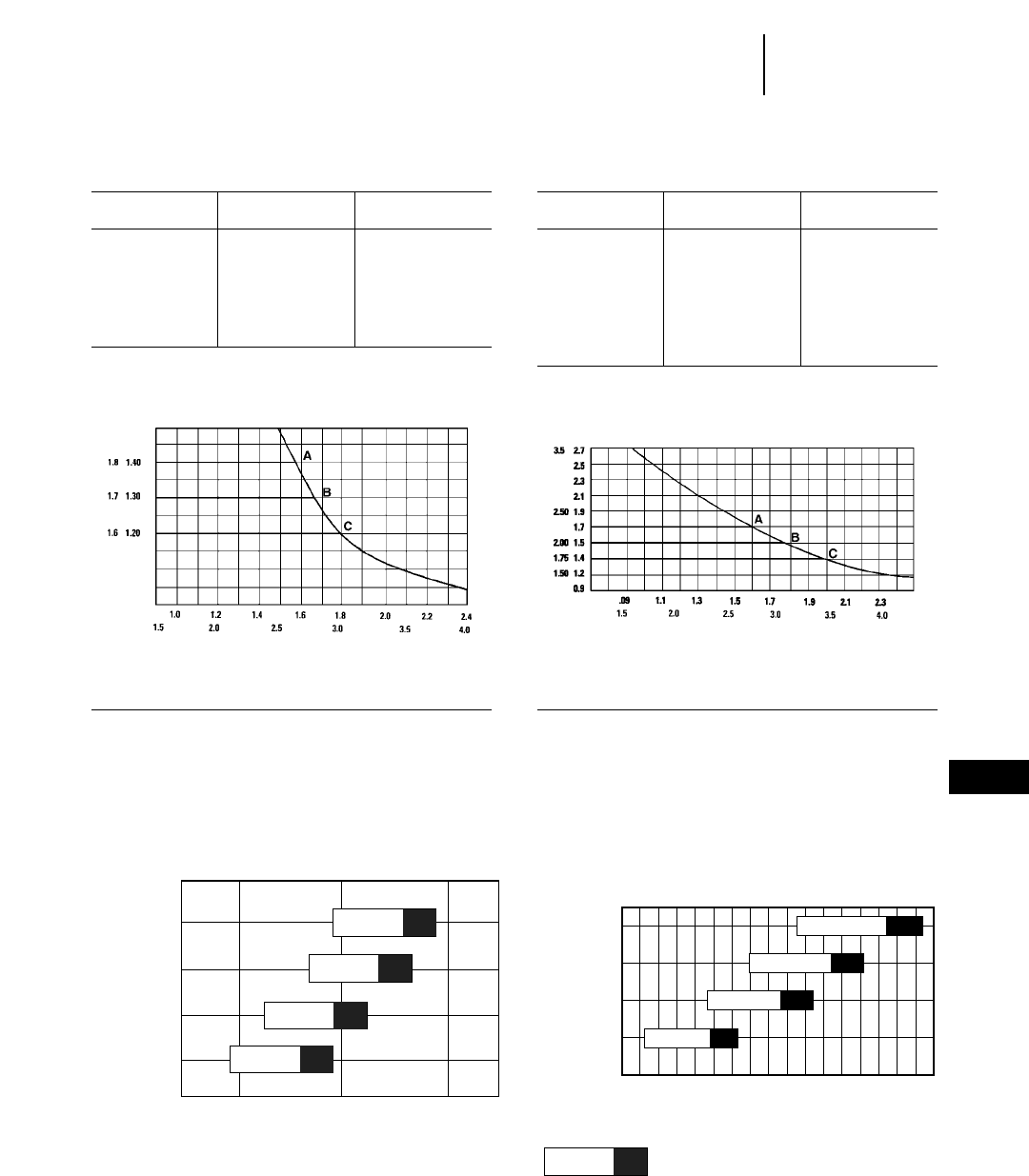
12-45
12
Wheel LoadersBucket Selection
●902–938G
MATERIAL DENSITY (THOUSANDS)
914G 924F
kg/m3
lb/yd3
m3
yd3
BUCKET CAPACITY
BUCKET CAPACITY
m3
yd3
kg/m3
lb/yd3
KEY
A — 1.4 m3(1.8 yd3)General Purpose Bucket, bolt-on edge
1.4 m3(1.8 yd3)General Purpose Bucket, bolt-on teeth and segments
B — 1.3 m3(1.7 yd3)General Purpose Bucket, bolt-on edge
1.3 m3(1.7 yd3)General Purpose Bucket, bolt-on teeth and segments
1.3 m3(1.7 yd3)General Bucket, bolt-on teeth
1.3 m3(1.7 yd3)General Purpose Bucket, flush mounted teeth
C — 1.2 m3(1.6 yd3)General Purpose Bucket, bolt-on teeth
902
Maximum
Bucket Type Rated Capacity Material Density
m3yd3kg/m3lb/yd3
General Purpose 0.6 0.78 2100 3540
Light Material 1.0 1.31 1230 2070
Stone Sieve 0.6 0.78 2050 3460
Multi-Purpose 0.6 0.78 1900 3200
High Dump 0.6 0.78 2000 3370
MATERIAL DENSITY (THOUSANDS)
KEY
A — 1.7 m3(2.25 yd3)Loose Material Bucket, bolt-on edge
1.7 m3(2.25 yd3)Loose Material Bucket, bolt-on teeth and segments
B — 1.5 m3(2.00 yd3)Loose Material Bucket, bolt-on teeth
1.5 m3(2.00 yd3)Excavating Bucket, bolt-on edge
1.5 m3(2.00 yd3)Excavating Bucket, bolt-on teeth and segments
C — 1.4 m3(1.75 yd3)Excavating Bucket, bolt-on teeth
2.2
1.9
2.0
2.1
30002500
1400 1600 1800 2000
3500
2.9
2.5
2.6
2.75
3.65
2.75
3.00
3.25
3000 40002500 3500
2.8
2.1
2.3
2.5
MATERIAL DENSITY
MATERIAL DENSITY
928G 938G
BUCKET CAPACITY
BUCKET CAPACITY
lb/yd3
lb/yd3
kg/m3
Bucket
Size
m3
yd3
Bucket
Size
yd3
m3
% = Bucket Fill Factor
115% 100% 95%
906
Maximum
Bucket Type Rated Capacity Material Density
m3yd3kg/m3lb/yd3
General Purpose 0.8 1.05 1850 3120
Light Material 1.2 1.57 1200 2020
Stone Sieve 0.7 0.92 2000 3370
Multi-Purpose 0.7 0.92 1730 2920
Side Dump 0.7 0.92 1850 3120
High Dump 0.7 0.92 2000 3370
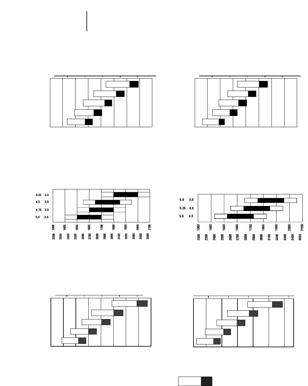
12-46
Wheel Loaders Bucket Selection
●950G–980G High Lift
4.2
4.7
5.0
5.4
5.7
5.5
6.0
6.5
7.0
7.5
2250 2500 2750 3000 3250 3500 3750
1400 1600 1800 2000 2200
4.2
4.7
5.0
5.4
5.7
5.5
6.0
6.5
7.0
7.5
2000 2250 2500 2750 3000 3250
1200 1400 1600 1800 2000
MATERIAL DENSITY MATERIAL DENSITY
MATERIAL DENSITY MATERIAL DENSITY
966F Series II 970F
980G 980G High Lift
BUCKET CAPACITYBUCKET CAPACITY
BUCKET CAPACITYBUCKET CAPACITY
Bucket
Size
m3
yd3
Bucket
Size
m3
yd3
kg/m3
lb/yd3
kg/m3
lb/yd3
kg/m3
lb/yd3
lb/yd3
Bucket
Size
m3
yd3
Bucket
Size
m3
yd3
kg/m3
1400
2250 2500 2750 3000 3250 3500 3750
3.25
3.5
3.75
4.0
4.25
2.5
2.7
2.9
3.1
3.3
1600 1800 2000 2200
MATERIAL DENSITY
950G
BUCKET CAPACITY
lb/yd3
Bucket
Size
m3
yd3
kg/m3
1400
2250 2500 2750 3000 3250 3500 3750
3.75
4.0
4.25
4.5
5.0
2.9
3.1
3.3
3.5
3.8
1600 1800 2000 2200
MATERIAL DENSITY
962G
BUCKET CAPACITY
lb/yd3
Bucket
Size
m3
yd3
kg/m3
% = Bucket Fill Factor
115% 100% 95%
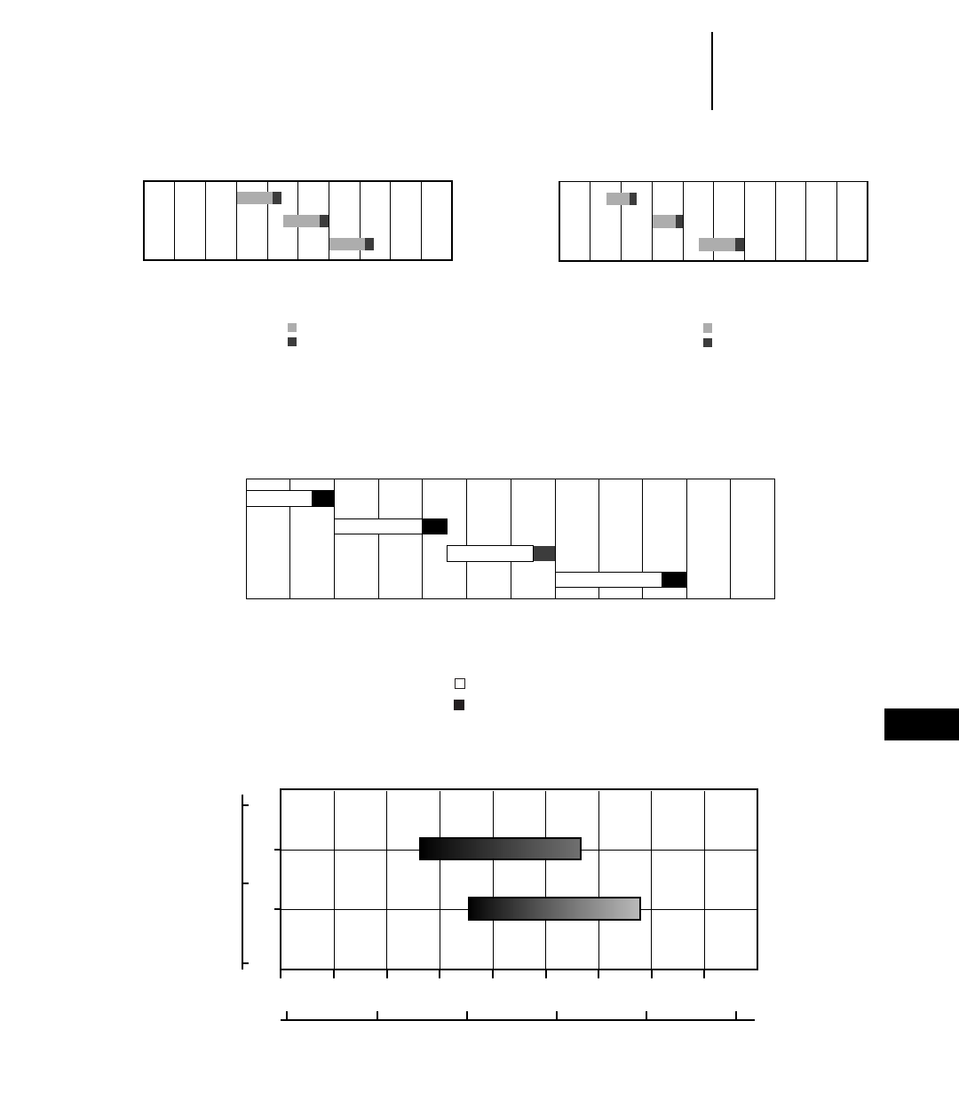
12-47
12
Wheel LoadersBucket Selection
●988F Series II ●988F Series II HL
●990 ●992G
8.0
9.0
7.25
6.0
6.7
5.5
2000
2200
2400
2600
2800
3000
3200
3400
3600
1100
1300
1500
1700
1900
2100
MATERIAL DENSITY (THOUSANDS)
988F Series II High Lift
BUCKET CAPACITY
yd3
m3
kg/m3
lb/yd3
9.9 13
9.2 12
8.4 11
7.6 10
2400
2500
2600
2700
2800
2900
3000
3100
3200
3300
3400
1100
1200
1300
1400
1500
MATERIAL DENSITY (THOUSANDS)
990 Series II
yd3
m3
kg/m3
lbs/yd3
Maximum
Optimum
NOTE: Percentages represent bucket fill factors
2.2
1.3 1.5 1.7 1.9 2.1 2.3
2.4 2.6 2.8 3.0 3.2 3.4 3.6 3.8
13
12
11
16
15
110% 90%100%
110% 90%100%
MATERIAL DENSITY (THOUSANDS)
992G
BUCKET CAPACITY
yd3
m3
kg/m3
lb/yd3
NOTE: Percentages represent bucket fill factors
Optimum
Maximum
Material density
8.0
9.0
7.25
6.0
6.7
5.5
2000
2200
2400
2600
2800
3000
3200
3400
3600
1100
1300
1500
1700
1900
2100
MATERIAL DENSITY (THOUSANDS)
988F Series II
BUCKET CAPACITY
yd3
m3
kg/m3
lb/yd3
NOTE: Percentages represent bucket fill factors
Optimum
Maximum
Material density
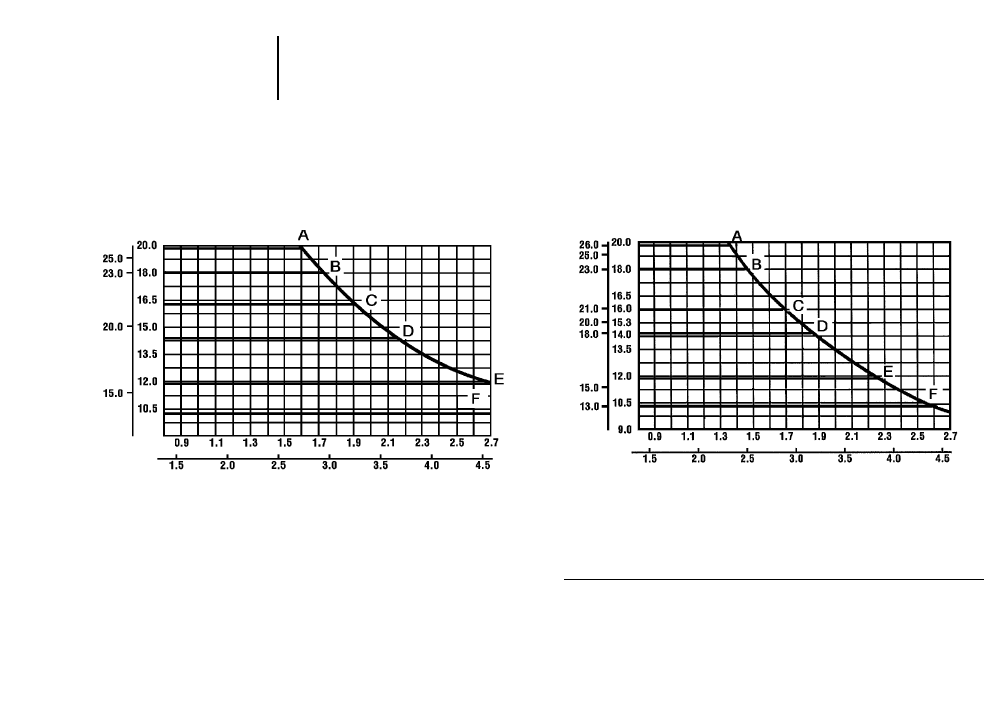
12-48
Wheel Loaders Bucket Selection
●994 ●994 HL
MATERIAL DENSITY (THOUSANDS)
994
BUCKET CAPACITY
m3
yd3
kg/m3
lb/yd3
MATERIAL DENSITY (THOUSANDS)
994 High Lift
BUCKET CAPACITY
m3
yd3
kg/m3
lb/yd3
KEY
A — 20.0 m3(26.0 yd3)Rock Bucket Spade edge with teeth
B — 18.0 m3(23.0 yd3)Rock Bucket Spade edge with teeth
C — 16.0 m3(21.0 yd3)Rock Bucket Spade edge with teeth and segments
D — 14.0 m3(18.0 yd3)Rock Bucket Spade edge with teeth and segments
E — 10.0 m3(13.0 yd3)General Purpose Bucket Spade edge with teeth
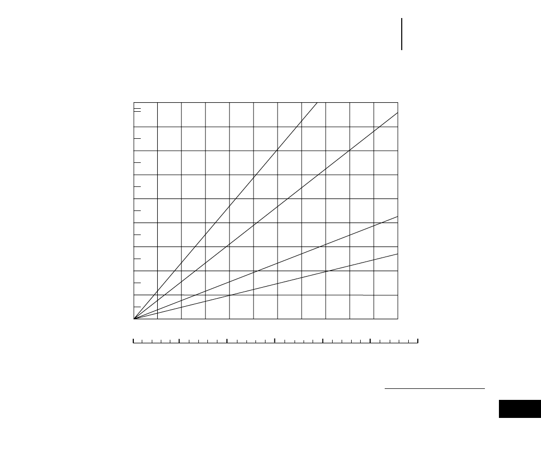
12-49
12
Wheel LoadersEstimated Haul or Return Time Charts
●928G
NOTE: Loader maneuver, load and
dump time must be added to travel time.
4th gear curve not indicated; primarily
used for transporting machine.
HAUL OR RETURN DISTANCE
928G
HAUL OR RETURN TIME (MINUTES)
Meters
Feet
1.6
1.4
1.2
1.0
0.8
0.6
0.4
0.2
0
0 100 200 300 400 500 600 700 800 900 1000
A
B
C
D
1.75
1.7
0 50 100 150 200 250 300
KEY
A — 1st Forward and Reverse Speed
B — 2nd Forward and Reverse Speed
C — 3rd Forward and Reverse Speed
D — 4th Forward Speed
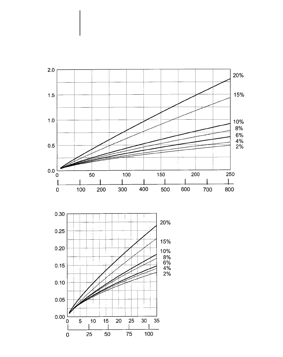
12-50
Wheel Loaders Travel Time — Loaded
●938G
●20.5R-25 Tires
938G TRAVEL TIME — LOADED
DISTANCE TRAVELED
TIME (MIN)
Meters
Feet
TOTAL RESISTANCE
(ROLLING PLUS GRADE)
TIME (MIN)
Meters
Feet
TOTAL RESISTANCE
(ROLLING PLUS GRADE)
DISTANCE TRAVELED
NOTE: Curves assume use of high-
est operating speed attain-
able: 4th gear for 2%-6% TR,
3rd gear for 8%-10% TR, 2nd
gear for 15% TR and 1st gear
for 20% TR.
In load and carry applications it is important to consult
the tire manufacturer on Ton-MPH ratings and pressure
recommendations.
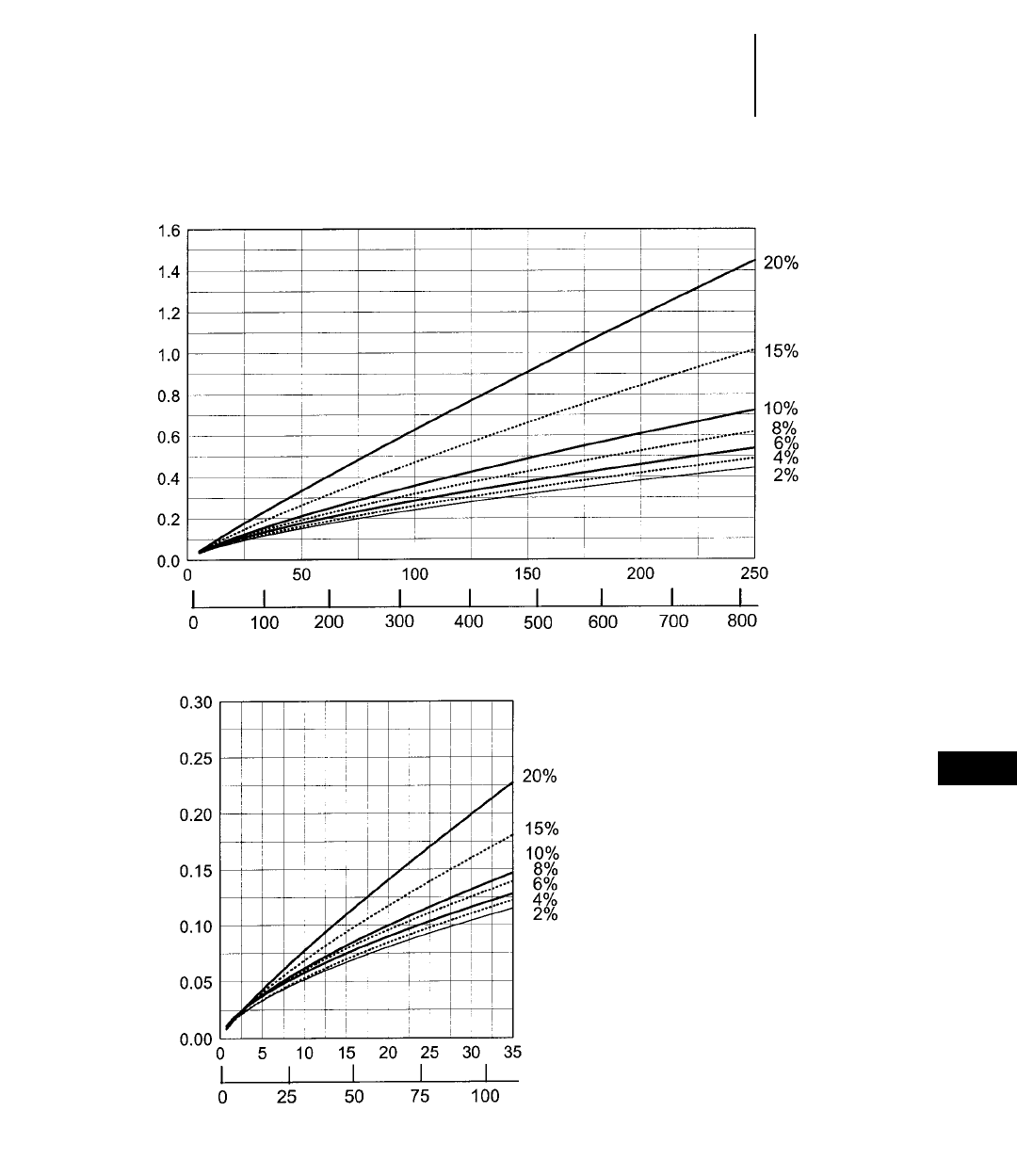
12-51
12
Wheel LoadersTravel Time — Empty
●938G
●20.5R-25 Tires
938G TRAVEL TIME — EMPTY
DISTANCE TRAVELED
TIME (MIN)
Meters
Feet
TOTAL RESISTANCE
(ROLLING PLUS GRADE)
TIME (MIN)
Meters
Feet
TOTAL RESISTANCE
(ROLLING PLUS GRADE)
DISTANCE TRAVELED
NOTE: Curves assume use of high-
est operating speed attain-
able: 4th gear for 2%-6% TR,
3rd gear for 8%-10% TR, 2nd
gear for 15% TR and 1st gear
for 20% TR.
In load and carry applications it is important to consult
the tire manufacturer on Ton-MPH ratings and pressure
recommendations.
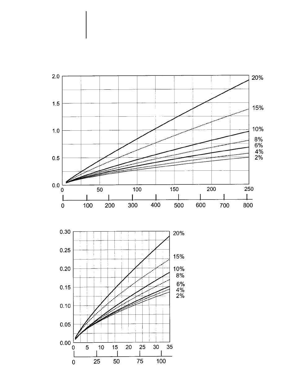
12-52
Wheel Loaders Travel Time — Loaded
●950G
●23.50-R25 Tires
950G TRAVEL TIME — LOADED
DISTANCE TRAVELED
TIME (MIN)
Meters
Feet
TOTAL RESISTANCE
(ROLLING PLUS GRADE)
TIME (MIN)
Meters
Feet
TOTAL RESISTANCE
(ROLLING PLUS GRADE)
DISTANCE TRAVELED
NOTE: Curves assume use of high-
est operating speed attain-
able: 4th gear for 2%-6% TR,
3rd gear for 8%-10% TR, 2nd
gear for 15% TR and 1st gear
for 20% TR.
In load and carry applications it is important to consult
the tire manufacturer on Ton-MPH ratings and pressure
recommendations.
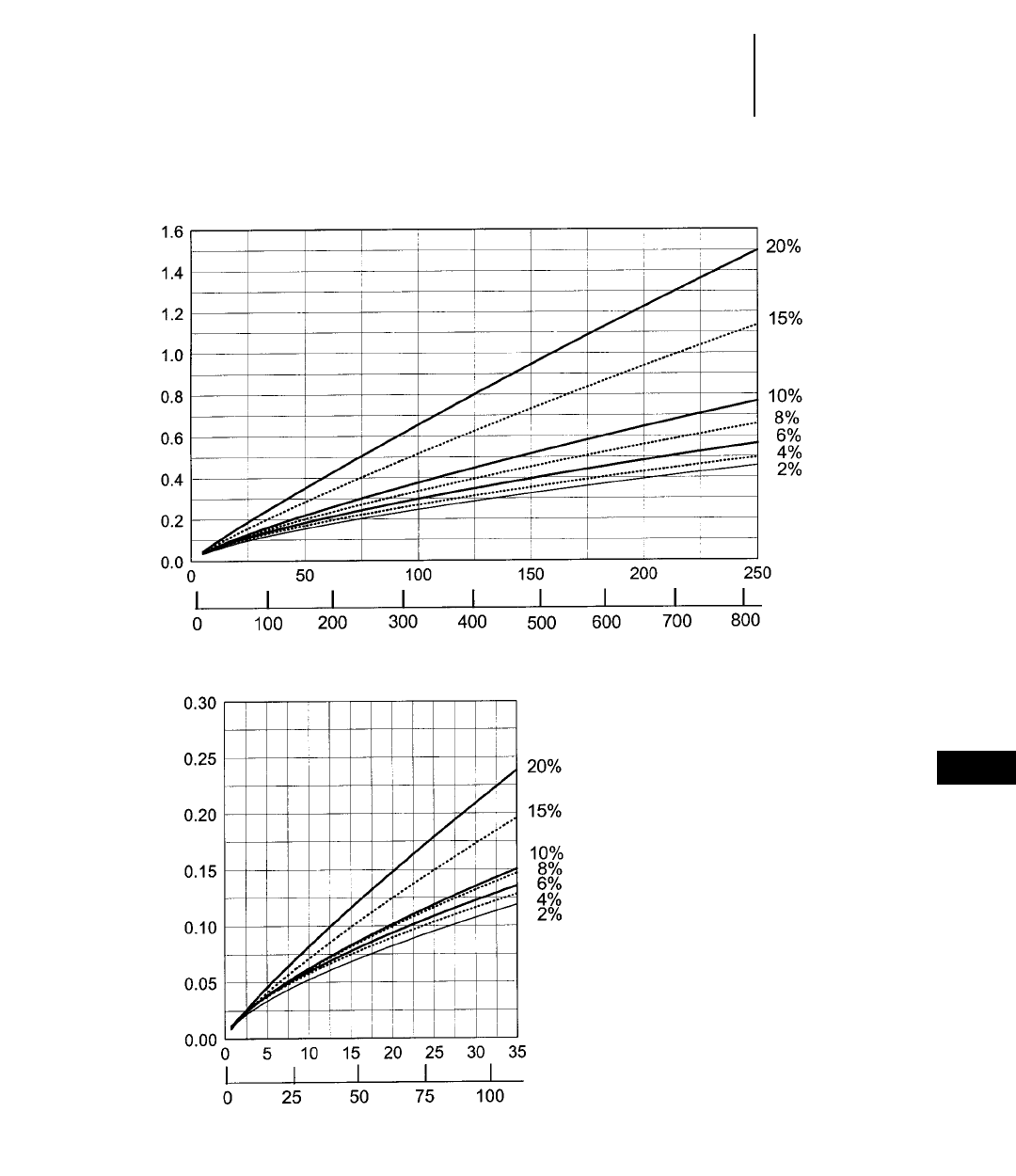
12-53
12
Wheel LoadersTravel Time — Empty
●950G
●23.50-R25 Tires
950G TRAVEL TIME — EMPTY
DISTANCE TRAVELED
TIME (MIN)
Meters
Feet
TOTAL RESISTANCE
(ROLLING PLUS GRADE)
TIME (MIN)
Meters
Feet
TOTAL RESISTANCE
(ROLLING PLUS GRADE)
DISTANCE TRAVELED
NOTE: Curves assume use of high-
est operating speed attain-
able: 4th gear for 2%-6% TR,
3rd gear for 8%-10% TR, 2nd
gear for 15% TR and 1st gear
for 20% TR.
In load and carry applications it is important to consult
the tire manufacturer on Ton-MPH ratings and pressure
recommendations.
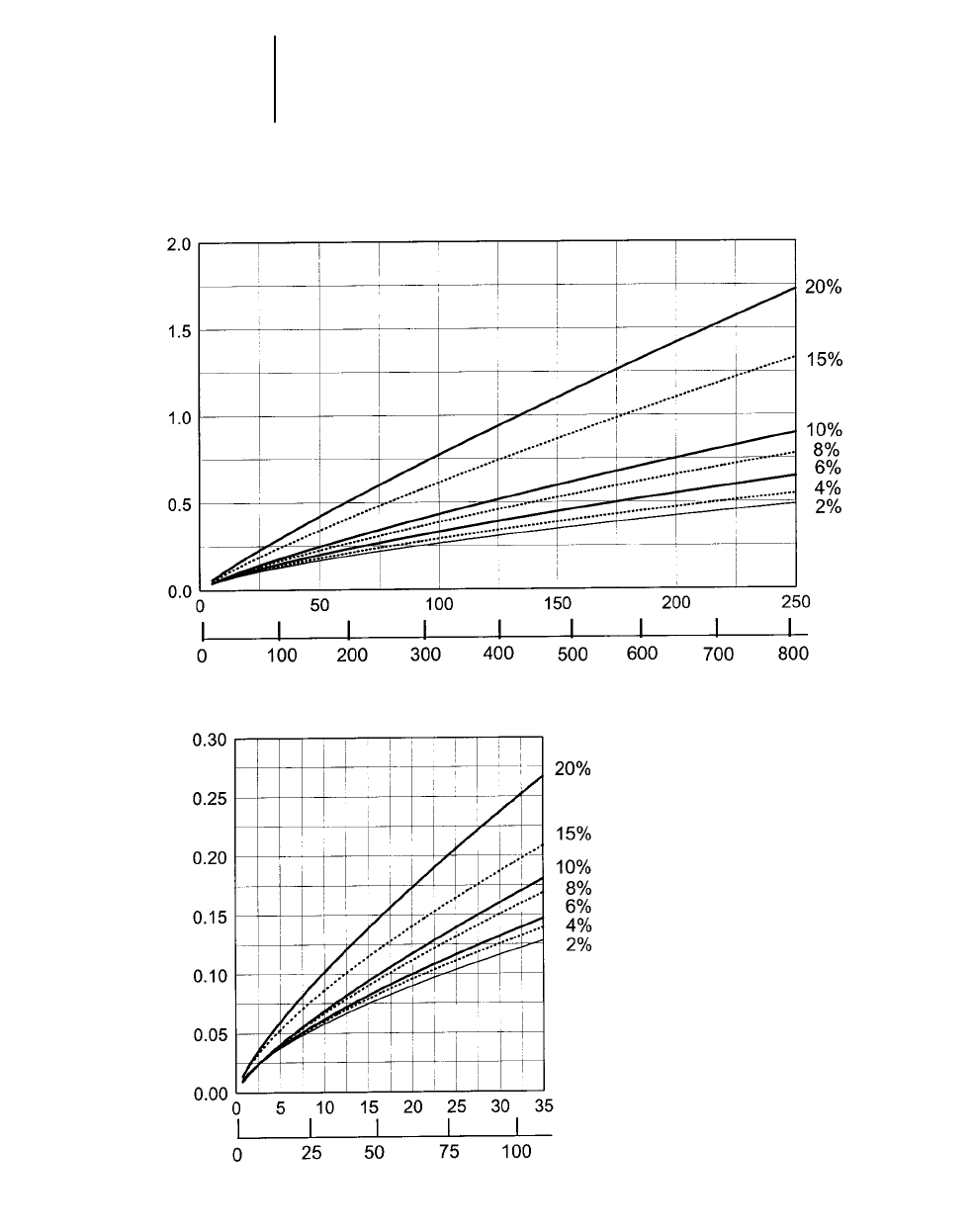
12-54
Wheel Loaders Travel Time — Loaded
●962G
●23.5-R25 Tires
962G TRAVEL TIME — LOADED
DISTANCE TRAVELED
TIME (MIN)
Meters
Feet
TOTAL RESISTANCE
(ROLLING PLUS GRADE)
TIME (MIN)
Meters
Feet
TOTAL RESISTANCE
(ROLLING PLUS GRADE)
DISTANCE TRAVELED
NOTE: Curves assume use of high-
est operating speed attain-
able: 4th gear for 2%-6% TR,
3rd gear for 8%-10% TR, 2nd
gear for 15% TR and 1st gear
for 20% TR.
In load and carry applications it is important to consult
the tire manufacturer on Ton-MPH ratings and pressure
recommendations.

12-55
12
Wheel LoadersTravel Time — Empty
●962G
●23.5-R25 Tires
962G TRAVEL TIME — EMPTY
DISTANCE TRAVELED
TIME (MIN)
Meters
Feet
TOTAL RESISTANCE
(ROLLING PLUS GRADE)
TIME (MIN)
Meters
Feet
TOTAL RESISTANCE
(ROLLING PLUS GRADE)
DISTANCE TRAVELED
NOTE: Curves assume use of high-
est operating speed attain-
able: 4th gear for 2%-6% TR,
3rd gear for 8%-10% TR, 2nd
gear for 15% TR and 1st gear
for 20% TR.
In load and carry applications it is important to consult
the tire manufacturer on Ton-MPH ratings and pressure
recommendations.
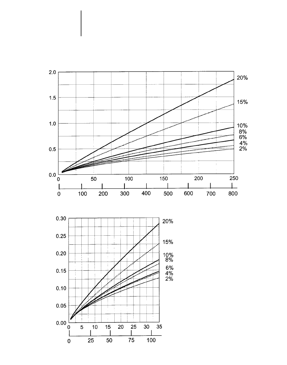
12-56
Wheel Loaders Travel Time — Loaded
●966F Series II
●26.5-25 Tires
966F SERIES II TRAVEL TIME — LOADED
DISTANCE TRAVELED
TIME (MIN)
Meters
Feet
TOTAL RESISTANCE
(ROLLING PLUS GRADE)
TIME (MIN)
Meters
Feet
TOTAL RESISTANCE
(ROLLING PLUS GRADE)
DISTANCE TRAVELED
NOTE: Curves assume use of high-
est operating speed attain-
able: 4th gear for 2%-6% TR,
3rd gear for 8%-10% TR, 2nd
gear for 15% TR and 1st gear
for 20% TR.
In load and carry applications it is important to consult
the tire manufacturer on Ton-MPH ratings and pressure
recommendations.
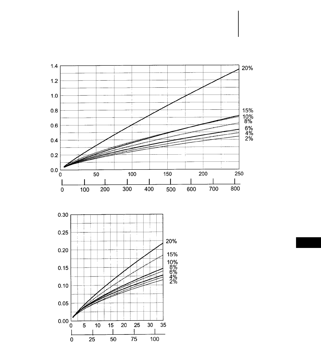
12-57
12
Wheel LoadersTravel Time — Empty
●966F Series II
●26.5-25 Tires
966F SERIES II TRAVEL TIME — EMPTY
DISTANCE TRAVELED
TIME (MIN)
Meters
Feet
TOTAL RESISTANCE
(ROLLING PLUS GRADE)
TIME (MIN)
Meters
Feet
TOTAL RESISTANCE
(ROLLING PLUS GRADE)
DISTANCE TRAVELED
NOTE: Curves assume use of high-
est operating speed attain-
able: 4th gear for 2%-6% TR,
3rd gear for 8%-10% TR, 2nd
gear for 15% TR and 1st gear
for 20% TR.
In load and carry applications it is important to consult
the tire manufacturer on Ton-MPH ratings and pressure
recommendations.
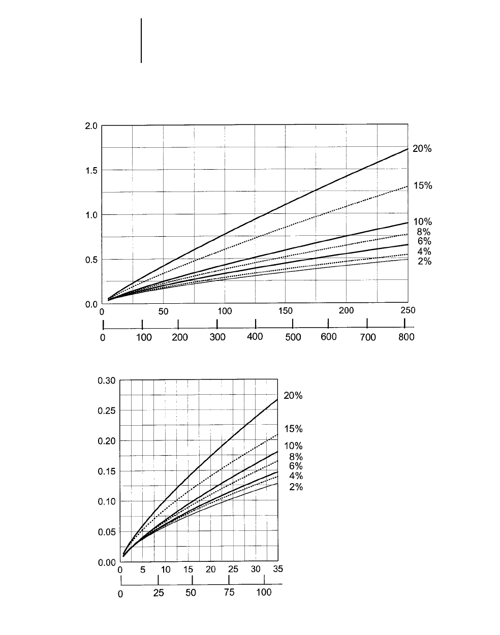
12-58
Wheel Loaders Travel Time — Loaded
●970F (Material Handler)
●26.5-25 Tires
970F MATERIAL HANDLER TRAVEL TIME — LOADED
DISTANCE TRAVELED
TIME (MIN)
Meters
Feet
TOTAL RESISTANCE
(ROLLING PLUS GRADE)
TIME (MIN)
Meters
Feet
TOTAL RESISTANCE
(ROLLING PLUS GRADE)
DISTANCE TRAVELED
NOTE: Curves assume use of high-
est operating speed attain-
able: 4th gear for 2%-6% TR,
3rd gear for 8%-10% TR, 2nd
gear for 15% TR and 1st gear
for 20% TR.
In load and carry applications it is important to consult
the tire manufacturer on Ton-MPH ratings and pressure
recommendations.
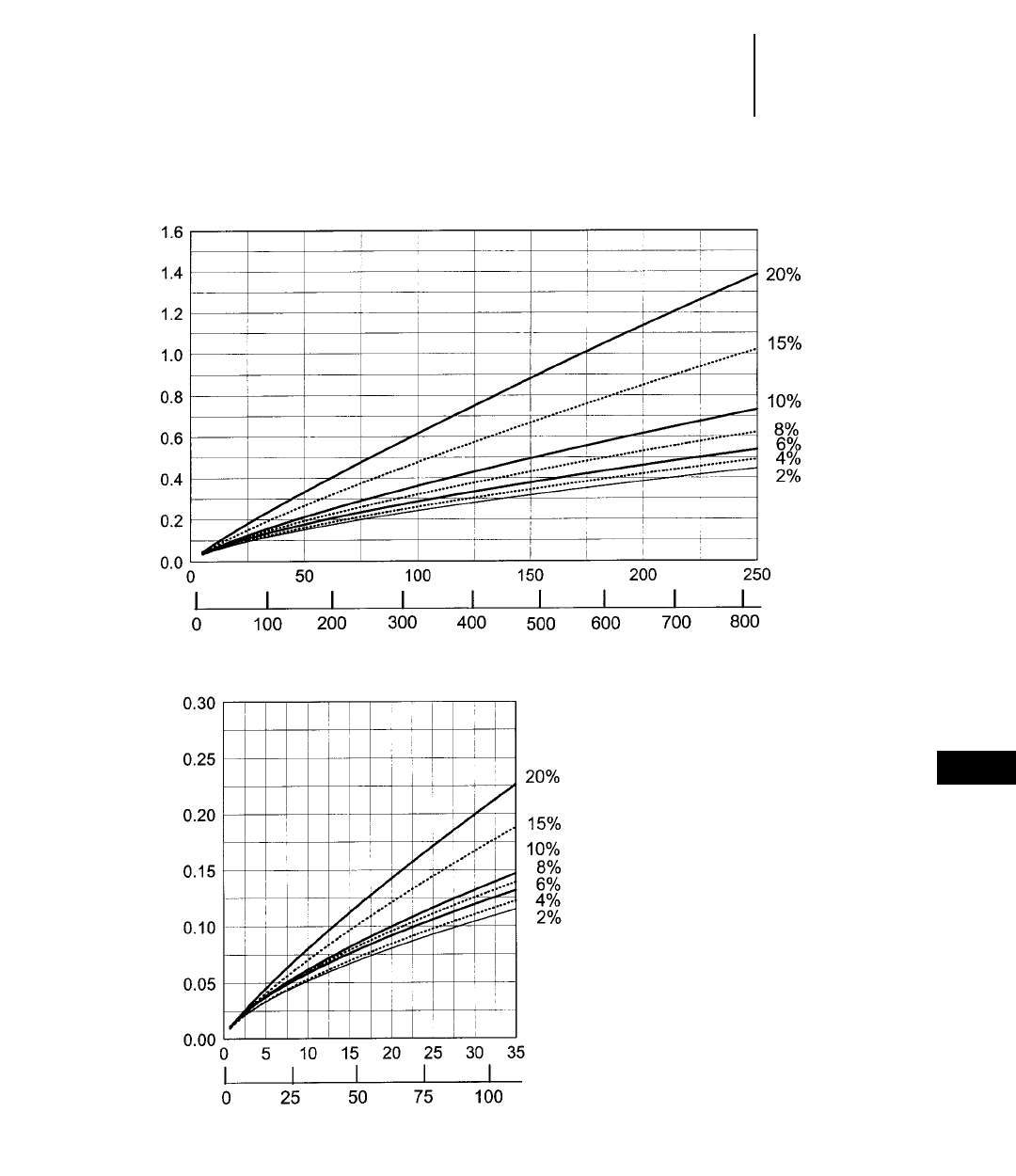
12-59
12
Wheel LoadersTravel Time — Empty
●970F (Material Handler)
●26.5-25 Tires
970F MATERIAL HANDLER TRAVEL TIME — EMPTY
DISTANCE TRAVELED
TIME (MIN)
Meters
Feet
TOTAL RESISTANCE
(ROLLING PLUS GRADE)
TIME (MIN)
Meters
Feet
TOTAL RESISTANCE
(ROLLING PLUS GRADE)
DISTANCE TRAVELED
NOTE: Curves assume use of high-
est operating speed attain-
able: 4th gear for 2%-6% TR,
3rd gear for 8%-10% TR, 2nd
gear for 15% TR and 1st gear
for 20% TR.
In load and carry applications it is important to consult
the tire manufacturer on Ton-MPH ratings and pressure
recommendations.
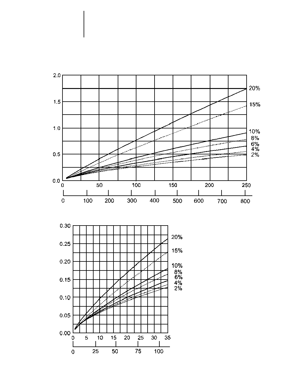
12-60
Wheel Loaders Travel Time — Loaded
●980G
●29.5-25 Tires
980G TRAVEL TIME — LOADED
DISTANCE TRAVELED
TIME (MIN)
Meters
Feet
TOTAL RESISTANCE
(ROLLING PLUS GRADE)
TIME (MIN)
Meters
Feet
TOTAL RESISTANCE
(ROLLING PLUS GRADE)
DISTANCE TRAVELED
NOTE: Curves assume use of high-
est operating speed attain-
able: 4th gear for 2%-6% TR,
3rd gear for 8%-10% TR, 2nd
gear for 15% TR and 1st gear
for 20% TR.
In load and carry applications it is important to consult
the tire manufacturer on Ton-MPH ratings and pressure
recommendations.
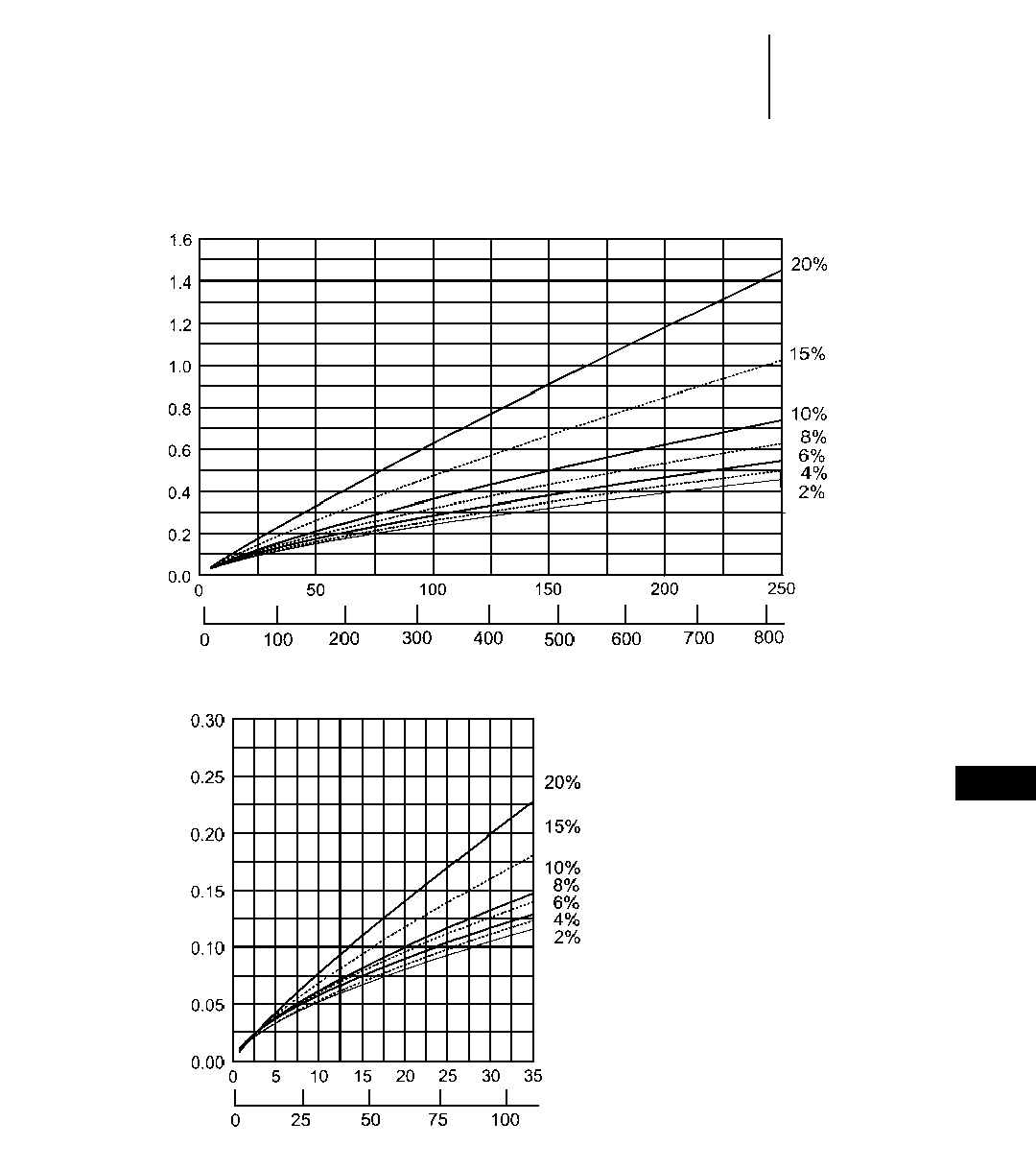
12-61
12
Wheel LoadersTravel Time — Empty
●980G
●29.5-25 Tires
980G TRAVEL TIME — EMPTY
DISTANCE TRAVELED
TIME (MIN)
Meters
Feet
TOTAL RESISTANCE
(ROLLING PLUS GRADE)
TIME (MIN)
Meters
Feet
TOTAL RESISTANCE
(ROLLING PLUS GRADE)
DISTANCE TRAVELED
NOTE: Curves assume use of high-
est operating speed attain-
able: 4th gear for 2%-6% TR,
3rd gear for 8%-10% TR, 2nd
gear for 15% TR and 1st gear
for 20% TR.
In load and carry applications it is important to consult
the tire manufacturer on Ton-MPH ratings and pressure
recommendations.
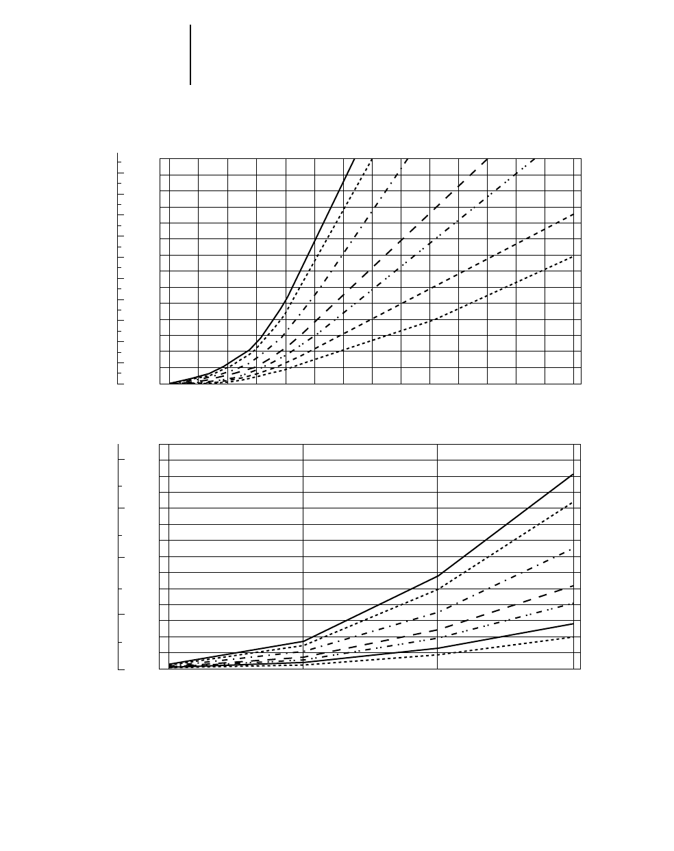
12-62
Wheel Loaders Travel Time — Loaded
●988F Series II
●35/65-33 Tires
988F SERIES II TRAVEL TIME — LOADED
DISTANCE ONE WAY
TOTAL RESISTANCE
(Grade plus Rolling)
700
600
500
400
300
200
100
00.05 0.1 0.15 0.2 0.3 0.4 0.5 0.6 0.7 0.8 0.9 1 1.1 1.2 1.3
2%4% 6% 8% 10%
15%
20%
20
40
60
80
100
120
140
160
180
200
220
0
NOTE: Curves assume use of highest operating
speed attainable: 4th gear for 2%-6% TR, 3rd
gear for 8%-10% TR, 2nd gear for 15% and
20% TR.
In load-and-carry applications it is
important to consult the tire manufacturer
on Ton-MPH ratings and pressure
recommendations.
140
120
100
80
60
40
20
00.05 0.1 0.15 0.2
20%
2%
4%
6%
8%
10%
15%
10
20
30
40
0
TIME
TIME
DISTANCE ONE WAY
TOTAL RESISTANCE
(Grade plus Rolling)
Minutes
FeetMeters
Minutes
FeetMeters
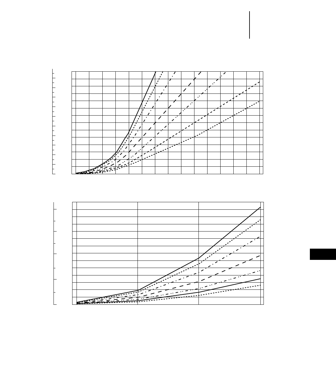
12-63
12
Wheel LoadersTravel Time — Empty
●988F Series II
●35/65-33 Tires
988F SERIES II TRAVEL TIME — EMPTY
DISTANCE ONE WAY
TOTAL RESISTANCE
(Grade plus Rolling)
700
600
500
400
300
200
100
00.05 0.1 0.15 0.2 0.3 0.4 0.5 0.6 0.7 0.8 0.9 1 1.1 1.2 1.3
2% 15%
20%
4% 6% 8% 10%
20
40
60
80
100
120
140
160
180
200
220
0
140
120
100
80
60
40
20
00.05 0.1 0.15 0.2
20%
2%
4%
6%
8%
10%
15%
10
20
30
40
0
TIME
TIME
DISTANCE ONE WAY
TOTAL RESISTANCE
(Grade plus Rolling)
Minutes
FeetMeters
Minutes
FeetMeters
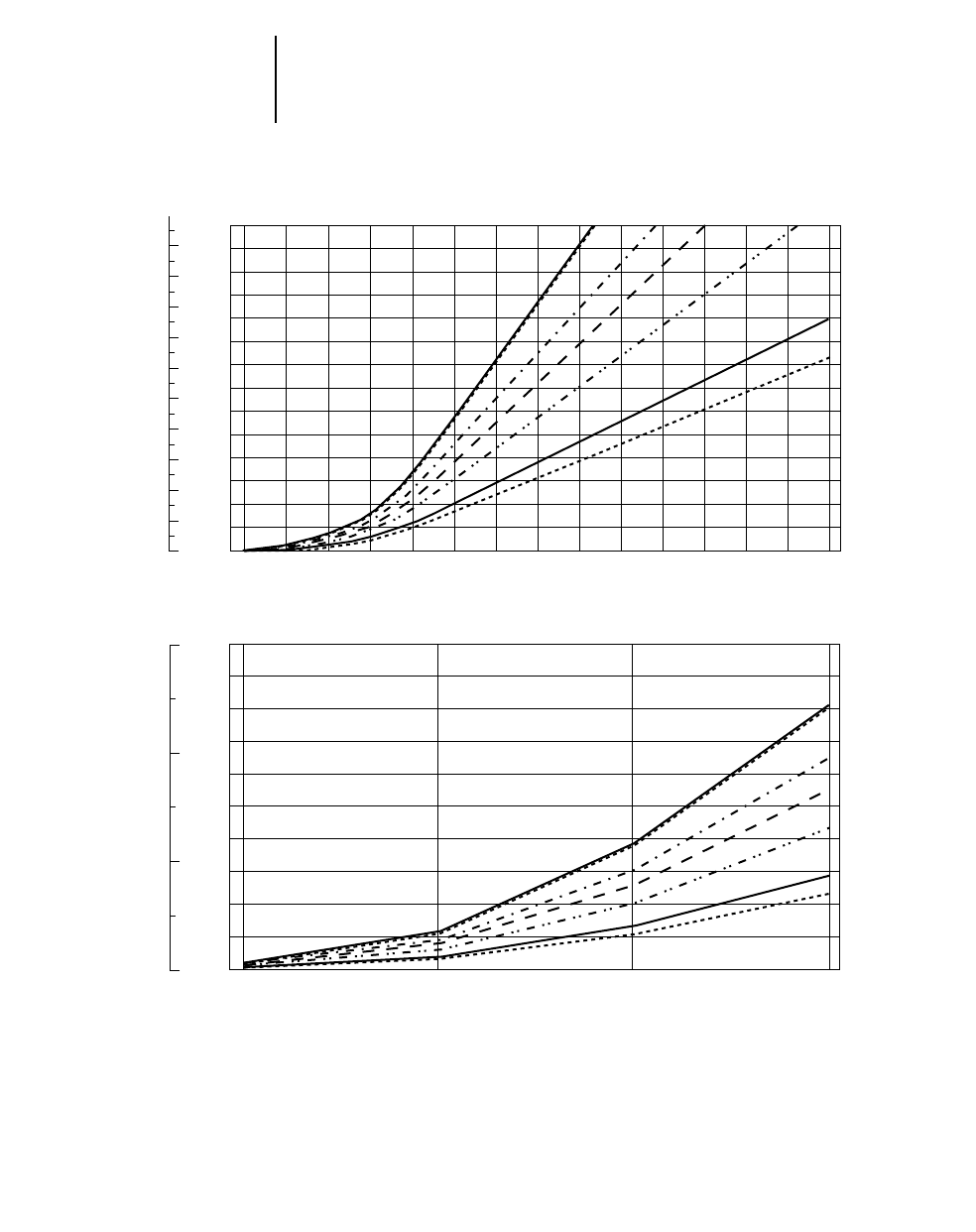
12-64
Wheel Loaders Travel Time — Loaded
●990 Series II
●41.25/70-39 Tires
990 SERIES II TRAVEL TIME — LOADED
DISTANCE ONE WAY
TOTAL RESISTANCE
(Grade plus Rolling)
700
600
500
400
300
200
100
00.05 0.1 0.15 0.2 0.3 0.4 0.5 0.6 0.7 0.8 0.9 1 1.1 1.2 1.3
2%4% 6% 8% 10%
15%
20%
20
40
60
80
100
120
140
160
180
200
220
0
100
80
60
40
20
00.05 0.1 0.15 0.2
20%
2%
4%
6%
8%
10%
15%
0
10
20
30
TIME
TIME
DISTANCE ONE WAY
TOTAL RESISTANCE
(Grade plus Rolling)
Minutes
FeetMeters
Minutes
FeetMeters
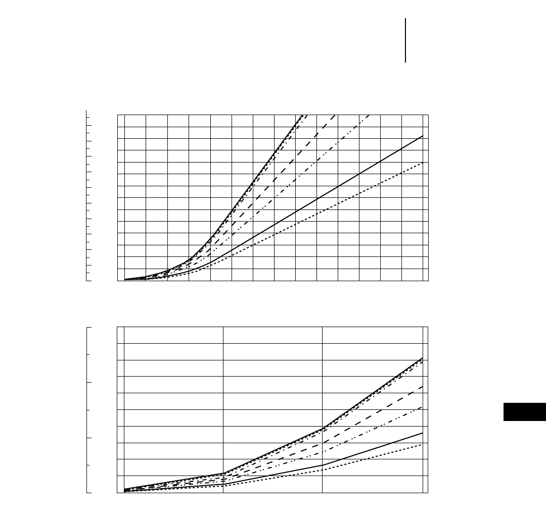
12-65
12
Wheel LoadersTravel Time — Empty
●990 Series II
●41.25/70-39 Tires
990 SERIES II TRAVEL TIME — EMPTY
DISTANCE ONE WAY
TOTAL RESISTANCE
(Grade plus Rolling)
700
600
500
400
300
200
100
00.05 0.1 0.15 0.2 0.3 0.4 0.5 0.6 0.7 0.8 0.9 1 1.1 1.2 1.3
2,4,6% 8% 10%
15%
20%
20
40
60
80
100
120
140
160
180
200
220
0
100
80
60
40
20
00.05 0.1 0.15 0.2
20%
2%
4%
6%
8%
10%
15%
0
10
20
30
TIME
TIME
DISTANCE ONE WAY
TOTAL RESISTANCE
(Grade plus Rolling)
Minutes
FeetMeters
Minutes
FeetMeters
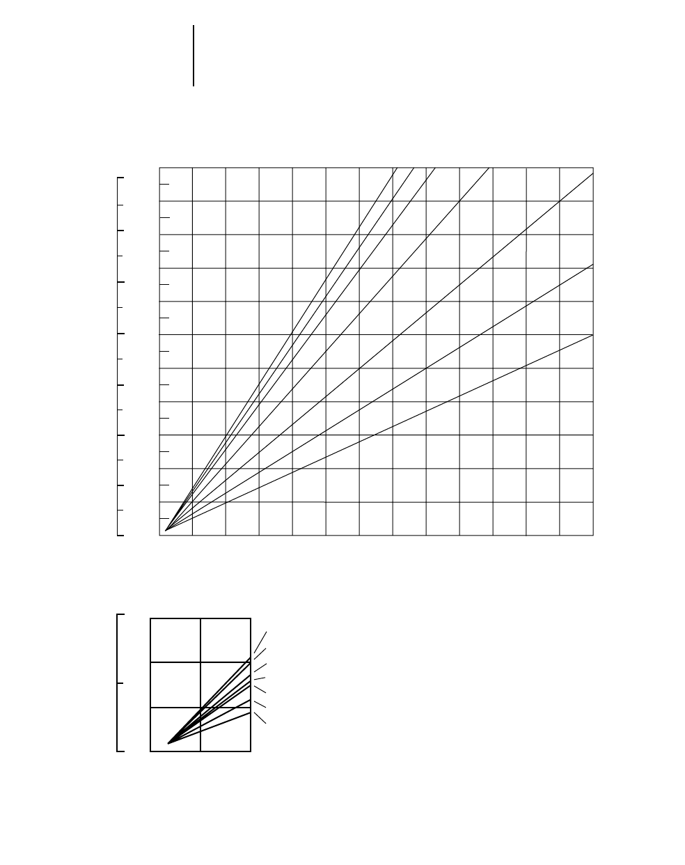
12-66
Wheel Loaders Travel Time — Loaded
●992G
●45/65-45 Tires
992G TRAVEL TIME — LOADED
DISTANCE ONE WAY
220
200
180
160
140
120
100
80
60
40
20
0
0.00 0.10 0.20 0.30 0.40 0.50 0.60 0.70 0.80 0.90 1.00
2%
1.301.10 1.20
700
600
500
400
300
200
100
0
4% 6% 8%
10%
15%
20%
100
50
0
30
20
10
00.05 0.10
2%
4%
6%
8%
10%
15%
20%
TOTAL RESISTANCE
(Grade plus Rolling)
NOTE: Curves assume use of highest operating speed
attainable: 3rd gear for 2%-10% TR, 2nd gear
for 15% TR and 1st gear for 20% TR.
In load-and-carry applications it is
important to consult the tire manufacturer
on Ton-MPH ratings and pressure
recommendations.
Time
Minutes
Feet Meters
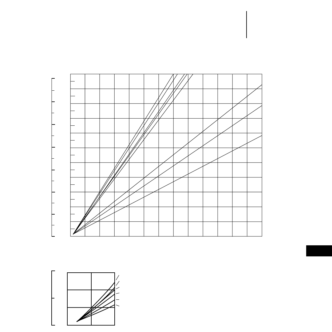
12-67
12
Wheel LoadersTravel Time — Empty
●992G
●45/65-45 Tires
992G TRAVEL TIME — EMPTY
DISTANCE ONE WAY
220
200
180
160
140
120
100
80
60
40
20
0
0.00 0.10 0.20 0.30 0.40 0.50 0.60 0.70 0.80 0.90 1.00
2%
1.301.10 1.20
700
600
500
400
300
200
100
0
4% 6%8% 10%
15%
20%
20%
100
50
0
30
20
10
00.05 0.10
2%
4%
6%
8%-10%
15%
20%
TOTAL RESISTANCE
(Grade plus Rolling)
NOTE: Curves assume use of highest operating speed
attainable: 3rd gear for 2%-10% TR, 2nd gear
for 15% TR and 1st gear for 20% TR.
Time
Minutes
Feet Meters
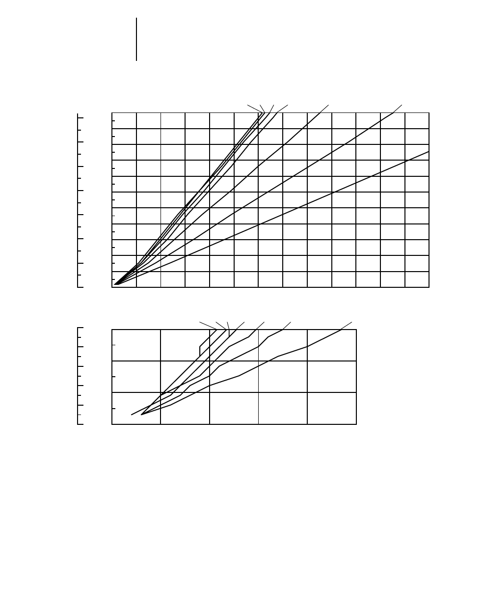
12-68
Wheel Loaders Travel Time — Loaded
●994
●50/80-57 Tires
994 TRAVEL TIME — LOADED
DISTANCE ONE WAY
0 0.05 0.1 0.15 0.2 0.25
0
10
20
30
20
40
60
80
100
0
0.00 0.10 0.20 0.30 0.40 0.50 0.60 0.70 0.80 0.90 1.00 1.10 1.20 1.30
200
400
600
0
300
500
700
100 20
40
60
80
100
120
140
160
180
200
220
2% 4% 6% 8% 10%
20%
2% 4% 6% 8% 10% 15% 20%
15%
TOTAL RESISTANCE
(Grade plus Rolling)
Minutes
Feet Meters
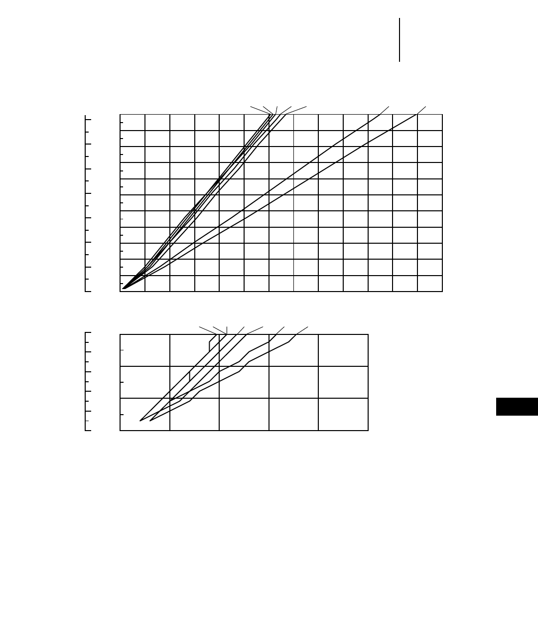
12-69
12
Wheel LoadersTravel Time — Empty
●994
●50/80-57 Tires
994 TRAVEL TIME — EMPTY
DISTANCE ONE WAY
0 0.05 0.1 0.15 0.2 0.25
0
10
20
30
20
40
60
80
100
0
0.00 0.10 0.20 0.30 0.40 0.50 0.60 0.70 0.80 0.90 1.00 1.10 1.20 1.3
200
400
600
0
300
500
700
100 20
40
60
80
100
120
140
160
180
200
220
2% 4% 6% 8% 15%
2% 4% 6% 8% 10% 15% 20%
20%10%
TOTAL RESISTANCE
(Grade plus Rolling)
Minutes
Feet Meters
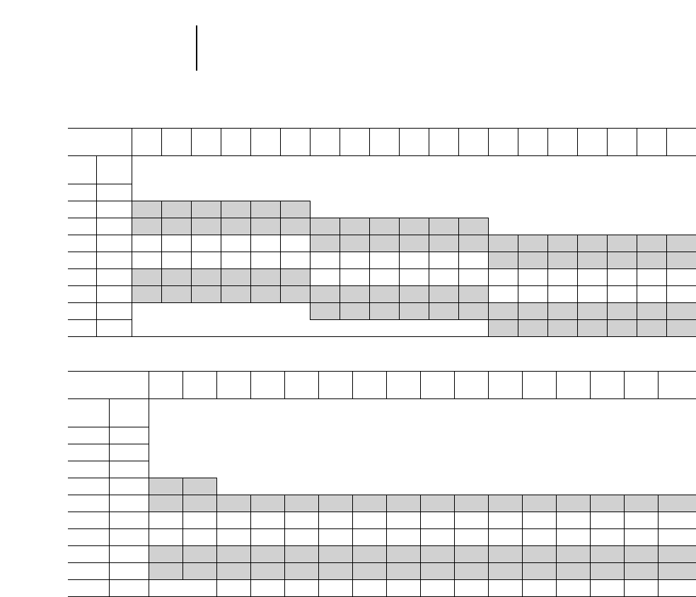
12-70
Wheel Loaders Production Estimating Table
●m3or yd3/60 min. hour
Bucket Size
(m3or yd3) 1.0 1.5 2.0 2.5 3.0 3.5 4.0 4.5 5.0 5.5 6.0 6.5 7.0 7.5 8.0 8.5 9.0 9.5 10.0
Cycle Cycles
Time Per Hr
0.35 171
0.40 150 150 225 330 375 450 525
0.45 133 135 200 268 332 400 466 530 600 665 730 800 865
0.50 120 120 180 240 300 360 420 480 540 600 660 720 780 840 900 960 1003 1080 1140 1200
0.55 109 109 164 218 272 328 382 436 490 545 600 655 705 765 820 870 925 980 1008 1090
0.60 100 100 150 200 250 300 350 400 450 500 550 600 650 700 750 800 850 900 950 1000
0.65 92 92 138 184 230 276 322 368 416 460 505 555 600 645 690 735 780 830 875 920
0.70 86 342 386 430 474 515 560 600 645 690 730 775 815 860
0.75 80 560 600 640 680 720 760 800
Bucket Size
(m3or yd3) 11.0 12.0 13.0 14.0 15.0 16.0 17.0 18.0 19.0 20.0 21.0 22.0 23.0 24.0 25.0 26.0
Cycle Cycles
Time Per Hr
0.35 171
0.40 150
0.45 133
0.50 120 1320 1440
0.55 109 1200 1310 1420 1520 1635 1740 1850 1960 2070 2180 2285 2395 2505 2615 2725 2830
0.60 100 1100 1200 1300 1400 1500 1600 1700 1800 1900 2000 2100 2200 2300 2400 2500 2600
0.65 92 1010 1105 1195 1285 1380 1470 1560 1655 1745 1840 1930 2020 2115 2205 2300 2390
0.70 86 945 1030 1120 1200 1290 1375 1460 1545 1630 1720 1805 1890 1975 2060 2150 2235
0.75 80 880 960 1040 1120 1200 1280 1360 1440 1520 1600 1680 1760 1840 1920 2000 2080
0.80 75 975 1050 1125 1200 1275 1350 1425 1500 1575 1650 1725 1800 1875 1950
Job Efficiency Efficiency
Worktime/Hr Factor Bucket Load Factor
60 Min Hr 100% Bucket Size 31.00
55 91% .95
50 83% .90
45 75% .85
40 69% .80
— — .75
Unshaded area indicates average production.
Unshaded area indicates average production.
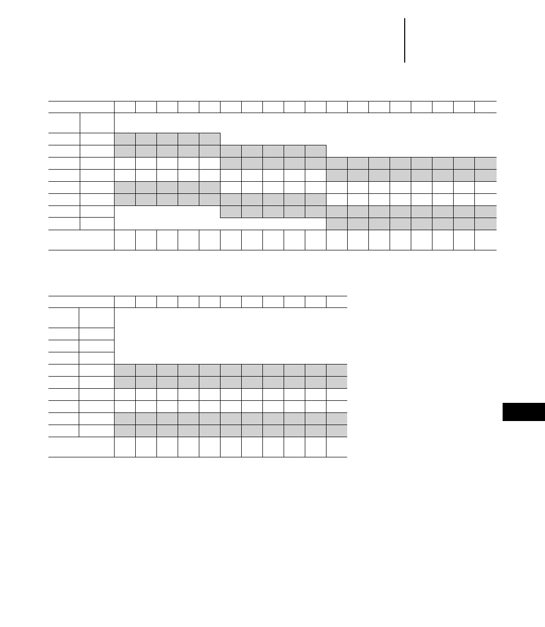
12-71
12
Wheel LoadersProduction Estimating Table
●60 min hour ●Shot Rock
●Metric Tons
Metric Tons ●1600 kg Lm3(1.6 t) density
Bucket Size m31.0 1.5 2.0 2.5 3.0 3.5 4.0 4.5 5.0 5.5 6.0 6.5 7.0 7.5 8.0 8.5 9.0 9.5
Cycle Cycles
Time Per Hr
0.40 150 240 360 480 600 720
0.45 133 213 319 426 532 638 745 851 958 1064 1170
0.50 120 192 288 384 480 576 672 768 864 960 1056 1152 1248 1344 1440 1536 1632 1730 1825
0.55 109 174 262 349 436 523 610 698 785 872 959 1046 1134 1221 1308 1395 1482 1570 1655
0.60 100 160 240 320 400 480 560 640 720 800 880 960 1040 1120 1200 1280 1360 1440 1520
0.65 92 147 221 294 368 442 515 589 662 736 810 883 957 1030 1104 1178 1251 1325 1400
0.70 86 482 550 619 688 757 826 894 963 1032 1101 1170 1238 1310
0.75 80 768 832 896 960 1024 1088 1150 1215
Bucket Payload 1.6 2.4 3.2 4.0 4.8 5.6 6.4 7.2 8.0 8.8 9.6 10.4 11.2 12.0 12.8 13.6 14.4 15.2
Metric (Tons)
Bucket Size m310.0 11.0 12.0 13.0 14.0 15.0 16.0 17.0 18.0 19.0 20.0
Cycle Cycles
Time Per Hr
0.40 150
0.45 133
0.50 120
0.55 109 1744 1918 2092 2267 2441 2616 2790 2964 3139 3313 3488
0.60 100 1600 1760 1920 2080 2240 2400 2560 2720 2880 3040 3200
0.65 92 1472 1619 1766 1913 2060 2208 2355 2502 2649 2796 2944
0.70 86 1376 1513 1651 1788 1926 2064 2201 2339 2476 2614 2752
0.75 80 1280 1408 1536 1664 1792 1920 2048 2176 2304 2432 2560
0.80 75 1200 1320 1440 1560 1680 1800 1920 2040 2160 2280 2400
Bucket Payload
Metric (Tons) 16 17.6 19.2 20.8 22.4 24.0 25.6 27.2 28.8 30.4 32.0
Unshaded area indicates average production.
Unshaded area indicates average production.
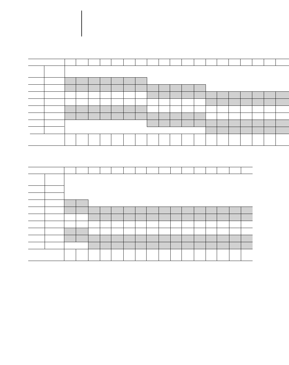
12-72
Wheel Loaders Production Estimating Table
●Shot Rock ●60 min hour
●U.S. Tons
U.S. Tons ●2700 lb/LCY (1.35 T) density
Bucket Size yd31.0 1.5 2.0 2.5 3.0 3.5 4.0 4.5 5.0 5.5 6.0 6.5 7.0 7.5 8.0 8.5 9.0 9.5 10.0
Cycle Cycles
Time Per Hr
0.40 150 203 330 420 510 615 705 810
0.45 133 180 293 360 454 545 625 720 810 905 985 1080 1170
0.50 120 162 254 324 408 492 565 650 730 815 890 970 1060 1140 1200 1300 1380 1470 1540 1620
0.55 109 147 240 294 370 448 515 590 665 740 805 885 960 1030 1090 1180 1250 1330 1400 1740
0.60 100 135 220 270 340 410 470 540 610 680 740 810 880 950 1000 1080 1150 1220 1280 1350
0.65 92 124 200 250 314 380 435 500 560 625 680 750 810 875 920 985 1060 1120 1180 1250
0.70 86 525 585 635 695 755 815 860 930 990 1050 1100 1160
0.75 80 760 800 865 920 975 1030 1080
Bucket Payload
(Tons) 1.35 2.2 2.7 3.4 4.1 4.7 5.4 6.1 6.8 7.4 8.1 8.8 9.5 10.0 10.8 11.5 12.2 12.8 13.5
Bucket Size yd311.0 12.0 13.0 14.0 15.0 16.0 17.0 18.0 19.0 20.0 21.0 22.0 23.0 24.0 25.0 26.0
Cycle Cycles
Time Per Hr
0.40 150
0.45 133
0.50 120 1782 1945
0.55 109 1620 1765 1905 2060 2200 2350 2495 2645 2790 2940 3080 3235 3375 3530 3670 3825
0.60 100 1485 1620 1750 1890 2020 2160 2290 2430 2560 2700 2830 2970 3100 3240 3370 3510
0.65 92 1365 1490 1610 1735 1855 1985 2105 2235 2355 2480 2600 2730 2850 2980 3100 3225
0.70 86 1275 1390 1505 1625 1735 1855 1965 2085 2200 2320 2430 2550 2665 2785 2895 3015
0.75 80 1190 1295 1400 1510 1615 1725 1830 1940 2045 2160 2260 2375 2480 2590 2695 2805
0.80 75 1310 1415 1515 1620 1715 1820 1920 2025 2120 2225 2325 2430 2525 2630
Bucket Payload
(Tons) 14.9 16.4 17.5 18.9 20.2 21.6 22.9 24.3 25.6 27.0 28.3 29.7 31.0 32.4 33.7 35.1
Unshaded area indicates average production.
Unshaded area indicates average production.
12-73
12
Wheel LoadersSpecial Attachments
●Work Tools
Quick coupler X X X X XXXXXXX
General purpose bucket XXXX XXXXXXXXX
Coke bucket
Coal bucket XXXXXXXXXXXX
Coal seam bucket X X
Woodchip bucket X X X XXXXX
Refuse bucket X X X X
Light material bucket XXXXXX XX
Loose material bucket XX
Snow bucket X X
Fertilizer bucket XXX
Sand & gravel bucket XXXXX
Crushed rock bucket X
Rock bucket X X X
Skeleton rock bucket X X
Slag bucket X X X X
Bonus bucket X
Multi-purpose bucket X XXXX
Side dump bucket X XXXX XX
Control discharge bucket
Bucket with top clamp XX
Tire loader
Material handling arm X X X XXXXX
Pallet fork XXXX X XXXXXXX
Pallet fork with top clamp X XXXX
Millyard fork X X X X X X
Log/lumber fork X XXXXX
Logging fork X X X X X
Core fork XXX
Grab & Grip bucket XX
Straight blade X X XXXX
Manual angle blade X X X X
Hydraulic angle blade X X X
V-plow X X X X X
Manual reverse plow X X X X X
Hydraulic reverse plow X X X X X
Clamp rake
Clearing rake
Loader rake X XXXXX
Hydraulic broom XXX
Block handling bucket X
Block handling fork X X
Breaker tine X X
Boom clearing rake X
Stone seive bucket XX
High dump bucket XX
Pickup sweeper XX
NOTE: List is not all-inclusive. Contact Balderson for special attachment needs.
992G
990 Series II
988F Series II
980G
970F
966F Series II
962G
950G
938G
928G
924F
914G
906
902
Work Tools

12-75
12
CONTENTS
Features . . . . . . . . . . . . . . . . . . . . . . . . . . . . .12-75
Options . . . . . . . . . . . . . . . . . . . . . . . . . . . . . .12-75
Specifications . . . . . . . . . . . . . . . . . . . . . . . . .12-76
Caterpillar Waste Handling Wheel Loaders are
equipped with the features and protection required
in a demanding waste handling environment. These
Caterpillar designed and built machines feature the
following advantages:
●Exceptional productivity with fast cycle times
for maximum production day-in day-out whether
dozing, loading, stacking, or load and carry.
●Protected work environment enhances oper-
ator comfort, convenience and productivity.
●Modified front frames – (Standard on the 966F
Series II WHA) provide large cutouts that allows
debris to fall out rather than packing and also
provide easy access if cleaning is necessary.
●Standard front drive guard and axle seal
guards protect from wire, string, strapping and
other debris from wrapping around and causing
damage.
●Front light guards protect the lights from debris
falling over the bucket spill plate.
●Hinged crankcase and power train guards
help protect the engine and power train. The hinged
design provides easy access for cleaning. (Powered
guards available on some models.)
●Standard waste application cooling system.
The improved, trash-resistant, multi-row module
(IMRM) radiator, hood and engine enclosures
work as a system to keep the radiator and engine
compartment free of debris.
●Trash resistant IMRM radiator has six fins per
inch (25.4 mm) and in-line tubes that resist plug-
ging by allowing debris to pass through the core.
●Hinged radiator prescreener eliminates debris
larger than what the radiator core will pass.
●Suction fan on 966F II pulls cooler outside air
through the prescreener and radiator helping pre-
vent debris from entering through other openings.
Reduces trash build-up and fire risk.
●Air conditioning features a roof mounted con-
denser improves air conditioning and engine cool-
ing efficiency. Standard on some models, optional
on others.
Recommended Waste Handling Options
●Powered crankcase and power train guards
raise and lower at the flip of a switch allowing fast,
easy and frequent cleanings.
●High lift arrangement increases bucket hinge
pin height offering increased stacking and stock-
piling capability. A critical feature when incoming
volumes exceed conveyor capacity, floor space or
when a unit goes down.
●Traction control system (TCS) option for 938G
provides maximum traction in slippery conditions.
TCS electronically senses and limits wheel slip at
each wheel independently.
●Limited-slip differential limits tire slip on both
front and rear axles. Increases traction and reduces
tire wear and scuffing in wet or dry conditions.
Provides an alternative to the No SPIN differen-
tial which is not recommended due to increased
tire wear, turning interference and poor tracking
on dry surfaces.
●Tire options:
L-5 bias hard rock lug
L-5 slick
RL-5K Goodyear radials
XMINE Michelin radials (varies by model)
Foam-filled
●Articulation guards (938G only) help protect
components in hitch area from damage.
●Bolt-on power train and crankcase guards on
938G and 950G help protect from contact damage.
WASTE HANDLING WHEEL LOADERS
12-76
Specifications
MODEL 938G WHA 950G WHA 966F Series II WHA
Flywheel Power 108 kW 145 hp 127 kW 170 hp 164 kW 220 hp
Peak Power 115 kW 158 hp 138 kW 185 hp —
Engine Model 3126T 3126TA 3306T
Rated Engine RPM 2200 2200 2200
Bore 110 mm 4.3" 110 mm 4.3" 121 mm 4.75"
Stroke 127 mm 5" 127 mm 5" 152 mm 6"
No. Cylinders 666
Displacement 7.2 L 439 in37.2 L 439 in310.5 L 638 in3
Speeds Forward km/h mph km/h mph km/h mph
1st 7 4.3 6.9 4.3 7.3 4.5
2nd 12.7 7.9 12.7 7.9 13 8.1
3rd 21.9 13.6 22.3 13.9 22.5 14
4th 35.9 22.3 37 23 38.8 24.1
Speeds Reverse
1st 7 4.3 7.6 4.7 8.3 5.2
2nd 12.7 7.9 13.9 8.7 14.8 9.2
3rd 21.9 13.6 24.5 15.3 25.6 15.9
4th —40.5 25.3 43.9 27.3
Hydraulic Cycle Time*
Rated Load in Bucket: Seconds Seconds Seconds
Raise 6 6.3 7.1
Dump 1.4 2.2 2
Lower (empty, float down) 2.8 2.2 2.4
Total 10.2 10.7 11.5
Tread Width** 2.02 m 6'8" 2.14 m 7'0" 2.20 m 7'3"
Width Over Tires** 2.60 m 8'6" 2.89 m 9'6" 2.94 m 9'8"
Ground Clearance** 400 mm 16" 400 mm 16" 476 mm 18.7"
Fuel Tank Capacity 254 L 67 U.S. gal 295 L 78 U.S. gal 304 L 79 U.S. gal
Hydraulic Tank Capacity 90 L 23.8 U.S. gal 153 L 40.4 U.S. gal 205 L 54 U.S. gal
Hinge Pin Height
Full Lift Std. 3.84 m 12'7" 3.98 m 13'1" 4.12 m 13'5"
High Lift w/ L-5 tires 4.20 m 13'9" 4.54 m 14'11" 4.80 m 15'9"
Operating weight up to: 13 605 kg 30,000 lb 18 027 kg 39,750 lb 26 400 kg 58,200 lb
**With standard lift arms.
**Wth standard tires.
Waste Handling
Wheel Loaders
Attachments
●Refuse bucket has excellent dozing and stock-
piling capability. Large spill plate helps protect
the machine from debris falling over the top of
the bucket. Available in pin-on or quick coupler
configurations.
●Pallet forks are ideal for handling refuse des-
tined for further recycling or stacking refuse in
landfills for covering.
●Multi-purpose bucket has the capability to
clamp and sort large objects, doze cover material
or other light dozing chores.
●Quick coupler increases versatility by allowing
a single machine to utilize a wide variety of attach-
ments in a host of applications.

13-1
CONTENTS
Features . . . . . . . . . . . . . . . . . . . . . . . . . . . . . .13-1
Specifications . . . . . . . . . . . . . . . . . . . . . . . . . .13-2
Performance data . . . . . . . . . . . . . . . . . . . . . . .13-4
Machine dimensions with general
purpose bucket . . . . . . . . . . . . . . . . . . . . . .13-12
Multi-purpose bucket dimensions . . . . . . . . .13-13
Rippers/Scarifiers . . . . . . . . . . . . . . . . . . . . . .13-14
SAE loader ratings . . . . . . . . . . . . . . . . . . . . .13-15
Estimating cycle time . . . . . . . . . . . . . . . . .13-16
Bucket fill factors . . . . . . . . . . . . . . . . . . . .13-17
Recommended operating capacities . . . . . .13-17
Loader production . . . . . . . . . . . . . . . . . . . . . .13-17
Estimating bucket load . . . . . . . . . . . . . . . .13-17
Estimating production . . . . . . . . . . . . . . . .13-18
Production and machine selection:
Alternative method of selection . . . . . . . . .13-18
Nomographs . . . . . . . . . . . . . . . . . . . . . . . .13-19
Travel time charts . . . . . . . . . . . . . . . . . . . . . .13-21
Production estimating table . . . . . . . . . . . . . .13-23
Waste handling track loaders . . . . . . . . . . . .13-25
Attachments . . . . . . . . . . . . . . . . . . . . . . . . . .13-27
Features of 933C and 939C:
●Hydrostatic drive train offers infinitely variable
speeds, fast acceleration, dynamic hydrostatic
braking, superior maneuverability and excellent
controllability.
Features of 953C-973
●Rear engine location provides natural stability
as a “working’’ counterweight, excellent visibility
and good weight to horsepower ratio.
●Hydrostatic drive train offers independent con-
trol of each track, power turns, infinitely variable
speeds, fast acceleration and counterrotation for
increased production.
●Z-bar linkage provides increased breakout force,
fewer grease points and fast dump speed.
●Pilot operated hydraulic controls offer low
lever forces for precise, consistent bucket control
and reduces operator fatigue.
●Implement power requirements have prior-
ity over track requirements automatically … full
implement power available for maximum break-
out force and simultaneous lift and dump capa-
bility results in fast loading and cycle time.
●Oscillating track roller frames decrease ground
shock, increase machine stability.
Features common to all models:
●Sound-suppressed, air-pressurized, resiliently
mounted ROPS cab for superior working envi-
ronment.
●Sealed and Lubricated Track reduces wear
and maintenance expense.
●Sealed loader linkage extends lubrication inter-
vals and reduces maintenance time.
●Automatic bucket controls let bucket rise to
pre-set dumping height and return to pre-set dig-
ging angle for fast cycle time.
●Radial rippers are Multishank with wide beam
coverage for utility ripping close to walls, footings
and embankments. Five shanks available for 933
and 939. Three shanks for 953C, 963B and 973.
13
TRACK LOADERS
MODEL 933C 939C
Flywheel Power 52 kW 70 hp 67.1 kW 90 hp
Operating Weight* 8485 kg 18,690 lb 9480 kg 20,900 lb
Engine Model 3046 3046
Rated Engine RPM 2400 2400
Bore 94 mm 3.7" 94 mm 3.7"
Stroke 120 mm 4.7" 120 mm 4.7"
No. Cylinders 66
Displacement 5 L 305 in35 L 305 in3
Speeds Forward/Reverse 0-9 km/h 0-5.6 mph 0-9 km/h 0-5.6 mph
Hydraulic Cycle Time, Bucket
Empty, in Seconds:
Raise 5.8 5.6
Dump 1.7 2.4
Lower (Empty, Float Down) 2 2.9
Total 9.5 10.9
Track Rollers (Each Side) 66
Width of Standard Track Shoe 356 mm 14" 406 mm 16"
Length of Track on Ground 2.05 m 6'8.9" 2.14 m 7'0.4"
Ground Contact Area
(With Std. Shoe) 1.46 m22265 in21.74 m22700 in2
Ground Pressure 54 kPa 7.8 psi 53.7 kPa 7.8 psi
Ground Clearance 324 mm 12.8" 369 mm 14.5"
Track Gauge 1.45 m 4'9" 1.55 m 5'1"
Width Without Bucket 1.81 m 5'11" 1.96 m 6'5"
Fuel Tank Refill Capacity 157 L 41.4 U.S. gal 157 L 41.4 U.S. gal
Hydraulic System Refill Capacity 56.8 L 15 U.S. gal 56.8 L 15 U.S. gal
LGP LGP
(Specs that differ from above) 933C 939C
Operating Weight 8744 kg 19,260 lb No
Width of Track Shoe 635 mm 2'1" LGP
Ground Contact Area 2.60 m24045 in2Model
Ground Pressure 32.8 kPa 4.76 psi
Track Gauge 1.68 m 5'6"
Width Without Bucket 2.31 m 7'7"
See Wheel Loader section of this book for summary of S.A.E. Guidelines for Loader Specifications, to which Caterpillar adheres.
*933C weights for standard and LGP models include basic machine (General Arrangement Number), lubricants, coolant, full fuel tank, operator, general purpose bucket,
bucket teeth, and OROPS.
*939C weights include basic machine (General Arrangement Number), lubricants, coolants, full fuel tank, operator, general purpose bucket and bucket teeth and OROPS.
13-2
Track Loaders Specifications
MODEL 953C 963B 973
Flywheel Power 90 kW 121 hp 119 kW 160 hp 157 kW 210 hp
Operating Weight* 14 680 kg 32,360 lb 19 630 kg 43,280 lb 25 040 kg 55,200 lb
Engine Model 3116T 3116TA 3306T
Rated Engine RPM 2200 2200 2200
Bore 105 mm 4.13" 105 mm 4.13" 121 mm 4.75"
Stroke 127 mm 5" 127 mm 5" 152 mm 6"
No. Cylinders 666
Displacement 6.6 L 403 in36.6 L 403 in310.5 L 638 in3
Speeds Forward/Reverse km/h mph km/h mph km/h mph
1st 0-10 0-6.2 0-10.1 0-6.3 0-10.3 0-6.4
2nd Infinitely Infinitely Infinitely
3rd Variable Variable Variable
Hydraulic Cycle Time, Bucket
Empty, in Seconds:
Raise 6.7 6.2 7.4
Dump** 1.4 1.3 1.4
Lower (Empty, Float Down) 3 2.3 2.6
Total 9.7 8.5 10
Track Rollers (Each Side) 667
Width of Standard Track Shoe 380 mm 15" 450 mm 17.7" 500 mm 19.7"
Length of Track on Ground 2.295 m 7'6" 2.454 m 8'1" 2.917 m 9'7"
Ground Contact Area
(With Std. Shoe) 1.74 m22704 in22.21 m23423 in22.92 m24522 in2
Ground Pressure 82.5 kPa 11.97 psi 86.8 kPa 12.6 psi 84.1 kPa 12.2 psi
Ground Clearance 377 mm 14.8" 439 mm 17" 456 mm 17.9"
Track Gauge 1.80 m 5'11" 1.85 m 6'0.8" 2.08 m 6'10"
Width Without Bucket 2.18 m 7'2" 2.30 m 7'6.5" 2.58 m 8'6"
Fuel Tank Refill Capacity 241 L 63.8 U.S. gal 296 L 78 U.S. gal 356 L 94 U.S. gal
Hydraulic System Refill Capacity 104 L 27.5 U.S. gal 138 L 36 U.S. gal 120 L 31.6 U.S. gal
Equipped With Wide Track Shoe Option
(Specs that differ from above) 953C 963B 973
Operating Weight 14 970 kg 33,010 lb 19 900 kg 43,880 lb 25 534 kg 56,293 lb
Width of Track Shoe 500 mm 1'8" 550 mm 1'9.7" 675 mm 2'2.6"
Ground Contact Area 2.30 m23558 in22.70 m24184 in23.94 m26104 in2
Ground Pressure 63.9 kPa 9.28 psi 72.3 kPa 10.5 psi 64.2 kPa 9.14 psi
Track Gauge 1.80 m 5'11" 1.85 m 7'6.5" 2.08 m 6'10"
Width Without Bucket 2300 mm 7'6" 2400 mm 9'4.2" 2755 mm 9'0"
**Includes GP bucket with bolt-on adapters, long tips and segments.
**Simultaneous lift/dump.
See Track Loader section of this book for summary of S.A.E. Guidelines for Loader Specifications, to which Caterpillar adheres.
13-3
13
Track LoadersSpecifications

BUCKET General Purpose Multi-Purpose LGP Arrangement
Capacity, Rated (Nominal Heaped) 1 m31.3 yd30.96 m31.25 yd30.96 m31.25 yd3
Capacity, Struck 0.84 m31.1 yd30.79 m31.03 yd30.8 m31.05 yd3
Bucket Width* 1969 mm 6'5" 1969 mm 6'5" 2330 mm 7'8"
Dump Clearance at Full Lift and
45° Discharge 2692 mm 8'10" 2642 mm 8'8" 2728 mm 8'11"
Maximum Reach at Full Lift and
45° Discharge 839 mm 2'9" 859 mm 2'9.8" 803 mm 2'7.6"
Digging Depth 148 mm 5.8" 160 mm 6.3" 148 mm 5.8"
Overall Length 4352 mm 14'3" 4352 mm 14'3" 4301 mm 14'1"
Overall Height 4426 mm 14'6" 4426 mm 14'6" 4203 mm 13'9"
Static Tipping Load 5821 kg 12,834 lb 5626 kg 12,392 lb 5630 kg 12,400 lb
Breakout Force** 77.4 kN 17,390 lb 71.3 kN 16,000 lb 83.6 kN 18,790 lb
Operating Weight*** 8042 kg 17,730 lb 9010 kg 19,840 lb 8744 kg 19,260 lb
***Bolt-on teeth increase bucket width by 42 mm (1.65"). Bolt-on cutting edge increases bucket width by 10 mm (0.39").
***Breakout force is measured 102 mm (4") behind tip of cutting edge with bucket hinge pin as pivot point.
***Operating weight includes coolant, lubricants, full fuel tank, bottom guards (STD), bucket teeth, ROPS canopy and operator. 426 kg (940 lb) counterweight is also
included with Multi-Purpose bucket.
***Machine stability can be affected by the addition of other attachments. Add or subtract the following to/from machine operating weight and static tipping load:
Change in Change in
Operating Weight Static Tipping Load
_______________ ________________
kg lb kg lb
Cab, ROPS . . . . . . . . . . . . . . . . . . . . . . . . . . . . . . . . . . . . . . . . . . . . . . . . . . . . . . . . . . . . . . . . +204 +450 +253 +558
Bucket teeth (long) & segments . . . . . . . . . . . . . . . . . . . . . . . . . . . . . . . . . . . . . . . . . . . . . . . . . +179 +394 –226 –498
Air Conditioner . . . . . . . . . . . . . . . . . . . . . . . . . . . . . . . . . . . . . . . . . . . . . . . . . . . . . . . . . . . . . . + 77 +170 +84 +185
457 mm (18") shoes . . . . . . . . . . . . . . . . . . . . . . . . . . . . . . . . . . . . . . . . . . . . . . . . . . . . . . . . . +108 +238 +76 +168
Ripper with 3 teeth (includes removal of 295 kg (650 lb) rear counterweight) . . . . . . . . . . . . . + 13 +29 +48 +106
Rear counterweight (per plate) . . . . . . . . . . . . . . . . . . . . . . . . . . . . . . . . . . . . . . . . . . . . . . . . . +116 +255 +195 +430
13-4
Track Loaders Performance Data
●933C

BUCKET General Purpose Multi-Purpose
Capacity, Rated (Nominal Heaped) 1.15 m31.5 yd31.15 m31.5 yd3
Capacity, Struck 0.95 m31.25 yd30.95 m31.25 yd3
Bucket Width* 2160 mm 7'1" 2160 mm 7'1"
Dump Clearance at Full Lift and 45° Discharge 2667 mm 8'9" 2604 mm 8'6.5"
Maximum Reach at Full Lift and 45° Discharge 866 mm 2'10.1" 877 mm 2'10.5"
Digging Depth 127 mm 5" 165 mm 6.5"
Overall Length 4359 mm 14'3.6" 4411 mm 14'6"
Overall Height 4384 mm 14'4.6" 4384 mm 14'4.6"
Static Tipping Load 6607 kg 14,565 lb 6396 kg 14,100 lb
Breakout Force** 89.9 kN 20,200 lb 92 kN 20,690 lb
Operating Weight*** 9480 kg 20,910 lb 10 030 kg 22,110 lb
***Bolt-on teeth increase bucket width by 42 mm (1.65"). Bolt-on cutting edge increases bucket width by 10 mm (0.39").
***Breakout force is measured 102 mm (4") behind tip of cutting edge with bucket hinge pin as pivot point.
***Operating weight includes coolant, lubricants, full fuel tank, bottom guards (STD), bucket teeth, ROPS canopy and operator.454 kg (1000 lb) rear counterweight is also
removed while using Multi-Purpose bucket.
***Machine stability can be affected by the addition of other attachments. Add or subtract the following to/from machine operating weight and static tipping load:
Change in Change in
Operating Weight Static Tipping Load
_______________ ________________
kg lb kg lb
Cab, ROPS . . . . . . . . . . . . . . . . . . . . . . . . . . . . . . . . . . . . . . . . . . . . . . . . . . . . . . . . . . . . . . . . +204 +450 +266 +586
Bucket teeth (long) & segments . . . . . . . . . . . . . . . . . . . . . . . . . . . . . . . . . . . . . . . . . . . . . . . . . +118 +260 –150 –330
Air Conditioner . . . . . . . . . . . . . . . . . . . . . . . . . . . . . . . . . . . . . . . . . . . . . . . . . . . . . . . . . . . . . . + 77 +170 +88 +194
Ripper with 3 teeth (includes removal of 295 kg (650 lb) rear counterweight) . . . . . . . . . . . . . + 17 +37 +49 +108
Rear counterweight (per plate) . . . . . . . . . . . . . . . . . . . . . . . . . . . . . . . . . . . . . . . . . . . . . . . . . +115 +255 +203 +448
13-5
13
Track LoadersPerformance Data
●939C

1.75 m3/2.25 yd3
General 1.75 m3/2.25 yd31.75 m3/2.25 yd3
1.75 m3/2.25 yd3Purpose General General
General Bolt-on Adapters, Purpose Purpose
Purpose Long Tips Bolt-on Weld-on
BUCKET Bare & Segments Cutting Edge Adapters & Tips
Capacity, Rated (Nominal Heaped) 1.75 m32.25 yd31.85 m32.4 yd31.85 m32.4 yd31.75 m32.25 yd3
Capacity, Struck 1.45 m31.90 yd31.55 m32.05 yd31.55 m32.05 yd31.45 m31.90 yd3
Cutting Edge, Type Straight Straight Straight Straight
Bucket Width§2380 mm 7'10" 2380 mm 7'10" 2380 mm 7'10" 2380 mm 7'10"
Teeth None 8, optional, bolt-on None 8, weld-on with
with replaceable tips replaceable tips
Dump Clearance @ Full Lift and
45° Discharge 2899 mm 9'6" 2706 mm 8'10" 2834 mm 9'3" 2732 mm 8'11"
Reach at 45° Discharge Angle
2133 mm (7') Clearance 1554 mm 5'1" 1495 mm 4'10" 1563 mm 5'1" 1457 mm 4'9"
Reach @ Full Lift and
45° Discharge 1011 mm 3'3.8" 1051 mm 3'5.4" 1051 mm 3'5.4" 998 mm 3'3.3"
Digging Depth 107 mm 4.2" 132 mm 5.2" 132 mm 5.2" 107 mm 4.2"
Overall Length 5889 mm 19'4" 6133 mm 20'1" 5988 mm 19'7" 6134 mm 20'1"
Overall Height 4869 mm 16'0" 4869 mm 16'0" 4869 mm 16'0" 4869 mm 16'0"
Static Tipping Load** 9931 kg 21,900 lb 9550 kg 21,060 lb 9672 kg 21,330 lb 9860 kg 21,740 lb
Breakout Force* 121 kN 27,220 lb 108.7 kN 24,460 lb 109.7 kN 24,680 lb 122.6 kN 27,580 lb
Operating Weight** 14 450 kg 31,870 lb 14 680 kg 32,360 lb 14 570 kg 32,140 lb 14 510 kg 32,000 lb
§Bolt-on teeth increase bucket width by 52 mm (2"). Bolt-on cutting edge increases bucket width by 17 mm (0.67").
*Breakout force is measured 100 mm (3.94") behind tip of cutting edge with bucket hinge pin as pivot point.
**Operating weight includes coolant, lubricants, full fuel tank, ROPS cab, General Purpose bucket, and 80 kg (176 lb) operator.
Machine stability can be affected by the addition of other attachments. Add or subtract the following to/from machine operating weight and static tipping load:
Change in
Static Tipping
Change in Load for General
Operating Weight Purpose Bucket
_______________ _______________
kg lb kg lb
ROPS canopy only (cab removed) . . . . . . . . . . . . . . . . . . . . . . . . . . . . . . . . . . . . . . . . . . . . . . –221 – 487 – 280 – 617
Ripper (includes rear hydraulic arrangement and bumper removal) . . . . . . . . . . . . . . . . . . . . . + 20 +44 ——
Air conditioner . . . . . . . . . . . . . . . . . . . . . . . . . . . . . . . . . . . . . . . . . . . . . . . . . . . . . . . . . . . . . . + 95 + 209 + 135 + 298
Wide track shoes . . . . . . . . . . . . . . . . . . . . . . . . . . . . . . . . . . . . . . . . . . . . . . . . . . . . . . . . . . . . +291 + 642 + 189 + 417
Rear bumper (removed) . . . . . . . . . . . . . . . . . . . . . . . . . . . . . . . . . . . . . . . . . . . . . . . . . . . . . . –564 –1243 –1180 –2601
13-6
Track Loaders Performance Data
●953C General Purpose Bucket

Multi-Purpose Multi-Purpose
Multi-Purpose Bolt-on Segments Bolt-on
BUCKET Bare & Long Teeth Cutting Edge
Capacity, Rated (Nominal Heaped) 1.5 m32 yd31.6 m32.1 yd31.6 m32.1 yd3
Capacity, Struck 1.25 m31.65 yd31.35 m31.75 yd31.35 m31.75 yd3
Cutting Edge, Type Straight Straight Straight
Bucket Width§2378 mm 7'10" 2378 mm 7'10" 2378 mm 7'10"
Teeth None 8, optional, bolt-on None
with replaceable tips
Dump Clearance @ Full Lift and
45° Discharge 2724 mm 8'11" 2655 mm 8'8" 2655 mm 8'8"
Reach at 45° Discharge Angle
2133 mm (7') Clearance 1440 mm 4'9" 1363 mm 4'6" 1433 mm 4'8"
Reach @ Full Lift and
45° Discharge 986 mm 3'2.8" 1019 mm 3'4.1" 1019 mm 3'4.1"
Digging Depth 158 mm 6.2" 182 mm 7.2" 182 mm 7.2"
Overall Length 6046 mm 19'10" 6261 mm 20'6" 6118 mm 20'0"
Overall Height 4860 mm 16'0" 4860 mm 16'0" 4860 mm 16'0"
Static Tipping Load** 8844 kg 19,500 lb 8490 kg 18,710 lb 8602 kg 18,970 lb
Breakout Force* 95.1 kN 21,400 lb 86.4 kN 19,440 lb 86.9 kN 19,550 lb
Operating Weight** 15 060 kg 33,200 lb 15 280 kg 33,690 lb 15 180 kg 33,470 lb
§Bolt-on teeth increase bucket width by 52 mm (2"). Bolt-on cutting edge increases bucket width by 17 mm (0.67").
*Breakout force is measured 100 mm (3.94") behind tip of cutting edge with bucket hinge pin as pivot point.
**Operating weight includes coolant, lubricants, full fuel tank, ROPS cab, General Purpose bucket, and 80 kg (176 lb) operator.
Machine stability can be affected by the addition of other attachments.
13-7
13
Track LoadersPerformance Data
●953C Multi-Purpose Bucket

General
General Purpose
General Purpose General Bolt-on
Purpose Bolt-on Purpose Segments
BUCKET Bare Cutting Edge Weld-on Teeth & Long Teeth
Capacity, Rated (Nominal Heaped) 2.3 m33 yd32.45 m33.2 yd32.3 m33 yd32.45 m33.2 yd3
Capacity, Struck 2 m32.6 yd32.14 m32.8 yd32 m32.6 yd32.14 m32.8 yd3
Cutting Edge, Type Straight Straight Straight Straight
Bucket Width§2498 mm 8'2.3" 2498 mm 8'2.3" 2498 mm 8'2.3" 2498 mm 8'2.3"
Teeth None None 8, weld-on, 8, optional, bolt-on
flush mounted with replaceable tips
with replaceable tips
Dump Clearance @ Full Lift and
45° Discharge 3144 mm 10'4" 3058 mm 10'0" 3087 mm 10'2" 3087 mm 10'2"
Reach at 45° Discharge Angle
2133 mm (7') Clearance 1772 mm 5'10" 1801 mm 5'11" 1784 mm 5'10" 1784 mm 5'10"
Reach @ Full Lift and
45° Discharge 1157 mm 3'10" 1228 mm 4'0" 1190 mm 3'11" 1157 mm 3'10"
Digging Depth 88 mm 3.5" 118 mm 4.6" 88 mm 3.5" 113 mm 4.5"
Overall Length 6342 mm 20'10" 6465 mm 21'3" 6599 mm 21'8" 6599 mm 21'8"
Overall Height 5314 mm 17'5" 5314 mm 17'5" 5314 mm 17'5" 5314 mm 17'5"
Static Tipping Load** 13 429 kg 29,611 lb 13 033 kg 28,738 lb 13 357 kg 29,452 lb 12 867 kg 28,372 lb
Breakout Force* 171.5 kN 38,588 lb 153.4 kN 34,515 lb 171.5 kN 38,587 lb 152.1 kN 34,223 lb
Operating Weight** 19 295 kg 42,545 lb 19 503 kg 43,004 lb 19 367 kg 42,704 lb 19 626 kg 43,275 lb
§Bolt-on teeth increase bucket width by 52 mm (2"). Bolt-on cutting edge increases bucket width by 33 mm (1.30").
*Breakout force is measured 100 mm (3.94") behind tip of cutting edge with bucket hinge pin as pivot point.
**Operating weight includes coolant, lubricants, full fuel tank, ROPS cab, General Purpose bucket, and 80 kg (176 lb) operator.
Machine stability can be affected by the addition of other attachments. Add or subtract the following to/from machine operating weight and static tipping load:
Change in
Static Tipping
Change in Load for General
Operating Weight Purpose Bucket
_______________ _______________
kg lb kg lb
Remove ROPS and cab . . . . . . . . . . . . . . . . . . . . . . . . . . . . . . . . . . . . . . . . . . . . . . . . . . . . . . –475 –1048 – 573 –1264
ROPS canopy only (cab removed) . . . . . . . . . . . . . . . . . . . . . . . . . . . . . . . . . . . . . . . . . . . . . . –168 – 371 – 192 –1423
Ripper (includes rear hydraulic arrangement and three shanks) . . . . . . . . . . . . . . . . . . . . . . . . +569 + 313 +1325 +2921
Air conditioner . . . . . . . . . . . . . . . . . . . . . . . . . . . . . . . . . . . . . . . . . . . . . . . . . . . . . . . . . . . . . . +108 + 238 + 172 +1379
Bumper (removed) . . . . . . . . . . . . . . . . . . . . . . . . . . . . . . . . . . . . . . . . . . . . . . . . . . . . . . . . . . . –260 – 573 – 561 –1239
Wide track shoes . . . . . . . . . . . . . . . . . . . . . . . . . . . . . . . . . . . . . . . . . . . . . . . . . . . . . . . . . . . . +273 + 602 + 185 +1408
Long teeth . . . . . . . . . . . . . . . . . . . . . . . . . . . . . . . . . . . . . . . . . . . . . . . . . . . . . . . . . . . . . . . . . +152 + 334 – 203 –1448
13-8
Track Loaders Performance Data
●963B

Multi-Purpose Multi-Purpose
Multi-Purpose Bolt-on Segments Bolt-on
BUCKET Bare & Long Teeth Cutting Edge
Capacity, Rated (Nominal Heaped) 1.9 m32.5 yd32 m32.6 yd32 m32.6 yd3
Struck 1.6 m32.1 yd31.7 m32.2 yd31.7 m32.2 yd3
Cutting Edge, Type Straight Straight Straight
Bucket Width§2498 mm 8'2.3" 2498 mm 8'2.3" 2498 mm 8'2.3"
Teeth None 8, optional, bolt-on None
with replaceable tips
Dump Clearance @ Full Lift and
45° Discharge 2967 mm 9'9" 2906 mm 9'6" 2874 mm 9'5"
Reach at 45° Discharge Angle
2133 mm (7') Clearance 1582 mm 5'2" 1580 mm 5'2" 1590 mm 5'3"
Reach @ Full Lift and
45° Discharge 1038 mm 3'5" 1063 mm 3'6" 1088 mm 3'7"
Digging Depth 170 mm 6.5" 195 mm 7.5" 200 mm 8"
Overall Length 6454 mm 21'2" 6710 mm 22'0" 6575 mm 21'7"
Overall Height 5295 mm 17'4" 5295 mm 17'4" 5295 mm 17'4"
Static Tipping Load** 12 646 kg 27,884 lb 12 213 kg 26,930 lb 12 257 kg 27,027 lb
Breakout Force* 167.7 kN 37,732 lb 149.5 kN 33,638 lb 149.8 kN 33,705 lb
Operating Weight** 19 820 kg 43,703 lb 20 061 kg 44,235 lb 20 028 kg 44,162 lb
§Bolt-on teeth increase bucket width by 52 mm (2"). Bolt-on cutting edge increases bucket width by 17 mm (0.67").
*Breakout force is measured 100 mm (3.94") behind tip of cutting edge with bucket hinge pin as pivot point.
**Operating weight includes coolant, lubricants, full fuel tank, ROPS cab, General Purpose bucket, and 80 kg (176 lb) operator.
Machine stability can be affected by the addition of other attachments.
13-9
13
Track LoadersPerformance Data
●963B

General General
General Purpose Purpose Rock
Purpose Bolt-on Segments Bolt-on Weld-on
BUCKET Bare & Long Teeth Cutting Edge Flush Teeth
Capacity, Rated
(Nominal Heaped) 2.8 m33.75 yd33.2 m34.2 yd33.2 m34.2 yd32.8 m33.75 yd3
Capacity, Struck 2.41 m33.16 yd32.77 m33.62 yd32.77 m33.62 yd32.46 m33.21 yd3
Cutting Edge, Type Straight Straight Straight Spade
Bucket Width§2854 mm 9'4" 2854 mm 9'4" 2854 mm 9'4" 2705 mm 8'11"
Teeth 8, optional, bolt-on 8, optional, bolt-on 8, optional, weld-on 8, optional, bolt-on
with replaceable tips with replaceable tips with replaceable tips with replaceable tips
Dump Clearance @ Full Lift
and 45° Discharge 3340 mm 10'11" 3266 mm 10'9" 3266 mm 10'9" 3014 mm 9'10"
Reach @ 45° Discharge
Angle, 2.133 m (7') Clearance 2006 mm 6'7" 2029 mm 6'8" 2029 mm 6'8" 2023 mm 6'8"
Reach @ Full Lift and
45° Discharge 1328 mm 4'4" 1375 mm 4'6" 1375 mm 4'6" 1464 mm 4'9"
Digging Depth 118 mm 4.6" 148 mm 5.8" 148 mm 5.8" 118 mm 4.6"
Overall Length 7123 mm 23'4" 7123 mm 23'4" 6942 mm 22'9" 7296 mm 23'11"
Overall Height 5735 mm 19'0" 5785 mm 19'0" 5785 mm 19'0" 5726 mm 18'9"
Static Tipping Load** 16 788 kg 37,010 lb 16 503 kg 36,383 lb 16 696 kg 36,809 lb 16 678 kg 36,768 lb
Breakout Force* 213 kN 47,981 lb 197 kN 44,188 lb 198 kN 44,507 lb 183 kN 41,223 lb
Operating Weight** 24 902 kg 54,899 lb 25 037 kg 55,196 lb 24 894 kg 54,882 lb 24 908 kg 54,912 lb
§Bolt-on teeth increase bucket width by 63.8 mm (2.5"). Bolt-on cutting edge increases bucket width by 19 mm (0.74").
*Breakout force is measured 100 mm (3.94") behind tip of cutting edge with bucket hinge pin as pivot point.
**Operating weight includes lubricants, full fuel tank, ROPS cab, General Purpose bucket, and 80 kg (176 lb) operator.
Machine stability can be affected by the addition of other attachments. Add or subtract the following to/from machine operating weight and static tipping load:
Change in Change in
Operating Weight Static Tipping Load
_______________ ________________
kg lb kg lb
Remove ROPS . . . . . . . . . . . . . . . . . . . . . . . . . . . . . . . . . . . . . . . . . . . . . . . . . . . . . . . . . . . . . – 485 –1070 – 545 –1202
ROPS canopy only (cab removed) . . . . . . . . . . . . . . . . . . . . . . . . . . . . . . . . . . . . . . . . . . . . . . – 175 – 385 – 208 – 459
Ripper (includes rear hydraulic arrangement) . . . . . . . . . . . . . . . . . . . . . . . . . . . . . . . . . . . . . . +1228 +2707 +2843 +6268
Air conditioner . . . . . . . . . . . . . . . . . . . . . . . . . . . . . . . . . . . . . . . . . . . . . . . . . . . . . . . . . . . . . . + 107 + 236 + 166 + 366
Bumper . . . . . . . . . . . . . . . . . . . . . . . . . . . . . . . . . . . . . . . . . . . . . . . . . . . . . . . . . . . . . . . . . . . + 151 + 332 + 345 + 761
Wide track shoes . . . . . . . . . . . . . . . . . . . . . . . . . . . . . . . . . . . . . . . . . . . . . . . . . . . . . . . . . . . . + 632 +1394 + 476 +1050
Long teeth . . . . . . . . . . . . . . . . . . . . . . . . . . . . . . . . . . . . . . . . . . . . . . . . . . . . . . . . . . . . . . . . . + 223 + 492 – 305 – 672
13-10
Track Loaders Performance Data
●973

Multi- Multi-
Multi- Purpose Purpose
Purpose Bolt-on Segments Bolt-on Steel Mill
BUCKET Bare & Long Teeth Cutting Edge Arrangement
Capacity, Rated
(Nominal Heaped) 2.6 m33.40 yd32.9 m33.8 yd32.9 m33.8 yd32.5 m33.25 yd3
Capacity, Struck 2.419 m32.87 yd32.56 m33.34 yd32.56 m33.34 yd32.03 m32.65 yd3
Cutting Edge, Type Straight Straight Straight Semi-Spade
Bucket Width§2710 mm 8'11" 2710 mm 8'11" 2710 mm 8'11" 2714 mm 8'11"
Teeth 8, optional, bolt-on 8, optional, bolt-on 8, optional, weld-on 6, standard, weld-on
with replaceable tips with replaceable tips with replaceable tips with replaceable tips
Dump Clearance @ Full Lift
and 45° Discharge 3044 mm 9'11" 2965 mm 9'9" 2965 mm 9'9" 2986 mm 9'10"
Reach @ 45° Discharge
Angle, 2.133 m (7') Clearance 1859 mm 6'1" 1861 mm 6'1" 1861 mm 6'1" 1784 mm 5'10"
Reach @ Full Lift and
45° Discharge 1287 mm 4'2" 1324 mm 4'4" 1324 mm 4'4" 1237 mm 4'1"
Digging Depth 211 mm 8.3" 241 mm 9.5" 241 mm 9.5" 118 mm 4.6"
Overall Length 7318 mm 24'1" 7318 mm 24'1" 7221 mm 23'8" 7572 mm 24'10"
Overall Height 5894 mm 19'4" 5894 mm 19'4" 5894 mm 19'4" 5825 mm 19'1"
Static Tipping Load** 14 120 kg 31,130 lb 13 930 kg 30,711 lb 14 114 kg 31,116 lb 18 470 kg 40,720 lb
Breakout Force* 174 kN 39,026 lb 161 kN 36,281 lb 163 kN 36,591 lb 203 kN 45,765 lb
Operating Weight** 26 086 kg 57,510 lb 26 205 kg 57,772 lb 26 067 kg 57,467 lb 27 551 kg 60,740 lb
§Bolt-on teeth increase bucket width by 63.8 mm (2.5"). Bolt-on cutting edge increases bucket width by 19 mm (0.74").
*Breakout force is measured 100 mm (3.94") behind tip of cutting edge with bucket hinge pin as pivot point.
**Operating weight includes lubricants, full fuel tank, ROPS cab, General Purpose bucket, and 80 kg (176 lb) operator.
Machine stability can be affected by the addition of other attachments.
13-11
13
Track LoadersPerformance Data
●973
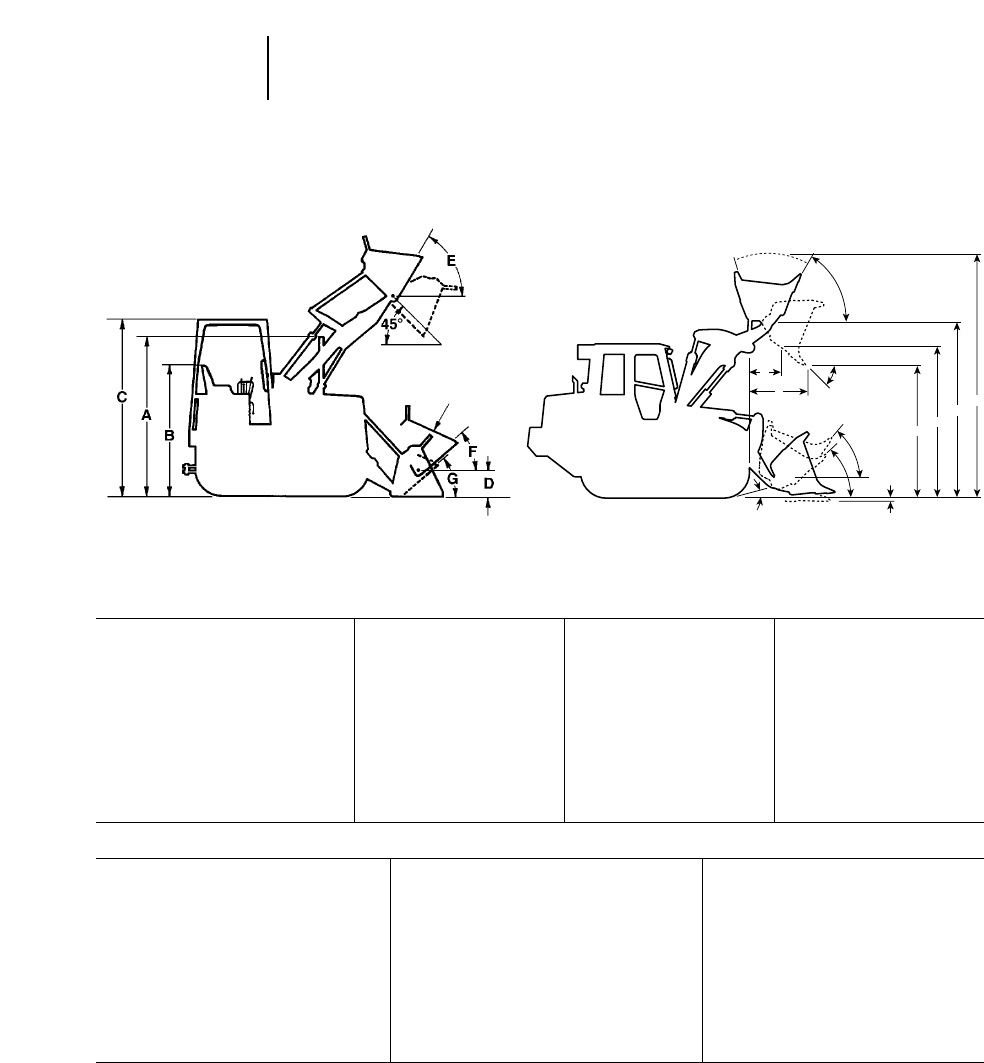
933C 939C 953C
AHeight to Top of Stack 2.80 m 9'2" 2.81 m 9'2" 2.441 m 8'0"
BHeight to Top of Seat 2 m 6'7" 2 m 6'7" 2.353 m 7'9"
CHeight to Top of ROPS 2.73 m 9'0" 2.74 m 9'0" 3.084 m 10'1"
DHinge Pin Height at Carry Position 402 mm 15.8" 414 mm 16.3" 424 mm 16.7"
ERollback at Maximum Lift 67.7° 67.7° 56°
FRollback at Carry Height 51.2° 51.2° 48°
GRollback at Ground Level 42.8° 42.6° 41°
Grading Angle (Bare Edge) ——74°
Width Without Bucket (std. track) 1.80 m 5'11" 1.96 m 6'5" 2.18 m 7'2"
(optional track) 2.31 m 7'7" 2.01 m 6'7" 2.30 m 7'7"
963B 973
AHeight to Top of Stack 3307 mm 10'11" 3.357 m 11'0"
BHeight to Top of Seat 2681 mm 8'10" 2.681 m 8'10"
CHeight to Top of ROPS 3423 mm 11'3" 3.423 m 11'3"
DHinge Pin Height at Carry Position 467 mm 18.4" 492 mm 1'7.4"
ERollback at Maximum Lift 59° 59°
FRollback at Carry Height 50° 50°
GRollback at Ground Level 42° 42°
Grading Angle (Bare Edge) 68° 69°
Width Without Bucket (std. track) 2580 mm 8'6" 2580 mm 8'6"
(optional track) 2755 mm 9'0.9" 2760 mm 9'0"
13-12
Track Loaders Machine Dimensions
●With General Purpose Bucket
A
E
F
C
B
D
933C-939C 953C-973
CARRY
POSITION CARRY
POSITION
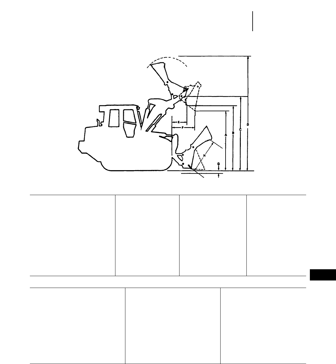
933C 939C 953C
AForward Dump Clearance* 2.56 m 8'5" 2.57 m 8'5" 2.72 m 8'11"
BBottom Dump Clearance* 2.62 m 8'7" 3.05 m 10'0" 3.16 m 10'5"
CHinge Pin Height* 3.31 m 10'10" 3.32 m 10'11" 3.60 m 11'10"
DOverall Height 4.67 m 15'4" 4.68 m 15'4" 5.37 m 17'8"
EBottom Dump Reach 453 mm 18" 453 mm 18" 540 mm 1'9.3"
FForward Dump Reach* 859 mm 2'10" 776 mm 2'7" 986 mm 3'3"
GDigging Depth 184 mm 7.2" 190 mm 7.5" 158 mm 6.2"
HBucket Opening 1103 mm 3'7" 930 mm 3'0" 1140 mm 3'9"
Reach at 2133 mm (7'0") Height* 1200 mm 3'11" 1200 mm 3'11" 1440 mm 4'9"
Tilt Back at Ground Level 43° 43° 43°
Closure Force, Clamp to Cutting Edge 50.7 kN 11,400 lb 56.8 kN 12,780 lb 71.8 kN 16,134 lb
Weight of Bucket and
Additional Hydraulics 754 kg 1663 lb 1005 kg 2216 lb 1413 kg 3115 lb
963B 973
AForward Dump Clearance* 3.04 m 9'11" 3.04 m 10'0"
BBottom Dump Clearance* 3.50 m 11'6" 3.65 m 12'0"
CHinge Pin Height* 4.22 m 13'10" 4.22 m 13'10"
DOverall Height 5.89 m 19'4" 6.52 m 21'5"
EBottom Dump Reach 612 mm 2'0.1" 721 mm 2'4.4"
FForward Dump Reach* 2967 mm 9'9" 1290 mm 4'2"
GDigging Depth 211 mm 8.3" 211 mm 8.3"
HBucket Opening 1260 mm 4'1" 1380 mm 4'6"
Reach at 2133 mm (7'0") Height* 1590 mm 5'2" 1860 mm 6'1"
Tilt Back at Ground Level 42° 45°
Closure Force, Clamp to Cutting Edge 72.3 kN 16,250 lb 89 kN 20,000 lb
Weight of Bucket and Additional Hydraulics 2884 kg 6359 lb 2829 kg 6237 lb
*45° Discharge and full lift.
*Operator may prefer to tip bucket forward when bottom dumping.
13-13
13
Track LoadersMulti-Purpose Bucket Dimensions
●Bare Cutting Edge
13-14
Track Loaders Specifications
●Rippers/Scarifiers
TRACK LOADER 933C 939C 953C 963B 973
Ripper-Scarifier Type — Radial Radial Radial Radial
Dimensions:
Ripper Shank
Maximum digging depth 276 mm 10.9" 193 mm 7.6" 284 mm 11.2" 360 mm 14.2" 428 mm 16.8"
Maximum reach at
ground line 721 mm 2'4.4" 504 mm 1'7.8" 1092 mm 3'7" 1160 mm 3'9.7" 1295 mm 4'3"
Maximum ground
clearance under tip
(shank pinned in
bottom hole) 520 mm 1'8.5" 604 mm 1'11.8" 415 mm 1'8.3" 513 mm 1'8.2" 670 mm 2'2.4"
Maximum ramp angle,
ripper up (shank pinned
in bottom hole) 24° 30.5° 19° 19° 20°
Shank section 36 376 mm 36 376 mm 50 3109 mm 58 3139 mm 74 3175 mm
1.4" 33" 1.4" 33" 2" 34.3" 2.3" 35.5" 2.9" 36.9"
Ripper Beam
Overall width 1.58 m 5'2" 1.58 m 5'2" 1.95 m 6'5" 1.95 m 6'5" 2.20 m 7'3"
Height 130 mm 5.1" 130 mm 5.1" 165 mm 6.5" 165 mm 6.5" 216 mm 8.5"
Length 140 mm 5.5" 140 mm 5.5" 211 mm 8.3" 211 mm 8.3" 254 mm 10"
Number of Pockets 55333
Pocket Spacing 356 mm 14" 356 mm 14" 900 mm 2'11.4" 896 mm 2'11.3" 1000 mm 3'3.4"
Shank Gauge 1.42 m 4'8" 1.42 m 4'8" 1.80 m 5'11" 1.79 m 5'11" 2 m 6'7"
Track clearance with
standard shoe 151 mm 5.9" 151 mm 5.9" NA NA NA
Installed weights:
Ripper with standard shanks 250 kg 550 lb 250 kg 550 lb 428 kg 944 lb 563 kg 1241 lb 1228 kg 2707 lb
Each additional shank 11 kg 24 lb 11 kg 24 lb NA NA NA
Ripper Forces*:
Penetration Force 2650 kg 5843 lb 2687 kg 5924 lb 4707 kg 10,380 lb 6385 kg 14,080 lb 8820 kg 19,450 lb
Pryout Force 5265 kg 11,610 lb 5265 kg 11,610 lb 10 388 kg 22,905 lb 13 897 kg 30,640 lb 17 450 kg 38,480 lb
*These values may vary slightly with different vehicle configurations.
NA – Not Applicable
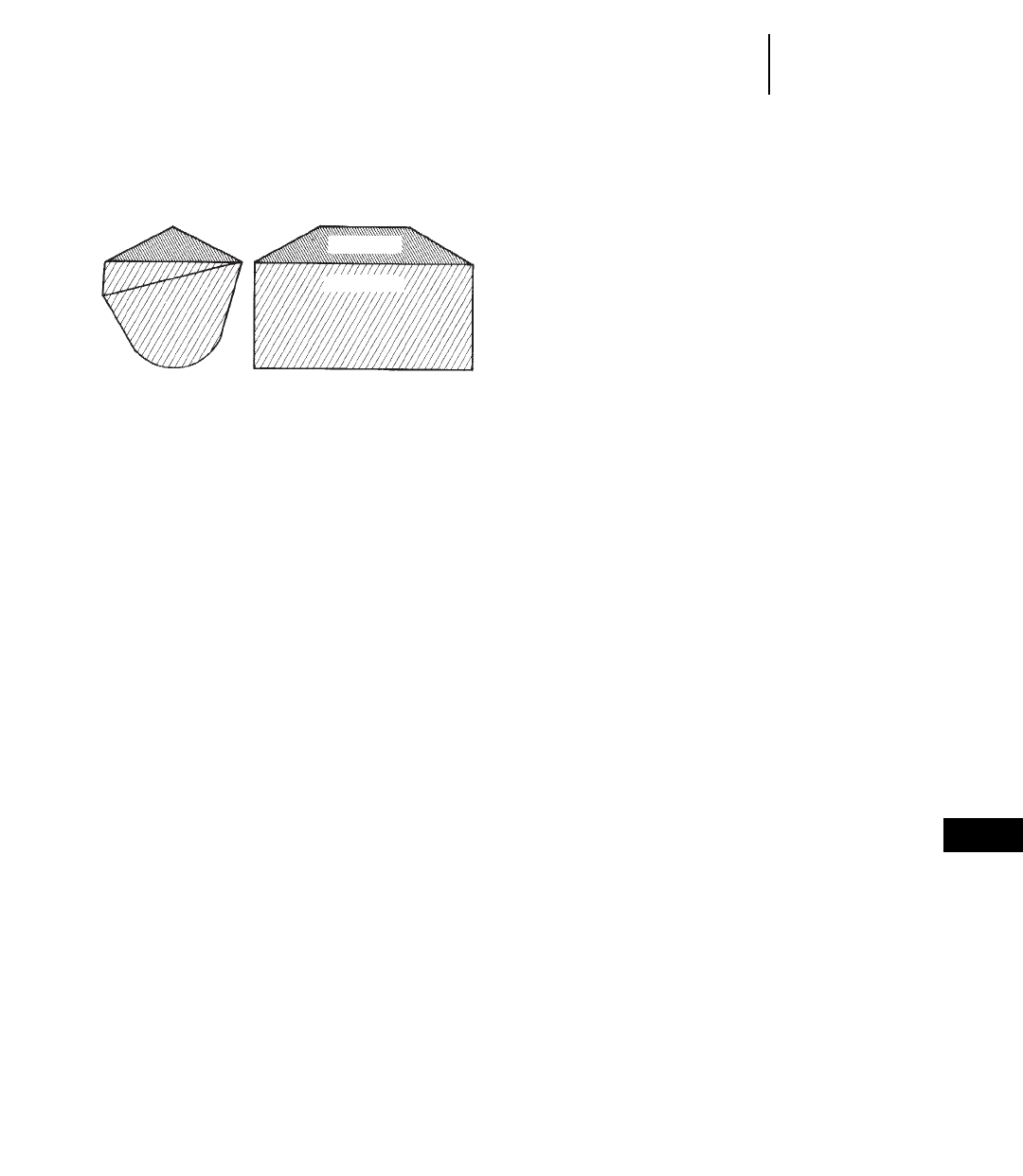
13-15
13
Track LoadersSAE Loader Ratings
Machine Selection
SAE BUCKET RATING
SAE Bucket Capacities
Struck capacity is that volume contained in a
bucket after a load is leveled by drawing a straight
edge resting on the cutting edge and the back of the
bucket.
Heaped capacity is a struck capacity plus that
additional material that would heap on the struck
load at a 2:1 angle of repose with the struck line
parallel to the ground.
SAE J742 (Oct. 79) specifies that the addition of
any auxiliary spill guard to protect against spillage
of material which might injure the operator will not
be included in bucket capacity ratings. Buckets with
irregular shaped cutting edges (vee edge) the strike
plane should be drawn at one-third the distance of
the protruding portion of the cutting edge.
Caterpillar rock buckets are built with integral see-
through rock guards. Caterpillar light material
buckets come standard with bolt-on edges. These
features which add to actual bucket capacity are
included in published ratings.
Dump Height
SAE J732 JUN92 specifies that dump height is
the vertical distance from the ground to the lowest
point of the cutting edge with the bucket hinge pin
at maximum height and the bucket at a 45° dump
angle. Dump angle is the angle in degrees that the
longest flat section of the inside bottom of the bucket
will rotate below horizontal.
Static Tipping Load
The minimum weight at center of gravity of “SAE
Rated’’load in bucket which will rotate rear of machine
to a point where, on track loaders, front rollers are
clear of the track under the following conditions:
a. Loader on hard level surface and stationary.
b. Unit at standard operating weight.
c. Bucket at maximum rollback position.
d. Load at maximum forward position during
raising cycle.
e. Unit with standard equipment as described in
specifications unless otherwise noted under the
heading.
Operating Load
In order to comply with SAE standard J818 MAY87,
the operating load for track loaders should not exceed
35% of the Static Tipping load rating. See “Perfor-
mance Data’’ of each machine in this handbook for
increases to static tipping load by adding cab, coun-
terweights, ripper-scarifier, etc.
SELECTING A MACHINE
Steps in selecting the proper size loader:
1. Determine production required or desired.
2. Determine loader cycle time and cycles per hour.
A machine size must be assumed to select a basic
cycle time.
3. Determine required payload per cycle in loose
cubic yards and pounds (meters and kilograms).
4. Determine bucket size needed.
5. Make machine selection using bucket size and pay-
load as criteria to meet production requirements.
6. Compare the loader cycle time used in calculations
to the cycle time of the machine selected. If there
is a difference, rework the process beginning at
step 2.
1. Production Required
The production required of a track loader should
be slightly greater than the production capability of
the other critical units in the earth or material mov-
ing system. For example, if a hopper can handle 300
tons per hour, a loader capable of slightly more than
300 tons should be used. Required production
should be carefully calculated so the proper machine
and bucket selections are made.
2. Loader Cycle Times
Material type, pile height, and other factors may
improve or reduce production, and should be added
to or subtracted from the basic cycle time when
applicable.
When hauls are involved, obtain haul and return
portions of the cycle from the estimated travel chart
(this section). Add the haul and return times to the
estimated basic cycle time to obtain total cycle time.
STRUCK
HEAPED

CYCLE TIME FACTORS
A basic cycle time (Load, Dump, Maneuver) of
0.25-0.35 minutes is average for a track loader [the
basic cycle for large loaders, 2 m3(2.6 yd3) and up,
can be slightly longer], but variations can be
authenticated in the field. The following values for
many variable elements are based on normal oper-
ations. Adding or subtracting any of the variable
times will give the total basic cycle time.
Estimating Cycle Time
Cycle time of a track loader needs to be determined
to find loads per hour. Total cycle time includes the
following segments:
Load Time + Maneuver Time + Travel Time +
Dump Time
Load Time —
Material Minutes
Uniform aggregates 0.03-0.05
Moist mixed aggregates 0.03-0.06
Moist loam 0.03-0.07
Soil, boulders, roots 0.04-0.20
Cemented materials 0.05-0.20
Maneuver Time — includes basic travel, four
changes of direction and turning time, and will be
about 0.20 minutes with a competent operator.
Travel Time — in a load and carry operation is
comprised of haul and return times which can be
determined by the travel charts in this section.
Dump Time — is dictated by the size and strength
of the dump target and varies from 0.00 to 0.10 min-
utes. Typical dump times into highway trucks are
from 0.04 to 0.07 minutes.
NOTE: When comparing hydrostatic track loaders
with former power shift models (using the
production estimating method) two factors
must be considered: (1) The hydrostatic
loaders on the average outcycle power shift
models by up to 10 percent due to faster
machine speed and easier operation. (2)
Hydrostatic loaders incorporate Z-bar link-
age, which provides substantially better
bucket fill factors. The degree to which each
factor affects estimated production should
be left to the user’s judgment depending on
the particular job application and conditions.
Example: Moist loam is being excavated from a
bank and loaded into trucks.
Minutes
Load — moist loam 0.05
Maneuver Time 0.20
Travel — none
required 0.00
Dump 0.05
Total Cycle 0.30 min. or
200 cycles per 60 min. hour
Minutes added (+)
or Subtracted (–)
From Basic Cycle
Materials
— Mixed . . . . . . . . . . . . . . . . . . . . .+0.02
— Up to 3 mm (1/8 in) . . . . . . . . . .+0.02
— 3 mm (1/8 in) to 20 mm
(3/4 in) . . . . . . . . . . . . . . . . . . . .–0.02
— 20 mm (3/4 in) to 150 mm
(6 in) . . . . . . . . . . . . . . . . . . . . . .–0.00
— 150 mm (6 in) and over . . . . . . .+0.03 and Up
— Bank or broken . . . . . . . . . . . . .+0.04 and Up
Pile
— Conveyor or Dozer piled 3 m
(10 ft) and up . . . . . . . . . . . . . . .–0.00
— Conveyor or Dozer piled 3 m
(10 ft) or less . . . . . . . . . . . . . . .+0.01
— Dumped by truck . . . . . . . . . . . .+0.02
Miscellaneous
— Common ownership of trucks
and loaders . . . . . . . . . . . . . . . .Up to –0.04
— Independently owned
trucks . . . . . . . . . . . . . . . . . . . . .Up to +0.04
— Constant operation . . . . . . . . . .Up to –0.04
— Inconsistent operation . . . . . . .Up to +0.04
— Small target . . . . . . . . . . . . . . . .Up to +0.04
— Fragile target . . . . . . . . . . . . . . .Up to +0.05
Using actual job conditions and the above factors,
total cycle time can be estimated. Convert total cycle
time to cycles per hour.
Cycles per hour at 60 Min
100% Efficiency = Total Cycle Time
in Minutes
Job efficiency is an important factor in machine
selection. Efficiency is the actual number of minutes
worked during an hour. Job efficiency accounts for
operator breaks, and other work interruptions. See
“Efficiency Considerations’’ page 13-18
13-16
Track Loaders ●Cycle Time Factors
●Estimating Cycle Time
13-17
13
Track Loaders●Bucket Fill Factors
●Recommended Operating Capacities
●Loader Production
Bucket Fill Factors
The following indicates the approximate amounts
of material as a percent of rated bucket capacity
which will actually be delivered per bucket per cycle.
This is known as “Bucket Fill Factor.’’
Loose Material Fill Factor
Mixed Moist Aggregates 95-110%
Uniform Aggregates 95-110
3 mm-9 mm (1/8 in-3/8 in) 90-110
12 mm-20 mm (1/2 in-3/4 in) 90-110
24 mm and over (1 in) 90-110
Blasted Rock
Well 80-95%
Average 75-90
Poor 60-75
Other
Rock Dirt Mixtures 100-120%
Moist Loam 100-120
Soil, Boulders, Roots 80-100
Cemented Materials 85-100
Fill factors on track loaders are affected by bucket
penetration, breakout force, rackback angle, bucket
profile and ground engaging tools such as bucket teeth
or bolt-on replaceable cutting edges and segments.
GENERAL PURPOSE BUCKET
MAXIMUM OPERATING CAPACITIES
GENERAL MAXIMUM
PURPOSE OPERATING
BUCKET SIZE CAPACITY
MODEL m3yd3kg lb
933C 1.0 1.3 1770 3900
939C 1.15 1.5 2040 4500
953C 1.75 2.25 3410 7490
963B 2.3 3.0 4700 10,360
973 2.8 3.75 6265 13,190
LOADER PRODUCTION
Loader production equals quantity of material the
bucket carries per load 2number of bucket loads
per hour.
Estimating Bucket Load
The quantity of material in a loader bucket is esti-
mated by two methods, depending on whether the
material being loaded is in a loose or bank state.
1. When the material is loose, as in stockpile load-
ing, the bucket load is estimated in loose meters
(or cubic yards) by a Bucket Fill Factor (see Tables
Section or chart following this discussion). The
quantity of material is determined as follows:
Rated Bucket Capacity 2Bucket Fill Factor =
Bucket Payload in Loose m3(yd3)
For example, a 973 with a 2.8 m3(3.75 yd3)
General-Purpose bucket loading uniform aggre-
gate from a stockpile will carry:
2.8 m321.0 = 2.8 loose cubic meters
(3.75 yd321.0 = 3.75 loose cubic yards)
Once the potential bucket load has been deter-
mined, check the static tipping load ratings on
the specific machine to determine if bucket load
is in fact a safe operating load. (Safe operating
load as defined by SAE for track loaders should
not exceed 35% of static tipping load.)
Productivity in many applications is measured
in tons. See Tables Section for material densities
if conversion to tons is desired.
2. When material is in the bank state, as in exca-
vation, productivity is measured in bank meters
(cubic yards). Bucket load in Bm3(BCY) is esti-
mated by applying one of the load factors from
the Tables section to convert the excavated mate-
rial in the bucket from Bm3(BCY) to Lm3(LCY)
to allow for the digging and carrying character-
istics of the material. The quantity of excavated
material a bucket carries is then determined as
follows:
Rated Bucket Capacity 2Load Factor 2Bucket
Fill Factor = Bucket Payload in Bm3(BCY)
Example: a 953C with a 1.75 m3(2.25 yd3)
General Purpose bucket loading wet loam earth
from bank:
1.75 m320.80 21.15 = 1.61 Bm3
(2.25 yd320.80 21.15 = 2.07 BCY)

13-18
Track Loaders Loader Production
●Estimating Production
●Alternative Machine Selection Method
Estimating Production
Machine and job considerations include:
●Machine model and bucket size
●Material type, particle size, density and load
factor (see Tables Section)
●Bucket fill factor
●Haul distance
●Underfoot conditions
●Altitude
●Dump target size, height, and type
Example:
Conditions —
Machine 953C
Bucket size 1.75 m3(2.25 yd3)
Material Moist Loam
Bucket fill factor 1.15
Haul length 30 m (100 ft)
Dump target Pile
Travel in forward speed
Cycle Time Minutes
Load time 0.03 min
Maneuver time 0.20
Travel time (from curves) 0.40
Dump time 0.00
Total 0.63 min
Loads Per Hour —
60 min/hr = 95 cycles per hour
0.63 min/cycle @ 100% efficiency
Load Per Cycle —
1.75 m321.15 BFF = 2.0 Lm320.81 LF
= 1.63 Bm3
(2.25 yd321.15 BFF = 2.58 LCY 20.81 LF
= 2.10 BCY)
Hourly Production —
1.63 Bm3 295 cycles/h = 154.9 Bm3/h
(2.10 BCY 295 cycles/hr = 199.1 BCY/hr)
Efficiency Considerations
Loader capacity should always be matched to
peak production requirements of the job. Actual “on-
the-job’’ loader productivity will be influenced by
factors such as operator skill, personal delays, job
layout and other delays. Experience and knowledge
of local conditions will be the best indicators of
actual job efficiency.
Efficiency
Operation Working Hour Factor
Day 50 min/Hr 0.83
An Alternative Machine Selection Method
Another method of selecting the right Track Loader
and bucket to meet production requirements is by
use of the nomographs on the following pages. The
method is quicker and easier than the proceding
example because it does not require as many calcu-
lations, yet the accuracy is about the same within
the normal limits of input data.
Be careful when entering and reading data from
the nomographs because some scales increase from
bottom to top, while others are the reverse. Do not be
overly concerned with the precision as affected by
pencil line width or reading to the hundredth of a
m3(yd3). Remember that bucket fill factor, material
density, and cycle time are at best close estimates.
Example problem
A track loader must produce 180 Lm3(235 LCY)
per hour. Estimated cycle time is 0.5 minutes, working
50 minutes per hour. Bucket fill factor is 100% and
the material density is 1600 kg/Lm3(2700 lb/LCY).
Determine bucket size, machine model and hourly
production in tons and yards.
Solution:
At full efficiency, it will cycle 120 times per hour.
Since only an average 50 minutes are available, only
100 cycles will be completed per hour.
Starting on Scale A at 100 cycles per hour draw a
straight line intersecting 180 m3/hr (235 yd3/hr) on
Scale B and continuing the line on to Scale C giv-
ing 1.80 m3(2.35 yd3) required payload.
Follow steps 1 through 7 on the next two pages.
● ● ●
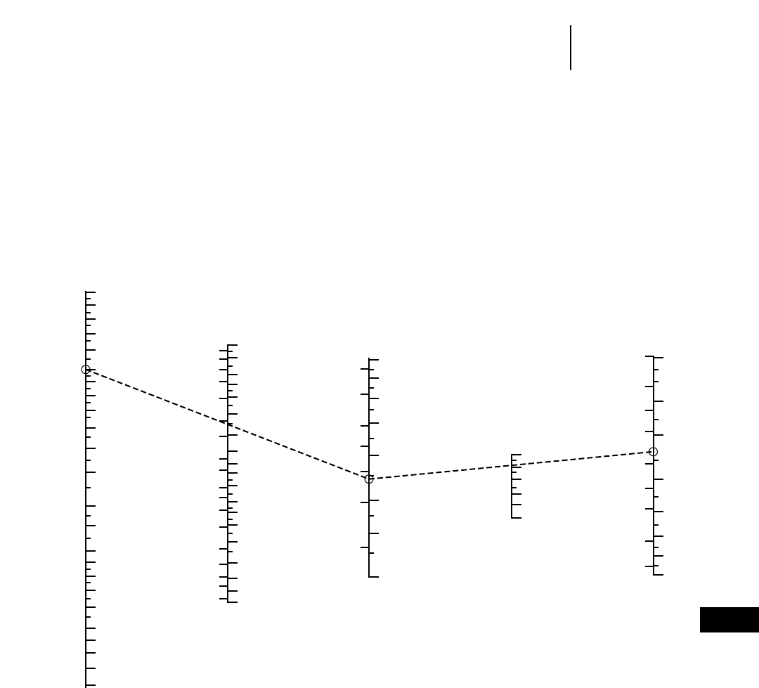
13-19
13
Track LoadersProduction and Machine Selection Nomograph
●To find required bucket payload and bucket size
1) Enter Scale A cycles per hour (100) and B hourly
production 180 m3/hr (235 yd3/hr).
2) Connect A and B and extend to C to find required
payload 1.8 m3(2.35 yd3).
3) Connect C to bucket fill factor on Scale D (1.0) and
extend to E to find required bucket size 1.8 m3
(2.35 yd3).
4) Transfer Scale A and C readings to nomograph
on following page.
200
180
160
140
120
100
80
60
50
40
30
25
20
18
16
14
12
10
9
8
7
6
1000
800
600
500
400
300
200
150
120
100
80
60
50
40
30
20
15
12
10
700
600
500
400
300
200
150
100
80
60
50
40
30
20
15
12
10
8
7
56
4.5
5
4
3.5
34
2.5
2
3
1.5 2
1
1
1.5
1
1.5
1
1.25
1.5
2
2
4
4
57
5
4.5
3
3.5
2.5
.75
6
3
120%
100
80
60
50
40
AB C D E
Cycles Hourly Required Bucket Required
per Hour Production Payload Fill Bucket
Required Volume Factor Volume
yd3
m3
m3/cycle yd3/cycle
yd3/hrm3/hr
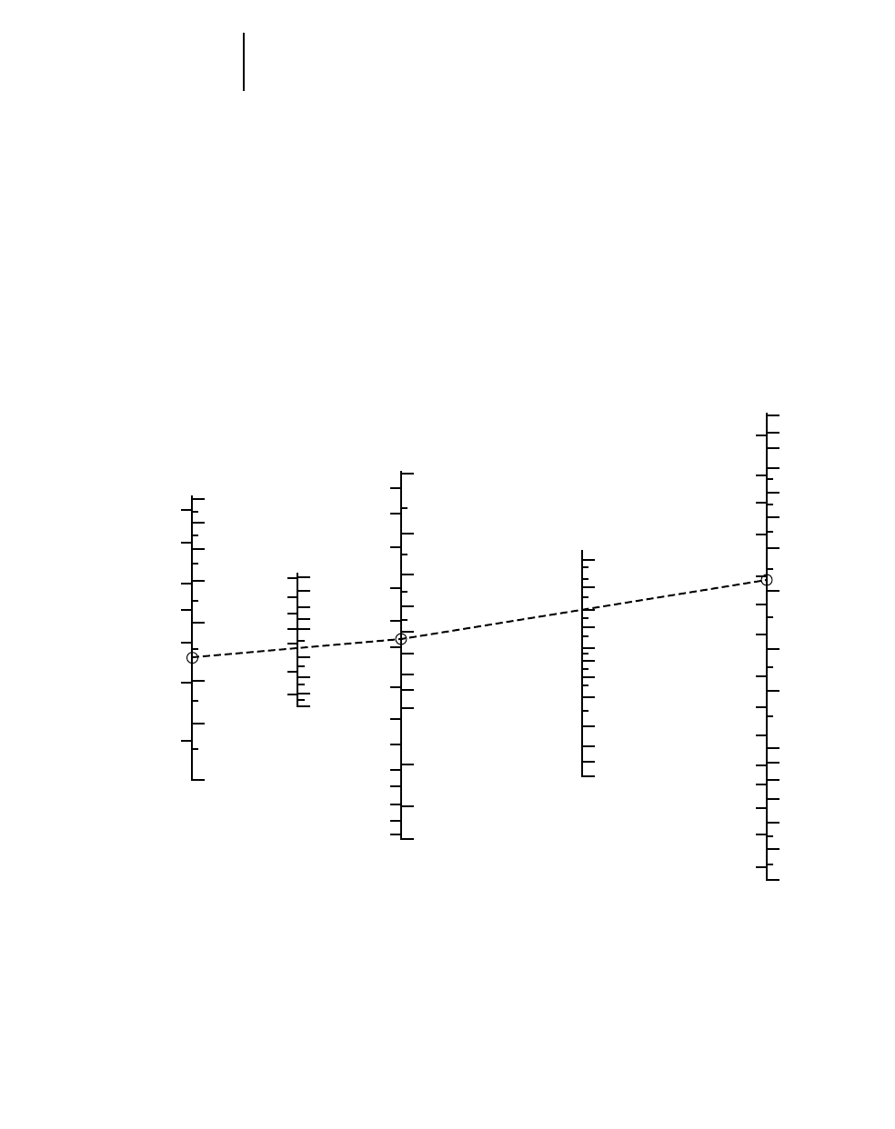
13-20
Track Loaders Production and Machine Selection Nomograph
●To find payload weight for stability and output in tons per hour
5) Connect C 1.8 m3(2.35 yd3) to F 1600 kg/m3
(2700 lb/yd3) and extend to G to find payload
weight 2880 kg (6345 lb).
6) Compare G bucket payload weight 2880 kg
(6345 lb) with maximum operating capacities table
in this section to see if the 1.75 m3(2.25 yd3) bucket
can handle the desired payload. Table indicates the
953C with a 1.75 m3(2.25 yd3) bucket equipped
with bolt-on cutting edge or teeth and segments
has a greater operating capacity of 3097 kg (6827 lb),
therefore stability is okay.
7) Extend Scale G reading 2880 kg (6345 lb)
through Scale A (100) to Scale I to find tons per
hour 288 metric ton/hr (317 U.S. ton/hr).
CFG A I
Required Material Bucket Cycles Tons per
Payload Density Payload per Hour Hour
7
56
4.5
5
4
3.5
34
2.5
2
3
1.5 2
1
1
1.5
1000
600
800
1000
1500
2000
3000
1200
1500
1800
2000
1200
3000
4000
5000
6000
2000
25,000
20,000
15,000
10,000
11 000
10 000
9000
8000
7000
6000
5000
4000
3000
2500
2000
1500
1200
1000
9000
8000
7000
6000
5000
4000
3000
200
140
100
80
60
50
40
30
20
15
12
10
1000
800
600
500
400
300
250
200
150
120
100
80
70
60
50
40
900
800
700
600
500
400
300
200
150
100
90
80
70
60
50
40
U.S.
Short Tons
Metric
Tons
cycle/hr
lb/cyclekg/cycle
lb/yd3
kg/m3
yd3/cyclem3/cycle
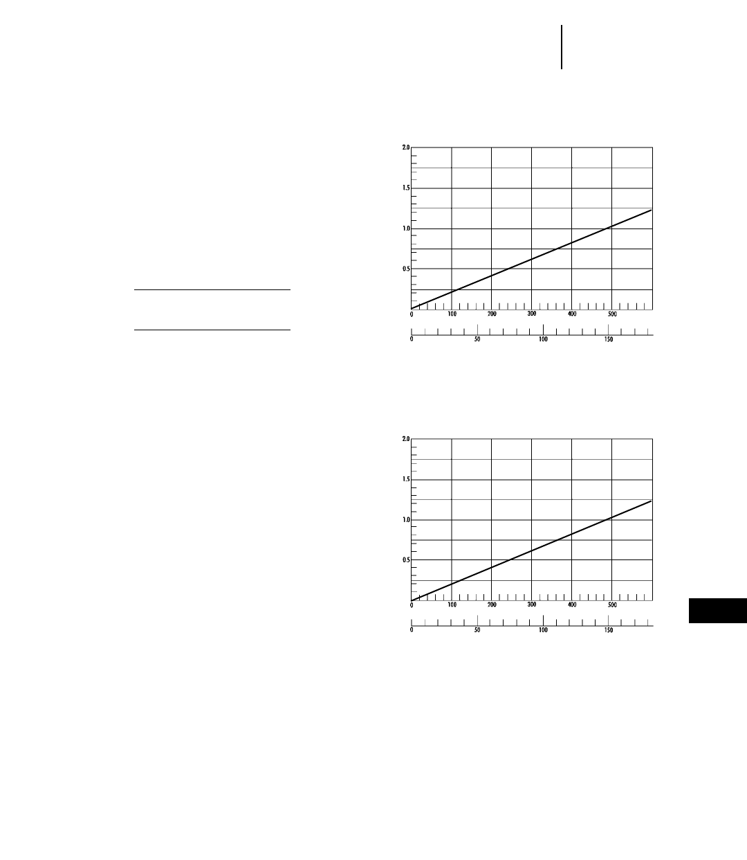
13-21
13
Track LoadersTravel Time Charts
●933C ●939C
TRAVEL TIME CHARTS
Conditions:
●No grades.
●Speeds loaded and empty essentially the same.
●Bucket position constant during travel.
●Travel encountered in maneuver time portion
of cycle not included.
●Acceleration time accounted for in maneuver time.
Travel Time (in minutes) =
Metric – number of meters traveled
speed (in km/h) 216.67
English – number of feet traveled
speed (in mph) 288
Hydrostatic top speed both forward
and reverse 9 km/h (5.6 mph).
933C
One Way Travel Distance
Feet
Meters
One Way Travel Time (Minutes)
939C
One Way Travel Distance
Feet
Meters
One Way Travel Time (Minutes)
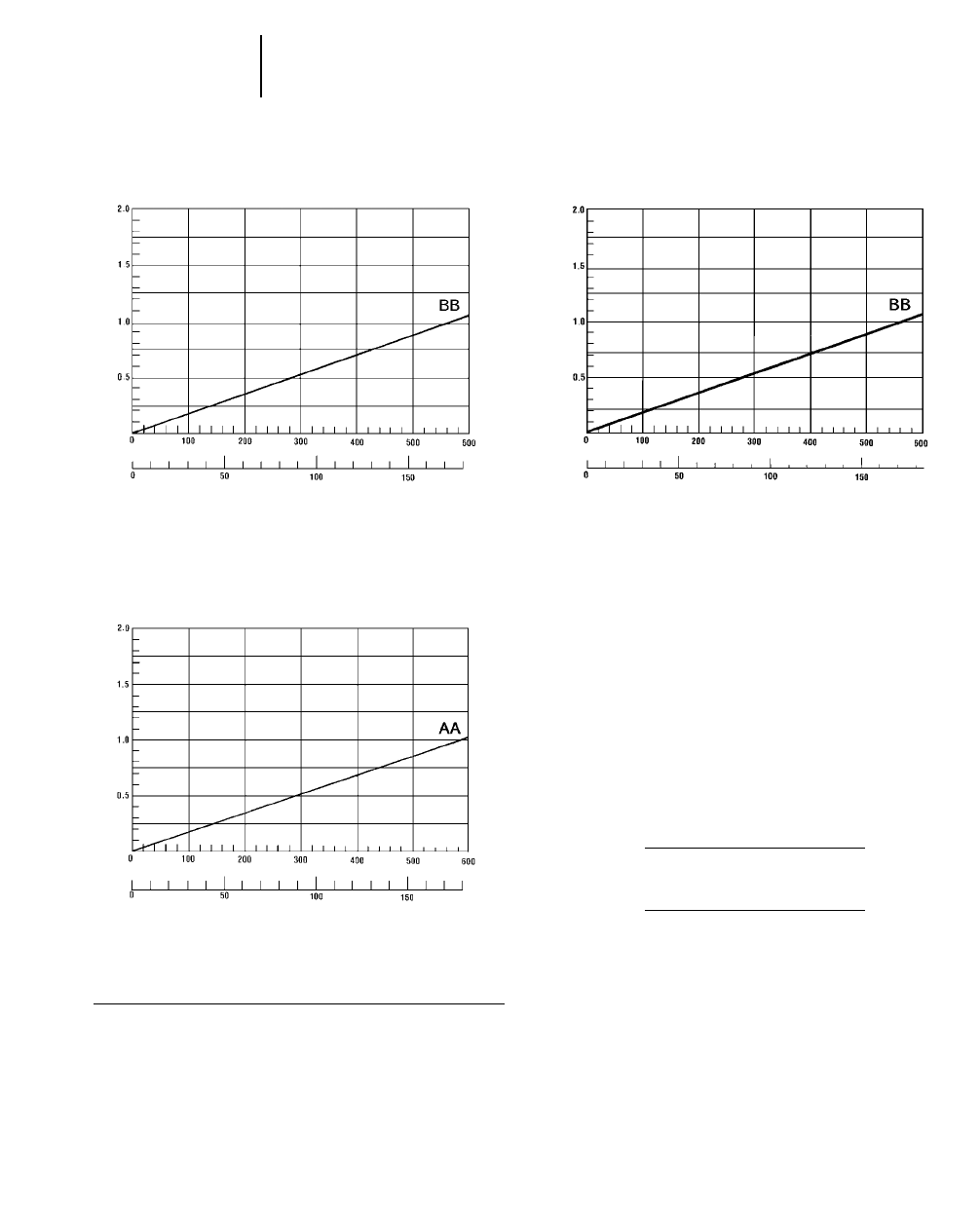
13-22
Track Loaders Travel Time Charts
●953C ●963B ●973
TRAVEL TIME CHARTS
Conditions:
●No grades.
●Speeds loaded and empty essentially the same.
●Bucket position constant during travel.
●Travel encountered in maneuver portion of cycle
not included.
●Acceleration time accounted for in maneuver time.
Travel Time (in minutes) =
Metric – number of meters traveled
speed (in km/h) 216.67
English – number of feet traveled
speed (in mph) 288
953C
One Way Travel Distance
Feet
Meters
One Way Travel Time (Minutes)
973
One Way Travel Distance
Feet
Meters
One Way Travel Time (Minutes)
963B
One Way Travel Distance
Feet
Meters
One Way Travel Time (Minutes)
KEY
AA — Hydrostatic top speed both forward and reverse
10.3 km/h (6.4 mph)
BB — Hydrostatic top speed both forward and reverse
10 km/h (6 mph)
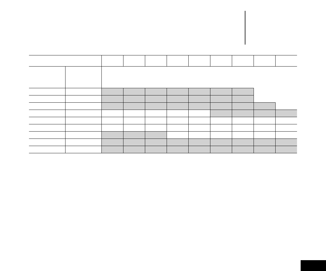
13-23
13
Track LoadersProduction Estimating Table
●m3or yd3/60 min. hour
●Estimated bucket payload in
bank m3or yd3
Bucket Size
(m3 or yd3) 1.0 1.5 2.0 2.5 3.0 3.5 4.0 4.5 5.0
Cycle
Time Cycles
Hundredths Per
of a minute Hr
0.25 240 240 360 480 600 720 840 960
0.30 200 200 300 400 500 600 700 800
0.35 171 171 257 342 428 513 599 684 769
0.40 150 150 225 300 375 450 525 600 675 750
0.45 133 133 200 268 332 400 466 530 600 665
0.50 120 120 180 240 300 360 420 480 540 600
0.55 109 109 164 218 272 328 382 436 490 545
0.60 100 100 150 200 250 300 350 400 450 600
0.65 92 92 138 184 230 276 322 368 416 460
Unshaded area indicates average work range
13-25
13
CONTENTS
Features . . . . . . . . . . . . . . . . . . . . . . . . . . . . .13-25
Specifications . . . . . . . . . . . . . . . . . . . . . . . . .13-26
Attachments . . . . . . . . . . . . . . . . . . . . . . . . . .13-27
Features
●Unmatched versatility — excavates, loads, dozes,
compacts, shreds, sorts, grapples — a true all pur-
pose machine.
●Additional heavy duty guarding helps protect
sheet metal and machine components from dam-
age in waste handling applications.
●Improved serviceability — swing open doors,
guards and oil coolers give quicker access for clean-
ing debris and for servicing.
●Hinged heavy duty radiator guard with quick
release “T’’ handles allows for easy access to the
radiator for cleaning.
●Rear Striker Bar (optional) keeps trash from
climbing the track and damaging fenders.
●Lamp Guard Group (front and rear) protects
lamps with bolt on grid guards.
●Single grouser trapezoidal-shaped center
hole track shoes (optional) provides maximum
traction and center holes allow sprocket to punch
out dirt and debris.
●Debris Barrier Package protects machine from
material entering engine and other compartments.
WASTE HANDLING TRACK LOADERS
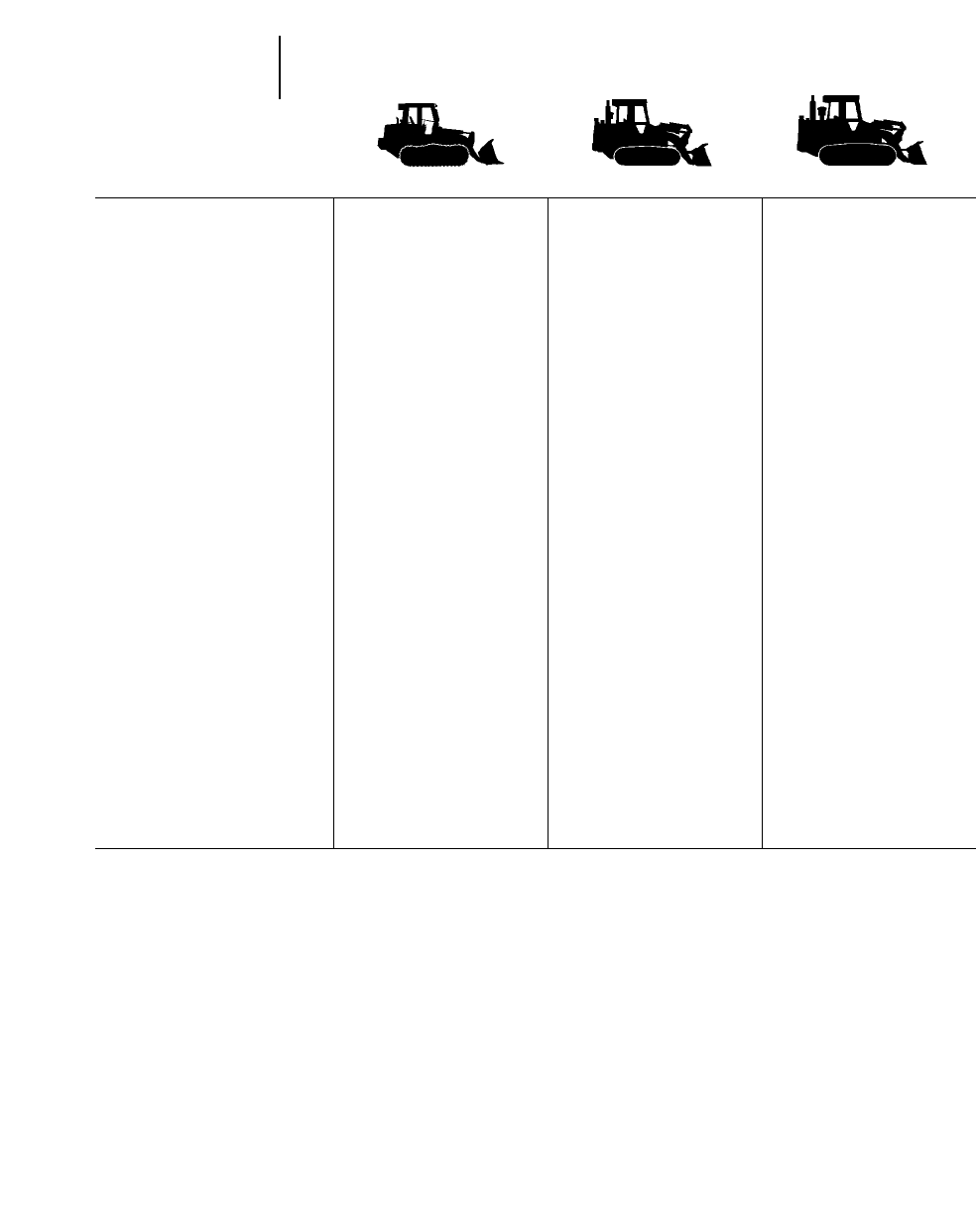
13-26
Specifications
MODEL 953C WHA 963B WHA 973 WHA
Flywheel Power 90 kW 121 hp 119 kW 160 hp 157 kW 210 hp
Operating Weight 15 840 kg 34,920 lb 21 269 kg 46,898 lb 29 266 kg 64,585 lb
Engine Model 3116T 3116TA 3306T
Rated Engine RPM 2200 2200 2200
Bore 105 mm 4.13" 105 mm 4.13" 121 mm 4.75"
Stroke 127 mm 5" 127 mm 5" 152 mm 6"
No. Cylinders 666
Displacement 6.6 L 403 in36.6 L 403 in310.5 L 638 in3
Speeds Forward, km/h mph km/h mph km/h mph
1st 0-10 0-6.2 0-10.1 0-6 0-10.3 0-6.4
2nd Infinitely Infinitely Infinitely
3rd Variable Variable Variable
Reverse
1st 0-10 0-6.2 0-10.1 0-6 0-10.3 0-6.4
2nd Infinitely Infinitely Infinitely
3rd Variable Variable Variable
Hydraulic Cycle Time, Bucket
Empty, in Seconds:
Raise 6.7 6.2 7.4
Dump 1.4 1.3 1.4
Lower (Empty, Float Down) 3 2.3 2.6
Total 11.1 9.8 11.4
Track Rollers (Each Side) 667
Width of Standard Track Shoe 380 mm 15" 450 mm 17.7" 500 mm 1'7.7"
Length of Track on Ground 2.295 m 7'6" 2.454 m 8'1" 2.85 m 9'6"
Ground Contact Area
(With Std. Shoe) 1.74 m22704 in22.21 m23426 in22.92 m24526 in2
Ground Pressure 89 kPa 12.9 psi 96.2 kPa 13.7 psi 100.2 kPa 14.3 psi
Ground Clearance 377 mm 14.8" 439 mm 17" 456 mm 17.9"
Track Gauge 1.80 m 5'11" 1.85 m 6'0.8" 2.08 m 6'10"
Width Without Bucket 2.18 m 7'2" 2.30 m 7'6.5" 2.58 m 8'5.6"
Fuel Tank Refill Capacity 241 L 63.6 U.S. gal 296 L 78 U.S. gal 356 L 94 U.S. gal
Hydraulic System Refill Capacity 65 L 17.2 U.S. gal 68 L 18 U.S. gal 60 L 16 U.S. gal
See Wheel Loader section of this book for summary of S.A.E. Guidelines for Loader Specifications, to which Caterpillar adheres.
Waste Handling
Track Loaders
13-27
13
Track LoadersAttachments
●Landfill Buckets
LANDFILL BUCKETS
Machine Model 953C 963B 973
Bucket Model B53-4L B63-6L B73-8L
Capacity, rated (Refuse) 2.7 m33.5 yd34.2 m35.5 yd35.58 m37.25 yd3
Capacity, rated (Earth) 1.91 m32.5 yd32.87 m33.75 yd34.2 m35.5 yd3
Width 2438 mm 8'0" 3033 mm 9'11" 3323 mm 10'11"
Height 1448 mm 4'9" 1967 mm 6'5" 2284 mm 7'6"
Depth 889 mm 2'11" 1585 mm 5'2" 1626 mm 5'4"
Teeth-optional 888
Clearance @ 45° dump 2852 mm 9'3" 2769 mm 9'1" 2918 mm 9'7"
Reach @ 45° dump 810 mm 2'8" 1406 mm 4'7" 1560 mm 5'1"
Digging depth 132 mm 5.2" 124 mm 4.9" 114 mm 4.5"
Weight (approx.) 998 kg 2200 lb 2475 kg 5460 lb 2905 kg 6400 lb
MUTLI-PURPOSE
LANDFILL BUCKETS
Machine Model 953C 963B 973
Bucket Model B53-3ML B63-4ML B73-6ML
Capacity, rated (Refuse) 2 m32.62 yd32.7 m33.5 yd34.4 m35.75 yd3
Capacity, rated (Earth) 1.53 m32 yd31.9 m32.5 yd32.68 m33.5 yd3
Width 2426 mm 8'0" 2529 mm 8'4" 3399 mm 11'2"
Height 1676 mm 5'6" 1905 mm 6'3" 1968 mm 6'6"
Depth 953 mm 3'2" 1060 mm 3'6" 1243 mm 4'1"
Teeth-optional 888
Clearance @ 45° dump 2738 mm 9'0" 2870 mm 9'5" 3121 mm 10'3"
Reach @ 45° dump 806 mm 2'8" 1013 mm 3'4" 1220 mm 4'0"
Digging depth 229 mm 9" 203 mm 8" 211 mm 8.3"
Weight (approx.) 1615 kg 3565 lb 2109 kg 4650 lb 2765 kg 6100 lb

13-28
Track Loaders Attachments
Work Tools 973 963B 953C 939C* 933C*
Quick coupler X X X
General purpose bucket X X X
Landfill bucket X X X
Landfill Multi-purpose X X X
Skeleton rock bucket X
Coal bucket X
Woodchip bucket
Fertilizer bucket
Multi-purpose bucket X X X
Side dump bucket X X
Demolition bucket X
Trim blade X X X
Straight blade X
Manual angle blade X
Hydraulic angle blade X
Fork XXX
Material handling arm X X X
Loader rake X X
*This list is not all-inclusive. Contact Caterpillar Attachment Products and Services for specific
attachment needs.

CONTENTS
Features . . . . . . . . . . . . . . . . . . . . . . . . . . . . . .14-1
Specifications . . . . . . . . . . . . . . . . . . . . . . . . . .14-2
Special attachments . . . . . . . . . . . . . . . . . . . . .14-4
Performance Data:
General purpose buckets . . . . . . . . . . . . . . .14-5
Pallet forks . . . . . . . . . . . . . . . . . . . . . . . . . .14-7
Material handling arm . . . . . . . . . . . . . . . . .14-8
Machine Dimensions:
General purpose buckets . . . . . . . . . . . . . . .14-9
Pallet forks . . . . . . . . . . . . . . . . . . . . . . . . .14-10
Material handling arm . . . . . . . . . . . . . . . .14-11
Bucket selection guide . . . . . . . . . . . . . . . . . .14-13
Machine/Attachment selection . . . . . . . . . . . .14-14
Features:
●Integral quick coupler for fast tool changes.
●Wide range of tools available to meet many jobs.
●Increased lift height and reach over conven-
tional loaders.
●Parallel lift from ground level to maximum height.
●High tilt force throughout lift cycle provides
exceptional load control.
●Pressure compensating valves provide precise
hydraulic
“
feel” on the IT28G.
●Transmission neutralizer lockout switch for low
speed maneuverability is standard. (IT14G-IT38G)
●Positive carry position for load stability and
retention.
●Standard third valve and optional fourth
function for multiple tool functions.
●Work tool interchangeability. IT14G thru IT28G
share the same tools. IT38G and IT62G can share
the same tools.
●Excellent center visibility to quick coupler and
work tool.
●Two position return to work kickouts.
INTEGRATED TOOLCARRIERS
14-1
14
MODEL IT14G IT24F
Flywheel Power 67 kW 90 hp 78 kW 105 hp
Engine Model 3054T 3114T
Rated Engine RPM 2200 2400
Bore 100 mm 3.94" 105 mm 4.13"
Stroke 127 mm 5" 127 mm 5"
No. Cylinders 44
Displacement 4 L 244 in34.4 L 268 in3
Speeds Forward: km/h mph km/h mph
1st 7.0 Lo* 4.3 7.1 4.4
2nd 20.0 Hi* 12.4 13.1 8.2
3rd 9.0 Lo** 5.6 23.6 14.8
4th 32.0 Hi** 19.9 38.2 23.9
Speeds Reverse:
1st 7.0 Lo* 4.3 7.1 4.4
2nd 20.0 Hi* 12.4 13.1 8.2
3rd 9.0 Lo** 5.6 23.6 14.8
4th 32.0 Hi** 19.9 —
Hydraulic Cycle Time,
rated load in bucket: Seconds Seconds
Raise 6.9 5.3
Dump 2.5 1.5
Lower (empty, float down) 3.1 4.3
Total 12.5 11.1
Fuel tank capacity 150 L 39.6 U.S. gal 157 L 41.5 U.S. gal
Hydraulic tank capacity 70 L 18.5 U.S. gal 53 L 14 U.S. gal
Hydraulic system capacity (includes tank) 100 L 26.4 U.S. gal 79 L 20 U.S. gal
**Hydrostatic transmission standard speed version.
**Hydrostatic transmission high speed version.
14-2
Integrated Toolcarriers Specifications
MODEL IT28G IT38G IT62G
Flywheel Power 93 kW 125 hp 108 kW 145 hp 149 kW 200 hp
Engine Model 3116T 3126T 3126TA
Rated Engine RPM 2300 2200 2200
Bore 105 mm 4.13" 110 mm 4.3" 110 mm 4.3"
Stroke 127 mm 5" 127 mm 5" 127 mm 5"
No. Cylinders 666
Displacement 6.6 L 403 in37.2 L 439 in37.2 L 439 in3
Speeds Forward: km/h mph km/h mph km/h mph
1st 7.6 4.7 7.0 4.3 6.9 4.3
2nd 12.0 7.5 12.7 7.9 12.7 7.9
3rd 24.6 15.3 21.9 13.6 22.3 13.9
4th 36.7 22.8 35.9 22.3 37.0 23.0
Speeds Reverse:
1st 7.6 4.7 7.0 4.3 7.6 4.7
2nd 12.0 7.5 12.7 7.9 13.9 8.7
3rd 24.6 15.3 21.9 13.6 24.5 15.3
4th ——40.5 25.3
Hydraulic Cycle Time,
rated load in bucket: Seconds Seconds Seconds
Raise 6.1 5.8 6.3
Dump 1.4 2.0 2.2
Lower (empty, float down) 2.8 2.9 2.2
Total 10.3 10.7 10.7
Fuel tank capacity 230 L 60.8 U.S. gal 254 L 67 U.S. gal 295 L 78 U.S. gal
Hydraulic tank capacity 70 L 18.5 U.S. gal 55 L 14.5 U.S. gal 88 L 23.3 U.S. gal
Hydraulic system capacity
(includes tank) 125 L 33 U.S. gal 90 L 23.8 U.S. gal 153 L 40.4 U.S. gal
14-3
14
Integrated ToolcarriersSpecifications

BUCKETS
General Purpose — for most material types with
choice of cutting edges and teeth.
Loose Material — designed for snow, woodchips,
hay, coal, etc. Add independently controlled top
clamp for materials like hay, brush, silage or compost.
Multi-purpose — versatile ... loads, strips top-soil,
bulldozes, clamps pipe, cleans up debris, plus many
other tasks.
High dump or “roll-out” — for extended dump
height of light materials.
Side dump — dump forward or to the left ... ideal
in close quarters or to reduce turning time.
Grading — long, flat floor and straight edge for fin-
ish work in housing developments, concrete pours,
landscaping and light dozing.
Grab and Grip — positive clamping jaws for garbage
pickup, snow removal, debris cleanup or any loose or
bundled loads.
FORKS
Log or lumber forks — with optional clamps, sin-
gle, double or full-width.
Wide frame forks — adjustable for control of long
pipes, culverts, etc.
Stinger fork — with long single shaft to penetrate
salvage autos or round hay bales.
Utility pallet forks — for a variety of tasks, with
three different tine sizes.
Pulpwood — choice of single or double top clamp
for positive control of material.
Sorting — designed for durability and efficiency in
stacking operations.
BLADES
Angling dozer — choice of manual or hydraulic
angling 25° left or right.
Straight blade — for spreading, leveling and other
utility dozing.
One-way snow blade — economical snow clear-
ing with minimal machine effort.
V-plow — excellent for breaking up large drifts or
high speed clearing operations.
Material Handling arm — carries and places pipe,
prefabricated building panels and handles bulky,
nonpalletized material ... two telescopic sections
extend for three position operation.
AND MORE ...
Rotary broom — for street cleanup, snow removal,
jobsite clean-up, clearing runways ... angles left or
right 30°.
Asphalt cutter — aids repair work on roads, pave-
ments, water and sewer mains ... cuts clean to
125 mm (5").
Hooks — for attachment to dumpsters, bins,
troughs, etc., to permit quick, easy, instant move-
ment from place to place.
These products are available through Caterpillar
Attachment Products and Services.
Balderson Work Tools
Work Tools IT62G IT38G IT28G IT24F IT14G
Light Material Bucket XXXX
Fertilizer Bucket X X
Bucket With Top Clamp XXXX
Grab and Grip Bucket XXXX
Multi-Purpose Bucket X XXXX
Side Dump Bucket X XXXX
High Dump Bucket X X X
Pallet Fork X XXXX
Log/Lumber Fork X XXXX
Core Fork X X X
Straight Blade X X X
Manual Angle Blade XXXX
Hydraulic Angle Blade X X X
Manual Reversible Plow X XXXX
Hydr. Reversible Plow X XXXX
V-Plow X X X
One Way Plow X X X
Asphalt Cutter X X X
Hydraulic Broom X XXXX
Hydraulic Hammers X X X
Tire Loader X X X X
Loader Rake XXXX
Woodchip X XXXX
Refuse XXXX
This list not all inclusive. Contact Caterpillar Attachment Products and Services
for special attachment needs.
14-4
Integrated Toolcarriers Special Attachments

Operating Specifications — Buckets
IT14G IT24F IT28G IT38G IT62G
Cutting Edge Corner Guard or Bolt-on Edge
Capacity, heaped 1.3 m31.7 yd31.6 m32 yd32 m32.6 yd32.5 m33.25 yd33.1 m34 yd3
Capacity, struck 1.1 m31.4 yd31.4 m31.8 yd31.7 m32.25 yd32.1 m32.7 yd32.7 m33.5 yd3
Width 2401 mm 7'10.5" 2395 mm 7'10" 2549 mm 8'4" 2708 mm 8'10" 2870 mm 9'5"
Dump clearance @
full lift and 45°
discharge 2920 mm 9'7" 2752 mm 9'0" 2911 mm 9'7" 2800 mm 9'2" 2840 mm 9'4"
Reach at 45°
discharge angle,
2130 mm/7'0"
clearance 1425 mm 4'8" 1547 mm 5'8" 1567 mm 5'2" 1657 mm 5'5" ***
Reach at full lift and
45° discharge 787 mm 2'7" 1088 mm 3'7" 1014 mm 3'4" 1200 mm 3'11" 1242 mm 4'11"
Reach with arms
horizontal and
bucket level 2150 mm 7'1" 2374 mm 7'10" 2383 mm 7'10" 2521 mm 8'3" 2775 mm 9'1"
Digging depth 175 mm 6.9" 132 mm 5.2" 108 mm 4.3" 70 mm 2.8" 88 mm 3.5"
Overall length 6424 mm 21'1" 6771 mm 22'3" 7318 mm 24'0" 7487 mm 24'7" 8263 mm 27'1"
Overall height
(bucket @ full
raise) 4801 mm 15'9" 4855 mm 15'11" 5080 mm 16'8" 5237 mm 17'2" 5436 mm 17'10"
Loader clearance
circle (bucket in
carry position) 10.4 m 34'1" 10.76 m 35'4" 11.36 m 37'4" 12.13 m 39'10" ***
Static tipping load**
Straight 5307 kg 11,675 lb 6091 kg 13,431 lb 8469 kg 18,674 lb 8861 kg 19,535 lb 13 014 kg 28,631 lb
Full turn 4588 kg 10,094 lb 5284 kg 11,651 lb 7335 kg 16,124 lb 7621 kg 16,802 lb 11 288 kg 24,834 lb
Breakout force* 7850 kg 17,270 lb 8813 kg 19,433 lb 10 631 kg 23,441 lb 12 650 kg 27,830 lb 13 280 kg 29,216 lb
Operating weight** 7861 kg 17,294 lb
4 forward, 3 reverse —9915 kg 21,863 lb 11 970 kg 26,394 lb 13 062 kg 28,714 lb —
4 forward, 4 reverse ————18 284 kg 40,225 lb
***Breakout force is measured 102 mm (4") behind tip of cutting edge with bucket hinge pin as pivot in accordance with SAE J732 JUN92.
***Operating Weight and static tipping load include lubricants, full fuel tank, ROPS cab and 80 kg (176 lb) operator.
***— IT14G includes high speed version, standard counterweight and 17.5R25 tires.
***— IT24F includes 17.5-25, 12 PR tires.
***— IT28G includes 20.5-25, 12 PR (L-2) tires and optional counterweight.
***— IT38G includes 20.5R25, XTLA (L-2) tires.
***Machine stability is affected by the tire size, tire ballast and attachments.
***Information unavailable.
14-5
14
Integrated ToolcarriersPerformance Data
●General Purpose Buckets

Operating Specifications — Buckets
IT14G IT24F IT28G IT38G
Cutting Edge Bolt-on Teeth
Capacity, heaped 1.2 m31.6 yd31.5 m32 yd31.9 m32.5 yd32.4 m33.1 yd3
Capacity, struck 1 m31.3 yd31.3 m31.70 yd31.6 m32.1 yd32 m32.6 yd3
Width 2424 mm 7'11.4" 2424 mm 7'11.4" 2532 mm 8'4" 2735 mm 8'11"
Dump clearance @
full lift and 45°
discharge 2975 mm 9'9" 2640 mm 8'8" 2799 mm 9'2" 2720 mm 8'11"
Reach at 45°
discharge angle,
2130 mm/7'0"
clearance 1351 mm 4'5" 1579 mm 5'2" 1605 mm 5'3" 1704 mm 5'7"
Reach at full lift and
45° discharge 757 mm 2'6" 1183 mm 3'11" 1109 mm 3'8" 1288 mm 4'3"
Reach with arms
horizontal and
bucket level 2090 mm 6'10" 2520 mm 8'3" 2529 mm 8'4" 2640 mm 8'8"
Digging depth 156 mm 6.1" 146 mm 5.7" 122 mm 4.8" 45 mm 1.8"
Overall length 6506 mm 21'4" 6894 mm 22'7" 7442 mm 24'5" 7601 mm 24'11"
Overall height
(bucket @ full
raise) 4801 mm 15'9" 4855 mm 15'11" 5080 mm 16'8" 5237 mm 17'2"
Loader clearance
circle (bucket in
carry position) 10.47 m 34'4" 10.87 m 35'8" 11.46 m 37'6" 12.23 m 40'1"
Static tipping load**
Straight 5400 kg 11,880 lb 6169 kg 13,603 lb 8567 kg 18,890 lb 9059 kg 20,037 lb
Full turn 4675 kg 10,285 lb 5356 kg 11,810 lb 7423 kg 16,370 lb 7806 kg 17,209 lb
Breakout force* 8438 kg 18,564 lb 9446 kg 20,828 lb 11 340 kg 25,000 lb 12 738 kg 28,024 lb
Operating weight** 7819 kg 17,202 lb — — —
4 forward, 3 reverse —9900 kg 21,830 lb 11 945 kg 26,340 lb 12 967 kg 28,527 lb
4 forward, 4 reverse ——— —
**Breakout force is measured 102 mm (4") behind tip of cutting edge with bucket hinge pin as pivot in accordance with SAE J732 JUN92.
**Operating Weight and static tipping load include lubricants, full fuel tank, ROPS cab and 80 kg (176 lb) operator.
**— IT14G includes high speed version, standard counterweight and 17.5R25 tires.
**— IT24F includes 17.5-25, 12 PR tires.
**— IT28G includes 20.5-25, 12 PR tires and optional counterweight.
**— IT38G includes 20.5R25 XTLA (L-2) tires.
**Machine stability is affected by the tire size, tire ballast and attachments.
14-6
Integrated Toolcarriers Performance Data
●General Purpose Buckets
Operating Specifications — Pallet Forks
IT14G IT24F IT28G
Fork tine length 1050 mm 3'5" 1050 mm 3'5" 1050 mm 3'5"
Ground to top of tine
clearance 3708 mm 12'2" 3629 mm 11'11" 3843 mm 12'7"
Reach with arms
horizontal and
forks level 1490 mm 4'11" 1584 mm 5'2" 1513 mm 5'0"
Overall length 6723 mm 22'1" 6939 mm 22'9" 7407 mm 24'4"
Static tipping load*
Straight 4267 kg 9387 lb 4952 kg 10,919 lb 7126 kg 15,713 lb
Full turn 3700 kg 8140 lb 4327 kg 9541 lb 6212 kg 13,697 lb
Operating weight*
4 forward, 3 reverse 7715 kg 16,973 lb 9588 kg 21,142 lb 11 550 kg 25,470 lb
IT14G IT24F IT28G IT38G IT62G
Fork tine length 1200 mm 3'11" 1200 mm 3'11" 1200 mm 3'11" 1219 mm 4'0" 1219 mm 4'0"
Ground to top of tine
clearance 3708 mm 12'2" 3629 mm 11'11" 3843 mm 12'7" 3716 mm 12'2" 3792 mm 12'5"
Reach with arms
horizontal and
forks level 1490 mm 4'11" 1584 mm 5'2" 1513 mm 5'0" 2891mm 9'6" 1976 mm 6'6"
Overall length 6873 mm 22'7" 7089 mm 23'3" 7557 mm 24'10" 7826 mm 25'8" 8756 mm 28'9"
Static tipping load*
Straight 4133 kg 9093 lb 4934 kg 10,879 lb 6922 kg 15,263 lb 7196 kg 15,830 lb 8928 kg 19,642 lb
Full turn 3582 kg 7880 lb 4309 kg 9501 lb 6032 kg 13,300 lb 6218 kg 13,680 lb 7753 kg 17,057 lb
Operating weight*
4 forward, 3 reverse 7732 kg 17,010 lb 9605 kg 21,179 lb 11 570 kg 25,510 lb 12 470 kg 27,390 lb —
4 forward, 4 reverse ————17 663 kg 38,859 lb
IT14G IT24F IT28G
Fork tine length 1350 mm 4'5" 1350 mm 4'5" 1350 mm 4'5"
Ground to top of tine
clearance 3708 mm 12'2" 3629 mm 11'11" 3843 mm 12'7"
Reach with arms
horizontal and
forks level 1490 mm 4'11" 1584 mm 5'2" 1513 mm 5'0"
Overall length 7023 mm 23'1" 7239 mm 23'9" 7707 mm 25'3"
Static tipping load*
Straight 4008 kg 8818 lb 4918 kg 10,844 lb 6729 kg 14,837 lb
Full turn 3471 kg 7636 lb 4293 kg 9466 lb 5862 kg 12,296 lb
Operating weight*
4 forward, 3 reverse 7745 kg 17,010 lb 9618 kg 21,208 lb 11 580 kg 25,580 lb
*Static tipping load and operating weight include lubricants, full fuel tank, ROPS cab and 80 kg (176 lb) operator.
*— IT14G includes high speed version, standard counterweight and 17.5R25 tires.
*— IT24F includes 17.5-25, 12 PR tires.
*— IT28G includes 20.5-25, 12 PR tires and optional counterweight.
*— IT38G includes 20.5R25 XTLA (L-2) tires.
*Machine stability and operating weight are affected by tire size, tire ballast and other attachments.
14-7
14
Integrated ToolcarriersPerformance Data
●Pallet Forks
The rated operating load
for a machine with pallet
fork is: SAE J1197 FEB91;
50% of full turn static
tipping load, or hydraulic/
structural limit. CEN 474-3:
60% of full turn static
tipping load on rough
terrain: 80% of full turn
static tipping load on firm
and level ground, or the
hydraulic/ structural limit.
Operating Specifications — Material Handling Arm The rated operating load for a machine with material handling
arm is 50% of full turn static tipping load, or the hydraulic/structural limit.
IT14G IT24F IT28G IT38G IT62G
Handling Arm
Position Retracted
Operating load —
Full articulation 1292 kg 2842 lb 1576 kg 3475 lb 2528 kg 5574 lb 2049 kg 4508 lb 3085 kg 6795 lb
Static tipping load*
Straight 2981 kg 6558 lb 3605 kg 7949 lb 5055 kg 11,146 lb 4746 kg 10,441 lb 7095 kg 15,548 lb
Full turn 2585 kg 5678 lb 3151 kg 6948 lb 4407 kg 9717 lb 4098 kg 9016 lb 6170 kg 13,590 lb
Operating weight*
4 forward, 3 reverse 7600 kg 16,720 lb 9473 kg 21,483 lb 11 440 kg 25,220 lb 12 380 kg 27,200 lb —
4 forward, 4 reverse ————17 506 kg 38,583 lb
IT14G IT24F IT28G IT38G IT62G
Handling Arm
Position Mid-position
Operating load —
Full articulation 1015 kg 2233 lb 1245 kg 2745 lb 1747 kg 3852 lb 1729 kg 3804 lb 2626 kg 5783 lb
Static tipping load*
Straight 2345 kg 5159 lb 2852 kg 6289 lb 4011 kg 8844 lb 4009 kg 8820 lb 6017 kg 13,253 lb
Full turn 2031 kg 4486 lb 2490 kg 5490 lb 3494 kg 7704 lb 3457 kg 7605 lb 5251 kg 11,565 lb
Operating weight*
4 forward, 3 reverse 7600 kg 16,720 lb 9473 kg 21,483 lb 11 440 kg 25,220 lb 12 380 kg 27,200 lb —
4 forward, 4 reverse ————17 506 kg 38,583 lb
IT14G IT24F IT28G IT38G IT62G
Handling Arm
Position Extended
Operating load —
Full articulation 837 kg 1841 lb 1031 kg 2273 lb 1449 kg 3195 lb 1492 kg 3282 lb 2288 kg 5040 lb
Static tipping load*
Straight 1936 kg 4259 lb 2362 kg 5208 lb 3327 kg 7336 lb 3463 kg 7619 lb 5240 kg 11,484 lb
Full turn 1675 kg 3685 lb 2062 kg 4547 lb 2898 kg 6390 lb 2983 kg 6563 lb 4576 kg 10,080 lb
Operating weight*
4 forward, 3 reverse 7600 kg 16,720 lb 9473 kg 21,483 lb 11 440 kg 25,220 lb 12 380 kg 27,200 lb —
4 forward, 4 reverse ————17 506 kg 38,583 lb
*Static tipping load and operating weight include lubricants, full fuel tank, ROPS cab and 80 kg (176 lb) operator.
*— IT14G includes high speed version, standard counterweight and 17.5R25 tires.
*— IT24F includes 17.5-25, 12 PR tires.
*— IT28G includes 20.5-25, 12 PR tires and optional counterweight.
*— IT38G includes 20.5R25 XTLA (L-2) tires.
*Machine stability and operating weight are affected by tire size, tire ballast and other attachments.
14-8
Integrated Toolcarriers Performance Data
●Material Handling Arm
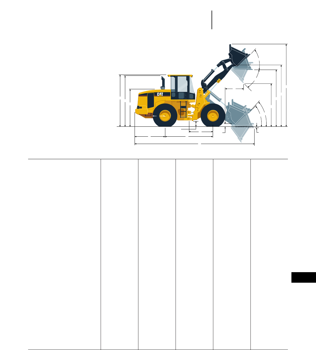
MODEL IT14G IT24F IT28G IT38G IT62G
Bucket 1.3 m31.7 yd31.6 m32 yd32 m32.6 yd32.5 m33.25 yd33.1 m34 yd3
A Maximum Overall Length 6424 mm 21'1" 6771 mm 22'3" 7318 mm 24'0" 7487 mm 24'7" 8263 mm 27'1"
B Wheel base 2600 mm 8'6" 2700 mm 8'10" 2900 mm 9'6" 3020 mm 9'11" 3350 mm 11'0"
C Machine center point to
front axle 1300 mm 4'3" 1350 mm 4'5" 1450 mm 4'9" 1510 mm 4'11" 1675 mm 5'6"
D Rear axle to counterweight 1658 mm 5'5" 1667 mm 5'6" 1955 mm 6'7" 1907 mm 6'3" 1938 mm 6'4"
E Ground clearance 456 mm 18" 321 mm 12.6" 407 mm 16" 400 mm 16" 474 mm 18.7"
F Height to top of engine
compartment 2080 mm 6'10" 2138 mm 7'0" 2149 mm 7'1" 2215 mm 7'3" 2254 mm 7'5"
G Height to top of ROPS 3100 mm 10'2" 3134 mm 10'4" 3268 mm 10'8" 3300 mm 10'10" 3374 mm 11'1"
H Height to top of stack 2255 mm 7'5" 3070 mm 10'1" 3184 mm 10'5" 3210 mm 10'6" 3224 mm 10'7"
J Tire radius
(empty machine) 620 mm 2'0" 612 mm 2'0" 684 mm 2'3" 688 mm 2'3" 728 mm 2'5"
K Maximum Digging Depth
(bucket level) 175 mm 6.9" 132 mm 5.2" 108 mm 4.3" 70 mm 2.8" 88 mm 3.5"
L Maximum rollback at
carry height 54° 55° 56° 46.6° 50°
M Maximum rollback
at ground 49° 53° 53° 48.8° 44°
N Dump Clearance at full lift
and 45° Discharge Angle 2920 mm 9'7" 2752 mm 9'0" 2911 mm 9'7" 2800 mm 9'2" 2841 mm 9'4"
O Hinge pin Height at
carry position 374 mm 15" 360 mm 14" 382 mm 15" 475 mm 18.7" *
P Reach at full lift and
45° Dump 787 mm 2'7" 1088 mm 3'7" 1014 mm 3'4" 1200 mm 3'11" 1242 mm 4'11"
Q Clearance Level Bucket
at full height 3565 mm 11'8" 3506 mm 11'6" 3694 mm 12'1" 3625 mm 11'11" 3742 mm 12'3"
R Maximum Hinge
Pin Height 3798 mm 12'6" 3766 mm 12'4" 3980 mm 13'1" 3930 mm 12'11" 4106 mm 13'6"
S Maximum Overall Height 4801 mm 15'9" 4855 mm 15'11" 5080 mm 16'8" 5237 mm 17'2" 5436 mm 17'10"
T Full Dump at
Maximum Lift 48° 49° 48° 45° 45°
U Maximum roll back at
Maximum Lift 57° 53° 55° 44.6° 58°
Tires 17.5R25 17.5-25 20.5-25 20.5R25 23.5-25
*Information unavailable.
14-9
14
Integrated ToolcarriersMachine Dimensions
●with General Purpose Buckets and Bolt-on Cutting Edge
P
OK
ML
N
Q
R
S
T
U
GH
F
EC
DB
A
IT38G
J
See rating plate on each tool. Plate shows the
effect of using the same tools on different size
machines and aids in machine tool selection.
Each plate states capabilities of standard
machine in terms of capacity. Any significant
weight change of attachments can adversely
affect these ratings.
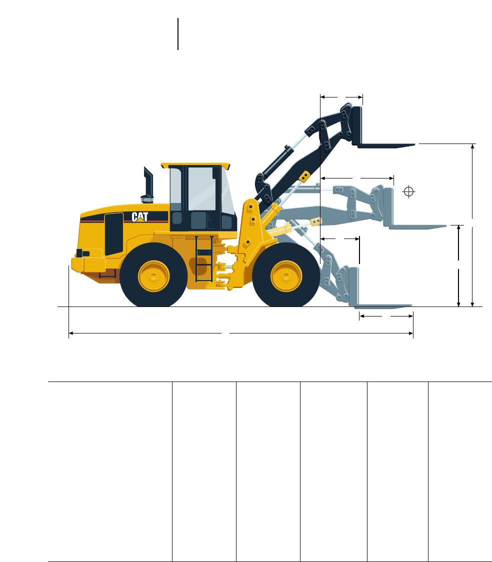
MODEL IT14G IT24F IT28G IT38G IT62G
Rated Operating Load
Per SAE J1197 1791 kg 3940 lb 2155 kg 4738 lb 3016 kg 6650 lb ————
Per CEN 474-3 Rough Terrain 2149 kg 4728 lb 2585 kg 5688 lb 3619 kg 7980 lb ————
Per CEN 474-3 Firm
level ground 2865 kg 6303 lb 3447 kg 7584 lb 4826 kg 10,640 lb ————
A Maximum Overall Length 6873 mm 22'7" 7089 mm 23'3" 7557 mm 24'10" 7826 mm 25'8" 8756 mm 28'9"
B Reach with forks at
ground level 745 mm 2'5" 852 mm 2'10" 750 mm 2'6" 955 mm 3'2" 1446 mm 4'9"
C Load center 600 mm 2'0" 600 mm 2'0" 600 mm 2'0" 600 mm 2'0" 610 mm 2'0"
D Reach with arms
horizontal and forks level 1490 mm 4'11" 1584 mm 5'2" 1513 mm 5'0" 1672 mm 5'6" 1976 mm 6'6"
E Reach with fork at
maximum height 586 mm 1'11" 836 mm 2'9" 703 mm 2'4" 946 mm 3'1" 1117 mm 3'8"
F Arms horizontal &
forks level 1808 mm 5'11" 1831 mm 6'0" 1923 mm 6'4" 1864 mm 6'1" 1738 mm 5'8"
G Ground to top of tine at
maximum height 3708 mm 12'2" 3629 mm 11'11" 3843 mm 12'7" 3716 mm 12'2" 3792 mm 12'5"
H Fork Tine Length 1200 mm 3'11" 1200 mm 3'11" 1200 mm 3'11" 1219 mm 4'0" 1219 mm 4'0"
Tires 17.5R25 17.5-25 20.5-25 20.5R25 23.5-25
14-10
Integrated Toolcarriers Machine Dimensions
●with Pallet Forks
B
H
D
E
F
G
A
IT38G
Load
center
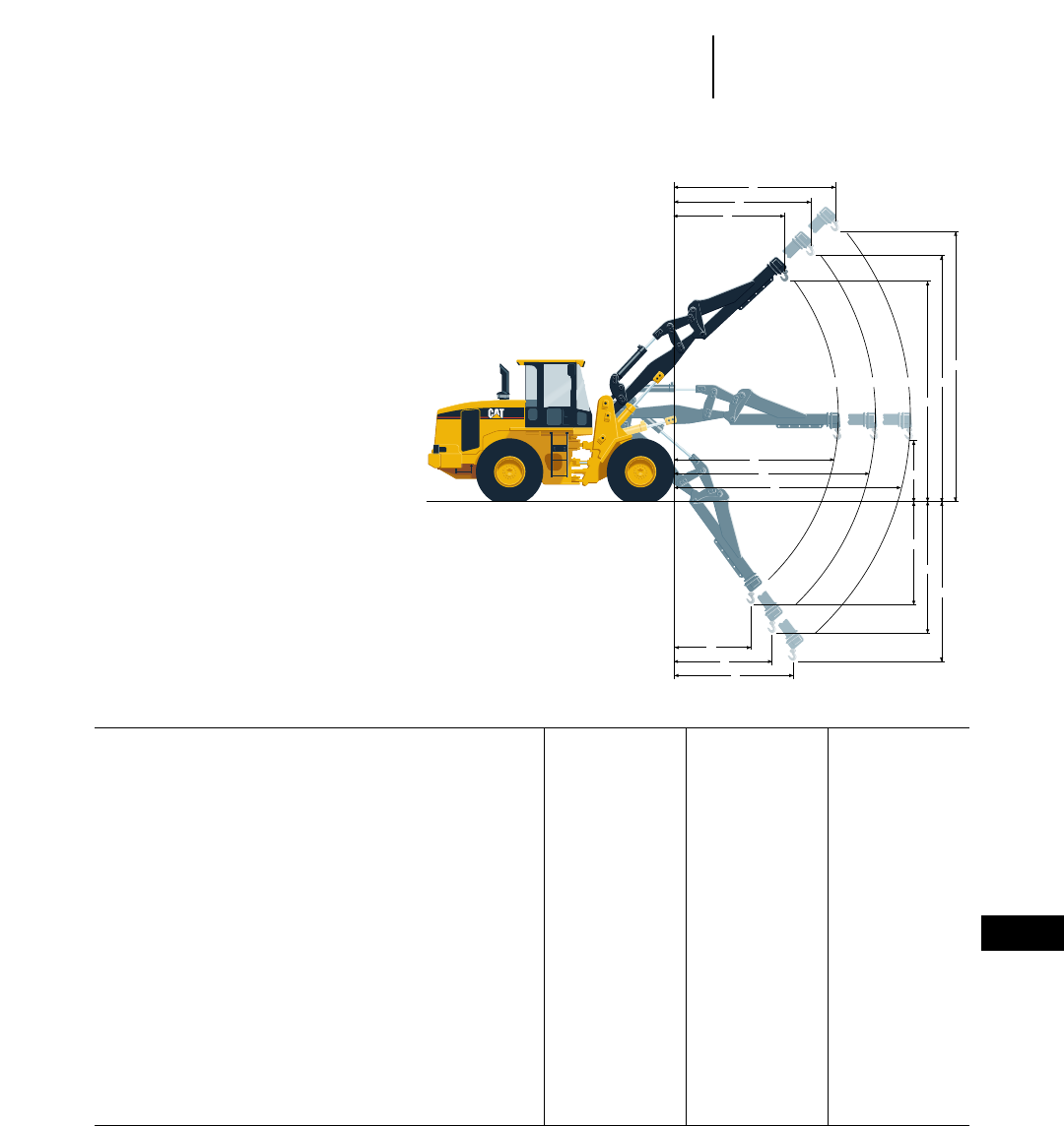
MODEL IT14G IT24F IT28G
A Operating load (retracted) @ full articulation 1292 kg 2842 lb 1576 kg 3475 lb 2528 kg 5574 lb
B Reach horizontal (retracted) 3179 mm 10'5" 3285 mm 10'7" 3187 mm 10'5"
C Operating load (mid-position) @ full articulation 1015 kg 2233 lb 1245 kg 2745 lb 1747 kg 3852 lb
D Reach horizontal (mid-position) 4178 mm 13'8" 4257 mm 14'0" 4986 mm 13'9"
E Operating load (extended) @ full articulation 837 kg 1841 lb 1031 kg 2273 lb 1449 kg 3195 lb
F Reach horizontal (extended) 5178 mm 17'0" 5257 mm 17'3" 5186 mm 17'0"
G Clearance horizontal 1585 mm 5'2" 1607 mm 5'4" 1983 mm 6'6"
H Reach full down (retracted) 1514 mm 4'11" 1646 mm 5'5" 1529 mm 5'0"
J Reach full down (mid-position) 2116 mm 6'11" 2257 mm 7'5" 2122 mm 7'0"
K Reach full down (extended) 2719 mm 8'11" 2869 mm 9'5" 2715 mm 8'11"
L Clearance full down (retracted) 1874 mm 6'2" 1786 mm 5'10" 1502 mm 4'11"
M Clearance full down (mid-position) 2670 mm 8'9" 2576 mm 8'6" 2306 mm 7'8"
N Clearance full down (extended) 3468 mm 11'5" 3367 mm 11'1" 3111 mm 10'2"
P Reach at maximum height (retracted) 1402 mm 4'7" 1783 mm 5'10" 1608 mm 5'3"
Q Reach at maximum height (mid-position) 1962 mm 6'5" 2396 mm 7'10" 2199 mm 7'3"
R Reach at maximum height (extended) 2522 mm 8'2" 3009 mm 9'11" 2791 mm 9'2"
S Clearance at maximum height (retracted) 5185 mm 17'0" 5039 mm 16'6" 5578 mm 18'3"
T Clearance at maximum height (mid-position) 6012 mm 19'9" 5828 mm 19'1" 6379 mm 20'11"
U Clearance at maximum height (extended) 6840 mm 22'5" 6617 mm 21'9" 7185 mm 23'7"
Tires 17.5R25 17.5-25 20.5-25
14-11
14
Integrated ToolcarriersMachine Dimensions
●with Material Handling Arm
R
Q
P
U
TECA
S
B
D
F
G
H
J
K
L
M
N
IT38G
For IT14G, IT24F and IT28G machines equipped
with 15.5 25 L-2 tires subtract 39 mm (1.5") from
lift height — add 39 mm (1.5") for below ground
measurements — add 42 mm (1.7") for all reach
measurements.
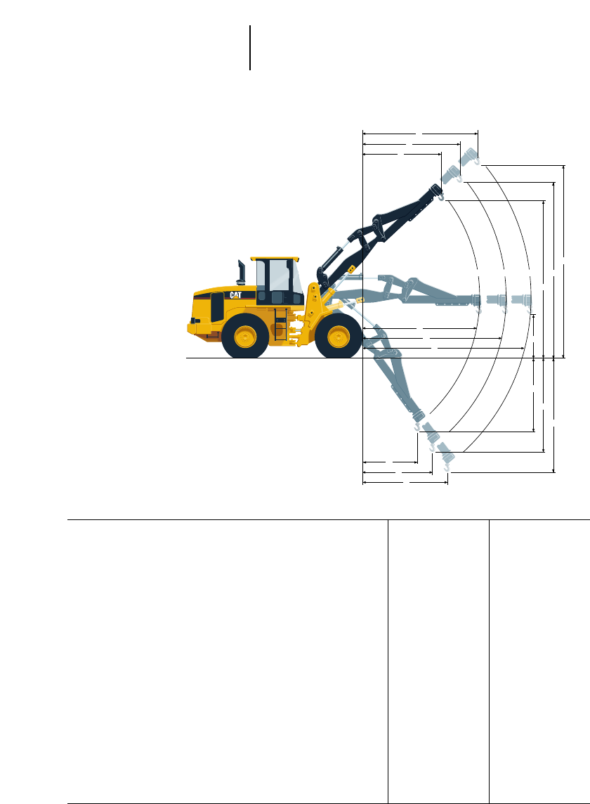
14-12
Integrated Toolcarriers Machine Dimensions
●with Material Handling Arm
MODEL IT38G IT62G*
A Operating load (retracted) @ full articulation 2049 kg 4508 lb 3085 kg 6795 lb
B Reach horizontal (retracted) 3816 mm 12'6" 4002 mm 13'2"
C Operating load (mid-position) @ full articulation 1729 kg 3804 lb 2626 kg 5783 lb
D Reach horizontal (mid-position) 4616 mm 15'2" 4802 mm 15'9"
E Operating load (extended) @ full articulation 1492 kg 3282 lb 2288 kg 5040 lb
F Reach horizontal (extended) 5416 mm 17'9" 5602 mm 18'5"
G Clearance horizontal 1562 mm 5'1" 1817 mm 6'0"
H Reach full down (retracted) 1840 mm 6'0" 2720 mm 8'11"
J Reach full down (mid-position) 2309 mm 7'7" 3354 mm 11'0"
K Reach full down (extended) 2777 mm 9'1" 3987 mm 13'1"
L Clearance full down (retracted) 2282 mm 7'6" 1483 mm 4'10"
M Clearance full down (mid-position) 2930 mm 9'7" 1971 mm 6'6"
N Clearance full down (extended) 3580 mm 11'9" 2460 mm 8'1"
P Reach at maximum height (retracted) 2506 mm 8'3" 2546 mm 8'4"
Q Reach at maximum height (mid-position) 3076 mm 10'1" 3109 mm 10'2"
R Reach at maximum height (extended) 3646 mm 11'11" 3672 mm 12'1"
S Clearance at maximum height (retracted) 5296 mm 17'5" 5774 mm 18'11"
T Clearance at maximum height (mid-position) 5857 mm 19'3" 6342 mm 20'10"
U Clearance at maximum height (extended) 6419 mm 21'1" 6910 mm 22'8"
Tires 20.5R25 23.5-25
*All dimensions are to lift eye.
R
Q
P
U
TECA
S
B
D
F
G
H
J
K
L
M
N
IT38G
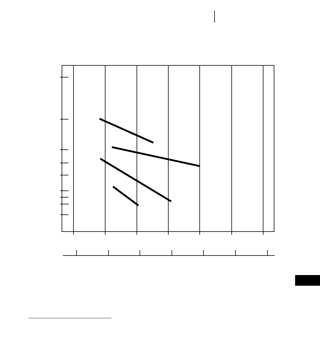
14-13
14
Integrated Toolcarriers
NOTE: Machines equipped same as those on Performance Data pages.
E*
D
3.1 (4.0)
2.5 (3.25)
2.0 (2.6)
1.8 (2.4)
1.6 (2.0)
1.4 (1.8)
1.3 (1.7)
1.2 (1.6)
1.0 (1.31)
C
B
A
2000
2500
3000
3500
4000
4500
5000
1200
1500
1800
2100
2400
2700
3000
BUCKET SELECTION BASED ON MATERIAL DENSITY
lb/yd3
kg/m3
MATERIAL DENSITY
m3(yd)3
BUCKET
CAPACITY
KEY
A — IT14G
B — IT24F
C — IT28G
D — IT38G
E — IT62G Information unavailable
Bucket Selection Guide
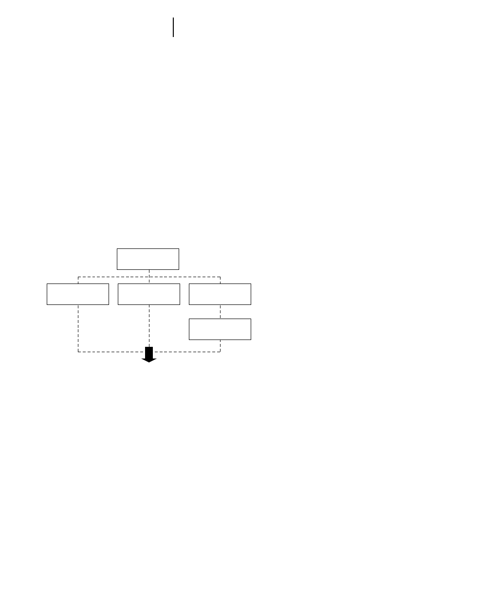
14-14
Integrated Toolcarriers Machine/Attachment Selection
MACHINE/ATTACHMENT SELECTION
The Integrated Toolcarrier’s versatility and the
wide range of attachments makes the “single machine
fleet” concept highly attractive to an increasing num-
ber of users.
A Job Analysis helps identify applications, work
requirements, material handling parameters and
the current working method. Thoroughly research
each element in the following chart, the gathered
information will help select the proper Integrated
Toolcarrier System.
●What kinds of work ... in site preparation?
are performed: (e.g., ... below ground level?
dozing, loading, ... at ground level?
stacking, digging, ... above ground level?
sweeping, handling ... in landscaping?
special materials, etc.) ... in maintenance
... equipment yard?
... etc.
●What work is done manually that could be done
with an Integrated Toolcarrier?
●What are the work
conditions?: ... underfoot?
... grades?
... tight quarters?
... time restraints?
... climate?
... etc.
Materials Handled:
Examining the materials handled will assist in
determining necessary attachments. Sizes and
weights of material(s) handled will indicate the
appropriate Integrated Toolcarrier model by defin-
ing lift and reach requirements. Concentrate on the
material flow at the job site — the point of origin
as well as the final destination for the various
materials will undoubtedly have material handling
requirements.
●What kinds of materials are handled (e.g. snow,
earth, bricks, chemicals, pipe, logs, etc.)
●What form are the materials handled in: bulk?
palletized?
●How much does each weigh?
●What are the dimensions of each?
●What are the...
movement
parameters: ... dozed what distance?
... load and carried what
distance?
... lifted how high?
... placed below ground
level?
... placed what distance
from machine?
Work Processes:
The first step in the job analysis is to identify all
work processes from start to finish. Key questions
outlined below will begin to indicate the required
attachments and potential Integrated Toolcarrier
applications.
JOB ANALYSIS METHOD
WORK
PROCESSES?
PRINCIPAL
WORK
UTILIZATION &
SEQUENCE?
CURRENT
EQUIPMENT?
MATERIALS
HANDLED?
●APPROPRIATE INTEGRATED TOOLCARRIER
MODEL SIZE
●NECESSARY ATTACHMENTS

14-15
14
Integrated ToolcarriersMachine/Attachment Selection
Current Equipment:
If determining material weight is not possible,
much information can be determined from looking
at the current equipment fleet. This will suggest
required performance capabilities such as lifting
capacity.
●Machines currently doing the work (e.g. wheel
loaders, lift trucks, sweepers, light capacity cranes,
snow plows, etc.)?
●What special (maximum) capabilities does each
machine have (production, lift height, load capac-
ity, width/height dimensions, reach, turning radius,
travel speed, etc.)?
●To what extent are each machine’s maximum capa-
bilities used?
●What are owning/operating costs of each?
Utilization & Sequence:
Utilization implies how often the current machines
are used and what will be the utilization factors for
the Integrated Toolcarrier with each individual
attachment. Sequence implies what order these
tasks are accomplished in and if two or more machines
operate at the same time. This portion of the job
analysis should assist in comparing econo-mies of
various systems. Other important consider-ations
may be the number of operators needed, storage
space, reduced maintenance requirements, etc.
●How often (what percent) is each machine used?
●How often and when does it sit idle?
●How often and when do two or more machines
work at the same time?
●Can the operation be changed to permit single
machine operation?
Principal Work:
Utilization and sequence will indicate the prin-
cipal work the Integrated Toolcarrier will do, further
assisting in attachment and model sizing and selec-
tion. The basic machine/tool package should be able
to handle the toughest, most frequently performed
jobs for the primary application. Secondary tools
can have a little more “give and take” in their per-
formance capabilities than the primary tool.
●What work can be accomplished by an Integrated
Toolcarrier?
●What work will take up the majority of Integrated
Toolcarrier time?
●What work will use the maximum static tipping
capabilities of the Integrated Toolcarrier?
●What high cost (owning and operating) and/or low
utilization machines can be replaced by an Inte-
grated Toolcarrier?
Additional Tips for Tool Sizing and Selection
Tool selection will principally concern hydraulic
power requirements and static tipping load consid-
erations. The standard tools offered by Caterpillar can
be used on any Integrated Toolcarrier machine with
little difficulty. However, tools such as the hydraulic
broom, claws, blades and asphalt cutter will require
additional consideration before proposing a system
to the customer.
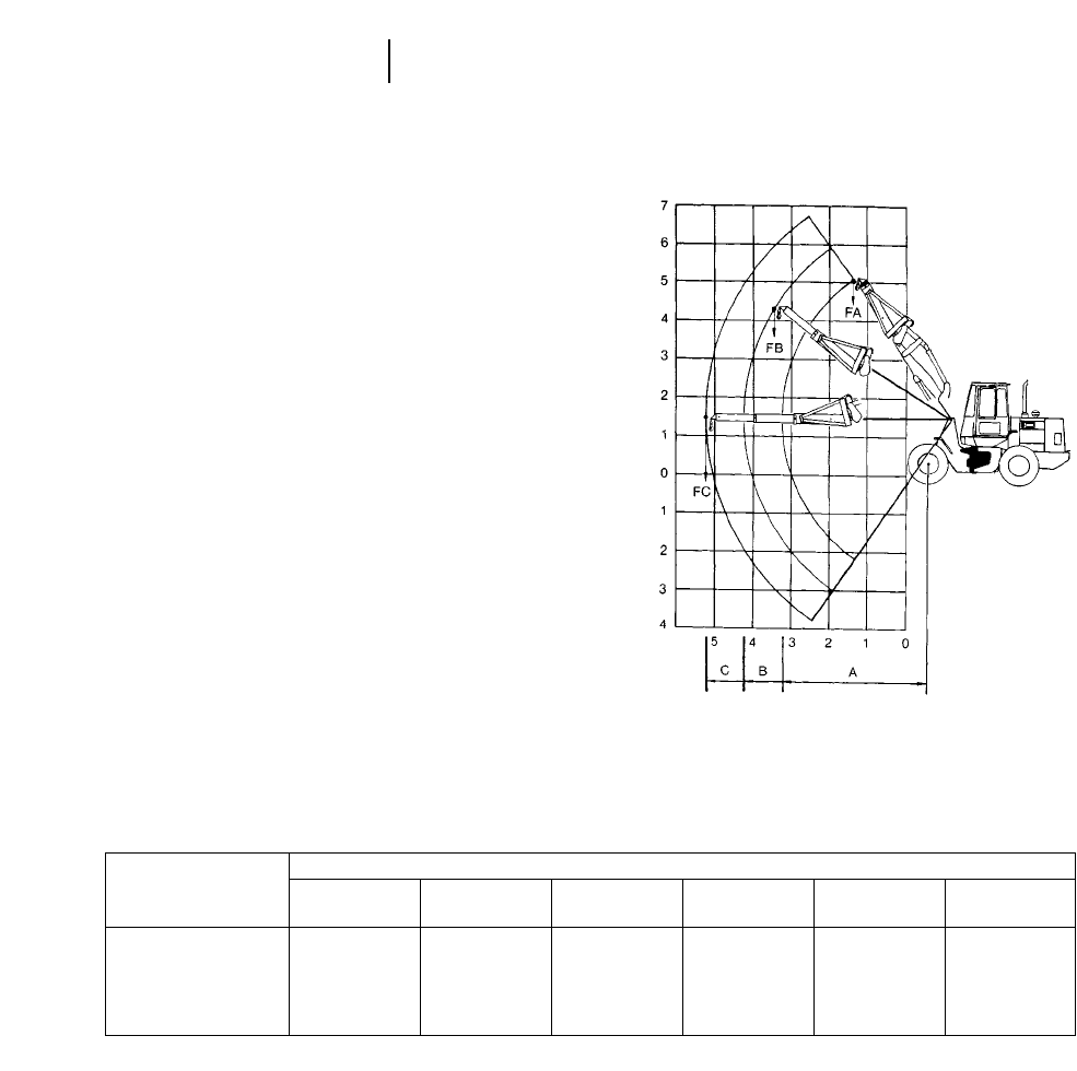
14-16
Integrated Toolcarriers Machine/Attachment Selection
Rating Plates
The Caterpillar tools have rating plates showing
rated or recommended load limits for each machine
in standard configuration. These rated loads are
determined by structural limitations on the tool
and/or hydraulic and stability criteria established
for each machine. The IT14G thru IT28G share com-
mon attachment points and can share attachments.
The IT38G and IT62G can share the same attach-
ments. This ability to interchange tools necessitates
the need for rating plates.
Shown below are examples of the rating plates
that will be found on each Caterpillar tool. Beginning
with the IT14G, the rating plate on each tool will refer
the user to the Operation and Maintenance Manual
for the rated operating load for that tool on a specific
machine model.
Material Handling Arm Part No. 9V1795
Table indicates rated load at standard vehicle configuration. See operator’s manual to determine rated load for vehicle configuration being used.
Load Radius Rated Load
Model A FA B FB C FC
m ft kg lb m ft kg lb m ft kg lb
IT14G 3.85 12.6 1292 2842 4.85 15.9 1015 2233 5.85 19.2 837 1841
IT24F 3.92 12.8 1554 3426 4.92 16.2 1220 2690 5.92 19.5 960 2117
IT28G 3.93 12.9 2528 5574 4.97 16.3 1747 3852 5.94 19.5 1449 3195
IT38G 4.57 15.0 4098 9016 5.37 17.7 3457 7605 6.17 20.3 2983 6563
IT62G 4.81 15.8 6170 13,590 5.61 18.4 5251 11,565 6.41 21.0 4576 10,080

14-17
14
Integrated ToolcarriersMachine/Attachment Selection
Fork Rating Plate
(Located on back of carriage, left side)
Table indicates rated pallet fork load at standard
machine configuration with 1200 mm (3'11") fork
tine length and a load center distance of 600 mm
(24"), see operator manual to determine rated load
for vehicle configuration being used.
Model kg lb Model kg lb
______________________ _________________
IT14G 1791 3940 IT24F 2147 4723
IT28G 2867 6321
Bucket Rating Plate
(Located left rear of buckets)
Bucket capacity, SAEJ742 FEB85 (nominally
heaped)
Table indicates rated load at vehicle configuration
noted by the asterisks. See operator manual to deter-
mine rated load for vehicle configuration being used.
Part No. 112-3121 — 1.4 m3(1.75 yd3) w/Bolt-On Cutting Edge
Model kg lb
______________________
IT14G* 2273 5000
IT24F** 2680 5909
Part No. 132-2257 — 1.6 m3(2.1 yd3) w/Bolt-On Cutting Edge
Model kg lb
______________________
IT24F** 2642 5825
Part No. 132-2256 — 1.8 m3(2.35 yd3) w/Bolt-On Cutting Edge
Model kg lb
______________________
IT24F** 2614 5746
IT28G*** 3708 8176
Part No. 132-2258 — 2.0 m3(2.6 yd3) w/Bolt-On Cutting Edge
Model kg lb
______________________
IT28G*** 3667 8087
***Specifications shown are for high-speed version IT14G and include lubricants,
full fuel tank, ROPS cab, 80 kg (176 lb) operator, standard 250 kg (550 lb)
counterweight and 17.5-R25 (L2 equivalent) tires.
***Specifications shown include lubricants, full fuel tank, ROPS cab, 80 kg (176 lb)
operator and 17.5 x 25, 12 PR (L2) tires.
***Specifications shown include optional counterweight, standard lubricants, full
fuel tank, ROPS cab, 80 kg (176 lb) operator and 20.5-25, 12 PR (L2) tires.
The bucket rating plate can be used to illustrate
the attachment sizing and selection process. The
charts explain each machine’s maximum payload.
The maximum material density would be determined
by dividing the payload by the bucket capacity. If the
actual material density exceeds the recommended
material density, the process should be repeated to
select the properly sized bucket.
A similar procedure would be used with the forks
and material handling arm to determine maximum
recommended lifting capacity and/or required IT
model size.
Pallet Fork
The pallet fork will fulfill many material handling
needs. A modified Class 3 fork carriage provides visi-
bility to the tines for precision pallet work. This car-
riage with non-standard spacing accepts many
Class 3 lift truck attachments.
Pallet fork rated operating loads are based on the
following:
SAE J1197 FEB91: 50% of the full turn static tip-
ping load or the hydraulic/structural limitations.
CEN 474-3 (European standard): 60% of the full
static tipping load on rough terrain or the hydraulic/
structural limitations. 80% of the full turn static
tipping load on firm, level ground or the struc-
tural/hydraulic limitation. Other local, regional or
international guidelines may also apply.
If operation is on rough ground these criteria may
need modification. In this instance, the size and rat-
ing of existing equipment should be considered.
Sizing for pallet work generally consists of answer-
ing the following questions.
1. What are the average loaded pallet dimensions?
2. Lift Capacity — what capacity is required to lift
and move the average pallet load? The maximum
pallet load?
3. Lift Height — can the machine reach the top
level of the standard pallet stack? What are the
maximum reach, lift and height requirements?
4. Maneuverability — can the machine work around
the current aisle configuration? In the stacking
aisles? Main aisles? Intersecting aisles? Are 90°
turns required in any aisle for material placement?
5. Length — what tine length is required to fit the
commonly used pallets? (1219 mm [48 in] tines
are standard length for most palletized material.)
6. Any machine height restrictions?
7. Any special fork configurations required?
Lift capacity, lift height, aisle configuration and
tine length are the most important considerations in
recommending a pallet handling machine.

14-18
Integrated Toolcarriers Machine/Attachment Selection
Example problem:
The following example applies the job analysis
method to a work situation.
Sewer & Water Contractor
Sets water lines (152 mm-610 mm [6 in-24 in] iron
pipe), sanitary sewer lines (152 mm-457 mm [6 in-
18 in] PVC) and storm sewer lines (610 mm-1067 mm
[24 in-42 in] concrete pipe) primarily in urban areas
... often-times across or down existing streets.
Materials
Loam/Clay: 1600 kg/m3(2700 lb/yd3) loose density
Bedding
(Gravel): 1900 kg/m3(3200 lb/yd3) loose density
Water Pipe: 610 mm (24 in) push-on joint ductile
iron, 6.1 m (20 ft) sections, 1309 kg
(2885 lb)
215 kg/m (144.3 lb/ft) 36.1 m (20 ft)
See trenching pages in the Excavator
backhoe section.
Storm Sewer: 1067 mm (42 in), Wall B, concrete
pipe, 1.5 m (5 ft) sections, 1556 kg
(3430 lb) 1021 kg/m (686 lb/ft 35 ft)
See trenching pages in the Excavator
backhoe section.
Manhole
Boxes: 1361 kg (3000 lb)
WHAT INTEGRATED TOOLCARRIER MODEL
SHOULD BE RECOMMENDED?
WHICH ATTACHMENTS?
Integrated Toolcarrier
Work Processes Attachment Possibilities
Bundled PVC and indi- Forks/Material
vidual concrete/iron Handling Arm
pipe-loaded/unloaded
(yardsite) and strung
along trench
Unload, handle, set Material Handling Arm
manhole boxes
Excess excavated mate- Bucket
rial truck loaded
Bedding material Bucket
handled/placed
Trench backfilled Bucket/Blade
Trench compaction Compactor Wheel
Rough and finish grading Bucket/Blade
Street cleanup Bucket/Broom
Pavement removal Rebar Snips/Asphalt
Cutter
Current Equipment
Utilization
Cat 225 . . . . . . . . . . . . . . . . . . . . . . . . . .90%
Champ CB607 lift truck,
3175 kg (7000 lb) capacity . . . . . . . . . .15%
Deere 444 with 1.1 m3(1.5 yd3)
G.P. bucket . . . . . . . . . . . . . . . . . . . . . .60%
Rosco D-50 sweeper . . . . . . . . . . .one half hour/day
Rammax 1361 kg (3000 lb) self-propelled
trench compactor . . . . . . . . . . . . . . . . .25%
Machine sizing
1350 mm (53 in) Forks
Operating Load at Full Turn*
Model kg lb
_______________________________
IT14G 1735 3817
IT24F 2146 4722
IT28G 2931 6463
Water pipes: IT14G ... 1 pipe —
1309 kg (2885 lb) no problem
IT24F ... 1 pipe —
no problem
IT28G ... 1 pipe —
no problem
Storm sewer pipes: IT14G ... 1 pipe —
1556 kg (3430 lb) no problem
IT24F ... 1 pipe —
no problem
IT28G ... 1 pipe —
no problem
*Note that the most conservative operating load (SAE J1197 FEB91) is used
here. The rated operating load for some competitive machines with pallet forks
will be based upon European standard CEN 474-3, assuming operation on
firm and level ground (i.e. using 80% of full turn static tipping load).

14-19
14
Integrated ToolcarriersMachine/Attachment Selection
Material Handling Arm (MHA)
The rated load for the MHA is 50% of the full turn
static tipping load in each position or hydraulic or
structural limitations. Manually extendable tele-
scopic sections enable maximum lifting capacity at
the full retracted position, and maximum lift height
and reach in the fully extended position.
Operating Load at Full Turn
Model Retracted Mid Extended
__________________________________________
IT14G 1292 kg 1015 kg 837 kg
2542 lb 2233 lb 1841 lb
IT24F* 1576 kg 1245 kg 1031 kg
3475 lb 2745 lb 2273 lb
IT28G 2528 kg 1747 kg 1449 kg
5574 lb 3852 lb 3195 lb
Storm sewer pipes: IT14G ... no
1556 kg (3430 lb) IT24F ... marginal in
retracted
IT28G ... yes in
retracted and mid
Manhole boxes: IT14G ... no
1361 kg (3000 lb) IT24F ... yes in
retracted
IT28G ... yes in
retracted, mid and
extended
Buckets
All general purpose buckets are interchangeable
on IT14G-IT28G due to common attachment points
on the quick couplers. Bucket selection will depend
on the material density in your application. Offering
multiple sized buckets allows the user the flexibil-
ity to closely match material density and bucket size
with machine capability. Equipping a machine with
too large a bucket will result in unacceptable sta-
bility — too small a bucket may provide inadequate
tire coverage.
Bucket 1900 kg/m3(3200 lb/yd3) ... 100% fill factor
50% Full Turn
Model Bucket Payload Static Tipping
__________________________________________
IT24F* 1.4 m32660 kg 2680 kg
1.8 yd35852 lb 5896 lb
1.6 m33040 kg 2642 kg
2.0 yd36688 lb 5812 lb
1.8 m33424 kg 2614 kg
2.4 yd37680 lb 5750 lb
IT28G 1.8 m33420 kg 3708 kg
2.3 yd37524 lb 8176 lb
2.0 m33800 kg 3668 kg
2.6 yd38360 lb 8087 lb
IT38G 2.3 m33856 kg 3850 kg
3.0 yd38500 lb 8488 lb
NOTE: Metric numbers are a product of conversion.
*IT24F and IT28G equipped with 17.5 325 tires.
Machine/Attachment Recommendation
IT28G — The greater static tipping load capabilities
allow it to do a greater portion of the contractor’s
total work processes. With the following attach-
ments, the IT28G could replace part or all of the
specialty units, such as the wheel loader, rough ter-
rain lift truck, street sweeper, and/or the trench
compactor.
1.8 m3(2.3 yd3), or 2.0 m3(2.6 yd3) General Purpose
Bucket
1350 mm (53 in) forks (handles all pipes)
Material Handling Arm — (handles pipe sizes under
1067 mm (42 in) concrete and manhole boxes ... 225
would have to set 1219 mm (48 in) and larger con-
crete pipe
Broom
Optional Attachments to Consider:
24-LH compactor wheel
Rebar snips
Asphalt cutter
15-1
CONTENTS
Features . . . . . . . . . . . . . . . . . . . . . . . . . . . . . .15-1
Specifications . . . . . . . . . . . . . . . . . . . . . . . . . .15-1
Performance Data . . . . . . . . . . . . . . . . . . . . . . .15-3
Dimensions . . . . . . . . . . . . . . . . . . . . . . . . . . .15-11
Tire Selection . . . . . . . . . . . . . . . . . . . . . . . . .15-11
Attachments . . . . . . . . . . . . . . . . . . . . . . . . . .15-12
Features:
●Tough, reliable machine components — Cat
3054 engine turbocharged on U.S. models, natu-
rally aspirated on non-U.S. models. Powershift
transmission, enclosed oil immersed brakes, dif-
ferential lock on front axle and mechanical driv-
eline. Variable displacement axial piston pump.
Proven components and well protected from the
perils of the jobsite.
●High visibility factors — include low boom pivot
point, side mounted power module and close fitting
fenders. Carefully profiled engine hood allows front
wheel visibility. Low profile stabilizers on 3-section
machines provides excellent forward visibility.
●Excellent Operator Comfort — with large spa-
cious operator station. Open cab or deluxe closed
cab with large glazed glass area. Single lever pilot
operated boom control. Powershift transmission
with 4 forward speeds, 3 reverse and transmis-
sion disconnect. Power assisted brakes and steer-
ing. Easy engine access for daily maintenance.
●Superior Performance — with low center of
gravity, maximized wheel base. Fast, responsive
hydraulic system with variable displacement axial
piston pump. Front and rear overhang is mini-
mized. Four wheel drive and steer with three steer-
ing modes, 2-wheel steer, circle steer and crab
steer.
MODEL TH62
Flywheel Power (Gross) 60 kW 81 hp
Turbocharged* 81 kW 109 hp
Operating Weight 6840 kg 15,080 lb
Engine Model 3054
Rated Engine RPM 2200
No. of Cylinders 4
Bore 100 mm 3.94 in
Stroke 127 mm 5.00 in
Displacement 4.0 L 243 in3
Speeds Forward: km/h mph
1st 6 4
2nd 11 7
3rd 22 14
4th 32 20
Speeds Reverse:
1st 6 4
2nd 11 7
3rd 22 14
Turning Circle Radius mft
Over Tires 3.63 11'11"
Over Forks 4.63 15'2"
Over Bucket 4.72 15'6"
Track 3.43 11'3"
Aisle Width
Over Forks 3.84 12'7"
Over Bucket @ carry 3.94 12'11"
Tires 15.4 x 24
Service Refill Cap:
Fuel Tank @ 90% fill 120 L 32 U.S. gal
Hydraulic Tank 150 L 40 U.S. gal
*U.S. models only.
15
TELESCOPIC HANDLERS
MODEL TH63 TH82 TH83 TH103
Flywheel Power (Gross) 60 kW 81 hp 60 kW 81 hp 81 kW 109 hp 81 kW 109 hp
Turbocharged* 81 kW 109 hp 81 kW 109 hp Std Std
Operating Weight 9260 kg 20,420 lb 7470 kg 16,470 lb 10 000 kg 22,050 lb 11 360 kg 25,050 lb
Engine Model 3054 3054 3054T 3054T
Rated Engine RPM 2200 2200 2200 2200
No. of Cylinders 4444
Bore 100 mm 3.94 in 100 mm 3.94 in 100 mm 3.94 in 100 mm 3.94 in
Stroke 127 mm 5.00 in 127 mm 5.00 in 127 mm 5.00 in 127 mm 5.00 in
Displacement 4.0 L 243 in34.0 L 243 in34.0 L 243 in34.0 L 243 in3
Speeds Forward: km/h mph km/h mph km/h mph km/h mph
1st 6 4646464
2nd 11 711 711 711 7
3rd 22 14 22 14 22 14 22 14
4th 32 20 32 20 32 20 32 20
Speeds Reverse:
1st 6 4646464
2nd 11 711 711 711 7
3rd 22 14 22 14 22 14 22 14
Turning Circle Radius mft mft mft mft
Over Tires 3.79 12'5" 3.79 12'5" 3.79 12'5" 4.19 13'9"
Over Forks 4.62 15'2" 4.62 15'2" 5.07 15'2" 5.61 18'5"
Over Bucket 4.71 15'5" 4.71 15'5" 5.24 17'2" 5.61 18'5"
Track 3.59 11'9" 3.59 11'9" 3.59 11'9" 3.86 12'8"
Aisle Width
Over Forks 3.84 12'7" 3.84 12'7" 4.28 14'8" 4.75 15'7"
Over Bucket @ carry 3.94 12'11" 3.94 12'11" 4.45 14'7" 4.75 15'7"
Tires 15.5 x 25 15.5 x 24 13.0 x 25 14.0 x 24
Service Refill Cap:
Fuel Tank @ 90% fill 120 L 32 U.S. gal 120 L 32 U.S. gal 120 L 32 U.S. gal 140 L 37 U.S. gal
Hydraulic Tank 150 L 40 U.S. gal 150 L 40 U.S. gal 150 L 40 U.S. gal 170 L 45 U.S. gal
*U.S. models only.
15-2
SpecificationsTelescopic Handlers
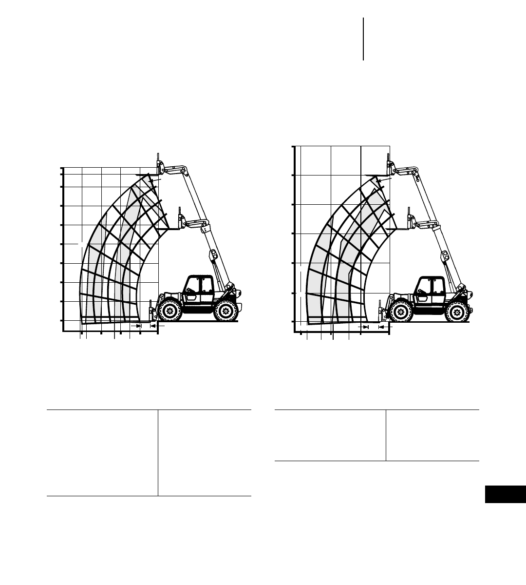
15-3
15
Telescopic HandlersPerformance Data
●Standard Forks and Carriage
●No Stabilizers
Maximum lift capacity 3000 kg 6615 lb
Maximum lift height 7.6 m 24'11"
Load at maximum height 1500 kg 3307 lb
Max. height at
maximum load 6.5 m 21'4"
Max. reach at
maximum load 1.54 mm 5'1"
Maximum forward reach 4.09 m 13'5"
Load at maximum reach 1330 kg 2932 lb
TH62
Non-U.S. Version
Maximum lift capacity 2725 kg 6000 lb
Maximum lift height 7.6 m 25'0"
Load at maximum height 1365 kg 3000 lb
Maximum forward reach 4.2 m 13'9"
Load at maximum reach 1435 kg 3160 lb
TH62
North American Version
8
7.6
7
6
5
4
3
2
1
0
68.5°
60°
50°
40°
20°
10°
0°
-2.5°
4.09
3.73
2.98
2.32
1.54
42103
0.5
1330
2000
1500
2500
1500
D
C
B
2000
3000
30°
30'
25'
20'
15'
10'
5'
0'
15' 10' 5' 0'
68.5°
60°
50°
40°
0°
13'9"
11'2"
9'0"
6'0"
30°
3000
D
C
B
10°
-2.5°
3160
4000
5000
6000
20°
2'
Numbers in chart measured in kilograms.
m
m
m
m
Numbers in chart measured in pounds.
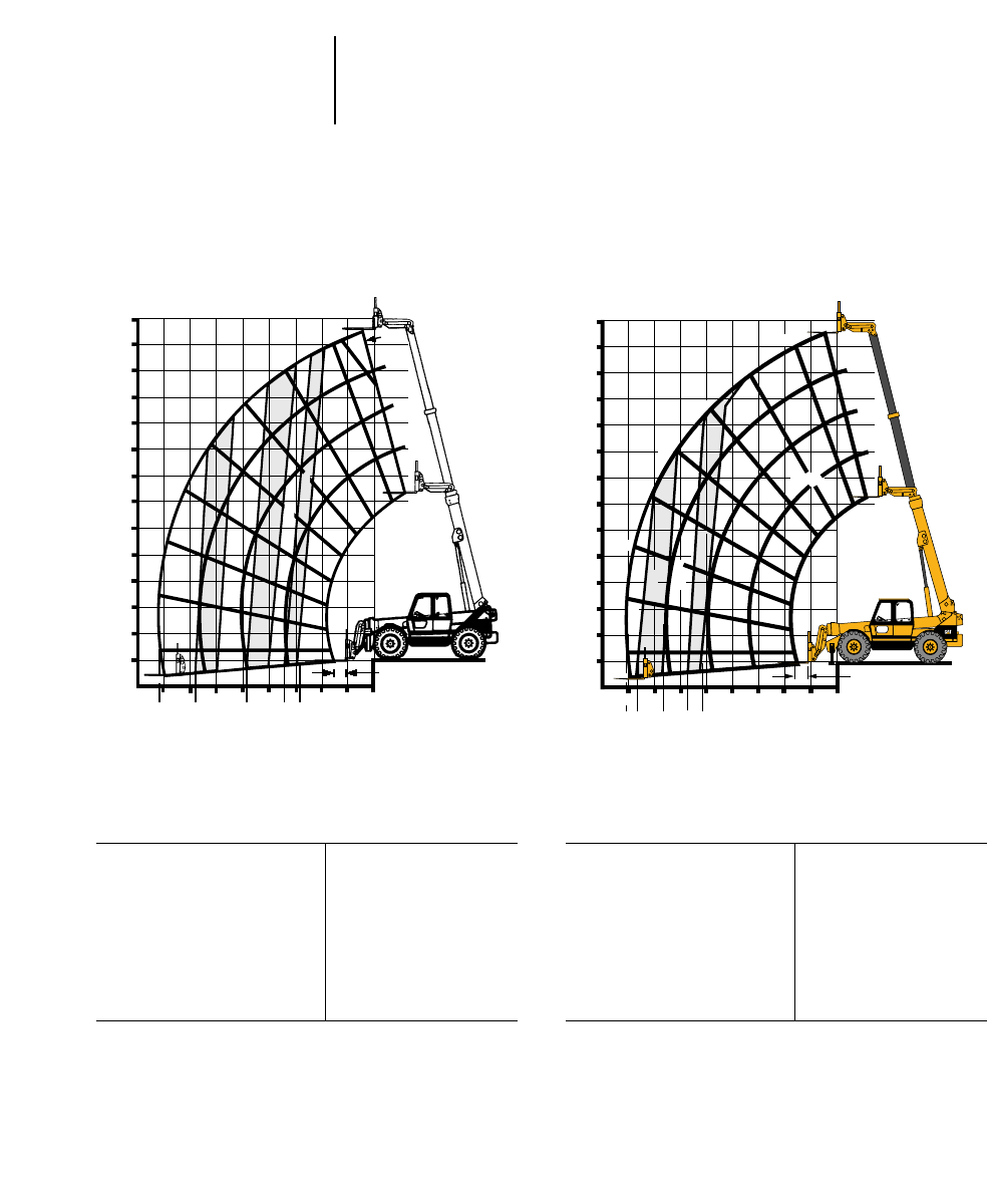
15-4
Performance Data
●Standard Forks and Carriage
●Non-U.S. Version
Telescopic Handlers
Maximum lift capacity 3000 kg 6615 lb
Maximum lift height 12.5 m 41'0"
Load at maximum height 2500 kg 5512 lb
Max. height at
maximum load 12.0 m 39'4"
Max. reach at
maximum load 2.86 m 9'5"
Maximum forward reach 8.10 m 26'7"
Load at maximum reach 475 kg 1047 lb
TH63
Stabilizers Up
Maximum lift capacity 3000 kg 6615 lb
Maximum lift height 12.5 m 41'0"
Load at maximum height 3000 kg 6515 lb
Max. height at
maximum load 12.5 m 41'0"
Max. reach at
maximum load 5.18 m 17'0"
Maximum forward reach 8.10 m 26'7"
Load at maximum reach 1425 kg 3142 lb
TH63
Stabilizers Down
13
12
11
10
9
7
6
4
2
1
0
70°76°
60°
50°
40°
20°
10°
0°
-4.5°
8.10
6.68
5.85
4.73
3.92
3.32
2.86
8543210
76
0.5
5
3
30°
8
2500
D
C
B
475
750
1000
1500
2000
2500
3000
12
13
11
10
9
8
76˚
70˚
60˚
50˚
40˚
30˚
20˚
7
6
5
4
3
2
1
0
10˚
0˚
-4.5˚
87654
8.10
7.67
6.62
5.72
5.18
0
1
2
3
0.5
D
C
B
3000
2500
2000
1500
1425
®
Numbers in chart measured in kilograms.
m
m
m
m
Numbers in chart measured in kilograms.
m
m
m
m
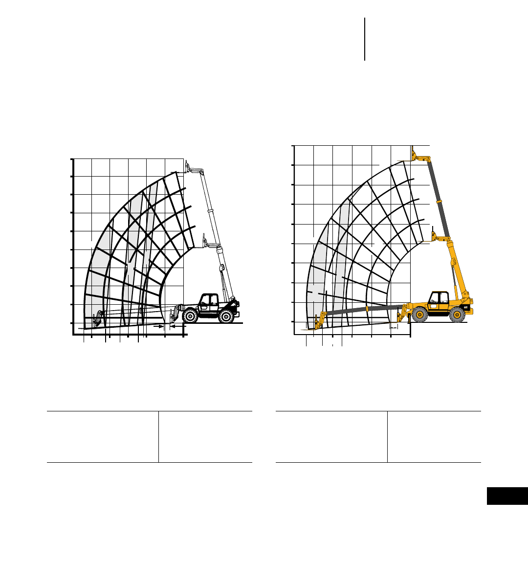
15-5
15
Telescopic HandlersPerformance Data
●Standard Forks and Carriage
●North American Version
Maximum lift capacity 2725 kg 6000 lb
Maximum lift height 12.5 m 41'0"
Load at maximum height 2725 kg 6000 lb
Maximum forward reach 8.2 m 27'0"
Load at maximum reach 554 kg 1220 lb
Maximum lift capacity 2725 kg 6000 lb
Maximum lift height 12.5 m 41'0"
Load at maximum height 2725 kg 6000 lb
Maximum forward reach 8.2 m 27'0"
Load at maximum reach 1365 kg 3000 lb
TH63
No Stabilizers
TH63
Stabilizers Down
45'
40'
35'
30'
25'
15'
10'
0'
70°76°
60°
50°
40°
20°
10°
0°
-4.5°
27'0"
21'1"
17'2"
14'7"
12'2"
10'10"
10'15' 5' 0'
20'25'
2'
5'
20'
D
C
B
30°
1220
3000
5000
2000
4000
6000
45'
40'
35'
30'
25'
20'
15'
10'
5'
0' 0˚
10˚
20˚
30˚
40˚
50˚
60˚
70˚
76˚
D
C
B
3000
4000
5000
6000
25' 20' 15' 10' 5' 0'
2'
17'7"
20'1"
22'8"
26'11"
-4.5˚
®
Numbers in chart measured in pounds. Numbers in chart measured in pounds.
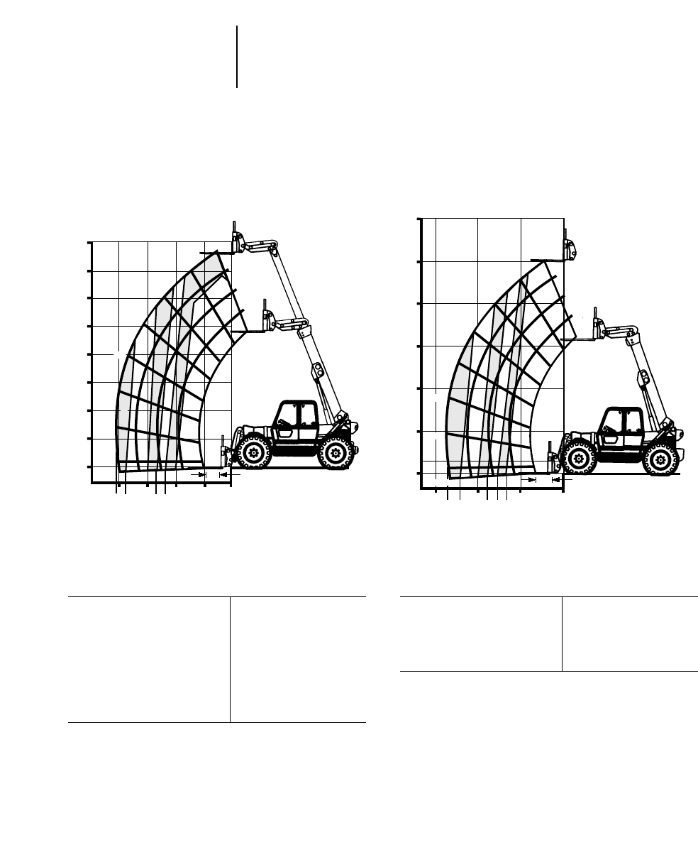
15-6
Performance Data
●Standard Forks and Carriage
●No Stabilizers
Telescopic Handlers
Maximum lift capacity 4000 kg 8820 lb
Maximum lift height 7.6 m 25'0"
Load at maximum height 3500 kg 7717 lb
Max. height at
maximum load 7.0 m 23'0"
Max. reach at
maximum load 1.97 m 6'6"
Maximum forward reach 4.06 m 13'4"
Load at maximum reach 1680 kg 3704 lb
TH82
Non-U.S. Version
Maximum lift capacity 3635 kg 8000 lb
Maximum lift height 7.6 m 25'0"
Load at maximum height 3182 kg 7000 lb
Maximum forward reach 4.2 m 13'9"
Load at maximum reach 1635 kg 3600 lb
TH82
North American Version
8
7
6
5
4
3
2
1
0
68.5°
60°
50°
40°
20°
10°
0°
-2.5°
4.06
3.66
3.04
2.58
2.27
1.97
42103
0.5
D
C
B
30°
1680
2500
3500
2000
3000
4000
25'
30'
20'
15'
10'
5'
0'
68.5°
60°
50°
40°
0°
13'7"
12'2"
10'1"
8'11"
7'9"
6'10"
30°
D
C
B
B
10°
-2.5°
20°
2'
3600
4000
5000
6000
7000
8000
15' 10' 5' 0'
Numbers in chart measured in kilograms.
m
m
m
m
Numbers in chart measured in pounds.
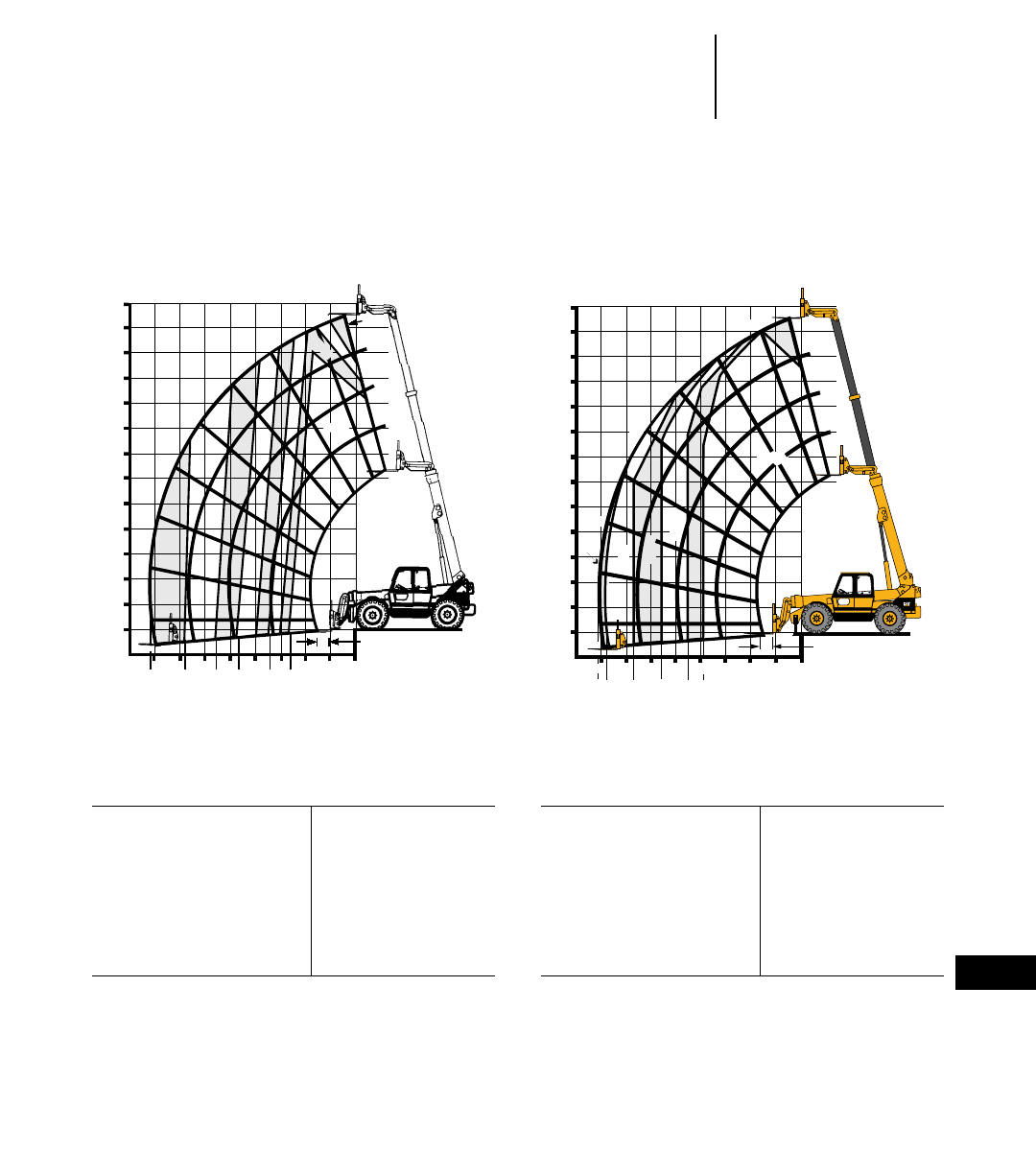
15-7
15
Telescopic HandlersPerformance Data
●Standard Forks and Carriage
●Non-U.S. Version
Maximum lift capacity 4000 kg 8820 lb
Maximum lift height 12.5 m 41'0"
Load at maximum height 2500 kg 5512 lb
Max. height at
maximum load 11.0 m 36'1"
Max. reach at
maximum load 2.64 m 8'8"
Maximum forward reach 8.14 m 26'8"
Load at maximum reach 700 kg 1543 lb
Maximum lift capacity 4000 kg 8820 lb
Maximum lift height 12.5 m 41'0"
Load at maximum height 3300 kg 7276 lb
Max. height at
maximum load 12.25 m 40'2"
Max. reach at
maximum load 3.72 m 12'2"
Maximum forward reach 8.14 m 26'8"
Load at maximum reach 1500 kg 3307 lb
TH83
Stabilizers Up
TH83
Stabilizers Down
13
12
11
10
9
7
6
4
2
1
0
70°76°
60°
50°
40°
20°
10°
0°
-4.5°
8.14
6.88
5.95
4.65
3.93
3.41
3.01
2.64
8543210
76
0.5
5
3
30°
8
2500
D
C
B
3000
700
1000
1500
2000
2500 3000
3500
4000
3500
Numbers in chart measured in kilograms.
m
m
m
m
12
13
11
10
9
8
76˚
70˚
60˚
50˚
40˚
30˚
20˚
7
6
5
4
3
2
1
0
10˚
0˚
-4.5˚
87654
8.14
7.69
6.65
5.37
4.47
3.72
0
1
2
3
0.5
D
C
B
4000
3300
3000
3500
2500
2000
1500
®
Numbers in chart measured in kilograms.
m
m
m
m
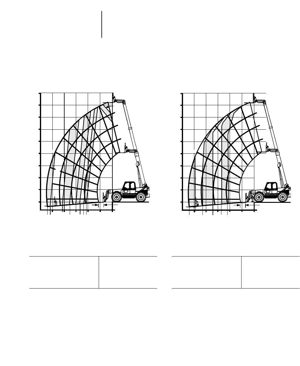
15-8
Performance Data
●Standard Forks and Carriage
●North American Version
Telescopic Handlers
Maximum lift capacity 3635 kg 8000 lb
Maximum lift height 12.5 m 41'0"
Load at maximum height 2725 kg 6000 lb
Maximum forward reach 8.2 m 27'0"
Load at maximum reach 870 kg 1910 lb
TH83
No Stabilizers
Maximum lift capacity 3635 kg 8000 lb
Maximum lift height 12.5 m 41'0"
Load at maximum height 3635 kg 8000 lb
Maximum forward reach 8.2 m 27'0"
Load at maximum reach 1770 kg 3890 lb
TH83
Stabilizers Down
45'
40'
35'
30'
25'
15'
10'
0'
70°76°
60°
50°
40°
20°
10°
0°
-4.5°
27'0"
25'6"
20'8"
17'5"
13'3"
11'9"
10'6"
10'15' 5' 0'
20'25'
2'
5'
20'
D
C
B
15'2"
30°
1910
2000
8000
7000
3000
4000
5000
6000
7000
5800
45'
40'
35'
30'
25'
15'
10'
0'
70°76°
60°
50°
40°
20°
10°
0°
-4.5°
27'0"
25'1"
22'0"
17'2"
13'9"
11'2"
10'15' 5' 0'
20'25'
2'
5'
20'
D
C
B
30°
3890
5000
7000
4000
6000
8000
Numbers in chart measured in pounds. Numbers in chart measured in pounds.
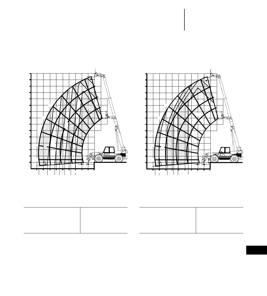
15-9
15
Telescopic HandlersPerformance Data
●Standard Forks and Carriage
●Non-U.S. Version
Maximum lift capacity 5000 kg 11,025 lb
Maximum lift height 13.5 m 44'0"
Load at maximum height 2500 kg 5513 lb
Maximum forward reach 8.66 m 28'4"
Load at maximum reach 1025 kg 2260 lb
TH103
Stabilizers Up
13
14
12
11
10
9
7
6
4
2
1
0
9
8.66
7.30
6.10
5.35
4.59
3.63
2.98
0°
10°
20°
1025
1500
2000
2500
3000
3000
4000
2500
5000
30°
40°
50°
60°
70°75°
-4.5°
10 8 7 6 5 4 3 2 10
0.5
5
3
8
D
C
B
Numbers in chart measured in kilograms.
m
m
m
m
13
14
12
11
10
9
7
6
4
2
1
0
910 8 7 6 5 4 3 2 10
0.5
5
3
8
0°
10°
20°
30°
50°
60°
70°75°
-4.5°
8.66
6.77
8.04
5.77
5.13
3.53
1400
2000
3000
3500
4000
5000
4000
3000
D
C
B
40°
Numbers in chart measured in kilograms.
m
m
m
m
Maximum lift capacity 5000 kg 11,025 lb
Maximum lift height 13.5 m 44'0"
Load at maximum height 3000 kg 6615 lb
Maximum forward reach 8.66 m 28'4"
Load at maximum reach 1400 kg 3087 lb
TH103
Stabilizers Down
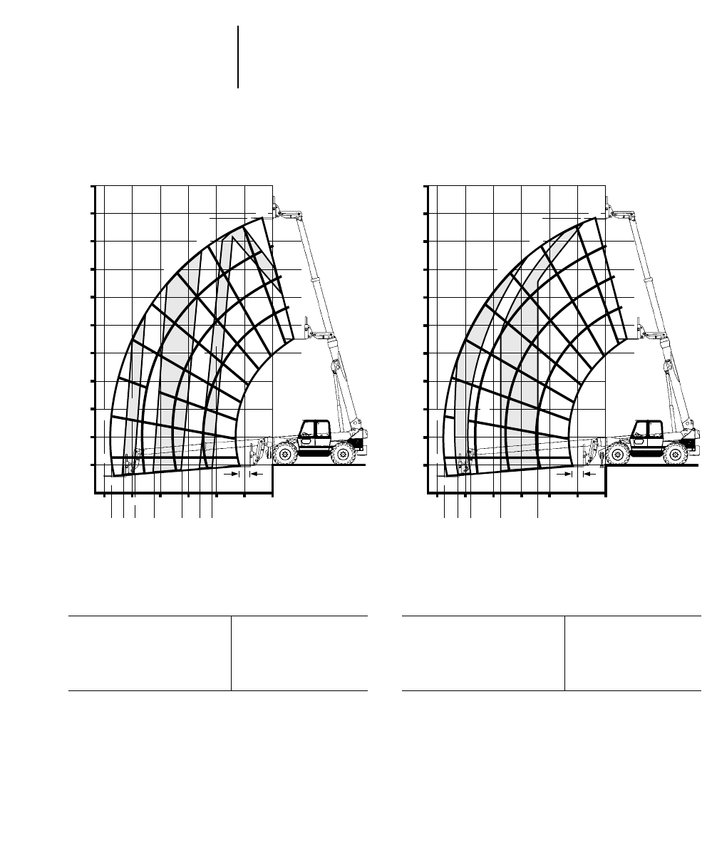
15-10
Performance Data
●Standard Forks and Carriage
●North American Version
Telescopic Handlers
Maximum lift capacity 4536 kg 10,000 lb
Maximum lift height 13.5 m 44'0"
Load at maximum height 2725 kg 6000 lb
Maximum forward reach 8.8 m 28'9"
Load at maximum reach 1075 kg 2370 lb
TH103
No Stabilizers
Maximum lift capacity 4536 kg 10,000 lb
Maximum lift height 13.5 m 44'0"
Load at maximum height 4536 kg 10,000 lb
Maximum forward reach 8.8 m 28'9"
Load at maximum reach 1365 kg 3000 lb
TH103
Stabilizers Down
50'
0'
5'
10'
15'
20'
25'
30'
35'
40'
45'44'3"
5'0'10'15'20'25'30'
28'9"
2'
0°
10°
20°
30°
50°
60°
70°
75°
-4.5°
40°
26'5"
21'0"
16'0"
12'11"
10'7"
24'4"
D
C
B
2370
2500
3000
4000
6000
8000
10000
6000
50'
0'
5'
10'
15'
20'
25'
30'
35'
40'
45'44'3"
5'0'10'15'20'25'30'
28'9"
2'
0°
10°
20°
30°
50°
60°
70°
75°
-4.5°
3000
4000
6000
8000
10000
40°
26'8"
24'4"
18'9"
12'1"
D
C
B
Numbers in chart measured in pounds.Numbers in chart measured in pounds.
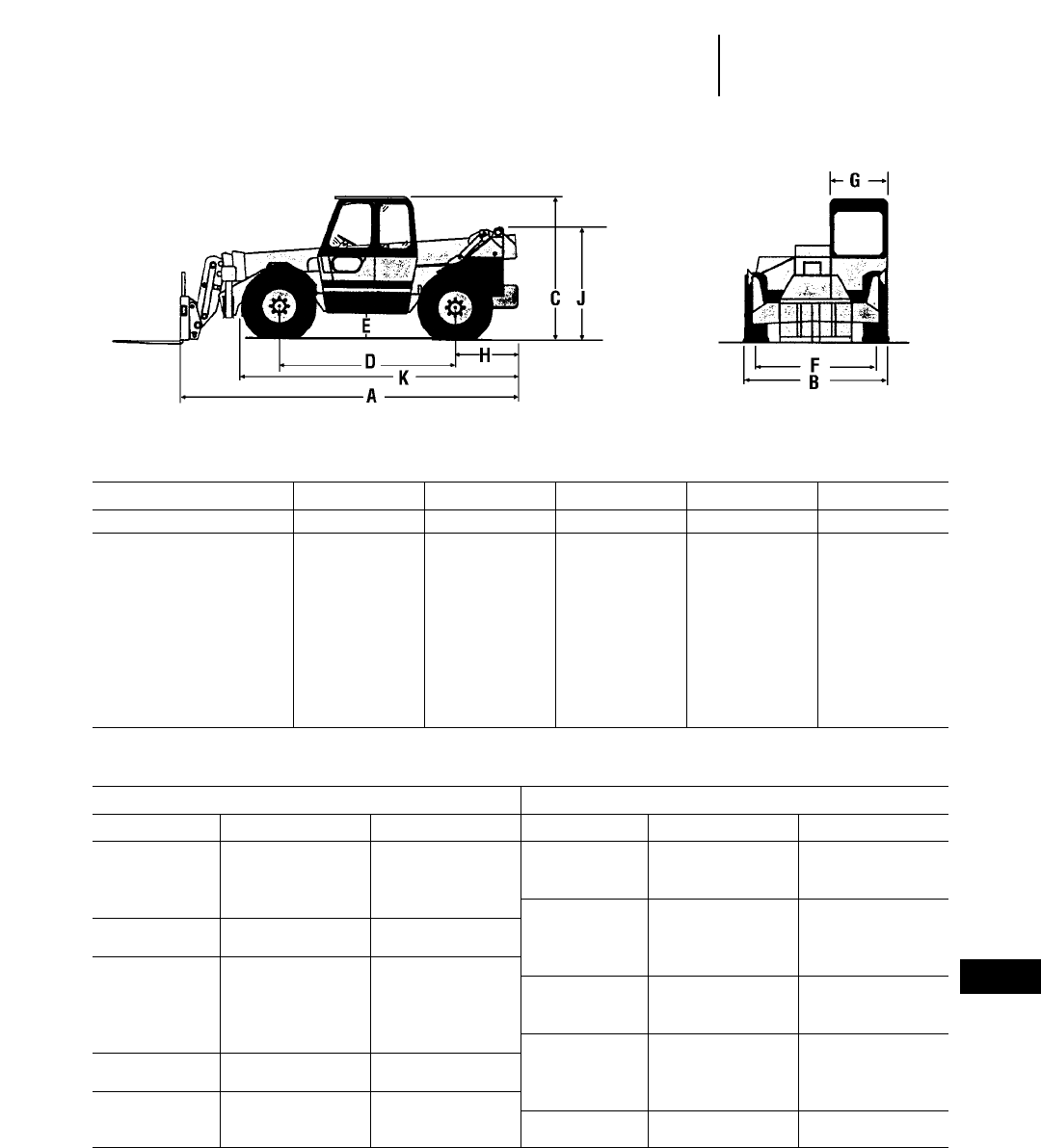
15-11
15
Telescopic HandlersShipping Dimensions
Tire Selection
Dimensions (approx.)
MODEL TH62 TH63 TH82 TH83 TH103
mm ft mm ft mm ft mm ft mm ft
A) Length to fork face 4760 15'7" 5720 18'9" 4760 15'7" 5720 18'9" 6332 20'9"
B) Width 2230 7'4" 2450 8'0" 2450 8'0" 2450 8'0" 2440 8'0"
C) Height 2430 8'0" 2450 8'0" 2450 8'0" 2450 8'0" 2675 8'9"
D) Wheel base 2900 9'6" 2970 9'9" 2970 9'9" 2970 9'9" 3175 10'5"
E) Ground clearance 450 18" 450 18" 450 18" 450 18" 496 1'7.5"
F) Wheel track 1850 6'1" 2080 6'10" 2080 6'10" 2080 6'10" 2074 6'10"
G) Cab width (inside) 900 2'11" 955 3'2" 955 3'2" 955 3'2" 955 3'2"
H) 777 2'7" 1085 3'7" 772 2'6" 1060 3'6" 1318 4'4"
J) 1770 5'10" 1932 6'4" 1770 5'10" 1990 6'6" 2058 6'9"
K) 4316 14'2" 4688 15'5" 4374 14'4" 4662 15'4" **
*Unavailable at time of printing.
Tire Selection
Non-U.S. Models North American Models
Model Tire Size Tire Type Model Tire Size Tire Type
TH62 15.5 x 24 10PR* Agricultural TH62 13.0 x 24 12PR* Construction(b)
17.5LR24 Agricultural 15.0 x 25 12PR*Construction(b)
13.0 x 24 12PR*Construction 17.5LR24 Agricultural
15.5 x 25 12PR*Construction TH63 13.0 x 24 12PR* Construction(a)
TH63 15.5 x 25 12PR* Construction 13.0 x 24 12PR*Construction(b)
15.5 x 80-24 Agricultural 15.5 x 25 12PR*Construction(a)
TH82 15.5 x 25 12PR* Construction 15.5 x 25 12PR*Construction(b)
13.0 x 24 Construction TH82 13.0 x 24 12PR* Construction(b)
15.5 x 80-2412P Agricultural 15.5 x 25 12PR*Construction(b)
17.5LR24 Agricultural 17.5LR24 Agricultural
49.5/70R24 Agricultural TH83 14.0 x 24 12PR* Construction(a)
TH83 14.0 x 24 12PR* Construction 14.0 x 24 12PR* Construction(b)
17.5 x 25 12PR*Construction 17.5 x 25 12PR Construction(a)
TH103 14.0 x 24 16PR* Construction 17.5 x 25 12 PR Construction(b)
17.5R25 Construction TH103 14.0 x 24 16PR* Construction(b)
17.5R25 Construction(b)
*Standard tire.
(a)No stabilizers.
(b)With stabilizers.
All carriages are bar type with load backrest to support bulky loads.
Widespread carriages provide added stability for lifting larger loads.
Standard and widespread carriages are also available in rotating mode.
Carriage Type
Model Standard Wide Rotate Wide/Rotate
TH62 & TH63
Capacity 3000 kg 6615 lb 2920 kg 6440 lb 2865 kg 6320 lb 2785 kg 6140 lb
Weight w/1220 mm (4'0") fork 240 kg 529 lb 320 kg 706 lb 375 kg 827 lb 455 kg 1003 lb
Width 1220 mm 4'0" 1880 mm 6'2" 1220 mm 4'0" 1880 mm 6'2"
Height 1155 mm 3'9" 1155 mm 3'9" 1155 mm 3'9" 1155 mm 3'9"
Max. fork spread 1200 mm 3'11" 1850 mm 6'1" 1200 mm 3'11" 1850 mm 6'1"
Floating fork movement 70 mm 3" 70 mm 3" 70 mm 3" 70 mm 3"
Rotation ——12°12°
TH82/TH83
Capacity 4000 kg 8820 lb 3920 kg 8640 lb 3890 kg 8580 lb 3810 kg 8400 lb
Weight w/1220 mm (4'0") fork 286 kg 631 lb 366 kg 807 lb 395 kg 871 lb 475 kg 1047 lb
Width 1220 mm 4'0" 1880 mm 6'2" 1220 mm 4'0" 1880 mm 6'2"
Height 1155 mm 3'9" 1155 mm 3'9" 1155 mm 3'9" 1155 mm 3'9"
Max. fork spread 1200 mm 3'11" 1850 mm 6'1" 1200 mm 3'11" 1850 mm 6'1"
Floating fork movement 70 mm 3" 70 mm 3" 70 mm 3" 70 mm 3"
Rotation ——12°12°
TH103
Capacity 5000 kg 11,025 lb 4920 kg 10,850 lb 4850 kg 10,690 lb 4680 kg 10,320 lb
Weight w/1220 mm (4'0") fork 318 kg 701 lb 398 kg 878 lb 468 kg 1032 lb 548 kg 1208 lb
Width 1220 mm 4'0" 1880 mm 6'2" 1220 mm 4'0" 1880 mm 6'2"
Height 1155 mm 3'9" 1155 mm 3'9" 1155 mm 3'9" 1155 mm 3'9"
Max. fork spread 1200 mm 3'11" 1850 mm 6'1" 1200 mm 3'11" 1850 mm 6'1"
Floating fork movement 70 mm 3" 70 mm 3" 70 mm 3" 70 mm 3"
Rotation ——12°12°
Fork Type Pallet Block
Model Forks/Set Size Model Forks/Set Size
TH62/TH63 2 50 x 100 x 1097 mm 2" x 4" x 43" TH62/TH63 4 50 x 50 x 1220 mm 2" x 2" x 48"
2 50 x 100 x 1220 mm 2" x 4" x 48" 6 50 x 50 x 1220 mm 2" x 2" x 48"
TH82/TH83 2 50 x 100 x 1220 mm 2" x 4" x 48" TH82/TH83/ 4 50 x 50 x 1220 mm 2" x 2" x 48"
TH103 2 50 x 125 x 1220 mm 2" x 5" x 48" TH103 6 50 x 50 x 1220 mm 2" x 2" x 48"
15-12
Attachment Selection — Non-U.S. Versions
●Carriages
●Forks
Telescopic Handlers
15-13
HEAVY DUTY BUCKET ●Cutting Edge Included
Model TH62 TH63/TH82/TH83/TH103
Capacity (heaped)* 1.0 m31.3 yd31.07 m31.4 yd3
Width 2190 mm 7'2" 2438 mm 8'0"
Weight 444 kg 979 lb 446 kg 983 lb
LOOSE MATERIAL BUCKET ●Cutting Edge Included
Model TH62 TH63/TH82/TH83/TH103
Capacity (heaped)* 1.5 m32.0 yd31.61 m32.1 yd3
Width 2290 mm 7'6" 2438 mm 8'0"
Weight 550 kg 1212 lb 590 kg 1300 lb
4 IN 1 BUCKET ●Hydraulic Gripping Jaw Included
Model TH62 TH63/TH82/TH83/TH103
Capacity (heaped)* 0.75 m31.0 yd30.78 m31.02 yd3
Width 2290 mm 7'6" 2440 mm 8'0"
Weight 440 kg 970 lb 480 kg 1058 lb
ROOT CROP BUCKET
Model TH62 & TH82
Capacity (heaped)* 1.5 m32.0 yd3
Width 2290 mm 7'6"
Weight 410 kg 904 lb
EXTENSION BOOM
Model TH62/TH63/TH82/TH83/TH103
Length 3660 mm 12'0"
Weight 310 kg 683 lb
Capacity 650 kg 1433 lb
MANURE FORK MANURE GRAB ●Hydraulic Top Grab Included
Model TH62 & TH82 Model TH62 & TH82
Capacity (heaped)* 1.9 m32.5 yd3Capacity (heaped)* 1.9 m32.5 yd3
Width 2290 mm 7'6" Width 2290 mm 7'6"
No. of tines 9No. of tines 9
Tine length 1060 mm 3'6" Tine length 1060 mm 3'6"
Weight 375 kg 827 lb Weight 595 kg 1312 lb
MANURE FORK WITH PUSHOFF ●Includes Hydraulic Top Grab and Push Off
Model TH62 & TH82
Capacity (heaped)* 1.73 m32.26 yd3
Width 2290 mm 7'6"
No. of tines 9
Tine length 1060 mm 3'6"
Weight 575 kg 1268 lb
*SAE Ratings.
15
Telescopic HandlersAttachments

GRAIN PUSHER BALE SPIKE
Model TH62 & TH82 Model TH62 & TH82
Blade width 2110 mm 6'11" Width 1820 mm 6'0"
Forward reach 2110 mm 6'11" No. of Tines 6
Weight 320 kg 706 lb Tine length 1370 mm 4'6"
Weight 130 kg 287 lb
AVAILABLE ATTACHMENTS TH62 TH63 TH82 TH83 TH103
Standard Carriage ●●●●●
Rotate Carriage* ●●●●●
Carriage, Wide/Framers ●●●●●
Carriage, Wide/Framers, Rotate* ●●●●●
Forks, Pallet — 2 of (50 x 100 x 1097 mm) ●●N/A N/A N/A
Forks, Pallet — 2 of (50 x 100 x 1220 mm) ●●●●N/A
Forks, Pallet — 2 of (50 x 125 x 1220 mm) N/A N/A N/A N/A ●
Forks, Block — 4 of (50 x 50 x 1220 mm) ●●●●●
Forks, Block — 6 of (50 x 50 x 1220 mm) ●●●●●
1.0 m3, Heavy Duty Bucket ●N/A N/A N/A N/A
1.07 m3, Heavy Duty Bucket N/A ●●●●
1.5 m3, Root Crop Ag Bucket ●N/A ●N/A N/A
1.5 m3, Loose Material Bucket ●N/A N/A N/A N/A
1.61 m3, Loose Material Bucket N/A ●●●●
4 In 1, 0.75 m3, Bucket* ●N/A N/A N/A N/A
4 In 1, 0.78 m3, Bucket* N/A ●●●●
Manure Fork ●N/A ●N/A N/A
Manure Grab* ●N/A ●N/A N/A
Manure Fork and Push Off* ●N/A ●N/A N/A
Extension Boom (3.66 m) ●●●●●
Blade, Grain Pusher ●N/A ●N/A N/A
Bale Spike — 2 Bales ●N/A ●N/A N/A
Quick Coupler, Hydraulic* ●●●●●
Hitch, Hydraulic Rear Tow ●N/A N/A N/A N/A
*Additional Hydraulics Required.
15-14
AttachmentsTelescopic Handlers

CONTENTS
COLD PLANERS
Features . . . . . . . . . . . . . . . . . . . . . . . . . . . . . .16-1
Specifications . . . . . . . . . . . . . . . . . . . . . . . . . .16-2
Production estimating . . . . . . . . . . . . . . . . . . .16-3
Machine selection . . . . . . . . . . . . . . . . . . . . . . .16-4
Cold planing fundamentals . . . . . . . . . . . . . . .16-4
Applications . . . . . . . . . . . . . . . . . . . . . . . . . . .16-5
Cold Planer use by project type . . . . . . . . . . . .16-6
RECLAIMER MIXERS/STABILIZER MIXERS
Features . . . . . . . . . . . . . . . . . . . . . . . . . . . . . .16-7
Specifications . . . . . . . . . . . . . . . . . . . . . . . . . .16-8
Optional equipment . . . . . . . . . . . . . . . . . . . . .16-8
Production estimating . . . . . . . . . . . . . . . . . . .16-9
Weight of materials . . . . . . . . . . . . . . . . . . . . .16-10
Stabilization/Reclamation production . . . . . .16-10
ASPHALT PAVERS
Features & Specifications . . . . . . . . . . . . . . .16-11
Barber-Greene . . . . . . . . . . . . . . . . . . . . . . . . .16-14
Production table . . . . . . . . . . . . . . . . . . . . . . .16-19
ROAD WIDENERS
Barber-Greene . . . . . . . . . . . . . . . . . . . . . . . . .16-20
WINDROW ELEVATORS
Barber-Greene . . . . . . . . . . . . . . . . . . . . . . . . .16-21
SMOOTH DRUM VIBRATORY SOIL
COMPACTORS
Features & Specifications . . . . . . . . . . . . . . .16-22
Production table . . . . . . . . . . . . . . . . . . . . . . .16-25
PADDED DRUM VIBRATORY SOIL COMPACTORS
Features & Specifications . . . . . . . . . . . . . . .16-26
Production table . . . . . . . . . . . . . . . . . . . . . . .16-28
DUAL DRUM VIBRATORY ASPHALT
COMPACTORS
Features & Specifications . . . . . . . . . . . . . . .16-29
Production rates . . . . . . . . . . . . . . . . . . . . . . .16-33
COMBINATION VIBRATORY
ASPHALT COMPACTORS
Features & Specifications . . . . . . . . . . . . . . .16-34
PNEUMATIC TIRE ASPHALT COMPACTORS
Features & Specifications . . . . . . . . .16-35 & 16-38
Production rates . . . . . . . . . . . . . . . . . . . . . . .16-37
Utilization . . . . . . . . . . . . . . . . . . . . . . . . . . . .16-40
Cold Planer Features:
●Cat Diesel Engines with large piston displace-
ment and individual adjustment-free fuel pumps
and valves.
●Up-cutting mandrels provide cutting efficiency
and improved bit life.
●Grade and slope system produces ± 3 mm
(0.125 in) tolerance.
●Non-contact sensors speed set-up on PM-565B
and PM-465.
●Short turning radii for productivity and jobsite
flexibility.
●Front-discharge conveyor on PM-565B and
PM-465 facilitates haul unit movement in con-
gested urban applications.
●Optimum weight-to-horsepower balance for
delivering maximum available horsepower to the
cutter.
●Computerized Monitoring System (CMS)
provides three warning levels for abnormal oper-
ating conditions on PM-565B and PM-465.
●Load control system on PM-565B keeps machine
operating at peak efficiency.
●Variable width cutter available for PM-565B.
●Water spray system for dust control and bit
cooling.
PAVING PRODUCTS
16-1
16
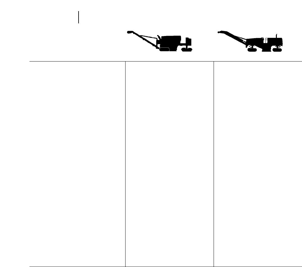
MODEL PM-465 PM-565B
Flywheel Power 343 kW 460 hp 466 kW 625 hp
Operating Weight 25 880 kg 57,060 lb 38 000 kg 83,600 lb
Engine Model 3406C 3408E
Rated Engine RPM 2100 2100
No. of Cylinders 68
Bore 137 mm 5.4" 137 mm 5.4"
Stroke 165 mm 6.5" 152 mm 6"
Displacement 14.6 L 893 in318 L 1099 in3
Drive Systems: Rotor Mechanical Mechanical
Drive Systems: Ground Hydrostatic with 4 Hydrostatic with 4
track design track design
Discharge Conveyor Width 762 mm 2'6" 762 mm 2'6"
Width of Standard Track Shoe 250 mm 10" 348 mm 13.7"
Track Length on Ground 1242 mm 4'1" 2045 mm 6'8.5"
Ground Contact Area
(w/std. shoe) 0.29 m2450 in20.43 m2672 in3
Operating Dimensions:
Height 4.6 m 15'0" 4835 mm 14'11"
Width 2.5 m 8'2" 3151 mm 10'7"
Length 12.83 m 42'1" 14.5 m 47'6"
Standard Mandrel (Width of Cut) 1905 mm 6'3" 2100 mm 6'11"
No. of Teeth 137 —
Depth of Cut (max.) 305 mm 12" 305 mm 12"
Optional Mandrel Widths 2000 mm 6'7" N/A
Speeds: Operating (max.) 0-37 m/min 0-120 ft/min 0-40 mpm 0-132 fpm
Speeds: Travel (max.) 0-5.2 km/hr 0-3.2 mph 0-6 km/hr 0-3.7 mph
Inside Turning Radius: Right 3.62 m 11'10" 4674 mm 15'4"
Inside Turning Radius: Left 4.12 m 13'6" ——
Grade Control Contacting and Standard
Non Contacting Non Contact Electric
Electric Over Hydraulic Over Hydraulic
Slope Control Electric Over Hydraulic —
Fuel Capacity 796 L 210 U.S. gal 946 L 250 U.S. gal
Water Capacity 2275 L 600 U.S. gal 3790 L 1000 U.S. gal
16-2
Cold Planers Specifications
Cutter/Drum Width — m2/min (yd2/min)
1220 mm 1900 mm 2010 mm 2100 mm 2210 mm 3050 mm 3500 mm 3810 mm
Speed 4'0" 6'3" 6'7" 6'11" 7'3" 10'0" 11'6" 12'6"
m/min ft/min m2yd2m2yd2m2yd2m2yd2m2yd2m2yd2m2yd2m2yd2
3.0 10 3.7 4.4 5.8 6.9 6.1 7.3 6.4 7.7 6.7 8.0 9.3 11.1 10.7 12.8 11.6 13.9
4.6 15 5.6 6.6 8.7 10.4 9.3 11.0 9.7 11.5 10.0 12.1 13.9 16.7 16.1 19.2 17.4 20.8
6.1 20 7.5 8.8 11.6 13.9 12.3 14.6 12.8 15.4 13.4 16.1 18.6 22.2 21.4 25.5 23.3 27.8
7.6 25 9.3 11.1 14.5 17.4 15.4 18.3 16.1 19.2 16.7 20.1 23.2 27.8 26.8 31.9 29.1 34.7
9.1 30 11.1 13.3 17.4 20.8 18.4 22.0 19.2 23.1 20.1 24.2 27.9 33.3 32.1 38.3 34.9 41.7
10.7 35 13.1 15.5 20.3 24.3 21.6 25.6 22.6 26.9 23.4 28.2 32.5 38.9 37.5 44.7 40.7 48.6
12.2 40 15.0 17.8 23.2 27.8 24.6 29.3 25.7 30.7 26.8 32.2 37.1 44.4 42.8 51.1 46.5 55.5
13.7 45 16.8 20.0 26.1 31.2 27.7 33.0 28.9 34.6 30.1 36.2 41.8 50.0 48.2 57.5 52.3 62.5
15.2 50 18.7 22.2 29.0 34.7 30.7 36.6 32.1 38.4 33.5 40.3 46.4 55.5 53.5 63.9 58.1 69.4
16.8 55 20.6 24.4 31.9 38.2 33.9 40.2 35.4 42.3 36.8 44.3 51.1 61.1 58.9 70.3 63.9 76.4
18.3 60 22.5 26.7 34.9 41.7 37.0 43.9 38.7 46.1 40.1 48.3 55.7 66.7 64.2 76.7 69.8 83.3
16-3
16
Cold PlanersProduction Estimating
Cutter/Drum Width — metric tons/min (U.S. tons/min)
1220 mm 1900 mm 2010 mm 2100 mm 2210 mm 3050 mm 3500 mm 3810 mm
4'0" 6'3" 6'7" 6'11" 7'3" 10'0" 11'6" 12'6"
Speed Metric U.S. Metric U.S. Metric U.S. Metric U.S. Metric U.S. Metric U.S. Metric U.S. Metric U.S.
m/min ft/min tons tons tons tons tons tons tons tons tons tons tons tons tons tons tons tons
3.0 10 0.23 0.26 0.36 0.40 0.38 0.42 0.41 0.44 0.44 0.46 0.58 0.64 0.67 0.74 0.73 0.80
4.6 15 0.35 0.38 0.54 0.60 0.57 0.63 0.61 0.66 0.66 0.69 0.87 0.96 1.00 1.10 1.09 1.20
6.1 20 0.46 0.51 0.72 0.80 0.76 0.84 0.82 0.88 0.88 0.92 1.16 1.28 1.34 1.47 1.46 1.79
7.6 25 0.58 0.64 0.91 1.00 0.94 1.04 1.02 1.10 1.10 1.15 1.45 1.60 1.67 1.83 1.82 1.99
9.1 30 0.69 0.77 1.09 1.20 1.14 1.26 1.23 1.33 1.32 1.39 1.74 1.91 2.01 2.20 2.19 2.40
10.7 35 0.81 0.89 1.27 1.40 1.34 1.47 1.44 1.55 1.54 1.62 2.03 2.24 2.34 2.57 2.56 2.79
12.2 40 0.92 1.02 1.45 1.60 1.53 1.68 1.65 1.76 1.76 1.85 2.32 2.55 2.68 2.94 2.92 3.19
13.7 45 1.04 1.15 1.63 1.80 1.71 1.88 1.84 1.99 1.98 2.08 2.61 2.87 3.01 3.31 2.28 3.59
15.2 50 1.16 1.28 1.81 2.00 1.91 2.10 2.05 2.21 2.20 2.32 2.90 3.19 3.35 3.67 3.65 3.99
16.8 55 1.27 1.41 1.99 2.20 2.09 2.31 2.25 2.43 2.42 2.55 3.19 3.51 3.68 4.04 4.01 4.39
18.3 60 1.39 1.53 2.18 2.40 2.28 2.51 2.46 2.65 2.64 2.78 3.48 3.83 4.02 4.41 4.38 4.79
NOTE: Above figures are based on a one-inch depth of cut. For greater depths of cut, multiply the production rate by cutting depth. Based on asphalt density of
115 lb/yd2, one inch thick.

MACHINE SELECTION
Prime considerations in selecting the proper cold
planer model are:
— specifics of work to be done
— type of projects generally done by the contractor
●City/Urban or Highway/Airport
— desired production capacities
Cold Planer Characteristics (Highway/Airport)
Highway/Airport work requires high-volume cold
planers. The PM-565B and other high horsepower
half-lane cold planers are being used more on Highway/
Airport projects. Users like to have one machine
that can work successfully on high production jobs
then switch to city/urban applications. The PM-565B
has proven to be a true cross-over cold planer.
Cold Planer Characteristics (City/Urban)
The PM-465 is a four track, front discharge cold
planer designed primarily for the Urban/City environ-
ment. The PM-465, with its tight turning radius and
easy set up, makes it suitable for many applications.
The PM-465 has the productive capacity to perform
effectively on highway applications as well. Machine
dimensions and weight allow transport on one truck,
often no special weight permits are required.
The PM-565B is a four-track, front discharge model.
Front discharge cold planers make traffic control
easier in congested quarters. The trucks travel for-
ward in the same direction as the cold planer. The
trucks move in and out of traffic faster increasing
production.
COLD PLANING FUNDAMENTALS
Definition
Cold planing is automatically controlled cold milling
to restore the pavement surface to a specified grade
and slope; remove bumps, ruts, and other imper-
fections; and leave a textured surface which can be
opened immediately to traffic or overlayed with new
pavement materials.
Production and Tooth Wear
Because pavement materials vary, so do produc-
tion and tooth wear. While predicting the exact pro-
duction rate and tooth wear on a particular job is
difficult, general guidelines are available.
Production depends on the milling rate (the speed
at which the cold planer moves forward). The
machine’s forward speed is determined, primarily,
by aggregate type, asphalt bond strength and depth
of cut. When milling asphalt pavement, the cold
planer’s teeth essentially are breaking the bond
between asphalt-coated aggregate, not actually frac-
turing the aggregate itself. A pavement made with
a mix containing a high percentage of fine aggre-
gate and a high asphalt content is more difficult to
mill than a pavement with a high percentage of
coarse aggregate.
A dense or fine mix usually requires more power
at the cutting drum, limiting the cold planer’s for-
ward speed. Decreased speed lowers production, and
the tough bond between the small aggregate parti-
cles causes increased cutting-tooth wear. Lower pro-
duction and higher tooth wear result in increased
unit costs.
Cutting depth affects power demand at the drum
and helps determine the cold planer’s forward
speed. However, production increases, to a point, as
the depth of cut increases. For example, changing
from a 25 mm (1 in) cut to a 51 mm (2 in) cut slows
the machine only slightly but doubles the amount of
material produced.
As the cut increases beyond the machine’s peak-
production depth, the reduced forward speed begins
to offset the production gains of the deeper cut. For
example, production at a 152 mm (6 in) cutting depth
and slow speed may be no greater than cutting at a
76 mm (3 in) depth and a much faster speed.
16-4
Cold Planers Considerations in Machine Selection
Cold Planing Fundamentals

As long as the cold planer maintains a productive
forward speed, deeper cuts will yield greater produc-
tion and tend to lower tooth cost. Tooth wear does
not increase in direct proportion to production when
the machine is working in an efficient range.
Tooth wear at various depths for a given material
is affected by how long the tooth remains in the cut.
Because the teeth are mounted on a circular drum,
each tooth cuts through the pavement in an arc. The
tooth arc at a 102 mm (4 in) cutting depth, however,
is not four times longer than at a 25 mm (1 in) cut-
ting depth, even though production may be four
times greater. The cutting arc at 102 mm (4 in) is
approximately twice as long as that at 25 mm (1 in).
The peak cutting depth for a particular cold planer
on a specific job is best determined by examining
production, and subsequent costs, of a single deep
cut versus multiple passes at a shallow depth.
APPLICATIONS
Although new applications for cold planers are
being discovered, most work can be classified in seven
general categories:
Leveling and Bonding
This application removes a layer of pavement to
eliminate potholes, ruts, bumps and other surface
imperfections. The cold planer leaves a level, tex-
tured surface ideal for bonding to a new, thin overlay
of asphalt or concrete. The surface has an interlock-
ing texture with double the bonding area of a con-
ventional smooth pavement. The textured surface
and overlay form a monolithic bond, eliminating the
shear plane that causes pavement layers to move
and separate. Thinner overlays can be used, making
the technique more economical than traditional
overlay methods.
Surface Refinishing
Rough pavement can also be cold planed to speci-
fied grade and slope, providing a new riding surface
without adding new paving materials. This appli-
cation is particularly useful when base and sub-base
are in good shape, or when several layers have been
added to the roadway over the years. Roads can be
cold planed during cold, wet months and reopened
immediately. New overlays can be added whenever
weather permits. This lengthens the practical work-
ing season for many contractors. The cold planer can
also be used to correct expansion joint faults and
pavement cracks.
Surface Repair
This category generally requires deeper cutting
than leveling. It consists of removing isolated dis-
tressed pavement sections down to subbase, if nec-
essary, prior to adding new overlay materials. Since
the cutter mandrel on Caterpillar cold planers cuts
forward and upward, there’s no damaging impact to
the underlying base.
Pavement Removal
Pavement buildup is a problem that plagues most
older streets, roads and highways. As overlays are
added, curbs and drains are buried — creating drain-
age problems. Overhead clearances are dangerously
reduced … and additional weight is added to over-
passes and bridges. Cold planing is an economical
method of curing all these problems.
Surface Texturing
Serious accidents increase when pavement becomes
slick from wear. The textured surface produced by
cold planing is highly skid-resistant and has dramat-
ically reduced hydroplaning characteristics.
Pavement Mining
Cold milling has made it practical to actually
“
mine’’
deteriorated pavement materials from existing roads
and streets. The cold planer produces an ideally-sized
asphalt or concrete material which can be recycled
in a variety of ways. Depending on type, age and
condition of pavement, the largest cold planer can
reclaim up to 900 tons of material per hour.
16-5
16
Cold PlanersApplications

COLD PLANER USE BY PROJECT TYPE
Applications Highway/Airport City/Urban
Planing (Milling) ●To establish grade and slope. ●To establish proper grade and slope.
●Remove excess pavement. ●To establish new grade and slope.
Partial Removal ●For use with hot mix recycle. ●To correct drainage and curb reveal.
●Remove pavement irregularities. ●To lower elevation at overpass.
●Texture for skid resistance. ●For use with hot recycle.
●Eliminate leveling course.
Full Depth Removal ●Total rebuild. RAP used for base or ●Total rebuild. RAP used for base or
hot recycle. hot recycle.
●Cold recycle.This requires additional ●Cold recycle. Requires additional
surface treatment. surface treatment.
Texturing ●For skid resistance and improved bond ●For skid resistance and improved bond
when overlay is applied. when overlay is applied.
Leveling ●At intersections to remove bumps,
shoving and improve drainage.
Special ●Joint and crack repair. ●Intersection defect repair.
●Cut rumble grooves on shoulders of ●Pothole repair.
bridge approaches. ●Railroad crossing repair.
●Tight radius profiling around manhole
covers, etc.
●Pavement adjustments (transitions from
existing pavements to new overlays).
16-6
Cold Planers Cold Planer Use By Project Type

RR-250B:
The RR-250B is a single rotor full depth reclaim-
ing machine. It uses a cutting mandrel to pulverize
and mix asphaltic pavement and base materials.
The machine is utilized to mechanically stabilize
deteriorated asphalt structures and complete recla-
mation with the addition of asphaltic emulsions or
other binding agents. The RR-250B can be equipped
with attachments that accurately inject liquid addi-
tives directly into the mixing hood. Optional rotors
can be installed to convert the RR-250B into a soil
stabilizer. The internally mounted breaker bar aids
in material sizing.
SS-250B:
The SS-250B is a single rotor soil stabilization
machine. The machine cuts, mixes and pulverizes
native in-place soils or select materials, with or
without additives. It modifies and stabilizes the soil
obtaining a strong base.
Both the RR & SS-250B feature automatic depth
control, engine load sensing, and rear steering.
RM-350B:
The RM-350B is a heavy-duty reclaimer/mixer,
that can perform either full depth reclamation, or
soil stabilization. Rotor options allow the RM-350B
to perform the pulverization of asphalt pavement, or
the mixing of stabilizing agents with soils to pro-
duce a strong base material.
The RM-350B features microprocessor control of
major machine systems, including propel speed,
rotor depth, and steering modes.
RR-250B/SS-250B Features:
●Maximum Production … rotor driven by Cat
turbocharged Diesel Engine through mechanical
drive system.
●Highly Efficient … load-sensing propel system
helps prevent overloading while allowing contin-
uous work near rated horsepower.
●Extremely Versatile … interchangeable rotors
provide both reclamation and stabilization capa-
bilities.
●Consistent Blending … automatic depth con-
trol, mid-mounted mixing chamber and multi-
speed rotor drive combine for optimum blending
and increased production.
RM-350B Features:
●Maximum Production … mechanical rotor
drive, with deep cutting and mixing capability,
via Cat turbocharged Diesel Engine and Cat
three-speed transmission.
●Efficient Operation … Cat Electronic Control
Module provides microprocessor control of major
machine systems.
●Highly Maneuverable … four steering modes
with automatic rear wheel alignment simplify
work in congested areas.
●Versatility … choice of three rotors for full depth
reclamation or soil stabilization.
●Reliability … field proven Cat components max-
imize machine availability.
16-7
16
Reclaimer Mixers/
Stabilizer Mixers
Features
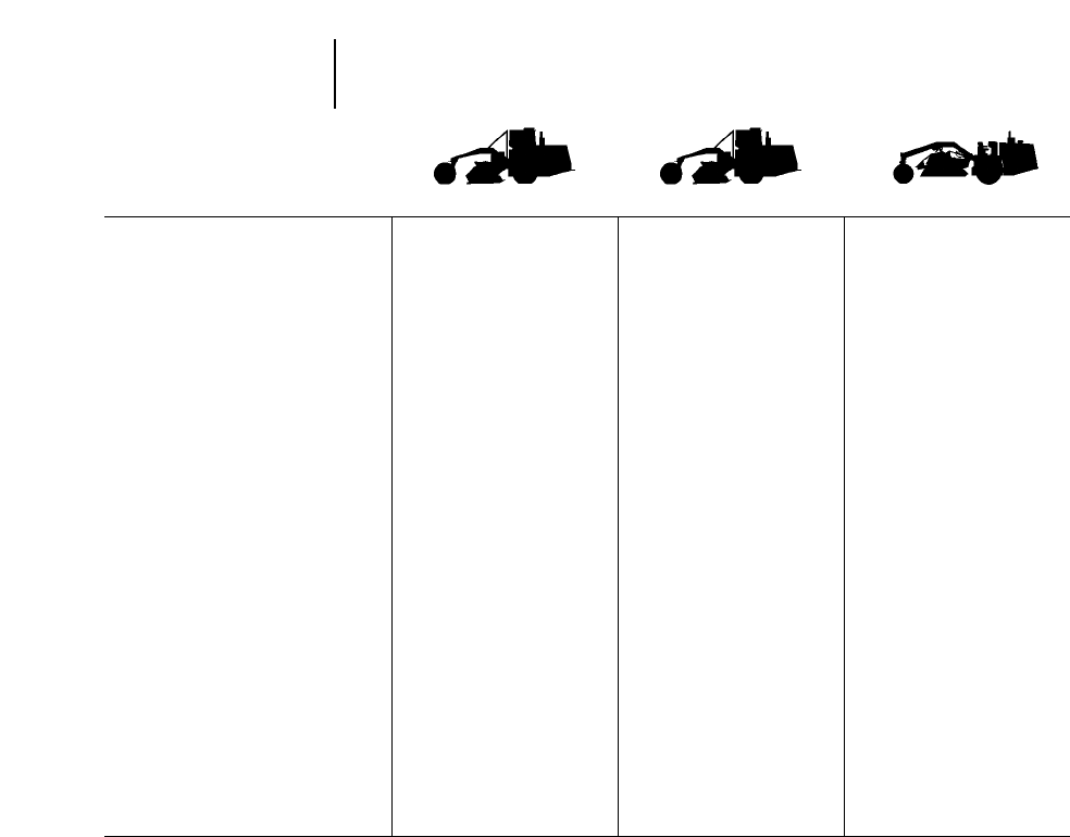
MODEL RR-250B SS-250B RM-350B
Flywheel Power 250 kW 335 hp 250 kW 335 hp 373 kW 500 hp
Operating Weight 19 264 kg 42,470 lb 14 343 kg 31,620 lb 24 040 kg 53,000 lb
Engine Model 3406C 3406C 3406D DITA
Rated Engine RPM 2100 2100 2100
No. Cylinders 666
Bore 137 mm 5.4" 137 mm 5.4" 137 mm 5.4"
Stroke 165 mm 6.5" 165 mm 6.5" 165 mm 6.5"
Displacement 14.6 L 893 in314.6 L 893 in314.6 L 893 in3
Drive Systems: Rotor 3 speed Mechanical 3 speed Mechanical 3 speed Mechanical
Drive Systems: Ground 4 speed Hydrostatic 4 speed Hydrostatic 4 speed Hydrostatic
Operating Dimensions: Height 2600 mm 8'6.5" 2600 mm 8'6.5" 3404 mm 11'2"
Operating Dimensions: Width 2921 mm 9'7" 2921 mm 9'7" 2997 mm 9'10"
Operating Dimensions: Length 8560 mm 28'1" 8560 mm 28'1" 9595 mm 31'6"
Width of Cut 2438 mm 8'0" 2438 mm 8'0" 2438 mm 8'0"
Depth of Cut (Max.) 330 mm 13" 457 mm 18" 508 mm 20"
Rotor Speed Trans Drive Speed Trans Drive Speed Trans Drive Speed
Low Low 123 rpm Low Low 123 rpm Low Low 115 rpm
Low High 168 rpm Low High 168 rpm Low High 160 rpm
High Low 284 rpm High Low 284 rpm High Low 215 rpm
Mimimum Turning Radius:
Standard 5.5 m 18'0" 5.5 m 18'0" 5.48 m 18'0"
Travel Speed (Max.) 19.3 km/h 12 mph 19.3 km/h 12 mph 16.8 km/h 10.5 mph
Standard Tires: Front 23.5 225-16 ply 28.1 2 26-10 PR Lug 23.5R25, L-2
Lug Type E-2 Loader/Dozer
Standard Tires: Rear 15.5 225-8 ply 14.9 2 24-6 PR Lug 19.5L 224-12 R-4
Lug Type L-2 Lug All
Fuel Capacity 416 L 110 U.S. gal 416 L 110 U.S. gal 779 L 206 U.S. gal
Cooling System 61 L 16 U.S. gal 61 L 16 U.S. gal 61 L 16 U.S. gal
Crankcase 34 L 9 U.S. gal 34 L 9 U.S. gal 34 L 9 U.S. gal
16-8
Reclaimer Mixers/
Stabilizer Mixers Specifications
Optional Equipment
OPTIONAL EQUIPMENT — RR-250B/SS-250B
●Roll Over Protective Structure (ROPS).
●Foot per minute indicator (available in metric).
●Working light package.
●Cab with heater, defroster and air conditioner.
●Liquid additive system (emulsion or water)
(English or Metric).
●Water spray system with in-line flow meter.
●Rear wheel power.
●Sound suppression package.
●Torque limiter.
●Mirror package.
OPTIONAL EQUIPMENT — RM-350B
●Roll Over Protective Structure (ROPS).
●Working light package.
●Roading light package.
●Deluxe cab.
●Liquid additive system (emulsion or water).
●Water spray system.
●Sound suppression package.
●Rear wheel power.
●Mirror package.
16-9
16
Reclaimer Mixers/
Stabilizer Mixers
Optional Equipment
Production Estimating
PRODUCTION ESTIMATING
The maximum cutting depth is 381 mm (15") for
the RR-250B and 457 mm (18") for the RM-350B.
The SS-250B can mix up to 457 mm (18"). In addi-
tion, the cutting width of their rotors is 8 feet. The
following formulas allow you to determine the
production in square yards (yd2)/minute or cubic
yards (yd3)/ minute.
Production in square yards (yd2) per minute
_________________________________________
FPM of travel speed
yd2/min = ___________________
1.125
9 ft2/yd2
_________________
8 ft Cutting width = 1.125 (This is a constant
value for an eight foot
wide rotor)
Gallons of additive (for units with pump and
_________________________________________
metering additive system)
________________________
GPM
________ = gal/yd2
yd2/min
Or, if required additive amounts are known, you can
determine necessary travel speed as shown:
GPM
________ =yd
2/min; yd2/min 31.125 = ft/min
gal/yd2
Production in Cubic Yards (yd3) per minute
Cutting or mixing
FPM of travel speed depth in inches yd3
___________________ 3__________________ =____
1.125 36 min
Production in Tons per Minute
_____________________________
Wt. of Material
yd3/min 3per yd in lbs = tons/min
______________
2000 lb/ton
Abbreviations
FPM = Feet Per Minute
GPM = Gallons Per Minute
Rotor Options for SS-250B
Maximum No. of Direction
Rotor Depth of Work Bits/Tools of Cut
Quick Change Tool 381 mm 15" 58 Up
Deep Mix Quick Change 457 mm 18" 58 Down
Combination 381 mm 15" 108 Up
Rotor Options for RR-250B
Maximum No. of Direction
Rotor Depth of Work Bits/Tools of Cut
Cone Tool Milldrum 330 mm 13" 188 Up
Breakaway Holder Rotor 330 mm 13" 188 Up
Quick Change 381 mm 15" 58 Up
Combination 381 mm 15" 108 Up
Rotor Options for RM-350B
Maximum No. of Direction
Rotor Depth of Work Bits/Tools of Cut
Reclamation 381 mm 15" 190 Up
Quick Change 508 mm 20" 58 Up
Combination 457 mm 18" 108 Up
Other rotors available by custom order.
WEIGHT OF MATERIALS
LOOSE IN-PLACE
Material kg/m3lbs/yd3kg/m3lbs/yd3
Clay — Dry 1480 2500 1840 3100
— Wet 1660 2800 2080 3500
Clay and Gravel — Dry 1420 2400 1660 2800
— Wet 1540 2600 1840 3100
Sand and Gravel — Dry 1720 2900 1930 3250
— Wet 2020 3400 2220 3750
Sand — Dry 1420 2400 1600 2700
— Damp 1690 2850 1900 3200
— Wet 1840 3100 2080 3500
Earth — Dry Packed 1510 2550 1900 3200
— Wet Excavated 1600 2700 2020 3400
— Top Soil 950 1600 1360 2300
— Loam 1250 2100 1540 2600
Bituminous Concrete — Windrowed Chunks (25% Voids) 1740 2925
— Compacted 2310 3900
STABILIZATION/RECLAMATION PRODUCTION
The following charts list production in square meters per minute, square yards per minute, cubic meters per minute,
and cubic yards per minute.The information is based on various travel speeds and cutting depths for the Caterpillar
RM-350B, RR-250B and SS-250B equipped with a 2438 mm (8 ft) cutting rotor.
16-10
Reclaimer Mixers/
Stabilizer Mixers Weight of Materials
Stabilization/Reclamation Production
PRODUCTION RATES
Travel m3/Minute
Speed m2/Cutting Depth — mm
m/min min 100 125 150 175 200 225 250 275 300 325 350 375 400 425 450 475 500
3 7.3 0.73 0.9 1.1 1.3 1.5 1.6 1.8 2.0 2.2 2.4 2.6 2.7 2.9 3.1 3.3 3.5 3.7
6 14.6 1.46 1.8 2.2 2.6 2.9 3.3 3.7 4.0 4.4 4.8 5.1 5.5 5.9 6.2 6.6 6.9 7.3
9 21.9 2.202.7 3.3 3.8 4.4 4.9 5.5 6.0 6.6 7.1 7.7 8.2 8.8 9.3 9.9 10.4 11.0
12 29.3 2.903.7 4.4 5.1 5.9 6.6 7.3 8.0 8.8 9.5 10.2 11.0 11.7 12.4 13.2 13.9 14.6
15 36.6 3.604.6 5.5 6.4 7.3 8.2 9.1 10.0 11.0 11.9 12.8 13.7 14.6 15.5 16.5 17.4 18.3
18 43.9 4.405.5 6.6 7.7 8.8 9.9 11.0 12.1 13.2 14.3 15.4 16.5 17.6 18.7 19.7 20.8 21.9
21 51.2 5.106.4 7.7 9.0 10.2 11.5 12.8 14.1 15.4 16.6 17.9 19.2 20.5 21.8 23.0 24.3 25.6
24 58.5 5.907.3 8.8 10.2 11.7 13.2 14.6 16.1 17.6 19.0 20.5 21.9 23.4 24.9 26.3 27.8 29.3
27 65.8 6.608.2 9.9 11.5 13.2 14.8 16.4 18.1 19.7 21.4 23.0 24.7 26.3 28.0 29.6 31.3 32.9
PRODUCTION RATES
Travel yd3/Minute
Speed yd2/Cutting Depth — inches
ft/min min 4567891011121314151617181920
10 8.9 0.98 1.2 1.5 1.7 2.0 2.2 2.5 2.7 3.0 3.2 3.5 3.7 4.0 4.2 4.5 4.7 4.9
20 17.8 1.96 2.5 3.0 3.4 4.0 4.4 4.9 5.5 5.9 6.4 6.9 7.4 7.9 8.4 8.9 9.4 9.9
30 26.7 2.903.7 4.5 5.2 5.9 6.7 7.4 8.2 8.9 9.6 10.4 11.1 11.9 12.6 13.4 14.0 14.8
40 35.6 3.904.9 5.9 6.9 7.9 8.9 9.9 10.9 11.9 12.8 13.9 14.8 15.8 16.8 17.8 18.7 19.8
50 44.5 4.906.2 7.4 8.6 9.9 11.1 12.4 13.6 14.8 16.0 17.3 18.5 19.8 21.0 22.3 23.4 24.7
60 53.4 5.907.4 8.9 10.3 11.9 13.3 14.8 16.4 17.8 19.2 20.8 22.2 23.7 25.2 26.7 28.1 29.7
70 62.3 6.808.6 10.4 12.0 13.8 15.6 17.3 19.1 20.8 22.4 24.3 25.9 27.7 29.5 31.2 32.8 34.6
80 71.2 7.809.9 11.9 13.7 15.8 17.8 19.8 21.8 23.7 25.6 27.7 29.6 31.6 33.7 35.6 37.5 39.6
90 80.1 8.8011.1 13.4 15.5 17.8 20.0 22.4 24.5 26.7 28.8 31.2 33.3 35.6 37.9 40.1 42.1 44.5

Features:
●Variable width Extend-A-Mat B screeds or
Pavemaster B fixed screeds available for
AP-650B, AP-800C, AP-1000B, AP-1050B and
AP-1055B.
●Single sliding operator’s station on AP-650B
thru AP-1055B can be positioned on either side of
paver for excellent visibility.
●Hydrostatic pumps provide infinitely variable
speed ranges.
●Direct hydrostatic drives on the AP-650B thru
AP-1055B eliminate gear boxes, differentials,
final drive chains etc.
●Patented variable speed hydraulic augers on
AP-200B extend with wings to ensure proper
material distribution.
●Self-dumping hydraulic hoppers are heavy-
duty and high capacity.
●Self-cleaning all-steel tracks on AP-200B assure
long life with virtually no maintenance required.
MODEL AP-200B
Flywheel Power 26 kW 35 hp
Rated Engine RPM 2650
No. Cylinders 2
Displacement 1.716 L 104.7 in3
Engine Model Hatz 2m40 Air-Cooled Diesel
Operating Weight (empty) 4080 kg 9000 lb
Speeds 0-54 m/min 0-176 ft/min
Maximum theoretical
capacity 609.6 (t)/hr 600 TPH
Track Assemblies:
Width 381 mm 15"
Length on Ground 760 mm 2'6"
Outside to Outside 2440 mm 8'0"
General Dimensions:
Basic Width 3000 mm 9'10"
Length 2440 mm 8'0"
Height (less exhaust
stack) 1730 mm 6'8"
Wheelbase —
Hopper Capacity 5.4 metric ton 6 standard tons
Screed (extendable) 2743 to 9'0" to
3658 mm 12'0"
Paving Width:
Minimum 914 mm 3'0"
(with optional cut-off shoes)
Maximum 3658 mm 12'0"
Service Refill Capacities:
Cooling system Air-cooled
Fuel tank 39.8 L 10.5 U.S. gal
Hydraulic oil tank 75.8 L 20 U.S. gal
16-11
16
Asphalt PaversFeatures and Specifications
MODEL AP-800C AP-1000B
Flywheel Power 80 kW 107 hp 130 kW 174 hp
Rated Engine RPM 2200 2200
No. Cylinders 46
Displacement 4 L 243 in36.6 L 403 in3
Engine Model 3054DIT 3116TA
Operating Weight:
Tractor 12 202 kg 26,900 lb 16 190 kg 35,700 lb
Pavemaster B Screed 8 ft 1374 kg 3030 lb ——
10 ft 1656 kg 3650 lb 1656 kg 3650 lb
Extend-A-Mat B Screed 8 ft 2994 kg 6600 lb ——
10 ft 3266 kg 7200 lb 3266 kg 7200 lb
Extend-A-Mat B Wide Plates 10 ft — —3760 kg 8300 lb
Speeds: Paving 0-76 m/min 0-250 ft/min 0-114 m/min 0-374 ft/min
Travel 0-19 km/h 0-12 mph 0-23.5 km/h 0-14.5 mph
Maximum theoretical capacity 1801 (t)/hr 1773 TPH 2177 (t)/hr 2400 TPH
Tires:
Front (4) 13 322 Solid Rubber 16 322 Solid Rubber
Rear (2) 16.00 324 18.00 325 16 PR sand rib
Dimensions:
Operating Width 8 ft Screed 3269 mm 10'9" ——
10 ft Screed 3327 mm 10'11" 3327 mm 10'11"
Shipping Width* 8 ft Screed 2438 mm 8'0" ——
10 ft Screed 3048 mm 10'0" 3048 mm 10'0"
Height (less exhaust) 2620 mm 8'7" 2769 mm 9'1"
Length (Extend-A-Mat B, push roller) 6477 mm 21'3" 6783 mm 22'3"
Turning Radius 2896 mm 9'6" 2900 mm 9'6"
Wheelbase 2336 mm 7'8" 2540 mm 8'4"
Hopper Capacity 5.5 m3195 ft36.1 m3215 ft3
Auger Diameter 406 mm 16" 406 mm 16"
Paving Widths:
Pavemaster B Screed
(Min. w/cutoff shoes) 8 ft 1828 mm 6'0" ——
(Max. w/extensions) 6096 mm 20'0" ——
Pavemaster B Screed
(Min. w/cutoff shoes) 10 ft 2438 mm 8'0" 2438 mm 8'0"
(Max. w/extensions) 6096 mm 20'0" 9147 mm 30'0"
Extend-A-Mat B Screed
(Min. w/cutoff shoes) 8 ft 1828 mm 6'0" ——
(Max. w/extensions) 4724 mm 15'6" ——
Extend-A-Mat B Screed
(Min. w/cutoff shoes) 10 ft 2438 mm 8'0" 2438 mm 8'0"
(Max. w/extensions) 6147 mm 20'2" 7290 mm 24'2"
Service Refill Capacities:
Cooling system 19 L 5 U.S. gal 37 L 9.78 U.S. gal
Fuel tank 189 L 50 U.S. gal 265 L 70 U.S. gal
Hydraulic oil tank 189 L 50 U.S. gal 189 L 50 U.S. gal
*Transport width — hoppers raised without end gates.
16-12
Asphalt Pavers Specifications
MODEL AP-650B AP-1050B AP-1055B
Flywheel Power 70 kW 121 hp 130 kW 174 hp 180 kW 174 hp
Rated Engine RPM 2200 2200 2200
No. Cylinders 466
Displacement 4 L 243 in36.6 L 403 in36.6 L 403 in3
Engine Model 3054TA 3116T 3116TA
Operating Weight:
Tractor 11 790 kg 25,990 lb 15 785 kg 34,800 lb 16 103 kg 35,500 lb
Pavemaster B Screed 8 ft 1374 kg 3030 lb ————
10 ft — —1656 kg 3650 lb 1656 kg 3650 lb
Extend-A-Mat B Screed 8 ft 2944 kg 6600 lb ————
10 ft — —3266 kg 7200 lb 3266 kg 7200 lb
Extend-A-Mat B
Wide plates 10 ft — —3760 kg 8300 lb 3760 kg 8300 lb
Speeds: Paving: 1st 0-67 m/min 0-220 ft/min 0-65.6 m/min 0-215 ft/min 0-61 m/min 0-200 ft/min
Speeds: Travel: 2nd 8 km/h 5 mph 8 km/h 5 mph 0-14.9 km/h 0-9.3 mph
Maximum theoretical capacity 1300 mtph 1435 TPH 2177 mtph 2400 TPH 2177 mtph 2400 TPH
Tracks Assemblies:
Width 356 mm 14" 356 mm 14" 457 mm 18"
Length on Ground 2249 mm 7'5" 2718 mm 8'11" 2718 mm 8'11"
Total Number of Track Pads 42 100 NA
Dimensions:
Operating Width 8 ft Screed 3269 mm 10'9" ————
10 ft Screed — —3327 mm 10'11" 3327 mm 10'11"
Shipping Width* 8 ft Screed 3269 mm 10'9" ————
10 ft Screed — —3048 mm 10'0" 3048 mm 10'0"
Height (less exhaust) 2623 mm 8'7" 2769 mm 9'1" 2769 mm 9'1"
Length (Screed**, Osc. pushroller) 5613 mm 18'5" 6579 mm 21'7" 6579 mm 21'7"
Turning Radius*** — —————
Hopper Capacity 5 m3177 ft36.1 m3215 ft36.1 m3215 ft3
Auger Diameter 406 mm 16" 406 mm 16" 406 mm 16"
Paving Widths:
8 ft Pavemaster B Screed
Minimum w/cutoff shoes 1828 mm 6'0" ————
Maximum w/extensions 6096 mm 20'0" ————
10 ft Pavemaster B Screed
Minimum w/cutoff shoes — —2438 mm 8'0" 2438 mm 8'0"
Maximum w/extensions — —9144 mm 30'0" 9144 mm 30'0"
8 ft Extend-A-Mat B Screed
Minimum w/cutoff shoes 1828 mm 6'0" ————
Maximum w/extensions 4724 mm 15'6" ————
10 ft Extend-A-Mat B Screed
Minimum w/cutoff shoes — —2438 mm 8'0" 2438 mm 8'0"
Maximum w/extensions — —7366 mm 24'2" 7366 mm 24'2"
Service Refill Capacities:
Cooling system 31.5 L 8.3 U.S. gal 31.5 L 8.3 U.S. gal 31.5 L 8.3 U.S. gal
Fuel tank 227 L 60 U.S. gal 227 L 60 U.S. gal 227 L 60 U.S. gal
Hydraulic oil tank 189 L 50 U.S. gal 151.4 L 40 U.S. gal 151.4 L 40 U.S. gal
***Transport width hopper folded, no end gates.
***Pavemaster B on AP-1050B, Extend-A-Mat B on AP-1055B.
***Counter-rotates within own track length.
16-13
16
Asphalt PaversSpecifications

Features:
●New variable width Extend-A-Mat B Screeds
or Pavemaster B fixed screeds available for all
Barber-Greene paver models.
●Designed With the Crew In Mind … for sim-
plified, more efficient operation and unmatched
access to operational controls and service areas.
●Simplified Drive System … variable pump/motor
propel system that covers all machine speed
ranges required to increase paver productivity.
●Material Handling System … fully hydrostatic
drive provides smooth efficient operation with the capa-
bility to handle today’s varied paving requirements.
●Complete Range of Models … both rubber tired
and crawler mounted pavers to meet any paving
requirement.
●Dependable Operation … job proven Barber-
Greene design and engineering for mile after mile
performance.
●Service Accessibility … swing-out panels and
decks provide generous access.
●Complete Customer Support … unmatched in
the paving industry.
16-14
Asphalt Pavers Features
●Barber-Greene
MODEL BG-210B BG-230
Flywheel Power 80 kW 107 hp 80 kW 107 hp
Rated Engine RPM 2200 2200
No. Cylinders 44
Displacement 4 L 243 in34 L 243 in3
Engine Model 3054DIT 3054DIT
Operating Weight:
Tractor 8786 kg 19,395 lb 12 202 kg 26,900 lb
Pavemaster B Screed 8 ft 1374 kg 3030 lb 1374 kg 3030 lb
10 ft 1656 kg 3650 lb 1656 kg 3650 lb
Extend-A-Mat B 8 ft 2994 kg 6600 lb 2994 kg 6600 lb
10 ft — ———
Extend-A-Mat B (wide plates) 10 ft — ———
Speeds: Paving 0-83.9 mpm 0-275 fpm 0-76 mpm 0-250 fpm
Speeds: Travel 0-21.7 kmph 0-13.5 mph 0-19 kmph 0-12 mph
Maximum theoretical capacity 1222 (t)/hr 1203 TPH 1801 (t)/hr 1773 TPH
Tires:
Front (4) (Solid Rubber) 305 mm 312" 322" 330 mm 313" 322"
559 mm 559 mm
Rear (2) 14:00 3 24 16:00 3 24 sand rib
Dimensions:
Operating Width 8 ft Screed 3226 mm 10'7" 3269 mm 10'9"
10 ft Screed — —3327 mm 10'11"
Shipping Width* 8 ft Screed 2502 mm 8'2.5" 2438 mm 8'0"
10 ft Screed — —3048 mm 10'0"
Height (less exhaust) 2578 mm 8'5.5" 2620 mm 8'71⁄8"
Length (Extend-A-Mat B, pushroller) 5842 mm 19'2" 6477 mm 21'3"
Turning Radius 3048 mm 10'0" 2896 mm 9'6"
Wheelbase 2007 mm 6'7" 2336 mm 7'8"
Hopper Capacity 4.8 m3170 ft35.5 m3195 ft3
Auger Diameter 357 mm 14" 406 mm 16"
Paving Widths:
8 ft Pavemaster B Screed
Minimum w/cutoff shoes 1828 mm 6'0" 1828 mm 6'0"
Maximum w/extensions 4877 mm 16'0" 6096 mm 20'0"
10 ft Pavemaster B Screed
Minimum w/cutoff shoes — ———
Maximum w/extensions — ———
8 ft Extend-A-Mat B Screed
Minimum w/cutoff shoes 1828 mm 6'0" 1828 mm 6'0"
Maximum w/extensions 4724 mm 15'6" 4724 mm 15'6"
10 ft Extend-A-Mat B Screed
Minimum w/cutoff shoes — —2438 mm 8'0"
Maximum w/extensions — —6147 mm 20'2"
Service Refill Capacities:
Cooling system 19 L 5 U.S. gal 19 L 5 U.S. gal
Fuel tank 189 L 50 U.S. gal 189 L 50 U.S. gal
Hydraulic oil tank 178 L 47 U.S. gal 189 L 50 U.S. gal
*Shipping width with hoppers raised and without end gates.
16-15
16
Asphalt PaversSpecifications
●Barber-Greene
●Rubber Tired Models
MODEL BG-240B BG-260C
Flywheel Power 86 kW 115 hp 130 kW 174 hp
Rated Engine RPM 2310 2200
No. Cylinders 46
Displacement 4.5 L 276 in36.6 L 403 in3
Engine Model JD4045T 3116TA
Operating Weight:
Tractor 11 896 kg 26,260 lb 16 170 kg 35,700 lb
Pavemaster B Screed 8 ft — ———
10 ft 1656 kg 3650 lb 1656 kg 3650 lb
Extend-A-Mat B 8 ft — ———
10 ft 3266 kg 7200 lb 3266 kg 7200 lb
Extend-A-Mat B (wide plates) 10 ft — —3760 kg 8300 lb
Speeds: Paving 0-80.8 mpm 0-265 fpm 0-114 mpm 0-374 fpm
Speeds: Travel 0-16.7 kmph 0-10.4 mph 0-23.5 kmph 0-14.5 mph
Maximum theoretical capacity 2936 (t)/hr 2890 TPH 2177 (t)/hr 2400 TPH
Tires:
Front (4) (Solid Rubber) 406 mm 316" 322" 406 mm 316" 322"
559 mm 559 mm
Rear (2) 16:00 3 24 18:00 3 25, 16 ply sand rib
Dimensions:
Operating Width 8 ft Screed — ———
10 ft Screed 3327 mm 10'11" 3327 mm 10'11"
Shipping Width* 8 ft Screed — ———
10 ft Screed 3048 mm 10'0" 3048 mm 10'0"
Height (less exhaust) 2616 mm 8'7" 2769 mm 9'1"
Length (Extend-A-Mat B, pushroller) 6731 mm 22'1" 6783 mm 22'3"
Turning Radius 3048 mm 10'0" 2900 mm 9'6"
Wheelbase 2184 mm 7'2" 2540 mm 8'4"
Hopper Capacity 6.5 m3230 ft35.8 m3230 ft3
Auger Diameter 406 mm 16" 406 mm 16"
Paving Widths:
8 ft Pavemaster B Screed
Minimum w/cutoff shoes — ———
Maximum w/extensions — ———
10 ft Pavemaster B Screed
Minimum w/cutoff shoes 2438 mm 8'0" 2438 mm 8'0"
Maximum w/extensions 6096 mm 20'0" 7925 mm 26'0"
8 ft Extend-A-Mat B Screed
Minimum w/cutoff shoes — ———
Maximum w/extensions — ———
10 ft Extend-A-Mat B Screed
Minimum w/cutoff shoes 2438 mm 8'0" 2438 mm 8'0"
Maximum w/extensions 5944 mm 19'6" 7290 mm 24'2"
Service Refill Capacities:
Cooling system 35 L 9.2 U.S. gal 37 L 9.78 U.S. gal
Fuel tank 157 L 41 U.S. gal 265 L 70 U.S. gal
Hydraulic oil tank 159 L 42 U.S. gal 189 L 50 U.S. gal
*Shipping width with hoppers raised and without end gates.
16-16
Asphalt Pavers Specifications
●Barber-Greene
●Rubber Tired Models
MODEL BG-225C BG-245C
Flywheel Power 90 kW 121 hp 130 kW 174 hp
Rated Engine RPM 2200 2200
No. Cylinders 46
Displacement 4 L 243 in36.6 L 403 in3
Engine Model 3054DIT 3116TA
Operating Weight:
Tractor 11 790 kg 25,990 lb 15 560 kg 34,300 lb
Pavemaster B Screed 8 ft 1374 kg 2850 lb ——
10 ft — —1472 kg 3650 lb
Extend-A-Mat B 8 ft 2994 kg 6600 lb ——
10 ft — — 3266 kg 7200 lb
Extend-A-Mat B
(wide plates) 10 ft — — 3760 kg 8300 lb
Speeds: Paving 0-67 mpm 0-220 fpm 0-65.6 mpm 0-215 fpm
Speeds: Travel 0-8 kmph 0-5 mph 0-8 kmph 0-5 mph
Maximum theoretical capacity 1300 (t)/hr 1435 TPH 2177 (t)/hr 2400 TPH
Track Assemblies:
Width 356 mm 14" 356 mm 14"
Length on ground 2244 mm 7'5" 2718 mm 8'11"
Total Number of Track Pads 92 100
Dimensions:
Operating Width 8 ft Screed 3269 mm 10'9" ——
10 ft Screed — —3327 mm 10'11"
Shipping Width* 8 ft Screed 2623 mm 8'7" ——
10 ft Screed — —3048 mm 10'0"
Height (less exhaust) 2623 mm 8'7" 2769 mm 9'1"
Length (Extend-A-Mat B Screed, pushroller) 5613 mm 18'5" 6579 mm 21'7"
Turning Radius** — ———
Hopper Capacity 5 m3177 ft36.1 m3215 ft3
Auger Diameter 406 mm 16" 446 mm 16"
Paving Widths:
8 ft Pavemaster B Screed
Minimum w/cutoff shoes 1828 mm 6'0" ——
Maximum w/extensions 6096 mm 20'0" ——
10 ft Pavemaster B Screed
Minimum w/cutoff shoes — —2438 mm 8'0"
Maximum w/extensions — —9144 mm 30'0"
8 ft Extend-A-Mat B Screed
Minimum w/cutoff shoes 1828 mm 6'0" ——
Maximum w/extensions 4724 mm 15'6" ——
10 ft Extend-A-Mat B Screed
Minimum w/cutoff shoes — —2438 mm 8'0"
Maximum w/extensions — —7366 mm 24'2"
Service Refill Capacities:
Cooling system 31.5 L 8.3 U.S. gal 31.5 L 8.3 U.S. gal
Fuel tank 227 L 60 U.S. gal 227 L 60 U.S. gal
Hydraulic oil tank 189 L 50 U.S. gal 151.4 L 40 U.S. gal
**Shipping width with hoppers raised and without end gates.
**Counter rotates within own track length.
16-17
16
Asphalt PaversSpecifications
●Barber-Greene
●Track Models
MODEL BG-265B BG-2455C
Flywheel Power 145 kW 195 hp 130 kW 174 hp
Rated Engine RPM 2200 2200
No. Cylinders 66
Displacement 6.6 L 403 in36.6 L 403 in3
Engine Model 3116TA 3116TA
Operating Weight:
Tractor 15 119 kg 33,375 lb 16 103 kg 35,500 lb
Pavemaster B Screed 8 ft — ———
10 ft 1656 kg 3650 lb 1656 kg 3650 lb
Extend-A-Mat B 8 ft ————
10 ft 3266 kg 7200 lb 3266 kg 7200 lb
Extend-A-Mat B
(wide plates) 10 ft 3760 kg 8300 lb 3760 kg 8300 lb
Speeds: Paving 0-50 mpm 0-164 fpm 0-61 mpm 0-200 fpm
Speeds: Travel 0-8.4 kmph 0-5.5 mph 0-14.9 kmph 0-9.3 mph
Maximum theoretical capacity 2936 (t)/hr 2890 TPH 2177 (t)/hr 2400 TPH
Track Assemblies:
Width 457 mm 18" 457 mm 18"
Length on ground 3251 mm 10'8" 2718 mm 107"
Total Number of Track Pads 94 —
Dimensions:
Operating Width 8 ft Screed — ———
10 ft Screed 3327 mm 10'11" 3327 mm 10'11"
Shipping Width* 8 ft Screed — ———
10 ft Screed 3048 mm 10'0" 3048 mm 10'0"
Height (less exhaust) 2565 mm 8'5" 2769 mm 9'1"
Length (Extend-A-Mat B Screed, pushroller) 6505 mm 21'4" 6579 mm 21'7"
Turning Radius** — —NA
Hopper Capacity 5.8 m3206 ft36.1 m3215 ft3
Auger Diameter 406 mm 16" 406 mm 16"
Paving Widths:
8 ft Pavemaster B Screed
Minimum w/cutoff shoes — ———
Maximum w/extensions — ———
10 ft Pavemaster B Screed
Minimum w/cutoff shoes 2438 mm 8'0" 2438 mm 8'0"
Maximum w/extensions 9754 mm 32'0" 9144 mm 30'0"
8 ft Extend-A-Mat B Screed
Minimum w/cutoff shoes — ———
Maximum w/extensions — ———
10 ft Extend-A-Mat B Screed
Minimum w/cutoff shoes 2438 mm 8'0" 2438 mm 8'0"
Maximum w/extensions 7366 mm 24'2" 7366 mm 24'2"
Service Refill Capacities:
Cooling system 34.8 L 9.2 U.S. gal 31.5 L 8.3 U.S. gal
Fuel tank 303 L 80 U.S. gal 227 L 60 U.S. gal
Hydraulic oil tank 107.7 L 45.1 U.S. gal 151.4 L 40 U.S. gal
**Shipping width with hoppers raised and without end gates.
**Counter rotates within own track length.
16-18
Asphalt Pavers Specifications
●Barber-Greene
●Track Models
Production in tons/hr with 1" compacted mat
Speed Paving Width
fpm 6'0" 7'0" 8'0" 9'0" 10'0" 11'0" 12'0"
10 22 26 29 33 37 40 44
20 44 51 58 66 73 80 88
30 66 77 87 99 110 120 131
40 88 102 116 131 146 161 175
50 110 129 145 164 183 201 219
16-19
16
Asphalt PaversProduction

Features:
●Superior maneuverability. All 700 Series
machines are equipped with four wheel steering
and three steering modes which provide unmatched
maneuverability on the job … turn radius under
4267 mm/14 ft.
●Unmatched traction. Four wheel drive on the
BG-730 and BG-750 with differential locks on the
drive axles combined with engine horsepower and
weight distribution make the toughest widening
jobs easy.
●High capacity conveyors. All machines have
high capacity 762 mm/30 in. wide belt conveyors for
handling large projects.
●Quick shift conveyor. The BG-730 and BG-750
conveyors are equipped with a dual drive system
allowing rapid change of direction. Conveyors on
all units shift hydraulically from side to side.
●Power dump front hopper lip. Front lip on
hopper hydraulically lifts to clean out material
after truck dumps, reducing hand work.
●Sliding operator’s console. Operator’s console
slides from side to side providing rapid change of
station location.
MODEL BG-730
Flywheel Power 111 kW 149 hp
Rated Engine RPM 2200
No. Cylinders 6
Displacement 6 L 365 in3
Engine Model 3056T
Operating Weight 14 062 kg 31,000 lb
Speeds: Paving 0-98 mpm 0-320 fpm
Speeds: Travel 0-24.1 kmph 0-15 mph
Maximum theoretical
capacity 3658 (t)/hr 3600 TPH
Tires 15.00 322.5
Dimensions:
Length with pushroller 7820 mm 25'8"
Operating height 2921 mm 9'7"
Shipping height 2578 mm 8'5.5"
Shipping width 3048 mm 10'0"
Turning Radius 3962 mm 13'0"
Wheelbase 4572 mm 15'0"
Hopper Capacity 10 m380 ft3
Truck entry width 2845 mm 9'4"
Laydown widths to 3048 mm to 10'
Service Refill Capacities:
Cooling system 28.4 L 7.7 U.S. gal
Fuel tank 151.4 L 40 U.S. gal
Hydraulic oil tank 151.4 L 40 U.S. gal
16-20
Road Wideners Features and Specifications
●Barber-Greene
16-21
16
Windrow ElevatorsFeatures and Specifications
●Barber-Greene
Features:
●Attaches easily to most pavers.
●Allows for continuous paving operations.
●High capacity conveyor with 1905 mm (75") dis-
charge height provides full power hopper loading.
●Foot shaft combining augers provide a wide
throat for pick up off-center and extra wide windrows.
●Wide throat allows machine to pickup windrows
from bottom dump trailers, end dump trailers or
trucks.
●Height adjustable scraper mounted behind
combining augers maintains a clean path for paver.
●Three point suspension allows machine to closely
follow road contours.
MODEL BG-650
Flywheel Power 80 kW 107 hp
Engine RPM 2100
Operating Weight 7973 kg 17,600 lb
Engine 3054DIT
Displacement 4 L 243 in3
General Dimensions
Operating height 2946 mm 9'8"
Shipping height 2946 mm 9'8"
Length 4267 mm 14'0"
Conveyor:
Maximum theoretical capacity 1829 (t)/hr 1800 TPH
Discharge height 1905 mm 6'2"
Width 1524 mm 5'0"
Lift 178 mm 7"
Tires:
Front (2) 178 mm 3559 mm 7" 322" Solid Rubber
Rear (2) 8.25 315 8.25 315
Service Refill Capacities:
Fuel 151.4 L 40 U.S. gal
Features:
●Designed with optimum horsepower-to-weight
ratio for best operating economy and peak per-
formance.
●Hydrostatic transmission allows infinitely vari-
able speeds in both forward and reverse.
●Drum-drive units feature a unique, Cat-designed
hydraulic flow divider valve (blade-equipped
CS-323C) or dual pump and circuit arrangement
that delivers positive tractive effort to both drum
and rear wheels, regardless of underfooting. This
increases the machine’s ability to maneuver in a
wide variety of soil types and conditions and
improves gross gradeability.
●NoSPIN high traction differential is standard
on all units for best traction of rear tires. (Except
CS-533C.)
●Routine maintenance simplified by grouped ser-
vice points and easy, ample access to service areas.
●Operator comfort provided by full-width padded
seats or adjustable bucket seats for all day produc-
tivity. All machine controls and instrumentation
are within easy sight and reach. Unobstructed visi-
bility increases work area productivity.
●ROPS (Roll Over Protective Structure) stan-
dard on all units. Enclosed cabs with EROPS rat-
ing available as an option to provide all-weather
comfort and productivity.
●Oil bath lubrication increases bearing service
life and eliminates daily maintenance.
●High centrifugal force and amplitude work
together for a highly productive compactor.
MODEL CS-323C
Flywheel Power 60 kW 80 hp
Rated Engine RPM 2200
No. Cylinders 4
Displacement 4 L 243 in3
Engine Model 3054 DINA
Speeds:
Forward 1
Reverse 1
Max. Speed (For./Rev.) 8.9 km/h 5.5 mph
Operating Weight 4540 kg 9985 lb
Shipping Weight 4395 kg 9670 lb
Drive Drum/rear wheel
Gradeability 49%
Steering:
Inside radius 2625 mm 8'6"
Outside radius 3895 mm 12'8"
Steering angle ±38°
Vibratory System:
Ecc. Weight Drive Hydraulic
Frequency 35 Hz 2100 vpm
Amplitude Settings 1
Centrifugal Force (Max.) 66.8 kN 15,000 lb
General Dimensions:
Overall width 1395 mm 4'6"
Drum width 1270 mm 4'2"
Drum diameter 1016 mm 3'4"
Tires 11.2 324 6-ply
Overall height 2514 mm 8'3"
Wheel to drum 2240 mm 7'4"
Overall length 4095 mm 13'4"
Curb Clearance 347 mm 13.7"
Service Refill Capacities:
Fuel tank 144 L 38 U.S. gal
Crankcase 7.6 L 2 U.S. gal
Hydraulic fluid 49.2 L 13 U.S. gal
16-22
Features and SpecificationsSmooth Drum Vibratory
Soil Compactors
16-23
16
Smooth Drum Vibratory
Soil Compactors
Specifications
MODEL CS-431C CS-433C CS-531C*
Flywheel Power 80 kW 107 hp 80 kW 107 hp 108 kW 145 hp
Rated Engine RPM 2200 2200 2200
No. Cylinders 446
Displacement 4 L 243 in34 L 243 in36.6 L 403 in3
Engine Model 3054T 3054T 3116T
Speeds:
Forward 222
Reverse 222
Max. Speed (For./Rev.) 12.8 km/h 0-8 mph 12.8 km/h 0-8 mph 12.8 km/h 0-8 mph
Operating Weight 6526 kg 14,375 lb 6670 kg 14,675 lb 9300 kg 20,450 lb
Shipping Weight 6243 kg 13,750 lb 6379 kg 14,080 lb 9090 kg 20,000 lb
Drive Rear wheel Drum/rear wheel Rear wheel
Steering:
Inside radius 3008 mm 9'10" 3008 mm 9'10" 3912 mm 12'10"
Outside radius 4684 mm 15'4" 4684 mm 15'4" 6325 mm 20'9"
Steering angle ±37° ±37° ±30°
Vibratory System:
Ecc. Weight Drive Hydraulic Hydraulic Hydraulic
Frequency 30 Hz 1800 vpm 30 Hz 1800 vpm 30 Hz 1800 vpm
Amplitude Settings 222
Centrifugal Force
High amplitude 12 727 kg 28,000 lb 12 727 kg 28,000 lb 24 060 kg 53,100 lb
Low amplitude 6273 kg 13,800 lb 6273 kg 13,800 lb 12 030 kg 26,550 lb
General Dimensions:
Overall width 1905 mm 6'3" 1905 mm 6'3" 2438 mm 8'0"
Drum width 1680 mm 5'6" 1680 mm 5'6" 2130 mm 7'0"
Drum diameter 1220 mm 4'0" 1220 mm 4'0" 1520 mm 5'0"
Tires 14.9" 324" 6-ply 14.9" 324" 6-ply 23.1" 326" 8-ply
Overall height 2900 mm 9'6" 2900 mm 9'6" 2667 mm 8'9"
Wheel to drum 2583 mm 8'6" 2583 mm 8'6" 2740 mm 9'0"
Overall length 4825 mm 15'10" 4825 mm 15'10" 5258 mm 17'3"
Curb clearance 380 mm 15" 380 mm 15" 483 mm 1'7"
Service Refill Capacities:
Fuel tank 167 L 44 U.S. gal 167 L 44 U.S. gal 220 L 58 U.S. gal
Crankcase 6.8 L 1.8 U.S. gal 6.8 L 1.8 U.S. gal 20 L 6.4 U.S. gal
Hydraulic fluid 71 L 18.7 U.S. gal 71 L 18.7 U.S. gal 110 L 29 U.S. gal
*Not offered in the United States.
MODEL CS-533C* CS-563C CS-573C* CS-583C
Flywheel Power 108 kW 145 hp 108 kW 145 hp 108 kW 145 hp 108 kW 145 hp
Rated Engine RPM 2200 2200 2200 2200
No. Cylinders 6666
Displacement 6.6 L 403 in36.6 L 403 in36.6 L 403 in36.6 L 403 in3
Engine Model 3116T 3116T 3116T 3116T
Speeds:
Forward 2222
Reverse 2222
Max. Speed (For./Rev.) 12.8 km/h 0-8 mph 12.8 km/h 0-8 mph 12.8 km/h 8 mph 12.8 km/h 8 mph
Operating Weight 9397 kg 20,700 lb 11 215 kg 24,700 lb 13 300 kg 29,300 lb 15 460 kg 34,030 lb
Shipping Weight 9284 kg 20,450 lb 10 900 kg 24,000 lb 13 010 kg 28,690 lb 15 140 kg 33,380 lb
Drive Drum/rear wheel Drum/rear wheel Drum/rear wheel Drum/rear wheel
Steering:
Inside radius 3912 mm 12'10" 3912 mm 12'10" 3800 mm 12'6" 3800 mm 12'6"
Outside radius 6325 mm 20'9" 6325 mm 20'9" 6170 mm 20'3" 6170 mm 20'3"
Steering angle ±30° ±30° ±30° ±30°
Vibratory System:
Ecc. Weight Drive Hydraulic Hydraulic Hydraulic Hydraulic
Frequency 30 Hz 1800 vpm 30 Hz 1800 vpm 30 Hz 1800 vpm 30 Hz 1800 vpm
Amplitude Settings 2222
Centrifugal Force
High amplitude 24 060 kg 53,100 lb 24 060 kg 53,100 lb 31 750 kg 70,000 lb 31 750 kg 70,000 lb
Low amplitude 12 030 kg 26,550 lb 12 030 kg 26,550 lb 16 675 kg 36,760 lb 16 675 kg 36,760 lb
General Dimensions:
Overall width 2438 mm 8'0" 2438 mm 8'0" 2508 mm 8'3" 2508 mm 8'3"
Drum width 2130 mm 7'0" 2130 mm 7'0" 2130 mm 7'0" 2130 mm 7'0"
Drum diameter 1520 mm 5'0" 1520 mm 5'0" 1520 mm 5'0" 1520 mm 5'0"
Tires 23.1" 326" 8-ply 23.1" 326" 8-ply 23.1" 326" 8-ply 23.1" 326" 8-ply
Overall height 2667 mm 8'9" 2997 mm 9'10" 2997 mm 9'10" 2997 mm 9'10"
Wheel to drum 2740 mm 9'0" 2740 mm 9'0" 2740 mm 9'0" 2740 mm 9'0"
Overall length 5258 mm 17'3" 5400 mm 17'9" 5400 mm 17'9" 5400 mm 17'9"
Curb clearance 483 mm 1'7" 483 mm 1'7" 483 mm 1'7" 483 mm 1'7"
Service Refill Capacities:
Fuel tank 220 L 58 U.S. gal 220 L 58 U.S. gal 220 L 58 U.S. gal 220 L 58 U.S. gal
Crankcase 20 L 5.4 U.S. gal 20 L 5.4 U.S. gal 20 L 5.4 U.S. gal 20 L 5.4 U.S. gal
Hydraulic fluid 110 L 29 U.S. gal 110 L 29 U.S. gal 110 L 29 U.S. gal 110 L 29 U.S. gal
*Not offered in the United States.
16-24
SpecificationsSmooth Drum Vibratory
Soil Compactors

16-25
16
Smooth Drum Vibratory
Soil Compactors
Production Table
COMPACTED LIFT THICKNESS
MODEL AND AVERAGE
MACHINE SPEED 150 mm 6 in 200 mm 8 in 250 mm 10 in 300 mm 12 in
PASSES MPH m3/hr yd3/hr m3/hr yd3/hr m3/hr yd3/hr m3/hr yd3/hr
CS-323C 3 2.5 249.5 326.0 332.7 434.7 415.9 543.3 499.0 652.0
3 3.0 299.4 391.2 399.2 521.6 499.0 652.0 598.8 782.4
3 3.5 349.3 456.4 465.8 608.5 582.2 760.7 698.7 912.8
3 4.0 399.2 521.6 532.3 695.5 665.4 869.3 798.5 1043.2
4 2.5 187.1 244.5 249.5 326.0 311.9 407.5 374.3 489.0
4 3.0 224.6 293.4 299.4 391.2 374.3 489.0 449.1 586.8
4 3.5 262.0 342.3 349.3 456.4 436.7 570.5 524.0 684.6
4 4.0 299.4 391.2 399.2 521.6 499.0 652.0 598.8 782.4
5 2.5 149.7 195.6 199.6 260.8 249.5 326.0 299.4 391.2
5 3.0 179.7 234.7 239.5 313.0 299.4 391.2 359.3 469.4
5 3.5 209.6 273.8 279.5 365.1 349.3 456.4 419.2 547.7
5 4.0 239.5 313.0 319.4 417.3 399.2 521.6 479.1 625.9
CS-431C 3 2.5 343.1 448.3 457.5 597.7 571.8 747.1 686.2 896.5
3 3.0 411.7 537.9 548.9 717.2 686.2 896.5 823.4 1075.8
3 3.5 480.3 627.6 640.4 836.7 800.5 1045.9 960.7 1255.1
3 4.0 548.9 717.2 731.9 956.3 914.9 1195.3 1097.9 1434.4
4 2.5 257.3 336.2 343.1 448.3 428.9 560.3 514.6 672.4
4 3.0 308.8 403.4 411.7 537.9 514.6 672.4 617.6 806.9
4 3.5 360.2 470.7 480.3 627.6 600.4 784.4 720.5 941.3
4 4.0 411.7 537.9 548.9 717.2 686.2 896.5 823.4 1075.8
5 2.5 205.9 269.0 274.5 358.6 343.1 448.3 411.7 537.9
5 3.0 247.0 322.7 329.4 430.3 411.7 537.9 494.1 645.5
5 3.5 288.2 376.5 384.3 502.0 480.3 627.6 576.4 753.1
5 4.0 329.4 430.3 439.2 573.8 548.9 717.2 658.7 860.6
CS-433C 3 2.5 343.1 448.3 457.5 597.7 571.8 747.1 686.2 896.5
3 3.0 411.7 537.9 548.9 717.2 686.2 896.5 823.4 1075.8
3 3.5 480.3 627.6 640.4 836.7 800.5 1045.9 960.7 1255.1
3 4.0 548.9 717.2 731.9 956.3 914.9 1195.3 1097.9 1434.4
4 2.5 257.3 336.2 343.1 448.3 428.9 560.3 514.6 672.4
4 3.0 308.8 403.4 411.7 537.9 514.6 672.4 617.6 806.9
4 3.5 360.2 470.7 480.3 627.6 600.4 784.4 720.5 941.3
4 4.0 411.7 537.9 548.9 717.2 686.2 896.5 823.4 1075.8
5 2.5 205.9 269.0 274.5 358.6 343.1 448.3 411.7 537.9
5 3.0 247.0 322.7 329.4 430.3 411.7 537.9 494.1 645.5
5 3.5 288.2 376.5 384.3 502.0 480.3 627.6 576.4 753.1
5 4.0 329.4 430.3 439.2 573.8 548.9 717.2 658.7 860.6
CS-533C 3 2.5 436.7 570.5 582.2 760.7 727.8 950.8 873.3 1141.0
CS-563C 3 3.0 524.0 684.6 698.7 912.8 873.3 1141.0 1048.0 1369.2
CS-573C 3 3.5 611.3 798.7 815.1 1064.9 1018.9 1331.2 1222.6 1597.4
CS-583C 3 4.0 698.7 912.8 931.5 1217.1 1164.4 1521.3 1397.3 1825.6
4 2.5 327.5 427.9 436.7 570.5 545.8 713.1 655.0 855.8
4 3.0 393.0 513.5 524.0 684.6 655.0 855.8 786.0 1026.9
4 3.5 458.5 599.0 611.3 798.7 764.2 998.4 917.0 1198.1
4 4.0 524.0 684.6 698.7 912.8 873.3 1141.0 1048.0 1369.2
5 2.5 262.0 342.3 349.3 456.4 436.7 570.5 524.0 684.6
5 3.0 314.4 410.8 419.2 547.7 524.0 684.6 628.8 821.5
5 3.5 366.8 479.2 489.1 639.0 611.3 798.7 733.6 958.4
5 4.0 419.2 547.7 558.9 730.2 698.7 912.8 838.4 1095.4
Features:
●Designed with optimum horsepower-to-
weight ratio for best operating economy and peak
performance.
●All units feature a unique, Cat-designed
hydraulic flow divider valve (CP-323C) or dual
pump and circuit arrangement that delivers
positive tractive effort to both drum and rear wheels,
regardless of underfooting. This increases the
machine's ability to maneuver in a wide variety of
soil types and conditions and improves gross
gradeability.
●NoSPIN high traction differential is standard
on all units for best traction of rear tires. (Except
CP-533C.)
●Optional Heavy-duty front-mounted blade
with reversible cutting edge is available to allow
backfilling and leveling during compaction.
●Routine maintenance simplified by grouped
service points and easy access to service areas.
●Operator comfort provided by full-width padded
seats or adjustable bucket seats for all day pro-
ductivity. All machine controls and instrumentation
are within easy sight and reach. Unobstructed
visibility increases work area productivity.
●ROPS (Roll Over Protective Structure) stan-
dard on all units. Enclosed cabs with EROPS rat-
ing available as an option to provide all-weather
comfort and productivity.
●Oil bath lubrication increases bearing service
life and eliminates daily maintenance.
●High centrifugal force and amplitude work
together for a highly productive compactor.
●Adjustable jaw-type cleaner bar keeps drums
clean between pads during forward and reverse
movement.
MODEL CP-323C
Flywheel Power 60 kW 80 hp
Rated Engine RPM 2200
No. Cylinders 4
Displacement 4 L 243 in3
Engine Model 3054 DINA
Speeds:
Forward 1
Reverse 1
Max. Speed (For./Rev.) 8.9 km/h 5.5 mph
Operating Weight 4745 kg 10,440 lb
Shipping Weight 4600 kg 10,125 lb
Drive Drum/rear wheel
Steering:
Inside radius 2625 mm 8'7.3"
Outside radius 3895 mm 12'9.3"
Steering angle ±38°
Vibratory System:
Ecc. Weight Drive Hydraulic
Frequency 35 Hz 2100 vpm
Amplitude Settings 1
Centrifical Force (Max.) 66.8 kN 15,000 lb
General Dimensions:
Overall width w/blade 1575 mm 5'2"
Overall width w/o blade 1393 mm 4'7"
Drum width 1270 mm 4'2"
Drum diameter over pads 1016 mm 3'4"
Tires 11.2 324 6-ply
Overall height 2514 mm 8'3"
Wheel to drum 2240 mm 7'4.2"
Overall length 4095 mm 13'5.2"
Curb Clearance 347 mm 13.7"
Service Refill Capacities:
Fuel Tank 144 L 38 U.S. gal
Crankcase 7.6 L 2 U.S. gal
Hydraulic fluid 49.2 L 13 U.S. gal
16-26
Features and SpecificationsPadded Drum Vibratory
Soil Compactors

16-27
16
Padded Drum Vibratory
Soil Compactors
Specifications
MODEL CP-433C CP-533C* CP-563C
Flywheel Power 80 kW 107 hp 108 kW 145 hp 108 kW 145 hp
Rated Engine RPM 2500 2200 2200
No. Cylinders 466
Displacement 4 L 243 in36.6 L 403 in36.6 L 403 in3
Engine Model 3054T 3116T 3116T
Speeds:
Forward 222
Reverse 222
Max. Speed (For./Rev.) 13.3 km/h 0-8 mph 12.8 km/h 0-8 mph 12.8 km/h 0-8 mph
Operating Weight 6912 kg 15,225 lb 10 760 kg 23,700 lb 11 670 kg 25,700 lb
Shipping Weight 6628 kg 14,600 lb 10 646 kg 23,450 lb 11 360 kg 25,000 lb
Drive Drum/rear wheel Drum/rear wheel Drum/rear wheel
Steering:
Inside radius 3008 mm 9'10" 3912 mm 12'10" 3912 mm 12'10"
Outside radius 4684 mm 15'4" 6325 mm 20'9" 6325 mm 20'9"
Steering angle ±37° ±30° ±30°
Vibratory System:
Ecc. Weight Drive Hydraulic Hydraulic Hydraulic
Frequency 30 Hz 1800 vpm 30 Hz 1800 rpm 30 Hz 1800 vpm
Amplitude Settings 222
Centrifugal Force
Low amplitude 6273 kg 13,800 lb 31 750 kg 70,000 lb 31 750 kg 70,000 lb
High amplitude 12 727 kg 28,000 lb 16 675 kg 36,760 lb 16 675 kg 36,760 lb
General Dimensions:
Overall width w/blade 1981 mm 6'6" 2740 mm 9'0" 2740 mm 9'0"
Overall width w/o blade 1905 mm 6'3" 2440 mm 8'0" 2440 mm 8'0"
Drum width 1680 mm 5'6" 2130 mm 7'0" 2130 mm 7'0"
Drum diameter over pads 1220 mm 4'0" 1549 mm 5'1" 1549 mm 5'1"
Tires 14.9" 324" 6-ply 23.1" 3 26" 8-ply 23.1" 326" 8-ply
Overall height 2900 mm 9'6" 2667 mm 8'9" 2997 mm 9'10"
Wheel to drum 2583 mm 8'6" 2740 mm 9'10" 2740 mm 9'0"
Overall length 4825 mm 15'10" 5258 mm 17'3" 5258 mm 17'3"
Curb clearance 380 mm 15" 483 mm 1'7" 483 mm 1'7"
Service Refill Capacities:
Fuel tank 167 L 44 U.S. gal 220 L 58 U.S. gal 220 L 58 U.S. gal
Crankcase 6.8 L 1.8 U.S. gal 20 L 5.4 U.S. gal 20 L 5.4 U.S. gal
Hydraulic fluid 71 L 18.7 U.S. gal 110 L 29 U.S. gal 110 L 29 U.S. gal
*Not offered in United States.

COMPACTED LIFT THICKNESS
MODEL AND AVERAGE
MACHINE SPEED 150 mm 6 in 200 mm 8 in 250 mm 10 in 300 mm 12 in
PASSES MPH m3/hr yd3/hr m3/hr yd3/hr m3/hr yd3/hr m3/hr yd3/hr
CP-323C 3 2.5 249.5 326.0 332.7 434.7 415.9 543.3 499.0 652.0
3 3.0 299.4 391.2 399.2 521.6 499.0 652.0 598.8 782.4
3 3.5 349.3 456.4 465.8 608.5 582.2 760.7 698.7 912.8
3 4.0 399.2 521.6 532.3 695.5 665.4 869.3 798.5 1043.2
4 2.5 187.1 244.5 249.5 326.0 311.9 407.5 374.3 489.0
4 3.0 224.6 293.4 299.4 391.2 374.3 489.0 449.1 586.8
4 3.5 262.0 342.3 349.3 456.4 436.7 570.5 524.0 684.6
4 4.0 299.4 391.2 399.2 521.6 499.0 652.0 598.8 782.4
5 2.5 149.7 195.6 199.6 260.8 249.5 326.0 299.4 391.2
5 3.0 179.7 234.7 239.5 313.0 299.4 391.2 359.3 469.4
5 3.5 209.6 273.8 279.5 365.1 349.3 456.4 419.2 547.7
5 4.0 239.5 313.0 319.4 417.3 399.2 521.6 479.1 625.9
CP-433C 3 2.5 343.1 448.3 457.5 597.7 571.8 747.1 686.2 896.5
3 3.0 411.7 537.9 548.9 717.2 686.2 896.5 823.4 1075.8
3 3.5 480.3 627.6 640.4 836.7 800.5 1045.9 960.7 1255.1
3 4.0 548.9 717.2 731.9 956.3 914.9 1195.3 1097.9 1434.4
4 2.5 257.3 336.2 343.1 448.3 428.9 560.3 514.6 672.4
4 3.0 308.8 403.4 411.7 537.9 514.6 672.4 617.6 806.9
4 3.5 360.2 470.7 480.3 627.6 600.4 784.4 720.5 941.3
4 4.0 411.7 537.9 548.9 717.2 686.2 896.5 823.4 1075.8
5 2.5 205.9 269.0 274.5 358.6 343.1 448.3 411.7 537.9
5 3.0 247.0 322.7 329.4 430.3 411.7 537.9 494.1 645.5
5 3.5 288.2 376.5 384.3 502.0 480.3 627.6 576.4 753.1
5 4.0 329.4 430.3 439.2 573.8 548.9 717.2 658.7 860.6
CP-563C 3 2.5 436.7 570.5 582.2 760.7 727.8 950.8 873.3 1141.0
3 3.0 524.0 684.6 698.7 912.8 873.3 1141.0 1048.0 1369.2
3 3.5 611.3 798.7 815.1 1064.9 1018.9 1331.2 1222.6 1597.4
3 4.0 698.7 912.8 931.5 1217.1 1164.4 1521.3 1397.3 1825.6
4 2.5 327.5 427.9 436.7 570.5 545.8 713.1 655.0 855.8
4 3.0 393.0 513.5 524.0 684.6 655.0 855.8 786.0 1026.9
4 3.5 458.5 599.0 611.3 798.7 764.2 998.4 917.0 1198.1
4 4.0 524.0 684.6 698.7 912.8 873.3 1141.0 1048.0 1369.2
5 2.5 262.0 342.3 349.3 456.4 436.7 570.5 524.0 684.6
5 3.0 314.4 410.8 419.2 547.7 524.0 684.6 628.8 821.5
5 3.5 366.8 479.2 489.1 639.0 611.3 798.7 733.6 958.4
5 4.0 419.2 547.7 558.9 730.2 698.7 912.8 838.4 1095.4
16-28
Production TablePadded Drum Vibratory
Soil Compactors
16-29
16
Dual Drum Vibratory
Asphalt Compactors
Features and Specifications
Features:
●Direct hydrostatic drive to both drums pro-
vides dependable, responsive propulsion effort and
maximum gradeability.
●On larger units, vibration automatically ceases
before machine comes to a stop to help pro-
duce a smooth, flawless mat surface.
●Flexible gear coupling between the vibratory
motor and shaft increase motor life.
●Larger units feature multiple operator positions
with operator positioned away from engine noise
and heat.
●Exhaust systems direct fumes away from operator.
●Smaller units feature padded seats and unob-
structed visibility of all rolling edges.
●Clean frame design and close side clearances
allow compactors to work close to curbs, walls and
other obstructions.
●External plumbing of all motors and brakes
makes maintenance easy. All servicing is possi-
ble from ground level.
●Large, rust-proof water tanks and pressure
spray system provide hours of reliable operation
between fill-ups.
MODEL CB-214C
Flywheel Power 28 kW 37 hp
Rated Engine RPM 2400
No. Cylinders 2
Displacement 1.72 L 105 in3
Engine Model Hatz 2M41
Speeds:
Forward 1
Reverse 1
Max. Speed (For./Rev.) 10.5 km/h 0-6.5 mph
Operating Weight 2320 kg 5115 lb
Shipping Weight 2110 kg 4652 lb
Drive Hydraulic
Gradeability 35%
Operator Position(s) Single/bucket seat
Steering:
Inside radius 2525 mm 8'3"
Outside radius 3525 mm 11'7"
Steering angle ±32°
Vibratory System:
Ecc. Weight Drive Hydraulic
Frequency 60 Hz 3600 vpm
Amplitude Settings 1
Centrifugal Force
per drum (Max.) 25.4 kN 5715 lb
General Dimensions:
Overall width 1090 mm 3'7"
Drum width 1000 mm 3'3.4"
Drum diameter 700 mm 2'3.5"
Overall height (ROPS) 7500 mm 8'2"
Wheelbase 1700 mm 5'7"
Overall length 2430 mm 7'11.5"
Curb clearance 400 mm 15.75"
Ground clearance 250 mm 10"
Service Refill Capacities:
Fuel tank 53 L 14 U.S. gal
Crankcase 4.5 L 1.19 U.S. gal
Hydraulic tank 29 L 7.7 U.S. gal
Sprinkler water 160 L 42 U.S. gal
16-30
SpecificationsDual Drum Vibratory
Asphalt Compactors
MODEL CB-224C CB-434C CB-534C CB-634C
Flywheel Power 28 kW 37 hp 60 kW 80 hp 80 kW 107 hp 108 kW 145 hp
Rated Engine RPM 2400 2200 2200 2200
No. Cylinders 2446
Displacement 1.72 L 104.7 in34 L 243 in34 L 243 in36.6 L 403 in3
Engine Model Hatz 2M41 3054 3054T 3116T
Speeds:
Forward 1122
Reverse 1122
Max. Speed (For./Rev.) 10.5 km/h 0-6.5 mph 11.6 km/h 0-7.2 mph 11 km/h 0-7 mph 12.2 km/h 0-7.6 mph
Operating Weight 2420 kg 5335 lb 6485 kg 14,300 lb 9195 kg 20,270 lb 11 680 kg 25,750 lb
Shipping Weight 2190 kg 4872 lb 5950 kg 13,120 lb 8495 kg 18,728 lb 10 855 kg 23,931 lb
Drive Hydraulic Hydraulic Hydraulic Hydraulic
Gradeability 35% — — —
Operator Position(s) Single/bucket seat Swivel/bucket seat Swivel/bucket seat Swivel/bucket seat
Steering:
Inside radius 2425 mm 7'11.5" 3404 mm 11'2" 4165 mm 13'8" 4318 mm 14'2"
Outside radius 3625 mm 11'11" 4832 mm 15'10.25" 5865 mm 19'3" 6655 mm 21'10"
Steering angle ±32° ±35° ±35° ±32°
Vibratory System:
Ecc. Weight Drive Hydraulic Hydraulic Hydraulic Hydraulic
Frequency 60 Hz 3600 vpm 48 Hz 2900 vpm 42 Hz 2520 vpm 42 Hz 2520 vpm
Amplitude Settings 1333
Centrifugal Force
per drum (Max.) 28.6 kN 6570 lb 74.7 kN 16,800 lb 118.1 kN 26,550 lb 118.1 kN 26,550 lb
General Dimensions:
Overall width 1300 mm 4'3" 1613 mm 5'4" 1850 mm 6'1" 2311 mm 7'7"
Drum width 1200 mm 3'11.2" 1422 mm 4'8" 1700 mm 5'7" 2130 mm 7'0"
Drum diameter 700 mm 2'3.5" 1100 mm 3'7.5" 1300 mm 4'3" 1300 mm 4'3"
Overall height 1640 mm 5'4" 2261 mm 7'5" 2410 mm 7'11" 2362 mm 7'9"
Wheelbase 1700 mm 5'7" 2616 mm 8'7" 3150 mm 10'4" 3150 mm 10'4"
Overall length 2430 mm 7'11.5" 4191 mm 13'9" 4940 mm 16'2" 4953 mm 16'3"
Curb clearance 400 mm 15.75" 381 mm 15" 416 mm 16" 416 mm 16"
Ground clearance 250 mm 10" 381 mm 15" 416 mm 16" 416 mm 16"
Service Refill Capacities:
Fuel tank 53 L 14 U.S. gal 144 L 38 U.S. gal 208 L 55 U.S. gal 208 L 55 U.S. gal
Crankcase 4.5 L 1.19 U.S. gal 7.6 L 2 U.S. gal 7.6 L 2 U.S. gal 17 L 4.5 U.S. gal
Hydraulic tank 29 L 7.7 U.S. gal 49.2 L 13 U.S. gal 60 L 15 U.S. gal 60 L 15 U.S. gal
Sprinkler water 160 L 42 U.S. gal 666 L 176 U.S. gal 950 L 264 U.S. gal 1200 L 317 U.S. gal

MODEL CB-214C CB-224C CB-434B*
Flywheel Power 28 kW 37 hp 28 kW 37 hp 60 kW 80 hp
Rated Engine RPM 2400 2400 2200
No. Cylinders 224
Displacement 1.72 L 105 in31.72 L 104.7 in34 L 243 in3
Engine Model Hatz 2M41 Hatz 2M41 3054
Speeds:
Forward 111
Reverse 111
Max. Speed (For./Rev.) 10.5 km/h 0-6.5 mph 10.5 km/h 0-6.5 mph 11.6 km/h 0-7.2 mph
Operating Weight 2320 kg 5115 lb 2420 kg 5335 lb 6595 kg 14,540 lb
Shipping Weight 2110 kg 4652 lb 2190 kg 4872 lb 6059 kg 13,350 lb
Drive Hydraulic Hydraulic Hydraulic
Gradeability 35% 35% —
Operator Position(s) Single/bucket seat Single/bucket seat Swivel/bucket seat
Steering:
Inside radius 2525 mm 8'3" 2425 mm 7'11.5" 3410 mm 11'2.25"
Outside radius 3525 mm 11'7" 3625 mm 11'11" 4832 mm 15'10.25"
Steering angle ±32° ±32° ±35°
Vibratory System:
Ecc. Weight Drive Hydraulic Hydraulic Hydraulic
Frequency 60 Hz 3600 vpm 60 Hz 3600 vpm 48 Hz 2900 vpm
Amplitude Settings 113
Centrifugal Force
per drum (Max.) 25.4 kN 5715 lb 28.6 kN 6570 lb 7640 kg 16,800 lb
General Dimensions:
Overall width 1090 mm 3'7" 1300 mm 4'3" 1613 mm 5'3.5"
Drum width 1000 mm 3'3.4" 1200 mm 3'11.2" 1422 mm 4'8"
Drum diameter 700 mm 2'3.5" 700 mm 2'3.5" 1100 mm 3'7.5"
Height w/ROPS 2500 mm 8'2" 1640 mm 5'4" 2970 mm 9'9"
Wheelbase 1700 mm 5'7" 1700 mm 5'6.9" 2616 mm 8'7"
Overall length 2430 mm 7'11.5" 2430 mm 7'11.5" 4191 mm 13'9"
Curb clearance 400 mm 15.75" 400 mm 15.75" 381 mm 15"
Ground clearance 250 mm 10" 250 mm 10" 381 mm 15"
Service Refill Capacities:
Fuel tank 53 L 14 U.S. gal 53 L 14 U.S. gal 144 L 38 U.S. gal
Crankcase 4.5 L 1.19 U.S. gal 4.5 L 1.19 U.S. gal 7.6 L 2 U.S. gal
Hydraulic tank 29 L 7.7 U.S. gal 29 L 7.7 U.S. gal 57 L 15 U.S. gal
Sprinkler water 160 L 42 U.S. gal 160 L 42 U.S. gal 666 L 176 U.S. gal
*Not available in the United States.
16-31
16
Dual Drum Vibratory
Asphalt Compactors
Specifications
16-32
MODEL CB-544* CB-534C*
Flywheel Power 60 kW 80 hp 79 kW 106 hp
Rated Engine RPM 2200 2200
No. Cylinders 44
Displacement 4 L 243 in34 L 243 in3
Engine Model 3054 3054T
Speeds:
Forward 22
Reverse 22
Max. Speed (For./Rev.) 8.9 km/h 5.5 mph 11.3 km/h 0-7 mph
Operating Weight 10 700 kg 23,593 lb 9910 kg 21,850 lb
Shipping Weight 9777 kg 21,558 lb 8440 kg 18,610 lb
Drive Hydraulic Hydraulic
Gradeability 35% —
Operator Position(s) 44
Steering:
Inside radius 3005 mm 9'10" 4165 mm 13'8"
Outside radius 4837 mm 15'10" 5865 mm 19'3"
Steering angle ±25° ±35°
Vibratory System:
Ecc. Weight Drive Hydraulic Hydraulic
Frequency 42/50 Hz 2520/3000 vpm 42 Hz 2520 vpm
Amplitude Settings 13
Centrifugal Force
per drum (Max.) 86.8 kN 19,530 lb 118.1 kN 27,087 lb
General Dimensions:
Overall width 1810 mm 5'11" 1850 mm 6'1"
Drum width 1700 mm 5'7" 1700 mm 5'7"
Drum diameter 1200 mm 3'11" 1300 mm 4'3"
Height w/ROPS 3000 mm 9'10" 3000 mm 9'10"
Wheelbase 3000 mm 9'10" 3150 mm 10'4"
Overall length 4200 mm 13'9" 4940 mm 16'2.5"
Curb clearance 855 mm 2'10" 416 mm 16"
Ground clearance 296 mm 12" 416 mm 16"
Service Refill Capacities:
Fuel tank 208 L 55 U.S. gal 208 L 55 U.S. gal
Crankcase 9 L 2.4 U.S. gal 7.6 L 2 U.S. gal
Hydraulic tank 55 L 14.5 U.S. gal 54.9 L 14.5 U.S. gal
Sprinkler water 850 L 225 U.S. gal 1000 L 264 U.S. gal
*Not available in the United States.
SpecificationsDual Drum Vibratory
Asphalt Compactors
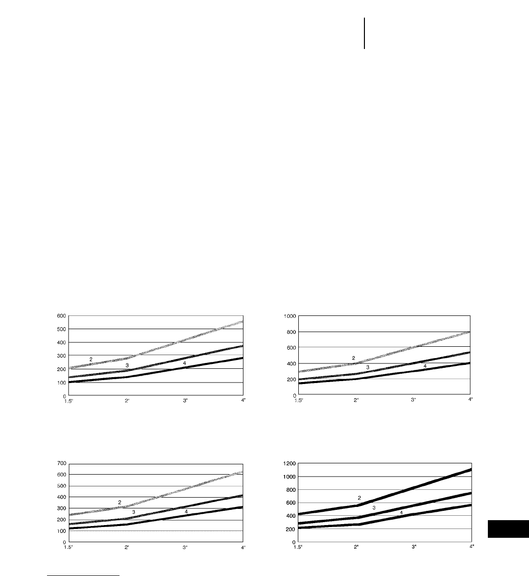
16-33
16
Dual Drum Vibratory
Asphalt Compactors
Figuring Asphalt Compaction
ASPHALT COMPACTION PRODUCTION RATES
Formula for Compacted Cubic Yards (yd3) Per Hour:
W 3S 3 L3 16.3 3 .83 =yd
3/hr
_______________________
P
W = Effective width of compaction per pass in feet
(See NOTE below)
S = Average speed in MPH
L = Compacted Lift in Inches
16.3 = Constant
0.83 = Efficiency Rate (50 minute hour)
P = Number of passes required to achieve
compaction
NOTE: In calculating the effective width of the
compactor, the width of the laydown lane
in relation to the roller width must be taken
into consideration.
Example: A CB-634C with a 2130 mm (84 in) drum
width takes two roller widths to cover a 3658 mm
(12 ft) lane, therefore the effective rolling width is
1829 mm (6 ft). A CB-534C with a 1702 mm (67 in)
drum width requires 3 passes to cover the 3658 mm
(12 ft) lane, so effective rolling width is 1219 mm
(4 ft). The CB-434C, with 1422 mm (56 in) drum
width, requires three passes to cover the 3658 mm
(12 ft) lane, so also has an effective rolling width of
1219 mm (4 ft) per pass.
Actual production rate will vary depending on many
variables including the following:
Asphalt mix
Temperature of mix
Ambient temperature
Lift thickness
Percent of density required
Operator technique
CB-224C
Capacity On Asphalt @ 3 MPH
Tons/Hr
Lift Thickness
CB-434B/CB-434C
Capacity On Asphalt @ 3 MPH
Tons/Hr
Lift Thickness
CB-534B/CB-534C/CB-544
Capacity On Asphalt @ 3 MPH
Tons/Hr
Lift Thickness
CB-634C
Capacity On Asphalt @ 3 MPH
Tons/Hr
Lift Thickness
KEY
2 — Two Passes
3 — Three Passes
4 — Four Passes
Combination Vibratory
Asphalt Compactors
16-34
Features and Specifications
Features:
●Direct hydrostatic drive to front drum and rear
tires, provides dependable, responsive propulsion
effort and maximum gradeability.
●Vibration stops when machine stops to help
produce a smooth flawless mat surface.
●Maximum Visibility Multiple Position sliding
console for visibility to front and rear of machine
as well as drum edges.
●Large rust-proof water tanks and pressure
spray system provides hours of reliable operation
between fill ups.
●Equal spacing between tires. The middle rear
tire on the CB-535B is mounted on a hydraulic
cylinder for equal weight per wheel and avoids
bridging low spots.
●ROPS Cab or ROPS Canopy available as an
option.
●Operator comfort is provided by adjustable
bucket seat. Machine controls and instruments
move with the operator to one of four operating
positions allowing easy access.
MODEL CB-535B** CB-545**
Flywheel Power 80 kW 107 hp 60 kW 80 hp
Rated Engine RPM 2200 2200
No. Cylinders 44
Displacement 4 L 243 in34 L 243 in3
Engine Model 3054 DIT 3054 DINA
Speeds:
Forward 32
Reverse 32
Max. Speed (For./Rev.) 12.7 km/h 7.9 mph 12.4 km/h 7.7 mph
Operating Weight 13 400 kg 29,547 lb 9410 kg 20,750 lb
Shipping Weight 13 035 kg 28,742 lb 8910 kg 19,645 lb
Drive Hydraulic Hydraulic
Gradeability ±35° ±35°
Position(s) 44
Steering:
Inside radius 4350 mm 14'3" 3005 mm 9'10"
Outside radius 6335 mm 20'9" 4837 mm 15"10"
Steering angle ±35° ±25°
Vibratory System:
Ecc. Weight Drive Hydraulic Hydraulic
Frequency 42 Hz 2520 vpm 42/50 Hz 2520/3000 vpm
Amplitude Settings 0.36/0.80/1.05 mm 0.33/0.58 mm
Centrifugal Force per drum/Drum (Max.) 118 kN 26,550 lb 80.54 kN 17,757 lb
Tires 15.00R* 13/80-20*
Weight per wheel 3000 kg 6615 lb 1100 kg 3991 lb
General Dimensions:
Overall width 1850 mm 6'1" 1810 mm 5'11"
Drum width 1700 mm 5'7" 1700 mm 5'7"
Drum diameter 1300 mm 4'3" 1200 mm 3'11"
Tire width 315 mm
Overall height (w/ROPS) 3000 mm 9'10" 3000 mm 9'10"
Wheelbase 3516 mm 11'6" 3000 mm 9'10"
Overall length 5300 mm 17'5" 4200 mm 13'9"
Curb clearance 416 mm 16" 855 mm 2'10"
Service Refill Capacities:
Fuel tank 208 L 55 U.S. gal 208 L 55 U.S. gal
Hydraulic fluid 55 L 14.5 U.S. gal 55 L 14.5 U.S. gal
Emulsion 130 L 34.3 U.S. gal 380 L 100 U.S. gal
Sprinkler water 440 L 116 U.S. gal 460 L 122 U.S. gal
**Optional treaded tires available.
**Not available in North America.

Features:
●Designed for high density compaction of any
hot or cold mix or surface seal applications.
●Tire positions overlap to provide full width com-
paction in a single pass.
●All wheel oscillation. Front and rear seek out
low spots and provide even wheel loads.
●High drive propel system: Completely hydro-
static with drive motors and brakes located in main-
frame away from contamination and damage.
●Hydraulic full-power steering makes for effort-
less steering.
●Ballast compartments are easily accessible for
quick loading and are located to provide a bal-
anced wheel/weight ratio. Large side covers pro-
vide for fast, convenient unloading.
MODEL PS-150B
Flywheel Power 60 kW 80 hp
Rated Engine RPM 2300
No. Cylinders 4
Displacement 3.9 L 243 in3
Engine Model 3054
Speeds:
Forward 2
Reverse 2
Max. Speed (For./Rev.) 25.6 km/h 15.9 mph
Wheel Configuration 5 front/6 rear
Tires 7.5" 315" 6 ply
Operating Weight Empty
(no ballast) 4885 kg 10,775 lb
Operating Weight Full
(max. ballast) 12 940 kg 28,535 lb
Maximum Weight
per Wheel 1438 kg 3173 lb
Steering:
Inside radius 4846 mm 15'3"
Outside radius 6375 mm 20'11"
General Dimensions:
Overall width 1750 mm 5'9"
Rolling width 1727 mm 5'8"
Overall height 3000 mm 9'10"
Wheelbase 3352 mm 11'0"
Overall length 4299 mm 14'1"
Ground clearance 267mm 10.5"
Service Refill Capacities:
Fuel tank 173 L 45.7 U.S. gal
Crankcase 7.3 L 1.9 U.S. gal
Sprinkler water 394 L 104 U.S. gal
16-35
16
Pneumatic Tire Asphalt
Compactors
Features and Specifications
MODEL PS-200B PS-360B
Flywheel Power 80 kW 107 hp 77.5 kW 104 hp
Rated Engine RPM 2200 2200
No. Cylinders 44
Displacement 3.9 L 243 in33.9 L 243 in3
Engine Model 3054T 3054T
Speeds:
Forward 22
Reverse 22
Max. Speed (For./Rev.) 19.3 km/h 12 mph 18 km/h 11.2 mph
Wheel Configuration 5 front/4 rear 3 front/4 rear
Tires 7.5" 315" 6 ply 14/70 320
Operating Weight Empty (no ballast) 4133 kg 9110 lb 8500 kg 18,740 lb
Operating Weight Full (max. ballast) 18 145 kg 40,000 lb 25 000 kg 55,115 lb
Maximum Weight per Wheel 2016 kg 4444 lb 3570 kg 7870 lb
Steering:
Inside radius 4648 mm 15'3" 3470 mm 11'5"
Outside radius 6375 mm 20'11" 6700 mm 22'0"
General Dimensions:
Overall width 1750 mm 5'9" 2150 mm 7'1"
Rolling width 1727 mm 5'8" 2275 mm 7'6"
Overall height 3000 mm 9'10" 2530 mm 8'4"
Wheelbase 3352 mm 11'0" 3650 mm 12'0"
Overall length 4299 mm 14'1" 4850 mm 15'11"
Ground Clearance 267 mm 10.5" 252 mm 10"
Service Refill Capacities:
Fuel tank 173 L 45.7 U.S. gal 200 L 53 U.S. gal
Crankcase 7.3 L 1.9 U.S. gal 7.3 L 1.9 U.S. gal
Sprinkler water 394 L 104 U.S. gal 394 L 104 U.S. gal
16-36
SpecificationsPneumatic Tire Asphalt
Compactors
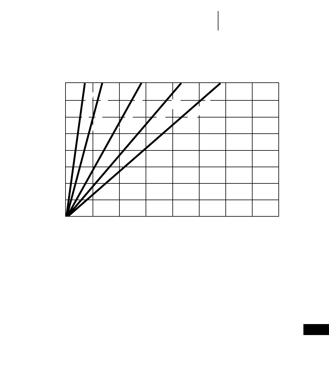
16-37
16
Pneumatic Tire Asphalt
Compactors
Production Rates
●PS-150B ●PS-200B
0
0
760
1000
1520
2000
2280
3000
3040
4000
3800
5000
4560
6000
5320
7000
6080
8000
0.0
25.4
50.8
76.2
101.6
127.0
152.4
177.8
203.2
0.00
1.00
2.00
3.00
4.00
5.00
6.00
7.00
8.00
3.2 km/h (2 mph)
1.6 km/h (1 mph)
6.4 km/h (4 mph)
9.7 km/h (6 mph)
12.9 km/h (8 mph)
LIFT
THICKNESS
in mm
m3(yd3) per hour per pass
Production Rate [m3(yd3)] = m3(yd3)/hr per pass
__________________
No. of passes required
m3
yd3
Features:
●Designed for high density compaction of any
hot or cold mix or surface seal applications.
●Tire positions overlap to provide full width com-
paction in a single pass.
●Wheel suspension helps eliminate bridging of
low spots and helps provide equal load under each
wheel. PS models have suspension front and rear.
PF models have rear suspension only.
●Single-lever fingertips control of forward and
reverse movement makes smooth shuttle rolling
easy.
●Heavy-duty 3-speed powershift transmission
allows infinitely variable travel speeds up to
26.5 km/h (16.5 mph), forward or reverse.
●Hydraulic full-power steering makes for effort-
less steering. Steer wheels swivel individually
preventing scuffing of material during turns, sim-
ilar to automotive style steering.
●Ballast compartments are easily accessible
for quick loading and are located to provide a
balanced wheel/weight ratio.
●Electric pump water spray system with cleaner
mats on all wheels keep tires clean and resis-
tant to pick-up during compaction.
●Optional on-the-run tire inflation device, engine
cooled for long life.
MODEL PF-300B/PS-300B
Flywheel Power 80 kW 107 hp
Rated Engine RPM 2200
No. Cylinders
Displacement 4 L 243 in3
Engine Model 3054 DIT
Speeds:
Forward 3
Reverse 3
Max. Speed 20 km/h 12.4 mph
Wheel Configuration 3 front/4 rear
Tires 13/80-20*
Operating Weight Empty
(no ballast) 14 000 kg 30,870 lb
Operating Weight Full
(max. ballast)** 23 300 kg 51,380 lb
Maximum Weight
per Wheel** 3300 kg 7280 lb
Shipping weight 14 000 kg 30,870 lb
Drive Mechanical
Gradeability ±45°
Operator positions 4
Steering:
Inside radius 4800 mm 15'9"
Outside radius 7700 mm 25'3"
General Dimensions:
Overall width 2000 mm 6'7"
Rolling width 1900 mm 6'3"
Tire width 315 mm 12"
Tire overlap 48 mm 1.9"
Overall height w/ROPS 3000 mm 9'10"
Wheelbase 4030 mm 13'3"
Overall length 5300 mm 17'5"
Ground clearance 250 mm 9.8"
Service Refill Capacities:
Fuel tank 215 L 56.8 U.S. gal
Crankcase 7 L 1.8 U.S. gal
Cooling system 28 L 7.4 U.S. gal
Differential 7 L 1.8 U.S. gal
Transmission 22 L 5.8 U. S. gal
Hydraulic fluid 10 L 2.6 U.S. gal
Sprinkler water 460 L 121 U.S. gal
**Optional treaded tires available.
**Includes added weight option.
16-38
Features and SpecificationsPneumatic Tire Asphalt
Compactors
16-39
16
Pneumatic Tire Asphalt
Compactors
Specifications
MODEL PS-500*
Flywheel Power 112 kW 150 hp
Rated Engine RPM 2300
No. Cylinders 8
Displacement 10.4 L 636 in3
Engine Model 3208
Speeds:
Forward 3
Reverse 3
Max. Speed 26.5 km/h 16.5 mph
Wheel Configuration 3 front/4 rear
Tires 15.00 R 24
Operating Weight Empty (no ballast) 19 000 kg 41,875 lb
Operating Weight Full (max. ballast) 35 000 kg 77,140 lb
Maximum Weight per Wheel 5000 kg 11,020 lb
Steering:
Inside radius 5150 mm 16'11"
Outside radius 8550 mm 28'1"
General Dimensions:
Overall width 2500 mm 8'2"
Rolling width 2420 mm 7'11"
Overall height w/ROPS 3630 mm 11'11"
Wheelbase 4465 mm 14'8"
Overall length 6270 mm 20'7"
Ground clearance 360 mm 14.2"
Service Refill Capacities:
Fuel tank 310 L 82 U.S. gal
Crankcase 12.5 L 3.3 U.S. gal
Sprinkler water 350 L 92 U.S. gal
*Not available in the United States.

The following table gives, as a guide, the utiliza-
tion possibilities of the equipment on different types
of materials. The symbols and values given corre-
spond to the following cases: ●equipment well suited
to this utilization — current utilization: 0.30/0.80
the top figure indicates the minimum rational thick-
ness in metres; the bottom figure indicates the
thickness capable of yielding a maximum output —
¶ possible but not current utilization.
Roadworks
Surface dressing ●
wearing course
(bituminous mixes) ≥0.03
base course 0.10
0.30
sub-base 0.10
0.40
sub-grade ●
Earthworks: coarse grained soils
rock
D > 250 mm
shot rock
D ≤250 mm
well graded gravel 0.10
GW 0.30
poorly grade gravel
GP ¶
silty gravel 0.10
GF 0.40
clayey gravel 0.15
GC 0.30
well graded sand 0.10
SW 0.40
poorly graded sand
SP ¶
silty sand 0.10
SF 0.40
clayey sand 0.10
SC 0.30
Earthworks: fine grained soils
low plasticity silt
ML ¶
low plasticity clay
CL ¶
high plasticity silt
MH
high plasticity clay
CH
lime stabilized fine soils 0.15
0.30
limestone 0.10
0.30
16-40
Utilization
●PS-300B ●PF-300B
Pneumatic Tire Asphalt
Compactors
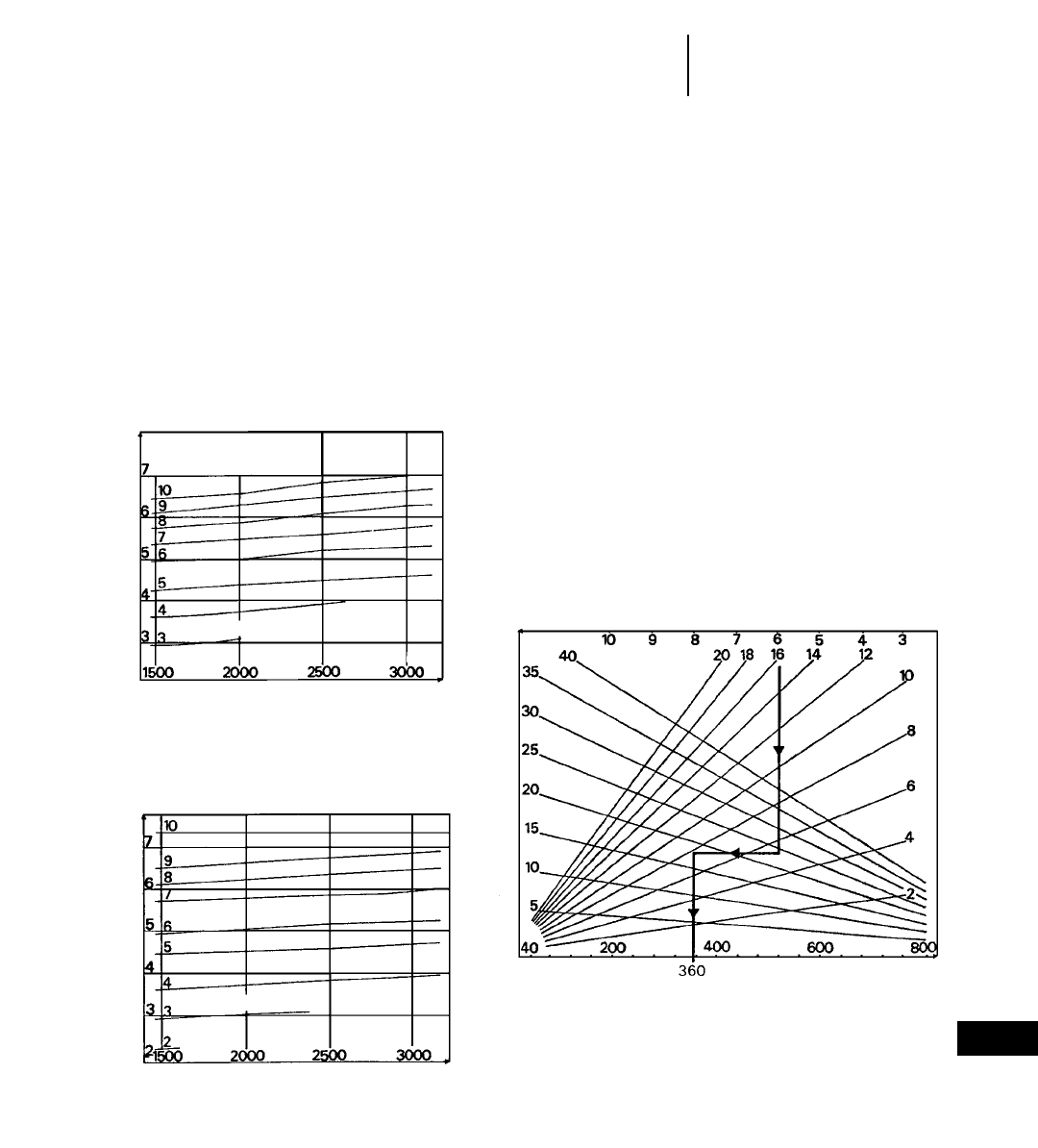
Nomograms of Ground Pressure
These nomograms make it possible to determine
the pressure exerted on the ground under a wheel as
a function of its load and of the tire inflation pressure.
Ground pressure values are theoretical because
they result from prints obtained on an indeformable
ground.
Nomogram of hourly output
The gross hourly output of the equipment is given
by the formula: Q (m3/h) = V.H.L./N where V is the
working speed in metres/hour; H is the thickness of
the compacted layer in metres; L is the compacted
width in metres; N is the number of passes.
The facing nomogram makes it possible to deter-
mine the gross hourly output of the equipment with-
out calculation: on the basis of the chosen working
speed, draw a vertical line; where it intersects with
the “layer thickness” line selected, draw a horizon-
tal line; where this horizontal intersects with the
“number of passes” line adopted, draw a vertical which
gives directly the value of the gross hourly output in m3/h.
The net output is obtained by multiplying the gross
value by a coefficient depending on jobsite conditions:
— easy: 0.8 — normal: 0.7 — difficult: 0.6
16-41
16
Pneumatic Tire Asphalt
Compactors
Utilization
●PS-300B ●PF-300B
*1 bar = 1.02 kgf/cm2
treadless tires
E 20 Pilote X (13/80-20) Michelin
treaded tires
F 20 Pilote XZZ (14/80-20) Michelin
ground pressure (bars)*
ground pressure (bars)*
lift thickness (cm)
load per wheel (kg)
load per wheel (kg)
inflation pressure (bars)*
gross hourly output (m3/h)
speed (km/h)
number of passes
inflation pressure (bars)*

The following table gives, as a guide, the utiliza-
tion possibilities of the equipment on different types
of materials. The symbols and values given corre-
spond to the following cases: ●equipment well suited
to this utilization — current utilization: 0.30/0.80
the top figure indicates the minimum rational thick-
ness in metres; the bottom figure indicates the
thickness capable of yielding a maximum output —
¶ possible but not current utilization.
Roadworks
Surface dressing ¶
wearing course
(bituminous mixes) ≥0.05
base course 0.15
0.40
sub-base 0.15
0.40
sub-grade ●
Earthworks: coarse grained soils
rock
D > 250 mm
shot rock
D ≤250 mm ¶
well graded gravel 0.15
GW 0.60
poorly graded gravel 0.20
GP 0.50
silty gravel 0.15
GF 0.60
clayey gravel 0.20
GC 0.50
well graded sand 0.15
SW 0.60
poorly graded sand 0.20
SP 0.50
silty sand 0.15
SF 0.60
clayey sand 0.15
SC 0.50
Earthworks: fine grained soils
low plasticity silt 0.20
ML 0.70
low plasticity clay 0.20
CL 0.50
high plasticity silt 0.15
MH 0.30
high plasticity clay 0.15
CH 0.30
lime stabilized fine soils 0.20
0.40
limestone 0.15
0.40
16-42
Utilization
●PS-500
Pneumatic Tire Asphalt
Compactors
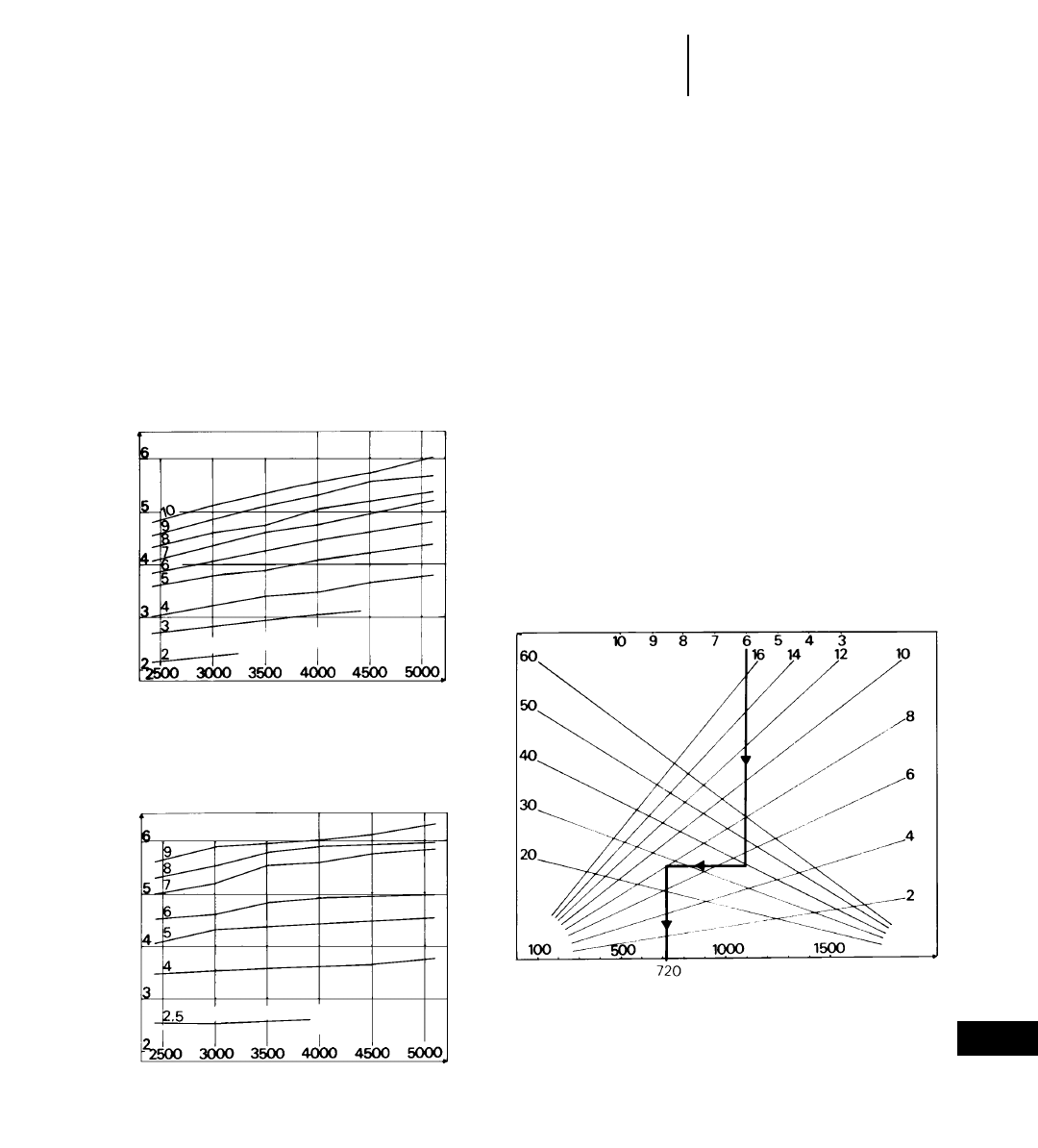
16-43
16
Nomograms of Ground Pressure
These nomograms make it possible to determine
the pressure exerted on the ground under a wheel as
a function of its load and of the tire inflation pressure.
Ground pressure values are theoretical because
they result from prints obtained on an indeformable
ground.
Nomogram of hourly output
The gross hourly output of the equipment is given
by the formula: Q (m3/h) = V.H.L./N where V is the
working speed in metres/hour; H is the thickness of
the compacted layer in metres; L is the compacted
width in metres; N is the number of passes.
The facing nomogram makes it possible to deter-
mine the gross hourly output of the equipment with-
out calculation: on the basis of the chosen working
speed, draw a vertical line; where it intersects with
the “layer thickness” line selected, draw a horizon-
tal line; where this horizontal intersects with the
“number of passes” line adopted, draw a vertical which
gives directly the value of the gross hourly output in m3/h.
The net output is obtained by multiplying the gross
value by a coefficient depending on jobsite conditions:
— easy: 0.8 — normal: 0.7 — difficult: 0.6
Pneumatic Tire Asphalt
Compactors
Utilization
●PS-500
*1 bar = 1.02 kgf/cm2
treadless tires
15.00-24 X (17/80-24) Michelin
treaded tires
16.00-20 XS Michelin
ground pressure (bars)*
ground pressure (bars)*
lift thickness (cm)
load per wheel (kg)
load per wheel (kg)
inflation pressure (bars)*
gross hourly output (m3/h)
speed (km/h)
number of passes
inflation pressure (bars)*

17-1
CONTENTS
Features . . . . . . . . . . . . . . . . . . . . . . . . . . . . . .17-1
Load-Haul-Dumps (LHDs):
Specifications . . . . . . . . . . . . . . . . . . . . . . . . .17-2
Dimensions and capacities . . . . . . . . . . . . . .17-4
Bucket selection . . . . . . . . . . . . . . . . . . . . . .17-5
Turning dimensions . . . . . . . . . . . . . . . . . . .17-5
Trucks:
Articulated specifications . . . . . . . . . . . . . . .17-6
Rigid frame specifications . . . . . . . . . . . . . . .17-7
Dimensions and capacities . . . . . . . . . . . . . .17-8
LHD and Truck Systems . . . . . . . . . . . . . . . . .17-9
Elphinstone machines:
●Produced by a joint venture company of Caterpillar
Inc. and Dale B. Elphinstone Pty Ltd.
●Manufactured in Burnie, Tasmania (Australia).
●Supported by the worldwide Caterpillar parts and
dealer network.
Features, all models:
●Rugged design for underground application.
●Caterpillar diesel engines and power trains.
●High proportion of Caterpillar parts.
●Extensive use of steel castings and forgings.
●Engineered for productivity, reliability, safety, and
machine rebuildability.
●Remote control options on loaders.
Elphinstone product line:
●Four models of Load-Haul-Dump (LHD) ma-
chines, with rated bucket payloads ranging from
6.5-17 tonnes (17 to 19 tons).
●Dump and ejector versions of an articulated truck,
with payload capacities of 40-44 tonnes (44-48 tons).
●Three models of rigid frame trucks; dump versions
with 38 tonne (42 tons) and 52 tonne (58 tons)
payload capacity; ejector version with 36 tonne
(40 tons) capacity.
17
ELPHINSTONE UNDERGROUND MACHINES
Loaders and Haulers for Hard Rock Mining
MODEL R1300 R1600
Bucket Size Minimum 2.4 m33 yd34.2 m35 yd3
Bucket Size Maximum 3.4 m34 yd35.9 m38 yd3
Tramming Capacity 6500 kg 14,330 lb 10 200 kg 22,490 lb
Length 8650 mm 28'5" 9710 mm 31'10"
Width Bucket 2000 mm 6'7" 2600 mm 8'6"
Width over Tires 1900 mm 6'3" 2400 mm 7'10"
Height 2000 mm 6'7" 2400 mm 7'10"
Operating Weight 19 000 kg 41,900 lb 29 800 kg 65,710 lb
Engine Power 123 kw 165 hp 201 kW 270 hp
Engine Model Cat 3306 DITA Cat 3176C ATAAC
Tire Size 17.5x25 20 Ply L5 STMS 18x25 28 Ply STMS
Outer Turning Radius 5575 mm 18'3" 6540 mm 21'5"
Inner Turning Radius 2972 mm 9'9" 3305 mm 10'10"
Articulation Angle 42.5° 42.5°
Oscillation Angle ±10° ±10°
Bucket Raise Time 5 7.6
Bucket Lower Time 2.3 1.6
Bucket Tip Time 22
Bucket Total Time 9.3 11.2
Travel Speeds km/h mph km/h mph
Forward 1 4.2 2.6 5.5 3.4
Forward 2 7.6 4.7 9.8 6.1
Forward 3 13.8 8.6 17.5 10.9
Forward 4 24.1 15 30.6 19
Reverse 1 3.7 2.3 6.2 3.9
Forward 2 6.8 4.2 11.2 7
Forward 3 12.4 7.7 19.8 12.3
Forward 4 21.7 13.5 34 21.1
Maximum Bucket Pin Height 2900 mm 9'6" 3752 mm 12'4"
Maximum Bucket Dump Angle 43° 45°
Break Out Force Tilt SAE 12 020 kg 26,500 lb 19 500 kg 43,000 lb
Static Tipping (Tramming) 22 615 kg 49,870 lb 33 350 kg 73,540 lb
Emergency Brake S.A.F.R. Inboard Spring Applied S.A.F.R. Inboard Spring Applied
Fluid Released, Enclosed Wet Disc @ Fluid Released, Enclosed Wet Disc @
All Wheels, Front and Rear Circuits All Wheels, Front and Rear Circuits
Service Brake Hydraulically Applied Spring Released, Fluid Applied Spring Released,
Enclosed Wet Disc @ All Wheels, Wet Disc
Front and Rear Circuits
Park Brake S.A.F.R. Inboard Spring Applied S.A.F.R. Inboard Spring Applied
Fluid Released, Enclosed Wet Disc @ Fluid Released, Enclosed Wet Disc @
All Wheels, Front and Rear Circuits All Wheels, Front and Rear Circuits
Fuel Capacity 260 L 69 U.S. gal 400 L 106 U.S. gal
17-2
Underground
Mining Load-Haul-Dump
•Specifications
17-3
17
Underground
Mining
Load-Haul-Dump
•Specifications
MODEL R1700 Series II R2900
Bucket Size Minimum 4.6 m36 yd36.4 m38 yd3
Bucket Size Maximum 6.7 m39 yd311.5 m315 yd3
Tramming Capacity 12 000 kg 26,460 lb 17 200 kg 37,930 lb
Length 10 417 mm 34'2" 10 970 mm 36'0"
Width Bucket 2818 mm 9'3" 3100 mm 10'2"
Width over Tires 2550 mm 8'4" 2900 mm 9'6"
Height 2630 mm 8'8" 2888 mm 9'6"
Operating Weight 36 000 kg 79,380 lb 46 500 kg 102,530 lb
Engine Power 231 kW 310 hp 269 kW 361 hp
Engine Model Cat 3176B ATAAC Cat 3406E ATAAC
Tire Size 26.5x25 32 Ply L5 STMS 29.5x29 34 Ply STMS
Outer Turning Radius 6755 mm 22'2" 7310 mm 24'0"
Inner Turning Radius 3165 mm 10'5" 3410 mm 11'2"
Articulation Angle 45° 42.5°
Oscillation Angle ±8° ±8°
Bucket Raise Time 6.7 6.7
Bucket Lower Time 2.4 2.4
Bucket Tip Time 2.8 2.8
Bucket Total Time 11.9 11.9
Travel Speeds km/h mph km/h mph
Forward 1 5.1 3.2 5.1 3.2
Forward 295.6 9.2 5.7
Forward 3 18.6 11.6 15.7 9.8
Forward 4 26.8 16.6 26.7 16.6
Reverse 1 5.8 3.6 6.4 4
Forward 2 10.3 6.4 11.2 7
Forward 3 17.9 11.1 19.3 12
Forward 4 30.6 19 32.5 20.2
Maximum Bucket Pin Height 4098 mm 13'5" 4540 mm 14'11"
Maximum Bucket Dump Angle 46° 46°
Break Out Force Tilt SAE 23 430 kg 51,660 lb 28 600 kg 63,060 lb
Static Tipping (Tramming) 31 900 kg 70,340 lb 39 690 kg 87,520 lb
Emergency Brake Combined Driveline Spring Applied Fluid Released,
and Service Brakes Wet Discs All Wheel Ends
Service Brake Fluid Applied Spring Released, Fluid Applied Wet
Wet Disc All Wheels Discs All Wheel Ends
Park Brake Spring Applied Hydraulic Spring Applied Fluid Released,
Released on Driveline Wet Discs All Wheel Ends
Fuel Capacity 520 L 137 U.S. gal 900 L 238 U.S. gal
Load Clearance — —2955 mm 9'8"

17-4
Underground
Mining Load-Haul-Dump
•Dimensions and Capacities
Model R1300 R1600 R1700 Series II R2900
Rated payload 6500 kg 14,330 lb 10 200 kg 22,490 lb 12 000 kg 26,460 lb 17 200 kg 37,930 lb
Bucket capacity 3.4 m34.4 yd35.9 m37.7 yd36.7 m38.8 yd311.5 m315 yd3
Overall width 2000 mm 6'7" 2600 mm 8'6" 2818 mm 9'3" 3100 mm 10'2"
Overall height 2000 mm 6'7" 2400 mm 7'10" 2630 mm 8'8" 2888 mm 8'6"
Length (tramming) 8650 mm 28'5" 9710 mm 31'10" 10 417 mm 34'2" 10 970 mm 36'0"
Empty weight 19 000 kg 41,900 lb 29 800 kg 65,710 lb 36 000 kg 79,380 lb 46 500 kg 102,530 lb
Loaded weight 25 500 kg 56,230 lb 40 000 kg 88,200 lb 48 000 kg 105,840 lb 63 700 kg 140,460 lb
Ground clearance 320 mm 12.6" 342 mm 13.5" 400 mm 15.7" 500 mm 19.7"
Axle oscillation ±10° ±10° ±8° ±8°
Model Bucket Type SAE Capacity
m3yd3
R1300 Standard 2.4 3.1
Standard 2.8 3.7
Standard 3.4 4.4
High penetration 2.4 3.1
High penetration 2.8 3.7
High penetration 3.4 4.4
Ejector 2.5 3.3
R1600 Standard 4.2 5.5
Standard 4.8 6.3
Standard 5.9 7.7
High penetration 4.2 5.5
High penetration 4.8 6.3
High penetration 5.9 7.7
Ejector 4.5 5.9
R1700 Series II Standard 4.6 6.0
Standard 5.0 6.5
Standard 5.8 7.6
Standard 6.7 8.8
High penetration 5.0 6.5
High penetration 5.8 7.6
High penetration 6.7 8.8
R2900 Standard 6.4 8.4
Standard 7.3 9.5
Standard 8.8 11.5
Standard 11.5 15.0
High penetration 6.4 8.4
High penetration 7.3 9.5
High penetration 8.8 11.5
High penetration 11.5 15.0
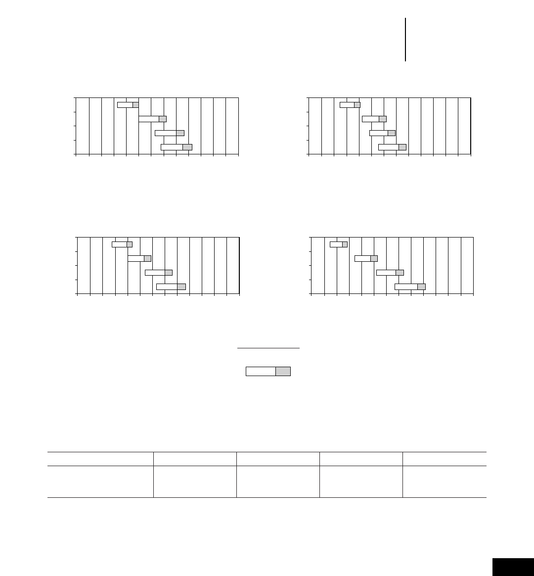
17-5
17
Underground
Mining
Load-Haul-Dump
•Bucket Selection
•Turning Dimensions
3.4
2.8
2.5
2.4
4.4
3.7
3.3
3.1
1000 1200 1400 1600 1800 2000 2200 2400 2600 2800 3000 3200 3400 3600
2200 2650 3090 3530 3970 4410 4850 5290 5730 6170 6610 7050 7500 7950
R1300
yd3
kg/m3
lb/yd3
m3
Bucket Capacity
Material Density
5.9
4.8
4.5
4.2
7.7
6.3
5.9
5.5
1000 1200 1400 1600 1800 2000 2200 2400 2600 2800 3000 3200 3600
2200 2650 3090 3530 3970 4410 4850 5290 5730 6170 6610 7050
3400
7500 7950
R1600
yd3
kg/m3
lb/yd3
m3
Bucket Capacity
Material Density
6.7
5.8
5.0
4.6
8.8
7.6
6.5
6.0
1000 1200 1400 1600 1800 2000 2200 2400 2600 2800 3000 3200 3600
2200 2650 3090 3530 3970 4410 4850 5290 5730 6170 6610 7050
3400
7500 7950
R1700 Series II
yd3
kg/m3
lb/yd3
m3
Bucket Capacity
Material Density
11.5
8.8
7.3
6.4
15.0
11.5
9.5
8.4
1000 1200 1400 1600 1800 2000 2200 2400 2600 2800 3000 3200 3600
2200 2650 3090 3530 3970 4410 4850 5290 5730 6170 6610 7050
3400
7500 7950
R2900
yd3
kg/m3
lb/yd3
m3
Bucket Capacity
Material Density
KEY
Bucket Fill Factor
115% 100% 95%
Turning Dimensions
Model R1300 R1600 R1700 Series II R2900
Turn radius (outside) 5575 mm 18'4" 6540 mm 21'5" 6755 mm 22'2" 7310 mm 24'0"
Turn radius (inside) 2972 mm 9'9" 3305 mm 10'10" 3165 mm 10'5" 3410 mm 11'2"
Articulation angle ±42.5° ±42.5° ±45° ±42.5°
17-6
Underground
Mining Articulated Trucks
•Specifications
MODEL AD40 Series II AE40 Series II
Engine Power 365 kW 489 hp 365 kW 489 hp
Engine Model 3408E HEUI 3408E HEUI
Tare Weight 38 100 kg 84,000 lbs 41 800 kg 92,170 lbs
Max. Capacity Tonnes 44 t 48 T 40 t 44 T
Capacity M3 (SAE) 2:1 Heaped 18.4 m324 yd318.4 m324 yd3
Distribution Loaded Front 48% 47%
Distribution Loaded Rear 52% 53%
Turning Radius 9228 mm 30'3" 9589 mm 31'6"
Height 2700 mm 8'10" 2890 mm 9'6"
Length 10 660 mm 35'0" 11 266 mm 37'0"
Loading Height 2660 mm 8'9" 2700 mm 8'10"
Width 3000 mm 9'10" 3200 mm 10'5"
Oscillation 12° 12°
Articulation 42.5° 42.5°
Tray Height Raised 5946 mm 19'6" N/A
Dump Time Sec 10 15
Travel Speeds km/h mph km/h mph
Forward 1 7.7 4.8 7.7 4.8
Forward 2 10.6 6.6 10.6 6.6
Forward 3 14.5 914.5 9
Forward 4 19.3 12 19.3 12
Forward 5 26.2 16.3 26.2 16.3
Forward 6 35.4 22 35.4 22
Forward 7 48.1 29.9 48.1 29.9
Forward 8 ————
Reverse 1 7.7 4.8 7.7 4.8
Reverse 2 10.6 6.6 10.6 6.6
Tire Size 29.5x29 2** Radials 29.5x29 2** Radials
Emergency Brake Spring Applied Hyd. Spring Applied Hyd.
Released All Wheels Released All Wheels
Service Brake Caterpillar Oil Cooled Hyd. Caterpillar Oil Cooled Hyd.
Applied Wet Disc All Applied Wet Disc All
Wheels Wheels
Park Brake Spring Applied Spring Applied
Hyd. Released Hyd. Released
All Wheels All Wheels
Fuel Capacity 520 L 137 U.S. gal 520 L 137 U.S. gal
17-7
17
Underground
Mining
Rigid Frame Trucks
•Specifications
MODEL 69D Dump 69D Ejector 73D
Engine Power 380 kW 510 hp 380 kW 510 hp 509 kW 683 hp
Engine Model 3408E HEUI 3408E HEUI 3412E HEUI
Tare Weight 30 100 kg 66,370 lbs 34 700 kg 78,500 lbs 40 300 kg 88,860 lbs
Max. Capacity Tonnes 38 t 42 T 36.2 t 40 T 52.2 t 58 T
Capacity M3 (SAE) 2:1 Heaped 18.3 m324 yd318.2 m324 yd331.9 m342 yd3
Distribution Loaded Front 33% 31% 33%
Distribution Loaded Rear 67% 69% 67%
Turning Radius 9616 mm 31'7" 9616 mm 31'7" 10 820 mm 35'6"
Height 3442 mm 11'4" 3442 mm 11'4" 3770 mm 12'4"
Length 8127 mm 26'8" 7830 mm 25'8" 9230 mm 30'3"
Loading Height 3058 mm 10'0" 3160 mm 10'4" 3400 mm 11'2"
Width 3665 mm 12'0" 3665 mm 12'0" 4200 mm 13'9"
Oscillation N/A N/A N/A
Articulation N/A N/A N/A
Tray Height Raised 5735 mm 18'10" N/A 6635 mm 21'9"
Dump Time Sec 9 16 11.4
Travel Speeds km/h mph km/h mph km/h mph
Forward 1 12.4 7.7 12.4 7.7 9.2 5.7
Forward 2 16.9 10.5 16.9 10.5 12.7 7.9
Forward 32314.3 23 14.3 17.2 10.7
Forward 4 30.9 19.2 30.9 19.2 23.2 14.4
Forward 5 41.2 25.6 41.2 25.6 31.4 19.5
Forward 6 54.2 33.7 54.2 33.7 42.3 26.3
Forward 7 76.6 47.6 76.6 47.6 57.3 35.6
Forward 8 ——————
Reverse 1 13.5 8.4 13.5 8.4 11.3 7
Reverse 2N/A N/A N/A
Tire Size 18x33 2** Radials 18x33 2** Radials 21x35 2** Radials
Emergency Brake Caterpillar Oil Cooled Hyd. Caterpillar Oil Cooled Hyd. Caterpillar Oil Cooled Hyd.
Applied Wet Discs on Rear Applied Wet Discs on Rear Applied Wet Discs on Rear
Dry Disc on Front Dry Disc on Front Dry Disc on Front
Service Brake Caterpillar Oil Cooled Hyd. Caterpillar Oil Cooled Hyd. Caterpillar Oil Cooled Hyd.
Applied Wet Disc on Rear Applied Wet Disc on Rear Applied Wet Disc on Rear
Dry Disc on Front Dry Disc on Front Dry Disc on Front
Park Brake Spring Applied Spring Applied Spring Applied
Hyd. Released Hyd. Released Hyd. Released
All Wheels All Wheels All Wheels
Fuel Capacity 530 L 140 U.S. gal 530 L 140 U.S. gal 700 L 185 U.S. gal
17-8
Articulated Trucks
Model AD40 Series II AE40 Series II
Heaped capacity* 18.4 m324.1 yd318.4 m324.1 yd3
Overall width 3000 mm 9'10" 3200 mm 10'6"
Overall height 2700 mm 8'10" 2890 mm 9'6"
Overall length 10 660 mm 35'0" 11 265 mm 36'11"
Empty weight 38 100 kg 84,010 lb 41 800 kg 92,170 lb
Loaded weight 78 100 kg 172,210 lb 81 800 kg 180,370 lb
Ground clearance 452 mm 17.8" 452 mm 17.8"
Frame oscillation ±12° ±12°
*2:1 per SAE.
Rigid Frame Trucks
Model 69D Dump 69D Ejector 73D
Max. capacity 38 t 41.9 T 36.2 t 39.9 T 52.2 t 57.5 T
Heaped capacity 18.3 m323.9 yd318.2 m323.8 yd331.9 m341.7 yd3
Height (FOPS) 3442 mm 11'4" 3442 mm 11'4" 3770 mm 12'4"
Length 8127 mm 26'8" 7830 mm 25'8" 9230 mm 30'3"
Width 3665 mm 12'0" 3665 mm 12'0" 4200 mm 13'9"
Loading height (empty) 3058 mm 10'0" 3160 mm 10'4" 3400 mm 11'2"
Body Selection
Model SAE Body Capacity
AD40 Series II 18.4 m324.1 yd3
21.3 m327.9 yd3
25.5 m333.4 yd3
AE40 Series II 18.4 m324.1 yd3
17.7 m323.2 yd3
20.8 m327.2 yd3
69D Dump 18.3 m323.9 yd3
22.7 m329.7 yd3
24.9 m332.6 yd3
69D Ejector 18.2 m323.8 yd3
73D 31.9 m341.7 yd3
24.0 m331.4 yd3
30.6 m340.0 yd3
Turning Dimensions
Articulated Trucks
Model AD40 Series II AE40 Series II
Turn radius (outside) 9228 mm 30'3" 9589 mm 31'6"
Turn radius (inside) 5296 mm 17'5" 5448 mm 19'11"
Articulation angle ±42.5° ±42.5°
Rigid Frame Trucks
Model 69D Dump 69D Ejector 73D
Turn circle (outside) 9616 mm 31'7" 9616 mm 31'7" 10 820 mm 35'6"
Turn circle (inside) 4372 mm 14'4" 4372 mm 14'4" 5090 mm 16'8"
Underground
Mining Articulated and Rigid Frame Trucks
•Dimensions and Capacities
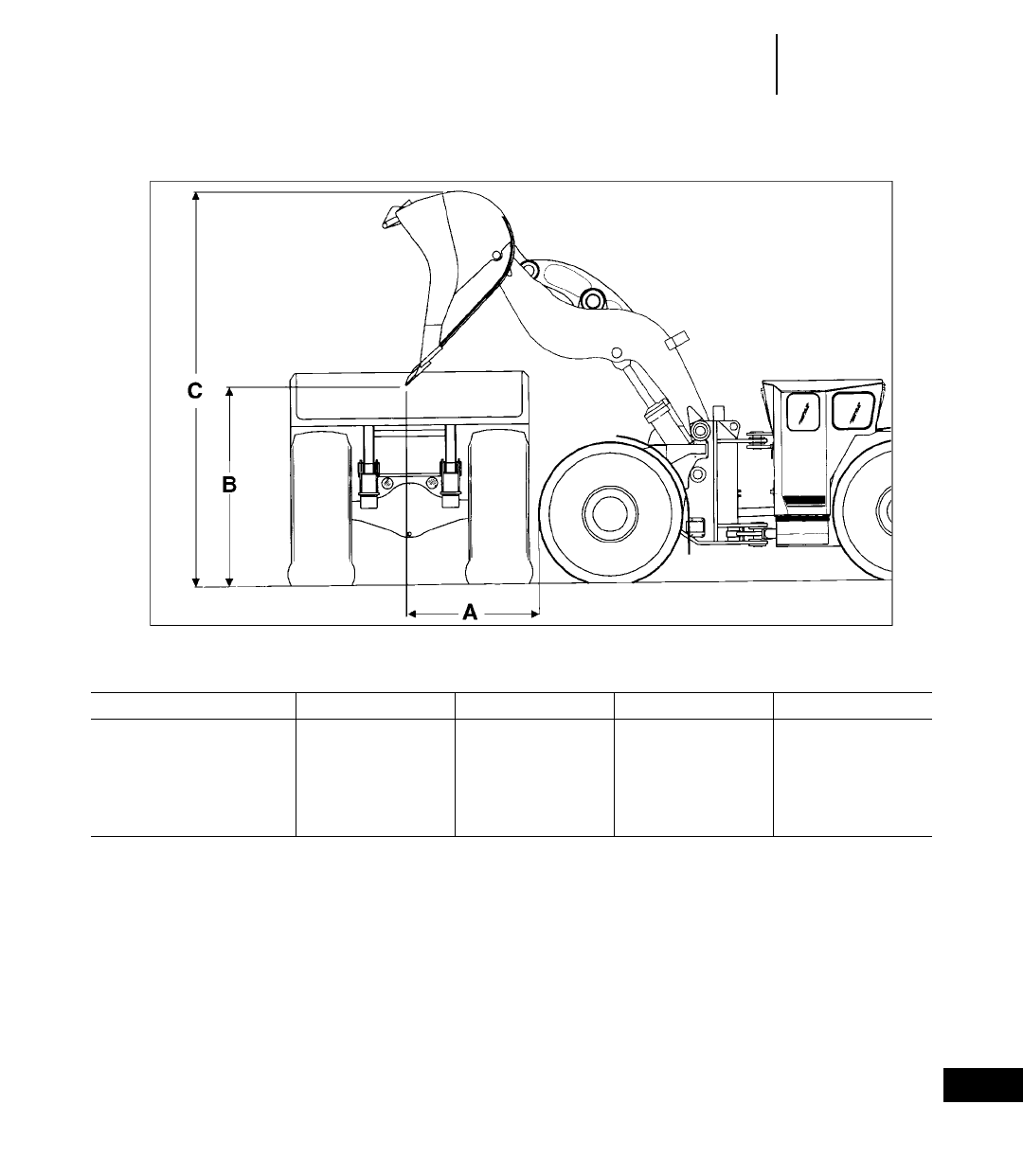
17-9
17
Underground
Mining
LHD and Truck Systems
Loader Target A B C
R1300 1637 mm 5'4.5" 1632 mm 5'4" 3525 mm 11'7"
R1600 AD40 Series II 1408 mm 4'7" 2213 mm 7'3" 4497 mm 14'9"
R1700 Series II AD40 Series II 1652 mm 5'5" 2490 mm 8'2" 4903 mm 16'1"
R2900 AD40 Series II 1625 mm 5'4" 2855 mm 9'4" 5370 mm 17'7"
R2900 69D 1625 mm 5'4" 2855 mm 9'4" 5370 mm 17'7"
R2900 73D 1625 mm 5'4" 2855 mm 9'4" 5370 mm 17'7"

18-1
CONTENTS
HYDRAULIC HAMMERS
Features:
H115s-H195 . . . . . . . . . . . . . . . . . . . . . . . . . .18-1
H45-H100 . . . . . . . . . . . . . . . . . . . . . . . . . . .18-2
Applications . . . . . . . . . . . . . . . . . . . . . . . . . . .18-3
Specifications . . . . . . . . . . . . . . . . . . . . . . . . . .18-4
Selection guide . . . . . . . . . . . . . . . . . . . . . . . . .18-7
Productivity tables . . . . . . . . . . . . . . . . . . . . . .18-8
MOBILE SHEARS
Features . . . . . . . . . . . . . . . . . . . . . . . . . . . . .18-10
Applications . . . . . . . . . . . . . . . . . . . . . . . . . .18-10
Shearing capabilities table . . . . . . . . . . . . . . .18-10
Specifications . . . . . . . . . . . . . . . . . . . . . . . . .18-11
Matching guide . . . . . . . . . . . . . . . . . . . . . . . .18-12
CONCRETE PULVERIZERS
Features . . . . . . . . . . . . . . . . . . . . . . . . . . . . .18-13
Applications . . . . . . . . . . . . . . . . . . . . . . . . . .18-13
Matching guide . . . . . . . . . . . . . . . . . . . . . . . .18-13
Specifications . . . . . . . . . . . . . . . . . . . . . . . . .18-14
CONCRETE CRUSHERS
Features . . . . . . . . . . . . . . . . . . . . . . . . . . . . .18-15
Applications . . . . . . . . . . . . . . . . . . . . . . . . . .18-15
Matching guide . . . . . . . . . . . . . . . . . . . . . . . .18-15
Specifications . . . . . . . . . . . . . . . . . . . . . . . . .18-16
HYDRAULIC HAMMERS
H115s-H195 Hammer Features:
●Shock Mount isolates both short and long dura-
tion forces to protect the carrier.
●Integrally Mounted Accumulator dampens pres-
sure peaks inside the hammer to further protect
the carrier hydraulic system, and assist the pis-
ton in the power stroke.
●Pressure Control Valve allows hammer to always
strike with maximum fixed energy per blow.
●Main Valve directs the firing cycle and blocks the
return port to protect the carrier hydraulics from
pressure peaks.
●Check Valve protects the carrier hydraulics from
pressure spikes.
●Tie Rods are heat torqued to ensure maximum
clamping force and minimal maintenance.
●Long Heavy Piston minimizes recoil forces to
protect hammer components and carrier structures.
●Slip Fit Thrust Ring is rotatable for longer life
and is replaceable. Dissipates shock loads in abu-
sive applications.
●High Abrasion Resilient Plastic Wear Plates
on all four sides guide the power cell within the
housing.
●Slip Fit Upper Tool Bushing is rotatable for
longer life and is replaceable. Guides the tool to
optimize in-line piston/tool contact.
●Slip Fit Lower Tool Bushing is field replace-
able and rotatable. It has grease retention grooves
for extended lubrication and wear indication.
●Sound Suppression consists of housing noise
abatement material, plugs and covers.
●Autolube available for all hammers.
18
HYDROMECHANICAL
WORK TOOLS

H45-H100 Hammer Features:
●Low Pressure Accumulator assists in the power
stroke of the piston.
●Custom Side Plates designed for Caterpillar
carrier geometry. Protects power cell and front end.
●High Pressure Accumulator protects against
internal cavitation. Dampens pressure peaks thus
protecting carrier hydraulic system.
●Distributor has high oil volume for ultra high
blow frequency.
●Pressure Adjusting Valve assures that all blows
are delivered at a constant blow energy.
●Long Heavy Piston delivers maximum impact
energy and minimizes recoil forces to carrier.
●Long Front End ensures proper piston — tool
alignment.
●Slip Fit Thrust Ring is rotatable for additional
life and dissipates harmful shock loads in abusive
applications.
●Slip Fit Upper Tool Bushing is rotatable for
additional life and provides positive alignment of
the tool.
●Slip Fit Lower Tool Bushing is field replace-
able. Grease retention grooves provide extended
lubrications and wear indication.
●Autolube available on all models.
●Sound suppressed versions available for all
models.
18-2
Hydraulic
Hammers Features
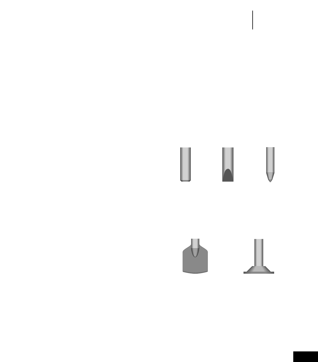
Hammer Applications
●Sewer and Water — The hammer can be used on
pockets of rock that slow down production. Also good
for breaking up old concrete pipes, manholes, etc.
●Road Construction — An essential tool during
improvements and upgrading. The hammer works
well on removing existing curbs, traffic islands,
ramps, or sections of concrete. With special tools,
it can cut asphalt.
●Bridge Renewal — Hammers are increasingly used
to remove old bridge surfaces, railing supports,
abutments, retaining walls, etc.
●Demolition — The hammer-equipped excavator
is often a key helper in industrial demolition. It
can break up fallen wall sections and floor sections
as well as handling loading ramps, foundations,
or other brick and concrete structures near ground
level.
●Mining — Hammers can break oversized mater-
ial to avoid secondary blasting, and size riprap.
●Trenching/Primary Excavation — In soft or lay-
ered materials, the hydraulic hammer with a moil
or chisel point can be cost-effective.
●Tunneling — This work has traditionally been
performed by tunnel boring machines or the drill-
and blast method. As hydraulic hammers have
improved in power and reliability, they have been
proven an economical alternative.
●Direct Quarrying — In many types of limestone,
direct quarrying with hydraulic hammers can
prove cost effective, especially where blasting is
prohibited. See Hydraulic Hammer productivity
graphs for production estimates.
A hammer need not be full time attachment for
these applications. It can be replaced by a bucket in
very little time so the excavator can be used for dig-
ging, loading, lifting, or other tasks.
Consult your Caterpillar dealer for advice on cor-
rect sizing, installation and tool selection.
NOTES: Internal components of hammers are
finely machined to close tolerances and require
clean oil with full lubricating properties. Hammers
also tend to heat hydraulic oil considerably and this
can lead to earlier oil deterioration and the need for
more frequent oil changes than recommended for
the basic excavator. Extra care should also be taken
to avoid the entry of dust or dirt when installing or
removing a hammer in the field.
18-3
18
Hydraulic
Hammers
Applications & Tool Selection
Choosing the Tool
Sedimentary and weak metamorphic rock
into which tool penetrates.
Concrete
Trenching
Benching
Various Models
Igneous and tough
metamorphic rock into
which tool doesn’t
penetrate.
Concrete
Boulders
Models H115s-H195
Frozen or Compact Ground.
Asphalt
Models H45-H100
Ground Compacting.
Models H45-H100
Chisel
Long Chisel
Soft Rock Chisel
Hard Rock Chisel
Blunt
Super Blunt
Moil
Long Moil
Pyramidal
Spade Compacting
Plate

18-4
Hydraulic
Hammers Specifications
Model H195 H180s H160s H140s
Working weight 6600 kg 14,520 lb 3800 kg 8360 lb 3000 kg 6600 lb 2200 kg 4840 lb
Impact frequency 300-400 bpm 350-470 bpm 400-600 bpm 360-520 bpm
Operating pressure 13 500 kPa 1958 psi 16 000 kPa 2321 psi 14 000 kPa 2031 psi 13 500 kPa 1958 psi
Carrier relief
pressure 21 000 kPa 3045 psi 21 000 kPa 3045 psi 21 000 kPa 3045 psi 21 000 kPa 3045 psi
Acceptable oil flow 300- 78- 220- 57- 210- 55- 160- 42-
400 L/min 104 gpm 300 L/min 78 gpm 310 L/min 81 gpm 230 L/min 60 gpm
Maximum back
pressure 1000 kPa 145 psi 1000 kPa 145 psi 500 kPa 73 psi 500 kPa 73 psi
Low pressure ————
Oil temperature –20°-+80°C –4°-+176°F –20°-+80°C –4°-+176°F –20°-+80°C –4°-+176°F –20°-+80°C –4°-+176°F
Oil viscosity 15-1000 cSt 15-1000 cSt 15-1000 cSt 15-1000 cSt
Line Size (minimum)
ID pressure 36 mm 1.42" 32 mm 1.25" 25 mm 1" 25 mm 1"
ID return 42 mm 1.65" 36 mm 1.42" 32 mm 1.25" 32 mm 1.25"
or or
2 232 mm 2 21.25"
Certified CIMA
tool energy* 9275 J 6841 ft-lb 5906 J 4357 ft-lb 4873 J 3594 ft-lb 3976 J 2934 ft-lb
Model H130s H120Cs H115s H100
Working weight 1700 kg 3740 lb 1300 kg 2860 lb 1000 kg 2200 lb 730 kg 1605 lb
Impact frequency 330-610 bpm 400-620 bpm 400-700 bpm 470-1000 bpm
Operating pressure 14 500 kPa 2103 psi 14 000 kPa 2031 psi 14 000 kPa 2031 psi 14 500 kPa 2103 psi
Carrier relief
pressure 21 000 kPa 3045 psi 21 000 kPa 3045 psi 21 000 kPa 3045 psi 21 000 kPa 3045 psi
Acceptable oil flow 120- 31- 120- 31- 70- 18- 60- 16-
220 L/min 57 gpm 160 L/min 42 gpm 130 L/min 34 gpm 120 L/min 31 gpm
Maximum back
pressure 1000 kPa 145 psi 1000 kPa 145 psi 1000 kPa 145 psi 1000 kPa 145 psi
Low pressure ———2700 kPa 392 psi
Oil temperature –20°-+80°C –4°-+176°F –20°-+80°C –4°-+176°F –20°-+80°C –4°-+176°F –20°-+80°C –4°-+176°F
Oil viscosity 15-1000 cSt 15-1000 cSt 15-1000 cSt 15-1000 cSt
Line Size (minimum)
ID pressure 32 mm 1.25" 25 mm 1" 25 mm 1" 25 mm 1"
ID return 32 mm 1.25" 25 mm 1" 25 mm 1" 25 mm 1"
Certified CIMA
tool energy* 3739 J 2758 ft-lb 2884 J 2127 ft-lb 1481 J 1092 ft-lb 1152 J 850 ft-lb
*Measured in accordance with the CIMA measuring guide for tool energy rating for hydraulic breakers developed by the Mounted Breaker Manufacturers Bureau of the
Construction Industry Manufacturers Association (CIMA-MBMB).

18-5
18
Hydraulic
Hammers
Specifications
Model H90C H70/H70s H63/H63s
Working weight1480 kg 1056 lb 370/400 kg 814/880 lb 275 kg 605 lb
Impact frequency2500-1300 bpm 600-1800 bpm 400-2000 bpm
Hammer operating pressure 13 500 kPa 1958 psi 12 500 kPa 1813 psi 14 000 kPa 2031 psi
Carrier relief pressure 21 000 kPa 3045 psi 21 000 kPa 3045 psi 21 000 kPa 3045 psi
Acceptable oil flow 60-150 L/min 16-39 gpm 50-150 L/min 13-39 gpm 20-100 L/min 5-26 gpm
Maximum back pressure 2000 kPa 290 psi 3000 kPa 435 psi 3500 kPa 508 psi
Low pressure 3300 kPa 479 psi 3900 kPa 566 psi 3100 kPa 450 psi
Oil temperature working range –20°-+80°C –4°-+176°F –20°-+80°C –4°-+176°F –20°-+80°C –4°-+176°F
Oil viscosity 15-1000 cSt 15-1000 cSt 15-1000 cSt
Line size (minimum)
ID pressure 25 mm 1" 25 mm 1" 19 mm 0.75"
ID return 25 mm 1" 25 mm 1" 19 mm 0.75"
Certified CIMA
tool energy* 735 J 542 ft-lb 622 J 459 ft-lb 372 J 274 ft-lb
Model H50/H50s H45/H45s
Working weight1180/208 kg 396/458 lb 125/131 kg 275/288 lb
Impact frequency2450-1800 bpm 750-2200 bpm
Hammer operating pressure 10 500 kPa 1523 psi 11 500 kPa 1668 psi
Carrier relief pressure 21 000 kPa 3045 psi 21 000 kPa 3045 psi
Acceptable oil flow 20-70 L/min 5-18 gpm 20-50 L/min 5-13 gpm
Maximum back pressure 3000 kPa 435 psi 3000 kPa 435 psi
Low pressure —3100 kPa 450 psi
Oil temperature working range –20°-+80°C –4°-+176°F –20°-+80°C –4°-+176°F
Oil viscosity 15-1000 cSt 15-1000 cSt
Line size (minimum)
ID pressure 15 mm 0.62" 12 mm 0.5"
ID return 15 mm 0.62" 12 mm 0.5"
Certified CIMA
tool energy* 198 J 146 ft-lb 137 J 101 ft-lb
1Includes standard tool.
2Approximate value, actual impact frequency depends on oil flow, oil viscosity, temperature, and materials to be broken.
Backhoe Loaders equipped with hydraulic hammers are well-suited to breaking concrete, asphalt and hard or frozen ground. Rock applications require hammers classed
at 2710 J (2000 ft-lb) and above.
*Measured in accordance with the CIMA measuring guide for tool energy rating for hydraulic breakers developed by the Mounted Breaker Manufacturers Bureau of the
Construction Industry Manufacturers Association (CIMA-MBMB).
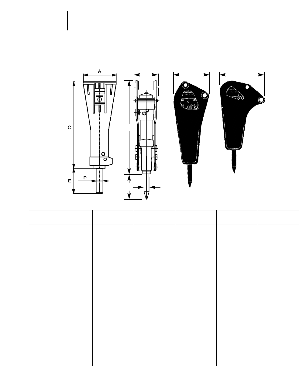
18-6
Hydraulic
Hammers Specifications
●Dimensions
ABCDE
Model mm in mm in mm in mm in mm in
H195 1090 42.9 1090 42.9 2805 110.4 195 7.7 732 28.8
H180s 730 28.7 730 28.7 2458 96.8 170 6.7 542 21.3
H160s 730 28.7 730 28.7 2306 90.8 160 6.3 560 22.0
H140s 585 23.0 540 21.3 2058 81.0 140 5.5 469 18.5
H130s 585 23.0 540 21.3 1870 73.6 130 5.1 397 15.6
H120Cs 585 23.0 540 21.3 1753 69.0 115 4.5 357 14.1
H115s 585 23.0 540 21.3 1595 62.8 106 4.2 390 15.4
H100 585 23.0 540 21.3 1380 54.3 95 3.7 459 18.1
H100s 585 23.0 540 21.3 1390 54.7 95 3.7 459 18.1
H100 (pin-on) 588 23.1 450 17.7 1512 59.5 95 3.7 459 18.1
H90C 510 20.1 380 15.0 1269 50.0 84 3.3 417 16.4
H90Cs 520 20.5 400 15.7 1277 50.3 84 3.3 417 16.4
H90C (pin-on) 888 35.0 348 13.7 1153 45.4 84 3.3 445 17.5
H70 470 18.5 380 15.0 1134 44.6 70 2.8 355 14.0
H70s 520 20.5 400 15.7 1150 45.3 70 2.8 355 14.0
H70 (pin-on) 771 30.4 348 13.7 1215 48.3 70 2.8 355 14.0
H70s (pin-on) 771 30.4 348 13.7 1215 48.3 70 2.8 355 14.0
H63 470 18.5 380 15.0 1025 40.4 63 2.5 364 14.3
H63s 440 17.3 380 15.0 1006 39.6 63 2.5 364 14.3
H50 340 13.4 280 11.0 920 36.2 50 2.0 261 10.3
H50s 440 17.3 316 12.4 893 35.2 50 2.0 262 10.3
H45 340 13.4 280 11.0 775 30.5 45 1.8 262 10.3
H45s 440 17.3 280 11.0 775 30.5 45 1.8 249 9.8
Pin-on Illustrated
B A
All
Models
C
ED
A

18-7
Hammer Machine Recommended Carrier Weight
Model Model(s) kg lb
H195 375 60 000-100 000 132,000-220,000
H180s 375, 350, 345B 40 000-80 000 88,000-176,000
H160s 350, 345B, 330B 32 000-55 000 70,400-121,000
H140s 330B, 325B, 322B 25 000-40 000 55,000-88,000
H130s 325B, 322B, M320, 320B 19 000-32 000 41,800-70,400
H120s 325B, 322B, M320, 320B, 17 000-26 000 37,400-57,200
M318, 317B, M315, 315B
H115s M320, 320B, M318, 317B, 12 000-20 000 26,400-44,000
315B, M312, 312B, M315
H100 446B, M315, M312, 8000-14 000 17,600-30,800
315B, 312B, 311B
H90C 446B, 436C, 426C, 7000-12 000 15,400-26,400
312B, 311B, 307B
H70 428C, 436C, 426C, 5000-8000 11,000-17,600
416C, 307
H63 416C 3000-6500 6600-14,300
H50 302.5 2500-4500 5500-9900
H45 302.5, 301.5 1300-3200 2860-7040
18
Hydraulic
Hammers
Selection Guide
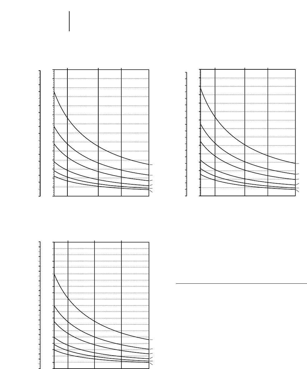
18-8
Hydraulic
Hammers Productivity
●m3/8 hr – yd3/8 hr
KEY
A — Bedding thickness less than 20 inches
B — Bedding thickness — 20 to 40 inches
C — Bedding thickness — 40 to 80 inches or closely
spaced vertical fractures
D — Some vertical fracturing
E — Widely spaced vertical fractures
F — Massive formation
The figures are for comparison and evaluation pur-
poses only. Results will vary depending on operation,
carrier and job conditions.
700
650
600
550
500
450
400
350
300
250
200
150
100
50
0
900
850
800
750
700
650
600
550
500
450
400
350
300
250
200
150
100
50
0
A
B
C
D
E
F
1405
(20,000)
2109
(30,000)
2812
(40,000) 3515
(50,000)
Model H140s
COMPRESSIVE STRENGTH
yd3/8 hr m3/8 hr
1500
1400
1300
1200
1100
1000
900
800
700
600
500
400
300
200
100
0
1900
1800
1700
1600
1500
1400
1300
1200
1100
1000
900
800
700
600
500
400
300
200
100
0
A
B
C
D
E
F
1405
(20,000)
2109
(30,000)
2812
(40,000) 3515
(50,000)
Model H180s
COMPRESSIVE STRENGTH
yd3/8 hr m3/8 hr
1000
900
800
700
600
500
400
300
200
100
0
1300
1200
1100
1000
900
800
700
600
500
400
300
200
100
0
A
B
C
D
E
F
1405
(20,000)
2109
(30,000)
2812
(40,000) 3515
(50,000)
Model H160s
COMPRESSIVE STRENGTH
yd3/8 hr m3/8 hr
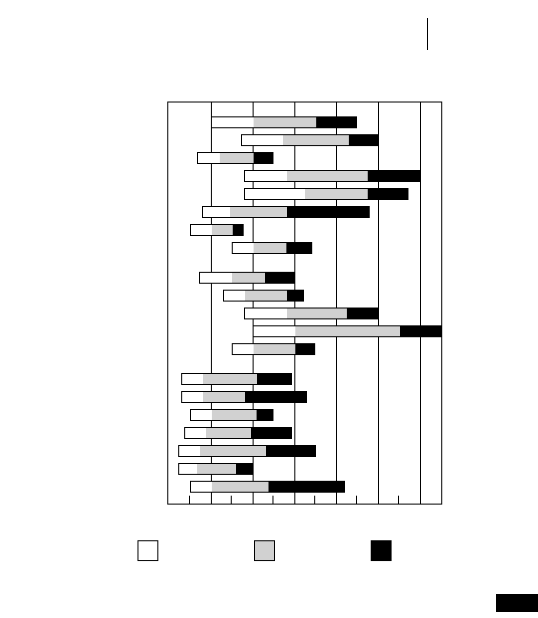
18-9
18
Hydraulic
Hammers
Productivity
●Common Rock Strengths
Rock Type
IGNEOUS
Granite (coarse)
Granite (fine)
Scoria
Basalt
Diabase
Rhyolite
Tuff
Welded Tuff
METAMORPHIC
Schist
Gneiss
Slate
Quartzite
Marble
SEDIMENTARY
Shale
Sandstone
Silt & Claystone
Caliche
Conglomerate
Breccia
Limestone
Common Rock Strengths
0 10,000 20,000 30,000 40,000 50,000 60,000
Compressive Strength (psi)
Slightly Altered
or Weathered Most Common
Material Strong or
Very Hard
The rock strengths shown are those most commonly encountered by Caterpillar in near surface excavations.
Highly altered or deeply weathered rocks can have strength values much lower than those listed. Also,
strength values greater than those shown may occasionally be encountered.
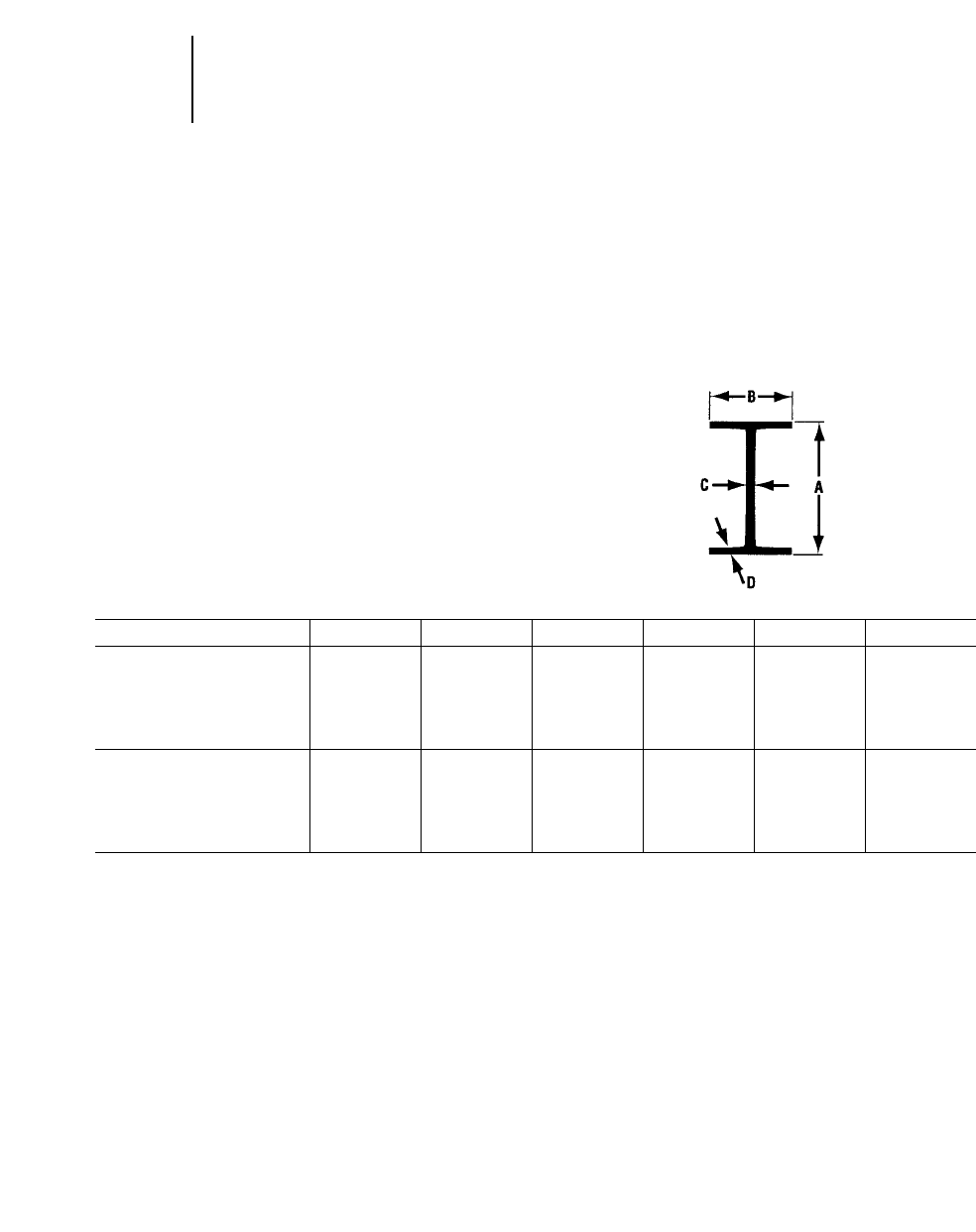
MOBILE SCRAP
AND DEMOLITION SHEARS
Features:
●180 degree side mounted rotation.
●Precision machined main bolt is field removable.
●500 Brinell hardness wear plates throughout the
upper and lower jaw.
●Hydraulic cylinder rod is protected. When acti-
vated the cylinder barrel is pushed out and the
rod remains protected by the housing at all times.
●Transportation safety bars are designed to con-
vert the shears to straight shears if the rotator is
down for repair or overhaul.
Applications:
The Cat Mobile Scrap and Demolition Shears are
widely used for demolishing steel structures, cut-
ting up cars, trucks, farm machinery, railroad cars,
large rubber tires, reinforced concrete structures,
cables and scrap in general.
18-10
Mobile
Shears ●Features
●Applications
●Shearing Capability Table
Model S25 S30 S40 S50 S80 S130
Narrow I-beams mm in mm in mm in mm in mm in mm in
AHeight 320 12.6 400 15.7 425 16.7 500 19.7 550 21.7 600 23.6
BFlange Width 131 5.2 115 6.1 163 6.4 185 7.3 200 7.9 215 8.5
CWeb Thickness 11.5 0.45 14.4 0.57 15.3 0.6 18 0.7 19 0.75 21.6 0.85
DFlange Thickness 17.3 0.68 21.8 0.86 23 0.9 27 1.1 30 1.2 32.4 1.28
Wide I-beams
AHeight 171 6.7 230 9.1 250 9.8 330 13 390 15.4 440 17.3
BFlange Width 180 7.1 240 9.4 260 10.2 300 11.8 300 11.8 300 11.8
CWeb Thickness 6 0.24 7.5 0.3 7.5 0.3 9.5 0.37 11 0.43 11.5 0.45
DFlange Thickness 9.5 0.37 12 0.47 12.5 0.49 16.5 0.65 19 0.75 21 0.83
The above profiles provide an indication of the shears relative cutting capability. The exact cutting dimensions depend on excavator operating pressure, the conditions of
the shear knives and jaws and the steel’s tensile strength.
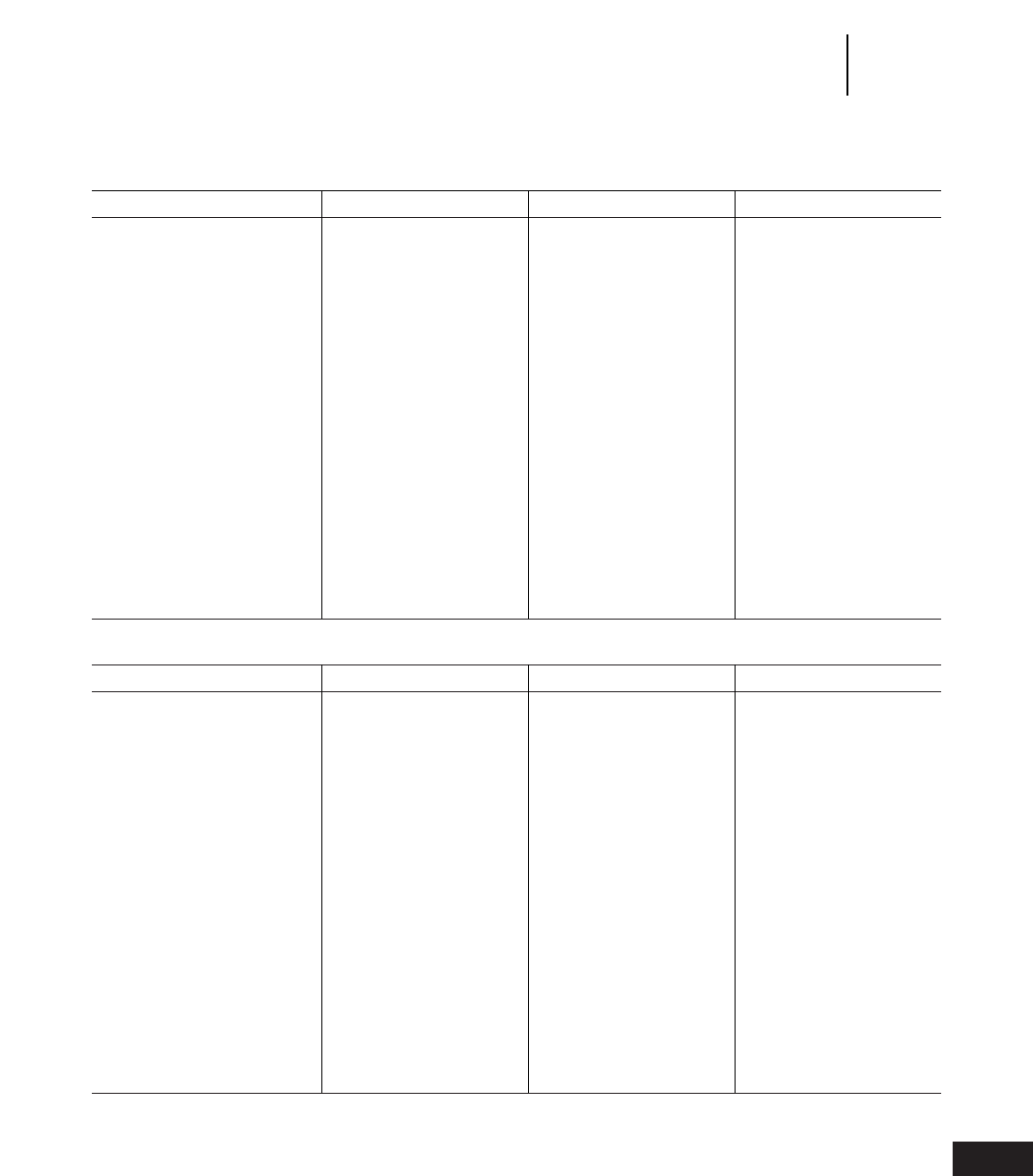
18-11
Technical Data (All dimensions are approximate.)
Model S25 S30 S40
Approximate Service Weight
Excluding Mounting Bracket 2400 kg 5300 lb 3300 kg 7300 lb 4785 kg 10,550 lb
Length 2930 mm 9'7.4" 3500 mm 11'5.8" 4120 mm 13'6"
Jaw Opening 550 mm 1'9.7" 550 mm 1'9.7" 710 mm 2'4"
Jaw Depth 530 mm 1'8.9" 530 mm 1'8.9" 725 mm 2'4"
Primary Cutter Length 300 mm 11.8" 300 mm 11.8" 330 mm 13"
Maximum Shear Force Throat/ 3495/ 393/202 st 5030/ 565/283 st 6750/ 759/385 st
Primary Blade Center 1800 kN 2530 kN 3426 kN
Maximum Oil Flow —
Hydraulic Cylinder 160 L/min 42 gpm 180 L/min 48 gpm 400 L/min 106 gpm
Maximum Oil Flow —
Rotation 15 L/min 4 gpm 17 L/min 4.5 gpm 23 L/min 6.1 gpm
Maximum Working Pressure
Hydraulic Cylinder 34 300 kPa 4980 psi 34 300 kPa 4980 psi 34 300 kPa 4980 psi
Rotation 20 200 kPa 2900 psi 20 200 kPa 2900 psi 20 200 kPa 2900 psi
Cycle Time @ Max. Flow
Open 4.3 sec 4.7 sec 4.3 sec
Close 7.5 sec 9.2 sec 7.2 sec
Hydraulic Rotation 180° 180° 180°
Approximate Base Machine
Operating Weight:
Boom 18 000 kg 40,000 lb 20 000 kg 44,000 lb 26 000 kg 57,000 lb
Stick 26 000 kg 57,000 lb 30 000 kg 66,000 lb 40 000 kg 88,000 lb
Model S50 S80 S130
Approximate Service Weight
Excluding Mounting Bracket 6200 kg 13,700 lb 7900 kg 17,500 lb 12 300 kg 27,200 lb
Length 4480 mm 14'8.4" 4650 mm 15'3" 5500 mm 18'0.5"
Jaw Opening 715 mm 2'4.2" 820 mm 2'8.3" 1100 mm 3'7.3"
Jaw Depth 795 mm 2'7.3" 820 mm 2'8.3" 1080 mm 3'6.5"
Primary Cutter Length 450 mm 17.7" 450 mm 17.7" 550 mm 1'9.7"
Maximum Shear Force Throat/ 8440/ 949/409 st 9280/ 1043/484 st 11 445/ 1287/591 st
Primary Blade Center 3635 kN 4310 kN 5255 kN
Maximum Oil Flow —
Hydraulic Cylinder 400 L/min 106 gpm 450 L/min 119 gpm 800 L/min 211 gpm
Maximum Oil Flow —
Rotation 31 L/min 8.2 gpm 53 L/min 14 gpm 47 L/min 12.4 gpm
Maximum Working Pressure
Hydraulic Cylinder 34 300 kPa 4980 psi 34 300 kPa 4980 psi 34 300 kPa 4980 psi
Rotation 20 200 kPa 2900 psi 20 200 kPa 2900 psi 20 200 kPa 2900 psi
Cycle Time @ Max. Flow
Open 4.6 sec 4.3 sec 4.2 sec
Close 7.8 sec 8.8 sec 8.5 sec
Hydraulic Rotation 180° 180° 180°
Approximate Base Machine
Operating Weight:
Boom 30 000 kg 66,000 lb 40 000 kg 88,000 lb 120 000 kg 265,000 lb
Stick 50 000 kg 110,000 lb 80 000 kg 176,000 lb N/A
18
Mobile
Shears
Specifications

Matching Guide
Stick Mounted/Reach Boom
Shear Cat Stick Range
Model Excavator mm ft
S25 320B 1900 6'3"
322B 2500-3600 8'2"-11'10"
325B 2000-4200 6'7"-13'9"
330B 2150-4800 7'1"-15'9"
S30 325B L 2000-2700 6'7"-8'10"
330B L 2150-3900 7'1"-12'10"
345B 2900-4800 9'6"-15'9"
350 L 3100-4800 10'2"-15'9"
S40 345B 2900-4800 10'2"-12'2"
350 L 3100-3700 9'6"-15'9"
S50 375 L 2900-5500 9'6"-18'1"
S80 375 L 2900-3400 9'6"-11'2"
375 L* 2900-4400 9'6"-14'5"
*GP Boom.
Reach Boom Mounted
Shear Cat
Model Excavator
S25 315B L
320B
322B
S30 320B
320B L
322B
322B L
325B L
330B L
S40 325B L
330B L
S50 330B L
S80 345B
350B L
S130 375
18-12
Mobile
Shears Matching Guide

CONCRETE PULVERIZERS
Features:
●Hydraulic cylinder rod is protected. When acti-
vated the cylinder barrel is pushed out and the
rod remains protected by the housing at all times.
●Large diameter slewing ring powered by a hydraulic
motor constitutes a rugged and fast 360 degree
rotation system.
●P16 and P25 Pulverizers provide the optimum
reach configuration. Fifteen replaceable teeth and
two square shaped cutting knives.
●P20, P28, P40 and P60 provide the optimum pro-
ductivity configuration. Twenty-one replaceable
teeth with six replaceable square cutting knives.
●Patented staggered tooth design enhances crush-
ing effectiveness of the jaws.
●Long powerful rebar cutters.
Applications:
Primary and secondary demolition in one operation.
Ideal for reinforced concrete found in bridge decks,
parking garages, support columns and abutments.
Matching Guide
Stick Mounted/Reach Boom
Pulverizer Cat Stick Range
Model Excavator mm ft
P16 320B L 1900-2900 6'3"-9'7"
322B L 2000-3600 6'7"-11'10"
325B L 2000-4200 6'7"-13'9"
P20 322B L 2000-3600 6'7"-11'10"
325B L 2000-4200 6'7"-13'9"
P25 325B L 2000-3200 6'7"-10'6"
330B L 2150-4800 7'1"-15'9"
345B L 3900-4800 12'10"-15'9"
350 L 4050-4800 13'3"-15'9"
P28 330B L 2150-3300 7'1"-10'10"
345B L 3900-4800 12'10"-15'9"
350 L 4050-4800 13'3"-15'9"
P40 345B L 3900-4800 12'10"-15'9"
350 L 3100-3700 9'6"-12'2"
375 L 4400-5500 14'5"-18'1"
P60 375 2900-4400 9'6"-14'5"
375* 2900-4400 9'6"-14'5"
*GP Boom.
18-13
18
Concrete
Pulverizers
●Features
●Applications
●Matching Guide

Technical Data (All dimensions are approximate.)
Model P16 P20 P25
Approximate Service Weight
Excluding Mounting Bracket 2100 kg 4650 lb 2400 kg 5300 lb 3000 kg 6600 lb
Length
Excluding Mounting Bracket 2450 mm 8'0.47" 2370 mm 7'9.3" 2730 mm 8'11.48"
Width: Fixed Jaw 530 mm 1'8.87" 635 mm 2'1" 650 mm 2'1.6"
Width: Moving Jaw 305 mm 12" 450 mm 17.7" 400 mm 15.75"
Jaw Opening 750 mm 2'5.53" 650 mm 2'1.7" 900 mm 2'11.43"
Maximum Crushing Force
Tooth — Jaw’s Tip 740 kN 83 st 773 kN 86 st 935 kN 105 st
Tooth — Throat 1235 kN 139 st 1748 kN 197 st 1515 kN 170 st
Maximum Shear Force Cutting
Blade Middle (Throat) 2110 kN 237 st 2574 kN 290 st 2990 kN 336 st
Maximum Oil Flow
Hydraulic Cylinder 200 L/min 53 gpm 200 L/min 53 gpm 250 L/min 66 gpm
Maximum Oil Flow
Rotation 20 L/min 5 gpm 20 L/min 5 gpm 20 L/min 5 gpm
Maximum Working Pressure
Hydraulic Cylinder 34 300 kPa 4980 psi 34 300 kPa 4980 psi 34 300 kPa 4980 psi
Maximum Working Pressure
Rotation 17 200 kPa 2465 psi 17 200 kPa 2465 psi 17 200 kPa 2465 psi
Cycle Time @ Max. Flow
Open 2.9 sec 2.9 sec 2.7 sec
Close 4.6 sec 4.6 sec 5.3 sec
Hydraulic Rotation Continuous 360° 360° 360°
Approximate Base Machine
Operating Weight 16 000 kg 35,000 lb 20 000 kg 44,000 lb 25 000 kg 55,000 lb
Model P28 P40 P60
Approximate Service Weight
Excluding Mounting Bracket 3600 kg 7950 lb 5500 kg 12,150 lb 8100 kg 17,900 lb
Length
Excluding Mounting Bracket 2650 mm 8'8.3" 2970 mm 9'8.9" 3265 mm 10'8.5"
Width: Fixed Jaw 730 mm 2'4.7" 820 mm 2'8.3" 950 mm 3'1.4"
Width: Moving Jaw 505 mm 1'7.9" 650 mm 2'1.6" 655 mm 2'1.8"
Jaw Opening 850 mm 2'9.5" 1050 mm 3'5.3" 1150 mm 3'9.3"
Maximum Crushing Force
Tooth — Jaw’s Tip 880 kN 99 st 1533 kN 173 st 1920 kN 216 st
Tooth — Throat 1973 kN 222 st 3776 kN 464 st 4130 kN 464 st
Maximum Shear Force Cutting
Blade Middle (Throat) 2853 kN 320 st 5931 kN 667 st 5770 kN 649 st
Maximum Oil Flow
Hydraulic Cylinder 250 L/min 66 gpm 400 L/min 106 gpm 600 L/min 159 gpm
Maximum Oil Flow
Rotation 20 L/min 5 gpm 20 L/min 5 gpm 20 L/min 5 gpm
Maximum Working Pressure
Hydraulic Cylinder 34 300 kPa 4980 psi 34 300 kPa 4980 psi 34 300 kPa 4980 psi
Maximum Working Pressure
Rotation 17 200 kPa 2465 psi 17 200 kPa 2465 psi 17 200 kPa 2465 psi
Cycle Time @ Max. Flow
Open 2.7 sec 3.4 sec 3.7 sec
Close 5.3 sec 6.6 sec 6.3 sec
Hydraulic Rotation Continuous 360° 360° 360°
Approximate Base Machine
Operating Weight 28 000 kg 62,000 lb 40 000 kg 88,000 lb 60 000 kg 132,000 lb
18-14
Concrete
Pulverizers Specifications

CONCRETE CRUSHERS
Features:
●Two powerful hydraulic cylinders protected from
damage by the unique static rod design.
●Each crushing arm has two cutters and two crush-
ing teeth.
●Replaceable cutters and teeth are bolted and tack
welded to the jaw.
●Rebar cutters have four cutting edges.
●Large diameter slewing ring powered by a hydraulic
motor constitutes a rugged and fast 360 degree
rotation system.
Applications:
Primary demolition where productivity is crucial,
reinforced concrete structures with thick walls and
large diameter columns. Also used on bridge decks,
parking garages, support columns and abutments
with a thickness of up to five feet.
Matching Guide
Stick Mounted/Reach Boom
Crusher Cat Stick Range
Model Excavator mm ft
CR20 320B L 1900-3900 6'3"-12'10"
322B L 2000-3600 6'7"-11'10"
CR28 325B L 2000-3200 6'7"-10'6"
330B L 2150-3900 7'1"-12'10"
345B L 4800 15'9"
350 L 4800 15'9"
CR35 345B L 2900-3900 9'6"-12'10"
350 L 3100-4050 10'2"-13'3"
CR50 375 2900-5500 9'6"-18'1"
375* 2900-5500 9'6"-18'1"
*GP Boom.
18-15
18
Concrete
Crushers
●Features
●Applications
●Matching Guide

Technical Data (All dimensions are approximate.)
Model CR20 CR28 CR35 CR50
Approximate Service Weight
Excluding Mounting Bracket 2500 kg 5500 lb 3300 kg 7300 lb 4600 kg 10,200 lb 6500 kg 14,400 lb
Length
Excluding Mounting Bracket 2100 mm 6'10.7" 2235 mm 7'7.9" 2620 mm 8'7.1" 2850 mm 9'4.2"
Jaw Opening (Maximum) 720 mm 2'4.3" 915 mm 3'0" 1190 mm 3'10.8" 1600 mm 5'3"
Cutter Length 280 mm 11" 400 mm 15.8" 500 mm 1'7.7" 450 mm 17.7"
Maximum Crushing Force
Tip 719 kN 81 st 793 kN 90 st 836 kN 94 st 1426 kN 161 st
Middle Tooth 965 kN 108 st 1169 kN 131 st 1233 kN 139 st 1909 kN 214 st
Maximum Shear Force
— Cutting 3593 kN 403 st 4815 kN 541 st 4987 kN 561 st 7262 kN 816 st
Maximum Oil Flow
Hydraulic Cylinder 160 L/min 42 gpm 180 L/min 48 gpm 250 L/min 66 gpm 450 L/min 119 gpm
Maximum Oil Flow
Rotation 20 L/min 5 gpm 20 L/min 5 gpm 20 L/min 5 gpm 20 L/min 5 gpm
Maximum Working Pressure
Hydraulic Cylinder 34 300 kPa 4980 psi 34 300 kPa 4980 psi 34 300 kPa 4980 psi 34 300 kPa 4980 psi
Maximum Working Pressure
Rotation 17 200 kPa 2465 psi 17 200 kPa 2465 psi 17 200 kPa 2465 psi 17 200 kPa 2465 psi
Cycle Time @ Max. Flow
Open 3.2 sec 3.2 sec 3.3 sec 3.2 sec
Close 5.1 sec 6.2 sec 5.5 sec 6.7 sec
Hydraulic Rotation Continuous 360° 360° 360° 360°
Approximate Base Machine
Operating Weight 20 000 kg 44,000 lb 28 000 kg 62,000 lb 35 000 kg 77,000 lb 50 000 kg 110,000 lb
18-16
Concrete
Crushers Specifications

CONTENTS
Design data . . . . . . . . . . . . . . . . . . . . . . . . . . . .19-2
Rating explanations . . . . . . . . . . . . . . . . . . . . .19-2
Industrial Diesel Engines . . . . . . . . . . . . . . . . .19-3
Fire Pump Engines . . . . . . . . . . . . . . . . . . . . . .19-7
Industrial Gaseous Fueled Engines . . . . . . . . .19-8
Generator Sets — Diesel — 50 Hz . . . . . . . . .19-10
Generator Sets — Diesel — 60 Hz . . . . . . . . .19-11
Olympian Generator Sets . . . . . . . . . . . . . . . .19-12
Generator Sets — Gaseous Fueled . . . . . . . .19-13
Marine Propulsion — Rating Levels . . . . . . .19-15
Marine Generator Sets . . . . . . . . . . . . . . . . . .19-18
Marine Auxiliary Engines . . . . . . . . . . . . . . .19-19
Truck Diesel Engines . . . . . . . . . . . . . . . . . . .19-20
NO. OF
TYPE MODELS RANGE
INDUSTRIAL Diesel 20 56 to 4920 kW
76 to 6600 hp
EPA Certified
Gaseous 13 30 to 3506 kW
Fueled 40 to 4700 hp
EPA Certified
GENERATOR SETS 50 HZ-kV•A w/fan
Prime-112 to 1944
Standby-125 to 2250
w/o fan
Prime-1960 to 6500
Standby-2160 to 7150
Diesel 13 60 HZ-kW w/fan
Prime-113 to 1825
Standby-125 to 2000
w/o fan
1525 to 4840
50 HZ-kV•A w/o fan
Gaseous 12 Continuous-45 to 3385
Fueled 60 HZ-kW w/o fan
Continuous-55 to 3050
OLYMPIAN 50 HZ-kV•A w/fan
GENERATOR Prime-6 to 100
SETS* Diesel Standby-8 to 200
60 HZ-kV•A w/fan
Prime-6 to 100
Standby-8 to 200
50 HZ-kV•A w/fan
Prime-6 to 50
Gaseous Standby-12 to 100
Fueled 60 HZ-kV•A w/fan
Prime-6 to 50
Standby-12 to 100
MARINE
Propulsion 17 63 to 5420 kW
85 to 7270 hp
50 HZ kV•A 63 to 6500
Generator 12 Prime
Sets 60 HZ-kW 65 to 4840
Prime
TRUCK 123 to 410 kW
Diesel 9 170 to 550 hp
EPA, CARB and
Canadian certified
*Olympian Generator Sets are manufactured exclusively for Caterpillar dealers.
ENGINES
19-1
19

DESIGN DATA
Diesel Engines
Bearings — Precision-type steel-backed aluminum
alloy with lead-tin overlay copper bonded to bear-
ing surface. High load carrying ability and excep-
tional fatigue strength.
Block — Cast from high tensile strength grey iron.
Internal ribbing provides added strength.
Cooling — Built-in, gear driven centrifugal pump
(belt driven for 3116 and 3208) circulates jacket
water through engine at all times. Water temper-
ature is thermostatically controlled. Heat exchang-
ers and radiators are available.
Crankshaft — Forged steel, dynamically balanced,
heat treated and superfinished.
Cylinder Liners — Internal surface induction hard-
ened (1.7 L, 3300, 3400, 3500 and 3600 Families)
for excellent wear life. Full-length watercooled for
efficient heat transfer.
Fuel System — Adjustment free for reduced engine
maintenance, individual fuel injection pumps have
built-in calibration — no adjustment required after
fuel nozzle replacement (1.7 L, 3500 and 3600
families have unit injectors). 3126, 3408E and
3412E use the Caterpillar Hydraulic Electronic
Fuel Injection (HEUI) system.
Governor — Hydra-mechanical (Woodward 3161 on
3500 and 3600 Families) for reliability, good
response and smooth, stable load changes.
Lubrication — Positive displacement gear pump
maintains continuous flow of lubricant under pres-
sure to all moving parts. Full-flow filtration is pro-
vided by replaceable cellulose filters. Watercooled
oil cooler maintains proper oil temperature.
Pistons — Three-ring design (two-ring on 3208)
reduces friction, provides excellent oil control, and
increases engine efficiency.
Starting — Electric and air starting systems are
offered for most models.
Valves — Hardened steel alloy. Valves rotate 3° each
time they lift to seat in a new position and allow
even heat distribution (except for 3116).
Gaseous Fueled Engines
Combustion System — The piston design and com-
pression ratios available provide the ability to utilize
a wide variety of gaseous fuels as well as provide
low emission output (below 2.0 grams/bhp-hr Nox).
Fuel System — Heavy-duty, industrial-type carbure-
tors designed to maintain optimum air-fuel ratio
at all loads and speeds.
Ignition System — Caterpillar Gaseous Fueled Engines
employ a low tension magneto, together with an
ignition transformer (one at each cylinder), to pro-
vide up to 34 kV to spark plugs. The Cat Electronic
Ignition system is also available on certain engines.
RATING EXPLANATIONS
All engine ratings listed include such standard
accessories as air cleaner and fuel, lube, and jacket
water pumps. Power required for auxiliaries such as
cooling fans, air compressors, charging alternators,
special pumps, etc., must be deducted to arrive at
the net power available to drive the load (except as
noted). Other ratings are available for specific appli-
cation and customer requirements, i.e., locomotive,
oil field, fire pump, irrigation, etc. Consult your
Caterpillar Dealer.
Rating Conditions
Performance is based on SAE J1349 standard con-
ditions of 100 kPa (29.61 in Hg) and 25° C (77° F).
Performance also applies at ISO 3046/1 (except for
Spark Ignited Engines), DIN 6271 and BS 5514 stan-
dard conditions of 100 kPa (29.61 in Hg), 27° C
(81° F) and 60% relative humidity.
Fuel consumption is based on fuel oil having an
LHV of 42 780 kJ/kg (18,390 Btu/lb) and weighing
838.9 g/liter (7.001 lb/U.S. gal). All ratings are based
on distillate fuel.
Altitude and Temperature Capabilities
Industrial Diesel Engines — Most intermittent and
continuous ratings are applicable to at least 1320 m
(5,000 ft) elevation without derating. Consult fac-
tory for specific applications.
Gaseous Fueled Engines — Ratings for turbo-
charged and aftercooled engines are generally
applicable to 1500 m (5000 ft). Naturally aspi-
rated engines are applicable to 150 m (500 ft).
Diesel Truck Engines — Refer to specification sheets
for altitude capability of individual truck engine
ratings.
19-2
Engines Design Data
Rating Explanations

19-3
19
EnginesIndustrial
●Diesel
Cat Diesel Engines for Industrial Applications
“Ind A” “Ind C” EPA
Model Continuous “Ind B” Intermittent “Ind D” “Ind E” Certi-
Type kW hp rpm kW hp rpm kW hp rpm kW hp rpm kW hp rpm fied
3054 NA 46 62 2200 — —————5169 2200 — ——
3054 NA 56 76 2400 — ——6587 2600 — —————
3304 NA 63 85 2000 67 90 2000 75 100 2200 — ——82110 2200
3116 T ———86115 1800 — ————————X
3116 TA ———97130 1800 — ————————X
3304 NA (PC) 63 85 2000 — ——75100 2200 — —————X
3054 T 72 96 2400 — ——83111 2600 — —————
3056 NA 84 114 2400 — ——96129 2600 — —————
3304 T (PC) 93 125 2000 — —— 123 165 2200 — —————
3208 NA 93 125 2400 112 150 2400 131 175 2800 — —————
3304 T 93 125 2000 112 150 2000 123 165 2200 131 175 2200 138 185 2200
3306 NA (PC) 93 125 2000 — —— 112 150 2200 — —————
3306 NA 93 125 2000 101 135 2000 112 150 2200 119 160 2200 127 170 2200
3116 T 97 130 2200 104 140 2200 108 145 2200 119 160 2200 119 160 2200 X
3116 T 104 140 2400 112 150 2400 116 155 2400 123 165 2400 123 165 2400 X
3116 TA 104 140 2200 112 150 2200 119 160 2200 146 195 2200 168 225 2200 X
3056 T 105 140 2400 — —— 119 159 2600 — —————
3116 TA 104 140 2200 112 150 2200 119 160 2200 142 190 2200 142 190 2200 X
3116 T —————— 127 170 2600 127 170 2600 127 170 2600 X
3116 T 104 140 2400 112 150 2400 116 155 2400 123 165 2400 123 165 2400 X
3116 TA ——— 119 160 1800 134 180 1800 — —————X
3116 TA 112 150 2400 123 165 2400 131 175 2400 157 210 2400 164 220 2400 X
3116 TA —————— 142 190 2600 142 190 2600 142 190 2600 X
3208 NA 112 150 2400 — —— 157 210 2800 — —————X
3208 T ——— 131 175 2400 — ————————
3306 T 116 155 2000 131 175 2000 149 200 2200 — —————
3208 T 119 160 2200 119 160 2200 123 165 2200 131 175 2200 138 185 2200 X
3116 TA 112 150 2400 123 165 2400 131 175 2400 146 200 2400 149 200 2400 X
3056 TA 119 160 2400 — —— 135 181 2600 — —————
3306 T 127 170 2000 149 200 2000 168 225 2200 — —————
3116 TA 131 175 2200 138 185 2200 145 195 2200 164 220 2200 164 220 2200
3116 TA 131 175 2200 138 185 2200 145 195 2200 153 205 2200 153 205 2200 X
3116 TA 142 190 2400 149 200 2400 157 210 2400 172 230 2400 172 230 2400
3116 TA —————— 172 230 2600 179 240 2600 179 240 2600
3116 ATAAC —————— 172 230 2450 — —————X
3116 TA —————— 194 260 2600 201 270 2600 201 270 2600
3306 T (PC) 142 190 2000 — —— 187 250 2200 — —————
3306 T 142 190 2000 168 225 2000 187 250 2200 198 265 2200 205 275 2200
3306 142 190 2000 157 210 2000 168 225 2000 160 215 2200 160 215 2200 X
3208 T 142 190 2400 142 190 2400 157 210 2600 — —————X
3116 TA 142 190 2400 149 200 2400 157 210 2400 157 210 2400 157 210 2400 X
3208 T 149 200 2400 — —— 168 225 2600 — —————
3208 T —————— 187 250 2600 194 260 2600 194 260 2600 X
3208 T 149 200 2400 168 225 2400 187 250 2600 — —————
3306 DITA 157 210 2000 172 230 2000 186 250 2200 198 265 2200 205 275 2200 X
3306 TA (PC) 160 215 2000 — —— 201 270 2200 — —————
3126 TA 160 215 2200 172 230 2200 179 240 2200 186 250 2200 190 255 2200 X
3126 TA 164 220 2400 172 230 2400 179 240 2400 190 255 2400 194 260 2400 X
3126 TA —————— 186 250 2500 186 250 2500 186 250 2500 X
3126 TA —————— 194 260 2600 194 260 2600 194 260 2600 X
NA — Naturally Aspirated PC — Pre-combustion Chamber (Continued on next page)
T — Turbocharged ATAAC — Air-to-air Aftercooled
TA — Turbocharged-Aftercooled DITA — Direct Injection Turbocharged-Aftercooled
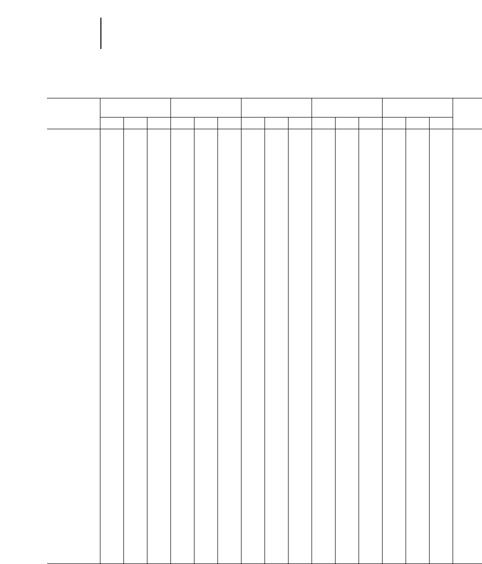
Cat Diesel Engines for Industrial Applications (cont’d)
“Ind A” “Ind C” EPA
Model Continuous “Ind B” Intermittent “Ind D” “Ind E” Certi-
Type kW hp rpm kW hp rpm kW hp rpm kW hp rpm kW hp rpm fied
3208 T 172 230 2400 183 245 2400 205 275 2600 213 285 2600 220 295 2600
3116 ATAAC —————— 205 275 2450 — —————X
3208 JWAC 183 245 2400 183 245 2400 224 300 2600 224 300 2400 224 300 2400 X
3208 ATAAC 187 250 2200 187 250 2200 187 250 2200 209 280 2200 209 280 2200
3306 TA 194 260 2000 205 275 2000 224 300 2200 231 310 2200 243 325 2200
3406 TA 199 267 1300 — —— 199 267 1300 — —————
3406 T 201 270 1800 224 300 2000 242 325 2100 283 380 2100 291 390 2100
3306 TA 205 275 2000 220 295 2000 242 325 2200 246 330 2200 250 335 2200 X
3208 ATAAC 205 275 2400 209 280 2400 224 300 2600 235 315 2600 246 330 2600
3406 TA 205 275 1800 242 325 2000 269 360 2100 313 420 2100 336 450 2100
3306 DITA 205 275 2000 216 290 2000 242 325 2200 246 330 2200 250 335 2200 X
3306 DITA 205 275 2000 216 290 2000 224 300 2200 239 320 2200 250 335 2200 X
3208 ATAAC 224 300 2400 224 300 2400 224 300 2400 235 315 2400 235 315 2400
3208 ATAAC —————— 231 310 2600 246 330 2600 246 330 2600
3176B ATAAC —————— 272 365 2100 298 400 2100 — ——X
3196 TA —————— 272 365 1800 — —————
3196 TA —————— 272 365 2100 — —————
3176B ATAAC 231 310 2100 250 335 2100 255 342 1800 291 390 2100 317 425 2100 X
3406 TA (PC) —————— 280 375 2100 — —————
3408 TA 238 319 1200 — —— 261 350 1200 — —————
3406 TA 242 325 1800 276 370 2000 298 400 2100 358 480 2100 373 500 2100
3408 T 242 325 1800 272 365 2000 317 425 2100 339 455 2100 358 480 2100
3196 TA 276 370 1800 298 400 1800 317 425 1800 339 455 1800 373 500 1800
3196 TA 276 370 2100 298 400 2100 317 425 2100 339 455 2100 373 500 2100
3406C DITA 287 385 1800 328 440 2000 343 460 2100 373 500 2100 384 515 2100 X
3406C DITA 280 375 1800 291 390 2000 298 400 2100 324 435 2100 362 485 2100 X
3406C DITA 268 360 1800 268 360 2000 268 360 2100 298 400 2100 324 435 2100 X
3406C DITA 257 345 1800 254 340 2000 250 335 2100 — —————X
3406 TA 313 420 1800 328 440 2000 343 460 2100 384 515 2100 392 525 2100
3456 TA —————— 410 550 2100 — —————
3406E ATAAC —————— 392 525 2100 421 565 2100 429 575 2100 X
3456 TA —————— 391 525 2100 — —————
3406E ATAAC 317 425 1800 317 425 2000 336 450 2100 — —————X
3408 TA (PC) —————— 354 475 2100 — —————
3412 TA (S) 317 425 1200 — —— 399 535 1300 — —————
3456 TA 317 425 1800 336 450 2000 336 450 1800 — —————
3456 TA 336 450 1800 354 475 2000 354 475 1800 — —————
3456 TA 354 475 1800 373 500 2000 373 500 1800 421 565 2100 429 575 2100
3408E TA 354 475 1800 392 525 2000 373 500 1800 — —————X
3408 TA 347 465 1800 366 490 2000 377 505 2100 392 525 2100 399 535 2100
3408C TA 347 465 1800 365 490 2000 377 505 2100 392 525 2100 399 535 2100 X
3456 TA —————— 410 550 2100 — —————
3408E TA —————— 429 575 2100 466 625 2100 504 675 2100 X
3456 TA —————— 429 575 2100 — —————
3412 T (S) 354 475 1800 384 515 2000 429 575 2100 522 700 2100 552 740 2100
3408E ATAAC —————— 466 625 2100 522 700 2100 660 750 2100 X
3456 TA 373 500 1800 391 525 2000 391 525 1800 447 600 2100 466 625 2100
3456 TA —————— 447 600 2100 — —————
3412 T (D) 373 500 1800 410 550 2000 485 650 2100 503 675 2100 522 700 2100
T — Turbocharged ATAAC — Air-to-air Aftercooled (Continued on next page)
TA — Turbocharged-Aftercooled DITA — Direct Injection Turbocharged-Aftercooled
PC — Pre-combustion Chamber JWAC — Jacket Water Aftercooled
19-4
Engines Industrial
●Diesel
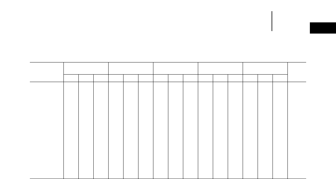
Cat Diesel Engines for Industrial Applications (cont’d)
“Ind A” “Ind C” EPA
Model Continuous “Ind B” Intermittent “Ind D” “Ind E” Certi-
Type kW hp rpm kW hp rpm kW hp rpm kW hp rpm kW hp rpm fied
3412E DITA 418 560 1800 447 600 2000 485 650 2100 522 700 2100 552 740 2100
3412E DITA 373 500 1800 448 600 2000 485 650 2100 — —————
3456 TA 384 515 1800 410 550 2000 410 550 1800 470 630 2100 492 660 2100
3412E DITA 433 580 1800 507 680 2000 560 750 2100 — —————
3412 TA 533 715 1800 541 725 2000 559 750 2100 656 880 2100 716 960 2100 X
3508 TA 507 680 1200 — —— 612 820 1300 — —————
3412 TA (D) 533 715 1800 552 740 2000 559 750 2100 656 880 2100 716 960 2100
3412 DITA 533 715 1800 541 725 2000 559 750 2100 656 880 2100 716 960 2100 X
3412E DITTA 548 735 1800 560 750 2000 560 750 2100 — —————
3508 TA 578 775 1800 — —— 634 850 1800 — —————
3508 TA 638 855 1800 697 935 1800 746 1000 1800 — —————
3512 TA 761 1020 1200 — —— 858 1150 1300 — —————
3512 TA 877 1175 1800 — —— 1007 1350 1800 — —————
3512 TA 955 1280 1800 1048 1405 1800 1119 1500 1800 — —————
3516 TA 1011 1355 1200 — —— 1242 1665 1300 — —————
3516 TA 1156 1550 1800 — —— 1268 1700 1800 — —————
3516 TA 1275 1710 1800 1391 1865 1800 1492 2000 1800 — —————
TA — Turbocharged-Aftercooled DITA — Direct Injection Turbocharged-Aftercooled
DITTA — Direct Injection Twin Turbocharged-Aftercooled
19-5
19
EnginesIndustrial
●Diesel
Rating Definitions:
NOTE: Application examples are for reference only. For an exact
determination of the appropriate rating, contact the factory
or your local Caterpillar Dealer.
Rating conditions:
All ratings are based on SAE J1349 standard ambient conditions of
29.6 in Hg (100 kPa), 30% relative humidity and 77°F (25°C).
Ratings also apply at AS1501, BS5514, DIN6271 and ISO3046/1
standard conditions.
Power is based on API gravity of 35 at 60°F (15°C), fuel having a
LHV of 18,390 Btu/lb (42 780 kJ/kg) used at 84°F (29°C) with a
density of 7.001 lb/U.S. gal (838.9 g/L).
Ratings are the total output capability of the engine equipped with
standard accessories: lube oil, fuel oil and jacket water pumps.
A Rating (Continuous):
• For heavy-duty services when engine is operated at rated load
and speed up to 100% of the time without interruption or load
cycling.
• Time at full load up to 100% of the duty cycle.
• Typical application examples include pipeline pumping, ventilation.
B Rating:
• For service where power and/or speed are cyclic.
• Time at full load not to exceed 80% of the duty cycle.
• Typical application examples include irrigation where normal
pump demand is 85% of engine rating, oil field mechanical
pumping/drilling, stationary/plant air compressors.
C Rating (Intermittent):
• For service where power and/or speed are cyclic. Horsepower
and speed capability of the engine can be utilized for one
uninterrupted hour followed by one hour of operation at or below
the A rating.
• Time at full load not to exceed 50% of the duty cycle.
• Typical application examples include agricultural tractors, harvesters
and combines, truck off-highway, fire pumps, blast hole drills, rock
crushers, wood chippers with high torque rise, oil field hoisting, and
portable air compressors.
D Rating:
• For service where rated power is required for periodic overloads.
The maximum horsepower and speed capability of the engine can
be utilized for a maximum of 30 uninterrupted minutes followed by
one hour at the C rating.
• Time at full load not to exceed 10% of the duty cycle.
• Typical application examples include offshore cranes, runway
snow blowers, water well drills, and fire pump certification power.
E Rating:
• For service where rated power is required for a short time for
initial starting or sudden overload. For emergency service where
standard power is unavailable. Horsepower and speed capability
of the engine can be utilized for a maximum of 15 uninterrupted
minutes followed by one hour at the C rating or duration of
emergency.
• Time at full load not to exceed 5% of the duty cycle.
• Typical application examples include standby centrifugal water
pumps, oil field well servicing, crash trucks and gas turbine
starters.
Cat Diesel Engines for Industrial Applications (cont’d)
Distillate Heavy Fuel
A Rating A Rating
(Continuous) (Continuous)
Engine Model kW bhp rpm kW bhp rpm
3606 TA 1490 1998 750 1350 1810 750
3606 TA 1560 2092 800 1355 1817 825
3606 TA 1730 2320 900 1570 2105 900
3606 TA 1850 2481 1000 1680 2253 1000
3608 TA 1980 2655 750 1800 2414 750
3608 TA 2080 2789 800 1800 2414 825
3608 TA 2300 3084 900 2090 2803 900
3608 TA 2460 3299 1000 2240 3004 1000
3612 TA 2980 3996 750 2700 3621 750
3612 TA 3120 4184 800 2710 3634 825
3612 TA 3460 4640 900 3140 4211 900
3612 TA 3700 4962 1000 3360 4506 1000
3616 TA 3960 5310 750 3600 4828 750
3616 TA 4160 5579 800 3600 4828 825
3616 TA 4600 6169 900 4180 5605 900
3616 TA 4920 6598 1000 4480 6008 1000
TA — Turbocharged-Aftercooled
19-6
Engines Industrial
●Diesel
19-7
19
EnginesFire Pump
Cat Engines for Fire Pump Packages
Disp. 1460 rpm 1750 rpm 1900 rpm 2100 rpm 2200 rpm
Engine Model Cycl. L cu in kW hp kW hp kW hp kW hp kW hp
3208 NA V8 10.4 636 75 101 90 121 97 130 105 141 108 145
3208 NA V8 10.4 636 91 122 105 141 112 150 123 165 127 170
3208 T V8 10.4 636 108 145 146 196 157 211 175 235 183 245
3306 T I-6 10.5 638 145 195 172 231 184 247 199 267 ——
3306 TA I-6 10.5 638 183 245 198 266 207 278 214 287 ——
3406 T I-6 14.6 893 *184* 247 218 292 *233* 312 246 330 ——
3406 TA I-6 14.6 893 224 300 313 420 317 425 321 430 ——
3406 T I-6 14.6 893 †242† 325 †276† 370 †280† 375 †280† 375 ——
3406 TA I-6 14.6 893 ——†343† 460 †343† 460 †360† 483 ——
3408 TA V8 18.0 1099 ——359 481 369 495 378 507 ——
3408 TA V8 18.0 1099 ——†380† 510 †392† 525 †392† 525 ——
3412 T V12 27.0 1649 ——401 538 ——427 572 ——
3412 TA V12 27.0 1649 ——476 638 551 739 551 739 ——
3412 T V12 27.0 1649 466† 625 †492† 660 †507† 680 †522† 700 ——
3412 TA V12 27.0 1649 ——†597† 800 †642† 860 †649† 870 ——
3508 TA V8 34.5 2105 *709* 950 *794* 1065 ——————
3512 TA V12 51.8 3158 *1067* 1430 *1193* 1600 ——————
3516 TA V16 69.0 4210 *1417* 1900 *1480* 1985 ——————
Disp. 2300 rpm 2400 rpm 2600 rpm 2800 rpm 3000 rpm
Engine Model Cycl. L cu in kW hp kW hp kW hp kW hp kW hp
3208 NA V8 10.4 636 112 150 116 156 119 160 123 165 119 160
3208 NA V8 10.4 636 131 176 134 180 136 182 139 187 138 185
3208 T V8 10.4 636 187 251 190 255 194 260 201 270 ——
3306 T I-6 10.5 638 203 272 ————————
3306 TA I-6 10.5 638 212 284 ————————
3406 T I-6 14.6 893 †261† 350 ————————
3406 TA I-6 14.6 893 †339† 455 ————————
3408 TA V8 18.0 1099 †380† 510 ————————
3412 T V12 27.0 1649 †466† 625 ————————
3412 TA V12 27.0 1649 †649† 870 ————————
*This rating is not listed or approved by ULI or FM, but it meets the same standards as the listed or approved ratings.
†These ratings are for engines with dry shielded exhaust manifolds and turbocharges.
T — Turbocharged
NA — Naturally Aspirated
TA — Turbocharged-Aftercooled
Rating Definition:
Standby: Fire pump engine ratings represent the output which may
be utilized to drive stationary fire pumps where the pumping equipment
has been sized according to ULI and FM procedures.
Compression 1800 rpm 1600 rpm 1500 rpm 1400 rpm 1200 rpm 1100 rpm 1000 rpm
Engine Model Ratio bkW bhp bkW bhp bkW bhp bkW bhp bkW bhp bkW bhp bkW bhp
G3304 NA L6385 56 75 52 70 48 65 41 55 37 50 34 45
G3304 NA H7195 63 85 60 80 56 75 48 65 45 60 41 55
G3306 NA L93125 82 110 78 103 71 95 62 83 56 75 52 70
G3306 NA H 108 145 97 130 94 126 86 115 75 100 67 90 60 80
G3306 TA1H 151 203 134 180 123 165 118 158 97 130 90 120 82 110
G3306 TA2L 157 211 140 188 138 185 123 164 108 145 101 135 90 125
G3306 TA H 164 220 145 195 138 185 127 170 108 145 101 135 90 120
G3406 TA1L 242 325 216 290 201 270 187 250 160 215 ——134 189
G3406 TA2L 272 365 242 325 228 305 209 280 183 245 164 230 153 205
G3406 NA H 160 215 149 200 138 185 131 175 112 150 101 135 93 125
G3406 TA2H 257 345 242 325 227 305 209 280 183 245 164 220 153 205
G3408 TA2L 298 400 265 355 250 335 224 300 194 260 179 240 160 215
G3408 TA1L 336 450 298 400 280 375 246 330 213 285 198 265 175 235
G3408 TA2H 298 400 265 355 250 335 231 310 198 265 183 245 168 235
G3408 TA1H 336 450 298 400 280 375 261 350 224 300 205 275 187 250
G3408 NA H 190 255 175 235 168 225 157 210 131 175 119 160 108 145
G3412 TA2H 504 675 448 600 421 565 393 525 336 450 306 410 280 325
G3412 TA1L 504 675 448 600 421 565 369 495 317 425 287 385 261 350
G3412 TA2H 448 600 399 535 373 500 347 465 298 400 272 365 250 335
G3412 TA1H 504 675 448 600 421 565 392 525 336 450 306 410 280 375
G3412 TA2,3 H 475 637 —t—t—t—t—t—t—t—t—t—t—t—t
G3412 TA1,3 H 504 675 —t—t—t—t—t—t—t—t—t—t—t—t
NA — Naturally Aspirated 154°C/130°F or lower temperature water to the aftercooler.
TA — Turbocharged-Aftercooled 232°C/90°F or lower temperature water to the aftercooler.
H — High compression ratio 3Low Emissions.
L — Low compression ratio
19-8
Engines Industrial
●Gaseous Fueled
Rating Definition:
Continuous: Output available without varying load for an unlimited
time. Continuous power in accordance with ISO8528, ISO3046/1,
AS2789, DIN6271, and BS5514.
19-9
19
EnginesIndustrial
●Gaseous Fueled
Compression 1400 rpm 1200 rpm 1100 rpm 1000 rpm
Engine Model Ratio bkW bhp bkW bhp bkW bhp bkW bhp
G3508 NA H 231 310 213 285 194 260
G3508 TA2,3 L 384 515 350 470 319 430
G3508 TA2H 392 525 362 485 328 440
G3508 TA1,3 L 500 670 407 545 373 500 336 450
3508 TA2H 407 545 373 500 336 450
G3512 NA H 392 525 362 485 328 440
G3512 TA1H 589 790 541 725 492 660
G3512 TA2H 608 815 556 745 504 675
G3512 TA1,3 L 705 945 604 810 556 745 504 675
G3512 TA2,3 L 750 1005 642 860 589 790 537 720
G3516 NA H 492 660 466 625 436 585
G3516 TA1H 783 1050 720 965 653 875
G3516 TA2H 809 1085 742 995 675 905
G3516 TA1,3 L 944 1265 809 1085 742 995 671 900
G3516 TA2,3 L 1000 1340 858 1150 783 1050 712 955
Compression 1000 rpm 900 rpm 800 rpm 700 rpm
Engine Model Ratio bkW bhp bkW bhp bkW bhp bkW bhp
G36061,3 L 1316 1765 1184 1588 1052 1410 984 1320
G36062,3 L 1242 1665 1119 1500 992 1330 928 1245
G36081,3 L 1754 2352 1579 2117 1402 1880 1312 1760
G36082,3 L 1659 2225 1491 2000 1324 1775 1242 1665
G36121,3 L 2632 3530 2368 3175 2107 2825 1976 2650
G36122,3 L 2487 3335 2237 3000 1987 2665 1864 2500
G36161,3 L 3509 4705 3158 4235 2808 3765 2632 2530
G36162,3 L 3320 4450 2984 4000 2652 3555 2632 3335
NA — Naturally Aspirated 154°C/130°F or lower temperature water to the aftercooler.
TA — Turbocharged-Aftercooled 232°C/90°F or lower temperature water to the aftercooler.
H — High compression ratio 3Low Emissions.
L — Low compression ratio
Rating Definition:
Continuous: Output available without varying load for an unlimited
time. Continuous power in accordance with ISO8528, ISO3046/1,
AS2789, DIN6271, and BS5514.
19-10
Engines Generator Sets
●50 Hz Diesel
50 Hz Diesel Gen Set Ratings
1500 rpm — With Fan
Gen Set Standby Prime Continuous
Model kV•A kV•A kV•A
3304 T 125 112 105
3208 T 175 150 145
3208 ATAAC 200 — —
3306 TA 250 225 188
3306 ATAAC 275 250 206
3406 T 300 275 238
3406 TA 350 320 238
3406 TA 400 365 319
3408 TA 400 365 319
3412 T 500 455 369
3412 TT 550 500 319
3412 TA 600 545 432
3412 TA 650 600 444
3412 TA 700 635 500
3412 TA 750 680 549
3412 TA 800 725 575
3508 TA 1000 910 812
3508B 1100 1000 906
3512 TA 1250 1150 1000
3512 TA 1400 1275 1206
3512B 1500 1360 1320
3512B 1600 1500 —
3516 TA 1750 1600 1600
3516 TA 2000 1825 1600
3516B 2250 2000 1750
1000 rpm
3406 TA — 188 —
3408 TA — 256 —
3412 TA — 350 —
3508 TA 525 500 488
3512 TA 812 750 700
3512 TA 950 856 838
3516 TA 950 875 689
3516 TA 1300 1169 1175
Gen Set 1000 rpm — Without Fan
Model Standby Prime Continuous
3606 TA 2690 2425 2200
3608 TA 3575 3250 2940
3612 TA 5375 4850 4400
3616 TA 7150 6500 5875
750 rpm
3606 TA 2160 1960 1775
3608 TA 2860 2600 2365
3612 TA 4325 3925 3550
3616 TA 5725 5200 4725
T — Turbocharged ATAAC — Air-to-air Aftercooled
TA — Turbocharged-Aftercooled kV•A — Generator output
TT — Twin Turbochargers
Rating Definitions:
Standby: Output available with varying load for the duration of the
interruption of the normal source power.*
Prime: Output available with varying load for an unlimited time.**
Continuous: Output available without varying load for an unlimited
time.***
***Fuel stop power in accordance with ISO3046/1, AS2789, DIN6271, and
BS5514.
***Prime power in accordance with ISO8528, overload power in accordance with
ISO3046/1, AS2789, DIN6271, and BS5514.
***Continuous power in accordance with ISO8528, ISO3046/1, AS2789, DIN6271,
and BS5514.
19-11
19
EnginesGenerator Sets
●60 Hz Diesel
60 Hz Diesel Gen Set Ratings
1800 rpm — With Fan
Gen Set Standby Prime Continuous
Model ekW ekW ekW
3304 T 125 113 100
3208 T 175 160 139
3208 ATAAC 200 — —
3306 TA 230 210 —
3306 ATAAC 250 225 210
3406 TA 300 275 265
3406 TA 350 320 265
3406 TA 400 365 290
3408 TA 400 365 300
3412 T 500 455 360
3412 TA 550 500 400
3412 TA 600 545 435
3412 TA 650 591 473
3412 TA 700 635 500
3412 TA 750 680 540
3412 TA 800 725 575
3508 TA 900 820 660
3508B 1000 910 832
3512 TA 1000 910 890
3512 TA 1100 1000 890
3512 TA 1250 1135 1010
3512B 1400 1275 1230
3512B 1500 1360 —
3516 TA 1750 1600 1450
3516B 2000 1825 1640
1200 rpm
3406 TA — 170 —
3408 TA — 225 —
3412 TA — 325 —
3508 TA 450 425 400
3512 TA 700 650 650
3512 TA 925 830 830
3516 TA 975 900 820
3516 TA 1250 1100 1020
Gen Set 900 rpm — Without Fan
Model Standby Prime Continuous
3606 TA 2000 1820 1650
3608 TA 2660 2420 2200
3612 TA 4000 3640 3300
3616 TA 5320 4840 4400
720 rpm
3606 TA 1680 1525 1375
3608 TA 2220 2020 1830
3612 TA 3360 3050 2750
3616 TA 4440 4040 3660
T — Turbocharged ATAAC — Air-to-air Aftercooled
TA — Turbocharged-Aftercooled ekW — Generator output at 0.8 p.f.
TT — Twin Turbochargers
Rating Definitions:
Standby: Output available with varying load for the duration of the
interruption of the normal source power.*
Prime: Output available with varying load for an unlimited time.**
Continuous: Output available without varying load for an unlimited
time.***
***Fuel stop power in accordance with ISO3046/1, AS2789, DIN6271, and
BS5514.
***Prime power in accordance with ISO8528, overload power in accordance with
ISO3046/1, AS2789, DIN6271, and BS5514.
***Continuous power in accordance with ISO8528, ISO3046/1, AS2789, DIN6271,
and BS5514.
19-12
Engines Generator Sets
●Olympian
Olympian Generator Sets*
Prime Standby
Gen Set 50 Hz 60 Hz 50 Hz 60 Hz
Model (kV•A) ekW (kV•A) (ekW)
Gas
CG012 6 6 12 12
CG015 10 10 15 15
CG020 15 15 20 20
CG025 20 20 25 25
CG030 20 20 30 30
CG035 25 25 35 35
CG040 30 30 40 40
CG050 40 40 50 50
CG070 50 50 70 70
CG085 70 70 80 80
CG100 90 90 100 100
CG125 110 110 125 125
Diesel
CD008 6688
CD010 8 8 10 10
CD012 10 10 .5 12.5 .5 12.5
CD015 .5 12.5 .5 12.5 15 15
CD017 15 15 .5 17.5 .5 17.5
CD020 15 15 20 20
CD025 20 20 25 25
CD030 25 25 30 30
CD035 30 30 35 35
CD040 45 36 50 40
CD050 50 45 55 50
CD060 59 54 65 60
CD075 67 68 75 75
CD080 79 72 88 80
CD100 100 90 110 100
CD125 100 100 125 125
CD150 135 135 150 150
CD175 160 160 175 175
CD200 180 180 200 200
*Olympian Generator Sets are manufactured exclusively for Caterpillar dealers by Generac Corporation.
kV•A — Generator output
ekW — Generator output at 0.8 p.f.
19-13
EnginesGenerator Sets
●Gaseous-Fueled 19
Gaseous-Fueled Generator Set Ratings
Continuous Standby
1500 rpm 1800 rpm 1800 rpm
Gen Set Without Fan Without Fan Compression
Model 50 Hz kV•A 60 Hz ekW 60 Hz ekW Ratio
G3304-NA 45 55 — L
G3304-NA 55 65 — H
G3306-NA 70 85 — L
G3306-NA 85 100 — H
G3306-TA2110 135 — L/H
G3306-TA1125 140 — L
G3306-TA1125 150 — L/H
G3406-NA 125 145 — H
G3408-NA 155 175 — H
G3306-NA — 160 160 H
G3406-TA2175 210 255 H
G3406-TA2175 210 245 L
G3406-TA1185 225 265 L
G3406-TA1185 225 275 H
G3408-TA2210 255 300 L
G3408-TA2210 255 310 H
G3412-NA 225 250 — H
G3408-TA1230 280 325 L
G3408-TA1230 280 340 H
G3412-TA2325 395 455 L
G3412-TA2325 395 480 H
G3412-TA1350 425 495 L
G3412-TA1355 425 515 H
G3508-TA3,4 455 — — L/H
G3508-TA2,4 480 — — L/H
G3508-TA1,4 505 — — L/H
G3512-TA2,4 725 — — L/H
G3512-TA1,4 765 — — L/H
G3516-TA2,4 975 — — L/H
G3516-TA1,4 1030 — — L/H
G3516-TA2,4 — — 1040 H
G3516-TA1,4 — — 1040 H
TA — Turbocharged-Aftercooled 132°C/90°F or lower water temperature to the aftercooler.
NA — Naturally Aspirated 254°C/130°F or lower water temperature to the aftercooler.
kV•A — Generator output 370°C/160°F or lower water temperature to the aftercooler.
ekW — Generator output at 0.8 p.f. 4Low emission.
H — High compression ratio
L — Low compression ratio
19-14
Engines Generator Sets
●Gaseous-Fueled
Gaseous-Fueled Generator Set Ratings (cont’d)
Continuous Standby
1000 rpm 1200 rpm 1800 rpm
Gen Set Without Fan Without Fan Compression
Model 50 Hz kV•A 60 Hz ekW 60 Hz ekW Ratio
G3508-NA — 210 — L
G3508-TA2— 370 — L
G3508-TA1— 380 — L
G3508-TA2,4 — 375 — L/H
G3508-TA1,4 — 400 — L/H
G3512-NA — 365 — L
G3516-NA — 460 — L
G3512-TA2— 555 — L
G3512-TA1— 570 — L
G3512-TA2,4 — 570 — L/H
G3512-TA1,4 — 600 — L/H
G3516-TA2— 750 — L
G3516-TA1— 770 — L
G3516-TA2,4 — 770 — L/H
G3516-TA1,4 — 820 — L/H
1000 rpm 900 rpm 1800 rpm
G3606-TA2,4 1494 1075 — L
G3606-TA1,4 1580 1135 — L
G3608-TA2,4 1990 1430 — L
G3608-TA1,4 2105 1515 — L
G3612-TA2,4 3000 2160 — L
G36122,4 3010 2180 — H
G3612-TA1,4 3175 2285 — L
G36121,4 3420 2475 — H
G3616-TA2,4 3995 2880 — L
G35162,4 4020 2900 — H
G3616-TA1,4 4230 3050 — L
G35161,4 4570 3285 — H
TA — Turbocharged-Aftercooled 132°C/90°F or lower water temperature to the aftercooler.
NA — Naturally Aspirated 254°C/130°F or lower water temperature to the aftercooler.
kV•A— Generator output 370°C/160°F or lower water temperature to the aftercooler.
ekW — Generator output at 0.8 p.f. 4Low emission.
H — High compression ratio
L — Low compression ratio
19-15
EnginesRating Levels
●Marine Propulsion 19
Cat Engines for Marine Propulsion Applications
Engine ABCDE
Model kW hp rpm kW hp rpm kW hp rpm kW hp rpm kW hp rpm
3304 NA 63 85 2000 — ——75100 2200 — —————
3304 T 93 125 2000 104 140 2000 123 165 2200 134 180 2200 142 190 2200
3208 NA 112 150 2400 134 180 2400 157 210 2800 157 210 2800 157 210 2800
3306 T 142 190 2000 164 220 2000 186 250 2200 — —— 209 280 2200
3116 TA 153 205 2400 153 205 2400 190 255 2600 205 275 2600 224 300 2800
3116 TA ———————————— 242 325 2800
3116 TA 172 230 2400 172 230 2400 209 280 2600 231 310 2600 261 350 2800
3126 TA ———————————— 287 385 2800
3126 TA ———————————— 313 420 2800
3208 T 160 215 2400 190 255 2400 216 290 2800 224 300 2800 239 320 2800
3208 TA ———————————— 325 435 2800
3306 TA 160 215 2000 175 235 2000 201 270 2200 235 315 2200 261 350 2200
3306 SCAC 175 235 2000 186 250 2000 216 290 2200 250 335 2200 265 355 2200
3208 TA 175 235 2400 205 275 2400 235 315 2600 254 340 2800 280 375 2800
3406 T 186 250 1800 224 300 1800 260 348 2100 — —— 300 402 2100
3176B —————— 336 450 2300 392 525 2300 448 600 2300
3406 TA 205 275 1200 231 310 1350 — ————————
3406 TA 240 322 1800 283 380 1800 358 480 2100 399 535 2100 433 580 2100
3408 TA 261 350 1250 294 394 1350 — ————————
3406E ——— 298 400 1800 — ————————
3406 TA 272 365 1800 328 440 2100 — ————————
3196 TA ———————————— 448 600 2300
3196 —————— 366 490 2300 425 570 2300 492 660 2300
3408 TA 280 375 1300 350 470 1800 — ————————
3408 TA 300 402 1800 384 515 2100 403 540 2100 425 570 2100 436 585 2100
3412 TA 317 425 1200 354 475 1200 570 764 2100 — —————
3406E 336 450 1800 410 550 2100 448 600 2100 522 700 2200 597 800 2300
3408 TA 339 455 1800 — ———————————
3412 T 375 503 1800 403 540 1800 403 540 1800 — —————
3508 TA 447 600 1200 — ———————————
3412 T 448 600 1800 459 615 1800 474 635 1800 — —————
3412 TA 465 624 1800 500 671 1800 — ————————
3412 TA 485 650 1800 537 720 1800 — ————————
3508 TA 526 705 1200 600 805 1300 611 820 1300 — —————
3412 TTA —————— 615 825 2100 671 900 2100 746 1000 2100
3508 TA 578 775 1600 — ———————————
3508 TA 578 775 1800 — —— 634 850 1800 — —————
3508B 578 775 1200 634 850 1200 671 900 1200 — —————
NA — Naturally Aspirated SCAC — Separate Circuit Aftercooled (Continued on next page)
T — Turbocharged TTA — Twin Turbocharged-Aftercooled
TA — Turbocharged-Aftercooled
Rating Definitions: (except 3600s)
A: For use with little load cycling in oceangoing displacement hulls
such as freighters, tugboats and bottomdrag trawlers, and deep
river towboats.
B: For use in midwater trawlers, purse seiners, crew and supply
boats, ferry boats with trips longer than one hour, and towboats
in rivers where locks, sandbars, curves or traffic dictate frequent
slowing.
Rating Definitions:
C: For use in yachts with displacement hulls, as well as ferries with
trips less than one hour, fish boats with higher speed journey out
and back (e.g., some lobster, crayfish and tuna), and short trip
coastal freighters.
D: For use in patrol, customs, police boats, and some fire boats.
Also for bow/stern thrusters.
E: For use in pleasure craft with planing hulls, as well as for patrol,
pilot and harbor master boats.

Cat Engines for Marine Propulsion Applications (cont’d)
Engine ABCDE
Model kW hp rpm kW hp rpm kW hp rpm kW hp rpm kW hp rpm
3412 TA —————— 634 850 2300 783 1050 2300 970 1300 2300
3412 TA ———————————— 1007 1350 2300
3508 TA 638 855 1600 675 905 1600 701 940 1600 — —————
3508 TA 638 855 1800 716 960 1800 746 1000 1800 858 1500 1800 — ——
3508 EUI 638 855 1600 — ———————————
3508 EUI 638 855 1800 716 960 1800 746 1000 1800 858 1150 1800 — ——
3512 TA 671 900 1200 — ———————————
3512B 738 990 900 — ———————————
3508B 746 1000 1600 783 1050 1600 821 1100 1600 — —————
3508B 746 1000 1800 783 1050 1800 821 1100 1800 — —————
3512 TA 790 1060 1200 902 1210 1300 932 1250 1300 — —————
3508B ——— 895 1200 1785 969 1300 1835 1044 1400 1880 1119 1500 1925
3512 TA 876 1175 1600 — ———————————
3512 TA 876 1175 1800 — —— 969 1300 1800 — —————
3516 TA 895 1200 1200 — ———————————
3512 TA 900 1200 1200 970 1300 1200 1060 1410 1200 — —————
3512 TA 954 1280 1600 1014 1360 1600 1051 1410 1600 — —————
3512 TA 954 1280 1800 1078 1445 1800 1119 1500 1800 1305 1750 1800 — ——
3512 EUI 954 1280 1600 — ———————————
3512 EUI 954 1280 1800 1078 1445 1800 1119 1500 1800 1305 1750 1800 — ——
3512B 970 1300 1200 1007 1350 1200 1100 1475 1200 — —————
3516B 984 1320 900 — ———————————
3516 TA 1051 1410 1200 1200 1610 1200 1242 1665 1200 — —————
3512B 1119 1500 1600 1175 1575 1600 1231 1650 1600 — —————
3512B 1119 1500 1800 1175 1575 1800 1231 1650 1800 — —————
3516 TA 1156 1550 1600 — ———————————
3516 TA 1156 1550 1800 — —— 1268 1700 1800 — —————
3516 TA 1195 1600 1200 1250 1675 1200 1305 1750 1200 — —————
3516B 1231 1650 1200 1305 1750 1200 1380 1850 1200 — —————
3512B ——— 1343 1800 1785 1455 1950 1835 1567 2100 1880 1679 2250 1925
3516 TA 1275 1710 1600 1350 1810 1600 1398 1875 1600 — —————
3516 TA 1275 1710 1800 1432 1920 1800 1491 2000 1800 1641 2200 1800 — ——
3516 EUI 1275 1710 1600 — ———————————
3516 EUI 1275 1710 1800 1432 1920 1800 1491 2000 1800 1641 2200 1800 — ——
3516B 1491 2000 1600 1567 2100 1600 1641 2200 1600 — —————
3516B 1491 2000 1800 1567 2100 1800 1641 2200 1800 — —————
3516B ——— 1790 2400 1785 1940 2600 1835 2088 2800 1880 2238 3000 1925
TA — Turbocharged-Aftercooled
19-16
Engines Rating Levels
●Marine Propulsion
Rating Definitions: (except 3600s)
A: For use with little load cycling in oceangoing displacement hulls
such as freighters, tugboats and bottomdrag trawlers, and deep
river towboats.
B: For use in midwater trawlers, purse seiners, crew and supply
boats, ferry boats with trips longer than one hour, and towboats
in rivers where locks, sandbars, curves or traffic dictate frequent
slowing.
Rating Definitions:
C: For use in yachts with displacement hulls, as well as ferries with
trips less than one hour, fish boats with higher speed journey out
and back (e.g., some lobster, crayfish and tuna), and short trip
coastal freighters.
D: For use in patrol, customs, police boats, and some fire boats.
Also for bow/stern thrusters.
E: For use in pleasure craft with planing hulls, as well as for patrol,
pilot and harbor master boats.
Cat Engines for Marine Propulsion Applications
CS MC
Engine Model kW hp rpm kW hp rpm
3606 TA 1490 2000 750 1640 2200 750
3606 TA 1560 2090 800 1720 2310 800
3606 TA 1730 2320 900 1900 2550 900
3606 TA 1850 2480 1000 2030 2720 1000
3608 TA 1980 2660 750 2180 2920 750
3608 TA 2080 2790 800 2290 3070 800
3608 TA 2300 3080 900 2530 3390 900
3608 TA 2460 3300 1000 2710 3630 1000
3612 TA 2980 4000 750 3280 4400 750
3612 TA 3120 4180 800 3440 4610 800
3612 TA 3460 4640 900 3800 5100 900
3612 TA 3700 4960 1000 4060 5440 1000
3616 TA 3960 5310 750 4360 5850 750
3616 TA 4160 5580 800 4580 6140 800
3616 TA 4600 6170 900 5060 6790 900
3616 TA 4920 6600 1000 5420 7270 1000
Fast commercial Military fast
vessel rating vessel rating
Engine Model kW hp rpm kW hp rpm
3612 4250 5700 1000 4500 6035 1000
3616 5650 7575 1000 6000 8050 1000
3618 7200 9655 1050 —0—0—0
TA — Turbocharged-Aftercooled
19-17
19
EnginesRating Levels
●Marine Propulsion
RATING DEFINITIONS: (3600s)
CS: Continuous Service is suitable for continuous duty applica-
tions, including dredges, for operation without interruption or
load cycling.
MC: Maximum Continuous is generally used for vessel applications
involving varying loads. The engine power actually produced is
limited by application guidelines, leaving a power reserve for
unusual operating conditions.
50 Hertz 60 Hertz*
Engine 1500 rpm 1000 rpm 750 rpm 1800 rpm 1200 rpm 900 rpm 720 rpm
Model kV•A kV•A kV•A ekW ekW ekW ekW
3304 NA 63—— 65———
3304 T 106 — — 105 — — —
3306 T 150, 194 — — 170 — — —
3306 T 181, 200 — — 175 — — —
3306 TA ———190———
3306 TA ———195———
3406 T 250 — — 250 — — —
3406 T 269 — — 260 — — —
3406 TA 300 — — 315 — — —
3406 TA 306 188 — 320 190 — —
3408 TA — 238 — — 245 — —
3408 TA 388 — — 370 — — —
3412 T 481 — — 400 — — —
3412 T 438, 506 — — 425 — — —
3412 TA 600 — — 550 — — —
3412 TA 575, 625 — — 500, 590 310 — —
3508 TA 631, 788 500 — 560, 715 450 — —
3508B 906, 1000 — — 910 — — —
3512 TA 950, 1206 913, 1019 — 850, 1070 750, 910 — —
3512B 1363, 1500 — — 1275, 1360 — — —
3516 TA 1281, 1606 1188, 1300 — 1135, 1440 1000, 1170 — —
3516B 1825, 2000 — — 1825 — — —
3606 TA** — 2425 1963 — — 1820 1525
3608 TA** — 3250 2600 — — 2420 2020
3612 TA** — 4850 3925 — — 3640 3050
3616 TA** — 6500 5200 — — 4840 4040
**@ .8 power factor.
**Cat does not manufacture a generator for these engine models.
ekW and kV•A are assumed using generators ranging in efficiency from 95.4 to 97.0.
NA — Naturally Aspirated
T — Turbocharged
TA — Turbocharged-Aftercooled
19-18
Engines Rating Levels
●Marine Gen Sets
Rating Definition:
For continuous electrical service with 10% overload capability for
one hour in 12 in accordance with ISO 3046/1, DIN 6271, BS 5514.
19-19
19
EnginesRatings
●Marine Auxiliary
Heat Exchanger Cooled Radiator Cooled
Engine Model kW hp rpm kW hp rpm
3304 NA 54 72 1200 — ——
3304 NA 59 79 1500 57 76 1500
3304 NA 77 104 1800 73 98 1800
3306B T 78, 96 105, 130 1200 — ——
3304 T 96 129 1500 94 126 1500
3304 T 118 158 1800 116 156 1800
3306B T 156, 171 209, 229 1500 130, 154, 169 174, 206, 227 1500
3406C TA 167 224 1000 — ——
3306B T 190 255 1800 183 245 1800
3406C TA 208 279 1200 — ——
3408C TA 208 279 1000 — ——
3306B TA 210 281 1800 206 276 1800
3406C T 229 307 1500 229 307 1500
3406C TA 260 348 1500 260 349 1500
3408C TA 266 357 1200 — ——
3406C T 228, 277 306, 371 1800 277 371 1800
3412C TA 336 451 1200 — ——
3408C TA 340 456 1500 340 456 1500
3406C TA 345 462 1800 345 462 1800
3408C TA 410 549 1800 410 555 1800
3412C T 431 578 1500 431 578 1500
3412C T 450 603 1800 450 603 1800
3412C TA 487, 534 653, 716 1500 534 716 1500
3412C TA 536, 620 719, 831 1800 620 831 1800
NA — Naturally Aspirated
T — Turbocharged
TA — Turbocharged-Aftercooled

Diesel Torque
Engine Rating Peak Torque Rise Weight
Model kW hp rpm N•m lb-ft rpm (%) kg lb
3126
ATAAC 131 175 2500 571 420 1440 25% 568 1250
ATAAC 152 190 2500 707 520 1440 40% 568 1250
ATAAC 157 210 2500 707 520 1440 23% 568 1250
ATAAC 157 210 2400 823 605 1440 45% 568 1250
ATAAC 172 230 2400 898 660 1440 37% 568 1250
ATAAC 187 250 2400 898 660 1440 26% 568 1250
ATAAC 187 250 2400 1088 800 1440 52% 568 1250
ATAAC 205 275 2400 1088 800 1440 39% 568 1250
ATAAC 205 275 2400 1170 860 1440 49% 568 1250
ATAAC 224 300 2400 1088 800 1440 27% 568 1250
ATAAC 224 300 2400 1170 860 1440 37% 568 1250
ATAAC 246 330 2400 1170 860 1440 19% 568 1250
C-10
ATAAC 227 305 2100 1424 1050 1200 34% 932 2050
ATAAC 227 305 1800 1550 1150 1200 29% 932 2050
ATAAC 227 305 1800 1550 1150 1200 51% 932 2050
ATAAC 250 335 1800 1695 1250 1200 28% 932 2050
ATAAC 250 335 2100 1695 1250 1200 49% 932 2050
ATAAC 250 335 1800 1830 1350 1200 38% 932 2050
ATAAC 261 350 1800 1830 1350 1200 32% 932 2050
ATAAC 261 350 1800 1830 1350 1200 54% 932 2050
ATAAC 276 370 1800 1830 1350 1200 25% 932 2050
ATAAC 250/276 *335/370* 1800 1695/1830 1250/1350 1200 28/25% 932 2050
ATAAC 209 280 2100 1322 975 1200 39% 932 2050
C-12
ATAAC 250 335 2100 2108 1550 1200 85% 940 2070
ATAAC 264 355 1800 1830 1350 1200 30% 940 2070
ATAAC 264/306 355*/410*1800 1830/2108 1350/1550 1200 30/21% 940 2070
ATAAC 264/306 355*/410*1800 1830/1972 1350/1450 1200 31% 940 2070
ATAAC 283 380 1800 1972 1450 1200 21% 940 2070
ATAAC 306 410 1800 1972 1450 1200 53% 940 2070
ATAAC 283/306 380*/410*1800 1972/2108 1450/1550 1200 31/30% 940 2070
ATAAC 283/321 380/430 1800 1972/2108 1450/1650 1200 31/53% 940 2070
ATAAC 306 410 2100 2108 1550 1200 51% 940 2070
ATAAC 317 **425** 2100 1972 1450 1200 41% 940 2070
ATAAC 317 **425** 2100 2108 1550 1200 51% 940 2070
ATAAC 321 430 1800 2244 1650 1200 32% 940 2070
ATAAC 321 430 2100 2244 1650 1200 53% 940 2070
ATAAC 339 455 2100 2108 1550 1200 36% 940 2070
3306C
ATAAC 224 300 1900 1496 1150 1200 46% 896 1975
3406C***
ATAAC 261 350 1800 1830 1450 1200 42% 1328 2926
ATAAC 317 425 1900 2244 1650 1200 40% 1328 2926
***Multi-Torque.
***Firetruck/RV rating.
***49-State and Canada.
ATAAC — Air-to-Air Aftercooled
19-20
Engines Truck Diesel
●3126 ●C-10
●C-12 ●3306C
●3406C
19-21
19
EnginesTruck Diesel
●3406E
Diesel Torque
Engine Rating Peak Torque Rise Weight
Model kW hp rpm N•m lb-ft rpm (%) kg lb
3406E
ATAAC 261 350 1800 1972 1450 1200 42% 1301 2867
ATAAC 264 355 1800 1836 1350 1200 30% 1301 2867
ATAAC 264 355 2100 1836 1350 1200 52% 1301 2867
ATAAC 264 355 1800 1836/1972 1350/1450 1200 40% 1301 2867
ATAAC 280 375 1800 1972 1450 1200 33% 1301 2867
ATAAC 280 375 2100 1972 1450 1200 55% 1301 2867
ATAAC 280 375 1800 1972/2108 1450/1550 1200 42% 1301 2867
ATAAC 280/324 375/435 1800 1972/2108 1450/1550 1200 33/22% 1301 2867
ATAAC 280/324 *375/435* 1800 1972/2244 1450/1650 1200 33/30% 1301 2867
ATAAC 317 425 1900 2244 1650 1200 40% 1301 2867
ATAAC 324 435 1800 2108 1550 1200 22% 1301 2867
ATAAC 324 435 2100 2108 1550 1200 42% 1301 2867
ATAAC 324 435 1800 2244 1650 1200 30% 1301 2867
ATAAC 324 435 2100 2244 1650 1200 52% 1301 2867
ATAAC 339 455 1800 2244 1650 1200 24% 1301 2867
ATAAC 339 455 2100 2244 1650 1200 45% 1301 2867
ATAAC 354 475 1800 2244 1650 1200 19% 1301 2867
ATAAC 354 475 2100 2244 1650 1200 39% 1301 2867
ATAAC 354/373 475/500 2100 2244/2516 1650/1850 1200 19/27% 1301 2867
ATAAC 354 475 1800 2380 1750 1200 26% 1301 2867
ATAAC 354 475 2100 2380 1750 1200 47% 1301 2867
ATAAC 373 500 2100 2244 1650 1200 32% 1301 2867
ATAAC 373 500 2100 2380 1750 1200 47% 1301 2867
ATAAC 373 500 1800 2516 1850 1200 27% 1301 2867
ATAAC 373 500 2100 2516 1850 1200 48% 1301 2867
ATAAC 410 550 2100 2516 1850 1200 41% 1301 2867
*Multi-Torque.
ATAAC — Air-to-Air Aftercooled
20-1
TRACK-TYPE TRACTORS
Gauge Length Rated Drawbar Pull — kg (lb)
Product Horse- Approx. m (ft) m (ft) and
Ident. power Machine and and Forward Speed — km/h (mph)
No. Years FW/ Weight Width Height Trans-
Model Prefix Built Drawbar kg (lb) m (ft) m (ft) mission 1st 2nd 3rd 4th 5th 6th
D2 4U 47-58 43/38 3258 1.02 2.74 DD 3609 2588 2061 1634 1067
(7175) (3'4") (9'0") (7950) (5700) (4540) (3600) (2350)
1.42 1.57 2.9 4.4 5.2 6.3 8.9
(4'8") (5'2") (1.8) (2.7) (3.2) (3.9) (5.5)
D2 4U 47-58 42/35 3258 1.02 2.74 DD 3609 2588 2061 1634 1067
(7175) (3'4") (9'0") (7950) (5700) (4540) (3600) (2350)
1.57 1.57 2.7 4.0 4.8 5.8 8.2
(5'2") (5'2") (1.7) (2.5) (3.0) (3.6) (5.1)
D2 5U 57-58 38/32 3119 1.27 2.74 DD 3033 2483 2007 1703 1035
(5870) (4'2") (9'0") (6680) (5420) (4420) (3570) (2280)
1.42 1.57 2.7 4.0 4.8 5.8 8.2
(4'8") (5'2") (1.7) (2.5) (3.0) (3.6) (5.1)
D2 5U 57-58 43/38 3373 1.27 2.74 DD 3609 2588 2061 1634 1067
(7430) (4'2") (9'0") (7950) (5700) (4540) (3600) (2250)
1.67 1.57 2.9 4.4 5.2 6.3 8.9
(5'6") (5'2") (1.8) (2.7) (3.2) (3.9) (5.5)
D3 79U 72-79 62/— 4812 1.42 2.77 PS
(10,610) (4'8") (9'1")
1.78 1.70 3.1 5.6 11.3
(5'10") (5'7") (1.9) (3.5) (7.0)
D3 LGP 6N 72-79 62/— 5410 1.65 2.97 PS
(11,925) (5'5") (9'10")
2.29 1.70 3.1 5.6 11.3
(7'6") (5'7") (1.9) (3.5) (7.0)
D3B 23Y 79-87 65 6719 1.42 2.77 PS 3.1 5.6 11.4
(14,812) (4'8") (9'1") (1.9) (3.5) (7.1)
1.78 2.67
(5'10") (8'9")
D3B 27Y 79-87 65 6877 1.42 2.77 PS 3.1 5.9 10.6
(15,160) (4'8") (9'1") (1.9) (3.7) (6.6)
1.78 2.67
(5'10") (8'9")
D3B LGP 24Y 79-87 65 7479 1.65 2.99 PS 3.1 5.6 11.4
(16,488) (5'5") (9'10") (1.9) (3.5) (7.1)
2.29 2.67
(7'6") (8'9")
D3B LGP 28Y 79-87 65 7637 1.65 2.99 PS 3.1 5.9 10.7
(16,836) (5'5") (9'10") (1.9) (3.7) (6.7)
2.29 2.67
(7'6") (8'9")
D3B 3YC 85-87 65 6719 1.42 2.77 DD 5593 3993 2694 1830 1326
(14,812) (4'8") (9'1") (12,330) (8802) (5940) (4034) (2925)
1.78 2.67 2.48 3.40 4.68 6.45 8.27
(5'10") (8'9") (1.5) (2.1) (2.9) (4.0) (5.1)
D3B LGP 5MC 85-87 65 7479 1.65 2.99 DD 5595 3993 2694 1830 1326
(16,488) (5'5") (9'10") (12,330) (8802) (5940) (4034) (2925)
2.29 2.67 2.48 3.40 4.68 6.45 8.27
(7'6") (8'9") (1.5) (2.1) (2.9) (4.0) (5.1)
NOTE: Power Shift models show speeds only, not drawbar pull.
NOTE: Track-Type Tractor weights do not include blades until 1967.
20
FORMER MODELS

Track-Type Tractors (cont’d)
Gauge Length Rated Drawbar Pull — kg (lb)
Product Horse- Approx. m (ft) m (ft) and
Ident. power Machine and and Forward Speed — km/h (mph)
No. Years FW/ Weight Width Height Trans-
Model Prefix Built Drawbar kg (lb) m (ft) m (ft) mission 1st 2nd 3rd 4th 5th 6th
D3C 5KG 87-90 67 7084 1.42 2.8 PS
(15,618) (4'8") (9'4")
1.79 2.66 3.1 5.9 10.8
(5'10.6") (8'8.9") (1.9) (3.7) (6.7)
D3C Series II 90-93 70 7001 1.42 PS
(15,435) (4'8")
1.79 3.1 5.9 10.8
(5'11") (1.9) (3.7) (6.7)
D3C XL 91-93 70 7242 1.42 PS
Series II (15,965) (4'8")
1.83 3.1 5.9 10.8
(6'0") (1.9) (3.7) (6.7)
D3C LGP 1PJ 87-90 67 7788 1.65 3.0 PS
(17,170) (5'4") (9'10.1")
2.29 2.66 3.1 5.9 10.8
(7'6") (8'8.9") (1.9) (3.7) (6.7)
D3C LGP 90-93 70 7788 1.65 PS
Series II (17,170) (5'5")
2.29 3.1 5.9 10.8
(7'6") (1.9) (3.7) (6.7)
D4 6U 47-59 48/43 4629 1.12 3.07 DD 4531 3496 2656 2089 1339
(10,195) (3'8") (11'0") (9980) (7700) (5850) (4600) (2950)
1.58 1.54 2.7 4.2 4.8 6.0 8.7
(5'2") (5'1") (1.7) (2.4) (3.0) (3.7) (5.4)
D4 6U 47-59 60/48 4847 1.12 3.16 DD 4858 3496 2724 2093 1326
(10,675) (3'8") (10'5") (10,700) (7700) (6000) (4610) (2920)
1.58 1.54 3.1 4.3 5.5 6.8 9.8
(5'2") (5'1") (1.9) (2.7) (3.4) (4.2) (6.1)
D4 6U 47-59 63/50 4844 1.12 3.18 DD 4858 3528 2724 2093 1326
(10,675) (3'8") (10'5") (10,700) (7770) (6000) (4610) (2920)
1.58 1.76 3.1 4.3 5.5 6.8 9.8
(5'2") (5'10") (1.9) (2.7) (3.4) (4.2) (6.1)
D4 7U 47-59 63/50 5067 1.52 3.16 DD 4858 3528 2724 2093 1326
(10,970) (5'0") (10'5") (10,700) (7770) (6000) (4610) (2920)
1.98 1.76 3.1 4.3 5.5 6.8 9.8
(6'6") (5'10") (1.9) (2.7) (3.4) (4.2) (6.1)
D4B 2XF 87 75 7450 1.42 2.78 PS 3.2 6.0 11.1
(16,420) (4'8") (9'1") (2.0) (3.7) (6.9)
1.78 2.67
(5'10") (8'9")
D4B LGP 1SG 87 75 7800 1.65 2.99 PS 3.2 6.0 11.1
(17,200) (5'5") (9'10") (2.0) (3.7) (6.9)
2.29 2.67
(7'6") (8'9")
D4C 39A 59-63 65/52 5064 1.12 3.05 DD 4858 3528 2724 2093 1321
(11,155) (3'8") (10'1") (10,700) (7770) (6000) (4610) (2910)
1.58 1.76 3.1 4.3 5.5 6.8 9.8
(5'2") (5'10") (1.9) (2.7) (3.4) (4.2) (6.1)
NOTE: Power Shift models show speeds only, not drawbar pull.
NOTE: Track-Type Tractor weights do not include blades until 1967.
20-2
Former Models Track-Type Tractors

20-3
Track-Type Tractors (cont’d)
Gauge Length Rated Drawbar Pull — kg (lb)
Product Horse- Approx. m (ft) m (ft) and
Ident. power Machine and and Forward Speed — km/h (mph)
No. Years FW/ Weight Width Height Trans-
Model Prefix Built Drawbar kg (lb) m (ft) m (ft) mission 1st 2nd 3rd 4th 5th 6th
D4C 40A 59-63 65/52 4881 1.52 3.05 DD 4858 3528 2724 2093 1321
(10,750) (5'0") (10'1") (10,700) (7770) (6000) (4610) (2910)
1.98 1.76 3.1 4.3 5.5 6.8 9.8
(6'6") (5'10") (1.9) (2.7) (3.4) (4.2) (6.1)
D4C 1RJ 87-90 78 7581 1.42 3.00 PS
(16,714) (4'7") (9'10.1")
1.83 2.66 3.1 5.9 11.1
(6'0") (8'8.9") (1.9) (3.7) (6.9)
D4C Series II 90-93 80 7557 1.42 PS
(16,660) (4'8")
1.83 3.2 5.9 11.1
(6'5") (2.0) (3.7) (6.9)
D4C LGP 2CJ 87-90 78 7905 1.65 3.00 PS
(17,427) (5'4") (9'10.1")
2.29 2.66
(7'6") (8'8.9")
D4C LGP 90-93 80 7905 1.65 PS
Series II (17,427) (5'5")
2.29 3.2 5.9 11.1
(7'6") (2.0) (3.7) (6.9)
D4D 78A 63-68 65/52 5900 1.52 3.35 DD 5300 3700 2560 1880 1350
(13,000) (5'0") (11'0") (11,690) (8160) (5640) (4150) (2980)
1.98 2.41 2.7 3.9 5.5 7.1 9.3
(6'6") (7'11") (1.7) (2.4) (3.4) (4.4) (5.8)
D4D 22C 67-68 65/— 5900 1.52 3.38 PS
(13,100) (5'0") (11'1")
1.98 2.41 3.2 5.8 9.3
(6'6") (7'11") (2.0) (3.6) (5.8)
D4D 82J 63 —/65 7910 1.52 3.38 DD 6150 4150 2820 2030 1420
(17,440) (5'0") (11'1") (13,550) (9140) (6210) (4480) (3120)
1.98 2.67 2.7 4.0 5.4 7.2 9.4
(6'6") (8'9") (1.7) (2.5) (3.4) (4.5) (5.9)
D4D 83J 67-71 —/65 8270 1.52 3.38 PS
(18,240) (5'0") (11'1")
1.98 2.67 3.2 5.7 9.3
(6'6") (8'9") (2.0) (3.6) (5.8)
D4D 83J 72-77 —/75 5900 1.52 3.38 DD 6150 4150 2820 2030 1420
(13,100) (5'0") (11'1") (13,550) (9140) (6210) (4480) (3120)
1.98 2.67 2.7 4.0 5.4 7.2 9.4
(6'6") (8'9") (1.7) (2.5) (3.4) (4.5) (5.9)
D4E 27X 77-84 80/— 9013 1.52 3.86 DD 6495 4425 3018 2172 1509
(19,820) (5'0") (12'8") (14,320) (9756) (6654) (4788) (3327)
2.44 2.72 2.8 4.0 5.5 7.2 9.5
(8'0") (8'11") (1.7) (2.5) (3.4) (4.5) (5.9)
D4E 28X 77-84 80/— 9090 1.52 3.86 PS
(20,040) (5'0") (12'8")
2.44 2.72 3.3 5.9 9.5
(8'0") (8'11") (2.1) (3.7) (5.9)
NOTE: Power Shift models show speeds only, not drawbar pull.
NOTE: Track-Type Tractor weights do not include blades until 1967.
20
Former ModelsTrack-Type Tractors

Track-Type Tractors (cont’d)
Gauge Length Rated Drawbar Pull — kg (lb)
Product Horse- Approx. m (ft) m (ft) and
Ident. power Machine and and Forward Speed — km/h (mph)
No. Years FW/ Weight Width Height Trans-
Model Prefix Built Drawbar kg (lb) m (ft) m (ft) mission 1st 2nd 3rd 4th 5th 6th
D4H (JPN) 8PB* 85-89 90/— 9975 1.67 3.422 PS
(21,991) (5'6") (11'3")
2.13 2.933 3.5 6.2 10.2
(7'0") (9'8") (2.2) (3.9) (6.3)
D4H (JPN) 2AC* 85-89 90/— 10 111 1.67 3.422 DD 7618 5843 4333 3207 2335 1640
(22,291) (5'6") (11'3") (16,798) (12,884) (9554) (7071) (5149) (3617)
2.13 2.933 2.5 3.2 4.3 5.5 7.2 9.5
(7'0") (9'8") (1.6) (2.0) (2.6) (3.4) (4.4) (5.9)
D4H (JPN) 8PB* 89-90 95/— 10 105 1.67 3.422 PS
(22,277) (5'6") (11'3")
2.13 2.933 3.5 6.2 10.2
(7'0") (9'8") (2.2) (3.9) (6.3)
D4H (JPN) 8PB 91-96 95/— 11 019 1.67 3.44 PS
(24,242) (5'6") (11'3")
2.13 2.939 3.5 6.2 10.2
(7'0") (9'8") (2.2) (3.9) (6.3)
D4H (JPN) 2AC* 89-90 95/— 10 231 1.67 3.422 DD 7454 5715 4235 3132 2277 1597
(22,555) (5'6") (11'3") (16,434) (12,599) (9336) (6904) (5020) (3520)
2.13 2.933 2.5 3.2 4.3 5.5 7.2 9.5
(7'0") (9'8") (1.6) (2.0) (2.6) (3.4) (4.4) (5.9)
D4H (JPN) 2AC 91-96 95/— 11 019 1.67 3.44 DD 7454 5715 4235 3132 2227 1597
(24,242) (5'6") (11'3") (16,434) (12,599) (9336) (6904) (5020) (3520)
2.13 2.939 2.5 3.2 4.3 5.5 7.2 9.5
(7'0") (9'8") (1.6) (2.0) (2.6) (3.4) (4.4) (5.9)
D4H LGP 9DB* 85-89 90/— 11 245 2.00 3.693 PS
(JPN) (24,790) (6'7") (10'4")
2.76 2.986 3.5 6.2 10.2
(9'1") (9'10") (2.2) (3.9) (6.3)
D4H LGP 3AC* 85-89 90/— 11 381 2.00 3.693 DD 7618 5843 4333 3207 2335 1640
(JPN) (25,090) (6'7") (10'4") (16,798) (12,884) (9554) (7071) (5149) (3617)
2.76 2.986 2.5 3.2 4.3 5.5 7.2 9.5
(9'1") (9'10") (1.6) (2.0) (2.6) (3.4) (4.4) (5.9)
D4H LGP 9DB* 89-90 95/— 11 350 2.00 3.693 PS
(JPN) (25,022) (6'7") (10'4")
2.76 2.986 3.5 6.2 10.2
(9'1") (9'10") (2.2) (3.9) (6.3)
D4H LGP 9DB 91-96 105/— 12 440 2.00 3.718 PS
(JPN) (27,368) (6'7") (12'2")
2.76 3.04 3.4 6.0 10.2
(9'1") (10'0") (2.1) (3.7) (6.4)
D4H LGP 3AC* 89-90 95/— 11 476 2.00 3.693 DD 7454 5715 4235 3132 2277 1597
(JPN) (25,300) (6'7") (10'4") (16,434) (12,599) (9336) (6904) (5020) (3520)
2.76 2.986 2.5 3.2 4.3 5.5 7.2 9.5
(9'1") (9'10") (1.6) (2.0) (2.6) (3.4) (4.4) (5.9)
D4H LGP 9GJ 92-96 105/— 12 440 2.00 3.718 PS
(JPN) (27,368) (6'7") (12'2")
2.76 3.04 3.4 6.0 10.2
(9'1") (10'0") (2.1) (3.7) (6.4)
D4H XL 8PS 92-96 105/— 11 786 1.77 3.446 PS
(JPN) (25,929) (5'10") (11'4")
2.28 2.99 3.4 6.0 10.2
(7'6") (9'10") (2.1) (3.7) (6.4)
*D4H models prior to Series II. Product identification number prefix still in use for current product.
NOTE: Power Shift models show speeds only, not drawbar pull.
NOTE: Track-Type Tractor weights do not include blades until 1967.
20-4
Former Models Track-Type Tractors

20-5
Track-Type Tractors (cont’d)
Gauge Length Rated Drawbar Pull — kg (lb)
Product Horse- Approx. m (ft) m (ft) and
Ident. power Machine and and Forward Speed — km/h (mph)
No. Years FW/ Weight Width Height Trans-
Model Prefix Built Drawbar kg (lb) m (ft) m (ft) mission 1st 2nd 3rd 4th 5th 6th
D5 81H 67-67 93/75 8300 1.52 3.89 DD 7870 4910 3330 2230 1440
(18,200) (5'0") (12'9") (17,330) (10,820) (7320) (4920) (3170)
2.02 2.00 3.8 4.7 5.8 7.1 8.9
(6'8") (8'7") (2.3) (2.9) (3.6) (4.4) (5.5)
D5 82H 67-67 93/75 8400 1.88 3.89 DD 7870 4910 3330 2230 1440
(18,600) (6'2") (12'9") (17,330) (10,820) (7320) (4920) (3170)
2.38 2.00 2.7 4.2 5.8 8.0 11.1
(7'10") (8'7") (1.7) (2.6) (3.6) (5.0) (6.9)
D5 83H 67-67 93/— 8500 1.52 3.89 PS
(18,800) (5'0") (12'9")
2.02 2.64 2.7 4.2 5.8 8.0 11.1
(6'8") (8'8") (1.7) (2.6) (3.6) (5.0) (6.9)
D5 84H 67-67 93/— 8700 1.88 3.89 PS
(19,200) (6'2") (12'9")
2.38 2.64 3.6 6.1 10.1
(7'10") (8'8") (2.2) (3.8) (6.3)
D5 98J 67-77 105 11 290 1.52 3.89 DD 8770 5500 3750 2540 1660
(24,400) (5'0") (12'9") (19,340) (12,130) (8270) (5610) (3660)
2.02 2.74 4.0 4.8 5.6 6.4 7.4 9.0
(6'8") (9'0") (2.5) (3.0) (3.5) (4.0) (4.6) (5.6)
D5 93J 67-77 105 11 290 1.52 3.89 DD 8770 5500 3750 2540 1660
(24,400) (5'0") (12'9") (19,340) (12,130) (8270) (5610) (3660)
2.02 2.74 2.7 4.2 5.8 8.0 11.1
(6'8") (9'0") (1.7) (2.6) (3.6) (5.0) (6.9)
D5 94J 66-77 105 11 390 1.88 3.89 DD 8770 5500 3750 2540 1660
(25,100) (6'2") (12'9") (19,340) (12,130) (8270) (5610) (3660)
2.38 2.74 2.7 4.2 5.8 8.0 11.1
(7'10") (9'0") (1.7) (2.6) (3.6) (5.0) (6.9)
D5 95J 66-77 105 11 290 1.52 3.89 PS
(24,900) (5'0") (12'9")
2.02 2.74
(6'8") (9'0")
D5 96J 66-77 105 11 600 1.88 3.89 PS
(25,600) (6'2") (12'9")
2.38 2.74
(7'10") (9'0")
D5B 25X 77-84 105/— 11 619 1.88 4.60 PS
(25,615) (6'2") (15'1")
3.15 2.77 3.5 6.1 10.1
(10'4") (9'1") (2.2) (3.8) (6.3)
D5B 23X 77-82 105/— 11 283 1.88 4.60 DD 8060 5030 3410 2290 1480
(24,875) (6'2") (15'1") (17,770) (11,100) (7520) (5060) (3260)
3.15 2.77 2.7 4.2 5.8 8.0 11.1
(10'4") (9'1") (1.7) (2.6) (3.6) (5.0) (6.9)
D5C 91-93 90 8460 1.54 PS
(18,650) (5'1")
2.01 3.5 6.3 10.0
(6'7") (2.2) (3.9) (6.2)
D5C LGP 91-93 90 8987 1.72 PS
(19,800) (5'8")
2.38 3.5 6.3 10.0
(7'10") (2.2) (3.9) (6.2)
NOTE: Power Shift models show speeds only, not drawbar pull.
NOTE: Track-Type Tractor weights do not include blades until 1967.
20
Former ModelsTrack-Type Tractors

Track-Type Tractors (cont’d)
Gauge Length Rated Drawbar Pull — kg (lb)
Product Horse- Approx. m (ft) m (ft) and
Ident. power Machine and and Forward Speed — km/h (mph)
No. Years FW/ Weight Width Height Trans-
Model Prefix Built Drawbar kg (lb) m (ft) m (ft) mission 1st 2nd 3rd 4th 5th 6th
D5H (FR) 8RC* 85-90 120/— 12 144 1.8 3.6 PS
(26,772) (5'11") (11'10") — — —
2.21 2.93 3.3 5.9 10.0
(7'3") (9'7") (2.1) (3.7) (6.2)
D5H (FR) 8RC 91-96 120/— 13 250 1.8 3.6 DD
(29,200) (5'11") (11'10")
2.31 3.0 3.3 5.9 10.0
(7'7") (9'10") (2.1) (3.7) (6.2)
D5H (FR) 7NC* 85-90 120/— 12 212 1.8 3.6 DD 9140 7005 5190 3835 2785 1950
(26,922) (5'11") (11'10") (20,150) (15,440) (11,440) (8450) (6140) (4300)
2.21 2.93 2.7 3.4 4.5 5.8 7.6 10.0
(7'3") (9'7") (1.7) (2.1) (2.8) (3.6) (4.7) (6.2)
D5H (FR) 7NC 91-96 120/— 13 250 1.8 3.6 DD 9140 7005 5190 3835 2785 1950
(29,200) (5'11") (11'10") (20,150) (15,440) (11,440) (8450) (6140) (4300)
2.31 3.0 2.7 3.4 4.5 5.8 7.6 10.0
(7'7") (9'10") (1.7) (2.1) (2.8) (3.6) (4.7) (6.2)
D5H LGP 1DD* 86-90 120/— 14 685 2.16 4.129 PS
(FR) (32,380) (7'1") (13'7")
3.02 3.069 3.3 5.9 10.0
(9'11") (10'1") (2.1) (3.7) (6.2)
D5H LGP 1DD 91-96 130/— 16 200 2.16 4.133 PS
(FR) (35,700) (7'1") (13'7")
3.02 3.135 3.3 5.9 10.0
(9'11") (10'3") (2.1) (3.7) (6.2)
D5H LGP 9HC* 85-90 120/— 14 878 2.16 4.129 DD 9140 7005 5190 3835 2785 1950
(FR) (32,800) (7'1") (13'7") (20,150) (15,440) (11,440) (8450) (6140) (4300)
3.02 3.069 2.7 3.4 4.5 5.8 7.6 10.0
(9'11") (10'1") (1.7) (2.1) (2.8) (3.6) (4.7) (6.2)
D5H LGP 9HC 91-96 130/— 16 200 2.16 4.133 DD 10 061 7725 5738 4256 3109 2195
(FR) (35,700) (7'1") (13'7") (22,181) (17,031) (12,650) (9384) (6855) (4840)
3.02 3.135 2.6 3.4 4.5 5.8 7.5 9.9
(9'11") (10'3") (1.6) (2.1) (2.7) (3.6) (4.7) (6.2)
D5H (JPN) 3MD* 86-90 120/— 12 144 1.8 3.6 PS
(26,772) (5'11") (11'10")
2.21 2.93 3.3 5.9 10.0
(7'3") (9'7") (2.1) (3.7) (6.2)
D5H (JPN) 3MD 91-96 120/— 13 250 1.8 3.6 PS
(29,200) (5'11") (11'10")
2.31 3.0 3.3 5.9 10.0
(7'7") (9'10") (2.1) (3.7) (6.2)
D5H (JPN) 1YD* 86-90 120/— 12 212 1.8 3.6 DD 9140 7005 5190 3835 2785 1950
(26,922) (5'11") (11'10") (20,150) (15,440) (11,440) (8450) (6140) (4300)
2.21 2.93 2.7 3.4 4.5 5.8 7.6 10.0
(7'3") (9'7") (1.7) (2.1) (2.8) (3.6) (4.7) (6.2)
D5H (JPN) 1YD* 91-96 120/— 13 250 1.8 3.6 DD 9140 7005 5190 3835 2785 1950
(29,200) (5'11") (11'10") (20,150) (15,440) (11,440) (8450) (6140) (4300)
2.31 3.0 2.7 3.4 4.5 5.8 7.6 10.0
(7'7") (9'10") (1.7) (2.1) (2.8) (3.6) (4.7) (6.2)
*D5H models prior to Series II. Product identification number prefix still in use for current product.
NOTE: Power Shift models show speeds only, not drawbar pull.
NOTE: Track-Type Tractor weights do not include blades until 1967.
20-6
Former Models Track-Type Tractors
20-7
Track-Type Tractors (cont’d)
Gauge Length Rated Drawbar Pull — kg (lb)
Product Horse- Approx. m (ft) m (ft) and
Ident. power Machine and and Forward Speed — km/h (mph)
No. Years FW/ Weight Width Height Trans-
Model Prefix Built Drawbar kg (lb) m (ft) m (ft) mission 1st 2nd 3rd 4th 5th 6th
D5H LGP 4KD* 86-90 120/— 14 685 2.16 4.129 PS
(JPN) (32,380) (7'1") (13'7")
3.02 3.069 3.3 5.9 10.0
(9'11") (10'1") (2.1) (3.6) (6.2)
D5H LGP 4KD 91-96 130/— 16 200 2.16 4.133 PS
(JPN) (35,700) (7'1") (13'7")
3.02 3.135 3.3 5.9 10.0
(9'11") (10'3") (2.1) (3.7) (6.2)
D5H LGP 2SD* 86-90 120/— 14 878 2.16 4.129 DD 9140 7005 5190 3835 2785 1950
(JPN) (32,800) (7'1") (13'7") (20,150) (15,440) (11,440) (8450) (6140) (4300)
3.02 3.069 2.7 3.4 4.5 5.8 7.6 10.0
(9'11") (10'1") (1.7) (2.1) (2.8) (3.6) (4.7) (6.2)
D5H LGP 2SD 91-96 130/— 16 200 2.16 4.133 DD 10 061 7725 5738 4256 3109 2195
(JPN) (35,700) (7'1") (13'7") (22,181) (17,031) (12,650) (9384) (6855) (4840)
3.02 3.135 2.6 3.4 4.5 5.8 7.5 9.9
(9'11") (10'3") (1.6) (2.1) (2.7) (3.6) (4.7) (6.2)
D5H XL 8RJ 92-96 130/— 13 900 1.89 3.606 PS
(FR) (30,600) (6'2") (11'10")
2.49 3.08 3.3 5.9 10.0
(8'2") (9'11") (2.1) (3.7) (6.2)
D6 4R 47-59 85 8042 1.88 3.75 DD 8618 5534 3837 2617 1842
(17,730) (6'2") (12'4") (19,000) (12,200) (8460) (5770) (4060)
1.52 1.91 2.7 4.2 5.8 8.0 10.6
(5'0") (6'3") (1.7) (2.6) (3.6) (5.0) (6.6)
D6 9U 47-59 93/75 8153 1.88 3.75 DD 8618 5534 3837 2617 1842
(17,975) (6'2") (12'4") (19,000) (12,200) (8460) (5770) (4060)
1.52 1.91 2.7 4.2 5.8 8.0 10.6
(5'0") (6'3") (1.7) (2.6) (3.6) (5.0) (6.6)
D6B 37A 59-67 93/75 8130 1.52 3.85 DD
(17,930) (5'0") (12'9")
2.02 1.91
(6'8") (6'3")
D6B 44A 59-67 93/75 8300 1.88 3.85 DD 7820 4940 3220 2120 1450
(18,300) (6'2") (12'9") (16,240) (10,900) (7090) (4670) (3190)
2.38 1.91 2.7 4.2 6.0 8.4 10.9
(7'10") (6'3") (1.7) (2.6) (3.7) (5.2) (6.8)
D6C 74A 63-67 120 10 400 1.88 3.95 DD 12 050 8020 5300 3360 2030
(23,000) (6'2") (13'0") (26,540) (17,670) (11,690) (7400) (4470)
2.38 1.92 2.4 3.4 4.8 6.8 9.5
(7'9") (6'4") (1.5) (2.1) (3.0) (4.2) (5.9)
D6C 76A 63-67 120 10 700 1.88 3.95 PS
(23,500) (6'2") (13'0")
2.38 1.92
(7'9") (6'4")
D6C 10K 67-76 140 13 880 1.88 3.73 PS
(30,600) (6'2") (12'3")
2.38 2.87 4.0 6.9 10.8
(7'9") (9'5") (2.5) (4.3) (6.7)
*D5H models prior to Series II. Product identification number prefix still in use for current product.
NOTE: Power Shift models show speeds only, not drawbar pull.
NOTE: Track-Type Tractor weights do not include blades until 1967.
20
Former ModelsTrack-Type Tractors
Track-Type Tractors (cont’d)
Gauge Length Rated Drawbar Pull — kg (lb)
Product Horse- Approx. m (ft) m (ft) and
Ident. power Machine and and Forward Speed — km/h (mph)
No. Years FW/ Weight Width Height Trans-
Model Prefix Built Drawbar kg (lb) m (ft) m (ft) mission 1st 2nd 3rd 4th 5th 6th
D6 LGP 69U 72-77 140 17 010 2.11 3.94 PS
(37,500) (6'11") (12'11")
3.02 2.97
(9'11") (9'9")
D6C 99J 67-76 140 14 243 1.88 3.73 DD 11 500 7750 5180 3350 2090
(31,400) (6'2") (12'3") (25,360) (17,090) (11,420) (7380) (4610)
2.38 2.87 2.7 4.0 5.6 7.9 11.1
(7'9") (9'5") (1.7) (2.5) (3.5) (4.9) (6.9)
D6C LGP 69U 72-77 140 13 835 2.11 2.97 PS
(30,500) (6'11") (9'9")
3.02 3.94
(9'11") (12'11")
D6D 3X 77-86 140 14 290 1.88 3.73 DD 11 500 7750 5180 3350 2090
(31,500) (6'2") (12'3") (25,360) (17,090) (11,420) (7380) (4610)
2.36 3.06 1.7 4.0 5.6 7.9 11.1
(7'9") (10'0") (2.7) (2.5) (3.5) (4.9) (6.9)
D6D 4X 77-86 140 14 290 1.88 3.73 PS 4.0 6.9 10.8
(31,500) (6'2") (12'3") (2.5) (4.3) (6.7)
D6D LGP 6X 77-86 140 17 370 2.1 3.94 PS 4.0 6.9 10.8
(38,300) (6'11") (12'1") (2.5) (4.3) (6.7)
3.02 3.06
(9'11") (10'0")
D6H 4RC* 85-90 165/— 16 950 1.88 4.069 PS
(37,367) (6'2") (13'4")
2.64 3.114 3.8 6.5 11.3
(8'8") (10'3") (2.4) (4.0) (7.0)
D6H 8KB 85-88 165/— 16 954 1.88 4.069 DD 12 500 9520 7140 5440 4010 2820
(37,377) (6'2") (13'4") (27,560) (20,990) (15,740) (11,990) (8840) (6220)
2.64 3.114 2.7 3.5 4.6 5.8 7.6 10.0
(8'8") (10'3") (1.7) (2.2) (2.9) (3.6) (4.7) (6.2)
D6H 3ZF* 88-90 165/— 17 055 1.88 4.069 PS/DS
(37,599) (6'2") (13'4")
2.64 3.114 3.8 6.5 11.3
(8'8") (10'3") (2.4) (4.0) (7.0)
D6H LGP 6FC* 87-90 165/— 19 555 2.225 4.493 PS
(43,111) (7'4") (14'9")
3.43 3.164 3.8 6.5 11.3
(11'3") (10'5") (2.4) (4.0) (7.0)
D6H LGP 3YG* 88-90 165/— 19 527 2.225 4.493 PS/DS
(43,049) (7'4") (14'9")
3.43 3.164 3.8 6.5 11.3
(11'3") (10'5") (2.4) (4.0) (7.0)
D6H (JPN) 2KD* 86-90 165/— 16 950 1.88 4.069 PS
(37,367) (6'2") (13'4")
2.64 3.114 3.8 6.5 11.3
(8'8") (10'3") (2.4) (4.0) (7.0)
*D6H models prior to Series II. Product identification number prefix still in use for current product.
NOTE: Power Shift models show speeds only, not drawbar pull.
NOTE: Track-Type Tractor weights do not include blades until 1967.
20-8
Former Models Track-Type Tractors

20-9
Track-Type Tractors (cont’d)
Gauge Length Rated Drawbar Pull — kg (lb)
Product Horse- Approx. m (ft) m (ft) and
Ident. power Machine and and Forward Speed — km/h (mph)
No. Years FW/ Weight Width Height Trans-
Model Prefix Built Drawbar kg (lb) m (ft) m (ft) mission 1st 2nd 3rd 4th 5th 6th
D6H (DS) 32F 92-96 123/165 18 111 1.88 4.07 PS 3.8 6.6 11.4
(E. Peoria) (39,928) (6'2") (13'4") (2.3) (4.1) (7.1)
4YF 3.36 3.12
(Sagami) (11'0") (10'3")
6CF
(Grenoble)
D6H (CB) 4RC 92-96 123/165 17 997 1.88 4.07 PS 3.8 6.6 11.4
(E. Peoria) (39,676) (6'2") (13'4") (2.3) (4.1) (7.1)
2KD 3.36 3.12
(Sagami) (11'0") (10'3")
4LG
(Grenoble)
D6H XL (DS) 9KJ 92-96 130/175 19 080 1.88 4.07 PS 3.8 6.6 11.4
(E. Peoria) (42,063) (6'2") (13'4") (2.3) (4.1) (7.1)
8SK 3.36 3.12
(Sagami) (11'0") (10'3")
9LK
(Grenoble)
D6H XL (CB) 8ZJ 92-96 130/175 18 966 1.88 4.07 PS 3.8 6.6 11.4
(E. Peoria) (41,811) (6'2") (13'4") (2.3) (4.1) (7.1)
9RK 3.36 3.12
(Sagami) (11'0") (10'3")
8KK
(Grenoble)
D6H XR (DS) 6CK 92-96 130/175 18 799 1.88 4.22 PS 3.8 6.6 11.4
(E. Peoria) (41,444) (6'2") (13'10") (2.3) (4.1) (7.1)
2TL 3.36 3.12
(Sagami) (11'0") (10'3")
1YL
(Grenoble)
D6H XR (CB) 5KK 92-96 130/175 18 799 1.88 4.22 PS 3.8 6.6 11.4
(E. Peoria) (41,444) (6'2") (13'10") (2.3) (4.1) (7.1)
7ZK 3.36 3.12
(Sagami) (11'0") (10'3")
2BL
(Grenoble)
D6H LGP (DS) 3YG 92-96 134/180 20 486 2.24 4.49 PS 3.8 6.6 11.4
(E. Peoria) (45,163) (7'3") (14'9") (2.3) (4.1) (7.1)
4GG 4.0 3.17
(Sagami) (13'1") (10'5")
5HF
(Grenoble)
D6H LGP (CB) 6FC 92-96 134/180 20 486 2.24 4.49 PS 3.8 6.6 11.4
(E. Peoria) (45,163) (7'3") (14'9") (2.3) (4.1) (7.1)
1KD 4.0 3.17
(Sagami) (13'1") (10'5")
2TG
(Grenoble)
NOTE: Power Shift models show speeds only, not drawbar pull.
NOTE: Track-Type Tractor weights do not include blades until 1967.
20
Former ModelsTrack-Type Tractors

20-10
Former Models Track-Type Tractors
Track-Type Tractors (cont’d)
Gauge Length Rated Drawbar Pull — kg (lb)
Product Horse- Approx. m (ft) m (ft) and
Ident. power Machine and and Forward Speed — km/h (mph)
No. Years FW/ Weight Width Height Trans-
Model Prefix Built Drawbar kg (lb) m (ft) m (ft) mission 1st 2nd 3rd 4th 5th 6th
D6H (JPN) 3ED* 86-92 165/— 16 954 1.88 4.069 DD 12 500 9520 7140 5440 4010 2820
(37,377) (6'2") (13'4") (27,560) (20,990) (15,740) (11,990) (8840) (6220)
2.64 3.114 2.7 3.5 4.6 5.8 7.6 10.0
(8'8") (10'3") (1.7) (2.2) (2.9) (3.6) (4.7) (6.2)
D6H (JPN) 4YF* 88-90 165/— 17 055 1.88 4.069 PS/DS
(37,599) (6'2") (13'4")
2.64 3.114 3.8 6.5 11.3
(8'8") (10'3") (2.4) (4.0) (7.0)
D6H LGP 1KD* 86-90 165/— 19 555 2.225 4.493 PS
(JPN) (43,111) (7'4") (14'9")
3.43 3.164 3.8 6.5 11.3
(11'3") (10'5") (2.4) (4.0) (7.0)
D6H LGP 8FC* 86-90 165/— 19 676 2.225 4.485 DD 12 500 9520 7140 5440 4010 2820
(JPN) (43,380) (7'4") (14'9") (27,560) (20,990) (15,740) (11,990) (8840) (6220)
3.43 3.164 2.7 3.5 4.6 5.8 7.6 10.0
(11'3") (10'5") (1.7) (2.2) (2.9) (3.6) (4.7) (6.2)
D6H LGP 4GG* 88-90 165/— 19 527 2.225 4.493 PS/DS
(JPN) (43,049) (7'4") (14'9")
3.43 3.164 3.8 6.5 11.3
(11'3") (10'5") (2.4) (4.0) (7.0)
D6H (FR) 4LG* 87-90 165/— 16 950 1.88 4.069 PS
(37,367) (6'2") (13'4")
2.64 3.114 3.8 6.5 11.3
(8'8") (10'3") (2.4) (4.0) (7.0)
D6H (FR) 1FJ* 88-90 165/— 16 954 1.88 4.069 DD 12 500 9520 7140 5440 4010 2820
(37,377) (6'2") (13'4") (27,560) (20,990) (15,740) (11,990) (8840) (6220)
2.64 3.114 2.7 3.5 4.6 5.8 7.6 10.0
(8'8") (10'3") (1.7) (2.2) (2.9) (3.6) (4.7) (6.2)
D6H (FR) 6CF* 88-90 165/— 17 055 1.88 4.069 PS/DS
(37,599) (6'2") (13'4")
2.64 3.114 3.8 6.5 11.3
(8'8") (10'3") (2.4) (4.0) (7.0)
D6H LGP 2TG* 87-90 165/— 19 555 2.225 4.493 PS
(FR) (43,111) (7'4") (14'9")
3.43 3.164 3.8 6.5 11.3
(11'3") (10'5") (2.4) (4.0) (7.0)
D6H LGP 5HF* 88-90 165/— 19 527 2.225 4.493 PS/DS
(FR) (43,049) (7'4") (14'9")
3.43 3.164 3.8 6.5 11.3
(11'3") (10'5") (2.4) (4.0) (7.0)
D6H (SCOT) 7PC 86-87 165/— 16 950 1.88 4.069 PS
(37,367) (6'2") (13'4")
2.64 3.114 3.8 6.5 11.3
(8'8") (10'3") (2.4) (4.0) (7.0)
D6H LGP 8YC 86-87 165/— 19 555 2.225 4.493 PS
(SCOT) (43,111) (7'4") (14'9")
3.43 3.164 3.8 6.5 11.3
(11'3") (10'5") (2.4) (4.0) (7.0)
*D6H models prior to Series II. Product identification number prefix still in use for current product.
NOTE: Power Shift models show speeds only, not drawbar pull.
NOTE: Track-Type Tractor weights do not include blades until 1967.

20-11
20
Former ModelsTrack-Type Tractors
Track-Type Tractors (cont’d)
Gauge Length Rated Drawbar Pull — kg (lb)
Product Horse- Approx. m (ft) m (ft) and
Ident. power Machine and and Forward Speed — km/h (mph)
No. Years FW/ Weight Width Height Trans-
Model Prefix Built Drawbar kg (lb) m (ft) m (ft) mission 1st 2nd 3rd 4th 5th 6th
D7 3T 54-55 108/90 11 770 1.88 4.27 DD
(25,925) (6'2") (14'0")
2.64 2.06
(8'1") (6'10")
D7C 17A 55-59 128/102 11 954 1.88 4.26 DD 11 759 8045 4521 3428 2397
(26,355) (6'2") (14'0") (25,900) (17,720) (11,960) (7550) (5280)
2.64 2.06 2.4 3.5 5.2 7.4 9.5
(8'1") (6'10") (1.5) (2.2) (3.2) (4.6) (5.9)
D7D 17A 59-61 140/112 12 056 1.88 4.26 DD 12 300 8600 5700 3650 2600
(26,555) (6'2") (14'0") (27,100) (18,900) (12,550) (8080) (5720)
2.64 2.06 2.4 3.5 5.2 7.4 9.5
(8'1") (6'10") (1.5) (2.2) (3.2) (4.6) (5.9)
D7E 47A 61-68 160/128 14 787 1.98 4.47 DD 14 741 10 296 6803 4259 3070
(32,590) (6'6") (14'8") (32,500) (22,700) (15,000) (9390) (6770)
2.56 2.30 2.4 3.5 4.9 7.4 9.4
(8'5") (7'7") (1.5) (2.2) (3.1) (4.6) (5.9)
D7E 48A 61-66 160/128 14 787 1.98 4.47 PS
(32,590) (6'6") (14'8")
2.56 2.30 3.3 5.7 9.3
(8'5") (7'7") (2.1) (3.6) (5.8)
D7E 47A 66-69 180/144 15 200 1.98 4.47 DD 17 140 11 350 7420 4540 3180
(33,500) (6'6") (14'8") (37,750) (25,000) (16,340) (9990) (7010)
2.56 2.18 2.4 3.5 5.0 7.4 9.5
(8'5") (7'2") (1.5) (2.2) (3.1) (4.6) (5.9)
D7E 48A 66-69 180 15 500 1.98 4.47 PS
(34,000) (6'6") (14'8")
2.56 2.18 3.7 6.4 10.1
(8'5") (7'2") (2.3) (4.0) (6.3)
D7F 94N 69-74 180 14 700 1.98 4.15 PS
(32,400) (6'6") (13'8")
2.56 2.26 3.5 6.3 9.5
(8'5") (7'5") (2.2) (3.9) (5.9)
D7F 93N 69-74 180 14 700 1.98 4.15 DD 17 100 11 350 7450 4580 3240
(32,400) (6'6") (13'8") (37,600) (25,000) (16,400) (10,000) (7140)
2.56 2.26 2.4 3.5 5.0 7.4 9.5
(8'5") (7'5") (1.5) (2.2) (3.4) (4.6) (5.9)
D7G 92V 77-86 200 20 090 1.98 4.19 PS 3.7 6.4 10.0
(44,300) (6'6") (13'9") (2.3) (4.0) (6.2)
2.62 3.35
(8'7") (11'0")
D7G 91V 77-86 200 20 090 1.98 4.19 DD 17 690 11 730 7680 4700 3320
(44,300) (6'6") (13'9") (39,010) (25,860) (16,940) (10,370) (7320)
2.62 3.35 2.5 3.7 5.3 7.8 10.1
(8'7") (11'0") (1.6) (2.3) (3.3) (4.9) (6.3)
D7G LGP 72W 77-86 200 22 630 2.18 4.22 PS 3.7 6.4 10.0
(52,100) (7'2") (13'9") (2.3) (4.0) (6.2)
3.3 3.28
(10'11") (10'9")
*D7H models prior to Series II. Product identification number prefix still in use for current product.
NOTE: Power Shift models show speeds only, not drawbar pull.
NOTE: Track-Type Tractor weights do not include blades until 1967.
Track-Type Tractors (cont’d)
Gauge Length Rated Drawbar Pull — kg (lb)
Product Horse- Approx. m (ft) m (ft) and
Ident. power Machine and and Forward Speed — km/h (mph)
No. Years FW/ Weight Width Height Trans-
Model Prefix Built Drawbar kg (lb) m (ft) m (ft) mission 1st 2nd 3rd 4th 5th 6th
D7H (CB) 79Z 92-96 171/230 24 778 1.98 4.74 PS 3.5 6.2 10.6
(E. Peoria) (54,635) (6'6") (15'6") (2.2) (3.8) (6.6)
4AB 3.9 3.5
(Sagami) (12'10") (11'6")
D7H (DS) 5BF 92-96 171/230 25 077 1.98 4.74 PS 3.5 6.2 10.6
(E. Peoria) (55,295) (6'6") (15'6") (2.2) (3.8) (6.6)
2RG 3.9 3.5
(Sagami) (12'10") (11'6")
D7H LGP (CB) 80Z 92-96 171/230 27 065 2.24 4.74 PS 3.5 6.2 10.6
(E. Peoria) (59,678) (7'4") (15'6") (2.2) (3.8) (6.6)
5WB 4.50 3.58
(Sagami) (14'9") (11'9")
D7H LGP (DS) 4FG 92-96 171/230 27 065 2.24 4.74 PS 3.5 6.2 10.6
(E. Peoria) (59,678) (7'4") (15'6") (2.2) (3.8) (6.6)
3XG 4.50 3.58
(Sagami) (14'9") (11'9")
D7H XR (CB) 79Z 92-96 171/230 25 193 1.98 4.74 PS 3.5 6.2 10.6
(E. Peoria) (55,551) (6'6") (15'6") (2.2) (3.8) (6.6)
4AB 3.9 3.5
(Sagami) (12'10") (11'6")
D7H XR (DS) 5BF 92-96 171/230 25 492 1.98 4.74 PS 3.5 6.2 10.6
(E. Peoria) (56,211) (6'6") (15'6") (2.2) (3.8) (6.6)
2RG 3.9 3.5
(Sagami) (12'10") (11'6")
D7H 77Z 85-86 215 19 680 1.98 4.73 DD 16 834 12 861 9703 7436 5522 3940
(43,380) (6'6") (15'6") (37,113) (28,353) (21,390) (16,394) (12,173) (8686)
2.54 2.7 3.5 4.5 5.8 7.6 10.0
(8'5") (1.7) (2.2) (2.8) (3.6) (4.7) (6.2)
D7H (US) 79Z* 85-90 215/— 23 647 1.981 4.619 PS
(52,134) (6'6") (15'2")
2.869 3.421 3.9 6.8 11.9
(9'5") (11'3") (2.4) (4.2) (7.4)
D7H (US) 77Z 85-90 215/— 23 570 1.981 4.619 DD 16 834 12 861 9703 7436 5522 3940
(51,960) (6'6") (15'2") (37,113) (28,353) (21,390) (16,394) (12,173) (8686)
2.869 3.421 2.7 3.5 4.6 5.8 7.6 10.0
(9'5") (11'3") (1.7) (2.2) (2.8) (3.6) (4.7) (6.2)
*D7H models prior to Series II. Product identification number prefix still in use for current product.
NOTE: Power Shift models show speeds only, not drawbar pull.
NOTE: Track-Type Tractor weights do not include blades until 1967.
20-12
Former Models Track-Type Tractors
20-13
Track-Type Tractors (cont’d)
Gauge Length Rated Drawbar Pull — kg (lb)
Product Horse- Approx. m (ft) m (ft) and
Ident. power Machine and and Forward Speed — km/h (mph)
No. Years FW/ Weight Width Height Trans-
Model Prefix Built Drawbar kg (lb) m (ft) m (ft) mission 1st 2nd 3rd 4th 5th 6th
D7H (US) 5BF* 88-90 215/— 24 351 1.981 4.624 PS/DS
(53,683) (6'6") (15'2")
2.871 3.429 3.7 6.4 11.1
(9'5") (11'3") (2.3) (4.0) (6.9)
D7H LGP 80Z* 85-90 215/— 25 237 2.235 4.619 PS
(US) (55,638) (7'4") (15'2")
3.371 3.503 3.9 6.8 11.9
(11'1") (11'6") (2.4) (4.2) (7.4)
D7H LGP 4FG* 87-90 230/— 25 894 2.235 4.624 PS/DS 3.7 6.4 11.1
(US) (57,086) (7'4") (15'2") (2.3) (4.0) (6.9)
3.377 3.505
(11'1") (11'6")
D7H (JPN) 4AB* 86-90 215/— 23 647 1.981 4.619 PS
(52,134) (6'6") (15'2")
2.869 3.421 3.9 6.8 11.9
(9'5") (11'3") (2.4) (4.2) (7.4)
D7H (JPN) 2SB* 86-91 215/— 23 570 1.981 4.619 DD 16 834 12 861 9703 7436 5522 3940
(51,960) (6'6") (15'2") (37,113) (28,353) (21,390) (16,394) (12,173) (8686)
2.869 3.421 2.7 3.5 4.6 5.8 7.6 10.0
(9'5") (11'3") (1.7) (2.2) (2.8) (3.6) (4.7) (6.2)
D7H (JPN) 2RG* 88-90 215/— 24 351 1.981 4.624 PS/DS
(53,683) (6'6") (15'2")
2.871 3.429 3.7 6.4 11.1
(9'5") (11'3") (2.3) (4.0) (6.9)
D7H LGP 5WB* 86-90 215/— 25 237 2.235 4.619 PS
(JPN) (55,638) (7'4") (15'2")
3.371 3.503 3.9 6.8 11.9
(11'1") (11'6") (2.4) (4.2) (7.4)
D7H LGP 82Z* 86-91 215/— 25 445 2.235 4.619 DD 16 834 12 861 9703 7436 5522 3940
(JPN) (56,096) (7'4") (15'2") (37,113) (28,353) (21,390) (16,394) (12,173) (8686)
3.371 3.503 2.7 3.5 4.6 5.8 7.6 10.0
(11'1") (11'6") (1.7) (2.2) (2.8) (3.6) (4.7) (6.2)
D7H LGP 3XG* 88-90 230/— 25 894 2.235 4.624 PS/DS
(JPN) (57,086) (7'4") (15'2")
3.377 3.505 3.7 6.4 11.1
(11'1") (11'6") (2.3) (4.0) (6.9)
*D7H models prior to Series II. Product identification number prefix still in use for current product.
NOTE: Power Shift models show speeds only, not drawbar pull.
NOTE: Track-Type Tractor weights do not include blades until 1967.
20
Former ModelsTrack-Type Tractors
Track-Type Tractors (cont’d)
Gauge Length Rated Drawbar Pull — kg (lb)
Product Horse- Approx. m (ft) m (ft) and
Ident. power Machine and and Forward Speed — km/h (mph)
No. Years FW/ Weight Width Height Trans-
Model Prefix Built Drawbar kg (lb) m (ft) m (ft) mission 1st 2nd 3rd 4th 5th 6th Remarks
D8 1H 35-41 110/95 14 790 1.98 4.64 * 9680 6870 5720 4800 3860 2740
(32,600) (6'6") (15'3") (21,350) (15,150) (12,610) (10,590) (8520) (6050)
2.64 2.28 2.7 3.8 4.5 5.1 6.3 8.5
(8'8") (7'6") (1.7) (2.4) (2.8) (3.2) (3.9) (5.3) RD-8 with 78" gauge
D8 8R 41-45 131/113 15 490 1.98 4.64 ** 13 060 9750 7940 6800 5620 3990
(34,160) (6'6") (15'3") (28,800) (21,500) (17,500) (15,000) (12,400) (8800)
2.64 1.85 2.5 3.5 4.2 4.8 5.8 7.9
(8'8") (6'1") (1.6) (2.2) (2.6) (3.0) (3.6) (4.9) Horsepower Increase
D8 2U 45-53 148/130 16 470 1.98 4.85 DD 13 560 9840 7120 5400 3900
(36,310) (6'6") (15'10") (29,900) (21,700) (15,700) (11,900) (8600)
2.64 2.18 2.5 3.7 4.6 5.9 7.7 HP increase,
(8'8") (7'2") (1.6) (2.3) (2.9) (3.7) (4.8) DD transmission
D8 13A 53-55 185/150 16 866 1.98 4.88 DD 20 358 12 939 8926 6955 4935
(37,150) (6'6") (16'1") (44,840) (28,500) (19,660) (15,320) (10,870)
2.64 2.18 3.1 4.3 5.6 7.2 9.3
(8'8") (7'2") (1.9) (2.7) (3.5) (4.5) (5.8)
D8D, G 15A 55-57 191/155 16 310 1.98 5.23 TC
(35,925) (6'6") (17'2")
2.58 2.23 5.8 8.5 11.9
(8'6") (7'8") (3.6) (5.3) (7.4)
D8E, F 14A 55-57 191/155 17 734 1.98 4.88 DD 20 439 16 135 10 964 7373 4953
Belt (39,060) (6'6") (16'1") (45,020) (35,540) (24,150) (16,240) (10,910)
2.64 2.26 2.4 3.1 4.5 6.1 8.3
(8'8") (7'6") (1.5) (1.9) (2.8) (3.8) (5.2)
D8H 35A 59-61 235 20 924 2.13 5.20 TC
(46,032) (7'0") (17'1")
2.87 2.39 5.6 8.2 12.2
(9'1") (7'10") (3.5) (5.1) (7.6)
D8H 36A 58-66 235/185 21 400 2.13 5.20 DD 19 958 15 648 10 931 8051 5869 3832
(47,180) (7'0") (17'1") (44,400) (34,500) (24,100) (17,750) (13,000) (8450)
2.87 2.39 2.4 3.0 4.3 5.6 7.4 10.1
(9'1") (7'10") (1.5) (1.9) (2.7) (3.5) (4.6) (6.3)
D8H 46A 58-74 270 21 863 2.13 5.20 PS
(48,210) (7'0") (17'1")
2.87 2.39 3.8 6.7 10.4
(9'1") (7'10") (2.4) (4.2) (6.5)
D8K 76V 74-82 300 31 980 2.13 5.26 DD 25 400 18 930 12 990 9370 6610 4090
(69,300)† (7'0") (17'3") (56,000) (41,740) (28,640) (20,650) (14,580) (9010)
3.05 2.44 2.7 3.5 4.8 6.3 8.2 11.3 Turbocharged, Sealed
(10'0") (8'0") (1.7) (2.2) (3.0) (3.9) (5.1) (7.0) and Lubricated Track
D8K 77V 74-82 300 31 430 2.13 5.26 PS
(70,500)* (7'0") (17'3")
3.05 2.44 4.0 7.1 10.9 Turbocharged, Sealed
(10'0") (8'0") (2.5) (4.4) (6.8) and Lubricated Track
D8L 53Y 82-86 335 37 305 2.2 4.95 PS
7JC 84-90 (82,243) (7'3") (16'2")
7YB 85-92 2.84 3.79 3.9 6.8 11.9
(9'4") (12'5") (2.4) (4.2) (7.4)
D8L SA 4FB 84-87 400/325 36 650 2.54 DD 31 679 23 115 17 196 12 388 9154 6428
(80,820) (8'4") (69,840) (50,960) (37,910) (27,310) (20,180) (14,170)
3.11 2.9 3.9 5.0 6.8 8.9 11.9
(10'3") (1.8) (2.4) (3.1) (4.2) (5.5) (7.4)
* Power transmitted through dry tape flywheel clutch to selective type hinge speed gear set.
** Power transmitted through flexible and over center engagement, dry flywheel clutch with metallic friction surfaces. Selective type change speed gear set.
† Approximate operating weight. Includes lubricants, coolant, full fuel tank, hydraulic control, 8S Bulldozer, ROPS canopy and operator.
All other weights listed in this column are shipping weights.
NOTE: Power Shift models show speeds only, not drawbar pull.
NOTE: Track-Type Tractor weights do not include blades until 1967.
20-14
Former Models Track-Type Tractors

Track-Type Tractors
20-15
Track-Type Tractors (cont’d)
Gauge Length Rated Drawbar Pull — kg (lb)
Product Horse- Approx. m (ft) m (ft) and
Ident. power Machine and and Forward Speed — km/h (mph)
No. Years FW/ Weight Width Height Trans-
Model Prefix Built Drawbar kg (lb) m (ft) m (ft) mission 1st 2nd 3rd 4th 5th 6th Remarks
D8N 9TC 87-92 285 37 462 2.08 4.95 PS 4 Turbocharged, Sealed
5TJ 92-95 285 (82,590) (6'10") (16'3") and Lubricated Track
3.05 3.43 3.5 6.2 10.8
(10'0") (11'3") (2.2) (3.9) (6.7)
D9D 18A 55-56 286/230 25 772 2.29 5.46 DD 27 631 21 207 15 423 10 706 7658 4958
(56,765) (7'6") (17'11") (60,860) (46,710) (33,970) (23,580) (16,670) (10,920)
3.03 2.67 2.6 3.4 4.7 6.3 8.1 10.9
(10'0") (8'9") (1.6) (2.1) (2.9) (3.9) (5.0) (6.8)
D9D 18A 56-59 320/260 26 125 2.29 5.46 DD 28 603 23 835 16 617 12 167 9171 6106
(57,543) (7'6") (17'11") (63,000) (52,500) (36,600) (26,800) (20,200) (13,450)
3.03 2.67
(10'0") (8'9")
D9D 19A 55-56 286/230 25 729 2.29 5.46 TC
(56,670) (7'6") (17'11")
3.03 2.67 6.6 9.0 12.6
(10'0") (8'9") (4.1) (5.6) (7.8)
D9D 19A 56-59 320/260 26 238 2.29 5.46 TC
(57,990) (7'6") (17'11")
3.03 2.68 6.6 9.5 13.0
(10'0") (8'9") (4.1) (5.9) (8.1)
D9E 50A 59-60 335 27 016 2.29 5.50 TC
(59,506) (7'6") (18'1")
3.03 2.70 6.8 9.7 13.2
(10'0") (8'11") (4.2) (6.0) (8.2)
D9D 34A 59-61 335 27 167 2.29 5.50 PS
(59,837) (7'6") (18'1")
3.03 2.70 4.2 7.2 11.2
(10'0") (8'11") (2.6) (4.5) (7.0)
D9E 49A 59-60 335/268 26 957 2.29 5.50 DD
(59,375) (7'6") (18'1")
3.03 2.70 2.7 3.5 4.8 6.4 8.2 11.4
(10'0") (8'11") (1.7) (2.2) (3.0) (4.0) (5.1) (7.1)
D9G 66A 61-74 385 31 072 2.29 5.50 PS
(68,500) (7'6") (18'1")
3.10 2.10 3.9 6.8 10.5
(10'0") (8'7") (2.4) (4.2) (6.5)
*NOTE: Power Shift models show speeds only, not drawbar pull.
*NOTE: Track-Type Tractor weights do not include blades until 1967.
20
Former Models

Track-Type Tractors (cont’d)
Gauge Length Rated Drawbar Pull — kg (lb)
Product Horse- Approx. m (ft) m (ft) and
Ident. power Machine and and Forward Speed — km/h (mph)
No. Years FW/ Weight Width Height Trans-
Model Prefix Built Drawbar kg (lb) m (ft) m (ft) mission 1st 2nd 3rd 4th 5th 6th Remarks
S
3
S D9G 29N 69-74 770 86 200•5.8* 8.0
§PS
3.9 6.8 10.0 L.H. of S
3
S D9G
(190,000) (19'0") (25'0") (2.4) (4.2) (6.2)
30N 7.3** 2.8
§§
R.H. of S
3
S D9G
(24'0") (9'2")
Dual D9G 90J 69-74 770 79 470•2.3* 12.9
§PS
3.9 6.8 10.5 Front of Dual D9G
(175,200) (7'6") (42'6") (2.4) (4.2) (6.5)
91J 3.3** 3.1
§§
Rear of Dual D9G
(10'9") (9'11")
S
3
S D9H 99V 74-77 820 83 400•5.8* 9.0
§PS
4.0 6.9 10.8 L.H. of S
3
S D9H
(183,900) (19'0") (26'1") (2.5) (4.3) (6.7)
12U 7.3** 2.9
§§
R.H. of S
3
S D9H
(24'0") (9'6")
Dual D9H 97V 74-80 820 81 100•2.3* 12.9
§PS
4.0 6.9 10.8 Front of Dual D9H
(178,800) (7'6") (42'6") (2.5) (4.3) (6.7)
98V 3.3** 3.1
§§
Rear of Dual D9H
(10'9") (9'11")
D9H 90V 74-81 410 32 840 2.3* 5.6
PS
4.0 6.9 10.8 Standard Model
(72,400) (7'6") (18'5") (2.5) (4.3) (6.7)
3.0 2.7
§§
(9'11") (8'10")
D9L 14Y 80-87 460 52 055 2.5 5.32
(114,656) (8'2") (17'5")
3.11 4.41 3.9 7.2 12.4
(10'2") (14'6") (2.4) (4.5) (7.7)
D9N 1JD 86-94 370 42 816 2.55 5.17 PS 3.9 6.9 12.1
(96,196) (7'5") (16'11.5") (2.4) (4.3) (7.5)
6XJ 93-95 2.43 3.91
(9'7") (12'10")
D10 84W 78-86 700 79 619 2.89 5.92 PS 3.9 6.9 11.9
(175,526) (9'6") (19'8") (2.4) (4.3) (7.4)
76X 3.61 3.48
§§
(11'11.5") (11'5")
D10N 2YD 87-93 520 66 400 2.55 5.89 PS
(147,405) (8'4") (18'4")
3SK 93-96 3.30 4.45 4.0 7.1 12.5
(10'10") (14'7") (2.5) (4.4) (7.7)
D11N 74Z 86-93 770 97 454 2.90 6.16 PS
(214,847) (9'6") (20'3")
4HK 93-96 3.65 4.56 3.9 6.8 11.6
(12'0") (14'11") (2.4) (4.4) (7.2)
D11R 8ZR 96-97 770 98 413 2.90 6.16 PS 3.9 6.8 11.6
(216,963) (9'6") (20'3") (2.4) (4.4) (7.2) Electronic Finger Tip
3.60 4.67 Control Steering
(11'10") (15'3")
* Gauge of both tractors combined. §Length including dozer blade.
**Width to outside of dozer blade. §§ Overall height excluding stack and canopy.
•Approximate weight of both machines plus Bulldozer, hydraulic controls, coolant and 5% fuel.
NOTE: Power Shift models show speeds only, not drawbar pull.
NOTE: Track-Type Tractor weights do not include blades until 1967.
20-16
Former Models Track-Type Tractors

TRACK-TYPE TRACTORS MANUFACTURED OUTSIDE U.S.A.
Product Horsepower
Ident. Years Flywheel/ Gauge
Source Model No. Prefix Built Drawbar Transmission m (ft)
U.K. D4C 24A 60-64 63/50 DD 1.52 (5'0")
D4D 88A 64-67 65/52 DD 1.52 (5'0")
D6C 82A 64-68 120/93 DD 1.88 (6'2")
D6C 83A 64-68 120/— PS 1.88 (6'2")
D6C 46J 71-77 140/— DD 1.88 (6'2")
D6C 47J 71-77 140/— PS 1.88 (6'2")
D8H 52A 59-61 235/— PS 2.13 (7'0")
D8H 22A 59-66 235/185 DD 2.13 (7'0")
D8H 68A 60-66 235/— PS 2.13 (7'0")
D8K 66V 74-82 300/— PS 2.13 (7'0")
Brazil D4D 97F 69-78 75/— DD 1.52 (5'0")
D4D 74U 71-78 75/— PS 1.52 (5'0")
D6C 24U 71-77 120/93 PS 1.88 (6'2")
D6C 23U 73-77 120/93 DD 1.88 (6'2")
D6D 74W 77-92 140/— DD 1.88 (6'2")
D6D 75W 77-92 140/— PS 1.88 (6'2")
D6D 9FK 92-96 140/— PS 1.88 (6'2")
D6E 2MJ 92-96 155/— PS 1.88 (6'2")
D6D 19B 85-91 140/— PS 1.88 (6'2")
D8L 7JC 84-90 335/— PS 2.2 (7'3")
D8L 7YB 85-92 335/— PS 2.2 (7'3")
D8N 7TK 93-95 285/— PS 2.08 (6'10")
Australia D4 29A 59-61 63/50 DD 1.12 (3'8")
D4 30A 59-60 63/50 DD 1.52 (5'0")
D4C 54A 60-62 63/52 DD 1.12 (3'8")
D4C 55A 60-62 65/52 DD 1.52 (5'0")
D4D 85A 63-68 65/52 DD 1.52 (5'0")
D5 51H 68-68 93/75 DD 1.88 (6'2")
D5 52H 68-69 93/— PS 1.88 (6'2")
D6 31A 58-60 93/75 DD 1.52 (5'0")
D6 32A 58-60 93/75 DD 1.18 (6'2")
D6B 56A 60-66 90/73 DD 1.52 (5'0")
D6B 57A 60-68 90/73 DD 1.88 (6'2")
D6C 71A 63-68 120/93 DD 1.88 (6'2")
D6C 73A 63-68 120/— PS 1.88 (6'2")
D6C 55J 69-72 125/— DD 1.88 (6'2")
D6C 56J 69-72 125/— PS 1.88 (6'2")
France D4C 69A 61-63 63/50 DD 1.52 (5'0")
D4D 86A 63-68 65/52 DD 1.52 (5'0")
D4D LGP 18J 66-68 65/52 DD 1.79 (5'10")
D4D 58J 67-68 65/— PS 1.52 (5'0")
D4E 68X 78-86 80/— DD 1.52 (5'0")
D4E 69X 78-85 80/— PS 1.52 (5'0")
D4E LGP 71X 78-85 80/— DD 1.77 (5'10")
D4E LGP 72X 78-86 80/— PS 1.77 (5'10")
D5 62J 69-77 105/— DD 1.88 (6'2")
D5 63J 69-77 105/— PS 1.88 (6'2")
D5 LGP 6R 70-77 105/— PS 2.06 (6'9")
D5 LGP 12R 70-77 105/— DD 2.06 (6'9")
D5B 43X 77-85 105/— DD 1.88 (6'2")
D5B 44X 77-86 105/— PS 1.88 (6'2")
D5B LGP 45X 77-86 105/— DD 2.06 (6'9")
D5B LGP 46X 77-86 105/— PS 2.06 (6'9")
D5B 8MB 84-86 105/— PS 1.52 (5'0")
D5H 8RC 85-96 120/— PS 1.80 (5'11")
D5H LGP 1DD 86-96 130/— PS 2.16 (7'1")
D5H XL 8RJ 86-96 130/— PS 1.89 (6'2")
D5H 7NC 85-96 120/— DD 1.80 (5'11")
D5H LGP 9HC 85-96 130/— DD 2.16 (7'1")
20-17
20
Former ModelsTrack-Type Tractors
●Made Outside U.S.A.

TRACK-TYPE TRACTORS MANUFACTURED OUTSIDE U.S.A. (cont’d)
Product Horsepower
Ident. Years Flywheel/ Gauge
Source Model No. Prefix Built Drawbar Transmission m (ft)
Scotland D6D 19X 78-86 140/— DD 1.88 (6'2")
D6D 20X 78-86 140/— PS 1.88 (6'2")
D6D 0IY 79-87 125/— PS 1.88 (6'2")
Glasgow D6H 7PC 86-87 165/— PS 1.88 (6'2")
D6H LGP 8YC 86-87 165/— PS 2.23 (7'4")
Japan D3 79U 73-79 62/— PS 1.42 (4'8")
D3 82U 73-78 62/— PS 1.42 (4'8")
D3 LGP 6N 73-79 62/— PS 1.65 (5'5")
D3 LGP 83U 73-79 62/— PS 1.65 (5'5")
D3B 23Y 79-87 65/— PS 1.42 (4'8")
D3B LGP 24Y 79-87 65/— PS 1.65 (5'5")
D3B 27Y 79-87 65/— PS 1.42 (4'8")
D3B LGP 28Y 79-87 65/— PS 1.65 (5'5")
D3B 3YC 85-87 65/— DD 1.42 (4'8")
D3B LGP 5MC 85-87 65/— DD 1.65 (5'5")
D3C 5KG 87-90 67/— PS 1.42 (4'7")
D3C Series II 7JG/4HJ 90-93 70/— PS 1.42 (4'7")
D3C LGP 1PJ 87-90 67/— PS 1.65 (5'4")
D3C LGP Series II 8GD/5CJ 90-93 70/— PS 1.65 (5'4")
D4D LGP 67A 65-68 65/52 DD 1.79 (5'10")
D4D 91A 65-68 65/52 DD 1.52 (5'0")
D4E 50X 77-86 80/— DD 1.52 (5'0")
D4E 51X 77-86 80/— PS 1.52 (5'0")
D4E LGP 52X 77-86 80/— DD 1.77 (5'10")
D4C 1RJ 87-90 78/— PS 1.42 (4'7")
D4C Series II 7KG 90-93 80/— PS 1.42 (4'7")
D4C LGP 2CJ 87-90 78/— PS 1.65 (5'4")
D4C LGP Series II 98G 90-93 80/— PS 1.65 (5'4")
D4H 8PB 85-96 90/95 PS 1.67 (5'5")
D4H LGP 9DB 85-96 105/— PS 2.0 (6'7")
D4H 2AC 85-92 90/95 DD 1.67 (5'5")
D4H LGP 3AC 85-90 90/95 DD 2.0 (6'7")
D4H XL 8PJ 92-96 105/— PS 1.77 (5'10")
D4H LGP 9GJ 92-96 105/— PS 2.0 (6'7")
D4H LGP 4NK 92-93 105/— DD 2.0 (6'7")
D5 37J 67-68 93/75 DD 1.88 (6'2")
D5 LGP 98A 67-68 93/75 DD 2.06 (6'9")
D5 67J 68-77 105/— DD 1.88 (6'2")
D5 97J 71-76 105/— PS 1.88 (6'2")
D5 LGP 68J 68-77 105/— DD 2.06 (6'9")
D5B 47X 77-86 105/— DD 1.88 (6'2")
D5B 48X 77-86 105/— PS 1.88 (6'2")
D5B LGP 49X 77-86 105/— DD 2.06 (6'9")
D5C 6PJ 91-93 90/— PS 1.54 (5'1")
D5C LGP 3MK 91-93 90/— PS 1.72 (5'8")
D5H 3MD 86-96 120/— PS 1.80 (5'11")
D5H LGP 4KD 86-96 130/— PS 2.16 (7'1")
D5H 1YD 86-96 120/— DD 1.80 (5'11")
D5H LGP 2SD 86-96 130/— DD 2.16 (7'1")
D6B 37H 66-67 93/75 DD 1.88 (6'2")
D6B LGP 38H 66-67 93/75 DD 2.06 (6'9")
D6C 41A 66-68 120/93 DD 1.88 (6'2")
D6C 96A 66-68 120/93 PS 1.88 (6'2")
D6C 26K 68-77 125/— DD 1.88 (6'2")
D6C 69C 68-77 125/— PS 1.88 (6'2")
D6C LGP 90B 71-77 140/— DD 2.11 (6'11")
D6D LGP LS 6HC 86-96 160/— DD 1.88 (6'2")
D6D 31X 86-98 140/— PS 1.88 (6'2")
D6D 30X 85-96 140/— DD 1.88 (6'2")
D6D PTNR 5YB 88-96 160/— PS 1.88 (6'2")
D7H 25B 85-92 215/— DD 1.98 (6'6")
2.54 (8'5")
D7H LGP 82Z 85-92 215/— DD 2.23 (7'4")
3.15 (10'4")
20-18
Former Models Track-Type Tractors
●Made Outside U.S.A.
20-19
20
Former ModelsAgricultural Tractors
AGRICULTURAL TRACTORS
Product Horse- Approx. Height Drawbar Pull kg (lb)*
Ident. power Machine m (ft) and
No. Years FW/ Weight Gauge Forward Speed km/h (mph)
Model Prefix Built Drawbar kg (lb) m (ft) 1st 2nd 3rd 4th 5th 6th 7th 8th 9th 10th
Challenger 65 7YC 87-90 270/200 14 061 3.24 14 825 10 393 8880 7701 6656 5708 4950 4245 2858 1725
(31,000) (10'8") (32,684) (22,912) (19,577) (16,978) (14,674) (12,583) (10,912) (9358) (6300) (3803)
2.15 4.2 6.4 7.5 8.6 9.9 11.3 13.0 14.9 19.3 29.3
(7'1") (2.6) (4.0) (4.7) (5.3) (6.1) (7.0) (8.1) (9.3) (12.0) (18.1)
Challenger 65B 7YC 91-92 285/225 14 060 3.24 14 893 11 074 9492 8252 7138 6109 5294 4545 3057 1851
(31,000) (10'8") (32,914) (24,413) (20,926) (18,193) (15,737) (13,467) (11,672) (10,019) (6740) (4080)
2.15 4.2 6.4 7.5 8.6 9.9 11.3 13.0 14.9 19.3 29.3
(7'1") (2.6) (4.0) (4.7) (5.3) (6.1) (7.0) (8.1) (9.3) (12.0) (18.1)
Challenger 65C 2ZJ 93-95 285/225 14 330 3.24 12 587 9574 8186 7156 6147 5230 4497 3855 2701 1637
(31,530) (10'8") (27,750) (21,106) (18,046) (15,775) (13,551) (11,530) (9914) (8498) (5955) (3610)
2.29 4.2 6.4 7.5 8.6 9.9 11.3 13.0 14.9 19.3 29.1
(7'5") (2.6) (4.0) (4.7) (5.3) (6.1) (7.0) (8.1) (9.3) (12.0) (18.1)
Challenger 65D 2ZJ 95-97 300 14 909 3.24 12 689 10 706 9161 7934 6837 5843 5005 4256 3119 2030
(32,875) (10'8") (27,975) (23,603) (20,197) (17,492) (15,072) (12,881) (11,034) (9382) (6875) (4475)
2.29 4.2 6.4 7.5 8.6 9.9 11.3 13.0 14.9 19.3 29.1
(7'5") (2.6) (4.0) (4.7) (5.3) (6.1) (7.0) (8.1) (9.3) (12.0) (18.1)
Challenger 70C 2YL 93-95 1st Gear 16 201 3.24 12 621 9574 8186 7156 6147 5230 4497 3855 2701 1637
215/154 (35,685) (10'8") (27,825) (21,106) (18,046) (15,775) (13,551) (11,530) (9914) (8498) (5955) (3610)
2nd & up 2.29 4.2 6.4 7.5 8.6 9.9 11.3 13.0 14.9 19.3 21.1
285/225 (7'5") (2.6) (4.0) (4.7) (5.3) (6.1) (7.0) (8.1) (9.3) (12.0) (18.1)
Challenger 75 4CJ 91-92 325/256 14 060 3.24 15 391 12 371 10 753 9382 8073 6923 6017 5162 3588 2181
(31,000) (10'8") (33,931) (27,273) (23,706) (20,684) (17,797) (15,263) (13,264) (11,379) (7910) (4830)
2.15 4.2 6.4 7.5 8.6 9.9 11.3 13.0 14.9 19.3 29.3
(7'1") (2.6) (4.0) (4.7) (5.3) (6.1) (7.0) (8.1) (9.3) (12.0) (18.1)
Challenger 75C 4KK 325/268 15 158 3.24 12 689 10 761 9329 8106 6932 5944 5095 4380 3075 1878
(33,419) (10'8") (27,975) (23,724) (20,567) (17,871) (15,282) (13,105) (11,232) (9657) (6780) (4140)
2.29 4.2 6.4 7.5 8.6 9.9 11.3 13.0 14.9 19.3 29.1
(7'5") (2.6) (4.0) (4.7) (5.3) (6.1) (7.0) (8.1) (9.3) (12.0) (18.1)
Challenger 75D 5AR 96-97 330 14 878 3.24 12 884 12 562 10 919 9526 8197 7030 6109 5241 3643 2225
(32,800) (10'8") (28,406) (27,693) (24,071) (21,003) (18,071) (15,498) (13,468) (11,554) (8031) (4904)
2.29 4.2 6.4 7.5 8.6 9.9 11.3 13.0 14.9 19.3 29.1
(7'5") (2.6) (4.0) (4.7) (5.3) (6.1) (7.0) (8.1) (9.3) (12.0) (18.1)
Challenger 85C 9TK 1-2 Gears 3.24 12 689 11 596 9544 8302 7089 6406 5490 4720 3146 2024
325/216 (10'8") (27,975) (25,565) (21,042) (18,304) (15,629) (14,122) (12,104) (10,406) (6935) (4461)
3-10 Gears 2.29 4.5 6.4 7.9 9.0 10.5 11.3 13.0 14.9 20.3 29.1
355/272 (7'5") (2.8) (4.0) (4.9) (5.6) (6.5) (7.0) (8.1) (9.3) (12.6) (18.1)
Challenger 85D 4GR 96-97 Gears 15 286 3.24 15 529 10 684 9599 8247 7175 6590 5705 4887 3825 2461
1-2 330 (33,700) (10'8") (34,234) (23,553) (21,162) (18,181) (15,819) (14,528) (12,578) (10,774) (8432) (5425)
3-5 360 2.29 4.0 6.25 7.75 8.9 10.2 11.2 12.8 14.7 20.3 29.1
6-10 370 (7'5") (2.5) (3.9) (4.8) (5.5) (6.4) (7.0) (8.0) (9.2) (12.6) (18.1)
D3B SA 2PC 85-87 101 6650 2.71 7634 6226 5306 4531 3888
(14,670) (8'11") (16,830) (13,725) (11,700) (9990) (8573)
4.1 5.0 5.7 6.5 7.6
(2.5) (3.1) (3.6) (4.0) (4.7)
D3C SA 7JF 87-92 101 7202 2.71 5552 4521 3827 3235 2755
(15,846) (8'11") (12,250) (9960) (8450) (7130) (6070)
1.52 4.1 5.0 5.7 6.5 7.6
(5'0") (2.5) (3.1) (3.6) (4.0) (4.7)
*Drawbar pull figures for SA and SR models are max. at lug.
NOTE: Drawbar pull figures for the Challenger 65 is at max. power as found in University of Nebraska Tractor Test no. 1268.
This test was performed on concrete. Therefore, usable drawbar pull may be less depending upon soil conditions.
Agricultural Tractors (cont’d)
Product Horse- Approx. Height Drawbar Pull kg (lb)*
Ident. power Machine m (ft) and
No. Years FW/ Weight Gauge Forward Speed km/h (mph)
Model Prefix Built Drawbar kg (lb) m (ft) 1st 2nd 3rd 4th 5th 6th 7th 8th 9th 10th
D4D SA 20J 66-68 —/68 6750 2.44 4590 3928 3098 2631 2232
(14,900) (8'0") (10,120) (8660) (6830) (5800) (4920)
1.52 4.0 4.7 5.6 6.4 7.4
(5'0") (2.5) (2.9) (3.5) (4.0) (4.6)
D4D SA 84J 66 —/68 6470 2.67 4880 4170 3310 2840 2420
(14,270) (8'9") (10,750) (9200) (7300) (6260) (5330)
1.52 4.0 4.7 5.6 6.4 7.4
(5'0") (2.5) (2.9) (3.5) (4.0) (4.6)
D4E SA 7PB 84-89 97 7600 2.71 5901 5148 5831 5002 4433
2CB 84-91 (16,760) (8'11") (13,102) (11,349) (12,859) (11,027) (9773)
3.4 4.6 5.5 6.4 8.3
(2.1) (2.8) (3.5) (4.0) (5.1)
D4E SA 29X 77-84 —/74 7585 2.72 5802 4986 4007 3814 2896
(16,722) (8'11") (12,791) (10,993) (8835) (8408) (6384)
1.52 4.1 4.7 5.8 6.6 7.5
(5'0") (2.5) (2.9) (3.6) (4.1) (4.7)
D5 SA 21J 67-67 —/90 9300 2.64 6620 5160 3990 3080 2290
(20,400) (8'8") (14,580) (11,360) (8740) (6790) (5030)
1.88
(6'2")
D5 SA 98J 67-77 —/90 9660 2.95 6120 5180 4110 3640 2950 2250
(21,300) (9'8") (13,500) (11,410) (9950) (7620) (6500) (4970)
1.88 3.7 4.6 5.8 7.1 8.8
(6'2") (2.3) (2.9) (3.6) (4.4) (5.5)
D5B SA 26X 77-84 —/90 2.77 6409 5384 4323 3688 3180 2486
(9'1") (14,130) (11,870) (9530) (8130) (7010) (5480)
1.88 4.0 4.7 5.6 6.6 7.4 9.0
(6'2") (2.5) (2.9) (3.5) (4.1) (4.6) (5.6)
D5B SA 22X 77-82 105/— 11 283 2.77 8060 5030 3410 2290 1480
(24,875) (9'1") (17,770) (11,100) (7520) (5060) (3260)
1.52 2.7 4.2 5.8 8.0 11.1
(5'0") (1.7) (2.6) (3.6) (5.0) (6.9)
D5B SA 24X 77-84 105/— 11 619 2.77
(25,615) (9'1")
1.52 3.5 6.1 10.1
(5'0") (2.2) (3.8) (6.3)
*Drawbar pull figures for SA and SR models are max. at lug.
NOTE: Drawbar pull figures for the Challenger 65 is at max. power as found in University of Nebraska Tractor Test no. 1268.
This test was performed on concrete. Therefore, usable drawbar pull may be less depending upon soil conditions.
20-20
Former Models Agricultural Tractors

20-21
Agricultural Tractors (cont’d)
Product Horse- Approx. Height Drawbar Pull kg (lb)*
Ident. power Machine m (ft) and
No. Years FW/ Weight Gauge Forward Speed km/h (mph)
Model Prefix Built Drawbar kg (lb) m (ft) 1st 2nd 3rd 4th 5th 6th 7th 8th 9th 10th
D6C SA 17R 70-76 140 13 064 2.67 850 6970 5880 4810 4080 3190
(28,800) (8'9") (18,750) (15,370) (12,780) (10,610) (9000) (7030)
4.0 4.8 5.6 6.4 7.4 8.8
(2.5) (3.0) (3.5) (4.0) (4.6) (5.5)
D6D SR 7XF 89-91 140 15 200 2.87 14 358 12 429 11 721 7067 6096 4931
(33,500) (9'5") (31,645) (27,394) (25,833) (15,576) (13,436) (10,868)
2.0 2.9 4.1 6.5 7.4 8.9
(1.2) (1.8) (2.5) (4.0) (4.6) (5.5)
D6D SA 38C 83-91 165 14 500 2.87 10 098 8510 9210 7789 6732 5456
123-161 kW (32,000) (9'5") (22,243) (18,744) (20,287) (17,156) (14,828) (12,017)
(165-215 HP) 4.5 5.3 6.1 7.1 8.2 9.8
(2.8) (3.3) (3.8) (4.4) (5.1) (6.1)
D6D SA 19B 83-91 165 14 500 2.87 10 098 8510 7181 8732 7560 6144
123-179 kW (32,000) (9'5") (22,243) (18,744) (15,817) (19,234) (16,651) (13,532)
(165-240 HP) 4.5 5.3 6.1 7.1 8.2 9.8
(2.8) (3.3) (3.8) (4.4) (5.1) (6.1)
D6E SR 8FJ 91-96 155/216 14 960 2.03 11 308 7771 8130 6866 5926 3135
121/170 (32,987) (6'8") (24,878) (17,097) (17,887) (15,105) (13,037) (6987)
1.88 3.0 4.3 5.8 6.8 7.7 9.3
(6'2") (1.9) (2.7) (2.6) (4.3) (4.8) (5.8)
Ag 6 05X 77-86 165/240 14 787 3.43 10 034 8455 7134 9041 7830
Generation One (32,600) (11'3") (22,120) (18,639) (15,727) (19,931) (17,268)
4.5 5.3 6.1 7.1 8.2
(2.8) (3.3) (3.8) (4.4) (5.1)
Ag 6 05X 77-86 200/240 14 787 3.48 12 407 10 482 10 667 9091 7830
Generation Two (32,600) (11'5") (27,353) (23,110) (23,514) (19,931) (17,263)
4.5 5.3 6.1 7.1 8.2
(2.8) (3.3) (3.8) (4.4) (5.1)
D7G SA 35N 80-86 250 18 462 3.2 19 101 13 622 11 358 10 015 8627 7584
std. trans. (40,700) (10'6") (42,110) (30,030) (25,040) (22,080) (19,020) (16,720)
3.5 4.8 5.6 6.4 7.2 8.2
(2.2) (3.0) (3.5) (4.0) (4.5) (5.1)
D7G SA 77-86 250 18 462 3.2 16 990 12 090 11 358 10 015 8627 7584
std. trans. (40,700) (10'6") (37,424) (26,631) (25,040) (22,080) (19,020) (16,720)
168-186 kW 3.5 4.8 5.6 6.4 7.2 8.2
(225-250 HP) (2.2) (3.0) (3.5) (4.0) (4.5) (5.1)
D8L SA 84-87 400 36 650 3.87 40 252 39 466 22 013 15 953 11 880 8446
(80,820) (12'8") (88,740) (64,960) (48,530) (35,170) (26,190) (18,620)
2.2 2.9 3.9 5.0 6.8 8.9 11.9
(7'3") (1.8) (2.4) (3.1) (4.2) (5.5) (7.4)
*Drawbar pull figures for SA and SR models are max. at lug.
NOTE: Drawbar pull figures for the Challenger 65 is at max. power as found in University of Nebraska Tractor Test no. 1268.
This test was performed on concrete. Therefore, usable drawbar pull may be less depending upon soil conditions.
20
Former ModelsAgricultural Tractors
20-22
Former Models Motor Graders
MOTOR GRADERS
Mold- Maximum Speed
Product Approx. Wheel- board Turning km/h km/h
Ident. Horse- Ship base Length Width Length Radius (mph) (mph)
No.Yearspower,Wt.mmmmm
Model Prefix Built Rated kg (lb) (ft) (ft) (ft) (ft) (ft) Controls Forward Rev.
212TD 79C 54-57 50 6030 5.03 6.68 2.07 3.05 11.10 Mech. 18.1 4.2
(13,290) (16'6") (21'11") (6'10") (10'0") (36'5") (11.2) (2.6)
112 3U 47-59 70 8770 5.72 7.59 2.39 3.66 10.87 Mech. 25.7 6.4
(19,330) (18'9") (24'11") (7'10") (12'0") (35'8") (16.0) (4.0)
112 81C 55-59 75 9435 5.72 7.59 2.39 3.66 10.74 Mech. 25.7 6.4
(20,805) (18'9") (24'11") (7'10") (12'0") (35'3") (16.0) (4.0)
112E 68E(U.S.) 59-64 85 9500 5.72 7.62 2.36 3.66 10.74 Mech. 29.3 9.3
91G(U.S.) 64-68 (20,900) (18'9") (25'0") (7'9") (12'0") (35'3") (18.2) (5.8)
112F 82F(U.S.) 60-64 100 9800 5.72 7.82 2.36 3.66 10.70 Mech. 29.9 9.7
46D(U.S.) 64-68 (21,600) (18'9") (25'8") (7'9") (12'0") (35'3") (18.6) (6.0)
74H(U.S.) 67-68
89J(U.S.) 68-74
80J(AUSTL) 69-84
120 89G(U.S.) 64-67 115 10 480 5.71 7.62 2.36 3.66 10.74 Mech. 32.2 10.3
(23,100) (18'9") (25'0") (7'9") (12'0") (35'3") (20.0) (6.4)
120 14K(U.S.) 67-69 125 10 600 5.71 7.80 2.36 3.66 10.74 Mech. 32.2 41.5
(23,500) (18'9") (25'8") (7'9") (12'0") (35'3") (20.0) (25.8)
120 10R(U.S.) 69-74 125 10 700 5.85 7.95 2.36 3.66 10.90 Mech. 32.2 6.6
(23,700) (19'2") (26'1") (7'9") (12'0") (35'9") (20.0) (4.1)
120 13U(U.S.) 71-74 125 11 000 5.85 7.95 2.36 3.66 10.90 Mech. 32.2 6.6
(24,300) (19'2") (26'1") (7'9") (12'0") (35'9") (20.0) (4.1)
120B 64U(BRAZ) 72-89 125 12 000 5.85 7.92 2.36 3.66 10.90 Mech. 35.4 23.8
(26,460) (19'2") (26'0") (7'9") (12'0") (35'9") (22.0) (14.8)
120G 87V(U.S.) 73-95 125 12 859 5.69 7.92 2.45 3.66 6.7 Hyd. 40.9 40.9
4HD(BRAZ) 86-95 (28,350) (18'8") (26'0") (8'0") (12'0") (22'0") (25.4) (25.4)
11W(AUSTL) 75-95
82V(CAN) 74-80
130G 74V(U.S.) 73-95 135 13 050 5.92 8.30 2.45 3.66 7.3 Hyd. 39.4 39.4
12W(AUSTL) 75-89 (28,770) (19'5") (27'3") (8'0") (12'0") (24'0") (24.5) (24.5)
12 6M(U.S.) 39-42 66 9440 5.72 7.62 2.39 3.66 10.87 Mech. 24.5 6.1
(20,820) (18'9") (25'0") (7'10") (12'0") (35'8") (15.2) (3.8)
12 9K(U.S.) 38-45 70 9590 5.72 7.62 2.39 3.66 10.87 Mech. 24.5 6.1
(21,140) (18'9") (25'0") (7'10") (12'0") (35'8") (15.2) (3.8)
12 7T(U.S.) 45-47 75 9750 5.72 7.62 2.39 3.66 10.87 Mech. 24.5 6.1
(21,500) (18'9") (25'0") (7'10") (12'0") (35'8") (15.2) (3.8)
12 8T(U.S.) 47-55 100 10 100 5.72 7.62 2.39 3.66 10.87 Mech. 31.1 6.6
94C(AUSTL) 55-58 (22,375) (18'9") (25'0") (7'10") (12'0") (35'8") (19.3) (4.1)
12 70D-71D(U.S.) 57-59 115 10 200 5.72 7.62 2.37 3.66 10.87 Mech. 31.1 10.1
80C(U.S.) 55-67 (22,410) (18'9") (25'0") (7'10") (12'0") (35'8") (19.3) (6.3)
38E(AUSTL) 58-60

20-23
20
Former ModelsMotor Graders
Motor Graders (cont’d)
Mold- Maximum Speed
Product Approx. Wheel- board Turning km/h km/h
Ident. Horse- Ship base Length Width Length Radius (mph) (mph)
No.Yearspower,Wt.mmmmm
Model Prefix Built Rated kg (lb) (ft) (ft) (ft) (ft) (ft) Controls Forward Rev.
12E 99E(U.S.) 59-65 115 11 100 5.72 8.03 2.36 3.66 10.90 Mech. 32.0 22.2
21F(AUSTL) 60-68 (24,400) (18'9") (26'4") (7'9") (12'0") (35'9") (19.9) (13.8)
17K(AUSTL) 68-75
12F 73G(U.S.) 65-67 115 12 973 6.0 8.20 2.36 3.66 11.40 Hyd. 32.0 22.2
(28,600) (19'8") (26'10") (7'9") (12'0") (37'5") Mech. (19.9) (13.8)
12F 89H(U.S.) 69-73 125 12 973 6.0 8.20 2.36 3.65 11.40 Hyd. 34.3 41.5
13K(U.S.) 67-73 (28,600) (19'8") (26'10") (7'9") (12'0") (37'5") Mech. (21.3) (25.8)
12G 61M(U.S.) 73-95 135 13 554 5.92 8.30 2.45 3.66 7.3 Hyd. 39.4 39.4
3PL(BRAZ) 93-95 (29,860) (19'5") (27'3") (8'0") (12'0") (24'0") (24.5) (24.5)
3WC(AUSTL) 85-95
140 14U(U.S.) 71-74 150 13 109 5.84 7.95 2.44 3.66 10.97 Mech. 38.8 47.0
11R(U.S.) 70-74 (28,900) (19'2") (26'1") (8'0") (12'0") (36'0") (24.1) (29.2)
55F(AUSTL) 71-75
24R(CAN) 71-74
140B 61S(BRAZ) 81-87 150 13 620 6.14 8.07 2.39 3.96 11.60 Mech. 37.6 25.6
(30,003) (20'2") (26'6") (7'10") (13'0") (38'0") (23.4) (15.9)
140G 72V(U.S.) 73-95 150 14 102 5.92 8.33 2.45 3.66 7.3 Hyd. 41.0 41.0
5MD(BRAZ) 87-95 (31,090) (19'5") (27'4") (8'0") (12'0") (24'0") (25.5) (25.5)
13W(AUSTL) 75-95
81V(CAN) 74-80
140G 72V(U.S.) 73-95 150 14 914 5.92 8.33 2.45 3.66 7.3 Hyd. 41.0 41.0
AWD (32,880) (19'5") (27'4") (8'0") (12'0") (24'0") (25.5) (25.5)
14B 78E(U.S.) 59-59 150 13 300 5.84 8.03 2.44 3.66 10.97 Mech. 34.8 11.3
64C(U.S.) 59-69 (29,280) (19'2") (26'4") (8'0") (12'0") (36'0") (21.6) (7.0)
14C 35F(U.S.) 59-61 150 12 973 5.84 8.03 2.44 3.66 10.97 Mech. 34.8 11.3
(28,600) (19'2") (26'4") (8'0") (12'0") (36'0") (21.6) (7.0)
14D 96F(U.S.) 61-65 150 13 700 6.15 8.33 2.44 3.96 11.58 Mech. 34.1 23.5
(30,300) (20'2") (27'4") (8'0") (13'0") (38'0") (21.2) (14.6)
14E 99G(U.S.) 65-68 150 13 699 6.15 8.33 2.44 3.96 11.58 Hyd. 36.4 24.9
(30,200) (20'2") (27'4") (8'0") (13'0") (38'0") Mech. (22.6) (15.5)
14E 12K(U.S.) 67-73 150 14 300 6.10 8.30 2.44 3.96 11.60 Hyd. 39.1 47.3
72G(U.S.) 69-73 (31,600) (20'2") (27'4") (8'0") (13'0") (38'0") Mech. (24.3) (29.4)
14G 96U(U.S.) 73-95 200 20 688 6.45 9.21 2.83 4.27 7.9 Hyd. 43.0 50.1
(45,610) (21'2") (30'3") (9'3") (14'0") (25'11") (26.8) (31.1)
16 49G(U.S.) 63-73 225 22 499 6.86 9.50 3.00 4.27 13.56 Hyd. 49.7 49.7
(49,600) (22'6") (31'2") (9'10") (14'0") (44'6") Mech. (30.9) (30.9)
16G 93U(U.S.) 73-95 275 27 284 6.96 9.99 3.08 4.88 8.2 Hyd. 43.6 43.6
(60,150) (22'10") (32'8") (10'1") (16'0") (27'0") (27.1) (27.1)

20-24
Former Models Hydraulic Excavators
HYDRAULIC EXCAVATORS (Track)
Product Approx. Track Max. Lift
Ident. No. Operating Gauge Height* Length* Width Reach** Capacity***
Prefix Years Flywheel Weight m m m m m kg
Model COSA (US) Built Horsepower kg (lb) (ft) (ft) (ft) (ft) (ft) (lb)
205 LC (3HC) 84-89 Deutz-67 13 135 1.895 3.00 7.30 2.40 8.17 3290
(4DC) Perkins-71 (28,957) (6'2.5") (9'10") (23'11") (7'10") (26'10") (7300)
205B 5ZF 90-92 80 12 900 1.895 2.976 7.67 2.495 8.9 3740
(28,443) (6'2.5") (9'9") (25'2") (8'2") (29'2") (8250)
211 LC (4EC) 84-89 Deutz-84 15 540 2.08 3.02 8.01 2.49 9.88 4240
(5CC) Perkins-94 (34,260) (6'9.9") (9'11") (26'3") (8'2") (32'5") (9340)
213 LC 3ZC 83-87 102 17 300 2.08 3.08 8.34 2.49 10.30 5127
(38,140) (6'10") (10'1") (27'4") (8'2") (33'9.5") (11,305)
215 (96L) 76-80 85 17 450 1.92 3.10 8.94 2.47 9.25 5090
(57Z) (14Z) 79-84 90 (38,480) (6'4") (10'1") (29'4") (8'0") (30'4") (11,200)
215 SA (57Y) (14Z) 82-84 90 19 440 2.18 3.22 8.94 2.73 9.23 5130
(42,860) (7'2") (10'6") (29'4") (8'11") (30'3") (11,300)
215B LC (9YB) 84-87 105 18 510 1.92 3.10 8.94 2.44 9.25 5760
(40,806) (6'4") (10'2") (29'4") (8'0") (30'4") (12,700)
215C LC (4HG) 87-89 115 19 570 1.92 3.1 8.94 2.42 9.29 7070
(43,150) (6'4") (10'2") (29'4") (7'11") (30'6") (15,200)
215D LC (9TF) 89-92 125 19 900 1.92 3.2 9.0 2.44 9.23 6830
(43,900) (6'4") (10'6") (24'6") (8'0") (30'3") (14,700)
219 (5CF) 87-89 130 21 120 2.18 3.12 8.94 2.73 10.39 7080
(46,550) (7'2") (10'3") (29'4") (8'11") (34'1") (15,300)
219D (5XG) 89-92 140 21 600 2.18 3.12 9.41 2.73 9.75 7670
(47,500) (7'2") (10'3") (30'10") (8'11") (32'0") (16,500)
219 LC (5CF) 87-89 130 22 020 2.18 3.12 8.94 2.73 10.39 7080
(48,550) (7'2") (10'3") (29'4") (8'11") (34'1") (15,300)
219D LC (5XG) 89-92 140 22 400 2.18 3.12 9.41 2.73 9.75 7670
(49,300) (7'2") (10'3") (30'10") (8'11") (32'0") (16,500)
225 LC (51U) 72-86 135 23 900 2.64 3.17 9.83 2.99 9.58 7300
(52,700) (8'8") (10'5") (32'3") (9'10") (31'5") (15,600)
225 SA (51U) 77-86 135 27 125 2.64 3.17 9.83 3.35 9.55 7340
(59,800) (8'8") (10'5") (32'3") (11'0") (31'4") (15,700)
225B (2ZD) 86-89 145 24 960 2.44 3.17 9.83 2.99 10.16 11 040
(3YD) 87-89 (55,030) (8'0") (10'5") (32'3") (9'10") (33'4") (26,100)
225D (6RG) 89-91 150 25 400 2.44 3.23 9.94 2.99 10.13 —
(55,900) (8'0") (10'7") (32'7") (9'10") (33'3")
225B LC (2ZD) 86-89 145 26 140 2.44 3.17 9.83 2.99 10.16 11 040
(3YD) 87-89 (58,230) (8'0") (10'5") (32'3") (9'10") (33'4") (26,100)
225D LC (2SJ) 89-91 165 26 700 2.44 3.23 9.94 2.99 10.13 12 450
(58,900) (8'0") (10'7") (32'7") (9'10") (33'3") (26,900)
***When shipped with medium stick and bucket curled under.
***Maximum reach at ground level, one-piece boom, longest stick.
***Lift capacity at 4.6 m (15'0") over front, one-piece boom, longest stick.

20
Former ModelsHydraulic Excavators
20-25
Hydraulic Excavators (cont’d)
Product Approx. Track Max. Lift
Ident. No. Operating Gauge Height* Length* Width Reach** Capacity***
Prefix Years Flywheel Weight m m m m m kg
Model COSA (US) Built Horsepower kg (lb) (ft) (ft) (ft) (ft) (ft) (lb)
229 (1GF) 86-89 145 29 140 2.64 3.38 9.83 3.45 10.11 —
(1AF) 86-89 (64,830) (8'8") (11'1") (32'3") (11'4") (33'2")
229 LC (1GF) 86-89 180 33 540 2.64 3.38 11.02 3.45 11.35 7940
Custom 180 (73,940) (8'8") (11'1") (36'2") (11'4") (37'3") (17,100)
229D (2LJ) 89-91 157 31 700 2.64 3.52 10.9 3.25 10.76 8300
(69,900) (8'8") (11'7") (35'9") (10'8") (35'4") (18,300)
231D 90-92 200 34 300 2.64 3.45 10.83 3.45 11.20 15 300
(75,600) (8'8") (11'4") (35'6") (11'4") (36'9") (33,000)
231D LC 90-92 200 35 500 2.64 3.45 10.83 3.45 11.20 15 300
(78,100) (8'8") (11'4") (35'6") (11'4") (36'9") (33,000)
235 (32K) 73-86 195 39 320 2.69 3.40 11.27 3.45 11.23 7050
(64R) (86,700) (8'10") (11'2") (37'0") (11'4") (36'10") (17,300)
235B (7WC) 86-88 215 40 960 2.69 3.40 11.27 3.45 11.23 9934
(9PC) (89,700) (8'10") (11'2") (37'0") (11'4") (36'10") (21,900)
235C (4DG) (5AF) 88-92 250 42 140 2.69 3.50 11.50 3.45 12.00 14 720
(2PG) (3WG) (92,800) (8'10") (11'4") (37'7") (11'4") (39'5") (35,000)
235D (8KJ) 92-93 250 46 270 2.69 3.50 11.50 3.45 12.00 14 840
(8TJ) (103,780) (8'10") (11'5") (37'7") (11'4") (39'5") (35,200)
235D LC (8KJ) 92-93 250 49 270 3.30 3.60 11.60 3.79 11.97 15 070
(8TJ) (108,620) (10'10") (11'9") (38'1") (12'5") (39'3") (35,700)
245 (82X) 74-88 325 65 745 3.24 4.62 13.18 3.71 14.02 14 930
(84X) (144,941) (10'7") (15'2") (43'3") (12'2") (46'0") (32,920)
245B 6MF 88-92 360 65 200 3.24 4.78 13.13 3.61 14.02 —
1SJ (143,500) (10'7") (15'8") (43'1") (11'10") (46'0")
245D (4LK) 92-93 385 68 420 3.24 5.46 12.82 3.61 13.84 14 640†
(7ZJ) (150,520) (10'7") (17'11") (42'0") (11'10") (45'9") (31,600)
*E70 3GB 87-89 52 6500 1.65 2.59 6.02 2.25 6.67 1300
3CG 87-89 (14,300) (5'5") (8'6") (19'9") (7'5") (21'10") (2750)
E70B 7YF(JPN) 89-94 54 6760 1.75 2.56 6.09 2.32 6.72 1315
5TG(OSJ) 89-94 (14,900) (5'9") (8'5") (20'0") (7'7") (22'1") (2900)
6AK(OSJ) 92-94
E110 3FG 87-89 74 10 700 1.9 2.73 7.345 2.5 7.93 2700
3GG 87-89 (23,600) (6'3") (8'11") (24'0") (8'2") (26'0") (5750)
E110B 9HF(OSJ) 90-92 79 11 600 1.99 2.70 7.25 2.495 8.10 3350
8MF(JPN) 90-92 (25,600) (6'6") (8'10") (23'9") (8'2") (26'7") (7200)
5GK(OSJ) 90-92
E120 1LF(OSJ) 87-89 84 12 200 1.99 2.775 7.66 2.490 8.58 3850
1MF(JPN) 87-89 (26,800) (6'6") (9'1") (25'1") (8'2") (28'2") (8300)
E120B 7NF(OSJ) 90-92 84 12 680 1.99 2.70 7.62 2.495 8.74 4310
6JF(JPN) 90-92 (28,200) (6'6") (8'10") (25'10") (8'2") (28'8") (9250)
4XK(OSJ) 90-92
***When shipped with medium stick and bucket curled under.
***Maximum reach at ground level, one-piece boom, longest stick.
***Lift capacity at 4.6 m (15'0") over front, one-piece boom, longest stick.
**†@ 7.5 m (25'0") over front, one-piece boom, longest stick.

20-26
Former Models Hydraulic Excavators
Hydraulic Excavators (cont’d)
Product Approx. Track Max. Lift
Ident. No. Operating Gauge Height* Length* Width Reach** Capacity***
Prefix Years Flywheel Weight m m m m m kg
Model COSA (US) Built Horsepower kg (lb) (ft) (ft) (ft) (ft) (ft) (lb)
E140 1PF(JPN) 87-94 89 13 970 1.99 2.89 8.29 2.55 5.49 4380
1NF(OSJ) (30,800) (6'6") (9'6") (27'6") (8'4") (18'0") (9650)
E200B 6KF(OSJ) 87-91 118 18 800 2.20 2.97 9.48 2.83 10.63 8100
4SG(JPN) 87-91 (41,400) (7'3") (9'9") (3'11") (9'4") (34'10") (17,350)
EL200B 7DF(OSJ) 87-91 118 20 100 2.38 2.97 9.48 3.18 10.63 8150
5EG(JPN) 87-91 (44,300) (7'10") (9'9") (31'1") (10'5") (34'10") (17,600)
E240 1FG(OSJ) 87-89 148 23 000 2.39 3.02 9.73 3.19 10.6 9800
2HF(JPN) 87-89 (50,700) (7'10") (9'11") (31'11") (10'6") (34'9") (21,600)
E240B 8SF(OSJ) 89-92 148 23 000 2.39 3.02 9.73 3.19 10.6 9800
9PF(JPN) (50,700) (7'10") (9'11") (31'11") (10'6") (34'9") (21,600)
E240C 2RL(OSJ) 92-93 148 23 000 2.39 3.02 9.73 3.19 10.6 9800
8MK(JPN) (50,700) (7'10") (9'11") (31'11") (10'6") (34'9") (21,600)
EL240 4JF(OSJ) 87-89 148 23 600 2.58 3.02 9.73 3.38 10.6 11 300
4MF(JPN) 87-89 (52,000) (8'6") (9'11") (31'11") (11'1") (34'9") (24,300)
EL240B 5WG(OSJ) 89-92 148 23 600 2.58 3.02 9.73 3.38 10.6 10 320
6MG(JPN) (52,000) (8'6") (9'11") (31'11") (11'1") (34'9") (22,750)
EL240C 9PK(OSJ) 92-93 148 23 600 2.58 3.02 9.73 3.38 10.6 10 320
9NK(JPN) (52,000) (8'6") (9'11") (31'11") (11'1") (34'9") (22,750)
E300 2CF(OSJ) 87-89 187 30 500 2.6 3.22 10.94 3.4 11.84 12 550
1KG(JPN) 87-89 (67,300) (8'6") (10'7") (35'11") (11'2") (38'9") (27,650)
E300B 1WJ(OSJ) 90-91 206 30 200 2.6 3.22 10.94 3.4 11.84 12 450
2HJ(JPN) 90-91 (66,580) (8'6") (10'7") (35'11") (11'2") (38'9") (26,850)
EL300 4NF(OSJ) 87-89 187 31 600 2.6 3.22 10.94 3.4 11.84 12 550
4SF(JPN) 87-89 (69,700) (8'6") (10'7") (35'11") (11'2") (38'9") (27,650)
EL300B 3FJ(OSJ) 90-91 206 31 200 2.6 3.22 10.94 3.4 11.84 12 450
1GK(JPN) 90-91 (68,780) (8'6") (10'7") (35'11") (11'2") (38'9") (26,850)
E450 3HG(OSJ) 87-93 276 46 000 2.89 3.49 11.96 3.15 13.08 10 900
3JG(JPN) 87-93 (101,430) (9'6") (11'5") (39'3") (10'4") (42'11") (23,500)
E650 3KG(OSJ) 87-92 375 62 600 3.25 4.84 14.0 3.49 13.33 15 850
3LG(JPN) 87-92 (138,000) (10'8") (15'11") (45'11") (11'5") (43'9") (34,000)
307 2WM 94-97 54 7600 1.75 2.9 6.3 2.4 6.38 2450
2PM(OSJ) (16,760) (5'9") (9'6") (20'8") (7'10") (20'11") (5390)
9ZL(JPN)
311 9LJ(OSJ) 93-96 79 11 100 1.99 2.76 7.25 2.49 8.10 3100
5PK(JPN) 93-96 (24,400) (6'6") (9'1") (23'9") (8'2") (26'7") (6650)
312 6GK(OSJ) 93-96 84 12 600 1.99 2.76 7.6 2.49 8.63 4200
7DK(JPN) 93-96 (27,910) (6'6") (9'1") (24'11") (8'2") (28'4") (9260)
312 6BL 93-97 84 12 600 1.99 2.76 7.6 2.49 8.63 4200
(27,780) (6'6") (9'1") (24'11") (8'2") (28'3") (9260)
312B 6SW 98 84 13 000 1.99 2.91 7.59 2.49 8.30 4590
9NW(blade) (28,665) (6'6") (9'6") (24'11") (8'2") (27'3") (10,120)
13 785 1.99 2.91 7.59 2.49 8.30 4940
(30,395) (6'6") (9'6") (24'11") (8'2") (27'3") (10,890)
312B L 9FS 97 84 13 270 1.99 2.91 7.59 2.59 8.30 5000
2KW(blade) (29,260) (6'6") (9'6") (24'11") (8'6") (27'3") (11,025)
14 055 1.99 2.91 7.59 2.59 8.30 5050
(30,990) (6'6") (9'6") (24'11") (8'6") (27'3") (11,135)
***When shipped with medium stick and bucket curled under.
***Maximum reach at ground level, one-piece boom, longest stick.
***Lift capacity at 4.6 m (15'0") over front, one-piece boom, longest stick.
*

20
Former ModelsHydraulic Excavators
20-27
Hydraulic Excavators (cont’d)
Product Approx. Track Max. Lift
Ident. No. Operating Gauge Height* Length* Width Reach** Capacity***
Prefix Years Flywheel Weight m m m m m kg
Model COSA (US) Built Horsepower kg (lb) (ft) (ft) (ft) (ft) (ft) (lb)
315 4YM(OSJ) 94-97 99 15 300 1.99 2.88 8.5 2.49 8.74 5250
6XM(JPN) 94-97 (33,730) (6'6") (9'5") (28'0") (8'2") (28'8") (11,290)
315 L 6YM(OSJ) 94-97 99 15 920 1.99 2.88 8.5 2.59 8.74 6320
(35,100) (6'6") (9'5") (28'0") (8'6") (28'8") (13,570)
315 3ZM 95-98 99 15 920 1.99 2.88 8.5 2.49 8.21 5300
(35,100) (6'6") (9'5") (28'0") (8'2") (26'11") (11,300)
317 4MM 95-98 99 17 260 2.15 2.88 8.5 2.75 8.62 4210
(38,050) (7'1") (9'5") (28'0") (9'0") (28'3") (9280)
317N 9SR 96-98 99 17 220 1.99 2.88 8.5 2.75 8.62 6450
(37,960) (6'6") (9'5") (28'0") (9'0") (28'3") (14,200)
318B L 9WW 98 110 17 700 2.20 3.02 8.67 2.80 8.94 8440
(39,030) (7'2") (9'10") (28'6") (9'2") (29'4") (18,610)
318B LN 6DZ 98 110 17 160 1.995 3.02 8.67 2.495 8.94 7590
(37,840) (6'6") (9'10") (28'6") (8'2") (29'4") (16,735)
320 7WK(OSJ) 91-96 128 19 120 2.20 2.93 9.37 2.80 10.63 6200
2DL(OSJ) (42,150) (7'3") (9'7") (30'9) (9'2") (34'9") (17,700)
8LG(OSJ)
7GJ(JPN)
3XM(JPN)
4ZJ(GOS)
320L 1TL(OSJ) 91-96 128 20 370 2.38 2.93 9.37 3.18 10.63 8150
9KK(OSJ) (44,910) (7'10") (9'7") (30'9") (10'5") (34'9") (17,600)
8HJ(JPN)
4JM(JPN)
3XK(GOS)
320N 1XM(OSJ) 94-96 128 20 050 1.90 2.93 9.37 2.59 10.63 8150
9WG(GOS) (44,150) (6'6") (9'7") (30'9") (8'6") (34'9") (17,600)
320S 6KM
322* 7WL(OSJ) 93-96 153 22 650 2.39 3.12 9.95 2.99 10.47 10 400
7WL(JPN) (50,000) (7'10") (10'3") (32'8") (9'10") (34'4") (22,500)
322L* 8CL(OSJ) 93-96 153 23 950 2.59 3.12 9.95 3.39 10.47 10 400
8CL(JPN) (52,800) (8'6") (10'3") (32'8") (11'1") (34'4") (22,500)
325* 5WK(OSJ) 91-95 168 25 520 2.39 3.24 10.27 2.99 11.50 11 100
8NL(OSJ) (56,270) (7'10") (10'8") (33'8") (9'10") (37'7") (24,000)
8JG(JPN) 91-95 168 25 520 2.39 3.24 10.27 2.99 11.50 11 000
5WK(JPN) (56,270) (7'10") (10'8") (33'8") (9'10") (37'7") (24,000)
325L* 6KK(OSJ) 91-95 168 27 010 2.59 3.24 10.27 3.39 11.50 11 650
9KL(OSJ) (59,560) (8'6") (10'8") (38'8") (11'1") (37'7") (25,150)
7CJ(JPN) 91-95 168 27 010 2.59 3.24 10.27 3.39 11.50 11 650
6KK(JPN) (59,560) (8'6") (10'8") (38'8") (11'1") (37'7") (25,150)
330* 9PJ(OSJ) 92-95 222 32 130 2.59 3.29 11.01 3.19 12.37 15 550
8RL(OSJ) (70,830) (8'6") (10'10") (36'2") (10'6") (40'6") (33,650)
9NG(JPN) 92-95 222 32 130 2.59 3.29 11.01 3.19 12.37 15 550
9PJ(JPN) (70,830) (8'6") (10'10") (36'2") (10'6") (40'6") (33,650)
330L* 6SK(OSJ) 92-95 222 33 510 2.59 3.29 11.01 3.34 12.37 14 600
9ML(OSJ) (73,880) (8'6") (10'10") (36'2") (10'11") (40'6") (31,500)
6WJ(JPN) 92-95 222 33 510 2.59 3.29 11.01 3.34 12.37 14 600
6SK(JPN) (70,830) (8'6") (10'10") (36'2") (10'11") (40'6") (31,500)
***When shipped with medium stick and bucket curled under.
***Maximum reach at ground level, one-piece boom, longest stick.
***Lift capacity at 4.6 m (15'0") over front, one-piece boom, longest stick.
HYDRAULIC EXCAVATORS (Wheel)
Product Approx. Max. Lift
Ident. No. Operating Height* Length* Width Reach** Capacity***
Prefix Years Flywheel Weight m m m m kg Standard
Model (USA) Built Horsepower kg (lb) (ft) (ft) (ft) (ft) (lb) Tire Size
206 (2RC) 84-89 Deutz-67 12 185 3.11 7.38 2.40 8.14 3360 Dual 9.00-20 12PR
(3GC) Perkins-71 (26,863) (10'2") (24'2.5") (7'10") (26'9") (7400)
212 (3JC) 84-89 Deutz-84 13 700 3.15 8.00 2.49 9.86 3850 Dual 10.00-20 12PR
(5DC) Perkins-94 (30,423) (10'4") (26'3") (8'2") (32'4") (8490)
212B (3PJ) 90-95 110 14 000 3.04 8.28 2.49 9.48 3900 Dual 10.00-20 12PR
(30,870) (10'0") (27'2") (8'2") (31'1") (8600)
214 (9MB) 84-89 Deutz-101 15 600 3.06 8.28 2.49 Dual 10.00-20 12PR
(1KB) Perkins-102 (34,175) (10'0") (27'2") (8'2")
214B 4CF 87-94 110 18 700 3.06 8.28 2.49 10.41 4200 Dual 10.00-20 12PR
(41,230) (10'0") (27'2") (8'2") (34'2") (9260)
214B FT 9NF 87-94 135 18 700 3.06 8.28 2.49 10.41 4200 Dual 10.00-20 12PR
(41,230) (10'0") (27'2") (8'2") (34'2") (9260)
224 (2JC) 84-89 Deutz-143 19 000 3.42 8.98 2.49 10.61 4800 Dual 10.00-20 12PR
(5TC) Perkins-124 (41,890) (11'3") (29'6") (8'2") (34'10") (10,600)
***When shipped with medium stick and bucket curled under.
***Maximum reach at ground level, one-piece boom, longest stick.
***Lift capacity at 4.6 m (15'0") over front, one-piece boom, longest stick.
5000 SERIES EXCAVATORS AND FRONT SHOVELS
Max Max
Product Approx. Rated* Breakout Crowd Truck Max Load Digging
Ident. No. Operating Capacity Force Force Gauge Reach* Height Depth
Prefix Years Flywheel Weight m3kg kg mmmm
Model (USA) Built Horsepower kg (lb) (yd3) (lb) (lb) (ft) (ft) (ft) (ft)
5130ME 5ZL 92-97 755 180 000 10.0 615 624 4.72 14.9 9.1 8.4
(397,000) (13.0) (138,400) (140,300) (15'6") (48'11") (29'10") (27'7")
5130FS 5ZL 92-97 755 179 000 10.5 715 770 4.72 12.4 9.1 —
(395,000) (13.7) (161,000) (173,000) (15'6") (40'8") (29'10")
*Standard boom and stick.
20-28
Former Models Hydraulic Excavators
20-29
20
Former ModelsLogging and Forest Product Machines
Skidders
LOGGING AND FOREST PRODUCT MACHINES
Product Ident. Year Flywheel Overall Track Overall Length Overall Width Operating Weight
Model No. Prefix Built Horsepower Length m (ft) m (ft) m (ft) kg (lb)
FB221 8XD 1986 197 4.47 9.78 3.20 28 180
(14'8") (32'1") (10'6") (62,000)
FB227 10W 1983-93 135/180 4.55 11.88 3.35 31 769
(14'11") (39'0") (11'0") (69,892)
DL221 8YD 1987 132 4.47 — — 22 816
(14'8") (50,300)
LL216 8JD 1986 128 — 10.70 to 11.23 2.64 17 577
(35'1" to 36'10") (8'8") (38,750)
LL228 8MD 1986 176 — 9.7 to 11.6 2.62 30 391
(32'0" to 38'0") (8'7") (67,000)
LL231 8PD 1986 235 5.03 10.6 to 11.6 3.56 39 146
(16'6") (35'0" to 38'0") (11'8") (86,300)
WHEEL SKIDDERS
Flywheel Operating Ground Wheel
Product Ident. Year Horsepower Weight Clearance Base
Model No. Prefix Built kW (HP) kg (lb) mm (in) m (ft/in)
508 Cable 9NC 87-89 71 7770 521 2.8
(95) (17,130) (20.5) (9'2")
508 Grapple 2HD 87-89 71 8766 521 2.8
(95) (19,308) (20.5) (9'2")
518 FB 8ZC 86-89 96 11 612 587 3.25
(130) (25,600) (23.1) (10'8")
518 PS Cable 50S 71-83 90 7718 505.4 2895.6
(120) (17,000) (19.8976) (9'6")
518 PS Grapple 55U 1-80/81-83 90/97 9307 505.4 2895.6
(120/130) (20,500) (19.8976) (9'6")
518 Cable 94U 3-84/85-92 90/97 9988 470 3251
(120/130) (22,000) (18.5039) (10'8.4")
518 Grapple 95U 81-90 97 11 259 470 3251
(130) (24,800) (18.5039) (10'8.4")
518 Series II Cable 94U 91-92 dual 97/108 10 260 470 3251
dual (130/145) (22,600) (18.5039) (10'8.4")
518 Series II Grapple 95U 91-92 dual 97/108 12 031 470 3251
dual (130/145) (26,500) (18.5039) (10'8.4")
518C Cable 1CL 93-95 115 11 528 450.7 3251
(154) (25,391) (17.74406) (10'8.4")
518C Grapple 9HJ 93-95 115 12 587 463.4 3251
(154) (27,725) (18.24406) (10'8.4")
TRACK SKIDDERS
Flywheel Operating
Product Ident. Year Horsepower Weight Gauge
Model No. Prefix Built kW (HP) kg (lb) m (ft/in)
D4 TSK Series II 8ZF 90-92 78 12 909 2.00
(105) (28,400) (6'6")
D4 TSK Series III 7PK 92-96 78 14 000 2.00
(105) (30,900) (6'6")
D5H TSK Series II 7EG 92-96 97 18 800 2.16
(130) (41,360) (7'11")
20-30
Former Models Backhoe Loaders
Pipelayers
BACKHOE LOADERS
Flywheel Operating Digging GP Bucket MP Bucket
Product Ident. Year Horsepower Weight Depth Capacity Capacity
Model No. Prefix Built kW (HP) kg (lb) mm (ft/in) m3(yd3)m
3(yd3)
416 5PC 85-90 46 6156 4420 0.76 0.76
(62) (13,574) (14'6") (1.0) (1.0)
416 Series II 5PC 90-92 46 6217 4420 0.76 0.76
(62) (13,708) (14'6") (1.0) (1.0)
416B 8ZK(8SG) 92-95 59 6227 4420 0.76 0.96
(79) (13,700) (14'6") (1.0) (1.25)
426 7BC 86-90 52 6549 4720 0.96 0.76
(70) (14,626) (15'6") (1.25) (1.0)
426 Series II 7BC 90-92 52 7315 4720 0.96 0.76
(70) (15,126) (15'6") (1.25) (1.0)
426B 6KL(5YJ) 92-95 59 6790 4720 0.96 1.04
(79) (14,970) (15'6") (1.25) (1.35)
428 6TC 86-90 52 6963 4790 1.0 0.92
(70) (15,350) (15'9") (1.38) (1.2)
428 Series II 6TC 90-92 52 7143 4750 1.0 0.92
(70) (15,750) (15'7") (1.375) (1.2)
428B 7EJ 92-95 60 7254 4810 1.0 0.92
(80) (15,992) (15'9") (1.3) (1.2)
436 5KF 88-90 57 6831 4960 1.0 0.76
(77) (15,062) (16'3") (1.38) (1.0)
436 Series II 5KF 90-92 57 6878 4950 1.0 0.76
(77) (15,166) (16'3") (1.375) (1.0)
436B 7FL(6MJ) 92-95 63 6857 4950 1.0 1.04
(84) (15,086) (16'3") (1.38) (1.35)
438 3DJ 88-90 63 7900 4810 1.0 0.92
(84) (17,420) (15'9") (1.38) (1.2)
438 Series II 3DJ 90-92 57 7364 4810 1.0 0.92
(77) (16,237) (15'9") (1.375) (1.2)
438B 3KK 92-95 62.7 8331 4870 1.0 0.92
(84) (18,367) (16'0") (1.3) (1.2)
446 6XF 89-95 71 8892 5220 1.1 1.10
(95) (19,603) (17'2") (1.5) (1.5)
446B 76 8890 5220 1.1 1.05
(102) (19,600) (17'2") (1.5) (1.375)
PIPELAYERS
Tractor Max. Lift
Speed Range Ground
Product Capacity
km/h (mph)
Ident. Approx. Counter- 1.2 m (4'0") Ground Contact
No. Years Engine Weight weight Overhang Clearance m2
Model Prefix Built HP kg (lb) kg (lb) kg (lb) Forward Reverse mm (in) (sq. in.)
MD6 9U39C 52-57 93 12 375 1590 12 035 2.7—10.6 3.2—10.0 321 1.77
(27,820) (3500) (26,530) (1.7—6.6) (2.0—6.2) (13") (2744)
561B 62A 59-66 90 14 560 2270 17 500 2.7—10.6 1.8—9.9 267 2.02
(32,100) (5000) (38,800) (1.7—6.6) (2.0—6.2) (11") (3130)
561B 62A 66-67 93 14 350 2270 17 600 2.7—10.9 3.4—10.3 267 2.02
(31,637) (5000) (38,800) (1.7—6.8) (2.1—6.4) (11") (3130)

20-31
20
Former ModelsPipelayers
Pipelayers (cont’d)
Tractor Max. Lift
Speed Range Ground
Product Capacity
km/h (mph)
Ident. Approx. Counter- 1.2 m (4'0") Ground Contact
No. Years Engine Weight weight Overhang Clearance m2
Model Prefix Built HP kg (lb) kg (lb) kg (lb) Forward Reverse mm (in) (sq. in.)
561C 85H 66-67 93 14 700 2450 18 000 2.7—11.1 3.4—10.1 395 2.02
(32,500) (5400) (40,000) (1.7—6.9) (2.1—6.3) (16") (3130)
561C 92J 67-77 105 14 700 2450 18 100 2.7—11.1 3.4—10.1 395 2.02
(32,500) (5400) (40,000) (1.7—6.9) (2.1—6.3) (16") (3130)
561D 54X 78-89 105 15 800 2990 18 100 3.5—10.1 4.2—12.2 395 2.02
(35,000) (6600) (40,000) (2.2—6.3) (2.6—7.6) (16") (3130)
571E PS 64A 61-67 160 22 680 2360 27 490 3.7—10.3 4.3—12.1 400 3.04
(50,000) (5200) (60,600) (2.3—6.4) (2.7—7.5) (16") (4710)
571E PS 64A 66-72 180 23 100 2360 27 500 3.7—10.1 4.3—11.9 400 3.04
(51,000) (5200) (60,600) (2.3—6.3) (2.7—7.4) (16") (4710)
571F 95N 72-74 180 22 800 4350 27 500 3.5—9.7 4.2—11.4 400 3.04
(50,300) (9600) (60,600) (2.2—6.0) (2.6—7.1) (16") (4710)
571G 916W 75-81 200 23 040 4350 27 500 3.7—10.0 4.5—11.9 399 3.04
52D(JPN) 87-96 200 (50,800) (9600) (60,600) (2.3—6.2) (2.8—7.9) (15.7") (4710)
MD7 17A 51-57 140 16 200 3400 24 585 2.4—9.5 2.9—8.7 394 3.12
(35,815) (7500) (54,200) (1.5—5.9) (1.8—5.4) (16") (4840)
572C 21A 57-61 128 26 200 4720 39 000 3.2—7.7 3.9—6.1 483 3.30
(57,820) (10,405) (86,000) (2.0—4.8) (2.4—3.8) (19") (5109)
572D 21A 59 140 26 500 4940 39 000 4.2—9.7 4.8—7.7 483 3.30
(58,520) (10,900) (86,000) (2.6—6.0) (3.0—4.8) (19") (5109)
572E PS 65A 61-69 180 28 000 6000 40 800 3.7—10.1 4.3—11.9 480 3.45
(62,000) (13,000) (90,000) (2.3—6.3) (2.7—7.4) (19") (5345)
572F PS 96N 70-74 180 27 600 6440 40 800 3.5—9.7 4.2—11.4 480 3.45
(61,000) (14,200) (90,000) (2.2—6.0) (2.6—7.1) (19") (5345)
583C 16A 55-58 190 35 440 8470 58 970 3.9—8.7 3.9—8.7 533 4.24
(78,132) (18,676) (130,000) (2.4—5.4) (2.4—5.4) (21") (6580)
583H TC 38A 59-60 235 38 000 9030 62 140 4.5—10.3 4.5—10.3 537 4.66
(83,840) (19,900) (137,000) (2.8—6.4) (2.8—6.4) (22") (7220)
583H PS 61A 60-74 191 35 600 8470 58 970 3.9—8.7 3.9—8.7 533 4.55
(78,500) (18,676) (130,000) (2.4—5.4) (2.4—5.4) (21") (7050)
583H PS 61A 60-67 225 38 200 9000 62 140 4.1—11.1 4.6—12.8 537 4.66
(84,270) (19,900) (137,000) (2.5—6.9) (8.9—8.0) (22") (7220)
583H PS 61A 61 235 38 900 10 400 62 140 3.9—10.1 4.8—12.6 537 4.66
(85,720) (22,880) (137,000) (2.4—6.3) (3.0—7.8) (22") (7220)
583H 61A 74 270 40 600 10 300 63 500 3.9—10.5 4.8—13.0 533 4.65
(89,500) (22,700) (140,000) (2.4—6.5) (3.0—8.1) (21") (7220)
583K 78V 74-89 300 40 960 7840 63 500 4.0—10.9 5.0—13.5 530 4.65
(90,300) (17,290) (140,000) (2.5—6.8) (3.1—8.4) (21") (7220)
594 62H 74 385 55 400 12 600 90 700 3.9—10.5 4.8—12.7 640 5.72
(122,000) (27,800) (200,000) (2.4—6.5) (3.0—7.9) (25") (8865)
594H 96V 74-82 410 56 065 12 555 90 700 4.0—10.8 5.0—13.2 630 6.48
(123,600) (27,680) (200,000) (2.5—6.7) (3.1—8.2) (25") (10,050)

WHEEL TRACTOR-SCRAPERS
Tire Size Approx. %
Product Horse- Capacity Approx. Dimensions m (ft) (Standard) & Weight
Ident. power Struck/ Shipping ply rating on Drivers Turning
No. Years Max/ Heaped Weight Width of Tractor & Loaded/ Circle
Model Prefix Built Rated m3(yd3) kg (lb) Length Width Height Tread Scraper Empty m (ft)
DW10 Tractor 1N 41-46 100/* — 6550 4.57 2.24 1.93 1.73 10.0 3 20-12 — —
(14,350) (15'0") (7'4") (6'4") (5'8") 18.0 3 24-16
DW10 Tractor 6V 46-47 100/* — 6850 4.57 2.24 1.93 1.73 10.0 3 20-12 — —
(15,100) (15'0") (7'4") (6'4") (5'8") 18.0 3 24-16
DW10 Tractor 1V 47-53 115/* — 7540 4.70 2.34 1.93 1.79 12.0 3 20-14 — —
(16,610) (15'5") (7'8") (6'4") (5'10") 21.0 3 25-20
DW10 & 1V 47-51 115/* 6.7/8.4 15 980 11.23 3.02 2.69 1.88 12.0 3 20-14 39/44 7.92
No.10 Scraper 3C (8.7/11) (35,240) (37'0") (9'11") (8'10") (6'2") 21.0 3 25-20 (26'0")
DW10 & 1V 52-53 115/* 5.3/6.9 15 130 10.72 2.87 2.36 1.80 12.0 3 20-14 42/46 11.23
No.10 Scraper 19C (7/9) (33,365) (35'2") (9'5") (7'9") (5'11") 21.0 3 25-20 (37'0")
Scraper — 16.0 3 21-20
DW15 & 45C 54-55 /150 5.3/6.9 15 960 11.10 2.87 2.36 1.80 12.0 3 20-14 42/46 10.36
No.10 Scraper 19C (7/9) (35,180) (36'5") (9'5") (7'9") (5'11") 21.0 3 25-20 (34'0")
Scraper — 16.0 3 21-20
DW15 & 45C 54-55 /150 7.7/9.2 9400 11.84 3.18 2.69 1.93 12.0 3 20-14 40/42 11.23
No.15 Scraper 4W (10/12) (20,720) (38'10") (10'5") (8'10") (6'4") 21.0 3 25-20 (37'0")
DW15 Tractor 45C 54-55 /150 — 9510 5.08 2.39 2.69 1.98 12.0 3 20-14 — —
(20,960) (16'8") (7'10") (8'10") (6'6") 21.0 3 25-20
DW15C & 59C or 70C 55-57 186/* 7.7/9.5 19 220 11.84 3.18 2.69 1.98 12.0 3 12-14 40/42 10.36
No.15 Scraper (10/12.5) (42,370) (38'10") (10'5") (8'10") (6'6") 21.0 3 25-20 (34'0")
DW15E & 75D or 76D 57-59 200/172 10/14 20 280 12.22 3.30 3.05 1.98 12.0 3 20-14 37/41 —
No. 428 Scraper (13/18) (44,711) (40'1") (10'10") (10'0") (6'6") 26.5 3 25-20
DW15F & 75D or 76D 58-59 200/172 10/14 20 280 12.22 3.30 3.05 1.98 12.0 3 20-14 37/41 —
No. 428 Scraper (13/18) (44,711) (40'1") (10'10") (10'0") (6'6") 26.5 3 25-20
DW20 & 21C 51-55 225/* 14/7.6 12 750 13.23 3.53 3.10 2.29 24.0 3 29-4 37/41 11.23
No. 20 Scraper 11C (18/23) (28,100) (43'5") (11'7") (10'2") (7'6") (37'0")
DW20 Tractor 6W 51-55 225/* — 11 620 5.39 2.79 2.41 2.18 14.0 3 24-16 — —
(For W20 Wagon) (25,610) (17'8") (9'2") (7'11") (7'2") 24.0 3 29-24
DW20E & 57C 55-57 300/* 14/19 26 040 13.36 3.58 3.45 2.24 14.0 3 24-16 34/42 11.58
No. 456 Scraper 67C (18/25) (57,400) (43'10") (11'9") (11'4") (7'4") 29.5 3 29-22 (38'0")
DW20F & 87E 58-60 320/* 14/19 26 870 13.36 3.58 3.45 2.24 14.0 3 24-16 38/42 11.58
No. 456 Scraper 88E (18/25) (59,240) (43'10") (11'9") (11'4") (7'4") 29.5 3 29-22 (38'0")
DW20G & 87E 58-60 345/* 15/21 27 200 13.36 3.58 3.45 2.24 14.0 3 24-16 38/42 11.58
No. 456 Scraper 88E (19.5/27) (59,960) (43'10") (11'9") (11'4") (7'4") 29.5 3 29-28 (38'0")
DW20G & 87E 58-60 345/* 18.5/26 31 070 14.05 3.91 3.81 2.39 14.0 3 24-16 37/40 11.58
No. 482 Scraper 88E (24/34) (68,500) (46'1") (12'10") (12'6") (7'10") 29.5 3 29-28 (38'0")
DW21 & 8W 51-55 225/* 11.5/15 24 790 12.37 3.53 3.28 2.13 24.0 3 29-24 — 10.67
No. 21 Scraper 8 (15/20) (54,650) (40'7") (11'7") (10'9") (7'0") (35'0")
DW21C & 58C 55-58 300/* 14/19 26 610 12.67 3.58 3.35 2.24 29.5 3 29-22 46/33 11.00
No. 470 Scraper 69C (18/25) (58,670) (41'7") (11'9") (11'0") (7'4") (36'0")
DW21D & 85E 58-58 320/* 14/19 26 310 12.78 3.58 3.35 2.24 29.5 3 29-22 52/67 11.00
No. 470 Scraper 86E (18/25) (58,010) (41'11") (11'9") (11'0") (7'4") (36'0")
DW21G & 85E 58-60 345/* 14.9/20.6 27 210 12.78 3.58 3.48 2.24 29.5 3 29-28 52/67 11.00
No. 470 Scraper 86E (19.5/27) (59,980) (41'11") (11'9") (11'5") (7'4") (36'0")
*Maximum HP only available.
20-32
Former Models Wheel Tractor-Scrapers

20-33
20
Former ModelsWheel Tractor-Scrapers
Wheel Tractor-Scrapers (cont’d)
Tire Size Approx. %
Product Horse- Capacity Approx. Dimensions m (ft) (Standard) & Weight
Ident. power Struck/ Shipping ply rating on Drivers Turning
No. Years Max/ Heaped Weight Width of Tractor & Loaded/ Circle
Model Prefix Built Rated m3(yd3) kg (lb) Length Width Height Tread Scraper Empty m (ft)
613A 71M 69-76 /150 8.4 13 334 9.67 2.44 2.85 1.89 18.0 3 25-12 49/63 9.04
(11) (29,395) (31'9") (8'0") (9'4.5") (6'2.5") (29'8")
613B 38W 76-84 /150 8.4 14 155 9.78 2.44 2.85 1.89 18.0 3 25-12 49/64 8.94
(11) (31,210) (32'1") (8'0") (9'4.5") (6'2.5") (29'4")
613C 84-93 175 8.4 14 670 10.0 2.44 3.06 1.89 18.00-25 63/49 8.9
(11) (32,340) (32'9") (8'0") (10'0") (6'2.5") 16 PR (E-2) (29'4")
615 46Z 81-87 /250 12.23 23 400 11.6 3.048 3.590 2.21 26.5-25, 65/35 9.63
(16) (51,590) (38'1") (10'0") (11'8") (7'3") 26 PR (E-2) (31'7")
615C 87-93 265 12.23 23 860 11.6 3.048 3.59 2.21 26.5-25 79/53 9.63
(16) (52,600) (38'1") (10'0") (11'9") (7'3") 26 PR (E-2) (31'7")
619B DD 89E 59-60 /225 Turbocharged, Electric start
619B DD 90E Turbocharged, Gas start
619C PS 61F 60-66 280/250 10.8/14 21 550 11.05 3.30 3.76 2.00 26.5 3 29-22 55/69 9.14
619C DD 62F (14/18) (47,500) (36'3") (10'11") (12'2") (6'7") (30'0")
619* 43F 64-65 /250 15.3/12.6 27 400 11.89 3.60 3.45 2.30 26.5 3 29-26 53/65.8 10.20
(20/16.5) (60,390) (40'0") (11'10") (11'4") (7'7") (33'6")
621 43H 65-72 /300 16.5/— 28 400 12.00 3.60 3.45 2.19 29.5 3 29-22 53/65 11.50
(21.5/—) (62,600) (39'5") (11'10") (11'4") (7'3") (37'8")
621 23H 65-74 /300 10.6/15.3 24 900 11.60 3.50 3.40 2.10 29.5 3 29-22 55 13.00
(14/20) (55,000) (38'1") (11'7") (11'2") (6'10") (42'6")
621B 45P 73-86 /330 10.7/15.3 30 205 12.7 3.45 3.63 2.21 29.5-29, 55/70 11.10
(14/20) (66,590) (41'7") (11'4") (11'11") (7'3") 28 PR (E-3) (36'6")
621E 6AB 86-93 /330 15.3 30 480 12.93 3.47 3.71 2.21 33.25-29 68/53 10.9
2PD (20) (67,195) (42'5") (11'4") (12'2") (7'3") 26 PR (E-3) (35'8")
623 52U 72-74 /300 16.8 29 900 11.90 3.50 3.70 2.20 29.5 3 29-28 53 13.70
(22) (66,000) (39'0") (11'7") (12'1") (7'3") (44'11")
623B 46P 73-86 /330 16.8 32 546 12.5 3.55 3.81 2.18 29.5-29, 49/63 8.90
(22) (71,750) (41'1") (11'8") (12'6") (7'2") 28 PR (E-2) (29'4")
623E 6CB 86-89 /330 16.8 33 317 12.61 3.55 3.81 2.21 29.5-29 52/65 10.9
(22) (73,450) (41'4") (11'8") (12'6") (7'3") 34 PR (E-2) (35'9")
623E 6YF 89-93 /365 17.6 35 290 12.61 3.55 3.94 2.18 29.5R25 66/51 10.9
(23) (77,800) (41'4") (11'8") (12'11") (7'2") (35'8")
627 54K 68-74 /450 10.6/15.3 29 900 12.00 3.50 3.60 2.20 29.5 3 29-28 49 13.30
(14/20) (66,000) (36'9") (11'7") (11'8") (7'3") (43'9")
627B 14S 73-86 T/225 10.7/15.3 34 610 13.3 3.45 3.63 2.18 29.5-29, 49/59 11.10
S/225 (14/20) (76,300) (43'9") (11'4") (11'11") (7'2") 28 PR (E-3) (36'6")
627E 6EB 86-90 T/225 10.7/15.3 34 670 12.89 3.47 3.71 2.21 (7'3") 33.25-29 59/48 10.90
S/225 (14/20) (76,435) (42'3") (11'4") (12'2") 2.18 (7'2") 26 PR (E-3) (35'9")
627E 7CG 90-93 T/330 15.3 35 160 12.93 3.47 3.71 2.21 33.25-29 59/48 10.9
S/225 (20) (77,500) (42'5") (11'4") (12'2") (7'3") 26 PR (E-3) (35'8")
627B/PP 15S 73-86 T/225 15.3 35 660 14.91 3.45 3.63 2.18 29.5-29, 51/60 11.1
S/225 (20) (78,620) (48'11") (11'4") (11'11") (7'2") 28 PR (E-3) (36'6")
627E/PP 6GB 86-89 T/225 10.7/15.3 36 130 12.89 3.47 3.71 2.21 (7'3") 33.25-29 60/49 10.90
S/225 (14/20) (79,655) (42'3") (11'4") (12'2") 2.18 (7'2") 26 PR (E-3) (35'9")
627E/PP 7CG 90-93 T/330 15.3 36 620 15.2 3.47 3.71 2.21 33.25-29 60/49 10.9
S/225 (20) (80,735) (49'7") (11'4") (12'2") (7'3") 26 PR (E-3) (35'8")
*Johnson Manufacturing Company built the J619 Elevating Scraper for Caterpillar in 1964.

Wheel Tractor-Scrapers (cont’d)
Tire Size Approx. %
Product Horse- Capacity Approx. Dimensions m (ft) (Standard) & Weight
Ident. power Struck/ Shipping ply rating on Drivers Turning
No. Years Max/ Heaped Weight Width of Tractor & Loaded/ Circle
Model Prefix Built Rated m3(yd3) kg (lb) Length Width Height Tread Scraper Empty m (ft)
630A & 52F 60-62 420/335 21/27 35 830 14.63 3.91 4.01 2.39 16.0 3 25-16 37/42 11.89
482C Scraper (27/35) (79,000) (48'0") (12'10") (13'2") (7'10") 29.5 3 35-28 (39'0")
Scraper 33.5 3 33-26
630A 52F 60-62 420/335 16/21.4 31 430 13.82 3.58 3.73 2.21 16.0 3 25-16 39/45 11.89
(21/28) (69,300) (45'4") (11'9") (12'3") (7'3") 29.5 3 35-28 (39'0")
630B 14G 62-63 420/335 16/23 33 520 14.12 3.81 3.71 2.41 16.0-25, 16 38/42 13.36
(21/30) (73,900) (46'4") (12'6") (12'2") (7'11") 29.5-35, 28 (43'10")
630B 14G 63-66 400/360 16/23 33 570 14.30 3.81 3.94 2.41 16.0-25, 16 37/42 13.36
(21/30) (74,000) (46'11") (12'6") (12'11") (7'11") 29.5-35, 34 (43'10")
630B 10G 62-69 /400 16/23 35 750 14.35 3.81 3.94 2.40 16.0-25, 16 38/44 13.36
(21/30) (78,800) (47'1") (12'6") (12'11") (7'10") 29.5-35, 34 (43'10")
631A 51F 60-62 420/335 16/21.4 30 250 12.88 3.58 3.56 2.21 29.5-35, 28 54/69 11.00
(21/28) (66,700) (42'3") (11'9") (11'8") (7'3") (36'0")
631B 13G 62-62 420/335 16/23 31 620 13.05 3.81 3.45 2.39 29.5-35, 28 51/67 11.31
(21/30) (69,700) (42'10") (12'6") (11'5") (7'10") (37'5")
631B 13G 62-66 420/360 16/23 31 840 13.29 3.81 3.63 2.41 29.5-35, 34 51/67 11.31
(21/30) (70,200) (43'7") (12'6") (11'11") (7'11") (37'5")
631C 67M 69-75 /415 16/23 36 350 13.54 3.45 3.91 2.39 29.5-35, 34 53/69 11.45
(21/30) (80,150) (44'5") (11'4") (12'10") (7'10") (37'7")
631D 24W 75-85 /450 16/23.7 42 370 14.25 3.96 4.17 2.46 33.25-35, /69 12.2
(21/31) (93,410) (46'9") (13'0") (13'8") (8'1") 38 PR (E-3) (40'1")
631E 1AB 85-91 473/450 16.1/23.7 43 365 14.28 3.94 4.29 2.46 37.25-35, 30 5367 12.2
(21/31) (95,600) (46'10") (12'11") (14'1") (8'1") (40'1")
632 14G 62-63 420/335 21.4/29 37 650 15.21 4.04 4.00 2.44 16.0-25, 16 36/40 13.36
(28/38) (83,000) (49'11") (13'3") (13'1") (8'0") 29.5-35, 34 (43'10")
632 14G 63-66 420/360 21.4/29 39 420 15.30 4.04 4.00 2.44 16.0-25, 16 41/62 13.36
(28/38) (86,910) (50'2") (13'3") (13'1") (8'0") 29.5-35, 34 (43'10")
633C 66M 69-75 /415 24.5 41 750 13.36 3.45 3.96 2.39 33.2-35, 32 53/67 11.78
(32) (92,050) (43'10") (11'4") (13'0") (7'10") (38'8")
633D 25W 75-85 450 26 47 570 14.40 3.96 4.24 2.46 33.25-35, 67 12.4
(34) (104,870) (47'3") (13'0") (13'11") (8'1") 38 PR (E-3) (40'7")
633E 85-95 475 26 50 800 14.40 3.96 4.24 2.46 13.15
(34) (112,000) (47'3") (13'0") (13'11") (8'1") 37.25R35 64/36 (43'2")
637 65M 70-75 /*640 16/23 41 300 13.65 3.45 3.93 2.39 33.25-35, 32 51/62 11.68
(21/30) (91,050) (44'9.5") (11'4") (12'11") (7'10") (38'4")
637/PP 79P 70-75 /*640 16/23 43 700 15.82 3.45 3.93 2.39 33.25-35, 32 51/63 11.68
(21/30) (96,350) (51'11") (11'4") (12'11") (7'10") (38'4")
637D 26W 75-85 450 16.1/23.7 46 987 14.8 3.96 4.17 2.46 33.25-35, 50/61 12.2
S250 (21/31) (103,590) (48'8") (13'0") (13'8") (8'1") 38 PR (E-3) (40'1")
637D/PP 27W 75-85 450 16.1/23.7 48 531 14.8 3.96 4.17 2.46 33.25-35, 50/61 12.2
S250 (21/31) (106,990) (48'8") (13'0") (13'8") (8'1") 38 PR (E-3) (40'1")
637E 1FB 85-91 473/450 16.1/23.7 49 940 14.28 3.94 4.29 2.46 37.25-35, 30 49/59 12.2
(21/31) (110,100) (46'10") (12'11") (14'1") (8'1") (40'1")
637E/PP 1FB 85-91 473/450 16.1/23.7 51 485 15.88 3.94 4.29 2.46 37.25-35, 30 50/60 12.2
(21/31) (113,500) (52'1") (12'11") (14'1") (8'1") (40'1")
639D 99X 79-84 /450 26 55 030 14.53 3.96 4.06 2.46 37.25-35, 42 51/59 12.4
(34) (121,318) (47'8") (13'0") (13'4") (8'1") 37.25-35, 42 (40'7")
641 64F 62-65 560/450 21.4/29 43 200 14.73 4.04 4.00 2.44 33.5-39, 38 51/66 12.68
(28/38) (95,300) (48'4") (13'3") (13'1") (8'0") (41'7")
641B 65K 69-81 /550 21.4/29 53 070 14.96 4.04 4.24 2.55 37.5-39, 36 54/69 13.00
(28/38) (117,000) (49'1") (13'3") (13'11") (8'4") (42'9")
*Maximum HP only available.
20-34
Former Models Wheel Tractor-Scrapers
20-35
20
Former ModelsWheel Tractor-Scrapers
Tractor-Towed Scrapers
Wheel Tractor-Scrapers (cont’d)
Tire Size Approx. %
Product Horse- Capacity Approx. Dimensions m (ft) (Standard) & Weight
Ident. power Struck/ Shipping ply rating on Drivers Turning
No. Years Max/ Heaped Weight Width of Tractor & Loaded/ Circle
Model Prefix Built Rated m3(yd3) kg (lb) Length Width Height Tread Scraper Empty m (ft)
650 63F 62-64 560/450 24.5/33.6 45 130 16.31 4.24 4.01 2.54 18.0-25, 20 36/40 13.87
(32/44) (99,500) (53'6") (13'11") (13'2") (8'4")S 33.5-39, 32 (45'6")
37.5-39, 36
650B 22G 62-72 /550 24.5/33.6 46 100 17.00 3.80 4.30 2.65 18.0-25, 20 52/65 14.00
(32/44) (101,700) (55'10") (12'6") (14'1") (8'9")S 37.5-39, 28 (46'0")
37.5-30, 36
651 33G 62-68 560/450 24.5/33.6 43 730 14.93 4.24 4.01 2.54 37.5-39, 36 51/65 13.29
(32/44) (96,400) (49'0") (13'11") (13'2") (8'4") (43'7")
651B 67K 69-84 /550 24.5/33.6 56 340 15.34 4.32 4.29 2.72 37.5-39, 36 52/67 13.5
(32/44) (124,200) (51'4") (14'2") (14'1") (8'11")S 37.5-39, 36 (44'2")
657 31G 62-68 T560/450 24.5/33.6 56 550 15.39 4.24 4.09 2.62 37.5-39, 4 48/56 13.29
S420/335 (32/44) (124,700) (50'6") (13'11") (13'5") (8'7") (43'7")
657 46M 68-69 T—/500 24.5/33.6 56 820 15.39 4.24 4.09 2.67 37.5-39, 44 48/55 14.57
S420/360 (32/44) (125,155) (50'6") (13'11") (13'5") (8'8") (47'10")
657B 68K 69-84 T—/550 24.5/33.6 63 100 15.7 4.32 4.21 2.67 37.5-39, 44 49/59 13.7
S—/400 (32/44) (139,100) (51'8") (14'2") (13'10") (8'9")S 37.5-39, 44 (45'1")
660 90F 62-64 560/450 30.6/41.3 49 130 17.04 4.24 4.37 2.59 18.0 3 25-20 37/41 13.87
(40/54) (108,300) (55'11") (13'11") (14'4") (8'6") 37.5 3 39-28 (45'6")
Scraper— 37.5 3 51-36
660B 58K 70-78 /550 30.6/41.3 59 875 17.27 3.81 4.37 18.0 3 25-20 41/46 14.00
(40/54) (132,000) (56'8") (14'2") (14'4") 37.5 3 39-28 (46'0")
666 77F 63-69 F460/450 30.6/41.3 56 700 17.04 4.24 4.37 2.59 18.0 3 25-20 34/35* 13.87
R420/335 (40/54) (125,000) (55'11") (13'11") (14'4") (8'6") 37.5 3 39-28 (45'6")
Scraper— 37.5 3 51-36
666 64H 67-69 F—/500 30.6/41.3 58 800 17.27 4.24 4.37 2.59 18.0 3 25-20 35/36* 13.87
R420/360 (40/54) (129,645) (56'8") (13'11") (14'4") (8'6") 37.5 3 39-28 (45'6")
Scraper— 37.5 3 51-51
666B 66K 69-78 /950 30.6/41.3 67 630 17.27 4.31 4.37 2.59 18.0 3 25-20 39/36 14.00
(40/54) (149,500) (56'8") (14'4") (14'4") (8'9") 37.5 3 39-28 (46'0")
*Tractor & Scraper Combined.
TRACTOR-TOWED SCRAPERS
Product Capacity
Ident. Struck/ Width of
No. Years Heaped Weight Width Length Height Cut
Model Prefix Built m3(yd3) kg (lb) m (ft) m (ft) m (ft) m (ft)
40 1W 49-59 2.8/3.4 3348 2.27 6.40 1.68 1.82
(3.6/4.5) (7380) (7'6") (21'0") (5'6") (6'0")
60 1D 47-53 4.6/6.1 5579 2.65 8.43 2.36 2.13
(6.0/8.0) (12,300) (8'9") (27'8") (7'9") (7'0")
60 2W 52-72 5.4/7.0 6100 2.85 8.52 2.36 2.40
(7.0/9.0) (13,500) (9'5") (28'3") (7'9") (7'11")
70 8C 46-53 6.7/8.4 8527 3.02 9.50 2.56 2.43
(8.7/11.0) (18,800) (10'0") (31'2") (8'5") (8'0")
70 3W 51-57 7.8/9.9 9140 3.16 9.53 2.61 2.59
(10.2/13.0) (20,150) (10'5") (31'4") (8'7") (8'6")
80 2D 46-52 10.3/13.8 11 793 3.38 10.82 2.92 2.74
(13.5/18.0) (26,000) (11'2") (35'6") (9'7") (9'0")
80 5W 50-56 11.5/15.3 13 533 3.50 10.92 3.09 2.89
(15.0/20.0) (29,836) (11'6") (35'0") (10'2") (9'6")
Tractor-Towed Scrapers (cont’d)
Product Capacity
Ident. Struck/ Width of
No. Years Heaped Weight Width Length Height Cut
Model Prefix Built m3(yd3) kg (lb) m (ft) m (ft) m (ft) m (ft)
90 9V 51-55 16.2/20.6 17 208 3.65 12.19 3.20 3.04
(21.2/27.0) (37,937) (12'0") (40'0") (10'6") (10'0")
435C 45D 56-61 9.9/13.8 10 659 3.28 10.16 3.01 2.84
(13.0/18.0) (23,500) (10'10") (33'4") (9'11") (9'4")
435D 45D 59-61 11.5/14.5 11 521 3.29 10.16 3.01 2.84
(15.0/19.0) (25,400) (10'10") (33'4") (9'11") (9'4")
435E 85F 61-72 9.2/13.0 10 400 3.29 10.06 3.07 2.84
(12.0/17.0) (22,900) (10'10") (33'1") (10'1") (9'4")
435F 45D 62-72 10.7/13.8 11 300 3.29 10.06 3.02 2.84
(14.0/18.0) (24,900) (10'10") (33'1") (9'11") (9'4")
435G 27G 63-73 9.2/13.0 10 400 3.27 10.08 2.97 2.84
(12.0/17.0) (22,900) (10'9") (33'1") (9'9") (9'4")
463 62C 55-60 13.8/29.1 14 061 3.58 11.58 3.39 3.15
(18.0/25.0) (31,000) (11'9") (38'0") (11'2") (10'4")
463C 62C 59-60 16.8/21.4 15 785 3.58 11.58 3.39 3.15
(22.0/28.0) (34,800) (11'9") (38'0") (11'2") (10'4")
463E 86F 60-71 13.8/20.0 15 600 3.58 11.65 3.28 3.15
(18.0/26.0) (34,400) (11'9") (38'3") (10'10") (10'4")
463F 62C 63-71 16.0/21.4 15 700 3.58 11.65 3.28 3.15
(21.0/28.0) (34,600) (11'9") (38'3") (10'10") (10'4")
463G 28G 63-71 13.8/20.0 13 200 3.58 11.52 3.14 3.15
(18.0/26.0) (29,200) (11'9") (37'10") (10'4") (10'4")
491 98C 56-64 20.6/26.0 16 964 3.65 12.13 3.96 3.16
(27.0/34.0) (37,400) (12'0") (39'10") (13'0") (10'5")
491B 9A 61-63 20.6/26.8 20 902 3.91 12.49 3.96 3.30
(27.0/35.0) (46,060) (12'10") (41'0") (13'0") (10'10")
491C 47E 63-70 20.6/26.8 21 600 3.91 12.64 3.96 3.30
(27.0/35.0) (47,500) (12'10") (41'6") (13'0") (10'10")
CONSTRUCTION & MINING TRUCKS/TRACTORS
Dimensions m (ft)
Product Flywheel
Ident. Kilowatts Capacity Approx. Dumping
No. Years (Horse- Metric Tons Weight Loading Height Turning Tire
Model Prefix Built power) (U.S.Tons) kg (lb) Width Length Height Height (55°) Circle Size
768B 79S 71-78 309 — 22 000 3.61 6.55 3.48 — — 18.0 18.00 333—24 PR
(415) — (48,500) (11'10") (21'6") (11'5") — — (59'1")
768C 02X 78-95 336 — 24 624 4.70 8.00 3.56 — — 18.5 18.00R33 E-4
(450) — (54,285) (15'5") (26'3") (11'8") — — (60'8")
769 99F 62-67 298 31.8 25 365 3.63 7.64 4.05 3.07 7.18 16.5 18.00 325—32 PR
(400) (35.0) (55,870) (11'11") (25'1") (13'4") (10'1") (26'7") (54'5")
769B 99F 67-78 309 32.0 28 000 3.64 7.85 3.89 3.15 7.24 18.0 18.00 325—32 PR
(415) (35.0) (61,800) (11'11.5") (25'9") (12'9") (10'4") (23'9") (59'1") E-3
769C 01X 78-95 336 36.9 30 675 4.70 8.00 3.85 3.24 7.68 18.5 18.00R33 E-4
(450) (40.6) (67,855) (15'5") (26'3") (12'8") (10'7") (25'2") (60'8")
771C 3BJ 92-95 336 40.0 34 170 4.74 8.20 4.00 3.30 7.68 18.5 18.00R33 E-4
(450) (44.0) (75,345) (15'7") (26'11") (13'1") (10'10") (25'2") (60'8")
772 80S 71-78 447 — 32 100 4.06 7.11 3.68 — — 22.1 24.00 335—36 PR
(600) — (70,800) (13'4") (23'4") (12'1") — — (72'6")
772B 64W 78-95 485 — 32 909 4.86 9.12 4.52 — — 23.5 24.00R35 E-4
(650) — (72,550) (15'11") (29'11") (14'10") — — (77'0")
20-36
Former Models Wheel Tractor-Scrapers
Construction & Mining Trucks/Tractors
20-37
20
Former ModelsConstruction & Mining Trucks/Tractors
Articulated Trucks
Construction & Mining Trucks/Tractors (cont’d)
Product Flywheel Dimensions m (ft)
Ident. Kilowatts Capacity Approx. Dumping
No. Years (Horse- Metric Tons Weight Loading Height Turning Tire
Model Prefix Built power) (U.S.Tons) kg (lb) Width Length Height Height (55°) Circle Size
773 63G 70-78 447 45.4 37 800 4.06 8.71 4.27 3.61 8.36 22.1 21.00 3 35—32 PR
(600) (50.0) (83,360) (13'4") (28'7") (14'0") (11'10") (27'5") (72'6") E-3
773B 63W 78-95 485 54.3 38 321 4.86 9.12 4.31 3.77 8.72 23.5 24.00R35 E-4
(650) (59.8) (84,500) (15'11") (29'11") (14'2") (12'5") (28'7") (77'0")
775B 7XJ 92-95 485 59.5 42 324 4.91 9.33 4.31 3.86 8.72 23.5 24.00R35 E-4
(650) (65.5) (93,325) (16'2") (30'7") (14'2") (12'8") (28'8") (77'7")
776 14H 75-84 649 — 49 686 3.51 8.06 3.40 — — 26.8 27.00 3 49—36 PR
(870) — (109,540) (11'6") (26'5.5") (11'2") — — (88'0") E-3
776B 6JC 84-92 649 — 49 896 3.51 8.06 3.40 — — 25.8 27.00 3 49—36 PR
(870) — (110,000) (11'6") (26'6") (11'2") — — (84'6") E-3
776C 2TK 92-96 649 — 49 896 3.51 8.06 4.55 — — 25.8 27.00R49
(870) — (110,000) (11'6") (26'5.5") (14'11") — — (84'6")
777 84A 74-84 649 77.1 58 886 5.463 9.78 4.90 4.14 9.29 26.8 24.00 3 49—42 PR
(870) (85.0) (129,820) (17'11") (32'1") (16'1") (13'7") (30'6") (88'0") E-3
777B 4YC 84-92 649 86.2 60 055 5.463 9.79 4.97 4.17 9.42 25.8 24.00 3 49—48 PR
(870) (95.0) (132,422) (17'11") (32'1") (16'4") (13'8") (30'11") (84'6") E-3
777C 4XJ 92-96 649 86.2 61 790 5.463 9.79 4.97 4.17 9.42 25.8 27.00R49
(870) (95.0) (136,227) (17'11") (32'1") (16'4") (13'8") (30'11") (84'6")
785 8GB 85-92 962 136.0 96 353 6.64 11.02 5.77 4.98 11.20 30.5 33.00 351
(1290) (150.0) (212,458) (21'9") (36'2") (18'11") (16'4") (36'9") (100'4")
789 9ZC 86-92 1272 177.0 121 922 7.67 12.18 6.15 5.21 11.91 30.2 37.00R57
(1705) (195.0) (268,837) (25'2") (39'11") (20'2") (17'1") (39'1") (99'2")
793 3SJ 90-92 1534 218.0 143 564 7.60 12.86 6.43 5.86 13.21 30.2 40.00-57
(2057) (240.0) (323,709) (24'11") (42'3") (21'1") (19'3") (43'4") (99'2")
793B 1HL 92-96 1534 218.0 143 564 7.60 12.86 6.43 5.86 13.21 30.2 40.00R57
(2057) (240.0) (323,709) (24'11") (42'3") (21'1") (19'3") (43'4") (99'2")
ARTICULATED TRUCKS
Dimensions m (ft)
Product Flywheel
Ident. Kilowatts Capacity Approx. Dumping
No. Years (Horse- Metric Tons Weight Loading Height Turning Tire
Model Prefix Built power) (U.S.Tons) kg (lb) Width Length Height Height (55°) Circle Size
D20D 9MG 92-94 134 18.0 15 000 2.75 8.43 3.30 2.40 5.0 7.25 23.5R25
(180) (20.0) (33,070) (9'0") (27'8") (10'10") (7'11") (16'5") (24'0")
D22 * 80-82 175 20.0 17 700 3.00 7.85 3.09 2.44 5.03 7.87 26.5R25
(235) (22.0) (39,000) (9'10") (25'9") (10'2") (8'0") (16'6") (25'10")
D25 * 80 175 22.7 17 300 3.00 7.85 3.09 2.44 5.03 7.87 26.5R25
(235) (25.0) (38,000) (9'10") (25'9") (10'2") (8'0") (16'6") (25'10")
D25B * 80-83 190 22.7 17 900 3.00 7.99 3.25 2.44 5.03 7.87 26.5R25
(255) (25.0) (39,400) (9'10") (26'2") (10'8") (8'0") (16'6") (25'10")
D25C 9YC 85-89 194 22.7 19 233 3.00 8.73 3.27 2.56 5.28 16.14 26.5R25
(260) (25.0) (42,400) (9'10") (28'8") (10'9") (8'5") (17'4") (52'11")
D30C 7ZC 85-89 194 27.2 21 320 3.30 8.86 3.33 2.85 5.46 16.33 29.5R25
(260) (30.0) (47,000) (10'10") (29'1") (10'11") (9'4") (17'11") (53'7")
*Information not available — DJB models.

Articulated Trucks (cont’d)
Product Flywheel
Ident. Kilowatts Capacity Approx. Dumping
No. Years (Horse- Metric Tons Weight Loading Height Turning Tire
Model Prefix Built power) (U.S.Tons) kg (lb) Width Length Height Height (55°) Circle Size
D35 * 81-83 190 31.8 20 000 3.27 8.44 3.25 2.91 5.46 7.87 26.5R25
(255) (35.0) (44,000) (10'9") (27'8") (10'8") (9'7") (17'11") (25'10") 33.25R29
D35C 2GD 85-89 194 31.8 23 860 3.50 9.44 3.34 2.93 5.32 16.00 Front 29.5R25
(260) (35.0) (52,600) (11'6") (31'0") (10'11") (9'7") (17'5") (52'5") Rear 33.5R29
D35 HP 3FD 85-89 287 31.8 24 950 3.50 9.80 3.51 2.93 5.32 15.78 Front 29.5R25
(385) (35.0) (55,000) (11'6") (32'2") (11'6") (9'7") (17'5") (51'9") Rear 33.5R29
D40D 2JJ 89-94 287 36.3 28 027 3.48 9.76 3.56 3.20 6.00 7.90 Front 29.5R25
(385) (40.0) (61,800) (11'5") (32'0") (11'8") (10'7") (19'8") (25'11") Rear 33.25R29
D44 * 81-86 336 40.0 28 000 3.66 10.05 3.86 2.90 6.35 9.96 33.25R29
(450) (44.0) (61,600) (12'0") (33'0") (12'8") (9'6") (20'10") (32'8")
D44B 4LD 86-87 343 40.0 32 296 3.73 10.05 3.98 2.98 6.40 9.08 33.25R29
(460) (44.0) (71,200) (12'3") (33'0") (13'1") (9'9") (21'0") (29'9")
D250 * 75-78 175 25.0 18 500 2.66 8.82 3.04 2.61 6.22 7.67 23.5R25
(235) (27.5) (40,700) (8'9") (29'0") (10'0") (8'7") (20'5") (25'2")
D250B 5WD 85-91 163 22.7 17 963 2.50 9.60 3.18 2.55 6.23 7.65 20.5R25
(218) (25.0) (39,600) (8'2.5") (31'8.5") (10'5") (8'4.5") (20'5") (25'1")
D250D 6NG 92-94 160 22.8 17 300 2.50 9.60 3.21 2.59 6.22 7.61 20.5R25
(214) (25.0) (38,150) (8'2") (31'6") (10'7") (8'6") (20'5") (25'0")
D275 * 78-80 175 25.0 18 700 2.66 8.82 3.17 2.61 6.22 7.75 23.5R25
(235) (27.5) (41,000) (8'9") (29'0") (10'7") (8'7") (20'5") (25'3")
D275B * 80-82 190 25.0 19 200 2.66 8.96 3.21 2.61 6.22 7.75 23.5R25
(255) (27.5) (42,400) (8'9") (29'5") (10'7") (8'7") (20'5") (25'5")
D300 * 76-78 190 30.0 19 500 2.80 8.82 3.04 2.68 6.22 7.67 23.5R25
(255) (33.0) (42,900) (9'2") (29'0") (10'0") (8'10") (20'5") (25'2")
D300B 4SD 85-91 194 27.2 19 800 2.50 9.60 3.18 2.55 6.23 7.76 23.5R25
(260) (30.0) (43,520) (8'2.5") (31'8.5") (10'5") (8'4.5") (20'5") (25'6")
D300D 5MG 92-95 213 27.2 20 680 2.88 9.87 3.28 2.66 6.42 7.76 23.5R25
(285) (30.0) (45,600) (9'6") (32'5") (10'9") (8'9") (21'1") (25'5")
D330 * 78-80 190 30.0 20 000 2.80 8.82 3.17 2.68 6.22 7.80 23.5R25
(255) (33.0) (43,000) (9'2") (28'11") (10'5") (8'9") (20'5") (25'7")
D330B * 80-83 190 30.0 20 200 2.76 9.08 3.25 2.68 6.33 7.92 23.5R25
(255) (33.0) (44,400) (9'1") (29'9") (10'8") (8'9") (20'9") (26'0")
D350 * 78-80 190 31.8 21 000 3.00 8.95 3.21 2.82 6.35 7.95 26.5R25
(255) (35.0) (46,000) (9'10") (29'4") (10'7") (9'3") (20'10") (26'1")
D350B * 80-83 190 31.8 21 400 3.00 9.09 3.25 2.85 6.40 7.95 26.5R25
(255) (35.0) (47,200) (9'10") (29'10") (10'8") (9'4") (21'0") (26'1")
D350C 8XC 85-89 194 31.8 23 315 3.00 9.93 3.27 2.91 6.52 16.16 26.5R25
(260) (35.0) (51,400) (9'10") (32'7") (10'9") (9'6") (21'5") (53'0")
D350D 9RF 89-94 213 31.8 24 595 3.00 9.95 3.34 2.93 6.52 16.06 26.5R25
(285) (35.0) (54,221) (9'10") (32'7") (11'0") (9'7") (21'5") (52'8")
D400 IMD 85-89 287 36.3 25 765 3.00 10.42 3.45 3.00 6.53 16.07 26.5R25
(385) (40.0) (56,800) (9'10") (34'2") (11'4") (9'10") (21'5") (52'9")
D400D 8TF 89-95 287 36.3 28 027 3.30 10.62 3.56 2.98 6.60 8.26 29.5R25
(385) (40.0) (61,800) (10'8") (34'10") (11'8") (9'9") (21'8") (27'2")
D550 * 78-86 336 50.0 37 800 3.66 11.35 3.86 3.30 7.83 9.65 33.25R29
(450) (55.0) (83,400) (12'0") (37'3") (12'8") (10'10") (25'8") (31'8")
D550B 8SD 86-87 343 50.0 40 370 3.72 11.74 3.97 3.22 8.28 8.73 33.25R29
(460) (55.0) (89,000) (12'2.5") (38'6") (13'0") (10'6") (27'2") (28'8")
*Information not available — DJB models.
20-38
Former Models Articulated Trucks
20-39
20
Former ModelsWheel Tractors
Compactors
WHEEL TRACTORS
Maximum
Product Length Speeds
Ident. Flywheel Approx. (Dozer on Ground Fwd. Rev.
No. Years Kilowatts Oper.Wt. ground) Tread Wheelbase Clearance Trans- km/h km/h
Model Prefix Built (Horsepower) kg (lb) m (ft) m (ft) m (ft) mm (in) mission (mph) (mph)
814B 90P 70-81 127 18 780 6.49 2.16 3.10 356 PS 32.7 39.3 *
(170) (41,400) (21'3") (7'1") (10'2") (14") 4F-4R (20.3) (24.4)
814B 161 20 927 6.82 459 29.9 *
(216) (46,137) (22'5") (18'0") (18.6)
824 29G 63-65 224 31 700 7.04 2.37 3.35 470 PS 34.1 34.1
(300) (70,000) (23'1") (7'10") (11'8") (18.2") 3F-3R (21.2) (21.2)
824B 36H 65-78 224 33 330 7.40 2.32 3.55 490 PS 29.8 29.8
(300) (73,480) (24'3.5") (7'7.5") (11'8") (19.4") 3F-3R (18.5) (18.5)
824C 235 30 380 7.69 477 33.2
(315) (66,975) (25'2") (18'8") (20.6)
834 43E 63-74 298 40 300 7.75 2.54 3.80 510 PS 32.8 35.7
(400) (88,800) (25'5") (8'4") (12'6") (20.0") 3F-3R (20.4) (22.2)
COMPACTORS
Product Flywheel Approx. Drum Articulated Maximum Speeds
Ident. Years Kilowatts Oper.Wt. Width Steering Angle, Fwd. Rev.
Model No. Prefix Built (Horsepower) kg (lb) m (ft) Maximum Transmission km/h (mph) km/h (mph)
815 91P 70-81 127 17 300 0.97 44° Power Shift 30.1 35.7 *
(170) (38,200) (3'2") Either Side 4F-4R (18.7) (22.2)
815B 161 20 035 *
(216) (44,175)
816 57U 72-81 127 18 550 1.02 44° Power Shift 30.1 35.7 **
(170) (40,900) (3'4") Either Side 4F-4R (18.6) (22.4)
816B 161 20 628 **
(216) (45,477)
825B 43N 70-78 224 30 075 1.13 44° Power Shift 29.8 29.8
(300) (66,300) (3'8.5") Either Side (18.5) (18.5)
835 44N 70-74 298 35 900 1.22 44° Power Shift 32.2 34.8
(400) (79,100) (4'0") Either Side 3F-3R (20.0) (21.6)
**Turbocharged, Articulated Steering.
**Turbocharged, ROPS Cab, Sleeve Metering Fuel System.
WHEEL LOADERS
Dump
Product Approx. Max.Reach Clearance Maximum
Ident. Flywheel Shipping Rated Breakout Width Ground at max at max Speeds
No. Years Horse- Wt. Capacity Force Over Tires Clearance height height km/h (mph)
Model Prefix Built power kg (lb) m3(yd3) kg (lb) m (ft) mm (in) mm (ft) m (ft) Fwd. Rev. Remarks
910 80V 73-79 65 6100 1.0 4530 2.07 405 860 2.46 24.1 10.6
(13,400) (1.25) (10,000) (6'10") (16") (2'10") (8'1") (15.0) (6.6)
910 40Y 79-89 65 6658 1.0 5838 2.07 405 930 2.40 23.9 10.6
(14,679) (1.25) (12,870) (6'10") (16") (3'0.6") (7'10") (14.8) (6.6)
910 41Y 79-89 65 6658 1.0 5838 2.07 405 930 2.40 23.5 24.9
(14,679) (1.25) (12,870) (6'10") (16") (3'0.6") (7'10") (14.6) (15.5)
910E 1SF 89-92 78 7298 1.3 6503 2.15 343 1000 2.57 34.0 22.4 3114 Engine
(16,062) (1.7) (14,339) (7'0") (13.5") (3'3.4") (8'5") (21.1) (13.9) Z Bar Linkage
910F 1SF 92-95 80 7009 1.3 6443 2.15 370 981 2.60 34.0 22.4 3114 Engine
(15,452) (1.7) (14,207) (7'0") (14.6") (3'3") (8'6") (21.1) (13.9) Z Bar Linkage
916 2XB 86-92 85 8554 1.4 9124 2.33 322 926 2.65 24.8 25.0 3204 Engine
(18,857) (1.75) (20,115) (7'8") (12.7") (3'0.5") (8'9") (15.4) (15.5) Z Bar Linkage
918F 3TJ 92-94 98 8973 1.5 9795 2.33 3.18 802 2.78 37.0 24.5 3114 Engine
(19,785) (2.0) (21,598) (91.6") (1'1") (2'8") (9'1") (23.0) (15.2) Z Bar Linkage
920 62K 69-84 80 8440 1.2 7901 2.16 335 740 2.77 43.8 23.2
(18,600) (1.5) (17,419) (7'1") (13") (2'5") (9'1") (27.2) (14.4)
922A 59A 60-62 80 7350 0.93 6850 2.12 368 655 2.60 30.4 32.8
(16,200) (1.25) (15,100) (7'0") (15") (2'2") (8'7") (18.9) (20.4)
922B 88J 62-68 80 7670 1.15 9000 2.25 390 680 2.60 33.6 42.9
(16,900) (1.50) (19,900) (7'5") (16") (2'3") (8'7") (20.9) (26.7)
926 94Z 84-87 105 8800 1.21 5070 2.33 341 924 2.67 30.3 32.3
(19,400) (1.75) (11,179) (7'8") (13.5") (3'0") (8'9") (18.8) (20.0)
926E 94Z 87-92 110 9432 1.7 10 044 2.33 341 1003 2.75 34.2 36.8 3204 Engine
(20,794) (2.25) (22,143) (7'8") (13.5") (3'3.5") (9'0") (21.2) (22.9) Z Bar Linkage
928F 2XL 93-96 120 10 870 2.1 10 090 2.43 318 956 2.74 36.5 21.1 3116 Engine
(23,920) (2.75) (22,200) (8'0") (13") (3'2") (9'0") (22.6) (13.1) Z Bar Linkage
930 41K 68-85 100 9660 1.7 7900 2.39 348 1350 2.79 44.2 23.3 3304 Engine
(21,300) (2.25) (17,410) (7'10") (13.7") (3'9") (9'2") (27.5) (14.5) Z Bar Linkage
936 33Z 83-87 125 11 884 2.1 12 514 2.56 329 1055 2.80 34.4 38.4
(26,200) (2.75) (28,708) (8'4.5") (13") (3'0") (9'2") (21.4) (23.9)
936E 33Z 87-92 135 12 300 2.3 12 920 2.56 379 1026 2.87 40.6 45.3
(27,000) (3.00) (28,483) (8'5") (14.9") (2'11") (9'2") (25.2) (28.2)
936F 8AJ 92-94 140 12 300 2.3 12 920 2.58 379 997 2.84 42.3 46.7 3304 Engine
(27,060) (3.00) (28,483) (8'5") (14.9") (3'3") (9'4") (26.3) (29.6) Box Frame
938F 94-97 140 13 030 2.5 12 330 2.61 400 1004 2.85 37.9 22.0 3116 Engine
(28,730) (3.25) (27,180) (8'7") (16") (3'4") (9'4") (23.6) (13.7) Wet Disc Brakes
Z Bar Linkage
944 87J 59-68 100 10 100 1.53 9800 2.40 450 905 2.96 38.5 46.6
(22,000) (2.0) (21,700) (7'10") (18") (3'0") (9'9") (23.9) (28.9)
20-40
Former Models Wheel Loaders

20-41
20
Former ModelsWheel Loaders
Wheel Loaders (cont’d)
Dump
Product Approx. Max.Reach Clearance Maximum
Ident. Flywheel Shipping Rated Breakout Width Ground at max at max Speeds
No. Years Horse- Wt. Capacity Force Over Tires Clearance height height km/h (mph)
Model Prefix Built power kg (lb) m3(yd3) kg (lb) m (ft) mm (in) m (ft) m (ft) Fwd. Rev. Remarks
950 81J 68-81 130 12 930 1.53 10 320 2.41 381 740 2.82 35.9 42.5 Articulated Steering,
(28,500) (2.07) (22,760) (7'11") (15") (2'5") (9'3") (22.3) (26.4) 4 Wheel Drive
950B 22Z 81-87 155 14 650 9.5 15 680 2.67 427 1125 2.95 36.4 39.4 Z Bar Linkage
(32,300) (3.75) (35,895) (5'9") (16.8") (3'8") (9'8") (22.6) (24.5)
950E 22Z 87-91 160 15 856 3.1 13 586 2.76 400 1160 2.85 36.2 39.9
(34,883) (4.0) (29,925) (9'0") (15.7") (3'10") (9'4") (22.4) (24.7)
950F 7ZF 90-92 170 16 086 3.1 14 954 2.76 474 1160 2.85 39.3 43.0 3116 Engine
(35,463) (4.0) (32,974) (9'0") (18.7") (3'10") (9'4") (24.4) (26.7) Wet Disc Brakes
950F II 5SK 93-98 170 16 880 3.1 14 960 2.76 460 1180 2.83 38.7 42.7
(37,220) (4.0) (32,980) (9'0") (18.1") (3'10") (9'3") (24.0) (26.5)
960F 9ZJ 94-98 200 18 070 3.5 14 500 2.77 454 1030 2.92 39.4 43.2 Material Handler
(39,840) (4.5) (31,970) (9'1") (17.9") (3'5") (9'6") (24.5) (26.8)
966A 33A 60-63 140 13 060 2.10 13 470 2.70 450 900 2.95 43.0 51.5
(28,800) (2.75) (29,700) (8'10") (18") (3'0") (9'8") (26.7) (32.3)
966B 75A 63-68 150 14 300 2.29 14 000 2.70 400 900 2.95 38.5 46.3
(31,500) (3.0) (31,000) (8'10") (16") (3'0") (9'8") (23.9) (28.8)
966C 76J 68-81 170 16 730 3.1 11 600 2.77 400 1420 2.95 38.0 45.1 3306 Engine
(36,890) (4.0) (25,578) (9'1") (15.7") (4'8") (9'8") (23.6) (28.0)
966D 99Y 80-87 200 19 730 3.3 20 972 2.86 451 1230 3.14 34.3 38.1 3306 Engine
(43,500) (4.25) (48,150) (9'4.8") (17.8") (4'0") (10'3.5") (21.3) (23.7) Z Bar Linkage
966E 99Y 87-90 216 20 324 3.8 18 939 2.94 476 1290 2.97 38.2 43.6
(44,767) (5.0) (41,715) (9'8") (18.7") (4'3") (9'9") (23.7) (27.0)
966F 4YG 90-93 220 20 466 3.8 20 493 2.94 476 1280 2.98 37.6 42.6
(45,119) (5.0) (45,187) (9'8") (18.7") (4'2") (9'9") (23.4) (26.4) Wet Disc Brakes
980 42H 66-70 235 20 000 3.06 18 860 2.87 399 1190 3.07 42.0 26.7
(44,000) (4.0) (41,570) (9'5") (16") (3'11") (10'1") (26.1) (16.6)
980B 89P 70-78 260 23 360 3.44-4.21 15 900 3.11 — 1120 3.20 43.0 27.4
(51,500) (4.5-5.5) (35,100) (10'2") — (3'8") (10'6") (26.7) (17.0)
980C 63X 79-91 270 27 559 5.2 23 188 3.15 417 1480 3.19 34.6 39.6 Dual
(60,755) (6.75) (51,121) (10'4") (16.4") (4'10") (10'6") (21.5) (24.5) Z Bar Linkage
980F 8CJ 91-92 275 27 580 5.3 23 188 3.15 469 1500 3.16 37.4 42.8 Electronic Shift
980F-II 92-95 (60,800) (7.0) (51,121) (10'4") (18.5") (4'11") (10'5") (23.2) (26.6)
988 87A 63-76 325 35 800 4.6-5.4 21 380 3.20 570 1450 3.33 30.6 30.6
(79,000) (6.0-7.0) (47,130) (10'7") (22.5") (4'9") (10'11") (19.0) (19.0)
988B 50W 76-93 375 43 365 5.4-6.3 36 330 3.52 474 2150 3.19 36.2 41.4 3408 Engine
(95,600) (7.0-8.25) (80,100) (11'7") (18") (7'1") (10'5") (22.5) (25.7) Z Bar Linkage
988F 8YG 93-95 400 43 540 5.4-6.1 37 363 3.52 496 1830 3.21 35.1 23.5 Bucket/HP increase
(95,900) (7.0-8.0) (82,371) (11'7") (19") (6'0") (10'6") (21.8) (14.6) STIC Steer
990 7HK 93-95 610 72 910 8.6 59 776 4.13 552 2070 3.99 22.5 25.0 ICTC &
(160,600) (11.2) (131,784) (13'6") (21.7") (6'10") (13'1") (14.0) (15.5) New Model
992 25K 68-73 550 47 670 7.65 36 900 3.93 530 2820 4.52 35.6 38.5
(105,100) (10.0) (81,360) (12'11") (21") (8'3") (14'10") (22.1) (23.8)
992B 25K 73-77 550 64 320 7.65 29 330 — — 1930 4.34 40.2 43.6
(141,800) (10.0) (84,660) — — (6'4") (14'3") (25.0) (27.1)
992C 97X 77-81 690 85 640 9.6 66 240 4.55 533 2310 4.17 21.1 23.3 3412 PCT Engine
(188,800) (12.5) (146,030) (14'11") (21") (7'7") (13'8") (13.1) (14.5) Z Bar Linkage
992C 49Z 81-92 690 88 430 10.4 66 285 4.50 544 2310 4.17 21.0 22.9 3412 DIT Engine
(194,950) (13.5) (146,132) (14'9") (21") (7'7") (13'8") (13.0) (14.2)
992D 7MJ 92-97 710 88 690 10.7 62 670 4.50 544 2300 4.17 21.0 22.9
(195,125) (14.0) (137,870) (14'9") (21") (7'7") (13'8") (13.0) (14.2)
TRACK LOADERS
Dimensions
Product Approx.
Ident. Operating Rated
No. Years Flywheel Weight Capacity Length** Width Height
Model Prefix Built Horsepower kg (lb) m3(yd3) m (ft) m (ft) m (ft) Remarks
931 78U 72-79 62 6940 0.77 2.74 1.78 1.96
(15,300) (1.0) (9'0") (5'10") (6'5")
931 LGP 10N 75-79 62 7498 1.15 2.74 2.29 1.98
(16,530) (1.5) (9'0") (7'6") (6'6")
931B 29Y 79-88 65 7362 0.8 4.13 1.84 2.68
(16,230) (1.0) (13'9") (6'0.5") (8'10")
931B LGP 30Y 79-88 65 8089 0.8 3.84 2.41 2.68
(17,834) (1.0) (12'7") (7'11") (8'10")
931C 2BJ1 67 7595 0.77 2.74 1.78 2.68
7HF (16,743) (1.0) (9'0") (5'10") (8'10")
931C LGP 6RF1 67 8170 0.77 2.74 1.78 2.68
8AF (18,012) (1.0) (9'0") (5'10") (8'10")
931C Series II 9AG 90-93 70 8047 0.83 4.14 1.97 2.68
6AJ (17,742) (1.08) (13'1") (6'5") (8'10")
933C 11A 55-58 50 7030 0.77 4.22 1.77 1.91 Integral loader.
(15,500) (1.0) (13'10") (5'10") (6'4")
933E 11A 58-65 50 7640 0.77 4.22 1.77 1.40 Integral loader.
(16,850) (1.0) (13'10") (5'10") (6'3")
933G 42A 65-68 60 7900 0.86 4.31 1.77 2.15 Patented Sealed
(17,500) (1.125) (14'2") (5'10") (7'1") Track.
935B 30F 87-88 75 7899 1.0 4.19 1.96 2.68
(17,414) (1.25) (13'9") (6'5") (8'10")
935C 8CF 78 8205 1.0 4.19 1.96 2.68
(18,089) (1.3) (13'9") (6'5") (8'10")
935C Series II SDJ 90-93 80 8759 1.0 4.37 1.97 2.68
(19,311) (1.3) (14'4") (6'5") (8'10")
941 80H 68-72 70 8900 0.96 4.50 1.86 2.75
(19,700) (1.25) (14'10") (6'1") (9'0")* Electric Start.
941B 80H 68-81 80 11 294 1.15 4.50 1.98 2.75 HP Increase,
(24,900) (1.5) (14'10") (6'6") (9'0")* Hydraulic Track
Adjusters.
943 31Y 80-85 80 11 750 1.15 5.426 2.21 3.02 Hydrostatic drive.
(25,900) (1.5) (17'10") (8'7") (9'11")
943 19Z 80-92 80 11 750 1.15 5.426 2.21 3.02 Hydrostatic drive
(25,900) (1.5) (17'10") (8'7") (9'11") made in France.
951B 79H 67-71 85 10 025 1.14 4.70 1.98 2.75
(22,100) (1.5) (15'6") (6'6") (9'0")* Pedal Steering.
951C 86J 71-81 95 12 338 1.34 4.77 1.98 2.75 HP Increase,
(27,200) (1.75) (15'8") (6'6") (9'0")* Sealed &
Lubricated Track.
**Height to top of stack. Others to top of seat back.
**Overall length to tip of smallest General Purpose bucket.
20-42
Former Models Track Loaders

20-43
20
Former ModelsTrack Loaders
Track Loaders (cont’d)
Dimensions
Product Approx.
Ident. Operating Rated
No. Years Flywheel Weight Capacity Length** Width Height
Model Prefix Built Horsepower kg (lb) m3(yd3) m (ft) m (ft) m (ft) Remarks
953 5Z 81-85 110 14 050 1.5 5.87 2.38 3.08 Hydrostatic drive.
(31,000) (2.0) (19'3") (7'10") (10'1")
953 20Z 81-92 110 14 050 1.5 5.87 2.38 3.08 Hydrostatic drive.
(31,000) (2.0) (19'3") (7'10") (10'1")
953 76Y 81-85 110 13 800 1.5 5.87 2.38 3.08 Hydrostatic drive.
(30,500) (2.0) (19'3") (7'10") (10'1")
953 77Y 81-85 110 13 800 1.5 5.87 2.38 3.08 Hydrostatic drive.
(30,500) (2.0) (19'3") (7'10") (10'1")
953B 5MK 92-96 120 14 400 1.75 4.23 2.38 3.08 Hydrostatic drive.
(31,800) (2.25) (13'4") (7'10") (10'1")
HT4 7U 50-55 54 2607 0.96 4.32 2.03 1.83
(5748) (1.25) (14'2") (6'8") (6'0")
955C 12A 55-60 70 9590 1.15 4.60 2.03 2.08 Integral loader.
(21,145) (1.5) (15'2") (6'8") (6'11")
955E 12A 58-60 70 10 160 1.15 4.60 2.03 2.09 Improved
(22,400) (1.5) (15'2") (6'8") (6'11") undercarriage.
955H 60A 60-66 100 11 320 1.34 4.79 1.90 2.65 Power shift, Turbo,
(24,950) (1.75) (15'9") (6'3") (8'8")* oil cooled brakes.
955K 61H 66-71 115 12 700 1.34 5.00 2.06 2.80 Horsepower and
(28,000) (1.75) (16'6") (6'9") (9'3")* bucket capacity
increase.
955L 85J 71-75 130 15 330 1.53 5.30 2.18 2.95 ROPS Cab, Sealed
(33,800) (2.0) (16'1") (7'2") (9'8")* & Lubricated
Tra ck.
955L 13X 75-81 130 15 853 1.72 5.26 2.18 2.95
(34,950) (2.25) (17'3") (7'2") (9'8")
963 6Z 81-85 150 18 250 2.0 6.35 2.50 3.30 Hydrostatic drive.
(40,250) (2.6) (20'10") (8'2") (10'10")
963 11Z 81-85 150 18 370 2.0 6.35 2.50 3.30 Hydrostatic drive.
(40,490) (2.6) (20'10") (8'2") (10'10")
963 18Z 82-86 150 18 250 2.0 6.35 2.50 3.30 Hydrostatic drive
(40,250) (2.6) (20'10") (8'2") (10'10") made in France.
963 21Z 82-95 150 18 370 2.0 6.35 2.50 3.30 Hydrostatic drive
(40,490) (2.6) (20'10") (8'2") (10'10") made in France.
No. 6 10A 53-55 80 13 229 1.5 4.90 2.44 2.11
(29,165) (2.0) (16'1") (8'1") (6'11")
977D 20A 55-60 100 14 430 1.72 5.19 2.44 2.22
(31,795) (2.25) (18'0") (8'0") (7'4")
977E 20A 58-60 100 15 850 1.72 5.19 2.44 2.29 Improved
(34,910) (2.25) (18'0") (8'0") (7'7") undercarriage.
977H 53A 60-66 150 17 000 1.90 5.28 2.44 2.29 Power shift, Turbo,
(37,500) (2.5) (17'4") (8'0") (7'7") oil cooled brakes.
977K 46H 66-78 170 19 100 1.90 5.50 2.38 3.05 Walk-through
(42,000) (2.5) (18'0") (7'10") (10'0")* compartment,
longer roller frame.
977L 14X 78-82 190 21 780 2.10 5.59 2.38 3.32 Horsepower and
(48,010) (2.75) (18'4") (7'10") (10'11")* bucket capacity
increase.
983 38K 69-78 275 34 460 3.82 6.78 2.90 2.79
(75,980) (5.0) (22'3") (9'6") (11'10")*
983B 58X 78-82 275 35 620 3.82 6.78 2.90 3.68
(78,530) (5.0) (22'3") (9'6") (12'1")* DI engine.
**Height to top of stack. Others to top of seat back.
**Overall length to tip of smallest General Purpose bucket.

20-44
Former Models Integrated Toolcarriers
INTEGRATED TOOLCARRIERS
Max Dump
Product Approx. Reach Clearance Maximum
Ident. Operating Rated Breakout Width Ground at Max at Max Speeds
No. Years Flywheel Weight Capacity Force Over Tires Clearance Height Height km/h (mph)
Model Prefix Built Horsepower kg (lb) m3(yd3) kg (lb) m (ft) mm (in) mm (in) m (ft) Fwd. Rev.
IT12 2YC 84-89 65 7393 1.0 7193 2.3 405 873 2.84 23.6 24.9
(16,299) (1.25) (15,858) (7'8") (15.9") (34") (9'4") (14.6) (15.4)
IT12B 1KF 89-93 78 7950 1.2 6160 2.15 343 958 2.69 34 22.4
(17,530) (1.6) (13,583) (7'1") (13.5") (37.7") (8'10") (21.1) (13.9)
IT12F 1KF 93-95 80 7893 1.3 6479 2.15 365 917 2.74 34 22.4
(17,401) (1.7) (14,247) (7'1") (1'2") (3'1") (8'11.8") (21.1) (13.9)
IT14B 3NJ 89-93 85 8333 1.2 7525 2.15 344 958 2.70 37.3 24.4
(18,374) (1.6) (16,593) (7'1") (13.6") (37.7") (8'11") (23.2) (15.2)
IT14F 4EL 93-95 85 7999 1.3 7170 2.15 365 918 2.74 37.3 24.4
(17,635) (1.7) (15,808) (7'1") (1'2") (3'1") (9'0") (23.2) (15.2)
IT18 9NB 84-86 85 8660 1.2 9105 2.4 285 990 2.84 25 25
(19,092) (1.5) (20,108) (7'10") (11.2") (39") (9'4") (15.5) (15.5)
IT18B 4ZD 86-92 95 9770 1.3 10 500 2.28 324 993 2.89 26.4 27.7
(21,540) (1.75) (21,350) (7'6") (12.8") (39") (9'6") (16.4) (17.2)
IT18F 6ZF 92-94 105 9959 1.6 8880 2.33 321 1089 2.75 37 24.5
(21,960) (2.0) (19,580) (7'8") (1'1") (3'7") (9'0") (23) (15.2)
IT28 2KC 84-86 105 9560 1.5 9505 2.4 285 1044 2.82 30.8 32.3
(21,076) (2.0) (20,955) (7'10") (11.2") (41") (9'3") (18.8) (20.0)
IT28B 1HF 86-93 110 10 580 1.7 10 456 2.32 324 1091 2.73 34.4 37.2
(23,325) (2.25) (23,050) (7'7") (12.8") (43") (8'11") (21.4) (23.1)
IT28F 3CL 93-96 125 11 430 2.0 9840 2.43 317 1093 2.72 35.4 21.4
(25,200) (2.6) (21,700) (8'0") (12") (43") (8'11") (21.9) (13.5)
950F CT 5SK 94-98 170 16 600 3.1 13 590 2.87 460 1714 2.845 38.7 42.7
(36,580) (4.0) (29,950) (9'5") (18") (68") (9'4") (24.0) (26.5)
20-45
20
Former ModelsPaving Products
●Cold Planers
●Reclaimers & Stabilizers
PAVING PRODUCTS — COLD PLANERS
General Dimensions (Shipping)
kW Approximate
Product Ident. Years Flywheel Operating Weight Height Length Width
Model No. Prefix Built (Horsepower) kg (lb) mm (ft) mm (ft) mm (ft)
PR-75 85-92 52 5900 2690 3050 2130
(77) (13,000) (8'10") (10'0") (7'0")
PR-105 85-92 67 7711 2921 3581 2515
(90) (17,000) (9'7") (11'9") (8'3")
PR-275 6RC — 201 17 237 2896 5740 2438
(270) (38,000) (9'6") (18'10") (8'0")
PR-450 85-92 336 28 308 4270 13 280 2870
(450) (58,000) (14'0") (43'8") (9'5")
PR-450C 92-97 336 28 308 3810 13 200 2490
(450) (58,000) (12'6") (43'6") (8'2")
PR-750B 85-92 559 42 638 3734 16 500 3575
(750) (94,000) (12'3") (54'0") (11'9")
PR-1000 Cutter
559 46 780 3810 16 590 4877
(750) (103,130) (12'6") (54'5") (16'0")
Track
186
(250)
PAVING PRODUCTS — RECLAIMERS & STABILIZERS
General Dimensions (Shipping)
kW Approximate
Product Ident. Years Flywheel Operating Weight Height Length Width
Model No. Prefix Built (Horsepower) kg (lb) mm (ft) mm (ft) mm (ft)
SS-250 6DD 85-96 250 13 300 3220 8780 2900
(335) (29,300) (10'7") (28'10") (9'7")
RR-250 6ED 85-96 250 17 876 3220 8780 2900
(335) (39,300) (10'7") (28'10") (9'7")

Former Models Paving Products
●Drum Mix Asphalt Plants
PAVING PRODUCTS — UNITIZED VENTURI-MIXERS &
UNITIZED DRUM-MIXERS
Drum Dimensions Performance
Diameter Length Gross Volume Production Range/hr. Air Flow
Model mm (ft) m (ft) m3(ft3) metric tons (tons) m3/min (ft3/min)
UVM-500 1829/1524 7.9 14.17 68-109 300-481
(6'0"/5'0") (26'0") (500) (75-120) (10,600-17,000)
UDM-600 1829 6.7 17.00 82 354.25
(6'0") (22'0") (600) (89) (12,500)
UDM-900 2134/1829 9.1 25.48 68-227 311-793
(7'0"/6'0") (30'0") (900) (75-250) (11,000-28,000)
UVM-1000 2134 9.754 28.34 82-272 425-1076
(7'0") (32'0") (1000) (90-300) (15,000-38,000)
UVM-1400 2286 10.973 39.64 100-358 481-1274
(7'6") (36'0") (1400) (110-395) (17,000-45,000)
UVM-1700 2591 11.582 48.14 122-480 651-1614
(8'6") (38'0") (1700) (135-450) (23,000-57,000)
PAVING PRODUCTS — PORTABLE VENTURI-MIXERS
Drum Dimensions Performance
Diameter Length Gross Volume Production Range/hr. Air Flow
Model mm (ft) m (ft) m3(ft3) metric tons (tons) m3/min (ft3/min)
PVM-1100 2134 10.97 31.15 82-295 425-1133
(7'0") (36'0") (1100) (90-325) (15,000-40,000)
PVM-1500 2286 12.19 42.48 100-363 510-1274
(7'6") (40'0") (1500) (110-400) (18,000-45,000)
PVM-2000 2591 12.80 56.64 122-454 680-1699
(8'6") (42'0") (2000) (135-500) (24,000-60,000)
PVM-2500 2896 12.80 70.79 136-499 793-2110
(9'6") (42'0") (2500) (150-550) (28,000-74,500)
PVM-2900 3048 13.41 82.12 168-553 906-2265
(10'0") (44'0") (2900) (185-610) (32,000-80,000)
PVM-3300 3200 13.41 93.45 181-612 991-2464
(10'6") (44'0") (3300) (200-675) (35,000-87,000)
20-46
20-47
20
Former ModelsPaving Products
●Stationary Venturi-Mixers
●SlipForm Pavers
PAVING PRODUCTS — STATIONARY VENTURI-MIXERS
Drum Dimensions Performance
Diameter Length Gross Volume Production Range/hr. Air Flow
Model mm (ft) m (ft) m3(ft3) metric tons (tons) m3/min (ft3/min)
SVM-1100 2134 10.97 31.15 82-295 425-1133
(7'0") (36'0") (1100) (90-325) (15,000-40,000)
SVM-1500 2286 12.19 42.48 100-363 510-1274
(7'6") (40'0") (1500) (110-400) (18,000-45,000)
SVM-2000 2591 12.80 56.64 122-454 680-1699
(8'6") (42'0") (2000) (135-500) (24,000-60,000)
SVM-2500 2896 12.80 70.79 136-499 793-2110
(9'6") (42'0") (2500) (150-550) (28,000-74,500)
SVM-2900 3048 13.41 82.12 168-553 906-2265
(10'0") (44'0") (2900) (185-610) (32,000-80,000)
SVM-3600 3200 14.63 101.94 190-623 1020-2565
(10'6") (48'0") (3600) (210-685) (36,000-90,000)
PAVING PRODUCTS — SLIPFORM PAVERS
Shipping Dimensions (Min.)
Product Approx. Standard
Ident. Operating Paving
No. Years Flywheel Weight Width Length Width Height
Model Prefix Built Horsepower kg (lb) m (ft) m (ft) m (ft) m (ft) Remarks
SF-175 5ZC — 142 9072 2.1 6.6 2.4 2.8
(20,000) (7'0") (21'6") (8'0") (9'4")
SF-250 6XC — 208 24 494 3.6 3.0 3.7
(54,000) (12'0") (10'0") (12'0")
SF-250B — — 250 27 216 3.7-7.3 1.5 3.66 3.20
(60,000) (12'0"-24'0") (5'0") (12'0") (10'6")
SF-350 — — 290 40 824 3.6-7.3 1.04 3.0 2.9
(90,000) (12'0"-24'0") (3'5") (10'0") (9'8")
SF-450 7GC 73-83 400 43 546* 3.66-7.62 9.35 3.05 2.90
(96,000) (12'0"-25'0") (30'8") (10'0") (9'6")
53 525**
(118,000)
SF-500 8DC — 400 52 164 7.6 8.9 3.0 3.0***
(115,000) (25'0") (29'21⁄2") (10'0") (10'2")
SF-550 5PD — 400 52 164 5.5-8.5 7 3.7 2.9
(115,000) (18'0"-28'0") (23'0") (12'0") (9'8")
***Weight of 25'0" machine.
***Weight of 38'0" machine.
***Machine legs and track shipped separately.
20-48
Former Models Paving Products
●Placer-Spreader-Trimmer ●Texturing/Curing
●Belt Placer ●Trimmer Reclaimer
●Tube Finisher
PAVING PRODUCTS — PLACER-SPREADER-TRIMMER, BELT PLACER
General Dimensions
Approximate
Product Ident. Years Flywheel Operating Weight Height Length Width
Model No. Prefix Built Horsepower kg (lb) m (ft) m (ft) m (ft)
PST-300 8EC — 250 38 193 2.64 10.57 9.02
(84,200) (8'8") (34'8") (29'7")
BP-100 1EF — 102 11 340 3.27 2.49 2.49
(22,000) (10'9") (8'2") (8'2")
PAVING PRODUCTS — TUBE FINISHER,TEXTURING/CURING
General Dimensions (Shipping)
Approximate
Product Ident. Years Flywheel Operating Weight Height Length Width
Model No. Prefix Built Horsepower kg (lb) mm (ft) mm (ft) mm (ft)
TF-250 6YC — 52 5897 2489 8484 2438
(13,000) (8'2") (27'10") (8'0")
TC-250 7HC — 56 5897 2489 8484 2438
(13,000) (8'2") (27'10") (8'0")
PAVING PRODUCTS — TRIMMER-RECLAIMER
General Dimensions (Shipping)
Approximate
Product Ident. Years Flywheel Operating Weight Height Length Width
Model No. Prefix Built Horsepower kg (lb) mm (ft) m (ft) mm (ft)
TR-225B 6WC — 250 21 319 3200 13.9 2896
(47,000) (10'6") (45'9.5") (9'6")
TR-500 8CC — 375 46 267 3099 8.9 3048
(102,000) (10'2") (29'23⁄4") (10'0")
20
Former ModelsPaving Products
●Asphalt Pavers
●Windrow Elevators
20-49
PAVING PRODUCTS — ASPHALT PAVERS & WINDROW ELEVATORS
Approx. Op. Screed Hopper Maximum
Product Ident. Years Flywheel Weight Width Capacity Op. Speed
Model No. Prefix Built kW (hp) kg (lb) Drive mm (ft) m3(ft3) m/min (ft/min)
AP-800 1BF 86-89 76 11 903 Wheel 2438 5.8 95
(102) (26,350) (8'0") (206) (312)
AB-800B 1BF 89-93 76 11 903 Wheel 2438 5.8 95
(102) (26,350) (8'0") (206) (312)
AP-1050 1JG 89-96 116 14 878 Track 3048 6.2 57
(155) (32,800) (10'0") (215) (186)
AP-1200 2JD 85-89 108 13 608 Wheel 3048 6.2 21.4
(145) (30,000) (10'0") (220) (13.3)
WE601B TEC 85-91 78 3856 NA 1524 NA NA
(102) (8500) (5'0")
AP-200 6AD 85-91 26 4080 Track 2743 5.4 0-54
(35) (9000) (9'0") (6) (0-776)
BG-200A NA 89-91 35 6750 Wheel 1803 3.26 56
(47) (14,900) (5'11") (116) (180)
BG-210 NA 90-91 79 10 192 Wheel 2438 4.76 84
(106) (22,500) (8'0") (170) (275)
BG-220 NA 84-87 58 9752 Wheel 2438 3.7 88
(78) (21,500) (8'0") (130) (289)
BG-220B 4ZM 91-94 80 12 483 Wheel 2438 4.3 88
(108) (27,525) (8'0") (155) (289)
BG-225 NA 84-87 58 11 339 Track 2438 3.7 58
(78) (25,000) (8'0") (130) (188)
BG-225B NA 118 16 400 Track 2438 4.3 57
(158) (36,200) (8'0") (155) (189)
BG-240 NA 85-86 72 13 154 Wheel 3048 3.7 81
(96) (29,000) (10'0") (130) (265)
BG-245 NA 85-87 72 14 514 Track 3048 5.8 58
(96) (32,000) (10'0") (206) (189)
BG-245B 3XL 87-96 116 16 080 Track 3048 5.8 55
(155) (35,450) (10'0") (206) (182)
BG-260 NA 85-87 106 14 514 Wheel 3048 5.8 77
(142) (32,000) (10'0") (206) (253)
BG-260B NA 116 14 740 Wheel 3048 5.8 90
(155) (32,500) (10'0") (206) (296)
BG-265 NA 85-87 106 16 782 Track 3048 5.8 50
(142) (37,000) (10'0") (206) (164)
BG-270B NA 145 15 510 Wheel 3048 6.5 90
(195) (34,200) (10'0") (230) (296)
BG-610 NA 85 58 4394 NA 1524 NA NA
(78) (9700) (5'0")
BG-610A NA 86-90 58 4911 NA 1524 NA NA
(78) (10,840) (5'0")
BG-710 NA 111 13 380 NA 3048 10.0 98
(149) (29,500) (10'0") (80) (320)
BG-750 NA 87-97 116 17 010 Wheel 4270 10.0 0-24.1
(155) (37,500) (14'0") (80) (0-15.0)
MTP-1260 NA 86-90 58 4911 NA 3048 7.7 58
(78) (10,840) (10'0") (275) (189)
MTP-1265 NA 88-91 167 25 368 NA 3048 11.2 50
(224) (56,000) (10'0") (400) (164)
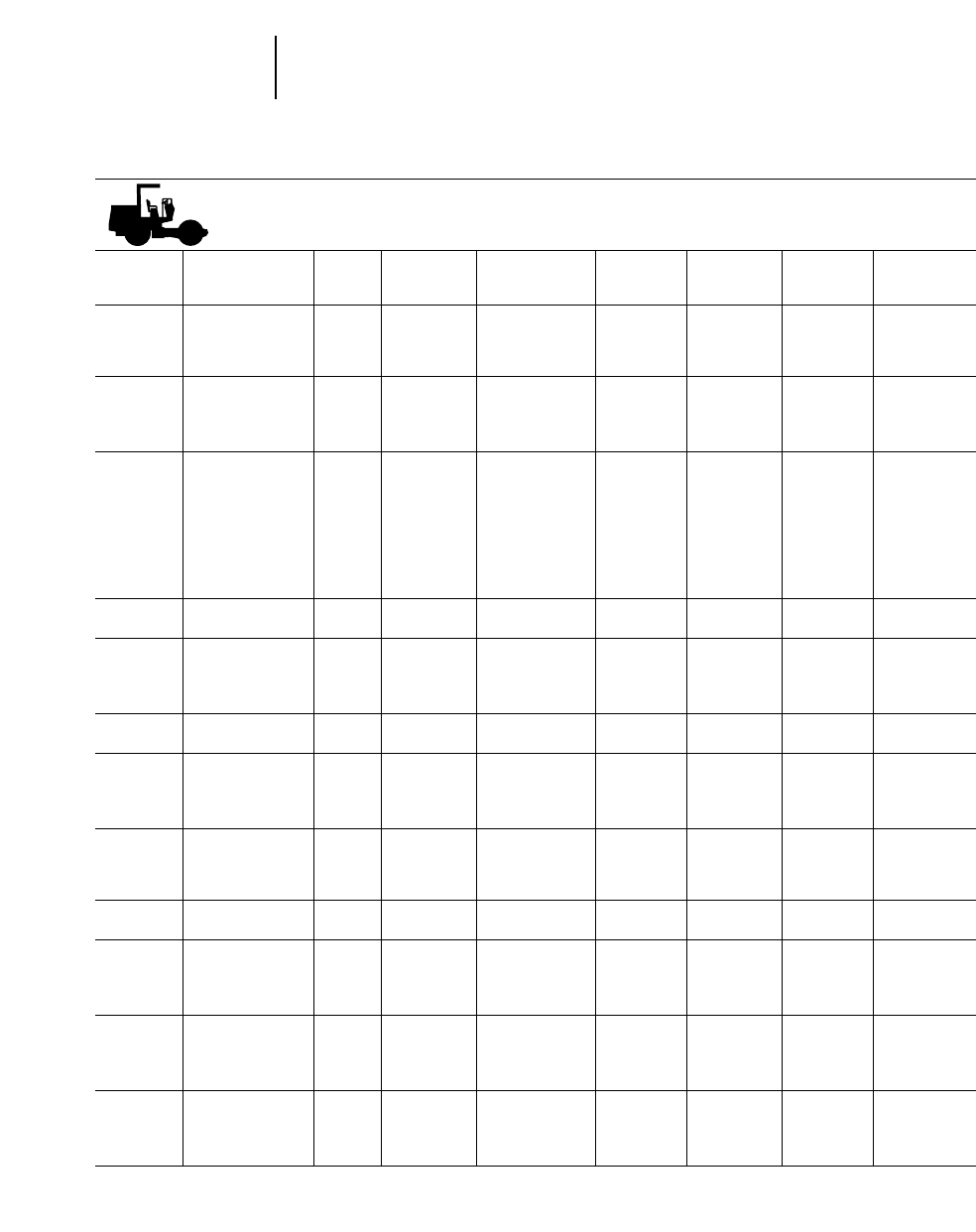
Former Models Paving Products
●Soil Vibratory Compactors
PAVING PRODUCTS — SOIL VIBRATORY COMPACTORS
Approx. Op. Drum Dynamic Maximum
Product Ident. Years Flywheel Weight Width Force Op. Speed
Model No. Prefix Built kW (hp) kg (lb) Drive mm (in) kg (lb) km/h (mph)
CS-323 1TM 85-95 57 4173 Wheel/ 1219 5760 0-10.9
(77) (9200) Drum (48") (12,700) (0-6.8)
CP-323 6JD 85-95 57 4218 Wheel/ 1219 5760 0-10.9
(77) (9300) Drum (48") (12,700) (0-6.8)
CS-431 6MD 85-87 52 6110 Wheel 1680 7260 21
(70) (13,480) (66") (16,000) (13)
CS-431B 1XF 88-94 76.5 6312 Wheel 1680 11 235 12.8
(102) (13,915) (66") (24,746) (8.0)
CS-433 6ND 85-87 60 6720 Wheel/ 1524 7260 10
(80) (14,820) Drum (60") (16,000) (6)
CP-433 6NP 85-87 60 6750 Wheel/ 1524 7260 10
(80) (14,870) Drum (60") (16,000) (6)
CS-433B 4FK 88-94 76.5 6448 Wheel/ 1680 11 235 12.8
(102) (14,215) Drum (66") (24,746) (8.0)
CP-433B 1MG 88-94 76.5 6668 Wheel/ 1680 11 235 12.8
(102) (15,225) Drum (66") (24,746) (8.0)
CS-531 3WM 93-95 108 9310 Wheel 2134 22 680 12.8
(145) (20,500) (84") (50,000) (8.0)
CS-533 3BL 93-95 108 10 110 Wheel/ 2134 22 680 12.8
(145) (22,500) Drum (84") (50,000) (8.0)
CP-533 3ZL 93-95 108 11 470 Wheel/ 2134 22 680 12.8
(145) (25,250) Drum (84") (50,000) (8.0)
CS-551 6ZD 85-89 115 10 428 Wheel 2130 18 150 12.1
8AD (155) (22,990) (84") (40,000) (7.5)
CS-553 7AD 85-89 115 10 782 Wheel/ 2130 18 150 10.5
(155) (23,770) Drum (84") (40,000) (6.5)
CP-553 7BD 85-89 115 12 247 Wheel/ 2130 22 680 10.5
(155) (27,000) Drum (84") (50,000) (6.5)
CS-563 8XF 89-95 108 11 130 Wheel/ 2134 22 680 12.8
(145) (24,500) Drum (84") (50,000) (8.0)
CP-563 1YJ 89-95 108 11 580 Wheel/ 2134 22 680 12.8
(145) (25,800) Drum (84") (50,000) (8.0)
CS-583 8YJ 91-95 108 15 040 Wheel/ 2134 22 680 12.8
(145) (33,090) Drum (84") (50,000) (8.0)
CS-643 7FD 85-87 100 14 900 Wheel/ 2200 16 800 15.5
(134) (32,855) Drum (86") (37,044) (9.6)
CP-643 7GD 85-87 100 16 300 Wheel/ 2200 12 600 15.5
(134) (35,942) Drum (86") (27,783) (9.6)
CS-653 7HD 85-91 100 17 100 Wheel/ 2200 22 230 15.5
(134) (37,690) Drum (86") (48,995) (9.6)
CP-653 7JD 85-91 100 18 500 Wheel/ 2200 22 230 15.5
(134) (40,774) Drum (86") (48,995) (9.6)
TSF-54 7KD 85-88 26 2131 Towed 1370 6810 Towed
(35) (4700) (54") (15,000)
TSM-54 7LD 86-88 26 2160 Towed 1370 6810 Towed
(35) (4760) (54") (15,000)
20-50

20
Former ModelsPaving Products
●Asphalt Vibratory Compactors
20-51
PAVING PRODUCTS — ASPHALT VIBRATORY COMPACTORS
Approx. Op. Drum Dynamic Maximum
Product Ident. Years Flywheel Weight Width Force Op. Speed
Model No. Prefix Built kW (hp) kg (lb) Drive mm (in) kg (lb) km/h (mph)
CB-214 6FD 85-88 24 2300 Drum (2) 1000 2041 10.6
(33) (5070) (39.4") (4500) (6.6)
CB-214B 6LF 88-93 24 2300 Drum (2) 990 2018 10.4
(33) (5072) (39") (4450) (6.5)
CB-224 6GD 85-88 24 2450 Drum (2) 1200 2450 10.6
(33) (5400) (47.2") (5400) (6.6)
CB-224B 6LF 88-93 24 2450 Drum (2) 1199 2449 10.4
(33) (5402) (47.2") (5400) (6.5)
CB-314 6HD 85-89 41 3357 Drum 1120 2770 8
(55) (7400) (44") (6100) (5)
CB-414 6KD 85-89 52 5780 Drum 1397 6350 13.7
(70) (12,750) (55") (14,000) (8.5)
CB-424 6LD 85-89 54 6220 Drum (2) 1397 4485 11.0
(73.5) (13,710) (55") (9885) (6.8)
CB-434 3TF 89-94 60 6610 Drum (2) 1422 7620 11.6
(80) (14,540) (56") (16,800) (7.2)
CB-434B* 6AL 94-95 60 6577 Drums 1422 7620 0-11.6
(80) (14,500) (56") (16,800) (0-7.2)
CB-514 6YD 85-88 68 9730 Drum (2) 1730 9073 11
(91) (21,450) (68") (20,000) (7)
CB-614 7CD 85-93 115 11 340 Drum (2) 1980 9525 11.2
(155) (25,000) (78") (21,000) (7)
CB-521 6RD 85-87 61 8800 Wheel 1700 5300 15
(82) (19,404) (67") (11,687) (9.3)
CB-522 6SD 85-87 45 10 100 Drum (2) 1700 10 350 8
(62) (22,271) (67") (22,822) (5)
CB-523 6TD 85-87 61 8800 Wheel/ 1700 5300 13
(82) (19,404) Drum (67") (11,687) (8)
CB-524 6WD 85-87 61 9500 Drum (2) 1700 10 350 11
(82) (20,948) (67") (22,822) (6.8)
CB-534 6EG2YF 87-93 93 9117 Drum (2) 1700 11 800 11.2
(125) (20,100) (67") (26,019) (7)
CB-534B* 4JL 93-95 80 9117 Drums 1676 12 043 0-11.3
(107) (20,100) (66") (26,550) (0-7.0)
CB-634 5CL 94-95 108 Drums 2134 12 043 0-9.2
(145) (84") (26,550) (0-5.7)
PF-200 85-92 49 7000 Wheel 1700 NA 24
(66) (15,430) Pneumatic (67") (14.9)
PS-110 7MD 85-96 57 12 500 Wheel 2134 NA 38.6
(77) (27,550) Pneumatic (84") (24)
PS-130 7ND 85-96 57 12 500 Wheel 1700 NA 38.6
(77) (27,550) Pneumatic (68") (24)
PS-150 7PD 85-96 57 15 050 Mechanical 1700 NA 38.6
(77) (37,300) (68") (24)
PS-300 85-95 77 21 000 Mechanical 1900 NA 26.5
PF-300 85-95 (102) (46,200) (75") (16.4)
*Non-current for U.S. only.
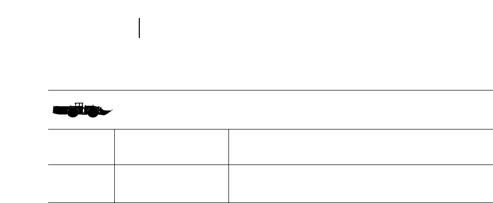
UNDERGROUND MINING
Product Approx. Max Bucket Breakout Maximum
Ident. No. Flywheel Operating Capacity Length Height Width Force Speeds
LHD Prefix Years Horsepower Weight kg m m mm kg km/h (mph)
Model (USA) Built kW (hp) kg (lb) (lb) (ft) (ft) (ft) (lb) Forward Reverse
R1500 NA NA 178 25 100 9000 9.19 2.30 2480 18 460 30.4 33.0
(239) (55,360) (19,850) (30'2") (7'7") (8'2") (140,700) (18.9) (20.5)
R2800 NA NA 231 42 660 16 200 10.70 2.68 3000 26 540 29.3 33.3
(310) (94,070) (35,720) (35'1") (8'10") (9'10") (68,530) (18.2) (20.7)
20-52
Former Models Underground Mining

CONTENTS
Estimating form . . . . . . . . . . . . . . . . . . . . . . . .21-2
Explanation of form:
Estimating Owning Costs . . . . . . . . . . . . . . .21-5
Guide for selecting ownership period . . . .21-6
Agricultural tractors depreciation . . . . . .21-9
Delivered price . . . . . . . . . . . . . . . . . . . . . .21-9
Residual value at replacement . . . . . . . . .21-9
Value to be recovered through work . . . .21-10
Interest . . . . . . . . . . . . . . . . . . . . . . . . . . .21-10
Insurance . . . . . . . . . . . . . . . . . . . . . . . . .21-10
Taxes . . . . . . . . . . . . . . . . . . . . . . . . . . . .21-10
Fuel consumption . . . . . . . . . . . . . . . . . . .21-11
Lube oils, filters, grease tables . . . . . . . .21-20
Tires:
Tire life estimator curves . . . . . . . . . . . .21-27
Goodyear life estimating system . . . . . .21-30
Undercarriage . . . . . . . . . . . . . . . . . . . . .21-31
Basic factors and conditions
multipliers . . . . . . . . . . . . . . . . . . . . . . . .21-32
Repair reserve . . . . . . . . . . . . . . . . . . . . .21-33
Cost estimating bar graphs . . . . . . . . . . .21-35
Special wear items . . . . . . . . . . . . . . . . . .21-42
Operator’s hourly wage . . . . . . . . . . . . . .21-42
O & O Cost Examples
Example I: Track-Type Tractor . . . . . . . . . .21-42
Example II: Wheel Loader . . . . . . . . . . . . .21-44
O & O form with example figures . . . . . . .21-45
Quick estimators . . . . . . . . . . . . . . . . . . . . . . .21-48
General
Machine users must balance Productivity and
Costs to achieve optimum performance ... that is,
achieve the desired production at the lowest possi-
ble cost. The approach most often used to measure
machine performance is this simple equation:
Lowest Possible Hourly Costs =Top Machine
____________________________
Highest Possible Performance
Hourly Productivity
Most sections of this Handbook deal with the pro-
ductivity of Caterpillar machines. This section con-
siders the cost aspect of performance.
Hourly Owning and Operating Costs for a given
machine can vary widely because they are influ-
enced by many factors: the type of work the machine
does, local prices of fuel and lubricants, shipping
costs from the factory, interest rates, etc. No attempt
is made in this handbook to provide precise hourly
costs for each model. Users must be able to estimate
with a reasonable degree of accuracy what a machine
will cost per hour to own and operate in a given appli-
cation and locality. Therefore, this section provides
a suggested method of estimating hourly owning
and operating costs as well as data on Caterpillar-
built machines which, when coupled with local con-
ditions, will permit accurate estimates.
The method suggested follows several basic
principles:
●No prices are provided for any items. For reliable
estimates, these must always be obtained locally.
●Calculations are based on the complete machine.
Separate estimates are not necessary for the basic
machine, dozer, control, etc.
●The multiplier factors provided will work equally
well in any currency expressed in decimals.
●Because of different standards of comparison, what
may seem a severe application to one machine
owner may appear only average to another. There-
fore, to better describe machine use, operating
conditions and applications are defined in zones.
●Unless otherwise specified, the word “hour” when
used in this section means clock or operating hours,
not Service Meter Units.
ESTIMATING OWNING & OPERATING COSTS
21-1
21
1
2
3
4
5
6
8
9
11
12
15
10a
10b

HOURLY OWNING AND OPERATING COST ESTIMATE DATE _____________
(1) (2)
Machine Designation . . . . . . . . . . . . . . . . . . . . . . . . . . . . . . . . . . . . . __________ __________
Estimated Ownership Period (Years) . . . . . . . . . . . . . . . . . . . . . . . . . __________ __________
Estimated Usage (Hours/Year) . . . . . . . . . . . . . . . . . . . . . . . . . . . . . __________ __________
Ownership Usage (Total Hours) . . . . . . . . . . . . . . . . . . . . . . . . . . . . __________ __________
OWNING COSTS
1. a. Delivered Price (including attachments) . . . . . . . . . . . . . . . . . __________ __________
b. Less Tire Replacement Cost if desired . . . . . . . . . . . . . . . . . . __________ __________
c. Delivered Price Less Tires . . . . . . . . . . . . . . . . . . . . . . . . . . . . __________ __________
2. Less Residual Value at Replacement . . . . . . . . . . . . . . . . . . . . . . (___%) __________ (___%) __________
(See subsection 2A on back)
3. a. Value to be recovered through work . . . . . . . . . . . . . . . . . . . . __________ __________
(line 1c less line 2)
b. Cost Per Hour:
Value
______ (1) __________ (2) __________ . . . . . . . . . . . . . . . . . . __________ __________
Hours
4. Interest Costs N + 1 3Del. Price 3Simple Int.
_____
N = No.Yrs. 2N % Rate
_________________________________ =
Hours/Year
+ 1 + 1
(1) _____ 3_______ 3___ % (2) _____ 3_______ 3___ %
______________________ =______________________ =__________ __________
_____ Hours/Yr. _____ Hours/Yr.
5. Insurance N + 1 3Del. Price 3Insurance
_____
N = No.Yrs. 2N % Rate
_________________________________ =
Hours/Year
+ 1 + 1
(1) _____ 3_______ 3___ % (2) _____ 3_______ 3___ %
______________________ =______________________ =__________ __________
_____ Hours/Yr. _____ Hours/Yr.
Or
$ __________ Per Yr. ÷ __________ Hours/Yr. = CATERPILLAR FORM NO. 01-085419-01 (52.00)
21-2
Owning & Operating Costs Estimating Form

(1) (2)
6. Property Tax N + 1 3Del. Price 3Tax Rate %
_____
N = No.Yrs. 2N
_________________________________ =
Hours/Year
+ 1 + 1
(1) _____ 3_______ 3___ % (2) _____ 3_______ 3___ %
______________________ =______________________ =__________ __________
_____ Hours/Yr. _____ Hours/Yr.
Or
$ __________ Per Yr. ÷ __________ Hours/Yr. =
7. TOTAL HOURLY OWNING COST
(add lines 3b, 4, 5, and 6) . . . . . . . . . . . . . . . . . . . . . . . . . . . .
OPERATING COSTS
8. Fuel: Unit Price 3Consumption
(1) ________ 3___________ =__________ __________
(2) ________ 3___________ =
9. Lube Oils, Filters, Grease:
(See subsection 9A on back) . . . . . . . . . . . . . . . . . . . . . . . . . . . . __________ __________
10. a. Tires: Replacement Cost ÷ Life in Hours
Cost
______ (1) __________ (2) __________ . . . . . . . . . . . . . . __________ __________
Life
b. Undercarriage
(Impact + Abrasiveness + Z Factor) 3Basic Factor
(1) (______ + ______ + ______) = ______ 3______ = __________ __________
(2) (______ + ______ + ______) = ______ 3______ =
(Total) (Factor)
11. Repair Reserve
(Extended Use Multiplier 3Basic Repair Factor)
(1) ______ 3______ = (2) ______ 3______ = __________ __________
12. Special Wear Items: Cost ÷ Life . . . . . . . . . . . . . . . . . . . . . . . . . . __________ __________
(See subsection 12A on back)
13. TOTAL OPERATING COSTS
(add lines 8, 9, 10a (or 10b), 11 and 12) . . . . . . . . . . . . . . . . . __________ __________
14. MACHINE OWNING PLUS OPERATING
(add lines 7 and 13) . . . . . . . . . . . . . . . . . . . . . . . . . . . . . . . . . __________ __________
15. OPERATOR’S HOURLY WAGE (include fringes) . . . . . . . . . . . . . __________ __________
16. TOTAL OWNING AND OPERATING COST . . . . . . . . . . . . . . . . . __________ __________
21-3
21
Owning & Operating CostsEstimating Form

SUBSECTION 2A: Residual Value at Replacement
Gross Selling Price (1) (___%) __________ (2) (___%) __________
Less: a. Commission __________ __________
b. Make-ready costs __________ __________
c. Inflation during
ownership period* __________ __________
Net Residual Value __________ (___%) __________ (___%) of original
(Enter on line 2) delivered price
*When used equipment auction prices are used to estimate residual value, the effect of inflation during the owner-
ship period should be removed to show in constant value what part of the asset must be recovered through work.
SUBSECTION 9A: Lube Oils, Filters, Grease
Unit Price 3Consumption = Cost/Hour
Engine (1)__________ 3__________ = ________ (2)__________ 3__________ = ________
Transmission __________ 3__________ = ________ __________ 3__________ = ________
Final Drives __________ 3__________ = ________ __________ 3__________ = ________
Hydraulics __________ 3__________ = ________ __________ 3__________ = ________
Grease __________ 3__________ = ________ __________ 3__________ = ________
Filters __________ 3__________ = ________ __________ 3__________ = ________
Total (1) ________ (2)__________
(Enter total on line 9 or use Quick Estimator Tables)
SUBSECTION 12A: Special Items
(cutting edges, ground engaging tools, bucket teeth, excavator stick repair, etc.)
(1) Cost Life Cost/Hour (2)
1. ____________ ÷ ____________ =____________ 1. ____________ ÷ ____________ = ____________
2. ____________ ÷ ____________ =____________ 2. ____________ ÷ ____________ = ____________
3. ____________ ÷ ____________ =____________ 3. ____________ ÷ ____________ = ____________
4. ____________ ÷ ____________ =____________ 4. ____________ ÷ ____________ = ____________
5. ____________ ÷ ____________ =____________ 5. ____________ ÷ ____________ = ____________
6. ____________ ÷ ____________ =____________ 6. ____________ ÷ ____________ = ____________
Total (1) ____________ (2) ____________
(Enter total on line 12)
REPAIR RESERVE CONVERSION FACTORS (line 11)
For use in countries outside the United States where parts and service costs might differ from those used in charts
and tables:
Labor Rate Ratio (1) ____________________ (2) ____________________
Parts Cost Ratio (1) ____________________ (2) ____________________
21-4
Owning & Operating Costs Supplemental Calculations to Estimating Form

(Line Items 1 through 7)
To protect his equipment investment and be able
to replace it, the machine owner must recover over
the machine’s useful life an amount equal to the loss
in resale value plus the other costs of owning the
equipment including interest, insurance and taxes.
The machine owner, for accounting purposes, esti-
mates resale value loss in advance, and recovers his
original equipment investment by establishing depre-
ciation schedules according to the various uses of the
equipment. Proper financial and tax assistance is
highly recommended when establishing deprecia-
tion schedules.
The machine depreciation method suggested
in this handbook is not based on or related to
any tax considerations, but rather is a simple
straight line write-off based solely on the num-
ber of years or hours the owner expects to use
the machine gainfully. Considering today’s eco-
nomic conditions worldwide and the trend toward
larger, more expensive equipment, many users
choose to keep these units on the job well after they
have been fully depreciated for tax purposes. On the
other hand, tax incentives in many areas may favor
trading a machine well before it approaches the limits
of its useful life.
Accordingly, it is imperative that careful con-
sideration be given the selection of depreciation
periods, and that for owning and operating cost
calculations they be based on useful life rather
than tax write-off life. The table of machine oper-
ating conditions (next page) only suggests such use-
ful life periods in clock or operating hours. Recognize,
however, that factors other than operating conditions
can influence machine depreciation periods — an
owner’s wish to accelerate recovery of his investment,
purchase of a machine for a job of specific duration,
local customs, local economic conditions, availabil-
ity of foreign exchange to buy a replacement, and
many others.
Maintenance practices are not considered in this
table but play an important part in determining eco-
nomic machine life. For example, operating condi-
tions may suggest a 12,000 hour depreciation period
for a machine, but poor maintenance could make it
uneconomical to retain the unit beyond 10,000 hours.
Good, regular maintenance often can extend econom-
ical machine life.
Therefore, a knowledge of the intended use, oper-
ating conditions and maintenance practices, plus any
special factors, is essential in establishing expected
machine life for depreciation purposes.
ESTIMATING OWNING COSTS
21-5
21
Owning & Operating CostsOwning Costs
1-7

GUIDE FOR SELECTING OWNERSHIP PERIOD BASED ON
APPLICATION AND OPERATING CONDITIONS
ZONE A ZONE B ZONE C
Moderate Average Severe
TRACK-TYPE
TRACTORS
D3-D7R
D8R/D9R
D10R/D11R
AGRICULTURAL
TRACTORS
CHALLENGER 35, 45 & 55
CHALLENGER 65E-95E
‘SR’TRACTORS
MOTOR GRADERS
120H Thru 16H
24H
EXCAVATORS
M312-M320, 307, 307B
311B-318B L
EXCAVATORS
320B, 322B,
325B, 330B
345B, 350, 375
5130B & 5230
FRONT SHOVELS
5080
5130B & 5230
21-6
Owning & Operating Costs Owning Costs
●Guide for Ownership Period
Pulling scrapers, most agricultural
drawbar, stockpile, coalpile.No impact.
Intermittent full throttle operation.
12,000 Hr
45,000 Hr
50,000 Hr
Pulling combines, grain wagons and
grain carts.
10,000 Hr
12,000 Hr
14,000 Hr
Light road maintenance. Finishing.
Plant and road mix work. Light
snowplowing. Large amounts of
traveling.
20,000 Hr
40,000 Hr
Utility construction, low density mate-
rial, rehandling and scrap handling
applications.
10,000 Hr
12,000 Hr
Shallow depth utility construction
where excavator sets pipe and digs
only 3 or 4 hours/shift. Free flowing,
low density material and little or no
impact. Most scrap handling arrange-
ments.
15,000 Hr
15,000 Hr
20,000 Hr
60,000 Hr
Continuous loading in loose banks
or stockpile. Good underfoot condi-
tions. (Might be considered similar
to “normal” wheel loader conditions.)
20,000 Hr
60,000 Hr
Continuous loading in well-shot rock
or fairly tight bank. Good underfoot
conditions; dry floor, little impact or
sliding on undercarriage.
18,000 Hr
50,000 Hr
Continuous loading in poorly-shot
rock, virgin or lightly-blasted tight
banks, e.g., shales, cemented grav-
els, caliches, etc.Adverse underfoot
conditions: rough floors; high impact
sliding on undercarriage.
15,000 Hr
40,000 Hr
Mass excavation or trenching where
machine digs all the time in natural
bed clay soils. Some traveling and
steady, full throttle operation. Most
log loading applications.
12,000 Hr
12,000 Hr
18,000 Hr
50,000 Hr
Continuous trenching or truck load-
ing in rock or shot rock soils. Large
amount of travel over rough ground.
Machine continuously working on
rock floor with constant high load
factor and high impact.
10,000 Hr
10,000 Hr
15,000 Hr
40,000 Hr
Continuous digging in sandy clay/
sandy gravel, site development and
lumber yard applications.
8,000 Hr
10,000 Hr
Continuous digging in rock/natural
bed clay, high impact, using ham-
mer, working in forests or quarries.
6,000 Hr
8,000 Hr
Haul road maintenance. Road con-
struction, ditching. Loose fill spreading.
Landforming, landleveling. Summer
road maintenance with medium to
heavy winter snow removal. Elevat-
ing grader use.
15,000 Hr
35,000 Hr
Maintenance of hard packed roads
with embedded rock. Heavy fill
spreading. Ripping-scarifying of
asphalt or concrete. Continuous
high load factor. High impact.
12,000 Hr
30,000 Hr
Pulling field cultivators, moldboard
plows, chisel plows, discing, primary
and finishing tillage.
8,000 Hr
10,000 Hr
12,000 Hr
Pulling layer scrapers, used in con-
struction applications, ripping, dozing.
N/A
8,000 Hr
10,000 Hr
Production dozing in clays, sands,
gravels.Pushloading scrapers, bor-
row pit ripping, most landclearing
applications. Medium impact condi-
tions. Production landfill work.
10,000 Hr
35,000 Hr
40,000 Hr
Heavy rock ripping. Pushloading
and dozing in hard rock.Work on rock
surfaces. Continuous high impact
conditions.
8,000 Hr
25,000 Hr
30,000 Hr

ZONE A ZONE B ZONE C
Moderate Average Severe
FELLER
BUNCHERS
BACKHOE
LOADERS
SKIDDERS
Wheel
Track
PIPELAYERS
561-572
583-589
WHEEL TRACTOR-
SCRAPERS
613C Series II,
615C Series II
621F-627F,631E-657E
CONSTRUCTION &
MINING TRUCKS &
TRACTORS
769D-777D
784C/785C/789C/793C
*Empty weight + payload.
21-7
21
Owning & Operating CostsOwning Costs
●Guide for Ownership Period
Continuous felling and stacking in
good underfoot conditions. Flat
ground uniform trees below 305 mm
(12 inches).
18,000 Hr
Light duty utility applications in light
to medium soil. Trenching depths
less 1.83 m (6 ft.)
12,000 Hr
Intermittent skidding for short dis-
tances, no decking.Good underfoot
conditions: level terrain, dry floor,
few if any stumps.
10,000 Hr
12,000 Hr
Little or no use in mud, water or on
rock. Use on level, regular surfaces.
20,000 Hr
25,000 Hr
Level or favorable hauls on good
haul roads. No impact. Easy-load-
ing materials.
12,000 Hr
22,000 Hr
Continuous operation at an average
gross weight less than recom-
mended. Excellent haul roads. No
overloading, low load factor. (See
Hourly Fuel Consumption section
for definition).
50,000 Hr
60,000 Hr
Continuous operation at an average
gross weight approaching recom-
mended. Minimal overloading, good
haul roads, moderate load factor.
(See Hourly Fuel Consumption sec-
tion for definition).
40,000 Hr
50,000 Hr
Continuous operation at or above
maximum recommended gross
weight. Overloading, poor haul
roads, high load factor. (See Hourly
Fuel Consumption section for
definition).
Note — Continual loading beyond
recommended maximum gross
weight will further reduce Zone C
hours. 30,000 Hr
40,000 Hr
Varying loading and haul road con-
ditions. Long and short hauls.
Adverse and favorable grades.
Some impact. Typical road-building
use on a variety of jobs.
10,000 Hr
17,000 Hr
High impact condition, such as load-
ing ripped rock. Overloading. Contin-
uous high total resistance conditions.
Rough haul roads.
8,000 Hr
12,000 Hr
Typical pipelayer use in operating
conditions ranging from very good
to severe.
15,000 Hr
20,000 Hr
Continuous use in deep mud or water
or on rock surfaces.
10,000 Hr
15,000 Hr
Continuous turning, steady skidding
for medium distances with moder-
ate decking. Good underfooting: dry
floor with few stumps and gradual
rolling terrain.
8,000 Hr
10,000 Hr
Continuous turning, steady skidding
for long distances with frequent
decking. Poor underfoot conditions:
wet floor, steep slopes and numer-
ous stumps.
7,200 Hr
8,000 Hr
Utility applications in medium to
heavy soil. Occasional use of con-
stant flow implements. Dig depths to
3.05 m (10 ft.)
10,000 Hr
Production applications or digging
in rock. Regular use of constant flow
implements. Dig depths over 3.05 m
(10 ft.)
5,000 Hr
Continuous cycling in good under-
foot conditions. Rolling terrain, some
trees up to 508 mm (20 inches) or
some hardwoods.
15,000 Hr
Continuous cycling in steep terrain
over stumps and fallen trees. Most
trees 508 mm (20 inches) or larger
hardwoods.
10,000 Hr

ZONE A ZONE B ZONE C
Moderate Average Severe
ARTICULATED
TRUCKS
WHEEL
TRACTORS &
COMPACTORS
WHEEL LOADERS
914G-966F Series II
970F
980G-992G
994
TRACK
LOADERS
933C-939C
953C
963B-973
INTEGRATED
TOOLCARRIERS
21-8
Owning & Operating Costs Owning Costs
●Guide for Ownership Period
Earthmoving and stockpile use with
well matched loading equipment.
Short to medium hauls on well-
maintained level haul roads. Free
flowing material. Few impact loads.
15,000 Hr
Light utility work. Stockpile work.
Pulling compactors. Dozing loose
fill. No impact.
15,000 Hr
Intermittent truck loading from stock-
pile, hopper charging on firm, smooth
surfaces. Free flowing, low density
materials. Utility work in governmen-
tal and industrial applications. Light
snowplowing.Load and carry on good
surface for short distances with no
grades.
12,000 Hr
12,000 Hr
15,000 Hr
60,000 Hr
Site clearing of small vegitation,
stripping top soil, carrying to stock-
pile. Intermittent truck loading from
stockpile. Free flowing, low density
materials with standard bucket. No
impact. Backfilling and grading.
8,000 Hr
10,000 Hr
12,000 Hr
Intermittent truck loading from stock-
pile, hopper charging on firm, smooth
surfaces. Free flowing, low density
materials. Utility work in govern-
mental and industrial applications.
Light snow-plowing. Load and carry
on good surface for short distances
with no grades.
12,000 Hr
Continuous truck loading from stock-
pile. Low to medium density materi-
als in properly sized bucket. Hopper
charging in low to medium rolling
resistance. Loading from bank in
good digging. Load and carry on poor
surfaces and slight adverse grades.
10,000 Hr
Loading shot rock (large loaders).
Handling high density materials with
counterweighted machine. Steady
loading from very tight banks. Contin-
uous work on rough or very soft sur-
faces. Load and carry in hard digging;
travel longer distances on poor sur-
faces with adverse grades.
8,000 Hr
Bank excavation, intermittent rip-
ping, basement digging of natural
bed clays, sands, silts, gravels.
Some traveling. Steady full throttle
operation.
6,000 Hr
8,000 Hr
10,000 Hr
Loading shot rock, cobbles, glacial
till, caliche. Steel mill work. High
density materials in standard bucket.
Continuous work on rock surfaces.
Large amount of ripping of tight, rocky
materials. High impact conditions.
Not Recommended
6,000 Hr
8,000 Hr
Continuous truck loading from stock-
pile. Low to medium density materi-
als in properly sized bucket. Hopper
charging in low to medium rolling
resistance.Loading from bank in good
digging. Load and carry on poor sur-
faces and slight adverse grades.
10,000 Hr
10,000 Hr
12,000 Hr
50,000 Hr
Loading shot rock (large loaders).
Handling high density materials with
counterweighted machine. Steady
loading from very tight banks. Contin-
uous work on rough or very soft sur-
faces. Load and carry in hard digging;
travel longer distances on poor sur-
faces with adverse grades.
8,000 Hr
—
10,000 Hr
40,000 Hr
Production dozing, pushloading in
clays, sands, silts, loose gravels.
Shovel clean-up.
12,000 Hr
Production dozing in rock. Push-
loading in rocky, bouldery borrow
pits. High impact conditions. Land-
fill compactor work.
8,000 Hr
Varying load and haul road condi-
tions. High rolling resistance and
poor traction during part of the job.
Some adverse grades.Some impact
loads. Typical use in road-building,
dam construction, open-pit mining,
etc.
10,000 Hr
Continuous use on very poorly main-
tained haul roads, high rolling resis-
tance and poor traction. Frequent
adverse grades and high impact
loads.Poorly-matched loading equip-
ment with continuous over-loading.
8,000 Hr
AGRICULTURAL TRACTOR DEPRECIATION
AND REPAIR COSTS
Unlike construction tractors which often are depre-
ciated over 10,000 hours, the expected useful life of
a Caterpillar steel tracked tractor in agriculture can
range up to and beyond 20,000 hours (about eighteen
years). The Challenger Tractor Line expected life is
about 10,000 hours.
The tractor’s decline in value is always a signifi-
cant portion of the machinery cost in farming. The
actual market value of any tractor is determined by
many variables ... machine age and condition, rate
of change in size and farm operations in the area,
popularity of given makes of tractors in the commu-
nity, etc.
Whatever the variables, the decline in value is
greater the first year than the second, greater the
second year than the third, etc. The shorter the
machine’s work life, the higher the percentage of its
value lost in a year.
Although the percentage of loss each year depends
on the life of the machine, it’s a general rule that
40 to 50% of the value will be lost in the first quar-
ter of the machine’s life. By the halfway point of life-
time, from 70 to 75% of value will be lost.
The sum of digits is a common, easily used method
for predicting the farm tractor’s depreciation value.
Assume a machine’s total life is 18 years. Assign
each of those years a value, beginning with 18 for
the first year, 17 for the second, 16 for the third, etc.
The sum of all 18 digits is 171 which when divided
into the initial new machine value, will give a spe-
cific monetary figure. The first year, 18 units of value
are written off, 17 the second year, etc.
The resale value loss for the first four-year’s of
machine life progresses as follows:
End Largest Loss of Loss of
of Remaining Value Value Remaining
Year Digit In Year To Date Value
1 18 18/171 or 10.5% 10.5% 89.5%
2 17 17/171 or 9.9% (10.5 + 9.9) 20.4% 79.6%
3 16 16/171 or 9.3% (20.4 + 9.3) 29.7% 70.3%
4 15 15/171 or 8.7% (29.7 + 8.7) 38.4% 61.6%
Repairs — The reverse of the sum of digits for-
mula can be used to predict repair costs for agricul-
tural tractors.
Again, assuming an 18-year life, the sum of the
digits would be 171. But the digit assigned the first
year would be 1, the second year 2, etc.
(NOTE: The digital method applied to depreciation
yields an eventual 100% of the purchase price. The
American Society of Agricultural Engineers recom-
mends repair costs for crawler tractors be figured at
78% and wheel tractors at 120% of purchase price.)
(Line Item 1a, b and c)
Delivered price should include all costs of putting
a machine on the user’s job including transporta-
tion and any applicable sales taxes.
On rubber tired machines, tires are considered a
wear item and covered as an operating expense.
Accordingly, some users may wish to deduct tire
costs from the delivered price particularly for larger
machines.
(Line Item 2 and Subsection 2A)
Any piece of earthmoving machinery will have
some residual value at trade-in. While many owners
prefer to depreciate their equipment to zero value,
others recognize the residual resale or trade-in value.
This is at the estimator’s option, but as in the dis-
cussion of depreciation, today’s higher equipment
costs almost dictate that resale value be considered
in determining the net depreciable investment. And
if machines are traded early for tax incentive pur-
poses, resale value becomes even more significant.
For many owners, potential resale or trade-in value
is a key factor in their purchasing decisions, since
this is a means of reducing the investment they must
recover through depreciation charges. The high
resale value of Caterpillar built machines can reduce
hourly depreciation charges, lower total hourly own-
ing costs and improve the owner’s competitive position.
RESIDUAL VALUE AT REPLACEMENT
DELIVERED PRICE
21-9
21
Owning & Operating CostsAg Tractors Depreciation
Delivered Price
Residual Value at Replacement
1
2
1
2
When resale or trade-in value is used in estimat-
ing hourly owning and operating costs, local cond-
tions must be considered, as used equipment values
vary widely around the world. However, in any given
used equipment business, factors which have great-
est influence on resale or trade-in value are the num-
ber of hours on the machine at the time of sale or
trade, the type of jobs and operating conditions in
which it worked, and the physical condition of the
machine. Your local Cat Dealer is your best source for
determining current used equipment values.
Subsection 2A can be used to calculate the esti-
mated residual value. If recent auction prices for
used machines are used as a guide, then the value
(or percentage) should be adjusted downward to
remove the effect of inflation. Governmental indices
on construction equipment costs or Dealer price
records can be used to calculate the amount of infla-
tion for the appropriate useful life. Another way to
estimate residual value is comparing the current
used machine value to the current new machine
price provided major product changes haven’t
occurred.
(Line Item 3a and b)
The delivered price less the estimated residual
value results in the value to be recovered through
work, divided by the total usage hours, gives the
hourly cost to protect the asset’s value.
(Line Item 4)
Many owners charge interest as part of hourly
owning and operating costs, others consider it as
general overhead in their overall operation. When
charged to specific machines, interest is usually
based on the owner’s average annual investment in
the unit.
Interest is considered to be the cost of using cap-
ital. The interest on capital used to purchase a
machine must be considered, whether the machine
is purchased outright or financed.
If the machine will be used for N years (where N
is the number of years of use), calculate the aver-
age annual investment during the use period and
apply the interest rate and expected annual usage:
[N + 1 ]Simple Interest
______ 3Delivered Price 3% rate
2N
_______________________________________________
hours/year
(Line Items 5 and 6)
Insurance cost and property taxes can be calcu-
lated in one of two ways. If the specific annual cost
is known this figure should be multiplied by the
estimated usage (hours/years) and used. However,
when the specific interest and tax costs for each
machine are not known, the following formulas can
be applied:
Insurance
_____________
N = No. Years
[N + 1 ]
______ 3Delivered Price 3Insurance rate %
2N
_______________________________________________
hours/year
Property Tax
______________
N = No. Years
[N + 1 ]
______ 3Delivered Price 3Tax rate %
2N
________________________________________________
hours/year
INSURANCE AND TAXES
INTEREST
VALUE TO BE RECOVERED
THROUGH WORK
21-10
Owning & Operating Costs Value to be Recovered Through Work
Interest
Insurance
Taxes
3
4
5
6
3
4
5-6

(Line Items 8 through 13)
(Line Item 8)
Fuel consumption can be closely measured in the
field. However, if no opportunity exists to do this,
consumption can be predicted when the machine
application is known.
Application determines engine load factor which
in turn controls engine fuel consumption. An engine
continuously producing full rated horsepower is oper-
ating at a load factor of 1.0. Earthmoving machines
may reach a 1.0 load factor intermittently, but sel-
dom operate at this level for extended periods of
time. Periods spent at idle, dozer and pusher travel
in reverse, haul units traveling empty, close maneu-
vering at part throttle and operating downhill are
examples of conditions which reduce load factor.
The following tables provide hourly fuel consump-
tion estimates at various load factors for Caterpillar
built machines. Since machine uses vary, applica-
tion guides are also provided to aid in estimating
load factor.
To estimate hourly fuel cost, select the load factor
based on application and find hourly consumption.
Then:
Hourly consumption 3Local Unit Price of Fuel =
Hourly Fuel Cost
When using these tables, keep in mind the many
variables which can affect fuel consumption. Two
operators of different temperament or attitude oper-
ating identical machines side by side in the same
material can have as much as 10-12% difference in
their consumption rates. However, the ranges shown
should be applicable across a wide spectrum of con-
ditions. Your Caterpillar dealer representative can
help select the most reasonable estimate for your
specific situation; we suggest you call on him.
Keep in mind also that a fuel consumption study
measured over a short period of operation will give
higher fuel consumption than shown here because:
(1) the study will be at 100% efficiency, without
breaks or idle time, and (2) the operators will know
they’re “under the gun” to produce and look good.
On the other hand, these tables allow for “normal”
inefficiencies in the working cycle and will more
closely relate to “normal” day to day operation.
FUEL CONSUMPTION
ESTIMATING OPERATING COSTS
21-11
21
Owning & Operating CostsFuel Consumption
8-13
8
8
FUEL CONSUMPTION TABLES & LOAD FACTOR GUIDES
TRACK-TYPE TRACTORS
Model Low Medium High
liter U.S. gal liter U.S. gal liter U.S. gal
D3C & LGP Series III 4-71⁄21-2 71⁄2-11 2-3 91⁄2-13 21⁄2-31⁄2
D4C & LGP Series III 51⁄2-91⁄211⁄2-21⁄291⁄2-13 21⁄2-31⁄211-15 3-4
D5C & LGP Series III 51⁄2-91⁄211⁄2-21⁄291⁄2-13 21⁄2-31⁄213-17 31⁄2-41⁄2
D4E 51⁄2-91⁄211⁄2-21⁄291⁄2-13 21⁄2-31⁄211-15 3-4
D5M XL & LGP 6-101⁄211⁄2-3 101⁄2-141⁄23-4 121⁄2-17 31⁄2-41⁄2
D5B 91⁄2-13 21⁄2-31⁄211-17 3-41⁄215-21 4-51⁄2
D6M XL & LGP 11-15 3-4 121⁄2-191⁄231⁄2-5 17-24 41⁄2-61⁄2
D6G 11-201⁄231⁄2-5 151⁄2-21 4-6 23-281⁄26-71⁄2
D6R XL, XR & LGP 13-221⁄231⁄2-6 171⁄2-25 41⁄2-61⁄225-301⁄261⁄2-81⁄2
D7G Series II* 19-25 5-61⁄226-34 7-9 32-40 81⁄2-101⁄2
D7R XR & LGP 19-23 5-6 25-28 61⁄2-71⁄232-36 81⁄2-10
D8R & LGP 23-28 6-71⁄228-38 71⁄2-10 38-51 10-131⁄2
D9R 36-47 91⁄2-121⁄247-58 121⁄2-151⁄260-76 16-20
D10R 44-59 111⁄2-151⁄259-76 151⁄2-20 76-93 20-241⁄2
D11R 62-87 161⁄2-23 87-112 23-291⁄2112-134 291⁄2-351⁄2
*D7G fuel consumption data is based on a precombustion chamber equipped engine. Fuel consumption for a direct injection equipped D7G should be approximately 10% less.
AGRICULTURAL TRACTORS
Model Low Medium High
liter U.S. gal liter U.S. gal liter U.S. gal
D4E SR 51⁄2-91⁄211⁄2-21⁄291⁄2-13 21⁄2-31⁄211-15 3-4
D6G SR 11-19 3-5 15-21 4-51⁄221-26 51⁄2-7
Challenger 35 91⁄2-21 21⁄2-51⁄221-32 51⁄2-81⁄232-42 81⁄2-11
Challenger 45 91⁄2-23 21⁄2-6 23-38 6-10 38-45 10-12
Challenger 55 11-26 3-7 26-42 7-11 42-53 11-14
Challenger 65E 34-42 9-11 42-49 11-13 49-61 13-16
Challenger 75E 34-42 9-11 42-49 11-13 53-64 14-17
Challenger 85E 34-42 9-11 42-53 11-14 53-61 14-16
Challenger 95E 34-42 9-11 45-57 12-15 57-72 15-19
LOAD FACTOR GUIDE
High: Steady ripping, shuttle pushloading and downhill dozing. Agricultural drawbar work at full throttle,
engine lugged to max. power most of the time. Little or no idling or travel in reverse.
Medium: Production dozing, pulling scrapers, most pushloading. Agricultural drawbar work at full throttle but
not always lugging engine. Some idling and some travel with no load.
Low: Considerable idling or travel with no load.
21-12
Owning & Operating Costs Hourly Fuel Consumption Tables
●Track-Type Tractors
●Agricultural Tractors
8
MOTOR GRADERS
Model Low Medium High
liter U.S. gal liter U.S. gal liter U.S. gal
120H* 9-13 2.4-3.4 13-17 3.4-4.5 17-21 4.5-5.5
135H* 10-14 2.6-3.7 14-18 3.7-4.8 18-22 4.8-5.9
12H 11-16 2.9-4.2 16-21 4.2-5.5 21-26 5.5-6.7
140H* 12-17 3.1-4.4 17-22 4.4-5.7 22-26 5.7-7.0
143H** 12-17 3.2-4.6 17-22 4.6-5.9 22-28 5.9-7.3
160H* 14-20 3.7-5.3 20-26 5.3-6.8 26-32 6.8-8.4
163H** 14-21 3.8-5.4 20-27 5.4-7.0 27-33 7.0-8.6
14H 15-22 4.0-5.8 22-28 5.8-7.5 28-35 7.5-9.2
16H 19-27 5.0-7.1 27-35 7.1-9.2 35-43 9.2-11.3
24H 32-46 8.6-12.2 46-60 12.2-15.8 60-74 15.8-19.4
***Multiply consumption by 1.10 when equipped with Variable Horsepower or Engine Power Management.
***Multiply consumption by 1.15 when operating in All Wheel Drive.
LOAD FACTOR GUIDE
High: Ditching, fill spreading, spreading base material, ripping, heavy road maintenance, snow plowing.
Medium: Average road maintenance, road mix work, scarifying, snow plowing.
Low: Finish grading, light maintenance, road travel.
EXCAVATORS
Model Low Medium High
liter U.S. gal liter U.S. gal liter U.S. gal
301.5 * *****
307/307B 3-5 3⁄4-11⁄45-8 11⁄4-2 7-10 13⁄4-21⁄2
311B 4-6 1-11⁄26-9 11⁄2-21⁄49-12 21⁄4-31⁄2
312B/312B L 4-6 1-11⁄26-10 11⁄2-21⁄210-13 21⁄2-31⁄2
315B 5-9 11⁄4-21⁄49-13 21⁄4-31⁄213-15 31⁄2-4
318B L * *****
M312 5-9 11⁄4-21⁄49-12 21⁄4-31⁄212-15 31⁄2-4
M315 6-10 13⁄4-21⁄210-13 21⁄2-31⁄213-16 31⁄2-41⁄2
M318 8-12 2-31⁄212-16 31⁄2-4 17-19 41⁄2-5
M320 9-13 2-31⁄213-17 31⁄2-41⁄217-20 41⁄2-51⁄2
320B 9-13 21⁄2-31⁄213-15 31⁄2-4 15-19 4-5
322B 11-15 3-4 16-18 41⁄4-43⁄418-23 43⁄4-61⁄4
325B 13-16 31⁄2-41⁄418-21 43⁄4-51⁄225-27 63⁄4-71⁄4
330B 18-24 43⁄4-61⁄224-30 61⁄2-8 34-38 9-10
345B 25-30 51⁄2-8 35-40 91⁄4-101⁄245-50 113⁄4-131⁄4
350 23-28 6-71⁄232-37 81⁄2-93⁄447-53 121⁄2-14
375 33-38 83⁄4-10 42-48 11-123⁄461-67 16-173⁄4
5130B 91-95 24-25 110-114 29-30 129-132 34-35
5230 163-193 43-51 193-204 51-54 208-227 55-60
*Insufficient data.
LOAD FACTOR GUIDE
High: Most pipeline applications in hard rocky material. Digging 90-95% of the daily work schedule.
Medium: Most residential sewer applications in natural bed clay. Digging 60-85% of the daily work sched-
ule. Most log loading applications.
Low: Most utility, urban applications in sandy loam. Digging less than 50% of the daily work schedule.
Scrap handling applications.
21-13
21
Owning & Operating CostsHourly Fuel Consumption Tables
● Motor Graders
● Excavators & Feller Bunchers
8
FRONT SHOVELS
Model Low Medium High
liter U.S. gal liter U.S. gal liter U.S. gal
5080 36-42 10-11 46-53 12-14 62-74 18-20
5130B 91-95 24-25 110-114 29-30 129-132 34-35
5230 163-193 43-51 193-204 51-54 208-227 55-60
LOAD FACTOR GUIDE
High: Steady cycling in hard to dig material.
Medium: Steady cycling with frequent periods at idle.
Low: Light easy work. Considerable idling.
PIPELAYERS
Model Low Medium High
liter U.S. gal liter U.S. gal liter U.S. gal
561M 4-71⁄21-2 71⁄2-11 2-3 91⁄2-13 21⁄2-31⁄2
572R 71⁄2-11 2-3 13-17 31⁄2-41⁄217-21 41⁄2-51⁄2
583R 91⁄2-13 21⁄2-31⁄2161⁄2-20 41⁄2-51⁄2221⁄2-26 61⁄2-71⁄2
589 17-21 41⁄2-51⁄226-30 7-8 34-40 9-101⁄2
LOAD FACTOR GUIDE
Pipelayer load factor depends largely on amount of time spent at idle speed.
WHEEL TRACTOR-SCRAPERS
Model Low Medium High
liter U.S. gal liter U.S. gal liter U.S. gal
613C Series II 15-19 4-5 21-25 51⁄2-61⁄2271⁄2-34 71⁄4-9
615C Series II 23-26 6-7 30-36 8-91⁄242-471⁄211-121⁄2
621F 27-32 7-81⁄238-44 10-111⁄249-57 13-15
623F 30-36 8-91⁄240-46 101⁄2-12 53-59 14-151⁄2
627F 451⁄2-51 12-131⁄264-70 17-181⁄285-891⁄2221⁄2-231⁄2
631E Series II 40-45 101⁄2-12 53-59 14-151⁄272-78 19-201⁄2
633E Series II 45-49 12-13 56-62 15-161⁄278-81 201⁄2-211⁄2
637E Series II 64-70 17-181⁄287-93 23-241⁄21131⁄2-121 30-32
651E 47-57 121⁄2-15 66-76 171⁄2-20 87-95 23-25
657E 87-98 23-26 116-1251⁄2301⁄2-33 153-163 401⁄2-43
LOAD FACTOR GUIDE
High: Continuous high total resistance conditions with steady cycling.
Medium: Typical road building use.
Low: Average use but with considerable idling, favorable grades, low rolling resistance and easy loading
material.
21-14
Owning & Operating Costs Hourly Fuel Consumption Tables
●Front Shovels ●Pipelayers
●Wheel Tractor-Scrapers
8
21-15
21
Owning & Operating CostsHourly Fuel Consumption Tables
● Backhoe Loaders ● Skidders
8
BACKHOE LOADERS
Model Low Medium High
liter U.S. gal liter U.S. gal liter U.S. gal
416C (NA) 4.5-6.4 1.2-1.7 6.4-8.3 1.7-2.2 8.3-10.2 2.2-2.7
428C (NA) 4.5-6.4 1.2-1.7 6.4-8.3 1.7-2.2 8.3-10.2 2.2-2.7
416C (T) 5.3-7.2 1.4-1.9 7.2-9.1 1.9-2.4 9.1-11.4 2.4-3.0
428C (T) 5.3-7.2 1.4-1.9 7.2-9.1 1.9-2.4 9.1-11.4 2.4-3.0
426C 5.3-7.2 1.4-1.9 7.2-9.1 1.9-2.4 9.1-11.4 2.4-3.0
436C 6.1-8.3 1.6-2.2 8.3-10.2 2.2-2.7 10.2-12.5 2.7-3.3
438C 6.1-8.3 1.6-2.2 8.3-10.2 2.2-2.7 10.2-12.5 2.7-3.3
446B 7.6-9.8 2.0-2.6 9.8-12.1 2.6-3.2 12.1-14.4 3.2-3.8
NA = Naturally Aspirated
T = Turbocharged
LOAD FACTOR GUIDE
High: Production work with long cycles and/or constant flow implements.
Medium: General work with regular cycles in medium applications.
Low: Utility work with intermittent cycles in light to medium applications.
SKIDDERS
Model Low Medium High
liter U.S. gal liter U.S. gal liter U.S. gal
515 9-12 21⁄2-31⁄412-16 31⁄4-41⁄416-22 41⁄4-53⁄4
525 10-14 23⁄4-33⁄414-18 33⁄4-43⁄418-25 43⁄4-61⁄2
528B 13-17 31⁄2-41⁄219-23 5-6 23-28 6-71⁄2
517 7-13 11⁄2-31⁄213-18 31⁄2-5 15-21 4-51⁄2
527 14-19 33⁄4-5 19-24 5-61⁄424-32 61⁄4-81⁄2
LOAD FACTOR GUIDE — 515
High: Skidding loads over 4536 kg (10,000 lb) in steep terrain (over 10%) with high skidding resistance.
Medium: Skidding loads up to 4536 kg (10,000 lb) in medium (5-10%) terrain with average skidding resistance.
Low: Skidding loads less than 2720 kg (6000 lb) in flat terrain (0-5%) with low skidding resistance.
LOAD FACTOR GUIDE — 525
High: Skidding loads over 6800 kg (15,000 lb) in steep terrain (over 10%) with high skidding resistance.
Medium: Skidding loads up to 6800 kg (15,000 lb) in moderate terrain (5-10%) with average skidding resistance.
Low: Skidding loads less than 4500 kg (10,000 lb) in flat terrain (0-5%) with low skidding resistance.
LOAD FACTOR GUIDE — 528B
High: Skidding loads over 11 300 kg (25,000 lb) in steep terrain (over 10%) with high skidding resistance.
Medium: Skidding loads up to 11 300 kg (25,000 lb) in moderate terrain (5-10%) with average skidding resistance.
Low: Skidding loads less than 6800 kg (15,000 lb) in flat terrain (0-5%) with low skidding resistance.
LOAD FACTOR GUIDE — 517
High: Skidding loads over 4536 kg (10,000 lb) in steep terrain (over 30%) with high skidding resistance.
Medium: Skidding loads up to 4536 kg (10,000 lb) in moderate terrain (8-30%) with medium skidding resistance.
Low: Skidding loads less than 4536 kg (10,000 lb) in flat terrain (0-8%) with low skidding resistance.
LOAD FACTOR GUIDE — 527
High: Skidding loads over 6360 kg (14,000 lb) in steep terrain (over 30%) with high skidding resistance.
Medium: Skidding loads up to 6360 kg (14,000 lb) in moderate terrain (8-30%) with medium skidding resistance.
Low: Skidding loads less than 6360 kg (14,000 lb) in flat terrain (0-8%) with low skidding resistance.
CONSTRUCTION & MINING TRUCKS & TRACTORS
Model Low Medium High
liter U.S. gal liter U.S. gal liter U.S. gal
769D 20.8-30.3 51⁄2-8 30.3-40 8-101⁄240-68 101⁄2-14
771D 22.7-32.2 6-81⁄232.2-41.6 81⁄2-11 41.6-55 11-141⁄2
773D 24.5-36 61⁄2-91⁄236-53 91⁄2-14 53-68 14-18
775D 30.3-41.6 8-11 41.6-56.8 11-15 56.8-73.8 15-191⁄2
776D 53.0-73.8 14-191⁄273.8-96.5 191⁄2-251⁄296.5-117.3 251⁄2-31
777D 36.0-53.0 91⁄2-14 53.0-73.8 14-191⁄273.8-96.5 191⁄2-251⁄2
784C/785C 53.0-79.5 14-21 79.5-109.8 21-29 100.8-145.7 29-381⁄2
789C 68.1-102.2 18-27 102.2-141.9 27-371⁄2141.9-185.5 371⁄2-49
793C 86-129 23-34 129-172 34-451⁄2172-215 451⁄2-57
NOTE: Load factors above 50% may be experienced in many applications.
LOAD FACTOR GUIDE
Low: 20%-30% Medium: 30%-40% High: 40%-50%
ARTICULATED TRUCKS
Model Low Medium High
liter U.S. gal liter U.S. gal liter U.S. gal
D25D 13.1-18.3 3.5-4.8 18.3-25.7 4.8-6.8 25.7-37.1 6.8-9.8
D30D 14.7-20.4 3.9-5.4 20.4-28.7 5.4-7.6 28.7-41.5 7.6-11.0
D250E 13.2-18.3 3.5-4.8 18.3-25.8 4.8-6.8 25.8-37.2 6.8-9.8
D300E 14.2-19.7 3.7-5.2 19.7-27.7 5.2-7.3 27.7-40.0 7.3-10.6
D350E 15.9-22.2 4.2-5.9 22.2-31.2 5.9-8.2 31.2-45.0 8.2-11.9
D400E 17.6-24.5 4.6-6.5 25.2-35.4 6.7-9.4 36.1-52.2 9.6-13.8
LOAD FACTOR GUIDE
High: Long haul time with frequent adverse grades. Continuous use on very poorly maintained haul roads
with high rolling resistance.
Medium: Normal load and haul time. Varying load and haul road conditions. Some adverse grades. Some
high rolling resistance.
Low: Large amount of idling. Short to medium hauls on well maintained level haul roads. Minimum total
resistance.
TELEHANDLERS
Model Intermittent Continuous
liter U.S. gal liter U.S. gal
TH62 NA 11.00 2.90 16.00 4.22
TH62 T 14.20 3.75 19.60 5.17
TH63 NA 11.00 2.90 16.00 4.22
TH63 T 14.20 3.75 19.60 5.17
TH82 NA 11.00 2.90 16.00 4.22
TH82 T 14.20 3.75 19.60 5.17
TH83 T 14.20 3.75 19.60 5.17
LOAD FACTOR GUIDE
Continuous: Continuous loading/cycling applications.
Intermittent: Average loading/cycle applications with periods at idle.
21-16
Owning & Operating Costs Hourly Fuel Consumption Tables
●Construction & Mining Trucks/Tractors
●Articulated Dump Trucks ●Telehandlers
8
WHEEL TRACTORS & COMPACTORS
Model Low Medium High
liter U.S. gal liter U.S. gal liter U.S. gal
814F 21-25 51⁄2-61⁄226-30 7-8 36-40 91⁄2-101⁄2
815F 26-30 7-8 36-42 91⁄2-11 44-47 111⁄2-121⁄2
816F 26-30 7-8 36-42 91⁄2-11 44-47 111⁄2-121⁄2
824G 28-32 71⁄2-81⁄238-44 10-111⁄251-57 131⁄2-15
825G 36-42 91⁄2-11 51-57 131⁄2-15 60-66 16-171⁄2
826G 36-42 91⁄2-11 51-57 131⁄2-15 60-66 16-171⁄2
834B 40-45 101⁄2-12 53-59 14-151⁄272-78 19-201⁄2
836 40-45 101⁄2-12 52-59 13-151⁄272-78 19-201⁄2
844 45-53 12-14 601⁄2-68 16-18 791⁄2-87 21-23
854G 58-66 15-17 83-91 22-24 116-125 30-33
LOAD FACTOR GUIDE
High: Heavy dozing, compacting heavy material. Heavy landfill work.
Medium: Production dozing, most pushloading, shovel cleanup, normal compaction.
Low: Considerable idling or travel with no load.
COMPACTION EQUIPMENT
Model Low Medium High
liter U.S. gal liter U.S. gal liter U.S. gal
CS-323C 8-11 2-3 11-13 3-31⁄211-15 3-4
CS-431C 8-11 2-3 11-13 3-31⁄211-15 3-4
CS-433C 11 311-13 3-31⁄213-15 31⁄2-4
CS-563C 13 31⁄213-15 31⁄2-4 15-21 4-51⁄2
CS-573 13 31⁄213-15 31⁄2-4 15-21 4-51⁄2
CS-583C 15-17 4-41⁄217-19 41⁄2-5 19-23 5-6
CP-323C 9-13 21⁄2-31⁄213-15 31⁄2-4 15-19 4-5
CP-433C 13 31⁄215-17 4-41⁄217-19 41⁄2-5
CP-533C 15 417-19 41⁄2-5 19-25 5-61⁄2
CP-563C 15 417-19 41⁄2-5 21-25 51⁄2-61⁄2
CB-214C 6-8 11⁄2-2 8-9 2-21⁄29-13 21⁄2-31⁄2
CB-224C 8 29-11 21⁄2-3 11-15 3-4
CB-434C 11-13 3-31⁄213-17 31⁄2-41⁄217-19 41⁄2-5
CB-534C 13 31⁄215-17 4-41⁄217-23 41⁄2-6
CB-535B 13 31⁄215-17 4-41⁄217-23 41⁄2-6
CB-544 11-13 3-31⁄213-17 31⁄2-41⁄217-19 41⁄2-5
CB-545 11-13 3-31⁄213-17 31⁄2-41⁄217-19 41⁄2-5
CB-634C 13-15 31⁄2-4 15-19 4-5 19-21 5-51⁄2
PF-300B 13 31⁄215-17 4-41⁄217-23 41⁄2-6
PS-300B 13 31⁄215-17 4-41⁄217-23 41⁄2-6
PS-500 13-15 31⁄2-4 15-19 4-5 19-21 5-51⁄2
LOAD FACTOR GUIDE
High: Vibration 80-100%, heavy cohesive soil, 305 mm (12") lifts or more.
Medium: Vibration 50-80%, granular soil, 100 mm-305 mm (4"-12") lifts.
Low: Vibration 30-50%, asphalt mix, 51 mm-305 mm (2"-4") lifts.
21-17
21
Owning & Operating CostsHourly Fuel Consumption Tables
● Wheel Tractors & Compactors
● Compaction Equipment
8
ASPHALT PAVERS
Model Low Medium High
liter U.S. gal liter U.S. gal liter U.S. gal
BG-201B 11-13 3-31⁄213-15 31⁄2-4 15-19 4-5
AP-800C 11-15 3-4 15-19 4-5 17-19 41⁄2-5
AP-1000B 18-20 43⁄4-51⁄422-24 53⁄4-61⁄425-27 61⁄2-71⁄4
AP-650B 11-15 3-4 15-19 4-5 19-21 5-51⁄2
AP-1050B 19-21 5-51⁄223-25 6-61⁄226-28 63⁄4-71⁄2
AP-1055B 19-21 5-51⁄223-25 6-61⁄226-28 63⁄4-71⁄2
BG-650 11-13 3-31⁄213-17 31⁄2-41⁄217-19 41⁄2-5
BG-730 13-17 31⁄2-41⁄217-19 41⁄2-5 19-25 5-61⁄2
LOAD FACTOR GUIDE
High: Wide width, deep lift paving.
Medium: 3-4 m (10'-12') width, 50-75 mm (2"-3") lift.
Low: Narrow width paving — low production.
WHEEL LOADERS & INTEGRATED TOOLCARRIERS
Model Low Medium High
liter U.S. gal liter U.S. gal liter U.S. gal
902 * *****
906 * *****
914G, IT14G 5-61⁄21-2 8-101⁄22-23⁄4111⁄2-13 3-31⁄2
924F, IT24F 51⁄2-71⁄211⁄2-2 91⁄2-12 21⁄2-3 13-15 31⁄2-4
928G, IT28G 71⁄2-11 2-3 11-15 3-4 15-19 4-5
938G, IT38G 9-121⁄22-3 13-17 31⁄2-41⁄218-22 43⁄4-53⁄4
950G 11-15 3-4 17-21 41⁄2-51⁄223-28 6-71⁄2
962G, IT62G 12-16 3-4 18-22 5-6 24-29 61⁄2-8
966F Series II 17-21 41⁄2-51⁄223-28 6-71⁄232-38 81⁄2-10
970F 19-23 5-6 25-30 61⁄2-8 35-41 9-11
980G 23-26 6-7 30-36 8-91⁄242-47 11-121⁄2
988F Series II 32-38 81⁄2-10 44-49 111⁄2-13 60-66 16-171⁄2
990 Series II 45-53 12-14 601⁄2-68 16-18 791⁄2-87 21-23
992G 58-66 15-17 83-91 22-24 116-125 30-33
994 102-1091⁄227-29 129-144 34-38 163-178 43-47
*Insufficient data.
LOAD FACTOR GUIDE
High: Steady cycling on basic loader cycle.
Medium: Steady cycling but over haul distances or work on basic loader cycle with frequent periods at idle.
Low: Light utility work. Considerable idling.
21-18
Owning & Operating Costs Hourly Fuel Consumption Tables
●Asphalt Pavers
●Wheel Loaders & Integrated Toolcarriers
8
TRACK LOADERS
Model Low Medium High
liter U.S. gal liter U.S. gal liter U.S. gal
933C 31⁄2-71⁄21-2 71⁄2-11 2-3 91⁄2-13 21⁄2-31⁄2
939C 51⁄2-91⁄211⁄2-21⁄291⁄2-13 21⁄2-31⁄213-17 31⁄2-41⁄2
953C 91⁄2-13 21⁄2-31⁄215-19 4-5 19-23 5-6
963B 13-17 31⁄2-41⁄219-23 5-6 23-28 6-71⁄2
973 19-23 5-6 28-34 71⁄2-9 36-42 91⁄2-11
LOAD FACTOR GUIDE
High: Continuous excavating and loading from bank. Land clearing.
Medium: Bank or stockpile loading with idling periods. Load and carry.
Low: Large amounts of idling in any application.
21-19
21
Owning & Operating CostsHourly Fuel Consumption Tables
●Track Loaders
8
21-20
Owning & Operating Costs Lube Oils, Filters, Grease
●Lubricants
(Line Item 9 and Subsection 9A)
Hourly costs of lube oils and grease can be approx-
imately estimated by taking consumptions from the
table below and applying local prices.
See the page following this table for instructions
on how to estimate local hourly filter costs.
For quick estimating, approximate hourly costs
in U.S. dollars for the total lube oils, filters and
grease for each machine are shown in the last table
in this area.
LUBE OILS, FILTERS, GREASE
9
APPROXIMATE HOURLY CONSUMPTION OF LUBRICANTS
(When operating in heavy dust, deep mud or water, increase the quantities by 25%.)
Hydraulic Lubricant Grease
Model Crankcase Transmission Final Drives Control Changes* Fittings**
U.S. U.S. U.S. U.S.
Track-Type Tractors liter gal liter gal liter gal liter gal
D3C/D4C Series III 0.045 0.012 0.011 0.003 0.009 0.002 0.015 0.004 16 320
D5C Series III 0.045 0.012 0.011 0.003 0.012 0.003 0.015 0.004 16 320
D4E 0.076 0.020 0.039 0.010 0.018 0.005 0.011 0.003 11 864
D5M 0.076 0.020 0.120 0.032 0.006 0.002 0.018 0.005 12 336
D5B 0.108 0.029 0.076 0.020 0.022 0.006 0.024 0.006 9 916
D6M 0.104 0.027 0.120 0.032 0.007 0.002 0.015 0.004 11 152
D6G 0.108 0.029 0.095 0.025 0.038 0.010 0.025 0.006 12 132
D6R 0.110 0.029 0.144 0.038 0.013 0.003 0.023 0.006 13 32
D7G 0.110 0.029 0.070 0.019 0.034 0.009 0.046 0.012 14 560
D7R 0.110 0.029 0.129 0.034 0.019 0.005 0.030 0.008 10 20
D8R 0.129 0.034 0.144 0.038 0.015 0.004 0.038 0.010 .313.7 580
D9R 0.181 0.048 0.163 0.043 0.015 0.004 0.038 0.010 .313.3 580
D10R 0.242 0.064 0.189 0.050 0.022 0.006 0.054 0.014 .313.3 628
D11R 0.424 0.112 0.344 0.091 0.030 0.008 0.102 0.027 .313.3 816
Agricultural Tractors
D4E SR 0.038 0.010 0.039 0.010 0.018 0.005 0.011 0.003 11 864
D6G SR 0.109 0.029 0.045 0.012 0.038 0.010 0.024 0.006 13 428
Challenger 35 0.130 0.034 0.121 0.032 *** *** *** *** 10 320
Challenger 45 0.130 0.034 0.121 0.032 *** *** *** *** 10 320
Challenger 55 0.130 0.034 0.121 0.032 *** *** *** *** 10 320
Challenger 65E 0.104 0.027 0.055 0.015 0.197 0.052 0.110 0.029 14 12
Challenger 75E 0.136 0.036 0.055 0.015 0.197 0.052 0.120 0.032 14 12
Challenger 85E 0.136 0.036 0.055 0.015 0.197 0.052 0.120 0.032 14 12
Challenger 95E 0.136 0.036 0.055 0.015 0.197 0.052 0.120 0.032 14 12
Motor Graders
120H 0.092 0.024 0.047 0.012 0.049 0.013 0.019 0.005 12 876
135H 0.092 0.024 0.047 0.012 0.061 0.016 0.019 0.005 12 876
12H 0.108 0.029 0.047 0.012 0.065 0.017 0.019 0.005 12 876
140H 0.108 0.029 0.047 0.012 0.065 0.017 0.019 0.005 12 876
143H 0.108 0.029 0.047 0.012 0.065 0.017 0.019 0.005 12 876
160H 0.108 0.029 0.047 0.012 0.080 0.021 0.019 0.005 12 876
163H 0.108 0.029 0.047 0.012 0.080 0.021 0.019 0.005 12 876
14H 0.108 0.029 0.083 0.022 0.098 0.026 0.032 0.015 12 916
16H 0.136 0.036 0.140 0.037 0.121 0.032 0.032 0.015 12 916
24H 0.272 0.072 0.224 0.060 0.330 0.087 0.127 0.034 20 2056
***Total number of lubricant changes (crankcase, transmission, final drives and hydraulic) over a 2000 hour period. Total may vary depending upon the sulfur content of
your diesel fuel. Always consult your machine’s Lube and Maintenance Guide.
***Total number of grease fittings you can expect to service over a 2000 hour period. Total can vary depending upon how your machine is equipped.
***Common sump with transmission.
NOTE: These figures are based upon machines operating in ideal conditions without
loss
of lubricants. They were computed by dividing recommended change intervals
(in hours) into tank capacity. Make-up quantities are
not
included in these computations.
9
21-21
21
Owning & Operating CostsLube Oils, Filters, Grease
● Lubricants
9
APPROXIMATE HOURLY CONSUMPTION OF LUBRICANTS
Hydraulic Lubricant Grease
Model Crankcase Transmission†Final Drives†† Control Changes* Fittings**
Excavators & U.S. U.S. U.S. U.S.
Front Shovels liter gal liter gal liter gal liter gal
301.5 ** ** ** ** ** ** ** ** ** **
307 0.041 0.011 ——0.003 0.001 0.053 0.014 15 777
307B 0.032 0.008 ——0.003 0.001 0.047 0.012 15 969
307B SB 0.032 0.008 ——0.003 0.001 0.047 0.012 15 1067
311B 0.059 0.016 ——0.005 0.001 0.079 0.021 15 863
312B 0.059 0.016 ——0.005 0.001 0.081 0.021 15 863
312B L 0.060 0.016 ——0.005 0.001 0.094 0.025 15 863
312B/312B L* 0.017 0.004 ——0.005 0.001 0.076 0.020 11 863
315B 0.059 0.016 ——0.005 0.001 0.094 0.025 15 912
315B L* 0.034 0.009 ——0.006 0.001 0.094 0.025 14 912
318B L/318B LN 0.059 0.016 ——0.005 0.001 0.094 0.025 15 912
M312 0.034 0.009 0.03 0.008 0.008 0.002 0.058 0.015 17 1088
M315 0.034 0.009 0.03 0.008 0.008 0.002 0.058 0.015 17 1088
M318 0.080 0.021 0.03 0.008 0.008 0.002 0.067 0.018 17 1088
M320 0.080 0.021 0.03 0.008 0.008 0.002 0.067 0.018 17 1088
320B (3066) 0.092 0.024 ——0.020 0.005 0.110 0.029 15 912
320 (3116) 0.084 0.022 ——0.020 0.005 0.096 0.025 11 910
322B 0.086 0.023 ——0.020 0.005 0.133 0.035 14 910
325B 0.080 0.021 ——0.016 0.004 0.155 0.041 14 910
330B 0.120 0.032 ——0.030 0.007 0.200 0.053 14 926
345B 0.136 0.036 ——0.030 0.007 0.260 0.069 14 926
350 0.120 0.032 ——0.016 0.004 0.265 0.070 12 1975
375 0.260 0.069 ——0.050 0.013 0.498 0.132 14 1991
5080 FS 0.260 0.069 ——0.050 0.013 0.498 0.132 11 1492
5130B FS 0.364 0.096 0.077 0.020 0.392 0.103 0.600 0.159 20 Auto-Lube*
5130B ME 0.364 0.096 0.077 0.020 0.392 0.103 0.600 0.159 20 2800 +
Auto-Lube*
5230 FS 0.760 0.200 0.090 0.024 0.499 0.131 0.830 0.169 22 Auto-Lube*
5230 ME 0.760 0.200 0.090 0.024 0.499 0.131 0.830 0.169 22 2800 +
Auto-Lube*
**France sourced.
**Insufficient data.
NOTE: ME includes manual hose reel for bucket pin lube.
AUTO LUBE* APPROXIMATE HOURLY CONSUMPTION OF GREASE
Grease Auto Lube Number Grease
Kg/hr lb./hr Canister Interval Of Canister
Model Grease Grease Refills* (minutes) Injectors Size (lb.)
5130B FS 0.34 0.75 13 10 48 120
5130B ME 0.27 0.60 10 10 36 120
5230 FS 0.47 1.04 5 10 48 400
5230 ME 0.33 0.73 4 10 38 400
*Total number of times you can expect to refill the auto lube grease canister in a 2000 hour period.
NOTE: These figures are based on auto lube system as set from the factory.
21-22
Owning & Operating Costs Lube Oils, Filters, Grease
●Lubricants
9
APPROXIMATE HOURLY CONSUMPTION OF LUBRICANTS
Hydraulic Lubricant Grease
Model Crankcase Transmission†Final Drives†† Control Changes* Fittings**
Backhoe U.S. U.S. U.S. U.S.
Loaders liter gal liter gal liter gal liter gal
416C 0.017 0.004 0.010 0.002 0.018 0.005 0.015 0.004 11 8012
426C 0.017 0.004 0.010 0.002 0.018 0.005 0.015 0.004 11 8012
428C 0.017 0.004 0.010 0.002 0.018 0.005 0.015 0.004 11 8012
436C 0.017 0.004 0.010 0.002 0.018 0.005 0.015 0.004 11 8012
438C 0.017 0.004 0.010 0.002 0.018 0.005 0.015 0.004 11 8012
446B 0.027 0.006 0.026 0.005 0.029 0.008 0.022 0.006 11 8092
***Total number of lubricant changes (crankcase, transmission, final drives and hydraulic) over a 2000 hour period. Total may vary depending upon the sulfur content of
your diesel fuel. Always consult your machine’s Lube and Maintenance Guide.
***The number shown here refers to the total number of grease fittings you can expect to service over a 2000 hour period.Total can vary depending upon how your machine
is equipped.
††Includes hydraulic pump drive (Excavators).
††Includes travel drives and swing drive (Excavators).
APPROXIMATE HOURLY CONSUMPTION OF LUBRICANTS
Hydraulic Lubricant Grease
Model Crankcase Transmission Final Drives†Control†† Changes* Fittings**
U.S. U.S. U.S. U.S.
Skidders liter gal liter gal liter gal liter gal
515/525 0.076 0.020 0.053 0.014 0.045 0.012 0.034 0.009 13 2436
528B 0.113 0.030 0.032 0.008 0.032 0.008 0.023 0.006 12 584
517 0.034 0.009 0.117 0.031 0.014 0.003 0.023 0.006 12 2336
527 0.044 0.011 0.132 0.034 0.014 0.003 0.034 0.009 11 2152
Pipelayers
561M 0.102 0.027 0.106 0.028 0.006 0.002 0.030 0.008 16 3400
572G 0.132 0.035 0.117 0.031 0.038 0.010 0.072 0.019 13 3632
578 0.132 0.035 0.155 0.041 0.011 0.003 0.083 0.022 14 2268
589 0.171 0.045 0.167 0.044 0.023 0.006 0.114 0.030 16 2464
Wheel-Tractor
Scrapers
613C Series II 0.102 0.027 0.024 0.009 0.016 0.004 0.049 0.013 12 5820
615C Series II 0.094 0.025 0.034 0.009 0.030 0.008 0.079 0.021 12 9004
621F 0.106 0.028 0.083 0.022 0.106 0.028 0.068 0.018 13 1326
623F 0.106 0.028 0.083 0.022 0.106 0.028 0.068 0.018 13 5448
627F 0.250 0.006 0.144 0.038 0.098 0.026 0.072 0.019 22 1326
631E Series II 0.182 0.048 0.127 0.033 0.092 0.024 0.085 0.022 12 1368
633E Series II 0.182 0.048 0.127 0.033 0.092 0.024 0.085 0.022 12 5488
637E Series II 0.290 0.077 0.185 0.049 0.164 0.043 0.085 0.022 22 1368
651E 0.272 0.072 0.136 0.036 0.098 0.026 0.094 0.025 12 1552
657E 0.454 0.120 0.257 0.048 0.182 0.048 0.094 0.025 24 2088
***Total number of lubricant changes (crankcase, transmission, final drives and hydraulic) over a 2000 hour period. Total may vary depending upon the sulfur content of
your diesel fuel. Always consult your machine’s Lube and Maintenance Guide.
***The number shown here refers to the total number of grease fittings you can expect to service over a 2000 hour period.Total can vary depending upon how your machine
is equipped.
††Includes differential (Construction & Mining Trucks/Tractors, Wheel Loaders and Articulated Trucks).
††Includes brakes, converter hoist system and steering system (Construction & Mining Trucks/Tractors).
NOTE: Lubricant changes shown for the tandem powered 627F, 637E Series II and 657E include both tractor and scraper engines.

APPROXIMATE HOURLY CONSUMPTION OF LUBRICANTS
Hydraulic Lubricant Grease
Model Crankcase Transmission Final Drives†Control†† Changes* Fittings**
Construction/Mining U.S. U.S. U.S. U.S.
Trucks/Tractors liter gal liter gal liter gal liter gal
769D 0.182 0.048 0.083 0.022 0.083 0.022 0.276 0.073 20 552
771D 0.182 0.048 0.083 0.022 0.083 0.022 0.276 0.073 20 552
773D 0.273 0.072 0.083 0.022 0.155 0.041 0.276 0.073 20 552
775D 0.273 0.072 0.083 0.022 0.155 0.041 0.276 0.073 20 552
776D 0.500 0.132 0.083 0.022 0.326 0.086 0.302 0.080 20 1056
777D 0.500 0.132 0.083 0.022 0.326 0.086 0.302 0.080 20 632
784C 0.531 0.140 0.076 0.020 0.292 0.077 0.337 0.101 .716.7 Auto Lube*
785C 0.531 0.140 0.076 0.020 0.292 0.077 0.337 0.101 .716.7 Auto Lube*
789C 0.796 0.210 0.076 0.020 0.375 0.099 0.531 0.157 .716.7 Auto Lube*
793C 0.584 0.154 0.076 0.020 0.445 0.118 0.580 0.170 .712.7 Auto Lube*
***Total number of lubricant changes (crankcase, transmission, final drives and hydraulic) over a 2000 hour period. Total may vary depending upon the sulfur content of
your diesel fuel. Always consult your machine’s Lube and Maintenance Guide.
***The number shown here refers to the total number of grease fittings you can expect to service over a 2000 hour period.Total can vary depending upon how your machine
is equipped.
††Includes differential (Construction & Mining Trucks/Tractors, Wheel Loaders and Articulated Trucks).
††Includes brakes, converter hoist system and steering system (Construction & Mining Trucks/Tractors).
NOTE: Lubricant changes shown for the tandem powered 627F, 637E Series II and 657E include both tractor and scraper engines.
AUTO LUBE* APPROXIMATE HOURLY CONSUMPTION OF GREASE
Grease Auto Lube Number Grease
Kg/hr lb./hr Canister Interval Of Canister
Model Grease Grease Refills* (minutes) Injectors Size (lb.)
784C/785C 0.022 0.010 1 60 27 60
789C 0.022 0.010 1 60 27 60
793C 0.023 0.011 1 60 29 60
*Total number of times you can expect to refill the auto lube grease canister in a 2000 hour period.
NOTE: These figures are based on auto lube system as set from the factory.
21-23
21
Owning & Operating CostsLube Oils, Filters, Grease
● Lubricants
9
APPROXIMATE HOURLY CONSUMPTION OF LUBRICANTS
Hydraulic Lubricant Grease
Model Crankcase Transmission Final Drives†Control†† Changes* Fittings**
U.S. U.S. U.S. U.S.
Articulated Trucks liter gal liter gal liter gal liter gal
D25D 0.110 0.029 0.065 0.017 0.080 0.021 0.135 0.036 16 2488
D30D 0.110 0.029 0.065 0.017 0.085 0.022 0.135 0.036 16 3688
D250E 0.110 0.029 0.060 0.016 0.093 0.025 0.100 0.026 20 1664
D300E 0.110 0.029 0.060 0.016 0.105 0.028 0.100 0.026 20 1664
D350E 0.136 0.036 0.130 0.034 0.193 0.051 0.133 0.035 20 4504
D400E 0.136 0.036 0.130 0.034 0.193 0.051 0.133 0.035 20 4504
Wheel Tractors &
Compactors
814F 0.113 0.030 0.060 0.016 0.051 0.013 0.043 0.011 12 192
815F 0.113 0.030 0.060 0.016 0.051 0.013 0.043 0.011 12 192
816F 0.113 0.030 0.060 0.016 0.051 0.013 0.043 0.011 12 192
824G 0.113 0.030 0.060 0.016 0.073 0.019 0.043 0.011 12 200
825G 0.113 0.030 0.060 0.016 0.096 0.025 0.043 0.011 12 200
826G 0.113 0.030 0.060 0.016 0.096 0.025 0.043 0.011 12 200
834B 0.166 0.044 0.102 0.027 0.102 0.027 0.121 0.032 12 318
836 *** *** *** *** *** *** *** *** *** ***
844 0.288 0.075 0.070 0.018 0.218 0.057 0.152 0.040 15 266
854G 0.408 0.108 0.169 0.045 0.353 0.093 0.243 0.054 15 76
Wheel Loaders &
Integrated Toolcarriers
902 *** *** *** *** *** *** *** *** *** ***
906 *** *** *** *** *** *** *** *** *** ***
914G 0.014 0.004 0.069 0.018 0.013 0.004 ——7 600
IT14G 0.014 0.004 0.069 0.018 0.013 0.004 ——7 600
924F 0.040 0.010 0.023 0.006 0.020 0.006 0.026 0.007 12 404
IT24F 0.040 0.010 0.023 0.006 0.020 0.006 0.026 0.007 12 584
928G 0.080 0.021 0.034 0.009 0.026 0.007 0.035 0.009 12 444
IT28G 0.080 0.021 0.034 0.009 0.026 0.007 0.035 0.009 12 784
938G 0.081 0.021 0.026 0.008 0.030 0.008 0.023 0.006 13 444
IT38G 0.081 0.021 0.026 0.008 0.030 0.008 0.150 0.006 13 444
950G 0.120 0.032 0.034 0.009 0.030 0.008 0.038 0.010 13 392
962G, IT62G 0.160 0.043 0.034 0.009 0.036 0.010 0.038 0.010 13 392
966F Series II 0.114 0.030 0.045 0.012 0.050 0.014 0.070 0.019 13 432
970F 0.116 0.031 0.046 0.013 0.050 0.014 0.070 0.019 13 432
980G 0.136 0.036 0.058 0.016 0.084 0.022 0.100 0.028 15 714
988F Series II 0.168 0.044 0.070 0.018 0.136 0.035 0.118 0.031 14 198
990 Series II 0.288 0.075 0.070 0.018 0.218 0.057 0.152 0.040 15 266
992G 0.408 0.108 0.169 0.045 0.353 0.093 0.243 0.054 15 76
994 0.800 0.208 0.291 0.076 0.621 0.164 0.450 0.119 17 3694
Telehandlers
TH62 0.031 0.008 0.012 0.003 0.011 0.003 0.095 0.025 17 1032
TH63 0.031 0.008 0.012 0.003 0.011 0.003 0.095 0.025 17 1032
TH82 0.031 0.008 0.012 0.003 0.011 0.003 0.095 0.025 17 1032
TH83 0.031 0.008 0.012 0.003 0.011 0.003 0.095 0.025 17 1032
Track Loaders
933C 0.048 0.012 0.014 0.004 0.008 0.002 0.026 0.007 14 720
939C 0.049 0.013 0.015 0.004 0.008 0.002 0.026 0.007 16 720
953C 0.084 0.022 0.033 0.007 0.015 0.004 0.033 0.009 8 832
963B 0.084 0.022 0.036 0.009 0.014 0.004 0.034 0.009 8 828
973 0.110 0.029 0.031 0.008 0.029 0.008 0.030 0.008 8 828
***Total number of lubricant changes (crankcase, transmission, final drives and hydraulic) over a 2000 hour period. Total may vary depending upon the sulfur content of
your diesel fuel. Always consult your machine’s Lube and Maintenance Guide.
***The number shown here refers to the total number of grease fittings you can expect to service over a 2000 hour period.Total can vary depending upon how your machine
is equipped.
***Insufficient data.
††Includes differential (Construction & Mining Trucks/Tractors, Wheel Loaders and Articulated Trucks).
††Includes brakes, converter hoist system and steering system (Construction & Mining Trucks/Tractors).
21-24
Owning & Operating Costs Lube Oils, Filters, Grease
●Lubricants
9
21-25
21
Owning & Operating CostsLube Oils, Filters, Grease
●Filters
GUIDE FOR ESTIMATING LOCAL HOURLY
COST OF FILTERS
The approximate hourly filter costs at right were
determined by using the following formula:
Change #Filters/ Total
Filters Interval* #Filters Cost** 2000 hr. Cost
Engine 250 hr. _____ $_____ _____ $_____
Transmission 500 hr. _____ $_____ _____ $_____
Hydraulic 500 hr. _____ $_____ _____ $_____
Fuel — primary 2000 hr. _____ $_____ _____ $_____
Fuel — final 500 hr. _____ $_____ _____ $_____
Air — primary 2000 hr. _____ $_____ _____ $_____
Air — secondary 1000 hr. _____ $_____ _____ $_____
Total
Filter
Cost/2000 hr. = $_____
Total Cost $_____ ÷ 2000 hr. = $_____ Hourly Filter Cost.
**Recommended change interval may vary with machine and sulfur content of
diesel fuel. Always consult Lube & Maintenance Guide.
**Cost of filter is suggested consumer list price. For the small excavators and the
613C, we assumed an average of $6.50 per filter.
NOTE: The approximate hourly filter costs do not
include labor. To determine your labor cost
you can apply your hourly labor rate to
5 minutes per each filter change. For exam-
ple, if your labor rate is $50.00 per hour
then your labor cost for one filter change
would be $4.17.
Approx.
Hourly
Filter
Model Cost Filters§
Backhoe Loaders
416C 0.16 16
426C 0.16 16
428C 0.16 16
436C 0.16 16
438C 0.16 16
446B 0.17 16
Skidders
515/525 0.21 30
528B 0.10 24
D4H TSK 0.09 24
527 0.10 24
Pipelayers
561M 0.25 35
572G 0.20 27
578 0.31 33
589 0.39 43
5000 Series
5130B 0.89 88
5230 1.49 140
Wheel Tractor-Scrapers
613C Series II 0.12 28
615C Series II 0.12 24
621E 0.21 38
623E 0.21 38
627E 0.31 52
631E Series II 0.25 40
633E Series II 0.25 40
637E Series II 0.34 59
651E 0.27 44
657E 0.52 80
Construction & Mining
Trucks & Tractors
769D, 771D 0.31 43
773D, 775D 0.32 47
776D, 777D 0.42 50
784C 0.61 80
785C 0.61 80
789C 0.76 88
793C 0.72 72
Telehandlers
TH62 0.23 22
TH63 0.23 22
TH82 0.23 22
TH83 0.23 22
TH103 * *
Approx.
Hourly
Filter
Model Cost Filters§
Articulated Trucks
D25D 0.17 32
D30D 0.17 32
D250E 0.15 28
D300E 0.15 28
D350E 0.17 32
D400E 0.25 40
Wheel Tractors
& Compactors
814F 0.13 28
815F, 816F 0.14 28
824G, 825G
826G 0.18 28
834B 0.26 36
844 * *
854G * *
836 * *
Wheel Loaders
& Integrated Toolcarriers
902 * *
906 * *
914G 0.27 23
IT14G 0.27 23
924F 0.15 24
IT24F 0.15 24
928G 0.24 26
IT28G 0.24 26
938G 0.24 24
IT38G 0.14 24
950G 0.14 34
962G, IT62G 0.14 34
966F Series II 0.18 45
970F 0.18 45
980G 0.26 46
988F Series II 0.39 51
990 Series II 0.43 56
992G 0.70 47
994 1.31 94
Track Loaders
933C 0.08 28
939C 0.08 30
953C 0.11 24
963B 0.09 19
973 0.09 20
**Insufficient data.
§Total number of filters changed over a 2000 hour period. Includes engine crank-
case, transmission, hydraulic, fuel (primary and final) and air (primary and sec-
ondary). Some models include coolant conditioner and air filters. Telehandlers
do not include air filters.
Approx.
Hourly
Filter
Model Cost Filters§
Track-Type Tractors
D3C Series III 0.08 23
D4C Series III 0.08 23
D5C Series III 0.08 23
D4E 0.09 23
D5M 0.25 35
D5B 0.11 26
D6M 0.27 35
D6G 0.09 24
D6R 0.13 24
D7G 0.10 24
D7R 0.08 24
D8R 0.35 33
D9R 0.47 51
D10R 0.52 47
D11R 0.62 53
Approx.
Hourly
Filter
Model Cost Filters§
Agricultural Tractors
D4E SR 0.09 23
D6G SR 0.12 27
Challenger 35 0.42 37
Challenger 45 0.42 37
Challenger 55 0.42 37
Challenger 65E 0.64 36
Challenger 75E 0.64 36
Challenger 85E 0.72 36
Challenger 95E 0.72 36
Motor Graders
120H 0.16 26
135H 0.16 26
12H 0.12 22
140H 0.12 22
143H 0.19 26
160H 0.12 22
163H 0.19 26
14H 0.12 22
16H 0.16 22
24H 0.67 58
9
GUIDE FOR ESTIMATING LOCAL HOURLY
COST OF FILTERS
The approximate hourly filter costs at right were
determined by using the following formula:
Change #Filters/ Total
Filters Interval* #Filters Cost** 2000 hr. Cost
Engine 250 hr. _____ $_____ _____ $_____
Transmission 500 hr. _____ $_____ _____ $_____
Hydraulic 500 hr. _____ $_____ _____ $_____
Fuel — primary 2000 hr. _____ $_____ _____ $_____
Fuel — final 500 hr. _____ $_____ _____ $_____
Air — primary 2000 hr. _____ $_____ _____ $_____
Air — secondary 1000 hr. _____ $_____ _____ $_____
Total
Filter
Cost/2000 hr. = $_____
Total Cost $_____ ÷ 2000 hr. = $_____ Hourly Filter Cost.
**Recommended change interval may vary with machine and sulfur content of
diesel fuel. Always consult Lube & Maintenance Guide.
**Cost of filter is suggested consumer list price.
NOTE: The approximate hourly filter costs at right
do not include labor. To determine your labor
cost you can apply your hourly labor rate to
5 minutes per each filter change. For exam-
ple, if your labor rate is $50.00 per hour then
your labor cost for one filter change would
be $4.17.
21-26
Owning & Operating Costs Lube Oils, Filters, Grease
●Filters
9
Filter
Engine
Fuel 55545455448858444448
Oil 99959899888898888888
Air Cleaner 11141414000040444444
Water Separater —————————————— 8 8— 8——
Hydraulic
Return 533333331222353333315
Drain —5555555———— 5— 5555510
By-Pass ————————————————————
Pilot 55555555122255555555
Screen 11111111————1—111111
Total Number
Change 26 29 29 27 29 30 29 32 14 16 20 20 32 26 38 38 30 38 30 51
8
8
4
—
15
10
—
5
1
51
Model Filters§
301.5 **
307 40
307B 26
311B 29
312B (3064) 29
312B (3054) 27
315B 29
315B L (3054) 30
318B L 29
318B L* 32
M312 14
M315 16
M318 20
Model Filters§
M320 20
320B (3066) 32
320 (3116) 26
322B 38
325B 38
330B 30
345B 38
350 30
375 51
5080 51
5130B 88
5230 140
**France sourced.
**Insufficient data.
§Total number of filters changed over a 2000 hour period. Includes engine
crankcase, transmission, hydraulic, fuel (primary and final) and air (primary and
secondary).
TOTAL NUMBER OF FILTERS CHANGED OVER 2000 Hr
307B
311B
312B (3064)
312B (3054)
315B
315B L (3054)
318B L
318B L (3046)
M312
M315
M318
M320
320B (3066)
320 (3116)
322B
325B
330B
345B
350
375
5080
Model
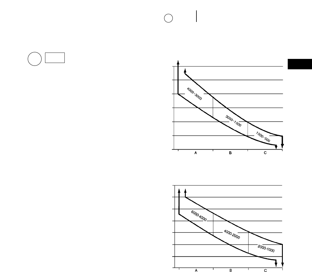
21-27
21
Owning & Operating CostsTires
10a
(Line Item10a)
Tire costs are an important part of the hourly cost
of any wheel machine. The best estimate of this item
is obtained when tire life figures based on experience
are used with prices the machine owner actually
pays for the replacement tires.
For cases in which tire experience is not available,
use the following tire life estimator curves.
Tire Life Estimators
●Curves do not allow for additional life from recap-
ping. They assume new tires run to destruction,
but this is not necessarily recommended.
●Based on standard machine tires. Optional tires
will shift these curves either up or down.
●Sudden failure (blow out) due to exceeding Ton-MPH
(tkm/h) limitations is not considered. Nor are pre-
mature failures, due to puncture by stumps or
sharpened tree limbs (Skidders) or rocks (Trucks,
Loaders, etc.).
●Application Zones:
Zone A: almost all tires actually wear through the
tread from abrasion.
Zone B: tires wear out normally but others fail
prematurely due to rock cuts, impacts and non-
repairable punctures.
Zone C: few, if any, tires wear through the tread
due to non-repairable damages, usually from rock
cuts, impacts and continuous overloading.
NOTE: Tire life can often be increased by using
extra tread and extra deep tread tires.
NOTE: Premature failure could occur at any time
due to puncture by stumps or sharpened
tree limbs.
TIRES
10a MOTOR GRADERS
ESTIMATED TIRE LIFE — HOURS
APPLICATION ZONES
SKIDDERS
ESTIMATED TIRE LIFE — HOURS
APPLICATION ZONES
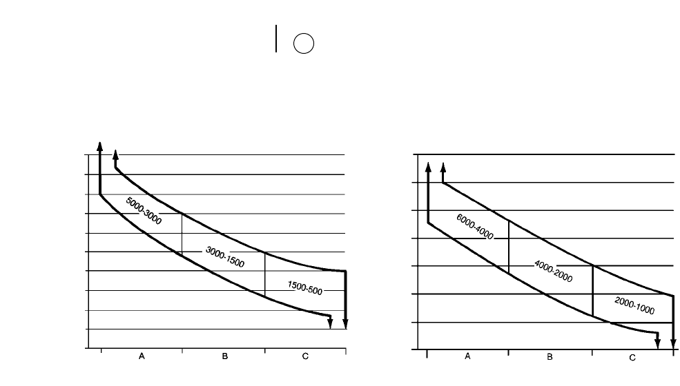
21-28
Owning & Operating Costs Tires
10a
CONSTRUCTION & MINING TRUCKS
ESTIMATED TIRE LIFE — HOURS
APPLICATION ZONES
WHEEL TRACTOR-SCRAPERS
ESTIMATED TIRE LIFE — HOURS
APPLICATION ZONES
Key:
Zone A — Almost all tires actually wear through the
tread due to abrasion.
Zone B — Some tires wear out normally while others
fail prematurely due to rock cuts, impacts
and non-repairable punctures.
Zone C — Few, if any, tires wear through the tread
because of non-repairable damages, usually
from rock cuts, impacts or continuous over-
loading.
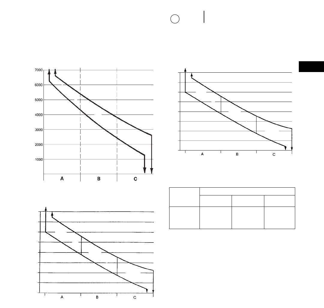
21-29
21
Owning & Operating CostsTires
10a
3000-1000
1000-500
Key:
Zone A — Almost all tires actually wear through the
tread due to abrasion.
Zone B — Some tires wear out normally, others fail
prematurely due to rock cuts, impacts, and
non-repairable punctures.
Zone C — Few, if any, tires wear through the tread
because of non-repairable damages, usually
from rock cuts, impacts, or continuous over-
loading.
WHEEL TRACTORS
WHEEL LOADERS
ESTIMATED TIRE LIFE — HOURS
APPLICATION ZONES
ARTICULATED TRUCKS
ESTIMATED TIRE LIFE — HOURS
APPLICATION ZONES
TRACTORS/WAGONS
ESTIMATED TIRE LIFE — HOURS
APPLICATION ZONES
6000-3000
5500-3000
3000-500
7000-5500
8000-4000
4000-2000
12,000-8000
Tires Cost Per Hour - Basic Factors
Application Zone A Zone B Zone C
Tire Life 8000-5000 5000-2500 2500-500
Model
990
992
994 $20-$40 $30-$80 $60-$400
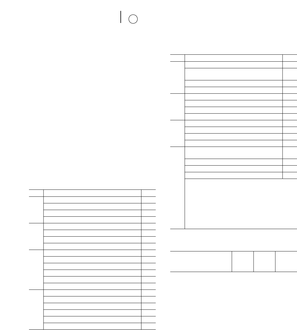
GOODYEAR LIFE ESTIMATING SYSTEM
As an additional assist in estimating hauling unit
tire life, Goodyear Tire and Rubber Co. has furnished
the following information which is included here
with their permission. READ THE PREAMBLE
CAREFULLY.
“… at present, there is no completely accurate,
fool-proof method of forecasting tire life. Tire engi-
neers have many theoretical methods … but these
generally are so involved and time consuming
that they are impractical for field use.
“However, the tire industry has made many sur-
veys of tire performance and arrived at a system
which can give rough estimates of tire life. Studies
done by the major tire companies and by at least
two major equipment manufacturers are in close
agreement.
“The table [which follows] shows how to apply this
system …”
ESTIMATED TIRE SERVICE LIFE
OF HAULING UNITS (Trucks & Scrapers)
No. Condition Factor
I Maintenance
Excellent 1.090
Average 0.981
Poor 0.763
II Speeds (Maximum)
10 mph ;16 km/h 1.090
20 mph ;32 km/h 0.872
30 mph ;48 km/h 0.763
III Surface Conditions
Soft Earth — No Rock 1.090
Soft Earth — Some Rock 0.981
Well Maintained — Gravel Road 0.981
Poorly Maintained — Gravel Road 0.763
Blasted — Sharp Rock 0.654
IV Wheel Positions
Trailing 1.090
Front 0.981
Driver (Rear Dump) 0.872
Driver (Bottom Dump) 0.763
Driver (Self Propelled Scraper) 0.654
No. Condition Factor
V Loads (See No. VIII note)
T&RA/ETRTO*
Recommended Loading 1.090
20% Overload 0.872
40% Overload 0.545
VI Curves
None 1.090
Medium 0.981
Severe 0.872
VII Grades (Drive Tires Only)
Level 1.090
5% Max. 0.981
15% Max. 0.763
VIII Other Miscellaneous Combinations
(See note below)
None 1.090
Medium 0.981
Severe 0.872
Condition VIII is to be used when overloading is
present in combination with one or more of the
primary conditions of maintenance, speeds, sur-
face conditions and curves. The combination of
severe levels in these conditions, together with an
overload, will create a new and more serious con-
dition which will contribute to early tire failure to
a larger extent than will the individual factors of
each condition.
*Tire and Rim Association/European Tire and Rim Technical Organization.
Type of Tire Base Average Life
Hours Miles km
E-3 Std. Bias Tread 2510 25,100 40 400
E-4 Bias Xtra Tread 3510 35,100 56 500
E-4 Radial Xtra Tread 4200 42,000 67 600
Using Base Hours (or Miles), multiply by the appro-
priate factor for each condition to obtain approximate
estimated hours (or miles) as the final product.
Example: An off-highway truck equipped with E-4
drive tires running on a well maintained haul road
having easy curves and minimum grades and receiv-
ing “average” tire maintenance attention but being
20% overloaded:
Condition: I II III IV V VI VII VIII
Factor: 0.981 30.872 30.981 30.872 30.872 30.981 30.981 30.981
33510 base hours = 2114 hours (say 2100 hours)
21-30
Owning & Operating Costs Tires
10a

21-31
21
Owning & Operating CostsTires
Undercarriage
10a
10b
As can be seen, this system requires the careful
application of strictly subjective judgments, and can
be expected to result in conservative estimates. Keep
in mind, however, that the system is offered only
as an aid in estimating and not as a rigid set of
rules.
On the other hand, if tire life on a given job is con-
sidered less than satisfactory, an analysis of these
factors may point to conditions which can be
improved to the betterment of tire life.
Replacement tire prices should always be obtained
from local tire company sources.
Since tires are considered a wear item in this
method of estimating owning and operating costs,
total tire replacement cost is deducted from machine
delivered price to arrive at a net figure for depreci-
ation purposes. Outlay for tires is then included as
an item in operating costs:
Replacement Cost of Tires
Hourly Tire Cost = _____________________________
Estimating Tire Life in Hours
Recapping can sometimes lower hourly tire cost.
Considerations are availability of molds, local recap-
ping costs, and experience with recap life.
(Line Item10b)
Undercarriage expense can be a major portion of
the operating costs for track-type machines, and
these costs can vary independently of basic machine
costs. That is, the undercarriage can be employed in
an extremely abrasive, high-wear environment while
the basic machine may be in an essentially easy
application, and vice-versa. For that reason, it is
recommended that the hourly cost of undercarriage
be calculated separately as a wear item rather than
being included in the repair reserve for the basic
machine. Notice that the repair reserves (Line
Item11) DO NOT include provision for undercar-
riage replacement.
Three primary conditions affect probable life-
expectancy of track-type undercarriage:
1. Impact. The most measurable effect of impact
is structural — that is bending, chipping, cracking,
spalling, roll-over, etc., and problems with hard-
ware and pin and bushing retention.
Impact ratings:
High — Non-penetrable hard surfaces with
150 mm (6") or higher bumps.
Moderate — Partially penetrable surfaces and
bumps of 75-150 mm (3-6") height.
Low — Completely penetrable surfaces
(which provide full shoe plate sup-
port) with few bumps.
2. Abrasiveness. The tendency of the underfoot
materials to grind away the wear surfaces of
track components.
Abrasiveness ratings:
High — Saturated wet soils containing a
high proportion of hard, angular or
sharp sand or rock particles.
Moderate — Slightly or intermittently damp
soils containing a low proportion of
hard, angular or sharp particles.
Low — Dry soils or rock containing a low
proportion of hard, angular or
sharp sand or rock chip particles.
Impact and abrasiveness in combination can
accelerate wear rates beyond their individual
effects when considered alone, thus further
reducing component life. This should be taken
into account in determining impact and abra-
siveness ratings or, if preferred, the combination
can be included in selecting the “Z” factor.
3. “Z” factor. Represents the combined effect on com-
ponent life of the many intangible environmen-
tal, operational and maintenance considerations
on a given job.
Environment and Terrain. Earth which may not
be abrasive itself can pack in sprocket teeth, caus-
ing interference and high stress as the teeth
engage the bushings. Corrosive chemicals in the
materials being moved or in the natural soil can
affect wear rates, while moisture and temperature
can exaggerate the effect. Temperature alone can
play its own role — hot slag and hard-frozen soils
being but the extremes. Constant sidehill work
can increase wear on the sides of components.
UNDERCARRIAGE
10b
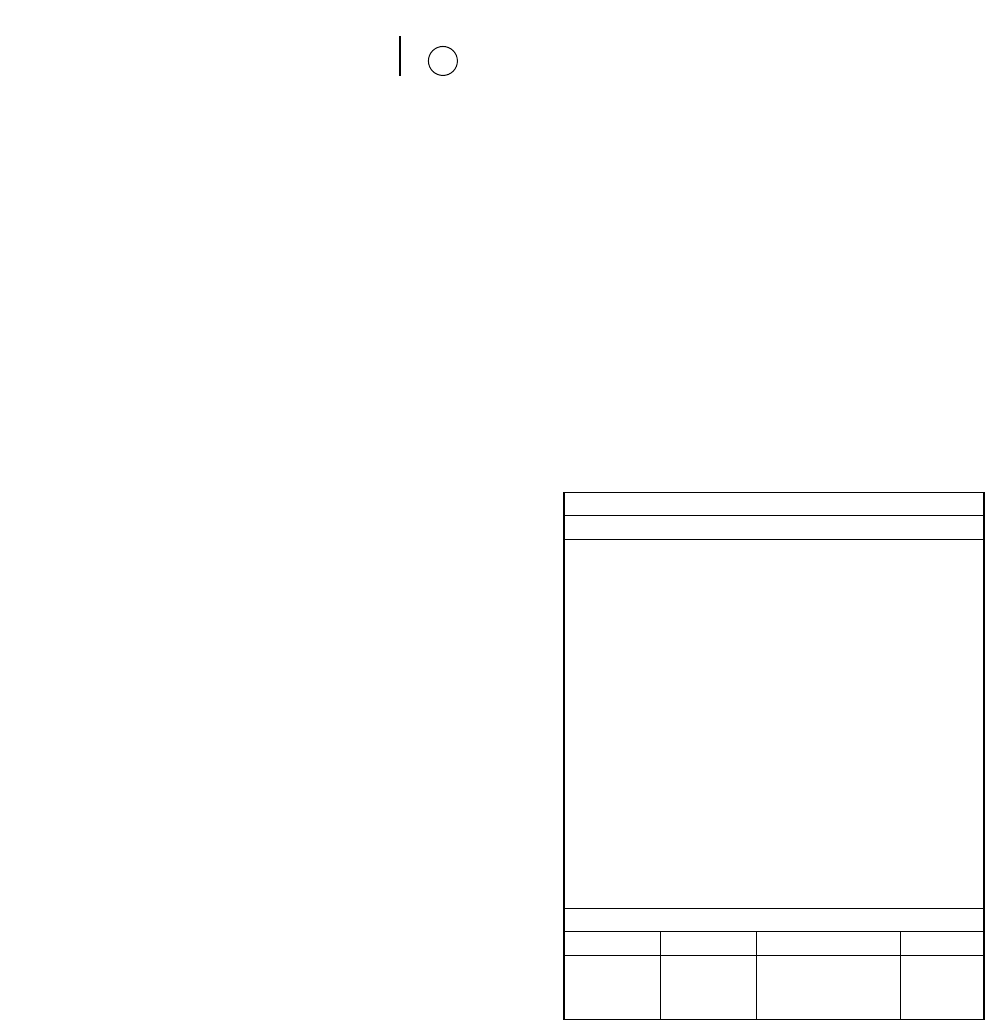
21-32
Owning & Operating Costs Undercarriage
10b
Operation. Some operator practices tend to
increase track wear and cost if not controlled on
the job. Such practices include high-speed opera-
tion, particularly in reverse; tight turns or con-
stant corrections in direction; and stalling the
tractor under load forcing the tracks to slip.
Maintenance. Good maintenance — proper track
tension, daily cleaning when working in sticky
materials, etc. — combined with periodic wear
measurement and timely attention to recom-
mended services (CTS) can extend component life
and lower costs by minimizing the effects of these
and other adverse conditions.
While impact and abrasion should not be too dif-
ficult to judge, selection of the proper “Z” factor will
require careful analysis of job conditions such as
weather, tendency for soil packing, side-hill loading,
corrosive environment, etc.; operational factors such
as high-speed reverse, tight turns, track slippage
under overload, etc.; and maintenance considerations
such as proper tensioning, use of Custom Track
Service, etc.
Selection of the “Z” multiplier is strictly a matter
of judgement and common sense, but its effect on
cost can be the difference between profit on a con-
trolled job and heavy loss where control is allowed
to slip. To assist in arriving at an appropriate value
for the “Z” factor, consider that proper maintenance
— or the lack thereof — will represent about 50% of
its effect, environment and terrain 30%, and operator
practices 20%. Thus, even a good operator working
under good field conditions can be counterbalanced
by poor maintenance practices to yield a fairly high
“Z” factor. On the other hand, close attention to
maintenance, tension and alignment can more than
offset a bad underfoot condition resulting in severe
sprocket packing, and lead to selection of a moder-
ate to low “Z” factor. Obviously, flexibility in selec-
tion of a “Z” factor has been built into the system,
and use of this flexibility is encouraged. Further, a
considerable measure of control can be maintained
over the “Z” factor, and any reduction of its effects
is money in the bank. Your Caterpillar Dealer CTS
man can be invaluable in this endeavor as well as
helping you establish a comprehensive undercar-
riage cost control program.
Estimating Undercarriage Cost
The guide below gives a basic factor for the vari-
ous track-type machines and a series of conditions
multipliers to modify the basic cost according to the
anticipated impact, abrasive and miscellaneous (“Z”)
conditions under which the unit will be operating.
Step 1. Select machine and its corresponding basic
factor.
Step 2. Determine range for impact, abrasiveness
and “Z” conditions.
Step 3. Add selected conditions multipliers and apply
sum to basic factor.
The result will be the estimated hourly cost for
undercarriage in that application.
Undercarriage Basic Factors
Model Basic Factor
5230 19.0
D11R 17.0
5130B 15.0
D10R 12.5
D9R 10.0
D8R 8.5
973, 589, D7R LGP 9.0
D7R, 963B, 578, D6R LGP, D7R XR 8.0
375, 5080 6.4
D6R, 953C, 572, D6M LGP, D6R XL, D6R XR 6.2
345B, 350 5.3
D5M LGP, D6 SR, D6M XL, 517, 527 5.0
330B 4.4
D3C (All), D4C (All), D5C (All), 933 (All), 939, 561M 3.7
325B 3.4
315B, 318B L, 320B, 322B 3.0
D4 SR 2.5
307, 307B, 311B, 312B 2.2
Conditions Multipliers
Impact Abrasiveness “Z”
High 0.3 0.4 1.0
Moderate 0.2 0.2 0.5
Low 0.1 0.1 0.2
Example: D10R in high impact, non-abrasive mate-
rial with a moderate “Z” factor.
D10R Basic Factor = 12.5
Multipliers: I = 0.3
A = 0.1
Z = 0.5
Hourly undercarriage cost = 12.5 (0.3 + 0.1 + 0.5) =
$11.25/hour

21-33
21
Owning & Operating CostsUndercarriage
Repair Reserve
11
10b
NOTE:1. Conditions Multipliers may be selected in
any combination. Thus, a multiplier of 0.4
(all low-range multipliers) represents the
best of the best, while 1.7 (all high range
multipliers) would be the worst of the worst
conditions.
2. The hourly undercarriage cost estimate
resulting from this method will be made
up of approximately 70% parts cost and
30% labor charges. The cost of undercar-
riage components is based on published
U.S. Consumers List Prices and may be
adjusted as needed for import duties,
exchange rates, etc. outside the United
States. Labor has been figured at $40.00
(U.S.) per shop hour.
3. For further information and guidance,
refer to the current issue of the Caterpillar
Custom Track Service Handbook.
4. This formula for estimating undercar-
riage cost should not be used for tractors
working in stockpile coal handling appli-
cations. Undercarriage costs are nominal
in stockpile coal handling, and using this
formula will result in estimating cost sub-
stantially above actual costs.
(Line Item11)
Repairs are normally the largest single item in
operating costs and include all parts and direct labor
(except operator’s wages) chargeable to the machine.
Shop overhead can be absorbed in general overhead
or charged to machines as a percent of direct labor
cost, whichever is the owner’s normal practice.
Hourly repair costs for a single machine normally
follow an upward stairstep pattern since major out-
lays for repairs usually come in spurts. However,
when broad averages are considered, the stairstep
becomes a smooth, upward curve. Since this hourly
repair cost curve starts low and gradually rises over
time, hourly operating costs must be adjusted upward
as the unit ages. Alternatively an average repair
cost can be used which provides a straight line graph.
Most owners prefer the average method, and it is
the one suggested here.
Since repair costs are low initially and rise gradu-
ally, averaging them produces extra funds at first
which are reserved to cover future higher costs.
Machine applications, operating conditions and
maintenance attention determine repair costs. In
any specific application, actual cost experience on
similar work provides the best basis for establishing
the hourly repair reserve. When local records are
inadequate or not available, the hourly repair reserve
charts following this discussion may be used. Turn
for a moment to these charts and examine their gen-
eral format.
These average costs are taken from a variety of
applications and every attempt was made to assure
accuracy. Recognize that any one application may
vary considerably from these averages. They are
only marginally useful in predicting costs since
few jobs are ‘average’.The use of these averages
would be especially questioned when special
attachments such as rippers are used, and when a
machine is moving from job to job. For these rea-
sons, we suggest the use of these averages for
comparative purposes and gross estimates only.
Your Caterpillar dealer has the ability to make more
accurate repair cost estimates and we suggest you
use his experience and expertise if you need help
in estimating operating costs.
Applying these basic factors and multipliers will
result in the average hourly cost over the entire
period. This should produce an excess in the early
hours (or a “sinking fund”) to cover normal increases
in actual repair costs as the machine ages.
The cost applies to the machine as described in each
individual chart, but does not cover the following:
●Dozer blade (although hydraulics are included)
●Bucket (although hydraulics are included)
●Ground engaging tools
●Undercarriage
●Tires, Chopper Blades or Tamping Feet
Assemblies and Rims
REPAIR RESERVE
11
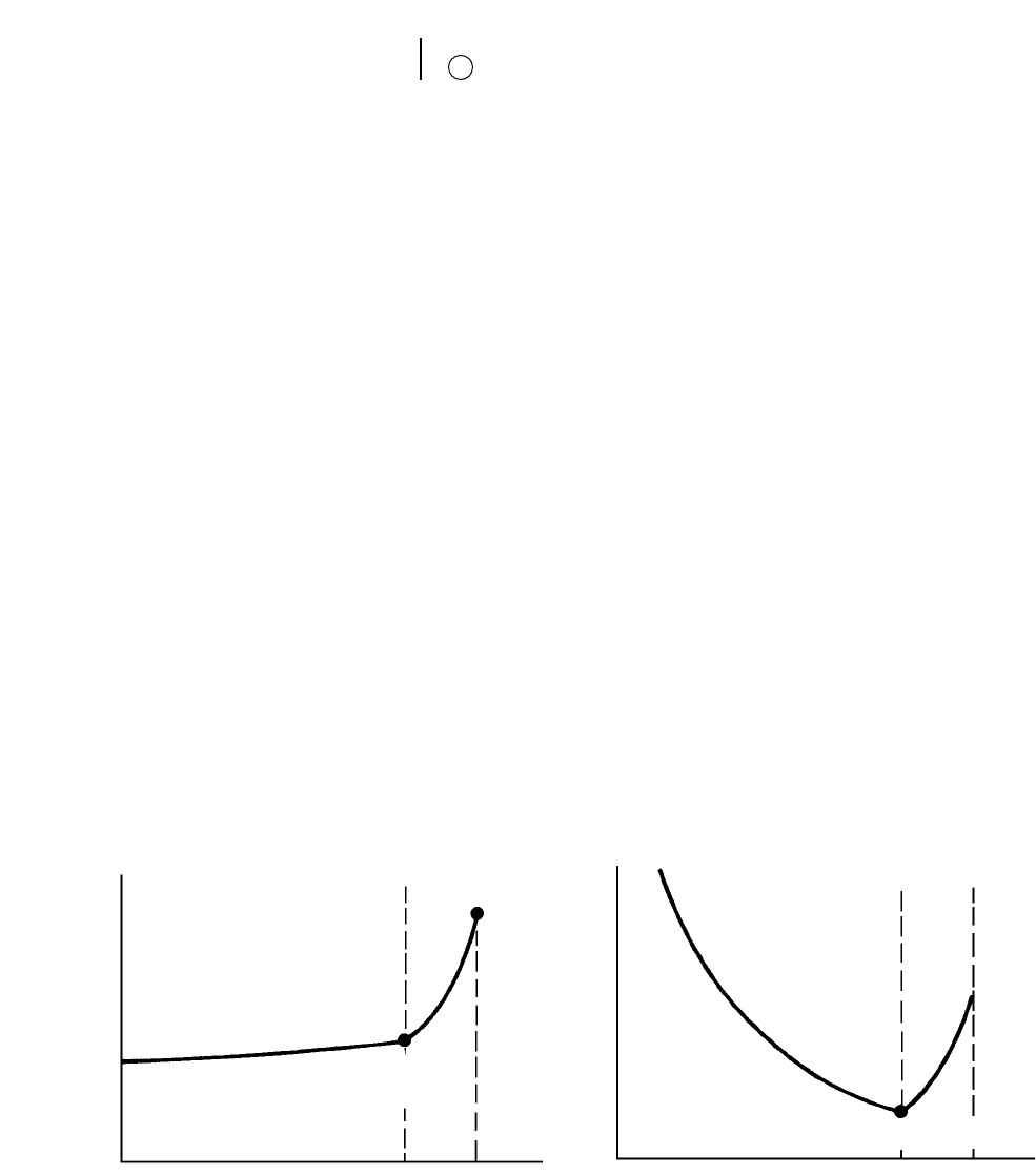
●Labor for daily and periodic maintenance
●Material/supply items for daily and periodic main-
tenance
●Fuel, oil and grease
●Service truck mileage costs
●Serviceman’s travel costs
●Machine transportation to and from shop
●Cost of performing Technical Analysis or Sched-
uled Oil Sampling
●Operator
●Risk or insurance
●Parts and labor price escalation
●Attachments
The basic repair factors are based on the first
10,000 hours of service, parts at published U.S. Con-
sumers List Prices, and labor at a total selling price
of $40.00 (U.S.) per hour. Extended use multipliers
are given for those cases where a machine is to be
used beyond 10,000 hours; the adjusted cost-per hour
will apply to the entire use period, not just the addi-
tional hours. For applications outside the United
States where import duties and other expenses have
a large effect on parts prices, and for other areas
where labor charges (remember to include shop and
tool overhead in addition to mechanic’s wages!) differ
greatly from the $40.00 base, an approximate break-
down of the total factor by percentages for parts and
labor also are given. This breakdown should permit
easy adjustment to local conditions.
As stated, repair costs are affected by applica-
tion, operation, maintenance, and age of the equip-
ment.The most significant effects on cost will be
those factors affecting major component life. A
second significant factor is whether the repair is
performed before or after catastrophic failure.
Repair before a major component fails can be one-
third of an after failure repair with only a moder-
ate sacrifice in life (see graphs). Repairing a major
component just prior to failure achieves optimum
cost per hour. Oil analysis and other diagnostic
tools, maintenance inspections and indicators, and
operator notes are vital to determine the optimum
repair point and thereby achieving lower hourly
repair costs. Maintenance practices are significant
because they affect component longevity and the
percentage of scheduled, before failure repairs.
Another important factor in using repair reserve
estimates is the Service Meter Unit (SMU) or hour
basis.The cost estimate should be flexed depend-
ing on the machine’s duty cycle. Fuel consump-
tion is often a good indicator of duty cycle, and
this factor may override the application zone. All of
these factors are significant in estimating repair
costs.Weigh them carefully prior to using the repair
reserve tables.
21-34
Owning & Operating Costs Repair Reserve
11
COMPONENT LIFE (SMU)
REPAIR COST $
AFTER
FAILURE
BEFORE
FAILURE
COMPONENT LIFE (SMU)
REPAIR COST $/HOUR
OPTIMUM REPAIR POINT
21-35
21
Owning & Operating CostsRepair Reserve
11
INSTRUCTIONS — To estimate hourly repair costs,
enter the chart for the machine in question and
determine the basic factor for the applicable job con-
ditions. Operating conditions zones for each bar are:
These generally conform to the definitions given
earlier in the section on depreciation. If the unit is to
be used more than 10,000 hours, apply the Extended-
life Multiplier for that period.
Example:
1 — A 988F Wheel Loader loading well-shot rock on
a hard, level quarry floor will be used for seven
years or about 15,000 hours.
Basic Repair Factor = 9.50
Extended-life Multiplier = 1.10
Estimated Repair Cost = 9.50 31.10 =
$10.45/Hour
2 — A D6H is used about 1600 hours per year on
general utility and clean-up work for a contrac-
tor who does not baby his equipment, but does
insist on careful operation, and has an excellent
preventive maintenance program. He intends to
trade at the end of five years. He can be consid-
ered to be at the lower end of the
“
normal” or
B zone, if not slightly less.
Basic Repair Factor = 4.50
Total Use:
5 years @ 1600 hr/yr = 8000 hours
Extended-use Multiplier = 1.0
Estimated Repair Cost = 4.50 31.0 =
$4.50/Hour
ACB
Repair Reserve charts follow …©
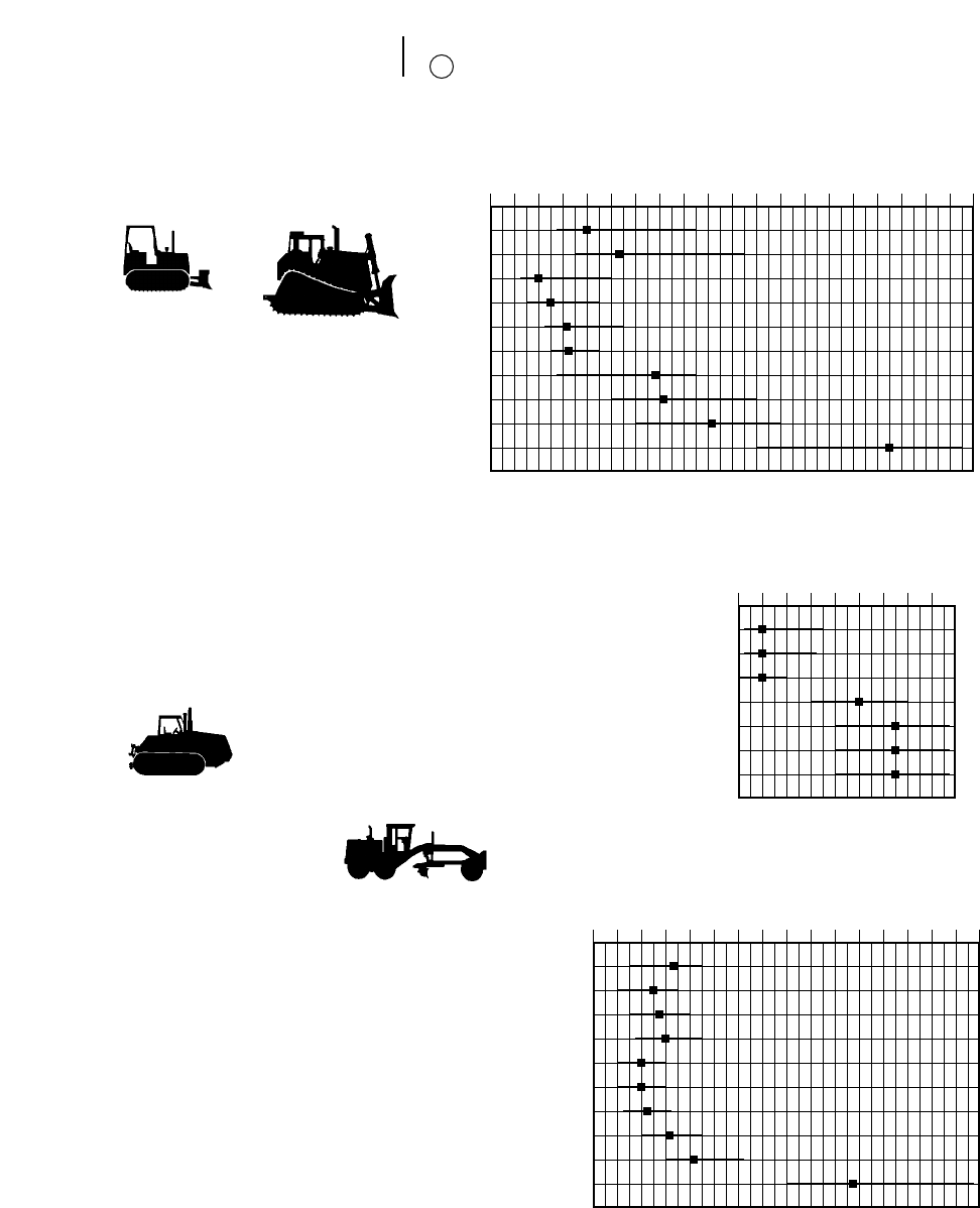
21-36
Owning & Operating Costs Repair Reserve
11
$2.00 4.00 6.00 8.00 10.00 12.00 14.00 16.00 18.00 20.00 22.00
D3C
D4C/D5C
*D5M
*D6M
D6R
D7R
D8R
D9R
D10R
D11R
$2.00 4.00 6.00 8.00 10.00 12.00 14.00 16.00 18.00
120H
*135H
12H
140H
*143H
*160H
*163H
14H
16H
24H
$2.00 4.00 6.00 8.00 10.00
*Challenger 35
*Challenger 45
*Challenger 55
Challenger 65E
Challenger 75E
*Challenger 85E
*Challenger 95E
Cost distribution
120H Thru 135H Extended-life Multipliers
65% Parts 0-10,000 hours 1.00
35% Labor 0-15,000 1.00
0-20,000 1.33
12H Thru 16H
65% Parts 0-10,000 hours 1.00
35% Labor 0-15,000 1.20
0-20,000 1.55
24H
60% Parts 0-15,000 hours 0.78
40% Labor 0-20,000 1.00
0-30,000 1.05
0-40,000 1.20
Includes basic motor grader equipped with ROPS cab.
MOTOR GRADERS
Cost distribution
60% Parts
40% Labor
AGRICULTURAL TRACTORS
(basic configuration)
Extended-life Multipliers
0-10,000 hours 1.0
0-15,000 1.1
0-20,000 1.3
Includes basic tractor equipped with ROPS canopy, straight bull-
dozer and hydraulic control.
NOTE: Repair time may be less on Elevated Sprocket Tractors
due to modular design of power train components.
TRACK-TYPE TRACTORS
Cost distribution
D3 to D7 — 60% Parts
40% Labor
D8 to D11 — 70% Parts
30% Labor
*Preliminary information
*Preliminary information
*Preliminary information
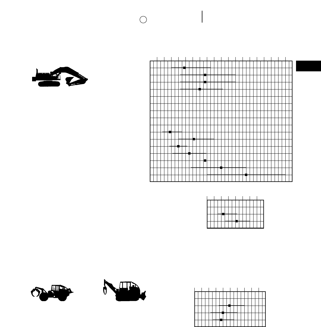
21-37
21
Owning & Operating CostsRepair Reserve
11
Cost distribution
50% Parts
50% Labor
Extended-life Multipliers
(Not available)
5130 & 5230
Cost distribution
70% Parts
30% Labor
Extended-life Multipliers
0-10,000 hours 0.40
0-20,000 0.80
0-30,000 1.00
0-40,000 1.21
0-60,000 1.25
Includes basic excavator equipped with largest bucket,
one-piece boom and medium stick. Logger with stan-
dard feller buncher.
$2.00 4.00 6.00 8.00 10.00 12.00 14.00 16.00 18.00 20.00
307/307B
311B
312B
315B
*318B L
*M315
*M318
*M320
*317
320B
322B
325B
330B
**345B
350
375
**Insufficient data
**Preliminary information
$2.00 4.00 6.00 8.00 10.00
*515/525
528
517
527
*Insufficient data
$20.00 40.00 60.00 80.00
*5080
5130B
5230
*Insufficient data
Cost distribution Extended-life Multipliers
55% Parts (Not available)
45% Labor
Includes basic skidder equipped with ROPS canopy,
arch, fairlead and winch. 518 Grapple skidders with
Cat grapple, 530B Grapple skidder with AEM grapple.
SKIDDERS
EXCAVATORS
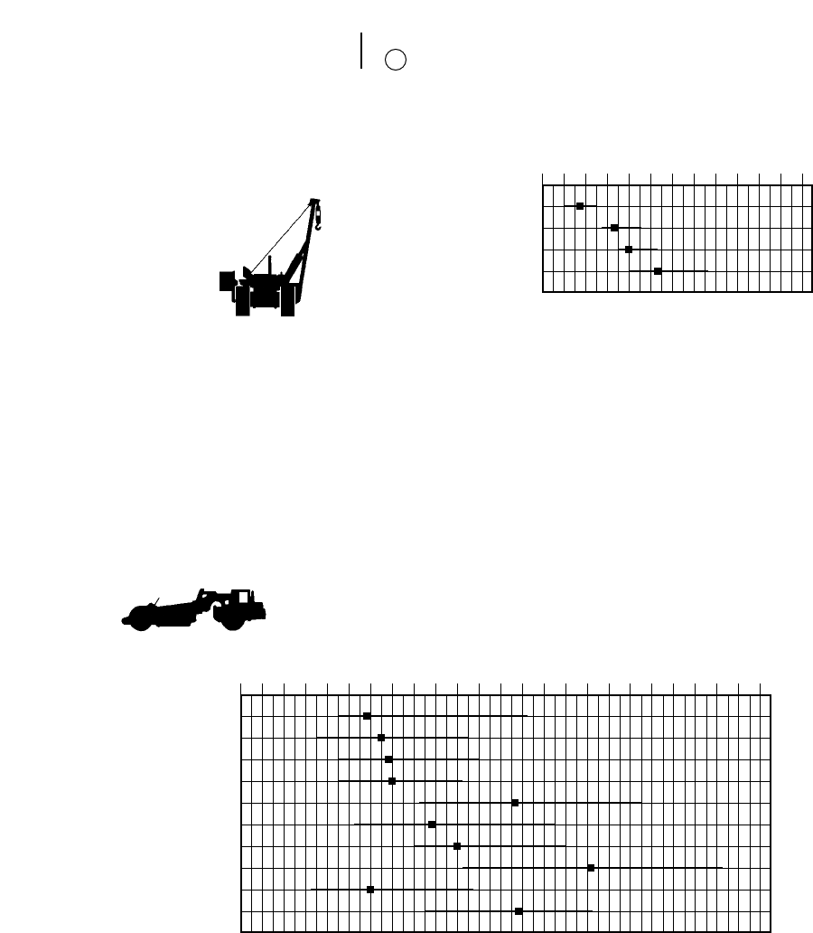
21-38
Owning & Operating Costs Repair Reserve
11
$2.00 4.00 6.00 8.00 10.00 12.00 14.00
561M
572R
583R
589
Cost distribution: Extended-life Multipliers:
55% Parts Period Single-engine Tandem & Elevator
45% Labor 0-10,000 1.00 1.00 (1.03 for Push-Pull)
1-15,000 1.06 1.08
0-20,000 1.21 1.24
Includes standard wheel tractor equipped with standard scraper.
$4.00 6.00 8.00 10.00 12.00 14.00 16.00 18.00 20.00 22.00 24.00 26.00 28.00
613C Series II
615C Series II
621F
623F
627F
631E Series II
633E Series II
637E Series II
651E
657E
WHEEL-TRACTOR SCRAPERS
Cost distribution Extended-life Multipliers
60% Parts (Not available)
40% Labor
Includes basic pipelayer equipped with counterweight
and boom.
PIPELAYERS
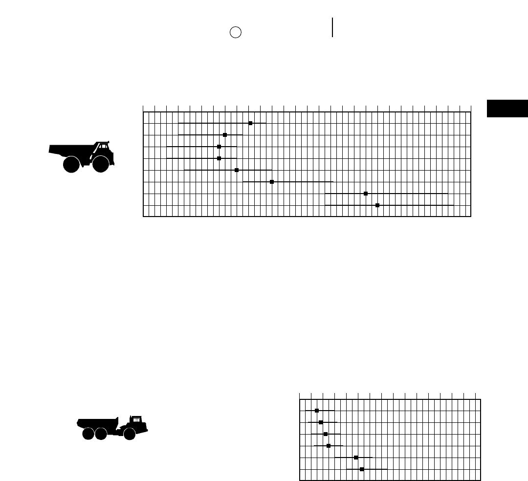
21-39
21
Owning & Operating CostsRepair Reserve
11
$2.00 4.00 6.00 8.00 10.00 12.00 14.00 16.00 18.00 20.00 22.00 24.00 26.00 28.00 30.00
769D
771D
773D
775D
777D
785C
789C
793C
$4.00 6.00 8.00 10.00 12.00 14.00 16.00 18.00
D25D
D30D
D250E
D300E
D350E
D400E
Cost distribution Extended-life Multipliers
55% Parts 0-10,000 hours 1.00
45% Labor 0-15,000 1.05
0-20,000 Not Available
ARTICULATED TRUCKS
Cost distribution Extended-life Multipliers
769-777
55% Parts 0-10,000 hours 0.20
45% Labor 0-20,000 1.00
785-793 0-30,000 1.18
70% Parts 0-40,000 1.50
30% Labor 0-60,000 1.50
Includes basic truck equipped with standard earth
body (785/789 — Option I Body) without liners. Off-
highway tractors’hourly repair costs are approximately
9% less than trucks.
CONSTRUCTION
& MINING
TRUCKS
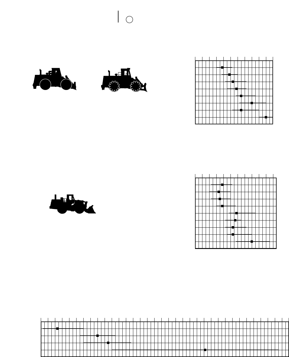
21-40
Owning & Operating Costs Repair Reserve
11
WHEEL LOADERS &
INTEGRATED TOOLCARRIERS
Cost Extended-life
distribution Multipliers
914-992
60% Parts 0-10,000 hours 1.00
40% Labor 0-15,000 1.10
994
75% Parts 0-10,000 0.25
25% Labor 0-20,000 0.54
0-30,000 1.00
0-40,000 1.07
0-60,000 1.25
Includes basic wheel loader equipped with
ROPS cab and General Purpose bucket (988
and 992 with Spade nose rock bucket).
WHEEL TRACTORS &
SOIL/LANDFILL COMPACTORS
Cost distribution Extended-life Multipliers
60% Parts (Not available)
40% Labor
Includes: 814F, 824G & 834B — Basic tractor equipped
with ROPS canopy and bulldozer.
815F & 825G — Basic compactor equipped
with ROPS canopy and fill-spreading bull-
dozer.
816F & 826G — Basic Landfill Compactor
equipped with ROPS cab and landfill bull-
dozer.
$2.00 4.00 6.00 8.00 10.00 12.00
814F
815F
816F
824G
825G
826G
834B
836
$2.00 4.00 6.00 8.00 10.00 12.00
914G, IT14G
924F, IT24F
928G, IT28G
938G, IT38G
950G
962G, IT62G
966F Series II
970F
980G
$8.00 10.00 12.00 14.00 16.00 18.00 20.00 22.00 24.00 26.00 28.00 30.00 32.00 34.00 36.00 38.00 40.00 42.00
988F
Series II
990
Series II
992G
994
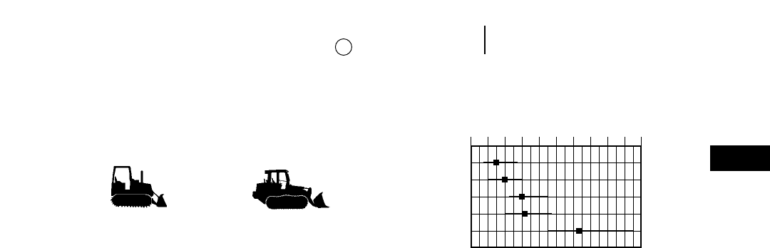
21-41
21
Owning & Operating CostsRepair Reserve
11
TRACK LOADERS
Cost distribution Extended-life Multipliers
55% Parts 0-10,000 hours 1.00
45% Labor 0-15,000 1.13
Includes basic track loader equipped with ROPS
canopy and General Purpose bucket.
$2.00 4.00 6.00 8.00 10.00 12.00
933C
939C
953C
963B
973
21-42
Owning & Operating Costs Special Wear Items
Operator’s Wage
Owning & Operating Examples
●Track-Type Tractor
12
15
(Line Item 12 and Subsection 12A)
All costs for high-wear items such as cutting edges,
ripper tips, bucket teeth, body liners, router bits, etc.,
and welding costs on booms and sticks should be
included here. These costs will vary widely depending
on applications, materials and operating techniques.
Consult your Caterpillar Dealer Parts Department
for estimated life under your job conditions.
(Line Item 15)
This item should be based on local wage scales and
should include the hourly cost of fringe benefits.
EXAMPLES OF FIGURING OWNING AND
OPERATING COSTS
Example I: ESTIMATING HOURLY OWNING
AND OPERATING COSTS OF A
TRACK-TYPE TRACTOR
Assume a power shift track-type tractor with
straight bulldozer, hydraulic control, tilt cylinder
and three-shank ripper, is purchased by a contrac-
tor for $135,000, delivered price at job site.
Application will be production dozing of bank
gravel. Minimal ripping will be required to loosen
material.
In the following calculations, refer as necessary
to the source material already reviewed.
OWNING COSTS —
To Determine Residual Value at Replacement
Enter delivered price, $135,000, in space (A). (See
example form at end of this discussion.) Since the
machine being considered is a track-type tractor, no
tires are involved. This particular owner’s experience
is that at trade-in time, the tractor will be worth
approximately 35% of its original value. This $47,250
trade-in value is entered in space (B) leaving a net
of $87,750 to be recovered through work.
Enter the value to be recovered through work in
space (C).
Indicated ownership period is 7 years with annual
usage of 1200 hours per year or 8400 hours of total
ownership usage.
Divide the Net Value from space (C), $87,750, by
Ownership Usage, 8400 hours, and enter result
$10.45 in space (D).
Interest, Insurance,Taxes
In this example, local rates are assumed as follows:
Interest 16%
Insurance 1%
Taxes 1%
_____
18%
Using the following formula:
N = 7:
[7 + 1 ]
______ 3$135,000 30.16
2 37
_____________________________ = $10.29
1,200
Enter $10.29 in space (E).
Insurance and property taxes can also be calcu-
lated using the same formula as shown for the inter-
est cost, and entering them on lines 5 and 6.
Items 3b, 4, 5 and 6 can now be added and the
result, $22.02 entered in space (H) Total Hourly
Owning Costs.
OPERATING COSTS —
Fuel
See fuel consumption tables. The intended appli-
cation, production dozing, indicates a medium load
factor. Assume that the estimated fuel consumption
from the table is 18.1 liter/hr (4.8 U.S. gal/hr.). Cost
of fuel in this locality is $0.34/liter ($1.25/U.S. gal.).
Consumption Unit Cost Total
18 liter/hr 3$0.34 liter = $6.12
5 gal/hr 3$1.25 gal. = $6.25
Enter this figure in space (I).
OPERATOR’S HOURLY WAGE
SPECIAL WEAR ITEMS
12
15

21-43
21
Owning & Operating CostsOwning & Operating Examples
●Track-Type Tractor
Lube Oils, Filters, Grease
For these items, you can use the lubricants con-
sumption tables and the filter cost calculator for a
detailed estimate, or you can obtain an estimate of
the total of these items from the Quick Estimator
table. We will assume local prices in this example
are about the same as those used for the Quick Esti-
mate Table and use this method. Assume the table
shows an approximate hourly cost for lube oils, filters
and grease (materials and labor) for this tractor of
$0.46. Enter this figure in space (J).
Tires
Since this example considers a track-type tractor,
space (K) is left blank.
Undercarriage
Our estimating reference gives an undercarriage
cost Basic Factor of 6.2 for this tractor. It is antici-
pated that with some ripping on the job, impact
loadings of the track components will be medium,
indicating an “I” multiplier of 0.2. The gravel-sand
mix in the bank, being dry, should be only moder-
ately abrasive for an “A” multiplier of 0.2. In analyz-
ing the miscellaneous conditions: there is enough
clay in the bank to produce some packing of the
sprockets; the operator is careful, but is forced into
some tight turns because of space limitations; there
is good drainage in the pit; track tension is checked
weekly; and all track-type equipment on the job is
enrolled in the Custom Track Service program.
Accordingly, the “Z” multiplier is judged to be some-
what greater than low level — 0.3 in this case.
It should be noted that in applying particularly
the “Z” factor, rather wide latitude for flexibility is
provided and was used in the above example. Such
flexibility is intended and its use encouraged.
Then:
Cost per hour = Basic Factor 3(I + A + Z)
Basic Factor = 6.2
Conditions Multipliers: I = 0.2
A = 0.2
Z = 0.3
Cost per hour 6.2 (0.2 + 0.2 + 0.3) = $4.34 which
is entered in space (L).
Repairs
In determining the depreciation period, we estab-
lished the intended use of the machine as a Zone B
application. The Repair Reserve graph for track-type
tractors indicates that the mid-range for our tractor
is approximately 4.50 on the basis of 10,000 hours
of use. The tractor is to be used over 8400 hours, so
the Extended-life Multiplier in this case is 1.0.
Therefore, Repair Reserve = 1.0 34.50 = $4.50
per hour, which is entered in space (M).
Special Items
Assuming the tractor is equipped with a three-
shank ripper and an “S” dozer, allowance must be
made for ripper tips, shank protectors, and dozer cut-
ting edges.
Assume your knowledge of the operation indicates
the ripper will be used only about 20% of total trac-
tor operating time. Estimated tip life while in use is
30 hours. Therefore, tips will be replaced:
30 Hours
_________ = each 150 hours of tractor operation
0.20
Shank protector life is estimated at three times
tip life or 450 hours of tractor operation. In this
medium duty application, no shank replacement is
expected in the 8400 hour depreciation period of the
tractor.
Cutting edge life is estimated to be 500 hours.
Using local prices for these items, hourly costs are
estimated as follows:
3 @ $35.00 ea.
Tips: ______________ = $0.70 per hour
150 hr.
3 @ $55.00 ea.
Shank Protectors: ______________ = $0.37 per hour
450 hr.
$125 per set
Cutting Edges: ______________ = $0.25 per hour
500 hr.
The total of these, $1.32; is entered in space (N).
Items 8, 9, 10b, 11 and 12 can now be added and
the result, $15.63, is entered in space (O), Total
Hourly Operating Costs.
Operator’s Hourly Wage
Assume this is $20.00 including fringe benefits.
This figure is entered in space (P).
Total Owning Costs, Total Operating Costs and
Operator’s Hourly Wage are now added together
and the result, $57.65, is entered in space (Q). The
itemized estimate of Hourly Owning and Operating
Costs is now complete.

21-44
Owning & Operating Costs Owning & Operating Example II
●Wheel Loader
Example II: ESTIMATING HOURLY OWNING AND
OPERATING COSTS OF A WHEELED
VEHICLE
With only a few simple changes, owning and oper-
ating costs for a wheeled vehicle are calculated using
the same format as that used for the Track-Type
Tractor. Only the differences will be explained as we
look at example calculations for a wheel loader.
OWNING COSTS —
To Determine Residual Value at Replacement
Enter delivered price in space (A). The cost of tires
is deducted since they will be treated as a wear item.
For purposes of illustration, the Wheel Loader is esti-
mated to have a potential 48% trade-in value (B) at
the end of the 5 year/7500 hour ownership usage,
leaving a net value to be recovered through work of
$34,320 (C).
Interest, Insurance,Taxes
Refer to the formulas using the same rates as
before and 1500 operating hours per year. The fac-
tor 4.22 is applied to the interest cost (E).
Insurance and property taxes can also be calcu-
lated using the same formula as shown for the inter-
est cost.
The sum of lines 3b, 4, 5 and 6 gives the total
hourly owning cost, line 7.
OPERATING COSTS —
Fuel
See the fuel consumption tables and apply the
actual cost of purchasing fuel in the project area (I).
Lube Oils, Filters, Etc.
Use either the item-by-item worksheet or the
summary tables. Enter the total item in space (J)
on line 9.
Tires
Use the tire replacement cost and the best esti-
mate of tire life based on experience and anticipated
job conditions.
Repairs
Find the applicable basic repair factor for Zone B
application from the bar charts (4.00). Again, the
use period for the Wheel Loader is 7500 hours, so
the Extended-life Multiplier is 1.0.
Therefore, Repair Reserve = 1.0 34.00 = $4.00
per hour.
Special Items
Ground engaging tools, welding, etc. are covered
here. Use current costs for cutting edges and similar
items. Use your best estimate of the hours of life
which can be expected from them based on previ-
ous experience in like materials. Enter the total on
line 12.
The total of lines 8 through 13 represents hourly
operating costs.
Operator’s Wages
To give a true picture of operator cost, include fringe
benefits as well as direct hourly wages (line 15).
TOTAL O&O
The total of lines 7, 13 and 15 is the total hourly
owning and operating cost of the machine. Keep in
mind that this is an estimate and can change radi-
cally from project to project. For the greatest accu-
racy, the hourly cost reflected in actual on-the-job
cost records should be used.
● ● ●

21-45
21
Owning & Operating CostsOwning & Operating Examples I & II
●Estimating Form
HOURLY OWNING AND OPERATING COST ESTIMATE DATE _____________
(1) (2)
Machine Designation . . . . . . . . . . . . . . . . . . . . . . . . . . . . . . . . . . . . . __________ __________
Estimated Ownership Period (Years) . . . . . . . . . . . . . . . . . . . . . . . . . __________ __________
Estimated Usage (Hours/Year) . . . . . . . . . . . . . . . . . . . . . . . . . . . . . __________ __________
Ownership Usage (Total Hours) . . . . . . . . . . . . . . . . . . . . . . . . . . . . __________ __________
OWNING COSTS
1. a. Delivered Price (including attachments) . . . . . . . . . . . . . . . . . __________ __________
b. Less Tire Replacement Cost if desired . . . . . . . . . . . . . . . . . . __________ __________
c. Delivered Price Less Tires . . . . . . . . . . . . . . . . . . . . . . . . . . . . __________ __________
2. Less Residual Value at Replacement . . . . . . . . . . . . . . . . . . . . . . (___%) __________ (___%) __________
(See subsection 2A on back)
3. a. Value to be recovered through work . . . . . . . . . . . . . . . . . . . . __________ __________
(line 1c less line 2)
b. Cost Per Hour:
Value 87,750 34,320
______ (1) __________ (2) __________ . . . . . . . . . . . . . . . . . . __________ __________
Hours 8400 7500
4. Interest Costs N + 1 3Del. Price 3Simple Int.
_____
N = No.Yrs. 2N % Rate
_________________________________ =
Hours/Year
7 + 1 135,000 16 5 + 1 66,000 16
(1) _____ 3_______ 3___ % (2) _____ 3_______ 3___ %
14 10
______________________ =______________________ =__________ __________
1200 1500
_____ Hours/Yr. _____ Hours/Yr.
5. Insurance N + 1 3Del. Price 3Insurance
_____
N = No.Yrs. 2N % Rate
_________________________________ =
Hours/Year
7 + 1 135,000 1 5 + 1 66,000 1
(1) _____ 3_______ 3___ % (2) _____ 3_______ 3___ %
14 10
______________________ =______________________ =__________ __________
1200 1500
_____ Hours/Yr. _____ Hours/Yr.
Or
$ __________ Per Yr. ÷ __________ Hours/Yr. = Estimating form continues next page
Track-type
Tractor
0007
1200
8400
87,750 (C)
10.45 (D)
10.29 (E)
0.64 (F)
(1)
135,000 (A)
0000
135,000
47,250 (B)
34,320
4.58
4.22
0.26
(2)
70,000
0,4000
66,000
31,680
Wheel
Loader
0,0005
0,1500
0,7500
35 48

21-46
Owning & Operating Costs Owning & Operating Examples I & II
●Estimating Form
(1) (2)
6. Property Tax N + 1 3Del. Price 3Tax Rate %
_____
N = No.Yrs. 2N
_________________________________ =
Hours/Year
7 + 1 135,000 1 5 + 1 66,000 1
(1) _____ 3_______ 3___ % (2) _____ 3_______ 3___ %
14 10
______________________ =______________________ =__________ __________
1200 1500
_____ Hours/Yr. _____ Hours/Yr.
Or
$ __________ Per Yr. ÷ __________ Hours/Yr. =
7. TOTAL HOURLY OWNING COST
(add lines 3b, 4, 5, and 6) . . . . . . . . . . . . . . . . . . . . . . . . . . . . __________ __________
OPERATING COSTS
8. Fuel: Unit Price 3Consumption
1.25 5
(1) ________ 3___________ =__________ __________
1.25 4
(2) ________ 3___________ =
9. Lube Oils, Filters, Grease:
(See subsection 9A on back) . . . . . . . . . . . . . . . . . . . . . . . . . . . . __________ __________
10. a. Tires: Replacement Cost ÷ Life in Hours
Cost 4000
______ (1) __________ (2) __________ . . . . . . . . . . . . . . __________ __________
Life 3500
b. Undercarriage
(Impact + Abrasiveness + Z Factor) 3Basic Factor
0.2 0.2 0.3 0.7 6.2
(1) (______ + ______ + ______) = ______ 3______ = __________ __________
(2) (______ + ______ + ______) = ______ 3______ =
(Total) (Factor)
11. Repair Reserve
(Extended Use Multiplier 3Basic Repair Factor)
1.0 4.5 1.0 4.00
(1) ______ 3______ = (2) ______ 3______ = __________ __________
12. Special Wear Items: Cost ÷ Life . . . . . . . . . . . . . . . . . . . . . . . . . . __________ __________
(See subsection 12A on back)
13. TOTAL OPERATING COSTS
(add lines 8, 9, 10a (or 10b), 11 and 12) . . . . . . . . . . . . . . . . . __________ __________
14. MACHINE OWNING PLUS OPERATING
(add lines 7 and 13) . . . . . . . . . . . . . . . . . . . . . . . . . . . . . . . . . __________ __________
15. OPERATOR’S HOURLY WAGE (include fringes) . . . . . . . . . . . . . __________ __________
16. TOTAL OWNING AND OPERATING COST . . . . . . . . . . . . . . . . . __________ __________
__________ __________
0.64 (G) 0.26
22.02 (H) 9.32
6.25 (I) 5.00
0.46 (J) 0.43
000 (K) 1.14
4.34 (L)
4.50 (M) 4.00
1.32 (N) 0.60
16.87 (O) 11.17
38.89 (O) 20.49
20.00 (P) 20.00
58.89 (Q) 40.49

21-47
21
Owning & Operating CostsOwning & Operating Examples I & II
●Supplemental Calculations to Estimating Form
SUBSECTION 2A: Residual Value at Replacement
Gross Selling Price (1) (___%) __________ (2) (___%) __________
Less: a. Commission __________ __________
b. Make-ready costs __________ __________
c. Inflation during
ownership period* __________ __________
Net Residual Value __________ (___%) __________ (___%) of original
(Enter on line 2) delivered price
*When used equipment auction prices are used to estimate residual value, the effect of inflation during the owner-
ship period should be removed to show in constant value what part of the asset must be recovered through work.
SUBSECTION 9A: Lube Oils, Filters, Grease
Unit Price 3Consumption = Cost/Hour
Engine (1)__________ 3__________ = ________ (2)__________ 3__________ = ________
Transmission __________ 3__________ = ________ __________ 3__________ = ________
Final Drives __________ 3__________ = ________ __________ 3__________ = ________
Hydraulics __________ 3__________ = ________ __________ 3__________ = ________
Grease __________ 3__________ = ________ __________ 3__________ = ________
Filters __________ 3__________ = ________ __________ 3__________ = ________
Total (1) ________ (2)__________
(Enter total on line 9 or use Quick Estimator Tables)
SUBSECTION 12A: Special Items
(cutting edges, ground engaging tools, bucket teeth, excavator stick repair, etc.)
(1) Cost Life Cost/Hour (2)
1. ____________ ÷ ____________ =____________ 1. ____________ ÷ ____________ = ____________
2. ____________ ÷ ____________ =____________ 2. ____________ ÷ ____________ = ____________
3. ____________ ÷ ____________ =____________ 3. ____________ ÷ ____________ = ____________
4. ____________ ÷ ____________ =____________ 4. ____________ ÷ ____________ = ____________
5. ____________ ÷ ____________ =____________ 5. ____________ ÷ ____________ = ____________
6. ____________ ÷ ____________ =____________ 6. ____________ ÷ ____________ = ____________
Total (1) ____________ (2) ____________
(Enter total on line 12)
REPAIR RESERVE CONVERSION FACTORS (line 11)
For use in countries outside the United States where parts and service costs might differ from those used in charts
and tables:
Labor Rate Ratio (1) ____________________ (2) ____________________
Parts Cost Ratio (1) ____________________ (2) ____________________
47,250 35 31,680 48
105 150 $0.70
165 450 $0.37
125 500 $0.25
$1.32

21-48
Owning & Operating Costs Quick Estimators
●U.S. Dollars Per Hour
QUICK ESTIMATOR HOURLY OWNING
AND OPERATING COSTS
NOTE: Hourly Owning and Operating Costs for a
given model of machinery vary widely
because they are influenced by many factors:
the type of work the machine does, local
prices for fuel and lubricants, shipping costs
from the factory, interest rates, operator’s
wages, tire or track life, rock versus earth,
hours per year, etc. Use the following figures
as QUICK GUIDELINES ONLY. When pre-
cise owning & operating cost estimates are
required, calculate them using the format
on the preceding pages and your particular
conditions.
Quick estimator figures shown are based on the
following assumptions:
●List prices f.o.b. factory.
●Machines equipped as indicated (certain attach-
ments included may not be normal in some areas).
●Ownership period: Guide for selecting ownership
period based on application and operating conditions.
●The basic repair factors are based on the first
10,000 hours of service.
●Parts at published U.S. Consumers List Prices.
●Labor for repairs at a total selling price of $50.00
(U.S.) per hour.
●MODERATE: Zone A, or moderate job conditions.
Typical U.S.A. Auction Results for
the machine used in computing
resale and depreciation.
●AVERAGE: Zone B, or average job conditions.
Typical U.S.A. Auction Results for
the machine used in computing
resale and depreciation.
●SEVERE: Zone C, or severe job conditions.
Typical U.S.A. Auction Results for
the machine used in computing
resale and depreciation and is
adjusted for machine condition.
●Lubricants and hydraulic oil at $6.35 per U.S. Gal.
plus labor.
●Grease at $0.71 per fitting (includes labor).
●Filters at U.S. Consumer’s List Prices plus labor.
●Fuel at $1.25 per U.S. Gal.
●Figures include average tire costs at 50% list
price.
●ALL FIGURES EXCLUDE INTEREST, INSUR-
ANCE, TAXES AND OPERATOR (due to wide
variance around the world).
Track-Type Tractors Example equipment: straight
bulldozer with tilt cylinder, hydraulic control, ROPS
canopy, crankcase and track roller guards, front pull
hook, light system, and vandalism protection.
O&O/hr.
Moderate Average Severe
D3C Series III $ 9.00 $ 14.00 $ 22.00
D4C Series III $11.00 $16.00 $25.00
D5C Series III $12.00 $16.00 $25.00
D5M $20.00 $25.00 $30.00
D5B $18.00 $21.00 $35.00
D6M $25.00 $31.00 $37.00
D6G $23.00 $30.00 $50.00
D6R $27.00 $35.00 $43.00
D7G $32.00 $41.00 $63.00
D7R $36.00 $46.00 $56.00
D8R $46.00 $61.00 $73.00
D9R $69.00 $86.00 $107.00
D10R $86.00 $104.00 $131.00
D11R $120.00 $135.00 $165.00
Agricultural Tractors Example equipment: program-
mable monitor, 544 kg (1200 lb) front counterweight,
additional light group, 132 Lpm (35 gpm) implement
pump and high torque steering motor.
D4E SR $15.00 $20.00 $30.00
D6G SR $22.00 $29.00 $45.00
Challenger 35 $15.00 $20.00 $30.00
Challenger 45 $18.00 $23.00 $33.00
Challenger 55 $20.00 $25.00 $35.00
Challenger 65E $21.00 $26.00 $36.00
Challenger 75E $22.00 $28.00 $38.00
Challenger 85E $22.00 $30.00 $39.00
Challenger 95E $23.00 $31.00 $40.00
Motor Graders Example equipment: hydraulic side-
shift with tip, ROPS cab, heater, front lights, van-
dalism protection.
O&O/hr.
Moderate Average Severe
120H $17.00 $22.00 $28.00
135H $18.00 $23.00 $29.00
12H $21.00 $25.00 $31.00
140H $22.00 $26.00 $33.00
143H $23.00 $29.00 $37.00
160H $23.00 $29.00 $37.00
163H $24.00 $32.00 $40.00
14H $27.00 $35.00 $46.00
16H $37.00 $48.00 $64.00
24H 55.00 71.00 87.00

21-49
21
Owning & Operating CostsQuick Estimators
●U.S. Dollars Per Hour
Excavators, Feller Bunchers and Front Shovels
Example equipment: largest undercarriage (or stan-
dard tires), largest bucket or standard feller buncher,
medium stick, one-piece boom.
O&O/hr.
Moderate Average Severe
301.5 * * *
307B/307B SB * * *
311B * * *
312B * * *
315B * * *
318B L/318B LN * * *
320B $19.00$$22.00$$34.00$
322B 19.00 25.00 38.00
325B 19.00 29.00 46.00
330B 27.00 32.00 51.00
345B * * *
350 39.00 50.00 79.00
375 62.00 80.00 124.00
5080 65.00 83.00 130.00
5130B * * *
5230 * * *
*Insufficient data.
Backhoe Loaders
O&O/hr.
Moderate Average Severe
416C $14.00 $16.00 $20.00
426C $15.00 $19.00 $22.00
428C $15.00 $19.00 $22.00
436C $16.00 $20.00 $24.00
438C $18.00 $21.00 $25.00
446B $18.00 $22.00 $26.00
Skidders Example equipment: dual function arch,
100" sorting head, 30.5-32 tires, standard blade.
O&O/hr.
Moderate Average Severe
515 $18.00 $27.00 $37.00
525 $19.00 $28.00 $40.00
528B $24.00 $34.00 $56.00
517 * * *
527 $33.00 $40.00 $50.00
*Insufficient data.
Pipelayers Example equipment: front pull hook,
lighting system and standard vandalism protection.
O&O/hr.
Moderate Average Severe
561M $17.00 $20.00 $23.00
572R $30.00 $36.00 $54.00
583R * * *
589 * * *
*Insufficient data.
Wheel-Tractor Scrapers Example equipment: stan-
dard tractor, standard scraper, standard tires.
O&O/hr.
Moderate Average Severe
613C Series II $ 35.00 $ 44.00 $ 61.00
615C Series II $51.00 $64.00 $88.00
621F $45.00 $60.00 $94.00
623F $58.00 $72.00 $110.00
627F $61.00 $80.00 $118.00
627F PP $62.00 $82.00 $121.00
631E Series II $66.00 $90.00 $142.00
633E Series II $85.00 $109.00 $168.00
637E Series II $99.00 $132.00 $201.00
637E Series II PP $101.00 $135.00 $206.00
651E $74.00 $98.00 $151.00
657E $108.00 $145.00 $216.00
657PP $110.00 $149.00 $222.00
Construction & Mining Trucks and Tractors Exam-
ple equipment: body liners on trucks, downshift
inhibitor, standard E-3 tires, standard body (Option I
— 785/789/793) with liners and standard tires.
Tractors do not include trailer.
O&O/hr.
Moderate Average Severe
769D $ 36.00 $ 45.00 $ 58.00
771D $37.00 $46.00 $58.00
773D $48.00 $61.00 $80.00
775D $50.00 $63.00 $82.00
776D $56.00 $82.00 $119.00
777D $58.00 $80.00 $109.00
784C * * *
785C $76.00 $102.00 $138.00
789C $101.00 $135.00 $175.00
793C 121.00 161.00 206.00
*Insufficient data.
Articulated Trucks
O&O/hr.
Moderate Average Severe
D25D $32.00 $37.00 $47.00
D30D $38.00 $44.00 $55.00
D250E $31.00 $37.00 $49.00
D300E $36.00 $42.00 $54.00
D350E $43.00 $50.00 $64.00
D400E $48.00 $56.00 $72.00

21-50
Owning & Operating Costs Quick Estimators
●U.S. Dollars Per Hour
Wheel Tractors Example equipment: straight bull-
dozer, ROPS cab, lighting system, vandalism pro-
tection, standard tires.
O&O/hr.
Moderate Average Severe
814F $28.00 $32.00 $48.00
824G $34.00 $41.00 $70.00
834B $51.00 $58.00 $92.00
844 * * *
854G * * *
Compactors Example equipment: fill spreading bull-
dozer, ROPS canopy, lighting system, vandalism
protection.
O&O/hr.
Moderate Average Severe
815F $28.00 $34.00 $ 52.00
816F $32.00 $38.00 $52.00
825G $36.00 $48.00 $70.00
826C $48.00 $56.00 $82.00
836 $56.00 $74.00 $104.00
Wheel Loaders Example equipment: 980 and up,
standard ROPS sound suppressed cab, heater and
air-conditioner. 966 and down, standard ROPS sound
suppressed cab, standard tires and smallest bucket
with teeth.
O&O/hr.
Moderate Average Severe
902 * * *
906 * * *
914G $$14.00 $$15.00 $$16.00
IT14G $14.00 $15.00 $16.00
924F $14.00 $18.00 $24.00
IT24F $15.00 $20.00 $25.00
928G $16.00 $21.00 $28.00
IT28G $18.00 $24.00 $30.00
938G $20.00 $25.00 $34.00
IT38G $$*$$*$$*
950G $24.00 $$31.00 $41.00
962G $25.00 $32.00 $44.00
966F Series II $31.00 $41.00 $62.00
970F $32.00 $44.00 $66.00
980G $38.00 $54.00 $75.00
988F Series II $60.00 $81.00 $109.00
990 Series II $75.00 $100.00 $140.00
992G $105.00 $125.00 $171.00
994 $142.00 $185.00 $228.00
*Insufficient data.
Track Loaders Example equipment: canopy, track
roller guards, front pull hook, lighting system, vandal-
ism protection and GP bucket with teeth and segments.
O&O/hr.
Moderate Average Severe
933C $12.00 $18.00 $26.00
939C $14.00 $19.00 $28.00
953C $21.00 $30.00 $41.00
963B $26.00 $38.00 $52.00
973 $36.00 $50.00 $68.00
Paving Compactors Example equipment: standard
equipment with working lights and all CP models
equipped with leveling blades.
O&O/hr.
Moderate Average Severe
CB-214C $ 5.00 $ 8.00 $11.00
CB-224C $8.00 $11.00 $18.00
CB-434C $15.00 $20.00 $24.00
CB-534C $18.00 $24.00 $26.00
CB-535B $18.00 $24.00 $26.00
CB-544 $18.00 $24.00 $26.00
CB-545 $18.00 $24.00 $26.00
CB-634C $20.00 $26.00 $29.00
CS-323C $11.00 $18.00 $22.00
CS-431C $15.00 $19.00 $24.00
CS-433C $16.00 $22.00 $31.00
CS-563C $14.00 $29.00 $36.00
CS-583C $16.00 $29.00 $36.00
CP-323C $16.00 $22.00 $30.00
CP-433C $18.00 $29.00 $35.00
CP-563C $25.00 $32.00 $42.00
CB-523 $14.00 $19.00 $22.00
CB-525 $14.00 $19.00 $22.00
PS-150 $6.00 $11.00 $18.00
PS-200 $8.00 $14.00 $18.00
PS-300B $12.00 $18.00 $22.00
PF-300B $12.00 $18.00 $22.00
PS-500 $14.00 $19.00 $22.00
Road Reclaimer Example equipment: standard
equipment with reclamation rotor.
O&O/hr.
Moderate Average Severe
RR-250B $141.00 $167.00 $213.00
SS-250B $95.00 $99.00 $139.00
RM-350B $164.00 $190.00 $236.00

21-51
21
Owning & Operating CostsQuick Estimators
●U.S. Dollars Per Hour
Cold Planers Example equipment: standard equip-
ment with stated rotor size.
O&O/hr.
Moderate Average Severe
PM-465 (75" rotor) $227.00 $291.00 $368.00
PM-565B (83" rotor) $270.00 $346.00 $437.00
PM-565B ESTIMATED* PRODUCTION TABLE
(83" DRUM) LIGHT APPLICATION/
SOFT LIME STONE AGGREGATE/
$232.40/O&O COST PER HR.
115 lbs/cu/ft
Square 86 lbs/sq/
Depth Yards/ Cost yd/inch/
Of Travel Hour Per depth
Cut Speed (50 Min Hour) sq/yd US Tons
1" 130 FPM 4995 0.05 215
3" 90 FPM 3460 0.07 446
5" 60 FPM 2305 0.10 495
7" 35 FPM 1345 0.17 405
10" 25 FPM 960 0.24 413
MODERATE APPLICATION
HARD LIMESTONE AGGREGATE
$270.27/O&O COST PER HR.
125 lbs/cu/ft
Square 93.75 lbs/sq/
Depth Yards/ Cost yd/inch/
Of Travel Hour Per depth
Cut Speed (50 Min Hour) sq/yd US Tons
1" 100 FPM 3840 0.07 180
3" 70 FPM 2690 0.10 378
5" 40 FPM 1535 0.18 360
7" 30 FPM 1155 0.23 379
10" 20 FPM 770 0.35 361
SEVERE APPLICATION
GRANITE/AGGREGATE
$436.89/O&O COST PER HR.
135 lbs/cu/ft
Square 101.25 lbs/
Depth Yards/ Cost sq/yd/
Of Travel Hour Per inch/depth
Cut Speed (50 Min Hour) sq/yd US Tons
1" 70 FPM 2690 0.16 136
3" 50 FPM 1920 0.23 292
5" 30 FPM 1155 0.38 292
7" 25 FPM 960 0.45 340
10" 15 FPM 575 0.76 291
*Production and costs are estimates that are dependent on number of variables.
Factors include, but are not limited to the following: percent asphalt, content,
material density, ambient temperature, asphalt condition, aggregate type.

CONTENTS
Selection, application, maintenance . . . . . . . .22-1
Tire construction . . . . . . . . . . . . . . . . . . . . . . . .22-2
Bias ply . . . . . . . . . . . . . . . . . . . . . . . . . . . . .22-2
Radial ply . . . . . . . . . . . . . . . . . . . . . . . . . . . .22-3
Tire types . . . . . . . . . . . . . . . . . . . . . . . . . . . . . .22-3
Tire size nomenclature . . . . . . . . . . . . . . . . . . .22-3
Code identification for
off-highway tires . . . . . . . . . . . . . . . . . . . . . .22-4
Manufacturers’ designations —
Firestone, General, Goodyear,
Bridgestone, Michelin . . . . . . . . . . . . . . . .22-5
Radial tire identification:
Michelin, Goodyear . . . . . . . . . . . . . . . . . . . .22-7
Bridgestone . . . . . . . . . . . . . . . . . . . . . . . . . .22-8
Ton-Miles Per Hour rating system . . . . . . . . . .22-8
Tire Drive-Away Recommendations . . . . . . . .22-9
T-km/h (Ton-MPH) ratings
— Goodyear bias ply . . . . . . . . . . . . . . . . . .22-10
— Bridgestone bias ply . . . . . . . . . . . . . . . .22-12
— Goodyear radial ply . . . . . . . . . . . . . . . .22-14
— Bridgestone radial ply . . . . . . . . . . . . . .22-16
— Michelin radial ply . . . . . . . . . . . . . . . . .22-19
Tire and Rim Association ratings . . . . . . . . .22-21
Tire selection . . . . . . . . . . . . . . . . . . . . . . . . . .22-21
Guide . . . . . . . . . . . . . . . . . . . . . . . . . . . . . .22-22
Standard cold inflation pressures . . . . . . . . .22-22
Liquid ballasting table . . . . . . . . . . . . . . . . . .22-30
SELECTION, APPLICATION, MAINTENANCE
Proper tire selection, application and maintenance
continue to be the most important factors in earth-
moving economics. Wheel tractors, loaders, scrap-
ers, trucks, motor graders, etc. are earthmoving
equipment whose productivity and payload unit cost
may depend more on tire performance than any
other factor.
Off-the-road tires must operate under a wide vari-
ety of conditions ranging from dry “potato dirt”
through wet severe shot rock. Speed conditions vary
from less than 1 mph average to 72 kmh (45 mph).
Gradients may vary from 75% favorable to 30%
adverse. Climatic conditions, operator skills, main-
tenance practices, etc. all may have a profound
effect on tire life and unit costs.
Although one specific tire construction has proven
to be more acceptable in more applications, no one
tire can meet all requirements on any one machine
and perhaps not even one job. The many differences
in tire requirements on earthmoving machines have
resulted in a wide variety of tread and carcass
designs being made available. The optimum tire
selection for a specific machine on a given job should
be a joint decision between the user and tire sup-
plier. Several tire manufacturers have technical and
application representatives in the field for proper
guidance in tire selection.
When job conditions change, it may be desirable
to select a different tire configuration to meet the
new requirements.
TIRES
22-1
22
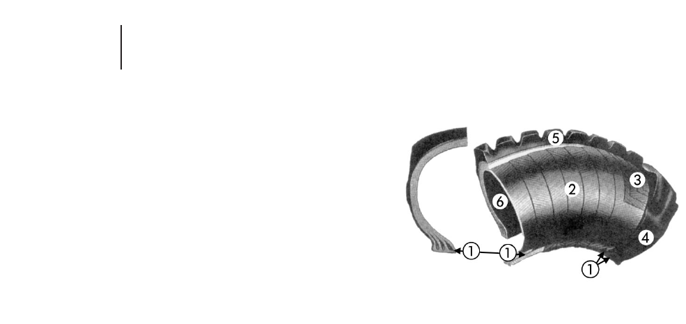
TIRE CONSTRUCTION
The pneumatic tire is essentially a flexible pres-
sure vessel utilizing structural members (nylon,
steel cable, etc.) to contain the hoop tension result-
ing from the inflation pressure. Rubber is utilized as
a protective coating and sealant over the structural
members and makes up the tread pattern which
provides the wearing medium at the ground inter-
face. The following brief explanation of the various
tire constructions will assist you in selecting tires
for your specific application.
Two distinct tire constructions approved on
all Caterpillar machines are the BIAS PLY
and RADIAL PLY tires. The following is a brief
explanation of the principal features of these two
constructions.
Bias Ply
1. Beads — The tire beads consist of steel wire-
bundles (3 or 4 in larger tires) which are forced
laterally by tire inflation pressure to wedge the
tire firmly on the rim’s tapered bead seat. The
nylon plies tie into the bead bundles. The forces
inherent in the tire are transmitted from the rim
through the bead bundles into the nylon.
2. Body plies — Layers of rubber-cushioned nylon
cord comprise the tire carcass. Alternating plies
of cord cross the tread centerline at an angle
(bias). The term “ply rating” is an index of tire
strength and not the actual number of tire plies.
3. Breakers or tread plies — These, if used, are con-
fined to the tire’s tread area and are intended to
improve carcass strength and provide additional
protection to the body plies. Some “work” tires
employ steel breakers or belts to further protect
the carcass.
4. Sidewalls — These are the protective rubber lay-
ers covering the body plies in the sidewall.
5. Tread — The wearing part of the tire which con-
tacts the ground. It transmits the machine weight
to the ground and provides traction and flotation.
6. Inner liner — This is the sealing medium which
retains the air and, combined with the “O” ring
seal and rim base, eliminates the need for inner
tubes and flaps.
7. Tubes and flaps — There are a few applications
where tire life may be improved by using tubes
and flaps (not shown).
8. Undertread — Protective rubber cushion lying
between tread and body ply.
22-2
Tires Tire Construction
●Bias Ply
Bias Ply Construction
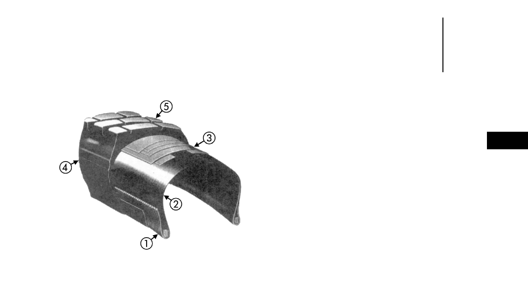
Radial Ply
1. Beads — A single bead bundle of steel cables or
steel strip (spiraled like a clock spring) comprise
the bead at each rim interface.
2. Radial carcass — This consists of a single layer
or ply of steel cables laid archwise (on the radian)
bead to bead.
3. Belts — Several layers or plies of steel cable form
the belts which underlie the tread area around
the tire circumference. The cable in each belt
crosses the tread centerline at an angle with the
angle being reversed from the preceding belt.
4. Sidewalls.
5. Tread.
6. Undertread — Protective rubber cushion lying
between tread and steel belts.
TIRE TYPES
Off-the-road tires are classified by application in
one of the following three categories:
1. Transport tire — For earthmoving machines that
transport material such as trucks and wheel
tractors.
2. Work tire — Normally applied to slow moving earth-
moving machines such as graders and loaders.
3. Load and carry — Wheel loaders engaged in
transporting as well as digging.
In actual practice there are few instances where
it is necessary to apply a type of tire in an applica-
tion not originally intended by the tire designer.
More tires are now being designed for a wide range
of applications.
TIRE SIZE NOMENCLATURE
Tire size nomenclature is derived from the
approximate cross section width and rim diameter
with various systems being available:
1. A wide base tire, for example, is designated as a
29.5-35 with the approximate cross section width
being the first number (inches) and the rim diam-
eter the second number (inches). Industry stan-
dards permit this tire’s width to be a maximum
of 824 mm (32.45") in service.
2. A standard base tire, for example, is designated
as a 24.00-35 with the approximate cross section
width being the first number (inches) and the rim
diameter the second number (inches). Industry
standards permit this tire width to be a maxi-
mum 718 mm (28.27") in service.
3. A low profile tire, for example, is designated as a
40/65-39 (formerly 65/40-39 or 40-39) with the
approximate cross section width being the first
(40) number (inches) and the rim diameter the
third (39) number (inches). The second number
(65 actually is 0.65) is the aspect ratio (section
height divided by section width).
If designated 40/65 R39, then the R denotes
radial construction.
The wide base tire has an aspect ratio of approx-
imately 0.83 and the standard base 0.95. The “low
profile tire” has an aspect ratio of 0.65.
When comparing a wide base tire to a standard
base tire, it must be remembered a larger first num-
ber on a wide base tire with the same rim diameter
does not mean the wide base is larger in overall
diameter. For example, the 18.00-25 standard base
tire is larger in diameter than the 20.5-25 wide base.
It is comparable in overall diameter to the 23.5-25
wide base.
22-3
22
TiresTire Construction
●Radial
Tire Types
Tire Size Nomenclature
Radial Ply Construction
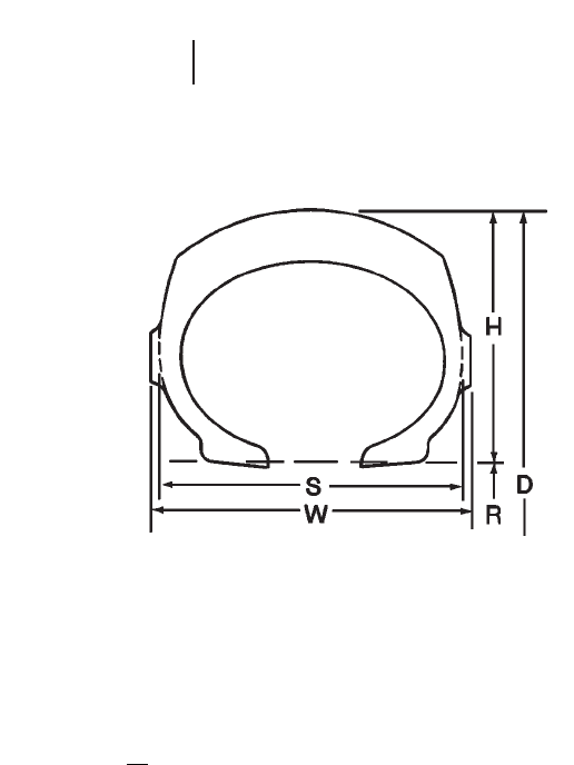
D = Tire Overall Diameter
R = Nominal Rim Diameter
H = Tire Section Height
S = Tire Section Width
W = Tire Width (includes ornamental ribs)
H= Aspect Ratio
S
CODE IDENTIFICATION FOR
OFF-HIGHWAY TIRES
The tire industry has adopted a code identifica-
tion system to be used for off-the-road tires. This
identification system will reduce the confusion
caused by the trade names for each type of tire
offered by each tire manufacturer. The industry code
identification is divided into six main categories by
types of service as follows:
C— Compactor Service
E— Earthmover Service
G— Grader Service
L— Loader & Dozer Service
LS — Log-Skidder Service
ML — Mining & Logging Service
The sub-categories are designated by numerals,
as follows: Code Identification
% Tread
Compactor Depth
C-1 Smooth 100
C-2 Grooved 100
Earthmover
E-1 Rib 100
E-2 Traction 100
E-3 Rock 100
E-4 Rock Deep Tread 150
E-7 Flotation 80
Grader
G-1 Rib 100
G-2 Traction 100
G-3 Rock 100
G-4 Rock Deep Tread 150
Loader & Dozer
L-2 Traction 100
L-3 Rock 100
L-4 Rock Deep Tread 150
L-5 Rock Extra Deep Tread 250
L-3S Smooth 100
L-4S Smooth Deep Tread 150
L-5S Smooth Extra Deep Tread 250
L-5/L-5S Half Tread Extra Deep 250
Mining & Logging
ML-1 Rib 100
ML-2 Traction 100
ML-3 Rock 100
ML-4 Rock Deep Tread 150
Log-Skidders
LS-1 Regular Tread 100
LS-2 Intermediate Tread 125
LS-3 Deep Tread 150
HF-4 Extra Deep Tread 250
22-4
Tires Off-Highway Tire Identification Codes
Tire cross-section

Tire and Rim
Assoc. Code Tread Type FIRESTONE GENERAL GOODYEAR BRIDGESTONE MICHELIN
Compactor
C-1 Smooth Plain Roller Smooth Road Roller X LISSE
Compactor Compactor X LC
C-2 Grooved All Weather
Compactor Compactor Alligator 2
Earthmover
E-1 Rib Rib Excavator Rock Rib LCM Hard Rock RIB XRIB
E-2 Traction Super Ground All Duty Earthmover Fast Grip, G-Lug XV, XL, XMP,
Grip DTL Sure Grip VKT, VFT, VGT, XG, XH, XS, XR
TL100 Sure Grip Lug VLT, VHB, VSB
E-3 Rock Rock Grip ND LCM Hard Rock Lug R-Lug, W-Lug XK, XR
Excavator CM 100 Hard Rock E-Lug, XRDN
Super Rock SL 100 Lug-8 VE Block XH
Grip XG-3 Super Hard V-LUG 2, VMT, XADN
E67 LCM Rock Lug VEL, VRL XADT
GSR Super Hard XAD65-1
Rock Lug-8 XHAD
HRL-3B XZH
GP-2B
RL-2+
RL-3J
RL-3
RL-2F
RL-3+
E-4 Rock Deep Super Rock ND Super LCM HRL-4B R-Lug S, E-Lug S XHDI, XDT
Tread Grip Deep Super LCM RL-4 XKDI
Tread CM 150 RL-4J E-Lug S2 XRS
Rock Master CRL 150 RL-4H/4H II VELS, VRLS
Deep Tread XG-4 RL-4J II VMTS, VALS
Power Lug RL-4A VZTS, VMTP
Deep Tread RL-4B
GP-4B
GP-4D
E-5 Rock Extra Super Deep
Deep Tread Tread
E-7 Flotation All Non-Skid EM Super Sand SRB-7A Alligator, VSJ XS
Sand Champion Flotation Sand Clipper 2 XRIB
Sand & Highway S-Lug
Grader
G-1 Rib Rib Road RBG-IA Rib Grader
Builder
G-2 Traction Super Ground Loader Grader SGG-2A Fast Grip, G-Lug XTL, XMPS,
Grip Road Loader Grader II VKT, VSW, VUT X SNOPLUS,
Builder SG-2B XGL2, XR
G-3 Rock Rock Grip Road ND LCM Grader RKG-3A R-Lug XH, XHAD, XHF
Builder XLD70-1, XRDN
G-4 Rock Deep Super Rock SGG-4B R-Lug XRD1, XLDD1
Tread Grip Deep XLD70-1
Tread Road
Builder
22-5
22
TiresManufacturer’s Designation

Tire and Rim
Assoc. Code Tread Type FIRESTONE GENERAL GOODYEAR BRIDGESTONE MICHELIN
Log-Skidder
LS-1 Regular
LS-2 Intermediate Forestry Tree Logger Timber Grip S
Special Timber Skid Fast Grip
LS-3 Deep Champion Timber Skid II
Spade Grip
Logger
HF-4 Timber Skid
Flotation
Loader & Dozer
L-2 Traction Super Ground Loader Grader II Sure Grip Fast Grip, VKT XTL, XGL 2
Grip LD LD Loader Loader VLT XF, XM27, XM47
Grader Sure Grip V-Grip, VSW, VUT X SNOPLUS
LD All Duty Lug D&L XMPS, XR
SGL E/L-2A
GP-2B
RL-2+
RL-2F
L-3 Rock Super Rock LD ND LCM Super Hard Rock R-Lug, VMT XRDN,
Grip LD LD 100 Loader V-Lug 2 XH, XHAD
GSR Super Hard Rock XHF, XK, XR
Lug D&L XLD70-1
Super Hard Rock
Lug 8-D&L
HRL E/L-3A
GP-2B
RL-2+
L-4 Rock Deep Tread Super Rock Grip LD-150 CRB Super Hard Rock R-Lug S, VALS XRD1, XLDD1,
Deep Tread Lug Xtra N-Lug, VCH XMINE D1
LD LD-150 Belted Tred D&L R-Lug S2 XKD1
Nylosteel XLD70-1
NRL D/L-4A
Belted
HRL D/L 4G
RL-4K
GP-4B
L-5 Rock Extra Deep Super Deep LD-250 CRB Super Xtra D-Lug XRD2, XLDD2
Tread Tread LD LD-250 Belted Tred D&L M-Lug S XMINE D2
GSR Nylosteel VSDL
NRL D/L-5A
Belted
RL-5K
RL-4K
L-3S Smooth Tread Plain Tread LD
L-4S Smooth Deep Plain Tread LD SMO D/L-4A Smooth Tread M XSMD 2
Tread
L-5S Smooth Extra Plain Tread LD LD-250 Super SMO D/L-5A Smooth Tread MS
Deep Tread Smooth CRB VSMS
LD-250 Super
Smooth Belted
L-5/L-5S Half Smooth Half Tread LD LD-250 Haf Trac D-Lug 2
CRB
LD-250 Haf Trac
Belted
22-6
Tires Manufacturer’s Designation

RADIAL TIRE IDENTIFICATION
Code Identification for Michelin Tires
All Michelin earthmover tires are radial construc-
tion, designated by the “X” marking. They contain a
single steel radial ply with a series of steel belts
placed around the tire’s circumference which rein-
force and stabilize the tread.
Following are the tread designs currently avail-
able from Michelin with the different internal con-
structions depending on the application.
Type A — Cut resistant tread compound with
reinforced sidewalls for work machines,
mine vehicles, and slow moving trans-
port machines on ground where there
is danger of cuts, penetration, etc.
Type B — Wear and heat resistant construction
for use on most transport machines.
Type C — For use on the highest speed transport
machines.
A4/B4/C4 — Additional tread compounds are avail-
able for haul trucks which can opti-
mize performance for specific site
conditions.
The current combinations of tread patterns, con-
struction, and tread depths offered, and primary
TRA codes are:
Tread Primary
Design Type A Type B Type C TRA Codes
XH x — x L3, G3, E3
XHD1 x x — E4
XF x — — L2
XMP — x — E2
XMPS x — — G2
XTL x — — L2, G2
XGL2 x — — L2, G2
XG — — x E2
XV — — x E2
XLDD1 x — — L4
XLDD2 x — — L5
XK x x — E3
XRDN x x — L3, E3
XRD1 x — — L4, E4
XRD2 x — — L5
XL —x—E2
XS —x—E7
XKD1 x x — E4
XMINED1 x — — L4
XMINED2 x — — L5
XSMD2 x — — L5S
XLISSE — — x C1
Tread Primary
Design Type A Type B Type C TRA Codes
XR x x — E3, G3
XADN x x — E3
XADT x — — E4
X SNOPLUS x — — L2, G2
XDT x x — E4
XRIB x — — E1
XAD65-1 — x — E3/E4
XLD70-1 x — — L3/L4
XHF x — — L3
XR5 — x — E3
Since Michelin radial tires contain a single steel
casing ply, they utilize the industry method of des-
ignating radial tire strength in terms of “stars.” Their
system consists of a one star, two star, and three star
rating as an indication of the tire’s carrying capacity.
The one star is the lightest construction, generally
used on work and slow moving transport machines.
Two star tires are used on most medium and high
speed transport machines. Three star construction
provides the greatest carrying capacity for a given
size and is only available in small standard base tires.
This combination of tread designs and types of con-
struction provides a range of radial tires which cover
most earthmoving applications. We recommend that
in applying steel radial tires to your machines you
provide all data to the tire manufacturer. Obtain his
recommendations as to which tire will provide the
most economical operation.
Code Identification for Goodyear Radial Tires
All Goodyear steel radial earthmover tires have
been designated Unisteel followed by a three or four
digit alpha-numeric code that identifies the partic-
ular tread. The currently active codes are:
RL-2+ E 2/3 and L 2/3
RL-2F E2 and L2 RL-4H/HII E4
RL-3 E3 RL-4J E4
RL-3+ E3 RL-4JII E4
RL-5K L5
RL-3J E3 and L3 GP-2B E2/3,
RL-4 E4 L2/3
RL-4A E4 SG-2B G2
RL-4B E4 RL-4K L4
GP-4B E4 GP-4B L4
GP-4D E4
22-7
22
TiresRadial Tire Identification
●Michelin
●Goodyear

The RL stands for Rock Lug and indicates that the
upper sidewall has rock protection. The number in
the code corresponds to the tire industry identifica-
tion system (2-traction, 3-rock, etc). The fourth digit,
if any, is used to designate tread design differences
for the same basic tread type (F-directional tread).
The carcass strength is indicated by a star rating
system instead of the ply rating system. These sym-
bols indicate the recommended inflation for a par-
ticular tire load.
Following the star rating code is Goodyear’s Cus-
tom Compound and Construction code. For a tire
designated “2S” the 2 indicates a heat resistant
compound and the S indicates standard construc-
tion and an H indicates heavy duty construction.
The higher the number the greater the abrasion and
cut resistance with a corresponding lower T-km/h
(TON-mph) rating.
Code Identification for Bridgestone Radial Tires
The Bridgestone steel radial earthmover has been
designated as V-Steel. The current nomenclature is:
V-Steel Ultra Traction (VUT) G2/L2
V-Steel K-Traction (VKT) E2/L2/G2
V-Steel F-Traction (VFT) E2
V-Steel L-Traction (VLT) E2/L2
V-Steel M-Traction (VMT) E3/L3
V-Steel G-Traction (VGT) E2
V-Steel M-Traction S (VMTS) E4
V-Steel R-Lug (VRL) E3
V-Steel R-Lug S (VRLS) E4
V-Steel A-Lug S (VALS) E4/L4
V-Steel H-Block (VHB) E2
V-Steel E-Lug (VEL) E3
V-Steel E-Lug S (VELS) E4
V-Steel D-Lug (VSDL) L5
V-Steel Smooth Tread MS (VSMS) L5S
V-Steel Snow Wedge (VSW) L2/G2
V-Steel Container Handler (VCH) L4
V-Steel Jamal (VSJ) E7
V-Steel Z-Traction S (VZTS) E4
V-Steel M-Traction Premium (VMTP) E4
Bridgestone has multiple tread compounds, with
the three most commonly used being: type 1A = stan-
dard, type 2A = cut resistant and type 3A = heat resis-
tant. The carcass strength, i.e., load carrying capacity
of tire is indicated by star rating system; 1-star, 2-star
and 3-star. All Bridgestone radial tires conform to the
international tire standard of TRA and ETRTO.
TON-MILES PER HOUR
Tire selection and machine operating practices
have, in some cases, become the critical factors in
the over-all success of earthmoving ventures. The
most serious problems occur when tires are operated
at temperatures above their capabilities. Separation
and related failures occur. To help you avoid tem-
perature related failures, Caterpillar has been
instrumental in developing the Ton-Miles Per Hour,
(Ton-MPH) method of rating tires.
Heat and Tire Failure
Tire manufacturing requires heat in the vulcan-
izing process converting crude rubber and additives
into a homogeneous compound. The heat required is
above 132°C (270°F).
A tire also generates heat as it rolls and flexes.
Heat generated faster than it can be radiated into
the atmosphere gradually builds within the tire and
reaches maximum level at the outermost ply or belt.
Over time, enough heat can develop from over-
flexing to actually reverse the vulcanizing process or
“revert” the rubber causing ply separation and tire
failure. Only a brief time at reversion temperature
initiates the failure. Experience shows that few pure
heat separation cases occur. Most so-called heat sep-
arations are in tires operating below the reversion
level.
As a tire’s operating temperature increases the
rubber and textiles within significantly lose strength.
The tire becomes more susceptible to failures from
cornering, braking, impact, cut through, fatigue and
heat separation. If operating tires at higher temper-
atures is absolutely necessary, it is essential the
machines be operated to reduce the probability of pre-
mature tire failure. No hard cornering without super-
elevation, no panic braking, etc.
The Ton-MPH formula was developed to predict
tire temperature buildup. The system is a method of
rating tires in proportion to the amount of work they
can do from a temperature standpoint. It utilizes
the product of load
3
speed to derive an index of the
tire temperature buildup. Maximum tire level-off
temperatures of 107°C (225°F) for fabric cord tires
and 93°C (200°F) for steel wire tires are the limits
Caterpillar recommends. Even at these tempera-
tures, failures may be initiated by overstressing the
tires. Some tire companies rate fabric cord tires at
111°C (232°F) and on occasion as high as 118°C
(250°F). These higher temperature levels are ques-
tionable under average field conditions.
22-8
Tires Radial Tire Identification
●Bridgestone
Ton-Miles Per Hour Rating System

It is possible by using a needle type pyrometer to
measure temperature at any desired point within
the tire carcass. However, the instrumentation and
the technique does not lend itself to general field
use. The greatest difficulty is locating the thickest
(therefore the hottest) tread bar in any given tire
using giant calipers. The tire must then be drilled
along the centerline of this bar from shoulder to
shoulder at 52 mm (2") intervals. These 3.18 mm
(1/8") diameter holes extend down through the tread
and undertread to the topmost reinforcement. This
procedure is fully described under SAE Recommended
practice J1015.
The Ton-MPH rating system as given in this SAE
specification is approved by most tire manufactur-
ers. Michelin, in addition to providing Ton-MPH rat-
ings has developed their own speed/load carrying
rating system and we recommend that Michelin be
consulted where high tire temperature with Michelin
tires might be a problem.
Heat generation in a specific tire at recommended
pressure depends on three factors:
●the weight the tire is carrying (flex per revolution),
●the speed the tire is traveling over the ground
(flexures over a period of time), and
●the air temperature surrounding the tire (ambi-
ent temperature) and road surface temperature.
Once a tire manufacturer has determined a tire’s
temperature characteristics and expressed them in
Ton-MPH, the above listed specific job conditions
can be used to determine any tire’s maximum work
capacity. These conditions provide on site ability to
predict and avoid costly tire separations.
Ton-Mile-Per-Hour Rating System
The tire TMPH can be matched to the site TMPH
as well as compared with TMPH values of different
makes and types of tires.
TMPH Job Rate
Average Tire Load 3Average Speed for the shift
Average Tire Load
“Empty” tire load + “loaded” tire load
2
Average Speed
Round trip distance in miles 3number of trips
Total Hours (in the shift)
For excessive haul length (20 miles or more) con-
sult your tire representative for modification to the
TMPH value.
To use in the metric system, change miles to kilom-
eters and use metric tons.
It should be noted that prolonged operation at
high carcass temperatures can fatigue the nylon at
the flex points in the sidewalls.
The following are the most recent Ton-MPH rat-
ings as made available by Goodyear, Michelin and
Bridgestone, and are subject to change on their part
at any time. Other tire manufacturers’ Ton-MPH
ratings will be included in future handbook editions
when and if made available. For latest Ton-MPH
ratings, consult specific tire manufacturer at time of
machine and/or tire purchase.
Load-and-Carry T-km/h (Ton-MPH)
The wheel loader, when used in load-and-carry
applications, may encounter temperature problems
similar to those normally associated only with tires
on scrapers, trucks and wagons. Do not place the
vehicle in load-and-carry applications with-
out first obtaining T-km/h (Ton-MPH) ratings
and pressure recommendations from the tire
manufacturer.
Conventional and Radial Steel Cord Tire Options
Tire options now provide types to operate in con-
ditions ranging from rock and abrasive materials,
to jobs with high speed hauls in good materials.
The best tire type can be different for the drive tires
than for other tires on the same machine. T-km/h
(Ton-MPH) should be calculated for all tires.
Tire Drive-Away Recommendations
Heat separation can be a problem during machine
delivery and moving machines from one job to
another. Whenever roading earthmoving machines,
check your supplier for the tire manufacturer’s rec-
ommended speed limitations on the specific tires
involved.
Some tire manufacturers also recommend that
vehicles equipped with extra tread depth or special
compounded tires should not be roaded without their
specific approval. Our tests support this recommen-
dation, especially for L-3, L-4, E-4 and L-5 tires.
22-9
22
TiresTon-Miles Per Hour Rating System
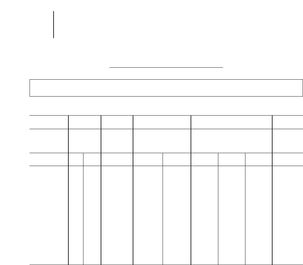
T-km/h (Ton-MPH) RATINGS
AT 38° C (100° F) AMBIENT TEMPERATURE
For Hauls of 20 Miles or Less One Way
GOODYEAR BIAS PLY CONSTRUCTION CONVENTIONAL SIZES
Industry
Code E-1 E-2 E-3 E-4 E-7
Hard Rock
Rib Sure Grip Hard Rock Lug XT
Tread Hard Rock Lug HRL-3A HRL-4A Hard Rock Sand Rib
Design HRR-1A SGL-2A Hard Rock Lug-8 HRL-3B Lug XT-8 HRL-4B SRB-7A
Custom
Code 2S 4S 4S 2S 4S 2S 4S 6S 4S
14.00-24 TKPH 102
TMPH 70
16.00-25 TKPH 182 131 102 131 95
TMPH 125 90 70 90 65
18.00-25 TKPH 146 182 131 117 234
TMPH 100 125 90 80 160
18.00-33 TKPH 219 161 146 124
TMPH 150 110 100 85
21.00-25 TKPH 270
TMPH 185
24.00-35 TKPH 255 234 204
TMPH 175 160 140
27.00-49 TKPH 460 328 277
TMPH 315 225 190
36.00-51 TKPH 679 489 628
TMPH 465 335 430
22-10
Tires T-km/h (Ton-MPH) Rating
●Goodyear Bias Ply
Conventional Sizes
Because of the variance between specific tires it is recommended that at the time of purchase you check with your tire supplier for the man-
ufacturer’s specific T-km/h (Ton-MPH) ratings for the tires purchased.
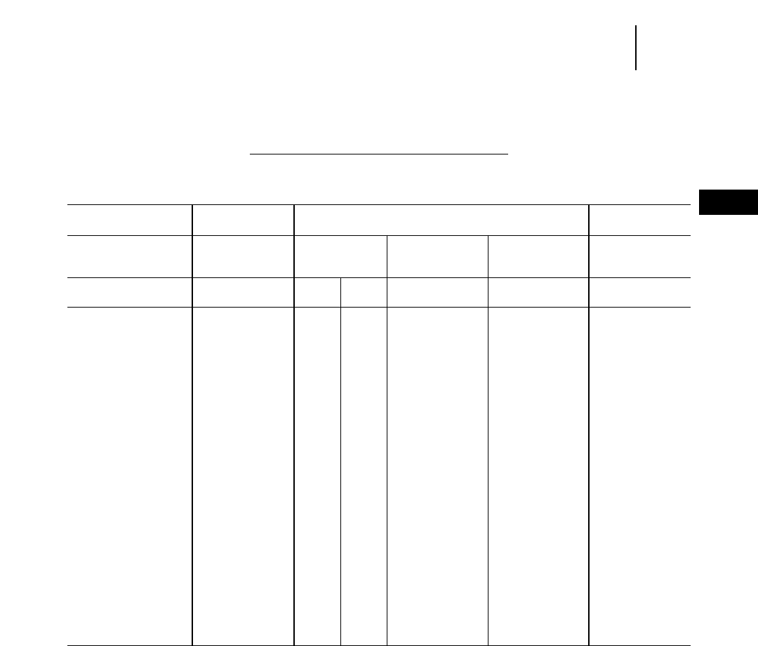
T-km/h (Ton-MPH) RATINGS
AT 38° C (100° F) AMBIENT TEMPERATURE
For Haul Lengths of 20 Miles or Less One Way
GOODYEAR BIAS PLY CONSTRUCTION WIDE BASE SIZES
Industry
Code E-2 E-3 E-7
Sure Grip Super Hard Super Hard Sand
Tread Lug Rock Lug Lug 8 Rib
Design SGL E/L 2A HRL E/L 3A HRL-3B HRL-3F SRB-7A
Custom
Code 4S 2S 4S 4S 3S 4S
20.5-25 TKPH 109 95
TMPH 75 65
23.5-25 TKPH 131 102
TMPH 90 70
26.5-25 TKPH 153 131
TMPH 105 90
29.5-25 TKPH 182 168 248
TMPH 125 115 170
29.5-29 TKPH 197 255 182 190
TMPH 135 175 125 130
29.5-35 TKPH 212 234
TMPH 145 160
33.25-29 TKPH 204
TMPH 140
33.25-35 TKPH 248 234
TMPH 170 160
33.5-33 TKPH 248 234
TMPH 170 160
37.25-35 TKPH 321 307
TMPH 220 210
37.5-33 TKPH 299 321 307
TMPH 205 220 210
37.5-39 TKPH 350 328
TMPH 240 225
22-11
22
TiresT-km/h (Ton-MPH) Rating
●Goodyear Bias Ply — Wide Base Size
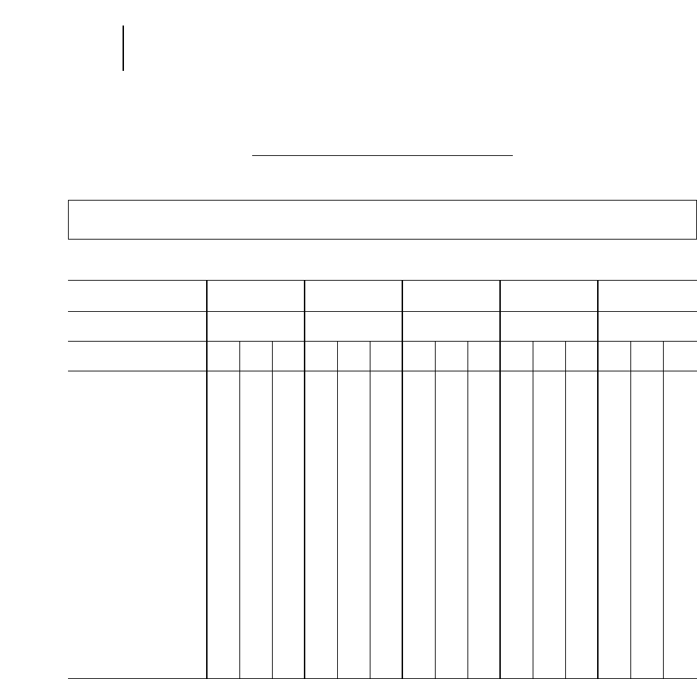
T-km/h (Ton-MPH) RATINGS
AT 38° C (100° F) AMBIENT TEMPERATURE
For Haul Lengths of 32 k (20 Miles) or Less One Way
Maximum Speed Not to Exceed 48 k (30 Miles) per Hour
BRIDGESTONE BIAS CONVENTIONAL SIZES
Industry
Code E-3 E-3 E-4 E-4 E-4
Tread
Design RL EL RLS ELS ELS2
Custom
Code E2A E1A E3A E2A E1A E3A E2A E1A E3A E2A E1A E3A E2A E1A E3A
12.00-24/25 TKPH 66 80
TMPH 45 55
14.00-24/25 TKPH 95 109 146 69 90
TMPH 65 75 100 47 62
16.00-25 TKPH 124 139 204 97 111
TMPH 85 95 140 66 76
18.00-24/25 TKPH 160 173 263 139 153 139
TMPH 110 119 180 95 105 95
24.00-25 TKPH 212
TMPH 145
18.00-33 TKPH 190 212 314 161 182 161 182
TMPH 130 145 215 110 125 110 125
24.00-35 TKPH 292 328 460 234 277 394
TMPH 200 225 315 160 190 270
24.00-49 TKPH 357 431 577 292 343 482 321 365 518
TMPH 245 295 395 200 235 330 220 250 355
27.00-49 TKPH 423 496 701 336 406 547 350 409 569
TMPH 290 340 480 230 278 275 240 280 390
33.00-51 TKPH 453 533 708 460 533 752
TMPH 310 365 485 315 365 515
36.00-51 TKPH 526 635 847 526 649 891
TMPH 360 435 580 360 445 610
40.00-57 TKPH 547 657 876 547 657 920
TMPH 375 450 600 375 450 630
22-12
Tires T-km/h (Ton-MPH) Rating
●Bridgestone Conventional Size
Because of the variance between specific tires it is recommended that at the time of purchase you check with your tire supplier for the man-
ufacturer’s specific T-km/h (Ton-MPH) ratings for the tires purchased.
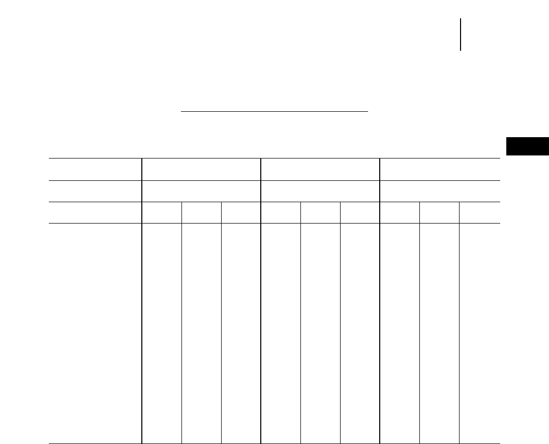
T-km/h (Ton-MPH) RATINGS
AT 38° C (100° F) AMBIENT TEMPERATURE
For Haul Lengths of 32 k (20 Miles) or Less One Way
Maximum Speed Not to Exceed 48 k (30 Miles) per Hour
BRIDGESTONE BIAS WIDE BASE SIZES
Industry
Code E-2 E-3 E-4
Tread
Design FG RL and VL2 RLS
Custom
Code E2A E1A E3A E2A E1A E3A E2A E1A E3A
20.5-25 TKPH 109 88 95
TMPH 75 60 65
23.5-25 TKPH 161 117 131 88
TMPH 110 80 90 60
26.5-25 TKPH 139 161
TMPH 95 110
29.5-25 TKPH 168 190 234
TMPH 115 130 160
26.5-29 TKPH 190
TMPH 130
29.5-29 TKPH 234 182 204 124 139
TMPH 160 125 140 85 95
33.5-33 TKPH 248 285
TMPH 170 195
37.5-33 TKPH 343
TMPH 235
29.5-35 TKPH 255
TMPH 175
33.25-35 TKPH 255 292 380
TMPH 175 200 260
37.25-35 TKPH 358 467
TMPH 245 320
37.5-39 TKPH 325 372 489
TMPH 223 255 335
22-13
22
TiresT-km/h (Ton-MPH) Rating
●Bridgestone Wide Base Size
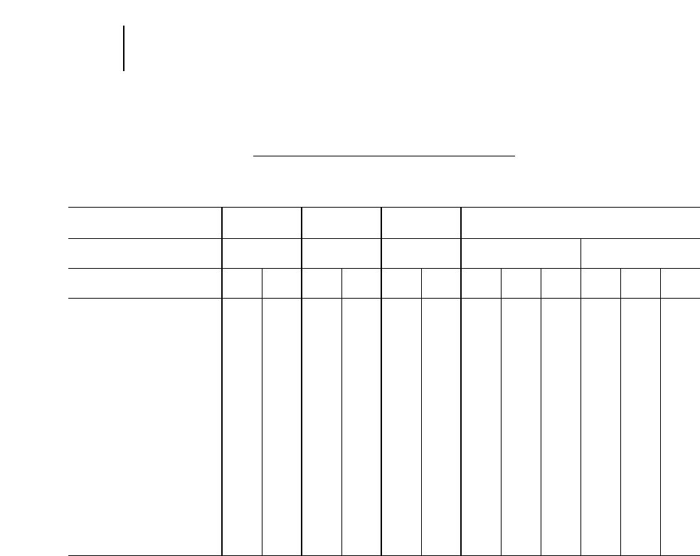
T-km/h (Ton-MPH) RATINGS
AT 38° C (100° F) AMBIENT TEMPERATURE
For Haul Lengths of 20 Miles or Less One Way
GOODYEAR RADIAL PLY CONSTRUCTION CONVENTIONAL SIZES
Industry
Code E-2 E-2/E-3 E-3 E-4
Tread RL-4H RL-4J
Design RL-2F GP2B RL-3+ RL-4HII RL-4JII
Custom
Code 2S 4S 2S 4S 2S 4S 2S 4S 6S 2S 4S 6S
14.00R25 TKPH 124 95
TMPH 85 65
16.00R25 TKPH 190 146 220 168 124
TMPH 130 100 150 115 85
18.00R25 TKPH 248 190 226 168 190 146
TMPH 170 130 155 115 130 100
18.00R33 TKPH 292 219 263 197 226 175 131
TMPH 200 150 180 135 155 120 90
24.00R35 TKPH 438 335 394 299 234
TMPH 300 230 270 205 160
27.00R49 TKPH 730 562 628 474 547 423 328 547 423 328
TMPH 500 385 430 325 327 290 225 375 290 225
33.00R51 TKPH 715 540 321
TMPH 490 370 220
36.00R51 TKPH 788 598 358 788 598 358
TMPH 540 410 245 540 410 245
37.00R57 TKPH 1022 781 460 1095 730 490
TMPH 700 535 315 750 500 335
40.00R57 TKPH 1145 875 518
TMPH 785 600 355
22-14
Tires T-km/h (Ton-MPH) Rating
●Goodyear Radial Ply — Conventional Sizes
T-km/h (Ton-MPH) RATINGS
AT 38° C (100° F) AMBIENT TEMPERATURE
For Haul Lengths of 20 Miles or Less One Way
GOODYEAR RADIAL PLY CONSTRUCTION WIDE BASE SIZES
Industry
Code E-2 E-3
Tread
Design AT-2A RL-2+ RL-2F GP-2B RL-3 RL-3F RL-3J
Custom
Code 2S 2S 4S 2S 4S 4S 4S 4S 4S
15.5R25 TKPH 146 109
TMPH 100 75
17.5R25 TKPH 190 146 109 151 124
TMPH 130 100 75 105 85
20.5R25 TKPH 175 131 168 146
TMPH 120 90 115 100
23.5R25 TKPH 197 146 197 160
TMPH 135 100 135 110
26.5R25 TKPH 226 168 226
TMPH 155 115 155
26.5R29 TKPH
TMPH
29.5R25 TKPH 270 204 270
TMPH 185 140 185
29.5R29 TKPH 306 233 379 284 270
TMPH 210 160 260 195 185
33.25R35 TKPH 474 357 335
TMPH 325 245 230
37.25R35 TKPH 547 416 379
TMPH 375 285 260
37.5R39 TKPH 613 460 430
TMPH 420 315 295
40.5/75R39 TKPH 445
TMPH 305
22/65R25 TKPH 284
TMPH 195
25/65R25 TKPH 182 182
TMPH 125 125
30/65R25 TKPH 160
TMPH 110
22-15
22
TiresT-km/h (Ton-MPH) Rating
●Goodyear Radial Ply — Wide Base Sizes
T-km/h (Ton-MPH) RATINGS
AT 38° C (100° F) AMBIENT TEMPERATURE
For Haul Lengths of 32 k (20 Miles) or Less One Way
Maximum Speed Not to Exceed 48 k (30 Miles) per Hour
BRIDGESTONE RADIAL PLY
Industry
Code E-4 E-4 E-4
Tread
Design VMTS VRLS/VWTS VELS
Custom
Code E2A E1A E3A E2A E1A E3A E2A E1A E3A
14.00R24 TKPH 91 119 136
TMPH 62 82 93
14.00R25 TKPH 91 119 136 85 112 128
TMPH 62 82 93 58 77 88
16.00R25 TKPH 123 157 179 112 146 165
TMPH 84 108 123 77 100 115
18.00R25 TKPH 169 209 244 144 179 209
TMPH 116 143 167 99 123 143
15.00R33 TKPH 199 246 287 170 211 246
TMPH 136 158 197 116 145 168
24.00R35 TKPH 338 415 489 314 358 453
TMPH 232 286 335 215 266 310
27.00R49 TKPH 486 600 702 415 513 600
TMPH 333 411 481 284 351 411
33.00R51 TKPH 660 815 953 558 690 807
TMPH 452 558 653 382 473 553
36.00R51 TKPH 642 793 927
TMPH 440 543 635
37.00R57 TKPH 694 858 1003
TMPH 475 588 687
40.00R57 TKPH 773 955 1117
TMPH 529 654 765
NOTE: For cycle lengths of 5 km (3 miles) or less (round trip), multiply the T-km/h (Ton-MPH) value in this table by 1.12.
22-16
Tires T-km/h (Ton-MPH) Rating
●Bridgestone Radial Ply
T-km/h (Ton-MPH) RATINGS
AT 38° C (100° F) AMBIENT TEMPERATURE
For Haul Lengths of 32 k (20 Miles) or Less One Way
Maximum Speed Not to Exceed 48 k (30 Miles) per Hour
BRIDGESTONE RADIAL PLY
Industry
Code E-2 E-2/E-3 E-3 E-3
Tread
Design VHB VKT/VFT VRL/VEL VMT
Custom
Code E2A E1A E3A E2A E1A E3A E2A E1A E3A E2A E1A E3A
14.00R24 TKPH 136 179 205 106 141 159
TMPH 93 123 140 73 97 109
14.00R25 TKPH 136 179 205
TMPH 93 123 140
16.00R25 TKPH 179 235 269 134 179 202
TMPH 123 161 184 92 123 138
18.00R25 TKPH 193 239 280 181 224 262
TMPH 132 164 192 124 153 179
18.00R33 TKPH 227 281 328 213 263 307
TMPH 155 192 225 146 180 210
24.00R35 TKPH 386 477 558 362 448 524
TMPH 264 327 382 248 307 359
27.00R49 TKPH 557 688 804 521 644 753
TMPH 382 471 551 357 441 516
33.00R51 TKPH 837 1034 1209
TMPH 573 708 828
36.00R51 TKPH 974 1203 1407
TMPH 667 824 964
NOTE: For cycle lengths of 5 km (3 miles) or less (round trip), multiply the T-km/h (Ton-MPH) value in this table by 1.12.
22-17
22
TiresT-km/h (Ton-MPH) Rating
●Bridgestone Radial Ply
T-km/h (Ton-MPH) RATINGS
AT 38° C (100° F) AMBIENT TEMPERATURE
For Haul Lengths of 38 k (20 Miles) or Less One Way
Maximum Speed Not to Exceed 48 k (30 Miles) per Hour
BRIDGESTONE RADIAL PLY
Industry
Code E-2/E-3 E-3 E-3 E-4
Tread
Design VKT VMT VRL/VAL VALS
Custom
Code E2A E1A E3A E2A E1A E3A E2A E1A E3A E2A E1A E3A
17.5R25 TKPH 95 125 145 90 117 138
TMPH 65 86 99 62 80 95
17.5R25 TKPH 120 154 180 114 144 171
TMPH 82 105 123 78 99 117
20.5R25 TKPH 129 166 193 120 157 184 110 147 165 92 119 138
TMPH 58 114 132 82 108 126 75 101 113 63 82 95
20.5R25 TKPH 160 206 240 149 194 229 137 182 205 114 148 171
TMPH 110 141 164 102 133 157 94 125 140 78 101 117
23.R25 TKPH 166 213 247 153 201 236 141 188 212 117 153 176
TMPH 114 146 169 105 138 162 57 129 145 80 105 121
23.R25 TKPH 205 263 307 190 245 292 175 233 262 146 189 219
TMPH 140 180 210 130 170 200 120 160 179 100 129 150
26.5R25 TKPH 257 312 349 220 293 330 165 220 256
TMPH 176 214 239 151 201 226 113 151 175
29.5R25 TKPH 310 376 421 266 354 399
TMPH 212 258 288 182 242 273
29.5R29 TKPH 330 401 449 212
TMPH 226 275 308 145
33.25R29 TKPH 407 494 552 319 435 493
TMPH 279 338 378 215 298 338
33.5R33 TKPH 444 539 603
TMPH 304 369 413
37.5R33 TKPH 534 648 724
TMPH 366 444 496
29.5R35 TKPH 279 380 431
TMPH 191 260 295
33.25R35 TKPH 441 536 599 346 472 535
TMPH 302 367 410 237 323 366
37.25R35 TKPH 530 644 720 413 563 638
TMPH 363 441 493 283 386 437
37.5R39 TKPH 573 696 778
TMPH
26/65R25 TKPH 162 205 243
TMPH
NOTE: For cycle lengths of 5 km (3 miles) or less (round trip), multiply the T-km/h (Ton-MPH) value in this table by 1.12.
22-18
Tires T-km/h (Ton-MPH) Rating
●Bridgestone Radial Ply
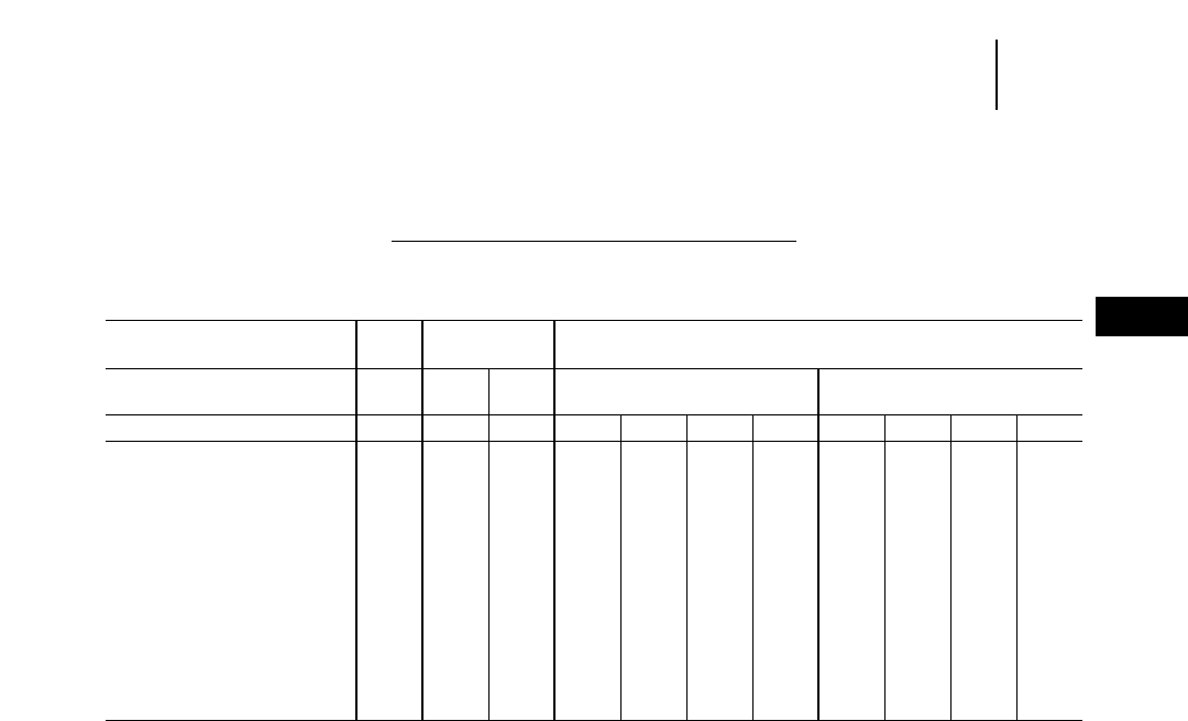
T-km/h (Ton-MPH) RATINGS
AT 38° C (100° F) AMBIENT TEMPERATURE
For Haul Cycles Less than 5 km (3 Miles) Round Trip*
MICHELIN RADIAL PLY CONSTRUCTION STANDARD BASE TIRES
Industry
Code E-2 E-3 E-4
Tread
Design XV XR XK XDT XKD1
Type C B B A4 A B4 B A4 A B4 B
18.00R33 TKPH 436 305 279 157 192 262 122 157 227
TMPH 299 209 191 108 132 179 84 108 155
24.00R35 TKPH 740 518 474 266 326 444 207 266 385
TMPH 507 355 325 182 223 304 142 182 264
27.00R49 TKPH 1090 763 698 392 480 567 654 392 480 567
TMPH 747 523 478 269 329 388 448 269 329 388
33.00R51 TKPH 558 682 806 930 496 620 744
TMPH 382 590 552 804 340 425 644
36.00R51 TKPH 1295 1184 592 740 888
TMPH 887 811 406 507 608
37.00R57 TKPH 678 848 1018
TMPH 464 581 697
40.00R57 TKPH 268 960 1152
TMPH 526 658 789
*Consult Michelin for TKPH (TMPH) ratings for haul cycles greater than 5 km (3 m).
NOTE: Additional tread compounds are available to meet specific T-km/h (TMPH).
22-19
22
TiresT-km/h (Ton-MPH) Rating
●Michelin Radial Ply — Standard Base Tires
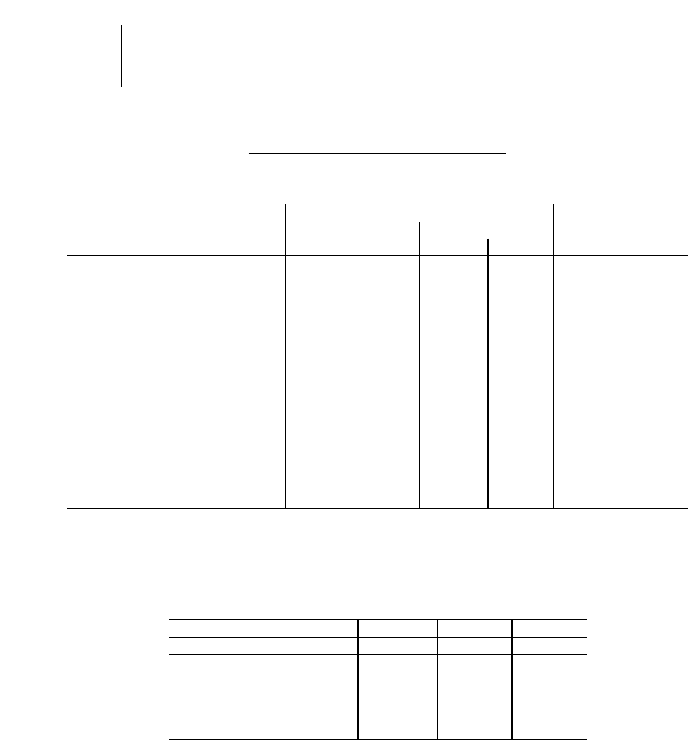
T-km/h (Ton-MPH) RATINGS
AT 38° C (100° F) AMBIENT TEMPERATURE
For Haul Cycles Less than 5 km (3 miles) Round Trip*
MICHELIN RADIAL PLY CONSTRUCTION WIDE BASE SIZES
Industry Code E-3 E-4
Tread Design XR XRDN XRS
Type B A B B
25/65R25 Low Profile TKPH 217
TMPH 149
29.5R29 TKPH 420
TMPH 288
33.25R29 TKPH 518
TMPH 355
33.5R33 TKPH 560
TMPH 384
37.5R33 TKPH 680
TMPH 466
29.5R35 TKPH 448
TMPH 307
33.25R35 TKPH 560
TMPH 384
37.25R35 TKPH 661 415
TMPH 453 284
37.5R39 TKPH 721
TMPH 494
40.5/75R39 TKPH 534 766 766
TMPH 366 525 525
*Consult Michelin for TKPH (TMPH) ratings on haul cycles greater than 5 km (3 m).
ISO Load Index Speed Symbol
AT 38° C (100° F) AMBIENT TEMPERATURE
For Haul Lengths Greater than 3 Miles (Round Trip)
MICHELIN RADIAL PLY CONSTRUCTION WIDE BASE SIZES
Industry Code E-3 E-3 (DT) E-3
Tread Design XADN XADT XAD65-1
Type
20.5R25 177B 177B
23.5R25 185B 185B
26.5R25 193B 193B
29.5R25 200B 200B
750/65R25 Low Profile 190B
22-20
Tires T-km/h (Ton-MPH) Rating
ISO Load Index Speed Symbol
●Michelin Radial Ply — Wide Base Sizes

TIRE AND RIM ASSOCIATION RATINGS
While the T-km/h (Ton-MPH) Rating System pro-
vides a method to determine the tire’s work capac-
ity, Tire and Rim Association Ratings provide a
guide for evaluating a tire’s structural capacity. These
two rating systems should be used in conjunction to
evaluate tire performance.
TIRE SELECTION
Selecting the optimum tire for a given application
is particularly critical for earthmoving. The machines
have the capability to outperform the tires and,
unless proper practices are observed, very costly
premature tire failures can occur. Job conditions
vary greatly throughout the world, as well as within
any given job site, and selecting the optimum tire
requires careful consideration of all factors involved.
In general, the tire manufacturer should be con-
sulted before making the selection for any given
application. In some cases, the tire manufacturer
can fabricate tires specifically tailored for a given
job site.
For those applications where wear is extremely
slow, especially as a result of only occasional oper-
ation throughout the year, the cheapest lightweight
tire needs to be given strong consideration.
As job conditions become severe, the following fac-
tors should be evaluated in selecting a tire:
Transport or Load-and-carry —
●T-km/h (Ton-MPH) (primary consideration)
●Minimum approved ply rating or greater
●Largest optional size
●Thickest tread commensurate with T-km/h
(Ton-MPH)
●Largest practical bar to gap ratio
●Most cut resistant tread commensurate with
T-km/h (Ton-MPH)
●Belted construction
Loader or Dozer —
●Minimum approved ply rating or greater
●Largest optional size
●Thickest tread
●Thickest available undertread
●Buttressed shoulder
●Most cut resistant tread
●Largest practical bar to gap ratio
●Belted construction
●Lowest aspect ratio
All tires should be operated at the tire manufac-
turer’s recommended inflation pressure for a given
application. Inflation pressure should be checked
every working day with an accurate Bourden-tube
type gauge. This gauge should be checked against a
known standard such as a dead weight tester at
least once a month.
Excess loads may result from factors such as vary-
ing material density, field modifications to equip-
ment, mud accumulation, load transfer, etc. Only
under these conditions may the actual in service tire
load exceed the rated machine load. When excess
loads are encountered, cold inflation pressures must
be increased to compensate for higher loads. Increase
tire inflation pressure 2% for each 1% increase in
load.
Maximum
Excess
Load Pressure
Bias Ply 15% 30%
Radial Ply 7% 14%
The above loads will result in reduced tire performance
and must be approved by the tire manufacturer.
The use of chains is difficult to justify except under
a few conditions. Chains are very costly and heavy,
and require more maintenance than most operations
can provide. On some models sufficient clearance
does not exist for chains with all tire combinations.
Extensive modifications may be required if chains
are needed for the job.
Foam filling tires is normally not recommended
due to high cost and lack of local filling facilities. Its
use should be confined to loader and dozer applica-
tions where penetrations occur almost daily. If foam
is used be sure to adhere to recommended equivalent
pressures of nitrogen and use highest available ply
rating.
22-21
22
TiresTire and Rim Association Ratings
Tire Selection
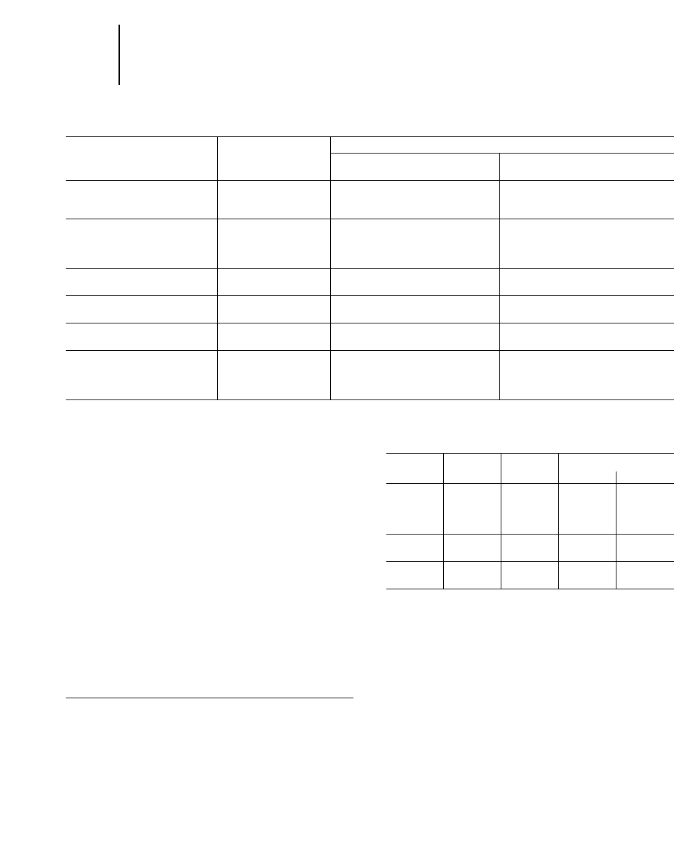
TIRE SELECTION GUIDE
Treads
Road or Wheel Tractors or
Material ground condition Wheel Tractor-Scrapers Wheel Loaders
Silt and clay, Good varying to poor. Traction Type (E-2). Traction Type (L-2).
No Rock, High rolling resistance.
High moisture content.
Silt and Clay, Good varying to poor. Rock-type (E-3) best unless traction Rock-type (L-3, L-4 or L-5) best unless
Some rock, is a problem — then use traction traction is a problem — then use
Variable moisture content. tires (E-2). Rock-type offers more traction (L-2) tires. Rock-type offers
resistance to cutting. more resistance to cutting.
Silty or clayey gravel and sand, Excellent to good. Rock-type (E-3) offers better wear. Rock-type (L-3, L-4 or L-5) offers
Low moisture content. Firm surface. better wear.
Silty or clayey gravel and sand, Poor, rutted, pot holes. Rock-type (E-3). Rock-type (L-3, L-4 or L-5).
High moisture content.
Blasted rock. Hard surface, rough. Rock-type (E-3 or L-3 and L-4 if Rock-type (L-5 or L-5S).
possible).
Sand Good to fair surface. Rock-type (E-3 or L-3S and L-4S if Rock-type (L-3 or L-3S) with low
Very low silt or clay content. possible) with low pressure. Creates pressure. Creates minimum soil
minimum soil disturbance resulting disturbance resulting in improved
improved flotation. flotation.
22-22
Tires Tire Selection
●Guide
●Standard Cold Inflation Pressures
TIRE SUPPLIER RECOMMENDED COLD
INFLATION PRESSURES
The following tables present Caterpillar and the
tire suppliers’ recommended cold inflation pressures
for tires on Caterpillar machines. An asterisk (*)
indicates the standard tire size and ply rating.
The inflation pressure is based on a ready-to-work
vehicle weight with no attachments, rated payload,
and average operating conditions. Pressures for
each application may need to be varied from
those shown and should always be obtained
from your tire supplier.
Pressures for all tires apply to rib, traction, rock,
deep tread, and super deep tread tires.
NOTE: Caterpillar now recommends using dry nitrogen (N2) gas for
both tire inflation and pressure adjustments on all current and past
production machines.
EXCAVATORS — Bias Ply
For complete tire data and inflation pressures, see the Excavator
section in this handbook.
SKIDDERS — Bias Ply
Pressure
Model Tire Size Ply Rating Front Rear
kPa psi kPa psi
525 28L-26 14 172 25 172 25
24.5-32 16 207 30 207 30
30.5-32 16 172 25 172 25
528B 24.5-32 16 210 30 210 30
30.5L-32 16 170 25 170 25
530B 24.5-32 16 210 30 210 30
30.5L-32 16 170 25 170 25
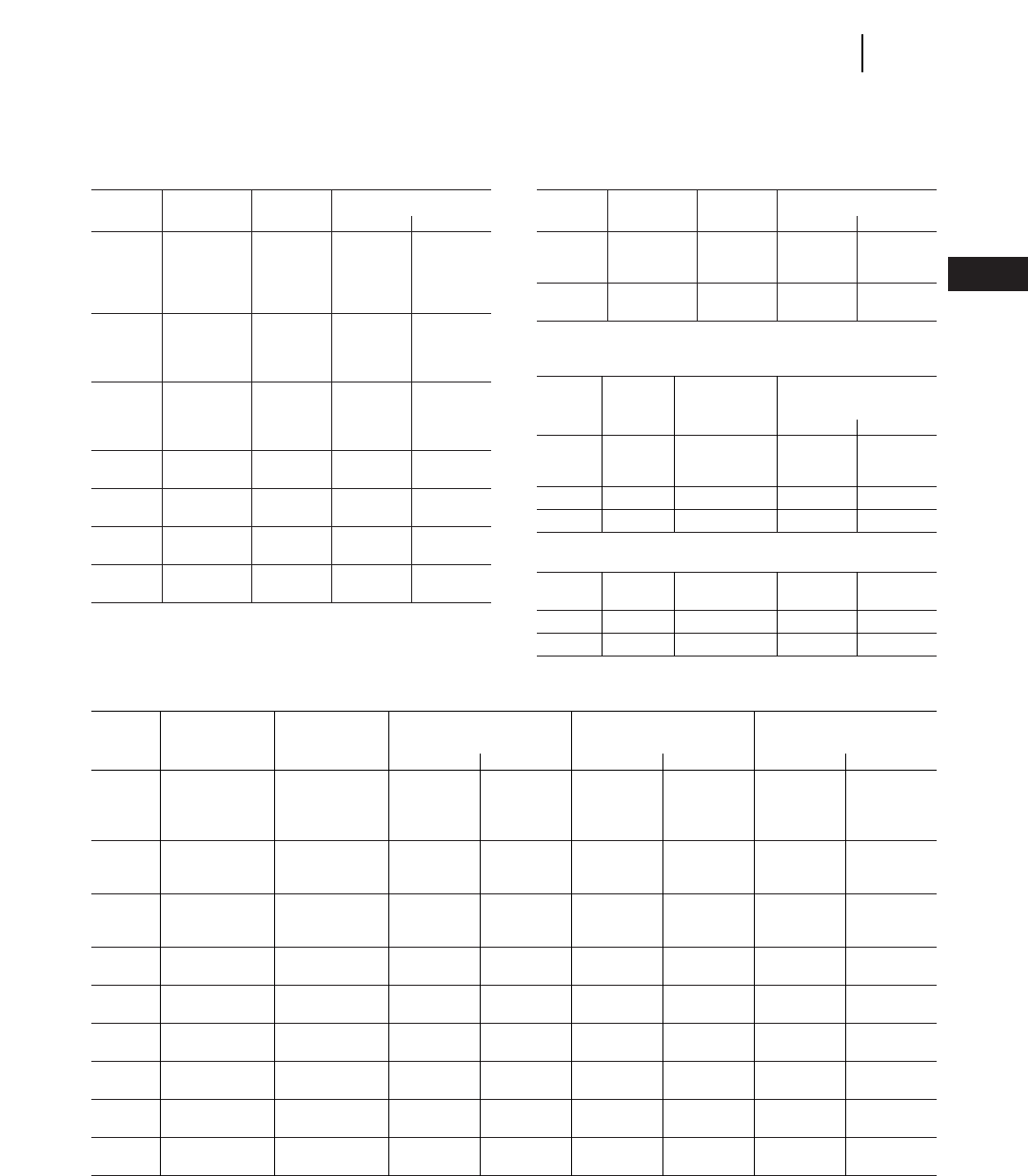
MOTOR GRADERS — Michelin, Goodyear and Bridgestone/Firestone Radial Ply
Michelin Goodyear Bridgestone
Strength Pressure Pressure Pressure
Model Tire Size Rating Front Rear Front Rear Front Rear
kPa psi kPa psi kPa psi kPa psi kPa psi kPa psi
120H 13.00R24TG ★310 45 310 45 310 45 310 45 310 45 310 45
14.00R24TG ★310 45 310 45 310 45 310 45 310 45 310 45
15.5R25 ★310 45 310 45 310 45 310 45 310 45 310 45
135H 13.00R24TG ★310 45 310 45 310 45 310 45 310 45 310 45
14.00R24TG ★310 45 310 45 310 45 310 45 310 45 310 45
15.5R25 ★310 45 310 45 310 45 310 45 310 45 310 45
12H 13.00R24TG ★310 45 310 45 310 45 310 45 310 45 310 45
14.00R24TG ★310 45 310 45 310 45 310 45 310 45 310 45
15.5R25 ★310 45 310 45 310 45 310 45 310 45 310 45
140H 14.00R24TG ★310 45 310 45 310 45 310 45 310 45 310 45
17.5R25 ★310 45 310 45 310 45 310 45 310 45 310 45
160H 14.00R24TG ★310 45 310 45 310 45 310 45 310 45 310 45
17.5R25 ★310 45 310 45 310 45 310 45 310 45 310 45
143H 14.00R24TG ★310 45 310 45 310 45 310 45 310 45 310 45
17.5R25 ★310 45 310 45 310 45 310 45 310 45 310 45
163H 14.00R24TG ★310 45 310 45 310 45 310 45 310 45 310 45
17.5R25 ★310 45 310 45 310 45 310 45 310 45 310 45
14H 16.00R24TG ★310 45 310 45 310 45 310 45 310 45 310 45
20.5R25 ★310 45 310 45 310 45 310 45 310 45 310 45
16H 18.00R25 ★310 45 310 45 310 45 310 45 310 45 310 45
23.5R25 ★310 45 310 45 310 45 310 45 310 45 310 45
MOTOR GRADERS — Bias Ply
Pressure
Model Tire Size Ply Rating Front Rear
kPa psi kPa psi
120H 13.00-24TG* 10*, 12 241 35 241 35
14.00-24TG 10, 12 241 35 241 35
15.5-25 10, 12 241 35 241 35
17.5-25 12 241 35 241 35
135H 13.00-24TG* 10*, 12 241 35 241 35
14.00-24TG 10, 12 241 35 241 35
15.5-25 12 276 40 276 40
17.5-25 12 241 35 241 35
12H 13.00-24TG* 12 310 45 310 45
14.00-24TG 10, 12 241 35 241 35
15.5-25 12 241 35 241 35
17.5-25 12 276 40 276 40
140H 14.00-24TG* 10*, 12 241 35 241 35
17.5-25 12 241 35 241 35
143H 14.00-24TG* 10*, 12 241 35 241 35
17.5-25 12 241 35 241 35
160H 14.00-24TG* 10, 12* 241 35 241 35
17.5-25 12 241 35 241 35
163H 14.00-24TG* 12 241 35 241 35
17.5-25 12 241 35 241 35
*Standard tire and ply rating.
MOTOR GRADERS — Bias Ply (continued)
Pressure
Model Tire Size Ply Rating Front Rear
kPa psi kPa psi
14H 16.00-24TG* 16 310 45 310 45
20.5-25 16 241 35 241 35
16H 18.00-25* 16 241 35 241 35
23.5-25 16 241 35 241 35
*Standard tire and ply rating.
WHEEL TRACTORS — Bias Ply
Ply Rating
or Pressure
Model Tire Size Strength Index Front Rear
kPa psi kPa psi
814F 23.5-25* 12 207 30 207 30
26.5-25 14 172 25 172 25
824G 29.5-25* 22 241 35 241 35
834B 35/65-33* 24 241 35 241 35
WHEEL TRACTOR — Radial Ply
814F 23.5R25 ★276 40 276 40
26.5R25 ★241 35 241 35
824G 29.5R25 ★345 50 345 50
834B 3565R33 ★345 50 345 50
*Standard tire, ply rating, and inflation pressures.
22-23
22
TiresStandard Cold Inflation Pressures
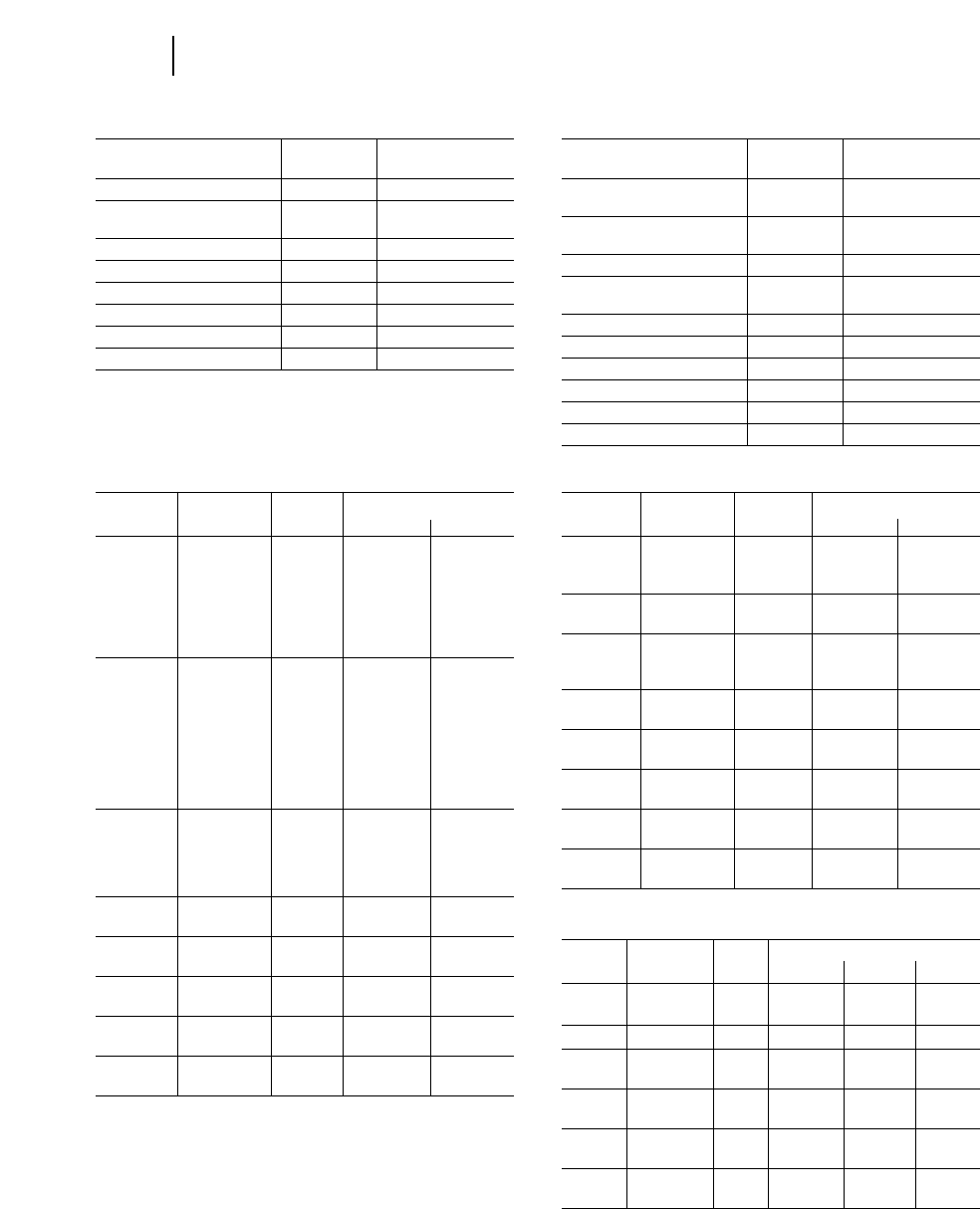
22-24
Tires Standard Cold Inflation Pressures
WHEEL TRACTOR-SCRAPERS — Bias Ply
Ply Pressure
Model Tire Size Rating Front Rear
kPa psi kPa psi
613C
Series II 23.5-25 20 310 45 310 45
615C 29.5-25 28 324 47 310 45
Series II 29.5-25 34 448 65 380 55
621F 33.25-29 26 380 55 310 45
29.5-29 34 413 60 310 45
29.5-35 28 380 55 275 40
623F 29.5-29 34 450 65 345 50
29.5-35 28 413 60 310 45
627F 29.5-29 34 413 60 450 65
29.5-35 34 345 50 380 55
631E 37.25-35 42 413 60 380 55
Series II
633E 37.25-35 42 413 60 380 55
Series II
637E 37.25-25 42 413 60 380 55
Series II
BACKHOE LOADERS (Front)
Ply/Star Pressure
Tire Size Rating kPa psi
9x16 F2 10 415 60
11Lx16 F3 10 360 52
12 440 64
14.5/75x16.1 F3 10 280 41
12.5/80-18 I3 SG LUG 10 310 45
12.5x20 R4 10 350 51
340/80R18 IT510 ★330 48
335/80R18 XM27 139 ★330 48
15-19.5 SSSG 8 275 40
BACKHOE LOADERS (Rear)
Ply/Star Pressure
Tire Size Rating kPa psi
16.9x24 R4 8 195 28
10 220 32
19.5x24 IT525 8 165 24
10 195 28
19.5LR24 IT510 ★275 40
16.9x28 R4 10 220 32
12 260 38
16.9/14x28 R1 12 235 34
16.9R28 IT510 ★275 40
16.9R28 XM27 ★275 40
18.4/15x26 R4 12 250 36
18.4/15x26 XM27 ★275 40
21Lx24 IT525 12 220 32
PAVING PRODUCTS — Bias Ply
Ply Pressure
Model Tire Size Rating Front Rear
kPa psi kPa psi
PS-150 7.50-15 6, 12, 14 * *
PS-210 7.50-15 12, 14 * *
PF-300 13.80-20/E20
PS-300 E20 Pilotex
(13/80-20) * *
PS-500 15.00R24 * *
CS-323C 11.2-24 6 — — 138 20
CP-323C 11.2-24 6 — — 138 20
CS-431C 14.9-24 6 — — 138 20
CS-433C 14.9-24 6 — — 138 20
CP-433C 14.9-24 6 — — 138 20
CS-563C 23.1-26 8 — — 138 20
CP-563C 23.1-26 8 — — 138 20
CS-573C 23.1-26 8 — — 138 20
CS-583C 23.1-26 8 — — 138 20
CB-525B 15.00-24 ★ ★ ★ — — 100 20
CB-523B 15.00-24 ★ ★ ★ — — 100 20
CS-583C 23.1-26 8 — — 83 20
CS-533C 23.1-26 8 — — 83 20
CP-533C 23.1-28 8 — — 241 20
RR-250 23.5-25 16 310 45 ——
15.5-25 8 — — 205 30
SS-250 28.1-26 10 165 24 ——
14.9-24 6 — — 124 18
RM-350 23.5-25 16 310 45 ——
15.5-25 8 — — 205 30
SM-350 28.1-26 10 241 35 ——
14.9-24 6 — — 124 18
AP-800B 16.00-24 12 — — 241 35
AP-1000 18.00-25 16 — — 241 35
*Tire pressure varies with application.
ARTICULATED TRUCK — Radial Ply
Tire Ply Pressure
Model Size Rating Front Center Rear
kPa psi kPa psi kPa psi
D25D 26.5R25 ★ ★ 400 58 — — 450 65
D30D 29.5R25 ★ ★ 325 47 — — 450 65
D250E 20.5R25 ★ ★ 375 54 450 65 450 65
23.5R25 ★ ★ 275 40 325 47 325 47
D300E 23.5R25 ★ ★ 325 47 400 58 400 58
30/65R25 ★ ★ 275 40 350 51 350 51
D350E 26.5R25 ★ ★ 375 54 350 51 350 51
29.5R25 ★ ★ 300 44 300 44 300 44
D400E 26.5R25 ★ ★ 400 58 425 62 425 62
29.5R25 ★ ★ 300 44 330 48 330 48
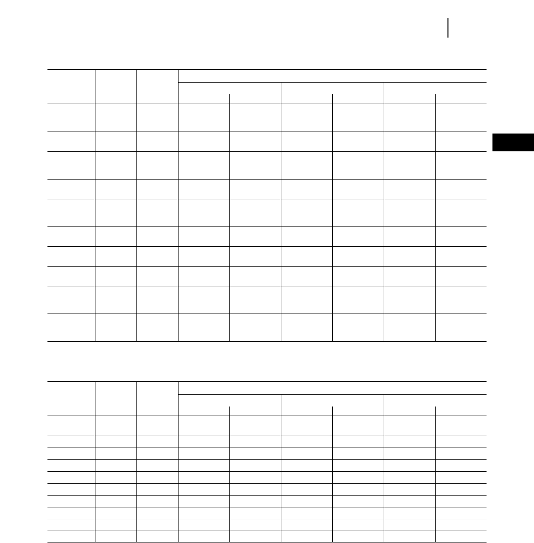
22-25
22
TiresStandard Cold Inflation Pressures
WHEEL TRACTOR-SCRAPERS — Radial Ply
Pressure
Strength Michelin Goodyear Bridgestone
Model Tire Size Index Front Rear Front Rear Front Rear
kPa psi kPa psi kPa psi kPa psi kPa psi kPa psi
613C 18.00R25 ★413 60 413 60 413 60 450 65 485 70 485 70
Series II 23.5R25 ★310 45 345 50 345 50 345 50 380 55 380 55
615C 26.5R25 ★ ★ 450 65 450 65 485 70 480 70 517 75 517 75
Series II 29.5R25 ★345 50 345 50 380 55 380 55 413 60 413 60
621F 29.5R29 ★ ★ 450 65 380 55 480 70 380 55 517 75 413 60
29.5R35 ★ ★ 450 65 380 55 ————45065 380 55
33.25R29 ★ ★ 413 60 345 50 413 60 345 50 413 60 345 50
623F 29.5R29 ★ ★ 485 70 413 60 517 75 413 60 517 75 517 75
29.5R35 ★ ★ 450 65 380 55 ————51775 450 65
627F 29.5R29 ★ ★ 413 60 413 60 517 75 517 75 517 75 517 75
29.5R35 ★ ★ 413 60 413 60 ————51775 517 75
33.25R29 ★ ★ 380 55 380 55 380 55 380 55 413 60 413 60
631E
Series II 37.25R35 ★ ★ 517 75 413 60 517 75 413 60 517 75 413 60
633E
Series II 37.25R35 ★ ★ 517 75 517 75 517 75 517 75 517 75 517 75
637E
Series II 37.25R35 ★ ★ 517 75 517 75 517 75 517 75 517 75 517 75
651E 37.5R39 ★ ★ 620 90 550 80 620 90 515 75 620 90 550 80
40.5/
75R39 ★ ★ 517 75 450 65 517 75 450 65 517 75 450 65
657E 37.5R39 ★ ★ 690 100 690 100 690 100 690 100 690 100 690 100
40.5/
75R39 ★ ★ 517 75 517 75 550 80 550 80 550 80 550 80
CONSTRUCTION & MINING TRUCKS & TRACTORS — Radial Ply
Pressure
Strength Michelin Goodyear Bridgestone
Model Tire Size Index Front Rear Front Rear Front Rear
kPa psi kPa psi kPa psi kPa psi kPa psi kPa psi
769D 18.00R33* ★ ★ 655 95 655 95 725 105 725 105 725 105 725 105
771D 18.00R33* ★ ★ 760 110 760 110 825 120 825 120 825 120 825 120
773D 24.00R35* ★ ★ 515 75 515 75 550 80 550 80 585 85 585 85
775D 24.00R35* ★ ★ 585 85 585 85 620 90 620 90 655 95 655 95
776D 27.00R49* ★ ★ 585 85 585 85 585 85 585 85 620 90 620 90
777D 27.00R49* ★ ★ 585 85 585 85 655 95 655 95 620 90 620 90
784B 36.00R51* ★ ★ 655 95 655 95 725 105 690 100 725 105 725 105
785B 33.00R51* ★ ★ 725 105 725 105 725 105 725 105 725 105 725 105
789B 37.00R57* ★ ★ 655 95 655 95 725 105 725 105 725 105 725 105
793C 40.00R57* ★ ★ 655 95 655 95 760 110 760 110 760 110 760 110
*Standard tire and ply rating.
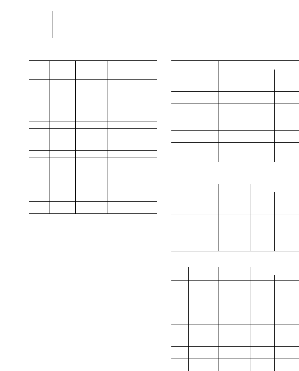
WHEEL LOADERS — Bias and Bias Belted
Ply Rating
or Pressure
Model Tire Size Strength Index Front Rear
kPa psi kPa psi
914G 15.5-25 12 275 40 175 25
15.5-25 12 225 33 175 25
924F 17.5-25 12 225 33 175 25
20.5-25 12 225 33 175 25
928G 17.5-25 12 325 47 225 33
20.5-25 12 225 33 175 25
938G 20.5-25 12 345 50 241 35
950G 23.5-25 16 414 60 241 35
962G 23.5-25 16 414 60 241 35
966G 26.5-25 20 448 65 241 35
972G 26.5-25 20 448 65 241 35
980G 29.5-25 22 414 60 241 35
29.5-25 28 517 75 241 35
988F 35/65-33* 30 552 80 276 40
Series II
990 41.25/70-39 34 483 70 276 40
Series II 41.25/70-39 42 483 70 276 40
992G 45/65-45 46 621 90 276 40
994 50/80-57 68 690 100 585 85
55.5/80-57 68 690 100 585 85
*Higher ply ratings are recommended for High Lift Machines.
NOTE: Tire pressure on front tires of front end loaders may be increased up to
100 kPa (15 psi).
LOG LOADERS — Bias and Bias Belted
Inflation Pressure
Model Tire Size Ply Rating Front Rear
kPa psi kPa psi
914G 15.5-25 12 300 44 200 29
17.5-25 12 250 36 175 25
924F 17.5-25 12 250 36 175 25
20.5-25 12 225 33 175 25
928G 17.5-25 12 350 50 250 36
20.5-25 12 250 36 200 29
938G 20.5-25 12 448 65 241 35
950G 23.5-25 16 414 60 241 35
966G 26.5-25 20 448 65 241 35
23.5-25 24 586 85 241 35
980G 29.5-25 28 552 80 241 35
988F 35/65-33 30 552 80 276 40
Series II
INTEGRATED TOOL CARRIERS —
Bias and Bias Belted
Inflation Pressure
Model Tire Size Ply Rating Front Rear
kPa psi kPa psi
IT14G 15.5-25 12 300 44 200 29
17.5-25 12 250 36 175 25
IT24F 15.5-25 12 275 40 175 25
17.5-25 12 225 33 175 25
IT28G 17.5-25 12 325 47 225 33
20.5-25 12 225 33 175 25
IT38G 20.5-25 12 345 50 241 35
20.5-25 16 483 70 241 35
TELEHANDLERS — Bias and Bias Belted
Ply Rating or Inflation Pressure
Model Tire Size Strength Index Front Rear
kPa psi kPa psi
TH62 13.0-24 12 310 45 310 45
15.5/80-24 10 310 45 310 45
15.5-25 12 276 40 276 40
TH82 13.0-24(ANSI) 12 380 55 380 55
13.0-24(FEM) 12 448 65 448 65
15.5/80-24 10 415 60 415 60
15.5-25 12 345 50 345 50
TH63 13.0-24 12 380 55 380 55
15.5/80-24 12 345 50 345 50
15.5-25(ANSI) 12 415 60 415 60
15.5-25(FEM) 12 415 60 415 60
TH83 14.0-24 12 415 60 415 60
17.5-25 12 345 50 345 50
TH103 14.0-24 12 518 75 518 75
17.5-25 12 485 70 485 70
22-26
Tires Standard Cold Inflation Pressures
Bias and Bias Belted
●Wheel Loaders ●Log Loaders ●Integrated Tool Carriers ●Telehandlers
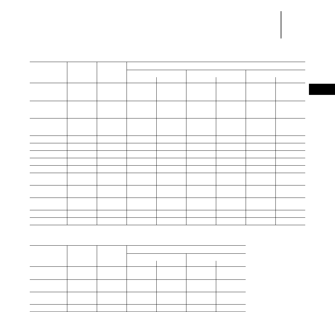
22-27
22
TiresStandard Cold Inflation Pressures
Radial Ply
●Wheel Loaders ●Telehandlers
WHEEL LOADERS — Radial Ply
Pressure
Strength Michelin Goodyear Bridgestone
Model Tire Size Index Front Rear Front Rear Front Rear
kPa psi kPa psi kPa psi kPa psi kPa psi kPa psi
914G 15.5R25 ★250 36 175 25 ————————
17.5R25 ★200 29 175 25 400 58 300 44 ————
924F 17.5R25 ★225 33 175 25 400 58 300 44 ————
555/70R25 ★200 29 175 25 ————————
20.5R25 ★200 29 175 25 400 58 300 44 ————
928G 17.5R25 ★375 54 200 29 400 58 300 44 ————
555/70R25 ★250 36 175 25 ————————
20.5R25 ★250 36 175 25 400 58 300 44 ————
938G 20.5R25 ★276 40 207 30 276 40 241 35 ————
950G 23.5R25 ★276 40 207 30 310 45 207 30 414 60 310 45
962G 23.5R25 ★310 45 207 30 345 50 207 30 414 60 310 45
966G 26.5R25 ★345 50 207 30 345 50 207 30 414 60 310 45
972G 26.5R25 ★414 60 207 30 414 50 276 40 414 60 310 45
980G 26.5R25 ★414 60 207 30 448 65 310 45 485 70 380 55
29.5R25 ★345 50 207 30 345 50 207 30 414 60 310 45
988F 35/65R33 ★483 70 207 30 483 70 345 50 585 85 450 65
Series II
990 45/65R39 ★552 80 276 40 ————————
Series II 40.5/75R39 ★————483 70 345 50 ————
992G 45/65R45 ★552 80 276 40 ————585 85 450 65
994 55/80R57 — 689 100 552 80 ————————
NOTE: Tire pressure on front tires of front end loaders may be increased up to 100 kPa (15 psi).
TELEHANDLERS — Radial Ply
Ply Rating or Pressure
Strength Michelin Goodyear
Model Tire Size Index Front Rear Front Rear
kPa psi kPa psi kPa psi kPa psi
TH62 17.5LR24 ★————276 40 276 40
TH82 445/70R24 ★310 45 310 45 ————
495/70R24 ★276 40 276 40 ————
TH83 15.5R25 ★————518 75 518 75
17.5R25 ★————415 60 415 60
TH103 17.5R25 ★————518 75 518 75

LOG LOADERS — Radial Ply
Pressure
Strength Michelin Goodyear Bridgestone
Model Tire Size Index Front Rear Front Rear Front Rear
kPa psi kPa psi kPa psi kPa psi kPa psi kPa psi
914G 15.5R25 ★275 40 175 25 ————————
17.5R25 ★225 33 175 25 400 58 300 44 ————
924F 17.5R25 ★275 40 175 25 400 58 300 44 ————
555/70R25 ★200 29 175 25 ————————
20.5R25 ★200 29 175 25 400 58 300 44 ————
928G 17.5R25 ★400 58 225 33 400 58 300 44 ————
555/70R25 ★275 40 275 40 ————————
20.5R25 ★275 40 275 40 400 58 300 44 ————
938G 20.5R25 ★310 45 207 30 345 50 276 40 ————
950G 23.5R25 ★414 60 207 30 414 60 276 40 414 60 310 45
966G 26.5R25 ★414 60 207 30 414 60 276 40 415 60 310 45
980G 29.5R25 ★448 65 207 30 438 70 276 40 485 70 345 50
988F 35/65R33 ★552 80 241 35 655 95 310 45 665 95 345 50
Series II
INTEGRATED TOOL CARRIERS — Radial Ply
Pressure
Strength Michelin Goodyear Bridgestone
Model Tire Size Index Front Rear Front Rear Front Rear
kPa psi kPa psi kPa psi kPa psi kPa psi kPa psi
IT14G 15.5R25 ★275 40 175 25 ————————
17.5R25 ★225 33 175 25 400 58 300 44 ————
IT24F 17.5R25 ★275 40 175 25 400 58 300 44 ————
555/70R25 ★200 29 175 25 ————————
20.5R25 ★200 29 175 25 400 58 300 44 ————
IT28G 17.5R25 ★375 54 200 29 400 58 300 44 ————
555/70R25 ★250 36 175 25 ————————
20.5R25 ★250 36 175 25 400 58 300 44 ————
IT38G 20.5R25 ★310 45 207 30 345 50 241 35 380 55 205 30
22-28
Tires Standard Cold Inflation Pressures
Radial Ply
●Log Loaders ●Integrated Tool Carriers
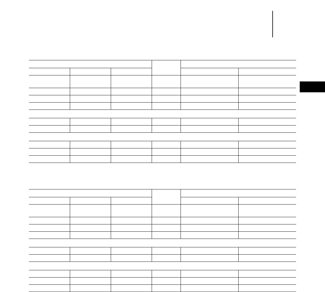
22-29
22
TiresStandard Cold Inflation Pressures
Bias and Bias Belted/Radial Ply
●Underground Mining ●Articulated Trucks ●Rigid Trucks
UNDERGROUND MINING — Bias and Bias Belted
LOAD – HAUL – DUMP Ply Bridgestone
Model Wheel Size Tire Size Rating Front* Rear*
kPa psi kPa psi
R1300 14.0325 17.5325 20 650 94 410 60
R1600 13.0325 18.0325 28 620 90 410 60
R1700 Series II 22.0325 26.5325 32 600 87 410 60
R2900 25.0325 29.5329 34 650 94 410 60
ARTICULATED TRUCKS
AD40 Series II 25.0329 29.53R29 40 620 90 620 90
AE40 Series II 29.5329 29.53R29 40 620 90 620 90
RIGID TRUCKS
69D Dump 13.0333 18.03R33 36 650 94 650 94
69D Ejector 13.0333 18.03R33 40 630 91 630 91
73D 15.0335 21.03R35 — — ———
*For standard loading applications.
NOTE: When tramming cycles exceed 150 m (500 ft) contact tire supplier.
UNDERGROUND MINING — Radial Ply
LOAD – HAUL – DUMP Strength Bridgestone
Model Wheel Size Tire Size Index Front* Rear*
kPa psi kPa psi
R1300 14.0325 17.5325 ★ ★ 700 102 410 60
R1600 13.0325 18.0325 ★ ★ 675 98 410 60
R1700 Series II 22.0325 26.5325 ★ ★ 650 94 410 60
R2900 25.0325 29.5329 ★ ★ 675 98 410 60
ARTICULATED TRUCKS
AD40 Series II 25.0329 29.53R29 ★ ★ 650 94 620 90
AE40 Series II 29.5329 29.53R29 ★ ★ 650 94 650 94
RIGID TRUCKS
69D Dump 13.0333 18.03R33 ★ ★ 700 102 700 102
69D Ejector 13.0333 18.03R33 ★ ★ 700 102 700 102
73D 15.0335 21.03R35 ★ ★ 700 102 700 102
*For standard loading applications.
NOTE: When tramming cycles exceed 150 m (500 ft) contact tire supplier.
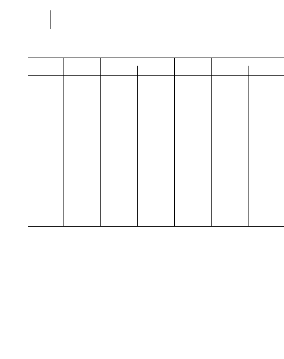
22-30
Tires Liquid Ballasting* Table
●75% Fillage**
BIAS PLY TIRES RADIAL PLY TIRES
WEIGHT MIXING PROPORTIONS WEIGHT MIXING PROPORTIONS
INCREASE INCREASE
PER TIRE CaCl*** Water PER TIRE CaCl*** Water
kg lb kg lb liter gal kg lb kg lb liter gal
13.00-24TG 188 414 55 122 132 35 185 407 57 125 128 34
14.00-24TG 215 475 63 140 151 40 256 565 79 173 179 47
15.5-25 192 423 56 125 136 36 224 493 69 151 155 41
16.00-24TG 333 735 98 217 234 62 355 783 109 240 246 65
17.5-25 262 577 77 170 185 49 311 686 95 210 216 57
18.00-25 454 1002 134 296 322 85 502 1107 154 340 348 92
18.4-34 417 919 123 272 295 78 ——— ———
20.5-25 405 892 119 263 284 75 448 987 137 303 310 82
23.1-26 522 1151 154 340 367 97 ——— ———
23.5-25 585 1291 173 382 412 109 633 1396 194 428 439 116
24.5-32 703 1549 207 458 496 131 ——— ———
26.5-25 758 1671 224 494 533 141 841 1853 258 568 583 154
26.5-29 752 1658 222 490 530 140 928 2045 284 627 644 170
28L-26 709 1563 209 462 500 132 ——— ———
29.5-25 970 2139 286 632 685 181 1073 2368 328 723 745 197
29.5-29 1050 2315 310 684 738 195 1190 2623 365 804 825 218
29.5-35 1159 2556 344 758 821 217 1286 2835 394 869 892 236
30.5L-32 874 1928 258 570 617 163 ——— ———
33.25-35 1485 3275 439 968 1048 277 1592 3508 487 1074 1105 292
37.25-35 1712 3775 505 1115 1211 320 2128 4692 653 1439 1476 390
38-39 1870 4123 552 1218 1317 348 ——— ———
35/65-33 1339 2953 396 873 942 249 1430 3152 438 967 992 262
40/65-39 2077 4580 614 1353 1465 387 2194 4836 673 1483 1522 402
41.25/70-39 1897 4183 561 1236 1336 353 ——— ———
45/65-45 2548 5617 753 1659 1794 474 ——— ———
***Ballast weight for bias ply tires from Goodyear data, radial ply weights from Michelin data.Contact your tire supplier for additional information. Under abnormal tire wear
conditions, ballasting of rear tires may be desirable. Ballasting of front tires also should only be done where extremely rapid tire wear rates are encountered. Excessive
weight will reduce machine performance.
***Fillage beyond 75% of tire enclosed volume is not recommended. With liquid ballasting, inflation pressure must be checked at least once per day.
***1.6 kg (31⁄2lb) Calcium Chloride per gallon water. Solution weighs 4.6 kg (10.15 lb) per gallon.
NOTE: When liquid ballasting telehandler tires, consult Telehandler’s Operation and Maintenance Manual for requirements. Also total machine mass with ballasted tires
must not exceed certification mass listed on the ROPS certification label.

CONTENTS
Elements of production . . . . . . . . . . . . . . . . . . .23-1
Volume measure . . . . . . . . . . . . . . . . . . . . . .23-2
Swell . . . . . . . . . . . . . . . . . . . . . . . . . . . . . . .23-2
Load factor . . . . . . . . . . . . . . . . . . . . . . . . . . .23-2
Material density . . . . . . . . . . . . . . . . . . . . . .23-2
Fill factor . . . . . . . . . . . . . . . . . . . . . . . . . . . .23-3
Soil density tests . . . . . . . . . . . . . . . . . . . . . .23-3
Figuring production on-the-job . . . . . . . . . . . .23-4
Load weighing . . . . . . . . . . . . . . . . . . . . . . . .23-4
Time studies . . . . . . . . . . . . . . . . . . . . . . . . .23-4
English example . . . . . . . . . . . . . . . . . . . . . .23-4
Metric example . . . . . . . . . . . . . . . . . . . . . . .23-5
Estimating production off-the-job . . . . . . . . . .23-5
Rolling resistance . . . . . . . . . . . . . . . . . . . . .23-5
Grade resistance . . . . . . . . . . . . . . . . . . . . . .23-6
Total resistance . . . . . . . . . . . . . . . . . . . . . . .23-6
Traction . . . . . . . . . . . . . . . . . . . . . . . . . . . . .23-6
Altitude . . . . . . . . . . . . . . . . . . . . . . . . . . . . .23-7
Job efficiency . . . . . . . . . . . . . . . . . . . . . . . . .23-8
English example . . . . . . . . . . . . . . . . . . . . . .23-8
Metric example . . . . . . . . . . . . . . . . . . . . . .23-10
Systems . . . . . . . . . . . . . . . . . . . . . . . . . . . . . .23-13
Fuel consumption and productivity . . . . . . . .23-14
Formulas and rules of thumb . . . . . . . . . . . . .23-15
INTRODUCTION
This section explains the earthmoving principles
used to determine machine productivity. It shows
how to calculate production on-the-job or estimate
production off-the-job.
Machine performance is usually measured on an
hourly basis in terms of machine productivity and
machine owning and operating cost. Optimum
machine performance can be expressed as follows:
Lowest Possible
Hourly Costs
Lowest cost per ton = ___________________
Highest Possible
Hourly Productivity
ELEMENTS OF PRODUCTION
Production is the hourly rate at which material
is moved. Production can be expressed in various
units:
Metric
Bank Cubic Meters — BCM — bank m3
Loose Cubic Meters — LCM — loose m3
Compacted Cubic
Meters — CCM — compacted m3
Tonnes
English
Bank Cubic Yards — BCY — bank yd3
Loose Cubic Yards — LCY — loose yd3
Compacted Cubic
Yards — CCY — compacted yd3
Tons
For most earthmoving and material handling
applications, production is calculated by multiply-
ing the quantity of material (load) moved per cycle
by the number of cycles per hour.
Production = Load/cycle 2cycles/hour
The load can be determined by
1) load weighing
2) load estimating based on machine rating
3) surveyed volume divided by load count
Generally, earthmoving and overburden removal
for coal mines are calculated by volume (bank cubic
meters or bank cubic yards). Metal mines and aggre-
gate producers usually work in weight (tons or tonnes).
MINING AND
EARTHMOVING
23-1
23

Volume Measure — Material volume is defined
according to its state in the earthmoving process.
The three measures of volume are:
BCM (BCY) — one cubic meter (yard) of material
as it lies in the natural bank state.
LCM (LCY) — one cubic meter (yard) of material
which has been disturbed and has
swelled as a result of movement.
CCM (CCY) — one cubic meter (yard) of material
which has been compacted and has
become more dense as a result of
compaction.
In order to estimate production, the relationships
between bank measure, loose measure, and com-
pacted measure must be known.
Swell — Swell is the percentage of original volume
(cubic meters or cubic yards) that a material increases
when it is removed from the natural state. When
excavated, the material breaks up into different size
particles that do not fit together, causing air pockets
or voids to reduce the weight per volume. For exam-
ple to hold the same weight of one cubic unit of bank
material it takes 30% more volume (1.3 times) after
excavation. (Swell is 30%.)
Loose cubic volume
for a given weight
1 + Swell = ______________________
Bank cubic volume for
the same given weight
Loose
Bank = __________
(1 + Swell)
Loose = Bank 2(1 + Swell)
Example Problem:
If a material swells 20%, how many loose cubic
meters (loose cubic yards) will it take to move 1000
bank cubic meters (1308 bank cubic yards)?
Loose = Bank 2(1 + Swell) =
1000 BCM 2(1 + .2) = 1200 LCM
1308 BCY 2(1 + .2) = 1570 LCY
How many bank cubic meters (yards) were moved
if a total of 1000 loose cubic meters (1308 yards)
have been moved? Swell is 25%.
Bank = Loose ÷ (1 + Swell) =
1000 LCM ÷ (1 + .25) = 800 BCM
1308 LCY ÷ (1 + .25) = 1046 BCY
Load Factor — Assume one bank cubic yard of
material weighs 3000 lb. Because of material char-
acteristics, this bank cubic yard swells 30% to 1.3 loose
cubic yards when loaded, with no change in weight.
If this 1.0 bank cubic yard or 1.3 loose cubic yards
is compacted, its volume may be reduced to 0.8 com-
pacted cubic yard, and the weight is still 3000 lbs.
Instead of dividing by 1 + Swell to determine bank
volume, the loose volume can be multiplied by the
load factor.
If the percent of material swell is known, the load
factor (L.F.) may be obtained by using the following
relationship:
100%
L.F. = ______________
100% + % swell
Load factors for various materials are listed in
the Tables Section of this handbook.
To estimate the machine payload in bank cubic
yards, the volume in loose cubic yards is multiplied
by the load factor:
Load (BCY) = Load (LCY) 2L.F.
The ratio between compacted measure and bank
measure is called shrinkage factor (S.F.):
Compacted cubic yards (CCY)
S.F. = ____________________________
Bank cubic yards (BCY)
Shrinkage factor is either estimated or obtained
from job plans or specifications which show the con-
version from compacted measure to bank measure.
Shrinkage factor should not be confused with per-
centage compaction (used for specifying embank-
ment density, such as Modified Proctor or CBR).
Material Density — Density is the weight per unit
volume of a material. Materials have various densi-
ties depending on particle size, moisture content and
variations in the material. The denser the material
the more weight there is per unit of equal volume.
Density estimates are provided in the Tables Section
of this handbook.
Weight kg (lbs)
Density = ________ =________
Volume m3 (yd3)
Weight = Volume 2Density
23-2
Mining and
Earthmoving Elements of Production
●Volume Measure ●Swell
●Load Factor ●Material Density

A given material’s density changes between bank
and loose. One cubic unit of loose material has less
weight than one cubic unit of bank material due to
air pockets and voids. To correct between bank and
loose use the following equations.
kg/BCM lbs/BCY
1 + Swell = ________ or ________
kg/LCM lbs/LCY
lb/BCY
lbs/LCY = __________
(1 + Swell)
lbs/BCY = lbs/LCY 2(1 + Swell)
Fill Factor — The percentage of an available vol-
ume in a body, bucket, or bowl that is actually used
is expressed as the fill factor. A fill factor of 87% for
a hauler body means that 13% of the rated volume
is not being used to carry material. Buckets often
have fill factors over 100%.
Example Problem:
A 14 cubic yard (heaped 2:1) bucket has a 105% fill
factor when operating in a shot sandstone (4125 lbs/
BCY and a 35% swell).
a) What is the loose density of the material?
b) What is the usable volume of the bucket?
c) What is the bucket payload per pass in BCY?
d) What is the bucket payload per pass in tons?
a) lb/LCY = lb/BCY ÷ (1 + Swell) = 4125 ÷ (1.35) =
3056 lb/LCY
b) LCY = rated LCY 2fill factor = 14 21.05 = 14.7
LCY
c) lbs/pass = volume 2density lb/LCY = 14.7 2
3056 = 44,923 lbs
BCY/pass = weight ÷ density lb/BCY = 44,923 ÷
4125 = 10.9 BCY
or bucket LCY from part b ÷ (1 + Swell) = 14.7 ÷
1.35 = 10.9 BCY
d) tons/pass = lbs ÷ 2000 lbs/ton = 44,923 ÷ 2000 =
22.5 tons
Example Problem:
Construct a 10,000 compacted cubic yard (CCY)
bridge approach of dry clay with a shrinkage factor
(S.F.) of 0.80. Haul unit is rated 14 loose cubic yards
struck and 20 loose cubic yards heaped.
a) How many bank yards are needed?
b) How many loads are required?
CCY 10,000
a) BCY = _____ =_______ = 12,500 BCY
S.F. 0.80
b) Load (BCY) = Capacity (LCY)
2 Load factor (L.F.) = 20 20.81
= 16.2 BCY/Load
(L.F. of 0.81 from Tables)
Number of 12,500 BCY
loads required = _______________ = 772 Loads
16.2 BCY/Load
● ● ●
Soil Density Tests — There are a number of
acceptable methods that can be used to determine
soil density. Some that are currently in use are:
Nuclear density moisture gauge
Sand cone method
Oil method
Balloon method
Cylinder method
All these except the nuclear method use the fol-
lowing procedure:
1. Remove a soil sample from bank state.
2. Determine the volume of the hole.
3. Weigh the soil sample.
4. Calculate the density kg/BCM (lb/BCY).
The nuclear density moisture gauge is one of the
most modern instruments for measuring soil den-
sity and moisture. A common radiation channel
emits either neutrons or gamma rays into the soil.
In determining soil density, the number of gamma
rays absorbed and back scattered by soil particles
is indirectly proportional to the soil density. When
measuring moisture content, the number of moder-
ated neutrons reflected back to the detector after
colliding with hydrogen particles in the soil is
directly proportional to the soil's moisture content.
All these methods are satisfactory and will provide
accurate densities when performed correctly. Several
repetitions are necessary to obtain an average.
23-3
23
Mining and
Earthmoving
Elements of Production
●Fill Factor
●Soil Density Tests
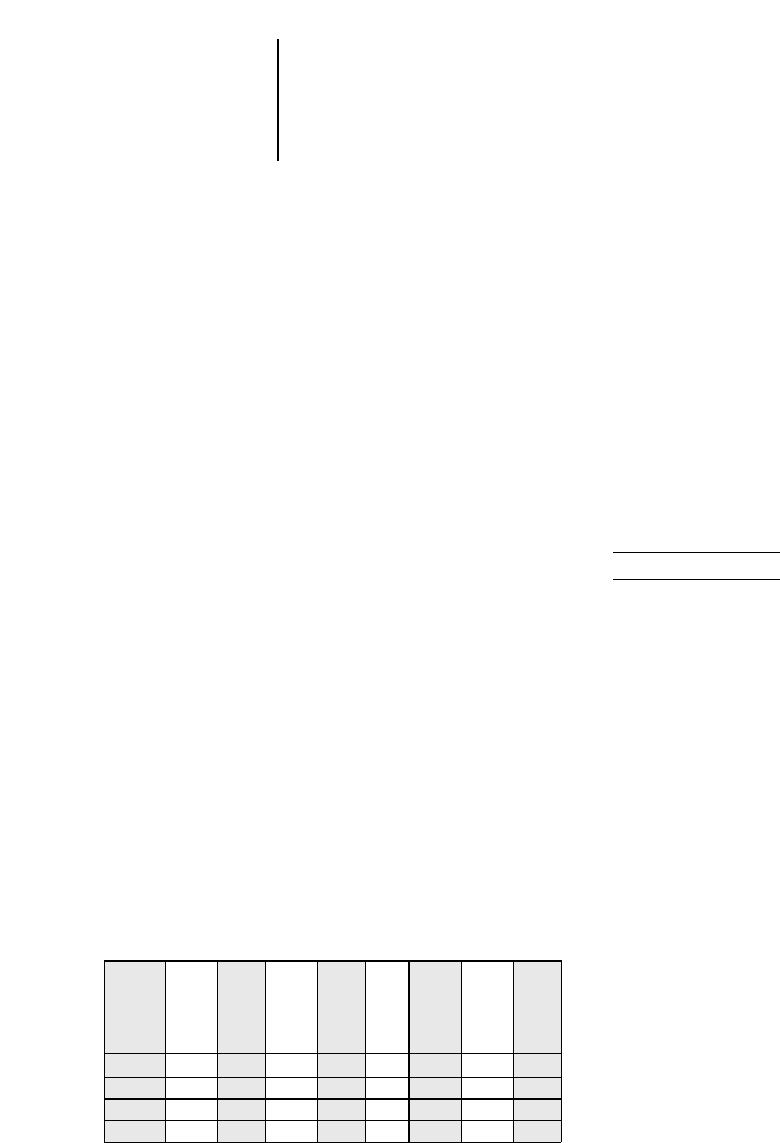
Total
Cycle
Times
(less Arrive Wait Begin Load End Begin Delay End
delays) Cut Time Load Time Load Delay Time Delay
0.00 0.30 0.30 0.60 0.90
3.50 3.50 0.30 3.80 0.65 4.45
4.00 7.50 0.35 7.85 0.70 8.55 9.95 1.00 10.95
4.00 12.50 0.42 12.92 0.68 13.60
NOTE: All numbers are in minutes
FIGURING PRODUCTION ON-THE-JOB
Load Weighing — The most accurate method of
determining the actual load carried is by weighing.
This is normally done by weighing the haul unit one
wheel or axle at a time with portable scales. Any
scales of adequate capacity and accuracy can be used.
While weighing, the machine should be relatively
level to reduce error caused by weight transfer.
Enough loads should be weighed to provide a good
average. Machine weight is the sum of the individ-
ual wheel or axle weights.
The weight of the load can be determined using
the empty and loaded weight of the unit.
Weight of
load = Gross machine weight – empty weight
To determine the bank cubic measure carried by
a machine, the load weight is divided by the bank-
state density of the material being hauled.
Weight of load
BCY = _____________
Bank density
Times Studies — To estimate production, the
number of complete trips a unit makes per hour must
be determined. First obtain the unit’s cycle time with
the help of a stop watch. Time several complete cycles
to arrive at an average cycle time. By allowing the
watch to run continuously, different segments such
as load time, wait time, etc. can be recorded for each
cycle. Knowing the individual time segments affords
a good opportunity to evaluate the balance of the
spread and job efficiency. The following is an exam-
ple of a scraper load time study form. Numbers in
the white columns are stop watch readings; numbers
in the shaded columns are calculated:
23-4
Mining and
Earthmoving Figuring Production On-the-Job
●Load Weighing
●Time Studies
●Example (English)
This may be easily extended to include other seg-
ments of the cycle such as haul time, dump time, etc.
Similar forms can be made for pushers, loaders,
dozers, etc. Wait Time is the time a unit must wait
for another unit so that the two can function together
(haul unit waiting for pusher). Delay Time is any
time, other than wait time, when a machine is not
performing in the work cycle (scraper waiting to
cross railroad track).
To determine trips-per-hour at 100% efficiency,
divide 60 minutes by the average cycle time less all
wait and delay time. Cycle time may or may not
include wait and/or delay time. Therefore, it is pos-
sible to figure different kinds of production: meas-
ured production, production without wait or delay,
maximum production, etc. For example:
Actual Production: includes all wait and delay time.
Normal Production (without delays): includes wait
time that is considered normal, but no delay time.
Maximum Production: to figure maximum (or opti-
mum) production, both wait time and delay time
are eliminated. The cycle time may be further
altered by using an optimum load time.
Example (English)
A job study of a Wheel Tractor-Scraper might yield
the following information:
Average wait time = 0.28 minute
Average load time = 0.65
Average delay time = 0.25
Average haul time = 4.26
Average dump time = 0.50
Average return time = 2.09
______
Average total cycle = 8.03 minutes
______
Less wait & delay time = 0.53
Average cycle 100% eff. = 7.50 minutes
Weight of haul unit empty — 48,650 lb
Weights of haul unit loaded —
Weighing unit #1 — 93,420 lb
Weighing unit #2 — 89,770 lb
Weighing unit #3 — 88,760 lb
__________
271,950 lb;
average = 90,650 lb
1. Average load weight = 90,650 lb – 48,650 lb =
42,000 lb
2. Bank density = 3125 lb/BCY
Weight of load
3. Load = _____________
Bank density
42,000 lb
=____________ = 13.4 BCY
3125 lb/BCY
4. Cycles/hr =
60 min/hr 60 min/hr
__________ =_____________ = 80 cycles/hr
Cycle time 7.50 min/cycle
5. Production = Load/cycle 2 cycles/hr
(less delays) = 13.4 BCY/cycle 28.0 cycles/hr
= 107.2 BCY/hr

Example (Metric)
A job study of a Wheel Tractor-Scraper might yield
the following information:
Average wait time = 0.28 minute
Average load time = 0.65
Average delay time = 0.25
Average haul time = 4.26
Average dump time = 0.50
Average return time = 2.09
______
Average total cycle = 8.03 minutes
______
Less wait & delay time = 0.53
Average cycle 100% eff. = 7.50 minutes
Weight of haul unit empty — 22 070 kg
Weights of haul unit loaded —
Weighing unit #1 — 42 375 kg
Weighing unit #2 — 40 720 kg
Weighing unit #3 — 40 260 kg
__________
123 355 kg;
average = 41 120 kg
1. Average load weight = 41 120 kg – 22 070 kg =
19 050 kg
2. Bank density = 1854 kg/BCM
Weight of load
3. Load = _____________
Bank density
19 050 kg
=____________ = 10.3 BCM
1854 kg/BCM
4. Cycles/hr =
60 min/hr 60 min/hr
__________ =_____________ = 80 cycles/hr
Cycle time 7.50 min/cycle
5. Production = Load/cycle 2 cycles/hr
(less delays) = 10.3 BCM/cycle 28.0 cycles/hr
= 82 BCM/hr
● ● ●
ESTIMATING PRODUCTION OFF-THE-JOB
It is often necessary to estimate production of
earthmoving machines which will be selected for a
job. As a guide, the remainder of the section is
devoted to discussions of various factors that may
affect production. Some of the figures have been
rounded for easier calculation.
Rolling Resistance (RR) is a measure of the
force that must be overcome to roll or pull a wheel
over the ground. It is affected by ground conditions
and load — the deeper a wheel sinks into the ground,
the higher the rolling resistance. Internal friction
and tire flexing also contribute to rolling resistance.
Experience has shown that minimum resistance is
approximately 2% (1.5% for radial tires or dual tired
trucks) of the gross machine weight (on tires).
Resistance due to tire penetration is approximately
1.5% of the gross machine weight for each inch of
tire penetration (0.6% for each cm of tire penetra-
tion). Thus rolling resistance can be calculated using
these relationships in the following manner:
RR = 2% of GMW + 0.6% of GMW per cm tire
penetration
RR = 2% of GMW + 1.5% of GMW per inch tire
penetration
It’s not necessary for the tires to actually penetrate
the road surface for rolling resistance to increase
above the minimum. If the road surface flexes under
load, the effect is nearly the same — the tire is always
running “uphill”. Only on very hard, smooth sur-
faces with a well compacted base will the rolling
resistance approach the minimum.
When actual penetration takes place, some vari-
ation in rolling resistance can be noted with various
inflation pressures and tread patterns.
NOTE: When figuring “pull” requirements for track-
type tractors, rolling resistance applies only to the
trailed unit’s weight on wheels. Since tracktype trac-
tors utilize steel wheels moving on steel “roads”, a
tractor’s rolling resistance is relatively constant and
is accounted for in the Drawbar Pull rating.
23-5
23
Mining and
Earthmoving
Figuring Production On-the-Job
●Example (Metric)
Estimating Production Off-the-Job
●Rolling Resistance

Grade Resistance is a measure of the force that
must be overcome to move a machine over unfavora-
ble grades (uphill). Grade assistance is a measure of
the force that assists machine movement on favor-
able grades (downhill).
Grades are generally measured in percent slope,
which is the ratio between vertical rise or fall and
the horizontal distance in which the rise or fall
occurs. For example, a 1% grade is equivalent to a
1 m (ft) rise or fall for every 100 m (ft) of horizontal
distance; a rise of 4.6 m (15 ft) in 53.5 m (175 ft)
equals an 8.6% grade.
4.6 m (rise)
__________________________ = 8.6% grade
53.3 m (horizontal distance)
15 ft (rise)
__________________________ = 8.6% grade
175 ft (horizontal distance)
Uphill grades are normally referred to as adverse
grades and downhill grades as favorable grades.
Grade resistance is usually expressed as a positive
(+) percentage and grade assistance is expressed as
a negative (–) percentage.
It has been found that for each 1% increment of
adverse grade an additional 10 kg (20 lb) of resis-
tance must be overcome for each metric (U.S.) ton of
machine weight. This relationship is the basis for
determining the Grade Resistance Factor which is
expressed in kg/metric ton (lb/U.S. ton):
Grade Resistance Factor = 10 kg/m ton 2 % grade
= 20 lb/U.S. ton 2 % grade
Grade resistance (assistance) is then obtained by
multiplying the Grade Resistance Factor by the
machine weight (GMW) in metric (U.S.) tons.
Grade Resistance = GR Factor 2GMW in metric
(U.S.) tons
Grade resistance may also be calculated using per-
centage of gross weight. This method is based on the
relationship that grade resistance is approximately
equal to 1% of the gross machine weight for 1% of
grade.
Grade Resistance = 1% of GMW 2% grade
Grade resistance (assistance) affects both wheel
and track-type machines.
Total Resistance is the combined effect of rolling
resistance (wheel vehicles) and grade resistance. It
can be computed by summing the values of rolling
resistance and grade resistance to give a resistance
in kilogram (pounds) force.
Total Resistance = Rolling Resistance +
Grade Resistance
Total resistance can also be represented as consist-
ing completely of grade resistance expressed in per-
cent grade. In other words, the rolling resistance
component is viewed as a corresponding quantity of
additional adverse grade resistance. Using this
approach, total resistance can then be considered in
terms of percent grade.
This can be done by converting the contribution of
rolling resistance into a corresponding percentage of
grade resistance. Since 1% of adverse grade offers a
resistance of 10 kg (20 lb) for each metric or (U.S.)
ton of machine weight, then each 10 kg (20 lb) of
resistance per ton of machine weight can be repre-
sented as an additional 1% of adverse grade. Rolling
resistance in percent grade and grade resistance in
percent grade can then be summed to give Total
Resistance in percent or Effective Grade. The fol-
lowing formulas are useful in arriving at Effective
Grade.
Rolling Resistance (%) = 2% + 0.6% per cm tire
penetration
= 2% + 1.5% per inch tire
penetration
Grade Resistance (%) = % grade
Effective Grade (%) = RR (%) + GR (%)
Effective grade is a useful concept when working
with Rimpull-Speed-Gradeability curves, Retarder
curves, Brake Performance curves, and Travel Time
curves.
Traction — is the driving force developed by a
wheel or track as it acts upon a surface. It is expressed
as usable Drawbar Pull or Rimpull. The following
factors affect traction: weight on the driving wheel
or tracks, gripping action of the wheel or track, and
ground conditions. The coefficient of traction (for any
roadway) is the ratio of the maximum pull devel-
oped by the machine to the total weight on the drivers.
Pull
Coeff. of traction = _________________
weight on drivers
Therefore, to find the usable pull for a given
machine:
Usable pull = Coeff. of traction 2weight on drivers
Example: Track-Type Tractor
What usable drawbar pull (DBP) can a 26 800 kg
(59,100 lb) Track-type Tractor exert while working
on firm earth? on loose earth? (See table section for
coefficient of traction.)
23-6
Mining and
Earthmoving Estimating Production Off-the-Job
●Grade Resistance
●Total Resistance
●Traction
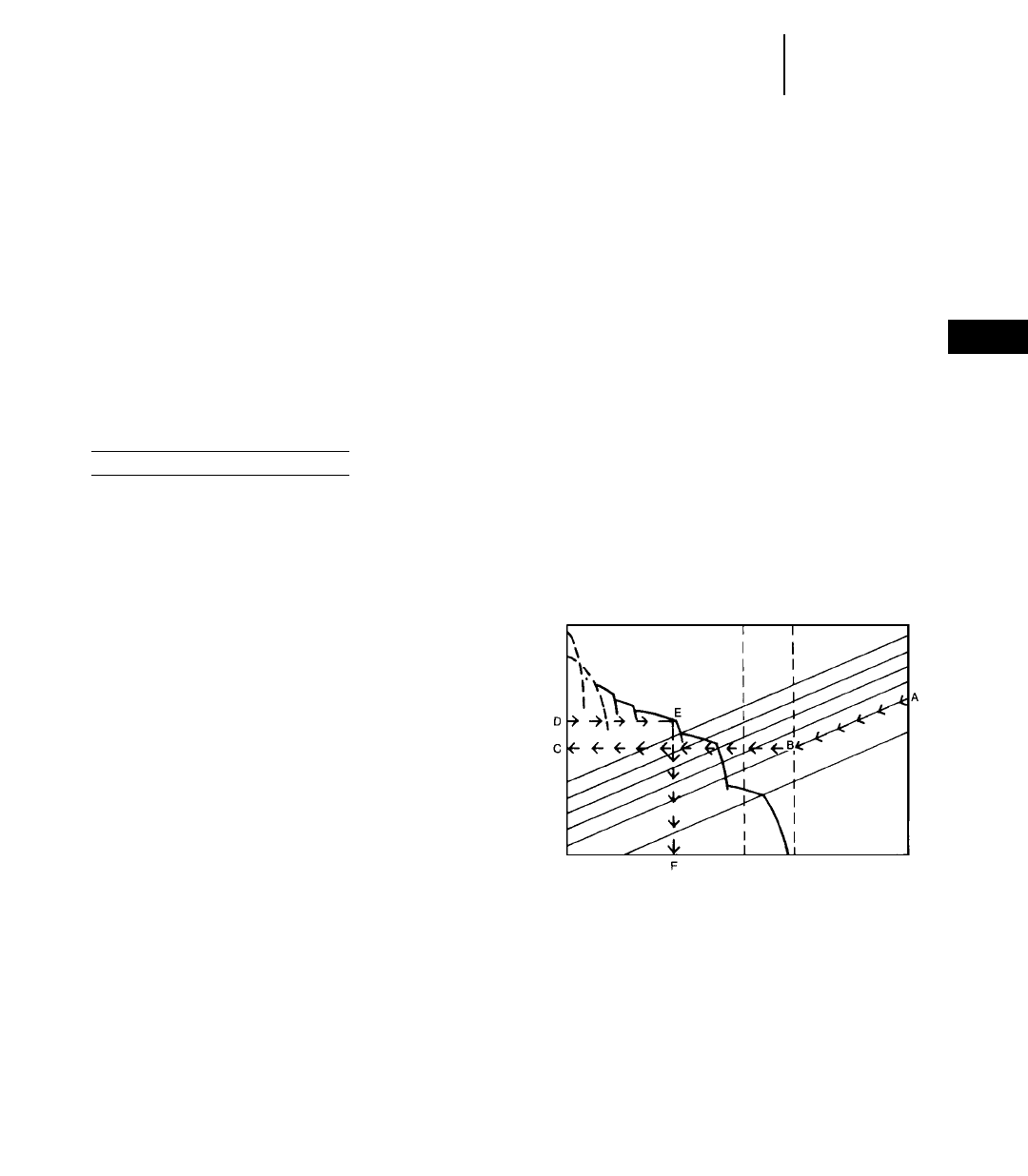
Answer:
Firm earth — Usable DBP =
0.90 226 800 kg = 24 120 kg
(0.90 259,100 lb = 53,190 lb)
Loose earth — Usable DBP =
0.60 226 800 kg = 16 080 kg
(0.60 259,100 lb = 35,460 lb)
If a load required 21 800 kg (48,000 lb) pull to move
it, this tractor could move the load on firm earth.
However, if the earth were loose, the tracks would
spin.
NOTE: D8R through D11R Tractors may attain
higher coefficients of traction due to their suspended
undercarriage.
Example: Wheel Tractor-Scraper
What usable rimpull can a 621F size machine exert
while working on firm earth? on loose earth? The
total loaded weight distribution of this unit is:
Drive unit Scraper unit
wheels: 23 600 kg wheels: 21 800 kg
(52,000 lb) (48,000 lb)
Remember, use weight on drivers only.
Answer:
Firm earth — 0.55 2 23 600 kg = 12 980 kg
(0.55 2 52,000 lb = 28,600 lb)
Loose earth — 0.45 2 23 600 kg = 10 620 kg
(0.45 2 52,000 lb = 23,400 lb)
On firm earth this unit can exert up to 12 980 kg
(28,600 lb) rimpull without excessive slipping. How-
ever, on loose earth the drivers would slip if more
than 10 620 kg (23,400 lb) rimpull were developed.
● ● ●
Altitude — Specification sheets show how much
pull a machine can produce for a given gear and
speed when the engine is operating at rated horse-
power. When a standard machine is operated in high
altitudes, the engine may require derating to main-
tain normal engine life. This engine deration will
produce less drawbar pull or rimpull.
The Tables Section gives the altitude deration in
percent of flywheel horsepower for current machines.
It should be noted that some turbocharged engines
can operate up to 3050 m (10,000 ft) before they
require derating. Most machines are engineered to
operate up to 1520 m (5000 ft) before they require
deration.
The horsepower deration due to altitude must be
considered in any job estimating. The amount of
power deration will be reflected in the machine’s
gradeability and in the load, travel, and dump and
load times (unless loading is independent of the
machine itself).
The example job problem that follows indicates one
method of accounting for altitude deration: by increas-
ing the appropriate components of the total cycle
time by a percentage equal to the percent of horse-
power deration due to altitude. (i.e., if the travel time
of a hauling unit is determined to be 1.00 minute at
full HP, the time for the same machine derated to 90%
of full HP will be 1.10 min.) This is an approximate
method that yields reasonably accurate estimates
up to 3000 m (10,000 feet) elevation.
Travel time for hauling units derated more than
10% should be calculated as follows using Rimpull-
Speed-Gradeability charts.
1) Determine total resistance (grade plus rolling)
in percent.
23-7
23
Mining and
Earthmoving
Estimating Production Off-the-Job
●Altitude
2) Beginning at point A on the chart follow the
total resistance line diagonally to its intersection,
B, with the vertical line corresponding to the appro-
priate gross machine weight. (Rated loaded and
empty GMW lines are shown dotted.)
3) Using a straight-edge, establish a horizontal
line to the left from point B to point C on the rim-
pull scale.
4) Divide the value of point C as read on the rim-
pull scale by the percent of total horsepower avail-
able after altitude deration from the Tables Section.
This yields rimpull value D higher than point C.
GROSS MACHINE WEIGHT (GMW)
EMPTY LOADED
SPEED
RIMPULL
TOTAL RESISTANCE
5) Establish a horizontal line right from point D.
The farthest right intersection of this line with a
curved speed range line is point E.
6) A vertical line down from point E determines
point F on the speed scale.
7) Multiply speed in kmh by 16.7 (mph by 88) to
obtain speed in m/min (ft/min). Travel time in min-
utes for a given distance in feet is determined by
the formula:
Distance in m (ft)
Time (min) = ______________________
Speed in m/min (ft/min)
The Travel Time Graphs in sections on Wheel
Tractor-Scrapers and Construction & Mining Trucks
can be used as an alternative method of calculating
haul and/or return times.
23-8
Mining and
Earthmoving Estimating Production Off-the-Job
●Job Efficiency
●Example Problem (English)
Job Efficiency is one of the most complex ele-
ments of estimating production since it is influenced
by factors such as operator skill, minor repairs and
adjustments, personnel delays, and delays caused by
job layout. An approximation of efficiency, if no job
data is available, is given below.
Efficiency
Operation Working Hour Factor
Day 50 min/hr 0.83
Night 45 min/hr 0.75
These factors do not account for delays due to weather
or machine downtime for maintenance and repairs.
You must account for such factors based on experi-
ence and local conditions.
4. Derate for Altitude:
Check power available at 7500 ft from altitude
deration table in the Tables Section.
631E Series II — 100% 12G — 85%
D9N — 100% 825C — 94%
1. Estimate Payload:
Est. load (LCY) 2L.F. 2Bank Density = payload
31 LCY 20.80 23000 lb/BCY = 74,400 lb payload
2. Establish Machine Weight:
Empty Wt. — 88,000 lb or 44 tons
Wt. of Load — 74,400 lb or 37.2 tons
Total (GMW) — 162,400 lb or 81.2 tons
3. Calculate Usable Pull (traction limitation):
Loaded: (weight on driving wheels = 54%) (GMW)
Traction Factor 2Wt. on driving wheels =
0.50 2162,400 lb 254% = 43,848 lbs
Empty: (weight on driving wheels = 69%) (GMW)
Traction Factor 2Wt. on driving wheels =
0.50 288,000 lbs 269% = 30,360 lbs
Example problem (English)
A contractor is planning to put the following spread
on a dam job. What is the estimated production and
cost/BCY?
Equipment:
11 — 631E Series II Wheel Tractor-Scrapers
2 — D9N Tractors with C-dozers
2 — 12G Motor Graders
1 — 825C Tamping Foot Compactor
Material:
Description — Sandy clay; damp, natural bed
Bank Density — 3000 lb/BCY
Load Factor — 0.80
Shrinkage Factor — 0.85
Traction Factor — 0.50
Altitude — 7500 ft
Job Layout — Haul and Return:
● ● ● ● ● ● ● ● ● ● ● ● ● ● ●
Total Effective Grade = RR (%) ± GR (%)
Sec. A: Total Effective Grade = 10% + 0% = 10%
Sec. B: Total Effective Grade = 4% + 0% = 4%
Sec. C: Total Effective Grade = 4% + 4% = 8%
Sec. D: Total Effective Grade = 10% + 0% = 10%
Sec. D — Fill 400'
RR = 200 lb/ton
Eff. Grade = 10%
Sec. C — Haul 1000'
RR = 80 lb/ton
Eff. Grade = 8%
Sec. B — Haul 1500'
RR = 80 lb/ton
Eff. Grade = 4%
Sec. A — Cut 400'
RR = 200 lb/ton
Eff. Grade = 10%
0% Grade
4% Grade
0% Grade0% Grade

Then adjust if necessary:
Load Time — controlled by D9N, at 100% power, no
change.
Travel, Maneuver and Spread time — 631E Series II,
no change.
5. Compare Total Resistance to Tractive Effort
on haul:
Grade Resistance —
GR = lb/ton 2tons 2adverse grade in percent
Sec. C: = 20 lb/ton 281.2 tons 24% grade =
6496 lb
Rolling Resistance —
RR = RR Factor (lb/ton) 2GMW (tons)
Sec. A: = 200 lb/ton 281.2 tons = 16,240 lb
Sec. B: = 80 lb/ton 281.2 tons = 6,496 lb
Sec. C: = 80 lb/ton 281.2 tons = 6,496 lb
Sec. D: = 200 lb/ton 281.2 tons = 16,240 lb
Total Resistance —
TR = RR + GR
Sec. A: = 16,240 lb + 0 = 16,240 lb
Sec. B: = 6,496 lb + 0 = 6,496 lb
Sec. C: = 6,496 lb + 6,496 lb= 12,992 lb
Sec. D:= 16,240 lb + 0 = 16,240 lb
Check usable pounds pull against maximum
pounds pull required to move the 631E.
Pull usable … 43,848 lb loaded
Pull required … 16,240 lb maximum total
resistance
Estimate travel time for haul from 631E (loaded)
travel time curve; read travel time from distance
and effective grade.
Travel time (from curves):
Sec. A: 0.60 min
Sec. B: 1.00
Sec. C: 1.20
Sec. D: 0.60
____
3.40 min
NOTE: This is an estimate only; it does not account
for all the acceleration and deceleration time, there-
fore it is not as accurate as the information obtained
from a computer program.
6. Compare Total Resistance to Tractive Effort
on return:
Grade Assistance —
GA = 20 lb/ton 2tons 2negative grade in percent
Sec. C: = 20 lb/ton 244 tons 24% grade =
3520 lbs
Rolling Resistance —
RR = RR Factor 2Empty Wt (tons)
Sec. D: =200 lb/ton 244 tons = 8800 lb
Sec. C: = 80 lb/ton 244 tons = 3520 lb
Sec. B: = 80 lb/ton 244 tons = 3520 lb
Sec. A: = 200 lb/ton 244 tons = 8800 lb
Total Resistance —TR = RR – GA
Sec. D: = 8,800 lb – 0 = 8,800 lb
Sec. C: = 3,520 lb – 3,520 lb = 0
Sec. B: = 3,520 lb – 0 = 3,520 lb
Sec. A: = 8,800 lb – 0 = 8,800 lb
Check usable pounds pull against maximum
pounds pull required to move the 631E.
Pounds pull usable … 30,360 lb empty
Pounds pull required … 8800 lb
Estimate travel time for return from 631E empty
travel time curve.
Travel time (from curves):
Sec. D: 0.40 min
Sec. C: 0.55
Sec. B: 0.80
Sec. A: 0.40
____
2.15 min
7. Estimate Cycle Time:
Total Travel Time (Haul plus Return) = 5.55 min
Adjusted for altitude: 100% 25.55 min = 5.55 min
Load Time 0.7 min
Maneuver and Spread Time 0.7 min
________
Total Cycle Time 6.95 min
8. Check pusher-scraper combinations:
Pusher cycle time consists of load, boost, return
and maneuver time. Where actual job data is not
available, the following may be used.
Boost time = 0.10 minute
Return time = 40% of load time
Maneuver time = 0.15 minute
Pusher cycle time = 140% of load time + 0.25
minute
Pusher cycle time = 140% of 0.7 min + 0.25 minute
= 0.98 + 0.25 = 1.23 minute
Scraper cycle time divided by pusher cycle time
indicates the number of scrapers which can be han-
dled by each pusher.
6.95 min
________ = 5.65
1.23 min
23-9
23
Mining and
Earthmoving
Estimating Production Off-the-Job
●Example Problem (English)

Each push tractor is capable of handling five plus
scrapers. Therefore the two pushers can adequately
serve the eleven scrapers.
9. Estimate Production:
Cycles/hour = 60 min ÷ Total cycle time
= 60 min/hr ÷ 6.95 min/cycle
= 8.6 cycles/hr
Estimated load = Heaped capacity 2L.F.
= 31 LCY 20.80
= 24.8 BCY
Hourly unit
production = Est. load 2cycles/hr
= 24.8 BCY 28.6 cycles/hr
= 213 BCY/hr
Adjusted
production = Efficiency factor 2hourly
production
= 0.83 (50 min hour) 2
213 BCY
= 177 BCY/hr
Hourly fleet
production = Unit production 2
No. of units
= 177 BCY/hr 211
= 1947 BCY/hr
10. Estimate Compaction:
Compaction
requirement = S.F. 2hourly fleet
production
= 0.85 21947 BCY/hr
= 1655 CCY/hr
Compaction capability (given the following):
Compacting width, 7.4 ft (W)
Average compacting speed, 6 mph (S)
Compacted lift thickness, 7 in (L)
No. of passes required, 3 (P)
825C production =
W 2S 2L216.3 (conversion
CCY/hr = __________________
Pconstant)
7.4 26 27 216.3
=__________________
3
= 1688 CCY/hr
Given the compaction requirement of 1655 CCY/hr,
the 825C is an adequate compactor match-up for
the rest of the fleet. However, any change to job lay-
out that would increase fleet production would upset
this balance.
11. Estimate Total Hourly Cost:
631E @ $65.00/hr 211 units $715.00
D9N @ $75.00/hr 22 units 150.00
12G @ $15.00/hr 22 units 30.00
825C @ $40.00/hr 21 unit 40.00
Operators @ $20.00/hr 216 men 320.00
_______
Total Hourly Owning and
Operating Cost $1,255.00
12. Calculate Performance:
Total cost/hr
Cost per BCY = _____________
Production/hr
$1,255.00
=_____________
1947 BCY/hr
= 64¢ BCY
NOTE: Ton-MPH calculations should be made to
judge the ability of the tractor-scraper tires to oper-
ate safely under these conditions.
13. Other Considerations:
If other equipment such as rippers, water wagons,
discs or other miscellaneous machines are needed
for the particular operation, then these machines
must also be included in the cost per BCY.
● ● ●
Example problem (Metric)
A contractor is planning to put the following spread
on a dam job. What is the estimated production and
cost/BCM?
Equipment:
11 — 631E Wheel Tractor-Scrapers
2 — D9N Tractors with C-dozers
2 — 12G Motor Graders
1 — 825C Tamping Foot Compactor
Material:
Description — Sandy clay; damp, natural bed
Bank Density — 1770 kg/BCM
Load Factor — 0.80
Shrinkage Factor — 0.85
Traction Factor — 0.50
Altitude — 2300 meters
23-10
Mining and
Earthmoving Estimating Production Off-the-Job
●Example Problem (English)
●Example Problem (Metric)
Total Effective Grade = RR (%) ± GR (%)
Sec. A: Total Effective Grade = 10% + 0% = 10%
Sec. B: Total Effective Grade = 4% + 0% = 4%
Sec. C: Total Effective Grade = 4% + 4% = 8%
Sec. D: Total Effective Grade = 10% + 0% = 10%
1. Estimate Payload:
Est. load (LCM) 2L.F. 2Bank Density = payload
24 LCM 20.80 21770 kg/BCM = 34 000 kg payload
2. Machine Weight:
Empty Wt. — 40 000 kg or 40 metric tons
Wt. of Load — 34 000 kg or 34 metric tons
Total (GMW) — 74 000 kg or 74 metric tons
3. Calculate Usable Pull (traction limitation):
Loaded: (weight on driving wheels = 54%) (GMW)
Traction Factor 2Wt. on driving wheels =
0.50 274 000 kg 254% = 19 980 kg
Empty: (weight on driving wheels = 69%) (GMW)
Traction Factor 2Wt. on driving wheels =
0.50 240 000 kg 269% = 13 800 kg
4. Derate for Altitude:
Check power available at 2300 m from altitude
deration table in the Tables Section.
631E — 100% 12G — 85%
D9N — 100% 825C — 94%
Then adjust if necessary:
Load Time — controlled by D9N, at 100% power, no
change.
Travel, Maneuver and Spread time — 631E, no
change.
5. Compare Total Resistance to Tractive Effort
on haul:
Grade Resistance —
GR = 10 kg/metric ton 2tons 2adverse grade
in percent
Sec. C: = 10 kg/metric ton 274 metric tons 24%
grade = 2960 kg
Rolling Resistance —
RR = RR Factor (kg/mton) 2GMW (metric tons)
Sec. A: = 100 kg/metric ton 274 metric tons
= 7400 kg
Sec. B: = 40 kg/metric ton 274 metric tons
= 2960 kg
Sec. C: = 40 kg/metric ton 274 metric tons
= 2960 kg
Sec. D: = 100 kg/metric ton 274 metric tons
= 7400 kg
Total Resistance —
TR = RR + GR
Sec. A: = 7400 kg + 0 = 7400 kg
Sec. B: = 2960 kg + 0 = 2960 kg
Sec. C: = 2960 kg + 2960 kg= 5920 kg
Sec. D:= 7400 kg + 0 = 7400 kg
Check usable kilogram force against maximum
kilogram force required to move the 631E.
Force usable … 19 980 kg loaded
Force required … 7400 kg maximum total
resistance
Estimate travel time for haul from 631E (loaded)
travel time curve; read travel time from distance
and effective grade.
Travel time (from curves):
Sec. A: 0.60 min
Sec. B: 1.00
Sec. C: 1.20
Sec. D: 0.60
____
3.40 min
NOTE: This is an estimate only; it does not account
for all the acceleration and deceleration time, there-
fore it is not as accurate as the information obtained
from a computer program.
6. Compare Total Resistance to Tractive Effort
on return:
Grade Assistance —
GA = 10 kg/mton 2metric tons 2negative
grade in percent
Sec. C: = 10 kg/metric ton 240 metric ton 2
4% grade = 1600 kg
23-11
23
Mining and
Earthmoving
Estimating Production Off-the-Job
●Example Problem (Metric)
Sec. D — Fill 150 m
RR = 100 kg/t
Eff. Grade = 10%
Sec. C — Haul 300 m
RR = 40 kg/t
Eff. Grade = 8%
Sec. B — Haul 450 m
RR = 40 kg/t
Eff. Grade = 4%
Sec. A — Cut 150 m
RR = 100 kg/t
Eff. Grade = 10%
0% Grade
4% Grade
0% Grade0% Grade
Job Layout — Haul and Return:

Rolling Resistance —
RR = RR Factor 2Empty Wt.
Sec. D: = 100 kg/metric ton 240 metric tons
= 4000 kg
Sec. C: = 40 kg/metric ton 240 metric tons
= 1600 kg
Sec. B: = 40 kg/metric ton 240 metric tons
= 1600 kg
Sec. A: = 100 kg/metric ton 240 metric tons
= 4000 kg
Total Resistance —TR = RR – GA
Sec. D: = 4000 kg – 0 = 4000 kg
Sec. C: = 1600 kg – 1600 kg = 0
Sec. B: = 1600 kg – 0 = 1600 kg
Sec. A: = 4000 kg – 0 = 4000 kg
Check usable kilogram force against maximum
force required to move the 631E.
Kilogram force usable … 13 800 kg empty
Kilogram force required … 4000 kg
Estimate travel time for return from 631E empty
travel time curve.
Travel time (from curves):
Sec. D: 0.40 min
Sec. C: 0.55
Sec. B: 0.80
Sec. A: 0.40
____
2.15 min
7. Estimate Cycle Time:
Total Travel Time (Haul plus Return) = 5.55 min
Adjusted for altitude: 100% 25.55 min = 5.55 min
Load Time 0.7 min
Maneuver and Spread Time 0.7 min
________
Total Cycle Time 6.95 min
8. Check pusher-scraper combinations:
Pusher cycle time consists of load, boost, return
and maneuver time. Where actual job data is not
available, the following may be used.
Boost time = 0.10 minute
Return time = 40% of load time
Maneuver time = 0.15 minute
Pusher cycle time = 140% of load time + 0.25
minute
Pusher cycle time = 140% of 0.7 min + 0.25 minute
= 0.98 + 0.25 = 1.23 minute
Scraper cycle time divided by pusher cycle time
indicates the number of scrapers which can be han-
dled by each pusher.
6.95 min
________ = 5.65
1.23 min
Each push tractor is capable of handling five plus
scrapers. Therefore the two pushers can adequately
serve the eleven scrapers.
9. Estimate Production:
Cycles/hour = 60 min ÷ Total cycle time
= 60 min/hr ÷ 6.95 min/cycle
= 8.6 cycles/hr
Estimated load = Heaped capacity 2L.F.
= 24 LCM 20.80
= 19.2 BCM
Hourly unit
production = Est. load 2cycles/hr
= 19.2 BCM 28.6 cycles/hr
= 165 BCM
Adjusted
production = Efficiency factor 2hourly
production
= 0.83 (50 min hour) 2
165 BCM
= 137 BCM/hour
Hourly fleet
production = Unit production 2
No. of units
= 137 BCM/hr 211 units
= 1507 BCM/hr
10. Estimate Compaction:
Compaction
requirement = S.F. 2hourly fleet
production
= 0.85 21507 BCM/hr
= 1280 CCM/hr
Compaction capability (given the following):
Compacting width, 2.26 m (W)
Average compacting speed, 9.6 km/h (S)
Compacted lift thickness, 18 cm (L)
No. of passes required, 3 (P)
825C production =
W 2S 2L210 (conversion
CCM/hr = _____________________
Pfactor)
2.26 29.6 218 210
CCM/hr =_____________________
3
CCM/hr =1302
Given the compaction requirement of 1280 CCM/h,
the 825C is an adequate compactor match-up for
the rest of the fleet. However, any change to job lay-
out that would increase fleet production would upset
this balance.
23-12
Mining and
Earthmoving Estimating Production Off-the-Job
●Example Problem (Metric)
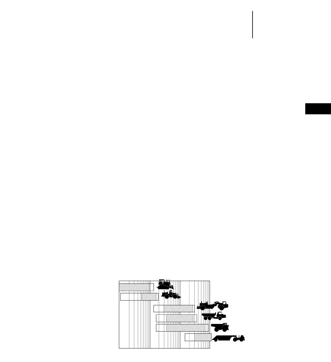
11. Estimate Total Hourly Cost:
631E @ $65.00/hr 211 units $715.00
D9N @ $75.00/hr 22 units 150.00
12G @ $15.00/hr 22 units 30.00
825C @ $40.00/hr 21 unit 40.00
Operators @ $20.00/hr 216 men 320.00
_______
Total Hourly Owning and
Operating Cost $1,255.00
12. Calculate Performance:
Total cost/hr
Cost per BCM = _____________
Production/hr
$1,255.00
=_____________
1507 BCM/hr
= 83¢/BCM
NOTE: Ton-km/h calculations should be made to
judge the ability of the tractor-scraper tires to oper-
ate safely under these conditions.
13. Other Considerations:
If other equipment such as rippers, water wagons,
discs or other miscellaneous machines are needed
for the particular operation, then these machines
must also be included in the cost per BCM.
SYSTEMS
Caterpillar offers a variety of machines for differ-
ent applications and jobs. Many of these separate
machines function together in mining and earth-
moving systems.
●Bulldozing with track-type tractors
●Load-and-Carry with wheel loaders
●Scrapers self-loading with elevator, auger, or
push-pull configurations, or push-loaded by track-
type tractors
●Articulated trucks loaded by excavators, track
loaders or wheel loaders
●Off-highway trucks loaded by shovels, excavators
or wheel loaders
Economic Haul Distances — Mobile equipment
systems for construction or mining jobs operate in
generalized economic application zones. These zones
vary by machine with distance, underfoot conditions,
grades, material type, production rate and operator
skill. Of these factors, distance provides the best ini-
tial basis for system selection. The following table
provides general rules of thumb for systems appl-
cation based on distance. These haul ranges will
vary by application.
● ● ●
23-13
23
Mining and
Earthmoving
Estimating Production Off-the-Job
●Example Problem (Metric)
●Systems
GENERAL HAUL DISTANCES FOR MOBILE SYSTEMS
Dozer
Wheel Loaders
Scraper
Articulated Truck
Rear Dump Truck
Wagon
10 m
32 ft 100 m
328 ft 1000 m
3280 ft 10 000 m
32,800 ft
HAUL DISTANCE

Caterpillar Earthmoving and Mining Systems
Production/50 Min. Hr.
Loading
Tonnes Tons Tool Passes Target
2270/2450 2500/2700 994 HL 7 793C
2450/2700 2700/3000 994 5 789C
2270/2450 2500/2700 994 HL 6 789C
2450/2700 2700/3000 994 4 785C
1450/1600 1600/1800 992G 6 785C
1540/1720 1700/1900 992G 4 777D
1180/1360 1300/1500 990 3 773D
730/910 800/1000 988F 3 769D
2720/2900 3000/3200 5230 ME 7 793C
2540/2720 2800/3000 5230 FS 8 793C
2630/2810 2900/3100 5230 ME 6 789C
2450/2630 2700/2900 5230 FS 6 789C
2540/2720 2800/3000 5230 ME 5 785C
2360/2540 2600/2800 5230 FS 5 785C
1900/2100 2100/2300 5130B ME 7 785C
1700/1900 1700/2100 5130B FS 7 785C
1800/2000 2000/2200 5130B ME 5 777D
1540/1810 1700/2000 5130B FS 5 777D
910/1090 1000/1200 375 ME 7 773D
730/820 800/1000 5080 FS 7 773D
730/910 800/1000 375 ME 5 769D
630/820 700/900 5080 FS 5 769D
Loading Match — Loading tools have a production
range that varies with material, bucket configuration,
target size, operator skill and load area conditions.
The loader/truck matches given in the following
table are with the typical number of passes and pro-
duction range.
Your Cat Dealer can provide advice and estimates
based on your specific conditions.
FUEL CONSUMPTION AND PRODUCTIVITY
Fuel efficiency is the term used to relate fuel con-
sumption and machine productivity. It is expressed
in units of material moved per volume of fuel con-
sumed. Common units are cubic meters or tonnes
per liter of fuel (cubic yards or tons/gal). Determin-
ing fuel efficiency requires measuring both fuel con-
sumption and production.
Measuring fuel consumption involves tapping into
the vehicle’s fuel supply system — without conta-
minating the fuel. The amount of fuel consumed
during operation is then measured on a weight or
volumetric basis.
23-14
Mining and
Earthmoving Production Estimating
●Loading Match
●Fuel Consumption
Caterpillar Aggregate Systems
Production/50 Min. Hr.
Loading
Tonnes Tons Tool Passes Target
1540/1720 1700/1900 992G 4 777D
1450/1630 1600/1800 992G 3 775D
1090/1270 1200/1400 990 4 775D
910/1180 1000/1300 990 3 773D
630/900 700/900 988F HL 5 773D
730/910 800/1000 988F 4 771D
540/730 600/800 980F HL 6 771D
630/820 700/900 988F 3 769D
450/630 500/700 980F HL 5 769D
1500/1800 1700/2000 5130B FS 5 777D
1270/1450 1400/1600 5130B FS 4 775D
1180/1360 1300/1500 5130B FS 3 773D
630/900 700/900 5080 FS 7 773D
730/910 800/1000 5080 FS 5 771D
630/820 700/900 5080 FS 4 769D

FORMULAS AND RULES OF THUMB
Production, hourly = Load (BCM) cycle 2
cycles/hr
= Load (BCY) cycle 2
cycles/hr
100%
Load Factor (L.F.) =_______________
100% + % swell
Load (bank measure) = Loose cubic meters
(LCM) 2L.F.
= Loose cubic yards (LCY)
2L.F.
Compacted cubic meters
(or yards)
Shrinkage Factor (S.F.) =_______________________
Bank cubic meters
(or yards)
Density = Weight/Unit Volume
Weight of load
Load (bank measure) =______________
Bank density
Rolling Resistance Factor
= 20 kg/t 2(6 kg/t/cm 2cm)
= 40 lb/ton + (30 lb/ton/inch 2inches)
Rolling Resistance
= RR Factor (kg/t) 2GMW (tons)
= RR Factor (lb/ton) 2GMW (tons)
Rolling Resistance
= 2% of GMW + 0.6% of GMW per cm tire
penetration
= 2% of GMW + 1.5% of GMW per inch tire
penetration
vertical change in elevation (rise)
% Grade = _______________________________
corresponding horizontal
distance (run)
Grade Resistance Factor = 10 kg/m ton 2% grade
= 20 lb/ton 2% grade
Grade Resistance = GR Factor (kg/t) 2 GMW (tons)
= GR Factor (lb/ton) 2GMW (tons)
Grade Resistance = 1% of GMW 2% grade
Total Resistance
= Rolling Resistance (kg or lb) + Grade Resistance
(kg or lb)
Total Effective Grade (%) = RR (%) + GR (%)
Usable pull (traction
limitation) = Coeff. of traction 2
weight on drivers
= Coeff. of traction 2(Total
wt 2% on drivers)
Pull required = Rolling Resistance + Grade
Resistance
Pull required = Total Resistance
Total Cycle Time = Fixed time + Variable time
Fixed time: See respective machine production
section.
Variable time = Total haul time + Total return time
Distance (m)
Travel Time =______________
Speed (m/min)
Distance (ft)
=______________
Speed (fpm)
60 min/hr
Cycles per hour =_________________________
Total cycle time (min/cycle)
Adjusted production = Hourly production 2
Efficiency factor
Hourly production required
No. of units required =_________________________
Unit hourly production
No. of scrapers a Scraper cycle time
pusher will load =__________________
Pusher cycle time
Pusher cycle time (min) = 1.40 Load time (min) +
0.25 min
GMW (kg) 2Total Effective
Grade 2Speed (km/h)
Grade Horsepower =___________________________
273.75
GMW (lb) 2Total Effective
Grade 2Speed (mph)
er =___________________________
375
23-15
23
Mining and
Earthmoving
Formulas and Rules of Thumb

CONTENTS
Estimating Wheel and Track
Skidder production . . . . . . . . . . . . . . . . . . . .24-1
Log skidding resistance table . . . . . . . . . . . .24-3
Metric example problem . . . . . . . . . . . . . . . .24-4
English example problem . . . . . . . . . . . . . . .24-5
Load capacity curves for Wheel Loaders
and Integrated Toolcarriers . . . . . . . . . . . . .24-7
Forestry machines . . . . . . . . . . . . . . . . . . . . .24-18
Log Loader lift and range diagrams . . . . . . .24-21
Heel Boom grapples . . . . . . . . . . . . . . . . . . . .24-39
Woodchips Dozer & Scoops . . . . . . . . . . . . . . .24-40
High Speed Disc Saws . . . . . . . . . . . . . . . . . .24-40
320B Stroke Delimber . . . . . . . . . . . . . . . . . .24-41
Logging Forks for Wheel Loaders
and Integrated Toolcarriers . . . . . . . . . . . .24-44
Log Volume Tables . . . . . . . . . . . . . . . . . . . . .24-46
Weights of Commercially
Important Woods . . . . . . . . . . . . . . . . . . . . .24-48
Estimating Number of Trees . . . . . . . . . . . . .24-51
Comparison of Log Rules . . . . . . . . . . . . . . . .24-51
Measurement Definitions . . . . . . . . . . . . . . . .24-52
Introduction
This chapter gives information for estimating per-
formance of Cat machines in logging. The chapters
on Earthmoving and Owning and Operating Costs
should be understood before applying this chapter.
Because of variations in conditions, actual experi-
ence should be considered whenever it is available.
ESTIMATING WHEEL AND TRACK
SKIDDER PRODUCTION
1. Determine the weight of the average log and
multiply log loads expected to be skidded. If aver-
age weights or volumes are not available from
local timber cruise or log scale data, they can be
estimated using the following procedure:
— Determine length and both end diameters of
the average size log to be skidded. Then deter-
mine its volume using tables in this section.
— Determine average log weight based on its
estimated volume and green density for the
species being skidded using the tables in this
section.
2. Determine operating weight of machines being
considered. If one end of the logs will be suspended
by a cable arch or hydraulic grapple, estimate the
percent of log weight that will be transferred to
the machine. Then determine total machine plus
load transferred weight. Weight transfer of small
diameter logs with substantial taper may be as
high as two-thirds when skidded with large end
ahead and as low as one-third with small end
ahead. Large diameter logs with little taper will
have weight transfer closer to 50% of their weight.
LOGGING AND FOREST PRODUCTS
24-1
24

3. Determine the average percent grade on the pro-
posed skid trails. Then determine the grade resis-
tance or assistance for the haul and return portions
of the cycle for each machine considered. If there
are significant differences in grade along the pro-
posed trails, the grade resistance or assistance
must be determined for each section of the trails.
For the haul portion of the cycle, grade resistance
must be determined for log loads.
Grade Resistance in Kilograms = % Grade 2
10 kg/metric ton 2GMW in tons
Grade Resistance in Pounds = % Grade 220 lb/
U.S. ton 2GMW in tons
4. Determine the average rolling resistance for each
wheel-type machine being considered based on
expected tire penetration or on typical rolling
resistance factors shown in the Tables Section.
If there are significant differences in underfoot
conditions and tire penetration along the pro-
posed skid trails, rolling resistance must also be
determined for machines with and without loads.
RR Factor in kg/metric ton = 20 kg/t + (6 kg/t/cm
2tire penetration in cm)
RR Factor in lb/U.S. ton = 40 lb/ton + (30 lb/ton/
inch 2tire penetration in inches)
Total Rolling Resistance in Kilograms = RR
Factor in kg/t 2GMW in metric tons
Total Rolling Resistance in Pounds = RR Factor
in lb/U.S. ton 2GMW in tons
5. Determine skidding resistance for log loads on
each machine using the tables on the next page.
For log weights and grades not shown, skidding
resistance must be determined by interpolation.
The arch skidding tables must be used when one
end of the logs will be suspended by a cable arch
or hydraulic grapple. The ground skidding tables
are used when logs are not suspended. If there
are significant differences in grade along the pro-
posed trails, then skidding resistance must be
determined for each section.
6. Determine the total resistance or pull required
to overcome the total of grade, rolling, and skid-
ding resistance. Total resistance must be deter-
mined for each machine and skid trail section on
both haul and return portions of the cycles.
Total Resistance on Return = Grade Resistance
+ Rolling Resistance
Total Resistance on Haul = Grade Resistance
+ Rolling Resistance + Skidding Resistance
7. Determine the traction limitations or usable
pull for each machine with and without loads
if one end of the logs will be suspended. Usable
pull is estimated using the approximate coeffi-
cient of traction factors for the soil conditions
shown in Tables Section.
Usable Pull in Kilograms = Coefficient of
Traction 2GMW in Kilograms
Usable Pull in Pounds = Coefficient of Traction
2GMW in Pounds
8. Determine maximum return and haul travel
speeds for each machine and skid trail section
on those loads whose total resistance (required
pull) estimated in step 6 is less than the usable
pull estimated in step 7. Travel speeds for track-
type tractors are estimated from the drawbar
pull graphs in the Tractor Section. Wheel skid-
der travel speeds are estimated from the rim-
pull graphs in the Skidder Section.
9. Determine return and haul travel times for each
machine, load and segment based on the length
of each skid trail segment and the speeds deter-
mined in step 8.
Travel Time in Minutes = Distance in meters
÷ [(speed in km/h) (16.7)]
Travel Time in Minutes = Distance in feet
÷ [(speed in mph) (88)]
10. Determine fixed times to maneuver machines
and to hook, unhook and deck logs based on local
experience.
11. Determine total cycle time and cycles per hour
for each machine with log loads on each skid trail.
Cycle Time = Return Time + Haul Time +
Fixed Time
Cycles/Hour = 60 ÷ cycle time in minutes
12. Determine production for each machine on each
skid trail at the expected job efficiency in the
desired units, such as number of logs, weight of
logs, cubic volume, board feet, cords, etc., using
the appropriate conversion factors.
Units/Hour = Cycles/Hour 2Unit/Cycle 2
Job Efficiency
24-2
Wheel and Track SkiddingLogging and Forest Products
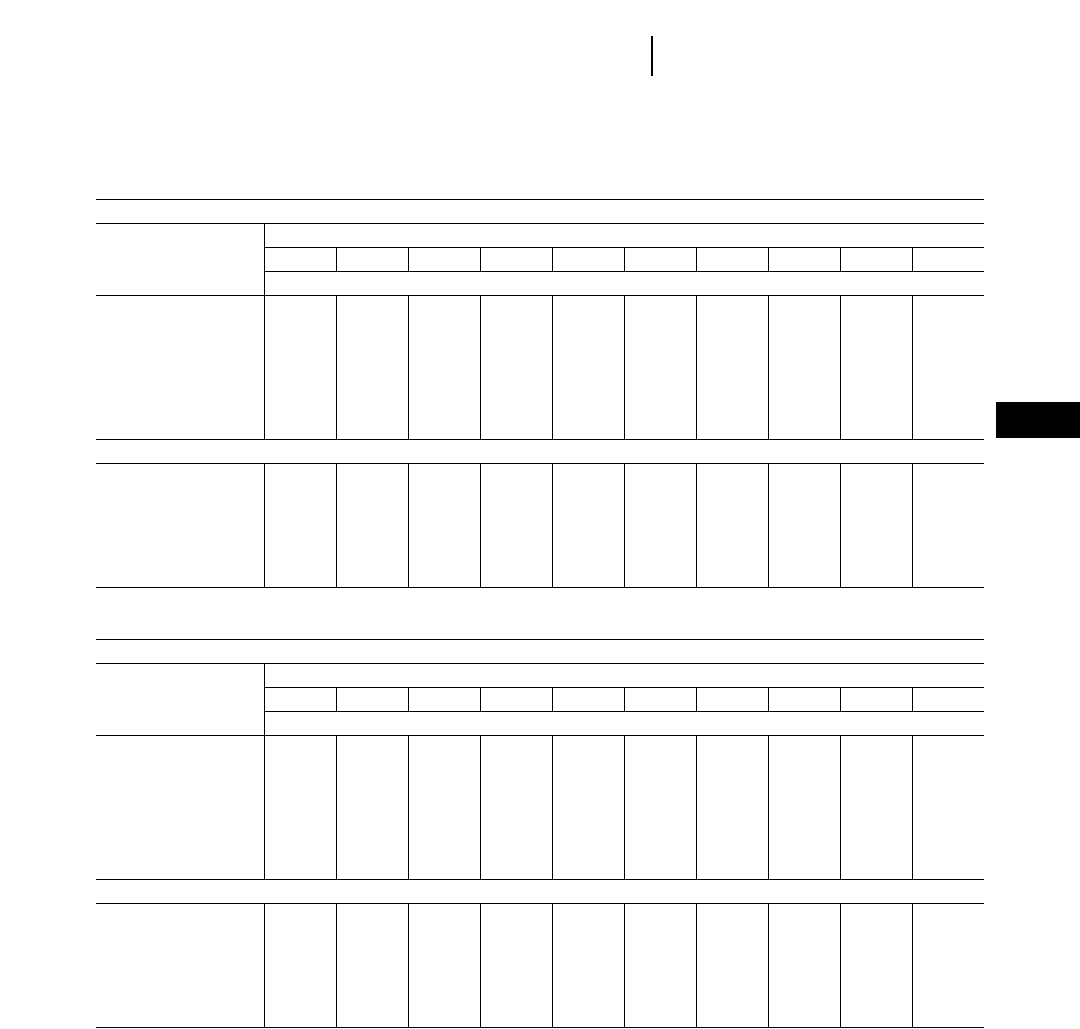
DRAWBAR KILOGRAMS PULL Required To Overcome Log Skidding Resistance
GROUND SKIDDING — Log Lengths
Load Weight (kg)
500 1000 1500 2000 2500 3000 3500 4000 4500 5000
*Grade Drawbar Kilograms Required
30% Upgrade 683 1205 1808 2410 3013 3615 4218 4820 5423 6025
20% Upgrade 550 1100 1650 2200 2750 3300 3850 4400 4950 5500
10% Upgrade 498 995 1493 1990 2488 2985 3483 3980 4478 4975
Level 445 890 1335 1780 2225 2670 3115 3560 4005 4450
10% Downgrade 392 784 1176 1568 1960 2352 2744 3136 3528 3920
20% Downgrade 340 679 1091 1358 1698 2037 2377 2716 3056 3395
30% Downgrade 287 574 861 1148 1435 1722 2009 2296 2583 2870
ARCH SKIDDING — Log Lengths
30% Upgrade 603 964 1246 1527 1809 2090 2377 2653 2935 3216
20% Upgrade 513 750 987 1224 1461 1698 1935 2172 2409 2645
10% Upgrade 343 535 728 920 1113 1305 1498 1690 1883 2075
Level 167 317 468 618 769 919 1070 1220 1371 1521
10% Downgrade — 105 207 313 417 521 625 729 833 937
20% Downgrade ———— 30100170239310380
DRAWBAR POUNDS PULL Required To Overcome Log Skidding Resistance
GROUND SKIDDING — Log Lengths
Load Weight (lb)
1000 2000 3000 4000 5000 6000 7000 8000 9000 10 000
*Grade Drawbar Pounds Pull Required
30% Upgrade 1365 2410 3615 4820 6025 7230 8435 9650 10 845 12 050
20% Upgrade 1100 2200 3300 4400 5500 6600 7700 8800 1 9900 11 000
10% Upgrade 995 1990 2985 3980 4975 5970 6965 7960 1 8955 1 9950
Level 890 1780 2670 3560 4450 5340 6230 7120 1 8010 1 8900
10% Downgrade 784 1568 2352 3136 3920 4704 5488 6272 1 7056 1 7840
20% Downgrade 679 1358 2037 2716 3395 4074 4753 5432 1 6111 1 6790
30% Downgrade 574 1148 1722 2296 2870 3444 4018 4592 1 5166 1 5740
ARCH SKIDDING — Log Lengths
30% Upgrade 1205 1928 2491 3054 3617 4180 4753 5306 1 5869 1 6432
20% Upgrade 1025 1499 1973 2447 2921 3395 3869 4343 1 4817 1 5291
10% Upgrade 685 1070 1455 1840 2225 2610 2995 3380 1 3765 1 4150
Level 333 634 935 1236 1537 1838 2139 2440 1 2741 1 3042
10% Downgrade — 209 414 625 833 1041 1249 1457 1 1665 1 1873
20% Downgrade ———— 591993394791 619 1 759
Data taken on dry, smooth, clay loam slopes, Resistances are less on wet soil. Source — Central States Forest Experiment Station, U.S. Forest Service.
Vertical Rise
*% Grade = ________________2100%
Horizontal Distance
24-3
24
Logging and Forest ProductsLog Skidding Resistance Table

Example problem (Metric)
Determine the production capabilities in logs per
hour of a 525 grapple skidder and a 527 grapple skidder
in a skidding application. Operating weights are
13 865 kilograms for the 525 with grapple and
19 353 kilograms for the 527 with grapple. The tim-
ber is Radiata pine with the average log being
18 meters long with a butt diameter of 350 milli-
meters and a top diameter of 100 millimeters.
The average skid trail is 150 meters long with a
5% average adverse skidding grade and 75 millimeters
average tire penetration. The coefficient of traction
is estimated to be 0.5 for wheels and 0.8 for tracks.
The logs will be bunched in groups of 6 logs for
the 525 and 9 logs for the 527. Maneuver time for a
log hook-up averages 0.3 minutes and hook-up time
averages 0.2 minutes. Landing maneuver, decking,
and unhook time average a total of 1.0 minute.
1. Average Load Size:
Volume/Log = (1.73 + 0.014)/2 = 0.935 m3
Density of
Radiata Pine = 865 kg/m3
Weight/Log = 865 20.935 = 809 kg
Six Log Load = 809 26 = 4853 kg
Nine Log Load = 809 29 = 7279 kg
2. Gross Machine Weights:
525 Empty GMW = 13 865 kg = 13.8 Metric tons
527 Empty GMW = 19 353 kg = 19.3 Metric tons
525 Load Weight Transferred = 0.6 2Load
Weight
527 Load Weight Transferred = 0.6 2 Load
Weight
525 Loaded:
13 865 + (0.6 24853) = 16 777 kg = 16.78
Metric tons
527 Loaded:
19 353 + (0.6 27279) = 23 720 kg = 23.72
Metric tons
3. Grade Resistance/Assistance:
Grade Assistance: Return = 5 210 kg/T 2 GMW
in tons (empty)
Grade Resistance: Haul = 5 210 kg/T 2 GMW
in tons
525 527
Assistance:
Return Empty (–690 kg) (–965 kg)
Resistance:
Haul Load 839 kg 1186 kg
4. Rolling Resistance — 525:
RR Factor = 20 kg/ton + (6 kg/ton/cm 27.5 cm)
= 65 kg/T
RR = 65 2GMW in tons
Resistance:
Return = 65 213.8 = 897 kg
Haul = 65 216.78 = 1091 kg
5. Skidding Resistance (derived from tables in
this section):
Skid Resistance/Log = 450 kg
Skid Resistance — Six Logs = 2700 kg
Skid Resistance — Nine Logs = 4050 kg
6. Total Resistance — Required Pull:
525 Return Empty = (–690) + 897 = 207 kg
525 Haul Load = 839 + 1091 + 2700 = 4630 kg
527 Return Empty = (–965) kg
527 Haul Load = 1186 + 4050 = 5236 kg
7. Usable Pull:
525 Return Empty = 0.5 213 865 = 6933 kg
525 Haul Load = 0.5 216 777 = 8389 kg
527 Return Empty = 0.8 219 353 = 15 482 kg
527 Haul Load = 0.8 223 720 = 18 976 kg
24-4
Estimating Skidding Production
●Metric Example
Logging and Forest Products

8. Travel Speeds: from rimpull/drawbar pull
graphs
525 527
Return Empty 14 km/h* 6.4 km/h*
Haul Load 6 km/h 3.2 km/h*
*Depending upon haul road conditions and job
site factors, a slower speed may be preferred
for a safer return.
9. Travel Times:
Travel Time = 150 m x 0.9 (speed in km/h)
525 527
Return Empty 0.64 min. 1.4 min.
Haul Load 1.54 min. 2.8 min.
10. Fixed Times:
Total Fixed Time = 0.3 + 0.2 + 1.0 = 1.5 min.
11. Cycles per Hour:
Cycles/hr = (60 min/hr)/(Total Cycle Time in min)
525 527
Total Cycle Time 3.64 min. 05.7 min.
Cycles per Hour 16.5 min. 10.5 min.
12. Production per Hour:
Logs/Hour = Cycles/hr 2Logs/cycle
525 527
Logs/cycle 0609
Logs/hour 99 95
Example problem (English)
Determine the production capabilities in logs per
hour of a 525 grapple skidder and a 527 grapple skid-
der in a thinning application. Operating weights are
30,570 pounds for the 525 with grapple and 42,670
pounds for the 527 with grapple. The timber is
Loblolly pine with the average log being 60 feet long
with a butt diameter of 14 inches and a top diame-
ter of 4 inches.
The average skid trail is 500 feet long with a 5%
average adverse skidding grade and 3 inches aver-
age tire penetration. The coefficient of traction is
estimated to be 0.5 for wheels and 0.8 for tracks.
The logs will be bunched in groups of 6 logs for
the 525 and 9 logs for the 527. Maneuver time for a
log hook-up averages 0.3 minutes and hook-up time
averages 0.2 minutes. Landing maneuver, decking,
and unhook time average a total of 1.0 minute.
1. Average Load Size:
Volume/Log = (64 + 5.2)/2 = 34.6 ft3
Density of
Loblolly Pine = 62 lb/ft3
Weight/Log = 62 234.6 = 2145 lb
Six Log Load = 2145 26 = 12,871 lb
Nine Log Load = 2145 29 = 19,305 lb
2. Gross Machine Weights:
525 Empty GMW = 30,570 lb = 15.3 tons
527 Empty GMW = 42,670 lb = 21.3 tons
525 Load Weight Transferred = 0.6 2Load
Weight
527 Load Weight Transferred = 0.6 2 Load
Weight
525 Loaded:
30,570 + (0.6 212,871) = 38,293 lb = 19.1 tons
527 Loaded:
42,670 + (0.6 219,306) = 54,254 lb = 27.1 tons
3. Grade Resistance/Assistance:
Grade Assistance: Return = 5 220 lb/T 2 GMW
in tons
Grade Resistance: Haul = 5 220 lb/T 2 GMW
in tons
24-5
24
Logging and Forest ProductsEstimating Skidding Production
●English Example

525 527
Assistance:
Return Empty (–1530 lb) (–2130 lb)
Resistance:
Haul Load 1910 lb 2710 lb
4. Rolling Resistance — 525:
RR Factor = 40 lb/ton + (30 lb/ton/in 23 in)
= 130 lb/T
RR = 130 2GMW in tons
Resistance:
Return = 130 215.3 = 1989 lb
Haul = 130 219.1 = 2483 lb
5. Skidding Resistance (derived from tables in
this section):
Skid Resistance/Log = 1169 lb
Skid Resistance — Six Logs = 7014 lb
Skid Resistance — Nine Logs = 10,521 lb
6. Total Resistance — Required Pull:
525 Return Empty = (–1530) + 1989 = 459 lb
525 Haul Load = 1910 + 2483 + 7014 = 11,407 lb
527 Return Empty = (–2130) lb
527 Haul Load = 2710 + 10,521 = 13,231 lb
7. Usable Pull:
525 Return Empty = 0.5 230,570 = 15,285 lb
525 Haul Load = 0.5 238,293 = 19,146 lb
527 Return Empty = 0.8 242,670 = 34,136 lb
527 Haul Load = 0.8 254,254 = 43,403 lb
8. Travel Speeds: from rimpull/drawbar pull
graphs
525 527
Return Empty 8.7 mph* 3.9 mph*
Haul Load 3.7 mph*2.0 mph*
*Depending upon haul road conditions and job
site factors, a slower speed may be preferred
for a safer return.
9. Travel Times:
Travel Time = 500 ft 2(60 min/hr)/
(5280 ft/mi)/(speed in mph)
525 527
Return Empty 0.65 min. 1.45 min.
Haul Load 1.53 min. 2.84 min.
10. Fixed Times:
Total Fixed Time = 0.3 + 0.2 + 1.0 = 1.5 min.
11. Cycles per Hour:
Cycles/hr = (60 min/hr)/(Total Cycle Time in min)
525 527
Total Cycle Time 3.68 min. 05.79 min.
Cycles per Hour 16.3 min. 10.40 min.
12. Production per Hour:
Logs/hr = Cycles/hr 2Logs/cycle
525 527
Logs/cycle 0609
Logs/hour 98 94
● ● ●
24-6
Estimating Skidding Production
●English Example
Logging and Forest Products

LOAD CAPACITY CURVES FOR WHEEL
LOADERS AND INTEGRATED
TOOLCARRIERS EQUIPPED WITH FORKS
Definitions:
Hydraulic Capacity: Weight that the hydraulic
system will lift with the rear of the loader anchored
and the load center of gravity midway on the fork
tines. Hydraulic capacity is not increased by coun-
terweighting.
Tipping Load: The loaded weight positioned as
described above, which will lift the rear wheels off
the ground with the machine in a static condition.
Static tipping load curves for wheel loaders equipped
with log or lumber forks are based on full machine
articulation.
Tipping load capacities are affected by counter-
weight and distance of the load center of gravity from
the front axle and degree of articulation. Fork cen-
ter of gravity and fork weight can also affect tipping
load.
Maximum Operating Load: Maximum operating
load should be based on static tipping load ratings
(tines level) and requires a firm, smooth, well-main-
tained operating area. Maximum operating loads
can be affected by:
●Underfoot conditions.
●Position or height the load is carried.
●Fork position or attitude.
●Degree machine is articulated during maneu-
vering.
● ● ●
Example problem:
Wheel Loader Selection 966F vs 950F
Optimum millyard performance depends on effi-
cient and proper use of wheel loaders performing
unloading, sorting and decking applications. The
following steps will aid in the proper wheel loader
selection.
Step 1: Determine the basic mill requirements (job
description).
EXAMPLE:
Logs arrive at the mill on trucks equipped with
double bunk trailers. Logs are a variety of hard-
woods, but white oak makes up the majority of
wood received. The trucks must be off-loaded
by a wheel loader equipped with log forks.
In addition to the off-loading, a primary loader
requirement is to supply the mill with raw mate-
rial in a load-and-carry operation. The loader
must also sort logs by species, grade and size,
and transport the excess logs from the unload-
ing area to the storage decks.
●Maximum sawmill requirements — 544 met-
ric tons/8 hr. day (600 U.S. tons).
●Maximum wood received — 30 truckloads/8 hr.
day.
●Average number of logs per truckload — 20.
●Average log specifications:
— length 4.9 m (16').
— butt diameter 660 mm (26").
— top diameter 430 mm (17").
●Maximum truck stake height — 3.98 m (13'1").
●Maximum haul distance (one way) from log
storage deck to the mill — 153 m (500').
●Haul and return to mill in 2nd forward — 10%
effective grade.
●Fixed times — load forks 0.7 min.
— maneuver and dump 0.5 min.
— truck unloading 1.0 min.
●Average log weight = 1180 kg/log (2600 lb/log)
Refer to Weights and Measure section of this
handbook to obtain appropriate log volume
and density information.
Step 2: Determine the basic machine options and
capacities.
Refer to Capacity curves in the Performance Hand-
book under Logging and Forest Products section.
For other fork configurations not listed contact the
Forest Machinery Unit for performance curves. Also
refer to attachment adaptability section for infor-
mation needed for performance curves.
EXAMPLE:
Consider a 950F vs. 966F. Both are equipped
with logging fork.
950F
Static Tipping Load 10 000 kg (22,000 lb)
Hydraulic Lift Capacity 11 600 kg (25,520 lb)
Maximum Operating Load 10 000 kg (22,000 lb)
966F
Static Tipping Load 13,500 kg (29,700 lb)
Hydraulic Lift Capacity 14,500 kg (31,900 lb)
Maximum Operating Load 13,500 kg (29,700 lb)
Step 3: Determine cycle times.
Refer to Production Travel Time Charts in the
Wheel Loader section of the Performance Handbook.
24-7
24
Logging and Forest ProductsLoad Capacity Curves
●Example Problem

EXAMPLE:
(Supplying the mill)
Time Time
Description (950F) (966F)
Haul and return 1.16 min 1.14 min
Load Forks* 0.7 min 0.7 min
Maneuver and dump* 0.5 min 0.5 min
________ ________
TOTAL 2.36 min 2.34 min
Cycles/45-min hr = 19.06 19.23
(Off-loading trucks)
Time Time
Description (950F) (966F)
Truck unloading* 1.0 min 1.0 min
Load Forks* 0.7 min 0.7 min
Maneuver and dump* 0.5 min 0.5 min
________ ________
TOTAL 2.2 min 2.2 min
Cycles/45-min hr = 20.45 20.45
*Fixed times which should be based on local
experience.
Step 4: Calculate Production
EXAMPLE:
Mill requirements:
— 950F
544 320 kg (1,200,000 lb)/8 hr/day
_______________________________ =
10 000 kg (22,000 lb)/loader cycle
55 loader cycles
_______________
8 hr/day
55 loader cycles/8 hr/day 2.88 hr/day
_______________________ = required to
19.06 cycles/45-min hr supply mill
— 966F
544 320 kg (1,200,000 lb)/8 hr/day
_______________________________ =
13 500 kg (29,700 lb)/loader cycle
41 loader cycles
_______________
8 hr/day
41 loader cycles/8 hr/day 2.13 hr/day
_______________________ = required to
19.23 cycles/45-min hr supply mill
Off-Load Requirements:
— 950F
20 logs/truck 230 truckloads/day =
600 logs/day
600 logs/day 21180 kg (2600 lb)/log =
707 616 kg/day
or
1,560,000 lbs/day
Incoming Wood
707 616 kg (1,560,000 lb)/8 hr/day
_______________________________ =
10,000 kg (22,000 lb)/loader cycle
71 loader cycles
_______________
8 hr/day
71 loader cycles/8 hr/day 3.47 hr/day
_______________________ = required to
29.45 cycles/hr off-load wood
— 966F
20 logs/truck 230 truckloads/day =
600 logs/day
600 logs/day 21180 kg (2600 lb)/log =
707 616 kg/day
or
1,560,000 lbs/day
Incoming Wood
707 616 kg (1,560,000 lb)/8 hr/day
_______________________________ =
13,500 kg (29,700 lb)/loader cycle
53 loader cycles
_______________
8 hr/day
53 loader cycles/8 hr/day 2.59 hr/day
_______________________ = required to
20.45 cycles/hr off-load wood
Total Production Required:
— 950F = 2.88 hr/day to supply mill
3.47 hr/day to off-load
____
6.35 hr/day total time
— 966F = 2.13 hr/day to supply mill
2.59 hr/day to off-load wood
____
4.72 hr/day total time
Step 5: Determine Wheel Loader selection.
EXAMPLE:
From the production study completed and
assuming 100% efficiency it appears both
machines are capable of handling the maximum
daily production. The 950F and 966F will have
1.65 hrs/day and 3.28 hrs/day respectively to
handle unscheduled activities such as sorting,
storage and yard clean-up. However, after com-
paring the maximum hinge pin height for the
two machines, the 950F is not capable of clear-
ing the stakes with a load. This leaves the 966F
as the machine to recommend, since it can handle
all restrictions and production requirements.
24-8
Load Capacity Curves
●Example Problem
Logging and Forest Products

24-9
24
Logging and Forest ProductsLoad Capacity Curves
●914G
●924F
1361 2722 4083 5444 6805 8166
0
A
B
9527
C
4064
3556
3048
2540
2032
1524
1016
508
00 3000 6000 9000 12,000 15,000 18,000 21,000
0
20
40
60
80
100
120
140
160
D
Millimeters
Kilograms
Pounds
Inches
HINGE PIN HEIGHT
CAPACITY IN FULL TURN
NO CLAMP
KEY
A — Hydraulic Lift Capacity Fork Racked
B — Static Tipping Load Full 40° Turn Fork Level
C — Hydraulic Lift Capacity Fork Level
D — Static Tipping Load Machine Straight, Fork Level
914G with Balderson Lumber and Log Fork
Curves based on machine with full fuel tank, operator,
17.5R25 tires and Balderson 125-9293 lumber/log fork
without top clamp. Fork weight is 616 kg (1358 lb).Total
operating weight, 7464 kg (16,444 lb). Forks of other
dimensions or weight may affect machine capacity.
Consult your Caterpillar Dealer for additional fork data.
Change in Change in
Operating Articulated Static
Weight Tipping Load
Racked Level
Add ROPS
canopy . . . . . . . . +317 kg +309 kg +233 kg
(+700 lb) (+682 lb) (+515 lb)
Add ROPS
canopy
and cab . . . . . +527 kg +388 kg +345 kg
(+1163 lb) (+856 lb) (+762 lb)
1361 2722 4083 5444 6805 8166
0
A
B
9527
C
4064
3556
3048
2540
2032
1524
1016
508
00 3000 6000 9000 12,000 15,000 18,000 21,000
0
20
40
60
80
100
120
140
160
D
CAPACITY IN FULL TURN
NO CLAMP
KEY
A — Hydraulic Lift Capacity Fork Racked
B — Static Tipping Load Full 40° Turn Fork Level
C — Hydraulic Lift Capacity Fork Level
D — Static Tipping Load Machine Straight, Fork Level
924F with Balderson Lumber and Log Fork
Curves based on machine with full fuel tank, operator,
17.5R25 tires and Balderson 8918C3 lumber/log fork
without top clamp. Fork weight 834 kg (1838 lb).Total
operating weight, 9280 kg (20,444 lb). Forks of other
dimensions or weight may affect machine capacity.
Consult your Caterpillar Dealer for additional fork data.
Change in Change in
Operating Articulated Static
Weight Tipping Load
Level
Without ROPS
canopy and cab
(platform
only) . . . . . . . . –418 kg –258 kg
(–922 lb) (–569 lb)
Without cab
(ROPS/
platform) . . . . –207 kg –128 kg
(–456 lb) (–282 lb)
Millimeters
Kilograms
Pounds
Inches
HINGE PIN HEIGHT
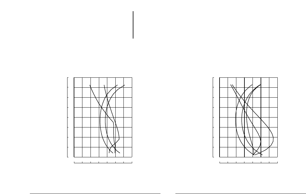
24-10
Load Capacity Curves
●928G
●938G
Logging and Forest Products
KEY
A — Hydraulic Lift Capacity Fork Racked
B — Static Tipping Load Full 40° Turn Fork Level
C — Hydraulic Lift Capacity Fork Level
D — Static Tipping Load Machine Straight, Fork Level
Curves based on machine with full fuel tank, operator,
ROPS cab, 20.5-25 tires, 250 kg (550 lb) counterweight,
lumber/log fork. Total operating weight, 11 603 kg
(25,561 lb). Forks of other dimensions or weight
may affect machine capacity. Consult your Caterpillar
Dealer for additional fork data.
KEY
A — Hydraulic Lift Capacity 40° Turn, Fork Racked
B — Static Tipping Load Full 40° Turn Fork Level
C — Hydraulic Lift Capacity Fork Level
D — Static Tipping Load Machine Straight, Fork Level
E — Hydraulic Tilt Capacity Fork Level
938G Logger with Balderson Millyard Fork
Curves based on machine with full fuel tank, operator,
ROPS cab, 20.5-25, 16PR(L-2) tires, with 810 kg
(1785 lb) rear tire ballast, 562 kg (1240 lb) counter-
weight, Balderson millyard fork 119-8243.00 with
1345 mm (4'5") tines, 1635 kg (3600 lb) combined weight.
Total operating weight, 14 297 kg (31,520 lb).
2722 4083 5444 6805 8166 9527
1361
A
B
10 888
C
4064
3556
3048
2540
2032
1524
1016
508
03000 6000 9000 12,000 15,000 18000, 21,000 24,000
0
20
40
60
80
100
120
140
160
D
Millimeters
Kilograms
Pounds
Inches
HINGE PIN HEIGHT
928G with Balderson Lumber and Log Fork
CAPACITY IN FULL TURN
NO CLAMP
5444 6805 8166 9527 10 888 12 249
4083
AE
13 610
DB
4064
3556
3048
2540
2032
1524
1016
508
0
C
9000 12,000 15,000 18,000 21,000 24,000 27,000 30,000
0
20
40
60
80
100
120
140
160
Millimeters
Kilograms
Pounds
Inches
HINGE PIN HEIGHT
CAPACITY IN FULL TURN
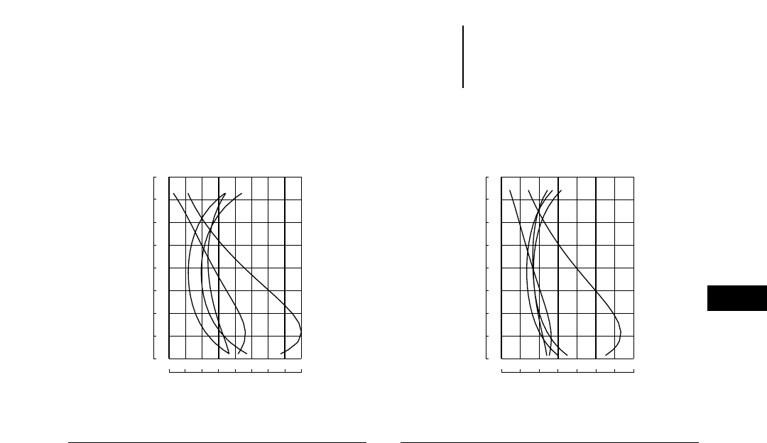
24-11
24
Logging and Forest ProductsLoad Capacity Curves
●938G
●950F Series II
KEY
A — Hydraulic Lift Capacity 40° Turn, Fork Racked
B — Articulated Tipping Capacity
C — Hydraulic Lift Capacity Fork Level
D — Static Tipping Load Machine Straight, Fork Level
E — Hydraulic Tilt Capacity Fork Level
938G Logger with
Balderson Log and Lumber Fork
Curves based on machine with full fuel tank, operator,
ROPS cab, 20.5-25, 16PR(L-2) tires, and 562 kg
(1240 lb) counterweight, with 810 kg (1785 lb) rear tire
ballast Balderson log and lumber fork with 1225 mm
(4'0") tines, 1660 kg (3660 lb) total weight.Total oper-
ating weight, 14 332 kg (31,595 lb).
Curves and operating weight on chart are based on
machine equipped with 23.5-25, 16PR(L-3) tires, coun-
terweight, 1244 kg (2743 lb) ballast in rear tires, full fuel
tank, operator, Balderson 896IC2 (BLF 950 ED-TC) log
fork with 1397 mm (4'7") tines and top clamp, 2018 kg
(4450 lb) combined weight. Total operating weight,
18 255 kg (40,245 lb). Forks of other dimensions or
weight may affect machine capacity. Consult your
Caterpillar dealer for additional information.
6805 8166 9527 10 888 12 249 13 610
5444
AE
14 971
D
BC
4064
3556
3048
2540
2032
1524
1016
508
012,000 15,000 18,000 21,000 24,000 27,000 30,000 33,000
16 332
36,000
0
20
40
60
80
100
120
140
160
Millimeters
Kilograms
Pounds
Inches
HINGE PIN HEIGHT
CAPACITY IN FULL TURN
KEY
A — Hydraulic Lift Capacity 35° Turn, Fork Racked
B — Articulated Tipping Capacity
C — Hydraulic Lift Capacity Fork Level
D — Static Tipping Load Machine Straight, Fork Level
E — Hydraulic Tilt Capacity Fork Level
950F Series II Logger with
Balderson Logging Fork and Top Clamp
8166 10 888 13 610 16 332 19 054 21 776
5444
AECBD
24 498
4064
3556
3048
2540
2032
1524
1016
508
012,000 18,000 24,000 30,000 36,000 42,000 48,000 54,000
0
20
40
60
80
100
120
140
160
Millimeters
Kilograms
Pounds
Inches
HINGE PIN HEIGHT
CAPACITY IN FULL TURN
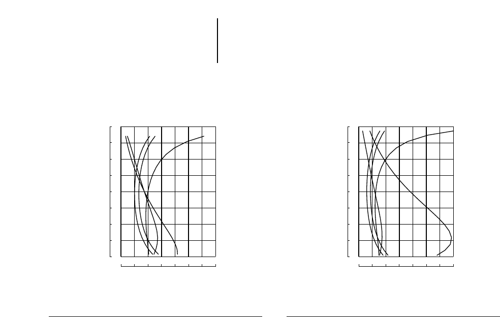
24-12
Load Capacity Curves
●950F Series II
●966F Series II
Logging and Forest Products
KEY
A — Hydraulic Lift Capacity 35° Turn, Fork Racked
B — Articulated Tipping Capacity
C — Hydraulic Lift Capacity Fork Level
D — Static Tipping Load Machine Straight, Fork Level
E — Hydraulic Tilt Capacity Fork Level
Curves and operating weight on chart are based on
machine equipped with 23.5-25 16PR(L-3) tires 1069 kg
(3246 lb) counterweight with 1244 kg (2587 lb) ballast
in rear tires, full fuel tank, operator, Balderson millyard
fork 5544C3 1930 kg (4250 lb) total weight.Total oper-
ating weight, 17 990 kg (39,660 lb).
KEY
A — Hydraulic Lift Capacity 35° Turn, Fork Racked
B — Articulated Tipping Capacity
C — Hydraulic Lift Capacity Fork Level
D — Static Tipping Load Machine Straight, Fork Level
E — Hydraulic Tilt Capacity Fork Level
966F Series II Logger with
Balderson Millyard Fork
Curves and operating weight on chart are based on
machine equipped with 26.5-25, 20PR(L-3) tires, coun-
terweight with 1515 kg (3440 lb) ballast in rear tires, full
fuel tank, operator, Balderson millyard fork 5831C1
with 1600 mm (5'3") tines and top clamp, 2450 kg
(5400 lb) combined weight. Total operating weight,
22 740 kg (50,130 lb).
8166 10 888 13 610 16 332 19 054 21 776
5444
A
EBD C
24 498
4064
3556
3048
2540
2032
1524
1016
508
012,000 18,000 24,000 30,000 36,000 42,000 48,000 54,000
0
20
40
60
80
100
120
140
160
Millimeters
Kilograms
Pounds
Inches
HINGE PIN HEIGHT
950F Series II Logger with
Balderson Millyard Fork and Top Clamps
CAPACITY IN FULL TURN
12 249 16 332 20 415 24 498 28 581 32 664
8166
EA BD C
36 747
4064
3556
3048
2540
2032
1524
1016
508
018,000 27,000 36,000 45,000 54,000 63,000 72,000 81,000
0
20
40
60
80
100
120
140
160
Millimeters
Kilograms
Pounds
Inches
HINGE PIN HEIGHT
CAPACITY IN FULL TURN
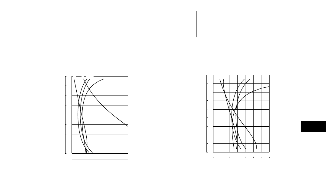
24-13
24
Logging and Forest ProductsLoad Capacity Curves
●966F Series II
●980G
KEY
A — Hydraulic Lift Capacity 35° Turn, Fork Racked
B — Articulated Tipping Capacity
C — Hydraulic Lift Capacity Fork Level
D — Static Tipping Load Machine Straight, Fork Level
E — Hydraulic Tilt Capacity Fork Level
Curves and operating weight on chart are based on
machine equipped with 26.5-25, 20PR(L-3) tires, coun-
terweight with 1515 kg (3440 lb) ballast in rear tires, full
fuel tank, operator, Balderson logging fork 9209C with
1600 mm (5'3") tines and top clamp, 2360 kg (5200 lb)
combined weight. Total operating weight, 22 634 kg
(49,910 lb).
KEY
A — Hydraulic Lift Capacity 35° Turn, Fork Racked
B — Articulated Tipping Capacity
C — Hydraulic Lift Capacity Fork Level
D — Static Tipping Load Machine Straight, Fork Level
E — Hydraulic Tilt Capacity Fork Level
980G Logger with Balderson Millyard Fork
Curves based on logging machine with full fuel tank,
ROPS cab, 29.5-25, 22PR(L-3) tires, with 1945 kg
(4290 lb) ballast in rear tires, 3810 kg (8400 lb) coun-
terweight, Balderson millyard fork weight of 1850 kg
(4075 lb).Total operating weight, 32 680 kg (72,050 lb).
12 249 16 332 20 415 24 498 28 581 32 664
8166 36 747
4064
3556
3048
2540
2032
1524
1016
508
018,000 27,000 36,000 45,000 54,000 63,000 72,000 81,000
0
20
40
60
80
100
120
140
160
A E B D C
Millimeters
Kilograms
Pounds
Inches
HINGE PIN HEIGHT
966F Series II Logger with
Balderson Logging Fork
CAPACITY IN FULL TURN
12 249 16 332 20 415 24 498 28 581 32 664
8166
EA B D
C
36 747
4572
4064
3556
3048
2540
2032
1524
1016
508
0
180
160
140
120
100
80
60
40
20
0
18,000 27,000 36,000 45,000 54,000 63,000 72,000 81,000
Millimeters
Kilograms
Pounds
Inches
HINGE PIN HEIGHT
CAPACITY IN FULL TURN
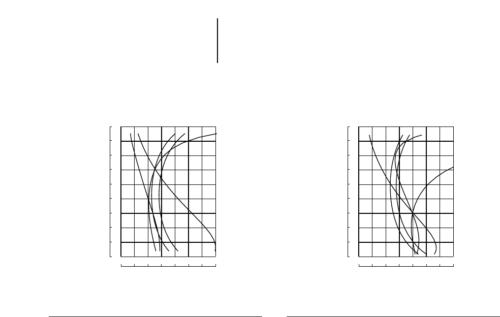
24-14
Load Capacity Curves
●980G
●988F Series II
Logging and Forest Products
KEY
A — Hydraulic Lift Capacity 35° Turn, Fork Racked
B — Articulated Tipping Capacity
C — Hydraulic Lift Capacity Fork Level
D — Static Tipping Load Machine Straight, Fork Level
E — Hydraulic Tilt Capacity Fork Level
Curves based on machine with full fuel tank, operator,
ROPS cab, 29.5-25, 22PR(L-3) tires, with 2060 kg
(4535 lb) ballast in rear tires, 3200 kg (7050 lb) coun-
terweight, Balderson logging fork with 1830 mm (6'0")
tines and top clamp with a combined weight of 3175 kg
(7000 lb).Total operating weight, 34 010 kg (74,975 lb).
KEY
A — Hydraulic Lift Capacity 30° Turn, Fork Racked
B — Articulated Tipping Capacity
C — Hydraulic Lift Capacity Fork Level
D — Static Tipping Load Machine Straight, Fork Level
E — Hydraulic Tilt Capacity Fork Level
988F Series II Logger with
Balderson Millyard Fork
Curves based on machine with full fuel tank, operator,
ROPS cab, 35/65-33 30PR(L-4) tires. Standard 4455 kg
(9825 lb) counterweight, 2690 kg (5930 lb) ballast in
rear tires Balderson 5196C2 millyard fork at 5480 kg
(12,080 lb).Total operating weight, 52 765 kg (116,325 lb).
Forks or other dimensions or weight will affect machine
capacity.
12 249 16 332 20 415 24 498 28 581 32 664
8166
AE DBC
36 747
4572
4064
3556
3048
2540
2032
1524
1016
508
0
180
160
140
120
100
80
60
40
20
0
18,000 27,000 36,000 45,000 54,000 63,000 72,000 81,000
Millimeters
Kilograms
Pounds
Inches
HINGE PIN HEIGHT
980G Logger with
Balderson Double Top Clamp Log Fork
CAPACITY IN FULL TURN
16 783 21 317 25 851 30 385 34 919 39 453
12 249
EDBA
C
43 987
4572
4064
3556
3048
2540
2032
1524
1016
508
0
180
160
140
120
100
80
60
40
20
0
27,000 37,000 47,000 57,000 67,000 77,000 87,000 97,000
Millimeters
Kilograms
Pounds
Inches
HINGE PIN HEIGHT
CAPACITY IN FULL TURN

24-15
24
Logging and Forest ProductsLoad Capacity Curves
●988F Series II
●990 Series II
KEY
A — Hydraulic Lift Capacity 30° Turn, Fork Racked
B — Articulated Tipping Capacity
C — Hydraulic Lift Capacity Fork Level
D — Static Tipping Load Machine Straight, Fork Level
E — Hydraulic Tilt Capacity Fork Level
Curves based on machine with full fuel tank, operator,
ROPS cab, 35/65-33 30PR(L-4) tires. Standard log
4455 kg (9825 lb) counterweight, 2690 kg (5930 lb)
ballast in rear tires Balderson 8965C DTC log fork at
4490 kg (9900 lb). Total operating weight 51 775 kg
(114,160 lb).
KEY
A — Hydraulic Lift Capacity 35° Turn, Fork Racked
B — Articulated Tipping Capacity
C — Hydraulic Lift Capacity Fork Level
D — Static Tipping Load Machine Straight, Fork Level
E — Hydraulic Tilt Capacity Fork Level
990 Series II Logger with
Balderson Double Top Clamp Log Fork
Curves based on machine with full fuel tank, operator,
ROPS cab, 45/65x39 X-MINE D2 radial tires 4788 kg
(10,555 lb) ballast in rear tires, 7845 kg (17,295 lb)
logger counterweight, Balderson 114-3557.02 log fork
with 2438 mm (8'0") tines and top clamp at 5896 kg
(13,000 lb), 1292.1 mm (4'3") link.Total operating weight
87 705 kg (193,360 lb).
25 851 30 385 34 919 39 453 43 987 48 521
21 317
BD C
AE
53 055
4572
4064
3556
3048
2540
2032
1524
1016
508
0
180
160
140
120
100
80
60
40
20
0
47,000 57,000 67,000 77,000 87,000 97,000 107,000 117,000
Millimeters
Kilograms
Pounds
Inches
HINGE PIN HEIGHT
988F Series II Logger with
Balderson Double Top Clamp Log Fork
CAPACITY IN FULL TURN
35 829 41 273 46 717 52 161 57 605 63 049
30 385
AEC BD
68 493
6192
5504
4816
4128
3440
2752
2064
1376
688
0
243
216
189
162
135
108
81
54
27
0
67,000 79,000 91,000 103,000 115,000 127,000 139,000 151,000
Millimeters
Kilograms
Pounds
Inches
HINGE PIN HEIGHT
CAPACITY IN FULL TURN
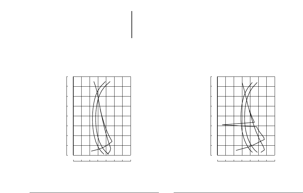
24-16
Load Capacity Curves
●IT14G
●IT24F
Logging and Forest Products
KEY
A — Hydraulic Lift Capacity Fork Racked
B — Static Tipping Load Full 40° Turn Fork Level
C — Hydraulic Lift Capacity Fork Level
D — Static Tipping Load Machine Straight, Fork Level
Curves and operating weight are based on machine
equipped with 17.5R25 tires, full fuel tank, 80 kg (176 lb)
operator, Balderson 9816C2 lumber and log fork with-
out top clamp. Fork weight is 803 kg (1770 lb). Total
operating weight 8020 kg (17,668 lb). Forks of other
dimensions or weight may affect machine capacity.
Consult your Caterpillar Dealer for additional fork data.
KEY
A — Hydraulic Lift Capacity Fork Racked
B — Static Tipping Load Full 40° Turn Fork Level
C — Hydraulic Lift Capacity Fork Level
D — Static Tipping Load Machine Straight, Fork Level
Curves and operating weight are based on machine
equipped with 17.5R25 tires, full fuel tank, 80 kg
(176 lb) operator, Balderson 9816C2 lumber and log
fork without top clamp. Fork weight is 803 kg (1770 lb).
Total operating weight 9963 kg (21,948 lb). Forks of
other dimensions or weight may affect machine capacity.
Consult your Caterpillar Dealer for additional fork data.
1361 2722 4083 5444 6805 8166
0
A
B
9527
C
4064
3556
3048
2540
2032
1524
1016
508
00 3000 6000 9000 12,000 15,000 18,000 21,000
0
20
40
60
80
100
120
140
160
D
Millimeters
Kilograms
Pounds
Inches
HINGE PIN HEIGHT
CAPACITY IN FULL TURN
IT14G with Balderson Lumber and Log Fork
1361 2722 4082 5443 6804 8165
0
A
B
9526
C
4064
3556
3048
2540
2032
1524
1016
508
00 3000 6000 9000 12,000 15,000 18,000 21,000
0
20
40
60
80
100
120
140
160
D
Millimeters
Kilograms
Pounds
Inches
HINGE PIN HEIGHT
CAPACITY IN FULL TURN
IT24F with Balderson Lumber and Log Fork
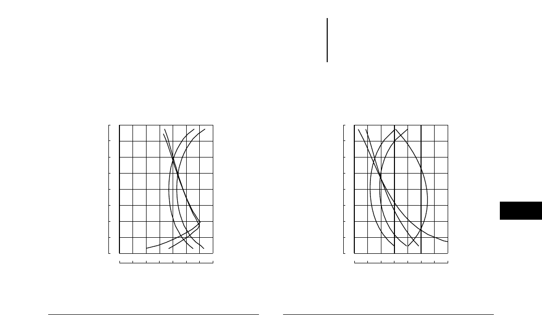
24-17
24
Logging and Forest ProductsLoad Capacity Curves
●IT28G
●IT38
KEY
A — Hydraulic Lift Capacity Fork Racked
B — Static Tipping Load Full 40° Turn Fork Level
C — Hydraulic Lift Capacity Fork Level
D — Static Tipping Load Machine Straight, Fork Level
Curves and operating weight are based on machine
equipped with 20.5-25 tires, 250 kg (550 lb) counter-
weight, full fuel tank, 80 kg (176 lb) operator, Balderson
lumber and log fork. Fork weight 1325 kg (2919 lb).
Total operating weight 11 908 kg (26,233 lb). Forks of
other dimensions or weight may affect machine capac-
ity. Consult your Caterpillar Dealer for additional fork data.
1361 2722 4082 5443 6804 8165
0
A
B
9526
C
4064
3556
3048
2540
2032
1524
1016
508
00 3000 6000 9000 12,000 15,000 18,000 21,000
0
20
40
60
80
100
120
140
160
D
Millimeters
Kilograms
Pounds
Inches
HINGE PIN HEIGHT
CAPACITY IN FULL TURN
IT28G with Balderson Lumber and Log Fork
KEY
A — Hydraulic Lift Capacity 40° Turn, Fork Racked
B — Articulated Tipping Capacity
C — Hydraulic Lift Capacity Fork Level
D — Static Tipping Load Machine Straight, Fork Level
E — Hydraulic Tilt Capacity Fork Level
Curves based on machine with full fuel tank, operator,
ROPS cab, 20.5-25, 16PR(L-2) tires, with 810 kg (1785 lb)
rear tire ballast, 760 kg (1675 lb) counterweight,
Balderson millyard fork 103-8617 with 9753C2 coupler
1345 mm (4'5") tines, 1815 kg (4000 lb) combined weight.
Total operating weight, 14 097 kg (31,080 lb). Forks of
other dimensions or weight may affect machine capacity.
Consult your Caterpillar Dealer for additional information.
5444 6805 8166 9527 10 888 12 249
4083
AC
13 610
BED
4064
3556
3048
2540
2032
1524
1016
508
09000 12,000 15,000 18,000 21,000 24,000 27,000 30,000
0
20
40
60
80
100
120
140
160
Millimeters
Kilograms
Pounds
Inches
HINGE PIN HEIGHT
CAPACITY IN FULL TURN
IT38 Logger with
Balderson Millyard Fork and Quick Coupler
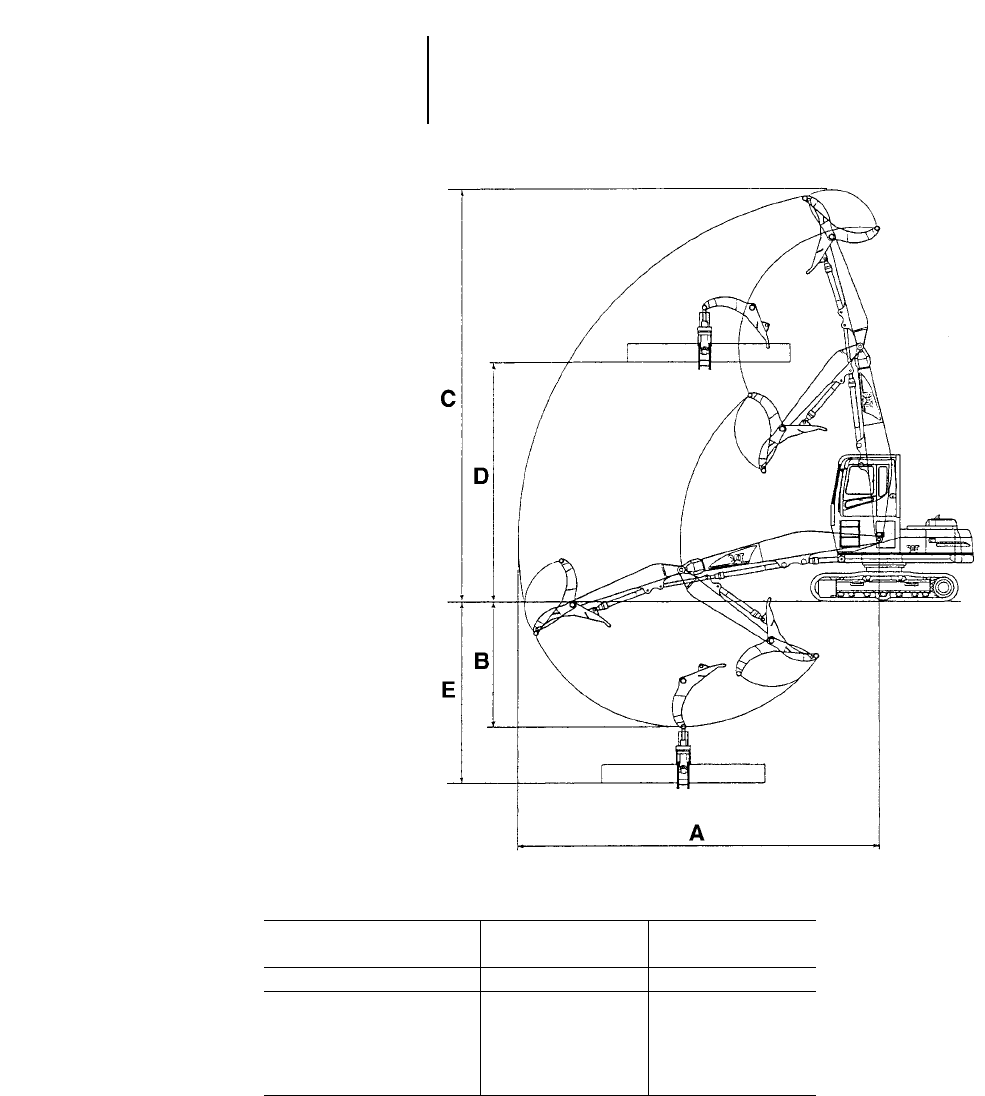
Working Envelope
320B FM 320B FM
w/high wide carbody w/reinforced carbody
mftmft
AMax. Reach 10.98 36'0" 10.98 36'0"
BMax. Depth 4 13'1" 4.17 13'8"
CMax. Height 12.63 41'5" 12.46 40'10"
DMax. Deck Height 7.37 24'2" 7.20 23'7"
EMax. Deck Depth 5.68 18'8" 5.85 19'2"
24-18
Logging and Forest Products Forestry Machines
●Introduction
●Range Dimensions
Introduction
Caterpillar foresty machines are specif-
ically designed for tough forest work.
Each model uses purpose built booms
and sticks designed by Caterpillar for
maximum performance and durability.
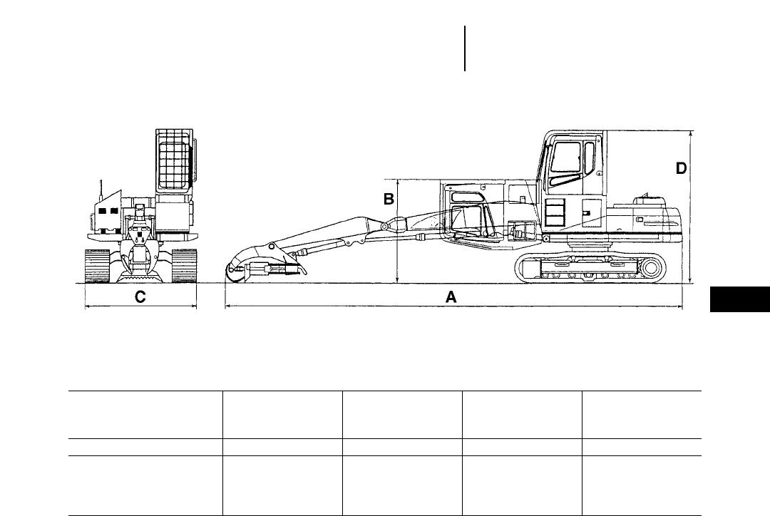
Shipping Dimensions
320B FM 320B FM 320B FM 320B FM
w/high wide carbody w/high wide carbody w/reinforced carbody w/reinforced carbody
1.22 m (4'0") cab riser 457 mm (18") cab riser 1.22 m (4'0") cab riser 457 mm (18") cab riser
mftmftmftmft
AOverall Length 13.62 44'8" 13.62 44'8" 13.62 44'8" 13.62 44'8"
BOverall Height 3.11 10'3" 3.66 12'0" 2.94 9'8" 3.49 11'5"
COverall Width 3.31 10'10" 3.31 10'10" 3.26 10'8" 3.26 10'8"
DCab Height 4.55 14'11" 3.79 12'5" 4.38 14'5" 3.62 11'11"
24-19
24
Logging and Forest ProductsForestry Machines
●Shipping Dimensions

Forest Machine 320B FM
kg lb
Booms*
Reach 2020 4450
Mass 2050 4520
LL Boom 2610 5750
Sticks** (for Reach)
Short 750 1650
• 650 1430
• 675 1490
Long 750 1650
Sticks (for Mass)
Short 750 1650
• 780 1720
Long — —
Sticks (for LL Boom)
LL Stick 905 2000
Upperstructure (complete w/o counterweight)
w/1.22 m (4'0") cab riser 7400 16,310
w/457 mm (18") cab riser 7180 15,830
Undercarriage (for high wide carbody)
— 600 mm (2'0") shoe 8850 19,510
— 700 mm (2'4") shoe 9175 20,230
— 800 mm (2'7") shoe 9165 20,210
Undercarriage (reinforced carbody)
— 600 mm (2'0") shoe 8390 18,500
— 700 mm (2'4") shoe 8710 19,200
— 800 mm (2'7") shoe 8700 19,180
Counterweight — Standard 3865 8520
— Heavy 5830 12,850
**Boom weights include boom, boom lines, boom cylinders and rod end pins, stick cylinder and head end pin.
**Stick weights include stick and stick lines.
24-20
Forestry Machines
●Major Component Weights
Logging and Forest Products

24-21
24
Logging and Forest Products
Height
50
45
40
35
30
25
20
15
10
5
–5
–10
–15
–20
320B Log Loader
●Lift and Range
LIFT AND RANGE DIAGRAM
320B Log Loader
CENTER
OF
ROTATION
GROUND LINE
■Undercarriage — long
■Logging Front — Caterpillar 320B LL HB-36,
10 970 mm (36'0") maximum reach
■Capacity, lbs., (thousands)
Top Number: Tipping over front
_________________
Middle Number: Tipping over side
_________________
Bottom Number: Hydraulic capacity
■All capacities are 100% stability and 100% hydraulic
with no deration for friction (100% efficiency)
■Grapple weight is not included
Calculations, weights and machine specifications are subject to change at any
time without notice.
STATIC TIPPING OVER FRONT
STATIC TIPPING OVER SIDE
HYDRAULIC CAPACITY
XXX
YYY
ZZZ
100% TIPPING & HYDRAULIC LOADS
LOADS IN KIPS AT HEEL/GRAPPLE PIN
GRAPPLE WEIGHT NOT INCLUDED
UNIT: THOUSAND POUNDS
–5 0 5 10 15 20 25 30 35 40 Feet
Radius
22.1
15.4
18.5
22.9
16.1
17.7
15.5
10.9
16.2
23.1
16.3
17.5
15.8
11.2
15.8
23.0
16.2
17.7
15.8
11.2
16.0
11.6
8.1
14.2
22.5
15.7
18.4
37.3
25.2
11.8
15.6
11.0
16.7
11.6
8.1
14.4
21.8
15.1
21.3
35.7
23.8 15.2
10.6
17.4
11.4
7.9
14.6
8.5
5.8
10.0
21.0
14.4
22.6
33.8
22.1
30.6
14.8
10.3
17.9
11.2
7.8
14.5
8.4
5.7
10.0
20.3
13.7
22.8
32.4
20.9
18.8
14.5
9.9
17.7
11.0
7.6
13.8
19.9
13.3
21.2
31.6
20.3
17.2
73.1
39.9
3.0
14.2
9.7
16.2
19.7
13.2
17.6
31.5
20.2
22.6
14.2
9.7
13.1
10.9
7.5
12.1
8.5
5.8
8.8
9.6
6.6
10.2
8.8
6.1
9.9
13.4
9.4
11.8
10.9
7.6
10.7
Front Tipping
Side Tipping
Limit
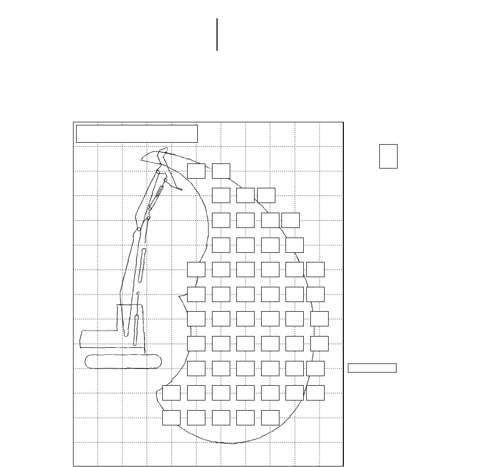
24-22
322B Log Loader — Heel Boom
●Lift and Range
Logging and Forest Products
Height
50
45
40
35
30
25
20
15
10
5
–5
–10
–15
–20
LIFT AND RANGE DIAGRAM
322B High Wide Forest Machine — Under/Under
CENTER
OF
ROTATION
GROUND LINE
■Undercarriage — long, extended gauge
■Logging Front — Caterpillar 322B LL Under-
Under Log Loader, 11 580 mm (38'0") maximum
reach
■Capacity, lbs., (thousands)
Top Number: Tipping over front
_________________
Middle Number: Tipping over side
_________________
Bottom Number: Hydraulic capacity
■All capacities are 100% stability and 100% hydraulic
with no deration for friction (100% efficiency)
■Grapple weight is not included
Calculations, weights and machine specifications are subject to change at any
time without notice.
STATIC TIPPING OVER FRONT
STATIC TIPPING OVER SIDE
MAXIMUM LIMIT
XXX
YYY
*
100% TIPPING & HYDRAULIC LOADS
LOADS IN KIPS AT HEEL/GRAPPLE PIN
GRAPPLE WEIGHT NOT INCLUDED
UNIT: THOUSAND POUNDS
–5 0 5 10 15 20 25 30 35 40 45 Feet
Radius
30.8*
30.8* 26.8*
26.8*
23.7*
23.7* 20.1*
18.4*
22.5*
22.5* 19.6*
19.1*16.9*
13.6*16.8*
13.4*
22.7*
22.7* 19.5*
19.0* 16.7*
14.1*14.9*
11.3*
23.7*
23.7*
20.8*
20.8* 19.9*
19.1*16.8*
14.0*14.0
10.6 13.4*
10.1*
25.3*
25.3*
30.8*
30.8* 20.5*
18.6*17.0*
13.8*14.0
10.6
26.7*
25.4*
34.6*
34.6* 21.0*
18.0*17.1*
13.5*13.8*
10.4*10.8*
9.0*
27.1*
24.1*
32.5*
32.5* 21.0*
17.3*16.8*
13.1*13.1*
10.3*
26.2*
23.2*
31.1*
31.1* 20.2*
16.8*15.8*
12.8*11.6*
10.2*
9.3*
8.9*
7.7*
7.7*
23.5*
22.8*
30.5*
30.5* 18.1*
16.6*13.6*
12.7*
18.5*
18.5*
23.1*
23.1*
14.1*
14.1*
18.8*
18.8* 14.2*
14.2* 9.7*
9.7*
8.5*
8.5* 5.6*
5.6*
12.1*
9.3*
19.8*
17.7*
Minimum of (Max Front Tipping, Max Limit*)
Minimum of (Max Side Tipping, Max Limit*)
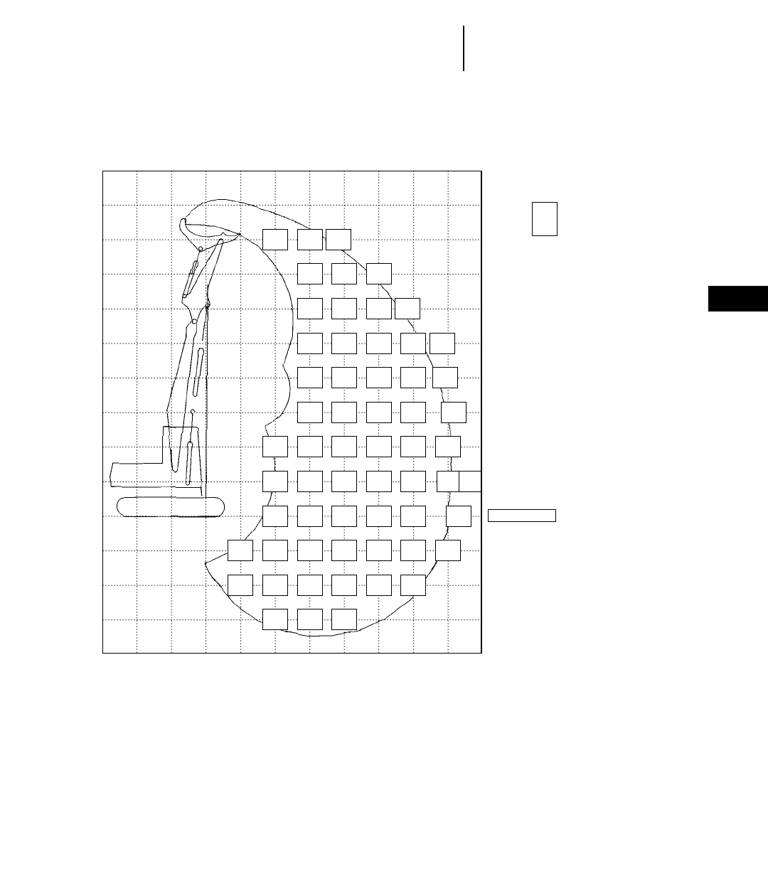
24-23
24
Logging and Forest Products322B Log Loader — Heel Boom
●Lift and Range
Height
50
45
40
35
30
25
20
15
10
5
–5
–10
–15
–20
LIFT AND RANGE DIAGRAM
322B High Wide Forest Machine — Over/Under
CENTER
OF
ROTATION
GROUND LINE
■Undercarriage — long, extended gauge
■Logging Front — Caterpillar 322B LL Over-
Under Log Loader, 12 500 mm (41'0") maximum
reach
■Capacity, lbs., (thousands)
Top Number: Tipping over front
_________________
Middle Number: Tipping over side
_________________
Bottom Number: Hydraulic capacity
■All capacities are 100% stability and 100% hydraulic
with no deration for friction (100% efficiency)
■Grapple weight is not included
Calculations, weights and machine specifications are subject to change at any
time without notice.
STATIC TIPPING OVER FRONT
STATIC TIPPING OVER SIDE
MAXIMUM LIMIT
XXX
YYY
*
100% TIPPING & HYDRAULIC LOADS
LOADS IN KIPS AT HEEL/GRAPPLE PIN
GRAPPLE WEIGHT NOT INCLUDED
UNIT: THOUSAND POUNDS
–5 0 5 10 15 20 25 30 35 40 45 Feet
Radius
30.0*
30.0* 24.9*
24.9* 21.9*
21.9*
23.7*
23.7* 20.3*
19.1*
22.6*
22.6* 19.7*
19.1* 16.7*
14.4*15.3*
12.1*
22.8*
22.8* 19.5*
19.0* 16.8*
14.5*14.3*
10.9*13.7
10.4
23.7*
23.7* 19.9*
19.1*16.9*
14.4*14.2*
10.9*12.4
9.3
23.3*
23.3* 20.5*
18.9*17.0*
14.0*14.2*
10.8*
25.2*
25.2*
32.4*
32.4* 21.0*
18.2*17.0*
13.6*14.0
10.6 10.1*
8.4*
26.5*
24.2*
35.6*
35.6* 20.9*
17.3*16.9*
13.2*13.6*
10.3*
26.3*
23.0*
35.6*
35.0*20.4*
16.7*16.2*
12.8*12.6*
10.2*
9.1*
8.3*8.8*
8.3*
7.3*
7.3*
24.3*
22.4*
32.1*
32.1* 18.8*
16.4*14.5*
12.6*
20.2*
20.2*
26.0*
26.0*
12.0*
12.0*
18.6*
18.6* 15.6*
15.6*
13.9*
13.9*
16.9*
16.9* 10.4*
10.4*
11.5*
11.5* 6.4*
6.4*
10.5*
10.1*5.5*
5.5*
11.3*
8.7*
17.4*
15.3*
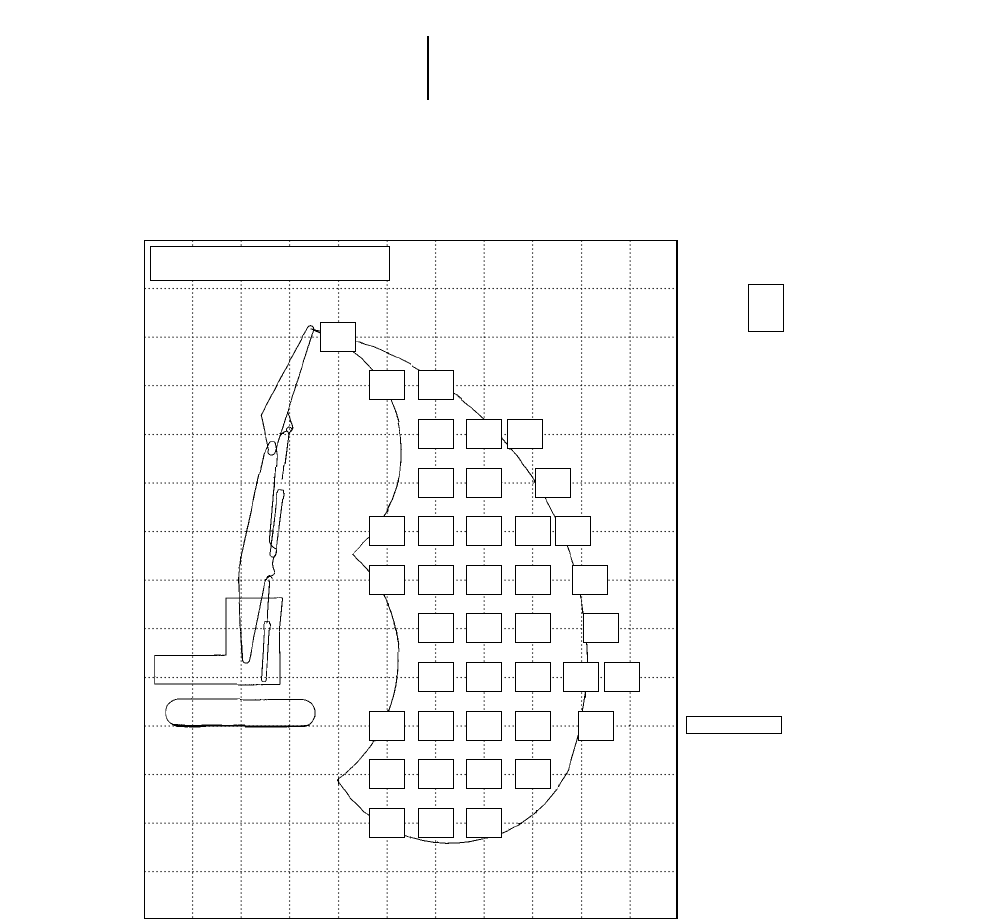
24-24
322B Log Loader — Butt-N-Top
●Lift and Range
Logging and Forest Products
Height
50
45
40
35
30
25
20
15
10
5
–5
–10
–15
–20
LIFT AND RANGE DIAGRAM
322B High Wide Forest Machine — B-N-T
CENTER
OF
ROTATION
GROUND LINE
■Undercarriage — long, extended gauge
■Logging Front — Caterpillar 322B LL Butt-N-
Top Log Loader, 10 970 mm (36'0") maximum
reach
■Capacity, lbs., (thousands)
Top Number: Tipping over front
_________________
Middle Number: Tipping over side
_________________
Bottom Number: Hydraulic capacity
■All capacities are 100% stability and 100% hydraulic
with no deration for friction (100% efficiency)
■Grapple weight is not included
Calculations, weights and machine specifications are subject to change at any
time without notice.
STATIC TIPPING OVER FRONT
STATIC TIPPING OVER SIDE
MAXIMUM LIMIT
XXX
YYY
*
100% TIPPING & HYDRAULIC LOADS
LOADS IN KIPS AT HEEL/GRAPPLE PIN
GRAPPLE WEIGHT NOT INCLUDED
UNIT: THOUSAND POUNDS
–5 0 5 10 15 20 25 30 35 40 45 Feet
Radius
48.2*
48.2*
30.5*
30.5* 26.0*
26.0*
24.3*
24.3* 21.3*
19.3*20.8*
17.6*
24.2*
24.2* 20.9*
19.6*18.1*
14.3*
25.1*
25.1*
30.9*
30.9* 21.1*
19.4*18.0*
14.5*16.1*
12.5*
26.4*
26.4*
34.1*
34.1* 21.6*
18.9*18.0*
14.3*14.5*
11.6*
27.6*
25.3*21.9*
18.3*17.8*
14.0*12.9*
11.1*
27.6*
24.2*21.5*
17.7*17.0*
13.7*11.5*
11.0*
25.7*
23.5*
23.4*
23.4* 20.0*
17.3*15.3*
13.5*
11.2*
11.0*
9.1*
9.1*
21.6*
21.6*
26.7*
26.7* 16.8*
16.8* 12.0*
12.0*
15.2*
15.2*
17.5*
17.5* 11.5*
11.5*
Minimum of (Max Front Tipping, Max Limit*)
Minimum of (Max Side Tipping, Max Limit*)
24-25
24
Logging and Forest Products325B Log Loader — Heel Boom
●Lift and Range
Height
50
45
40
35
30
25
20
15
10
5
–5
–10
–15
–20
LIFT AND RANGE DIAGRAM
325B High Wide Forest Machine — Under/Under
CENTER
OF
ROTATION
GROUND LINE
■Undercarriage — long, extended gauge
■Logging Front — Caterpillar 325B LL Under-
Under Log Loader, 12 190 mm (40'0") maximum
reach
■Capacity, lbs., (thousands)
Top Number: Tipping over front
_________________
Middle Number: Tipping over side
_________________
Bottom Number: Hydraulic capacity
■All capacities are 100% stability and 100% hydraulic
with no deration for friction (100% efficiency)
■Grapple weight is not included
Calculations, weights and machine specifications are subject to change at any
time without notice.
STATIC TIPPING OVER FRONT
STATIC TIPPING OVER SIDE
MAXIMUM LIMIT
XXX
YYY
*
100% TIPPING & HYDRAULIC LOADS
LOADS IN KIPS AT HEEL/GRAPPLE PIN
GRAPPLE WEIGHT NOT INCLUDED
UNIT: THOUSAND POUNDS
–5 0 5 10 15 20 25 30 35 40 45 Feet
Radius
73.6*
54.3*
36.6*
136.6*
90.7*
44.9*
43.2*
32.7*
29.5*
72.5*
53.4*
32.9*
44.9*
34.3*
27.7*
30.3*
23.3*
24.1*
23.8*
18.1*
20.2*
73.8*
54.5*
31.9*
45.4*
34.8*
27.5*
30.9*
23.8*
23.8*
22.4*
17.1*
20.6*
73.9*
54.5*
27.3*
45.3*
34.7*
27.7*
30.9*
23.8*
23.7*
22.6*
17.3*
20.5*
17.0*
12.8*
17.5*
74.7*
55.2*
31.6*
44.4*
33.9*
29.0*
30.4*
23.4*
24.2*
22.4*
17.1*
20.6*
17.1*
12.9*
17.5*
70.7*
51.7*
37.1*
43.0*
32.6*
31.0*
29.7*
22.6*
25.1*
22.0*
16.7*
20.8*
16.9*
12.8*
17.5*
13.8*
10.3*
13.9*
41.0*
30.8*
31.8*
28.7*
21.7*
25.8*
21.4*
16.2*
21.0*
16.7*
12.5*
17.3*
13.4*
9.9*
12.4*
39.1*
29.0*
33.1*
27.6*
20.8*
25.9*
20.9*
15.7*
20.8*
16.4*
12.3*
16.7*
13.3*
9.8*
10.8*
37.7*
27.7*
32.4*
59.0*
11.5*
26.5*
26.8*
20.0*
25.1*
20.4*
15.3*
19.8*
16.2*
12.1*
15.2*
37.0*
27.1*
29.2*
58.8*
41.3*
26.3*
138.0*
83.7*
10.0*
26.4*
19.6*
22.7*
20.2*
15.0*
17.5*
16.1*
12.0*
12.5*
37.1*
27.1*
23.9*
59.9*
42.2*
28.4*
140.6*
85.7*
16.8*
26.4*
19.6*
18.6*
20.3*
15.1*
13.7*
16.3*
12.1*
7.3*
14.3*
10.7*
6.7*
13.6*
10.1*
9.0*
16.3*
12.2*
16.2*
14.7*
11.0*
15.3*
18.9*
14.3*
17.6*
35.7*
27.0*
25.6*
Max Front Tipping
Max Side Tipping
Max Limit*
24-26
325B Log Loader — Heel Boom
●Lift and Range
Logging and Forest Products
Height
50
45
40
35
30
25
20
15
10
5
–5
–10
–15
–20
LIFT AND RANGE DIAGRAM
325B High Wide Forest Machine — Over/Under
CENTER
OF
ROTATION
GROUND LINE
■Undercarriage — long, extended gauge
■Logging Front — Caterpillar 325B LL Over-
Under Log Loader, 12 800 mm (42'0") maximum
reach
■Capacity, lbs., (thousands)
Top Number: Tipping over front
_________________
Middle Number: Tipping over side
_________________
Bottom Number: Hydraulic capacity
■All capacities are 100% stability and 100% hydraulic
with no deration for friction (100% efficiency)
■Grapple weight is not included
Calculations, weights and machine specifications are subject to change at any
time without notice.
STATIC TIPPING OVER FRONT
STATIC TIPPING OVER SIDE
MAXIMUM LIMIT
XXX
YYY
*
100% TIPPING & HYDRAULIC LOADS
LOADS IN KIPS AT HEEL/GRAPPLE PIN
GRAPPLE WEIGHT NOT INCLUDED
UNIT: THOUSAND POUNDS
–5 0 5 10 15 20 25 30 35 40 45 Feet
Radius
73.1*
54.3*
36.3*
44.6*
34.5*
28.7*
29.6*
22.8*
24.0*
72.0*
53.4*
32.6*
45.9*
35.6*
27.4*
31.1*
24.3*
22.8*
22.3*
17.2*
20.6*
73.5*
54.7*
31.1*
46.3*
36.0*
27.2*
31.5*
24.7*
23.6*
22.9*
17.9*
20.1*
46.1*
35.0*
26.5*
31.4*
24.6*
23.6*
23.0*
17.9*
20.4*
20.7*
15.9*
17.6*
17.0*
13.0*
15.6*
14.9*
11.3*
14.5*
13.6*
10.2*
13.9*
17.4*
13.4*
17.5*
45.3*
35.0*
26.0*
72.8*
54.1*
23.2*
30.9*
24.1*
24.2*
22.7*
17.7*
20.6*
17.4*
13.4*
17.5*
13.5*
10.2*
14.4*
12.0
9.0
13.0
12.4
9.3
11.8
43.7*
33.6*
28.0*
30.1*
23.3*
25.1*
22.2*
17.2*
20.8*
17.2*
13.2*
17.5*
13.4*
10.1*
14.1*
41.6*
31.6*
30.7*
28.9*
22.2*
25.9*
21.6*
16.6*
21.0*
16.8*
12.8*
17.5*
12.3
9.3
10.3
13.3*
10.0*
13.2*
39.3*
29.5*
32.6*
27.8*
21.1*
26.0*
21.0*
16.0*
21.0*
16.5*
12.5*
17.2*
12.0
9.0
8.0
13.2*
9.9*
11.4*
37.6*
27.9*
32.8*
57.8*
41.0*
25.4*
136.5*
83.6*
13.8*
26.8*
20.2*
25.4*
20.4*
15.5*
20.3*
16.2*
12.2*
16.2*
13.2
9.9
6.7
13.3*
10.0*
7.3*
36.7*
27.2*
30.4*
26.3*
19.8*
23.7*
20.1*
15.2*
18.6*
16.0*
12.1*
14.1*
58.3*
41.3*
28.7*
36.9*
27.3*
26.1*
26.3*
19.8*
20.4*
20.2*
15.3*
15.5*
16.2*
12.2*
10.5*
56.4*
42.3*
30.1*
28.4*
21.9*
21.3*
Max Front Tipping
Max Side Tipping
Max Limit*

24-27
24
Logging and Forest Products325B Log Loader — Butt-N-Top
●Lift and Range
Height
50
45
40
35
30
25
20
15
10
5
–5
–10
–15
–20
LIFT AND RANGE DIAGRAM
325B High Wide Forest Machine — B-N-T
CENTER
OF
ROTATION
GROUND LINE
■Undercarriage — long, extended gauge
■Logging Front — Caterpillar 325B LL Butt-N-
Top Log Loader, 11 280 mm (37'0") maximum
reach
■Capacity, lbs., (thousands)
Top Number: Tipping over front
_________________
Middle Number: Tipping over side
_________________
Bottom Number: Hydraulic capacity
■All capacities are 100% stability and 100% hydraulic
with no deration for friction (100% efficiency)
■Grapple weight is not included
Calculations, weights and machine specifications are subject to change at any
time without notice.
STATIC TIPPING OVER FRONT
STATIC TIPPING OVER SIDE
MAXIMUM LIMIT
XXX
YYY
*
100% TIPPING & HYDRAULIC LOADS
LOADS IN KIPS AT HEEL/GRAPPLE PIN
GRAPPLE WEIGHT NOT INCLUDED
UNIT: THOUSAND POUNDS
–5 0 5 10 15 20 25 30 35 40 45 Feet
Radius
176.6*
113.5*
52.2*
71.7*
52.9*
40.6*
74.5*
55.3*
35.6*
45.0*
34.5*
31.3*
33.4*
25.8*
28.6*
75.2*
55.9*
35.2*
45.6*
35.1*
29.7*
31.7*
24.7*
26.1*
25.0*
19.4*
24.1*
74.9*
55.6*
35.4*
45.5*
35.0*
29.7*
31.8*
24.7*
25.8*
23.8*
18.5*
22.8*
21.1*
16.4*
21.3*
73.4*
54.3*
37.9*
44.7*
34.3*
30.9*
31.4*
24.4*
26.3*
23.7*
18.5*
22.7*
18.9*
14.7*
19.3*
43.5*
33.2*
32.9*
30.8*
23.9*
27.1*
23.5*
18.2*
22.9*
18.6*
14.4*
18.9*
17.7*
13.7*
17.5*
42.0*
31.8*
34.8*
30.1*
23.2*
27.8*
23.1*
17.9*
22.9*
18.5*
14.3*
18.5*
17.1*
13.3*
15.7*
40.7*
30.6*
35.3*
29.4*
22.5*
27.7*
22.7*
17.5*
22.3*
18.3*
14.2*
17.3*
17.0*
13.2*
13.9*
39.8*
29.8*
33.4*
28.9*
22.0*
26.2*
22.4*
17.3*
20.6*
18.3*
14.1*
14.8*
17.5*
13.5*
11.7*
62.6*
44.0*
24.1*
39.5*
29.5*
28.8*
28.6*
21.8*
22.8*
22.4*
17.2*
17.3*
18.5*
14.3*
8.8*
63.0*
45.2*
25.6*
39.6*
29.6*
22.0*
28.7*
21.9*
17.3*
22.5*
17.3*
11.7*
64.9
48.1
Max Front Tipping
Max Side Tipping
Max Limit*
24-28
325B Log Loader
●Lift and Range
Logging and Forest Products
Height
35
30
25
20
15
10
5
–5
–10
–15
LIFT AND RANGE DIAGRAM
325B High Wide Forest Machine
with Hoist Cylinder Adapter
CENTER
OF
ROTATION
GROUND LINE
■Undercarriage — long, extended gauge
■Excavator Front — Caterpillar 325B LL with hoist
cylinder adapter, heavy counterweight, R-Boom,
R-Stick, 9450 mm (31'0") maximum reach
■Capacity, lbs., (thousands)
Top Number: Tipping over front
_________________
Middle Number: Tipping over side
_________________
Bottom Number: Hydraulic capacity
■All capacities are 100% stability and 100% hydraulic
with no deration for friction (100% efficiency)
■Grapple weight is not included
Calculations, weights and machine specifications are subject to change at any
time without notice.
STATIC TIPPING OVER FRONT
STATIC TIPPING OVER SIDE
MAXIMUM LIMIT
XXX
YYY
*
100% TIPPING & HYDRAULIC LOADS
LOADS IN KIPS AT HEEL/GRAPPLE PIN
GRAPPLE WEIGHT NOT INCLUDED
UNIT: THOUSAND POUNDS
–5 0 5 10 15 20 25 30 35 40 45 Feet
Radius
47.0*
36.1*
13.9*
44.0*
34.0*
18.1*
32.6*
25.4*
12.2*
43.6*
33.6*
19.8*
30.6*
23.9*
17.1*
26.9*
21.0*
11.7*
164.0*
104.9*
39.5*
68.9*
50.8*
27.3*
42.6*
32.7*
21.8*
30.2*
23.5*
18.7*
24.0*
18.8*
11.6*
66.0*
48.3*
32.2*
41.4*
31.6*
24.0*
29.6*
23.0*
19.7*
22.7*
17.7*
12.1*
22.6*
17.7*
11.9*
63.7*
46.3*
35.0*
40.3*
30.5*
25.6*
29.0*
22.4*
20.3*
22.4*
17.5*
13.6*
22.3*
17.4*
12.7*
62.5*
45.3*
34.6*
39.5*
29.9*
25.7*
28.6*
22.0*
20.1*
22.9*
17.8*
14.1*
147.4*
92.3*
25.8*
62.3*
45.0*
31.4*
39.2*
29.6*
24.0*
28.4*
21.9*
18.5*
24.8*
19.2*
15.4*
62.5*
45.3*
26.1*
39.3*
29.7*
20.1*
Max Front Tipping
Max Side Tipping
Max Limit*
24-29
24
Logging and Forest Products325B Log Loader
●Lift and Range
Height
35
30
25
20
15
10
5
–5
–10
–15
–20
LIFT AND RANGE DIAGRAM
325B High Wide Forest Machine
without Hoist Cylinder Adapter
CENTER
OF
ROTATION
GROUND LINE
STATIC TIPPING OVER FRONT
STATIC TIPPING OVER SIDE
MAXIMUM LIMIT
XXX
YYY
*
100% TIPPING & HYDRAULIC LOADS
LOADS IN KIPS AT HEEL/GRAPPLE PIN
GRAPPLE WEIGHT NOT INCLUDED
UNIT: THOUSAND POUNDS
–5 0 5 10 15 20 25 30 35 40 45 Feet
Radius
27.9*
21.4*
12.3*
26.2*
20.1*
15.1*
22.9*
17.6*
11.7*
36.6*
27.6*
17.6*
25.8*
19.7*
15.9*
20.4*
15.6*
11.7*
56.5*
40.6*
27.1*
35.3*
26.5*
20.4*
25.2*
19.1*
17.2*
19.2*
14.6*
12.2*
19.2*
14.6*
12.1*
54.2*
38.6*
32.0*
34.2*
25.4*
23.1*
24.6*
18.6*
18.7*
18.9*
14.4*
13.6*
18.8*
14.3*
12.6*
53.1*
37.6*
34.0*
33.5*
24.8*
24.7*
24.2*
18.2*
19.6*
19.3*
14.7*
14.1*
125.4*
77.0*
25.9*
52.8*
37.4*
33.6*
33.2*
24.5*
24.9*
24.0*
18.1*
19.5*
20.9*
15.8*
16.5*
126.4*
77.7*
41.7*
53.1*
37.6*
31.4*
33.3*
24.6*
23.6*
24.4*
18.4*
17.6*
Max Front Tipping
Max Side Tipping
Max Limit*
■Undercarriage — long, extended gauge
■Excavator Front — Caterpillar 325B LL without
hoist cylinder adapter, R-Boom, R-Stick, 9300 mm
(30'6") maximum reach
■Capacity, lbs., (thousands)
Top Number: Tipping over front
_________________
Middle Number: Tipping over side
_________________
Bottom Number: Hydraulic capacity
■All capacities are 100% stability and 100% hydraulic
with no deration for friction (100% efficiency)
■Grapple weight is not included
Calculations, weights and machine specifications are subject to change at any
time without notice.
24-30
325B Log Loader
●Lift and Range
Logging and Forest Products
■Undercarriage — long, extended gauge
■Excavator Front — Caterpillar 325B LL with hoist
cylinder adapter, heavy counterweight, M-Boom,
R-Stick, 8530 mm (28'0") maximum reach
■Capacity, lbs., (thousands)
Top Number: Tipping over front
_________________
Middle Number: Tipping over side
_________________
Bottom Number: Hydraulic capacity
■All capacities are 100% stability and 100% hydraulic
with no deration for friction (100% efficiency)
■Grapple weight is not included
Calculations, weights and machine specifications are subject to change at any
time without notice.
Height
35
30
25
20
15
10
5
–5
–10
–15
LIFT AND RANGE DIAGRAM
325B High Wide Forest Machine
with Hoist Cylinder Adapter
CENTER
OF
ROTATION
GROUND LINE
STATIC TIPPING OVER FRONT
STATIC TIPPING OVER SIDE
MAXIMUM LIMIT
XXX
YYY
*
100% TIPPING & HYDRAULIC LOADS
LOADS IN KIPS AT HEEL/GRAPPLE PIN
GRAPPLE WEIGHT NOT INCLUDED
UNIT: THOUSAND POUNDS
–5 0 5 10 15 20 25 30 35 40 45 Feet
Radius
44.0*
33.9*
15.6*
39.3*
30.5*
12.3*
71.8*
53.4*
16.1*
66.3*
49.6*
14.6*
43.8*
33.8*
18.9*
30.9*
24.1*
11.5*
70.0*
51.8*
24.3*
43.1*
33.1*
22.5*
30.4*
23.7*
17.4*
27.1*
21.2*
11.4*
157.8*
100.2*
50.1*
67.4*
49.5*
32.1*
42.0*
32.1*
24.6*
29.9*
23.3*
20.3*
25.3*
19.8*
11.7*
65.0*
47.5*
35.4*
40.9*
31.1*
26.1*
29.4*
22.8*
20.7*
24.9*
19.4*
12.6*
149.1*
93.5*
23.8*
63.7*
46.3*
35.4*
40.2*
30.5*
26.1*
29.1*
22.4*
20.1*
25.8*
20.0*
14.1*
149.2*
93.6*
36.5*
63.2*
45.9*
32.0*
39.8*
30.2*
23.9*
29.0*
22.4*
17.4*
28.3*
21.9*
16.7*
Max Front Tipping
Max Side Tipping
Max Limit*
24-31
24
Logging and Forest Products325B Log Loader
●Lift and Range
■Undercarriage — long, standard gauge
■Excavator Front — Caterpillar 325B LL without
hoist cylinder adapter, M-Boom, R-Stick, 8530 mm
(28'0") maximum reach
■Capacity, lbs., (thousands)
Top Number: Tipping over front
_________________
Middle Number: Tipping over side
_________________
Bottom Number: Hydraulic capacity
■All capacities are 100% stability and 100% hydraulic
with no deration for friction (100% efficiency)
■Grapple weight is not included
Calculations, weights and machine specifications are subject to change at any
time without notice.
Height
35
30
25
20
15
10
5
–5
–10
–15
LIFT AND RANGE DIAGRAM
325B Standard Gauge Forest Machine
without Hoist Cylinder Adapter
CENTER
OF
ROTATION
GROUND LINE
STATIC TIPPING OVER FRONT
STATIC TIPPING OVER SIDE
MAXIMUM LIMIT
XXX
YYY
*
100% TIPPING & HYDRAULIC LOADS
LOADS IN KIPS AT HEEL/GRAPPLE PIN
GRAPPLE WEIGHT NOT INCLUDED
UNIT: THOUSAND POUNDS
–5 0 5 10 15 20 25 30 35 40 45 Feet
Radius
38.0*
28.8*
15.7*
33.8*
25.8*
12.3*
37.8*
28.7*
16.8*
26.5*
20.3*
11.5*
37.0*
28.0*
18.4*
26.0*
19.9*
17.0*
23.1*
17.7*
11.4*
135.8*
84.8*
41.9*
57.9*
41.9*
26.6*
36.0*
27.0*
20.9*
25.5*
19.4*
18.1*
21.5*
16.4*
11.8*
128.8*
79.5*
18.2*
55.6*
39.8*
31.9*
34.9*
26.1*
23.6*
25.0*
19.0*
19.4*
21.1*
16.1*
12.5*
127.1*
78.2*
24.0*
54.2*
38.6*
34.5*
34.2*
25.4*
25.2*
24.6*
18.6*
20.1*
21.8*
16.6*
14.1*
127.2*
78.3*
36.7*
53.8*
38.2*
34.1*
33.8*
25.1*
25.2*
24.5*
18.5*
19.3*
24.0*
18.1*
16.9*
128.3*
79.1*
44.6*
54.0*
38.4*
31.3*
34.0*
25.2*
22.9*
29.0*
21.8*
19.3*
Max Front Tipping
Max Side Tipping
Max Limit*
24-32
330B Log Loader — Heel Boom
●Lift and Range
Logging and Forest Products
Height
55
50
45
40
35
30
25
20
15
10
5
–5
–10
–15
–20
LIFT AND RANGE DIAGRAM
330B High Wide Forest Machine — Under/Under
CENTER
OF
ROTATION
GROUND LINE
■Undercarriage — long, extended gauge
■Logging Front — Caterpillar 330B LL Under-
Under Log Loader, 13 100 mm (43'0") maximum
reach
■Capacity, lbs., (thousands)
Top Number: Tipping over front
_________________
Middle Number: Tipping over side
_________________
Bottom Number: Hydraulic capacity
■All capacities are 100% stability and 100% hydraulic
with no deration for friction (100% efficiency)
■Grapple weight is not included
Calculations, weights and machine specifications are subject to change at any
time without notice.
STATIC TIPPING OVER FRONT
STATIC TIPPING OVER SIDE
MAXIMUM LIMIT
XXX
YYY
*
100% TIPPING & HYDRAULIC LOADS
LOADS IN KIPS AT HEEL/GRAPPLE PIN
GRAPPLE WEIGHT NOT INCLUDED
UNIT: THOUSAND POUNDS
–5 0 5 10 15 20 25 30 35 40 45 50 Feet
Radius
40.1*
29.0*
29.4*
41.1*
29.8*
30.7*
30.0*
21.7*
26.7*
24.8*
17.8*
16.7*
41.3*
30.1*
30.0*
30.4*
22.1*
26.9*
23.1*
16.6*
22.4*
21.0*
14.9*
15.1*
58.6*
41.8*
26.5*
41.1*
29.9*
30.5*
30.3*
22.0*
26.9*
23.3*
16.8*
23.7*
18.7*
13.2*
14.1*
59.0*
42.1*
31.2*
40.5*
29.3*
31.7*
30.0*
21.7*
27.4*
23.2*
16.6*
23.8*
18.3*
12.9*
20.3*
17.3*
12.1*
13.6*
94.8*
63.7*
28.4*
57.2*
40.5*
36.8*
39.5*
28.4*
33.3*
29.4*
21.2*
28.1*
22.9*
16.4*
24.0*
18.3*
12.9*
20.3*
16.4*
11.5*
13.3*
54.9*
38.4*
42.2*
38.3*
27.3*
34.8*
28.7*
20.5*
28.7*
22.5*
16.0*
24.1*
18.1*
12.7*
19.9*
16.0*
11.1*
13.3*
52.5*
36.3*
44.5*
37.0*
26.1*
35.4*
28.0*
19.8*
28.7*
22.1*
15.6*
23.8*
17.9*
12.5*
19.0*
16.0*
11.1*
13.6*
80.7*
51.8*
22.9*
80.1*
51.4*
22.3*
49.7*
33.8*
41.5*
35.3*
24.5*
32.5*
27.0*
18.9*
25.8*
21.5*
15.1*
20.0*
17.8*
12.4*
12.9*
50.7*
34.7*
44.6*
36.0*
25.1*
34.8*
27.4*
19.3*
27.9*
21.7*
15.3*
22.5*
17.8*
12.4*
16.9*
16.3*
11.3*
11.8*
200.0*
104.0*
8.2*
203.2*
106.2*
13.6*
81.0*
52.1*
23.5*
49.5*
33.6*
35.3*
35.1*
24.4*
27.9*
26.9*
18.8*
21.7*
21.5*
15.1*
15.6*
52.4*
37.0*
25.4*
32.2*
23.1*
19.7
59.0*
42.1*
33.4*
Max Front Tipping
Max Side Tipping
Max Limit*
24-33
24
Logging and Forest Products330B Log Loader — Heel Boom
●Lift and Range
Height
55
50
45
40
35
30
25
20
15
10
5
–5
–10
–15
–20
LIFT AND RANGE DIAGRAM
330B High Wide Forest Machine — Over/Under
CENTER
OF
ROTATION
GROUND LINE
■Undercarriage — long, extended gauge
■Logging Front — Caterpillar 330B LL Over-
Under Log Loader, 13 700 mm (45'0") maximum
reach
■Capacity, lbs., (thousands)
Top Number: Tipping over front
_________________
Middle Number: Tipping over side
_________________
Bottom Number: Hydraulic capacity
■All capacities are 100% stability and 100% hydraulic
with no deration for friction (100% efficiency)
■Grapple weight is not included
Calculations, weights and machine specifications are subject to change at any
time without notice.
STATIC TIPPING OVER FRONT
STATIC TIPPING OVER SIDE
MAXIMUM LIMIT
XXX
YYY
*
100% TIPPING & HYDRAULIC LOADS
LOADS IN KIPS AT HEEL/GRAPPLE PIN
GRAPPLE WEIGHT NOT INCLUDED
UNIT: THOUSAND POUNDS
–5 0 5 10 15 20 25 30 35 40 45 50 Feet
Radius
90.0*
59.7*
51.2*
107.7*
70.9*
34.2*
59.1*
42.2*
34.2*
40.4*
28.9*
20.9*
58.2*
41.4*
37.5*
41.5*
30.3*
31.8*
30.0*
21.7*
21.9*
28.0*
20.2*
17.2*
58.1*
41.3*
33.8*
42.3*
30.9*
30.9*
31.0*
22.7*
27.1*
23.3*
16.8*
18.1*
22.5*
16.1*
15.0*
42.4*
31.1*
30.3*
31.2*
22.9*
27.1*
23.9*
17.3*
23.8*
19.4*
13.8*
13.6*
58.8*
41.9*
23.0*
42.2*
30.8*
30.4*
31.1*
22.8*
27.1*
24.0*
17.4*
23.8*
18.9*
13.5*
19.6*
17.5*
12.4*
12.8*
41.5*
30.2*
29.1*
30.7*
22.4*
27.6*
23.8*
17.2*
23.9*
18.9*
13.5*
20.7*
16.3*
11.5*
12.4*
58.6*
41.8*
25.3*
40.4*
29.2*
30.9*
30.1*
21.8*
28.3*
23.4*
16.9*
24.1*
18.7*
13.3*
20.7*
15.6*
10.9*
12.2*
55.7*
39.2*
34.7*
39.0*
28.0*
34.0*
29.3*
21.0*
28.9*
22.9*
16.4*
24.2*
18.5*
13.1*
20.5*
15.2*
10.6*
12.2*
52.9*
36.7*
43.5*
37.6*
26.7*
35.5*
28.4*
20.3*
28.9*
22.4*
15.9*
24.1*
18.2*
12.8*
19.9*
15.1*
10.5*
12.4*
51.1*
35.0*
44.8*
36.4*
25.5*
35.2*
27.7*
19.6*
28.5*
22.0*
15.5*
23.3*
18.0*
12.6*
18.5*
15.4*
10.7*
11.5*
79.5*
50.9*
20.9*
50.0*
34.1*
42.9*
35.6*
24.8*
33.5*
27.2*
19.1*
26.9*
21.7*
15.3*
21.4*
17.9*
12.5*
15.9*
16.1*
11.2*
9.2*
200.2*
104.1*
11.0*
80.2*
51.5*
23.6*
49.8*
33.9*
37.9*
35.4*
24.6*
29.9*
27.1*
19.0*
23.6*
21.7*
15.2*
17.9*
17.9*
12.5*
10.8*
80.5*
51.7*
28.9*
49.7*
33.8*
30.2*
35.4*
24.6*
23.9*
27.0*
18.9*
18.2*
21.6*
15.1*
11.9*
Max Front Tipping
Max Side Tipping
Max Limit*
24-34
330B Log Loader — Butt-N-Top
●Lift and Range
Logging and Forest Products
Height
50
45
40
35
30
25
20
15
10
5
–5
–10
–15
–20
LIFT AND RANGE DIAGRAM
330B High Wide Forest Machine — B-N-T
CENTER
OF
ROTATION
GROUND LINE
■Undercarriage — long, extended gauge
■Logging Front — Caterpillar 330B LL Butt-N-
Top Log Loader, 12 190 mm (40'0") maximum
reach
■Capacity, lbs., (thousands)
Top Number: Tipping over front
_________________
Middle Number: Tipping over side
_________________
Bottom Number: Hydraulic capacity
■All capacities are 100% stability and 100% hydraulic
with no deration for friction (100% efficiency)
■Grapple weight is not included
Calculations, weights and machine specifications are subject to change at any
time without notice.
STATIC TIPPING OVER FRONT
STATIC TIPPING OVER SIDE
MAXIMUM LIMIT
XXX
YYY
*
100% TIPPING & HYDRAULIC LOADS
LOADS IN KIPS AT HEEL/GRAPPLE PIN
GRAPPLE WEIGHT NOT INCLUDED
UNIT: THOUSAND POUNDS
–5 0 5 10 15 20 25 30 35 40 45 50 Feet
Radius
58.7*
42.0*
35.6*
45.4*
32.7*
28.2*
60.0
43.2 41.4
30.3 32.0*
23.4*
23.0*
60.3*
43.5*
36.1*
41.8*
30.6*
32.5*
31.1*
22.8*
29.3*
26.2*
19.2*
20.5*
59.9*
43.1*
35.5*
41.6*
30.5*
32.7*
31.1*
22.9*
29.1*
24.2*
17.7*
24.9*
23.0*
16.8*
19.0*
58.7*
42.1*
36.7*
41.0*
29.9*
33.7*
30.8*
22.6*
29.4*
24.2*
17.8*
25.7*
21.1*
15.4*
18.2*
57.0*
40.5*
42.5*
40.0*
29.0*
35.2*
30.3*
22.2*
30.0*
24.0*
17.6*
25.7*
20.0*
14.5*
17.9*
54.8*
38.6*
45.5*
38.9*
28.0*
36.5*
29.7*
21.6*
30.3*
23.7*
17.3*
25.4*
19.5*
14.1*
17.9*
52.8*
36.8*
46.6*
37.8*
27.0*
36.8*
29.1*
21.0*
30.0*
23.4*
16.9*
24.5*
19.4*
14.1*
16.8*
51.4*
35.5*
44.9*
37.0*
26.2*
35.4*
28.6*
20.6*
28.4*
23.2*
16.7*
22.4*
19.9*
14.4*
14.3*
81.6*
52.9*
18.8*
50.7*
34.9*
39.9*
36.5*
25.8*
31.8*
28.3*
20.3*
25.1*
23.1*
16.6*
18.5*
81.7*
53.0*
26.4*
50.5*
34.7*
31.8*
36.4*
25.7*
25.6*
28.3*
20.3*
19.6*
Max Front Tipping
Max Side Tipping
Max Limit*
24-35
24
Logging and Forest Products330B Log Loader
●Lift and Range
Height
40
35
30
25
20
15
10
5
–5
–10
–15
–20
LIFT AND RANGE DIAGRAM
330B High Wide Forest Machine
with Hoist Cylinder Adapter
CENTER
OF
ROTATION
GROUND LINE
–5 0 5 10 15 20 25 30 35 40 45 Feet
Radius
65.5*
46.7*
15.6*
41.0*
30.1*
21.3*
33.4*
24.6*
12.6*
42.0*
30.8*
13.4*
59.0*
42.5*
24.1*
58.0*
41.7*
26.2*
40.6*
29.7*
23.4*
30.5*
22.4*
16.3*
29.1*
21.4*
12.2*
236.1*
129.9*
52.1*
92.9*
62.7*
36.4*
56.5*
40.3*
29.1*
39.8*
29.0*
24.8*
30.2*
22.2*
22.0*
26.8*
19.7*
12.3*
88.5*
59.1*
43.1*
54.6*
38.6*
32.3*
38.9*
28.1*
26.4*
29.7*
21.7*
22.6*
25.6*
18.8*
12.7*
85.1*
56.2*
47.3*
53.0*
37.2*
34.6*
38.0*
27.3*
27.6*
29.3*
21.3*
22.9*
25.4*
18.5*
13.5*
83.3*
54.7*
47.5*
51.9*
36.2*
35.2*
37.3*
26.7*
27.7*
28.9*
20.9*
22.5*
26.1*
19.0*
14.8*
208.2*
110.9*
34.2*
82.7*
54.2*
44.2*
51.3*
35.7*
33.7*
37.0*
26.4*
26.4*
28.8*
20.8*
20.4*
209.5*
111.8*
48.5*
82.9*
54.4*
37.9*
51.3*
35.6*
29.5*
37.0*
26.4*
22.7*
83.8*
55.1*
27.8*
51.8*
36.1*
21.7*
Max Front Tipping
Max Side Tipping
Max Limit*
■Undercarriage — long, extended gauge
■Excavator Front — Caterpillar 330B LL with hoist
cylinder adapter, R-Boom, R-Stick, 10 100 mm
(33'0") maximum reach
■Capacity, lbs., (thousands)
Top Number: Tipping over front
_________________
Middle Number: Tipping over side
_________________
Bottom Number: Hydraulic capacity
■All capacities are 100% stability and 100% hydraulic
with no deration for friction (100% efficiency)
■Grapple weight is not included
Calculations, weights and machine specifications are subject to change at any
time without notice.
STATIC TIPPING OVER FRONT
STATIC TIPPING OVER SIDE
MAXIMUM LIMIT
XXX
YYY
*
100% TIPPING & HYDRAULIC LOADS
LOADS IN KIPS AT HEEL/GRAPPLE PIN
GRAPPLE WEIGHT NOT INCLUDED
UNIT: THOUSAND POUNDS
24-36
330B Log Loader
●Lift and Range
Logging and Forest Products
■Undercarriage — long, extended gauge
■Excavator Front — Caterpillar 330B LL without
hoist cylinder adapter, 10 100 mm (33'0") maxi-
mum reach
■Capacity, lbs., (thousands)
Top Number: Tipping over front
_________________
Middle Number: Tipping over side
_________________
Bottom Number: Hydraulic capacity
■All capacities are 100% stability and 100% hydraulic
with no deration for friction (100% efficiency)
■Grapple weight is not included
Calculations, weights and machine specifications are subject to change at any
time without notice.
STATIC TIPPING OVER FRONT
STATIC TIPPING OVER SIDE
MAXIMUM LIMIT
XXX
YYY
*
100% TIPPING & HYDRAULIC LOADS
LOADS IN KIPS AT HEEL/GRAPPLE PIN
GRAPPLE WEIGHT NOT INCLUDED
UNIT: THOUSAND POUNDS
Height
35
30
25
20
15
10
5
–5
–10
–15
–20
LIFT AND RANGE DIAGRAM
330B High Wide Forest Machine
without Hoist Cylinder Adapter
CENTER
OF
ROTATION
GROUND LINE
–5 0 5 10 15 20 25 30 35 40 45 Feet
Radius
35.8*
25.7*
18.8*
26.7*
19.2*
16.3*
25.5*
18.3*
12.2*
49.9*
34.9*
23.1*
35.0*
25.0*
20.6*
26.4*
19.0*
19.2*
23.3*
16.7*
12.3*
78.0*
51.1*
36.2*
48.0*
33.3*
27.2*
34.1*
24.1*
22.8*
25.9*
18.5*
20.3*
22.3*
15.9*
12.7*
74.5*
48.2*
42.9*
46.4*
31.8*
31.0*
33.2*
23.3*
25.0*
25.5*
18.1*
21.4*
22.1*
15.7*
13.5*
72.7*
46.7*
46.1*
45.2*
30.8*
33.5*
32.5*
22.7*
26.5*
25.1*
17.7*
22.2*
22.6*
16.0*
14.8*
23.7*
181.9*
94.7*
34.2*
72.1*
46.2*
46.2*
44.7*
30.3*
34.2*
32.1*
22.4*
27.0*
25.0*
17.6*
21.9*
35.4*
183.3*
95.6*
48.5*
72.3*
46.3*
43.7*
44.7*
30.3*
33.0*
32.2*
22.4*
25.7*
185.8*
97.3*
52.5*
73.2*
47.1*
38.1*
45.2*
30.8*
28.8*
36.2*
26.1*
18.1*
29.4*
21.2*
12.6*
37.1*
26.7*
13.4*
Max Front Tipping
Max Side Tipping
Max Limit*
24-37
24
Logging and Forest Products330B Log Loader
●Lift and Range
■Undercarriage — long, extended gauge
■Excavator Front — Caterpillar 330B LL with hoist
cylinder adapter, heavy counterweight, M-Boom,
M-Stick, 8530 mm (28'0") maximum reach
■Capacity, lbs., (thousands)
Top Number: Tipping over front
_________________
Middle Number: Tipping over side
_________________
Bottom Number: Hydraulic capacity
■All capacities are 100% stability and 100% hydraulic
with no deration for friction (100% efficiency)
■Grapple weight is not included
Calculations, weights and machine specifications are subject to change at any
time without notice.
STATIC TIPPING OVER FRONT
STATIC TIPPING OVER SIDE
MAXIMUM LIMIT
XXX
YYY
*
100% TIPPING & HYDRAULIC LOADS
LOADS IN KIPS AT HEEL/GRAPPLE PIN
GRAPPLE WEIGHT NOT INCLUDED
UNIT: THOUSAND POUNDS
Height
35
30
25
20
15
10
5
–5
–10
–15
–20
LIFT AND RANGE DIAGRAM
330B High Wide Forest Machine
with Hoist Cylinder Adapter
CENTER
OF
ROTATION
GROUND LINE
–5 0 5 10 15 20 25 30 35 40 45 Feet
Radius
96.0*
65.5*
34.1*
77.5*
54.2*
26.8*
96.0*
65.5*
34.3*
57.6*
41.4*
30.2*
49.1*
35.5*
23.8*
94.0*
63.8*
37.3*
57.0*
40.8*
31.0*
39.9*
29.1*
24.9*
39.4*
28.7*
22.9*
90.5*
60.9*
42.8*
55.7*
39.6*
33.1*
39.5*
28.7*
27.8*
34.9*
25.5*
23.0*
86.9*
57.8*
47.8*
54.2*
38.3*
35.3*
38.8*
28.1*
28.5*
32.9*
24.0*
24.0*
84.7*
56.0*
48.5*
53.0*
37.2*
36.1*
38.2*
27.5*
28.5*
32.7*
23.8*
24.7*
84.1*
55.4*
44.9*
52.4*
36.6*
34.6*
37.9*
27.2*
26.8*
34.1*
24.7*
23.7*
84.3*
55.6*
38.2*
52.3*
36.6*
30.3*
38.0*
27.3*
21.9*
52.9*
37.1*
21.4*
Max Front Tipping
Max Side Tipping
Max Limit*
24-38
Logging and Forest Products 330B Log Loader
●Lift and Range
■Undercarriage — long, standard gauge
■Excavator Front — Caterpillar 330B LL without
hoist cylinder adapter, M-Boom, M-Stick, 8530 mm
(28'0") maximum reach
■Capacity, lbs., (thousands)
Top Number: Tipping over front
_________________
Middle Number: Tipping over side
_________________
Bottom Number: Hydraulic capacity
■All capacities are 100% stability and 100% hydraulic
with no deration for friction (100% efficiency)
■Grapple weight is not included
Calculations, weights and machine specifications are subject to change at any
time without notice.
STATIC TIPPING OVER FRONT
STATIC TIPPING OVER SIDE
MAXIMUM LIMIT
XXX
YYY
*
100% TIPPING & HYDRAULIC LOADS
LOADS IN KIPS AT HEEL/GRAPPLE PIN
GRAPPLE WEIGHT NOT INCLUDED
UNIT: THOUSAND POUNDS
Height
35
30
25
20
15
10
5
–5
–10
–15
–20
LIFT AND RANGE DIAGRAM
330B Forest Machine
without Hoist Cylinder Adapter
CENTER
OF
ROTATION
GROUND LINE
–5 0 5 10 15 20 25 30 35 40 45 Feet
Radius
51.0*
36.0*
24.3*
43.3*
30.8*
23.8*
50.4*
35.5*
25.3*
35.1*
25.1*
23.9*
34.6*
24.8*
22.9*
80.2*
52.9*
35.5*
49.1*
34.3*
28.1*
34.7*
24.7*
24.7*
30.6*
21.9*
23.0*
76.3*
49.7*
42.9*
47.5*
32.9*
31.5*
34.0*
24.1*
26.2*
28.8*
20.5*
24.0*
74.2*
48.0*
47.0*
46.4*
31.8*
34.1*
33.4*
23.5*
27.4*
28.5*
20.3*
24.8*
73.5*
47.4*
47.1*
45.7*
31.3*
35.0*
33.1*
23.2*
27.7*
29.7*
21.1*
25.3*
187.7*
98.6*
45.8*
73.7*
47.5*
44.3*
45.7*
31.2*
33.7*
33.2*
23.3*
25.8*
189.1*
99.6*
49.7*
74.5*
48.2*
38.3*
46.2*
31.7*
29.0*
Max Front Tipping
Max Side Tipping
Max Limit*
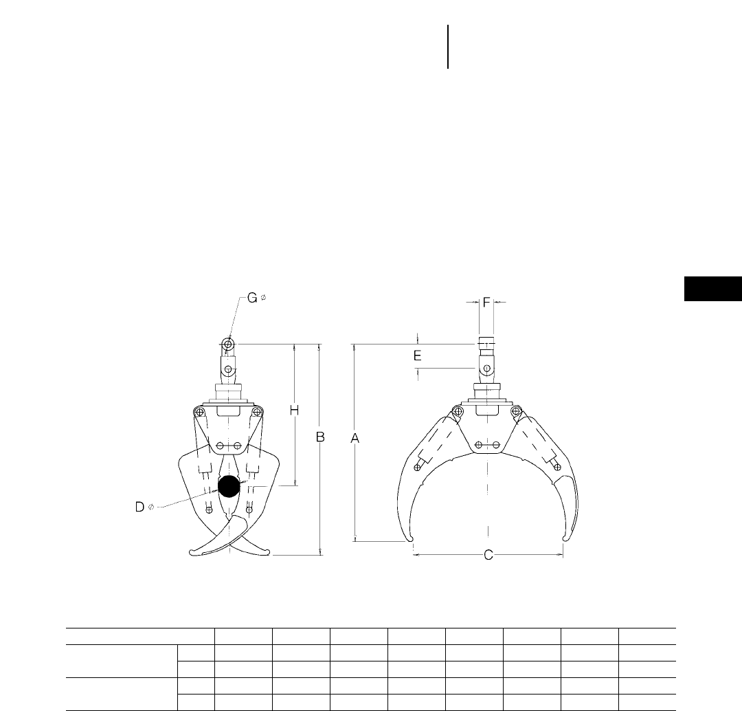
24-39
24
Logging and Forest ProductsGrapples for Heel Boom
Log Loaders
Features:
●Full 360° continuous rotation.
●Applicable to shovel logging and sorting appli-
cations.
●Paddle style tines are made of abrasion resis-
tant material.
●Induction hardened pins and bushings.
●Heavy well hydraulic cylinders with large diam-
eter rod and integral load check valves.
Dimensions:
Grapple Model ABCDEFGH
B52 mm 1854 2006 1372 195 254 152 63 1371
(320B LL/322B LL) in 73 79 54 7.7 10 6 2.5 54
B60 mm 2032 2160 1524 218 254 152 63 1448
(325B LL/330B LL) in 80 85 60 8.6 10 6 2.5 57

24-40
Logging and Forest Products Woodchips Dozers & Scoops
High Speed Disc Saws
●Balderson
WHEEL TRACTOR MODEL 814F 824G 834B
Balderson Models
Replaces “S” Blade BD814US-14' BD824US-15'9" BD834US-20'
Blade:
Capacity 16.74 m321.9 yd324 m331.4 yd329.8 m339 yd3
Length (cutting width) 4.3 m 14'4" 4.78 m 15'7" 6.09 m 20'0"
Height 1.88 m 6'2" 2.24 m 7'4" 2.24 m 7'4"
Wing angle 25° 30° 30°
Weight, Installed (without hydraulics)
BD (S) Dozer 1973 kg 4350 lb 3630 kg 8000 lb 4627 kg 9470 lb
WHEEL TRACTOR MODEL 814F 824G 834B
Balderson Models
Replaces “S” Blade B14-20S B24-27S B34-40S
Chip Scoop:
Lift and Carrying Capacity 15.3 m320 yd320.6 m327 yd334.4 m339.5 yd3
Dozing Capacity 30.4 m340 yd341.3 m354 yd349.4 m365 yd3
Width 3.73 m 12'3" 4.03 m 13'3" 4.83 m 15'10"
Height 2.29 m 7'6" 2.79 m 9'2" 2.25 m 7'4"
Depth 2.46 m 8'1" 2.95 m 9'8" 3.02 m 9'11"
Weight 5390 kg 11,880 lb 11 420 kg 19,125 lb 11 105 kg 24,480 lb
NOTE: For specifications of Woodchip Dozers used on track-type tractors, see the Bulldozer section in this handbook.
SPECIFICATIONS
Excavator Model 325B FB
Balderson Model BFS325II
Saw Disc
Blade diameter 1397 mm 4'7"
Weight 320 kg 700 lb
Saw kerf 51 mm 2"
Blade speed 1250 RPM
Replaceable carbide inserts for teeth and rakers
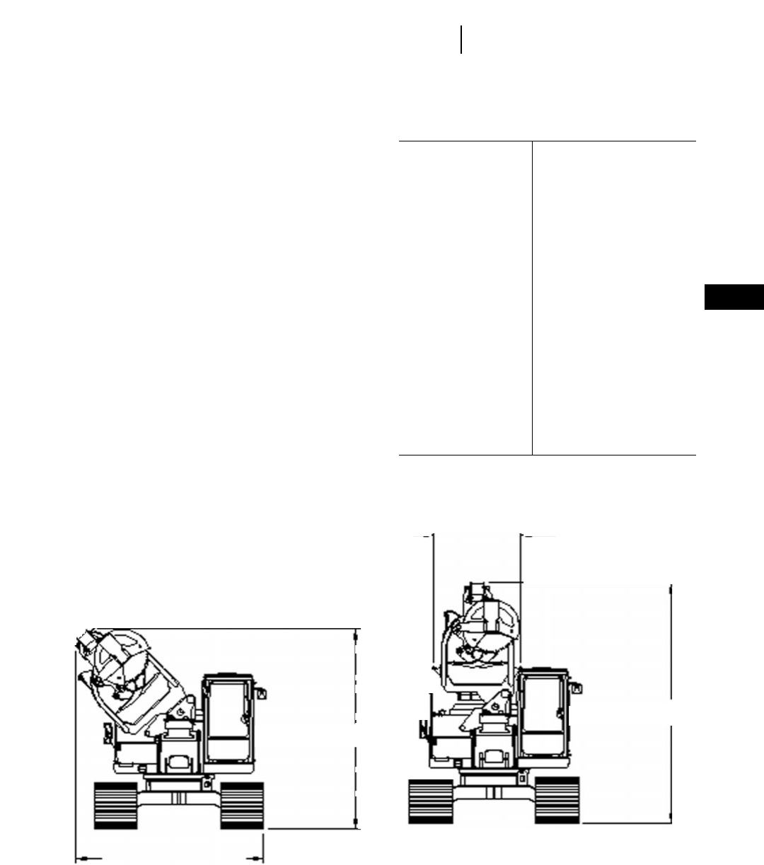
24-41
24
Logging and Forest Products320B Stroke Delimber
Features:
●Dual Motion Stroking Action. Rear grapple
moves the tree to the rear while the boom strokes
forward.
●Full 12 m (40'0") delimbing stroke with tail
swing limited to 5.6 m (18'6").
●Unique dual motion design keeps tree stem weight
and delimbing machine close to swing centerline.
●Balanced loading allows mounting on a smaller
carrier than is required for conventional delimbers.
●Simple conversion from shipping to working
mode. One person can do the conversion using
only 2 wrenches in 10-15 minutes.
MODEL 320B
Carrier 320B Forest Machine
Stroke Length 12.19 m 40'0"
Max. Tree Diameter:
@ Rear Grapple 660 mm 2'2"
Through Center Arch 1168 mm 3'10"
Tail Swing 5.64 m 18'6"
Drive Type Hydraulic Cylinder
Boom Speed m/min 198-251
Boom Speed ft/min 650-825
Delimb Stroke Force 71.2 kN 16,000 lb
Pulling Force 57.4 kN 12,900 lb
Lift Capacity @
11.6 m (38'0") 1089 kg 2400 lb
Topping Saw Capacity
Circular Saw 381 mm 15"
Chain Saw 533 mm 1'9"
Butt Saw Capacity 609 mm 2'0"
711 mm 2'4"
Delimber Attachment
Weight 9935 kg 21,900 lb
Max. Total Package
Weight (all options
installed) 30 390 kg 67,000 lb
Shipping Dimensions: Working Dimensions:
3658 mm (12'0")
3658 mm (11'7")
1397 mm (4'7")
4496 mm (14'9")
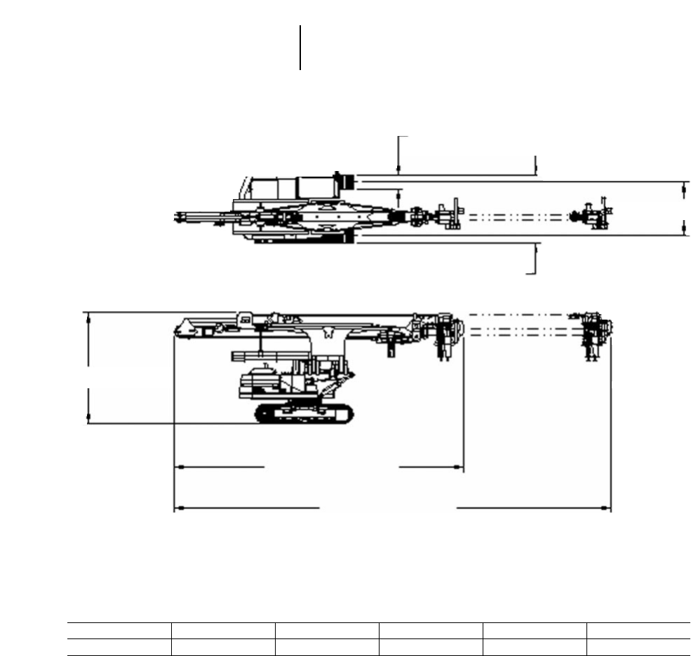
24-42
Logging and Forest Products 320B Stroke Delimber
●Operating Dimensions
A
B
C
D
E
F
ABCDEF
813 mm 2'8" 2.4 m 7'10" 3.2 m 10'6" 4.6 m 15'1" 11.96 m 39'3" 18.06 m* 59'3"
*Maximum stroke position.
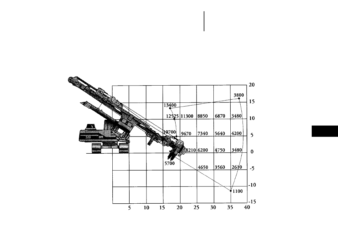
24-43
24
Logging and Forest Products320B Stroke Delimber
●Working Range
Lift Capacity
& Working
Envelope
FEET
Center
of
Rotation
Groundline
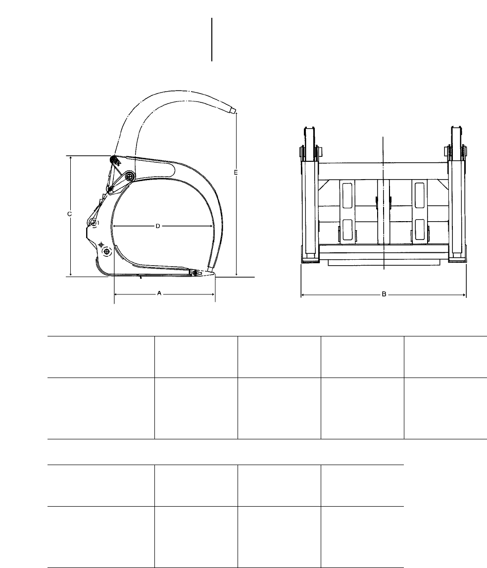
24-44
Logging and Forest Products Logging Forks
●990 ●988F ●980G
●966F Series II
Caterpillar Model 990 988F 988F 980G
Balderson Model High Capacity BFHC988DTC BLF988DTC BLF980DTC
Group Number Logging Fork
Logging Arrangement 114-3557 8966 8965 125-4135
Bucket Arrangement — *8965* 9210
A — Tine Length 2438 mm 8'0" 2286 mm 7'6" 2286 mm 7'6" 1829 mm 6'0"
B — Overall Width 2762 mm 9'1" 2743 mm 9'0" 2775 mm 9'1" 2756 mm 9'2"
C — Back Height 3670 mm 12'0" 3505 mm 11'6" 2974 mm 9'9.1" 2040 mm 6'8.3"
D — Minimum Opening 2498 mm 8'2" 2540 mm 8'4" 2370 mm 7'9.3" 1828 mm 5'11.95"
E — Maximum Clamp Opening 4529 mm 14'10" 4598 mm 15'0.9" 3713 mm 12'2.2" 2990 mm 9'9"
Weight, Approximate 4930 kg 10,870 lb 5350 kg 11,800 lb 4490 kg 9400 lb 3175 kg 7000 lb
Caterpillar Model 980G 966F Series II 966F Series II
Balderson Model Millyard Fork BLF966DTC Millyard Fork
Group Number
Logging Arrangement 133-1545 9209 5831C
Bucket Arrangement 9209
A — Tine Length 1829 mm 6'0" 1600 mm 5'3" 1651 mm 5'5"
B — Overall Width 2388 mm 7'10" 2362 mm 7'9" 2388 mm 7'10"
C — Back Height 2070 mm 6'10" 1899 mm 6'2.75" 1905 mm 6'3"
D — Minimum Opening 254 mm 10" 1624 mm 5'3.95" 432 mm 17"
E — Maximum Clamp Opening 2746 mm 9'0" 2539 mm 8'3.95" 2642 mm 8'8"
Weight, Approximate 2742 kg 5450 lb 2360 kg 5200 lb 2450 kg 5400 lb
*BLF988DTC with bucket arrangement — must order Balderson Link Assembly #137519.
NOTE: Third valve required. Counterweight recommended.
Logging forks with millyard style clamps are available where logging application requires clamp to close between tines.
Contact your Caterpillar Dealer or Balderson for more information.
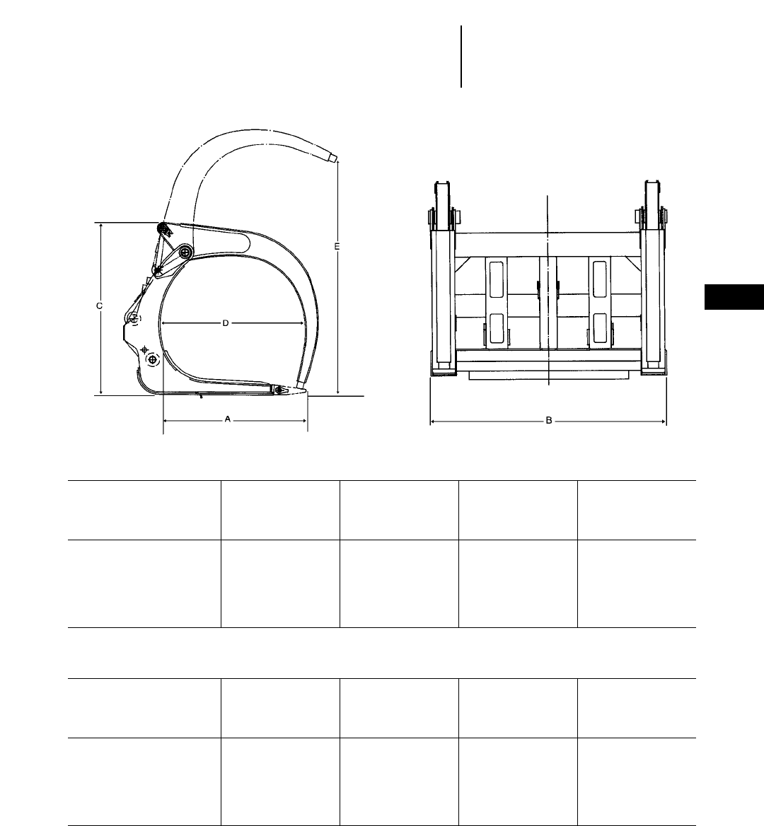
Caterpillar Model 966C 950G/962G 950G/962G 938G
Balderson Model BLF966DTC BLF950DTC Millyard Fork Millyard Fork
Group Number
Logging Arrangement 8963 157-3467 157-3466 119-8243
Bucket Arrangement 8963
A — Tine Length 1448 mm 4'9" 1626 mm 5'4" 1626 mm 5'4" 1372 mm 4'6"
B — Overall Width 2362 mm 7'9" 2261 mm 7'5" 2261 mm 7'5" 2288 mm 7'6"
C — Back Height 1822 mm 5'11.75" 1895 mm 6'2.59" 1890 mm 6'2.42" 1842 mm 6'1"
D — Minimum Opening 1359 mm 4'5.5" 1328 mm 4'4.27" 448 mm 17.64" 165 mm 6.5"
E — Maximum Clamp Opening 2500 mm 8'2.45" 2565 mm 8'5" 2913 mm 9'6.7" 2794 mm 9'2"
Weight, Approximate 2155 kg 4750 lb 2200 kg 4860 lb 2310 kg 5100 lb 1633 kg 3600 lb
950F Series II 950F Series II
Custom Custom
Caterpillar Model IT38G IT38G Toolcarrier Toolcarrier
Balderson Model Grapple Fork Millyard Fork Grapple Fork Log & Lumber Fork
Group Number
Logging Arrangement 119-2297 125-2607 119-2301 114-3532
Bucket Arrangement
A — Tine Length 1056 mm 3'6" 1372 mm 4'6" 1158 mm 3'10" 1219 mm 4'0"
B — Overall Width 1637 mm 5'4" 2286 mm 7'6" 1702 mm 5'7" 2134 mm 7'0"
C — Back Height 1905 mm 6'3" 1902 mm 6'3" 2095 mm 6'10" 1859 mm 6'1"
D — Minimum Opening 1029 mm 3'4" 165 mm 6.5" 1024 mm 3'4" 339 mm 14"
E — Maximum Clamp Opening 2595 mm 8'6" 2845 mm 9'4" 2927 mm 9'7" 2705 mm 8'11"
Weight, Approximate 2085 kg 4600 lb 1555 kg 3430 lb 2130 kg 4700 lb 1540 kg 3400 lb
NOTE: Third valve required. Counterweight recommended.
Logging forks with millyard style clamps are available where logging application requires clamp to close between tines.
Contact your Caterpillar Dealer or Caterpillar Attachment Products and Services for more information.
24-45
24
Logging and Forest ProductsLogging Forks
●966C ●950G ●962G ●938G
●IT38G ●950 Series II Custom Toolcarrier

24-46
Log Volume TablesLogging and Forest Products
USE OF LOG VOLUME TABLES
The tabulated volumes on these pages were cal-
culated with no taper in log diameter from base to
top. Therefore each value listed in the table repre-
sents the volume of a true cylinder. In practice this
may occur only in short sections of large diameter
trees. To obtain the volume of solid wood logs, exclud-
ing bark:
1. Establish the base diameter of the log inside the
bark and above the butt flare (extreme end taper).
2. Repeat the procedure for the top (small end) of log.
3. Enter log volume table at each of the two estab-
lished diameters. Move horizontally to the ver-
tical column closest to the length of the log being
measured.
4. Establish the volume figures for each end of the
log, add the two together and divide by two to
obtain average log volume.
METRIC LOG VOLUMES (in Cubic Meters)
Log LOG LENGTH (METERS)
Diameter
(cm) 24681012141618202224262830
10 0.016 0.031 0.047 0.063 0.078 0.094 0.12 0.13 0.14 0.16 0.17 0.19 0.20 0.22 0.24
15 0.035 0.071 0.11 0.14 0.18 0.21 0.25 0.28 0.32 0.35 0.39 0.42 0.46 0.49 0.53
20 0.06 0.13 0.19 0.25 0.31 0.38 0.44 0.50 0.57 0.63 0.69 0.75 0.82 0.86 0.94
25 0.10 0.20 0.30 0.39 0.49 0.59 0.69 0.79 0.88 0.98 1.08 1.18 1.28 1.37 1.47
30 0.14 0.28 0.42 0.57 0.71 0.85 0.99 1.13 1.27 1.42 1.56 1.70 1.84 1.98 2.12
35 0.19 0.38 0.58 0.7 0.96 1.15 1.35 1.54 1.73 1.93 2.12 2.31 2.50 2.69 2.89
40 0.25 0.50 0.75 1.01 1.26 1.51 1.77 2.02 2.27 2.52 2.78 3.02 3.27 3.51 3.77
45 0.32 0.64 0.95 1.27 1.59 1.91 2.22 2.54 2.86 3.18 3.50 3.82 4.13 4.45 4.77
50 0.39 0.79 1.18 1.57 1.96 2.36 2.76 3.16 3.54 3.94 4.34 4.71 5.10 5.49 5.89
55 0.48 0.95 1.43 1.90 2.38 2.85 3.33 3.80 4.28 4.75 5.23 5.70 6.18 6.65 7.12
60 0.57 1.13 1.70 2.26 2.83 3.39 3.96 4.52 5.09 5.65 6.22 6.78 7.35 7.92 8.48
65 0.66 1.33 1.99 2.65 3.32 3.98 4.65 5.31 5.98 6.64 7.30 7.96 8.62 9.29 9.95
70 0.77 1.54 2.31 3.08 3.85 4.62 5.40 6.15 6.93 7.70 8.48 9.23 10.0 10.77 11.54
75 0.88 1.77 2.65 3.53 4.42 5.30 6.19 7.06 7.95 8.84 9.72 10.60 11.49 12.37 13.25
80 1.01 2.01 3.02 4.02 5.03 6.03 7.05 8.06 9.07 10.08 11.09 12.10 13.10 14.10 15.10
85 1.13 2.27 3.40 4.54 5.67 6.81 7.94 9.08 10.20 11.32 12.47 13.62 14.75 15.89 17.02
90 1.27 2.54 3.82 5.09 6.36 7.63 8.90 10.17 11.43 12.71 13.99 15.27 16.54 17.81 19.10
95 1.42 2.84 4.75 5.67 7.09 8.51 9.92 11.33 12.76 14.18 15.60 17.01 18.43 19.85 21.26
100 1.57 3.14 4.71 6.28 7.85 9.42 11.0 12.58 14.16 15.72 17.30 18.85 20.42 22.0 23.56
125 2.45 4.90 7.36 9.82 12.27 14.73 17.18 19.6 22.1 24.5 27.0 29.5 32.0 34.4 36.8
150 3.53 7.1 10.6 14.1 17.7 21.2 24.7 28.3 31.8 35.3 38.8 42.4 45.9 49.5 53.0
175 4.8 9.6 14.5 19.2 24.0 28.9 33.7 38.5 43.3 48.1 53.0 57.7 62.6 67.3 72.2
200 6.3 12.6 18.8 25.1 31.4 37.7 44.0 50.3 56.5 62.8 69.1 75.4 81.7 88.0 94.2

24-47
24
Logging and Forest ProductsLog Volume Tables
ENGLISH MEASURE LOG VOLUMES (in Cubic Feet)
Log LOG LENGTH (FEET)
Diameter
(inches) 8 12162024283236404448525660708090100
40.7 1 1.4 1.7 2.1 2.4 2.8 3.1 3.5 3.8 4.2 4.5 4.9 5.2 6.1 7 7.8 8.7
61.6 2.4 3.1 3.9 4.7 5.5 6.3 7.1 7.8 8.6 9.4 10 11 12 13 16 18 20
82.8 4.2 5.6 7 8.4 9.8 11 13 14 15 17 18 19 21 24 28 31 35
10 4.4 6.5 8.7 11 13 15 17 20 22 24 26 28 31 33 38 44 49 55
12 6.3 9.4 13 16 19 22 25 28 31 35 38 41 44 47 55 63 71 79
14 8.5 13 17 21 26 30 34 39 43 47 51 56 60 64 74 86 96 101
16 11 17 22 28 34 39 45 50 56 61 67 73 78 84 98 112 126 140
18 14 21 28 35 42 49 57 64 71 78 85 92 99 106 124 141 159 177
20 17 26 35 44 52 61 70 79 87 96 105 113 122 131 153 175 196 218
22 21 32 42 53 63 74 85 95 106 116 127 137 148 158 185 211 238 264
24 25 38 50 63 75 88 101 113 126 138 151 163 176 189 220 251 283 314
26 29 44 59 74 89 103 118 113 147 162 177 192 207 221 258 295 332 369
28 34 51 68 86 103 120 137 154 171 188 205 222 240 256 299 342 385 428
30 39 59 79 98 118 137 157 177 196 216 236 255 275 295 344 393 442 491
32 45 67 89 118 134 156 179 201 223 246 268 290 313 335 391 447 503 559
34 50 76 101 126 151 177 202 227 252 277 303 328 353 378 441 504 567 631
36 57 85 113 141 170 198 226 255 282 311 339 368 396 424 495 566 637 707
38 63 95 126 158 189 220 252 284 315 347 378 410 441 473 551 630 709 788
40 70 105 140 175 210 244 279 314 349 384 419 454 489 524 611 698 785 873
50 109 164 218 273 327 382 436 491 545 600 645 709 764 818 955 1091 1227 1364
60 157 234 314 393 471 550 628 707 785 864 943 1021 1100 1178 1374 1571 1767 1964
70 214 321 428 535 642 748 855 962 1069 1176 1283 1389 1497 1604 1871 2138 2405 2673
80 279 420 559 698 838 977 1117 1257 1396 1536 1676 1815 1955 2095 2441 2293 3142 3491
kg/m3lb/ft3
Species (Green) (Green)
A.Temperate Zone*
Alder, Red . . . . . . . . . . . . . . . . . . . . . 737 46
Ash, White . . . . . . . . . . . . . . . . . . . . . 769 48
Aspen . . . . . . . . . . . . . . . . . . . . . . . . . 689 43
Baldcypress . . . . . . . . . . . . . . . . . . . . 817 51
Basswood . . . . . . . . . . . . . . . . . . . . . . 673 42
Beech . . . . . . . . . . . . . . . . . . . . . . . . . 865 54
Birch, Paper . . . . . . . . . . . . . . . . . . . . 801 50
Yellow . . . . . . . . . . . . . . . . . . . . . . . 929 58
Cedar, Alaska . . . . . . . . . . . . . . . . . . . 577 36
Incense . . . . . . . . . . . . . . . . . . . . . 721 45
Northern, White . . . . . . . . . . . . . . . 449 28
Port-Orford . . . . . . . . . . . . . . . . . . . 897 56
Western Red . . . . . . . . . . . . . . . . . 433 27
Cherry, Black . . . . . . . . . . . . . . . . . . . 721 45
Cottonwood, Eastern . . . . . . . . . . . . . 785 49
Douglas Fir, (Coast) . . . . . . . . . . . . . . 881 55
(Inland Empire) . . . . . . . . . . . . . . . 577 36
Elm, American . . . . . . . . . . . . . . . . . . 865 54
Fir, Alpine . . . . . . . . . . . . . . . . . . . . . . 449 28
Balsam . . . . . . . . . . . . . . . . . . . . . . 721 45
Nobel . . . . . . . . . . . . . . . . . . . . . . . 481 30
Red . . . . . . . . . . . . . . . . . . . . . . . . 769 48
Silver . . . . . . . . . . . . . . . . . . . . . . . 577 36
White . . . . . . . . . . . . . . . . . . . . . . . 753 47
Gum, Black . . . . . . . . . . . . . . . . . . . . . 721 45
Blue . . . . . . . . . . . . . . . . . . . . . . . . 1121 70
Red . . . . . . . . . . . . . . . . . . . . . . . . 801 50
Tupelo . . . . . . . . . . . . . . . . . . . . . . 897 56
Hemlock, Eastern . . . . . . . . . . . . . . . . 801 50
Western . . . . . . . . . . . . . . . . . . . . . 961 60
Hickory, Pecan . . . . . . . . . . . . . . . . . . 993 62
True . . . . . . . . . . . . . . . . . . . . . . . . 1009 62
Larch, Western . . . . . . . . . . . . . . . . . . 769 48
Locust, Black . . . . . . . . . . . . . . . . . . . 929 58
Magnolia, Cucumber . . . . . . . . . . . . . 785 49
*NOTE: Weights taken from U.S. Dept. of Agriculture handbook No. 72, Wood
Handbook.
kg/m3lb/ft3
Species (Green) (Green)
Maple, Big Leaf . . . . . . . . . . . . . . . . . 753 47
Black . . . . . . . . . . . . . . . . . . . . . . . 865 54
Red . . . . . . . . . . . . . . . . . . . . . . . . 801 50
Silver . . . . . . . . . . . . . . . . . . . . . . . 721 45
Sugar . . . . . . . . . . . . . . . . . . . . . . . 897 56
Oak, Black . . . . . . . . . . . . . . . . . . . . . 1009 63
Chestnut . . . . . . . . . . . . . . . . . . . . 977 61
Red . . . . . . . . . . . . . . . . . . . . . . . . 1009 63
Red, Swamp . . . . . . . . . . . . . . . . . 1073 67
Swamp Chestnut . . . . . . . . . . . . . . 1041 65
White . . . . . . . . . . . . . . . . . . . . . . . 993 62
White, Swamp . . . . . . . . . . . . . . . . 1105 69
Pine, Jack . . . . . . . . . . . . . . . . . . . . . . 801 50
Loblolly . . . . . . . . . . . . . . . . . . . . . 993 62
Lodgepole . . . . . . . . . . . . . . . . . . . 625 39
Long Leaf . . . . . . . . . . . . . . . . . . . . 993 62
Norway (Red) . . . . . . . . . . . . . . . . . 673 42
Short Leaf . . . . . . . . . . . . . . . . . . . 993 62
Slash . . . . . . . . . . . . . . . . . . . . . . . 993 62
Sugar . . . . . . . . . . . . . . . . . . . . . . . 817 51
Western Yellow, (Ponderosa) . . . . . 721 45
White (Western) . . . . . . . . . . . . . . . 561 35
White (Eastern) . . . . . . . . . . . . . . . 577 36
Poplar, Yellow . . . . . . . . . . . . . . . . . . . 609 38
Redwood . . . . . . . . . . . . . . . . . . . . . . 801 50
Spruce, Black . . . . . . . . . . . . . . . . . . . 513 32
Engleman . . . . . . . . . . . . . . . . . . . 625 39
Red . . . . . . . . . . . . . . . . . . . . . . . . 545 34
Sitka . . . . . . . . . . . . . . . . . . . . . . . . 529 33
White . . . . . . . . . . . . . . . . . . . . . . . 545 34
Sweetgum . . . . . . . . . . . . . . . . . . . . . 801 50
Sycamore . . . . . . . . . . . . . . . . . . . . . . 833 52
Tamarack . . . . . . . . . . . . . . . . . . . . . . 753 47
Walnut, Black . . . . . . . . . . . . . . . . . . . 929 58
Willow, Black . . . . . . . . . . . . . . . . . . . 801 50
24-48
Weights of Commercially Important Woods
●Temperate Zone
Logging and Forest Products
WEIGHTS OF COMMERCIALLY IMPORTANT WOODS
24-49
24
Logging and Forest ProductsWeights of Commercially Important Woods
●Southeast Asia
●West Africa
kg/m3lb/ft3
Species (Green) (Green)
B. Southeast Asia
Apitong . . . . . . . . . . . . . . . . . . . . . . . . 961 60
Bintangor . . . . . . . . . . . . . . . . . . . . . . 865 54
Chumprak . . . . . . . . . . . . . . . . . . . . . . 929 58
Ebony . . . . . . . . . . . . . . . . . . . . . . . . . 1746 1090
Geronggang . . . . . . . . . . . . . . . . . . . . 721 45
Jelutong . . . . . . . . . . . . . . . . . . . . . . . 641 40
Kapur (Borneo Camphorwood) . . . . . 1073 67
Keruing . . . . . . . . . . . . . . . . . . . . . . . . 1121 70
Krabak . . . . . . . . . . . . . . . . . . . . . . . . 817 51
Kruen . . . . . . . . . . . . . . . . . . . . . . . . . 1121 70
Lumbayau . . . . . . . . . . . . . . . . . . . . . . 929 58
Mahogany, Philippine
(Red Luan) . . . . . . . . . . . . . . . . . . . 753 47
(White Luan) . . . . . . . . . . . . . . . . . 769 48
(Yellow Luan) . . . . . . . . . . . . . . . . . 769 48
Mahoni . . . . . . . . . . . . . . . . . . . . . . . . 913 57
Alayan Kauri (Damar Minyak) . . . . . . 817 51
Melantai . . . . . . . . . . . . . . . . . . . . . . . 705 44
Melapi . . . . . . . . . . . . . . . . . . . . . . . . . 849 53
Mangkulang . . . . . . . . . . . . . . . . . . . . 929 58
Meranti Bakau . . . . . . . . . . . . . . . . . . 849 53
Meranti, Dark Red . . . . . . . . . . . . . . . 753 47
Meranti, White . . . . . . . . . . . . . . . . . . 769 48
Meranti, Yellow . . . . . . . . . . . . . . . . . . 769 48
Mersawa . . . . . . . . . . . . . . . . . . . . . . . 817 51
Nyatoh . . . . . . . . . . . . . . . . . . . . . . . . 897 56
Palosapis . . . . . . . . . . . . . . . . . . . . . . 817 51
Pulai . . . . . . . . . . . . . . . . . . . . . . . . . . 545 34
Ramin . . . . . . . . . . . . . . . . . . . . . . . . . 1073 67
Rosewood (Sonokelina) . . . . . . . . . . . 1314 82
Seraya, Dark Red . . . . . . . . . . . . . . . . 753 47
Seraya, Yellow . . . . . . . . . . . . . . . . . . 769 48
Seraya, White . . . . . . . . . . . . . . . . . . . 769 48
Teak . . . . . . . . . . . . . . . . . . . . . . . . . . 1073 67
kg/m3lb/ft3
Species (Green) (Green)
C. West Africa
Abura . . . . . . . . . . . . . . . . . . . . . . . . . 850 53.06
Ako . . . . . . . . . . . . . . . . . . . . . . . . . . . 800 49.94
Azobe . . . . . . . . . . . . . . . . . . . . . . . . . 1300 81.16
Aniegre (Mukali) . . . . . . . . . . . . . . . . . 950 59.31
Bete . . . . . . . . . . . . . . . . . . . . . . . . . . 900 56.19
Bosse . . . . . . . . . . . . . . . . . . . . . . . . . 900 56.19
Bubinga . . . . . . . . . . . . . . . . . . . . . . . 1000 62.43
Dibetau . . . . . . . . . . . . . . . . . . . . . . . . 750 46.82
Douka (Makore) . . . . . . . . . . . . . . . . . 950 59.31
Doussie . . . . . . . . . . . . . . . . . . . . . . . 1200 74.91
Framire . . . . . . . . . . . . . . . . . . . . . . . . 850 53.06
Fromager . . . . . . . . . . . . . . . . . . . . . . 550 34.34
Ilomba . . . . . . . . . . . . . . . . . . . . . . . . 750 46.82
Iroko . . . . . . . . . . . . . . . . . . . . . . . . . . 1200 74.91
Kokrodua (Afrormosia) . . . . . . . . . . . . 1000 62.43
Kosipo . . . . . . . . . . . . . . . . . . . . . . . . 900 56.19
Limba . . . . . . . . . . . . . . . . . . . . . . . . . 750 46.82
Mahogany . . . . . . . . . . . . . . . . . . . . . 750 46.82
Moabi . . . . . . . . . . . . . . . . . . . . . . . . . 1100 68.67
Niangon . . . . . . . . . . . . . . . . . . . . . . . 900 56.19
Okoume . . . . . . . . . . . . . . . . . . . . . . . 650 40.57
Ozigo . . . . . . . . . . . . . . . . . . . . . . . . . 900 56.19
Padouk . . . . . . . . . . . . . . . . . . . . . . . . 1000 62.43
Samba (Obeche) . . . . . . . . . . . . . . . . 650 40.58
Sapelli . . . . . . . . . . . . . . . . . . . . . . . . 900 56.19
Sipo . . . . . . . . . . . . . . . . . . . . . . . . . . 800 49.94
Tchitola . . . . . . . . . . . . . . . . . . . . . . . . 850 53.06
Tiaba . . . . . . . . . . . . . . . . . . . . . . . . . 900 56.19
Tola . . . . . . . . . . . . . . . . . . . . . . . . . . . 850 53.06
24-50
Weights of Commercially Important Woods
●Australia
●New Zealand
●Papua New Guinea
Logging and Forest Products
kg/m3lb/ft3
Species (Green) (Green)
D. Australia
Ash Alpine . . . . . . . . . . . . . . . . . . . . . 1041 65
Mountain . . . . . . . . . . . . . . . . . . . . 1009 63
Silvertop . . . . . . . . . . . . . . . . . . . . 1330 83
Black Butt . . . . . . . . . . . . . . . . . . . . . . 1121 70
Box Long Leaf . . . . . . . . . . . . . . . . . . 993 62
Yellow . . . . . . . . . . . . . . . . . . . . . . . 1105 69
Black . . . . . . . . . . . . . . . . . . . . . . . 1105 69
Brownbarrel . . . . . . . . . . . . . . . . . . . . 1073 67
Candle Bark . . . . . . . . . . . . . . . . . . . . 657 41
Gum Grey . . . . . . . . . . . . . . . . . . . . . . 1217 76
Manna . . . . . . . . . . . . . . . . . . . . . . 1121 70
Mountain . . . . . . . . . . . . . . . . . . . . 1169 73
Mountain Grey . . . . . . . . . . . . . . . . 1057 66
River Red . . . . . . . . . . . . . . . . . . . . 1137 71
Forest Red . . . . . . . . . . . . . . . . . . . 1201 75
Southern Blue . . . . . . . . . . . . . . . . 1217 76
Spotted . . . . . . . . . . . . . . . . . . . . . 1201 75
Sydney Blue . . . . . . . . . . . . . . . . . 1153 72
Iron Bark Gray . . . . . . . . . . . . . . . . . . 1330 83
Narrowleaved . . . . . . . . . . . . . . . . . 1330 83
Red . . . . . . . . . . . . . . . . . . . . . . . . 1330 83
Jarrah . . . . . . . . . . . . . . . . . . . . . . . . . 1169 73
Karri . . . . . . . . . . . . . . . . . . . . . . . . . . 1169 73
Mahogany Red . . . . . . . . . . . . . . . . . . 1153 72
White . . . . . . . . . . . . . . . . . . . . . . . 1282 80
Myrtle . . . . . . . . . . . . . . . . . . . . . . . . . 1169 73
Peppermint . . . . . . . . . . . . . . . . . . . . . 1120 70
Pine Radiata . . . . . . . . . . . . . . . . . . . . 865 54
Monerey . . . . . . . . . . . . . . . . . . . . . 865 54
Celerytop . . . . . . . . . . . . . . . . . . . . 1057 66
Stringy Bark Brown . . . . . . . . . . . . . . 1233 77
Messmate . . . . . . . . . . . . . . . . . . . 1169 73
Yellow . . . . . . . . . . . . . . . . . . . . . . . 1217 76
White . . . . . . . . . . . . . . . . . . . . . . . 1121 70
Tallowwood . . . . . . . . . . . . . . . . . . . . . 1201 75
Wandoo . . . . . . . . . . . . . . . . . . . . . . . 1282 80
kg/m3lb/ft3
Species (Green) (Green)
E. New Zealand
Exotic Softwoods
Radiata Pine . . . . . . . . . . . . . . . . . 1000 62
Douglas Fir . . . . . . . . . . . . . . . . . . 734 45
Corsican Pine . . . . . . . . . . . . . . . . 985 61
Redwood . . . . . . . . . . . . . . . . . . . . 1016 63
Larch . . . . . . . . . . . . . . . . . . . . . . . 960 60
Indigenous Softwoods
Mati . . . . . . . . . . . . . . . . . . . . . . . . 1120 70
Rimu . . . . . . . . . . . . . . . . . . . . . . . 1130 70
Exotic Hardwoods
Eucaliptus Botryoides . . . . . . . . . . 893 56
Eucaliptus Saligna . . . . . . . . . . . . . 1200 75
Indigenous Hardwoods
Beech — Silver . . . . . . . . . . . . . . . 920 57
Beech — Red . . . . . . . . . . . . . . . . 1200 75
Tawa . . . . . . . . . . . . . . . . . . . . . . . 1022 64
kg/m3lb/ft3
Species (Green) (Green)
F. Papua New Guinea
Pine, Hoop . . . . . . . . . . . . . . . . . . . . . 520 32
Pine, Kauri . . . . . . . . . . . . . . . . . . . . . 480 30
Pine, Klinki . . . . . . . . . . . . . . . . . . . . . 510 31
Kwila . . . . . . . . . . . . . . . . . . . . . . . . . . 800 50
Erima . . . . . . . . . . . . . . . . . . . . . . . . . 390 24
Taun . . . . . . . . . . . . . . . . . . . . . . . . . . 680 42
Walnut, PNG . . . . . . . . . . . . . . . . . . . 560 35
Cedar, Pencil . . . . . . . . . . . . . . . . . . . 720 50
Mersawa . . . . . . . . . . . . . . . . . . . . . . . 650 40
Celtis, Hard . . . . . . . . . . . . . . . . . . . . 780 48
Rosewood, PNG . . . . . . . . . . . . . . . . 600 37
Beech, PNG . . . . . . . . . . . . . . . . . . . . 830 51
Oak, PNG . . . . . . . . . . . . . . . . . . . . . . 650 40
Ebony, PNG Black . . . . . . . . . . . . . . . 1115 69
Ebony, PNG White . . . . . . . . . . . . . . . 720 50
Hardwood, Yellow . . . . . . . . . . . . . . . . 780 48
Hopea, Heavy . . . . . . . . . . . . . . . . . . 960 60
Hopea, Light . . . . . . . . . . . . . . . . . . . . 710 44
Podocarp, Black . . . . . . . . . . . . . . . . . 410 25
Terminalia, Brown . . . . . . . . . . . . . . . . 450 28
24-51
24
Logging and Forest ProductsTree Counts
Comparison of Log Rules
ESTIMATING NUMBER OF TREES PER HECTARE
Spacing (Meters)
Spacing
(Meters) 12345678
110 000 5000 3333 2500 2000 1667 1428 1250
25000 2500 1667 1250 1000 834 714 625
33333 1667 1111 834 667 556 477 417
42500 1250 834 625 500 417 357 313
52000 1000 667 500 400 330 286 250
61667 834 556 417 333 278 238 208
71428 714 477 357 286 238 204 179
81250 625 417 313 250 208 179 156
ESTIMATING NUMBER OF TREES PER ACRE
Spacing (Feet)
Spacing
(Feet) 56789101112
51742 1452 1244 1089 968 871 792 726
61452 1210 1037 1907 806 726 660 605
71244 1037 1888 1777 691 622 565 518
81089 1907 1777 1680 605 544 495 453
91968 1806 1691 1605 537 484 440 403
10 1871 1726 1622 1544 484 435 396 363
11 1792 1660 1565 1495 440 396 360 330
12 1726 1605 1518 1453 403 363 330 302
13 1671 1558 1478 1418 372 335 304 279
14 1622 1518 1444 1390 346 311 283 259
15 1580 1484 1415 1363 323 290 264 242
COMPARISON OF LOG RULES ●Board Foot Values
for 16-Foot Logs
Diameter at
Small End,
Inside Bark, International Scribner
Inches 1/4 Inch Scribner Decimal Spaulding Doyle
4 5 10 10 —0—0
6201820—04
8403230—016
10 65 54 60 50 36
12 95 79 80 77 64
14 135 114 110 114 100
16 180 159 160 161 144
18 230 213 210 216 196
20 290 280 280 276 256
22 355 334 330 341 324
24 425 404 400 412 400
26 500 500 500 488 484
28 585 582 580 569 576
30 675 657 660 656 676
32 770 736 740 748 784
34 875 800 800 845 900
36 980 923 920 950 1024
38 1095 1068 1070 1064 1156
40 1220 1204 1200 1185 1296

24-52
Measurement DefinitionsLogging and Forest Products
UNIT OF MEASUREMENT DEFINITIONS
1 board foot = 1/12 ft3of solid wood
(1' 21' 21")
1000 board feet = 83.33 ft3of solid wood
1 c. unit of wood = 100 solid ft3
= 1200 board feet
= 2.833
1 cord of wood = 128 ft3of stacked logs
= 3.62 m3
1 unit of wood = 200 ft3of loose chips
= 5.66 m3
1 cord of wood = 0.85 units
1 Hoppus Ton = 50 ft3(assumed)
= 63.65 ft3(actual)
= 600 board feet
= 763.8 BF Brereton
= 1.8 m3actual
= 1.4 m3assumed
1 cubic meter = 35.32 ft3
= 424 board feet
= 333 board feet Hoppus tons
= 0.555 Hoppus Tons
1 MBF Brereton = 2.36 m3
= 785.4 board feet Hoppus
1 MBF Hoppus = 1273 board feet-Brereton
MBF = Thousand board feet
1 Super Foot = 1 board foot
100 Super Feet = 1000 board foot
= 0.236 m3
600 Super Feet = 50 ft3
1 lb/ft3= 16.0185 kg/m3
CUBIC FEET OF SOLID WOOD PER CORD
Length of Diameter at Small End
Sticks-Ft. 1"-2.5" 2.5"-5.5" Over 5.5"
2658491
4648289
8597784
12 54 71 78
RULE OF THUMB CONVERSIONS
1 c. unit of wood = 1.117 cords = 1.25 units of chips
= 250 ft3of chips = 7.08 m3
1 cord of wood = 85 ft3of solid wood = 1.06 units of
chips = 2.41 m3
1 unit of chips = 80 ft3of solid wood = 2.27 m3
1 cord of wood = 500 board feet = 1.18 m3
2000 pounds of chips = 500 pounds of pulp
1 cord = 212 ft3of chips = 6 m3

CONTENTS
Introduction . . . . . . . . . . . . . . . . . . . . . . . . . . .25-1
Machine selection . . . . . . . . . . . . . . . . . . . . . . .25-1
How to equip . . . . . . . . . . . . . . . . . . . . . . . . . . .25-2
Production factors . . . . . . . . . . . . . . . . . . . . . . .25-2
Estimating hourly production . . . . . . . . . . . . .25-3
Track-Type Tractors . . . . . . . . . . . . . . . . . . .25-4
Wheel Tractors . . . . . . . . . . . . . . . . . . . . . . .25-5
Wheel Loaders . . . . . . . . . . . . . . . . . . . . . . . .25-7
Wheel Tractor-Scrapers . . . . . . . . . . . . . . . .25-8
Example problem . . . . . . . . . . . . . . . . . . . . . . .25-9
INTRODUCTION
Efficient methods have been developed for handling
and storing coal with mobile equipment. Generally, a
power plant or other industrial facility which uses
coal, meets its daily requirements with incoming coal
shipments and will maintain an emergency stockpile
or deadpile. The deadpile is designed to meet the
burn requirements during any interruption of coal
shipments. Interruptions may include inclement
weather, carrier strikes, scheduling problems, etc.
The deadpile will contain approximately a 90 day
supply of coal and is constructed by thoroughly com-
pacting lifts, or layers, of coal approximately 15 cm
(6 in) thick. Thorough compaction of the entire stock-
pile, including the sides, eliminates air spaces, reduc-
ing the possibility of spontaneous combustion.
Reclaiming the deadpiled coal is critical when
incoming shipments are not able to satisfy the burn
requirements. Four basic types of mobile equipment
are available for stockpiling and reclaiming coal —
track-type tractors, wheel tractors, wheel loaders,
and wheel tractor-scrapers. Each type has its own
specific advantages. The equipment selected must
be able to meet the maximum hourly burn rate.
MACHINE SELECTION
Track-Type Tractors
Track-type tractors continue to be the most widely
used machines for coal handling operations.
Equipped with a U-shaped coal dozer, they are suita-
ble for meeting high production requirements over
dozing distances of less than 152 m (500 ft). Their
tractive capabilities and gradeability permit them to
operate on the sides of the stockpile and surge pile
which often prove inaccessible to other types of
equipment. They can also remove snow and frost
penetrated coal from the stockpile surface so that
rubber-tired equipment can work efficiently.
Wheel Tractors
These machines, with their long wheel base, low
center of gravity, and articulated design, offer good
stability and maneuverability. They have the abil-
ity to travel at a higher speed than the track-type
tractor, moving easily from one area of operation to
another, and provide greater compactive effort with
fewer passes. They are capable of performing some
utility functions. However, their coefficient of trac-
tion is less than that of track-type tractors. The most
efficient dozing distance for the wheel tractor is usu-
ally less than 152 m (500 ft).
Coal scoops are also available for wheel tractors
and may improve production under certain operat-
ing conditions.
Wheel Loaders
As dozing and hauling distances increase, wheel
loaders are able to effectively move coal in load-and-
carry operations. Since coal is a relatively light
material, the loaders should be equipped with larger
buckets sized for coal density. Versatility and mobil-
ity allow them to perform a variety of tasks, both
on and off the stockpile. They can load trucks or rail-
cars, dig out bottom ash and boiler slag from the
ash storage areas, and move railcars within the vicin-
ity of the power plant. Generally wheel loaders are
more efficient than track or wheel tractors at dis-
tances of 122 m (400 ft) or more.
Coal Scrapers
Tandem powered coal scrapers are generally used
when large volumes and long haul distances [over
152 m (500 ft)] are involved. They are able to effec-
tively self-load coal, and have the advantage of being
able to provide both high speed and large capacity;
in addition, scrapers provide the greatest compac-
tive effort. Coal scrapers are even more effective
when top loading systems and drive-over reclaiming
hoppers are used.
STOCKPILE COAL HANDLING
25-1
25
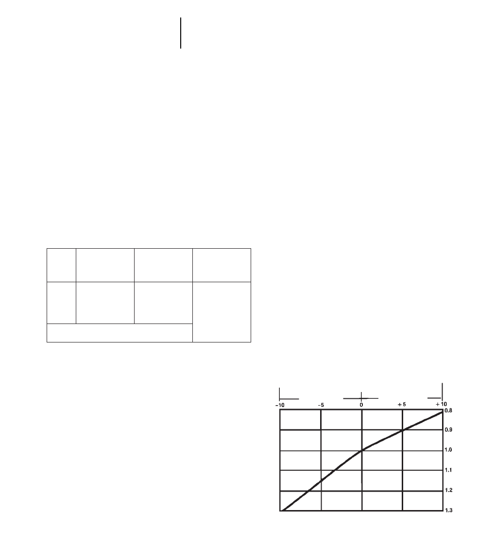
HOW TO EQUIP
Counterweighting
While larger blades or buckets allow for greater
production, counterweighting is often necessary to
improve the machine’s balance and handling capa-
bility. For track-type tractors, a rear counterweight
is recommended. Wheel machines use various meth-
ods to add weight. For example, scoop dozers use
front counterweights, and wheel machines often use
tire ballast. Below is a weight comparison of the
Caterpillar standard U-blade to the Balderson Coal
Dozer, along with the recommended counterweight
for D11R, D10R, D9R, D8R, and 834B.
25-2
How to Equip
Production Factors
Stockpile Coal Handling
Track Shoe Width
Track shoes are an important consideration since
shoe width determines tractive capability and com-
paction. Depending on the coal being stockpiled, the
utility company will often have a strong preference
concerning track shoe width. Basically, utilities
stockpiling low rank or sub-bituminous rank lignite
coal usually prefer the standard shoe width for max-
imum compactive effort to reduce the possibility of
spontaneous combustion.
Utilities burning medium or high rank bituminous
coals are not as concerned with spontaneous com-
bustion and sometimes prefer a wider shoe that
allows increased tractive capability on loose or less
densely compacted coal stockpiles.
Tires
Many utility companies have established a tire
preference for wheel machines. Normally a radial
tire allows for the maximum tire print in the stock-
pile surface providing the best traction.
Tire pressure may be of equal importance to tire
selection. Tests with hydro-inflated (liquid ballasting)
tires indicate that inflation pressure of approxi-
mately 275 kPa (40 psi) improves machine perfor-
mance over higher inflation pressure. Lower than
275 kPa (40 psi) is not recommended for hydro-
inflated tires. (For more hydro-inflation informa-
tion see the Tire section.)
Other
The 834B’s performance may be improved in the
varying underfoot conditions of a coal stockpile with
the use of a Detroit NoSPIN differential. This dif-
ferential provides added tractive capability on all
coal piles, particularly loose coal.
PRODUCTION FACTORS
1. The effect of grade — dozer production will
increase 3% for each 1% of favorable grade and
decrease 2% for each 1% of adverse grade up to
grades of 10%. The graph below exemplifies this
point.
COAL STOCKPILE BLADE WEIGHT COMPARISON/
COUNTERWEIGHTING
Balderson
Caterpillar Coal Dozer/
Model U-Blade Scoop Counterweight
kg lb kg lb kg lb
D11R 11 608 25,590 10 115 22,300 4989 11,000
D10R 6188 13,643 6620 14,600 2928 6,456
D9R 4179 9,214 4490 9,900 3142 6,926
D8R 2825 6,228 3560 7,850 2749 6,060
834B 2994 6,600 4070 8,975 75% CaCI2in all
*834B with Balderson Scoop 8700 19,180 tires —
5360 11,816
Both Caterpillar and Balderson weights include blade or scoop only. The change
in machine weight is determined by adding or subtracting the difference between
the Caterpillar and Balderson blade. Counterweight or ballast may also need to
be considered. Effect of Grade on Production
% Grade
As a rule of thumb, track-type tractors can negotiate grades of about 60% in
loose
coal. Wheel tractor dozers can negotiate grades up to 25% on fairly well
com-
pacted
coal.
Favorable Unfavorable
Production Correction Factors
2. Slot dozing, which consists of dozing repeatedly
in the same tracks, will increase production. The
deeper the slot, the greater the increase in produc-
tion. Obviously this will disrupt the surface of the
pile; however it does provide maximum production.
25-3
25
Stockpile Coal HandlingProduction Factors
Estimating Hourly Production
Slot Slot Increase
Condition Depth in Production
Slight 60 cm ;2 ft 10%
Consistent 60 cm-1.5 m ;2-5 ft 25%
Very Consistent Over 1.5 m ;Over 5 ft 30% +
5. The degree of compaction required — for medium
and high rank bituminous coal, track-type tractors
will normally provide ample compaction to prevent
fires. For low rank coals, such as sub-bituminous
and lignite, rubber tired machines, pneumatic com-
pactors or sealing may be required to prevent fires.
The following table illustrates the compaction that
is possible if the coal is spread in thin lifts and the
machine makes a sufficient number of passes over
the entire lift surface.
3. Relative traction — machines will provide greater-
tractive effort as the compaction beneath them
increases.
Coefficient
Condition: Machine of Traction
Well Compacted Coal Track-type *0.75-0.80
Wheel *0.40-0.50
Loose Coal Track-type *0.60-0.00
Wheel *0.30-0.40
*D11R, D10R, D9R and D8R will often achieve a higher coefficient of traction
due to their suspended undercarriage.
4. Rolling Resistance of rubber tired equipment will
decrease as the compaction of the coal beneath the
machines increases. Here are total rolling resis-
tances on various surfaces.
kg/Metric lb/U.S.
Ton Ton
●Main travel area from 29 65
loading area to stockpile
traveled and maintained.
●Travel over the compacted 36 80
deadpile.
●Travel over thin lifts of 54 120
uncompacted coal on the
deadpile.
●Travel on loose piles under 90- 200-
stacking conveyor or 136 300
on a windrow.
ESTIMATING HOURLY PRODUCTION
The following graphs may be used for estimating
the hourly production of machines handling mixed
bituminous coal. The graphs are based on 100%
machine efficiency under normal job conditions and
average operator; they do not take into account
adverse grades, downtime, wait time, poor traction,
etc. These production estimates should be evaluated
in light of individual job conditions and efficiency.
Moreover, a job efficiency correction factor should
be applied to the production estimate shown when
using these graphs.
To estimate travel times for a specific machine
refer to the performance graphs or charts in the
appropriate model section of this book.
NOTE: Capacities and production curves on the next
pages are based on bituminous coal with a
density of 890 kg/m3or 1500 lb/yd3or 55 lb/ft3.
For sub-bituminous coal with a density of
800 kg/m3or 1350 lb/yd3or 50 lb/ft3multiply
tonnage figure by .90. For lignite with an
average density of 710 kg/m3or 1200 lb/yd3
or 45 lb/ft3multiply tonnage figure by .80.
Machine kg/m3lb/ft3lb/yd3
Track-type Tractors 960-1160 60-72 1620-1950
Wheel Tractors 1040-1200 65-75 1750-2030
Wheel Loaders 1040-1250 65-78 1750-2110
Wheel Tractor-
Scrapers 1100-1280 68-80 1840-2160
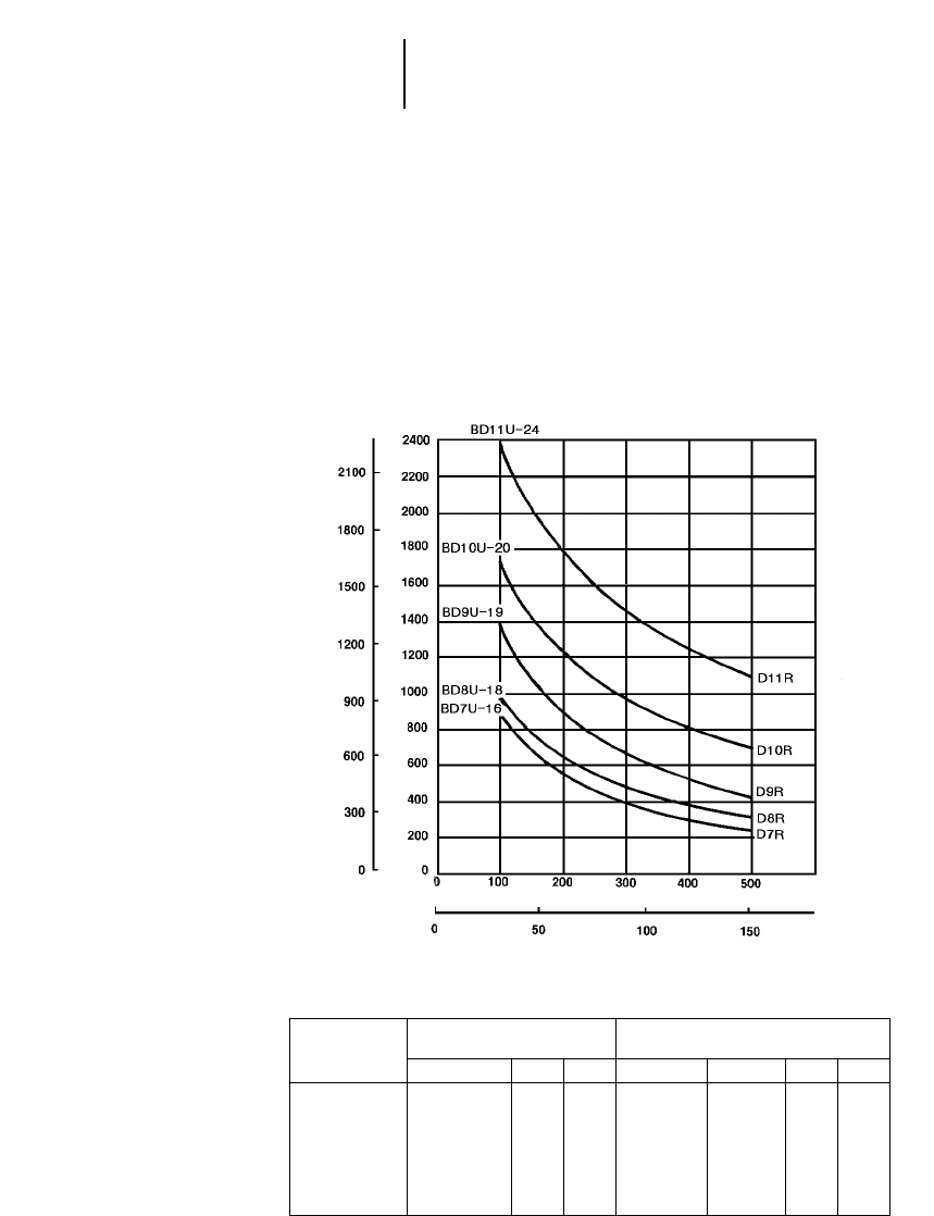
25-4
Estimated Hourly Production
●Track-Type Tractors
Stockpile Coal Handling
PRODUCTION IN TONS/HR.
DOZING DISTANCE (ONE WAY)
Feet
Meters
Metric
Tons English
Short Tons
Track-Type Tractors Estimated Production
with Balderson U-Blade (Coal Dozer)
Factors:
●Mixed Bituminous Coal
●Storage and Reclamation
●0% Grade
●.80 Coefficient of Traction
(Tons per 60-Minute Hour)
NOTE: This chart is
based on numerous
field studies made
under varying job
conditions. Refer to
correction factors fol-
lowing these charts.
Balderson Blade Capacities
U-Blade
Tractor Model m ft Metric tons U.S. tons m3yd3
D11R BD11U-24 7.32 24' 64.0070.5071.9094.8
D10R BD10U-20 6.10 20' 40.85 45.0045.9060.8
D9R BD9U-19 5.79 18' 31.8035.1035.6046.8
D8R BD8U-18 5.49 18' 19.0021.0021.4028.8
D7R BD7U-16 4.88 16' 14.28 15.75 16.05 21.8
D6R BD6U 4.27 14' 08.84 09.75 09.9013.8
Refer to Track-Type Tractor/Bulldozer section for additional special attachment specifications.
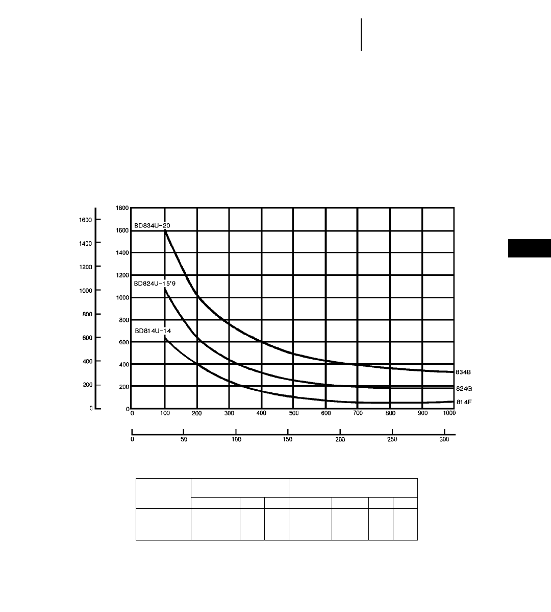
25-5
25
Stockpile Coal HandlingEstimated Hourly Production
●Wheel Tractors
PRODUCTION IN TONS/HR.
DOZING DISTANCE (ONE WAY)
Feet
Meters
Metric
Tons English
Short Tons
Wheel Tractors Estimated Production
with Balderson U-Blade (Coal Dozer)
Factors:
●Mixed Bituminous Coal
●Storage and Reclamation
●0% Grade
●.80 Coefficient of Traction
(Tons per 60-Minute Hour)
NOTE: This chart is
based on numerous
field studies made
under varying job
conditions. Refer to
correction factors fol-
lowing these charts.
Balderson Blade Capacities
U-Blade
Tractor Model m ft Metric tons U.S. tons m3yd3
834B BD834U-20 6.17 20'3" 18.8 20.8 21.2 27.70
824G BD824U-15'9 4.79 15'9" 14.3 15.8 16.1 21.10
814F BD814U-14 4.32 14'2" 09.4 10.3 10.6 13.80
NOTE: Blade capacities in tons figured using weight of coal at 890 kg/m3(1500 lb/yd3).
Refer to Track-Type Tractor/Bulldozer section for additional special attachment specifications.
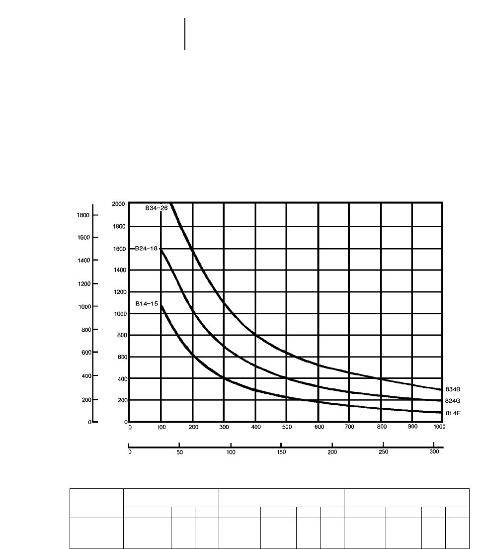
25-6
Estimated Hourly Production
●Wheel Tractors
Stockpile Coal Handling
PRODUCTION IN TONS/HR.
DOZING DISTANCE (ONE WAY)
Feet
Meters
Metric
Tons English
Short Tons
Wheel Tractors Estimated Production
with Balderson Coal Scoop
Factors:
●Mixed Bituminous Coal
●Storage and Reclamation
●0% Grade
●.80 Coefficient of Traction
(Tons per 60-Minute Hour)
Balderson Scoop Capacities Doze
Coal Scoop (Lift and Carry) Capacities
Tractor Model m ft Metric tons U.S. tons m3yd3Metric tons U.S. tons m3yd3
834B B34-26 5.3 17'4" 18.3 20.2 19.9 26 37.5 41.25 37.5 49
824G B24-17 4.0 13'2" 12.3 13.5 13.0 17 24.5 27.0026.0 34
814F B14-15 3.7 12'3" 08.2 09.0 11.5 15 16.3 18.0019.1 25
Refer to Track-Type Tractor/Bulldozer section for additional special attachment specifications.
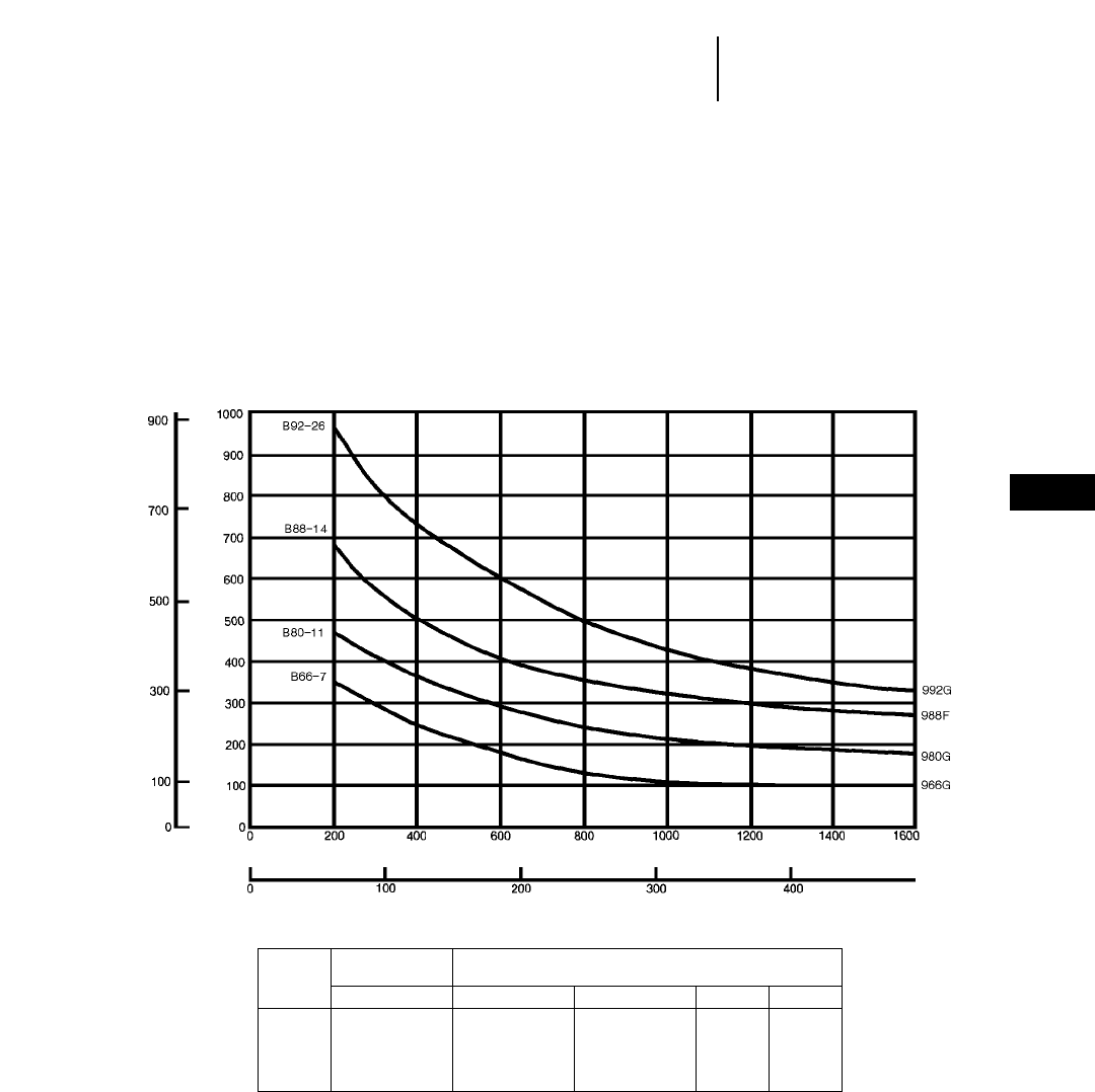
25-7
25
Stockpile Coal HandlingEstimated Hourly Production
●Wheel Loaders
PRODUCTION IN TONS/HR.
HAUL DISTANCE (ONE WAY)
Feet
Meters
Metric
Tons English
Short Tons
Wheel Loaders Estimated Production
with Balderson Coal Bucket
Factors:
●Mixed Bituminous Coal
●Storage and Reclamation
●0% Grade
●.80 Coefficient of Traction
(Tons per 60-Minute Hour)
Balderson Blade Capacities
Coal Bucket
Loader Model Metric tons U.S. tons m3yd3
992G B92-25 17.0 18.8 19.3 25.25
988F B88-14 9.4 10.4 10.3 13.50
980G B80-11 7.3 8.1 8.2 10.75
966G B66-7 4.8 5.3 5.5 07.25
NOTE: Bucket capacities include bottom cutting edge in tons figured using weight of coal at 890 kg/m3
(1500 lb/yd3).
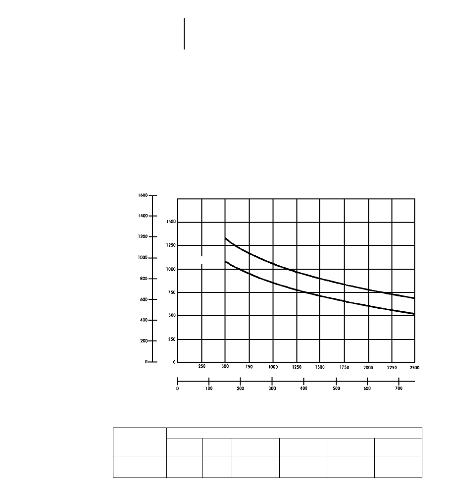
25-8
Estimated Hourly Production
●Wheel Tractor-Scrapers
Stockpile Coal Handling
PRODUCTION IN TONS/HR.
HAUL DISTANCE (ONE WAY)
Feet
Meters
Metric
Tons English
Short Tons
Wheel Tractor-Scrapers Estimated Production
Factors:
●Mixed Bituminous Coal
●Storage and Reclamation
●0% Grade
●.50 Coefficient of Traction
(Tons per 60-Minute Hour)
Bowl Capacities
Coal Metric U.S. Struck 1:1 2:1 3:1
Scraper tons tons m3yd3m3yd3m3yd3m3yd3
657E 49.9 55 45 59 56 73 50 65 47 62
637E Series II 34.5 38 31 41 38 50 34 45 37 44
Average fixed time to load, maneuver and dump:
657E — 1.12 min.
637E Series II — 1.10 min.
NOTE:
●The 657E Coal Scraper is 1049 mm (41.3") longer
and bowl sides and apron are 1080 mm (42.5")
higher than its earthmoving counterpart.
●The 637E Series II Coal Scraper is 762 mm (30")
longer and bowl sides, apron and ejector are 915 mm
(36") higher than its earthmoving counterpart.
●The rimpull, travel times, and retarder performance
for the coal scrapers are the same as for the stan-
dard machines. See Wheel Tractor-Scrapers sec-
tion for charts and graphs.
657E
637E Series II

Example Problem
A coal-fired utility company has a coal require-
ment of approximately 315 metric tons (350 tons) per
hour. Specify the coal handling machine that will
satisfy this demand.
Conditions:
Lignite Coal 710 kg/m3(1200 lb/yd3)
90 m (300 ft) push distance
5% adverse grade
50 minute hour operation efficiency
Solution:
Calculate the D9R’s production equipped with the
Balderson BD9U-19 Coal U-Blade by using the
D9R production curve. Start at 90 m (300 ft) and
read up to the D9R production line, then over to
the left to determine its maximum hourly produc-
tion of 612 metric tons (675 tons).
Since the graphs are based on a 890 kg/m3
(1500 lb/yd3) coal density, this production figure has
to be adjusted to reflect lignite coal:
Coal density correction factor = 710/890 (1200/
1500) = 0.8.
Obtain the production correction factor for the 5%
adverse grade from the chart: 0.9.
The correction factor for the 50 minute hour is
50/60 = .83.
Now calculate the adjusted D9R hourly produc-
tion using the correction factors:
Metric 612 2 .8 2 .9 2 .83 = 366 tons/hour
English 675 2 .8 2 .9 2 .83 = 403 tons/hour
The D9R falls in the required production range.
For short periods of peak power capacity, produc-
tion could be increased by slot dozing.
Production for the D10R, 824G and 834B can be
calculated using the same method.
D10R
Metric 850 2 .8 2 .9 2 .83 = 508 tons/hour
English 935 2 .8 2 .9 2 .83 = 559 tons/hour
824G
Metric 400 2 .8 2 .9 2 .83 = 239 tons/hour
English 440 2 .8 2 .9 2 .83 = 263 tons/hour
834B
Metric 689 2 .8 2 .9 2 .83 = 412 tons/hour
English 760 2 .8 2 .9 2 .83 = 454 tons/hour
Therefore, the D9R or 834B could most economi-
cally satisfy the production requirements.
25-9
25
Stockpile Coal HandlingExample Problem

CONTENTS
Variables affecting clearing operations . . . . . .26-1
Job surveys . . . . . . . . . . . . . . . . . . . . . . . . . . . .26-2
Clearing methods and equipment . . . . . . . . . .26-2
Equipment selection table . . . . . . . . . . . . . . . .26-3
Production estimating:
General . . . . . . . . . . . . . . . . . . . . . . . . . . . . .26-4
Cutting . . . . . . . . . . . . . . . . . . . . . . . . . . . . . .26-5
Piling . . . . . . . . . . . . . . . . . . . . . . . . . . . . . . .26-6
Special attachments . . . . . . . . . . . . . . . . . . . . .26-8
Land clearing must be treated more as an art than
a science because production rates and methods vary
greatly from one area to another. This section deals
with the many variables in clearing and includes
methods, equipment and procedures to determine
productivity rates.
VARIABLES AFFECTING CLEARING
OPERATIONS
Vegetative Growth — Factors affecting production
and therefore cost, include the number of trees, size
of trees, wood density, root systems, vines and under-
growth. These factors can be estimated by a “tree-
count” as discussed under “Job Survey.”
End Use of Land — Since different end uses require
different degrees of clearing (i.e. highways, dams,
tree crops, row crops, etc.), this is one of the most
important factors to consider in choosing the proper
clearing method and equipment.
Soil Conditions or Bearing Capacity — Factors
affecting clearing operations include topsoil depth,
soil type, moisture content, and the presence of rocks
and stones.
Topography — Grade and terrain factors such as
steep slopes, ditches, swampy areas, boulders and
even ant hills greatly affect the normal operation of
some equipment.
Rainfall and Climate — Usually all phases of
land clearing from cutting to burning are concerned
to some degree with temperature changes and the
amount of rainfall during the clearing operation.
Job Specifications — Specifications dictate the
degree of clearing to be done, area size, completion
dates, method of debris disposal, soil conservation
and other factors which affect method and equip-
ment selection.
LAND CLEARING
26-1
26

JOB SURVEYS
Knowledge of rainfall and climate, end use of the
land, and job specifications can be obtained from
records, surveys, engineering studies, and written
specifications. You should personally review the
land to be cleared to gain other necessary and valu-
able information.
The survey should include a study of general
topography and soil conditions. Note such problem
factors as hills, rocks, or swamps which would sig-
nificantly affect production or which would require
special treatment.
Cruise the area to be cleared and determine the
acreage of each vegetative type (i.e. upland woods,
low timberlands, swamps). Make at least three tree
counts at random for each vegetation type. To conduct
these counts, randomly locate two points 100 meters
(328 feet) apart. Count and measure vegetative
growth along a straight line between these points
for a width of about 5 meters (16 feet) on both sides.
This gives the population of 1/10 hectare (1/4 acre).
NOTE:
1. Density of vegetation less than 30 cm (12 in)
diameter
Dense — 1480 trees/hectare or more
(600 trees/acre)
Medium — 990-1480 trees/hectare
(400-600 trees/acre)
Light — less than 990 trees/hectare
(400 trees/acre)
2. Presence of hardwoods expressed in percent
3. Presence of heavy vines
4. Average number of trees per hectare (2.47 acres)
in each of the following ground level diameter size
ranges:
Less than 30 cm (1 ft)
31 cm-60 cm (1-2 ft)
61 cm-90 cm (2-3 ft)
91 cm-120 cm (3-4 ft)
121 cm-180 cm (4-6 ft)
5. Sum of diameter of all trees per hectare (2.47 acres)
above 180 cm (6 ft) in diameter at ground level.
CLEARING METHODS AND EQUIPMENT
Methods for Initial Felling — There are several
methods indicating the degree of clearing for initial
felling and several types of equipment for use with
each method. Equipment use in different size vege-
tation and different size areas is summarized in the
table on the next page. This information should serve
only as a rough guideline in selecting equipment.
The economical land area for each type of equipment
will vary with the capital cost of equipment and
moving cost. It is also affected by whether there are
alternate uses for equipment such as using tractors
for other construction work or tillage.
Land Clearing Machines — Job size, severity of
job such as tree size, and time limit to complete will
influence machine selection. Some machines, such
as the D6R, D7R and D8R are more suited for this
type work than others, but imagination and resource-
fulness can allow the use of other types of machines
in specific applications. For example, loaders are
used more today in raking and piling operations than
ever before.
Operator Protection and Machine Guarding —
Daily production has been estimated to increase 20%
when cab guards are used. Cabs designed specifi-
cally for clearing are available from Rome and other
auxiliary equipment manufacturers.
The radiator, engine, and underside of the tractor
must be well protected. Perforated hoods, screens,
crankcase guards and hydraulic cylinder guards are
generally recommended.
Generally speaking, lower cost clearing can be done
with larger tractors if the amount of clearing involved
is sufficient to merit the initial investment in the
bigger machine. Because most clearing work requires
frequent direction changes, a power shift transmis-
sion should be standard equipment. The direct drive
transmission tractor is recommended when the trac-
tor is used principally in constant drawbar work
such as chaining or pulling a disc harrow. In most
applications, a winch should also be considered on
one of every three tractors in a fleet.
26-2
Job Surveys
Methods and Equipment
Land Clearing
EQUIPMENT SELECTION TABLE
CUTTING AT OR ABOVE KNOCKING TO INCORPORATING
UPROOTING GROUND LEVEL THE GROUND INTO THE SOIL
LIGHT CLEARING — Vegetation up to 5 cm (2 in) diameter
Small areas
4.0 hectares
(10 acres)
Medium areas
40 hectares
(100 acres)
Large areas
400 hectares
(1,000 acres)
INTERMEDIATE CLEARING — Vegetation 5 to 20 cm (2 to 8 in) diameter
Small areas
4.0 hectares
(10 acres)
Medium areas
40 hectares
(100 acres)
Large areas
400 hectares
(1,000 acres)
LARGE CLEARING — Vegetation 20 cm (8 in) diameter or larger
Small areas
4.0 hectares
(10 acres)
Medium areas
40 hectares
(100 acres)
Large areas
400 hectares
(1,000 acres)
NOTE: The most economical size area for each type of equipment will vary with the relative cost of capital equipment versus labor. It is also affected by whether there
are alternate uses for equipment such as using tractors for tillage.
26-3
26
Land ClearingEquipment Selection Table
Bulldozer blade, axes, grub
hoes and mattocks
Bulldozer blade
Bulldozer blade, root rake,
grubber, root plow, anchor
chain drawn between two
crawler tractors; rails
Bulldozer blade
Bulldozer blade
Shearing blade, angling
(tilted) bulldozer blade,
rakes, anchor chain drawn
between two crawler
tractors, root plow
Bulldozer blade
Shearing blade, angling
(tilted), knockdown beam,
rakes, tree stumper
Shearing blade, angling
(tilted), tree pusher, rakes,
tree stumper, anchor chain
with ball drawn between two
crawler tractors
Axes, crosscut saws, power
chain saws
Shearing blade (angling or
V-type), tree shear [up to
70 cm (26 in) softwood;
35 cm (14 in) hardwood],
shearing blade — power
saw combination
Shearing blade (angling or
V-type), shearing blade —
power saw combination
Bulldozer blade
Bulldozer blade
Anchor chain with ball drawn
between two crawler
tractors. [Use dozer blade
for trees over 18 cm (7 in).]
—
—
—
Axes, crosscut saws, power
chain saws, wheel-mounted
circular saws
Power chain saws, tractor-
mounted circular saws,
single scissor type tree
shears
Shearing blade (angling or
V-type)
Bulldozer blade
Bulldozer blade, rolling
brush cutter [up to 12 cm
(5 in) diameter], rotary
mower [up to 10 cm (4 in)
diameter]
Bulldozer blade, flail-type
rotary cutter, anchor chain
Heavy-duty disc plow; disc
harrow
Heavy-duty disc plow; disc
harrow
Bulldozer blade with
duty harrow
Axes, machetes, brush
hooks, grub hoes and
mattocks, wheel-mounted
circular saws
Heavy duty sickle mowers
[up to 3.7 cm (11⁄2in)
diameter] tractor-mounted
circular saws, suspended
rotary mowers
—
Bulldozer blade
Bulldozer blade, rotary
mowers; flail-type rotary
cutters; rolling brush cutters
Rolling brush cutter; flail-
type cutter; anchor chain
drawn between two crawler
tractors; rails
Moldboard plows, disc
plows, disc harrows
Moldboard plows; disc
plows, disc harrows
Undercutter with disc;
moldboard plows; disc
plows; disc harrows
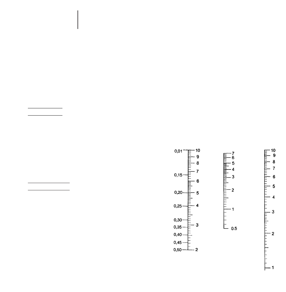
PRODUCTION ESTIMATING
GENERAL — CONSTANT SPEED OPERATIONS
Production is the hourly clearing rate usually
expressed in hectares or acres.
For many land clearing operations, production is
calculated by multiplying the tractor speed by the
width of cut and converting to hectares or acres per
hour.
Metric system:
The base formula is:
Width of cut (meters) 2
speed (km/h)
______________________ = hectares/h
10
When an efficiency of 82.5% is used, the formula
becomes:
Width of cut (m) 2
speed (km/h) 2 .825
______________________ = hectares/h
10
English measure:
Width of cut (ft) 2speed (mph)
_____________________________ = acres/hr
43,560 (ft2)
The American Society of Agricultural Engineers
formula for estimating hourly production of a con-
stant speed operation is based on 82.5% efficiency.
With this efficiency, the formula becomes:
Width of cut (ft) 2 speed (mph)2 .825
___________________________________ = acres/hr
43,560 (ft2)
Width of cut is the effective working width of the
equipment and may not be the same as its rated
width. Working width should be measured on the
job but can be estimated when necessary.
The actual machine speed can be determined by
measuring the amount of time to travel a given dis-
tance. When using the metric system, the time to
travel 16.7 meters or a multiple thereof, can be con-
verted into kilometers per hour.
1.0
______________________ = speed (km/h)
(Time in min. to travel
16.7 meters)
Since 88 ft/min. equals one mph, the lapsed time
to travel 88 ft, or a multiple of 88 ft, can easily be
converted into miles per hour.
1.0
__________________________ = speed (mph)
(Time in min. to travel 88 ft)
The following nomographs in both the Metric and
English systems convert speed and width of cut
directly into acres or hectares per hour at 82.5% effi-
ciency without the need for calculations.
METRIC
26-4
Production Estimating
●General
Land Clearing
Minutes
to
travel
16.7 m
Speed
km/h Production*
hectares/hour Width of Cut**
meters
**Based on 82.5% efficiency.
**When width of cut exceeds 10 meters, use a multiple of the width of cut and
increase production proportionately.
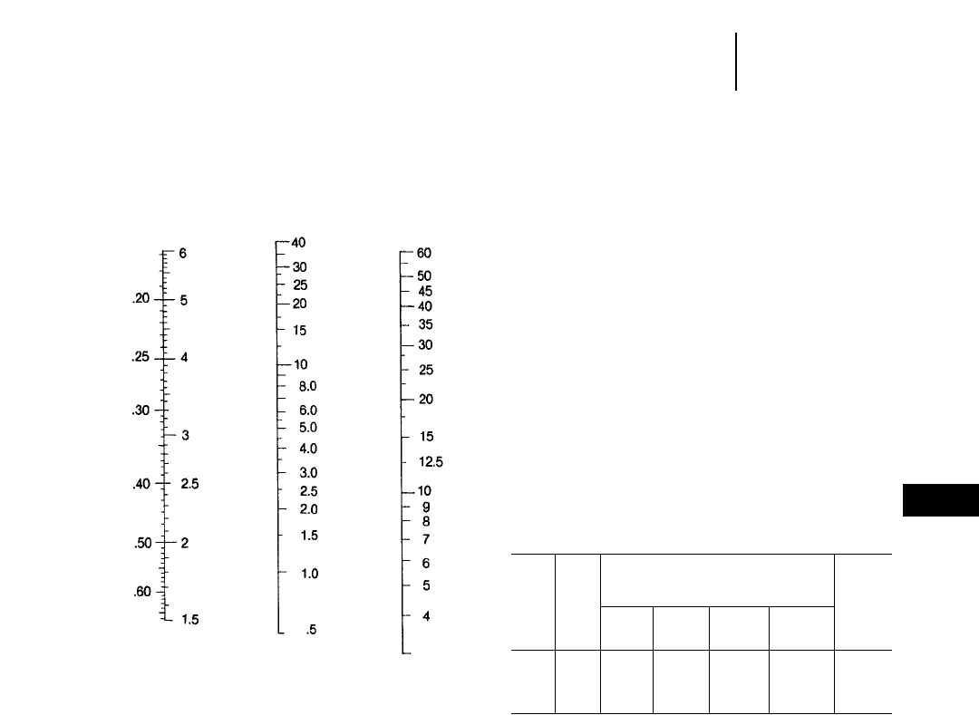
ENGLISH
**Based on 82.5% efficiency.
**When width of cut exceeds 60 feet, use a multiple of the width of cut and
increase production proportionately.
CUTTING PRODUCTION ESTIMATING
Most land clearing operations such as bulldozing,
cutting, grubbing, raking and piling are not per-
formed at constant speed. Because off-the-job pro-
duction is difficult to estimate for these operations,
Rome Industries has developed formulas for esti-
mating cutting and piling time. These formulas take
into consideration variable prime mover speeds
through a factor, “B”, the base time for each tractor
to cover one hectare (2.47 acres) of light material.
To estimate tractor cutting time per hectare
(2.47 acres) on a specific land clearing job, apply the
factors shown in the following table, together with
data obtained from the job survey, in the formula:
T = X [A(B)+M1N1+M2N2+M3N3+M4N4+DF]
where
T = Time per hectare (2.47 acres) in minutes
X = Hardwood or density factor affecting total
time
A = Density or vine presence factor affecting base
time
B = Base time for each tractor per hectare
(2.47 acres)
M= Minutes per tree in each diameter range
N = Number of trees per hectare (2.47 acres) in
each diameter range obtained from field
survey
D = Sum of diameter in 30 cm (1 ft) increments
of all trees per hectare (2.47 acres) above
180 cm (6 ft) in diameter at ground level
obtained from field survey
F = Minutes per 30 cm (1 ft) of diameter for trees
above 180 cm (6 ft) in diameter.
Hardwoods affect over-all or total time as follows:
75-100% hardwoods: Add 30% to total time (X=1.3)
25-75% hardwoods: No change (X=1.0)
0-25% hardwoods: Subtract 30% from total time
(X=0.7)
Production Factors for Felling
with Rome K/G Blades
Base Dia.
Minutes above
per 180 cm
hectare Diameter Range per 30 cm
(2.47 30-60 cm 60-90 cm 90-120 cm 120-180 cm (6'
acres) (1-2 ft) (2-3 ft) (3-4 ft) (4-6 ft) per foot)
Tractor “B” “M
1
”“M
2
”“M
3
”“M
4
” “F”
165 hp 85 0.7 3.4 6.8 — —
230 hp 58 0.5 1.7 3.3 10.2 3.3
305 hp 45 0.2 1.3 2.2 6 1.8
405 hp 39 0.1 0.4 1.3 3 1.0
Explanation of columns in table:
Tractor — Based on current model tractors (power
shift when applicable) working on reasonably level
terrain (below 10% grade) with good footing, no
stones, average mixture of soft and hard woods.
Tractor is in proper operating condition, blade is
sharp, and properly adjusted.
Base Minutes — The base figures represent the
number of minutes required for each tractor to cover
a hectare (2.47 acres) of light material where no
trees require splitting or other individual treatment.
Time required is affected by the density of material
less than 30 cm (1 ft) in diameter and the presence
of vines.
a. dense — 1480 trees/hectare (600 or more trees/
acre): Add 100% to base time (A=2.0)
b. medium — 990-1480 trees/hectare (400-600
trees/acre): No change (A=1.0)
c. light — less than 990 trees/hectare (400 trees/
acre): Subtract 30% from total time (A=0.7)
26-5
26
Land ClearingProduction Estimating
●Cutting
Minutes
to
travel
88 ft
Speed
mph Production*
acres/hour Width of Cut**
feet
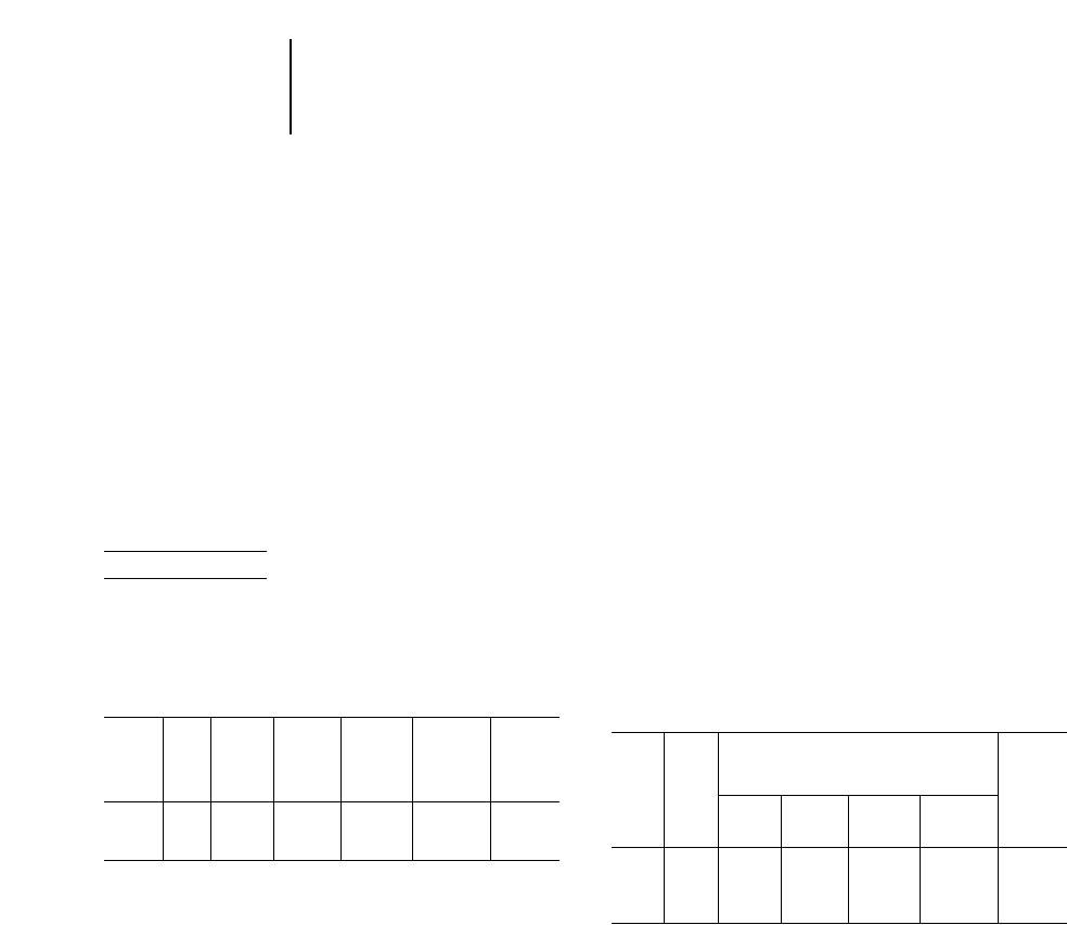
Presence of heavy vines: Add 100% to base time
(A=2.0). Very heavy vines add 300% to base time.
(A=3.0)
Dia. Range — M1represents minutes required to
cut trees from 31-60 cm (1-2 ft) in diameter at ground
level.
M2same for trees 61-90 cm (2-3 ft) diameter.
M3same for trees 91-120 cm (3-4 ft) diameter.
M4same for trees 121-180 cm (4-6 ft) diameter.
For Dia. above 180 cm (6 ft) — The figures in this
column represent size the number of minutes
required per 30 cm (1 ft) of diameter for each trac-
tor to cut trees above 180 cm (6 ft) in diameter.
Thus, to fell a 240 cm (8 ft) diameter tree would
require 821.8 or approximately 14.4 minutes with
a D8R.
Example problem:
Calculate the felling production of a D8L with K/G
Blade in these conditions: reasonably level terrain,
firm ground, well drained, 85% hardwoods with
heavy vines and the following average tree count
per hectare (2.47 acre):
Less Sum Dia’s
than Above
Diameter 30 cm 31-60 cm 61-90 cm 91-120 cm 121-180 cm 180 cm
Range (1 ft) (1-2 ft) (2-3 ft) (3-4 ft) (4-6 ft) (6 ft)
“B” “N
1
”“N
2
”“N
3
”“N
4
” “D”
Number
488 cm
of
1100 35 6 6 4 (16 ft)
Trees
Solution:
T = X [A(B)+M1N1+M2N2+M3N3+M4N4+DF]
T = 1.3 [2.0 (45)+0.2 (35)+1.3 (6)+2.2 (6)+6
(4)+16 (1.8)]
= 1.3 (90+7+7.8+13.2+24+28.8)
= 1.3 (170.8)
= 222 minutes/hectare (90 min/acre)
● ● ●
Where the job requires grubbing trees and stumps
greater than 30 cm (1 ft) in diameter at the same
time the trees are sheared, use the same basic pro-
cedure as defined above including the variables for
the presence of hardwoods. After time per hectare
(acre) in minutes has been determined, increase the
over-all or total time by 25%.
Where the job requires re-entering the area (after
all trees have been sheared) to remove stumps with
a tilted shearing blade or stumper, increase the total
time by 50%.
PILING PRODUCTION ESTIMATING
A procedure has also been developed for estimat-
ing piling production for a tractor equipped with a
K/G blade or rake.
To estimate tractor hours per hectare (acre) on a
specific land clearing job, apply the factors shown
in the following table with data obtained from the
job survey, in the formula:
T = B+M1N1+M2N2+M3N3+M4N4+DF
where
T = Time per hectare (2.47 acre) in minutes.
B = Base time for each tractor per hectare
(2.47 acre).
M= Minutes per tree in each diameter range.
N = Number of trees per hectare (2.47 acre) in
each diameter range obtained from field
cruise.
D = Sum of diameter in 30 cm (1 ft) increments
of all trees per hectare (2.47 acre) above
180 cm (6 ft) in diameter at ground level
obtained from field cruise.
F = Minutes per 30 cm (1 ft) of diameter for trees
above 180 cm (6 ft) in diameter.
Production Factors for Piling in Windrows*
Base Dia.
Minutes above
per 180 cm
hectare Diameter Range per 30 cm
(2.47 30-60 cm 60-90 cm 90-120 cm 120-180 cm (6'
acres) (1-2 ft) (2-3 ft) (3-4 ft) (4-6 ft) per foot)
Tractor “B” “M
1
”“M
2
”“M
3
”“M
4
” “F”
165 hp 157 0.5 1.0 4.2 — —
230 hp 125 0.4 0.7 2.5 5.0 —
305 hp 111 0.1 0.5 1.8 3.6 0.9
405 hp 97 0.08 0.1 1.2 2.1 0.3
*May be used with most types of raking tools and angled shearing blade.Windrows
to be spaced approximately 61 meters (200 feet) apart.
Explanation of columns in table:
Tractor — Production with tractor working alone
based on current model tractors (power shift when
applicable) working on reasonably level (below 10%
grade) terrain with good footing, no stones, average
mixture of soft and hard woods. The tractor is in
proper operating condition. Decrease total time by
25-50% depending on the number and size of trees
when using three or more tractors in combination.
Base Minutes — The base figures represent the
number of minutes required for each tractor to cover
a hectare (2.47 acres) of light material.
26-6
Production Estimating
●Cutting
●Piling
Land Clearing
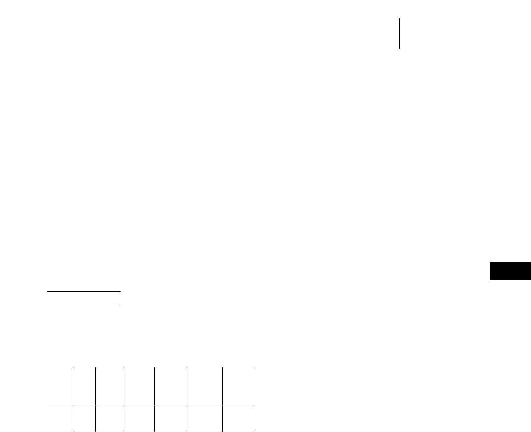
Dia. Range — M1represents minutes required to
pile trees from 31-60 cm (1-2 ft) diameter at ground
level.
M2same for trees 61-90 cm (2-3 ft) diameter.
M3same for trees 91-120 cm (3-4 ft) diameter.
M4same for trees 121-180 cm (4-6 ft) diameter.
For Dia. above 180 cm (6 ft) — The figures in this
column represent for each tractor size the number
of minutes required per 30 cm (1 ft) of diameter to
pile trees above 180 cm (6 ft) in diameter. Thus, to
pile a 240 cm (8 ft) diameter tree would require
820.9 or approximately 7.2 minutes with a D8L
tractor.
Where the job requires piling of grubbed trees and
stumps greater than 30 cm (1 ft) in diameter, use
the same basic procedure defined above and then
increase over-all or total time by 25%.
In dense small diameter brush with few or no
large trees, or when cutting is vine entangled, reduce
the base time by 30%.
Example problem:
Calculate the windrow piling production of a D7R
Series II with Balderson Rake in level terrain, no
grubbing, and average mixture of hardwoods and
softwoods where the average tree count per hectare
(2.47 acres) is:
Less Sum Dia’s
than Above
Diameter 30 cm 31-60 cm 61-90 cm 91-120 cm 121-180 cm 180 cm
Range (1 ft) (1-2 ft) (2-3 ft) (3-4 ft) (4-6 ft) (6 ft)
“B” “N
1
”“N
2
”“N
3
”“N
4
” “D”
Number
of
1100 35 6 6 2 0
Trees
Solution:
T = B+M1N1+M2N2+M3N3+M4N4+DF
= 125+0.4 (35)+0.6 (6)+2.5 (6)+5.0 (2)+[DF=0]
= 42.6
= 177.6 minutes/hectare (72 min/acre)
● ● ●
To find the number of machines required for each
operation, use the formula:
Hr/hectare (acre) 2number of hectares (acres) =
number of machines needed*
*Average machine production for all operation in hr/hectare (acre).
To cost estimate each method or phase of opera-
tion, use this calculation:
Owning and Operating cost/hr 2hr/hectare (acre)
2 number of hectares (acres) = cost
Because of the many variables that increase or
decrease production, these formulas should be con-
sidered only as guidelines in arriving at a rough pro-
duction estimate. This estimate should be tempered
by personal judgment based on past experience and
personal knowledge of the area.
26-7
26
Land ClearingProduction Estimating
●Piling
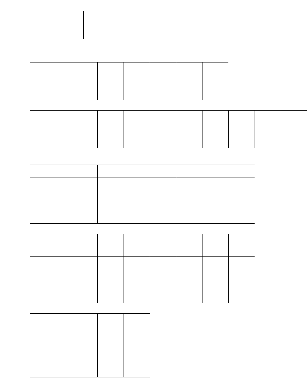
26-8
Land Clearing
ROME K/G BLADES Tractors Equipped with CAT C-Frame
Tractor Model D6M D6R D7R D8K & D8R D8L
Blade Model KGBA5H KGBA6H KGBA7H KGBA8 KGBA8L
Overall Width, Mounted m 3.29 3.29 3.40 3.76 3.88
ft 10'9.5" 10'9.5" 11'2" 12'4" 12'9"
Weight kg 1600 1600 2364 3090 3157
lb 3520 3520 5200 6820 6960
ROME K/G BLADES Tractors Equipped with Rome C-Frame
Tractor Model D6M LGP D6R LGP D6R D7R LGP D7R D7R D8K* D8K
Blade Model KB5HLGP KGB6HLGP KGB6CH KGB7HLGP KGB7HTCA KGB7H KGB8KTC KGB8K
Overall Width, Mounted m 3.89 3.89 3.16 3.96 3.40 3.40 3.76 3.76
ft 12'9" 12'9" 10'4.5" 13'0" 11'2" 11'2" 12'4" 12'4"
Weight kg 2140 2140 2282 3770 3572 3420 5320 5160
lb 4708 4708 5030 8310 7860 7530 11,730 11,380
*Equipped with Caterpillar Tilt Cylinder
BALDERSON BLADE RAKES
Tractor Model D6R D7R
& Dozer 6A 6S 6SLGP 7A 7S 7SLGP
Raking Width m 3.3 2.62 3.18 3.72 3.18 3.66
ft 10'10" 8'6" 10'5" 12'3" 10'5" 12'
Opening at Tooth Tips mm 356 305 310 406 381 381
in 14" 12" 12.22" 16" 15" 15"
Tooth Penetration mm 432 457 406 559 559 559
ft/in 17" 18" 16" 1'10" 1'10" 1'10"
Total Weight kg 718 675 825 1144 1245 1119
lb 1585 1490 1820 2525 2470 2470
BALDERSON RAKES FOR WHEEL LOADERS
950G/ 966G/
Wheel 914G 924F 928G 938G 962G 972G
Loader Model Loader Loader Loader Loader Loader Loader
and Rake type Rake Rake Rake Rake Rake Rake
Raking Width mm 2210 2165 2837 2845 3048 3353
ft 7'3" 7'1" 9'4" 9'4" 10'0" 11'0"
Tooth Penetration mm 762 762 914 914 965 1143
ft 2'6" 2'6" 3'0" 3'0" 3'2" 3'9"
Opening at Tooth Tips mm 318 324 349 298 298 330
in 12.75" 12.8" 13.8" 11.75" 11.75" 13"
Rake Weight kg 770 760 1420 1450 1590 2210
lb 1700 1675 3130 3200 3500 4880
BALDERSON RAKES FOR TRACK LOADERS
Track 953C 963B
Loader Model Loader Loader
and Rake type Rake Rake
Raking Width mm 2845 2388
ft 9'4" 7'10"
Tooth Penetration mm 635 635
ft 2'1" 2'1"
Opening at Tooth Tips mm 298 330
in 11.75" 13"
Rake Weight kg 1450 1450
lb 3200 3200
This listing is not all-inclusive. Contact Balderson for special attachment needs.
Special Attachments
●Rome
●Balderson

27-1
CONTENTS
Introduction . . . . . . . . . . . . . . . . . . . . . . . . . . .27-1
Landfill methods . . . . . . . . . . . . . . . . . . . . . . . .27-1
Equipment selection . . . . . . . . . . . . . . . . . . . . .27-2
Track-Type Tractors . . . . . . . . . . . . . . . . . . .27-2
Track Loaders . . . . . . . . . . . . . . . . . . . . . . . .27-2
Landfill Compactors . . . . . . . . . . . . . . . . . . .27-2
Wheel Loaders . . . . . . . . . . . . . . . . . . . . . . . .27-3
Wheel Tractor-Scrapers . . . . . . . . . . . . . . . .27-3
Machine selection factors . . . . . . . . . . . . . . .27-3
Refuse densities . . . . . . . . . . . . . . . . . . . . . . . .27-4
Compaction factors . . . . . . . . . . . . . . . . . . . . . .27-5
Compaction comparison . . . . . . . . . . . . . . . . . .27-6
Compactor production . . . . . . . . . . . . . . . . . . .27-6
Landfill estimating (example problems) . . . . .27-6
INTRODUCTION
An increasing volume of refuse is generated by
every person, commercial entity and household day
after day ... 365 days a year. Disposal of this waste
is a major problem worldwide. Increased govern-
mental legislation designed to protect the environ-
ment and rising transportation and land acquisition
costs have made waste disposal a significant user
of earthmoving and specialty mobile equipment.
The most commonly accepted disposal method is
burying refuse in a sanitary landfill. A sanitary
landfill protects the environment by disposing solid
waste on land in an engineered cell. Building a cell
involves spreading the waste in thin layers, compact-
ing it to the smallest practical volume, covering it
with soil by the end of each working day, and com-
pacting the cover material. Proper equipment selec-
tion and operating technique can maximize refuse
and cover compaction and extend the operational
landfill life.
LANDFILL METHODS
There are three basic landfill methods:
In the area method, waste is usually deposited at
the toe of the previously compacted cell and then
spread and compacted. This method is attractive for
landfills receiving over 450 metric tons (500 tons)
of refuse per day because it reduces truck unloading
congestion. Cover material is normally handled by
wheel tractor-scrapers from nearby borrow sites.
The trench method is normally found at smaller
landfills where the ground water table is deep. A
trench is excavated and refuse is deposited and com-
pacted within it. Excavated material becomes the
cover material. Since the trench working face is
narrow, truck congestion can occur. This method is
usually attractive to landfills receiving under
450 metric tons (500 tons) of refuse per day.
27
WASTE DISPOSAL

The ramp method combines the characteristics of
both area and trench designs. Refuse is dumped,
spread and compacted on existing slopes and covered
with material excavated directly in front of the work-
ing face. The excavated area becomes part of the next
cell. This is a good way for a landfill to begin opera-
tion with a minimum of equipment expenditures.
EQUIPMENT SELECTION
A landfill’s largest single cost for daily operation
is purchasing, operating and maintaining the mobile
equipment. Undersized, inadequate or unreliable
equipment results in breakdowns, higher operating
costs and improper landfill operation.
Landfill equipment performs three distinct
functions:
1. Waste handling and compaction equipment dis-
pose of the waste. Track-type tractors, track
loaders, and steel-wheeled landfill compactors
are the primary machines.
2. Cover material handling machines provide daily
cover requirements. If supplying cover material
is a machine’s sole function at a landfill, it can
be selected on the basis of normal earthmoving
considerations, such as material characteristics,
distance to borrow areas, volume to be trans-
ported, and other basic earthmoving principles,
i.e., maximizing earth movement in the least
amount of time at the lowest cost per yard.
3. Support equipment includes motor graders,
hydraulic excavators, water trucks, air compres-
sors, service vehicles, water pumps, generators
and any other necessary equipment.
Track-Type Tractors
The track-type tractor is the most popular and ver-
satile machine on a sanitary landfill. They not only
spread and compact refuse and cover material, they
also prepare the site, rip cover material, build haul
roads, knock down trees, remove stumps, and work
in virtually all weather conditions. They are well-
suited for all three landfill methods (area, ramp, and
trench).
The crawler tractor can achieve compaction den-
sities of 475 to 590 kg/m3(800-1000 lb/yd3). Maxi-
mum compaction is achieved when it works on a 3:1
slope, permitting the grousers to rip and tear while
pushing and compacting waste up-slope. Economic
limit of cover or waste movement by a track-type
tractor is normally under 90 m (300 ft).
Track Loaders
Track loaders are highly versatile allowing them
to perform many applications. Small landfills under
135 metric tons (150 tons) per day generally utilize
a minimum amount of equipment. Track loaders can
serve both the waste handling and cover material
functions.
The track loader is an ideal machine for the trench
method. Since the bucket does not extend outside
the tracks, it can obtain full compaction to the trench
walls. Rippers can be attached to handle frozen cover
material. Compaction densities are similar to or
slightly higher than the track-type tractor — 475 to
590 kg/m3(800-1000 lb/yd3). Many people believe
track loaders equipped with single grouser shoes
provide maximum demolition and compaction den-
sities. Loading the bucket during compaction passes
increases weight helping achieve higher densities.
Equipping track loaders with multi-purpose buck-
ets increases their versatility in single machine
applications, allowing the operator to selectively
grapple items out of the working face.
Track loaders are also ideal for transfer stations.
The machine’s weight compacts the trash reducing
volume and increases density. Wider and larger
capacity buckets from Balderson Special Attach-
ments are needed to fully utilize the capabilities of
the track loader in this application.
Landfill Compactors (Steel-Wheeled)
Landfill compactors are specialized pieces of equip-
ment effective in spreading and compacting large
volumes of waste. Compactors offer higher opera-
tional speeds than track machines. This is the rec-
ommended machine if more than one spreading and
compaction machine is needed and waste does not
have to be pushed more than 90 m (300 ft).
Landfill compactors over 20 410 kg (45,000 lb) oper-
ating weight achieve the highest compaction levels
— from 710 to 950 kg/m3(1200-1600 lb/yd3).
Landfill compactors normally operate on slopes no
steeper than 4:1 due to reduced compaction and oper-
ational safety. Compactors should not be used to
excavate cover material.
27-2
Waste Disposal Equipment Selection
●Track-Type Tractors ●Track Loaders
●Landfill Compactors

Wheel Loaders
Although not recommended as a waste handling
and compaction machine, wheel loaders are used by
those communities sharing a single machine which
travels from landfill to landfill. Versatility and
mobility are the primary wheel loader advantages.
In landfills over 272 metric tons (300 tons) per day,
wheel loaders will sometimes be used to perform
general clean-up tasks. Wheel loaders are also pop-
ular in transfer stations to load and separate refuse.
Special foam-filled tires should be considered due
to the constant threat of tire puncture. However,
foam filled tires will have reduced ton-mile-per hour
capabilities.
Wheel loaders can achieve compaction densities of
530 to 650 kg/m3(900-1100 lb/yd3). A disadvantage
of wheel loaders is that they can leave ruts in the
refuse, requiring extra cover material.
Wheel Tractor-Scrapers
A scraper can be used to excavate trenches for site
preparation, but usually performs a cover operation
at a landfill and is most economical at distances over
185 m (600 ft). A scraper should be selected as if it
were performing a typical earthmoving job.
Preferably, the scraper unloads the cover mate-
rial close to the working face, either at the base or top.
The cover material is then spread by the machine(s)
working on the refuse. This reduces the possibility
of tire damage from driving over the refuse. Foam
filled tires are not recommended for scrapers due to
the high travel speeds. Since excavating and trans-
porting cover material is a major expense at a land-
fill, scrapers with work alone capability have been
the most popular.
Machine Selection Factors
Selecting the type, size, quantity, and combination
of machines required to spread, compact, and cover
varying daily refuse volumes is determined by the
following parameters:
1. Amount and type of waste to be handled (daily
tonnage)
2. Amount and type of soil cover to be handled
3. Distance cover material to be transported
4. Weather conditions
5. Compaction requirements
6. Landfill method utilized
7. Supplemental tasks
8. Budget
9. Growth
A. Daily tonnage and type of waste — Amount of
waste produced by a community is the major vari-
able in selecting the appropriate size machine.
The chart serves as a guideline in sizing a land-
fill machine. For example, if a community gener-
ates approximately 180 metric tons (200 tons) of
refuse per day, a D6 or 963 and a 816 Landfill
Compactor should be considered.
WASTE EQUIPMENT SELECTION BASED UPON POPULATION
AND DAILY REFUSE TONNAGE
Metric U.S.
Tons/ Tons/
Population Day Day Machine(s)Required
0-20,000 0-45 0-50 D3 or 933
20,000-60,000 45-136 50-150 D4 or 939 and an 816
60,000-100,000 136-226 150-250 D5 or D6 or 953 and
816
100,000-140,000 226-317 250-350 D6 or D7 or
963 and 816
140,000-200,000 317-453 350-500 D7 or D8 or
973 and 816
200,000-300,000 453-680 500-750 D8 or D9 and 826
300,000-more 680-more 750-more D9, D10 and
836/variety of
support equipment
NOTE: Daily tonnage figures are based on 2.26 kg (5 lb) of residential refuse per
person per day.The amount of waste/person/day can vary depending on
the community and should be adjusted to the individual community.
Type of waste to be handled will strongly influence
machine selection. The major solid waste compo-
nents for a community should be identified and the
proper machine chosen based on the type of waste
and the compaction desired. For example, if the site
receives a high proportion of noncompactible heavy
industrial waste (rocks, bricks, concrete, reinforcing
rod, etc.) a compactor might not achieve normal
compaction densities and the pushing and tractive
ability of a track-type tractor may be needed. How-
ever, a small track-type tractor has more difficulty
compacting bulk waste such as washing machines
and telephone poles than a landfill compactor.
27-3
27
Waste DisposalEquipment Selection
●Wheel Loaders ●Wheel Tractor-Scrapers
●Machine Selection Factors

Waste varies from location to location, even within
a community; however, the following figures are rep-
resentative in the U.S.:
Characterization of
Domestic — Household Waste
Component Percent by Weight
Paper 42
Food 16
Glass 14
Metal 12
Plastics 5
Wood 5
Rubber and Leather 4
Textiles 2
NOTE: Moisture content can have a significant effect on weight characteristics.
Field tests have indicated moisture content can vary from 10-80% during
dry and wet seasons.
B. Amount and type of cover material to be handled
— Although landfill size and type will vary, a rule
of thumb for estimating needed cover material
is one cubic meter (cubic yard) of cover material
for every four cubic meters (or cubic yards) of in-
place compacted waste. That is, about 20-25% of
a sanitary landfill’s volume consists of soil used
for cover (including daily and final covering). On
smaller landfills, the percentage of soil could
be as high as 50% to meet reasonable cover
requirements.
It is important to remember that cover mate-
rial also occupies landfill space reducing the vol-
ume available for refuse. For example a landfill
with 1 900 000 m3(2,500,000 yd3) of total volume
would provide for disposing of 1 520 000 m3
(2,000,000 yd3) of refuse and allow 380 000 m3
(500,000 yd3) of cover material. This example con-
siders one cubic yard of cover for every 4 cubic
yards of in place compacted waste.
The type of cover material can also be impor-
tant. If the material is sandy or highly abrasive,
a rubber tired wheel loader or scraper might be
considered rather than a track-type unit.
C. Distance cover material is to be transported will
have a large effect on cover equipment selection.
The following economic limits or guidelines are
recommended for cover material movement. The
quantity of material to be moved and the time
available must be considered when using these
guidelines.
Track-type tractor 0-90 m (0-300 ft)
Track loader 0-152 m (0-500 ft)
Wheel loader 0-185 m (0-600 ft)
Wheel tractor-scraper over 185 m (over 600 ft)
D. Weather conditions — when working in inclem-
ent weather, the tractive capability of a track-
type machine may be necessary for poor underfoot
conditions or to rip frozen cover material.
E. Compaction requirements — are becoming criti-
cal as extended landfill life is sought. If high
density is desired, then a compactor may be
necessary.
REFUSE DENSITIES
Generally, loose residential and commerical refuse
weighs 150-180 kg/m3(250-300 lb/yd3). A refuse col-
lection vehicle will increase this density to 237-415
kg/m3(400-700 lb/yd3). In-place landfill density can
vary from 355-890 kg/m3(600-1500 lb/yd3), depend-
ing on the compactive effort applied to the refuse.
Landfill sites that accept a high percentage of demo-
lition waste can have densities up to 1485 kg/m3
(2500 lb/yd3). Cover material will generally raise fill
densities 60-120 kg/m3(100-200 lb/yd3) over the fig-
ures given above.
Weight of Refuse
kg/m3lb/yd3
Loose Refuse: 148-178 250-300
Packer Truck 237-415 400-700
Fill Density: 356-890 600-1500
Refuse and Cover: 415-1009 700-1700
27-4
Waste Disposal Machine Selection Factors
Refuse Densities
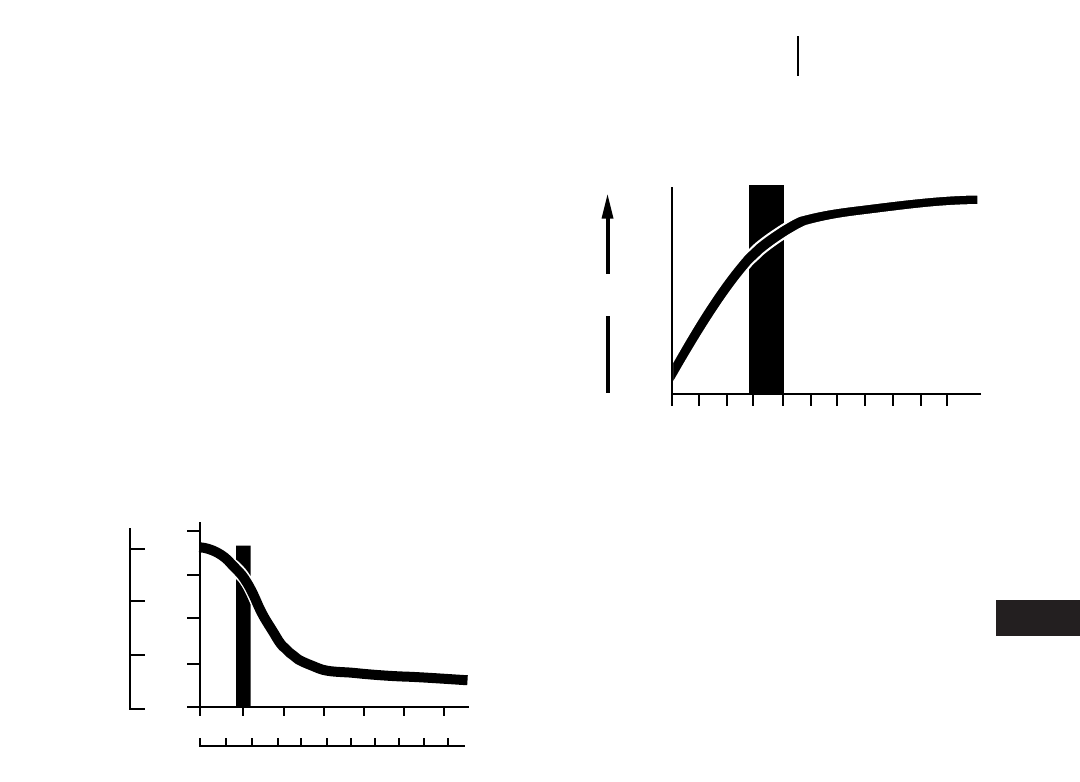
FACTORS GOVERNING COMPACTION
Assuming equal machine weight, regardless of
the type of machine, the following factors (1-4) affect
compaction:
1. Refuse Layer Thickness — The depth of each com-
pacted layer is perhaps the single most important
controllable factor influencing density. To obtain
maximum density, waste should be spread and
compacted in layers not exceeding a depth of
610 mm (2 ft). Thicker layers will reduce the
density that a machine can develop in a given
number of passes. (Density figures shown do not
include cover material.)
2. Number of passes made over the refuse also
affects density. Regardless of the type of machine
used, the unit should make 3-4 passes to achieve
optimum density. The following graph illustrates
that more than four passes result in little addi-
tional compactive effort. The added expense of
additional passes is not justified by the incremen-
tal increase in density.
3. Slope — Maximum compactive effort by a track-
type unit is achieved by working the waste on a
slope of 3:1. Track-type machines achieve higher
densities by grinding and shredding the refuse
into smaller pieces as they climb a slope.
Just the opposite is true for the landfill com-
pactor. The flatter the slope, the better the com-
paction. This is because the weight of the landfill
compactor is more efficiently utilized and concen-
trated when working on a flat surface.
4. Moisture Content — has been shown to have a
significant effect on compacted density. It is
believed that water tends to weaken the bridg-
ing characteristics of refuse, particularly paper
such as large pieces of cardboard, etc., thereby
allowing tighter consolidation. The water may
also act as a lubricant — much as it does for soils.
A minimum amount of moisture can increase
refuse compaction density by 10%.
The optimum moisture content for maximum
compaction of household refuse appears to be
around 50% by weight. Field tests show actual
moisture contents varying from 10-80% during
dry and wet seasons. Although higher moisture
content can provide higher in-place densities, the
chance of leachate formation also increases.
27-5
27
Waste DisposalFactors Governing Compaction
1500
1000
500
0
750
1000
500
250
00 .5 1.0 1.5 2.0 2.5 3.0
01 234 5678910
Meters
Feet
lb/yd3kg/m3
LAYER THICKNESS
012345678910
Number of machine passes
Increasing
Density
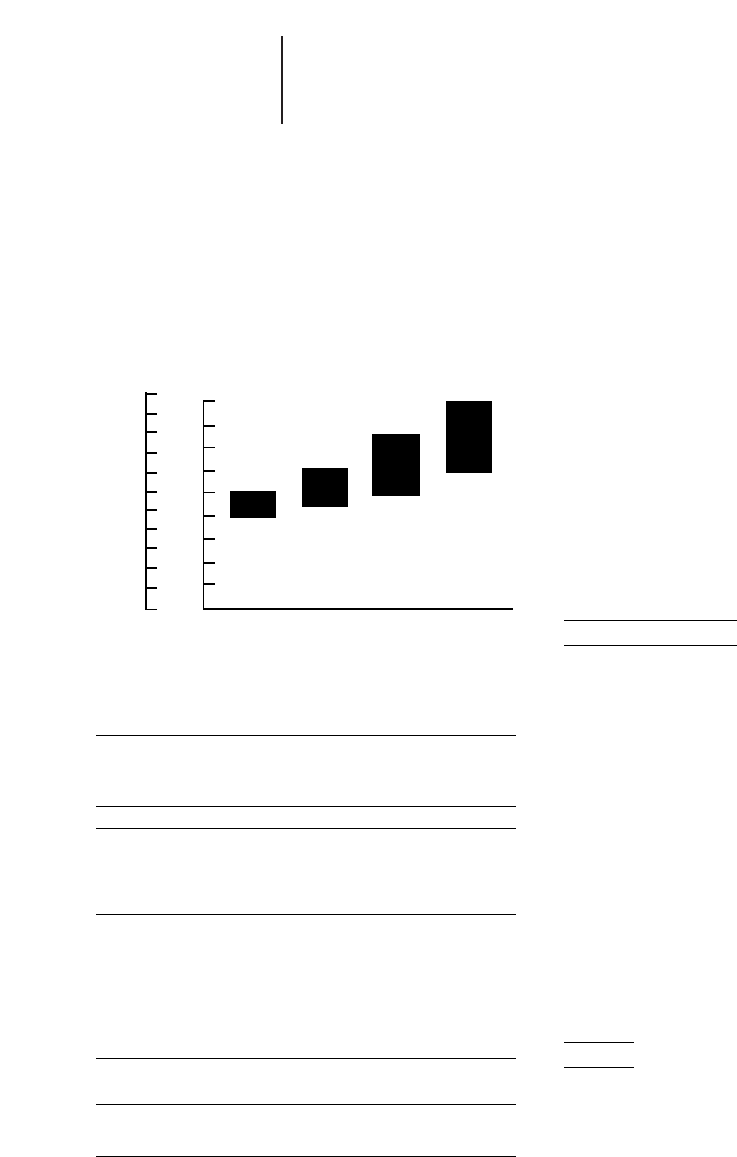
COMPACTION COMPARISON ESTIMATE
The following graph may be used as a rule of
thumb for the compactive ranges of various types
of landfill machines if proper operating technique
is employed.
EXAMPLE OF INCREASED COMPACTION
ON POTENTIAL LANDFILL LIFE
Landfill refuse capacity 1 530 000 m3(2,000,000 yd3)
Operating days 260
Daily volume 365 metric tons (400 tons)
Yearly volume 94 328 metric tons (104,000 tons)
Compaction Landfill Life Gain
590 kg/m31000 lb/yd39.6 years 0
710 kg/m31200 lb/yd311.5 years 1.9 years
830 kg/m31400 lb/yd313.4 years 3.8 years
950 kg/m31600 lb/yd315.3 years 5.7 years
1070 kg/m31800 lb/yd317.2 years 7.6 years
In this example, each 120 kg (200 lb) increase in
refuse density results in an additional 1.9 years of
landfill life. Also this example is exclusive of cover
requirements.
COMPACTOR PRODUCTION GUIDELINES
Tons/Day Tons/Hr
Model Metric U.S. Metric U.S.
836 1016 1000 127.5 125.5
826G 813 800 102.5 100.5
816F 508 500 63.5 62.5
All models are pushing refuse 61 m (200 ft) spreading and making 3 to 4 passes
to compact. A pass is defined as a machine traveling over refuse one time in one
direction.
F. Landfill method utilized — impacts the equip-
ment needed. The area method, which is gener-
ally suited for flat or gradual sloping surfaces will
get maximum compaction effort with a compactor.
The trench method may require a track loader
due to its excavating and tractive capabilities.
G. Supplemental tasks — should be reviewed before
selecting a landfill machine. Will the machine be
required for site clearing, maintaining access
roads, excavating, etc.? Auxiliary duties may
require additional machine capability and/or attach-
ments. If versatility is the key consideration, a track-
type machine again becomes the logical choice.
H. Budget — Smaller landfill operations with lim-
ited budgets may have to consider single machine
versatility ahead of specialized machines or mul-
tiple units.
I. Growth — Future increases in refuse volume
must be considered to properly size machines.
LANDFILL ESTIMATING
Example Problem #1
A professional engineer has developed a small,
rural sanitary landfill master plan. The local leg-
islative regulatory agency has approved the plan
and site.
Assume:
Topography: flat
Land availability:
area has several suitable sites at nominal price
Population served: 30,000
Projected population in 3 years: 40,000
Current daily refuse volume: ?
Type of refuse: mostly household, some commercial
Operation: propose 8 hours/day, 51⁄2 days/week
Present equipment: none — new site
What would your comments and recommenda-
tions be on the following:?
a. Probable amount of refuse generated daily?
b. Type of machine for the proposed SLF?
c. Size of machine for the proposed SLF?
Solution
a. At three year projected population — 2.26 kg/day
(5 lb/day) per person 340,000 people = 90.4 met-
ric tons (100 tons) daily.
b. Track loader — excavating ability, single machine
application based on tonnage requirements.
c. 953B handle current refuse, and has extra capac-
ity for future growth. Small compactor if addi-
tional compaction is required.
27-6
Waste Disposal Compaction Comparison Estimate
Landfill Estimating
●Example Problem
1800
1600
1400
1200
1000
800
600
400
200
0
1100
1000
900
800
700
600
500
400
300
200
100
0TTT/TTL 816 826 836
kg/m3lb/yd3
DENSITY

Example Problem #2
Existing sanitary landfill has been in operation
for several years.
Assume:
Type of operation: area fill
Cover material: suitable material within 90 m
(300 ft).
Current daily refuse volume: 500 metric tons
(550 tons)
Anticipated daily refuse volume in 3 years:
680 metric tons (750 tons)
Type of refuse: household, commercial, large amount
of brush and building demolition debris
Land availability: limited, very expensive
Available Refuse Volume: 3 249 125 m3
(4,250,000 yd3)
Operation: 8 hours/days, 51⁄2days/week
Present equipment: D8 (3 years old)
What would your comments and recommendations
be on the following:
a. What range of in-place densities could be expected
using a track-type tractor; a Cat steel-wheeled
landfill compactor?
b. What effect does machine selection have on site
life?
c. What are the advantages and limitations of steel-
wheeled landfill compactors?
d. What are the advantages and limitations of
track-type units?
e. How many machines should be used on the site?
f. What type should they be?
g. What size should they be?
Solution
a. The Track-Type Tractor will achieve 475 to
595 kg/m3(800 to 1,000 lb/yd3) in-place density.
The Cat steel-wheeled landfill compactor will
achieve 595 to 830 kg/m3(1,000 to 1,400 lb/yd3)
in-place density.
b. There are 3 249 125 m3(4,250,000 yd3) available.
500 metric tons (550 tons) per day is how many
m3(yd3)? Assume a minimum density of 475 kg/m3
(800 lb/yd3).
1000 kg/
500 metric metric ton = 1052 m3/daytons/day 3__________
475 kg/m3
550 tons/day 32000 lb/ton = 1,375 yd3/day
___________
800 lb/yd3
5.5 days/week 352 weeks/year = 286 days/year
Yearly volume: 1,052 3286 = 300 872 m3
1,375 3286 = 393,250 yd3
Landfill life at this density:
3 250 000 m34,250,000 yd310.8
________________ =________________ =
300 872 m3/year 393,250 yd3/year years
Similar calculations are performed to generate the
following tables.
500 METRIC TONS/DAY (550 TONS/DAY)
Density Landfill
kg/m3lb/yd3Life (years)
475 800 10.8
595 1000 13.5
715 1200 16.2
835 1400 18.9
950 1600 21.6
680 METRIC TONS/DAY (750 TONS/DAY)
Density Landfill
kg/m3lb/yd3Life (years)
475 800 7.9
595 1000 9.9
715 1200 11.9
835 1400 13.9
950 1600 15.9
From the tables we determine that a track-type
tractor, at 500 metric tons per day (550 tons/day),
will provide 13.5 landfill life years at 595 kg/m3
(1,000 lb/yd3). Compaction will extend that life
5.4 years to 18.9 years at 835 kg/m3(1,400 lb/yd3).
Proper compaction techniques are necessary
to achieve the higher refuse densities and increase
landfill life.
27-7
27
Waste DisposalLandfill Estimating
●Example Problem

c. Advantages: Provides highest compaction densi-
ties extending landfill life.
Limitations: Specialty unit designed to spread
and compact — does not excavate virgin mate-
rial economically, but can handle stockpile cover
material.
d. Advantages: most versatile unit, well suited to
site preparation, finishing and access road con-
struction and maintenance; all weather machines
with excellent tractive ability. Limitation: com-
paction — cannot achieve the in-place refuse den-
sities of the specialized landfill compactors.
e. Minimum of two. Additional equipment would
depend on supplemental tasks.
f. Track-type tractor — for earthmoving and refuse
spreading work; steel-wheeled compactor-quan-
tity of refuse and land cost would justify.
g. D8 — keeping existing unit; D9 — when new trac-
tor is necessary; 826G — with large amount of
demolition debris and brush and projected increase
in tonnage would justify 826G over 816F.
27-8
Waste Disposal Landfill Estimating
●Example Problem
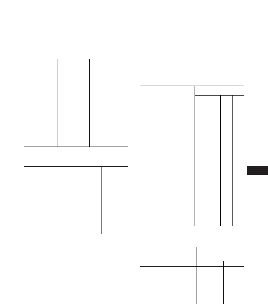
SWELL — VOIDS — LOAD FACTORS
SWELL (%) VOIDS (%) LOAD FACTOR
5 4.8 .952
10 9.1 .909
15 13.0 .870
20 16.7 .833
25 20.0 .800
30 23.1 .769
35 25.9 .741
40 28.6 .714
45 31.0 .690
50 33.3 .667
55 35.5 .645
60 37.5 .625
65 39.4 .606
70 41.2 .588
75 42.9 .571
80 44.4 .556
85 45.9 .541
90 47.4 .526
95 48.7 .513
100 50.0 .500
TABLES
28-1
28
TYPICAL ROLLING RESISTANCE FACTORS
Various tire sizes and inflation pressures will greatly reduce or
increase the rolling resistance. The values in this table are approxi-
mate, particularly for the track and track + tire machines.These values
can be used for estimating purposes when specific performance
information on particular equipment and given soil conditions is not
available. See Mining and Earthmoving Section for more detail.
ROLLING RESISTANCE,
PERCENT*
UNDERFOOTING Tires Track Track
Bias Radial ** +Tires
1.5%* 1.2% 0% 1.0%
2.0% 1.7% 0% 1.2%
3.0% 2.5% 0% 1.8%
4.0% 4.0% 0% 2.4%
5.0% 5.0% 0% 3.0%
8.0% 8.0% 0% 4.8%
10.0% 10.0% 2% 7.0%
14.0% 14.0% 5% 10.0%
20.0% 20.0% 8% 15.0%
**Percent of combined machine weight.
**Assumes drag load has been subtracted to give Drawbar Pull for good to mod-
erate conditions. Some resistance added for very soft conditions.
BUCKET FILL FACTORS
Loose Material Fill Factor
Mixed Moist Aggregates 95-100%
Uniform Aggregates up to 3 mm (1/8") 95-100%
3 mm-9 mm (1/8"-3/8") 90-950%
12 mm-20 mm (1/2"-3/4") 85-900%
24 mm (1") and over 85-900%
Blasted Rock
Well Blasted 80-95%0
Average Blasted 75-900%
Poorly Blasted 60-750%
Other
Rock Dirt Mixtures 100-120%
Moist Loam 100-110%
Soil, Boulders, Roots 80-100%
Cemented Materials 85-950%
NOTE: Loader bucket fill factors are affected by bucket penetration, breakout
force, rackback angle, bucket profile and ground engaging tools such as
bucket teeth or bolt-on replaceable cutting edges.
NOTE: For bucket fill factors for hydraulic excavators, see bucket payloads in the
hydraulic excavator section.
A very hard, smooth roadway, con-
crete, cold asphalt or dirt surface,
no penetration or flexing . . . . . . . .
A hard, smooth, stabilized surfaced
roadway without penetration under
load, watered, maintained . . . . . .
A firm, smooth, rolling roadway with
dirt or light surfacing, flexing slightly
under load or undulating, maintained
fairly regularly, watered . . . . . . . .
A dirt roadway, rutted or flexing
under load, little maintenance, no
water, 25 mm (1") tire penetration
or flexing . . . . . . . . . . . . . . . . . . . .
A dirt roadway, rutted or flexing
under load, little maintenance, no
water, 50 mm (2") tire penetration
or flexing . . . . . . . . . . . . . . . . . . . .
Rutted dirt roadway, soft under
travel, no maintenance, no stabili-
zation, 100 mm (4") tire penetration
or flexing . . . . . . . . . . . . . . . . . . . .
Loose sand or gravel . . . . . . . . . .
Rutted dirt roadway, soft under
travel, no maintenance, no stabili-
zation, 200 mm (8") tire penetra-
tion and flexing . . . . . . . . . . . . . . .
Very soft, muddy, rutted roadway,
300 mm (12") tire penetration, no
flexing . . . . . . . . . . . . . . . . . . . . . .
ANGLE OF REPOSE OF VARIOUS MATERIALS
ANGLE BETWEEN
HORIZONTAL AND
SLOPE OF HEAPED PILE
MATERIAL Ratio Degrees
Coal, industrial . . . . . . . . . . . . . . . 1.4:1—1.3:1 35-38
Common earth, Dry . . . . . . . . . . . 2.8:1—1.0:1 20-45
Moist . . . . . . . . . . 2.1:1—1.0:1 25-45
Wet . . . . . . . . . . . 2.1:1—1.7:1 25-30
Gravel, Round to angular . . . . . . . 1.7:1—0.9:1 30-50
Sand & clay . . . . . . . . . . . 2.8:1—1.4:1 20-35
Sand, Dry . . . . . . . . . . . . . . . . . . . 2.8:1—1.7:1 20-30
Moist . . . . . . . . . . . . . . . . . 1.8:1—1.0:1 30-45
Wet . . . . . . . . . . . . . . . . . . 2.8:1—1.0:1 20-45
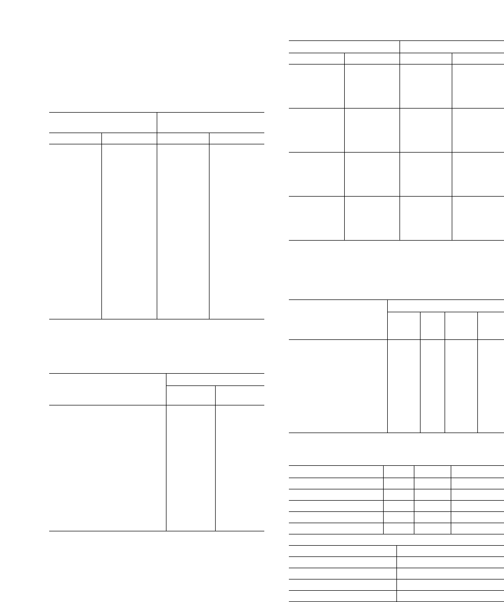
28-2
Tables
ROUND REINFORCED CONCRETE PIPE
APPROXIMATE WEIGHT PER FOOT
INSIDE WEIGHT
DIAMETER PER FT.
mm ft/in kg lb
305 12" 42 93
380 15" 58 127
460 18" 76 168
530 1'9" 97 214
610 2'0" 120 265
685 2'3" 146 322
760 2'6" 174 384
840 2'9" 205 452
915 3'0" 238 524
1070 3'6" 311 686
1220 4'0" 393 867
1370 4'6" 485 1069
1525 5'0" 588 1295
1675 5'6" 699 1542
1830 6'0" 821 1811
1980 6'6" 952 2100
2135 7'0" 1093 2409
2285 7'6" 1242 2740
2440 8'0" 1402 3090
2590 8'6" 1578 3480
2740 9'0" 1753 3865
NOTE: Table courtesy of American Concrete Pipe Assn.
COEFFICIENT OF TRACTION FACTORS
TRACTION FACTORS
Rubber
MATERIAL Tires Tracks
Concrete . . . . . . . . . . . . . . . . . . . .90 .45
Clay loam, dry . . . . . . . . . . . . . . . .55 .90
Clay loam, wet . . . . . . . . . . . . . . . .45 .70
Rutted clay loam . . . . . . . . . . . . . .40 .70
Dry sand . . . . . . . . . . . . . . . . . . . .20 .30
Wet sand . . . . . . . . . . . . . . . . . . . .40 .50
Quarry pit . . . . . . . . . . . . . . . . . . . .65 .55
Gravel road
(loose not hard) . . . . . . . . . . . . . .36 .50
Packed snow . . . . . . . . . . . . . . . . .20 .27
Ice . . . . . . . . . . . . . . . . . . . . . . . . .12 .12
Semi-skeleton shoes
Firm earth . . . . . . . . . . . . . . . . . . .55 .90
Loose earth . . . . . . . . . . . . . . . . . .45 .60
Coal, stockpiled . . . . . . . . . . . . . . .45 .60
NOTE: The elevated sprocket design Track-type Tractors (D11N, D10N, D9N and
D8N), with their suspended undercarriage, provide up to 15% more effi-
cient tractive effort than rigid tracked Track-type Tractors.
SPEED CONVERSION
km/h Equivalents in m/min MPH Equivalents in FPM
km/h m/min km/h m/min mph fpm mph fpm
1 16.7 21 350.0 1 88 21 1848
2 33.3 22 366.7 2 176 22 1936
3 50.0 23 383.3 3 264 23 2024
4 66.7 24 400.0 4 352 24 2112
5 83.3 25 416.7 5 440 25 2200
6 100.0 26 433.3 6 528 26 2288
7 116.7 27 450.0 7 616 27 2376
8 133.3 28 466.7 8 704 28 2464
9 150.0 29 483.3 9 792 29 2552
10 166.7 30 500.0 10 880 30 2640
11 183.3 31 516.7 11 968 31 2728
12 200.0 32 533.3 12 1056 32 2816
13 216.7 33 550.0 13 1144 33 2904
14 233.3 34 566.7 14 1232 34 2992
15 250.0 35 583.3 15 1320 35 3080
16 266.7 36 600.0 16 1408 36 3168
17 283.3 37 616.7 17 1496 37 3256
18 300.0 38 633.3 18 1584 38 3344
19 316.7 39 650.0 19 1672 39 3432
20 333.3 40 666.7 20 1760 40 3520
NOTE: Since 1 km/h equals 16.7
m/min (1000 ÷ 60), to inter-
polate add 1.67 m/min for
each 0.1 km/h.
NOTE: Since 1 mph equals 88 fpm
(5280 ÷ 60), to interpolate
add 8.8 fpm for every
0.1 mph.
1 mph = 26.9 m/min.
BEARING POWERS
BEARING POWER
U.S.
MATERIAL Bar lb/ Metric tons/
in2t/m2ft2
Rock (semi-
shattered) . . . . . . . . . . . . 4.8 70 50 5.0
Rock (solid) . . . . . . . . . . . . . 24.1 350 240 24.0
Clay, dry . . . . . . . . . . . . . . . 3.8 55 40 4.0
medium dry . . . . . . . . 1.9 27 20 2.0
soft . . . . . . . . . . . . . . . 1.0 14 10 1.0
Gravel, cemented . . . . . . . . 7.6 110 80 8.0
Sand, compact dry . . . . . . . 3.8 55 40 4.0
clean dry . . . . . . . . . . 1.9 27 20 2.0
Quicksand & alluvial
soil . . . . . . . . . . . . . . . . . . 0.5 750.5
AGRICULTURAL COMMODITIES
CONVERSION FACTORS
lb kg Metric Ton
1 Bushel of Corn* 56 25.40 0.02540
1 Bushel of Soybean* 60 27.22 0.02721
1 Bushel of Oats* 32 14.51 0.01451
1 Bushel of Wheat* 60 27.22 0.02721
1 Bale of Cotton 478 216.81 0.21681
1 metric ton of Corn 39.37 Bushels*
1 metric ton of Soybean 36.75 Bushels*
1 metric ton of Oats 68.92 Bushels*
1 metric ton of Wheat 36.75 Bushels*
1 metric ton of Cotton 4.61 Bales
*Bushel is a volume measurement, 1 Bushel = 35.24 liters = 9.31 U.S. Gallons.
In the agricultural mercantile exchange, the Bushel is widely used for grains as
weight. For the above weights, the market assumes a standard density for each
type of grain.

CURVE SUPERELEVATION
IN PERCENT GRADE,TO PROVIDE NO LATERAL TIRE FORCE
28-3
28
Tables
TURN Speed Speed Speed Speed Speed Speed Speed Speed
RADIUS 16 km/h 24 km/h 32 km/h 40 km/h 48 km/h 56 km/h 64 km/h 72 km/h
m ft 10 mph 15 mph 20 mph 25 mph 30 mph 35 mph 40 mph 45 mph
15.2 50 13%30%——————
30.5 100 7%15%27%—————
45.7 150 4%10%18%28%————
61.0 200 3% 8% 13% 21% 30% — — —
91.5 300 2% 5% 9% 14% 20% 27% — —
152.4 500 1% 3% 5% 8% 12% 16% 21% 27%
213.4 700 1% 2% 4% 6% 9% 12% 15% 19%
304.9 1000 1% 2% 3% 4% 6% 8% 11% 14%
Negotiating curves can generate high lateral tire
forces. These forces contribute to high tire wear and
ply separation. Superelevating the curve helps elim-
inate these forces. The amount of superelevation
depends on the curve’s radius and the speed at
which it is negotiated.
The following table is a guide for providing the
superelevation necessary to eliminate lateral forces.
Superelevated turns present a danger when slip-
pery. For this reason, curves superelevated over 10%
should be used with caution. Unless the proper
speed is maintained, matching the elevation of the
curve, a vehicle may slide off of the lower edge of
the roadway. Superelevated curves should be main-
tained in good tractive conditions.
MAXIMUM SPEED ON CURVES FOR VARIOUS SUPERELEVATION GRADES
WITH A 0.20 LATERAL COEFFICIENT OF TRACTION
Another approach to superelevated curves is to
determine the safe speed for negotiating a turn at
a certain lateral tire force. In general, a 20% lateral
coefficient of traction is safe for all but slippery con-
ditions. The following table shows maximum speed
with various superelevations to maintain a 0.20 lat-
eral coefficient of traction.
TURN Flat 5% 10%
RADIUS Curve Super- Super-
elevation elevation
m ft km/h mph km/h mph km/h mph
7.6 25 14 916 10 17 11
15.2 50 20 12 22 14 24 15
30.5 100 28 17 31 19 34 21
45.7 150 34 21 38 24 42 26
61.0 200 39 24 44 27 48 30
91.5 300 48 30 54 34 59 37
152.5 500 62 39 70 43 76 47
213.5 700 74 46 ————
A transition “spiral” may be necessary at higher speeds when entering or depart-
ing from a superelevated turn.
LOOSE BANK LOAD
WEIGHT* OF MATERIALS kg/m3lb/yd3kg/m3lb/yd3FACTORS
Basalt . . . . . . . . . . . . . . . . . . . . . . . . . . . . . . . . . . 1960 3300 2970 5000 .67
Bauxite, Kaolin . . . . . . . . . . . . . . . . . . . . . . . . . . . 1420 2400 1900 3200 .75
Caliche . . . . . . . . . . . . . . . . . . . . . . . . . . . . . . . . . 1250 2100 2260 3800 .55
Carnotite, uranium ore . . . . . . . . . . . . . . . . . . . . . 1630 2750 2200 3700 .74
Cinders . . . . . . . . . . . . . . . . . . . . . . . . . . . . . . . . . 560 950 860 1450 .66
Clay — Natural bed . . . . . . . . . . . . . . . . . . . . . . . 1660 2800 2020 3400 .82
Dry . . . . . . . . . . . . . . . . . . . . . . . . . . . . . . 1480 2500 1840 3100 .81
Wet . . . . . . . . . . . . . . . . . . . . . . . . . . . . . . 1660 2800 2080 3500 .80
Clay & gravel — Dry . . . . . . . . . . . . . . . . . . . . . . . 1420 2400 1660 2800 .85
Wet . . . . . . . . . . . . . . . . . . . . . . . 1540 2600 1840 3100 .85
Coal — Anthracite, Raw . . . . . . . . . . . . . . . . . . . . 1190 2000 1600 2700 .74
Washed . . . . . . . . . . . . . . . . . 1100 1850 .74
Coal — Ash, Bituminous Coal . . . . . . . . . . . . . . . 530-650 900-1100 590-890 1000-1500 .93
Coal — Bituminous, Raw . . . . . . . . . . . . . . . . . . . 950 1600 1280 2150 .74
Washed . . . . . . . . . . . . . . . . 830 1400 .74
Decomposed rock —
75% Rock, 25% Earth . . . . . . . . . . . . . . . . . . . . 1960 3300 2790 4700 .70
50% Rock, 50% Earth . . . . . . . . . . . . . . . . . . . . 1720 2900 2280 3850 .75
25% Rock, 75% Earth . . . . . . . . . . . . . . . . . . . . 1570 2650 1960 3300 .80
Earth — Dry packed . . . . . . . . . . . . . . . . . . . . . . . 1510 2550 1900 3200 .80
Wet excavated . . . . . . . . . . . . . . . . . . . . 1600 2700 2020 3400 .79
Loam . . . . . . . . . . . . . . . . . . . . . . . . . . . 1250 2100 1540 2600 .81
Granite — Broken . . . . . . . . . . . . . . . . . . . . . . . . . 1660 2800 2730 4600 .61
Gravel — Pitrun . . . . . . . . . . . . . . . . . . . . . . . . . . 1930 3250 2170 3650 .89
Dry . . . . . . . . . . . . . . . . . . . . . . . . . . . . 1510 2550 1690 2850 .89
Dry 6-50 mm (1/4"-2") . . . . . . . . . . . . . . 1690 2850 1900 3200 .89
Wet 6-50 mm (1/4"-2") . . . . . . . . . . . . . 2020 3400 2260 3800 .89
Gypsum — Broken . . . . . . . . . . . . . . . . . . . . . . . . 1810 3050 3170 5350 .57
Crushed . . . . . . . . . . . . . . . . . . . . . . . 1600 2700 2790 4700 .57
Hematite, iron ore, high grade . . . . . . . . . . . . . . . 1810-2450 4000-5400 2130-2900 4700-6400 .85
Limestone — Broken . . . . . . . . . . . . . . . . . . . . . . 1540 2600 2610 4400 .59
Crushed . . . . . . . . . . . . . . . . . . . . . 1540 2600 ———
Magnetite, iron ore . . . . . . . . . . . . . . . . . . . . . . . . 2790 4700 3260 5500 .85
Pyrite, iron ore . . . . . . . . . . . . . . . . . . . . . . . . . . . 2580 4350 3030 5100 .85
Sand — Dry, loose . . . . . . . . . . . . . . . . . . . . . . . . 1420 2400 1600 2700 .89
Damp . . . . . . . . . . . . . . . . . . . . . . . . . . . 1690 2850 1900 3200 .89
Wet . . . . . . . . . . . . . . . . . . . . . . . . . . . . . 1840 3100 2080 3500 .89
Sand & clay — Loose . . . . . . . . . . . . . . . . . . . . . . 1600 2700 2020 3400 .79
Compacted . . . . . . . . . . . . . . . . . . 2400 4050
Sand & gravel — Dry . . . . . . . . . . . . . . . . . . . . . . 1720 2900 1930 3250 .89
Wet . . . . . . . . . . . . . . . . . . . . . . 2020 3400 2230 3750 .91
Sandstone . . . . . . . . . . . . . . . . . . . . . . . . . . . . . . 1510 2550 2520 4250 .60
Shale . . . . . . . . . . . . . . . . . . . . . . . . . . . . . . . . . . 1250 2100 1660 2800 .75
Slag — Broken . . . . . . . . . . . . . . . . . . . . . . . . . . . 1750 2950 2940 4950 .60
Snow — Dry . . . . . . . . . . . . . . . . . . . . . . . . . . . . . 130 220
Wet . . . . . . . . . . . . . . . . . . . . . . . . . . . . . 520 860
Stone — Crushed . . . . . . . . . . . . . . . . . . . . . . . . . 1600 2700 2670 4500 .60
Taconite . . . . . . . . . . . . . . . . . . . . . . . . . . . . . . . . 1630-1900 3600-4200 2360-2700 5200-6100 .58
Top Soil . . . . . . . . . . . . . . . . . . . . . . . . . . . . . . . . . 950 1600 1370 2300 .70
Taprock — Broken . . . . . . . . . . . . . . . . . . . . . . . . 1750 2950 2610 4400 .67
Wood Chips** . . . . . . . . . . . . . . . . . . . . . . . . . . . . — ————
**Varies with moisture content, grain size, degree of compaction, etc. Tests must be made to determine exact material characteristics.
**Weights of commercially important wood species can be found in the last pages of the Logging & Forest Products section. To obtain wood weights use the following
equations: lb/yd3= (lb/ft3) 2.4 227
kg/m3= (kg/m3) 2.4
28-4
Tables
ALTITUDE DERATION
PERCENT FLYWHEEL HORSEPOWER*
AVAILABLE AT SPECIFIED ALTITUDES
0-760 m 760-1500 m 1500-2300 m 2300-3000 m 3000-3800 m 3800-4600 m
MODEL (0-2500') (2500-5000') (5000-7500') (7500-10,000') (10,000-12,500') (12,500-15,000')
D3C Series III 100 100 100 100 96 88
D3C XL Series III 100 100 100 100 96 88
D3C LGP Series III 100 100 100 100 96 88
D4C Series III 100 100 97 88 81 74
D4C XL Series III 100 100 97 88 81 74
D4C LGP Series III 100 100 97 88 81 74
D5C Series III 100 100 100 100 ** **
D5C XL Series III 100 100 100 100 ** **
D5C LGP Series III 100 100 100 100 ** **
D5M XL & LGP 100 100 100 100 100 100
D5E 100 100 94 87 80 73
D6M XL & LGP 100 100 100 99 91 84
D6D 100* 100* 100* 100* 94* *87*
D6G 100 100 100 100 94 87
D6R 100* 100* 100* 100 94 87
D6R (DIFF STR) 100 100 100 100 100 95
D6R XL 100 100 100 100 94 87
D6R XR 100 100 100 100 94 87
D6R LGP 100 100 100 100 94 87
D6R LGP (DIFF STR) 100 100 100 100 95 87
D7G 100* 100* 100* 94 86 80
D7R 100* 100* 100* 93* 86* *79*
D7R (DIFF STR) 100 100 95 88 81 75
D7R XR 100 100 100 93 86 79
D7R LGP 100 100 100 93 86 79
D7R LGP (DIFF STR) 100 100 95 88 81 75
D8R 100 100 100 100 94 87
D8R LGP 100 100 100 100 94 87
D9R 100 100 100 95 87 80
D10R 100 100 100 100 97 86
D11R 100 100 100 93 86 80
D4E SR 100 100 100 94 87 80
D6E SR 100 100 100 100 94 87
Challenger 35 100 100 100 100 89 82
Challenger 45 100 100 94 86 80 74
Challenger 55 100 100 100 90 82 76
Challenger 65E 100 100 *** *** *** ***
Challenger 75E 100 100 *** *** *** ***
Challenger 85E 100 100 *** *** *** ***
Challenger 95E 100 100 *** *** *** ***
Lexion 460/465 ** ** ** ** ** **
Lexion 480/485 ** ** ** ** ** **
***Refer to “Captive Vehicle Engine Fuel Specifications” microfiche at your local dealer.
***Information not available at time of printing.
***Electronically controlled engine, no deration at higher altitudes.
28-5
28
Tables

ALTITUDE DERATION (Continued)
0-760 m 760-1500 m 1500-2300 m 2300-3000 m 3000-3800 m 3800-4600 m
MODEL (0-2500') (2500-5000') (5000-7500') (7500-10,000') (10,000-12,500') (12,500-15,000')
120H NA 100 100 100 100 100 95
120H NA-VHPO 100 100 100 100 100 100
120H STD 100 100 100 100 100 100
120H ES 100 100 100 100 100 100
120H ES-SSO 100 100 100 100 100 100
135H NA 100 100 100 100 95 88
135H NA-VHPO 100 100 100 100 100 98
135H STD 100 100 100 100 100 98
12H NA 100 100 100 100 100 100
12H STD 100 89 83 77 71 65
12H ES 100 100 100 100 100 100
12H ES-SSO 100 100 100 100 100 100
140H NA 100 100 100 100 98 91
140H NA-VHPO 100 100 100 96 88 82
140H STD 100 100 100 100 97 89
140H ES 100 100 100 96 88 82
140H ES-SSO 100 100 100 97 90 83
143H NA 100 100 100 92 85 79
143H NA-SSO 100 100 100 97 90 83
160H NA 100 100 100 98 91 84
160H NA-VHPO 100 100 100 100 97 89
160H STD 100 100 100 97 89 82
160H ES 100 100 100 100 97 89
160H ES-SSO 100 100 100 100 97 90
160H NA 100 100 100 100 93 85
14H GL 100 100 100 98 91 84
14H GL-SSO 100 100 100 99 91 84
16H GL 100 100 100 100 100 100
24H GL 100 100 100 100 93 85
301.5 ** ** ** ** ** **
307B (4M40) 100 100 ** ** ** **
307 (3054) 100 100 89 81 ** **
311B 100 100 90 87 83 **
312B/312B L (3064 T) 100 100 90 87 83 **
312B/312B L (3054 T) 100 100 98 95 92 88
315B (3046 T) 100 100 90 87 83 **
315B L (3046 T) 100 100 90 87 83 **
315B L (3054 T) 100 100 98 95 92 88
318B L/318B LN (3046 T) 100 100 90 87 83 **
M312 100 100 100 100 92 85
M315 100 100 100 100 92 85
M318 100 100 100 100 100 93
M320 100 100 100 100 100 93
**Refer to “Captive Vehicle Engine Fuel Specifications” microfiche at your local dealer.
**Information not available at time of printing.
VHPO = Variable Horsepower Option
SSO = Sound Suppression Option
28-6
Tables

ALTITUDE DERATION (Continued)
0-760 m 760-1500 m 1500-2300 m 2300-3000 m 3000-3800 m 3800-4600 m
MODEL (0-2500') (2500-5000') (5000-7500') (7500-10,000') (10,000-12,500') (12,500-15,000')
320B (3066 T) 100 100 90 87 83 **
320B L (3066 T) 100 100 90 87 83 **
320B N (3066 T) 100 100 90 87 83 **
320B (3116 T) 100 100 100 100 100 96
320B L (3116 T) 100 100 100 100 100 96
320B N (3116 T) 100 100 100 100 100 96
322B 100 100 100 100 100 97
322B L 100 100 100 100 100 97
322B LN 100 100 100 100 100 97
325B 100 100 100 100 94 87
325B L 100 100 100 100 94 87
325B LN 100 100 100 100 94 87
330B 100 100 100 100 95 92
330B L 100 100 100 100 95 92
330B LN 100 100 100 100 95 92
345B 100 100 100 100 100 **
350 100 100 100 100 96 88
375 100 100 100 93 86 78
5080 100 100 100 93 86 78
5130B§100 100 100 100 93 86
5230§100 100 100 93 86 79
416C (Turbo normalized) 100 100 98 96 94 88
416C (Turbo) 100 100 98 96 94 88
426C (Turbo) 100 100 98 96 94 88
436C (Turbo) 100 100 98 96 94 88
428C (NA) 100 98 90 84 74 60
428C (Turbo) 100 100 98 96 94 88
438C (Turbo) 100 100 98 96 94 88
446B (Turbo) 100 100 97 91 83 77
515/525 100* 100* 100 100 94 86
528B Cable 100* 100* 100 100 100 93
D4H TSK Series II 100 100 100 100 94 87
517 100 100 100 99 95 87
527 100 100 100 100 99 91
561M 100 100 100 94 86 80
572R 100* 100* 100* 94 86 80
583R 100 100 100 100 94 87
589 100 100 94 87 80 73
**Refer to “Captive Vehicle Engine Fuel Specifications” microfiche at your local dealer.
**Information not available at time of printing.
§EUI engine — Automatic altitude deration.
28-7
28
Tables

ALTITUDE DERATION (Continued)
0-760 m 760-1500 m 1500-2300 m 2300-3000 m 3000-3800 m 3800-4600 m
MODEL (0-2500') (2500-5000') (5000-7500') (7500-10,000') (10,000-12,500') (12,500-15,000')
621F 100 100 94 87 80 74
631E Series II 100 100 96 88 82 75
651E 100 100 100 95 87 80
627F Tractor 100* 100* 100* 96 89 82
627F Scraper 100* 100* 100* 92 85 79*
637E Series II Tractor 100 100 96 88 83 76
637E Series II Scraper 100* 100* 100 95 87 80
657E Tractor 100 100 100 94 88 81
657E Scraper 100 100 100 95 90 84
613C Series II 100 100 100 100 95 87
615C Series II 100* 100* 95 88 81 74
623F 100 100 94 87 80 74
633E Series II 100 100 96 88 82 75
769D§100 100 100 93 88 82
771D§100 100 100 93 88 82
773D§100 100 100 100 93 85
775D§100 100 100 100 93 85
777D§100 100 100 100 93 87
785C*§100 100 100 93 86 80
789C*§100 100 100 93 86 80
793C*§100 100 100 100 100 93
776D§100 100 100 100 93 87
784C§100 100 100 93 86 80
D25D 100 100 100 100 100 95
D30D 100 100 95 88 81 75
D250E Series II 100 100 100 100 100 95
D300E Series II 100 100 95 88 81 75
D350E 100 100 100 100 99 91
D400E 100 100 100 96 88 82
814F 100* 100* 100 100 97 94
824G 100 100 100 97 89 82
834B 100 100 90 80 70 60
844 100 100 100 100 92 85
854G 100 100 100 92 85 77
815B 100* 100* 100 100 97 94
825G 100 100 100 97 89 82
816F 100 100 100 100 97 94
826G 100 100 100 97 89 82
836 100 100 90 80 70 60
**Refer to “Captive Vehicle Engine Fuel Specifications” microfiche at your local dealer.
§EUI engine — Automatic altitude deration.
28-8
Tables

ALTITUDE DERATION (Continued)
0-760 m 760-1500 m 1500-2300 m 2300-3000 m 3000-3800 m 3800-4600 m
MODEL (0-2500') (2500-5000') (5000-7500') (7500-10,000') (10,000-12,500') (12,500-15,000')
902 * * * * * *
906 * * * * * *
914G 100 100 100 89 86 74
924F 100 100 100 100 97 89
928G 100 100 100 100 92 85
930T 100 100 94 87 80 73
938G 100 100 100 100 100 97
950G 100 100 100 * * *
962G 100 100 100 * * *
966F Series II 100 100 100 100 100 93
970F 100 100 100 100 100 85
980G 100 100 100 100 96 88
988F Series II 100 100 100 94 89 79
990 Series II 100 100 100 100 92 85
992G 100 100 100 92 85 77
994 100 100 100 100 95 88
933C 100 100 100 100 96 88
939C 100 100 100 100 * *
953C 100 100 100 100 100 100
963B 100 100 100 100 100 100
973 100 100 100 100 100 98
IT14G 100 100 100 89 86 74
IT24F 100 100 100 100 100 93
IT28G 100 100 100 100 92 85
IT38G 100 100 100 96 88 82
IT62G 100 100 100 * * *
TH62 100 * * * * *
TH63 100 * * * * *
TH82 100 * * * * *
TH83 100 * * * * *
TH103 100 * * * * *
PM-465 100 100 100 * * *
PM-565B 100 100 100 * * *
RR-250B 100 100 100 100 100 100
SS-250B 100 100 100 100 100 100
RM-350B 100 100 100 * * *
AP-200B 100 100-90 90-83 83-73 73-62 62-52
AP-800C 100 100 100-97 97-93 93-89 89-83
AP-1000B 100 100 100-97 97-93 93-89 89-83
AP-650B 100 100 100 97-93 93-89 89-83
AP-1050B 100 100 100-97 97-93 93-89 89-83
AP-1055B 100 100 100-97 97-93 93-89 89-83
*Information not available at time of printing.
28-9
28
Tables

28-10
Tables
ALTITUDE DERATION (Continued)
0-760 m 760-1500 m 1500-2300 m 2300-3000 m 3000-3800 m 3800-4600 m
MODEL (0-2500') (2500-5000') (5000-7500') (7500-10,000') (10,000-12,500') (12,500-15,000')
BG-210B 100 100 100-97 97-93 93-89 89-83
BG-230 100 100 100-97 97-93 93-89 89-83
BG-240B 100 100 100-97 97-93 93-89 89-83
BG-260C 100 100 100-97 97-93 93-89 89-83
BG-225C 100 100 100-97 97-93 93-89 89-83
BG-245C 100 100 100-97 97-93 93-89 89-83
BG-2455C 100 100 100-97 97-93 93-89 89-83
BG-265B 100 100 100-97 97-93 93-89 89-83
BG-730 100 100 100-97 97-93 93-89 89-83
BG-650 100 100 100-97 97-93 93-89 89-83
CS-323C 100 100 100-97 97-93 93-89 89-83
CS-431C 100 100 100-97 97-93 93-89 89-83
CS-433C 100 100 100-97 97-93 93-89 89-83
CS-531C * * * * * *
CS-533C 100 100 100-97 97-93 93-89 89-83
CS-563C 100 100 100-97 97-93 93-89 89-83
CS-573C 100 100 100-97 97-93 93-89 89-83
CS-583C 100 100 100-97 97-93 93-89 89-83
CP-323C 100 100-90 90-83 83-73 73-62 62-52
CP-433C 100 100 100-97 97-93 93-89 89-83
CP-533C 100 100 100-97 97-93 93-89 89-83
CP-563C 100 100 100-97 97-93 93-89 89-83
CB-214C 100 100 100-97 97-93 93-89 89-83
CB-224C 100 100 100-97 97-93 93-89 89-83
CB-434B * * * * * *
CB-434C 100 100 100-97 97-93 93-89 89-83
CB-534C 100 100 100-97 97-93 93-89 89-83
CB-544 * * * * * *
CB-634C 100 100 100-97 97-93 93-89 89-83
PS-150B 100 100-90 90-83 83-73 73-62 62-52
PS-200B 100 100 100-97 83-73 73-62 62-52
PS-360B * * * * * *
PF-300B 100 100 100-97 83-73 73-62 62-52
PS-300B 100 100 100-97 83-73 73-62 62-52
PS-500 100 100 100-97 97-93 93-89 89-83
CB-535B * * * * * *
CB-545B * * * * * *
R1300 * * * * * *
R1600 * * * * * *
R1700 Series II * * * * * *
R2900 * * * * * *
AD40/AE40 * * * * * *
69D * * * * * *
73D * * * * * *
*Insufficient data.
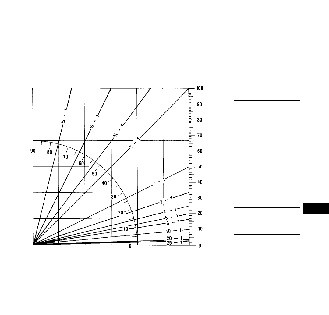
28-11
28
Tables
GRADE COMPARISON CHART
DEGREES — PERCENT — SLOPE
PERCENT
DEGREES SLOPE
GRADE IN DEGREES
AND PERCENTS
DEGREES PERCENT
1 1.8
2 3.5
3 5.2
4 7.0
5 8.8
6 10.5
7 12.3
8 14.0
9 15.8
10 17.6
11 19.4
12 21.3
13 23.1
14 24.9
15 26.8
16 28.7
17 30.6
18 32.5
19 34.4
20 36.4
21 38.4
22 40.4
23 42.4
24 44.5
25 46.6
26 48.8
27 51.0
28 53.2
29 55.4
30 57.7
31 60.0
32 62.5
33 64.9
34 67.4
35 70.0
36 72.7
37 75.4
38 78.1
39 81.0
40 83.9
41 86.9
42 90.0
43 93.3
44 96.6
45 100.0
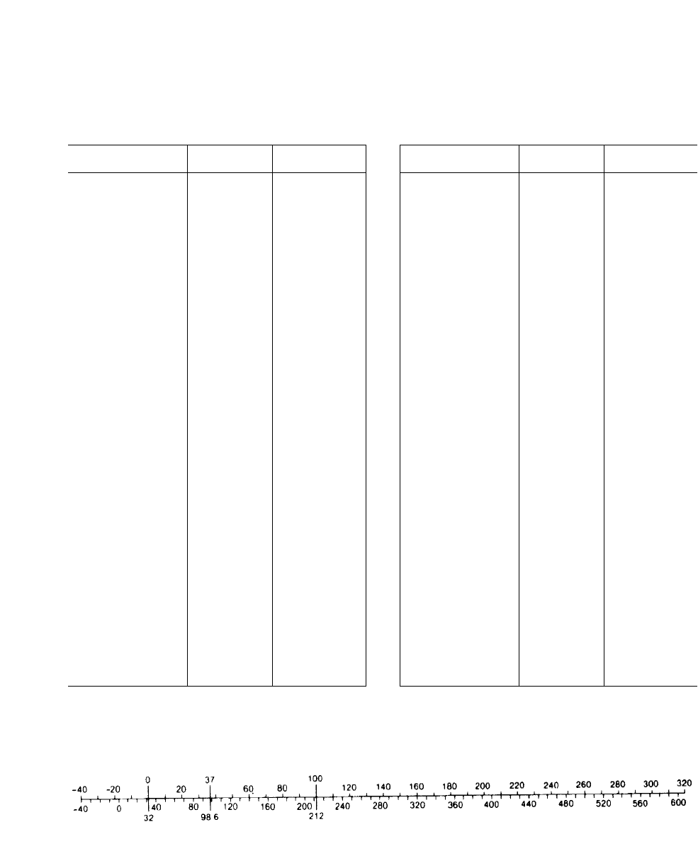
Multiply To Obtain
Metric Unit By English Unit
kilometer (km) .6214 mile
meter (m) 1.0936 yard
meter (m) 3.28 foot
centimeter (cm) .0328 foot
millimeter (mm) .03937 inch
sq kilometer (km2) .3861 square mile
hectare (ha) 2.471 acre
sq meter (m2) 10.764 square foot
sq meter (m2) 1550 square inch
sq centimeter (cm2) .1550 square inch
cu centimeter (cm3) .061 cubic inch
cu meter (m3) 1.308 cubic yard
liter (L) 61.02 cubic inch
liter (L) .001308 cubic yard
km/h .621 mph
liter (L) .2642 U.S. gallon
liter (L) .22 Imperial gallon
metric ton (t) .984 long ton
metric ton (t) 1.102 short ton
kilogram (kg) 2.205 pound, avdp.
gram (g or gr) .0353 ounce, avdp.
kilonewton (kN) 225 pound (force)
newton (N) .225 pound (force)
cu centimeter (cm3) .0338 fluid ounce
kilograms/cu meter 1.686 pounds/cu yd
kilograms/cu meter .062 pounds/cu ft
kilograms/sq cm (kg/cm2) 14.225 pounds/sq in
kilocalorie (kcal) 3.968 Btu
kilogram-meter (kg•m) 7.233 foot-pound
meter-kilogram (m•kg) 7.233 pound-foot
metric horsepower (CV) .9863 hp
kilowatt (kW) 1.341 hp
kilopascal (kPa) .145 psi
bar 14.5 psi
tons/m31692 pounds/cu yd
decaliter .283 bushel
Multiply To Obtain
English Unit By Metric Unit
mile, statute (m) 1.609 kilometer
yard (yd) .9144 meter
foot (ft) .3048 meter
inch (in) 25.4 millimeter
sq mile (mile2) 2.590 sq kilometer
acre .4047 hectare
sq foot (ft2) .0929 sq meter
sq inch (in2) .000645 sq meter
cu yard (yd3) .7645 cu meter
cu inch (in3) 16.387 cu centimeter
cu foot (ft3) .0283 cu meter
cu inch (in3) .0164 liter
cubic yard (yd3) 764.55 liter
mph 1.61 km/h
Ton — mph 1.459 tkm/h
U.S. gallon (US Gal) 3.785 liter
U.S. gallon .833 Imperial gallon
long ton (lg ton) 1.016 metric ton
short ton (sh ton) .907 metric ton
pound (lb) .4536 kilogram
ounce (oz) 28.35 gram
pound (lb) (force) .00445 kilonewton
pound (lb) (force) 4.45 newton
fluid oz (fl oz) 29.57 cu centimeter
lb/cu ft (lb/ft3) 16.018 kg/cu meter
lb/cu yd (lb/yd3) .5933 kg/cu meter
pounds/sq. in. .0703 kilogram/sq cm
psi .0689 bar
psi 6.89 kilopascal
Btu .2520 kilogram-calorie
foot-pound (ft-lb) .1383 kilogram-meter
horsepower (hp) 1.014 metric horsepower
horsepower (hp) .7457 kilowatt
pounds/cu yd .0005928 tons/m3
pounds (No. 2 diesel fuel) .1413 U.S. gallon
bushel 3.524 decaliter
28-12
Tables
CONVERSION FACTORS
NOTE: Some of the above factors have been rounded for convenience. For exact conversion factors please consult International System of Units (SI) table.
Temperature conversion
Degree C
Degree F
°C = (°F – 32) ÷ 1.8 °F = (C 21.8) + 32

28-13
28
Tables
METRIC UNIT EQUIVALENTS
1 km = 1000 m
1 m = 100 cm
1 cm = 10 mm
1 km2= 100 ha
1 ha = 10,000 m2
1 m2= 10,000 cm2
1 cm2= 100 mm2
1 m3= 1000 liters
1 liter = 1000 cm3
1 metric ton = 1000 kg
1 quintal = 100 kg
1 N = 0.10197 kg•m/s2
1 kg = 1000 g
1 g = 1000 mg
1 bar = 14.504 psi
1 cal = 427 kg•m
= 0.0016 cv•h
= 0.00116 kw•h
torque unit
1 CV = 75 kg•m/s
1 kg/cm2= 0.97 atmosph.
POWER UNIT EQUIVALENTS
kW = Kilowatt
hp = Mechanical Horsepower
CV = Cheval Vapeur (Steam
Horsepower)
French Designation For
Metric Horsepower
PS = Pferdestärke (Horsepower)
German Designation For
Metric Horsepower
1 hp = 1.014 CV = 1.014 PS
= 0.7457 kW
1 PS = 1 CV = 0.986 hp
= 0.7355 kW
1 kW = 1.341 hp
= 1.36 CV
= 1.36 PS
ENGLISH UNIT EQUIVALENTS
1 mile = 1760 yd
1 yd = 3 ft
1 ft = 12 in
1 sq mile = 640 acres
1 acre = 43,560 sq ft
1 sq ft = 144 sq in
1 cu ft = 7.48 gal liq
1 gal = 231 cu in
= 4 quarts liq
1 quart = 32 fl oz
1 fl oz = 1.80 cu in
1 sh ton = 2000 lb
1 lg ton = 2240 lb
1 lb = 16 oz, avdp
1 Btu = 778 ft lb
= 0.000393 hph
= 0.000293 kwh
1 mechanical hp = 550 ft-lb/sec
1 atmosph. = 14.7 lb/in2

Track-Type Tractors
D3C Series III & Hystat 3046
D3C XL Series III & Hystat 3046
D3C LGP Series III & Hystat 3046
D4C Series III & Hystat 3046
D4C XL Series III & Hystat 3046
D4C LGP Series III & Hystat 3046
D5C Series III & Hystat 3046 T
D5C XL Series III & Hystat 3046 T
D5C LGP Series III & Hystat 3046 T
D5M XL 3116 T
D5M LGP 3116 T
D5E 3306
D6M XL 3116 T
D6M LGP 3116 T
D6G 3306 T
D6R 3306 T
D6R XL 3306 T
D6R XL (IG) 3306 T
D6R XR 3306 T
D6R LGP 3306 T
D7G 3306 T
D7R 3306 TA
D7R XR 3306 TA
D7R LGP 3306 TA
D8R 3406C TA
D8R LGP 3406C TA
D9R 3408E TA
D10R 3412 TA
D11R 3508B TA
Agricultural Equipment
D4E SR 3304 T
D6G SR 3306 T
Challenger 35 3116 ATAAC
Challenger 45 3116 ATAAC
Challenger 55 3126 ATAAC
Challenger 65E 3176 ATAAC
Challenger 75E 3176 ATAAC
Challenger 85E 3196 ATAAC
Challenger 95E 3196 ATAAC
Lexion 460/465 3126 ATAAC
Lexion 480/485 3176 ATAAC
Waste Handling
Arrangements
D6R WDA 3306 T
D7R WDA 3306 TA
D8R WDA 3406C TA
D9R WDA 3408E TA
D10R WDA 3412 TA
953C WDA 3116 T
963B WDA 3116 TA
973 WDA 3306 T
Motor Graders
120H NA 3116 T
120H NA (VHP) 3116 TA
120H STD 3116 TA
120H ES 3116 TA
135H NA 3116 T
135H NA (VHP) 3116 TA
135H STD 3116 TA
12H NA 3306 T
12H STD 3306
12H ES 3306 T
140H NA 3306 T
140H STD 3306 T
140H ES 3306 T
143H NA 3306 T
160H NA 3306 T
160H NA (VHP) 3306 TA
160H STD 3306 T
160H ES 3306 TA
163H NA 3306 TA
14H 3306 TA
16H 3406 TA
24H 3412E TA
Excavators
301.5 3003
307B Mitsubishi 4M40EI
307 3054***
311B 3064 T
312B/312B L 3064 T*
312B L 3054 T***
315B/315B L 3046 T*
315B L 3054 T***
318B L/318B LN 3046 T
M312 3054 TA
M315 3054 TA
M318 3116 T
M320 3116 T
320B/320B L/320B N 3066 T*
320B/320B L/320B N/320B S 3116 T**
322B/322B L 3116 T
322B L/322B LN 3116 TA**
325B/325B L/325B LN 3116 TA
330B/330B L/330B LN 3306 TA
345B/345B L 3176 ATAAC
350/350 L 3306 ATAAC
375/375 L 3406C ATAAC
5130B 3508 (EUI) TA
5230 3516 (EUI) TA
Front Shovels
5080 3406 TA
5130B 3508 (EUI) TA
5230 3516 (EUI) TA
Backhoe Loaders
416C 3054
426C 3054 T
436C 3054 T
446B 3114 T
428C 3054
438C 3054 T
Wheel Skidders
515 3304 T
525 3304 T
528B 3306 T
Track Skidders
517 3304 T
527 3304 T
Pipelayers
561M 3116 T
572R 3306 T
583R 3406 TA
589 3408 TA
Wheel Tractor-Scrapers
613C Series II 3116 T
615C Series II 3306 TA
623F 3406 TA
633E Series II 3408 TA
621F 3406 TA
631E Series II 3408 TA
651E 3412 TA
627F Tractor 3406 TA
627F Scraper 3306 T
637E Series II Tractor 3408 TA
637E Series II Scraper 3306 TA
657E Tractor 3412 TA
657E Scraper 3408 TA
Construction & Mining Trucks
769D 3408E TA
771D 3408E TA
773D 3412E TA
775D 3412E TA
777D 3508B (EUI) TA
785C 3512 (EUI) TA
789C 3516 (EUI) TA
793C 3516B (EUI) TA
Construction & Mining Tractors
776D 3508B (EUI) TA
784C 3512 (EUI) TA
28-14
Tables
Machine Engine Machine Engine Machine Engine
Model Model Model Model Model Model
***Japan Sourced.
***Belgium Sourced.
***France Sourced.
IG — Intermediate Gauge
VHP — Variable Horsepower

28-15
28
Tables
Articulated Trucks
D25D 3306 TA
D30D 3306 TA
D250E Series II 3306 TA
D300E Series II 3306 TA
D350E 3406 TA
D400E 3406 TA
Wheel Tractors
814F 3306 TA
824G 3406C TA
834B 3408 TA
844 3412E TA
854G 3508B TA
Soil Compactors
815F 3306 TA
825G 3406C TA
Landfill Compactors
816F 3306 TA
826G 3406C TA
836 3408 TA
Wheel Loaders
902 3024
906 3034
914G 3054 T
924F 3114 T
928G 3116 T
938G 3126 T
950G 3126 TA
962G 3126 TA
966F Series II 3306 T
970F 3306 TA
980G 3406 T
988F Series II 3408E TA
990 Series II 3412E TA
992G 3508B TA
994 3516 TA
Track Loaders
933C 3046
939C 3046 T
953C 3116 T
963B 3116 TA
973 3306 T
Integrated Toolcarriers
IT14G 3054 T
IT24F 3114 T
IT28G 3116 T
IT38G 3126 T
IT62G 3126 TA
Telehandlers
TH62 3054
TH63 3054
TH82 3054
TH83 3054 T
TH103 3054 T
Paving Products
Cold Planers
PM-465 3406C
PM-565B 3408 TA
Reclaimer/Stabilizers
RR-250B 3406C TA
SS-250B 3406C TA
RM-350B 3406D TA
Asphalt Pavers
AP-200B Hatz 2M40L
AP-800C 3054 T
AP-1000B 3116 TA
AP-650B 3054 TA
AP-1050B 3116 T
AP-1055B 3116 TA
BG-210B 3054 T
BG-230 3054 T
BG-240B JD4045T*
BG-260C 3116 TA
BG-225C 3054 T
BG-245C 3116 TA
BG-265B 3116 TA
BG-2455C 3116 TA
Road Wideners
BG-730 3056 T
Windrow Elevators
BG-650 3054 T
Compactors
Smooth Drum-Soil
CS-323C 3054
CS-431C 3054 T
CS-433C 3054 T
CS-531C 3116 T
CS-533C 3116 T
CS-563C 3116 T
CS-573C 3116 T
CS-583C 3116 T
Padded Drum-Soil
CP-323C 3054
CP-433C 3054 T
CP-533C 3116 T
CP-563C 3116 T
Dual Drum-Asphalt
CB-214C Hatz 2M41
CB-224C Hatz 2M41
CB-434C/434B 3054
CB-534C 3054 T
CB-544 3054
CB-634C 3116 T
Single Drum-Combination
CB-535B 3054 T
CB-545 3054
Pneumatic Tire-Asphalt
PS-150B 3054
PS-200B 3054 T
PS-360B 3054 T
PF-300B 3054 T
PS-300B 3054 T
PS-500 3208
Underground Mining
R1300 3306 TA
R1600 3176C ATAAC
R1700 Series II 3176 ATAAC
R2900 3406E ATAAC
AD40/AE40 Series II 3408E TA
69D 3408E TA
73D 3412E TA
Machine Engine Machine Engine Machine Engine
Model Model Model Model Model Model
*John Deere.

Engine Fuel
Model and Injection Bore 2Stroke Displacement
(Cylinders) Machine Aspiration System mm in L in3
3003 (3) 301.5 NA DI 75 272 2.95 22.83 0.95 58.2
Hatz 2M41L CB-214C, CB-224C, AP200B NA DI 102 2105 4 24.13 1.716 105
(2)
3024 (4) 902 NA DI 84 2100 3.31 23.94 2.22 135
Mitsubishi 307B* NA DI 95 2100 3.7 23.94 2.84 173
4M40EI (4)
3034 (4) 906 NA DI 97 2100 3.32 23.94 2.95 180
3054 416C, 428C, 307***, CB-434B, NA DI 100 2127 3.94 25.0 4.0 243
(I-4) CB-544, CB-434C, CB-545,
CS-323C, CP-323C, PS-150B,
TH62, TH82, TH63
(416C), 426C, (428C), 436C, 438C, T (optional)
312B L***, 315B L***, AP-800C,
BG-210B, BG-225C, BG-230,
BG-650, 914G, IT14G, PS-200B,
PS-360B, PF-300B, PS-300B,
CS-431C, CS-433C, CP-433C,
CB-534C, CB-534B, CB-535B,
(TH62), (TH63), (TH82),
TH83, TH103
M312, M315, AP-650B TA
3064 311B, 312B* T DI 105 2127 4.1 25.0 4.40 268
(I-4)
3114 446B, IT24F, 924F T DI 105 2127 4.13 25.0 4.4 268
(I-4)
JD4045 BG-240B T DI 106 2127 4.19 25.0 4.5 276
3046 D3C Series III, D3C XL Series III, NA DI 94 2120 3.7 24.7 5.0 305
(I-6) D3C LGP Series III, D4C Series III,
933C, D4C XL Series III,
D4C LGP Series III
D5C Series III, D5C XL Series III, T DI
D5C LGP Series III, 315B/315B L*,
939C, 318B L, 318B LN
DI — Direct Injection NA — Naturally Aspirated
T — Turbocharged
***Japan sourced.
***Belgium sourced.
***France sourced.
NOTE: Materials and specifications subject to change without notice. Component commonality of Cat Engines for all applications does not imply complete interchange-
ability. Contact your Caterpillar Dealer for specific information.
28-16
Tables

28-17
28
Tables
Engine Fuel
Model and Injection Bore 2Stroke Displacement
(Cylinders) Machine Aspiration System mm in L in3
3056 BG-730 T DI 100 2127 3.94 25.0 6.0 365
(I-6)
3066 320B*, 320B L*, 320B N* T DI 102 2130 4.0 25.1 6.4 391
(I-6)
3116 M318, M320, 320B**, 320B L**, T DI 105 2127 4.13 25.0 6.6 402
(I-6) 320B N**, 320B S**, 613C Series II,
928G, 953C, IT28F, AP-1050B,
CS-533C, CS-531C, CS-563C,
CS-573C, CS-583C, CB-634C,
CP-533C, CP-563C, 322B, 322B L,
322B LN, BG-750, 120H NA,
135H NA, D5M, D6M, 561M
BG-260C, BG-245C, AP-1055B, TA DI
120H NA***, 135H***, 120H STD,
135H STD, 120H ES, 322B/
322B LN**, 325B, 325B L, 325B LN,
963B, BG-270B, BG-265B,
BG-2455C, AP1000B
Challenger 35, Challenger 45 T ATAAC DI
3304 D4E SR, 515, 525, 527, 517 T DI 121 2152 4.75 267425
(I-4)
3126 938G, IT38G T DI 110 2127 4.33 25.0 7.2 442
(I-6) 950G, 962G, IT62G TA
Challenger 55, Lexion 460/465 ATAAC
3176 Challenger 65E, Challenger 75E, T ATAAC DI 125 2140 4.92 25.5 10.2 629
(I-6) R1700 Series II, R1600, 345B,
345B L, Lexion 480/485
3208 NA DI 114 2127 4.5 2510.4 636
(V-8)
PC — Precombustion TA — Turbocharged and Aftercooled
DI — Direct Injection T ATAAC — Turbocharged and Air/Air Aftercooled
T — Turbocharged NA — Naturally Aspirated
***Japan sourced.
***Belgium sourced.
***With VHP option.
NOTE: Materials and specifications subject to change without notice. Component commonality of Cat Engines for all applications does not imply complete interchange-
ability. Contact your Caterpillar Dealer for specific information.

Engine Fuel
Model and Injection Bore 2Stroke Displacement
(Cylinders) Machine Aspiration System mm in L in3
3306 D5E, 12H STD NA DI 121 2152 4.75 2610.5 638
(I-6) D6R XL, D6R XR, D6R, D6R LGP, T DI
D6R WHA, D6G, D6G SR, D7G,
12H NA, 140H NA, 143H NA,
160H NA, 140H STD, 160H STD,
12H ES, 140H ES, 528B, 572R,
627F Sc., 973, 966F Series II
D7R, D7R XR, D7R LGP, D7R WHA, TA DI
637E Series II Sc., R1300, 615C,
D25D, 970F, D30D, D250E Series II,
D300E Series II, 330B, 330B L,
330B LN, 814F, 815F, 816F,
160H NA***, 163H NA,
160H ES, 14H
350, 350 L T ATAAC DI
3196 Challenger 85E, Challenger 95E T ATAAC DI 130 2150 5.1 25.9 12 732
(I-6)
3406 980G, PM-465 T DI 137 2165 5.4 26.5 14.6 893
(I-6) 621F, 623F, 627F Tr., D350E, D400E, TA DI
RR-250B, SS-250B, RM-350B, 16H
583R, 824G, 825G, 826G, D8R,
D8R LGP, D8R WHA
375, 375 L, 5080, R2900 T ATAAC DI
3408 D9R, D9R WHA, 589, 631E-II, TA DI 137 2152 5.4 2618 1099
(V-8) 633E-II, 637E-II Tr., 657E Sc., 771D,
769D, 834B, 836, 988F-II, PM-565B,
AD40, 69D
T ATAAC
3412 D10R, D10R WHA, 651E, 657E Tr., TA DI 137 2152 5.4 2627 1649
(V-12) 773D, 775D, 990, 24H, 73D, 844
3508 D11R, 777D, 776D, 5130B, 992G, TA DI 170 2190 6.7 27.5 34.5 2105
(V-8) 854G
3512 785C, 784C TA DI 170 2190 6.7 27.5 51.8 3158
(V-12)
3516 789C, 793C, 994, 5230 TA DI 170 2190 6.7 27.5 69.1 4211
(V-16)
PC — Precombustion TA — Turbocharged and Aftercooled
DI — Direct Injection T ATAAC — Turbocharged and Air/Air Aftercooled
T — Turbocharged NA — Naturally Aspirated
***Japan sourced.
***Belgium sourced.
***With VHP option.
NOTE: Materials and specifications subject to change without notice. Component commonality of Cat Engines for all applications does not imply complete interchange-
ability. Contact your Caterpillar Dealer for specific information.
28-18
Tables

29-1
SECTION page
Abrasiveness ratings (undercarriage) . . . . . . . . . . . . . . . . . . . . . . . . . . . 21 31
Agricultural commodities conversion factors . . . . . . . . . . . . . . . . . . 28 2
Agricultural Equipment . . . . . . . . . . . . . . . . . . . . . . . . . . . . . . . . . . . . . . 21-18
Depreciation and repair costs. . . . . . . . . . . . . . . . . . . . . . . . . . . . . . . . . . 21 9
Former Models . . . . . . . . . . . . . . . . . . . . . . . . . . . . . . . . . . . . . . . . . . . . . 20 19
Horsepower ratings. . . . . . . . . . . . . . . . . . . . . . . . . . . . . . . . . . . . . . . . . . . 211
Altitude:
Deration table . . . . . . . . . . . . . . . . . . . . . . . . . . . . . . . . . . . . . . . . . . . . . . 28 5
Discussion of . . . . . . . . . . . . . . . . . . . . . . . . . . . . . . . . . . . . . . . . . . . . . . . 23 7
Angle blade (Challenger) . . . . . . . . . . . . . . . . . . . . . . . . . . . . . . . . . . . . . . . 216
Angle of repose (materials table) . . . . . . . . . . . . . . . . . . . . . . . . . . . . . . . 28 1
Angling “A” blade, description of . . . . . . . . . . . . . . . . . . . . . . . . . . . . . . . . 138
Articulated Dump Trucks . . . . . . . . . . . . . . . . . . . . . . . . . . . . . . . . . . . . 10 1-30
Former models. . . . . . . . . . . . . . . . . . . . . . . . . . . . . . . . . . . . . . . . . . . . . . 20 37
Ground Pressure . . . . . . . . . . . . . . . . . . . . . . . . . . . . . . . . . . . . . . . . . . . . 10 5
Special Arrangements. . . . . . . . . . . . . . . . . . . . . . . . . . . . . . . . . . . . . . . . 10 4
Asphalt Pavers. . . . . . . . . . . . . . . . . . . . . . . . . . . . . . . . . . . . . . . . . . . . . . 16 11
Attachment (options) selection:
Backhoe Loaders . . . . . . . . . . . . . . . . . . . . . . . . . . . . . . . . . . . . . . . . . . . . . 529
Blades . . . . . . . . . . . . . . . . . . . . . . . . . . . . . . . . . . . . . . . . . . . . . . . . . . . . . 136
Dozers & scoops . . . . . . . . . . . . . . . . . . . . . . . . . . . . . . . . . . . . . . . . . . . . . 154
11 8, 16, 20
24 40
Excavators . . . . . . . . . . . . . . . . . . . . . . . . . . . . . . . . . . . . . . . . . . . . . . . . . . 4146
Grapples . . . . . . . . . . . . . . . . . . . . . . . . . . . . . . . . . . . . . . . . . . . . . . . . . . . 65, 13
High speed disc saws . . . . . . . . . . . . . . . . . . . . . . . . . . . . . . . . . . . . . . . . 24 40
Hydromechanical work tools . . . . . . . . . . . . . . . . . . . . . . . . . . . . . . . . . . 18 1-16
Integrated Toolcarriers . . . . . . . . . . . . . . . . . . . . . . . . . . . . . . . . . . . . . . . 14 4, 13
Land clearing. . . . . . . . . . . . . . . . . . . . . . . . . . . . . . . . . . . . . . . . . . . . . . . 26 8
Log and lumber forks . . . . . . . . . . . . . . . . . . . . . . . . . . . . . . . . . . . . . . . . 24 44
Log loading fronts . . . . . . . . . . . . . . . . . . . . . . . . . . . . . . . . . . . . . . . . . . . 24 21
Motor Graders . . . . . . . . . . . . . . . . . . . . . . . . . . . . . . . . . . . . . . . . . . . . . . . 312
Reclaimers/Stabilizers . . . . . . . . . . . . . . . . . . . . . . . . . . . . . . . . . . . . . . . 16 8
Telescopic Material Handlers. . . . . . . . . . . . . . . . . . . . . . . . . . . . . . . . . . 15 12
Backhoe Loaders. . . . . . . . . . . . . . . . . . . . . . . . . . . . . . . . . . . . . . . . . . . . . 51-30
Digging forces . . . . . . . . . . . . . . . . . . . . . . . . . . . . . . . . . . . . . . . . . . . . . . . 56
Former models. . . . . . . . . . . . . . . . . . . . . . . . . . . . . . . . . . . . . . . . . . . . . . 20 30
Ballast:
Fillage table (Tires). . . . . . . . . . . . . . . . . . . . . . . . . . . . . . . . . . . . . . . . . . 22 30
Landfill Compactors . . . . . . . . . . . . . . . . . . . . . . . . . . . . . . . . . . . . . . . . . 11 19
Wheel Tractors . . . . . . . . . . . . . . . . . . . . . . . . . . . . . . . . . . . . . . . . . . . . . 11 6
Barber-Greene:
Asphalt Pavers . . . . . . . . . . . . . . . . . . . . . . . . . . . . . . . . . . . . . . . . . . . . . 16 14
Road Wideners . . . . . . . . . . . . . . . . . . . . . . . . . . . . . . . . . . . . . . . . . . . . . 16 20
Windrow Elevators . . . . . . . . . . . . . . . . . . . . . . . . . . . . . . . . . . . . . . . . . . 16 21
Bearing powers (materials table). . . . . . . . . . . . . . . . . . . . . . . . . . . . . . . 28 2
Bias ply tires, definition of . . . . . . . . . . . . . . . . . . . . . . . . . . . . . . . . . . . . 22 2
Blades, description of . . . . . . . . . . . . . . . . . . . . . . . . . . . . . . . . . . . . . . . . . . 137
Abrasiveness Ratings —INDEX— Blades
29

SECTION page
Brake Performance Curves:
Construction & Mining Trucks/Tractors . . . . . . . . . . . . . . . . . . . . . . . . . . 910
Use of:
Construction & Mining Trucks/Tractors . . . . . . . . . . . . . . . . . . . . . . . . 98
Bucket capacities:
Backhoe Loaders . . . . . . . . . . . . . . . . . . . . . . . . . . . . . . . . . . . . . . . . . . . . . 520
Excavators . . . . . . . . . . . . . . . . . . . . . . . . . . . . . . . . . . . . . . . . . . . . . . . . . . 4102
Definition of . . . . . . . . . . . . . . . . . . . . . . . . . . . . . . . . . . . . . . . . . . . . . . . 491
Ditch cleaning . . . . . . . . . . . . . . . . . . . . . . . . . . . . . . . . . . . . . . . . . . . . . 4125
Front shovels . . . . . . . . . . . . . . . . . . . . . . . . . . . . . . . . . . . . . . . . . . . . . . 4174
Long reach . . . . . . . . . . . . . . . . . . . . . . . . . . . . . . . . . . . . . . . . . . . . . . . . 4123
Integrated Toolcarriers . . . . . . . . . . . . . . . . . . . . . . . . . . . . . . . . . . . . . . . 14 5
Telescopic Material Handlers. . . . . . . . . . . . . . . . . . . . . . . . . . . . . . . . . . 15 13
Track Loaders . . . . . . . . . . . . . . . . . . . . . . . . . . . . . . . . . . . . . . . . . . . . . . 13 4
Underground Mining . . . . . . . . . . . . . . . . . . . . . . . . . . . . . . . . . . . . . . . . 17 4
Wheel Loaders. . . . . . . . . . . . . . . . . . . . . . . . . . . . . . . . . . . . . . . . . . . . . . 12 6
Bucket fill factors (materials table). . . . . . . . . . . . . . . . . . . . . . . . . . . . . 28 1
Excavators . . . . . . . . . . . . . . . . . . . . . . . . . . . . . . . . . . . . . . . . . . . . . . . . . . 4120
Front shovels. . . . . . . . . . . . . . . . . . . . . . . . . . . . . . . . . . . . . . . . . . . . . . . . 4176
Track Loaders . . . . . . . . . . . . . . . . . . . . . . . . . . . . . . . . . . . . . . . . . . . . . . 13 17
Wheel Loaders. . . . . . . . . . . . . . . . . . . . . . . . . . . . . . . . . . . . . . . . . . . . . . 12 40
Bucket payload:
Excavators . . . . . . . . . . . . . . . . . . . . . . . . . . . . . . . . . . . . . . . . . . . . . . . . . . 4120
Track Loaders . . . . . . . . . . . . . . . . . . . . . . . . . . . . . . . . . . . . . . . . . . . . . . 13 17
Wheel Loaders. . . . . . . . . . . . . . . . . . . . . . . . . . . . . . . . . . . . . . . . . . . . . . 12 40
Bucket selection:
Excavators . . . . . . . . . . . . . . . . . . . . . . . . . . . . . . . . . . . . . . . . . . . . . . . . . . 492
Integrated Toolcarriers . . . . . . . . . . . . . . . . . . . . . . . . . . . . . . . . . . . . . . . 14 13
Telescopic Material Handlers. . . . . . . . . . . . . . . . . . . . . . . . . . . . . . . . . . 15 13
Underground Mining . . . . . . . . . . . . . . . . . . . . . . . . . . . . . . . . . . . . . . . . 17 5
Wheel Loaders. . . . . . . . . . . . . . . . . . . . . . . . . . . . . . . . . . . . . . . . . . . . . . 12 45
Bulldozers . . . . . . . . . . . . . . . . . . . . . . . . . . . . . . . . . . . . . . . . . . . . . . . . . . . 135
Blade options (summary) . . . . . . . . . . . . . . . . . . . . . . . . . . . . . . . . . . . . . . 136
Blade selection . . . . . . . . . . . . . . . . . . . . . . . . . . . . . . . . . . . . . . . . . . . . . . 137
Blade Specifications . . . . . . . . . . . . . . . . . . . . . . . . . . . . . . . . . . . . . . . . . . 141, 54
11 8, 16, 20
Correction factors . . . . . . . . . . . . . . . . . . . . . . . . . . . . . . . . . . . . . . . . . . . . 153
Dimension drawing. . . . . . . . . . . . . . . . . . . . . . . . . . . . . . . . . . . . . . . . . . . 140
SAE Blade Capacity Definition . . . . . . . . . . . . . . . . . . . . . . . . . . . . . . . . . 140
Waste disposal. . . . . . . . . . . . . . . . . . . . . . . . . . . . . . . . . . . . . . . . . . . . . . 11 20
Cable & ferrule sizes (Winches). . . . . . . . . . . . . . . . . . . . . . . . . . . . . . . . . 178
Coal handling dozers/scoops/buckets. . . . . . . . . . . . . . . . . . . . . . . . . . . 155
Production estimating. . . . . . . . . . . . . . . . . . . . . . . . . . . . . . . . . . . . . . . . 25 4
Code identification (Tires) . . . . . . . . . . . . . . . . . . . . . . . . . . . . . . . . . . . . 22 4
Cold inflation pressures (Tires) . . . . . . . . . . . . . . . . . . . . . . . . . . . . . . . 22 22
Cold Planers . . . . . . . . . . . . . . . . . . . . . . . . . . . . . . . . . . . . . . . . . . . . . . . . 16 1
Applications. . . . . . . . . . . . . . . . . . . . . . . . . . . . . . . . . . . . . . . . . . . . . . . . 16 5
Former models. . . . . . . . . . . . . . . . . . . . . . . . . . . . . . . . . . . . . . . . . . . . . . 20 45
Use by project type . . . . . . . . . . . . . . . . . . . . . . . . . . . . . . . . . . . . . . . . . . 16 6
29-2
Brake Performance Curves —INDEX— Cold Planers

29-3
SECTION page
Cold planing fundamentals . . . . . . . . . . . . . . . . . . . . . . . . . . . . . . . . . . 16 4
Compaction:
Comparison (Waste Disposal). . . . . . . . . . . . . . . . . . . . . . . . . . . . . . . . . . 27 6
Factors (Waste Disposal) . . . . . . . . . . . . . . . . . . . . . . . . . . . . . . . . . . . . . 27 5
Production . . . . . . . . . . . . . . . . . . . . . . . . . . . . . . . . . . . . . . . . . . . . . . . . . 27 6
Fundamentals:
Landfill. . . . . . . . . . . . . . . . . . . . . . . . . . . . . . . . . . . . . . . . . . . . . . . . . . 11 19
Soil . . . . . . . . . . . . . . . . . . . . . . . . . . . . . . . . . . . . . . . . . . . . . . . . . . . . . 11 13
Compactors:
Dual Drum Vibratory Asphalt . . . . . . . . . . . . . . . . . . . . . . . . . . . . . . . . . 16 29
Former Models . . . . . . . . . . . . . . . . . . . . . . . . . . . . . . . . . . . . . . . . . . . . . 20 39, 50
Landfill . . . . . . . . . . . . . . . . . . . . . . . . . . . . . . . . . . . . . . . . . . . . . . . . . . . 11 17
Padded Drum Vibratory Soil . . . . . . . . . . . . . . . . . . . . . . . . . . . . . . . . . . 16 26
Pneumatic Tire Asphalt . . . . . . . . . . . . . . . . . . . . . . . . . . . . . . . . . . . . . . 16 35
Combination Vibratory . . . . . . . . . . . . . . . . . . . . . . . . . . . . . . . . . . . . . . . 16 34
Soil . . . . . . . . . . . . . . . . . . . . . . . . . . . . . . . . . . . . . . . . . . . . . . . . . . . . . . . 11 11
Application zones. . . . . . . . . . . . . . . . . . . . . . . . . . . . . . . . . . . . . . . . . . 11 14
Smooth Drum Vibratory Soil . . . . . . . . . . . . . . . . . . . . . . . . . . . . . . . . . . 16 22
Concrete Crushers . . . . . . . . . . . . . . . . . . . . . . . . . . . . . . . . . . . . . . . . . . 18 13-14
Applications. . . . . . . . . . . . . . . . . . . . . . . . . . . . . . . . . . . . . . . . . . . . . . . . 18 15
Features. . . . . . . . . . . . . . . . . . . . . . . . . . . . . . . . . . . . . . . . . . . . . . . . . . . 18 15
Matching guide . . . . . . . . . . . . . . . . . . . . . . . . . . . . . . . . . . . . . . . . . . . . . 18 15
Specifications. . . . . . . . . . . . . . . . . . . . . . . . . . . . . . . . . . . . . . . . . . . . . . . 18 16
Concrete Pulverizers . . . . . . . . . . . . . . . . . . . . . . . . . . . . . . . . . . . . . . . . 18 15-16
Applications. . . . . . . . . . . . . . . . . . . . . . . . . . . . . . . . . . . . . . . . . . . . . . . . 18 13
Features. . . . . . . . . . . . . . . . . . . . . . . . . . . . . . . . . . . . . . . . . . . . . . . . . . . 18 13
Matching guide . . . . . . . . . . . . . . . . . . . . . . . . . . . . . . . . . . . . . . . . . . . . . 18 13
Specifications. . . . . . . . . . . . . . . . . . . . . . . . . . . . . . . . . . . . . . . . . . . . . . . 18 14
Conversion factors, Agricultural Commodities . . . . . . . . . . . . . . . . . 28 2
Metric-English/English-Metric. . . . . . . . . . . . . . . . . . . . . . . . . . . . . . . . . 28 12
Construction & Mining Trucks/Tractors . . . . . . . . . . . . . . . . . . . . . . . . 91-44
Former Models . . . . . . . . . . . . . . . . . . . . . . . . . . . . . . . . . . . . . . . . . . . . . 20 36
Power Train Efficiencies, Mechanical . . . . . . . . . . . . . . . . . . . . . . . . . . . . 99
Counterweights:
Stockpile Coal Handling . . . . . . . . . . . . . . . . . . . . . . . . . . . . . . . . . . . . . . 25 2
Wheel Tractors . . . . . . . . . . . . . . . . . . . . . . . . . . . . . . . . . . . . . . . . . . . . . 11 6
Curl and Crowd Forces:
Excavators . . . . . . . . . . . . . . . . . . . . . . . . . . . . . . . . . . . . . . . . . . . . . . . . . . 491
Front Shovels . . . . . . . . . . . . . . . . . . . . . . . . . . . . . . . . . . . . . . . . . . . . . . . 4173
Curve superelevation table . . . . . . . . . . . . . . . . . . . . . . . . . . . . . . . . . . 28 3
Cushion “C” blade, description of. . . . . . . . . . . . . . . . . . . . . . . . . . . . . . . . 138
Cycle times:
Articulated/Construction & Mining Trucks. . . . . . . . . . . . . . . . . . . . . . . . 98
Excavators . . . . . . . . . . . . . . . . . . . . . . . . . . . . . . . . . . . . . . . . . . . . . . . . . . 4147
Front Shovels . . . . . . . . . . . . . . . . . . . . . . . . . . . . . . . . . . . . . . . . . . . . . . . 4175
Track Loaders . . . . . . . . . . . . . . . . . . . . . . . . . . . . . . . . . . . . . . . . . . . . . . 13 16
Wheel Loaders. . . . . . . . . . . . . . . . . . . . . . . . . . . . . . . . . . . . . . . . . . . . . . 12 39
Wheel Tractor-Scrapers . . . . . . . . . . . . . . . . . . . . . . . . . . . . . . . . . . . . . . . 811, 73
Cold Planing Fundamentals —INDEX— Cycle Times
29

SECTION page
Delay time (figuring production) . . . . . . . . . . . . . . . . . . . . . . . . . . . . . . . . 23 4
Delivered price (O & O) . . . . . . . . . . . . . . . . . . . . . . . . . . . . . . . . . . . . . . 21 9
Demolition Arrangements (Excavators). . . . . . . . . . . . . . . . . . . . . . . . . . 4127
Demolition Shears. . . . . . . . . . . . . . . . . . . . . . . . . . . . . . . . . . . . . . . . . . . 18 10
Depreciation, discussion of (O & O) . . . . . . . . . . . . . . . . . . . . . . . . . . . . . 21 5
Ditch Cleaning Excavators . . . . . . . . . . . . . . . . . . . . . . . . . . . . . . . . . . . . 4125
Dozing tools, descriptions of . . . . . . . . . . . . . . . . . . . . . . . . . . . . . . . . . . . . 137
Drawbar pull and tillage discussion (Ag Tractors) . . . . . . . . . . . . . . . . 217
Drawbar pull forward:
Direct drive:
Agricultural Tractors. . . . . . . . . . . . . . . . . . . . . . . . . . . . . . . . . . . . . . . . 213
Track-Type Tractors . . . . . . . . . . . . . . . . . . . . . . . . . . . . . . . . . . . . . . . . 121
Power shift:
Pipelayers . . . . . . . . . . . . . . . . . . . . . . . . . . . . . . . . . . . . . . . . . . . . . . . . 75
Landfill Compactors . . . . . . . . . . . . . . . . . . . . . . . . . . . . . . . . . . . . . . . 11 18
Soil Compactors. . . . . . . . . . . . . . . . . . . . . . . . . . . . . . . . . . . . . . . . . . . 11 12
Track Skidders. . . . . . . . . . . . . . . . . . . . . . . . . . . . . . . . . . . . . . . . . . . . . 611
Track-Type Tractors . . . . . . . . . . . . . . . . . . . . . . . . . . . . . . . . . . . . . . . . 113
Wheel Skidders . . . . . . . . . . . . . . . . . . . . . . . . . . . . . . . . . . . . . . . . . . . . 63
Wheel Tractors. . . . . . . . . . . . . . . . . . . . . . . . . . . . . . . . . . . . . . . . . . . . 11 4
Dual Drum Vibratory Asphalt Compactors. . . . . . . . . . . . . . . . . . . . . 16 29
Engines . . . . . . . . . . . . . . . . . . . . . . . . . . . . . . . . . . . . . . . . . . . . . . . . . . . . 19 1-22
Design data . . . . . . . . . . . . . . . . . . . . . . . . . . . . . . . . . . . . . . . . . . . . . . . . 19 2
Rating explanation . . . . . . . . . . . . . . . . . . . . . . . . . . . . . . . . . . . . . . . . . . 19 2
Used in Caterpillar Products . . . . . . . . . . . . . . . . . . . . . . . . . . . . . . . . . . 28 14
English unit equivalents . . . . . . . . . . . . . . . . . . . . . . . . . . . . . . . . . . . . . 28 13
Equipment selection:
Land Clearing . . . . . . . . . . . . . . . . . . . . . . . . . . . . . . . . . . . . . . . . . . . . . . 26 2
Stockpile Coal Handling . . . . . . . . . . . . . . . . . . . . . . . . . . . . . . . . . . . . . . 25 1
Waste Disposal . . . . . . . . . . . . . . . . . . . . . . . . . . . . . . . . . . . . . . . . . . . . . 27 2
Estimating:
Draft or drawbar pull (Agricultural Tractors). . . . . . . . . . . . . . . . . . . . . . 218
Form (O & O). . . . . . . . . . . . . . . . . . . . . . . . . . . . . . . . . . . . . . . . . . . . . . . 21 2
Landfill (Waste Disposal) . . . . . . . . . . . . . . . . . . . . . . . . . . . . . . . . . . . . . 27 6
Operating Costs (O & O). . . . . . . . . . . . . . . . . . . . . . . . . . . . . . . . . . . . . . 21 11
Owning Costs (O & O) . . . . . . . . . . . . . . . . . . . . . . . . . . . . . . . . . . . . . . . 21 5
Tire life . . . . . . . . . . . . . . . . . . . . . . . . . . . . . . . . . . . . . . . . . . . . . . . . . . . 21 27
Undercarriage costs (O & O) . . . . . . . . . . . . . . . . . . . . . . . . . . . . . . . . . . 21 31
29-4
Delay Time —INDEX— Estimating

29-5
SECTION page
Estimating Production:
Asphalt Pavers . . . . . . . . . . . . . . . . . . . . . . . . . . . . . . . . . . . . . . . . . . . . . 16 19
Bulldozers . . . . . . . . . . . . . . . . . . . . . . . . . . . . . . . . . . . . . . . . . . . . . . . . . . 149
Cold Planers . . . . . . . . . . . . . . . . . . . . . . . . . . . . . . . . . . . . . . . . . . . . . . . 16 3
Compactor production (waste disposal) . . . . . . . . . . . . . . . . . . . . . . . . . . 27 6
Dual Drum Vibratory Asphalt Compactors . . . . . . . . . . . . . . . . . . . . . . . 16 33
Elements of production. . . . . . . . . . . . . . . . . . . . . . . . . . . . . . . . . . . . . . . . 217
Excavators . . . . . . . . . . . . . . . . . . . . . . . . . . . . . . . . . . . . . . . . . . . . . . . . . . 4150
Front shovels . . . . . . . . . . . . . . . . . . . . . . . . . . . . . . . . . . . . . . . . . . . . . . 4175
Trenching . . . . . . . . . . . . . . . . . . . . . . . . . . . . . . . . . . . . . . . . . . . . . . . . . 4154
Hydraulic hammers . . . . . . . . . . . . . . . . . . . . . . . . . . . . . . . . . . . . . . . . . 18 8
Land Clearing . . . . . . . . . . . . . . . . . . . . . . . . . . . . . . . . . . . . . . . . . . . . . . 26 4
Mining and Earthmoving . . . . . . . . . . . . . . . . . . . . . . . . . . . . . . . . . . . . . 23 4
Padded Drum Vibratory Soil Compactors . . . . . . . . . . . . . . . . . . . . . . . . 16 28
Pneumatic Tire Asphalt Compactors . . . . . . . . . . . . . . . . . . . . . . . . . . . . 16 37
Ripping . . . . . . . . . . . . . . . . . . . . . . . . . . . . . . . . . . . . . . . . . . . . . . . . . . . . 168
Production graphs . . . . . . . . . . . . . . . . . . . . . . . . . . . . . . . . . . . . . . . . . . 175
Seismic velocity charts . . . . . . . . . . . . . . . . . . . . . . . . . . . . . . . . . . . . . . 169
Road Reclaimer/Soil Stabilizer. . . . . . . . . . . . . . . . . . . . . . . . . . . . . . . . . 16 9
Smooth Drum Vibratory Soil Compactors . . . . . . . . . . . . . . . . . . . . . . . . 16 25
Soil Compactors. . . . . . . . . . . . . . . . . . . . . . . . . . . . . . . . . . . . . . . . . . . . . 11 15
Stockpile Coal Handling . . . . . . . . . . . . . . . . . . . . . . . . . . . . . . . . . . . . . . 25 3
Tillage . . . . . . . . . . . . . . . . . . . . . . . . . . . . . . . . . . . . . . . . . . . . . . . . . . . . . 217
Towed Scrapers . . . . . . . . . . . . . . . . . . . . . . . . . . . . . . . . . . . . . . . . . . . . . . 183
Track Loaders . . . . . . . . . . . . . . . . . . . . . . . . . . . . . . . . . . . . . . . . . . . . . . 13 16
Trees per acre/hectare. . . . . . . . . . . . . . . . . . . . . . . . . . . . . . . . . . . . . . . . 24 51
Skidders. . . . . . . . . . . . . . . . . . . . . . . . . . . . . . . . . . . . . . . . . . . . . . . . . . . 24 1
Waste Disposal . . . . . . . . . . . . . . . . . . . . . . . . . . . . . . . . . . . . . . . . . . . . . 27 6
Wheel Loaders. . . . . . . . . . . . . . . . . . . . . . . . . . . . . . . . . . . . . . . . . . . . . . 12 70
Wheel Tractor-Scrapers . . . . . . . . . . . . . . . . . . . . . . . . . . . . . . . . . . . . . . . 861
Excavators . . . . . . . . . . . . . . . . . . . . . . . . . . . . . . . . . . . . . . . . . . . . . . . . . . 41-196
Attachment summary. . . . . . . . . . . . . . . . . . . . . . . . . . . . . . . . . . . . . . . . . 4140
Curl & crowd forces. . . . . . . . . . . . . . . . . . . . . . . . . . . . . . . . . . . . . . . . . . . 491
Front shovels . . . . . . . . . . . . . . . . . . . . . . . . . . . . . . . . . . . . . . . . . . . . . . 4173
Demolition arrangements. . . . . . . . . . . . . . . . . . . . . . . . . . . . . . . . . . . . . . 4127
Ditch cleaning . . . . . . . . . . . . . . . . . . . . . . . . . . . . . . . . . . . . . . . . . . . . . . . 4125
Former models. . . . . . . . . . . . . . . . . . . . . . . . . . . . . . . . . . . . . . . . . . . . . . 20 24
Front shovels. . . . . . . . . . . . . . . . . . . . . . . . . . . . . . . . . . . . . . . . . . . . . . . . 4161
Long reach . . . . . . . . . . . . . . . . . . . . . . . . . . . . . . . . . . . . . . . . . . . . . . . . 4123
Major component weights. . . . . . . . . . . . . . . . . . . . . . . . . . . . . . . . . . . . . . 429
Long reach . . . . . . . . . . . . . . . . . . . . . . . . . . . . . . . . . . . . . . . . . . . . . . . . . . 4124
Material handling arrangements. . . . . . . . . . . . . . . . . . . . . . . . . . . . . . . . 4182
Shoe selection . . . . . . . . . . . . . . . . . . . . . . . . . . . . . . . . . . . . . . . . . . . . . . . 4137
Front shovels . . . . . . . . . . . . . . . . . . . . . . . . . . . . . . . . . . . . . . . . . . . . . . 4173
Stick/bucket combinations . . . . . . . . . . . . . . . . . . . . . . . . . . . . . . . . . . . . . 4135
Quick Coupler . . . . . . . . . . . . . . . . . . . . . . . . . . . . . . . . . . . . . . . . . . . . . . . 4140
Estimating Production —INDEX— Excavators
29

SECTION page
Fill factor (discussion of) . . . . . . . . . . . . . . . . . . . . . . . . . . . . . . . . . . . . . . 23 3
Filters (O & O). . . . . . . . . . . . . . . . . . . . . . . . . . . . . . . . . . . . . . . . . . . . . . . 21 20
Fire Pump Engines . . . . . . . . . . . . . . . . . . . . . . . . . . . . . . . . . . . . . . . . . . 19 7
Fixed times (hauling units)
Articulated Trucks . . . . . . . . . . . . . . . . . . . . . . . . . . . . . . . . . . . . . . . . . . . 98
Construction & Mining Trucks. . . . . . . . . . . . . . . . . . . . . . . . . . . . . . . . . . 98
Wheel Tractor-Scrapers . . . . . . . . . . . . . . . . . . . . . . . . . . . . . . . . . . . . . . . 811
Forestry Machines . . . . . . . . . . . . . . . . . . . . . . . . . . . . . . . . . . . . . . . . . . 24 18
Formulas & rules of thumb (Earthmoving) . . . . . . . . . . . . . . . . . . . . . . 23 15
Front Shovels (Excavators) . . . . . . . . . . . . . . . . . . . . . . . . . . . . . . . . . . . . . 4161
Fuel consumption:
Machine productivity . . . . . . . . . . . . . . . . . . . . . . . . . . . . . . . . . . . . . . . . 23 14
Tables (O & O). . . . . . . . . . . . . . . . . . . . . . . . . . . . . . . . . . . . . . . . . . . . . . 21 12
Generator Sets:
Diesel . . . . . . . . . . . . . . . . . . . . . . . . . . . . . . . . . . . . . . . . . . . . . . . . . . . . . 19 10
Gaseous Fueled . . . . . . . . . . . . . . . . . . . . . . . . . . . . . . . . . . . . . . . . . . . . . 19 13
Marine . . . . . . . . . . . . . . . . . . . . . . . . . . . . . . . . . . . . . . . . . . . . . . . . . . . . 19 18
Olympian . . . . . . . . . . . . . . . . . . . . . . . . . . . . . . . . . . . . . . . . . . . . . . . . . . 19 12
Goodyear:
Tire life (estimating system). . . . . . . . . . . . . . . . . . . . . . . . . . . . . . . . . . . 21 30
Grade:
Comparison chart/degrees & percent. . . . . . . . . . . . . . . . . . . . . . . . . . . . 28 11
Resistance (discussion of) . . . . . . . . . . . . . . . . . . . . . . . . . . . . . . . . . . . . . 23 6
Grapples . . . . . . . . . . . . . . . . . . . . . . . . . . . . . . . . . . . . . . . . . . . . . . . . . . . . 66, 13
SAE definition . . . . . . . . . . . . . . . . . . . . . . . . . . . . . . . . . . . . . . . . . . . . . . . 65
Ground pressures:
Articulated Trucks . . . . . . . . . . . . . . . . . . . . . . . . . . . . . . . . . . . . . . . . . . 10 5
Excavators . . . . . . . . . . . . . . . . . . . . . . . . . . . . . . . . . . . . . . . . . . . . . . . . . . 4137
Front shovels . . . . . . . . . . . . . . . . . . . . . . . . . . . . . . . . . . . . . . . . . . . . . . 4173
Track Loaders (LGP). . . . . . . . . . . . . . . . . . . . . . . . . . . . . . . . . . . . . . . . . 13 2
Track-Type Tractors . . . . . . . . . . . . . . . . . . . . . . . . . . . . . . . . . . . . . . . . . . 123
Heel Boom Grapples. . . . . . . . . . . . . . . . . . . . . . . . . . . . . . . . . . . . . . . . . 24 39
High speed disc saws . . . . . . . . . . . . . . . . . . . . . . . . . . . . . . . . . . . . . . . . 24 40
Hydraulic controls . . . . . . . . . . . . . . . . . . . . . . . . . . . . . . . . . . . . . . . . . . . 131
Hydraulic hammers . . . . . . . . . . . . . . . . . . . . . . . . . . . . . . . . . . . . . . . . . 18 1-8
Applications. . . . . . . . . . . . . . . . . . . . . . . . . . . . . . . . . . . . . . . . . . . . . . . . 18 2
Features. . . . . . . . . . . . . . . . . . . . . . . . . . . . . . . . . . . . . . . . . . . . . . . . . . . 18 1
Production tables . . . . . . . . . . . . . . . . . . . . . . . . . . . . . . . . . . . . . . . . . . . 18 8
Selection guide . . . . . . . . . . . . . . . . . . . . . . . . . . . . . . . . . . . . . . . . . . . . . 18 7
Specifications. . . . . . . . . . . . . . . . . . . . . . . . . . . . . . . . . . . . . . . . . . . . . . . 18 3
Hydromechanical Work Tools . . . . . . . . . . . . . . . . . . . . . . . . . . . . . . . . 18 1-16
Hydraulic Hammers . . . . . . . . . . . . . . . . . . . . . . . . . . . . . . . . . . . . . . . . . 18 1
Concrete Crushers . . . . . . . . . . . . . . . . . . . . . . . . . . . . . . . . . . . . . . . . . . 18 15
Concrete Pulverizers. . . . . . . . . . . . . . . . . . . . . . . . . . . . . . . . . . . . . . . . . 18 13
Mobile Shears . . . . . . . . . . . . . . . . . . . . . . . . . . . . . . . . . . . . . . . . . . . . . . 18 10
29-6
Fill Factor —INDEX— Hydromechanical Work Tools

29-7
SECTION page
Impact Ratings (undercarriage) . . . . . . . . . . . . . . . . . . . . . . . . . . . . . . . . 21 31
Industrial Engines:
Diesel . . . . . . . . . . . . . . . . . . . . . . . . . . . . . . . . . . . . . . . . . . . . . . . . . . . . . 19 3
Gaseous Fueled . . . . . . . . . . . . . . . . . . . . . . . . . . . . . . . . . . . . . . . . . . . . . 19 8
Index . . . . . . . . . . . . . . . . . . . . . . . . . . . . . . . . . . . . . . . . . . . . . . . . . . . . . . 29 1-18
Integrated Toolcarriers . . . . . . . . . . . . . . . . . . . . . . . . . . . . . . . . . . . . . . 14 1-20
Former models. . . . . . . . . . . . . . . . . . . . . . . . . . . . . . . . . . . . . . . . . . . . . . 20 44
Tools (attachments). . . . . . . . . . . . . . . . . . . . . . . . . . . . . . . . . . . . . . . . . . 14 4
Interest, Insurance & Taxes (O & O) . . . . . . . . . . . . . . . . . . . . . . . . . . . 21 10
Introduction . . . . . . . . . . . . . . . . . . . . . . . . . . . . . . . . . . . . . . . . . . . . . . . . . . 1-3
Job:
Efficiency/layout (estimating production) . . . . . . . . . . . . . . . . . . . . . . . . 23 8
Survey (Land Clearing) . . . . . . . . . . . . . . . . . . . . . . . . . . . . . . . . . . . . . . 26 2
“K/G” blade, description of. . . . . . . . . . . . . . . . . . . . . . . . . . . . . . . . . . . . . . 139
Production factors . . . . . . . . . . . . . . . . . . . . . . . . . . . . . . . . . . . . . . . . . . . 26 5
Land Clearing . . . . . . . . . . . . . . . . . . . . . . . . . . . . . . . . . . . . . . . . . . . . . . 26 1-8
Clearing methods & equipment . . . . . . . . . . . . . . . . . . . . . . . . . . . . . . . . 26 2
Variables affecting operations . . . . . . . . . . . . . . . . . . . . . . . . . . . . . . . . . 26 1
Landfill:
Blades . . . . . . . . . . . . . . . . . . . . . . . . . . . . . . . . . . . . . . . . . . . . . . . . . . . . . 154
11 20
Description of. . . . . . . . . . . . . . . . . . . . . . . . . . . . . . . . . . . . . . . . . . . . . . 139
Compactors . . . . . . . . . . . . . . . . . . . . . . . . . . . . . . . . . . . . . . . . . . . . . . . . 11 17
Estimating (Waste Disposal) . . . . . . . . . . . . . . . . . . . . . . . . . . . . . . . . . . 27 6
Equipment selection . . . . . . . . . . . . . . . . . . . . . . . . . . . . . . . . . . . . . . . . . 27 2
Methods (Waste Disposal) . . . . . . . . . . . . . . . . . . . . . . . . . . . . . . . . . . . . 27 1
Production estimating. . . . . . . . . . . . . . . . . . . . . . . . . . . . . . . . . . . . . . . . 27 6
Refuse densities . . . . . . . . . . . . . . . . . . . . . . . . . . . . . . . . . . . . . . . . . . . . 27 4
Lifting capacity:
Backhoe Loaders . . . . . . . . . . . . . . . . . . . . . . . . . . . . . . . . . . . . . . . . . . . . . 521
Excavators . . . . . . . . . . . . . . . . . . . . . . . . . . . . . . . . . . . . . . . . . . . . . . . . . . 458
Material handling arrangements . . . . . . . . . . . . . . . . . . . . . . . . . . . . . . 4182
Log Loaders . . . . . . . . . . . . . . . . . . . . . . . . . . . . . . . . . . . . . . . . . . . . . . . . 24 21
Pipelayers . . . . . . . . . . . . . . . . . . . . . . . . . . . . . . . . . . . . . . . . . . . . . . . . . . 73
Telescopic Material Handlers. . . . . . . . . . . . . . . . . . . . . . . . . . . . . . . . . . 15 3
Liquid ballasting (Tires) . . . . . . . . . . . . . . . . . . . . . . . . . . . . . . . . . . . . . . 22 30
Loading/hauling systems. . . . . . . . . . . . . . . . . . . . . . . . . . . . . . . . . . . . . 23 13
Load factor (discussion of). . . . . . . . . . . . . . . . . . . . . . . . . . . . . . . . . . . . . 23 2
Load weighing (figuring production) . . . . . . . . . . . . . . . . . . . . . . . . . . . . 23 4
Impact Ratings —INDEX— Load Weighing
29

SECTION page
Log:
Comparison of log rules . . . . . . . . . . . . . . . . . . . . . . . . . . . . . . . . . . . . . . 24 51
Forestry machines. . . . . . . . . . . . . . . . . . . . . . . . . . . . . . . . . . . . . . . . . . . 24 18
Loaders . . . . . . . . . . . . . . . . . . . . . . . . . . . . . . . . . . . . . . . . . . . . . . . . . . . 24 7
Loading forks. . . . . . . . . . . . . . . . . . . . . . . . . . . . . . . . . . . . . . . . . . . . . . . 24 7
Lumber forks. . . . . . . . . . . . . . . . . . . . . . . . . . . . . . . . . . . . . . . . . . . . . . . 24 44
Rule of thumb conversions . . . . . . . . . . . . . . . . . . . . . . . . . . . . . . . . . . . . 24 52
Skidding resistance table . . . . . . . . . . . . . . . . . . . . . . . . . . . . . . . . . . . . . 24 3
Stroke Delimber . . . . . . . . . . . . . . . . . . . . . . . . . . . . . . . . . . . . . . . . . . . . 24 41
Volume tables . . . . . . . . . . . . . . . . . . . . . . . . . . . . . . . . . . . . . . . . . . . . . . 24 46
Logging and Forest Products. . . . . . . . . . . . . . . . . . . . . . . . . . . . . . . . . 24 1-52
Former models. . . . . . . . . . . . . . . . . . . . . . . . . . . . . . . . . . . . . . . . . . . . . . 20 29
Units of measurement . . . . . . . . . . . . . . . . . . . . . . . . . . . . . . . . . . . . . . . 24 52
Long Reach Excavators . . . . . . . . . . . . . . . . . . . . . . . . . . . . . . . . . . . . . . . 4123
Lube oils and grease fittings (O & O) . . . . . . . . . . . . . . . . . . . . . . . . . . 21 20
Machine dimensions:
Backhoe Loaders . . . . . . . . . . . . . . . . . . . . . . . . . . . . . . . . . . . . . . . . . . . . . 528
Excavators . . . . . . . . . . . . . . . . . . . . . . . . . . . . . . . . . . . . . . . . . . . . . . . . . . 416
Demolition Arrangements. . . . . . . . . . . . . . . . . . . . . . . . . . . . . . . . . . . . 4127
Ditch cleaning . . . . . . . . . . . . . . . . . . . . . . . . . . . . . . . . . . . . . . . . . . . . . 4125
Front shovels . . . . . . . . . . . . . . . . . . . . . . . . . . . . . . . . . . . . . . . . . . . . . . 4172
Long reach . . . . . . . . . . . . . . . . . . . . . . . . . . . . . . . . . . . . . . . . . . . . . . . . 4123
Integrated Toolcarriers . . . . . . . . . . . . . . . . . . . . . . . . . . . . . . . . . . . . . . . 14 9
Track Loaders . . . . . . . . . . . . . . . . . . . . . . . . . . . . . . . . . . . . . . . . . . . . . . 13 12
Wheel Loaders. . . . . . . . . . . . . . . . . . . . . . . . . . . . . . . . . . . . . . . . . . . . . . 12 31
Track-Type Tractors . . . . . . . . . . . . . . . . . . . . . . . . . . . . . . . . . . . . . . . . . . 13
Machine selection:
Cold Planers . . . . . . . . . . . . . . . . . . . . . . . . . . . . . . . . . . . . . . . . . . . . . . . 16 4
Excavators . . . . . . . . . . . . . . . . . . . . . . . . . . . . . . . . . . . . . . . . . . . . . . . . . . 4134
Integrated Toolcarriers . . . . . . . . . . . . . . . . . . . . . . . . . . . . . . . . . . . . . . . 14 14
Land Clearing . . . . . . . . . . . . . . . . . . . . . . . . . . . . . . . . . . . . . . . . . . . . . . 26 2
Stockpile Coal Handling . . . . . . . . . . . . . . . . . . . . . . . . . . . . . . . . . . . . . . 25 1
Track Loaders . . . . . . . . . . . . . . . . . . . . . . . . . . . . . . . . . . . . . . . . . . . . . . 13 15
Waste Disposal . . . . . . . . . . . . . . . . . . . . . . . . . . . . . . . . . . . . . . . . . . . . . 27 2
Wheel Loaders. . . . . . . . . . . . . . . . . . . . . . . . . . . . . . . . . . . . . . . . . . . . . . 12 39
Wheel Tractors . . . . . . . . . . . . . . . . . . . . . . . . . . . . . . . . . . . . . . . . . . . . . 11 6
Marine Auxiliary Engines . . . . . . . . . . . . . . . . . . . . . . . . . . . . . . . . . . . . 19 19
Marine Generator Sets. . . . . . . . . . . . . . . . . . . . . . . . . . . . . . . . . . . . . . . 19 18
Marine Propulsion Engines, rating levels. . . . . . . . . . . . . . . . . . . . . . 19 15
Material density (discussion of) . . . . . . . . . . . . . . . . . . . . . . . . . . . . . . . . 23 2
Material handling arrangements:
Excavators . . . . . . . . . . . . . . . . . . . . . . . . . . . . . . . . . . . . . . . . . . . . . . . . . . 4182
Integrated Toolcarriers . . . . . . . . . . . . . . . . . . . . . . . . . . . . . . . . . . . . . . . 14 8, 11, 16
Metric unit equivalents . . . . . . . . . . . . . . . . . . . . . . . . . . . . . . . . . . . . . . 28 13
29-8
Log —INDEX— Metric Unit Equivalents

29-9
SECTION page
Mining and Earthmoving . . . . . . . . . . . . . . . . . . . . . . . . . . . . . . . . . . . . 23 1-16
Elements of production. . . . . . . . . . . . . . . . . . . . . . . . . . . . . . . . . . . . . . . 23 1
Systems . . . . . . . . . . . . . . . . . . . . . . . . . . . . . . . . . . . . . . . . . . . . . . . . . . . 23 13
Loading match. . . . . . . . . . . . . . . . . . . . . . . . . . . . . . . . . . . . . . . . . . . . . . 23 14
Formulas and rules of thumb. . . . . . . . . . . . . . . . . . . . . . . . . . . . . . . . . . 23 15
Mobile Shears. . . . . . . . . . . . . . . . . . . . . . . . . . . . . . . . . . . . . . . . . . . . . . . 18 10-12
Applications. . . . . . . . . . . . . . . . . . . . . . . . . . . . . . . . . . . . . . . . . . . . . . . . 18 10
Capability tables . . . . . . . . . . . . . . . . . . . . . . . . . . . . . . . . . . . . . . . . . . . . 18 10
Features. . . . . . . . . . . . . . . . . . . . . . . . . . . . . . . . . . . . . . . . . . . . . . . . . . . 18 10
Matching Guide. . . . . . . . . . . . . . . . . . . . . . . . . . . . . . . . . . . . . . . . . . . . . 18 12
Specifications. . . . . . . . . . . . . . . . . . . . . . . . . . . . . . . . . . . . . . . . . . . . . . . 18 11
Motor Graders . . . . . . . . . . . . . . . . . . . . . . . . . . . . . . . . . . . . . . . . . . . . . . . 31-12
Former models. . . . . . . . . . . . . . . . . . . . . . . . . . . . . . . . . . . . . . . . . . . . . . 20 22
Front mounted scarifiers . . . . . . . . . . . . . . . . . . . . . . . . . . . . . . . . . . . . . . 310
Rippers/Scarifiers . . . . . . . . . . . . . . . . . . . . . . . . . . . . . . . . . . . . . . . . . . . . 311
Nomenclature. . . . . . . . . . . . . . . . . . . . . . . . . . . . . . . . . . . . . . . . . . . . . . . . . 8-14
Nomographs:
Land Clearing . . . . . . . . . . . . . . . . . . . . . . . . . . . . . . . . . . . . . . . . . . . . . . 26 4
Track Loaders . . . . . . . . . . . . . . . . . . . . . . . . . . . . . . . . . . . . . . . . . . . . . . 13 19
Trenching (Excavators). . . . . . . . . . . . . . . . . . . . . . . . . . . . . . . . . . . . . . . . 4156
Wheel Loaders. . . . . . . . . . . . . . . . . . . . . . . . . . . . . . . . . . . . . . . . . . . . . . 12 43
Operator and machine protection . . . . . . . . . . . . . . . . . . . . . . . . . . . . . . 5
Owning & Operating Costs (O & O) . . . . . . . . . . . . . . . . . . . . . . . . . . . . 21 1-52
Agricultural tractor depreciation and repair. . . . . . . . . . . . . . . . . . . . . . 21 9
Estimating form . . . . . . . . . . . . . . . . . . . . . . . . . . . . . . . . . . . . . . . . . . . . 21 2
Example I: Track-Type Tractor. . . . . . . . . . . . . . . . . . . . . . . . . . . . . . . . . 21 42
Example II: Wheel Loader . . . . . . . . . . . . . . . . . . . . . . . . . . . . . . . . . . . . 21 44
O & O form with example figures . . . . . . . . . . . . . . . . . . . . . . . . . . . . . . 21 45
Operator’s hourly wage. . . . . . . . . . . . . . . . . . . . . . . . . . . . . . . . . . . . . . . 21 42
Ownership period guide . . . . . . . . . . . . . . . . . . . . . . . . . . . . . . . . . . . . . . 21 6
Residual value at replacement. . . . . . . . . . . . . . . . . . . . . . . . . . . . . . . . . 21 9
Special wear items . . . . . . . . . . . . . . . . . . . . . . . . . . . . . . . . . . . . . . . . . . 21 42
Value recovered through work . . . . . . . . . . . . . . . . . . . . . . . . . . . . . . . . . 21 10
Padded Drum Vibratory Soil Compactors . . . . . . . . . . . . . . . . . . . . . 16 26
Pallet forks . . . . . . . . . . . . . . . . . . . . . . . . . . . . . . . . . . . . . . . . . . . . . . . . . 14 7, 10, 17
Parts replacement warning . . . . . . . . . . . . . . . . . . . . . . . . . . . . . . . . . . . . 7
Paving Products . . . . . . . . . . . . . . . . . . . . . . . . . . . . . . . . . . . . . . . . . . . . 16 1-44
Former models. . . . . . . . . . . . . . . . . . . . . . . . . . . . . . . . . . . . . . . . . . . . . . 20 45
Performance data:
Backhoe Loaders . . . . . . . . . . . . . . . . . . . . . . . . . . . . . . . . . . . . . . . . . . . . . 55
Integrated Toolcarriers . . . . . . . . . . . . . . . . . . . . . . . . . . . . . . . . . . . . . . . 14 5
Telescopic Material Handlers. . . . . . . . . . . . . . . . . . . . . . . . . . . . . . . . . . 15 3
Track Loaders . . . . . . . . . . . . . . . . . . . . . . . . . . . . . . . . . . . . . . . . . . . . . . 13 4
Wheel Loaders. . . . . . . . . . . . . . . . . . . . . . . . . . . . . . . . . . . . . . . . . . . . . . 12 6
Winches . . . . . . . . . . . . . . . . . . . . . . . . . . . . . . . . . . . . . . . . . . . . . . . . . . . . 181
Mining and Earthmoving —INDEX— Performance Data
29

SECTION page
Pipelayers . . . . . . . . . . . . . . . . . . . . . . . . . . . . . . . . . . . . . . . . . . . . . . . . . . . 71-6
Former models. . . . . . . . . . . . . . . . . . . . . . . . . . . . . . . . . . . . . . . . . . . . . . 20 30
Hook speeds. . . . . . . . . . . . . . . . . . . . . . . . . . . . . . . . . . . . . . . . . . . . . . . . . 76
Pneumatic Tire Asphalt Compactors . . . . . . . . . . . . . . . . . . . . . . . . . . 16 35
Power Angling & Tilt blade, description of . . . . . . . . . . . . . . . . . . . . . . . 138
Power unit equivalents . . . . . . . . . . . . . . . . . . . . . . . . . . . . . . . . . . . . . . 28 13
Preface. . . . . . . . . . . . . . . . . . . . . . . . . . . . . . . . . . . . . . . . . . . . . . . . . . . . . . . 4
Production estimating; see estimating production
Quick estimators (O & O) . . . . . . . . . . . . . . . . . . . . . . . . . . . . . . . . . . . . . 21 48
Radial ply tires, definition of . . . . . . . . . . . . . . . . . . . . . . . . . . . . . . . . . . 22 3
Rake blades, description of . . . . . . . . . . . . . . . . . . . . . . . . . . . . . . . . . . . . . 139
Rakes (Land Clearing) . . . . . . . . . . . . . . . . . . . . . . . . . . . . . . . . . . . . . . . . 26 8
Range dimensions (diagrams):
Backhoe Loaders . . . . . . . . . . . . . . . . . . . . . . . . . . . . . . . . . . . . . . . . . . . . . 56
Excavators . . . . . . . . . . . . . . . . . . . . . . . . . . . . . . . . . . . . . . . . . . . . . . . . . . 434
Demolition Arrangements. . . . . . . . . . . . . . . . . . . . . . . . . . . . . . . . . . . . 4128
Ditch cleaning . . . . . . . . . . . . . . . . . . . . . . . . . . . . . . . . . . . . . . . . . . . . . 4125
Front shovels . . . . . . . . . . . . . . . . . . . . . . . . . . . . . . . . . . . . . . . . . . . . . . 4168
Long reach . . . . . . . . . . . . . . . . . . . . . . . . . . . . . . . . . . . . . . . . . . . . . . . . 4123
Material handling arrangements . . . . . . . . . . . . . . . . . . . . . . . . . . . . . . 4182
Log Loaders . . . . . . . . . . . . . . . . . . . . . . . . . . . . . . . . . . . . . . . . . . . . . . . . 24 21
Telescopic Material Handlers. . . . . . . . . . . . . . . . . . . . . . . . . . . . . . . . . . 15 3
Reclaimers/Stabilizer Mixers . . . . . . . . . . . . . . . . . . . . . . . . . . . . . . . . . 16 7
Refuse densities. . . . . . . . . . . . . . . . . . . . . . . . . . . . . . . . . . . . . . . . . . . . . 27 4
Repair reserve (O & O) . . . . . . . . . . . . . . . . . . . . . . . . . . . . . . . . . . . . . . . 21 33
Retarder Curves:
Articulated Dump Trucks . . . . . . . . . . . . . . . . . . . . . . . . . . . . . . . . . . . . . 10 9
Use of . . . . . . . . . . . . . . . . . . . . . . . . . . . . . . . . . . . . . . . . . . . . . . . . . . . . . . 811
Wheel Tractor-Scrapers . . . . . . . . . . . . . . . . . . . . . . . . . . . . . . . . . . . . . . . 820
Rimpull-speed-gradeability curves:
Articulated Dump Trucks . . . . . . . . . . . . . . . . . . . . . . . . . . . . . . . . . . . . . 10 8
Construction & Mining Trucks/Tractors . . . . . . . . . . . . . . . . . . . . . . . . . . 910
Landfill Compactors . . . . . . . . . . . . . . . . . . . . . . . . . . . . . . . . . . . . . . . . . 11 18
Soil Compactors. . . . . . . . . . . . . . . . . . . . . . . . . . . . . . . . . . . . . . . . . . . . . 11 12
Track Skidders . . . . . . . . . . . . . . . . . . . . . . . . . . . . . . . . . . . . . . . . . . . . . . 611
Wheel Skidders . . . . . . . . . . . . . . . . . . . . . . . . . . . . . . . . . . . . . . . . . . . . . . 63
Use of . . . . . . . . . . . . . . . . . . . . . . . . . . . . . . . . . . . . . . . . . . . . . . . . . . . . . . 88
Wheel Tractor-Scrapers . . . . . . . . . . . . . . . . . . . . . . . . . . . . . . . . . . . . . . . 813
Wheel Tractors . . . . . . . . . . . . . . . . . . . . . . . . . . . . . . . . . . . . . . . . . . . . . 11 4
Rippers/Scarifiers . . . . . . . . . . . . . . . . . . . . . . . . . . . . . . . . . . . . . . . . . . . . 157
311
13 14
Dimension drawings . . . . . . . . . . . . . . . . . . . . . . . . . . . . . . . . . . . . . . . . . . 158
Forces, definition of. . . . . . . . . . . . . . . . . . . . . . . . . . . . . . . . . . . . . . . . . . . 158
Tip selection. . . . . . . . . . . . . . . . . . . . . . . . . . . . . . . . . . . . . . . . . . . . . . . . . 167
29-10
Pipelayers —INDEX— Rippers/Scarifiers

29-11
SECTION page
Rolling resistance:
Discussion of (estimating production) . . . . . . . . . . . . . . . . . . . . . . . . . . . 23 5
Factors table . . . . . . . . . . . . . . . . . . . . . . . . . . . . . . . . . . . . . . . . . . . . . . . 28 1
Rome blades . . . . . . . . . . . . . . . . . . . . . . . . . . . . . . . . . . . . . . . . . . . . . . . . . 139
26 8
SAE (Society of Automotive Engineers) Guidelines:
Breakout Force
Loaders, Track and Wheel . . . . . . . . . . . . . . . . . . . . . . . . . . . . . . . . . . 12 37
Bucket Capacity
Excavators . . . . . . . . . . . . . . . . . . . . . . . . . . . . . . . . . . . . . . . . . . . . . . . . 491
Track Loaders . . . . . . . . . . . . . . . . . . . . . . . . . . . . . . . . . . . . . . . . . . . . 13 15
Wheel Loaders . . . . . . . . . . . . . . . . . . . . . . . . . . . . . . . . . . . . . . . . . . . . 12 39
Bulldozer Blade Capacity . . . . . . . . . . . . . . . . . . . . . . . . . . . . . . . . . . . . . . 140
Curl and Crowd Forces:
Excavators . . . . . . . . . . . . . . . . . . . . . . . . . . . . . . . . . . . . . . . . . . . . . . . . 491
Front Shovels. . . . . . . . . . . . . . . . . . . . . . . . . . . . . . . . . . . . . . . . . . . . . . 4173
Tipping Conditions:
Excavators . . . . . . . . . . . . . . . . . . . . . . . . . . . . . . . . . . . . . . . . . . . . . . . . 458
Loaders, Track and Wheel . . . . . . . . . . . . . . . . . . . . . . . . . . . . . . . . . . 12 38
Saw, high speed disc. . . . . . . . . . . . . . . . . . . . . . . . . . . . . . . . . . . . . . . . . 24 40
Scarifiers. . . . . . . . . . . . . . . . . . . . . . . . . . . . . . . . . . . . . . . . . . . . . . . . . . . . 310
Seismic velocity charts (rippers). . . . . . . . . . . . . . . . . . . . . . . . . . . . . . . . 169
Semi-Universal “SU” blade:
Description of . . . . . . . . . . . . . . . . . . . . . . . . . . . . . . . . . . . . . . . . . . . . . . . 137
Production estimating chart. . . . . . . . . . . . . . . . . . . . . . . . . . . . . . . . . . . . 151
Shipping dimensions, see machine dimensions
Skidders (Track & Wheel) . . . . . . . . . . . . . . . . . . . . . . . . . . . . . . . . . . . . . . 61-14
Former models. . . . . . . . . . . . . . . . . . . . . . . . . . . . . . . . . . . . . . . . . . . . . . 20 29
Smooth Drum Vibratory Soil Compactors . . . . . . . . . . . . . . . . . . . . . 16 22
Soil Compactors . . . . . . . . . . . . . . . . . . . . . . . . . . . . . . . . . . . . . . . . . . . . 11 11-16
Types & application zones . . . . . . . . . . . . . . . . . . . . . . . . . . . . . . . . . . . . 11 14
Soil density testing . . . . . . . . . . . . . . . . . . . . . . . . . . . . . . . . . . . . . . . . . . 23 3
Specifications:
Agricultural Tractors . . . . . . . . . . . . . . . . . . . . . . . . . . . . . . . . . . . . . . . . . 26
Articulated Dump Trucks . . . . . . . . . . . . . . . . . . . . . . . . . . . . . . . . . . . . . 10 2
Asphalt Pavers . . . . . . . . . . . . . . . . . . . . . . . . . . . . . . . . . . . . . . . . . . . . . 16 11
Backhoe Loaders . . . . . . . . . . . . . . . . . . . . . . . . . . . . . . . . . . . . . . . . . . . . . 52
Bulldozers:
Challenger Tractors. . . . . . . . . . . . . . . . . . . . . . . . . . . . . . . . . . . . . . . . . 213
Landfill Compactors . . . . . . . . . . . . . . . . . . . . . . . . . . . . . . . . . . . . . . . 11 20
Soil Compactors. . . . . . . . . . . . . . . . . . . . . . . . . . . . . . . . . . . . . . . . . . . 11 16
Track-Type Tractors . . . . . . . . . . . . . . . . . . . . . . . . . . . . . . . . . . . . . . . . 141, 54
Waste Disposal Track-Type Tractors . . . . . . . . . . . . . . . . . . . . . . . . . . . 125
Wheel Tractors. . . . . . . . . . . . . . . . . . . . . . . . . . . . . . . . . . . . . . . . . . . . 11 8
Cold Planers . . . . . . . . . . . . . . . . . . . . . . . . . . . . . . . . . . . . . . . . . . . . . . . 16 2
Rolling Resistance —INDEX— Specifications
29

SECTION page
Compactors:
Dual Drum Vibratory Asphalt . . . . . . . . . . . . . . . . . . . . . . . . . . . . . . . 16 29
Landfill. . . . . . . . . . . . . . . . . . . . . . . . . . . . . . . . . . . . . . . . . . . . . . . . . . 11 18
Padded Drum Vibratory Soil. . . . . . . . . . . . . . . . . . . . . . . . . . . . . . . . . 16 26
Pneumatic Tire Asphalt . . . . . . . . . . . . . . . . . . . . . . . . . . . . . . . . . . . . 16 35
Combination Vibratory Asphalt . . . . . . . . . . . . . . . . . . . . . . . . . . . . . . 16 34
Soil . . . . . . . . . . . . . . . . . . . . . . . . . . . . . . . . . . . . . . . . . . . . . . . . . . . . . 11 12
Smooth Drum Vibratory Soil . . . . . . . . . . . . . . . . . . . . . . . . . . . . . . . . 16 22
Concrete Crushers . . . . . . . . . . . . . . . . . . . . . . . . . . . . . . . . . . . . . . . . . . 18 16
Concrete Pulverizers. . . . . . . . . . . . . . . . . . . . . . . . . . . . . . . . . . . . . . . . . 18 14
Construction & Mining Tractors . . . . . . . . . . . . . . . . . . . . . . . . . . . . . . . . 96
Construction & Mining Trucks. . . . . . . . . . . . . . . . . . . . . . . . . . . . . . . . . . 92
Engines:
Generator Sets. . . . . . . . . . . . . . . . . . . . . . . . . . . . . . . . . . . . . . . . . . . . 19 10
Industrial . . . . . . . . . . . . . . . . . . . . . . . . . . . . . . . . . . . . . . . . . . . . . . . . 19 3
Marine Generator Sets . . . . . . . . . . . . . . . . . . . . . . . . . . . . . . . . . . . . . 19 18
Marine Propulsion. . . . . . . . . . . . . . . . . . . . . . . . . . . . . . . . . . . . . . . . . 19 15
Truck . . . . . . . . . . . . . . . . . . . . . . . . . . . . . . . . . . . . . . . . . . . . . . . . . . . 19 20
Excavators . . . . . . . . . . . . . . . . . . . . . . . . . . . . . . . . . . . . . . . . . . . . . . . . . . 42
Front Shovels. . . . . . . . . . . . . . . . . . . . . . . . . . . . . . . . . . . . . . . . . . . . . . 4162
Hydraulic Controls . . . . . . . . . . . . . . . . . . . . . . . . . . . . . . . . . . . . . . . . . . . 132
Hydraulic Hammers . . . . . . . . . . . . . . . . . . . . . . . . . . . . . . . . . . . . . . . . . 18 4
Integrated Toolcarriers . . . . . . . . . . . . . . . . . . . . . . . . . . . . . . . . . . . . . . . 14 2
Lexion Combines. . . . . . . . . . . . . . . . . . . . . . . . . . . . . . . . . . . . . . . . . . . . . 29
Mobile Shears . . . . . . . . . . . . . . . . . . . . . . . . . . . . . . . . . . . . . . . . . . . . . . 18 11
Motor Graders:
ES Versions . . . . . . . . . . . . . . . . . . . . . . . . . . . . . . . . . . . . . . . . . . . . . . . 39
NA Versions . . . . . . . . . . . . . . . . . . . . . . . . . . . . . . . . . . . . . . . . . . . . . . . 36
Global Versions . . . . . . . . . . . . . . . . . . . . . . . . . . . . . . . . . . . . . . . . . . . . 38
Standard Versions . . . . . . . . . . . . . . . . . . . . . . . . . . . . . . . . . . . . . . . . . . 34
Pipelayers . . . . . . . . . . . . . . . . . . . . . . . . . . . . . . . . . . . . . . . . . . . . . . . . . . 72
Rippers, Ripper/Scarifiers:
Motor Graders . . . . . . . . . . . . . . . . . . . . . . . . . . . . . . . . . . . . . . . . . . . . . 310
Track Loaders . . . . . . . . . . . . . . . . . . . . . . . . . . . . . . . . . . . . . . . . . . . . 13 84
Track-Type Tractors . . . . . . . . . . . . . . . . . . . . . . . . . . . . . . . . . . . . . . . . 161
Reclaimers/Stabilizers . . . . . . . . . . . . . . . . . . . . . . . . . . . . . . . . . . . . . . . 16 8
Super Rural Tractors . . . . . . . . . . . . . . . . . . . . . . . . . . . . . . . . . . . . . . . . . 210
Telescopic Material Handlers. . . . . . . . . . . . . . . . . . . . . . . . . . . . . . . . . . 15 1
Track Skidders . . . . . . . . . . . . . . . . . . . . . . . . . . . . . . . . . . . . . . . . . . . . . . 610
Track Loaders . . . . . . . . . . . . . . . . . . . . . . . . . . . . . . . . . . . . . . . . . . . . . . 13 2
Track-Type Tractors . . . . . . . . . . . . . . . . . . . . . . . . . . . . . . . . . . . . . . . . . . 13
Underground Mining, LHD . . . . . . . . . . . . . . . . . . . . . . . . . . . . . . . . . . . 17 2
Trucks. . . . . . . . . . . . . . . . . . . . . . . . . . . . . . . . . . . . . . . . . . . . . . . . . . . 17 4
Versatile Flotation System Trailers (VFS). . . . . . . . . . . . . . . . . . . . . . . . . 28
Waste Handling:
Compactors . . . . . . . . . . . . . . . . . . . . . . . . . . . . . . . . . . . . . . . . . . . . . . 11 18
Track Loaders (WHA) . . . . . . . . . . . . . . . . . . . . . . . . . . . . . . . . . . . . . . 13 25
Track-Type Tractors (WHA) . . . . . . . . . . . . . . . . . . . . . . . . . . . . . . . . . . 126
Wheel Loaders (WHA). . . . . . . . . . . . . . . . . . . . . . . . . . . . . . . . . . . . . . 12 76
Wheel Loaders. . . . . . . . . . . . . . . . . . . . . . . . . . . . . . . . . . . . . . . . . . . . . . 12 2
29-12
Specifications —INDEX— Specifications

29-13
SECTION page
Wheel Skidders . . . . . . . . . . . . . . . . . . . . . . . . . . . . . . . . . . . . . . . . . . . . . . 62
Wheel Tractor-Scrapers:
Auger scrapers. . . . . . . . . . . . . . . . . . . . . . . . . . . . . . . . . . . . . . . . . . . . . 85
Elevating scrapers. . . . . . . . . . . . . . . . . . . . . . . . . . . . . . . . . . . . . . . . . . 84
Standard scrapers . . . . . . . . . . . . . . . . . . . . . . . . . . . . . . . . . . . . . . . . . . 82
Tandem powered & Push-Pull . . . . . . . . . . . . . . . . . . . . . . . . . . . . . . . . 83
Wheel Tractors . . . . . . . . . . . . . . . . . . . . . . . . . . . . . . . . . . . . . . . . . . . . . 11 12
Winches . . . . . . . . . . . . . . . . . . . . . . . . . . . . . . . . . . . . . . . . . . . . . . . . . . . . 178
Windrow Elevators . . . . . . . . . . . . . . . . . . . . . . . . . . . . . . . . . . . . . . . . . . 16 21
Speed conversion table . . . . . . . . . . . . . . . . . . . . . . . . . . . . . . . . . . . . . . 28 2
Stabilizer/Mixers . . . . . . . . . . . . . . . . . . . . . . . . . . . . . . . . . . . . . . . . . . . . 16 7
Stockpile Coal Handling . . . . . . . . . . . . . . . . . . . . . . . . . . . . . . . . . . . . . 25 1-10
Straight “S” blade:
Description of . . . . . . . . . . . . . . . . . . . . . . . . . . . . . . . . . . . . . . . . . . . . . . . 138
Production estimating chart. . . . . . . . . . . . . . . . . . . . . . . . . . . . . . . . . . . . 152
Swell (discussion of) . . . . . . . . . . . . . . . . . . . . . . . . . . . . . . . . . . . . . . . . . . 23 2
Swell-voids-load factors table . . . . . . . . . . . . . . . . . . . . . . . . . . . . . . . . 28 1
Tables . . . . . . . . . . . . . . . . . . . . . . . . . . . . . . . . . . . . . . . . . . . . . . . . . . . . . . 28 1-18
Telescopic Material Handlers. . . . . . . . . . . . . . . . . . . . . . . . . . . . . . . . . 15 1-14
Attachments . . . . . . . . . . . . . . . . . . . . . . . . . . . . . . . . . . . . . . . . . . . . . . . 15 12
Dimensions . . . . . . . . . . . . . . . . . . . . . . . . . . . . . . . . . . . . . . . . . . . . . . . . 15 11
Performance data . . . . . . . . . . . . . . . . . . . . . . . . . . . . . . . . . . . . . . . . . . . 15 3
Specifications. . . . . . . . . . . . . . . . . . . . . . . . . . . . . . . . . . . . . . . . . . . . . . . 15 1
Tire Selection. . . . . . . . . . . . . . . . . . . . . . . . . . . . . . . . . . . . . . . . . . . . . . . 15 11
Temperature conversion . . . . . . . . . . . . . . . . . . . . . . . . . . . . . . . . . . . . . 28 12
Time studies (figuring production) . . . . . . . . . . . . . . . . . . . . . . . . . . . . . . 23 4
Tire & Rim Association ratings . . . . . . . . . . . . . . . . . . . . . . . . . . . . . . . 22 21
Tires . . . . . . . . . . . . . . . . . . . . . . . . . . . . . . . . . . . . . . . . . . . . . . . . . . . . . . . 22 1-30
Code identification . . . . . . . . . . . . . . . . . . . . . . . . . . . . . . . . . . . . . . . . . . 22 4
Cold inflation pressures . . . . . . . . . . . . . . . . . . . . . . . . . . . . . . . . . . . . . . 22 22
Construction (bias & radial ply). . . . . . . . . . . . . . . . . . . . . . . . . . . . . . . . 22 2
ISO load index speed symbol . . . . . . . . . . . . . . . . . . . . . . . . . . . . . . . . . . 22 20
Life estimator curves (O & O) . . . . . . . . . . . . . . . . . . . . . . . . . . . . . . . . . 21 27
Goodyear life estimating system . . . . . . . . . . . . . . . . . . . . . . . . . . . . . 21 30
Liquid Ballasting . . . . . . . . . . . . . . . . . . . . . . . . . . . . . . . . . . . . . . . . . . . 22 30
11 6
Manufactures designation . . . . . . . . . . . . . . . . . . . . . . . . . . . . . . . . . . . . 22 5
Radial tire identification. . . . . . . . . . . . . . . . . . . . . . . . . . . . . . . . . . . . . . 22 7
Selection & maintenance:
Discussion of application/guide . . . . . . . . . . . . . . . . . . . . . . . . . . . . . . 22 1, 21
Wheel Tractors. . . . . . . . . . . . . . . . . . . . . . . . . . . . . . . . . . . . . . . . . . . . 11 6
Size nomenclature. . . . . . . . . . . . . . . . . . . . . . . . . . . . . . . . . . . . . . . . . . . 22 3
Specifications:
Construction & Mining Trucks/Tractors . . . . . . . . . . . . . . . . . . . . . . . . 97
Wheel Tractor-Scrapers. . . . . . . . . . . . . . . . . . . . . . . . . . . . . . . . . . . . . . 87
Ton-miles per hour:
Charts. . . . . . . . . . . . . . . . . . . . . . . . . . . . . . . . . . . . . . . . . . . . . . . . . . . 22 10
Method of rating/definitions . . . . . . . . . . . . . . . . . . . . . . . . . . . . . . . . . 22 8
Types — Load & carry/Transport/Work. . . . . . . . . . . . . . . . . . . . . . . . . . 22 3
Specifications —INDEX— Tires
29

SECTION page
Total resistance (estimating production) . . . . . . . . . . . . . . . . . . . . . . . . . 23 6
Towed Scrapers . . . . . . . . . . . . . . . . . . . . . . . . . . . . . . . . . . . . . . . . . . . . . . 183
Former models. . . . . . . . . . . . . . . . . . . . . . . . . . . . . . . . . . . . . . . . . . . . . . 20 35
Track Loaders . . . . . . . . . . . . . . . . . . . . . . . . . . . . . . . . . . . . . . . . . . . . . . 13 1-28
Former models. . . . . . . . . . . . . . . . . . . . . . . . . . . . . . . . . . . . . . . . . . . . . . 20 42
Rippers/Scarifiers . . . . . . . . . . . . . . . . . . . . . . . . . . . . . . . . . . . . . . . . . . . 13 14
SAE ratings (discussion of). . . . . . . . . . . . . . . . . . . . . . . . . . . . . . . . . . . . 13 15
Waste Handling. . . . . . . . . . . . . . . . . . . . . . . . . . . . . . . . . . . . . . . . . . . . . 13 25
Track spacing guide (Challenger tractors) . . . . . . . . . . . . . . . . . . . . . . . . 215
Track Skidders. . . . . . . . . . . . . . . . . . . . . . . . . . . . . . . . . . . . . . . . . . . . . . . 69
Track-Type Tractors . . . . . . . . . . . . . . . . . . . . . . . . . . . . . . . . . . . . . . . . . . 11-24
Blade selection . . . . . . . . . . . . . . . . . . . . . . . . . . . . . . . . . . . . . . . . . . . . . . 137
Extreme slope operation. . . . . . . . . . . . . . . . . . . . . . . . . . . . . . . . . . . . . . . 124
Former models. . . . . . . . . . . . . . . . . . . . . . . . . . . . . . . . . . . . . . . . . . . . . . 20 1
Traction (estimating production) . . . . . . . . . . . . . . . . . . . . . . . . . . . . . . . . 23 6
Coefficient factors:
Coal stockpile (table). . . . . . . . . . . . . . . . . . . . . . . . . . . . . . . . . . . . . . . . . 25 3
Materials table . . . . . . . . . . . . . . . . . . . . . . . . . . . . . . . . . . . . . . . . . . . . . 28 2
Travel speeds — direct drive:
Agricultural Tractors . . . . . . . . . . . . . . . . . . . . . . . . . . . . . . . . . . . . . . . . . 212
Track-Type Tractors . . . . . . . . . . . . . . . . . . . . . . . . . . . . . . . . . . . . . . . . . . 121
Travel speeds — power shift:
Landfill Compactors . . . . . . . . . . . . . . . . . . . . . . . . . . . . . . . . . . . . . . . . . 11 18
Motor Graders . . . . . . . . . . . . . . . . . . . . . . . . . . . . . . . . . . . . . . . . . . . . . . . 310
Pipelayers . . . . . . . . . . . . . . . . . . . . . . . . . . . . . . . . . . . . . . . . . . . . . . . . . . 76
Soil Compactors. . . . . . . . . . . . . . . . . . . . . . . . . . . . . . . . . . . . . . . . . . . . . 11 12
Track Skidders . . . . . . . . . . . . . . . . . . . . . . . . . . . . . . . . . . . . . . . . . . . . . . 611
Track-Type Tractors . . . . . . . . . . . . . . . . . . . . . . . . . . . . . . . . . . . . . . . . . . 120
Wheel Skidders . . . . . . . . . . . . . . . . . . . . . . . . . . . . . . . . . . . . . . . . . . . . . . 63
Wheel Tractors . . . . . . . . . . . . . . . . . . . . . . . . . . . . . . . . . . . . . . . . . . . . . 11 4
Travel time charts:
Articulated Dump Trucks . . . . . . . . . . . . . . . . . . . . . . . . . . . . . . . . . . . . . 10 10
Construction & Mining Trucks/Tractors . . . . . . . . . . . . . . . . . . . . . . . . . . 913
Track Loaders . . . . . . . . . . . . . . . . . . . . . . . . . . . . . . . . . . . . . . . . . . . . . . 13 21
Use of . . . . . . . . . . . . . . . . . . . . . . . . . . . . . . . . . . . . . . . . . . . . . . . . . . . . . . 810
Wheel Loaders. . . . . . . . . . . . . . . . . . . . . . . . . . . . . . . . . . . . . . . . . . . . . . 12 49
Wheel Tractor-Scrapers . . . . . . . . . . . . . . . . . . . . . . . . . . . . . . . . . . . . . . . 814
Tree cutters & pushers. . . . . . . . . . . . . . . . . . . . . . . . . . . . . . . . . . . . . . . 26 8
Trees per acre/hectare (estimating production) . . . . . . . . . . . . . . . . . . . 24 51
Truck Engines . . . . . . . . . . . . . . . . . . . . . . . . . . . . . . . . . . . . . . . . . . . . . . 19 20
Two-Way dozer (description) . . . . . . . . . . . . . . . . . . . . . . . . . . . . . . . . . . . . 139
29-14
Total Resistance —INDEX— Two-Way Dozer

29-15
SECTION page
Undercarriage (basic factors & condition multipliers) . . . . . . . . . . . . . . 21 31
Underground Mining (Elphinstone) . . . . . . . . . . . . . . . . . . . . . . . . . . . . 17 1-10
Bucket capacities . . . . . . . . . . . . . . . . . . . . . . . . . . . . . . . . . . . . . . . . . . . 17 4
Dimensions & capacities (LHD) . . . . . . . . . . . . . . . . . . . . . . . . . . . . . . . . 17 4
Trucks. . . . . . . . . . . . . . . . . . . . . . . . . . . . . . . . . . . . . . . . . . . . . . . . . . . 17 6
Former Models . . . . . . . . . . . . . . . . . . . . . . . . . . . . . . . . . . . . . . . . . . . . . 20 52
Loading/hauling systems . . . . . . . . . . . . . . . . . . . . . . . . . . . . . . . . . . . . . 17 9
Specifications, LHD . . . . . . . . . . . . . . . . . . . . . . . . . . . . . . . . . . . . . . . . . 17 2
Trucks. . . . . . . . . . . . . . . . . . . . . . . . . . . . . . . . . . . . . . . . . . . . . . . . . . . 17 6
Unit equivalents — English, Metric, Power . . . . . . . . . . . . . . . . . . . . 28 13
Universal “U” blade:
Coal dozer (production estimating chart) . . . . . . . . . . . . . . . . . . . . . . . . 25 4
Description of . . . . . . . . . . . . . . . . . . . . . . . . . . . . . . . . . . . . . . . . . . . . . . . 137
Earthmoving (production estimating chart) . . . . . . . . . . . . . . . . . . . . . . . 150
V-Tree Cutter blade, description of . . . . . . . . . . . . . . . . . . . . . . . . . . . . . . 139
Variable radius “VR” blade (description of) . . . . . . . . . . . . . . . . . . . . . . . 138
Capacities . . . . . . . . . . . . . . . . . . . . . . . . . . . . . . . . . . . . . . . . . . . . . . . . . . 154
Versatile Flotation System (description of) . . . . . . . . . . . . . . . . . . . . . . . 24
Vital Information Management System (VIMS) . . . . . . . . . . . . . . . . . . 4174
Volume Measure (discussion of) . . . . . . . . . . . . . . . . . . . . . . . . . . . . . . . . 23 2
W-Landfill blade . . . . . . . . . . . . . . . . . . . . . . . . . . . . . . . . . . . . . . . . . . . . 11 20
Wait time (figuring production) . . . . . . . . . . . . . . . . . . . . . . . . . . . . . . . . . 23 4
Waste Disposal/Handling. . . . . . . . . . . . . . . . . . . . . . . . . . . . . . . . . . . . . 27 1-8
Compactors (Landfill) . . . . . . . . . . . . . . . . . . . . . . . . . . . . . . . . . . . . . . . . 11 17
Refuse densities . . . . . . . . . . . . . . . . . . . . . . . . . . . . . . . . . . . . . . . . . . . . 27 4
Track Loaders . . . . . . . . . . . . . . . . . . . . . . . . . . . . . . . . . . . . . . . . . . . . . . 13 25
Track-Type Tractors . . . . . . . . . . . . . . . . . . . . . . . . . . . . . . . . . . . . . . . . . . 125
Wheel Loaders. . . . . . . . . . . . . . . . . . . . . . . . . . . . . . . . . . . . . . . . . . . . . . 12 75
Weights:
Commercially important wood . . . . . . . . . . . . . . . . . . . . . . . . . . . . . . . . . 24 48
Materials . . . . . . . . . . . . . . . . . . . . . . . . . . . . . . . . . . . . . . . . . . . . . . . . . . 28 4
Stabilization/reclamation . . . . . . . . . . . . . . . . . . . . . . . . . . . . . . . . . . . 16 10
Round reinforced concrete pipe . . . . . . . . . . . . . . . . . . . . . . . . . . . . . . . . 28 2
Wheel Loaders . . . . . . . . . . . . . . . . . . . . . . . . . . . . . . . . . . . . . . . . . . . . . . 12 1-78
Former models. . . . . . . . . . . . . . . . . . . . . . . . . . . . . . . . . . . . . . . . . . . . . . 20 40
SAE ratings, discussion of . . . . . . . . . . . . . . . . . . . . . . . . . . . . . . . . . . . . 12 37
Waste Handling. . . . . . . . . . . . . . . . . . . . . . . . . . . . . . . . . . . . . . . . . . . . . 12 75
Wheel Skidders . . . . . . . . . . . . . . . . . . . . . . . . . . . . . . . . . . . . . . . . . . . . . . 61-8
Undercarriage —INDEX— Wheel Skidders
29

SECTION page
Wheel Tractor-Scrapers. . . . . . . . . . . . . . . . . . . . . . . . . . . . . . . . . . . . . . . 81-74
Former models. . . . . . . . . . . . . . . . . . . . . . . . . . . . . . . . . . . . . . . . . . . . . . 20 32
Push loading times (fixed), typical. . . . . . . . . . . . . . . . . . . . . . . . . . . . . . . 811
Wheel Tractors. . . . . . . . . . . . . . . . . . . . . . . . . . . . . . . . . . . . . . . . . . . . . . 11 1-10
Former models. . . . . . . . . . . . . . . . . . . . . . . . . . . . . . . . . . . . . . . . . . . . . . 20 39
Winches . . . . . . . . . . . . . . . . . . . . . . . . . . . . . . . . . . . . . . . . . . . . . . . . . . . . . 177
Windrow Elevators . . . . . . . . . . . . . . . . . . . . . . . . . . . . . . . . . . . . . . . . . . 16 21
Woodchip dozers and scoops . . . . . . . . . . . . . . . . . . . . . . . . . . . . . . . . . . 155
11 9
24 40
“Z” factor (undercarriage) . . . . . . . . . . . . . . . . . . . . . . . . . . . . . . . . . . . . . 21 31
29-16
Wheel Tractor-Scrapers —INDEX— “Z” Factor
