Pi Bot Robots Setup Guide
User Manual:
Open the PDF directly: View PDF ![]() .
.
Page Count: 7
PiBot Robots Setup Guide
Ports and Signals
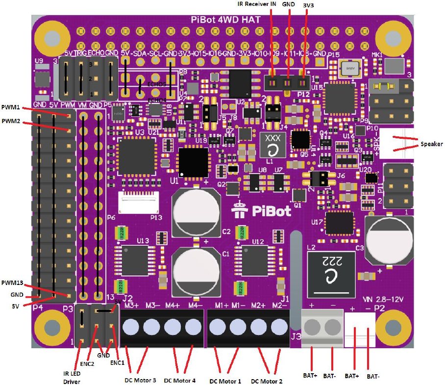
PiBot 4WD
Figure 1 PiBot 4WD HAT Ports and Signals
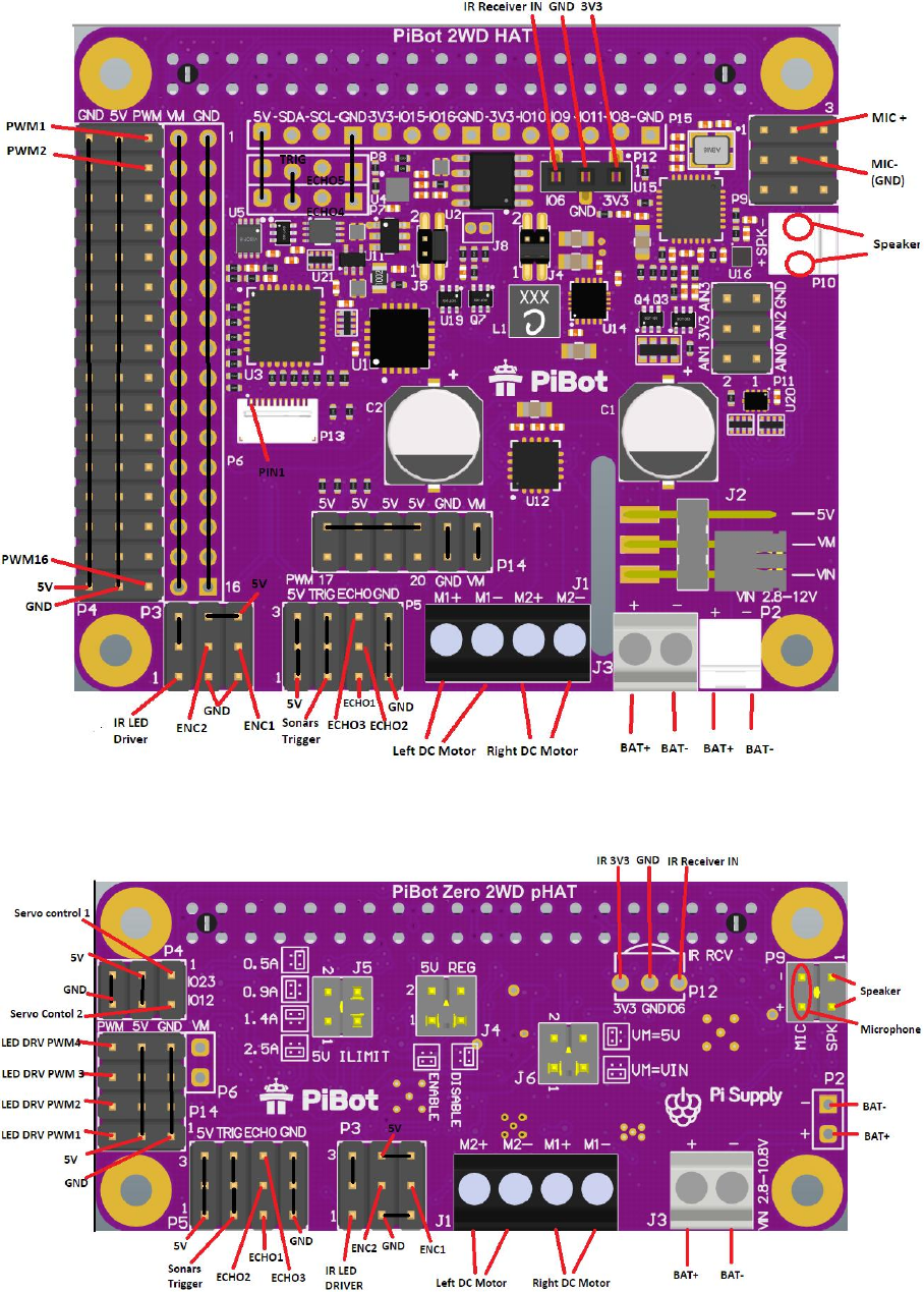
PiBot 2WD
Figure 2 PiBot 2WD HAT Ports and Signals
PiBot Zero
Figure 3 PiBot Zero Ports and Signals Top
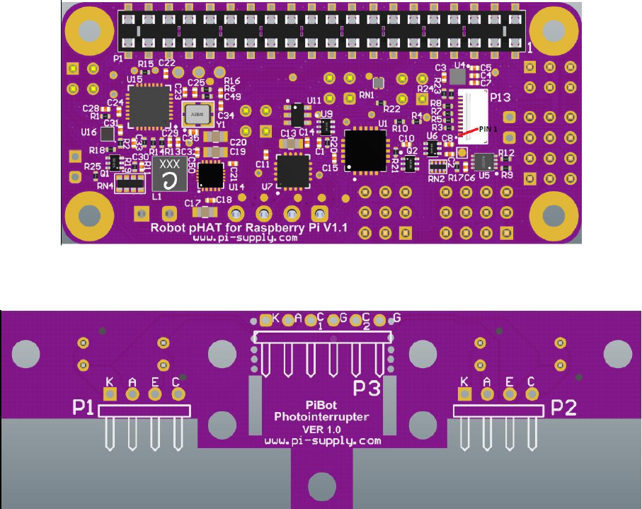
Figure 4 PiBot Zero Ports and Signals Bottom
PiBot Photointerrupter Board
Figure 5 PiBot Photointerrupter Board Ports
Header P1
This header can be used if two photointerrupters are separated by braking board.
K - IR LED’s Kathode of photointerrupter 1
A - IR LED’s Anode of photointerrupter 1
E - Phototransistor emitter of photointerrupter 1
C - Phototransistor collector of photointerrupter 1
Header P2
This header can be used if two photointerrupters are separated by braking board.
K - IR LED’s Kathode of photointerrupter 2
A - IR LED’s Anode of photointerrupter 2
E - Phototransistor emitter of photointerrupter 2
C - Phototransistor collector of photointerrupter 2
Header P3
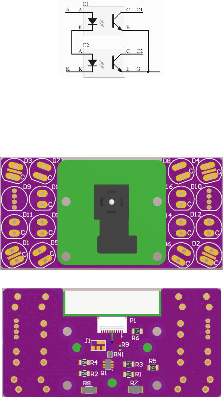
Figure 6 Photointerrupter Board Schematic
K - Kathode end of series connection of IR LED’s, see Figure 6,
A - Anode end of series connection of IR LED’s, see Figure 6,
C1 – Phototransistor’s collector of photointerrupter 1,
C2 – Phototransistor’s collector of photointerrupter 2,
G – Common ground connection.
PiBot LED Panel Board
Figure 7 LED Panel front
Figure 8 LED Panel back

Bare LED panel should be populated with desired LEDs according to Table 1 LED Panel population. If
D9 is populated than D11, D13 and D15 should not be populated. . If D10 is populated than D12, D14
and D16 should not be populated.
Table 1 LED Panel population
LED Positions
LED Type
Part reference
D1, D2, D3, D4
Through hole 25mA white or
250mA SMD white.
C513A-WSN-CW0Z0151,
MLCAWT-A1-0000-000WE7
D5, D6, D7, D8
Infrared LEDs
HSDL-4261
D9, D10
RGB LEDs
WP154A4SEJ3VBDZGW/CA
D11,D12,D13,D14,D15,D16
Single color LEDs
Any 5mm,20mA TH signal LED
PiBot HAT to Raspberry Pi Mounting
PiBot 2WD
Use 9 – 10mm (9mm recommended) spacers to fix PiBot 2WD directly on top of Raspberry Pi.
Use 2X20 pins adaptor header to stack PiBot 2WD on Top PiJuice.
Connections
Power
Battery connects to J3 terminal block or P2 2.54mm header.
DC Motors
Two DC motors that driver robot wheels connects to J1 and J2 (only on 4WD) terminal block like
designated.
Photointerrupter Board
Photointerrupter board can be used to make Speed Encoder. Use 5 wires proto cable to connect
Photointerrupter board P3 header with PiBot 2WD P3 header by connecting corresponding pins from
Table 2.
Table 2 Photointerrupter Board connection with PiBot 2WD
Photointerrupter board P3 pin
PiBot 2WD pin
1 (K)
1 (IR LED DRIVER)
2 (A)
6 or 9 (5V)
3 (C1)
8 (ENC1)
4 (G)
4 or 7 (GND)
5 (C2)
5 (ENC2)
Servos
Servo (e.g motor for camera pan tilt) should have 3 pin 2.54 female cable connector in order to
connecto to PiBot HAT.
PiBot 4WD
Connect Servo motors to any of 13 PWM channels on P4 Header.

PiBot 2WD
Connect Servo motors to any of 16 PWM channels on P4 Header (Channel 16 cannot be used if IR LED
Driver is connected).
PiBot Zero
Connect Servo motors to any of two channels on P4 Header.
LED Panel
Connect LED Panel to PiBot HAT using 0.5mm pitch, 10 core FPC cable through P1 connector on panel
board and P13 connector on PiBot HAT. Connector pin 1 must be matched on both sides.
Single LEDs
LEDs can be wired to any of PWM output drive channels. It is recommended to connect LED’s
Cathode to PWM output and Anode to 5V rail.
Sonars
Use 4 core 2.54mm female/female cable to connect Sonars to one of 3 Sonar channels on PiBot 2WD
Header P5. On PiBot 4WD or PiBot 2WD, Headers P7 and P8 can also be used to connect to additional
Sonars with 4 core female/male cable.
IR Receiver
Connect Infrared remote receiver ic like TSOP4338 to female header P12 on PiBot HAT, directly or
using cable with 2.54 male pins connector (PiBot Zero requires soldering of female header or direct
IR ic soldering).
Speaker
PiBot 4WD
Connect loudspeaker using cable with 2.54 female connector to P10 header on PiBot 4WD.
PiBot 2WD
Connect loudspeaker using cable with 2.54 female connector to P10 header on PiBot 2WD.
PiBot Zero
Connect loudspeaker using cable with 2.54 female connector to P9 header, pins 1-2 on PiBot Zero.
Electret Microphone
PiBot 4WD
Connect Electret microphone using cable with 2.54 female connector to P9 header on PiBot 4WD.
Wire Mic output to pin 2 (MIC+) and Mic ground to pin 5 (see Figure 2).
PiBot 2WD
Connect Electret microphone using cable with 2.54 female connector to P9 header on PiBot 2WD.
Wire Mic output to pin 2 (MIC+) and Mic ground to pin 5 (see Figure 2).
PiBot Zero
Connect Electret microphone using cable with 2.54 female connector to P9 header on PiBot Zero.
Wire Mic output to pin 4 (MIC+) and Mic ground to pin 3 (see Figure 3).
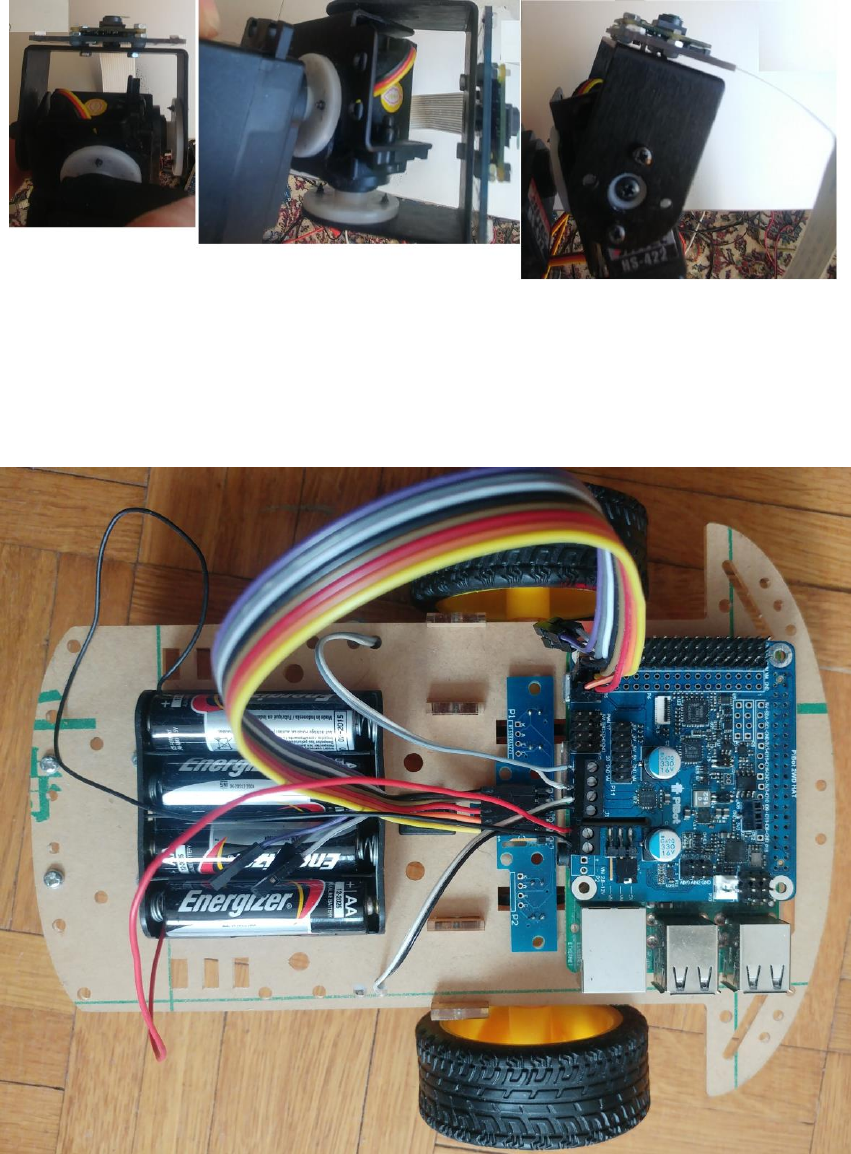
Camera Pan/Tilt Assembly
Camera can be connected to Raspberry Pi camera connector and mounted to Pan/Tilt hardware with
servos together with LED Panel Board using screws. Figure 9 shows example of Camera Mounting to
PiBot LED Panel Board and Lynx B-Pan/Tilt Kit.