CRT3371 GM 7100M Pioneer 7150M Service Manual
User Manual: GM-7100M
Open the PDF directly: View PDF ![]() .
.
Page Count: 32

PIONEER CORPORATION 4-1, Meguro 1-Chome, Meguro-ku, Tokyo 153-8654, Japan
PIONEER ELECTRONICS (USA) INC. P.O.Box 1760, Long Beach, CA 90801-1760 U.S.A.
PIONEER EUROPE NV Haven 1087 Keetberglaan 1, 9120 Melsele, Belgium
PIONEER ELECTRONICS ASIACENTRE PTE.LTD. 253 Alexandra Road, #04-01, Singapore 159936
C PIONEER CORPORATION 2004 K-ZZB. DEC. 2004 Printed in Japan
ORDER NO.
CRT3371
MONO POWER AMPLIFIER
GM-7100M/XU/EW
Service
Manual
GM-7100M/XU/EW
For details, refer to "Important check points for good servicing".
GM-7100M/XU/UC
GM-7100M/XU/ES
GM-7100M/XU/CN
GM-7150M/XU/UC

2
1234
1234
F
E
D
C
B
A
GM-7100M/XU/EW
SAFETY INFORMATION
CAUTION
This service manual is intended for qualified service technicians; it is not meant for the casual do-it-yourselfer.
Qualified technicians have the necessary test equipment and tools, and have been trained to properly and safely repair
complex products such as those covered by this manual.
Improperly performed repairs can adversely affect the safety and reliability of the product and may void the warranty.
If you are not qualified to perform the repair of this product properly and safely, you should not risk trying to do so
and refer the repair to a qualified service technician.
WARNING
This product contains lead in solder and certain electrical parts contain chemicals which are known to the state of
California to cause cancer, birth defects or other reproductive harm.
Health & Safety Code Section 25249.6 - Proposition 65
- Service Precaution
You should conform to the regulations governing the product (safety, radio and noise, and other regulations),
and should keep the safety during servicing by following the safety instructions described in this manual.
3
5678
F
E
D
C
B
A
5678
GM-7100M/XU/EW
[Important Check Points for Good Servicing]
In this manual, procedures that must be performed during repairs are marked with the below symbol.
Please be sure to confirm and follow these procedures.
1. Product safety
Please conform to product regulations (such as safety and radiation regulations), and maintain a safe servicing environment by
following the safety instructions described in this manual.
1 Use specified parts for repair.
Use genuine parts. Be sure to use important parts for safety.
2 Do not perform modifications without proper instructions.
Please follow the specified safety methods when modification(addition/change of parts) is required due to interferences such as
radio/TV interference and foreign noise.
3 Make sure the soldering of repaired locations is properly performed.
When you solder while repairing, please be sure that there are no cold solder and other debris.
Soldering should be finished with the proper quantity. (Refer to the example)
4 Make sure the screws are tightly fastened.
Please be sure that all screws are fastened, and that there are no loose screws.
5 Make sure each connectors are correctly inserted.
Please be sure that all connectors are inserted, and that there are no imperfect insertion.
6 Make sure the wiring cables are set to their original state.
Please replace the wiring and cables to the original state after repairs.
In addition, be sure that there are no pinched wires, etc.
7 Make sure screws and soldering scraps do not remain inside the product.
Please check that neither solder debris nor screws remain inside the product.
8 There should be no semi-broken wires, scratches, melting, etc. on the coating of the power cord.
Damaged power cords may lead to fire accidents, so please be sure that there are no damages.
If you find a damaged power cord, please exchange it with a suitable one.
9 There should be no spark traces or similar marks on the power plug.
When spark traces or similar marks are found on the power supply plug, please check the connection and advise on secure
connections and suitable usage. Please exchange the power cord if necessary.
0 Safe environment should be secured during servicing.
When you perform repairs, please pay attention to static electricity, furniture, household articles, etc. in order to prevent injuries.
Please pay attention to your surroundings and repair safely.
2. Adjustments
To keep the original performance of the products, optimum adjustments and confirmation of characteristics within specification.
Adjustments should be performed in accordance with the procedures/instructions described in this manual.
4. Cleaning
For parts that require cleaning, such as optical pickups, tape deck heads, lenses and mirrors used in projection monitors, proper
cleaning should be performed to restore their performances.
3. Lubricants, Glues, and Replacement parts
Use grease and adhesives that are equal to the specified substance.
Make sure the proper amount is applied.
5. Shipping mode and Shipping screws
To protect products from damages or failures during transit, the shipping mode should be set or the shipping screws should be
installed before shipment. Please be sure to follow this method especially if it is specified in this manual.

4
1234
1234
F
E
D
C
B
A
GM-7100M/XU/EW
CONTENTS
SAFETY INFORMATION............................................2
1. SPECIFICATIONS.......................................................5
2. EXPLODED VIEWS AND PARTS LIST ......................6
2.1 PACKING..............................................................6
2.2 EXTERIOR............................................................8
3. SCHEMATIC DIAGRAM...........................................12
3.1 OVERALL CONNECTION DIAGRAM(GUIDE PAGE) ....12
3.2 REMOTE CONTROL UNIT ................................18
4. PCB CONNECTION DIAGRAM................................20
4.1 AMP UNIT..........................................................20
4.2 REMOTE CONTROL UNIT ................................24
5. ELECTRICAL PARTS LIST........................................25
6. ADJUSTMENT.........................................................28
7. GENERAL INFORMATION.......................................29
7.1 DIAGNOSIS .......................................................29
7.1.1 DISASSEMBLY.........................................29
7.1.2 CONNECTOR FUNCTION DESCRIPTION ......31
8. OPERATIONS...........................................................32

5
5678
F
E
D
C
B
A
5678
GM-7100M/XU/EW
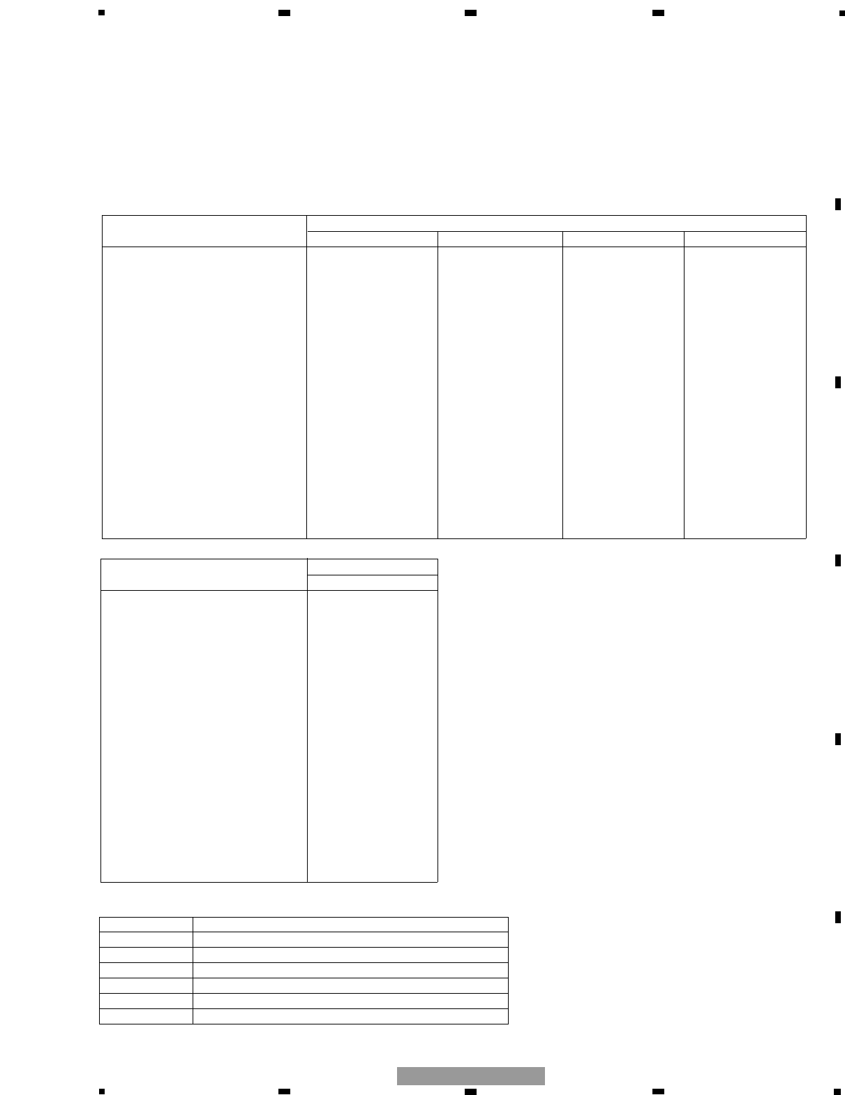
1. SPECIFICATIONS
Power source .......................................................................................................... 14.4 V DC (10.8 — 15.1 V allowable)
Grounding system .......................................................................................................................................... Negative type
Current consumption .................................................................................................... 33.0 A (at continuous power, 4 Ω)
Backup current.................................................................................................................................................. 3 mA or less
Average current drawn* .......................................................................................................... 9.0 A (4 Ωfor one channel)
16.0 A (2 Ωfor one channel)
Fuse ........................................................................................................................................................................ 30 A ×2
Dimensions ...................................................................................................................... 300 (W) ×60 (H) ×327 (D) mm
Weight .................................................................................................................... 4.7 kg (Leads for wiring not included)
Maximum power output .............................................................................................. 500 W ×1 (4 Ω) / 800 W ×1 (2 Ω)
Continuous power output .............................................................. 250 W ×1 (at 14.4 V, 4 Ω, 20 — 240 Hz 0.5% THD)
360 W ×1 (at 14.4 V, 2 Ω, 20 — 240 Hz 0.8% THD)
Continuous power output (DIN power) .......................................................... 380 W ×1 (4 Ω) (DIN45324, +B=14.4 V)
Load impedance .......................................................................................................................... 4 Ω(2 — 8 Ωallowable)
Frequency response .............................................................................................................. 10 — 240 Hz (+0 dB, –3 dB)
Signal-to-noise ratio .................................................................................................................... 100 dB (IEC-A network)
Distortion ........................................................................................................................................ 0.03 % (10 W, 120 Hz)
Low pass filter .................................................................................................................. Cut off frequency: 40 — 240 Hz
Cut off slope: –12 dB/oct
Bass Boost .............................................................................................................................................. Frequency: 50 Hz
Level: 0/6/9/12 dB
Gain control .................................................................................................................................. RCA: 200 mV — 6.5 V
Speaker: 0.8 — 26 V
Maximum input level / impedance ...................................................................................................... RCA: 6.5 V / 22 kΩ
Speaker: 26 V / 40 kΩ
Note:
• Specifications and the design are subject to possible modification without notice due to improvements.
*Average current drawn
• The average current drawn is nearly the maximum current drawn by this unit when an audio signal is input. Use this value when
working out total current drawn by multiple power amplifiers.
6
1234
1234
F
E
D
C
B
A
GM-7100M/XU/EW
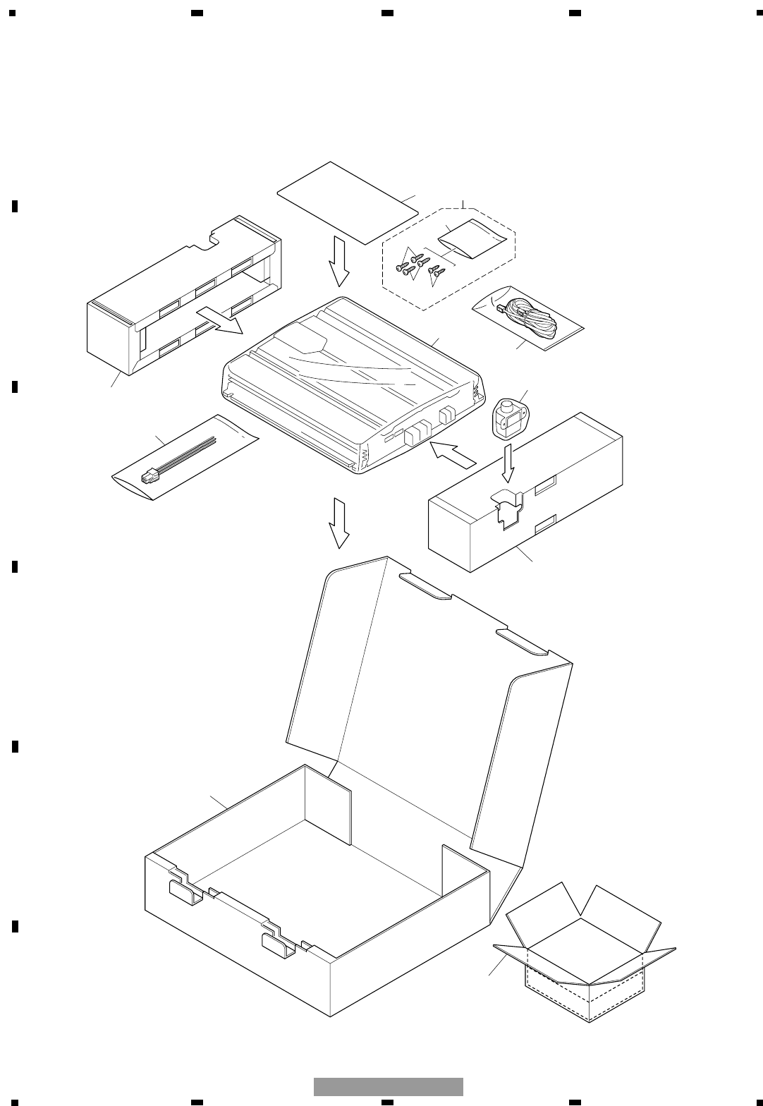
2. EXPLODED VIEWS AND PARTS LIST
2.1 PACKING
7
5
6
3
11
12
8
8
9
10
1
5
4
2
Part No.
Mark No. Description GM-7150M/XU/UC
1 Cord Assy CDE7736
2 Cord Assy CDE7804
3 Screw Assy CEA4836
4 Screw BYC30P100FZK
5 Screw BYC40P180FZK
* 6 Polyethylene Sheet CNM4338
7 Polyethylene Bag CEG1351
8 Protector CHP2911
9 Carton CHG5367
10 Contain Box CHL5367
11-1 Polyethylene Bag CEG1116
11-2 Owner’s Manual CRD3921
* 11-3 Warranty Card CRY1070
* 11-4 Card Not used
11-5 Owner’s Manual Not used
12 Remote Control Assy CXC4064
Part No.
Mark No. Description GM-7100M/XU/EW GM-7100M/XU/UC GM-7100M/XU/ES GM-7100M/XU/CN
1 Cord Assy CDE7736 CDE7736 CDE7736 CDE7736
2 Cord Assy CDE7804 Not used Not used Not used
3 Screw Assy CEA4836 CEA4835 CEA4835 CEA4835
4 Screw BYC30P100FZK Not used Not used Not used
5 Screw BYC40P180FZK BYC40P180FZK BYC40P180FZK BYC40P180FZK
* 6 Polyethylene Sheet CNM4338 CNM4338 CNM4338 CNM4338
7 Polyethylene Bag CEG1317 CEG1351 CEG1317 CEG1317
8 Protector CHP2911 CHP2911 CHP2911 CHP2911
9 Carton CHG5364 CHG5366 CHG5365 CHG5466
10 Contain Box CHL5364 CHL5366 CHL5365 CHL5466
11-1 Polyethylene Bag CEG1116 CEG1116 CEG1116 CEG1116
11-2 Owner’s Manual CRD3920 CRD3922 CRD3923 CRB2042
* 11-3 Warranty Card CRY1157 Not used Not used ARY7046
* 11-4 Card Not used ARY1048 Not used Not used
11-5 Owner’s Manual Not used Not used CRD3924 Not used
12 Remote Control Assy CXC4064 Not used Not used Not used
7
5678
F
E
D
C
B
A
5678
GM-7100M/XU/EW
-PACKING SECTION PARTS LIST
NOTE:
-Parts marked by “*” are generally unavailable because they are not in our Master Spare Parts List.
-The >mark found on some component parts indicates the importance of the safety factor of the part.
Therefore, when replacing, be sure to use parts of identical designation.
-Screws adjacent to ∇mark on the product are used for disassembly.
-For the applying amount of lubricants or glue, follow the instructions in this manual.
( In the case of no amount instructions, apply as you think it appropriate.)
-Owner's Manual
Part No. Language
CRD3920 English, Spanish, German, French, Italian, Dutch
CRD3921 English, French, Spanish
CRD3922 English, French, Spanish
CRD3923 English, Spanish
CRD3924 Arabic, Portuguese(B)
CRB2042 Traditional Chinese
7
7
2
2
2
2
3
3
3
3
3
33
15
15
15
22
22
40
29
36
34
34
33
33
17
18
15
15
15
15
15
33
32
20
23
34
31
30
33
19
16
21
35 34
14
28
26
25 24 33
14
27
2
2
2
5
2
2
3
48 41 42
43
45
46 44
47
4
44
1
1
1
5
5
5
5
1
1
1
8
9
39
39
12
10
12
12
13
4
4
38
38
6
11
37
A
49
B
8
1234
1234
F
E
D
C
B
A
GM-7100M/XU/EW
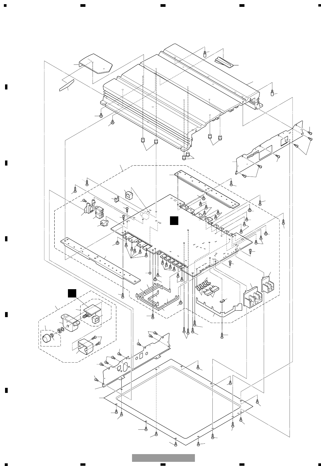
2.2 EXTERIOR

9
5678
F
E
D
C
B
A
5678
GM-7100M/XU/EW
1 Screw BBZ30P060FTC
2 Screw BBZ30P080FZK
3 Screw BBZ30P100FZK
4 Screw BBZ30P120FTC
5 Screw BSZ30P050FZK
* 6 Badge See Contrast table(2)
7 Screw CBA1810
8 Case CNB3072
9 Panel See Contrast table(2)
10 Panel See Contrast table(2)
11 Heat Sink See Contrast table(2)
12 Spacer CNV8256
13 Amp Unit See Contrast table(2)
14 Screw BBZ30P060FZK
15 Screw BBZ30P080FZK
16 Pin Jack(CN111) See Contrast table(2)
17 Terminal(CN853) See Contrast table(2)
18 Terminal(CN855) See Contrast table(2)
19 Socket(CN801) CKM1463
20 Connector(CN701) See Contrast table(2)
21 Holder CND2456
22 Terminal CND2458
23 Holder CND2466
24 Buss Bar CND2467
25 Buss Bar CND2468
26 Buss Bar CND2469
27 Buss Bar CND2471
28 Buss Bar CND2472
29 Buss Bar CND2729
30 Spacer CNM9570
31 Sub Heat Sink CNR1778
32 Sub Heat Sink CNR1779
33 Screw IMS30P050FZK
34 Screw PPZ30P100FSN
35 Screw PPZ30P100FZK
36 Terminal(CN850) VNF1084
37 Lighting Conductor Unit CXC4334
38 Screw IBZ30P060FTC
39 Screw PPZ30P100FZK
>40 Fuse(FU100,101)(30A) CEK1330
41 Remote Control Unit See Contrast table(2)
42 Connector(CN1351) See Contrast table(2)
43 Screw See Contrast table(2)
44 Grille See Contrast table(2)
45 Cover See Contrast table(2)
46 Knob Unit See Contrast table(2)
47 Spring See Contrast table(2)
48 Remote Control Assy See Contrast table(2)
49 Sheet CNM9571
Mark No. Description Part No. Mark No. Description Part No.
-EXTERIOR SECTION PARTS LIST
10
1234
1234
F
E
D
C
B
A
GM-7100M/XU/EW
Part No.
Mark No. Description GM-7150M/XU/UC
* 6 Badge CAH1917
9 Panel CNB3058
10 Panel CNB3114
11 Heat Sink CNR1792
13 Amp Unit CWH1270
16 Pin Jack(CN111) CKB1069
17 Terminal(CN853) CKE1054
18 Terminal(CN855) CKE1056
20 Connector(CN701) CKS4962
41 Remote Control Unit CWM9848
42 Connector(CN1351) CKS4962
43 Screw BPZ20P100FZK
44 Grille CNS8140
45 Cover CNS8141
46 Knob Unit CXC4335
47 Spring CBL1692
48 Remote Control Assy CXC4064
(2) CONTRAST TABLE
GM-7100M/XU/EW, GM-7100M/XU/UC, GM-7100M/XU/ES,GM-7100M/XU/CN and GM-7150M/XU/UC are constructed
the same except for the following:
Part No.
Mark No. Description GM-7100M/XU/EW GM-7100M/XU/UC GM-7100M/XU/ES GM-7100M/XU/CN
* 6 Badge CAH1919 CAH1919 CAH1916 CAH1916
9 Panel CNB3057 CNB3059 CNB3060 CNB3060
10 Panel CNB3125 CNB3061 CNB3124 CNB3124
11 Heat Sink CNR1765 CNR1765 CNR1766 CNR1766
13 Amp Unit CWH1270 CWH1271 CWH1271 CWH1271
16 Pin Jack(CN111) CKB1069 CKB1068 CKB1068 CKB1068
17 Terminal(CN853) CKE1054 CKE1055 CKE1055 CKE1055
18 Terminal(CN855) CKE1056 CKE1057 CKE1057 CKE1057
20 Connector(CN701) CKS4962 Not used Not used Not used
41 Remote Control Unit CWM9848 Not used Not used Not used
42 Connector(CN1351) CKS4962 Not used Not used Not used
43 Screw BPZ20P100FZK Not used Not used Not used
44 Grille CNS8140 Not used Not used Not used
45 Cover CNS8141 Not used Not used Not used
46 Knob Unit CXC4335 Not used Not used Not used
47 Spring CBL1692 Not used Not used Not used
48 Remote Control Assy CXC4064 Not used Not used Not used

11
5678
F
E
D
C
B
A
5678
GM-7100M/XU/EW
12
1234
1234
F
E
D
C
B
A
GM-7100M/XU/EW
A-a A-b
A-aA-a A-b A-b
A-b A-b
A-a A-a
Large size
SCH diagram
Guide page
Detailed page
Note: When ordering service parts, be sure to refer to " EXPLODED VIEWS AND PARTS LIST" or
"ELECTRICAL PARTS LIST". A-a
A
A
A
B
B
Decimal points for resistor
and capacitor fixed values
are expressed as :
2.2 2R2
0.022 R022
←
←
The > mark found on some component parts indicate
the importance of the safety factor of the part.
Therefore, when replacing, be sure to use parts of
identical designation.
Symbol indicates a resistor.
No differentiation is made between chip resistors and
discrete resistors.
NOTE :
Symbol indicates a capacitor.
No differentiation is made between chip capacitors and
discrete capacitors.
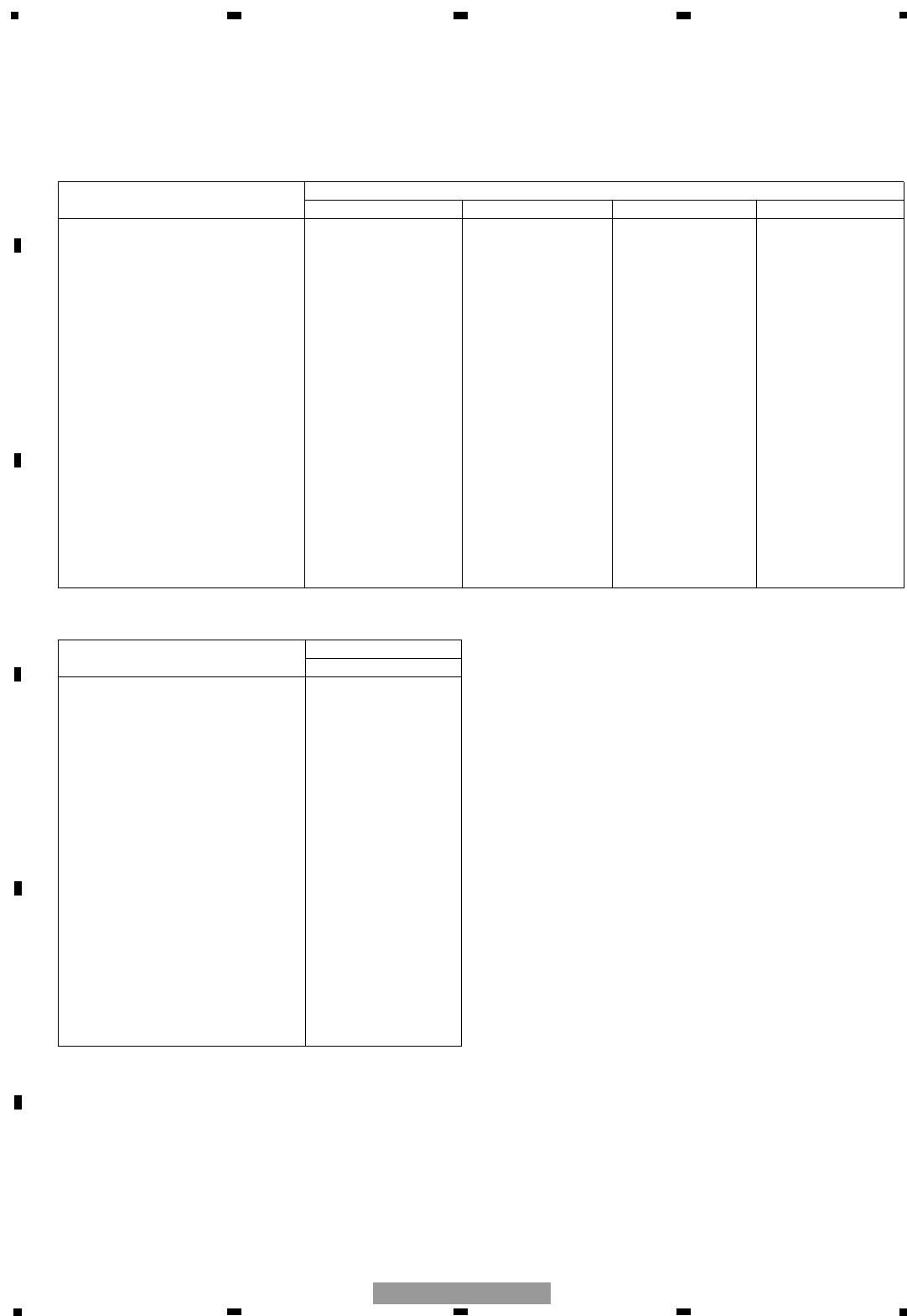
CN1351
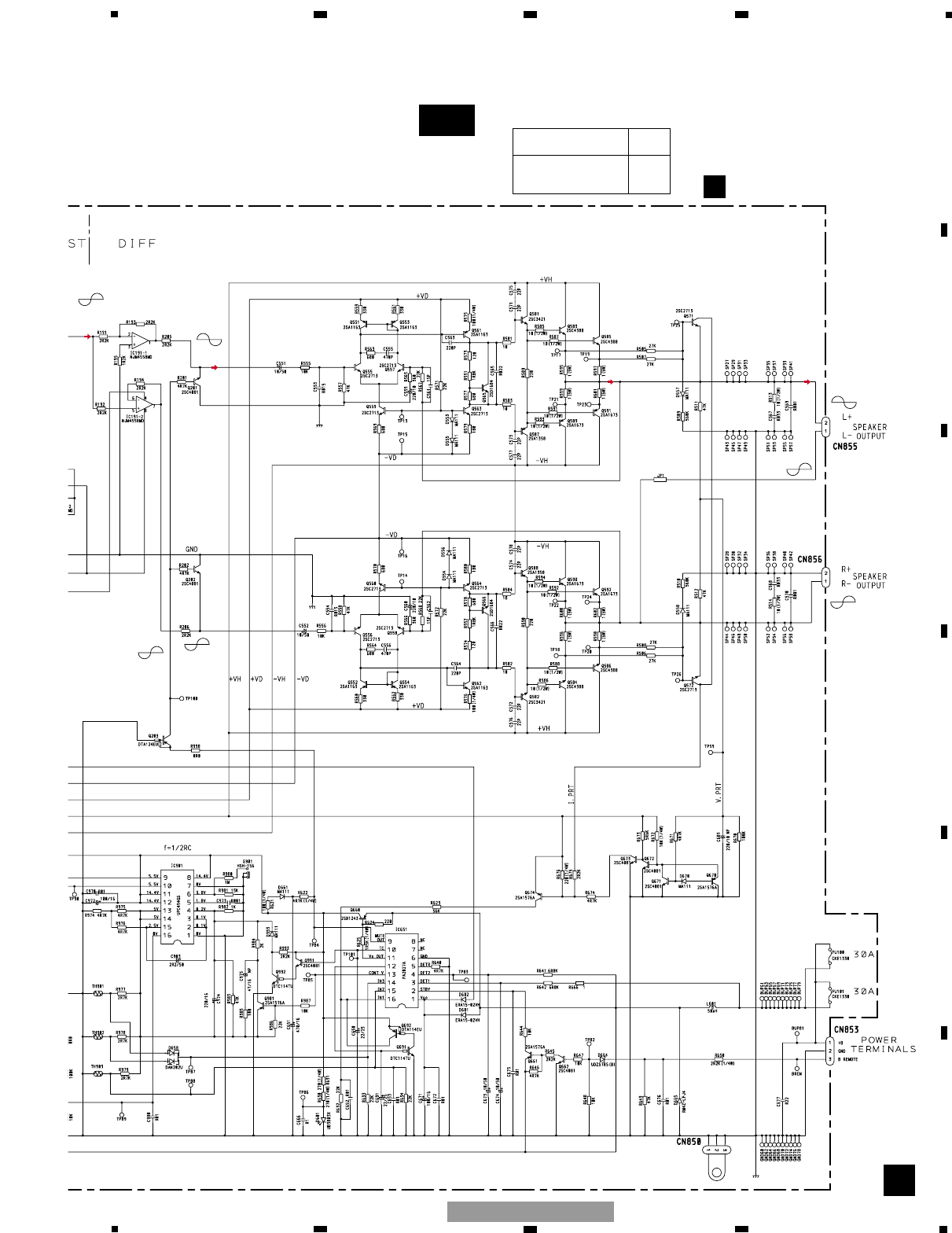
BASS BOOST
GAIN
LPF
0dB 0dB
+18.5dBs
(BB ON
INPUT MAX)
0dB -1.7dB ~
-32.0dB 0dB or +12dB
or +6dB ( or +9
-0.8dB
+17.5dBs
+18.3dBs +17.5dBs
-15dBs
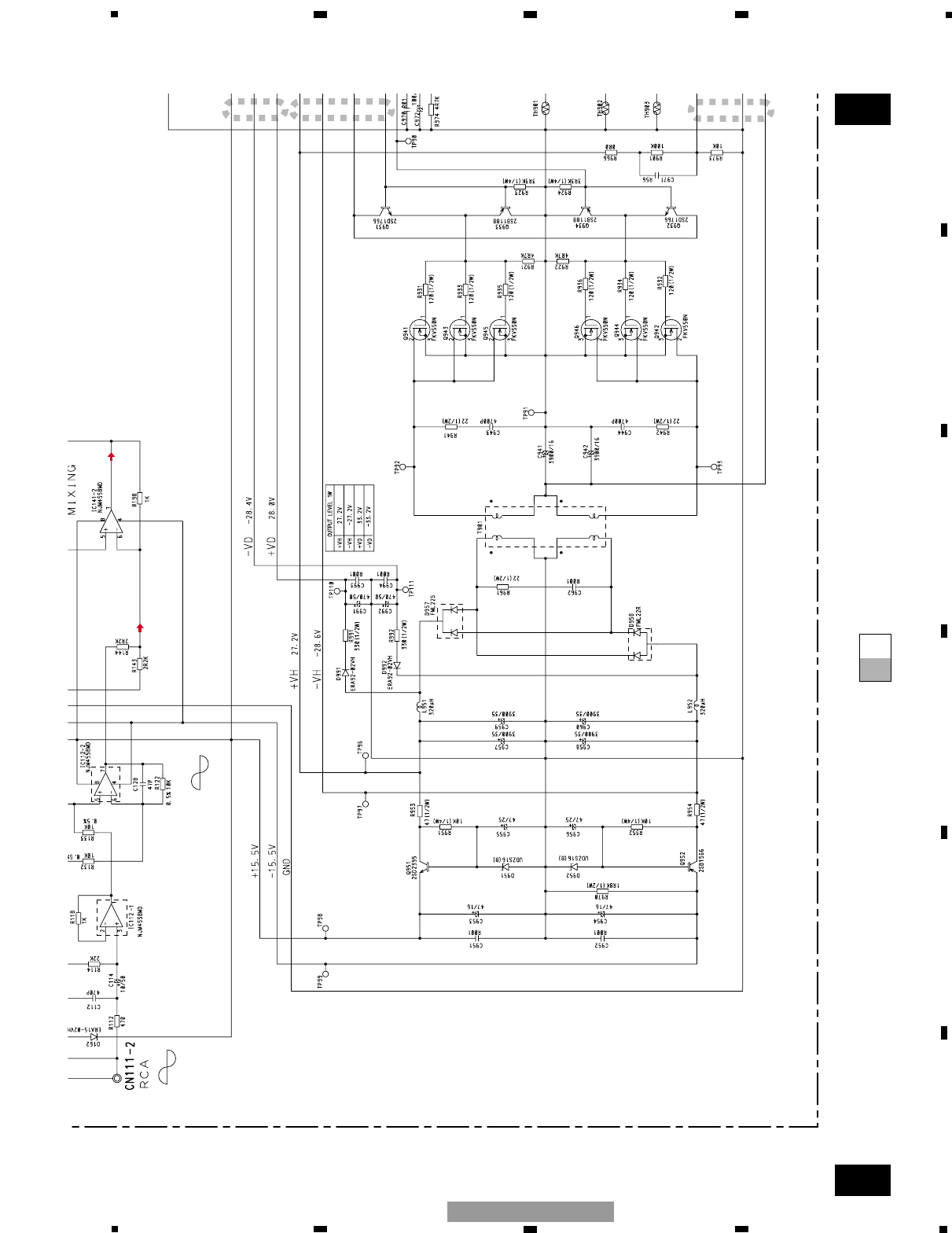
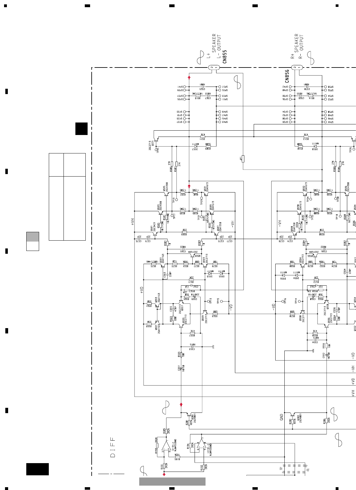
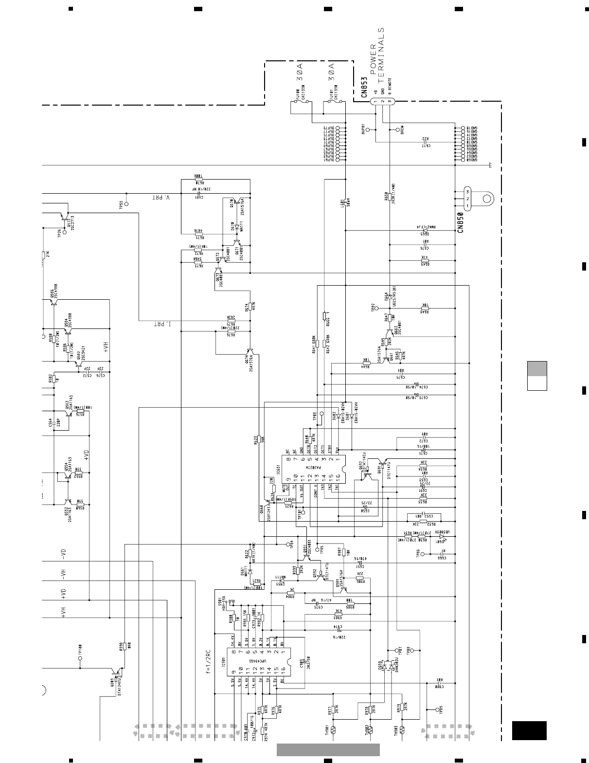
3. SCHEMATIC DIAGRAM
3.1 OVERALL CONNECTION DIAGRAM(GUIDE PAGE)
14
1234
1234
F
E
D
C
B
A
GM-7100M/XU/EW
A-a A-b
A-a
A-a
A-b 1
A
A
B
B
Decimal points for resistor
and capacitor fixed values
are expressed as :
2.2 2R2
0.022 R022
←
←
The > mark found on some component parts indicates
the importance of the safety factor of the part.
Therefore, when replacing, be sure to use parts of
identical designation.
Symbol indicates a resistor.
No differentiation is made between chip resistors and
discrete resistors.
NOTE :
Symbol indicates a capacitor.
No differentiation is made between chip capacitors and
discrete capacitors.
CN1351
BASS BOOST
GAIN
LPF
0dB 0dB
+18.5dBs
(BB ON
INPUT MAX)
0dB -1.7dB ~
-32.0dB 0dB or +12dB
or +6dB ( or +9dB)
-0.8dB
+17.5dBs
+18.3dBs +17.5dBs
-15dBs
-2.6dBs
18
1234
1234
F
E
D
C
B
A
GM-7100M/XU/EW
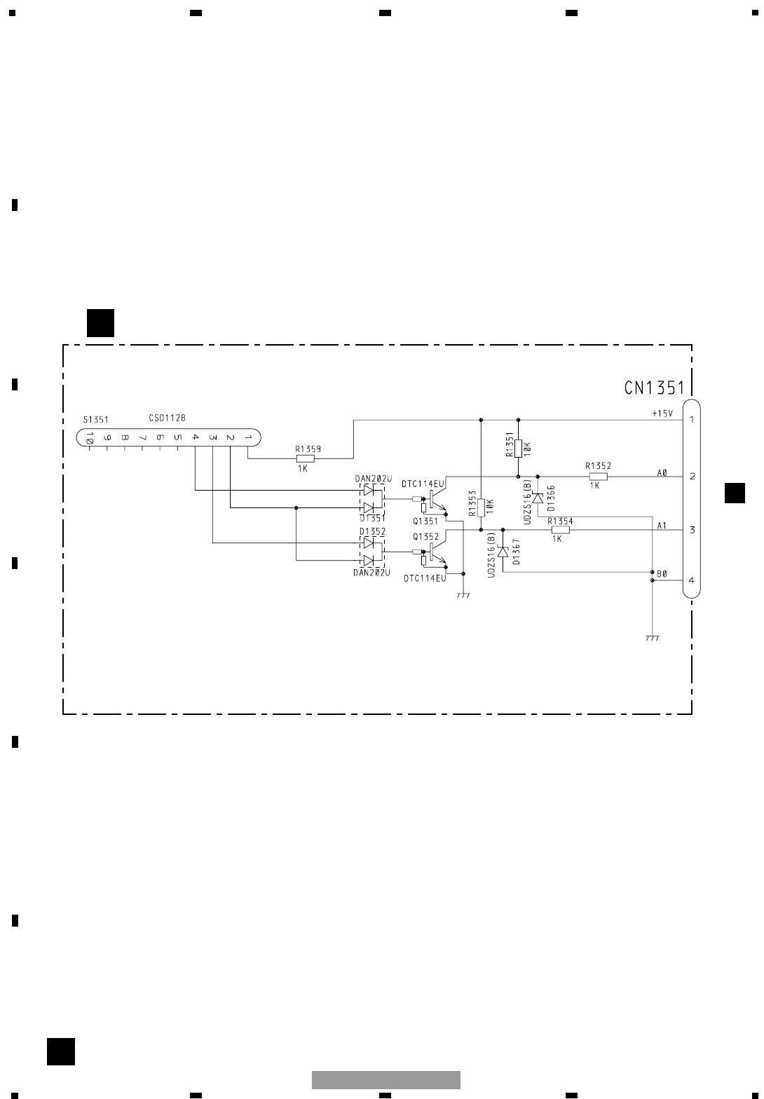
3.2 REMOTE CONTROL UNIT (GM-7100M/XU/EW, GM-7150M/XU/UC)
B
A
CN701
BREMOTE CONTROL UNIT

19
5678
F
E
D
C
B
A
5678
GM-7100M/XU/EW
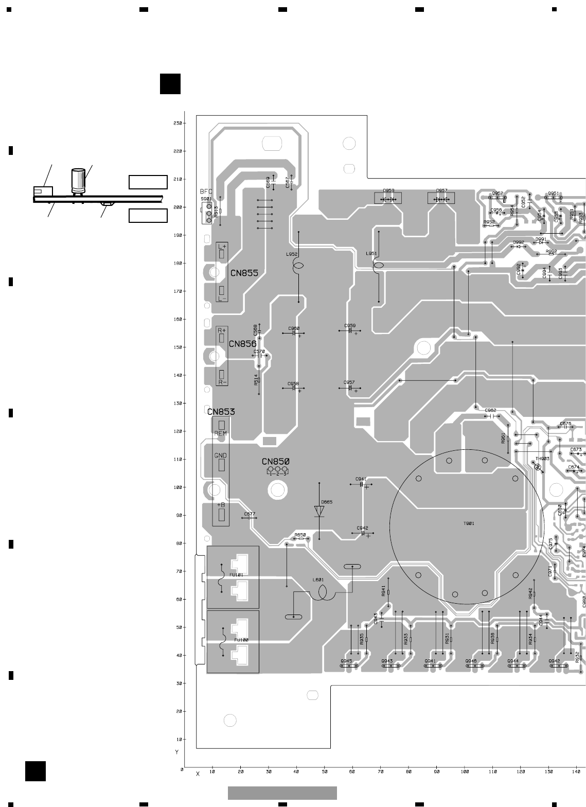
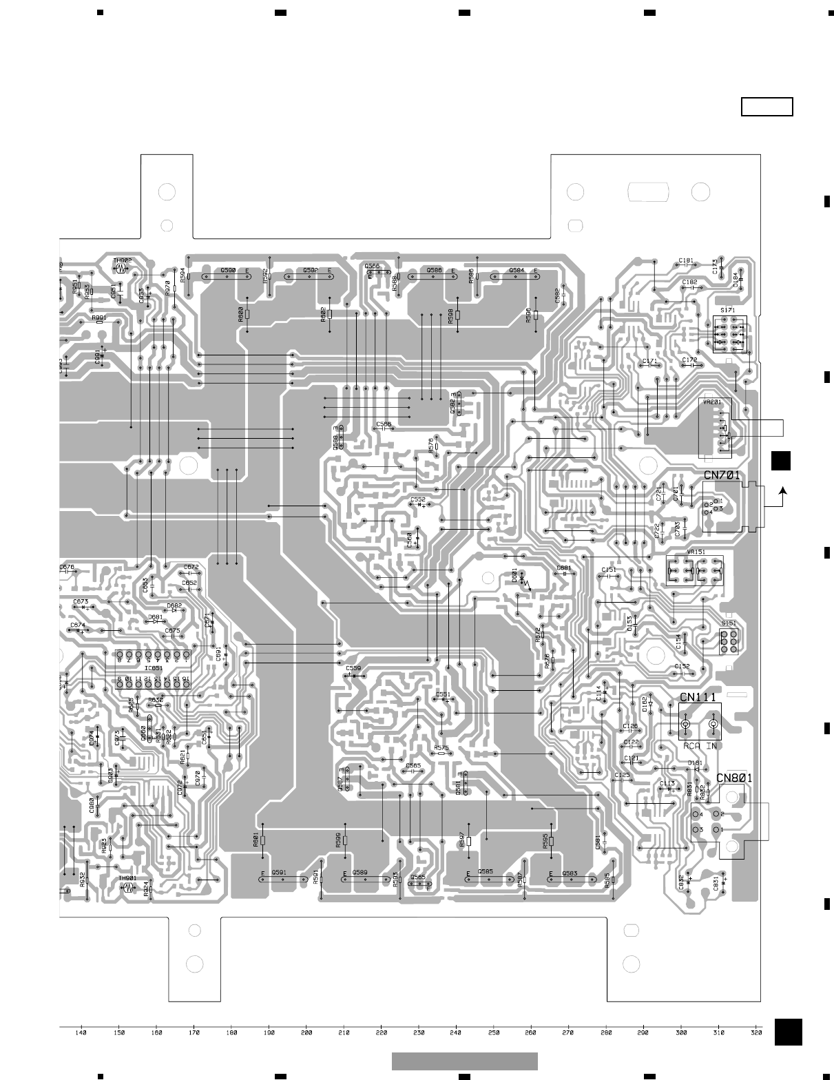
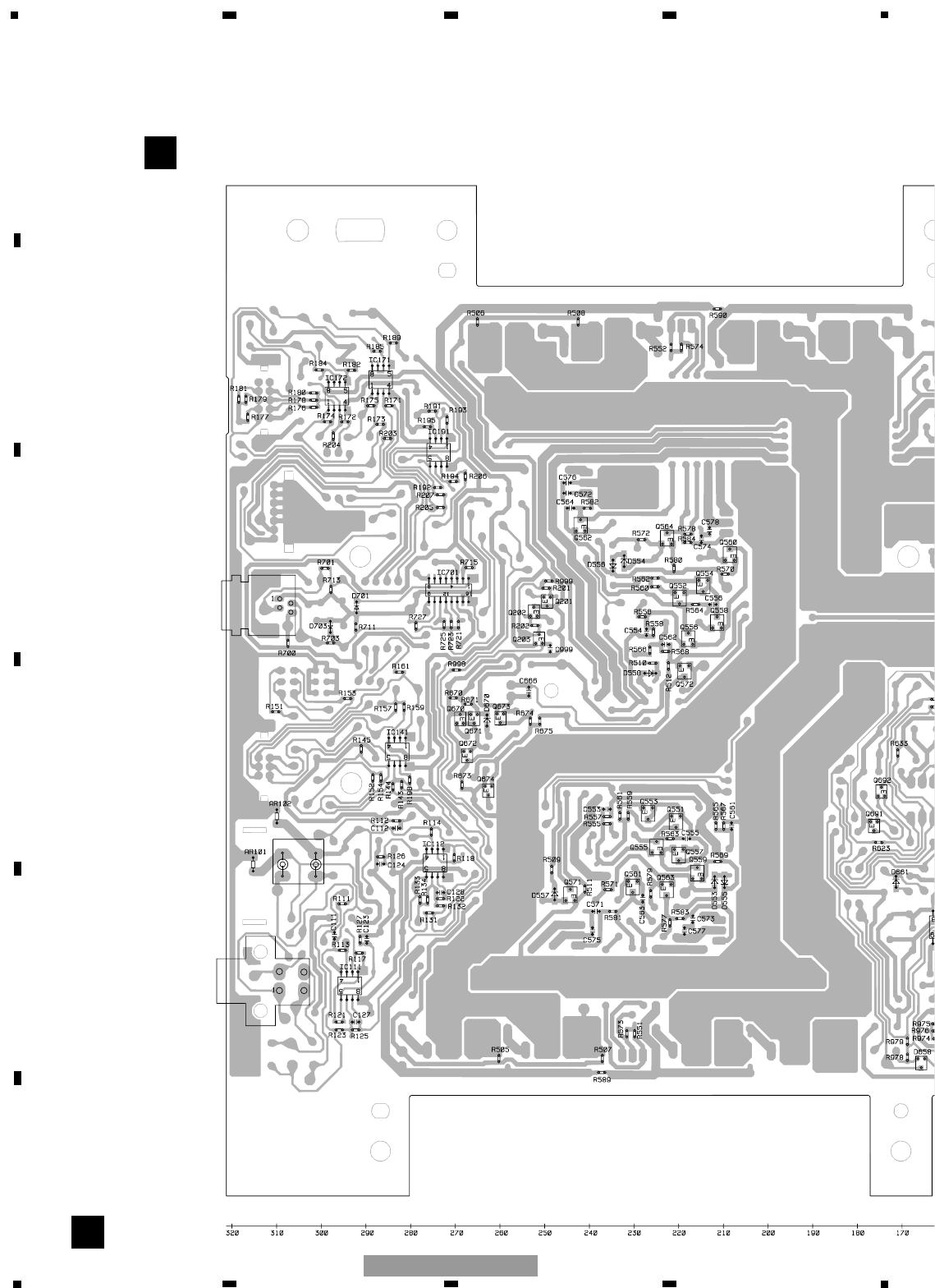
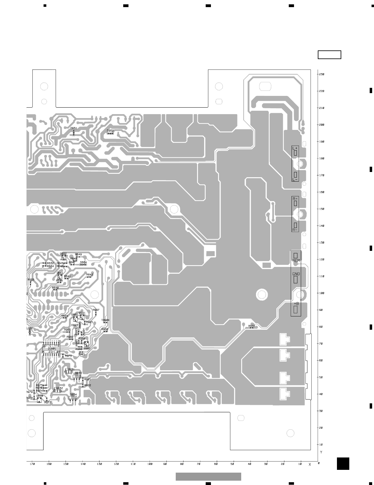
4. PCB CONNECTION DIAGRAM
4.1 AMP UNIT
Capacitor
Connector
P.C.Board Chip Part
A
AAMP UNIT
SIDE B
SIDE A
NOTE FOR PCB DIAGRAMS
1.The parts mounted on this PCB
include all necessary parts for
several destination.
For further information for
respective destinations, be sure
to check with the schematic dia-
gram.
2.Viewpoint of PCB diagrams
3 2 1 3 2 1 3 2 1 3 2 1 3 2 1 3 2 1
SPEAKER
OUTPUT
SPEAKER
OUTPUT
POWER
SUPPLY
20
1234
1234
F
E
D
C
B
A
GM-7100M/XU/EW
24
1234
1234
F
E
D
C
B
A
GM-7100M/XU/EW
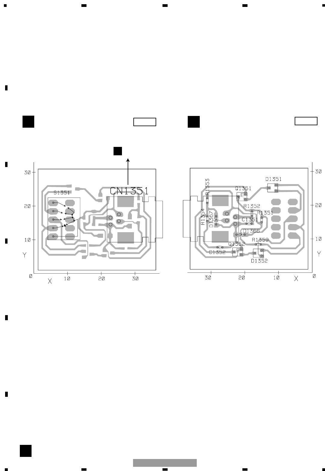
4.2 REMOTE CONTROL UNIT (GM-7100M/XU/EW, GM-7150M/XU/UC)
B
BREMOTE CONTROL UNIT BREMOTE CONTROL UNIT
SIDE A SIDE B
5
4
3
2
1
1
3
2
4
BASS BOOST
12dB
9dB
6dB
0dB
ACN701
1

NOTE:
Parts whose parts numbers are omitted are subject to being not supplied.
The part numbers shown below indicate chip components.
Chip Resistor
RS1/_S___J,RS1/__S___J
Chip Capacitor (except for CQS.....)
CKS....., CCS....., CSZS.....
The > mark found on some component parts indicatesthe importance of the safety factor of the part.
Therefore, when replacing, be sure to use parts of identical designation.
Meaning of the figures and others in the parentheses in the parts list.
Example) IC 301 is on the point (face A, 91 of x-axis, and 111 of y-axis) of the corresponding
PC board.
IC 301 (A, 91, 111) IC NJM2068V
25
5678
F
E
D
C
B
A
5678
GM-7100M/XU/EW
Unit Number : CWH1270(EW,7150M/UC)
Unit Number : CWH1271(UC,ES,CN)
Unit Name : Amp Unit
MISCELLANEOUS
IC 111 (B,294,54) IC NJM4558MD
IC 112 (B,275,81) IC NJM4558MD
IC 141 (B,283,106) IC NJM4558MD
IC 171 (B,287,189) IC NJM4558MD
IC 191 (B,274,173) IC NJM4558MD
IC 651 (A,168,99) IC PA2027A
IC 701 (B,271,142) IC(EW,7150M/UC) MAX309ESE
IC 901 (B,159,67) IC UPC494GS
Q 201 (B,249,140) Transistor 2SC4081
Q 202 (B,252,137) Transistor 2SC4081
Q 203 (B,251,131) Transistor DTA124EU
Q 551 (B,221,90) Transistor 2SA1163
Q 552 (B,220,140) Transistor 2SA1163
Q 553 (B,227,92) Transistor 2SA1163
Q 554 (B,215,143) Transistor 2SA1163
Q 555 (B,225,85) Transistor 2SC2713
Q 556 (B,218,131) Transistor 2SC2713
Q 557 (B,220,83) Transistor 2SC2713
Q 558 (B,211,135) Transistor 2SC2713
Q 559 (B,216,79) Transistor 2SC2713
Q 560 (B,209,150) Transistor 2SC2713
Q 561 (B,230,76) Transistor 2SA1163
Q 562 (B,242,157) Transistor 2SA1163
Q 563 (B,223,75) Transistor 2SC2713
Q 564 (B,223,154) Transistor 2SC2713
Q 565 (A,230,38) Transistor 2SD1684
Q 566 (A,219,201) Transistor 2SD1684
Q 571 (B,244,74) Transistor 2SC2713
Q 572 (B,219,124) Transistor 2SC2713
Q 581 (A,243,65) Transistor 2SC3421
Q 582 (A,241,166) Transistor 2SC3421
Q 583 (A,276,39) Transistor 2SC4388
Q 584 (A,250,200) Transistor 2SC4388
Q 585 (A,254,39) Transistor 2SC4388
Q 586 (A,228,200) Transistor 2SC4388
Q 587 (A,211,66) Transistor 2SA1358
Q 588 (A,209,157) Transistor 2SA1358
Q 589 (A,221,39) Transistor 2SA1673
Q 590 (A,173,200) Transistor 2SA1673
Q 591 (A,199,39) Transistor 2SA1673
Q 592 (A,195,200) Transistor 2SA1673
Q 660 (A,158,77) Transistor 2SB1243
Q 661 (B,154,110) Transistor 2SA1576A
Q 662 (B,151,121) Transistor 2SC4081
Q 670 (B,269,113) Transistor 2SA1576A
Q 671 (B,266,113) Transistor 2SC4081
Q 672 (B,267,105) Transistor 2SC4081
Q 673 (B,260,114) Transistor 2SC4081
Q 674 (B,263,97) Transistor 2SA1576A
Q 691 (B,176,89) Transistor DTC114TU
Q 692 (B,175,97) Transistor DTA114EU
Q 931 (B,148,55) Transistor 2SD1766
Q 932 (B,155,44) Transistor 2SD1766
Q 933 (B,143,50) Transistor 2SB1188
Q 934 (B,146,38) Transistor 2SB1188
Q 941 (A,91,36) Transistor FKV550N
Q 942 (A,136,36) Transistor FKV550N
Q 943 (A,76,36) Transistor FKV550N
Q 944 (A,121,36) Transistor FKV550N
Q 945 (A,61,36) Transistor FKV550N
Q 946 (A,106,36) Transistor FKV550N
Q 951 (A,129,203) Transistor 2SD2395
Q 952 (A,109,203) Transistor 2SB1566
Q 981 (B,138,70) Transistor 2SA1576A
Q 991 (B,140,86) Transistor 2SC4081
Q 992 (B,144,85) Transistor DTC114TU
D 161 (A,307,69) Diode ERA15-02VH
D 162 (A,292,89) Diode ERA15-02VH
D 553 (B,212,77) Diode MA111
D 554 (B,232,149) Diode MA111
D 555 (B,210,77) Diode MA111
D 556 (B,235,148) Diode MA111
D 557 (B,248,74) Diode MA111
D 558 (B,226,124) Diode MA111
D 601 (A,258,121) LED UB3803X
D 658 (B,166,36) Diode DAN202U
D 661 (B,171,77) Diode MA111
D 664 (B,140,117) Diode UDZS7R5(B)
D 665 (A,48,102) Diode RM4Z-LFJ4
D 670 (B,263,113) Diode MA111
D 681 (A,157,108) Diode ERA15-02VH
D 682 (A,162,111) Diode ERA15-02VH
D 701 (B,292,138) Diode(EW,7150M/UC) UDZS16(B)
D 703 (B,298,134) Diode(EW,7150M/UC) UDZS16(B)
D 951 (B,145,195) Diode UDZS16(B)
D 952 (B,123,195) Diode UDZS16(B)
D 957 (A,89,203) Diode FML22S
D 958 (A,70,203) Diode FML22R
D 991 (A,125,187) Diode ERA92-02VH
D 992 (A,122,186) Diode ERA92-02VH
D 993 (B,142,81) Diode MA111
L 601 (A,60,72) Choke Coil 50µH CTH1323
L 951 (A,69,166) Choke Coil 320µH CTH1326
L 952 (A,41,166) Choke Coil 320µH CTH1326
T 901 (A,101,86) Transformer CTT1123
5. ELECTRICAL PARTS LIST
=====Circuit Symbol and No.===Part Name Part No.
--- ------ ------------------------------------------ ------------------------- =====Circuit Symbol and No.===Part Name Part No.
--- ------ ------------------------------------------ -------------------------
A

26
1234
1234
F
E
D
C
B
A
GM-7100M/XU/EW
TH 901 (A,151,37) Thermistor CCX1013
TH 902 (A,149,202) Thermistor CCX1013
TH 903 (A,128,105) Thermistor CCX1064
S 171 (A,314,181) Switch CSH1029
(UC,ES,CN)(BASS BOOST)
S 901 (A,9,200) Switch(BFC) HSH-156
VR 151 (A,309,119) Volume 20kΩ(E)(LPF) CCS1266
VR 201 (A,311,154) Volume 10kΩ(A)(GAIN) CCS1241
FU 100 (A,20,45) Fuse 30A CEK1330
FU 101 (A,20,68) Fuse 30A CEK1330
AR 101 (B,315,81) Surge Protector RCCA-201Q31UA-PI
AR 102 (B,310,92) Surge Protector RCCA-201Q31UA-PI
RESISTORS
R 111 (B,295,72) RS1/16S471J
R 112 (B,283,91) RS1/16S471J
R 113 (B,295,62) RS1/16S223J
R 114 (B,275,88) RS1/16S223J
R 117 (B,292,61) RS1/16S102J
R 118 (B,270,82) RS1/16S102J
R 121 (B,296,46) RS1/16S1002D
R 122 (B,273,73) RS1/16S1002D
R 123 (B,296,44) RS1/16S1002D
R 125 (B,292,44) RS1/16S1002D
R 126 (B,287,83) RS1/16S1002D
R 127 (B,291,64) RS1/16S1002D
R 132 (B,273,72) RS1/16S1002D
R 133 (B,278,73) RS1/16S1002D
R 143 (B,282,99) RS1/16S222J
R 144 (B,284,98) RS1/16S222J
R 145 (B,291,107) RS1/16S561J
R 151 (B,310,115) RS1/16S272J
R 153 (B,294,118) RS1/16S272J
R 161 (B,283,124) RS1/16S222J
R 173 (B,287,179) RS1/16S101J
R 175 (B,289,184) RS1/16S182J
R 177 (B,316,181) (UC,ES,CN) RS1/16S121J
R 179 (B,317,185) (UC,ES,CN) RS1/16S122J
R 181 (B,318,185) (UC,ES,CN) RS1/16S104J
R 185 (B,288,196) RS1/16S331J
R 189 (B,284,198) RS1/16S273J
R 191 (B,275,182) RS1/16S222J
R 192 (B,274,165) RS1/16S222J
R 193 (B,272,180) RS1/16S222J
R 194 (B,270,167) RS1/16S222J
R 195 (B,276,179) RS1/16S122J
R 198 (B,280,100) RS1/16S102J
R 201 (B,250,143) RS1/16S472J
R 202 (B,252,134) RS1/16S472J
R 203 (B,285,176) RS1/16S560J
R 205 (B,273,161) RS1/16S222J
R 206 (B,268,168) RS1/16S222J
R 505 (B,260,38) RS1/16S273J
R 506 (B,265,202) RS1/16S273J
R 507 (B,237,38) RS1/16S273J
R 508 (B,243,202) RS1/16S273J
R 509 (B,248,80) RS1/16S564J
R 510 (B,226,126) RS1/16S564J
R 511 (B,241,75) RS1/16S473J
R 512 (B,222,125) RS1/16S473J
R 513 (A,13,204) RD1/2PM100J
R 514 (A,27,143) RD1/2PM100J
R 551 (B,230,43) RS1/16S182J
R 552 (B,222,197) RS1/16S182J
R 555 (B,236,90) RS1/16S103J
R 556 (B,228,136) RS1/16S103J
R 557 (B,236,92) RS1/16S473J
R 558 (B,226,133) RS1/16S473J
R 559 (B,231,92) RS1/16S331J
R 560 (B,225,143) RS1/16S331J
R 561 (B,233,92) RS1/16S331J
R 562 (B,225,145) RS1/16S331J
R 563 (B,222,87) RS1/16S681J
R 564 (B,216,139) RS1/16S681J
R 565 (B,212,89) RS1/16S361J
R 566 (B,226,129) RS1/16S361J
R 567 (B,210,89) RS1/16S223J
R 568 (B,223,129) RS1/16S223J
R 569 (B,211,82) RS1/16S681J
R 570 (B,210,146) RS1/16S681J
R 571 (B,236,75) RS1/16S223J
R 572 (B,228,154) RS1/16S223J
R 573 (B,232,43) RS1/16S121J
R 574 (B,219,197) RS1/16S121J
R 575 (A,234,73) RD1/4PU101J
R 576 (A,235,157) RD1/4PU101J
R 577 (B,222,68) RS1/16S681J
R 578 (B,218,155) RS1/16S681J
R 579 (B,226,74) RS1/16S181J
R 580 (B,221,147) RS1/16S181J
R 581 (B,235,70) RS1/16S100J
R 582 (B,240,161) RS1/16S100J
R 583 (B,220,69) RS1/16S100J
R 584 (B,218,153) RS1/16S100J
R 585 (A,282,34) RD1/2PM100J
R 586 (A,246,205) RD1/2PM100J
R 587 (A,258,34) RD1/2PM100J
R 588 (A,225,205) RD1/2PM100J
R 589 (B,237,34) RS1/16S221J
R 590 (B,211,205) RS1/16S221J
R 591 (A,204,34) RD1/2PM100J
R 592 (A,190,205) RD1/2PM100J
R 593 (A,225,34) RD1/2PM100J
R 594 (A,169,205) RD1/2PM100J
R 595 (A,265,54) 1ΩCCN1151
R 596 (A,261,195) 1ΩCCN1151
R 597 (A,243,54) 1ΩCCN1151
R 598 (A,240,195) 1ΩCCN1151
R 599 (A,210,45) 1ΩCCN1151
R 600 (A,184,186) 1ΩCCN1151
R 601 (A,188,45) 1ΩCCN1151
R 602 (A,206,186) 1ΩCCN1151
R 621 (A,168,70) RD1/4PU101J
R 622 (A,165,75) RD1/4PU472J
R 623 (B,175,86) RS1/16S563J
R 624 (B,151,85) RS1/16S221J
R 625 (A,155,88) RD1/4PU152J
R 630 (A,163,86) RD1/4PU271J
R 631 (A,162,80) RD1/4PU271J
R 632 (B,163,118) RS1/16S223J
R 633 (B,171,106) RS1/16S223J
R 634 (B,163,116) RS1/16S223J
R 640 (B,156,102) RS1/16S472J
R 641 (B,150,109) RS1/16S682J
R 642 (B,136,110) RS1/16S682J
R 644 (B,154,106) RS1/16S103J
R 645 (B,150,118) RS1/16S222J
R 646 (B,150,116) RS1/16S472J
R 647 (B,146,117) RS1/16S103J
R 648 (B,145,119) RS1/16S103J
R 649 (B,143,122) RS1/16S473J
R 650 (A,44,82) RD1/4PU222J
R 666 (B,39,79) RS1/16S1R0J
R 670 (B,270,118) RS1/16S104J
=====Circuit Symbol and No.===Part Name Part No.
--- ------ ------------------------------------------ ------------------------- =====Circuit Symbol and No.===Part Name Part No.
--- ------ ------------------------------------------ -------------------------
>
>

27
5678
F
E
D
C
B
A
5678
GM-7100M/XU/EW
R 671 (B,267,117) RS1/16S472J
R 672 (A,263,107) RD1/4PU103J
R 673 (B,269,99) RS1/16S562J
R 674 (B,253,113) RS1/16S472J
R 675 (B,251,113) RS1/16S222J
R 676 (A,266,100) RD1/4PU221J
R 700 (B,307,130) (EW,7150M/UC) RS1/16S472J
R 701 (B,299,147) (EW,7150M/UC) RS1/16S102J
R 703 (B,298,130) (EW,7150M/UC) RS1/16S102J
R 711 (B,292,134) (EW,7150M/UC) RS1/16S473J
R 713 (B,298,142) (EW,7150M/UC) RS1/16S473J
R 715 (B,267,147) (EW,7150M/UC) RS1/16S473J
R 721 (B,269,135) (EW,7150M/UC) RS1/16S104J
R 723 (B,271,135) (EW,7150M/UC) RS1/16S122J
R 725 (B,273,135) (EW,7150M/UC) RS1/16S471J
R 727 (B,279,134) (EW,7150M/UC) RS1/16S101J
R 831 (A,304,66) RD1/4PU683J
R 832 (A,307,65) RD1/4PU683J
R 901 (B,141,65) RS1/16S104J
R 921 (B,140,49) RS1/16S472J
R 922 (B,140,45) RS1/16S472J
R 923 (A,148,50) RD1/4PU332J
R 924 (A,159,34) RD1/4PU332J
R 931 (A,95,41) RD1/2PM121J
R 932 (A,142,34) RD1/2PM121J
R 933 (A,81,41) RD1/2PM121J
R 934 (A,125,41) RD1/2PM121J
R 935 (A,65,41) RD1/2PM121J
R 936 (A,112,41) RD1/2PM121J
R 941 (A,73,68) RD1/2PM220J
R 942 (A,125,57) RD1/2PM220J
R 951 (A,139,200) RD1/4PU103J
R 952 (A,112,193) RD1/4PU103J
R 953 (A,143,201) RD1/2PM470J
R 954 (A,119,204) RD1/2PM470J
R 961 (A,116,112) RD1/2PM220J
R 966 (B,126,77) RS1/16S0R0J
R 970 (A,165,202) RD1/2PM182J
R 973 (B,152,63) RS1/16S103J
R 974 (B,162,42) RS1/16S472J
R 975 (B,162,45) RS1/16S472J
R 976 (B,162,44) RS1/16S472J
R 977 (B,161,37) RS1/16S272J
R 978 (B,169,38) RS1/16S272J
R 979 (B,169,41) RS1/16S272J
R 980 (B,141,68) RS1/16S105J
R 981 (B,149,77) RS1/16S153J
R 982 (B,147,73) RS1/16S102J
R 983 (B,142,76) RS1/16S473J
R 984 (B,141,76) RS1/16S202J
R 985 (B,142,71) RS1/16S101J
R 986 (B,141,71) RS1/16S223J
R 987 (B,132,88) RS1/16S103J
R 991 (A,140,188) RD1/2PM331J
R 992 (A,126,183) RD1/2PM331J
R 993 (B,139,82) RS1/16S222J
R 998 (B,270,124) RS1/16S0R0J
CAPACITORS
C 111 (B,297,65) CKSRYB471K50
C 112 (B,283,89) CKSRYB471K50
C 113 (A,299,64) CEAT100M50
C 114 (A,280,92) CEAT100M50
C 121 (A,284,71) CFTNA223J50
C 122 (A,284,75) CFTNA223J50
C 123 (B,290,64) CCSRCH470J50
C 124 (B,287,81) CCSRCH470J50
C 125 (A,287,66) CFTNA103J50
C 126 (A,284,79) CFTNA103J50
C 127 (B,292,46) CCSRCH470J50
C 128 (B,273,75) CCSRCH470J50
C 151 (A,283,120) CFTNA274J50
C 153 (A,288,105) CFTNA154J50
C 171 (A,289,176) CFTNA273J50
C 173 (A,311,205) CEANP4R7M50
C 181 (A,299,203) CFTNA224J50
C 551 (A,239,87) CEAT100M50
C 552 (A,233,139) CEAT100M50
C 553 (B,236,93) CKSRYB153K50
C 554 (B,227,133) CKSRYB153K50
C 555 (B,218,87) CKSRYB471K50
C 556 (B,212,139) CKSRYB471K50
C 559 (A,210,94) CEAT221M10
C 560 (A,230,128) CEAT221M10
C 561 (B,208,89) CCSRCH150J50
C 562 (B,223,130) CCSRCH150J50
C 563 (B,228,73) CCSRCH221J50
C 564 (B,244,161) CCSRCH221J50
C 565 (A,231,68) CFTNA223J50
C 566 (A,218,160) CFTNA223J50
C 567 (A,38,206) CFTNA333J50
C 568 (A,27,158) CFTNA333J50
C 569 (A,32,209) CQHA102J2A
C 570 (A,27,147) CQHA102J2A
C 571 (B,239,70) CCSRCH220J50
C 572 (B,245,164) CCSRCH220J50
C 573 (B,217,69) CCSRCH220J50
C 574 (B,215,154) CCSRCH220J50
C 575 (B,239,66) CCSRCH220J50
C 576 (B,245,166) CCSRCH220J50
C 577 (B,219,66) CCSRCH220J50
C 578 (B,213,156) CCSRCH220J50
C 650 (A,136,89) CEAT220M25
C 651 (A,174,80) CEAT471M16
C 652 (A,171,117) CFTNA103J50
C 653 (A,159,120) CFTNA103J50
C 666 (B,254,120) CKSQYB104K50
C 671 (A,175,105) CEAT101M16
C 672 (A,171,121) CFTNA103J50
C 673 (A,143,112) CEAT100M50
C 674 (A,142,106) CEAT100M50
C 675 (A,167,104) CFTNA103J50
C 676 (A,134,122) CFTNA103J50
C 677 (A,26,89) CFTNA224J50
C 681 (A,271,121) CEANP221M10
C 691 (A,179,97) CEAT220M25
C 721 (A,295,145) (EW,7150M/UC) CFTNA473J50
C 722 (A,295,129) (EW,7150M/UC) CFTNA473J50
C 831 (A,311,41) CEAT100M50
C 832 (A,302,41) CEAT100M50
C 903 (A,149,70) CEAT2R2M50
C 941 (A,67,101) 3900µF/16V CCH1644(P35)
C 942 (A,67,84) 3900µF/16V CCH1644(P35)
C 943 (A,70,53) CQHA472J2A
C 944 (A,129,52) CQHA472J2A
C 951 (A,150,196) CQHA102J2A
C 952 (A,123,202) CQHA102J2A
C 953 (A,158,197) CEAT470M16
C 954 (A,128,194) CEAT470M16
=====Circuit Symbol and No.===Part Name Part No.
--- ------ ------------------------------------------ ------------------------- =====Circuit Symbol and No.===Part Name Part No.
--- ------ ------------------------------------------ -------------------------

28
1234
1234
F
E
D
C
B
A
GM-7100M/XU/EW
6. ADJUSTMENT
There is no information to be shown in this chapter.
=====Circuit Symbol and No.===Part Name Part No.
--- ------ ------------------------------------------ -------------------------
C 955 (A,134,194) CEAT470M25
C 956 (A,114,198) CEAT470M25
C 957 (A,63,135) 3900µF/35V CCH1645(P35)
C 958 (A,43,135) 3900µF/35V CCH1645(P35)
C 959 (A,63,156) 3900µF/35V CCH1645(P35)
C 960 (A,43,155) 3900µF/35V CCH1645(P35)
C 962 (A,110,125) CQHA102J2A
C 970 (A,173,64) CFTNA103J50
C 971 (A,132,67) CFTNA564J50
C 972 (A,168,67) CEAT101M16
C 973 (A,151,77) CQHA102J2A
C 974 (A,144,75) CEAT221M16
C 975 (A,133,77) CEANP470M16
C 980 (A,144,56) CFTNA103J50
C 991 (A,146,182) CEAT471M50(P45)
C 992 (A,121,180) CEAT471M50(P45)
C 993 (A,136,176) CQHA102J2A
C 994 (A,130,176) CQHA102J2A
Unit Number : CWM9848(EW,7150M/UC)
Unit Name : Remote Control Unit
MISCELLANEOUS
Q 1351 (B,21,23) Transistor DTC114EU
Q 1352 (B,22,6) Transistor DTC114EU
D 1351 (B,12,25) Diode DAN202U
D 1352 (B,16,6) Diode DAN202U
D 1366 (B,21,11) Diode UDZS16(B)
D 1367 (B,29,16) Diode UDZS16(B)
S 1351 (A,6,11) Switch(BASS BOOST) CSD1128
RESISTORS
R 1351 (B,15,16) RS1/16S103J
R 1352 (B,18,18) RS1/16S102J
R 1353 (B,31,21) RS1/16S103J
R 1354 (B,31,16) RS1/16S102J
R 1359 (B,16,8) RS1/16S102J
B
29
5678
F
E
D
C
B
A
5678
GM-7100M/XU/EW
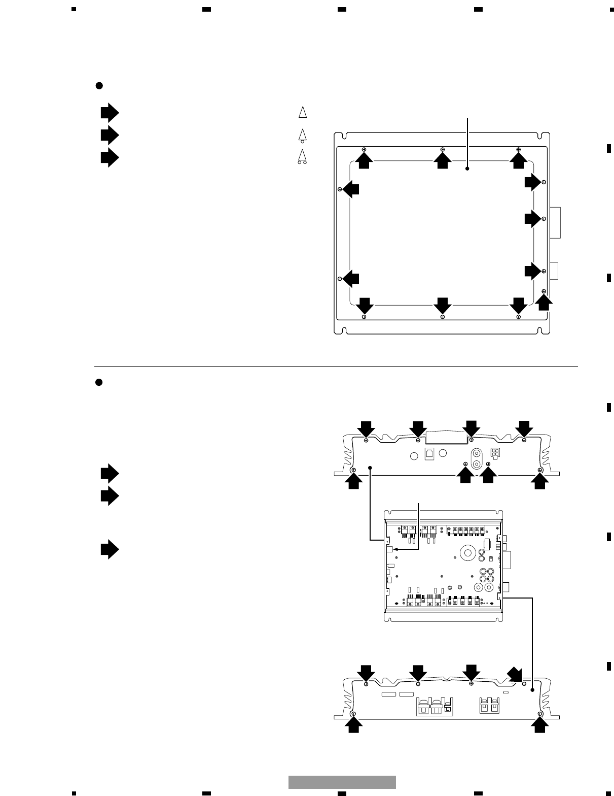
Removing the Case (Fig. 1)
Removing the Panel (Fig. 2)
Remove two black screws (M3 x 10).
Remove six white screws (M3 x 6).
Remove four black screws (M3 x 5).
Panel for the Power Terminal side
Case
Panel for the RCA side
Panel for the RCA side
Panel for the Power Terminal side
Fig. 1
Fig. 2
Remove six black screws (M3 x 8).
Remove six black screws (M3 x 8).
RCA Terminal
(CN111)
Remove two black screws (M3 x 5).
(They are used to secure the RCA Holder.)
2 2 2
22 2 3
3
3
3
22
33
333
3
1
1
1111
3
2
3
1
2
1
1
1
Caution)
When you disassemble/re-assemble the Product
with it placed upside down, take care not to
damage the top surface.
The Product uses several different types of
screws. Take care not to confuse them during
re-assembly.
Panels are used for two sides individually, one
for the RCA side and the other for the Power
Terminal side.
7. GENERAL INFORMATION
7.1 DIAGNOSIS
7.1.1 DISASSEMBLY
30
1234
1234
F
E
D
C
B
A
GM-7100M/XU/EW
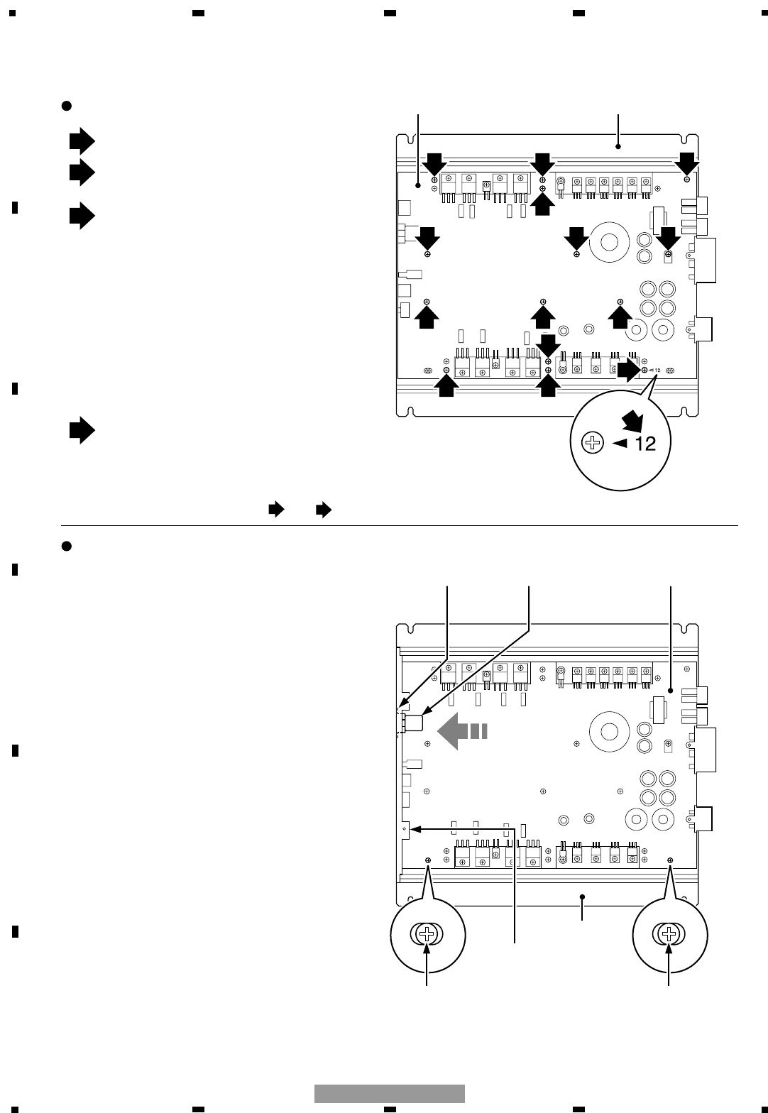
Caution when re-assembling the Amp Unit and the Heat Sink
Remove six black screws (M3 x 10).
Remove six white screws (M3 x 12).
Amp Unit Heat Sink
Heat Sink
Amp UnitRCA Holder
Stud
Move the Amp Unit
Fig. 3
Stud
2 2 2
2 2 2
3
3
1 1
1 1 1
1
2
3
1
A
A
Removing the Amp Unit (Fig. 3)
Screw holes in the PCB are printed with
numbers 1 to 12.
Remove screws in numerical order.
Re-assembly takes the reverse order of
disassembly.
Remove all of twelve screws. Then,
remove the two black screws (M3 x 5).
Tighten screws whose length is M3 x 8 or
more into the two screw holes so as to
raise the Amp Unit above the Heat Sink.
Then, remove the Amp Unit.
Caution)
The Amp Unit is adhered on the Heat Sink with
silicon grease. This means forcibly removing the
Amp Unit from the Heat Sink may break the
PCB.
Be aware that the RCA Terminal may break
unless the Amp Unit and the Heat Sink are
assem-bled following the correct procedures
given below.
1) Secure the RCA-side Panel on the Heat Sink
with screws. (Fig. 2)
2) Place the Amp Unit on the Heat Sink aligning
with two studs. (Fig. 4)
3) Move the Amp Unit until the RCA Holder on
the Amp Unit comes in contact with the inside
of the Panel. (Fig. 4)
Caution in steps 2) and 3)
When you place the Amp Unit on the Heat Sink,
you will find no positioning marks to determine
the direction of two panels. To position them
correctly, the Amp Unit needs to be moved to
the place where it comes in contact with the
RCA-side panel.
If you do not position them, an excessive force
can be applied to the RCA Terminal. This may
result in breakage.
4) Secure the RCA-side Panel and the RCA
Holder with screws. (Fig. 2)
5) Secure the Amp Unit on the Heat Sink with
screws. (Fig. 3)
6) Secure the Panel for the Power Terminal side
in place with screws. (Fig. 2)
Fig. 4
RCA Terminal
(CN111)
Panel for the
RCA side
(Since screw threads differ, and screws cannot be used.)
12
31
5678
F
E
D
C
B
A
5678
GM-7100M/XU/EW
7.1.2 CONNECTOR FUNCTION DESCRIPTION (GM-7100M/XU/EW)
32
1234
1234
F
E
D
C
B
A
GM-7100M/XU/EW
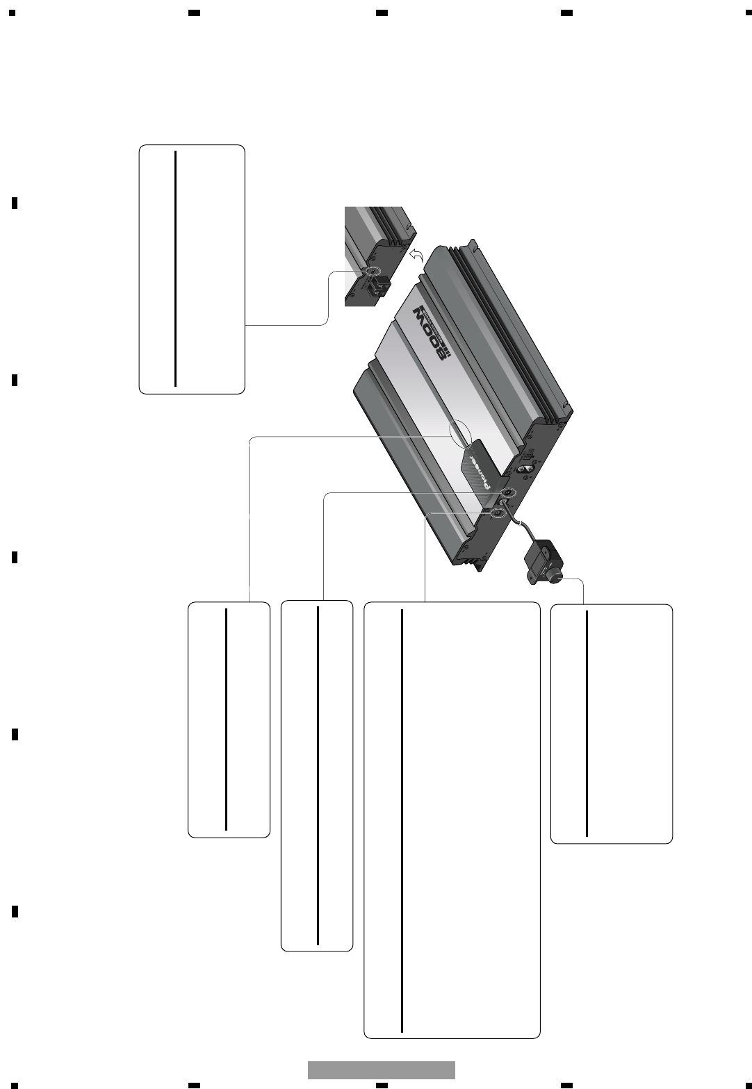
8. OPERATIONS (GM-7100M/XU/EW)
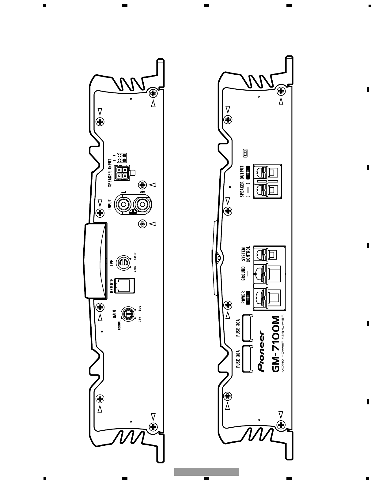
BFC (Beat Frequency Control) Switch
If you hear a beat while listening to an
MW/LW broadcast with your car stereo,
change the BFC switch using a small stan-
dard tip screwdriver.
Power Indicator
The power indicator lights when the
power is switched on.
LPF (Low-Pass-Filter) Cut Off Frequency Control
You can select a cut off frequency from 40 to 240 Hz.
Gain Control
If the sound level is too low, even when the volume of the car stereo used along
with this power amplifier is turned up, turn gain control on the front of the
power amplifier clockwise. If the sound distorts when the volume is turned up,
turn the gain control counter-clockwise.
• When using with an RCA equipped car stereo (standard output of 500 mV), set to the
NORMAL position. When using with an RCA equipped Pioneer car stereo with max.
output of 4 V or more, adjust level to match the car stereo output level.
• If you hear too much noise when using the speaker input terminals, turn the gain control
counter-clockwise.
Bass Boost Control
You can select a bass boost level from
0, 6, 9 and 12 dB.
For instruction of connecting the bass
boost remote control to the amplifier, see
the “Connection Diagram” section.
