Piper_Cherokee_PA28_151_1974 Piper Cherokee PA28 151 1974
User Manual: Piper_Cherokee_PA28_151_1974
Open the PDF directly: View PDF ![]() .
.
Page Count: 98

-if"."rXn"-
AIRCRAFT MODIFICATIONS INC.
F.A.A. APPROVED
AIRPLAI{E SIIPPLB,IENTAL
ELIGHT MANUAL
For
PIPER CIIEROKEE MODEL
PA-28-151
wirh
LYCOMING
0-320-D2A, -D28, -DzC, or -D3G
ENGINE INSTAILED
REcrsrmrroN NrnaER
N tP\^3:I
SERIAL NI]I,IBER
ftris Supplenental Flight ManuaL is F.A.A. approved material and must be
Ln Ehe airplane for all operations when Lycorning O-3?O-D?A, 0-320-D28, O-320-D2C
rr 0-320-D3G engine is installed in accordance with STC
SA2969SW. Ttre
lnformation contained herein supplernents or supersedes the lnformation
:n the form of placards, narkings, and approved rnanual material. For
limitations, procedures and perforrnance informatlon not contained in this
iuppleurental Flight Manual- consult the basic airplane placards, rnarkings
rnd approved manual-
material.
F.A.A. APPROVED
FEDERAL
AVIATION ADMINISIRATION
Southwest Region
Fort l{orth, Te:<as 76LOL
DATE: October 21 1981
S.T.C. No. 5A29695[{
Pagelof2pages
Woco-Modison
CooperAirport
o
P.O.
Box 5249
. Woco,
Texos
76708. 847-752-8381
I
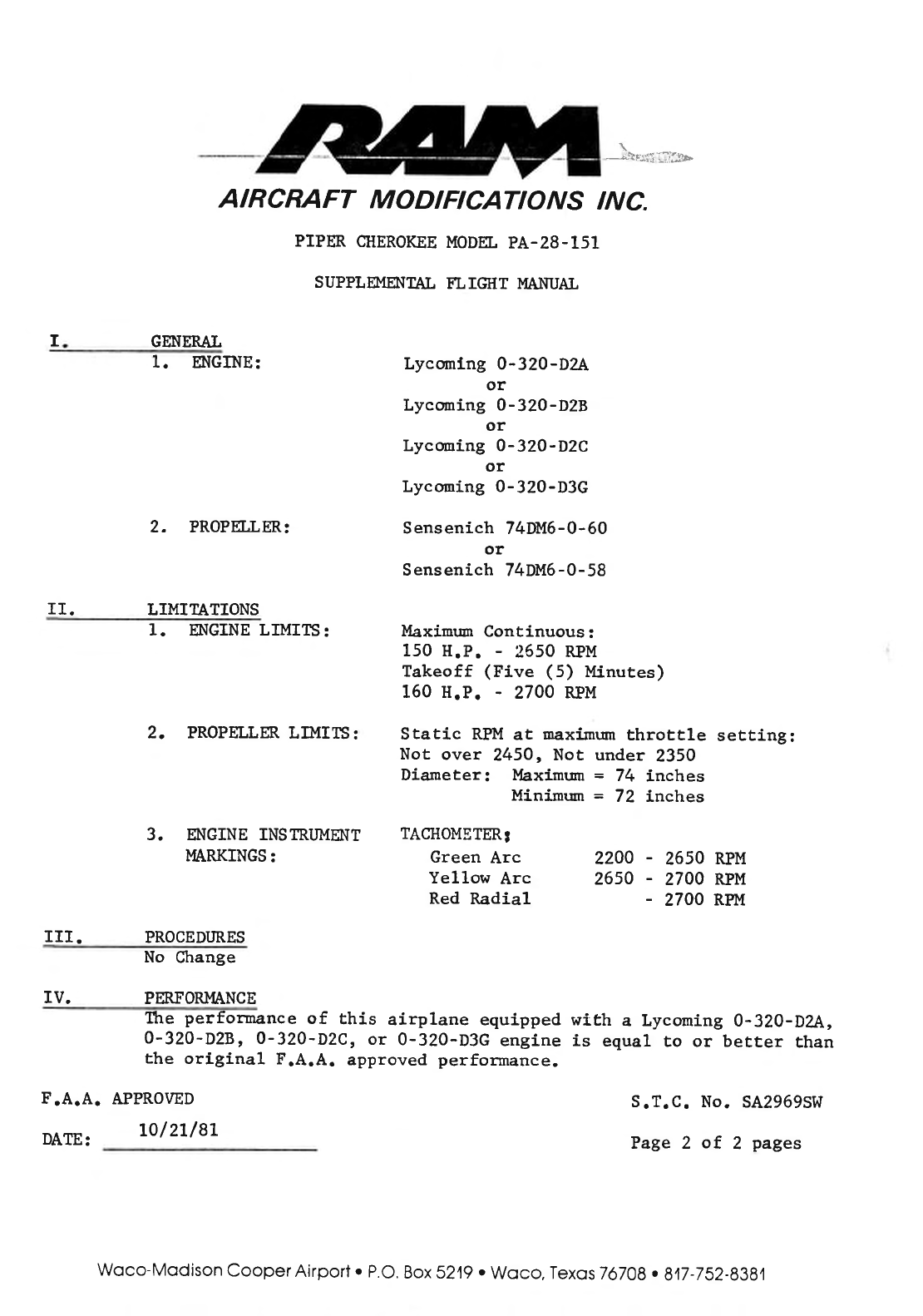
2. PROPFT.T ER:
II. LIMITATIONS
1. NGINE LTMIIS:
2. PROPELLM.
LD{I15:
3. M{GINE INSTR.I]MENT
I4ARKINGS:
F.A.A. APPROVED
DATE: L|/LL/8L
{tF:jiii;:i:b
Lycmrlng 0-320-D2A
or
Lycoming 0-32O-D2B
or
Lyconing O-32O-D2C
or
Lycoming 0-320-D3G
Sensenich 74DM6-0-60
or
Sensenich 74DM6-0-58
Maximum
Continuous:
150 H.P. - 2550 RPM
Takeoff (Five (5) llinutes)
150 H.P. - 2700 RPM
Static RPM
at maximum
throttle setting:
Not over 2450, Not under 2350
Diameter: Maximrmr
= 74 inches
Minimurn = 72 inches
TACIIOMETERI
Green Arc
Yellow Arc
Red Radial
2200 - 2650 RPM
2650 - 2700 RPM
- 2700 RPM
AIRCRAFT MODIFICATIONS INC.
PIPER CIIEROKEE
MODEL
PA-28-151
SUPPLN,IE{TAL FL IGIIT MANUAL
GENEMI.
1. ENGINE:
III. PROCEDIJRES
No Change
IV. PERFORMANCE
the perfonnance of Lhis airptane equipped with a Lycoming O-320-D2A,
O'32O-D2B' 0-320-D2C, or 0-320-D3G engine is equal to or better than
the original F.A.A. approved perfor:mance.
S.T.C. No. SA2969SW
Page2of2pages
Woco-Modison
Cooper
Airport
. P.O.
Box 5249.
Woco, Texos
76708
. 817-752-8384
ttfrd Sottr!f gula
Eqertmrnt
0F
Crsruportation-fcdral
B0lation
lldminignation
Fupplgmsntsl
?[Upe €ntifirsts
(€ontinusfion
Fheet'ir
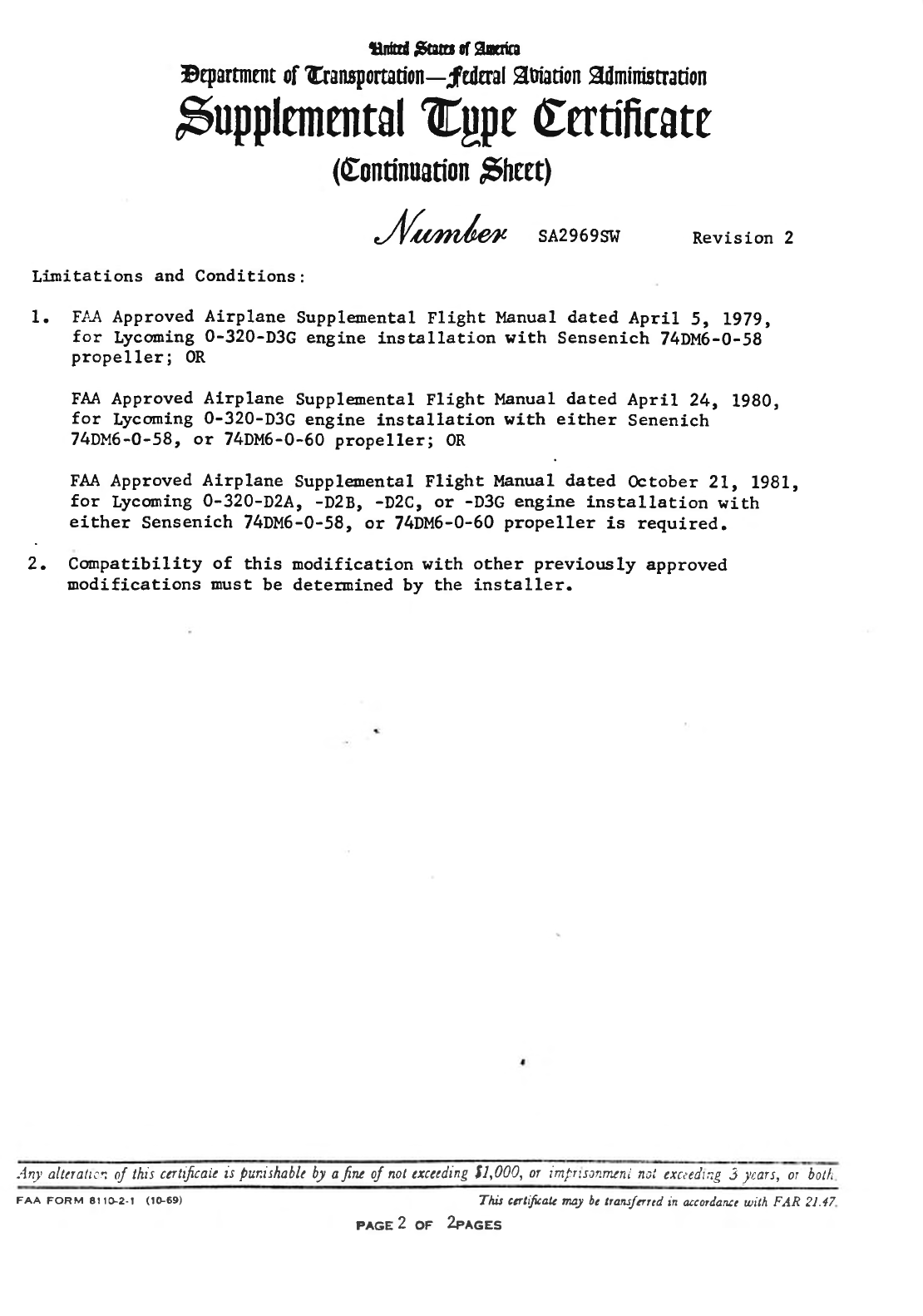
J(r"rrl'.* SA2969S!il Revision 2
Lfunitations and Conditions :
1. Fl.A Approved Airplane Supplenental Flight Manual dated April 5, L979,
for Lycming 0-320-D3G engine lnstallation with Sensenich 74DM6-O-58
propeller;0R
FAA Approved Alrplane Supplpoental Flight Manual dated ApriL 24, 1980,
for Lycoming 0-320-D3G engine installation with either Senenich
74DM6-0-58, or 74DM6-0-60 propeller; OR
FAA
Approved Airplane Supple'r'ental Flight Manual dated October 21, 1981,
for Lycoring 0-320-D2A, -D28, -DzC, or -D3G engine installation with
either Sensenich 74DM6-0-58, ot 74DM6-0-60
propeller is required.
2. Conpatibility of this nodification with other previously approved
uodifications must be deterained by the installer.
An1,allerattcrt
oJ this
ccrttfuaie
is
punishable
by
afru oJ nol cxcccding t|,000, or imfrtscnmtrti
ncl cxctcdtng
3 yars, or botli
FAA FoRM 8rrG2-t (tG69) This cettifuak nu2 bc
nazstarcd in ucordante
with FAR 21.47
pecg 2 or 2erces
CHEROKEE
WARRIOR
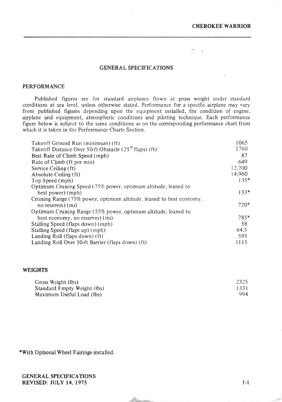
GENERAL SPECIFICATIONS
PERFOR.MANCE
Published figures are for standard airplanes
flown at gross weight under standard
conditions at sea level, unless otherwise stated. Performance for a specific airplane may vary
from published figures depending upon the equipment installed, the condition of engine,
airplane and equipment, atmospheric conditions and piloting technique. Each performance
figure below is subject to the same conditions as on the corresponding
performance
chart from
which it is taken in the Performance Charts Section.
Takeoff Ground Run
(minimum) (ft)
Takeoff
Distance
Over 5Gft Obstacle
(25
o
flaps)
(ft)
Best
Rate
of Climb Speed
(mph)
Rate
of Climb
(ft per
min)
Service Ceiling
(ft)
Absolute
Ceiling
(ft)
Top Speed
(mph)
Optimum Cruising Speed
(75%
power,
optimum altitude,
leaned to
best
power)
(mph)
Cruising
Range
(75%
power,
optimum
altitude, leaned to best economy.
no reserves)
(mi)
Optimum Cruising Range
(55%
power.
optimum altitude, leaned
to
best economy, no reserves)
(mi)
Stalling
Speed
(flaps
down)
(mph)
Stalling Speed
(flaps
up)
(mph)
Landing
Roll
(flaps
down)
(ft)
Landing Roll Over 50-ft
Banier
(flaps
down)
(ft)
l
065
17 60
87
649
12,700
14,960
I
35*
I 33*
720*
785
*
58
64.5
s95
lll5
WEIGHTS
Gross
Woight
(lbs)
Standard
Empty
Wciglrt
(lbs)
Maximum
Useful
Load
(lbs)
*With
Optional
Wheel Fairings
installed.
GENERAL SPECIFICATIONS
REVISED: JULY 14.1975
2325
133
I
994
-JL-*-
l-l
CHEROKEE
WARRIOR
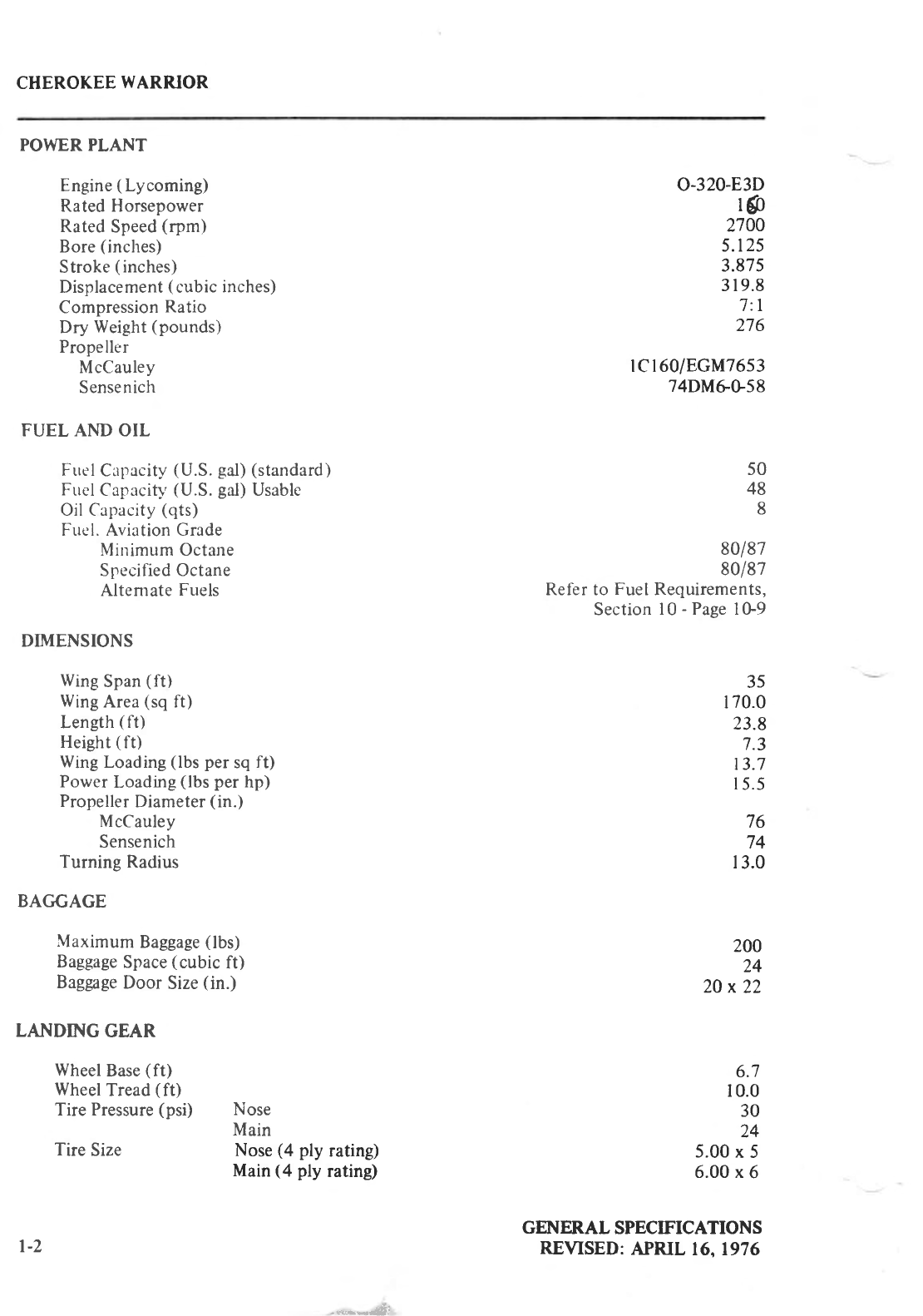
POWER PLANT
Engine
(Lycoming)
Rated Horsepower
Rated
Speed
(rpm)
Bore
(inches)
Stroke
(
inches)
Displacement
(
cubic
inches)
Compression
Ratio
Dry Weight
(pounds)
Propeller
McCauley
Sensenich
FUEL AND OIL
Fuel
Capacity
(U.S.
gal)
(standard)
Fuel
Caprcitf'
(U.S.
gal)
Usable
Oil Capacity
(qts)
Fuel. Aviation Grade
Minimum Octane
Specified Octane
Altemate
Fuels
DIMENSIONS
Wing
Span
(ft)
Wing
Area
(sq
ft)
Length
(ft)
Heieht
(ft)
Wing
Loading
(lbs
per
sq
ft)
Power
Loading
(lbs
per
hp)
Propeller
Diameter
(in.)
McCauley
Sensenich
Turning
Radius
BAC'GAGE
Maximum
Baggage
(lbs)
Baggage
Space
(cubic
ft)
Baggage
Door Size
(in.)
LANDING GEAR
Wheel
Base
(ft)
Wheel
Tread
(ft)
Tire Pressure
(psi) Nose
Main
o-320-E3D
rs
2700
5.125
3.875
319.8
7:l
276
rcr60/EGM76s3
74DMGG58
50
48
8
8o/87
80/87
Refer to
Fuel
Requirements,
Section
l0 -
Page I G9
35
170.0
23.8
7.3
13.7
15.5
76
74
t
3.0
Nose
(4 ply rating)
Main
(4 ply rating)
200
24
20x22
6.7
10.0
30
24
5.00
x 5
6.00 x
6
GEITIERAL
SPECIFICATIONS
REVISED:
APRIL
16,1976
t-2
Tire
Size
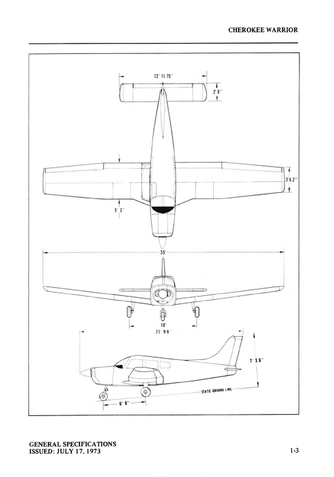
CHEROKEE
WARRIOR
I
?
36
GENERAL SPECIFICATIONS
ISSUED: JULY 17.1973 1-3
DESCRIPIIlIlI
AIRPU]IE A]ID
SYSIETS
The Airplane 2-l
Airframe 2-l
Engine
and
Propeller 2-2
Landing Gear 2-4
Flight
Controls 2-6
Frrel
System 2-7
Electrical
System 2-9
Vacuum
System 2-13
Instnrment Panel
. 2-13
Pitot-Static
System 2-15
Heating
and
Ventilating 2-15
Cabin
Features 2-18
Baggage Area 2-18
StallWarning... 2-18
Finish 2-18
Emergency
Locator Transmitter 2-19
Piper
External Power 2-19
J
2-i
CHEROKEE
WARRIOR
DESCRIPTION
AIRPLANE AND SYSTEMS
THE AIRPLANE
The Cherokee Warrior is a single-engine, fixed gear
monoplane of all metal
construction
with low semi-tapered wings.
The fuselage
provides
a spacious, four-place
interior with optional features to ensure
individual comfort during short or extended cross-country flight.
The Cherokee
Warrior can serve as a rental or crossrountry airplane and also as a training
and utility airplane. Performance
and loading characteristics combine with economical
operation to make
the Warrior a
versatile
airplane in the business or personal
aviation fields.
AIRFRAME
The primary structure,
with the exception
of the steel tube engine
mount, steel
landing
gear struts and isolated areas, is of aluminum alloy construction. Tough fiberglass and
thermoplasfic are used
extensively
in the extremities - the wing tips, the engine
cowling, etc. -
and in nonstructural
components
throughout the
airplane.
The fuselage
is a conventional semi-monocoque
structure. On the right side of the airplane
is a large cabin door for ease
of entrance
and exit and a large baggage
door to provide effortless
loading
into the 24 cubic foot compartment. Maintenance
has been reduced
to a minimum with
advanced
fuselage
design.
The wing is a conventional
semi-tapered
design incorporating a laminar flow, NACA
652415, airfoil section. The cantilever wings are attached to each side of the fuselage by
insertion of the butt ends of the main spars into a spar box carry-through which is an integral
part of the fuselage
structure. The spar box carry-through
structure,
located
under the rear
seat,
provides
in effect
a continuous main
spar
with splices at each side of the fuselage.
There are also
fore and aft attachments
at the rear
and at an auxiliary front spar. This type of wing
structure
provides
unobstructed cabin space for the rear
passengers
and allows
for a lighter wing structure
to improve
the useful load of the
airplane.
Both ailerons and flaps are of modern,
all metal
construction
for smooth control of the
aircraft. The ailerons are tapered to accommodate the semi-tapered
wings.
In the fully retracted
position, the right flap locks to provide a step for cabin entry. The flaps have three extended
positions:
10,25, and
40 degrees.
A horizontal stabilator, vertical fin, and a rudder make up the empennage. They utilize a
lightweight metal construction with fiberglass
tips.
AIRPIJ\NE AND SYSTEMS
REVISED:
JULY 14.1975 2-l
CHEROKEE
WARRIOR
ENGINE AND PROPELLER
The PA-28-l 5 | is powered by a Lycoming O-320-E3D four cylinder. direct drive,
horizontally
opposed
engine
rated at 150 HP
at 2700
RPM. It is equipped
with a starter,
a 60
amp l4 volt alternator,
a shielded
igrrition, dual
magnetos,
vacuuln
pump
drive, a fuel
pump,
and a wetted pol-vtrrethane
foam induction air filter. A recommended
overhaul
period
of 2000
hours
is based
on Lycoming service
erperience.
Operation
beyond
the recommended
time is
the
decision
of the
operator. Since
Lycoming
from time to time revises
the
recommended
overhaul
period.
thc'owner
should check
with his dealer
for the latest
overltauI
period
on his
engine
as
well as any
additional
Lycoming Servicc
Information.
The engine
compartment
is easily accessible
for inspection
through
top-hinged
side
panels
on either
side
of the engine cowlings.
The engine cowlings
are cantilever
strltctures attached
at
the fire wall. The engine
mounts are constructed
ol steel tubing,
and
dynafocal
mounts
are
provided
to reduce
vibration.
The. exhaust
system
is constructed
of stainless
steel and
incorporates
a
single
muffler with
heater shrouds
to supply heated
air for the cabin. the defroster
systent and the carburetor
deicing
system.
An oil cooler
is located on the left rear
of thc' engine mounted
to thc engine
baffling.
Engine cooling
air,
which is picked
up in the nose section
of the
engine cowling
and
carried
through the baffling. is utilized on the left side
for the oil cooler.
A winterization
plate is
provided
to restrict
air during
winter
operation.
(See
Winterization
in Harrdling
and Servicing.)
Engine air enters
on either
side of the
propeller
tltrouglt
openings
itt
thc' nose
cowling
and
is carrred
through
the engine
baffling
around
tlte engine
and oil cooler.
Air for the muffler
shroud
is also
pickc'd
up from the
nose cowling and carried
through
a largc
duct
to the shroud.
Carburetor
indrrction
air enters a chin scoop
on the
lower right cowling
and is
passed
through
a
wetted polyurethane
filter to the carburetor
air box. Heated air enters
the carburetor
air box
through a hose connected
to the heater
shroud.
A Mgcar.rley
lCl60/8GM7653 or a Sensenich
74DM6-0-58
fixed pitch propeller
is installed
as
standard
equipment.
The McCauley
propeller
has a diameter
of 76
inches
with a
pitch
of 53
inches
and the Sensenich
has a 74 inch diameter
with a 58 inch pitch.
The pitch of both
propellers
is determined
at75% of the diameter.
Both
propellerunitsare of an
aluminum
alloy
construction.
The pilot should
read
and
follow the
procedures
recommended
in the Lycoming
Operator's
Manual for this engine
in order to obtain maximum engine
efficiency
and time between
engine
overhauls.
AIRPLANE AND SYSTEMS
ISSUED:
JULY
17,1973
)-)
CHEROKEE WARRIOR
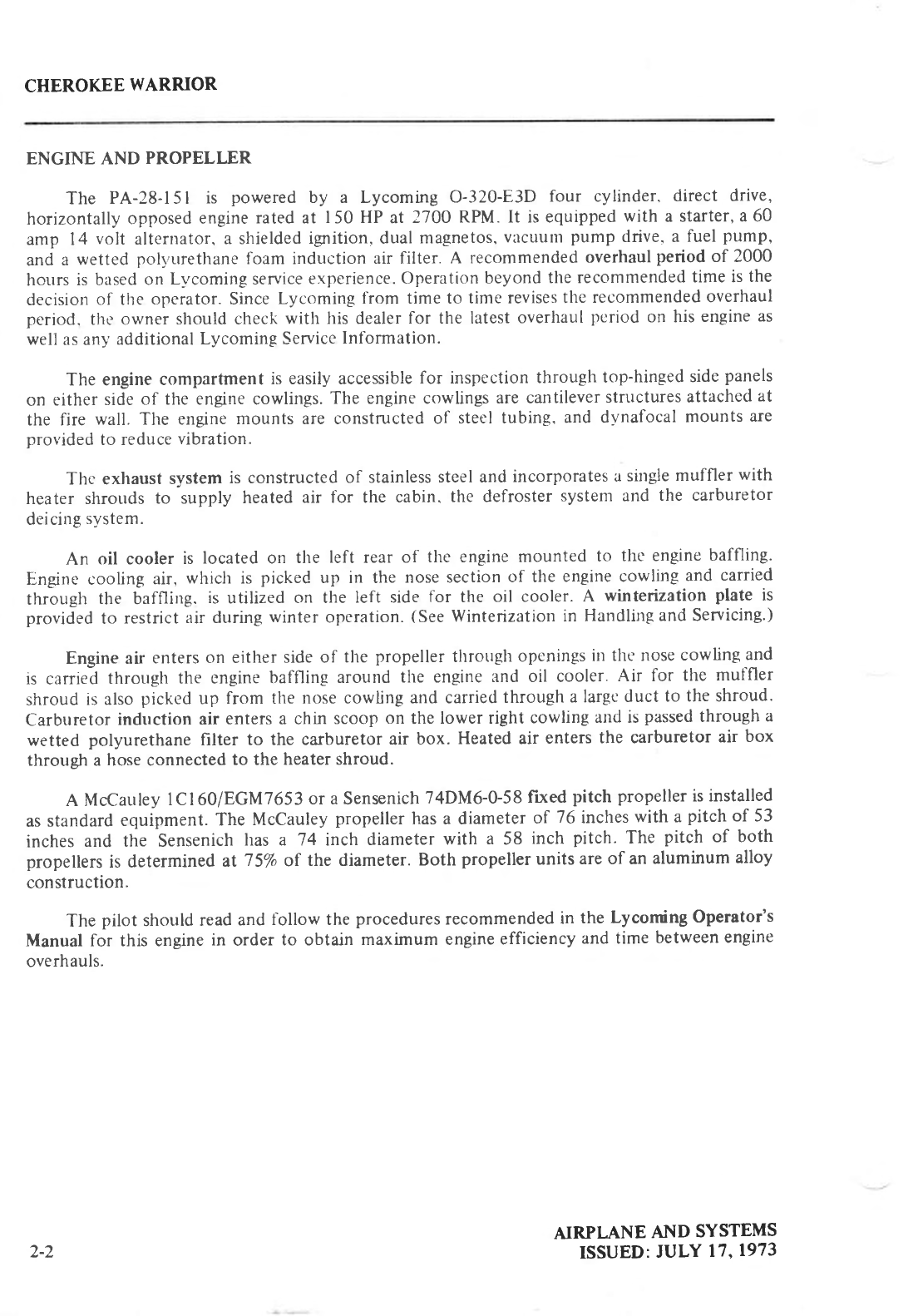
Throttle
Quadrant
and Console
AIRPLANE
AND SYSTEMS
ISSUED:
JULY 17,1973 2-3
CHEROKEE
WARRIOR
LANDING GEAR
The fixed gear
PA-28-
I
5 I is equipped
with is a Cleveland
5.00
x 5 wheel on the
nose
gear
and a Cleveland
6.00 x 6 wheel
orr each main gear.
Cleveland
single
disc
hydraulic
brake
assemblies
are
provided
on thc'main
gear.
The nose
gear
has a 5.00
x 5 four ply
tire,
while the
main wheel assemblies
have 6.00
x 6 four ply tires.
At gross
weight.
the
main
gear
tires
require
a
pressure
of 24 psi,
and
the
nose
gear
tire
requires
a
pressure
of 30 psi.
The nose
gear
is steerable
through
a 30 degree arc
each
side
of center
by the use of the
rudder pedals
ind toe brakes.
A spring device
is incorporated
for rudder centering
and to
provide rudder trim. A bungee assembly
on the nose
gear
steering
mechanism
reduces
ground
iteering effort and dampens
shocks
and bumps
during taxiing.
The steering
mechanism
also
incorporates
a shimmy
damPener.
The three struts
are of the air-oil
type
with the
normal static
load extension
being 3'25
inches
for the
nose
gear
and
4.50
incltes
for the main
gear.
The brakes
are
actuated
by toc
brakc
pedals
which are attached
to the rudder
pedals
or
by
a hand lever
and master
cylinder
located
below
and
behind
the center
of the instrument
sub
panel.
Hydraulic
cylinders
are located
above
eaclt
pedal
and
adjacelrt
to the hand
brake lever.
The brake
fluid resenoir
is installetl
on the
top left front face of the
fire
wall. The
parking
brake
is incorporated
in the master
cylirrder
and
is actuated
by pulling
back
on tlte brake
lever
and
depressing
the
knob attached
to the'left
side
of tlte
handle.
To release
the
parking
brake,
pull
batt on the brake lever to disengage
the catch mechanism
and allow the handle
to swing
forward.
AIRPLANE
AND SYSTEMS
ISSUED:
JULY 17.1973
24
CHEROKEE
WARRIOR
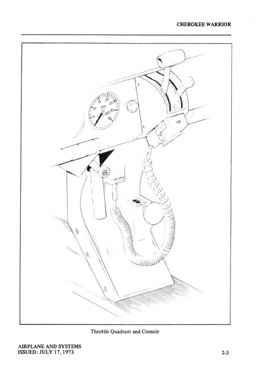
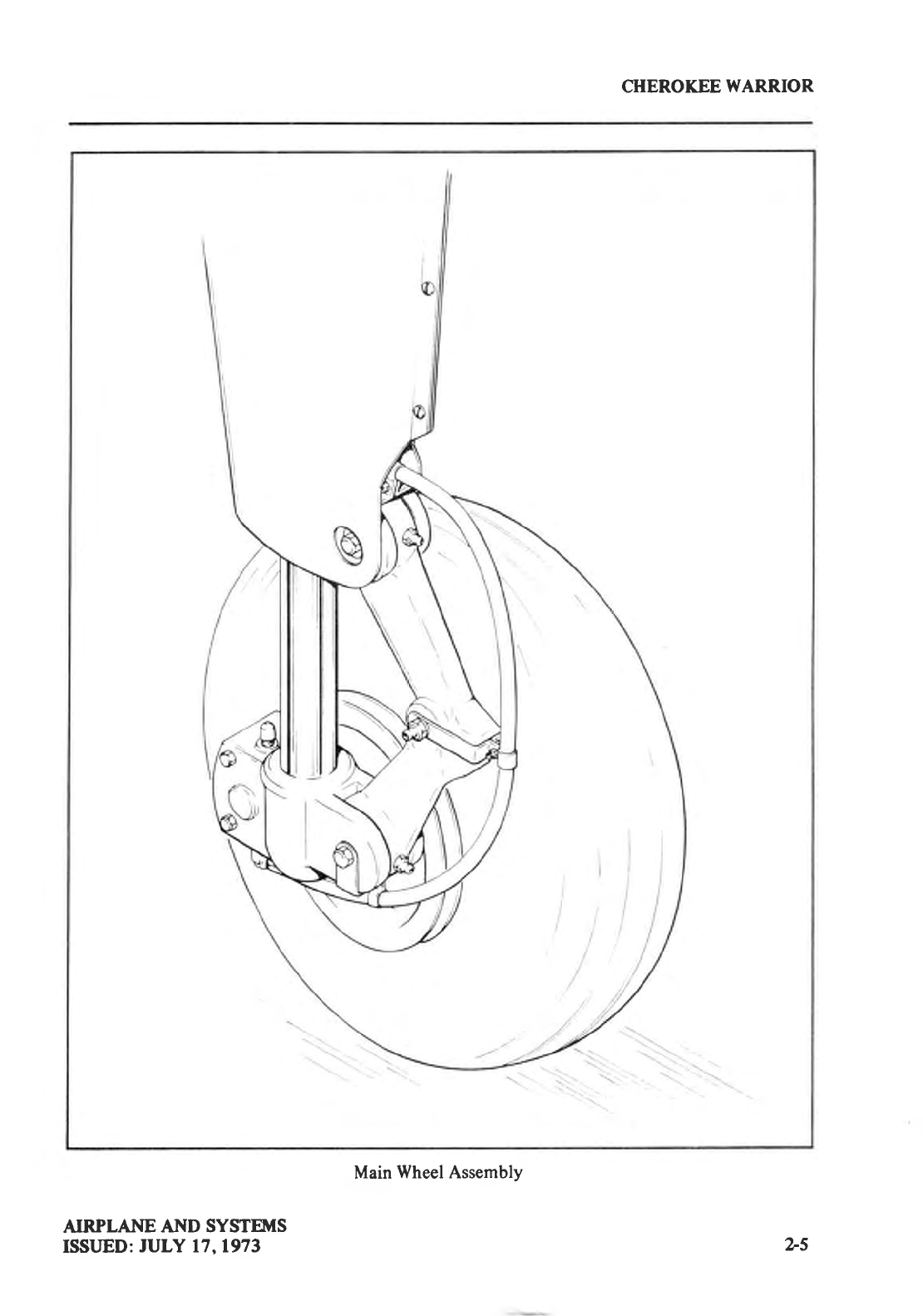
Main
Wheel Assembly
AIRPLANE AND SYSTEMS
ISSLJED:
IULY 17,1973 2-5
CHEROKEE
WARRIOR
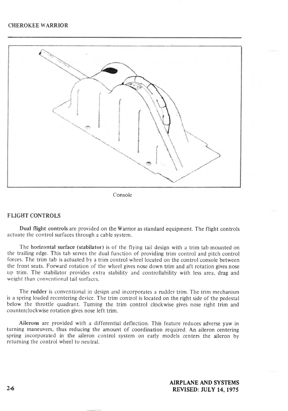
Console
FLIGHT CONTROLS
Dual flight controls are
provided
on the Warrior as standard
equipment. The flight controls
actuate
the control surfaces
through a cable system.
The horizontal
surface
(stabilator)
is of the flying tail design
with a trim tab mounted on
the trailing edge. This tab serves the dual function of providing
trim control and
pitch control
forces.
The trim tab is
actuated by a trim control wheel
located
on the control
console
between
the front seats. Forward rotation of the wheel
gives
nose
down trim and
aft rotation
gives
nose
up trim. The stabilator provides
extra stability and controllability with less area, drag
and
weight
than convcrrtional
tail
surfaccs.
The rudder is conventional
in design
and incorporates a rudder trim. The trim mechanism
is a spring loaded
recentering
device. The trim control is located
on the
right side of the
pedestal
below the throttle quadrant.
Tuming the trim control clockwise
gives
nose
right trim and
counterclockwise
rotation
gives
nose left trim.
Ailerons are provided
with a differential
deflection.
This feature reduces
adverse
yaw in
turning maneuvers.
thus reducing
the amount of coordination required.
An aileron
centering
spring incorporated in the aileron control system
on early models centen the aileron by
returning
the control
wheel
to neutral.
AIRPLANE AI\D SYSTEMS
REVISED:
JULY 14.1975
24
CHEROKEE
WARRIOR
Manually controlled flaps are
provided on the PA-28-151. The flapsare balanced
forlight
operating forces and spring loaded to return to the retracted
(up) position. A control handle,
which is located between the two front seats
on the control console,
extends
the flaps by the
use
of a control cable. To extend the flaps, the handle is pulled up to the desired flap setting
of
lO, 25 or 40 degrees.
To retract, depress the button on the end of the handle and lower the
control. When
extending or retracting flaps, there
is a pitch change
in the airplane.
This pitch
change can be conected either by stabilator trim or increased control wheel force.
When
the
flaps are in the retracted
(up) position the right flap, provided with an over-center
lock
mechanism, acts as a step.
NOTE
The right flap will support a
load
only in the
fully retracted
(up)
position.
When the flap is to be used as a step,
make sure the
flaps
are
in the retracted
(up) position.
FUEL SYSTEM
Fuel is stored in two twenty-five gallon
(24 gallons
usable)
fuel tanks,
giving
the airplane a
total capacity of fifty U.S.
gallons
(48 gallons
usable). The tanks
are secured to the leading edge
of each wing with screws and
nut plates.
This allows easy removal
for service or inspection.
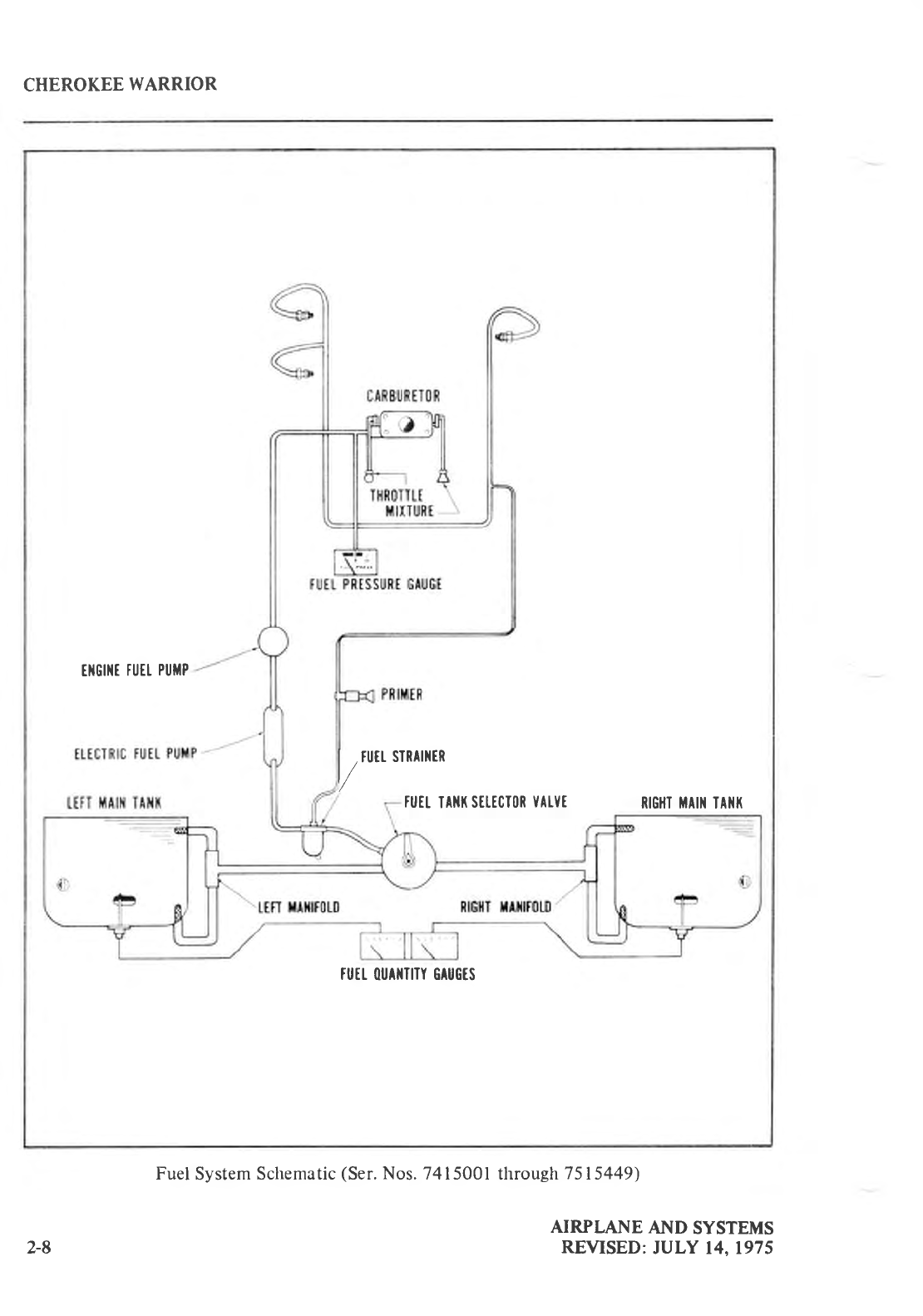
On serial numbers
7415001 through
7515449
each
fuel tank has two outlets, one forward
and one aft, to ensure an even
fuel flow. Fuel is pumped from the tanks through the forward
and aft tank outlets to fuel manifolds in the inboard section of either wing. Each
manifold is a
small collector with an inlet hose from each
of the tank outlets, and an outlet hose to the fuel
selector
valve.
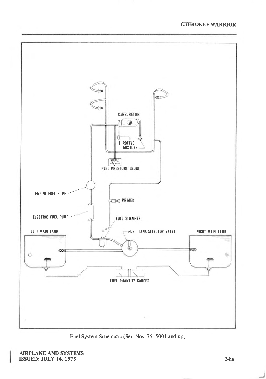
On serial
numbers
7615001
and up there is only one outlet on each
tank and
no
fuel manifolds are used.
The fuel tank selector control is located on the left side
panel forward of the pilot's seat.
The button on the selector cover must be depressed and held while the handle is moved
to the
OFF position. The button releases automatically
when the handle is moved back to the ON
position.
An auxiliary electric fuel pump is provided in case
of the failure of the engine driven
pump. The electric
pump should
be ON for all takeoffs
and
landings and
when
switching
tanks.
The fuel pump switch is located in the switch panel
above
the throttle quadrant.
'l'lrc
fuel druins
shotrltl
bc o;rcnctl
daily
prior
to first flight to chcck
fr>r
watcr or sedimcnt.
h,aclr tank has an individual
drain at the bottom, inboard
rear corner, and each
fuel manifold
(on early
models only) is
equipped
with a drain. The
outlets are
located on the underside of the
wings.
A gascolator,
located
on the lower left front of the
fire
wall,
has a drain
which is accessible
from outside the nose section. The gascolator
should also be drained before the first flight of
the day.
(See
the
Handling and Servicing Section for the complete
fuel draining
procedure.)
Fuel quantity and fuel pressure
gauges
are mounted in a gauge
cluster located on the left
side of the
instrument
panel
to the right of the control
wheel.
An optional engine priming system
is available
to facilitate starting.
The primer pump is
located to the immediate left of the throttle quadrant.
AIRPLANE AND SYSTEII{S
REVISED: JULY 14,1975 2-7
CHEROKEE
WARRIOR
EIIGIIIT
FUEt
PUTIP
l/"" SIRATnER
FUEI
IAIII(
SELICIOR
YATYI RIGHI MAI]I IAI{I(
TUTI.
OUAIITITY
GAUGTS
Fuel
System
Schematic
(Ser.
Nos.
7415001 through
7515449)
AIRPLANE
AND SYSTEMS
REVISED:
JULY 14,1975
2-8
CHEROKEE
WARRIOR
THRl]TITT
MIIIURT
tlfGflft
tutt PUfiP
--='
fl.tclnlc
tufl.
PUilP
--
r.ttl t^ilr lAlil( futl rrill stttcl0R
Yrtvl. RIGHI TAI]i TAITI(
TUIL {lUAilIIIY GAUGTS
Fuel System Schematic
(Ser.
Nos. 7615001 and up)
AIRPLANE AND SYSTEMS
ISSLJED: JULY 14,1975 2-8a
)
CHEROKEE
WARRIOR
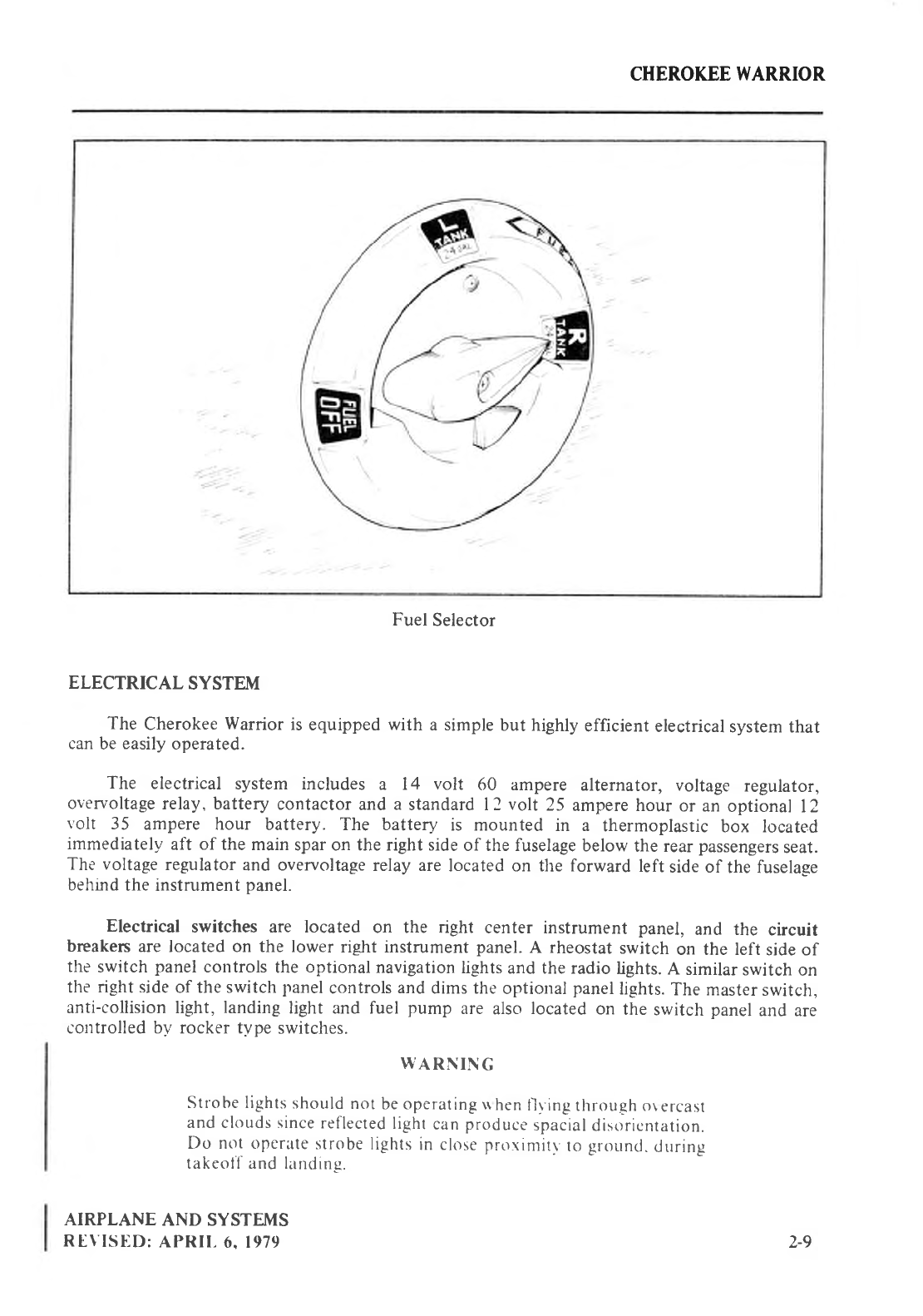
Fuel Selector
ELECTRICAL SYSTEM
The Cherokee
Warrior
is equipped
with a simple
but highly
efficient
electrical
system that
can
be
easily
operated.
The electrical system includes a l4 volt 60 ampere alternator, voltage regulator,
overvoltage
relay, battery contactor
and a standard l2 volt 25 ampere hour or an optional l2
volt 35 ampere hour battery. The battery is mounted in a thermoplastic box located
immediately
aft of the main
spar on the right side
of the fuselage
below
the rear
passengers
seat.
The voltage
regulator
and overvoltage
relay are
located on the forward left side of the fuselage
behind
the instrument
panel.
Electrical switches are located on the right center instrument panel, and the circuit
breakers
are located on the lower right instrument
panel.
A rheostat
switch on the left side of
the switch panel
cotrtrols
the optional
navigation
lights
and the radio
lights.
A similar
switch
on
the
right side
of the switch
panel
controls
and
dims the
optional
panel
lights.
The master
switch,
anti-collision light, landing light and fuel pump are also
located
on the switch panel
and are
controlled by rocker tvpe
switches.
WARNING
Strobe lights
should
not
be operating * hen
l)r.ing
through o\ercast
and clouds since
reflected
light
can
producc-
spacial
distlricntation.
Do not operate
strobe
lights
in close prorinritr
to
grouncr
.
tjrrrrng
takeoll' and landing.
AIRPLANE
AND SYSTEMS
REVISIID:
APRIL
6. 1979 2-9
CHEROKEE
WARRIOR
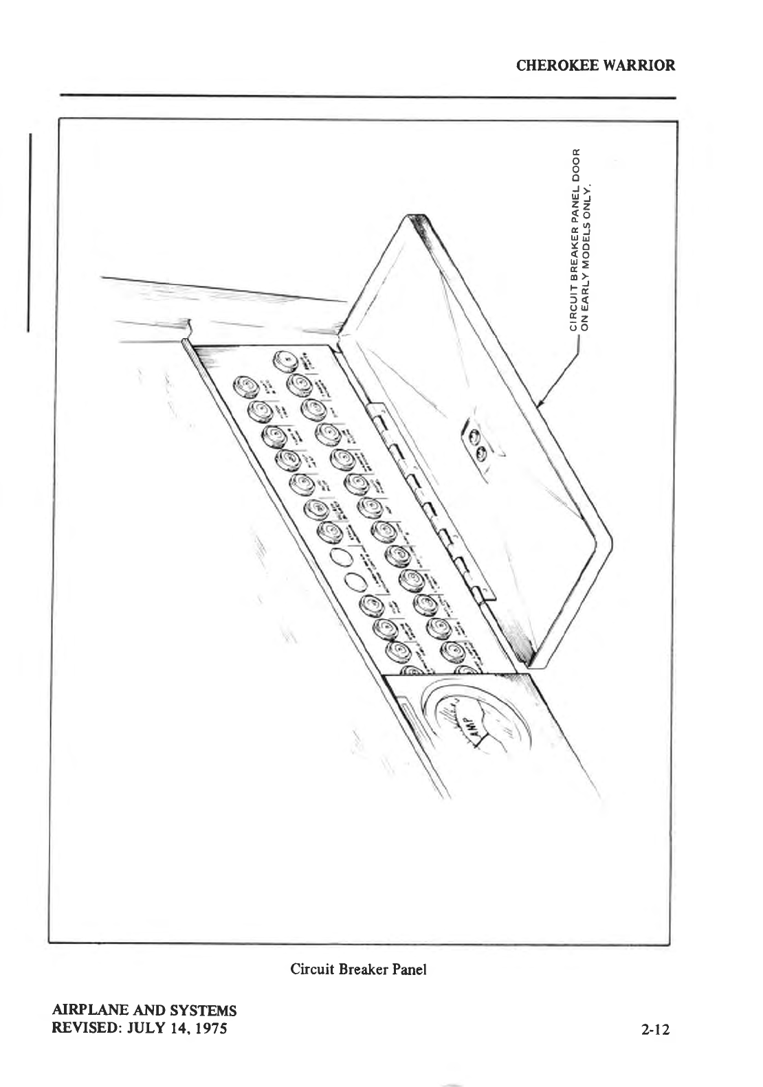
A hinged
door
protects
and
gives
easv access
to the circuit breaker
panel.
Each circuit
breaker
on
the
panel
is
of
the
push to reset type
and is clearlv
marked
as
to its function
and
amperage. Circuit
prorisions
have
been
included
to handle a
full complement of
communication and
navigational
equlpment.
Standard
electrical
accessories
include a starter. an electric fuel pump. an audible stall
warning
indicator,
fuel
gauges,
ammeter.
and
annunciator
panel*.
T|e alnunciator
panel*
includes
alternator
and
low
oil pressure
indicator
lights.
When
the
optional
gyro s)'stem
is installed.
the
urnunciator
partel
also
includes a low vacuum
indicator
light. The annunciator
panel
lights are
provided
only as a
warning
to the
pilot that a
system may
not be
operating
properly,
and that he should check and
monitor the applicable system
gauge
to
de termine
wlten or if any
necessary action
is
required.
The system
also provides
for such optional electrical
accessories as additional lights
and
gallges,
a
heated
pitot head,
attd communication
and
navigational
equipment.
The master switch is a split rocker switch. One side of the switch is the battery side
("BAT") and the other
is the
alternator
side
("ALT"). Henceforth, the
words
"masterswitch"
Irsed in this
manual
will mean
both "BAT" and
"ALT" switches
and they are to be depressed
simultaneously
to OFF or ON as
directed.
Primary electrical
power is provided by the 14 volt 60 amp alternator. The alternator
system
offers
many advantages
over the generator
system
both in operation and maintenance.
T|e main
advantage
is full electrical
power
output at lower engine
RPM. This
provides
improved
radio and electrical
equipment
operation
and
increased
battery
life by reducing battery load.
This
will make
cold
weather
starting
easier.
Secondary
electrical
power
is
provided
by the standard
or optiotral
battery.
Unlike previous generator
systems,
the ammeter as installed does not show battery
discharge:
rather.
it indicates
the electrical
load on tlte alternator in amperes.
With all the
electrical
equipment
off and
the
master switch
on. the ammeter
will indicate the
charging
rate
of tlte
battery.
As each
electrical
unit
is switched
ott.
the ammeter
will indicate the total ampere
clraw of all the urrits
including
the batter1,.
For exantple.
the maximum
continuous load for
1ig|t flight with radios
on is abont
30 amperes.
This 30 ampere
value
plus
approximately 2
amperes
for a fully charged
battery
will appear cotrtiltuously
under
these tlight conditions.
The
amopnt of current showlr
on the ammeter
will tell inrmediately
if tlte alternatcr
system is
operating
normally.
as the
amount
of current
showrr
should
equal
the total amperage drawn b1'
the
electrical
equipmetrt
which is operating.
If 1c outpgt is indicated
on the ammeter
dttring
fligltt. redttce
the electrical load b1'
turlilg off all unnecessary
electrical
eqtripment.
C'lreck
both
the
5
ampere field breaker
and tlte
60 ampere
outpr,rt
breaker
and reset
if open.
If neithc'r
circuit
breaker
is
open. tttrn the
"AL'I"
srvitch
off for I second
to reset the
overvoltage
relav.
If thc amnteter continues
to indicate
no
output.
maintain
mhimum electncal
load and
termirtate
the
flight
as sooll
as
practical.
Maintenance
ou the alternator
should
prove to be a minor factor. Should service
be
required.
contact
the
local
Piper
Dealer.
*Serial
nos. 7515001
and
up
AIRPLANE
AND
SYSTEMS
REVISED:
APR|l.
6. 1979
2-t
0
CHEROKEE WARRIOR
STARTER
A ACCESSORIES ALTERNATOR
FIELD
{
STARTER
SOLENOID
Y,CABIN
LIGHT
MA9TER
SOLENOID
---_l
EXTERNAL
POWER
RECEPTACLE
RELAY EN€RGIZING
CIRCUIT
AMMT
TFR ( )HASIER
5Wt
I CH
t- t- - |
19 l
t--
! ALTEENATOR
. SOURCE-POWER
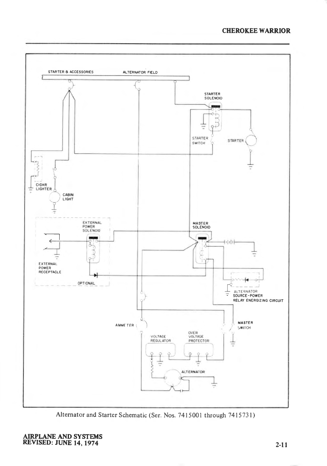
Alternator
and Starter
Schematic
(Ser.
Nos. 741
5001
through
7415731)
NRPI.ANE AND SYSTEMS
REVISED:
JLJhtE
14. 197
42-tl
CHEROKEE WARRIOR
STARTER
A ACCESSORIES ALTERI{ATOR
FIELD
5A
(rN
L|NEI
?
I
I
STA
sot
---{
-t r-t
lr
=[
STARTER
swtTcH
RTER
-Er{oro
=')
o
lol
I
LAMP
TEST
\ waRN
r/ L|GHT
T.ASTER
soLENOtl
,. / LIGHT
\--
Y
I
- - -;;;;-
POWER
-i
1I
=
EXTERNAL
POWER
i nEceprecue
e
T
5A
(rN
L|NE) 5"-or-----1,
t,
I
r
F-----rI
------l
$*-lr--oiJ
rul
t*-----
4 ALTERf{ATOR
: souncE-powER
RELAY EI{ERGIZI
I
I oPTlo4L_ _ __J
AMMETER \ d d MASTER
) /--/ swrrc'
r
I
-L
EI{ERGIZING CIRCUIT
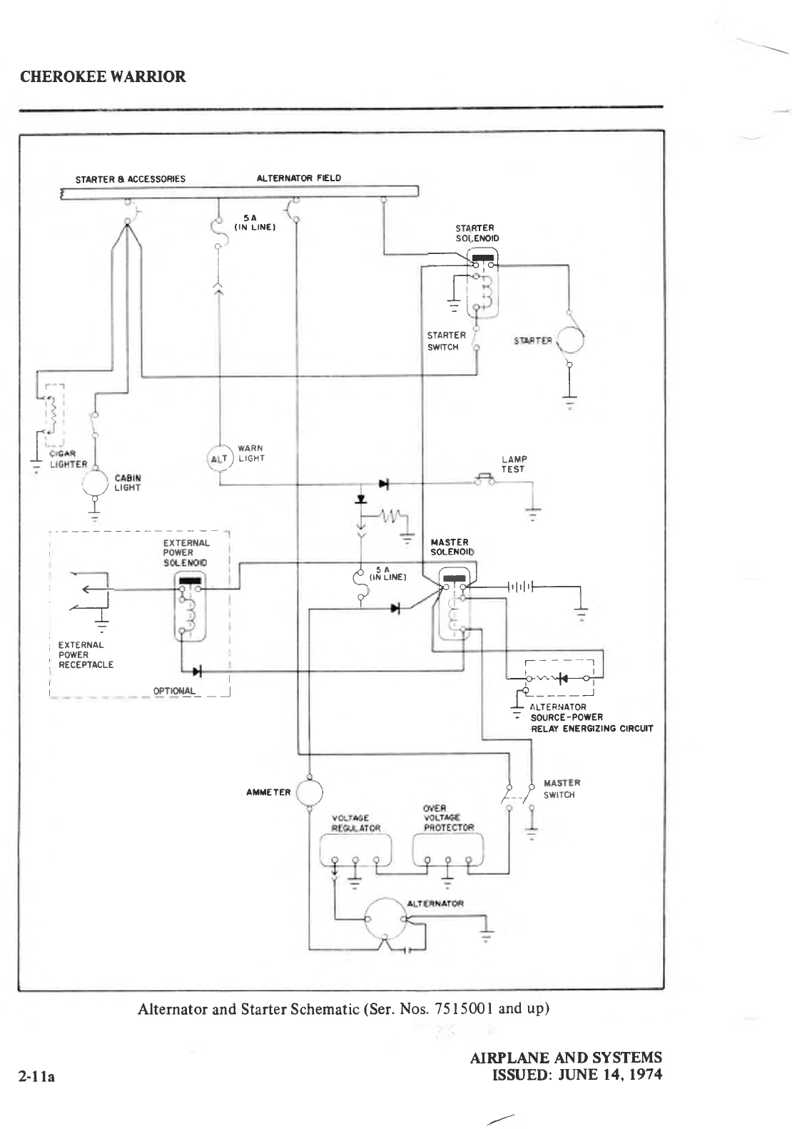
Alternator
and Starter
Schematic
(Ser.
Nos. 7515001
and
up)
AIRPLAI{E AND SYSTEMS
ISSUED:
JUNE
14.1974
2-lla
CHEROKEE
WARRIOR
o
o
J;
Ul
'r
z,
s6
aul
lrj Ul
YO
(o
u>
o>
r.i
)<
olJ
!z
oO
NRPLANE AND SYSTEMS
REVISED:
JULY 14.1975
Circuit Breaker
Panel
2-12
CHEROKEE
WARRIOR
VACUUM SYSTEM*
The vacuum
system is designed
to operatc
the air driven
gyro
instruments. l'his includes
thc dircctiottal nrtd uttitudc
gyros
whcn installcd.
The system consists of an engine
<lriverr
\lrcuunl
ptl
nll). il
vircuilrn
rcgttllrtrlr,
il
l-i
ltcr lrrrrl
tlrc llccessitry
lllturtbing.
The vacuum
pump
is a dry' type
pump whrclt
eliminates
the nced for an air/oil separator
and
its plunrbing.
A sltear drive
protects
the
pump from damage. If the drive
shears. thc'gyros
will
heconrc
inoperrtivc.
A vacuum gauge.
mounted
on the far right instrument
panel provides
a pilot check
for the
system during operation.
A decrease
in pressure
in a system that remained
constant
over an
extended
period
mav indicate a dirty filter.
dirty screens,
possibly
a sticky
vacuum
regulator or
leak irt thc systent
(a low vacuum
indicator light is
provided
in the annunciator
panel**).
Zero
pressure
would indicate a sheared
pump dnve. detective
pump, possibly
a defective
gauge
or
collapsed line. In the c'vent
of any gauge
variation from the norm, the pilot should
have
a
mechanic
check
the system
to prevent
possible
damage
to the system components
or eventual
failure
of the system.
A vacuum
regulator is
provided
in the
system to protect
the
gyros.
The valve is set so the
normal
vacuurn
reads 5.0
+ .l inchc's of mercury, a
setting
which
provides
sufficient
vacuum
to
opcrate all the
gyros
at their
rated RPM.
Higher settings
will damage the
gyros
and
with
a low
setting
the
gyros
will be unreliable. The regulator
is
located behind the instrument
panel.
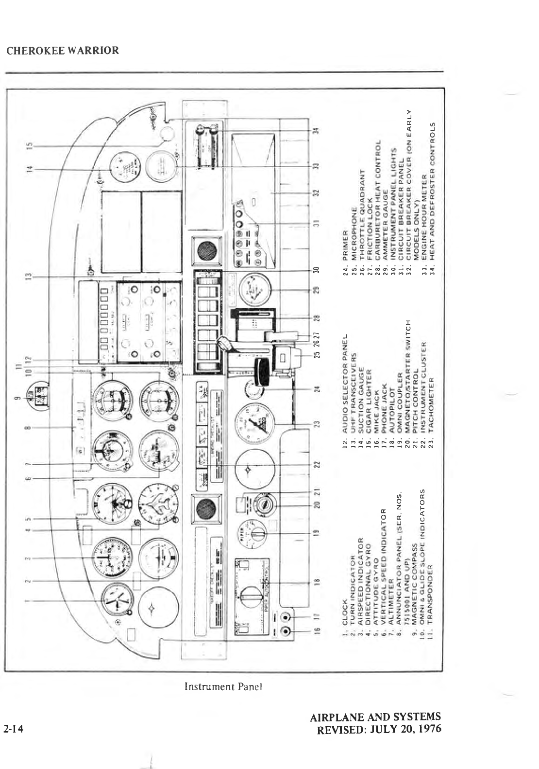
INSTRUMENT
PANEL
Thc instrument
panel is designed
to be firnctiorral and professional,
accommodating
complete
instruments and avionics equipment
for VFR and IFR flights.
A wide range of
optional instmments and avionics
pennit
an equipment selection
to suit individual
needs.
A natural scparation
of the flight groul'r
and
power
group
is
provided
by placing
the fligltt
group in the upper instrument
panel
and
thc power group
in the center and
lower instrument
panels.
The radios and the- circuit breakers are located on the upper and lower right panel
respective'ly. and havt'
circuits
provided
for a complete
line of optional
radio equipment.
An
engine cluster is located to tht-' right of the pilot control wheel and includes a fuel pressure
gauge.
a rig}t and let't
main fuel quantity gauge.
an oil temperature
gauge
and an oil pressure
gallge.
Standard instruments
on the Warrior panel
include a compass, an airspeed indicator, a
tachometer. an altimeter, an ammeter,
an engine
cluster.
and an annunciator
panel**.
The
conlpass
is mounted to thc top of the instrument
panel
in clear
view of the pilot. The
annunciator
panel
is mounted
in the upper
instrument
panel
to warn
the pilot of a possible
nrall'unction in the alternator.
oil pressure.
or
vacuum
systems.
r\ r'otn;llt'tc
lttte
<ll
iltstrtnrrenl
olltious
uvrriluhlc
l'rlr
tlrc
panel
irtclrrdes u
suctir)n
gaugc,
vt
rlrtrrl
sP1'q'11
rrttlitrrlot. rrllrttttlt'
gylo,
tlirt:ctiorr;rl
91,rt-1.
clock.
tru-spceitl ilrdicator
and a turn
rrrrtl
sliP
intlieutor
ol turrr eorlrul inatol'.
-[-lrc
attitudc
gyro
ancl directional
gyro
are
vacuum
operatcd
throrrglt
the use ol a vucuum pump
installcd on the engine,
while
the
turn
and slip
indicator is electrically'operated. The
vacuum
suction
gaugc
is on the far
right of the
instrument
panel
*Optional
equipment
**Serial
nos. 7515001
and up
AIRPLANE
AND SYSTEMS
REVISED:
JUNE
14.1974 2-t3
CHEROKEE
WARRIOR
)
4 -i
t!o
= <ogF@6oiN oi
NNNNNNOO6OO
I
U
,F
@
N6€6@F€OO-N6
NNNN
.o
od.
n^
:Y F
dE
FU
AIRPLANE
AND SYSTEMS
REVISED:
JULY
20,1976
Instrument
Panel
2-14
CHEROKEE
WARRIOR
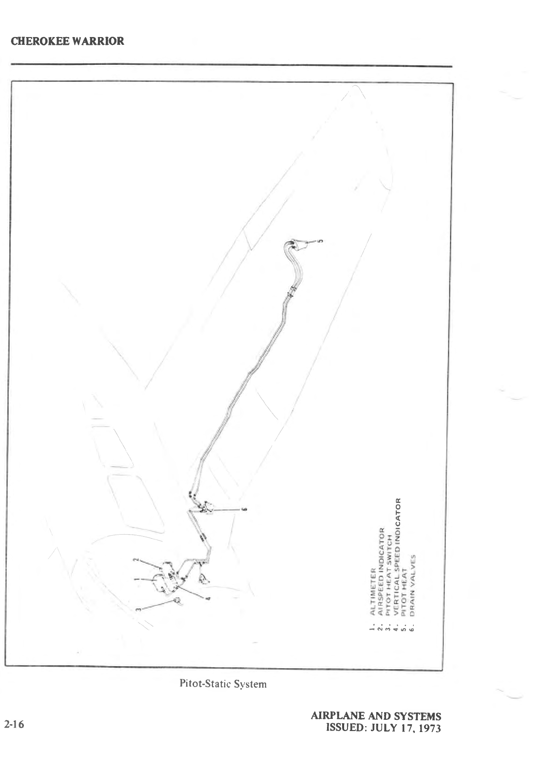
PITOT-STATIC
SYSTEM
The system
suppLies both pitot and
static
pressure
for the airspeed indicator. altimeter.
and
the optional
vertical
speed
indicator.
Pitot and static
pressure
are
pickc-d
up Lty
a pitot head
installed on the bottom
of the
left
wing
and carried
through
pitot and
static
lirte's within the
wing
and
fuselage to tire
gaugcs
on the
instrument
yranel.
A static
valve.
which
is mounted to the
knee
guard
below
the instrument
pancl
on the left
side,
provides
an
alternate static source for the s-vstem
when
opened.
Both the
pitot and static lines can be drained throLrgh separate
drain
valves located
on the
left lower
side
of the fuselage interior.
A heated
pitot head.
which alleviates
problems
with icing and heavy rain.
is available as
optional
equipment.
The switch for the heated
pitot head
is
located
on the electrical
switch
panel
to the left of the right control wheel.
To prevent
bugs and water from entering the
pitot and static
pressure
holes,
a cover should
be
placed
over the pitot head. A partially
or completely blocked
pitot head will
give
erratic
or
zero
readings on the instruments.
NOTE
During the preflight, check to make sure the pitot cover is
removed.
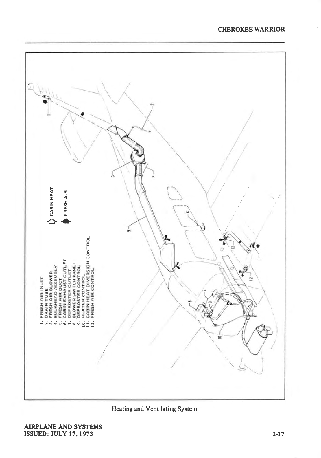
HEATING AND VENTILATING SYSTEM
Heat for the cabin interior and the defroster system
is provided
by a sluoud attached
to
the muffler. The amount of heat can be resrrlated
with the controls
located
on the far rieht side
of the
instnrment
panel.
The airflow between front and rear seats can
be regulated by the heat
diversion
controls
located
on either side of the console atop the
heat ducts.
CAUTION
When
cabin
heat is operated.
heat
duct surface
becomes
hot.
This
could result in
burns if
arms or legs
are
placed
too closeto
heat
duct
outlets or surface.
Fresh
air
inlets are located
in the leading edges of the
wings
on the
fin.
At each
front
seat
location
there
is
a hrge adjustable fresh
air outlet on the side of the
cabin near
the
floor. Rear
seat
vents
arc
optiotxtl.
Cabin air
is exhausted through
an orrtlet located
below'
the
rear
seat.
An optional
overhead
ventilating
s1'stem
with outlc'ts over
each
seat
is
also
available.
An
additiorral
oPtion to aid in I'reslt
air circulation is a cabin air blorver
to forcr-'
lrr througli
thc
overlteac'l
vt-nt
svstenr.
This blower is ops1x1e4 br l latr
srvitch rvith
four pctsitions
- "OFF."
"LOW." "l\41:D."
and
"HIGll." The switch is
locatc.ci
on tlie right
side
of the instrumer'lt
parlcl
witlt
tlic hcutcr
lrrd
dcl'roster
ctrrrtrols.
AIRPLANE
AND SYSTEMS
REVISUD:
Al'Rll. 6. 1979 2-l 5
CTIEROKEE WARRIOR
tr
o
F
(
o
dNo96€
NRPLAI{E AI\D SYSTEMS
ISSUED:
JULY
17,1973
Pitot-Static
System
2-r6
CHEROKEE
WARRIOR
F
-ta
=6
@ u.l
C)lJ-
G+
J
o
tr
F
z
o
.u
fr-rz
Joi;=;.;;;;c;jj
/
//
/'/
/
/
/'.
\ /_ \ /
AIRPI.ANE AI{D SYSTEMS
ISSLJED: JULY 17,1973
Heating
and
Ventilating
System
2-t7
CITEROKEE WARRIOR
CABIN FEATURES
For ease
of entry and
exit and for pilot-passenger
comfort, the front seats
are adjustable
fore and aft. The right front seat
tilts forward
to allow easy
entry to the rear
seats. The
cabin
interior
includes
a pilot storm
window,
ash
trays
and
armrests
on each front seat,
two map
pockets
and
pockets
on
the backs
of the front
seats.
The front seats
can be equipped
with optional
headrests
and
optional
push
button vertical
adjustment.
Seat belts are standard
equipment for both front and rear seats. The shoulder
straps
controlled by inertia reeb are standard
equipment
on the front seats
and are offered as an
option for the reat seats. The
shoulder
strap is
routed over
the shoulder
adjacent to the window
and attached
to the seat
belt in the
general
area
of the occupants'
inboard
hip.
A check
of the inertia
reel
mechanism
is made by pulling
sharply on the strap. The reel
should
lock in place
under this test and prevent
the
strap from extending.
For normal
body
movements,
the strap
will extend
or retract
as required. ,
BACCAGE
AREA
A 24 cubic foot bag:gage
ar€a, located
behind
the rear
seat,
is
accessible from
the
cabin or
loaded
through
a large
20 x 22 inch outside
baggage
door on the right side of the fuselage.
Maximum
capacity is 200 pounds.
Tie-down
straps
are available
and they should
be used at all
times.
NOTE
It is the pilot's responsibility to be sure when the baggage
is
loaded that the aircraft C.G. falls within the allowable
C.G.
range.
(See
Weight
and
Balance
Section.)
STALL WARNING
An approaching
stall is indicated
by an audible
alarm located
behind the instrument
panel.
The indicator
activates
at between
five and
ten miles
per
hour
above stall speed.
FINISH
All exterior
surfaces
are primed
with etching
primer
and finished with a durable
acrylic
Iacquer
which
is available
in a variety
of colors
and
combinations.
To keep
the
finish
attract-ive,
economy
size
spray
cans
of touch-up
paint
are available
from
piper
Dealers.
NRPI.ANE AND SYSTEMS
ISSUED:
JULY 17,
t973
2-t8
CHEROKEE
WARRIOR
PIPER
EXTERNAL FOWER*
An optional starting
installation
known as
Piler External Power
(PEP)
is accessible
through
a receptacle
located
on the right side
of the fuselage
aft of the baggage
door. An external
battery
can be connected
to the socket,
thus allowing
the operator to crank the engine without
having
to gain
access to the airplane's
battery. Instructions
on a
placard
located
on the cover
of
the
receptacle
should be followed
before
using the external
power.
For instructions
on the use
of the PEP
see: STARTING WITH EXTERNAL POWER
under the Operating
Instructions
Secfion of this
manual.
*Optional
equipment
AIRPLANE AND SYSTEMS
ISSUED: JULY 17,1973 2-t9
CHEROKEE
WARRIOR
SECTION I
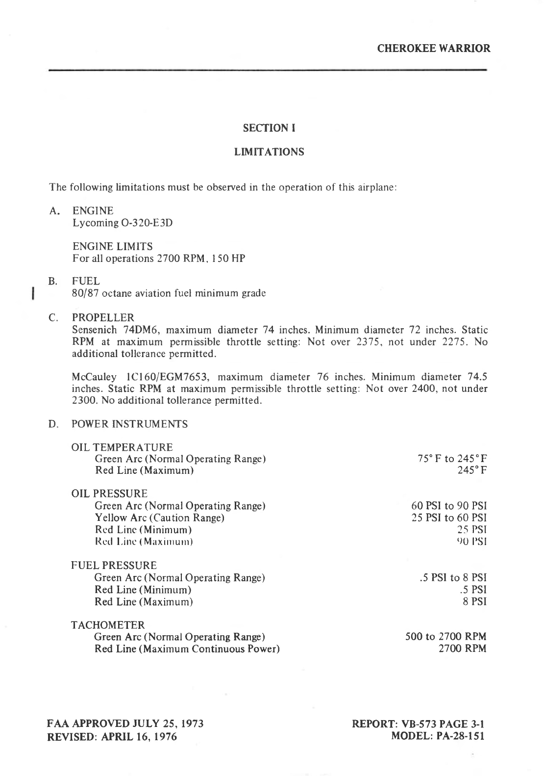
LIMITATIONS
The following limitations must be observed in the operation of this airplane:
A. ENGINE
Lycoming O-320-E3D
ENGINE
LIMITS
For
all operations 2700 RPM, 150 HP
B. FUEL
80187
octane aviation
fuel minimum
grade
C. PROPELLER
Sensenich 74DM6, maximum
diameter
74 inches. Minimum diameter 72 inches. Static
RPM at maximum
permissible
throttle setting:
Not over
2375,
not under
2275. No
additional
tollerance
permitted.
McCauley lcl60/EGM7653, maximum diameter
76 inches. Minimum diameter 74.5
inches.
Static
RPM
at maximum
permissible
throttle setting:
Not over 2400,
not under
2300.
No
additional tollerance
permitted.
D. POWER INSTRUMENTS
OIL TEMPERATURE
FAA
APPROVED
JULY
25,1973
REVISED:
APRIL 16.1976
Green Arc
(Normal
Operating
Range)
Red
Line
(Maximum)
OIL PRESSURE
Green Arc
(Normal
Operating Range)
Yellow
Arc
(Caution
Range)
Rcd
Line
(Mininrum)
l(c:tl
l.inc
(
Mirxirnurrr)
FUEL
PRESSURE
Green
Arc
(NormalOperating
Range)
Red
Line
(Minimum)
Red
Line
(Maximum)
TACHOMETER
Green Arc
(NormalOperating
R*g.)
Red
Line
(Maximum
Continuous
Power)
75'F
to
245'F
245"F
60 PSI tO 90 PSI
25 PSI
to 60
PSI
25
PSI
()0
I'sl
.5
PSI
to 8
PSI
.5 PSI
8 PSI
500 to 2700
RPM
27OO
RPM
REPORT: VB-573
PAGE 3-l
MODEL:
PA-28-151
CHEROKEE WARRJOR
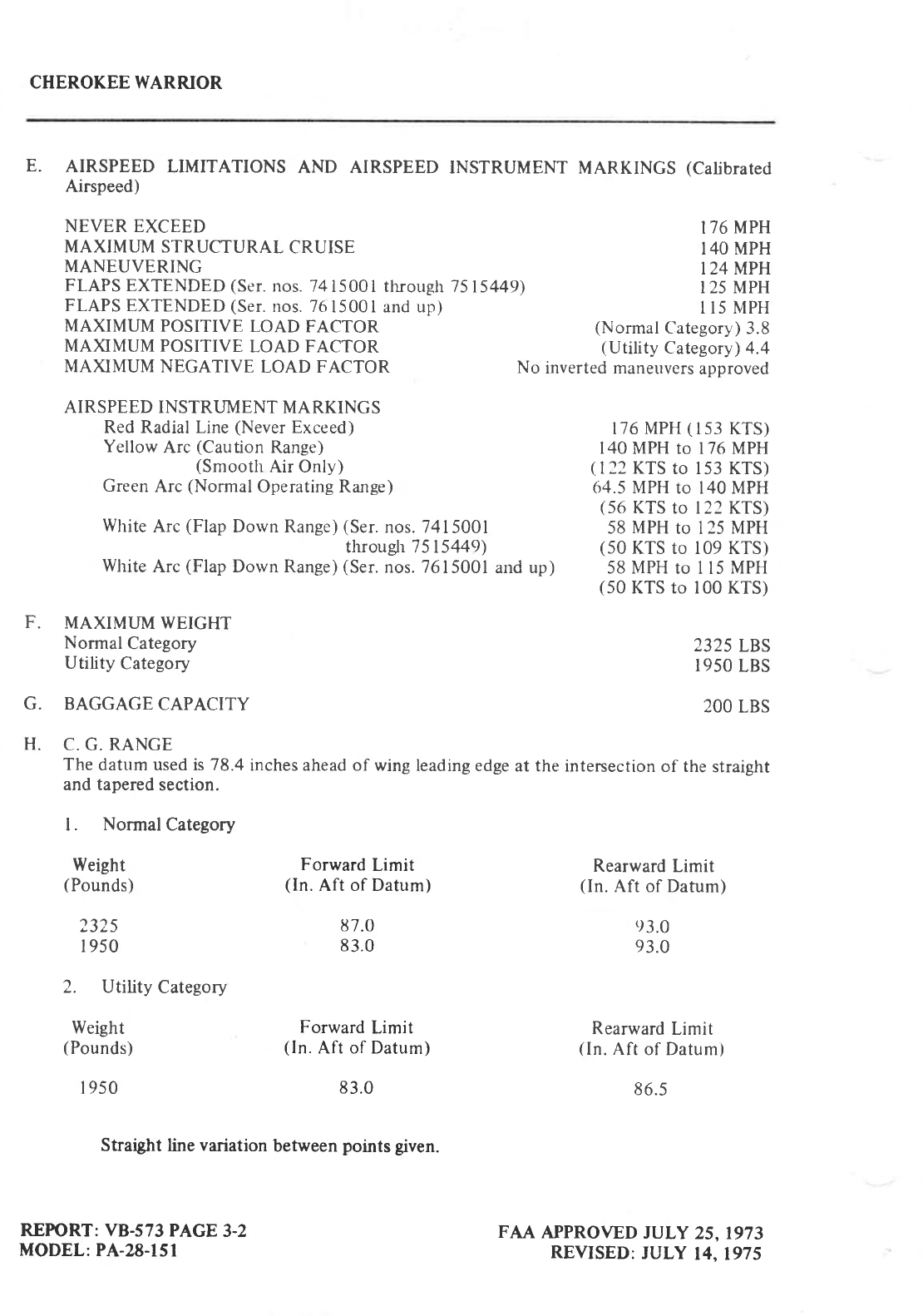
E. AIRSPEED
LIMITATIONS
AND AIRSPEED
INSTRUMENT
MARKINGS
(Calibrated
Airspeed)
NEVER EXCEED 176
MPH
MAXIMUM STRUCTURAL
CRUISE I4O MPH
MANEUVERING I24 MPH
FLAPS
EXTENDED
(Ser.
nos. 7415001
tlrough 7515449) 125 MPH
FLAPS EXTENDED
(Ser.
nos. 7615001
and up) I 15 MPH
MAXIMUM
POSITIVE
LOAD
FACTOR (Normal
Category)
3.8
MA)0MUM POSITIVE
LOAD FACTOR (Utility
Category)
4.4
MAXIMUM
NEGATIVE
LOAD FACTOR No
inverted maneuvers
approved
F.
G.
AIRSPEED
INSTRI.JMENT MARKINGS
Red Radial Line
(Never
Exceed)
Yellow
Arc
(Caution
Range)
(Smooth
Air Only)
Green
Arc
(Normal
Operating Range)
White
Arc
(Flap
Dorvn Range)
(Ser.
nos. 7415001
through 7515449)
White
Arc
(Flap
Dorvn Range)
(Ser.
nos. 7615001
MAXIMUM WEIGHT
Normal
Category
Utility
Category
BAGGAGE
CAPACITY
176
MPH
(
I s3 KTS)
140 MPH to 176 MPH
(
I 22 KTS
to 153 KTS)
64.5 MPH
tO I40 MPH
(56
KTS
to 122 KTS)
58
MPH
to 125
MPH
(50
KTS to 109 KTS)
and up) 58 MPH
to I 15
MPH
(50
KTS to 100 KTS)
H. C. G. RANGE
The
datum used is 78.4
inches ahead of wing
leading edge
at the intersection
of the
straight
and tapered
section.
l. Normal
Category
Weight
(Pounds)
232s
I 950
2. Utility
Category
Weight
(Pounds)
I
950
REPORT: VB-s73
PAGE
3-2
MODEL:
PA-28-l5l
Forward
Limit
(ln.
Aft of Datum)
ti7.0
83.0
Forward
Limit
(ln.
Aft of Datum)
83.0
2325
LBS
I95O
LBS
2OO
LBS
Rearward
Limit
(ln.
Aft
of
Datum)
e3.0
93.0
Rearward
Limit
(ln.
Aft
of Datum)
86.5
FAA APPROVED
JULY
25,1973
REVISED:
JULY
14.1975
Straight
line
variation
between
points given.
CHEROKEE WARRIOR
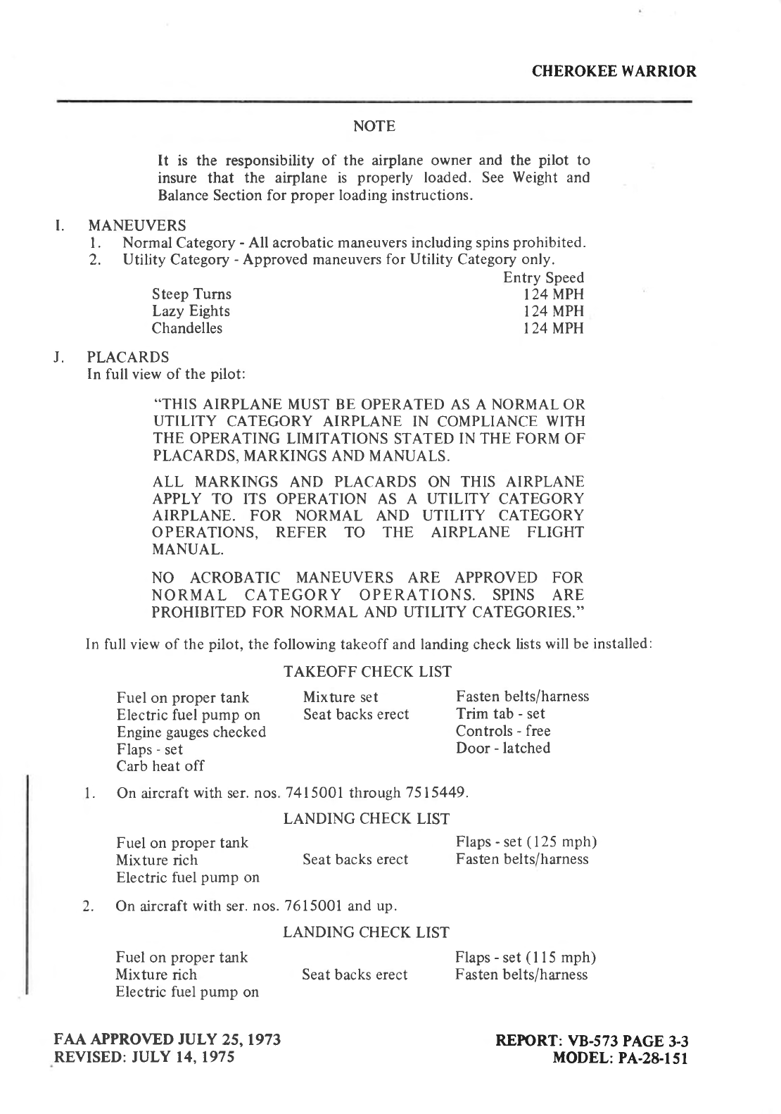
NOTE
It is the responsibility of the airplane owner
and the pilot to
insure that the airplane is properly
loaded. See Weight and
Balance Section for
proper
loading
instructions.
I. MANEUVERS
l. Normal
Category
-
All acrobatic maneuvers including spins
prohibited.
2. Utility
Category
-
Approved maneuvers
for Utility Category
only.
Steep
Turns
Lazy
Eights
Chandelles
J. PLACARDS
In full view of the
pilot:
Entry
Speed
I24MPH
I24MPH
I24 MPH
..THIS
AIRPLANE
MUST BE OPERATED AS A NORMAL OR
UTILITY CATEGORY AIRPLANE IN COMPLIANCE
WITH
THE
OPERATING
LIMITATIONS STATED IN THE
FORM
OF
PLACARDS,
MARKINGS AND MANUALS.
ALL MARKINGS
AND PLACARDS
ON THIS AIRPLANE
APPLY TO ITS OPERATION AS A UTILITY CATEGORY
AIRPLANE. FOR NORMAL AND UTILITY CATEGORY
OPERATIONS, REFER TO THE AIRPLANE FLIGHT
MANUAL.
NO ACROBATIC MANEUVERS ARE APPROVED FOR
NORMAL CATEGORY OPERATIONS. SPINS ARE
PROHIBITED
FOR NORMAL AND UTILITY CATEGORIES.''
In full view of the
pilot,
the following takeoff and landing check
lists will
be installed:
TAKEOFF
CHECK
LIST
Fuel on
proper
tank Mixture set Fasten belts/harness
Electric fuel
pump
on Seat backs
erect Trim
tab
-
set
Engine
gauges
checked Controls
- free
Flaps
-
set Door
-
latched
Carb heat off
l. On aircraft
with
ser.
nos.
Fuel on
proper
tank
Mixture rich
Electric fuel
pump
on
74I
5001 through
7 5|5449.
LANDING CHECK LIST
Flaps
-
set
(
125
mph)
Seat backs erect Fasten
belts/harness
2. On aircraft
with
ser.
nos. 7615001
and
up.
LANDING
CHECK LIST
Fuel
on
proper
tank Flaps
-
set
(
I I 5
mph)
Mixture
rich Seat
backs
erect Fasten
belts/harness
Electric
fuel
pump
on
FAA APPROVED JULY 25,1973
REVISED:
JULY 14.1975 REFORT:
VB-573
PAGE
3-3
MODEL:
PA-28-l5l
CHEROKEE WARRIOR
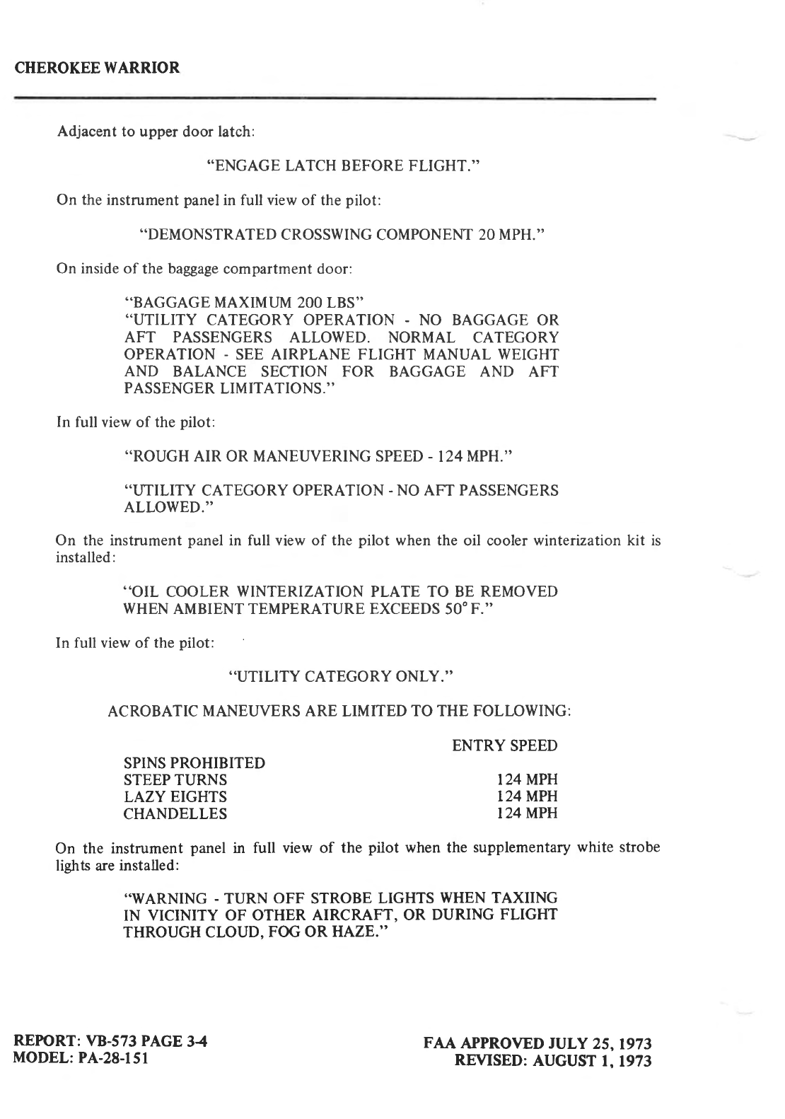
Adjacent
to upper
door
latch:
..ENGAGE
LATCH BEFORE FLIGHT.''
On the instrument
panel
in full view
of the
pilot:
..DEMONSTRATED
CROSSWING
COMPONENT
20 MPH.''
On inside of the
baggage
compartment door:
..BAGGAGE
MAXIMI.JM
2OO LBS''
..UTILITY CATEGORY OPERATION
- NO BAGGAGE
OR
AFT PASSENGERS
ALLOWED. NORMAL CATEGORY
OPERATION
- SEE AIRPLANE FLIGHT MANUAL WEIGHT
AND BALANCE SECTION FOR BAGGAGE AND AFT
PASSENGER
LIMITATIONS.''
In full view of the
pilot:
..ROUGH
AIR OR MANEUVERING SPEED
- I24 MPH.''
..UTILITY
CATEGORY
OPERATION
-
NO AFT PASSENGERS
ALLOWED.''
On the instrument
panel
in full view of the
pilot when the
oil cooler
winterization kit is
installed:
..OIL COOLER
WINTERIZATION
PLATE TO BE
REMOVED
WHEN
AMBIENT TEMPERATURE EXCEEDS
5OOF.''
In full view
of the
pilot:
..UTILITY
CATEGORY
ONLY.''
ACROBATIC
MANEUVERS
ARE LIMITED
TO THE FOLLOWING:
SPINS
PROHIBITED
STEEP TURNS
LAZY EIGHTS
CHANDELLES
ENTRY
SPEED
I24 MPH
124 MPH
I24 MPH
FAA APPROVED JULY 25,1973
REVISED:
AUGUST
1,1973
On the instrument
panel
in full view of the pilot when the supplementary
white strobe
lights are
installed:
..WARNING
- TURN OFF STROBE
LIGHTS
WHEN
TAXIING
IN VICINITY OF OTHER
AIRCRAFT, OR DURING FLIGHT
THROUGH CLOUD.
FOG OR
HAZE."
REPIORT:
VB-573 PAGE
34
MODEL:
PA-28-151
CHEROKEE
WARRIOR
SECTION U
PROCEDURES
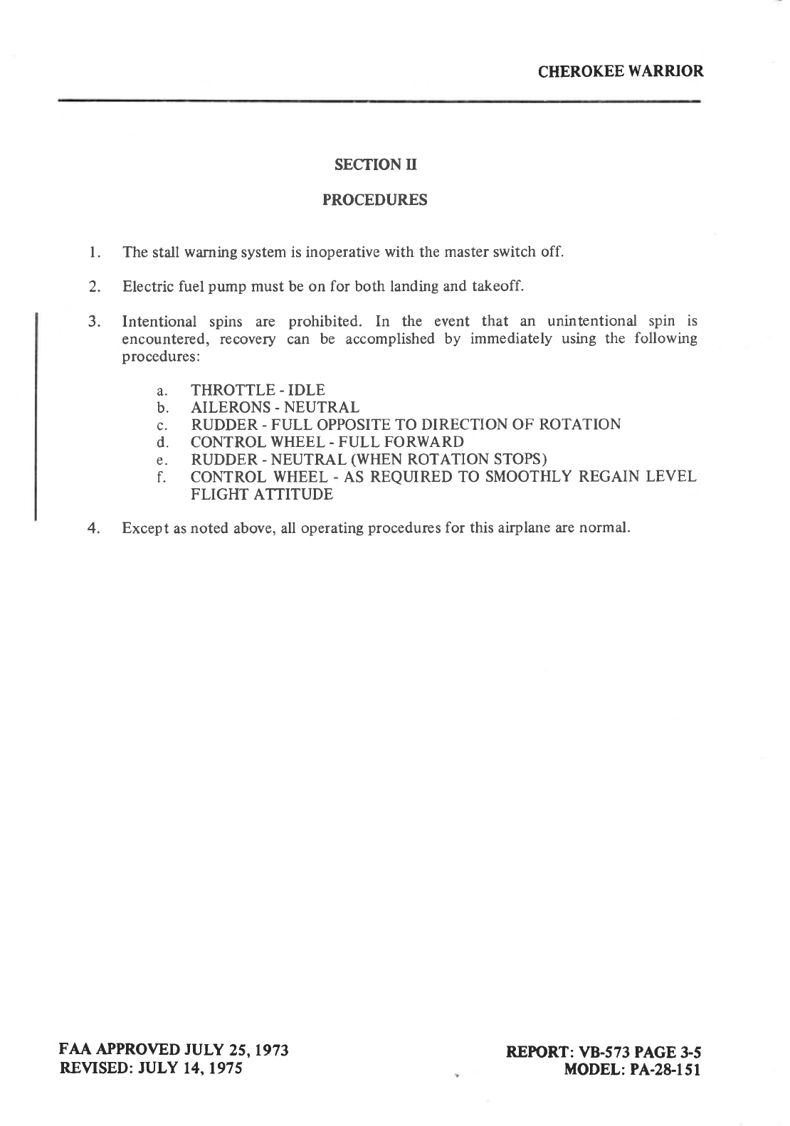
l. The stall
warning
system
is inoperative
with the
master switch off.
2. Electric fuel
pump
must be on for both landing and
takeoff.
3. Intentional spins are prohibited. In the event that an unintentional spin is
encountered, recovery can be accomplished
by immediately
using the following
procedures:
a. THROTTLE
-
IDLE
b. AILERONS.
NEUTRAL
c. RUDDER
-
FULL OPPOSITE
TO DIRECTION
OF ROTATION
d. CONTROL
WHEEL
- FULL FORWARD
e. RUDDER
-
NEUTRAL
(WHEN
ROTATION STOPS)
f. coNTRoL WHEEL
- AS REQLIRED TO SMOOTHLY REGAIN LEVEL
FLIGHT ATTITUDE
4. Except
as
noted
above, all
operating
procedures
for this airplane are
normal.
FAA APPROVED
JULY 25,1973
REVISED: JULY 14,1975 REPTORT:
VB-573 PAGE
3-5
MODEL:
PA-28-151
CHEROKEE
WARRIOR
THIS PAGE
INTENTIONALLY LEFT BLANK
REFORT: \tB-573 PAGE
3{
MODEL:
PA-2&lsl FAA APPROVED
JULY 25, 1973
REVISED:
AUGUST 1,1973
CHEROKEE WARRIOR
SECTION M
PERFORMANCE
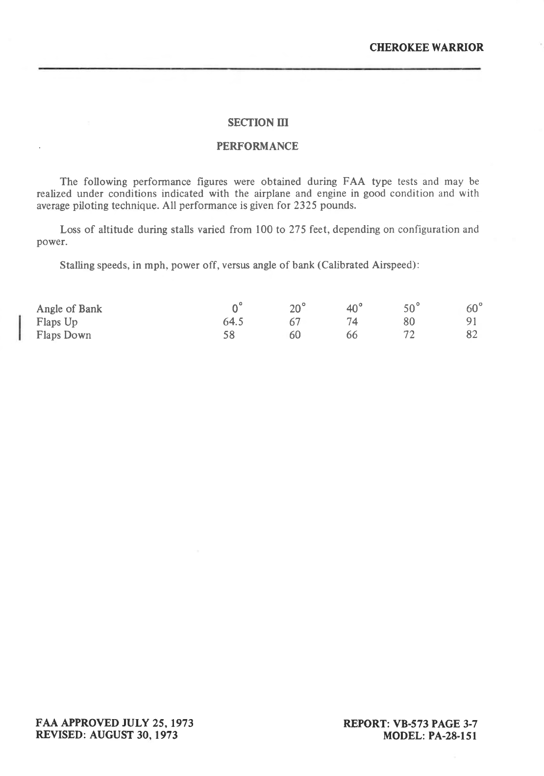
The following performance
figures were obtained during FAA type tests and may be
reahzed under conditions
indicated
with the airplane
and engine in good
condition
and with
average
piloting
technique.
All performance
is
given
for 2325
pounds.
Loss of altitude during stalls
varied from 100
to275 feet, depending on configuration
and
power.
Stalling speeds, in mph.
power
off, versus
angle
of bank
(Calibrated
Airspeed):
Angle of Bank
Flaps
Up
Flaps
Down
FAA APPROVED JULY 25,1973
REVISED:
AUGUST
30. 1973
00
64.5
58
60'
9l
82
400
74
66
20"
67
60
500
80
72
REPORT:
VB-573 PAGE
3-7
MODEL: PA-28-151
CHEROKEE WARRIOR
SECTION
ry
OPTIONAL EQUIPMENT
NOTE
THE INFORMATION CONTAINED IN THIS SECTION
APPLTES WHEN
THE RELATED EQUIPMENT IS INSTALLED
IN THE AIRCRAFT.
A. Electric Pitch
Trim Installation
B. AutoFlite II Installation
C. Installation of Piper
AutoControl III and/or
AutoControl IIIB
FAA APPROVED
JULY 25, 1973
REVISED:
JANUARY
17,
197 5 REFTORT:
VB-573 PAGE
13.9
MODEL: PA-2&151
CHEROKEE WARRIOR
I
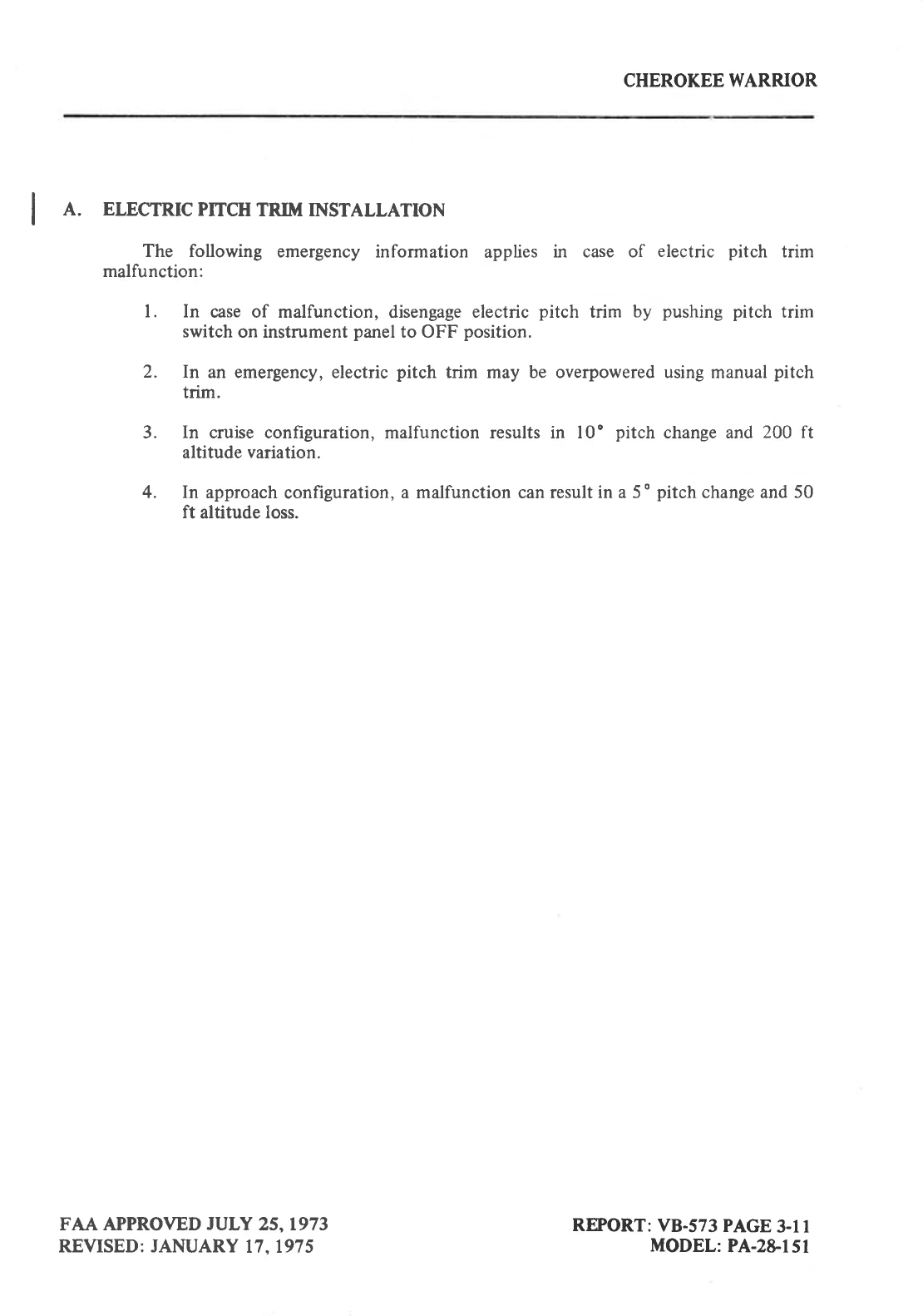
I A. ELECTRTC
PrTCH
TRrM TNSTALLATTON
The following emergency information applies in case of electric pitch trim
malfunction:
l. In case of malfunction, disengage electric
pitch trim by pushing
pitch trim
switch
on instrument
panel
to OFF position.
2. In an emergency, electric
pitch trim may be overpowered using manual
pitch
trim.
3. [n cruise configuration, malfunction results in l0' pitch
change and
2OO ft
altitude
variation.
4. In approach
configuration,
a malfunction can result
in a 5
o
pitch
change and 50
ft altitude loss.
FAA APPROVED
JULY 25.1973
REVISED: JANUARY
17. 1975 REFORT:
VB-573
PAGE
3-l I
MODEL:
PA-2&151
CHEROKEE WARRIOR
I
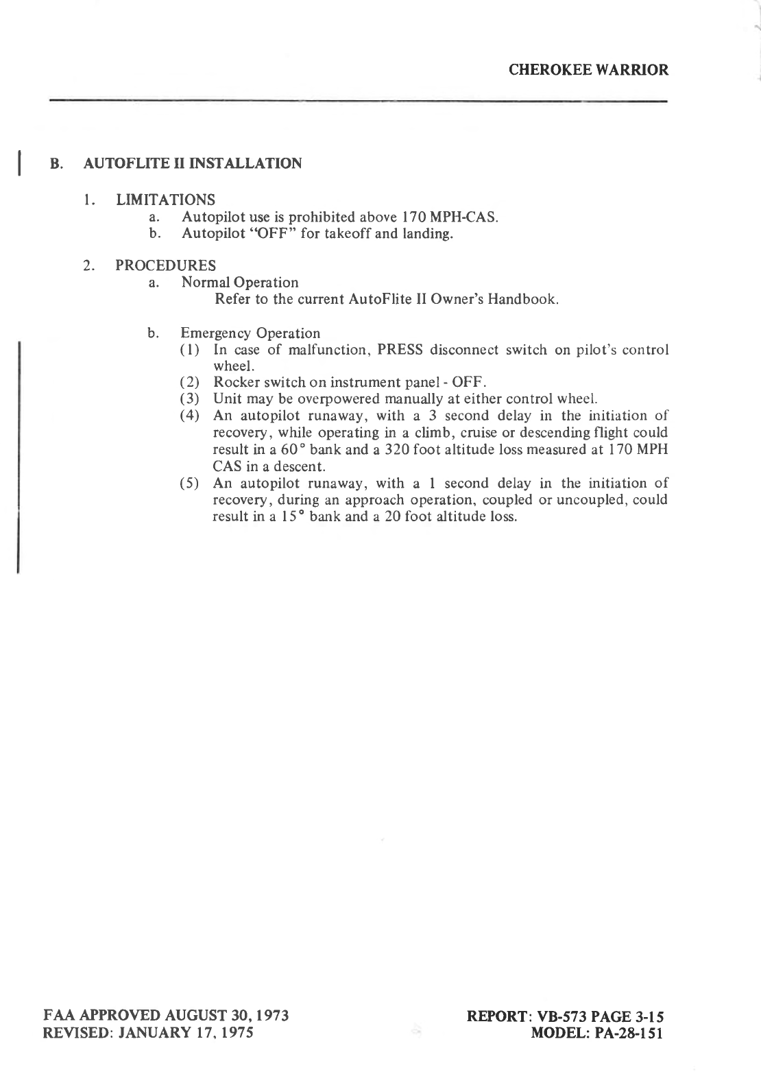
I B. AUTOFLITE II INSTALLATION
I. LIMITATIONS
a. Autopilot
use is
prohibited
above 170 MPH-CAS.
b. Autopilot
"OFF" for takeoff and landing.
2' t*o::outflHaloperation
Refer
to the current
AutoFlite
II Owner's Handbook.
b. Emergency
Operation
(l) In case of malfunction, PRESS
disconnect switch on pilot's control
wheel.
(2) Rocker
switch on instrument
panel
- OFF.
(3) Unit may be overpowered
manually
at either
control
wheel.
(4) An autopilot runaway, with a 3 second
delay in the initiation of
recovery, while operating in a climb, cruise
or descending flight could
result
in a 60' bank and a 320 foot altitude loss
measured
at I
70 MPH
CAS in a
descent.
(5) An autopilot runaway, with a I second delay in the initiation of
recovery, during an approach
operation,
coupled
or uncoupled, could
result
in a l5 o
bank and a 2O foot altitude loss.
FAA APPROVED
AUGUST
30.1973
REVISED: JANUARY 17. 197 5 REPORT:
VB-573
PAGE
3-15
MODEL:
PA-28-l5l
CHEROKEE WARRIOR
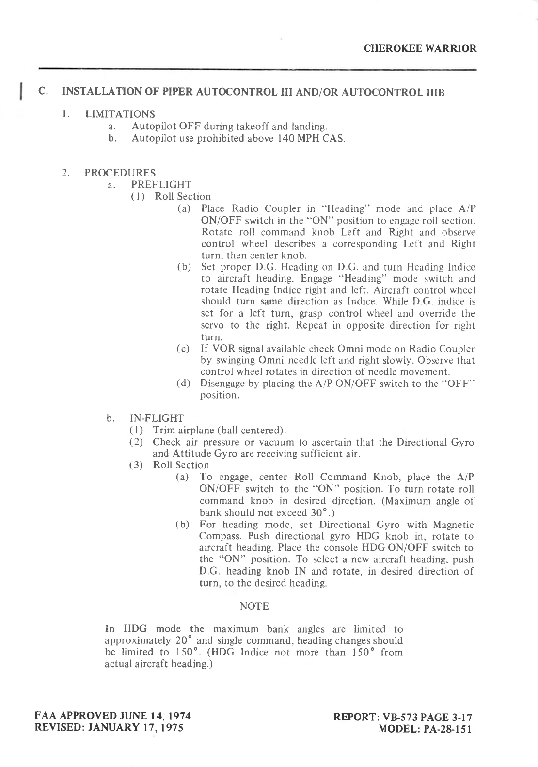
c. INSTALLATION
OF PIPER
AUTOCONTROL
lrr AND/OR AUTOCONTROL
IIIB
I. LIMITATIONS
a. Autopilot OFF
during
takeoff and
landing.
b. Autopilot
use
prohibited
above 140 MPH CAS.
2. PROCEDURES
a. PREFLIGHT
(l) Roll
Section
(a) Place Radio Coupler in "Heading" mode and place
A/P
ON/OFF switch
in the "ON" position
to engage roll section.
Rotate roll command knob Left and Right and observe
control wheel describes
a corresponding
Left and Right
turn. then center knob.
(b) Set
proper
D.G. Heading
or1
D.G.
and turn Heading
lndice
to aircraft heading. Engage
"Heading" mode switch and
rotate Heading
lndice right and letl. Aircraft control
wheel
should turn same
direction as lndice. While
D.G. indice is
set for a left turn, grasp
control wheel and override
the
servo to the right. Repeat
in opposite
direction for right
turn.
(c) If VOR signal
available check
Omni mode on Radio
Coupler
by swinging Omni needle left and right slowly.
Observe that
control
wheel
rotates in direction of needle movement.
(d) Disengage
by placing
the A/P ON/OFF switch to the
"OFF"
position.
b. IN-FLIGHT
(
l) Trim airplane
(ball centered).
(2) Check air pressure
or vacuum
to ascertain that the Directional Gyro
and Attitude Gyro are receiving sufficient
air.
(3) Roll Section
(a) To engage,
center Roll Command Knob, place the A/P
ON/OFF switch tcl the "ON" position.
To turn rotate roll
command knob in desired direction. (Maximum angle
of
bank should not exceed
30o.)
(b) For heading mode, set Directional Gyro with Magnetic
Compass. Push directional gyro HDG knob in, rotate to
aircraft heading.
Place
the console
HDG ON/OFF switch to
the "ON" position. To select
a new aircraft
heading,
push
D.G. heading knob IN and rotate, in desired
direction of
turn, to the desired heading.
NOTE
In HDG mode the maximum bank angles are limited to
approximately 20" and single
command. heading
changes
should
be limited to 150'. (flDG lndice not more than 150o from
actual aircraft
heading.)
FAA
APPROVED
JUNE
14,1974
REVISED:
JANUARY
17.
197 5 REPORT: VB-573
PAGE
3-17
MODEL:
PA-28-151
CHEROKEE
WARRJOR
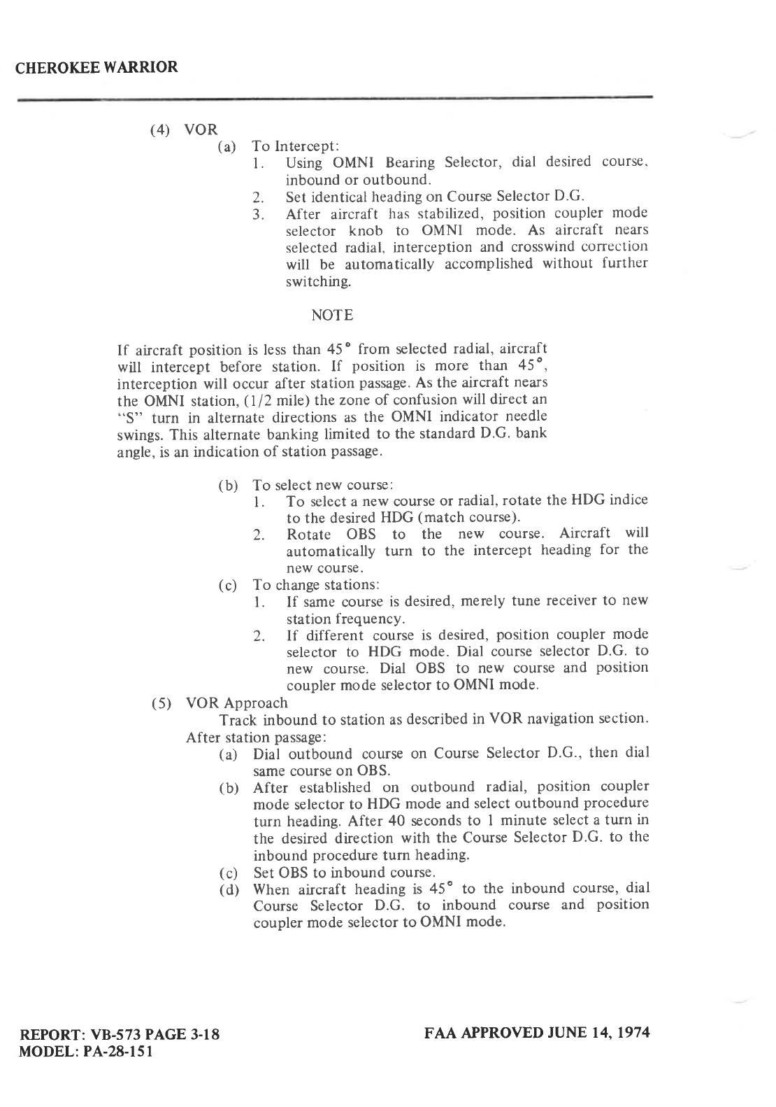
(4) VOR(a) To IntercePt:
l. Using OMNI Bearing
Selector,
dial desired
course'
inbound
or outbound.
2. Set identical
heading
on Course
Selector
D.G.
3. After aircraft has stabilized,
position coupler mode
selector knob to OMNI mode. As aircraft nears
selected
radial, interception and crosswind
correction
will be automatically accomplished
without further
switching.
NOTE
If aircraft
position is less
than 45
o from selected
radial,
aircraft
will intercipt before station. If position is more than 45",
interception
will occur after
station
passage.
As the
aircraft
nears
the OMNI station,
(l/2 mile)
the
zone of confusion
will direct an
"S" turn in alternate
directions
as
the OMNI indicator needle
swings.
This alternate
banking
limited to the
standard
D.G. bank
angle,
is an
indication
of station
passage.
(b) To select
new course:
l. To select a
new
course
or radial,
rotate
the
HDG indice
to the desired
HDG (match
course).
2. Rotate OBS to the new course. Aircraft will
automatically turn to the intercept heading
for the
new
course.
(c) To change
stations:
L If same
course
is desired,
merely tune receiver
to new
station
frequency.
2. If different course
is desired,
position coupler mode
selector
to HDG mode. Dial course
selector
D.G. to
new course. Dial OBS to new course and position
coupler
mode selector
to OMNI mode.
(5) VOR Approach
Track inbound
to station as
described
in VOR navigation
section.
After station
passage:
(a) Dial outbound course
on Course
Selector
D'G., then dial
same course
on OBS.
(b) After established
on outbound radial, position coupler
mode selector
to HDG mode and
select outbound
procedure
turn heading.
After 40 seconds to I minute select
a turn in
the desired direction with the Course
Selector
D.G. to the
inbound
procedure
turn heading.
(c) Set OBS to inbound
course.
(d) When aircraft heading
is 45" to the inbound course,
dial
Course Selector D.G. to inbound course and position
coupler
mode selector
to OMNI mode.
REPORT:
VB-573 PAGE 3-18
MODEL:
PA-28-151 FAA APPROVED
JUNE 14.1974
CHEROKEE
WARRIOR
NOTE
For precise tracking over OMNI station, without "S" turn,
position coupler mode selector to HDG mode just prior to
station passage.
If holding pattern is dcsired,
position coupler
mode selector
to HDG mode at station passage
inbound and
select
outbound heading
in direction
of turn. After elapsed time.
dial inbound course on Course Selector D.G. When aircraft
heading
is 45
o
to radial,
position
coupler
mode selector
to OMNI
mode.
(6) LOC Approach Only
(a) To intercept dial ILS outbound course
on Course Selector
D.G. When stabilized,
position coupler mode selector to
(b)iJfr
il*"tii':"#:i*rl'r.B.;"rff JHi'illi:ffi':l:r
procedure turn heading.
After one minute, dial inbound
procedure
turn heading
in direction of turn.
(c) When aircraft
heading
is 45o to ILS inbound course
dial
inbound course on Course Selector D.G. and position
coupler
mode
selector to LOC NORM mode.
(d) At the missed
approach
point (M.A.P.),
or when
missed
liji: lit : ;'ff [ 1I3.T
:il #.t'J,ff.ff
:: I
e
c
t o r t o
H D
G
(7) LOC Approach
-
Back
Course
(Reverse)
(a) To intercept dial ILS Back Course outbound heading on
Course Selector D.G. When stabilized,
position coupler
mode
selector
to LOC NORM mode.
(b) After interception
and when beyond fix, position coupler
mode selector
to HDG and dial outbound procedure
turn
heading. After one minute, dial inbound procedure
turn
heading
in direction of turn.
(c) When heading 45" to inbound course, dial inbound course
on Course Selector
D.G.
and
position
coupler mode
selector
to LOC REV mode.
(d) Approximately ll2 rntle from runway, position coupler
mode selector
to HDG mode
to prevent
"S" turn over ILS
station
near
runway threshold.
(e) Missed
approach
- same
as
Front Course.
(See (6) d)
REPORT:
VB-573
PAGE
3-19
MODEL:
PA-28-151
FAA APPROVED
JUNE
14. 1974
CHEROKEE
WARRIOR
C. EMERGENCY OPERATION
(l) In an
emergency the
AutoControl
can
be disconnected
by:
(a) Placing
the
A/P ON/OFF
switch to the
"OFF" position.
(b) Pulling the Autopilot circuit
breaker
(aircraft
S/N 28-7615001
and up).
(2\ The AutoControl
can
be
overpowered
at either
control
wheel.
(
3
) *"**:Tfi.':;
:;?l;, T'l #':':ff
l, ::'::,::
"ffi
,:t"b1i
::
"ii
result in a
600 bank and 100 foot altitude
loss.
(4) An Autopilot runaway, with a I second
delay in the initiation of
l! i,lil? ;',tlT;?
;ll 1%"[;,o;'11
llx?
;:lo
"o
or
u nc ou
pre
d' co ur
d
3. PERFORMANCE
No change.
REPORT:
VB-573 PAGE
3-20
MODEL:
PA-28-151 FAA APPROVED JUNE
14,1974
REVISED:
DECEMBER
l, 197
5
ETERGE]ICY
PROCEDURES
Introduction
Engine
Power
Loss During
Takeoff +l
+l
+2
+2
+3
+3
44
Engine
Power
Loss
In Flight
Spins .
Power
Off Ianding
Open
Door
Fire
Loss
of Oil Presure
Loss
of Fuel Pressure
High
Oil Temperature
+5
+5
+5
%
+6
Alternator Failure
Engine
Roughness
+i
CHEROKEE
WARRIOR
EMERGENCY PROCEDURES
INTRODUCTION
This section
contains
procedures
that are recommended if an emergency condition should
occur during
gound operation,
takeoff, or in flight. These
procedures
are suggested as the
best
course of action for coping
with the particular
condition
described. but are
not a
substitute for
sound
judgment and common sense.
Since emergencies rarely happen in modern aircraft, their
occurrence is usually unexpected,
and the best corrective action may not always
be obvious.
Pilots
should
familiarize
themselves with the
procedures
given
in this section and be
prepared
to
take appropriate action should
an emergency
arise.
Most basic emergency
procedures,
such
as
power
off landings, are a part of normal pilot
training. Although these emergencies
are discussed
here, this information is not intended to
replace
such training, but only to provide
a source of reference and review. and to provide
information on procedures
which are not the same for all aircraft.
It is suggested that the
pilot
review
standard emergency
procedures
periodically
to remain
proficient
in them.
ENGINE POWER LOSS
DURING TAKEOFF
The proper action to be taken if loss
of power occurs during takeoff will depend on
circumstances.
L If sufficient runway remains
for a
normal
landing,
land straight ahead.
2. If insufficient runway remains,
maintain a safe airspeed
and make only a shallow
turn
if necessary
to avoid obstructions.
Use of flaps
depends
on circumstances.
Normally,
flaps
should be fully extended for touchdown.
3. If you have
gained
sufficient altitude to attempt a restart,
proceed
as
follows:
a. MAINTAIN SAFE AIRSPEED
b. FUEL SELECTOR
- SWITCH TO ANOTHER TANK CONTAINING FUEL
c. ELECTRIC
FUEL PUMP
-
CHECK
ON
d. MIXTURE -
CHECK RICH
e. CARBURETORHEAT-ON
NOTE
If engine failure was
caused by fuel exhaustion,
power
will not
be
rcgained
after tanks
are switched until empty
fuel lines are filled,
which
may require up
to ten seconds.
If power
is not regained,
proceed
with
the
POWER
OFF
LANDING
procedure.
EDTERGENCY
PROCEDURES
ISSIJED:
JULY 17,1973 +l
CHEROKEE
WARRIOR
ENGINE POWER IJOSS
IN FLIGHT
Complete enghe
power
los is usually
caused
by fuel flow intemrption, and
power
will be
restored shortly
after fuel flow is restored. If power
loss occurs
at low altitude, the first step is
to prepare
for an emergency landing
(See
POWER
OFF
LANDING).
Maintain
an airspeed of at
least 85 MPH,
and
if altitude
permits,
proceed
as follows:
l. Fuel
Selector
-
Switch to another
tank containing fuel.
2. Electric Fuel Pump
-
On
3. Mixture
- Rich
4. Carburetor
Heat
- On
5. Engine
Gaups
- Check
for indication
of the cause
of power
loss.
6. Primer
- Check
locked
7. If no fuel
pressure
is indicated,
check tank selector
position
to be sure it is
on a tank
containing fuel.
When
power
is restored:
E. Carburetor
Heat
- Off
9. Electric
Fuel Pump
- Off
If the above steps do not restore
power, prepare
for an
emergency landing.
If time
permits:
l. Ignition Switch
- "L" then
"R" then back to "BOTH."
2. Throttle and Mixture
- Different
settings.
(This
may restore
power
if the problem
is
too rich or too lean a mixture,
or
partial
fuel system restriction.)
3. Try another
fuel tank.
(Water
in the fuel
could
take
some
time to be used
up,
and
allowing the engine
to windmill may restore
power.
If power
loss
is
due to water, fuel
pressure
indications will
be normal.)
NOTE
If engine failure
was caused
by fuel exhaustion,
power
will not
be
restored after
tanks are switched
until empty fuel lines are
filled,
which may
require up to ten
seconds.
If power
is
not restored,
proceed
with
POWER
OFF
LANDING
procedure.
FOWER
OFF LAI{DING
If loss of power
occurs at altitude, trim the aircraft for best
ghding
angle 85 MPH, and
look
for a suitable field. If measures taken
to restore
power
iue not effective,
and
if time permits,
check
your
charts
for
airports in the immediate vicinity;it may
be
possible
to land at one if you
have
sufficient
altitude.
If possible,
notify the FAA by radio of your
difficulty and intentions.
If another
pilot
or
passenger
is
aboard, let them
help.
When
you have located
a suitable field,
establish a spiral
pattern
around
this field. Try to
be 1000 feet
above the field
at the downwind
position
to make a normal approach.
When
the
field can easily be
reached, slow up to 76
MPH
for the
shortest landing.
Excess
altitude may be
lost
by widening
your
pattern,
using flaps
or slipping,
or a combination
of these.
EMERGENCY PROCEDURES
ISSUED:
ruLY 17,1973
4-2
CHEROKEE WARRJOR
Touchdowns
should normally be
made
at the lowest
posible
airspeed,
with full flaps.
When
committed
to landing:
l. Ignition
-
Off
2. Master
Switch
-
Off
3. Fuel Selector
-
Off
4. Mixture
-
Idle CutOff
5. Seat Belt
tight
and Shoulder
Harness
in place.
SPINS
Intentional
spins are prohibited
in this aircraft.
If a spin is inadvertently entered,
immediately use the following
recovery
procedures:
I. THROTTLE
-
IDLE
2. RUDDER
-
FULL OPPOSITE
TO DIRECTION OF
ROTATION
3. CONTROL
WHEEL
-
FULL FORWARD
4. RUDDER
-
NEUTRAL
(WHEN
ROTATTON
STOPS)
5. CONTROL
WHEEL
- AS REQUIRED TO SMOOTHLY
REGAIN
LEVEL
FLIGHT
ATTITUDE
OPEN DOOR
The
cabin door on the Cherokee Warrior
is double latched, so
the
chances
of it springing
open in flight
at both the
top and bottom are remote. However, should
you forget
the
upper
latch, or not engage the lower
latch, the door may
spring
partially
open.
This will usually
happen
at takeoff or soon
afterward. An open
door
will not affect normal flight characteristics,
and a normal
landing
can be made with
the door open.
If both
upper
and lower latches
open, the door will trail slightly
open, and airspeed
wiil
be
reduced slightly.
To close the door in flight,
proceed
as follows:
l. Slow
aircraft to 100 MPH.
2. Cabin
Vents
-
Close
3. Storm
Window
- Open
4. If upper latch is open
- latch. If lower
latch is open
- open top latch,
push
door
further
open, and
then close rapidly.
Latch top latch.
A slip
in the
direction
of the
open
door will assist in latching
procedure.
EMERGENCY PROCEDURES
ISSLJED:
JULY 17.1973 +3
CHEROKEE
WARRIOR
FIRE
The presence
of fire is noted through smoke, smell, and heat in the cabin. It is essential
that the source of the fire be promptly identified through instrument readings, character
of the
smoke. or other indications,
since the action to be taken differs
somewhat
in each
case.
l Source
of Fire
- Check
a. Electrical
Fire
(Smoke
in Cabin):
(
l) Master Switch
- Off
(2) Vents
-
Open
(3) Cabin
Heat
-
Off
(4) Land as soon
as
practicable
b. Engine Fire:
(
I
) In case of engine
fire in flight
(a) Fuel Selector
-
OFF
(b) Throttle
-
CLOSE
(c) Mixture
-
IDLE CUT
OFF
(d) Heater
-
Off (In all cases of fire)
(e) Defroster
- OFF (ln all cases
of fire)
(f) If terrain
permits
- Land Immediately
The possibility
of an engine
fire in flight is extremely
remote.
The
procedure
given
above
is
general
and
pilot judgment
should
be the deciding
factor
for action
in such an
emergency.
(2)
ll,*i?
:l;'ffiT:Jffi
,"ljl:f.'".
1. Mixture
-
IDLE CUT-OFF
2. Throttle -
OPEN
3. Turn engine with starter
(This is an attempt to pull the flre into
the engine.)
(b) If engine has already started
and is
running,
continue operating
to try
pulling
the
fire into the engine.
(c) In either
case stated in (a) and (b), if the fire continues
longer
than a
few seconds, the fire should be extinguished
by the best available
external means.
(d) If extemal
fire extinguishing
is to be applied
l. Fuel Selector
Valve
- OFF
2. Mixture
-
IDLE CUTOFF
EMERGENCY
PROCEDUR.ES
ISSUED:
JULY
17.1973
H
CHEROKEE
WARRIOR
LOSS OF OIL PRESSURE
Loss of oil pressure
may be either partial or complete.
A partial loss of oil pressure
usually
indicates
a malfunction
in the oil pressure
regulating system, and a landing
should
be made as
soon as
possible
to investigate the cause and
prevent
engine damage.
A complete
loss of oil pressure
indication may signify oil exhaustion or may be the result
of a faulty gauge.
In either case,
proceed
toward the nearest airport, and be prepared
for a
forced landing. If the problem is not a pressure
gauge
malfunction, the engine may stop
suddenly.
Maintain altitude until such time as a dead stick landing can
be
accomplished.
Don't
change
power
settings
unnecessarily,
as this may
hasten
complete
power
loss.
Depending on the circumstances,
it may be advisable to make
an off airport landing
while
power is
still available,
particularly
if other
indications of actual oil pressure
loss, such as sudden
increase
in temperatures,
or oil smoke,
are apparent, and an airport
is
not close.
lf engine
stoppage occurs,
proceed
to POWER
OFF LANDING.
LOSS OF FUEL PRESSURE
l. Electric
Boost Pump
-
On
2. Fuel Selector
-
Check
on full tank
If problem is not an empty fuel tank, land as soon
as
practical
and have the fuel system
checked.
HIGH OIL TEMPERATURE
An abnormally high oil temperature
indication may be caused
by a low oil level,
an
obstruction in the oil cooler,
damaged or improper baffle seals,
a def'ective
gauge,
or other
causes.
Land as
soon as
practical
at an appropriate airport and
have the
cause
investigated.
A steady,
rapid rise in oil temperature
is a sign of trouble.
Land at the
nearest airport
and
let a mechanic investigate
the problem.
Watch
the oil pressure
gauge
for an
accompanying
loss
of pressure.
EMERGENCY
PROCEDURES
ISSUED:
JULY
17,1973 +5
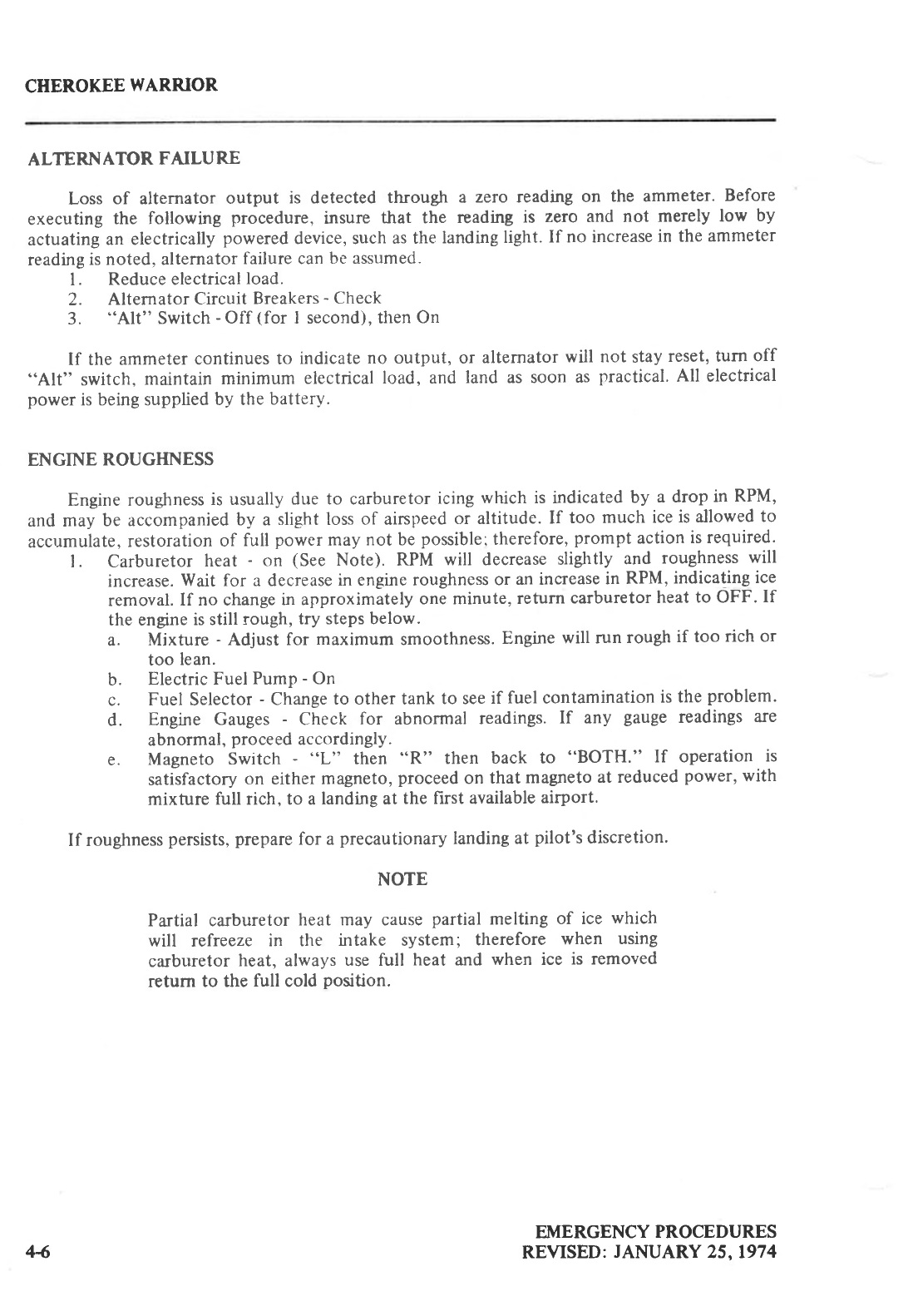
CHEROKEE
WAR.RIOR
ALTERNATOR FAILURE
Loss of alternator output is detected through a zero readhg on the ammeter. Before
executing the following procedure, insure that the reading is zero and not merely low by
actuating
an electrically
powered
device, such
as the
landing
light.
If no increase
in the
ammeter
reading
is noted, alternator
failure can
be assumed.
l. Reduce electrical
load.
2. Alternator
Circuit
Breakers
- Check
3. "Alt" Switch
-
Off (for I second), then
On
If the ammeter
continues
to indicate
no output, or alternator
will not stay
reset, turn off
"Alt" switch, maintain minimum electrical
load, and land as soon as
practical.
All electrical
power
is being supplied
by the
battery.
ENGINE ROUGHNESS
Engine roughness
is usually
due to carburetor
icing
which is indicated
by a drop in RPM,
and may be accompanied
by a slight loss of airspeed
or altitude.
If too much ice
is allowed
to
accumulate,
restoration
of full power
may not be
possiblel
therefore,
prompt action
is required.
l. Carburetor heat - on (See Note). RPM will decrease
slightly and roughness
will
increase.
Wait for a decrease
in engine roughness
or an increase
in RPM,
indicating
ice
removal.
If no change
in approximately
one minute,
return
carburetor
heat
to OFF. If
the engine
is still rough,
try steps below.
a. Mixture - Adjust for maximum smoothness.
Engine
will run rough
if too rich or
too lean.
b. Electric
Fuel
Pump
- On
c. Fuel Selector
- Change
to other tank to see
if fuel
contamination
is the
problem.
d. Engine Gauges
- Check for abnormal readings.
If any gauge
readings
are
abnormal,
proceed
accordingly.
e. Magneto Switch - "L" then "R" then back to "BOTH." If operation is
satisfactory
on either
magneto,
proceed
on that magneto
at reduced
power,
with
mixture full rich, to a landing at the first available
airport.
If roughness
persists,
prepare
for a
precautionary
landing
at pilot's
discretion.
NOTE
Partial carburetor
heat may cause
partial melting of ice which
will refreeze in the intake system; therefore when using
carburetor
heat, always
use full heat and when ice is removed
retum to the full cold position.
EMERGENCY
PROCEDURES
REVISED:
JANUARY
25, 197
444
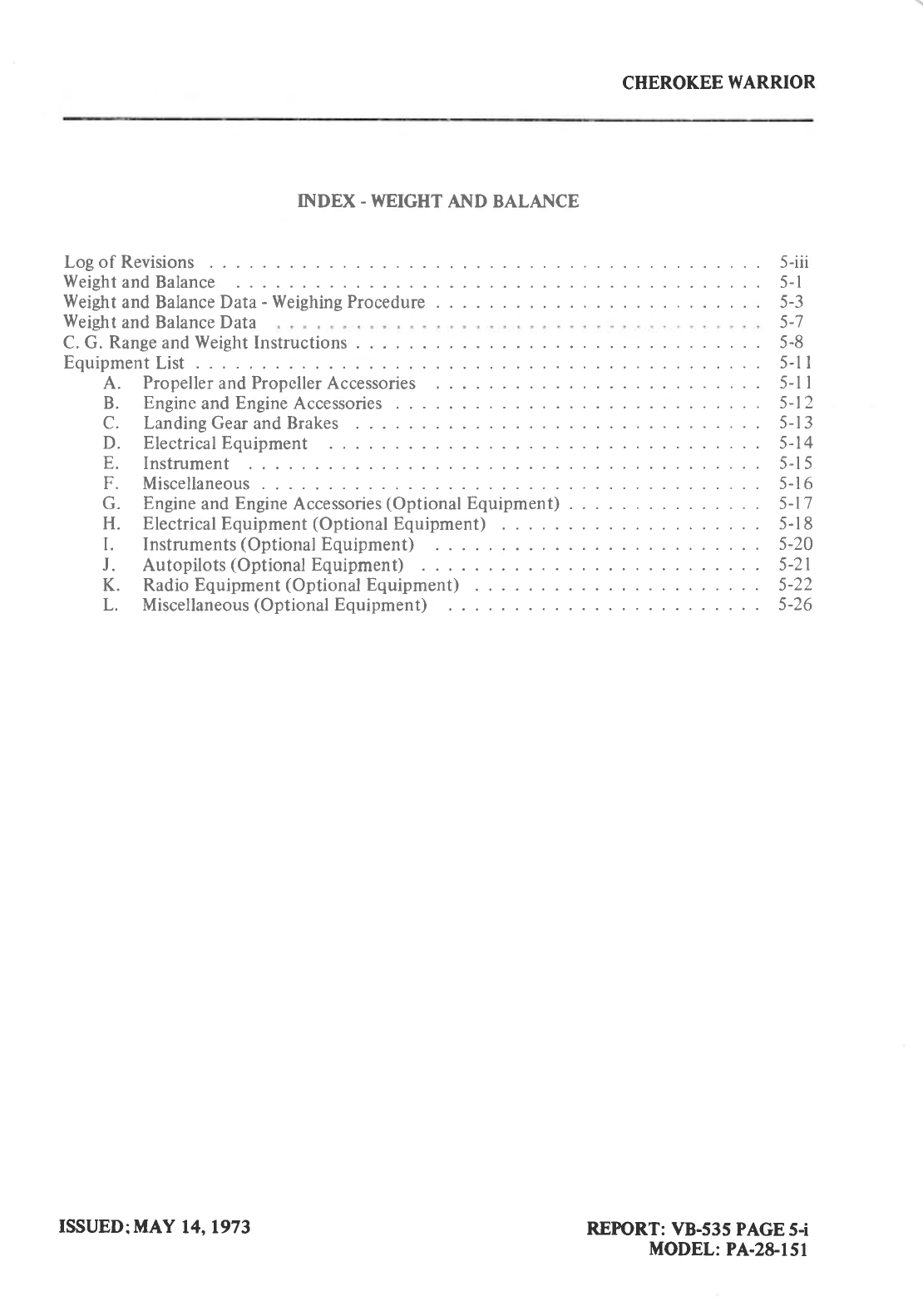
CHEROKEE
WARRIOR
INDEX. WEIGHT
AND BALANCE
Log of Revisions
Weight
and Balance
Weight
and Balance Data
-
Weight
and Balance Data
C. G. Range and
Weight
Instructions
Equipment
List .
A. Propeller and Propeller Accessories
B. Engine
and
Engine
Accessories
C. Landing Gear
and
Brakes
D. ElectricalEquipment
E. Instrument
F. Miscellaneous
G. Engine
and
Engine
Accessories
(Optional
Equipment) . . .
H. Electrical
Equipment
(Optional
Equipment) . . .
I. Instruments
(Optional
Equipment) . .
J. Autopilots
(Optional
Equipment) . . .
K. Radio Equipment
(Optional
Equipment)
. . .
L. Miscellaneous
(Optional
Equipment)
Weighing Procedure
5-iii
5-l
5-3
5-7
5-8
5-l I
5-l I
5-t2
5-r
3
5-14
5-l 5
5-16
5-17
5-l
8
5-20
5-21
5-22
5-26
REPTORT:
VB-535
PAGE
5-i
MODEL:
PA-2&151
ISSUED:MAY
14, 1973
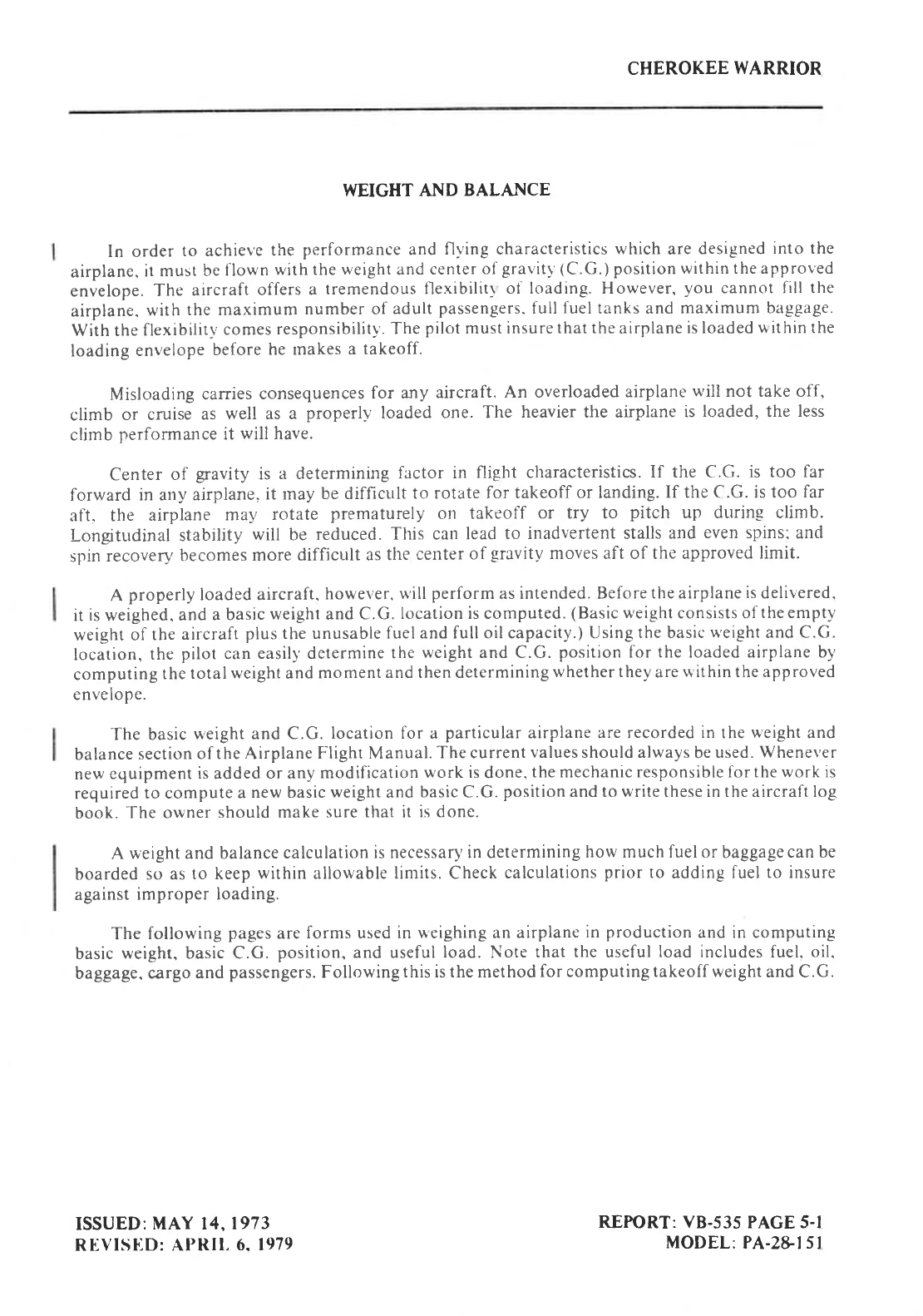
CHEROKEE
WARRIOR
WEIGHT AND BALANCE
In order
to achiel'e
the
performance and
flying characteristics
which
are
designed
into the
airplane,
it
must be
flown
with
the weight and
center
of
gravitl
(C.G.1
position within the approved
envelope.
The
aircraft
offers
a tremendous
flexibilitl
of loading. However,
you
cannot fill the
airplane.
with
the maximum
number of
adult
passengers.
full
fuel
tanks and maximum
baggage.
With the
flexibility
comes
responsibility'.
The
pilot
must insurethat
theairplane is loaded
uithin the
loading
envelope
before
he tnakes
a takeoff.
Misloading
carries
consequences
for any aircraft.
An overloaded
airplane
will not take off,
climb or cruise
as well as a properl-v-
loaded
one. The heavier the airplane
is loaded,
the less
climb perforrnance
it will have.
Center of gravity is a determining
factor in flight characteristics.
If the C.G. is too far
forward in arry airplane,
it rnay
be difficult to rotate
for takeoff or landing.
If the C.G. is too far
aft, the airplane may rotate prematurely
orr takeoff or try to pitch up dnring climb.
I-ongitudinal
stability
will be reduced.
This can
lead
to inadvertent stalls
and
even spins:
and
spin
recovery
becomes
more
difficult as
the
center
of gravity
moves aft of the approved
limit.
A properly loadeC aircraft.
however.
u'ill
perform
as intended. Before
the airplane
is
delivered.
it
is
weighed,
and
a basic
weight and
C.G.
location is computed.
(Basic
weight
consists of
theempty
weight of
the
aircraft
plus the unusable
fueland full oil capacity.) Using
the basic
u'eight
and C.G.
location,
the
pilot can easily'determine
the
weight and C.G.
position
for the loaded airplane by
compuring
the
total
weight
and
moment
and then determining
whether thev
are
u ithin the approved
envelope.
The basic
u,eight and C.G.
location for a particular
airplane are recorded
in the
weight
and
balance
section
of the Airplane
Flight Manual.
The current
values should always
be
used. Whenever
new
cquipment
is
added
or any
modification
work is
done,
the mechanic responsible for the work is
required
to compute
a
new basic
weight
and
basic C.G.
position
and to write these in the aircraft log
book.
The owner
should make
sure that it is done.
A weight
and balance
calculation
is necessar-v in determining
how much fuel or
baggagecan
be
boarded
so as
to keep
within allowable limits. Check
calculations
prior
to adding
fuel to insure
against
improper
loading.
The
following
pages
are
forms used in
ueighing
an
airplane
in
production
and in computing
basic
weight, basic C.G.
position. and useful
load.
Note
that
the
useful
load
includes fuel.
oil.
baggage.
cargo
and
passengers.
Following
this is the method
for computing takeoff weight
and C.G.
ISSUED:
MAY 14, 1973
REVISUD:
Al'Rll.
6. 1979 REPORT: vB-535
PAGE 5-l
MODEL:
PA-2&l5l
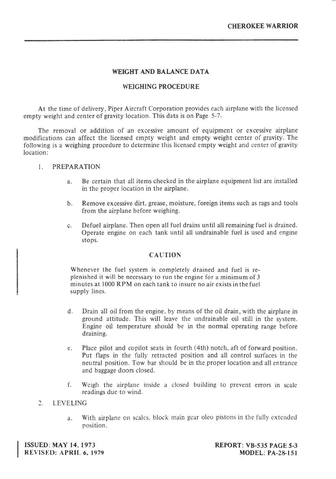
CHEROKEE
WARRIOR
I{EIGHT AND BAI.ANCE DATA
WEIGHING PROCEDURE
At the time of delivery,
Piper Aircraft Corporation
provides
each airplane
with the licensed
empty weight and centerof gravity
location. This data
is
on Page
5-7.
The removal or addition of an excessive
amount of equipment or excessive
airplane
modifications can affect the licensed empty weight and empty weight center
of gravity.
The
following is a weighing
procedure
to determine
this
licensed
empty weight
and
center of gravity
location:
I. PREPARATION
a. Be certain that all
items checked in the airplane equipment
list are installed
in the proper
location in the airplane.
b. Remove excessive
dirt. grease,
moisture, foreign items such as rags and
tools
from the airplane
before
weighing.
c. Defuel airplane.
Then open all fuel
drains
until all remaining fuel is drained.
Operate engine on each tank until all undrainable fuel is used and engine
stops.
CAUTION
Whenever
the fuel system
is completely
drained and fuel is re-
plenished
it will be necessary to run the engine for a minimum of
3
minutes at 1000 RPM on each tank to insure no
air exists in the fuel
supply lines.
d. Drain all oil from the engine. by means of the
oil drain, with the
airplane in
ground attitude. This will leave
the undrainable
oil still in the system.
Engine oil temperature
should be in the normal operating
range before
draining.
e. Place
pilot and copilot seats in fourth (4th) notch, aft of forward
position.
Put flaps in the fully' retracted position and all control surfaces in the
neutral
position.
Tow bar should
be
in the
proper
location
and all entrance
and baggage doon closed.
f. Weigh the airplane inside a closed building to prevent errors in scale
readinss
due to wind.
2. LEVELING
a. With airplane
ol'r
scales.
block
main
gear
oleo
pistons
in the fully
extended
position.
ISSUED:MAY
14. 1973
REVISIiD:
APRII-
6. 1979 REPORT:
VB-535
PAGE
5-3
MODEL:
PA-28-l5l
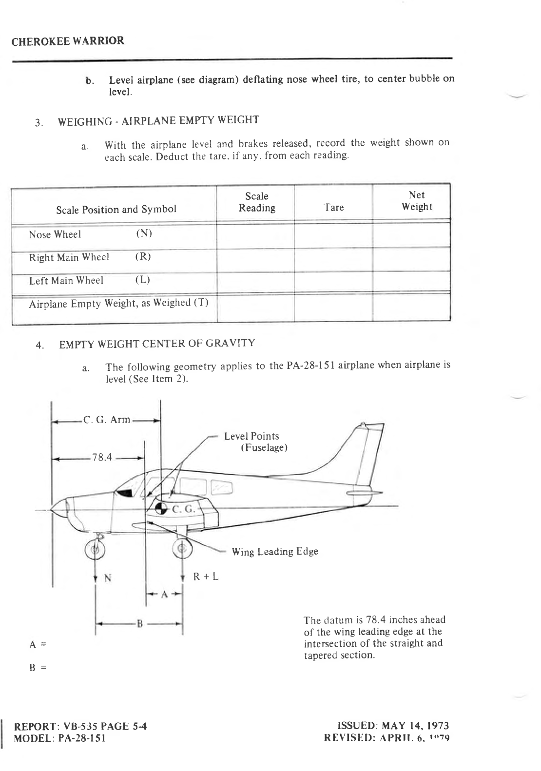
CHEROKEE
WARRIOR
b. Level airplane
(see
diagram) deflating nose
wheel tire, to center
bubble on
level.
3. WEIGHING
-
AIRPLANE
EMPTY
WEIGHT
a. With the airplane
level
and brakes
released,
record
the weight
shown
on
c'ach scale.
Deduct
the
tare. if any'
from
each reading'
4. EMPTY
WEIGHT
CENTER
OF GRAVITY
a. The following geometry
applies
to the
PA-28-l5l airplane
when
airplane
is
level
(See
Item
2).
C.
G. Arm
Level
Points
(Fuselage)
78.4
Wing Leading
Edge
R+L
The
clatunt
is
78.4 inches ahead
of the
wing leading edge at the
intersection
of the straight
and
tapered
section.
A-
B-
REPORT:
vB-s35
PAGE 54
MODEL:
PA-28-l5l ISSUED: IvtAY
14, 1973
REVISED:
APRll.
6.
t,r79
Scale
Position
and
SYmbol
Scale
Reading Tare Net
Weight
Nose
Wheel (N)
Rieht
Main
Wheel (R)
Left
Main
Wheel (L)
Airplane
Empty
Weight, as
Weighed
(T)
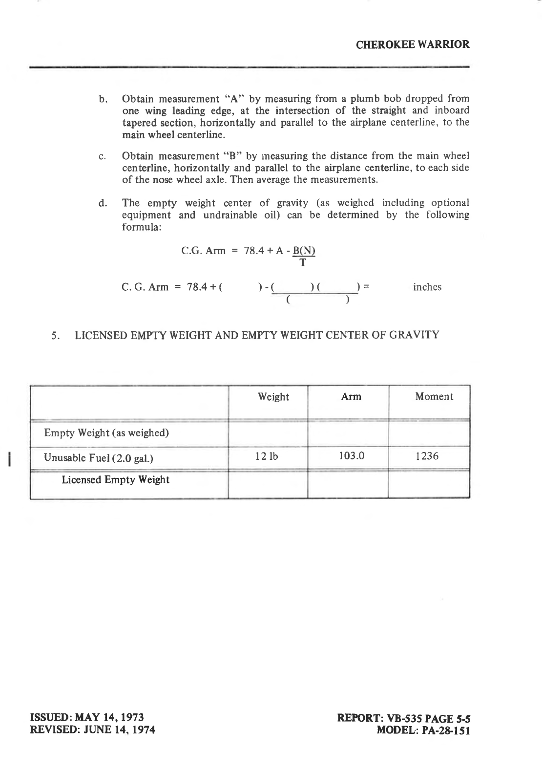
CHEROKEE
WARRIOR
Obtain measurement
"A" by measuring
from a plumb
bob dropped from
one wing leading edge, at the intersection
of the straight
and inboard
tapered section, horizontally and
parallel
to the airplane centerline,
to the
main wheel centerline.
Obtain measurement
"B" by measuring
the distance from the main
wheel
centerline,
horizontally
and
parallel
to the airplane centerline,
to each side
of the nose
wheel
axle.
Then average the
measurements.
The empty weight center of gravity (as weighed including optional
equipment and undrainable
oil) can be determined
by the following
formula:
C.G.Arm
= 78.4+A-B(N)
T
C.
G. Arm = 78.4
+ ()-( )( )-
() inches
5. LICENSED
EMPTY WEIGHT AND EMPTY WEIGHT CENTER
OF GRAVITY
b.
d.
Weight Arm Moment
Empty Weight
(as
weighed)
Unusable
Fuel
(2.0
gal.) t2 tb 103.0 1236
Licensed
Empty Weight
ISSUED:
MAY 14, 1973
REVISED:
JLjNE
14,1974 REPORT:
VB-535
PAGE
5-5
MODEL:
PA-2&lSl
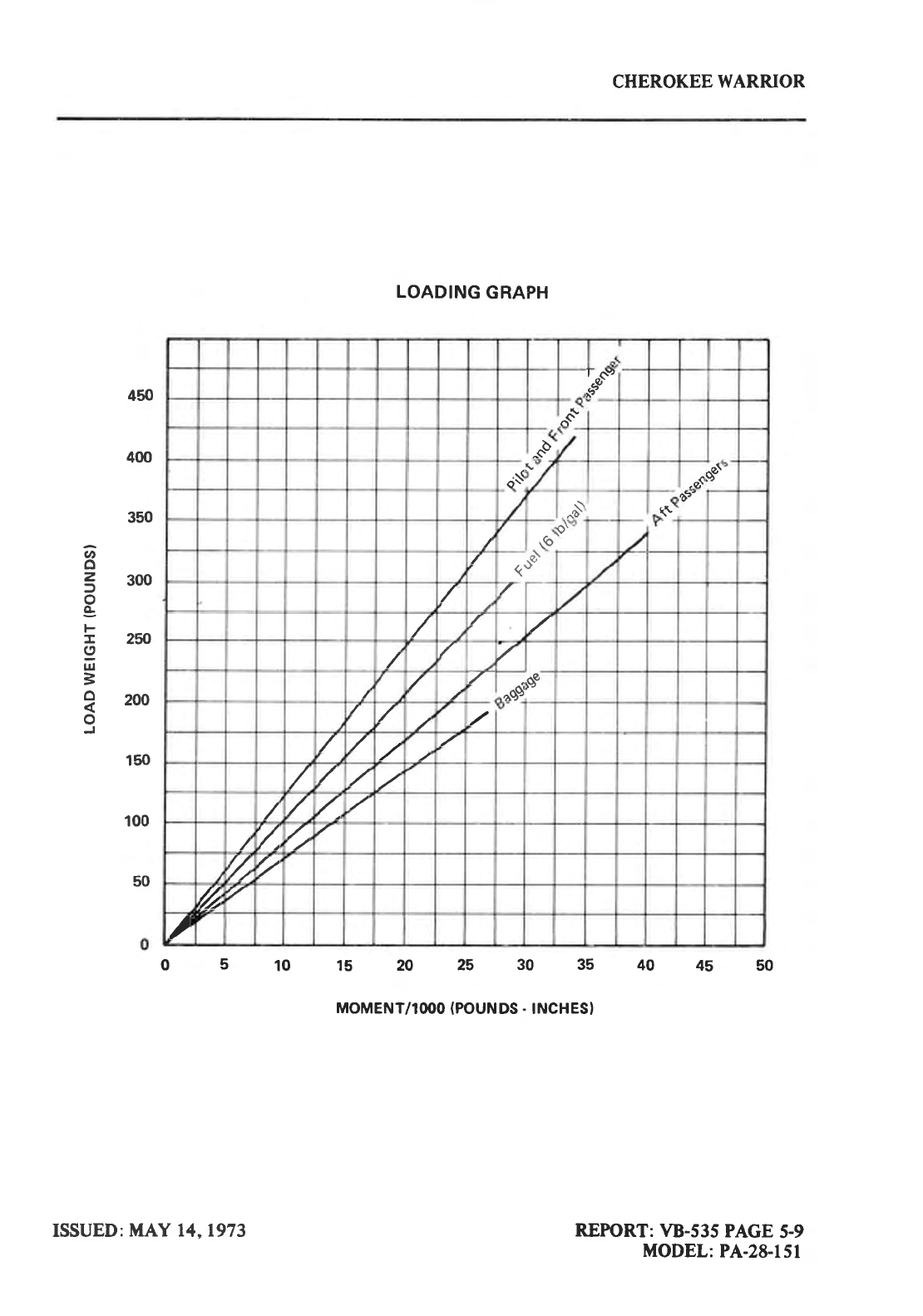
CHEROKEE
WARRIOR
;d,"
"(+
3
.;$!
.a( gal
xi +?9'
\6 9\
(A
7-
"Ss
rs"
at
Zt/
z'/
/
450
400
350
U'
o
3 3oo
o
g
r 25O
I
ul
=
O o^^
o
150
100
50
LOADING
GRAPH
05101520253035404550
MOMENT/IOOO
(POUNDS
. INCHES)
REPTORT:
VB-535
PAGE
5-9
MODEL:
PA-28-151
ISSUED:
I|{AY 14, 1973
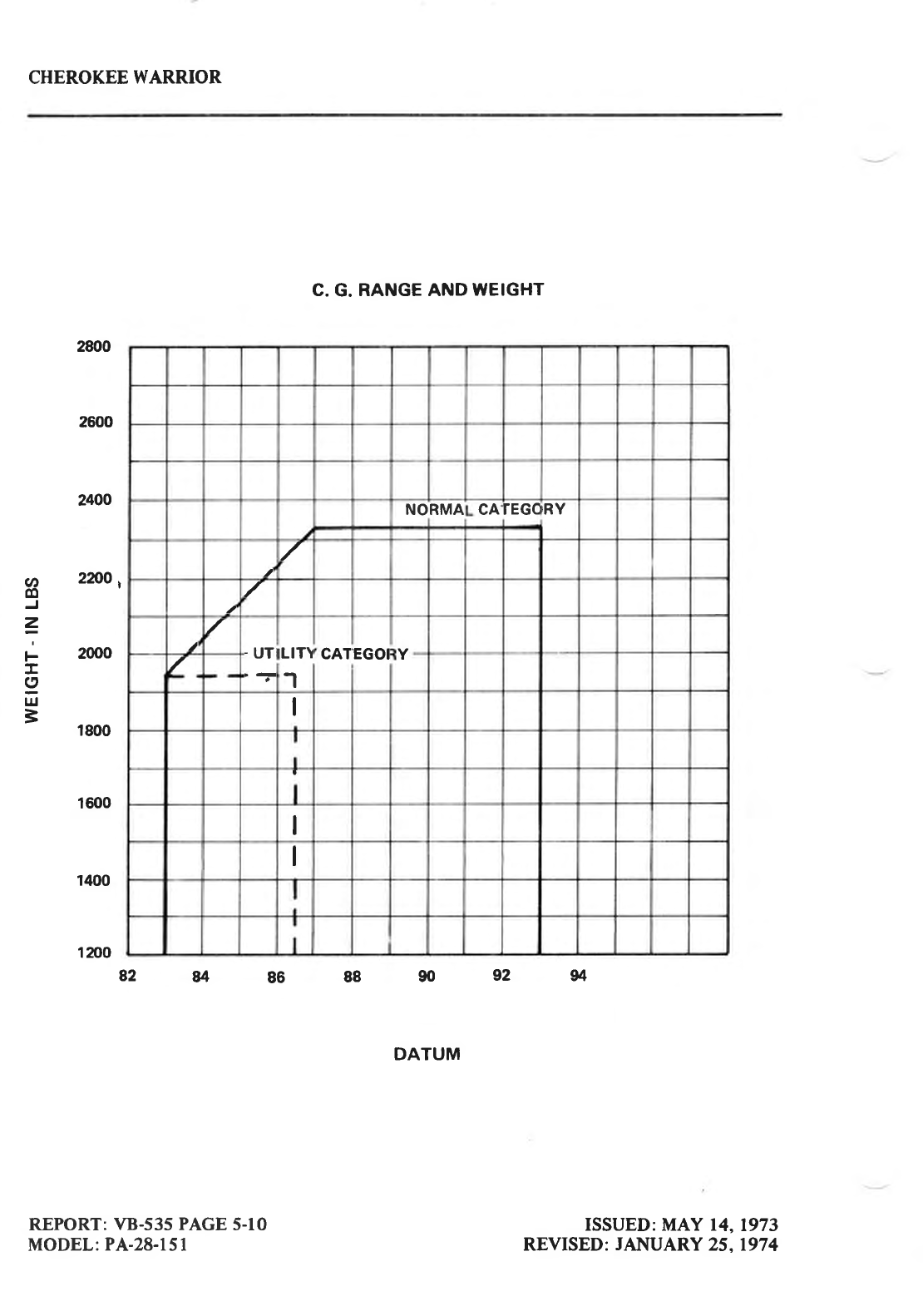
CHEROKEE
WARRIOR
v,
o
=
F
I
I
LlJ
=
2800
2600
2400
zmo
I
2000
1800
1600
1400
1 200
REPORT:
VB-535 PAGE
5-10
MODEL:
PA-28-151
C.
G.
RANGE AND
WEIGHT
DATUM
ISSUED: MAY 14,
1973
REVISED:
JANUARY
25. 197
4
NORMA CArEGC
rRY
.a /
/
t
/-UTLIT\
1
CATEGOIY
/
I
I
82''p.8688909294
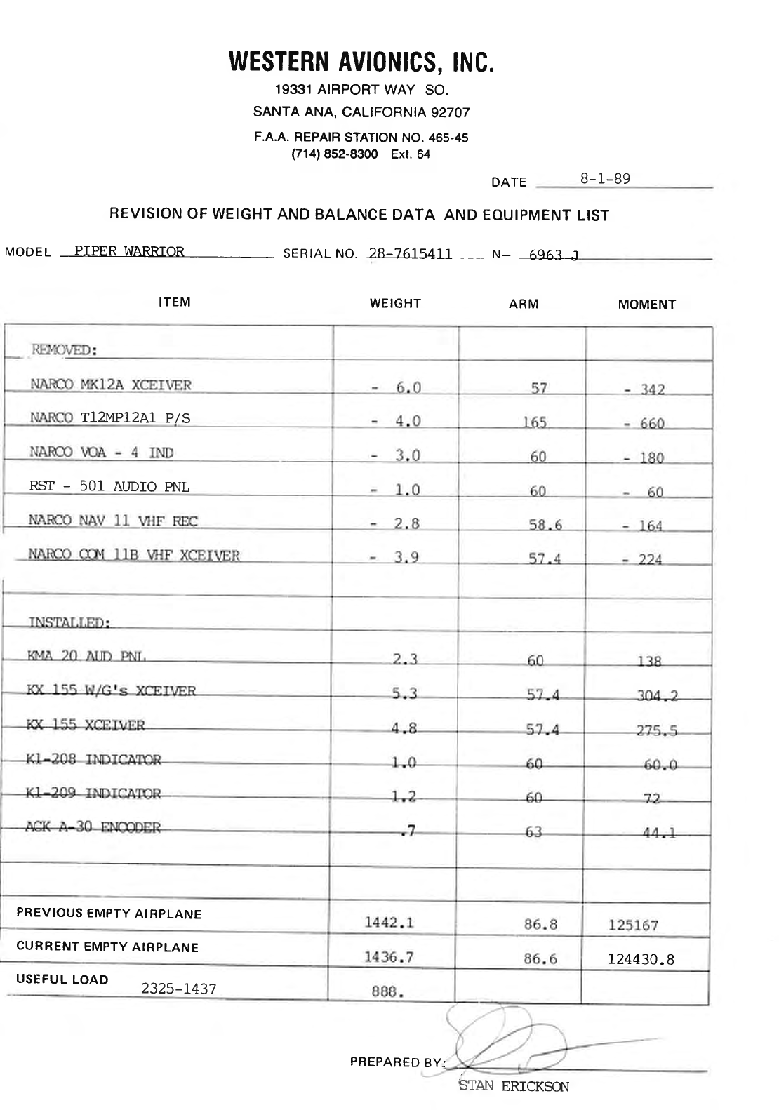
WESTERN
AVIONICS,
INC.
19331
AIRPORT
WAY SO.
SANTA ANA,
CALIFORNIA
92707
F.A.A.
REPAIR
STATION NO.
465-45
(714)
852-8300
Ext. 64
DATE B- 1-89
REVISION
OF WEIGHT
AND BALANCE
DATA AND
EOUIPMENT
LIST
MODEL PIPER
WARRIOR SERTAL NO. 28-261q41'l N- 6q63 J
ITEM WEIGHT ARM MOMENT
T12MP12A1
P/S
RST - 501 AUDIO PNL
PREVIOUS
EMPTY
AI
RPLANE
L24430.8
CURRENT
EMPTY
AIRPLANE
STAI{
USEFUL
LOAD 2325-L437
PREPARED
BY:
ERICKSO\
0PERrilil8
rlrsIRUCIl0llS
Preflight
Walk-Around Inqpection
Starting
Engrne
Starting
Engine
When
Cold
Starting
Engine When
Hot
Starting
Engine
When Flooded
Starting
Engrne with External Power Source
Warm-Up
Ground Check
Takeoff
Climb
Stalls
.
Cruising
Turbulent Air Operation
Maneuven
Engine Power Loss .
Approach and Landing . .
Stopping
Engine 7'9
Airspeed Data . 7-9
Mooring 7'9
Weight and
Balance 7'9
Emergency
Locator Transmitter 7-10
7-l
7-l
7-2
7-3
7-3
7-3
7-3
74
74
7-5
7-6
7-6
7-6
7-7
7:7
73
7-8
74
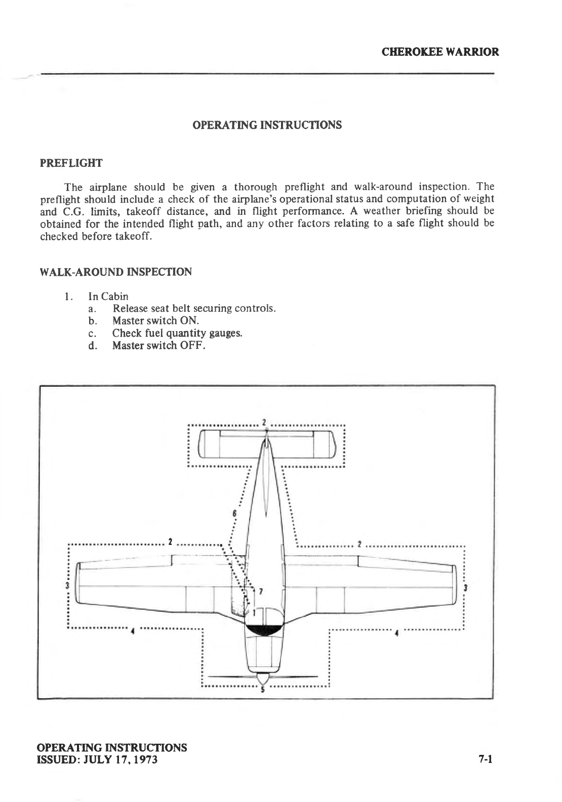
CHEROKEE WARRIOR
OPERATING INSTRUCTIONS
PREFLIGHT
The airplane
should be given a thorough preflight and walk-around
inspection. The
preflight
should
include a check
of the airplane's operational
status
and computation of weight
and C.G. limits, takeoff distance, and in flight perfornance.
A weather
briefing
should be
obtained
for the intended
flight path,
and
any
other
factors relating
to a safe
flight should
be
checked
before takeoff.
WALK-AROUND
INSPECTION
l. In Cabin
a. Release seat
belt securing controls.
b. Master
switch ON.
c. Check
fuel
quantity
gauges.
d. Master switch
OFF.
2,
OPERATING INSTRUCTION S
ISSUED: JULY 17,1973 7-l
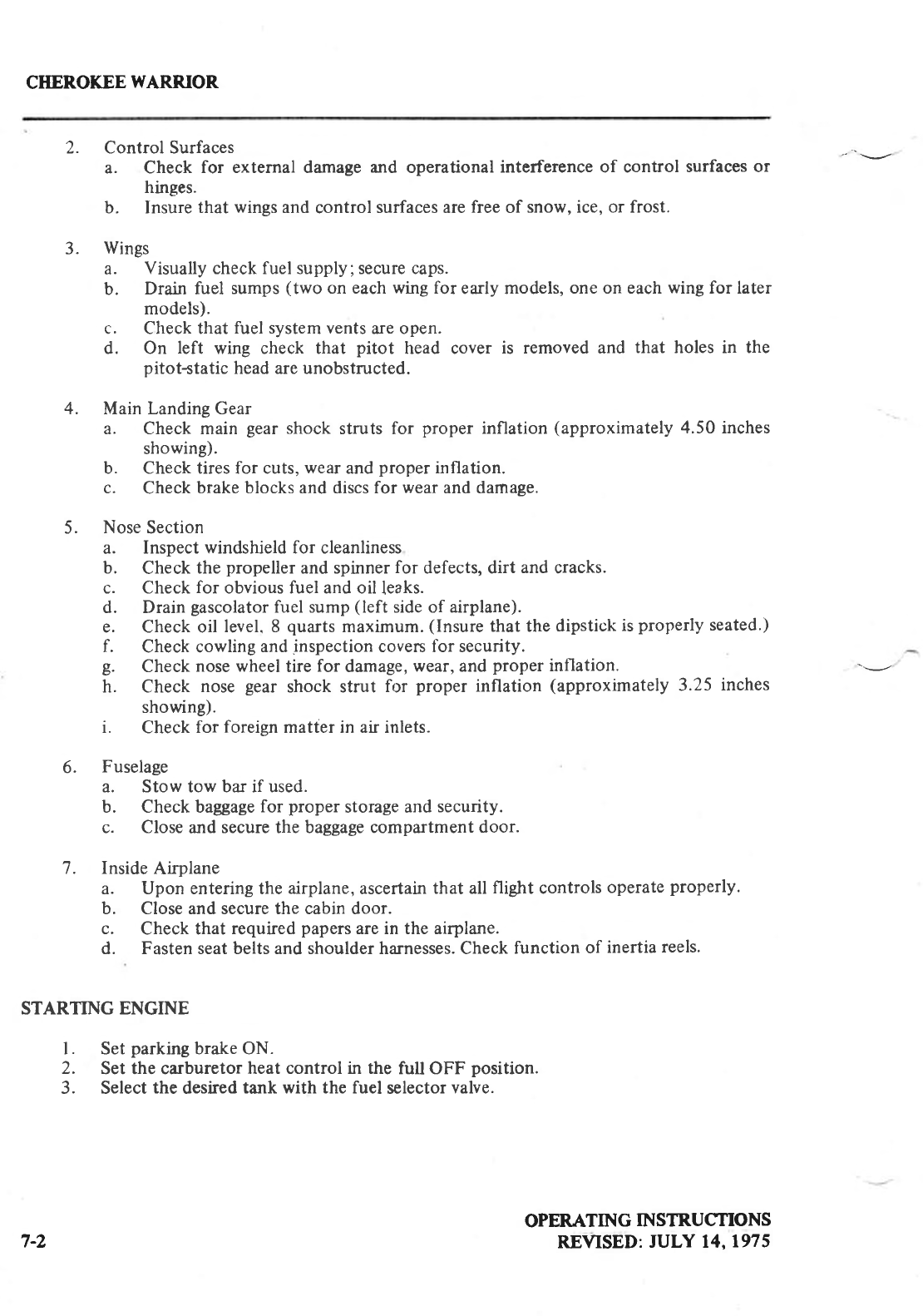
CIIEROKEE
WARRIOR
2. Control Surfaces
a. Check for external damage and operational
interference of control surfaces or
hinges.
b. Insure
that wings
and control surfaces are
free of snow, ice, or frost.
3. Wings
a. Visually check fuel supply, secure caps.
b. Drain fuel sumps
(two on each wing for early models,
one on each
wing for later
models).
c. Check that fuel system vents
are open.
d. On left wing check that pitot head cover is removed and that holes in the
pitot*tatic head are unobstructed.
4. Main Landing Gear
a. Check main gear
shock struts for proper inflation (approximately
4.50 inches
showing).
b. Check tires for cuts,
wear
and
proper
inflation.
c. Check
brake blocks and discs for wear
and damage.
5. Nose
Section
a. Inspect windshield for cleanliness
b. Check
the propeller
and spinner
for defects, dirt and cracks.
c. Check
for obvious fuel and oil leaks.
d. Drain
gascolator
fuel sump
(left side of airplane).
e. Check oil level. 8 quarts
maximum.
(Insure
that the
dipstick
is
properly
seated.)
f. Check cowling
and
inspection
covers for security.
g. Check
nose wheel
tire for damage,
wear, and
proper
inflation. -v
h. Check nose gear shock strut for proper inflation (approximately
3.25 inches
showing).
i. Check
for foreign matter in air inlets.
6. Fuselage
a. Stow tow bar if used.
b. Check baggage
for proper storage and
security.
c. Close
and secure the baggage compartment
door.
7. Inside
Airplane
a. Upon entering the airplane,
ascertain
that all flight controls operate
properly.
b. Close and secure the cabin door.
c. Check that required
papers
are in the airplane.
d. Fasten seat belts and shoulder harnesses. Check
function
of inertia
reels.
STARTING ENGINE
l. Set
parking
brake ON.
2. Set the carburetor
heat control in the fult OFF position.
3. Select
the desired
tank with the fuel selector
valve.
OPERATING INSTR.UCTIONS
REVISED:
JULY 14,1975
7-2
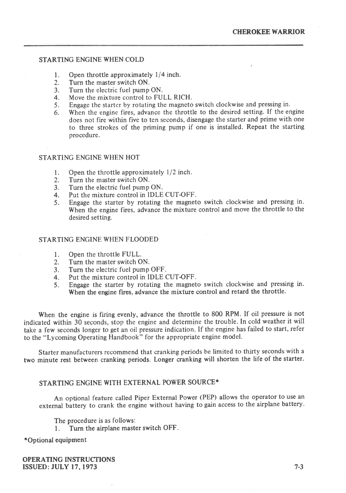
CHEROKEE
WARRIOR
STARTING
ENGINE
WHEN COLD
l. Open throttle
approximately
l/4 inch.
2. Turn
the master switch ON.
3. Turn the electric
fuel
pump
ON.
4. Move the mixture
control to FULL RICH.
5. Engage the starter
by rotating the
magneto switch
clockwise
and
pressing
in.
6. When the engine
fires, advance
the throttle
to the desired
setting.
If the
engine
does not fire
within five
to ten seconds, disengage
the
starter
and
prime
with one
to three strokes
of the
priming pump
if one is installed.
Repeat the starting
procedure.
STARTING
ENGINE
WHEN HOT
l. Open
the throttle
approximately
l/2 inch.
2. Turn the
master switch
ON.
3. Turn the electric
fuel
pump
ON.
4. Put the
mixture control
in IDLE CUT-OFF.
5. Engage the starter
by rotating
the magrreto
switch clockwise
and pressing
in.
When the engine
fires, advance the
mixture control
and
move the
throttle
to the
desired
setting.
STARTING
ENGINE
WHEN FLOODED
l. Open
the throttle
FULL.
2. Turn the
master switch
ON.
3. Turn the
electric
fuel
pump
OFF.
4. Put the mixture
control
in IDLE CUTOFF.
5. Engage
the starter by rotating
the magneto
switch
clockwise
and pressing
in.
When the engine
fues, advance
the mixture control
and retard
the
throttle.
When the engine
is firing evenly, advance
the throttle to 800 RPM.
If oil pressure
is not
indicated
within 30
seconds,
stop the engine
and determine
the trouble.
In cold
weather it will
take
a few seconds
longer to get
an
oil pressure
indication.
If the
engine has
failed
to start,
refer
to the
"Lycoming
Operating
Handbook" for the
appropriate
engine
model.
Starter
manufacturers
recommend that
cranking
periods
be
limited to thirty
seconds
with
a
two minute rest
between
cranking
periods.
Longer cranking
will shorten
the life of the
starter.
STARTING
ENGINE
WITH EXTERNAL
POWER SOURCE*
An optional
feature
called
Piper
External
Power
(PEP)
allows
the operator
to use an
external
Uittery to crank
the engine
without having
to gain
access
to the airplane
battery.
The
procedure
is
as
follows:
l. Turn the
airplane
master
switch
OFF'
*Optional
equipment
OPERATING
INSTRUCTIONS
ISSUED: JULY 17,1973 7-3
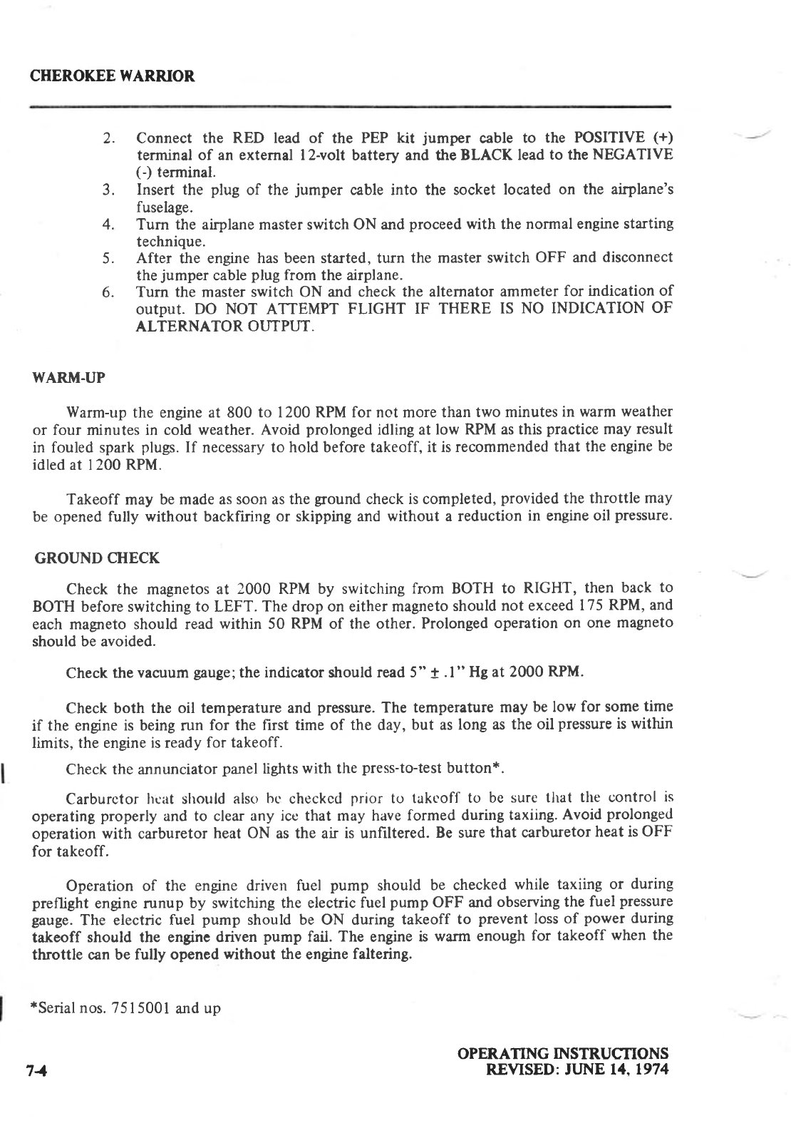
CHEROKEE WARRIOR
2. Connect the RED lead of the PEP kit jumper cable
to the POSITIVE
1+1
terminal of an external l2-volt battery and the
BLACK lead
to the
NEGATIVE
(-) terminal.
3. Insert
the plug of the jumper cable into the socket
located
on the airplane's
fuselage.
Turn the airplane master switch ON and
proceed
with the normal engine starting
technique.
After the engine has been started, turn the master switch OFF and disconnect
the
jumper cable
plug from the airplane.
Turn the master switch ON and check the alternator ammeter for indication of
output. DO NOT ATTEMPT FLIGHT IF THERE IS NO INDICATION OF
ALTERNATO R O I.-TTPIj"T.
WARM-UP
Warm-up
the engine at 800
to 1200 RPM for not more than
two minutes
in warm
weather
or four minutes in cold weather.
Avoid
prolonged
idling at low RPM as this
practice
may
result
in fouled spark
plugs.
If necessary
to hold before takeoff,
it is recommended
that the engine
be
idled at 1200 RPM.
Takeoff may be
made as soon as the
ground
check
is completed,
provided
the throttle
may
be opened
fully without backfiring
or skipping and
without a reduction
in engine
oil pressure.
GROUND
CHECK
Check the magnetos at 2000 RPM by switching
from BOTH to RIGHT,
then
back
to
BOTH before switching
to LEFT.
The drop on either magneto
should
not exceed
175
RPM, and
each magneto should read
within 50 RPM
of the other.
Prolonged
operation
on one
magneto
should be avoided.
Check
the
vacuum
gauge;
the
indicator
should
read 5" + .l " Hg at 2000
RPM.
Check both the oil temperature and
pressure.
The temperature
may
be low for some
time
if the engine
is being run for the first time of the day,
but as
long as
the oil pressure
is within
limits, the engine is ready
for takeoff.
Check
the annunciator
panel
lights
with the
press-to-test
button*.
Carburctor
hcat should
also
bc checkcd
prior tr.r takcoff
to be
sure that the control
is
operating
properly
and to clear
any ice that may have
formed during
taxiing.
Avoid
prolonged
operation
with carburetor
heat ON as the air is unfiltered.
Be sure
that carburetor
heat is OFF
for takeoff.
Operation
of the engine driven fuel pump should
be checked
while taxiing or during
preflight
engine runup
by switching the electric
fuel
pump
OFF and
observing the
fuel
pressure
gauge.
The electric
fuel pump should be ON during
takeoff to prevent
loss
of power
during
takeoff should the engine driven
pump
fail. The engine
is warm enough
for takeoff
when the
throttle can be fully opened
without the engine
faltering.
*Serial
nos. 7515001
and
up
OPERATING
INSTRUCTIONS
REVISED: JLJNE 14.1974
4.
5.
6.
71

CHEROKEE WARRIOR
TAKEOFF
Just before
takeoff the following
items
should be
checked:
l. Fuel
-
on
proper
tank
2. Electric
fuel
pump
-
on
3. Engine
gauges
- checked
4. Flaps
-
set
5. Carburetor heat
-
off
6. Mixture
-
set
7. Seat backs
-
erect
8. Safety belts/harness
- fastened
9. Trim tab
- set
10. Controls
-
free
I l. Door
-
latched
The takeoff technique
is conventional. The trim tab should
be
set
slightly
aft of neutral
with the exact setting determined by the loading of the airplane. Allow the airplane to
accelerate
to 50 to 60 miles
per
hour,
then ease back
on the
wheel enough to let the airplane
fly
itself from the
ground.
Premature raising of the
nose
or raising
it to an
excessive angle
will result
in a delayed takeoff. After takeoff, let the airplane accelerate
to the desired climb speed
by
lowering
the nose slightly.
Takeoffs are normally made with flaps up; however,
for short field takeoffs and for
takeoffs
under difficult conditions
such as deep
grass
or a soft surface,
distances can be reduced
appreciably
by lowering the flaps to 25
o
and rotating at lower airspeeds.
Short
Field, Obstacle Clearance:
Lower the flaps to 25
o.
Apply full power
before brake
release.
Accelerate to 66 MPH CAS
and rotate, maintaining 66 MPH CAS until obstacle clearance
has
been attained.
After the
obstacle has been cleared
accelerate to 87 miles
per
hour
and
then
slowly retract
the flaps.
Short
Field, No Obstacle:
Use of partial
flaps does
not decrease
minimum ground
roll, therefore,
leave the tlaps up or
lower the flaps to 25o as
desired. Apply full power
before
brake
release. Accelerate
to 65 MPH
CAS with flaps up or 52 MPH CAS with flaps at 25' and rotate. After breaking
ground,
accelerate
to best
rate
of climb speed of 87 MPH CAS. Slowly
retract the flaps
while climbing
out.
Soft Field,
Obstacle Clearance:
Lower the flaps to 25". Accelerate airplane, lift nose
gear
off as soon as
possible,
and
lift
off at lowest
possible
airspeed. Accelerate
just above
the ground
to 66 MPH
CAS to climb
past
obstacle clearance
height.
Continue climbing
while accelerating to the best
rate of climb speed,
87 miles
per
hour, and slowly retract the flaps.
Soft Field, No Obstacle:
Lower the flaps to 25'. Accelerate
the airplane
and lift the nose
gear
off as soon as
possible,
then lift off at the lowest
possible
airspeed.
Accelerate
just above the ground to the
best
rate of climb speed, 87 miles
per
hour. Climb out while
slowly
retracting the
flaps.
OPERATING
INSTRUCTIONS
REVISED:
APRIL
16.1976
NOTE
Mixture full rich except a minimum
amount of leaning is permitted for
smooth engine
operation
when taking off
at high
elevation.
7-5
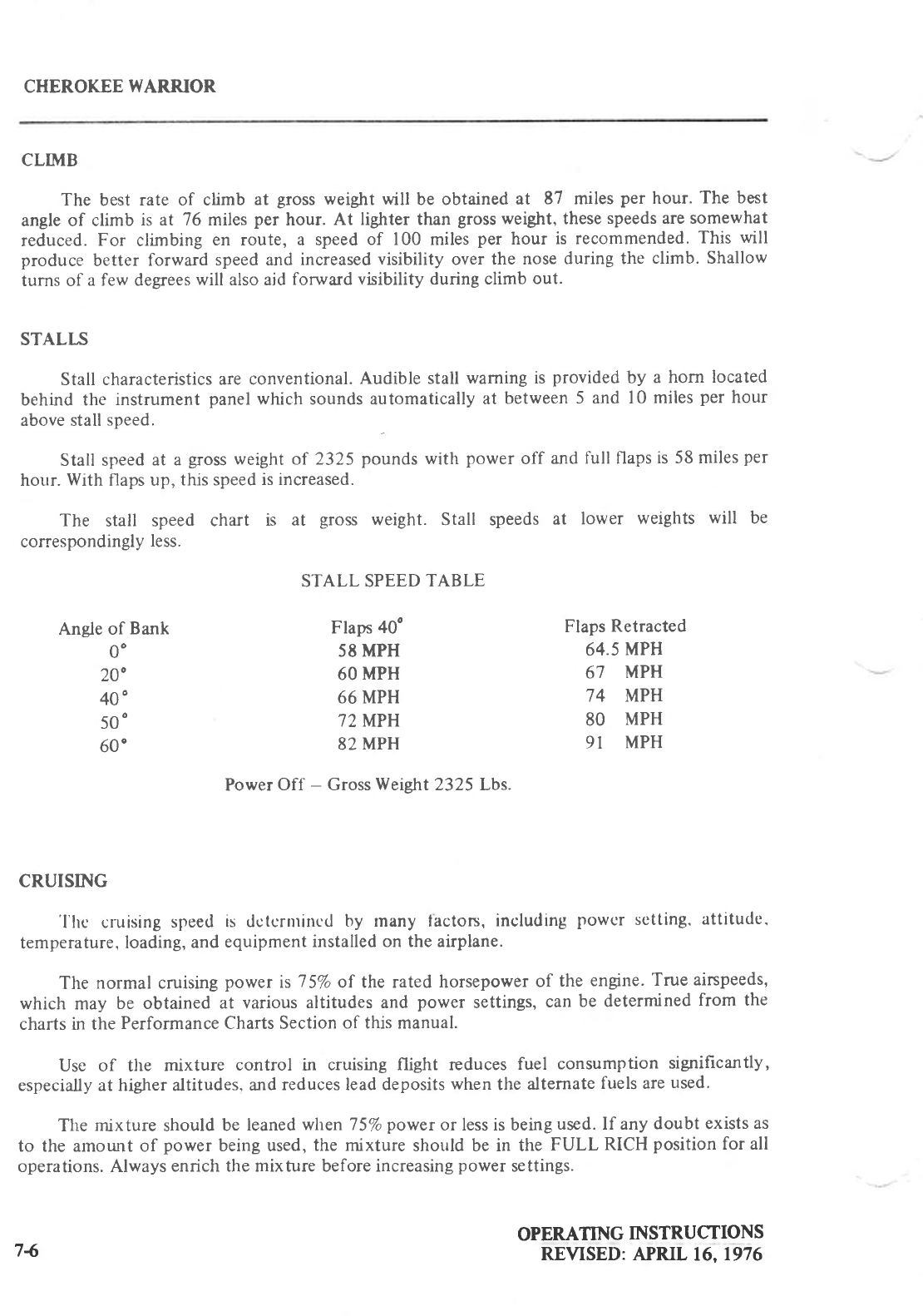
CHEROKEE
I{ARRIOR
CLIMB
The best rate of climb at gross
weight will be obtained
at 87 miles
per hour.
The best
angle of climb is at 76 miles
per hour. At lighter than gross
weight, these
speeds are somewhat
reduced.
For climbing en route, a speed
of 100 miles
per hour is recommended.
This will
produce better forward
speed and increased
visibility over
the nose
during the climb. Shallow
turns of a few degrees
will also aid
forward
visibility during climb
out.
STALI"S
Stall characteristics
are conventional.
Audible stall
waming is provided
by a horn located
behind the instrument panel
which sounds automatically
at between
5 and l0 miles
per hour
above stall
speed.
Stall speed
at a gross
weight of 2325 pounds
witlt power off and
full flaps
is 58 miles
per
hour.
With flaps up, this speed
is increased.
The stall speed chart is at gross weight. Stall speeds
at lower weights will be
correspondingly
less.
STALL SPEED
TABLE
Angle of Bank Flaps
40' Flaps
Retracted
OO 58
MPH 64.5
MPH
2OO 60 MPH 67 MPH
4OO 66 MPH 74 MPH
5OO 72 MPH 80 MPH
60' 82
MPH 9I MPH
Power
Off - Gross
Weight
2325 Lbs.
CRUISING
'l'hc cruising
speed
is dctcnnincd
by many lacton, including
powcr sctting.
attitude.
temperature,
loading,
and
equipment
installed on the airplane.
The normal cruising
power is 7
5%
of the rated horsepower
of the engine.
True
airspeeds,
which may be obtained at various
altitudes and power settings,
can
be determined
from the
charts in the
Performance Charts Section
of this manual.
Use of the mixture control in cruising flight reduces fuel consumption significantly,
especially at higher altitudes,
and
reduces lead deposits
when
the alternate
fuels are
used.
Tlre mixture should
be
leaned
when75%
powerorlessisbeingused.
If anydoubtexistsas
to the amount of power being used,
the mixture should be in the FULL RICH position
for all
operations. Always
enrich the mixture before increasing
power
settings.
OPERATING
INSTRUCTIONS
REVISED: APRIL
16,1976
74
CTTEROKEE
WARRIOR
To lean
the mixture, pull the mixture control until the engine becomes rough, indicating
that the lean
mixture limit has been
reached in the leaner
cylinders.
Then enrich the
mixture by
pushing
the
control
toward the instrument
panel
until engine
operation becomes smooth.
The continuous
use
of carburetor
heat during cruising
flight decreases
engine efficiency.
Unless icing conditions in the carburetor are severe.
do not cruise
with carburetor
heat on.
Apply FULL carburetor
heat slowly and only for a few seconds
at intervals
determined
by the
icing conditions.
In order to keep the airplane in best
lateral trim during cruise
flight, the fuel should be
used alternately from each
tank. It is recommended
that one tank be used for one hour after
takeoff, the other tank be used for two hours,
then return to the first tank. The second tank
will contain approximately one
half
hour of fuel. Do not run tanks completely dry in flight.
The following is a list of some fuel management recommendations:
I . Fuel quantity should
be visually
checked
in both tanks
before
entering the airplane.
2. Takeoff should be made on the fuller tank to assure
best fuel flow. and this tank
selected
before or immediately after starting
to establish an
adequate fuel
flow before
takeoff. The tank with the
higher fuel
quantity
should
be selected
for landing.
3. Fuel tank
selection
at low altitude
is not recommended since
adequate recovery
time
is essential
in the event
of an error in fuel
selection.
4. The electric
fuel pump should
be turned on before
switching tanks
and left on for a
short
period
thereafter.
5. To avoid the necessity
of making a hasty selection
and to assure
a continuous
tuel
flow, the selector
should be changed
to another tank before the fuel is exhausted
from the tank in use.
6. Operation of the engine
driven
pump should be checked
while taxiing or during the
preflight runup by switching off the electric fuel pump and observing
the fuel
pressure.
7. During cruise, the electric fuel pump should be in the off position so that any
malfunction
of the engine driven
fuel
pump is immediately
apparent.
8. If signs
of fuel stawation should occur at any time during l-light,
fuel exhaustion
should be suspected. at which time the
fuel
selector
should
immediately
be
positioned
to the fuller tank and
the
electric
fuel
pump switched
to the
on position.
TURBULENT AIR OPERATION
In keeping with good
operating
practice
r"sed
in all
aircraft,
it is recommended
that
when
turbulc-nt air is cncountercd
or cxpected, the airspeed
be reduced
to maneuvering
spced
to
reduce
the structural
load caused by gusts
and to allow for inadvertent
speed
build-ups
which
may
occur as a
result
of the
turbulence
or distractions
caused
by the conditions.
MANEUVERS
The airplane
must be operated as a normal or utility category
airplane
in compliance
with
the operating
limitations stated in the form of placards
and markings,
and those
given
in the
Airplane
Flight Manual.
Except for training
maneuvers
(steep
turns,
chandelles,
andlazy
eights)
which are permitted only when the airplane is loaded to the utility category.
acrobatic
maneuvers are
prohibited.
OPERATING
INSTRUCTIONS
REVISED:
JUNE
14.1974 7-7
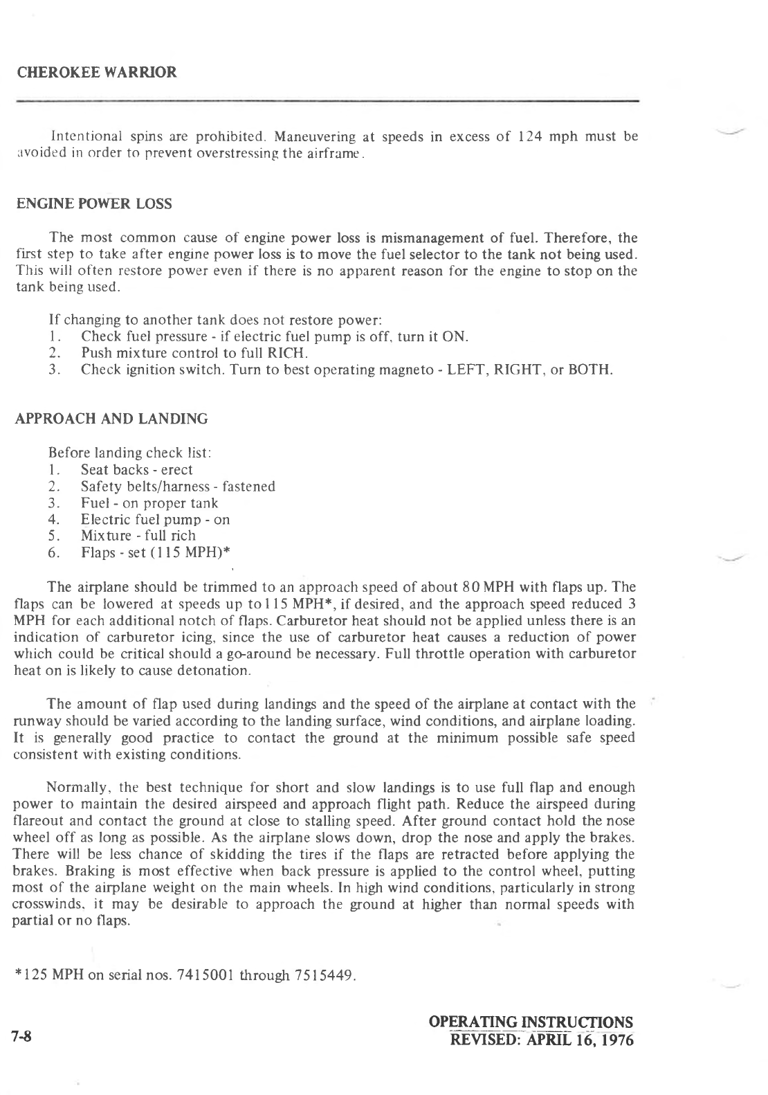
CHEROKEE
WARRIOR
Intentional spins
are prohibited. Maneuvering
at speeds in excess of 124 mph must be
luvoided
in
order
to prevent
overstressing
the airframe.
ENGINE POWER LOSS
The most common cause
of engine
power loss is mismanagement of fuel. Therefore, the
flrst step
to take after engrne
power
loss
is to move
the fuel selector to the tank not being used.
This rvill often restore
power even if there is no apparent reason for the engine
to stop
on the
tank being used.
If changing to another tank does not restore
power:
I . Check fuel
pressure
- if electric
fuel
pump is
off, turn it ON.
2. Push
mixture control to full RICH.
3. Check ignition switch. Turn to best
operating magneto
- LEFT, RIGHT, or BOTH.
APPROACH AND LANDING
Before
landing check list:
l. Seat backs
-
erect
2. Safety belts/harness
- fastened
3. Fuel
- on
proper
tank
4. Electric fuel
pump - on
5. Mixture -
full rich
6. Flaps
-
set
(
I l5 MPH)*,
The airplane should be trimmed to an
approach speed
of about
80MPH with flaps up.
The
flaps can be lowered at speeds
up tol l5 MPH*, if desired,
and the approach speed reduced
3
MPH for each
additional notch of flaps. Carburetor heat should not be applied unless there
is an
indication of carburetor
icing, since
the use of carburetor heat causes
a reduction of power
which could be critical should a
goaround be
necessary.
Full throttle operation
with carburetor
heat
on is likely to cause detonation.
The amount of flap used during landings and the
speed of the airplane at contact
with the
runway
should
be
varied
according to the landing surface, wind conditions,
and airplane
loading.
It is generally good practice to contact the ground at the minimum possible
safe speed
consistent with existing conditions.
Normally, the best technique
for short and slow landings is to use full flap and enough
power to maintain the desired airspeed and approach flight path. Reduce the airspeed
during
flareout and contact the ground
at close to stalling speed. After ground
contact hold the nose
wheel
off as long as
possible.
As the airplane slows
down, drop the nose and apply the
brakes.
There will be less chance of skidding the tires if the flaps are retracted
before applying the
brakes.
Braking is most effective when back
pressure
is applied to the control wheel,
putting
most of the airplane
weight on the main wheels.
In high
wind conditions,
particularly
in strong
crosswinds.
it may be desirable to approach the ground at higher than normal speeds
with
partial
or no flaps.
*125
MPH
on serial nos. 7415001
throush 7515449.
OPERATING
INSTRUCTIONS
nrvtsnu AP-m[
t6, tg76
7A
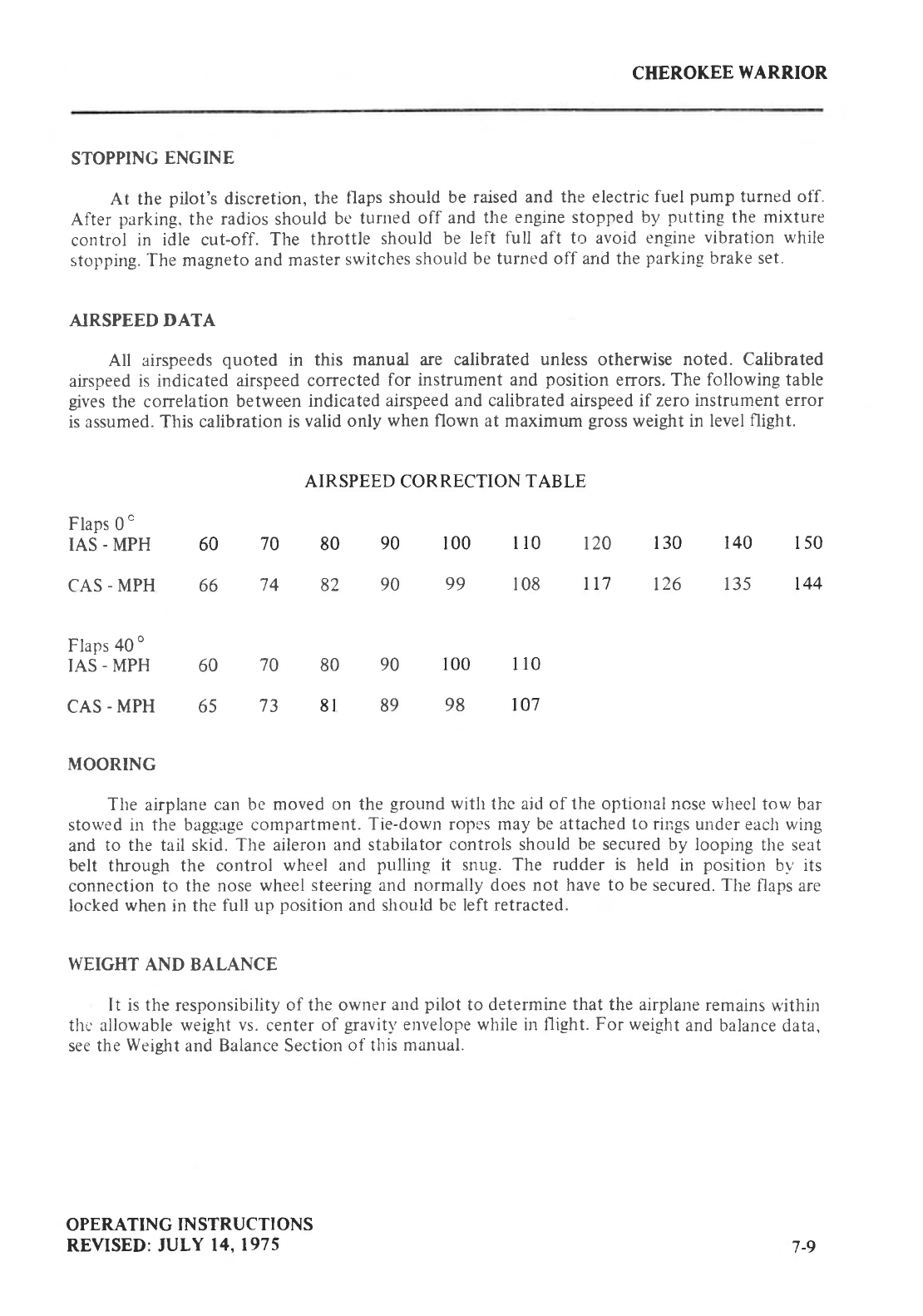
CHEROKEE
WARRIOR
STOPPING
ENGINE
At the pilot's discretion,
the flaps should be raised
and the electric
fuel pump turned off.
After parking.
the
radios
should
be
turned off and the
engine stopped by putting
the mixture
control in idle cut-off. The throttle should be left full aft to avoid engine
vibration while
stopping.
-fhe
magneto
and master
switches
should
be turned off arrd the
parking
brake set.
AIRSPEED DATA
All airspeeds
quoted in this manual are calibrated
unless
otherwise noted. Calibrated
airspeed
is indicated
airspeed corrected
for instrument and position errors. The following table
gives
the correlation
between
indicated
airspeed and calibrated airspeed if zero instrument
error
is assumed.
This calibration is
valid only when
flown at maximum gross
weight in level
flight.
AIRSPEED CORRECTION
TABLE
Flaps
0
"
IAS
-
MPH
CAS
- MPH
Flaps
40
o
IAS
-
MPH
CAS
- MPH
135t26lt7108
99
82
66
110
80
t0798
89
8l
65
80
60 70
74
70
73
90
90
90
150
140
130t2Qr10
r00
t44
60 100
MOORING
The airplane
can be moved on the
ground
with thc ajd of the optiorral nose whecl
tow bar
stowed in the baggage compartment.
Tie-down ropi-s may be
attached to rings
under each wing
and to the tail skid. The aileron and stabilator
controls should
be
secured by looping
the seat
belt through the control wheel and pulling it snug. The rudder is held in position by' its
connection to the nose
wheel steeriug and normally does
not have to be
secured. The
flaps are
locked
when
in the
full up position
and should
be left retracted.
WEIGHT AND BALANCE
It is the
responsibility
of the owner
and
pilot to determine
that
the airplane
remains
within
thc allowable
weight vs.
center
of gravitl'
etrvelope while in flight.
For weight
and
balance data,
see the
Weieht
and Balance Section
of this
manual.
OPERATING
IN
STRUCTI
ONS
REVISED: JULY
14.1975 7-9
CHEROKEE
WARRIOR
EMERGEN CY LOCATOR TRANST{ITTER*
The Emergency
Locator Transmitter
(ELT) when installed,
is located
in the aft portion of
thc fuselage
just below the stabilator
leading
edge and is
accessible
through a
plate
on the
right
side
of thi fuselage.
(On
aircraft
manufactured
prior
to mid-1975.
this
plate
is retained
by three
stcel Phillips
head screws.
On aircraft
manufactttred
lrom mid-1975 and on, this plate is
.rttached
with three
slottecl-head
nylon screws
for ease of removal;these
screws
may
be readily
rcmoved
with a variety
of common
items
such as
a dime, a key. a
knife blade.
etc.
If there are
po tools
available
in iur
emergency
the screw
heads
may be broken
off by any means.)
The ELT
is an emergency
locator
transmitter
which
meets
the requirements
of FAR 91.52. The
unit operates
on a self-contained
batter-v.'.
The replacement
date as
required
by
FAA regulations
is marked on the transmitter
label.
The
batter!'
should
also
be
replaced
if the transmitter
has
been
used in an
emergencl situation
or if
accumulated
test time exceeds
one
hour.
The unit is equipped
with
a
portable
antenna
to allou
the
locator to be
removed
from the airplane
in case
of an
emergencv and used
as
a
portable signal
transmltter.
On the unit itself
is a
three
position
selector
switch
placarded "OFF," "ARM," "ON." The
"ARM" position is provided to set
the unit to the automatic
position so that it will transmit
only after impact and will continue
to transmit until the battery is drained to depletion
or until
the switch is manually
moved to the
"OFF" position.
The "ARM" position
is
selected
when the
transmitter
is installed
at the factory and the switch should
remain in that position
whenever
the r.rnit is installed
in the airplane.
The "ON" position is provided
so the
unit can be
used
as a
portable
transmitter or in the event the automatic
feature was not triggered by impact or to
periodically
test
the function of the
transmitter.
Select
the "OFF" position when changing
the battery, when rearming the unit if it has
been activated
for anv
reason.
or to discontinue
transmission.
NOTE
If the switch has been placed in the "ON" position for any
reason,
the "OFF" position has to be selected
before
selecting
"ARM." If "ARM" is selected directly
from the "ON" position
the
unit will continue
to transmit
in the
"ARM" position.
A pilot's remote
switch,
located
on the
left side
panel,
is
provided
to allow the
transmitter
be controlled
from inside
the cabin.
l. On some
models
the pilot's
remote
switch
has three
positions
and is
placarded
"ON,"
"AUTO/ARM," and "OFF/RESET." T|e switch is normally left in the
"AUTO/ARI\,I" position. To turn the transmitter
off. move
the switch momentarily
to the
"OFFi
RESET"
position.
The
aircraft
master
switclt
mttst be
'rON" to turn the
transmitter "OFF." To activate
the transmitter
for tests
or other reasons.
move
the
switch upward to the "ON" position and leave it in that position as long as
transmission
is desired.
On other models
the pilot's renrote switch has two posittons
artd is placarded
"ON/RESET" and
"ARM (NORI\IAL
POSITION)."
The
switch
is trorntally left in the
down or "ARNI" position.
To turn the transmitter
off. move tlte switch to the
"ON/RESET" position
for one second
then
return
it to the "ARI\'{"
position.
To
-)
+Optional
equipnrent
OPERATING INSTRUCTIONS
REVIStID:
APRll.
6. tgig
7-10
CHEROKEE WARRIOR
activate
the transmitter
for tests
or other reasons,
move the switch upward to the
"ON/RESET" position
and leave
it in that position
as
long
as
transmission
is
desired.
The locator
should
be checked
during the ground
check
to make
certain the unit has not
been accidentally
activated.
Check by tuning a radio receiver
to 121.5
MHz. If there is an
oscillating
sound, the locator
may have
been
activated
and should
be turned
off immediately.
Reset
to the "ARM" position
and
check
again to insure
against
outside
interference.
NOTE
If for any reason
a test transmission
is necessary,
the operator
must first obtain permission from a local FAA/FCC
representative
(or other
applicable
Authority).
Test
transmission
should
be kept
to a minimal
duration.
OPERATING
IN
STRUCTIONS
REVISED:
JULY
20.1976 7
-ll

IIPERATI}IG TIPS
Operating
Tips 8-l
8-i
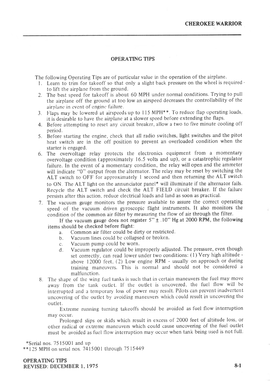
CHEROKEE
WARRIOR
OPERATING TIPS
The following
Operating
Tips are of particular
value in the operation
of the airplane.
l. Learn to trim for takeoff so that only a slight
back
pressure
on the
wheel is required
'
to lift the airplane
from the
ground.
2. The best speed
for takeoff is about 60 MPH under
normal conditions.
Trying to pull
the airplane
off the ground
at too low an airspeed
decreases
the controllability
of the
airplanc
in cvcnt of
enginc
failure.
3. t laps
may bg
lowered at airspccds
up
to I l5 MPH**. To reduce
flap
operating
loads,
it is desirable
to have the
airplane
at a slower
speed
before
extending
the flaps.
4. Before attempting
to reset
any circuit breaker,
allow
a two to five
minute
cooling
off
period.
5. Before
starting
the engine, check
that all radio switches,
light switches
and the
pitot
heat switch are in the off position to prevent
an overloaded
condition when the
starter
is
engaged.
6. The overuoltage
relay protects the electronics equipment from a momentary
overvoltage condition
(approximately 16.5
volts and up), or a catastrophic
regulator
failure.
In the event
of a momentary condition, the relay
will open
and the
ammeter
will indicate
"0" output from the alternator.
The relay
may be reset
by switching
the
ALT switch to OFF for approximately
I second and then returning
the
ALT switch
to ON. The ALT light
on the annunciator
panel*
will illuminate
if the
alternator
fails.
Recycle the ALT switch and check the ALT FIELD circuit breaker.
If the failure
persists
after
this action,
reduce
electrical loads and
land as soon
as
practical.
7
. The vacuum gauge
monitors the pressure
available
to assure
the correct operating
speed of the vacuum driven gyroscopic
flight instruments.
It also monitors the
condition
of the
common
air
filter by measuring
the
flow of air through
the
filter.
If the vacuum gauge
does
not register
5" t .10" Hg at 2000 RPM, the following
items
should be checked
before
flight:
a. Common
air
filter could
be dirty or restricted.
b. Vacuum lines could
be collapsed
or broken.
c. Vacuum
pump
could
be worn.
d. Vacuum regulator
could
be improperly
adjusted.
The
pressure,
even
though
set correctly,
can read
lower under
two conditions:
(
I
) Very high altitude
-
above 12000 feet, (2) Low engine
RPM - usually
on approach
or during
training maneLlvers.
This is normal and should not be considered
a
malfunction.
8. The shape
of the wing fuel tanks
is such that
in certain
maneuvers
the fuel may move
away from the tank outlet. lf the outlet is uncovered,
the fuel flow will be
interrupted
and a temporary
loss of power may result.
Pilots can
prevent
inadvertent
uncovering
of the outlet by avoiding
maneuven
which could
result in uncovering
the
outlet.
Extreme mnning turning takeoffs
should be avoided
as
fuel flow intemrption
may occur.
Prolonged slips
or skids
which result
in excess
of 2000 feet of altitude
loss, or
other radical or extreme
maneuvers
which could cause
uncovering
of the fuel outlet
must be avoided
as
fuel flow interruption
may occur
when tank being
used is
not full.
*Serial
nos.
75 15001
and
up
x*125
MPH
on
serial
nos.
7415001
tluough
7515449
OPERATING
TIPS
REVISED:
DECEMBER
l, 1975 8-l
CHEROKEE
WARRIOR
9.
10.
Anti-collision lights should
not be operating
when flying through overcast and clouds,
since reflected light can produce spacial disorientation. Do not operate
strobe lights
when taxiing in the vicinity of other aircraft.
The rudder pedals are suspended
from a torque tube which extends across
the
fuselage. The pitot should
become
familiar with the proper
positioning
of his
feet on
the rudder
pedals
so as to avoid interference with the torque tube when moving the
rudder pedals
or operating the toe brakes.
In an effort to avoid accidents,
pilots should obtain and study the safety related
information made available in FAA publications such as regulations, advisory
circulars, Aviation News, AIM and safety
aids.
During letdown and low power flight operations, it may be necessary to lean because
of excessively rich mixture. Always
go
to full rich prior to landing sequence.
When leaning, careful observation of the temperature instruments should be
practiced.
When alternate fuels are used, the engine should be run up to 1200 RPM for one
minute
prior to shutdown
to clean out any
unburned fuel.
OPERATING TIPS
REVISED:
APRJL
t6,1976
I l.
t2.
13.
t4.
8-2
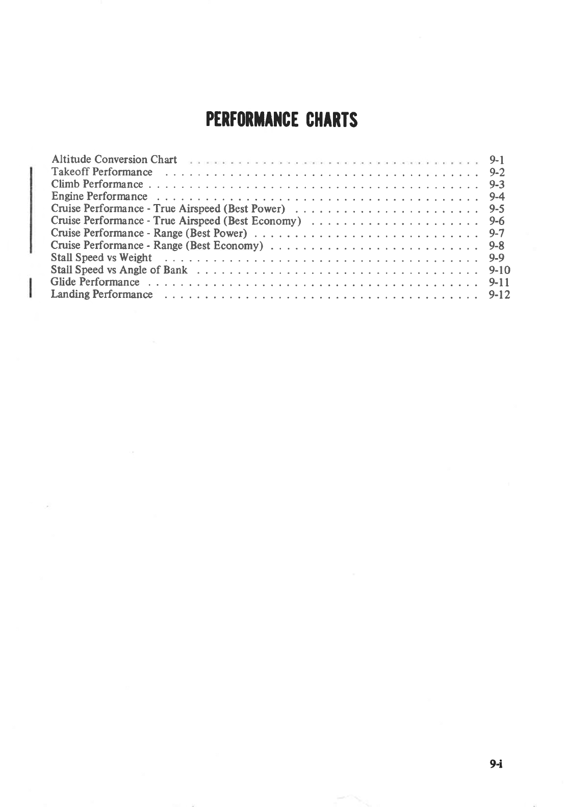
PERTI|RTA]ICE
CHARTS
Altitude Conversion Chart
Takeoff Performance
Climb Performance
Engine
Performance
Cruise Performance
- True Airspeed
(Best
Power)
Cruise Performance
- True Airspeed
(Best
Economy)
Cruise Performance
- Range
(Best
Power) . .
Cruise Performance
- Range
(Best
Economy) .
Stall Speed vs
Weight
Stall Speed vs
Angle of Bank
Glide Perforrnance
Landing Performance
9-l
9-2
9-3
9-4
9-5
9-6
9-7
9-8
9-9
9-10
9-l
I
9-t2
9-i
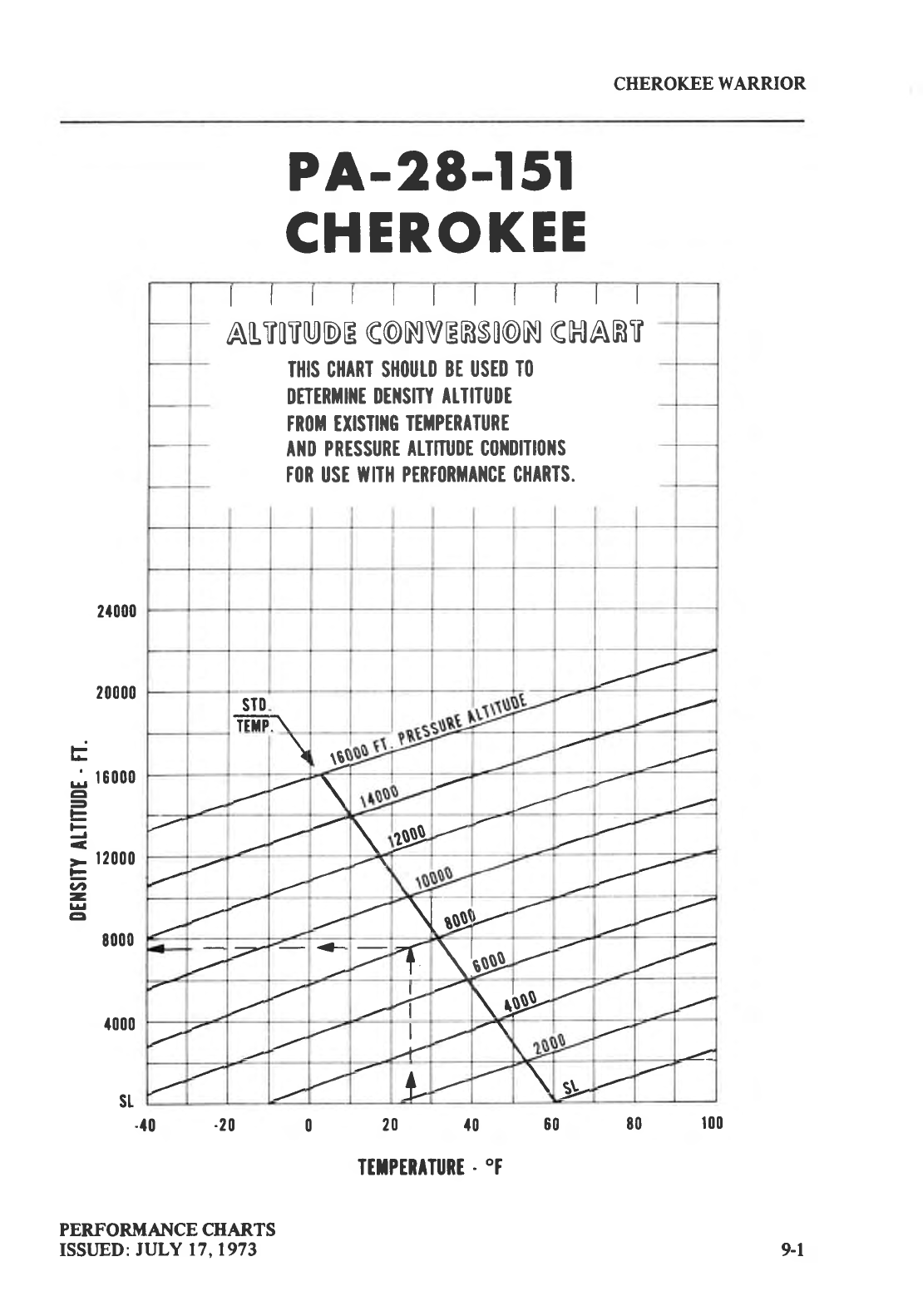
CHEROKEE
WARRIOR
PA-28-l 5l
CHEROKEE
lllllllllll
ALTOTUDE
G@NVERSO@N
CHAR]I
THIS CHART SH(lUTll
BE USED
T(l
DTIERTI]IT
IIE]ISITY
AI.IIIUDE
TR(IH TXISTI]IG
IETPTRATURT
A]ID PRESSURE
AIT]TUIIE C(I}IIIITI(I]IS
T(lR
USE
UIIIH PIRT(IRiIAIICE
CHARTS.
sI0
TiiiF\
\q
\
\4D
\uE
;,- +- =T\lue
+\40-
I
-L
L\-$-
-f0 -20 0 20 f0 00 80 100
ITTPERITURE.
'T
PERFORMAI{CE CHARTS
ISSI.JED: JULY 17,1973
2{000
20000
F
; r6000
cl
E
F
r- 12000
=
vt
-
lrl
EI
8000
{000
st
9-1
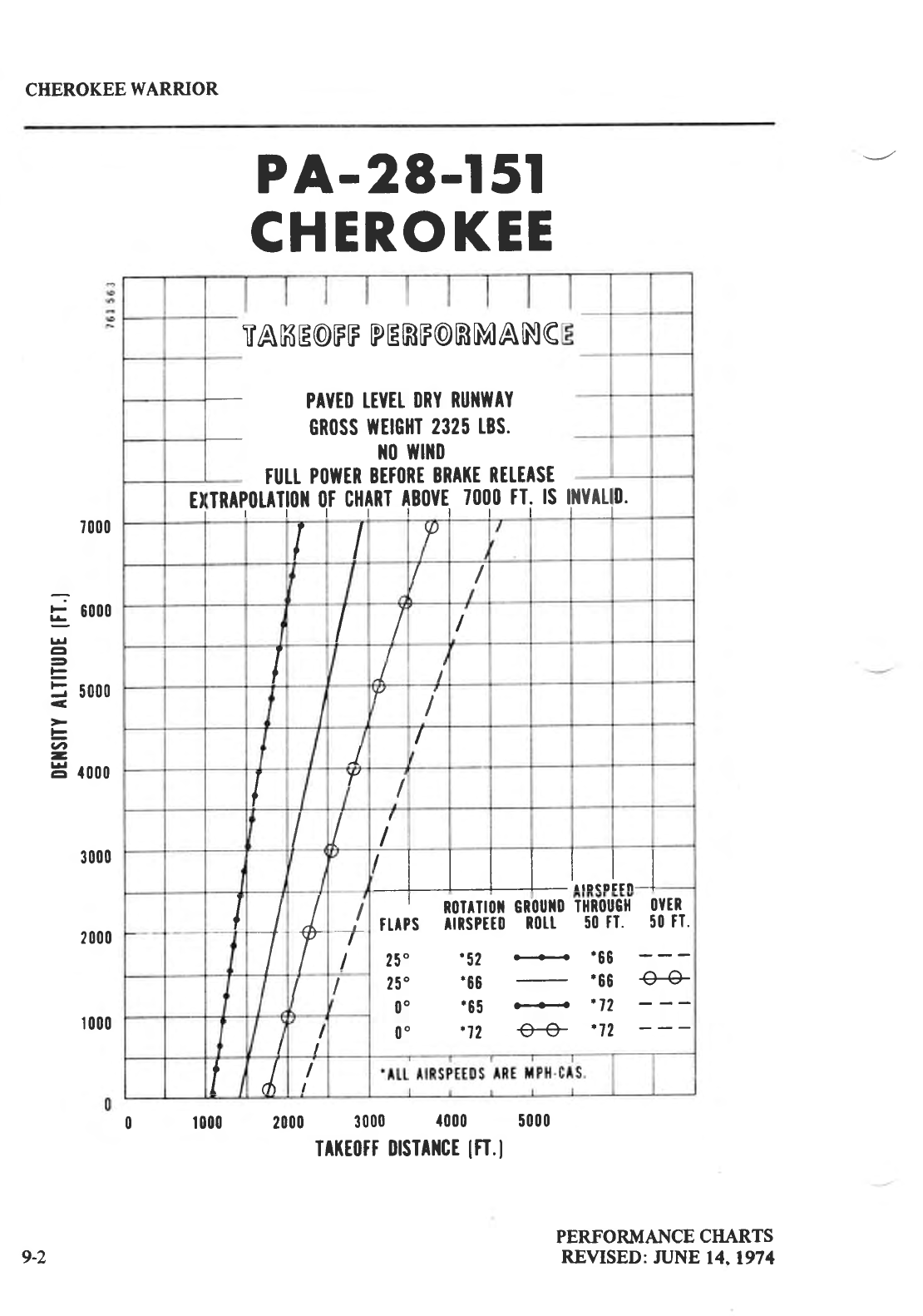
CHEROKEE
WARRIOR
PA-28-l 5l
CHEROKEE
7000
E 6000
g.l
EI
=
5 rooo
<
>
ts
aaa
-
H rooo
3 000
2000
r
000
0 1000 2000 3000 f000 5000
TAr(rorf
DFIrilcE
lfT.l
PERFORMANCE
CIIARTS
REVISED:
ruNE 14,1974
TAKE@FF
PERFORMANG
PAYTD
TEYEI
IIRY RUNITAY
GR(ISS
YIEIGHT
2325
tBS.
ll0 YflllD
fUtt P(IITER
BET(IRT
BRTKT
RETEASE
NYAtI
tl
TRAP(ILATI(I}I
OT
CHART
AB(IYT
TOOO
TI. IS
rlllllll
E} ll.
Il?
//
III
II
JI
YI
)I
IYI
lII
,lllll.,"."t,,_J
I-t
t'II
fttPs
25"
25'
0"
00
R0lrTl(lil
Gn0ull|l
illR(}uGll
0YtR
ilRsPttll R0LL 50
rT. 50
tT.
.52 .- '66
'68 '66 €4
'65 .--<--o ,lz
'72 € '12
I
I
II
II
I
tJI
I
9-2
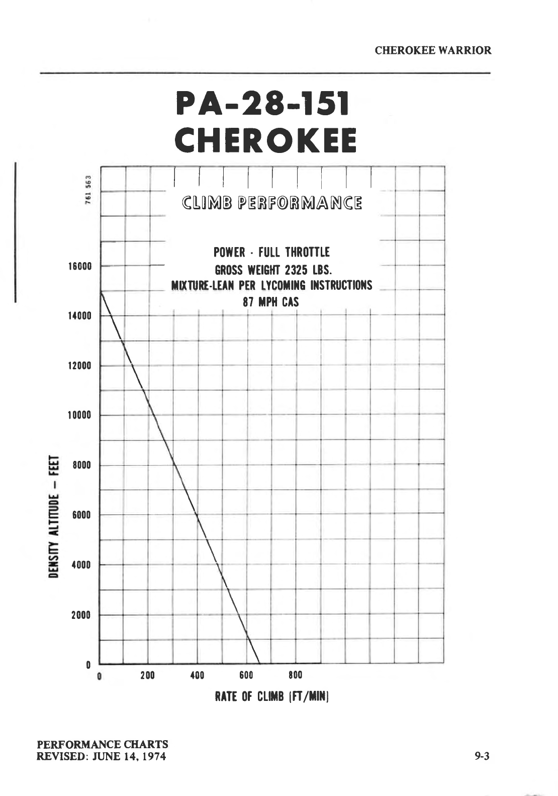
CHEROKEE
WARRIOR
ttttll|tl
GIOMB
PERF@RMANGE
P(IIYTR
. TULT THR(IIITT
cn(lss WETGHI 2325
rBS.
ruruRE.rrrlr
prR
r.ycoil]tc tltslnucll(llls
\87
tPil
CtS
\
\
\
\
\
\
\
\
\
\
| 6000
I f000
| 2000
r 0000
8000
6000
t000
2000
0
PERFORJI{ANCE
CHARTS
REVISED:
JLJNE 14,1974
200
PA-28-l 5l
CHEROKEE
f00 600 t00
RrTr 0t cutB
ln/nHl
9-3
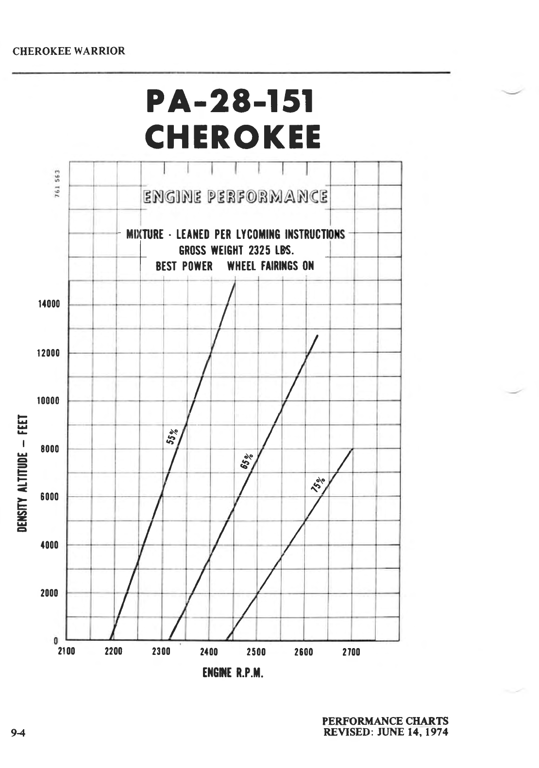
CHEROKEE
WARRIOR
rf000
r 2000
PA-28-l 5l
CHEROKEE
2100 2200 2300 2{00 2500 2600 2700
ilGilT R.P.T.
F
Ll
ld
lr
I
' 8000
r!
cl
E
F
vt
-
Ll
cr
{000
r 0000
2000
PERFOR"IT{ANCE
CHARTS
REVISED: JUNE 14,1974
- Ht)IURE
. IEAIIEII PER tYCIIHI]IG IIISTRUCTI
L 6R0SS
WflGHT 2325
tN.
I BEST
P0WIR fVHEEt
tAlRl]lCS 011
I
I
//
I/
I/
I/
s'-/ /
/N
8r /
I
/
o\o
,s)/
II
f
/
/ / /
I
I
/
/
///
/
f
/
I
/t
/
94
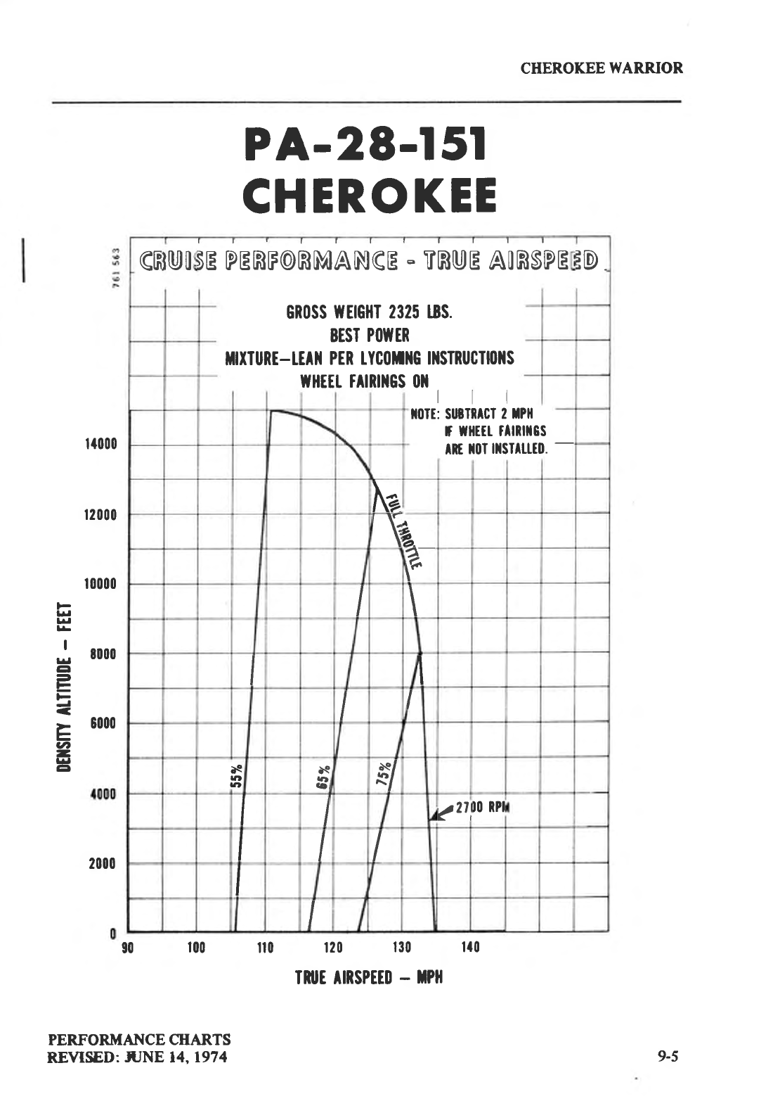
CHEROKEE
WARRIOR
PA-28-l 5l
CHEROKEE
r{000
t2000
t 0000
F
ltl
l^l
l!
I
; 1000
a
=
F
=
ts 8000
0
-
lrl
EI
2000
90 100 il|| r20 130 lf 0
IruE TNSPffD
. TPII
PERFORMAT{CE
CIIARTS
REVISED:.HJNE
14,1974
GF
tu0
'E PERF@RMANGE
- TRUE AORSPE
GRoSS
rfErGllT 2325 18S.
EEST
P(IU'ER
mxlunt-tEAil
PtR tYc(ltltc tllsTnucll0ils
wHttt tAtRmGs
011
rtl
tl0lt: SUBIIICI
2 IPll
r tflEtt illRlt8s
Am
x|ll
lxsltttfll.
-
ID
Na
T),..
f".--
I\
I
lQ
rat
|t'
N
tat
aal v?2tl
IO RPI
Il
I
9-5
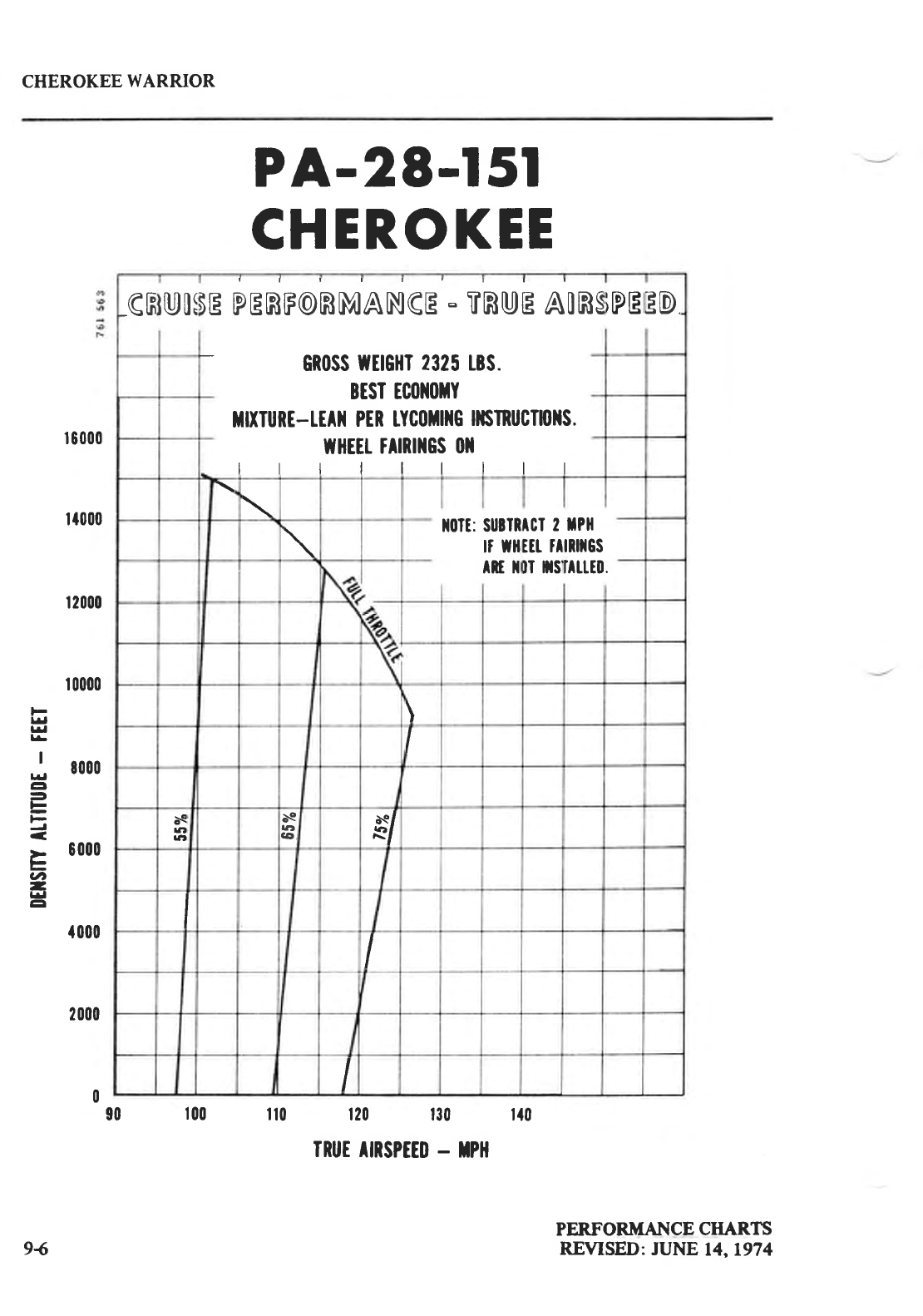
CHEROKEE
WARRIOR
r
E000
r{000
r2000
r
0000
F
lrl
l^a
l!
I
; 8000
EI
=
h
F
]-
at,
-
Ll
EI
{000
2000
0
PA-28-l 5l
CHEROKEE
PERFORMANCE
CHARTS
REVISED:
JUNE
t4,1974
-GF
tu0t
'EPERF@RMANGE
- TRUE
AORS
GR(ISS
WETCHI
2325
tBS.
BtsI tc(lll0tY
mxTuRt-[rAlr
PtR tYc0illlc
[6nucTl{11{s.
wHEtt
tAlnlllcs
0ll
rttlltll
iPE
ED
lt|llt: SUETR
rr tl
Amx
ACI 2
En
rl
DI
tls'
TPII
tRttGs
n|'tt0.
\
I
dS
rat
aal
N
ttit
CO $/
I
I
90 100 il(l 120 t30 tf|l
94
TRUI
IIRSPT$
- NPH
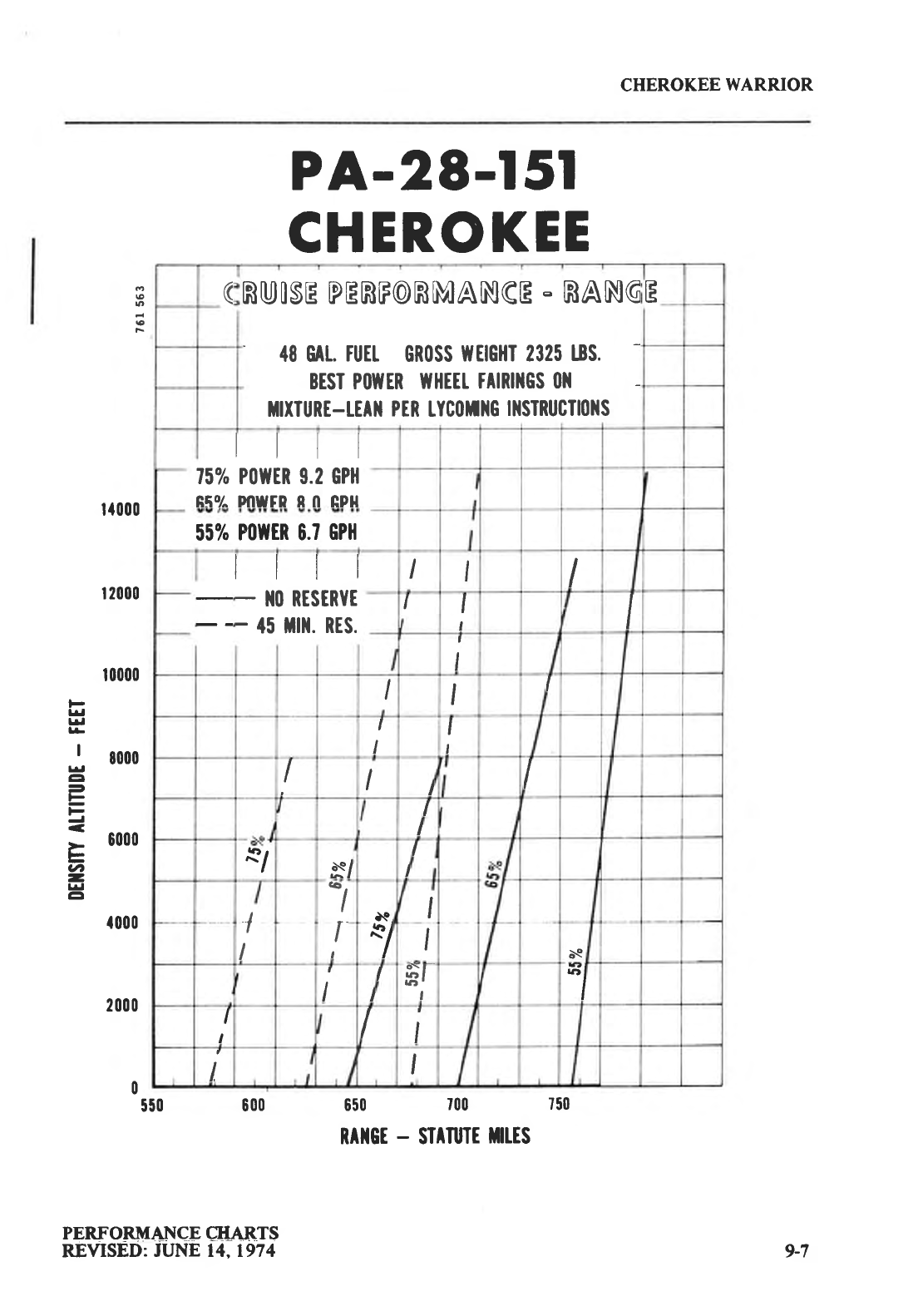
CHEROKEE
WARRIOR
I
n
€
F
F
lrl
f.l
ll
I
trl
tr
l-
=
ut
-
ttl
EI
rf000
r 2000
r 0000
8000
6000
f000
2000
0E00
550
PA-28-l 5l
CHEROKEE
650 700 750
RA]IGE
- SIIruTE
iltES
(RUISE PERF@RMANGE
- RANG
18 GAt.
TUEI
GR(ISS
IYEIGHI 2325
I8S.
BESI P(IUTER
UIHEET
TAIRI]IGS
(}}I
ilxIuRE-rEAll
PER
tYC0illG
lllSIRUCIl0llS
E
rttt
75% P(lrtER 9.2 GPH
Rqo/^ F{lwFP Rn npH
55%
POITTR 6.7
GPl|
llll
- II(l RESERYE
- {5 illt. RES.
II
II
t
I
III
,
II
t
IIII
I
I
*1 x/ I
I
I
I
'l
t.Q,
*l I
IbQ
II
Ih=t
,
-/
I
III
LI
PERF ORMAfjCE
EIIA]RTS
REVISED:
JUNE 14.1974 9-7
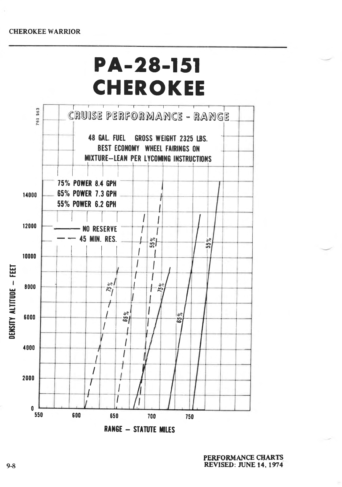
CHEROKEE WARRJOR
PA-29-l 5l
CHEROKEE
t{000
| 2000
|
0000
Ll
lrl
lr
I
; 8000
GI
=
E
> 6000
l-
tl
-
l*l
EI
f000
2000
0550 600 650 700 t50
RAilGT
- STITUTE
TIttS
PEMORMAI{CE
CI-IARTS
REVISED:
JUNE
14.1974
I
3RUISE
PERF@RMANGE
- RANG
fi eil ruil GR0SS
WHCHT
2325 18S.
BEST rc0lt0rY
WHtEt
FAnil0S
011
ilxIURt-tEril
pER
tyc0tilG
tltsTRucTt(l]ts
llllttrrl
iE_
rttl
tJh
65%
Sllo
rutHt u.{ tint
P(IIITR
7.3
GPH
POU'ER
6.2 GPH I
I
lttl
- lr0
RrstRYE
- f5
ilil. Rts.
tttr
lII
I
II
$r
I
ld'e
Ii/
III
o\
o/
I
lfl
I9t I
lx
,l 'l I
I
INI*/
I6/
II
I*r
II
II I
,
III
Iil
I
IIIt I
lt
9-8
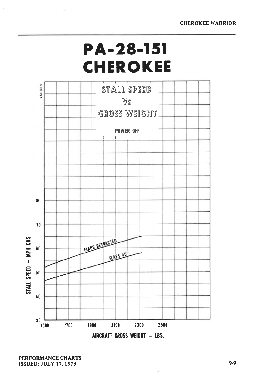
CHEROKEE
WARRJOR
80
PA-28-l 5l
CHER.OKEE
1500 n00 1900 2100 2300 2500
TIRCRTTT GRI|SS
TTTIGHT
- tBS.
aa,
CJ
-60
a.
-
I
EI
!+l Grt
E iru
v,
v, 10
30
PERFORMANCE
CHARTS
ISSI.JED:
JULY 17,1973
STALL
SPEED
VS
GR@SS
WEIGHT
P0lvtR
(lFt
rttll
9-9
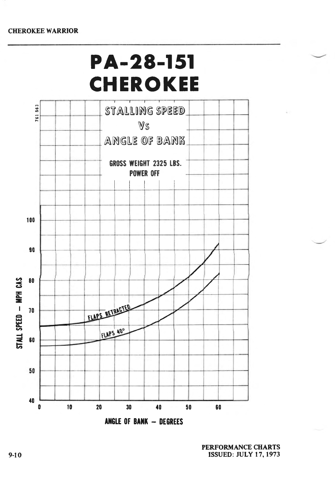
CHEROKEE
WARRIOR
o
6
€
PA-28-l 5l
CHEROKEE
0r02030f05060
ATGTE
OT BITT
- OEORTIS
100
g0
280
CJ
-
L
-llo
a
lrl
t*l
G
v,
=oo
a
PERFORMANCE CHARTS
ISSUED:
JULY 17,1973
STALLONG
SPEED
Vs
ANGLE @F
BANK
GR(ISS
U|HGHT 2325
tBS.
P(lutER
(|ft
trrtl
t
/
,/
oifl
$u*si\
9-10
{0
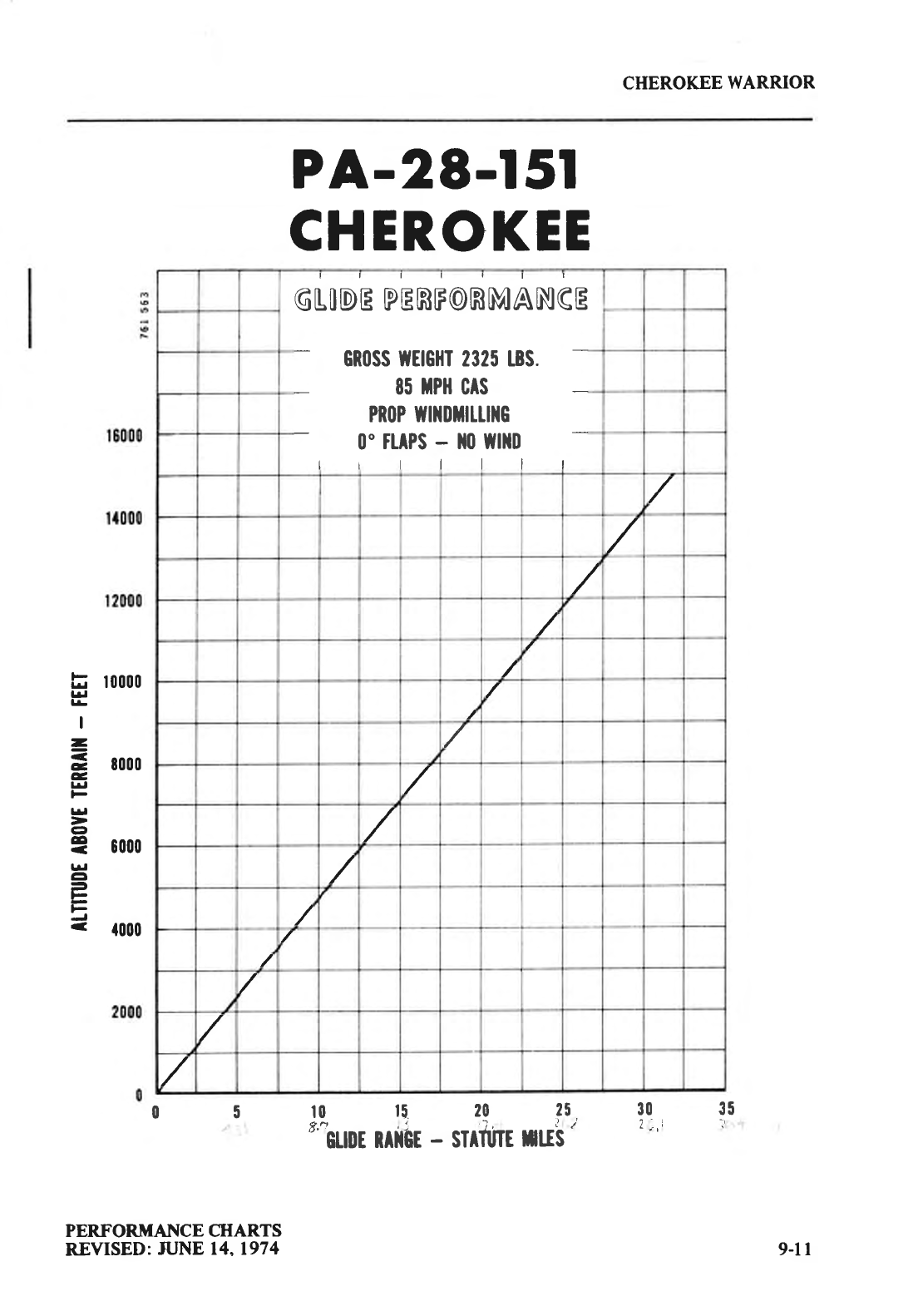
CHEROKEE
WARRIOR
tr roooo
td
l!
I
=
= tooo
e
l^l
F
lrl
ct
= oooo
td
tl
=
F
PA-28-l 5l
CHEROKEE
GLODE
PERFORMANGE
GR|ISS ftEtGHI 2325 t3S.
85 tPil CrS
PR(IP fftlilriltultc
0"
TLAPS
- 110 Wlllll
lrlllll
/
/
/
/
/
/
/
/
/
/
/
/
/
0 5 l0 15 20 25 30 35
f,-n
GtIDt
RITSI
- SITTUTE
HUS
PERFORMAI{CE CHARTS
REVISED:
JUNE 14,1974 9-11
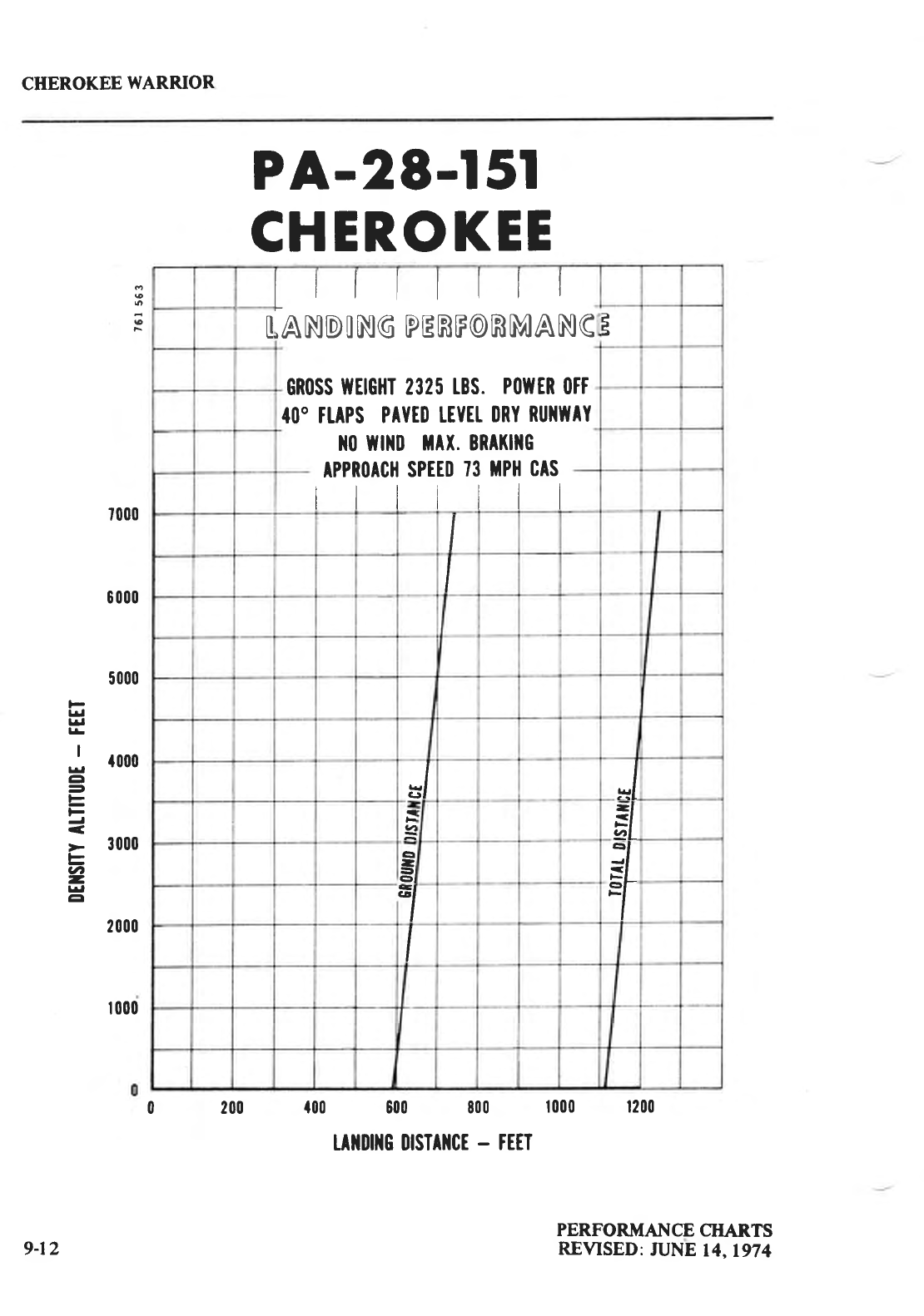
CHEROKEE
WARRIOR
I
o
€
F
PA-28-l 5l
CHEROKEE
0 200 f00 600 800 t000 1200
ulrDiltc llrsTAlrcE
- FEIT
7000
6 000
5000
l-
lrl
f.l
l!
I
; {000
ct
=
E
F
F
U'
-
frl
tl
2000
| 000
9-12 PERFORMANCE
CHARTS
REVISED:
JUNE
14,1974
Llllllll
,ANDING
PERF@RMANG
GR0SS
tfEtGHT 2325
tBS. P(llltR
(ltt
40" TIAPS
PAYED
TEYTI
IIRY
RUI{IIAY
1t0 Tilltll
tAx. BRAKIIIG
APPR(IACH
SPTED
73 TPH
CAS
lllllll
It
EI =l
{
ul EI
G
-
-i
el +
1
HA}IDIIIIG A]ID SERYICI]IG
Ground
Handling
Towing
Taxiing
Parking
Mooring
Cleaning
Cleaning
Engine
Compartment
Cleaning
Landing Gear .
Cleaning
Exterior Surfaces
Cleaning
Windshield
and
Windows
Cleaning Headliner, Side
Panels
and Seats
Cleaning Carpets
Power
Plant Induction
Air Filter
Removal
of Induction Air Filter
Installation of Induction Air Filter
Brake
Service
Landing Gear Service
Propeller
Service l0-8
Oil
Requirements l0-8
Fuel System l0-9
Servicing
Fuel
System l0-9
Fuel Requirements l0-9
Filling Fuel Tanks I
GlO
Draining Fuel
Valves
and
Lines I GlO
Draining
Fuel
System I Gl I
Tire Inflation I Gl I
Battery Service l0-l I
Winterization l0-l I
Facts
You
Should Know lO-12
Preventive Maintenance 10-14
Required
Service
and lnspection
Periods 10-15
lG,l
lG,l
l0-t
to-2
to-2
l0-3
l0-3
l0-3
l0-4
104
l0-4
l0-5
l0-5
l0-5
l0-5
to-7
to-7
l0-i
CHEROKEE
WARRIOR
HAN DLING AI{D SERVICING
This section contains
information on preventive
maintenance.
Refer to the PA-28-151
Service Manual for further maintenance
procedures.
Any complex repair or modification should
be accomplished
by a Piper
Certified Service Center.
GROUND HANDLING
TOWING
The airplane
may be moved by using the nose
wheel tow bar available
with the
airplane, or by power equipment that will not damage
or cause
excess
strain to the nose
gear
assembly. The tow bar is stowed
in the
baggage compartment.
CAUTION
When towing with power equipment,
do not turn the nose
gear
beyond its turning radius in either direction as this will result
in
damage to the nose
gear
and steering
mechanism.
CAUTION
Do not tow the airplane
when the controls are
secured.
TAXIING
Before attempting to taxi the airplane,
ground personnel
should be instructed and
approved by a qualified person
authorized by the owner. Engine starting and shut-down
procedures
and taxiing techniques
should be covered.
When it is ascertained
that the
propeller
back blast
and taxi areas are clear,
power
should
be
applied to start
the taxi roll,
and the
following
checks
should be
performed:
l. Tlxi forwurd u
I'cw l'cct
and apply
tlrc brakcs
to dctcrrninc
tltcir
cl'lcctivcncss.
b. While
taxiing,
make slight turns
to ascertain the
effectiveness
of the
steering.
c. Observe
wing clearances
when taxiing near
buildings
or other stationary
objects.
If possible,
station an observer outside
to guide
the
airplane.
d. When
taxiing on uneven
ground, avoid holes
and ruts.
e. Do not operate
the engine at high
RPM
when running
up or taxiing
over
gSound
containing loose stones,
gravel,
or any loose
material
that might cause
damage
to
the propeller
blades.
HANDLING AND SERVICING
ISSUED: JULY 17.1973 tGr
CTIEROKEE
WARRIOR
PARKING
When parking the airplane, be sure that it is sufficiently protected from adverse
weather conditions and that it presents
no danger
to other aircraft.
When parking the
airplane for any length of time or overnight. it is suggested
that it be moored securely.
a. To park the airplane, head
it into the wind if possible.
b. Set the
parking
brake by pulling
back
on the brake lever and depressing the knob
on the handle. To release the parking
brake,
pull back on the handle until the
catch
disengages;then
allow the handle to swing
forward.
CAUTION
Care should
be exercised when
setting brakes that are overheated
or during cold weather when
accumulated moisture may freeze a
brake.
c. Aileron and stabilator
controls
may be secured with the front seat belt. Wheel
chocks mav be
used
if thev are available.
MOORING
The airplane should be moored for immovability, security, and protection. The
following
procedures
should be
used for the proper
mooring of the airplane:
a. Head
the airplane into the wind, if possible.
b. Retract the flaps.
c. Immobilize the ailerons and stabilator by looping the seat
belt through the
control wheel and
pulling
it snug.
d. Block the
wheels.
e. Secure tie-down ropes to the wing tiedown rings and to the tail skid at
approximately
45 degree angles to the
ground.
When
using
rope of non-synthetic
material, leave
sufficient
slack to avoid
damage to the airplane
should the ropes
contract.
CAUTION
Use bowline knots, square knots,
or locked slip knots.
Do not use
plain
slip
knots.
NOTE
Additional preparations
for high winds include using tie-down
ropes from the landing
gear
forks
and securing the rudder.
f. Install a pitot head cover if one is available. Be sure to remove
the pitot head
cover before flight.
g. Cabin and baggage doors should be locked when the airplane is unattended.
HANDLING AND SERVICING
ISSUED:
ruLY 17,1973
ro2
CIIEROKEE
WARRIOR
CLEANING
CLEANING ENGINE COMPARTMENT
Before
cleaning the engine
compartment,
place
a strip of tape over the magneto
vents
to prevent
any solvent from entering these units.
a. Place
a
large
pan
under
the engine to catch waste.
b. With the engine cowling removed, spray or brush the engine
with solvent or a
mixture of solvent and degreaser.
In order to remove especially
heavy dirt and
grease
deposits, it may be necessary to brush areas
that were
sprayed.
CAUTION
Do not spray
solvent
into the alternator,
vacuum
pump, statter,
or air intakes.
c. Allow the solvent to remain on the engine
from five to ten minutes.
Then rinse
the engine clean
with additional solvent and allow
it to dry.
CAUTION
Do not operate the engine until excess solvent has evaporated
or
otherwise been
removed.
d. Remove the
protective
tape from the magnetos.
e. Lubricate
the
controls,
bearing surfaces, etc.,
in accordance
with the Lubrication
Chart.
CLEANING LANDING GEAR
Before cleaning
the landing gear,
place
a cover
of plastic
or a similar waterproof
material
over the wheel and brake assembly.
a. Place a
pan
under the
gear
to catch
waste.
b. Spray
or brush the gear
area
with solvent or a mixture of solvent and
degreaser.
In order to remove especially heavy dirt and
grease
deposits,
it may be
necessary
to brush areas that were sprayed.
c. Allow the solvent to remain
on the
gear
from five to ten minutes.
Then rinse the
gear
with additional solvent and allow
it to dry.
d. Remove the cover
from the
wheel and remove the
catch
pan.
e. Lubricate the gear
in accordance with the Lubrication Chart.
HANDLING AND SERVICING
ISSUED:
JULY 17,1973 l0'3
CHEROKEE
WARRIOR
CLEANING EXTERIOR
SURFACES
The airplane should
be
washed
with a
mild soap and
water. Harsh
abrasives
or alkaline
soaps or detergents could make scratches
on painted or plastic
surfaces or could cause
corrosion
of metal.
Cover areas
where
cleaning
solution could cause damage. To wash the
airplane,
use the following
procedure:
a. Flush
away loose dirt with water.
b. Apply cleaningsolution with
a spongc, a soft cloth,
or a soft bristle brush.
c. To remove
exhaust
stains, allow the solution to remain on the
surface
longer.
d. To remove
stubborn oil and
grease
stains use
a cloth
dampened
with naphtha.
e. Rinse
all
surfaces
thoroughly.
f. Any good
automotive
wax may be used
to protect
and
preserve painted
surfaces.
Soft cleaning
cloths or a chamois
should be used to prevent
scratches
when
cleaning
or polishing.
A heavier
coating of wax on the leading surfaces
will
reduce the
abrasion
problems
in these areas.
CLEANING WINDSHIELD AND WINDOWS
A certain amount of care is needed to keep
the windows clean
and
unmarred. The
followin
g procedure
is recommended
:
a. Remove
dirt, mud, and other loose
particles
from exterior surlhces
with clean
water.
b. Wash
with mild soap and clean water
or with aircraft
plastic
cleaner.
Use
a
soft
cloth or sponge in a straight back and forth motion. Do not rub harshly.
c. Remove
oil or erease
with a cloth moistened
with kerosene.
CAUTION
Do not use gasoline,
alcohol, benzene, carbon tetrachoride,
thinner, acetone, or window cleaning sprays.
d. After cleaning
plastic
surfaces, apply a thin coat of hard polishing
wax. Rub
lightly with a soft cloth. Do not use a
circular
motion.
e. A severe scratch or mar in plastic
can
be removed
by rubbing out the scratch
with jeweler's
rouge.
Smooth
both sides and apply
wax.
CLEANING HEADLINER, SIDE PANELS
AND SEATS
a. Clean
headliner,
side panels
and seats with a whisk broom, dusting
cloth, or a
vacuum cleaner.
b. Soiled upholstery may be cleaned with a
good upholstery cleaner
suitable
for the
material. Carefully follow the manufacturer's instructions. Avoid soaking or
harsh
rubbing.
CAUTION
Solvent cleanen require adequate ventilation.
HANDLING AND SERVICING
ISSUED:
JULY 17.1973
l(H
CHEROKEE
WAR"R.IOR
CLEANING
CARPETS
To clean
carpets,
first remove loose dirt with a
vacuum
or a
whisk broom.
For soiled
spots and
stubborn
stains use a noninflammable dry cleaning
fluid. Floor carpets
may be
removed
and cleaned
like any
household carpet.
POWER PLANT INDUCTION
AIR FILTER
The wet-type polyurethane
foam air filter must be inspected
at least once every
fifty
hours.
Under extremely
adverse operating conditions,
it may
be necessary
to inspect
the filter
more
frequently. The filter
is
disposable
and
inexpensive
and a spare
should
be
kept on
hand for
a
rapid replacement.
REMOVAL OF INDUCTION
AIR FILTER
The filter is located
in the lower right front of the engine
compartment
and
may be
removed
by the
following
procedure:
a. Open the
right side
of the
engine
cowling.
b. Loosen
each of the
four quarter-turn
fasteners
securing
the
air
filter cover.
c. Separate
the cover
and remove
the filter.
d. Inspect
the filter. If it is excessively dirty or shows
any
damage,
replace
it
immediately.
INSTALLATION
OF
INDUCTION
FILTER
When
replacing
the
filter, install the
filter in the reverse
order
of removal.
HANDLING AND SERVICING
ISSLJED:
JULY 17,1973 lG5
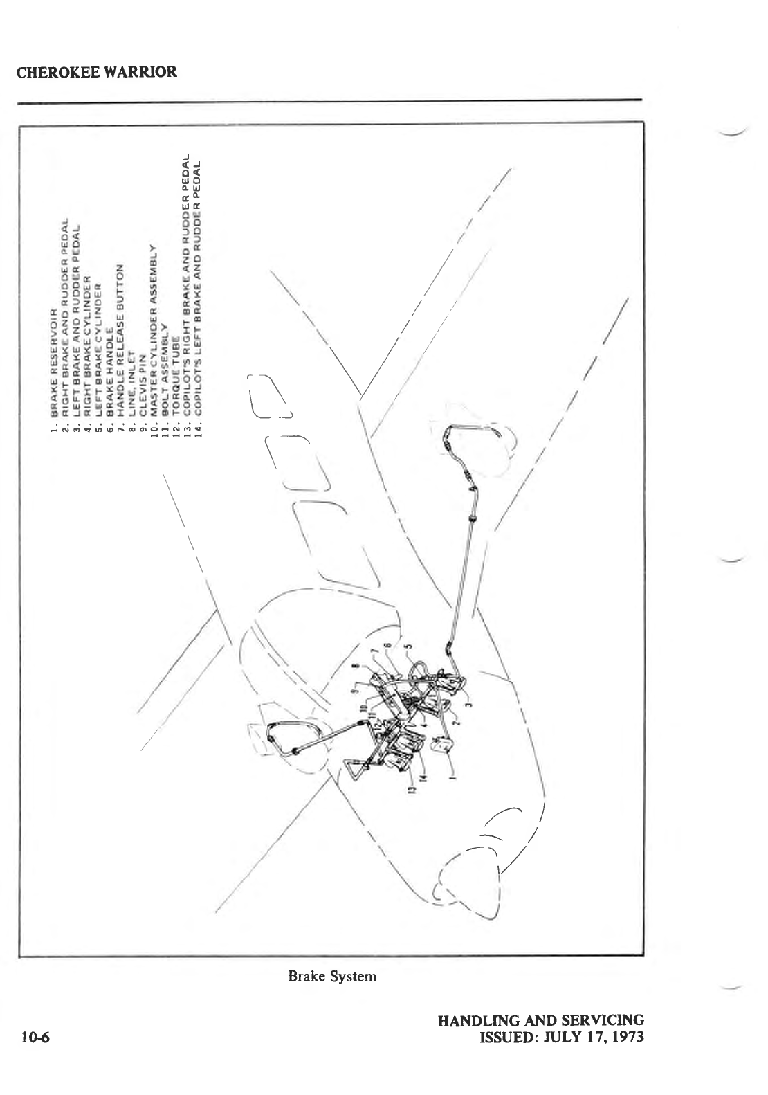
CHEROKEE
WARRIOR
/^l
^r,/
v
\\
\- _--J
r ----\
:\
\\
J
(J
o(
ulO
o trj
a!c
ultr
-NO*OQF6OO-NO9
\
\
Brake
System
HANDLING AT.{D
SERVICING
ISSUED: ruLY 17,1973105
CHEROKEE
WARRIOR
BRAKE SERVICE
The brake system is filled with MIL-H-5606 (peholeum base)
hydraulic brake fluid. The
fluid level
should be checked
periodically
or at each
50 hour inspection
and replenished
when
necessary. The brake reservoir is located on the upper left side of the fire wall in the engine
compartment.
If the
entire system
must be
refilled,
fill with fluid under
pressure
from the brake
end of the system.
This
will eliminate air from the system.
No adjustment of brake clearances
is necessary.
If after extended service
brake blocks
become
excessively
worn,
they
should be
replaced
with new segments.
LANDING GEAR SERVICE
The main landing
gears
use Cleveland 6.00 x 6 wheels, and the nose
gear
carries
a Cleveland
5.00 x 5 wheel.
All three
tires are
4 ply rating,
Type III tires with tubes;
the main
gear
tires are
6.00 x 6 and the
nose
gear
tire is 5.00
x 5.
(See
Tire Inflation, this Section.)
Main wheels
are removed
by taking off the hub cap, pin, axle nut, and the two bolts
holding the brake
segment
in place,
after
which the
wheel
slips
easily
from the axle.
The nose
wheel is
removed
by taking off the axle
nut and
washer
from one side,
sliding
out
the axle rod and plugs,
lightly tapping out the axle tube, and then removing
the wheel and
spacer tubes
from between
the fork. Wheels
are
replaced
by reversing
the
procedure.
Tires
are removed
from the wheels by deflating
the tire, removing
the through
bolts, and
separating
the wheel
halves.
Landing
gear
oleo
struts should
be checked
for proper
strut exposure
and
visible leaks.
The
required
extensions
for the struts under normal static load (empty weight of airplane
plus
full
fuel and oil) are 3.25 inches
for the nose
gear
and 4.50 inches
for the main gear.
If the strut
exposure
is below that required,
it should be determined
whether
air or oil is needed
by first
raising
the airplane
on jacks.
Depress the valve core
to allow air to escape
from the strut housing
chamber. Remove the filler plug and slowly raise
the strut to full compression.
If the fluid is
then visible up to the bottom of the filler plug hole, only proper extension
with air is
required.
If fluid is below the bottom of the filler plug
hole,
oil should
be added.
Replace
the
plug
with the
valve
core
removed.
Then attach a clcar
plastic
hose to the
valve stem
of the
filler
plug
and
submerge
the other end
in a container
of hydraulic
fluid (MlL-H-5606).
Fully compress
and
extend the strut several
times, thus drawing fluid from the container and expelling air. The
torquie link assembly
must be disconnected
to let the strut be extended a minimum of l0
inches.
(The nose gear torque links need not be disconnected.)
DO NOT allow the strut to
extend
beyond l2 inches.
When air bubbles
cease
to flow through
the hose,
fully compress
the
strut, remove the f,rller
plug, and again check the fluid level. When the fluid level is correct,
disconnect
the hose, reinstall
the valve
core,
the filler plug, and the main gear
torque links-
With the fluid in the strut housing at the proper level,
attach a
strut pump to the air valve.
With the airplane
on the ground under normal static load, inflate the oleo strut to the proper
strut exposure.
HANDLING AND SERVICING
ISSLJED: JULY 17,1973 to-7
CIIEROKEE WARRIOR
In jacking the airplane
for landing
gear
or other service, two hydraulic
jacks and a tail stand
should be used. At least 250 pounds
of ballast should be placed
on the tailstand before
jacking
the airplane. The hydraulic jacks
are
placed
under the
jack points on the underside
of the wings,
and the airplane
is
jacked
up until the tail stand can be attached to the tail skid. After attaching
the tail stand and adding
the ballast,
the
jacking can
be continued until the airplane
is at the
desired heieht.
The steering arrns
from the rudder pedals
to the nose
gear
are
adjusted at the rudder pedals
or at the nose wheel by turning in or out the tlrreaded rod end bearings.
Adjustments are
normally made at the forward end of the rods and should be done in such a
way that the
nose
wheel is in line with the fore and aft axis of the airplane
when the rudder pedals
and rudder are
centered. Alignment of the nose wheel
can
be checked
by pushing
the airplane
back and
forth
with the rudder
centered
to determine that the
plane
follows
a
perfectly
straight line.
The turning arc of the nose wheel is 30 degrees
either
side
of center and is factory adjusted
at stops
on the bottom of the
forging. The turning radius of the
nose wheel is l3 feet.
The rudder bar stops should be carefully adjusted so that the rudder
bar reaches
its full
traveljust
after the rudder
hits
its stops.
This
guarantees
that the rudder
will be allowed
to move
through its full travel.
PROPELLER SERVICE
The spinner and backing plate should be cleaned and inspected
for cracks
frequently.
Before each flight the propeller
should be
inspected for nicks, scratches,
or corrosion.
If found,
they should be repaired as soon as
pssible
by a rated mechanic, since
a nick or scratch
causes
an
area of increased
stress which can lead to serious
cracks or the loss of a propeller
tip. The back
face of the blades should be painted when necessary
with flat black paint to retard glare.
To
prevent corrosion, all zurfaces
should be cleaned
and waxed periodically.
OIL REQUIREMENTS
The oil capacity
of the Lycoming O-320-E3D
series engines
is 8 quarts
and
the minimum
safe
quantity is 2 quarts.
It is recommended that the oilbe changed
every 50
hours and sooner
under unfavorable operating conditions. The following grades
are recomrnended
for the
specified tem
peratures
:
Temperafures
Above
60"
F
Between 30' and
90"
F
Between 0" and
70" F
Below l0'F
Single
Viscosity
Grade
SAE 50
SAE 40
SAE
30
SAE
20
Multi-Viscosity
Grade
SAE
40
or SAE 50
SAE
40
SAE 40 or 20W-30
sAE 20W-30
HANDLING AT{D SERVICING
ISSUED:
JULY 17,1973
lo{
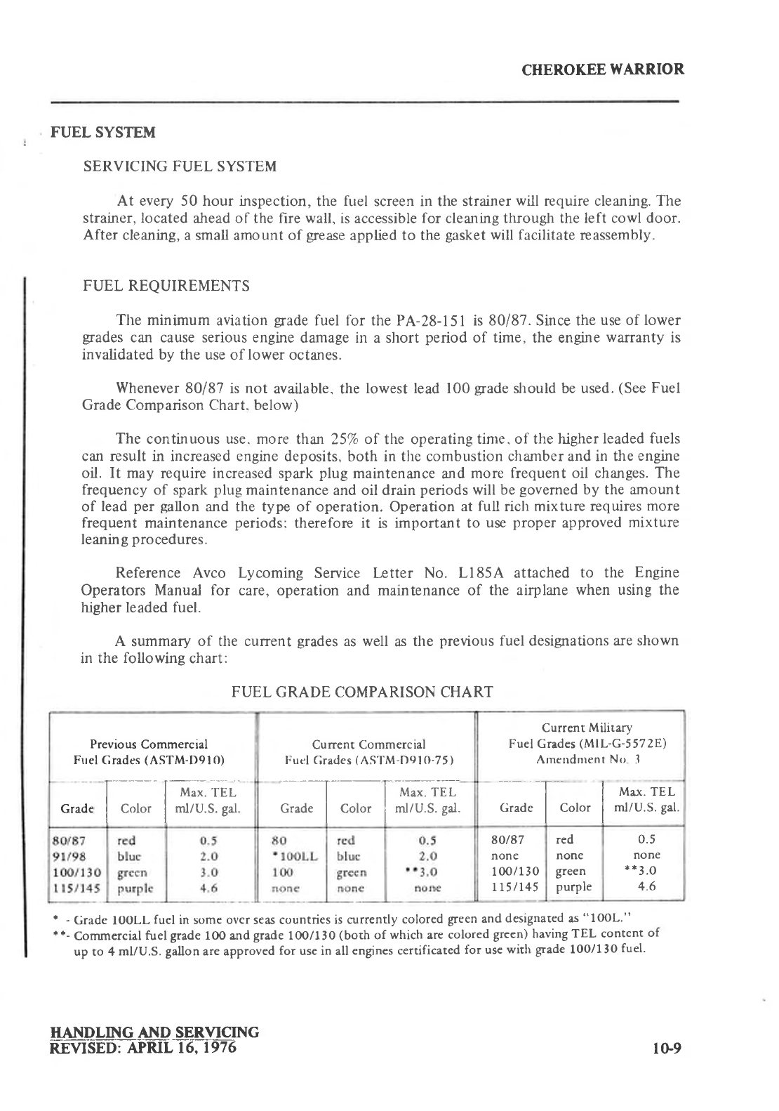
CHEROKEE
WARRIOR
FUEL SYSTEM
SERVICING
FUEL
SYSTEM
At every 50 hour inspection,
the
fuel
screen in the strainer
will
require cleaning. The
strainer, located
ahead of the
fire
wall, is
accessible
for cleaning througJr the left cowl door.
After
cleaning,
a small amount of grease
applied to the
gasket
will
facilitate reassembly.
FUEL REQUIREMENTS
The minimum aviation
grade
fuel for the PA-28-l5l is 80/87. Shce the
use of lower
grades
can cause serious engine
damage in a short period
of time, the engine
warranty
is
invalidated by the use
of lower
octanes.
Whenever
80187 is not available. the lowest lead l00grade should be used.
(See
Fuel
Grade Comparison
Chart. below)
The continuous use. more than 257o
of the operating
time. of the higher
leaded fuels
can result in increased engine
deposits, both in the combustion
chamber and in the
engine
oil. It may require increased spark
plug maintenance
and more frequent oil changes. The
frequency of spark
plug
maintenance
and oil drain
periods
will be
governed
by the amount
of lead
per gallon
and the type of operation. Operation
at full rich mixture requires
more
frequent maintenance
periods:
therefore
it is important to use
proper approved
mixture
leaning
procedures.
Reference Avco Lycoming Service Letter No. Ll85A attached to the Engine
Operators Manual for care, operation
and maintenance of the airplane
when using the
higher leaded fuel.
A summary
of the current
grades
as well as
the previous
fuel designations are
shown
in the following chart:
FUEL
GRADE COMPARISON CHART
t - Gradc IOOLL fuel in some ovcr seas countries
is currently colored
green
and
designated as
"lOOL."
* *- Commercial
fuel grade lOO and
grade
IOO/130
(both of which are colored
green)
having
TEL content of
up to 4 ml/U.S. gallon
are approved
for use in all
engines certificated
for use
with grade lOO/130
fuel.
HAN_D rp{ q AND SFsyIqrNG
REVISED:
APRIL 16,1976
Previous
Commercial
Fuel
Grades
(ASTM-D9l
0) Current Commercial
Fuel
Grades
(ASTM
D9lO-75)
Current
Military
Fuel Grades
(MlL-G-5
572E)
Arne ndnrent
No 3
Grade l.-_-- [ rrl"*.'rrr-
I c"to' I nrtru.s.
gar.
--l --f rur"*. re I
Grade
I color I nllu.S.
Sat. T I r'l^*. rrr-
Grade
I color I ml/U.S.
Sal.
80/87
none
I 00/1 30
L15 / 145
red
none
green
purple
0.5
none
**3.0
4.6
lG,9
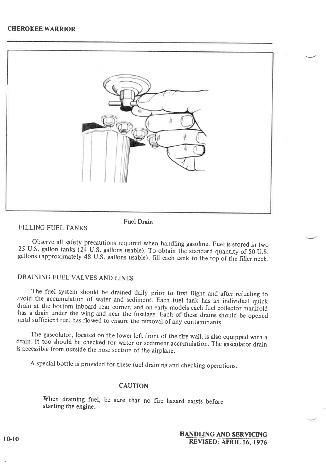
CHEROKEE
WARR.IOR
Fuel
Drain
FILLING
FUEL
TANKS
Observe
all safety
precautions
required
when
handling
gasoline.
Fuel
is stored
in two
25 U.S.
gallon
tanks
(24 U.S.
gallons
usable).
To obtain
tiJstandard quantity
of 50 U.S.
gallons
(approximately
48 U.S.
gallons
usable),
fill each
tank
to the
toi of the
filler
neck.
DRAINING
FUEL VALVES
AND
LINES
The fuel system
should
be drained
daily prior to first flight and
after
refueling
to
avoid
the accumulation
of water
and
sediment.
Each
fuel tanli
has
an individuat quict
drain
at the
bottom
inboard
rear
corner,
and
on
early
models
each
fuel
collector
manifold
has
a drain
under
the wing
and
near
the fuselage.
Eich of these
drains
should
be
opened
until
sufficient
fuel
has
flowed
to ensure
the
removal
of any
contaminants.
The
gascolator'
located
on
the
lower
left
front
of the
fire wall,
is
also
equipped
with
a
drain.
It too should
be
checked
for water
or sediment
accumulation.
The
gascoiator
drain
is
accessible
from
outside
the
nose
section
of the
airplane.
A special
bottle
is
provided
for these
fuel
draining
and
checking
operations.
CAUTION
when draining
fuel, be sure that no fire hazard
exists
before
starting
the
engine.
HANDLING AT{D SERVICING
REVISED
IFRil6J'16-
tGl0
CHEROKEE WARRIOR
DRAINING FUEL SYSTEM
The bulk of the fuel may be drained
by opening the individual
drain on each
tank.
The remaining fuel in the lines
may be drained
through the fuel
collector
manifold
clrains
(on early models only) and the gascolator
drain. Any individual tank may be drained
through its individual drain.
CAUTION
Whenever the fuel system is completely drained and fuel is re-
plenished it will be necessary
to run the engine for a
minimum of
3
minutes
at 1000
RPM on each
tank to insure
no air exists
in the fuel
supply lines.
TIRE INFLATION
For maximum service
from the
tires, keep
them
inflated to the
proper pressures.
The main
gear
tires should
be inflated to 24 psi
and the
nose
gear
should be inflated to 30 psi.
Interchange the tires on the main
wheels
if necessary to produce
even wear. All wheels
and
tires
are balanced
before original installation, and the relationship of the tire, tube, and wheel
should be maintained if at all possible.
Unbalanced
wheels
can cause extreme vibration on
takeoff. ln the installation
of new components, it may
be
necessary to rebalance the wheel
with
the
tire
mounted.
When
checking
the pressure,
examine the tires
for wear,
cuts,
bruises,
and slippage.
BATTERY SERVICE
Access to the l2-volt battery is
obtained
by raising
the
rear
seat
and removing
the cover of
the battery box. The plastic
battery box has
a drain tube
which is
normally
closed
off with a
cap and
which
should
be
opened occasionally
to drain off any
accumulation
of liquid.
The battery should
be checked
for proper fluid level. DO NOT fill the battery above the
baffle plates.
DO NOT fill the battery with acid - use
only water. A hydrometer
check
will
determine
the percent
of charge
in the battery.
If the battery is not up to charge,
recharge starting at a 4 amp rate and
finishing
with a 2
amp
rate.
Quick
charges are
ltot
recommended.
WINTERIZATION
For winter operation a winterization
plate is installed
on the inlet opening
of the oil
cooler.
This
plate
should be installed
whenever
the ambient
temperature
reaches
50" F or less.
The plate
should
be
removed and stored
in the cockpit
when
the ambient
temperature
exceeds
50"
F.
HANDLING
AND SERVICING
RE!'f SEl):
APRll. 6. 1979 l0-l
l
