Plug In Gait Reference Guide
User Manual:
Open the PDF directly: View PDF ![]() .
.
Page Count: 104 [warning: Documents this large are best viewed by clicking the View PDF Link!]
- Contents
- About this guide
- Plug-in Gait models and templates
- Plug-in Gait bones
- Plug-in Gait lower body forces and moments
- Plug-in Gait kinematic and kinetic calculations
- About Plug-in Gait processes
- Segment meshes
- Plug-in Gait internal models
- Overview of the Plug-in Gait modeling process
- Static vs. dynamic models
- The chord function
- Lower body kinematics
- Upper body kinematics
- Angle outputs
- Kinetic modeling
- Plug-in Gait output angles
- Plug-in Gait output specification

© Copyright 2016–2018 Vicon Motion Systems Limited. All rights reserved.
Vicon Motion Systems Limited reserves the right to make changes to information in this document without notice.
Companies, names, and data used in examples are fictitious unless otherwise noted. No part of this publication may be
reproduced, stored in a retrieval system, or transmitted in any form or by any means, electronic or mechanical, by
photocopying or recording, or otherwise without the prior written permission of Vicon Motion Systems Ltd.
Vicon® is a registered trademark of Oxford Metrics plc. Vicon Blade™, Vicon Control™, Vicon Lock™, Vicon Lock+™,
Vicon Nexus™, Vicon MX™, Vicon Pegasus™, Vicon ProCalc™, Vicon Shogun™, Vicon Studio™, T-Series™, Vicon Tracker™,
Vicon Vantage™, Vicon Vero™, Vicon Vertex™, and Vicon Vue™ are trademarks of Oxford Metrics plc.
VESA® is a registered trademark owned by VESA ( ). Other product and company names herein may www.vesa.org/about-vesa/
be the trademarks of their respective owners.
Vicon Motion Systems is an Oxford Metrics plc company. Email: Web: support@vicon.com http://www.vicon.com
Plug-in Gait Reference Guide
Contents
About this guide . . . . . . . . . . . . . . . . . . . . . . . . . . . . . . . . . . . 3
Regulatory information . . . . . . . . . . . . . . . . . . . . . . . . . . . . . . . . 4
Plug-in Gait models and templates . . . . . . . . . . . . . . . . . . . 5
Lower body modeling with Plug-in Gait . . . . . . . . . . . . . . . . . . 6
Upper body modeling with Plug-in Gait . . . . . . . . . . . . . . . . . 18
Full body modeling with Plug-in Gait . . . . . . . . . . . . . . . . . . . 26
Plug-in Gait labeling skeleton templates (VSTs) in
ViconNexus . . . . . . . . . . . . . . . . . . . . . . . . . . . . . . . . . . . . . . . . 31
Plug-in Gait bones . . . . . . . . . . . . . . . . . . . . . . . . . . . . . . . . 33
Complete list of Plug-in Gait bones . . . . . . . . . . . . . . . . . . . . 34
Plug-in Gait virtual markers . . . . . . . . . . . . . . . . . . . . . . . . . . . 38
Plug-in Gait joint centers . . . . . . . . . . . . . . . . . . . . . . . . . . . . . 39
Plug-in Gait lower body forces and moments . . . . . . . . . 40
Plug-in Gait kinematic and kinetic calculations . . . . . . . 43
About Plug-in Gait processes . . . . . . . . . . . . . . . . . . . . . . . . . 44
Segment meshes . . . . . . . . . . . . . . . . . . . . . . . . . . . . . . . . . . . . 45

© Copyright 2016–2018 Vicon Motion Systems Limited. All rights reserved.
Vicon Motion Systems Limited reserves the right to make changes to information in this document without notice.
Companies, names, and data used in examples are fictitious unless otherwise noted. No part of this publication may be
reproduced, stored in a retrieval system, or transmitted in any form or by any means, electronic or mechanical, by
photocopying or recording, or otherwise without the prior written permission of Vicon Motion Systems Ltd.
Vicon® is a registered trademark of Oxford Metrics plc. Vicon Blade™, Vicon Control™, Vicon Lock™, Vicon Lock+™,
Vicon Nexus™, Vicon MX™, Vicon Pegasus™, Vicon ProCalc™, Vicon Shogun™, Vicon Studio™, T-Series™, Vicon Tracker™,
Vicon Vantage™, Vicon Vero™, Vicon Vertex™, and Vicon Vue™ are trademarks of Oxford Metrics plc.
VESA® is a registered trademark owned by VESA ( ). Other product and company names herein may www.vesa.org/about-vesa/
be the trademarks of their respective owners.
Vicon Motion Systems is an Oxford Metrics plc company. Email: Web: support@vicon.com http://www.vicon.com
Plug-in Gait internal models . . . . . . . . . . . . . . . . . . . . . . . . . . 46
Overview of the Plug-in Gait modeling process . . . . . . . . . . 47
Static vs. dynamic models . . . . . . . . . . . . . . . . . . . . . . . . . . . . 48
The chord function . . . . . . . . . . . . . . . . . . . . . . . . . . . . . . . . . . 49
Lower body kinematics . . . . . . . . . . . . . . . . . . . . . . . . . . . . . . 50
Upper body kinematics . . . . . . . . . . . . . . . . . . . . . . . . . . . . . . . 62
Angle outputs . . . . . . . . . . . . . . . . . . . . . . . . . . . . . . . . . . . . . . 68
Kinetic modeling . . . . . . . . . . . . . . . . . . . . . . . . . . . . . . . . . . . . 69
Plug-in Gait output angles . . . . . . . . . . . . . . . . . . . . . . . . . 74
Angle definitions . . . . . . . . . . . . . . . . . . . . . . . . . . . . . . . . . . . . 75
Plug-in Gait kinematic variables . . . . . . . . . . . . . . . . . . . . . . . 78
Upper body angles as output from Plug-in Gait . . . . . . . . . 88
Lower body angles as output from Plug-in Gait . . . . . . . . . . 93
Plug-in Gait output specification . . . . . . . . . . . . . . . . . . . 96
Global (laboratory) co-ordinate system . . . . . . . . . . . . . . . . . 97
Pelvis . . . . . . . . . . . . . . . . . . . . . . . . . . . . . . . . . . . . . . . . . . . . . . 98
Femur . . . . . . . . . . . . . . . . . . . . . . . . . . . . . . . . . . . . . . . . . . . . . 99
Tibia . . . . . . . . . . . . . . . . . . . . . . . . . . . . . . . . . . . . . . . . . . . . . . 100
Foot . . . . . . . . . . . . . . . . . . . . . . . . . . . . . . . . . . . . . . . . . . . . . . . 101
Joint kinematic definitions . . . . . . . . . . . . . . . . . . . . . . . . . . 102
Joint kinetics . . . . . . . . . . . . . . . . . . . . . . . . . . . . . . . . . . . . . . 103

Plug-in
Gait
Reference
Vicon Motion Systems Ltd. 26-Oct-2018 Page of 3 104
About this guide
This guide provides in-depth descriptions of Plug-in Gait models and templates, and
details of the calculations performed by Plug-in Gait. For information on how to use
Plug-in Gait with Vicon Nexus, see in the Modeling with Plug-in Gait
Vicon Nexus User
.
Guide
It is assumed that you are familiar with standard motion capture, data processing, and
data management in Nexus; and with data visualization, analysis and reporting in Vicon
Polygon. For more information on these processes, see the documentation for Nexus
and Polygon.

Plug-in
Gait
Reference
Vicon Motion Systems Ltd. 26-Oct-2018 Page of 4 104
Regulatory information
For Vicon Nexus regulatory details, see in the Vicon Nexus regulatory information
Nexus documentation area of the Vicon website ( ).docs.vicon.com

Plug-in
Gait
Reference
Vicon Motion Systems Ltd. 26-Oct-2018 Page of 5 104
Plug-in Gait models and templates
The following topics contain information on the differences between the Plug-in Gait
models, including details of the relevant outputs and marker sets. A description of the
labeling skeleton templates that you can use with Plug-in Gait is also available:
Lower body modeling with Plug-in Gait on page 6
Upper body modeling with Plug-in Gait on page 18
Full body modeling with Plug-in Gait on page 26
Plug-in Gait labeling skeleton templates (VSTs) in ViconNexus on page 31
If you are using Plug-in Gait for gait analysis, the precision of the marker placement is
critical for obtaining accurate clinical results. Use the information and illustrations in
the above topics to place markers on the patient.

Plug-in
Gait
Reference
Vicon Motion Systems Ltd. 26-Oct-2018 Page of 6 104
Lower body modeling with Plug-in Gait
This section describes lower body modeling with Plug-in Gait. It covers the following
information:
Outputs from Plug-in Gait lower body model on page 6
Marker sets for Plug-in Gait lower body model on page 8
Marker placement for Plug-in Gait lower body model on page 9
KAD marker sets for Plug-in Gait lower body model on page 14
KAD marker placement for Plug-in Gait lower body model on page 15
For details about the labeling skeleton templates to be used with Plug-in Gait lower
body models, see Plug-in Gait labeling skeleton templates (VSTs) in ViconNexus on
.page 31
Outputs from Plug-in Gait lower body model
Use a Plug-in Gait lower body model if you require the kinematic and kinetic calculation
outputs listed in the following table. The output variables are prefixed by the
appropriate context (L for left or R for right).
Joint angles, force, and moments are expressed in the three anatomical planes: sagittal,
frontal, and coronal. Even if the joint powers are scalar, they can also be expressed in
the anatomical planes in Vicon Polygon. Forces, moments, and powers are all
normalized to the subject's height and body mass.
Output Description
Kinematics:
Angles
AbsAnkleAngle The angle between the AJC to KJC vector and the AJC to
TOE vector.
AnkleAngles Relative. The angles between the shank and the foot.

Plug-in
Gait
Reference
Vicon Motion Systems Ltd. 26-Oct-2018 Page of 7 104
Output Description
FootProgressAngles Absolute. The angles between the foot and the global
coordinate system.
HipAngles Relative. The angles between the pelvis and the thigh.
KneeAngles Relative. The angles between the thigh and the shank.
PelvisAngles Absolute. The angles between the pelvis and the laboratory
coordinate system.
Kinetics:
Forces
AnkleForce The force between the shank and the foot.
GroundReactionForce The force exchanged between the foot and the ground
while walking.
HipForce The force between the pelvis and the thigh.
KneeForce The force between the thigh and the shank.
NormalizedGRF The ground reaction force expressed as a percentage of
the body weight.
WaistForce The force between the pelvis and the thorax.a
Moments
AnkleMoment The moment between the shank and the foot.
HipMoment The moment between the pelvis and the thigh.
KneeMoment The moment between the thigh and the shank.

Plug-in
Gait
Reference
Vicon Motion Systems Ltd. 26-Oct-2018 Page of 8 104
Output Description
WaistMoment The moment between the pelvis and the thorax.a
Powers
AnklePower The power between the shank and the foot.
HipPower The power between the pelvis and the thigh.
KneePower The power between the thigh and the shank.
WaistPower The power between the pelvis and the thorax.a
a This output variable is calculated only if you use a Plug-in Gait model that contains
the thorax.
Marker sets for Plug-in Gait lower body model
All Plug-in Gait marker sets are designed for the Newington-Helen Hayes model on
which Plug-in Gait is based. The marker set for Plug-in Gait lower body modeling
includes markers for the pelvis and the lower limbs.
There are two variations of the standard marker set for the lower body model:
A single sacral (SACR) marker for the pelvis
Two posterior superior iliac spine (PSIS) markers for the pelvis
These markers provide the same function; if you use two PSIS markers, Plug-in Gait
calculates the midpoint between them and uses that to perform the calculations. If you
use a single SACR marker, you identify that position to Plug-in Gait rather than having it
calculated.
Using the two PSIS markers has the benefit of providing redundancy, so if one of the
pelvis markers is missing, it is possible to reconstruct a virtual marker based on the
remaining three markers. You can do this using a Rigid Body Fill in Nexus.
Plug-in
Gait
Reference
Vicon Motion Systems Ltd. 26-Oct-2018 Page of 9 104
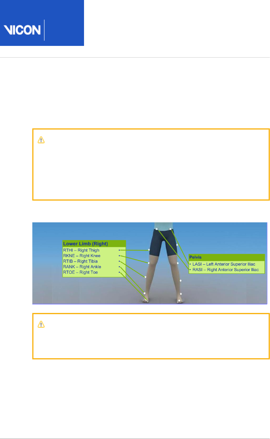
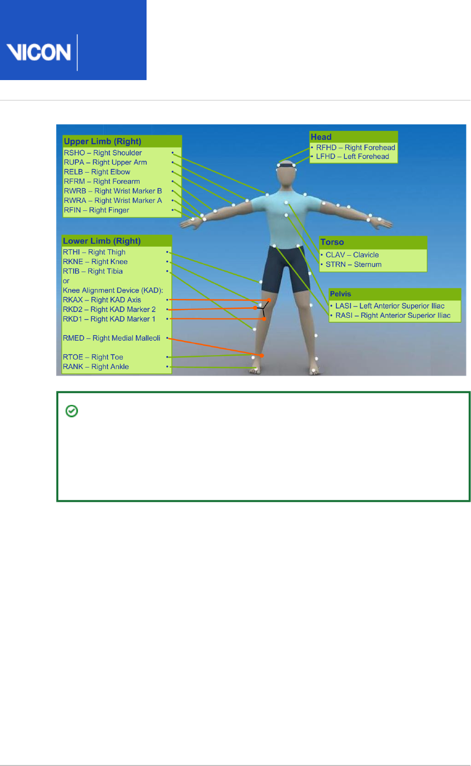
Marker placement for Plug-in Gait lower body model
To demonstrate where to attach the standard lower body model markers to your
patient, the following images show front, back, and side views. Some markers are
shown from two views to help you better determine their position on your patient.
Important
As shown in the following images, some asymmetry is desirable as it helps the
auto labeling routine distinguish right from left. In a lower body marker set,
you can place the THI and/or TIB markers asymmetrically. Similarly, avoid
symmetrical placement of marker clusters or groups of markers and also
ensure markers are asymmetrical within each cluster/group.
The following image shows the view. The left lower body markers are not labeled; front
place markers on the left side in a similar way to those on the right.
Important
The THI and TIB markers anterior-posterior position is critical for identifying
the orientation of the knee and ankle flexion axis.

Plug-in
Gait
Reference
Vicon Motion Systems Ltd. 26-Oct-2018 Page of 10 104
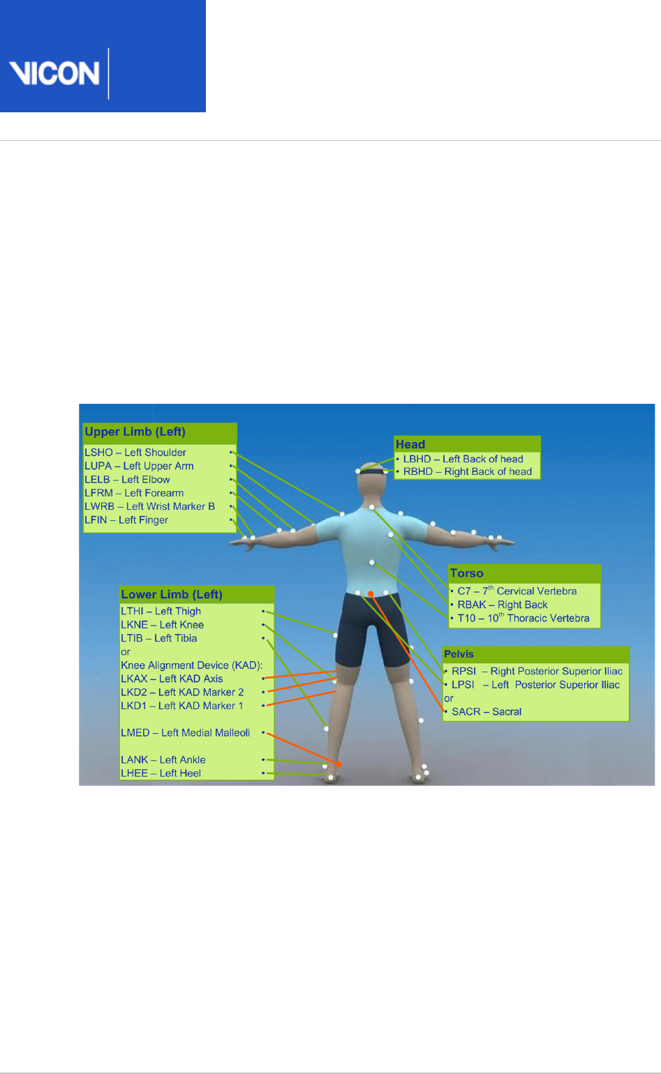
The following image shows the view. The figure includes the SACR marker back
variation, which is highlighted in orange. The right lower body markers are not labeled;
attach markers on that side in a similar way to those on the left (with some asymmetry,
as described above).
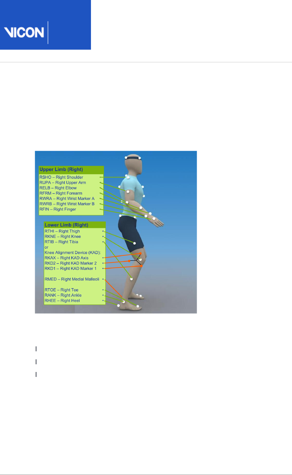
The following image shows the view. The left side view is not shown; attach right side
markers on that side in a similar way to the right markers (with some asymmetry, as
described above).
The following tables list the markers defined in Plug-in Gait templates for lower body
modeling and describe where to place them on the patient:

Plug-in
Gait
Reference
Vicon Motion Systems Ltd. 26-Oct-2018 Page of 11 104
Pelvis marker placement
The following markers are positioned on the patient's pelvis:
Marker
label
Definition Position on patient
SACR Sacral On the skin mid-way between the posterior superior iliac
spines (PSIS) and positioned to lie in the plane formed by the
ASIS and PSIS points.
LASI Left ASIS Left anterior superior iliac spine
RASI Right
ASIS
Right anterior superior iliac spine
LPSI Left PSIS Left posterior superior iliac spine (immediately below the
sacro-iliac joints, at the point where the spine joins the pelvis)
This marker is used with the RPSI marker as an alternative to
the single SACR marker.
RPSI Right
PSIS
Right posterior superior iliac spine (immediately below the
sacro-iliac joints, at the point where the spine joins the pelvis)
This marker is used with the LPSI marker as an alternative to
the single SACR marker.
In some patients, especially obese individuals, the markers either can't be placed
exactly on the ASIS, or are invisible in this position to cameras. In these cases, move
each marker laterally by an equal amount along the ASIS-ASIS axis. The true inter-ASIS
distance must then be manually measured and entered in the pane at the Properties
bottom of the tab on the pane. These markers, together with either Subjects Resources
the SACR marker or the LPSI and RPSI markers, define the pelvic coronal plane.

Plug-in
Gait
Reference
Vicon Motion Systems Ltd. 26-Oct-2018 Page of 12 104
Lower limb marker placement
The following markers are positioned on each of the patient's lower limbs. For
additional guidance, see the notes at the bottom of the table.
Marker
label
Definition Position on patient
Left lower limb markers
LTHI Left thigh Over the lower lateral 1/3 surface of the left thigh
LKNE Left knee On the flexion-extension axis of the left knee
LTIB Left tibia Over the lower 1/3 surface of the left shank
LANK Left ankle On the lateral malleolus along an imaginary line that passes
through the transmalleolar axis
LHEE Left heel On the calcaneous at the same height above the plantar
surface of the foot as the toe marker
LTOE Left toe Over the second metatarsal head, on the mid-foot side of the
equinus break between fore-foot and mid-foot
Right lower limb markers
RTHI Right
thigh
Over the upper lateral 1/3 surface of the right thigh
RKNE Right
knee
On the flexion-extension axis of the right knee.
RTIB Right
tibia
Over the upper 1/3 surface of the right shank
RANK Right
ankle
On the lateral malleolus along an imaginary line that passes
through the transmalleolar axis

Plug-in
Gait
Reference
Vicon Motion Systems Ltd. 26-Oct-2018 Page of 13 104
Marker
label
Definition Position on patient
RHEE Right
heel
On the calcaneous at the same height above the plantar
surface of the foot as the toe marker
RTOE Right toe Over the second metatarsal head, on the mid-foot side of the
equinus break between fore-foot and mid-foot
Notes
Knee markers To locate the precise point for placing the knee markers (LKNE, RKNE),
passively flex and extend the knee a little while watching the skin surface on the lateral
aspect of the knee joint. Identify where knee joint axis passes through the lateral side
of the knee by finding the lateral skin surface that comes closest to remaining fixed in
the thigh. This landmark should also be the point about which the lower leg appears to
rotate. Mark this point with a pen. With an adult patient standing, this pen mark should
be about 1.5 cm above the joint line, mid-way between the front and back of the joint.
Attach the marker at this point.
If you are using a knee alignment device (KAD), see also KAD marker placement for Plug-
.in Gait lower body model on page 15
Thigh markers The thigh markers (LTHI, RTHI) are used to calculate the knee flexion
axis orientation. Place the LTHI marker over the lower lateral 1/3 surface and the RTHI
marker over the upper lateral 1/3 surface of the thigh, just below the swing of the hand,
although the height is not critical. The anterior-posterior placement of the marker is
critical for correct alignment of the knee flexion axis. Try to keep the thigh marker off
the belly of the muscle, but place the thigh marker at least two marker diameters
proximal of the knee marker. Adjust the position of the marker so that it is lies in the
plane that contains the hip and knee joint centers and the knee flexion/extension axis.
If you are using a KAD, the precise placement of the thigh markers is not crucial.
Tibia markers The tibia markers (LTIB, RTIB) are used to determine the alignment of the
ankle flexion axis. Similarly to the thigh markers, place the LTIB marker over the lower 1
/3 surface of the shank and the RTIB marker over the upper 1/3 surface of the shank.
The tibial marker should lie in the plane that contains the knee and ankle joint centers
and the ankle flexion/extension axis. In a normal patient, the ankle joint axis between
the medial and lateral malleoli is externally rotated by around 20 degrees with respect
to the knee flexion axis. The placements of the shank markers should reflect this.
If you are using a KAD, the ankle dorsi-plantar flexion axis is assumed to be parallel to
the knee flexion axis unless:

Plug-in
Gait
Reference
Vicon Motion Systems Ltd. 26-Oct-2018 Page of 14 104
The tibial torsion is manually measured and entered in the pane at the Properties
bottom of the pane.SubjectsResources
or
One marker on each medial malleolus is attached (RMED, LMED). During the static
trial, Plug-in Gait automatically calculates the tibial torsion as the angle between the
knee flexion and the ankle dorsi-plantar flexion axes.
Toe and heel markers If the toe markers (LTOE, RTOE) cannot be placed level with the
heel markers (LHEE, RHEE), you must configure Plug-in Gait to compensate for this. For
details of the relevant settings, see in the Plug-in Gait Static pipeline
Vicon Nexus User
.
Guide
KAD marker sets for Plug-in Gait lower body model
In addition to the standard lower body marker sets, an alternative marker set enables
you to use a knee alignment device (KAD).
The KAD is a light-weight, spring-loaded G-clamp, whose adjustable jaws bridge the
knee and whose stem is aligned with the knee flexion axis.
One standard-sized marker is fixed to the tip of the stem and two markers are mounted
on the ends of two additional rods fixed to the device. The three markers are
equidistant from the point where the stem meets the jaws of the clamp, enabling the
3D position of this point, known as the 'virtual knee marker', to be calculated.
Instead of the THI and TIB markers in the standard model, the KAD markers (left and
right KAX, KD1, and KD2) are used to calculate the orientation of the medio-lateral axes
of knee and ankle respectively.
The KAD is applied to the patient during a static trial to enable Plug-in Gait to
calculate:
The offset angle between the knee flexion axis orientation as calculated by using the
KAD markers and knee flexion axis orientation as calculated by using the THI markers
(Thigh Rotation Offset). When a KAD is present, the ankle dorsi-plantar flexion axis is
assumed to be aligned with the knee flexion axis unless the tibial torsion
measurement is entered.
The angle between the ankle dorsi-plantar flexion axis orientation as calculated by
using the KAD and the tibial torsion measurement and the ankle dorsi-plantar flexion
axis orientation as calculated using the TIB markers (Shank Rotation Offset).
These calculations eliminate the reliance on the anterior posterior position of the THI
and TIB markers.
Plug-in
Gait
Reference
Vicon Motion Systems Ltd. 26-Oct-2018 Page of 15 104
A variation of the KAD marker set defines the additional LMED and RMED markers for
the medial malleoli.
When you use a KAD, the tibial torsion measurement is critical for Plug-in Gait to
identify the correct orientation of the ankle dorsi-plantar flexion axis. In fact, if the
tibial torsion is left at 0 (zero), the ankle flex axis is assumed to be aligned with the
knee flex axis. To enable Plug-in Gait to automatically calculate the tibial torsion
measurement, attach the LMED and RMED markers on the medial malleoli of your
patient.
When the static trial has been processed, you can remove the KAD and the MED
markers, and for dynamic trials, place the KNE marker exactly where the KAD pad used
to be on the femural epicondyle.
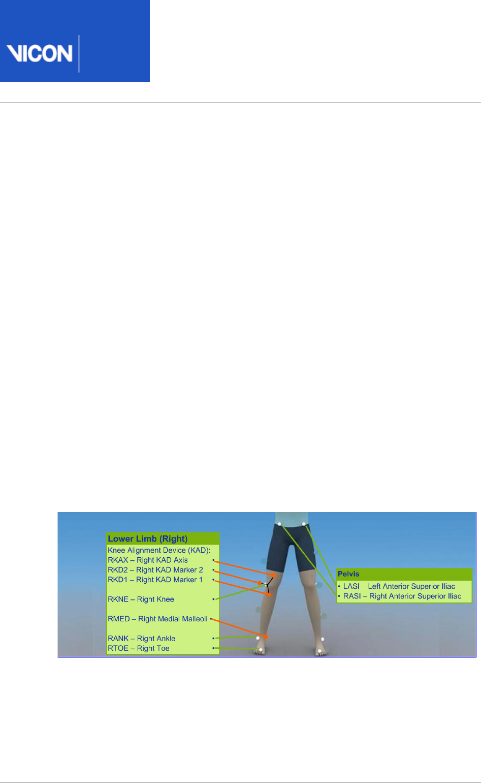
KAD marker placement for Plug-in Gait lower body model
The following images show front, back, and side views to demonstrate where to attach
the lower body model markers to your patient. You do this before capturing a static trial
as described in the . Some markers are shown from two views
Vicon Nexus User Guide
to help you better determine their position on your patient.
The following image shows the front view. It includes the knee alignment device (KAD)
marker variations, which are highlighted in orange.
The left lower body markers are not labeled; attach markers on that side in a similar
way to those on the right (with some asymmetry as described in Marker placement for
).Plug-in Gait lower body model on page 9

Plug-in
Gait
Reference
Vicon Motion Systems Ltd. 26-Oct-2018 Page of 16 104
The following image shows the back view. It includes the knee alignment device (KAD)
marker variations, which are highlighted in orange.
The right lower body markers are not labeled in this figure; attach markers on that side
in a similar way to those on the left (with some asymmetry as described in Marker
).placement for Plug-in Gait lower body model on page 9
The following image shows the right side view. It includes the knee alignment device
(KAD) marker variations, which are highlighted in orange.
The left side view is not shown; attach markers on that side in a similar way to the right
markers (with some asymmetry as described in Marker placement for Plug-in Gait lower
).body model on page 9
If a knee alignment device (KAD) is used, it is attached instead of the LKNE and RKNE
markers for the static trial only. Before dynamic capture and modeling, it must be
removed and LKNE and RKNE markers attached instead.
The KAD markers are constructed in such a way as to enable the model to calculate a
position for a virtual knee marker, which corresponds to the external pad. So, the
external pad should be positioned as described for the knee marker.

Plug-in
Gait
Reference
Vicon Motion Systems Ltd. 26-Oct-2018 Page of 17 104
The following table shows the KAD marker labels included for static trials.
Marker
Label
Definition Position
LKAX Left knee Left KAD axis
For the left side, labeling goes from this counter clockwise
LKAX marker
LKD1 Device 1 Left KAD marker 1
LKD2 Device 2 Left KAD marker2
RKAX Right
knee
Right KAD axis
For the right side, labeling goes from the RKAX clockwise
marker
RKD1 Device 1 Right KAD marker 1
RKD2 Device 2 Right KAD marker 2
For dynamic trials, the KAD must be removed, and the left or right KNE marker
positioned at the same point as the external KAD pad.

Plug-in
Gait
Reference
Vicon Motion Systems Ltd. 26-Oct-2018 Page of 18 104
Upper body modeling with Plug-in Gait
This section describes Plug-in Gait upper body modeling, so you can determine if an
upper body model will provide the data you require for your clinical analysis.
The following topics are covered:
Outputs from Plug-in Gait upper body model on page 18
Marker sets for Plug-in Gait upper body modeling on page 20
Marker placement for Plug-in Gait upper body model on page 20
For details about the labeling skeleton templates to be used with Plug-in Gait upper
body models, see Plug-in Gait labeling skeleton templates (VSTs) in Vicon Nexus on
.page 31
Outputs from Plug-in Gait upper body model
Use a Plug-in Gait upper body model if you require the kinematic and kinetic
calculation outputs listed in the following table. The output variables are prefixed by
the appropriate context ( for left or for right).L R
Output Description
Kinematics:
Angles
ElbowAngles Relative. The angles between the upper arm and the forearm.
HeadAngles Absolute. The angles between the head and the laboratory
coordinate system.
NeckAngles The angles between head relative to thorax.
ShoulderAngles Relative. The angles between the upper arm and the thorax.
SpineAngles The angles between the thorax relative to the pelvis.

Plug-in
Gait
Reference
Vicon Motion Systems Ltd. 26-Oct-2018 Page of 19 104
Output Description
ThoraxAngles Absolute. The angles between the thorax and the laboratory
coordinate system.
WristAngles Relative. The angles between the forearm and the hand.
Kinetics:
Forces
ElbowForce The force between the upper arm and the forearm.
NeckForce The force between the head relative to thorax.
ShoulderForce The force between the upper arm and the thorax.
WristForce The force between the forearm and the hand.
Moments
ElbowMoment The moment between the upper arm and the forearm.
NeckMoment The moment between the head relative to thorax.
ShoulderMoment The moment between the upper arm and the thorax.
WristMoment The moment between the forearm and the hand.
Powers
ElbowPower The power between the upper arm and the forearm.
NeckPower The power between the head relative to thorax.
ShoulderPower The power between the upper arm and the thorax.
WristPower The power between the forearm and the hand.
Plug-in
Gait
Reference
Vicon Motion Systems Ltd. 26-Oct-2018 Page of 20 104
Marker sets for Plug-in Gait upper body modeling
The marker set for Plug-in Gait upper body modeling includes markers for the head,
torso, and upper limbs.
There are two variations of the standard marker set for the upper body model:
Additional upper arm (UPA) and forearm (FRM) markers
No UPA and FRM markers
The UPA and FRM markers are optional; however, using them improves marker tracking
during dynamic trials.
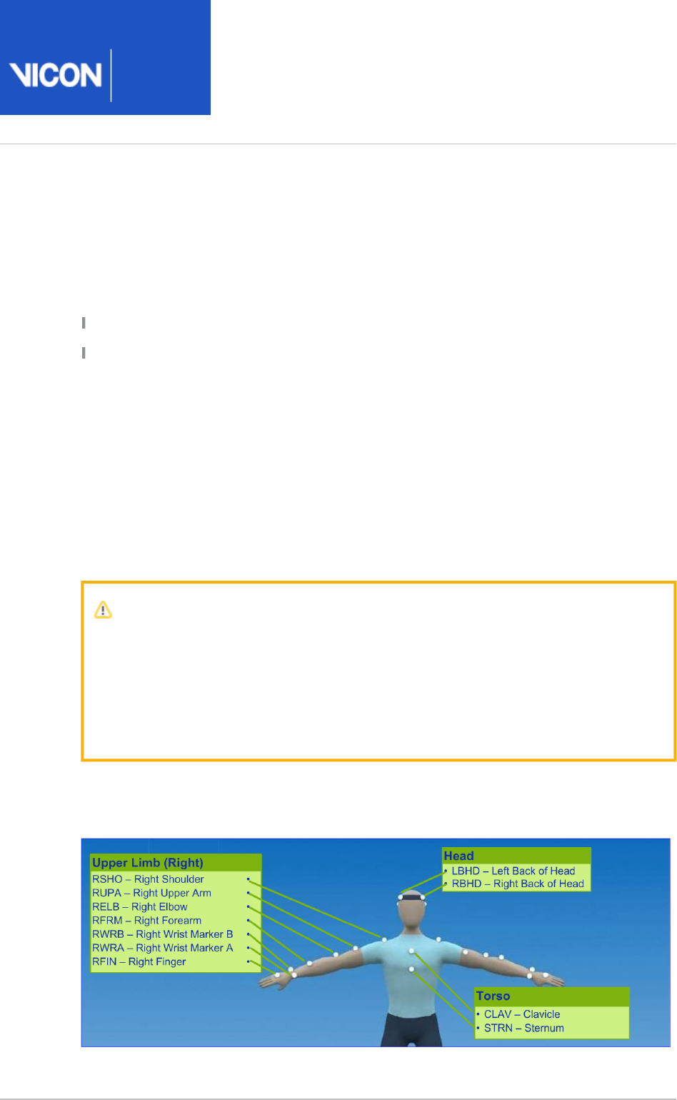
Marker placement for Plug-in Gait upper body model
The following images show front, back, and side views to demonstrate where to attach
the upper body markers to your patient. You do this before capturing a static trial as
described in the . Some markers are shown from two views to
Vicon Nexus User Guide
help you better determine their position on your patient.
Important
As shown in the following images, some asymmetry is desirable as it helps the
auto labeling routine distinguish right from left. For upper body modeling, you
can place the UPA and FRM markers asymmetrically. Similarly, avoid
symmetrical placement of marker clusters or groups of markers and also
ensure markers are asymmetrical within each cluster/group.
The following image shows the front view. The left upper body markers are not labeled;
attach markers on that side in a similar way to those on the right (with some asymmetry
as described above).
Plug-in
Gait
Reference
Vicon Motion Systems Ltd. 26-Oct-2018 Page of 21 104
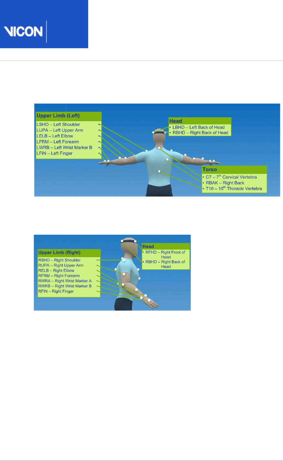
The following image shows the back view. The right upper body markers are not
labeled; attach markers in a similar way to those on the left (with some asymmetry as
described above).
The following image shows the right side view. The left side view is not shown; attach
markers on that side in a similar way to those on the right (with some asymmetry as
described above).

Plug-in
Gait
Reference
Vicon Motion Systems Ltd. 26-Oct-2018 Page of 22 104
The following tables list the markers defined in Plug-in Gait templates for upper body
modeling and describe where to place them on the patient:
Head markers
The following table describes the markers positioned on the patient's head. To save
time, many users buy a headband and permanently attach markers to it.
Marker
label
Definition Position on patient
LFHD Left front
head
Left temple
RFHD Right
front
head
Right temple
LBHD Left back
head
Left back of head (defines the transverse plane of the head,
together with the frontal markers)
RBHD Right
back
head
Right back of head (defines the transverse plane of the head,
together with the frontal markers)
Important
If the back markers cannot be placed level with the front markers, you must
configure Plug-in Gait to compensate for this during the subject calibration
process. To do this, in the for the Properties Process Static Plugin Gait Model
pipeline operation, under , select .Assume Horizontal Head

Plug-in
Gait
Reference
Vicon Motion Systems Ltd. 26-Oct-2018 Page of 23 104
Torso markers
The following table describes the markers positioned on the patient's torso. The torso
markers (C7, T10, CLAV, STRN) define the thorax sagittal plane; therefore, their lateral
positioning is most important.
Marker
label
Definition Position on patient
C7 7th
cervical
vertebra
On the spinous process of the 7th cervical vertebra
T10 10th
thoracic
vertebra
On the spinous process of the 10th thoracic vertebra
CLAV Clavicle On the jugular notch where the clavicles meet the sternum
STRN Sternum On the xiphoid process of the sternum
RBAK Right
back
Anywhere over the right scapula
(This marker has no equivalent marker on the left side. This
asymmetry helps the autolabeling routine determine right
from left on the subject. Placement is not critical as it is not
included in the Plug-in Gait model calculations.)

Plug-in
Gait
Reference
Vicon Motion Systems Ltd. 26-Oct-2018 Page of 24 104
Upper limb markers
The following table describes the markers positioned on the patient's upper body.
Marker labels shown with an asterisk * are optional; however, using them improves
marker tracking during dynamic trials.
Marker
label
Definition Position on patient
Left upper limb markers
LSHO Left
shoulder
On the acromio-clavicular joint
*LUPA Left
upper
arm
On the upper lateral 1/3 surface of the left arm (Place
asymmetrically with RUPA)
LELB Left
elbow
On the lateral epicondyle
*LFRM Left
forearm
On the lower lateral 1/3 surface of the left forearm (Place
asymmetrically with RFRM)
LWRA Left wrist
marker A
At the thumb side of a bar attached to a wristband on the
posterior of the left wrist, as close to the wrist joint center as
possible. Loose markers can be used but for better tracking
of the axial rotations, a bar is recommended.
LWRB Left wrist
marker B
At the little finger side of a bar attached to a wristband on
the posterior of the left wrist, as close to the wrist joint
center as possible. Loose markers can be used but for better
tracking of the axial rotations, a bar is recommended.
LFIN Left
finger
Just proximal to the middle knuckle on the left hand

Plug-in
Gait
Reference
Vicon Motion Systems Ltd. 26-Oct-2018 Page of 25 104
Marker
label
Definition Position on patient
Right upper limb markers
RSHO Right
shoulder
On the acromio-clavicular joint
*RUPA Right
upper
arm
On the lower lateral 1/3 surface of the right arm (Place
asymmetrically with LUPA)
RELB Right
elbow
On the lateral epicondyle approximating the elbow joint axis
*RFRM Right
forearm
On the lower lateral 1/3 surface of the right forearm (Place
asymmetrically with LFRM)
RWRA Right
wrist
marker A
At the thumb side of a bar attached symmetrically with a
wristband on the posterior of the right wrist, as close to the
wrist joint center as possible
RWRB Right
wrist
marker B
At the little finger side of a bar attached symmetrically with a
wristband on the posterior of the right wrist, as close to the
wrist joint center as possible
RFIN Right
finger
Just below the middle knuckle on the right hand

Plug-in
Gait
Reference
Vicon Motion Systems Ltd. 26-Oct-2018 Page of 26 104
Full body modeling with Plug-in Gait
If you require Plug-in Gait full body modeling, use both a lower and an upper body
model to provide the data you require for your clinical analysis.
This topic explains:
Outputs from Plug-in Gait full body model on page 26
Marker sets for Plug-in Gait full body modeling on page 26
Marker placement for Plug-in Gait full body model on page 27
For a description of the labeling skeleton templates to be used with Plug-in Gait lower
body, upper body, or full body models, see Plug-in Gait labeling skeleton templates
.(VSTs) in Vicon Nexus on page 31
Outputs from Plug-in Gait full body model
Use a Plug-in Gait lower body and upper body model if you require the kinematic and
kinetic calculation outputs listed in Outputs from Plug-in Gait lower body model on
and Outputs from Plugin Gait upper body model. The output variables are page 6
prefixed by the appropriate context (L for left or R for right).
Marker sets for Plug-in Gait full body modeling
There are two variations of the standard lower body model:
A single sacral (SACR) marker
Two posterior superior iliac spine (PSIS) markers for the pelvis.
These markers provide the same function; if you use two PSIS markers, Plug-in Gait
calculates the midpoint between them and uses that to perform the calculations. If you
use a single SACR marker, you identify that position to Plug-in Gait rather than having it
calculated.
In addition to the standard lower body marker sets, an additional marker set enables
you to use a knee alignment device (KAD). The KAD markers (left and right KAX, KD1,
and KD2) are used instead of the THI and TIB markers in the standard model to
calculate the orientation of the medio-lateral axes of knee and ankle respectively.

Plug-in
Gait
Reference
Vicon Motion Systems Ltd. 26-Oct-2018 Page of 27 104
A variation of the KAD marker set defines the additional LMED and RMED markers for
the medial malleoli. The MED markers enable Plug-in Gait to automatically calculate the
tibial torsion measurement. For further information on the KAD and MED markers, see
.KAD marker sets for Plug-in Gait lower body model on page 14
When you use KAD+MED markers, in order to verify the ankle axis, the Plug-in Gait
Static pipeline displays the torsioned tibia instead of the untorsioned tibia. If joint
angles are required, you must also run the Plug-in Gait Dynamic pipeline.
Marker placement for Plug-in Gait full body model
The following images show front, back, and side views to demonstrate where to attach
the full body model markers to your patient. You do this when you are capturing a
static trial as described in the .
Vicon Nexus User Guide
Some markers are shown from two views to help you better determine their position on
your patient.
The following image shows the front view. This view includes the knee alignment
device (KAD) marker variations, which are highlighted in orange. If you have chosen to
use a Plug-in Gait marker set that includes KAD markers, attach the KAD pad to the
patient instead of the THI and TIB markers. For details on the KAD, see KAD marker
.placement for Plug-in Gait lower body model on page 15
Important
As shown in the following images, some asymmetry is desirable as it helps the
auto labeling routine distinguish right from left. For a full body set, you can
place the THI, TIB, UPA and FRM markers asymmetrically. Similarly, avoid
symmetrical placement of marker clusters or groups of markers and also
ensure markers are asymmetrical within each cluster/group.
The left body markers are not labeled in this figure; attach markers on that side in a
similar way (with some asymmetry) to those on the right.
Plug-in
Gait
Reference
Vicon Motion Systems Ltd. 26-Oct-2018 Page of 28 104
Tip
To assist with labeling, place the UPA, FRM, THI, and TIB markers at slightly
different heights on the left and right sides:
Upper 1/3: LUPA, RFRM, RTHI. RTIB
Lower 1/3: RUPA, LRFM, LTHI, LTIB
Plug-in
Gait
Reference
Vicon Motion Systems Ltd. 26-Oct-2018 Page of 29 104
The following image shows the back view. This view includes the sacral (SACR) and
knee alignment device (KAD) marker variations, which are highlighted in orange. For
details on the SACR marker, see Marker sets for Plug-in Gait lower body model on page
. If you have chosen to use a Plug-in Gait marker set that includes KAD markers, 8
attach the KAD pad to the patient instead of the THI and TIB markers. For details on
the KAD, see KAD marker sets for Plugin Gait lower body model.
The right body markers are not labeled in this figure; attach markers on that side in a
similar way to those on the left (with some asymmetry as described above). The RBAK
marker has no equivalent marker on the left side; this asymmetry helps the autolabeling
routine determine right from left on the subject.
Plug-in
Gait
Reference
Vicon Motion Systems Ltd. 26-Oct-2018 Page of 30 104
The following image shows the right side view. This view includes the knee alignment
device (KAD) marker variations, which are highlighted in orange. If you have chosen to
use a Plug-in Gait marker set that includes KAD markers, attach the KAD pad to the
patient instead of the THI and TIB markers. For details on the KAD, see KAD marker sets
.for Plug-in Gait lower body model on page 14
The left side view is not shown; attach markers on that side in a similar way to the right
markers (with some asymmetry as described above).
For detailed guidance on placing markers on a patient for full body modeling, the
following sections:
Marker placement for Plug-in Gait lower body model on page 9
KAD marker placement for Plugin Gait lower body model on page 15
Marker placement for Plugin Gait upper body model on page 20

Plug-in
Gait
Reference
Vicon Motion Systems Ltd. 26-Oct-2018 Page of 31 104
Plug-in Gait labeling skeleton templates (VSTs)
in ViconNexus
The Plug-in Gait biomechanical model calculates joint kinematics and kinetics from the
XYZ marker positions and specific subject anthropometric measurements. As with all
motion capture and analysis in Vicon Nexus, the information about the marker set as
well as the generic relationship between the physical markers attached to a subject is
contained in a labeling skeleton template ( ) file. This template defines a generic
.vst
model of the chosen marker set.
You create a subject in Nexus based on a specific template file and then you calibrate
the generic marker set model defined in the template to your particular subject. The
calibration process creates a labeling skeleton ( ) file which is strictly specific to
.vsk
your subject. Nexus then uses this subject-specific file to automatically label
.vsk
dynamic motion capture trials for that patient both in real time and in post-processing.
Important
The labeling skeleton templates included in the supplied files are used
.vst
only to define the marker set and to enable Nexus to perform automatic
labeling. They are not biomechanical models that will output valid joint angles
or other kinematic/kinetic variables. To derive valid kinematics or kinetics, use
Plug-in Gait or create your own biomechanical model using Vicon BodyBuilder,
Python or MATLAB.

Plug-in
Gait
Reference
Vicon Motion Systems Ltd. 26-Oct-2018 Page of 32 104
The following table lists the predefined Plug-in Gait labeling skeleton templates (
.vst
files) supplied with Nexus, identifying the portion of the body it applies to for gait
analysis.
Plug-in Gait
template file
Description Lower
body
modeling
Upper
body
modeling
PlugInGait
FullBody Ai.
vst
Full body model defining two markers on
the posterior superior iliac spine (PSIS)
y y
PlugInGait
LowerBody
Ai.vst
Lower body model defining two markers
on the posterior superior iliac spine (PSIS)
y n
An extended version of Plug-in Gait that defines additional markers for foot modeling is
available. For information about the Oxford Foot Model plug-in, contact .Vicon Support
These Plug-in Gait template files are installed under the Nexus folder ModelTemplates
(by default, ). If you create a C:\Program Files (x86)\Vicon\Nexus2.#\ModelTemplates
template of your own, store it in this location, so that it will be immediately available for
selection from the drop-down list when you create a subject node based on a
predefined template file. (If you choose not to store it in this location, you can instead
browse to the relevant location.)


Plug-in
Gait
Reference
Vicon Motion Systems Ltd. 26-Oct-2018 Page of 34 104
Complete list of Plug-in Gait bones
Name Description Name Description
PELO Pelvis Origin HEDO Head Origin
PELP Pelvis Proximal HEDP Head Proximal
PELA Pelvis Anterior HEDA Head Anterior
PELL Pelvis Lateral HEDL Head Lateral
RFEO Right Femur Origin TRXO Thorax Origin
RFEP Right Femur Proximal TRXP Thorax Proximal
RFEA Right Femur Anterior TRXA Thorax Anterior
RFEL Right Femur Lateral TRXL Thorax Lateral
LFEO Left Femur Origin CSPO C Spine Origin
LFEP Left Femur Proximal CSPP C Spine Proximal
LFEA Left Femur Anterior CSPA C Spine Anterior
LFEL Left Femur Lateral CSPL C Spine Lateral
RTIO Right Tibia Origin SACO Sacrum Origin
RTIP Right Tibia Proximal SACP Sacrum Proximal
RTIA Right Tibia Anterior SACA Sacrum Anterior
RTIL Right Tibia Lateral SACL Sacrum Lateral

Plug-in
Gait
Reference
Vicon Motion Systems Ltd. 26-Oct-2018 Page of 35 104
Name Description Name Description
LTIO Left Tibia Origin RCLO Right Clavicle Origin
LTIP Left Tibia Proximal RCLP Right Clavicle Proximal
LTIA Left Tibia Anterior RCLA Right Clavicle Anterior
LTIL Left Tibia Lateral RCLL Right Clavicle Lateral
RFOO Right Foot Origin LCLO Left Clavicle Origin
RFOP Right Foot Proximal LCLP Left Clavicle Proximal
RFOA Right Foot Anterior LCLA Left Clavicle Anterior
RFOL Right Foot Lateral LCLL Left Clavicle Lateral
LFOO Left Foot Origin RHUO Right Humerus Origin
LFOP Left Foot Proximal RHUP Right Humerus Proximal
LFOA Left Foot Anterior RHUA Right Humerus Anterior
LFOL Left Foot Lateral RHUL Right Humerus Lateral
RTOO Right Toe Origin LHUO Left Humerus Origin
RTOP Right Toe Proximal LHUP Left Humerus Proximal
RTOA Right Toe Anterior LHUA Left Humerus Anterior
RTOL Right Toe Lateral LHUL Left Humerus Lateral
LTOO Left Toe Origin RRAO Right Radius Origin
LTOP Left Toe Proximal RRAP Right Radius Proximal

Plug-in
Gait
Reference
Vicon Motion Systems Ltd. 26-Oct-2018 Page of 36 104
Name Description Name Description
LTOA Left Toe Anterior RRAA Right Radius Anterior
LTOL Left Toe Lateral RRAL Right Radius Lateral
LRAO Left Radius Origin
LRAP Left Radius Proximal
LRAA Left Radius Anterior
LRAL Left Radius Lateral
RHNO Right Hand Origin
RHNP Right Hand Proximal
RHNA Right Hand Anterior
RHNL Right Hand Lateral
LHNO Left Hand Origin
LHNP Left Hand Proximal
LHNA Left Hand Anterior
LHNL Left Hand Lateral
RFIO Right Finger Origin
RFIP Right Finger Proximal
RFIA Right Finger Anterior
RFIL Right Finger Lateral

Plug-in
Gait
Reference
Vicon Motion Systems Ltd. 26-Oct-2018 Page of 37 104
Name Description Name Description
LFIO Left Finger Origin
LFIP Left Finger Proximal
LFIA Left Finger Anterior
LFIL Left Finger Lateral
RTBO Right Thumb Origin
RTBP Right Thumb Proximal
RTBA Right Thumb Anterior
RTBL Right Thumb Lateral
LTBO Left Thumb Origin
LTBP Left Thumb Proximal
LTBA Left Thumb Anterior
LTBL Left Thumb Lateral

Plug-in
Gait
Reference
Vicon Motion Systems Ltd. 26-Oct-2018 Page of 38 104
Plug-in Gait virtual markers
Plug-in Gait creates virtual markers that lie on the axes of a segment's coordinate
systems: at the origin, anterior axis, lateral axis, and proximal (vertical) axis. These
virtual markers are not necessary for the basic use of Plug-in Gait. Advanced users may
use them for exporting the rotational and translational motion of the segments for
analysis.
The following table lists the virtual markers created for each segment.
Virtual marker Segment coordinate system
sgmentNameO segment Origin
segmentNameA Anterior axis
segmentNameP Proximal axis
segmentNameL Lateral axis
For example, Plug-in Gait would create the following virtual markers for the pelvis
segment:
PELO: pelvis Origin
PELA: pelvis Anterior axis
PELP: pelvis Proximal axis
PELL: pelvis Lateral axis
Plug-in
Gait
Reference
Vicon Motion Systems Ltd. 26-Oct-2018 Page of 39 104
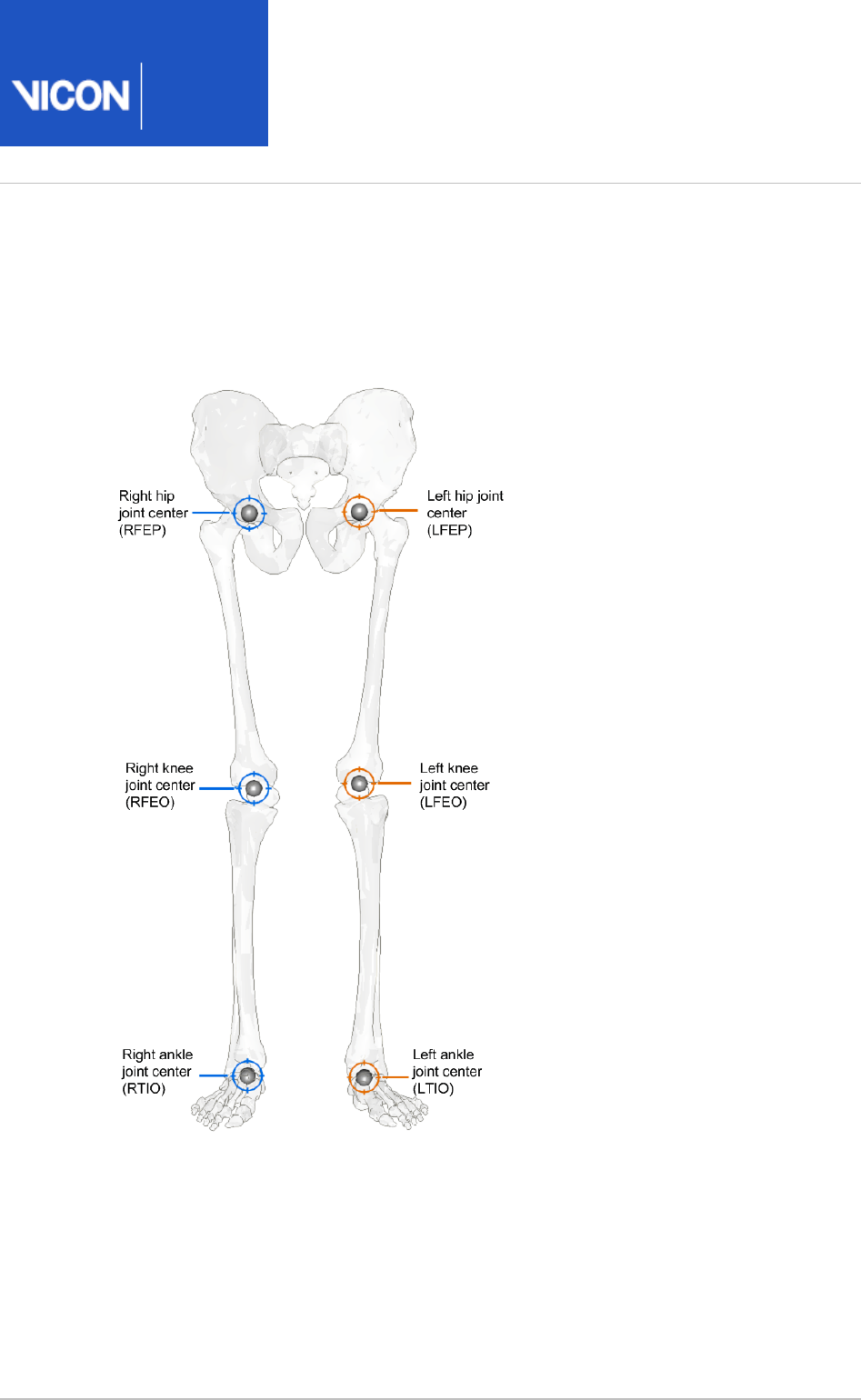
Plug-in Gait joint centers
The following image shows Plug-in Gait joint centers:

Plug-in
Gait
Reference
Vicon Motion Systems Ltd. 26-Oct-2018 Page of 40 104
Plug-in Gait lower body forces and moments
The forces calculated by Plug-in Gait and displayed by Vicon Polygon are in the local co-
ordinate frame of the distal segment in the hierarchical kinetic chain.
This means that the Ankle joint forces are recorded in the Foot segment axis system.
Therefore:
Ground Reaction force Z will look similar to Ankle Force X
Ground Reaction Force Y will look similar to Ankle Force Z
Ground Reaction Force X will look similar to Ankle Force Y
For the tibia this changes, as the axis orientation now changes:
Z force is therefore compression or tension at the joint
Y force is mediolateral forces at the joint
X force is anteroposterior forces at the joint
The positive force acts in the positive direction of the axis in the distal segment on
which it acts. A negative force acts in the negative direction along the axis.
In Plug-in Gait, we use an external moment and force description. That means that:
For the Z axis, a negative force is compression and a positive force, tension
For the Y axis, a positive force for the right side is medial and negative lateral
For the X axis, a positive force is anterior and negative posterior

Plug-in
Gait
Reference
Vicon Motion Systems Ltd. 26-Oct-2018 Page of 41 104
The following table lists all the lower body forces and moments with their positive and
negative descriptors.
Description Segment
axes
Force or moment
component
+ve
descriptor
-ve
descriptor
Ankle Force
X
Foot Compression/Tension Tension Compression
RAnkle Force
Y
Right Foot Medial/Lateral Medial Lateral
Ankle Force
Z
Foot Anterior/Posterior Anterior Posterior
Knee Force X Tibia Anterior/Posterior Anterior Posterior
RKnee Force
Y
Right Tibia Medial/Lateral Medial Lateral
LKnee Force
Y
Left Tibia Medial/Lateral Lateral Medial
Knee Force Z Tibia Tension/Compression Tension Compression
Hip Force X Thigh Anterior/Posterior Anterior Posterior
RHip Force Y Right
Thigh
Medial/Lateral Medial Lateral
LHip Force Y Left Thigh Medial/Lateral Lateral Medial
Hip Force Z Thigh Tension/Compression Tension Compression
Ankle
Moment X
Foot Dorsi/Plantar flexion Dorsiflexion Plantar
flexion
Ankle
Moment Y
Foot Abduction/Adduction Adduction Abduction

Plug-in
Gait
Reference
Vicon Motion Systems Ltd. 26-Oct-2018 Page of 42 104
Description Segment
axes
Force or moment
component
+ve
descriptor
-ve
descriptor
Ankle
Moment Z
Foot Rotation Internal External
Knee
Moment X
Tibia Flexion/Extension Flexion Extension
Knee
Moment Y
Tibia Varus/Valgus Varus Valgus
Knee
Moment Z
Tibia Rotation Internal External
Hip Moment
X
Thigh Flexion/Extension Flexion Extension
Hip Moment
Y
Thigh Abduction/Adduction Adduction Abduction
Hip Moment
Z
Thigh Rotation Internal External

Plug-in
Gait
Reference
Vicon Motion Systems Ltd. 26-Oct-2018 Page of 43 104
Plug-in Gait kinematic and kinetic calculations
The following topics describe the way in which Plug-in Gait performs calculations to
measure the kinematics and kinetics of subjects. They provide an in-depth
understanding of marker placement, and will help you to interpret the results. They
describe the geometrical relationships between markers, and segments, and gives fixed
values applied to the kinetic segments. Given the same inputs, you should be able to
replicate the results.
Lower body kinematics on page 50
Upper body kinematics on page 62
Angle outputs on page 68
Kinetic modeling on page 69
The internal structure and the specific algorithms used are not covered.

Plug-in
Gait
Reference
Vicon Motion Systems Ltd. 26-Oct-2018 Page of 44 104
About Plug-in Gait processes
The pipeline consists of the following components: all individual Plug-in Gait Dynamic
pipeline operations:
A quintic spline filter based on code written by Herman Woltring. This filter is
intended to be applied to the real marker trajectory data before the modeling stage.
No further explicit filtering of the data occurs during the modeling stage.
Operations that automatically detect and autocorrelate gait cycle events.
The modeling stage, which takes the real marker trajectories, and generates 'virtual'
marker trajectories that represent kinematic and kinetic quantities (angles, moments
etc.) and representations of the modeled segments.
An export operation, to enable you to save your processed trial data to a C3D file.
This guide covers only the modeling stage of the process. You can perform modeling on
the real marker data independently from the filtering and event detection processes by
selecting the appropriate check box in the pipeline.

Plug-in
Gait
Reference
Vicon Motion Systems Ltd. 26-Oct-2018 Page of 45 104
Segment meshes
Plug-in Gait outputs virtual markers that are used for several purposes:
To calculate variables
For visualization purposes, such as to define the positions of meshes (representing
bones), which can be displayed in the Polygon application. These mesh outputs are
rigidly linked to the calculated rigid body segments but are not necessarily the same.
The origins and axes for the meshes are dependent on the meshes contained in the
Polygon mesh file.

Plug-in
Gait
Reference
Vicon Motion Systems Ltd. 26-Oct-2018 Page of 46 104
Plug-in Gait internal models
Internally, the modeling stage consists of four interdependent models:
A kinematic lower body
A kinematic upper body
A kinetic lower body
A kinetic upper body
The kinematic models are responsible for the definitions of the rigid body segments,
and the calculations of joint angles between these segments.
The kinetic models then apply masses and moments of inertia to the segments, and
enable the "reactions" that occur on the segments to be calculated.

Plug-in
Gait
Reference
Vicon Motion Systems Ltd. 26-Oct-2018 Page of 47 104
Overview of the Plug-in Gait modeling process
To run the models, you must supply the required subject measurements. When you
have done this, the stages of the Plug-in Gait modeling process are:
The initial stage checks that the required components are present. This includes
checks for required markers present in the trial, and subject parameter values.
Modeling only continues if these requirements are met. The pelvis markers are the
minimum required for the lower body model, and the thorax markers are required for
the upper body model.
Various static values that can be calculated as being fixed for the whole trial, and are
needed for the definitions of the segments, are calculated.
The positions of the rigid segments are defined on a frame-by-frame basis. Each
segment is defined by an origin in global (laboratory) coordinates, and three
orthogonal axis directions.
In general, the three axis directions are defined using two directions derived from the
marker data.
One of these directions is taken as a dominant or principal direction, and used to
directly define one of the axes in the segment.
The second direction is subordinate to the first, and is used with the first direction to
define a plane.
The third axis of the segment is taken to be perpendicular to this plane.
Then the second axis can be found that is perpendicular to both the first and third
axes. All segment axis systems are right-handed systems.
The outputs that are required from the modeling are then calculated, based on the
frame-by-frame positions of the segments.

Plug-in
Gait
Reference
Vicon Motion Systems Ltd. 26-Oct-2018 Page of 48 104
Static vs. dynamic models
The kinematic models are run slightly differently for the static trials, to calculate certain
static 'calibration' angles that are required for the dynamic modeling. These differences
are noted in the descriptions of the models, otherwise it should be assumed that the
model is calculated in the same way for both trial types.
When the static modeling is being performed, calculated subject measurements are
output to the subject measurements file. This is not done for the dynamic trial, even if
new values are calculated internally to enable the model to be run.
Plug-in
Gait
Reference
Vicon Motion Systems Ltd. 26-Oct-2018 Page of 49 104
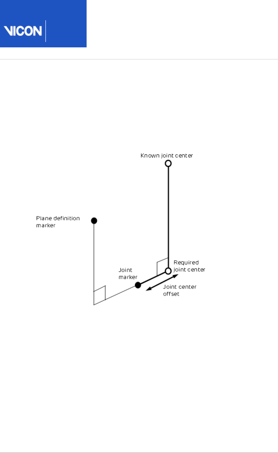
The chord function
To define joint centers, the chord function is used extensively in the Plug-in Gait
models. Three points are used to define a plane. One of these points is assumed to be a
previously calculated joint center, and a second is assumed to be a real marker, at some
known, perpendicular distance (the joint center offset) from the required joint center.
(It's called a chord because by definition, the three points (two joint centers and the
joint marker) lie on the periphery of a circle.)
A modified version of the function calculates the required joint center position when
the plane definition marker is rotated out of this plane by a known angle round the
proposed joint center axis. For an illustration of this, see Dynamic knee joint center
.calculation on page 54

Plug-in
Gait
Reference
Vicon Motion Systems Ltd. 26-Oct-2018 Page of 50 104
Lower body kinematics
Lower body fixed values on page 50
Pelvis on page 52
Knee Alignment Device (KAD) on page 52
Knee joint center on page 53
Femur on page 55
Ankle joint center on page 55
Tibia on page 58
Foot on page 59
Lower body fixed values
The Newington-Gage model is used to define the positions of the hip joint centers in
the pelvis segment.
If the InterAsis distance has not been entered in the subject measurements, this is
calculated as the mean distance between the LASI and RASI markers, for each frame in
the trial for which there is a valid position for each marker.
If the Asis to Trocanter distances have not been entered, they are calculated from the
left and right leg lengths using the formula:
AsisTrocDist = 0.1288 * LegLength – 48.56
This is done independently for each leg.
The value C is then calculated from the mean leg length:
C = MeanLegLength*0.115 – 15.3, aa is half the InterAsis distance, and mm the marker
radius.
These are used to then calculate the offset vectors for the two hip joint centers (LHJC
and RHJC) as follows:
X = C*cos(theta)*sin(beta) – (AsisTrocDist + mm) * cos(beta)
Y = -(C*sin(theta) – aa)
Z = -C*cos(theta)*cos(beta) – (AsisTrocDist + mm) * sin(beta)
where theta is taken as 0.5 radians, and beta as 0.314 radians.

Plug-in
Gait
Reference
Vicon Motion Systems Ltd. 26-Oct-2018 Page of 51 104
For the right joint center, the Y offset is negated (since Y is in the lateral direction for
the pelvis embedded coordinate system).
The position of the top of the lumbar vertebra 5 (the reference point for Dempster data
) is then estimated ason page 104
(LHJC + RHJC)/2 + (0.0, 0.0, 0.828) * Length(LHJC – RHJC)
where the value 0.828 is a ratio of the distance from the hip joint center level to the
top of the lumbar 5 compared to distance between the hip joint centers on the pelvis
mesh.
Knee and ankle offsets are then calculated by adding half the measured joint width and
marker diameter to give the distance from the center point of the marker to the joint
center.
The general direction of the subject walking in the global coordinate system is then
found by looking at the first and last valid position of the LASI marker. The X
displacement is compared to the Y displacement. If the X displacement is bigger, the
subject is deemed to have been walking along the X axis either positively or negatively,
depending on the sign of the X offset. Otherwise, the Y axis is chosen. These directions
are used to define a coordinate system matrix (similar to a segment definition) denoted
the ProgressionFrame. Note that it's assumed that the Z axis is always vertical, and that
the subject is walking along one of these axes, and not diagonally, for example.
If the distance between the first and last frame of the LASI marker is less than a
threshold of 800mm however, the progression frame is calculated using the direction
the pelvis is facing during the middle of the trial. This direction is calculated as a mean
over 10% of the frames of the complete trial. Within these frames, only those which
have data for all the pelvis markers are used. For each such frame, the rear pelvis
position is calculated from either the SACR marker directly, or the center point of the
LPSI and RPSI markers. The front of the pelvis is calculated as the center point
between the LASI and RASI markers. The pelvis direction is calculated as the direction
vector from the rear position to the front. This direction is then used in place of the
LASI displacement, as described above, and compared to the laboratory X and Y axes to
choose the Progression Frame.

Plug-in
Gait
Reference
Vicon Motion Systems Ltd. 26-Oct-2018 Page of 52 104
Pelvis
First the pelvis segment coordinate system is defined from the waist markers. The
origin is taken as the midpoint of the two asis markers. The dominant axis, taken as the
Y axis, is the direction from the right asis marker to the left asis marker. The secondary
direction is taken as the direction from the sacrum marker to the right asis marker. If
there is no sacrum marker trajectory, the posterior markers are used. If both are visible,
the mean is used. If just one is visible, then that one is used. The Z direction is generally
upwards, perpendicular to this plane, and the X axis generally forwards.
The position and scale of the pelvis is thus determined by the two asis markers, since
they determine the origin of the coronal orientation of the pelvis. The posterior sacral
markers (or psis markers) determine only the anterior tilt of the pelvis. Their actual
distance behind the asis markers and lateral position is immaterial, allowing a sacral
wand marker to be used, for example.
If the asis markers are also used to calculate the inter asis distance, they are therefore
also used to determine the lateral positions of the hip joint centers within the pelvis
segment. It is important for these to be as accurate as possible, since they affect the
determination of the femur segments, and thus influence both the hip angles, and also
the knee joint angles.
Knee Alignment Device (KAD)
For the model to determine the knee and ankle joint centers, the markers must be very
carefully positioned, and it is the responsibility of clinical staff to use their anatomical
knowledge to position markers such that the model is able to make as good an
approximation to the joint centers as possible.
The dynamic model uses the Thigh and Shank wand markers to define the plane of
containing the joint centers, and one method of marker placement is to carefully
position these markers to align with your judgment of where the joint centers are.
Alternatively, the Knee Alignment Device (KAD) may be used. This must be placed on
the patient during the static trial to indicate the plane of the knee joint center. Then
the model calculates the relative angle of the Thigh wand marker, and this angle is
used in the dynamic trial to determine the joint center without the KAD. This technique
relies on the accurate placement of the KAD, rather than the accurate placement of
the wand marker.
Plug-in
Gait
Reference
Vicon Motion Systems Ltd. 26-Oct-2018 Page of 53 104
Knee joint center
Static knee joint center calculation on page 53
Dynamic knee joint center calculation on page 54
Static knee joint center calculation
If a KAD is being used in the static model, firstly a virtual KNE marker is determined by
finding the point that is equidistant from the three KAD markers, such that the
directions from the point to the three markers are mutually perpendicular.
For the right knee, the markers RKAX, RKD1, RKD2 must be labeled in a clockwise
direction, and for the left knee, the markers LKAX, LKD1, LKD2 must be labeled anti-
clockwise. That is, if the two KD markers are positioned anteriorly, the upper marker
should be KD1.
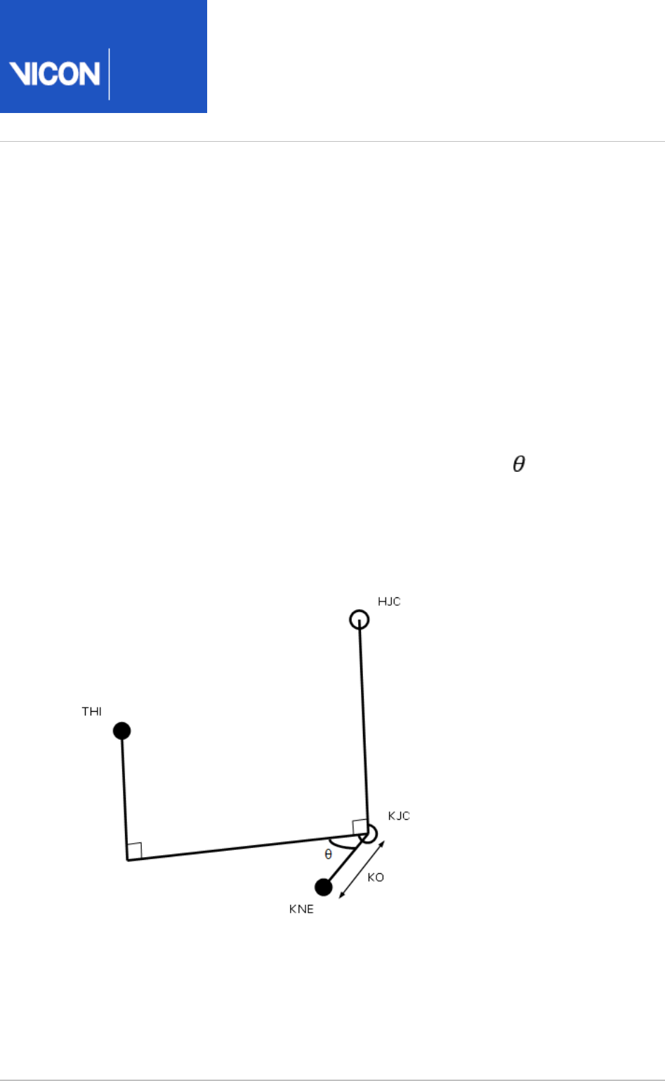
The joint center KJC is then determined using the chord function with the HJC, KNE
and KAX. The HJC-KJC and KJC-KNE lines will be perpendicular, and the KJC-KNE line
has a length equal to the knee offset (KO).
The thigh marker rotation offset ( ) is then calculated by projecting its position on to
a plane perpendicular to the HJC-KJC line.
Plug-in
Gait
Reference
Vicon Motion Systems Ltd. 26-Oct-2018 Page of 54 104
If a KAD is not being used in a static trial, then processing proceeds exactly as for a
dynamic trial.
Note that for static trials without a KAD, the anterior-posterior position of the KJC is
determined by the position of the THI wand marker, and the value of wand offset value
that is entered (if you do not enter a value, a value of zero is assumed). Correct
determination of the KJC (and the AJC) is very important, especially for the kinetic
calculations. In the clinic, you have to assess which method of marker positioning gives
the best estimate of the KJC: using a KAD or using the THI marker.
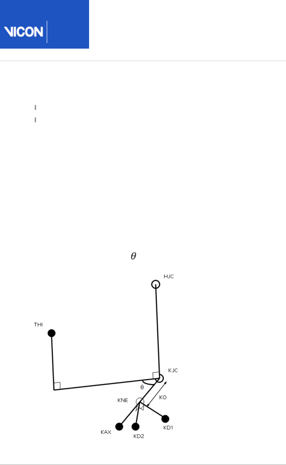
Dynamic knee joint center calculation
In the dynamic model, the KJC is determined using the modified chord function, from
the global position of the HJC, the thigh wand marker (THI), and the knee marker (KNE),
together with the knee offset (KO), and thigh wand angle offset ( ) from the subject
measurements.
KJC is found such that the KNE marker is at a distance of KO from the KJC, in a
direction perpendicular to the line from the HJC to KJC. It is also found such that the
angle between the KJC-KNE line and the KJC-THI line, projected onto a plane
perpendicular to the HJC-KJC line, is the same as the thigh wand offset angle.
There is only one position for the KJC that satisfies these two conditions.

Plug-in
Gait
Reference
Vicon Motion Systems Ltd. 26-Oct-2018 Page of 55 104
Femur
The femur origin is taken as the knee joint center. The primary Z axis is taken from the
knee joint center (KJC) to the hip joint center (HJC). The secondary axis is taken
parallel to the line from the knee joint center to the knee marker (or virtual knee
marker, for static KAD trials). This in fact directly gives the direction of the Y axis. For
both the left and the right femur, the Y axis is directed towards the left of the subject.
The X axis for both femura is hence directed forwards from the knee.
Note that in a static trial although a KAD determines the plane in which the knee joint
center lies, it does not directly determine the lateral orientation of the "knee axis"
which is implicitly defined as the Y axis of the femur segment. The lateral orientation is
defined by the vertical orientation of the Z axis (the line joining the hip and knee joint
centers). The Y axis may pass either above or below the KNE marker.
Ankle joint center
The ankle joint center is determined in a similar manner to the knee joint center (see
).Knee joint center on page 53
Static ankle joint center calculation on page 55
Dynamic ankle joint center calculation on page 57
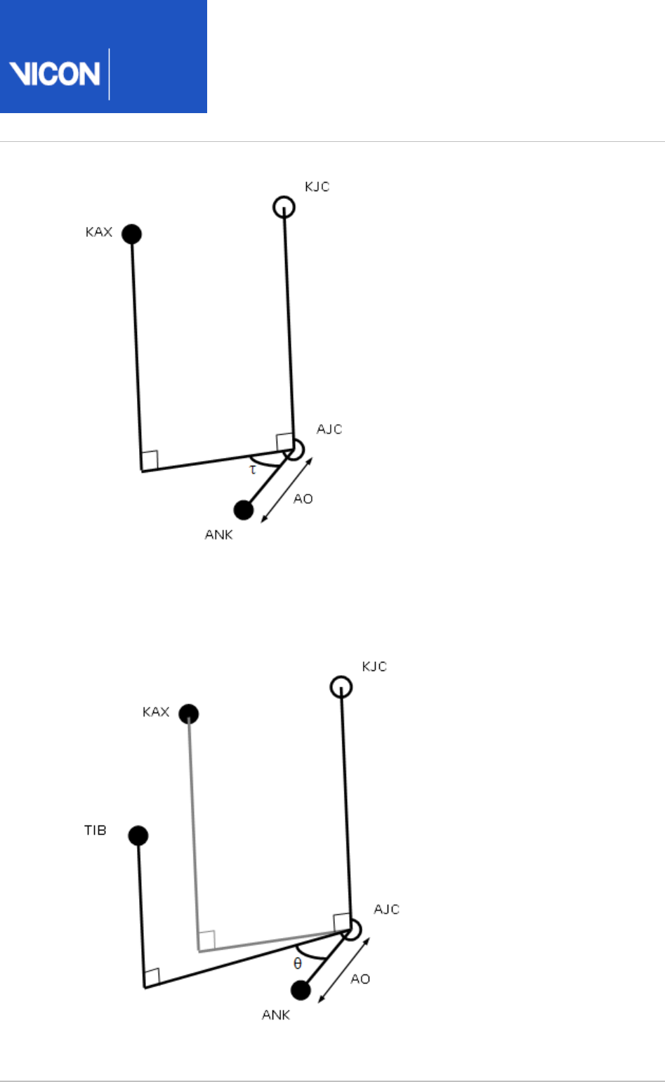
Static ankle joint center calculation
In static trials with a KAD, the KAX marker is used to define the plane of the knee axis,
and the plane of the ankle axis is assumed to be parallel to this. A value for Tibial
Torsion can be entered, and the plane of the in which the Ankle joint center lies will be
rotated by this amount relative to the plane containing the KAX marker.
Thus the AJC is found using the modified chord function, such that it has a distance
equal to the ankle offset from the ANK marker (AO), and such that the ANK-AJC line
forms an angle equal to the Tibial Torsion with the projection of the KAX-AJC line into
the plane perpendicular to the KJC-AJC line. Note that Tibial Torsion is thus considered
as an external rotation of the ankle axis relative to the knee axis.
Plug-in
Gait
Reference
Vicon Motion Systems Ltd. 26-Oct-2018 Page of 56 104
The shank marker rotation offset is then calculated by projecting its position onto the
same plane. Note that this value takes into account the value of the tibial torsion, and
in general, you would expect it to be slightly less than the value for Tibial Torsion, if the
TIB wand marker is conventionally placed.

Plug-in
Gait
Reference
Vicon Motion Systems Ltd. 26-Oct-2018 Page of 57 104
Dynamic ankle joint center calculation
In the dynamic trial, and static trials without a KAD, the ankle joint center is calculated
from the knee joint center, shank wand marker and ankle marker with the ankle offset
and shank rotation offset using the modified chord function. Thus the ankle joint
center is at a distance of ankle offset from the ankle marker, and the angle between
the KJC-AJC-ANK plane and the KJC-AJC-TIB plane is equal to the tibia rotation offset.

Plug-in
Gait
Reference
Vicon Motion Systems Ltd. 26-Oct-2018 Page of 58 104
Tibia
Tortioned tibia on page 58
Untortioned tibia on page 58
Tortioned tibia
The tibial rotation offset as determined by the static trial already takes into account
the tibial torsion. Thus a Tortioned Tibia is defined with an origin at the AJC, the Z Axis
in the direction from the AJC to the KJC, the Y axis leftwards along the line between
the AJC and ANK marker, and the X axis generally forwards. This is representative of the
distal end of the tibia.
Untortioned tibia
A second tibia is also generated representing the tibia before tibial torsion is applied, by
rotating the X and Y axes of the Tortioned Tibia round the Z axis by the negative of the
tibial torsion (i.e. externally for +ve values). This represents the proximal end, and is
used to calculate the knee joint angles.
Plug-in
Gait
Reference
Vicon Motion Systems Ltd. 26-Oct-2018 Page of 59 104
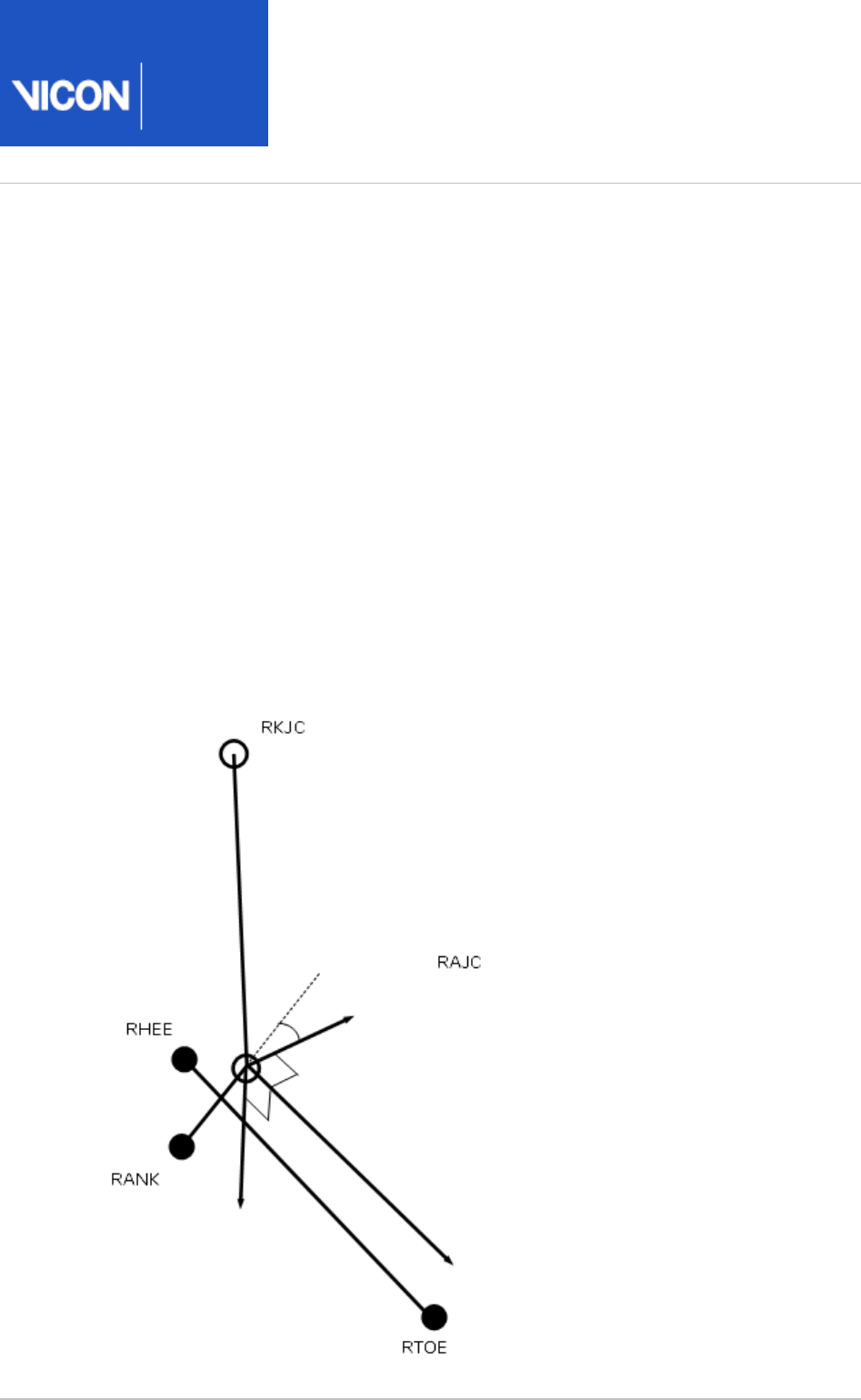
Foot
Static foot on page 59
Dynamic foot on page 61
Static foot calculation
The heel marker is used in the static trial, and the model effectively makes two
segments. For both segments, the AJC is used as the origin.
The main foot segment is constructed using the TOE-HEE line as the primary axis. If the
settings for the model have the foot flat check box selected (ie you have selected Left
and/or in the properties for the Foot Right Foot Assume Horizontal Process Static Plug-
pipeline operation), then HEE is moved vertically (along the global Z axis) in Gait Model
to be at the same height as TOE. This line is taken as the Z axis, running forwards along
the length of the foot. The direction of the Y axis from the untortioned tibia is used to
define the secondary Y axis. The X axis thus points down, and the Y axis to the left.
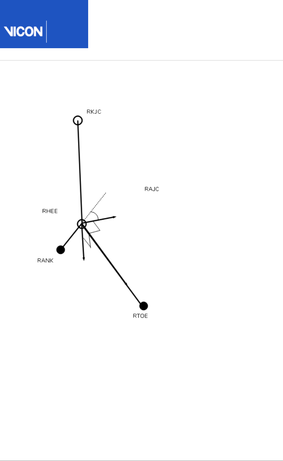
Plug-in
Gait
Reference
Vicon Motion Systems Ltd. 26-Oct-2018 Page of 60 104
A second foot segment is constructed, using the TOE-AJC as the primary axis, and
again the Y axis of the untortioned tibia to define the perpendicular X axis and the foot
Y axis (the 'uncorrected' foot).
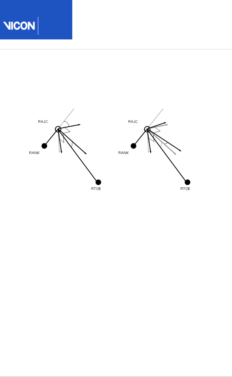
The Static offset angles (Plantar Flexion offset and Rotation offset) are then calculated
from the 'YXZ' Cardan Angles between the two segments (rotating from the
'uncorrected' segment to the heel marker based foot segment). This calculation is
performed for each frame in the static trial, and the mean angles calculated. The static
plantar-flexion offset is taken from the rotation round the Y axis, and the rotation
offset is the angle round the X axis. The angle round the Z axis is ignored.
Plug-in
Gait
Reference
Vicon Motion Systems Ltd. 26-Oct-2018 Page of 61 104
Dynamic foot calculation
In the dynamic trial, the foot is calculated in the same way as for the 'uncorrected' foot.
The resulting segment is then rotated first round the Y axis by the Plantar Flexion
offset. Then the resulting segment is rotated around its X axis by the rotation offset.

Plug-in
Gait
Reference
Vicon Motion Systems Ltd. 26-Oct-2018 Page of 62 104
Upper body kinematics
Upper body fixed values on page 62
Head on page 63
Thorax on page 63
Shoulder joint center on page 64
Clavicle on page 64
Elbow joint center on page 65
Wrist joint center on page 66
Humerus on page 66
Radius on page 66
Hand on page 67
Upper body fixed values
A shoulder offset value is calculated from the Subject measurement value entered, plus
half the marker diameter. Elbow, wrist and hand offset values are also calculated from
the sum of the respective thickness with the marker diameter divided by two.
A progression frame is independently calculated in just the same way as for the lower
body. C7 is tested first to determine if the subject moved a distance greater than the
threshold. If not, the other thorax markers T10 CLAV and STRN are used to determine
the general direction the thorax was facing in from a mean of 10% of the frames in the
middle of the trial.
Note that in principle it could be possible to arrive at different reference frames for the
upper and lower body, though the circumstances would be extreme.

Plug-in
Gait
Reference
Vicon Motion Systems Ltd. 26-Oct-2018 Page of 63 104
Head
The head origin is defined as the midpoint between the LFHD and RFHD markers (also
denoted 'Front').
The midpoint between the LBHD and RBHD markers ('Back') is also calculated, along
with the 'Left' and 'Right' sides of the head from the LFHD and LBHD midpoint, and the
RFHD and RBHD midpoint respectively.
The predominant head axis, the X axis, is defined as the forward facing direction (Front
- Back). The secondary Y axis is the lateral axis from Right to Left (which is
orthogonalized as usual).
For the static processing, the YXZ Euler angles representing the rotation from the head
segment to the lab axes are calculated. The Y rotation is taken as the head Offset
angle, and the mean of this taken across the trial.
For the dynamic trial processing, the head Offset angle is applied around the Y axis of
the defined head segment.
Thorax
The orientation of the thorax is defined before the origin. The Z axis, pointing upwards,
is the predominant axis. This is defined as the direction from the midpoint of the STRN
and T10 to the midpoint of CLAV and C7. A secondary direction pointing forwards is the
midpoint of C7 and T10 to the midpoint of CLAV and STRN. The resulting X axis points
forwards, and the Y axis points leftwards.
The thorax origin is then calculated from the CLAV marker, with an offset of half a
marker diameter backwards along the X axis.
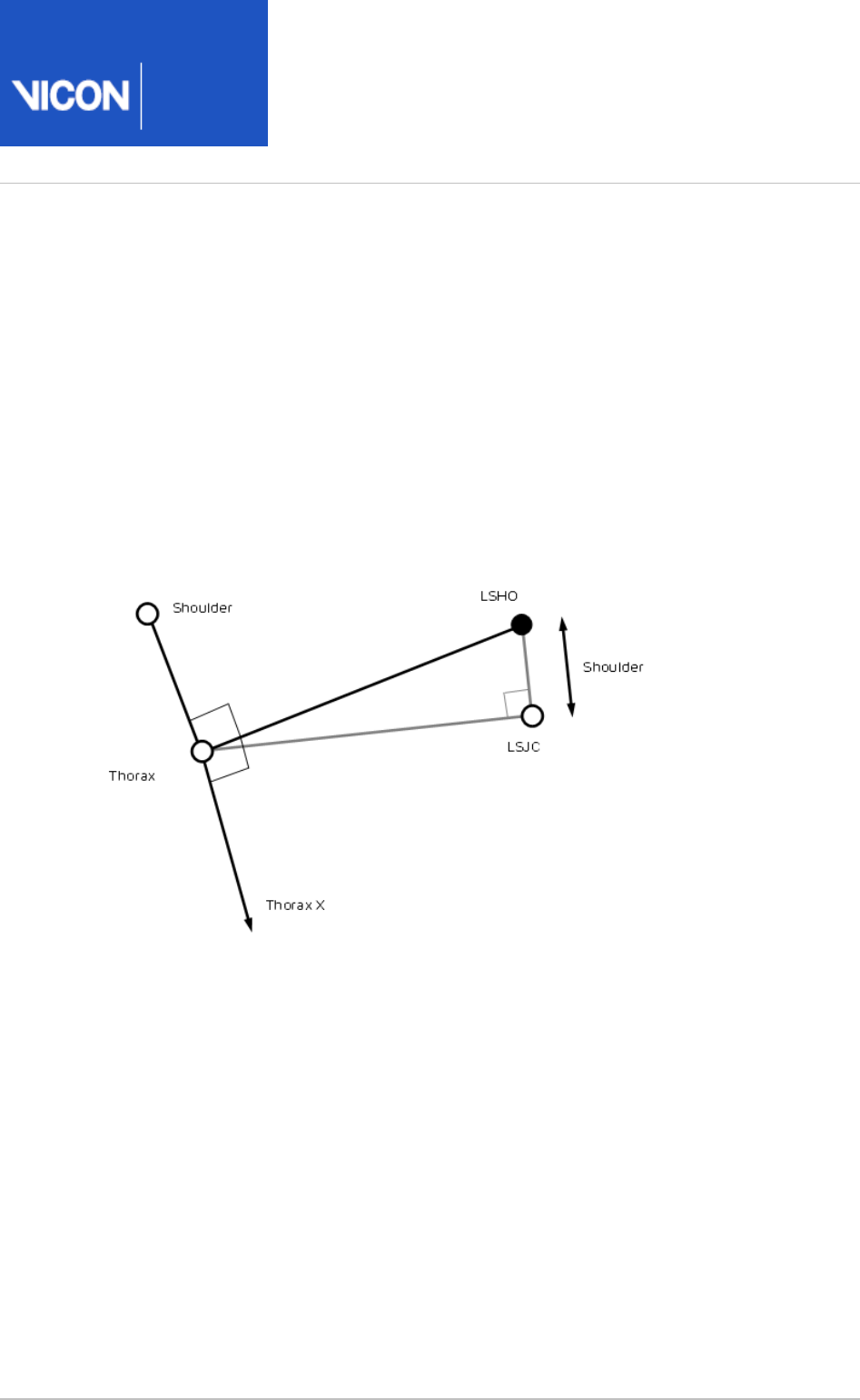
Plug-in
Gait
Reference
Vicon Motion Systems Ltd. 26-Oct-2018 Page of 64 104
Shoulder joint center
The clavicles are considered to lie between the thorax origin, and the shoulder joint
centers. The shoulder joint centers are defined as the origins for each clavicle. Note
that the posterior part of the shoulder complex is considered too flexible to be modeled
with this marker set.
Initially a direction is defined, which is perpendicular to the line from the thorax origin
to the SHO marker, and the thorax X axis. This is used to define a virtual shoulder
'wand' marker.
The chord function is then used to define the shoulder joint center (SJC) from the
Shoulder offset, thorax Origin, SHO marker and shoulder 'wand'.
Clavicle
The clavicle segment is defined from the direction from the joint center to the thorax
origin as the Z axis, and the shoulder wand direction as the secondary axis. The X axis
for each clavicle points generally forwards, and the Y axis for the left points upwards,
and the right clavicle Y axis points downwards.

Plug-in
Gait
Reference
Vicon Motion Systems Ltd. 26-Oct-2018 Page of 65 104
Elbow joint center
A construction vector direction is defined, being perpendicular to the plane defined by
the shoulder joint center, the elbow marker (LELB) and the midpoint of the two wrist
markers (LWRA, LWRB).
The elbow joint center is defined using the chord function, in the plane defined by the
shoulder joint center, the elbow marker and the previously defined construction vector.
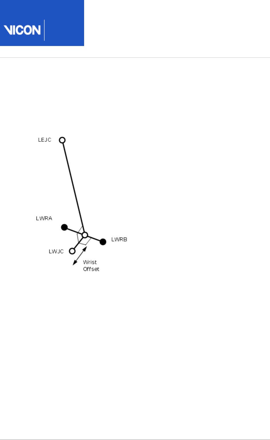
Plug-in
Gait
Reference
Vicon Motion Systems Ltd. 26-Oct-2018 Page of 66 104
Wrist joint center
After the elbow joint center is calculated, the wrist joint center (WJC) is calculated. In
this case the chord function is not used. The wrist joint center is simply offset from the
midpoint of the wrist bar markers along a line perpendicular to the line along the wrist
bar, and the line joining the wrist bar midpoint to the elbow joint center.
Humerus
After the wrist joint center is defined, the Humerus is calculated with its origin at the
EJC, a principal Z axis from EJC to SJC, and a secondary line approximating to the X axis
between the EJC and the WJC.
Radius
The radius origin is set at the wrist joint center. The principal axis is the Z axis, from the
WJC to the EJC. The secondary line approximating to the Y axis is taken as the Y axis of
the Humerus segment.

Plug-in
Gait
Reference
Vicon Motion Systems Ltd. 26-Oct-2018 Page of 67 104
Hand
The hand is defined by first defining its origin. The chord function is used again for this,
with the WJC, FIN marker and Hand Offset. The midpoint of the wrist bar markers is
used to define the plane of calculation.
The principal Z axis is then taken as the line from the hand origin to the WJC, and a
secondary line approximating the Y axis is defined by direction of the line joining the
wrist bar markers.

Plug-in
Gait
Reference
Vicon Motion Systems Ltd. 26-Oct-2018 Page of 68 104
Angle outputs
The output angles for all joints are calculated from the YXZ Cardan angles derived by
comparing the relative orientations of the two segments.
The knee angles are calculated from the femur and the Untortioned tibia segments,
whilst the ankle joint angles are calculated from the Tortioned tibia and the foot
segment.
In the case of the feet, since they are defined in a different orientation to the tibia
segments, an offset of 90 degrees is added to the flexion angle. This does not affect
the Cardan angle calculation of the other angles since the flexion angle is the first in
the rotation sequence.
The progression angles of the feet, pelvis, thorax and head are the YXZ Cardan
calculated from the rotation transformation of the subject's Progression Frame for the
trial onto each segment orientation.

Plug-in
Gait
Reference
Vicon Motion Systems Ltd. 26-Oct-2018 Page of 69 104
Kinetic modeling
The kinetic modeling parts of the model simply assign masses and radii of gyration to
the segments defined in the kinematic model. An estimate of the position of the center
of mass is required in the segment. This is defined as a point at a given proportion
along a line from the distal joint center (normally the origin of the segment) towards
the proximal joint center of a "typical" segment. The masses of each segment are
calculated as a proportion of the total body mass. The principal axes moments of
inertia are calculated from (mass) normalized radii of gyration from these tables too. In
general the moment is considered to be zero around the longitudinal axis of most
segments. Since experimental data were not available, estimates have been made for
the radii of gyration of the pelvis and thorax. You can change these values in the
pane of the pipeline operation.Properties Process Dynamic Plug-in Gait Model
The following diagram shows the kinetic hierarchy.
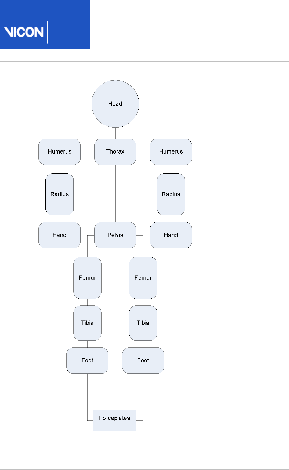
Plug-in
Gait
Reference
Vicon Motion Systems Ltd. 26-Oct-2018 Page of 70 104
Note that the clavicles are not considered to have mass in themselves, so reactions for
the humerus segments are consider to act directly on the thorax.

Plug-in
Gait
Reference
Vicon Motion Systems Ltd. 26-Oct-2018 Page of 71 104
The feet are only 'connected' to the forceplates where forceplate measurements and
marker data indicate a match. Only one segment is chosen to be in contact with a
given forceplate for each frame.
Note also that the "untortioned" tibiae are used for the kinetic modeling. This means
that where the KAD and a tibial torsion have been used, and the proximal frame is
chosen to reference the ankle moments, the flexion and abduction moments will not
correspond to the axes used to calculate the ankle angles. Having said that, the axes
are calculated with a "floating axis" definition, so even for corresponding segments the
axes will not be coincident.
Even though the "untortioned" tibiae are used for the reference frames, a difference in
moments will be observed if the trial is processed with a different tibial torsion. When
the tibial torsion is applied in the static trial, the ankle joint center is moved backwards,
then the "untortioned" tibia is calculated by rotating the tortioned tibia round the Z
axis, keeping the ankle joint center in position. Thus, for a given trial, as tibial torsion is
increased, and the joint center is rotated backwards around the ankle marker, the ankle
flexion moment will generally become more positive.
Segment CoM Mass Radius of gyration
Pelvisa0.895 0.142 0.31
Femur 0.567 0.1 0.323
Tibia 0.567 0.0465 0.302
Foot 0.5 0.0145 0.475
Humerus 0.564 0.028 0.322
Radius 0.57 0.016 0.303
Handb0.6205 0.006 0.223
Thoraxc0.63 0.355 0.31
Headdsee below 0.081 0.495

Plug-in
Gait
Reference
Vicon Motion Systems Ltd. 26-Oct-2018 Page of 72 104
a) Pelvis: The center of mass is defined along a line from the midpoint of the hip joint
centers, to the center of the top surface of the Lumbar 5 vertebra. For simplified
scaling, this distance is defined as 0.925 times the distance between the hip joint
centers, and the Lumbar5 is defined as lying directly on the Z axis (derived by
inspection from the bone mesh used in Polygon). The radius of gyration for the pelvis is
an estimate, and is applied round all three axes.
b) Hand: The length of the hand in this model is defined as the distance from the wrist
joint center to the finger tip. An estimate of 0.75 is taken as the proportion of this
length to the "Knuckle II" reference point referred to in the .Dempster data on page 104
c) Thorax: The thorax length is taken as the distance between an approximation to the
C7 vertebra and the L5 vertebra in the Thorax reference frame. C7 is estimated from the
C7 marker, and offset by half a marker diameter in the direction of the X axis. L5 is
estimated from the L5 provided from the pelvis segment, but localized to the thorax,
rather than the pelvis. The positions are calculated for all frames in the trial, and
averaged to give the mean length. The Center of mass is deemed to lie at a proportion
of 0.63 along this line.
d) Head: The center of mass of the head is defined as being 0.52 * the distance from
the front to the back of the head along the X axis from the head origin (the midpoint of
the front head markers). The length of the head used for the inertial normalization is
the distance from this point to the C7 vertebra (the mean position localized to the head
segment). The inertia value for the head is applied around all three axes.

Plug-in
Gait
Reference
Vicon Motion Systems Ltd. 26-Oct-2018 Page of 73 104
Whole body center of mass
The center of mass is calculated whenever the head or thorax segment is present. A
weighted sum of all the centers of mass of all the segments is made, where segments
are defined by markers. The sum is still made if segments, such as the hands, for
example, do not have markers. The center of mass is the center of mass of all the
modeled segments.
Caution
Note that this center of mass algorithm has not been clinically tested, and
may be misleading in some clinical situations. In particular, the thorax
segment is modeled kinetically as a rigid body which includes the mass of the
abdomen (which is not independently modeled). The markers which define the
thorax are at the top of the thorax, and the center of mass is assumed to be
on a line directed towards the L5 vertebra. Any bending of the trunk in the
upper lumbar region will cause this assumption to fail, which may cause a
significant error in the position of the center of mass for the whole body.
The projection of the center of mass onto the floor is made simply by setting the Z
value to zero.

Plug-in
Gait
Reference
Vicon Motion Systems Ltd. 26-Oct-2018 Page of 74 104
Plug-in Gait output angles
The output angles for all joints are calculated from the YXZ Cardan angles derived by
comparing the relative orientations of the segments proximal (parent) and distal (child)
to the joint.
The knee angles are calculated from the femur and the Untorsioned tibia segments,
while the ankle joint angles are calculated from the Torsioned tibia and the foot
segment.
In the case of the feet, because they are defined in a different orientation to the tibia
segments, an offset of 90 degrees is added to the flexion angle. This does not affect
the Cardan angle calculation of the other angles because the flexion angle is the first
in the rotation sequence.
The progression angles of the feet, pelvis, thorax and head are the YXZ Cardan
calculated from the rotation transformation of the subject's progression frame for the
trial onto each segment orientation.
The following topics provide further details.
Angle definitions on page 75
Plug-in Gait kinematic variables on page 78
Upper body angles as output from Plug-in Gait on page 88
Lower body angles as output from Plug-in Gait on page 93

Plug-in
Gait
Reference
Vicon Motion Systems Ltd. 26-Oct-2018 Page of 75 104
Angle definitions
Plug-in Gait uses Cardan angles, modified in the case of the ankle angles, to represent
both:
Absolute rotations of the pelvis and foot segments and
Relative rotations at the hip, knee, and ankle joints
These angles can be described either as a set of rotations carried out one after the
other (ordered).
For more information about the use of Cardan angles to calculate joint kinematics,
refer to Kadaba, Ramakrishnan and Wooten (1990) and Davis, Õunpuu, Tyburski and
Gage (1991) (see ).Plug-in Gait references
The rotations are measured about anatomical axes in order to simplify their
interpretation.
For more information on joint angle descriptions, including the issues of gimbal lock
and Codman's Paradox, see:
Ordered rotations on page 75
Angle goniometric description on page 76
Ordered rotations
To describe an angle using ordered rotations, the following are true:
One element is 'fixed'. For absolute rotations the laboratory axes are fixed. The
proximal segment axes are fixed for relative rotations.
The second element 'moves'. This means the segment axes move for absolute
rotations and distal segment moves for relative rotations.
A joint angle is then defined using the following ordered rotations:
The first rotation (flexion) is made about the common flexion axis. The other two
axes, abduction and rotation, are afterwards no longer aligned in the two elements.
The second rotation (abduction) is made about the abduction axis of the moving
element. The third rotation (rotation) is made about the rotation axis of the moving
element.

Plug-in
Gait
Reference
Vicon Motion Systems Ltd. 26-Oct-2018 Page of 76 104
Angle goniometric description
In addition to using ordered rotations, joint angles can also be described using
goniometric information. Using goniometric definitions, a joint angle is described by
the following:
Flexion is about the flexion axis of the proximal (or absolute) element.
Rotation is about the rotation axis of the distal element.
Abduction axis 'floats' so as always to be at right angles to the other two.
Cardan angles work well unless a rotation approaching 90 degrees brings two axes into
line. When this happens, one of the possible rotations is lost and becomes
unmeasurable. Fortunately, this does not frequently occur in the joints of the lower
limbs during normal or pathological gait. However this may occur in the upper limb and
particularly at the shoulder. For more information, see and Gimbal lock on page 76
also below.Codman's Paradox on page 76
Gimbal lock
Gimbal lock occurs when using Cardan (Euler) angles and any of the rotation angles
becomes close to 90 degrees, for example, lifting the arm to point directly sideways or
in front (shoulder abduction about an anterior axis or shoulder flexion about a lateral
axis respectively). In either of these positions the other two axes of rotation become
aligned with one another, making it impossible to distinguish them from one another, a
singularity occurs and the solution to the calculation of angles becomes unobtainable.
For example, assume that the humerus is being rotated in relation to the thorax in the
order Y,X,Z and that the rotation about the X-axis is 90 degrees.
In such a situation, rotation in the Y-axis is performed first and correctly. The X-axis
rotation also occurs correctly BUT rotates the Z axis onto the Y axis. Thus, any rotation
in the Y-axis can also be interpreted as a rotation about the Z-axis.
True gimbal lock is rare, arising only when two axes are close to perfectly aligned.
Codman's Paradox
The second issue however, is that in each non-singular case there are two possible
angular solutions, giving rise to the phenomenon of "Codman's Paradox" in anatomy
(Codman, E.A. (1934).
The Shoulder. Rupture of the Supraspinatus Tendon and other
. Boston: Thomas Todd Company), where
Lesions in or about the Subacromial Bursa
different combinations of numerical values of the three angles produce similar physical
orientations of the segment. This is not actually a paradox, but a consequence of the

Plug-in
Gait
Reference
Vicon Motion Systems Ltd. 26-Oct-2018 Page of 77 104
1.
2.
3.
4.
non-commutative nature of three-dimensional rotations and can be mathematically
explained through the properties of rotation matrices (Politti, J.C., Goroso, G.,
Valentinuzzi, M.E., & Bravo, O. (1998).
Codman's Paradox of the Arm Rotations is Not a
. Medical Engineering & Physics, 20, 257-260).
Paradox: Mathematical Validation
Codman proposed that the completely elevated humerus could be shown to be in
either extreme external rotation or in extreme internal rotation by lowering it either in
the coronal or sagittal plane respectively, without allowing any rotation about the
humeral longitudinal axis.
To demonstrate Codman's Paradox, complete the following steps:
Place the arm at the side, elbow flexed to 90 degrees and the forearm internally
rotated across the stomach.
Elevate the arm 180 degrees in the sagittal plane.
Lower the arm 180 degrees to the side in the coronal plane.
Observe that the forearm now points 180 degrees externally rotated from its
original position with no rotation about the humeral longitudinal axis actually
having occurred.
Note the difficulty in describing whether the fully elevated humerus was
internally or externally rotated.
This ambiguity can cause switching between one solution and the other, resulting in
sudden discontinuities. A combination of gimbal lock and Codman's Paradox can lead
to unexpected results when joint modeling is carried out. In practice, the shoulder is
the only joint commonly analyzed that has a sufficient range of motion about all
rotation axes for these to be an issue. Generally, if you are aware of the reasons for the
inconsistent data, you can manipulate any erroneous results by adding 180 or 360
degrees.
As Plug-in Gait uses Cardan (Euler) angles in all cases to calculate joint angles, they are
subject to both Gimbal Lock in certain poses, and the inconsistencies that occur as a
result of Codman's Paradox.
Plug-in Gait includes some steps to minimize the above effects by trying to keep the
shoulder angles in consistent and understandable quadrants. This is not a complete
solution however, as the above issues are inherent when using Cardan (Euler) angles
and clinical descriptions of motion.
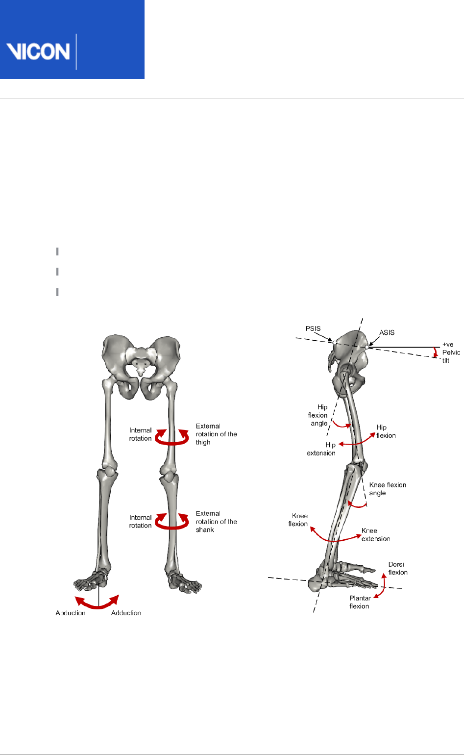
Plug-in
Gait
Reference
Vicon Motion Systems Ltd. 26-Oct-2018 Page of 78 104
Plug-in Gait kinematic variables
When gait cycle events have been defined, derived kinematic quantities are calculated
and written to file.
Note that throughout this section, axes are described as follows:
Transverse axes are those axes which pass from one side of the body to the other;
Sagittal axes pass from the back of the body to the front; and
Frontal axes pass in a direction from the center of the body through the top of the
head.

Plug-in
Gait
Reference
Vicon Motion Systems Ltd. 26-Oct-2018 Page of 79 104
List of kinematic variables calculated by Plug-in Gait
The following table lists all the kinematic variables calculated by Plug-in Gait. It
includes information describing each variable in terms of ordered rotations or
goniometric definitions.
For example, knee rotation is a relative angle measured between the thigh as the
proximal segment and the shank as the distal segment. Its 'goniometric' axis is fixed to
the shank as the distal segment. Incidentally, this angle, although always calculated, is
often omitted from reports because it is so difficult to measure with precision.
Foot rotation and foot progression, also known as foot alignment, are not expressed in
terms of goniometric axes, since the ankle angles are not calculated as strict Cardan
angles. Both rotations measure the alignment of the foot. The first is relative to the
shank, and the second is measured as an absolute angle in the laboratory's transverse
plane.
Absolute angles are measured relative to laboratory axes with the sagittal and
transverse axes automatically selected according to the direction of walking. In Plug-in
Gait, the laboratory axis closest to the subject's direction of progression is labeled the
laboratory sagittal axis.
Each variable is listed in the following table:
Angle
rotation
Goniometric Description
Pelvic tilt Absolute Pelvic tilt is normally calculated about the laboratory's
transverse axis. If the subject's direction of forward
progression is closer to the laboratory's sagittal axis,
however, then pelvic tilt is measured about this axis.
The sagittal pelvic axis, which lies in the pelvis
transverse plane, is normally projected into the
laboratory sagittal plane. Pelvic tilt is measured as the
angle in this plane between the projected sagittal
pelvic axis and the sagittal laboratory axis. A positive
value (up) corresponds to the normal situation in
which the PSIS is higher than the ASIS.
Pelvic
obliquity
Absolute
Pelvic obliquity is measured about an axis of rotation
perpendicular to the axes of the other two rotations.
This axis does not necessarily correspond with any of

Plug-in
Gait
Reference
Vicon Motion Systems Ltd. 26-Oct-2018 Page of 80 104
Angle
rotation
Goniometric Description
the laboratory or pelvic axes. Pelvic obliquity is
measured in the plane of the laboratory transverse
axis and the pelvic frontal axis. The angle is measured
between the projection into the plane of the
transverse pelvic axis and projection into the plane of
the laboratory transverse axis (the horizontal axis
perpendicular to the subject's axis of progression). A
negative pelvic obliquity value (down) relates to the
situation in which the opposite side of the pelvis is
lower.
Pelvic
rotation
Absolute Pelvic rotation is calculated about the frontal axis of
the pelvic co-ordinate system. It is the angle
measured between the sagittal axis of the pelvis and
the sagittal laboratory axis (axis closest to subject's
direction of progression) projected into the pelvis
transverse plane. A negative (external) pelvic rotation
value means the opposite side is in front.
Hip flexion
/extension
Relative Hip flexion is calculated about an axis parallel to the
pelvic transverse axis which passes through the hip
joint centre. The sagittal thigh axis is projected onto
the plane perpendicular to the hip flexion axis. Hip
flexion is then the angle between the projected
sagittal thigh axis and the sagittal pelvic axis. A
positive (Flexion) angle value corresponds to the
situation in which the knee is in front of the body.
Hip ab
/adduction
Relative
Hip adduction is measured in the plane of the hip
flexion axis and the knee joint centre. The angle is
calculated between the long axis of the thigh and the
frontal axis of the pelvis projected into this plane. A
positive number corresponds to an adducted (inwardly
moved) leg.

Plug-in
Gait
Reference
Vicon Motion Systems Ltd. 26-Oct-2018 Page of 81 104
Angle
rotation
Goniometric Description
Hip
rotation
Relative Hip rotation is measured about the long axis of the
thigh segment and is calculated between the sagittal
axis of the thigh and the sagittal axis of the pelvis
projected into the plane perpendicular to the long axis
of the thigh. The sign is such that a positive hip
rotation corresponds to an internally rotated thigh.
Knee
flexion
/extension
Relative The sagittal shank axis is projected into the plane
perpendicular to the knee flexion axis. Knee flexion is
the angle in that plane between this projection and
the sagittal thigh axis. The sign is such that a positive
angle corresponds to a flexed knee.
Knee ab
/adduction
(Knee
valgus
/varus)
Relative This is measured in the plane of the knee flexion axis
and the ankle center, and is the angle between the
long axis of the shank and the long axis of the thigh
projected into this plane.
A positive number corresponds to varus (outward
bend of the knee).
Knee
rotation
Relative Knee rotation is measured about the long axis of the
shank. It is measured as the angle between the
sagittal axis of the shank and the sagittal axis of the
thigh, projected into a plane perpendicular to the long
axis of the shank. The sign is such that a positive
angle corresponds to internal rotation. If a tibial
torsion value is present in the Session form, it is
subtracted from the calculated knee rotation value. A
positive tibial torsion value therefore has the effect of
providing a constant external offset to knee rotation.
Ankle dorsi
/plantar
flexion
Relative The foot vector is projected into the foot sagittal
plane. The angle between the foot vector and the
sagittal axis of the shank is the foot dorsi/plantar
flexion. A positive number corresponds to dorsiflexion.

Plug-in
Gait
Reference
Vicon Motion Systems Ltd. 26-Oct-2018 Page of 82 104
Angle
rotation
Goniometric Description
Foot
rotation
Relative This is measured about an axis perpendicular to the
foot vector and the ankle flexion axis. It is the angle
between the foot vector and the sagittal axis of the
shank, projected into the foot transverse plane. A
positive number corresponds to an internal rotation.
Foot-based
dorsi
/plantar
flexion
This optional angle is defined similarly to ankle dorsi
/plantar flexion, but it is measured in a plane
containing the knee and ankle centers and the toe
marker.
Foot
progression
Absolute This is the angle between the foot vector (projected
into the laboratory's transverse plane) and the sagittal
laboratory axis. A positive number corresponds to an
internally rotated foot.
Head tilt Absolute Head tilt is normally calculated about the laboratory's
transverse axis. If the subject's direction of forward
progression is closer to the laboratory's sagittal axis,
however, then head tilt is measured about this axis.
The sagittal head axis is normally projected into the
laboratory sagittal plane. Head tilt is measured as the
angle in this plane between the projected sagittal
head axis and the sagittal laboratory axis. A positive
value (up) corresponds to forward head tilt.
Head
obliquity
Absolute
Head lateral tilt is measured about an axis of rotation
perpendicular to the axes of the other two rotations.
This axis does not necessarily correspond with any of
the laboratory or head axes. Head lateral tilt is
measured in the plane of the laboratory transverse
axis and the head frontal axis. The angle is measured
between the projection into the plane of the
transverse head axis and projection into the plane of
the laboratory transverse axis (the horizontal axis

Plug-in
Gait
Reference
Vicon Motion Systems Ltd. 26-Oct-2018 Page of 83 104
Angle
rotation
Goniometric Description
perpendicular to the subject's axis of progression). A
negative head obliquity value (down) relates to the
situation in which the opposite side of the head is
lower.
Head
rotation
Absolute Head rotation is calculated about the frontal axis of
the head co-ordinate system. It is the angle measured
between the sagittal axis of the head and the sagittal
laboratory axis (axis closest to subject's direction of
progression) projected into the head transverse plane.
A negative (external) head rotation value means the
opposite side is in front.
Thorax tilt Absolute Thorax tilt is normally calculated about the
laboratory's transverse axis. If the subject's direction
of forward progression is closer to the laboratory's
sagittal axis, however, then thorax tilt is measured
about this axis. The sagittal thorax axis is normally
projected into the laboratory sagittal plane. Thorax tilt
is measured as the angle in this plane between the
projected sagittal thorax axis and the sagittal
laboratory axis. A positive value (up) corresponds to
forward thorax tilt.
Thorax
obliquity
Absolute
Thorax obliquity is measured about an axis of rotation
perpendicular to the axes of the other two rotations.
This axis does not necessarily correspond with any of
the laboratory or thorax axes. Thorax obliquity is
measured in the plane of the laboratory transverse
axis and the Thorax frontal axis. The angle is
measured between the projection into the plane of
the transverse thorax axis and projection into the
plane of the laboratory transverse axis (the horizontal
axis perpendicular to the subject's axis of progression.

Plug-in
Gait
Reference
Vicon Motion Systems Ltd. 26-Oct-2018 Page of 84 104
Angle
rotation
Goniometric Description
As the thorax segment is defined with the frontal Z
axis point downward a positive (up) thorax obliquity
angle relates to the situation in which the opposite
side of the thorax is lower.
Thorax
rotation
Absolute Thorax rotation is calculated about the frontal axis of
the thorax co-ordinate system. It is the angle
measured between the sagittal axis of the thorax and
the sagittal laboratory axis (axis closest to subject's
direction of progression) projected into the thorax
transverse plane. As the thorax segment is defined
with the frontal Z axis point downward a positive
(internal) thorax rotation value means the opposite
side is in front.
Neck
flexion
/extension
Relative The sagittal head axis is projected onto the plane
perpendicular to the thorax sagittal axis. Neck flexion
is then the angle between the projected sagittal head
axis and the sagittal thorax axis around the fixed
transverse axis of the thorax. A positive (flexion) angle
value corresponds to the situation in which the head
is tilted forward.
Neck
lateral
flexion
Relative The angle between the long axis of the head and the
long axis of the thorax around a floating transverse
axis.
Neck
rotation
Relative
Neck rotation is measured about the long axis of the
head. It is measured as the angle between the sagittal
axis of the head and the sagittal axis of the thorax,
around a floating frontal axis. As the thorax frontal
axis points downward while the head frontal axis
points upward, a positive angle therefore refers to
rotation of the head toward the opposite side.

Plug-in
Gait
Reference
Vicon Motion Systems Ltd. 26-Oct-2018 Page of 85 104
Angle
rotation
Goniometric Description
Spine
flexion
/extension
Relative Spine flexion is the angle between the sagittal thorax
axis and the sagittal pelvis axis around the fixed
transverse axis of the pelvis. A positive (flexion) angle
value corresponds to the situation in which the thorax
is tilted forward.
Spine
lateral
flexion
Relative The angle between the long axis of the thorax and the
long axis of the pelvis, around a floating transverse
axis.
Spine
rotation
Relative It is measured as the angle between the sagittal axis
of the thorax and the sagittal axis of the pelvis,
around a floating frontal axis. As the thorax frontal
axis points downward while the pelvis frontal axis
points upward, a positive angle therefore refers to
rotation of the thorax toward the opposite side.
Shoulder
flexion
/extension
Relative Shoulder flexion is calculated about an axis parallel to
the thorax transverse axis. Shoulder flexion is the
angle between the projected sagittal-humerus axis
and the sagittal-thorax axis around the fixed
transverse axis. of the thorax. A positive (flexion)
angle value corresponds to the situation in which the
arm is in front of the body.
Shoulder ab
/adduction
Relative
The angle is calculated between the transverse axis of
the humerus and the transverse axis of the thorax
around a floating sagittal axis. A negative number
corresponds to an abducted (outwardly moved) arm.

Plug-in
Gait
Reference
Vicon Motion Systems Ltd. 26-Oct-2018 Page of 86 104
Angle
rotation
Goniometric Description
Shoulder
rotation
Relative Shoulder rotation is measured about the long axis of
the humerus segment and is calculated between the
sagittal axis of the humerus and the sagittal axis of
the thorax around a floating frontal axis. The sign is
such that a positive shoulder rotation corresponds to
an internally rotated humerus.
Elbow
flexion
/extension
Relative Elbow flexion is the only kinematic parameter
calculated at the elbow as the segment definitions of
the Humerus and radius result in two of the axes
being shared. Elbow flexion is calculated between the
sagittal radius axis and the sagittal humerus axis
around the fixed transverse axis of the humerus. A
positive number indicates a flexion angle.
Wrist
flexion
/extension
Relative Wrist flexion is the angle between the sagittal hand
axis and the sagittal radius axis around the fixed
transverse axis of the radius. A positive (flexion) angle
value corresponds to the situation in which the wrist
bends toward the palm.
Wrist ab
/adduction
Relative The angle is calculated between the transverse axis of
the hand and the transverse axis of the radius around
a floating sagittal axis. A positive number corresponds
to the hand abducting toward the thumb.
Wrist
rotation
Relative Wrist rotation is measured about the long axis of the
hand segment and is calculated between the sagittal
axis of the hand and the sagittal axis of the radius
around a floating frontal axis. The sign is such that a
positive wrist rotation corresponds to the hand
rotating in the direction of the thumb.

Plug-in
Gait
Reference
Vicon Motion Systems Ltd. 26-Oct-2018 Page of 87 104
For more information, see also:
Complete pelvis position description
A pelvis in which the three markers all lay in the horizontal plane and the line joining
the ASIS markers was parallel to a laboratory axis, would have zero tilt, obliquity and
rotation.
To visualize the pelvic angles, start with a pelvis in this neutral position, tilt it about the
transverse axis by the amount of pelvic tilt, rotate it about its (tilted) sagittal axis by the
amount of pelvic obliquity and rotate it about its (tilted and oblique) frontal axis by the
amount of pelvic rotation. The pelvis is now in the attitude described by those degrees
of tilt, obliquity and rotation.
The transverse and frontal plane kinematics of all joints are influenced by the
mathematics involved with embedded axes. The following is an example which
demonstrates the effect of using embedded axes to calculate "pelvic obliquity" in a
static trial: If a calibration device, designed with 15 degrees of pelvic tilt and level ASIS
markers, is statically rotated 20 degrees from a lab's axis of progression, a report
generated by Plug-in Gait will show 10 degrees of pelvic obliquity. For more clarification
about the effect of embedded axes on joint kinematics, refer to Kadaba, Ramakrishnan
and Wooten (1990).
Complete hip position description
A thigh whose long axis was parallel to the frontal pelvic axis, and in which the knee
flexion axis was parallel to the pelvic transverse axis, would be in the neutral position
(described by zeroes in all three angles). To move from this neutral position to the
actual thigh position described by the three angles, first flex the hip by the amount of
the hip flexion, then adduct by the amount of hip adduction, then rotate the thigh
about the (flexed and adducted) long axis of the thigh, and it is in the position
described by those three angles.
Complete knee position description
A neutral shank is positioned such that the shank is in line with the thigh and the ankle
flexion axis is parallel to the knee flexion axis. From this position, flex the knee by the
amount of knee flexion, bend inward by the amount of valgus/varus, and rotate by the
amount of knee rotation, to produce the actual position described by those three
angles.

Plug-in
Gait
Reference
Vicon Motion Systems Ltd. 26-Oct-2018 Page of 88 104
Upper body angles as output from Plug-in Gait
The following tables display the upper body segment angles from Plug-in Gait.
All upper body angles are calculated in rotation order YXZ.
As Euler angles are calculated, each rotation causes the axis for the subsequent
rotation to be shifted. X’ indicates an axis which has been acted upon and shifted by
one previous rotation, X’’ indicates a rotation axis which has been acted upon and
shifted by two previous rotations.

Plug-in
Gait
Reference
Vicon Motion Systems Ltd. 26-Oct-2018 Page of 89 104
Left upper body angles
Angles Positive rotation Axis Direction
LHeadAngles 1 Backward Tilt Prg.Fm. Y Clockwise
2 Right Tilt Prg.Fm. X' Anti-clockwise
3 Right Rotation Prg.Fm. Z'' Clockwise
LThoraxAngles 1 Backward Tilt Prg.Fm. Y Clockwise
2 Right Tilt Prg.Fm. X' Anti-clockwise
3 Right Rotation Prg.Fm. Z'' Clockwise
LNeckAngles 1 Forward Tilt Thorax Y Clockwise
2 Left Tilt Thorax X' Clockwise
3 Left Rotation Thorax Z'' Clockwise
LSpineAngles 1 Forward Thorax Tilt Pelvis Y Anti-Clockwise
2 Left Thorax Tilt Pelvis X' Clockwise
3 Left Thorax Rotation Pelvis Z'' Anti-Clockwise
LShoulderAngles 1 Flexion Thorax Y Anti-clockwise
2 Abduction Thorax X' Anti-clockwise
3 Internal Rotation Thorax Z'' Anti-clockwise
LElbowAngles 1 Flexion Humeral Y Anti-clockwise
2 - Humeral X' -

Plug-in
Gait
Reference
Vicon Motion Systems Ltd. 26-Oct-2018 Page of 90 104
Angles Positive rotation Axis Direction
3 - Humeral Z'' -
LWristAngles 1 Ulnar Deviation Radius X Clockwise
2 Extension Radius Y' Clockwise
3 Internal Rotation Radius Z'' Clockwise

Plug-in
Gait
Reference
Vicon Motion Systems Ltd. 26-Oct-2018 Page of 91 104
Right upper body angles
Angles Positive rotation Axis Direction
RHeadAngles 1 Backward Tilt Prg.Fm. Y Clockwise
2 Left Tilt Prg.Fm. X' Clockwise
3 Left Rotation Prg.Fm. Z'' Anti-clockwise
RThoraxAngles 1 Backward Tilt Prg.Fm. Y Clockwise
2 Left Tilt Prg.Fm. X' Clockwise
3 Left Rotation Prg.Fm. Z'' Anti-clockwise
RNeckAngles 1 Forward Tilt Thorax Y Clockwise
2 Right Tilt Thorax X' Anti-clockwise
3 Right Rotation Thorax Z'' Anti-clockwise
RSpineAngles 1 Forward Thorax Tilt Pelvis Y Anti-Clockwise
2 Right Thorax Tilt Pelvis X' Anti-clockwise
3 Right Thorax Rotation Pelvis Z'' Clockwise
RShoulderAngles 1 Flexion Thorax Y Anti-clockwise
2 Abduction Thorax X' Clockwise
3 Internal Rotation Thorax Z'' Clockwise
RElbowAngles 1 Flexion Humeral Y Clockwise
2 - Humeral X' -

Plug-in
Gait
Reference
Vicon Motion Systems Ltd. 26-Oct-2018 Page of 92 104
Angles Positive rotation Axis Direction
3 - Humeral Z'' -
RWristAngles 1 Ulnar Deviation Radius X Anti-clockwise
2 Extension Radius Y' Clockwise
3 Internal Rotation Radius Z'' Anti-clockwise

Plug-in
Gait
Reference
Vicon Motion Systems Ltd. 26-Oct-2018 Page of 93 104
Lower body angles as output from Plug-in Gait
The following tables display the lower body segment angles from Plug-in Gait.
All lower body angles are calculated in rotation order YXZ except for ankle angles,
which are calculated in order YZX.
As Euler angles are calculated, each rotation causes the axis for the subsequent
rotation to be shifted. X’ indicates an axis which has been acted upon and shifted by
one previous rotation, X’’ indicates a rotation axis which has been acted upon and
shifted by two previous rotations.

Plug-in
Gait
Reference
Vicon Motion Systems Ltd. 26-Oct-2018 Page of 94 104
Left lower body angles
Angles Positive rotation Axis Direction
LPelvisAngles 1 Anterior Tilt Prg.Fm. Y Anti-clockwise
2 Upward Obliquity Prg.Fm. X' Anti-clockwise
3 Internal Rotation Prg.Fm. Z'' Clockwise
LFootProgressAngles 1 - Prg.Fm. Y -
2 - Prg.Fm. X' -
3 Internal Rotation Prg.Fm. Z'' Clockwise
LHipAngles 1 Flexion Pelvis Y Clockwise
2 Adduction Pelvis X' Clockwise
3 Internal Rotation Pelvis Z'' Clockwise
LKneeAngles 1 Flexion Thigh Y Anti-clockwise
2 Varus/Adduction Thigh X' Clockwise
3 Internal Rotation Thigh Z'' Clockwise
LAnkleAngles 1 Dorsiflexion Tibia Y Clockwise
2 Inversion/ Adduction Tibia X'' Clockwise
3 Internal Rotation Tibia Z' Clockwise

Plug-in
Gait
Reference
Vicon Motion Systems Ltd. 26-Oct-2018 Page of 95 104
Right lower body angles
Angles Positive rotation Axis Direction
RPelvisAngles 1 Anterior Tilt Prg.Fm. Y Anti-clockwise
2 Upward Obliquity Prg.Fm. X' Clockwise
3 Internal Rotation Prg.Fm. Z'' Anti-clockwise
RFootProgressAngles 1 - Prg.Fm. Y -
2 - Prg.Fm. X' -
3 Internal Rotation Prg.Fm. Z'' Anti-clockwise
RHipAngles 1 Flexion Pelvis Y Clockwise
2 Adduction Pelvis X' Anti-clockwise
3 Internal Rotation Pelvis Z'' Anti-clockwise
RKneeAngles 1 Flexion Thigh Y Anti-clockwise
2 Varus/Adduction Thigh X' Anti-clockwise
3 Internal Rotation Thigh Z'' Anti-clockwise
RAnkleAngles 1 Dorsiflexion Tibia Y Clockwise
2 Inversion/ Adduction Tibia X'' Anti-clockwise
3 Internal Rotation Tibia Z' Anti-clockwise

Plug-in
Gait
Reference
Vicon Motion Systems Ltd. 26-Oct-2018 Page of 96 104
Plug-in Gait output specification
The following topics provide definitions to enable you to reliably reconstruct the
segment co-ordinate systems using Plug-in Gait outputs in third-party modeling
software.
Global (laboratory) co-ordinate system on page 97
Pelvis on page 98
Femur on page 99
Tibia on page 100
Foot on page 101
Joint kinematic definitions on page 102
Joint kinetics on page 103
The Plug-in Gait model consists of seven segments (including the left and right side):
Pelvis
Femur (left and right)
Tibia (left and right)
Feet (left and right)
When calculations are performed, a scaling length for each of the 7 Plug-in Gait Static
segments is written to the subject's . file.
mp
The process outputs joint kinematics and kinetics to a . file, Plug-in Gait Dynamic
c3d
which also defines them in terms of their order and sign conventions.
For information about the definition of the Plug-in Gait model itself and the algorithms
used to locate the segment co-ordinate systems and calculate the segment lengths
from skin fixed marker data, see Plug-in Gait kinematic and kinetic calculations on page
. The marker names used here are from the standard Plug-in Gait marker 43
definitions. For precise definitions of their location, see Plug-in Gait models and
.templates on page 5

Plug-in
Gait
Reference
Vicon Motion Systems Ltd. 26-Oct-2018 Page of 97 104
Global (laboratory) co-ordinate system
The laboratory co-ordinate system is required here as a reference for the pelvis
kinematics. The lab system is also used later in the definition of the foot co-ordinate
frame.
The global Z axis defines the vertical, i.e. perpendicular to the lab floor.
The global X and Y axes are in the plane of the lab floor, with X often defining the
direction if normal walking along the laboratory walkway.
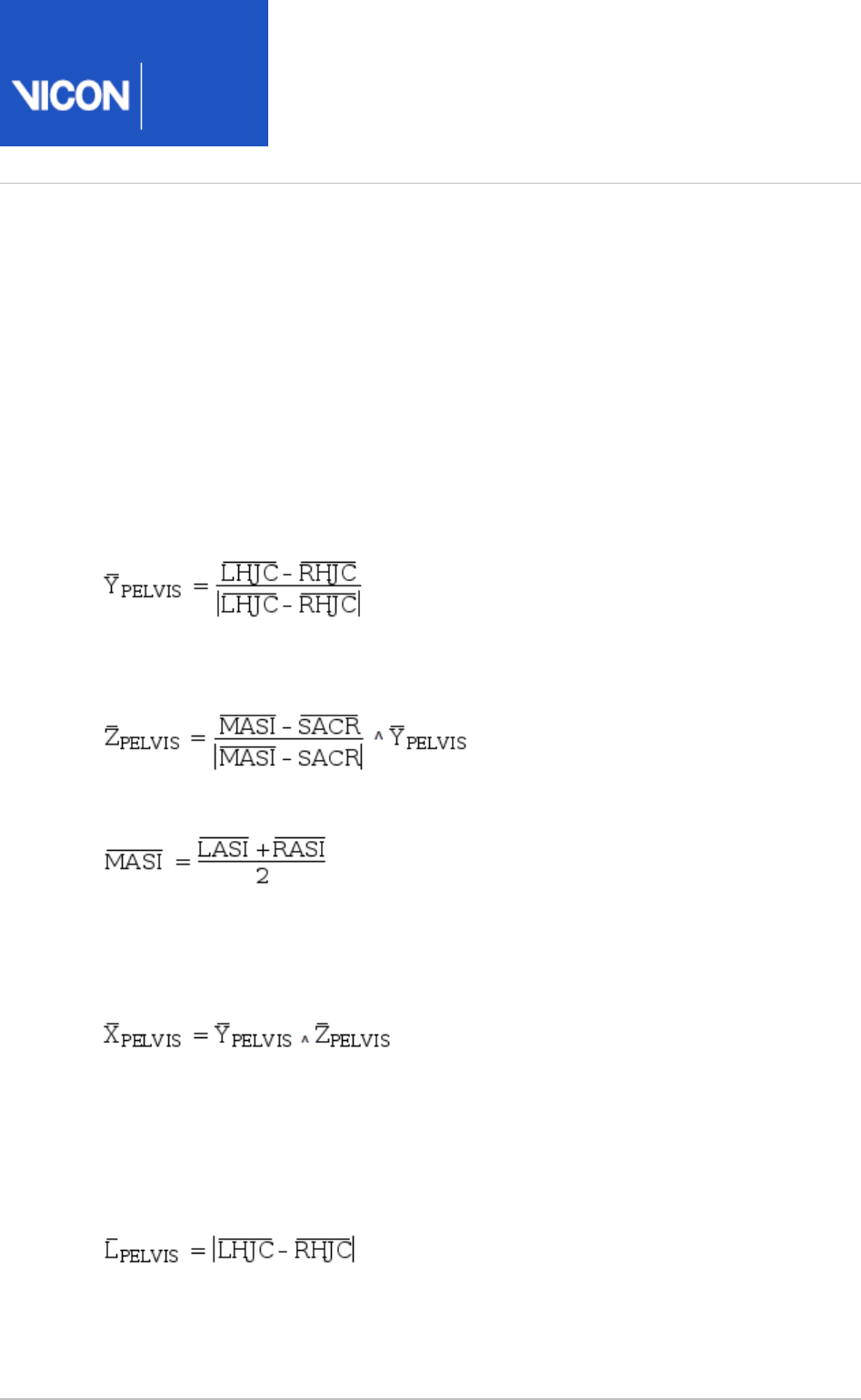
Plug-in
Gait
Reference
Vicon Motion Systems Ltd. 26-Oct-2018 Page of 98 104
Pelvis
The origin of the pelvis co-ordinate system in Plug-In Gait is the midpoint of the vector
connecting the two asis landmarks (LASI and RASI). The co-ordinate system of the
pelvis is reconstructed from the surface markers on the ASIS and PSIS landmarks, but
should be considered to be related to the bony geometry of the pelvis as follows.
The Y axis is lateral (to the left) and is directed from the right hip joint centre (RHJC) to
the left hip joint centre (LHJC), where the HJC are defined as the centre of the
spherical part of the femoral head:
The Z axis is then perpendicular to Y and the vector between the sacrum (SACR) and
the midpoint of the asis landmarks:
where:
(The sacral marker is not always used, and this landmark can be calculated as being at
the midpoint of the vector connecting the LPSI and RPSI markers).
The X axis is naturally the cross product of the Y and Z pelvis axes:
In the Plug-in Gait model, the pelvis Y axis is assumed to be parallel to the vector
between the LASI and RASI markers, but the definition above is more suitable when
constructing a co-ordinate system from known hip joint centers.
The length of the pelvis segment calculated by the Plug-in Gait model is equal to the
inter-hip distance:
Plug-in Gait also outputs the inter-asis distance, which can also be used to assist in
reconstruction of the morphology of the pelvis.

Plug-in
Gait
Reference
Vicon Motion Systems Ltd. 26-Oct-2018 Page of 99 104
Femur
The accuracy/validity of the femoral coordinate system is affected by the estimation of
the knee joint center location as well as the knee flexion extension axis. These two
estimations are reliant upon your providing accurate marker placement and subject
measurements.
The co-ordinate axes are aligned with the long axis of the femurs and the knee flexion
axes as follows.
The Z axis of the femur is directed from the knee joint center to the hip joint center:
The X axis is anterior and is perpendicular to the knee flexion axis, :
Finally, the Y axis is lateral (to the left for both legs) and is given by:
The scaling length of the femur is simply the distance from the knee joint center to the
hip joint center:

Plug-in
Gait
Reference
Vicon Motion Systems Ltd. 26-Oct-2018 Page of 100 104
Tibia
The Tibia effectively has two co-ordinate systems: a proximal one for calculating knee
joint angles and a distal one for calculating ankle joint angles.
Both segments have their origins at the ankle joint center (AJC) and are defined in a
manner similar to the femoral segments. Again, the location of the ankle joint center
and ankle flexion axis calculated by Plug-in Gait are reliant upon your providing
accurate marker placement and subject measurements.
Firstly, the proximal system uses the knee joint center, ankle joint center and the knee
flexion axis, :
The distal coordinate system is then rotated about the long axis of the tibia (Z) such
that it is aligned with the ankle flexion axis, :
The scaling length of the tibia is the distance from the ankle joint center to the knee
joint center:

Plug-in
Gait
Reference
Vicon Motion Systems Ltd. 26-Oct-2018 Page of 101 104
Foot
The origin of the foot segments of the Plug-in Gait model is located at the ankle joint
centers. The foot co-ordinate system is defined in a rather more complex manner
within the Plug-in Gait model than is necessary to recreate the motion of the bones
from the Plug-in Gait kinematics output.
Firstly, the system Z axis is equal to the vector from the toe to heel markers (HEE and
TOE), projected into the plane of the laboratory floor (X-Y plane):
Where:
The X axis is then perpendicular to this and the ankle flexion axis and is directed
vertically:
And finally, the Y axis is naturally the cross product of these two axes:
The scaling length of the foot is the distance from the ankle joint center to the toe
marker:

Plug-in
Gait
Reference
Vicon Motion Systems Ltd. 26-Oct-2018 Page of 102 104
1.
Joint kinematic definitions
The following table specifies how the rotations within each of the joints of the model
are ordered as trajectories in the . file.
c3d
Note
Angles are always given in the . file as degrees.
c3d
For all of the joints, the joint co-ordinate system method of reporting kinematics has
been used to specify flexion, abduction, and rotation. It is difficult to give a consistent
definition of these angles for all of the joints due to the differing meaning of flexion
etc.
Instead, the axis in the proximal segment embedded co-ordinate system about which
each of the rotations takes place (together with the order these rotations should be
applied) is given in the following table showing Euler angle specification:
Joint 1st Component 2nd Component 3rd Component Order
Global Pelvis Tilt (Y) Obliquity (X) Rotation (-Z) 1,2,3
Left Hip Flexion (-Y) Adduction (-X) Rotation (-Z) 1,2,3
Left Knee Flexion (Y) Adduction (-X) Rotation (-Z) 1,2,3
Left Ankle Flexion (-Y)1Inversion (Z) Rotation (X) 1,3,2
Right Hip Flexion (-Y) Adduction (X) Rotation (Z) 1,2,3
Right Knee Flexion (Y) Adduction (X) Rotation (Z) 1,2,3
Right Ankle Flexion (-Y)1Inversion (-Z) Rotation (-X) 1,3,2
The feet segments are peculiar to the rest of the model, not only because of the
different rotation order, but also because the orientation of the foot at zero
degrees flexion is straight upwards, that is, the toe will point towards the knee.
An offset of +90 degrees should be applied in order to point the foot forwards.

Plug-in
Gait
Reference
Vicon Motion Systems Ltd. 26-Oct-2018 Page of 103 104
Joint kinetics
The output from Plug-in Gait also contains forces, moments and powers for each of the
segments.
Note
Forces, moments and powers are given in the . file in Newtons, Newton-
c3d
meters and Watts respectively.
For both forces and moments, the reaction frame can be specified within Plug-in Gait
to be proximal, distal, or in the global frame.
For each of the forces, the components in the .c3d file match the co-ordinate
directions described in this document. For the moments, however, the order they are
stored in the .c3d file matches the rotation order shown in the table in Joint kinematic
, and therefore do not correspond to any of the segment definitions on page 102
embedded co-ordinate systems.

Plug-in
Gait
Reference
Vicon Motion Systems Ltd. 26-Oct-2018 Page of 104 104
1.
The following table lists the components of the moments in terms of the axes about
which they act.
Joint 1st Component 2nd Component 3rd Component
Left hip -Y X Z
Left knee Y X Z
Left ankle (prox.)1 Y X Z
Left ankle (dist.)1Y Z -X
Right hip -Y -X -Z
Right knee Y -X -Z
Right ankle (prox.)1Y -X -Z
Right ankle (dist.)1Y -Z X
Due to the differing alignment of the foot and tibia segment co-ordinate
systems, the components of the ankle moment differ depending on whether they
are represented in the proximal, distal or global co-ordinate systems.
References
Dempster, WT. (1955) . WADC Technical
Space requirements of the seated operator
Report 55–159, Wright-Patterson Air Force Base, OH.
