PortVision DX User Guide Ftp://ftp.comtrol.com/legacy/dev_mstr/portvision_dx/docs/Port Vision_DX_User_Guide Port Vision
User Manual: ftp://ftp.comtrol.com/legacy/dev_mstr/portvision_dx/docs/PortVision_DX_User_Guide user guide pdf
Open the PDF directly: View PDF ![]() .
.
Page Count: 155 [warning: Documents this large are best viewed by clicking the View PDF Link!]
- Table of Contents
- Introduction
- Installing PortVision DX
- User Interface Overview
- Managing the View
- Network Configuration
- Firmware
- Software Settings
- Accessing Configuration Web Pages
- Configuration Files
- Telnet SSH Sessions
- Accessing Other Applications
- Changing PortVision DX Options
- Logging Events
- Troubleshooting

User Guide

Trademark Notices
Comtrol, NS‐Link, RocketLinx, and DeviceMaster are trademarks of Comtrol Corporation.
Microsoft and Windows are registered trademarks of Microsoft Corporation.
HyperTerminal is a registered trademark of Hilgraeve, Inc.
Portions of SocketServer are copyrighted by GoAhead Software, Inc. Copyright © 2001. GoAhead Software, Inc. All
Rights Reserved.
Other product names mentioned herein may be trademarks and/or registered trademarks of their respective owners.
First Edition, September 5, 2014
Copyright © 2001 ‐ 2014. Comtrol Corporation.
All Rights Reserved.
Comtrol Corporation makes no representations or warranties with regard to the contents of this document or to the
suitability of the Comtrol product for any particular purpose. Specifications are subject to change without notice. Some
software or features may not be available at the time of publication. Contact your reseller for current product information.
Part Number: 2000602 Rev. A -- This is a pdf copy of the PortVision DX Help System
Table of Contents
Introduction __________________________________________________________________ 1
Requirements 7
Features 8
Locating the Latest Documentation 8
Downloading the Latest Documentation Catalog File 9
Downloading Documentation from Comtrol 10
Accessing Previously Downloaded Documentation 11
Installing PortVision DX _______________________________________________________ 13
User Interface Overview _______________________________________________________ 17
Main Screen 18
Menu Bar 19
Tool Bar 19
Device Tree Pane 19
Device Tree Details Pane 20
Device List Pane 21
Device List Details Pane 22
Status Bar 23
Buttons 23
Scan 24
Refresh All 24
Properties 24
Save 24
Load 25
Upload 25
Reboot 25
Webpage 25
Help 26
About 26
Exit 26
File Menu 26
Manage Menu 27
View Menu 31
Tools Menu 32
Log File 33
Applications Shortcuts 35
Options...Screen 36
Help Menu 37
Properties Screen 37
What's This Help Feature 38
DeviceMaster LT/PRO/RTS/Serial Hub/500 Properties 39
General Tab (DeviceMaster LT | PRO | RTS | Serial Hub | 500) 39
Software Settings Tab (DeviceMaster LT | PRO | RTS | Serial Hub | 500) 42
Web Interface Tab (DeviceMaster LT | PRO | RTS | Serial Hub | 500) 44
iii
Table of Contents
DeviceMaster UP Properties 45
General Tab (DeviceMaster UP) 45
Software Settings Tab (DeviceMaster UP) 48
Web Interface Tab (DeviceMaster UP) 50
IO-Link Master Properties 51
General Tab (IO-Link Master) 51
Software Settings Tab (IO-Link Master) 54
Web Interface Tab (IO-Link Master) 56
RocketLinx Properties 57
General Tab (RocketLinx) 57
Web Interface Tab (RocketLinx) 61
General Tab (Other Hardware) 62
Add New Device Screen 64
Add New Device Screen (Managed) 65
Add New Device Screen (Other Hardware) 67
Managing the View ___________________________________________________________ 69
Scanning the Network 70
Managing Devices 71
Using Folders 71
Adding Folders 72
Moving Folders 72
Renaming Folders 73
Deleting Folders 73
Moving Devices into a Folder 74
Adding a New Device 74
Remote Using the IP Address 75
Local Using the IP Address or MAC Address 75
Unmanaged Switches or Third-Party Devices 76
Renaming a Device 76
Deleting a Device 77
Changing the Detection Type (DeviceMaster) 77
Saving Device Diagnostics Data Files (IO-Link Master) 78
Editing Notes 78
Changing the Device List View 78
Refreshing the View 79
Managing Sessions 80
Importing PortVision Plus Sessions 80
Creating a New Session 81
Saving a Session 82
Opening an Existing Session 82
Exporting the Device List 83
Network Configuration ________________________________________________________ 85
DeviceMaster (LT, PRO, RTS, Serial Hub, and 500) 86
Assigning IP Addresses to Multiple Devices 88
Assign a Range of IP Address to Multiple DeviceMasters 88
Same IP Address on Multiple DeviceMasters 89
iv

PortVision DX User Guide
DeviceMaster UP 90
Assigning IP Addresses to Multiple Devices 92
Assign a Range of IP Address to Multiple DeviceMasters 92
Same IP Address on Multiple DeviceMasters 93
IO-Link Master 94
RocketLinx 96
Firmware ___________________________________________________________________ 99
DeviceMaster (LT, PRO, RTS, Serial Hub, and 500) 99
Checking the SocketServer Version 100
Uploading SocketServer 102
Checking the Bootloader Version 104
Uploading Bootloader 105
DeviceMaster UP 107
Checking Protocol-Specific Firmware Versions 108
Uploading Protocol-Specific Firmware 109
Checking the Bootloader Version 111
Uploading Bootloader 112
IO-Link Master 114
EtherNet/IP and Modbus/TCP 114
Images and Applications 114
Checking the Software Versions 116
Uploading Images and Applications 117
RocketLinx (Managed) 119
Checking the Configuration Web Page Version 120
Uploading Firmware 121
Uploading Firmware on a Single RocketLinx 121
Uploading the Web User Interface on Multiple RocketLinx Switches 123
Checking the Bootloader Version 124
Uploading Bootloader 125
Software Settings ___________________________________________________________ 127
DeviceMaster 127
Security Considerations 128
Accessing the Software Settings Tab 128
DeviceMaster UP 129
Accessing the Software Settings Tab 129
IO-Link Master 130
Accessing Configuration Web Pages ___________________________________________ 131
Locating Configuration Web Page Information 131
Configuration Files __________________________________________________________ 133
Converting DeviceMaster Configuration Files 133
Saving Configuration Files 134
Main Screen 134
Software Settings Tab 136
Loading Configuration Files 137
Main Screen 137
Software Settings Tab 139
v
Table of Contents
Reset to Factory Default 140
Telnet SSH Sessions ________________________________________________________ 141
DeviceMaster TCP and UDP Socket Ports 141
Accessing Other Applications _________________________________________________ 143
Adding Shortcuts 143
Changing Application Shortcuts 144
Removing Application Shortcuts 144
Test Terminal 145
Port Monitor 145
PuTTY 145
Changing PortVision DX Options ______________________________________________ 147
Logging Events _____________________________________________________________ 149
Enabling Event Logging 149
Accessing the Event Log 150
Clearing the Event Log 151
Troubleshooting ____________________________________________________________ 153
Using the LED Tracker 153
IO-Link Master 153
RocketLinx 154
OFF-LINE Devices 155
Contacting Technical Support 155
vi

Introduction
PortVision DX automatically detects Comtrol Ethernet attached products physically attached to
the local network segment so that you can configure the network address, upload firmware, and
manage the following products:
•DeviceMaster family
•DeviceMaster PRO
•DeviceMaster RTS
•DeviceMaster Serial Hub
•DeviceMaster 500
•DeviceMaster LT
•DeviceMaster UP
•IO-Link Master
•RocketLinx
In addition to identifying Comtrol Ethernet attached products, you can use PortVision DX to
display any third-party switch and hardware that may be connected directly to those devices. All
non-Comtrol products and unmanaged RocketLinx devices are treated as non-intelligent devices
and have limited feature support. For example, you cannot configure or update firmware on a
third-party switch.
Requirements
PortVision DX may require that you have the latest Microsoft Service pack for your operating
system (32/64-bit):
•Windows 8/8.1
•Windows Server 2012
•Windows 7
•Windows Server 2008
•Windows Vista
•Windows Server 2003
•Windows XP
To utilize all PortVision DX features, make sure that your Comtrol Ethernet attached product has
the latest firmware versions installed. If you do not have the appropriate version on your device,
you should upload the latest version before performing configuration procedures.
Introduction 7

PortVision DX User Guide
Features
PortVision DX supports these features on Comtrol Ethernet attached products:
• Network settings configuration tailored for that product. The DeviceMaster can also
assign sequential or identical IP addresses to multiple DeviceMasters simultaneously.
• Ability to upload the latest firmware (default application for the product) or bootloader.
• Ability to save and load configuration files so that standard configuration settings can be
propagated across similar products.
• Access to Comtrol Ethernet attached product configuration web pages.
• Access to Telnet/SSH sessions, which opens a command prompt window and
establishes a telnet connection with an IP connected device.
• Remotely reboot any Comtrol Ethernet attached (managed) product.
• Locate technical documentation and connector pin-out information for your Comtrol
Ethernet attached product in the Properties window.
• Provides event logging at the device-level and application-level.
• Capability to access your favorite applications with shortcuts from PortVision DX. By
default it provides access to the following applications:
• Test Terminal (serial port test application)
• Port Monitor (serial port monitoring application)
• PuTTY (free MIT-licensed Windows 32-bit Telnet, SSH, and Rlogin client)
Locating the Latest Documentation
You can download the latest document version or access the documentation (after you have
downloaded it) in PortVision DX from the Help > Documentation menu option or from the
Properties page Documentation... menu.
To open Comtrol product documentation, you must have a pdf Reader installed on your system.
You can download the Acrobat Reader from the Adobe web site.
8 Introduction
PortVision DX User Guide
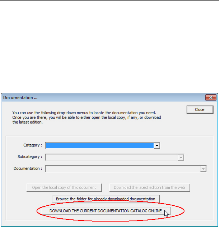
Downloading the Latest Documentation Catalog File
PortVision DX includes the documentation catalog file that was available at the time PortVision
DX was built. The documentation catalog is continually updated and the first time you want to
download product documentation, you should first download the latest catalog file. You may want
to occasionally update this file so that you can retrieve the latest documents released.
Use this procedure to update your documentation catalog file.
1. Click Documentation from the Help menu on the Main screen or on the Properties
page.
2. Click the DOWNLOAD THE CURRENT DOCUMENTATION CATALOG ONLINE button.
You are now ready to download the latest documentation from Comtrol.
Introduction 9
PortVision DX User Guide
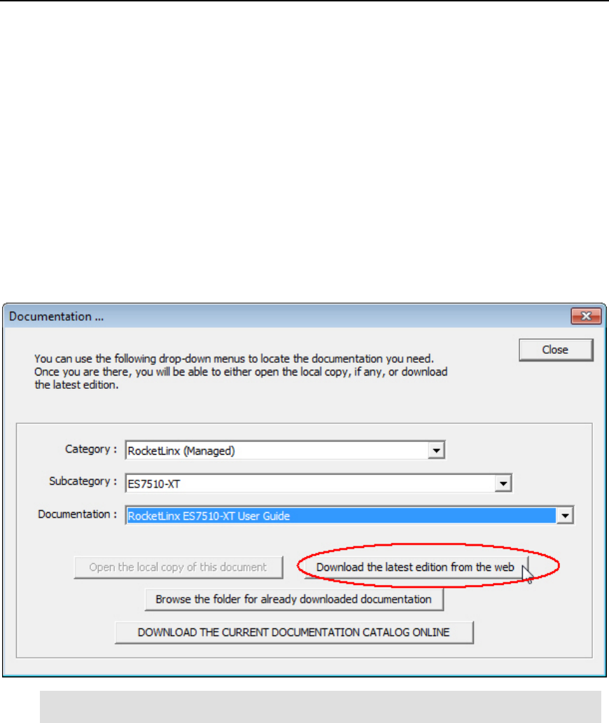
Downloading Documentation from Comtrol
You can use this procedure to download documentation for your Comtrol product or products.
You can also use this procedure to check to see a newer edition has been released since you
downloaded the document. You must have an internet connection to use this procedure.
1. Click Documentation from the Help menu on the Main screen or on the Properties
page.
2. Select the appropriate product Category from the drop-list.
3. If appropriate, select the appropriate Subcategory (model/description) from the drop-list.
4. Select the document that you want to download from the Documentation drop-list.
5. Click the Download the latest edition from the web button.
Note: Downloading a manual may take a few moments or longer depending on your
internet connection.
The document that you selected is saved into the PortVision DX/doc subdirectory and opens on
your system. The document can be reopened using the following procedure.
10 Introduction
PortVision DX User Guide
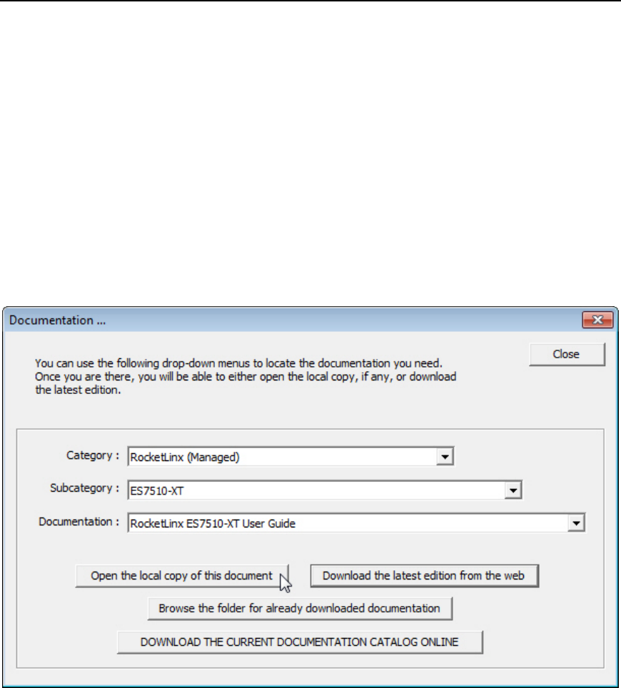
Accessing Previously Downloaded Documentation
After you have downloaded product documentation, you can open the downloaded version from
PortVision DX using the following procedure.
If you have an internet connection, you may want to check for the latest version.
1. Click Documentation from the Help menu on the Main screen.
2. Select the appropriate product Category from the drop-list.
3. If appropriate, select the appropriate Subcategory (model/description) from the drop-list.
4. Select the document that you want to download from the Documentation drop-list.
5. Click the Open the local copy of this document button.
Introduction 11

PortVision DX User Guide
12 Introduction
Installing PortVision DX
During initial configuration, PortVision DX automatically detects and identifies Comtrol Ethernet
attached products, if they are in the same network segment.
You can use the one of the links below to download the latest version.
• ftp://ftp.comtrol.com/dev_mstr/portvision_dx
• ftp://ftp.comtrol.com/io_link_master/portvision_dx
• ftp://ftp.comtrol.com/rocketlinx/portvision_dx
Note: Depending on your operating system, you may need to respond to a Security
Warning to permit access.
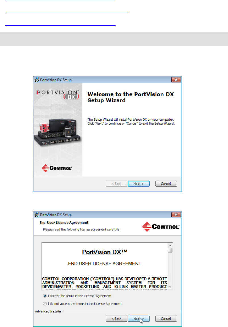
1. Execute the PortVision_DX[version].msi file.
2. Click Next on the Welcome screen.
3. Click I accept the terms in the License Agreement and Next.
Installing PortVision DX 13
PortVision DX User Guide
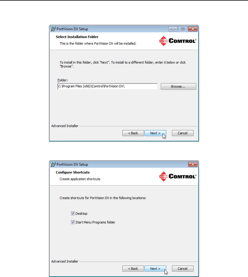
4. Click Next or optionally, browse to a different location and then click Next.
5. Click Next to configure the shortcuts.
14 Installing PortVision DX
PortVision DX User Guide
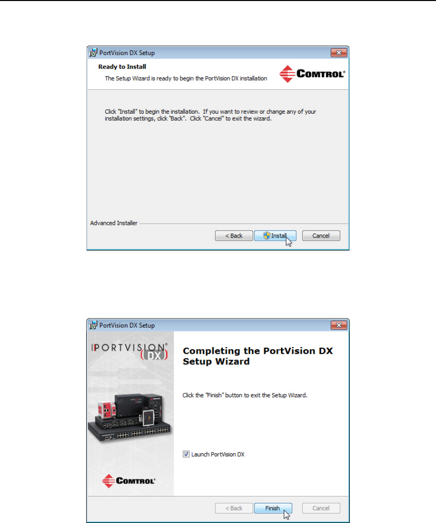
6. Click Install.
7. Depending on the operating system, you may need to click Yes to the Do you want to
allow the following program to install software on this computer? query.
8. Click Launch PortVision DX and Finish in the last installation screen.
9. Depending on the operating system, you may need to click Yes to the Do you want to
allow the following program to make changes to this computer? query.
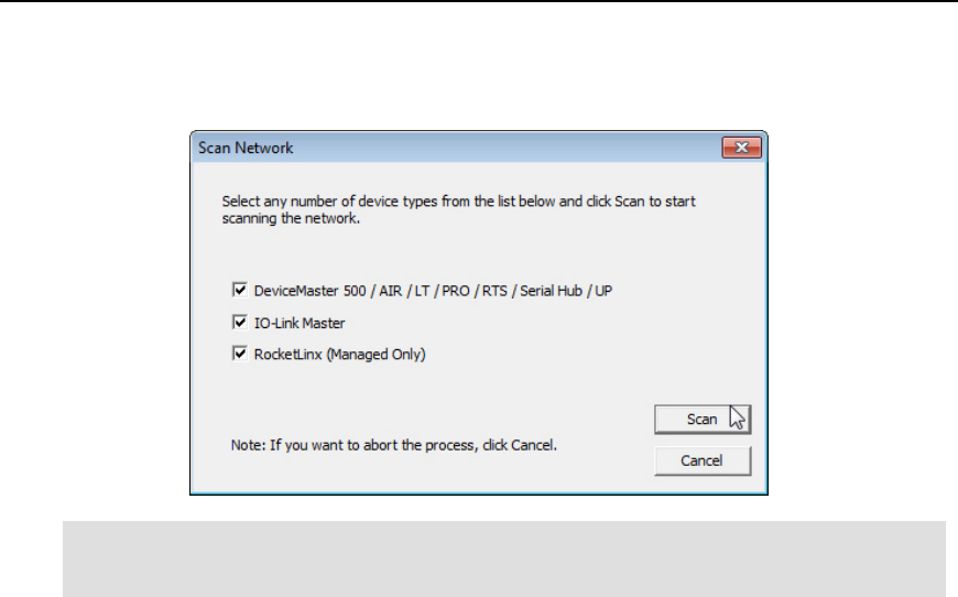
10. Click the Scan button.
Installing PortVision DX 15
PortVision DX User Guide
11. Select the Comtrol Ethernet attached products that you want to locate and then click
Scan.
Note: If the ComtrolEthernet attached product is not on the local segment and it has been
programmed with an IP address, it will be necessary to manually add the Comtrol
Ethernet attached product to PortVision DX.
16 Installing PortVision DX

PortVision DX User Guide
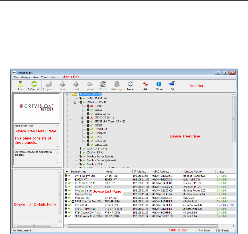
Main Screen
The PortVision DX Main screen displays the status of the devices that have been located on the
network during the Scan process or Comtrol Ethernet attached products that have been added
using the Add New Device window.
The PortVision DX main screen consists of the following parts.
18 User Interface Overview
PortVision DX User Guide
Menu Bar
The Menu bar provides easy access to the following menus.
• File menu
• Manage menu
• View menu
• Tools menu
• Help menu
Tool Bar
The Tool Bar provides a fast way to access many PortVision DX features without using a menu or
the popup menus. You can toggle the button text off or not display under the View menu.
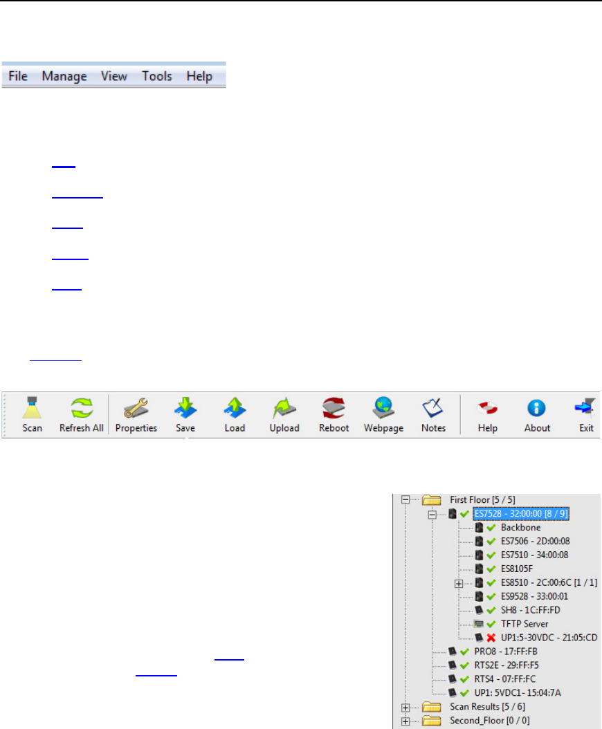
Device Tree Pane
The Device Tree pane (top right) includes a list of all devices
that can potentially be added to PortVision DX and preserves
their hierarchical relationship. It also shows device status with a
green check mark to indicate the device is on-line and a red X
to indicate that the device is off-line.
The Device Tree pane contains a Scan Results folder, which
lists the devices located when you scan the network. You can
organize devices into folders. as shown in the image.
User Interface Overview 19
PortVision DX User Guide
Device Tree Details Pane
The Device Tree Details pane is located to the left of the Device Tree pane.
There are three panels in the Device Tree Details pane, which displays different information
depending on whether you highlight a folder or a device.
If there are not any notes associated with a folder or
device, the bottom panel displays Use menu or tool bar to
add notes in this area.
If you highlight a folder:
• The top panel displays the PortVision DX logo.
• The middle panel displays the folder name.
• The bottom panel displays any notes that have
been associated to that folder using the Edit
Notes feature.
If the folder is a managed RocketLinx switch, it displays
the panes like a device.
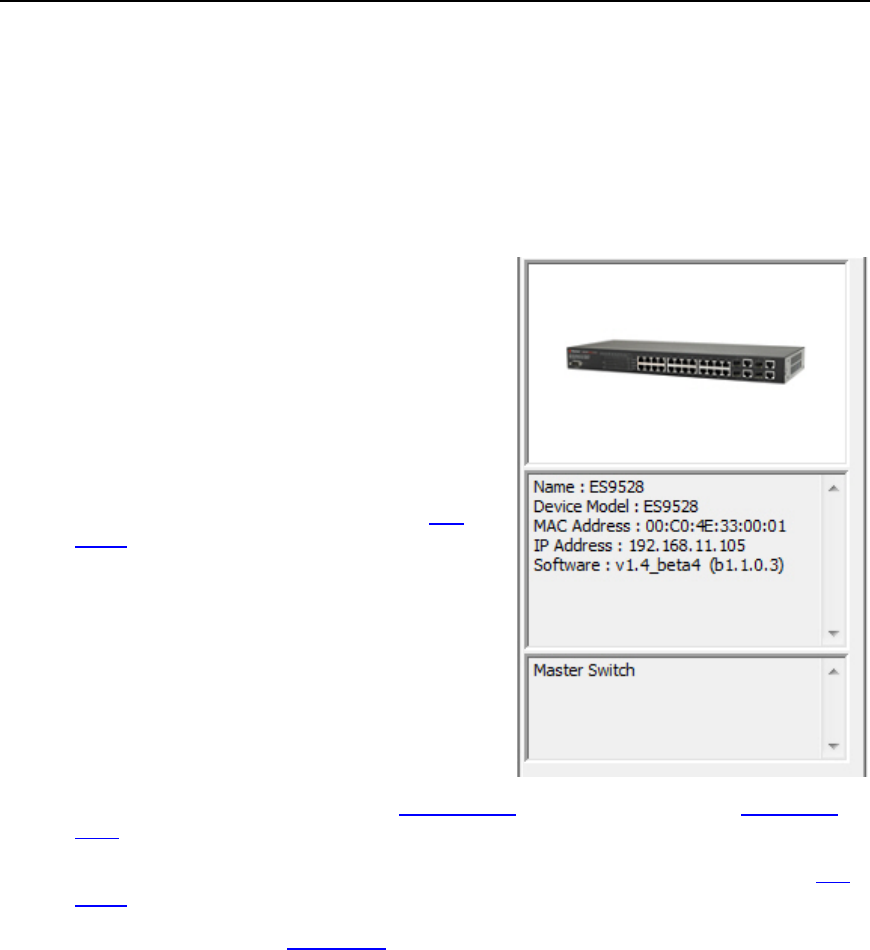
If you highlight a device:
• The top panel displays an image of the device if
an image is available.
• The middle panel displays the same device status that would display in the Device List
pane, if the appropriate folder is highlighted.
• The bottom panel displays notes that have been associated to this device using the Edit
Notes feature.
If you double-click a device, the Properties page opens for that device.
20 User Interface Overview
PortVision DX User Guide
Device List Pane
The Device List pane includes a list of all of the devices that can potentially be added to
PortVision DX and technically located under the tree branch selected from the top. For instance, if
you select a switch from the Device Tree, all of the devices connected to that switch (according to
the Device Tree) display in the Device List.
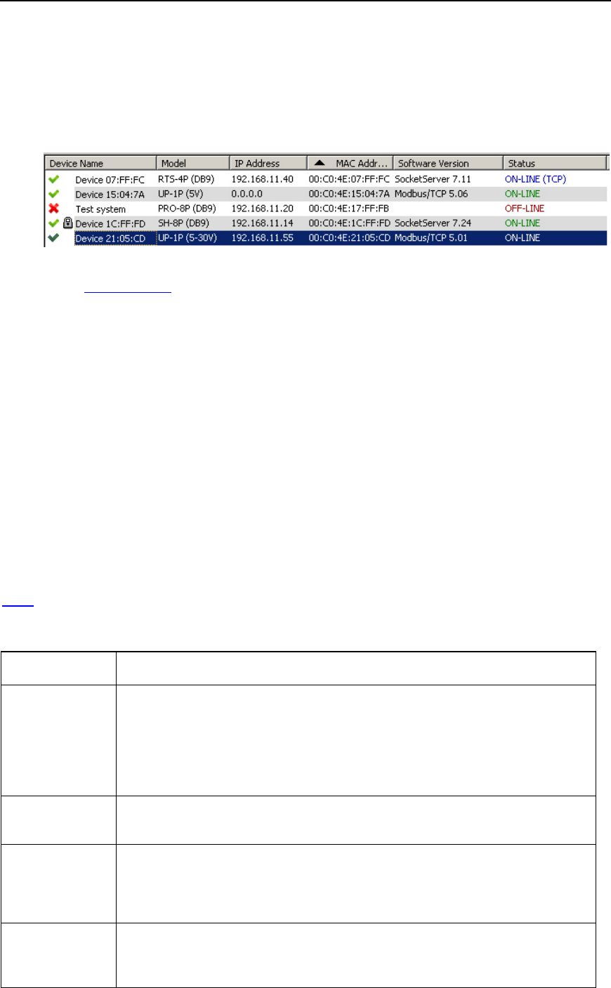
The Device List pane displays the Device Name, Model, IP Address, MAC Address, Software
Version, and Device Status. In addition, it displays:
• A green check mark indicates that the device is on-line.
• An IP address of 0.0.0.0 displays when the IP address is disabled or if there is no DHCP
server available.
• A red X indicates that the device is off-line.
• The lock symbol indicates that the device has security enabled (Secure Data or Config
mode).
• A dark green check mark indicates that the device is highlighted.
You can customize the view that PortVision DX provides in the Device Tree and Device List
panes.
For example, you can sort any column in the Device List pane in ascending or descending order
by clicking the Device Name, Model, IP Address, MAC Address, Software Version, or Status in
the title bar. Descriptions of the columns and the different device statuses are provided in the
Scan discussion.
This table illustrates the different device statuses and what they mean.
Device Status
Description
Firmware
uploaded
The device has been uploaded with new firmware and the hardware is in the
processes of re
booting. This message is typically updated to ON-LINE after
the next polling cycle.
You can click
Refresh to update the display without waiting for the next
polling cycle.
Initializing
The device has been rebooted and the default applications are in the
p
rocesses of loading.
OFF-LINE
(displayed in
maroon)
The device is not available to PortVision DX. It may not be powered on or is
not on the same network segment as PortVision DX.
ON
-LINE
(displayed in
The device is powered on, PortVision DX can access and be used to
configure a Comtrol Ethernet attached product.
If this is an unmanaged RocketLinx or other hardware that you added using
User Interface Overview 21
PortVision DX User Guide
Device Status
Description
green)
the Add New Device feature, you can choose to display the switch to ON-
LINE or OFF
-LINE. You can change the status using the General tab on the
Properties
screen. PortVision DX cannot poll unmanaged switches to
determine whether they are on
-line or not.
If polling has been disabled (set to 0 seconds) in the
Options screen, a
device can display as ON
-LINE in the Device List pane but actually be off-
line. You can open the General tab on the Prope
rties screen to verify that it
displays ON
-LINE.
ON-LINE (TCP)
The device is on-line and has a TCP connection with PortVision DX.
Rebooting
The device is rebooting and will be initialized before it goes ON-LINE.
Failed to upload
The device did not load the firmware. Make sure are trying to load the
correct firmware. Try uploading the firmware a second time before contacting
Technical Support.
192.168.250.250*
If two or more devices share the same network configuration, the IP
addresses appear in maroon
and an asterisk is displayed after the IP
address.
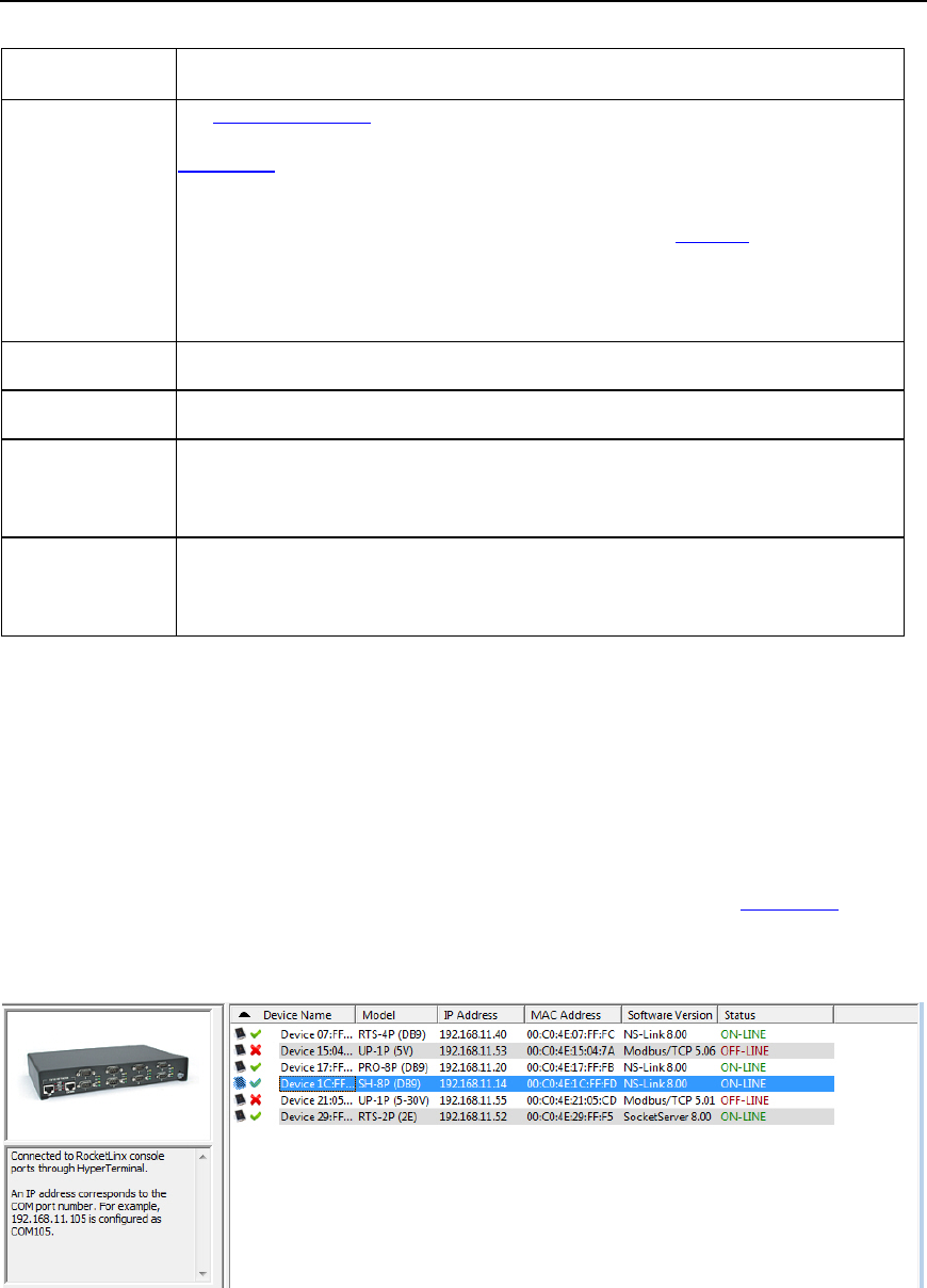
Device List Details Pane
The Device List Details pane is empty if you do not have a device highlighted in the Device List.
If you highlight a device in Device List, the Device List Details pane two panels display
accordingly:
• The top panel displays an image of the selected device (if available).
• The lower panel displays the notes associated to the device using the Edit Notes feature.
If there are not any notes associated with the device, the bottom panel displays Use menu or
toolbar to add notes in this area.
The text window allows you to save information about a device. You can store up to 2048
characters (2K) of information about this device.
22 User Interface Overview
PortVision DX User Guide
Status Bar
At the bottom of the Main screen, PortVision DX provides status information in a Status bar.
Status Bar
Description
First block
Shows the status of an operation when needed. It opens enough
space to display the message.
Second block
Displays the folder name.
Third block
Displays the number of devices in the folder.
Fourth block
Displays the number of selected devices in the Device List pane.
Fifth block
Displays the general status of PortVision DX. For example, it may
display a message such as, Polling, during the polling cycle or Ready.
Buttons
Click the appropriate link to locate information about the Tool Bar buttons:
• Scan
• Refresh All
• Properties
• Save
• Load
• Upload
• Reboot
• Webpage
• Help
• About
• Exit
User Interface Overview 23
PortVision DX User Guide
Scan
If you click the Scan button, PortVision DX scans the network for new devices and
updates the device status of existing units. PortVision DX polls the network every two
minutes to refresh status, but you may need to scan the network if you have added a
new device using the Add New Device screen.
The polling interval for scanning the network can be adjusted in the Options screen.
Optionally, you can select Scan Network from the Tools menu to scan the network for new
devices.
PortVision DX does not scan the network for new devices unless you click Scan or enable the
Always scan network feature under the Tools menu in the Options screen.
Refresh All
If you click the Refresh All button, PortVision DX refreshes the view of all of devices
and folders on the Main screen.
Optionally, you can click the Tools menu and then Refresh All to refresh the Main screen.
Click the Scan button or the Scan Network option, if you want to locate any new devices added
to the network.
Optionally, you can refresh a single or selected devices if you do not want to refresh all devices.
Properties
If you click the Properties button, PortVision DX opens the Properties screen for the
device or devices selected in the Device List (lower) pane on the Main screen.
Use the Properties screen to configure the device, which also displays a picture of your Comtrol
Ethernet attached product with What’s This Help and access to the user documentation.
Optionally, you can right-click on a device and then click Properties from the popup menu or
highlight a device and click the Manage menu and then Properties.
Save
If you click the Save button, PortVision DX saves the current configuration settings of the
Comtrol Ethernet attached product in a file. You can select one or multiple items from a
list of properties available in the configuration file.
If you are deploying multiple Comtrol Ethernet attached products that share settings, you can
save a configuration file after configuring the first Comtrol Ethernet attached product and load the
configuration information into the remaining Comtrol Ethernet attached products at one time.
Configuration files are saved as .dc files.
Note: The Comtrol Ethernet attached product must be similar. For example, you cannot
use a configuration file for a DeviceMaster on a RocketLinx.
Optionally, you can click the Manage menu and then Save Configuration File or right-click on a
device and click Save Configuration File from the popup menu.
24 User Interface Overview
PortVision DX User Guide
Load
If you click the Load button and you have previously saved a device configuration file,
you can load portions of the configuration that you select in the Field Selection pop up
and apply it to a selected device or devices.
Comtrol Ethernet attached product specific information such as Device ID (DeviceMaster name,
MAC address, model, and software version) are not loaded into the selected Comtrol Ethernet
attached product or Comtrol Ethernet attached products.
If you are using a static IP address, you will need to configure the IP address for each Comtrol
Ethernet attached product.
Optionally, you can click the Device menu and then Load Configuration File or right-click on a
Comtrol Ethernet attached product or Comtrol Ethernet attached products and click Load
Configuration File from the popup menu.
Upload
If you click the Upload button, PortVision DX uploads firmware into the selected Comtrol
Ethernet attached product or Comtrol Ethernet attached products. If you have not done
so, download the latest firmware. Make sure that you select firmware appropriate for
your model and requirements.
It is recommended that you copy the firmware to your hard drive before uploading the firmware to
the Comtrol Ethernet attached product.
Do not attempt to upload firmware across a wifi connection.
If you are uploading protocol firmware for the DeviceMaster UP, you must first run the .msi file
and use the .cmtl file that is extracted and placed on your system..
Reboot
If you click the Reboot button, PortVision DX reboots or resets the selected device or
devices. The network LEDs on the Comtrol Ethernet attached product flash during the
boot cycle.
Optionally, you can highlight a device or devices and click the Manage menu and Advanced and
then Reboot or right-click and click Advanced and then Reboot from the popup menu.
If a DeviceMaster is configured with Secure Config Mode in SocketServer, it can only be
rebooted from the web page unless Secure Config Mode is disabled.
Webpage
If you click the Webpage button, PortVision DX opens your default browser, connects to
the Comtrol Ethernet attached product through the IP address, and opens the default
web page for your Comtrol Ethernet attached product default application.
You can locate web page information for your product from the following places:
• DeviceMaster users can use the SocketServer help system for information about the
fields and configuration methods. The SocketServer help system is also available
separately as a chm or zip file (html version).
• DeviceMaster UP users should use the appropriate DeviceMaster UP document for their
protocol for information about configuring the default application for your DeviceMaster
model.
User Interface Overview 25
PortVision DX User Guide
• IO-Link Master users can use the web interface help system or the IO-Link Master User
Guide.
• RocketLinx users can use the online help system in the web configuration pages or the
appropriate RocketLinx User Guide. Java is required to open the RocketLinx web pages.
Help
The Help button opens the PortVision DX help system.
Optionally, you can right-click on a device and click Help from the popup menu or click
the Help menu and then Help Contents F1.
About
The About button displays the PortVision DX version.
Optionally, you can click the Help menu and then About PortVision DX.
Exit
The Exit button closes PortVision DX.
Optionally, you can click the File menu and then Exit.
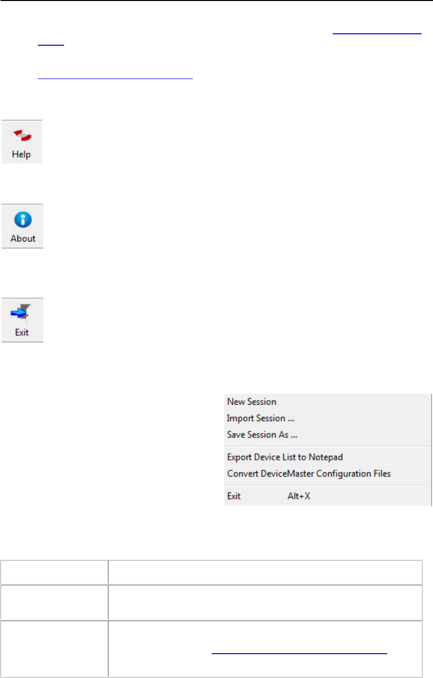
File Menu
The File menu is located on the Main menu and
provides you with a way to manage different
sessions. A session is simply a view of the
devices on the network.
The default session is the last view that displayed
before exiting PortVision DX and is saved in the
PVdxDefSes.pvs file in the \Program
Files\Comtrol\PortVision DX directory.
You may want to save unique sessions to customize views of your devices.
File Menu
Description
New Session
Clears the existing session and brings up an empty session to start the
process from the beginning.
Import Session ...
Opens a previously saved session from your system.
This also allows you to
import existing PortVision Plus sessions
so that
they can be saved as PortVision DX sessions.
26 User Interface Overview
PortVision DX User Guide
File Menu
Description
Save Session As …
Allows you to save the current network setup (session) as it appears
on the
Main window into a disk file for later reference.
Export Device List to
Notepad
Allows you to export a text file that is delimited with commas so that
you can import the information into a spreadshe
et.
Convert DeviceMaster
Configuration Files
Allows you to convert a configuration file that was created on a
DeviceMaster running SocketServer v8.04 (or previous) and load it
onto a DeviceMaster running SocketServer v9.00 (or higher).
This means that you
can upgrade SocketServer to the latest version
and recover your previous DeviceMaster settings using this option.
Exit
This closes PortVision DX. Optionally, you can click the Exit button.
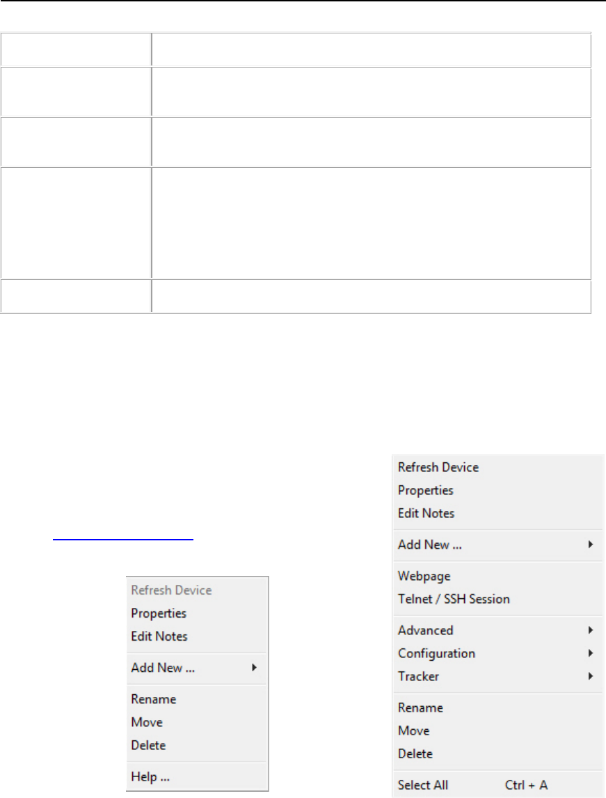
Manage Menu
You can use the Manage menu to perform most PortVision DX tasks. The Manage menu is
available at the top of the Main screen or can be accessed by right-clicking in the Device Tree or
Device List.
• If you click a folder or device in the Device Tree and
right-click a Manage submenu pops up. Only options
applicable to the Device Tree appear when you select
the Manage menu from the Menu bar. Refer to the
Manage Menu Options table for descriptions of how to
use the options.
User Interface Overview 27
PortVision DX User Guide
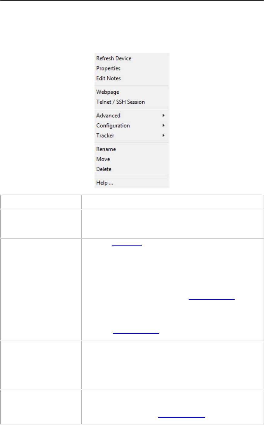
• If you click the Device List pane and click the Manage menu the following menu pops up.
Only options applicable to the Device List appear when you select the Manage menu. If a
Comtrol Ethernet attached product is not highlighted and you right-click in the Device List
pane, only the Help item appears in the menu.
Manage Menu
Description
Refresh Device
Allows you to refresh the view for a specific device immediately,
instead of waiting for PortVision DX to refresh during it’s normal
polling cycle.
Properties
(
Device List Pane Active)
Opens the Properties screen for the highlighted Device Name in
the
Device List pane on the Main screen.
Optionally, double
-click the Comtrol Ethernet attached product or
right
-click and then click Properties from the popup menu.
You can use the
Properties screen to configure the Comtrol
Ethernet attached product and it also displays a picture of your
Comtrol Ethernet attached product with
What’s This Help.
You can use the
Properties screen to review device information if
it is an unmanaged switch or third
-party device. If the unmanaged
switch is a Comtrol switch,
it displays a picture of your Comtrol
switch with
What’s This Help.
Edit Notes
Opens a text window for the selected device that allows you to
save information about the device. You can store up to 2048
characters (2K) of information about this device.
Optionally, you ca
n click the Notes button or right-click on a device
and click
Edit Notes from the popup menu.
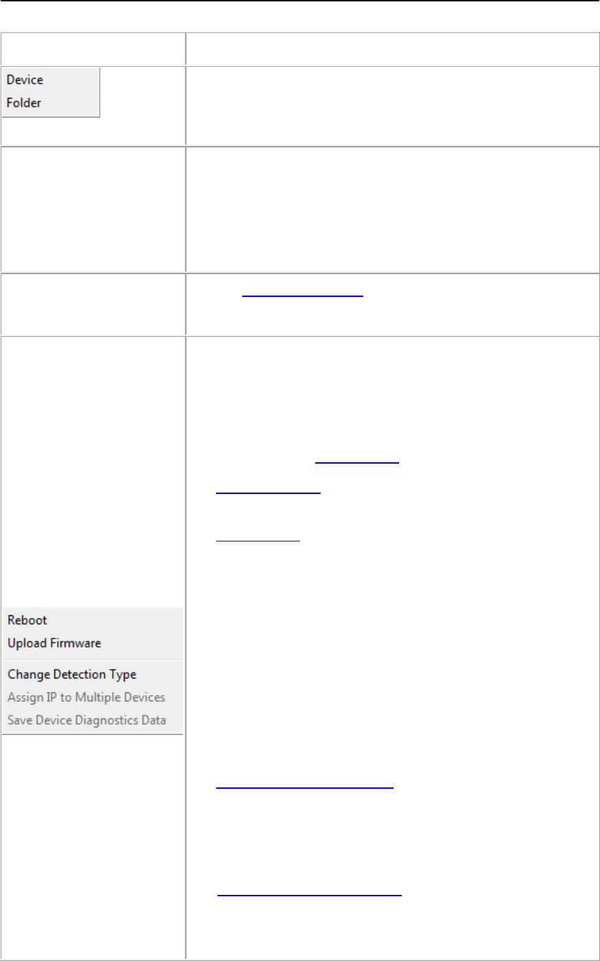
Add New ...
You can add a new Device or Folder when the Device Tree pane
is active.
• If you click Device, the Add New Device screen opens.
28 User Interface Overview
PortVision DX User Guide
Manage Menu
Description
• If you click Folder, the Add New Folder pop up opens.
You can
Rename, Move, or Delete a Device or Folder using the
Manage
menu or Manage pop up menu.
Webpage
(
Device List Pane Active)
Opens the default browser and connects to the Comtrol Ethernet
attached product through the IP address to open the default
application, which is the same as clicking the
Webpage button on
the
Main screen.
Optionally, right
-click on a Comtrol Ethernet attached product and
click
Webpage from the popup menu.
Telnet/SSH Session
(
Device List Pane Active)
Opens a
Telnet/SSH session for the selected Comtrol Ethernet
attached product.
Advanced
(Submenu)
Advanced provides access to these options when the Device List
pane is active.
• Reboot or resets the selected Comtrol Ethernet attached
product or Comtrol Ethernet attached products. The network
LEDs on the Comtrol Ethernet attached product flash during
the boot cycle. This option is disabled if Secure Config Mode
is enabled on a DeviceMaster in SocketServer.
• Upload Firmware uploads firmware into the selected Comtrol
Ethernet attached product or Comtrol Ethernet attached
products unless Secure Config Mode is enabled on a
DeviceMaster.
If you have not done so, download the latest firmware. It is
recommended that you copy or if necessary, unpackage the
firmware to your hard drive before uploading the firmware to
the Comtrol Ethernet attached product.
• Change Detection Type defines the way that PortVision DX
should communicate with the DeviceMaster.
• LOCAL means that the DeviceMaster is on this local
network segment.
• REMOTE means that the DeviceMaster is not connected
to this segment of the network.
• Assign IP to Multiple Devices you can use this feature to
assign an IP address or a range of IP addresses to the
selected Comtrol Ethernet attached products.
You must shift-click multiple Comtrol Ethernet attached product
of the same family for this option to be available.
• Save Device Diagnostics Data is an IO-Link Master option
that saves the diagnostic data collected on the IO-
Link Master.
This file is intended for Comtrol Technical Support to diagnose
IO-Link Master problems.
User Interface Overview 29
PortVision DX User Guide
Manage Menu
Description
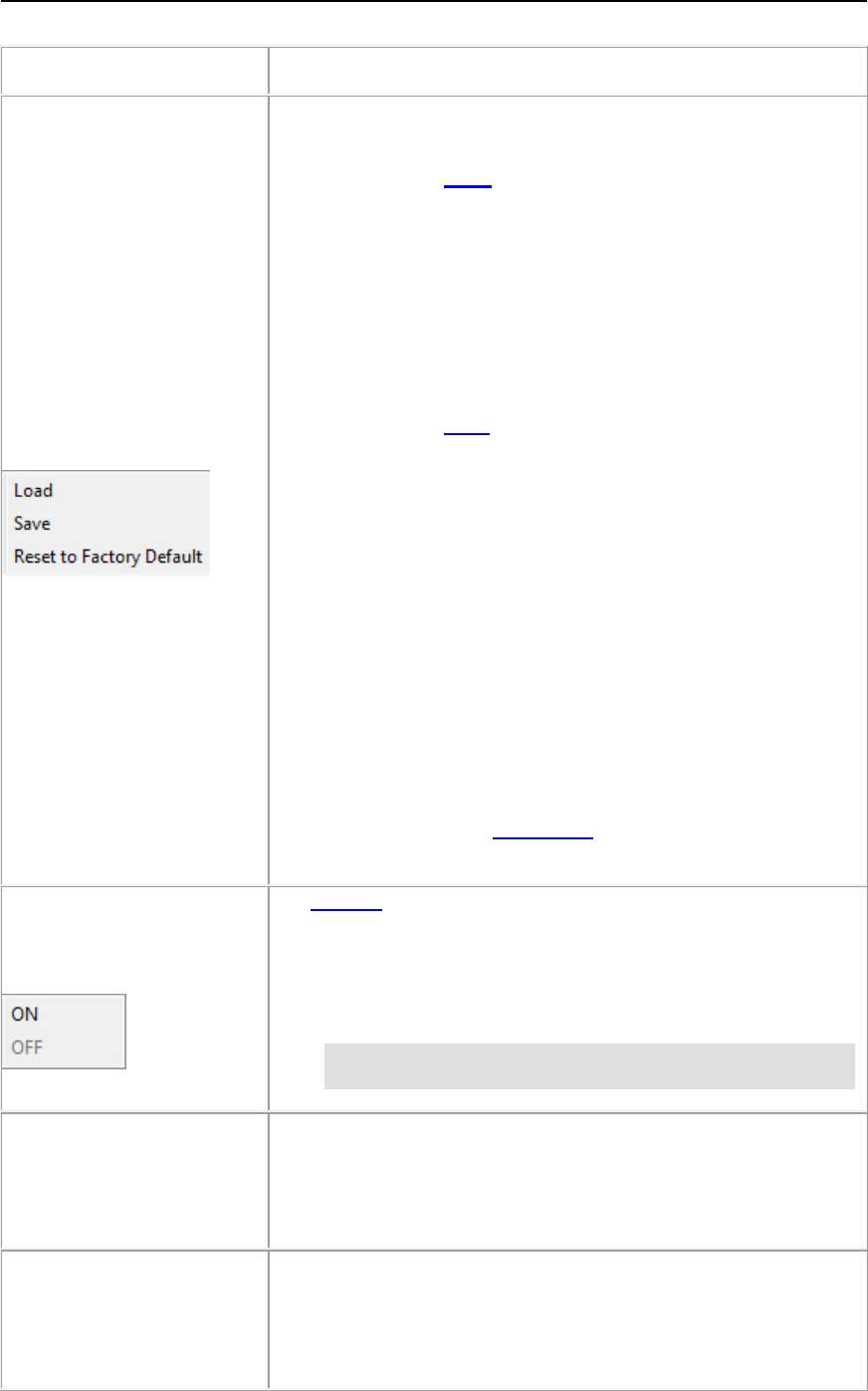
Configuration
(Submenu)
The Configuration menu provides access to these options when
the
Device List pane is active.
• If you click the Load submenu item and you have previously
saved a Comtrol Ethernet attached product configuration file
(from the same family), you can load portions of the
configuration that you select in the Field Selection pop up and
apply it to a selected Comtrol Ethernet attached product or
Comtrol Ethernet attached products.
Device specific information such as
Device ID (device name, MAC
address, model, and software version) are not loaded into the
selected Comtrol Ethernet attached products.
• If you click the Save submenu item, PortVision DX saves the
current configuration of a Comtrol Ethernet attached product in
a file, which must be from the same family. For example, you
cannot load a configuration file for a DeviceMaster on a
RocketLinx.
You can click one or multiple items from a list of properties
available in the configuration file.
If you are deploying multiple Comtrol Ethernet attached
products that share settings, you can save a configuration file
after configuring the first Comtrol Ethernet attached product and
load the configuration information into the remaining Comtrol
Ethernet attached products at one time. Configuration files are
saved as .dc files.
• If you click Reset to Factory Default values for your product
except for the default IP address, NetMask, and IP gateway.
You can refer to the User Guide for your product for
information about the default values.
Tracker
(Submen
u)
The Tracker feature allows you to send a signal to an IO-Link
Master or RocketLinx managed switch to toggle an LED so that
you can identify a particular unit in a cabinet or installation.
Ref
er to the LED table for your IO-Link Master or RocketLinx to
identify which LED will flash.
Note: Only the RocketLinx family of managed switches and
IO-Link Master supports this feature.
Rename
Allows you to rename the highlighted Device or Folder.
Option
ally, you can right-click on the Comtrol Ethernet attached
product and click
Rename from the popup menu or double-click on
the
Device or Folder name and type a new name.
Move
You can click a device (or devices) or folder (folders), click the
Manage menu a
nd move it into a folder. You can move devices
into folders and you can also layer folders within a folder.
Optionally, you can also do the same thing by dragging or by right
-
clicking a device (or devices) or folder (or folders) and the clicking
30 User Interface Overview
PortVision DX User Guide
Manage Menu
Description
Move from the popup menu.
Delete
Allows you to delete a device or folder from the PortVision DX
display. This action does not affect the functionality of the device ,
it merely removes a device from the view.
Optionally, you can right
-click on the device (or devices) or folder
(or folders) and click
Delete from the popup menu.
Select All
(
Device List Pane Active)
This Manage menu option selects all Comtrol Ethernet attached
products in the
Main screen.
Note: This option is not included on the popup menu when
you right-click within the Device List or Device Tree.
It is only available through the Manage menu.
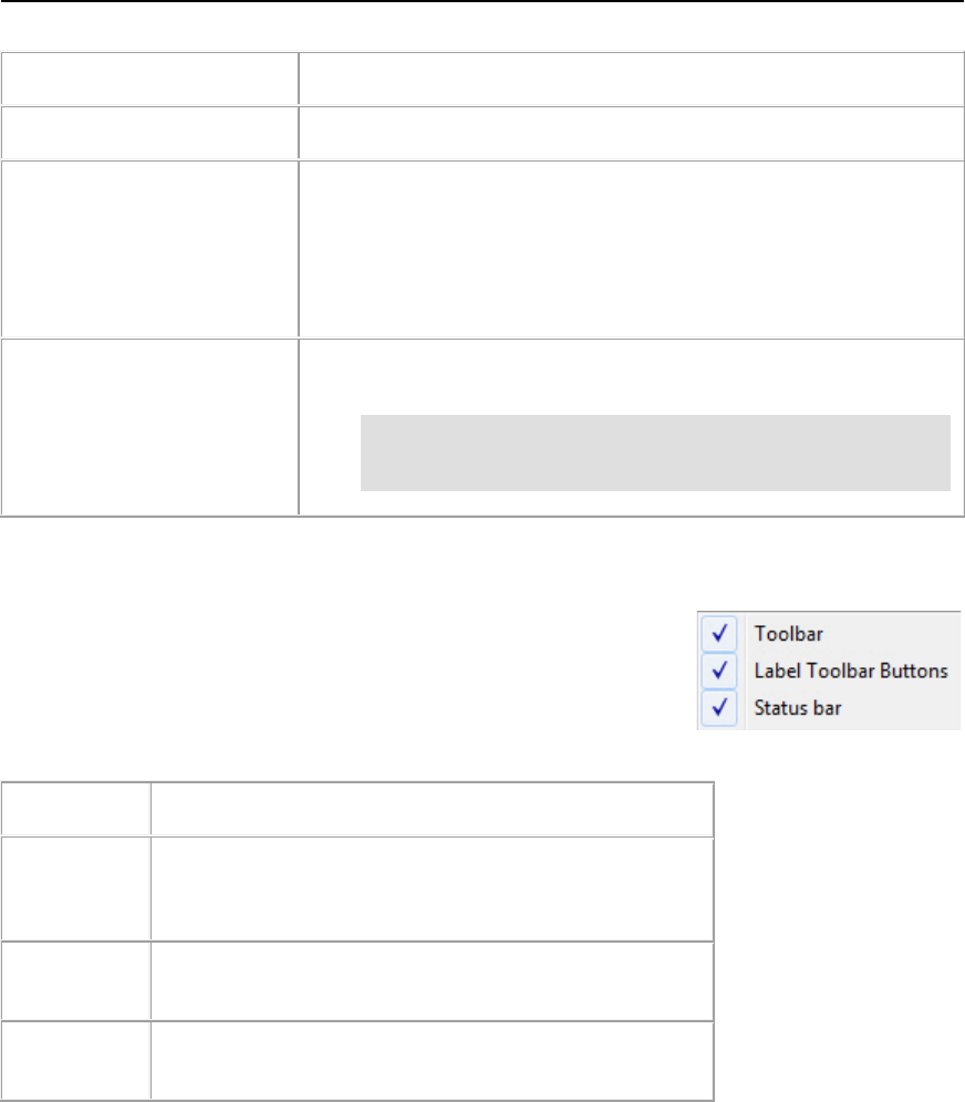
View Menu
You can use the View menu at the top of the Main screen to toggle the
PortVision DX view.
View Menu
Description
Toolbar
This option is enabled by default. You can disable this
option if you do not want the Tool Bar displayed on the
Main screen.
Label Toolbar
Buttons
This option is enabled by default. You can disable this
option if you do not want the Tool Bar text displayed.
Status Bar
This option is enabled by default. You can disable the
Status Bar at the bottom of the Main screen.
User Interface Overview 31
PortVision DX User Guide
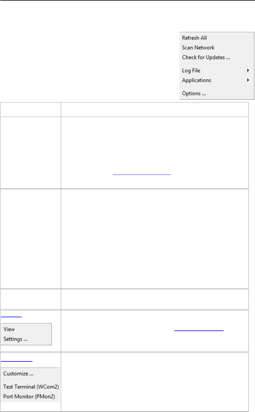
Tools Menu
The Tools menu is on the Main screen and contains the following
items.
Tools Menu
Description
Refresh All
If you click the Refresh All menu item, PortVision DX refreshes the
view of all devices on the
Main screen.
Optionally, use the
Refresh button.
Click the
Scan Network option in the Tools menu or the Scan
button, if
you want to locate any new devices added to the network.
Optionally, you ca
n refresh one or multiple Comtrol Ethernet attached
products.
Scan Network
If you click the Scan Network menu item or the Scan button,
PortVision DX scans the network for new devices and updates
the
device status of existing units.
PortVision DX polls the network every two minutes to refresh Comtrol
Ethernet attached product status, but you will need to scan the network
if you have added a Comtrol Ethernet attached product using the
Add
New Device
screen. The polling interval can be adjusted in the Options
screen.
PortVision DX does not scan the network for new Comtrol Ethernet
attached products unless you click
Scan Network or enable the
Always scan network
feature under the Tools menu in the Options
screen.
Check for Updates
This option opens the Technical Support web page, which requires an
active connection to the internet.
Log File
The
Log File item contains two submenus, View and Settings.
Applications
The Applications Customize selection allows you to create shortcuts
for up to twenty existing programs or util
ities that you may want to
access from PortVision DX.
After defining a shortcut name and providing a path to the executable, it
appears as a submenu selection under
Applications.
By default these Comtrol serial port applications are available:
32 User Interface Overview

PortVision DX User Guide
Tools Menu
Description
• Test Terminal (WCom2) is a terminal program that enables you to
open a port, send characters and commands to the port, and
toggle the output control signals.
If you have a peripheral device connected to the port and know the
device’s command set, you can also send commands to the device.
For example, if you have a modem connected to the port, you can
use AT commands to query the modem and dial out to host
systems.
• Port Monitor (PMon2)
offers a summary of all port statistics in one
easy-to-read spreadsheet view. This enables you to verify
operation of all Comtrol serial ports from a single window.
Reports can be automatically generated on an hourly and/or daily
basis. A report covers all ports collectively. You can also set how
often the values are recalculated, fine-tuning thoroughness against
system efficiency, and automatically run external batch files to
perform additional processing and analysis after the reports are
generated.
To use Port Monitor or Test Terminal, you will need to know the COM
port number or numbers
that you want test.
If necessary, use the help system in Test Terminal or Port Monitor.
Testing procedures are available in the
Port Monitor and Test Terminal
User Guide
.
Options...
Opens the Options... screen, which allows you to customize the
following default settings for PortVision DX.
Log File
The Log File menu item under the Tools menu has two screens associated with it:
• Settings
• View
Log File - Settings
Menu Description
Enable Logging
You can use this option to enable or disable logging.
The default is disabled, but if you enable logging, PortVision DX
immediately begins gathering data and stores it in the selected log file.
The default file is PVPLog.pvl.
Access the View Log button on the View menu.
All other options do not take effect unless you enable logging.
Clear the existing
contents of the log
Every time you click this option (if the logging is enabled and as soon as
you click OK in the dialog), it will empties the log file before logging any
User Interface Overview 33

PortVision DX User Guide
Log File - Settings
Menu Description
file
more events.
Log device
-level
events
If enabled, PortVision DX logs all of the events that are happening at the
device level, such as: changing IP information, status change, and so
forth for all or specified Comtrol Ethernet attached product units.
Log application
-level
events
If enabled, PortVision DX logs all of the events that are happening at the
application level, such as: clicking a button, changing the settings, and
so forth.
Do not log “Polling…”
messages
If you enable Log application-level events, then you can select
whether you want to see the Polling… message recorded each time
PortVision DX polls or not.
Limit the size of the
log file to #
megabytes
If you enable Limit the size of the log file to # megabytes, the log file is
limited to the specified size.
When size limit is
reached, overwrite
the earliest entries
(keep it current)
Optionally enable this option, if you want to overwrite the earliest entries
in the log file.
If you do not enable this option, the application stops logging when it
reaches the specified size limit
Log Filename/Save
Log as
PortVision DX provides a default path based on the PortVision DX
installation path and file name (PVPLog.pvl) in this box.
You can change the default path and log file name by clicking the Save
Log as button.
If the path is invalid or there is a file error involved, you will see an error
message on the screen and you have to change the name.
NOTE
Log events for ALL
devices
If Log device-level events is enabled, PortVision DX logs all device-
level events.
Log events for ALL devices logs events on all Comtrol Ethernet
attached products.
Optionally, check individual Comtrol Ethernet attached products in the
pane at the right.
Ok
Closes the window. If you enabled logging, PortVision DX also starts
logging data in the log file specified in the Log Filename box.
34 User Interface Overview
PortVision DX User Guide
After enabling the log file, you can view the results using the View screen.
Log File - View Menu
Description
Browse
If you wish to open a log file other than what is specified in the
Log File Settings
menu, use the Browse button to locate the
log file.
Optionally, you can enter a path and file name manually.
Device
-Level Events
Click this option to view data gathered by the Log device-level
events
option in the Settings menu.
Application
-Level Events
Click this option to view data gathered by the Log application-
level events
option in the Settings menu.
S
kip “Polling... Messages”
When you click this option, PortVision DX turns on a filter so that
it ignores polling messages while viewing the log file.
View Log/Refresh View
Click this button to view or refresh the log file.
Export to Notepad
Opens a Notepad file that contains the current view of the log
file. You can save or print the file.
Erase Log File Contents
This eases all stored data in the log file.
Done
Closes the window but does not disable logging.
If you want to disable logging, you must unch
eck the Enable
logging
option using the Settings menu.
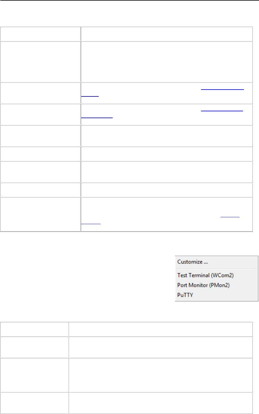
Applications Shortcuts
The Customize option under the Tools > Applications menu
allows you to create up to twenty shortcuts in the Applications
Shortcut screen to applications that you may want to call from
PortVision DX.
Shortcuts for Test Terminal and Port Monitor were set up during
PortVision DX installation.
The following table provides information about the Applications Shortcuts screen.
Application Shortcuts
Description
Available Shortcuts
This drop-down list contains the applications that have been set-up in
PortVision DX.
New
Click the New button so that you can create a new entry.
After you click New, you must complete the Shortcut Name,
Description, Command/Path, and Working Directory text boxes.
Add
Click the Add button after you have completed the Shortcut Name,
Description, Command/Path, and Working Directory text boxes.
User Interface Overview 35

PortVision DX User Guide
Application Shortcuts
Description
Update
Click the Update button after you have changed an entry or entries
in the Shortcut Name, Description, Command/Path, and Working
Directory text boxes for a selected Available Shortcut.
Remove
Select an Available Shortcut and click the Remove button if you
want to remove the shortcut from PortVision DX.
Shortcut Name
This is the name that displays under the Tools > Applications
menu.
Description
This is a description that displays for the application selected in the
Available Shortcuts drop-down list. This description can provide
you with additional information other than the shortcut name.
Command/Path
Browse to the location of the application that you want to execute.
Working Directory
Browse to the working directory related to the application.
Options...Screen
The Options... screen allows you to customize how PortVision DX default settings run in your
environment. Access the Options... screen by clicking the Tools menu and then click the
Options... menu option.
Options... Menu
Description
Save settings on exit
If checked (default), PortVision DX saves all the existing options
into registry when closing PortVision DX.
Always scan network
If checked, PortVision DX scans the network every time that you run
the application.
The default for
Always scan network is disabled. You can enable
this option so t
hat every time PortVision DX is started, it scans the
network and updates the view.
Timestamp Device Notes
automatically
If checked, PortVision DX automatically timestamps any entries
made in the
Device Notes for all Comtrol Ethernet attached
products.
S
ave the current session
before each polling cycle
If checked, PortVision DX will save the current session every time
PortVision DX is scheduled to poll.
This option is unchecked by default. Unless you click this option,
PortVision DX only saves the current
information when you close
the application or when you click
Save Session As...
Always save a backup
copy of the current
session
If checked (default), PortVision DX always gets a backup before
creating a new
PVPDefSes.pvs on the disk, which avoids any data
loss.
Ask for confirmation on
exit (
Main window)
If checked (default), PortVision DX queries you as to whether you
want to exit all PortVision DX windows.
36 User Interface Overview
PortVision DX User Guide
Options... Menu
Description
Ask for confirmation
closing the
Device
Configuration
window
If checked (default), PortVision DX always asks if you want to save
the current configuration before closing the
Properties window.
It does not matter if something has been changed or not, PortVision
DX will always ask if you want to save the current settings to a file.
Polling Interval
Use this option to change the Polling Interval (default is 120
seconds). Acceptable polling intervals range from any value from 0
through 43200 seconds (0
–12 hours).
If you set the polling interval to 0 (zero), polling is disabled
completely.
If you select
any value that causes an overlap in polling cycles,
PortVision DX optimizes that value to avoid any system resource
problem or system crash. This optimization happens during the
process and will not affect your selected value.
Default Settings
Click this button to return the Options... screen to the default
values.
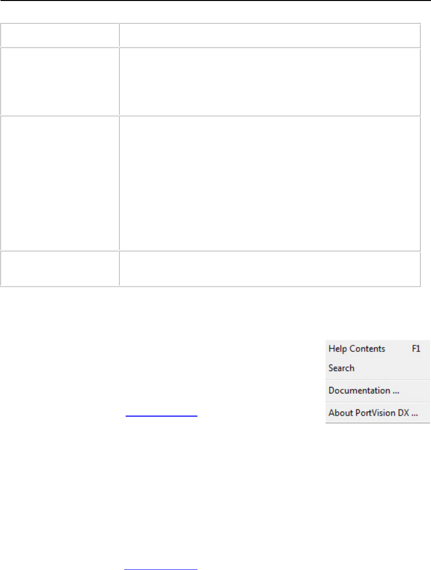
Help Menu
You can use the Help menu to open the help system in of these modes:
• Help Contents
• Search (Advanced)
In addition, you can use the Documentation option to download the
latest documentation for your Comtrol products.
If you used the default installation path, the documents that you download are stored in the
Program Files\Comtrol\PortVision DX\Docs subdirectory.
Properties Screen
The Properties screen may contain up to three tabs depending on the product:
• General tab is typically used to configure the IP network information and other device-
specific device settings for a specific Comtrol Ethernet attached product. The General
tab also contains unmanaged RocketLinx switches and third-party device information that
you enter using the Add New Device screen.
• Software Settings tab provides an easy way to review software settings for
DeviceMasters, DeviceMaster UPs, and IO-Link Masters. To review managed RocketLinx
software settings, click the Web Interface tab.
• Web Interface tab is available for products with a valid IP address, which have a web
page and allows you to access configuration settings for the device.
User Interface Overview 37
PortVision DX User Guide
The Properties screen also provides:
• Tools menu provides an alternate method to apply or undo changes, save settings to or
load configuration settings from a file (if applicable), and reboot the Comtrol Ethernet
attached product.
• Documentation menu links you to the latest documentation for your product.
• What’s This help for the connectors in the graphic of the hardware, which can be used
when you connect cables or to determine the meaning of the LEDs for all Comtrol
products.
Refer to the appropriate Comtrol Ethernet attached product Properties screen for detailed
information.
• DeviceMaster (DeviceMaster LT | PRO | RTS | Serial Hub | 500)
• DeviceMaster UP
• IO-Link Master
• RocketLinx
• Other hardware
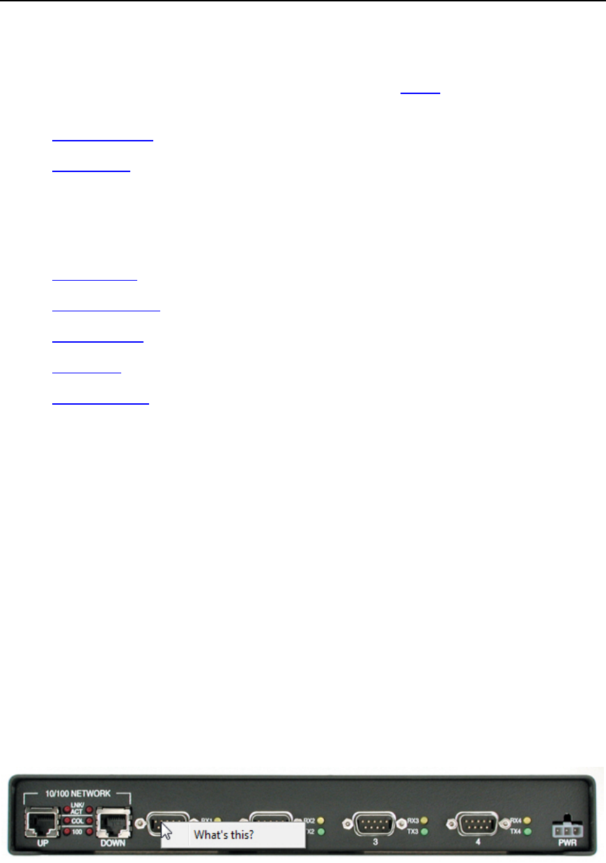
What's This Help Feature
The product pictures in the Properties screen provide hardware information about:
• LEDs
• Port connectors
• Cabling and signal information
• Power requirements
• If applicable to the product, DI/DO, alarms and DIP switches
To use the What’s This help feature in the Properties screen, use this procedure.
1. Double-click the Comtrol Ethernet attached product in the Device List pane or right-click
the device and select Properties.
2. Right-click the connector in the graphic for which you want information, highlight the
What’s This popup, and then click the link.
The image above may not reflect your actual product.
38 User Interface Overview
PortVision DX User Guide
DeviceMaster LT/PRO/RTS/Serial Hub/500 Properties
The Properties screen consists of the following tabs:
•General
•Software Settings
•Web Interface
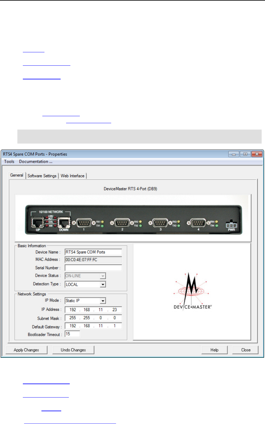
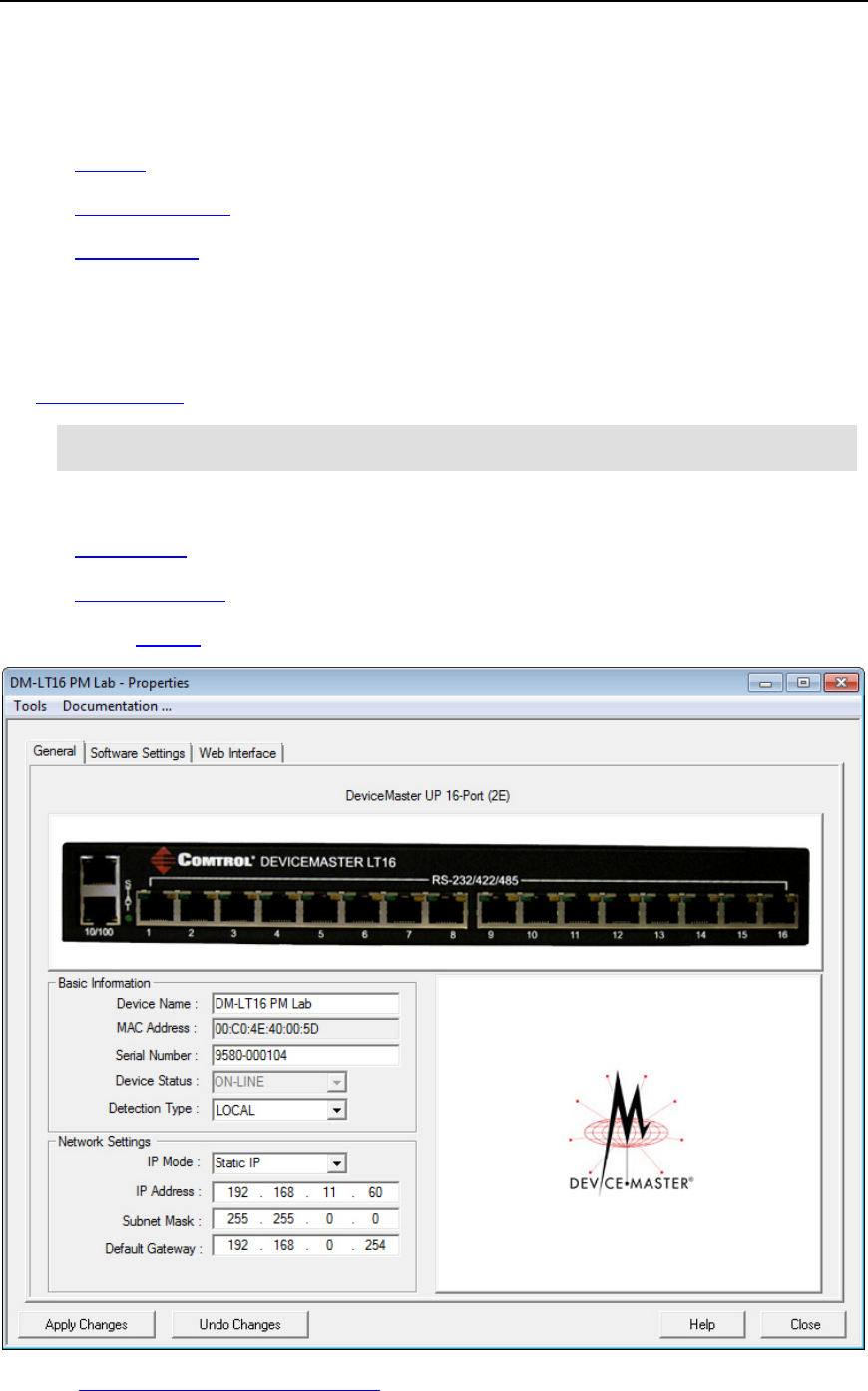
General Tab (DeviceMaster LT | PRO | RTS | Serial Hub | 500)
Use the General tab of the Properties screen to configure or change the network and device
settings for the DeviceMaster. You can also access hardware information about your
DeviceMaster using the What’s This help feature.
Note: If you have secured the DeviceMaster with a password, you must enter the user
name and password to access the General tab.
The General tab contains this information:
•Basic Information pane
•Network Settings pane
•Action buttons
Refer to Programming Network Information for procedures for using this screen.
DeviceMaster LT/PRO/RTS/Serial Hub/500 Properties 39

PortVision DX User Guide
Basic Information
Description
Device Name
The field default value is Device and the last three pairs of digits from the
MAC address.
You can change the name by entering a new name in this field. The name
change displays on the Main screen after clicking Apply Changes.
Optionally, you can use the Rename option on the Main screen.
MAC Address
This field contains the MAC address of the DeviceMaster that you are
configuring. You cannot change the MAC address of a DeviceMaster.
A MAC Address label is located on every DeviceMaster. The first three pairs
of digits start with 00 C0 4E.
Serial Number
You can enter the serial number of the DeviceMaster in the event you
require the serial number. There is a serial number label on the
DeviceMaster.
Device Status
This is the Status that displays on the Main screen in the Device List pane.
Detection Type
REMOTE means that the DeviceMaster is not connected to this segment of
the network and IP communications are used.
LOCAL means that the DeviceMaster is on this local network segment and
MAC communications are used, which does not require an IP address but is
still highly recommended to assign an IP address.
Network Settings
Description
IP Mode
•Disable IP Disables IP communications in the DeviceMaster, which
means that it runs in MAC mode. The MAC addressing simplifies
implementation and ongoing support by eliminating the address
administration issues inherent in network protocols.
MAC addresses are predefined by Comtrol and there is no potential for
an address conflict at setup. Isolated from foreign LAN segments
minimizing potential security issues.
This means that the DeviceMaster will no longer be able to access telnet
or the web page.
If you click Disable IP, the IP Address text box is disabled and set to
255.255.255.255. The subnet mask and default gateway are also
disabled with their existing values.
•DHCP IP Configures the DeviceMaster to use DHCP. Make sure that
the network administrator is provided with the MAC address of the
DeviceMaster so that it can be configured with the network. See your
System Administrator to acquire a unique reserved IP address if you are
using DHCP.
If you click DHCP IP, the IP Address text box is disabled and set to
0.0.0.0 until the DHCP server assigns an address. After the next refresh
cycle, the DHCP address should display.
40 DeviceMaster LT/PRO/RTS/Serial Hub/500 Properties

PortVision DX User Guide
Network Settings
Description
•Static IP Configures the DeviceMaster with the static IP address
information that you provide in the IP Address, Subnet Mask, and
Default Gateway fields.
IP Address
The IP address programmed into the DeviceMaster after applying the
changes and rebooting the DeviceMaster.
See your net
work administrator for a valid IP address.
The default IP address programmed from the factory is 192.168.250.250.
Subnet Mask
The Subnet Mask is a 32-bit value (255.x.x.x) that enables IP packets to
distinguish the network ID and host ID portions of the I
P address.
The default Subnet Mask programmed from the factory is 255.255.0.0.
Default Gateway
The Default Gateway is a TCP/IP configuration item that is the IP address of
a directly reachable IP router.
The
Default Gateway programmed from the factory is 192.168.250.1.
Bootloader
Timeout
This option is available if you have installed SocketServer version 9.06 or
higher.
Allows you to change the Bootloader time
-out value before the default
application, typically, SocketServer.
You may need to increase this
time-out value to 45 for compatibility with
spanning tree devices (normally switches. If you change the time
-
out value to
0, this prevents SocketServer web page from loading.
Buttons (Tools Menu)
Descriptions
Apply Changes
Applies the current changes to the DeviceMaster.
Undo Changes
Undoes all the changes only, if you have not applied it to the
DeviceMaster.
Help
Opens page-level help for this screen.
Close
Closes the window and queries you as to whether you want to save the
settings to a file or n
ot if you made changes and did not click Apply
Changes
.
You can disable this query using the
Options... screen in the Tools
menu
(
Ask for confirmation on closing Properties screen item).
DeviceMaster LT/PRO/RTS/Serial Hub/500 Properties 41
PortVision DX User Guide
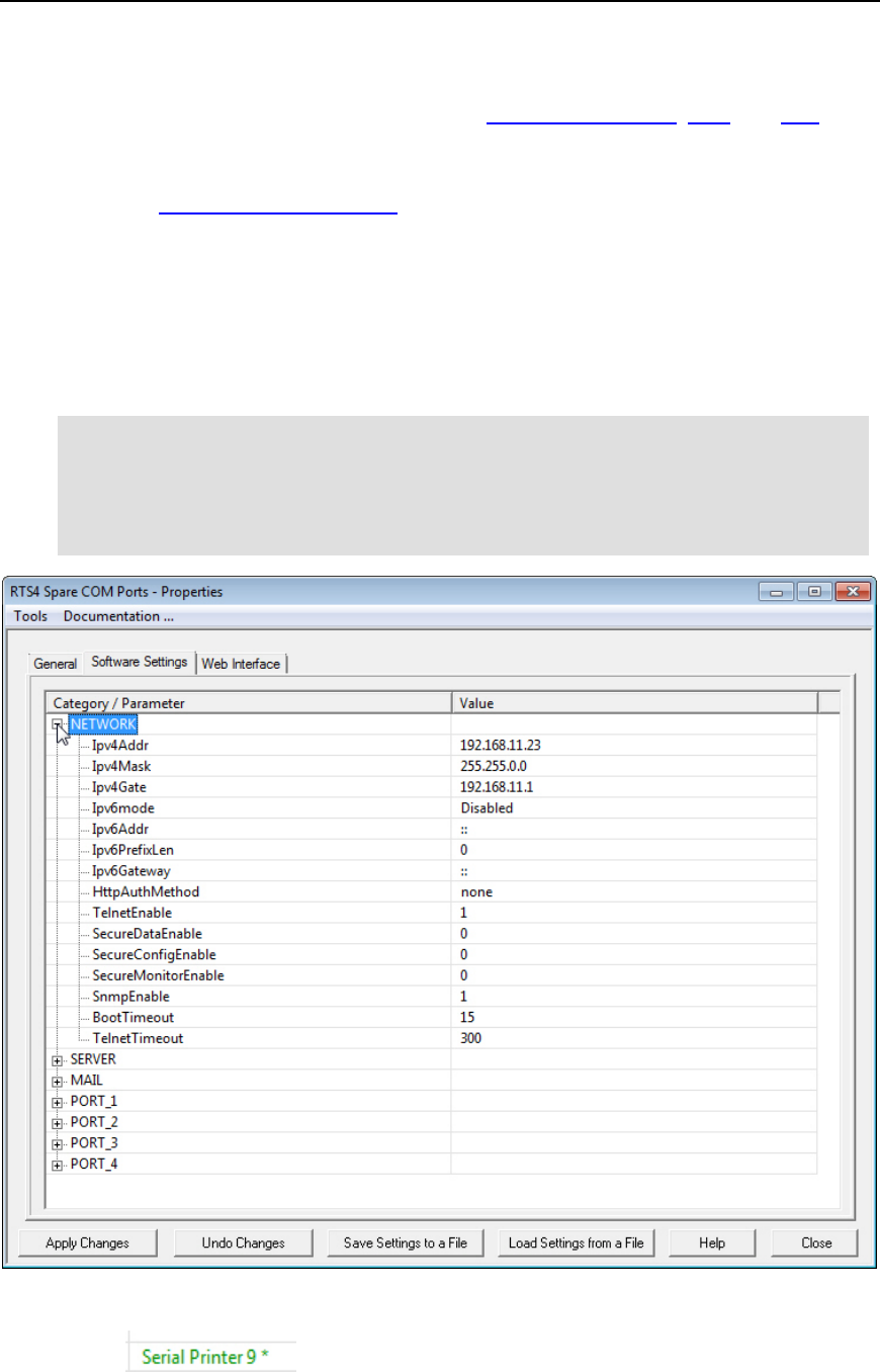
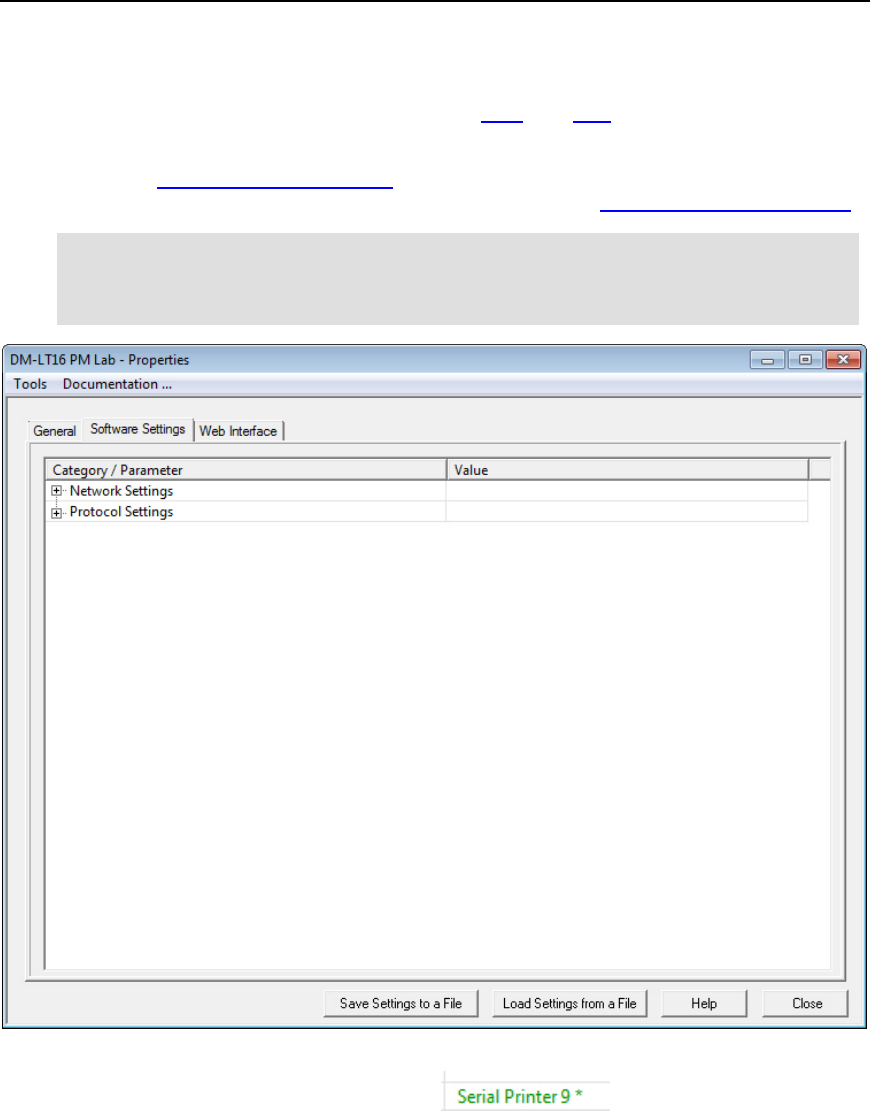
Software Settings Tab (DeviceMaster LT | PRO | RTS | Serial Hub | 500)
The Software Settings tab provides a way to review, edit software settings, save, and load
SocketServer configuration files on a DeviceMaster. The Software Settings tab settings displays
SocketServer, which is independent of the NS-Link device driver.
You may want to use the Web Interface tab:
•If you are not familiar with the configuration parameters you should use the web interface
because the web interface provides user-friendly configuration parameters and help
•If you need to clone port properties
Make sure that you review the changes that you make before saving and uploading a file. For
example, if you accidently enter RS-421 for the Serial Mode, a <null> is loaded into that field,
which displays when you return to the Software Settings tab.
Note: If the Software Settings tab does not appear, that means that the DeviceMaster is
not available for IP connection. Which could mean that an incorrect user name or
password was entered or that there is no IP communications. This could be a
wrong IP address, no IP address assigned to the DeviceMaster, or the
DeviceMaster is configured for DHCP and connected directly to the PC, and it is
unable to get an IP address from the DHCP server .
Changes are displayed in green with an asterisk.
For example:
42 DeviceMaster LT/PRO/RTS/Serial Hub/500 Properties

PortVision DX User Guide
Buttons (Tools Menu)
Descriptions
Apply Changes
Applies the current changes to the DeviceMaster.
Undo Changes
Undoes all the changes only, if you have not applied it to the
DeviceMaster
Save Settings to a File
Allows you to save the current configuration of this DeviceMaster in
a file. All network and SocketServer (if applicable) settings are
saved.
A Field Selection pop up appears so that you can select appropriate
configuration values.
Optionally, you can use the Save button or the Save Configuration
option in the Device menu on the Main screen, if you want to save
specific portions of the configuration.
Load Settings from a
File
Loads a previously saved DeviceMaster configuration file.
A Field Selection pop up appears so that you can select appropriate
configuration values.
You must click Apply Changes
before the changes are saved to the
DeviceMaster.
Help
Opens page-level help for this screen.
Close
Closes the window and queries you as to whether you want to save
the settings to a file or not if you made changes and did not click
Apply Changes.
You can disable this query using the Options... screen in the Tools
menu (Ask for confirmation on closing Properties screen item).
DeviceMaster LT/PRO/RTS/Serial Hub/500 Properties 43
PortVision DX User Guide
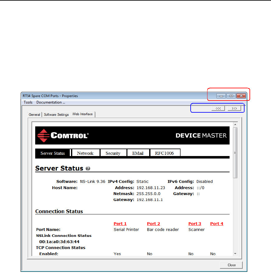
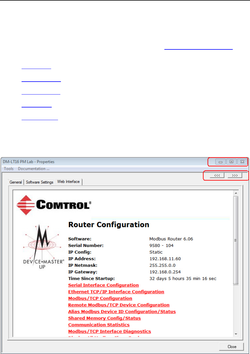
Web Interface Tab (DeviceMaster LT | PRO | RTS | Serial Hub | 500)
This allows you to access SocketServer (or the NS-Link web page, if you installed the
DeviceMaster device driver) from PortVision DX.
You can maximize the Web Interface page for a better view.
When the screen is maximized, the Forward and Backward buttons work the same as your
browser navigation.
44 DeviceMaster LT/PRO/RTS/Serial Hub/500 Properties
PortVision DX User Guide
DeviceMaster UP Properties
The Properties screen consists of the following tabs:
•General
•Software Settings
•Web Interface
General Tab (DeviceMaster UP)
Use the General tab of the Properties screen to configure the network and device settings for the
DeviceMaster UP. You can also access hardware information about your DeviceMaster UP using
the What’s This help feature.
Note: If you have secured the DeviceMaster UP with a password, you must enter the
user name and password to access the General tab.
The General tab contains this information:
•Identification
•Network Settings
•Action buttons
Refer to Programming Network Information for procedures for using this screen.
DeviceMaster UP Properties 45

PortVision DX User Guide
Identification
Description
Device Name
The field default value is Device and the last three pairs of digits from the
MAC address.
You can change the name by entering a new name in this field. The name
change displays on the Main screen after clicking Apply Changes.
Optionally, you can use the Rename option on the Main screen.
MAC Address
This field contains the MAC address of the DeviceMaster UP that you are
configuring. You cannot change the MAC address of a DeviceMaster UP.
A MAC Address label is located on every DeviceMaster UP. The first three
pairs of digits start with 00 C0 4E.
Serial Number
You can enter the serial number of the DeviceMaster UP in the event you
require the serial number. There is a serial number label on the
DeviceMaster UP.
Device Status
This is the Status that displays on the Main screen in the Device List pane.
Detection Type
REMOTE means that the DeviceMaster UP is not connected to this
segment of the network.
LOCAL means that the DeviceMaster UP is on this local network
segment.
Network
Settings Description
IP Mode
•Disable IP Disables IP communications in the DeviceMaster UP so that
it runs in MAC mode. DeviceMaster UP protocols do not support MAC
mode.
•DHCP IP Configures the DeviceMaster UP to use DHCP. Make sure th
at
the network administrator is provided with the MAC address of the
DeviceMaster UP so that it can be configured with the network. See your
System Administrator to acquire a unique reserved IP address if you are
using DHCP.
If you click DHCP IP, the IP Address text box is disabled and set to
0.0.0.0.
•Static IP Configures the DeviceMaster UP with the static IP address
information that you provide in the IP Address, Subnet Mask, and
Default Gateway fields.
IP Address
The IP address programmed into the DeviceMaster UP after applying the
changes and rebooting the DeviceMaster UP.
See your network administrator for a valid IP address.
The default IP address programmed from the factory is 192.168.250.250.
Subnet Mask
The
Subnet Mask is a 32-bit value (255.x.x.x) that enables IP packets to
46 DeviceMaster UP Properties

PortVision DX User Guide
Network
Settings Description
distinguish the network ID and host ID portions of the IP address.
The default Subnet Mask programmed from the factory is 255.255.0.0.
Default Gateway
The Default Gateway is a TCP/IP configuration item that is the IP address of
a directly reachable IP router.
The
Default Gateway programmed from the factory is 192.168.250.1.
Buttons (Tools
Menu) Descriptions
Apply Changes
Applies the current changes to the DeviceMaster UP.
Undo Changes
Undoes all the changes only, if you have not applied it to the DeviceMaster UP.
Help
Opens page-level help for this screen.
Close
Closes the window and queries you as to whether you want to save the settings
to a file or not if you made changes and did not click
Apply Changes.
You can disabl
e this query using the Options... screen in the Tools menu (Ask
for confirmation on closing Properties screen item
).
DeviceMaster UP Properties 47
PortVision DX User Guide
Software Settings Tab (DeviceMaster UP)
The Software Settings tab provides a way to review, save, and load protocol settings
(configuration file) on a DeviceMaster UP.
You may want to use the Web Interface tab, if you are not familiar with the protocol settings. If
you need information about the protocol settings, you can open the User Guide for your protocol.
Note: If the Software Settings tab does not appear, that means that the DeviceMaster
UP is not available for IP connection, which could mean that an incorrect user
name or password was entered, or if the DeviceMaster UP is configured for MAC
mode (MAC mode is not supported by the DeviceMaster UP protocols).
Differences between the protocol settings on the DeviceMaster UP and the configuration file are
displayed in green with an asterisk. For example:
48 DeviceMaster UP Properties

PortVision DX User Guide
Buttons (Tools
Menu) Descriptions
Apply Changes
The Apply Changes button only appears if you have loaded a
configuration file that contains settings different from those on the
DeviceMaster UP.
This saves the configuration file that you are viewing in the
Software
Settings
tab to the DeviceMaster UP.
In addition, you must reboot the DeviceMaster
UP to activate any
changes made to the
Network Settings tab.
Undo Changes
The Undo Changes button only appears if you have loaded a
configuration file that contains settings different from those on the
DeviceMaster UP.
This selection reloads the protocol
settings from the DeviceMaster UP
and the
Apply Changes button disappears.
Save Settings to a File
Allows you to save the current configuration (protocol settings) of this
DeviceMaster UP in a file. All network and DeviceMaster UP (if
applicable) setting
s can be saved depending on your selections.
A
Field Selection pop up appears so that you can select appropriate
configuration values. For example, you may not want the use the same IP
address.
Load Settings from a
File
Loads a previously saved DeviceMaster UP configuration file.
A
Field Selection pop up appears so that you can select appropriate
configuration values.
After you load a configuration file to the
Software Settings tab, make
sure that you review the differences that are displayed in green with
an
asterisks before uploading the file to the DeviceMaster UP.
You must click
Apply Changes before the changes are saved to the
DeviceMaster UP.
If the
Apply Changes is not visible, the configuration file and
DeviceMaster UP contain the same settings.
Help
Opens page-level help for this screen.
Close
Closes the window and queries you as to whether you want to save the
settings to a file or not if you made changes and did not click
Apply
Changes
.
You can disable this query using the
Options... screen in the Tools menu
(
Ask for confirmation on closing Properties screen item).
DeviceMaster UP Properties 49
PortVision DX User Guide
Web Interface Tab (DeviceMaster UP)
This allows you to access the protocol web configuration pages for your protocol from PortVision
DX.
For information about the web page for your protocol, locate the appropriate documentation for
your protocol.
•EtherNet IP
•Modbus Router
•Modbus Server
•Modus/TCP
•PROFINET IO
You can maximize the Web Interface page for a better view.
When the screen is maximized, the Forward and Backward buttons work the same as your
browser navigation.
50 DeviceMaster UP Properties
PortVision DX User Guide
IO-Link Master Properties
The Properties screen consists of the following tabs:
•General
•Software Settings
•Web Interface
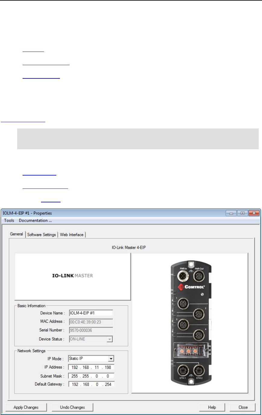
General Tab (IO-Link Master)
Use the General tab of the Properties screen to configure the network and device settings for the
IO-Link Master. You can also access hardware information about your IO-Link Master using the
What’s This help feature.
Note: If you have secured the IO-Link Master with a password, you must enter the user
name, Admin, Operator, or User (case-sensitive) and password to access the
General tab.
The General tab contains this information:
•Identification
•Network Settings
•Action buttons
IO-Link Master Properties 51

PortVision DX User Guide
Refer to Programming Network Information for procedures for using this screen.
Identification
Description
Device Name
This is the device name that PortVision DX uses, the default value is Device and
the last three pairs of digits from the MAC address.
You can c
hange the name by entering a new name in this field. The name change
displays on the
Main screen after clicking Apply Changes.
Optionally, you can use the
Rename option on the Main screen.
MAC Ad
dress
This field contains the MAC address of the IO-Link Master that you are configuring.
You cannot change the MAC address of a IO
-Link Master.
A MAC Address label is located on every IO
-Link Master. The first three pairs of
digits start with 00 C0 4E.
Serial
Number
The IO-Link Master serial number is displayed in the event you require the serial
number.
Device Status
This is the Status that displays on the Main screen in the Device List pane.
Note: If the IO-Link Master has a Rotary switch, the Rotary settings override the network
settings on this page. See the IO-Link Master web interface help system if you need information
about the rotary switch or the IOLM 4-EIP User Guide.
Network Settings
Description
IP Mode
•DHCP IP Configures the IO-Link Master to use DHCP. Make sure
that the network administrator is provided with the MAC address of
the IO-Link Master so that it can be configured with the network.
If you click DHCP IP, the IP Address text box displays the last IP
address programmed in the IO-Link Master.
See your System Administrator to acquire a unique reserved IP
address if you are using DHCP.
•Static IP Configures the IO-Link Master with the static IP address
information that you provide in the IP Address, Subnet Mask, and
Default Gateway fields.
IP Address
The IP address programmed into the IO-Link Master after applying the
changes and rebooting the IO
-Link Master.
See you
r network administrator for a valid IP address.
The default IP address programmed from the factory is
192.168.1.250.
Subnet Mask
The Subnet Mask is a 32-bit value (255.x.x.x) that enables IP packets to
distinguish the network ID and host ID portions of th
e IP address.
The default Subnet Mask programmed from the factory is
255.255.255.0.
52 IO-Link Master Properties

PortVision DX User Guide
Network Settings
Description
Default Gateway
The Default Gateway is a TCP/IP configuration item that is the IP address
of a directly reachable IP router.
The
Default Gateway programmed from the factory is 0.0.0.0.
Buttons (Tools Menu)
Descriptions
Apply Changes
This button applies the current changes to the IO-Link Master.
Undo Changes
This button undoes all the changes only, if you have not applied it
to the IO
-Link Master.
Help
Opens page-level help for this screen.
Close
This button closes the window and queries you as to whether you
want to save the settings to a file or not if you made changes and
did not click
Apply Changes.
You can disable this query using the
Options... screen in the Tools
menu (
Ask for confirmation on closing Properties screen item).
IO-Link Master Properties 53
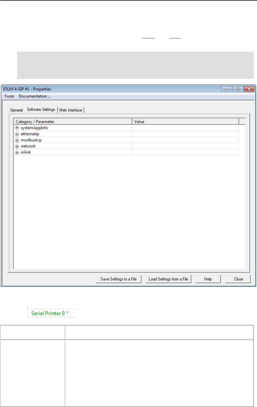
PortVision DX User Guide
Software Settings Tab (IO-Link Master)
The Software Settings tab provides a way to review, save, and load protocol settings
(configuration file) on an IO-Link Master.
Note: If the Software Settings tab does not appear, that means that the IO-Link Master
is not available for connection. Which could mean that an incorrect user name or
password was entered. Make sure that you initial capitalize the user names,
Admin, User, or Operator.
Differences between the settings on the IO-Link Master and the configuration file are displayed in
green with an asterisk so that you can review the content before applying the changes. For
example:
Buttons (Tools Menu)
Descriptions
Apply Changes
The Apply Changes button only appears if you have loaded a
configuration file that contains settings different from those on the IO
-
Link Master.
T
his saves the configuration file that you are viewing in the Software
Settings
tab to the IO-Link Master.
In addition, you must reboot the IO
-
Link Master to activate any changes
made to the
Network Settings tab.
54 IO-Link Master Properties

PortVision DX User Guide
Buttons (Tools Menu)
Descriptions
Undo Changes
The Undo Changes button only appears if you have loaded a
configuration file that contains settings different from those on the IO
-
Link Master.
This selection reloads the protocol settings from the IO
-
Link Master and
the
Apply Changes button disappears.
Save Settings to a File
Allows you to save the current configuration (protocol settings) of this
IO
-Link Master in a file. All network and IO-Link Master (if applicable)
settings can be saved depending on your selections.
A
Field Selection pop up appears so that you can select appropriate
configuration values. For example, you may not want the use the same
IP address.
Load Settings from a
File
Loads a previously saved IO-Link Master configuration file.
A
Field Selection pop up appears so that you can select appropriate
configuration val
ues.
After you load a configuration file to the
Software Settings tab, make
sure that you review the differences that are displayed in green with an
asterisks before uploading the file to the IO
-Link Master.
You must click
Apply Changes before the changes are saved to the
IO
-Link Master.
If the
Apply Changes is not visible, the configuration file and IO-Link
Master contain the same settings.
Help
Opens page-level help for this screen.
Close
Closes the window and queries you as to whether you want to save the
settings to a file or not if you made changes and did not click
Apply
Changes
.
You can disable this query using the
Options... screen in the Tools
menu (
Ask for confirmation on closing Properties screen item).
IO-Link Master Properties 55
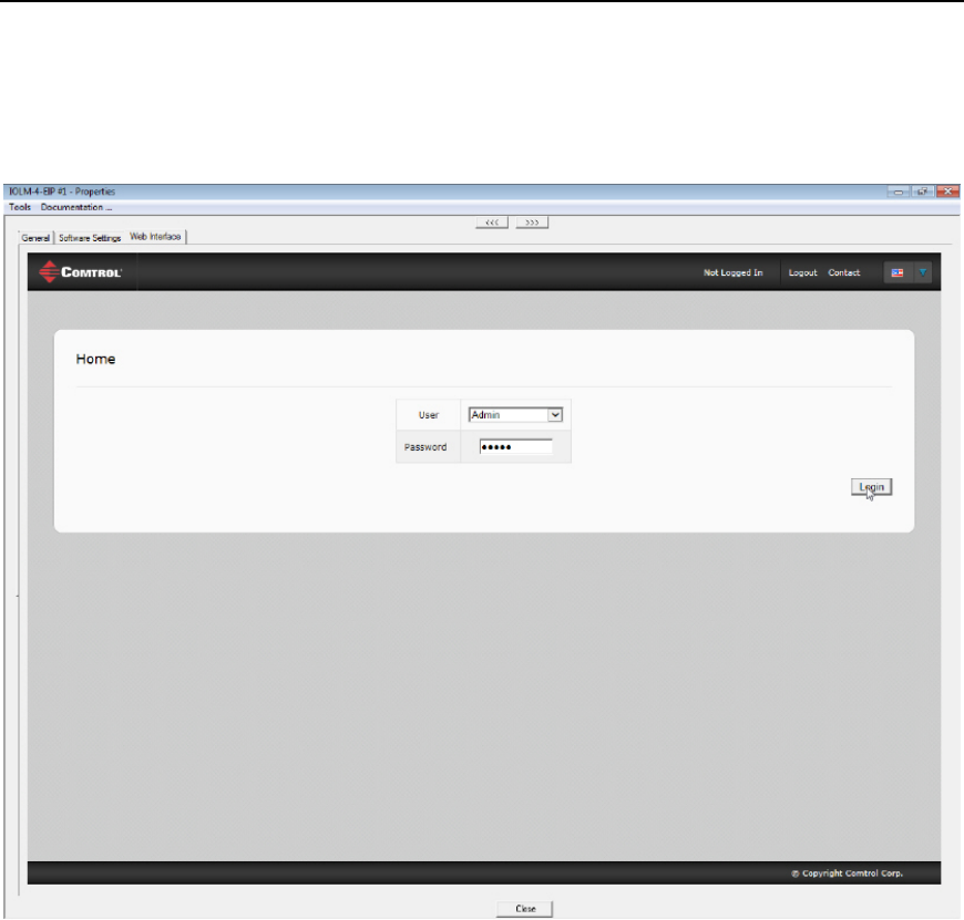
PortVision DX User Guide
Web Interface Tab (IO-Link Master)
This allows you to access the IO-Link Master web configuration pages for your protocol from
PortVision DX.
56 IO-Link Master Properties
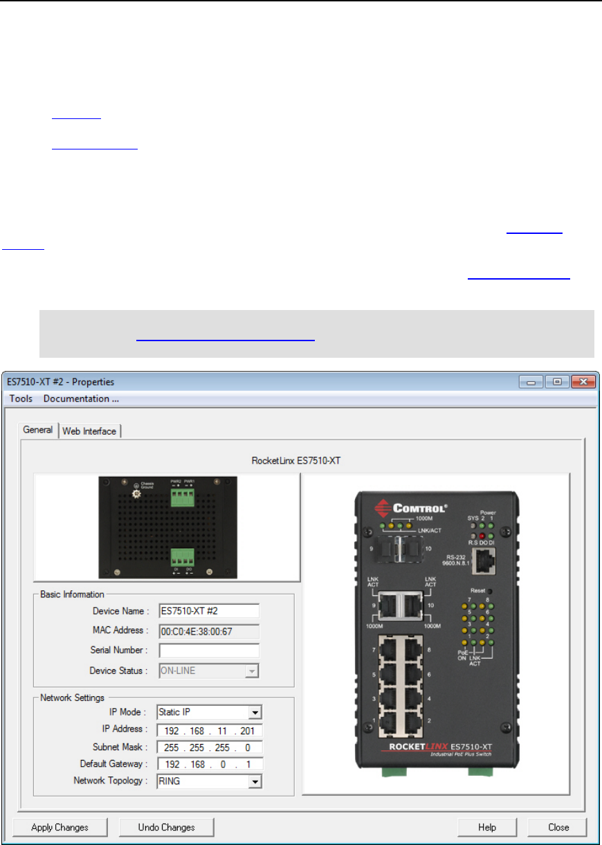
PortVision DX User Guide
RocketLinx Properties
The Properties screen consists of the following tabs:
•General
•Web Interface
General Tab (RocketLinx)
Use the General tab of the Properties screen to configure the network and device settings for a
managed RocketLinx switch or to edit an unmanaged RocketLinx added using the Add New
Device screen.
You can also access hardware information about your RocketLinx using the What’s This help
feature.
Note: You cannot configure or locate an unmanaged RocketLinx using PortVision DX.
You can manually add an unmanaged device for display purposes and to maintain
a central location to store your network information.
RocketLinx Properties 57

PortVision DX User Guide
The General tab contains the following information:
•Basic Information
•Network Settings
•Action buttons
Note: If you have secured the RocketLinx with a password, you must enter the user
name and password to access the General tab.
Refer to Programming Network Information for procedures for using this screen.
Basic Information
Description
Device Name
Managed RocketLinx Switches:
The field default value is Device and the last three pairs of digits from
the MAC address.
Unmanaged RocketLinx Switches
:
This is name that was entered when the switch was added using the
Add New Device option.
You can change the name by entering a new name in this field. The name
change displays on the
Main screen after clicking Apply Changes.
Optionally, you can use the
Rename option on the Main screen.
MAC Address
Managed RocketLinx Switches:
This field contains the MAC address of the managed RocketLinx that
you are configuring. You cannot change the MAC address of a
RocketLinx.
A MAC Address label is located on every managed RocketLinx. The
first three pairs of digits start with 00 C0 4E.
Unmanaged RocketLinx Switches
:
This field is empty because unmanaged RocketLinx switches do not
have MAC addresses.
Serial Number
You can enter the serial number of the RocketLinx switch in the event you
require the serial number. There is a serial number label on the
RocketLinx.
Device Status
This is the Status that displays on the Main screen in the Device List pane.
Managed RocketLinx Switches:
ON-LINE means that the RocketLinx is powered on, PortVision DX
can access and be used to configure the device.
OFF-LINE means that the RocketLinx is not available to PortVision
DX. It may not be powered on or is not on the same network segment
as PortVision DX.
58 RocketLinx Properties

PortVision DX User Guide
Basic Information
Description
Unmanaged RocketLinx Switches:
You can choose to set this option to ON-LINE or OFF-LINE. This
status is displayed on the Main screen. PortVision DX cannot poll
unmanaged switches to determine whether they are on-line or not.
Network Settings
Description
IP Mode
Managed RocketLinx Switches:
•DHCP IP Configures the RocketLinx to use DHCP. If you click DHCP IP
,
the IP Address text box is disabled and set to 0.0.0.0.
See your System Administrator to acquire a unique reserved IP address if
you are using DHCP. They need the MAC address of the unit to provide
you with an IP address.
•Static IP Configures the RocketLinx with the static IP address
information that you provide in the IP Address, Subnet Mask, and
Default Gateway fields.
Unmanaged RocketLinx Switches: This is an inactive field because
unmanaged switches do not use IP addresses.
IP Address
Managed RocketLinx Switches:
The IP address programmed into the RocketLinx after applying the
changes and rebooting the RocketLinx.
See your network administrator for a valid IP address.
The default IP address programmed from the factory is 192.168.250.250.
Unmanaged RocketLinx Switches
: inactive field because unmanaged
switches do not use IP addresses.
Subnet Mask
Managed RocketLinx Switches:
The Subnet Mask is a 32-bit value (255.x.x.x) that enables IP packets to
distinguish the network ID and host ID portions of the IP address.
The default Subnet Mask programmed from the factory is 255.255.0.0.
Unmanaged RocketLinx Switches: inactive field because unmanaged
switches do not use subnet masks.
Default Gateway
Managed RocketLinx Switches:
The Default Gateway is a TCP/IP configuration item that is the IP
address of a directly reachable IP router.
The Default Gateway programmed from the factory is 192.168.250.1.
Unmanaged RocketLinx Switches: inactive field because unmanaged
switches do not use IP addresses.
RocketLinx Properties 59

PortVision DX User Guide
Network Settings
Description
Network Topology
This is an informational field.
You can select the topology† that reflects on this RocketLinx.The following
options are available:
•BUS - In local area networks where bus topology is used, each node is
connected to a single cable. Each computer or server is connected to
the single bus cable. A signal from the source travels in both directions
to all machines connected on the bus cable until it finds the intended
recipient. If the machine address does not match the intended address
for the data, the machine ignores the data. Alternatively, if the data
matches the machine address, the data is accepted.
•MESH - The value of fully meshed networks is proportional to the
exponent of the number of subscribers, assuming that communicating
groups of any two endpoints, up to and including all the endpoints, is
approximated by Reed's Law.
•RING - A network topology that is set up in a circular fashion in which
data travels around the ring in one direction and each device on the right
acts as a repeater to keep the signal strong as it travels. Each device
incorporates a receiver for the incoming signal and a transmitter to send
the data on to the next device in the ring. The network is dependent on
the ability of the signal to travel around the ring.
•STAR - In local area networks with a star topology, each network host is
connected to a central hub with a point-to-point connection. In Star
topology every node (computer workstation or any other peripheral) is
connected to central node called hub or switch. The switch is the server
and the peripherals are the clients. The network does not necessarily
have to resemble a star to be classified as a star network, but all of the
nodes on the network must be connected to one central device. All traffic
that traverses the network passes through the central hub.
•TREE - The type of network topology in which a central 'root' node (the
top level of the hierarchy) is connected to one or more other nodes that
are one level lower in the hierarchy (i.e., the second level) with a point-
to-point link between each of the second level nodes and the top level
central 'root' node, while each of the second level nodes that are
connected to the top level central 'root' node will also have one or more
other nodes that are one level lower in the hierarchy (i.e., the third level)
connected to it, also with a point-to-point link, the top level central 'root'
node being the only node that has no other node above it in the
hierarchy (The hierarchy of the tree is symmetrical.) Each node in the
network having a specific fixed number, of nodes connected to it at the
next lower level in the hierarchy, the number, being referred to as the
'branching factor' of the hierarchical tree.
•HYBRID - Hybrid networks use a combination of any two or more
topologies in such a way that the resulting network does not exhibit one
of the standard topologies (e.g., bus, star, ring, etc.). For example, a tree
network connected to a tree network is still a tree network topology. A
hybrid topology is always produced when two different basic network
topologies are connected. Two common examples for Hybrid network
are: star ring network and star bus network
•DAISY-CHAIN - Except for star-based networks, the easiest way to add
more computers into a network is by daisy-chaining, or connecting each
computer in series to the next. If a message is intended for a computer
60 RocketLinx Properties

PortVision DX User Guide
Network Settings
Description
partway down the line, each system bounces it along in sequence until it
reaches the destination. A daisy-chained network can take two basic
forms: linear and ring.
•POINT-TO-POINT - The simplest topology is a permanent link between
two endpoints. Switched point-to-point topologies are the basic model of
conventional telephony
† "Hierarchical Network." Wikipedia. Wikimedia Foundation, 23 Sept. 2012. Web. 25 Sept.2012.
http://en.wikipedia.org/wiki/Hierarchical_network.
Buttons (Tools Menu)
Descriptions
Apply Changes
Applies the current changes to the RocketLinx.
Undo Changes
Undoes all the changes only, if you have not applied it to the
RocketLinx.
Help
Opens page-level help for this screen.
Close
Closes the window and queries you as to whether you want to save
the settings to a file or not.
You can disable this query using the Options... screen in the Tools
menu (Ask for confirmation on closing Properties screen item).
Web Interface Tab (RocketLinx)
This opens your default browser and allows you to access the managed RocketLinx web
configuration pages for your switch from PortVision DX.
Use the RocketLinx web page help system or the appropriate RocketLinx User Guide for more
information about configuration.
Note: Java is required to operate RocketLinx web interfaces.
RocketLinx Properties 61
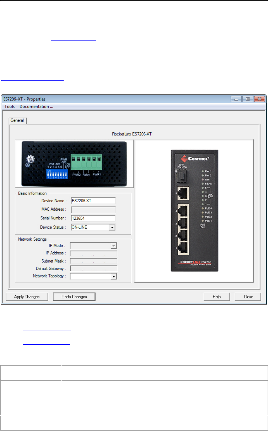
PortVision DX User Guide
General Tab (Other Hardware)
You must use the Add New Device screen to add:
•RocketLinx unmanaged switches
•Third-party switches and devices
After a device is added, you can use the General tab on the Properties screen to modify any
information.
The General tab contains the following information:
•Basic Information
•Network Settings
•Action buttons
Basic Information
Description
Device Name
You can change the name by entering a new name in this field. The name
change displays on the
Main screen after clicking Apply Changes.
Optionally, you can use the
Rename option on the Main screen.
MAC Address
This field displays a MAC addresses, if it was entered in the Add New
62 General Tab (Other Hardware)

PortVision DX User Guide
Basic Information
Description
Device screen.
You can enter a MAC address if you did not do so during initial set up.
Serial Number
You can enter the serial number of the device or switch for identification
purposes.
Device Status
This is the Status that displays on the Main screen in the Device List pane.
You can choose to set this option to ON
-LINE or OFF-LINE, which is
displayed on the
Main screen.
PortVision DX cannot poll unmanaged switches or third
-party devices to
determine whether they are on
-line or not.
Network Settings
Description
IP Mode
This is an informational field for your convenience.
IP Address
This is an informational field for your convenience.
Subnet Mask
This is an informational field for your convenience.
Default Gateway
This is an informational field for your convenience.
Buttons (Tools Menu)
Descriptions
Apply Changes
Applies the current changes to the device.
Un
do Changes
Undoes all the changes only, if you have not applied it to
the device.
Help
Opens page-level help for this screen.
Close
Closes the window and queries you as to whether you
want to save the settings to a file or not.
You can disable this query
using the Options... screen in
the
Tools menu (Ask for confirmation on closing
Properties screen item
).
General Tab (Other Hardware) 63
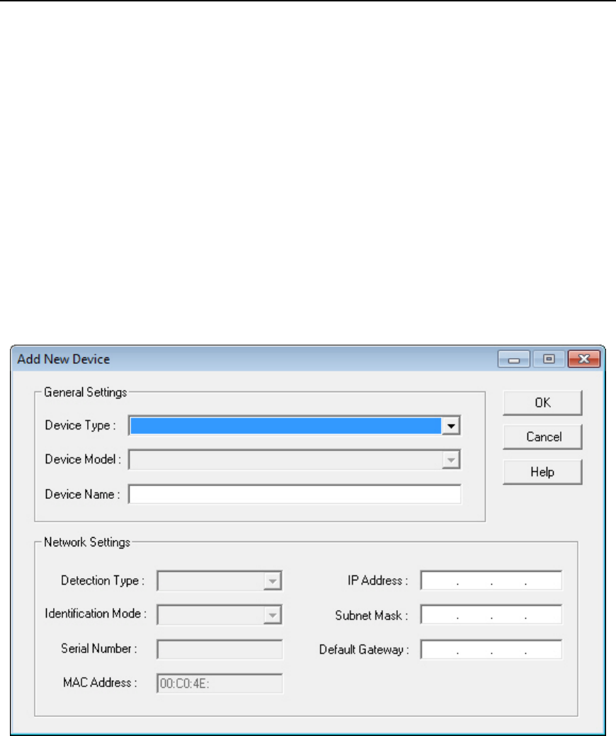
PortVision DX User Guide
Add New Device Screen
You can use the Add New Device screen to:
•Configure a Comtrol Ethernet attached products that is not on the local network.
•Add a new Comtrol Ethernet attached product manually, if you do not want to scan the
network.
•Add unmanaged devices to the PortVision DX view so that you can maintain information
about the devices in your network.
There are several methods available to access the Add New Device screen:
•Click the Manage menu and then click Add New... Device
•Right-click a folder or device in the Device Tree pane and then click Add New... Device
from the menu
64 Add New Device Screen
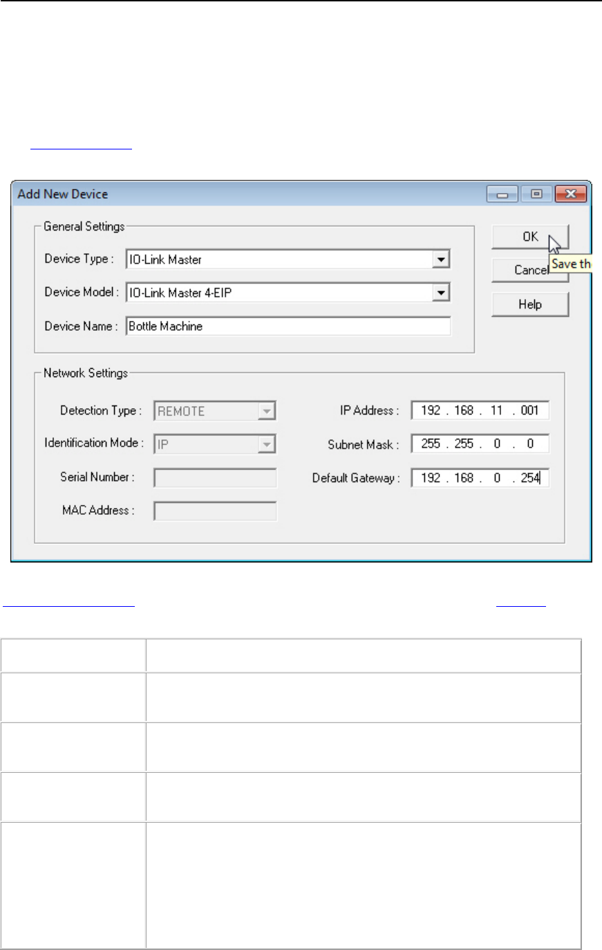
PortVision DX User Guide
Add New Device Screen (Managed)
Use the Add New Device screen to configure Comtrol Ethernet attached products that are not on
the local network or to add a new Comtrol Ethernet attached product manually, if you do not want
to scan the network.
The Add New Device screen can be accessed from the Manage menu by clicking Add New...
Device or by right-clicking a folder or device and then clicking Add New... Device from the menu.
The following table provides information about the Add New Device fields. You can refer to
Adding a New Device for procedures. You can change this information using the General tab on
the Properties screen.
Add New Device
Description
Device Type
Select the type of Comtrol Ethernet attached product that you want to
add to PortVision DX.
Device Model
This drop down list contains the Comtrol Ethernet attached product
model list.
Device Name
You must enter a Device Name for the Comtrol Ethernet attached
product.
Detection Type
(DeviceMaster, Only)
If this is a DeviceMaster, click one of the Detection Types:
•REMOTE (default) means that the Comtrol Ethernet attached
product is not connected to this segment of the network.
•LOCAL means that the Comtrol Ethernet attached product is on
this local network segment.
Add New Device Screen - Managed 65

PortVision DX User Guide
Add New Device
Description
Identification Mode
(DeviceMaster, Only)
If this is a DeviceMaster you may need to select an appropriate
Identification Mode
:
•If you click REMOTE for the Detection Type, you must enter IP
Mode values (IP Address, Subnet Mask, and Default Gateway).
•If you click LOCAL for the Detection Type, you can click IP or
MAC.
•If you click IP, you must enter IP Mode values (IP Address,
Subnet Mask, and Default Gateway).
•If you click MAC, you must enter the MAC Address.
Serial Number
Depending on the product type, you can optionally enter the Comtrol
Ethernet attached product serial number.
If this is an IO
-Link Master, the serial number is propagated into this
field if it has a valid IP addr
ess.
MAC Address
(DeviceMaster, Only)
If you click MAC as the Identification Mode for a DeviceMaster, you
must enter the MAC address of the DeviceMaster you want PortVision
DX to locate on the network.
A MAC address label is attached to all DeviceMasters.
The first three
pairs of digits start with 00 C0 4E.
IP Address
DeviceMaster
If you clicked
REMOTE as the Detection Type or IP as the
Identification Mode
, you must enter the IP address programmed into
the DeviceMaster.
Subnet Mask
A 32-bit value (255.x.x.x) that enables IP packets to distinguish the
network ID and host ID portions of the IP address.
Default Gateway
A TCP/IP configuration item that is the IP address of a directly
reachable IP router.
Ok
Adds the new configuration to the network as a new Comtrol Ethernet
attached product.
Cancel
Closes the window without saving any data.
66 Add New Device Screen - Managed
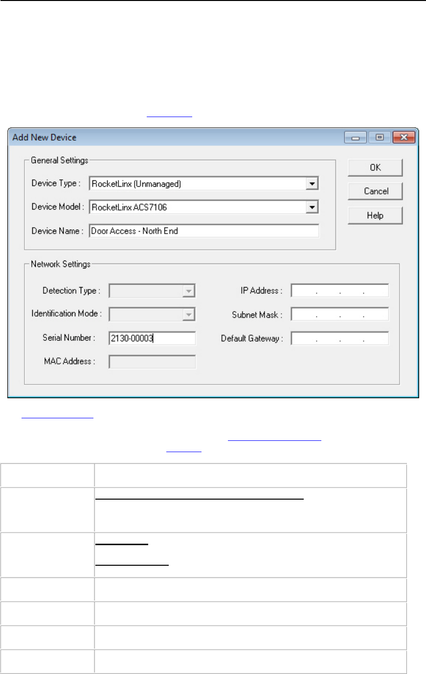
PortVision DX User Guide
Add New Device Screen (Other Hardware)
Use the Add New Device screen to add other hardware to PortVision DX so that you can maintain
information about the devices in your network.
PortVision DX does not manage or configure non-Comtrol Ethernet attached products or
unmanaged RocketLinx switches but you can display them and if applicable, enter additional
information about them using the Edit Notes function.
The Add New Device screen can be accessed from the Manage menu by clicking Add New...
Device or by right-clicking a folder or device in the Device Tree pane and then clicking Add
New... Device from the menu list. You can refere to Adding a New Device for procedures. You
can change this information using the General tab on the Properties screen.
Add New Device
Description
Device Type
RocketLinx - Click RocketLinx (Unmanaged).
Select
Other Hardware if it is not a Comtrol device.
Device Model
RocketLinx - Select the appropriate RocketLinx model.
Other Hardware
- Select Network Switch or Serial/Ethernet Device.
Device Name
You must enter a name to identify the device.
Detection Type
This field is disabled.
Identification Mode
This field is disabled.
Serial Number
You can optionally enter the device serial number.
Add New Device Screen (Other Hardware) 67

PortVision DX User Guide
Add New Device
Description
MAC Address
RocketLinx - Disabled since unmanaged RocketLinx switches do not
have MAC addresses.
Other Hardware
- You can optionally enter a MAC address for the
device for record keeping practices.
IP Address
RocketLinx - disabled since unmanaged RocketLinx switches do not
use addresses.
Other Hardware
- You can optionally enter an IP address for this
device
for record keeping practices.
Subnet Mask
RocketLinx - Disabled.
Other Hardware
- You can optionally enter a subnet mask for record
keeping practices.
Default Gateway
RocketLinx - Disabled.
Other Hardware
- You can optionally enter a default IP gateway
address
for record keeping practices.
Ok
Adds the new configuration to the network as a new device.
Cancel
Closes the window without saving any data.
68 Add New Device Screen (Other Hardware)

Managing the View
PortVision DX makes it easy to manage how your products are displayed. This section discusses
the following features:
•Scanning the network
•Managing devices
•Using folders
•Adding new devices
•Renaming devices
•Deleting devices
•Changing the Detection Type
•OFF-LINE Devices
•Saving Device Diagnostics Files (IO-Link Master)
•Editing notes
•Changing the Device List view
•Refreshing the view
•Managing sessions
Managing the View 69
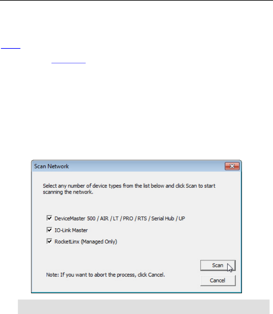
PortVision DX User Guide
Scanning the Network
PortVision DX does not scan the network for new devices unless you chose to do so. You can
refresh the view of the devices displayed in PortVision DX without scanning the network or simply
wait for the next polling cycle. PortVision DX polls the devices and refreshes the view, which is
dependent on the polling cycle interval.
You can follow these steps to scan the network:
1. Click the Scan button or optionally do one of the following:
• Click the Scan Network option under the Tools menu and click the product type
or types for which you want to locate.
• Click the Enable the Always scan network feature under the Tools menu in the
Options screen and click the product type or types for which you want to locate.
2. Click the product type or types for which you want to locate and click the Scan button on
the Scan Network pop up.
Note: You can save time and only scan for products that you have connected to the
network.
70 Managing the View
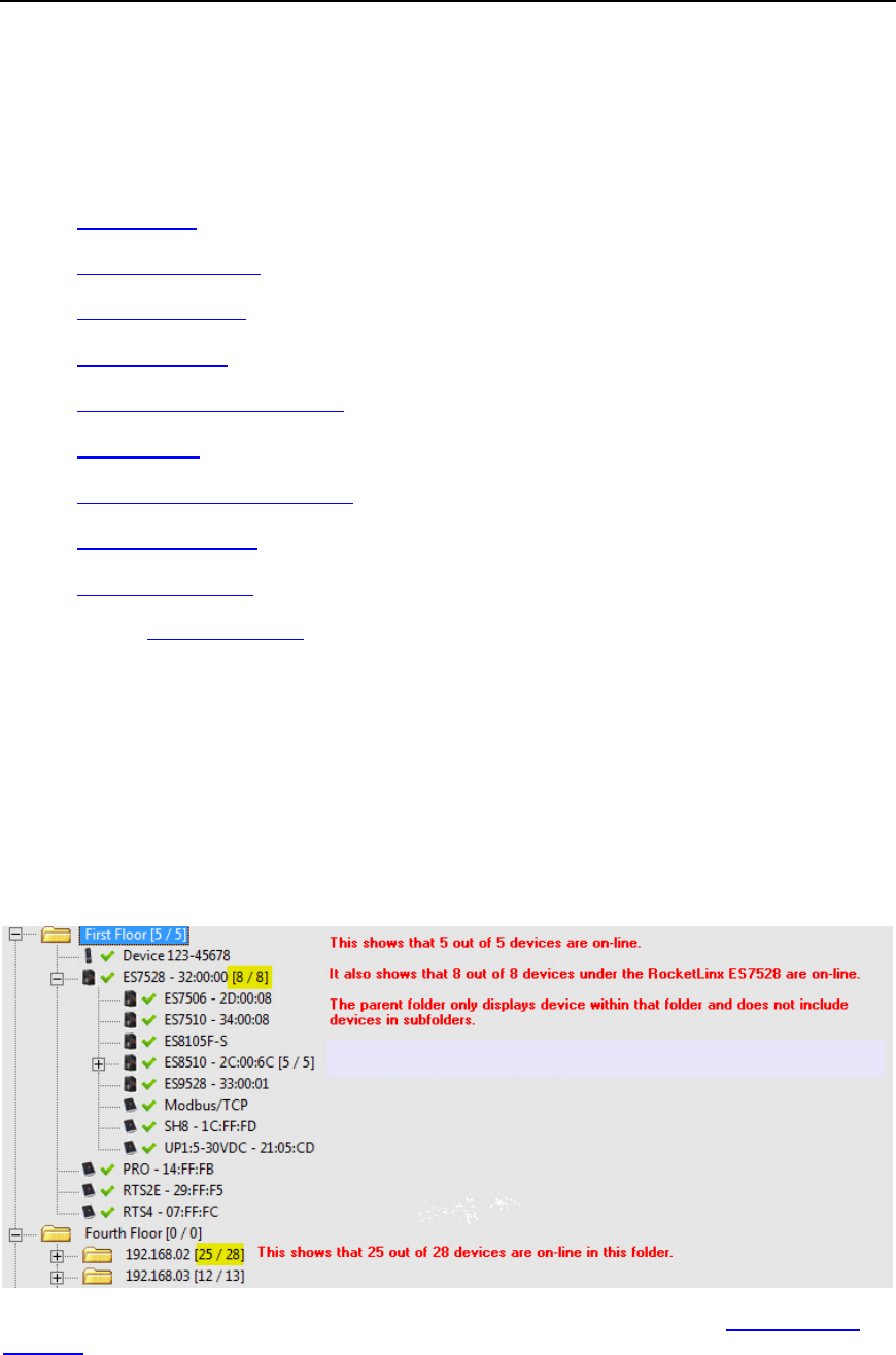
PortVision DX User Guide
Managing Devices
After you have scanned the network to locate Comtrol Ethernet attached products, which are
placed in the Scan Results folder you are ready to customize your view. This subsection
discusses the following topics:
• Using folders
• Adding new devices
• Renaming devices
• Deleting devices
• Changing the Detection Type
• Editing Notes
• Changing the Device List view
• Refreshing the view
• Managing sessions
You can create multiple sessions if different views are required.
Using Folders
You can use the Manage menu and Add New... Folder option to create folders in the Device
Tree pane and display the contents of the selected folder in the Device List pane.
Folders are displayed first numerically and then alphabetically. The number of devices (managed
or unmanaged) in a folder are displayed in brackets after the folder name and the number of
devices online.
You can use a device as a folder and layer switches or devices under it.
If you want to customize folder names for a specific audience, you may want to create multiple
sessions.
Managing the View 71

PortVision DX User Guide
Adding Folders
Folders permit you to organize your devices in a logical view. Folders are displayed first
numerically and then alphabetically. You can use a device as a folder and layer devices or
switches under it.
Use the following procedure to add a folder or folders in the Device Tree pane.
1. Right-click the Device Tree pane or optionally click an existing folder under which, you
want to nest additional folders. You can place folders outside of the Scan Results folder
or nest them within the folder.
2. Right-click and then click Add New...Folder.
Optionally, you can use the Manage menu and the Add New... Folder option.
3. Enter the folder name.
The number of devices (managed or unmanaged) in a folder are displayed in brackets after the
folder name and the number of devices online.
After you create a folder or folders, you can drag a device or devices to the appropriate folder. A
device can only display in a single folder.
You can move or add new devices into the folder.
Moving Folders
You can use several methods to move folders in the Device Tree pane.
• Highlight the folder and drag it where you want it to display. You can move devices under
another device.
• Right-click the folder, click Move, click the target folder and then the Ok button.
• Highlight the folder, click the Manage menu, click Move, click the target folder and then the
Ok button.
Folders are displayed first numerically and then alphabetically. The number of devices (managed
or unmanaged) in a folder are displayed in brackets after the folder name and the number of
devices online.
72 Managing the View

PortVision DX User Guide
Renaming Folders
Use the following procedure to rename a folder in the Device Tree pane.
Folders are displayed first numerically and then alphabetically. The number of devices (managed
or unmanaged) in a folder are displayed in brackets after the folder name and the number of
devices online.
You may want to rename the folder named Scan Results [#] after each Scan Network process if
you store all of your devices in the Scan Results folder. Optionally, create a folder structure to
organize your devices.
1. Highlight the folder (or device with children devices) in the Device Tree pane that you
want to rename.
2. Right-click and then click Rename.
Optionally, you can use one of these methods:
• Highlight the folder, click the Manage menu and the Rename option.
• Click the folder so that you can type the name in the folder.
3. Enter the new folder name and press Enter.
Deleting Folders
Use the following procedure to delete folders and their contents in the Device Tree pane.
This action does not affect the functionality of the devices in the folder, it merely removes the
folder from the view.
1. Highlight the folder in the Device Tree pane that you want to delete.
2. Right-click and then click Delete.
Optionally, you can use one of these methods:
• Press the Delete key.
• Highlight the folder, click the Manage menu and the Delete option.
• Highlight the folder, press the Delete key, and click Yes to Confirm Delete pop up
message.
Managing the View 73

PortVision DX User Guide
Moving Devices into a Folder
Use this procedure to move a device or devices (from the Device Tree or Device List panes) into
another folder. Folders only reside in the Device Tree pane.
You can use the procedure below.
1. Right-click the device or devices that you want to move into a folder.
2. Click Move.
3. Click the target folder into which you want the device or devices moved.
4. Click Ok to close the window.
Optionally, you can use one of these methods:
• Highlight a device or devices and drag the devices into a specific folder or under a managed
RocketLinx switch.
• Highlight a device or devices, click the Manage menu, select the Move option, click the
target folder (or managed RocketLinx switch), and then click Ok.
Adding a New Device
You can add a new device or switch (managed or unmanaged) manually, if you do not want to
scan the network to locate and add new devices.
There may be cases where you want to use the Add New Device window to:
• Configure DeviceMasters that are not on the local network or other Comtrol Ethernet
attached products, such as: IO-Link Master, or RocketLinx (remote)
• Configure DeviceMasters in PortVision DX that are on the local network segment (local)
• Add RocketLinx unmanaged switches and third-party switches or devices
If you use the Add New Device screen to add unmanaged RocketLinx switches, third-party
switches, or devices remember that you are not using PortVision DX to configure or manage
those devices. PortVision DX merely is providing a you with a view of your network.
When you add an unmanaged RocketLinx or third-party switch or device, it always shows ON-
LINE, unless you use the General tab on the Properties screen to change the status to OFF-
LINE.
74 Managing the View

PortVision DX User Guide
Remote Using the IP Address
Use the following procedure to add a remote device (Comtrol Ethernet attached product) to
PortVision DX.
1. Access the Add New Device window using one of these methods:
• Click Add New... Device in the Manage menu.
• Right-click anywhere in the Device Tree pane and click Add New... Device.
• Right-click a folder or device and click Add New... Device.
2. Select the appropriate Device Type from the drop-down list.
3. Select the Device Model from the drop-down list.
4. Enter a Device Name for the new device.
5. If DeviceMaster, select REMOTE for the Detection Type.
6. Enter the IP Address, Subnet Mask, and Default Gateway.
7. Click Ok.
8. If necessary, click Refresh for the new device to display in the Device List pane.
Local Using the IP Address or MAC Address
Use the following procedure to add a local DeviceMaster to PortVision DX.
1. Locate the network information or MAC address of the device you want to add.
2. Access the Add New Device window using one of these methods:
• Click Add New... Device in the Manage menu.
• Right-click a folder or managed RocketLinx switch and click Add New... Device.
3. Select the Device Type from the drop-down list.
4. Select the Device Model from the drop-down list.
5. Enter a Device Name for the new device.
6. Select LOCAL for the Detection Type.
7. Select the Identification Mode to MAC or IP.
• If you selected MAC for the Identification Mode, enter the MAC Address. A MAC
address label is attached to all Comtrol Ethernet attached products. The first three
pairs of digits start with 00 C0 4E. The DeviceMaster UP and RocketLinx do not
support MAC mode.
• If you selected IP for the Identification Mode, enter the IP Address, Subnet Mask,
and Default Gateway.
8. Optionally, enter the serial number.
9. Click Ok. If necessary, click Refresh for the new device to display in the Device List
pane.
Managing the View 75

PortVision DX User Guide
Unmanaged Switches or Third-Party Devices
Use the following procedure to add a remote device (managed or unmanaged) to PortVision DX.
Remember PortVision DX does not manage or configure non-Comtrol Ethernet attached products
but you can display them and if applicable, enter information about them using the Edit Notes
function. If the product has a valid IP address, the Web Interface tab appears in the Properties
page so that you can access any device configuration pages.
1. Access the Add New Device window using one of these methods:
• Click Add New... Device in the Manage menu.
• Right-click anywhere in the Device Tree pane and click Add New... Device.
• Right-click a folder and click Add New... Device.
2. Select the appropriate Device Type from the drop-down list.
• If this is an unmanaged RocketLinx switch, click RocketLinx (Unmanaged).
• If this is a third-party device, click Other Hardware.
3. Select the Device Model from the drop-down list.
4. Enter a Device Name for the new device.
5. Optionally, enter a serial number for the device.
6. Optionally, enter a MAC address for the device.
7. Optionally, enter the IP address, subnet mask, and IP default gateway.
8. Click Ok.
9. If necessary, click Refresh for the new device to display in the Device List pane.
Renaming a Device
The default device name is Device and last three pairs of digits from the MAC address, for
example: Device 15 05 CD.
You can rename a device using one of the following methods:
• Right-click the device in the Device Tree or Device List pane, click Rename, and enter the
new name.
• Highlight the device, click Rename in the Manage menu, and enter the new name.
76 Managing the View
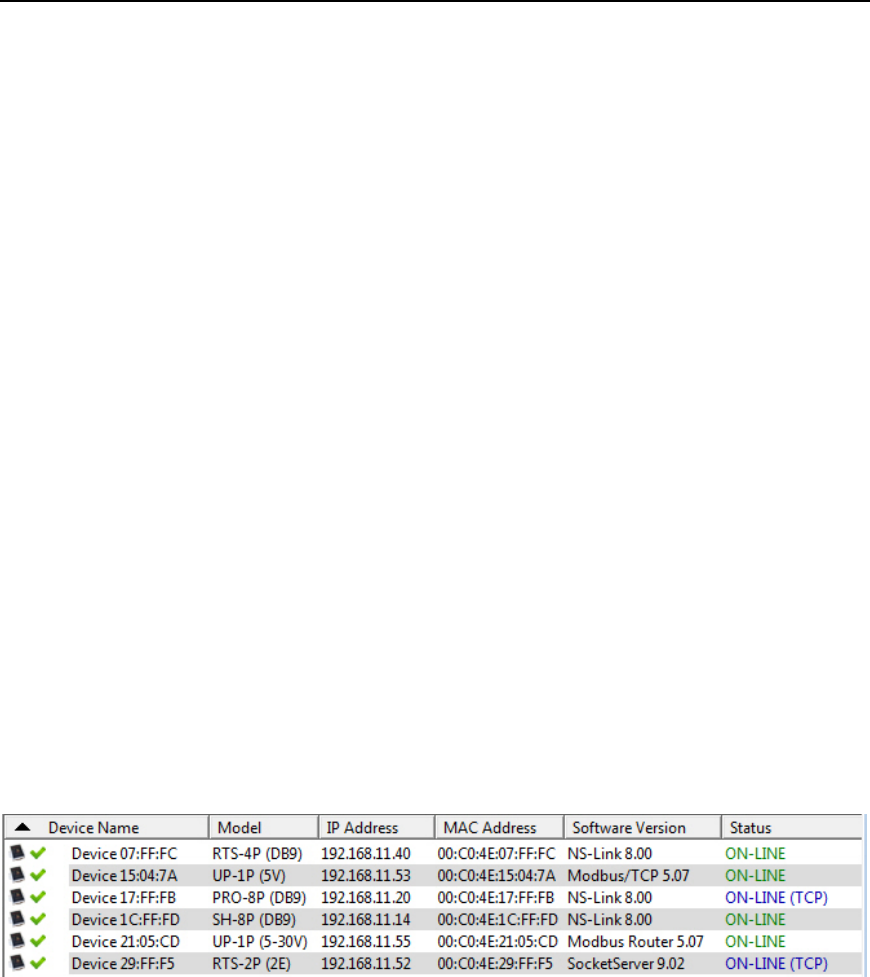
PortVision DX User Guide
Deleting a Device
You can delete a device from the PortVision DX display.
This action does not affect the functionality of the device, it merely removes a device from the
view.
1. Highlight the device (or devices) that you want to remove from PortVision DX.
2. Use one of the following methods to delete the device or devices:
• Click Delete in the Manage menu, and click Yes to Confirm Delete pop up message..
• Press the Delete key and click Yes to Confirm Delete pop up message.
• Right-click the device or devices, click Delete, and click Yes to Confirm Delete pop up
message.
Changing the Detection Type (DeviceMaster)
You can change the Detection Type for single or multiple DeviceMasters several ways:
• Right-click the device (or devices) in the List View pane and then click Change Detection
Type.
• Highlight the device (or devices) and click Change Detection Type on the Device menu.
• Double-click on the device, select the desired Detection Type, click Apply Changes, and
then Close.
If the Detection Type is changed to Remote, the DeviceMaster displays in the Device List in blue
and (TCP) displays with the Status as shown in the following graphic.
Managing the View 77
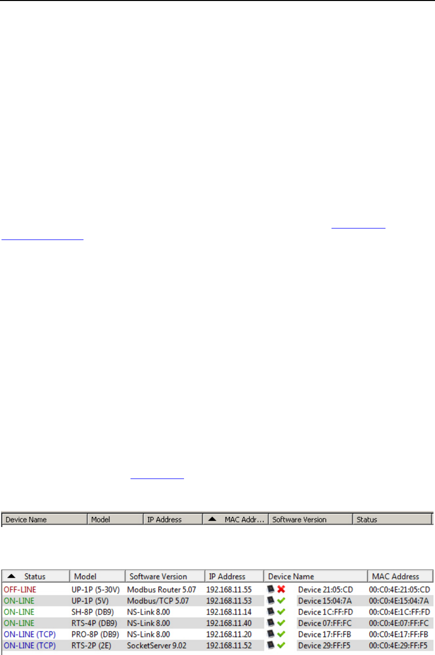
PortVision DX User Guide
Saving Device Diagnostics Data Files (IO-Link Master)
The Save Device Diagnostics Data option is available for the IO-Link Master.
If you are experiencing technical difficulties, Comtrol Technical Support may request that you
send this file to Comtrol.
1. Right-click the IO-Link Master, click Advanced, and then Save Device Diagnostics
Data.
2. Browse to the location where you want to save the file.
3. Enter a file name and click Save.
Editing Notes
You can store information about a folder or device in the Notes field in the Tree Details and
Device List Details panes of the Main screen. The information is displayed when the folder or
device is highlighted.
Use the following procedure to enter up to 1028 characters of information about a device or
folder.
1. Highlight the device or folder for which you want record notes.
2. Click the Notes button or the Edit Device Note option under the Manage menu.
3. Enter up to 1028 characters of information about the device.
4. Click Ok.
The notes display immediately in the Tree Details or Device List Details panes.
You can change the notes by following the above procedure.
Changing the Device List View
You can customize what order the information is displayed in the Device List pane, which does
not affect the contents of the Tree Details pane.
By default PortVision DX displays the information in this order:
You can change the order by clicking the column heading and moving it to the position you want
to view. For example, you may want to view the information by the Model.
Remember that you can also click a column name so PortVision DX orders the column either
alphabetically or numerically.
78 Managing the View

PortVision DX User Guide
You can also create different sessions to display information using different criteria.
Refreshing the View
You can refresh a specific device or refresh all of the devices in PortVision DX. Refreshing the
view is not the same as scanning for new devices.
Use one of the following methods to refresh the view on the Main screen.
• Click the Refresh All button to refresh all devices.
• Right-click a device or devices and then click Refresh in the popup menu to refresh a single
or multiple devices.
You can change the polling interval in the Options menu that PortVision DX uses to refresh the
Device List pane.
Managing the View 79
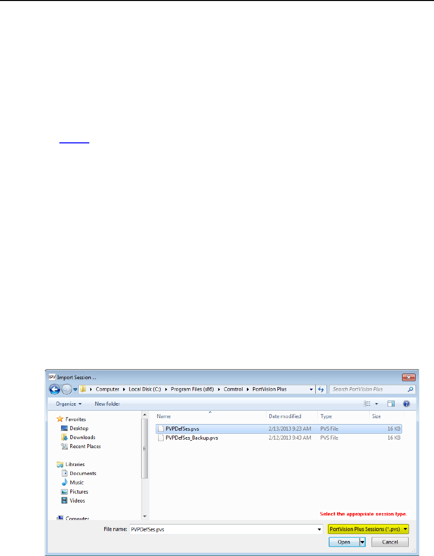
PortVision DX User Guide
Managing Sessions
Sessions can be useful if you wish to create a different friendly view of devices on the network.
A default session is being saved or updated every time you exit the application. PortVision DX
opens the same default session at the next start up. The default session name is
PVPDefSes.pxs and is located in the Program Files/Comtrol/PortVision DX subdirectory if you
installed PortVision DX in the default location.
You can use folders to organize the devices, which allows you to display a network organized by
meaningful labels or allow different people to open different sessions designed for their needs.
Importing PortVision Plus Sessions
You can use this procedure to import existing PortVision Plus sessions so that you can save them
in PortVision DX.
1. Click File and then Import Session ...
2. Respond to the Do you want to save the current session query:
• If you click No:
a. Browse to the location that your PortVision Plus files are located. The default
PortVision Plus subdirectory is Program Files (x86)/Comtrol/PortVision Plus.
b. Highlight the session name.
c. Select PortVision Plus Sessions (*.pvs) in the drop list and then click Open.
• If you click Yes:
a. Browse to the location you want to save the PortVision DX session files. The
default PortVision DX subdirectory is Program Files (x86)/Comtrol/PortVision
DX.
b. Enter a file name and click Save.
c. Browse to the location that your PortVision Plus files are located. The default
PortVision Plus subdirectory is Program Files (x86)/Comtrol/PortVision Plus.
80 Managing the View
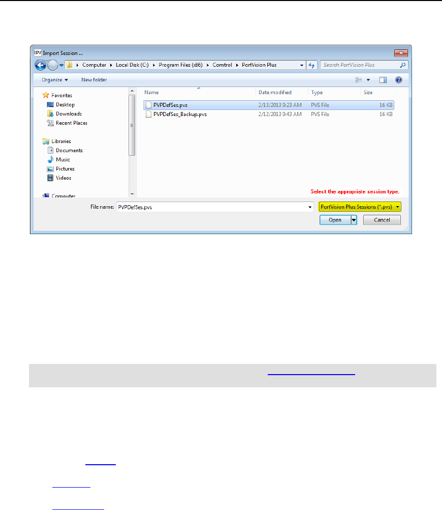
PortVision DX User Guide
d. Select PortVision Plus Sessions (*.pvs) in the drop list and then click Open.
You can save the session with a new file name in the PortVision DX subdirectory or the session is
saved as the default session (PVDXDefSes.pvsx) when you close PortVision DX.
Creating a New Session
You can create a new session from an empty session by using the following procedure or you
can edit an existing session and save the session with a new name.
1. Click New Session under the File menu.
Note: If you have PortVision Plus sessions, you can import the sessions and save them
as PortVision DX sessions.
2. Scan the network using the Scan button or the Scan Network option under the Tools
menu.
3. Optionally, edit the contents of the Device Tree or Device List panes:
• Create folders and move the devices under meaningful folder names.
• Rename devices.
• Reorganize the Device List pane by Model, IP Address, MAC Address, Software
Version, or Status.
4. Click Save Session As... in the File menu to save the session under a unique file or
optionally click Exit to save the session under the default name, PVPDefSes.pxs.
Managing the View 81

PortVision DX User Guide
Saving a Session
PortVision DX allows you to save the existing view (session) as a file.
Optionally, you can do the following to create a unique session in the Device Tree and Device List
panes:
• Create or move folders and move devices under meaningful folder names.
• Rename the devices.
• Organize the Device List pane by Device Name, Model, IP Address, MAC Address, Software
Version, or Status.
Use the following steps to save a session:
1. Click Save Session As... in the File menu.
2. Enter a name that corresponds to that session and click Save.
3. Optionally, browse to a new directory. By default, PortVision DX saves the session to the
directory in which the current session was opened.
The default directory is Program Files/Comtrol/PortVision DX and the default session
under the default name, PVPDefSes.pxs.
Opening an Existing Session
Use the following to open a different PortVision DX session.
PortVision DX always opens the session last saved.
1. Click Import Session ... on the File menu.
2. Click No or Yes to the Do you want to save the current session? query.
3. If necessary, browse to a directory that contains the PortVision DX session.
By default, PortVision DX opens the directory where the current session was opened. The
default directory is Program Files/Comtrol/PortVision DX and the default name is
PVPDefSes.pxs.
4. Highlight the appropriate session.
82 Managing the View
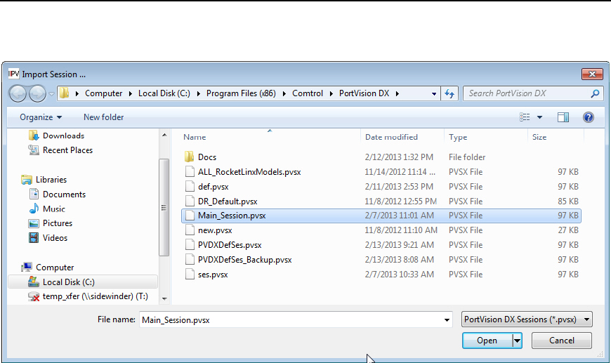
PortVision DX User Guide
5. Select PortVision DX Sessions (*.pvsx) in the drop list and then click Open.
Exporting the Device List
You may want to use the Export Device List to Notepad option so that you can import data into
a spreadsheet.
Only devices with an ON-LINE status are exported.
1. Click File | Export Device List to Notepad.
2. Optionally, save the file. The default name is PVDXDefSes.pvsx.txt.
You can import the data in this file into a spreadsheet, using commas as the delimiter.
Managing the View 83

Network Configuration
Select the appropriate link to locate network settings configuration procedures for your product:
•DeviceMaster, which includes the following models:
•DeviceMaster 500
•DeviceMaster LT
•DeviceMaster PRO
•DeviceMaster RTS
•DeviceMaster Serial Hub
•DeviceMaster UP
•IO-Link Master
•RocketLinx
Network Configuration 85
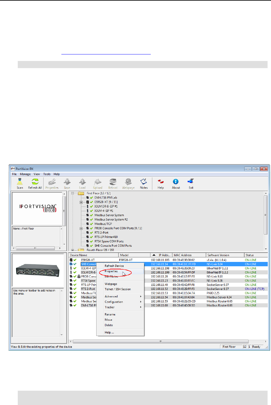
PortVision DX User Guide
DeviceMaster (LT, PRO, RTS, Serial Hub, and 500)
Use the following procedure to program network information into a single DeviceMaster at a time.
If necessary, you can program multiple DeviceMasters at the same time.
Note: For initial configuration, the DeviceMaster must be on the same network segment.
1. Highlight the DeviceMaster for which you want to program network information and
access the General tab on the Properties screen using one of these methods:
•Double-click the DeviceMaster in the Device Tree or Device List.
•Right-click the DeviceMaster in the Device Tree or Device List and click Properties.
•Highlight the DeviceMaster in the Device Tree or Device List, click the Properties
button.
•Highlight the DeviceMaster in the Device Tree or Device List, click the Manage menu,
and then Properties.
2. If necessary, enter the user name and password.
3. Optionally, change the Device Name. The default Device Name is the last three pairs of
numbers from the MAC address. A device name is required.
Note: You cannot edit the MAC Address field, it is automatically populated with the
DeviceMaster MAC address, if it was discovered during a scan.
86 Network Configuration - DeviceMaster LT/PRO/RTS/Serial Hub/500
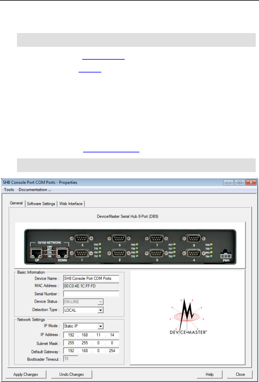
PortVision DX User Guide
4. If the serial number does not display, you can enter the serial number of the
DeviceMaster in the event that you require it later.
Note: The Device Status field is an informational field that displays the same status
displayed on the Main screen.
5. Select the appropriate Detection Type, local or remote.
6. Click the appropriate IP Mode:
•Disable IP to run the DeviceMaster using the MAC addressing scheme and disable all
IP communications.
•DHCP IP to use the DeviceMaster with DHCP. Contact the Network Administrator to
provide the MAC address of the DeviceMaster and ask if you should change the
Subnet Mask, or Default Gateway values.
•Static IP to program a static IP address and enter the appropriate values (IP address,
subnet mask, and default gateway) for your site.
7. Optionally, change the Bootloader Timeout value.
Note: You must have SocketServer v9.06 or higher for the Bootloader Timeout field to
display.
8. After entering the changes, click Apply Changes.
9. Click Close.
Network Configuration - DeviceMaster LT/PRO/RTS/Serial Hub/500 87
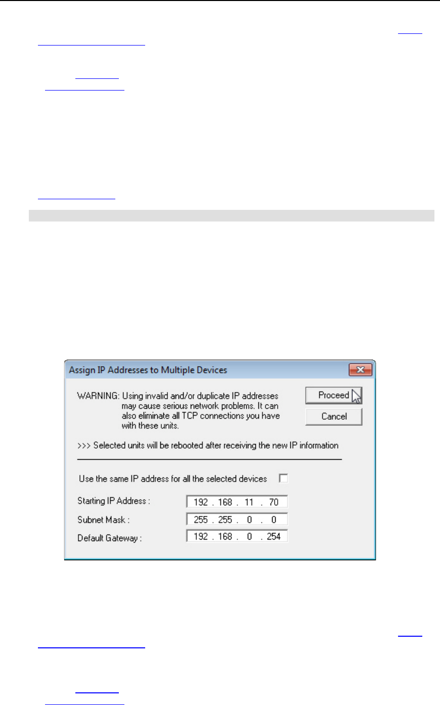
PortVision DX User Guide
10. After programming the network information, you need to verify that you have the latest
version of SocketServer loaded before performing any other configuration procedures.
You can use the Web Interface tab if you need to configure socket or serial tunneling settings or
you can use the Webpage feature. Optionally, you can modify socket or serial tunneling settings
using the Software Settings tab if you are familiar with the parameters.
Assigning IP Addresses to Multiple Devices
Use the appropriate procedure to assign IP addresses to multiple DeviceMaster units.
•Assign a range of IP address to multiple DeviceMasters, which may be useful if you are
setting up multiple new DeviceMasters
•Same IP address on multiple DeviceMasters
Note: For initial configuration, the DeviceMasters must be on the same network segment.
Assign a Range of IP Address to Multiple DeviceMasters
Use this procedure to assign a range of IP addresses. Make sure that the DeviceMasters are not
daisy-chained to another.
1. Right-click the DeviceMasters in the Device Tree or Device List pane, which you want to
assign the IP addresses and then click Assign IP to Multiple Devices (or optionally, use
the Manage menu).
2. Enter the starting IP address that you want assigned to the DeviceMasters.
3. Optionally, enter the Subnet Mask and Default Gateway values that you want to assign
to the units. These fields are left blank if you do not enter values.
4. Click Proceed.
5. After programming the network information, you need to verify that you have the latest
version of SocketServer loaded before performing any other DeviceMaster configuration
procedures.
You can use the Web Interface tab if you need to configure socket or serial tunneling settings or
you can use the Webpage feature. Optionally, you can modify socket or serial tunneling settings
using the Software Settings tab if you are familiar with the parameters.
88 Network Configuration - DeviceMaster LT/PRO/RTS/Serial Hub/500
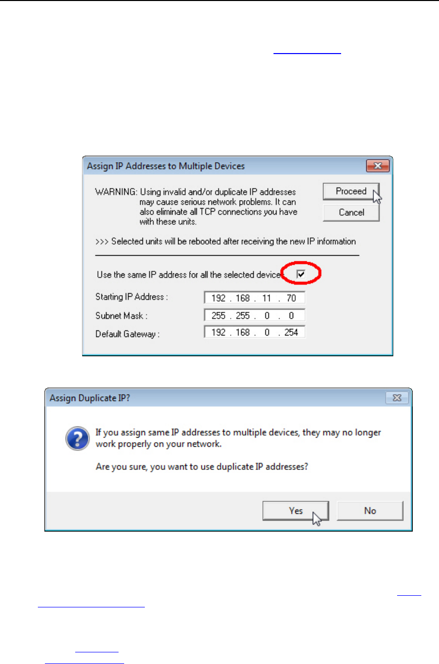
PortVision DX User Guide
Same IP Address on Multiple DeviceMasters
If you use duplicate IP addresses for DeviceMasters that the Detection Type is set to REMOTE,
you may lose the DeviceMaster connection completely. Make sure that the DeviceMasters are
not daisy-chained to another.
1. Right-click the DeviceMasters in the Device Tree or Device List pane, which you want to
assign the IP addresses and then click Assign IP to Multiple Devices (optionally, use
the Manage menu).
2. If you want to assign the same IP address to all units, click Use the same IP address for
all the selected devices.
3. Click Yes to the Assign Duplicate IP popup message.
4. Enter the IP address that you want programmed into the DeviceMasters.
5. Click Proceed.
6. After programming the network information, you need to verify that you have the latest
version of SocketServer loaded before performing any other DeviceMaster configuration
procedures.
You can use the Web Interface tab if you need to configure socket or serial tunneling settings or
you can use the Webpage feature. Optionally, you can modify socket or serial tunneling settings
using the Software Settings tab if you are familiar with the parameters.
Network Configuration - DeviceMaster LT/PRO/RTS/Serial Hub/500 89
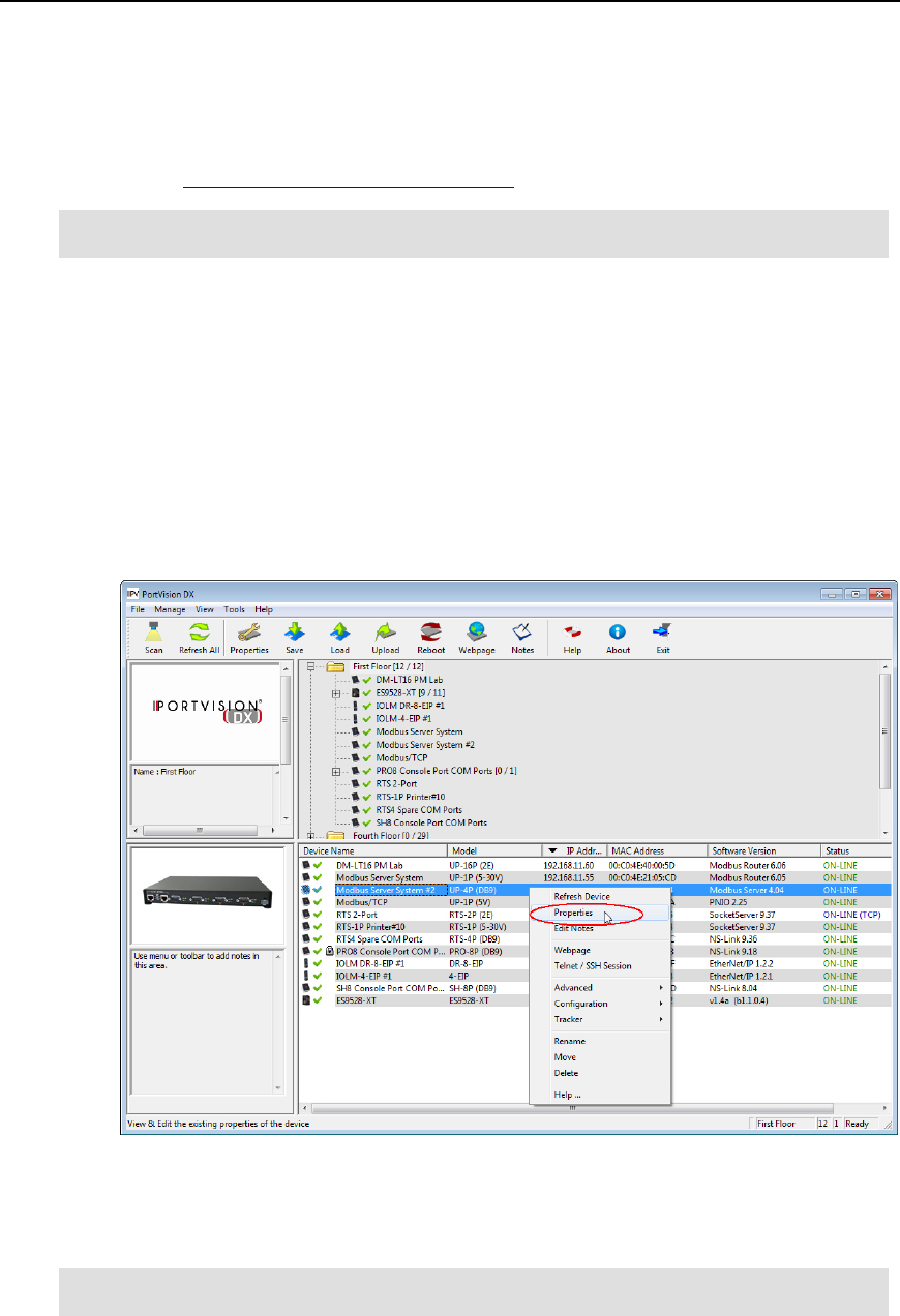
PortVision DX User Guide
DeviceMaster UP
Use the following procedure to program network information into a single DeviceMaster UP at a
time.
You can optionally, program multiple DeviceMaster UPs at the same time.
Note: For initial configuration, the DeviceMaster UP must be on the same network
segment.
1. Highlight the DeviceMaster UP for which you want to program network information and
access the General tab on the Properties screen using one of these methods:
•Double-click the DeviceMaster UP in the Device Tree or Device List.
•Right-click the DeviceMaster UP in the Device Tree or Device List and click
Properties.
•Highlight the DeviceMaster UP in the Device List or Device Tree , click the
Properties button.
•Highlight the DeviceMaster UP in the Device Tree or Device List, click the Manage
menu, and then Properties.
2. If necessary, enter the user name and password.
3. Optionally, change the Device Name. The default Device Name is the last three pairs of
numbers from the MAC address. A device name is required.
Note: You cannot edit the MAC Address field, it is automatically populated with the
DeviceMaster UP MAC address, if it was discovered during a scan.
4. If the serial number does not display, you can enter the serial number of the
DeviceMaster UP in the event that you require it later.
90 Network Configuration - DeviceMaster UP

PortVision DX User Guide
5. Select the appropriate Detection Type, local or remote.
Note: The Device Status field is an informational field that displays the same status
displayed on the Main screen.
6. Click the appropriate IP Mode:
•Disable IP disables IP communications. Do not use this option unless you are going
to load the NS-Link device driver to run in MAC mode and not load any
DeviceMaster UP protocol.
•DHCP IP to use the DeviceMaster UP with DHCP. Contact the Network
Administrator to provide the MAC address of the DeviceMaster UP and ask if you
should change the Subnet Mask, or Default Gateway values.
•Static IP to program a static IP address and enter the appropriate values for your
site.
7. After entering the changes, click Apply Changes.
8. Click Close.
9. After programming the network information, you need to verify that you have the latest
version of firmware for your protocol loaded before performing any other configuration
procedures.
You can use the Web Interface tab to configure protocol settings or you can use the Webpage
feature. Optionally, you can modify protocol settings using the Software Settings tab if you are
familiar with the parameters.
Network Configuration - DeviceMaster UP 91
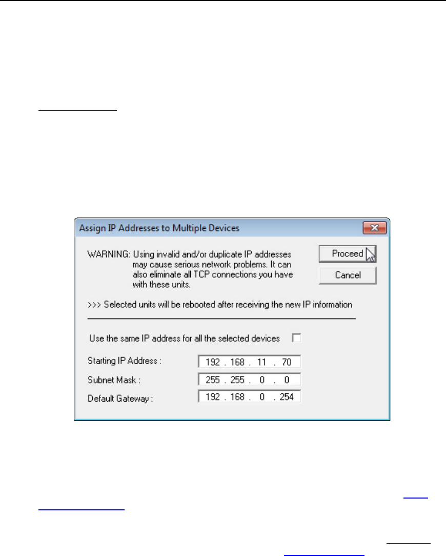
PortVision DX User Guide
Assigning IP Addresses to Multiple Devices
Use the appropriate procedure to assign IP addresses to multiple DeviceMaster UP units.
•Assign a range of IP address to multiple DeviceMaster UPs
•Same IP address on multiple DeviceMaster UPs
Assign a Range of IP Address to Multiple DeviceMasters
1. Right-click the DeviceMaster UPs in the Device List pane, which you want to assign the
IP addresses and then click Assign IP to Multiple Devices (optionally, use the Manage
menu).
2. Enter the starting IP address that you want assigned to the DeviceMaster UPs.
3. Optionally, enter the Subnet Mask and Default Gateway values that you want to assign to
the units. These fields are left blank if you do not enter values.
4. Click Proceed.
5. After programming the network information, you need to verify that you have the latest
version of firmware for your protocol loaded before performing any other configuration
procedures.
You can use the Web Interface tab to configure protocol settings or you can use the Webpage
feature. Optionally, you can modify protocol settings using the Software Settings tab if you are
familiar with the parameters.
92 Network Configuration - DeviceMaster UP
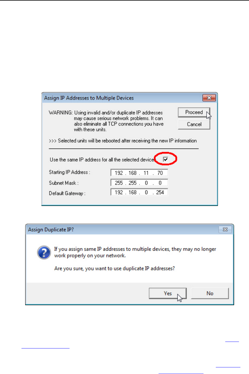
PortVision DX User Guide
Same IP Address on Multiple DeviceMasters
If you use duplicate IP addresses for non-local DeviceMaster UPs, you may lose the
DeviceMaster UP connection completely.
1. Right-click the DeviceMaster UPs in the Device List pane, which you want to assign the
IP addresses and then click Assign IP to Multiple Devices (optionally, use the Manage
menu).
2. If you want to assign the same IP address to all units, click Use the same IP address for
all the selected devices.
3. Click Yes to the Assign Duplicate IP popup message.
4. Enter the IP address that you want programmed into the DeviceMasters.
5. Click Proceed.
6. After programming the network information, you need to verify that you have the latest
version of firmware for your protocol loaded before performing any other configuration
procedures.
You can use the Web Interface tab to configure protocol settings or you can use the Webpage
feature. Optionally, you can modify protocol settings using the Software Settings tab if you are
familiar with the parameters.
Network Configuration - DeviceMaster UP 93
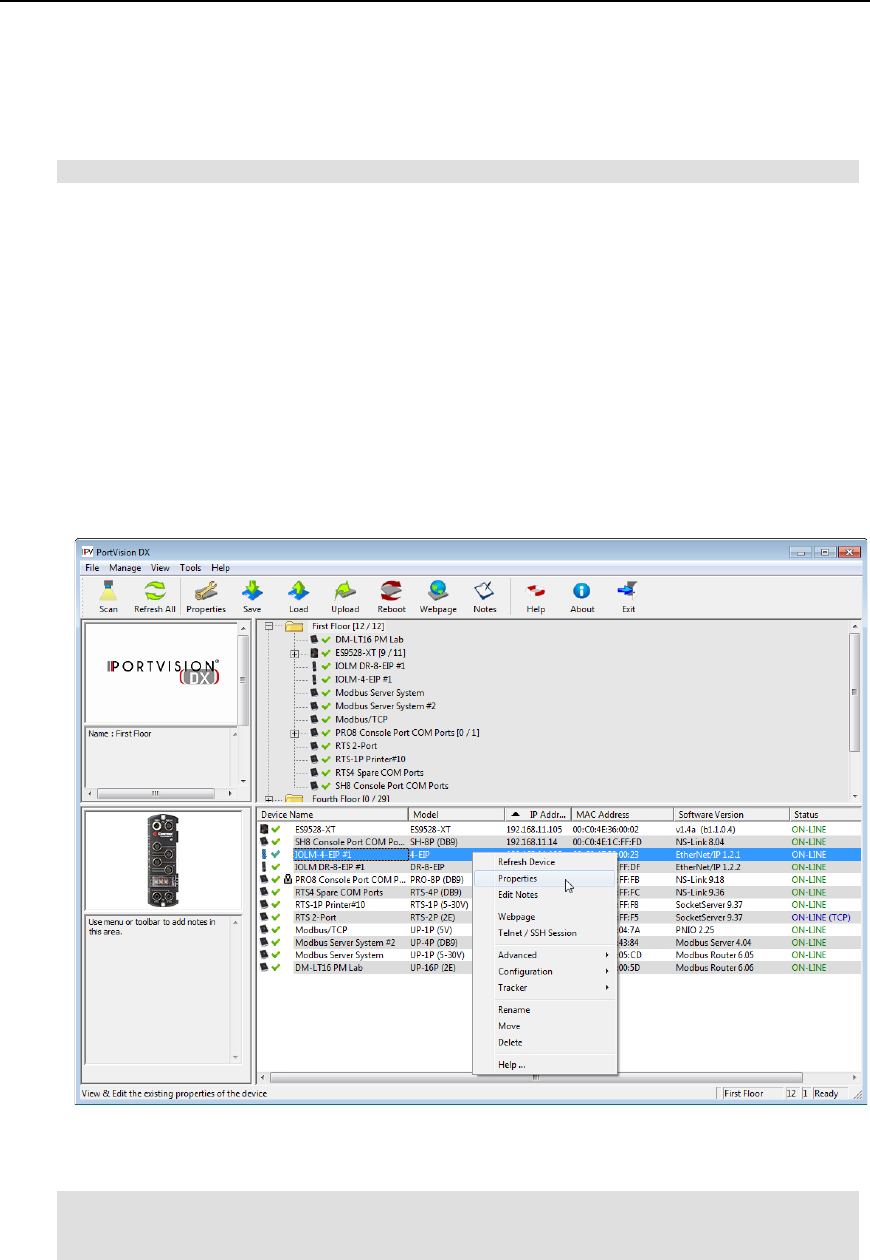
PortVision DX User Guide
IO-Link Master
Use the following procedure to program network information into a single IO-Link Master at a
time.
Note: For initial configuration, the IO-Link Master must be on the same network segment.
1. Highlight the IO-Link Master for which you want to program network information and
access the Properties screen using one of these methods:
•Double-click the IO-Link Master in the Device Tree or Device List.
•Right-click the IO-Link Master in the Device Tree or Device List and click Properties.
•Highlight the IO-Link Master in the Device Tree or Device List, click the Properties
button.
•Highlight the IO-Link Master in the Device Tree or Device List, click the Manage
menu, and then Properties.
2. If necessary, enter the user name and password. In the event that you need to type the
user names, remember that they are case-sensitive (Admin, Operator, and User).
3. Optionally, change the Device Name. The default Device Name is the last three pairs of
numbers from the MAC address.
Note: The MAC Address and Serial Number fields are automatically populated if the IO-
Link Master was discovered during a scan. The Device Status field displays the
same status as the Main screen.
94 Network Configuration - IO-Link Master
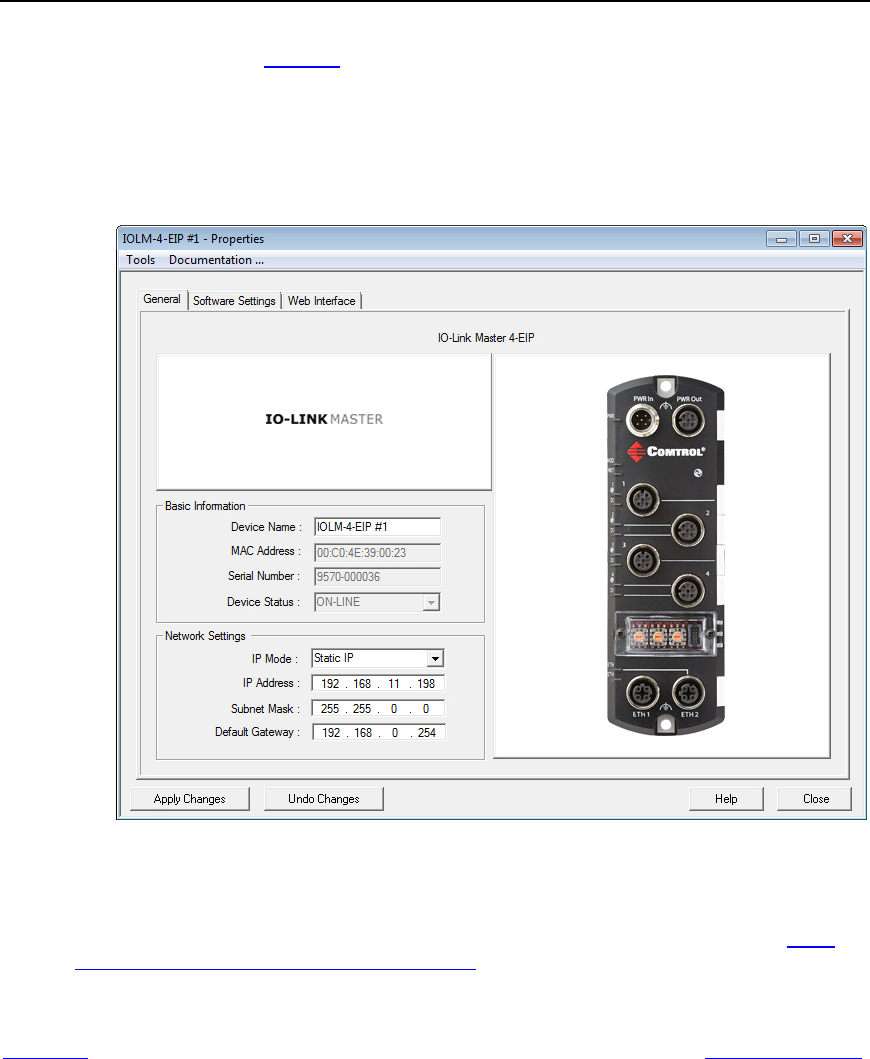
PortVision DX User Guide
4. Click the appropriate IP Mode:
•DHCP IP to use the IO-Link Master with DHCP. Contact the Network Administrator
to provide the MAC address of the IO-Link Master and ask if you should change the
Subnet Mask, or Default Gateway values.
•Static IP to program a static IP address and enter the appropriate values for your
site.
5. After entering the changes, click Apply Changes.
6. Click Close.
7. After programming the network information, you need to verify that you have the latest
version of software (images and applications) loaded before performing any other
configuration procedures.
You can use the Web Interface tab to configure IO-Link Master settings or you can use the
Webpage feature. Optionally, you can modify IO-Link Master settings using the Software Settings
tab if you are familiar with the parameters.
Network Configuration - IO-Link Master 95
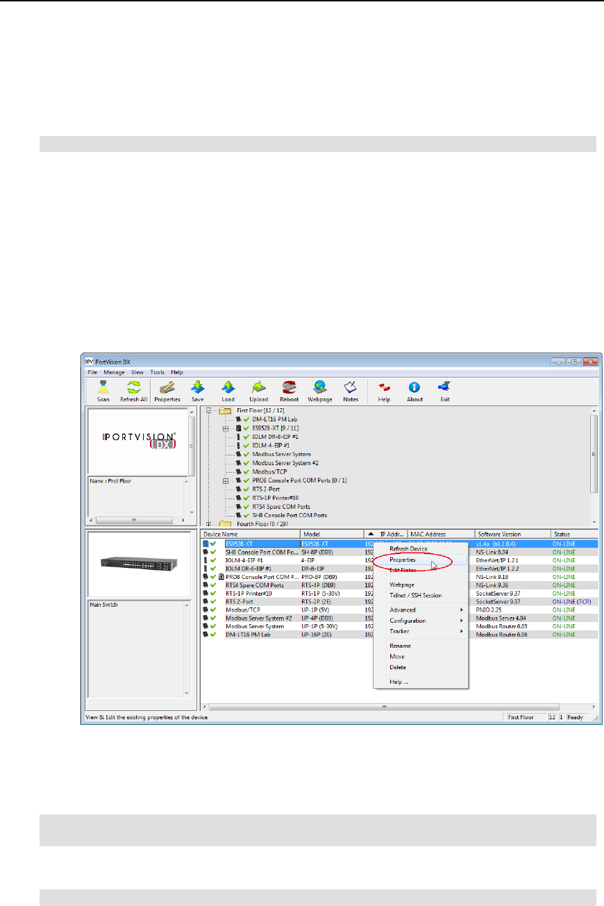
PortVision DX User Guide
RocketLinx
Use the following procedure to program network information into a single RocketLinx at a time.
You can optionally, program multiple RocketLinx switches at the same time.
Note: For initial configuration, the RocketLinx must be on the same network segment.
1. Highlight the RocketLinx for which you want to program network information and access
the Properties screen using one of these methods:
•Double-click the RocketLinx in the Device Tree or Device List.
•Right-click the RocketLinx in the Device Tree or Device List and click Properties.
•Highlight the RocketLinx in the Device Tree or Device List, click the Properties
button.
•Highlight the RocketLinx in the Device Tree or Device List, click the Manage menu,
and then Properties.
2. If necessary, enter the user name and password.
3. Optionally, change the Device Name. The default Device Name is the last three pairs of
numbers from the MAC address.
Note: The MAC Address field is automatically populated when the RocketLinx is
discovered during a scan.
4. Optionally, enter the serial number of the RocketLinx in the event that you require it later.
Note: The Device Status field displays the same status as the Main screen.
96 Network Configuration - RocketLinx
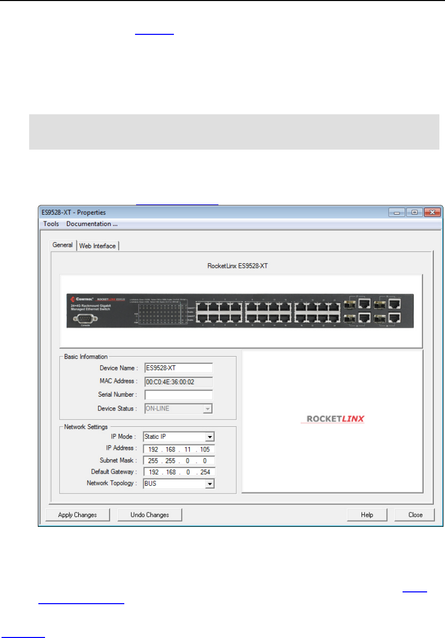
PortVision DX User Guide
5. Click the appropriate IP Mode:
•DHCP IP to use the RocketLinx with DHCP. Contact the Network Administrator to
provide the MAC address of the RocketLinx and ask if you should change the Subnet
Mask, or Default Gateway values.
•Static IP to program a static IP address and enter the appropriate values for your site.
Note: PortVision DX does not support DHCP programming on the RocketLinx ES7506. If
you want to configure the RocketLinx ES7506, you must use the web interface or
CLI.
6. If using a static IP address, enter a valid IP address, subnet mask, and default gateway
for your network.
7. Optionally, select the Network Topology. This is an informational field.
8. After entering the changes, click Apply Changes.
9. Click Close.
10. After programming the network information, you need to verify that you have the latest
version of firmware loaded before performing any other configuration procedures.
You can use the Web Interface tab to configure RocketLinx settings or you can use the
Webpage feature.
Network Configuration - RocketLinx 97

Firmware
Refer to the following pages for information about the firmware for your product:
•DeviceMaster including these models:
•DeviceMaster LT
•DeviceMaster PRO
•DeviceMaster RTS
•DeviceMaster Serial Hub
•DeviceMaster 500
•DeviceMaster UP
•IO-Link Master (images and applications)
•RocketLinx (managed switches only)
DeviceMaster (LT, PRO, RTS, Serial Hub, and 500)
You may need to update the firmware on the DeviceMaster to support the latest features and
functionality. If you have a DeviceMaster UP, see the DeviceMaster UP Firmware page for
protocol-specific firmware.
There are several types of firmware that run on the DeviceMaster:
•SocketServer is the default application shipped on most DeviceMaster models, excluding
models shipped with protocol-specific firmware for the DeviceMaster UP.
Note: Technical Supports recommends that you update to the latest version of
SocketServer before installing an NS-Link device driver or configuring socket ports.
•Bootloader is the Redboot operating system that runs the DeviceMaster during the power
on phase, which then starts a default application on the DeviceMaster.
Note: Typically, you do not update the Bootloader unless instructed by Technical Support
or the web (ftp) site.
Firmware - DeviceMaster LT/PRO/RTS/Serial Hub/500 99
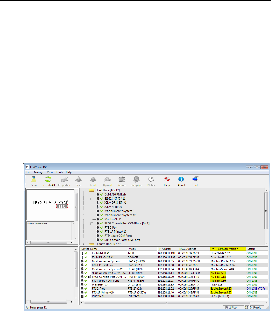
PortVision DX User Guide
Checking the SocketServer Version
SocketServer is integrated in the firmware that comes pre-installed on most DeviceMasters,
which provides an interface to TCP/IP socket mode configuration and DeviceMaster services.
You should update SocketServer before:
•Configuring serial socket ports using SocketServer.
•Installing an NS-Link device driver for tty or COM ports.
Comtrol recommends verifying that your DeviceMaster contains the latest SocketServer version
to avoid installation problems.
Use the following procedure to check the SocketServer version on the DeviceMaster.
1. If necessary, click Scan.
2. Check the SocketServer version number (or NS-Link version if you have installed a
DeviceMaster NS-Link device driver for your operating system) of the Software Version
for the DeviceMaster.
100 Software Settings - DeviceMaster LT/PRO/RTS/Serial Hub/500
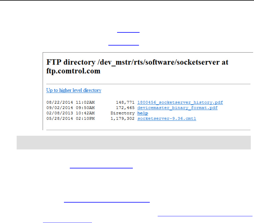
PortVision DX User Guide
3. Check to see if a later version is available using one of these methods:
•Comtrol ftp site using the ftp interface
•Direct link to the Comtrol ftp directory that contains the latest SocketServer
version
Note: Although this link goes to the DeviceMaster RTS subdirectory, the firmware for the
DeviceMaster family is the same.
4. If the version on the ftp site is later than the version on the DeviceMaster, download the
file and then go to Uploading SocketServer.
If the SocketServer version on the DeviceMaster is current, you are ready to continue the
installation and configuration process .
5. You can use the appropriate DeviceMaster Guide to complete the DeviceMaster
configuration and installation process:
•NS-Link COM ports - Optionally, refer to the DeviceMaster NS-Link Device Driver
Guide for Windows for detailed information about device driver configuration.
•TCP/IP socket ports - Optionally refer to the SocketServer help system for
additional information.
•NS-Link tty ports - Refer to the readme file packaged with the device driver.
Software Settings - DeviceMaster LT/PRO/RTS/Serial Hub/500 101
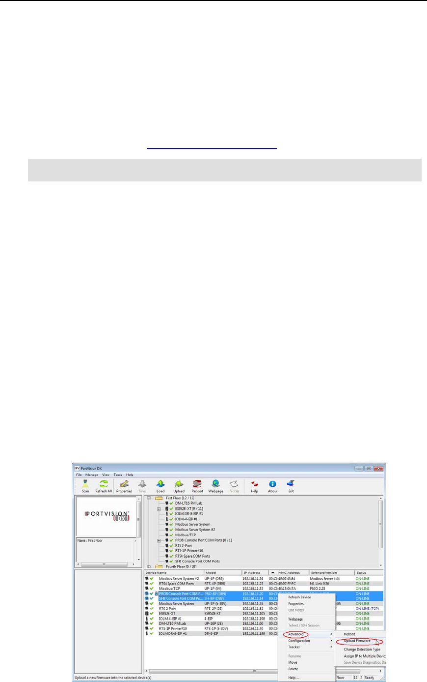
PortVision DX User Guide
Uploading SocketServer
Use this section to upload SocketServer on the DeviceMaster. Technical Support recommends
updating SocketServer before any software installation or configuration to avoid configuration
problems.
Note: Do not attempt to uploadfirmware across a wifi connection.
You can upload one DeviceMaster or several DeviceMasters at a time.
1. Make sure that you have downloaded the latest version.
Note: Although this link goes to the DeviceMaster RTS subdirectory, the firmware for the
DeviceMaster family is the same.
2. If necessary, disable DeviceMaster NS-Link driver for Windows before uploading the
Bootloader.
a. Click the Start button and open the Comtrol | DeviceMaster | DeviceMaster
Driver Management Console.
b. If necessary, click Yes to the User Account Control pop up message.
c. Right-click the DeviceMaster that you want to disable.
d. Select Disable.
e. Click Ok to close the Comtrol Drivers Management Console.
3. In the Device List pane, use one of the following methods to start the upload firmware
process:
•Highlight the DeviceMaster or shift-click multiple DeviceMasters and click the
Upload button
•Right-click the DeviceMaster or shift-click multiple DeviceMasters, click
Advanced, and then Upload Firmware
•Highlight the DeviceMaster or shift-click multiple DeviceMasters, click Advanced
and then Upload Firmware on the Manage menu
102 Software Settings - DeviceMaster LT/PRO/RTS/Serial Hub/500
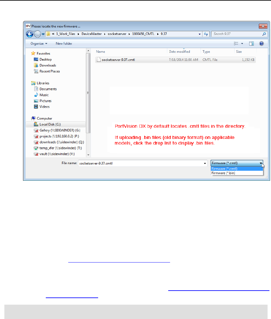
PortVision DX User Guide
4. Browse to the SocketServer .cmtl file and then click Open.
5. Click Yes to the Upload Firmware message that warns you that this is a sensitive
process.
It may take a few moments for the firmware to upload onto the DeviceMaster. The
DeviceMaster reboots itself during the upload process.
6. Click Ok to the advisory message about waiting to use the DeviceMaster until the status
reads ON-LINE. In the next polling cycle, PortVision DX updates the Device List pane
and displays the new SocketServer version.
7. You can use the appropriate DeviceMasterand Guide to complete the DeviceMaster
configuration process.
1.
•NS-Link COM ports - Optionally, refer to the DeviceMaster NS-Link Device Driver
Guide for Windows for detailed information about device driver configuration.
Note: Make sure that you enable the driver ifyou disabled it before
uploadingSocketServer..
•TCP/IP socket ports - Optionally refer to the SocketServer help system for
additional information.
•NS-Link tty ports - Refer to the readme file packaged with the device driver.
If the firmware uploads fail and it is on the other side of several switches, a router, or wireless you
can use TFTP to upload SocketServer.
Software Settings - DeviceMaster LT/PRO/RTS/Serial Hub/500 103
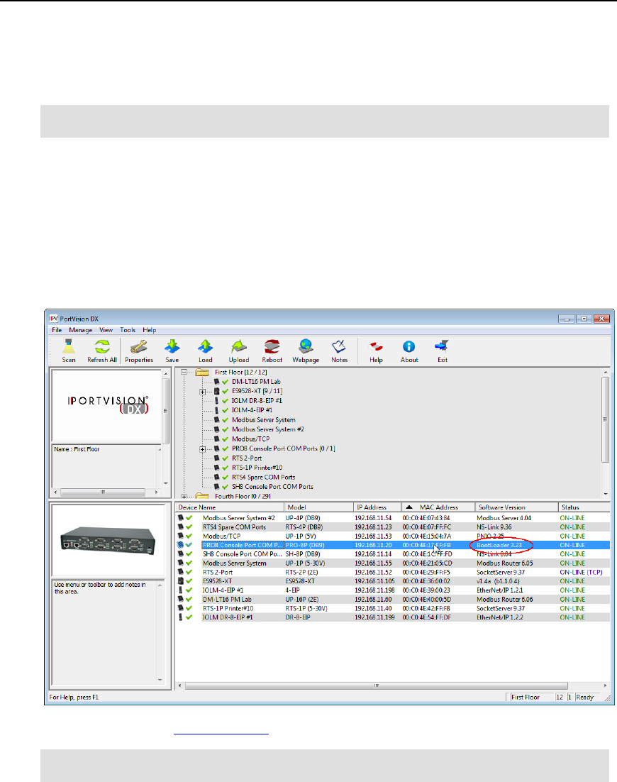
PortVision DX User Guide
Checking the Bootloader Version
Use the following procedure to check the Bootloader version.
Note: Typically, you do not update the Bootloader unless instructed by Technical Support
or the ftp (web) site.
1. In PortVision DX, right-click the DeviceMaster in the Device List pane for which you want
to determine the Bootloader version and click Reboot.
2. Click Yes to the Confirm Reboot query.
3. Right-click the DeviceMaster and click Refresh as many times as necessary to catch the
reboot cycle in the Device List pane.
The Bootloader version displays briefly during the reboot cycle before the default
application (SocketServer) loads.
4. You can check the Comtrol ftp site to see if a later version is available.
Note: Although this link goes to the DeviceMaster RTS subdirectory, the firmware for the
DeviceMaster family is the same.
104 Software Settings - DeviceMaster LT/PRO/RTS/Serial Hub/500
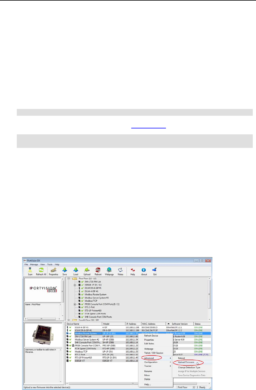
PortVision DX User Guide
Uploading Bootloader
Typically, do not upload the Bootloader unless advised to by Technical Support (or the ftp/web
site).
Technical Support recommends connecting the DeviceMaster directly to a PC or laptop when
uploading Bootloader.
Note: Do not attempt to upload firmware across a wifi connection.
You may also want to connect the DeviceMaster to a UPS while uploading Bootloader to avoid
any power interruption. A power interruption while loading Bootloader will require that you send
the DeviceMaster back to Comtrol for repair.
Note: Only upload Bootloader to one DeviceMaster at a time.
1. Make sure that you have downloaded the latest version.
Note: Although this link goes to the DeviceMaster RTS subdirectory, the firmware for the
DeviceMaster family is the same.
2. If necessary, disable DeviceMaster NS-Link driver for Windows before uploading the
Bootloader.
a. Click the Start button and open the Comtrol | DeviceMaster | DeviceMaster
Driver Management Console.
b. If necessary, click Yes to the User Account Control pop up message.
c. Right-click the DeviceMaster that you want to disable.
d. Select Disable.
e. Click Ok to close the Comtrol Drivers Management Console.
3. Right-click the DeviceMaster in the Device List pane for which you want to update, click
Advanced and then Upload Firmware.
Software Settings - DeviceMaster LT/PRO/RTS/Serial Hub/500 105
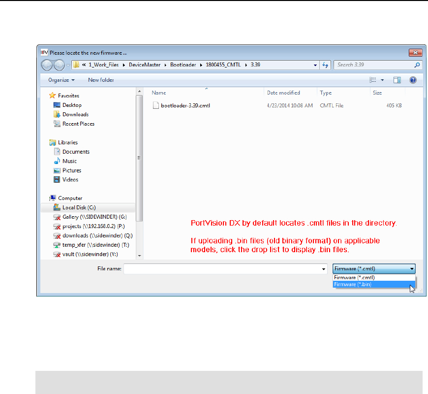
PortVision DX User Guide
4. Browse to the Bootloader .cmtl file, and then click Open (Please locate the new
firmware), and then click Yes (Upload Firmware).
5. It may take a few moments for the firmware to upload onto the DeviceMaster. The
DeviceMaster reboots itself during the upload process.
6. Click Ok to the advisory message about waiting to use the DeviceMaster until the status
reads ON-LINE.
Note: Make surethat you enable the driver if you disabled it before uploading the
Bootloader..
106 Software Settings - DeviceMaster LT/PRO/RTS/Serial Hub/500

PortVision DX User Guide
DeviceMaster UP
You may need to update the firmware on the DeviceMaster UP to support the latest features and
functionality.
There are several types of firmware that run on the DeviceMaster UP:
•SocketServer is the default application shipped on some DeviceMaster UP models,
excluding models shipped with protocol-specific firmware for the DeviceMaster UP.
If your DeviceMaster UP has SocketServer loaded, you will need to load the
appropriate protocol for your environment, unless you want to operate the DeviceMaster
UP with the NS-Link device driver and SocketServer.
•Protocol-specific firmware for the DeviceMaster UP.
•EtherNet/IP
•Modbus Router
•Modbus Server
•Modbus/TCP
•PROFINET IO
Typically, one of the first steps after installing the hardware is to upload firmware that
meets your protocol requirements, which overwrites SocketServer.
DeviceMaster UP models that are shipped from the factory with one of the protocols listed
above includes protocol identification on the compliance label on the DeviceMaster UP and
PortVision DX displays the protocol type in the Software Version column on the main
page..
•Bootloader is the Redboot operating system that runs the DeviceMaster UP during the
power on phase, which then starts a default application on the DeviceMaster UP.
Typically, you do not update the Bootloader unless instructed by Technical Support or the
web site.
Firmware - DeviceMaster UP 107

PortVision DX User Guide
Checking Protocol-Specific Firmware Versions
The DeviceMaster UP may or may not have come from the factory loaded with the protocol
firmware that you want to configure.
The first step is to check to see if the appropriate firmware is loaded and if it is the latest version.
1. If necessary, click Scan so that the DeviceMaster UP displays.
2. Check the name and version number of the Software Version loaded on the
DeviceMaster UP.
3. If the Software Version displays as SocketServer, you will need to download the protocol
firmware that you want to configure.
4. If the appropriate protocol displays, check the Comtrol ftp site to see if a later version is
available.
5. If the version on the ftp site is later than the version on the DeviceMaster UP, download
the file and then go to Uploading Protocol-Specific Firmware.
If the firmware type is the protocol that you want to configure and the version on the
DeviceMaster UP is current, you are ready to open the configuration web page using the
DeviceMaster UP IP address or highlight the DeviceMaster UP in PortVision DX and click the
Webpage button.
You can download and access the latest Quick Start and User Guides for your protocol for
configuration procedures.
108 Firmware - DeviceMaster UP
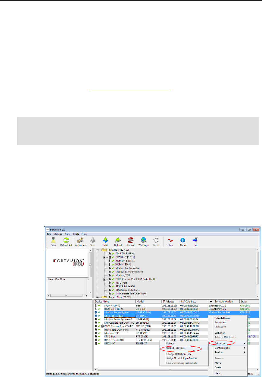
PortVision DX User Guide
Uploading Protocol-Specific Firmware
Use this section to upload protocol firmware on the DeviceMaster UP. Technical Support
recommends updating firmware before any software installation or configuration to avoid
configuration problems.
Note: Do not attempt to upload firmware across a wifi connection.
You can upload one DeviceMaster UP or several DeviceMaster UPs at a time.
1. Make sure that you have downloaded the latest version.
2. You must unpackage the firmware, if the file you download does not contain a .cmtl
extension.
Note: You must unpackage the .msi file before uploading the firmware (.cmtl) to the
DeviceMaster UP. If you attempt to unpackage the .msi file of the previous or same
version on the same system, the installation program prompts you to remove the
existing version.
3. In the Device List pane, use one of the following methods to start the upload firmware
process:
•Highlight the DeviceMaster UP or shift-click multiple DeviceMaster UPs and click
the Upload button
•Right-click the DeviceMaster UP or shift-click multiple DeviceMaster UPs, click
Advanced, and then Upload Firmware
•Highlight the DeviceMaster UP or shift-click multiple DeviceMaster UPs, click
Advanced and then Upload Firmware on the Manage menu
Firmware - DeviceMaster UP 109
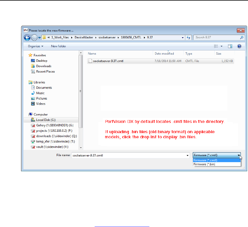
PortVision DX User Guide
4. Browse, click the firmware (.cmtl) file, Open (Please locate the new firmware), and then
click Yes (Upload Firmware).
5. It may take a few moments for the firmware to upload onto the DeviceMaster UP. The
DeviceMaster UP reboots itself during the upload process.
6. Click Ok to the advisory message about waiting to use the DeviceMaster UP until the
status reads ON-LINE. In the next polling cycle, PortVision DX will update the Device List
pane and display the new firmware version.
You can use PortVision DX to download and access the latest Quick Start and User
Guides for your protocol.
If the firmware uploads fail and it is on the other side of several switches, a router, or wireless you
can use TFTP to upload firmware.
110 Firmware - DeviceMaster UP
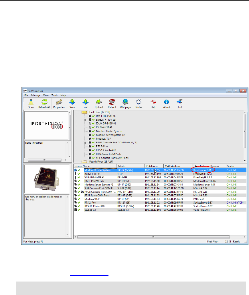
PortVision DX User Guide
Checking the Bootloader Version
Use the following procedure to check the Bootloader version.
1. In PortVision DX, right-click the DeviceMaster UP in the Device List pane for which you
want to determine the Bootloader version and click Reboot.
2. Click Yes to the Confirm Reboot query.
3. Right-click the DeviceMaster UP and click Refresh as many times as necessary to catch
the reboot cycle in the Device List pane.
The Bootloader version is briefly displayed during the reboot cycle before the default
application loads.
4. You can check the Comtrol ftp site to see if a later version is available.
Note: Typically, you do not update the Bootloader unless instructed by Technical Support
or the ftp/web site.
Firmware - DeviceMaster UP 111
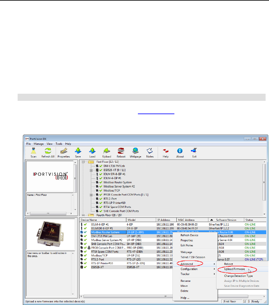
PortVision DX User Guide
Uploading Bootloader
Typically, do not upload the Bootloader unless advised to by Technical Support (or the ftp site).
Note: Do not attempt to upload firmware across a wifi connection.
Technical Support recommends connecting the DeviceMaster UP directly to a PC or laptop when
uploading Bootloader. You may also want to connect the DeviceMaster UP to a UPS while
uploading Bootloader to avoid any power interruption. A power interruption while loading
Bootloader will require that you send the DeviceMaster UP back to Comtrol for repair.
Note: Only upload Bootloader to one DeviceMaster UP at a time.
1. Make sure that you have downloaded the latest version.
2. Right-click the DeviceMaster UP in the Device List pane for which you want to update,
click Advanced and then Upload Firmware.
112 Firmware - DeviceMaster UP
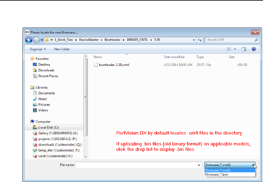
PortVision DX User Guide
3. Browse to the Bootloader .cmtl file, and then click Open (Please locate the new
firmware), and then click Yes (Upload Firmware).
4. It may take a few moments for the firmware to upload onto the DeviceMaster UP. The
DeviceMaster UP reboots itself during the upload process.
5. Click Ok to the advisory message about waiting to use the DeviceMaster UP until the
status reads ON-LINE.
Firmware - DeviceMaster UP 113

PortVision DX User Guide
IO-Link Master
The following topics are discussed in this section:
•Images and software
•Checking image and application versions
•Uploading image and application files
EtherNet/IP and Modbus/TCP
Images and Applications
You may need to update the images or application on the IO-Link Master to support the latest
features and functionality.
Images
Description
U
-Boot
Bootloader
U-Boot is a high-level bootloader that has networking and console
command line capabilities. Among other things, it implements a
TFTP server and Comtrol's new discovery protocol. This verifies that
a Linux kernel image exists in NAND, then copies it to RAM and
starts the IO-Link Master.
The U-Boot version is displayed after the image name.
FPGA
The FPGA partition/image contains configuration data used by
programmable hardware within the IO-Link Master unit.
uImage
-
Primary/Backup
The uImage contains the Linux kernel and the RAM-resident root file
system. It does not contain industrial protocol support or application-
specific features.
There is a Primary and Backup version loaded on the IO-Link
Master. The IO-Link Master automatically reloads the Backup
uImage if the file system corrupted.
The uImage version is displayed after the Primary/Backup uImage.
Application Base
The Application Base image comprises a flash-resident file system
containing application and protocol support. The Application Base is
built from a collection of application subassemblies -- each of which
may be updated individually between releases of the application
base as a whole.
The application subassemblies in the Application Base image are
displayed in the lower portion of this page.
The Application Base assembly has a 2-tuple version number: (for
example, 1.10).
Application subassemblies have 3-tuple or 4-tuple version numbers (for example, 1.10.1). The
first two values in a subassembly version correspond to the version of the application base
assembly for which it was built and tested.
114 Firmware - IO-Link Master

PortVision DX User Guide
For example, a subassembly with version 1.10.3 was tested with application base version 1.10.
When using this page or PortVision DX, an application subassembly can install only if its version
number matches that of the installed application base assembly. A subassembly with a version of
1.20.2.4 will only install if the application base version is 1.20. It will not install on a device with
application base version 1.09 or 1.20.
Application
Subassemblies Description
application-manager
The Application Manager version loaded on the IO-Link Master.
configuration-manager
The Configuration Manager version loaded on the IO-Link Master.
discovery-protocol
The Discovery Protocol version loaded on the IO-Link Master.
ethernetip
The EtherNet/IP version loaded on the IO-Link Master.
event-log
The Event log version loaded on the IO-Link Master.
iolink-driver
The IO-Link version loaded on the IO-Link Master.
web-user-interface
The web interface version loaded on the IO-Link Master.
Firmware - IO-Link Master 115
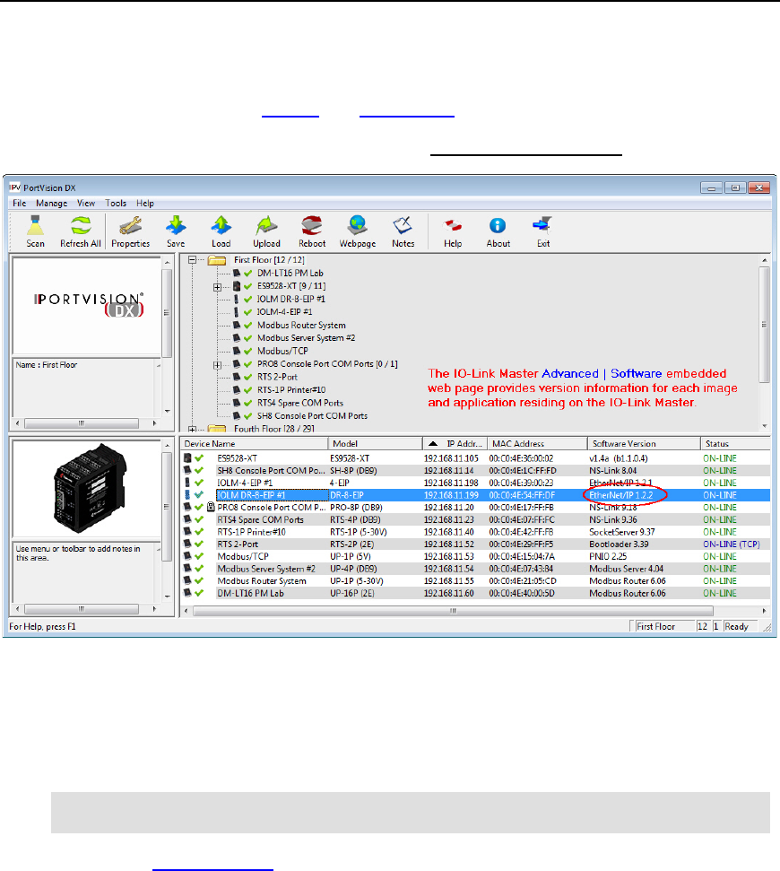
PortVision DX User Guide
Checking the Software Versions
The IO-Link Master has multiple images and applications loaded.
The PortVision DX List Device pane only displays the application base version.
The fastest and easiest way to determine all of your software versions is to view the IO-Link
Master Advanced/Software page.
1. Highlight the IO-Link Master in the Device List pane and click Webpage.
2. Click Advanced and then Software.
Note: Optionally, you can click Help | Support, which also provides complete image and
application version information.
3. Check the Comtrol ftp site for the latest versions.
116 Firmware - IO-Link Master
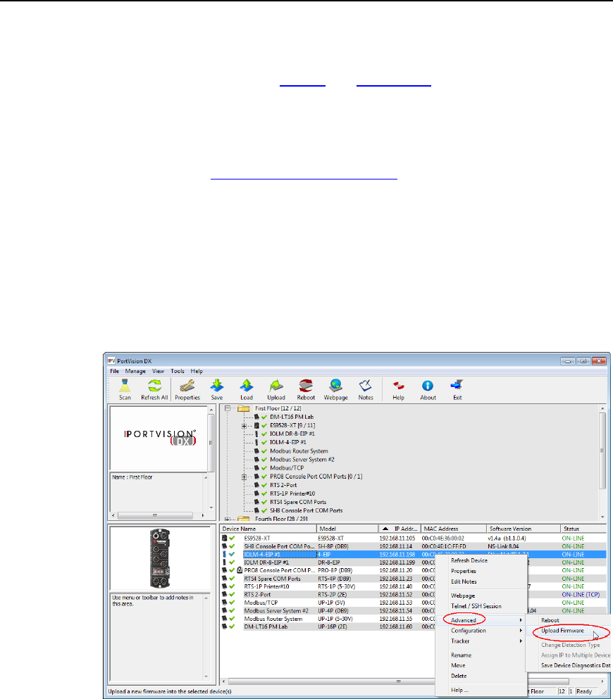
PortVision DX User Guide
Uploading Images and Applications
You can use the following procedure to load images and applications on the IO-Link Master.
Optionally, you can use the IO-Link Master Advanced/Software page in the web interface to load
images or applications.
Note: Do not attempt to upload images or applications across a wifi connection.
1. Make sure that you have downloaded the latest version.
2. In the Device List pane that you want to update or shift-click multiple IO-Link Masters,
and use one of the following methods:
•Highlight or shift-click multiple IO-Link Masters and click the Upload button
•Right-click or shift-click multiple IO-Link Masters, click Advanced, and then
Upload Firmware
•Highlight or shift-click multiple IO-Link Masters, click Advanced and then Upload
Firmware on the Manage menu
Firmware - IO-Link Master 117
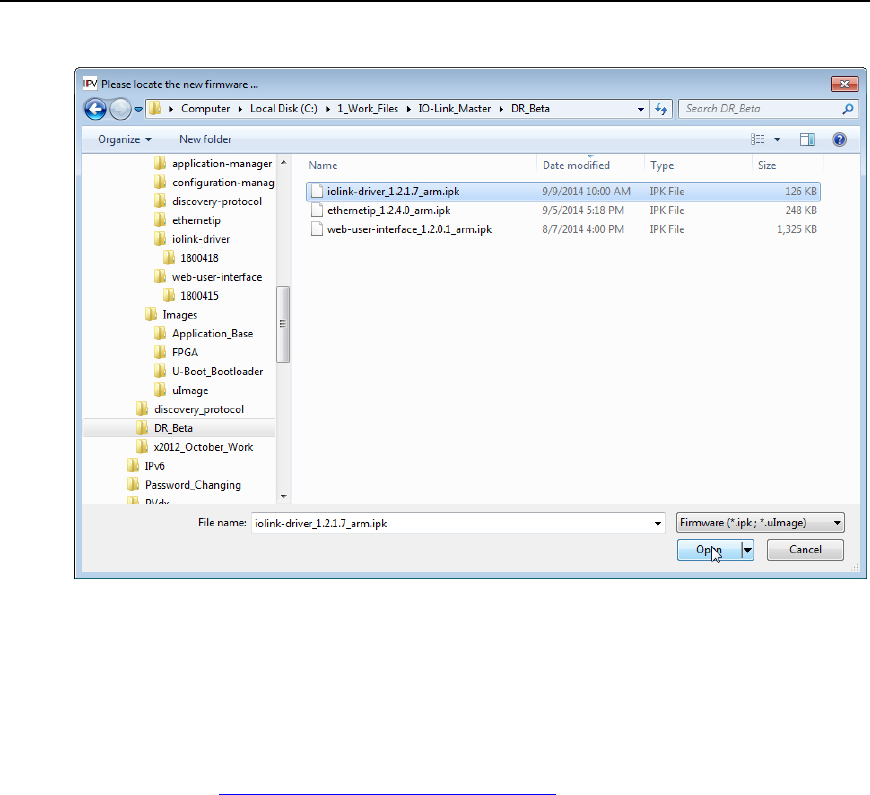
PortVision DX User Guide
3. Browse to the image or application file, highlight the file, and then click Open.
4. Click Yes to the Upload Firmware message that warns you that this is a sensitive
process.
It may take a few moments for the firmware to upload onto the IO-Link Master.
5. Click Ok to the advisory message about waiting to use the IO-Link Master until the status
reads ON-LINE. In the next polling cycle.
6. You can use the appropriate IO-Link Master document to complete the IO-Link Master
configuration process.
118 Firmware - IO-Link Master

PortVision DX User Guide
RocketLinx (Managed)
RocketLinx managed switches contain firmware for which an updated may be available. Typically,
firmware updates provide new features or functionality.
There are two types of firmware that run on managed RocketLinx switches, Bootloader and the
Configuration Web Page firmware. You can check for latest version of firmware for your
RocketLinx.
•ES7506
•ES7510
•ES7510-XT
•ES7528
•ES8508 and ES8508-XT
•ES8508F and ES8508F-XT (Single- and Multi-Mode)
•ES8509-XT
•ES8510 and ES8510-XT
•ES8510-XTE
•ES9528 and ES9528-XT
Note: The above list reflects the managed RocketLinx switches at the release this
PortVision DX help system. See the Comtrol web site for the latest RocketLinx
models.
Firmware - RocketLinx 119
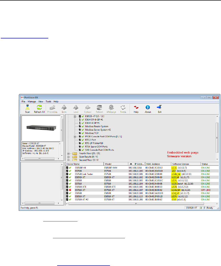
PortVision DX User Guide
Checking the Configuration Web Page Version
The web user interface for configuration is integrated in the firmware that comes pre-installed on
managed RocketLinx switches.
You may want to verify that you have the latest web user interface before configuring the
RocketLinx. Comtrol recommends verifying that your RocketLinx contains the latest web user
interface version so that you have the latest features and functionality.
Use the following procedure to check the web user interface version on the RocketLinx.
1. If necessary, click Scan.
2. Check the web user interface version number of the Software Version for the RocketLinx.
3. Check the Comtrol ftp site to see if a later version is available.
4. If the version on the ftp site is later than the version on the RocketLinx, download the file
and then go to Uploading RocketLinx Firmware.
5. If the firmware version on the RocketLinx is current, you are ready to continue the
installation and configuration process.
6. You can use the appropriate User Guide to complete the RocketLinx configuration
process.
120 Firmware - RocketLinx
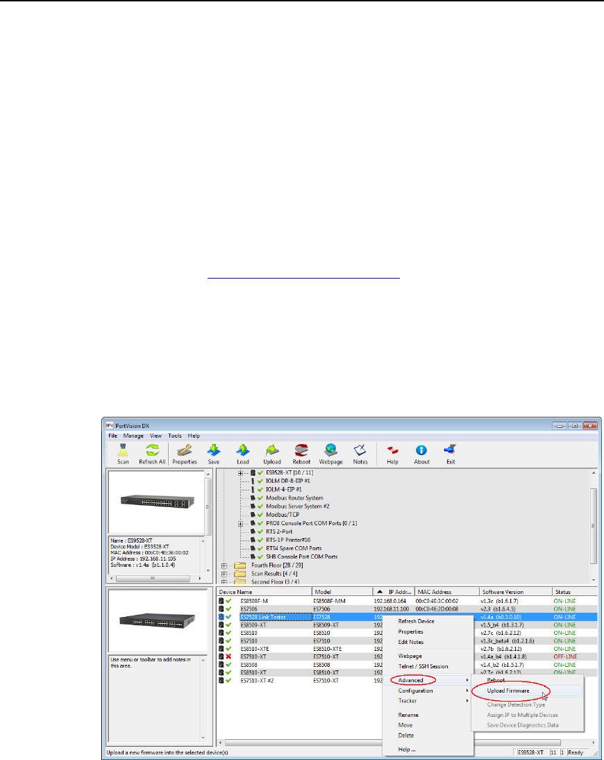
PortVision DX User Guide
Uploading Firmware
Use this page to upload the web user interface on the RocketLinx. Technical Support
recommends updating the firmware before initial configuration to make sure that you have all of
the features and functionality available for your RocketLinx model.
Note: Do not attempt to upload firmware or Bootloader across a wifi connection.
You can upload one RocketLinx or several RocketLinx switches at a time.
Uploading Firmware on a Single RocketLinx
Use this procedure to load the latest firmware on one RocketLinx.
1. Make sure that you have downloaded the latest firmware version.
2. Highlight the RocketLinx on the Main screen in the Device List pane that you want to
update and use one of the following methods:
•Click the Upload button
•Right-click and then click Advanced and then Upload Firmware
•Click Advanced and then Upload Firmware on the Manage menu
Firmware - RocketLinx 121
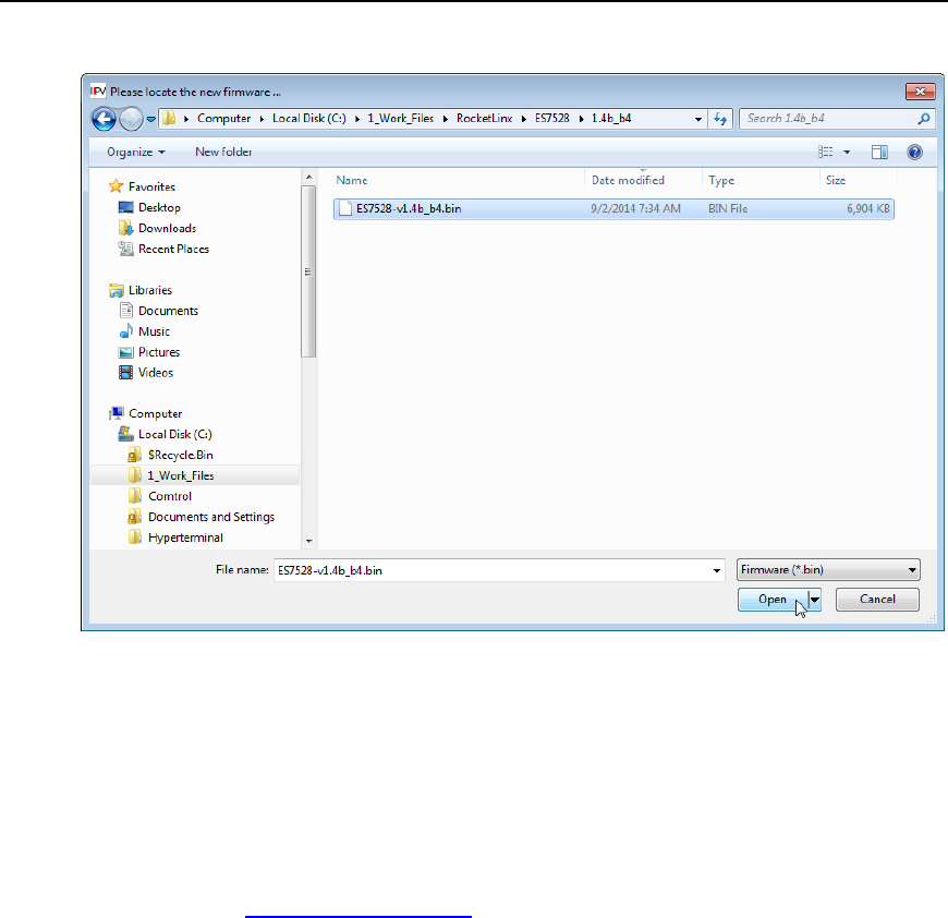
PortVision DX User Guide
3. Browse to the firmware .bin file and then click Open.
4. Click Yes to the Upload Firmware message that warns you that this is a sensitive
process.
5. It may take a few moments for the firmware to upload onto the RocketLinx. The
RocketLinx reboots itself during the upload process.
6. Click Ok to the advisory message about waiting to use the RocketLinx until the status
reads ON-LINE. In the next polling cycle, PortVision DX updates the Device List pane
and displays the new web user interface version.
7. You can use the appropriate User Guide to complete the RocketLinx configuration
process.
122 Firmware - RocketLinx

PortVision DX User Guide
Uploading the Web User Interface on Multiple RocketLinx Switches
Use this procedure to load the latest web user interface on several RocketLinx switches. You can
only load firmware on multiple switches if they are all of the same model, since the web user
interface is model-specific.
Note: Do not use this procedure to upload Bootloader. Technical Support does not
recommend uploading Bootloader on multiple RocketLinx switches.
1. Make sure that you have downloaded the latest firmware version.
2. Shift-click the RocketLinx switches for which you want to update and use one of the
following methods:
•Click the Upload button
•Right-click and then click Advanced and then Upload Firmware
•Click Advanced and then Upload Firmware on the Manage menu
3. Browse to the firmware .bin file and then click Open.
4. Click Yes to the Upload Firmware message that warns you that this is a sensitive
process.
5. It may take a few moments for the firmware to upload onto the RocketLinx. The
RocketLinx reboots itself during the upload process.
6. Click Ok to the advisory message about waiting to use the RocketLinx until the status
reads ON-LINE. In the next polling cycle, PortVision DX updates the Device List pane
and displays the firmware version.
7. You can use the CD that shipped with your product for installation procedures or use the
appropriate User Guide to complete the RocketLinx configuration process.
Firmware - RocketLinx 123
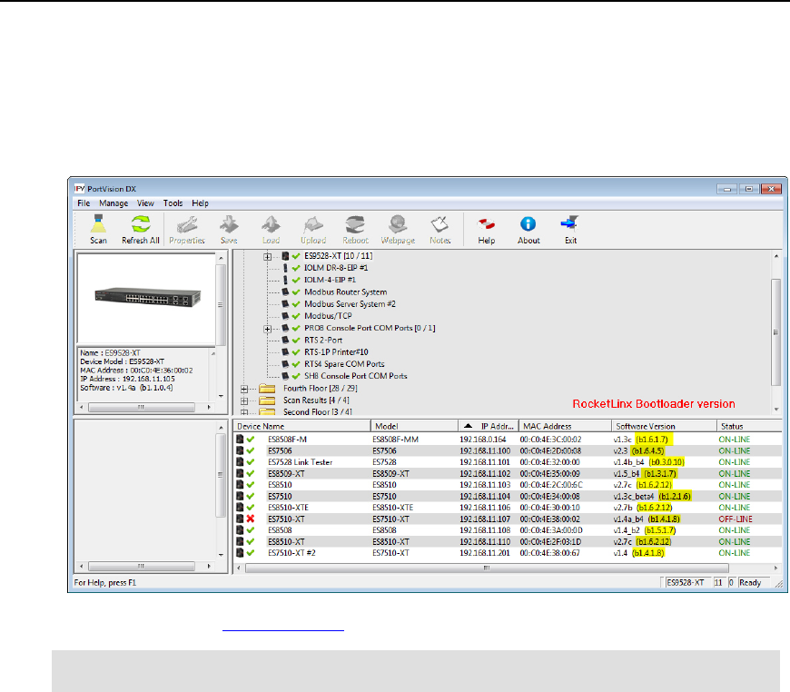
PortVision DX User Guide
Checking the Bootloader Version
Use the following procedure to check the Bootloader version.
1. In PortVision DX, right-click the RocketLinx for which you want to determine the
Bootloader version.
2. You can check the Comtrol ftp site to see if a later version is available.
Note: Typically, you do not update the Bootloader unless instructed by Technical Support
or the ftp site.
124 Firmware - RocketLinx
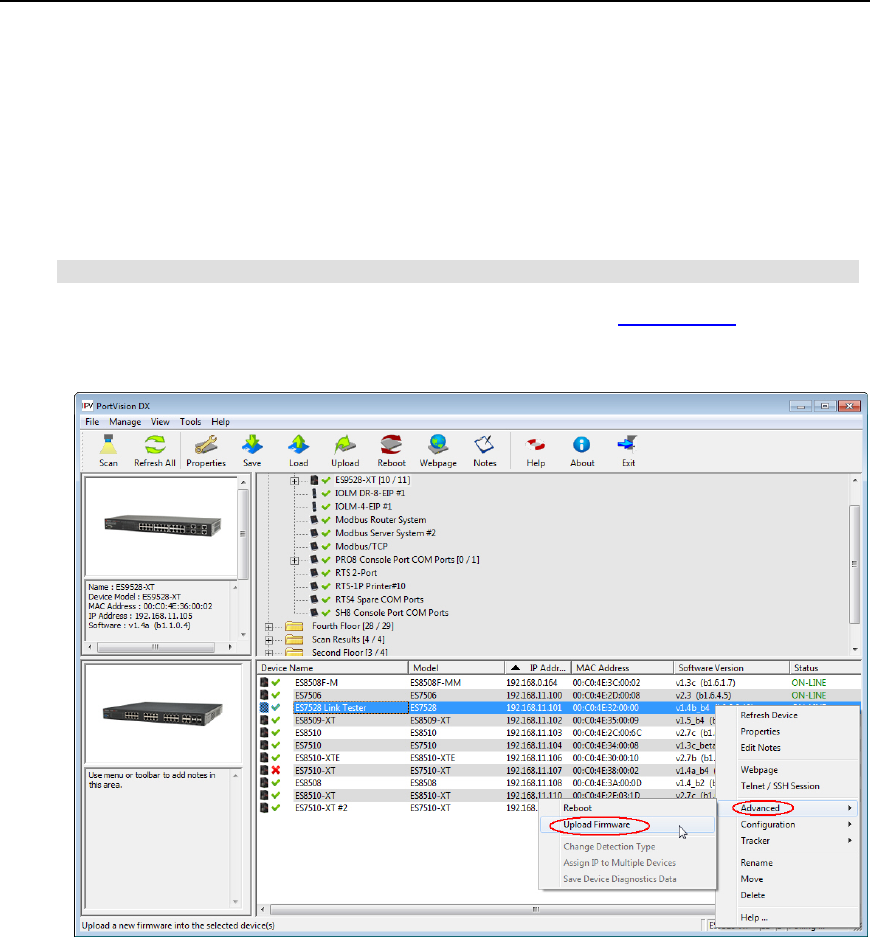
PortVision DX User Guide
Uploading Bootloader
Typically, do not upload the Bootloader unless advised to by Technical Support (or the ftp site).
Technical Support recommends connecting the RocketLinx directly to a PC or laptop when
uploading Bootloader. You may also want to connect the RocketLinx to a UPS while uploading
Bootloader to avoid any power interruption. A power interruption while loading Bootloader will
require that you send the RocketLinx back to Comtrol for repair.
Note: Only upload Bootloader to one RocketLinx at a time.
1. Make sure that you have located Bootloader downloaded the latest version.
2. Right-click the RocketLinx in the Device List pane for which you want to update, click
Advanced and then Upload Firmware.
Firmware - RocketLinx 125
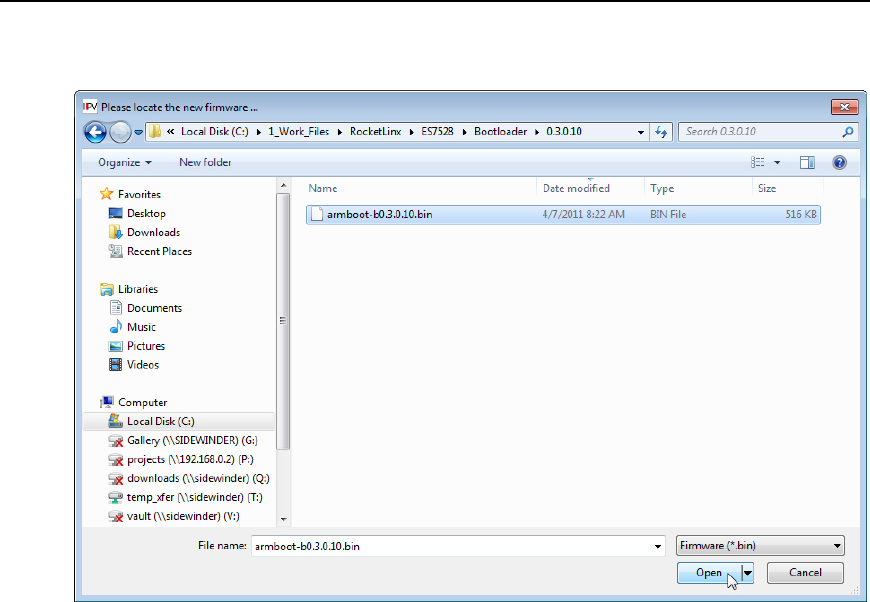
PortVision DX User Guide
3. Browse to the Bootloader .bin file, and then click Open (Please locate the new firmware),
and then click Yes (Upload Firmware).
4. It may take a few moments for the firmware to upload onto the RocketLinx. The
RocketLinx reboots itself during the upload process.
5. Click Ok to the advisory message about waiting to use the RocketLinx until the status
reads ON-LINE.
126 Firmware - RocketLinx

Software Settings
The DeviceMaster, DeviceMaster UP, and IO-Link Master provide the Software Settings tab.
The Software Settings tab on the Properties screen contains the configuration parameters for
the DeviceMaster, DeviceMaster UP, or IO-Link Master web interface configuration. You can do
the following using the Software Settings tab:
•Save device configuration files
•Load device configuration files on similar DeviceMasters, DeviceMaster UPs, or IO-Link
Masters
•Review or edit software settings
Note: You must use the embedded web page to edit software settings for the IO-Link
Master family or the DeviceMaster UP, this operation is not supported in the
Software Settings tab for these products.
If you are not familiar with the software parameters for your DeviceMaster, you may want to use
the Web Interface tab to access the DeviceMaster configuration pages. You must know valid
values for software settings parameters to use the Software Settings tab. Although the
parameters on the Software Settings tab reflect the contents of the device's configuration, the
order of the parameters on this tab are not be in the same order as the settings in the web
interface.
You can access the Software Settings tab on the Properties screen by using one of these
methods:
•Double-click the device in the Device Tree or Device List.
•Right-click the device in the Device Tree or Device List and click Properties.
•Highlight the device in the Device Tree or Device List, click the Properties button.
•Highlight the device in the Device Tree or Device List, click the Manage menu, and then
Properties.
DeviceMaster
The Software Settings tab on the Properties screen contains configuration parameters for
SocketServer and does not contain NS-Link device driver configuration parameters.
SocketServer is used to configure sockets and set up serial tunneling.
You can refer to the SocketServer help system or use the Web Interface tab to open the help
system for information about the parameters.
If your site is running different versions of SocketServer, you may notice that the parameter
categories may not be in the same order or contain the same parameters.
If you are using the Software Settings tab to edit parameters and you want to clone port
characteristics, you can use the SocketServer web page to clone port parameters.
Note: If the Software Settings tab does not appear, that means that the DeviceMaster is
not available for IP connection. Which could mean that an incorrect user name or
password was entered or that you are operating in MAC mode.
Software Settings - DeviceMaster 127

PortVision DX User Guide
Security Considerations
The following list provides basic PortVision DX operations that are affected how the DeviceMaster
interacts with PortVision DX when security is enabled using the web interface (SocketServer/NS-
Link).
•PortVision DX must scan the DeviceMaster before configuring security.
•PortVision DX locates the DeviceMaster before setting either Secure Data Mode or Secure
Config Mode.
•If PortVision DX discovers the DeviceMaster after setting security, the following conditions
occur:
•The IP address of the DeviceMaster does not display.
•The Software Settings and Web Interface tabs are not present in the Properties page.
•The IP mode displays as DHCP without the ability to modify.
•The Upload and Reboot icons are grayed out and the options are disabled in the
popup menus.
Note: If the DeviceMaster was previously configured with security, PortVision DX features
are reduced.
Accessing the Software Settings Tab
You can access the Software Settings tab on the Properties screen using one of these
methods:
•Double-click the DeviceMaster in the Device Tree or Device List.
•Right-click the DeviceMaster in the Device Tree or Device List and click Properties.
•Highlight the DeviceMaster in the Device Tree or Device List, click the Properties button.
•Highlight the DeviceMaster in the Device Tree or Device List, click the Manage menu,
and then Properties.
128 Security Considerations - DeviceMaster LT/PRO/RTS/Serial Hub/500

PortVision DX User Guide
DeviceMaster UP
The Software Settings tab on the Properties screen provides a way to review the firmware
configuration values for your DeviceMaster UP.
You can refer to the User Guide for your protocol or reference the Web Interface tab for
information about the configuration parameters.
Note: If the Software Settings tab does not appear, that means that the DeviceMaster
UP is not available for IP connection. Which could mean that an incorrect user
name or password was entered, or it is in MAC mode (DIsable IP), which is not
supported in the DeviceMaster UP.
Accessing the Software Settings Tab
You can access the Software Settings tab using one of these methods:
•Double-click the DeviceMaster UP in the Device Tree or Device List.
•Right-click the DeviceMaster UP in the Device Tree or Device List and click Properties.
•Highlight the DeviceMaster UP in the Device Tree or Device List, click the Properties
button.
•Highlight the DeviceMaster UP in the Device Tree or Device List, click the Manage menu,
and then Properties.
Software Settings - DeviceMaster UP 129

PortVision DX User Guide
IO-Link Master
The Software Settings tab on the Properties screen provides a way to review the firmware
configuration values for your IO-Link Master.
If you save and load configuration files for an IO-Link Master. The Password fields are populated
with passwords (hashed) that means that the IO-Link Master had a valid password when they
saved the configuration file. If they send that same file back to any IO-Link Master, it sets the
password of that IO-Link Master accordingly.
Note: If the Software Settings tab does not appear, that means that the IO-Link Master
is not available for connection. Which could mean that an incorrect user name or
password was entered. Make sure that you initial capitalize the user names,
Admin, User, or Operator.
130 Software Settings - IO-Link Master

Accessing Configuration Web Pages
This page discusses how to access the Comtrol Ethernet attached product configuration web
page and where to locate information about configuration options and procedures.
Comtrol Ethernet attached products provide a browser-based configuration page that can be
accessed using one of these methods.
•Entering the IP address of the Comtrol Ethernet attached product in your web browser.
•Highlight the Comtrol Ethernet attached product in the List View pane and click the
Webpage button.
•Right-click the Comtrol Ethernet attached product in the List View pane and click
Webpage from the submenu.
•Use the Web Interface tab in the Properties screen to open the web page.
Locating Configuration Web Page Information
You can use these links to locate configuration information for the following products:
•DeviceMaster (SocketServer): Refer to the SocketServer help system or the appropriate
document for your product:
•DeviceMaster Installation and Configuration Guide for the DeviceMaster PRO,
DeviceMaster RTS, and DeviceMaster Serial Hub
•DeviceMaster LT User Guide
•DeviceMaster UP
•EtherNet/IP: Refer to the EtherNet/IP User Guide and EtherNet/IP Interface
Configuration Quick Start for detailed information.
•Modbus Router: Refer to the Modbus Router User Guide for detailed information.
•Modbus Server: Refer to the Modbus Server User Guide for detailed information.
•Modbus/TCP: Refer to the Modbus/TCP User Guide and Modbus/TCP Interface
Configuration Quick Start for detailed information.
•PROFINET IO: Refer to the PROFINET IO Installation Quick Start for
configuration information.
•IO-Link Master: Refer to the IO-Link Master web configuration help system or the IO-Link
Master Installation and Configuration Guide for detailed information.
•RocketLinx: Download the appropriate RocketLinx User Guide.
Accessing Configuration Web Pages 131
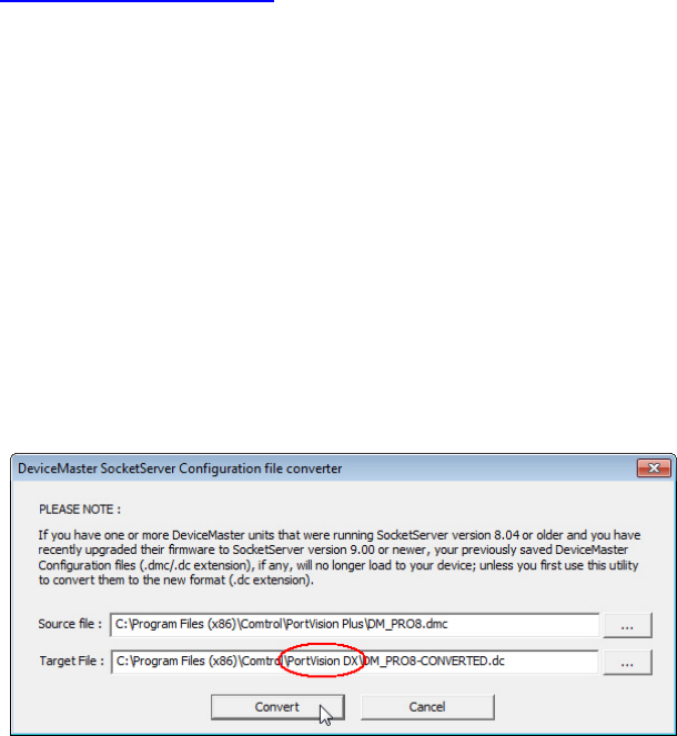
Configuration Files
If you are deploying multiple Comtrol Ethernet attached products that share common values, you
can save the configuration file (.dc), which loads that configuration onto other Comtrol Ethernet
attached products of the same model. You can choose what properties you want to save or load.
You can save configuration files from the:
•Main screen
•Software Settings tab for the DeviceMaster, DeviceMaster UP, or IO-Link Master.
If you want to program the network settings in multiple Comtrol Ethernet attached products, you
can use the Assign IP to Multiple Device option.
Converting DeviceMaster Configuration Files
You can use the Convert DeviceMaster Configuration Files option to convert a configuration
file that was created on a DeviceMaster running SocketServer v8.04 (or previous) and load it onto
a DeviceMaster running SocketServer v9.00 (or higher).
This means that you can upgrade SocketServer to the latest version and recover your previous
DeviceMaster settings using this option.
Use this procedure to convert DeviceMaster configuration files for SocketServer (v8.04 or
previous).
1. Click the File menu and click the Convert DeviceMaster Configuration Files option.
2. Browse and locate the old configuration file.
If you placed it in the default folder, it is located in the Program Files
(x86)/Comtrol/PortVision Plus or Program Files (x86)/Comtrol/PortVision DX
subdirectory depending on whether you used PortVision Plus or PortVision DX to create
the configuration file.
3. Optionally, you may want to change the path to reflect PortVision DX or file name and
then click Convert.
You will receive a popup message that notifies you that the file was successfully
converted. If the original configuration file was not from SocketServer v8.04 or earlier or
the file was corrupt, you will receive a message that reflects a conversion failure.
4. If you have converted your files, you can close the window.
Configuration Files - DeviceMaster 133
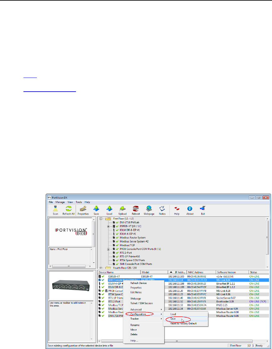
PortVision DX User Guide
Saving Configuration Files
If you are deploying multiple Comtrol Ethernet attached products of the same model that share
common values, you can save the configuration file (.dc) and load that configuration onto other
Comtrol Ethernet attached products of the same model.
If you save a configuration file, you can choose what properties you want to save.
•Main screen (all Comtrol Ethernet attached products)
•Software Settings tab (DeviceMaster, DeviceMaster UP, and IO-Link Master)
Main Screen
Use this procedure to save a configuration file using the Main screen.
1. From the Device List pane on the Main screen, use one of the following methods:
•Highlight the Comtrol Ethernet attached product, click the Save button
•Right-click the Comtrol Ethernet attached product, click Configuration, and then
Save.
•Highlight the Comtrol Ethernet attached product, click the Manage menu, click
Configuration, and then Save.
2. Browse to the location you want to save the file, enter a file name and click Save.
134 Configuration Files - DeviceMaster
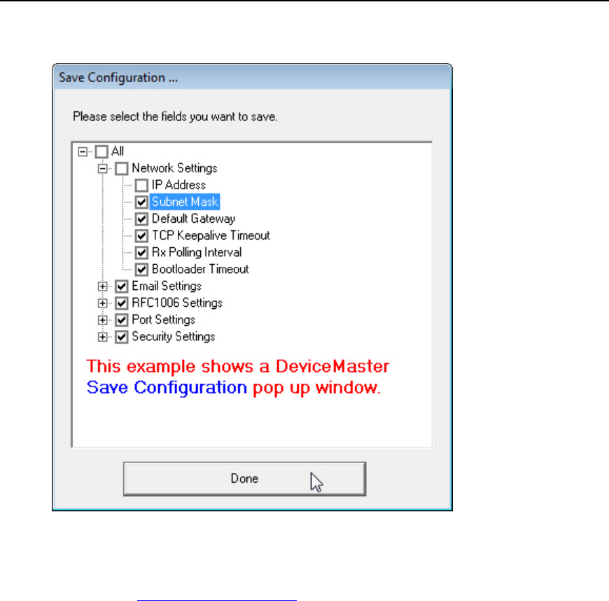
PortVision DX User Guide
3. Click the All checkbox or click only the properties that you want saved for each property
category in the configuration file.
4. Click Done.
5. Click Ok to close the Save Configuration Created popup message.
6. You can now load that configuration file onto another similar Comtrol Ethernet attached
product.
Configuration Files - DeviceMaster 135
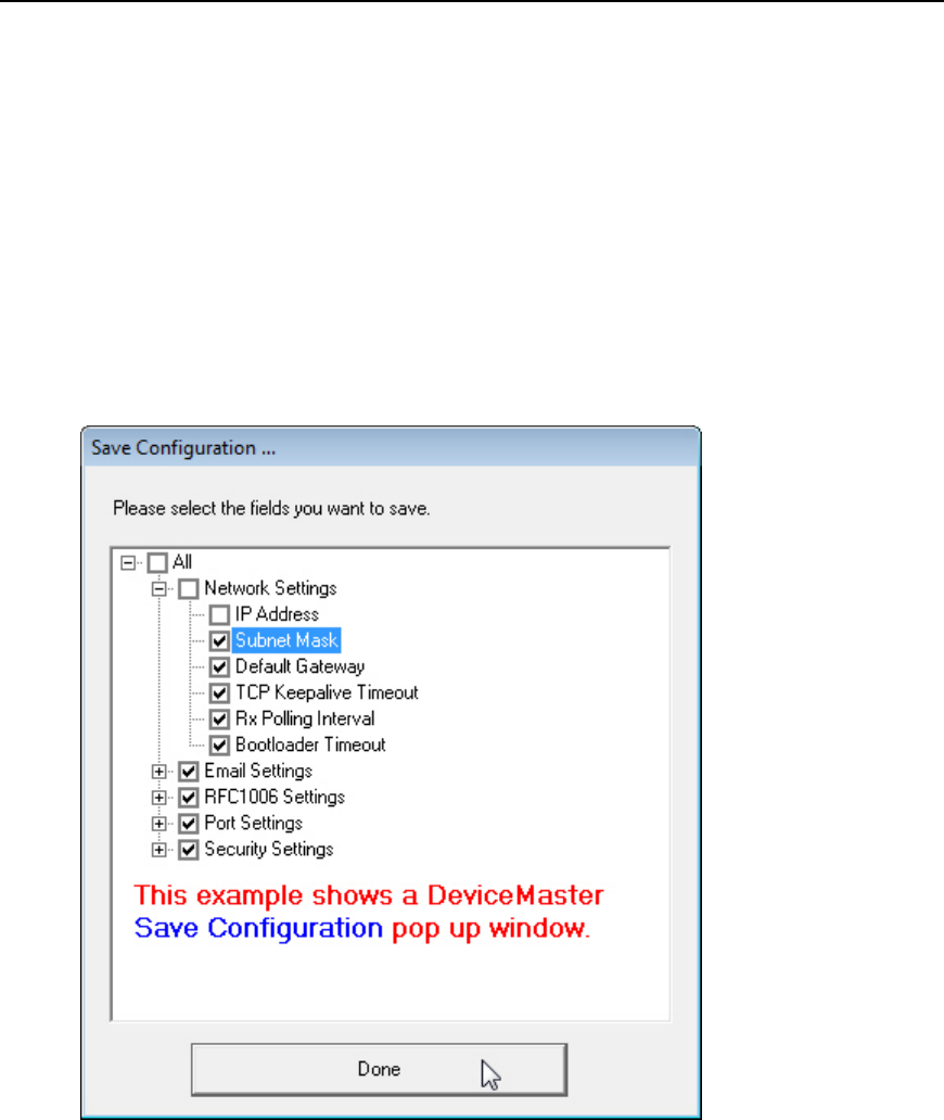
PortVision DX User Guide
Software Settings Tab
Use the following procedure to create a configuration file from the Software Settings tab on the
DeviceMaster, DeviceMaster UP, and IO-Link Master.
1. If you have not done so, access the Properties screen for the DeviceMaster,
DeviceMaster UP, and IO-Link Master for which you want to save the configuration.
2. Click the Software Settings tab.
3. Click the Save Settings to a File, browse to the location you want to save the file, enter
a file name, and click Save.
4. Click the All checkbox or click only the properties that you want saved for each property
category in the configuration file.
5. Click Done.
6. Click Ok to close the Save Configuration Completed message.
136 Configuration Files - DeviceMaster
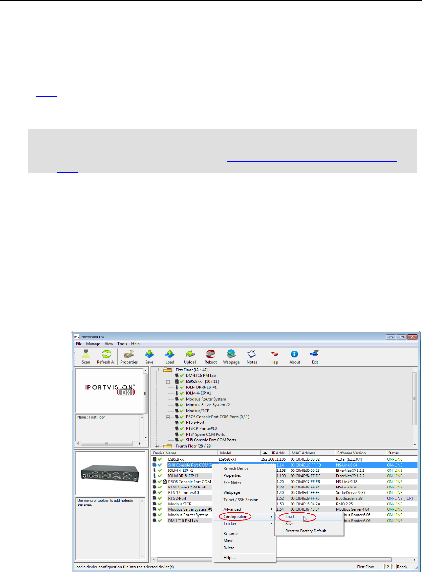
PortVision DX User Guide
Loading Configuration Files
If you have previously saved a Comtrol Ethernet attached product configuration file, you can load
that configuration and apply it to a selected device or devices.
•Main screen (all Comtrol Ethernet attached products)
•Software Settings tab (DeviceMaster, DeviceMaster UP, and IO-Link Master)
Note: If this is a DeviceMaster configuration file with SocketServer v8.04 or previous and
you want to load it on a DeviceMaster running SocketServer v9.00 or higher, you
must convert the configuration file. See Converting DeviceMaster Configuration
Files.
Main Screen
Use this procedure to load a configuration file using the Main screen to one or more devices.
1. From the Device List pane on the Main screen, use one of the following methods:
•Highlight the Comtrol Ethernet attached product, click the Load button
•Right-click the Comtrol Ethernet attached product, click Configuration, and then
Load.
•Highlight the Comtrol Ethernet attached product, click the Manage menu, click
Configuration, and then Load.
2. Click Yes to the warning that it will take 25 seconds per device and that it may also
reboot the devices.
3. Browse to the location of the configuration file, click the file name and then Open.
Configuration Files - DeviceMaster 137
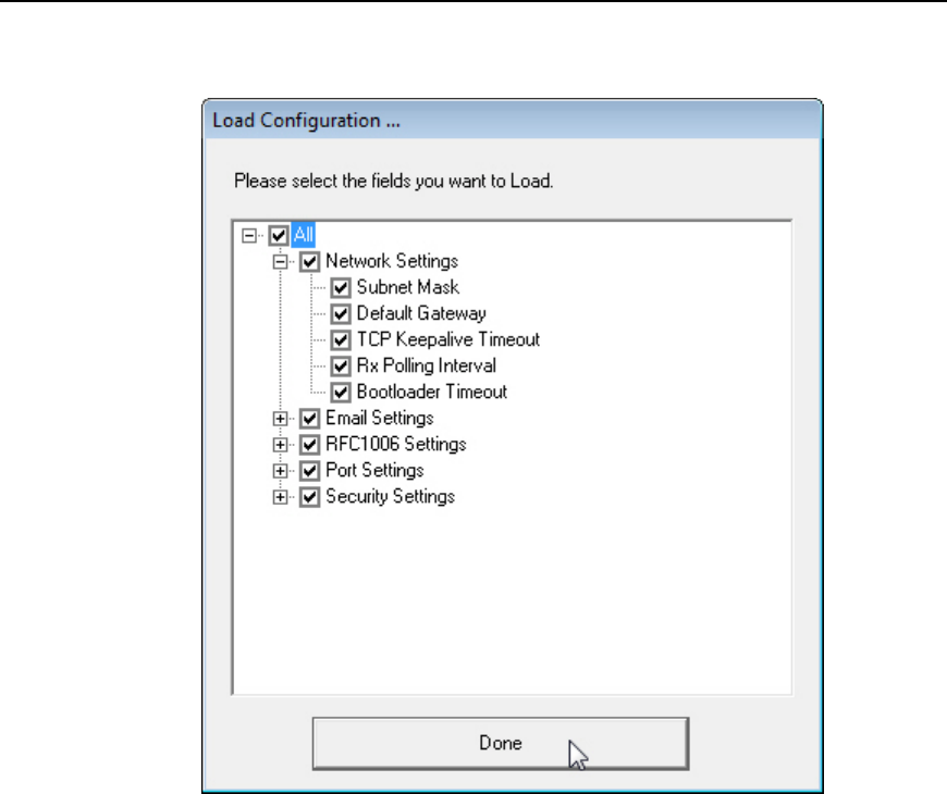
PortVision DX User Guide
4. Click the All checkbox or click only the properties that you want to load for each property
category in the configuration file and click Done.
5. Click Ok to close the Load Configuration popup message.
138 Configuration Files - DeviceMaster

PortVision DX User Guide
Software Settings Tab
Use the following procedure to load a configuration file from the Software Settings tab.
1. If you have not done so, access the Properties screen for the device for which you want
to load the configuration.
2. Click the Software Settings tab.
3. Click Load Settings from a File, browse to the location of the configuration file, click the
file name, and then Open.
4. Click the All checkbox or click only the properties that you want to load for each property
category in the configuration file and click Done.
5. Click Apply Changes.
6. Click Close to exit the Software Settings tab.
Note: PortVision DX does not send it to the device unless you click Apply Changes.
Configuration Files - DeviceMaster 139
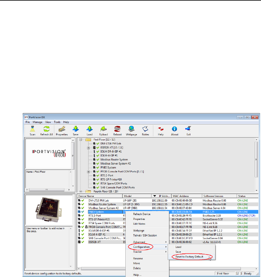
PortVision DX User Guide
Reset to Factory Default
If you select the Reset to Factory Default option, all configuration settings, except for the IP
address, subnet mask, and IP gateway are reset to their factory default values.
Use the following procedure to reset the device to it's factory default values.
1. From the Device List pane on the Main screen, use one of the following methods:
•Right-click the Comtrol Ethernet attached product, click Configuration, and then Reset
to Factory Default.
•Highlight the Comtrol Ethernet attached product, click the Manage menu, click
Configuration, and then Reset to Factory Default.
2. Click Yes to the Set Configuration to factory default pop up message.
PortVision DX will show the status as Reset to factory default until the next polling cycle.
140 Reset to Factory Default

Telnet SSH Sessions
There are two ways to access a Telnet/SSH session in PortVision DX:
•Right-click the Comtrol Ethernet attached product in the Device List pane and click
Telnet/SSH Session.
•Highlight the Comtrol Ethernet attached product in the Device List pane, click the
Manage menu and then Telnet/SSH Session.
You may need to use the Telnet/SSH Session option to upload firmware on DeviceMasters that
reside on the other side of several switches, a router, or wireless.
Note: You can use this option to access the RocketLinx managed switches CLI
(Command Line Interface).
DeviceMaster TCP and UDP Socket Ports
Following list is all of the logical TCP and UDP socket ports implemented in DeviceMaster.
Socket Port Number
Description
22 SSH
23 Telnet
TCP Ports 22 (ssh) and 23 (telnet) are used for administrative and
diagnostic purposes and aren't required for normal use and are enabled
by default and Port 23 may be d
isabled.
80 HTTP
443 SSL or HTTPS
TCP Ports 80 (http) and 443 (https) are used by the web server for
administration and configuration and are enabled by default and cannot
be disabled.
102 RFC1006
TCP Port 102 is used for RFC1006 (ISO over TCP) serial port access.
Not used for normal NS
-Link SocketServer access.
The RFC1006 server can be disabled by setting the server port number
to
-1 and is enabled by default.
161 SNMP UDP
Port 161 is used by the SNMP agent if SNMP is enabled which is the
default.
460
6
TCP Port 4606 is required if you want to use NS-Link or PortVision DX if
you want to update firmware without setting up a TFTP server and this
port cannot be disabled.
4607
TCP Port 4607 is only used for diagnostic purposes and is not required
for norma
l operation and this port cannot be disabled. If SocketServeris
to be used, then the user may enable usage of TCP or UDP ports for
access to the serial ports. These ports are not enabled by default and
are also user configurable to different values. Defaul
ts for TCP would
begin at 8000 and for UDP would begin at 7000.
TCP 8000
- 8xxx
This user configurable port is incremented per serial port on the
DeviceMaster.
For example: A DeviceMaster 16
-port would have Ports 8000 through
8015.
Telnet SSH Sessions 141

PortVision DX User Guide
Socket Port Number
Description
UDP 7000
- 7xxx
This user configurable port is incremented per serial port on the
DeviceMaster.
For example: A DeviceMaster 16
-port would have Ports 7000 through
7015.
142 Telnet SSH Sessions
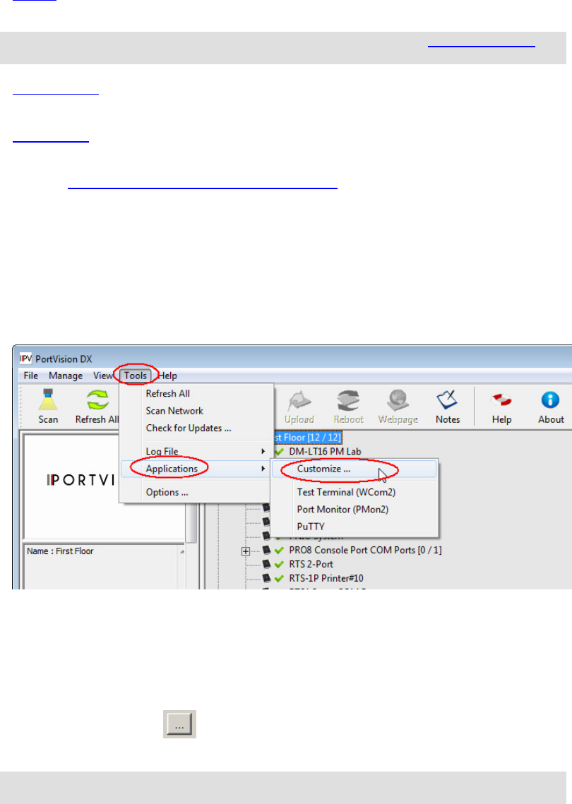
Accessing Other Applications
You can configure PortVision DX to open up to twenty applications using the Applications -
Customize menu item under the Tools menu.
PortVision DX installs three applications, PuTTY, Test Terminal and Port Monitor.
•PuTTY opens PuTTY, which is a free Win32 Telnet, SSH, and Rlogin client. If necessary,
refer to the PuTTY help system.
Note: If the PuTTY shortcut is not displayed, you can add using the Adding Shortcuts
discussion.
•Test Terminal opens a port, send characters and commands to the port, and toggle the
output control signals.
•Port Monitor verifies operation of all Comtrol serial COM ports from a single window if
they installed during the installation process.
You can use the Port Monitor and Test Terminal User Guide or the help systems for detailed
information about how to use these applications.
Adding Shortcuts
You can add shortcuts for your applications that you may want to access from PortVision DX
using the following procedure.
1. From the Main screen, click the Tools menu, highlight Applications and then click
Customize.
2. Click New, if you need to clear the contents of the text boxes on the Applications
Shortcuts window.
3. Enter an appropriate Shortcut Name.
4. Enter an application description.
5. Click the browse button to the location of the executable, highlight the executable,
and click Open. .
Note: If you are missing the PuTTY shortcut, browse to this location and file: Program
Files (x86)\Comtrol\PortVision DX\PUTTY.EXE
6. If required by the application, enter the working directory for the application.
Accessing Other Applications 143
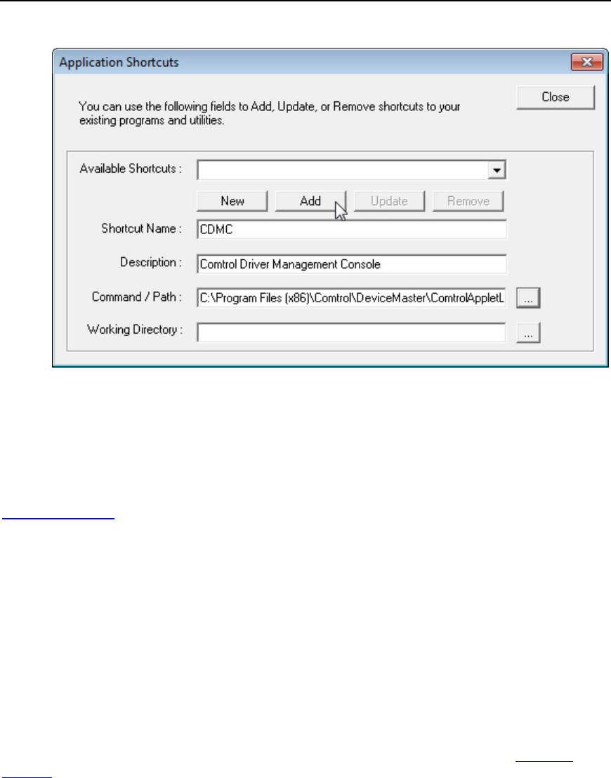
PortVision DX User Guide
7. Click Add when to add the application.
8. Click Close when you are done adding applications.
The shortcuts now appear nested under the Applications submenu.
Changing Application Shortcuts
You can make changes to the application shortcuts using the following procedure. You can also
remove a shortcut.
1. From the Main screen, click the Tools menu, highlight Applications and then click
Customize.
2. Select the shortcut in the Available Shortcuts drop list.
3. Make any necessary changes.
4. Click Update.
5. Click Close when you have made all of your changes to the shortcuts.
Removing Application Shortcuts
You can remove application shortcuts using the following procedure. You can also change a
shortcut.
1. From the Main screen, click the Tools menu, highlight Applications and then click
Customize.
2. Select the shortcut in the Available Shortcuts drop list.
3. Click Remove.
4. Click Close when you have made all of your changes to the shortcuts.
144 Acessing Other Applications

PortVision DX User Guide
Test Terminal
DeviceMaster users can use Test Terminal to open a port, send characters and commands to the
port, and toggle the output control signals.
1. To use Test Terminal, you will need to know the COM port number or numbers that you
want test.
2. To start Test Terminal, click Test Terminal (WCom2) from the Applications drop list in
the Tools menu.
If you need help using Test Terminal, use the help system in Test Terminal or refer to the Port
Monitor and Test Terminal User Guide.
Port Monitor
DeviceMaster users can use Port Monitor to verify operation of all Comtrol serial COM ports from
a single window if you installed them during the installation process.
1. To use Port Monitor, you will need to know the COM port number or numbers that you
want test.
2. To start Port Monitor, click Port Monitor (PMon2) from the Applications drop list in the
Tools menu.
If you need help using Port Monitor, use the help system in Port Monitor or refer to the Port
Monitor and Test Terminal User Guide.
PuTTY
PuTTY is a free (MIT-licensed) Windows 32-bit Telnet, SSH, and Rlogin client that is included
with PortVision DX.
Refer to the PuTTY help system if you need information about using the application.
Acessing Other Applications 145
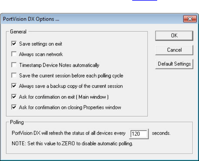
Changing PortVision DX Options
This section discusses using the Options... screen that is located in the Tools menu, which
allows you to change or reset PortVision DX default settings.
You can use the following procedure to change or reset PortVision DX options.
1. Click Options... from the Tools menu.
2. Click or uncheck options to fit your environment. See Options... for an explanation of the
choices in this screen.
Changing PortVision DX Options 147
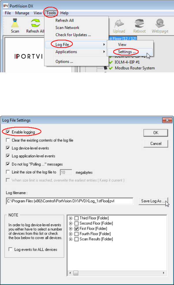
Logging Events
PortVision DX has an event logging feature available that you can enable if you want to log
device-level or application-level (or both types of events). If you enable application-level event
logging, you can disable the Polling... messages.
Enabling Event Logging
For PortVision DX to create an event log, you must enable logging in the Log File Settings
menu.
1. From the Main screen, click the Tools menu, click Log File, and then click the Settings...
option.
2. Check the Enable logging option.
3. If necessary, adjust the other options to fit the type of events you want to log.
4. Optionally, use the Save Log as... button and provide a different log file name before
clicking the Ok button.
Logging Events 149
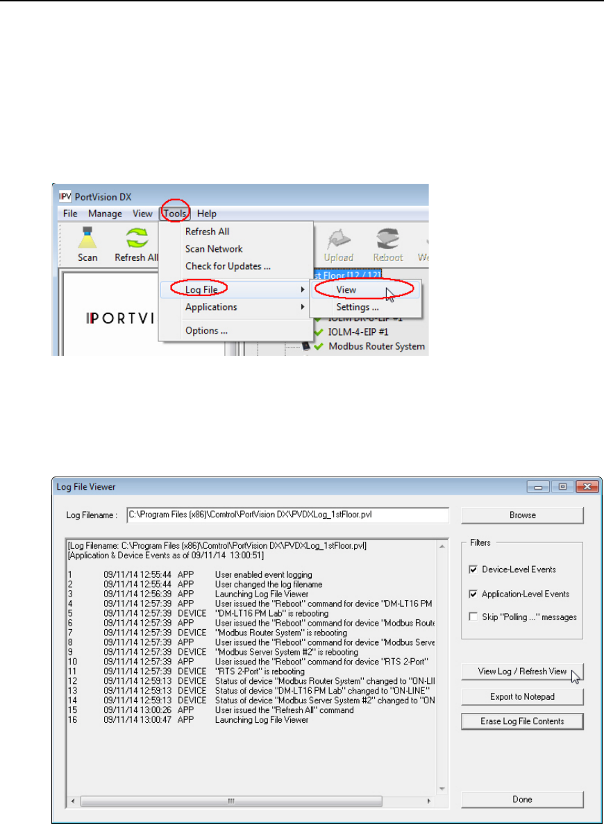
PortVision DX User Guide
5. Use a .pvl extension on the file name so that PortVision DX quickly locates your file in
the View screen.
Accessing the Event Log
Before you can access the event log, you must have previously created a log file and know the
location.
1. From the Main screen, click the Tools menu, click Log File, and then click View.
2. If necessary, use the Browse button to locate the log file or manually enter the location
and log file name.
3. If necessary, disable or enable the Filters (Device-Level, Application-Level, or Skip
“Polling...” messages events) to view the type of logging events you want to review.
4. Click the View Log/Refresh View button.
5. Optionally, save or print the log file to a Notepad file using the Export to Notepad button.
6. To refresh the event log, click the View Log/Refresh View button.
150 Logging Events

PortVision DX User Guide
Clearing the Event Log
Use the following steps to clear the event log. Optionally, you can delete the log file using any
means available in Windows.
You may want to save the contents of the existing log using the Log File - View menu.
1. If necessary, minimize the Log File - View menu.
2. From the Main screen, click the Tools menu and then Log File - Settings.
3. Verify that the correct Log Filename is displayed or use the Browse button to locate the
appropriate file.
4. Check the Erase Log File Contents.
5. Click Yes to the Are you sure you want to ERASE fog file contents permanently query.
6. Click Done to close the window.
Logging Events 151
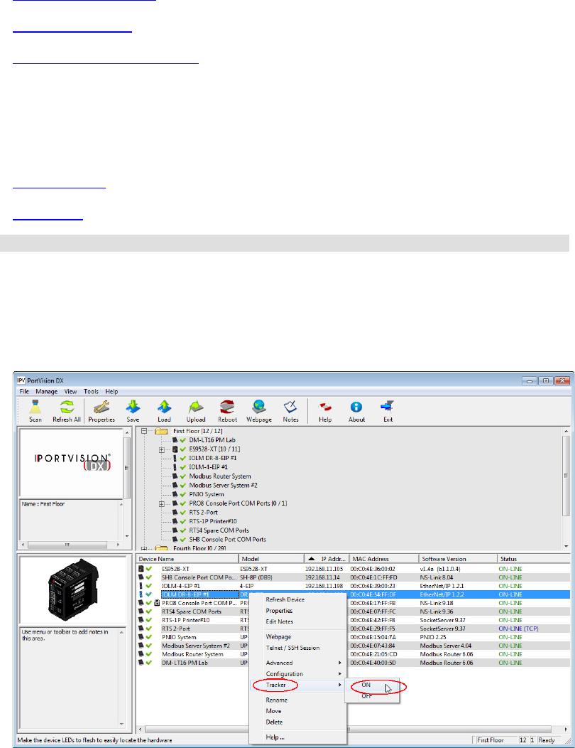
Troubleshooting
The following topics are available in this section:
•Using the LED Tracker
•OFF-LINE Devices
•Contacting Technical Support
Using the LED Tracker
The IO-Link Master and RocketLinx supports the LED Tracker feature, which allows you to toggle
on/off the LEDs on a specific device so that you can locate the physical unit.
•IO-Link Master
•RocketLinx
Note: The DeviceMaster and DeviceMaster UP do not support the LED Tracker option.
IO-Link Master
Use this procedure to toggle the LED Tracker feature on the IO-Link Master.
1. Right-click or highlight the IO-Link Master in the Device List pane, click Tracker, and then
click ON.
Troubleshooting 153
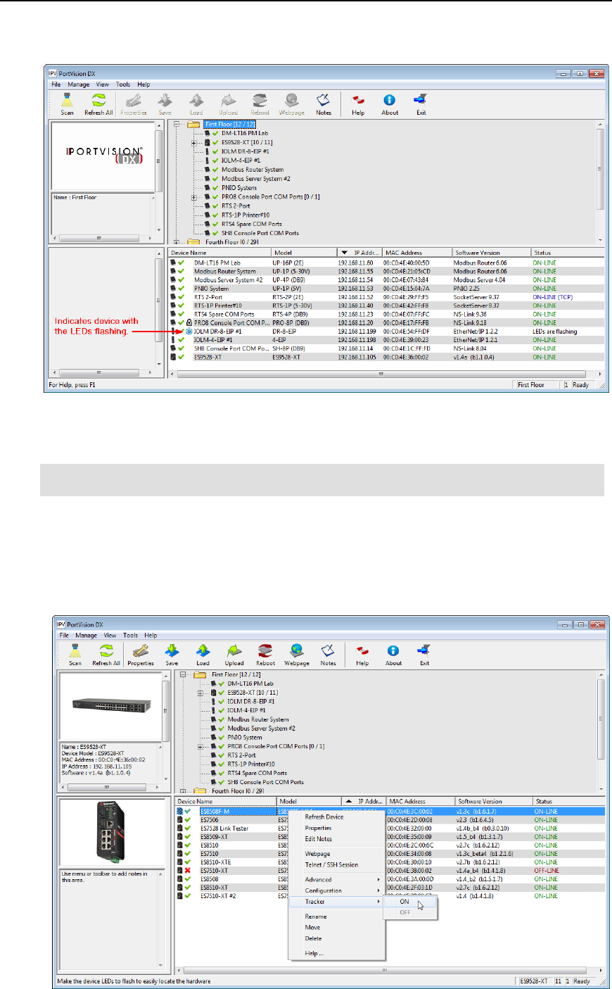
PortVision DX User Guide
The IO-Link Master cycles the IO-Link and DI LEDs. PortVision DX displays LEDs are
flashing in the Status.
2. Right-click or highlight the IO-Link Master in the Device List pane, click Tracker, and then
OFF.
Note: The IO-Link Master LEDs will continue cycling the LEDs until you turn the Tracker
OFF.
RocketLinx
Use this procedure to toggle the LED Tracker feature on the RocketLinx (managed).
1. Right-click or highlight the RocketLinx in the Device List pane, click Tracker, and then
click ON. The LED Tracker disables itself after a few moments.
154 Troubleshooting

PortVision DX User Guide
The RocketLinx flashes the SYS LED for five seconds.
2. If necessary, you may need to click Tracker and ON several times to catch the flashing
SYS LED.
OFF-LINE Devices
The Device List may display OFF-LINE device status for a variety of reasons. You may want to
click Refresh to see if the device displays ON-LINE.
Note: Remember, unmanaged RocketLinx switches and other hardware can be toggled
from ON-LINE to OFF-LINE using the General tab of the Properties screen.
PortVision DX can only determine whether a Comtrol Ethernet attached product is
on-line or off-line.
• The device is not powered.
• The device is in the process of booting up and may show as ON-LINE at the next PortVision
DX request.
• The device has not completed loading firmware. If possible, check the status LED on the
Comtrol Ethernet attached product.
• A firewall is blocking communications between the device and PortVision DX.
• The device is using the same IP address as another device. If this is the case, an asterisk is
displayed behind the IP address in the Device List pane.
• Incorrect IP addressing in the device has been implemented.
• The device is getting an IP address from a DHCP server so the address is different than
what PortVision DX knows.
• A DeviceMaster is using LOCAL as the Detection Type but it is on the other side of a router
or switch that has Layer 2 MAC mode disabled and only supports Layer 3. If this is the case,
simply change the Detection Type from LOCAL to REMOTE.
• The device is too busy to respond to the PortVision DX request for status.
• The device’s Ethernet cable is disconnected or connect into the wrong Ethernet port.
The DeviceMaster 2E/4/8/16-port models with external power supplies follow the IEEE
specifications for standard Ethernet 10/100BASE-TX topologies.
When using the UP and DOWN ports, the DeviceMaster 2E/4/8/16 is classified as a switch.
When using the UP port only, it is a simple end node device. The maximum number of daisy-
chained DeviceMaster 2E/4/8/16 units, and the maximum distance between units is based on
the Ethernet standards and will be determined by your own environment and the conformity of
your network to these standards.
Contacting Technical Support
You can contact Comtrol by calling +1.763.957.6000 (8AM to 6PM CST/USA).
Optionally, you can refer to the Support web page or the Comtrol forum for more information.
Troubleshooting 155
