PortalPlus Installation Manual Portal Plus
PortalPlusInstallationM PortalPlusInstallationM
User Manual: PortalPlusInstallationManual
Open the PDF directly: View PDF ![]() .
.
Page Count: 20

www.videx-security.com
Installation manual
Version 1.1

Portal Plus Manual
2

Portal Plus Manual
3
TableofContents
MANUALINTRODUCTION..........................................................................................................4
SYSTEMINTRODUCTION............................................................................................................4
SYSTEMCOMPONENTS..............................................................................................................5
CONTROLS..................................................................................................................................6
3.5A13.8VdcPSU...................................................................................................................6
CONTROLPCB............................................................................................................................6
FUSES.....................................................................................................................................6
JUMPER..................................................................................................................................6
ON‐BOARDBATTERY..............................................................................................................6
RESETIPBUTTON...................................................................................................................6
READERS.....................................................................................................................................8
PROXIMITYREADERS.............................................................................................................8
BIOMETRICREADERS.............................................................................................................9
LOCKOUTPUT..........................................................................................................................10
FAILCLOSED(Powertounlock)...........................................................................................10
FAILOPEN(Powertolock)...................................................................................................10
DOORCONTACTSANDEXITBUTTONINPUTS.........................................................................11
PROGRAMMABLEINPUTS........................................................................................................11
NETWORKCOMMUNICATION.................................................................................................12
TCP/IP...................................................................................................................................12
MIXEDTCP/IP&RS485........................................................................................................13
RS485(SERIAL).....................................................................................................................13
RS485CABLINGANDTERMINATION.......................................................................................14
EWSSPECIFICATIONS...............................................................................................................15
EWSTECHNICALCHARACTERISTICS.........................................................................................15
EXAMPLEWIRINGDIAGRAM...................................................................................................16
TROUBLESHOOTING................................................................................................................17

Portal Plus Manual
4
MANUAL INTRODUCTION
The information in this manual is intended as an installation and commissioning guide for the
Portal Plus access control system. This manual should be read carefully before the
installation commences. Any damage caused to the equipment due to faulty installations
where the information in this manual has not been followed is not the responsibility of Videx
Security Ltd. This manual covers the hardware aspects of the Portal Plus system. The Portal
Plus PROS manual covers the software aspects of the system and should be used in
conjunction with this one.
VIDEX run free training courses for engineers who have not installed this system before.
Technical help is also available on 0191 224 3174 during office hours or via e-mail
tech@videx-security.com.
SYSTEM INTRODUCTION
The Portal Plus is a networkable access control system with windows based
programming and management software with support for up to 15000 users and
unlimited entrances. It allows greater flexibility in the design and installation of an
access control system having a modular design and facilities for proximity, bio
access and coded access readers. A range of readers are available all in the same
robust design which also includes an illuminated touch to exit switch. Proximity
reader modules are also available for the Videx 4000, VR4K and VR series entrance
panels allowing full integration with an intercom system.
Based on 2 door controllers (available with or without integral 3.5A switched mode
power supply) and including an RS485 bus that will link up-to 64 doors (32
controllers). Additionally, an optional integral Ethernet connection (TCP/IP) is
available allowing controllers to be connected to an existing LAN or WAN with the
potential expansion to unlimited doors.
The system includes distributed intelligence allowing the systems to continue
functioning even during times of network problems. The user information is retained
using a lithium battery on each control PCB. In the event of this battery requiring
replacement, power should remain on during the change.
Both anti pass back and mantrap options are available as standard as are free inputs
and outputs that can be programmed as per an installation or user requirement.
The user friendly windows based software allows the adding, editing or deletion of
users and includes finger print enrolment integrated into the software. Using this in
conjunction with the desk mount USB finger print reader eliminates the need to enroll
a user twice.

Portal Plus Manual
5
SYSTEM COMPONENTS
CONTROLS
PPCU1 Lockable boxed 2 door controller (RS485 BUS) c/w 3.5A 13.8Vdc PSU Dimensions 265mm x
360mm x 75mm
PPCU2 Lockable boxed 2 door controller (RS485&TCP/IP BUS) c/w 3.5A 13.8Vdc PSU Dimensions
265mm x 360mm x 75mm
PPCU3 Lockable IP55 boxed 2 door controller (RS485 BUS) c/w 3.5A 13.8Vdc PSU Dimensions
300mm x 300mm x 150mm
PPCU4 Lockable IP55 boxed 2 door controller (RS485& TCP/IP BUS) c/w 3.5A 13.8Vdc PSU
Dimensions 300mm x 300mm x 150mm
EWSH Boxed 2 door controller (RS485 BUS) Dimensions 200mm x 144mm x 43mm
EWSiH Boxed 2 door controller (RS485&TCP/IP BUS) Dimensions 200mm x 144mm x 43mm
EWS 2 door controller PCB (RS485 BUS) Dimensions 152mm x 85mm x 27mm
EWSi 2 door controller PCB (RS485&TCP/IP BUS) Dimensions 152mm x 85mm x 27mm
READERS
MTPXS-M Surface mount aluminum grey proximity reader. Dimensions 92mmx51mmx25mm
XPROX Panel mount proximity reader module. (40mm x 40mm window)
4849PP 4000 Series module proximity reader
VR4KPPM VR4K vandal resistant proximity reader module
MTPAD Surface mount aluminum grey coded access keypad. Dimensions 92mmx51mmx25mm
BIOCS Surface mount aluminum grey finger print reader. Dimensions 92mmx51mmx25mm
ACCESSORIES
BIOE Desk mount USB finger print reader
481 RS485 to USB converter
MTTS-EXIT Surface mount aluminum grey touch to exit switch. Dimensions 92mmx51mmx25mm
FOBS/CARDS
PBX-1E ABS fob
PBX-2 Thin card
PBX-2C Thick card
Portal Plus Manual
6
CONTROLS
The control cabinet will include a 2 entrance control PCB and may also include a 3.5A
13.8Vdc power supply. If the power supply is not included then ensure that the power supply
used has an adequite current rating to supply both the control equipment and the lock
release.
3.5A 13.8Vdc PSU
The integral power supply has a current rating of 3.5A. It includes battery charging and
battery drop out to prevent the battery being damaged due to deep discharge. There are
three independently fused outputs. One should be used to power the control equipment,
another for the door release for door one and the last for the lock release for door 2. There is
also a forth fuse to protect against a short circuit battery. Each output also includes a green
healthy output LED.
FUSES
Mains Fuse Control
Equipment Fuse Lock 1 Fuse Lock 2 Fuse Battery Fuse
T3.15A T1.0A T1.25A T1.25A T1.0A
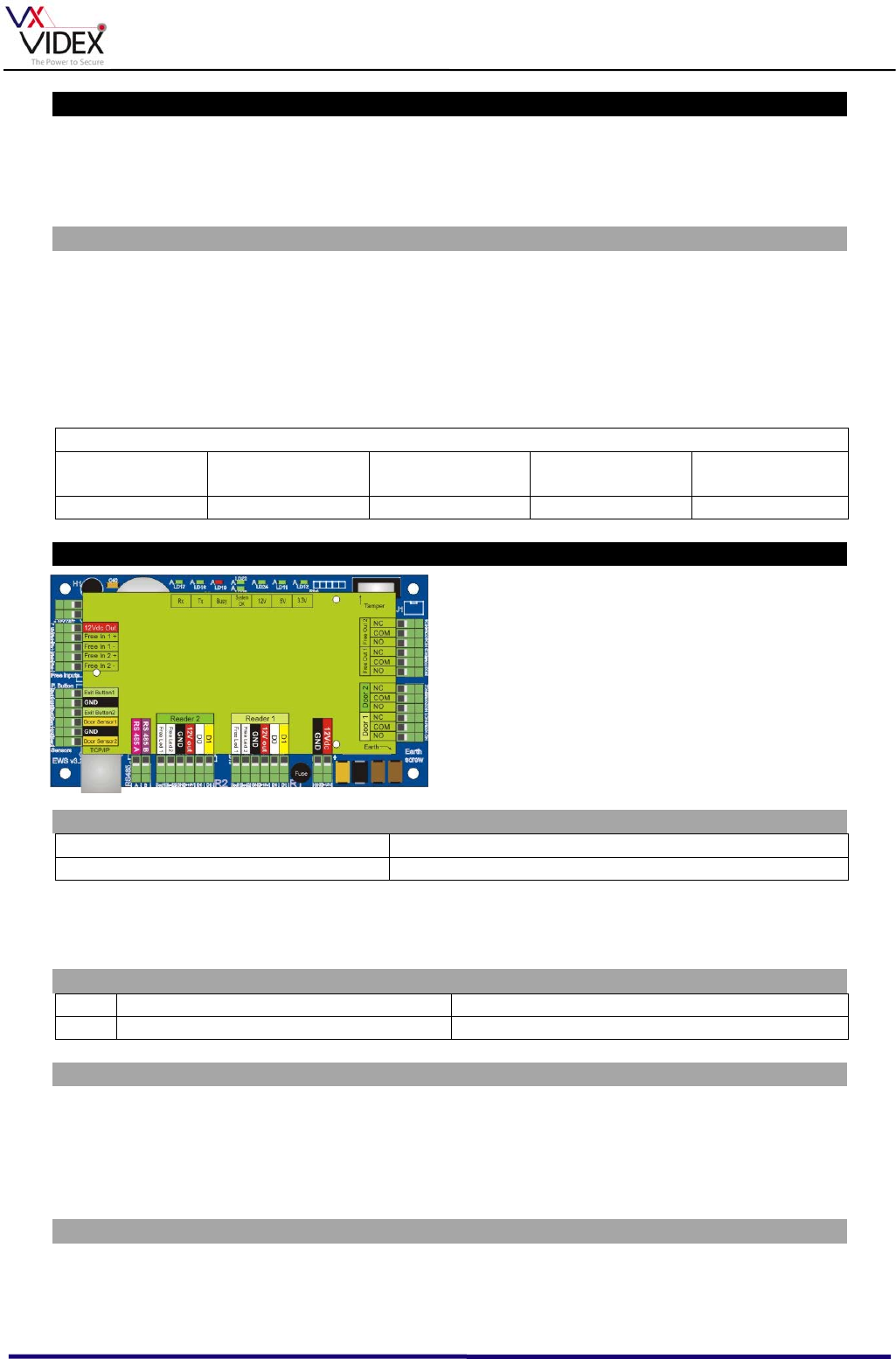
CONTROL PCB
There are two versions of the control PCB, one
with Ethernet connection (EWSi) and one
without (EWS). Both PCB’s have RS485
connection and control two readers, two lock
outputs, two door monitoring inputs and two
push to exit button inputs as well as two free
inputs and outputs. The following page
identifies all the connections on the PCB.
FUSES
Input Fuse Readers fuse
T2A T1.0A
Note: These fuses are ‘solder in’ type and are only a last line of defence to protect against
damage to the control PCB electronics. If these fuses fail then the PCB should be returned
for repair.
JUMPER
Fitted (Closed) Removed (Opened)
JP3 RS485 ‘Controller at the end of line’ RS485 ‘Controller in the middle of the bus’
ON-BOARD BATTERY
The battery specification is 3V lithium, 20mm Diameter with nominal capacity 230mAh. Part
number CR2032. The battery should be replaced while the controller is powered to avoid
loss of data. Ensure the polarity is correct before inserting the battery (See holder). The
battery should last up to 7 years with infrequent power cuts but we suggest it is replaced
every 3 years as a precaution.
RESET IP BUTTON
If you forget the password to gain entry to the IP portal setup page then power down, press
this button and keep pressed while you power up to reset all TCP/IP settings on that
controller to default.
Portal Plus Manual
7
Portal Plus Manual
8
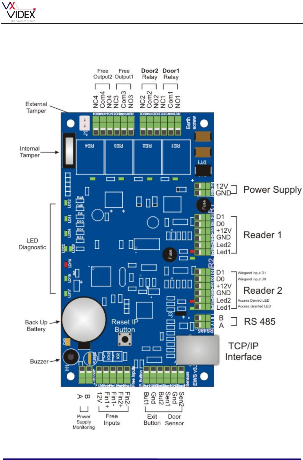
READERS
PROXIMITY READERS
Proximity readers require 6 connections. Readers should be no more than 50m from
the control PCB and can be wired in alarm cable.
CONNECTION FUNCTION COLOUR
+ 12Vdc supply to reader Red
- 0V supply to reader Black
D0 Wiegand data 0 (Approx. 4Vdc in standby) White
D1 Wiegand data 1 (Approx. 4Vdc in standby) Yellow
LG- Green LED switched 0V trigger Green
LR- Red LED switched 0V trigger Orange
The Reader output can supply up to 400mA.
Portal Plus Manual
9
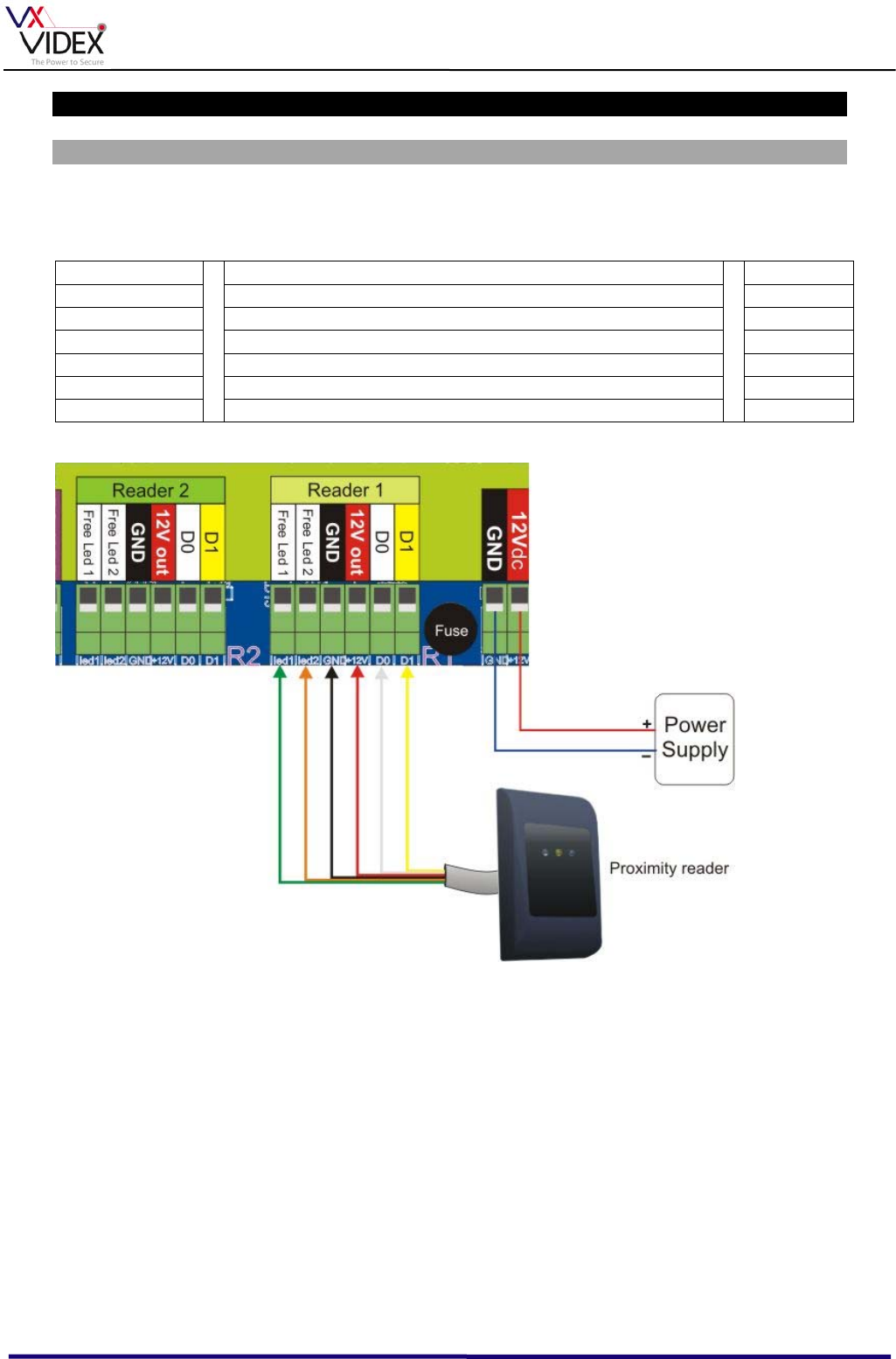
BIOMETRIC READERS
Biometric readers require 4 connections for the Wiegand bus and a further 2 connections for
the RS485 bus. Readers should be no more than 50m from the control unit. The Wiegand
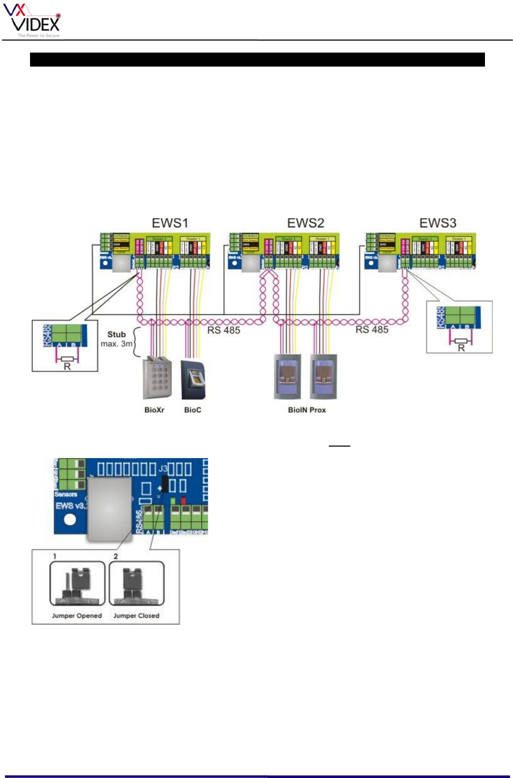
bus can be wired in alarm cable. The RS485 bus must be wired in a shielded twisted pair
cable and wired in a daisy chain with any other RS485 devices on the bus. (If the distance is
less than 3m from the controller then it is possible to branch off the RS485).
CONNECTION FUNCTION COLOUR
+ 12Vdc supply to reader Red
- 0V supply to reader Black
D0 Wiegand data 0 (Approx. 4Vdc in standby) White
D1 Wiegand data 1 (Approx. 4Vdc in standby) Yellow
A RS485 Bus (Twisted pair shielded cable) Pink
B Purple
Note: Bio readers require a link to both the reader terminals and the RS485 bus connections.
It is ok to make a very short star connection to the Bio reader (Max 3m). If a longer distance
is required it will be necessary to run the bio reader in series with the other control PCB’s (i.e.
run an RS485 pair to and from the reader).
Portal Plus Manual
10
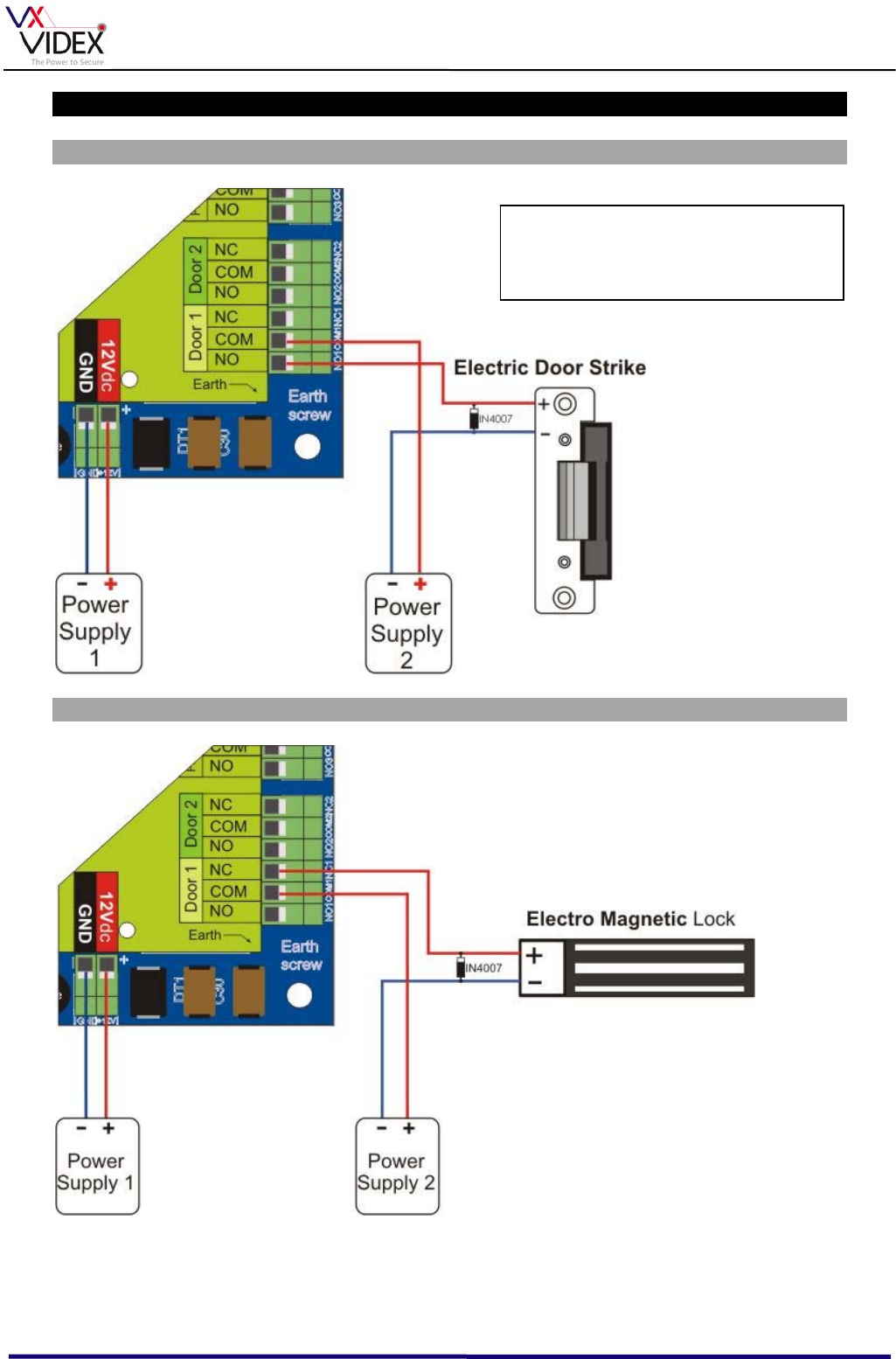
LOCK OUTPUT
FAIL CLOSED (Power to unlock)
FAIL OPEN (Power to lock)
The lock outputs are dry contact change over relays rated at 250Vac 10A.
IMPORTANT NOTE: Always fit back
EMF protection to the lock. This can be
a diode as shown or a suitable value
MOV.
Portal Plus Manual
11
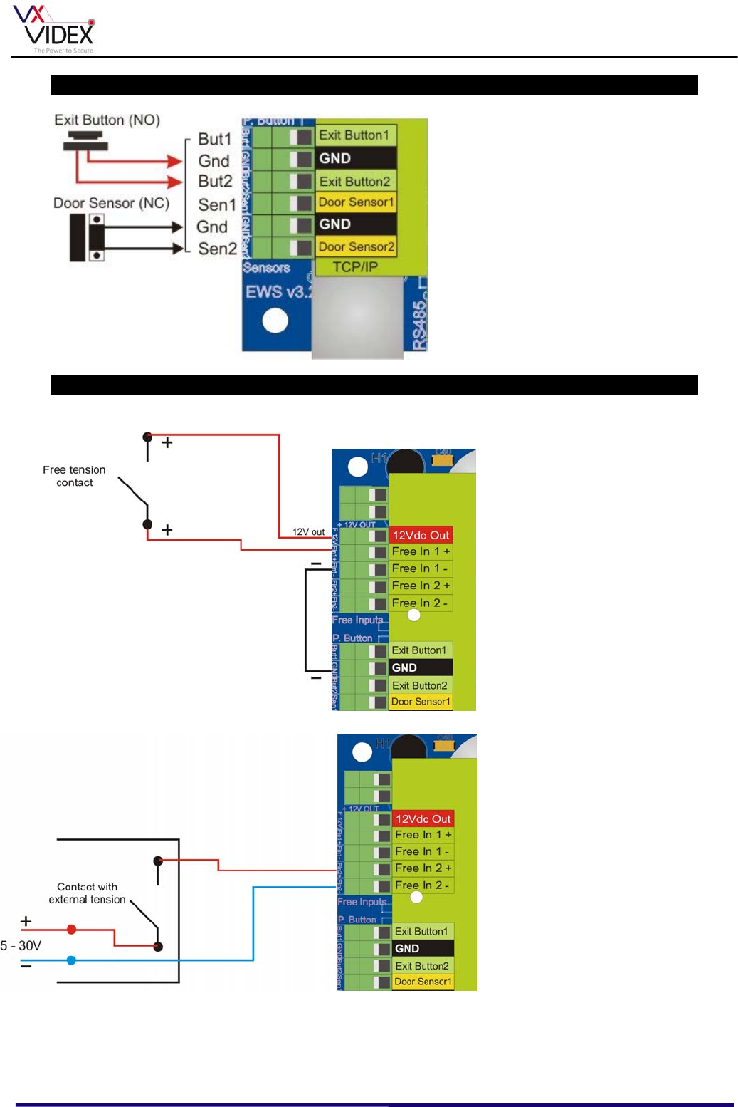
DOOR CONTACTS AND EXIT BUTTON INPUTS
Push to exit inputs will trigger their
respective door relay.
The door contacts can be used in
junction with the PROS software and
the free output relays to identify the
different door open conditions (Door
forced, door left open, door opened
by access control etc).
PROGRAMMABLE INPUTS
Programmable inputs can be
used to trigger any of the four
available relays on the control
PCB (Including the lock
relays) and any combination
of relays can be triggered at
the same time (i.e. A trigger
from free input 1 could trigger
both the lock relay 1 and free
output relay 2 at the same
time).
Either the 12V or the 0V can
be switched. The inputs are
opto-isolated and so require
both the 12V and the 0V to
be connected.
There is also a useful
‘FireAlarm’ feature whereby
one of the free inputs can be
linked to the fire alarm and
when activated will trigger
both the lock output relays on
the PCB for as long as the
fire alarm is triggered. (Note:
The fire alarm will need to
connect to all controllers and
this feature relies on the
controller PCB still
functioning correctly and so
cannot be classed as fail safe.
For fire exit doors we still recommend a green break glass to release the door in an
emergency.
Portal Plus Manual
12
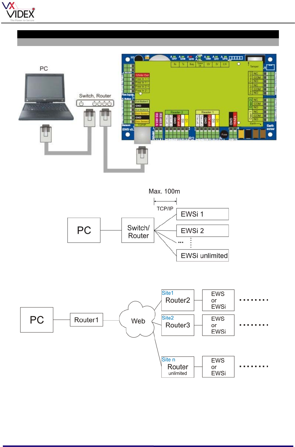
NETWORK COMMUNICATION
TCP/IP
Using this method, each EWS control PCB will have its own unique IP address and
connection made to a switch or router via a patch lead. The EWS is supplied with a default
IP address and so IP addresses must be set to those supplied by the network administrator
prior to connection to the network. Please see the PROS manual for more information.
PATCH CABLE
Portal Plus Manual
13
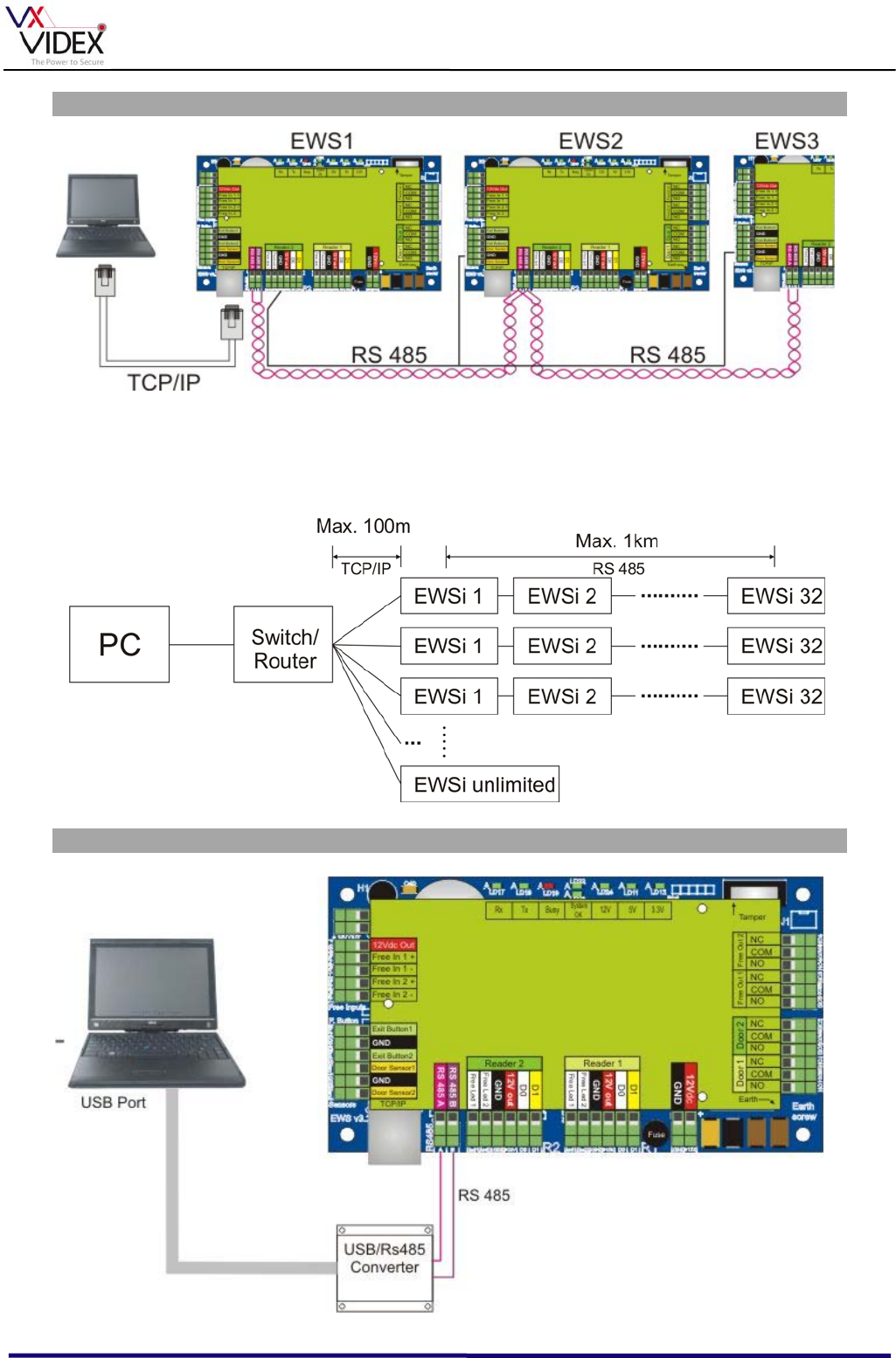
MIXED TCP/IP & RS485
IMPORTANT:
One RS485 bus can connect 32 controllers maximum (CPU’s and Readers with RS485
combined). For more devices add more TCP converters or another RS485 converter to another
communication port on the PC. Also remember to link the grounds between the controllers as
shown above.
RS485 (SERIAL)
A
rt.481
The RS485 can then be series linked to another
31 devices.
Remember to set the Art.481 switch to RS485
and set the termination jumper correctly (i.e.
closed if the Art.481 is at the end of the RS485
bus and open if it is in the middle).
CROSS OVER CABLE
Portal Plus Manual
14
RS485 CABLING AND TERMINATION
For reliable communication over an RS485 network, the end of line points must be terminated with a
120 Ohm resistor.
The RS485 Communication Line must be made in a daisy chain, NOT in a star wired communication.
The cable must be twisted and shielded with a min. 0.5 mm2 cross section. Ideally a cable with low
capacitance specifically designed for RS485 communication is preferred.
Connect the ground (0V) of each unit in the RS 485 line using a third wire in the same cable (A 2 pair
RS485 cable will allow for one of the additional cores to be used as the ground).
The shield of the RS485 cable must be connected to the buildings EARTH at one end of the RS485
link only. All RS485 cable shields should also be linked together. The Fingerprint Readers use the
same RS485 communication line. The Fingerprint Readers must also be part of the daisy chain. If
stubs are used for the Fingerprint Readers, their length must not exceed 3m.
On the EWS PCB, there is a 120 ohm resistor for termination. To use this termination resistor close
the Jumper J3 on the first and last unit in the RS485 Line. All other must be open.
IMPORTANT:
One RS485 bus can connect 32 units (EWS and Readers with RS485). For more devices add
more TCP/IP controllers.
Portal Plus Manual
15
EWS SPECIFICATIONS
Reader inputs 2
Wiegand interface Length: 8-128 bit
Data: 8-32 bit
Parity: 0-4 bit
Door relays 2
Door sensor inputs 2
Door egress inputs 2
Users/Events 1000/30000 - 15000/2500
Programmable outputs 2 (relays)
Programmable inputs 2 (opto couplers)
Clock & date Internal dedicated chip
Data retention CR2032 Lithium battery
Tamper Onboard or external
Connections Pluggable terminals
Communication interface RS485
Network (optional)
Diagnostic Buzzer
16 LED
EWS TECHNICAL CHARACTERISTICS
Supply voltage 11-15Vdc
Consumption 300mA (without readers)
Reader supply 400mA Max
Door relays 250Vac, 10 A
Programmable outputs relays 250Vac, 10 A
Programmable inputs 5-30Vdc, 3mA-28mA
Main fuse 2A
Readers fuse 1A
Input Supply fuse 315mA
Wiegand levels 1.3V Max (Logic 0) - 2.5V Min (Logic 1)
Environment temperature 0 - 45C°
Humidity 0-80%
Battery back up 3V Lithium 20mm Dia. Part No CR2032
Portal Plus Manual
16
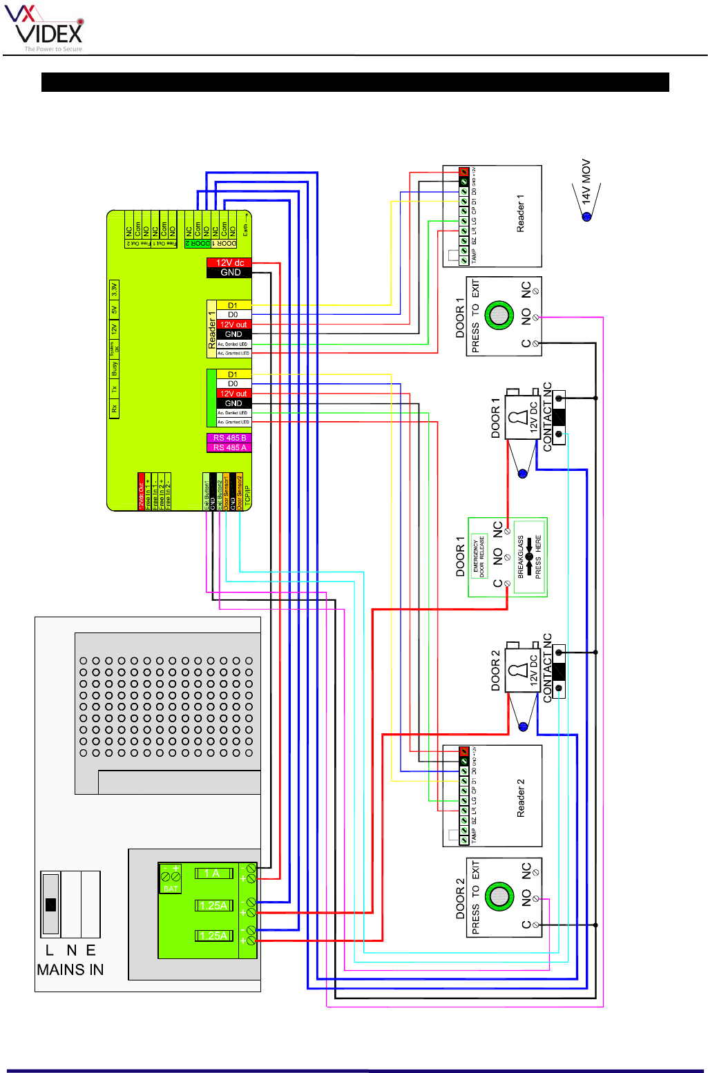
EXAMPLE WIRING DIAGRAM

Portal Plus Manual
17
TROUBLE SHOOTING
RS485 Communication problems
1. Check that none of the A & B connections are reversed.
2. Check the end of lines are terminated correctly
3. Check all controllers that are not at the end of line do not have end of line termination.
4. Check there is only one communication port setup on the PROS software and that all controllers
are communicating through that portal.
5. Check the switch on the Art.481 is towards the RS485 position.
6. Ensure the correct driver has been installed on the PC for the Art.481 converter. See PROS
manual for more information.
7. When the RS485 is communicating correctly, the Rx & Tx LED’s on each controller should be
flickering (As long as the PC software is running and on the main screen with no other windows
open).
8. Try breaking the bus down to a smaller size.
Reader not reading fob/card
1. Check the reader has 12Vdc on the + & - terminals
2. Check the D0 & D1 connections are ok and not crossed. To do this check the voltage at the
reader is approx. 4Vdc. Disconnect one of them at the controller and the reader and check again
at the reader that correct wire now has no voltage. The terminal on the reader (D0 or D1) with no
connection to the controller should sit at 5Vdc.
Lock release not operating when the programmed fob/card is presented
1. First check that the relay on the controller is energising correctly.
2. If it isn’t then check that the reader is accepting the fob (LED goes green).
3. Check for 12Vdc across the lock at the correct time.
4. Check that there is no setting on the PC software that could prevent the door from opening (Door
locked etc).
Fobs work on some doors but not others
1. Check the fob in question does not have an access level which would prevent access through
certain doors.
2. Check anti-pass back settings.
3. Check the controller has all user data by reloading the users data to that controller.
One controller is not working
1. Check that the System OK, 12V, 5V & 3.3V LED’s are all illuminated.
2. Check that the PC PROS software can see the controller and is setup correctly with the correct
serial no/IP Address.
3. Check the controller has all user data by reloading the user’s data to that controller.
4. Check the readers connections.

Portal Plus Manual
18

Portal Plus Manual
19

Portal Plus Manual
20
Northern Office
Videx Security Ltd
Unit 4-7 Chillingham Ind. Est.
Newcastle Upon Tyne
NE6 2XX
TEL 0870 300 1240
FAX 0191 224 5678
Southern Office
1 Osprey
Trinity Park
Trinity Way
London
E4 8TD
FAX 0208 523 5825
TECHNICAL SUPPORT
tech@videx-security.com
TEL 0191 224 3174
FAX 0191 224 4938
http://www.videx-security.com
