Power Analyzer Manual Rev 1r0
User Manual: Power Analyzer Manual rev 1r0
Open the PDF directly: View PDF ![]() .
.
Page Count: 17
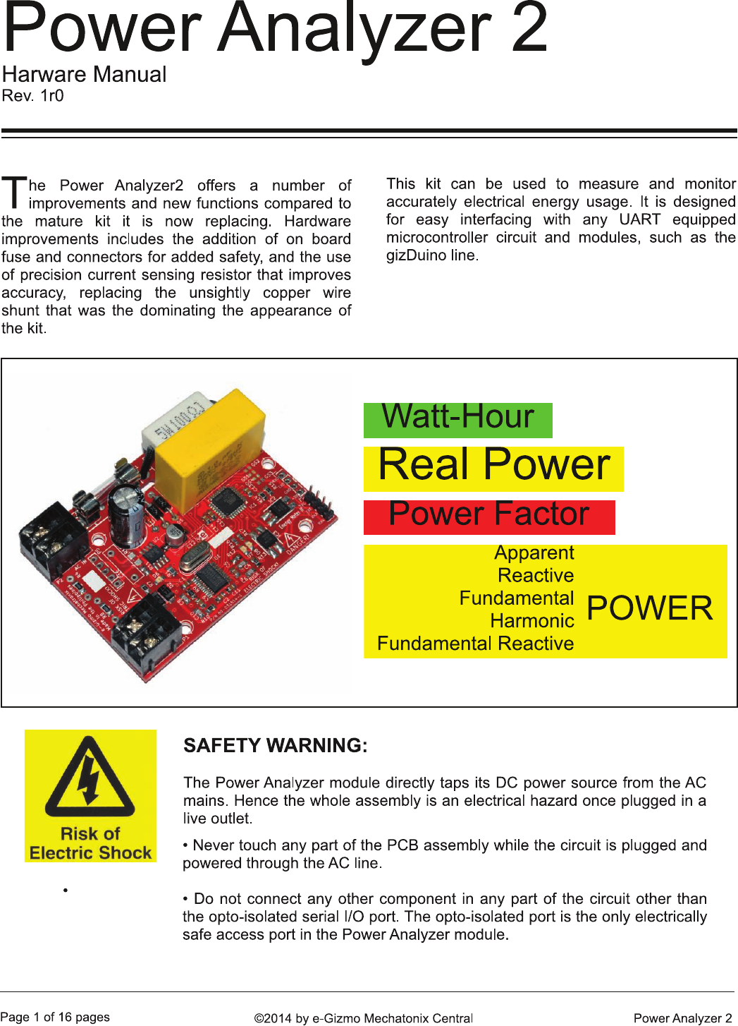
FEATURES:
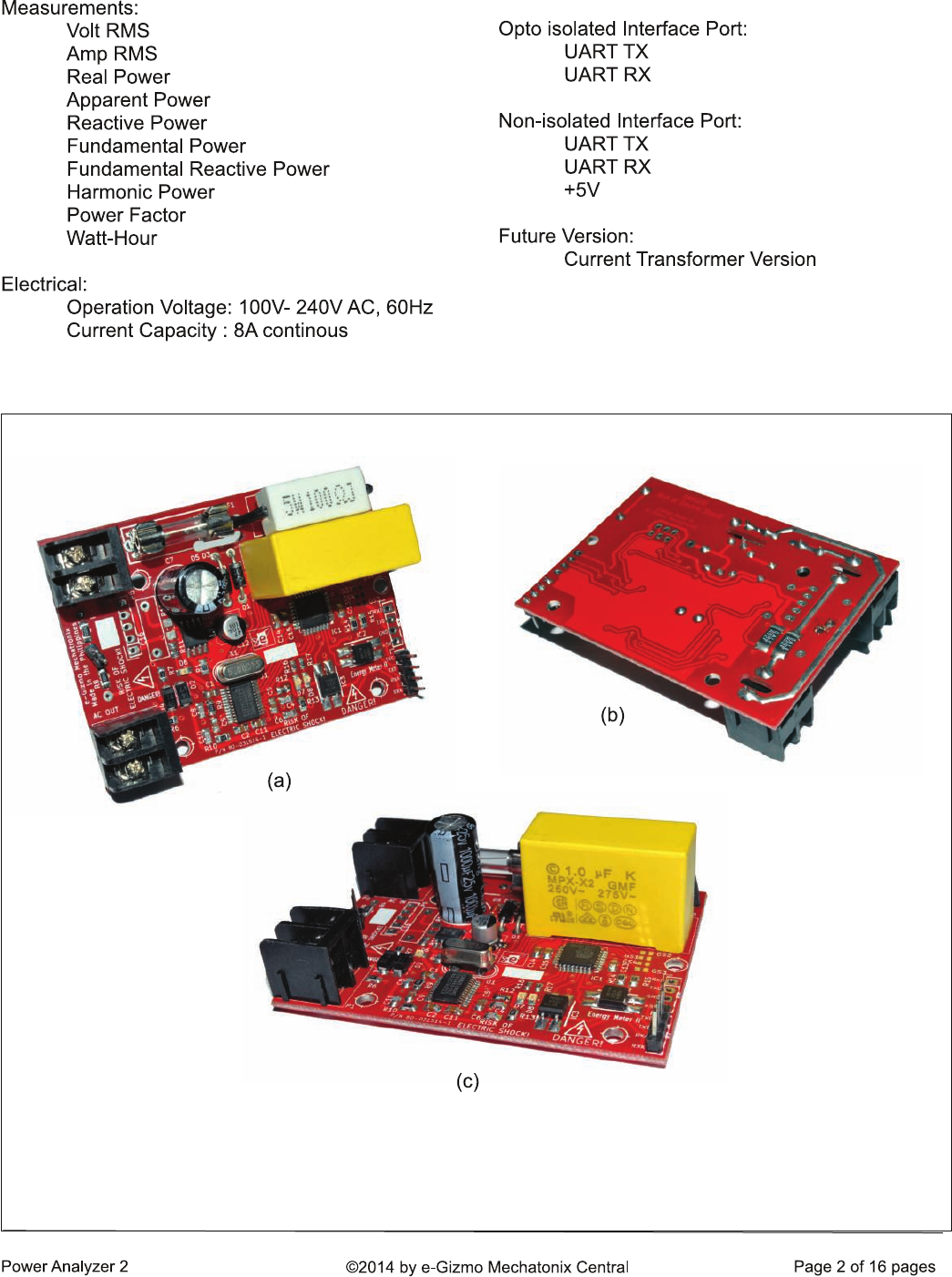
Figure 1. The AC Power Analyzer module. Notable improvements compared to its predecessor includes
(a) AC source side and load side terminals are now clearly separated and a 10A on board fuse is added.
(b) A pair of 1% SMD current shunt replaced the ugly copper coil shunt. As always, MPX-X2 safety
qualified AC capacitor is used for the critical capacitive AC voltage divider and power supply circuit.
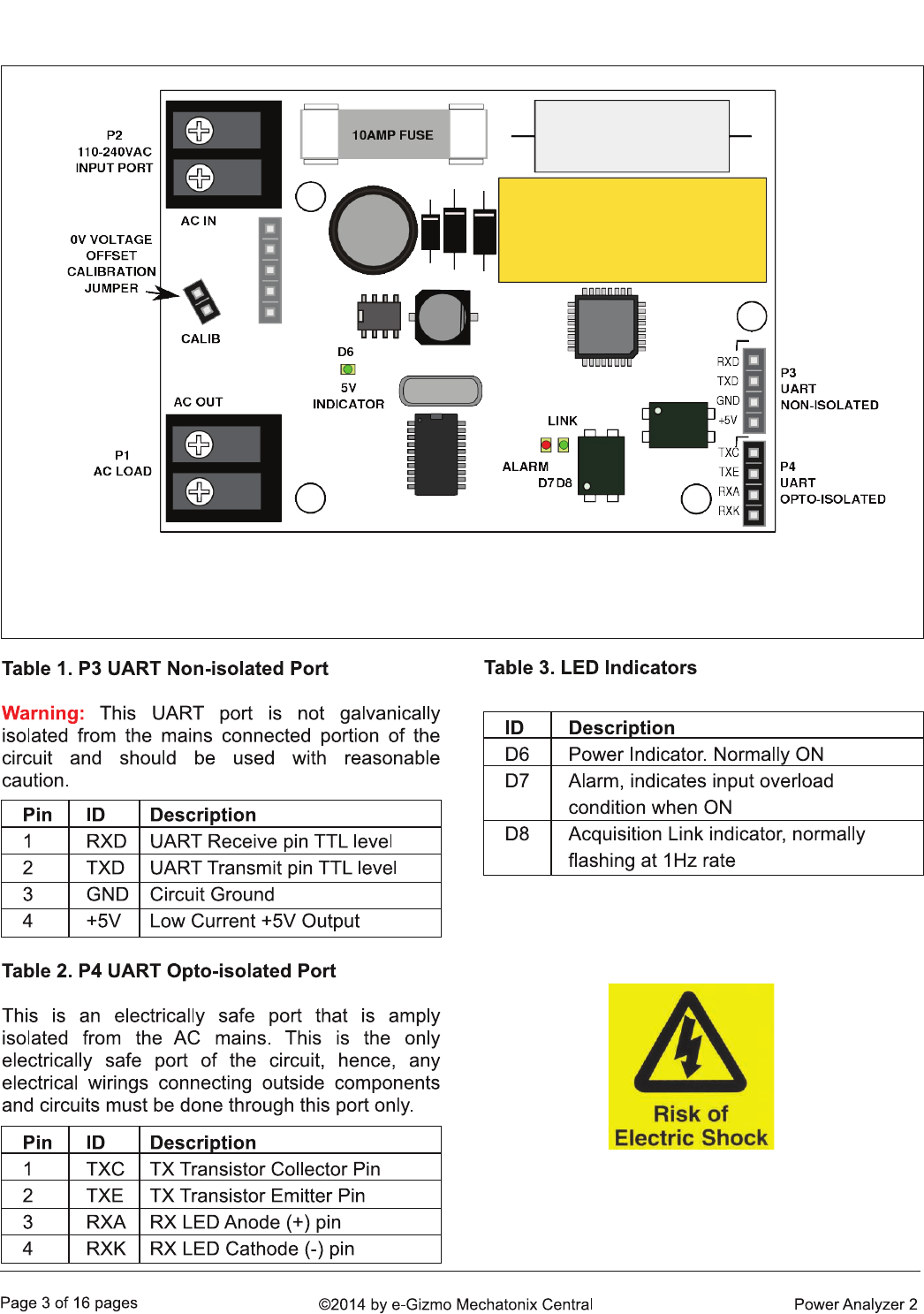
1. COMPONENTS LOCATOR GUIDE
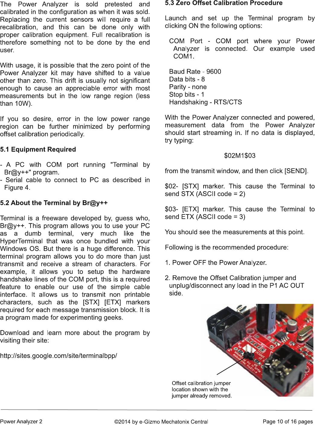
Figure 2. Location of connectors and major components. Note that under normal use, the 0V Voltage
Offset Calibration jumper must be installed. Once connected to AC, dangerous voltage appears to all
components in the circuit, except P4. P4 is the only port considered safe for connecting your circuits.
KEEPING IT SAFE
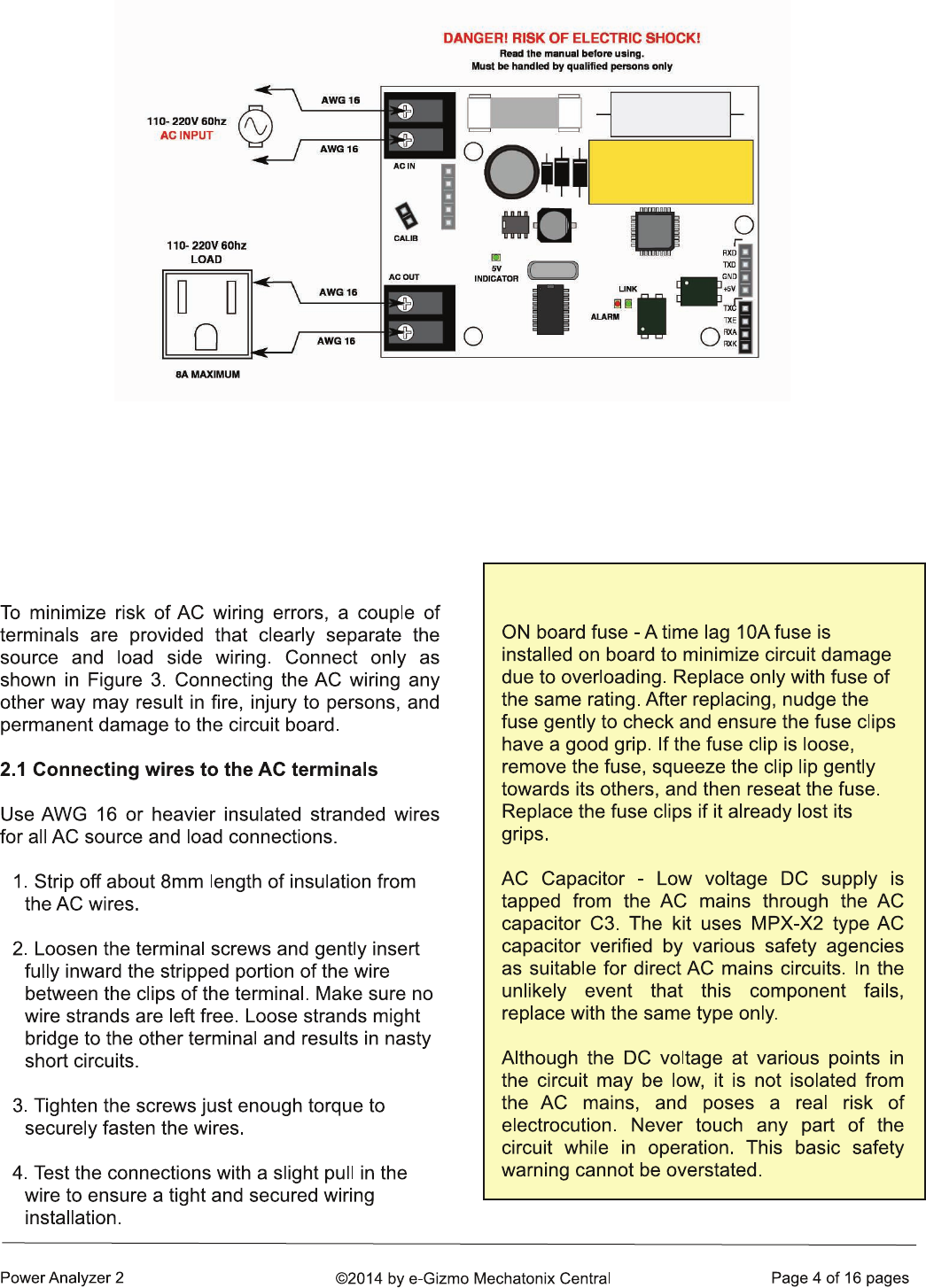
2. AC WIRINGS
Figure 3. AC source and load side wiring. Make sure all wires are securely fastened into their
correct connectors. Heavy AC power may pass through this circuit, any loose wiring will pose a
hazard.
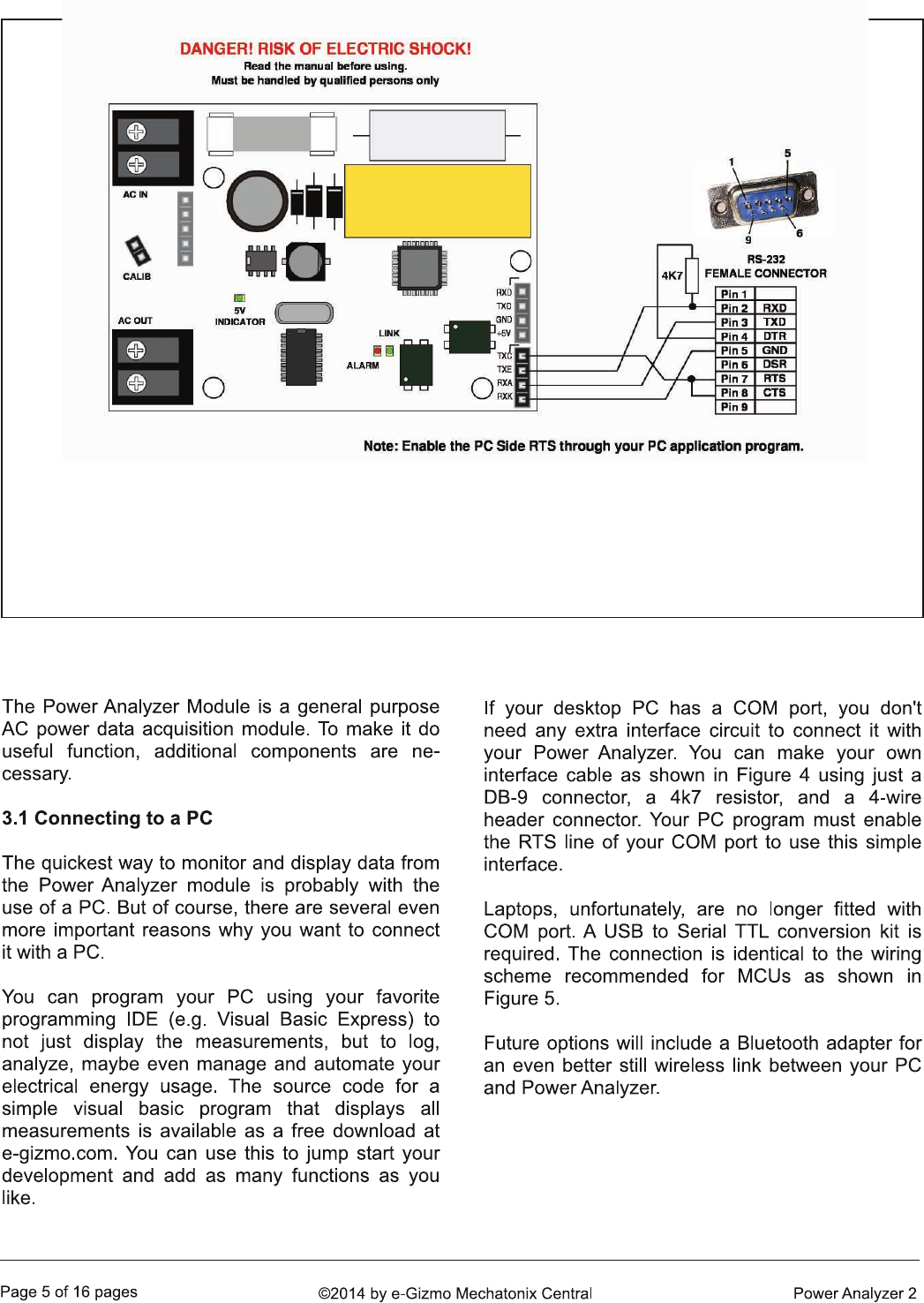
3. APPLICATION
Figure 4. Interface wiring to a PC RS-232 COM port is surprisingly simple. Measurements can be
displayed on a PC using terminal programs such as Terminal by Br@y++ (see section 5.2). If you can
write your own PC app, then, you can customize your own display and functions. A sample program
written in VB.net can be downloaded for free from the corresponding product page of this kit @ e-
gizmo.com.
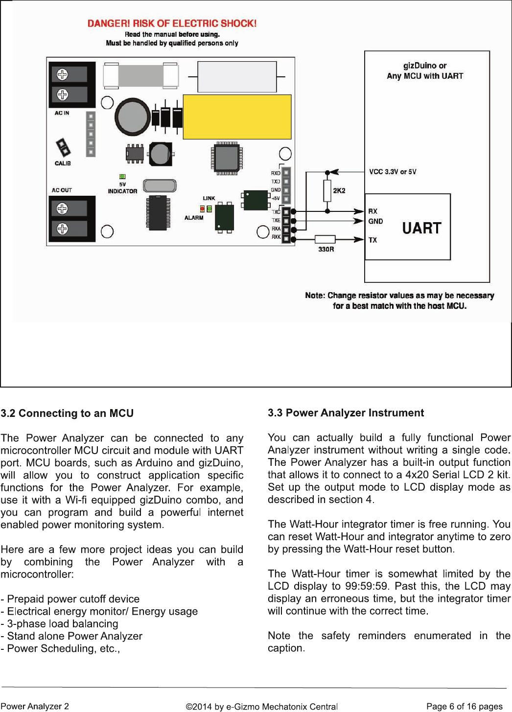
Figure 5. Interfacing the Power Analyzer with an MCU or gizDuino/Arduino controller. Any MCU equipped
with a UART may be used. Resistor values shown are for reference only, and may need to be changed
as the application circuit may so require.
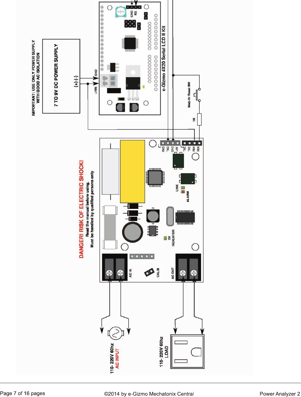
Figure 6. It is very easy to build an AC Power measuring instrument using the Power Analyzer kit. You only need to add a
4x20 Serial LCD2 kit as a display unit powered by a separate DC supply. A transformer type AC-DC adapter with good AC
isolation is recommended for the Serial LCD2 kit. Note that the Serial LCD2 is now connected to the non-isolated port, and
makes it an electrical hazard as well. Make sure everything is enclosed in an insulating case.
4. SERIAL OUTPUT MODES
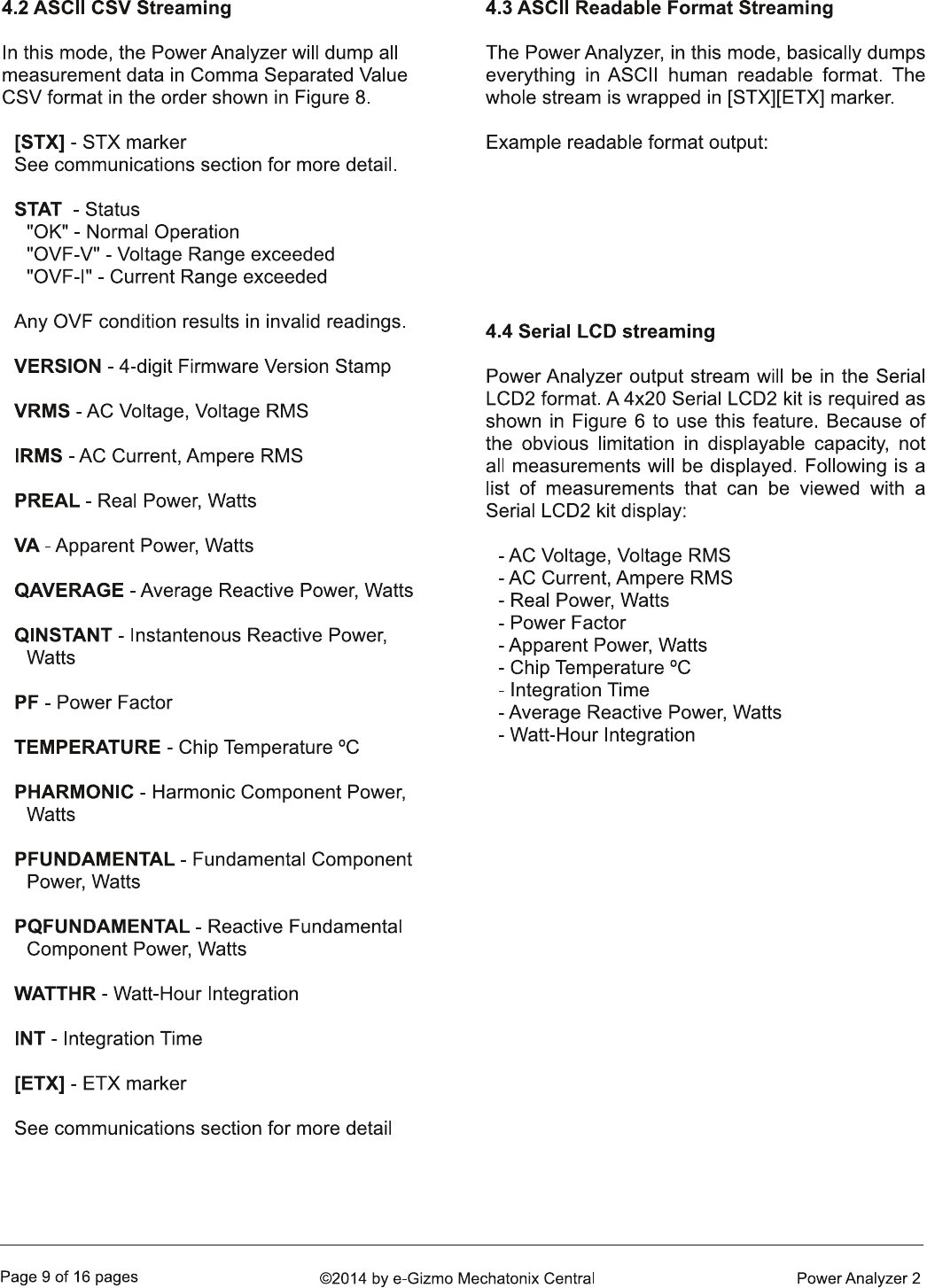
[STX]STAT,VERSION,VRMS,IRMS,PREAL,VA,QAVERAGE,QINSTANT,PF,TEMPERATURE,PHARMONIC,PFUNDAMENTAL,PQFUNDAMENTAL,WATTHR,INT[ETX]
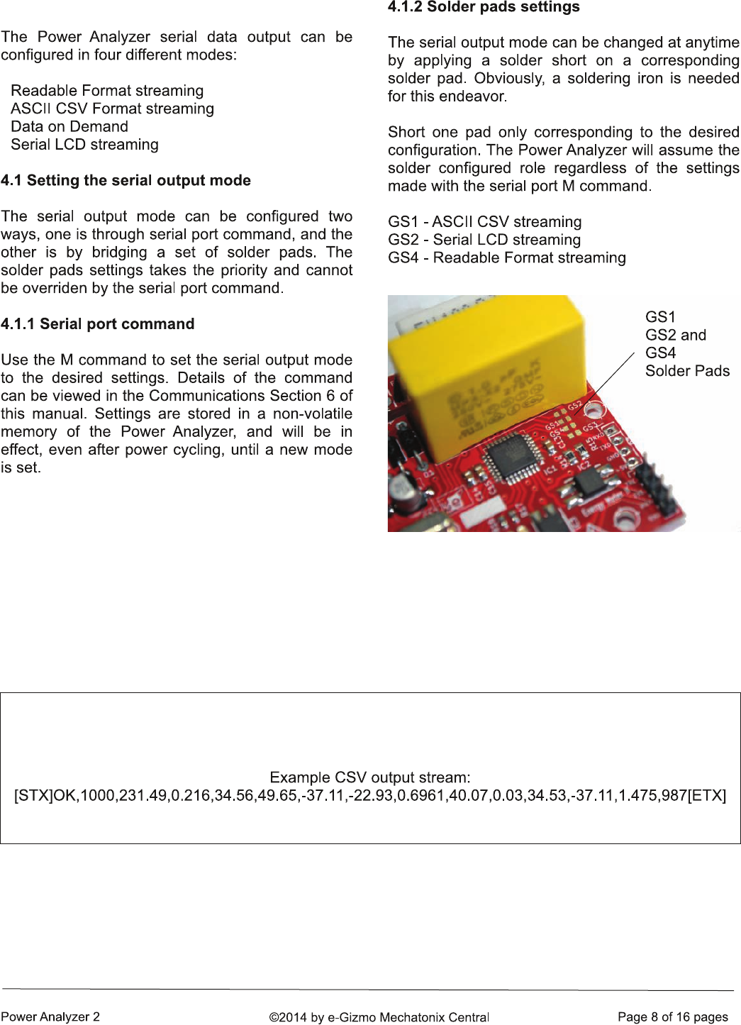
Figure 7. Solder pads locations. By applying a solder to
bridge a pair of pads (left to right), the serial output
mode can be set to a desired mode. Leaving these
pads unsoldered will allow the display mode to be set
using serial port command.
Figure 8. Comma Separated Value CSV transmission format. The third line displays an example CSV
stream. [STX] and [ETX] are non printable ASCII characters and may be displayed by the terminal
program using various symbols (e.g. a blank box character).
Volt RMS: 231.46 Amp RMS: 0.22 Real Power: 34.73
VA: 50.04 Q Power: -37.49 Q Instant: -17.76
PF: 0.6940 Temperature: 41.88
Harmonic: 0.03 Fundamental: 34.69 Fundamental Reactive: -37.49
Watt-Hour: 3.122
Integration Time: 0:23:46
5. OFFSET CALIBRATION
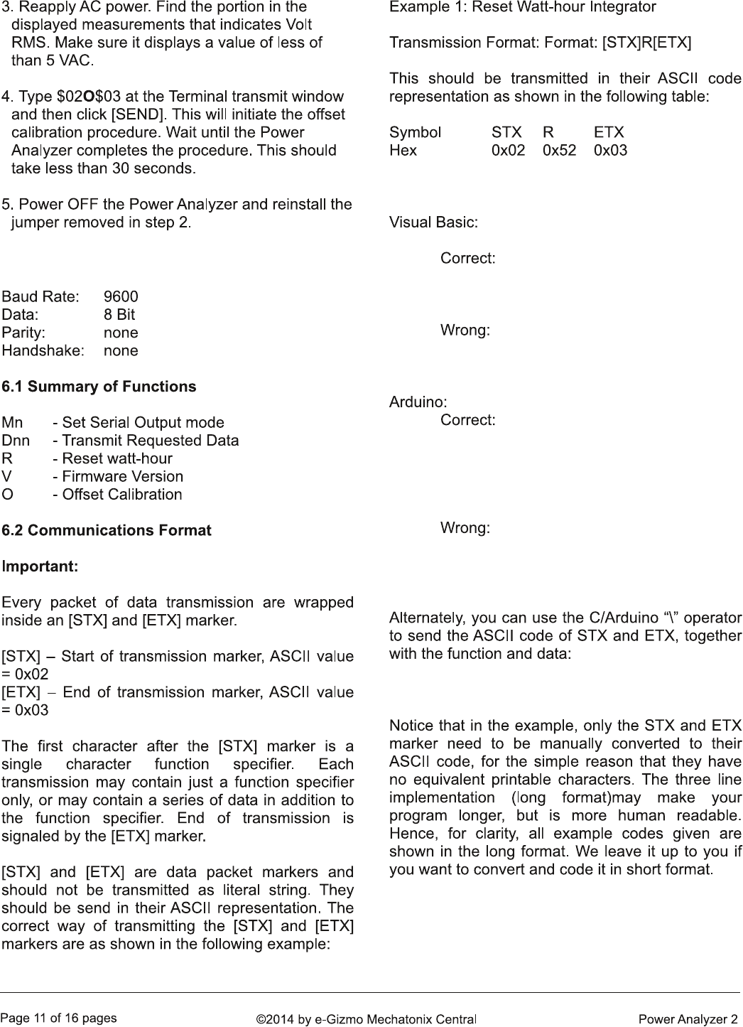
6. COMMUNICATIONS
‘ correct way to send [STX] & ETX marker
Serial1.print(chr(2)+”R”+chr(3))
Serial1.print(“[STX]R[ETX]”) ‘WRONG!
Serial.write(0x02); // correct way to send [STX]
Serial.print(“R”); // ASCII equivalent of ‘R’ 0x52
Serial.write(0x03); // [ETX] marker
Serial.print(“[STX]R[ETX]”); // WRONG!
Serial.print(“\002R\003”); //“\002”=STX, “\003”=ETX
Serial.write(0x02); //STX code
Serial.print(“D02”); //Transmit Real Power
Serial.write(0x03); //ETX code
0A -
0B -
0C -
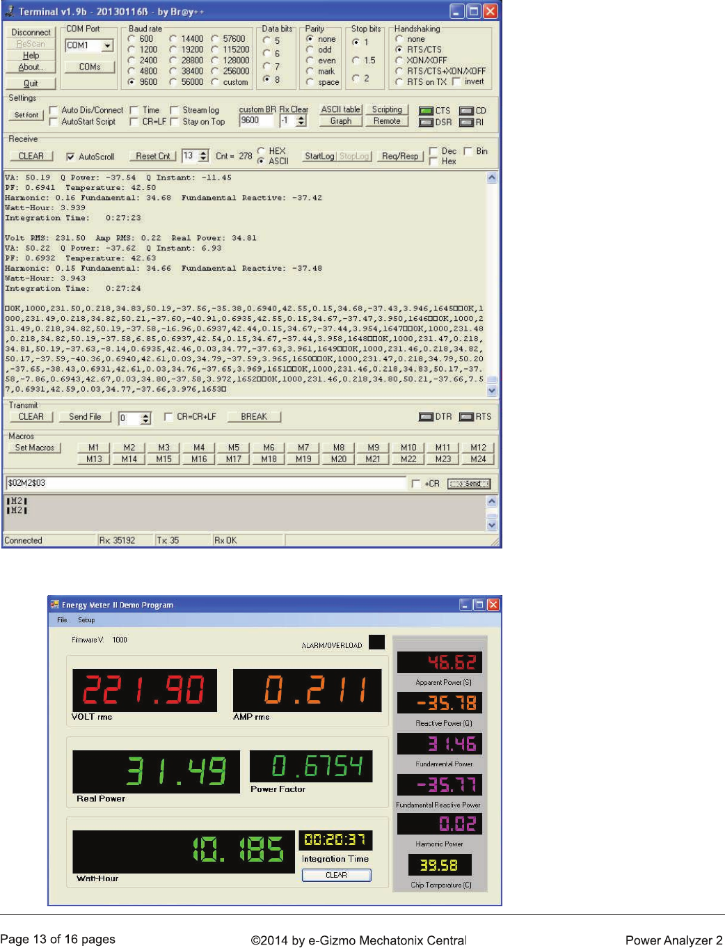
7. USEFUL INFORMATION
Figure 10. Screen capture
example of a Terminal program
session. Note the communi-
cation interface setup.
Figure 11. Visual Basic example
program showing all
measurements. If you can
develop your own PC app, then
you can customize your PC
functions and display in any
way you want.
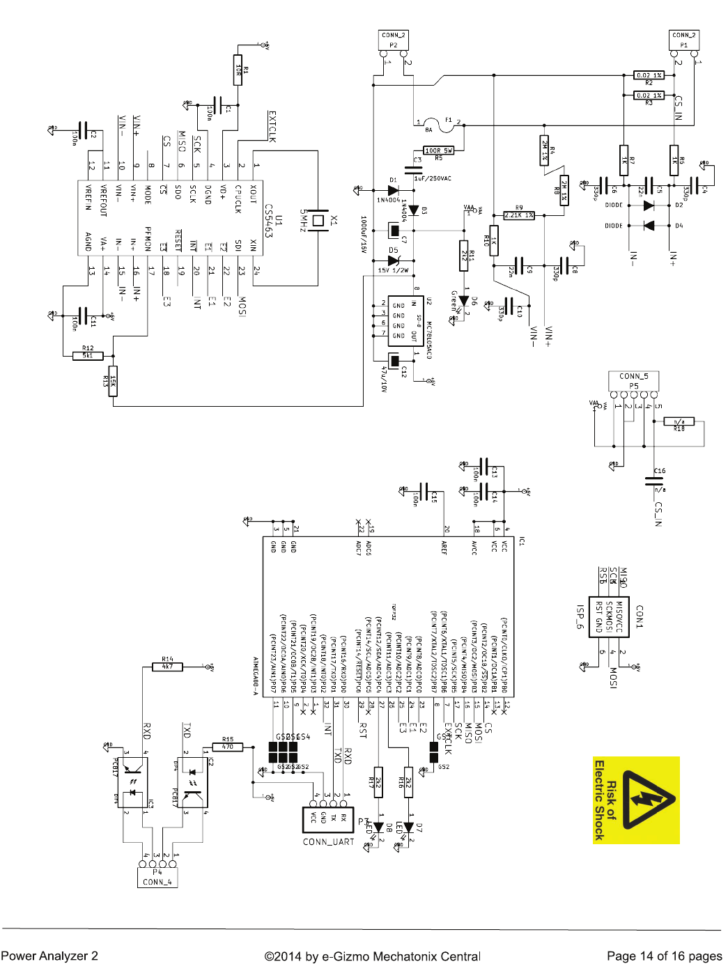
Figure 12. The Power Analyzer 2 complete schematic diagram. The
Power Analyzer uses the same CS5463 analyzer chip as before. The on
board MCU, on the other hand, uses a ATMEGA168, which made it
possible to pack in more functions and features.
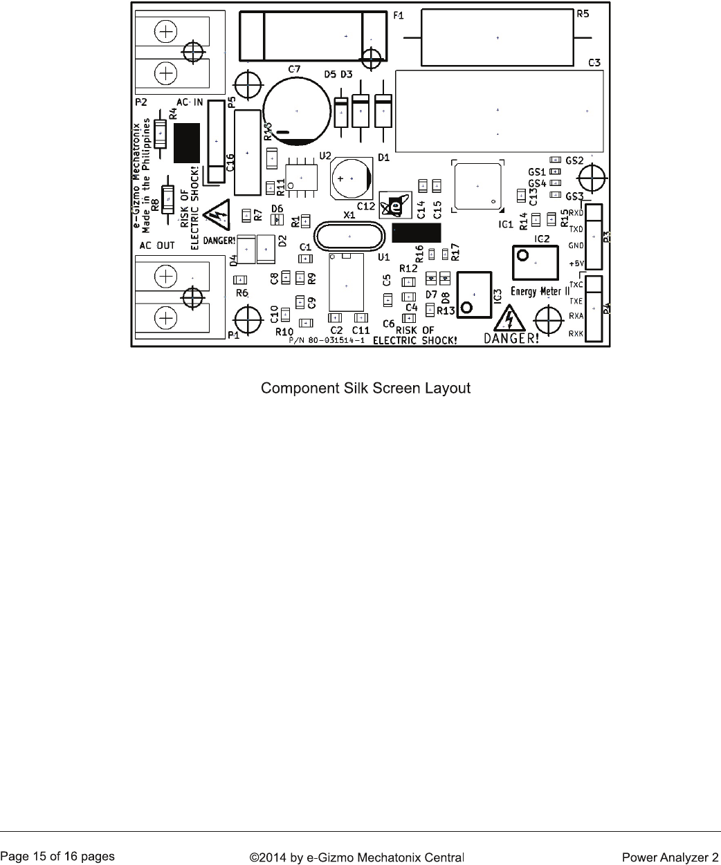
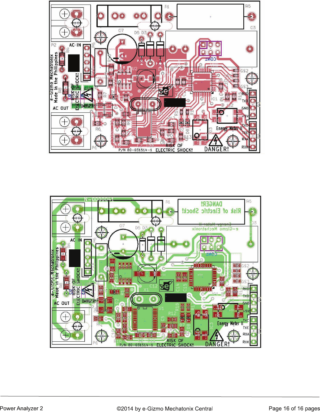
8. PCB ARTWORKS

ERROR: undefined
OFFENDING COMMAND: !eW6acVF7
STACK:
