Powers 535 Process Controller
User Manual: Powers-535-Process-Controller Igor's of metalworking and electrical manuals
Open the PDF directly: View PDF ![]() .
.
Page Count: 10
1 /4 DIN PROCESS CONTROLLER
Single Loop
Profile Controller (optional)
NEMA 4X Front Panel
PowerTune®
5 3 5
The Interface Solution Experts
www.miinet.com
5 3 5
The Interface Solution Experts
NOW A
PRODUCT!
PS535 V6 July 2003
DESCRIPTION
The 535 is a 1/4 DIN single loop process controller
(SLC) designed to control any analog process
variable (temperature, pressure, flow, level, etc.) in
batch and continuous processes. The 535’s outstand-
ing feature mix enables it to bring processes under
control faster, more accurately and easily than com-
petitive SLC’s, PLC, and PC based control systems.
The 535 is widely considered to be a best-in-class
instrument due to three fundamental strengths.
Four Field changeable output module
locations (mA, Relay, SSR, DC, Logic,
Loop Power)
Two Universal (U, mA, RTD, T/C)
PV inputs Option board I/O
• RSP
• 5 contact inputs
• Actuator Slideware
Optional RS 485
Communications
Module Socketed
PROM
10 year lithium battery
for memory retention
Rugged Construction
• NEMA 4x front panel
• Thick damage resistant keys
• EMI/RFI resistance
• Input/output isolation
Operator Interface
• 3 line vaccum flourescent display
• English prompts/messages
• Key color state indication
Tuning and Control Algorithms
• Powertune - Adaptive tuning
• Powertune - Pretuning
• Powertune - Powerback anti overshoot
• 8 stored PID sets
• Multiple output algorithms
Expanded information about these strengths is
detailed throughout this brochure.
Page 2 PS535 V6
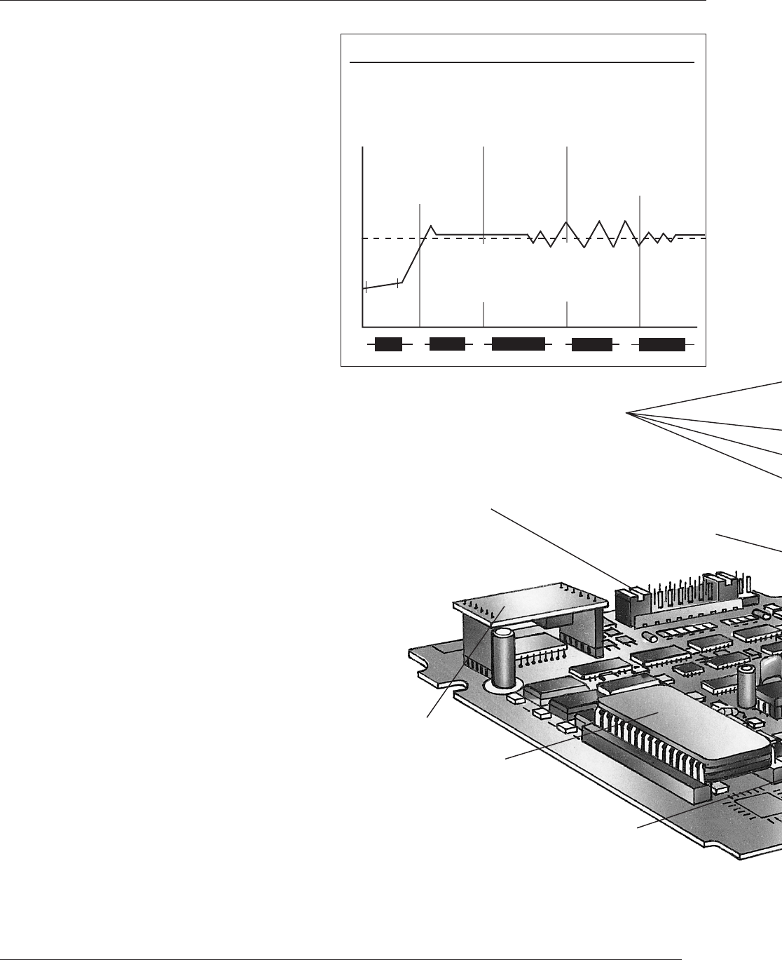
PowerTune® Powerback
reduces or eliminates SP
overshoot at power up or
after setpoint changes.
PowerTune® Functions
PowerTune® Pretune
gets process up and
running quickly and
accurately. Optimal
pretune performance
is achieved by
selecting a pretune
algorithm appropriate
for your process.
Pretune
➤
➤
Powerback
➤
➤
➤
Normal Opertion
➤
Load Chage
➤
➤
Adaptive Tune
➤
➤
PowerTune® Pretune automatically sets:
1) Initial PID parameters
2) Adaptive Tuning parameters
3) Powerback parameters
PowerTune® Adaptive
Tune modifies PID
parameters to
eliminate oscillation
or drift when load
changes occur.
Adaptive tune works
automatically without
disturbing the
process.
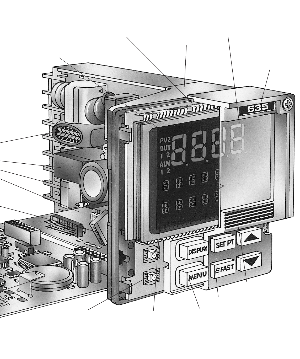
Compression gasket for
reliable NEMA 4X Seal Extra large mounting lip to
compensate for off size panel
cutouts
Recessed location for
engineering unit label
Extra large dedicated PV
indication is viewable from a
distance in all light conditions
Custom built vacuum florescent
display with two full alpha-numeric
lines and dedicated x-large
PV readout
Optically correct, high contrast/low
glare filter provides crisp reading even
in sunlight
Red under key LED provides clear state
indication (A/M, RSP) from a distance
Thick silicone rubber keys provide
excellent feel and damage resistance
Backlit keypad provides view ability in dark areas
Two nine character
alpha numeric displays
indicates prompts
in English
Recessed location for loop
tag information
FEATURE ILLUSTRATION
PS535 V6 Page 3
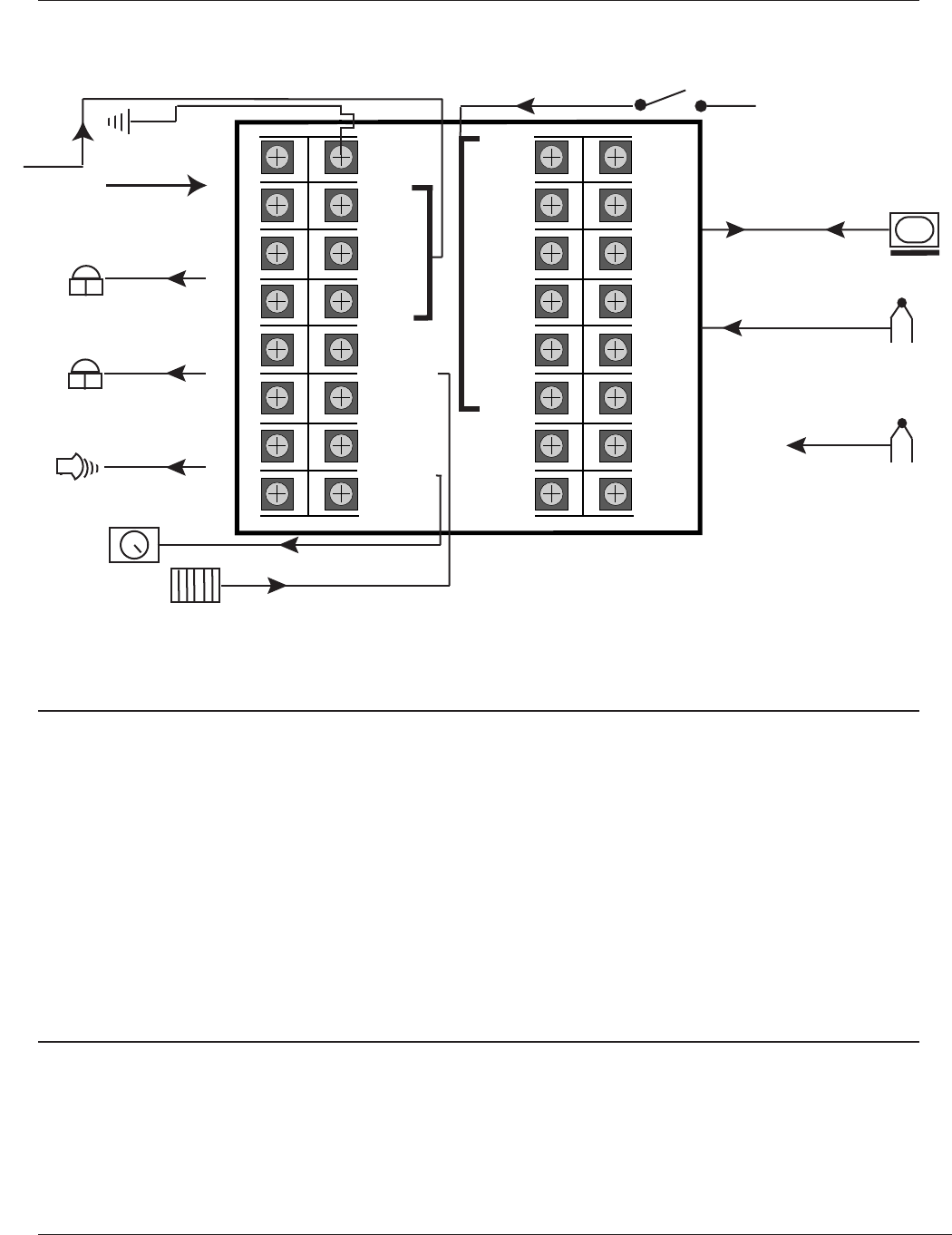
TOP (as viewed from back of controller)
1
2
3
4
5
6
7
816
15
14
13
12
11
10
917
18
19
20
21
22
23
24 32
31
30
29
28
27
26
25
LINE
NEUTRAL
OUT 1–
OUT 1+
OUT 2–
OUT 2+
OUT 3–
OUT 3+
EARTH
GND
S/W 1
S/W 2
S/W 3
OUT
4 –
OUT
4 +
DIN
GND
DIN 1
DIN 2
DIN 3
DIN 4
DIN 5
COLD
JUNC–
COLD
JUNC+
RTD 3RD
PV1–
PV1+
COMM–
COMM+
PV2–
PV2+
not
used
}
}
}
RS 485
UNIVERSAL PV INPUT 2
UNIVERSAL PV INPUT 1
CONTACT INPUTS
}
}
OUTPUT 4
REMOTE SET POINT INPUT
+
-
{
{
{
OUTPUT 3
XOUTPUT 2
OUTPUT 1
X
OPTIONAL
ACTUATOR
SLIDEWARE
FEEDBACK
{
90-250Vac
24Vac or dc
RSP–
RSP+
Input Functions
PV Input (Universal) RSP Input (Optional) Contact Inputs (Optional)
PV1 PV2 Switch on demand Range Activate RSP
PV1 PV2 Switch on PV1 failure Bias Trip to Manual
PV1 - PV2 Gain Lock in Manual mode
PV1 + PV2 Local SP Tracking Select Alternate SP (1-8)
Average of PV1, PV2 Select Alternate PID (1-8)
High Select Acknowledge Alarm
Low Select Inhibit Integral Control
Invert Control Action
Inhibit Adaptive Tuning
Emulate Front panel Keys
Digital Input for Data Acquisition
Output Functions
Outputs are plug-in modules.
Types include: Analog (mA), Mechanical Relay, Solid State Relay, DC Logic, and Loop Power.
Output 1 Output 2 Output 3 Output 4
Control Second Control Alarm Alarm
Alarm Retransmission Retransmission
Retransmission RS 485 Driver RS 485 Driver
RS 485 Driver Loop Power Loop Power
Page 4 PS535 V6

INPUT FUNCTIONS
PROCESS VARIABLE
Two universal inputs are available. Any input type may be field
selected via jumper. Dual inputs may be used to:
• Select input on demand
• Switch upon failure
• Derive a PV by subtracting (PV1 - PV2)
• Derive a PV by adding (PV1 + PV2)
• Derive a PV by averaging (PV1 + PV2)/2
• Select highest PV
• Select lowest PV
THERMOCOUPLES RANGE °F RANGE °C
B 104 to 3301 40 to 1816
E –454 to 1832 –270 to 1000
J –346 to 1832 –210 to 1000
K –418 to 2500 –250 to 1371
N –328 to 2372 –200 to 1300
R 32 to 3182 0 to 1750
S 32 to 3182 0 to 1750
T –328 to 752 –200 to 400
W 32 to 4172 0 to 2300
W5 32 to 4172 0 to 2300
Platinel II –148 to 2550 –100 to 1399
RTDs RANGE °F RANGE °C
100ohm Pt.(DIN) –328 to 1562 –200 to 850
–328.0 to 545.0 –200.0 to 285.0
100ohm Pt.(JIS) –328 to 1202 –200 to 650
–328.0 to 545.0 –200.0 to 285.0
100ohm Pt.(SAMA) –328 to 1202 –200 to 650
–328.0 to 545.0 –200.0 to 285.0
Transmitter Signals Input Range
Milliamps DC 4 to 20
0 to 20
Voltage DC 1 to 5
0 to 5
Millivolts DC 0 to 10
0 to 30
0 to 60
0 to 100
–25 to 25
ACCURACY
TYPICAL MAXIMUM
LINEAR(Voltage) ± 0.025% of full scale ± 0.100% of full scale
(Current) ± 0.050% of full scale ± 0.150% of full scale
RTD 1° ± 0.050% of span ± 0.150% of span
0.1° ± 0.095% of span ± 0.225% of span
THERMOCOUPLE
J, K, N, E (> 0°C) ± 0.060% of span ± 0.150% of span
J, K, N, E (< 0°C) ± 0.150% of span ± 0.375% of span
T (> 0°C) ± 0.100% of span ± 0.250% of span
T (< 0°C) ± 0.250% of span ± 0.625% of span
R, S (> 500°C) ± 0.150% of span ± 0.375% of span
R, S (< 500°C) ± 0.375% of span ± 0.925% of span
B (> 500°C) ± 0.150% of span ± 0.375% of span
B (< 500°C) ± 0.500% of span ± 1.000% of span
W, W5 & Platinel II ± 0.125% of span ± 0.325% of span
Display accuracy is ± 1 digit.
These accuracy specifications are at reference conditions
(25°C) and only apply for NIST ranges. Detailed accuracy
information is available upon request.
LINEARIZATION
Thermocouple and RTD inputs are automatically linearized.
Transmitter inputs may be linearized with a square root
function or user-defineable 15-point straight line linearization
function.
INPUT IMPEDANCE
Current Input: 250ohms Thermocouples: 10Mohms
Voltage Input: 1Mohm RTDs: 10Mohms
UPDATE RATE
Input is sampled and output updated 10 times per second.
Display is updated five times per second.
TRANSMITTER LOOP POWER
Isolated 24Vdc (nominal) loop power supply is available if a
loop power module is installed in an output socket not used for
control. Capacity is 25mA.
INPUT SIGNAL FAILURE PROTECTION
When input is lost, output is commanded to a predetermined
output (–5 to 105%). Thermocouple burnout is selectable for
upscale or downscale.
INPUT FILTER
Single pole lowpass digital filter with selectable time constant
from 0 to 120 seconds.
CALIBRATION
Comes fully calibrated from the factory and continuously
calibrates itself for component aging due to temperature and
time, except for the reference voltage. Field calibration can be
easily performed in the field with a precision multimeter and
thermocouple simulator. Process variable offset and gain
factors are provided to correct for sensor errors.
SETPOINT SELECTION
A remote setpoint input is available. Signal is 0–20/4–20mAdc
or 0–5/1–5Vdc (jumper selectable). Signal may be ratioed and
biased. Eight local setpoints may be stored in memory.
Setpoint selection is made via SET PT key or digital
contact(s).
DIGITAL INPUTS
A set of five external dry contacts or open collector transistor
driven inputs are available. Each can be configured to perform
one of the following functions:
• Select remote setpoint • Select either direct or reverse
• Select manual control control action
• Select second local setpoint • Addressable through serial
• Select a second set of PID values communications only
• Acknowledge alarms • Inhibit the reset term
• Simulate DISPLAY, FAST, and • Lock controller in manual
MENU keys mode
• Disable adaptive tuning
In addition, if the set of five digital inputs is installed, four may
be designated to select one of eight local setpoints (and
associated PID set, if desired ) via a binary coded decimal
(BCD) input.
PS535 V6 Page 5

OUTPUT FUNCTIONS
OUTPUT MODULES
The controller can have a total of four control outputs, alarm
outputs and/or loop power modules installed. There are five
types of output modules which can be configured to suit your
particular application. The modules may be ordered factory-
installed, or they may be installed in the field.
Analog module: Either 0-20mA or 4-20mA (front panel select-
able) into a load up to 1000ohms. Accuracy ±5 microamps@25°C.
Mechanical relay module: SPDT electromechanical relay. Resis-
tive load rated at 5 amps at 120/240Vac. Normally open or nor-
mally closed selection is made by jumper. Output 4 is rated at 0.5
amps at 24Vac and is always normally open.
Solid state relay (triac) module: Resistive load rated at 1 amp at
120/240Vac. Output 4 is rated at 0.5 amps at 24Vac. These out-
puts are normally open.
DC logic (SSR drive) module: “On” voltage is 17Vdc (nominal).
“OFF” voltage is less than 0.5Vdc. (Current limited to 40mA.)
Loop power supply module: Current is limited to 25mA@24V.
Control Outputs
Up to two output modules may be designated for control. Any
combination of output modules, with the exception of the loop
power supply module, may be used.
Duplex control is available if output modules are installed in
the first and second output sockets.
Position proportioning control with feedback is available if
mechanical or solid state relay modules are installed in the first
two output sockets, and the slidewire feedback option is
installed. Slidewire feedback range is 0 to 1050ohms.
"Velocity” position proportioning control is available by
installing mechanical or solid state relay modules in the first
two output sockets. A special time based algorithm controls an
electric actuator without the slideware feedback signal.
Staged (split range) outputs are available if analog modules
are installed in the first and second output sockets. This
algorithm will allow the output range to be split between the
two outputs.
CONTROL ALGORITHM
PID, P with manual reset, PI, PD with manual reset, and
On-Off are selectable from the front panel. Duplex outputs
each use the same algorithm, except On-Off may be used with
PID. The PID algorithm used is non-interacting.
TUNING PARAMETERS
Proportional Band: 0.1 to 999% of input range
Integral: 1 to 9999 seconds/repeat
Derivative: 0 to 600 seconds
Manual Reset/Load Line: 0 to 100% output
Cycle Time: 0.3 to 120 seconds
On-Off Deadband: up to 15% of input range (in eng. units)
Up to eight sets of PID values may be stored in memory and
selected automatically, based on setpoint value, process
variable value, or the corresponding local setpoint (SP1–SP8)
Retransmission Output
Based on available outputs (any socket not used for control),
up to two different variables can be simultaneously
programmed for retransmission. Each precise, 16-bit resolution
output may be scaled for any range. Variable selection
includes: PV, SP, RAMP, SP, and OUTPUT.
Transmitter Loop Power
Isolated 24Vdc (nominal) loop power supply is available if a
loop power module is installed in an output socket not used for
control. Capacity is 25mA. Two or four wire transmitters can be
powered.
ALARMS
The 535 controller has two software alarms. High and low
alarms may be sourced to:
• Process Variable High
• Process Variable Low
• Process Variable High & Low
• Deviation from S.P.
• Band around S.P.
• Rate of Change
• Manual Control Module
• Remote S.P.
• Control Output
If an alarm is tripped, the alarm message will show, the ACK
key will illuminate (if acknowledgeable) and the ALM icon will
light. If the alarm is tied to the first available non-control output,
the “1” below the ALM icon will light. Similarly, if the alarm is
tied to the second non-control output, the “2” below the ALM
will light. The availabilty of outputs determines how many
alarms can be tied to relays.
Up to two alarm outputs are available if an associated
mechanical, solid state relay or DC logic module is installed in
any output socket not used for control.
Global Alarm feature allows one or more of the internal
software alarms to be tied to the same single, physical output.
The acknowledge key is active for alarms associated with
either loop.
Page 6 PS535 V6
Ramping SP can automatically select alternate PID sets
Up to three relay type events to outputs are available for equipment sequencing
Special Profile I/O
Last segment event can
stay energized after profile
is completed
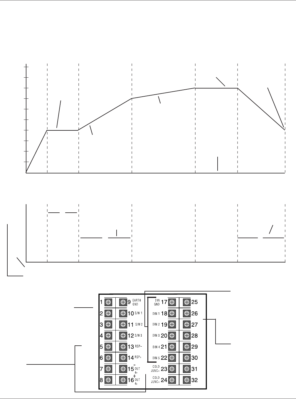
PROFILE CONTROL OPTION
The 535 Profile Controller’s unique operator interface makes it
simple to set up and operate while retaining powerful profile
functions detailed below. The 535 can store 20 recipes, with a
sample shown below. Recipes are selectable via front panel,
contact inputs, or serial communications. Recipes may be
linked to create extra-long recipes.
:20 :40 1:00 1:20 1:40 2:00 2:20 2:40 3:00 3:20 3:40 4:00
Guaranteed soak
function insures
soak set point
has been
achieved before
soak segment
starts
•
••
•
••
•
Changes in ramp or
soak segment possible
while profile is running.
Segment can be
skipped while running.
Ramps and soaks can
be time or rate based
Time base can be
hrs:min or min:sec
Recipes may be
linked or repeated
99 times
Ramp 1 Soak 1 Ramp 2 Ramp 3 Soak 3 Ramp 4
Event 1
Event 2
Event 3
PID Set
12 2223
on
Events can be
used in ramp or
soak segments
Power Restoration Modes:
1) RESUME recipe where it left off
2) HOLD at last SP prior to power loss
3) ABORT recipe
4) RESTART recipe
Outputs 2-4
• Event outputs
• SP retransmission to slave controller
• Alarm output
• Second Control output
Contact Inputs:
• Start Recipe
• Hold Recipe
• Reset Recipe
• Skip to next segment
• Abort Recipe
• Recipe 1-7 selection
RS 485:
All profile configuration and
operation are accessible
through serial communication
{
{
}
on
on
Set Point
Time
Segment
PS535 V6 Page 7
200
180
160
140
120
100
80
60
40
20
➤
➤
➤
➤
➤
➤
➤
➤
➤
➤
➤
➤
➤
➤
{
{
Line
Power
Out
1
Out
2
Out
3
Out 4
Maximum 12 ramps
and 12 soaks per
recipe
{

GENERAL SPECIFICATIONS
CONTROLLER ARCHITECTURE
The 535 Controller hardware can be configured as follows:
Inputs: Two univeral process variable inputs are standard.
Available options include: remote setpoint, slidewire feedback
and 5 digital inputs.
Outputs: Four outputs are available. See Ordering Information.
RS-485 Communications: Available as option with any
configuration.
SERIAL COMMUNICATIONS
Isolated serial communications is available using an RS-485
interface. Baud rates of up to 19,600 are selectable. The
protocol supports CRC data checking. If communications are
lost, a time-out feature will command the controller to a par-
ticular control mode and specific setpoint or output if desired.
Outputs 2-4 and digital inputs can act as “host-controlled” I/O
independent of the controller’s function. The PV may be
sourced via this interface. May be installed in the field.
DIGITAL DISPLAYS
Upper display: five-digit, seven-segment. Used exclusively for
displaying the process variable value. Height is 15mm (0.6 in.).
2nd display: nine-character, 14-segment alphanumeric. Used
for displaying setpoint, deviation, output value, slidewire
position (actual valve position) and configuration information.
Height is 6mm (0.25 in.).
3rd display: nine-character, 14-segment alphanumeric. Used
for indicating which loop is displayed and for displaying alarm
messages and configuration information. Height is 6mm
(0.25 in.).
All displays are vacuum fluorescent. Color is blue-green.
STATUS INDICATORS
There are two types of indicators: icons and illuminated keys.
ALM 1 and ALM 2 icons: alarm 1 and alarm 2 status.
OUT 1 and OUT 2 icons: control output 1 and control output
2 status.
MAN key illuminated: controller is in manual control mode.
ACK key illuminated: alarm may be acknowledged.
SET PT key illuminated: setpoint other than primary local
setpoint is active.
MENU key illuminated: controller is in configuration mode.
MOUNTING
Panel-mounted.
WIRING CONNECTIONS
29 screw terminals in the rear of the instrument.
POWER CONSUMPTION
15VA at 120Vac, 60Hz (typical).
WEIGHT
Approximately 1 kg (2.2 lbs.).
AMBIENT TEMPERATURE
Operative Limits: 0 to 50°C (32 to 122°F).
Storage Limits: –40 to 70°C (–40 to 158°F).
RELATIVE HUMIDITY
10 to 90%, non-condensing.
VOLTAGE AND FREQUENCY
Universal power supply: 90 to 250Vac, 48 to 62Hz. 24V
(AC or DC power optional).
NOISE IMMUNITY
Common mode rejection (process input): >120 dB.
Normal mode rejection (process input): >80 dB.
AC line is double filtered and transient protected. Snubbers are
provided for each relay output.
ISOLATION
Inputs and outputs are grouped into the following blocks:
Block 1: process variable
Block 2: outputs 1, 2, and 4
Block 3: communications, set of five digital
inputs, output 3 (Earth Ground)
Block 4: remote setpoint
Each block is electrically isolated from the other blocks to
withstand a HIPOT potential of 500Vac for 1 minute or 600Vac
for 1 second, with the exception of blocks 1 and 4, which are
isolated to withstand a HIPOT potential of 50 volts peak
for 1 minute between each other. Inputs and outputs are not
isolated from other inputs and outputs within the same block.
CONSTRUCTION
Case: flame resistant ABS
Chassis assembly: plug-in type.
Keys: silicone rubber with diffusion printed graphics.
NEMA rating: front panel conforms to NEMA 4X when
instrument is properly installed.
AGENCY APPROVALS
MEMORY RETENTION
Lithium battery maintains all programming for approximately
ten years.
Page 8 PS535 V6
LISTED
4N66
Process Control Equipment
LR 84063 (Heavy Industrial)
(Available as an option)

SECURITY
There are two levels of access: restricted and full. A
configurable code is used to enter the full access level. Func-
tions not available in the restricted level are configurable. Six
different groups of parameters can be restricted.
PROFILE CONTROLLER OPTION
When a 535 is specified as a profile controller, the SET PT
(setpoint key) is replaced at the factory with a RUN key to fa-
cilitate operation. Setpoint access is available through use of
the DISPLAY key. All functions are described in the manual
supplement. The 535 with profile option, provides full ramp and
soak capability with the following features:
20 RECIPES/PROGRAMS
Up to 20 recipes/programs may be stored in memory and recalled
by number through the front panel keys, digital inputs or RS-485
Communications.
24 SEGMENTS PER RECIPE
12 ramps and 12 dwells may be programmed for each recipe.
Programming a dwell time of OFF effectively skips the dwell allow-
ing 2 consecutive ramps of different rates. Recipes may be linked if
more than 24 segments are necessary.
GUARANTEED SOAK WITH ADJUSTABLE HYSTERESIS
When activated, dwell time doesn’t start until the ramp setpoint
has been achieved within the specified hysteresis (a positive or
negative deviation from the dwell setpoint).
3 EVENT OUTPUT CAPABILITY
Up to 3 event outputs, programmable per segment, may be
selected depending on the availability of controller outputs. The
535 has 4 outputs. If 1 is used for control, 3 are available for
events. Likewise, if 1 is for control and 1 for an alarm, 2 are
available for events. These outputs are available to turn on fans,
start another process and perform other functions.
RAMPS PROGRAM IN TIME OR RATE
A ramp can be programmed to take place over a specific amount
of time or be based on the rate of change of the PV per hour. If
time based, the time to reach setpoint must be between 0:01 and
99:59 (hours:minutes). If rate based, the setpoint must be reached
at a rate between –9999 and 9999 engineering units per hour.
DUAL TIME BASE
Two modes are available, Hours:Minutes or Minutes:Seconds
MULTIPLE CYCLES, 1–99 PER EACH RECIPE
Recipes may be programmed to automatically repeat up to 99
times.
RECIPE LINKING
All 20 recipes may be linked to form a new longer version.
For example, select recipe 4 to automatically follow recipe 2.
REMOTE FUNCTIONS VIA DIGITAL INPUT
Using the optional digital inputs, the following functions may be re-
motely activated: Start, Hold, Reset, Abort and Segment advance.
MODIFY RECIPES WHILE RUNNING
Individual recipes may be modified by the operator while running.
REMOTE RECIPE CHOICE VIA DIGITAL INPUT
Using the optional digital inputs, recipes 1-7 may be selected
remotely.
POWER RESTORATION MODES
Four different power restoration modes are available. Upon power
failure and subsequent return, the controller can either: 1) Resume
a recipe where it left off 2) Return to the last output of the recipe
and hold it 3) Abort the recipe 4) Start a new recipe automatically.
TIE PID SETS TO RECIPES OR SEGMENTS
Any one of eight PID sets may be tied to each recipe or segment
to optimize control.
MASTER/SLAVE CAPABILITY
The 535 with profile controller option can retransmit the ramping
setpoint to up to four 535s with remote setpoint creating a master/
slave relationship. With this capability, 5 loops, each running the
same recipe, can be controlled.
SEGMENT ADVANCE
The operator may advance through the program segments
while a recipe is running.
MOUNTING AND DIMENSIONS
PS535 V6 Page 9
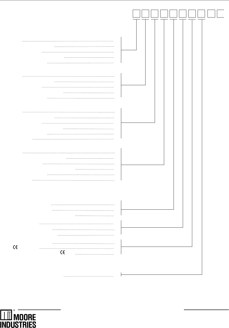
Order
Output 1: Control Code
None 0
Mechanical Relay (5 amp) 1
Analog (milliamp) 2
Solid State Relay (triac) (1 amp) 3
DC Logic (SSR drive) 4
Output 2: Control, Alarm, or Retransmission
None 0
Mechanical Relay (5 amp) 1
Analog (milliamp) 2
Solid State Relay (triac) (1 amp) 3
DC Logic (SSR drive) 4
Output 3: Control, Alarm, Retransmission, or Loop Power
None 0
Mechanical Relay (5 amp) 1
Analog (milliamp) 2
Solid State Relay (triac) (1 amp) 3
DC Logic (SSR drive) 4
Loop Power 5
Output 4: Alarm, Retransmission, or Loop Power
None 0
Mechanical Relay (0.5 amp, 24V) 1
Analog (milliamp) 2
Solid State Relay (triac) (0.5 amp, 24V) 3
DC Logic (SSR drive) 4
Loop Power 5
Options
Enter “0” if not desired
Slidewire Feedback for Position
Proportioning Output A
24 (AC or DC) Operation F
Slidewire and 24 (AC or DC) )Operation G
Remote Setpoint B
Profile Controller Option C
Remote Setpoint and Profile E
Set of Five Digital Inputs D
Certification H
Five Digital Inputs and Certification J
Serial Communications
Enter “0” if not desired
RS-485 Serial Communications S
0535 – 0
Note 1: Capability for position proportioning output is specified by ordering 535-11xxAxxx00, 535-33xxAxxx00, or 535-44xxAxxx00. Note 2: Capabil-
ity for velocity proportioning output is specified by ordering 535-11xxxxxx00, 535-33xxxxxx00, or 535-44xxxxxx00. Note 3: Up to two outputs may be
used for alarms. Note 4: All outputs are interchangeable modules. Note 5: The mechanical relay and solid state relay modules are derated to 0.5
amp at 24Vac when used as the fourth output.
The Interface Solution Experts
• www.miinet.com
United States • info@miinet.com
Tel: (818) 894-7111 • FAX: (818) 891-2816
Australia • sales@mooreind.com.au
Tel: (02) 8536-7200 • FAX: (02) 9525-7296
Belgium • info@mooreind.be
Tel: 03/448.10.18 • FAX: 03/440.17.97
The Netherlands • sales@mooreind.nl
Tel: (0)344-617971 • FAX: (0)344-615920
China • sales@mooreind.sh.cn
Tel: 86-21-62481120 • FAX: 86-21-62490635
United Kingdom • sales@mooreind.com
Tel: 01293 514488 • FAX: 01293 536852
Specifications and information subject to change without notice. Printed in U.S.A.
