20818c_Joule GPS Full User GuideCS5 Powertap Joule Manual
User Manual: Powertap Joule GPS User Manual
Open the PDF directly: View PDF ![]() .
.
Page Count: 53
CycleOps Joule™ GPS
User Guide
Joule GPS is compatible with any ANT+TM
compatible power meter, speed sensor,
cadence sensor, or heart rate sensor.
INT
WATTS
451 160
21 96
1:06:45
HR
MPH CAD
170 894
AV WATTS MX WATTS
RIDE TIME KJ
9:34
A
71º
380
Joule GPS User Guide page 2
© 2012 Saris Cycling Group, Inc.
5253 Verona Road
Madison, WI 53711
All rights reserved. No part of this publication may be copied, photographed, reproduced, translated,
transmitted electronically or placed on digital media without the prior written consent of Saris Cycling
Group, Inc.
Trademarks
Saris Cycling Group, Inc.,CycleOps, and CycleOps logo, are all registered trademarks of Saris Cycling Group, Inc.
All other product, brand, or trade names used in this manual may be trademarks or registered trademarks of
their respective owners.
Modifications
Saris Cycling Group, Inc reserves the right to make improvements and/or updates to the products
described herein at any time without notice.
Connect your Joule with ANT+ heart rate monitors or bike sensors. For a complete listing of ANT+ certified
products and their specific interoperability, visit the ANT+ product directory.
http://www.thisisant.com/modules/mod_product-directory.php
This device complies with part 15 of FCC Rules and Rss-210 of IC Rules. Operation is subjected to the following two conditions:
(1) This device may not cause harmful interference, and (2) This device must accept any interference received, including
interference that may cause undesired operation. The manufacturer is not responsible for any radio or tv interference caused
by unauthorized modifications to this equipment. Such modifications could void the user authority to operate the equipment.

CHAPTER
6. TRAINING 25
Workouts
Auto Interval
Countdown
7. DEVICE 30
Date & Time
Display
Memory
Altimeter
About
8. DATA & DOWNLOADS 35
Download
PowerAgent
9. FAQ & TROUBLESHOOTING 35
10. PRECAUTIONS 36
11. FEATURES LIST 37
TECHNICAL SPECIFICATIONS 38
12. WARRANTY 39
Appendix A, History Report Definitions 40
Appendix B, Error messages 46
Appendix C, Metrics 49
Appendix D, GPS Signals 51
TABLE OF CONTENTS
Joule GPS User Guide page 3
CHAPTER
1. STARTING OUT 4
Unpacking
Compatibility
Installation
Charging
2. OVERVIEW & SETUP 7
Dashboards
Main Menu
User
Sensor and Pairing
Buttons and Screen
3. DASHBOARDS 11
Dashboard 1,2,3: Metrics
Dashboard 4: Intervals
Dashboard 5: GPS Map
4. NAVIGATION 16
Navigation Overview
Waypoints
Routes
GPS Status
Compass
5. HISTORY REPORTS 23
Overview
Reports

Joule GPS User Guide page 4
Thank you for purchasing the CycleOps Joule GPS. This user guide is just one of the resources to help
you understand all the features the Joule GPS has to offer.
Please visit www.cycleops.com to:
• Learn more about the Joule GPS and the CycleOps system of products including stationary trainers,
indoor cycles, software and power meters
• Register all CycleOps products and activate warranty
• View instructional videos
• Sign up for the CycleOps Power newsletter-your source for the latest news and technical updates from
CycleOps Power
PACKAGE CONTENTS:
PART QTY
Joule GPS computer 1
Heart rate strap (select models) 1
Stem/Handlebar mount 1
Front mount 1
Mount o-rings (2 sm, 2 lg) 4
Micro USB cable 1
CHAPTER 1: STARTING OUT
UNPACKING JOULE GPS
Joule GPS is compatible with any ANT+
power meter, heart rate sensor, cadence
sensor, speed sensor, or combination
speed/cadence sensor.
COMPATIBILITY
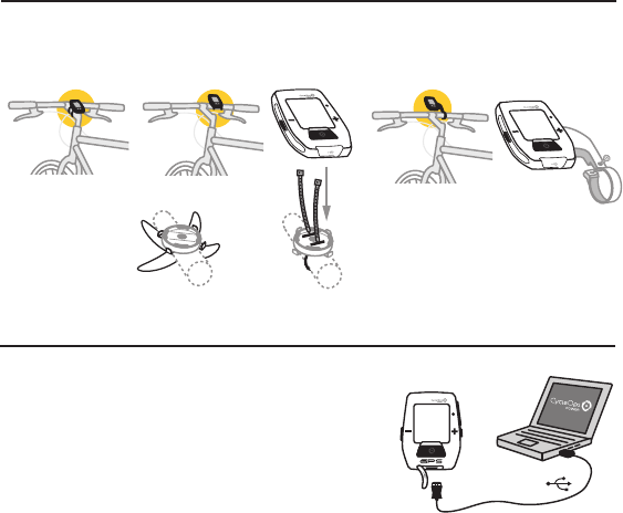
CHARGING
The Joule GPS is powered by energy from a rechargeable battery.
To charge the battery, plug into a computer or AC wall adapter
(#7060 not included). Typical battery charge lasts approximately
20 hours of operation.
Should the battery become completely discharged (no partial
charge remaining), plug the Joule GPS into a computer or AC wall
adapter, press the reset button on the back panel of the Joule
GPS, and the charging process should begin.
Joule GPS User Guide page 5
Micro-USB
USB
INT
INSTALLATION
Installing the CycleOps Joule GPS
OUT-FRONT MOUNT
INT
INT
O-Rings: Crisscross under
stem/handlebar, latch on hooks OR Zip tie around stem,
through slots
STEM/HANDLEBAR MOUNT
INT
INT
CHAPTER 1: STARTING OUT
INT
Main Menu
Ride
History
Sensors
Training
Navigation
User
Device
Back to Dashboard
9:34A71º
[ENTER]
Press & Hold 3 sec.
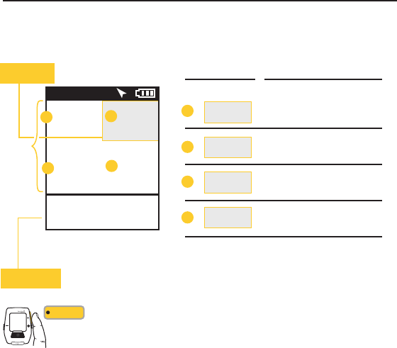
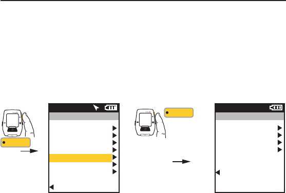
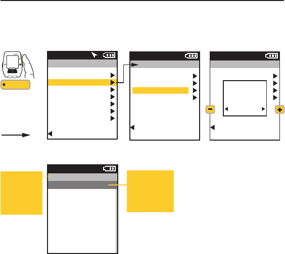
CHAPTER 2: JOULE GPS OVERVIEW & SETUP
DASHBOARDS
When the Joule GPS is turned on you are presented with one of 5 Dashboard screens (3 dashboards
displaying various Metrics, 1 dashboard displaying completed intervals, and 1 dashboard displaying the
GPS map). Pressing the Enter button allows you to scroll through all of the Dashboard screens. Dashboard
1, by default, is initially set to display 6 metric windows in the configurable area. Other screens can appear
between the Dashboards and the GPS Map, depending on what features you are using (e.g. Training and
Workouts, Navigating to a Waypoint, Following a Route, etc...).
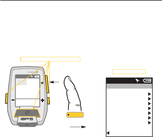
• To view the Main Menu from any Dashboard, press and hold the ENTER button for 3 seconds.
• To return to the Dashboard from any Menu press and hold the ENTER button for 3 seconds.
Press any of the 4 buttons to turn the unit on
WATTS
--- ---
--- ---
0:00:00
HR
MPH CAD
0.0 0.0
AV WATTS MX WATTS
RIDE TIME KJ
9:34
A
71º
0
INT
Displays the Main Menu
Joule GPS User Guide page 6
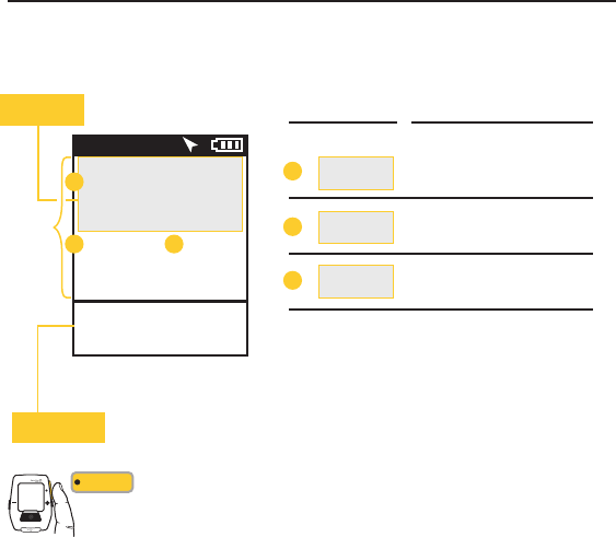
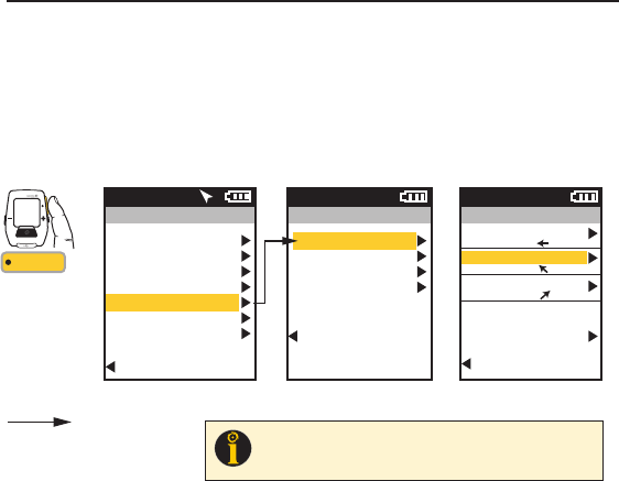
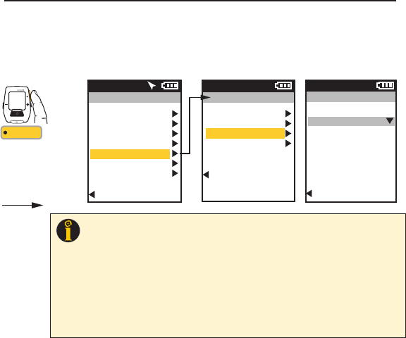
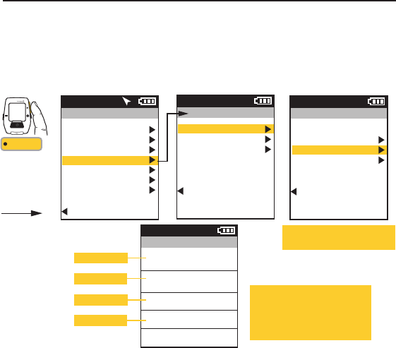
CHAPTER 2: JOULE GPS OVERVIEW & SETUP
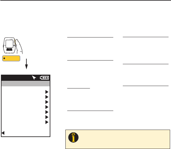
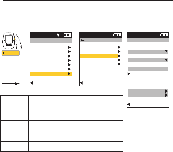
MAIN MENU
Enter the Main Menu to stop and save Rides, to review ride History, create/edit/select/pair Sensors, to use
the Training features and functions, to define individual Users, and configure the Device. Access to the main
menu can be gained while viewing any Dashboard by pressing and holding the Enter button. Use the (+)
and (-) buttons to scroll to your selection.
Joule GPS User Guide page 7
Main Menu
Ride
History
Sensors
Training
Navigation
User
Device
Back to Dashboard
9:34A71º
RIDE
Resume Ride
Stop and Save
Stop and Delete
Last Ride
Select a Ride
Report - Max
Report - Totals
HISTORY
Select a Bike
NEW BIKE
Add a Bike
SENSOR
Workouts
Auto Interval
Countdown
TRAINING
Waypoints
Routes
GPS Status
Compass
NAVIGATION
Select a User
NEW USER
Add a User
USER
Date and Time
Display
Memory
Altimeter
About Joule
DEVICE
INT
[ENTER]
Press
& Hold 3 sec.
FROM DASHBOARD
TIP: Once you have entered the menu system (holding Enter button down for
3 seconds) the Interval button will act as the “back” button. Each time it is
pressed you return to the previous screen. Also, at the bottom of every menu
screen, there is a “Back to...” previous screen selection choice.
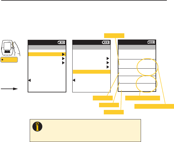
USER Multiple users can be stored
on each Joule GPS. (e.g. Jim, Bob,
Rachel can all share same device with
unique information). To add another user,
select Add a User, enter the name,
weight, height and date of birth for the
new user. If the training data is known
for this particular user it can be entered
now or enter it later, after a few rides.
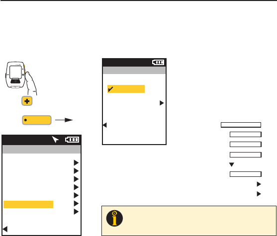
CHAPTER 2: JOULE GPS OVERVIEW & SETUP
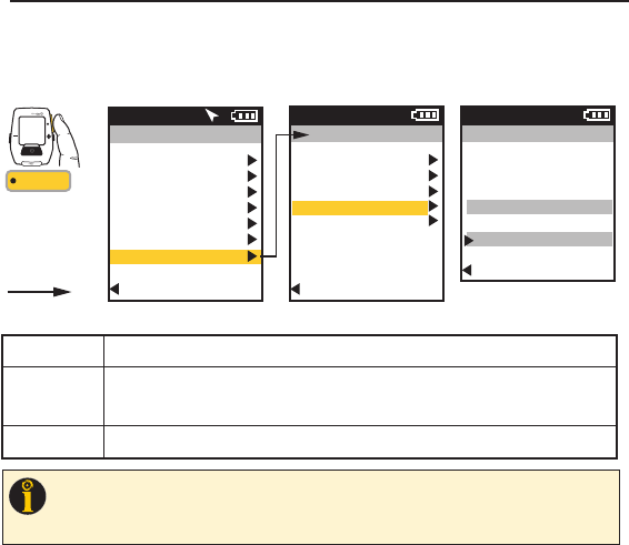
USER
The Joule GPS allows sharing of the same device with multiple users (i.e. Rachel, Jim, Bob). Each user can
have multiple bikes (e.g. TT bike, Road bike, MTB); each bike can have multiple sensors associated with it
(e.g. PowerTap, Cadence, HR strap, Speed). A default User is already defined within the Joule GPS. You can
either edit the settings and values associated with that User or start from scratch by adding a new User.
Main Menu
Ride
History
Sensors
Training
Navigation
User
Device
Back to Dashboard
9:34A71º
User
Select a User
USER
Add a User
Back to Main Menu
9:34A
INT
FROM MAIN MENU
[ENTER]
Press
to scroll to User.
Press Name
Weight, lb
Height, in
Date of Birth
Gender
FTP
Power Zones
Heart Rate Zones
Joule GPS User Guide page 8
TIP: When editing within a data field, the ENTER button allows you to enter, then
move forward in the field; the INTERVAL button allows you to move backwards;
the PLUS/MINUS buttons allow you to pick a letter or number. Moving to the end
of the field and pressing ENTER twice exits the field.
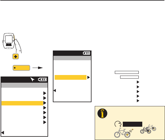
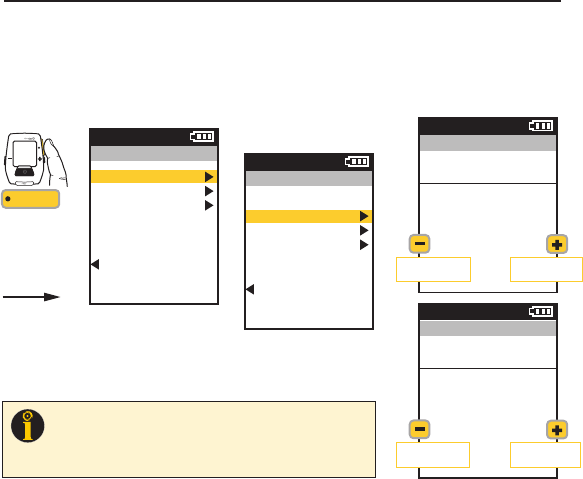
CHAPTER 2: JOULE GPS OVERVIEW & SETUP
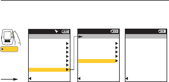
SENSORS & PAIRING
Pairing is a term used to describe the association of your Joule GPS with a particular sensor that is
broadcasting an ANT+ signal (e.g. a PowerTap hub, a Heart Rate strap, a remote cadence sensor, a remote
speed sensor, etc.). Sensors can be shared between bikes (e.g. a heart rate strap). Each User can define
multiple bikes. Each bike may have one or more sensors associated with it.
Main Menu
Ride
History
Sensors
Training
Navigation
User
Device
Back to Dashboard
9:34A71º
Sensors
Select a Sensor
NEW BIKE
Add a Bike
Back to Main Menu
9:34A
INT
FROM MAIN MENU
[ENTER]
Press
to scroll to Sensors.
Press
ADDING SENSORS & PAIRING Multiple
bikes can be paired with unique names. (e.g.: Jim’s
Racing Bike, Jim’s Mountain Bike, etc.). To add
another bike, select Add a Bike, enter a unique
name and the weight of the bike. Next, select a
sensor to add, make sure the sensor is awake and
broadcasting; select Start Pairing. Under Sensor ID
”Pairing” will flash until the ID is found and
displayed. Select Activate Sensor and return to the
Bike screen to define another sensor.
Name
Weight, lb
Power Sensor
Cadence Sensor
Speed/Combo
Heart Rate Sensor
RU Sensor
Joule GPS User Guide page 9
12” or 30cm
TIP: The Joule pairs to sensor(s) closest to the
device first. Hold the Joule within 12” of PowerTap
hub when pairing in the presence of other sensors.
other sensors
Joule GPS User Guide page 10
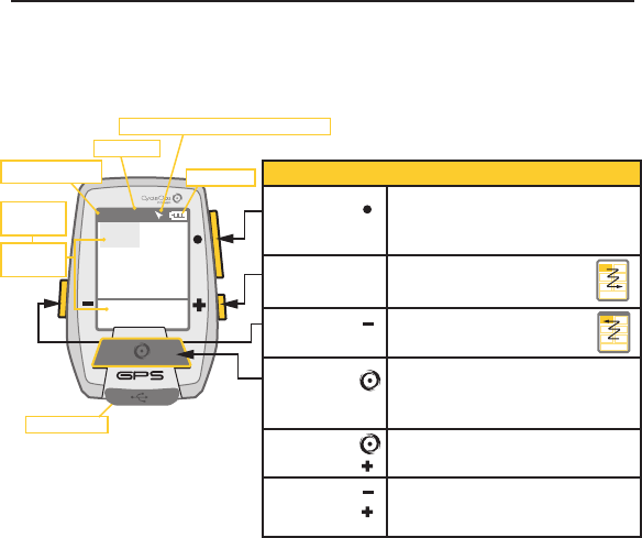
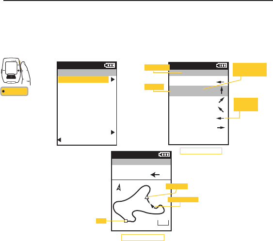
BUTTONS and SCREEN
There are three buttons on the sides of the Joule GPS and one large button below the screen. The
screen is divided into 3 display areas. The top area, Title Bar, displays time, temperature, compass, and
battery level. The large middle section, displays user-selected metrics and can be configured to show 3
to 6 windows. The lower section shows complimentary metrics associated with the highlighted metric.
CHAPTER 2: JOULE GPS OVERVIEW & SETUP
Highlighted
Metric,
Complimentary
Metrics
Micro-USB port
Ride Time or Clock
Temperature
North Arrow and GPS Signal Lock Indicator
Battery Level
[ENTER] button * Press once to move through each Dashboard
* Hold for 3 seconds - Go to Menu
* In Menus, press to selects menu item
* In Menus, hold for 3 seconds to go to Dashboard
Shifts selected metric or “highlight box”
to the right and down
Shifts selected metric or “highlight box”
to the left and up
* Press to mark intervals
* Hold for 3 seconds - Go to Interval view
* Hold for 3 seconds - Go to Ride view
* In Menus, press to go back to previous screen
Press together to put the Joule to sleep
Press together to “find” sensors that may have
been lost or were not awake when the Joule
powered up.
[PLUS] button
[MINUS] button
[PLUS] button
[MINUS] button
[INTERVAL] button
[INTERVAL] button
BUTTONS FUNCTION
WATTS
451 160
21 96
1:06:45
HR
MPH CAD
170 894
AV WATTS MX WATTS
RIDE TIME KJ
9:34
A
71º
380
INT
Joule GPS User Guide page 11
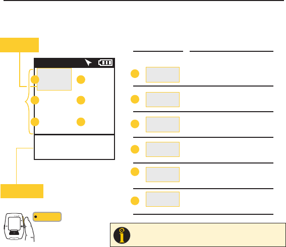
CHAPTER 3: DASHBOARDS
DASHBOARD 1
METRIC 1
METRIC 1
METRIC 2 METRIC 3
METRIC 2 METRIC 3
WATTS WATTS
451 160
21 96
1:06:45
HR
HR
MPH
MPH
CAD
CAD
170 894
AV WATTS MX WATTS
AV WATTS MX WATTS
AV HR MX HR
RIDE TIME
RIDE TIME
KJ
KJ
9:34A71º
Selected metric
highlights gray Selected Metric
Detail View:
2 Related Metrics
Detail Views
AA
B
B
AV MPH MX MPH
AV CAD MX CAD
MILES Kilojoules
KJ/HR TSS
C
C
D
D
E
E
F
F
380
Press • [ENTER] to
advance through
Dashboards
INT
[ENTER]
TIP
: All dashboards are fully customizable from 3-6 metric windows
per dashboard (See Chapter 7) and any of 23 metrics to choose
from. See Appendix C for full list of metrics.
DASHBOARD 1
The Dashboards display various metrics, summaries and navigation information that can be easily customized.
When a new metric is highlighted, the detailed view changes to show the related complimentary metrics.
Joule GPS User Guide page 12
DASHBOARD 2
Dashboards can be customized to display from 3 to 6 metric windows. The example on previous page
displayed 6. The example below, Dashboard 2, displays 4 metric windows. Each window can display any of
23 metrics, plus even more related/complimentary metrics. See Appendix C for a full list of metrics.
CHAPTER 3: DASHBOARDS
METRIC 2 METRIC 3
Detail View:
2 Related Metrics
DASHBOARD 2
1:06:45
RIDE TIME
21
MPH
WATTS
132 185
AV HR MX HR
9:34A71º
A
CD
451 160
HR
B
METRIC 1
Selected metric
highlights gray
METRIC 1 METRIC 2 METRIC 3
WATTS
HR
MPH
AV WATTS MX WATTS
AV HR MX HR
RIDE TIME
Selected Metric Detail Views
A
B
AV MPH MX MPH
Total Miles Kilojoules
C
D
Press • [ENTER] to
advance through
Dashboards
INT
[ENTER]
Joule GPS User Guide page 13
DASHBOARD 3
Dashboard 3 is configured to display 3 metric windows (default configuration). Press the Plus (+) or Minus
(-) button to highlight a different Metric. See Appendix C for a full list of metrics.
CHAPTER 3: DASHBOARDS
Detail View:
2 Related Metrics
1:06:45
RIDE TIME
25
SPD GRADE
9:34A71º
A
B C
26.00 380
MILES KJ
DASHBOARD 3
METRIC 1
Selected metric
highlights gray
METRIC 1 METRIC 2 METRIC 3
SPEED
GRADE
MILES KJ
AV MPH MX WATTS
RIDE TIME
Selected Metric Detail Views
A
B
AV GRADE FT GAIN
C
Press • [ENTER] to
advance through
Dashboards
INT
[ENTER]
METRIC 2 METRIC 3
5%
Joule GPS User Guide page 14
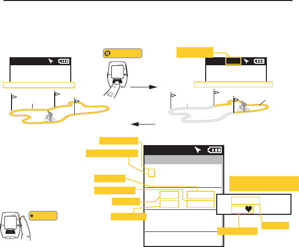
CHAPTER 3: DASHBOARDS
INTERVALS SUMMARY
Interval Dashboard contains
a summary of your Intervals.
Press • [ENTER] to
advance to the Intervals
Dashboard.
INT
[ENTER]
Intervals
2160w0:10:14
80kj 1.25mi
9:34A71º
Interval number
Current interval at top
Interval time
Interval distance 1285w0:05:02
101kj 2.65mi
0192w0:12:32
221kj 2.65mi
Avg. Power
Total kilojoules
10:12:32
2.65mi146
15.2mph
If power data is not available,
Speed and HR are displayed:
Avg. Heart Rate Avg. Speed
WATTS
176 2
PWR ZONE
9:34A71º
WATTS
451 5
PWR ZONE
9:34AINT 2
Interval marker
(replaces Temperature)
INTERVALS DASHBOARD
Intervals are useful for viewing ride data specific to a section of a ride, such as a hill or other period of high intensity
riding. Press the Interval button to begin an Interval. Press it again to end the current interval and begin another interval.
Press and Hold for 3 seconds to go from Ride View to Interval View; Press and Hold again to return to Ride View.
[INTERVAL]
INT
Press & Hold
3 sec. to go to
Interval View
Press & Hold
3 sec. to go
back to Ride
View
RIDE VIEW INTERVAL VIEW
Metrics displayed are for current interval
ENTIRE RIDE INTERVAL 2
INTERVAL 1
UP TO 99 INTERVALS
Metrics displayed are for overall ride
Joule GPS User Guide page 15
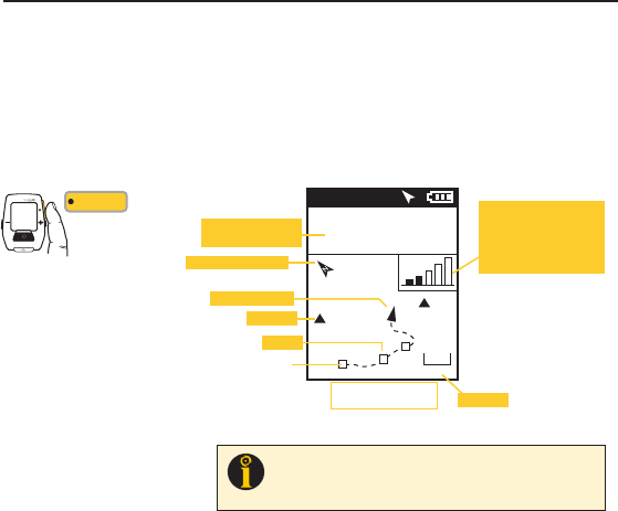
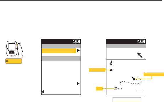
CHAPTER 3: DASHBOARDS
NAVIGATION or GPS MAP DASHBOARD
The Dashboard associated with Navigation is a GPS map with a current position indicator and a rendering of
the path ridden to that point in time. The screen may also display waypoints (), interval markers (), and a
pacing icon (), depending upon which navigation feature is being used. Pressing the PLUS (+) and MINUS (-)
buttons will zoom the screen in and out. Various zoom levels range from 75 meters to 80 kilometers (250 ft to
50 miles). Two configurable metric windows display at the top of the screen. When following a route which
contains turn by turn directions, the metrics are replaced with info related to the distance to the next turn.
Press • [ENTER] to
advance through
Dashboards, and
Interval, to the Map
INT
[ENTER]
GPS MAP Dashboard
9:34A71º
WATTS
184 96
CAD
01
2
Ofce
Home
5 mi
Metric of the selected
Category is shown
North arrow (compass)
Waypoints
Zoom level
Position indicator
Intervals
Start
Press + [PLUS] to zoom in
Press - [MINUS] to zoom out
Satellite Reception Indicator.
Once the GPS signal is
locked on the device, this
icon is not visible. Five bars
indicate a strong signal.
TIP: The GPS signal locking process can take anywhere from less than a
minute to several minutes, depending on weather, environmental
conditions and/or when the last time the device was powered up. See
Appendix D for more information.
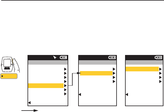
CHAPTER 4: NAVIGATION
NAVIGATION OVERVIEW
The Navigation section of the Joule GPS menu allows you work with a variety of features including Waypoints, Routes,
Compass calibration, etc. Waypoints assist with remembering and navigating to a particular location. Routes allow you
to follow a particular predefined path. Waypoints can be created directly on the Joule GPS and stored on the Joule or in
the CycleOps PowerAgent software application (available on both Mac and PC). Routes can be created from previous
rides in PowerAgent and uploaded to the Joule. Routes can also be created on one of the many mapping sites on the
Internet, imported into PowerAgent and uploaded to the Joule. The Joule GPS also has a magnetic compass, which
operates whether the GPS signal is available or not.
See Appendix D for more general information on the GPS (Global Positioning System).
Joule GPS User Guide page 16
Using +/- button,
scroll to Navigation,
Press • [ENTER] to
advance to the
options related to
navigation.
INT
[ENTER]
INT
[ENTER]
Press
& Hold 3 sec.
FROM DASHBOARD
Main Menu
Ride
History
Sensors
Training
Navigation
User
Device
Back to Dashboard
9:34A71º
Navigation
Waypoints
Routes
GPS Status
Compass
Back to Main Menu
9:34A
Joule GPS User Guide page 17
CHAPTER 4: NAVIGATION
WAYPOINTS
For the purposes of the Joule GPS, waypoints are single specific locations on earth. Your home can be a waypoint. Your
favorite trail head or cafe can be a waypoint. The Joule GPS can create, delete, select, and store waypoints. Each waypoint
you create is stored on the device. Each waypoint is listed by its name, a distance and heading from your current location. A
waypoint labeled “Start” is always in the list and represents the starting point of your ride. You can select a waypoint in your
list to navigate to or create a waypoint representing your current location by selecting New Waypoint.
INT
[ENTER]
Press & Hold
3 sec. to enter
Menus. Scroll
to Navigation;
Press •[ENTER] ;
Select Waypoints,
Press •[ENTER]
Scroll to a Waypoint
Press •[ENTER]
FROM DASHBOARD
Main Menu
Ride
History
Sensors
Training
Navigation
User
Device
Back to Dashboard
9:34A71º
Navigation
Waypoints
Routes
GPS Status
Compass
Back to Main Menu
9:34A
Waypoints
Start
Home
Tucson ride
New Waypoint
Back to Navigation
9:34A
10.2 mi
29 mi
1388 mi
TIP: The heading arrow is accurate as long as the compass has been calibrated.
The calibration typically only has to be done once, when you first receive the unit.
For more information, refer to Compass Calibration toward the end of chapter 4.
Joule GPS User Guide page 18
CHAPTER 4: NAVIGATION
WAYPOINTS, continued
To navigate to a particular waypoint, select it from the list. At this point you can navigate to it, rename it or delete it.
Selecting the Navigate To option will take you the GPS Map Dashboard. The name of the waypoint will be listed at the top of
the screen along with the distance to the waypoint, from your current position, along a straight line, in the direction
indicated by the heading arrow.
Press • [ENTER] to
advance through the
Menus. Once Waypoint
is selected the Distance
To and the Heading to the
waypoint is displayed on
the GPS Map Dashboard.
INT
[ENTER]
Waypoint
Navigate To
Name
Home
Location
29 mi NW
Delete Waypoint
Back to Waypoints
9:34A
Home
GPS Map Dashboard
9:34A
DIST TO
24 HDG TO
0
Home
10 mi
Waypoint ()
Position indicator
Start
Joule GPS User Guide page 19
CHAPTER 4: NAVIGATION
ROUTES
Routes allow you train using the pace of a previous ride as a measurement of your pace during the current ride over
the same course. Routes also allow you to navigate an unfamiliar path.Routes can be created and copied onto the
Joule GPS using the CycleOps PowerAgent software. Routes can also be created using your favorite mapping web
site, exported from the site, imported into PowerAgent and copied to the Joule GPS. For those routes that have
associated turn by turn navigation data, the Joule GPS will display information on the Map dashboard as each turn
approaches. Routes created from a previous ride will have associated pacing data. As you follow a route with
pacing data a small icon () will appear along the route. This icon represents the pace of the ride from which the
route was created.
INT
[ENTER]
Press & Hold
3 sec. to enter
Menus. Scroll
to Navigation;
Press •[ENTER] ;
Select Routes,
Press •[ENTER]
Scroll to a route,
Press •[ENTER]
FROM DASHBOARD
Main Menu
Ride
History
Sensors
Training
Navigation
User
Device
Back to Dashboard
9:34A71º
Routes
Paoli Loop
Ironman WI
Belleville Loop
Horribly Hilly 100
Back to Navigation
9:34A
Navigation
Waypoints
Routes
GPS Status
Compass
Back to Main Menu
9:34A
Press • [ENTER] to
advance through the
Menus. Once Ride Route
is selected the Turn by
Turn Route Dashboard
will be displayed.
Pressing • [ENTER] again
will display the Route on
the GPS map screen.
INT
[ENTER]
Route
Ride Route
Name
Paoli Loop
Length
24.45 mi
Location
1.2 mi NE
Delete Route
Back to Routes
9:34A
Paoli Loop
N
W
W
NW
W
S
0.00 mi
0.62 mi
3.84 mi
0.24 mi
0.29 mi
1.40 mi
9:34A
Route Name
Heading
Distance to next
map point (turn)
Direction of
next turn
Route Dashboard
Joule GPS User Guide page 20
CHAPTER 4: NAVIGATION
ROUTES, continued
Select a Route to ride or delete from your list of routes. If the route you select to ride has associated Turn by Turn
directions, a Route dashboard will appear in your list of dashboards. The Route dashboard will display the heading,
the distance, and direction to the next map point. The route is also displayed on Map Dashboard. If the route does
not have turn by turn directions associated with it, the route will appear on the Map dashboard but the Route
dashboard will not appear in the list of dashboards.
Paoli Loop
GPS Map Dashboard
9:34A
DIST TO
12 HDG TO
010 mi
Position indicator
Start
Pacing icon
Joule GPS User Guide page 21
CHAPTER 4: NAVIGATION
GPS STATUS
Information related to your GPS signal can be checked in the GPS Status area. Your GPS signal can be set
to Active or Off. The current accuracy of your position is estimated in meters. The exact location of your
position in Latitude and Longitude notation (i.e. degrees, minutes, seconds) is displayed. Also, the current
elevation as calculated by the Joule GPS barometer.
INT
[ENTER]
Press & Hold
3 sec. to enter
Menus. Scroll
to Navigation;
Press •[ENTER] ;
Select GPS Status
FROM DASHBOARD
Main Menu
Ride
History
Sensors
Training
Navigation
User
Device
Back to Dashboard
9:34A71º
GPS Status
Status
Active/Off
Accuracy
5m
Location
N43°01’14.307”
W89°28’11.189”
Altitude
737
Back to Navigation
9:34A
Navigation
Waypoints
Routes
GPS Status
Compass
Back to Main Menu
9:34A
TIP: Your current location is listed as a latitude and longitude pair. The numbers making up the pair are in degrees,
minutes, and seconds. The letter associated with the number is a compass point, North, South, East, West. When viewing
a map, latitude lines run horizontally, longitude lines run vertically, converging at each pole, widest at the equator.
Lines of Latitude are numbered from zero degrees to 90°, north and south. These numbers can be subdivided into
minutes and seconds for greater granularity. 0° Latitude is the equator, the imaginary line that divides the earth into north
and south hemispheres.
Lines of Longitude, also numbered in degrees, subdivided in minutes and seconds. 0° Longitude is the Prime Meridian,
established 1884, an imaginary line that runs through Greenwich, England. From the Prime Meridian, the lines of
Longitude run 180° east and 180° west until they meet in the Pacific Ocean, making up the imaginary line known as the
International Date Line.
Using the Latitude/Longitude numbered pair you can describe any location on Earth. In fact, the example in the menu
above is the location of Saris Cycling Group, near Madison, Wisconsin.
Joule GPS User Guide page 22
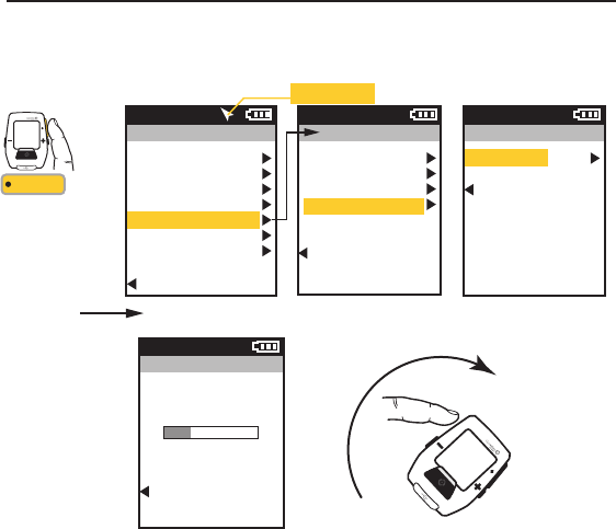
CHAPTER 4: NAVIGATION
COMPASS
The Joule GPS contains a magnetic compass. The arrow near the right side of the Title bar on the
dashboard points North, regardless of your direction of travel. It is good practice to calibrate the compass
upon receipt of the device as well as after each firmware upgrade.
INT
INT
[ENTER]
Press & Hold
3 sec. to enter
Menus. Scroll
to Navigation;
Press •[ENTER] ;
Select Compass,
Press •[ENTER]
Select Calibrate,
Press •[ENTER]
FROM DASHBOARD
Main Menu
Ride
History
Sensors
Training
Navigation
User
Device
Back to Dashboard
9:34A71º
Compass
Calibrate
Back to Navigation
9:34A
Compass
Place the unit on a
flat surface. Rotate
two full turns slowly.
Cancel
9:34A
Navigation
Waypoints
Routes
GPS Status
Compass
Back to Main Menu
9:34A
Compass Arrow
CHAPTER 5: RIDE HISTORY REPORTS
HISTORY REPORTS
The Joule GPS can create and display reports comparing one of your rides to the average of what you have done
over a previous time frame. History reports by the last ride or any selected ride are compiled and compared to
averages over 2 weeks, 4 weeks, 8 weeks, 6 months or 12 months prior to the selected ride. The data is either
averaged by Date or by Ride (see explanation below). Compared information includes Power, Heart Rate, Time in
zones, Climbing, watt per kilogram Surges and more Note: the averages do not include the selected ride.
Joule GPS User Guide page 23
Main Menu
Ride
History
Sensors
Training
Navigation
User
Device
Back to Dashboard
9:34A71º
Averages by Ride gives the
average by the total number of
rides for the given time period. If
only 3 rides were completed
during a 2 week period the
average will be given for 3 rides.
Average by Date gives the
average for the whole time period.
Every non-riding day during the
given period of time will be
calculated as zero.
History
Last Ride
Select a Ride
Report - Max
Report - Totals
Back to Main Menu
9:34A
History
Last Ride
Select a Ride
Report - Max
Report - Totals
Back to Main Menu
9:34A
Average
Data By
Date Rides
INT
[ENTER]
Press & Hold
3 sec. to enter
Menus. Scroll
to History;
Press •[ENTER] ;
Select a report,
FROM DASHBOARD
Summary - 2
8/27/12 2 Wk
178
86
17.3
135
156
78
16.5
126
AV
WATTS
AV
CAD
AV
MPH
AV
HR
9:34APress +[PLUS] to
scroll to the next
time frame.
Press -[MINUS] to
return to previous
time frame.
Press •[ENTER] to
scroll to each
report:
Summary 1 & 2
Pwr Detail 1 & 2
Work
Peak Pwr 1 & 2
Time in Zones
Climbing
Surges
Press [INTERVAL]
to view previous
report.
CHAPTER 5: RIDE HISTORY REPORTS
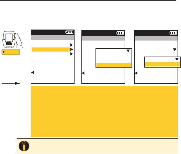
HISTORY REPORTS, Continued
There are two types of ride history reports: A History Report comparing Maximum values of the selected ride with
Maximum values over the specified time frame. Also, a History Report comparing the totals achieved in the selected
ride with Totals over the specified time frame.
Joule GPS User Guide page 24
Maximum History reports allow for comparison
of the maximum values achieved in a selected
time frame to the average achieved in that
same time frame. Note: Max view is the max
values achieved for each report metric over the
average of two weeks, four weeks, etc.
Totals History reports allow for comparison of
the totals achieved in a selected time frame to
the averages achieved in that same time frame.
Note: Total view is the total values achieved for
each report metric over the average of two
weeks, four weeks, etc.
Main Menu
Ride
History
Sensors
Training
Navigation
User
Device
Back to Dashboard
9:34A71º
History
Last Ride
Select a Ride
Report - Max
Report - Totals
Back to Main Menu
9:34A
History
Last Ride
Select a Ride
Report - Max
Report - Totals
Back to Main Menu
9:34A
Average
Data By
Date Rides
INT
[ENTER]
Press & Hold
3 sec. to enter
Menus. Scroll
to History;
Press •[ENTER] ;
Select a report,
FROM DASHBOARD
Power Detail - 2
MAX 2 Wk
3.1
8.3
0:11:57
21%
2.8
11.7
0:08:14
27%
AV
W/KG
MAX
W/KG
ZERO
WATTS
ZERO
WATTS
9:34APress +[PLUS] to
scroll to the next
time frame.
Press -[MINUS] to
return to previous
time frame.
Press •[ENTER] to
scroll to each
report.
Press [INTERVAL]
to view previous
report.
Joule GPS User Guide page 25
My Workout 1
9:34A
PWR ZONE
My Workout 1
PWR ZONE 1
My Workout 1
PWR ZONE 2
My Workout 1
PWR ZONE 3
My Workout 1
PWR ZONE 2
2 185
0:10:30
0:06:30
0:10:00
0:05:00
WATTS
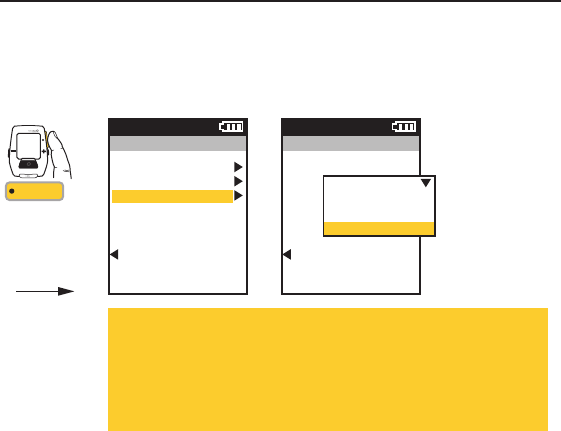
TRAINING using WORKOUTS
The Joule GPS has a robust set of features that assist in training. These features include the ability to create and follow
a Workout, either outdoor or indoor; set up Auto Intervals based on time, distance or GPS position; and the ability to set
a Countdown reminder using time, distance or quantity of work. Creat the workout script using the CycleOps
PowerAgent application software. Within PowerAgent, the workout can be created manually or converted from a
previous ride activity, then transferred to the Joule GPS. The Joule GPS is compatible with the PowerBeam Pro Trainer.
CHAPTER 6: TRAINING
This menu lists all of the workouts
stored on the device.
When the user selects a workout,
that workout is initiated. The workout
info and segments are displayed as
the Workout dashboard in the list of
dashboards.
INT
[ENTER]
Press & Hold
3 sec. to enter
Menus. Scroll
to Training;
Press •[ENTER] ;
Select Workouts,
FROM DASHBOARD
Training
Workouts
Auto Interval
Countdown
Back to Main Menu
9:34A
Workouts
Select a Workout
Power Test
My Workout 1
Converted Ride 1
Back to Training
9:34A
Current info
Segment 1
Segment 2
Segment 3, etc.
Main Menu
Ride
History
Sensors
Training
Navigation
User
Device
Back to Dashboard
9:34A71º
Target Slope
Segment length by distance
Segment length by timePower Zone
Target Power
Power Range
My Workout 1
9:34A
TRG SLOPE
Current
5.0%
1
4
2
250 W
3
150-175 W
5.0% 451
0.25 mi
1.23 mi
0:05:00
0:08:00
WATTS
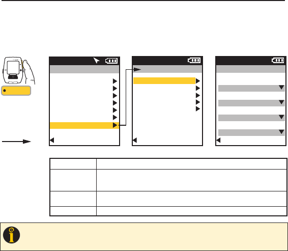
TRAINING with PowerBeam PRO using Scripted WORKOUTS
Workouts for the PowerBeam Pro can be imported to the Joule GPS from Power Agent. Within this “scripted” workout,
resistance can be based on target slope (mimicking the resistance of a specific grade or incline), target power (a
specific resistance value in terms of watts), power range (resistance within a range of wattage values) or power zone (a
number representing a range of power values). The length of each segment can be based on distance or time. To initiate
a scripted workout, select Workouts, then scroll down to the name of the workout and select it.
CHAPTER 6: TRAINING
INT
[ENTER]
Press & Hold
3 sec. to enter
Menus. Scroll
to Training;
Press •[ENTER] ;
Select Workouts,
FROM DASHBOARD
Training
Workouts
Auto Interval
Countdown
Back to Main Menu
9:34A
Workouts
Select a Workout
Manual Slope
Manual Power
Power Test
My Workout 1
Converted Ride 1
Back to Training
9:34A
Joule GPS User Guide page 26
NOTE:
A workout with a slope-based segment will only appear when the Joule GPS is
communicating with a PowerBeam Pro.
You can also ride a power-based workout with any trainer, as well as outdoors.
Also, Manual Slope and Manual Power are only displayed in the Workouts menu if the
Device is paired to and communicating with a PowerBeam Pro.
Manual Slope
9:34A
TRG SLOPE
5.0% 451
WATTS
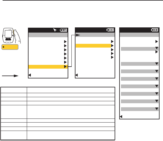
TRAINING with PowerBeam PRO using Manual WORKOUTS
Manual or “unscripted” workouts are exclusively available when using the PowerBeam Pro. When paired to a
PowerBeam Pro, two choices appear in the Workouts menu, along with any named workout files. Titled “Manual Slope”
and “Manual Power,” the choices represent Target Slope Mode and Target Power Mode, respectively. Entering either of
these areas allows the user to set the PowerBeam resistance to mimic a specific slope (grade or incline) percentage or
a specific power value. The +[PLUS] and -[MINUS] buttons can be used to increment or decrement the resistance value.
CHAPTER 6: TRAINING
INT
[ENTER]
Press & Hold
3 sec. to enter
Menus. Scroll
to Training;
Press •[ENTER] ;
Select Workouts,
FROM DASHBOARD
Training
Workouts
Auto Interval
Countdown
Back to Main Menu
9:34A
Workouts
Select a Workout
Manual Slope
Manual Power
Power Test
My Workout 1
Converted Ride 1
Back to Training
9:34A
Target slope
decrease by 0.5% Target slope
increase by 0.5%
Manual Power
9:34A
TRG PWR
270 265
WATTS
Target power
decrease by 10w Target power
increase by 10w
Joule GPS User Guide page 27
NOTE:
Upon selecting Manual Slope or Manual Power, the Joule GPS assumes control
of the paired PowerBeam Pro without a workout script. At this point, resistance must
control the via the device +[PLUS] and -[MINUS] buttons.
Also, Manual Slope and Manual Power are only displayed in the Workouts menu if the
Device is paired to and communicating with a PowerBeam Pro.
Auto Interval Mode:
Distance:
Select Distance, scroll to and enter the amount of distance you want to travel before the interval is marked.
Time:
Select Time, scroll to and enter the amount of time that you want to pass before the interval is marked.
Position:
Select Position, scroll to Position Option, press •[ENTER]. Choose either Current Position or First
Interval to set the GPS position of where the interval will be marked. Current Position indicates that
each time you pass your current position on earth an interval will be marked. Choosing First Interval
indicates that the position marker will be set when you press the interval button the first time. Each
time you pass that point on earth an interval will be marked.
CHAPTER 6: TRAINING
TRAINING using AUTO INTERVAL
Auto Interval allows you to set the Joule GPS to record intervals automatically during your ride based on an amount of time
which has passed, or a distance traveled, or passing a specific GPS position point. The interval is automatically marked and
will appear on the Interval dashboard. Select Off to turn Auto Interval off.
Training
Workouts
Auto Interval
Countdown
Back to Main Menu
9:34A
Auto Interval
Mode
Time
0:10:00
Back to Training
9:34A
Off
Distance
Time
Position
Auto Interval
Mode
Position
Position Option
Current Position
Back to Training
9:34A
Current Position
First Interval
INT
[ENTER]
Press & Hold
3 sec. to enter
Menus. Scroll
to Training;
Press •[ENTER] ;
Select Auto Interval
FROM DASHBOARD
Joule GPS User Guide page 28
TIP
: Use Auto Interval in Position Mode when participating in a criterium or cyclocross event to count each lap. Set the
Position Option to First Interval prior to warmup. When you get to the start line press the interval button, indicating an
interval will be marked each time you pass this point (within 30 meters of point).
Joule GPS User Guide page 29
CHAPTER 6: TRAINING
TRAINING using COUNTDOWN
Countdown allows you to set the Joule GPS to notify you when a specific distance has been traveled; a
specific amount of time has passed; or a specific amount of work has been completed (measured in
kilojoules). In order to use the Countdown feature you must select the Countdown metric for display in one
of your Dashboards. See chapters 3 and 7, and Appendix C for more information on setting display metrics.
Training
Workouts
Auto Interval
Countdown
Back to Main Menu
9:34A
Countdown
Mode
Work, kJs
1500
Back to Training
9:34A
Off
Distance
Time
Kilojoules of Work
INT
[ENTER]
Press & Hold
3 sec. to enter
Menus. Scroll
to Training;
Press •[ENTER] ;
Select Countdown,
FROM DASHBOARD
Countdown Mode:
Distance:
Select Distance, scroll to and enter the amount of distance you want to travel before being notified.
Time:
Select Time, scroll to and enter the amount of time that you want to pass before being notified.
Kilojoules:
Select KJs, scroll to and enter the amount of kilojoules of work completed before being notified.
Note: Kilojoules Countdown only applies when power measurement is present.
CHAPTER 7: DEVICE MENU
Joule GPS User Guide page 30
DEVICE Overview, DATE & TIME
The final choice on the Main Menu has to do with configuring the device itself. This includes time and date settings;
display settings (dashboard configuration, lighting, sleep, language and units); device memory management, data
recording control, odometer management, the altimeter offset and information about the Joule GPS itself, such as
firmware version numbers.
Main Menu
Ride
History
Sensors
Training
Navigation
User
Device
Back to Dashboard
9:34A71º
INT
[ENTER]
Press & Hold
3 sec. to enter
Menus. Scroll
to Training;
Press •[ENTER] ;
Select an option,
FROM DASHBOARD
TIP
: Coordinated Universal Time (UTC) is basically “world time.” UTC time zones begin at Longitude 0 (zero), the Prime Meridian. Example: In the
United States, Central Standard Time is 6 hours less than UTC time (UTC-6); Pacific Standard Time is 8 hours less UTC time (UTC-8). When Daylight
Savings Time is in effect, subtract 1 hour from U.S. UTC values. In Europe, Central European Time is 2 hours more (UTC+2). In Asia, Hong Kong Time
is 8 hours more (UTC+8).
Device
Date and Time
Display
Memory
Altimeter
About Joule
Back to Main Menu
9:34A
Date and Time
Set from GPS
Yes/No
Time Zone
Auto
Daylight Savings
Yes/No
Clock Format
12/24 Hr
Back to Device
9:34A
Set from GPS
Time Zone
Daylight Savings
Clock Format
DATE & TIME MENU MENU INPUT OPTION
Yes/No. Yes means the time is set from GPS data. No means the time is set manually.
Auto or UTC time. Select Auto to set the time zone automatically. Select the associated UTC time
zone for your area to set the time zone manually. When operating the Joule GPS near the boundary
of a Time Zone, the Auto setting may not work well. To avoid inconsistencies, Select the UTC time.
Yes/No. Yes means Daylight Savings Time is active in your current location and the clock will be
adjusted accordingly. No means Daylight Savings Time is not active.
12/24. Set the clock to display 12 hour or 24 hour format.
Joule GPS User Guide page 31
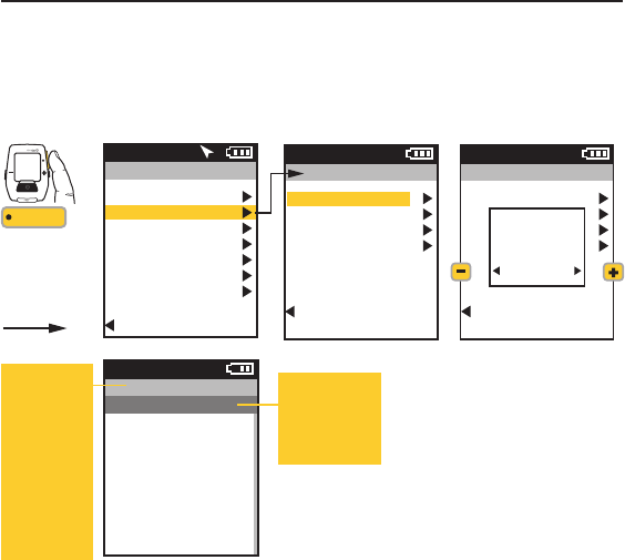
CHAPTER 7: DEVICE MENU
Change number of metric display windows & individual metrics within each Dashboard
Yes/No. Yes to display Map Dashboard. No to not show in list of Dashboards.
Select metrics to be displayed above map on Map Dashboard.
0-4. Level of backlight brightness.
Yes/No. Yes means, when the device is on, the backlight is on continually, at the
specified level, between sunset and sunrise. The GPS location is used to
determine when sunrise and sunset occur. The backlight functions normally with
button presses between sunrise and sunset.
0-5. Level of screen contrast.
Never on, 10 sec, 20 sec, 30 sec, 1 min, Always On.
3, 5, or 10 min. Period of inactivity before device goes into sleep mode.
Display language: English, Deutsch, Français, Italiano, Español, Nederlands.
Display units: English or Metric
Dashboard
Show Map
Edit
Backlight Level
Smart Backlight
Contrast
Backlight Timeout
Sleep Time
Language
Units
DISPLAY MENU MENU INPUT OPTION
DEVICE DISPLAY
All of the Dashboard configuration, lighting levels, sleep, language, metrics, and units can be set in the Device Display
area. You can determine the number of dashboards to display, as well as the number and type of metric associated with
each dashboard. See Appendix C for a full list of all metrics.
Main Menu
Ride
History
Sensors
Training
Navigation
User
Device
Back to Dashboard
9:34A71º
INT
[ENTER]
Press & Hold
3 sec. to enter
Menus. Scroll
to Training;
Press •[ENTER] ;
Select an option,
FROM DASHBOARD
Device
Date and Time
Display
Memory
Altimeter
About Joule
Back to Main Menu
9:34A
Display
Dashboard
Show Map
Yes/No
Edit
Backlight Level
0-4
Smart Backlight
Yes/No
Contrast
0-5
Backlight Timeout
Off - Always On
Sleep Time
3-10 min
Language
En, De, Fr, It...
Units
English/Metric
Back to Device
9:34A
Joule GPS User Guide page 32
CHAPTER 7: DEVICE MENU
Record Control
End Ride Time
Odometer
Memory Remaining
Clear Ride Memory
Clear History
MEMORY MENU MENU INPUT OPTION
DEVICE MEMORY
The Memory page allows the user to monitor and manage the space available on the Joule GPS as well as set some recording
and saving attributes. Also the odometer value can be monitored, updated or reset. Ride summary data, used for history reports
(Chapter 5), and Ride file data can be cleared here.
Main Menu
Ride
History
Sensors
Training
Navigation
User
Device
Back to Dashboard
9:34A71º
INT
[ENTER]
Press & Hold
3 sec. to enter
Menus. Scroll
to Training;
Press •[ENTER] ;
Select an option,
FROM DASHBOARD
Device
Date and Time
Display
Memory
Altimeter
About Joule
Back to Main Menu
9:34A
Memory
Record Control
Speed/HR
End Ride Time
15-90 min
Odometer
1526
Reset Odometer
Memory Remaining
33.4 Hours
Clear Ride Memory
Clear History
Back to Device
9:34A
Speed/Heart Rate. Sets when data will be recorded. Select Speed to record whenever
speed is present (via either the hub, a speed sensor or the GPS) and greater than
3.6 kph (2.2 mph). Select Heart Rate to record when a heart rate is present.
15, 30, 60, 90 minute and Never options for auto saving a ride once it is ended.
For example: Selecting the 30 min option would cause the ride to automatically
save after 30 minutes of inactivity. “Never” means the user will save manually.
Displays total miles or kilometers accumulated since device was put in service or
since last reset. This number is editable by selecting it and pressing [ENTER];
Increase/decrease each digit using +/- buttons; Enter moves to next digit. Press
Enter twice at end of field to exit field.
The amount of ride storage space available, in terms of ride time.
Clears all ride files from device. Does not clear ride history data used for reports.
Clears all ride history data (no data available for reports).
Joule GPS User Guide page 33
CHAPTER 7: DEVICE MENU
Displays the current altitude above sea level. The value is listed in feet or meters, depending on what the user chose as the Units
setting in the Display section of the Device menu.
Optional. Enter your actual home altitude/elevation here (gathered from a known benchmark or topographic map data).
This value will be used to establish an offset for any variances in the actual barometer reading, making the displayed
elevation value more consistent for any day, regardless of weather conditions. If you live below sea level, negative values
can be entered as well. Leaving this field blank simply uses the Current Altitude as the base value for the ride.
Once selected the device will begin to use the actual entered value of your Home Altitude as the base from which to
calculate barometer differentials.
Current Altitude
Home Altitude
Use Home Altitude?
ALTIMETER MENU MENU INPUT OPTION
DEVICE ALTIMETER
The Joule GPS contains a barometric Altimeter that allows you to monitor your current altitude, also referred to as current elevation.
Selecting Altimeter in the Device menu shows the current altitude, as calculated from the barometer. You may set a known value for
“home” altitude or the elevation of the starting point of the ride, and adjust the value of the current altitude to this known value.
Main Menu
Ride
History
Sensors
Training
Navigation
User
Device
Back to Dashboard
9:34A71º
INT
[ENTER]
Press & Hold
3 sec. to enter
Menus. Scroll
to Training;
Press •[ENTER] ;
Select an option,
FROM DASHBOARD
Device
Date and Time
Display
Memory
Altimeter
About Joule
Back to Main Menu
9:34A
Altimeter
Current Altitude
2480 (in ft or m)
Home Altitude
760 (ft/m)
Use Home Altitude?
Back to Device
9:34A
NOTE
: The barometer in your Joule GPS is very sensitive to barometric pressure. If weather patterns are changing,
resulting in a rising or falling barometer, the current elevation value will also change. The less stable the weather
the less stable the elevation value. However, even if the weather is not clear and windless, it is the pressure
differentials that are used to calculate elevation gains and losses, not the actual elevation change. The resulting
calculation during the relatively short time frame of any particular ride is accurate.
Joule GPS User Guide page 34
CHAPTER 7: DEVICE MENU
DEVICE ABOUT JOULE
This screen contains information about the Joule GPS, including the version of firmware currently running on the device and the
number for Customer Support, typically available Monday through Friday, 8 a.m. to 5 p.m., Central Standard Time.
Main Menu
Ride
History
Sensors
Training
Navigation
User
Device
Back to Dashboard
9:34A71º
INT
[ENTER]
Press & Hold
3 sec. to enter
Menus. Scroll
to Training;
Press •[ENTER] ;
Select an option,
FROM DASHBOARD
Device
Date and Time
Display
Memory
Altimeter
About Joule
Back to Main Menu
Firmware Version
19.063
Designed in
Madison, WI by
Saris Cycling Group
800-783-7257
Back to Device
9:34A
About Joule
9:34A
FREQUENTLY ASKED QUESTIONS
For the most current FAQ’s and troubleshooting please visit the customer support section of our website, www.cycleops.com.
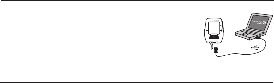
DOWNLOAD
To further configure the Joule GPS and customize the dashboards, install PowerAgent
software from www.cycleops.com/poweragent. PowerAgent also allows you to download
and analyze your ride data, as well as upload your ride to different social media and social
fitness sites.
INT
MicroUSB
USB
CHAPTER 8: DATA & DOWNLOADS
CHAPTER 9: FAQ & TROUBLESHOOTING
Joule GPS User Guide page 35

CHAPTER 10: IMPORTANT PRECAUTIONS
• Keep eyes on the road. Do not become overly engaged with display.
• We recommend getting familiar with the computer functions while stationary.
• The computer and chest strap are water resistant, not waterproof. Avoid sustained water
contact and do not deliberately place in water or under high-pressure sprays.
• Avoid spraying the unit directly with solvent. Do not use thinner or other solvents to
clean parts.
• Failure to adhere to these precautions may cause premature failure or incorrect
operation of the unit and may void the warranty.
Other Important Notes:
• Battery Life: The Joule GPS has a rechargeable battery that will last a significant amount
of time when fully charged. However, some features of the Joule will use more power
then others:
-Setting the backlight time out to a long period of time (something more then 30
seconds) will impact battery life, depending on how often buttons are pushed, causing
the backlight to go on.
-Setting the backlight to “always on” will impact battery life.
-Setting the Smart Backlight option could impact battery life if a significant amount of
time is spent using the device at night.
-Displaying the GPS Map Dashboard for extended periods of time can impact battery life,
as a lot of processing power is required to keep the live map display up to date.
• GPS signal lock time can vary depending on environmental conditions. See Appendix D
for more information on GPS.
Joule GPS User Guide page 36
!
IMPORTANT

CHAPTER 11: FEATURES AND TECHNICAL SPECIFICATIONS FOR JOULE GPS
Joule GPS User Guide page 37
JOULE GPS FEATURES
3 Customizable Dashboards
Altitude
Battery Level Indicator (sensors, Joule GPS)
Cadence (current, average, maximum)
Current Heading
Distance Remaining in Workout
Distance to Next Route Point
Distance to Ride Partner
Heading to Next Route Point
Heart Rate (current, average, maximum)
Heart Rate Zone
Intensity Factor
Intervals Summary Screen
Kilojoules
Kilojoules per Hour
Normalized Power
Peak Power (5 second, 5 minute, 20 minute)
Pedal Balance (Current, Average)
Percent Grade (Current, Average)
Power (Current, Average, Maximum)
Power Zone (Current, Average)
Ride Distance
Ride Time
Speed (Current, Average, Maximum)
Surge Count (W/Kg)
Temperature
Time of Day
Time Remaining in Workout
Time to Ride Partner
Total Ascent
Total Kilojoules
Training Stress Score
VAM
Watts per Kilogram (Current, Average, Maximum)

ANT+ Compatible Yes
Barometric Altimeter Yes
Battery Rechargeable
Battery Life Approximately 20 hours
Display Size 40L x 30W (mm)
Display Type Dot matrix (128x160)
Download cable Micro USB
Interval button Yes
Mount Type Stem/Handlebar, Front
Operational Temperature 0-140 F degrees
Ride History 1 year
Ride Memory Approximately 80 hours
Unit Dimensions 78L x 53W x 26D (mm)
Water Resistant Yes, IPX 7
Weight 70 grams
CHAPTER 11: FEATURES AND TECHNICAL SPECIFICATIONS FOR JOULE GPS
JOULE GPS TECHNICAL SPECIFICATIONS
Joule GPS User Guide page 38

CHAPTER 12: Warranty
WARRANTY
In the event that warranty service is required, original sales receipt may be required.
The Joule is warranted to the original retail purchaser to be free from defects in materials and workmanship. Warranty coverage is
valid to the original purchaser only and proof of purchase will be required.
• Electronics
- 1 year
- 2 years (Europe)
THIS WARRANTY DOES NOT COVER:
• Normal wear and tear.
• Any damage, failure or loss caused by accident, misuse, neglect, abuse, improper assembly, improper maintenance or failure to
follow instructions or warnings in User Guide.
• Use of products in a manner or environment for which they were not designed.
LIMITATIONS
The foregoing warranties are in lieu of and exclude all other warranties not expressly set forth herein, whether expressed or implied
by operation of law or otherwise, including, but not limited to, warranties of merchantability or fitness for a particular purpose. Saris
Cycling Group shall in no event be liable for incidental or consequential losses, damages or expenses in connection with its exercise
products. Saris Cycling Group’s liability hereunder is expressly limited to the replacement of goods not complying with this warranty
or, at Saris Cycling Group election, to the repayment of an amount of the purchase price of the exercise product in question. Some
states do not permit the exclusion or limitation of implied warranties or incidental or consequential damages, so the preceding
limitations and exclusions may not apply to you.
PROCEDURES
Warranty service will be performed by Saris Cycling Group or an authorized Saris Cycling Group Dealer. The original purchaser must
provide proof of purchase. Service calls and/or transportation to and from the Authorized Saris Cycling Group Dealer are the
responsibility of the purchaser.
• Saris Cycling Group will have the option to repair or replace any product(s) which requires warranty service.
• Saris Cycling Group will replace any unit that is structurally defective with a new unit or replace the unit with a unit of equal value.
• In the event a product cannot be repaired, Saris Cycling Group will apply a limited credit reimbursement toward another CycleOps
product of equal or greater value.
Joule GPS User Guide page 39

Appendix A: HISTORY REPORT DEFINITIONS
Summary Report Definitions
Ride Time
Time of ride defined as any time spent moving. Note: time spent stopped can be included if Joule Mode settings are changed from
speed record control to heart rate record control.
MI/KM
The ride length from start to finish measured in miles or kilometers.
KJ
Kilojoule (1000 Joules). A Joule is unit of work equal to the work done by a force of 1 newton to move an object a distance of 1
meter. Kilojoules are a common unit used to express the total volume of work accomplished during a given workout, ride, or exercise
bout. Kilojoules are used to express the total training load. One Joule per second equals 1 watt. The average power output in watts
multiplied by the time in seconds divided by 1000 equals the total amount of work, during the specified time frame, in kilojoules.
TEMP C/F
The current temperature measured by the Joule’s internal sensor.
AV WATTS
1. Average power during a ride. 2. A common unit used to express effort or intensity amongst cyclists. Note: Average calculation may
or may not include zeros (time spent coasting or with no power) depending on Joule’s set up. By default, zeros are included. For 2
WK, 4 WK rolling averages are time weighted over the selected period.
AV CAD
Average pedal revolutions per minute during a ride. Note: Average calculation may or may not include zeros (time spent coasting or
with no power) depending on Joule’s set up. By default, zeros are included. For 2 WK, 4 WK rolling averages a time-weighted
average over the selectable time period is used.
AV MPH/KPH
Average speed in miles per hour or kilometers per hour during a ride.
AV HR
Average heart rate in beats per minute during a ride. Note: For 2 WK, 4 WK rolling averages, a time weighted average over the
selectable time period is used.
Joule GPS User Guide page 40

Appendix A: HISTORY REPORT DEFINITIONS
Power Detail Report
AV WATTS
1. Average power during a ride. 2. A common unit used to express effort or intensity amongst cyclists. Note: Average calculation may
or may not include zeros (time spent coasting or with no power) depending on Joule’s set up. By default, zeros are included. For 2
WK, 4 WK rolling averages a time weighted average over the selectable time period is used.
MX WATTS
Maximum power in watts during a ride. Note: For 2 WK, 4 WK rolling averages a time weighted average over the selectable time
period is used.
ZERO WATTS
Cumulative ride time when Power is zero displayed in absolute minutes or as percentage of total ride time.
NORMALIZED POWER
An estimate of the power that you could have maintained for the same physiological “cost” if your power output had been perfectly
constant. The formula for calculating NP was developed by Training Peaks.
AV W/KG
Average power in watts divided by rider weight in kg during a ride.
MX W/KG
Maximum power in watts divided by rider weight in kg during a ride.
Joule GPS User Guide page 41

Appendix A: HISTORY REPORT DEFINITIONS
Work Report and Peak Power Report
KJ
Kilojoule (1000 Joules). A Joule is unit of work equal to the work done by a force of 1 newton to move an object a distance of 1
meter. Kilojoules are a common unit used to express the total volume of work accomplished during a given workout, ride, or exercise
bout. Kilojoules are used to express the total training load. One Joule per second equals 1 watt. The average power output in watts
multiplied by the time in seconds divided by 1000 equals the total amount of work, during the specified time frame, in kilojoules.
KJ/HR
Average Kilojoules per hour during a ride.
TSS
Training Stress Score estimating the total amount of glycogen burned on a ride.
IF
Ratio of the normalized power to threshold power. Joule uses the mid-point between the threshold zone (zone 3) and the race pace
zone (zone 4) as the threshold power value.
Peak Power
The highest average power output that can be held for a given duration. 2. For most individuals a peak sustainable power or peak
power output lasting 4 to 8 minutes is equivalent to an intensity that elicits their VO2 max, or maximal capacity to consume oxygen.
3. For most individuals a peak sustainable power output lasting 20 to 40 minutes is equivalent to an intensity that elicits their lactate
threshold or a value of blood lactate 2 to 3 mm above their baseline blood lactate. 4. For most individuals a peak sustainable power
output lasting 40 minutes to 2 hours is equivalent to an intensity that elicits their lactate threshold, or a value of blood lactate just
above to 1 mm above their baseline blood lactate. 5. In cycling, the peak sustainable power for any given duration is analogous to
their best performance for a given time. For example, a runner might have a personal best of 5 minutes in a mile run and 35 minutes
in a 10 KM run, whereas a cyclist might have a personal best or peak sustainable power of 300 watts for 5 minutes and 240 watts
for 35 minutes.
Joule GPS User Guide page 42

Appendix A: HISTORY REPORT DEFINITIONS
Time in Zones Report
Training Zones
1. Discrete bins or intervals specific to a particular energy or physiological system. From short maximal efforts to long maximal
efforts these energy systems run along a continuum from anaerobic to aerobic metabolic pathways. Common reference points for
this continuum include the power at lactate threshold and power at VO2 max.
Recovery Zone (Zone 1)
1. An easy exercise intensity where there is minimal stress or strain on the body. 2. On a 1 to 10 rating of perceived exertion scale,
the recovery zone corresponds to a 1 to 2 or “really easy” to “easy”. 3. On a 6 to 20 rating of perceived exertion scale, the recovery
zone corresponds to a 6 to 10 or “very very light” to “very light.” 4. An exercise intensity dependent solely on aerobic metabolism of
primarily fat. 5. An exercise intensity that can be held for an indefinite time frame.
Endurance Zone (Zone 2)
1. A moderate exercise intensity where there is some stress or strain on the body 2. On a 1 to 10 RPE scale, an intensity
corresponding to 3 to 4 or “moderate” to “sort of hard”. 3. On a 6 to 20 RPE scale, an intensity corresponding to a 10 to 13 or “fairly
light” to “somewhat hard.” 4. An exercise intensity depending on the aerobic metabolism of both fat and carbohydrate. 5. An exercise
intensity that can be held as long as the athlete were supplied with an influx of carbohydrate (i.e., allowed to eat).
Lactate Threshold (LT) Zone (Zone 3)
1. A hard intensity zone marked by a sudden increase in breathing rate. 2. On a 1 to 10 RPE scale, an intensity corresponding to a 5
to 7 or “hard” to “really hard.” 3. On a 6 to 20 RPE scale, an intensity corresponding to a 13 to 16 or “somewhat hard” to “very hard”.
4. A range of exercise intensity beginning at a slight inflection or rise in the blood lactate over a resting baseline to an intensity
corresponding with a blood lactate 2 to 3 mm above a resting baseline. 5. A demarcation between aerobic metabolism to a mix of
anaerobic and aerobic metabolism. 6. An all out exercise intensity that can be held between 40 minutes to 2 hours depending on the
availability of stored carbohydrate or glycogen within the body.
Joule GPS User Guide page 43

Appendix A: HISTORY REPORT DEFINITIONS
Time in Zones Report...Continued
Race Pace Zone (Zone 4)
1. An extremely hard or all out intensity zone. 2. On a 1 to 10 RPE scale, an intensity corresponding to a 7 to 8 or “really hard” to
“really really hard.” 3. On a 6 to 20 RPE sale, an intensity corresponding to a 16 to 18 or “very hard” to “very very hard.” 4. An
exercise intensity dependent primarily on the aerobic and anaerobic metabolism of carbohydrate. 5. An all out exercise intensity that
can be held between 10 minutes to 30 minutes.
Max Zone (Zone 5)
1. An all out or maximal intensity zone. 2. On a 1 to 10 RPE scale, an intensity corresponding to a 9 to 10 or “really really hard” to
“maximal.” 3. On a 6 to 20 RPE scale, an intensity corresponding to an 18 to 20, or “very very hard” to “maximal.” 4. An exercise
intensity that elicits the causes the body to reach its maximal capacity to consume oxygen (i.e., an exercise intensity that elicits VO2
max). 5. An all out or maximal effort that can be held between 2 to 8 minutes or an average of 4 minutes.
Joule GPS User Guide page 44

Appendix A: REPORT DEFINITIONS
Climbing and Surges Report
M/FT GAIN
The total vertical distance in feet or meters traveled or climbed over a given distance ridden.
AV% GRADE
The rise or vertical increase in elevation divided by the run or horizontal distance traveled multiplied by 100 (rise ÷ run x 100).
M/FT LOST
The total vertical distance in feet or meters descended over a given distance ridden.
VAM
1. The rate of vertical ascent in meters per hour. Note: At an 8% grade, a rate of ascent of 1800 meters per hour requires a power
output of 6.3 watts per kg and is considered the upper limit for climbing speed in professional cyclists. To compare that with age
group racers and recreational riders, their VAM on the same grade would be around 1064 and 560 m/hr, respectively.
Surges
A surge is a sudden, short acceleration lasting a minimum of 3 seconds within a particular w/kg zone. The value is simply displayed as
the number of times this occurs per watts/kg zone. Once a surge is recorded in a w/kg zone, the w/kg value must drop at least 0.1
w/kg below the minimum zone value before a positive increase in value back into that zone can be considered a new surge. For this
metric to be calculated correctly, the rider’s weight must be accurate, as listed in the User section of the Main Menu on the Joule GPS.
Joule GPS User Guide page 45
Message Action Action
Bike
Selected Edit Shows the bike screen Use Activates the selected bike
for the selected bike
Delete Bike
Cancel Dismisses popup OK Deletes the selected bike
Delete Sensor
Cancel Dismisses popup OK Deletes the selected sensor
Rolldown
Complete OK Dismisses popup
Navigate to
Cancel Dismisses popup OK Begins navigating to the selected waypoint
Delete Waypoint
Cancel Dismisses popup OK Deletes the selected waypoint
Ride
Cancel Dismisses popup OK Begins following the selected route
Delete Route
Cancel Dismisses popup OK Deletes the selected route
Calibration
Complete OK Dismisses popup
Selected Edit Shows the user Use Activates the selected user
Below screen for the selected user
Power Cancel Turns off power zone warnings. OK Dismisses popup
Above Warnings are re-activated the
next time the unit wakes up.
Power Cancel Turns off power zone warnings. OK Dismisses popup
Below Warnings are re-activated the
next time the unit wakes up.
Heart Rate Cancel Turns off heart rate zone warnings. OK Dismisses popup
Above Warnings are re-activated the next
time the unit wakes up.
Heart Rate Cancel Turns off heart rate zone warnings. OK Dismisses popup
Warnings are re-activated the
next time the unit wakes up.
Appendix B: POP-UP WINDOWS
Message Action Action
MEMORY
FULL OK Dismisses popup
LOST SIGNAL FIND Initiates an immediate find OK Turns off finding for specified sensor until device
GPS goes to sleep
SENSOR
DEVICE
LOW
BATTERY OK Dismisses popup
GPS
SIGNAL
LOST OK Dismisses popup
Workout
Complete RESTART Restarts the workout OK Dismisses popup
SPEED OK Dismisses popup (popup will dismiss automatically
UP when you reach the minimum speed)
SLOW OK Dismisses popup (popup will dismiss automatically
DOWN when you reach the maximum speed)
PowerBeam
Detected
GPS Off OK Dismisses popup
Are you
riding
indoors? No Continues searching for GPS Yes Turns the GPS off
GPS Off OK Dismisses popup
GPS NOT
ACQUIRED
Turn GPS
Off? No Continues searching for GPS Yes Turns the GPS off
Route Point Map Shows the map screen OK Dismisses popup
Off Course
Warning Map Shows the map screen OK Dismisses popup
Course
Found OK Dismisses popup
This section describes the various pop-up messages you may see on the device.
Joule GPS User Guide page 46
Message Action Action
Bike
Selected Edit Shows the bike screen Use Activates the selected bike
for the selected bike
Delete Bike
Cancel Dismisses popup OK Deletes the selected bike
Delete Sensor
Cancel Dismisses popup OK Deletes the selected sensor
Rolldown
Complete OK Dismisses popup
Navigate to
Cancel Dismisses popup OK Begins navigating to the selected waypoint
Delete Waypoint
Cancel Dismisses popup OK Deletes the selected waypoint
Ride
Cancel Dismisses popup OK Begins following the selected route
Delete Route
Cancel Dismisses popup OK Deletes the selected route
Calibration
Complete OK Dismisses popup
Selected Edit Shows the user Use Activates the selected user
Below screen for the selected user
Power Cancel Turns off power zone warnings. OK Dismisses popup
Above Warnings are re-activated the
next time the unit wakes up.
Power Cancel Turns off power zone warnings. OK Dismisses popup
Below Warnings are re-activated the
next time the unit wakes up.
Heart Rate Cancel Turns off heart rate zone warnings. OK Dismisses popup
Above Warnings are re-activated the next
time the unit wakes up.
Heart Rate Cancel Turns off heart rate zone warnings. OK Dismisses popup
Warnings are re-activated the
next time the unit wakes up.
Appendix B: POP-UP WINDOWS
Message Action Action
MEMORY
FULL OK Dismisses popup
LOST SIGNAL FIND Initiates an immediate find OK Turns off finding for specified sensor until device
GPS goes to sleep
SENSOR
DEVICE
LOW
BATTERY OK Dismisses popup
GPS
SIGNAL
LOST OK Dismisses popup
Workout
Complete RESTART Restarts the workout OK Dismisses popup
SPEED OK Dismisses popup (popup will dismiss automatically
UP when you reach the minimum speed)
SLOW OK Dismisses popup (popup will dismiss automatically
DOWN when you reach the maximum speed)
PowerBeam
Detected
GPS Off OK Dismisses popup
Are you
riding
indoors? No Continues searching for GPS Yes Turns the GPS off
GPS Off OK Dismisses popup
GPS NOT
ACQUIRED
Turn GPS
Off? No Continues searching for GPS Yes Turns the GPS off
Route Point Map Shows the map screen OK Dismisses popup
Off Course
Warning Map Shows the map screen OK Dismisses popup
Course
Found OK Dismisses popup
Joule GPS User Guide page 47
This section describes the various pop-up messages you may see on the device.
Joule GPS User Guide page 48
Message Action Action
Calculate a new
HR to Power
Calibration. 5 min
warm up, then 15
minutes in 5
segments,
maintaining steady
cadence Cancel Dismisses popup OK Starts test sequence
Test Complete
accuracy = _._
FTP = ___ Back Re-starts the power test Save Saves the test results
Calibration
Unsuccessful OK Dismisses popup
Sending Cancel Cancels sending the parameters
to the PowerCal
Success OK Dismisses popup
Failed OK Dismisses popup
Clear Memory
Are you sure?
This will not
affect any
reports. No Dismisses popup Yes Clears the memory
Clear History
Are you sure?
This will delete
all ride data and
reports. No Dismisses popup Yes Clears the history
Appendix B: POP-UP WINDOWS
Joule GPS User Guide page 49
Appendix C: METRIC LIST
Maximum Watts
MX WATTS
2999
Average Watts
AV WATTS
2999
Watts
WATTS
2999
Power
20 Min Peak
20 MIN
2999
5 Min Peak
5 MIN
2999
5 Sec Peak
5 SEC
2999
Peak Power
Maximum Cadence
MX CAD
250
Average Cadence
AV CAD
250
Current Cadence
CAD
250
Cadence
Kilojoules Countdown
KJ
9999
Distance Countdown
MILES
999.9
Countdown Time
RIDE TIME
99:59:59
Countdown
Maximum Heart Rate
MX HR
250
Average Heart Rate
AV HR
250
Heart rate
HR
250
Heart Rate
Total Ascent (ft or m)
FT GAIN
9999
Current Altitude (ft or m)
ALTITUDE FT
29999
Current grade
% GRADE
45.0
Grade
Total Ascent (ft or m)
FT GAIN
9999
Current Altitude (ft or m)
ALTITUDE FT
29999
Vertical ascent
VAM
45.0
Gain/Loss
Category Metric 1 Metric 2 Metric 3
Kilojoules of Work
KJ
2999
Ride Distance (mi or km)
MILES
99.99
Ride Time
RIDE TIME
99:59:59
Ride
Interval Avg Power
INT AVG PWR
2999
Interval Time
INT TIME
99:59:59
Interval #
INTERVAL
99
Interval
Cadence
CAD
250
Average Balance
AVG BAL
100%
Balance
BALANCE
100%
Pedal
Balance
Joule GPS User Guide page 50
Appendix C: METRIC LIST
Maximum Watts/kg
MX W/KG
20.0
Average Watts/kg
AV W/KG
20.0
Watts Per Kilogram
W/KG
20.0
Watts/kg
Heart Rate Zone
HR ZONE
3
Average Power Zone
AV PWR ZONE
4.2
Current Power Zone
PWR ZONE
6
Zones
Intensity Factor
IF
2.000
Normalized Power
NORM PWR
2999
Training Stress Score
TSS
234.7
Scores
Training Stress Score
TSS
234.7
Kilojoules / Hour
KJ / HR
9999
Kilojoules Of Work
KJ
9999
Work
Maximum Speed
MX MPH
20.0
Average Speed
AV MPH
20.0
Current Speed
MPH
20.0
Speed
Pacer Time
PACER TM
99:59:59
Pacer Distance (mi or km)
PACER MI
+
-99.9
Ride
Partner
Cur. Heading or Bearing
BRG
SSE
Heading To
HDG TO
99.99
Distance To
DIST TO
99.99
Route
+10 w/kg Surge
>10 W/KG
999
8-10 w/kg Surge
8-10 W/KG
999
6-8 w/kg Surge
6-8 W/KG
999
Surges
Sunset
SET
12:59
Sunrise
RISE
12:59
Temperature (F or C)
TEMP F
199
Weather
999999
Distance Remaining
REM DIST
Time Remaining
REM TIME
# of Segments Remaining
REM SEG
999
Workout
Category Metric 1 Metric 2 Metric 3

Joule GPS User Guide page 51
Appendix D: GPS OVERVIEW
Understanding GPS Signal Acquisition and Signal Strength
Overview:
The Global Positioning System, GPS, originally developed for military purposes, was deployed over the span of years
beginning in the 1980s, completing deployment in 1995. Today the GPS system is primarily used for civilian
applications. Within the next 5 to 6 years there will be 3 fully independent Global Navigational Satellite Systems in
service - the United States will continue to provide and improve GPS, the European Union will complete deployment
of their system, GALILEO and Russia will complete deployment of their system GLONASS.
The GPS is a constellation of 32 fully operational satellites orbiting the earth in 6 different orbital planes, with 5 to 6
satellites per orbit. At any one time 24 of the satellites are considered “in service.” The others are available in case
one of the 24 needs to come offline for maintenance issues. The satellites circle the earth at an attitude of 20,180
kilometers (about 12 miles). Each orbit takes about 12 hours, but due to the earth’s rotation, each satellite returns to
it’s starting point above earth in just under 24 hours. The 6 orbital planes, including the number and spacing of
satellites in each plane are designed to ensure that there are a minimum of 4 satellites in view of any location on
earth at any time. Typically there are more than 4. The more satellites a receiver locks onto, the more accurate the
position data. Receivers positioned in higher latitudes will typically “see” less satellites. The master control station
for the entire GPS network is located in Colorado. There are 5 additional monitoring stations around the world.
Technical Details, Cell Phones:
As mentioned above, the GPS network was designed prior to the 1980s. The transmission rate from satellite to a
receiver on the ground is only 50 bits per second. In perfect weather conditions, once a communication is established
with the first satellite, it takes a minimum of 30 seconds to receive the initial information, a 1500 bit message block. A
receiver will need to lock on a minimum of 4 satellites to get an initial good position location. In order to find other
satellites the receiver will reference a copy of a data file, containing position data of all other satellites in the system.
This file is commonly referred to as the almanac file. Each satellite is in constant communication with the other
satellites in the system. Each satellite continually gathers up-to-date position data of the other satellites. This
information becomes the bulk of the almanac file. Receivers typically keep their copy of the almanac file updated
without notice to the user. However, receiver almanac files can become out of date by moving great distances between
powering up the device or not powering it up for a long time. If this is the case, downloading a completely new copy of
the almanac will take approximately 12.5 minutes under good sky conditions (the almanac file is approximately 25
message blocks in size, downloading at 50 bits/sec). Once the first satellite is locked, the almanac file is determined to
either already be up-to-date or a new one is downloaded, the receiver begins to look for and lock other satellites. The
complete lock process is accelerated at this point because finding additional satellites is much quicker once the
receiver knows where to look for them via position info from the now up-to-date almanac data.
Cell phones acquire a GPS lock faster then other receivers. Most of the newer phones use what is called A-GPS,or
Assisted GPS technology. This is in essence a hybrid communication technology that allows the receiving cell
phone to acquire a GPS signal lock quickly using assistance from other technologies. Assisting technologies
include cell tower triangulation, the high speed data transmission link between the phone and the tower, and the
fact that the tower, in a fixed position, is always locked onto and monitoring the GPS satellite constellation, 24
hours per day, 7 days per week. Leveraging these technologies, the cell phone can acquire a GPS signal lock
quickly compared with other receivers communicating directly with the satellites at 50 bits per second.
GPS Signal Strength:
GPS signal strength can be affected by many conditions. These include weather, the environment, receiver
movement, and the orbital position of the satellites. This is especially noticeable at the point in time when the
receiver is attempting to get a full GPS lock (typically means the reciever is locked onto a minimum of 4 satellites
for accurate location data).
When considering the weather, the signal strength is affected by the density of any clouds. Heavy rain or snow
clouds can be a negative when it comes to GPS signal locking. This type of atmosphere tends to slow the locking
process. The best conditions are sunny days and/or high thin cloud cover.
Environmental considerations include whether the receiver is in a mountainous or flat area, urban or rural area,
under a tree canopy, or some combination of the above. Mountainous topography can include deep valleys or
canyons. It can be hard to receive a satellite signal when not much sky is visible. Similarly, in urban areas, tall
buildings, sometimes referred to as urban canyons, can cut down on the amount of viewable sky. Also, in rural
areas, where the receiver may be under tree-lined roads or trails, the density of the tree canopy could have an
effect on the GPS signal. The best environmental conditions for a GPS signal would be flatter terrain, rural areas,
with lots of open sky, and light to nonexistent tree cover.
The global satellite network itself can also affect the GPS signal. As mentioned earlier, the GPS network consists of 24
satellites in 6 different orbits around the earth. There are brief times during the day where the location of each satellite
in its orbit has left a bit of a “coverage hole” over a particular geographical area. In this case, the user of the receiver
may just need to wait a few minutes for more satellites to move into that geographical area.
Receiver movement can have an affect on the initial GPS signal lock. Typically, it is better to keep the receiver unit
stationary while the unit is trying to complete the lock of the GPS signal. If movement is necessary during the locking
process, the process may take more time to complete. This occurs because, as part of the locking process, distances
to each satellite are being calculated. Any significant movement would cause the distance to change and thus a
recalculation.
The GPS signal is a radio frequency (RF) signal. Anything that affects RF can have an impact on GPS signal reception.
Indoors, this can mean the thickness of the walls around the reciever or the type of material the walls are constructed
from. Outdoors, this can mean paying attention to events that can affect electro-magnetic radiation (EMR), like solar
flares from the Sun. Solar activity, like the weather, is tracked and predicted, by various organizations. On days when a
major solar flare produces a huge EMR blast toward the earth, your GPS signal will be affected.

Joule GPS User Guide page 52
Appendix D: GPS OVERVIEW
Understanding GPS Signal Acquisition and Signal Strength
Overview:
The Global Positioning System, GPS, originally developed for military purposes, was deployed over the span of years
beginning in the 1980s, completing deployment in 1995. Today the GPS system is primarily used for civilian
applications. Within the next 5 to 6 years there will be 3 fully independent Global Navigational Satellite Systems in
service - the United States will continue to provide and improve GPS, the European Union will complete deployment
of their system, GALILEO and Russia will complete deployment of their system GLONASS.
The GPS is a constellation of 32 fully operational satellites orbiting the earth in 6 different orbital planes, with 5 to 6
satellites per orbit. At any one time 24 of the satellites are considered “in service.” The others are available in case
one of the 24 needs to come offline for maintenance issues. The satellites circle the earth at an attitude of 20,180
kilometers (about 12 miles). Each orbit takes about 12 hours, but due to the earth’s rotation, each satellite returns to
it’s starting point above earth in just under 24 hours. The 6 orbital planes, including the number and spacing of
satellites in each plane are designed to ensure that there are a minimum of 4 satellites in view of any location on
earth at any time. Typically there are more than 4. The more satellites a receiver locks onto, the more accurate the
position data. Receivers positioned in higher latitudes will typically “see” less satellites. The master control station
for the entire GPS network is located in Colorado. There are 5 additional monitoring stations around the world.
Technical Details, Cell Phones:
As mentioned above, the GPS network was designed prior to the 1980s. The transmission rate from satellite to a
receiver on the ground is only 50 bits per second. In perfect weather conditions, once a communication is established
with the first satellite, it takes a minimum of 30 seconds to receive the initial information, a 1500 bit message block. A
receiver will need to lock on a minimum of 4 satellites to get an initial good position location. In order to find other
satellites the receiver will reference a copy of a data file, containing position data of all other satellites in the system.
This file is commonly referred to as the almanac file. Each satellite is in constant communication with the other
satellites in the system. Each satellite continually gathers up-to-date position data of the other satellites. This
information becomes the bulk of the almanac file. Receivers typically keep their copy of the almanac file updated
without notice to the user. However, receiver almanac files can become out of date by moving great distances between
powering up the device or not powering it up for a long time. If this is the case, downloading a completely new copy of
the almanac will take approximately 12.5 minutes under good sky conditions (the almanac file is approximately 25
message blocks in size, downloading at 50 bits/sec). Once the first satellite is locked, the almanac file is determined to
either already be up-to-date or a new one is downloaded, the receiver begins to look for and lock other satellites. The
complete lock process is accelerated at this point because finding additional satellites is much quicker once the
receiver knows where to look for them via position info from the now up-to-date almanac data.
Cell phones acquire a GPS lock faster then other receivers. Most of the newer phones use what is called A-GPS,or
Assisted GPS technology. This is in essence a hybrid communication technology that allows the receiving cell
phone to acquire a GPS signal lock quickly using assistance from other technologies. Assisting technologies
include cell tower triangulation, the high speed data transmission link between the phone and the tower, and the
fact that the tower, in a fixed position, is always locked onto and monitoring the GPS satellite constellation, 24
hours per day, 7 days per week. Leveraging these technologies, the cell phone can acquire a GPS signal lock
quickly compared with other receivers communicating directly with the satellites at 50 bits per second.
GPS Signal Strength:
GPS signal strength can be affected by many conditions. These include weather, the environment, receiver
movement, and the orbital position of the satellites. This is especially noticeable at the point in time when the
receiver is attempting to get a full GPS lock (typically means the reciever is locked onto a minimum of 4 satellites
for accurate location data).
When considering the weather, the signal strength is affected by the density of any clouds. Heavy rain or snow
clouds can be a negative when it comes to GPS signal locking. This type of atmosphere tends to slow the locking
process. The best conditions are sunny days and/or high thin cloud cover.
Environmental considerations include whether the receiver is in a mountainous or flat area, urban or rural area,
under a tree canopy, or some combination of the above. Mountainous topography can include deep valleys or
canyons. It can be hard to receive a satellite signal when not much sky is visible. Similarly, in urban areas, tall
buildings, sometimes referred to as urban canyons, can cut down on the amount of viewable sky. Also, in rural
areas, where the receiver may be under tree-lined roads or trails, the density of the tree canopy could have an
effect on the GPS signal. The best environmental conditions for a GPS signal would be flatter terrain, rural areas,
with lots of open sky, and light to nonexistent tree cover.
Understanding GPS, continued
The global satellite network itself can also affect the GPS signal. As mentioned earlier, the GPS network consists of 24
satellites in 6 different orbits around the earth. There are brief times during the day where the location of each satellite
in its orbit has left a bit of a “coverage hole” over a particular geographical area. In this case, the user of the receiver
may just need to wait a few minutes for more satellites to move into that geographical area.
Receiver movement can have an affect on the initial GPS signal lock. Typically, it is better to keep the receiver unit
stationary while the unit is trying to complete the lock of the GPS signal. If movement is necessary during the locking
process, the process may take more time to complete. This occurs because, as part of the locking process, distances
to each satellite are being calculated. Any significant movement would cause the distance to change and thus a
recalculation.
The GPS signal is a radio frequency (RF) signal. Anything that affects RF can have an impact on GPS signal reception.
Indoors, this can mean the thickness of the walls around the reciever or the type of material the walls are constructed
from. Outdoors, this can mean paying attention to events that can affect electro-magnetic radiation (EMR), like solar
flares from the Sun. Solar activity, like the weather, is tracked and predicted, by various organizations. On days when a
major solar flare produces a huge EMR blast toward the earth, your GPS signal will be affected.

Understanding GPS, continued
Understanding GPS Signal Acquisition and Signal Strength
Overview:
The Global Positioning System, GPS, originally developed for military purposes, was deployed over the span of years
beginning in the 1980s, completing deployment in 1995. Today the GPS system is primarily used for civilian
applications. Within the next 5 to 6 years there will be 3 fully independent Global Navigational Satellite Systems in
service - the United States will continue to provide and improve GPS, the European Union will complete deployment
of their system, GALILEO and Russia will complete deployment of their system GLONASS.
The GPS is a constellation of 32 fully operational satellites orbiting the earth in 6 different orbital planes, with 5 to 6
satellites per orbit. At any one time 24 of the satellites are considered “in service.” The others are available in case
one of the 24 needs to come offline for maintenance issues. The satellites circle the earth at an attitude of 20,180
kilometers (about 12 miles). Each orbit takes about 12 hours, but due to the earth’s rotation, each satellite returns to
it’s starting point above earth in just under 24 hours. The 6 orbital planes, including the number and spacing of
satellites in each plane are designed to ensure that there are a minimum of 4 satellites in view of any location on
earth at any time. Typically there are more than 4. The more satellites a receiver locks onto, the more accurate the
position data. Receivers positioned in higher latitudes will typically “see” less satellites. The master control station
for the entire GPS network is located in Colorado. There are 5 additional monitoring stations around the world.
Technical Details, Cell Phones:
As mentioned above, the GPS network was designed prior to the 1980s. The transmission rate from satellite to a
receiver on the ground is only 50 bits per second. In perfect weather conditions, once a communication is established
with the first satellite, it takes a minimum of 30 seconds to receive the initial information, a 1500 bit message block. A
receiver will need to lock on a minimum of 4 satellites to get an initial good position location. In order to find other
satellites the receiver will reference a copy of a data file, containing position data of all other satellites in the system.
This file is commonly referred to as the almanac file. Each satellite is in constant communication with the other
satellites in the system. Each satellite continually gathers up-to-date position data of the other satellites. This
information becomes the bulk of the almanac file. Receivers typically keep their copy of the almanac file updated
without notice to the user. However, receiver almanac files can become out of date by moving great distances between
powering up the device or not powering it up for a long time. If this is the case, downloading a completely new copy of
the almanac will take approximately 12.5 minutes under good sky conditions (the almanac file is approximately 25
message blocks in size, downloading at 50 bits/sec). Once the first satellite is locked, the almanac file is determined to
either already be up-to-date or a new one is downloaded, the receiver begins to look for and lock other satellites. The
complete lock process is accelerated at this point because finding additional satellites is much quicker once the
receiver knows where to look for them via position info from the now up-to-date almanac data.
Cell phones acquire a GPS lock faster then other receivers. Most of the newer phones use what is called A-GPS,or
Assisted GPS technology. This is in essence a hybrid communication technology that allows the receiving cell
phone to acquire a GPS signal lock quickly using assistance from other technologies. Assisting technologies
include cell tower triangulation, the high speed data transmission link between the phone and the tower, and the
fact that the tower, in a fixed position, is always locked onto and monitoring the GPS satellite constellation, 24
hours per day, 7 days per week. Leveraging these technologies, the cell phone can acquire a GPS signal lock
quickly compared with other receivers communicating directly with the satellites at 50 bits per second.
GPS Signal Strength:
GPS signal strength can be affected by many conditions. These include weather, the environment, receiver
movement, and the orbital position of the satellites. This is especially noticeable at the point in time when the
receiver is attempting to get a full GPS lock (typically means the reciever is locked onto a minimum of 4 satellites
for accurate location data).
When considering the weather, the signal strength is affected by the density of any clouds. Heavy rain or snow
clouds can be a negative when it comes to GPS signal locking. This type of atmosphere tends to slow the locking
process. The best conditions are sunny days and/or high thin cloud cover.
Environmental considerations include whether the receiver is in a mountainous or flat area, urban or rural area,
under a tree canopy, or some combination of the above. Mountainous topography can include deep valleys or
canyons. It can be hard to receive a satellite signal when not much sky is visible. Similarly, in urban areas, tall
buildings, sometimes referred to as urban canyons, can cut down on the amount of viewable sky. Also, in rural
areas, where the receiver may be under tree-lined roads or trails, the density of the tree canopy could have an
effect on the GPS signal. The best environmental conditions for a GPS signal would be flatter terrain, rural areas,
with lots of open sky, and light to nonexistent tree cover.
The global satellite network itself can also affect the GPS signal. As mentioned earlier, the GPS network consists of 24
satellites in 6 different orbits around the earth. There are brief times during the day where the location of each satellite
in its orbit has left a bit of a “coverage hole” over a particular geographical area. In this case, the user of the receiver
may just need to wait a few minutes for more satellites to move into that geographical area.
Receiver movement can have an affect on the initial GPS signal lock. Typically, it is better to keep the receiver unit
stationary while the unit is trying to complete the lock of the GPS signal. If movement is necessary during the locking
process, the process may take more time to complete. This occurs because, as part of the locking process, distances
to each satellite are being calculated. Any significant movement would cause the distance to change and thus a
recalculation.
The GPS signal is a radio frequency (RF) signal. Anything that affects RF can have an impact on GPS signal reception.
Indoors, this can mean the thickness of the walls around the reciever or the type of material the walls are constructed
from. Outdoors, this can mean paying attention to events that can affect electro-magnetic radiation (EMR), like solar
flares from the Sun. Solar activity, like the weather, is tracked and predicted, by various organizations. On days when a
major solar flare produces a huge EMR blast toward the earth, your GPS signal will be affected.
Joule GPS User Guide page 53
Appendix D: GPS OVERVIEW
