IEC 61508 Assessment Honeywell Burner EC7820A Q13 03 070 R002 V2 R1
User Manual: Honeywell Burner EC7820A
Open the PDF directly: View PDF ![]() .
.
Page Count: 21
- ...
- IEC 61508 Functional Safety Assessment
- Report No.: HCC 09/10-38 R002
- Version V2, Revision R1, July 12, 2013
- Michael Medoff
- Management summary
- 1 Purpose and Scope
- 2 Project management
- 3 Product Description
- 4 IEC 61508 Functional Safety Assessment
- 5 Results of the IEC 61508 Functional Safety Assessment
- 6 Terms and Definitions
- 7 Status of the document
The document was prepared using best effort. The authors make no warranty of any kind and shall not be liable in any
event for incidental or consequential damages in connection with the application of the document.
© All rights reserved.
IEC 61508 Functional Safety Assessment
Project:
Honeywell 7800 Series Burner Control System
Customer:
Honeywell Combustion Controls
Golden Valley, MN
USA
Contract No.: Q13/03-070
Report No.: HCC 09/10-38 R002
Version V2, Revision R1, July 12, 2013
Michael Medoff
© exida DRAFT_Q13-03-070 Honeywell R002 V2 R1 IEC 61508 Assessment.docx, July 12, 2013
T-034 V2R1 www.exida.com Page 2 of 21
Management summary
This report summarizes the results of the functional safety assessment according to IEC 61508
carried out on the:
Honeywell 7800 Series Burner Control System
Model S7830 has been assessed to be interference free and may be used in the above system
without impacting safety.
The functional safety assessment performed by exida-certification consisted of the following
activities:
- exida assessed the development process used by Honeywell Combustion Controls by an
on-site audit and creation of a safety case against the requirements of IEC 61508.
- exida performed a detailed Failure Modes, Effects, and Diagnostic Analysis (FMEDA) of the
devices to document the hardware architecture and failure behavior.
- exida reviewed field failure data to ensure that the FMEDA analysis was complete.
- exida reviewed the manufacturing quality system in use at Honeywell Combustion Controls.
The functional safety assessment was performed to the requirements of IEC 61508: ed2, 2010, SIL
3. A full IEC 61508 Safety Case was prepared, using the exida SafetyCaseDB tool, and used as
the primary audit tool. Hardware process requirements and all associated documentation were
reviewed. Environmental test reports were reviewed. Also the user documentation (safety manual)
was reviewed.
See section 3 of this document for details on which hardware and software versions have been
included in this assessment.
The results of the Functional Safety Assessment can be summarized by the following statements:
The Honeywell 7800 Series Burner Control System were found to meet the requirements of
IEC 61508 for up to SIL 3 (SIL 3 Capable), single use (HFT = 0).
The manufacturer will be entitled to use the Functional Safety Logo.
The manufacturer
may use the mark:

© exida DRAFT_Q13-03-070 Honeywell R002 V2 R1 IEC 61508 Assessment.docx, July 12, 2013
T-034 V2R1 www.exida.com Page 3 of 21
Table of Contents
Management summary .................................................................................................... 2
1 Purpose and Scope ................................................................................................... 5
2 Project management .................................................................................................. 6
2.1 exida ............................................................................................................................ 6
2.2 Roles of the parties involved ........................................................................................ 6
2.3 Standards / Literature used .......................................................................................... 6
2.4 Reference documents .................................................................................................. 7
2.4.1 Documentation provided by Honeywell Combustion Controls ............................ 7
2.4.2 Documentation generated by exida.................................................................... 8
3 Product Description .................................................................................................... 9
4 IEC 61508 Functional Safety Assessment ............................................................... 12
4.1 Methodology ............................................................................................................... 12
4.2 Assessment level ....................................................................................................... 12
5 Results of the IEC 61508 Functional Safety Assessment ........................................ 13
5.1 Lifecycle Activities and Fault Avoidance Measures ..................................................... 13
5.1.1 Functional Safety Management ....................................................................... 13
5.1.2 Safety Requirements Specification and Architecture Design ............................ 14
5.1.3 Hardware Design ............................................................................................. 14
5.1.4 Software Design .............................................................................................. 14
5.1.5 Validation ......................................................................................................... 14
5.1.6 Verification ....................................................................................................... 14
5.1.7 Modifications .................................................................................................... 14
5.1.8 User documentation ......................................................................................... 14
5.2 Proven-in-use analysis ............................................................................................... 15
5.2.1 IEC 61508 Proven In Use requirements ........................................................... 15
5.2.2 IEC 61508-2 Clause 7.4.7.7 ............................................................................. 16
5.2.3 IEC 61508-2 Clause 7.4.7.8 ............................................................................. 16
5.2.4 IEC 61508-2 Clause 7.4.7.9 ............................................................................. 17
5.2.5 IEC 61508-2 Clause 7.4.7.10 ........................................................................... 17
5.2.6 IEC 61508-2 Clause 7.4.7.11 ........................................................................... 17
5.2.7 IEC 61508-2 Clause 7.4.7.12 ........................................................................... 18
5.3 Hardware Assessment ............................................................................................... 19
6 Terms and Definitions .............................................................................................. 20
7 Status of the document ............................................................................................ 21
7.1 Liability ....................................................................................................................... 21
7.2 Releases .................................................................................................................... 21

© exida DRAFT_Q13-03-070 Honeywell R002 V2 R1 IEC 61508 Assessment.docx, July 12, 2013
T-034 V2R1 www.exida.com Page 4 of 21
7.3 Future Enhancements ................................................................................................ 21
7.4 Release Signatures .................................................................................................... 21

© exida DRAFT_Q13-03-070 Honeywell R002 V2 R1 IEC 61508 Assessment.docx, July 12, 2013
T-034 V2R1 www.exida.com Page 5 of 21
1 Purpose and Scope
This document shall describe the results of the IEC 61508 functional safety assessment of the:
7800 Series Burner Control System
by exida according to the requirements of IEC 61508: ed2, 2010.
The results of this provides the safety instrumentation engineer with the required failure data as per
IEC 61508 / IEC 61511 and confidence that sufficient attention has been given to systematic
failures during the development process of the device.
© exida DRAFT_Q13-03-070 Honeywell R002 V2 R1 IEC 61508 Assessment.docx, July 12, 2013
T-034 V2R1 www.exida.com Page 6 of 21
2 Project management
2.1 exida
exida is one of the world’s leading accredited Certification Bodies and knowledge companies
specializing in automation system safety and availability with over 300 years of cumulative
experience in functional safety. Founded by several of the world’s top reliability and safety experts
from assessment organizations and manufacturers, exida is a global company with offices around
the world. exida offers training, coaching, project oriented system consulting services, safety
lifecycle engineering tools, detailed product assurance, cyber-security and functional safety
certification, and a collection of on-line safety and reliability resources. exida maintains a
comprehensive failure rate and failure mode database on process equipment.
2.2 Roles of the parties involved
Honeywell Combustion Controls Manufacturer of the Honeywell 7800 Series Burner Control
System.
exida Performed the hardware assessment
exida Performed the IEC 61508 Functional Safety Assessment
according to option 2 (see section 1)
Honeywell Combustion Controls contracted exida to perform the IEC 61508 Functional Safety
Assessment of the above mentioned devices.
2.3 Standards / Literature used
The services delivered by exida were performed based on the following standards / literature.
[N1]
IEC 61508 (Parts 1 - 7):
2010 Functional Safety of Electrical/Electronic/Programmable
Electronic Safety-Related Systems

© exida DRAFT_Q13-03-070 Honeywell R002 V2 R1 IEC 61508 Assessment.docx, July 12, 2013
T-034 V2R1 www.exida.com Page 7 of 21
2.4 Reference documents
2.4.1 Documentation provided by Honeywell Combustion Controls
D01 3.5; 6/1/2009 Dev Process Overview
D02 11/11/2009 NPI Phases and Phase Gate Checklists
D03 8/23/2004 BBC Configuration Management Plan Guidelines
D04 REV. D; 9/1/1998 Engineering Development Proceedure for Engineering Specifications
D05 6/3/2010 Honeywall 7800 Safety Case Database
D08 V1R2; 6/2/2010
Honeywell 7800 Safety Requirements Specification
D14 V0R1; 4/1/2005 Honeywell 7800 Validation Test Specification
D15 Rev 2; 3/3/1992 EC7850 Product FMEA
D16 11/11/2009 Safety Fault Tree 9204xx.pdf
D18 V1R1; 6/2/2010 Honeywell 7800 Series Relay Modules Validation Test Report
D22 V1R0; 6/2/2010 Honeywell 7800 Safety Manual
D23 NA; 3/11/2008
System Architecture Design Checklist
D25 NA; 4/30/2010
Safety Requirements Checklist - Honeywell 7800 Series Relay Modules
D26 6/1/2010 7800 Proven-in-use calculation
D31 11/92; 5/1/1994 EN298 Test Report of the examination of HONEYWELL BURNER CONTROL
UNIT, type EC 78xx family
D35 5/27/2010 Fault Injection Test results
D34 11/9/2009 Modification Testing Policy, RM7800 SERIES Modification / Regression
Testing
P01 Issue : 1.22; 2/9/2005 PRODUCT REQUIREMENTS SPEC and SOFTWARE DESIGN SPEC
RM7800E Enhanced Burner Control Project Number GF32595
P02 1/27/2005 STP (Software Test Plan) to PRD (Product Requirements) Cross Reference
P03 Issue : 1.2; 1/31/2005 Software Test Plan, RM7800E Enhanced Burner Control Project Number
GF32595
P04 11/30/2004
7800E RM7890A1056/B1048 State-I/O Chart (sio90.pdf)
P05 V0 R1;
Safety Requirements Document for RM7800
P06 10/21/1991 NGPP (Model 7800) Hardware Block diagram
P07 11/9/2009 NGPP (Model 7800) Safety Analysis - Safety Measures
P08 11/9/2009 7800 Series Safety Relay Concept
P09 1/31/2005 Safety Relay Overview Diagram
P10 10/6/2005 Safety via Interpreter, Measures for Software Integrity
P11 10/7/2005 Top Level Software Flow Diagram
P12 Build Code 4616;
Software Configuration Document (4616)
P13 1/31/2005 Test Results RM7800 Report No. EXM43430 for Dev. No. GF32595
P14 10/21/1991 Safety Audit Checklist for NGPP (Model 7800)
P15 Rev. 5-06; 7800 Fault Codes, S7800A Keyboard Display Module, Product Data
P16 Rev. 8-00; Engineering Guide (Safety Manual), 7800 SERIES, Programmer Control, A
GUIDE SPECIFICATION FOR THE ENGINEER
P17 Rev. 02-02; Installation Instructions, RM7800E,G,L,M; RM7840E,G,L,M 7800 SERIES
Relay Modules
P18 10/7/2005 Process/Document Overview, Introduction to the 7800 SERIES
© exida DRAFT_Q13-03-070 Honeywell R002 V2 R1 IEC 61508 Assessment.docx, July 12, 2013
T-034 V2R1 www.exida.com Page 8 of 21
P19 11/9/2009 Version History, Historical Summary of Model 78xx Software Version
Modifications
2.4.2 Documentation generated by exida
[R1]
Honeywell Combustion
7800 SafetyCaseDB IEC
61508.esc
Detailed safety case documenting results of assessment
(internal document)
[R2]
DRAFT_Q13-03-070
Honeywell R002 V2 R1
IEC 61508
Assessment.docx
IEC 61508 Functional Safety Assessment,
Honeywell 7800
Series Burner Control System (This report)
[R3]
HCC 09-10-38 R001
V2R1 Honeywell 7800
FMEDA.doc, July 3, 2013
Failure Modes Effects and Diagnostic Analysis: Honeywell
7800 Series Burner Control System
© exida DRAFT_Q13-03-070 Honeywell R002 V2 R1 IEC 61508 Assessment.docx, July 12, 2013
T-034 V2R1 www.exida.com Page 9 of 21
3 Product Description
The Honeywell 7800 Series Burner Control System is intended for use in a wide range of
commercial and industrial combustion control applications including burners, boilers, furnaces,
packaged rooftop units, ovens, kilns, and water heaters.
The product should be designed to meet all requirements for SIL 3 according to [N1], so that it can
be used as a single product with Hardware Fault Tolerance (HFT) of zero to implement SIL 3
combustion control Safety Integrity Functions (SIF).
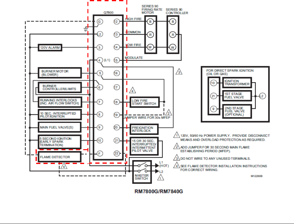
The Honeywell 7800 Series Burner Control System is a microprocessor-based integrated burner
controller for automatically fired gas, oil, or combination fuel single burner applications. The
RM7800/RM7840 Burner controls are used for UL/CSA On/Off, UL/CSA Modulating, and FM/IRI
Modulating burner applications. The 7800 series system consists of a Burner control, Dust Cover,
Subbase, Amplifier, Purge Card and Optional Keyboard Display Module (standard with RM7800
and RM7838), which includes the following models: EC7810, EC7820, EC7830, EC7840, EC7850,
RM7800, RM7838, RM7840, RM7888, RM7890, RM7897, RM7898.
Functions provided by the 7800 Series include automatic burner sequencing, flame supervision,
system status indication, system or self-diagnostics and troubleshooting.
Figure 1: Controller and Sensor/Flame Detector, Parts included in the FMEDA
© exida DRAFT_Q13-03-070 Honeywell R002 V2 R1 IEC 61508 Assessment.docx, July 12, 2013
T-034 V2R1 www.exida.com Page 10 of 21
This assessment applies to the following model numbers: EC7810A, EC7820A, EC7830A,
EC7840L, EC7850A, RM7800[E,G,L,M], RM7830A, RM7838, RM7840[E,G,L,M], RM7850A,
RM7888, RM7890, RM7897A, RM7897C and RM7898A used with one of the following flame
detectors and flame amplifiers:
a. C7008A, C7009A Flame Rod sensors with R7847B Flame Amplifier
b. C7915A infra-red sensor with R7852B Flame Amplifier
c. C7012E,F, C7061A,F,M C7961E,F, C7076A,D,F ultra-violet sensors with R7847C,
R7861A, R7851C, R7886A Flame Amplifiers
NOTE: You may also view Figure 3.2 for the model and product versions. The product versions are
referred to as series numbers below:
Figure 3.2 7800 Series Burner Control System Model and Series
Model S7830 has been assessed to be interference free and may be used with the above products
without impacting safety.
MODEL SERIES MODEL SERIES MODEL SERIES MODEL SERIES
RM7800E 3RM7897A 1C7008A 1R7847B 4
RM7800G 2RM7897C 1C7009A 1
RM7800L 4R7852B 1
RM7800M 3RM7898A 1C7915A 1
R7847C 4
RM7838A 3RM7830A 3C7012E 7
RM7838B 4C7012F 5R7861A 1
RM7838C 4RM7850A 3
C7061A 1R7851C 1
RM7840E 3EC7810A 4C7061F 1
RM7840G 2EC7820A 4C7061M 1R7886A 2
RM7840L 3EC7830A 4
RM7840M 2EC7840L 1C7961E 1
EC7850A 4C7061F 1
RM7888A 2
C7076A 1
RM7890A 4C7076D 1
RM7890B 4C7076F 1
RM7890C 4
RM7890D 4
RELAY MODULES
FLAME SENSORS
FLAME AMPLIFIERS

© exida DRAFT_Q13-03-070 Honeywell R002 V2 R1 IEC 61508 Assessment.docx, July 12, 2013
T-034 V2R1 www.exida.com Page 11 of 21
Table 1 gives an overview of the different versions that were considered in the FMEDA of the 7800
Series.
Table 1 Version Overview
RM7800 using Ampli-
Check™ RM7800 using Amplifiers with Ampli-Check diagnostics
(amplifiers: R7847B, R7852B, R7849B)
RM7800 using Self-Check™ RM7800 using Detectors/Amplifiers with Self-Check
diagnostics (C7012E,F; C7061A,F,M;C7961A,F; C7076A,D,F
with R7847C, R7861A, R7851C, R7886A)
The RM7800 is classified as a Type B1 device according to IEC 61508, having a hardware fault
tolerance of 0.
1 Type B element: “Non-Complex” element (using discrete components); for details see 7.4.4.1.3 of IEC
61508-2, ed2, 2010.

© exida DRAFT_Q13-03-070 Honeywell R002 V2 R1 IEC 61508 Assessment.docx, July 12, 2013
T-034 V2R1 www.exida.com Page 12 of 21
4 IEC 61508 Functional Safety Assessment
The IEC 61508 Functional Safety Assessment was performed based on the information received
from Honeywell and is documented here.
4.1 Methodology
As part of the IEC 61508 functional safety assessment the following aspects have been reviewed:
• Development process, including:
o Functional Safety Management, including training and competence recording, FSM
planning, and configuration management
o Specification process, techniques and documentation
o Validation activities, including development test procedures, test plans and reports,
production test procedures and documentation
o Verification activities and documentation
o Installation, operation, and maintenance requirements, including user documentation
• Product design
o Hardware architecture and failure behavior, documented in a FMEDA
• Proven-in-use Criteria
o Field Warranty Return Data and Shipping Data
4.2 Assessment level
The Honeywell 7800 Series Burner Control System has been assessed per IEC 61508 to Safety
Integrity Level 3.

© exida DRAFT_Q13-03-070 Honeywell R002 V2 R1 IEC 61508 Assessment.docx, July 12, 2013
T-034 V2R1 www.exida.com Page 13 of 21
5 Results of the IEC 61508 Functional Safety Assessment
exida assessed the development process used by Honeywell Combustion Controls during the 7800
Series Burner Control System IEC 61508 assessment against the objectives of IEC 61508 parts 1,
2, and 3, see [R01]. In addition, exida assessed the field warranty return data and shipping history
of the product to verify that the proven-in-use requirements have been met. The proven in use
evidence was then used as justification for IEC 61508 requirements related to the avoidance and
control of systematic failures. A Safety Case was created for the 7800 Series Burner Control
System thereby documenting how this product meets all of the requirements from IEC 61508. This
safety case is summarized in this report.
5.1 Lifecycle Activities and Fault Avoidance Measures
The 7800 Series Burner Control was not developed with a process that is fully compliant with IEC
61508. However, all of the requirements of IEC 61508 have been satisfied either by proven-in-use,
by a part of the development process that is compliant, or by supplemental development work that
was done in order to bring the product up to compliance. This section will summarize at a high level
how each of the requirements has been satisfied.
The result of the assessment can be summarized by the following observations:
All of the requirements of IEC 61508 SIL 3 have been satisfied either by the development
process used to originally develop the 7800 Series Burner Control System, the proven-in-use
evidence, or supplemental development work that was done in order to bring the product to
compliance.
5.1.1 Functional Safety Management
FSM Planning
Development projects are managed according to a standard development process consisting of
Tasks that belong to 1 of 6 Phases. There are Gate assessments at the end of each phase which
verify that all required tasks of that phase have been successfully completed before it is ok to
proceed to the next phase. Tasks are further detailed with who is responsible for the task.
Version Control
All documents, including design drawings are under version control as defined in [D03].
SourceSafe is used as the version control system.
Training, Competency recording
This requirement is met by the proven-in-use evidence.

© exida DRAFT_Q13-03-070 Honeywell R002 V2 R1 IEC 61508 Assessment.docx, July 12, 2013
T-034 V2R1 www.exida.com Page 14 of 21
5.1.2 Safety Requirements Specification and Architecture Design
A safety requirements specification was created for the 7800 Series Burner Control System after
the product had been in the field for many years (see [D08]). This document was created as part of
the effort to bring the product into compliance with IEC 61508. As part of the assessment, the
specification was reviewed by an independent third party, and the safety requirements checklist
was filled out as part of the review.
Items from IEC 61508-2, Table B.1 include project management, documentation, separation of
safety requirements from non-safety requirements, structured specification, inspection of the
specification, semi-formal methods and checklists.
5.1.3 Hardware Design
The requirements in the area of the hardware design process are satisfied by proven-in-use.
5.1.4 Software Design
The requirements in the area of the software design process are satisfied by proven-in-use.
5.1.5 Validation
All safety requirements were validated by an independent third party test that was done as part of
the assessment. Most requirements were validated by dynamic analysis; some requirements were
validated by static analysis. The validation test report includes a table showing how all safety
requirements have been validated. The results of the validation testing have been documented and
reviewed as part of the assessment. In addition, the proven-in-use analysis supports the validation
requirements.
Items from IEC 61508-2, Table B.5 included functional testing and functional testing under
environmental conditions, fault insertion testing, project management, documentation, failure
analysis, and field experience. This meets SIL 3.
5.1.6 Verification
The verification requirements are satisfied by the proven-in-use evidence.
5.1.7 Modifications
The modification process was not analyzed as part of this assessment. As a result, the
assessment is limited to the current version of the product as defined in section 3 of this document.
5.1.8 User documentation
A safety manual has been created for the 7800 Series Burner Control System. This safety manual
was assessed by exida. The final version is considered to be in compliance with the requirements
of IEC 61508. The document includes all required reliability data and operations, maintenance, and
proof test procedures.

© exida DRAFT_Q13-03-070 Honeywell R002 V2 R1 IEC 61508 Assessment.docx, July 12, 2013
T-034 V2R1 www.exida.com Page 15 of 21
Items from IEC 61508-2, Table B.4 include operation and maintenance instructions, user
friendliness, maintenance friendliness, project management, documentation, limited operation
possibilities, protection against operator mistakes and operation only by skilled operators. This
meets SIL 3.
5.2 Proven-in-use analysis
The functional safety standard IEC 61508 has specific requirements with regard to Proven In Use
considerations for existing products. These requirements are listed in both IEC 61508-2 and IEC
61508-3. This proven in use assessment is being done as part of a complete assessment of the
7800 Series Burner Control System.
The relevant requirements and their reference are listed in this section. For each requirement an
argument is provided why the 7800 Series Burner Control System meets this requirement.
5.2.1 IEC 61508 Proven In Use requirements
5.2.1.1 IEC 61508-2 Clause 7.4.7.6
“A previously developed subsystem shall only be regarded as proven in use when it has a clearly
restricted functionality and when there is adequate documentary evidence which is based on the
previous use of a specific configuration of the subsystem (during which time all failures have been
formally recorded, see 7.4.7.10), and which takes into account any additional analysis or testing,
as required (see 7.4.7.8). The documentary evidence shall demonstrate that the likelihood of any
failure of the subsystem (due to random hardware and systematic faults) in the E/E/PE safety-
related system is low enough so that the required safety integrity level(s) of the safety function(s)
which use the subsystem is achieved.”
For a device to be considered proven-in-use the volume of operating experience needs to
be considered. For the 7800 Series Burner Control System, this information is obtained from
the sales data which is documented in [D26].
The product and has been on the market for over 15 years.
For this assessment, operating experience and field failure rates were only considered for
units that shipped from 2005 through 2009. Units that were shipped after that date were not
counted because of the uncertainty of whether they have been installed, yet. The sales
data [D26] indicates that the total number of shipped units during this time period is over
50,000. For failure rates calculated on the basis of field returns only the hours recorded
during the warranty period of the manufacturer are used by exida, since this is the only time
frame when failures can be expected to be reported. It must be assumed that all failures
after the warranty period are not reported to the manufacturer.
Honeywell offers a 12 month warranty period; this period starts on the date of
installation. Volume of operating experience must be based on installation dates and
not on shipment dates. Since installation dates are not available, it is assumed that
the relays are installed 6 months after shipment. From these assumptions, the
number of operational hours is estimated to be 410,143,608.
These operating hours are considered to be sufficient taking into account the medium
complexity of the sub-system and the use in SIL 3 safety functions.

© exida DRAFT_Q13-03-070 Honeywell R002 V2 R1 IEC 61508 Assessment.docx, July 12, 2013
T-034 V2R1 www.exida.com Page 16 of 21
The warranty database case history [D26] indicates that 282 failures were found during this
period.
There is no evidence that all devices are returned when a failure occurs within the warranty
period. Therefore it is to be assumed that only 70% of failures are returned. This leads to
the following number of estimated failures for the 7800:
Estimated failures = 282 / 0.7 = 403 failures
From this information, an overall failure rate for the 7800 Series Burner Control System can
be calculated. The failure rate point estimate yields 9.82E-07 [1/hr]. IEC 61508 requires the
calculation of a 70% upper confidence limit for the failure rate. Given the data above the
70% upper confidence limit for the failure rate equals 1.01E-06 [1/hr].
This information must be compared to the information obtained from a Failure Modes,
Effects and Diagnostic Analysis of the product. The failure rates calculated from the field
data must be less than the failure rates obtained from the FMEDA. If the field failure rate is
larger this is an indication of serious systematic design issues.
The FMEDA shows that the 7800 Series Burner Control System has an expected failure
rate of 1.07E-06 [1/hr]. Therefore, the actual failure rate is less than the failure predicted by
the FMEDA, which shows that there is not a significant number of systematic design issues.
5.2.2 IEC 61508-2 Clause 7.4.7.7
“The documentary evidence required by 7.4.7.6 shall demonstrate that the previous conditions of
use (see note) of the specific subsystem are the same as, or sufficiently close to, those which will
be experienced by the subsystem in the E/E/PE safety-related system, in order to determine that
the likelihood of any unrevealed systematic faults is low enough so that the required safety
integrity level(s) of the safety function(s) which use the subsystem is achieved.
NOTE The conditions of use (operational profile) include all the factors which may influence the likelihood of
systematic faults in the hardware and software of the subsystem. For example, environment, modes of use,
functions performed, configuration, interfaces to other systems, operating system, translator, human factors.”
The 7800 Series Burner Control System is a device with a very specific function which is
control all functions of a burner system. Therefore, the device will be used in a similar
manner as it was previously used. In addition, this device is used in industrial
environments, so the operating conditions encountered are likely to be similar.
Consequently, as the conditions of use are considered identical or sufficiently close, this
requirement is met.
5.2.3 IEC 61508-2 Clause 7.4.7.8
“When there is any difference between the previous conditions of use and those which will be
experienced in the E/E/PE safety-related system, then any such difference(s) shall be identified
and there shall be an explicit demonstration, using a combination of appropriate analytical
methods and testing, in order to determine that the likelihood of any unrevealed systematic faults
is low enough so that the required safety integrity level(s) of the safety function(s) which use the
subsystem is achieved.”
As stated in section 5.2.2 the previous conditions of use for the 7800 Series Burner Control
System and the expected conditions of use are considered to be identical or sufficiently
close. Therefore this requirement is met.

© exida DRAFT_Q13-03-070 Honeywell R002 V2 R1 IEC 61508 Assessment.docx, July 12, 2013
T-034 V2R1 www.exida.com Page 17 of 21
5.2.4 IEC 61508-2 Clause 7.4.7.9
“The documentary evidence required by 7.4.7.6 shall establish that the extent of previous use of
the specific configuration of the subsystem (in terms of operational hours), is sufficient to support
the claimed rates of failure on a statistical basis. As a minimum, sufficient operational time is
required to establish the claimed failure rate data to a single-sided lower confidence limit of at
least 70 % (see IEC 61508-7, annex D and IEEE 352). An operational time of any individual
subsystem of less than one year shall not be considered as part of the total operational time in the
statistical analysis (see note).
NOTE The necessary time, in terms of operational hours, required to establish the claimed rates of failure
may result from the operation of a number of identical subsystems, provided that failures from all the
subsystems have been effectively detected and reported (see 7.4.7.10). If, for example, 100 subsystems each
work fault-free for 10,000 h, then the total time of fault-free operation may be considered as 1,000,000 h. In
this case, each subsystem has been in use for over a year and the operation therefore counts towards the
total number of operational hours considered.”
For a failure rate the lower confidence limit that the standard refers to is not conservative, so
exida uses an upper confidence limit.
The calculated operational hours for the 7800 Series Burner Control System are
410,143,608. These operating hours are considered to be sufficient taking into account the
medium complexity of the sub-system and the use in safety functions up to SIL 3. A single
sided upper confidence limit of 70% is calculated for the failure rate derived from the field
failure data of the 7800 Series Burner Control System. As a result this requirement is met.
5.2.5 IEC 61508-2 Clause 7.4.7.10
“Only previous operation where all failures of the subsystem have been effectively detected and
reported (for example, when failure data has been collected in accordance with the
recommendations of IEC 60300-3-2) shall be taken into account when determining whether the
above requirements (7.4.7.6 to 7.4.7.9) have been met.”
Assuming 100% failure reporting is unrealistic irrespective of the failure data reporting and
collection methods utilized. Consequently in the Proven In Use failure rate calculation it is
assumed that only a percentage of the actual failures is reported during the warranty period.
This percentage is 70%. Based on this assumption it is argued that this requirement is met.
5.2.6 IEC 61508-2 Clause 7.4.7.11
“The following factors shall be taken into account when determining whether or not the above
requirements (7.4.7.6 to 7.4.7.9) have been met, in terms of both the coverage and degree of detail
of the available information (see also 4.1 of IEC 61508-1):
a) the complexity of the subsystem;
b) the contribution made by the subsystem to the risk reduction;
c) the consequence associated with a failure of the subsystem;
d) the novelty of design.”

© exida DRAFT_Q13-03-070 Honeywell R002 V2 R1 IEC 61508 Assessment.docx, July 12, 2013
T-034 V2R1 www.exida.com Page 18 of 21
Each of the factors listed in this clause have been considered in the above requirements.
The design is not considered to be overly complex compared to other similar products. In
addition, the design was created almost 20 years ago, so the design cannot be considered
novel , but rather it is a proven device, similarly designed to other comparable products.
The consequence associated with failure of this subsystem is application dependent and
therefore is not known at this time. The contribution by this device to the risk reduction will
be relatively small since it is only one part of the safety related system, and since good
standard practice involves creating other layers of protection as well. Consequently this
requirement has been met.
5.2.7 IEC 61508-2 Clause 7.4.7.12
“The application of a "proven-in-use" safety-related subsystem in the E/E/PE safety related
system should be restricted to those functions and interfaces of the subsystem which meet the
relevant requirements (see 7.4.7.6 to 7.4.7.10).
NOTE The measures 7.4.7.4 to 7.4.7.12 are also applicable for subsystems which contain software. In this
case it has to be assured that the subsystem performs in its safety related application only that function for
which evidence of the required safety integrity is given. See also 7.4.2.11 of IEC 61508-3.”
The 7800 Series Burner Control System has a limited set of safety functions which apply to
all installations. These functions meet the requirements of 7.4.7.6 to 7.4.7.10 as stated
above. Consequently this requirement is met.

© exida DRAFT_Q13-03-070 Honeywell R002 V2 R1 IEC 61508 Assessment.docx, July 12, 2013
T-034 V2R1 www.exida.com Page 19 of 21
5.3 Hardware Assessment
To evaluate the hardware design of the Honeywell 7800 Series Burner Control System, a Failure
Modes, Effects, and Diagnostic Analysis was performed. This is documented in [R3]. The FMEDA
was verified using Fault Injection Testing as part of the assessment (see [D35]).
A Failure Modes and Effects Analysis (FMEA) is a systematic way to identify and evaluate the
effects of different component failure modes, to determine what could eliminate or reduce the
chance of failure, and to document the system in consideration. An FMEDA (Failure Mode Effect
and Diagnostic Analysis) is an FMEA extension. It combines standard FMEA techniques with
extension to identify online diagnostics techniques and the failure modes relevant to safety
instrumented system design.
From the FMEDA failure rates are derived for each important failure category. Table 1 lists these
failure rates as reported in the FMEDA reports. The failure rates are valid for the useful life of the
devices, which are defined as in the FMEDA report [R3] as approximately 10 years. This
information is listed in the Safety Manual, see [D22].
Table 1: Failure rates for Simplex Safety PLC according to IEC 61508
(*Note that the SD and SU category includes failures that do not cause a spurious trip)
Device λSD λSU2 λDD λDU SFF
RM7800 using Amplifiers
with Ampli-Check
diagnostics 830 FIT 146 FIT 0 FIT 7 FIT 99.3%
RM7800 using
Detectors/Amplifiers with
Self-Check diagnostics 967 FIT 146 FIT 0 FIT 8 FIT 99.3%
These results must be considered in combination with PFDAVG or PFH values of other devices of a
Safety Instrumented Function (SIF) in order to determine suitability for a specific Safety Integrity
Level (SIL). The Safety Manual states that the application engineer should calculate the PFDAVG or
PFH for each defined safety instrumented function (SIF) to verify the design of that SIF.
The architectural constraints requirements of IEC 61508-2, Table 2 are also reviewed. The 7800
Series Burner Control System is classified as a Type B device according to IEC 61508, having a
hardware fault tolerance of 0. The analysis shows that the system has a safe failure fraction > 99%
and therefore per even worst case assumptions, the non-redundant unit may be used up to SIL
3 based on architecture constraints.
The analysis shows that design of The Honeywell 7800 Series Burner Control System meets
the hardware requirements of IEC 61508 SIL 3 when used as a single element (HFT = 0).
2 It is important to realize that the No Effect failures are no longer included in the Safe Undetected failure
category according to IEC 61508, ed2, 2010.

© exida DRAFT_Q13-03-070 Honeywell R002 V2 R1 IEC 61508 Assessment.docx, July 12, 2013
T-034 V2R1 www.exida.com Page 20 of 21
6 Terms and Definitions
DET De-energize to trip
ET Energize to trip
Fault tolerance Ability of a functional unit to continue to perform a required function in the
presence of faults or errors (IEC 61508-4, 3.6.3)
FIT Failure In Time (1x10⁻⁹ failures per hour)
FMEDA Failure Mode Effect and Diagnostic Analysis
HFT Hardware Fault Tolerance
Low demand mode Mode, where the frequency of demands for operation made on a safety-
related system is no greater than twice the proof test frequency.
PFDAVG Average Probability of Failure on Demand
SFF Safe Failure Fraction summarizes the fraction of failures, which lead to a
safe state and the fraction of failures which will be detected by diagnostic
measures and lead to a defined safety action.
SIF Safety Instrumented Function
SIL Safety Integrity Level
SIS Safety Instrumented System – Implementation of one or more Safety
Instrumented Functions. A SIS is composed of any combination of
sensor(s), logic solver(s), and final element(s).
Type A element “Non-Complex” element (using discrete components); for details see
7.4.4.1.2 of IEC 61508-2
Type B element “Complex” element (using complex components such as micro controllers or
programmable logic); for details see 7.4.4.1.3 of IEC 61508-2

© exida DRAFT_Q13-03-070 Honeywell R002 V2 R1 IEC 61508 Assessment.docx, July 12, 2013
T-034 V2R1 www.exida.com Page 21 of 21
7 Status of the document
7.1 Liability
exida prepares reports based on methods advocated in International standards. Failure rates are
obtained from a collection of industrial databases. exida accepts no liability whatsoever for the use
of these numbers or for the correctness of the standards on which the general calculation methods
are based.
7.2 Releases
Version: V2
Revision: R1
Version History: V2, R1: Updated to 2010 standard; included 4 new models: C7061M, C7076F,
RM7888A1019, and RM7888A1927 and analyzed the S7830; TES
July 3, 2013
V1, R2: Updated version number table, R. Chalupa, March 4, 2011
V1, R1: Expanded model list, R. Chalupa, February 28, 2011
V1, R0: Added product version numbers; Updated FMEDA and PIU Data;
Updated Document Versions/Dates; June 3rd, 2010
V0, R2: Reviewed Draft, May 29th, 2010
V0, R1: Draft; May 28th, 2010
Authors: Michael Medoff
Review: V0, R1: Dr. William Goble;
Release status: Released
7.3 Future Enhancements
At request of client.
7.4 Release Signatures
Dr. William M. Goble, Principal Partner
Michael Medoff, Senior Safety Engineer
