Motion Controller Quick Start Guide CONTROLLERS Q172DCPU Q170MCPU,Q172DCPU,Q173DCPU A(09.09)
User Manual: MOTION CONTROLLERS Q172DCPU
Open the PDF directly: View PDF ![]() .
.
Page Count: 88
- Title
- Status of Revision
- About This Manual
- Related Manuals
- Safety Guidelines
- Screenshots and Software version
- Typographic Conventions
- Table of Contents
- 1 Introduction
- 2 Details of the modules
- 3 Mounting and wiring
- 4 Start-up and trial operation
- 4.1 Start-up procedure
- 4.2 Software installation
- 4.2.1 Programming software
- 4.2.2 Operating system (OS)
- b Set the rotary switch 1 (on the motion controller) to "A" to set the installation mode.
- d Select "Start" - "All Programs" - "MELSOFT Application" - "MT Works2" - "Install".
- e The installation screen appears. Select "Online" - "Transfer Setup" to set the communication setup screen. Further details in the section "Transfer setup" (section 5.2.1) of this quick-start guide.
- f Click the button Install Motion Controller OS. When the motion controller OS has already been installed, the OS type and version are displayed in addition to the CPU type.
- h Click the button Browse and specify the OS's source folder. The CPU type, OS type and version appear.
- i Click the button Execution. The installation is started.
- 5 Project creation
- 5.1 Sample project creation with MT Developer2 and GX Developer
- 5.2 Additional procedures
- 5.2.1 Transfer setup
- 5.2.2 Project opening
- 5.2.3 Writing project to the Motion/PLC CPU
- b Select Program memory as target memory to write to.
- c Click on Parameter+ Program to select the data to be written.
- d Click the Execute button. When a password is registered, the Password Check dialog box appears. When program write is to be executed, a message appears if there are programs that have not been converted.
- e The screen on the left appears if the motion controller is in RUN mode. Click the OK button.
- b Select Program memory/Device memory as target memory to write to.
- c Click on Parameter+ Program to select the data to be written.
- d Click the Execute button. When program write is to be executed, a message appears if there are programs that have not been converted.
- e The screen on the left appears if the motion controller is in RUN mode. Click the Yes button.
- 5.2.4 Monitoring function
- 5.2.5 Device monitoring and testing
- 5.2.6 Motion CPU change
- c The "CPU/OS Change" screen appears. Select a CPU type and OS type. Click the OK button.
- Click the Yes button to change the CPU or OS type. Click the No button to stop the change of the CPU or OS type.
- d The confirmation screen appears asking wether to change the OS type. Click the Yes button.
- e A dialog box appears notifying the CPU and OS types have been changed. Click the OK button.
- 6 Sample programs
- A Appendix
- Index

MITSUBISHI ELECTRIC
MITSUBISHI ELECTRIC
INDUSTRIAL AUTOMATION
MELSEC System Q
Programmable Controllers
Quick-Start Guide
Motion Controller
Q170MCPU
Q172DCPU
Q173DCPU
Art. No.:
09 09 2009
Version A

Quick-Start Guide
Motion controller Q170MCPU/Q172DCPU/Q173DCPU
Art. no.:
Version Revisions/Additions/Corrections
A 09/2009 pdp - rw —
About This Manual
The texts, illustration, diagrams and examples in this manual are provided
for information purposes only. They are intended as aids to help explain the
installation, operation, programming and use of the
Mitsubishi motion controllers.
If you have any questions about the installation and operation of any of the
products described in this manual please contact your local sales office
or distributor (see back cover). You can find the latest information
and answers to frequently asked questions on our website at
www.mitsubishi-automation.com.
MITSUBISHI ELECTRIC EUROPE BV reserves the right to make changes
to this manual or the technical specifications of its products at any time without notice.
©2005
MITSUBISHI ELECTRIC EUROPE B.V.

Related Manuals
The following manuals are also related to this Quick-Start Guide. These can be obtained free of charge
from our website at www.mitsubishi-automation.com.
Device Manual Name Manual Number/
Art. No.
Motion controller
Q170MCPU Motion controller User's Manual
This manual explains specifications of the Q170MCPU Motion controller, Q172DLX Servo external signal
interface module, Q173DPX Manual pulse generator interface module, Servo amplifiers, SSCNET cables,
and the maintenance/inspection for the system, trouble shooting and others.
IB-0300156
Q173DCPU/Q172DCPU Motion controller Programming Manual (COMMON)
This manual explains the Multiple CPU system configuration, performance specifications, common
parameters, auxiliary/applied functions, error lists and others.
IB-0300134
Q173DCPU/Q172DCPU Motion controller (SV13/SV22) Programming Manual (Motion SFC)
This manual explains the functions, programming, debugging, error lists for Motion SFC and others. IB-0300135
Q173DCPU/Q172DCPU Motion controller (SV13/SV22) Programming Manual (REAL MODE)
This manual explains the servo parameters, positioning instructions, device lists, error lists and others. IB-0300136
Q173DCPU/Q172DCPU Motion controller (SV22) Programming Manual (VIRTUAL MODE)
This manual explains the dedicated instructions to use the synchronous control by virtual main shaft,
mechanical system program create mechanical module, servo parameters, positioning instructions,
device lists, error lists and others.
IB-0300137
Motion controller Setup Guidance (MT Developer2 Version1)
This manual explains the items related to the setup of the Motion controller programming software MT
Developer2.
IB-0300142
PLC
QCPU User's Manual (Hardware Design, Maintenance and Inspection)
This manual explains the specifications of the QCPU modules, power supply modules, base units, exten-
sion cables, memory card battery, and the maintenance/inspection for the system, trouble shooting,
error codes and others.
SH-080483ENG
QnUCPU User's Manual (Function Explanation, Program Fundamentals)
This manual explains the functions, programming methods and devices and others to create programs
with the QCPU.
SH-080807ENG
QCPU User's Manual (Multiple CPU System)
This manual explains the Multiple CPU system overview, system configuration, I/O modules, communi-
cation between CPU modules and communication with the I/O modules or intelligent function mod-
ules.
SH-080485ENG
QCPU Programming Manual (Common Instructions)
This manual explains how to use the sequence instructions, basic instructions, application instructions
and micro computer program.
SH-080809ENG
QCPU (Q Mode)/QnACPU Programming Manual (PID Control Instructions)
This manual explains the dedicated instructions used to exercise PID control. SH-080040
QCPU (Q Mode)/QnACPU Programming Manual (SFC)
This manual explains the system configuration, performance specifications, functions, programming,
debugging, error codes and others of MELSAP3.
SH-080041
I/O Module Type Building Block User's Manual
This manual explains the specifications of the I/O modules, connector, connector/terminal block con-
version modules and others.
SH-080042
Servo amplifier
SSCNET III Compatible MR-J3-쏔B Servo amplifier Instruction Manual
This manual explains the I/O signals, parts names, parameters, start-up procedure and others for MR-J3-
쏔B Servo amplifier.
SH-030051
SSCNET III Compatible Linear Servo MR-J3-쏔B-RJ004 Servo amplifier Instruction Manual
This manual explains the I/O signals, parts names, parameters, start-up procedure and others for Linear
Servo MR-J3-쏔B-RJ004 Servo amplifier.
SH-030054
SSCNET III Compatible Fully Closed Loop Control MR-J3-쏔B-RJ006 Servo amplifier Instruction Manual
This manual explains the I/O signals, parts names, parameters, start-up procedure and others for Fully
Closed Loop Control MR-J3-쏔B-RJ006 Servo amplifier.
SH-030056
SSCNET III Compatible, STO Function Compatible MR-J3-쏔BSafety Servo amplifier Instruction Manual
This manual explains the I/O signals, parts names, parameters, start-up procedure and others for safety
servo MR-J3-쏔BSafety Servo amplifier.
SH-030084

Motion controller Q170MCPU/ Q172DCPU/ Q173DCPU I
Safety Guidelines
General safety information and precautions
For use by qualified staff only
This manual is only intended for use by properly trained and qualified electrical technicians who are
fully acquainted with the relevant automation technology safety standards. All work with the hard-
ware described, including system design, installation, configuration, maintenance, service and test-
ing of the equipment, may only be performed by trained electrical technicians with approved qual-
ifications who are fully acquainted with all the applicable automation technology safety standards
and regulations. Any operations or modifications to the hardware and/or software of our products
not specifically described in this manual may only be performed by authorised MITSUBISHI ELECTRIC
staff.
Proper use of the products
The motion controllers are only intended for the specific applications explicitly described in this man-
ual. All parameters and settings specified in this manual must be observed. The products described
have all been designed, manufactured, tested and documented in strict compliance with the relevant
safety standards. Unqualified modification of the hardware or software or failure to observe the warn-
ings on the products and in this manual may result in serious personal injury and/or damage to prop-
erty. Only peripherals and expansion equipment specifically recommended and approved by
MITSUBISHI ELECTRIC may be used in combination with programmable controllers of MELSEC
System Q.
All and any other uses or application of the products shall be deemed to be improper.
Relevant safety regulations
All safety and accident prevention regulations relevant to your specific application must be observed
in the system design, installation, configuration, maintenance, servicing and testing of these products.
The regulations listed below are particularly important in this regard.
This list does not claim to be complete, however; you are responsible for being familiar with and con-
forming to the regulations applicable to you in your location.
●VDE Standards
– VDE 0100
Regulations for the erection of power installations with rated voltages below 1000 V
– VDE 0105
Operation of power installations
– VDE 0113
Electrical installations with electronic equipment
– VDE 0160
Electronic equipment for use in power installations
– VDE 0550/0551
Regulations for transformers
– VDE 0700
Safety of electrical appliances for household use and similar applications
– VDE 0860
Safety regulations for mains-powered electronic appliances and their accessories for house-
hold use and similar applications.

II
●Fire safety regulations
●Accident prevention regulations
–VBG Nr.4
Electrical systems and equipment
Safety warnings in this manual
In this manual warnings that are relevant for safety are identified as follows:
m
DANGER:
Failure to observe the safety warnings identified with this symbol can result in health and injury
hazards for the user.
b
WARNING:
Failure to observe the safety warnings identified with this symbol can result in damage to the
equipment or other property.

Motion controller Q170MCPU/ Q172DCPU/ Q173DCPU III
Specific safety information and precautions
The following safety precautions are intended as a general guideline for using PLC systems together
with other equipment. These precautions must always be observed in the design, installation and op-
eration of all control systems.
m
DANGER:
●Observe all safety and accident prevention regulations applicable to your specific applica-
tion. Always disconnect all power supplies before performing installation and wiring work
or opening any of the assemblies, components and devices.
●Assemblies, components and devices must always be installed in a shockproof housing fitted
with a proper cover and fuses or circuit breakers.
●Devices with a permanent connection to the mains power supply must be integrated in the
building installations with an all-pole disconnection switch and a suitable fuse.
●Check power cables and lines connected to the equipment regularly for breaks and insulation
damage. If cable damage is found immediately disconnect the equipment and the cables
from the power supply and replace the defective cabling.
●Before using the equipment for the first time check that the power supply rating matches that
of the local mains power.
●Take appropriate steps to ensure that cable damage or core breaks in the signal lines cannot
cause undefined states in the equipment.
●You are responsible for taking the necessary precautions to ensure that programs interrupt-
ed by brownouts and power failures can be restarted properly and safely. In particular, you
must ensure that dangerous conditions cannot occur under any circumstances, even for brief
periods.
●EMERGENCY OFF facilities conforming to EN 60204/IEC 204 and VDE 0113 must remain fully
operative at all times and in all PLC operating modes. The EMERGENCY OFF facility reset
function must be designed so that it cannot ever cause an uncontrolled or undefined restart.
●You must implement both hardware and software safety precautions to prevent the possibil-
ity of undefined control system states caused by signal line cable or core breaks.
●When using modules always ensure that all electrical and mechanical specifications and
requirements are observed exactly.
●Residual current protective devices pursuant to DIN VDE Standard 0641 Parts 1-3 are not
adequate on their own as protection against indirect contact for installations with PLC
systems. Additional and/or other protection facilities are essential for such installations.
●Do not install/remove the module onto/from base unit or terminal block more than 50 times,
after the first use of the product (conforming to IEC 61131-2). Failure to do so may cause the
module to malfunction due to poor contact of connector.

IV
Precautions to prevent damages by electrostatic discharge
Electronic devices and modules can be damaged by electrostatic charge, which is conducted from the
human body to components of the PLC. Always take the following precautions, when handling the
PLC:
b
WARNING:
●Before touching a module of the PLC, always touch grounded metal, etc. to discharge static
electricity from human body.
●Wear isolating gloves when touching the powered PLC, e. g. at maintenance during visual
check.
●You shouldn’t wear clothing made of synthetic fibre at low humidity. This clothing gets a very
high rate of electrostatic charge.


VI
Typographic Conventions
Use of notes
Notes containing important information are clearly identified as follows:
Use of examples
Examples containing important information are clearly identified as follows:
Numbering in figures and illustrations
Reference numbers in figures and illustrations are shown with white numbers in a black circle and the
corresponding explanations shown beneath the illustrations are identified with the same numbers,
like this:
Procedures
In some cases the setup, operation, maintenance and other instructions are explained with num-
bered procedures. The individual steps of these procedures are numbered in ascending order with
black numbers in a white circle, and they must be performed in the exact order shown:
Text.
Text.
Text.
Footnotes in tables
Footnote characters in tables are printed in superscript and the corresponding footnotes shown be-
neath the table are identified by the same characters, also in superscript.
If a table contains more than one footnote, they are all listed below the table and numbered in as-
cending order with black numbers in a white circle, like this:
Text
Text
Text
NOTE Note text
Example 왓Example text 쑶

Table of Contents
Motion controller Q170MCPU/ Q172DCPU/ Q173DCPU VII
Table of Contents
1 Introduction
1.1 What is motion control? . . . . . . . . . . . . . . . . . . . . . . . . . . . . . . . . . . . . . . . . . . . . . . . . . . . . . . . . . . . . . . . . 1-1
1.1.1 Block diagram of a motion control system. . . . . . . . . . . . . . . . . . . . . . . . . . . . . . . . . . . . . . 1-2
1.1.2 Difference between Q170MCPU and QD Motion controllers . . . . . . . . . . . . . . . . . . . . 1-2
1.2 Specification . . . . . . . . . . . . . . . . . . . . . . . . . . . . . . . . . . . . . . . . . . . . . . . . . . . . . . . . . . . . . . . . . . . . . . . . . . . 1-3
1.2.1 Q170MCPU . . . . . . . . . . . . . . . . . . . . . . . . . . . . . . . . . . . . . . . . . . . . . . . . . . . . . . . . . . . . . . . . . . . 1-3
1.2.2 Q172DCPU, Q173DCPU. . . . . . . . . . . . . . . . . . . . . . . . . . . . . . . . . . . . . . . . . . . . . . . . . . . . . . . . 1-4
1.3 Terminology . . . . . . . . . . . . . . . . . . . . . . . . . . . . . . . . . . . . . . . . . . . . . . . . . . . . . . . . . . . . . . . . . . . . . . . . . . . 1-5
2 Details of the modules
2.1 Q170MCPU . . . . . . . . . . . . . . . . . . . . . . . . . . . . . . . . . . . . . . . . . . . . . . . . . . . . . . . . . . . . . . . . . . . . . . . . . . . . 2-1
2.1.1 Frontview and partnames . . . . . . . . . . . . . . . . . . . . . . . . . . . . . . . . . . . . . . . . . . . . . . . . . . . . . 2-1
2.1.2 System configuration. . . . . . . . . . . . . . . . . . . . . . . . . . . . . . . . . . . . . . . . . . . . . . . . . . . . . . . . . . 2-3
2.1.3 Minimum equipment. . . . . . . . . . . . . . . . . . . . . . . . . . . . . . . . . . . . . . . . . . . . . . . . . . . . . . . . . . 2-4
2.2 Q172DCPU/Q173DCPU. . . . . . . . . . . . . . . . . . . . . . . . . . . . . . . . . . . . . . . . . . . . . . . . . . . . . . . . . . . . . . . . . 2-5
2.2.1 Frontview and partnames . . . . . . . . . . . . . . . . . . . . . . . . . . . . . . . . . . . . . . . . . . . . . . . . . . . . . 2-5
2.2.2 System configuration. . . . . . . . . . . . . . . . . . . . . . . . . . . . . . . . . . . . . . . . . . . . . . . . . . . . . . . . . . 2-6
2.2.3 Minimum equipment. . . . . . . . . . . . . . . . . . . . . . . . . . . . . . . . . . . . . . . . . . . . . . . . . . . . . . . . . . 2-7
3 Mounting and wiring
3.1 Module mounting into cabinet . . . . . . . . . . . . . . . . . . . . . . . . . . . . . . . . . . . . . . . . . . . . . . . . . . . . . . . . . 3-1
3.1.1 Mounting of Q170MCPU. . . . . . . . . . . . . . . . . . . . . . . . . . . . . . . . . . . . . . . . . . . . . . . . . . . . . . . 3-1
3.1.2 Mounting of Q172DCPU/Q173DCPU . . . . . . . . . . . . . . . . . . . . . . . . . . . . . . . . . . . . . . . . . . . 3-3
3.2 Wiring . . . . . . . . . . . . . . . . . . . . . . . . . . . . . . . . . . . . . . . . . . . . . . . . . . . . . . . . . . . . . . . . . . . . . . . . . . . . . . . . . 3-6
3.2.1 Wiring for Q170MCPU . . . . . . . . . . . . . . . . . . . . . . . . . . . . . . . . . . . . . . . . . . . . . . . . . . . . . . . . . 3-6
3.2.2 Wiring for QD Motion controller . . . . . . . . . . . . . . . . . . . . . . . . . . . . . . . . . . . . . . . . . . . . . .3-10
3.3 SSCNET III connection . . . . . . . . . . . . . . . . . . . . . . . . . . . . . . . . . . . . . . . . . . . . . . . . . . . . . . . . . . . . . . . . .3-11
3.3.1 SSCNET III cable . . . . . . . . . . . . . . . . . . . . . . . . . . . . . . . . . . . . . . . . . . . . . . . . . . . . . . . . . . . . . . 3-11
3.3.2 Connection between the Q170MCPU and servo amplifiers. . . . . . . . . . . . . . . . . . . . .3-11
3.3.3 Connection between the Q172DCPU and servo amplifiers . . . . . . . . . . . . . . . . . . . . .3-12
3.3.4 Connection between the Q173DCPU and servo amplifiers . . . . . . . . . . . . . . . . . . . . .3-13
3.3.5 Setting the axis No. and axis select switch of servo amplifier . . . . . . . . . . . . . . . . . . .3-14
4 Start-up and trial operation
4.1 Start-up procedure . . . . . . . . . . . . . . . . . . . . . . . . . . . . . . . . . . . . . . . . . . . . . . . . . . . . . . . . . . . . . . . . . . . . . 4-2
4.2 Software installation . . . . . . . . . . . . . . . . . . . . . . . . . . . . . . . . . . . . . . . . . . . . . . . . . . . . . . . . . . . . . . . . . . . 4-4
4.2.1 Programming software . . . . . . . . . . . . . . . . . . . . . . . . . . . . . . . . . . . . . . . . . . . . . . . . . . . . . . . . 4-4
4.2.2 Operating system (OS). . . . . . . . . . . . . . . . . . . . . . . . . . . . . . . . . . . . . . . . . . . . . . . . . . . . . . . . . 4-4

Table of Contents
VIII
5 Project creation
5.1 Sample project creation with MT Developer2 and GX Developer . . . . . . . . . . . . . . . . . . . . . . . . . 5-1
5.2 Additional procedures. . . . . . . . . . . . . . . . . . . . . . . . . . . . . . . . . . . . . . . . . . . . . . . . . . . . . . . . . . . . . . . . .5-11
5.2.1 Transfer setup. . . . . . . . . . . . . . . . . . . . . . . . . . . . . . . . . . . . . . . . . . . . . . . . . . . . . . . . . . . . . . . . 5-11
5.2.2 Project opening . . . . . . . . . . . . . . . . . . . . . . . . . . . . . . . . . . . . . . . . . . . . . . . . . . . . . . . . . . . . . . 5-12
5.2.3 Writing project to the Motion/PLC CPU. . . . . . . . . . . . . . . . . . . . . . . . . . . . . . . . . . . . . . . . 5-13
5.2.4 Monitoring function . . . . . . . . . . . . . . . . . . . . . . . . . . . . . . . . . . . . . . . . . . . . . . . . . . . . . . . . . . 5-15
5.2.5 Device monitoring and testing. . . . . . . . . . . . . . . . . . . . . . . . . . . . . . . . . . . . . . . . . . . . . . . .5-16
5.2.6 Motion CPU change . . . . . . . . . . . . . . . . . . . . . . . . . . . . . . . . . . . . . . . . . . . . . . . . . . . . . . . . . . 5-17
6 Sample programs
6.1 Sample program with OS SV22: 2_axes_motion . . . . . . . . . . . . . . . . . . . . . . . . . . . . . . . . . . . . . . . . . 6-1
6.1.1 System configuration. . . . . . . . . . . . . . . . . . . . . . . . . . . . . . . . . . . . . . . . . . . . . . . . . . . . . . . . . . 6-1
6.1.2 Functions . . . . . . . . . . . . . . . . . . . . . . . . . . . . . . . . . . . . . . . . . . . . . . . . . . . . . . . . . . . . . . . . . . . . . 6-2
6.1.3 System setting data of the motion CPU. . . . . . . . . . . . . . . . . . . . . . . . . . . . . . . . . . . . . . . . . 6-3
6.1.4 Axis Data Setting . . . . . . . . . . . . . . . . . . . . . . . . . . . . . . . . . . . . . . . . . . . . . . . . . . . . . . . . . . . . . . 6-4
6.1.5 Motion SFC Program . . . . . . . . . . . . . . . . . . . . . . . . . . . . . . . . . . . . . . . . . . . . . . . . . . . . . . . . . . 6-5
6.1.6 Mechanical system program . . . . . . . . . . . . . . . . . . . . . . . . . . . . . . . . . . . . . . . . . . . . . . . . . . . 6-8
6.1.7 CAMs . . . . . . . . . . . . . . . . . . . . . . . . . . . . . . . . . . . . . . . . . . . . . . . . . . . . . . . . . . . . . . . . . . . . . . . . . 6-9
6.2 Sample program with OS SV22: 2_axes_motion_no_inputs. . . . . . . . . . . . . . . . . . . . . . . . . . . . . 6-10
6.2.1 System configuration. . . . . . . . . . . . . . . . . . . . . . . . . . . . . . . . . . . . . . . . . . . . . . . . . . . . . . . . .6-10
6.2.2 Functions . . . . . . . . . . . . . . . . . . . . . . . . . . . . . . . . . . . . . . . . . . . . . . . . . . . . . . . . . . . . . . . . . . . .6-11
AAppendix
A.1 Exterior Dimensions . . . . . . . . . . . . . . . . . . . . . . . . . . . . . . . . . . . . . . . . . . . . . . . . . . . . . . . . . . . . . . . . . . . .A-1
A.1.1 Motion controller Q170MCPU. . . . . . . . . . . . . . . . . . . . . . . . . . . . . . . . . . . . . . . . . . . . . . . . . .A-1
A.1.2 Motion controller Q172DCPU and Q173DCPU . . . . . . . . . . . . . . . . . . . . . . . . . . . . . . . . . .A-2
A.2 Troubleshooting . . . . . . . . . . . . . . . . . . . . . . . . . . . . . . . . . . . . . . . . . . . . . . . . . . . . . . . . . . . . . . . . . . . . . . .A-3
A.2.1 Q170MCPU . . . . . . . . . . . . . . . . . . . . . . . . . . . . . . . . . . . . . . . . . . . . . . . . . . . . . . . . . . . . . . . . . . .A-3
A.2.2 QD-Motion controller. . . . . . . . . . . . . . . . . . . . . . . . . . . . . . . . . . . . . . . . . . . . . . . . . . . . . . . . . .A-4

What is motion control? Introduction
Motion controller Q170MCPU/ Q172DCPU/ Q173DCPU 1 - 1
1 Introduction
This english document is the original instruction.
This start-up guidance is intended for those who use the Q170MCPU standalone motion controller
and QD-Motion controller for the first time. How to use programming tool MT Works2 for motion CPU
and programming tool GX (IEC) Developer for sequencer CPU will be explained.
Refer to our QD-Motion controller/Q170MCPU manuals for further information.
(For manual numbers see preamble of this quick start guide.)
1.1 What is motion control?
A Motion control system comes from the combination of a Motion CPU and a PLC CPU.
While the Motion CPU controls complex servo movements by synchronizing the connected servo ax-
es, the PLC CPU is responsible for machine's general control and communication.
With a motion control system you are able to solve different positioning applications from position-
ing with one axis in small production lines up to multi-axis positioning in large-scale systems.
The Motion CPU controls different more or less complex motion sequences via the connected servo
amplifiers and motors.
Typical applications of a motion control systems are:
●Plastics and textile processing,
●Packaging,
●Printing and paper converting,
●Forming,
●Wood and glass working,
●Production of semiconductors.
Introduction What is motion control?
1 - 2
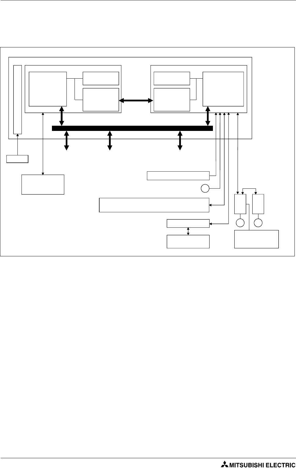
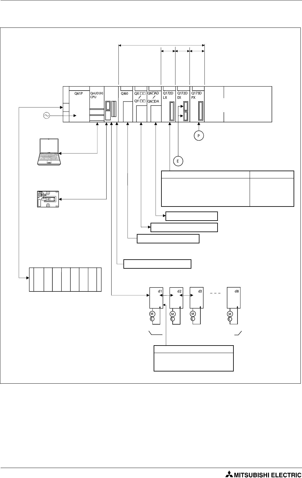
1.1.1 Block diagram of a motion control system
The following diagram shows the components of a motion control system with CPUs, modules, servo
amplifiers and motors.
All of Mitsubishi motion controllers exploit the potentiality of the proprietary high-speed motion
network SSCNET III.
A Multiple CPU system is a system in which between the PLC CPU area and Motion CPU area are con-
nected with the Multiple CPU high speed bus in order to control the I/O modules and intelligent func-
tion modules. PLC CPU area is fixed as CPU No. 1, and Motion CPU area is fixed as CPU No. 2. The Motion
CPU area controls the servo amplifiers connected by SSCNET III cable.
The Multiple CPU high speed transmission memory between the PLC CPU area and Motion CPU area
can communicate at a rate of 0.88 ms.
1.1.2 Difference between Q170MCPU and QD Motion controllers
With the motion controller Q170MCPU, the functionality of the PLC CPU and the Motion CPU is inte-
grated in one compact housing. That means, compared to the modules Q172DCPU and Q173DCPU,
there is no need of an additional PLC and base unit for the configuration of a motion system.
Synchronous encoder interface is included as standard, enabling multiple axes synchronization with
an external encoder.
Applications as labelling, packaging and material handling do not require any other optional module.
Fig. 1-1: Block diagram of a motion control system
PLC CPU area (CPU No.1 fixed)
PLC control
processor
Motion control
processor
Motion controller
Device
memory
Multiple CPU
high speed
transmission
memory
Q series PLC system bus
SSCNET III
Personal computer
GX (IEC) Developer
MT Developer2
Motion CPU area (CPU No.2 fixed)
Device
memory
Multiple CPU
high speed
transmission
memory
Servo
amplifier
Servomotor
MM
Servo external
input signals
(FLS, RLS, DOG)
Forced stop input (24 V DC)
Input signal/Mark detection input signal (4 points)
Output signal (2 points)
PERIPHERAL I/F)
Personal computer
MT Developer2
24 V DC
P
Manual pulse generator/Incremental
synchronous encoder 1 module
PLC I/O module
(DI/O)
PLC intelligent
function module
(A/D, D/A, Network etc.)
Motion module
(Proximity dog signal, manual
pulse generator input)
Multiple
CPU high
speed bus
Power supply
Specification Introduction
Motion controller Q170MCPU/ Q172DCPU/ Q173DCPU 1 - 3
1.2 Specification
1.2.1 Q170MCPU
Item Specification
Power Supply 24 V DC +/-10 %, ripple ratio 5 % or less
Mass [kg] 0.9
Dimensions [mm] 178 (H) x 52 (W) x 135 (D)
Digital Inputs (Mark detection) 4
Digital Outputs 2
Synchronous Encoder
앫A/B-phase pulse train
앫Open-collector-type: up to 800 kpps, up to 10 m
앫Differential-type: up to 1 Mpps, up to 30 m
Peripheral Interface 100/10 Mbps Ethernet, USB, RS-232
Connectable servo amplifier MR-J3-첸B servo amplifiers over SSCNET III
(Rotational, Linear and Fully closed loop compatible)
Compatible extension base unit Q52B/Q55B
Compatible motion modules Q172DLX/Q172DEX/Q173DPX
Memory back up Q6BAT (included with Q170MCPU)
Tab. 1-1: Q170MCPU General specifications
Item Specification
Number of controlled axes Up to 16
Operation Cycle - SV13 OS
(SW8DNC-SV13QG)
0.44 ms/1 to 6 axes
0.88 ms/7 to 16 axes
Operation Cycle - SV22 OS
(SW8DNC-SV22QF)
0.44 ms/1 to 4 axes
0.88 ms/5 to 12 axes
1.77 ms/13 to 16 axes
Interpolation functions Linear interpolation (up to 4 axes), Circular interpolation (2 axes),
Helical interpolation (3 axes)
Control modes
PTP (Point to Point) control, Speed control, Speed-position control, Fixed- pitch
feed, Constant speed control, Position follow-up control, Speed control with
fixed position stop, Speed switching control, High-speed oscillation control,
Synchronous control (SV22)
CAM function
앫Up to 256 CAM profiles can be stored internally
앫Resolution per cycle 256, 512, 1 024 or 2 048 points
앫Stroke resolution 32 767
앫Two-way CAM and Feed CAM
Programming language Motion SFC, Dedicated instruction, Mechanical support language (SV22)
Tab. 1-2: Q170MCPU Motion Control specifications
Item Specification
Processing speed (sequence instruction) LD instruction: 0.02 μs
MOV instruction: 0.04 μs
Program capacity 20k steps (80 kbyte)
Programming language Ladder, IL, SFC, ST, MELSAP-L
(IEC61131-3 programming compatible)
Tab. 1-3: Q170MCPU PLC control specifications
Introduction Specification
1 - 4
1.2.2 Q172DCPU, Q173DCPU
Item Q172DCPU Q173DCPU
Internal current
consumption (5 V DC) [A] 1.14 1.25
Mass [kg] 0.33
Dimensions [mm] 98 (H) x 27.4 (W) x 119.3 (D)
Compatible motion
modules Q172DLX/Q172DEX/Q173DPX
Connectible Servo
amplifiers
MR-J3-B쏔 Servo amplifiers over SSCNET III
(Rotational, Linear and fully closed loop compatible)
Tab. 1-4: Q172DCPU/Q173DCPU general specifications
Item Q172DCPU Q173DCPU
Number of control axes Up to 8 axes Up to 32 axes
Operation cycle
(default)
SV13 0.44 ms/1 to 6 axes
0.88 ms/7 to 8 axis
0.44 ms/1 to 6 axes
0.88 ms/7 to 18 axis
1.77 ms/19 to 32 axes
SV22 0.44 ms/1 to 4 axes
0.88 ms/5 to 8 axis
0.44 ms/1 to 4 axes
0.88 ms/5 to 12 axis
1.77 ms/13 to 28 axes
3.55 ms/29 to 32 axes
Interpolation functions Linear interpolation (up to 4 axes), Circular interpolation (2 axes),
Helical interpolation (3 axes)
Control modes
PTP (Point to Point) control, Speed control, Speed-position control, Fixed- pitch feed, Con-
stant speed control, Position follow-up control, Speed control with fixed position stop,
Speed switching control, High-speed oscillation control, Synchronous control (SV22)
Acceleration/
Deceleration control
Automatic trapezoidal acceleration/deceleration
S-curve acceleration/deceleration
Compensation Backlash compensation, Electronic gear, Phase compensation (SV22)
Programming language Motion SFC, Dedicated instruction, Mechanical support language (SV22)
Servo program capacity 14k steps
Number of positioning
points
3 200 points
(Positioning data can be designated directly)
Peripheral IF Via PLC CPU (USB/RS-232)
Home position return
function
Proximity dog type (2 types), Count type (3 types), Data set type (2 types), Dog cradle type,
Stopper type (2 types), Limit switch combined type
(Home position return retry function provided, home position shift function provided)
Tab. 1-5: Q172DCPU/Q173DCPU Motion control specifications
Terminology Introduction
Motion controller Q170MCPU/ Q172DCPU/ Q173DCPU 1 - 5
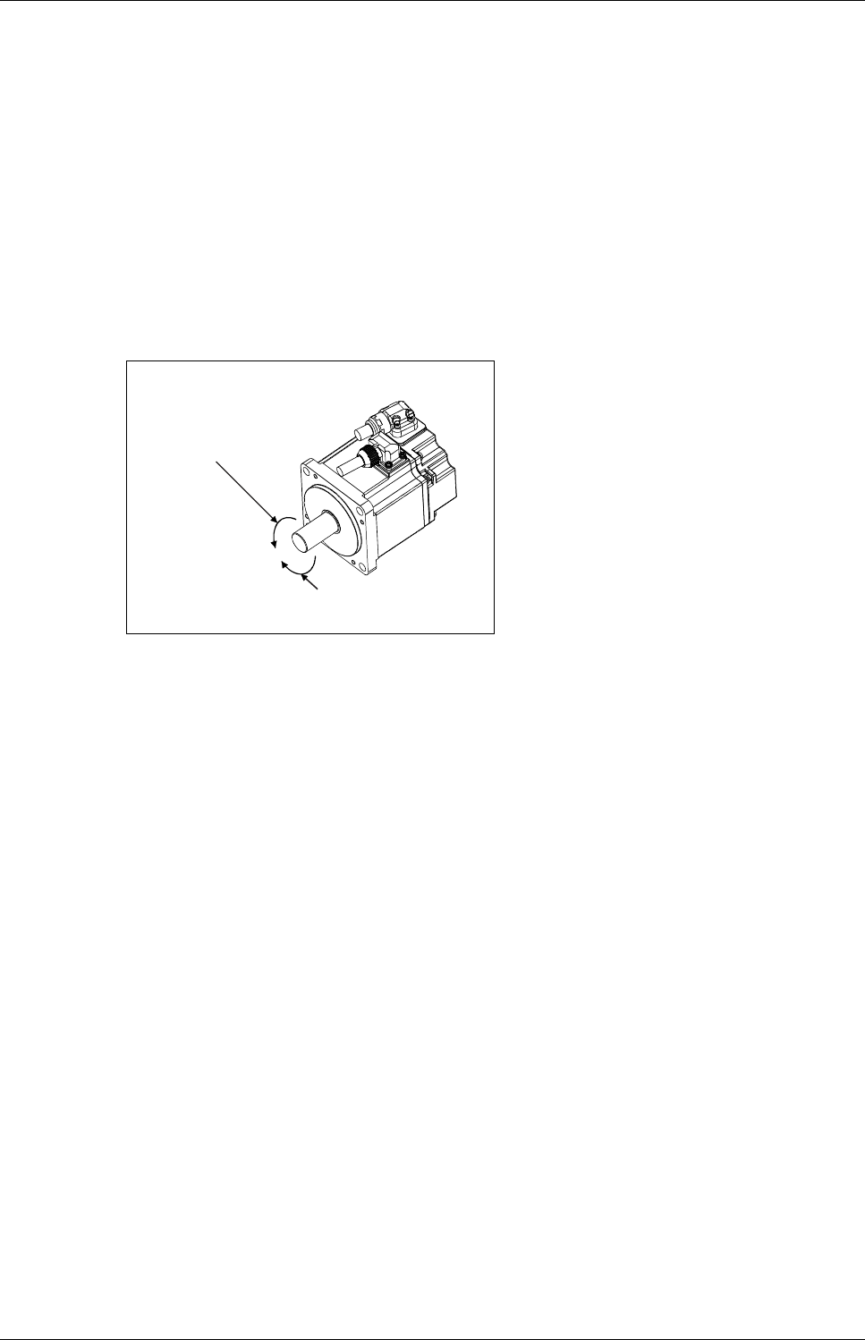
1.3 Terminology
The terms and abbreviations below are important for motion controllers and are used frequently in
this guide.
Direction of rotation of electric motors
The direction (or sense) of rotation of electric motors is defined looking at the end of the motor shaft.
Direction of rotation is described as:
● Clockwise/Reverse
or
●Counterclockwise/Forward
Abbreviations
– FLS Upper stroke limit
– RLS Lower stroke limit
– STOP Stop signal
– DOG Proximity dog
– EMI Emergency signal input
–CW Clockwise
–CCW Counterclockwise
– SSCNET III Optical bus system for data communication
Fig. 1-2: Direction of rotation
Forward rotation (CCW)
Reverse rotation (CW)
Motor

Introduction Terminology
1 - 6
Q170MCPU Details of the modules
Motion controller Q170MCPU/ Q172DCPU/ Q173DCPU 2 - 1
2 Details of the modules
2.1 Q170MCPU
2.1.1 Frontview and partnames
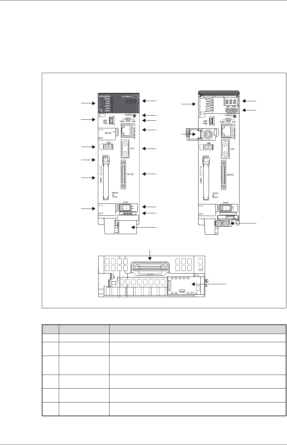
Fig. 2-1: Q170MCPU
No. Name Application
쐃7-segment LED Displays operation status and error information.
쐇POWER LED ON (Red): The internal power (5 V DC) is ON.
OFF: The internal power (5 V DC) is OFF.
쐋RUN/STOP/RESET
switch
RUN: Sequence-/Motion SFC program started
STOP: Sequence-/Motion SFC program stopped
RESET: Reset of the hardware (momentary switch, set minimum for 1 sec)
쐏PERIPHERAL I/F
connector
For Ethernet-communication with peripheral devices.
Data transmission speed: 10 Mbps/100 Mbps
쐄SSCNET III connector
CN1 Connector to connect the servo amplifiers via optical bus cable.
쐂EXT. IO connector Connector for manual pulse generator/incremental synchronous encoder/digital I/O
signals. (Voltage-output/open-collector type, Differential-output type)
Tab. 2-1: Description of the partnames in fig. 2-1.
Front view
With front cover open and
battery holder removed
쐅
쐈
쐉
씈
씉
씊
쐅
씍
쐃
쐇
쐋
쐏
쐄
쐂
쐆
쐊
쐎
쐃
씋
씌
Bottom view
쐎
씎
Details of the modules Q170MCPU
2 - 2
No. Name Application
쐆24VDC connector Connector for 24 V DC power supply
쐊Serial number Shows the serial number, printed on the rating plate
쐎Battery holder Battery holder to set the Q6BAT/Q7BAT
쐅Status LED
MODE Displays the mode of the PLC CPU
ON (green): Q mode
RUN
Diplays the operating status of the PLC CPU
ON: The operating status is ”RUN”
OFF: The operating status was set to ”STOP” or operation has been halted due
to an error.
Flashing: Failure during writing of parameters or programs
ERR.
Diplays the operating status of the PLC CPU
ON: Detection of an error during self-diagnosis
OFF: Normal operation
Flashing: The detected error stops operation.
(Resetting with the RUN/STOP/RESET switch becomes valid.)
USER
Diplays the operating status of the PLC CPU
ON: Annunciator turned ON
OFF: Normal operation
BAT.
Diplays the operating status of the PLC CPU
ON (yellow): Low battery voltage at memory card
ON (green for 5 sec): Restoring of data backup to the standard ROM by the latch data
backup is completed
ON (green): Backup of data to the standard ROM by latch data backup is
completed
OFF: Normal operation
BOOT
Diplays the operating status of the PLC CPU
ON: Start of boot operation
OFF: No boot operation
쐈USB connector Connector to connect the peripheral devices for USB connection
(Connector type mini B)
쐉Forced stop input
connector (EMI)
Input to stop all axis at once
Open: Forced stop (EMI ON)
24 V DC: Forced stop release (EMI OFF)
씈Eject button for
memory card Used to eject the memory card from the Motion controller
씉Memory card loading
connector Connector used to load the memory card to the Motion controller
씊— Not usable
씋Rotary switch SW1, SW2
앫Setting of the operation mode
(Normal operation mode, Installation mode, Mode operated by ROM, etc.)
앫Each switch setting is from 0 to F
(Factory default setting: SW1: A, SW2: 0)
씌FG terminal Frame ground:
Ground terminal connected with the shield pattern of the printed circuit board
씍RS-232 connector Connector to connect the peripheral devices for RS-232 connection
(Connect with the dedicated cable QC30R2)
씎Extension cable
connector Connector for transfer of signals to/from the extension base unit
Tab. 2-1: Description of the partnames in fig. 2-1.
NOTE For more details of the partnames and status LEDs please refer to the user’s manual of the motion
controller Q170MCPU.
Q170MCPU Details of the modules
Motion controller Q170MCPU/ Q172DCPU/ Q173DCPU 2 - 3
2.1.2 System configuration
GX (IEC) Developer and MT Works2 can be used simultaneously on one personal computer.
Interrupt module (QI60) and analog I/O module (Q6쏔AD/Q6쏔DA) can also be used as the
Motion CPU area control module.
Fig. 2-2: System configuration
Motion CPU area
control module
GOT
USB/RS-232
Extension base unit
(Q52B/Q55B)
Up to 1 extension
Extension
cable
(QC첸B)
Servo amplifier model MR-J3-첸B,
up to 16 axes
External input signals of servo amplifier
앫
Proximity dog
앫
Upper stroke limit
앫
Lower stroke limit
External input signals Number of inputs
앫
FLS: Upper stroke limit
앫
RLS: Lower stroke limit
앫
STOP: Stop signal
앫
DOG/CHANGE: Proximity dog/
Speed-position switching
8 axes/module
Input/output (Up to 256 points)
EMI forced stop input (24 V DC)
Forced stop input cable
(Q170DEMICBL첸M)
SSCNET III cable
(MR-J3BUS첸M(-A/-B))
SSCNET III
Manual pulse generator/Incremental synchronous encoder x 3/module
(MR-HDP01)
24 V DC
Servo external
signals
interface module
Manual pulse
generator
interface module
Motion controller
Q170MCPU
I/O module/
Intelligent
function module
(Up to 512points)
PLC CPU area
control module
Manual pulse generator/ Incre-
mental synchronous encoder
x 1/module
앫Input signal/Mark detection input signal
(4 points)
앫Output signal (2 points)
PERIPHERAL I/F
Panel personal computer
Personal computer
IBM PC/AT
Details of the modules Q170MCPU
2 - 4
2.1.3 Minimum equipment
24V connector, DI/O connector, SRAM backup battery, EMI connector included
Product Details
Controller
Q170MCPU
Standalone motion controller, 16 axes, SSCNETIII
Software
MT Developer2-E Programming software for Q-/QH-/QD-/Q170MCPU motion
controller (Windows 2000/XP/Vista)
MT Developer OS Systems Operating systems for Q-/QH-/QD-/Q170MCPU motion con-
troller
MR Configurator (Setup221) Servo setup software
GX (IEC) Developer PLC programming software
Tab. 2-2: Minimum equipment for Q170MCPU
MR Configurator
GX Developer
Q172DCPU/Q173DCPU Details of the modules
Motion controller Q170MCPU/ Q172DCPU/ Q173DCPU 2 - 5
2.2 Q172DCPU/Q173DCPU
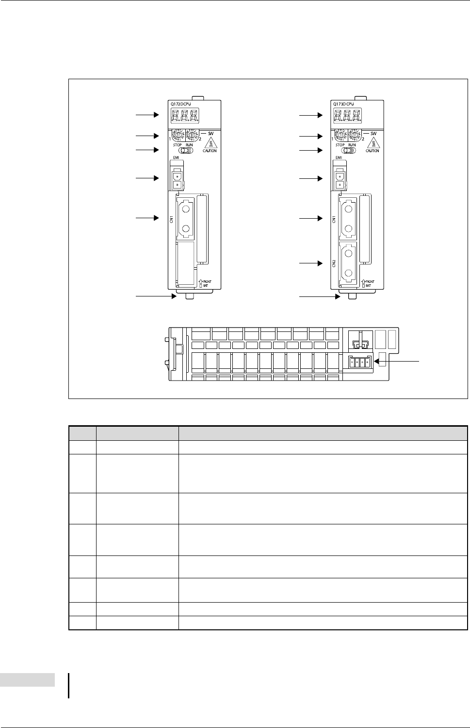
2.2.1 Frontview and partnames
햲
Q173DCPU only
Fig. 2-3: Q172DCPU, Q173DCPU
No. Name Application
쐃7-segment LED Displays operation status and error information
쐇Rotary switch SW1, SW2
앫Setting of the operation mode
(Normal operation mode, Installation mode, Mode operated by ROM, etc.)
앫Each switch setting is from 0 to F
(Factory default setting: SW1: A, SW2: 0)
쐋RUN/STOP switch
RUN: Motion SFC program started
STOP: Motion SFC program stopped
(Factory default setting is STOP)
쐏Forced stop input
connector (EMI)
Input to stop all axis at once
Open: Forced stop (EMI ON)
24 V DC: Forced stop release (EMI OFF)
쐄SSCNET III connector
CN1
Connector to connect the servo amplifiers of system 1 (channel 1) via optical bus cable
(Q172DCPU: up to 8 axes; Q173DCPU: up to 16 axes)
쐂SSCNET III connector
CN2
햲
Connector to connect the servo amplifiers of system 2 (channel 2) via optical bus cable
(up to 16 axes)
쐆Module loading lever Used to install the module on the base unit
쐊Battery connector (BAT) Connector to connect the battery holder unit Q170DBATC
Tab. 2-3: Description of the partnames in fig. 2-3.
NOTE For more details of the partnames please refer to the user’s manual of the motion controllers
Q172DCPU and Q173DCPU.
Q172DCPU Front view
쐃
쐇
쐋
쐏
쐄
쐆
쐊
Q172DCPU-/Q173DCPU Bottom view
Q173DCPU Front view
쐃
쐇
쐋
쐏
쐄
쐂
쐆
Details of the modules Q172DCPU/Q173DCPU
2 - 6
2.2.2 System configuration
Fig. 2-4: System configuration
Q172D
CPU/
Q173D
CPU
Motion CPU control module
PLC CPU/
Motion CPU
Main base unit
(Q3첸DB)
100/200 V AC
USB/RS-232
Battery holder unit
(Q170DBATC)
Extension base unit
(Q6첸B)
Extension
cable
(QC첸B) Up to 7 extensions
Power supply
module
Servo amplifier model MR-J3-첸B,
up to 8 axes (Q172DCPU)/
up to 32 axes (Q173DCPU)
External input signals of servo amplifier
앫
Proximity dog
앫
Upper stroke limit
앫
Lower stroke limit
External input signals Number of inputs
앫
FLS: Upper stroke limit
앫
RLS: Lower stroke limit
앫
STOP: Stop signal
앫
DOG/CHANGE: Proximity dog/
Speed-position switching
8 axes/module
(Up to 4 modules)
Analog input/output
Input/output (Up to 256 points)
Interrupt signals (16 points)
EMI forced stop input (24 V DC)
Forced stop input cable
(Q170DEMICBL첸M)
SSCNET III cable
(MR-J3BUS첸M(-A/-B))
SSCNET III (CN1)
Manual pulse generator x 3/module
(MR-HDP01) (Up to 1 module)
Serial absolute synchronous encoder x 2/module
(Q170ENC) (Up to 6 modules)
Serial absolute synchronous encoder cable
(Q170ENCCBL첸M)
I/O module
Intelligent function module
Servo external
signals
interface module
Synchronous
encoder
interface module
Manual pulse
generator
interface module
Q172DCPU/Q173DCPU Details of the modules
Motion controller Q170MCPU/ Q172DCPU/ Q173DCPU 2 - 7
2.2.3 Minimum equipment
EMI connector/cable is sold separately. The Forced stop input cannot be invalidated by internal
parameter.
Product Details
Controller
Q38DB 8 slot base unit
Q61P or similar
Power supply module
Input: 100–240 V AC
Output: 5 V DC/6 A
QnUD(E)(H)CPU PLC CPU Module; 4096 I/O
Q172DCPU/
Q173DCPU Motion controller CPU module, 8/32 axes, SSCNET III
Software
MT Developer2-E Programming software for Q-/QH-/QD-/Q170MCPU motion
controller (Windows 2000/XP/Vista)
MT Developer OS Systems Operating systems for Q-/QH-/QD-/Q170MCPU motion con-
troller
MR Configurator (Setup221) Servo setup software
GX (IEC) Developer PLC programming software
Tab. 2-4: Minimum equipment for Q172DCPU/Q173DCPU
MR Configurator
GX Developer

Details of the modules Q172DCPU/Q173DCPU
2 - 8
Module mounting into cabinet Mounting and wiring
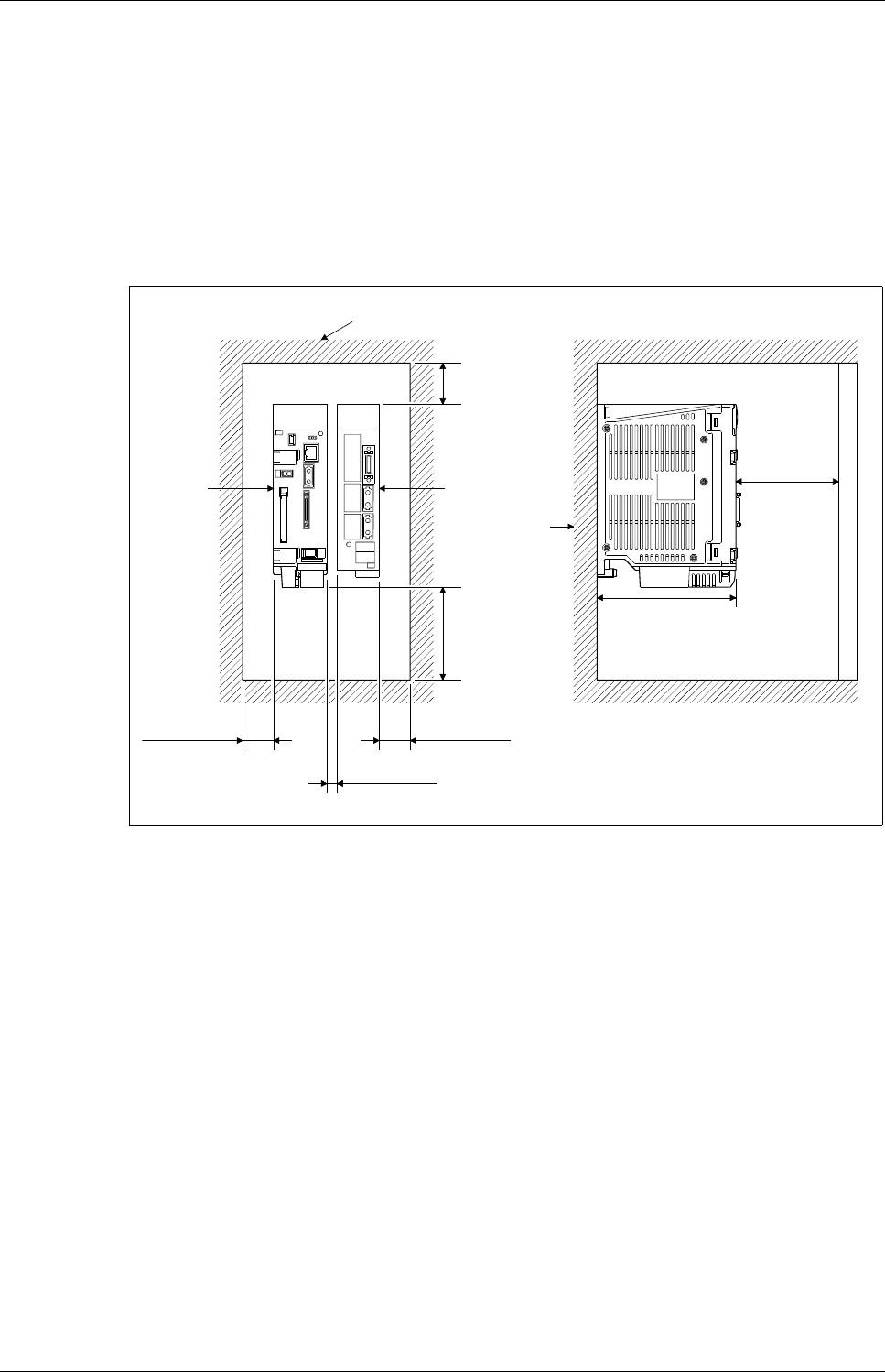
Motion controller Q170MCPU/ Q172DCPU/ Q173DCPU 3 - 1
3 Mounting and wiring
3.1 Module mounting into cabinet
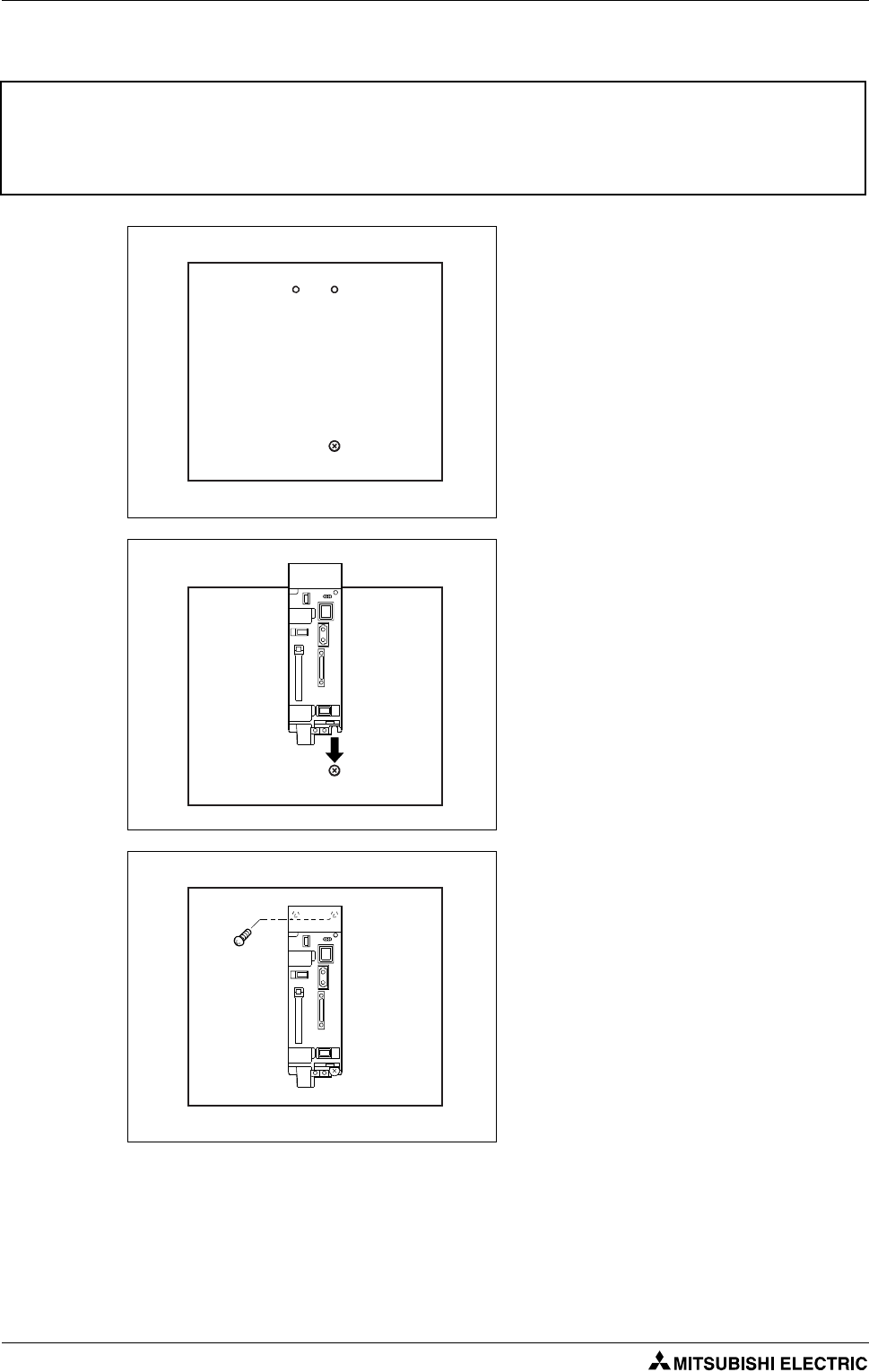
3.1.1 Mounting of Q170MCPU
Keep the clearances shown below between the top/bottom faces of the module and other structures
or parts to ensure good ventilation and facilitate module replacement.
Fit the Motion controller at the left side of the servo amplifier.
Fig. 3-1: Module mounting position
Top of panel or wiring duct
욷40 mm
Servo amplifier
Motion
controller
욷90 mm
Panel
욷30 mm
욷10 mm
욷30 mm
욷100 mm
135 mm
Door
Mounting and wiring Module mounting into cabinet
3 - 2
Mounting method for the motion controller
b
WARNING:
Completely turn off the externally supplied power used in the system before installation or
removing the module. Not doing so could result in electric shock or damage to the product.
Fit the holes for the bottom mounting
screws of the Motion controller into the
panel.
Place the bottom side notch of the Motion
controller onto the bottom side screw.
Fit the mounting screws into the holes at the
top of the Motion controller and then
retighten the all mounting screws using the
allowed torque.
Module mounting into cabinet Mounting and wiring
Motion controller Q170MCPU/ Q172DCPU/ Q173DCPU 3 - 3
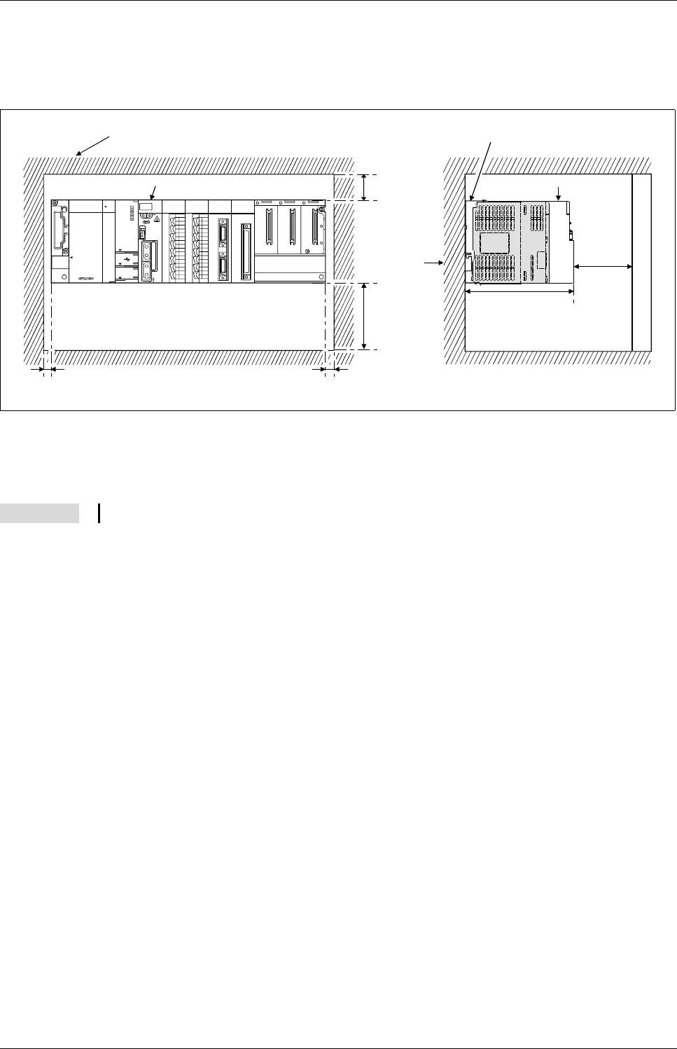
3.1.2 Mounting of Q172DCPU/Q173DCPU
Keep the clearances shown below between the top/bottom faces of the module and other structures
or parts to ensure good ventilation and facilitate module replacement.
욷20 mm when the adjacent module is not removed and the extension cable is connected.
Fig. 3-2: Module mounting position
NOTE It is not possible to mount the main base unit by DIN rail.
QX40
0 1 2 3 4 5 6 7
8 9 A B C D E F
SY.ENC1
Q172DEX
Q172DEX
2
1
TREN
SY.ENC
2
1
Q173DPX
PULSER
Q173DPX
PLS. A
3
2
1
PLS. B
3
2
1
TREN
3
2
1
Q03DCP U
US E R
MODE
RUN
ERR.
BAT.
BOOT
PULL
USB
RS -232
QX40
0 1 2 3 4 5 6 7
8 9 A B C D E F
Top of panel or wiring duct
욷40 mm
욷100 mm
Panel
욷5 mm욷5 mm
욷100 mm
123.5 mm
Door
Base unit
Motion CPU module Motion CPU module
Mounting and wiring Module mounting into cabinet
3 - 4
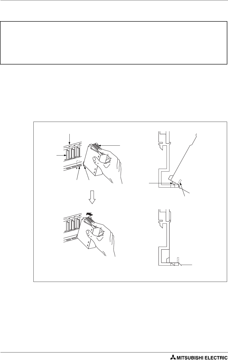
Installation of the module on Q3첸B and Q6첸B
Securely insert the module fixing protection into the module fixing hole so that the latch is not
misaligned.
Using the module fixing hole as a fulcrum, push the module in the direction of arrow to install it
into the base unit.
Make sure that the module is installed in the base unit securely.
When using module in a place where there is large vibration or impact, install it by the unit fixing
screws (M3 x 12).
b
WARNING:
●Completely turn off the externally supplied power used in the system before installing the
module. Not doing so could result in electric shock or damage to the product.
●When installing the module, always insert the module fixing projection into the module
fixing hole of the base unit. If the module is forcibly installed without the latch being inserted,
the module connector and module will be damaged.
Fig. 3-3: Installation of the module
Module
connector
Module
Module fixing
hook
Base unit Base unit
Module loading lever
Module fixing
hole
Module fixing
hook
Module mounting into cabinet Mounting and wiring
Motion controller Q170MCPU/ Q172DCPU/ Q173DCPU 3 - 5
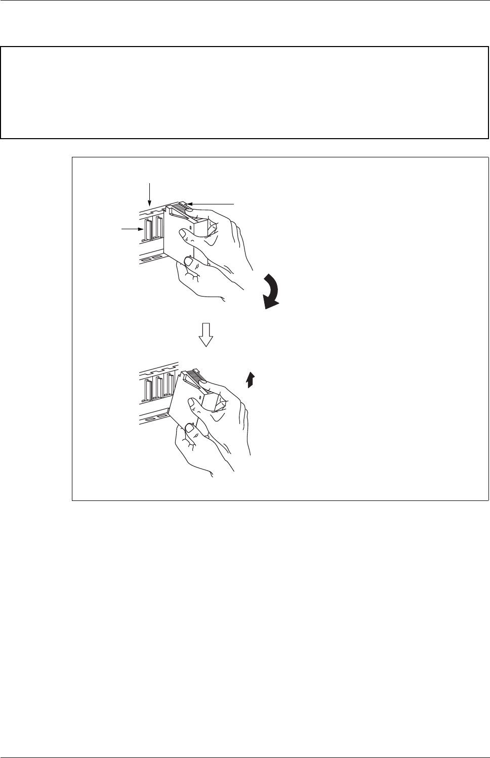
Removal of the module from Q3첸B and Q6첸B
b
WARNING:
●Completely turn off the externally supplied power used in the system before removing the
module. Not doing so could result in electric shock or damage to the product.
●When the module fixing screw is used, always remove the module by removing the module
fixing screw and then taking the module fixing latch off the module fixing hole of the base
unit. Attempting to remove the module by force may damage the module fixing latch.
Fig. 3-4: Removal of the module
Module
connector
Module
Base unit
Support the module with both hands and se-
curely press the module fixing hook with your
finger.
Pull the module based on the supporting point
of module bottom while pressing the module
fixing hook.
While lifting a module, take off the module fixing
projection from the module fixing hole.
Mounting and wiring Wiring
3 - 6
3.2 Wiring
3.2.1 Wiring for Q170MCPU
Power supply and EMI
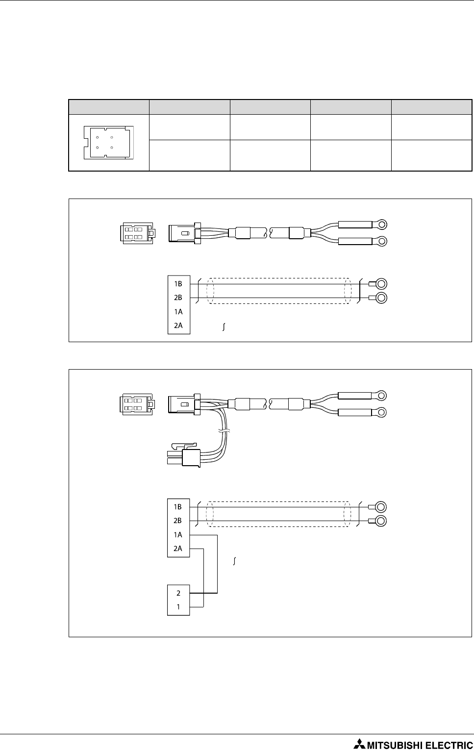
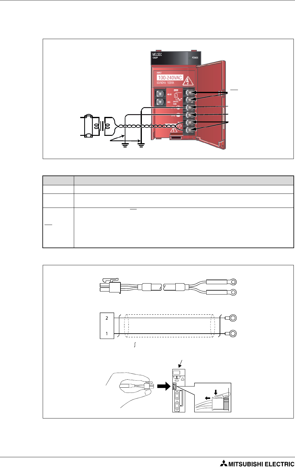
Use "1A" and "2A" when the 24 V DC voltage is applied on EMI terminal and the forced stop input
of EMI terminal is invalidated.
Use a cable of wire size AWG22.
Connector layout Pin No. Signal name Pin No. Signal name
1A
24V(+) 1B 24V(+)
2A
24G 2B 24G
Tab. 3-1: Power supply 24 V
Fig. 3-5: 24 V DC power supply cable without EMI connector
Fig. 3-6: 24 V DC power supply cable with EMI connector
1A 1B
2A 2B
2A 2B
1A 1B
Q170MCPU side
1827587-2 (Terminal)
1-1827864-2 (Connector)
Solderless terminal
24V(+)
24G
24V(+)
24G
24V(+)
24G
: Twisted pair cable
Solderless terminal size: R1.25-3.5
2A 2B
1A 1B
Q170MCPU side
1827587-2 (Terminal)
1-1827864-2 (Connector)
Solderless terminal
24V(+)
24G
24V(+)
24G
24V(+)
24G
: Twisted pair cable
5556PBTL (Terminal)
5557-02R-210 (Connector)
EMI.COM
EMI
2
1
Solderless terminal size: R1.25-3.5
Wiring Mounting and wiring
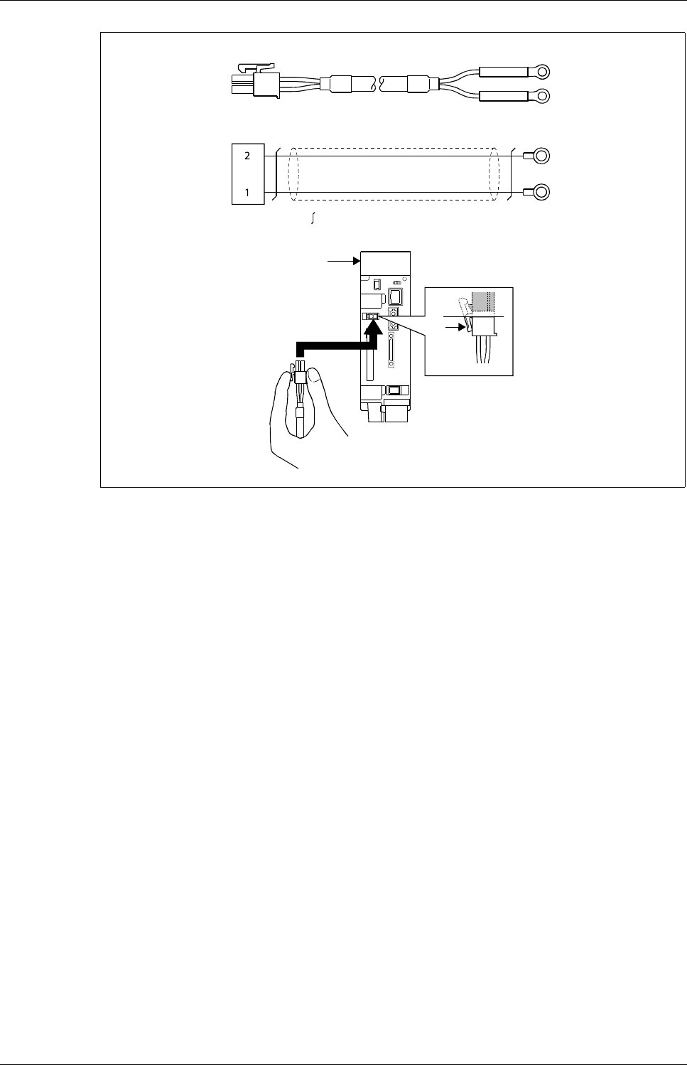
Motion controller Q170MCPU/ Q172DCPU/ Q173DCPU 3 - 7
햲
Use a cable of wire size AWG22.
햳
Tab
Fig. 3-7: Forced stop input cable for EMI
2
1
Q170MCPU side
5556TL (Terminal)
5557-02R (Connector)
Solderless terminal
EMI.COM
EMI
: Twisted pair cable
햲
EMI.COM
EMI
Solderless terminal size: R1.25-3.5
Q170MCPU
햳
Mounting and wiring Wiring
3 - 8
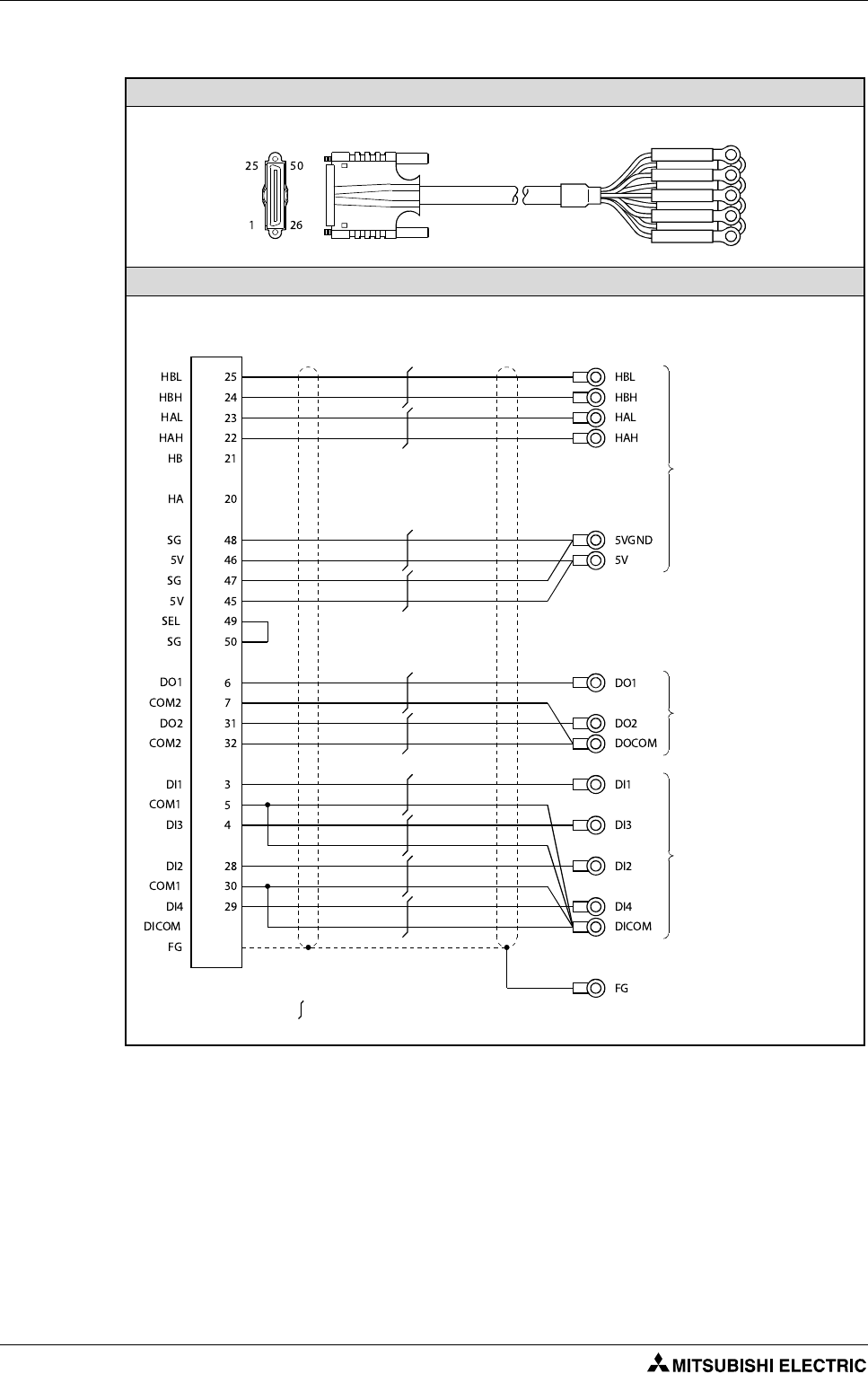
Digital I/O
The maximum length of the cable should be 30 m.
Connect SEL to the SG terminal if differential-output type is used.
Cable
Connection diagram
Tab. 3-2: Differential-output type cable for internal I/F connector
Q170MCPU side Solderless terminal
HDR-E50MSG1+ (Connector)
HDR-E50LPH (Connector case)
Differential-output type
Manual pulse generator/
incremental synchronous
encoder side
Output signal side
Input signal/mark detection
input side
: Twisted pair cable
Shell
Wiring Mounting and wiring
Motion controller Q170MCPU/ Q172DCPU/ Q173DCPU 3 - 9
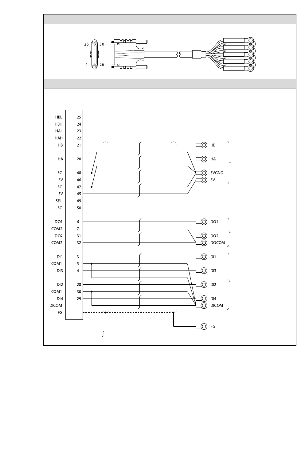
The maximum length of the cable should be 10 m.
When voltage-output/open-collector type is used, open between SEL and SG.
Cable
Connection diagram
Tab. 3-3: Voltage-output/open-collector type cable for internal I/F connector
Q170MCPU side Solderless terminal
HDR-E50MSG1+ (Connector)
HDR-E50LPH (Connector case)
Voltage-output/open-
collector type
Manual pulse generator/
incremental synchronous
encoder side
Output signal side
Input signal/mark detection
input side
: Twisted pair cable
Shell
Mounting and wiring Wiring
3 - 10
3.2.2 Wiring for QD Motion controller
Power supply and EMI
햲
Use a cable of wire size AWG22.
Fig. 3-8: Power supply module for QD motion controller (example with Q62P)
Terminal(s) Function
FG Ground terminal connected to the shield pattern of the printed circuit board.
LG Grounding for the power supply filter. The potential of Q61P-A1, Q61P-A2, Q61P, Q62P, Q64P and Q61SP is
half of the input voltage.
ERR
The following functions of the ERR termials are only availible, when the power supply module is mounted on a main base
unit. When mounted on an extension base unit the terminals are always OFF (open).
앫The terminals are ON (connected) when the whole system operates normally.
앫The terminals turn OFF (open) when the AC power is not input, a stop error (including a reset) occurs in
the CPU module or the fuse is blown.
앫In a multiple CPU system configuration the terminals turn OFF (open) when a stop error occurs in any of
the CPU modules.
Tab. 3-4: Explanation of the terminals in fig. 3-8
Fig. 3-9: Forced stop input cable for EMI
Power supply module
ERR
FG
LG
INPUT
100–240 V AC
Grounding
Ground
wire
AC
2
1
Q170MCPU side
5556TL (Terminal)
5557-02R (Connector)
Solderless terminal
EMI.COM
EMI
: Twisted pair cable
햲
EMI.COM
EMI
Solderless terminal size: R1.25-3.5
Motion CPU module
Removal 햲
햳
SSCNET III connection Mounting and wiring
Motion controller Q170MCPU/ Q172DCPU/ Q173DCPU 3 - 11
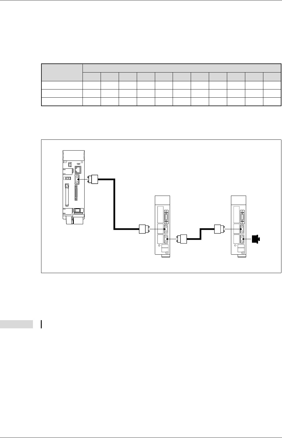
3.3 SSCNET III connection
3.3.1 SSCNET III cable
The cables in the following table are applicable for the connection between the Q170MCPU/QD-Mo-
tion controllers and the servo amplifier MR-J3-첸B and between the servo amplifiers MR-J3-첸B.
3.3.2 Connection between the Q170MCPU and servo amplifiers
햲
Chose the right SSCNET III cable type in tab. 3-5 depending on the cable length for your system
configuration.
햳
Attach a cap to the SSCNET III connectors of the system not being used.
Cable Symbol for cable length (첸)
0,15 m 0,3 m 0,5 m 1 m 3 m 5 m 10 m 20 m 30 m 40 m 50 m
MR-J3BUS첸M
0150305 1 3 ——————
MR-J3BUS첸M-A
————— 5 1020———
MR-J3BUS첸M-B
————————304050
Tab. 3-5: SSCNET III cable identification
Fig. 3-10: SSCNET III connection method with Q170MCPU
NOTE
If the connectors CN1A und CN1B are mixed up at the servo amplifiers, no communication is possible.
Q170MCPU
햲
햲
Servo amplifier Servo amplifier
Cap
햳
CN1A
CN1B
CN1A
CN1B
CN1
Mounting and wiring SSCNET III connection
3 - 12
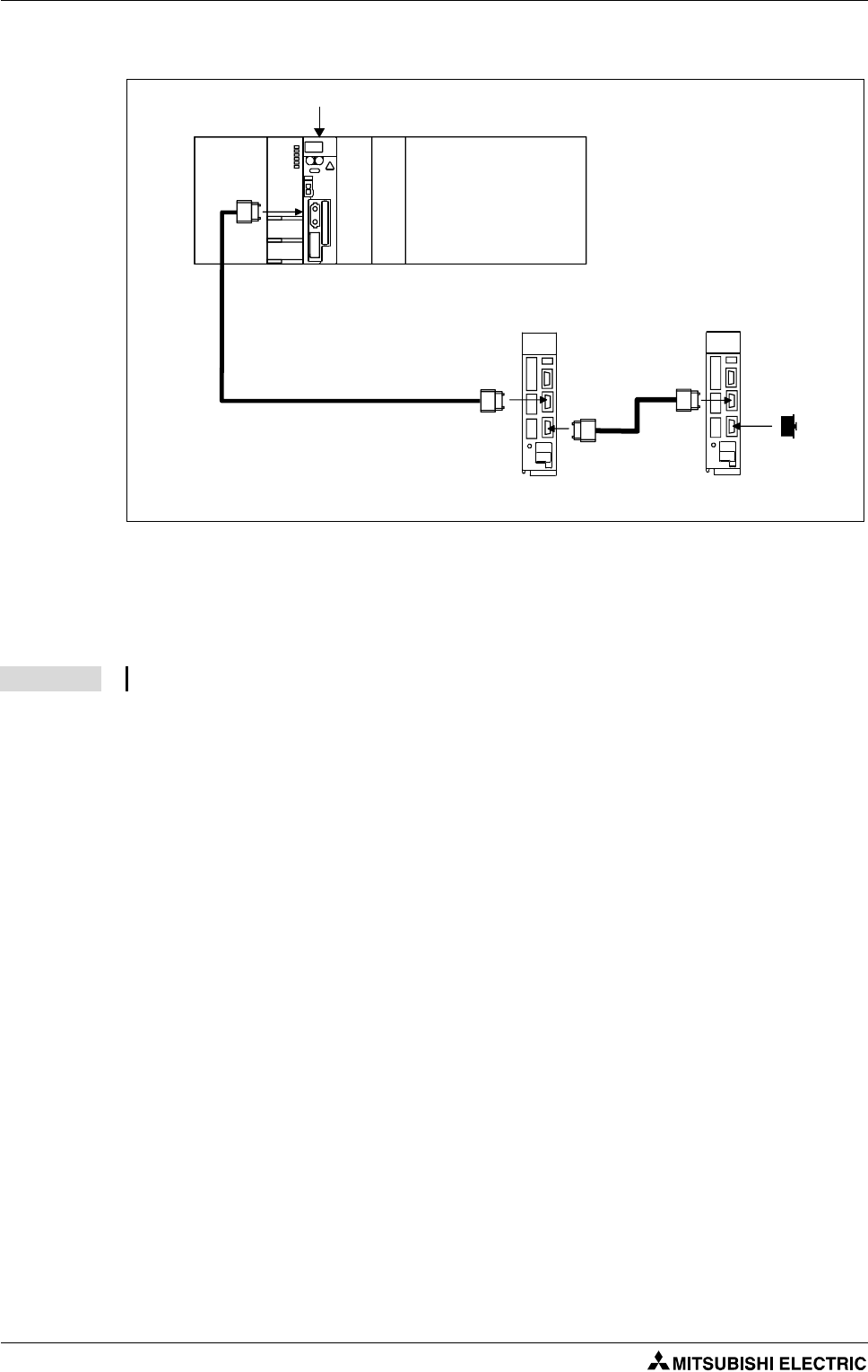
3.3.3 Connection between the Q172DCPU and servo amplifiers
햲
Chose the right SSCNET III cable type in tab. 3-5 depending on the cable length for your system
configuration.
햳
Attach a cap to the SSCNET III connectors of the system not being used.
Fig. 3-11: SSCNET III connection method with Q172DCPU
NOTE
If the connectors CN1A und CN1B are mixed up at the servo amplifiers, no communication is possible.
Q172DCPU Motion CPU module
햲
햲
Servo amplifier Servo amplifier
Cap
햳
CN1A
CN1B
CN1A
CN1B
CN1
SSCNET III connection Mounting and wiring
Motion controller Q170MCPU/ Q172DCPU/ Q173DCPU 3 - 13
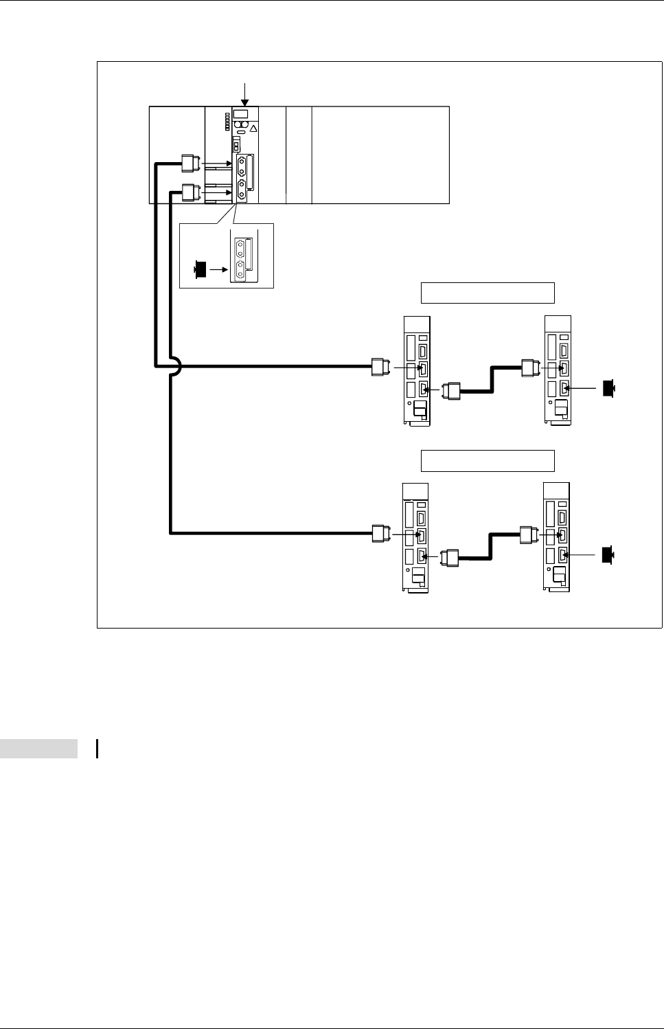
3.3.4 Connection between the Q173DCPU and servo amplifiers
햲
Chose the right SSCNET III cable type in tab. 3-5 depending on the cable length for your system
configuration.
햳
Attach a cap to the SSCNET III connectors of the system not being used.
Fig. 3-12: SSCNET III connection method with Q173DCPU
NOTE
If the connectors CN1A und CN1B are mixed up at the servo amplifiers, no communication is possible.
Q173DCPU Motion CPU module
햲
햲
Servo amplifier Servo amplifier
Cap
햳
CN1A
CN1B
CN1A
CN1B
CN1
CN2
햲
Servo amplifier Servo amplifier
햲
Cap
햳
CN1A
CN1B
CN1A
CN1B
SSCNET III Channel 1
SSCNET III Channel 2
Cap
햳
Mounting and wiring SSCNET III connection
3 - 14
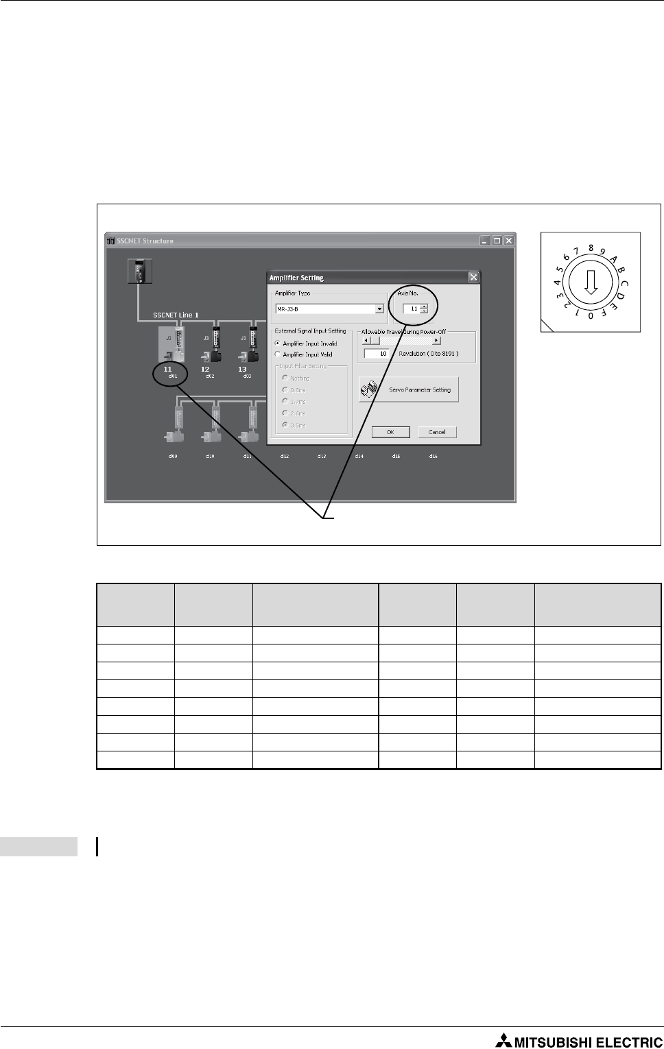
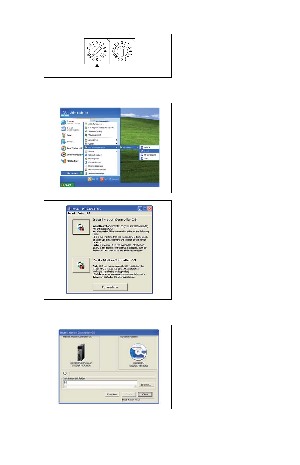
3.3.5 Setting the axis No. and axis select switch of servo amplifier
Axis No. is used to set the axis number of servo amplifiers connected to SSCNET III motion bus in the
program. Axis No. of 1 to 16 can be set.
Axis No. is set in the system setting of MT Developer2. Axis No. (1 to 16) is allocated and set for the set-
ting axis number (d01 to d16) of servo amplifier.
Since the axis number (d01 to d16) of servo amplifier on the system setting screen corresponds to axis
select rotary switch (0 to F) of servo amplifier, set the axis select rotary switch referring to the table be-
low (Tab. 3-6).
Fig. 3-13: Setting the axis No.
dno. SSCNET III
channel
Axis select
rotary switch of
servo amplifier
dno. SSCNET III
channel
Axis select
rotary switch of
servo amplifier
d01 1 "0" d09 1 "8"
d02 1 "1" d10 1 "9"
d03 1 "2" d11 1 "A"
d04 1 "3" d12 1 "B"
d05 1 "4" d13 1 "C"
d06 1 "5" d14 1 "D"
d07 1 "6" d15 1 "E"
d08 1 "7" d16 1 "F"
Tab. 3-6: Correspondence between dno.s and axis select switches of servo amplifier
NOTE The dno. represents the station number, which is set by the rotary switch at the servo amplifier.
Setting display of axis No. Axis select switch
(Servo amplifier)
Set the axis No. relative to axis number (dno.).

Start-up and trial operation
Motion controller Q170MCPU/ Q172DCPU/ Q173DCPU 4 - 1
4 Start-up and trial operation
m
DANGER:
●Be sure to ground the Motion controllers, servo amplifiers and servomotors (Ground
resistance: 100 Ω or less). Do not ground commonly with other devices.
●Never open the front case or terminal cover at times other than wiring work or periodic
inspections even if the power is OFF. The insides of the Motion controller and servo amplifier
are charged and may lead to electric shocks.
●When performing wiring work or inspections, turn the power OFF, wait at least ten minutes,
and then check the voltage with a tester, etc. Failing to do so may lead to electric shocks.
●Wire the units after mounting the Motion controller, servo amplifier and servomotor. Failing
to do so may lead to electric shocks or damage.
b
WARNING:
●Check that the combination of modules are correct. Wrong combination may damage the
modules.
●When using a regenerative resistor, shut the power OFF with an error signal. The regenera-
tive resistor may abnormally overheat due to a fault in the regenerative transistor, etc. and
may lead to fires.
●Always take heat measure such as flame proofing for the inside of the control panel where
the servo amplifier or regenerative resistor is mounted and for the wires used. Failing to do
so may lead to fires.
●Do not mount a phase advancing capacitor, surge absorber or radio noise filter (option
FR-BIF) on the output side of the servo amplifier.
●Correctly connect the output side (terminal U, V, W). Incorrect connections will lead the servo
motor to operate abnormally.
●Set parameter values to those that are compatible with the Motion controller, servo ampli-
fier, servo motor and regenerative resistor model name and the system name application.
The protective functions may not function if the settings are incorrect.
●Always mount a leakage breaker on the Motion controller and servo amplifier power source.
●Install emergency stop circuit externally so that operation can be stopped immediately and
the power shut off.
●Use the program commands for the program with the conditions specified in the instruction
manual.
●Some devices used in the program have fixed applications, so use these with the conditions
specified in the programming manual.
●If safety standards (ex., robot safety rules, etc.,) apply to the system using the Motion
controller, servo amplifier and servo motor, make sure that the safety standards are satis-
fied.
●Construct a safety circuit externally of the Motion controller or servo amplifier if the abnor-
mal operation of the Motion controller or servo amplifier differ from the safety directive
operation in the system.
●The system must have a mechanical allowance so that the machine itself can stop even if the
stroke limits switch is passed through at the max. speed.
●Execute the test operation in the system that it is low-speed as much as possible and put
forced stop and confirm the operation and safety.
Start-up and trial operation Start-up procedure
4 - 2
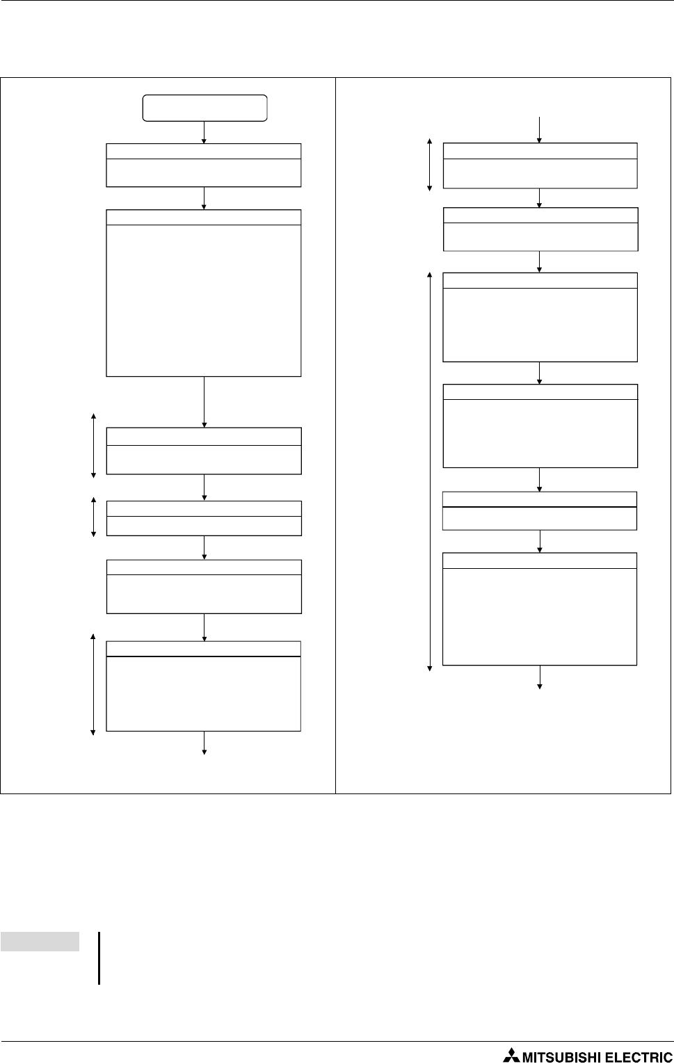
4.1 Start-up procedure
The mode indicated in the brackets [ ] at top left of each step is the mode for checking or setting
using MT Developer2/GX (IEC) Developer.
The operating system software is not installed at the time of Motion CPU module purchase.
Be sure to install the operating system software to be used before a system start.
Fig. 4-1: Start-up procedure (1)
NOTE An error may occur if the power is turned on before system setting. In the case, reset the Multiple
CPU system after system setting. Refer to the "Q173DCPU/Q172DCPU Motion controller Program-
ming Manual (COMMON)" at the system setting error occurrence.
START
Turn OFF Motion controller's power supply
Check that the power supply of Motion
controller is OFF.
Install operating system software
앫Check the installation position and
condition of each module.
앫Check the connecting condition of
connectors.
앫Check that all terminal screws are tight.
앫Check the ground wires of servo
amplifier, etc.
앫Check the servo motor wiring (U, V, W).
앫Check the regenerative option wiring.
앫Check the circuit of emergency stop or
forced stop.
Install the operating system software to the
Motion controller using MT Developer2.
Set the axis number of servo amplifier.
Set the RUN/STOP/RESET switch of Motion
controller to STOP, and turn ON the Motion
controller's power supply.
Set the following positioning parameters
using MT Developer2.
앫Multiple CPU setting
앫Automatic refresh setting
앫System setting
Servo amplifier setting
Turn ON power supply
Parameters setting
Check wiring and module installation
Motion CPU
area
Motion CPU
area
Servo
amplifier
[Installation mode]
[System setting]
Turn ON power supply again
Turn ON again the power supply or reset of
Motion controller.
Check external inputs to Q172DLX
Check the wiring of following external inputs
by monitoring of MT Developer2.
앫FLS (Upper stroke limit input)
앫RLS (Lower stroke limit input)
앫STOP (Stop signal)
Check the wiring of following external inputs
by monitoring of MT Developer2 or LED
indicators.
앫Manual pulse generator/incremental
synchronous encoder setting
Check the wiring of I/O modules.
Set the following positioning parameters
using MT Developer2.
앫Fixed parameters
앫Home position return data
앫JOG operation data
앫Servo parameters
앫Parameter block
앫Limit output data
Check external inputs to Q173DPX
Check I/O module
Positioning parameters setting
Motion CPU
area
[Servo data setting]
Set the PLC parameter using GX (IEC)
Developer.
Parameter setting
[Parameter setting]
PLC CPU
area
Start-up procedure Start-up and trial operation
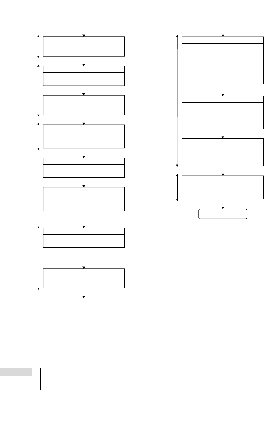
Motion controller Q170MCPU/ Q172DCPU/ Q173DCPU 4 - 3
The mode indicated in the brackets [ ] at top left of each step is the mode for checking or setting
using MT Developer2/GX (IEC) Developer.
Axis No. and error description of servo amplifier which detected errors are displayed on initial
check screen.
Fig. 4-1: Start-up procedure (2)
NOTE An error may occur if the power is turned on before system setting. In the case, reset the Multiple
CPU system after system setting. Refer to the "Q173DCPU/Q172DCPU Motion controller Program-
ming Manual (COMMON)" at the system setting error occurrence.
Create Motion programs
Create the Motion programs using
MT Developer2.
Write PLC programs
Create the PLC programs to start the Motion
programs using GX (IEC) Developer.
Write the PLC programs created to the PLC
CPU area (CPU No.1 fixed).
Check the emergency stop ON and forced
stop ON, and turn ON the power supply of
servo amplifiers.
Check that the mounted servo amplifiers
operate correctly.
Check that the upper/lower stroke limits
operate correctly.
Turn ON servo amplifiers power supply
Check servo amplifier
Check upper/lower stroke limits
Create PLC programs
Motion CPU
area
Motion CPU
area
[Test mode •
Servo start-up
(Upper/lower
stroke limit check)]
[Programming]
Motion CPU
area
[Programming]
PLC CPU
area
Write Motion programs
Write the positioning data and Motion
programs created to the Motion CPU area
(CPU No.2 fixed).
Turn ON power supply again
Turn ON again or reset the Motion controller's
power supply.
[Test mode •
Servo start-up
(Initial check)]
Check home position return
Check the followings by executing the home
position return.
앫Home position return direction
앫Home position return data
앫Proximity dog position
Set the RUN/STOP/RESET switch of Motion
controller to RUN and check that all
positioning controls by Motion programs are
correct.
Check the sequence operation by executing
the PLC program using an actual external
input.
Check Motion program
Check by automatic operation
PLC CPU
area
[Monitor]
Check the followings by making the machine
operate with the JOG operation of MT
Developer2.
앫Machine operates correctly
(no vibration, hunting, etc.)
앫Stroke limits operate correctly
앫Machine stops by the emergency stop or
forced stop
Check machine operation
[Test mode •
JOG operation]
Motion CPU
area
END
[Test mode •
home position return]
[Programming]
Start-up and trial operation Software installation
4 - 4
4.2 Software installation
4.2.1 Programming software
Install all of the software listed in the table below.
4.2.2 Operating system (OS)
As the OS software is not pre-installed, the first step before using the system is installing it into Motion
CPU.
This section explains the method for displaying the installation screen and install the OS.
Install one of the following OS.
Product Detail
MELSOFT MT Works2 (MT Developer2) Ver. 1.05F or later
GX Developer2) Ver. 8.48A or later
MR Configurator (optional) Ver. C2 or later
Tab. 4-1: Software
Motion CPU Operating system Detail
Q170MCPU SV13 (SW8DNC-SV13QG) Conveyor assembly use
SV22 (SW8DNC-SV22QF) Automatic machinery use
Q172DCPU SV13 (SW8DNC-SV13QD) Conveyor assembly use
SV22 (SW8DNC-SV22QC) Automatic machinery use
Q173DCPU SV13 (SW8DNC-SV13QB) Conveyor assembly use
SV22 (SW8DNC-SV22QA) Automatic machinery use
Tab. 4-2: Assignment of operating system to motion controller
Software installation Start-up and trial operation
Motion controller Q170MCPU/ Q172DCPU/ Q173DCPU 4 - 5
Operating system installation
햲Power off the motion controller.
햴Power on the motion CPU. After the power is turned on, the 7-segment LED displays "INS", and
the motion CPU gets into the installation mode.
햸Insert the CD-ROM with the motion controller OS into the CD-ROM drive of the personal compu-
ter.
햳Set the rotary switch 1 (on the motion con-
troller) to "A" to set the installation mode.
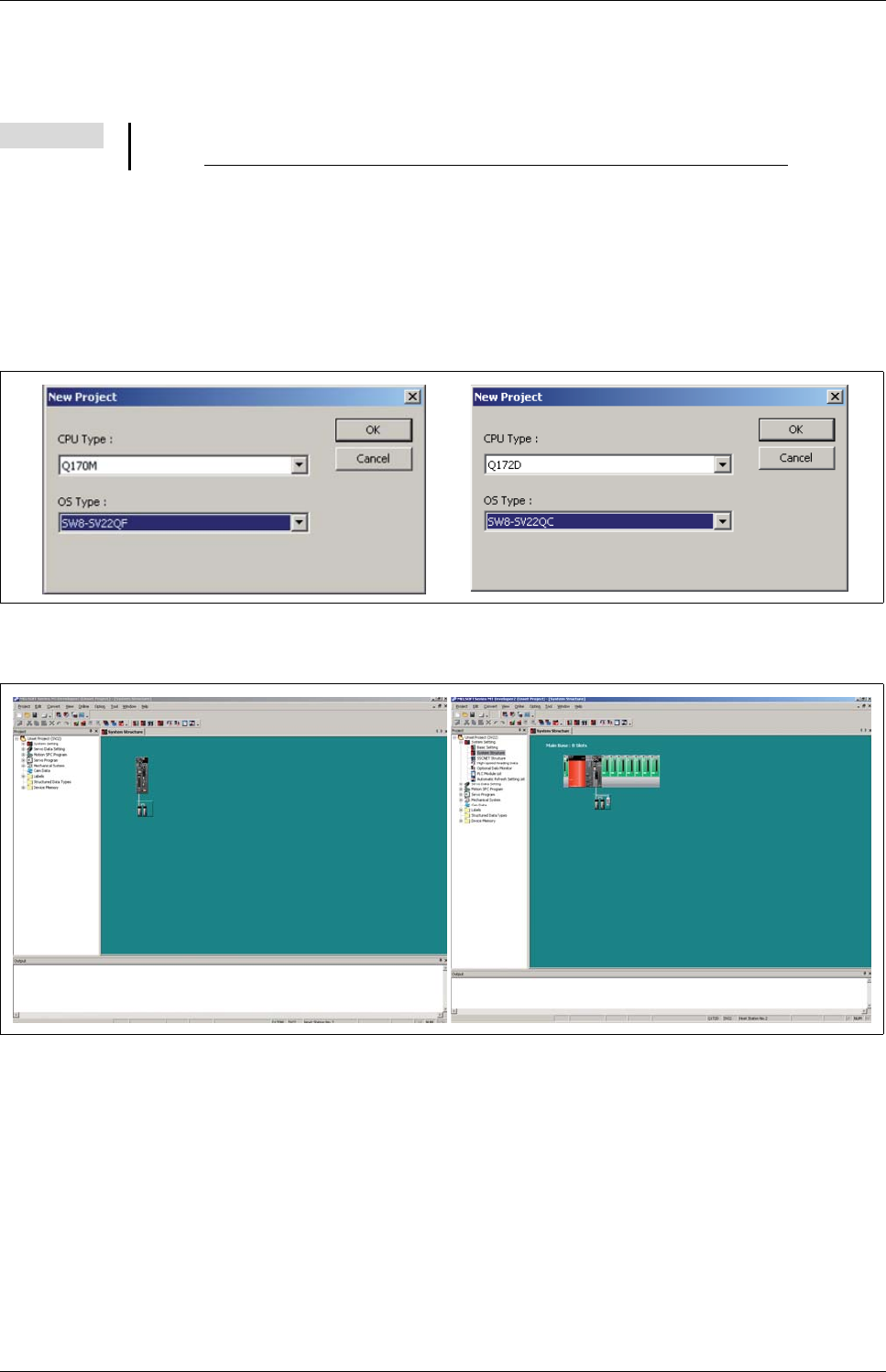
햵Select "Start" - "All Programs" - "MELSOFT
Application" - "MT Works2" - "Install".
햶The installation screen appears.
Select "Online" - "Transfer Setup" to set the
communication setup screen. Further de-
tails in the section "Transfer setup" (section
5.2.1) of this quick-start guide.
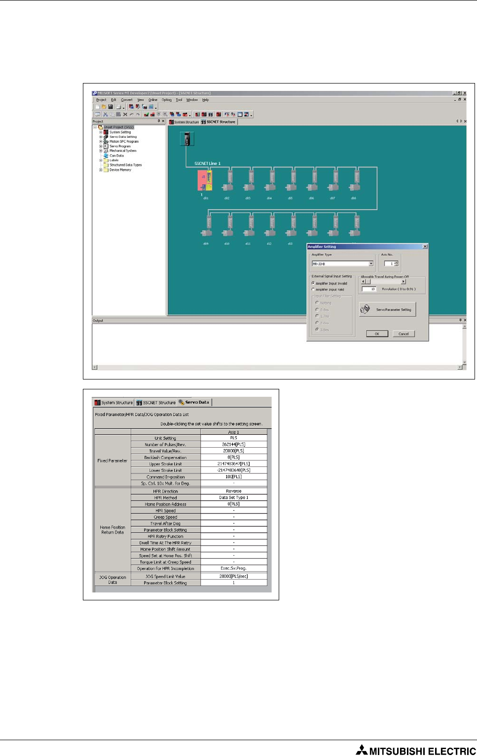
햷Click the button Install Motion Controller
OS. When the motion controller OS has al-
ready been installed, the version is dis-
played in addition to the CPU type.
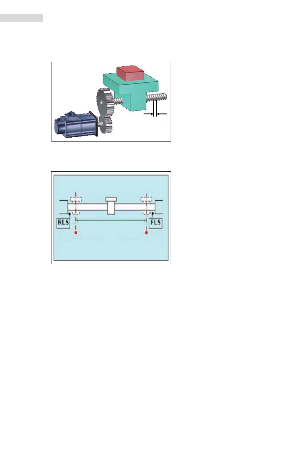
햹Click the button Browse and specify the
OS's source folder. The CPU type and OS
version appear.
햺Click the button Execution. The installation
is started.
Rotary switch 1

Start-up and trial operation Software installation
4 - 6
#Once the installation is finished, power off the motion CPU. Set the rotary switch 1 (SW1) to "0"
and the rotary switch 2 (SW2) to "0" to set the motion CPU to the RAM operation mode.
$Power on the motion CPU. When the power is turned on, "." in the first digit on the 7-segment
LED flashes.
Sample project creation with MT Developer2 and GX Developer Project creation
Motion controller Q170MCPU/ Q172DCPU/ Q173DCPU 5 - 1
5 Project creation
5.1 Sample project creation with MT Developer2 and
GX Developer
New project creation
Start MT Developer2 and create a new project with CPU and OS Type selected as shown below.
After clicking OK in the New Project Window, the MT Developer2 project window will appear, as
shown below.
NOTE The sample programs, described in this manual can be downloaded free of charge through the
website www.mitsubishi-automation.com/mymitsubishi/mymitsubishi_content.html.
Project creation Sample project creation with MT Developer2 and GX Developer
5 - 2
System Structure Settings
Double-click the amplifier icon (SSCNET Structure) to confirm the set amplifier type is correct. If
any I/O are wired to the amp, such as home or limit sensors, select the Detail Setting tab and set
the External Signal Input Setting to Amplifier Input Valid.
– "Travel Value/Rev." should represent how far the load moves for every rotation of the motor.
Servo Data Settings and Parameter Block
In the "MT Developer2 Project Window
Menu", double-click Servo Data to bring
up the "Servo Data" tab.
Edit the settings so that they match the
screenshot shown in the left figure.
Sample project creation with MT Developer2 and GX Developer Project creation
Motion controller Q170MCPU/ Q172DCPU/ Q173DCPU 5 - 3
Servomotor: HF-KP43
Unit setting: mm
Number of Pulses/Rev.: 262 144 [PULSES]
Travel Value/Rev.: 1/5 x 5 000.0 = 1 000.0 [μm]
쑶
– "Upper stroke limit" and "Lower stroke limit" enable software stroke limits.
– "Exec.Sv.Prog." will allow the servo programs to be executed even if the servo motor has not
yet been homed. If "Not Exec.Sv.Prog." is selected and the servo has not been homed, the servo
programs will stop and an error will occur.
Example 왓The ball screw lead is 5 mm and the mechanical gear ratio is 1/5.
Fig. 5-1: Mechanical configuration of the
example
Fig. 5-2: Stroke limits
Gear ratio 1 : 5
5 mm
Stroke range
(Machine motion range)
Stroke limit
(Lower limit value)
Stroke limit
(Upper limit value)
Project creation Sample project creation with MT Developer2 and GX Developer
5 - 4
– The Parameter Blocks, accessible by the "Servo Data" menu, serve to make setting changes
easy by allowing data such as the acceleration/deceleration control to be set for each posi-
tioning processing.
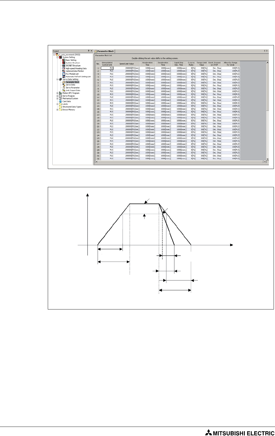
A maximum of 64 blocks can be set as parameter blocks.
Fig. 5-3: Time diagram for setting of parameter blocks
Speed Speed limit value
Rapid stop cause occurrence
Time
Real rapid stop
deceleration time
Set deceleration time
Set accele-
ration time
Real accele-
ration time
Set rapid stop
deceleration
time
Positioning
speed set in
the servo
program
Real deceleration time
Sample project creation with MT Developer2 and GX Developer Project creation
Motion controller Q170MCPU/ Q172DCPU/ Q173DCPU 5 - 5
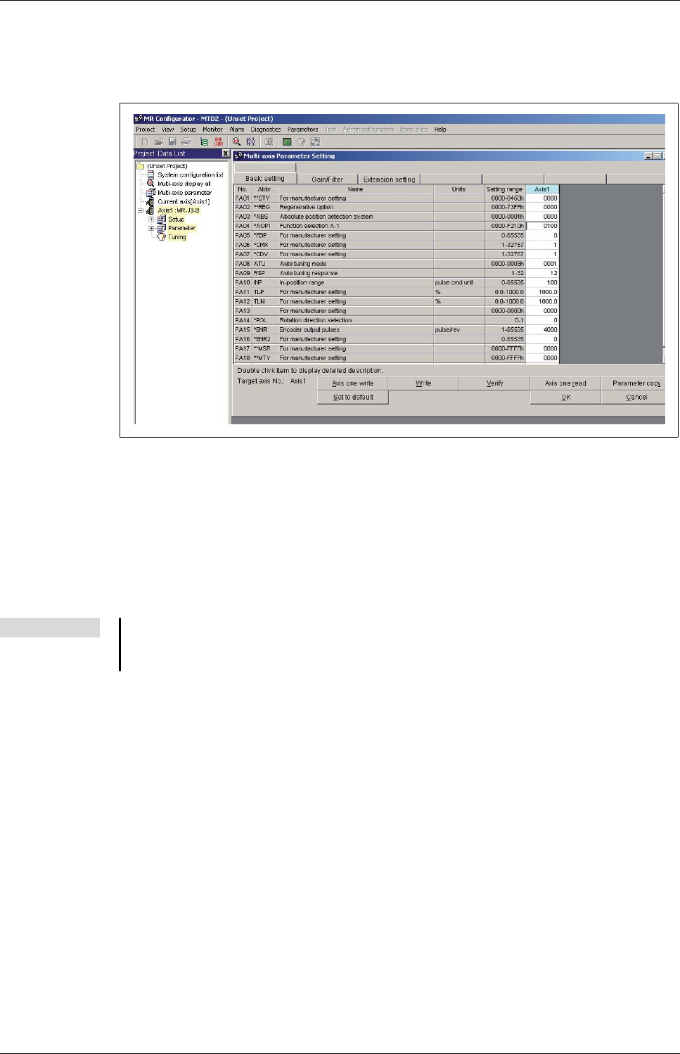
Servo Parameter Settings
In the "Project Window Menu", double-click Servo Parameter. This will launch the servo setup
software called MR Configurator.
Please change the following parameter in the "Basic setting":
●PA04: 0100
(Disabling the EMG input on servo amplifier. This will allow the amplifier to operate
regardless of forced stop input status.)
●PA14: 0 or 1 according to the motor rotation direction (CW or CCW)
and click OK.
Note Launching MR Configurator from within MT Developer2 is not the same as launching MR Con-
figurator from the Windows Start Menu. Opening from within MTD2 allows changes to servo
parameters to be saved within the MTD2 project files.
Project creation Sample project creation with MT Developer2 and GX Developer
5 - 6
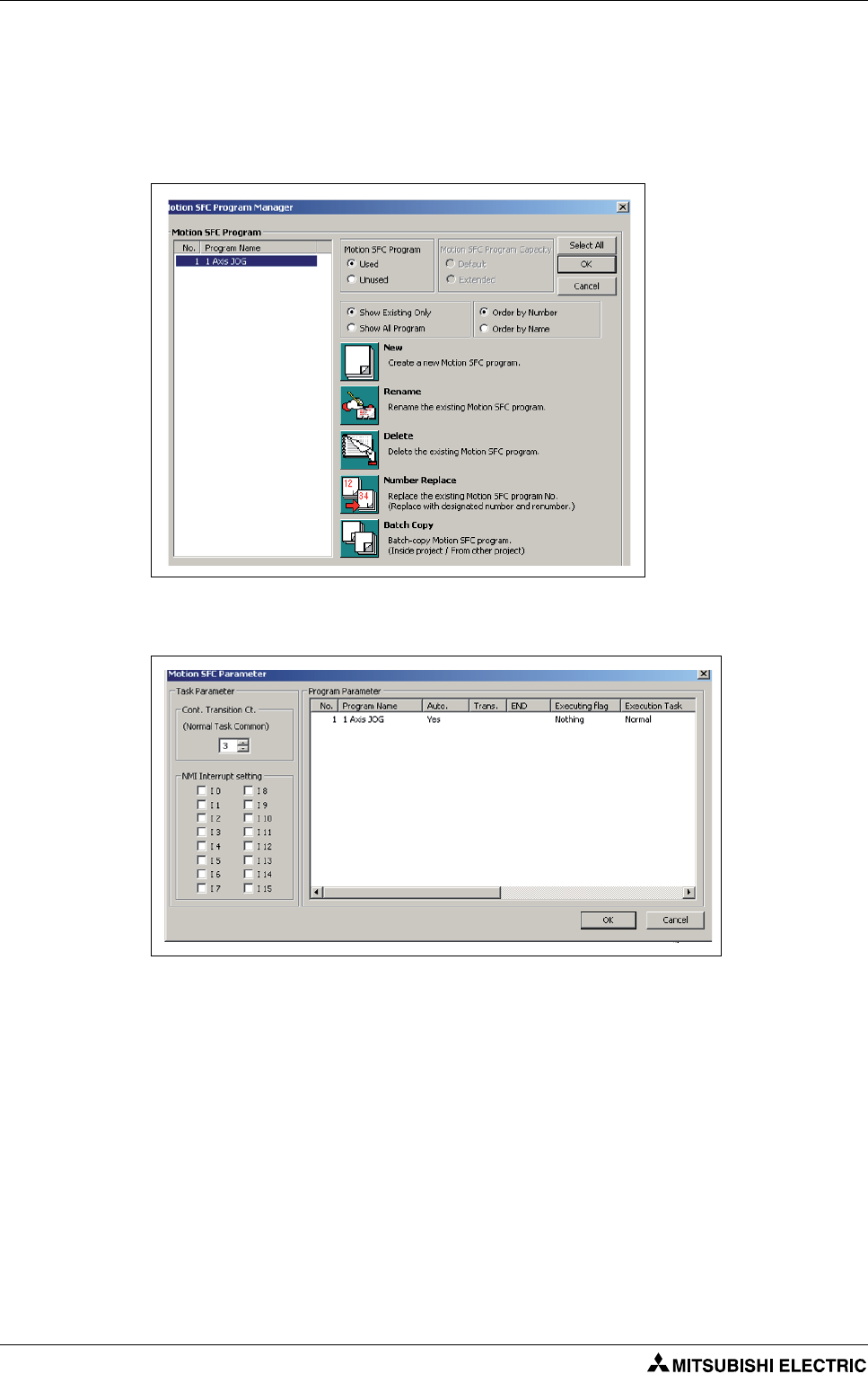
Motion SFC Program Creation
In the "Project Window Menu" under "Motion SFC Program", double-click Motion SFC Program
Manager. This open the "Motion SFC Program Manager" pop-up window.
Click the icon New which opens up the "New Motion SFC Program" window. Set the Motion SFC
Program No. to "1", enter "1 Axis JOG" as the program name and then click OK.
In the "Project Window Menu" under “Motion SFC Program”, double-click Motion SFC Parameter.
This open the “Motion SFC Parameter” pop-up window.
Double-click program 1 and then change the Start Setting to "Automatic Start".
Then close this window.
Sample project creation with MT Developer2 and GX Developer Project creation
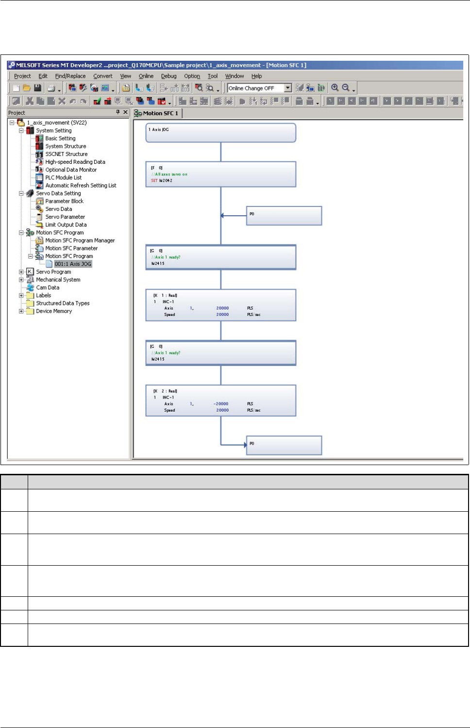
Motion controller Q170MCPU/ Q172DCPU/ Q173DCPU 5 - 7
Prepare an SFC program. The sample program below allows a simple forward and backward
movement of Axis 1.
Step Description
5a
Add an F-block, 2 x G-block, 2 x K-block, a Jump, and a Pointer to the program by left-clicking the respective button on the menu bar
and left-clicking in the program workspace. Press the Esc key (or right click) after adding each block to the workspace.
5b
Double-click the F-block, enter "0" for the program number. Next, press Enter or click the Edit button. In the Program Editor window,
type "SET M2402". The common system device M2402 enables "Servo On" for all axes when set.
5c
Double-click the G-block, enter "0" for the program number. Next, press Enter and then input the text "M2415". The axis status device
M2415 shows if axis 1 is ready. We are telling the controller to wait until the axis is fully initialized before moving on to the next step.
Without such a delay in front of a motion command (K-block), an error is likely to occur.
5d
Double-click the K-block, enter "1" for the program number. Next, press Enter and select "Linear Interpol." as the Command Class and
"INC-1" as the Servo Command. Click OK. The Servo Program Editor window will now open.
In the Servo Program Editor window, set the Axis to 1 and the travel amount to 20000 PLS. Then set the Speed to 20000 PLS/s.
5e
Repeat step 5c.
5f
Repeat step 5d changing the travel amount to -20000 PLS.
5g
Connect each function block to the one after it by clicking the Connect button from the menu bar and then left-clicking on one block
and dragging to the next box.
Tab. 5-1: Detailed procedure for preparing the SFC program

Project creation Sample project creation with MT Developer2 and GX Developer
5 - 8
File Conversion, Download and Program Run
Click the Batch Conversion button from the menu bar. If all steps were followed correctly, you
should receive a "Complete successfully" message in the output bar at the bottom of the screen.
Transfer programs and parameters to the Motion controller using the setting in the screenshot
below.
Batch
conversion
Output
screen

Sample project creation with MT Developer2 and GX Developer Project creation
Motion controller Q170MCPU/ Q172DCPU/ Q173DCPU 5 - 9
Please refer to the "Writing project to the Motion/PLC CPU" section of this quick-start guide for
further details on writing/reading programs (section 5.2.3).
PLC program creation and download to PLC CPU
Start GX Developer and create a new project with the correct PLC series and PLC type as shown
below.
In the "Project Window Menu" under "Parameter", double-click PLC parameter. This opens the "Q
parameter setting" pop-up window.
Click I/O assignment and afterwards Read PLC data.
Select Q03UD as
PLC type in case
Q170MCPU is used.
Read PLC
Data

Project creation Sample project creation with MT Developer2 and GX Developer
5 - 10
The pop-up warning windows shown below will appear:
Click Yes. Then close the "Q parameter setting" windows by clicking End confirming the chosen
setting.
Transfer programs and parameters to the PLC controller using the setting in the screenshot below.
Please refer to "Transfer setup" (section 5.2.1) for further information on transfer setup setting and
to "Writing project to the Motion/PLC CPU" (section 5.2.3) of this quick-start guide for further
information on writing/reading programs.
!Enjoy your program!
Cycle the power supply of Q170MCPU and MR-J3 servo both.
According to the program, you created, the motor will automatically rotate 1 revolution in both
directions. The movement will be stopped by using RUN/STOP switch at the Q170MCPU front
panel.

Additional procedures Project creation
Motion controller Q170MCPU/ Q172DCPU/ Q173DCPU 5 - 11
5.2 Additional procedures
5.2.1 Transfer setup
This section explains how to set the communication between PC and Q170MCPU/Q172DCPU by the
Transfer Setup screen.
For the sake of simplicity, it will be explained how to configure the communication by using a direct
connection with an USB cable.
Operating Procedure (Motion CPU access)
Double-click on Serial/USB button in the "PC side I/F" selection.
Select USB and close the pop-up window.
Select PLC module in the "CPU side I/F".
Select No specification in the "Other Station" setting.
Select PLC No.2 as "Target System".
Operating Procedure (PLC CPU access)
Double-click on Serial/USB button in the "PC side I/F" selection.
Select USB and close the pop-up window.
Select PLC module in the "CPU side I/F".
Select No specification in the "Other Station" setting.
Select PLC No.1 as "Target System".
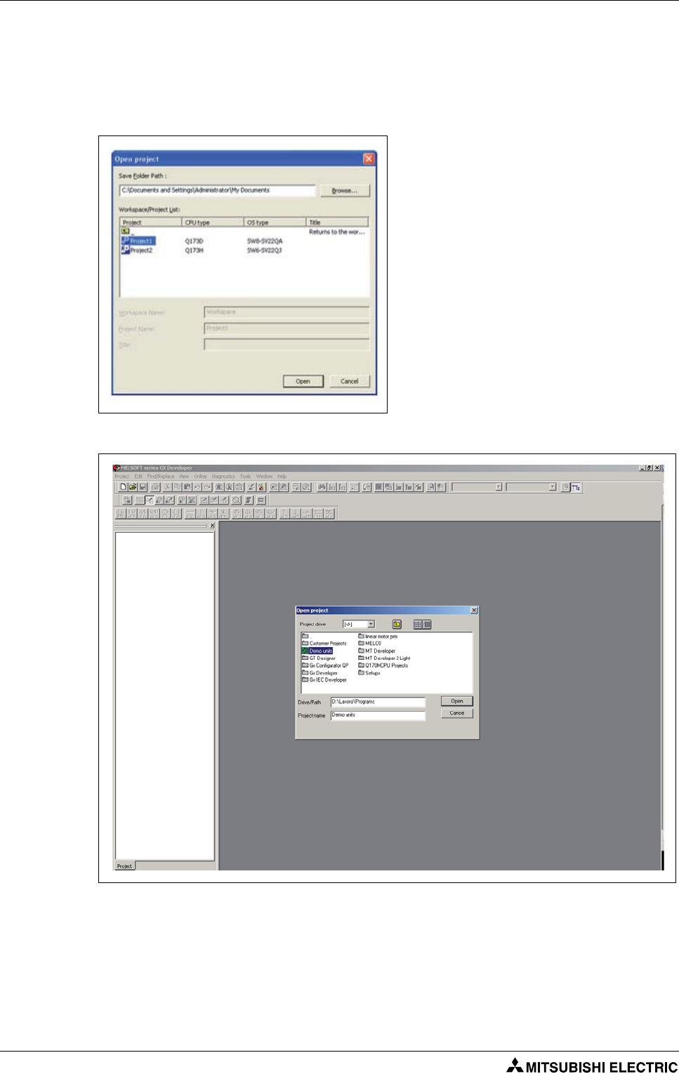
Project creation Additional procedures
5 - 12
5.2.2 Project opening
This section explains the method for reading a project saved in the hard disk or other memory media
of the personal computer.
Operating Procedure (MT Developer2 project)
Operating Procedure (GX Developer project)
Select "Project" - "Open Project". The Open Project window appears.
Enter the folder (drive/path), where the workspace is saved, in the "Folder" field.
Select the project data.
Click the Open button.
Select "Project" - "Open Project". The "Open
Project" window appears.
Enter the folder (drive/path), where the
workspace is saved, in the Folder field.
Double click Workspace in the "Workspace/
Project List".
Select the project data. Details of the speci-
fied project data are displayed in the
"Project Name" and "Title" columns.
Click the Open button.
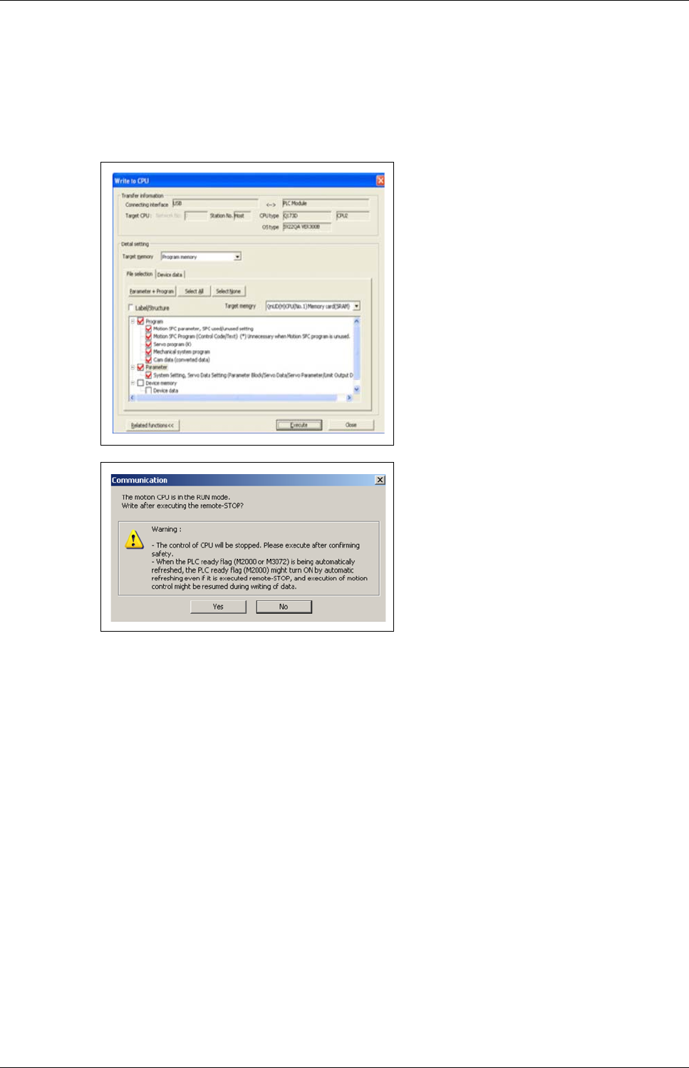
Additional procedures Project creation
Motion controller Q170MCPU/ Q172DCPU/ Q173DCPU 5 - 13
5.2.3 Writing project to the Motion/PLC CPU
This section explains the method for writing a project saved in the hard disk or other memory media
of the personal computer to the Motion/PLC controller internal memory.
Operating Procedure (MT Developer2)
Select "Online" - "Write to CPU". The "Write to CPU" screen appears.
Once download is complete, another message will appear asking if you would like to place the
controller back in Run mode. Again, select Yes and then Close.
The specified data is written to the target memory. When writing is completed, the dialog box
appears notifying the process completion.
Select Program memory as target memory
to write to.
Click on Parameter+ Program to select the
data to be written.
Click the Execute button.
When a password is registered, the Pass-
word Check dialog box appears.
When program write is to be executed, a
message appears if there are programs that
have not been converted.
The screen on the left appears if the motion
controller is in RUN mode.
Click the OK button.
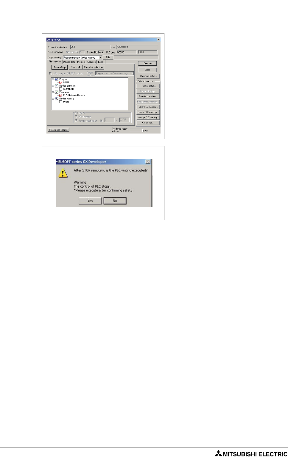
Project creation Additional procedures
5 - 14
Operating Procedure (GX Developer)
Select "Online" - "Write to PLC". The "Write to PLC" screen appears.
The specified data is written to the target memory. When writing is completed, the dialog box
appears notifying the process completion.
Select Program memory/Device memory
as target memory to write to.
Click on Parameter+ Program to select the
data to be written.
Click the Execute button.
When program write is to be executed, a
message appears if there are programs that
have not been converted.
The screen on the left appears if the motion
controller is in RUN mode.
Click the Yes button.
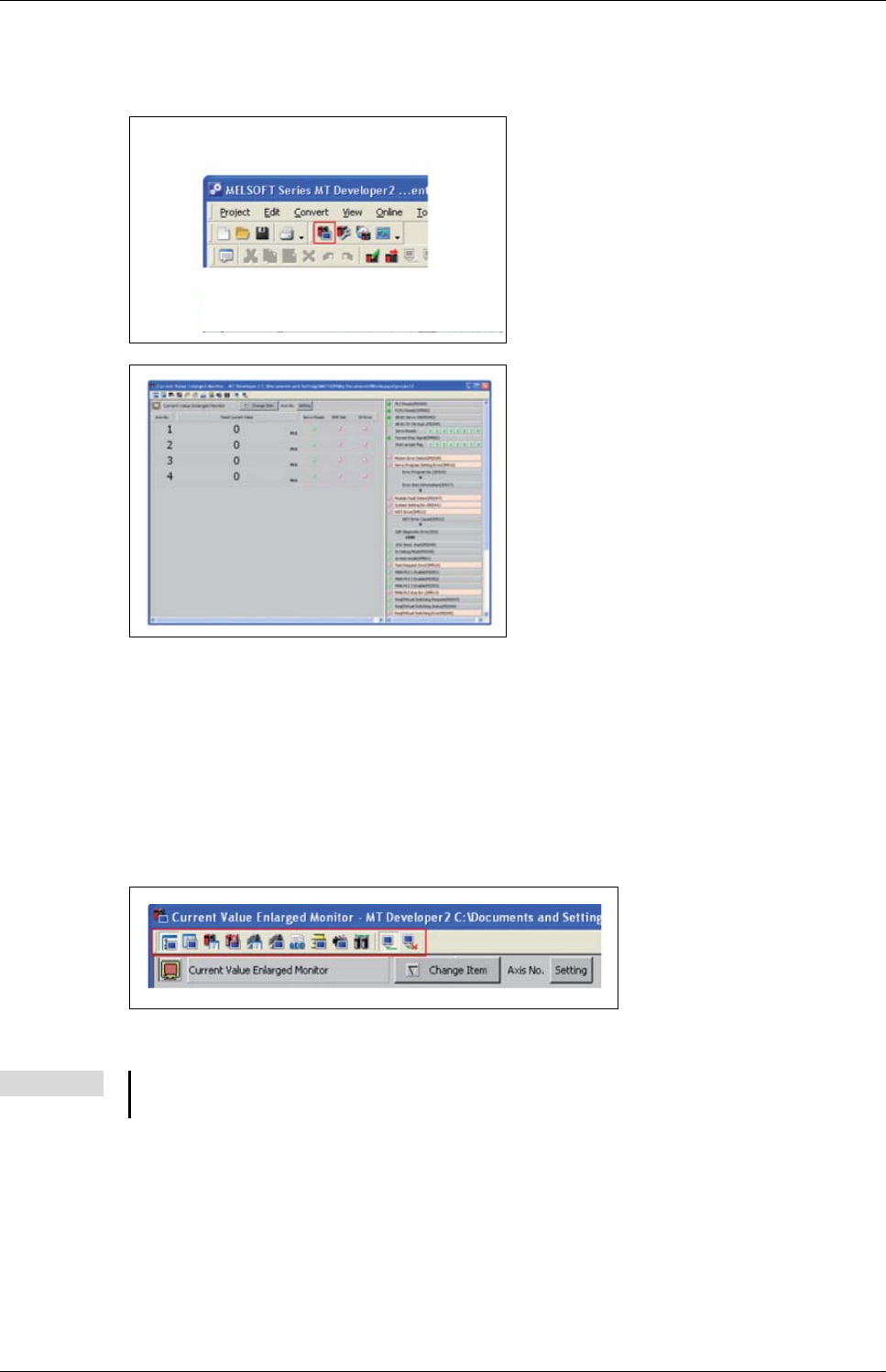
Additional procedures Project creation
Motion controller Q170MCPU/ Q172DCPU/ Q173DCPU 5 - 15
5.2.4 Monitoring function
Operating Procedure
Clicking on the buttons in the shown toolbar is possible to select the devices to be monitored:
– Current value monitor
– Motion error
–Axis monitor
– Servo Monitor
– Positioning monitor
–…
Click the monitor icon of the application
jump toolbar on the main frame.
Monitor is started.
NOTE Refer to MT Developer2 Help for further information.
Tip: Press function key "F1" for immediate help on displayed function.
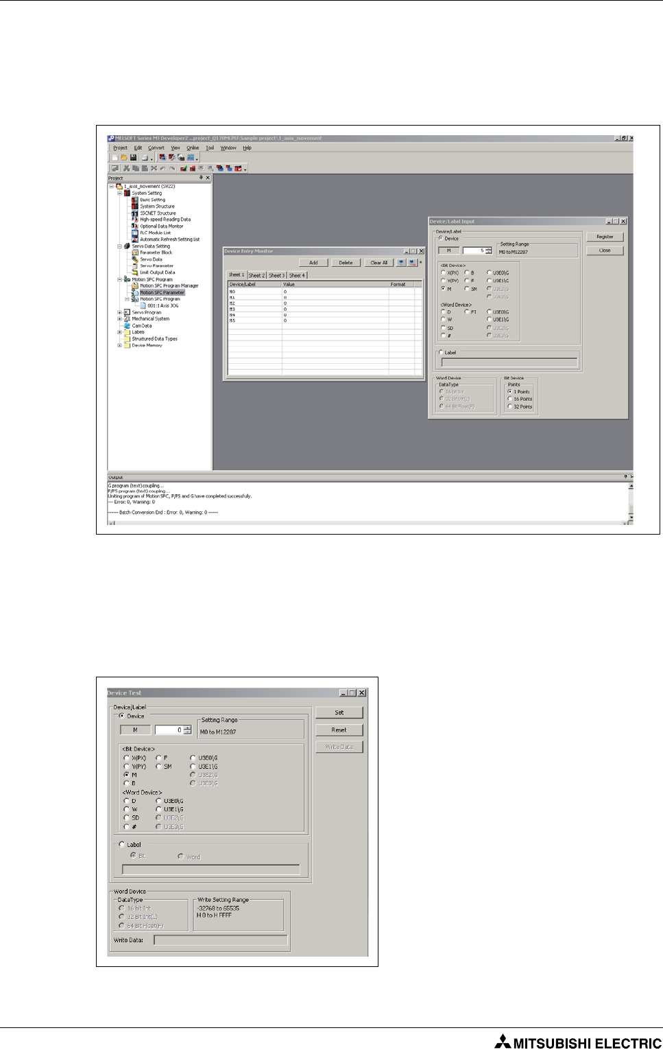
Project creation Additional procedures
5 - 16
5.2.5 Device monitoring and testing
Operating Procedure (MT Developer2)
Select "Online" - "Monitor" - "Commons" - "Entry Device Monitor".
The "Device Entry Monitor" screen appears.
Click Add. The "Device"/"Label" windows appears.
Select the device to be monitored and then push Register button.
The chosen devices will be displayed in the "Device Entry Monitor".
Click Close.
Click Start Monitoring button. The actual values of the registered devices will be displayed in the
column "Value".
Double-click the value of the Device to be
tested. The "Device Test" window appears.
Click Set or Reset to test the selected bit
device or Write Data to write a value into
the selected register.
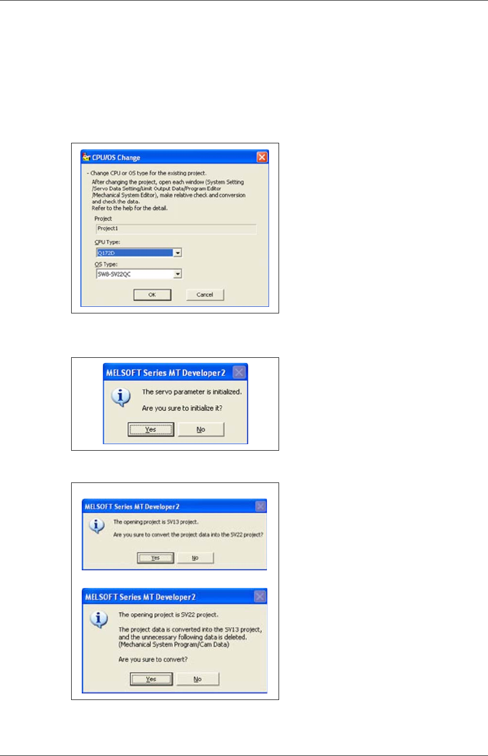
Additional procedures Project creation
Motion controller Q170MCPU/ Q172DCPU/ Q173DCPU 5 - 17
5.2.6 Motion CPU change
This section explains the method for changing the CPU and OS types of the open project.
Operating Procedure
Open a project to change its CPU and OS types.
Opening existing projects.
Select "Project" - "Change CPU/OS Type".
When the CPU type is changed from Q17nCPU to Q17nDCPU/Q170MCPU/Q17nHCPU, the follow-
ing screen appears.
The "CPU/OS Change" screen appears. Se-
lect a CPU type and OS type.
Click the OK button.
Click the Yes button to change the CPU or
OS type.
Click the No button to stop the change of
the CPU or OS type.
When changing from SV13 to SV22
When changing from SV22 to SV13
The confirmation screen appears asking
wether to change the OS type.
Click the Yes button.

Project creation Additional procedures
5 - 18
A dialog box appears notifying the CPU and
OS types have been changed.
Click the OK button.
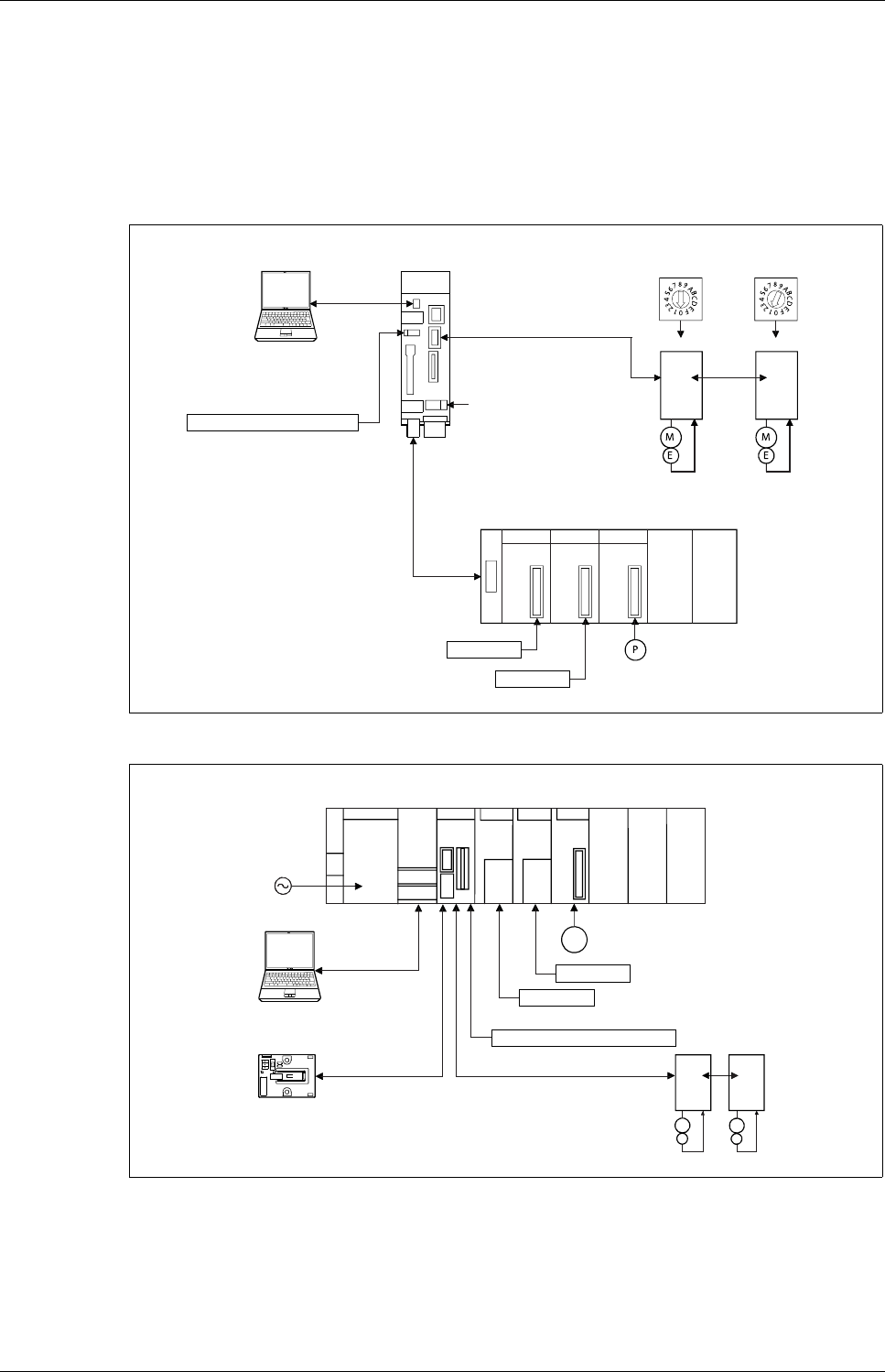
Sample program with OS SV22: 2_axes_motion Sample programs
Motion controller Q170MCPU/ Q172DCPU/ Q173DCPU 6 - 1
6 Sample programs
6.1 Sample program with OS SV22: 2_axes_motion
6.1.1 System configuration
Fig. 6-1: System configuration with Q170MCPU, two axes and extension base unit
Fig. 6-2: System configuration with Q172DCPU and two axes
Motion controller
Q170MCPU Rotary switches
Personal computer
IBM PC/AT
d01 d02
SSCNET III
SSCNET III cable
(MR-J3BUS첸M(-A/-B))
Extension cable
(QC첸B)
Extension base unit (QC55B)
24 V DC
Q173DPX
QX80
Manual pulse generator/
Incremental synchronous encoder
Input
Forced stop input (24 V DC)
USB/RS232
QY80
Output
d02
d01
E
M
E
M
Motion
CPU
Q61P QnUD(H)
CPU
QX80 QY80 Q173D
PX
P
PLC CPU/
Motion CPU
Personal computer
IBM PC/AT
SSCNET III (CN1)
SSCNET III cable
(MR-J3BUS첸M(-A/-B))
Forced stop input cable (Q170DEMICBL첸M)
Main base unit
(Q3쏔DB)
100/200 V AC
Manual pulse generator
(MR-HDP01)
Input
EMI forced stop input (24 V DC)
USB/RS232
Output
Battery holder unit
Q170DBATC
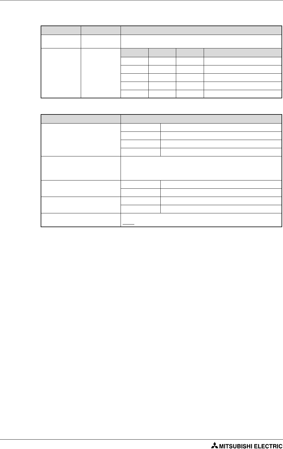
Sample programs Sample program with OS SV22: 2_axes_motion
6 - 2
6.1.2 Functions
Input Function Details
PX0 Forced stop When PX0 turns off, servomotors are forced to stop and motion control is sus-
pended (E7 warning).
PX1 and PX2 and
PX7
Motion selection
input
PX2 PX1 PX7 Motion mode
OFF OFF OFF
JOG mode
OFF ON OFF
Man. pulse generator mode
ON OFF OFF
Home position return mode
ON ON OFF
Operation mode (Real)
ON ON ON
Operation mode (Virtual)
Tab. 6-1: Functions of the inputs
Motion mode Details
JOG mode
PX3: Axis 1 JOG forward rotation
PX4: Axis 1 JOG reverse rotation
PX5: Axis 2 JOG forward rotation
PX6: Axis 2 JOG reverse rotation
Man. pulse generator mode
Manual pulse generator operation of axis 1 is executed with the manual pulse
generator P1.
Manual pulse generator operation of axes 1 and 2 is executed with the manual
pulse generator P2.
Home position return mode PX3: OFF 씮 ON Home position return of axis 1 is executed.
PX4: OFF 씮 ON Home position return of axis 2 is executed
Operation mode (Real) PX3: OFF 씮 ON Sample movement (point-to-point)
PX4: OFF 씮 ON Sample movement (linear interpolation)
Operation mode (Virtual) 2 synchronized cams movement automatically started.
NOTE: Home position required beforehand
Tab. 6-2: Details of motion mode
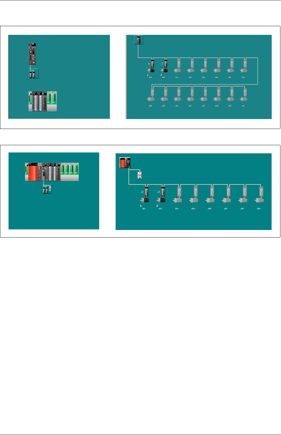
Sample program with OS SV22: 2_axes_motion Sample programs
Motion controller Q170MCPU/ Q172DCPU/ Q173DCPU 6 - 3
6.1.3 System setting data of the motion CPU
Fig. 6-3: Structure of the system (left) and of SSCNET III (right) with Q170MCPU
Fig. 6-4: Structure of the system (left) and of SSCNET III (right) with QD motion controller
Extension Base - Stage 1 : 5 Slots
SSCNET Line 1
Main Base : 8 Slots
SSCNET Line 1
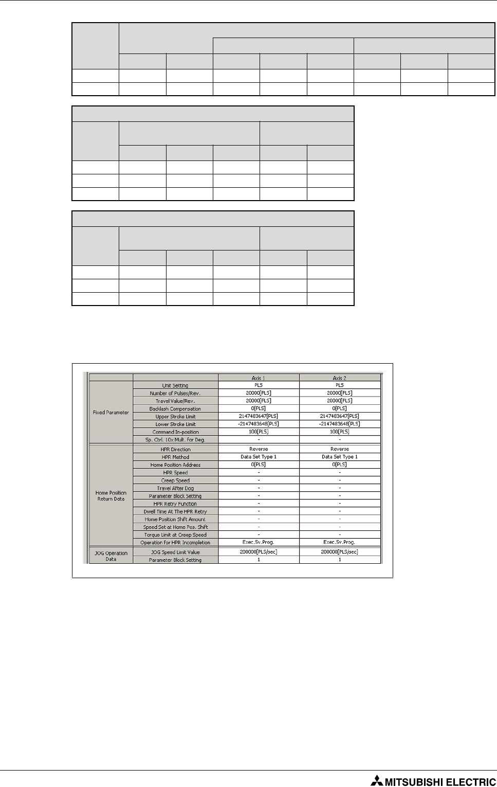
Sample programs Sample program with OS SV22: 2_axes_motion
6 - 4
6.1.4 Axis Data Setting
PLC
CPU specific send range
User setting area Auto refresh
point (K) I/O No. point Start End point Start End
CPU No. 1 7 U3E0 7168 G10000 G17167 0 — —
CPU No. 2 7 U3E1 6468 G10000 G16467 700 G16468 G17167
PLC No. 1
No. Auto refresh CPU specific
send range
point Start End Start End
1 —————
2 —————
3 —————
PLC No. 2
No. Auto refresh CPU specific
send range
point Start End Start End
1 20 M2000 M2319 G16468 G16487
2 40 M2400 M3039 G16488 G16527
3 640 D0 D639 G16528 G17167
Tab. 6-3: Multiple CPU setting - Auto refresh setting
Fig. 6-5: Setting of the axis data
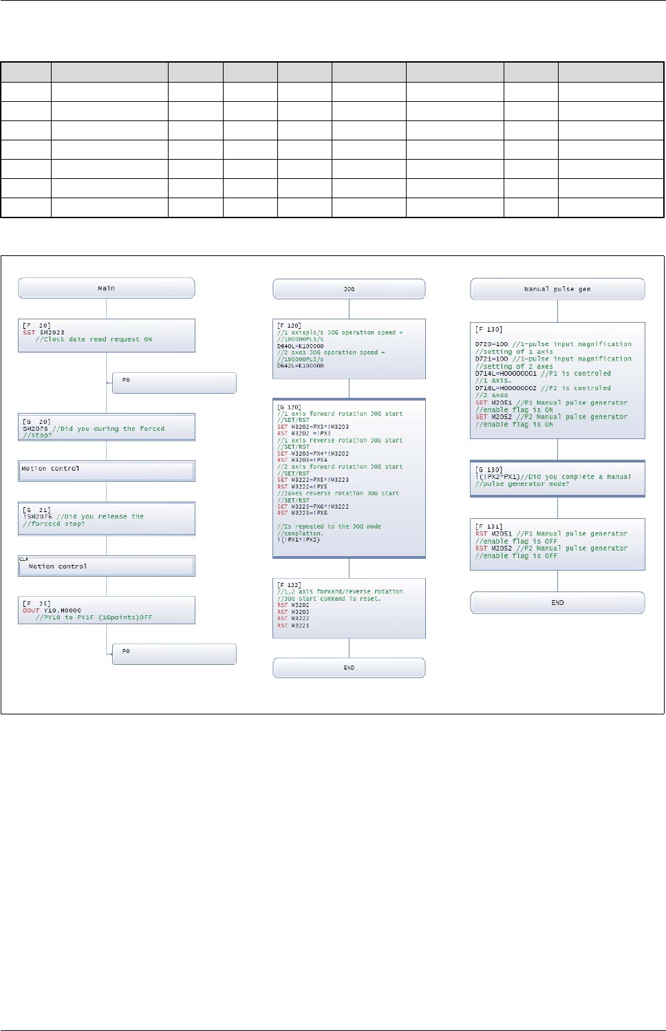
Sample program with OS SV22: 2_axes_motion Sample programs
Motion controller Q170MCPU/ Q172DCPU/ Q173DCPU 6 - 5
6.1.5 Motion SFC Program
No. Program Name Task Auto. END Cont. Trans. Executing Flag Cycle Interrupt
20
Main
Normal Yes — — Nothing — —
110
Motion control
Normal No — — Nothing — —
120
JOG
Normal No — — Nothing — —
130
Manual pulse gen
Normal No — — Nothing — —
140
Home position re
Normal No — — Nothing — —
150
Programming oper
Normal No — — Nothing — —
160
Virtual mode
Normal No — — Nothing — —
Tab. 6-4: Program overview
Fig. 6-6: Motion SFC Programs "Main", "JOG" and "Manual pulse generator"
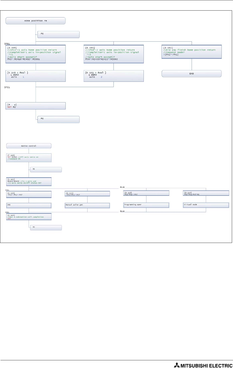
Sample programs Sample program with OS SV22: 2_axes_motion
6 - 6
Fig. 6-7: Motion SFC Programs "Home position return" and "Motion control"
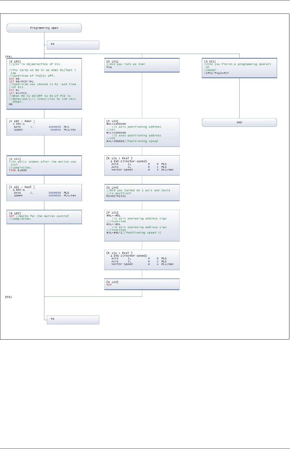
Sample program with OS SV22: 2_axes_motion Sample programs
Motion controller Q170MCPU/ Q172DCPU/ Q173DCPU 6 - 7
Fig. 6-8: Motion SFC Program "Programming operation"
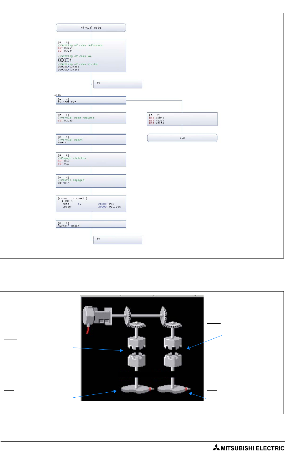
Sample programs Sample program with OS SV22: 2_axes_motion
6 - 8
6.1.6 Mechanical system program
Fig. 6-9: Motion SFC Program "Virtual mode"
Fig. 6-10: Mechanical system
Clutch:
Clutch ON/OFF Command Dev.: M12
Clutch Status Device: M13
Clutch:
Clutch ON/OFF Command Dev.: M10
Clutch Status Device: M11
V.1
Axis 1 Axis 2
CAM:
Cam No. Dev.: D2000
Stroke Setting Dev.: D2002
Number of Pulses/Rev.: 20 000 [PLS]
CAM:
Cam No. Dev.: D2004
Stroke Setting Dev.: D2006
Number of Pulses/Rev.: 20 000 [PLS]
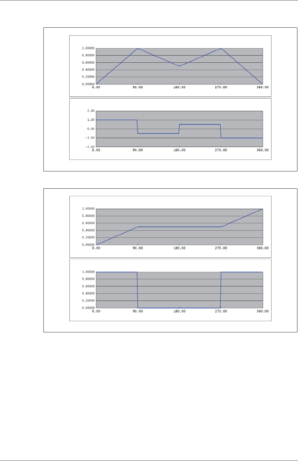
Sample program with OS SV22: 2_axes_motion Sample programs
Motion controller Q170MCPU/ Q172DCPU/ Q173DCPU 6 - 9
6.1.7 CAMs
Fig. 6-11: CAM 1 (Axis 1)
Fig. 6-12: CAM 2 (Axis 2)
Stroke Ratio Graph
Speed Graph
Absolute Angle [deg]
Absolute Angle [deg]
Speed Stroke Ratio
Stroke Ratio Graph
Speed Graph
Absolute Angle [deg]
Absolute Angle [deg]
Speed Stroke Ratio
Sample programs Sample program with OS SV22: 2_axes_motion_no_inputs
6 - 10
6.2 Sample program with OS SV22: 2_axes_motion_no_inputs
This second sample program is mainly similar to the first one in section 6.1. The only difference is, that
the hard wired inputs have been replaced by internal bit devices.
6.2.1 System configuration
Fig. 6-13: System configuration with Q170MCPU and two axes
Fig. 6-14: System configuration with Q172DCPU and two axes
Motion controller
Q170MCPU Rotary switches
Personal computer
IBM PC/AT
d01 d02
SSCNET III
SSCNET cable
(MR-J3BUS첸M(-A/-B))
24 V DC
Forced stop input (24 V DC)
USB
d02
d01
E
M
E
M
Motion
CPU
Q61P QnUD(H)
CPU
PLC CPU/
Motion CPU
Personal computer
IBM PC/AT
SSCNET III (CN1)
SSCNET III cable
(MR-J3BUS첸M(-A/-B))
Forced stop input cable (Q170DEMICBL첸M)
Main base unit
(Q3쏔DB)
100/200 V AC
EMI forced stop input (24 V DC)
USB/RS232
Battery holder unit
Q170DBATC
Sample program with OS SV22: 2_axes_motion_no_inputs Sample programs
Motion controller Q170MCPU/ Q172DCPU/ Q173DCPU 6 - 11
6.2.2 Functions
Bit Devices Function Details
M100 Forced stop When M100 turns off, servomotors are forced to stop and motion control is sus-
pended (E7 warning).
M101 and M102
and M107
Motion selection
input
M102 M101 M107 Motion mode
OFF OFF OFF
JOG mode
ON OFF OFF
Home position return mode
ON ON OFF
Operation mode (Real)
ON ON ON
Operation mode (Virtual)
Tab. 6-5: Functions of bit devices
Motion mode Details
JOG mode
M103: Axis 1 JOG forward rotation
M104: Axis 1 JOG reverse rotation
M105: Axis 2 JOG forward rotation
M106: Axis 2 JOG reverse rotation
Home position return mode M103: ON Home position return of axis 1 is executed.
M104: ON Home position return of axis 2 is executed
Operation mode (Real) M103: OFF 씮 ON Sample movement 1 (point-to-point)
M104: ON Sample movement 2 (linear interpolation)
Operation mode (Virtual) 2 synchronized cams movement automatically started.
NOTE: Home position required beforehand
Tab. 6-6: Details of motion mode
NOTE Refer to the section "Device monitor and testing" (section 5.2.5) of this quick-start guide for further
details of bit devices setting/resetting.

Sample programs Sample program with OS SV22: 2_axes_motion_no_inputs
6 - 12
Exterior Dimensions Appendix
Motion controller Q170MCPU/ Q172DCPU/ Q173DCPU A - 1
A Appendix
A.1 Exterior Dimensions
A.1.1 Motion controller Q170MCPU
Fig. A-1: Dimensions of Q170MCPU
38
7
8
154
6
7
52
52
4.6
135
178
161
168
Unit: [mm]
With battery holder
removed
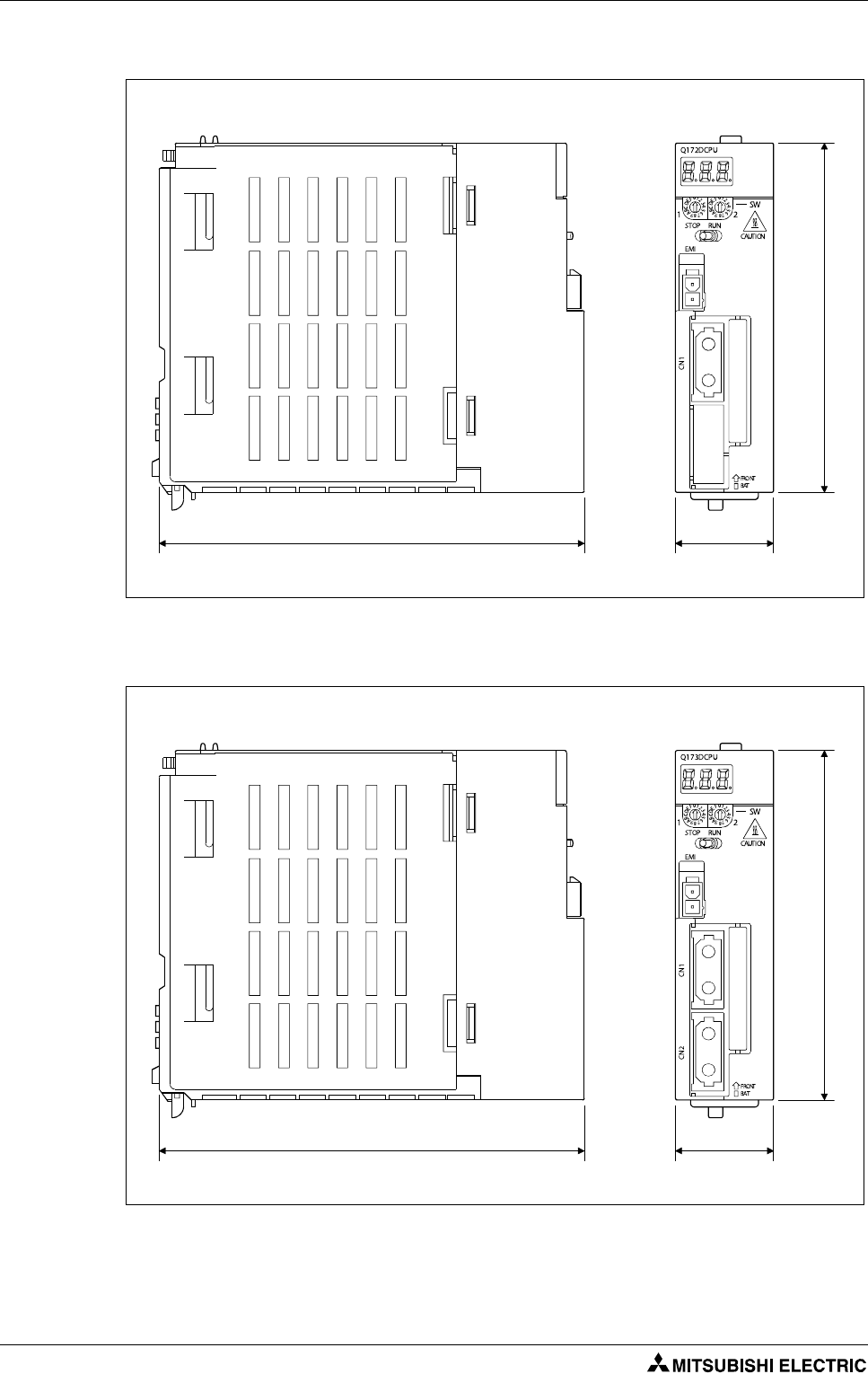
Appendix Exterior Dimensions
A - 2
A.1.2 Motion controller Q172DCPU and Q173DCPU
Fig. A-2: Dimensions of Q172DCPU
Fig. A-3: Dimensions of Q173DCPU
98
27.4
119.3
Unit: [mm]
98
27.4
119.3
Unit: [mm]
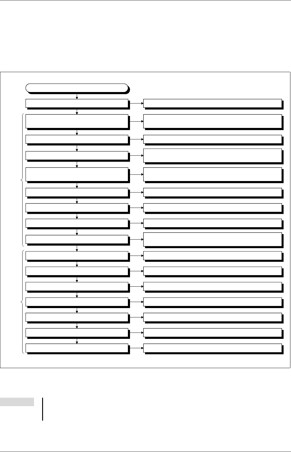
Troubleshooting Appendix
Motion controller Q170MCPU/ Q172DCPU/ Q173DCPU A - 3
A.2 Troubleshooting
The following flowcharts show the contents of the troubles with the motion controllers classified into
a variety of groups according to the types of events.
A.2.1 Q170MCPU
Fig. A-4: Troubleshooting flowchart for Q170MCPU
NOTE The procedure of fault finding for each event group (a) to (p), mentioned on the right side of the
above flowchart, is described in chapter 6 of the user’s manual of the motion controller
Q170MCPU.
Motion
CPU
area
PLC
CPU
area
Error-occurrence description
"POWER" LED turns off
"." does not flash in the first digit of
7-segment LED
"A00" displays on 7-segment LED
"AL" 씮 "L01" displays on 7-segment LED
"AL" 씮 "A1" 씮 "첸" displays on
7-segment LED
"BT첸" displays on 7-segment LED
"…" displays on 7-segment LED
Servo amplifier does not start
"AL" 씮 "S01" displays on 7-segment LED
"MODE" LED does not turn on
"MODE" LED is flickering
"RUN" LED turns off
"RUN" LED is flickering
"ERR." LED turns on/is flickering
"USER" LED turns on
"BAT. " LED (Yellow) turns on
(a) "Flowchart for when "POWER LED" turns off"
(b) "Flowchart for when "." does not flash in the first digit of
7-segment LED"
(c) "Flowchart for when "A00" displays on 7-segment LED"
(d) "Flowchart for when "AL" 씮 "L01" displays on
7-segment LED"
(e) "Flowchart for when "AL" 씮 "A1" 씮 "첸" displays on
7-segment LED"
(f) "Flowchart for when "BT첸" displays on 7-segment LED"
(g) "Flowchart for when "…" displays on 7-segment LED"
(h) "Flowchart for when the Servo amplifier does not start
(i) "Flowchart for when "AL" 씮 "S01" displays on
7-segment LED"
(j) "Flowchart for when "MODE" LED does not turn on"
(k) "Flowchart for when "MODE" LED is flickering"
(l) "Flowchart for when "RUN" LED turns off"
(m) "Flowchart for when "RUN" is flickering"
(n) "Flowchart for when "ERR." LED turns on/is flickering"
(o) "Flowchart for when "USER" LED turns on"
(p) "Flowchart for when "BAT. " LED (Yellow) turns on"
Appendix Troubleshooting
A - 4
A.2.2 QD-Motion controller
Fig. A-5: Troubleshooting flowchart for Q172DCPU and Q173DCPU
NOTE The procedure of fault finding for each event group (a) to (i), mentioned on the right side of the
above flowchart, is described in chapter 6 of the user’s manual of the motion controllers
Q172DCPU and Q173DCPU.
Error-occurrence description
"POWER" LED turns off
"." does not flash in the first digit of
7-segment LED
"A00" displays on 7-segment LED
"AL" 씮 "L01" displays on 7-segment LED
"AL" 씮 "A1" 씮 "첸" displays on
7-segment LED
"BT첸" displays on 7-segment LED
"…" displays on 7-segment LED
Servo amplifier does not start
"AL" 씮 "S01" displays on 7-segment LED
(a) "Flowchart for when "POWER LED" turns off"
(b) "Flowchart for when "." does not flash in the first digit of
7-segment LED"
(c) "Flowchart for when "A00" displays on 7-segment LED"
(d) "Flowchart for when "AL" 씮 "L01" displays on 7-segment LED"
(e) "Flowchart for when "AL" 씮 "A1" 씮 "첸" displays on
7-segment LED"
(f) "Flowchart for when "BT첸" displays on 7-segment LED"
(g) "Flowchart for when "…" displays on 7-segment LED"
(h) "Flowchart for when the Servo amplifier does not start
(i) "Flowchart for when "AL" 씮 "S01" displays on 7-segment LED"

Index
Motion controller Q170MCPU/ Q172DCPU/ Q173DCPU i
Index
B
Base unit
Module installation
. . . . . . . . . . . . . . . . . . . . . . . . . . .3-4
Module removal
. . . . . . . . . . . . . . . . . . . . . . . . . . . . . .3-5
C
CCW
. . . . . . . . . . . . . . . . . . . . . . . . . . . . . . . . . . . . . . . . . . . . .1-5
Change of
CPU type
. . . . . . . . . . . . . . . . . . . . . . . . . . . . . . . . . . . 5-17
OS type
. . . . . . . . . . . . . . . . . . . . . . . . . . . . . . . . . . . . 5-17
CPU type change
. . . . . . . . . . . . . . . . . . . . . . . . . . . . . . . 5-17
CW
. . . . . . . . . . . . . . . . . . . . . . . . . . . . . . . . . . . . . . . . . . . . . . .1-5
D
Dimensions
Q170MCPU
. . . . . . . . . . . . . . . . . . . . . . . . . . . . . . . . . . A-1
Q172DCPU
. . . . . . . . . . . . . . . . . . . . . . . . . . . . . . . . . . A-2
Q173DCPU
. . . . . . . . . . . . . . . . . . . . . . . . . . . . . . . . . . A-2
DOG
. . . . . . . . . . . . . . . . . . . . . . . . . . . . . . . . . . . . . . . . . . . . .1-5
E
EMI
Abbreviation
. . . . . . . . . . . . . . . . . . . . . . . . . . . . . . . . .1-5
F
FLS
. . . . . . . . . . . . . . . . . . . . . . . . . . . . . . . . . . . . . . . . . . . . . . .1-5
Forced stop input
Q170MCPU
. . . . . . . . . . . . . . . . . . . . . . . . . . . . . . . . . . .3-7
QD motion controller
. . . . . . . . . . . . . . . . . . . . . . . 3-10
I
I/F connector
Q170MCPU
. . . . . . . . . . . . . . . . . . . . . . . . . . . . . . . . . . .3-8
I/F connector cable
Differential-output type
. . . . . . . . . . . . . . . . . . . . . .3-8
Open-collector type
. . . . . . . . . . . . . . . . . . . . . . . . . .3-9
Voltage-output type
. . . . . . . . . . . . . . . . . . . . . . . . . .3-9
M
Module mounting
Q170MCPU
. . . . . . . . . . . . . . . . . . . . . . . . . . . . . . . . . . .3-2
Q172DCPU
. . . . . . . . . . . . . . . . . . . . . . . . . . . . . . . . . . .3-4
Q173DCPU
. . . . . . . . . . . . . . . . . . . . . . . . . . . . . . . . . . .3-4
Motion-Control-System
Block diagram
. . . . . . . . . . . . . . . . . . . . . . . . . . . . . . . .1-2
Overview
. . . . . . . . . . . . . . . . . . . . . . . . . . . . . . . . . . . . .1-1
O
Operating system
Installation
. . . . . . . . . . . . . . . . . . . . . . . . . . . . . . . . . . .4-5
Versions
. . . . . . . . . . . . . . . . . . . . . . . . . . . . . . . . . . . . . .4-4
OS type change
. . . . . . . . . . . . . . . . . . . . . . . . . . . . . . . . .5-17
P
Power supply
Q170MCPU
. . . . . . . . . . . . . . . . . . . . . . . . . . . . . . . . . . .3-6
QD motion controller
. . . . . . . . . . . . . . . . . . . . . . . .3-10
R
RLS
. . . . . . . . . . . . . . . . . . . . . . . . . . . . . . . . . . . . . . . . . . . . . .1-5
Rotary switch setting
Q170MCPU
. . . . . . . . . . . . . . . . . . . . . . . . . . . . . . . . . . .2-2
Q172DCPU, Q173DCPU
. . . . . . . . . . . . . . . . . . . . . . .2-5
S
Specification
Q170MCPU
. . . . . . . . . . . . . . . . . . . . . . . . . . . . . . . . . . .1-3
Q172DCPU
. . . . . . . . . . . . . . . . . . . . . . . . . . . . . . . . . . .1-4
Q173DCPU
. . . . . . . . . . . . . . . . . . . . . . . . . . . . . . . . . . .1-4
SSCNET III
Cables
. . . . . . . . . . . . . . . . . . . . . . . . . . . . . . . . . . . . . .3-11
Connection with Q170MCPU
. . . . . . . . . . . . . . . .3-11
Connection with Q172DCPU
. . . . . . . . . . . . . . . . .3-12
Connection with Q173DCPU
. . . . . . . . . . . . . . . . .3-13

Index
ii

HEADQUARTERS
EUROPEMITSUBISHI ELECTRIC EUROPE B.V.
German Branch
Gothaer Straße 8
D-40880 Ratingen
Phone: +49 (0)2102 / 486-0
Fax: +49 (0)2102 / 486-1120
CZECH REPUBLICMITSUBISHI ELECTRIC EUROPE B.V.
Czech Branch
Avenir Business Park, Radlická 714/113a
CZ-158 00 Praha 5
Phone: +420 (0)251 551 470
Fax: +420 (0)251-551-471
FRANCEMITSUBISHI ELECTRIC EUROPE B.V.
French Branch
25, Boulevard des Bouvets
F-92741 Nanterre Cedex
Phone: +33 (0)1 / 55 68 55 68
Fax: +33 (0)1 / 55 68 57 57
IRELANDMITSUBISHI ELECTRIC EUROPE B.V.
Irish Branch
Westgate Business Park, Ballymount
IRL-Dublin 24
Phone: +353 (0)1 4198800
Fax: +353 (0)1 4198890
ITALYMITSUBISHI ELECTRIC EUROPE B.V.
Italian Branch
Viale Colleoni 7
I-20041 Agrate Brianza (MB)
Phone: +39 039 / 60 53 1
Fax: +39 039 / 60 53 312
POLANDMITSUBISHI ELECTRIC EUROPE B.V.
Poland Branch
Krakowska 50
PL-32-083 Balice
Phone: +48 (0)12 / 630 47 00
Fax: +48 (0)12 / 630 47 01
SPAINMITSUBISHI ELECTRIC EUROPE B.V.
Spanish Branch
Carretera de Rubí 76-80
E-08190 Sant Cugat del Vallés (Barcelona)
Phone: 902 131121 // +34 935653131
Fax: +34 935891579
UKMITSUBISHI ELECTRIC EUROPE B.V.
UK Branch
Travellers Lane
UK-Hatfield, Herts. AL10 8XB
Phone: +44 (0)1707 / 27 61 00
Fax: +44 (0)1707 / 27 86 95
JAPANMITSUBISHI ELECTRIC CORPORATION
Office Tower “Z” 14 F
8-12,1 chome, Harumi Chuo-Ku
Tokyo 104-6212
Phone: +81 3 622 160 60
Fax: +81 3 622 160 75
USAMITSUBISHI ELECTRIC AUTOMATION, Inc.
500 Corporate Woods Parkway
Vernon Hills, IL 60061
Phone: +1 847 478 21 00
Fax: +1 847 478 22 53
EUROPEAN REPRESENTATIVES
AUSTRIAGEVA
Wiener Straße 89
AT-2500 Baden
Phone: +43 (0)2252 / 85 55 20
Fax: +43 (0)2252 / 488 60
BELARUSTEHNIKON
Oktyabrskaya 16/5, Off. 703-711
BY-220030 Minsk
Phone: +375 (0)17 / 210 46 26
Fax: +375 (0)17 / 210 46 26
BELGIUMESCO DRIVES & AUTOMATION
Culliganlaan 3
BE-1831 Diegem
Phone: +32 (0)2 / 717 64 30
Fax: +32 (0)2 / 717 64 31
BELGIUMKoning & Hartman b.v.
Woluwelaan 31
BE-1800 Vilvoorde
Phone: +32 (0)2 / 257 02 40
Fax: +32 (0)2 / 257 02 49
BOSNIA AND HERZEGOVINAINEA BH d.o.o.
Aleja Lipa 56
BA-71000 Sarajevo
Phone: +387 (0)33 / 921 164
Fax: +387 (0)33/ 524 539
BULGARIAAKHNATON
4 Andrej Ljapchev Blvd. Pb 21
BG-1756 Sofia
Phone: +359 (0)2 / 817 6004
Fax: +359 (0)2 / 97 44 06 1
CROATIAINEA CR d.o.o.
Losinjska 4 a
HR-10000 Zagreb
Phone: +385 (0)1 / 36 940 - 01/ -02/ -03
Fax: +385 (0)1 / 36 940 - 03
CZECH REPUBLICAutoCont C.S. s.r.o.
Technologická 374/6
CZ-708 00 Ostrava-Pustkovec
Phone: +420 595 691 150
Fax: +420 595 691 199
CZECH REPUBLICB:ELECTRIC, s.r.o.
Mladoboleslavská 812
CZ-197 00 Praha 19 - Kbely
Phone: +420 286 850 848, +420 724 317 975
Fax: +420 286 850 850
DENMARKBeijer Electronics A/S
Lykkegårdsvej 17, 1.
DK-4000 Roskilde
Phone: +45 (0)46/ 75 76 66
Fax: +45 (0)46 / 75 56 26
ESTONIABeijer Electronics Eesti OÜ
Pärnu mnt.160i
EE-11317 Tallinn
Phone: +372 (0)6 / 51 81 40
Fax: +372 (0)6 / 51 81 49
FINLANDBeijer Electronics OY
Jaakonkatu 2
FIN-01620 Vantaa
Phone: +358 (0)207 / 463 500
Fax: +358 (0)207 / 463 501
GREECEUTECO A.B.E.E.
5, Mavrogenous Str.
GR-18542 Piraeus
Phone: +30 211 / 1206 900
Fax: +30 211 / 1206 999
HUNGARYMELTRADE Ltd.
Fertő utca 14.
HU-1107 Budapest
Phone: +36 (0)1 / 431-9726
Fax: +36 (0)1 / 431-9727
LATVIABeijer Electronics SIA
Vestienas iela 2
LV-1035 Riga
Phone: +371 (0)784 / 2280
Fax: +371 (0)784 / 2281
LITHUANIABeijer Electronics UAB
Savanoriu Pr. 187
LT-02300 Vilnius
Phone: +370 (0)5 / 232 3101
Fax: +370 (0)5 / 232 2980
EUROPEAN REPRESENTATIVES
MALTAALFATRADE Ltd.
99, Paola Hill
Malta- Paola PLA 1702
Phone: +356 (0)21 / 697 816
Fax: +356 (0)21 / 697 817
MOLDOVAINTEHSIS srl
bld. Traian 23/1
MD-2060 Kishinev
Phone: +373 (0)22 / 66 4242
Fax: +373 (0)22 / 66 4280
NETHERLANDSHIFLEX AUTOM.TECHNIEK B.V.
Wolweverstraat 22
NL-2984 CD Ridderkerk
Phone: +31 (0)180 – 46 60 04
Fax: +31 (0)180 – 44 23 55
NETHERLANDSKoning & Hartman b.v.
Haarlerbergweg 21-23
NL-1101 CH Amsterdam
Phone: +31 (0)20 / 587 76 00
Fax: +31 (0)20 / 587 76 05
NORWAYBeijer Electronics AS
Postboks 487
NO-3002 Drammen
Phone: +47 (0)32 / 24 30 00
Fax: +47 (0)32 / 84 85 77
ROMANIASirius Trading & Services srl
Aleea Lacul Morii Nr. 3
RO-060841 Bucuresti, Sector 6
Phone: +40 (0)21 / 430 40 06
Fax: +40 (0)21 / 430 40 02
SERBIACraft Con. & Engineering d.o.o.
Bulevar Svetog Cara Konstantina 80-86
SER-18106 Nis
Phone:+381 (0)18 / 292-24-4/5
Fax: +381 (0)18 / 292-24-4/5
SERBIAINEA SR d.o.o.
Izletnicka 10
SER-113000 Smederevo
Phone: +381 (0)26 / 617 163
Fax: +381 (0)26 / 617 163
SLOVAKIAAutoCont Control s.r.o.
Radlinského 47
SK-02601 Dolny Kubin
Phone: +421 (0)43 / 5868210
Fax: +421 (0)43 / 5868210
SLOVAKIACS MTrade Slovensko, s.r.o.
Vajanskeho 58
SK-92101 Piestany
Phone: +421 (0)33 / 7742 760
Fax: +421 (0)33 / 7735 144
SLOVENIAINEA d.o.o.
Stegne 11
SI-1000 Ljubljana
Phone: +386 (0)1 / 513 8100
Fax: +386 (0)1 / 513 8170
SWEDENBeijer Electronics AB
Box 426
SE-20124 Malmö
Phone: +46 (0)40 / 35 86 00
Fax: +46 (0)40 / 35 86 02
SWITZERLANDEconotec AG
Hinterdorfstr. 12
CH-8309 Nürensdorf
Phone: +41 (0)44 / 838 48 11
Fax: +41 (0)44 / 838 48 12
TURKEYGTS
Bayraktar Bulvari Nutuk Sok. No:5
TR-34775 Yukari Dudullu-Umraniye-ISTANBUL
Phone: +90 (0)216 526 39 90
Fax: +90 (0)216 526 3995
UKRAINECSC Automation Ltd.
4-B, M. Raskovoyi St.
UA-02660 Kiev
Phone: +380 (0)44 / 494 33 55
Fax: +380 (0)44 / 494-33-66
EURASIAN REPRESENTATIVES
KAZAKHSTANKazpromautomatics Ltd.
Mustafina Str. 7/2
KAZ-470046 Karaganda
Phone: +7 7212 / 50 11 50
Fax: +7 7212 / 50 11 50
MIDDLE EAST REPRESENTATIVES
ISRAELILAN & GAVISH Ltd.
24 Shenkar St., Kiryat Arie
IL-49001 Petah-Tiqva
Phone: +972 (0)3 / 922 18 24
Fax: +972 (0)3 / 924 0761
ISRAELTEXEL ELECTRONICS Ltd.
2 Ha´umanut, P.O.B. 6272
IL-42160 Netanya
Phone: +972 (0)9 / 863 39 80
Fax: +972 (0)9 / 885 24 30
LEBANONCEG INTERNATIONAL
Cebaco Center/Block A Autostrade DORA
Lebanon - Beirut
Phone: +961 (0)1 / 240 430
Fax: +961 (0)1 / 240 438
AFRICAN REPRESENTATIVE
SOUTH AFRICACBI Ltd.
Private Bag 2016
ZA-1600 Isando
Phone: + 27 (0)11 / 928 2000
Fax: + 27 (0)11 / 392 2354
MITSUBISHI
ELECTRIC
FACTORY AUTOMATION
Mitsubishi Electric Europe B.V. /// FA - European Business Group /// Gothaer Straße 8 /// D-40880 Ratingen /// Germany
Tel.: +49(0)2102-4860 /// Fax: +49(0)2102-4861120 /// info@mitsubishi-automation.com /// www.mitsubishi-automation.com
MITSUBISHI ELECTRIC
