C Q50 Workmanship Standards
User Manual: Q50 Workmanship Standards
Open the PDF directly: View PDF ![]() .
.
Page Count: 10
General Business
Q50 REV. D Page 1 of 10
Q-50
QUALITY PROGRAM
Q50 WORKMANSHIP
STANDARDS
General Business
Q50 REV. D Page 2 of 10
TITLE: Q50 Workmanship Standards
APPROVAL AUTHORITY:
Global V.P. of Quality
Dir. of Operations Engineering
Kent Darzi
Marty Hunt
VP, Supply Chain & Procurement
Director Supply Chain Planning &
Distribution
Mike Martin
Gerry Kelley
FORMS: N/A
REFERENCE DOCUMENT: IPC-A-610 Acceptability of Electronic
Assemblies
IPC-A-610DC Telecom Addendum
IPC/WHMA-A-620 Acceptability of Electronic
Wire Harnesses and Cables
IPC-7711/7721 Rework, Repair and
Modifications of Electronic Assemblies
REVISION HISTORY:
Revision
Date
Revised
Author
Change History
A
06/26/92
Unknown
New
B
03/24/02
Unknown
Adopted IPC-A-610 and created HTML
document format.
C
11/30/04
W. Powell
General update. Adopted IPC/WHMA-
A-620 for Cable and Wire Harness
requirements. Converted document to
pdf format.
D
05/16/12
J. Berry
General update. Deleted Rework,
Repair and Modification Section 4.0
and re-numbered. Added IPC-A-
610DC Telecom Addendum and IPC-
7711/7721 to “Reference Documents”
and “Document Hierarchy” sections for
Rework, Repair and Modification
industry methods and acceptability.
D
1/23/18
G Giles
Review as required, no changes
General Business
Q50 REV. D Page 3 of 10
1.0 PURPOSE
The purpose of this document is to achieve uniformity in the quality and
appearance of each product produced by ADTRAN and ADTRAN suppliers
and subcontractors. This is accomplished by providing general requirements of
quality acceptance for those who design, manufacture, and inspect the
products. It is the intent of ADTRAN that all work be done to meet the preferred
criteria in this manual. Work that is judged minimally acceptable indicates that
process improvements are required.
2.0 SCOPE (Document Hierarchy)
ADTRAN has adopted IPC-A-610 Class 2 as the primary workmanship
standard for all electronic assemblies. The purpose of this ADTRAN specific
workmanship standards manual is to clarify or modify the requirements that
ADTRAN has deemed unique or more critical than that which is stated in IPC
610. Therefore, the requirements listed in the ADTRAN Q50 Workmanship
Standard supersedes the like requirement described in IPC 610. For the
purpose of judging adequacy of workmanship, the following documents will be
used in the order below:
1. ADTRAN Engineering documentation (drawings, bills of materials,
specifications, RWI’s and Engineering Change Orders).
2. ADTRAN Q50 Workmanship Standards
3. IPC- A- 610 Acceptability of Electronic Assemblies
4. IPC- A- 610DC Telecom Addendum
5. IPC-7711/7721 Rework, Repair and Modifications of Electronic
Assemblies
6. IPC/WHMA-A-620 Acceptability for Wire Harnesses and Cables
3.0 RESPONSIBILITY
Recommended additions, corrections and deletions should be forwarded to the
Quality Assurance Department. The Quality Assurance Department will
conduct periodic review of this document.
This document is provided as an aid for quality workmanship verification and is
to be used by trained personnel. Dimensions given are not absolute, but
provided as guidelines.
General Business
Q50 REV. D Page 4 of 10
4.0 HARDWARE
4.1 Torque Requirements
Torque values specified in Table 4.1 represent the best balance between
torque and tension unless otherwise stated on the Engineering drawing.
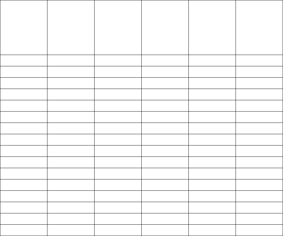
TABLE 4.1 BOLT TIGHTENING TORQUE SPECIFICATIONS
Thread
Size
Aluminum
Nominal
(in-lb)
Low
Carbon
Steel
Nominal
(in-lb)
Stainless
Steel
Nominal
(in-lb)
Nylon
Nominal
(in-lb)
Brass
Nominal
(in-lb)
2-56
1.5
1.7
2.0
0.1
1.3
4-40
3.1
3.6
4.3
0.3
2.8
6-32
5.8
6.6
8.1
0.5
5.1
8-32
10.7
12.1
14.8
0.9
9.3
10-24
15.4
17.6
21.4
1.3
13.5
10-32
17.6
20.1
24.4
1.5
15.5
¼-20
36.9
42.0
51.1
3.1
32.4
¼-28
42.2
48.1
58.5
3.6
37.0
5/16-18
76.0
86.5
105.3
6.4
66.7
5/16-24
84.1
95.8
116.5
7.1
73.8
3/8-16
134.9
153.6
186.8
11.4
118.3
3/8-24
152.9
174.0
211.6
12.9
134.0
7/16-14
215.9
245.8
298.9
18.3
189.3
7/16-20
241.1
274.5
333.8
20.4
211.4
½-13
329.4
375.0
456.1
27.9
288.8
½-20
371.2
422.6
513.9
31.4
325.5
Definition of Tight
Because of the many variables affecting tightening, tight is defined as
meaning the fastener cannot be appreciably tightened further without
damage to the threads or material.
Faceplate Fastening
General Business
Q50 REV. D Page 5 of 10
All 4-40 self-tapping hardware used to fasten PCBs to faceplates shall
be installed with a hex driver to a torque of up to 10 in-lb unless
otherwise specified. 4-5 in-lb is recommended for plastic faceplates. 10
in-lb is recommended for metal faceplates. Phillips or slot drivers are
prohibited to eliminate any potential burring during installation.
5.0 COSMETIC REQUIREMENTS
5.1 Surface Classification
Three classes of cosmetic grading will be used to identify the level of
cosmetic characteristics of a part. These classes distinguish between the
requirements for surfaces normally viewed by a product’s end user and
those of lesser importance that are seldom viewed.
Class A: External surface which is in plain view of the customer during
normal use, (panel fronts, faceplates, chassis fronts, etc.).
Class B: External surface which is not in plain view of the customer during
normal use, but may be visible to the customer during installation or
maintenance, (chassis sides, top, or bottom, faceplate edges, etc.).
Class C: Surfaces seldom, if ever, seen by the customer, (inside of
chassis, inside battery boxes, back of faceplates, back of chassis etc.).
5.2 Inspection Criteria
5.2.1 Class A:
Distance from Eye: 18 to 24 inches away using unaided eyes.
Viewing Time: 10 seconds maximum.
Type of Light: 85 minimum Foot Candles Cool White Florescent.
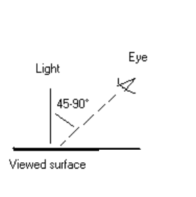
Viewing Angle: 45-90degrees. With part manipulation allowed.
5.2.2 Class B:
Distance from Eye: 24 to 36 inches away using unaided eyes.
Viewing Time: 5 maximum seconds.
Type of Light: 85 minimum Foot Candles Cool White Florescent.
Viewing Angle: 45-90 degrees. No part manipulation allowed.
Viewing must be done at a constant viewing angle.
5.2.3 Class C:
Distance from Eye: 48 to 60 inches away using unaided eyes.
Viewing Time: 5 maximum seconds.
Type of Light: 85 Foot Candles Cool White Florescent.
General Business
Q50 REV. D Page 6 of 10
Viewing Angle: 90 degrees. No part manipulation allowed.
Viewing must be done at a constant viewing angle.
5.3 Fabricated Metal
5.3.1 Class A :
Preferred:
No nicks, dents, scratches or any other surface blemish.
Acceptable (Minimum): Plating may have minimal discoloration.
Scratch - Qty 1 @ 0.015” Wide x 0.10” Long per 50 Square Inches
(example: 5” x 10” area),
Scratch - Qty 2 @ 0.015” Wide x 0.10” Long or combination of up to
0.20” long per 100 Square Inches,
Scratch - Qty 3 @ 0.015” Wide x 0.10” Long or combination of up to
0.030” long per 300 Square Inches or greater
Unacceptable: Smears, runs, non-uniform glossiness and coverage,
fingerprints, corrosion, scratches through the plating, excessive
grease/oils, grit, dust or other foreign matter that may affect the
decorative, adhesion and protective surface finish.
5.3.2 Class B:
Acceptable (Minimum):
Scratch - Qty 1 @ 0.015” Wide x 0.25” Long per 50 Square Inches.
Scratch - Qty 2 @ 0.015” Wide x 0.250” Long or combination of up to
0.50” per 100 Square Inches.
Scratch - Qty 3 @ 0.015” Wide x 0.25” Long or combination of up to
0.75” per 300 Square Inches or greater.
Runs or Smears 1x per 50 square inches and multiple increments
thereof, i.e. 2x @100 sq. in, 3x @150 etc.
Minimal non-uniform glossiness, and discoloration.
Unacceptable: Fingerprints, corrosion, scratches through the
plating, excessive grease/oils, grit, dust or other foreign matter that
may affect the decorative, adhesion and protective surface finish.
5.3.3 Class C:
Acceptable (Minimum):
General Business
Q50 REV. D Page 7 of 10
Scratch - Qty 3 @ 0.015” Wide x 0.50” Long or combination of up to
1.50” per 50 Square Inches.
Scratch - Qty 4 @ 0.015” Wide x 0.50” Long or combination of up to
2.00” per 100 Square Inches.
Scratch - Qty 5 @ 0.015” Wide x 0.50” Long or combination of up to
2.50” per 300 Square Inches or greater.
Minimal non-uniform glossiness, coverage, and discoloration.
Unacceptable: Scratches through plating, corrosion, excessive
grease/oils, grit, dust or other foreign matter that may affect adhesion
and protective surface finish.
5.4 Painted Fabricated Material/Parts
Note: ADTRAN Mechanical Engineering dept. approves paint color and
gloss (see paint specifications). Texture will be measured using paint chips
(min and max).
Note: All material/parts shall pass tape test using 3M Scotch Tape # C-
4210 invisible tape.
5.4.1 Class A:
Preferred: No nicks, dents, scratches or any other surface blemish.
Shall be wrinkle and bubble free.
Acceptable (Minimum):
No scratches allowed on areas less than 100 Square Inches.
Scratch - Qty 1 @ 0.015” Wide x 0.10” Long per area greater than
100 Square Inches.
Unacceptable: Smears, runs, non-uniform glossiness, texture and
coverage, finger-prints, corrosion, orange peel, excessive
grease/oils, wrinkles, grit, dust or other foreign matter that may affect
the decorative, adhesion and protective surface finish.
5.4.2 Class B:
Preferred: Shall be wrinkle and bubble free.
Acceptable (Minimum):
Scratch - Qty 1 @ 0.015” Wide x 0.30” Long per 50 Square Inches.
Scratch - Qty 2 @ 0.015” Wide x 0.30” Long or combination of up to
0.60” per 100 Square Inches.
Scratch - Qty 3 @ 0.015” Wide x 0.30” Long or combination of up to
0.90” per 300 Square Inches and greater.
Unacceptable: Smears, runs, non-uniform glossiness, texture and
coverage, finger-prints, corrosion, orange peel, excessive
grease/oils, wrinkles, grit, dust or other foreign matter that may affect
the decorative, adhesion and protective surface finish.
5.4.3 Class C:
General Business
Q50 REV. D Page 8 of 10
Acceptable (Minimum):
Scratch - Qty 2 @ 0.015” Wide x 0.50” Long or combination of up to
1.00” per 100 Square Inches.
Scratch - Qty 4 @ 0.015” Wide x 0.50” Long or combination of up to
2.00 “per 100 Square Inches and greater.
Runs or Smears 1x per 50 square inches and multiple increments
thereof, i.e. 2x @100 sq. in, 3x @150 etc.
Minimal non-uniform glossiness, coverage, and discoloration.
Unacceptable: Corrosion, excessive grease/oils, grit, dust or other
foreign matter that may affect the adhesion and protective surface
finish.
5.5 Silkscreen, Pad Print, and Labels
Characters on stamped, engraved, silkscreened, printed or typed labels,
nameplates, faceplates, or any other customer-visible surfaces shall be
legible in all cases.
5.5.1 APPEARANCE
Preferred
1. Characters are clean, legible, aligned, and evenly spaced.
2. Labels and decals are not torn, scratched, bent, or chipped.
Acceptable (minimum)
Lines of a number or letter may be broken (or the ink thin over a
portion of the character) providing the character is legible and cannot
be confused with another number or character.
Unacceptable
Characters are smeared, broken, or missing causing text to be
illegible.
5.5.2 POSITIONING
Preferred
Customer-visible labels, decals, or nameplates orientated to read
from left to right or bottom to top with reference to normal operating
position of the equipment.
Acceptable (minimum)
1. Labels, decals, nameplates or stamps should be applied in a
consistent location and orientation.
2. Customer-visible labels, decals, or nameplates shall be mounted
squarely and shall not have a skew of more than 1/32 (0.020) inch
per linear inch relative to the edge of the surface being applied.
Unacceptable
Skew greater than 1/32 (0.020) inch per linear inch relative to the
edge of the surface being applied.
5.5.3 FASTENING
General Business
Q50 REV. D Page 9 of 10
Preferred
Adhesive labels, nameplates or logos shall be flush with the
mounting surface. Nameplates or logos mounted with hardware shall
be properly secured to avoid the possibility of rattling or movement.
Unacceptable
Lifting (poor adhesion), Wrinkling, Turned-up edges, Voids (caused
by contamination or trapped air between decal and the surface of
panel or chassis, or my improper mounting), Skewed
5.6 Plastic Parts (both surface and entire part)
Note: First Articles may be used as go/no go examples.
Preferred:
No nicks, dents, scratches or any other surface blemish.
Acceptable (minimum):
Scratches: 1x @ 0.10” long max
Sinks: 0.003” max
Pits: 2 per total surface area
Discoloration: use limit sample
Gate Blush: use limit sample
Flow/Knit/Weld lines: 2 @ 0.25” each
Flash: 0.02”
Cracking: None
Warping: See part drawing
Short shot: None
Haze: None
Drag/pull marks: use limit sample
Texture Variation: None. see part drawing for texture type. Texture to
be consistent and uniform coverage
Unacceptable:
Nicks, dents, scratches, or any other surface blemish that exceeds
minimum acceptable requirements under appropriate viewing
conditions.
5.7 Cosmetic Definitions
Bleed out: Substance that runs out of seams. Color can vary from
dark brown to gray white.
Blister: Enclosed raised spot on a surface.
Burn Deposits: Rough discolored plating on edges or, in/on
General Business
Q50 REV. D Page 10 of
10
Burr: Thin slivers of base material at the junction of a cut edge.
Chips or Voids: Areas of a surface that have been broken or
chipped, or are missing coating.
Corrosion: Surface impurities or oxidation (Rust).
Drag/pull marks: Scratches or wiping mark from part dragging
against mold when part is ejected from mold.
Discoloration: Unintended inconsistency or change in color from the
approved standard color chip.
Fisheye: Cratering caused by organic contamination.
Flash: Thin protrusion of material at the parting line or junction of
mold.
Flow mark: Visible mark resulting from solidification of two material
flow fronts. Also known as Knit or weld lines.
Foreign Material: Dirt, lint, or other particles trapped in the finish.
Gate blush: Discolored area near mold gate.
Haze: Cloudiness on a transparent part.
Machine Marks: Visible lines caused during the punching and
forming of sheet metal. Lines are straight and uniform.
Non adhesion: Plated, painted, pad print, silkscreen or label
material is separating from base material.
Non uniform coverage: Area that has insufficient or excessive
coating.
Orange Peel: Rippled appearance of material surface. Looks like
orange peel in texture.
Oxidation: Rust.
Runs: Excessive coating forming drips or stains.
Pit: Small crater or void on surface.
Sink: Shallow depression on surface resulting from internal
shrinkage during molding.
Short shot: Insufficient fill of material during molding.
Spot Welds: Indentations or rough areas from spot welding that
exceeds the drawing or specification requirements.
Tape test: Apply a typical 3M Scotch Tape # C-4210 invisible tape
over lettering or paint to be tested, and with normal pressure press
the tape in place. Then tear off the tape in a continuous motion at a
90 degree angle to surface being tested. There shall be no evidence
of ink or paint on tape.
Tool Marks: Creases or other indentations from tooling during the
manufacturing process.
Void: Unfilled space where paint, plating or lettering should have
been.
Warpage: Dimensional distortion of a part.
Water marks: Stains caused by excessive water not being blown off
the part before drying sets in.
Weld Porosity: Pinholes in welds.
