DM 383 XXX_Datasheet TX4n QSFPp To 4 SFPp Smart DAC Data Sheet
User Manual: TX4n
Open the PDF directly: View PDF ![]() .
.
Page Count: 10
Methode Electronics
www.methode.com
7401 West Wilson Avenue
Chicago, IL 60706
Phone: 708-867-6777 Fax: 708-867-3149
ISO 9001 Certified
SFF-8432 MSA compliant
SFF-8431 MSA Compliant
SFF-8436 MSA Compliant
Hot-pluggable SFP+ and QSFP+ footprint
Supports Serial ID
Lengths up to 7m
Robust Die Cast Housings
Product Overview:
The DM-383-XXX QSFP+ to 4* SFP+ Direct Attach cable assembly is a high performance integrated
duplex data link for bi-directional communication over copper cable for lengths up to 7m. It is
compliant with the IPF MSA (SFF-8432) and QSFP+ 10 Gbs 4X MSA (SFF-8436) for mechanical
form factors and SFP+ MSA (SFF-8431 Appendix E) for direct attach cables. It is data rate agnostic
and supports speeds of up to 10Gbps. The DM-383-XXX provides a cost effective alternative to
optical links.
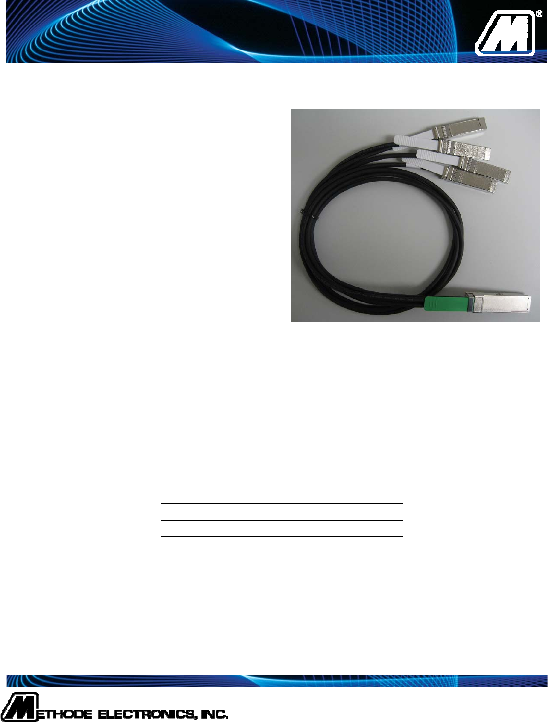
DM-383-XXX
4 Channels of 10Gbps
QSFP+ by 4* SFP+ Passive
Cable
Ordering Information
Part Number Length AWG
DM-383-100 1 M 30
DM-383-300 3 M 30
DM-383-500 5 M 24
DM-383-700 7 M 24
Methode Electronics
www.methode.com
7401 West Wilson Avenue
Chicago, IL 60706
Phone: 708-867-6777 Fax: 708-867-3149
ISO 9001 Certified
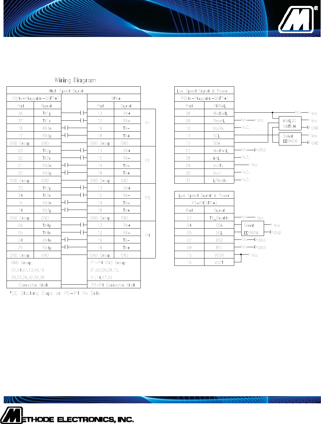
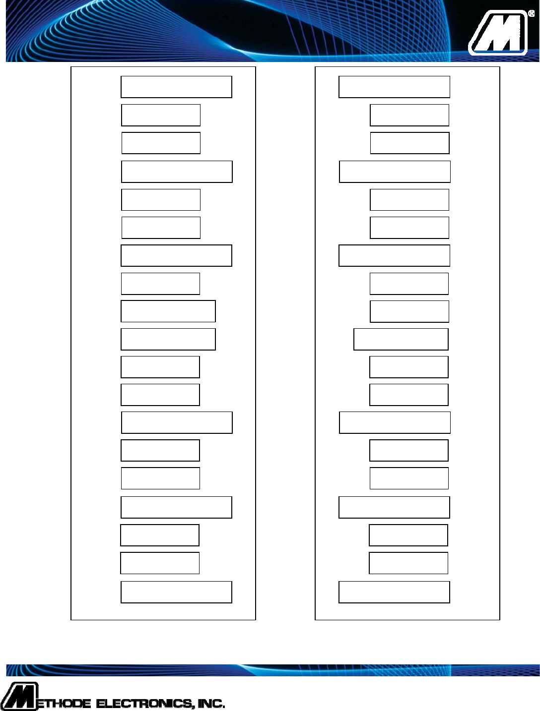
Figure 1: Block Diagram
Methode Electronics
www.methode.com
7401 West Wilson Avenue
Chicago, IL 60706
Phone: 708-867-6777 Fax: 708-867-3149
ISO 9001 Certified
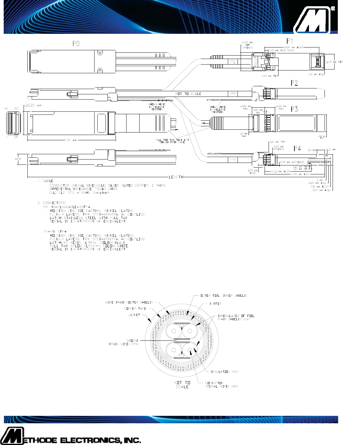
Figure 2: Mechanical Dimensions of Module
Figure 3: Cable Cross Section
Methode Electronics
www.methode.com
7401 West Wilson Avenue
Chicago, IL 60706
Phone: 708-867-6777 Fax: 708-867-3149
ISO 9001 Certified
Figure 4: SFP+ Transceiver Electrical Pad Layout
VeeR
Rx_LOS
RS0
Mod_ABS
VeeT
VeeR
RD+
VccR
RD-
VeeR
VeeT
TD-
TD+
10
9
8
7
6
5
4
3
2
1
11
12
13
14
15
16
17
18
19
20
Bottom of Board
(As viewed thru top of board) To
p
of Board
VeeT
VccT
SCL
SDA
Tx_DIS
Tx_Fault
RS1
Methode Electronics
www.methode.com
7401 West Wilson Avenue
Chicago, IL 60706
Phone: 708-867-6777 Fax: 708-867-3149
ISO 9001 Certified
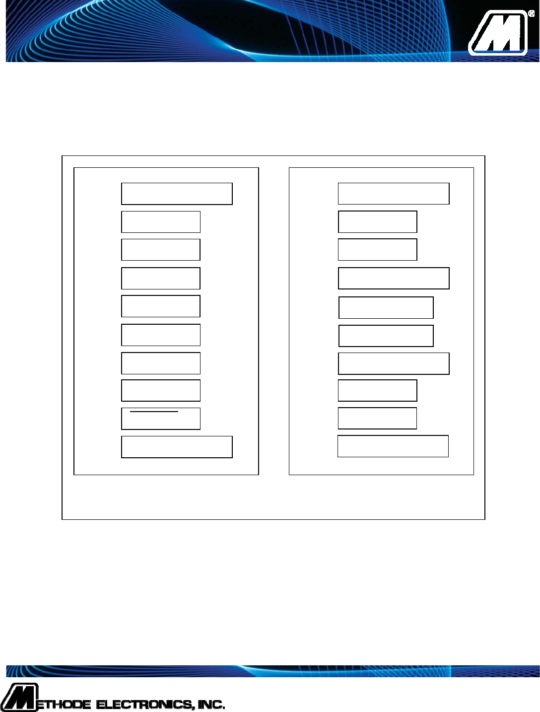
Figure 5: QSFP+ Transceiver Electrical Pad Layout
Gnd
Gnd
VccTx
Vcc1
IntL
ModPrsL
RX4p
38
37
36
35
34
33
32
31
30
29
28
27
26
25
24
Top Side – Viewed from Top Bottom Side – Viewed from Bottom
Gnd
Gnd
RX4n
RX2p
Gnd
RX2n
Gnd
23
22
21
20
TX1n
TX1p
TX3n
TX3p
LPMode
Gnd
Gnd
VccRx
SCL
SDA
RX3p
Gnd
Gnd
RX3n
RX1p
Gnd
RX1n
Gnd
TX2n
TX2p
TX4n
TX4p
ModeSelL
ResetL
1
2
3
4
5
6
7
8
9
10
11
12
13
14
15
16
17
18
19
Methode Electronics
www.methode.com
7401 West Wilson Avenue
Chicago, IL 60706
Phone: 708-867-6777 Fax: 708-867-3149
ISO 9001 Certified
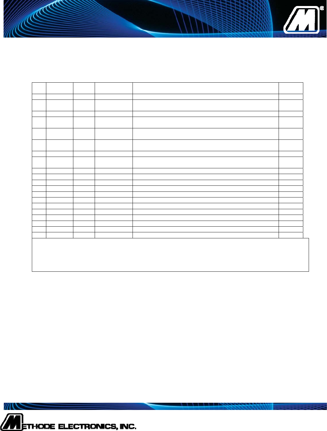
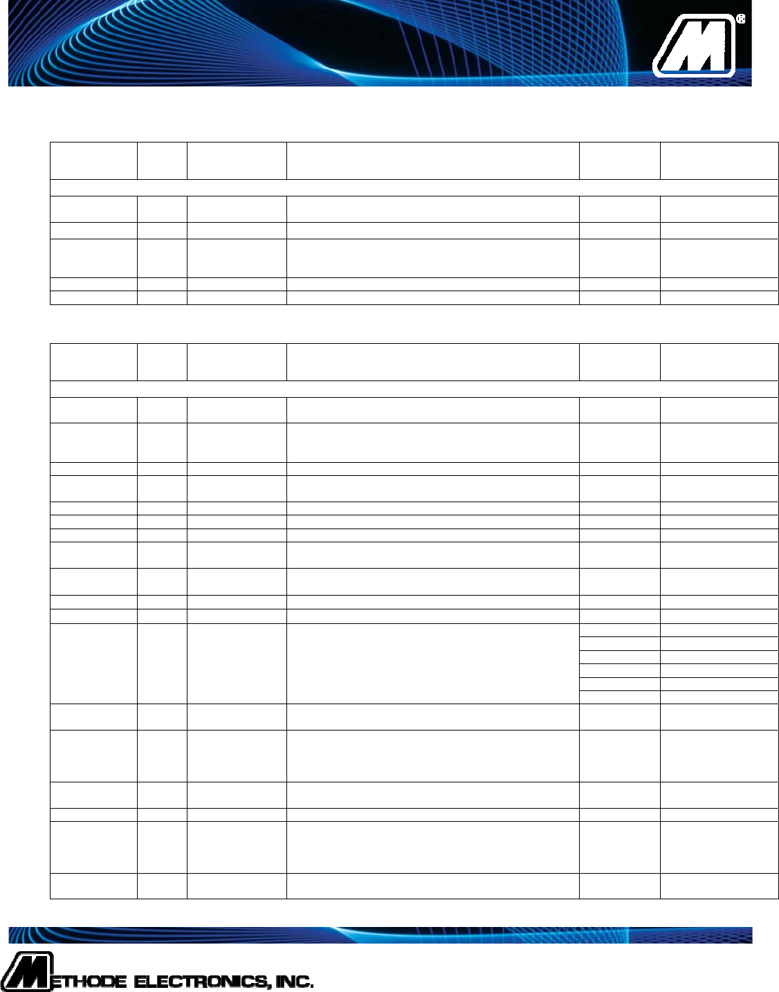
Pin Logic Symbol Power
Sequence Name/Description Note
1 VeeT 1st Module Transmitter Ground 2
2 LVTTL-O Tx_Fau
lt
3rd Module Transmitter Fault 3
3 LVTTL-I Tx_Dis 3rd Transmitter Disable; Turns off transmitter laser output 4
4 LVTTL-
I/O
SDA 3rd 2-wire Serial Interface Data Line 5
5 LVTTL-
I/O
SCL 3rd 2-wire Serial Interface Clock 5
6 MOD_
ABS
3rd Module Absent, connected to VeeT or VeeR in the module
7 LVTTL-I RS0 3rd Rate Select 0 7
8 LVTTL-O Rx_LO
S
3rd Receiver Loss of Signal Indication 3
9 LVTTL-I RS1 3rd Rate Select 1 7
10 VeeR 1st Module Receiver Ground 2
11 VeeR 1st Module Receiver Ground 2
12 CML-O RD- 3rd Receiver Inverted Data Output
13 CML-O RD+ 3rd Receiver Non-Inverted Data Output
14 VeeR 1st Module Receiver Ground 2
15 VccR 2nd Module Receiver 3.3 V Supply
16 VccT 2nd Module Transmitter 3.3 V Supply
17 VeeT 1st Module Transmitter Ground 2
18 CML-I TD+ 3rd Transmitter Non-Inverted Data Input
19 CML-I TD- 3rd Transmitter Inverted Data Input
20 VeeT 1st Module Transmitter Ground 2
1. Labeling as inputs (I) and outputs (O) are from the perspective of the module
2. The module signal ground contacts, VeeR and VeeT, shall be isolated from the module case.
3. This contact is an open collector/drain output contact and shall be pulled up on the host.
4. TX_Disable is an input contact with a 4.7-10 kΩ pullup to VccT inside the module.
5. Serial Clock and Data line to access Serial ID specified in Table 2.
6. Pulled Low to Veet with 33K resistor in the module.
Table 1: SFP+ Module Electrical Pin Definition
Methode Electronics
www.methode.com
7401 West Wilson Avenue
Chicago, IL 60706
Phone: 708-867-6777 Fax: 708-867-3149
ISO 9001 Certified
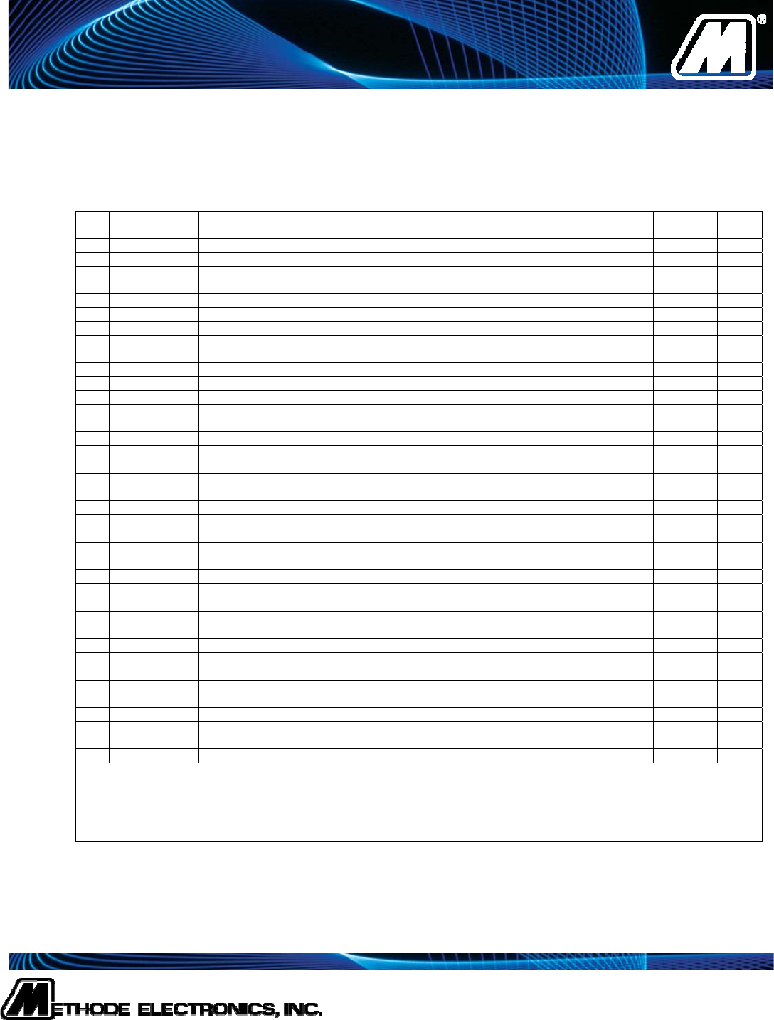
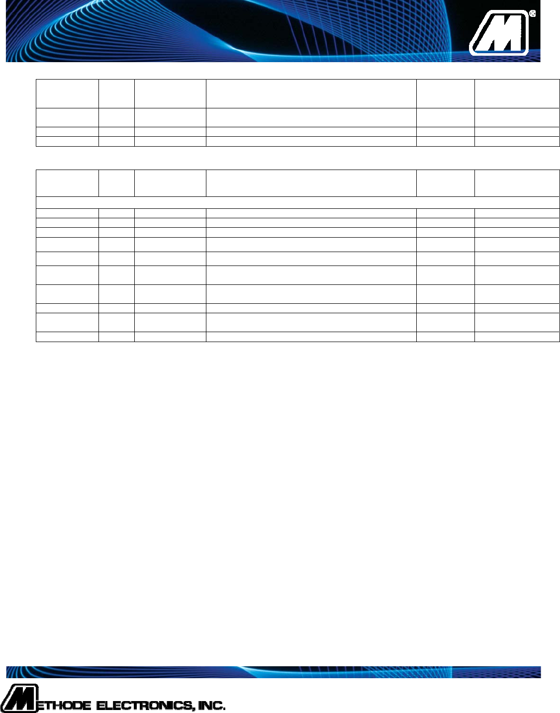
Pin Logic Symbol Name/Description Plug
Sequence Note
1 GND Module Ground 1 1
2 CML-I Tx2n Transmitter Inverted Data Input 3
3 CML-I Tx2p Transmitter Non-Inverted Data Input 3
4 GND Module Ground 1 1
5 CML-I Tx4n Transmitter Inverted Data Input 3
6 CML-I Tx4p Transmitter Non-Inverted Data Input 3
7 GND Module Ground 1 1
8 LVTTL-I ModSelL Module Select 3
9 LVTTL-I ResetL Module Reset 3
10 VccRx 3.3V Power Supply Receiver 2 2
11 LVCMOS-I/O SCL 2-wire serial interface clock 3
12 LVCMOS-I/O SDA 2-wire serial interface data 3
13 GND Module Ground 1 1
14 CML-O Rx3p Receiver Non-Inverted Data Output 3
15 CML-O Rx3n Receiver Inverted Data Output 3
16 GND Module Ground 1 1
17 CML-O Rx1p Receiver Non-Inverted Data Output 3
18 CML-O Rx1n Receiver Inverted Data Output 3
19 GND Module Ground 1 1
20 GND Module Ground 1 1
21 CML-O Rx2n Receiver Inverted Data Output 3
22 CML-O Rx2p Receiver Non-Inverted Data Output 3
23 GND Module Ground 1 1
24 CML-O Rx2n Receiver Inverted Data Output 3
25 CML-O Rx2p Receiver Non-Inverted Data Output 3
26 GND Module Ground 1 1
27 LVTTL-O ModPrsL Module Present 3
28 LVTTL-O IntL Interrupt 3
29 VccTx 3.3V Power Supply Transmitter 2 2
30 Vcc1 3.3V Power Supply 2 2
31 LVTTL-I LPMode Low Power Mode 3
32 GND Module Ground 1 1
33 CML-I Tx3p Transmitter Non-Inverted Data Input 3
34 CML-I Tx3n Transmitter Inverted Data Input 3
35 GND Module Ground 1 1
36 CML-I Tx1p Transmitter Non-Inverted Data Input 3
37 CML-I Tx1n Transmitter Inverted Data Input 3
38 GND Module Ground 1 1
Note 1: GND is the symbol for signal and supply (power) common for the QSFP+ module. All are
common within the QSFP+ module and all module voltages are referenced to this potential unless otherwise noted. Connect these directly to the
host board signal-common ground plane.
Note 2: Vcc Rx, Vcc1 and Vcc Tx are the receiver and transmitter power supplies and shall be applied concurrently. Vcc Rx, Vcc1and Vcc Tx
may be internally connected within the QSFP+ transceiver module in any combination. The connector pins are each rated for a maximum current
of 500 mA.
Table 2: QSFP+ Module Electrical Pin Definition
Methode Electronics
www.methode.com
7401 West Wilson Avenue
Chicago, IL 60706
Phone: 708-867-6777 Fax: 708-867-3149
ISO 9001 Certified
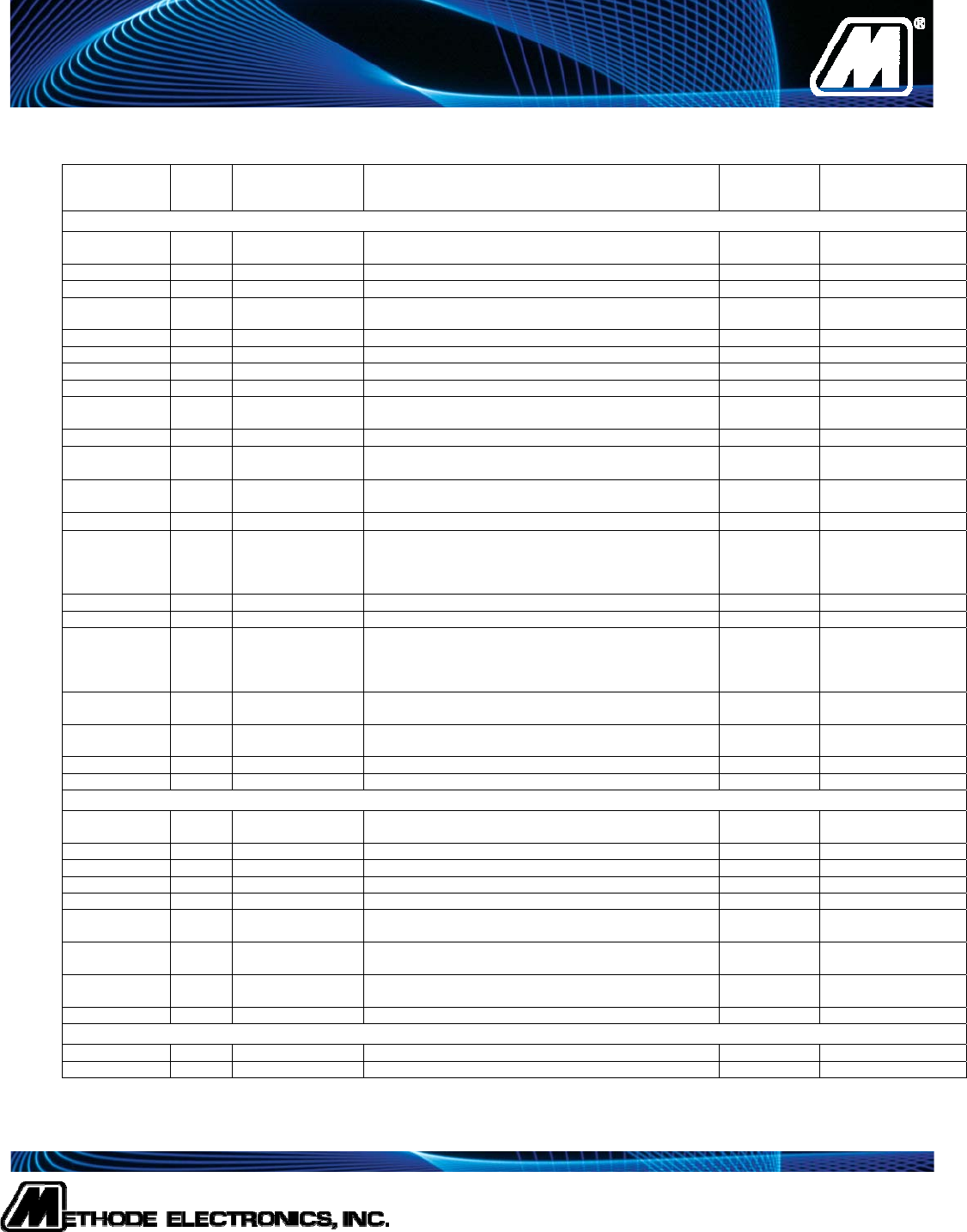
SFP+ Side Serial Identification
The module identification is located in the EEPROM, which is accessed over the 2-wire serial management interface. The
address of the EEPROM is 0xA0 (1010000X). The following table shows the SFP+ EEPROM memory map and the actual data.
Data
Address Field
Size Field Name Field Description Field
Value
V
alue
Description
BASE ID FIELDS
0 1 Identifier Type of transceiver 03 SFP+
TRANSCEIVER
1 1 Ext. Identifier Extended identifier of type of serial transceiver 04 WITH SERIAL ID
2 1 Connector Code for connector type 21 COPPER PIGTAIL
3-10 8 Transceiver Code for electronic or optical compatibility 00,00,00,00,
00,04,00,00 SFP+ Passive Cable
11 1 Encoding Code for serial encoding algorithm 00 UNSPECIFIED
12 1 BR, Nominal Nominal signaling rate, units of 100Mbits/sec 64 10Gb Bit Rate
13 1 Rate Identifier Type of rate select functionality 00 UNSPECIFIED
14 1 Length (SMF, km) Link length supported for single mode fiber, units of km 00 NA
15 1 Length (SMF) Link length supported for single mode fiber, units of
100m 00 NA
16 1 Length (50m) Link length supported for 50
m OM2 fiber, units of 10m 00 NA
17 1 Length (62.5m) Link length supported for 62.5
m OM1 fiber, units of
10m 00 NA
18 1 Length (cable) Link length supported for copper or direct attach cable,
units of m VARIES 0xXX METER
19 1 Length (OM3) Link length supported for 50
m OM3 fiber, units of 10m 00 RESERVED
20-35 16 Vendor name SFP+ vendor name (ASCII)
4D,65,74,68,
6F,64,65,20,
45,6C,65,63,
2E,20,20,20
Methode Elec
(ASCII)
36 1 Transceiver Code for electronic or optical compatibility 00 UNALLOCATED
37-39 3 Vendor OUI SFP+ transceiver vendor IEEE company ID 00,17,05 Methode OUI
40-55 16 Vendor PN Part number provided by SFP+ transceiver vendor
(ASCII)
44,4D,2D,33,
38,33,2D,XX,
XX,XX,XX,20
,20,20,20,20
DM-383-XXX
(ASCII)
56-59 4 Vendor rev Revision level for part number provided by vendor
(ASCII) 2D,20,20,20 Rev -
60-61 2 Wavelength Laser wavelength (Passive/Active Cable Specification
Compliance) 00,00 RESERVED
62 1 Unallocated 00 RESERVED
63 1 CC_BASE Check code for Base ID Fields (addresses 0 to 62) VARIES
EXTENDED ID FIELDS
64-65 2 Options Indicates which optional SFP+ signals are
implemented 00,00
66 1 BR, max Upper bit rate margin, units of % 00
67 1 BR, min Lower bit rate margin, units of % 00
68-83 16 Vendor SN Serial number provided by vendor (ASCII) VARIES (ASCII)
84-91 8 Date code Vendor’s manufacturing date code VARIES YY-MM-DD-LOT#
92 1 Diagnostic
Monitoring Type Indicates which type of diagnostic monitoring is
implemented (if any) 00 None included
93 1 Enhanced
Options Indicates which optional enhanced features are
implemented (if any) 00 None included
94 1 SFF-8472
Compliance Indicates which revision of SFF-8472 the transceiver
complies with 00 None included
95 1 CC_EXT Check code for the Extended ID Fields (addr. 64 to 94) VARIES
VENDOR SPECIFIC ID FIELDS
96-127 32 Vendor Specific Vendor Specific EEPROM All FF’s
128-255 128 Reserved Reserved for SFF-8079 All FF’s
Table 3: SFP+ MSA Serial ID Data
Methode Electronics
www.methode.com
7401 West Wilson Avenue
Chicago, IL 60706
Phone: 708-867-6777 Fax: 708-867-3149
ISO 9001 Certified
QSFP+ Side Memory Map
Lower Memory Map The lower 128 bytes of the 2-wire serial bus address space is located in the EEPROM, which is accessed
over the 2-wire serial management interface. The address of the EEPROM is 0xA0 (1010000X). The following table shows the
QSFP+ lower memory map and the actual data.
Data
Address Field
Size Field Name Field Description Field
Value
V
alue
Description
BASE ID FIELDS
0 1 Identifier Type of serial transceiver 0C QSFP+
TRANSCEIVER
1 1 Status Reserved 00
2 1 Status Status Indicators 06 Page 0 Upper
Memory Only, IntL
Output = 1
3-126 124 Measurements and Diagnostics All 00
127 1 Page Select 00
Serial ID Memory Map The module identification is located in the upper 128 bytes of the 2-wire serial bus address space of
the EEPROM, which is accessed over the 2-wire serial management interface. The address of the EEPROM is 0xA0
(1010000X). The following table shows the QSFP+ Serial Identification memory map and the actual data.
Data
Address Field
Size Field Name Field Description Field
Value
V
alue
Description
BASE ID FIELDS
128 1 Identifier Type of serial transceiver 0C QSFP+
TRANSCEIVER
129 1 Ext. Identifier Extended identifier of type of serial transceiver 00 Power Level 1,
No CLEI Code
present in Page 02h
130 1 Connector Code for connector type 21 COPPER PIGTAIL
131-138 8 Transceiver Code for electronic compatibility or optical compatibility 08,00,00,00,
00,00,00,00 40GBase-CR
139 1 Encoding Code for serial encoding algorithm 00 UNSPECIFIED
140 1 BR, Nom Nominal bit rate, units of 100Mbits/sec 64 10Gb Bit Rate
141 1 Ext Rate Sel Tags for Extended Rate Select Compliance 00 NA
142 1 Length (SMF)-
km Link length supported for SMF fiber in km 00 NA
143 1 Length (E-50m) Link length supported EBW 50/125
m fiber, units of 2
m 00 NA
144 1 Length (50m) Link length supported for 50/125
m fiber, units of 1 m 00 NA
145 1 Length (62.5 m) Link length supported for 62.5/125
m fiber, units of 1 m 00 NA
146 1 Length (Copper) Link length supported for copper, units of 1 m
01 DM-383-50
01 DM-383-100
02 DM-383-200
03 DM-383-300
05 DM-383-500
07 DM-383-700
147 1 Device Tech Device technology A0 Copper Cable
Unequalized
148-163 16 Vendor name Vendor name (ASCII)
4D,65,74,68,
6F,64,65,20,
45,6C,65,63,
2E,20,20,20
Methode Elec.
(ASCII)
164 1 Ext Transceiver
Codes Extended Transceiver Codes 05 QDR Speed
165-167 3 Vendor OUI Vendor IEEE company ID 00,17,05 Methode OUI
168-183 16 Vendor PN Part number provided by Vendor (ASCII)
44,4D,2D,33,
38,33,2D,XX,
XX,XX,XX,20
20,20,20,20
DM-383-XXX
(ASCII)
184-185 2 Vendor rev Revision level for part number provided by vendor
(ASCII) 2D,20 Rev -
Methode Electronics
www.methode.com
7401 West Wilson Avenue
Chicago, IL 60706
Phone: 708-867-6777 Fax: 708-867-3149
ISO 9001 Certified
186-187 2 Copper Cable
Attenuation Copper Cable Attenuation in dB (at 2.5Ghz in address
186 and 5.0Ghz in address 187) VARIES
188-189 2 Wavelength
Tolerance Guaranteed range of laser wavelength 00,00 NA
190 1 Max Case Temp Maximum Case Temperature in Degrees C. 55 85 Degrees C.
191 1 CC_BASE Check code for Base ID Fields (addresses 120-190) VARIES
Data
Address Field
Size Field Name Field Description Field
Value
V
alue
Description
EXTENDED ID FIELDS
192-193 2 Reserved Reserved 00,00
194 1 Squelch Options 00
195 1 Options 00
196-211 16 Vendor SN Serial number provided by vendor (ASCII) VARIES YYWWXXXX(ASCII)
212-219 8 Date code Vendor’s manufacturing date code VARIES YY-MM-DD-LOT#
220 1 Diagnostic
Monitoring Type Indicates which type of diagnostic monitoring is
implemented (if any) in the transceiver 00 None Implemented
221 1 Enhanced
Options Indicates which optional enhanced features are
implemented by the transceiver 00 None Implemented
222 1 Reserved Reserved 00
223 1 CC_EXT Check code for the Extended ID Fields (addresses 192
to 222) VARIES
224-255 32 Vendor Specific Vendor Specific EEPROM All FF’s
Table 4: QSFP+ MSA Serial ID Data
