Quectel EC25&EC21 AT Commands Manual V1.3
Quectel_EC25%26EC21_AT_Commands_Manual_V1.3
Quectel_EC25%26EC21_AT_Commands_Manual_V1.3
Quectel_EC25%26EC21_AT_Commands_Manual_V1.3
User Manual:
Open the PDF directly: View PDF ![]() .
.
Page Count: 241 [warning: Documents this large are best viewed by clicking the View PDF Link!]
- About the Document
- Contents
- Table Index
- 1 Introduction
- 2 General Commands
- 2.1. ATI Display Product Identification Information
- 2.2. AT+GMI Request Manufacturer Identification
- 2.3. AT+GMM Request TA Model Identification
- 2.4. AT+GMR Request TA Revision Identification of Software Release
- 2.5. AT+CGMI Request Manufacturer Identification
- 2.6. AT+CGMM Request Model Identification
- 2.7. AT+CGMR Request TA Revision Identification of Software Release
- 2.8. AT+GSN Request International Mobile Equipment Identity (IMEI)
- 2.9. AT+CGSN Request Product Serial Number Identification
- 2.10. AT&F Set all Current Parameters to Manufacturer Defaults
- 2.11. AT&V Display Current Configuration
- 2.12. AT&W Store Current Parameters to User Defined Profile
- 2.13. ATZ Set all Current Parameters to User Defined Profile
- 2.14. ATQ Set Result Code Presentation Mode
- 2.15. ATV TA Response Format
- 2.16. ATE Set Command Echo Mode
- 2.17. A/ Repeat Previous Command Line
- 2.18. ATS3 Set Command Line Termination Character
- 2.19. ATS4 Set Response Formatting Character
- 2.20. ATS5 Set Command Line Editing Character
- 2.21. ATX Set CONNECT Result Code Format and Monitor Call Progress
- 2.22. AT+CFUN Set Phone Functionality
- 2.23. AT+CMEE Error Message Format
- 2.24. AT+CSCS Select TE Character Set
- 2.25. AT+QURCCFG Configure URC Indication Option
- 3 Serial Interface Control Commands
- 4 Status Control Commands
- 4.1. AT+CPAS Mobile Equipment Activity Status
- 4.2. AT+CEER Extended Error Report
- 4.3. AT+QCFG Extended Configuration Settings
- 4.3.1. AT+QCFG="gprsattach" GPRS Attach Mode Configuration
- 4.3.2. AT+QCFG="nwscanmode" Network Search Mode Configuration
- 4.3.3. AT+QCFG="nwscanseq" Network Searching Sequence Configuration
- 4.3.4. AT+QCFG="roamservice" Roam Service Configuration
- 4.3.5. AT+QCFG="servicedomain" Service Domain Configuration
- 4.3.6. AT+QCFG="band" Band Configuration
- 4.3.7. AT+QCFG="hsdpacat" HSDPA Category Configuration
- 4.3.8. AT+QCFG="hsupacat" HSUPA Category Configuration
- 4.3.9. AT+QCFG="rrc" RRC Release Version Configuration
- 4.3.10. AT+QCFG="sgsn" UE SGSN Release Version Configuration
- 4.3.11. AT+QCFG="msc" UE MSC Release Version Configuration
- 4.3.12. AT+QCFG="PDP/duplicatechk" Establish Multi PDNs with the Same APN
- 4.3.13. AT+QCFG="urc/ri/ring" RI Behavior When RING URC is Presented
- 4.3.14. AT+QCFG="urc/ri/smsincoming" RI Behavior When Incoming SMS URCs are Presented
- 4.3.15. AT+QCFG="urc/ri/other" RI Behavior When Other URCs are Presented
- 4.3.16. AT+QCFG="risignaltype" RI Signal Output Carrier
- 4.3.17. AT+QCFG="urc/delay" Delay URC Indication
- 4.3.18. AT+QCFG="urc/cache" URC Cache Function
- 4.3.19. AT+QCFG="tone/incoming" Ring tone Function
- 4.4. AT+QINDCFG URC Indication Configuration
- 5 (U)SIM Related Commands
- 5.1. AT+CIMI Request International Mobile Subscriber Identity (IMSI)
- 5.2. AT+CLCK Facility Lock
- 5.3. AT+CPIN Enter PIN
- 5.4. AT+CPWD Change Password
- 5.5. AT+CSIM Generic (U)SIM Access
- 5.6. AT+CRSM Restricted (U)SIM Access
- 5.7. AT+QCCID Show ICCID
- 5.8. AT+QPINC Display PIN Remainder Counter
- 5.9. AT+QINISTAT Query Initialization Status of (U)SIM Card
- 5.10. AT+QSIMDET (U)SIM Card Detection
- 5.11. AT+QSIMSTAT (U)SIM Card Insertion Status Report
- 6 Network Service Commands
- 6.1. AT+COPS Operator Selection
- 6.2. AT+CREG Network Registration
- 6.3. AT+CSQ Signal Quality Report
- 6.4. AT+CPOL Preferred Operator List
- 6.5. AT+COPN Read Operator Names
- 6.6. AT+CTZU Automatic Time Zone Update
- 6.7. AT+CTZR Time Zone Reporting
- 6.8. AT+QLTS Obtain the Latest Time Synchronized Through Network
- 6.9. AT+QNWINFO Query Network Information
- 6.10. AT+QSPN Display the Name of Registered Network
- 7 Call Related Commands
- 7.1. ATA Answer an Incoming Call
- 7.2. ATD Mobile Originated Call to Dial a Number
- 7.3. ATH Disconnect Existing Connection
- 7.4. AT+CVHU Voice Hang up Control
- 7.5. AT+CHUP Hang up Call
- 7.6. +++ Switch from Data Mode to Command Mode
- 7.7. ATO Switch from Command Mode to Data Mode
- 7.8. ATS0 Set Number of Rings before Automatically Answering Call
- 7.9. ATS6 Set Pause before Blind Dialing
- 7.10. ATS7 Set Time to Wait for Connection Completion
- 7.11. ATS8 Set the Time to Wait for Comma Dial Modifier
- 7.12. ATS10 Set Disconnection Delay after Indicating the Absence of Data Carrier
- 7.13. AT+CBST Select Bearer Service Type
- 7.14. AT+CSTA Select Type of Address
- 7.15. AT+CLCC List Current Calls of ME
- 7.16. AT+CR Service Reporting Control
- 7.17. AT+CRC Set Cellular Result Codes for Incoming Call Indication
- 7.18. AT+CRLP Select Radio Link Protocol Parameter
- 7.19. AT+QECCNUM Configure Emergency Call Numbers
- 7.20. AT+QHUP Hang up Call with a Specific Release Cause
- 8 Phonebook Commands
- 9 Short Message Service Commands
- 9.1. AT+CSMS Select Message Service
- 9.2. AT+CMGF Message Format
- 9.3. AT+CSCA Service Center Address
- 9.4. AT+CPMS Preferred Message Storage
- 9.5. AT+CMGD Delete Message
- 9.6. AT+CMGL List Messages
- 9.7. AT+CMGR Read Message
- 9.8. AT+CMGS Send Message
- 9.9. AT+CMMS More Messages to Send
- 9.10. AT+CMGW Write Message to Memory
- 9.11. AT+CMSS Send Message from Storage
- 9.12. AT+CNMA New Message Acknowledgement to UE/TE
- 9.13. AT+CNMI SMS Event Reporting Configuration
- 9.14. AT+CSCB Select Cell Broadcast Message Types
- 9.15. AT+CSDH Show SMS Text Mode Parameters
- 9.16. AT+CSMP Set SMS Text Mode Parameters
- 9.17. AT+QCMGS Send Concatenated Messages
- 9.18. AT+QCMGR Read Concatenated Messages
- 10 Packet Domain Commands
- 10.1. AT+CGATT Attachment or Detachment of PS
- 10.2. AT+CGDCONT Define PDP Context
- 10.3. AT+CGQREQ Quality of Service Profile (Requested)
- 10.4. AT+CGQMIN Quality of Service Profile (Minimum Acceptable)
- 10.5. AT+CGEQREQ 3G Quality of Service Profile (Requested)
- 10.6. AT+CGEQMIN 3G Quality of Service Profile (Minimum Acceptable)
- 10.7. AT+CGACT Activate or Deactivate PDP Context
- 10.8. AT+CGDATA Enter Data State
- 10.9. AT+CGPADDR Show PDP Address
- 10.10. AT+CGCLASS GPRS Mobile Station Class
- 10.11. AT+CGREG Network Registration Status
- 10.12. AT+CGEREP Packet Domain Event Reporting
- 10.13. AT+CGSMS Select Service for MO SMS Messages
- 10.14. AT+CEREG EPS Network Registration Status
- 10.15. AT+QGDCNT Packet Data Counter
- 10.16. AT+QAUGDCNT Auto Save Packet Data Counter
- 11 Supplementary Service Commands
- 11.1. AT+CCFC Call Forwarding Number and Conditions Control
- 11.2. AT+CCWA Call Waiting Control
- 11.3. AT+CHLD Call Related Supplementary Services
- 11.4. AT+CLIP Calling Line Identification Presentation
- 11.5. AT+CLIR Calling Line Identification Restriction
- 11.6. AT+COLP Connected Line Identification Presentation
- 11.7. AT+CSSN Supplementary Service Notifications
- 11.8. AT+CUSD Unstructured Supplementary Service Data
- 12 Audio Commands
- 12.1. AT+CLVL Loudspeaker Volume Level Selection
- 12.2. AT+CMUT Mute Control
- 12.3. AT+QAUDLOOP Enable/Disable Audio Loop Test
- 12.4. AT+VTS DTMF and Tone Generation
- 12.5. AT+VTD Set Tone Duration
- 12.6. AT+QAUDMOD Set Audio Mode
- 12.7. AT+QDAI Digital Audio Interface Configuration
- 12.8. AT+QEEC Set Echo Cancellation Parameters
- 12.9. AT+QSIDET Set the Side Tone Gain in Current Mode
- 12.10. AT+QMIC Set Uplink Gains of MIC
- 12.11. AT+QRXGAIN Set Downlink Gains of RX
- 12.12. AT+QIIC IIC Read & Write
- 12.13. AT+QTONEDET Enable/Disable DTMF Detection
- 12.14. AT+QLDTMF Play Local DTMF
- 12.15. AT+QLTONE Play a Local Customized Tone
- 13 Hardware Related Commands
- 14 DFOTA Related AT Command
- 15 FTP(S) Related AT Commands
- 16 HTTP(S) Related AT Commands
- 17 MMS Related AT Commands
- 18 SMTP Related AT Commands
- 19 TCP(IP) Related AT Commands
- 20 GNSS Related AT Commands
- 21 Appendix
- 21.1. References
- 21.2. Factory Default Settings Restorable with AT&F
- 21.3. AT Command Settings Storable with AT&W
- 21.4. AT Command Settings Storable with ATZ
- 21.5. Summary of CME ERROR Codes
- 21.6. Summary of CMS ERROR Codes
- 21.7. Summary of URC
- 21.8. SMS Character Sets Conversions
- 21.9. Release Cause Text List of AT+CEER


LTE Module Series
EC25&EC21 AT Commands Manual
EC25&EC21_AT_Commands_Manual 1 / 239
Our aim is to provide customers with timely and comprehensive service. For any
assistance, please contact our company headquarters:
Quectel Wireless Solutions Co., Ltd.
7th Floor, Hongye Building, No.1801 Hongmei Road, Xuhui District, Shanghai 200233, China
Tel: +86 21 5108 6236
Email: info@quectel.com
Or our local office. For more information, please visit:
http://www.quectel.com/support/sales.htm
For technical support, or to report documentation errors, please visit:
http://www.quectel.com/support/technical.htm
Or email to: support@quectel.com
GENERAL NOTES
QUECTEL OFFERS THE INFORMATION AS A SERVICE TO ITS CUSTOMERS. THE INFORMATION
PROVIDED IS BASED UPON CUSTOMERS‟ REQUIREMENTS. QUECTEL MAKES EVERY EFFORT
TO ENSURE THE QUALITY OF THE INFORMATION IT MAKES AVAILABLE. QUECTEL DOES NOT
MAKE ANY WARRANTY AS TO THE INFORMATION CONTAINED HEREIN, AND DOES NOT ACCEPT
ANY LIABILITY FOR ANY INJURY, LOSS OR DAMAGE OF ANY KIND INCURRED BY USE OF OR
RELIANCE UPON THE INFORMATION. ALL INFORMATION SUPPLIED HEREIN IS SUBJECT TO
CHANGE WITHOUT PRIOR NOTICE.
COPYRIGHT
THE INFORMATION CONTAINED HERE IS PROPRIETARY TECHNICAL INFORMATION OF
QUECTEL WIRELESS SOLUTIONS CO., LTD. TRANSMITTING, REPRODUCTION, DISSEMINATION
AND EDITING OF THIS DOCUMENT AS WELL AS UTILIZATION OF THE CONTENT ARE
FORBIDDEN WITHOUT PERMISSION. OFFENDERS WILL BE HELD LIABLE FOR PAYMENT OF
DAMAGES. ALL RIGHTS ARE RESERVED IN THE EVENT OF A PATENT GRANT OR
REGISTRATION OF A UTILITY MODEL OR DESIGN.
Copyright © Quectel Wireless Solutions Co., Ltd. 2018. All rights reserved.

LTE Module Series
EC25&EC21 AT Commands Manual
EC25&EC21_AT_Commands_Manual 2 / 239
About the Document
History
Revision
Date
Author
Description
1.0
2016-05-30
James CAI/
Bonnie ZHAO
Initial
1.1
2017-01-18
Ivan ZHANG/
Sophie ZHU
1. Added the following AT commands:
+QRIR/+QINDCFG/+QINISTAT/+QLTS/+QSPN/
+QHUP/+QEEC/+QSIDET/+QMIC/+QRXGAIN/
+QIIC/+QADC
2. Added AT+QCFG commands shown as below:
"urc/ri/ring"/"urc/ri/smsincoming"/"urc/ri/other"/"risig
naltype"/"urc/delay"/"urc/cache"
3. Updated the description for <Act> parameter in
AT+COPS command: added the value 100 which
indicates CDMA network
1.2
2017-11-14
Jessica GENG
1. Added commands AT+QTONEDET, AT+QLDTMF,
AT+QLTONE and AT+QCFG=“tone/incoming”
2. Updated the description of parameter <ci> in
commands AT+CREG, AT+CGREG and
AT+CEREG
3. Deleted command AT+QCFG="tdscsq" and the
description of +QURCCFG? in command
AT+QURCCFG
4. Updated the description of commands
AT+QUCCFG, AT+CTZU, AT+QDAI, AT+QEEC,
AT+QIIC and AT+QCFG="band"
5. Updated the examples of commands AT+QIIC and
AT+COPS
6. Deleted some related information about CDMA
7. Updated the supported baud rates of command
AT+IPR
1.3
2018-09-20
Alessa TANG/
Jessica GENG/
1. Added Chapters 14~20.
2. Added "ccinfo" as a supported value of <urctype>

LTE Module Series
EC25&EC21 AT Commands Manual
EC25&EC21_AT_Commands_Manual 3 / 239
Demi QU
in AT+QINDCFG.
3. Updated the range of <index> in AT+QEEC.
4. Updated the default value description of <st_gain>
in AT+QSIDET.

LTE Module Series
EC25&EC21 AT Commands Manual
EC25&EC21_AT_Commands_Manual 3 / 239
Contents
About the Document ................................................................................................................................... 2
Contents ....................................................................................................................................................... 3
Table Index ................................................................................................................................................... 8
1 Introduction .......................................................................................................................................... 9
1.1. Scope of the Document ............................................................................................................. 9
1.2. AT Command Syntax ................................................................................................................. 9
1.3. Supported Character Sets ....................................................................................................... 10
1.4. AT Command Interface ............................................................................................................ 10
1.5. Unsolicited Result Code .......................................................................................................... 10
1.6. Turn off Procedure ................................................................................................................... 11
2 General Commands ........................................................................................................................... 12
2.1. ATI Display Product Identification Information ...................................................................... 12
2.2. AT+GMI Request Manufacturer Identification ...................................................................... 13
2.3. AT+GMM Request TA Model Identification ........................................................................... 13
2.4. AT+GMR Request TA Revision Identification of Software Release ..................................... 14
2.5. AT+CGMI Request Manufacturer Identification .................................................................... 14
2.6. AT+CGMM Request Model Identification ............................................................................. 15
2.7. AT+CGMR Request TA Revision Identification of Software Release ................................... 15
2.8. AT+GSN Request International Mobile Equipment Identity (IMEI) ...................................... 16
2.9. AT+CGSN Request Product Serial Number Identification ................................................... 17
2.10. AT&F Set all Current Parameters to Manufacturer Defaults ................................................ 17
2.11. AT&V Display Current Configuration .................................................................................... 18
2.12. AT&W Store Current Parameters to User Defined Profile .................................................... 19
2.13. ATZ Set all Current Parameters to User Defined Profile ...................................................... 19
2.14. ATQ Set Result Code Presentation Mode ............................................................................ 20
2.15. ATV TA Response Format .................................................................................................... 20
2.16. ATE Set Command Echo Mode ............................................................................................ 22
2.17. A/ Repeat Previous Command Line ..................................................................................... 22
2.18. ATS3 Set Command Line Termination Character ................................................................. 23
2.19. ATS4 Set Response Formatting Character .......................................................................... 24
2.20. ATS5 Set Command Line Editing Character ........................................................................ 24
2.21. ATX Set CONNECT Result Code Format and Monitor Call Progress ................................. 25
2.22. AT+CFUN Set Phone Functionality ...................................................................................... 26
2.23. AT+CMEE Error Message Format ........................................................................................ 27
2.24. AT+CSCS Select TE Character Set ...................................................................................... 28
2.25. AT+QURCCFG Configure URC Indication Option ............................................................... 29
3 Serial Interface Control Commands ................................................................................................ 31
3.1. AT&C Set DCD Function Mode ............................................................................................ 31
3.2. AT&D Set DTR Function Mode ............................................................................................. 31
3.3. AT+IFC Set TE-TA Local Data Flow Control ......................................................................... 32

LTE Module Series
EC25&EC21 AT Commands Manual
EC25&EC21_AT_Commands_Manual 4 / 239
3.4. AT+ICF Set TE-TA Control Character Framing .................................................................... 33
3.5. AT+IPR Set TE-TA Fixed Local Rate .................................................................................... 34
3.6. AT+QRIR Restore RI Behavior to Inactive ........................................................................... 35
4 Status Control Commands ............................................................................................................... 37
4.1. AT+CPAS Mobile Equipment Activity Status ......................................................................... 37
4.2. AT+CEER Extended Error Report ........................................................................................ 38
4.3. AT+QCFG Extended Configuration Settings ........................................................................ 39
4.3.1. AT+QCFG="gprsattach" GPRS Attach Mode Configuration ....................................... 40
4.3.2. AT+QCFG="nwscanmode" Network Search Mode Configuration.............................. 41
4.3.3. AT+QCFG="nwscanseq" Network Searching Sequence Configuration ..................... 42
4.3.4. AT+QCFG="roamservice" Roam Service Configuration ............................................ 43
4.3.5. AT+QCFG="servicedomain" Service Domain Configuration ...................................... 43
4.3.6. AT+QCFG="band" Band Configuration ...................................................................... 44
4.3.7. AT+QCFG="hsdpacat" HSDPA Category Configuration............................................. 46
4.3.8. AT+QCFG="hsupacat" HSUPA Category Configuration ............................................ 46
4.3.9. AT+QCFG="rrc" RRC Release Version Configuration ............................................... 47
4.3.10. AT+QCFG="sgsn" UE SGSN Release Version Configuration ................................... 48
4.3.11. AT+QCFG="msc" UE MSC Release Version Configuration ....................................... 48
4.3.12. AT+QCFG="PDP/duplicatechk" Establish Multi PDNs with the Same APN ............... 49
4.3.13. AT+QCFG="urc/ri/ring" RI Behavior When RING URC is Presented ......................... 50
4.3.14. AT+QCFG="urc/ri/smsincoming" RI Behavior When Incoming SMS URCs are
Presented ...................................................................................................................................... 52
4.3.15. AT+QCFG="urc/ri/other" RI Behavior When Other URCs are Presented .................. 53
4.3.16. AT+QCFG="risignaltype" RI Signal Output Carrier .................................................... 53
4.3.17. AT+QCFG="urc/delay" Delay URC Indication ............................................................ 54
4.3.18. AT+QCFG="urc/cache" URC Cache Function ............................................................ 55
4.3.19. AT+QCFG="tone/incoming" Ring tone Function ........................................................ 56
4.4. AT+QINDCFG URC Indication Configuration ....................................................................... 57
5 (U)SIM Related Commands ............................................................................................................... 60
5.1. AT+CIMI Request International Mobile Subscriber Identity (IMSI) ....................................... 60
5.2. AT+CLCK Facility Lock ......................................................................................................... 61
5.3. AT+CPIN Enter PIN .............................................................................................................. 63
5.4. AT+CPWD Change Password .............................................................................................. 65
5.5. AT+CSIM Generic (U)SIM Access ........................................................................................ 66
5.6. AT+CRSM Restricted (U)SIM Access ................................................................................... 67
5.7. AT+QCCID Show ICCID ....................................................................................................... 68
5.8. AT+QPINC Display PIN Remainder Counter........................................................................ 69
5.9. AT+QINISTAT Query Initialization Status of (U)SIM Card .................................................... 70
5.10. AT+QSIMDET (U)SIM Card Detection.................................................................................. 70
5.11. AT+QSIMSTAT (U)SIM Card Insertion Status Report .......................................................... 71
6 Network Service Commands ............................................................................................................ 74
6.1. AT+COPS Operator Selection .............................................................................................. 74
6.2. AT+CREG Network Registration ........................................................................................... 76

LTE Module Series
EC25&EC21 AT Commands Manual
EC25&EC21_AT_Commands_Manual 5 / 239
6.3. AT+CSQ Signal Quality Report ............................................................................................. 78
6.4. AT+CPOL Preferred Operator List ........................................................................................ 79
6.5. AT+COPN Read Operator Names ........................................................................................ 81
6.6. AT+CTZU Automatic Time Zone Update .............................................................................. 81
6.7. AT+CTZR Time Zone Reporting ........................................................................................... 82
6.8. AT+QLTS Obtain the Latest Time Synchronized Through Network ..................................... 84
6.9. AT+QNWINFO Query Network Information .......................................................................... 85
6.10. AT+QSPN Display the Name of Registered Network ........................................................... 87
7 Call Related Commands .................................................................................................................... 89
7.1. ATA Answer an Incoming Call ............................................................................................... 89
7.2. ATD Mobile Originated Call to Dial a Number ...................................................................... 90
7.3. ATH Disconnect Existing Connection ................................................................................... 92
7.4. AT+CVHU Voice Hang up Control ........................................................................................ 92
7.5. AT+CHUP Hang up Call ........................................................................................................ 93
7.6. +++ Switch from Data Mode to Command Mode ................................................................. 93
7.7. ATO Switch from Command Mode to Data Mode ................................................................ 94
7.8. ATS0 Set Number of Rings before Automatically Answering Call ........................................ 95
7.9. ATS6 Set Pause before Blind Dialing ................................................................................... 96
7.10. ATS7 Set Time to Wait for Connection Completion .............................................................. 96
7.11. ATS8 Set the Time to Wait for Comma Dial Modifier ............................................................ 97
7.12. ATS10 Set Disconnection Delay after Indicating the Absence of Data Carrier .................... 98
7.13. AT+CBST Select Bearer Service Type ................................................................................. 98
7.14. AT+CSTA Select Type of Address ...................................................................................... 101
7.15. AT+CLCC List Current Calls of ME..................................................................................... 101
7.16. AT+CR Service Reporting Control ...................................................................................... 103
7.17. AT+CRC Set Cellular Result Codes for Incoming Call Indication ...................................... 104
7.18. AT+CRLP Select Radio Link Protocol Parameter .............................................................. 105
7.19. AT+QECCNUM Configure Emergency Call Numbers ........................................................ 106
7.20. AT+QHUP Hang up Call with a Specific Release Cause ................................................... 108
8 Phonebook Commands ................................................................................................................... 110
8.1. AT+CNUM Subscriber Number ........................................................................................... 110
8.2. AT+CPBF Find Phonebook Entries .....................................................................................111
8.3. AT+CPBR Read Phonebook Entries .................................................................................. 112
8.4. AT+CPBS Select Phonebook Memory Storage .................................................................. 113
8.5. AT+CPBW Write Phonebook Entry ..................................................................................... 114
9 Short Message Service Commands ............................................................................................... 116
9.1. AT+CSMS Select Message Service ................................................................................... 116
9.2. AT+CMGF Message Format ............................................................................................... 117
9.3. AT+CSCA Service Center Address ..................................................................................... 118
9.4. AT+CPMS Preferred Message Storage .............................................................................. 119
9.5. AT+CMGD Delete Message ............................................................................................... 121
9.6. AT+CMGL List Messages ................................................................................................... 122
9.7. AT+CMGR Read Message ................................................................................................. 125

LTE Module Series
EC25&EC21 AT Commands Manual
EC25&EC21_AT_Commands_Manual 6 / 239
9.8. AT+CMGS Send Message .................................................................................................. 129
9.9. AT+CMMS More Messages to Send .................................................................................. 131
9.10. AT+CMGW Write Message to Memory............................................................................... 132
9.11. AT+CMSS Send Message from Storage ............................................................................ 134
9.12. AT+CNMA New Message Acknowledgement to UE/TE ..................................................... 135
9.13. AT+CNMI SMS Event Reporting Configuration .................................................................. 137
9.14. AT+CSCB Select Cell Broadcast Message Types ............................................................. 139
9.15. AT+CSDH Show SMS Text Mode Parameters ................................................................... 140
9.16. AT+CSMP Set SMS Text Mode Parameters ...................................................................... 141
9.17. AT+QCMGS Send Concatenated Messages ..................................................................... 142
9.18. AT+QCMGR Read Concatenated Messages ..................................................................... 144
10 Packet Domain Commands ............................................................................................................ 146
10.1. AT+CGATT Attachment or Detachment of PS .................................................................... 146
10.2. AT+CGDCONT Define PDP Context .................................................................................. 147
10.3. AT+CGQREQ Quality of Service Profile (Requested) ........................................................ 148
10.4. AT+CGQMIN Quality of Service Profile (Minimum Acceptable) ......................................... 151
10.5. AT+CGEQREQ 3G Quality of Service Profile (Requested) ............................................... 154
10.6. AT+CGEQMIN 3G Quality of Service Profile (Minimum Acceptable) ................................. 158
10.7. AT+CGACT Activate or Deactivate PDP Context ............................................................... 162
10.8. AT+CGDATA Enter Data State ............................................................................................ 163
10.9. AT+CGPADDR Show PDP Address ................................................................................... 164
10.10. AT+CGCLASS GPRS Mobile Station Class ....................................................................... 165
10.11. AT+CGREG Network Registration Status ........................................................................... 166
10.12. AT+CGEREP Packet Domain Event Reporting .................................................................. 168
10.13. AT+CGSMS Select Service for MO SMS Messages .......................................................... 170
10.14. AT+CEREG EPS Network Registration Status ................................................................... 171
10.15. AT+QGDCNT Packet Data Counter ................................................................................... 172
10.16. AT+QAUGDCNT Auto Save Packet Data Counter............................................................. 173
11 Supplementary Service Commands .............................................................................................. 175
11.1. AT+CCFC Call Forwarding Number and Conditions Control ............................................. 175
11.2. AT+CCWA Call Waiting Control .......................................................................................... 177
11.3. AT+CHLD Call Related Supplementary Services ............................................................... 179
11.4. AT+CLIP Calling Line Identification Presentation ............................................................... 181
11.5. AT+CLIR Calling Line Identification Restriction .................................................................. 182
11.6. AT+COLP Connected Line Identification Presentation ....................................................... 183
11.7. AT+CSSN Supplementary Service Notifications ................................................................ 185
11.8. AT+CUSD Unstructured Supplementary Service Data ...................................................... 186
12 Audio Commands ............................................................................................................................ 188
12.1. AT+CLVL Loudspeaker Volume Level Selection ................................................................ 188
12.2. AT+CMUT Mute Control ...................................................................................................... 189
12.3. AT+QAUDLOOP Enable/Disable Audio Loop Test ............................................................. 189
12.4. AT+VTS DTMF and Tone Generation ................................................................................. 190
12.5. AT+VTD Set Tone Duration................................................................................................. 191

LTE Module Series
EC25&EC21 AT Commands Manual
EC25&EC21_AT_Commands_Manual 7 / 239
12.6. AT+QAUDMOD Set Audio Mode ........................................................................................ 192
12.7. AT+QDAI Digital Audio Interface Configuration .................................................................. 193
12.8. AT+QEEC Set Echo Cancellation Parameters ................................................................... 195
12.9. AT+QSIDET Set the Side Tone Gain in Current Mode ....................................................... 196
12.10. AT+QMIC Set Uplink Gains of MIC..................................................................................... 197
12.11. AT+QRXGAIN Set Downlink Gains of RX .......................................................................... 198
12.12. AT+QIIC IIC Read & Write .................................................................................................. 199
12.13. AT+QTONEDET Enable/Disable DTMF Detection ........................................................... 200
12.14. AT+QLDTMF Play Local DTMF .......................................................................................... 201
12.15. AT+QLTONE Play a Local Customized Tone ..................................................................... 202
13 Hardware Related Commands ........................................................................................................ 204
13.1. AT+QPOWD Power off ....................................................................................................... 204
13.2. AT+CCLK Clock .................................................................................................................. 204
13.3. AT+CBC Battery Charge ..................................................................................................... 205
13.4. AT+QADC Read ADC Value ............................................................................................... 206
13.5. AT+QSCLK Enable/Disable Entering into Sleep Mode ...................................................... 207
14 DFOTA Related AT Command ........................................................................................................ 208
15 FTP(S) Related AT Commands ....................................................................................................... 209
16 HTTP(S) Related AT Commands .................................................................................................... 210
17 MMS Related AT Commands .......................................................................................................... 211
18 SMTP Related AT Commands ........................................................................................................ 212
19 TCP(IP) Related AT Commands ..................................................................................................... 213
20 GNSS Related AT Commands ........................................................................................................ 214
21 Appendix ........................................................................................................................................... 215
21.1. References ............................................................................................................................ 215
21.2. Factory Default Settings Restorable with AT&F .................................................................... 217
21.3. AT Command Settings Storable with AT&W .......................................................................... 219
21.4. AT Command Settings Storable with ATZ ............................................................................. 219
21.5. Summary of CME ERROR Codes ......................................................................................... 220
21.6. Summary of CMS ERROR Codes ......................................................................................... 222
21.7. Summary of URC................................................................................................................... 224
21.8. SMS Character Sets Conversions ......................................................................................... 226
21.9. Release Cause Text List of AT+CEER .................................................................................. 232

LTE Module Series
EC25&EC21 AT Commands Manual
EC25&EC21_AT_Commands_Manual 8 / 239
Table Index
TABLE 1: TYPES OF AT COMMANDS AND RESPONSES ............................................................................. 10
TABLE 2: AT&V RESPONSE ............................................................................................................................. 18
TABLE 3: ATV0&ATV1 RESULT CODES NUMERIC EQUIVALENTS AND BRIEF DESCRIPTION ................ 21
TABLE 4: PARAMETER CONFIGURATIONS SUPPORTED BY AT+CBST ................................................... 100
TABLE 5: DELAY CLASS ................................................................................................................................ 151
TABLE 6: DFOTA RELATED AT COMMAND .................................................................................................. 208
TABLE 7: FTP(S) RELATED AT COMMANDS ................................................................................................ 209
TABLE 8: HTTP(S) RELATED AT COMMANDS ............................................................................................. 210
TABLE 9: MMS RELATED COMMANDS ......................................................................................................... 211
TABLE 10: SMTP RELATED AT COMMANDS ................................................................................................ 212
TABLE 11: TCP(IP) RELATED AT COMMANDS ............................................................................................. 213
TABLE 12: GNSS RELATED AT COMMANDS ............................................................................................... 214
TABLE 13: RELATED DOCUMENTS .............................................................................................................. 215
TABLE 14: TERMS AND ABBREVIATIONS .................................................................................................... 216
TABLE 15: FACTORY DEFAULT SETTINGS RESTORABLE WITH AT&F .................................................... 217
TABLE 16: AT COMMAND SETTINGS STORABLE WITH AT&W .................................................................. 219
TABLE 17: AT COMMAND SETTINGS STORABLE WITH ATZ ..................................................................... 219
TABLE 18: DIFFERENT CODING SCHEMES OF +CME ERROR: <ERR> ................................................... 220
TABLE 19: DIFFERENT CODING SCHEMES OF +CMS ERROR: <ERR> ................................................... 222
TABLE 20: SUMMARY OF URC ..................................................................................................................... 224
TABLE 21: THE WAY OF SMS TEXT INPUT OR OUTPUT............................................................................ 226
TABLE 22: THE INPUT CONVERSIONS TABLE (DCS=GSM 7 BIT AND AT+CSCS=“GSM”) ...................... 227
TABLE 23: THE OUTPUT CONVERSIONS TABLE (DCS=GSM 7 BIT AND AT+CSCS=“GSM”) .................. 228
TABLE 24: GSM EXTENDED CHARACTERS ................................................................................................ 228
TABLE 25: THE INPUT CONVERSIONS TABLE (DCS=GSM 7 BIT AND AT+CSCS=“IRA”) ........................ 229
TABLE 26: IRA EXTENDED CHARACTERS .................................................................................................. 230
TABLE 27: THE OUTPUT CONVERSIONS TABLE (DCS=GSM 7 BIT AND AT+CSCS=“IRA”) .................... 230
TABLE 28: GSM EXTENDED CHARACTERS ................................................................................................ 231
TABLE 29: RELEASE CAUSE TEXT LIST OF AT+CEER .............................................................................. 232

LTE Module Series
EC25&EC21 AT Commands Manual
EC25&EC21_AT_Commands_Manual 9 / 239
1 Introduction
1.1. Scope of the Document
This document presents the AT Commands Set for Quectel cellular engines EC25 & EC21.
1.2. AT Command Syntax
The “AT” or “at” prefix must be set at the beginning of each command line. To terminate a command line
enter <CR>. Commands are usually followed by a response that includes
“<CR><LF><response><CR><LF>”. Throughout this document, only the responses are presented,
“<CR><LF>” are omitted intentionally.
The AT Commands Set implemented by EC25 & EC21 is a combination of 3GPP TS 27.007, 3GPP TS
27.005 and ITU-T recommendation V.25ter as well as the AT Commands developed by Quectel.
All these AT commands can be split into three categories syntactically: “basic”, “S parameter”, and
“extended”. They are listed as follows:
- Basic syntax
These AT commands have the format of “AT<x><n>”, or “AT&<x><n>”, where “<x>” is the command, and
“<n>” is/are the argument(s) for that command. An example of this is “ATE<n>”, which tells the DCE
whether received characters should be echoed back to the DTE according to the value of “<n>”. “<n>” is
optional and a default will be used if it is missing.
- S parameter syntax
These AT commands have the format of “ATS<n>=<m>”, where “<n>” is the index of the S register to set,
and “<m>” is the value to assign to it.
- Extended syntax
These commands can be operated in several modes, as following table:

LTE Module Series
EC25&EC21 AT Commands Manual
EC25&EC21_AT_Commands_Manual 10 / 239
Table 1: Types of AT Commands and Responses
1.3. Supported Character Sets
EC25 & EC21 AT command interface defaults to the GSM character set. EC25 & EC21 modules support
the following character sets:
- GSM format
- UCS2
- IRA
The character set can be configured and interrogated by using the AT+CSCS command (3GPP TS
27.007) and it is defined in 3GPP TS 27.005. The character set affects transmission and reception of SMS
and SMS Cell Broadcast Messages, as well as the entry and display of phone book entries text field.
1.4. AT Command Interface
EC25 & EC21 AT command interface includes two USB ports (USB MODEM port and USB AT port) and
one main UART port. The main UART port and two USB ports support AT command communication and
data transfer.
1.5. Unsolicited Result Code
As an Unsolicited Result Code and a report message, URC is not issued as part of the response related
to an executed AT command. URC is issued by the EC25 & EC21 without being requested by the TE and
it is issued automatically when a certain event occurs. Typical events leading to URCs are incoming calls
(RING), received short messages, high/low voltage alarm, high/low temperature alarm, etc.
Test Command
AT+<x>=?
This command returns the list of parameters and value ranges
set by the corresponding Write Command or internal processes.
Read Command
AT+<x>?
This command returns the currently set value of the parameter
or parameters.
Write Command
AT+<x>=<…>
This command sets the user-definable parameter values.
Execution
Command
AT+<x>
This command reads non-variable parameters affected by
internal processes in the UE.

LTE Module Series
EC25&EC21 AT Commands Manual
EC25&EC21_AT_Commands_Manual 11 / 239
1.6. Turn off Procedure
It is recommended to execute AT+QPOWD command to turn off the module, as it is the safest and best
way. This procedure is realized by letting the module log off from the network and allowing the software to
enter into a secure and safe data state before disconnecting the power supply.
After sending AT+QPOWD, do not enter any other AT commands. The module outputs message,
POWERED DOWN and sets the STATUS pin as low to enter into the shutdown state. In order to avoid
data loss, it is suggested to wait for 1s to switch off the VBAT after the STATUS pin is set as low and the
URC POWERED DOWN is outputted. If POWERED DOWN has not been received after 65s, the VBAT
shall be switched off compulsorily.

LTE Module Series
EC25&EC21 AT Commands Manual
EC25&EC21_AT_Commands_Manual 12 / 239
2 General Commands
2.1. ATI Display Product Identification Information
The command delivers a product information text.
Parameter
Example
ATI
Quectel
EC25
Revision: EC25EFAR02A09M4G
OK
ATI Display Product Identification Information
Execution Command
ATI
Response
TA issues product information text.
Quectel
EC2x
Revision: <revision>
OK
Maximum Response Time
300ms
Reference
V.25ter
<revision> Identification text of product software version
LTE Module Series
EC25&EC21 AT Commands Manual
EC25&EC21_AT_Commands_Manual 13 / 239
2.2. AT+GMI Request Manufacturer Identification
The command returns a manufacturer identification text. See also AT+CGMI.
2.3. AT+GMM Request TA Model Identification
The command returns a product model identification text. It is identical with AT+CGMM.
AT+GMI Request Manufacturer Identification
Test Command
AT+GMI=?
Response
OK
Execution Command
AT+GMI
Response
TA reports one or more lines of information text which permit
the user to identify the manufacturer.
Quectel
OK
Maximum Response Time
300ms
Reference
V.25ter
AT+GMM Request TA Model Identification
Test Command
AT+GMM=?
Response
OK
Execution Command
AT+GMM
Response
TA returns a product model identification text.
EC2x
OK
Maximum Response Time
300ms
Reference
V.25ter
LTE Module Series
EC25&EC21 AT Commands Manual
EC25&EC21_AT_Commands_Manual 14 / 239
2.4. AT+GMR Request TA Revision Identification of Software Release
The command delivers a product firmware version identification text. It is identical with AT+CGMR.
Parameter
Example
AT+GMR
EC25EFAR02A09M4G
OK
2.5. AT+CGMI Request Manufacturer Identification
The command returns a manufacturer identification text. See also AT+GMI.
AT+GMR Request TA Revision Identification of Software Release
Test Command
AT+GMR=?
Response
OK
Execution Command
AT+GMR
Response
TA reports one or more lines of information text which permit
the user to identify the revision of software release.
<revision>
OK
Maximum Response Time
300ms
Reference
V.25ter
<revision> Identification text of product software version
AT+CGMI Request Manufacturer Identification
Test Command
AT+CGMI=?
Response
OK
Execution Command
AT+CGMI
Response
TA returns manufacturer identification text.
Quectel
LTE Module Series
EC25&EC21 AT Commands Manual
EC25&EC21_AT_Commands_Manual 15 / 239
2.6. AT+CGMM Request Model Identification
The command returns a product model identification text. It is identical with AT+GMM.
2.7. AT+CGMR Request TA Revision Identification of Software Release
The command delivers a product firmware version identification text. It is identical with AT+GMR.
OK
Maximum Response Time
300ms
Reference
3GPP TS 27.007
AT+CGMM Request Model Identification
Test Command
AT+CGMM=?
Response
OK
Execution Command
AT+CGMM
Response
TA returns product model identification text.
EC2x
OK
Maximum Response Time
300ms
Reference
3GPP TS 27.007
AT+CGMR Request TA Revision Identification of Software Release
Test Command
AT+CGMR=?
Response
OK
Execution Command
AT+CGMR
Response
TA returns identification text of product software version.
<revision>
OK
Maximum Response Time
300ms
Reference
3GPP TS 27.007
LTE Module Series
EC25&EC21 AT Commands Manual
EC25&EC21_AT_Commands_Manual 16 / 239
Parameter
2.8. AT+GSN Request International Mobile Equipment Identity (IMEI)
The command returns the International Mobile Equipment Identity (IMEI) number of ME. It is identical with
AT+CGSN.
Parameter
The serial number (IMEI) varies with the individual ME device.
<revision> Identification text of product software version
AT+GSN Request International Mobile Equipment Identity (IMEI)
Test Command
AT+GSN=?
Response
OK
Execution Command
AT+GSN
Response
TA reports the IMEI (International Mobile Equipment Identity)
number in information text which permits the user to identify
the individual ME device.
<IMEI>
OK
Maximum Response Time
300ms
Reference
V.25ter
<IMEI> IMEI of the ME
NOTE
LTE Module Series
EC25&EC21 AT Commands Manual
EC25&EC21_AT_Commands_Manual 17 / 239
2.9. AT+CGSN Request Product Serial Number Identification
The command returns International Mobile Equipment Identity (IMEI) number of ME. It is identical with
AT+GSN.
Parameter
The serial number (IMEI) varies with the individual ME device.
2.10. AT&F Set all Current Parameters to Manufacturer Defaults
The command resets AT command settings to their factory default values.
AT+CGSN Request Product Serial Number Identification
Test Command
AT+CGSN=?
Response
OK
Execution Command
AT+CGSN
Response
<IMEI>
OK
Maximum Response Time
300ms
Reference
3GPP TS 27.007
<IMEI> IMEI of the ME
AT&F Set all Current Parameters to Manufacturer Defaults
Execution Command
AT&F[<value>]
Response
TA sets all current parameters to the manufacturer defined
profile. See Table 8.
OK
Maximum Response Time
300ms
Reference
V.25ter
NOTE

LTE Module Series
EC25&EC21 AT Commands Manual
EC25&EC21_AT_Commands_Manual 18 / 239
Parameter
2.11. AT&V Display Current Configuration
The command displays the current settings of several AT command parameters, including the single-letter
AT command parameters which are not readable otherwise.
Table 2: AT&V Response
<value> 0 Set all TA parameters to manufacturer defaults
AT&V Display Current Configuration
Execution Command
AT&V
Response
TA returns the current parameter settings. See Table 2.
OK
Maximum Response Time
300ms
Reference
V.25ter
AT&V
&C: 1
&D: 2
&F: 0
&W: 0
E: 1
Q: 0
V: 1
X: 4
Z: 0
S0: 0
S3: 13
S4: 10
S5: 8
S6: 2
S7: 0
S8: 2
S10: 15
OK
LTE Module Series
EC25&EC21 AT Commands Manual
EC25&EC21_AT_Commands_Manual 19 / 239
2.12. AT&W Store Current Parameters to User Defined Profile
The command stores the current AT command settings to a user defined profile in non-volatile memory.
Parameter
2.13. ATZ Set all Current Parameters to User Defined Profile
The command restores the current AT command settings to the user defined profile in non-volatile
memory, if one was stored with AT&W before. Any additional AT command on the same command line
may be ignored.
Parameter
AT&W Store Current Parameters to User Defined Profile
Execution Command
AT&W[<n>]
Response
TA stores the current parameter settings in the user defined
profile. See Table 9.
OK
Maximum Response Time
300ms
Reference
V.25ter
<n> 0 Profile number to store current parameters
ATZ Set all Current Parameters to User Defined Profile
Execution Command
ATZ[<value>]
Response
TA sets all current parameters to the user defined profile. See
Table 10.
OK
Maximum Response Time
300ms
Reference
V.25ter
<value> 0 Reset to profile number 0

LTE Module Series
EC25&EC21 AT Commands Manual
EC25&EC21_AT_Commands_Manual 20 / 239
2.14. ATQ Set Result Code Presentation Mode
The command controls whether the result code is transmitted to the TE. Other information text transmitted
as response is not affected.
Parameter
2.15. ATV TA Response Format
The command determines the contents of header and trailer transmitted with AT command result codes
and information responses.
The result codes, their numeric equivalents and brief descriptions of the use of each are listed in the
following table.
ATQ Set Result Code Presentation Mode
Execution Command
ATQ<n>
Response
This parameter setting determines whether or not the TA
transmits any result code to the TE. Information text
transmitted in response is not affected by this setting.
If <n>=0:
OK
If <n>=1:
(none)
Maximum Response Time
300ms
Reference
V.25ter
<n> 0 TA transmits result code
1 Result codes are suppressed and not transmitted
ATV TA Response Format
Execution Command
ATV<value>
Response
This parameter setting determines the contents of the header
and trailer transmitted with result codes and information
responses.
When <value>=0
0
When <value>=1
OK

LTE Module Series
EC25&EC21 AT Commands Manual
EC25&EC21_AT_Commands_Manual 21 / 239
Parameter
Example
ATV1 //Set <value>=1
OK
AT+CSQ
+CSQ: 30,99
OK //When <value>=1, the result code is OK.
ATV0 //Set <value>=0
0
AT+CSQ
+CSQ: 30,99
0 //When <value>=0, the result code is 0.
Table 3: ATV0&ATV1 Result Codes Numeric Equivalents and Brief Description
Maximum Response Time
300ms
Reference
V.25ter
<value> 0 Information response: <text><CR><LF>
Short result code format: <numeric code><CR>
1 Information response: <CR><LF><text><CR><LF>
Long result code format: <CR><LF><verbose code><CR><LF>
ATV1
ATV0
Description
OK
0
Acknowledges execution of a command
CONNECT
1
A connection has been established; the DCE is moving
from command mode to data mode
RING
2
The DCE has detected an incoming call signal from
network
NO CARRIER
3
The connection has been terminated or the attempt to
establish a connection failed
ERROR
4
Command not recognized, command line maximum length
exceeded, parameter value invalid, or other problem with
processing the command line
NO DIALTONE
6
No dial tone detected
LTE Module Series
EC25&EC21 AT Commands Manual
EC25&EC21_AT_Commands_Manual 22 / 239
2.16. ATE Set Command Echo Mode
The command controls whether or not the module echoes characters received from TE during AT
command mode.
Parameter
2.17. A/ Repeat Previous Command Line
The command repeats previous AT command line, and “/” acts as the line terminating character.
BUSY
7
Engaged (busy) signal detected
NO ANSWER
8
“@” (Wait for Quiet Answer) dial modifier was used, but
remote ringing followed by five seconds of silence was not
detected before expiration of the connection timer (S7)
ATE Set Command Echo Mode
Execution Command
ATE<value>
Response
This setting determines whether or not the TA echoes
characters received from TE during command state.
OK
Maximum Response Time
300ms
Reference
V.25ter
<value> 0 Echo mode OFF
1 Echo mode ON
A/ Repeat Previous Command Line
Execution Command
A/
Response
Repeat the previous command
Reference
V.25ter

LTE Module Series
EC25&EC21 AT Commands Manual
EC25&EC21_AT_Commands_Manual 23 / 239
Example
ATI
Quectel
EC25
Revision: EC25EFAR02A09M4G
OK
A/ //Repeat the previous command
Quectel
EC25
Revision: EC25EFAR02A09M4G
OK
2.18. ATS3 Set Command Line Termination Character
The command determines the character recognized by the module to terminate an incoming command
line. It is also generated for result codes and information text, along with character value set via ATS4.
Parameter
ATS3 Set Command Line Termination Character
Read Command
ATS3?
Response
<n>
OK
Write Command
ATS3=<n>
Response
This parameter setting determines the character recognized
by TA to terminate an incoming command line. The TA also
returns this character in output.
OK
Maximum Response Time
300ms
Reference
V.25ter
<n> 0-13-127 Command line termination character (Default 13=<CR>)
LTE Module Series
EC25&EC21 AT Commands Manual
EC25&EC21_AT_Commands_Manual 24 / 239
2.19. ATS4 Set Response Formatting Character
The command determines the character generated by the module for result code and information text,
along with the command line termination character set via ATS3.
Parameter
2.20. ATS5 Set Command Line Editing Character
The command determines the character value used by the module to delete the immediately preceding
character from the AT command line (i.e. equates to backspace key).
ATS4 Set Response Formatting Character
Read Command
ATS4?
Response
<n>
OK
Write Command
ATS4=<n>
Response
This parameter setting determines the character generated
by the TA for result code and information text.
OK
Maximum Response Time
300ms
Reference
V.25ter
<n> 0-10-127 Response formatting character (Default 10=<LF>)
ATS5 Set Command Line Editing Character
Read Command
ATS5?
Response
<n>
OK
Write Command
ATS5=<n>
Response
This parameter setting determines the character recognized
by TA as a request to delete the immediately preceding
character from the command line.
OK
Maximum Response Time
300ms
LTE Module Series
EC25&EC21 AT Commands Manual
EC25&EC21_AT_Commands_Manual 25 / 239
Parameter
2.21. ATX Set CONNECT Result Code Format and Monitor Call Progress
The command determines whether or not the module transmits particular result codes to the TE. It also
controls whether or not the module verifies the presence of a dial tone when it begins dialing, and whether
or not engaged tone (busy signal) detection is enabled.
Parameter
Reference
V.25ter
<n> 0-8-127 Response editing character (Default 8=<Backspace>)
ATX Set CONNECT Result Code Format and Monitor Call Progress
Execution Command
ATX<value>
Response
This parameter setting determines whether or not the TA
detected the presence of dial tone and busy signal and
whether or not TA transmits particular result codes.
OK
Maximum Response Time
300ms
Reference
V.25ter
<value> 0 CONNECT result code only returned, dial tone and busy detection are both
disabled
1 CONNECT <text> result code only returned, dial tone and busy detection are
both disabled
2 CONNECT <text> result code returned, dial tone detection is enabled, busy
detection is disabled
3 CONNECT <text> result code returned, dial tone detection is disabled, busy
detection is enabled
4 CONNECT <text> result code returned, dial tone and busy detection are
both enabled

LTE Module Series
EC25&EC21 AT Commands Manual
EC25&EC21_AT_Commands_Manual 26 / 239
2.22. AT+CFUN Set Phone Functionality
The command controls the functionality level. It can also be used to reset the UE.
Parameter
Example
AT+CFUN=0 //Switch phone to minimum functionality
OK
AT+COPS?
+COPS: 0 //No operator is registered
OK
AT+CPIN?
AT+CFUN Set Phone Functionality
Test Command
AT+CFUN=?
Response
+CFUN: (list of supported <fun>s),(list of supported <rst>s)
OK
Read Command
AT+CFUN?
Response
+CFUN: <fun>
OK
Write Command
AT+CFUN=<fun>[,<rst>]
Response
OK
If there is any error related to ME functionality:
+CME ERROR: <err>
Maximum Response Time
15s, determined by network.
Reference
3GPP TS 27.007
<fun> 0 Minimum functionality
1 Full functionality (Default)
4 Disable the ME from both transmitting and receiving RF signals
<rst> 0 Do not reset the ME before setting it to <fun> functionality level.
This is the default setting when <rst> is not given.
1 Reset the ME. The device is fully functional after the reset. This value is available
only for <fun>=1

LTE Module Series
EC25&EC21 AT Commands Manual
EC25&EC21_AT_Commands_Manual 27 / 239
+CME ERROR: 13 //(U)SIM failure
AT+CFUN=1 //Switch phone to full functionality
OK
+CPIN: SIM PIN
AT+CPIN=1234
OK
+CPIN: READY
+QUSIM: 1
+QIND: PB DONE
+QIND: SMS DONE
AT+CPIN?
+CPIN: READY
OK
AT+COPS?
+COPS: 0,0,"CHINA MOBILE",7 //Operator is registered
OK
2.23. AT+CMEE Error Message Format
The command controls the format of error result codes: ERROR, error numbers or verbose messages as
+CME ERROR: <err> and +CMS ERROR: <err>.
AT+CMEE Error Message Format
Test Command
AT+CMEE=?
Response
+CMEE: (list of supported <n>s)
OK
Read Command
AT+CMEE?
Response
+CMEE: <n>
OK
Write Command
AT+CMEE=<n>
Response
TA disables or enables the use of result code +CME ERROR:
<err> as an indication of an error related to the functionality of
the ME.

LTE Module Series
EC25&EC21 AT Commands Manual
EC25&EC21_AT_Commands_Manual 28 / 239
Parameter
<n> 0 Disable result code
1 Enable result code and use numeric values
2 Enable result code and use verbose values
Example
AT+CMEE=0 //Disable result code
OK
AT+CPIN?
ERROR //Only ERROR will be displayed
AT+CMEE=1 //Enable error result code with numeric values
OK
AT+CPIN?
+CME ERROR: 10
AT+CMEE=2 //Enable error result code with verbose (string)
values
OK
AT+CPIN?
+CME ERROR: SIM not inserted
2.24. AT+CSCS Select TE Character Set
The Write Command informs the module which character set is used by the TE. This enables the UE to
convert character strings correctly between TE and UE character sets.
OK
Maximum Response Time
300ms
Reference
3GPP TS 27.007
AT+CSCS Select TE Character Set
Test Command
AT+CSCS=?
Response
+CSCS: (list of supported <chset>s)
OK
Read Command
AT+CSCS?
Response
+CSCS: <chset>

LTE Module Series
EC25&EC21 AT Commands Manual
EC25&EC21_AT_Commands_Manual 29 / 239
Parameter
Example
AT+CSCS? //Query the current character set
+CSCS: “GSM”
OK
AT+CSCS=“UCS2” //Set the character set to “UCS2”
OK
AT+CSCS?
+CSCS: “UCS2”
OK
2.25. AT+QURCCFG Configure URC Indication Option
The command is used to configure the output port of URC.
OK
Write Command
AT+CSCS=<chset>
Response
Set character set <chset> which is used by the TE. The TA
can then convert character strings correctly between the TE
and ME character sets.
OK
Maximum Response Time
300ms
Reference
3GPP TS 27.007
<chset> “GSM” GSM default alphabet
“IRA” International reference alphabet
“UCS2” UCS2 alphabet
AT+QURCCFG Configure URC Indication Option
Test Command
AT+QURCCFG=?
Response
+QURCCFG: "urcport",("usbat","usbmodem","uart1")
OK
Write Command
AT+QURCCFG="urcport"[,<urcportv
If the configuration parameter <urcportvalue> is omitted,
return current configuration:
LTE Module Series
EC25&EC21 AT Commands Manual
EC25&EC21_AT_Commands_Manual 30 / 239
Parameter
1. Configuration of URC output port will be saved to NV immediately by default.
2. After configuration of URC output port is set successfully, it will take effect immediately.
Example
AT+QURCCFG=?
+QURCCFG: "urcport",("usbat","usbmodem","uart1")
OK
AT+QURCCFG="urcport"
+QURCCFG: "urcport","usbat"
OK
AT+QURCCFG="urcport","usbmodem"
OK
AT+QURCCFG="urcport"
+QURCCFG: "urcport","usbmodem"
OK
alue>]
+QURCCFG: "urcport",<urcportvalue>
OK
If the configuration parameter <urcportvalue> is not omitted,
response:
OK
ERROR
Maximum Response Time
300ms
<urcportvalue> Set URC output port
"usbat" USB AT port
"usbmodem" USB modem port
"uart1" Main UART
NOTES
LTE Module Series
EC25&EC21 AT Commands Manual
EC25&EC21_AT_Commands_Manual 31 / 239
3 Serial Interface Control Commands
3.1. AT&C Set DCD Function Mode
The command controls the behavior of the UE‟s DCD (data carrier detection) line.
Parameter
3.2. AT&D Set DTR Function Mode
The command determines how the UE responds if DTR line is changed from low to high level during data
mode.
AT&C Set DCD Function Mode
Execution Command
AT&C[<value>]
Response
This parameter determines how the state of circuit 109(DCD)
relates to the detection of received line signal from the distant
end.
OK
Maximum Response Time
300ms
Reference
V.25ter
<value> 0 DCD line is always ON
1 DCD line is ON only in the presence of data carrier
AT&D Set DTR Function Mode
Execution Command
AT&D[<value>]
Response
This parameter determines how the TA responds when circuit
108/2 (DTR) is changed from low to high level during data
mode.
OK
Maximum Response Time
300ms

LTE Module Series
EC25&EC21 AT Commands Manual
EC25&EC21_AT_Commands_Manual 32 / 239
Parameter
3.3. AT+IFC Set TE-TA Local Data Flow Control
The command determines the flow control behavior of the serial port.
Parameter
Reference
V.25ter
<value> 0 TA ignores status on DTR
1 LowHigh on DTR: Change to command mode while remaining the connected call.
2 LowHigh on DTR: Disconnect data call, and change to command mode. When DTR
is at high level, auto-answer function is disabled.
AT+IFC Set TE-TA Local Data Flow Control
Test Command
AT+IFC=?
Response
+IFC: (list of supported <dce_by_dte>s),(list of supported
<dte_by_dce>s)
OK
Read Command
AT+IFC?
Response
+IFC: <dce_by_dte>,<dte_by_dce>
OK
Write Command
AT+IFC=<dce_by_dte>,<dte_by_dce>
Response
This parameter setting determines the data flow control on
the serial interface for data mode.
OK
Maximum Response Time
300ms
Reference
V.25ter
<dce_by_dte> Specifies the method that will be used by TE when receiving data from TA
0 None
2 RTS flow control
<dte_by_dce> Specifies the method that will be used by TA when receiving data from TE
0 None
2 CTS flow control
LTE Module Series
EC25&EC21 AT Commands Manual
EC25&EC21_AT_Commands_Manual 33 / 239
Flow control is only applicable for data mode.
Example
AT+IFC=2,2 //Open the hardware flow control
OK
AT+IFC?
+IFC: 2,2
OK
3.4. AT+ICF Set TE-TA Control Character Framing
The command determines the serial interface character framing format and parity received by TA from TE.
Parameter
AT+ICF Set TE-TA Control Character Framing
Test Command
AT+ICF=?
Response
+ICF: (list of supported <format>s),(list of supported
<parity>s)
OK
Read Command
AT+ICF?
Response
+ICF: <format>,<parity>
OK
Write Command
AT+ICF=[<format>,[<parity>]]
Response
This parameter setting determines the serial interface
character framing format and parity received by TA from TE.
OK
Maximum Response Time
300ms
Reference
V.25ter
<format> 3 8 data 0 parity 1 stop
<parity> 0 Odd
1 Even
NOTE
LTE Module Series
EC25&EC21 AT Commands Manual
EC25&EC21_AT_Commands_Manual 34 / 239
1. The command is applied for command state.
2. The <parity> field is ignored if the <format> field specifies no parity.
3.5. AT+IPR Set TE-TA Fixed Local Rate
The command is used to query and set the baud rate of the UART. The default baud rate value (<rate>) is
115200bps. The setting of <rate> will not be restored with AT&F.
Parameter
2 Mark (1)
3 Space (0)
AT+IPR Set TE-TA Fixed Local Rate
Test Command
AT+IPR=?
Response
+IPR: (list of supported auto detectable <rate>s),(list of
supported fixed-only <rate>s)
OK
Read Command
AT+IPR?
Response
+IPR: <rate>
OK
Write Command
AT+IPR=<rate>
Response
This parameter setting determines the data rate of the TA on
the serial interface. After the delivery of any result code
associated with the current command line, the rate of
command takes effect.
OK
Maximum Response Time
300ms
Reference
V.25ter
<rate> Baud rate per second
9600
19200
38400
57600
NOTES

LTE Module Series
EC25&EC21 AT Commands Manual
EC25&EC21_AT_Commands_Manual 35 / 239
1. If a fixed baud rate is set, make sure that both TE (DTE, usually external processor) and TA (DCE,
Quectel module) are configured to the same rate.
2. The value of AT+IPR cannot be restored with AT&F and ATZ; but it is still storable with AT&W.
3. In multiplex mode, the baud rate cannot be changed by the Write Command AT+IPR=<rate>; and
the setting is invalid and cannot be stored even if AT&W is executed after the Write Command.
4. A selected baud rate takes effect after the Write Commands are executed and acknowledged by OK.
Example
AT+IPR=115200 //Set fixed baud rate to 115200bps
OK
AT&W //Store current setting, that is, the serial communication
speed is 115200bps after restarting module
OK
AT+IPR?
+IPR: 115200
OK
AT+IPR=115200;&W //Set fixed baud rate to 115200bps and store current setting
OK
3.6. AT+QRIR Restore RI Behavior to Inactive
If the RI (ring indicator) behavior is "always", it can be restored to inactive by the Execution Command.
The RI behavior is controlled by AT+QCFG. Please refer to AT+QCFG="urc/ri/ring",
AT+QCFG="urc/ri/smsincoming" and AT+QCFG="urc/ri/other" for more details.
115200
230400
460800
921600
2900000
3000000
AT+QRIR Restore RI Behavior to Inactive
Test Command
AT+QRIR=?
Response
OK
Execution Command
AT+QRIR
Response
OK
NOTES

LTE Module Series
EC25&EC21 AT Commands Manual
EC25&EC21_AT_Commands_Manual 36 / 239
ERROR
Maximum Response Time
300ms

LTE Module Series
EC25&EC21 AT Commands Manual
EC25&EC21_AT_Commands_Manual 37 / 239
4 Status Control Commands
4.1. AT+CPAS Mobile Equipment Activity Status
The Execution Command queries the module‟s activity status.
Parameter
Example
AT+CPAS
+CPAS: 0 //The module is idle
OK
AT+CPAS Mobile Equipment Activity Status
Test Command
AT+CPAS=?
Response
+CPAS: (list of supported <pas>s)
OK
Execution Command
AT+CPAS
Response
TA returns the activity status of ME:
+CPAS: <pas>
OK
ERROR
If there is any error related to ME functionality:
+CME ERROR: <err>
Maximum Response Time
300ms
Reference
3GPP TS 27.007
<pas> 0 Ready
3 Ringing
4 Call in progress or call hold

LTE Module Series
EC25&EC21 AT Commands Manual
EC25&EC21_AT_Commands_Manual 38 / 239
RING
AT+CLCC
+CLCC: 1,1,4,0,0,“15695519173”,161
OK
AT+CPAS
+CPAS: 3 //The module is ringing
OK
AT+CLCC
+CLCC: 1,0,0,0,0,“10010”,129
OK
AT+CPAS
+CPAS: 4 //Call in progress
OK
4.2. AT+CEER Extended Error Report
The command is used to query an extended error and report the cause of the last failed operation, such
as:
- the failure to release a call
- the failure to set up a call (both mobile originated or terminated)
- the failure to modify a call by using supplementary services
- the failure to activate, register, query, deactivate or deregister a supplementary service
- the failure to attach GPRS or the failure to activate a PDP context
- the failure to detach GPRS or the failure to deactivate a PDP context
The release cause <text> is a text to describe the cause information given by the network.
AT+CEER Extended Error Report
Test command
AT+CEER=?
Response
OK
Execution command
AT+CEER
Response
+CEER: <text>
OK
ERROR
If error is related to ME functionality:

LTE Module Series
EC25&EC21 AT Commands Manual
EC25&EC21_AT_Commands_Manual 39 / 239
Parameter
<text> Release cause text. Reason for the last call failure to setup or release (listed in
Chapter 14.9). Both CS and PS domain call types are reported. Cause data is
captured from Call Manager events and cached locally for later use by this
command.
4.3. AT+QCFG Extended Configuration Settings
The command is used to query and configure various settings of UE.
+CME ERROR: <err>
Maximum Response Time
300ms
AT+QCFG Extended Configuration Settings
Test Command
AT+QCFG=?
Response
+QCFG: “gprsattach”,
(list of supported <attachmode>s)
+QCFG: “nwscanmode”,
(list of supported <scanmode>s),
(list of supported <effect>s)
+QCFG: “nwscanseq”,
(list of supported <scanseq>s),
(list of supported <effect>s)
+QCFG: “roamservice”,
(list of supported <roammode>s),
(list of supported <effect>s)
+QCFG: “servicedomain”,
(list of supported <service>s),
(list of supported <effect>s)
+QCFG: “band”,
(list of supported <bandval>s),
(list of supported <ltebandval>s)
(list of supported <effect>s)
+QCFG: “hsdpacat”,
(list of supported <cat>s)
+QCFG: “hsupacat”,
(list of supported <cat>s)
+QCFG: “rrc”,
(list of supported <rrcr>s)

LTE Module Series
EC25&EC21 AT Commands Manual
EC25&EC21_AT_Commands_Manual 40 / 239
4.3.1. AT+QCFG="gprsattach" GPRS Attach Mode Configuration
The command specifies the mode to attach GPRS when UE is powered on. This configuration is valid
only after the module is restarted.
+QCFG: “sgsn”,
(list of supported <sgsnr>s)
+QCFG: “msc”,(list of supported <mscr>s)
+QCFG: "pdp/duplicatechk",(list of supported <enable>s)
+QCFG: "tdscsq",(list of supported <value>s)
+QCFG: "urc/ri/ring",(list of supported <typeri>s),
(list of supported <pulseduration>s),
(list of supported <activeduration>s),
(list of supported <inactiveduration>s),
(list of supported <ringnodisturbing>s)
+QCFG: "urc/ri/smsincoming",
(list of supported <typeri>s),
(list of supported <pulseduration>s)
+QCFG: "urc/ri/other",
(list of supported <typeri>s),
(list of supported <pulseduration>s)
+QCFG: "risignaltype",
(list of supported <risignatype>s)
+QCFG: "urc/cache",
(list of supported <value>s)
+QCFG: "tone/incoming"
(list of supported <value>s)
OK
Maximum Response Time
300ms
Reference
AT+QCFG="gprsattach" GPRS Attach Mode Configuration
Write Command
AT+QCFG=“gprsattach”[,<attachmode
>]
Response
If <attachmode> is omitted, return current configuration:
+QCFG: “gprsattach”,<attachmode>
OK
If the configuration parameter <attachmode> is not omitted,
configure the GPRS attach mode:
OK

LTE Module Series
EC25&EC21 AT Commands Manual
EC25&EC21_AT_Commands_Manual 41 / 239
Parameter
4.3.2. AT+QCFG="nwscanmode" Network Search Mode Configuration
The command specifies the network mode to be serached. If <effect> is omitted, the configuration will
take effect immediately.
Parameter
ERROR
If there is any error related to ME functionality:
+CME ERROR: <err>
Maximum Response Time
300ms
<attachmode> Number format, the mode to attach GRPS when UE is powered on
0 Manual attach
1 Auto attach
AT+QCFG="nwscanmode" Network Search Mode Configuration
Write Command
AT+QCFG=“nwscanmode”[,<scanmod
e>[,<effect>]]
Response
If <scanmode> and <effect> are both omitted, return the
current configuration:
+QCFG: “nwscanmode”,<scanmode>
OK
If <scanmode> and <effect> are not omitted, set the
network mode to be searched:
OK
ERROR
If there is any error related to ME functionality:
+CME ERROR: <err>
Maximum Response Time
300ms
<scanmode> Number format, network search mode
0 AUTO
1 GSM only
2 WCDMA only
3 LTE only

LTE Module Series
EC25&EC21 AT Commands Manual
EC25&EC21_AT_Commands_Manual 42 / 239
4.3.3. AT+QCFG="nwscanseq" Network Searching Sequence Configuration
The command specifies the sequence of searching network. This configuration is valid only after the
module is restarted.
Parameter
4 TD-SCDMA only
5 UMTS only
6 CDMA only
7 HDR only
8 CDMA and HDR only
<effect> Number format. When to take effect
0 Take effect after UE reboots
1 Take effect immediately
AT+QCFG="nwscanseq" Network Searching Sequence Configuration
Write Command
AT+QCFG=“nwscanseq”[,<scanseq>]
Response
If <scanseq> is omitted, return current configuration:
+QCFG: “nwscanseq”,<scanseq>
OK
If <scanseq> is omitted, specify the network searching
sequence:
OK
ERROR
If there is any error related to ME functionality:
+CME ERROR: <err>
Maximum Response Time
300ms
<scanseq> Number format. Network search sequence
(e.g.: 04030201(LTE/WCDMA/TD-SCDMA/GSM))
00 Automatic (LTE/ WCDMA/TD-SCDMA/GSM)
01 GSM
02 TD-SCDMA
03 WCDMA
04 LTE
05 CDMA

LTE Module Series
EC25&EC21 AT Commands Manual
EC25&EC21_AT_Commands_Manual 43 / 239
4.3.4. AT+QCFG="roamservice" Roam Service Configuration
The command is used to enable or disable the roam service. If <effect> is omitted, the configuration will
take effect immediately.
Parameter
4.3.5. AT+QCFG="servicedomain" Service Domain Configuration
The command specifies the registered service domain. If <effect> is omitted, the configuration will take
effect immediately.
AT+QCFG="roamservice" Roam Service Configuration
Write Command
AT+QCFG=“roamservice”[,<roammod
e>[,<effect>]]
Response
If <roammode> and <effect> are both omitted, return the
current configuration:
+QCFG: "roamservice",<roammode>
OK
If <roammode> and <effect> are not omitted, configure the
mode of roam service :
OK
ERROR
If there is any error related to ME functionality:
+CME ERROR: <err>
Maximum Response Time
300ms
<roammode> Number format. The mode of roam service
1 Disable roam service
2 Enable roam service
255 AUTO
<effect> Number format. When to take effect
0 Take effect after UE reboots
1 Take effect immediately
AT+QCFG="servicedomain" Service Domain Configuration
Write Command
AT+QCFG=“servicedomain”[,<service
>[,<effect>]]
Response
If <service> and <effect> are both omitted, return the
current configuration:

LTE Module Series
EC25&EC21 AT Commands Manual
EC25&EC21_AT_Commands_Manual 44 / 239
Parameter
4.3.6. AT+QCFG="band" Band Configuration
The command specifies the preferred frequency bands to be searched of UE. If <effect> is omitted, the
configuration will take effect immediately.
+QCFG: "servicedomain",<service>
OK
If <service> and <effect> are not omitted, configure the
service domain of UE:
OK
ERROR
If there is any error related to ME functionality:
+CME ERROR: <err>
Maximum Response Time
300ms
<service> Service domain of UE
0 CS only
1 PS only
2 CS & PS
<effect> Number format. When to take effect
0 Take effect after UE reboots
1 Take effect immediately
AT+QCFG="band" Band Configuration
Write Command
AT+QCFG=“band”[,<bandval>,<lteban
dval>,<tdsbandval>[,<effect>]]
Response
If configuration parameters are omitted (that is, only execute
AT+QCFG="band"), return current configuration:
+QCFG: “band”,<bandval>,<ltebandval>,<tdsbandval>
OK
If configuration parameters are all entered, configure the
preferred frequency bands to be searched:
OK
ERROR
If there is any error related to ME functionality:

LTE Module Series
EC25&EC21 AT Commands Manual
EC25&EC21_AT_Commands_Manual 45 / 239
Parameter
+CME ERROR: <err>
Maximum Response Time
300ms
<bandval> A hexadecimal value that specifies the GSM and WCDMA frequency band. If it
is set to 0, it means not to change GSM and WCDMA frequency band. (e.g.:
00000013=00000001(GSM900)+00000002(GSM1800)+00000010(WCDMA
2100))
00000000 No change
00000001 GSM900
00000002 GSM1800
00000004 GSM850
00000008 GSM1900
00000010 WCDMA 2100
00000020 WCDMA 1900
00000040 WCDMA 850
00000080 WCDMA 900
00000100 WCDMA 800
00000200 WCDMA 1700
0000FFFF Any frequency band
<ltebandval> A hexadecimal value that specifies the LTE frequency band. If it is set to 0 or
0x40000000, it means not to change LTE frequency band. (e.g.: 0x15=0x1(LTE
B1)+0x4(LTE B3)+0x10(LTE B5))
0x1 (CM_BAND_PREF_LTE_EUTRAN_BAND1) LTE B1
0x4 (CM_BAND_PREF_LTE_EUTRAN_BAND3) LTE B3
0x10 (CM_BAND_PREF_LTE_EUTRAN_BAND5) LTE B5
0x40 (CM_BAND_PREF_LTE_EUTRAN_BAND7) LTE B7
0x80 (CM_BAND_PREF_LTE_EUTRAN_BAND8) LTE B8
0x80000(CM_BAND_PREF_LTE_EUTRAN_BAND20) LTE B20
0x7FFFFFFFFFFFFFFF(CM_BAND_PREF_ANY) Any frequency band
<tdsbandval> A hexadecimal value that specifies the TD-SCDMA frequency band. If it is set to
0 or 0x40000000, it means not to change TD-SCDMA frequency band. (e.g.:
0x21=0x1(TDS BCA)+0x20(TDS BCF))
0x1 (CM_BAND_PREF_TDS_BANDA) TDS BCA
0x2 (CM_BAND_PREF_TDS_BANDB) TDS BCB
0x4 (CM_BAND_PREF_TDS_BANDC) TDS BCC
0x8 (CM_BAND_PREF_TDS_BANDD) TDS BCD
0x10 (CM_BAND_PREF_TDS_BANDE) TDS BCE
0x20 (CM_BAND_PREF_TDS_BANDF) TDS BCF
<effect> When to take effect
0 Take effect after UE reboots
LTE Module Series
EC25&EC21 AT Commands Manual
EC25&EC21_AT_Commands_Manual 46 / 239
4.3.7. AT+QCFG="hsdpacat" HSDPA Category Configuration
The command specifies the HSDPA category. This configuration is valid only after the module is restarted.
Parameter
4.3.8. AT+QCFG="hsupacat" HSUPA Category Configuration
The command specifies the HSUPA category. This configuration is valid only after the module is restarted.
1 Take effect immediately
AT+QCFG="hsdpacat" HSDPA Category Configuration
Write Command
AT+QCFG=“hsdpacat”[,<cat>]
Response
If <cat> is omitted, return the current configuration:
+QCFG: "hsdpacat",<cat>
OK
If <cat> is not omitted, configure the HSDPA category:
OK
ERROR
If there is any error related to ME functionality:
+CME ERROR: <err>
Maximum Response Time
300ms
<cat> HSDPA category
6 Category 6
8 Category 8
10 Category 10
12 Category 12
14 Category 14
18 Category 18
20 Category 20
24 Category 24
AT+QCFG="hsupacat" HSUPA Category Configuration
Write Command
AT+QCFG=“hsupacat”[,<cat>]
Response
If <cat> is omitted, return the current configuration:
+QCFG: "hsupacat",<cat>
LTE Module Series
EC25&EC21 AT Commands Manual
EC25&EC21_AT_Commands_Manual 47 / 239
Parameter
4.3.9. AT+QCFG="rrc" RRC Release Version Configuration
The command specifies the RRC release version. This configuration is valid only after the module is
restarted.
Parameter
OK
If <cat> is not omitted, configure the HSUPA category:
OK
ERROR
If there is any error related to ME functionality:
+CME ERROR: <err>
Maximum Response Time
300ms
<cat> HSUPA category
5 Category 5
6 Category 6
AT+QCFG="rrc" RRC Release Version Configuration
Write Command
AT+QCFG=“rrc”[,<rrcr>]
Response
If <rrcr> is omitted, return the current configuration:
+QCFG: “rrc”,<rrcr>
OK
If <rrcr> is not omitted, configure the RRC release version:
OK
ERROR
If there is any error related to ME functionality:
+CME ERROR: <err>
Maximum Response Time
300ms
<rrcr> RRC release version.
0 R99
LTE Module Series
EC25&EC21 AT Commands Manual
EC25&EC21_AT_Commands_Manual 48 / 239
4.3.10. AT+QCFG="sgsn" UE SGSN Release Version Configuration
The command specifies the UE SGSN release version. This configuration is valid only after the module is
restarted.
Parameter
4.3.11. AT+QCFG="msc" UE MSC Release Version Configuration
The command specifies the UE MSC release version. This configuration is valid only after the module is
restarted.
1 R5
2 R6
3 R7
4 R8
AT+QCFG="sgsn" UE SGSN Release Version Configuration
Write Command
AT+QCFG=“sgsn”[,<sgsnr>]
Response
If <sgsnr> is omitted, return the current configuration:
+QCFG: “sgsn”,<sgsnr>
OK
If <sgsnr> is not omitted, configure the SGSN release
version:
OK
ERROR
If there is any error related to ME functionality:
+CME ERROR: <err>
Maximum Response Time
300ms
<sgsnr> SGSN release version
0 R97
1 R99
2 Dynamic
AT+QCFG="msc" UE MSC Release Version Configuration
Write Command
AT+QCFG="msc"[,<mscr>]
Response
If <mscr> is omitted, return the current configuration:
+QCFG: "msc",<mscr>
LTE Module Series
EC25&EC21 AT Commands Manual
EC25&EC21_AT_Commands_Manual 49 / 239
Parameter
4.3.12. AT+QCFG="PDP/duplicatechk" Establish Multi PDNs with the Same APN
The command allows/refuses establishing multi PDNs with the same APN profile. The configuration will
take effect immediately.
OK
If <mscr> is not omitted, configure the MSC release version:
OK
ERROR
If there is an error related to ME functionality:
+CME ERROR: <err>
Maximum Response Time
300ms
<mscr> MSC release version
0 R97
1 R99
2 Dynamic
AT+QCFG="pdp/duplicatechk" Establish Multi PDNs with the Same APN
Write Command
AT+QCFG=“pdp/duplicatechk”[,<enabl
e>]
Response
If <enable> is omitted, return the current configuration:
+QCFG: “pdp/duplicatechk”,<enable>
OK
If <enable> is not omitted, allow/refuse establishing multiple
PDNs with the same APN profile:
OK
ERROR
If there is any error related to ME functionality:
+CME ERROR: <err>
Maximum Response Time
300ms

LTE Module Series
EC25&EC21 AT Commands Manual
EC25&EC21_AT_Commands_Manual 50 / 239
Parameter
4.3.13. AT+QCFG="urc/ri/ring" RI Behavior When RING URC is Presented
AT+QCFG="urc/ri/ring", AT+QCFG="urc/ri/smsincoming" and AT+QCFG="urc/ri/other" control the
RI (ring indicator) behavior when a URC is reported. These configurations will be stored into NV
automatically. The ring indicator is active low. AT+QCFG="urc/ri/ring" specifies the RI behavior when
URC RING is presented to indicate an incoming call.
The sum of parameter <activeduration> and <inactiveduration> determines the interval time of “RING”
indications when a call is coming.
Parameter
<enable> 0 Refused to establish multi PDNs with the same APN profile
1 Allowed to establish multi PDNs with the same APN profile
AT+QCFG="urc/ri/ring" RI Behavior When RING URC is Presented
Write Command
AT+QCFG="urc/ri/ring"[,<typeri>[,<pul
seduration>[,<activeduration>[,<inacti
veduration>[,<ringnodisturbing>]]]]]
Response
If <typeri>, <pulseduration>, <activeduration>,
<inactiveduration> and <ringnodisturbing> are omitted,
return the current configuration:
+QCFG:
"urc/ri/ring",<typeri>,<pulseduration>,<activeduration>,
<inactiveduration>,<ringnodisturbing>,<pulsecount>
OK
If all configuration parameters are entered, set the RI
behavior when RING URC is presented:
OK
ERROR
If there is any error related to ME functionality:
+CME ERROR: <err>
Maximum Response Time
300ms
<typeri> RI behavior when URCs are presented
"off" No change. Ring indicator keeps inactive.
"pulse" Pulse. Pulse width determined by <pulseduration>.
"always" Change to active. RI behavior can be restored to inactive by
AT+QRIR.

LTE Module Series
EC25&EC21 AT Commands Manual
EC25&EC21_AT_Commands_Manual 51 / 239
"auto" When “RING” is presented to indicate an incoming call, the
ring indicator changes to and keeps active. When ring of the
incoming call ends, either answering or hanging up the
incoming call, the ring indicator will change to inactive.
"wave" When RING is presented to indicate an incoming call. The ring
indicator outputs a square wave. Both <activeduration> and
<inactiveduration> are used to set parameters of the square
wave. When the ring of incoming call ends, either answering
or hanging up the incoming call, the ring indicator will change
to inactive.
<pulseduration> Set the width of pulse. The value ranges from 1 to 2000ms and the default is
120ms. This parameter is only meaningful when <typeri> is “pulse”. If this
parameter is not needed, it can be set as null.
<activeduration> The active duration of the square wave. The value ranges from 1 to 10000ms,
and the default is 1000ms. This parameter is only meaningful when <typeri>
is “wave”.
<inactiveduration> Set the inactive duration of the square wave. The value ranges from 1 to
10000ms, and the default is 5000ms. This parameter is only meaningful when
<typeri> is “wave”.
<ringnodisturbing> Set whether the ring indicator behavior could be disturbed. This parameter is
only meaningful when <typeri> is configured to “auto” or “wave”. For
example, when <typeri> is configured to “wave”, if the square wave does not
need to be disturbed by other URCs (including SMS related URCs), then
<ringnodisturbing> should be set to "on".
"off" RI behavior can be disturbed by other URCs when the
behavior is caused by an incoming call ringing.
"on" RI behavior cannot be disturbed by other URCs when the
behavior is caused by an incoming call ringing.
<pulsecount> The count of pulse. This parameter is only meaningful when <typeri> is
“pulse”. The value ranges from 1 to 5 and the default is 1. The interval time
between two pulses is equal to <pulseduration>.

LTE Module Series
EC25&EC21 AT Commands Manual
EC25&EC21_AT_Commands_Manual 52 / 239
4.3.14. AT+QCFG="urc/ri/smsincoming" RI Behavior When Incoming SMS URCs are
Presented
The command specifies the RI (ring indicator) behavior when related incoming message URCs are
presented. Related incoming message URCs list: +CMTI, +CMT, +CDS and +CBM.
Parameter
AT+QCFG="urc/ri/smsincoming" RI Behavior When Incoming SMS URCs are
Presented
Write Command
AT+QCFG="urc/ri/smsincoming"[,<typ
eri>[,<pulseduration>]]
Response
If <typeri> and <pulseduration> are omitted, return the
current configuration:
+QCFG:
"urc/ri/smsincoming",<typeri>,<pulseduration>,<pulsec
ount>
OK
If <typeri> and <pulseduration> are not omitted, set the RI
behavior when incoming SMS URCs are presented:
OK
ERROR
If there is any error related to ME functionality:
+CME ERROR: <err>
Maximum Response Time
300ms
<typeri> RI behavior when URCs are presented
"off" No change. Ring indicator keeps inactive.
"pulse" Pulse. Pulse width determined by <pulseduration>.
"always" Change to active. RI behavior can be restored to inactive by
AT+QRIR.
<pulseduration> Set the width of pulse. Value ranges from 1 to 2000ms and the default is 120ms.
This parameter is only valid when <typeri> is “pulse”.
<pulsecount> The count of pulse. This parameter is only meaningful when <typeri> is “pulse”.
The value ranges from 1 to 5 and the default is 1. The interval time between two
pulses is equal to <pulseduration>.
LTE Module Series
EC25&EC21 AT Commands Manual
EC25&EC21_AT_Commands_Manual 53 / 239
4.3.15. AT+QCFG="urc/ri/other" RI Behavior When Other URCs are Presented
The command specifies the RI (ring indicator) behavior when other URCs are presented.
Parameter
4.3.16. AT+QCFG="risignaltype" RI Signal Output Carrier
The command specifies the RI (ring indicator) signal output carrier.
AT+QCFG="urc/ri/other" RI Behavior When Other URCs are Presented
Write Command
AT+QCFG="urc/ri/other"[,<typeri>[,<p
ulseduration>]]
Response
If <typeri> and <pulseduration> are omitted, return the
current configuration:
+QCFG:
"urc/ri/other",<typeri>,<pulseduration>,<pulsecount>
OK
If <typeri> and <pulseduration> are not omitted, set the RI
behavior when other URCs are presented:
OK
ERROR
If there is any error related to ME functionality:
+CME ERROR: <err>
Maximum Response Time
300ms
<typeri> RI behavior when URCs are presented
"off" No change. Ring indicator keeps inactive.
"pulse" Pulse. Pulse width determined by <pulseduration>.
<pulseduration> Set the width of pulse. Value ranges from 1 to 2000ms and the default is 120ms.
This parameter is effect only when <typeri> is “pulse”.
<pulsecount> The count of pulse. This parameter is only meaningful when <typeri> is “pulse”.
The value ranges from 1 to 5 and the default is 1. The interval time between two
pulses is equal to <pulseduration>.
AT+QCFG="risignaltype" RI Signal Output Carrier
Write Command
AT+QCFG="risignaltype",[<risignatyp
e>]
Response
If <risignatype> is omitted, return the current configuration:
+QCFG: "risignaltype",<risignatype>

LTE Module Series
EC25&EC21 AT Commands Manual
EC25&EC21_AT_Commands_Manual 54 / 239
Parameter
4.3.17. AT+QCFG="urc/delay" Delay URC Indication
The command can delay the output of URC indication until ring indicator pulse ends.
OK
If <risignatype> is not omitted, configure the RI signal
output carrier:
OK
ERROR
If there is any error related to ME functionality:
+CME ERROR: <err>
Maximum Response Time
300ms
<risignaltype> RI signal output carrier.
"respective" The ring indicator behaves on the port where URC is
presented.
For example, if a URC is presented on UART port, it is
physical ring indicator. If the URC is presented on USB port,
it is virtual ring indicator. If the URC is presented on USB AT
port, and the port does not support ring indicator, then there
will be no ring indicator. AT+QURCCFG=“urcport” can get
the port on which URC is presented.
"physical" No matter which port URC is presented on, URC only
causes the behavior of physical ring indicator.
AT+QCFG="urc/delay" Delay URC Indication
Write Command
AT+QCFG="urc/delay"[,<enable>]
Response
If <enable> is omitted, return the current configuration :
+QCFG: "urc/delay",<enable>
OK
If <enable> is not omitted, set when the URC indication will
be outputted:
OK
ERROR
If there is any error related to ME functionality:
LTE Module Series
EC25&EC21 AT Commands Manual
EC25&EC21_AT_Commands_Manual 55 / 239
Parameter
4.3.18. AT+QCFG="urc/cache" URC Cache Function
Parameter
The settings of the command will take effect immediately and will not be saved after power off.
+CME ERROR: <err>
Maximum Response Time
300ms
<enable> 0 URC indication will be outputted when ring indicator pulse starts.
1 URC indication will be outputted when ring indicator pulse ends (only effective
when the type of ring indicator is “pulse”. Please refer to
AT+QCFG="urc/ri/ring",AT+QCFG="urc/ri/smsincoming"and AT+QCFG="urc/ri/other"
for more details).
AT+QCFG="urc/cache" URC Cache Function
Write Command
AT+QCFG="urc/cache",<enable>
Response
If <enable> is omitted, return the current configuration:
+QCFG: "urc/cache",<enable>
OK
If <enable> is not omitted, enable/disable URC cache
function:
OK
ERROR
If there is any error related to ME functionality:
+CME ERROR: <err>
Maximum Response Time
300ms
<enable> 0 Disable URC cache
1 Enable URC cache
NOTE

LTE Module Series
EC25&EC21 AT Commands Manual
EC25&EC21_AT_Commands_Manual 56 / 239
Example
AT+QCFG="urc/cache"
+QCFG: "urc/cache",0 //URC cache function is disabled
OK
AT+QCFG="urc/cache",1 //Enable URC cache
OK
AT+QCFG="urc/cache"
+QCFG: "urc/cache",1
OK
//Make a call and send two messages to the module
AT+QCFG="urc/cache",0 //Disable URC cache
OK
RING //Output cached URC
NO CARRIER //Output cached URC
+CMTI: "ME",0 //Output cached URC
+CMTI: "ME",1 //Output cached URC
AT+QCFG="urc/cache"
+QCFG: "urc/cache",0 //URC cache function is disabled
OK
4.3.19. AT+QCFG="tone/incoming" Ring tone Function
AT+QCFG="tone/incoming" Ring Tone Function
Write Command
AT+QCFG="tone/incoming",<enable>
Response
If <enable> is omitted, return the current configuration:
+QCFG: "tone/incoming",<enable>
OK
If <enable> is not omitted, enable/disable ring tone function:
OK
ERROR

LTE Module Series
EC25&EC21 AT Commands Manual
EC25&EC21_AT_Commands_Manual 57 / 239
Parameter
The settings of the command will take effect immediately, and will be saved after power off.
Example
AT+QCFG="tone/incoming"
+QCFG: "tone/incoming",0 //Ring tone function is disabled
OK
AT+QCFG="tone/incoming",1 //Enable ring tone
OK
AT+QCFG="tone/incoming"
+QCFG: "tone/incoming",1
OK
4.4. AT+QINDCFG URC Indication Configuration
The command is used to control URC indication.
If there is any error related to ME functionality:
+CME ERROR: <err>
Reference
<enable> 0 Disable ring tone
1 Enable Nokia ring tone
2 Enable ring tone
AT+QINDCFG URC Indication Configuration
Test command
AT+QINDCFG=?
Response
+QINDCFG: "all",(0,1),(0,1)
+QINDCFG: "csq",(0,1),(0,1)
+QINDCFG: "smsfull",(0,1),(0,1)
+QINDCFG: "ring",(0,1),(0,1)
+QINDCFG: "smsincoming",(0,1),(0,1)
+QINDCFG: "act",(0,1),(0,1)
NOTE

LTE Module Series
EC25&EC21 AT Commands Manual
EC25&EC21_AT_Commands_Manual 58 / 239
Parameter
<urctype> URC type
"all" Main switch of all URCs. Default is ON.
"csq" Indication of signal strength and channel bit error rate
change (similar to AT+CSQ). Default is OFF. If this
configuration is ON, present:
+QIND: “csq”,<rssi>,<ber>
"smsfull" SMS storage full indication. Default is OFF. If this
configuration is ON, present:
+QIND: “smsfull”,<storage>
"ring" “RING” indication. Default is ON.
"smsincoming" Incoming message indication. Default is ON.
Related URCs list:
+CMTI, +CMT, +CDS
"act" Indication of network access technology change.
Default is OFF. If this configuration is ON, present:
+QIND: "act",<actvalue>
<actvalue> is string format. The values are as below:
“GSM”
“EGPRS”
“WCDMA”
“HSDPA”
“HSUPA”
+QINDCFG: "ccinfo",(0,1),(0,1)
OK
Write command
AT+QINDCFG=<urctype>[,<enable>[,<
savetonvram>]]
Response
If <enable> and <savetonvram> are omitted, the current
configuration will be returned:
+QINDCFG: <urctype>,<enable>
OK
If <enable> and <savetonvram> are not omitted, set the
URC indication configurations:
OK
ERROR
If there is any error related to ME functionality:
+CME ERROR: <err>
Maximum Response Time
300ms

LTE Module Series
EC25&EC21 AT Commands Manual
EC25&EC21_AT_Commands_Manual 59 / 239
“HSDPA&HSUPA”
“LTE”
“TD-SCDMA”
“CDMA”
“HDR”
“EVDO”
“UNKNOWN”
The examples of URC are as below:
+QIND: "act","HSDPA&HSUPA"
+QIND: "act","UNKNOWN"
The description of “act” is as below:
1. If module does not register on network, the
<actvalue> would be “UNKNOWN”.
2. If this configuration is ON, the URC of "act" will be
reported immediately. Only when the network
access technology changes, a new URC will be
reported.
"ccinfo" Indication of voice call state change.
<enable> URC indication is ON or OFF
0 OFF
1 ON
<savetonvram> Whether to save configuration into NV. Not saved by default.
0 Not save
1 Save

LTE Module Series
EC25&EC21 AT Commands Manual
EC25&EC21_AT_Commands_Manual 60 / 239
5 (U)SIM Related Commands
5.1. AT+CIMI Request International Mobile Subscriber Identity (IMSI)
The command requests the International Mobile Subscriber Identity (IMSI) which is intended to permit the
TE to identify the individual SIM card or active application in the UICC (GSM or USIM) that is attached to
MT.
Parameter
Example
AT+CIMI
460023210226023 //Query IMSI number of (U)SIM which is attached to ME
OK
AT+CIMI Request International Mobile Subscriber Identity (IMSI)
Test Command
AT+CIMI=?
Response
OK
Execution Command
AT+CIMI
Response
TA returns <IMSI> for identifying the individual (U)SIM which
is attached to ME.
<IMSI>
OK
If there is any error related to ME functionality:
+CME ERROR: <err>
Maximum Response Time
300ms
Reference
3GPP TS 27.007
<IMSI> International Mobile Subscriber Identity (string without double quotes)

LTE Module Series
EC25&EC21 AT Commands Manual
EC25&EC21_AT_Commands_Manual 61 / 239
5.2. AT+CLCK Facility Lock
The command is used to lock, unlock or interrogate a MT or a network facility <fac>. It can be aborted
when network facilities are being set or interrogated. The factory default password of PF, PN, PU, PP and
PC lock is “12341234”.
Parameter
AT+CLCK Facility Lock
Test Command
AT+CLCK=?
Response
+CLCK: (list of supported <fac>s)
OK
Write Command
AT+CLCK=<fac>,<mode>[,<passwd>[
,<class>]]
Response
This command is used to lock, unlock or interrogate the ME or
network facility <fac>. Password is normally needed to do
such actions. When querying the status of network service
(<mode>=2) the response line for „not active‟ case
(<status>=0) should be returned only if service is not active
for any <class>.
If <mode> is not equal to 2 and the command is set
successfully:
OK
If <mode>=2 and command is set successfully:
+CLCK: <status>[,<class>]
[+CLCK: <status>[,<class>]]
[…]
OK
Maximum Response Time
5s
Reference
3GPP TS 27.007
<fac> “SC” (U)SIM (lock SIM/UICC card installed in the currently selected card slot)
(SIM/UICC asks password in MT power-up and when this lock command issued).
“AO” BAOC (Bar All Outgoing Calls) (refer to 3GPP TS 22.088 clause 1).
“OI” BOIC (Bar Outgoing International Calls) (refer to 3GPP TS 22.088 clause 1).
“OX” BOIC-exHC (Bar Outgoing International Calls except to Home Country) (refer to
3GPP TS 22.088 clause 1).
“AI” BAIC (Bar All Incoming Calls) (refer to 3GPP TS 22.088 clause 2).

LTE Module Series
EC25&EC21 AT Commands Manual
EC25&EC21_AT_Commands_Manual 62 / 239
Example
AT+CLCK="SC",2 //Query the status of (U)SIM card
+CLCK: 0 //The (U)SIM card is unlocked (OFF)
OK
AT+CLCK="SC",1,"1234" //Lock (U)SIM card, and the password is 1234
OK
AT+CLCK="SC",2 //Query the status of (U)SIM card
+CLCK: 1 //The (U)SIM card is locked (ON)
OK
AT+CLCK="SC",0,"1234" //Unlock (U)SIM card
“IR” BIC-Roam (Bar Incoming Calls when Roaming outside the home country) (refer
to 3GPP TS 22.088 clause 2).
“AB” All Barring services (refer to 3GPP TS 22.030) (applicable only for <mode>=0).
“AG” All outgoing barring services (refer to 3GPP TS 22.030) (applicable only for
<mode>=0).
“AC” All incoming barring services (refer to 3GPP TS 22.030) (applicable only for
<mode>=0).
“FD” SIM card or active application in the UICC (GSM or USIM) fixed dialing memory
feature (if PIN2 authentication has not been done during the current session,
PIN2 is required as <passwd>).
“PF” Lock Phone to the very first inserted SIM/UICC card (also referred in the present
document as PH-FSIM) (MT asks password when other SIM/UICC cards are
inserted).
“PN” Network Personalization (refer to 3GPP TS 22.022)
“PU” Network Subset Personalization (refer to 3GPP TS 22.022)
“PP” Service Provider Personalization (refer to 3GPP TS 22.022)
“PC” Corporate Personalization (refer to 3GPP TS 22.022)
<mode> 0 Unlock
1 Lock
2 Query status
<passwd> Password
<class> 1 Voice
2 Data
4 FAX
7 All telephony except SMS (Default)
8 Short message service
16 Data circuit synchronization
32 Data circuit asynchronization
<status> 0 Off
1 On

LTE Module Series
EC25&EC21 AT Commands Manual
EC25&EC21_AT_Commands_Manual 63 / 239
OK
5.3. AT+CPIN Enter PIN
The command is used to enter a password or query whether or not the module requires a password which
is necessary before it can be operated. The password may be (U)SIM PIN, (U)SIM PUK, PH-SIM PIN,
etc.
Parameter
AT+CPIN Enter PIN
Test Command
AT+CPIN=?
Response
OK
Read Command
AT+CPIN?
Response
TA returns an alphanumeric string indicating whether or not
some password is required.
+CPIN: <code>
OK
Write Command
AT+CPIN=<pin>[,<new_pin>]
Response
TA stores a password, such as (U)SIM PIN, (U)SIM PUK, etc.,
which is necessary before it can be operated. If the PIN is to
be entered twice, the TA shall automatically repeat the PIN. If
no PIN request is pending, no action is taken and an error
message +CME ERROR is returned to TE.
If the PIN required is (U)SIM PUK or (U)SIM PUK2, the
second pin is required. This second pin <new_pin> is used to
replace the old pin in the (U)SIM.
OK
Maximum Response Time
5s
Reference
3GPP TS 27.007
<code> READY MT is not pending for any password
SIM PIN MT is waiting for SIM PIN to be given
SIM PUK MT is waiting for SIM PUK to be given
SIM PIN2 MT is waiting for SIM PIN2 to be given
SIM PUK2 MT is waiting for SIM PUK2 to be given
PH-NET PIN MT is waiting for network personalization password to be given
PH-NET PUK MT is waiting for network personalization unblocking password

LTE Module Series
EC25&EC21 AT Commands Manual
EC25&EC21_AT_Commands_Manual 64 / 239
Example
//Enter PIN
AT+CPIN?
+CPIN: SIM PIN //Queried PIN code is locked
OK
AT+CPIN=1234 //Enter PIN
OK
+CPIN: READY
AT+CPIN? //PIN has already been entered
+CPIN: READY
OK
//Enter PUK and PIN
AT+CPIN?
+CPIN: SIM PUK //Queried PUK code is locked
OK
AT+CPIN="26601934","1234" //Enter PUK and new PIN password
OK
+CPIN: READY
AT+CPIN?
+CPIN: READY //PUK has already been entered
to be given
PH-NETSUB PIN MT is waiting for network subset personalization password to be
given
PH-NETSUB PUK MT is waiting for network subset personalization unblocking
password to be given
PH-SP PIN MT is waiting for service provider personalization password to
be given
PH-SP PUK MT is waiting for service provider personalization unblocking
password to be given
PH-CORP PIN MT is waiting for corporate personalization password to be
given
PH-CORP PUK MT is waiting for corporate personalization unblocking
password to be given
<pin> String type. Password. If the requested password was a PUK, such as (U)SIM PUK1,
PH-FSIM PUK or another passwords, then <pin> must be followed by <new_pin>.
<new_pin> String type. New password required if the requested code was a PUK.

LTE Module Series
EC25&EC21 AT Commands Manual
EC25&EC21_AT_Commands_Manual 65 / 239
OK
5.4. AT+CPWD Change Password
The command sets a new password for the facility lock function defined by AT+CLCK.
Parameter
AT+CPWD Change Password
Test Command
AT+CPWD=?
Response
TA returns a list of pairs which present the available facilities
and the maximum length of their password.
+CPWD: (list of supported <fac>s),(<pwdlength>s)
OK
Write Command
AT+CPWD=<fac>,<oldpwd>,<newpwd
>
Response
TA sets a new password for the facility lock function.
OK
Maximum Response Time
5s
Reference
3GPP TS 27.007
<fac> “SC” (U)SIM (lock SIM/UICC card) (SIM/UICC asks password in MT power-up and
when this lock command is issued)
“AO” BAOC (Bar All Outgoing Calls, refer to 3GPP TS 22.088 clause 1)
“OI” BOIC (Bar Outgoing International Calls, refer to 3GPP TS 22.088 clause 1)
“OX” BOIC-exHC (Bar Outgoing International Calls except to Home Country, refer to
3GPP TS 22.088 clause 1)
“AI” BAIC (Bar All Incoming Calls, refer to 3GPP TS 22.088 clause 2)
“IR” BIC-Roam (Bar Incoming Calls when Roaming outside the home country, refer
to 3GPP TS 22.088 clause 2)
“AB” All barring services (refer to 3GPP TS 22.030, applicable only for <mode>=0)
“AG” All outgoing barring services (refer to 3GPP TS 22.030, applicable only for
<mode>=0)
“AC All incoming barring services (refer to 3GPP TS 22.030, applicable only for
<mode>=0)
“P2” (U)SIM PIN2
<pwdlength> Integer type. Maximum length of password.
<oldpwd> Password specified for the facility from the user interface or with command.

LTE Module Series
EC25&EC21 AT Commands Manual
EC25&EC21_AT_Commands_Manual 66 / 239
Example
AT+CPIN?
+CPIN: READY
OK
AT+CPWD="SC","1234","4321" //Change (U)SIM card password to “4321”
OK
//Restart module or re-activate the SIM card
AT+CPIN? //Query PIN code is locked
+CPIN: SIM PIN
OK
AT+CPIN="4321" //PIN must be entered to define a new password “4321”
OK
+CPIN: READY
5.5. AT+CSIM Generic (U)SIM Access
The command allows a direct control of the (U)SIM that is installed in the currently selected card slot by a
distant application on the TE. The TE shall then keep the processing of (U)SIM information within the
frame specified by GSM/UMTS.
<newpwd> New password
AT+CSIM Generic (U)SIM Access
Test Command
AT+CSIM=?
Response
OK
Write Command
AT+CSIM=<length>,<command>
Response
+CSIM: <length>,<response>
OK
ERROR
If there is any error related to ME functionality:
+CME ERROR: <err>
Maximum Response Time
300ms
Reference

LTE Module Series
EC25&EC21 AT Commands Manual
EC25&EC21_AT_Commands_Manual 67 / 239
Parameter
5.6. AT+CRSM Restricted (U)SIM Access
The command offers easy and limited access to the (U)SIM database. It transmits the (U)SIM command
number <command> and its required parameters to the MT.
Parameter
3GPP TS 27.007
<length> Integer type. Length of <command> or <response> string.
<command> Command transferred by the MT to the (U)SIM in the format as described in
3GPP TS 51.011.
<response> Response to the command transferred by the (U)SIM to the MT in the format as
described in 3GPP TS 51.011.
AT+CRSM Restricted (U)SIM Access
Test Command
AT+CRSM=?
Response
OK
Write Command
AT+CRSM=<command>[,<fileld>[,<P1
>,<P2>,<P3>[,<data>][,<pathld>]]]
Response
+CRSM: <sw1>,<sw2>[,<response>]
OK
ERROR
If there is any error related to ME functionality:
+CME ERROR: <err>
Maximum Response Time
300ms
Reference
3GPP TS 27.007
<command> (U)SIM command number
176 READ BINARY
178 READ RECORD
192 GET RESPONSE
214 UPDATE BINARY
220 UPDATE RECORD
242 STATUS

LTE Module Series
EC25&EC21 AT Commands Manual
EC25&EC21_AT_Commands_Manual 68 / 239
5.7. AT+QCCID Show ICCID
The command returns the ICCID (Integrated Circuit Card Identifier) number of the (U)SIM card.
Parameter
<fileId> Integer type. Identifier for an elementary data file on (U)SIM, if used by
<command>.
<P1>, <P2>, <P3> Integer type. Parameters transferred by the MT to the (U)SIM. These
parameters are mandatory for every command, except GET RESPONSE and
STATUS. The values are described in 3GPP TS 51.011.
<data> Information which shall be written to the (U)SIM (hexadecimal character
format; refer to AT+CSCS).
<pathId> The directory path of an elementary file on a SIM/UICC in hexadecimal
format.
<sw1>, <sw2> Integer type. Information from the (U)SIM about the execution of the actual
command. These parameters are delivered to the TE in both cases, on
successful or failed execution of the command.
<response> Response of a successful completion of the command previously issued
(hexadecimal character format; refer to AT+CSCS). STATUS and GET
RESPONSE return data, which gives information about the current
elementary data field. The information includes the type of file and its size
(refer to 3GPP TS 51.011). After READ BINARY, READ RECORD or
RETRIEVE DATA command, the requested data will be returned.
<response> is not returned after a successful UPDATE BINARY, UPDATE
RECORD or SET DATA command.
AT+QCCID Show ICCID
Test Command
AT+QCCID=?
Response
OK
Execution Command
AT+QCCID
Response
+QCCID: <iccid>
OK
ERROR
Maximum Response Time
300ms
<iccid> ICCID (Integrated Circuit Card Identifier) number of the (U)SIM card

LTE Module Series
EC25&EC21 AT Commands Manual
EC25&EC21_AT_Commands_Manual 69 / 239
Example
AT+QCCID //Query ICCID of the (U)SIM card
+QCCID: 89860025128306012474
OK
5.8. AT+QPINC Display PIN Remainder Counter
The command can query the number of attempts left to enter the password of (U)SIM PIN/PUK.
Parameter
AT+ QPINC Display PIN Remainder Counter
Test Command
AT+QPINC=?
Response
+QPINC: ("SC","P2")
OK
Read Command
AT+QPINC?
Response
+QPINC: "SC", <pincounter>,<pukcounter>
+QPINC: "P2", <pincounter>,<pukcounter>
OK
Write Command
AT+QPINC=<facility>
Response
+QPINC: <facility>,<pincounter>,<pukcounter>
OK
ERROR
If there is any error related to ME functionality:
+CME ERROR: <err>
Maximum Response Time
300ms
<facility> “SC” (U)SIM PIN
“P2” (U)SIM PIN2
<pincounter> Number of attempts left to enter the password of PIN
<pukcounter> Number of attempts left to enter the password of PUK
LTE Module Series
EC25&EC21 AT Commands Manual
EC25&EC21_AT_Commands_Manual 70 / 239
5.9. AT+QINISTAT Query Initialization Status of (U)SIM Card
The command is used to query the initialization status of (U)SIM card.
Parameter
5.10. AT+QSIMDET (U)SIM Card Detection
The command enables (U)SIM card hot-swap function. (U)SIM card is detected by GPIO interrupt. The
level of (U)SIM card detection pin should also be set when the (U)SIM card is inserted.
AT+QINISTAT Query Initialization Status of (U)SIM Card
Test Command
AT+QINISTAT=?
Response
+QINISTAT: (0-7)
OK
Execution Command
AT+QINISTAT
Response
+QINISTAT: <status>
OK
Maximum Response Time
300ms
<status> Initialization status of (U)SIM card. Actual value is the sum of several of the following four
kinds (e.g. 7=1+2+4 means CPIN READY & SMS DONE & PB DONE).
0 Initial state
1 CPIN READY. Operation like lock/unlock PIN is allowed
2 SMS initialization completed
4 Phonebook initialization completed
AT+ QSIMDET (U)SIM Card Detection
Test Command
AT+QSIMDET=?
Response
+QSIMDET: (0,1),(0,1)
OK
Read Command
AT+QSIMDET?
Response
+QSIMDET: <enable>,<insertlevel>
OK
Write Command
Response
LTE Module Series
EC25&EC21 AT Commands Manual
EC25&EC21_AT_Commands_Manual 71 / 239
Parameter
1. Hot-swap function is invalid if the configured value of <insertlevel> is inconsistent with hardware
design.
2. Hot-swap function takes effect after the module is restarted.
Example
AT+QSIMDET=1,0 //Set (U)SIM card detection pin level as low when (U)SIM card is inserted
OK
<Remove (U)SIM card>
+CPIN: NOT READY
<Insert (U)SIM card>
+CPIN: READY //If PIN1 of the (U)SIM card is unlocked
5.11. AT+QSIMSTAT (U)SIM Card Insertion Status Report
The command queries (U)SIM card insertion status or determines whether (U)SIM card insertion status
report is enabled. The configuration of this command can be saved by AT&W.
AT+QSIMDET=<enable>,<insertlevel>
OK
ERROR
Maximum Response Time
300ms
<enable> Enable or disable (U)SIM card detection
0 Disable
1 Enable
<insertlevel> The level of (U)SIM detection pin when a (U)SIM card is inserted
0 Low level
1 High level
AT+ QSIMSTAT (U)SIM Card Insertion Status Report
Test Command
AT+QSIMSTAT=?
Response
+QSIMSTAT: (0,1)
OK
NOTES

LTE Module Series
EC25&EC21 AT Commands Manual
EC25&EC21_AT_Commands_Manual 72 / 239
Parameter
Example
AT+QSIMSTAT? //Query (U)SIM card insertion status
+QSIMSTAT: 0,1
OK
AT+QSIMDET=1,0
OK
AT+QSIMSTAT=1 //Enable (U)SIM card insertion status report
OK
AT+QSIMSTAT?
+QSIMSTAT: 1,1
OK
<Remove (U)SIM card>
+QSIMSTAT : 1,0 //Report of (U)SIM card insertion status, removed
+CPIN: NOT READY
AT+QSIMSTAT?
+QSIMSTAT: 1,0
Read Command
AT+QSIMSTAT?
Response
+QSIMSTAT: <enable>,<inserted_status>
OK
Write Command
AT+QSIMSTAT=<enable>
Response
OK
ERROR
Maximum Response Time
300ms
<enable> Enable or disable (U)SIM card insertion status report. If it is enabled, when (U)SIM
card is removed or inserted, the URC +QSIMSTAT: <enable>,<insertedstatus>
will be reported.
0 Disable
1 Enable
<insertedstatus> (U)SIM card is inserted or removed. This argument is not allowed to be set.
0 Removed
1 Inserted
2 Unknown, before (U)SIM initialization

LTE Module Series
EC25&EC21 AT Commands Manual
EC25&EC21_AT_Commands_Manual 73 / 239
OK
<Insert (U)SIM card>
+QSIMSTAT: 1,1 //Report of (U)SIM card insertion status, inserted
+CPIN: READY

LTE Module Series
EC25&EC21 AT Commands Manual
EC25&EC21_AT_Commands_Manual 74 / 239
6 Network Service Commands
6.1. AT+COPS Operator Selection
The command returns the current operators and their status, and allows setting automatic or manual
network selection.
AT+COPS Operator Selection
Test Command
AT+COPS=?
Response
TA returns a set of five parameters, each representing an
operator presenting in the network. Any of the formats may be
unavailable and should then be an empty field. The list of
operators shall be in the order of: home network, networks
referenced in (U)SIM and other networks.
+COPS: (list of supported <stat>,long alphanumeric <oper>,
short alphanumeric <oper>,numeric <oper>s)[,<Act>])s]
[,,(list of supported <mode>s),(list of supported <format>s)]
OK
If there is any error related to ME functionality:
+CME ERROR: <err>
Read Command
AT+COPS?
Response
TA returns the current mode and the currently selected
operator. If no operator is selected, <format>, <oper> and
<Act> are omitted.
+COPS: <mode>[,<format>[,<oper>][,<Act>]]
OK
If there is any error related to ME functionality:
+CME ERROR: <err>
Write Command
AT+COPS=<mode>[,<format>[,<oper
>[,<Act>]]]
Response
TA forces an attempt to select and register the GSM/UMTS
network operator. If the selected operator is not available, no
other operator shall be selected (except <mode>=4). The
format of selected operator name shall apply to further Read

LTE Module Series
EC25&EC21 AT Commands Manual
EC25&EC21_AT_Commands_Manual 75 / 239
Parameter
Command (AT+COPS?).
OK
If there is any error related to ME functionality:
+CME ERROR: <err>
Maximum Response Time
180s, determined by network.
Reference
3GPP TS 27.007
<stat> 0 Unknown
1 Operator available
2 Current operator
3 Operator forbidden
<oper> Operator in format as per <mode>
<mode> 0 Automatic mode. <oper> field is ignored
1 Manual operator selection. <oper> field shall be present and <Act> optionally
2 Manually deregister from network
3 Set only <format> (for AT+COPS? Read Command), and do not attempt
registration/deregistration (<oper> and <Act> fields are ignored). This value is
invalid in the response of Read Command.
4 Manual/automatic selection. <oper> field shall be presented. If manual selection
fails, automatic mode (<mode>=0) is entered
<format> 0 Long format alphanumeric <oper> which can be up to 16 characters long
1 Short format alphanumeric <oper>
2 Numeric <oper>. GSM location area identification number
<Act> Access technology selected. Values 3, 4, 5 and 6 occur only in the response of Read
Command while MS is in data service state and is not intended for the AT+COPS Write
Command.
0 GSM
2 UTRAN
3 GSM W/EGPRS
4 UTRAN W/HSDPA
5 UTRAN W/HSUPA
6 UTRAN W/HSDPA and HSUPA
7 E-UTRAN
100 CDMA

LTE Module Series
EC25&EC21 AT Commands Manual
EC25&EC21_AT_Commands_Manual 76 / 239
Example
AT+COPS=? //List all current network operators
+COPS:
(1,"CHN-UNICOM","UNICOM","46001",2),(1,"CHN-UNICOM","UNICOM","46001",0),(2,"CHN-UNICO
M","UNICOM","46001",7),(1,"46011","46011","46011",7),(3,"CHINA
MOBILE","CMCC","46000",0),,(0,1,2,3,4),(0,1,2)
OK
AT+COPS? //Query the currently selected network operator
+COPS: 0,0,“CHN-UNICOM”,7
OK
6.2. AT+CREG Network Registration
The Read Command returns the network registration status. The write command sets whether or not to
present URC.
AT+CREG Network Registration Status
Test Command
AT+CREG=?
Response
+CREG: (list of supported <n>s)
OK
Read Command
AT+CREG?
Response
TA returns the status of result code presentation and an
integer <stat> which shows whether the network has
currently indicated the registration of the ME. Location
information elements <lac> and <ci> are returned only when
<n>=2 and ME is registered on the network.
+CREG: <n>,<stat>[,<lac>,<ci>[,<Act>]]
OK
If there is any error related to ME functionality:
+CME ERROR: <err>
Write Command
AT+CREG[=<n>]
Response
TA controls the presentation of an unsolicited result code
+CREG: <stat> when <n>=1 and there is a change in the ME
network registration status.
OK
Maximum Response Time
300ms

LTE Module Series
EC25&EC21 AT Commands Manual
EC25&EC21_AT_Commands_Manual 77 / 239
Parameter
Example
AT+CREG=1
OK
+CREG: 1 //URC reports that ME has registered on network
AT+CREG=2 //Activate extended URC mode
OK
+CREG: 1,“D509”,”80D413D”,7 //URC reports that operator has found location area code
and cell ID
Reference
3GPP TS 27.007
<n> 0 Disable network registration unsolicited result code
1 Enable network registration unsolicited result code: +CREG: <stat>
2 Enable network registration unsolicited result code with location information:
+CREG: <stat>[,<lac>,<ci>[,<Act>]]
<stat> 0 Not registered. ME is not currently searching a new operator to register to
1 Registered, home network
2 Not registered, but ME is currently searching a new operator to register to
3 Registration denied
4 Unknown
5 Registered, roaming
<lac> String type. Two bytes location area code in hexadecimal format
<ci> String type. 16-bit (GSM) or 28-bit (UMTS/LTE) cell ID in hexadecimal format
<Act> Access technology selected
0 GSM
2 UTRAN
3 GSM W/EGPRS
4 UTRAN W/HSDPA
5 UTRAN W/HSUPA
6 UTRAN W/HSDPA and HSUPA
7 E-UTRAN

LTE Module Series
EC25&EC21 AT Commands Manual
EC25&EC21_AT_Commands_Manual 78 / 239
6.3. AT+CSQ Signal Quality Report
The command indicates the received signal strength <rssi> and the channel bit error rate <ber>.
Parameter
AT+CSQ Signal Quality Report
Test Command
AT+CSQ=?
Response
The Test Command returns values supported by the TA.
+CSQ: (list of supported <rssi>s),(list of supported <ber>s)
OK
Execution Command
AT+CSQ
Response
The Execution Command returns received signal strength
indication <rssi> and channel bit error rate <ber> from the
ME.
+CSQ: <rssi>,<ber>
OK
+CME ERROR: <err>
Maximum Response Time
300ms
Reference
3GPP TS 27.007
<rssi> 0 -113dBm or less
1 -111dBm
2...30 -109dBm... -53dBm
31 -51dBm or greater
99 Not known or not detectable
100 -116dBm or less
101 -115dBm
102...190 -114dBm...-26dBm
191 -25dBm or greater
199 Not known or not detectable
100~199 Extended to be used in TD-SCDMA indicating received signal code
power (RSCP)
<ber> Channel bit error rate (in percent)
0...7 As RXQUAL values in the table in 3GPP TS 45.008 subclause 8.2.4
99 Not known or not detectable
LTE Module Series
EC25&EC21 AT Commands Manual
EC25&EC21_AT_Commands_Manual 79 / 239
Example
AT+CSQ=?
+CSQ: (0-31,99),(0-7,99)
OK
AT+CSQ
+CSQ: 28,99 //The current signal strength indication is 28 and channel bit error rate is 99
OK
After using network related commands such as AT+CCWA and AT+CCFC, users are advised to wait for
3s before entering AT+CSQ. This is recommended to ensure that any network access required for the
preceding command has been finished.
6.4. AT+CPOL Preferred Operator List
The command edits and queries the list of preferred operators.
AT+CPOL Preferred Operator List
Test Command
AT+CPOL=?
Response
+CPOL: (list of supported <index>s),(list of supported
<format>s)
OK
Read Command
AT+CPOL?
Response
Query the list of preferred operators:
+CPOL:
<index>,<format>,<oper>[,<GSM>,<GSM_compact,<UTR
AN>,<E-UTRAN>]
<index>,<format>,<oper>[,<GSM>,<GSM_compact,<UTR
AN>,<E-UTRAN>]
[…]
OK
Write Command
AT+CPOL=<index>[,<format>[,<oper>
[<GSM>,<GSM_compact>,<UTRAN>,
<E-UTRAN>]]]
Response
Edit the list of preferred operators:
OK
ERROR
NOTE

LTE Module Series
EC25&EC21 AT Commands Manual
EC25&EC21_AT_Commands_Manual 80 / 239
Parameter
The access technology selection parameters <GSM>, <GSM_compact>, <UTRAN> and <E-UTRAN>
are required for SIM cards or UICC‟s containing PLMN selector with access technology.
If the <index> is given but the <operator> is left out, the
entry is deleted.
Maximum Response Time
300ms
Reference
3GPP TS 27.007
<index> Integer type. The order number of operator in the (U)SIM preferred operator list
<format> 0 Long format alphanumeric <oper>
1 Short format alphanumeric <oper>
2 Numeric <oper>
<oper> String type. <format> indicates the format is alphanumeric or numeric (see
AT+COPS)
<GSM> GSM access technology
0 Access technology is not selected
1 Access technology is selected
<GSM_compact> GSM compact access technology
0 Access technology is not selected
1 Access technology is selected
<UTRAN> UTRAN access technology
0 Access technology is not selected
1 Access technology is selected
<E-UTRAN> E-UTRAN access technology
0 Access technology is not selected
1 Access technology is selected
NOTE
LTE Module Series
EC25&EC21 AT Commands Manual
EC25&EC21_AT_Commands_Manual 81 / 239
6.5. AT+COPN Read Operator Names
The command returns the list of operator names from the ME. Each operator code <numericn> that has
an alphanumeric equivalent <alphan> in the ME memory is returned.
Parameter
6.6. AT+CTZU Automatic Time Zone Update
The Write Command enables and disables automatic time zone update via NITZ. The configuration is
stored to NV automatically.
AT+COPN Read Operator Names
Test Command
AT+COPN=?
Response
OK
Execution Command
AT+COPN
Response
+COPN: <numeric1>,<alpha1>
[+COPN: <numeric2>,<alpha2>
[…]]
OK
+CME ERROR: <err>
Maximum Response Time
Depends on the number of operator names.
Reference
3GPP TS 27.007
<numericn> String type. Operator in numeric format (see AT+COPS)
<alphan> String type. Operator in long alphanumeric format (see AT+COPS)
AT+CTZU Automatic Time Zone Update
Test Command
AT+CTZU=?
Response
+CTZU: (0,1,3)
OK
Write Command
AT+CTZU=<onoff>
Response
OK
ERROR
Read Command
AT+CTZU?
Response
+CTZU: <onoff>

LTE Module Series
EC25&EC21 AT Commands Manual
EC25&EC21_AT_Commands_Manual 82 / 239
Parameter
<onoff> Integer type. The mode of automatic time zone update.
0 Disable automatic time zone update via NITZ.
1 Enable automatic time zone update via NITZ
3 Enable automatic time zone update via NITZ and update LOCAL time to RTC
Example
AT+CTZU?
+CTZU: 0
OK
AT+CTZU=?
+CTZU: (0,1,3)
OK
AT+CTZU=1
OK
AT+CTZU?
+CTZU: 1
OK
6.7. AT+CTZR Time Zone Reporting
This command controls the time zone reporting of changed event. If reporting is enabled, the MT returns
the unsolicited result code +CTZV: <tz> or +CTZE: <tz>,<dst>,<time> whenever the time zone is
changed. The configuration is stored to NV automatically.
OK
Maximum Response Time
300ms
Reference
3GPP TS 27.007
AT+CTZR Time Zone Reporting
Test Command
AT+CTZR=?
Response
+CTZR: (0-2)
OK

LTE Module Series
EC25&EC21 AT Commands Manual
EC25&EC21_AT_Commands_Manual 83 / 239
Parameter
Example
AT+CTZR=2
OK
AT+CTZR?
+CTZR: 2
Write Command
AT+CTZR=<reporting>
Response
OK
ERROR
Read Command
AT+CTZR?
Response
+CTZR: <reporting>
OK
Maximum Response Time
300ms
Reference
3GPP TS 27.007
<reporting> Integer type. The mode of time zone reporting
0 Disable time zone reporting of changed event
1 Enable time zone reporting of changed event by unsolicited result code:
+CTZV: <tz>
2 Enable extended time zone reporting by unsolicited result code:
+CTZE: <tz>,<dst>,<time>
<tz> String type. The sum of the local time zone (difference between the local time and GMT
is expressed in quarters of an hour) plus daylight saving time. The format is “±zz”,
expressed as a fixed width, two-digit integer with the range -48 ... +56. To maintain a
fixed width, numbers in the range -9 ... +9 are expressed with a leading zero, e.g. “-09”,
“+00” and “+09”.
<dst> Integer type. Indicates whether <tz> includes daylight savings adjustment
0 <tz> includes no adjustment for daylight saving time
1 <tz> includes +1 hour (equals 4 quarters in <tz>) adjustment for daylight saving
time
2 <tz> includes +2 hours (equals 8 quarters in <tz>) adjustment for daylight saving
time
<time> String type. The local time. The format is “YYYY/MM/DD,hh:mm:ss”, expressed as
integers representing year (YYYY), month (MM), date (DD), hour (hh), minute (mm)
and second (ss). This parameter can be provided by the network when delivering time
zone information and will be presented in the unsolicited result code of extended time
zone reporting if provided by the network.

LTE Module Series
EC25&EC21 AT Commands Manual
EC25&EC21_AT_Commands_Manual 84 / 239
OK
+CTZE: “+32”,0,“2017/11/04,06:51:13” //<reporting> is 2
6.8. AT+QLTS Obtain the Latest Time Synchronized Through Network
The command is used to obtain the latest time synchronized through network.
Parameter
AT+QLTS Obtain the Latest Time Synchronized Through Network
Test Command
AT+QLTS=?
Response
+QLTS: list of supported <mode>s
OK
Execution Command
AT+QLTS
Response
Execution Command returns the latest time that has been
synchronized through network:
+QLTS: <time>,<dst>
OK
Write Command
AT+QLTS=<mode>
Response
+QLTS: <time>,<dst>
OK
ERROR
If error is related to ME functionality
+CME ERROR: <err>
Maximum Response Time
300ms
<mode> Query network time mode
0 Query the latest time that has been synchronized through network
1 Query the current GMT time calculated from the latest time that has been
synchronized through network
2 Query the current LOCAL time calculated from the latest time that has been
synchronized through network
<time> String type value. Format is "yy/MM/dd,hh:mm:ss±zz", where characters indicate year (two
last digits), month, day, hour, minutes, seconds and time zone (indicates the difference,
expressed in quarters of an hour, between the local time and GMT; range -48...+48). E.g.
6th of May 2004, 22:10:00 GMT+2 hours equals to “04/05/06,22:10:00+08”
<dst> Daylight saving time.

LTE Module Series
EC25&EC21 AT Commands Manual
EC25&EC21_AT_Commands_Manual 85 / 239
If the time has not been synchronized through network, the command will return a null time string: +QLTS:
""
Example
AT+QLTS=? //Query supported network time modes
+QLTS: (0-2)
OK
AT+QLTS //Query the latest time synchronized through network
+QLTS: "2017/10/13,03:40:48+32,0"
OK
AT+QLTS=0 //Query the latest time synchronized through network. It offers the same
function as Execution Command AT+QLTS.
+QLTS: "2017/10/13,03:40:48+32,0"
OK
AT+QLTS=1 //Query the current GMT time calculated from the latest time that has been
synchronized through network
+QLTS: "2017/10/13,03:41:22+32,0"
OK
AT+QLTS=2 //Query the current LOCAL time calculated from the latest time that has been
synchronized through network
+QLTS: "2017/01/13,11:41:23+32,0"
OK
6.9. AT+QNWINFO Query Network Information
The command indicates network information such as access technology selected, the operator and the
band selected.
AT+QNWINFO Query Network Information
Test Command
AT+QNWINFO=?
Response
OK
Execution Command
AT+QNWINFO
Response
+QNWINFO: <Act>,<oper>,<band>,<channel>
NOTE

LTE Module Series
EC25&EC21 AT Commands Manual
EC25&EC21_AT_Commands_Manual 86 / 239
Parameter
OK
Maximum Response Time
300ms
<Act> String type. The access technology selected
“NONE”
“CDMA1X”
“CDMA1X AND HDR”
“CDMA1X AND EHRPD”
“HDR”
“HDR-EHRPD”
“GSM”
“GPRS”
“EDGE”
“WCDMA”
“HSDPA”
“HSUPA”
“HSPA+”
“TDSCDMA”
“TDD LTE”
“FDD LTE”
<oper> String type. The operator in numeric format
<band> String type. The band selected
“CDMA BC0” – “CDMA BC19”
“GSM 450”
“GSM 480”
“GSM 750”
“GSM 850”
“GSM 900”
“GSM 1800”
“GSM 1900”
“WCDMA 2100”
“WCDMA 1900”
“WCDMA 1800”
“WCDMA 1700 US”
“WCDMA 850”
“WCDMA 800”
“WCDMA 2600”
“WCDMA 900”
“WCDMA 1700 JAPAN”
“WCDMA 1500”

LTE Module Series
EC25&EC21 AT Commands Manual
EC25&EC21_AT_Commands_Manual 87 / 239
Example
AT+QNWINFO=?
OK
AT+QNWINFO
+QNWINFO: "FDD LTE",46001,"LTE BAND 3",1650
OK
6.10. AT+QSPN Display the Name of Registered Network
Parameter
“WCDMA 850 JAPAN”
“LTE BAND 1” – “LTE BAND 43”
“TDSCDMA BAND A”
“TDSCDMA BAND B”
“TDSCDMA BAND C”
“TDSCDMA BAND D”
“TDSCDMA BAND E”
“TDSCDMA BAND F”
<channel> Integer type. Channel ID
AT+QSPN Display the Name of Registered Network
Test Command
AT+QSPN=?
Response
OK
Execution Command
AT+QSPN
Response
+QSPN: <FNN>,<SNN>,<SPN>,<alphabet>,<RPLMN>
OK
Reference
<SPN> Service provider name
<alphabet> Alphabet of full network name and short network name
0 GSM 7-bit default alphabet
1 UCS2
<RPLMN> Registered PLMN
<FNN> Full network name
<SNN> Short network name

LTE Module Series
EC25&EC21 AT Commands Manual
EC25&EC21_AT_Commands_Manual 88 / 239
1. If <alphabet> is 0, <FNN> and <SNN> will be shown in GSM 7 bit default alphabet string.
2. If <alphabet> is 1, <FNN> and <SNN> will be shown in UCS2 hexadecimal string.
Example
AT+QSPN //Query the EONS information of RPLMN
+QSPN: "CHN-UNICOM","UNICOM","",0,"46001"
OK
NOTES

LTE Module Series
EC25&EC21 AT Commands Manual
EC25&EC21_AT_Commands_Manual 89 / 239
7 Call Related Commands
7.1. ATA Answer an Incoming Call
The command connects the module to an incoming voice or data call indicated by a RING URC.
1. Any additional commands on the same command line are ignored.
2. This command may be aborted generally by receiving a character during execution. The aborting is
not possible during some states of connection establishment such as handshaking.
3. See also ATX.
Example
RING //A voice call is ringing
AT+CLCC
ATA Answer an Incoming Call
Execution Command
ATA
Response
TA sends off-hook to the remote station.
Response in case of data call, if successfully connected:
CONNECT <text>
And TA switches to data mode.
Note: <text> outputs only when <value> is greater than 0 in
ATX <value> parameter setting.
When TA returns to command mode after call release:
OK
Response in case of voice call, if successfully connected:
OK
Response if no connection:
NO CARRIER
Maximum Response Time
90s, determined by network.
Reference
V.25ter
NOTES

LTE Module Series
EC25&EC21 AT Commands Manual
EC25&EC21_AT_Commands_Manual 90 / 239
+CLCC: 1,0,0,1,0,“”,128 //PS call in LTE mode
+CLCC: 2,1,4,0,0,“02154450290”,129 //Incoming call
OK
ATA //Accept the voice call with ATA
OK
7.2. ATD Mobile Originated Call to Dial a Number
The command can be used to set up outgoing voice and data calls. Supplementary services can also be
controlled with this command.
ATD Mobile Originated Call to Dial a Number
Execution Command
ATD<n>[<mgsm>][;]
Response
This command can be used to set up outgoing voice, data or
fax calls. It also serves to control supplementary services.
If no dial tone and (parameter setting ATX2 or ATX4):
NO DIALTONE
If busy and (parameter setting ATX3 or ATX4):
BUSY
If a connection cannot be established:
NO CARRIER
If connection is successful and non-voice call.
CONNECT <text>
And TA switches to data mode.
Note: <text> outputs only when <value> is greater than 0 in
ATX<value> parameter setting.
When TA returns to command mode after call release:
OK
If connection is successful and voice call:
OK
Maximum Response Time
5s, determined by network (AT+COLP=0).
Reference
V.25ter

LTE Module Series
EC25&EC21 AT Commands Manual
EC25&EC21_AT_Commands_Manual 91 / 239
Parameter
1. This command may be aborted generally by receiving an ATH command or a character during
execution. The aborting is not possible during some states of connection establishment such as
handshaking.
2. Parameter “I” and “i” can be omitted only when there is no “*” or “#” code within the dial string.
3. See ATX command for setting result code and call monitoring parameters.
4. Responses returned after dialing with ATD
For voice call, two different responses mode can be determined. TA returns “OK” immediately either
after dialing was completed or after the call was established. The setting is controlled by AT+COLP.
Factory default is AT+COLP=0, which causes the TA to return “OK” immediately after dialing was
completed. Otherwise TA will return “OK”, “BUSY”, “NO DIAL TONE”, or “NO CARRIER”.
5. Using ATD during an active voice call:
- When a user originates a second voice call while there is already an active voice call, the first
call will be automatically put on hold.
- The current states of all calls can be easily checked at any time by using AT+CLCC command.
Example
ATD10086; //Dialing out the party‟s number
OK
<n> String of dialing digits and optionally V.25ter modifiers
Dialing digits: 0-9, * , #, +, A, B, C
Following V.25ter modifiers are ignored: ,(comma), T, P, !, W, @
<mgsm> String of GSM modifiers:
I Actives CLIR (Disable presentation of own number to called party)
i Deactivates CLIR (Enable presentation of own number to called party)
G Activates closed user group invocation for this call only
g Deactivates closed user group invocation for this call only
<;> Only required to set up voice call, return to command mode
NOTES
LTE Module Series
EC25&EC21 AT Commands Manual
EC25&EC21_AT_Commands_Manual 92 / 239
7.3. ATH Disconnect Existing Connection
The command disconnects circuit switched data calls or voice calls. AT+CHUP is also used to disconnect
the voice call.
Parameter
7.4. AT+CVHU Voice Hang up Control
The command controls whether ATH can be used to disconnect the voice call.
ATH Disconnect Existing Connection
Execution Command
ATH[n]
Response
Disconnect existing call by local TE from command line and
terminate the call.
OK
Maximum Response Time
90s, determined by network.
Reference
V.25ter
<n> 0 Disconnect existing call from command line and terminate the call
AT+CVHU Voice Hang up Control
Test Command
AT+CVHU=?
Response
+CVHU: (list of supported <mode>s)
OK
Read Command
AT+CVHU?
Response
+CVHU: <mode>
OK
Write Command
AT+CVHU=<mode>
Response
OK
ERROR
Maximum Response Time
300ms
Reference
3GPP TS 27.007
LTE Module Series
EC25&EC21 AT Commands Manual
EC25&EC21_AT_Commands_Manual 93 / 239
Parameter
7.5. AT+CHUP Hang up Call
The command cancels all voice calls in the state of Active, Waiting and Held. For data connections, use
ATH.
Example
RING //Incoming call
AT+CHUP //Hang up the call
OK
7.6. +++ Switch from Data Mode to Command Mode
The +++ character sequence causes the module to switch from data mode to command mode. It allows
inputting AT commands while maintaining the data connection with the remote device.
<mode> 0 ATH can be used to disconnect the voice call.
1 ATH is ignored but OK response is returned.
AT+CHUP Hang up Call
Test Command
AT+CHUP=?
Response
OK
Execution Command
AT+CHUP
Response
OK
ERROR
Maximum Response Time
90s, determined by network.
Reference
3GPP 27.007
+++ Switch from Data Mode to Command Mode
Execution Command
+++
Response
This command is only available when TA is in data mode. The
“+++” character sequence causes the TA to cancel the data
flow over the AT interface and switch to command mode. This
allows entering AT command while maintaining the data
connection with the remote server or, accordingly, the GPRS
LTE Module Series
EC25&EC21 AT Commands Manual
EC25&EC21_AT_Commands_Manual 94 / 239
1. To prevent the +++ escape sequence from being misinterpreted as data, the following sequence
should be followed:
- Do not input any character within 1s before inputting +++.
- Input +++ within 1s, and no other characters can be inputted during the time.
- Do not input any character within 1s after +++ has been inputted.
- Switch to command mode successfully; otherwise return to Step 1.
2. To return back to data mode from command mode, please enter ATO.
3. Another way to change to command mode is through DTR level change, and please refer to AT&D
command for details.
7.7. ATO Switch from Command Mode to Data Mode
The command resumes the connection and switches back from command mode to data mode.
connection.
OK
Maximum Response Time
300ms
Reference
V.25ter
ATO Switch from Command Mode to Data Mode
Execution Command
ATO[n]
Response
TA resumes the connection and switches back to data mode
from command mode.
If connection is not successfully resumed:
NO CARRIER
If connection is successfully resumed, TA returns to data
mode from command mode
CONNECT <text>
Maximum Response Time
300ms
Reference
V.25ter
NOTES
LTE Module Series
EC25&EC21 AT Commands Manual
EC25&EC21_AT_Commands_Manual 95 / 239
Parameter
When TA returns to data mode from command mode successfully, CONNECT <text> is returned. Please
note that <text> outputs only when <value> is greater than 0 in ATX<value> parameter setting.
7.8. ATS0 Set Number of Rings before Automatically Answering Call
The command controls automatic answering mode for the incoming calls.
Parameter
If <n> is set too high, the calling party may hang up before the call is answered automatically.
Example
ATS0=3 //Set three rings before automatically answering a call
OK
<n> 0 Switch from command mode to data mode
ATS0 Set Number of Rings before Automatically Answering Call
Read Command
ATS0?
Response
<n>
OK
Write Command
ATS0=<n>
Response
This parameter setting determines the number of rings before
auto-answer.
OK
Maximum Response Time
300ms
Reference
V.25ter
<n> 0 Automatic answering is disabled
1-255 Enable automatic answering on the ring number specified
NOTE
NOTE
LTE Module Series
EC25&EC21 AT Commands Manual
EC25&EC21_AT_Commands_Manual 96 / 239
RING //A call is coming
RING
RING //Automatically answering the call after three rings
7.9. ATS6 Set Pause before Blind Dialing
The command is implemented for compatibility reasons only, and has no effect.
Parameter
7.10. ATS7 Set Time to Wait for Connection Completion
The command specifies the amount of time (unit: second) to wait for the connection completion in case of
answering or originating a call. If no connection is established during the time, the module disconnects
from the line.
ATS6 Set Pause before Blind Dialing
Read Command
ATS6?
Response
<n>
OK
Write Command
ATS6=<n>
Response
OK
Maximum Response Time
300ms
Reference
V.25ter
<n> 0-2-10 Number of seconds to wait before blind dialing
ATS7 Set Time to Wait for Connection Completion
Read Command
ATS7?
Response
<n>
OK
LTE Module Series
EC25&EC21 AT Commands Manual
EC25&EC21_AT_Commands_Manual 97 / 239
Parameter
7.11. ATS8 Set the Time to Wait for Comma Dial Modifier
The command is implemented for compatibility reasons only, and has no effect.
Parameter
Write Command
ATS7=<n>
Response
This parameter setting determines the amount of time (unit:
second) to wait for the connection completion in case of
answering or originating a call.
OK
Maximum Response Time
300ms
Reference
V.25ter
<n> 0 Disabled
1-255 Number of seconds to wait for connection completion. Unit: second.
ATS8 Set the Time to Wait for Comma Dial Modifier
Read Command
ATS8?
Response
<n>
OK
Write Command
ATS8=<n>
Response
OK
Maximum Response Time
300ms
Reference
V.25ter
<n> 0 No pause when comma encountered in dial string
1-2-255 Number of seconds to wait for comma dial modifier
LTE Module Series
EC25&EC21 AT Commands Manual
EC25&EC21_AT_Commands_Manual 98 / 239
7.12. ATS10 Set Disconnection Delay after Indicating the Absence of
Data Carrier
The command determines the amount of time (unit: tenths of a second) during which the UE remains
connected in absence of a data carrier.
Parameter
7.13. AT+CBST Select Bearer Service Type
The Write Command selects the bearer service <name>, the data rate <speed> and the connection
element <ce> to be used when data calls are originated.
ATS10 Set Disconnection Delay after Indicating the Absence of Data Carrier
Read Command
ATS10?
Response
<n>
OK
Write Command
ATS10=<n>
Response
This parameter setting determines the amount of time (unit:
tenths of a second) during which the TA will remain connected
in absence of a data carrier. If the data carrier is once more
detected before disconnection, the TA remains connected.
OK
Maximum Response Time
300ms
Reference
V.25ter
<n> 1-15-254 Number of tenths of seconds to wait before disconnecting after UE has indicated
the absence of received line signal
AT+CBST Select Bearer Service Type
Test Command
AT+CBST=?
Response
+CBST: (list of supported <speed>s),(list of supported
<name>s),(list of supported <ce>s)
OK
Read Command
Response

LTE Module Series
EC25&EC21 AT Commands Manual
EC25&EC21_AT_Commands_Manual 99 / 239
Parameter
AT+CBST?
+CBST: <speed>,<name>,<ce>
OK
Write Command
AT+CBST=[<speed>[,<name>[,<ce>]]]
Response
TA selects the bearer service <name> with data rate
<speed>, and the connection element <ce> to be used when
data calls are originated.
OK
Maximum Response Time
300ms
Reference
3GPP TS 27.007
<speed> 0 Automatic speed selection
7 9600 bps (V.32)
12 9600 bps (V.34)
14 14400 bps (V.34)
16 28800 bps (V.34)
17 32000 bps (V.34)
39 9600 bps (V.120)
43 14400 bps (V.120)
48 28800 bps (V.120)
51 56000 bps (V.120)
71 9600 bps (V.110)
75 14400 bps (V.110)
80 28800 bps (V.110 or X.31 flag stuffing)
81 38400 bps (V.110 or X.31 flag stuffing)
83 56000 bps (V.110 or X.31 flag stuffing; this setting can be used in conjunction with
asynchronous non-transparent UDI or RDI service in order to get FTM)
84 64000 bps (X.31 flag stuffing; this setting can be used in conjunction with
asynchronous non-transparent UDI service in order to get FTM)
116 64000 bps (bit transparent)
134 64000 bps (multimedia)
<name> 0 Asynchronous Modem
1 Synchronous Modem
4 Asynchronous Modem (RDI)
<ce> 0 Transparent
1 Non-transparent
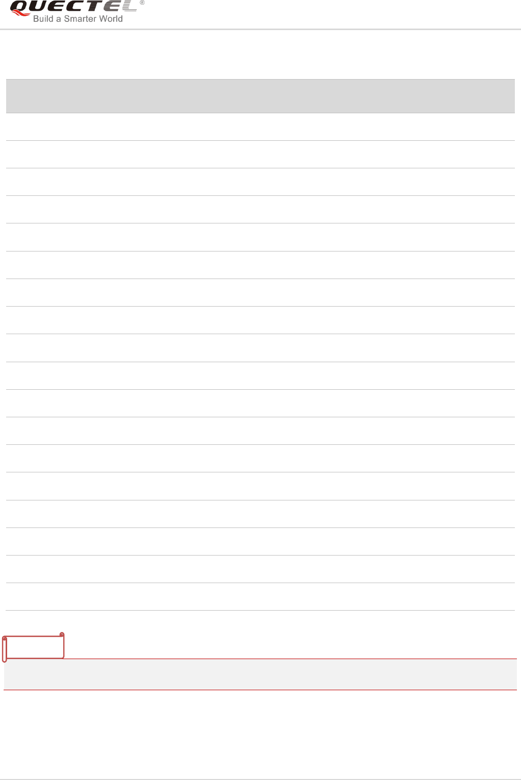
LTE Module Series
EC25&EC21 AT Commands Manual
EC25&EC21_AT_Commands_Manual 100 / 239
Table 4: Parameter Configurations Supported by AT+CBST
3GPP TS 22.002 lists the allowed combinations of the sub-parameters.
<speed>
GSM
WCDMA
SYNC.
ASYNC.
ASYNC.
(RDI)
TRANSP.
NON-
TRANSP.
0
Y
Y
N
Y
N
N
Y
7
Y
N
N
Y
N
N
Y
12
Y
N
N
Y
N
N
Y
14
Y
Y
N
Y
N
N
Y
16
N
Y
N
Y
N
N
Y
17
N
Y
N
Y
N
N
Y
39
Y
N
N
Y
N
N
Y
43
Y
Y
N
Y
N
N
Y
48
N
Y
N
Y
N
N
Y
51
N
Y
N
Y
N
N
Y
71
Y
N
N
Y
N
N
Y
75
Y
Y
N
Y
N
N
Y
80
Y
Y
N
Y
N
N
Y
81
Y
Y
N
Y
N
N
Y
83
Y
Y
N
Y
Y
N
Y
84
N
Y
N
Y
N
N
Y
116
N
Y
Y
N
N
Y
N
134
N
Y
Y
N
N
Y
N
NOTE
LTE Module Series
EC25&EC21 AT Commands Manual
EC25&EC21_AT_Commands_Manual 101 / 239
7.14. AT+CSTA Select Type of Address
The Write Command selects the type of number for further dialing commands ATD according to 3GPP
Specifications. Test command returns values supported a compound value.
Parameter
7.15. AT+CLCC List Current Calls of ME
The execution command returns the list of all current calls. If the command is executed successfully, but
no calls existed, no information response but OK is sent to TE.
AT+CSTA Select Type of Address
Test Command
AT+CSTA=?
Response
+CSTA: (list of supported <type>s)
OK
Read Command
AT+CSTA?
Response
+CSTA: <type>
OK
Write Command
AT+CSTA=<type>
Response
OK
Maximum Response Time
300ms
Reference
3GPP TS 27.007
<type> Current address type setting.
129 Unknown type
145 International type (contains the character “+”)
AT+CLCC List Current Calls of ME
Test Command
AT+CLCC=?
Response
OK
Execution Command
AT+CLCC
Response
TA returns a list of current calls of ME. If the command is
executed successfully, but no calls are existed, then no
information but OK response is sent to TE.
[+CLCC :

LTE Module Series
EC25&EC21 AT Commands Manual
EC25&EC21_AT_Commands_Manual 102 / 239
Parameter
<id1>,<dir>,<stat>,<mode>,<mpty>[,<number>,<type>[,<
alpha>]]
[+CLCC:
<id2>,<dir>,<stat>,<mode>,<mpty>[,<number>,<type>[,<
alpha>]]
[...]
OK
If there is any error related to ME functionality:
+CME ERROR: <err>
Maximum Response Time
300ms
<idx> Integer type. Call identification number as described in 3GPP TS 22.030 subclause
4.5.5.1. This number can be used in AT+CHLD command operation
<dir> 0 Mobile originated (MO) call
1 Mobile terminated (MT) call
<stat> State of the call
0 Active
1 Held
2 Dialing (MO call)
3 Alerting (MO call)
4 Incoming (MT call)
5 Waiting (MT call)
<mode> Bearer/tele service
0 Voice
1 Data
2 FAX
<mpty> 0 Call is not one of multiparty (conference) call parties
1 Call is one of multiparty (conference) call parties
<number> Phone number in string type in format specified by <type>
<type> Type of address of octet in integer format (refer to 3GPP TS 24.008 subclause 10.5.4.7 for
details). Usually, it has three kinds of values:
129 Unknown type
145 International type (contains the character “+”)
161 National type
<alpha> Alphanumeric representation of <number> corresponding to the entry found in phonebook.

LTE Module Series
EC25&EC21 AT Commands Manual
EC25&EC21_AT_Commands_Manual 103 / 239
Example
ATD10086; //Establish a call
OK
AT+CLCC
+CLCC: 1,0,0,1,0,"",128 //PS call in LTE mode
+CLCC: 2,0,0,0,0,“10086”,129 //Establish a call, and the call has been answered
OK
7.16. AT+CR Service Reporting Control
The command controls the module whether or not to transmit an intermediate result code +CR: <serv> to
the TE when a call is being set up.
If it is enabled, an intermediate result code is transmitted at the point during connect negotiation at which
the TA has determined which speed and quality of service will be used, before any error control or data
compression reports are transmitted, and before any final result code (e.g. CONNECT) is transmitted.
Parameter
AT+CR Service Reporting Control
Test Command
AT+CR=?
Response
+CR: (list of supported <mode>s)
OK
Read Command
AT+CR?
Response
+CR: <mode>
OK
Write Command
AT+CR=[<mode>]
Response
TA controls whether or not intermediate result code +CR:
<serv> is returned from the TA to the TE when a call is being
set up.
OK
Maximum Response Time
300ms
Reference
3GPP TS 27.007
<mode> 0 Disable
1 Enable
LTE Module Series
EC25&EC21 AT Commands Manual
EC25&EC21_AT_Commands_Manual 104 / 239
7.17. AT+CRC Set Cellular Result Codes for Incoming Call Indication
The command controls whether or not to use the extended format of incoming call indication. When it is
enabled, an incoming call is indicated to the TE with unsolicited result code +CRING: <type> instead of
the normal RING.
Parameter
<serv> ASYNC Asynchronous transparent
SYNC Synchronous transparent
REL ASYNC Asynchronous non-transparent
REL SYNC Synchronous non-transparent
GPRS GPRS
AT+CRC Set Cellular Result Codes for Incoming Call Indication
Test Command
AT+CRC=?
Response
+CRC: (list of supported <mode>s)
OK
Read Command
AT+CRC?
Response
+CRC: <mode>
OK
Write Command
AT+CRC=[<mode>]
Response
TA controls whether or not the extended format of incoming
call indication is used.
OK
Maximum Response Time
300ms
Reference
3GPP TS 27.007
<mode> 0 Disable extended format
1 Enable extended format
<type> ASYNC Asynchronous transparent
SYNC Synchronous transparent
REL ASYNC Asynchronous non-transparent
REL SYNC Synchronous non-transparent
FAX Facsimile
VOICE Voice

LTE Module Series
EC25&EC21 AT Commands Manual
EC25&EC21_AT_Commands_Manual 105 / 239
Example
AT+CRC=1 //Enable extended format
OK
+CRING: VOICE //Indicate incoming call to the TE
ATH
OK
AT+CRC=0 //Disable extended format
OK
RING //Indicate incoming call to the TE
ATH
OK
7.18. AT+CRLP Select Radio Link Protocol Parameter
The Write Command sets radio link protocol (RLP) parameters used when non-transparent data calls are
originated.
AT+CRLP Select Radio Link Protocol Parameter
Test Command
AT+CRLP=?
Response
TA returns values supported. RLP (Radio Link Protocol)
versions 0 and 1 share the same parameter set. TA returns
only one line for this set (where <ver> is not presented).
+CRLP:
(list of supported <iws>s),(list of supported <mws>s),(list of
supported <T1>s),(list of supported <N2>s),<ver>
+CRLP:
(list of supported <iws>s),(list of supported <mws>s),(list of
supported <T1>s),(list of supported <N2>s),<ver>
+CRLP:
(list of supported <iws>s),(list of supported <mws>s),(list of
supported <T1>s),(list of supported <N2>s),<ver>
OK
Read Command
AT+CRLP?
Response
TA returns current settings for RLP version. RLP versions 0
and 1 share the same parameter set. TA returns only one line
for this set (where <ver> is not presented).
+CRLP: <iws>,<mws>,<T1>,<N2>,<ver>
+CRLP: <iws>,<mws>,<T1>,<N2>,<ver>
LTE Module Series
EC25&EC21 AT Commands Manual
EC25&EC21_AT_Commands_Manual 106 / 239
Parameter
7.19. AT+QECCNUM Configure Emergency Call Numbers
The command can be used to query, add and delete ECC numbers (emergency call numbers). There are
two kinds of ECC numbers: ECC numbers without (U)SIM and ECC numbers with (U)SIM. The default
ECC numbers without SIM is 911, 112, 00, 08, 110, 999, 118 and 119. The default ECC number with
(U)SIM is 911 and 112. 911 and 112 will always be supported as ECC numbers, and cannot be deleted.
ECC numbers can be saved into NV automatically. If the (U)SIM card contains ECC file, the numbers in
ECC file can also be regarded as ECC numbers.
The maximal supported ECC numbers of each type is 20.
+CRLP: <iws>,<mws>,<T1>,<N2>,<ver>
OK
Write Command
AT+CRLP=[<iws>[,<mws>[,<T1>[,<N2
>[,<ver>]]]]]
Response
TA sets radio link protocol (RLP) parameters used when
non-transparent data calls are set up.
OK
Maximum Response Time
300ms
Reference
3GPP TS27.007
<iws> 0-61 Interworking window size (IWF to MS)
0-240-488 For <ver>=2
<mws> 0-61 Mobile window size (MS to IWF)
0-240-488 For <ver>=2
<T1> 38-48-255 Acknowledgment timer T1 in a unit of 10ms
42-52-255 For <ver>=2
<N2> 1-6-255 Retransmission attempts N2
<ver> 0-2 RLP version number in integer format
AT+QECCNUM Configure Emergency Call Numbers
Test Command
AT+QECCNUM=?
Response
+QECCNUM: (0-2)
OK
Write Command
AT+QECCNUM=<mode>,<type>[,<ecc
Response
If <mode> is equal to 0, query the ECC numbers. In this

LTE Module Series
EC25&EC21 AT Commands Manual
EC25&EC21_AT_Commands_Manual 107 / 239
Parameter
<mode> ECC number operation mode
0 Query ECC numbers
1 Add ECC numbers
2 Delete ECC numbers
<type> ECC number type
0 ECC numbers without (U)SIM
1 ECC numbers with (U)SIM
<eccnum> String type. ECC numbers ( e.g. 110, 119)
Example
AT+QECCNUM=? //Query the supported ECC number operation mode
+QECCNUM: (0-2)
OK
AT+QECCNUM? //Query the ECC numbers with or without (U)SIM
+QECCNUM: 0,"911","112","00","08","110","999","118","119"
+QECCNUM: 1,"911","112"
OK
AT+QECCNUM=0,1 //Query the ECC numbers with (U)SIM
+QECCNUM: 1,"911","112"
num1>[,<eccnum2>,…[,<eccnumN>]]
]
cases, <eccnumN> should be omitted, and the response is:
+QECCNUM: <type>,<eccnum1>,<eccnum2>[…]
OK
If <mode> is not equal to 0: <mode>=1 is used to add the
ECC number; <mode>=2 is used to delete the ECC number.
In this case, at least one ECC number <eccnumN> should be
inputted, and the response is:
OK
ERROR
Read Command
AT+QECCNUM?
Response
+QECCNUM: 0,<eccnum1>,<eccnum2>[…]
+QECCNUM: 1,<eccnum1>,<eccnum2>[…]
OK
Maximum Response Time
300ms

LTE Module Series
EC25&EC21 AT Commands Manual
EC25&EC21_AT_Commands_Manual 108 / 239
OK
AT+QECCNUM=1,1,"110", "234" //Add "110" and "234" into the type of ECC numbers with (U)SIM
OK
AT+QECCNUM=0,1 //Query the ECC numbers with (U)SIM
+QECCNUM: 1, "911","112","110","234"
OK
AT+QECCNUM=2,1,"110" //Delete "110" from the type of ECC numbers with (U)SIM
OK
AT+QECCNUM=0,1 //Query the ECC numbers with (U)SIM
+QECCNUM: 1, "911","112","234"
OK
7.20. AT+QHUP Hang up Call with a Specific Release Cause
The command can terminate a call or calls (including both voice call and data call) with a specific 3GPP
TS 24.008 release cause specified by the host.
Parameter
AT+QHUP Hang up Call with a Specific Release Cause
Test Command
AT+QHUP=?
Response
OK
Write Command
AT+QHUP=<cause>[,<idx>]
Response
OK
ERROR
If there is any error related to ME functionality:
+CME ERROR: <err>
Maximum Response Time
90s, determined by network.
<cause> Release cause. 3GPP TS 24.008 release cause to be indicated to the network.
1 Release cause "unassigned (unallocated) number"
16 Release cause "normal call clearing"
17 Release cause "user busy"
18 Release cause "no user responding"
21 Release cause "call rejected"
27 Release cause "destination out of order"
31 Release cause "normal, unspecified"
88 Release cause "incompatible destination"

LTE Module Series
EC25&EC21 AT Commands Manual
EC25&EC21_AT_Commands_Manual 109 / 239
Example
AT+QHUP=? //Test Command
OK
ATD10010; //Dial 10010
OK
ATD10086; //Dial 10086
OK
AT+CLCC //Query the status of calls
+CLCC: 1,0,1,0,0,"10010",129
+CLCC: 2,0,0,0,0,"10086",129
OK
AT+QHUP=17,1 //Terminate the call whose ID is 1. Disconnect cause is "user busy"
OK
AT+CLCC //Query the status of calls
+CLCC: 1,0,0,0,0,"10086",129
OK
AT+QHUP=16 //Terminate all existed calls. Disconnect cause is "normal call clearing"
OK
AT+CLCC
OK
<idx> Call identification number is an optional index in the list of current calls indicated by
AT+CLCC. AT+QHUP will terminate the call identified by the given call number. The
default call number 0 is not assigned to any call, but signifies all calls.
0 Terminate all known calls. However, if circuit switches data calls and
voice calls at the same time, this command only terminates the CSD
calls.
1…7 Terminate the specific call with identification number.

LTE Module Series
EC25&EC21 AT Commands Manual
EC25&EC21_AT_Commands_Manual 110 / 239
8 Phonebook Commands
8.1. AT+CNUM Subscriber Number
The command can get the subscribers own number(s) from the (U)SIM.
Parameter
AT+CNUM Subscriber Number
Test Command
AT+CNUM=?
Response
OK
Execution Command
AT+CNUM
Response
[+CNUM: [<alpha>],<number>,<type>]
[+CNUM: [<alpha>],<number>,<type>]
OK
ERROR
If there is any error related to ME functionality:
+CME ERROR: <err>
Maximum Response Time
300ms
Reference
3GPP 27.007
<alpha> Optional alphanumeric string associated with <number>. The used character set
should be the one selected with AT+CSCS command
<number> String type phone number of format specified by <type>
<type> Type of address of octet in integer format (Refer to 3GPP TS 24.008 subclause
10.5.4.7 for details ). Usually, it has three kinds of values:
129 Unknown type
145 International type (contains the character “+”)
161 National type

LTE Module Series
EC25&EC21 AT Commands Manual
EC25&EC21_AT_Commands_Manual 111 / 239
8.2. AT+CPBF Find Phonebook Entries
The command can search the phonebook entries starting with the given <findtext> string from the current
phonebook memory storage selected with AT+CPBS, and return all found entries sorted in alphanumeric
order.
Parameter
AT+CPBF Find Phonebook Entries
Test Command
AT+CPBF=?
Response
+CPBF: <nlength>,<tlength>
OK
Write Command
AT+CPBF=<findtext>
Response
[+CPBF: <index>,<number>,<type>,<text>]
[…]
OK
ERROR
If there is any error related to ME functionality:
+CME ERROR: <err>
Maximum Response Time
Depends on the storage of phonebook entries.
Reference
3GPP 27.007
<nlength> Integer type. Indicates the maximum length of field <number>
<tlength> Integer type. Indicates the maximum length of field <text>
<findtext> String type field of maximum length <tlength> in current TE character set specified by
AT+CSCS.
<index> Integer type values in the range of location numbers of phone book memory.
<type> Type of address of octet in integer format (refer to 3GPP TS 24.008 subclause
10.5.4.7 for details). Usually, it has three kinds of values:
129 Unknown type
145 International type (contains the character “+”)
161 National type
<text> String type field of maximum length <tlength> in current TE character set specified by
AT+CSCS.

LTE Module Series
EC25&EC21 AT Commands Manual
EC25&EC21_AT_Commands_Manual 112 / 239
8.3. AT+CPBR Read Phonebook Entries
The command can return phonebook entries in location number range <index1>... <index2> from the
current phonebook memory storage selected with AT+CPBS. If <index2> is left out, only location
<index1> is returned.
Parameter
AT+CPBR Read Phonebook Entries
Test Command
AT+CPBR=?
Response
+CPBR: (list of supported <index>s),<nlength>,<tlength>
OK
Write Command
AT+CPBR=<index1>[,<index2>]
Response
+CPBR: <index1>,<number>,<type>,<text>
[+CPBR: <index2>,<number>,<type>,<text>
[…]]
OK
ERROR
If there is any error related to ME functionality:
+CME ERROR: <err>
Maximum Response Time
Depends on the storage of phonebook entries.
Reference
3GPP 27.007
<index> Integer type value in the range of location numbers of phone book memory.
<nlength> Integer type. Indicates the maximum length of field <number>
<tlength> Integer type. Indicates the maximum length of field <text>
<index1> The first phone book record to read
<index2> The last phonebook record to read
<type> Type of address of octet in integer format (refer to 3GPP TS 24.008 subclause
10.5.4.7 for details ). Usually, it has three kinds of values:
129 Unknown type
145 International type(contains the character “+”)
161 National type
<text> String type field of maximum length <tlength> in current TE character set specified by
AT+CSCS.

LTE Module Series
EC25&EC21 AT Commands Manual
EC25&EC21_AT_Commands_Manual 113 / 239
8.4. AT+CPBS Select Phonebook Memory Storage
The command selects phonebook memory storage, which is used by other phonebook commands. The
Read Command returns currently selected memory, the number of used locations and the total number of
locations in the memory when supported by manufacturer. The Test Command returns supported
storages as compound value.
Parameter
AT+CPBS Select Phonebook Memory Storage
Test Command
AT+CPBS=?
Response
+CPBS: (list of supported <storage>s)
OK
ERROR
If there is any error related to ME functionality:
+CME ERROR: <err>
Read Command
AT+CPBS?
Response
+CPBS: <storage>,<used>,<total>
OK
ERROR
If there is any error related to ME functionality:
+CME ERROR: <err>
Write Command
AT+CPBS=<storage>
Response
OK
ERROR
If there is any error related to ME functionality:
+CME ERROR: <err>
Maximum Response Time
300ms
Reference
3GPP 27.007
<storage> “SM” (U)SIM phonebook
“DC” ME dialed calls list (AT+CPBW may not be applicable to this storage)
“FD” (U)SIM fix dialing-phone book (AT+CPBW operation need the authority of PIN2)
“LD” (U)SIM last-dialing-phone book (AT+CPBW may not be applicable to this storage)
“MC” ME missed (unanswered) calls list (AT+CPBW may not be applicable to this
storage)

LTE Module Series
EC25&EC21 AT Commands Manual
EC25&EC21_AT_Commands_Manual 114 / 239
8.5. AT+CPBW Write Phonebook Entry
The command writes phonebook entry in location number <index> in the current phonebook memory
storage selected with AT+CPBS. It can also delete a phonebook entry in location number <index>.
Parameter
“ME” Mobile equipment phonebook
“RC” ME received calls list (AT+CPBW may not be applicable to this storage)
“EN” (U)SIM (or ME) emergency number (AT+CPBW may not be applicable to this
storage)
“ON” (U)SIM own numbers (MSISDNs) list
<used> Integer type. Indicates the total number of used locations in selected memory
<total> Integer type. Indicates the total number of locations in selected memory
AT+CPBW Write Phonebook Entry
Test Command
AT+CPBW=?
Response
+CPBW: (The range of supported <index>s), <nlength>, (list
of supported <type>s), <tlength>
OK
ERROR
If there is any error related to ME functionality:
+CME ERROR: <err>
Write Command
AT+CPBW=[<index>][,<number>[,<ty
pe>[,<text>]]]
Response
OK
ERROR
If there is any error related to ME functionality:
+CME ERROR: <err>
Maximum Response Time
300ms
Reference
3GPP 27.007
<index> Integer type value in the range of location numbers of phone book memory. If <index>
is not given, the first free entry will be used. If <index> is given as the only parameter,
the phonebook entry specified by <location> is deleted.
<nlength> Integer type. Indicates the maximum length of field <number>.
<tlength> Integer type. Indicates the maximum length of field <text>.
<type> Type of address of octet in integer format (refer to 3GPP TS 24.008 subclause

LTE Module Series
EC25&EC21 AT Commands Manual
EC25&EC21_AT_Commands_Manual 115 / 239
Example
AT+CSCS=“GSM”
OK
AT+CPBW=10,“15021012496”,129,“QUECTEL”
OK //Make a new phonebook entry at location 10
AT+CPBW=10 //Delete the entry at location 10
OK
AT+CPBR=10
OK
10.5.4.7 for details). Usually, it has three kinds of values:
129 Unknown type
145 International type (contains the character “+”)
161 National type
<text> String type field of maximum length <tlength> in current TE character set specified by
AT+CSCS.

LTE Module Series
EC25&EC21 AT Commands Manual
EC25&EC21_AT_Commands_Manual 116 / 239
9 Short Message Service Commands
9.1. AT+CSMS Select Message Service
The command selects messaging service <service> and returns the types of messages supported by the
ME.
Parameter
AT+CSMS Select Message Service
Test Command
AT+CSMS=?
Response
+CSMS: (list of supported <service>s)
OK
Read Command
AT+CSMS?
Response
+CSMS: <service>,<mt>,<mo>,<bm>
OK
Write Command
AT+CSMS=<service>
Response
+CSMS: <mt>,<mo>,<bm>
OK
If there is any error related to ME functionality:
+CMS ERROR: <err>
Maximum Response Time
300ms
Reference
3GPP TS 27.005
<service> Type of message service
0 3GPP TS 23.040 and 3GPP TS 23.041 (the syntax of SMS AT commands is
compatible with 3GPP TS 27.005 Phase 2 version 4.7.0; Phase 2+ features
which do not require new command syntax may be supported, e.g. correct
routing of messages with new Phase 2+ data coding schemes).
1 3GPP TS 23.040 and 3GPP TS 23.041 (the syntax of SMS AT commands is
compatible with 3GPP TS 27.005 Phase 2+ version; the requirement of

LTE Module Series
EC25&EC21 AT Commands Manual
EC25&EC21_AT_Commands_Manual 117 / 239
Example
AT+CSMS=? //Test command
+CSMS: (0,1)
OK
AT+CSMS=1 //Set type of message service as 1
+CSMS: 1,1,1
OK
AT+CSMS? //Read command
+CSMS: 1,1,1,1
OK
9.2. AT+CMGF Message Format
The command specifies the input and output format of the short messages. <mode> indicates the format
of messages used with Test, Read, Write and Execution Commands and unsolicited result codes resulting
from received messages.
The format of messages can be either PDU mode (entire TP data units used) or text mode (headers and
body of the messages given as separate parameters). Text mode uses the value of parameter <chset>
specified by AT+CSCS command to inform the character set to be used in the message body in the
TA-TE interface.
<service> setting 1 is mentioned under corresponding command
descriptions).
<mt> Mobile terminated messages
0 Type not supported
1 Type supported
<mo> Mobile originated messages
0 Type not supported
1 Type supported
<bm> Broadcast type messages
0 Type not supported
1 Type supported
AT+CMGF Message Format
Test Command
AT+CMGF=?
Response
+CMGF: (list of supported <mode>s)

LTE Module Series
EC25&EC21 AT Commands Manual
EC25&EC21_AT_Commands_Manual 118 / 239
Parameter
9.3. AT+CSCA Service Center Address
The Write Command updates the SMSC address when mobile originated SMS are transmitted. In text
mode, the setting is used by Write Command. In PDU mode, setting is used by the same command, but
only when the length of the SMSC address is coded into the <pdu> parameter which equals to zero.
OK
Read Command
AT+CMGF?
Response
+CMGF: <mode>
OK
Write Command
AT+CMGF[=<mode>]
Response
TA sets parameter to denote which kind of I/O format of
messages is used.
OK
Maximum Response Time
300ms
Reference
3GPP TS 27.005
<mode> 0 PDU mode
1 Text mode
AT+CSCA Service Center Address
Test Command
AT+CSCA=?
Response
OK
Read Command
AT+CSCA?
Response
+CSCA: <sca>,<tosca>
OK
Write Command
AT+CSCA=<sca>[,<tosca>]
Response
OK
If there is any error related to ME functionality:
+CME ERROR: <err>
Maximum Response Time
300ms
Reference
3GPP TS 27.005

LTE Module Series
EC25&EC21 AT Commands Manual
EC25&EC21_AT_Commands_Manual 119 / 239
Parameter
Example
AT+CSCA=“+8613800210500”,145 //Set SMS service center address
OK
AT+CSCA? //Query SMS service center address
+CSCA: “+8613800210500”,145
OK
9.4. AT+CPMS Preferred Message Storage
The command selects the memory storages <mem1>, <mem2> and <mem3> to be used for reading,
writing, etc.
AT+CPMS Preferred Message Storage
Test Command
AT+CPMS=?
Response
+CPMS: (list of supported <mem1>s),(list of supported
<mem2>s),(list of supported <mem3>s)
OK
Read Command
AT+CPMS?
Response
+CPMS:
<mem1>,<used1>,<total1>,<mem2>,<used2>,<total2>,<m
em3>,<used3>,<total3>
OK
Write Command
AT+CPMS=<mem1>[,<mem2>[,<mem
3>]]
Response
TA selects memory storages <mem1>, <mem2> and
<mem3> to be used for reading, writing, etc.
+CPMS:
<used1>,<total1>,<used2>,<total2>,<used3>,<total3>
OK
<sca> Service center address. 3GPP TS 24.011 RP SC address Address-Value field in string
format; BCD numbers (or GSM 7 bit default alphabet characters) are converted to
characters of the currently selected TE character set (refer to AT+CSCS command
in 3GPP TS 27.007). The type of address is given by <tosca>.
<tosca> Type of service center address. 3GPP TS 24.011 RP SC address Type-of-Address
octet in integer format (default refer to <toda>).

LTE Module Series
EC25&EC21 AT Commands Manual
EC25&EC21_AT_Commands_Manual 120 / 239
If there is any error related to ME functionality:
+CMS ERROR: <err>
Maximum Response Time
300ms
Reference
3GPP TS 27.005
Parameter
Example
AT+CPMS? //Query the current SMS message storage
+CPMS: “ME”,0,255,“ME”,0,255,“ME”,0,255
OK
AT+CPMS=“SM”,“SM”,“SM” //Set SMS message storage as “SM”
+CPMS: 0,50,0,50,0,50
OK
AT+CPMS? //Query the current SMS message storage
+CPMS: “SM”,0,50,“SM”,0,50,“SM”,0,50
OK
<mem1> Messages to be read and deleted from this memory storage
“SM” (U)SIM message storage
“ME” Mobile equipment message storage
“MT” Same as “ME” storage
<mem2> Messages will be written and sent to this memory storage
“SM” (U)SIM message storage
“ME” Mobile equipment message storage
“MT” Same as “ME” storage
<mem3> Received messages will be placed in this memory storage if routing to PC is not set
(AT+CNMI)
“SM” (U)SIM message storage
“ME” Mobile equipment message storage
“MT” Same as “ME” storage
<usedx> Integer type. Number of current messages in <memx>
<totalx> Integer type. Total number of messages which can be stored in <memx>

LTE Module Series
EC25&EC21 AT Commands Manual
EC25&EC21_AT_Commands_Manual 121 / 239
9.5. AT+CMGD Delete Message
The command deletes short messages from the preferred message storage <mem1> location <index>. If
<delflag> is presented and not set to 0, then the ME shall ignore <index> and follow the rules of
<delflag> shown as below.
Parameter
AT+CMGD Delete Message
Test Command
AT+CMGD=?
Response
+CMGD: (list of supported <index>s),(list of supported
<delflag>s)
OK
Write Command
AT+CMGD=<index>[,<delflag>]
Response
TA deletes message from preferred message storage
<mem1> location <index>.
OK
If there is any error related to ME functionality:
+CMS ERROR: <err>
Maximum Response Time
300ms.
Note: Operation of <delflag> depends on the storage of
deleted messages.
Reference
3GPP TS 27.005
<index> Integer type value in the range of location numbers supported by the associated memory.
<delflag> 0 Delete the message specified in <index>
1 Delete all read messages from <mem1> storage
2 Delete all read messages from <mem1> storage and sent mobile originated
messages
3 Delete all read messages from <mem1> storage, sent and unsent mobile
originated messages
4 Delete all messages from <mem1> storage
<mem1> Messages to be read and deleted from this memory storage
“SM” (U)SIM message storage
“ME” Mobile equipment message storage
“MT” Same as “ME” storage

LTE Module Series
EC25&EC21 AT Commands Manual
EC25&EC21_AT_Commands_Manual 122 / 239
Example
AT+CMGD=1 //Delete the message specified in <index>=1
OK
AT+CMGD=1,4 //Delete all messages from <mem1> storage
OK
9.6. AT+CMGL List Messages
The Read Command returns messages with status value <stat> from preferred message storage
<mem1> to the TE. If the status of the message is “REC UNREAD”, the status in the storage changes to
“REC READ”. When executing command AT+CMGL without status value <stat>, it will report the list of
SMS with “REC UNREAD” status.
AT+CMGL List Messages
Test Command
AT+CMGL=?
Response
+CMGL: (list of supported <stat>s)
OK
Write Command
AT+CMGL[=<stat>]
Response
If in text mode (AT+CMGF=1) and the command is executed
successfully:
For SMS-SUBMITs and/or SMS-DELIVERs:
+CMGL:
<index>,<stat>,<oa/da>,[<alpha>],[<scts>][,<tooa/toda>,<
length>]<CR><LF><data>[<CR><LF>
+CMGL:
<index>,<stat>,<da/oa>,[<alpha>],[<scts>][,<tooa/toda>,<
length>]<CR><LF><data>[...]]
For SMS-STATUS-REPORTs:
+CMGL:
<index>,<stat>,<fo>,<mr>,[<ra>],[<tora>],<scts>,<dt>,<st
>[<CR><LF>
+CMGL:
<index>,<stat>,<fo>,<mr>,[<ra>],[<tora>],<scts>,<dt>,<st
>[...]]
For SMS-COMMANDs:
+CMGL: <index>,<stat>,<fo>,<ct>[<CR><LF>
+CMGL: <index>,<stat>,<fo>,<ct>[...]]

LTE Module Series
EC25&EC21 AT Commands Manual
EC25&EC21_AT_Commands_Manual 123 / 239
Parameter
For CBM storage:
+CMGL:<index>,<stat>,<sn>,<mid>,<page>,<pages><CR
><LF><data>[<CR><LF>
+CMGL:
<index>,<stat>,<sn>,<mid>,<page>,<pages><CR><LF><d
ata>[...]]
OK
If in PDU mode (AT+CMGF=0) and the command is executed
successfully:
+CMGL:<index>,<stat>,[<alpha>],<length><CR><LF><pd
u><CR><LF>
+CMGL:
<index>,<stat>,[alpha],<length><CR><LF><pdu>[...]]
OK
If there is any error related to ME functionality:
+CMS ERROR: <err>
Execution Command
AT+CMGL
Response
List all messages with “REC UNREAD” status from message
storage <mem1>, and then the status in the storage changes
to “REC READ”.
Maximum Response Time
300ms.
Note: Operation of <stat> depends on the storage of listed
messages.
Reference
3GPP TS 27.005
<stat> In text mode:
“REC UNREAD” Received unread messages
“REC READ” Received read messages
“STO UNSENT” Stored unsent messages
“STO SENT” Stored sent messages
“ALL” All messages
In PDU mode:
0 Received unread messages
1 Received read messages
2 Stored unsent messages
3 Stored sent messages

LTE Module Series
EC25&EC21 AT Commands Manual
EC25&EC21_AT_Commands_Manual 124 / 239
4 All messages
<index> Integer type value in the range of location numbers supported by the associated
memory
<da> Destination Address. 3GPP TS 23.040 TP-Destination-Address Address-Value field in
string format. BCD numbers (or GSM 7 bit default alphabet characters) are
converted to characters of the currently selected TE character set (refer to
AT+CSCS command in 3GPP TS 27.007). The type of address is given by <toda>.
<oa> Originating address. 3GPP TS 23.040 TP-Originating-Address Address-Value field in
string format. BCD numbers (or GSM 7 bit default alphabet characters) are converted
to characters of the currently selected TE character set (refer to AT+CSCS command
in 3GPP TS 27.007). The type of address is given by <tooa>.
<alpha> String type alphanumeric representation of <da> or <oa> corresponding to the entry
found in MT phonebook. Implementation of this feature is manufacturer specified. The
used character set should be the one selected with AT+CSCS command (see
definition of this command in 3GPP TS 27.007).
<scts> Service center time stamp. 3GPP TS 23.040 TP-Service-Centre-Time-Stamp in
time-string format (refer to <dt>).
<toda> Type of recipient address. 3GPP TS 24.011 TP-Recipient-Address Type-of-Address
octet in integer format.
<tooa> Type of originating address. 3GPP TS 24.011 TP-Originating-Address
Type-of-Address octet in integer format (default refer to <toda>).
<length> Message length. Integer type. Indicating in the text mode (AT+CMGF=1) the length
of the message body <data> (or <cdata>) in characters, or in PDU mode
(AT+CMGF=0) the length of the actual TP data unit in octets (i.e. the RP layer SMSC
address octets are not counted in the length).
<data> In the case of SMS: 3GPP TS 23.040 TP-User-Data in text mode responses; format:
- If <dcs>, indicates that 3GPP TS 23.038 GSM 7 bit default alphabet is used and
<fo> indicates that 3GPP TS 23.040 TP-User-Data-Header-Indication is not set.
- If TE character set other than “HEX” (refer to AT+CSCS command in 3GPP TS
27.007): ME/TA converts GSM alphabet into current TE character set according to
rules of Annex A in 3GPP TS 27.007.
- If TE character set is “HEX”: ME/TA converts each 7-bit character of GSM 7 bit
default alphabet into two IRA character long hexadecimal number (e.g. character
(GSM 7 bit default alphabet 23) is presented as 17 (IRA 49 and 55)).
- If <dcs>, indicates that 8-bit or UCS2 data coding scheme is used, or <fo>
indicates that 3GPP TS 23.040 TP-User-Data-Header-Indication is set: ME/TA
converts each 8-bit octet into two IRA character long hexadecimal number (e.g.
octet with integer value 42 is presented to TE as two characters 2A (IRA 50 and
65)).
In the case of CBS: 3GPP TS 23.041 CBM Content of Message in text mode
responses; format:
- If <dcs>, indicates that 3GPP TS 23.038 GSM 7 bit default alphabet is used:
- If TE character set other than “HEX” (refer to AT+CSCS command in 3GPP
TS27.007): ME/TA converts GSM alphabet into current TE character set according

LTE Module Series
EC25&EC21 AT Commands Manual
EC25&EC21_AT_Commands_Manual 125 / 239
Example
AT+CMGF=1 //Set SMS message format as text mode
OK
AT+CMGL=“ALL” //List all messages from message storage
+CMGL: 1,“STO UNSENT”,“”,,
<This is a test from Quectel>
+CMGL: 2,“STO UNSENT”,“”,,
<This is a test from Quectel>
OK
9.7. AT+CMGR Read Message
The Read Command returns SMS message with location value <index> from message storage <mem1>
to the TE. If status of the message is “REC UNREAD”, status in the storage changes to “REC READ”.
to rules of Annex A in 3GPP TS 27.007.
- If TE character set is “HEX”: ME/TA converts each 7-bit character of the GSM 7 bit
default alphabet into two IRA character long hexadecimal number.
- If <dcs>, indicates that 8-bit or UCS2 data coding scheme is used: ME/TA converts
each 8-bit octet into two IRA character long hexadecimal number.
<pdu> In the case of SMS: 3GPP TS 24.011 SC address followed by 3GPP TS 23.040 TPDU
in hexadecimal format: ME/TA converts each octet of TP data unit into two IRA
character long hexadecimal number (e.g. octet with integer value 42 is presented to
TE as two characters 2A (IRA 50 and 65)) 3GPP TS 27.007.
<mem1> Messages to be read and deleted from this memory storage
“SM” (U)SIM message storage
“ME” Mobile equipment message storage
“MT” Same as “ME” storage
AT+CMGR Read Message
Test Command
AT+CMGR=?
Response
OK
Write Command
AT+CMGR=<index>
Response
TA returns SMS message with location value <index> from
message storage <mem1> to the TE. If status of the
message is “REC UNREAD”, status in the storage changes to
“REC READ”.
If in text mode (AT+CMGF=1) and the command is executed
successfully:

LTE Module Series
EC25&EC21 AT Commands Manual
EC25&EC21_AT_Commands_Manual 126 / 239
For SMS-DELIVER:
+CMGR:
<stat>,<oa>,[<alpha>],<scts>[,<tooa>,<fo>,<pid>,<dcs>,<
sca>,<tosca>,<length>]<CR><LF><data>
OK
For SMS-SUBMIT:
+CMGR:
<stat>,<da>,[<alpha>][,<toda>,<fo>,<pid>,<dcs>,[<vp>],<
sca>,<tosca>,<length>]<CR><LF><data>
OK
For SMS-STATUS-REPORTs:
+CMGR:
<stat>,<fo>,<mr>,[<ra>],[<tora>],<scts>,<dt>,<st>
OK
For SMS-COMMANDs:
+CMGR:
<stat>,<fo>,<ct>[,<pid>,[<mn>],[<da>],[<toda>],<length><
CR><LF><cdata>]
OK
For CBM storage:
+CMGR:
<stat>,<sn>,<mid>,<dcs>,<page>,<pages><CR><LF><dat
a>
OK
If in PDU mode (AT+CMGF=0) and command is executed
successfully:
+CMGR: <stat>,[<alpha>],<length><CR><LF><pdu>
OK
If there is any error related to ME functionality:
+CMS ERROR: <err>
Maximum Response Time
Depends on the length of message content.
Reference
3GPP TS 27.005

LTE Module Series
EC25&EC21 AT Commands Manual
EC25&EC21_AT_Commands_Manual 127 / 239
Parameter
<index> Integer type value in the range of location numbers supported by the associated
memory
<stat> In text mode
“REC UNREAD” Received unread messages
“REC READ” Received read messages
“STO UNSENT” Stored unsent messages
“STO SENT” Stored sent messages
“ALL” All messages
In PDU mode
0 Received unread messages
1 Received read messages
2 Stored unsent messages
3 Stored sent messages
4 All messages
<alpha> String type alphanumeric representation of <da> or <oa> corresponding to the entry
found in MT phonebook. Implementation of this feature is manufacturer specified. The
used character set should be the one selected with AT+CSCS command (see definition
of this command in 3GPP TS 27.007).
<da> Destination address. 3GPP TS 23.040 TP-Destination-Address Address-Value field in
string format. BCD numbers (or GSM 7 bit default alphabet characters) are converted to
characters of the currently selected TE character set (refer to AT+CSCS command in
3GPP TS 27.007). The type of address is given by <toda>.
<oa> Originating address. 3GPP TS 23.040 TP-Originating-Address Address-Value field in
string format. BCD numbers (or GSM 7 bit default alphabet characters) are converted to
characters of the currently selected TE character set (refer to AT+CSCS command in
3GPP TS 27.007). The type of address is given by <tooa>.
<scts> Service center time stamp. 3GPP TS 23.040 TP-Service-Centre-Time-Stamp in
time-string format (refer to <dt>).
<fo> First octet. Depending on the command or result code: First octet of 3GPP TS 23.040
SMS-DELIVER, SMS-SUBMIT (default 17), SMS-STATUS-REPORT, or
SMS-COMMAND in integer format. If a valid value has been entered once, the
parameter can be omitted.
<pid> Protocol identifier. 3GPP TS 23.040 TP-Protocol-Identifier in integer format (default
0).
<dcs> Data coding scheme. Depending on the command or result code: 3GPP TS 23.038
SMS Data Coding Scheme (default 0), or Cell Broadcast Data Coding Scheme in
integer format.
<vp> Validity period. Depending on SMS-SUBMIT <fo> setting: 3GPP TS 23.040
TP-Validity-Period either in integer format or in time-string format (refer to <dt>).
<mn> Message number. 3GPP TS 23.040 TP-Message-Number in integer format.
<mr> Message reference. 3GPP TS 23.040 TP-Message-Reference in integer format.
<ra> Recipient address. 3GPP TS 23.040 TP-Recipient-Address Address-Value field in

LTE Module Series
EC25&EC21 AT Commands Manual
EC25&EC21_AT_Commands_Manual 128 / 239
string format. BCD numbers (or GSM default alphabet characters) are converted to
characters of the currently selected TE character set (refer to AT+CSCS command).
The type of address is given by <tora>.
<tora> Type of recipient address. 3GPP TS 24.011 TP-Recipient-Address Type-of-Address
octet in integer format (default refer <toda>).
<toda> Type of recipient address. 3GPP TS 24.011 TP-Recipient-Address Type-of-Address
octet in integer format.
<tooa> Type of originating address.3GPP TS 24.011 TP-Originating-Address Type-of-Address
octet in integer format (default refer to <toda>).
<sca> Service center address. 3GPP TS 24.011 RP SC address Address-Value field in string
format. BCD numbers (or GSM 7 bit default alphabet characters) are converted to
characters of the currently selected TE character set (refer to AT+CSCS command in
3GPP TS 27.007). The type of address is given by <tosca>.
<tosca> Type of service center address. 3GPP TS 24.011 RP SC address Type-of-Address octet
in integer format (default refer to <toda>).
<length> Message length. Integer type. Indicating in the text mode (AT+CMGF=1) the length of
the message body <data> (or <cdata>) in characters, or in PDU mode (AT+CMGF=0)
the length of the actual TP data unit in octets (i.e. the RP layer SMSC address octets
are not counted in the length).
<data> The text of short message. Please refer Chapter 14.8 for details.
<pdu> In the case of SMS: 3GPP TS 24.011 SC address followed by 3GPP TS 23.040 TPDU
in hexadecimal format: ME/TA converts each octet of TP data unit into two IRA
character long hexadecimal number (e.g. octet with integer value 42 is presented to TE
as two characters 2A (IRA 50 and 65)).
<prt> Priority
0 Normal
1 Interactive
2 Urgent
3 Emergency
<fmt> Format
0 GSM 7 bit
1 ASCII
6 UNICODE
<prv> Privacy
0 Normal
1 Restricted
2 Confidential
3 Secret
<lang> Language
0 Unspecified
1 English
2 French
3 Spanish
4 Japanese

LTE Module Series
EC25&EC21 AT Commands Manual
EC25&EC21_AT_Commands_Manual 129 / 239
Example
+CMTI: “SM”,3 //Indicates that new message has been received and saved
to <index>=3 of “SM”
AT+CSDH=1
OK
AT+CMGR=3 //Read message
+CMGR: “REC UNREAD”,“+8615021012496”,,“13/12/13,15:06:37+32”,145,4,0,0,“+861380021050
0”,145,27
<This is a test from Quectel>
OK
9.8. AT+CMGS Send Message
The Write Command sends a short message from TE to network (SMS-SUBMIT). After invoking the write
command, wait for the prompt “>” and then start to write the message. After that, enter <CTRL-Z> to
indicate the ending of PDU and begin to send the message. Sending can be cancelled by giving <ESC>
character. Abortion is acknowledged with “OK”, though the message will not be sent. The message
reference <mr> is returned to the TE on successful message delivery. The value can be used to identify
message upon unsolicited delivery status report result code.
5 Korean
6 Chinese
7 Hebrew
<type> 0 Normal
1 CPT
2 Voice Mail
3 SMS Report
<mem1> Messages to be read and deleted from this memory storage
“SM” (U)SIM message storage
“ME” Mobile equipment message storage
“MT” Same as “ME” storage
AT+CMGS Send Message
Test Command
AT+CMGS=?
Response
OK
Write Command
1) If text mode (AT+CMGF=1):
AT+CMGS=<da>[,<toda>]<CR>
text is entered
Response
TA sends message from TE to the network (SMS-SUBMIT).
Message reference value <mr> is returned to the TE on
successful message delivery. Optionally (when AT+CSMS

LTE Module Series
EC25&EC21 AT Commands Manual
EC25&EC21_AT_Commands_Manual 130 / 239
Parameter
Example
AT+CMGF=1 //Set SMS message format as text mode
OK
AT+CSCS=“GSM” //Set character set as GSM which is used by the TE
OK
AT+CMGS=“15021012496”
> <This is a test from Quectel> //Enter in text. Use <CTRL+Z> to send message, or
<ESC> quits without sending
+CMGS: 247
<Ctrl+Z/ESC>
ESC quits without sending
2) If PDU mode (AT+CMGF=0):
AT+CMGS=<length><CR>
PDU is given <Ctrl+Z/ESC>
<service> value is 1 and network supports) <scts> is
returned. Values can be used to identify message upon
unsolicited delivery status report result code.
If in text mode (AT+CMGF=1) and sent successfully:
+CMGS: <mr>
OK
If in PDU mode (AT+CMGF=0) and sent successfully:
+CMGS: <mr>
OK
If there is any error related to ME functionality:
+CMS ERROR: <err>
Maximum Response Time
120s, determined by network.
Reference
3GPP TS 27.005
<da> Destination address. 3GPP TS 23.040 TP-Destination-Address Address-Value field in
string format. BCD numbers (or GSM 7 bit default alphabet characters) are
converted to characters of the currently selected TE character set (refer to
AT+CSCS command in 3GPP TS 27.007). The type of address is given by <toda>.
<toda> Type of recipient address. 3GPP TS 24.011 TP-Recipient-Address Type-of-Address
octet in integer format.
<length> Message length. Integer type. Indicating in the text mode (AT+CMGF=1) the length of
the message body <data> (or <cdata>) in characters, or in PDU mode (AT+CMGF=0),
the length of the actual TP data unit in octets (i.e. the RP layer SMSC address octets
are not counted in the length).
<mr> Message reference. 3GPP TS 23.040 TP-Message-Reference in integer format.

LTE Module Series
EC25&EC21 AT Commands Manual
EC25&EC21_AT_Commands_Manual 131 / 239
OK
9.9. AT+CMMS More Messages to Send
The command controls the continuity of the SMS relay protocol link. If the feature is enabled (and
supported by the currently used network) multiple messages can be sent faster as the link is kept open.
Parameter
AT+CMMS More Messages to Send
Test Command
AT+CMMS=?
Response
+CMMS: (list of supported <n>s)
OK
Read Command
AT+CMMS?
Response
+CMMS: <n>
OK
Write Command
AT+CMMS=<n>
Response
OK
ERROR
If there is any error related to ME functionality:
+CMS ERROR: <err>
Maximum Response Time
120s, determined by network.
Reference
3GPP TS 27.005
<n> 0 Feature disabled
1 Keep enabled until the time between the response of the latest message send command
(AT+CMGS, AT+CMSS, etc.) and the next send command exceeds 1-5 seconds (the
exact value is up to ME implementation), and then ME shall close the link and TA
switches <n> back to 0 automatically
2 Feature enabled (if the time between the response of the latest message send command
and the next send command exceeds 1-5 seconds (the exact value is up to ME
implementation), ME shall close the link but TA will not switch <n> back to 0
automatically)
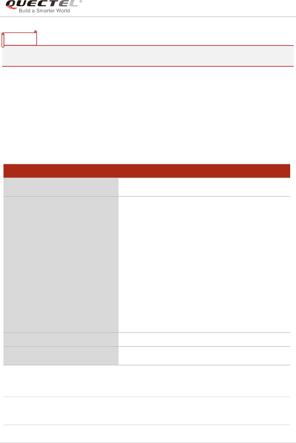
LTE Module Series
EC25&EC21 AT Commands Manual
EC25&EC21_AT_Commands_Manual 132 / 239
After the use of Read Command, a delay of 5-10 seconds is required before issuing the Write Command.
Otherwise the +CMS ERROR: 500 may appear.
9.10. AT+CMGW Write Message to Memory
The Write and Execution Commands store short messages from TE to memory storage <mem2>, and
then the memory location <index> of the stored message is returned. Message status will be set to
“stored unsent” by default, but parameter <stat> also allows other status values to be given.
The syntax of input text is the same as the one specified in AT+CMGS Write Command.
Parameter
AT+CMGW Write Message to Memory
Test Command
AT+CMGW=?
Response
OK
Write Command
1) If text mode (AT+CMGF=1):
AT+CMGW=<oa/da>[,<tooa/toda>[,<st
at>]]<CR>
text is entered
<Ctrl+Z/ESC>
<ESC> quits without sending
2) If PDU mode (AT+CMGF=0):
AT+CMGW=<length>[,<stat>]<CR>
PDU is given <Ctrl+Z/ESC>
Response
TA transmits SMS message (either SMS-DELIVER or
SMS-SUBMIT) from TE to memory storage <mem2>, and
then the memory location <index> of the stored message is
returned. By default the message status will be set to „stored
unsent‟, but parameter <stat> also allows other status values
to be given.
If writing is successful:
+CMGW: <index>
OK
If there is any error related to ME functionality:
+CMS ERROR: <err>
Maximum Response Time
300ms
Reference
3GPP TS 27.005
<da> Destination address. 3GPP TS 23.040 TP-Destination-Address Address-Value field in
string format. BCD numbers (or GSM 7 bit default alphabet characters) are converted to
characters of the currently selected TE character set (refer to AT+CSCS command in
NOTE

LTE Module Series
EC25&EC21 AT Commands Manual
EC25&EC21_AT_Commands_Manual 133 / 239
Example
AT+CMGF=1 //Set SMS message format as text mode
OK
AT+CSCS=“GSM” //Set character set as GSM which is used by the TE
OK
AT+CMGW=“15021012496”
> <This is a test from Quectel> //Enter in text. Use <CTRL+Z> to write message or
<ESC> to quit without sending.
+CMGW: 4
OK
AT+CMGF=0 //Set SMS message format as PDU mode
OK
AT+CMGW=18
> 0051FF00000008000A0500030002016D4B8BD5
+CMGW: 5
3GPP TS 27.007). The type of address is given by <toda>.
<oa> Originating address. 3GPP TS 23.040 TP-Originating-Address Address-Value field in
string format. BCD numbers (or GSM 7 bit default alphabet characters) are converted to
characters of the currently selected TE character set (refer to AT+CSCS command in
3GPP TS 27.007). The type of address given by <tooa>.
<tooa> Type of originating address. 3GPP TS 24.011 TP-Originating-Address Type-of-Address
octet in integer format (default refer to <toda>).
<stat> PDU mode Text mode Explanation
0 “REC UNREAD” Received unread messages
1 “REC READ” Received read messages
2 “STO UNSENT” Stored unsent messages
3 “STO SENT” Stored sent messages
4 “ALL” All messages
<toda> Type of recipient address. 3GPP TS 24.011 TP-Recipient-Address Type-of-Address
octet in integer format.
<length> Message length. Integer type, indicating in the text mode (AT+CMGF=1) the length of
the message body <data> (or <cdata>) in characters, or in PDU mode (AT+CMGF=0),
the length of the actual TP data unit in octets (i.e. the RP layer SMSC address octets
are not counted in the length).
<pdu> In the case of SMS: 3GPP TS 24.011 SC address followed by 3GPP TS 23.04TPDU in
hexadecimal format: ME/TA converts each octet of TP data unit into two IRA character
long hexadecimal number (e.g. octet with integer value 42 is presented to TE as two
characters 2A (IRA 50 and 65)).
<index> Index of message in selected storage <mem2>.

LTE Module Series
EC25&EC21 AT Commands Manual
EC25&EC21_AT_Commands_Manual 134 / 239
OK
9.11. AT+CMSS Send Message from Storage
The Write Command sends messages with location value <index> from message storage <mem2> to
the network. If a new recipient address <da> is given for SMS-SUBMIT, it shall be used instead of the one
stored with the message.
Parameter
AT+CMSS Send Message from Storage
Test Command
AT+CMSS=?
Response
OK
Write Command
AT+CMSS=<index>[,<da>[,<toda>]]
Response
TA sends message with location value <index> from
message storage <mem2> to the network (SMS-SUBMIT). If
new recipient address <da> is given, it shall be used instead
of the one stored with the message. Reference value <mr> is
returned to the TE on successful message delivery. Values
can be used to identify message upon unsolicited delivery
status report result code.
If in text mode (AT+CMGF=1) and sent successfully:
+CMSS: <mr>[,<scts>]
OK
If in PDU mode (AT+CMGF=0) and sent successfully:
+CMSS: <mr> [,<ackpdu>]
OK
If there is any error related to ME functionality:
+CMS ERROR: <err>
Maximum Response Time
120s, determined by network.
Reference
3GPP TS 27.005
<index> Integer type value in the range of location numbers supported by the associated
memory.
<da> Destination Address. 3GPP TS 23.040 TP-Destination-Address Address-Value field in
string format. BCD numbers (or GSM 7 bit default alphabet characters) are

LTE Module Series
EC25&EC21 AT Commands Manual
EC25&EC21_AT_Commands_Manual 135 / 239
Example
AT+CMGF=1 //Set SMS message format as text mode
OK
AT+CSCS=“GSM” //Set character set as GSM which is used by the TE
OK
AT+CMGW=“15021012496”
> Hello //Enter in text. Use <CTRL+Z> to send message or
<ESC> to quit without sending.
+CMGW: 4
OK
AT+CMSS=4 //Send the message of index 4 from memory storage.
+CMSS: 54
OK
9.12. AT+CNMA New Message Acknowledgement to UE/TE
The Write and Execution Commands confirm successful receipt of a new message (SMS-DELIVER or
SMS-STATUS-REPORT) routed directly to the TE. If the UE does not receive acknowledgement within
required time (network timeout), it sends an RP-ERROR message to the network. The UE will
automatically disable routing to the TE by setting both <mt> and <ds> values of AT+CNMI to 0.
converted to characters of the currently selected TE character set (refer to
AT+CSCS command in 3GPP TS 27.007). The type of address is given by <toda>.
<toda> Type of recipient address. 3GPP TS 24.011 TP-Recipient-Address Type-of-Address
octet in integer format.
<mr> Message reference. 3GPP TS 23.040 TP-Message-Reference in integer format.
<scts> Service center time stamp. 3GPP TS 23.040 TP-Service-Centre-Time-Stamp in
time-string format (refer to <dt>).
<ackpdu> The format is the same as <pdu> in case of SMS, but without 3GPP TS 24.011 SC
address field and the parameter shall be bounded by double quote characters like a
normal string type parameter.
AT+CNMA New Message Acknowledgement to UE/TE
Test Command
AT+CNMA=?
Response
+CNMA: (list of supported <n>s)
OK
Execution Command
AT+CNMA
Response
OK
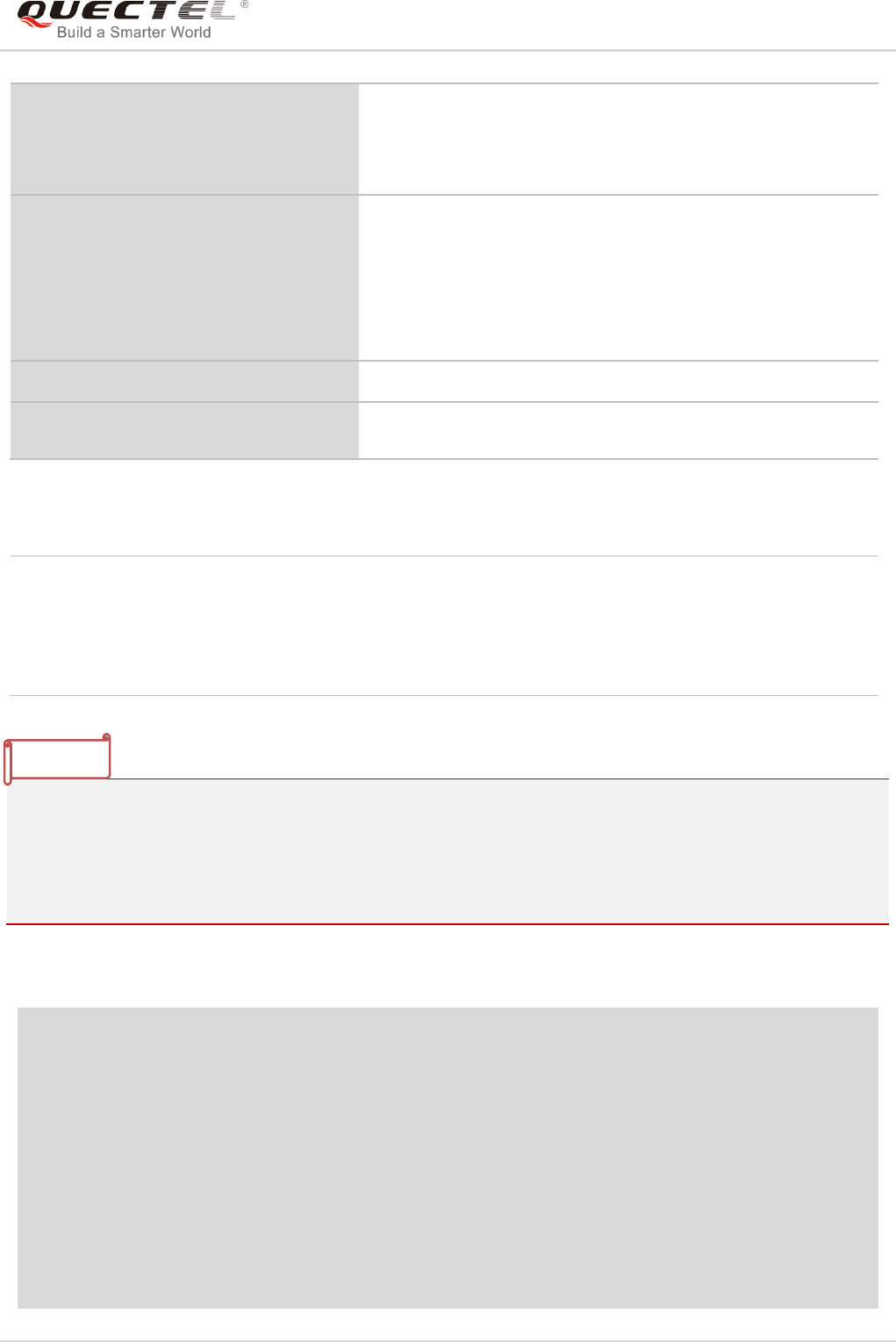
LTE Module Series
EC25&EC21 AT Commands Manual
EC25&EC21_AT_Commands_Manual 136 / 239
Parameter
<n> Parameter required only for PDU mode
0 Command operates similarly as in text mode
1 Send positive (RP-ACK) acknowledgement to the network. Accepted only in PDU mode
2 Send negative (RP-ERROR) acknowledgement to the network. Accepted only in PDU
mode
The Execution and Write Commands shall only be used when AT+CSMS parameter <service> equals 1
(phase 2+) and an appropriate URC has been issued by the module, i.e.:
+CMT for <mt>=2 incoming message classes 0,1,3 and none;
+CMT for <mt>=3 incoming message classes 0 and 3;
+CDS for <ds>=1.
Example
AT+CSMS=1
OK
AT+CNMI=1,2,0,0,0
OK
+CMT: “+8615021012496”,,“13/03/18,17:07:21+32”,145,4,0,0,“+8613800551500”,145,28
This is a test from Quectel. //Short message is outputted directly when an SMS is incoming.
AT+CNMA //Send ACK to the network
OK
AT+CNMA
+CMS ERROR:340 //The second time to return error. It needs ACK only once
ERROR
If there is any error related to ME functionality:
+CMS ERROR: <err>
Write Command
AT+CNMA=<n>
Response
OK
ERROR
If there is any error related to ME functionality:
+CMS ERROR: <err>
Maximum Response Time
300ms
Reference
3GPP TS 27.005
NOTE

LTE Module Series
EC25&EC21 AT Commands Manual
EC25&EC21_AT_Commands_Manual 137 / 239
9.13. AT+CNMI SMS Event Reporting Configuration
The Write Command selects the procedure on how the received new messages from the network are
indicated to the TE when TE is active, e.g. DTR is at low level (ON). If TE is inactive (e.g. DTR is at high
level (OFF)), message receiving should be done as specified in 3GPP TS 23.038.
Parameter
<mode> 0 Buffer unsolicited result codes in the TA. If TA result code buffer is full, indications
can be buffered in some other place or the oldest indications may be discarded
and replaced with the new received indications.
1 Discard indication and reject new received message unsolicited result codes
when TA-TE link is reserved (e.g. in on-line data mode). Otherwise forward them
directly to the TE.
2 Buffer unsolicited result codes in the TA when TA-TE link is reserved (e.g. in data
AT+CNMI SMS Event Reporting Configuration
Test Command
AT+CNMI=?
Response
+CNMI: (list of supported <mode>s),(list of supported
<mt>s),(list of supported <bm>s),(list of supported
<ds>s),(list of supported <bfr>s)
OK
Read Command
AT+CNMI?
Response
+CNMI: <mode>,<mt>,<bm>,<ds>,<bfr>
OK
Write Command
AT+CNMI[=<mode>[,<mt>[,<bm>[,<ds
>[,<bfr>]]]]]
Response
TA selects the procedure on how the received new messages
from the network are indicated to the TE when TE is active,
e.g. DTR is at low level (ON). If TE is inactive (e.g. DTR is at
high level (OFF)), message receiving should be done as
specified in 3GPP TS 23.038.
OK
ERROR
If there is any error related to ME functionality:
+CMS ERROR: <err>
Maximum Response Time
300ms
Reference
3GPP TS 27.005

LTE Module Series
EC25&EC21 AT Commands Manual
EC25&EC21_AT_Commands_Manual 138 / 239
mode) and flush them to the TE after reservation. Otherwise forward them directly
to the TE.
<mt> The rules for storing received SMS depend on its data coding scheme (refer to 3GPPTS
23.038) and preferred memory storage (AT+CPMS) setting, and the value is:
0 No SMS-DELIVER indications are routed to the TE.
1 If SMS-DELIVER is stored into ME/TA, indication of the memory location is routed
to the TE by using unsolicited result code: +CMTI: <mem>,<index>
2 SMS-DELIVERs (except class 2) are routed directly to the TE using unsolicited
result code: +CMT: [<alpha>],<length><CR><LF><pdu> (PDU mode enabled)
or +CMT: <oa>,[<alpha>],<scts>[,<tooa>,<fo>,<pid>,<dcs>,<sca>,<tosca>,
<length>]<CR><LF><data> (text mode enabled; about the parameters in italics,
please refer to AT+CSDH command) or ^HCMT:
<oa>,<scts>,<lang>,<fmt>,<length>,<prt>,<prv>,<type>,<stat><CR><LF><da
ta> (text mode for CDMA SMS). Class 2 messages result in indication as defined
in <mt>=1.
3 Class 3 SMS-DELIVERs are routed directly to TE by using unsolicited result
codes defined in <mt>=2. Messages of other classes result in indication as
defined in <mt>=1.
<bm> The rules for storing received CBMs depend on its data coding scheme (refer to 3GPP TS
23.038) and the setting of Select CBM Types (AT+CSCB), and the value is:
0 No CBM indications are routed to the TE.
2 New CBMs are routed directly to the TE using unsolicited result code:
+CBM: <length><CR><LF><pdu> (PDU mode); or
+CBM: <sn>,<mid>,<dcs>,<page>,<pages><CR><LF><data> (text mode)
<ds> 0 No SMS-STATUS-REPORTs are routed to the TE.
1 SMS-STATUS-REPORTs are routed to the TE using unsolicited result code:
+CDS: <length><CR><LF><pdu> (PDU mode)
+CDS: <fo>,<mr>,[<ra>],[<tora>],<scts>,<dt>,<st> (text mode)
2 If SMS-STATUS-REPORT is stored into ME/TA, indication of the memory location
is routed to the TE using unsolicited result code:
+CDSI: <mem>,<index>
<bfr> 0 TA buffer of unsolicited result codes defined within this command is flushed to the
TE when <mode> 1...2 is entered (OK response shall be given before flushing the
codes).
1 TA buffer of unsolicited result codes defined within this command is cleared when
<mode> 1...2 is entered.
Unsolicited result code:
+CMTI: <mem>,<index> Indicates that new message has been received
+CMT: [<alpha>],<length><CR><LF><pdu> Short message is outputted directly
+CBM: <length><CR><LF><pdu> Cell broadcast message is outputted directly
NOTE

LTE Module Series
EC25&EC21 AT Commands Manual
EC25&EC21_AT_Commands_Manual 139 / 239
Example
AT+CMGF=1 //Set SMS message format as text mode
OK
AT+CSCS=“GSM” //Set character set as GSM which is used by the TE
OK
AT+CNMI=1,2,0,1,0 //Set SMS-DELIVERs are routed directly to the TE
OK
+CMT: “+8615021012496”,,“13/03/18,17:07:21+32”,145,4,0,0,“+8613800551500”,145,28
This is a test from Quectel. //Short message is outputted directly when an SMS is incoming.
9.14. AT+CSCB Select Cell Broadcast Message Types
The Write Command selects which types of CBMs are to be received by the ME. The command writes the
parameters in NON-VOLATILE memory.
Parameter
AT+CSCB Select Cell Broadcast Message Types
Test Command
AT+CSCB=?
Response
It returns supported modes as a compound value.
+CSCB: (list of supported <mode>s)
OK
Read Command
AT+CSCB?
Response
+CSCB : <mode>,<mids>,<dcss>
OK
Write Command
AT+CSCB=<mode>[,mids>[,<dcss>]]
Response
TA selects which types of CBMs are to be received by the ME.
OK
If there is any error related to ME functionality:
+CMS ERROR: <err>
Maximum Response Time
300ms
Reference
3GPP TS 27.005
<mode> 0 Message types specified in <mids> and <dcss> are accepted
1 Message types specified in <mids> and <dcss> are not accepted

LTE Module Series
EC25&EC21 AT Commands Manual
EC25&EC21_AT_Commands_Manual 140 / 239
9.15. AT+CSDH Show SMS Text Mode Parameters
The Write Command controls whether detailed header information is shown in text mode result codes.
Parameter
<show> 0 Do not show header values defined in commands +CSCA, +CSMP (<sca>,
<tosca>, <fo>, <vp>, <pid>, <dcs>) and <length>, <toda> or <tooa> in +CMT,
+CMGL, +CMGR result codes for SMS-DELIVERs and SMS-SUBMITs in text
mode
1 Show the values in result codes
Example
AT+CSDH=0
OK
AT+CMGR=2
+CMGR: “STO UNSENT” ,“”,
<This is a test from Quectel>
<mids> String type. All different possible combinations of CBM message identifiers (refer to <mid>)
(default is empty string), e.g. “0,1,5,320-478,922”
<dcss> String type. All different possible combinations of CBM data coding schemes (refer to
<dcs>) (default is empty string), e.g. “0-3,5”
AT+CSDH Show SMS Text Mode Parameters
Test Command
AT+CSDH=?
Response
+CSDH: (list of supported <show>s)
OK
Read Command
AT+CSDH?
Response
+CSDH: <show>
OK
Write Command
AT+CSDH[=<show>]
Response
OK
ERROR
Maximum Response Time
300ms
Reference
3GPP TS 27.005
LTE Module Series
EC25&EC21 AT Commands Manual
EC25&EC21_AT_Commands_Manual 141 / 239
OK
AT+CSDH=1
OK
AT+CMGR=2
+CMGR: “STO UNSENT”,“”,,128,17,0,0,143,“+8613800551500”,145,18
<This is a test from Quectel>
OK
9.16. AT+CSMP Set SMS Text Mode Parameters
The command is used to set values for additional parameters needed when a short message is sent to
the network or placed in a storage in text mode.
Parameter
AT+CSMP Set SMS Text Mode Parameters
Test Command
AT+CSMP=?
Response
OK
Read Command
AT+CSMP?
Response
+CSMP: <fo>,<vp>,<pid>,<dcs>
OK
Write Command
AT+CSMP=<fo>[,<vp>[,<pid>[,<dcs>]]
]
Response
TA selects values for additional parameters needed when SM
is sent to the network or placed in a storage when text mode
is selected (AT+CMGF=1). It is possible to set the validity
period starting from when the SM is received by the SMSC
(<vp> ranges from 0 to 255) or define the absolute time of the
validity period termination (<vp> is a string).
OK
Maximum Response Time
300ms
Reference
3GPP TS 27.005
<fo> First octet. Depending on the command or result code: First octet of 3GPP TS 23.040
SMS-DELIVER, SMS-SUBMIT (default 17), SMS-STATUS-REPORT, SMS-COMMAND
in integer format. If a valid value has been entered once, parameter can be omitted.
<vp> Validity period. Depending on SMS-SUBMIT <fo> setting: 3GPP TS 23.040
TP-Validity-Period either in integer format or in time-string format (refer to <dt>).

LTE Module Series
EC25&EC21 AT Commands Manual
EC25&EC21_AT_Commands_Manual 142 / 239
9.17. AT+QCMGS Send Concatenated Messages
The command is used to send concatenated massages. Different from AT+CMGS, when sending a
concatenated message via this command, each segment of the concatenated message must be identified
by the additional parameters: <uid>, <msg_seg> and <msg_total>. When sending all segments of the
message one by one, AT+QCMGS must be executed multiple times (equal to <msg_total>) for each
segment. This command is only used in text mode (AT+CMGF=1).
Parameter
<uid> Message identification in the user data header (UDH). Range: 0-255. This
parameter is defined and inputted by the user. All segments of a same
concatenated message must have the same <uid>. Different concatenated
messages should have different <uid>.
<msg_seg> Sequence number of a concatenated message. Range: 0-7.
<msg_seg>=0 means: ignore the value and regard it as a non-concatenated
message.
<msg_total> The total number of the segments of one concatenated message. Range: 0-7.
<msg_total>=0 or 1 means: ignore the value and regard it as a
non-concatenated message.
<da> Please refer to AT+CMGS.
<toda> Please refer to AT+CMGS.
<pid> Protocol identifier. 3GPP TS 23.040 TP-Protocol-Identifier in integer format (default 0).
<dcs> Data coding scheme. Depending on the command or result code: 3GPP TS 23.038
SMS Data Coding Scheme (default 0), or Cell Broadcast Data Coding Scheme in
integer format.
AT+QCMGS Send Concatenated Messages
Test Command
AT+QCMGS=?
Response
OK
Write Command
If text mode (+CMGF=1):
AT+QCMGS=<da>[,<toda>][,<uid>,<m
sg_seg>,<msg_total>]<CR>
text is entered
<Ctrl+Z/ESC>
Response
If in text mode (AT+CMGF=1) and sent successfully:
+QCMGS: <mr>
OK
ERROR
If there is any error related to ME functionality:
+CMS ERROR: <err>
Maximum Response Time
120s, determined by network.

LTE Module Series
EC25&EC21 AT Commands Manual
EC25&EC21_AT_Commands_Manual 143 / 239
<mr> Please refer to AT+CMGS.
1. For concatenated messages, the maximum length will be reduced by the length of the user data
header (UDH). 3GPP TS 23.040 defines two kinds of UDH length: 6 bytes and 7 bytes, so the two
kinds of <uid> are 8-bit (6 bytes) and 16-bit (7 bytes). AT+QCMGS uses 8-bit <uid>.
- In the case of GSM 7 bit default alphabet data coding scheme, the maximum length of each
segment of a concatenated message is (140 octets - 6 )*8/7=153 characters.
- In the case of 16 bit UCS2 data coding scheme, the maximum length of each segment is
(140-6)/2=67 characters.
- In the case of 8-bit data coding scheme, the maximum length of each segment is 140-6=134
characters.
2. <mr> Message-Reference field gives an integer representation of a reference number of the
SMS-SUBMIT or SMS-COMMAND submitted to the SC by the MS, and it is used to confirm
whether the SMS-DELIVER has been received from SC duplicate or not.
<uid> The field of UDH. It is message identification of the concatenated SMS, which is different
from <mr>. Each segment in a concatenated message should have the same <uid>, but
<mr> must be incremented for each segment of a concatenated message.
3. AT+QCMGS does not support to send message in PDU mode (AT+CMGF=0).
Example
AT+CMGF=1 //Set SMS message format as text mode
OK
AT+CSCS="GSM" //Set character set as GSM which is used by the TE
OK
AT+QCMGS="15056913384",120,1,2 <CR> //Input 120 for <uid>, and send the first segment of the
concatenated SMS
>ABCD<Ctrl-Z>
+QCMGS: 190
OK
AT+QCMGS="15056913384",120,2,2 <CR> //Send the second segment of the concatenated SMS.
>EFGH<Ctrl-Z>
+QCMGS: 191
OK
NOTES

LTE Module Series
EC25&EC21 AT Commands Manual
EC25&EC21_AT_Commands_Manual 144 / 239
9.18. AT+QCMGR Read Concatenated Messages
The function of this command is similar to AT+CMGR, except that the message to be read is a segment of
concatenated messages, and parameters <uid>, <msg_seg> and <msg_total> would be shown in the
result. Several segments should be concatenated to a whole concatenated message according to these
three parameters. Similar to AT+QCMGS, AT+QCMGR is only used in text mode (AT+CMGF=1).
AT+QCMGR Read Concatenated Messages
Test Command
AT+QCMGR=?
Response
OK
Write Command
AT+QCMGR=<index>
Response
If in text mode (AT+CMGF=1) and command is executed
successfully:
For SMS-DELIVER:
+QCMGR:
<stat>,<oa>,[<alpha>],<scts>[,<tooa>,<fo>,<pid>,<dcs>,<
sca>,<tosca>,<length>][,<uid>,<msg_seg>,<msg_total>]
<CR><LF><data>
OK
For SMS-SUBMIT:
+QCMGR:
<stat>,<da>,[<alpha>][,<toda>,<fo>,<pid>,<dcs>,[<vp>],<
sca>,<tosca>,<length>][,<uid>,<msg_seg>,<msg_total>]
<CR><LF><data>
OK
For SMS-STATUS-REPORTs:
+QCMGR:
<stat>,<fo>,<mr>,[<ra>],[<tora>],<scts>,<dt>,<st>
OK
For SMS-COMMANDs:
+QCMGR:
<stat>,<fo>,<ct>[,<pid>,[<mn>],[<da>],[<toda>],<length><
CR><LF><cdata>]
OK
Else, If there is any error related to ME functionality:
+CMS ERROR: <err>
Maximum Response Time
Depends on the length of message content.

LTE Module Series
EC25&EC21 AT Commands Manual
EC25&EC21_AT_Commands_Manual 145 / 239
Parameter
<uid> Message identification in the user data header (UDH). Range: 0-65535 (see NOTES).
All segments of a same concatenated message have same <uid>. Different
concatenated messages should have different <uid>.
<msg_seg> Sequence number of a concatenated message. Range: 1-7.
<msg_total> The total number of the segments of one concatenated message. Range: 2-7.
Other parameters please refer to AT+CMGR
1. The <uid> in AT+QCMGR is different from the <uid> in AT+QCMGS. It is possible that UE receives
concatenated messages with 8-bit or 16-bit <uid>. So its maximal value is 255 with 8-bit and 65535
with 16-bit.
2. If the message to be read is not a concatenated message, <uid>, <msg_seg> and <msg_total>
would not be shown in the result.
Example
+CMTI: "SM",3 //The first message of a concatenated message comes
+CMTI: "SM",4 //The second message of a concatenated message comes
AT+QCMGR= 3 //Read the first segment of the concatenated message
+QCMGR: "REC UNREAD","+8615056913384",,"13/07/30,14:44:37+32",120,1,2
ABCD
OK
AT+QCMGR= 4 //Read the second segment of the concatenated message
+QCMGR: "REC UNREAD","+8615056913384",,"13/07/30,14:44:37+32",120,2,2
EFGH
OK
NOTES

LTE Module Series
EC25&EC21 AT Commands Manual
EC25&EC21_AT_Commands_Manual 146 / 239
10 Packet Domain Commands
10.1. AT+CGATT Attachment or Detachment of PS
The Write Command is used to attach the MT to, or detach the MT from the Packet Domain service. After
the command has been completed, the MT remains in V.25ter command state. If the MT is already in the
requested state, the command is ignored and the OK response will be returned. If the requested state
cannot be achieved, an ERROR or +CME ERROR response is returned.
Parameter
AT+CGATT Attachment or Detachment of PS
Test Command
AT+CGATT=?
Response
+CGATT: (list of supported <state>s)
OK
Read Command
AT+CGATT?
Response
+CGATT: <state>
OK
Write Command
AT+CGATT=<state>
Response
OK
If there is any error related to ME functionality:
+CME ERROR: <err>
Maximum Response Time
140s, determined by network.
Reference
3GPP TS 27.007
<state> Indicates the state of PS attachment
0 Detached
1 Attached
Other values are reserved and will result in an ERROR response to the Write Command

LTE Module Series
EC25&EC21 AT Commands Manual
EC25&EC21_AT_Commands_Manual 147 / 239
Example
AT+CGATT=1 //Attach to PS service
OK
AT+CGATT=0 //Detach from PS service
OK
AT+CGATT? //Query the current PS service state
+CGATT: 0
OK
10.2. AT+CGDCONT Define PDP Context
The command specifies PDP context parameters for a specific context <cid>. A special form of the Write
Command (AT+CGDCONT=<cid>) causes the values for context <cid> to become undefined. It is not
allowed to change the definition of an already activated context.
The Read Command returns the current settings for each defined PDP context.
AT+CGDCONT Define PDP Context
Test Command
AT+CGDCONT=?
Response
+CGDCONT: (range of supported <cid>s),<PDP_type>,
<APN>,<PDP_addr>,(list of supported <data_comp>s),(list
of supported <head_comp>s)
OK
Read Command
AT+CGDCONT?
Response
+CGDCONT:
<cid>,<PDP_type>,<APN>,<PDP_addr>,<data_comp>,<h
ead_comp>[…]
OK
Write Command
AT+CGDCONT=<cid>[,<PDP_type>[,<
APN>[,<PDP_addr>[,<data_comp>[,<
head_comp>]]]]]
Response
OK
ERROR
Maximum Response Time
300ms
Reference
3GPP TS 27.007

LTE Module Series
EC25&EC21 AT Commands Manual
EC25&EC21_AT_Commands_Manual 148 / 239
Parameter
10.3. AT+CGQREQ Quality of Service Profile (Requested)
The command allows the TE to specify the quality of service profile that is used when the MT activates a
PDP context.
The Write Command specifies a profile for the context <cid>. A special form of the Write Command,
AT+CGQREQ=<cid> causes the requested profile for context number <cid> to become undefined. The
Read Command returns the current settings for each defined context. Details can be found in 3GPP TS
23.107 and all parameters are saved in NV automatically.
<cid> PDP context identifier. A numeric parameter which specifies a particular PDP context
definition. The parameter is local to the TE-MT interface and is used in other PDP
context-related commands. The range of permitted values (minimum value=1) is
returned by the test form of the command.
<PDP_type> Packet data protocol type, a string parameter which specifies the type of packet data
protocol.
“IP” IPV4
“PPP”
“IPV6”
“IPV4V6”
<APN> Access point name, a string parameter that is a logical name used to select the GGSN
or the external packet data network. If the value is null or omitted, then the
subscription value will be requested.
<PDP_addr> A string parameter identifies the MT in the address space applicable to the PDP. If the
value is null or omitted, then a value may be provided by the TE during the PDP startup
procedure or, failing that, a dynamic address will be requested. The allocated address
may be read using the AT+CGPADDR command.
<data_comp> A numeric parameter that controls PDP data compression (applicable for SNDCP only)
(refer to 3GPP TS 44.065).
0 Off (Default if value is omitted)
1 On (Manufacturer preferred compression)
2 V.42bis
3 V.44 (Not supported currently)
<head_comp> A numeric parameter that controls PDP header compression (refer to 3GPP TS 44.065
and 3GPP TS 25.323).
0 Off
1 On
2 RFC1144
3 RFC2507
4 RFC3095

LTE Module Series
EC25&EC21 AT Commands Manual
EC25&EC21_AT_Commands_Manual 149 / 239
Parameter
AT+CGQREQ Quality of Service Profile (Requested)
Test Command
AT+CGQREQ=?
Response
+CGQREQ: <PDP_type>,
(list of supported <precedence>s),
(list of supported <delay>s),
(list of supported <reliability>s),
(list of supported <peak>s),
(list of supported <mean>s)
OK
Read Command
AT+CGQREQ?
Response
[+CGQREQ:
<cid>,<precedence>,<delay>,>reliability>,<peak>,<mean
>]
[+CGQREQ:
<cid>,<precedence>,<delay>,<reliability>,<peak>,<mean
>]
[…]
OK
Write Command
AT+CGQREQ=<cid>[,<precedence>[,
<delay>[,<reliability>[,<peak>[,<mean
>]]]]]
Response
OK
If there is any error related to ME functionality:
+CME ERROR: <err>
Maximum Response Time
300ms
Reference
3GPP TS 27.007
<cid> A numeric parameter which specifies a particular PDP context definition (see
AT+CGDCONT command)
<PDP_type> Packet Data Protocol type
“IP” Internet Protocol (IETF STD 5)
“PPP”
“IPV6”
“IPV4V6”
<precedence> A numeric parameter which specifies the precedence class
0 Network subscribed value
1 High Priority. Service commitments shall be maintained ahead of precedence
classes 2 and 3

LTE Module Series
EC25&EC21 AT Commands Manual
EC25&EC21_AT_Commands_Manual 150 / 239
2 Normal priority. Service commitments shall be maintained ahead of
precedence class 3
3 Low priority. Service commitments shall be maintained
<delay> A numeric parameter which specifies the delay class. This parameter defines the
end-to-end transfer delay incurred in the transmission of SDUs through the network.
For the details, please refer to Table 5.
0 Network subscribed value
<reliability> A numeric parameter which specifies the reliability class
0 Network subscribed value
1 Non real-time traffic, error-sensitive application that cannot cope with data loss
2 Non real-time traffic, error-sensitive application that can cope with infrequent
data loss
3 Non real-time traffic, error-sensitive application that can cope with data loss,
GMM/SM, and SMS
4 Real-time traffic, error-sensitive application that can cope with data loss
5 Real-time traffic, error non-sensitive application that can cope with data loss
<peak> A numeric parameter which specifies the peak throughput class, in octets per second.
0 Network subscribed value
1 Up to 1 000 (8 kbit/s)
2 Up to 2 000 (16 kbit/s)
3 Up to 4 000 (32 kbit/s)
4 Up to 8 000 (64 kbit/s)
5 Up to 16 000 (128 kbit/s)
6 Up to 32 000 (256 kbit/s)
7 Up to 64 000 (512 kbit/s)
8 Up to 128 000 (1024 kbit/s)
9 Up to 256 000 (2048 kbit/s)
<mean> A numeric parameter which specifies the mean throughput class, in octets per hour.
0 Network subscribed value
1 100 (~0.22 bit/s)
2 200 (~0.44 bit/s)
3 500 (~1.11 bit/s)
4 1 000 (~2.2 bit/s)
5 2 000 (~4.4 bit/s)
6 5 000 (~11.1 bit/s)
7 10 000 (~22 bit/s)
8 20 000 (~44 bit/s)
9 50 000 (~111 bit/s)
10 100 000 (~0.22 kbit/s)
11 200 000 (~0.44 kbit/s)
12 500 000(~1.11 kbit/s)
13 1000 000 (~2.2 kbit/s)
14 2 000 000 (~4.4 kbit/s)
15 5 000 000 (~11.1 kbit/s)

LTE Module Series
EC25&EC21 AT Commands Manual
EC25&EC21_AT_Commands_Manual 151 / 239
Table 5: Delay Class
10.4. AT+CGQMIN Quality of Service Profile (Minimum Acceptable)
The command allows the TE to specify a minimum acceptable profile which is checked by the MT against
the negotiated profile when the PDP context is activated. The write command specifies a profile for the
context identified by the context identification parameter <cid>.
A special form of the write command, AT+CGQMIN=<cid> causes the minimum acceptable profile for
context number <cid> to become undefined. In this case no check is made against the negotiated profile.
The read command returns the current settings for each defined context. Details can be found in 3GPP
TS 23.107 and all parameters are saved in NV automatically.
16 10 000 000 (~22 kbit/s)
17 20 000 000 (~44 kbit/s)
18 50 000 000 (~111 kbit/s)
31 Best effort
SDU Size
Delay Class
Mean Transfer Delay
95 Percentile
128 octets
1 (Predictive)
<0.5
<1.5
2 (Predictive)
<5
<25
3 (Predictive)
<50
<250
4 (Best Effort)
Unspecified
-
1024 octets
1 (Predictive)
<0.5
<1.5
2 (Predictive)
<5
<25
3 (Predictive)
<50
<250
4 (Best Effort)
Unspecified
-
AT+CGQMIN Quality of Service Profile (Minimum Acceptable)
Test Command
AT+CGQMIN=?
Response
+CGQMIN: <PDP_type>,
(list of supported <precedence>s),
(list of supported <delay>s),
(list of supported <reliability>s),

LTE Module Series
EC25&EC21 AT Commands Manual
EC25&EC21_AT_Commands_Manual 152 / 239
Parameter
(list of supported <peak>s),
(list of supported <mean>s)
OK
Read Command
AT+CGQMIN?
Response
[+CGQMIN:
<cid>,<precedence>,<delay>,<reliability>,<peak>,<mean
>]
[+CGQMIN:
<cid>,<precedence>,<delay>,<reliability>,<peak>,<mean
>]
[…]
OK
Write Command
AT+CGQMIN=<cid>[,<precedence>[,<
delay>[,<reliability>[,<peak>[,<mean>
]]]]]
Response
OK
If there is any error related to ME functionality:
+CME ERROR: <err>
Maximum Response Time
300ms
Reference
3GPP TS 27.007
<cid> A numeric parameter which specifies a particular PDP context definition (see
AT+CGDCONT command)
<PDP_type> Packet Data Protocol type
“IP” IPV4. Internet Protocol (IETF STD 5)
“PPP”
“IPV6”
“IPV4V6”
<precedence> A numeric parameter which specifies the precedence class
0 Network subscribed value
1 High Priority. Service commitments shall be maintained ahead of precedence
classes 2 and 3
2 Normal priority. Service commitments shall be maintained ahead of
precedence class 3
3 Low priority. Service commitments shall be maintained
<delay> A numeric parameter which specifies the delay class. This parameter defines the
end-to-end transfer delay incurred in the transmission of SDUs through the network.
For the detail please refer to Table 5
0 Network subscribed value

LTE Module Series
EC25&EC21 AT Commands Manual
EC25&EC21_AT_Commands_Manual 153 / 239
<reliability> A numeric parameter which specifies the reliability class.
0 Network subscribed value
1 Non real-time traffic, error-sensitive application that cannot cope with data
loss
2 Non real-time traffic, error-sensitive application that can cope with infrequent
data loss
3 Non real-time traffic, error-sensitive application that can cope with data loss,
GMM/SM, and SMS
4 Real-time traffic, error-sensitive application that can cope with data loss
5 Real-time traffic, error non-sensitive application that can cope with data loss
<peak> A numeric parameter which specifies the peak throughput class, in octets per second.
0 Network subscribed value
1 Up to 1 000 (8 kbit/s)
2 Up to 2 000 (16 kbit/s)
3 Up to 4 000 (32 kbit/s)
4 Up to 8 000 (64 kbit/s)
5 Up to 16 000 (128 kbit/s)
6 Up to 32 000 (256 kbit/s)
7 Up to 64 000 (512 kbit/s)
8 Up to 128 000 (1024 kbit/s)
9 Up to 256 000 (2048 kbit/s)
<mean> A numeric parameter which specifies the mean throughput class, in octets per hour.
0 Network subscribed value
1 100 (~0.22 bit/s)
2 200 (~0.44 bit/s)
3 500 (~1.11 bit/s)
4 1 000 (~2.2 bit/s)
5 2 000 (~4.4 bit/s)
6 5 000 (~11.1 bit/s)
7 10 000 (~22 bit/s)
8 20 000 (~44 bit/s)
9 50 000 (~111 bit/s)
10 100 000 (~0.22 kbit/s)
11 200 000 (~0.44 kbit/s)
12 500 000(~1.11 kbit/s)
13 1000 000 (~2.2 kbit/s)
14 2 000 000 (~4.4 kbit/s)
15 5 000 000 (~11.1 kbit/s)
16 10 000 000 (~22 kbit/s)
17 20 000 000 (~44 kbit/s)
18 50 000 000 (~111 kbit/s)
31 Best effort

LTE Module Series
EC25&EC21 AT Commands Manual
EC25&EC21_AT_Commands_Manual 154 / 239
10.5. AT+CGEQREQ 3G Quality of Service Profile (Requested)
The command allows the TE to specify a UMTS Quality of Service Profile that is used when the MT
activates a PDP context. Details can be found in 3GPP TS 23.107 and all parameters are saved in NV
automatically.
AT+CGEQREQ 3G Quality of Service Profile (Requested)
Test Command
AT+CGEQREQ=?
Response
+CGEQREQ: <PDP_type>,
(list of supported <Traffic class>s),
(list of supported <Maximum bitrate UL>s),
(list of supported <Maximum bitrate DL>s),
(list of supported <Guaranteed bitrate UL>s),
(list of supported <Guaranteed bitrate DL>s),
(list of supported <Delivery order>s),
(list of supported <Maximum SDU size>s),
(list of supported <SDU error ratio>s),
(list of supported <Residual bit error ratio>s),
(list of supported <Delivery of erroneous SDUs>s),
(list of supported <Transfer delay>s),
(list of supported <Traffic handling priority>s),
(list of supported <Source statistics descriptor>s),
(list of supported <Signalling indication>s)
OK
Read Command
AT+CGEQREQ?
Response
[+CGEQREQ: <cid>,
<Traffic class>,
<Maximum bitrate UL>,
<Maximum bitrate DL>,
<Guaranteed bitrate UL>,
<Guaranteed bitrate DL>,
<Delivery order>,
<Maximum SDU size>,
<SDU error ratio>,
<Residual bit error ratio>,
<Delivery of erroneous SDUs>,
<Transfer delay>,
<Traffic handling priority>,
<Source statistics descriptor>,
<Signalling indication>]
[...]

LTE Module Series
EC25&EC21 AT Commands Manual
EC25&EC21_AT_Commands_Manual 155 / 239
Parameter
OK
Write Command
AT+CGEQREQ=[<cid>[,<Traffic
class>[,<Maximum bitrate UL>
[,<Maximum bitrate DL>
[,<Guaranteed bitrate UL>
[,<Guaranteed bitrate DL>
[,<Delivery order>
[,<Maximum SDU size>
[,<SDU error ratio>
[,<Residual bit error ratio>
[,<Delivery of erroneous SDUs>
[,<Transfer delay>
[,<Traffic handling priority>
[,<Source statistics descriptor>
[,<Signalling indication>]]]]]]]]]]]]]]]
Response
OK
ERROR
Maximum Response Time
300ms
Reference
3GPP TS 27.007
<cid> PDP context identifier, a numeric parameter which specifies a
particular PDP context definition. The parameter is local to the TE-MT
interface and is used in other PDP context-related commands. The
range of permitted values (minimum value=1) is returned by the test
form of the command
<PDP_type> Packet data protocol type, a string parameter which specifies the type
of packet data protocol
“IP” IPV4. Internet protocol (IETF STD 5)
“PPP”
“IPV6”
“IPV4V6”
The following parameters are defined in 3GPP TS 23.107
<Traffic class> Integer type. Indicates the type of application for which the UMTS
bearer service is optimized (refer to 3GPP TS 24.008 subclause
10.5.6.5). If the parameter is specified as conversational or streaming,
then the Guaranteed and Maximum bitrate parameters should also be
provided.
0 Conversational
1 Streaming
2 Interactive
3 Background

LTE Module Series
EC25&EC21 AT Commands Manual
EC25&EC21_AT_Commands_Manual 156 / 239
4 Subscribed value
<Maximum bitrate UL> Integer type. Indicates the maximum number of kbits/s delivered to
UMTS (up-link traffic) at a SAP. As an example a bit rate of 32kbit/s
would be specified as „32‟ (e.g. AT+CGEQREQ=…,32, …).
0 Subscribed value
1~5760
<Maximum bitrate DL> Integer type. Indicates the maximum number of kbits/s delivered by
UMTS (down-link traffic) at a SAP. As an example a bitrate of 32kbit/s
would be specified as „32‟ (e.g. AT+CGEQREQ=…,32, …).
0 Subscribed value
1~42200
<Guaranteed bitrate UL> Integer type. Indicates the guaranteed number of kbits/s delivered to
UMTS (up-link traffic) at a SAP (provided that there is data to deliver).
As an example a bitrate of 32kbit/s would be specified as „32‟ (e.g.
AT+CGEQREQ=…,32, …).
0 Subscribed value
1~5760
<Guaranteed bitrate DL> Integer type. Indicates the guaranteed number of kbits/s delivered by
UMTS (down-link traffic) at a SAP (provided that there is data to
deliver). As an example a bitrate of 32kbit/s would be specified as „32‟
(e.g. AT+CGEQREQ=…,32, …).
0 Subscribed value
1~42200
<Delivery order> Integer type. Indicates whether the UMTS bearer shall provide
in-sequence SDU delivery or not (refer to 3GPP TS 24.008 subclause
10.5.6.5).
0 No
1 Yes
2 Subscribed value
<Maximum SDU size> Integer type. (1,2,3,…) indicates the maximum allowed SDU size in
octets. If the parameter is set to „0‟ the subscribed value will be
requested (refer to 3GPP TS 24.008 subclause 10.5.6.5).
0 Subscribed value
10...1520 (Value needs to be divisible by 10 without remainder)
1520
<SDU error ratio> String type. Indicates the target value for the fraction of SDUs lost or
detected as erroneous. SDU error ratio is defined only for conforming
traffic. The value is specified as „mEe‟. As an example a target SDU
error ratio of 5*10-3 would be specified as “5E3” (e.g.
AT+CGEQREQ=…,"5E3",…).
“0E0” Subscribed value
“1E1”
“1E2”
“7E3”

LTE Module Series
EC25&EC21 AT Commands Manual
EC25&EC21_AT_Commands_Manual 157 / 239
“1E3”
“1E4”
“1E5”
“1E6”
<Residual bit error ratio> String type. Indicates the target value for the undetected bit error ratio
in the delivered SDUs. If no error detection is requested, Residual bit
error ratio indicates the bit error ratio in the delivered SDUs. The value
is specified as “mEe”. As an example a target residual bit error ratio of
5•10-3 would be specified as “5E3” (e.g.
AT+CGEQREQ=…,“5E3”,…).
“0E0” Subscribed value
“5E2”
“1E2”
“5E3”
“4E3”
“1E3”
“1E4”
“1E5”
“1E6”
“6E8”
<Delivery of erroneous SDUs> Integer type. Indicates whether SDUs detected as erroneous shall be
delivered or not (refer to 3GPP TS 24.008 subclause 10.5.6.5).
0 No
1 Yes
2 No detect
3 Subscribed value
<Transfer delay> Integer type. (0,1,2,…) indicates the targeted time between request to
transfer an SDU at one SAP to its delivery at the other SAP, in
milliseconds. If the parameter is set to „0‟ the subscribed value will be
requested (refer to 3GPP TS 24.008 subclause 10.5.6.5).
0 Subscribed value
100~150 (value needs to be divisible by 10 without remainder)
200~950 (value needs to be divisible by 50 without remainder)
1000~4000 (value needs to be divisible by 100 without remainder)
<Traffic handling priority> Integer type. (1,2,3,…) specifies the relative importance for handling of
all SDUs belonging to the UMTS bearer compared to the SDUs of
other bearers. If the parameter is set to „0‟ the subscribed value will be
requested (refer to 3GPP TS 24.008 subclause 10.5.6.5).
0 Subscribed
1
2
3
<Source statistics descriptor> Integer type. Specifies characteristics of the source of the submitted
SDUs for a PDP context.

LTE Module Series
EC25&EC21 AT Commands Manual
EC25&EC21_AT_Commands_Manual 158 / 239
10.6. AT+CGEQMIN 3G Quality of Service Profile (Minimum Acceptable)
The command allows the TE to specify a minimum acceptable profile, which is checked by the MT against
the negotiated profile returned in the PDP context establishment and PDP context modification
procedures. Details can be found in 3GPP TS 23.107 and all parameters are saved in NV automatically.
0 Characteristics of SDUs is unknown
1 Characteristics of SDUs correspond to a speech source
<Signalling indication> Integer type. Indicates signaling content of submitted SDUs for a PDP
context.
0 PDP context is not optimized for signaling
1 PDP context is optimized for signaling
AT+CGEQMIN 3G Quality of Service Profile (Minimum Acceptable)
Test Command
AT+CGEQMIN=?
Response
+CGEQMIN: <PDP_type>,
(list of supported <Traffic class>s),
(list of supported <Maximum bitrate UL>s),
(list of supported <Maximum bitrate DL>s),
(list of supported <Guaranteed bitrate UL>s),
(list of supported <Guaranteed bitrate DL>s),
(list of supported <Delivery order>s),
(list of supported <Maximum SDU size>s),
(list of supported <SDU error ratio>s),
(list of supported <Residual bit error ratio>s),
(list of supported <Delivery of erroneous SDUs>s),
(list of supported <Transfer delay>s),
(list of supported <Traffic handling priority>s),
(list of supported <Source statistics descriptor>s),
(list of supported <Signalling indication>s)
OK
Read Command
AT+CGEQMIN?
Response
[+CGEQMIN: <cid>,
<Traffic class>,
<Maximum bitrate UL>,
<Maximum bitrate DL>,
<Guaranteed bitrate UL>,
<Guaranteed bitrate DL>,
<Delivery order>,
<Maximum SDU size>,
<SDU error ratio>,

LTE Module Series
EC25&EC21 AT Commands Manual
EC25&EC21_AT_Commands_Manual 159 / 239
Parameter
<Residual bit error ratio>,
<Delivery of erroneous SDUs>,
<Transfer delay>,
<Traffic handling priority>,
<Source statistics descriptor>,
<Signalling indication>]
[…]
OK
Write Command
AT+CGEQMIN=[<cid>[,<Traffic class>
[,<Maximum bitrate UL>
[,<Maximum bitrate DL>
[,<Guaranteed bitrate UL>
[,<Guaranteed bitrate DL>
[,<Delivery order>
[,<Maximum SDU size>
[,<SDU error ratio>
[,<Residual bit error ratio>
[,<Delivery of erroneous SDUs>
[,<Transfer delay>
[,<Traffic handling priority>
[,<Source statistics descriptor>
[,<Signalling indication>]]]]]]]]]]]]]]]
Response
OK
If there is any error related to ME functionality:
+CME ERROR: <err>
Maximum Response Time
300ms
Reference
3GPP TS 27.007
<cid> PDP context identifier. A numeric parameter which specifies a
particular PDP context definition. The parameter is local to the TE-MT
interface and is used in other PDP context-related commands. The
range of permitted values (minimum value=1) is returned by the test
form of the command
<PDP_type> Packet data protocol type. A string parameter which specifies the type
of packet data protocol.
“IP” IPV4
“PPP”
“IPV6”
“IPV4V6”
The following parameters are defined in 3GPP TS 23.107

LTE Module Series
EC25&EC21 AT Commands Manual
EC25&EC21_AT_Commands_Manual 160 / 239
<Traffic class> Integer type. Indicates the type of application for which the UMTS
bearer service is optimized (refer to 3GPP TS 24.008 subclause
10.5.6.5). If the parameter is specified as conversational or streaming,
then the Guaranteed and Maximum bitrate parameters should also be
provided.
0 Conversational
1 Streaming
2 Interactive
3 Background
4 Subscribed value
<Maximum bitrate UL> Integer type. Indicates the maximum number of kbits/s delivered to
UMTS (up-link traffic) at a SAP. As an example a bitrate of 32kbit/s
would be specified as „32‟ (e.g. AT+CGEQREQ=…,32, …).
0 Subscribed value
1~5760
<Maximum bitrate DL> Integer type. Indicates the maximum number of kbits/s delivered by
UMTS (down-link traffic) at a SAP. As an example a bitrate of 32kbit/s
would be specified as „32‟ (e.g. AT+CGEQREQ=…,32, …).
0 Subscribed value
1~42200
<Guaranteed bitrate UL> Integer type. Indicates the guaranteed number of kbits/s delivered to
UMTS (up-link traffic) at a SAP (provided that there is data to deliver).
As an example a bitrate of 32kbit/s would be specified as „32‟ (e.g.
AT+CGEQREQ=…,32, …).
0 Subscribed value
1~5760
<Guaranteed bitrate DL> Integer type. Indicates the guaranteed number of kbits/s delivered by
UMTS (down-link traffic) at a SAP (provided that there is data to
deliver). As an example a bitrate of 32kbit/s would be specified as „32‟
(e.g. AT+CGEQREQ=…,32, …).
0 Subscribed value
1~42200
<Delivery order> Integer type. Indicates whether the UMTS bearer shall provide
in-sequence SDU delivery or not (refer to 3GPP TS 24.008 subclause
10.5.6.5).
0 No
1 Yes
2 Subscribed value
<Maximum SDU size> Integer type. (1,2,3,…) indicates the maximum allowed SDU size in
octets. If the parameter is set to „0‟ the subscribed value will be
requested (refer to 3GPP TS 24.008 subclause 10.5.6.5).
0 Subscribed value
10...1520 (value needs to be divisible by 10 without remainder)
1502

LTE Module Series
EC25&EC21 AT Commands Manual
EC25&EC21_AT_Commands_Manual 161 / 239
<SDU error ratio> String type. Indicates the target value for the fraction of SDUs lost or
detected as erroneous. SDU error ratio is defined only for conforming
traffic. The value is specified as „mEe‟. As an example a target SDU
error ratio of 5*10-3 would be specified as “5E3” (e.g.
AT+CGEQREQ=…,”5E3”,…).
“0E0” Subscribed value
“1E2”
“7E3”
“1E3”
“1E4”
“1E5”
“1E6”
“1E1”
<Residual bit error ratio> String type. Indicates the target value for the undetected bit error ratio
in the delivered SDUs. If no error detection is requested, Residual bit
error ratio indicates the bit error ratio in the delivered SDUs. The value
is specified as “mEe”. As an example a target residual bit error ratio of
5•10-3 would be specified as “5E3” (e.g.
AT+CGEQREQ=…,”5E3”,…).
“0E0” Subscribed value
“5E2”
“1E2”
“5E3”
“4E3”
“1E3”
“1E4”
“1E5”
“1E6”
“6E8”
<Delivery of erroneous SDUs> Integer type. Indicates whether SDUs detected as erroneous shall be
delivered or not (refer to 3GPP TS 24.008 subclause 10.5.6.5).
0 No
1 Yes
2 No detect
3 Subscribed value
<Transfer delay> Integer type. (0,1,2,…) indicates the targeted time between request to
transfer an SDU at one SAP to its delivery at the other SAP, in
milliseconds. If the parameter is set to „0‟ the subscribed value will be
requested (refer to 3GPP TS 24.008 subclause 10.5.6.5).
0 Subscribed value
100~150 (value needs to be divisible by 10 without remainder)
200~950 (value needs to be divisible by 50 without remainder)
1000~4000 (value needs to be divisible by 100 without remainder)
<Traffic handling priority> Integer type. (1,2,3,…) specifies the relative importance for handling of

LTE Module Series
EC25&EC21 AT Commands Manual
EC25&EC21_AT_Commands_Manual 162 / 239
10.7. AT+CGACT Activate or Deactivate PDP Context
The Write Command is used to activate or deactivate the specified PDP context(s). After the command
has been completed, the MT remains in V.250 command state. If any PDP context is already in the
requested state, the state for that context remains unchanged. If the MT is not PS attached when the
activation form of the command is executed, the MT first performs a PS attach and then attempts to
activate the specified contexts. If no <cid>s specify the activation/deactivation form of the command, it
will activate or deactivate all defined contexts.
all SDUs belonging to the UMTS bearer compared to the SDUs of
other bearers. If the parameter is set to „0‟ the subscribed value will be
requested (refer to 3GPP TS 24.008 subclause 10.5.6.5).
0 Subscribed
1
2
3
<Source statistics descriptor> Integer type. Specifies characteristics of the source of the submitted
SDUs for a PDP context.
0 Characteristics of SDUs are unknown
1 Characteristics of SDUs corresponds to a speech source
<Signalling indication> Integer type. Indicates signaling content of submitted SDUs for a PDP
context.
0 PDP context is not optimized for signaling
1 PDP context is optimized for signaling
AT+CGACT Activate or Deactivate PDP Context
Test Command
AT+CGACT=?
Response
+CGACT: (list of supported <state>s)
OK
Read Command
AT+CGACT?
Response
+CGACT: <cid>,<state>[<CR><LF>+CGACT: <cid>,<state
>…]
OK
Write Command
AT+CGACT=<state>,<cid>
Response
OK
NO CARRIER
If there is any error related to ME functionality:
+CME ERROR: <err>

LTE Module Series
EC25&EC21 AT Commands Manual
EC25&EC21_AT_Commands_Manual 163 / 239
Parameter
Example
AT+CGDCONT=1,“IP”,“UNINET” //Define PDP context
OK
AT+CGACT=1,1 //Activated PDP
OK
AT+CGACT=0,1 //Deactivated PDP
OK
10.8. AT+CGDATA Enter Data State
The Write Command causes the MT to perform whatever actions that are necessary to establish
communication between the TE and the network using one or more packet domain PDP types. This may
include per-forming a PS attach and one or more PDP context activations. Commands following the
AT+CGDATA command in the AT command line will not be processed by the MT.
If the <L2P> parameter value is unacceptable to the MT, the MT shall return an ERROR or +CME ERROR
response. Otherwise, the MT issues the intermediate result code CONNECT and enters V.250 online data
state. After data transfer is completed, and the layer 2 protocol termination procedure has been
completed successfully, the command state is reentered and the MT returns the final result code OK.
Maximum Response Time
150s, determined by network.
Reference
3GPP TS 27.007
<state> Indicates the state of PDP context activation
0 Deactivated
1 Activated
Other values are reserved and will result in an ERROR response to the Write Command
<cid> A numeric parameter which specifies a particular PDP context definition (see
AT+CGDCONT command)
AT+CGDATA Enter Data State
Test Command
AT+CGDATA=?
Response
+CGDATA: (list of supported <L2P>s)
OK
Write Command
AT+CGDATA=<L2P>[,<cid>[,<cid>[,…
Response
CONNECT

LTE Module Series
EC25&EC21 AT Commands Manual
EC25&EC21_AT_Commands_Manual 164 / 239
Parameter
10.9. AT+CGPADDR Show PDP Address
The Write Command returns a list of PDP addresses for the specified context identifiers. If no <cid> is
specified, the addresses for all defined contexts are returned.
]]]
ERROR
If there is any error related to ME functionality:
+CME ERROR: <err>
Maximum Response Time
300ms
Reference
3GPP TS 27.007
<L2P> A string parameter that indicates the layer 2 protocol to be used between the TE and MT:
PPP (Point to Point protocol) for a PDP such as IP
Other values are not supported and will result in an ERROR response to the execution
command
<cid> A numeric parameter which specifies a particular PDP context definition (see
AT+CGDCONT command)
AT+CGPADDR Show PDP Address
Test Command
AT+CGPADDR=?
Response
+CGPADDR: (list of defined <cid>s)
OK
Write Command
AT+CGPADDR[=<cid>[,<cid>[,…]]]
Response
+CGPADDR: <cid>,<PDP_addr>
[+CGPADDR: <cid>,<PDP_addr>[…]]
OK
ERROR
Maximum Response Time
300ms
Reference
3GPP TS 27.007

LTE Module Series
EC25&EC21 AT Commands Manual
EC25&EC21_AT_Commands_Manual 165 / 239
Parameter
Example
AT+CGDCONT=1,“IP”,“UNINET” //Define PDP context
OK
AT+CGACT=1,1 //Activated PDP
OK
AT+CGPADDR=1 //Show PDP address
+CGPADDR: 1,“10.76.51.180”
OK
10.10. AT+CGCLASS GPRS Mobile Station Class
The command is used to set the MT to operate according to the specified mode of operation. See 3GPP
TS 23.060.
<cid> A numeric parameter which specifies a particular PDP context definition (see
AT+CGDCONT command)
<PDP_addr> A string that identifies the MT in the address space applicable to the PDP. The address
may be static or dynamic. For a static address, it will be the one set by AT+CGDCONT
command when the context was defined. For a dynamic address it will be the one
assigned during the last PDP context activation that used the context definition referred
to by <cid>. <PDP_address> is omitted if none is available.
AT+CGCLASS GPRS Mobile Station Class
Test Command
AT+CGCLASS=?
Response
+CGCLASS: (list of supported <class>s)
OK
Read Command
AT+CGCLASS?
Response
+CGCLASS: <class>
OK
Write Command
AT+CGCLASS=<class>
Response
OK
ERROR
If there is any error related to ME functionality:
+CME ERROR: <err>
LTE Module Series
EC25&EC21 AT Commands Manual
EC25&EC21_AT_Commands_Manual 166 / 239
Parameter
10.11. AT+CGREG Network Registration Status
The command queries the network registration status and controls the presentation of an unsolicited
result code +CGREG: <stat> when <n>=1 and there is a change in the MT‟s GPRS network registration
status in GERAN/UTRAN, or unsolicited result code +CGREG: <stat>[,[<lac>],[<ci>],[<Act>],[<rac>]]
when <n>=2 and there is a change of the network cell in GERAN/UTRAN.
Parameter
Maximum Response Time
300ms
Reference
3GPP TS 27.007
<class> A string parameter which indicates the GPRS mobile class (Functionality in
descending order)
“A” Class A
AT+CGREG Network Registration Status
Test Command
AT+CGREG=?
Response
+CGREG: (list of supported <n>s)
OK
Read Command
AT+CGREG?
Response
+CGREG: <n>,<stat>[,<lac>,<ci>[,<Act>]]
OK
Write Command
AT+CGREG[=<n>]
Response
OK
ERROR
Maximum Response Time
300ms
Reference
3GPP TS 27.007
<n> 0 Disable network registration unsolicited result code
1 Enable network registration unsolicited result code +CGREG: <stat>
2 Enable network registration and location information unsolicited result code
+CGREG: <stat>[,<lac>,<ci>[,<Act>]]

LTE Module Series
EC25&EC21 AT Commands Manual
EC25&EC21_AT_Commands_Manual 167 / 239
Example
AT+CGREG=2
OK
AT+CGATT=0
OK
+CGREG: 2
AT+CGATT=1
OK
+CGREG: 1,“D504”,“80428B5”,7
<stat> 0 Not registered. MT is not currently searching an operator to register to. The UE is
in GMM state GMM-NULL or GMM-DEREGISTERED-INITIATED. The GPRS
service is disabled, but the UE is allowed to attach for GPRS if requested by the
user.
1 Registered, home network. The UE is in GMM state GMM-REGISTERED or
GMM-ROUTING-AREA-UPDATING-INITIATED INITIATED on the home PLMN.
2 Not registered, but MT is currently trying to attach or searching an operator to
register to. The UE is in GMM state GMM-DEREGISTERED or
GMM-REGISTERED-INITIATED. The GPRS service is enabled, but an allowable
PLMN is currently not available. The UE will start a GPRS attach as soon as an
allowable PLMN is available.
3 Registration denied. The UE is in GMM state GMM-NULL. The GPRS service is
disabled, and the UE is not allowed to attach for GPRS if requested by the user.
4 Unknown
5 Registered, roaming
<lac> String type. Two-byte location area code in hexadecimal format (e.g. “00C3” equals 195 in
decimal)
<ci> String type. 16-bit (GSM) or 28-bit (UMTS/LTE) cell ID in hexadecimal format
<Act> Access technology selected
0 GSM
2 UTRAN
3 GSM W/EGPRS
4 UTRAN W/HSDPA
5 UTRAN W/HSUPA
6 UTRAN W/HSDPA and HSUPA
7 E-UTRAN

LTE Module Series
EC25&EC21 AT Commands Manual
EC25&EC21_AT_Commands_Manual 168 / 239
10.12. AT+CGEREP Packet Domain Event Reporting
The Write Command enables or disables sending of unsolicited result codes +CGEV: XXX from MT to TE
in the case of certain events occurring in the Packet Domain MT or the network. <mode> controls the
processing of unsolicited result codes specified within this command. <bfr> controls the effect on buffered
codes when <mode> 1 or 2 is entered.
Parameter
AT+CGEREP Packet Domain Event Reporting
Test Command
AT+CGEREP=?
Response
+CGEREP: (list of supported <mode>s),(list of supported
<bfr>s)
OK
Read Command
AT+CGEREP?
Response
+CGEREP: <mode>,<bfr>
OK
Write Command
AT+CGEREP=mode[,<bfr>]
Response
OK
ERROR
Execution Command
AT+CGEREP
Response
OK
Maximum Response Time
300ms
Reference
3GPP TS 27.007
<mode> 0 Buffer unsolicited result codes in the MT; if MT result code buffer is full, the oldest
ones can be discarded. No codes are forwarded to the TE.
1 Discard unsolicited result codes when MT-TE link is reserved (e.g. in on-line data
mode), otherwise forward them directly to the TE.
2 Buffer unsolicited result codes in the MT when MT-TE link is reserved (e.g. in
on-line data mode) and flush them to the TE when MT-TE link becomes available.
Otherwise forward them directly to the TE.
<bfr> 0 MT buffer of unsolicited result codes defined within this command is cleared when
<mode> 1 or 2 is entered.
1 MT buffer of unsolicited result codes defined within this command is flushed to the
TE when <mode> 1 or 2 is entered (OK response shall be given before flushing
the codes).

LTE Module Series
EC25&EC21 AT Commands Manual
EC25&EC21_AT_Commands_Manual 169 / 239
The unsolicited result codes and the corresponding events are defined as follows:
1. +CGEV: REJECT <PDP_type>, <PDP_addr>: A network request for PDP context activation
occurred when the MT was unable to report it to the TE with a +CRING unsolicited result code and
was automatically rejected.
Note: This event is not applicable for EPS.
2. +CGEV: NW REACT <PDP_type>, <PDP_addr>, [<cid>]: The network has requested a context
reactivation. The <cid> used to reactivate the context is provided if known to the MT.
Note: This event is not applicable for EPS.
3. +CGEV: NW DEACT <PDP_type>, <PDP_addr>, [<cid>]: The network has forced a context
deactivation. The <cid> used to activate the context is provided if known to the MT.
4. +CGEV: ME DEACT <PDP_type>, <PDP_addr>, [<cid>]: The mobile equipment has forced a
context deactivation. The <cid> used to activate the context is provided if known to the MT.
5. +CGEV: NW DETACH: The network has forced a Packet Domain detach. This implies that all active
contexts have been deactivated. These are not reported separately.
6. +CGEV: ME DETACH: The mobile equipment has forced a Packet Domain detach. This implies that
all active contexts have been deactivated. These are not reported separately.
7. +CGEV: NW CLASS <class>: The network has forced a change of MS class. The highest available
class is reported (see AT+CGCLASS).
8. +CGEV: ME CLASS <class>: The mobile equipment has forced a change of MS class. The highest
available class is reported (see AT+CGCLASS).
9. +CGEV: PDN ACT <cid>: Activated a context. The context represents a PDN connection in LTE or a
Primary PDP context in GSM/UMTS.
10. +CGEV: PDN DEACT <cid>: Deactivated a context. The context represents a PDN connection in
LTE or a Primary PDP context in GSM/UMTS.
Example
AT+CGEREP=?
+CGEREP: (0-2),(0,1)
OK
AT+CGEREP?
+CGEREP: 0,0
OK
NOTE
LTE Module Series
EC25&EC21 AT Commands Manual
EC25&EC21_AT_Commands_Manual 170 / 239
10.13. AT+CGSMS Select Service for MO SMS Messages
The command specifies the service or service preference that the MT will use to send MO (mobile
originated) SMS messages.
Parameter
The circuit switched service route is the default method.
AT+CGSMS Select Service for MO SMS Messages
Test Command
AT+CGSMS=?
Response
+CGSMS: (list of currently available <service>s)
OK
Read Command
AT+CGSMS?
Response
+CGSMS: <service>
OK
Write Command
AT+CGSMS=[<service>]
Response
OK
If there is any error related to ME functionality:
+CME ERROR: <err>
Maximum Response Time
300ms
Reference
3GPP TS 27.007
<service> A numeric parameter which indicates the service or service preference to be used
0 GPRS
1 Circuit switch
2 GPRS preferred (use circuit switched if GPRS not available)
3 Circuit switch preferred (use GPRS if circuit switched not available)
NOTE

LTE Module Series
EC25&EC21 AT Commands Manual
EC25&EC21_AT_Commands_Manual 171 / 239
10.14. AT+CEREG EPS Network Registration Status
The command queries the network registration status and controls the presentation of an unsolicited
result code +CEREG: <stat> when <n>=1 and there is a change in the MT‟s EPS network registration
status in E-UTRAN, or unsolicited result code +CEREG: <stat>[,[<tac>],[<ci>],[<Act>]] when <n>=2 and
there is a change of the network cell in E-UTRAN.
Parameter
AT+CEREG EPS Network Registration Status
Test Command
AT+CEREG=?
Response
+CEREG: (list of supported <n>s)
OK
Read Command
AT+CEREG?
Response
+CEREG: <n>,<stat>[,<tac>,<ci>[,<Act>]]
OK
Write Command
AT+CEREG[=<n>]
Response
OK
ERROR
Maximum Response Time
300ms
Reference
3GPP TS 27.007
<n> 0 Disable network registration unsolicited result code
1 Enable network registration unsolicited result code +CEREG: <stat>
2 Enable network registration and location information unsolicited result code
+CEREG: <stat>[,<tac>,<ci>[,<Act>]]
<stat> 0 Not registered. MT is not currently searching an operator to register to
1 Registered, home network
2 Not registered, but MT is currently trying to attach or searching an operator to
register to
3 Registration denied
4 Unknown
5 Registered, roaming
<tac> String type. Two-byte tracking area code in hexadecimal format
<ci> String type. 28-bit E-UTRAN cell ID in hexadecimal format
<Act> Access technology selected
0 GSM
2 UTRAN
LTE Module Series
EC25&EC21 AT Commands Manual
EC25&EC21_AT_Commands_Manual 172 / 239
10.15. AT+QGDCNT Packet Data Counter
The command allows the application to check how much bytes are sent to or received by the module.
Parameter
<op>
A numeric parameter. The operation about data counter
0 Reset the data counter
1 Save the results of data counter to NV
If results need to be automatically saved, please refer to AT+QAUGDCNT command.
<bytes_sent>
A numeric parameter. The amount of sent bytes.
<bytes_recv>
A numeric parameter. The amount of received bytes.
When module is powered on, <bytes_sent> and <bytes_recv> will be loaded from results of data
counter in NV. The default result in NV is 0.
3 GSM W/EGPRS
4 UTRAN W/HSDPA
5 UTRAN W/HSUPA
6 UTRAN W/HSDPA and HSUPA
7 E-UTRAN
AT+QGDCNT Packet Data Counter
Test Command
AT+QGDCNT=?
Response
+QGDCNT: (0,1)
OK
Read Command
AT+QGDCNT?
Response
+QGDCNT: <bytes_sent>,<bytes_recv>
OK
Write Command
AT+QGDCNT=<op>
Response
OK
ERROR
If there is any error related to ME functionality:
+CME ERROR: <err>
Maximum Response Time
300ms
NOTE
LTE Module Series
EC25&EC21 AT Commands Manual
EC25&EC21_AT_Commands_Manual 173 / 239
Example
AT+QGDCNT=? //Test command
+QGDCNT: (0,1)
OK
AT+QGDCNT? //Query the current bytes sent and received
+QGDCNT: 3832,4618
OK
AT+QGDCNT=1 //Save the results to NV
OK
AT+QGDCNT =0 //Reset counter
OK
10.16. AT+QAUGDCNT Auto Save Packet Data Counter
The command allows AT+QGDCNT command to save results to NV automatically.
AT+QAUGDCNT Auto Save Packet Data Counter
Test Command
AT+QAUGDCNT=?
Response
+QAUGDCNT: (0,30-65535)
OK
Read Command
AT+QAUGDCNT?
Response
+QAUGDCNT: <value>
OK
Write Command
AT+QAUGDCNT=<value>
Response
OK
ERROR
If there is any error related to ME functionality:
+CME ERROR: <err>
Maximum Response Time
300ms

LTE Module Series
EC25&EC21 AT Commands Manual
EC25&EC21_AT_Commands_Manual 174 / 239
Parameter
<value>
A numeric parameter. Default value is 0. The parameter is the time-interval for
command AT+QGDCNT to save results to NV automatically. If it is set to 0, auto-save
feature would be disabled. Unit is second.
The configuration would not be saved into NV.
Example
AT+QAUGDCNT=? //Test command
+QAUGDCNT: (0,30-65535)
OK
AT+QGDCNT=35 //Set <value>
OK
AT+QAUGDCNT? //Query the interval of auto-save
+QAUGDCNT: 35
OK
NOTE

LTE Module Series
EC25&EC21 AT Commands Manual
EC25&EC21_AT_Commands_Manual 175 / 239
11 Supplementary Service Commands
11.1. AT+CCFC Call Forwarding Number and Conditions Control
The command allows control of the call forwarding supplementary service according to 3GPP TS 22.082.
Registration, erasure, activation, deactivation and status query are supported.
AT+CCFC Call Forwarding Number and Conditions Control
Test Command
AT+CCFC=?
Response
+CCFC: (list of supported <reads>s)
OK
Write Command
AT+CCFC=<reads>,<mode>[,<numbe
r>[,<type>[,<class>[,<subaddr>[,<sat
ype>[,time]]]]]]
Response
TA controls the call forwarding supplementary service.
Registration, erasure, activation, deactivation, and status
query are supported.
Only <reads> and <mode> should be entered with mode
(0-2,4)
If <mode> is not equal to 2 and the command is executed
successfully:
OK
If <mode>=2 and the command is executed successfully
(only in connection with <reads> 0-3):
For registered call forwarding numbers:
+CCFC:
<status>,<class1>[,<number>,<type>[,<subaddr>,<satyp
e>[,<time>]]] [<CR><LF>+CCFC: ....]
OK
If no call forwarding numbers are registered (and therefore all
classes are inactive):
+CCFC: <status>,<class>
OK

LTE Module Series
EC25&EC21 AT Commands Manual
EC25&EC21_AT_Commands_Manual 176 / 239
Parameter
Example
AT+CCFC=0,3,“15021012496” //Register the destination number for unconditional call
forwarding (CFU)
OK
where <status>=0 and <class>=15
If there is any error related to ME functionality:
+CME ERROR: <err>
Maximum Response Time
300ms
Reference
3GPP TS 27.007
<reads> 0 Unconditional
1 Mobile busy
2 No reply
3 Not reachable
4 All call forwarding (0-3)
5 All conditional call forwarding (1-3)
<mode> 0 Disable
1 Enable
2 Query status
3 Registration
4 Erasure
<number> Phone number in string type of forwarding address in format specified by <type>
<type> Type of address in integer format; default value is 145 when dialing string includes
international access code character “+”; otherwise 129
<subaddr> String type sub-address of format specified by <satype>
<satype> Type of sub-address in integer
<class> 1 Voice
2 Data
4 FAX
7 All telephony except SMS
8 Short message service
16 Data circuit synchronization
32 Data circuit asynchronization
<time> 1…30 When “no reply” (<reads>=no reply) is enabled or queried, this gives the time in
seconds to wait before call is forwarded; default value is 20
<status> 0 Not active
1 Active

LTE Module Series
EC25&EC21 AT Commands Manual
EC25&EC21_AT_Commands_Manual 177 / 239
AT+CCFC=0,2 //Query the status of CFU without specifying <class>
+CCFC: 1,1,“+8615021012496”,145,,,
OK
AT+CCFC=0,4 //Erase the registered CFU destination number
OK
AT+CCFC=0,2 //Query the status, no destination number
+CCFC: 0,255
OK
11.2. AT+CCWA Call Waiting Control
The command allows control of the call waiting supplementary service according to 3GPP TS 22.083.
Activation, deactivation and status query are supported.
AT+CCWA Call Waiting Control
Test Command
AT+CCWA=?
Response
+CCWA: (list of supported <n>s)
OK
Read Command
AT+CCWA?
Response
+CCWA: <n>
OK
Write Command
AT+CCWA[=<n>][,<mode>[,<class>]]
Response
TA controls the call waiting supplementary service. Activation,
deactivation and status query are supported.
If <mode> is not equal to 2 and the command is executed
successfully:
OK
If <mode>=2 and the command is executed successfully:
+CCWA:
<status>,<class1>[<CR><LF>+CCWA:<status>,<class2>[.
..]]
OK
If there is any error related to ME functionality:
+CME ERROR: <err>
LTE Module Series
EC25&EC21 AT Commands Manual
EC25&EC21_AT_Commands_Manual 178 / 239
Parameter
1. <status>=0 should be returned only if service is not active for any <class> i.e. +CCWA: 0, 7 will be
returned in this case.
2. When <mode>=2, all active call waiting classes will be reported. In this mode the command is
aborted by pressing any key.
3. Unsolicited result code:
When the presentation call waiting at the TA is enabled (and call waiting is enabled) and a terminating
call set up during an established call, an unsolicited result code is returned:
+CCWA: <number>,<type>,<class>[,<alpha>]
Example
AT+CCWA=1,1 //Enable presentation of an unsolicited result code
OK
ATD10086; //Establish a call
Maximum Response Time
300ms
Reference
3GPP TS 27.007
<n> 0 Disable presentation of an unsolicited result code
1 Enable presentation of an unsolicited result code
<mode> When <mode> parameter is not given, network is not interrogated
0 Disable
1 Enable
2 Query status
<class> A sum of integers, each integer represents a class of information
1 Voice (telephony)
2 Data (bearer service)
4 FAX (facsimile)
16 Data circuit synchronization
32 Data circuit asynchronization
<status> 0 Disable
1 Enable
<number> Phone number in string type of calling address in format specified by <type>
<type> Type of address octet in integer format
129 Unknown type (IDSN format number)
145 International number type (ISDN format )
<alpha> Optional string type alphanumeric representation of <number> corresponding to the entry
found in phone book
NOTES

LTE Module Series
EC25&EC21 AT Commands Manual
EC25&EC21_AT_Commands_Manual 179 / 239
OK
+CCWA: “02154450293”,129,1 //Indication of a call that has been waiting
11.3. AT+CHLD Call Related Supplementary Services
The command allows the control of the following call related services:
- A call can be temporarily disconnected from the MT but the connection is retained by the network;
- Multiparty conversation (conference calls);
- The served subscriber who has two calls (one held and the other either active or alerting) can
connect the other parties and release the served subscriber‟s own connection.
Calls can be put on hold, recovered, released and added to a conversation, and transferred similarly as
defined in 3GPP TS 22.030.
This is based on the GSM/UMTS supplementary services HOLD (Call Hold; refer to 3GPP TS 22.083
clause 2), MPTY (MultiParty; refer to 3GPP TS 22.084) and ECT (Explicit Call Transfer; refer to 3GPP TS
22.091). The interaction of this command with other commands based on other GSM/UMTS
supplementary services is described in the GSM/UMTS standards. Call Hold, MultiParty and Explicit Call
Transfer are only applicable to teleservice 11.
AT+CHLD Call Related Supplementary Services
Test Command
AT+CHLD=?
Response
+CHLD: (list of supported <n>s)
OK
Write Command
AT+CHLD[=<n>]
Response
TA controls the supplementary services call hold, multiparty
and explicit call transfer. Calls can be put on hold, recovered,
released, added to conversation and transferred.
OK
If there is any error related to ME functionality:
+CME ERROR: <err>
Maximum Response Time
300ms
Reference
3GPP TS 27.007

LTE Module Series
EC25&EC21 AT Commands Manual
EC25&EC21_AT_Commands_Manual 180 / 239
Parameter
Example
ATD10086; //Establish a call
OK
+CCWA: “02154450293”,129,1 //Indication of a call that has been waiting
AT+CHLD=2 //Place the active call on hold and accept the waiting call as
the active call
OK
AT+CLCC
+CLCC: 1,0,1,0,0,“10086”,129 //The first call on hold
+CLCC: 2,1,0,0,0,“02154450293”,129 //The second call be active
OK
AT+CHLD=21 //Place the active call except call X=1 on hold
OK
AT+CLCC
+CLCC: 1,0,0,0,0,“10086”,129 //The first call be active
+CLCC: 2,1,1,0,1,“02154450293”,129 //The second call on hold
OK
AT+CHLD=3 //Add a held call to the active calls in order to set up a
conference (multiparty) call
OK
AT+CLCC
+CLCC: 1,0,0,0,1,“10086”,129
+CLCC: 2,1,0,0,1,“02154450293”,129
<n> 0 Terminate all held calls or UDUB (User Determined User Busy) for a waiting call. If
a call is waiting, terminate the waiting call. Otherwise, terminate all held calls (if
any)
1 Terminate all active calls (if any) and accept the other call (waiting call or held
call).
1X Terminate the specific call number X (X=1-7)
2 Place all active calls on hold (if any) and accept the other call (waiting call or held
call) as the active call
2X Place all active calls except call X (X=1-7) on hold
3 Add the held call to the active calls
4 Connects the two calls and disconnects the subscriber from both calls (ECT)

LTE Module Series
EC25&EC21 AT Commands Manual
EC25&EC21_AT_Commands_Manual 181 / 239
OK
11.4. AT+CLIP Calling Line Identification Presentation
The command refers to the GSM/UMTS supplementary service CLIP (Calling Line Identification
Presentation) that enables a called subscriber to get the calling line identity (CLI) of the calling party when
receiving a mobile terminated call.
Parameter
AT+CLIP Calling Line Identification Presentation
Test Command
AT+CLIP=?
Response
+CLIP: (list of supported <n>s)
OK
Read Command
AT+CLIP?
Response
+CLIP: <n>,<m>
OK
Write Command
AT+CLIP=<n>
Response
TA enables or disables the presentation of the calling line
identity (CLI) at the TE. It has no effect on the execution of the
supplementary service CLIP in the network.
OK
If there is any error related to ME functionality:
+CME ERROR: <err>
Maximum Response Time
15s, determined by network.
Reference
3GPP TS 27.007
<n> 0 Suppress unsolicited result codes
1 Display unsolicited result codes
<m> 0 CLIP not provisioned
1 CLIP provisioned
2 Unknown
<number> Phone number in string type of calling address in format specified by <type>
<subaddr> String type subaddress of format specified by <satype>
<satype> Type of subaddress octet in integer format (refer to 3GPP TS 24.008 [8] subclause
10.5.4.8)

LTE Module Series
EC25&EC21 AT Commands Manual
EC25&EC21_AT_Commands_Manual 182 / 239
Unsolicited result code:
When the presentation of the CLIP at the TE is enabled (and calling subscriber allows), an unsolicited
result code is returned after every RING (or +CRING: <type>) at a mobile terminating call:
+CLIP: <number>,<type>,[subaddr],[satype],[<alpha>],<CLI_validity>
Example
AT+CPBW=1,“02151082965”,129,“QUECTEL”
OK
AT+CLIP=1
OK
RING
+CLIP: “02151082965”,129,,,“QUECTEL”,0
11.5. AT+CLIR Calling Line Identification Restriction
AT+CLIR refers to the CLIR supplementary service (Calling Line Identification Restriction) according to
3GPP TS 22.081 and the OIR supplementary service (Originating Identification Restriction) according to
3GPP TS 24.607 that allows a calling subscriber to enable or disable the presentation of the calling line
identity (CLI) to the called party when originating a call.
<type> Type of address octet in integer format
129 Unknown type (IDSN format)
145 International number type (ISDN format)
161 National number
<alpha> String type alphanumeric representation of <number> corresponding to the entry
found in phone book
<CLI_validity> 0 CLI valid
1 CLI has been withheld by the originator
2 CLI is not available due to interworking problems or limitations of originating
network
AT+CLIR Calling Line Identification Restriction
Test Command
AT+CLIR=?
Response
+CLIR: (list of supported <n>s)
OK
NOTE

LTE Module Series
EC25&EC21 AT Commands Manual
EC25&EC21_AT_Commands_Manual 183 / 239
Parameter
11.6. AT+COLP Connected Line Identification Presentation
The command refers to the GSM/UMTS supplementary service COLP (Connected Line Identification
Presentation) that enables a calling subscriber to get the connected line identity (COL) of the called party
after setting up a mobile originated call. The command enables or disables the presentation of the COL at
the TE. It has no effect on the execution of the supplementary service COLR in the network.
Read Command
AT+CLIR?
Response
+CLIR: <n>,<m>
OK
Write Command
AT+CLIR[=<n>]
Response
TA restricts or enables the presentation of the calling line
identity (CLI) to the called party when originating a call.
The command overrides the CLIR subscription (default is
restricted or allowed) when temporary mode is provisioned as
a default adjustment for all following outgoing calls. This
adjustment can be revoked by using the opposite command.
OK
If there is any error related to ME functionality:
+CME ERROR: <err>
Maximum Response Time
15s, determined by network.
Reference
3GPP TS 27.007
<n> Parameter sets the adjustment for outgoing calls
0 Presentation indicator is used according to the subscription of the CLIR service
1 CLIR invocation
2 CLIR suppression
<m> Parameter shows the subscriber CLIR service status in the network
0 CLIR not provisioned
1 CLIR provisioned in permanent mode
2 Unknown (e.g. no network, etc.)
3 CLIR temporary mode presentation restricted
4 CLIR temporary mode presentation allowed

LTE Module Series
EC25&EC21 AT Commands Manual
EC25&EC21_AT_Commands_Manual 184 / 239
Parameter
AT+COLP Connected Line Identification Presentation
Test Command
AT+COLP=?
Response
+COLP: (list of supported <n>s)
OK
Read Command
AT+COLP?
Response
+COLP: <n>,<m>
OK
Write Command
AT+COLP[=<n>]
Response
TA enables or disables the presentation of the COL
(Connected Line) at the TE for a mobile originating a call. It
has no effect on the execution of the supplementary service
COLR in the network.
Intermediate result code is returned from TA to TE before any
+CR or V.25ter responses.
OK
Maximum Response Time
15s, determined by network.
Reference
3GPP TS 27.007
<n> Parameter sets/shows the result code presentation status in the TA
0 Disable
1 Enable
<m> Parameter shows the subscriber COLP service status in the network
0 COLP not provisioned
1 COLP provisioned
2 Unknown (e.g. no network, etc.)
<number> Phone number in string type, format specified by <type>
<type> Type of address octet in integer format
129 Unknown type (IDSN format number)
145 International number type (ISDN format )
<subaddr> String type sub-address of format specified by <satype>
<satype> Type of sub-address octet in integer format (refer to 3GPP TS 24.008 subclause
10.5.4.8)
<alpha> Optional string type alphanumeric representation of <number> corresponding to the
entry found in phone book

LTE Module Series
EC25&EC21 AT Commands Manual
EC25&EC21_AT_Commands_Manual 185 / 239
Intermediate result code:
When enabled (and called subscriber allows), an intermediate result code is returned before any +CR or
V.25ter responses:
+COLP: <number>,<type>,[<subaddr>],[<satype>],[<alpha>]
Example
AT+CPBW=1,“02151082965”,129,“QUECTEL”
OK
AT+COLP=1
OK
ATD02151082965;
+COLP: “02151082965”,129,,,“QUECTEL”
OK
11.7. AT+CSSN Supplementary Service Notifications
The command refers to supplementary service related network initiated notifications. The Write
Command enables/disables the presentation of notification result codes from TA to TE.
AT+CSSN Supplementary Service Notifications
Test Command
AT+CSSN=?
Response
+CSSN: (list of supported <n>s),(list of supported <m>s)
OK
Read Command
AT+CSSN?
Response
+CSSN: <n>,<m>
OK
Write Command
AT+CSSN=<n>[,<m>]
Response
OK
ERROR
If there is any error related to ME functionality:
+CME ERROR: <err>
Maximum Response Time
300ms
Reference
3GPP TS 27.007
NOTE

LTE Module Series
EC25&EC21 AT Commands Manual
EC25&EC21_AT_Commands_Manual 186 / 239
Parameter
1. When <n>=1 and a supplementary service notification is received after a mobile originated call setup,
the +CSSI intermediate result code is sent to TE before any other MO call setup result codes:
+CSSI: <code1>
2. When <m>=1 and a supplementary service notification is received during a mobile terminated call
setup or during a call, the +CSSU unsolicited result code is sent to TE:
+CSSU: <code2>
11.8. AT+CUSD Unstructured Supplementary Service Data
The command allows control of the Unstructured Supplementary Service Data (USSD) according to
3GPP TS 22.090. Both network and mobile initiated operations are supported.
Parameter <mode> is used to disable/enable the presentation of an unsolicited result code. The value
<mode>=2 is used to cancel an ongoing USSD session. For an USSD response from the network, or a
network initiated operation, the format is: +CUSD: <status>[,<rspstr>,[<dcs>]].
<n> Integer type. Sets/shows the +CSSI intermediate result code presentation status to the
TE
0 Disable
1 Enable
<m> Integer type. Sets/shows the +CSSU unsolicited result code presentation status to the
TE
0 Disable
1 Enable
<code1> Integer type. It is manufacturer specific and supports the following codes:
0 Unconditional call forwarding is active
1 Some of the conditional call forwardings are active
2 Call has been forwarded
3 Waiting call is pending
5 Outgoing call is barred
<code2> Integer type. It is manufacturer specific and supports the following codes:
0 The incoming call is a forwarded call
2 Call has been put on hold (during a voice call)
3 Call has been retrieved (during a voice call)
5 Held call was terminated by another party
10 Additional incoming call forwarded
NOTES

LTE Module Series
EC25&EC21 AT Commands Manual
EC25&EC21_AT_Commands_Manual 187 / 239
When <reqstr> is given, a mobile initiated USSD string or a response USSD string to a network initiated
operation is sent to the network. The response USSD string from the network is returned in a subsequent
+CUSD URC.
Parameter
AT+CUSD Unstructured Supplementary Service Data
Test Command
AT+CUSD=?
Response
+CUSD: (list of supported <mode>s)
OK
Read Command
AT+CUSD?
Response
+CUSD: <mode>
OK
Write Command
AT+CUSD[=<mode>[,<reqstr>[,<dcs>
]]]
Response
OK
ERROR
If there is any error related to ME functionality:
+CME ERROR: <err>
Maximum Response Time
120s, determined by network.
Reference
3GPP TS 27.007
<mode> Integer type. Sets/shows the result code presentation status to the TE
0 Disable the result code presentation to the TE
1 Enable the result code presentation to the TE
2 Cancel session (not applicable to Read Command response)
<reqstr> Unstructured Supplementary Service Data (USSD) to be sent to the network. If this
parameter is not given, network is not interrogated.
<rspstr> Unstructured Supplementary Service Data (USSD) received from the network
<dcs> Integer type. 3GPP TS 23.038 Cell Broadcast Data Coding Scheme (default 15)
<status> USSD response from the network or the network initiated operation
0 No further user action required (network initiated USSD Notify, or no further
information needed after mobile initiated operation)
1 Further user action required (network initiated USSD Request, or further
information needed after mobile initiated operation)
2 USSD terminated by network
3 Another local client has responded
4 Operation not supported
5 Network time out
LTE Module Series
EC25&EC21 AT Commands Manual
EC25&EC21_AT_Commands_Manual 188 / 239
12 Audio Commands
12.1. AT+CLVL Loudspeaker Volume Level Selection
The command is used to select the volume of the internal loudspeaker of the MT.
Parameter
This parameter will not be saved.
AT+CLVL Loudspeaker Volume Level Selection
Test Command
AT+CLVL=?
Response
+CLVL: (list of supported <level>s)
OK
Read Command
AT+CLVL?
Response
+CLVL: <level>
OK
Write Command
AT+CLVL=<level>
Response
OK
If there is any error related to ME functionality:
+CME ERROR: <err>
Maximum Response Time
300ms
Reference
3GPP TS 27.007
<level> Integer type value (0-3-5) with manufacturer specific range (Smallest value represents
the lowest sound level)
NOTE
LTE Module Series
EC25&EC21 AT Commands Manual
EC25&EC21_AT_Commands_Manual 189 / 239
12.2. AT+CMUT Mute Control
The command is used to enable/disable the uplink voice muting during a voice call.
Parameter
This parameter will not be saved and must be set during the call.
12.3. AT+QAUDLOOP Enable/Disable Audio Loop Test
The command is used to enable/disable audio loop test.
AT+CMUT Mute Control
Test Command
AT+CMUT=?
Response
+CMUT: (list of supported <n>s)
OK
Read Command
AT+CMUT?
Response
+CMUT: <n>
OK
Write Command
AT+CMUT=<n>
Response
OK
If there is any error related to ME functionality:
+CME ERROR: <err>
Maximum Response Time
300ms
Reference
3GPP TS 27.007
<n> 0 Mute OFF
1 Mute ON
AT+QAUDLOOP Enable/Disable Audio Loop Test
Test Command
AT+QAUDLOOP=?
Response
+QAUDLOOP: (0,1)
NOTE
LTE Module Series
EC25&EC21 AT Commands Manual
EC25&EC21_AT_Commands_Manual 190 / 239
Parameter
This parameter will not be saved.
12.4. AT+VTS DTMF and Tone Generation
The command is used to send ASCII characters which cause MSC to transmit DTMF tones to a remote
subscriber. It can only be operated in voice call.
OK
Read Command
AT+QAUDLOOP?
Response
+QAUDLOOP: <enable>
OK
Write Command
AT+QAUDLOOP=<enable>
Response
OK
ERROR
Maximum Response Time
300ms
<enable> Numeric type. To enable or disable audio loop test
0 Disable audio loop test
1 Enable audio loop test
AT+VTS DTMF and Tone Generation
Test Command
AT+VTS=?
Response
+VTS: (0-9,A-D,*,#),(0-255)
OK
Write Command
AT+VTS=<dtmfstring>[,<duration>]
Response
OK
ERROR
If there is any error related to ME functionality:
+CME ERROR: <err>
Maximum Response Time
Depends on the length of <dtmfstring> and <duration>.
NOTE

LTE Module Series
EC25&EC21 AT Commands Manual
EC25&EC21_AT_Commands_Manual 191 / 239
Parameter
Example
ATD12345678900; //Dial
OK
<Call connect>
AT+VTS="1" //The remote caller can hear the DTMF tone
OK
AT+VTS="1234567890A" //Send multiple tones at a time
OK
12.5. AT+VTD Set Tone Duration
The command sets the duration of DTMF tones. It can also set time interval of two tones when sending
multiple tones at a time.
Reference
3GPP TS 27.007
<dtmfstring> ASCII characters in the set 0...9, #, *, A, B, C, D. The string should be
enclosed in quotation marks ("...").
When sending multiple tones at a time, the time interval of two tones
<interval> can be specified by AT+VTD. The maximal length of the string is
31.
<duration> The duration of each tone in 1/10 seconds with tolerance.
The value ranges from 0 to 255.
If the duration is less than the minimum time specified by the network, the
actual duration will be the network specified time.
If this parameter is omitted, <duration> is specified by AT+VTD.
AT+VTD Set Tone Duration
Test Command
AT+VTD=?
Response
+VTD: (0-255),(0-255)
OK
Read Command
AT+VTD?
Response
+VTD: <duration>,<interval>
OK
LTE Module Series
EC25&EC21 AT Commands Manual
EC25&EC21_AT_Commands_Manual 192 / 239
Parameter
These parameters will not be saved.
12.6. AT+QAUDMOD Set Audio Mode
The command sets the audio mode required for the connected device. It will take effect at next sound
activity.
Write Command
AT+VTD=<duration>[,<interval>]
Response
OK
ERROR
If there is any error related to ME functionality:
+CME ERROR: <err>
Maximum Response Time
300ms
Reference
3GPP TS 27.007
<duration> The duration tone in 1/10 seconds with tolerance. The value ranges from 0 to
255, and the default is 3. If the duration is less than the minimum time
specified by the network, the actual duration will be network specified time.
<interval> The time interval of two tones when sending multiple tones at a time by
AT+VTS. The value ranges from 0 to 255, and the default is 0.
AT+QAUDMOD Set Audio Mode
Test Command
AT+QAUDMOD=?
Response
+QAUDMOD: (list of supported <mode>s)
OK
Read command
AT+QAUDMOD?
Response
+QAUDMOD: <mode>
OK
Write Command
AT+QAUDMOD=<mode>
Response
OK
NOTE

LTE Module Series
EC25&EC21 AT Commands Manual
EC25&EC21_AT_Commands_Manual 193 / 239
Parameter
12.7. AT+QDAI Digital Audio Interface Configuration
The command is used to configure the digital audio interface.
- When <io>=1, customers can define the PCM formats by themselves. In the following conditions, the
module can be used directly with default settings (master mode, short-synchronization, 2048K clock
frequency, 16-bit liner data format, 8K sampling rate).
- When <io>=2, and the external codec chip linked with PCM interface is the NAU8814 model and
configurable through the I2C
- when <io>=3, and the external codec chip linked with PCM interface is the ALC5616 model and
configurable through the I2C
- when <io>=5, and the external codec chip linked with PCM interface is the TLV320AIC3104 model
and configurable through the I2C
If there is any error related to ME functionality:
+CME ERROR: <err>
Maximum Response Time
300ms
Reference
Quectel
<mode> Numeric type. Indicates the current configured audio mode
0 Echo canceller, noise suppressor, digital gain and calibration parameter for Handset
1 Echo canceller, noise suppressor, digital gain and calibration parameter for Headset
2 Echo canceller, noise suppressor, digital gain and calibration parameter for Speaker
AT+QDAI Digital Audio Interface Configuration
Test Command
AT+QDAI=?
Response
+QDAI: (list of supported <io>s),(list of supported
<mode>s),(list of supported <fsync>s),(list of supported
<clock>s),(list of supported <format>s),(list of supported
<sample>s),(list of supported <num_slots>s),(list of
supported <slot_mapping>s)
OK
Read Command
AT+QDAI?
Response
+QDAI:
<io>[,<mode>,<fsync>,<clock>,<format>,<sample>,<num
_slots>,<slot_mapping>]
LTE Module Series
EC25&EC21 AT Commands Manual
EC25&EC21_AT_Commands_Manual 194 / 239
Parameter
1. The parameter settings will be saved to NV immediately by default and will take effect after the
module is reset.
2. 4096K clock frequency is only applicable for 16K sampling rate.
3. 128K clock frequency is not supported.
OK
Write Command
AT+QDAI=<io>[,<mode>,<fsync>,<clo
ck>[,<format>[,<sample>[,<num_slot
s>,<slot_mapping>]]]]
Response
OK
ERROR
Maximum Response Time
300ms
Reference
Quectel
<io> 1 Digital PCM output (customer defined)
2 Analog output (for audio codec NAU8814)
3 Analog output (for our default audio codec ALC5616)
5 Analog output (for audio codec TLV320AIC3104)
<mode> 0 Master mode
1 Slave mode
<fsync> 0 Primary mode (short-synchronization)
1 Auxiliary mode (long-synchronization)
<clock> Clock frequency
0 128K
1 256K
2 512K
3 1024K
4 2048K
5 4096K
<format> Data format
0 16-bit linear
1 8-bit a-law
2 8-bit u-law
<sample> 0 8K
1 16K
<num_slots> 1 Number of slot
<slot_mapping> Slot mapping value. The range is 1-16.
NOTES

LTE Module Series
EC25&EC21 AT Commands Manual
EC25&EC21_AT_Commands_Manual 195 / 239
4. 8-bit a-law and 8-bit u-law data formats are not supported.
5. Bit per frame=<clock>/<sample>. For example, if <clock> is 2048K and <sample> is 8K, then bit
per frame is 256. Bit per frame should be greater than 16.
6. When slave mode is selected, master and synchronization clock should be provided for the module.
7. When a recommended codec is selected and 16K sampling rate is desired, please input <sample>.
Currently only ALC5616 supports 16K (AT+QDAI=3,0,0,5,0,1,1,1).
Example
AT+QDAI=? //Query the range.
+QDAI: (1-3,5),(0,1),(0,1),(0-5),(0-2),(0,1),(1),(1-16)
OK
AT+QDAI? //Query the current interface configuration.
+QDAI: 3,0,0,4,0,0,1,1
OK
AT+QDAI=1,1,0,4,0,0,1,1 //Set AUX PCM interface to slave, short-synchronization, 8K sample and
2048K BCLK.
OK
12.8. AT+QEEC Set Echo Cancellation Parameters
The command is used to set echo cancellation parameters.
AT+QEEC Set Echo Cancellation Parameters
Test Command
AT+QEEC=?
Response
+QEEC: (0-50),(0-65535)
OK
Read Command
AT+QEEC?
Response
+QEEC: <index>,<value>
......
+QEEC: <index>,<value>
OK
Write Command
AT+QEEC=<index>,<value>
Response
OK
ERROR
LTE Module Series
EC25&EC21 AT Commands Manual
EC25&EC21_AT_Commands_Manual 196 / 239
Parameter
These parameters will not be saved.
Example
AT+QEEC=? //Query the range.
+QEEC: (0-50), (0-65535)
OK
AT+QEEC=6,1234 //Set the value of index 6 to 1234.
OK
12.9. AT+QSIDET Set the Side Tone Gain in Current Mode
The command is used to set the side tone gain value in current mode. It will take effect at next sound
activity.
<index> Numeric type. Indicates the parameter‟s index.
Range: 0-50
<value> Numeric type. Indicates the parameter‟s value.
Range: 0-65535
AT+QSIDET Set the Side Tone Gain in Current Mode
Test Command
AT+QSIDET=?
Response
+QSIDET: (list of supported <st_gain>s)
OK
Read Command
AT+QSIDET?
Response
+QSIDET: <st_gain>
OK
Write Command
AT+QSIDET=<st_gain>
Response
OK
ERROR
Maximum Response Time
300ms
NOTE
LTE Module Series
EC25&EC21 AT Commands Manual
EC25&EC21_AT_Commands_Manual 197 / 239
Parameter
This parameter will not be saved.
12.10. AT+QMIC Set Uplink Gains of MIC
The command is used to set the uplink gains of microphone.
Parameter
Reference
Quectel
<st_gain> Numeric type. Indicates the configured side tone gain in current mode
Range: 0-65535. Default value is 0.
AT+QMIC Set Uplink Gains of MIC
Test Command
AT+QMIC=?
Response
+QMIC: (0-65535),(0-65535)
OK
Read Command
AT+QMIC?
Response
+QMIC: <txgain>,<txdgain>
OK
Write Command
AT+QMIC=<txgain>[,<txdgain>]
Response
OK
ERROR
Maximum Response Time
300ms
<txgain> Numeric type. Indicates uplink codec gain and the range is 0-65535. The default value might
be different in different audio modes.
<txdgain> Numeric type. Indicates uplink digital gain and the range is 0-65535. The default value might
be different in different audio modes.
NOTE

LTE Module Series
EC25&EC21 AT Commands Manual
EC25&EC21_AT_Commands_Manual 198 / 239
These parameters will not be saved.
12.11. AT+QRXGAIN Set Downlink Gains of RX
The command is used to set RX digital gains to change the downlink volume.
Parameter
Example
AT+QRXGAIN=? //Test command.
+QRXGAIN: (0-65535)
OK
AT+QRXGAIN? //Query the current value. The default value might be different in
different audio modes.
+QRXGAIN: 20577
OK
AT+QRXAGIN Set Downlink Gains of RX
Test Command
AT+QRXGAIN=?
Response
+QRXGAIN: (0-65535)
OK
Read Command
AT+QRXGAIN?
Response
+QRXGAIN: <rxgain>
OK
Write Command
AT+QRXGAIN=<rxgain>
Response
OK
ERROR
Maximum Response Time
300ms
<rxgain> Numeric type. Indicates downlink digital gains. The range is 0-65535. The default value
might be different in different audio modes.
NOTE
LTE Module Series
EC25&EC21 AT Commands Manual
EC25&EC21_AT_Commands_Manual 199 / 239
AT+QRXGAIN=8192 //Set digital gain to 8192.
OK
AT+QRXGAIN? //Query the current configuration.
+QRXGAIN: 8192
OK
12.12. AT+QIIC IIC Read & Write
The command is used to configure the codec via IIC interface.
Parameter
These parameters will not be saved.
AT+QIIC IIC Read & Write
Test Command
AT+QIIC=?
Response
+QIIC: (0,1),(0~0xff),(0~0xff),(1,2),(0~0xffff)
OK
Write Command
AT+QIIC=<rw>,<device>,<addr>,<byt
es>[,<value>]
If all configuration parameters are entered:
Response
OK
If all configuration parameters are omitted:
Response
+QIIC: <value>
OK
Maximum Response Time
300ms
<rw> 0 Write command
1 Read command
<device> 0-0xFF 7-bit device address
<addr> 0-0xFF Register address
<bytes> 1-2 Read/write bytes
<value> 0-0xFFFF Data value
NOTE
LTE Module Series
EC25&EC21 AT Commands Manual
EC25&EC21_AT_Commands_Manual 200 / 239
Example
AT+QIIC=1,0x1B,0x00,2 //Read register value, slave address: 0x1B, register address:
0x00, read two bytes.
+QIIC: 0x0021
OK
AT+QIIC=0,0x1B,0x00,2,0x0000 //Write register value, slave address: 0x1B, register address:
0x00, write two bytes.
OK
12.13. AT+QTONEDET Enable/Disable DTMF Detection
The command is used to enable or disable DTMF detection. When this function is enabled, DTMF tones
sent by other side will be detected, and it will be reported on the assigned serial port.
Parameter
1. This setting will take effect immediately. And it will revert to the default values after resetting the
module.
AT+ QTONEDET Enable/Disable DTMF Detection
Test Command
AT+QTONEDET=?
Response
+QTONEDET: (0,1)
OK
Read Command
AT+QTONEDET?
Response
+QTONEDET: <enable>
OK
Write Command
AT+QTONEDET=<enable>
Response
OK
ERROR
Maximum Response Time
300ms
<enable> Enable or disable DTMF detection
0 Disable
1 Enable
NOTES

LTE Module Series
EC25&EC21 AT Commands Manual
EC25&EC21_AT_Commands_Manual 201 / 239
2. DTMF characters - ASCII:
DTMF
ASCII
DTMF
ASCII
0
48
8
56
1
49
9
57
2
50
A
65
3
51
B
66
4
52
C
67
5
53
D
68
6
54
*
42
7
55
#
35
12.14. AT+QLDTMF Play Local DTMF
The command is used to play a local DTMF string, and the maximum length is 20 characters. It can be
used to stop playing the DTMF string.
Parameter
AT+QLDTMF Play Local DTMF
Test Command
AT+QLDTMF=?
Response
+QLDTMF: (1-1000),(0-9,*,#,A-D )
OK
Write Command
AT+QLDTMF=<n>,<DTMF_string>[,<y
>]
Response
OK
+CME ERROR: <err>
After the DTMF string is completely played:
+QLDTMF: 5
Execute Command
AT+QLDTMF
Response
OK
Maximum Response Time
300ms
<n> Numeric type. Indicates every DTMF‟s play time and mute time. The range is 1
-1000, and the unit is 1/100 second when <y> is set to 1, or 1/10 second when <y>
is not set.
<DTMF_string> String type. Maximum 20 DTMF strings, separated by comma. DTMF format: 0-9,
*, #, A-D.

LTE Module Series
EC25&EC21 AT Commands Manual
EC25&EC21_AT_Commands_Manual 202 / 239
These parameters will not be saved.
Example
AT+QLDTMF=? //Query the range.
+QLDTMF: (1-1000),(0-9,*,#,A-D)
OK
AT+QLDTMF=2,“A,B,1,2,#” //Play A,B,1,2,#, on time & mute time is 200ms.
OK
AT+QLDTMF //Stop playing.
OK
12.15. AT+QLTONE Play a Local Customized Tone
The command is used to play a local customized tone, use <period_on> to indicate play time and
<period_off> to indicate mute time, and <duration> to indicate total time.
Parameter
AT+QLTONE Play a Local Customized Tone
Test Command
AT+QLTONE=?
Response
+QLTONE: (0,1),(100-4000),(0-1000),(0-1000),(0-15300000)
OK
Write Command
AT+QLTONE=<mode>[,<frequency>,
<period_on>,<period_off>,<duration>
]
Response
OK
+CME ERROR: <err>
After the tone is completely played:
+QLTONE: 0
Maximum Response Time
300ms
<mode> 0 Stop playing
1 Start to play
<frequency> Tone‟s frequency. The range is 100-4000, the unit is Hz.
NOTE

LTE Module Series
EC25&EC21 AT Commands Manual
EC25&EC21_AT_Commands_Manual 203 / 239
These parameters will not be saved.
Example
AT+QLTONE=? //Query the range.
+QLTONE: (0,1),(100-4000),(0-1000),(0-1000),(0-15300000)
OK
AT+QLTONE=1,1000,200,300,3000 //Play a 1000Hz tone, play time is 200ms and mute time is
300ms. Total time is 3000ms.
OK
+QLTONE: 0
AT+QLTONE=0 //Stop playing.
OK
<period_on> Tone‟s play time. The range is 0-1000, the unit is ms.
<period_off> Tone‟s mute time. The range is 0-1000, the unit is ms.
<duration> Tone‟s total time. The ranges is 0-15300000, the unit is ms.
NOTE

LTE Module Series
EC25&EC21 AT Commands Manual
EC25&EC21_AT_Commands_Manual 204 / 239
13 Hardware Related Commands
13.1. AT+QPOWD Power off
The command is used to shut down the module. The UE will return OK immediately when the command is
executed. Then the UE deactivates the network. After it is completed, the UE outputs POWERED DOWN
and enters into the shutdown state. The maximum time for unregistering network is 60 seconds. The UE
is not allowed to turn off the power before the module‟s STATUS pin is set low or the URC POWERED
DOWN is outputted to avoid data loss.
Parameter
13.2. AT+CCLK Clock
The command sets and queries the real time clock (RTC) of the module. The current setting is retained
until the module is totally disconnected from power.
AT+QPOWD Power off
Test Command
AT+QPOWD=?
Response
+QPOWD: (0,1)
OK
Execution Command
AT+QPOWD[=<n>]
Response
OK
POWERED DOWN
Maximum Response Time
300ms
<n> 0 Immediately power down
1 Normal power down
AT+CCLK Clock
Test Command
AT+CCLK=?
Response
OK

LTE Module Series
EC25&EC21 AT Commands Manual
EC25&EC21_AT_Commands_Manual 205 / 239
Parameter
Example
AT+CCLK? //Query the local time
+CCLK: “08/01/04,00:19:43+00”
OK
13.3. AT+CBC Battery Charge
The command returns battery charge status <bcs> and battery charge level <bcl> of the MT.
Read Command
AT+CCLK?
Response
+CCLK: <time>
OK
Write Command
AT+CCLK=<time>
Response
OK
If there is any error related to ME functionality:
+CME ERROR: <err>
Maximum Response Time
300ms
Reference
3GPP TS 27.007
<time> String type value. The format is “yy/MM/dd,hh:mm:ss±zz”, indicating year (two last digits),
month, day, hour, minutes, seconds and time zone (indicates the difference, expressed in
quarters of an hour, between the local time and GMT; range -48...+56). E.g. May 6th, 1994,
22:10:00 GMT+2 hours equals to “94/05/06,22:10:00+08”.
AT+CBC Battery Charge
Test Command
AT+CBC=?
Response
+CBC: (list of supported <bcs>s),(list of supported
<bcl>s),<voltage>
OK
Execution Command
AT+CBC
Response
+CBC: <bcs>,<bcl>,<voltage>
LTE Module Series
EC25&EC21 AT Commands Manual
EC25&EC21_AT_Commands_Manual 206 / 239
Parameter
13.4. AT+QADC Read ADC Value
The command is used to read the voltage value of ADC channel.
Parameter
OK
If there is any error related to ME functionality:
+CME ERROR: <err>
Maximum Response Time
300ms
Reference
3GPP TS 27.007
<bcs> Battery charge status
0 ME is not charging
1 ME is charging
2 Charging has been finished
<bcl> Battery charge level
0-100 Battery has 0-100 percent of capacity remaining vent
<voltage> Battery voltage (Mv)
AT+QADC Read ADC Value
Test Command
AT+QADC=?
Response
+QADC: (0,1)
OK
Read Command
AT+QADC=<port>
Response
+QADC: <status>,<value>
OK
Maximum Response Time
300ms
<port> Channel number of the ADC
0 ADC Channel 0
1 ADC Channel 1
<status> Indicate whether the ADC value is read successfully
LTE Module Series
EC25&EC21 AT Commands Manual
EC25&EC21_AT_Commands_Manual 207 / 239
13.5. AT+QSCLK Enable/Disable Entering into Sleep Mode
The command is used to control whether the module enters into sleep mode. When entering into sleep
mode is enabled, DTR is pulled up and WAKEUP_IN is pulled up, the module can directly enter into sleep
mode. If entering into sleep mode is enabled, DTR is pulled down and WAKEUP_IN is pulled down, there
is a need to pull the DTR pin and the WAKEUP_IN pin up first, and then the module can enter into sleep
mode.
Parameter
0 Fail
1 Success
<value> The voltage of specified ADC channel. Unit is mV.
AT+QSCLK Enable/Disable Entering into Sleep Mode
Test Command
AT+QSCLK=?
Response
+QSCLK: (list of supported <n>s)
OK
Read Command
AT+QSCLK?
Response
+QSCLK: <n>
OK
Write Command
AT+QSCLK=<n>
Response
OK
Maximum Response Time
300ms
Reference
Quectel
<n> 0 Disable slow clock
1 Enable slow clock. It is controlled by DTR

LTE Module Series
EC25&EC21 AT Commands Manual
EC25&EC21_AT_Commands_Manual 208 / 239
14 DFOTA Related AT Command
Please refer to Quectel_EC2x&EG9x&EM05_DFOTA_User_Guide for details of DFOTA function.
Table 6: DFOTA Related AT Command
Command
Description
AT+QFOTADL
Upgrade firmware via DFOTA

LTE Module Series
EC25&EC21 AT Commands Manual
EC25&EC21_AT_Commands_Manual 209 / 239
15 FTP(S) Related AT Commands
Please refer to Quectel_EC2x&EG9x&EM05_FTP(S)_AT_Commands_Manual for details of FTP(S)
function.
Table 7: FTP(S) Related AT Commands
Command
Description
AT+QFTPCFG
Configure parameters for FTP(S) server
AT+QFTPOPEN
Login to FTP(S) server
AT+QFTPCWD
Configure the current directory on FTP(S) server
AT+QFTPPWD
Get the current directory on FTP(S) server
AT+QFTPPUT
Upload a file to FTP(S) server
AT+QFTPGET
Download a file from FTP(S) server
AT+QFTPSIZE
Get the file size on FTP(S) server
AT+QFTPDEL
Delete a file on FTP(S) server
AT+QFTPMKDIR
Create a folder on FTP(S) server
AT+QFTPRMDIR
Delete a folder on FTP(S) server
AT+QFTPLIST
List content of a directory on FTP(S) server
AT+QFTPNLIST
List file names of a directory on FTP(S) server
AT+QFTPMLSD
List standardized file and directory information
AT+QFTPMDTM
Get the file modification time on FTP(S) server
AT+QFTPRENAME
Rename a file or folder on FTP(S) server
AT+QFTPLEN
Get the length of transferred data
AT+QFTPSTAT
Get the status of FTP(S) server
AT+QFTPCLOSE
Log out from FTP(S) server

LTE Module Series
EC25&EC21 AT Commands Manual
EC25&EC21_AT_Commands_Manual 210 / 239
16 HTTP(S) Related AT Commands
Please refer to Quectel_EC2x&EG9x&EM05_HTTP(S)_AT_Commands_Manual for details of HTTP(S)
function.
Table 8: HTTP(S) Related AT Commands
Command
Description
AT+QHTTPCFG
Configure parameters for HTTP(S) server
AT+QHTTPURL
Set URL of HTTP(S) server
AT+QHTTPGET
Send GET request to HTTP(S) server
AT+QHTTPGETEX
Send range GET request to HTTP(S) server
AT+QHTTPPOST
Send POST request to HTTP(S) server via UART/USB
AT+QHTTPPOSTFILE
Send POST request to HTTP(S) server via file
AT+QHTTPREAD
Read response from HTTP(S) server via UART/USB
AT+QHTTPREADFILE
Read response from HTTP(S) server via file
AT+QHTTPSTOP
Cancel HTTP(S) request

LTE Module Series
EC25&EC21 AT Commands Manual
EC25&EC21_AT_Commands_Manual 211 / 239
17 MMS Related AT Commands
Please refer to Quectel_EC2x&EG9x&EM05_MMS_AT_Commands_Manual for details of MMS function.
Table 9: MMS Related Commands
Command
Description
AT+QMMSCFG
Configure parameters of MMS
AT+QMMSEDIT
Edit MMS messages
AT+QMMSEND
Send MMS messages

LTE Module Series
EC25&EC21 AT Commands Manual
EC25&EC21_AT_Commands_Manual 212 / 239
18 SMTP Related AT Commands
Please refer to Quectel_EC2x&EG9x&EM05_SMTP_AT_Commands_Manual for details of SMTP
function.
Table 10: SMTP Related AT Commands
Command
Description
AT+QSMTPCFG
Configure parameters for SMTP server
AT+QSMTPDST
Add or delete recipients
AT+QSMTPSUB
Edit the subject of an Email
AT+QSMTPBODY
Edit the body of an Email
AT+QSMTPATT
Add or delete attachments for an Email
AT+QSMTPCLR
Clear the content of an Email
AT+QSMTPPUT
Send an Email

LTE Module Series
EC25&EC21 AT Commands Manual
EC25&EC21_AT_Commands_Manual 213 / 239
19 TCP(IP) Related AT Commands
Please refer to Quectel_EC2x&EG9x&EM05_TCP(IP)_AT_Commands_Manual for details of TCP(IP)
function.
Table 11: TCP(IP) Related AT Commands
Command
Description
AT+QICSGP
Configure parameters of a TCP/IP context
AT+QIACT
Activate a PDP context
AT+QIDEACT
Deactivate a PDP context
AT+QIOPEN
Open a socket service
AT+QICLOSE
Close a socket service
AT+QISTATE
Query socket service status
AT+QISEND
Send data
AT+QIRD
Retrieve the received TCP/IP data
AT+QISENDEX
Send hex string
AT+QISWTMD
Switch data access modes
AT+QPING
Ping a remote server
AT+QNTP
Synchronize local time with NTP server
AT+QIDNSCFG
Configure address of DNS server
AT+QIDNSGIP
Get IP address by domain name
AT+QICFG
Configure optional parameters
AT+QISDE
Control whether to echo the data for AT+QISEND
AT+QIGETERROR
Query the last error code

LTE Module Series
EC25&EC21 AT Commands Manual
EC25&EC21_AT_Commands_Manual 214 / 239
20 GNSS Related AT Commands
Please refer to Quectel_EC25&EC21_GNSS_AT_Commands_Manual for details of GNSS function.
Table 12: GNSS Related AT Commands
Command
Description
AT+QGPSCFG
GNSS configurations
AT+QGPSDEL
Delete assistance data
AT+QGPS
Turn on GNSS
AT+QGPSEND
Turn off GNSS
AT+QGPSLOC
Acquire positioning information
AT+QGPSGNMEA
Acquire NMEA sentences
AT+QGPSXTRA
Enable gpsOneXTRA assistance function
AT+QGPSXTRATIME
Inject gpsOneXTRA time
AT+QGPSXTRADATA
Inject gpsOneXTRA data file

LTE Module Series
EC25&EC21 AT Commands Manual
EC25&EC21_AT_Commands_Manual 215 / 239
21 Appendix
21.1. References
Table 13: Related Documents
SN
Document Name
Remark
[1]
V.25ter
Serial asynchronous automatic dialing and control
[2]
3GPP TS 27.007
Digital cellular telecommunications (Phase 2+);
Universal Mobile Telecommunications System (UMTS);
LTE; AT command set for User Equipment (UE)
[3]
3GPP TS 27.005
Digital cellular telecommunications (Phase 2+);
Universal Mobile Telecommunications System (UMTS);
LTE; Use of Data Terminal Equipment – Data Circuit
terminating Equipment (DTE-DCE) interface for Short
Message Service (SMS) and Cell Broadcast Service
(CBS)
[4]
Quectel_EC2x&EG9x&EM05_
DFOTA_User_Guide
EC2x&EG9x&EM05 DFOTA User Guide
[5]
Quectel_EC2x&EG9x&EM05_
FTP(S)_AT_Commands_Manu
al
EC2x&EG9x&EM05 FTP(S) AT Commands Manual
[6]
Quectel_EC2x&EG9x&EM05_
HTTP(S)_AT_Commands_Ma
nual
EC2x&EG9x&EM05 HHTP(S) AT Commands Manual
[7]
Quectel_EC2x&EG9x&EM05_
MMS_AT_Commands_Manual
EC2x&EG9x&EM05 MMS AT Commands Manual
[8]
Quectel_EC2x&EG9x&EM05_
SMTP_AT_Commands_Manu
al
EC2x&EG9x&EM05 SMTP AT Commands Manual
[9]
Quectel_EC2x&EG9x&EM05_
TCP(IP)_AT_Commands_Man
ual
EC2x&EG9x&EM05 TCP(IP) AT Commands Manual
[10]
Quectel_EC25&EC21_GNSS_
EC2x&EG9x&EM05 GNSS AT Commands Manual

LTE Module Series
EC25&EC21 AT Commands Manual
EC25&EC21_AT_Commands_Manual 216 / 239
Table 14: Terms and Abbreviations
AT_Commands_Manual
Abbreviation
Description
AMR
Adaptive Multi-Rate
CSD
Circuit Switch Data
DCD
Dynamic Content Delivery
DCE
Data Communication Equipment
DTE
Data Terminal Equipment
DTR
Data Terminal Ready
ECT
Explicit Call Transfer supplementary service
GPRS
General Packet Radio Service
ME
Mobile Equipment
MS
Mobile Station
PDP
Packet Data Protocol
PSC
Primary Synchronization Code
RTS/CTS
Request To Send/Clear To Send
TA
Terminal Adapter
TCP
Transmission Control Protocol
TE
Terminal Equipment
UDP
User Datagram Protocol
UE
User Equipment
NV
Non-Volatile Random Access Memory

LTE Module Series
EC25&EC21 AT Commands Manual
EC25&EC21_AT_Commands_Manual 217 / 239
21.2. Factory Default Settings Restorable with AT&F
Table 15: Factory Default Settings Restorable with AT&F
AT Command
Parameters
Factory Defaults
ATE
<value>
1
ATQ
<n>
0
ATS0
<n>
0
ATS3
<n>
13
ATS4
<n>
10
ATS5
<n>
8
ATS6
<n>
2
ATS7
<n>
0
ATS8
<n>
2
ATS10
<n>
15
ATV
<value>
1
ATX
<value>
4
AT&C
<value>
1
AT&D
<value>
2
AT+CREG
<n>
0
AT+CGREG
<n>
0
AT+CBST
<speed>,<name>,<ce>
0,0,1
AT+CMEE
<n>
1
AT+CSCS
<chset>
“GSM”
AT+CSTA
<type>
129
AT+CR
<mode>
0

LTE Module Series
EC25&EC21 AT Commands Manual
EC25&EC21_AT_Commands_Manual 218 / 239
AT+CRC
<mode>
0
AT+CSMS
<service>
0
AT+CMGF
<mode>
0
AT+CSMP
<fo>,<vp>,<pid>,<dcs>
17,167,0,0
AT+CSDH
<show>
0
AT+CSCB
<mode>
0
AT+CPMS
<mem1>,<mem2>,<mem3>
“ME”,“ME”,“ME”
AT+CNMI
<mode>,<mt>,<bm>,<ds>,<bfr>
2,1,0,0,0
AT+CMMS
<n>
0
AT+CVHU
<mode>
0
AT+CLIP
<n>
0
AT+COLP
<n>
0
AT+CLIR
<n>
0
AT+CSSN
<n>
0
AT+CTZR
<reporting>
0
AT+CPBS
<storage>
ME
AT+CGEREP
<mode>,<brf>
0,0
AT+CEREG
<n>
0
AT+CCWA
<n>
0
AT+CUSD
<mode>
0
AT+CLVL
<level>
3
AT+QAUDMOD
<mode>
0
AT+QAUDLOOP
<enable>
0

LTE Module Series
EC25&EC21 AT Commands Manual
EC25&EC21_AT_Commands_Manual 219 / 239
21.3. AT Command Settings Storable with AT&W
Table 16: AT Command Settings Storable with AT&W
21.4. AT Command Settings Storable with ATZ
Table 17: AT Command Settings Storable with ATZ
AT Command
Parameters
Display with AT&V
ATE
<value>
Yes
ATQ
<n>
Yes
ATS0
<n>
Yes
ATS7
<n>
Yes
ATS10
<n>
Yes
ATV
<value>
Yes
ATX
<value>
Yes
AT&C
<value>
Yes
AT&D
<value>
Yes
AT+IPR
<rate>
No
AT+CREG
<n>
No
AT+CGREG
<n>
No
AT+CEREG
<n>
No
AT Command
Parameters
Factory Defaults
ATE
<value>
1
ATQ
<n>
0

LTE Module Series
EC25&EC21 AT Commands Manual
EC25&EC21_AT_Commands_Manual 220 / 239
21.5. Summary of CME ERROR Codes
Final result code +CME ERROR: <err> indicates an error related to mobile equipment or network. The
operation is similar to ERROR result code. None of the following commands in the same command line is
executed. Neither ERROR nor OK result code shall be returned.
<err> values are mostly used by common message commands. The following table lists most of general
and GRPS related ERROR codes. For some GSM protocol failure cause described in GSM specifications,
the corresponding ERROR codes are not included.
Table 18: Different Coding Schemes of +CME ERROR: <err>
ATS0
<n>
0
ATS7
<n>
0
ATS10
<n>
15
ATV
<value>
1
ATX
<value>
4
AT&C
<value>
1
AT&D
<value>
2
AT+CREG
<n>
0
AT+CGREG
<n>
0
AT+CEREG
<n>
0
Code of <err>
Meaning
0
Phone failure
1
No connection to phone
2
Phone-adaptor link reserved
3
Operation not allowed

LTE Module Series
EC25&EC21 AT Commands Manual
EC25&EC21_AT_Commands_Manual 221 / 239
4
Operation not supported
5
PH-SIM PIN required
6
PH-FSIM PIN required
7
PH-FSIM PUK required
10
SIM not inserted
11
SIM PIN required
12
SIM PUK required
13
SIM failure
14
SIM busy
15
SIM wrong
16
Incorrect password
17
SIM PIN2 required
18
SIM PUK2 required
20
Memory full
21
Invalid index
22
Not found
23
Memory failure
24
Text string too long
25
Invalid characters in text string
26
Dial string too long
27
Invalid characters in dial string
30
No network service
31
Network timeout
32
Network not allowed - emergency calls only
40
Network personalization PIN required

LTE Module Series
EC25&EC21 AT Commands Manual
EC25&EC21_AT_Commands_Manual 222 / 239
21.6. Summary of CMS ERROR Codes
Final result code +CMS ERROR: <err> indicates an error related to mobile equipment or network. The
operation is similar to ERROR result code. None of the following commands in the same command line is
executed. Neither ERROR nor OK result code shall be returned.
<err> values are mostly used by common message commands:
Table 19: Different Coding Schemes of +CMS ERROR: <err>
41
Network personalization PUK required
42
Network subset personalization PIN required
43
Network subset personalization PUK required
44
Service provider personalization PIN required
45
Service provider personalization PUK required
46
Corporate personalization PIN required
47
Corporate personalization PUK required
901
Audio unknown error
902
Audio invalid parameters
903
Audio operation not supported
904
Audio device busy
Code of <err>
Meaning
300
ME failure
301
SMS ME reserved
302
Operation not allowed
303
Operation not supported

LTE Module Series
EC25&EC21 AT Commands Manual
EC25&EC21_AT_Commands_Manual 223 / 239
304
Invalid PDU mode
305
Invalid text mode
310
SIM not inserted
311
SIM pin necessary
312
PH SIM pin necessary
313
SIM failure
314
SIM busy
315
SIM wrong
316
SIM PUK required
317
SIM PIN2 required
318
SIM PUK2 required
320
Memory failure
321
Invalid memory index
322
Memory full
330
SMSC address unknown
331
No network
332
Network timeout
500
Unknown
512
SIM not ready
513
Message length exceeds
514
Invalid request parameters
515
ME storage failure
517
Invalid service mode
528
More message to send state error
529
MO SMS is not allow

LTE Module Series
EC25&EC21 AT Commands Manual
EC25&EC21_AT_Commands_Manual 224 / 239
21.7. Summary of URC
Table 20: Summary of URC
530
GPRS is suspended
531
ME storage full
Index
URC Display
Meaning
Condition
1
+CREG: <stat>
Indicate registration status of the ME
AT+CREG=1
2
+CREG:
<stat>[,<lac>,<ci>[,<Act>]]
After cell neighborhood changing
shows whether the network has
currently indicated the registration of
the ME, with location area code
AT+CREG=2
3
+CGREG: <stat>
Indicate network registration status of
the ME
AT+CGREG=1
4
+CGREG:
<stat>[,<lac>,<ci>[,<Act>]]
Indicate network registration and
location information of the ME
AT+CGREG=2
5
+CTZV: <tz>
Time zone reporting
AT+CTZR=1
6
+CTZE: <tz>,<dst>,<time>
Extended time zone reporting
AT+CTZR=2
7
+CMTI: <mem>,<index>
New message is received, and saved
to memory
See AT+CNMI
8
+CMT:
[<alpha>],<length><CR><LF>
<pdu>
New short message is received and
output directly to TE (PDU mode)
See AT+CNMI
9
+CMT:
<oa>,[<alpha>],<scts>[,<tooa>
,<fo>,<pid>,<dcs>,<sca>,<tosc
a>,<length>]<CR><LF><data>
New short message is received and
output directly to TE (Text mode)
See AT+CNMI
10
^HCMT:
<oa>,<scts>,<lang>,
<fmt>,<length>,<prt>,<prv>,<ty
pe>,<stat><CR><LF><data>
New short message is received and
output directly to TE
See AT+CNMI
11
+CBM:
<length><CR><LF><pdu>
New CBM is received and output
directly (PDU mode)
See AT+CNMI
12
+CBM:
New CBM is received and output
See AT+CNMI

LTE Module Series
EC25&EC21 AT Commands Manual
EC25&EC21_AT_Commands_Manual 225 / 239
<sn>,<mid>,<dcs>,<page>,<p
ages><CR><LF><data>
directly to TE (Text mode)
13
+CDS:
<length><CR><LF><pdu>
New CDS is received and output
directly (PDU mode)
See AT+CNMI
14
+CDS:
<fo>,<mr>,[<ra>],[<tora>],<sct
s>,<dt>,<st>
New CDS is received and output
directly to TE (Text mode)
See AT+CNMI
15
+CDSI: <mem>,<index>
New message status report is
received, and saved to memory
See AT+CNMI
16
^HCDS:
<oa>,<scts>,<lang>,
<fmt>,<length>,<prt>,<prv>,<ty
pe>,<stat><CR><LF><data>
New CDS is received and output
directly to TE
See AT+CNMI
17
+COLP:
<number>,<type>,[<subaddr>],
[<satype>],[<alpha>]
The presentation of the COL
(connected line) at the TE for a
mobile originated call
AT+COLP=1
18
+CLIP:
<number>,<type>,[subaddr],[s
atype],[<alpha>],<CLI validity>
Mobile terminating call indication
AT+CLIP=1
19
+CRING: <type>
An incoming call is indicated to the
TE with unsolicited result code
instead of the normal RING
AT+CRC=1
20
+CCWA:
<number>,<type>,<class>[,<al
pha>]
Call waiting indication
AT+CCWA=1,1
21
+CSSI: <code1>
Shows the +CSSI intermediate result
code presentation status to the TE
AT+CSSN=1
22
+CSSU: <code2>
Shows the +CSSU unsolicited result
code presentation status to the TE
AT+CSSN=<n>,1
23
+CUSD:
<status>[,<rspstr>,[<dcs>]]
USSD response from the network, or
a network initiated operation
AT+CUSD=1
24
RDY
ME initialization is successful
N/A
25
+CFUN: 1
All function of the ME is available
N/A
26
+CPIN: <state>
SIM card pin state
N/A
27
+QIND: SMS DONE
SMS initialization finished
N/A
28
+QIND: PB DONE
Phonebook initialization finished
N/A
29
POWERED DOWN
Module power down
AT+QPOWD

LTE Module Series
EC25&EC21 AT Commands Manual
EC25&EC21_AT_Commands_Manual 226 / 239
21.8. SMS Character Sets Conversions
In 3GPP TS 23.038 DCS (Data Coding Scheme) defined three kinds of alphabets in SMS, GSM 7 bit
default alphabet, 8 bit data and UCS2(16bit). AT+CSMP can set the DCS in text mode (AT+CMGF=1). In
text mode, DCS (Data Coding Scheme) and AT+CSCS determine the way of SMS text input or output.
Table 21: The Way of SMS Text Input or Output
30
+CGEV: REJECT
<PDP_type>, <PDP_addr>
A network request for PDP activation,
and was automatically rejected.
AT+CGEREP=2,1
31
+CGEV: NW REACT
<PDP_type>, <PDP_addr>,
[<cid>]
The network request PDP
reactivation
AT+CGEREP=2,1
32
+CGEV: NW DEACT
<PDP_type>, <PDP_addr>,
[<cid>]
The network has forced a context
deactivation
AT+CGEREP=2,1
33
+CGEV: ME DEACT
<PDP_type>, <PDP_addr>,
[<cid>]
The ME has forced a context
deactivation.
AT+CGEREP=2,1
34
+CGEV: NW DETACH
The network has forced a Packet
Domain detach.
AT+CGEREP=2,1
35
+CGEV: ME DETACH
The mobile equipment has forced a
Packet Domain detach.
AT+CGEREP=2,1
36
+CGEV: NW CLASS <class>
The network has forced a change of
MS class.
AT+CGEREP=2,1
37
+CGEV: ME CLASS <class>
The mobile equipment has forced a
change of MS class.
AT+CGEREP=2,1
DCS
AT+CSCS
The Way of SMS Text Input or Output
GSM 7 bit
GSM
Input or output GSM character sets.
GSM 7 bit
IRA
Input or output IRA character sets.
Input: UE will convert IRA characters to GSM characters.
Output: UE will convert GSM characters to IRA characters.
GSM 7 bit
UCS2
Input or output a hex string similar to PDU mode. So only support
characters „0‟-„9‟ and „A‟-„F‟.
Input: UE will convert the UCS2 hex string to GSM characters.
Output: UE will convert the GSM characters to UCS2 hex string.
UCS2
-
Ignore the value of AT+CSCS, input or output a hex string similar to

LTE Module Series
EC25&EC21 AT Commands Manual
EC25&EC21_AT_Commands_Manual 227 / 239
When DCS=GSM 7 bit, the input or output needs conversion. The detailed conversion tables are shown
as below.
Table 22: The Input Conversions Table (DCS=GSM 7 bit and AT+CSCS=“GSM”)
PDU mode. So only support characters „0‟-„9‟ and „A‟-„F‟.
8 bit
-
Ignore the value of AT+CSCS, input or output a hex string similar to
PDU mode. So only support characters „0‟-„9‟ and „A‟-„F‟.
0
1
2
3
4
5
6
7
0
00
10
20
30
40
50
60
70
1
01
11
21
31
41
51
61
71
2
02
12
22
32
42
52
62
72
3
03
13
23
33
43
53
63
73
4
04
14
24
34
44
54
64
74
5
05
15
25
35
45
55
65
75
6
06
16
26
36
46
56
66
76
7
07
17
27
37
47
57
67
77
8
08
18
28
38
48
58
68
78
9
09
19
29
39
49
59
69
79
A
0A
Submit
2A
3A
4A
5A
6A
7A
B
0B
Cancel
2B
3B
4B
5B
6B
7B
C
0C
1C
2C
3C
4C
5C
6C
7C
D
0D
1A
2D
3D
4D
5D
6D
7D
E
0E
1E
2E
3E
4E
5E
6E
7E
F
0F
1F
2F
3F
4F
5F
6F
7F

LTE Module Series
EC25&EC21 AT Commands Manual
EC25&EC21_AT_Commands_Manual 228 / 239
Table 23: The Output Conversions Table (DCS=GSM 7 bit and AT+CSCS=“GSM”)
Table 24: GSM Extended Characters
0
1
2
3
4
5
6
7
0
00
10
20
30
40
50
60
70
1
01
11
21
31
41
51
61
71
2
02
12
22
32
42
52
62
72
3
03
13
23
33
43
53
63
73
4
04
14
24
34
44
54
64
74
5
05
15
25
35
45
55
65
75
6
06
16
26
36
46
56
66
76
7
07
17
27
37
47
57
67
77
8
08
18
28
38
48
58
68
78
9
09
19
29
39
49
59
69
79
A
0D0A
2A
3A
4A
5A
6A
7A
B
0B
2B
3B
4B
5B
6B
7B
C
0C
1C
2C
3C
4C
5C
6C
7C
D
0D
1A
2D
3D
4D
5D
6D
7D
E
0E
1E
2E
3E
4E
5E
6E
7E
F
0F
1F
2F
3F
4F
5F
6F
7F
0
1
2
3
4
5
6
7
0
1B40
1
2
3
4
1B14

LTE Module Series
EC25&EC21 AT Commands Manual
EC25&EC21_AT_Commands_Manual 229 / 239
Table 25: The Input Conversions Table (DCS=GSM 7 bit and AT+CSCS=“IRA”)
5
6
7
8
1B28
9
1B29
A
B
C
1B3C
D
1B3D
E
1B3E
F
1B2F
0
1
2
3
4
5
6
7
0
20
20
30
00
50
20
70
1
20
20
21
31
41
51
61
71
2
20
20
22
32
42
52
62
72
3
20
20
23
33
43
53
63
73
4
20
20
02
34
44
54
64
74
5
20
20
25
35
45
55
65
75
6
20
20
26
36
46
56
66
76
7
20
20
27
37
47
57
67
77
8
backspace
20
28
38
48
58
68
78
9
20
20
29
39
49
59
69
79
A
0A
Submit
2A
3A
4A
5A
6A
7A
B
20
Cancel
2B
3B
4B
1B3C
6B
1B28

LTE Module Series
EC25&EC21 AT Commands Manual
EC25&EC21_AT_Commands_Manual 230 / 239
Table 26: IRA Extended Characters
Table 27: The Output Conversions Table (DCS=GSM 7 bit and AT+CSCS=“IRA”)
C
20
20
2C
3C
4C
1B2F
6C
1B40
D
0D
20
2D
3D
4D
1B3E
6D
1B29
E
20
20
2E
3E
4E
1B14
6E
1B3D
F
20
20
2F
3F
4F
11
6F
20
A
B
C
D
E
F
0
20
20
20
20
7F
20
1
40
20
20
5D
20
7D
2
20
20
20
20
20
08
3
01
20
20
20
20
20
4
24
20
5B
20
7B
20
5
03
20
0E
20
0F
20
6
20
20
1C
5C
1D
7C
7
5F
20
09
20
20
20
8
20
20
20
0B
04
0C
9
20
20
1F
20
05
06
A
20
20
20
20
20
20
B
20
20
20
20
20
20
C
20
20
20
5E
07
7E
D
20
20
20
20
20
20
E
20
20
20
20
20
20
F
20
60
20
1E
20
20
0
1
2
3
4
5
6
7

LTE Module Series
EC25&EC21 AT Commands Manual
EC25&EC21_AT_Commands_Manual 231 / 239
Table 28: GSM Extended Characters
0
40
20
20
30
A1
50
BF
70
1
A3
5F
21
31
41
51
61
71
2
24
20
22
32
42
52
62
72
3
A5
20
23
33
43
53
63
73
4
E8
20
A4
34
44
54
64
74
5
E9
20
25
35
45
55
65
75
6
F9
20
26
36
46
56
66
76
7
EC
20
27
37
47
57
67
77
8
F2
20
28
38
48
58
68
78
9
C7
20
29
39
49
59
69
79
A
0D0A
2A
3A
4A
5A
6A
7A
B
D8
2B
3B
4B
C4
6B
E4
C
F8
C6
2C
3C
4C
D6
6C
F6
D
0D
E6
2D
3D
4D
D1
6D
F1
E
C5
DF
2E
3E
4E
DC
6E
FC
F
E5
C9
2F
3F
4F
A7
6F
E0
0
1
2
3
4
5
6
7
0
7C
1
2
3
4
5E
5
6

LTE Module Series
EC25&EC21 AT Commands Manual
EC25&EC21_AT_Commands_Manual 232 / 239
Because the low 8 bit of UCS2 character is the same as the IRA character:
The conversion table of DCS=GSM 7 bit and AT+CSCS=“UCS2” is similar to AT+CSCS=“IRA”.
The conversion table of fmt=GSM 7 bit and AT+CSCS=“GSM” is similar to AT+CSCS=“GSM”.
The conversion table of fmt= GSM 7 bit and AT+CSCS=“IRA” is similar to AT+CSCS=“IRA”.
The conversion table of fmt=GSM 7 bit and AT+CSCS=“UCS2” is similar to AT+CSCS=“IRA”.
The difference is the way of SMS text input or output. Please refer to Table 21 for more details.
21.9. Release Cause Text List of AT+CEER
Table 29: Release Cause Text List of AT+CEER
7
8
7B
9
7D
A
B
C
5B
D
7E
E
5D
F
5C
CS Internal Cause
No cause information available (default)
Phone is offline
No service available
Network release, no reason given
Received incoming call
Client ended call

LTE Module Series
EC25&EC21 AT Commands Manual
EC25&EC21_AT_Commands_Manual 233 / 239
UIM not present
Access attempt already in progress
Access failure, unknown source
Concur service not supported by network
No response received from network
GPS call ended for user call
SMS call ended for user call
Data call ended for emergency call
Rejected during redirect or handoff
Lower-layer ended call
Call origination request failed
Client rejected incoming call
Client rejected setup indication
Network ended call
No funds available
No service available
Full service not available
Maximum packet calls exceeded
Video connection lost
Video protocol closed after setup
Video protocol setup failure
Internal error
CS Network Cause
Unassigned/unallocated number
No route to destination
Channel unacceptable

LTE Module Series
EC25&EC21 AT Commands Manual
EC25&EC21_AT_Commands_Manual 234 / 239
Operator determined barring
Normal call clearing
User busy
No user responding
User alerting, no answer
Call rejected
Number changed
Non selected user clearing
Destination out of order
Invalid/incomplete number
Facility rejected
Response to status enquiry
Normal, unspecified
No circuit/channel available
Network out of order
Temporary failure
Switching equipment congestion
Access information discarded
Requested circuit/channel not available
Resources unavailable, unspecified
Quality of service unavailable
Requested facility not subscribed
Incoming calls barred within the CUG
Bearer capability not authorized
Bearer capability not available
Service/option not available

LTE Module Series
EC25&EC21 AT Commands Manual
EC25&EC21_AT_Commands_Manual 235 / 239
Bearer service not implemented
ACM >= ACM max
Requested facility not implemented
Only RDI bearer is available
Service/option not implemented
Invalid transaction identifier value
User not member of CUG
Incompatible destination
Invalid transit network selection
Semantically incorrect message
Invalid mandatory information
Message non-existent/not implemented
Message type not compatible with state
IE non-existent/not implemented
Conditional IE error
Message not compatible with state
Recovery on timer expiry
Protocol error, unspecified
Interworking, unspecified
CS Network Reject
IMSI unknown in HLR
Illegal MS
IMSI unknown in VLR
IMEI not accepted
Illegal ME
GPRS services not allowed

LTE Module Series
EC25&EC21 AT Commands Manual
EC25&EC21_AT_Commands_Manual 236 / 239
GPRS and non GPRS services not allowed
MS identity cannot be derived
Implicitly detached
PLMN not allowed
Location area not allowed
Roaming not allowed
GPRS services not allowed in PLMN
No suitable cells in location area
MSC temporary not reachable
Network failure
MAC failure
Synch failure
Congestion
GSM authentication unacceptable
Service option not supported
Requested service option not subscribed
Service option temporary out of order
Call cannot be identified
No PDP context activated
Semantically incorrect message
Invalid mandatory information
Message type non-existent
Message type not compatible with state
Information element non-existent
Message not compatible with state
RR release indication

LTE Module Series
EC25&EC21 AT Commands Manual
EC25&EC21_AT_Commands_Manual 237 / 239
RR random access failure
RRC release indication
RRC close session indication
RRC open session failure
Low level failure
Low level failure no redial allowed
Invalid SIM
No service
Timer T3230 expired
No cell available
Wrong state
Access class blocked
Abort message received
Other causes
Timer T303 expired
No resources
Release pending
Invalid user data
PS Internal Cause
Invalid connection identifier
Invalid NSAPI
Invalid primary NSAPI
PDP establish timeout
Invalid field
SNDCP failure
RAB setup failure

LTE Module Series
EC25&EC21 AT Commands Manual
EC25&EC21_AT_Commands_Manual 238 / 239
No GPRS context
PDP activate timeout
PDP modify timeout
PDP inactive max timeout
PDP lower layer error
PDP duplicate
Access technology change
PDP unknown reason
CS PS Network Cause
LLC or SNDCP failure
Insufficient resources
Missing or unknown APN
Unknown PDP address or PDP type
User authentication failed
Activation rejected by GGSN
Activation rejected, unspecified
Service option not supported
Requested service option not subscribed
Service option temporary out of order
NSAPI already used (not sent)
Regular deactivation
QoS not accepted
Network failure
Reactivation required
Feature not supported
Semantic error in the TFT operation

LTE Module Series
EC25&EC21 AT Commands Manual
EC25&EC21_AT_Commands_Manual 239 / 239
Syntactical error in the TFT operation
Unknown PDP context
PDP context without TFT already activated
Semantic errors in packet filter
Syntactical errors in packet filter
Invalid transaction identifier
Semantically incorrect message
Invalid mandatory information
Message non-existent/not implemented
Message type not compatible with state
IE non-existent/not implemented
Conditional IE error
Message not compatible with state
Protocol error, unspecified
