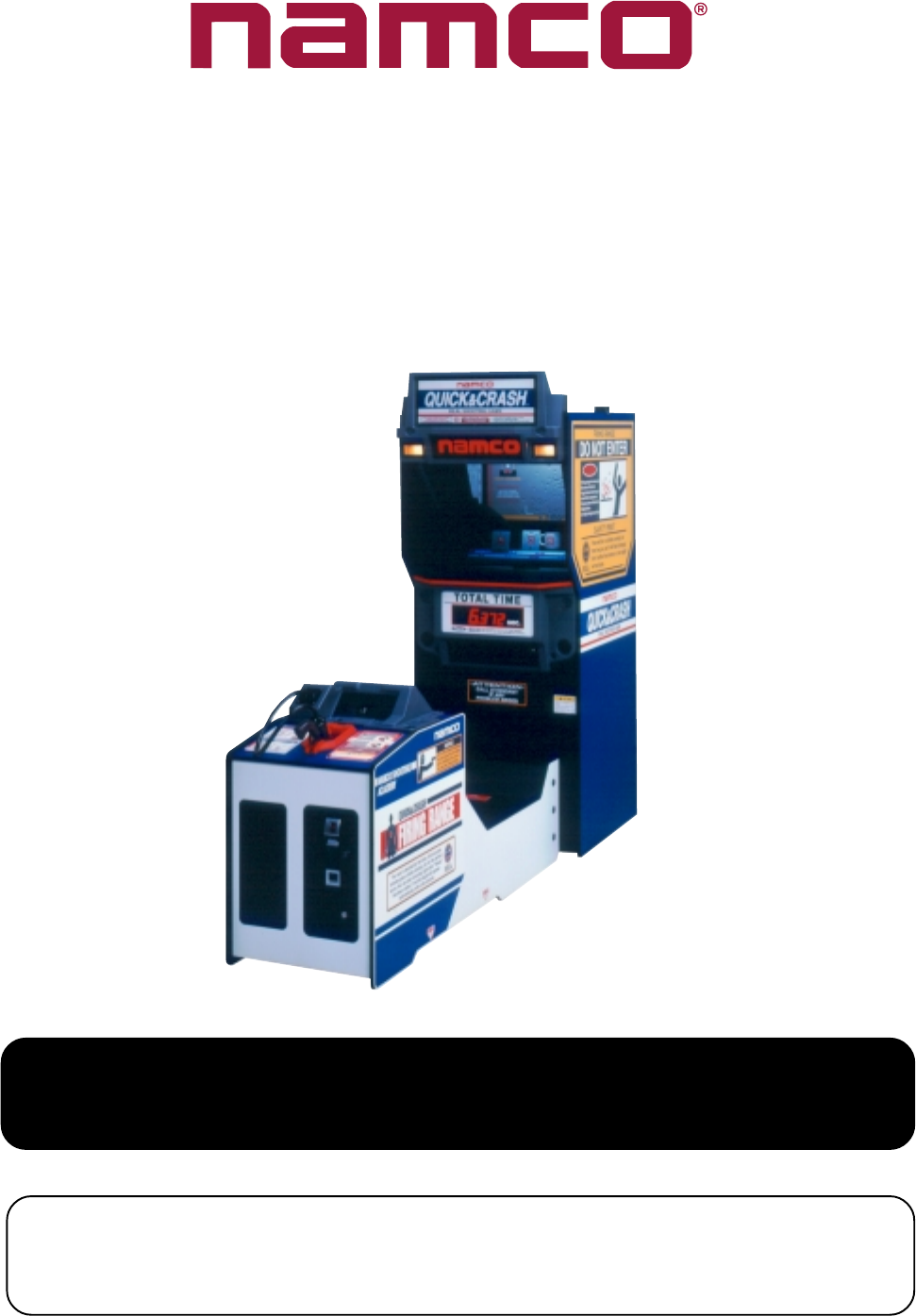
Opmanual PDF Quick & Crash [Operator's] [English]
User Manual: PDF T E X T F I L E S
Open the PDF directly: View PDF ![]() .
.
Page Count: 131 [warning: Documents this large are best viewed by clicking the View PDF Link!]
- Contents
- OPERATORS MANUAL
- GENERAL SAFETY CONSIDERATIONS
- ALLGEMEINE SICHERHEITSHINWEISE
- GENERELLE SIKKERHEDSOVERVEJELSER
- CONSIDERACIONES GENERALES DE SEGURIDAD.
- CONSIGNES GENERALES DE SECURITE
- ΕΞΕΤΑΣΗ ΓΕΝΙΚΗΣ ΑΣΦΑΛΕΙΑΣ
- CONSIDERAZIONI GENERALI SULLA SICUREZZA
- VANLIGE SIKKERHETSTILTAK
- ALGEMENE VEILIGHEIDSOVERWEGINGEN
- AVISOS DE PERIGO
- ALLMÄNNA SÄKERHETSBEAKTANDEN
- YLEISET TURVALLISUUNÄKÖKODAT
- 1. SPECIFICATIONS
- 2. HOW TO PLAY
- 3. MAJOR COMPONENTS
- 4. MOVING THE MACHINE
- 5. INSTALLATION
- 6. ADJUSTMENTS
- 7. MAINTENANCE
- 7-1 Regular Cleaning
- 7-2 Replacing the Game PC Board
- 7-3 Replacing the Cup Target Sensor PC Board
- 7-4 Replacing the Rear Glass
- 7-5 Replacing the Light Guard
- 7-6 Replacing the Rear Fluorescent Tubes and Starters.
- 7-7 Replacing the Front Acrylic
- 7-8 Replacing the Half Mirror
- 7-9 Replacing the 7-Segment PC Board
- 7-10 Replacing the Front Fluorescent and Starter
- 7-11 Replacing the Cup Target Sensor Assy
- 7-12 Replacing the Header Fluorescent and Starter.
- 7-13 Replacing the Header Lamp
- 7-14 Replacing the Dot Matrix Display.
- 7-15 Replacing the Launcher Solenoid
- 7-16 Replacing the Launcher Sensor
- 7-17 Replacing the Shutter Solenoid
- 7-17 Replacing the Shutter Sensor
- 7-18 Removing the Flat Target Assembly
- 7-19 Replacing the Flat Target Solenoid
- 7-20 Replacing the Flat Target Drive Cable
- 7-21 Replacing the Flat Target Motor
- 7-22 Replacing the Flat Target Sensor PC Board
- 7-23 Replacing the Flat Target Position Detection Sensor
- 7-24 Replacing the Flat Target Sensor Assy
- 7-25 Replacing the Flat Target Origin Sensor
- 7-26 Replacing the Gun Detection Sensor
- 7-27 Replacing the [SET] and [START] Lamps
- 7-28 Replacing the Speaker
- 7-29 Replacing the Holder Cushions (A) (B) (C)
- 7-30 Replacing the Xenon PC Board
- 7-31 Replacing the Xenon Drive PC Board
- 7-32 Removing the Xenon Fan and Filter
- 7-33 Replacing the Gun Assy
- 7-34 Replacing the Gun Switch, Trigger and Lens
- 7-35 Replacing the Gun Harness Assy
- 8. ERROR MESSAGES
- 9. PARTS
- 10. SCHEMATICS
OPERATORS MANUAL
IT IS THE RESPONSIBILITY OF THE OPERATOR TO MAINTAIN CUSTOMER SAFETY
AT ALL TIMES, AND IT IS IMPERATIVE THAT THE DETAILS SET OUT IN THIS MANUAL
ARE FOLLOWED PRECISELY
Part No. 90500074 Issue 1
QUICK & CRASH
Page 2
Contents
OPERATORS MANUAL ............................................................................................................................. 1
GENERAL SAFETY CONSIDERATIONS .................................................................................................. 4
ALLGEMEINE SICHERHEITSHINWEISE ................................................................................................. 6
GENERELLE SIKKERHEDSOVERVEJELSER ......................................................................................... 8
CONSIDERACIONES GENERALES DE SEGURIDAD. .......................................................................... 10
CONSIGNES GENERALES DE SECURITE............................................................................................ 12
ΕΞΕΤΑΣΗ ΓΕΝΙΚΗΣ ΑΣΦΑΛΕΙΑΣ ............................................................................................................ 14
CONSIDERAZIONI GENERALI SULLA SICUREZZA .............................................................................. 16
VANLIGE SIKKERHETSTILTAK............................................................................................................... 18
ALGEMENE VEILIGHEIDSOVERWEGINGEN........................................................................................ 20
AVISOS DE PERIGO ............................................................................................................................... 22
ALLMÄNNA SÄKERHETSBEAKTANDEN ............................................................................................... 24
YLEISET TURVALLISUUNÄKÖKODAT ................................................................................................... 26
1. SPECIFICATIONS .............................................................................................................................. 28
2. HOW TO PLAY ................................................................................................................................... 29
How to Play the Game ........................................................................................................................ 29
3. MAJOR COMPONENTS ..................................................................................................................... 30
4. MOVING THE MACHINE .................................................................................................................... 31
5. INSTALLATION ................................................................................................................................... 31
5-1 Joining the Front and Rear Cabinets......................................................................................... 35
5-2 Removing the Flat Target Packing. ........................................................................................... 37
6. ADJUSTMENTS.................................................................................................................................. 38
6-1 Adjustment Switches ................................................................................................................. 39
6-2 Setting Mode ............................................................................................................................. 40
6-2-1 Setting Mode Operation ....................................................................................................... 40
6-2-2 Ticket Payout Setting ........................................................................................................... 41
6-3 Test Mode ................................................................................................................................. 42
6-4 Adjusting the Launcher Solenoid ..............................................................................................43
6-5 Adjusting the Shutter Solenoid .................................................................................................. 44
6-6 Adjusting the Flat Target (U)/(L) Solenoids ............................................................................... 45
Page 3
7. MAINTENANCE .................................................................................................................................. 46
7-1 Regular Cleaning ...................................................................................................................... 48
7-1-1 Cleaning the Glasses and Half Mirror. ............................................................................... 48
7-1-2 Cleaning the Flat Target Sensor Assy .................................................................................. 48
7-1-3 Cleaning the Cup Target Sensor .......................................................................................... 49
7-1-4 Cleaning the Gun Lens ........................................................................................................ 50
7-1-5 Cleaning the Fibre Optic Cable ............................................................................................ 51
7-1-6 Cleaning the Gun Holster Detection Sensor ........................................................................ 52
7-2 Replacing the Game PC Board ................................................................................................. 53
7-3 Replacing the Cup Target Sensor PC Board ............................................................................. 54
7-4 Replacing the Rear Glass ......................................................................................................... 55
7-5 Replacing the Light Guard ........................................................................................................ 56
7-6 Replacing the Rear Fluorescent Tubes and Starters. ............................................................... 57
7-7 Replacing the Front Acrylic ....................................................................................................... 58
7-8 Replacing the Half Mirror .......................................................................................................... 60
7-9 Replacing the 7-Segment PC Board ......................................................................................... 62
7-10 Replacing the Front Fluorescent and Starter............................................................................. 64
7-11 Replacing the Cup Target Sensor Assy ..................................................................................... 66
7-12 Replacing the Header Fluorescent and Starter. ........................................................................ 68
7-13 Replacing the Header Lamp ..................................................................................................... 69
7-14 Replacing the Dot Matrix Display. ............................................................................................. 70
7-15 Replacing the Launcher Solenoid .............................................................................................72
7-16 Replacing the Launcher Sensor ................................................................................................ 73
7-17 Replacing the Shutter Solenoid ................................................................................................. 74
7-17 Replacing the Shutter Sensor ................................................................................................... 76
7-18 Removing the Flat Target Assembly .......................................................................................... 77
7-19 Replacing the Flat Target Solenoid ........................................................................................... 78
7-20 Replacing the Flat Target Drive Cable.......................................................................................80
7-21 Replacing the Flat Target Motor ................................................................................................ 81
7-22 Replacing the Flat Target Sensor PC Board ............................................................................. 83
7-23 Replacing the Flat Target Position Detection Sensor ................................................................ 84
7-24 Replacing the Flat Target Sensor Assy ..................................................................................... 85
7-25 Replacing the Flat Target Origin Sensor ................................................................................... 86
7-26 Replacing the Gun Detection Sensor ........................................................................................ 87
7-27 Replacing the [SET] and [START] Lamps ................................................................................. 89
7-28 Replacing the Speaker .............................................................................................................. 90
7-29 Replacing the Holder Cushions (A) (B) (C) ............................................................................... 92
7-30 Replacing the Xenon PC Board ................................................................................................93
7-31 Replacing the Xenon Drive PC Board ....................................................................................... 96
7-32 Removing the Xenon Fan and Filter ......................................................................................... 97
7-33 Replacing the Gun Assy ............................................................................................................ 98
7-34 Replacing the Gun Switch, Trigger and Lens ............................................................................ 99
7-35 Replacing the Gun Harness Assy ........................................................................................... 101
8. ERROR MESSAGES ........................................................................................................................ 104
9. PARTS .............................................................................................................................................. 106
10.SCHEMATICS ................................................................................................................................... 129
Page 4
No part of this publication may be reproduced by any mechanical, photographic or electronic process, or in the form of
phonographic recording, nor may it be stored in a retrieval system, transmitted or otherwise copied for private use, without
permission from NAMCO EUROPE LIMITED.
While the information contained in this manual is given in good faith and was accurate at the time of printing,
NAMCO EUROPE LIMITED reserve the right to make changes and alterations without notice.
This equipment has been manufactured in accordance with European Directives, and has been tested and complies with the
directives 89/336/EEC and 72/23/EEC by the application of EN55014-1, EN55014-2 and EN60335 standards and as such
bears the CE marking. Any changes or modifications to this equipment must be in accordance with the European Directives.
Any unauthorised changes to this equipment may contravene such directives.
Under some conditions of extreme external interference, e.g. radio transmissions, electrostatic discharge or mains born
transients, some degradation of performance may occur. However the equipment will recover normal performance once the
source of interference has ceased or been removed.
If the game processor resets due to an interruption of the mains voltage, any credits established will be lost.
This equipment is not a machine as defined by the machinery directive 89/392/EEC.
SAFETY WARNING
In order to use this equipment safely, be sure to read this Operators Manual carefully before installation, adjustment or use of
this equipment.
Whenever the owner of this equipment entrusts dis-assembly, installation, adjustment or routine maintenance to another
person, the owner should ensure that that person read the appropriate precautions and relevant sections of this manual before
starting work.
In order that no accidents occur when the equipment is in operation, strictly follow the notes on safety as described
below.
This manual along with the Installation Manual (where applicable) form an integral part of the equipment and must be available
to the operating or service personnel at all times.
This equipment is for indoor use only and should only be used for the purpose intended.
Namco Europe Ltd. bears no responsibility for accidents, injury or damage resulting from unauthorized changes to, or improper
use of this equipment.
SAFETY NOTES
The following safety notes are used throughout this manual. Familiarize yourself with each of these notes and its meaning
before installing, servicing or making adjustments to this equipment.
WARNING Warning denotes a hazard that could result in injury or death. Do not proceed beyond a warning note until
the indicated conditions are fully understood and met.
CAUTION Caution denotes a hazard that could result in damage to the equipment. Do not proceed beyond a caution
note until the indicated conditions are fully understood and met.
GENERAL SAFETY CONSIDERATIONS
Only operate this equipment after checking that it has been installed correctly and in accordance with this
manual.
All warning notices must always be kept in good condition and replaced if worn, so that customers can resd
them clearly.
If there is an error or problem with this game, operation must be stopped immediately and the problem rectified
before any further use.
Installation, service, adjustment or routine maintenance should be carried out by suitably qualified persons only.
For continued protection against fire hazard, replace fuses with the same type and rating. The use of other fuses
or material is prohibited.
To prevent possible electric shock due to failure, this equipment MUST be fitted with a securely connected
EARTHED plug.
If at any time the mains lead becomes damaged, it must be replaced immediately.
Do not turn the power switch ON until the equipment has ben installed correctly.
Before connecting the machine to the mains supply, ensure that the equipment is set for the correct voltage and that the
correct fuses are fitted.

Page 5
REMOVING AND REPLACING PARTS
Adjustments or maintenance on this equipment should be carried out by suitably qualified
personnel only.
Do not make any alteration to this equipment without prior approval. Doing so could cause
unforeseeable danger.
Only parts specified by Namco Europe Ltd. should be used when replacing parts. (Including
screws)
Ensure that the power to the equipment is turned OFF before commencing any maintenance work.
(Trouble shooting, repairs etc.)
If performing work not described in this manual, contact your distributor for instructions, as no
responsibility will be accepted for damage or injury.
Parts of the Power Supply carry high voltage even after switching OFF and could cause burns or
electric shock. Take care not to touch these parts accidentally.
Make sure that the equipment is switched OFF before connecting or disconnecting any plugs or
connectors.
When moving the mains connector from the equipment, or the mains plug from the wall outlet,
always grasp the plug and not the cable.
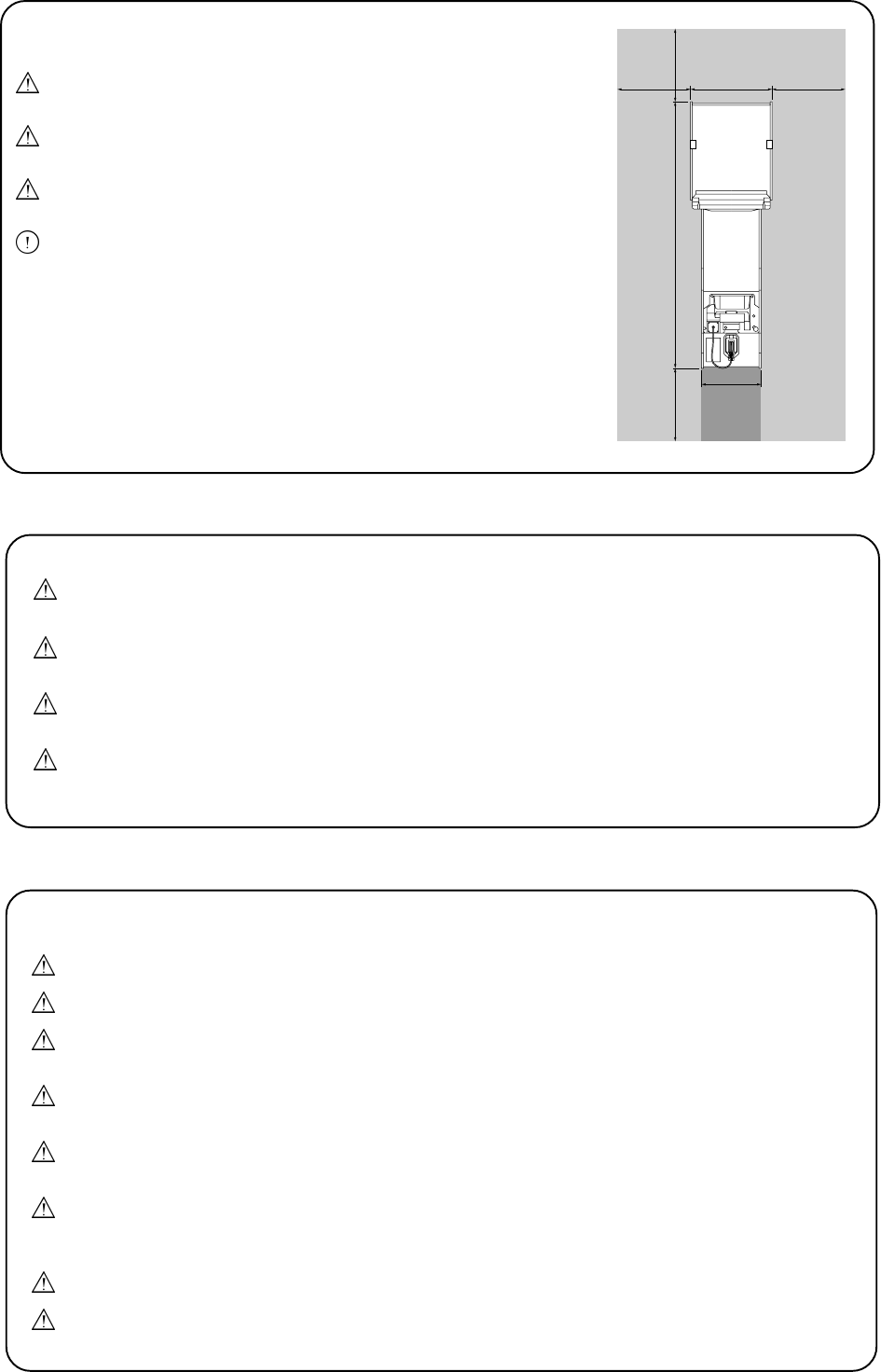
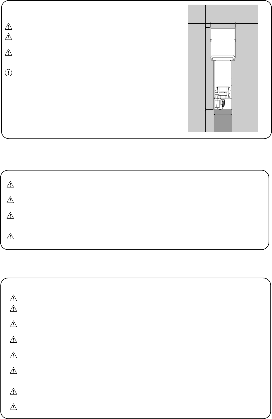
MOVING THE EQUIPMENT
This equipment is fitted with castors to make it easier to move. Take care when moving the
equipment on an inclined surface.
The Header Assembly has a forward centre of gravity, so it is important that at least two people
are used to fit or remove the Header Assembly.
The fitting position of the Header Assembly is high, and it is important that a means of reaching
the height safely, without stretching, is available. (e.g. Steps, Step Stool etc.)
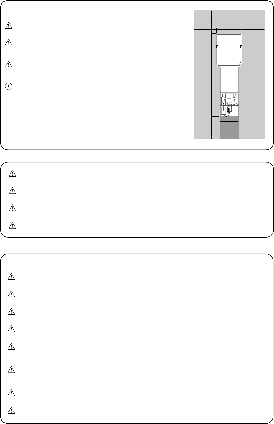
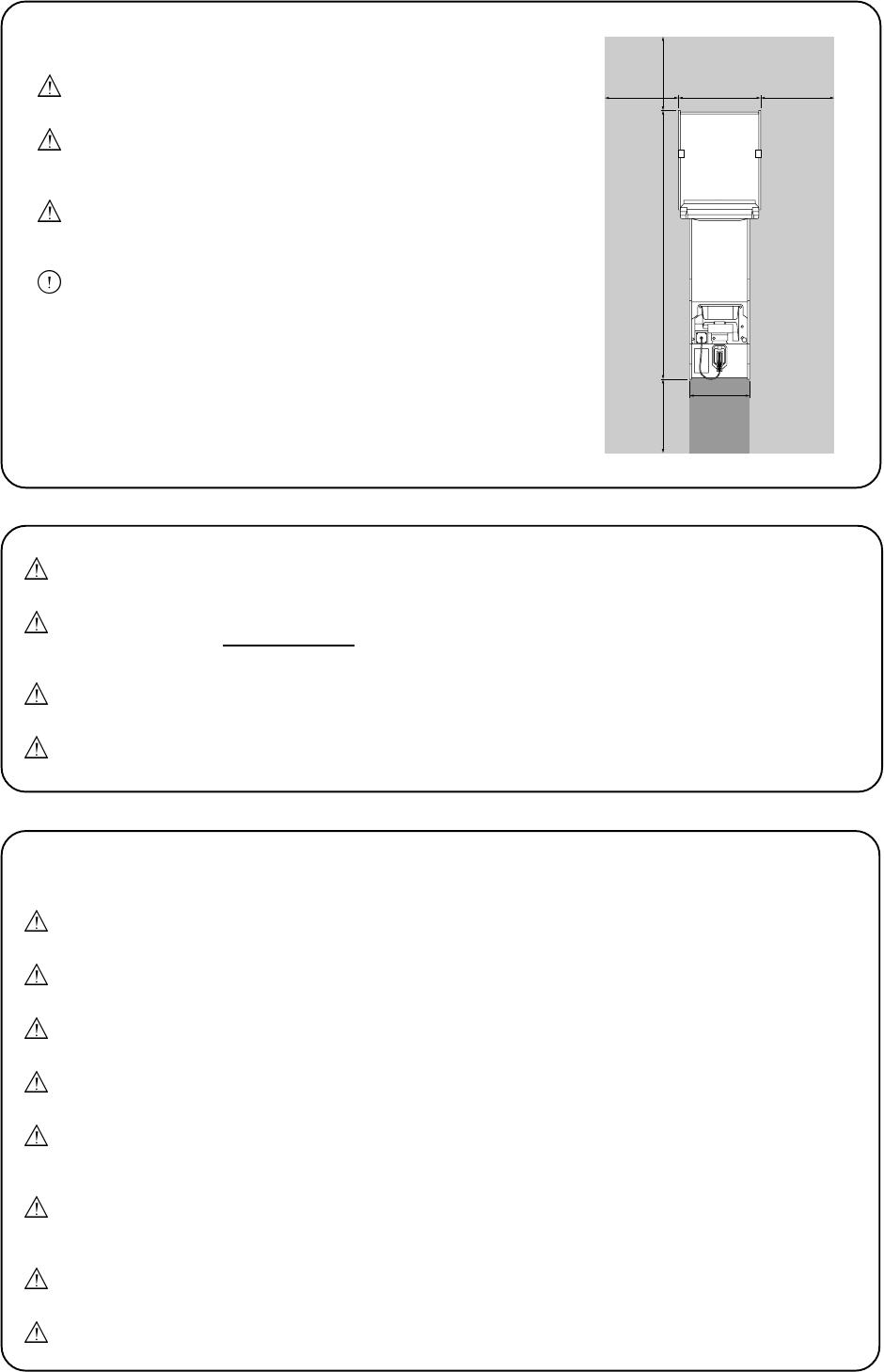
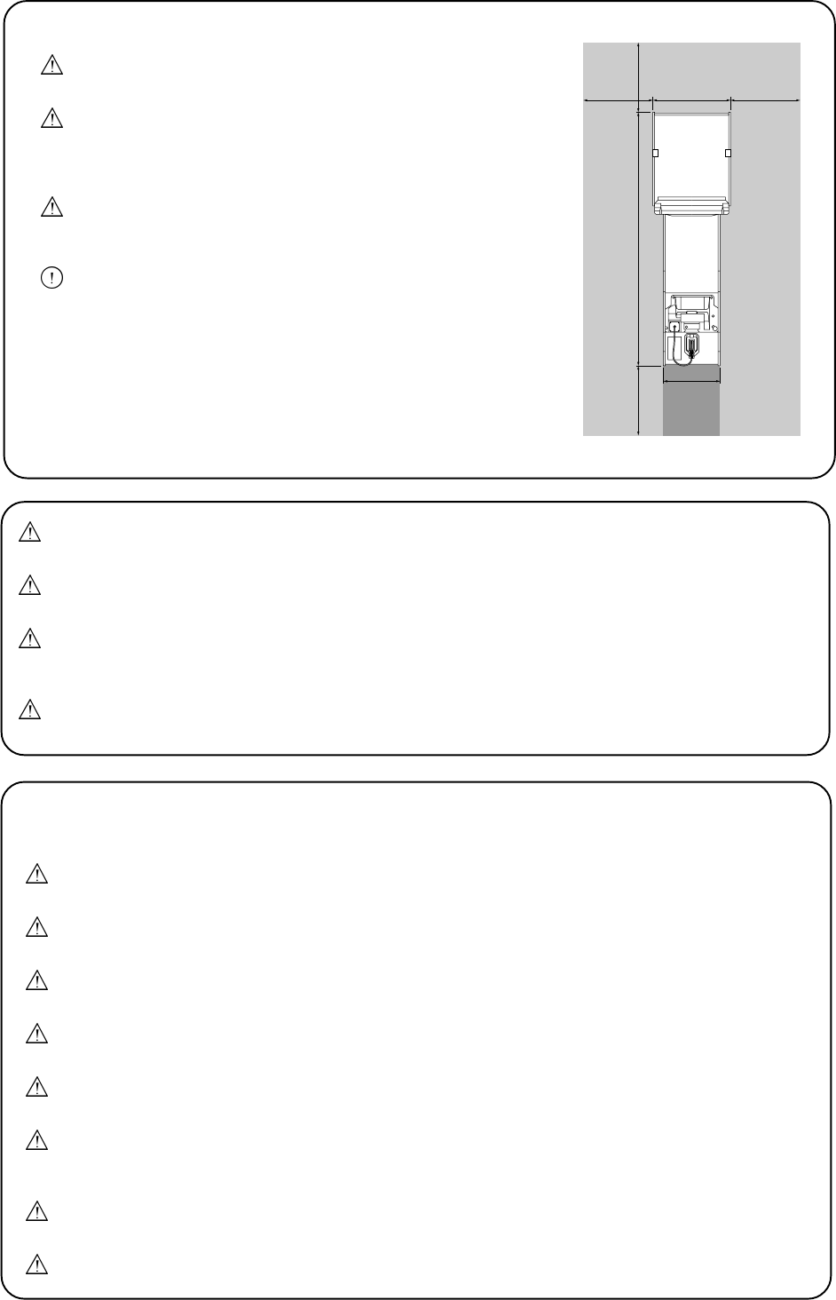
The overall height of the equipment , with the Header Assembly fitted, is 2050mm. Take care of
any overhead obstructions. (e.g. Light Fittings, Electric Cables etc.
NOTES ON INSTALLATION
NEVER turn the power to the machine ON until installation has
been completed.
In order to prevent possible electric shocks, be sure that the
equipment is connected to the mains with a securely
connected earthed plug.
So that customers are not injured by the movement of the
equipment, ensure that there is at least 500mm seperation
between other equipment or walls.
In order to avoid damage to the equipment due to mis-operation,
ensure that the voltage of the mains supply is 230volts AC.
Note: If the location of this equipment has a polished floor, it is
recommended that rubber pads are fitted under the level adjusters
to prevent the equipment sliding on the floor when in use.
Note: In order to gain access to the Power Supply and CPU assemblies,
ensure that the rear of the equipment is seperated from a wall or
other equipment by at least 100cm
55cm
76cm
243cm
100cm 100cm
100cm
100cm
Maintenance Zone
Maintenance
zone
Play
zone
Maintenance
zone
Page 6
Dieses Dokument darf in keiner Weise vervielfältigt werden. Jegliche Tonaufnahmen sowie die Speicherung auf Datenträger
(Suchsysteme), die Weitergabe oder sonstiges Kopieren für den gewerblichen und privaten Gebrauch sind untersagt und
bedürfen der vorherigen Genehmigung durch NAMCO EUROPE LIMITED.
Die informationen in diesem Handbuch entsprechen den Tatsachen bei Drucklegung. NAMCO EUROPE LIMITED behält sich
jedoch das Recht zu Änderungen ohne vorherige Bekanntgabe vor.
Dieses Gerät trägt das CE-Zeichen und wurde gemäß den EU-Richtlinien produziert. Es erfüllt die Richtlinien 89/336/EEC und
72/23/EEC und Standards EN55014-1, EN55014-2 und EN60335. Alle Veränderungen an diesem Gerät müssen in
Übereinstimmung mit den EU-Richtlinien erfolgen. Nicht genehmigte Veränderungen an diesem Gerät verstoßen gegen diese
Richtlinien.
Extreme äußere Störungen, wie z.B. durch Radiobetrieb, elektrostatische Entladung oder zeitweilige Netzschwankungen
können zu einer Leistungsminderung führen. Sobald diese Faktoren jedoch ausgeschaltet oder beseitigt wurden, erreicht das
Gerät seine normale Leistung.
Achtung! Falls der Spielprozessor auf Grund von Netzunterbrechungen oder Abnahme der Netzspannung aussetzt, kann es
zum Verlust von Spielkrediten kommen.
Dieses Gerät fällt nicht unter die Maschinen-Richtlinie 89/392/EEC
SICHERHEITSHINWEISE
Um einen ordnungsgemäßen Betrieb dieses Gerätes zu gewährleisten, muß vor Aufstellung, Inbetriebnahme und Gebrauch das
Handbuch sorgfältig gelesen werden.
Sobald der Besitzer dieses Gerätes die Demontage, Aufstellung, Inbetriebnahme oder den Service einer anderen Person
überträgt, muß er sicherstellen, daß diese Person vor Arbeitsbeginn die nötigen Sicherheitshinweise und die dazugehörigen
Kapitel des Handbuches liest und versteht.
Um jegliche Unfälle während des Betriebes zu vermeiden, müssen obige Hinweise strikt befolgt werden.
Dieses Handbuch sowie das spezielle Geräte-Handbuch (wenn vorhanden) gehören zum Gerät und müssen dem Betreiber und
Wartungspersonal stets zugänglich sein
Dieses Gerät ist ausschließlich für den gewerblichen Gebrauch in geschlossenen Räumen bestimmt und darf nur dort betrieben
werden.
NAMCO EUROPE Ltd. übernimmt keinerlei Haftung für Unfälle, Verletzungen oder Beschädigungen, die auf nicht genehmigte
Veränderungen oder unsachgemäßen Betrieb des Gerätes zurückzuführen sind.
SICHERHEITSHINWEISE
Folgende Sicherheitsbegriffe werden im gesamten Handbuch benutzt. Machen Sie sich daher bitte vor Inbetriebnahme, Wartung
und Durchführung von Einstellungen am Gerät mit diesen Warnhinweisen vertraut.
WARNUNG WARNUNG bezeichnet eine Gefahrenquelle für Leib und Leben. Erscheint dieser Warnhinweis, darf
erst weitergearbeitet werden, wenn die entsprechenden Erklärungen vollständig verstanden und
befolgt wurden.
VORSICHT VORSICHT bezeichnet eine Gefahrenquelle für die Beschädigung des Gerätes. Erscheint dieser
Warnhinweis, darf erst weitergearbeitet werden, wenn die entsprechenden Erklärungen vollständig
verstanden und befolgt wurden.
ALLGEMEINE SICHERHEITSHINWEISE
Das Gerät darf nur betrieben werden, nachdem es vorschriftsmäßig und in Übereinstimmung mit dem Handbuch
aufgestellt wurde.
Die Warnschilder müssen in gutem Zustand sein und ersetzt werden, wenn sie nicht mehr gut lesbar sind.
Bei Auftreten eines Fehlers oder Problems muß das Gerät sofort abgeschaltet werden und darf erst nach
fachgerechter Behebung des Fehlers wieder in Betrieb genommen werden.
Aufstellung, Service, Einstellungen und Wartung dürfen nur von dafür qualifiziertem Fachpersonal durchgeführt
werden.
Zur Vermeidung von Feuer, defekte Sicherungen nur durch vorgeschriebene Sicherungen ersetzen. Die
Verwendung von andersartigen Sicherungen oder unterschiedlichem Material ist untersagt.
Zur Vermeidung von Elektroschlägen muß dieses Gerät mit einem ordnungsgemäß geerdeten Netzstecker
versehen sein.
Bei Beschädigungen des Netzteiles muß dieses umgehend ersetzt werden.
Gerät erst nach abgeschlossener Aufstellung einschalten.
Vor Einstecken des Netzsteckers bitte sicherstellen, daß Netzspannung und Gerätespannung übereinstimmen, und die
vorgeschriebenen Sicherungen verwendet wurden.
D
Page 7
HINWEISE ZUR AUFSTELLUNG
NIEMALS das Gerät einschalten bevor die Aufstellung völlig
abgeschlossen ist.
Zur Vermeidung von Elektroschlägen muß das Gerät mit einem
ordnungsgemäß geerdetem Netzstecker an die
Stromversorgung angeschlossen werden.
Um zu vermeiden, daß Kunden durch die Gerätebewegungen
verletzt werden, muß ein Sicherheitsabstand zu anderen Geräten
und Wänden von mindestens 50cm eingehalten werden.
Zur Vermeidung von Beschädigungen durch Fehlbetrieb am Gerät
sicherstellen, daß die Netzspannung 230 Volt beträgt.
Hinweis: Ist das Gerät für einen Aufstellplatz mit glattem Fußboden
bestimmt, müssen die Standbeine mit Gummiplättchen unterlegt
werden, damit das Gerät fest steht und nicht auf dem Boden
hin- und herrutscht.
Hinweis: Zu Reparaturzwecken am Netzteil und den CPU-Komponenten
muß die Rückseite des Gerätes mindestens100cm von anderen
Geräten und der Wand entfernt sein.
Zum leichteren Transport ist das Gerät mit Rollen ausgerüstet. Daher besondere Vorsicht auf
abschüssigem Boden
Der Schwerpunkt des Aufsatzes liegt sehr weit vorn. Daher werden für den Ab- und Aufbau des
Aufsatzes mindestens 2 Personen benötigt.
Der Aufsatz wird in großer Höhe montiert. Daher muß aus Sicherheitsgründen eine Steighilfe,
wie z. B. eine Leiter, ein Tritt oder ähnliches, verwendet werden.
Die Gesamthöhe de Gerätes beträgt 2.05m. Daher Vorsicht bei tiefer hängenden
Beleuchtungskörpern.
AUS- UND EINBAU VON KOMPONENTEN UND TEILEN
Aufstellung, Service, Einstellung und Wartung dürfen nur von dafür qualifiziertem Fachpersonal
durchgeführt werden.
Es dürfen keierlei Veränderungen ohne vorherige Genehmigung am Gerät vorgenommen
werden. Zuwiderhandlungen stellen eine Gefahrenquelle dar.
Für die Repartur dürfen nur Originalersatzteile (incl. Schrauben) von NAMCO EUROPE LTD.
verwendet werden.
Vor Beginn aller Wartungsarbeiten (Fehlersuche, Reparaturen etc.) muß der Netzstecker
gezogen werden.
Bei Arbeiten, die nicht in diesem Handbuch beschrieben werden, muß vorher der Händler zu
Rate gezogen werden, da sonst keinerlei Haftung bei Beschädigungen und Verletzungen
übernommen wird.
Teile des Netzteiles und Bilschirmes bleiben nach Abschalten noch heiß und führen
Hochspannung. Dies kann zu Verbrennungen oder einem Elektroschlag führen. Diese Teile
dürfen nich berührt werden.
Vor der Montage oder dem Entfernen von Steckverbindungen und Steckern muß das Gerät
ausgeschaltet werden.
Bei Ziehen des Gerätesteckers oder des Netzsteckers aus der Wandsteckdose stets den
Stecker greifen und nicht das Kabel.
55cm
76cm
243cm
100cm 100cm
100cm
100cm
Maintenance Zone
Maintenance
zone
Play
zone
Maintenance
zone
Page 8
Denne udgivelse må ikke reproduceres af nogen som helst mekanisk, fotografisk eller elektrornisk proces eller i form af
indspilning, den må heller ikke lagres i et eftersøgningssystem transmitteres eller kopieres til nogen form for offentlig benyttelse
uden tilladelse fra Namco Europe Limited.
Da informationerne i denne manual er givet med god tro og var korrekt på udskivningstidspunktet,
forbeholder Namco Europe Limited sig retten til, at foretage ændringer og forandringer uden varsel.
Denne maskine er frernstillet i overensstemmelse med Det Europæiske fællesskabs direktiver og er blevet testet og fuldendt
med direktiverne 89/336/EEC og 72/23/EEC standarder og som sådan bærer CE mærket. Enhver form for ændring eller
modiflkation af denne maskine skal være i overensstemmelse med Det Europæiske fællesskabs direktiver.
I tilfælde af forbigående ekstreme eksterne forstyrrelser, så som radio udsendelser, elektronisk afgivelse eller forstyrrelser på
ledningsnettet, kan nedbrydning forekomme. Maskinen vil dog køre normalt så snart forstyrrelsen ophører eller bliver fjernet.
Bemærk:- Hvis spilleprocessoren resetter p.g.a. en forstyrrelse eller reduktion af hovedstrømmen kan de
etabledrede kreditter gå tabt.
Dette spil er ikke en maskine defineret af maskin direktivet 89/392/EEC -
SIKKERHEDS ADVARSEL
For at betjene denne maskine sikkert, læs da denne brugemanual grundigt før installation, justering eller brug af maskinen.
Når som helst ejeren af denne maskine overlader demontering, installation, justeringer eller daglig vedligehold til en anden person,
skal ejeren sikre sig at denne person læser de sikkerhedsregler og relevante punkter i denne manual før arbejdet begynder.
For at undgå ulykker nor maskinen er i gang, følg nøje de sikkerhedsregler der er beskrevet herunder.
Denne manual sammen med installations manualen er en uløselig del af udstyret og skal altid være til
råidighed for det arbejdende og servicerende personale.
Denne rnaskine er kun til indendørs brug og bør kun bruges til det beregnede formål.
Namco Ltd. bærer intet ansvar for ulykker eller skader som er et resultat af uautoriserede ændringer eller
fejlagtig brug af denne rnaskine.
SIKKERHEDSREGLER
De følgende sikkerhedsregler er brugt helt igennem denne manual. Gør dig bekendt med hver enkelt af dem og meningen
heraf før installering, servicering eller justering af denne maskine.
ADVARSEL Advarsel betegner en episode der kan resultere i skader eller død. Begiv dig ikke forbi et
advarselsskilt før de indikerede betingelser er fuldstændig forstået.
FORSIGTIG Forslgtig betegner en episode der kan resultere i ødelæggelse af maskinen. Begiv dig ikke forbi et
advarselsskit før de indikerede betingeser er fuldstændig forstået.
GENERELLE SIKKERHEDSOVERVEJELSER
Betjen kun maskinen efter at have tjekket, at den er korrekt installeret og er i overensstemmelse med manualen.
Advarselsskiltene skal altid være i god stand og erstattes hvis de er slidt, så kunden tydeligt kan læse dem.
Hvis der er en fejl eller et problem med maskinen skal betjening straks stoppes, og problemet afhjælpes før
yderligere brug.
Installations service, justeringer eller daglig vedligehold bør kun udføres af en kvalificeret person.
For fortsat beskyttelse mod brandfare, sikres at hoved sikringerne kun erstattes med samme type kapacitet. Brug af
anden kapacitet eller materiale er forbudt.
For at undgå elektrisk stød p.g.a. en fejl skal denne maskine være forbundet med et sikkert jordstik.
Hvis hoved ledningerne på noget tidspunkt bliver beskadiget skal de strakt erstattes.
Tænd ikke for strømmen før maskinen er korrekt installeret.
Før tilslutning af maskinen til hovedstrømmen sikres, at maskinen er indstillet til den rette spænding.
Page 9
PUNKTER OM INSTALLATION
Tænd aldrig for strømmen til maskinen før installering er
fuldført.
For at undgå mulige elektriske stød sikres, at maskinen er forbundet
til hovedstrømmen med sikkert monterede jordstik.
For at kunder ikke kommer til skade ved spillets bevægelser sikres,
at der er mindst 50cm afstand til andre maskiner og vægge.
For at undgå skader på maskinen p.g.a. fejlbetjening sikres, at
spændingen på hovedstrømmen er 230 volt AC.
BEMÆRK : Hvis denne maskine placeres på et poleret gulv, anbefales
det at ligge gummimåtter under justeringsfødderne for at
undgå at maskinen glider på gulvet.
BEMÆRK : For at få adgang til strømforsyningen og CPU justeringer
sikres, at bagsiden af hoved kabinettet står adskilt fra andre
maskiner eller væggen med mindst 100cm.
AT FJERNE OG UDSKIFTE SEKTIONER OG DELE.
Justeringer eller vedligehold af denne maskine bør kun udføres af kvalificeret personale.
Skift ikke noget på maskinen uden godkendelse, det kan føre til uforudset fare.
Der bør kun bruges dele specificeret af Namco Europe Limited når der skiftes eller repareres
dele (inklusiv skruer).
Sørg for, at strømmen til maskinen er slukket før der foretages nogen form for arbejde
(fejlfinding, reparation etc.)
Hvis der foretages arbejde der ikke er beskrevet i denne manual, kontakt da din leverandør for
at få kyndig vejledning, da intet ansvar vil blive accepteret ved skader.
Dele af strømforsyningen og monitoren forbliver varme eller bærer høj spænding selv efter
maskinen er slukket, det kan føre til forbrændinger eller elektriske stød. Pas på ikke at røre
disse dele ved et uheld.
Læg mærke til at maskinen er slukket før samlinger eller stik tages ud eller sættes i.
Når hovedsamlingen fjernes fra maskinen eller hovedstikket fjernes fra væggen, tag da altid ved
stikket, ikke ledningen.
Maskinen er smurt med olie for at gøre den lettere bevægelig. Pas på når maskinen flyttes på
en skrå overflade.
Hoved sektionens forreste center er meget tung, det er derfor vigtigt, at mindst 2 personer
benyttes til at montere el. flytte hoved sektionen.
Monterins højden af hoved sektionen er meget høj og det er vigtigt, at have hjælpemidler til at
nå sikkert uden at skulle strække sig. (fek.s. trapper, trappestole el. lign.).
Den fulde højde af hoved sektionen er 2.05m. Pas på øvre forhindringer f.eks. lys inventar
55cm
76cm
243cm
100cm 100cm
100cm
100cm
Maintenance Zone
Maintenance
zone
Play
zone
Maintenance
zone
Page 10
No se permite la reproducción total ni parcial de esta publicación por ningún medio mecánico, fotográfico o electrónico,
grabaciones fonográficas, ni su almacenamiento informático, su transmisión o su copia, ya sea para uso público o privado, sin
permiso de NAMCO EUROPE LIMITED.
Si bien la información contenida en este manual se da de buena fe y es correcta en el momento de su impresión, NAMCO
EUROPE LIMITED se reserva el derecho de hacer cambios y alteraciones sin previo aviso.
Esta máquina ha sido fabricada según las directrices de la Comunidad Europea, ha sido probada, y se ajusta a las directrices
89/336/EEC y 72/23/EEC, mediante la aplicación de los estándares EN55014-1, EN55014-2 y EN60335 y por ende lleva el sello
de la C.E. Cualquier cambio o modificación que se haga a esta máquina ha de ajustarse a las directrices de la Comunidad
Europea. Cualquier cambio no autorizado hecho al producto pudiera contravenir estas directrices.
Bajo ciertas condiciones de extrema interferencia externa, p. ej. transmisiones de radio, descargas electrostáticas u oscilaciones
de la red eléctrica puede tener lugar un descenso del rendimiento. No obstante, la máquina recuperará su rendimiento normal
una vez que la fuente de interferencias sea retirada o cese de producirlas.
Nota: Si el procesador de juegos se reinicializa a causa de caídas o interrupciones en la alimentación eléctrica, se perderán
todos los créditos.
Este juego no se ajusta a la definición de máquina de la Normativa de Maquinaria 89/392/EEC
AVISOS DE SEGURIDAD.
Para utilizar esta máquina con seguridad, lea cuidadosamente este Manual de Operador antes de proceder a la instalación, ajuste
o uso de esta máquina.
Cada vez que el propietario de esta máquina confíe a terceros su desmontaje, instalación, ajuste o mantenimiento rutinario deberá
asegurarse de que tales personas lean las precauciones adecuadas y las secciones relevantes de este manual antes de comenzar
su trabajo.
Para que no ocurra accidente alguno mientras la máquina se encuentre en funcionamiento, siga estrictamente las notas de
seguridad tal como más adelante se describen.
Este manual, junto con el Manual de Instalación (cuando proceda), forma parte integral del equipo y debe estar a disposición del
personal de mantenimiento y operación en todo momento.
Esta máquina es únicamente para ser usada en interiores, y sólo debe usarse para aquello para lo que ha sido creada.
Namco Ltd. queda exenta de cualquier responsabilidad por accidentes, heridas o daños causados por cambios no autorizados o
uso indebido de esta máquina.
NOTAS DE SEGURIDAD.
En este manual se usan las notas siguientes. Familiarícese con cada una de ellas y su significado antes de instalar,
revisar, o hacer ajustes en esta máquina.
AVISO. Aviso señala un riesgo que puede ocasionar lesiones o la muerte. Tras ver esta nota, no
continúe hasta entender completamente y cumplir las condiciones exigidas.
PRECAUCIÓN. Precaución señala un riesgo que puede ocasionar daños a la máquina. Tras ver esta nota, no
continúe hasta entender completamente y cumplir las condiciones exigidas.
CONSIDERACIONES GENERALES DE SEGURIDAD.
Opere sólo con esta máquina tras comprobar que ha sido instalada correctamente y de acuerdo con este manual.
Las notas de aviso deben mantenerse siempre en buen estado y reemplazarse si estuvieran desgastadas para que
los usuarios puedan leerlas con claridad.
Si hubiera algún error o problema con la máquina, debe interrumpirse su operación inmediatamente, y subsanar el
problema antes de volver a usarla.
Las revisiones de instalación, los ajustes, y el mantenimiento rutinario deberán llevarse a cabo sólo por personal
cualificado.
Para asegurar una continua protección contra riesgo de incendios, asegúrese de que los fusibles eléctricos sean
reemplazados solamente por otros del mismo tipo y especificaciones. El uso de otros fusibles o material está
prohibido.
Para evitar posibles descargas eléctricas por cortes, esta máquina debe estar provista de un enchufe debidamente
conectado, con TOMA DE TIERRA.
Si en cualquier momento el cable de alimentación se dañara, deberá ser reemplazado inmediatamente.
No encienda el interruptor de la máquina hasta que ésta haya sido correctamente instalada.
.Antes de enchufar la máquina a la red eléctrica, asegúrese de que la máquina está preparada para el voltaje correcto, y de
que se usan los fusibles adecuados.

Page 11
RETIRAR Y REEMPLAZAR PARTES Y UNIDADES.
Las revisiones de instalación, los ajustes, y el mantenimiento rutinario deberán llevarse a cabo sólo
por personal cualificado.
No realice alteraciones en esta máquina sin aprobación previa. De hacerlo así, pueden causar
peligros imprevisibles.
Sólo deben usarse las partes especificadas por Namco Europe Ltd. para reparaciones o reemplazos
(incluidos los tornillos).
Asegúrese de que la máquina está desconectada antes de comenzar cualquier trabajo de
mantenimiento (reparaciones, resolución de problemas, etc.)
Al realizar trabajos no descritos en este manual, póngase en contacto con su distribuidor para recibir
instrucciones. Se declina cualquier responsabilidad por daños o lesiones.
Hay partes de la fuente de alimentación y del monitor que se mantienen calientes o almacenan alto
voltaje incluso tras desconectar la máquina, y pueden producir quemaduras o descargas eléctricas.
Tenga cuidado de no tocar accidentalmente estas partes.
Asegúrese de que la máquina está apagada antes de conectar o desconectar cualquier enchufe o
conector.
Al retirar el conector principal de la máquina, o la clavija de alimentación del enchufe de la red, agarre
NOTAS DE INSTALACIÓN.
JAMÁS ENCIENDA la máquina antes de haber completado la
instalación.
Para evitar posibles descargas eléctricas, asegúrese de que la
máquina está conectada a la red con un enchufe provisto de
toma de tierra.
Para que los usuarios no sufran lesiones debido al movimiento del
juego, asegúrese de que hay al menos 500 mm de separación entre
éste y otras máquinas o las paredes.
Para evitar daños a la máquina causados por operación incorrecta,
asegúrese de que el voltaje de la red es de 230 voltios, corriente
alterna.
Notas : Si el lugar donde se instalará la máquina tiene un piso pulido, se
recomienda colocar tacos de goma bajo los ajustadores de nivel
para evitar que la máquina se deslice por el suelo.
Notas : Para acceder a las unidades de Fuente de Alimentación y CPU,
asegúrese de que la parte trasera del mueble principal está
separada de muros u otras máquinas al menos 100cm
El juego tiene ruedecitas para hacer más fácil su traslado. Tenga cuidado al mover la máquina
en una superficie inclinada.
La Unidad de Igualación tiene el centro de gravedad desplazado hacia adelante. Es importante
que su montaje y desmontaje se haga por al menos dos personas.
La posición de la Unidad de Igualación es bastante alta, y es importante que haya un medio de
alcanzar su altura con seguridad, sin estirarse (p. ej. una escalera, un taburete, etc.)
La altura total de la Unidad principal es de 2.05mm. Tenga cuidado de que no haya obstáculos
p. ej. luces.
55cm
76cm
243cm
100cm 100cm
100cm
100cm
Maintenance Zone
Maintenance
zone
Play
zone
Maintenance
zone
Page 12
Aucun élément de cette publication ne sera reproduit, ni par procédé mécanique, photographique ou électronique, ni par un
moyen denregistement phonographique. Ces informations ne seront ni stockées grâce à un procédé de récupération, ni
transmises ou autrement copiées pour un usage publique ou privé, sans lautorisation de NAMCO EUROPE LIMITED.
Malgré le fait que les informations contenues dans ce manuel soient données de bonne foi et étaient actualisées au moment de
leur impression, NAMCO EUROPE LIMITED se réserve le droit de procéder à des changements ou à des modifications sans
avis préliminaire.
Ce jeu a été fabriqué en respect des normes de la Communauté Européenne, après avoir été testé il répond aux normes 89/
336/EEC et 72/23/EEC, en application des standards EN55014-1, EN55014-2 et EN60335, et comme tel il comporte
lautocollant de conformité avec les normes de la Communauté Européenne. Tout changement non autorisé sur ce produit
pourrait contrevenir à ces normes.
Sous certaines conditions extrêmes dinterférence exteme, par example des transmissions radio, des décharges
électrostatiques ou bien de interférences passagères sur le réseau, certaines dégradations ou anomalies peuvent se produire.
Le jeu retrouvera cependant son état normal de fonctionnement lorsque la cause de ces anomalies aura cessé ou se trouvera
déplacée.
Note:-
Si le processeur du jeu se reprogramme suite à une interruption ou une réduction de lalimentation, les crédits quil aurait pu
contenir peuvent se trouver perdus.
Ce jeu nest pas une machine, telle que définie par la norme sur les machines 89/392/EEC
MESURES DE SECURITE
Afin dutiliser ce jeu en toute sécurité, bien lire ce manuel dutilisation avant de procéder à son installation, son réglage ou son
exploitation.
Si le propriétaire de ce jeu en confie la démontage, linstallation, le réglage ou la maintenance habituelle à une autre personne,
il devra sassurer que cette personne ait lu les conseils dutilisation et les passages du manuel se rapportant à ce thème, avant
quelle ne commence son travail.
Afin déviter tout accident pendant la durée dexploitation de ce jeu, se conformer strictment aux conseils de sécurité décrits à la
suite.
Ce manuel ainsi que le manuel dinstallation du jeu (là où nécessaire) font partie des éléments nécessaires à linstallation de la
machine et doivent être mis à la disposition de lutilisateur et du personnel de maintenance à tout moment.
Ce jeu est uniquement destiné à un usage intérieur et devra être utilisé comme tel.
Namco Ltd. ne sera aucunement tenu responsable en cas daccidents, de blessure ou de dommage quelconque résultant de
modifications non autorisées ou dusage impropre du jeu.
CONSIGNES GENERALES DE SECURITE
Allumer lappareil seulement après avoir vérifié quil a été correctement installé, et que les instructions du manuel
ont été respectées.
Les notes de mise en garde doivent constamment demeurer en bon état et être remplacées en cas de disparition,
afin que le client puisse les lire clairement.
Sil y una erreur ou un problème avec la machine, lutilisation doit être immédiatement interrompue et le
problème résolu avant toute nouvelle utilisation.
Linstallation, le service, le réglage, ou la maintenance doivent être effectués uniquement par les personnes
qualifiées.
Afin déviter un éventuel incendie, sassurer que les fusibles soient remplacés par le même type de fusibles et au
bon voltage. Lutilisation dautres sortes de fusibles ou autres matériels est interdite.
Pour prévenir une éventuelle électrocution due à un défaut matériel, ce jeu DOIT être muni dune prise de TERRE
connectée en toute sécurité
Si à tout moment les fils électriques sont endommagés, il faut les remplacer immédiatment
Ne pas mettre le jeu en mode de fonctionnement avant quil nait été correctement installé.
Avant de connecter la machine au réseau, sassurer que la machine est installée sous la bonne tension et que les
fusibles correspondent.
REMARQUES SUR LA SECURITE
Les termes de sécurité détaillés à la suite seront utilisés tout au long de la lecture de ce manuel. Il convient de vous
familiariser aves chacun de ces termes ainsi que leur signification avant de procéder à linstallation, à la maintenace ou au
réglage du jeu.
AVERTISSEMENT Ce terme annonce un danger qui pourrait éventuellement avoir des conséquences
dommageables ou mortelles. Ne pas passer oûtre ce signal jusquà ce que les conditions
indiquées soient entiérement comprises et effectuées.
ATTENTION Ce terme indique quun danger menace la machine. Ne pas passer oûtre ce signal jusquà ce que
les conditions indiquées soient entiérement comprises et effectuées.
Page 13
NOTES DINSTALLATION
NE JAMAIS mettre le jeu en marche avant que linstallation
ne soit complétement effectuée.
Afin de prévenir une éventuelle électrocution, sassurer
que la machine est connectée au réseau avec une prise de
terre reliée selon les normes de sécurité.
Afin que les clients ne soient pas blessés par les
mouvements du jeu, sassurer quil existe au moins 500
mm de séparation aves les autres jeux ou les murs.
Afin déviter que la machine ne soit abimée suite à une
mauvaise opération, sassurer que la tension sur le réseau
principal soit de 230 volts AC.
Note: Si lendroit où doit être installée la machine à un sol pôli, il est
recommandé de poser des tampons feutrés sous les vérins
pour éviter que le jeu ne glisse sur le sol
Note: Afin de facilité laccès aux CPU at à lalimentation, sassurer
quil y a un espace dau moins 100cm entre larrière du
meuble et le mur ou tout autre jeu.
Le jeu est foumi avec des roulettes pour une meilleure mobilité. Prendre garde quand la
machine est déplacée sur une surface inclinée.
Le centre de gravité de la partie supérieure du jeu est situé sur lavant, il est donc
indispensable que deux personnes au moins soient employées pour installer ou déplacer la
partie supérieure.
Linstallation de la partie supérieure du jeu seffectue en hauteur, il est donc important dutiliser
un élevateur quelconque pour en effectuer le montage.
La hauteur totale de lassemblage principal est de 2050 mm, prendre garde aux encombrements
de la partie supérieure (ex : illuminations du bandeau).
DEPLACER ET REMPLACER LES UNITES ET LES PIECES DETACHEES.
Linstallation, le service, le réglage, ou la maintenance doivent être effectués uniquement par
les personnes qualifiées.
Ne pas apporter de modifications sur cette machine sans autorisation préalable, faute de quoi
cela pourrait entraîner un danger.
Seules les pièces détachées Namco Europe Ltd. doivent être utilsées pour le remplacement ou
la réparation de pièces (y compris les vis)
Sassurer que linterrupteur soit sor OFF avant de commencer tout travail de maintenance
(localisation dune panne, rèparations, etc.)
Si dans ce manuel il manque une information pour réaliser un quelconque travail, contacter
votre distributeur, car aucune responsabilité ne sera acceptée en cas de domage ou de
blessure.
Les pièces de lalimentation et du moniteur restent chaudes, à tension élévée même lorsque la
machine est hors tension, elle pourrait occasionner des brûlures ou des électrocutions.
Attention de ne pas toucher ces endroits accidentellement.
Sassurer que la machine soit hors tension avant de brancher ou débrancher toute prise ou
connecteur.
Lorsque lon manipule la prise au réseau de la machine, ou lorsque les prises principales
doivent être débranchées, saisir toujours la prise, et non le câble.
55cm
76cm
243cm
100cm 100cm
100cm
100cm
Maintenance Zone
Maintenance
zone
Play
zone
Maintenance
zone
Page 14
Κανένα µέρος αυτής της έκδοσης δεν µπορεί να αναπαραχθεί µε οποιοδήποτε µηχανικ# ,φωτογραφικ# ή ηλεκτρονικ#
µέσο , ή µε µορφή φωνητικής ηχογράφησης και ούτε να αποθηκευτεί µε επανορθωτικ# σύστηµα , να µεταδοθεί ή να
αντιγραφεί για δηµ#σια ή ιδιωτική χρήση , χωρίς την άδεια της NAMCO EUROPE LIMITED.
Καθώς αυτές οι πληροφορίες σε αυτ# το εγχειρίδιο έχουν δοθεί µε καλή πίστη και ακριβώς την ώρα της τύπωσης , η
εταιρεία
NAMCO EUROPE LIMITED κρατάει το δικαίωµα να κάνει οποιεσδήποτε αλλαγές χωρίς ειδοποίηση.
Τα µηχανήµατα έχουν κατασκευαστεί σύµφωνα µε τους #ρους της Ευρωπαϊκής Κοιν#τητας , και έχουν ελεγχθεί
σύµφωνα µε τους ν#µους
89/336/ΕΟΚ και 72/23/ΕΟΚ µε την αίτηση των ΕΝ55014-1, ΕΝ55014-2 και ΕΝ60335 στάνταρτς και #λα έχουν το CE σήµα
. Οποιαδήποτε αλλαγή ή µετατροπή σε αυτ# το µηχάνηµα πρέπει να είναι σύµφωνα µε τους #ρους της Ευρωπαϊκής
Κοιν#τητας. Οποιεσδήποτε αλλαγές χωρίς άδεια σε αυτ# το προϊ#ν µπορεί να παραβεί αυτούς τους #ρους.
Σε κάποιες περιπτώσεις υπερβολικής εξωτερικής παρεµβολής ,π.χ. ραδιοφωνικές µεταδ#σεις , ηλεκτροστατικές
µεταβολές ή παροδικές εµβολές , µπορεί να παρουσιαστούν κάποιες αθλι#τητες στην παρουσίαση . Πάντως το
µηχάνηµα θα επανέλθει στην φυσιολογική παρουσίαση εφ #σον η πηγή της παρεµβολής σταµατήσει ή αποµακρυνθεί .
Σηµείωση : Εάν γίνει reset στον processor του µηχανήµατος κατά τη διάρκεια της κύριας παροχής , π#ντοι που έχουν
κερδηθεί µπορεί να χαθούν.
Αυτ# το παιχνίδι δεν είναι µηχάνηµα #πως προσδιορίζεται απ# τους #ρους Μηχανηµάτων 89/392/ΕΟΚ .
ΕΞΕΤΑΣΗ ΓΕΝΙΚΗΣ ΑΣΦΑΛΕΙΑΣ
Αφο χει κατανοηθε αυτ το εγχειρδιο , µνο ττε να λειτουργσει το µηχνηµα να γνει λεγχοσ εφ σον
χει γνει η εγκατσταση.
Οι προειδοποισεισ πρπει να µνουν καθαρσ και σε καλ κατσταση στε ο πελτησ να τισ διαβζει καθαρ.
Εν υπρχει λθοσ πρβληµα µε το µηχνηµα , η λειτουργα πρπει να σταµατει αµσωσ και να διορθνεται το
λθοσ πριν οποιαδποτε λλη χρση.
Εγκατσταση , µετατροπ λεγχοσ ρουτνασ µπορε να γνεται µνο απ εξουσιοδοτηµνα τοµα .
Για συνεχ προστασα απ φωτι , πρπει οι ασφλειεσ να αντικαθιστονται µε διου τπου .Η χρση λλων
ασφαλειν αντικειµνων απαγορεεται.
Για την αποφυγ ηλεκτρικν σοκ λγο βλβησ , το µηχνηµα ΠΡΕΠΕΙ να χει πρτα ενωθε µε γεωση.
Εν κποια στιγµ καταστραφε η κρια παροχ , πρπει να αντικατασταθε αµσωσ.
Να µην ανψει το µηχνηµα ( ) µχρι να χει εγκατασταθε σωστ και πλρωσ.
Πριν την παροχ ρεµατοσ στο µηχνηµα , να εσαι σγουροσ τι τα και λεσ οι ασφλειεσ εναι σωστ
ενωµνα και τοποθετηµνα.
ও
Ο∆ΗΓΙΕΣ ΑΣΦΑΛΕΙΑΣ
Για την ασφαλ χρση του µηχανµατοσ , πρπει να διαβσεισ το εγχειρδιο χρσησ προσεκτικ πριν την εγκατσταση
,τοποθτηση χρση του µηχανµατοσ.
Οποτεδποτε ο ιδιοκττησ αυτο του µηχανµατοσ ζητει απ κποιο πρσωπο να εγκαταστσει , να κνει
οποιαδποτε αλλαγ λεγχο ρουτνασ στο µηχνηµα , πρπει να εναι σγουροσ τι χει διαβσει τισ οδηγεσ αυτο
του εγχειριδου πριν να αρχσει να δουλεει .
Προσ αποφυγν οποιουδποτε ατυχµατοσ κατ την λειτουργα του µηχανµατοσ , αυστηρσ ακολουθονται οι
οδηγεσ ασφλειασ πωσ δνονται παρακτω .
Αυτ το εγχειρδιο σε συνδυασµ µε το εγχειρδιο εγκατστασησ (που διατθεται) αποτελε να ολοκληρωµνο µροσ
των παροχν και πρπει να εναι διαθσιµο για την λειτουργα και το οποιαδποτε στιγµ.
Αυτ το µηχνηµα εναι για χρση µνο σε εσωτερικ χρο και θα πρπει να χρησιµοποιεται µνο για τουσ λγουσ
για τουσ οποουσ κατασκευστηκε.
Η εταιρεα δεν φρει καµα ευθνη για ατυχµατα , πληγσ καταστροφσ που µπορε να προκληθον απ
αλλαγσ χωρσ δεια σε εισαγωγεσ αυτο του µηχανµατοσ.
ΣΗΜΕΙΩΣΕΙΣ ΑΣΦΑΛΕΙΑΣ
Οι ακλουθεσ σηµεισεισ ασφλειασ χρησιµοποιονται µσω αυτο του εγχειριδου . ∆ιβασε αυτσ προσεκτικ
για να γνει κατανοητ το νηµ τουσ πριν την εγκατσταση , σρβισ οποιαδποτε αλλαγ γνει στο µηχνηµα.
ΠΡΟΕΙ∆ΟΠΟΙΗΣΗ Η προειδοποηση αφορ κνδυνο ο οποοσ µπορε να εναι λγοσ θαντου . Να µην
προχωρσεισ σε οποιαδποτε κνηση µχρι αυτο οι ροι γνουν κατανοητο.
ΠΡΟΣΟΧΗ Η προσοχ αφορ κνδυνο ο οποοσ µπορε να προκαλσει πρβληµα στο µηχνηµα .
Να µην προχωρσεισ σε οποιαδποτε κνηση µχρι αυτο οι ροι γνουν κατανοητο.

Page 15
ΑΠΟΜΑΚΡΥΝΣΗ ΚΑΙ ΑΝΤΙΚΑΤΑΣΤΑΣΗ ΜΕΡΩΝ - ΑΝΤΑΛΛΑΚΤΙΚΩΝ
Εγκατσταση , µετατροπ λεγχοσ ρουτνασ µπορε να γνεται µνο απ
εξουσιοδοτηµνα τοµα .
∆εν πρπει να γνονται µετατροπσ στα µηχανµατα ωρσ γκριση . Μπορε να
προκληθε απρβλεπτοσ κνδυνοσ.
Μνο µρη που διευκρινζονται απ την εταιρεα µπορον να
χρησιµοποιηθον για αντικατσταση επιδιρθωση. (συµπεριλαµβνοντε και οι βδεσ)
Να εναι σγουρα κλειστ το ρεµα πριν οποιαδποτε δουλει στο µηχνηµα.
Εν γνει κποια δουλει στο µηχνηµα χωρσ να διευκρινζεται στο εγχειρδιο , να
επικοινωνσεισ µε τον αντιπρσωπο για οδηγεσ γιατ καµα ευθνη δεν φρουµε για
καταστροφσ βλβεσ.
Μρη του τροφοδοτικο του µνιτορ παραµνουν ζεστ χουν υψηλ τση ακµα
και ταν σβσει το µηχνηµα και µπορον να προκαλσουν κψιµο
λεκτροσκ.Γιαυτ δεν πρπει να ρχονται σε επαφ µε χρια .
Το µηχνηµα πρπει να εναι σβηστ κατ την σνδεση αποσνδεση πρζασ
κονκτορα.
Κατ την αποµκρυνση των κεντρικν κονκτορ απ το µηχνηµα τησ κυρασ πρζασ
, πρπει να πινουµε το πλαστικ µροσ και χι το καλδιο.
ΣΗΜΕΙΩΣΕΙΣ ΓΙΑ ΤΗΝ ΕΓΚΑΤΑΣΤΑΣΗ
ΠΟΤΕ να µην ανβει το µηχνηµα εν δεν χει
ολοκληρωθε η εγκατσταση.
Για την αποφυγ ηλεκτρικν σοκ πρπει το µηχνηµα να
χει γειωθε.
Για την αποφυγ κινδνου σε κποιον πακτη , πρπει το
µηχνηµα να χει απσταση τουλχιστον 500 απ λλο
µηχνηµα τοχο.
Για την αποφυγ βλβησ στο µηχνηµα λγο λθοσ
λειτουργασ , πρπει η παροχ να εναι 230 ..
ΣΗΜΕΙΩΣΗ:Εν το πτωµα στο οποο εναι τοποθετηµνο το
µηχνηµα γλυστρει,εναι καλ να µπει να
κοµµτι µοκτασ για αποφυγ µετακνησησ του
µηχανµατοσ εν ρα λειτουργασ του.
ΣΗΜΕΙΩΣΗ:Για την εκολη πρσβαση στην κυρωσ παροχ
το πρπει η πσω πρτα του µηχανµατοσ να
απχει τουλχιστον 1000 απ τον τοχο λλο
µηχνηµα.
Το µηχνηµα εναι εφοδιασµνο µε καρολια για την εκολη µετακνησ του.
Το επνω µροσ του µηχανµατοσ χει επιπλον βροσ γιαυτ χρειζονται δο για την
µεταφορ.
Η κεφαλ (καπκι) του µηχανµατοσ εναι πολ ψηλ και γιαυτ χρειζεται προσοχ
στην τοποθτησ του, να µην χτυπσει καταστραφε.
Το συνολικ ψοσ τησ κεφαλσ εναι 2050 . Φρντισε να µην χτυπσει σε λµπεσ
κ.λ.π.
55cm
76cm
243cm
100cm 100cm
100cm
100cm
Maintenance Zone
Maintenance
zone
Play
zone
Maintenance
zone

Page 16
Nessuna parte di questa pubblicazione può essere riprodotta con processo meccanico, fotografico o lettronico, nè sotto forma di
registrazione fonografica, nò può essere memorizzata in un sistema di salvataggio, trasmessa o in altro modo copiata per uso
pubblico o privato, senza lautorizzazione di NAMCO EUROPE LIMITED.
Le informazioni contnute in questo manuale sono state date in buona fede ed erano accurate al momento della pubblicazione.
Tuttavia NAMCO EUROPE LIMITED, si riserva il diritto di apporre cabiamenti e variazioni senza alcun preavviso.
Questo apparecchio è stato costruito in conformità alle Direttive della Comunità Europea, ed è stato provato e soddisfa le
Direttive 89/336/EEC e 72/23/EEC per lapplicazione degli standards delle norme EN55014-1, EN55014-2 e EN60335, e per
questo porta il marchio CE. Qualsiasi cambiamento o modifica di questo apparecchio deve essere in conformità con le Direttive
della Comunità Europea.
In caso di condizioni di estrema interferenza dallesterno, per esempio trasmissioni radio, scariche elettrostatiche o transitori
sulla linea, può verificarsi un decadimento delle prestazioni. Comunque lapparecchio ritornerà al rendimento normale quando la
sorgente dell,interferenza avrà cessato di emettere o sarà stata rimossa.
Nota bene: se il processore del gioco resetta a causa di una interruzione o diminuzione del voltaggio di linea, un eventuale
credito, già concesso, può essere annullato.
Questo goco non è una macchina così come viene definita dalla Direttiva Macchine 89/392/EEC.
AVVERTENZE PER LA SICUEZZA
Allo scopo di usare questo apparecchio in sicurezza, leggere questo Manuale delloperatore attentamente prima
dellinstallazione, regolazione o uso di questa macchina.
Tutte le volte che il proprietario di questo apparecchio affida lo smontaggio, linstallazione, la regolazione o la manutenzione
ordinaria ad unaltra persona, il proprietario stesso deve assicurarsi che quella persona legga le precauzioni necessarie e i
paragrafi importanti di questo manuale prima di iniziare a lavorare.
Perchè non succeda alcun incidente quando la macchina è operante, seguire rigorosamente le note sulla sicurezza
come specificato più avanti.
Questo manuale insieme con il manuale di installazione (dove si può applicare) forma una parte integrante dellapparechio e
deve essere disponibile sempre al personale operante e di servizio.
Quest macchina deve essere usata solo in interni e deve essere usata solo per gli scopi per cui è progettata.
Namco Europe Ltd non si assume responsabilità per incidenti, ferite o damni risultanti da cambiamenti non autorizzati o da uso
improprio della macchina.
CONSIDERAZIONI GENERALI SULLA SICUREZZA
Mettere in funzione lapparecchio solo dopo aver controllato che linstallazione sia stata effettuata correttamente
ed in conformità alle istruzioni del manuale.
Gli avvisi Warning devono sempre essere conservati in buone condizioni e sostituti se consumati, cosicchè il
cliente li possa leggere chiaramente.
Se vi sono errori o problemi con la macchina, si deve interrompere il funzionamento immediatamente e risolvere
il problema prima di ogni ulteriore uso.
Linstallazione, lassistenza, le regolazioni e la manuzenzione ordinaria devono essere eseguite solo da persone
idonee e qualificate.
Per una protezione costante contro il rischio di fuoco, assicurarsi che i fusibili sulle alimentazioni siano solo
sostituiti con lo stesso tipo e caratteristiche. Luso di altri fusibili o materiali è proibito.
Per prevenire possibili scosse elettriche dovute a difetti, quest macchina DEVE essere installata con un
connettore sicuramente MESSO A TERRA.
In caso il cavo di alimentazione di rete risultasse danneggiato deve essere sostituito immedatamente.
Non accendere la macchina finchè la stessa non è stata installata completamente e correttamente.
Prima di collegare la macchina alla rete, assicurarsi che la macchina sia preparata per il voltaggio corretto e che siano
inseriti i fusibili adatti.
NOTE PER LA SICUREZZA
Le seguenti note sulla sicurezza sono usate dal principio alla fine di questo manuale. Valutare attentamente ciascuna di
queste note ed il loro significato prima di installare, fare assistenza o regolazioni su questa macchina.
WARNING Warning evidenzia un rischio di ferita o di morte. Non procedere oltre una nota Warning
finchè le avvertenze specifcate non siano completamente capite e conosciute.
CAUTION Caution evidenzia un rischio di danneggiare la macchina. Non proceder oltre una note Caution finchè
le avvertenze specificate non siano completamente capite e conosciute.
Page 17
NOTES DINSTALLATION
NON ACCENDERE MAI la macchina finchè linstallazione
non è stata completata.
Allo scopo di prevenire possibili scosse elettriche, la
macchina deve essere obbligatoriamente collegata alla
rete con un connettore messo a terra con connessioni
sicure.
Perchè i clienti non siano feriti dal movimento del gioco,
assicurarsi che ci siano almeno 500mm di distanza
rispetto alle altre macchine o rispetto al muro.
Per evitare danni alla macchina durante la messa in opera,
assicurarsi che il voltaggio della rete sia 230 volts AC.
Note: Il luogo di destinazione della macchina deve avere il
pavimento liscio e si raccomanda di sistemare dei cuscinetti
di gomma sotto i piedini di livellamento per prevenire lo
sciovolament della macchina sul pavimento.
Note: Per garantire laccesso allalimentatore e alla scheda madre,
assicurarsi che il retro del mobile principale sia separato dalla
parete o da altre macchine di almeno 100cm.
RIMOZIONE E SOSTITUZIONE DI GRUPPI E PARTI STACCATE
Linstallazione, lassistenza, le regolazioni e la manuzenzione ordinaria devono essere eseguite
solo da persone idonee e qualificate.
Non apporre alcuna modifica alla macchina senza autorizzazione preventiva. Il fare questo può
causare un pericolo non prevedibile.
Quando si rimpiazza o si riparano delle parti (incluse le viti) si possono usare solo parti
approvate dalla Namco Europe Ltd.
Assicurarsi che la macchina sia SPENTA prima di incominciare qualsiasi lavoro di
manutenzione (guasti, riparazioni etc.)
Se state per iniziare un lavoro non descritto in questo manuale, contattate il vostro distributore
per instruzioni poichè non si accetta alcuna responsabilità per danni o ferite.
Parti dellalimentatore e del monitor rimangono caldi o portano alta tensione anche dopo aver
spento lapparecchiatura e possono causare bruciature o scosse elettriche. Attenzione a non
toccare queste parti accidentalmente.
Assicurarsi che la macchina abbia linterruttore nella posizione OFF prima di inserire o
disinserire qualsiasi connettore o spina.
Quando vengono rimossi i connettori principali dalla macchina oppure la spina
dellalimentazione dalla parete bisogna sempre afferrare il connettore e non il cavo.
Il gioco è fornito di ruote per rendere più facile il suo spostamento. Fare attenzione quando si
muove la macchina su una superficie inclinata.
La testata ha il baricentro spostato in avanti, è perciò importante che ci siano almeno 2 persone
per montare o smontare la testata stessa.
La posizione di fissaggio della testata è molto alta, ed è importante che ci sia un mezzo
disponibile per raggiungere tale altezza in sicurezza e senza allungamenti. (Ad esempio scalini,
scale portatili etc.)
Laltezza totale della parte principale è 2050mm, fare attenzione ad eventuali ostacoli sopra la
testata ovvero ad eventuali installazioni di luci.
55cm
76cm
243cm
100cm 100cm
100cm
100cm
Maintenance Zone
Maintenance
zone
Play
zone
Maintenance
zone
Page 18
Ingen del av denne utgivelsen må reproduseres av noen mekaniske, fotografiske elle elektroniske prosesser, eller i
form av fotografiske opptak, og ikke kan det lagres i et gjenvinnbart system, sendt eler kopiert for offentlig eller privat
bruk, uten tillatelse fra NAMCO EUROPE LIMITED.
Da informasjonen i denne manualen er gitt i god tru og var korrekt da den ble utgitt, tillegger NAMCO EUROP
LIMITED seg retten til å lage forandringer uten varsel.
Denne maskinen er produsert i samsvar med direktiver framsatt av det Europeiske samfunn. Maskinen er testet og
samsvarer med direktivene 89/336/EEC og 72/23/eec med anvendelse av EN55014-1, EN55014-2 og EN60335
standarder, og derfor bærer CE merket. Hvilken som helst forandring eller modifisering må skje etter direktivene satt
av det Europeiske samfunn. Uautoriserte forandringer på dette produktet, kan motstride disse direktivene.
Under noen forhold av ekstreme ytre forstyrrelser, f.eks radio sendere, elektronisk utladning eller transiente
spenninger, kan man regne med noe senket ytelse. Men maskinen vil oppnå normal ytelse når kilden til forstyrrelsene
opphører eller er fysisk fjernet.
Merk:- Hvis spillets prosessor resettes p.g.a et kutt eller reduksjon av hovedspenningen kan oppsparte kreditt på
spillet forsvinne.
Dette spillet er ikke en maskin som er definert ved Maskin direktivet 89/392/EEC.
VANLIGE SIKKERHETSTILTAK
Bruk bare denne maskinen etter å ha kontrollert at den er korrekt installert ifølge manualen.
Advarsel skiltene må bestandig holdes i skikket stand og eventuelt byttes ut hvis det oppstår skade på
dem, slik at kunden uten vanskelighet kan lese dem.
Hvis det er en feil eller et problem med maskinen, må den straks settes ut av funksjon. Og må under
ingen omstendigheter startes før problemet er rettet på.
Installasjon, service, justering eller rutine vedlikehold skal bare utføres av kvalifiserte personer.
For fortsatt beskyttelse mot brann, forsikre deg at hoved sikringen bare byttes ut med en av samme
type og verdi. Bruk av andre sikringer eller materiale er forbudt.
For å forhindre mulige elektriske sjokk grunnet funksjonsfeil, må denne maskinen være ordentlig
jordet.
Hvis ledningen til hoved strømforsyningen skades må den straks byttes ut.
Ikke slå på maskinen før den er korrekt installert.
Før du kopler maskinen til strømnettet, forsikre deg om at maskinen innstilt for den korrekte spenningen og de
riktige sikringene benyttes.
Sikkerhets advarsel.
For å bruke denne maskinen uten noe form for fare, sørg for å lese denne manualen nøye før installasjon,
justeringer eller bruk av maskinen.
Når eieren av denne maskinen overlater avmontering, installasjon, justering eller rutine vedlikehold til en annen
person, skal eieren forsikre seg om at denne personen leser de passende forsiktighetsreglene og relevante deler
av manualen før han starter på arbeidet.
For å forhindre at ulykker inntreffer når maskinen er i drift, følg strengt teksten om sikkerhet som beskrevet
nedenfor.
Denne manualen sammen med installasjons manualen (hvor det er anvendelig) er en intrigert del av utstyret og
må være tilgjengelig for drift- og servispersonell til alle tider.
Denne maskinen er bare for innendørs bruk og skal bare benyttes etter mente hensikter.
Namco Ltd. bærer intet ansvar ved ulykker, kvestelse eller skade som følge av uautoriserte forandringer, eller for
uriktig buk av maskinen.
Sikkerhets beskjeder.
Følgende sikkerhets punkter er brukt ut denne manualen. Gjør deg kjent med disse punktene og deres
mening før installasjon, service eller du utfører noen innstillinger på denne maskinen.
ADVARSEL Advarsel innebærer en risiko som kan føre til kvestelse eller død. Ikke fortsett utover
advarslen før den er ordentlig forstått og mottiltak er igangsatt.
FORSIKTIG Forsiktig innebærer en risiko som kan medføre skade på maskinen. Ikke fortsett utover
advarslen før den er ordentlig forstått og mottiltak er igangsatt.
Page 19
FJERNE OG UTSKIFTE ENHETER OG DELER.
Installasjon, service, justering eller rutine vedlikehold skal bare utføres av kvalifiserte personer.
Ikke lag noen forandringer på denne maskinen uten godkjenning. Dette kan medføre uforutsette
farer.
Bare deler spesifisert av Namco Europe Ltd. skal benyttes ved utskifting eller reparasjon av
deler (dette gjelder også skruer).
Forsikre deg om at strømmen er slått av før du påbegynner noe som helst vedlikeholdsarbeid
(feilsøking, reparasjon osv.)
Hvis du utfører arbeid som ikke er beskrevet i denne manualen, ta kontakt med din distributør
for instruksjon da ikke noe ansvar vill bli akseptert for skade på maskin eller på personer.
Deler av strømforsyningen og monitoren er fortsatt varm eller bærer høye spenninger selv etter
strømmen er slått av og kan forsake skader eller elektriske sjokk. Forsikre deg om at du ikke
berører disse delene.
Forsikre deg om at maskinen er slått av før du kopler sammen eller tar fra hverandre plugger
eller koplinger.
Når du fjerner hoved koplingene fra maskinen, eller hoved pluggen fra støpselet, ta bestandig
tak i pluggen og ikke ledningen.
Spillet har montert hjul for å gjøre det letter å flytte på. Hver forsiktig når det skal flyttes på en
hellende overflate.
Hoved enheten i spillet har tyngdepunktet i fronten, så det er viktig at minst 2 personer blir
brukt til å montere eller flytte denne enheten.
Monterings posisjonen til hoved enheten er veldig høy, og det er viktig at denne høyden nås
sikkert, uten at man må strekke seg. Benytt deg av hjelpemiddel. (f.eks sto, krakk, gardintrapp
osv)
Den totale høyden på hoved enheten er 2050mm. vær forsiktig med høye hindringer som f.eks
lysrør.
MERKNADER VED INSTALLASJON
Slå ALDRI på maskinens strømforsyning før installasjonen er fullført.
For å forhindre eventuelle elektriske sjokk, forsikre deg om at
maskinen er koplet til et strømnett med ordentlig jording.
For å forhindre at kundene blir skadet av spillets bevegelige
deler. forsikre deg om at det er minst 500mm avstand mellom
andre maskiner eller vegger.
For å forhindre skade på maskinen p.g.a. feil bruk, sørg for at
spenningen til hoved strømforsyningen er 230Volt AC.
MERKNADER: Hvis plassen hvor spillet skal plasseres har polerte gulv
anbefales det at du benytter gummi sko under nivå
justeringene, for å forhindre at maskinen kan flytte på seg.
MERKNADER: For å få adgang til strømforsyningen og CPU-kort, forsikre
deg om at bakparten av hoved kabinettet er skilt fra vegger
eller andre maskiner med minst 100cm.
55cm
76cm
243cm
100cm 100cm
100cm
100cm
Maintenance Zone
Maintenance
zone
Play
zone
Maintenance
zone
Page 20
Niets uit deze publikatie mag worden gereproduceerd door enig mechanisch, fotografisch of electronisch proces, of in de vorm
van een fonografische opname, noch mag het opgeslagen worden in een retrieval systeem, doorgezonden of anderszins
gekopieerd voor publiek of privégebruik, zonder toestemming van Namco Europe Limited.
Ofschoon de informatie in deze handleiding in goed vertrouwen is gegeven en nauwkeurig was ten tijde van het drukken, houdt
Namco zich het recht voor om veranderingen en aanpassingen te maken zonder bericht.
Deze machine is geproduceerd volgens Richtlijnen van de Europese Gemeenschap, en is getest en is in overeenstemming met
de Richtlijnen 89/336/EEC en 72/23/EEC door de toepassing van de standaards EN55014-1, EN55014-2 en EN60335 en draagt
als zodanig het CE-merk. Enige veranderingen of aanpassingen aan deze machine dienen in overeenstemming te zijn met de
Richtlijnen van de Europese Gemeenschap. Enige ongeauthoriseerde veranderingen aan dit produkt kunnen in strijd zijn met
deze Richtlijnen.
Onder sommige omstandigheden van extreme externe storingen, bijv. radiotransmissies, electrostatische ontladingen of pieken
op het net, kan prestatieteruggang optreden. De machine zal echter normaal presteren zodra de storingsbron gestopt of
verwijderd is.
Let op: - als de spelprocessor reset a.g.v. een onderbreking of vermindering van de netstroom, dan kunnen opgebouwde credits
verloren gaan.
Dit spel is niet een machine zoals omschreven in de Machinery Directive 89/392/EEC.
ALGEMENE VEILIGHEIDSOVERWEGINGEN
Stel deze machine alleen in gebruik nadat gecontroleerd is of de machine correct en overeenkomstig de
handleiding is geïnstalleerd.
De waarschuwingsstickers dienen altijd in goede staat te worden gehouden en vervangen indien versleten, zodat
de klant ze goed kan lezen.
Als zich een fout of probleem voordoet met de machine, dan dient de machine onmiddellijk stopgezet en het
probleem verholpen te worden voordat de machine verder gebruikt wordt.
Installatie, service, aanpassingen of routine-onderhoud dient alleen uitgevoerd te worden door hierin bekwame
personen.
Om blijvende bescherming tegen brandgevaar te garanderen, dient ervoor gezorgd te worden dat de
netzekeringen alleen vervangen worden door zekeringen van hetzelfde type en dezelfde sterkte. het gebruik van
andere zekeringen of ander materiaal is verboden.
Om mogelijke electrische schokken a.g.v. storingen te voorkomen, MOET deze machine voorzien zijn van een
goed vastzittende aardstekker.
Mocht het netsnoer op enig moment beschadigd worden, dan moet deze onmiddellijk vervangen worden.
Zet de machine niet AAN totdat deze correct is geïnstalleerd.
Voordat de machine op het lichtnet wordt aangesloten, dient gecontroleerd te worden of de machine op het correcte
voltage staat afgesteld en of de correcte zekeringen zijn aangebracht.
Veiligheidsopmerkingen
De volgende veiligheidsopmerkingen worden overal in deze handleiding gebruikt. Maak uzelf vertrouwd met deze
opmerkingen en hun betekenis vóór installatie, het plegen van onderhoud of het aanbrengen van aanpassingen aan deze
machine.
WAARSCHUWING Waarschuwing geeft een gevaar aan dat zou kunnen resulteren in letsel of de dood. Ga
niet verder dan een waarschuwingsopmerking totdat de aangegeven omstandigheden
volledig begrepen zijn en hieraan voldaan is.
VOORZICHTIG Voorzichtig geeft een gevaar aan dat zou kunnen resulteren in schade aan de machine. Ga niet
verder dan een voorzichtigheidsopmerking totdat de aangegeven omstandigheden volledig
begrepen zijn en hieraan voldaan is
Om deze machine veilig te kunnen gebruiken, dient vóór installatie, aanpassing of gebruik van deze machine, de
Bedieningshandleiding zorgvuldig gelezen te worden.
Telkens wanneer de eigenaar van deze machine de demontage, installatie, aanpassing of routine-onderhoud toevertrouwd aan
een andere persoon, dient de eigenaar er voor te zorgen dat deze persoon de juiste voorzorgsmaatregelen en relevante
gedeeltes uit de handleiding leest voordat hij begint.
Om er voor te zorgen dat geen ongelukken gebeuren als de machine gebruikt wordt, dienen onderstaande
veiligheidsaanwijzingen zorgvuldig opgevolgd te worden.
Deze handleiding maakt samen met de installatiehandleiding (waar van toepassing) een integraal deel uit van de apparatuur en
moet te allen tijde ter beschikking staan van exploitatie- en onderhoudspersoneel.
Deze machine is alleen bedoeld voor gebruik binnenshuis en dient alleen gebruikt te worden voor bedoelde doeleinden.
Namco Ltd. is niet verantwoordelijk voor ongelukken, letsel of schade die voortkomt uit ongeoorloofde veranderingen aan of
onjuist gebruik van deze machine.
Veiligheidsopmerkingen

Page 21
Het spel is voorzien van wieltjes, waardoor het gemakkelijker is om te verplaatsen. Wees
voorzichtig als de machine op een hellend vlak gereden wordt.
Het zwaartepunt van de Header Assembly ligt aan diens voorkant, waardoor het belangrijk is dat
minimaal 2 personen de Header Assembly aanbrengen of verwijderen.
De Header Assembly moet op een hoge positie geplaatst worden en het is dus belangrijk dat
deze hoogte veilig kan worden bereikt zonder veel te strekken. (bijv. middels een trap of een
kruk)
De hoogte van het hoofdgedeelte is 2050mm: kijk dus uit voor obstakels zoals lampen.
Verwijderen en vervangen van Assemblies en onderdelen
Installatie, service, aanpassingen of routine-onderhoud dient alleen uitgevoerd te
worden door hierin bekwame personen.
Maak geen veranderingen aan deze machine zonder goedkeuring vooraf. Dit kan
onvoorzien gevaar opleveren.
Alleen onderdelen die door Namco Europe Ltd. zijn gespecificeerd dienen gebruikt te
worden bij het vervangen of repareren van onderdelen (incl. schroeven).
Zorg ervoor dat de machine UITgeschakeld is voordat er enig onderhoudswerk wordt
verricht (troubleshooting, reparaties etc.)
Bij het verrichten van werkzaamheden die niet in deze handleiding staan beschreven,
dient voor instructies altijd contact opgenomen te worden met de verdeler aangezien
geen verantwoording wordt genomen voor schade of letsel.
Delen van de voeding en de monitor blijven warm of behouden hoogspanning zelfs nadat
de machine UITgeschakeld is en zouden verbrandingen of electrische schokken kunnen
veroorzaken. Ben voorzichting en raak deze delen niet per ongeluk aan.
Zorg ervoor dat de machine is UITgeschakeld voordat pluggen of connectors ingestoken
of uitgetrokken worden.
Als het netsnoer uit de machine of uit het stopcontact verwijderd wordt, dient altijd de
stekker vastgepakt te worden en niet het snoer.
Opmerkingen aangaande Installatie
Sluit de machine nooit aan op de stroomtoevoer totdat de
installatie is voltooid.
Om mogelijke electrische schokken te voorkomen, dient ervoor
gezorgd te worden dat de machine middels een goed vastzittende
aardstekker op het lichtnet is aangesloten.
Om ervoor te zorgen dat klanten niet gewond raken door de
beweging van het spel, dient ervoor gezorgd te worden dat er
minimaal 500mm ruimte is tussen andere machines of muren.
Om schade aan de machine door verkeerd gebruik te voorkomen,
dient ervoor gezorgd te worden dat het voltage van het lichtnet
230volts AC bedraagt.
OPMERKING: Als de machine op een gladde ondergrond wordt
gebruikt, is het raadzaam rubber matjes onder de stelpootjes
te bevestigen om te voorkomen dat de machine over de
vloer gaat glijden.
OPMERKING: Om toegang te krijgen tot de voeding- en de CPU-
assemblies, dient ervoor gezorgd te worden dat de
achterkant van het kabinet minimaal 100cm verwijderd is
van de muur of andere machines.
55cm
76cm
243cm
100cm 100cm
100cm
100cm
Maintenance Zone
Maintenance
zone
Play
zone
Maintenance
zone
Page 22
Nenhuma parte desta publicacão poderá ser reproduzida por processos mecanográficos, fotográficos, electrónicos ou ainda
sob a forma de gravacão sonora nem tão pouco poderá ser gravada através de sistemas informáticos transmissiveis ou de
outra forma copiados para uso publico ou privado sem autorização expressa da NAMCO EUROPA LIMITADA.
A informação contida neste manual foi fornecida de boa fé, sendo rigorosa na altura da sua publicação. A NAMCO EUROPA
LIMITADA, reserva-se o direito de proceder a mudanças e alterações sem qualquer aviso prévio.
Esta maquina foi fabricada de acordo com as Directivas Comunitárias Europeias e tem sido testada em conformidade com as
seguintes Directivas: 89/336/EEC e 72/23/EEC através dos requerimentos normativos, EN55014-1, EN55014-2 e EN60335 e
como tal sustenta o certificado de marca de CE. Quaisqueres alterações ou modificações efectuadas nesta maquina deverão
ser em conformidade com as Directivas da Comunidade Europeia. Quaisquer alterações não autorizadas a este equipamento
poderão infrigir tais Directivas.
O funcionamento normal desta maquina, poderá ser afectado debaixo de algumas condicões extremas de interferências
externas tais como; transmissões via radio, descargas electroestáticas e passagens de corrente na rede de alimentação.
Contudo o seu funcionamento normal será restabelecido logo que a fonte de interferências tenha cessado ou tenha sido
neutralizada.
Nota :- Se o processador de jogo for inicializado devido a uma interrupção ou quebra da corrente principal, quaisqueres creditos
obtidos poderão desaparecer.
Este jogo por si só não contitui uma maquina tal como defenido pelas Directivas de Maquinaria de 89/392/EEC8.
AVISOS DE PERIGO
Esta maquina só deverá ser colocada em funcionamento após ter sido verificado que se encontra instalada
correctamente e de acordo com o manual de instruções.
Os avisos de perigo devem ser sempre mantidos em boas condições de leitura de forma a permitir uma leitura
clara por parte do utilizador, caso se encontrem danificados deverão ser substituidos.
Caso esta maquina manifeste algum erro ou problema durante o seu funcionamento, deverá ser imediatamente
parada até que o problema em questão seja rectificado.
A montagem, assistência e afinações ou manutenção de rotina desta maquina, deverão ser somente executadas
por tecnicos ou pessoas devidamente qualificadas para o efeito.
Afim de garantir uma proteção anti - fogo permanente nesta maquina, certifique-se que os fusiveis de proteção
são sempre substituidos por fusiveis de igual valor ou calibre aos de origem. O uso de outro tipo de fusiveis ou
material é proibido.
Esta maquina deve estar sempre equipada com uma ficha com circuito de protecção à Terra, afim de evitar
possiveis choques electricos, caso surga uma falha no sistema.
Se a qualquer altura o cabo de alimentação principal ficar danificado, deverá ser imediatamente substituido.
Não ligar a maquina sem que esta tenha sido correctamente instalada.
Antes de ligar a maquina à tomada da rede de alimentação principal, certifique-se de que a maquina está preparada para
a voltagem correspondente e de que também se encontra protegida com os fusiveis apropriados.
AVISOS DE SEGURANÇA
Afim de usar esta maquina com segurança, certifique-se que lê este manual de operador atentamente antes de proceder á
montagem e afinação ou uso da mesma.
Sempre que o proprietário desta maquina confiar a desmontagem, instalação, afinação ou manutenção preventiva da mesma a
outra pessoa, deverá este assegurar - se que a pessoa em questão lê as precauções apropriadas e capitulos relevantes deste
manual antes de iniciar o trabalho.
Afim de evitar qualquer tipo de acidente quando a maquina estiver em funcionamento, deverá seguir rigorosamente os
procedimentos de segurança descritos abaixo.
Este manual juntamente com o manual de instalação (aonde aplicavel), contituem parte integrante do equipamento e deverão
estar sempre disponiveis ao operador e pessoal tecnico de assistência.
Esta maquina destina-se a ser operada em espaços interiores apenas e a sua utilização deve circunscrever-se somente aos
fins previstos.
A Namco Ltd. declina qualquer responsabilidade por acidentes, ferimentos ou danos resultantes de modificações não
autorizadas ou uso indevido desta maquina.
AVISOS DE SEGURANÇA
Os seguintes avisos de segurança são usados através de todo o manual. Familarize-se com cada um destes avisos e
respectivos significados antes de instalar, assistir ou efectuar qualquer afinação nesta maquina.
PERIGO Perigo revela uma situação anormal que poderá resultar em ferimentos ou morte. Não avance para
além de um aviso de Perigo sem que todas as condições indicadas estejam completamente
esclarecidas e resolvidas.
CAUTELA Cautela revela uma situação anormal que poderá resultar em danos materiais para a maquina. Não avance
para além de um aviso de Cautela sem que todas as condições indicadas estejam completamente
esclarecidas e resolvidas.

Page 23
Esta maquina está equipada com rodas afim de facilitar a sua deslocação tenha cuidado ao
mover a maquina num plano inclinado.
O bloco Superior (Cabeça) tem o centro de gravidade para a frente, porconseguinte é
importante que pelo menos sejam utilizadas duas pessoas para montar ou desmontar este
Bloco Superior.
A posição do bloco superior quando montado na maquina é muito alta. Torna-se importante ter
meios seguros de alcance, tais como; escadotes ou escadas afim de evitar riscos
desnecessários.
A altura total do bloco principal, é de 2050mm, tenha cuidado com qualquer tipo de obstruções
existentes em altura como por exemplo; calhas electricas ou candeiros.
SUBSTITUIÇÃO E MONTAGEM DE PEÇAS
A montagem, assistência e afinações ou manutenção de rotina desta maquina, deverão ser
somente executadas por tecnicos ou pessoas devidamente qualificadas para o efeito.
Não faça qualquer tipo de alteração prévia nesta maquina sem aprovação prévia. Se tal
acontecer poderá provocar danos e perigos imprevisiveis.
A substituição ou reparação de peças deverá ser feita apenas com peças de origem ou
especificadas pela Namco Europa Ltd. (incluindo parafusos)
Certifique-se que a maquina se encontra desligada sempre que iniciar qualquer tipo de trabalho
de manutenção. (identifação de avarias, reparação etc.)
Caso esteja a efectuar um trabalho não descrito neste manual, certifique-se que contacta o seu
distribuidor para obter instruções, caso contrário não serão aceites responsabilidades por
danos causados ou ferimentos.
Algumas zonas da fonte de alimentação e do monitor ficam quentes e transportam correntes de
alta voltagem, mesmo depois de a maquina ter sido desligada, podendo causar queimaduras e
choques electricos. Tome cuidado para não tocar acidentalmente estas zonas.
Certifique-se que a maquina está desligada antes de ligar ou desligar qualquer tipo de fichas ou
junções.
Quando desligar a ficha principal da maquina ou a ficha do cabo de alimentação das tomadas
da parede, deverá sempre agarrar na ficha e nunca puxar pelo cabo da mesma.
NOTAS SOBRE A INSTALAÇÃO
NUNCA ligar a maquina sem que a instalação esteja
completamente finalizada.
Afim de evitar possiveis choques electricos, certifique-se
que a maquina está ligada à rede de alimentação com uma
ficha protegida com circuito de terra.
Afim de evitar ferimentos pessoais nos clientes,
provocados pelo movimento da maquina, certifique-se que
existe pelo menos 500mm de separação entre outras
maquinas ou paredes.
Afim de evitar danos na maquina causados por falhas de
operação, certifique-se que a voltagem da rede de
alimentação principal é de 230volt AC.
NOTAS :Se esta maquina estiver colocada sobre um chão polido,
recomenda-se a utilização de tapetes de borracha debaixo
dos pés niveladores, afim de prevenir a maquina de
deslizar no chão.
NOTAS :Quando precisar de aceder à fonte de alimentação e ás
placas (CPU), certifique-se que a parte trazeira do móvel
central está separada da parede ou de outras maquinas
pelo menos 100cm afim de ganhar espaço de manobra.
55cm
76cm
243cm
100cm 100cm
100cm
100cm
Maintenance Zone
Maintenance
zone
Play
zone
Maintenance
zone
Page 24
Ingen del av denna publikation får reproduceras, varken fotografiskt, elektroniskt eller i någon form av ljudinspelning. Det får inte
heller lagras i något återvinningssystem, översändas eller på annat sätt kopieras för offentlig eller privat användning, utan
tillstånd från NAMCO EUROPE LIMITED.
Eftersom informationen i denna manual lämnas ut i god tro och var korrekt när den trycktes, reserverar sig NAMCO EUROPE
LIMITED för ändringar.
Denna maskin har tillverkats enligt direktiv från europeiska unionen, är testad och uppfyller direktiven enligt 89/336EEC och
72/23/EEC med tillämpning av EN55014-1, EN55014-2 och EN60335 standard och bär därmed också CE-märket. Varje
förändring eller modifiering av denna maskin måste ske i överens-stämmelse med EU-direktiven.
En förändring i denna produkt, som inte är auktoriserad, kan strida mot dessa direktiv.
Under vissa omständigheter när det gäller extrema externa störningar, t ex radiosändningar, elektrostatiska urladdningar eller
nätburna strömstörningar, kan resultera i en något nedsatt funktion. Maskinen kommer dock att återgå till normal funktion, så
snart störningen har upphört eller avlägsnats
OBS! Om spelprocessorn startar om till följd av ett avbrott eller reducering av strömmen kan registrerade krediter gå förlorade.
Detta spel är inte en maskin enligt definitionen i Maskindirektivet 89/392/EEC
SÄKERHETS VARNING
För att maskinen ska kunna användas på ett säkert sätt, ska manualen läsas noggrant före installation, användning
eller justering.
Om ägaren till maskinen anförtror någon annan person att montera isär, installera, justera maskinen eller utföra
rutinunderhåll, ska ägaren försäkra sig om att denna person läser om försiktighetsåtgärder och tillämpliga delar av
denna manual innan arbetet påbörjas.
För att förhindra att någon olycka händer när maskinen är igång, måste säkerhetspunkterna beskrivna nedan följas
strikt.
Denna manual tillsammans med installationsmanualen (när tillämpligt) utgör en integrerad del av utrustningen och
måste vara ständigt tillgänglig för operatörer och service personal.
Maskinen är avsedd för inomhusbruk och ska endast användas för detta ändamål.
Namco Ltd. bär inget ansvar för olyckor eller skador som orsakats av icke auktoriserade ändringar i maskinen eller
felaktigt användande av densamma.
ALLMÄNNA SÄKERHETSBEAKTANDEN
Sätt inte igång maskinen utan att ha kontrollerat att den är korrekt installerad och i överensstämmelse med
manualen.
Varningsanvisningarna måste alltid hållas i gott skick och ersättas när de blir slitna, så att kunderna kan läsa dem
dem tydligt.
Om det uppstår fel eller problem med maskinen, måste användningen stoppas omedelbart och problemet rättas
till innan den åter används.
Installation, service, justeringar eller rutinunderhåll ska endast utföras av en för ändamålet kvalificerad person.
För kontinuerligt skydd mot brandfara, ska man försäkra sig om att huvudsäkringarna endast ersätts med samma
typ och specifikationer. Användandet av andra säkringar eller material är förbjuden.
För att förhindra en eventuell elektrisk stöt förorsakad av fel, MÅSTE maskinen vara försedd med säkert ansluten
JORDAD kontakt.
Om strömförsörjningskabeln på något sätt skadas, måste den bytas ut omedelbart.
Vrid inte strömbrytaren till ON innan maskinen är korrekt installerad.
Innan strömmen sätts på till maskinen, måste man försäkra sig om att den är inställd på rätt spänning och att rätt
säkringar är isatta.
SÄKERHETSANVISNINGAR
Säkerhetsanvisningarna nedan används genomgående i manualen. Gör dig förtrogen med varje anvisning och
dess innebörd innan installation, service eller justeringar görs på denna maskin.
VARNING Varning anger en fara som skulle kunna skada eller förorsaka dödsfall. Fortsätt inte
vid en sådan varningsanvising innan de påvisade förhållandena är förstådda och
åtgärdade i sin helhet.
OBSERVERA OBSERVERA anger en fara som skulle kunna förorsaka skada på maskinen. Fortsätt inte
vid en sådan varningsanvising innan de påvisade förhållandena är förstådda och åtgärdade i
sin helhet.
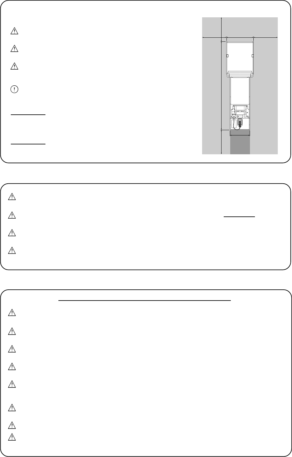
Page 25
ATT BEAKTA VID INSTALLATION
Sätt aldrig på strömmen på maskinen innan installationen är
klar.
För att förhindra elektriska chocker, försäkra dig om att
maskinen kopplas till strömförsörjning med jordad kontakt
För att undvika skador av spelets rörelser, försäkra dig om
att det finns ett avstånd på minst 500 mm till annan maskin
eller vägg.
För att undvika skador på maskinen p g a felaktigt
handhavande, försäkra dig om att strömstyrkan är 230 volt
AC.
OBSERVERA: Om maskinen är placerad på ett polerat golv,
rekommenderas att placera gummibrickor under
nivåjusteringen för att förhindra att maskinen glider
på golvet.
OBSERVERA: För att kunna komma åt strömförsörjningen och
CPU, se till att baksidan av huvudkabinettet är
placerat minst 100cm från vägg eller annan maskin.
ATT TA BORT ELLER BYTA UT ENHETER OCH DELAR
Justeringar och underhåll på denna maskin skall endast utföras av kvalificerad
personal.
Gör inga ändringar på denna maskin utan ett godkännande i förväg. Detta kan förorsaka
oförutsägbar fara.
Endast delar som är specificerade av Namco Europe Ltd. ska användas vid utbyten eller
reparation av delar (inklusive skruvar).
Försäkra dig om att strömmen är avstängd innan underhållsarbete påbörjas (felsökning,
reparationer etc.)
Om arbete ska utföras som inte är beskrivet i denna manual, är det viktigt att kontakta
återförsäljaren för instruktioner eftersom inget ansvar accepteras för åverkan eller
personskador.
Delar av strömförsörjningen och monitorn är varma och strömbärande även efter
strömmen stängts av och kan orsaka brännskador eller elektriska stötar.
Försäkra dig om att maskinen är avstängd innan kontakter sätts i eller tas ur.
När kontakten tas ur maskinen eller ur väggen, ta alltid tag i kontakten och inte i
sladden.
Spelet är försett med hjul för att underlätta förflyttningar. Var försiktig om spelet ska
flyttas på en sluttande yta.
Toppskylten har tyngdpunkten framtill, därför är det viktigt att minst 2 personer sätter
dit eller tar bort den.
Toppskyltens placering är mycket högt upp och det är viktigt att sådana hjälpmedel
används så att man når upp utan att sträcka sig (t ex trappstege, pall osv).
Den totala höjden är 2050 mm, tänk på eventuella högt placerade hinder, t ex lampor.
55cm
76cm
243cm
100cm 100cm
100cm
100cm
Maintenance Zone
Maintenance
zone
Play
zone
Maintenance
zone
Page 26
Tästä julkaisusta ei saa ottaa missään muodossa kopioita yksityis- tai julkiseen käyttöön ilman NAMCO EUROPE LIMITED:in
lupaa.
Tässä ohjekirjassa olevat tiedot pitävät julkaisuhetkellä paikkansa. NAMCO EUROPE LIMITED:illä on kuitenkin oikeus
muutoksiin ilman erillistä ilmoitusta.
Tämä laite on valmistettu EC direktiivien mukaisesti. Se on testattu ja todettu noudattavan seuraavia direktiivejä: 89/336/EEC ja
72/23/EEC (EN55014-1, EN55014-2 ja EN 60335 standardit). Näin ollen tämä laite on varustettu CE-merkinnällä. Kaikki tähän
laitteeseen kohdistetut muutokset on tehtävä EC- direktiivien mukaisesti. Mikä tahansa valtuuttamattoman huoltomiehen tekemä
muutos voi olla direktiivien vastainen.
Laitteen toiminta voi häiriintyä määrätyissä olosuhteissa, jotka johtuvat äärimmäisistä ulkoisista sähköhäiriöistä, kuten
radiolähetys, elektrostaattinen purkaus tai vahvavirrasta syntynyt häiriö. Toiminta normalisoituu kuitenkin heti, kun ulkoinen
sähköhäiriö on poistettu.
Huom:- Jos peliprosessori resetoituu sähkökatkoksen tai vastaavan johdosta, voivat kaikki pelivaraukset hävitä.
Tämä laite ei ole 89/392/EEC direktiivien mukainen kone.
Turvallisuusvaroitus
Tämän laitteen turvallinen käyttö edellyttää käyttöohjekirjan huolellista lukemista ennen laitteen asennusta, säätöä tai käyttöä.
Jos tämän laitteen omistaja antaa jollekin toiselle osapuolelle tehtäväksi purkaa, asentaa, säätää tai muuten huoltaa laitetta, on
omistajan varmistuttava siitä, että toinen osapuoli on lukenut ja ymmärtänyt käyttöohjekirjan oleelliset osat ennen työhön
ryhtymistä.
Turvallisuusohjeita on seurattava tarkoin vahinkojen välttämiseksi laitteen ollessa käytössä .
Tämä ohje sekä mahdollinen asennusohje muodostavat laitteiston oleellisen osan ja on siksi aina oltava huolto- ja
käyttöhenkilökunnan käytettävissä.
Tämä laite on tarkoitettu vain sisätilakäyttöön. Sitä ei saa käyttää muihin tarkoituksiin.
Namco Ltd ei vastaa niistä onnettomuuksista, loukaantumisista tai vahingoista, jotka johtuvat laitteeseen ilman Namco Ltd:n
lupaa tehdyistä muutoksista laitteen väärästä käytöstä.
YLEISET TURVALLISUUNÄKÖKODAT
Varmista, että laite on asennettu oikein ja ohjekirjan mukaisesti ennen käyttöönottoa.
Varoitustaulut on pidettävä hyvässä kunnossa. Jos ne ovat kuluneet, ne on ehdottomasti vaihdettava, jotta
asiakkaalla olisi mahdollisuus lukea niitä selvästi.
Jos laitteeseen tulee vika tai ongelmia, on se pysäytettävä välittömästi ja ongelma selvitettävä ennen uutta
käyttöönottoa.
Vain riittävän ammattipätevyyden omaava henkilö saa suorittaa asennus-, huolto-, säätö- tai muita laitteeseen
kohdistuvia rutiinitoimenpiteitä.
Jotta palovaaraa ei syntyisi, saa pääsulakkeita vaihtaa vain samankokoisiin sulakkeisiin. Muiden sulakkeiden tai
materiaalin käyttö on ehdottomasti kielletty.
Sähköiskujen välttämiseksi vikatapauksissa, laite on ehdottomasti kytkettävä maadoitetulla johdolla
maadoitettuun pistorasiaan.
Vioittunut verkkojohto on välittömästi vaihdettava.
Älä kytke laitetta päälle, ennen kuin se on oikein asennettu.
Varmista ennen verkkoon kytkemistä, että virtalähteen jännitteen asetus on asetettu oikealle jännitteelle ja että siinä on
oikeat sulakkeet.
Turvallisuusohjeet
Tässä käyttöohjekirjassa on käytetty seuraavia turvallisuuteen liittyviä huomautuksia. Tutustu jokaiseen näistä. Älä asenna,
huolla tai säädä laitteistoa, ennen kuin olet täysin ymmärtänyt mitä ne tarkoittavat.
VAARA Vaara tarkoittaa uhkaa, joka voi johtaa loukkantumiseen tai kuolemaan, Älä koskaan ohita Vaara-
merkintää, ennenkuin ohjeissa esitetyt olosuhteet on ymmärretty täysin.
VAROITUS Varoitus tarkoittaa uhkaa, joka voi johtaa laitteen vioittumiseen. Älä koskaan ohita Vaara-merkintää,
ennenkuin ohjeissa esitetyt olosuhteet on ymmärretty täysin.
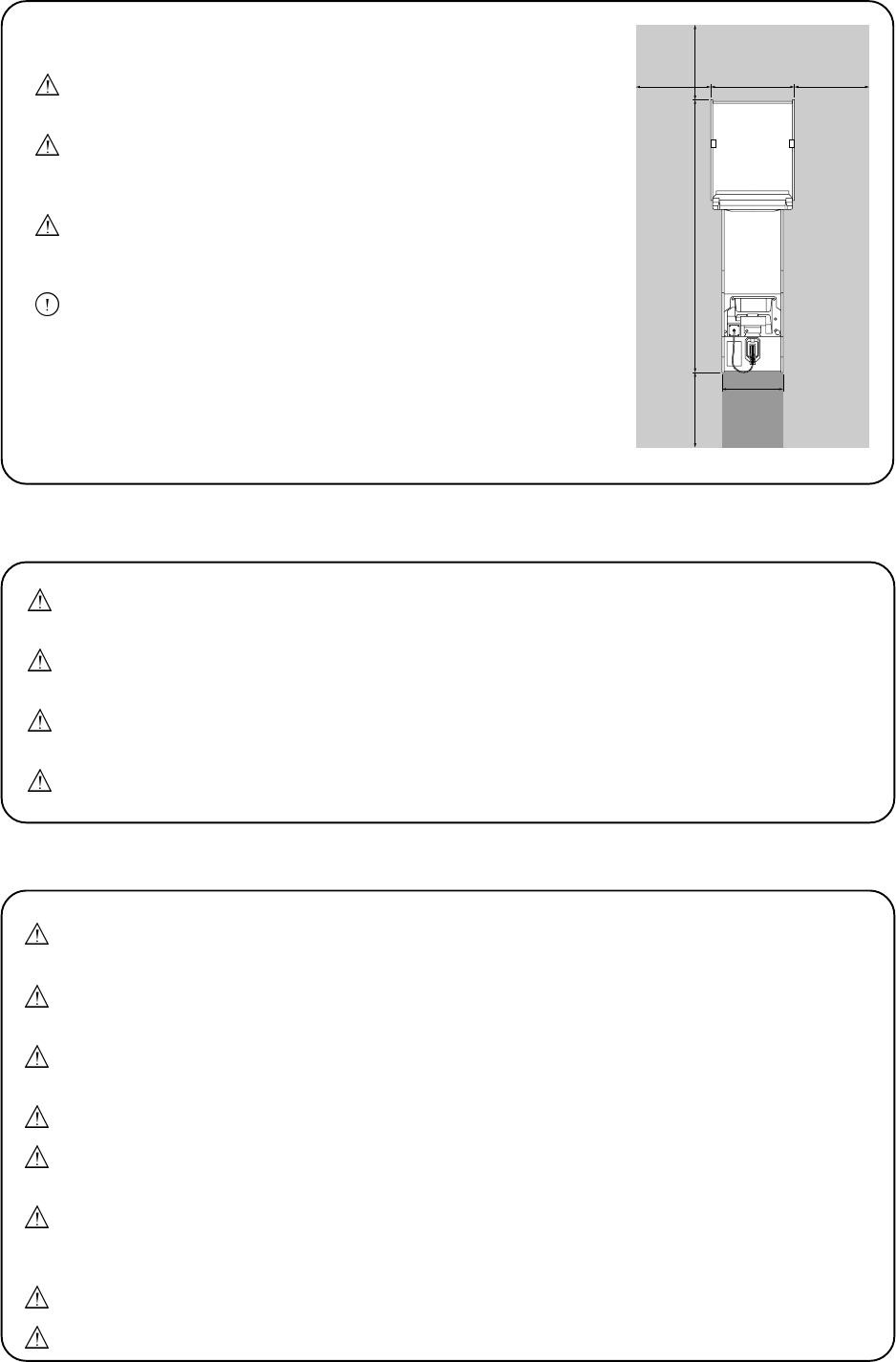
Page 27
ASENNUSHUOMIOITA
Älä koskaan kytke laitetta päälle ennen kuin asennus on
suoritettu loppuun.
Tämän laitteen virtalähde on kytkettävä maadoitetulla
johdolla maadoitettuun pistorasiaan, jotta sähköiskun vaaraa
ei olisi.
Varmista, että laitteen ja seinän tai toisen laitteen välissä on
vähintään 500 mm, jotta asiakkaat eivät loukkaannu laitteen
likkumisesta johtuen.
Varmista, että virtalähteen jännite on 230 V AC, jotta ei laite vioitu.
Huomio: Jos tämä laite sijoitetaan liukkaalle esim. vahatulle lattialle,
suositellaan laitettavaksi kumityynyt säätöjalkoihin liikkumisen
estämiseksi.
Huomio: Varmista, että takaosan taakse jää vähintään 100cm tilaa,
jotta virtalähteeseen ja CPU-korttiin pääsee käsiksi.
Laite on varustettu kääntyvillä pyörillä. Tämä on pidettävä mielessä, kun laitetta siirretään
kaltevalla alustalla.
Yläosan painopiste on yläosan etuosassa. Tästä syystä on yläosaa asennettaessa tai
poistettaessa oltava vähintään kaksi henkilöä.
Yläosan asennusasento on erittäin korkealla. On tärkeää, että tarvittavalle korkeudelle
päästään vaivattomasti ilman venyttämistä. (esim. käytä tukevia tuoleja tai tikkaita)
Laitteen kokonaiskorkeus on yli 2050 mm. Varmista, ettei katossa ole esteitä. esim. valaisimia.
Vain riittävän ammattipätevyyden omaava henkilö saa suorittaa asennus-, huolto-, säätö- tai
muita laitteeseen kohdistuvia rutiinitoimenpiteitä.
Tälle laitteelle ei saa tehdä mitään hyväksymättömiä muutoksia. Se voi aiheuttaa ennalta-
arvaamattomia vaaroja.
Vain Namco Europe Ltd:n määrittelemiä varaosia saa käyttää vaihtaessasi tai korjatessasi
osia. (sisältäen ruuvit).
Varmista, että laite on kytketty POIS PÄÄLTÄ ennen työn aloittamista.
Ota yhteyttä maahantuojaan ohjeita varten, jos joudut tekemään työtehtäviä, joita ei ole esitelty
huoltokirjassa, muuten vastuuta vioista tai loukkaantumisista ei ole.
Virtalähde ja monitori pysyvät kuumina ja niissä on alueita, joissa on korkeajännite vaikka laite
on kytketty pois päältä. Palovammojen tai sähköiskun saaminen on mahdollista. Älä koske
näihin laitteisiin.
Varmista, että laite on kytketty POIS PÄÄLTÄ ennen johtojen kytkemistä tai irrottamista.
Irrottaessasi verkkojohdon seinästä tai laitteesta, ota kiinni itse pistokkeesta, ei johdosta.
55cm
76cm
243cm
100cm 100cm
100cm
100cm
Maintenance Zone
Maintenance
zone
Play
zone
Maintenance
zone
Page 28
1. SPECIFICATIONS
POWER REQUIREMENTS:- 230v / 180watts AC
AMBIENT OPERATING +5°C to +25°C
TEMPERATURE:-
COIN ACCEPTOR:- Mars CashFlow - Single Channel
DIMENSIONS:-
Assembled 760(w) x 2,430(d) x 2,050(h)
Gun Cabinet 550(w) x 1,670(d) x 930(h)
Target Cabinet 760(w) x 1,000(d) x 1,670(h)
Header Assembly 720(w) x 180(d) x 380(h)
WEIGHT:-
Assembled 210kg
Gun Cabinet 65kg
Target Cabinet 143kg
Header Assembly 2kg
ACCESSORIES:- Keys: (Cash Door) ............... 2
(Coin Door) ................ 2
IEC Mains Lead .......................... 1
Operators Manual ....................... 1
CashFlow Documents ................ 1
M5 Security Wrench ................... 1
M8 Security Wrench ................... 1
M8x35 Socket Cap Screw .......... 6
M8x30 Flat Washer .................... 6
E14 24v 15w Lamp ..................... 1
Page 29
2. HOW TO PLAY
Game Description
This game is a Quick Draw Shooting Game where the player draws a gun, aims at
the targets that appear and tries to hit the targets as quickly as possible.
A target appears as soon as the gun is drawn from the holster and the player tries to
complete the four stages (level 1 to level 4) in the shortest possible time.
Flat Bulls-eye targets appear in levels 1 to 3, and in level four, after the Bulls-eye
targets have been hit, a cup shaped target appears. When the cup shaped target is
hit, the cup smashes. The total time taken is displayed and the game is over.
Game Rules
The gun assembly must be placed in the holder before starting. (If the gun is not
placed in the holder, a message is displayed on the dot matrix display and an audible
instruction is given to replace the gun).
However the relevant stage will begin after the time set in the setting mode (Start
Time) is reached.
The time limit to complete each stage can be set for 5, 10 or 15 seconds. After the
time has elapsed, that stage is over and the game moves on to the next stage.
The maximum number of shots for the complete game (levels 1 to 4) can be set as 10,
20 or 30. If the player runs out of shots the game is over even if time or other stages
have not been completed.
How to Play the Game
1) Insert sufficient coins to establish a credit.
2) After the welcome and ready message, the player draws the gun. A target will
appear and the TIME display starts.
3) The player aims and fires the gun at the target. When a bulls-eye target is hit it
will fall over. When the cup target is hit it is blown apart.
4) The TIME display will continually show the total time taken.
5) At game over the players ranking, out of 100, is displayed.
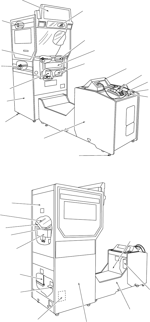
Page 30
3. MAJOR COMPONENTS
Signboard Assy
Dot matrix display
Rear fluorescent tubes
Flat target (U) Assy
Flat target (L) Assy
Shutter Assy
Front fluorescent tube
Time display
7 segment PC board
Target Cabinet
Gun Cabinet
Castor
Adjustable foot
Gun Assy
[SET] lamp
[START] lamp
Instruction panel
Top cover
Rear maintenence door (U)
Rear glass
Chip slope (R)
Chip slope (L)
Launcher Assy
Game PC board
SMPSU
SSR PC board
Target Cabinet
Gun Cabinet
Xenon Assy
Front maintenance door
Page 31
4. MOVING THE MACHINE
This equipment is fitted with castors to make it easier to move. Take care when
moving the equipment on an inclined floor.
The overall height of this equipment is 2050mm. Take care of any overhead
obstructions. (e.g. Light Fittings, Electric Cables etc.)
WARNING NEVER turn the power to the machine ON until installation
has been completed.
WARNING In order to prevent possible electric shocks, be sure that the
machine is connected to the mains with a securely connected
earthed plug.
WARNING So that customers are not injured , ensure that there is at
least 100cm separation between other machines or walls.
CAUTION In order to avoid damage to the machine due to mis-operation,
ensure that the voltage of the mains supply is 230volts AC.
5. INSTALLATION
Notes on Installation
NOTE If the location site of this machine has a polished floor it is
recommended that rubber pads are fitted under the level adjusters
to prevent the machine sliding on the floor.
In order to gain access to the Power Supply and CPU assemblies,
make sure that the rear of the machine is separated from a wall
or other machine by at least 100cm.

Page 32
DIESES GERÄT IST NUR FÜR DIE GEWERBLICHE AUFSTELLUNG IN
GESCHLOSSENEN RÄUMEN BESTIMMT.
DAS GERÄT DARF AN FOLGENDEN PLÄTZEN NICHT AUFGESTELLT WERDEN
1. Im Freien.
2. In direktem Sonnenschein, an extrem feuchten und staubigen Plätzen, an Plätzen mit
Wasseranschlüssen und möglichen Leckagen, nahe Klima- und Heizungsanlagen, an
Plätzen mit extrem hohen oder niedrigen Temperaturen.
3. In der Nähe von Notausgängen oder Feuerlöschgeräten.
4. An unstabilen Plätzen oder Plätzen mit übermäßiger Vibration.
5. An Plätzen, die nicht eben sind.
쮕
DENNE MASKINE ER KUN DESIGNET TIL INDENDØRSBRUG
INSTALLER IKKE MASKINEN PÅ FØLGENDE STEDER
1. Udendørs
2. Direkte sollys, steder med høj fugtighed el. støv, steder med vand udslip, i
nærheden af air-condition eller varme udstyr, steder med usædvanlig høj el. kold
temperatur.
3. Steder hvor den vil stå i vejen for nødudgange eller brandslukningsudstyr.
4. Ustabile steder eller steder med for store vibrationer.
5. Steder der ikke er plane.
ESTA MÁQUINA ESTA DISEÑADA ÚNICAMENTE PARA USO EN INTERIORES. NO
INSTALE LA MÁQUINA EN LOS SIGUIENTES LUGARES.
1. Exteriores.
2. Bajo luz solar directa, en lugares con polvo o humedad excesiva, lugares donde hay
filtraciones de agua, cerca de aparatos de calefacción o de aire acondicionado, lugares
con temperatura ambiente muy alta o muy baja.
3. Lugares donde la máquina obstruya salidas de emergencia o equipos de extinción de
incendios.
4. Suelos inestables o lugares con vibraciones excesivas.
5. Lugares con suelos no nivelados.
This machine is designed for INDOOR USE ONLY.
Do not install in the following places.
1. Outdoors
2. Direct Sunlight, places with excessive humidity or dust, places where there is
water leakage, near air-conditioning or heating equipment, places with
excessive heat or cold temperature.
3. Places where it would be in the way of emergency exits or fire extinguishing
equipment.
4. Unstable places or places with excessive vibration.
5. Places that are not level.
6. This machine must not be cleaned with a water jet, or installed in an area where
a water jet could be used.
Page 33
ও
DENNE MASKINEN ER BARE KONSTRUERT FOR INNENDØRS BRUK
IKKE INSTALLER MASKINEN PÅ FØLGENDE PLASSER.
1. Utendørs
2. Konstant sollys, plasser med mye fuktighet og støv, plasser hvor det er vannlekasje,
nære luft kjølere eller varme elementer, plasser med overdreven høy eller lav temperatur.
3. Plasser hvor det vill stå i veien for nødutganger eller brannslukking utstyr.
4. Ustabile plasser eller plasser med overdreven vibrasjon.
5. Plasser som ikke er i vater.
DEZE MACHINE IS ALLEEN VOOR GEBRUIK BINNENSHUIS ONTWORPEN
INSTALLEER DE MACHINE NIET OP DE VOLGENDE PLAATSEN
1. Buiten
2. In direct zonlicht, op plaatsen met een zeer hoge vochtigheidsgraad of met veel stof, op
plaatsen waar een waterlek is, dichtbij aircos of verwarmingsapparatuur, op plaatsen
met een zeer hoge of koude temperatuur.
3. Op plaatsen waar nooduitgangen of blusapparatuur worden geblokkeerd.
4. Op onstabiele plaatsen of plaatsen waar grote trillingen voorkomen.
5. Op plaatsen die niet vlak zijn.
CETTE MACHINE EST DESTINEE UNIQUEMENT A UN USAGE INTERIEUR
NE PAS INSTALLER LA MACHINE DANS LES ENDROITS SUIVANTS
1. A lextérieur.
2. Directement exposée au soleil, aux endroits excessivement humides ou poussiéreux,
aux endroits où il y a des risques de fuite deau, près de ventilateurs ou source de
chaleur, aux endroits très chauds ou froids.
3. Dans des zones de proximité des sorties de secours ou daccès aux équipements
dextinction du feu.
4. Dans des emplacements instables ou soumis à de fortes vibrations.
5. Dans des endroits dénivelés.
ΤΟ ΜΗΧΑΝΗΜΑ ΕΙΝΑΙ ΣΧΕ∆ΙΑΣΜΕΝΟ ΓΙΑ ΧΡΗΣΗ ΣΕ ΕΣΩΤΕΡΙΚΟ ΧΩΡΟ ΜΟΝΟ
ΜΗΝ ΤΟΠΟΘΕΤΗΣΕΤΕ ΤΟ ΜΗΧΑΝΗΜΑ ΣΤΟΥΣ ΑΚΟΛΟΥΘΟΥΣ ΧΩΡΟΥΣ
1. Εξωτερικά
2. Απευθείας στον ήλιο,σε µέρη /που υπάρχει υγρασία ή σκ/νη,µέρη /που υπάρχει
άφθονο νερ/,κοντά σε air-condition ή άλλου είδους θέρµανση,µέρη µε υπερβολική
υψηλή ή χαµηλή θερµοκρασία.
3. Σε µέρη /που εµποδίζουν µέσα ανάγκης π.χ. πυροσβεστήρες ή άλλα.
4 Μη σταθερά µέρη ή µέρη µε πολλούς κραδασµούς.
5. Μέρη που δεν είναι επίπεδα.
QUESTA MACCHINA E PROGETTATA PER ESSERE USATA ESCLUSIVAMENTE IN
AMBIENTI INTERNI.
NON INSTALLARE LA MACCHINA NEI SEGUENTI LUOGHI.
1. In ambienti esterni.
2. Alla luce diretta del sole, in posti con eccesiva umidità o polvere, in luoghi dove ci siano
infiltrazioni dacqua, vicino ad apparecchi di condizionamento daria oppure
riscaldamento, in posti eccessivamente caldi o freddi.
3. In luoghi dove potrebbe esserci un uscita di emergenza o unattrezzatura per lo
spegnimento del fuoco.
4. In posti non stabili o con eccessive vibrazioni.
5. In luoghi non piani.

Page 34
ESTA MAQUINA FOI CONCEBIDA PARA UTILIZAÇÃO EM ESPACOS
INTERIORES APENAS
NÃO INSTALAR A MAQUINAS NOS SEGUINTES LOCAIS:-
1. Exteriores.
2. `Luz solar directa, locais com humidade excessiva ou pó, locais aonde existam fugas de
água perto de ar condicionados ou equipamentos calorificos e locais com temperaturas
excessivamente quentes ou frias.
3. Locais aonde ficaria colocada no caminho de saidas de emergência ou equipamentos
extintores de fogo.
4. Locais estruturalmente instaveis ou locais com vibrações excessivas.
5. Locais não nivelados.
DENNA MASKIN ÄR AVSEDD ENBART FÖR INOMHUSBRUK
INSTALLERA EJ MASKINEN PÅ FÖLJANDE STÄLLEN
1. Utomhus
2. I direkt solsken, platser med extremt hög luftfuktighet eller damm, platser där det
förekommer vattenläckage, nära luftkonditionering eller värmeelement, i extremt hög
eller låg temperatur.
3. Platser där den skulle kunna vara i vägen för nödutgångar och
brandsläckningsutrustning.
4. Instabila ställen eller där stark vibration förekommer.
5. Platser med nivåskillnad.
TÄMÄ LAITE ON SUUNNITELTU VAIN SISÄKÄYTTÖÖN
ÄLÄ ASENNA LAITETTA SEURAAVIIN PAIKKOIHIN:
1. Ulkotilaan
2. Suoraan aurinkovaloon, kosteisiin tai pölyisiin paikkoihin, vesivuotopaikkojen
läheisyyteen, ilmanvaihto- tai lämmityslaitteen lähistölle tai paikkoihin, jossa on erittäin
kuumaa tai kylmää.
3. Varauloskäytävien, muiden pakoteiden tai tulensammutusvälineiden eteen.
4. Epävakaisiin tai täriseviin paikkoihin.
5. Kaltevalle alustalle.
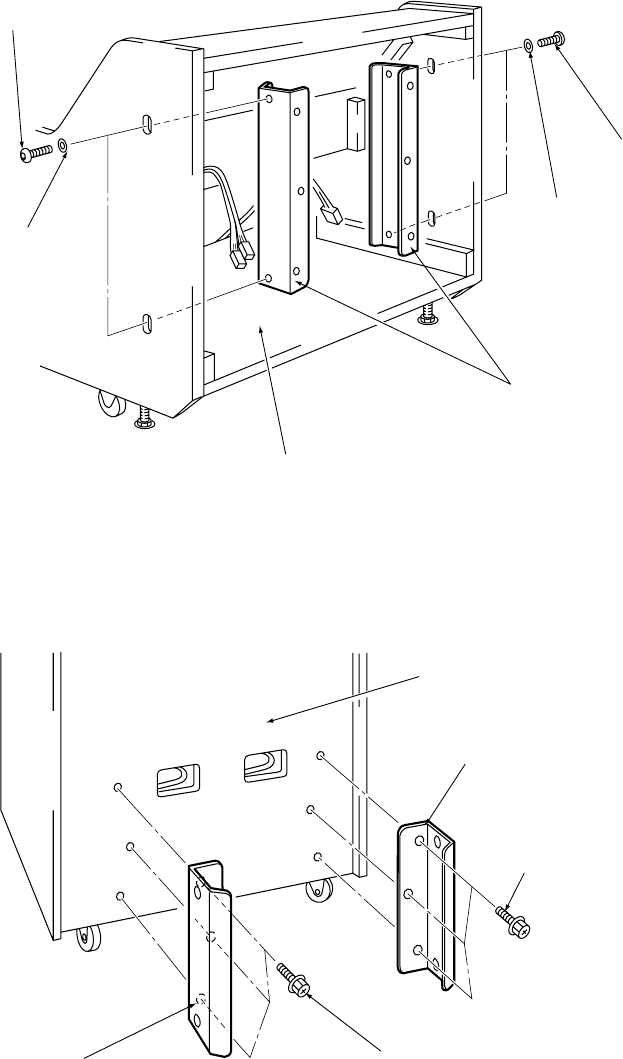
Page 35
5-1 Joining the Front and Rear Cabinets
1. Remove 4off Button head screws (M8x35) and remove the Joint Brackets from
inside the Gun Cabinet. (Do not lose the screws as these are required for refitting
later).
2. Fit the Joint Brackets to the Target Cabinet with 6off Button head screws
(M8x35), with flat washers, supplied.
Button head screw
(M8x35) x2
Spring washer
(M8) x2
Joint brackets
Gun Cabinet
Spring washer
(M8) x2
Button head screw
(M8x35) x2
Target cabinet
Joint bracket
Button head screw
(with flat washer)
(M8x35)
Joint bracket Button head screw
(with flat washer)
(M8x35)
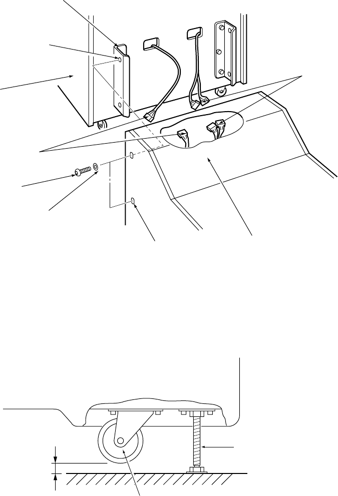
Page 36
3. Connect the connectors and slide the Gun Cabinet upto the Target Cabinet,
taking care not to trap any wires, and retain using the 4off Button head screws
removed in 1 above.
4. When the game is fully assembled and in its correct position, lower the four level
adjusters on the Gun Cabinet, with a spanner, so that the game is level and the
castors are raised from the floor by approx. 5mm. Tighten the lock nuts with a
spanner to ensure that the level adjusters do not move.
Connectors
Gun Cabinet
Connectors
Threaded Hole
Joint bracket
Target Cabinet
Button head screw
(M8x35)
x2 each side
Spring washer
(M8)
x2 each side
Slotted hole
Adjustable Foot
Castor
Approx. 5mm
Target Cabinet
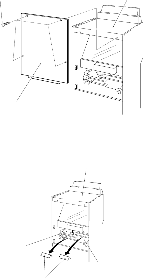
Page 37
5-2 Removing the Flat Target Packing.
1. Remove the four off Button head screws (M5x35) and remove the rear upper
door on the Target Cabinet.
(Note: Take care that the door does not fall when removing the four screws ).
2. Remove the cardboard packing from both the Upper and Lower Flat Target
Assemblies
Note: Retain the packing pieces for refitting at any time the game is moved or
transported .
3. Refit the rear upper door.
Target Cabinet
Target Assy (L)
Packing
Target Assy (U)
Button head screw
(M5x35) Target cabinet
Rear maintenance door (U)
Page 38
6. ADJUSTMENTS
Adjustment or maintenance on this machine should be carried out by
qualified personnel only.
Einstellungen und Wartung des Gerätes dürfen nur von dafür
qualifiziertem Fachpersonal vorgenommen werden.
Justeringer eller vedligehold af denne maskine bør kun udføres af
kvalificeret personale.
Los ajustes y el mantenimiento de esta máquina deben ser realizados sólo
por personal cualificado.
Linstallation, le service, le réglage, ou la maintenance doivent être
effectués uniquement par les personnes qualifiées.
Μετατροπές ή επιδιορθώσεις στα µηχανήµατα πρέπει να γίνονται µ/νο απ/
εξουσιοδοτηµένα άτοµα.
Regolazioni e manutenzione su questa macchina devono essere fatti solo
da personale specializzato.
Justering eller vedlikehold på denne maskinen skall bare utføres av
kvalifiserte personell.
Aanpassingen of onderhoud aan deze machine dient alleen uitgevoerd te
worden door bekwaam personeel.
Afinações ou manutenção nesta maquina, deverão ser efectuadas sómente
por pessoal qualificado.
Justeringar och underhåll på denna maskin skall endast utföras av
kvalificerad personal.
Tätä laitetta saa säätää tai huoltaa vain siihen ammattipätevyyden omaava
henkilökunta.
Page 39
6-1 Adjustment Switches
The Adjustment switches are located inside the coin door.
1. Service Switch.
Press this switch to obtain game credits without incrementing the play meter, to
change the settings when in the Setting Mode and to select test numbers when in
the Test Mode.
2. Test Switch
Slide the test switch ON to enter test mode.
The Test Mode allows testing and the changing of game settings. (Refer to
sections 6-2 Setting Mode" page 40 and 6-3 Test Mode page 42)
3. Select Switch
This switch is used to select items when in the Setting Mode, and to operate
selected tests when in the Test Mode.
4. Volume Controls
These control the sound level of the speakers in the Target Cabinet and the Gun
Cabinet.
COIN COUNTER
TEST SERVICE
SELECT
2 Amp Q/B
(Coin Fuse)
VOLUME VOLUME

Page 40
6-2 Setting Mode
This mode allows the changing of various game and price settings.
6-2-1 Setting Mode Operation
1. Slide the Test switch on while pushing the Select switch.
2. The item and settings are displayed on the Dot Matrix Display. The selected item
changes each time the Select switch is operated.
3. Press the Service switch to change the setting of the selected item.
Note: When setting the Ticket Payout number pull the gun trigger to change
the value.
4. Slide the Test switch OFF to store the changed settings and to return to the
normal game mode.
Note: Any credits established are lost each time the test switch is turned on
or off.
5. To return the settings to the Factory Settings slide the test switch off while
pressing the service switch.
Note:- The price of play on this machine is set within the Cashflow Coin Mech.
Ensure that the Game Pricing is set to 1 Credit 1 Coin.
rebmuNmetIyalpsiDxirtaMtoDnoitpircseDteSyrotcaF
1gnicirpemaG)S(NIOC#-TIDERC1 emag1rofecirpehtsteS
snioc9ot1=# 1
2edomtekciT
gnittes #EDOMTEKCIT edomtekcitehtsteS
edomtekciT]1[/tekcitnoN]0[=# 0
3tratsemaG
emit ces#EMITTRATS
hcaegnitratsyllacitamotuarofemitehtsteS
deyalpsidYDAERretfaegats
).ces(51ot1=#
8
4emitemaG
timil #EMITEGATS levelhcaeroftimilemitmumixaM
).ces(51/01/5=# 01
5stohsfo.oN#TIMILSTOHS emagrofstohsforebmunmumixaM
03/52/02/51=# 02
6yrtneemaN
emit #YRTNEEMAN emangniretneroftimilemiT
04/53/03/52/02/51=# 03
7dnuostcarttA#DNUOSTCARTTA nodnuostcartta]1[/ffodnuostcartta]0[=# 1
8gnivoM
tcartta #TCARTTAGNIVOM
tcarttalamrontahtsemitforebmunehtsteS
tegratgnivomaerofebdemrofrepsiedom
demrofrepsiedomtcartta
semit01ot0)niecnO(=#
3
9tekciteerF
gnittes TKTEERF# nevigsitekciteerfarehtehwsteS
nevigtekcit]1[/tekciton]0[=# 1
01 tuoyaptekciT
.oN
TKT
REBMUNYAP
EDCBA
#-#-#-#-#
.tuoyapotstekcitforebmunehtsteS
EotAurhtegnahcotreggirtnuglluP
eulavehtegnahcothctiwsecivresesU
9ot0=#
5=A
4=B
3=C
2=D
1=E
11
tekcitsunoB
erocstuoyap
gnittes
TEKCITSUNOB
KNARYAP#
stekcitsunobgniyaprofdedeenknarehtsteS
sihtotputuosyap(5ot1,)sunobon(0=#
)gniknar
3
21
tekcitsunoB
.oNtuoyap
gnittes
SUNOB
TEKCITYAP#
.deyapebotstekcitsunobforebmunehtsteS
05ot0=# 02

Page 41
6-2-2 Ticket Payout Setting
nDo not operate in ticket mode without a ticket dispenser connected
1. Free ticket setting
This setting when ON will pay one ticket at the end of each game if no score
tickets have been awarded.
2. Ticket payout No. setting
This sets the number of tickets to be payed out depending upon achieved
ranking at the end of each level. The game will give a rank between A to E
as a default value according to the total time at the end of each level, and
pays out the tickets (0 to 9 tickets) preset for that rank.
3. Bonus ticket payout score setting
Pays out bonus tickets if the ranking of the total time is within the top 3 (can
be set from the top 1 up to the top 5).
4. Bonus ticket payout No. setting
Sets the number of tickets to pay out to the player achieving the rank level
set in 3 above.
tekcittuoyaP
eulavtluafeD
fodneehttaemiT
1leveL
fodneehttaemiT
2leveL
fodneehttaemiT
3leveL
fodneehttaemiT
4leveL
AknaRstekciT5997.0999.1999.2999.3
BknaRstekciT4999.0994.2994.3999.4
CknaRstekciT3994.1999.2999.3999.5
DknaRstekciT2999.1994.3994.4999.6
EknaRtekciT1000.2005.3000.5000.7

Page 42
6-3 Test Mode
1. Open the coin door and slide the test switch ON. The Test Item and Test No.
(number) are displayed on the Dot Matrix Display.
2. Press the Select switch to step to the next Item.
3. Press the Service switch to change the Test No. (number). Each time the service
switch is pressed the Test No. (number) will change and the indicated test will
begin.
Note: In the sound test, the number is changed by operating the trigger on
the gun assembly.
4. Slide the Test switch OFF to return to normal game mode.
Note: Any credits established are lost each time the test switch is turned on
or off.
redrOmetIyalpsiDxirtaMtoDnoitpircseD
1tsetpmaLTSETPMAL
)eulavon(
sihtgnitratsretfadnocesenO.spmalehtfohcaestseT
tsetpmalehtdnayletelpmocsthgilxirtaMtoDeht,tset
.strats
redrotseT
yletelpmocsthgilyalpsiDxirtaMtoDehT
sthgilpmalredaeHtfeL
sthgilpmalredaeHthgiR
sthgilpmal]TES[
sthgilpmal]TRATS[
2tsetnoitarepO#TSETNOITOM.tinuevridhcaeforosnesdnanoitarepoehtstseT
fostigid5lla,NOsinoitarepohcaerofrosnesehtnehW
.8rebmunehtyalpsidlliwDELtnemges7eht
=#
=#
=#
=#
=#
=#
=#
tsettnemevomyssA)U(tegrattalF]1[
tsettnemevomyssA)L(tegrattalF]2[
tsetnoitarepoyssArehcnuaL]3[
tsetnoitarepoNWOD/PUyssA)U(tegrattalF]4[
tsetnoitarepoNWOD/PUyssA)L(tegrattalF]5[
tsetnoitarepoyssArettuhS]6[
tsetpmalnoneX]7[
3tsethctiwS#TSETWS]1[tsetehT.srosnesgniviecerthgildnasehctiwsstseT
.stegratehttanugehtgnirifybdemrofrepera]3[ot
88[,detavitcasihctiwsrorosnesanehW
888.
si]
.yalpsiDemiTehtnideyalpsid
=#
=#
=#
=#
tsetrosnestegratpuC]1[
tsetrosnes)U(tegrattalF]2[
tsetrosnes)L(tegrattalF]3[
nioC,hctiwsreggirT,rosnesnoitcetednuG]4[
4tsetdnuoS#TSETDNUOSdnuosehtstseT
lliwrebmuneht,detareposireggirtehtemithcaE
tahtotdetaicossaataddnuosehtdnaenoybesaercni
.sdnoces01fomumixamarofdecudorpeblliwrebmun
=#]021ot1[
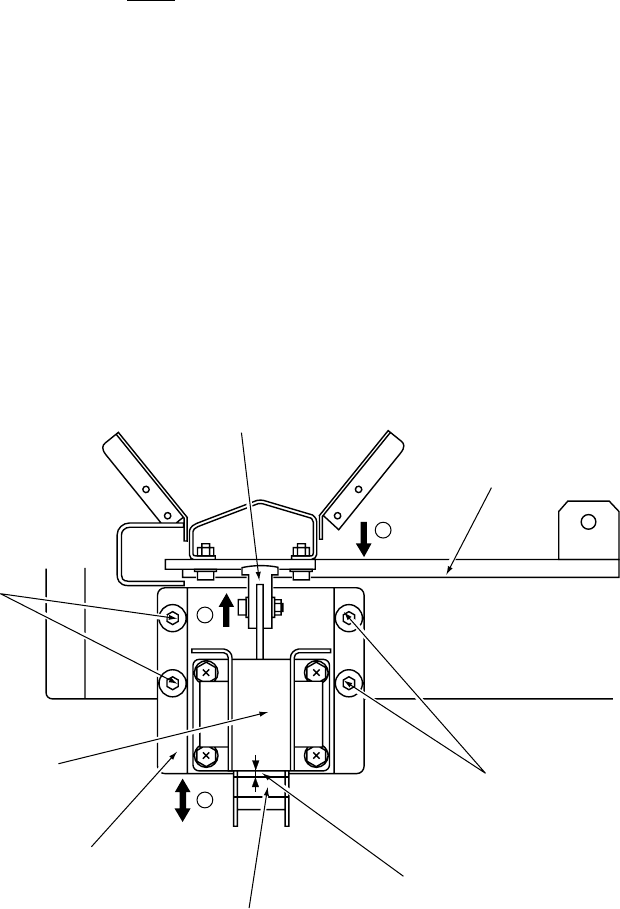
Page 43
6-4 Adjusting the Launcher Solenoid
The Launcher Solenoid must be adjusted after replacement.
1. Loosen the 4off socket flange head screws (M6x10), only sufficiently so that the
solenoid bracket can just be moved by hand.
If the screws are loosened too much it will make it difficult to adjust the solenoid.
2. Lower the solenoid bracket in the direction of arrow (a), and hold it in place by
hand so that it does not move up. Push the plunger block up, in the direction of
arrow (b), until it comes in contact with the solenoid arm.
3. Whilst maintaining the position of step 2 above, move the solenoid bracket in the
direction of arrow (c) so that there is a gap of approximately 2.5mm between the
launcher solenoid and solenoid plunger.
4. Re-tighten the 4off flange socket head screws (M6x10).
After re-tightening the 4off flange socket head screws (M6x10) check that
the gap between the launcher solenoid and solenoid plunger is still approx.
2.5mm, if not repeat steps 1 to 4 above.
c
b
a
Plunger block
Solenoid arm
Flange socket
head screw
(M6x10) x2
The space between the
solenoid plunger and solenoid
body should be approx. 2.5mm
Solenoid plunger
Solenoid bracket
Launcher solenoid
Flange socket
head screw
(M6x10) x2
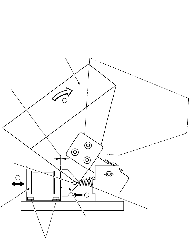
Page 44
6-5 Adjusting the Shutter Solenoid
The Shutter Solenoid must be adjusted after replacement.
1. Loosen the 4off socket flange head screws (M5x8), only sufficiently so that the
solenoid can just be moved by hand.
If the screws are loosened too much it will make it difficult to adjust the solenoid.
2. Move, and hold, the Cup target cover as far as it will go in the direction of arrow
(b). Move the Shutter solenoid in the direction of arrow (c) so that there is a gap
of approximately 1mm between the Shutter solenoid and the solenoid plunger.
Take care not to over stretch the solenoid spring.
3. Re-tighten the 4off flange socket head screws (M5x8).
After re-tightening the 4off flange socket head screws (M5x8) check that the
gap between the Shutter Solenoid and Solenoid Plunger is still approx.
1mm, if not repeat steps 1 to 3 above.
a
b
c
Cup target cover
Adjust so that the space
between the shutter solenoid
and the solenoid plunger is
approximately 1mm.
Shutter solenoid shaft
Shutter solenoid
Flange socket head
screws (M5x8)
Solenoid plunger
Solenoid spring
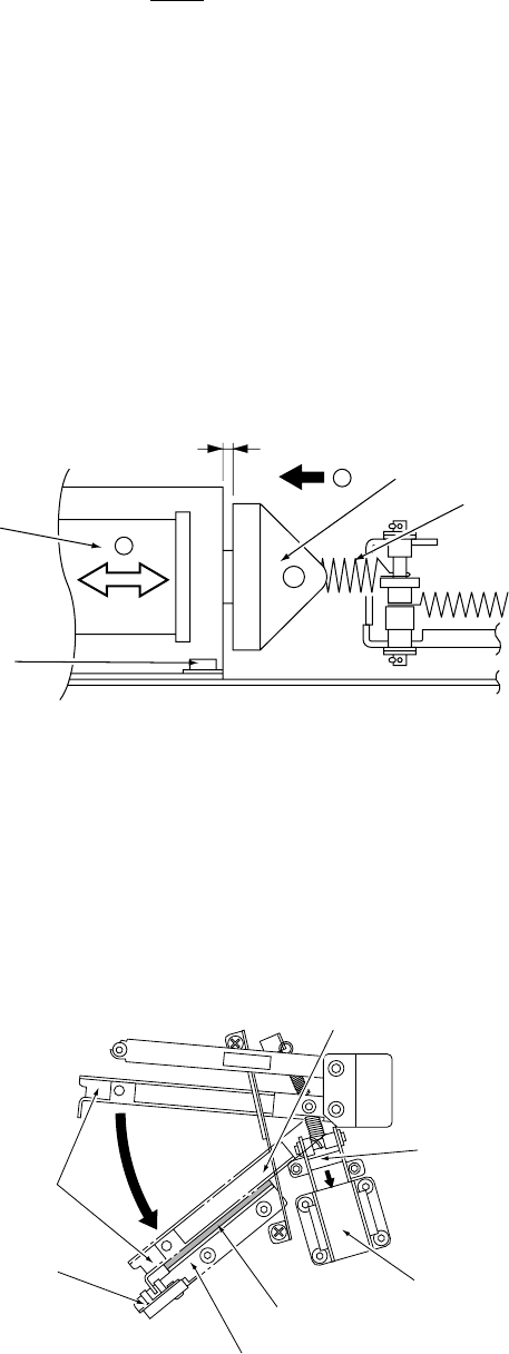
Page 45
6-6 Adjusting the Flat Target (U)/(L) Solenoids
The Flat Target (U)/(L) Solenoid must be adjusted after replacement.
1. Loosen the 4off socket flange head screws (M5x8), only sufficiently so that the
solenoid can just be moved by hand.
If the screws are loosened too much it will make it difficult to adjust the solenoid.
2. Move and hold the solenoid plunger in the direction of arrow (a). Move the Flat
target (U)/(L) solenoid in the direction of arrow (b) so that there is a gap of
approximately 0.5mm between the flat target (U)/(L) solenoid and the solenoid
plunger.
Take care not to over stretch the solenoid spring.
3. Re-tighten the 4off flange socket head screws (M5x8).
After re-tightening the 4off flange socket head screws (M5x8) check that the
gap between the Flat Target (U)/(L) solenoid and solenoid plunger is still
approx. 0.5mm, if not repeat steps 1 to 3 above.
Firmly press the solenoid plunger in the direction of the arrow, and make sure
that the main arm comes in contact the Rubber Stopper D when the solenoid
plunger comes in contact with the Flat Target (U)/(L) solenoid.
a
b
Solenoid plunger
Solenoid spring
Flat target solenioid
Flange socket head
screws (M5x8)
Adjust so that the gap between
the Flat Target solenoid
and the solenoid plunger
is approx. 0.5mm
Make sure that the main arm
comes in contact with the
rubber stopper D
Solenoid plunger
Flat target (U)/(L) solenoid
Rubber stopper D
Stopper D
Flat target (U)/(L) position
detector sensor
Main arm
Page 46
7. MAINTENANCE
Adjustment or maintenance on this machine should be carried out by
qualified personnel only.
Ensure that the POWER to the machine is turned OFF before commencing
any maintenance work. (Trouble shooting, service or repairs etc.)
Einstellungen und Wartung des Gerätes dürfen nur von dafür qualifiziertem
Fachpersonal vorgenommen werden.
Vor Beginn aller Wartungsarbeiten (Fehlersuche, Reparaturen etc.) muß der
Netzstecker gezogen werden.
Justeringer eller vedligehold af denne maskine bør kun udføres af
kvalificeret personale.
Sørg for, at strømmen til maskinen er slukket før der foretages nogen form
for arbejde (fejlfinding, reparation etc.)
Los ajustes y el mantenimiento de esta máquina deben ser realizados sólo
por personal cualificado.
Asegúrese de que la máquina está desconectada antes de comenzar
cualquier trabajo de mantenimiento (reparaciones, resolución de
problemas, etc.)
Linstallation, le service, le réglage, ou la maintenance doivent être
effectués uniquement par les personnes qualifiées.
Sassurer que linterrupteur soit sor OFF avant de commencer tout travail
de maintenance (localisation dune panne, rèparations, etc.)
Μετατροπές ή επιδιορθώσεις στα µηχανήµατα πρέπει να γίνονται µ/νο απ/
εξουσιοδοτηµένα άτοµα.
Να είναι σίγουρα κλειστ/ το ρεύµα πριν οποιαδήποτε δουλειά στο
µηχάνηµα.
Regolazioni e manutenzione su questa macchina devono essere fatti solo
da personale specializzato.
Assicurarsi che la macchina sia SPENTA prima di incominciare qualsiasi
lavoro di manutenzione (guasti, riparazioni etc.)
Justering eller vedlikehold på denne maskinen skall bare utføres av
kvalifiserte personell.
Forsikre deg om at strømmen er slått av før du påbegynner noe som helst
vedlikeholdsarbeid (feilsøking, reparasjon osv.)

Page 47
Aanpassingen of onderhoud aan deze machine dient alleen uitgevoerd te
worden door bekwaam personeel.
Zorg ervoor dat de machine UITgeschakeld is voordat er enig
onderhoudswerk wordt verricht (troubleshooting, reparaties etc.)
Afinações ou manutenção nesta maquina, deverão ser efectuadas sómente
por pessoal qualificado.
Certifique-se que a maquina se encontra desligada sempre que iniciar
qualquer tipo de trabalho de manutenção. (identifação de avarias,
reparação etc.)
Justeringar och underhåll på denna maskin skall endast utföras av
kvalificerad personal.
Försäkra dig om att strömmen är avstängd innan underhållsarbete påbörjas
(felsökning, reparationer etc.)
Tätä laitetta saa säätää tai huoltaa vain siihen ammattipätevyyden omaava
henkilökunta.
Varmista, että laite on kytketty POIS PÄÄLTÄ ennen työn aloittamista.
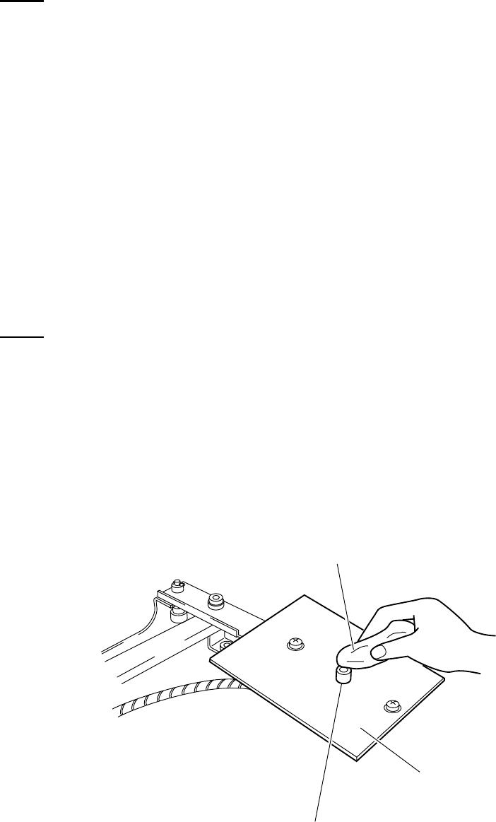
Page 48
7-1 Regular Cleaning
This game relies upon light to operate correctly and it is important that glasses,
mirrors, sensors and lenses are kept clean.
Never use any solvent products to clean the above items as the solvent may
cause irreparable damage.
7-1-1 Cleaning the Glasses and Half Mirror.
Take care when removing, cleaning or replacing a glass or half mirror so as not
to break or scratch them.
Glass and the half mirror should be cleaned with a propriety, non abrasive, glass
cleaner or a damp cloth soaked in a mild detergent. When using a mild detergent
ensure that the detergent is rinsed off.
See section 7-4 page 55 for removing the Rear Glass.
See section 7-7 page 58 for removing the Front Acrylic.
See section 7-8 page 60 for removing the Half Mirror.
7-1-2 Cleaning the Flat Target Sensor Assy
Never use any solvent products to clean the sensor as the solvent may cause
irreparable damage.
1.Remove the display cover as described in section 7-9 page 62.
2.Remove the maintenance door and cover B as described in section 7-10
page 64
3. Wipe and clean the surface of the Flat Target sensor with a clean, dry, lint
free cloth.
4. Reassemble in the reverse order.
Soft, dry,
lint free cloth
Flat target
Flat target
sensor Assy
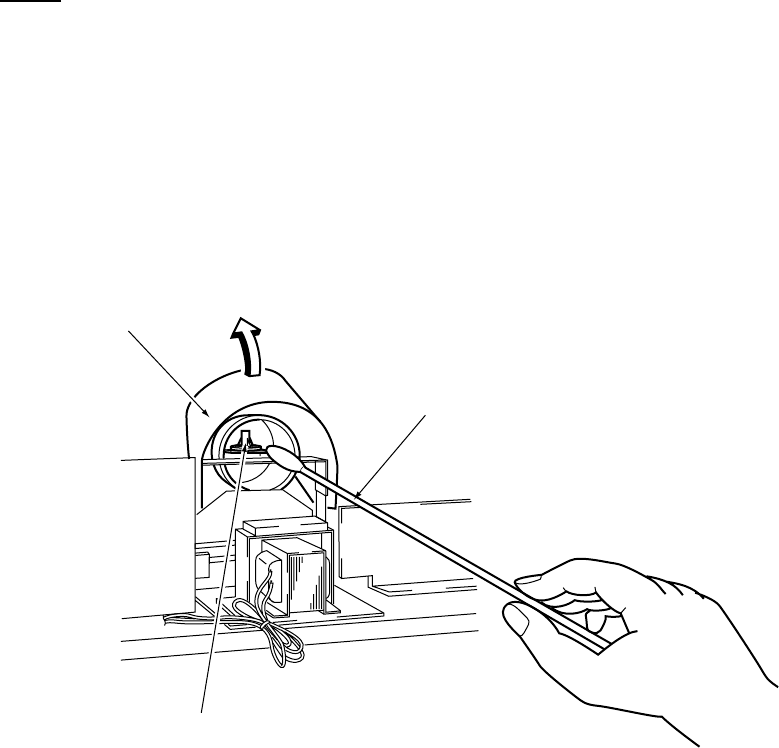
Page 49
7-1-3 Cleaning the Cup Target Sensor
Never use any solvent products to clean the sensor as the solvent may cause
irreparably damage.
1.Remove the display cover as described in section 7-9 page 62.
2.Remove the maintenance door as described in section 7-10 page 64
3. Move the Cup Target Cover in the direction of the arrow, in the following
figure, and clean the surface of the sensor with a clean cotton swab.
4. Reassemble in reverse order.
Move the Cup Target
cover in the direction
of the arrow
Cotton swab
Cup Target
sensor Assy
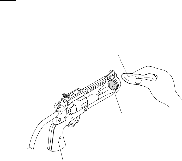
Page 50
7-1-4 Cleaning the Gun Lens
Never use any solvent products to clean the lens as the solvent may cause
irreperable damage.
1. Wipe and clean the surface of the Gun Lens with a clean, dry, lint free
cloth.
Gun Assy
Lens
Soft, dry cloth
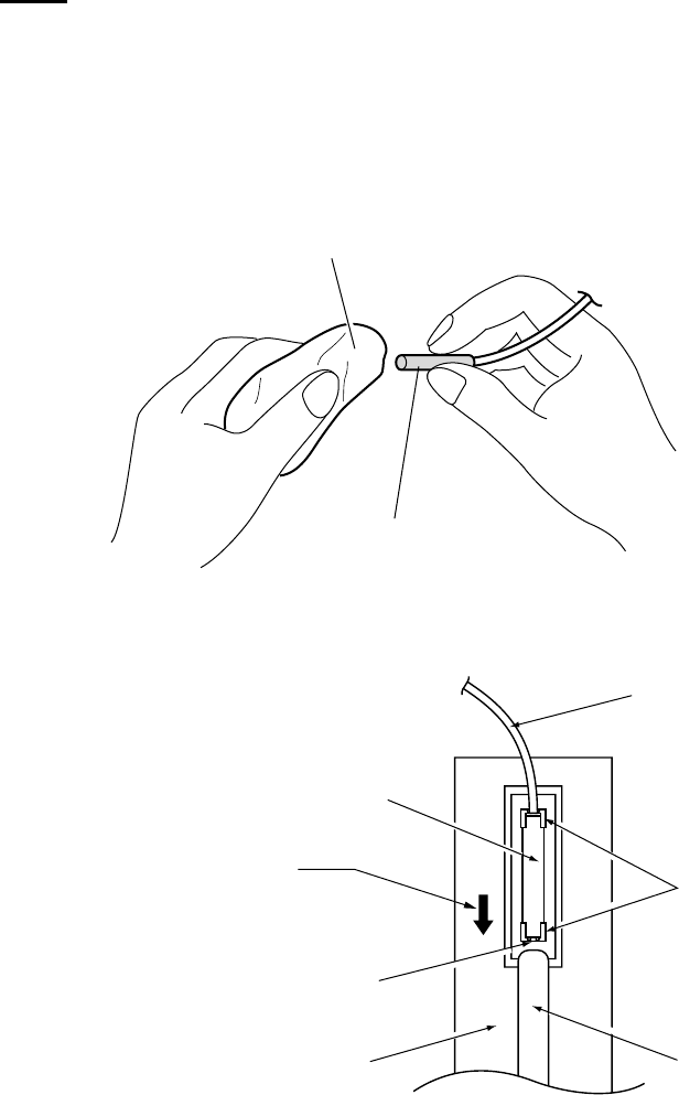
Page 51
7-1-5 Cleaning the Fibre Optic Cable
Never use any solvent products to clean the Fibre Optic Cable as the solvent
may cause irreparable damage.
1.Remove the Fibre Optic Cable as described in section 7-30 page 93
2. Wipe and clean the surface of the Fibre Optic Lens with a clean, dry, lint
free cloth.
3. Reassemble in reverse order.
Soft, dry cloth
Fibre optic
Fiber Optic Cable
Holder
Xenon Tube
Xenon PC Board
When refitting, push the
Fiber Optic in until the end
comes into contact with
the stopper in the holder
Stopper
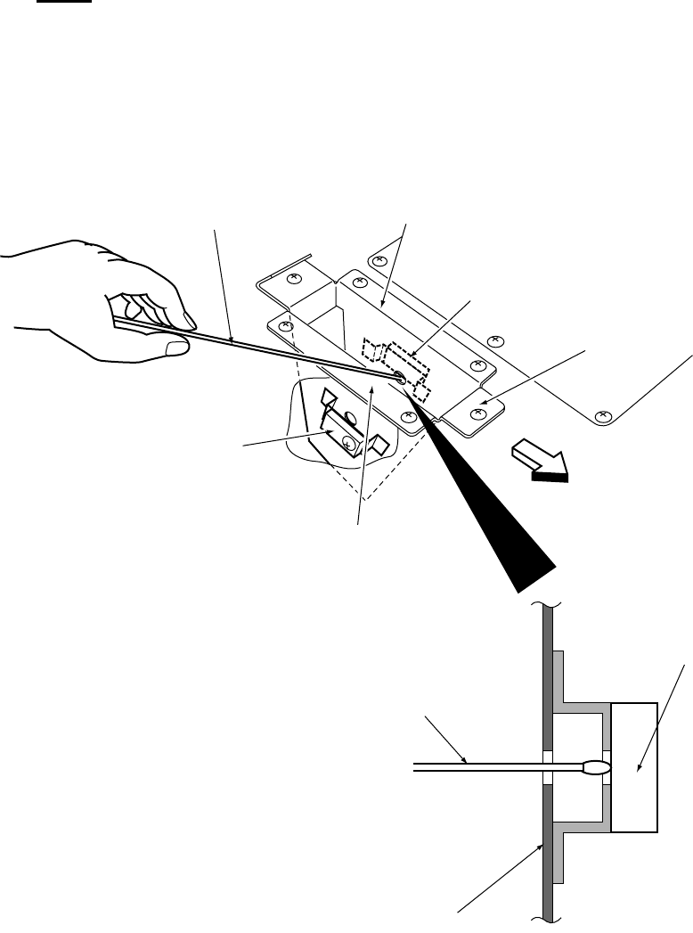
Page 52
7-1-6 Cleaning the Gun Holster Detection Sensor
Never use any solvent products to clean the lens as the solvent may cause
irreparable damage.
1.Remove the holster cover as described in section 7-26 page 87.
2. Wipe and clean the surface of the Gun Holster Detection Sensor with a
clean, dry, lint free cloth.
3. Reassemble in reverse order.
FRONT
Cotton swab Holder bracket (R)
Gun detection sensor
(Projection side)
Holder bracket (C)
Holder bracket (L)
Gun detection sensor
(Receiving side)
Cotton swab
Gun detection sensor
(Projection side)
Holder bracket
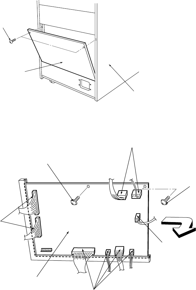
Page 53
7-2 Replacing the Game PC Board
Note: The Game PC Board is susceptible to damage from static electricity. Anti static
precautions should be taken when removing, handling and refitting the Game
PC Board.
1. Remove the 2off Button head screws (M5x35) and remove the rear maintenance
door (L) of the Target Cabinet.
2. Disconnect all the connectors from the PC Board.
3. Remove the 2off pozi head screws
4. Slide the Game PC Board in the direction of the arrow, in the diagram above, and
remove the board.
5. Reassemble in the reverse order.
Button head screw
(M5x35)
Target Cabinet
Maintenance Door (L)
Connectors
Connectors
Connectors
Connector
Game PC Board
Pozi flange head screw
(M3x6)
Pozi head screw
(M3x6)
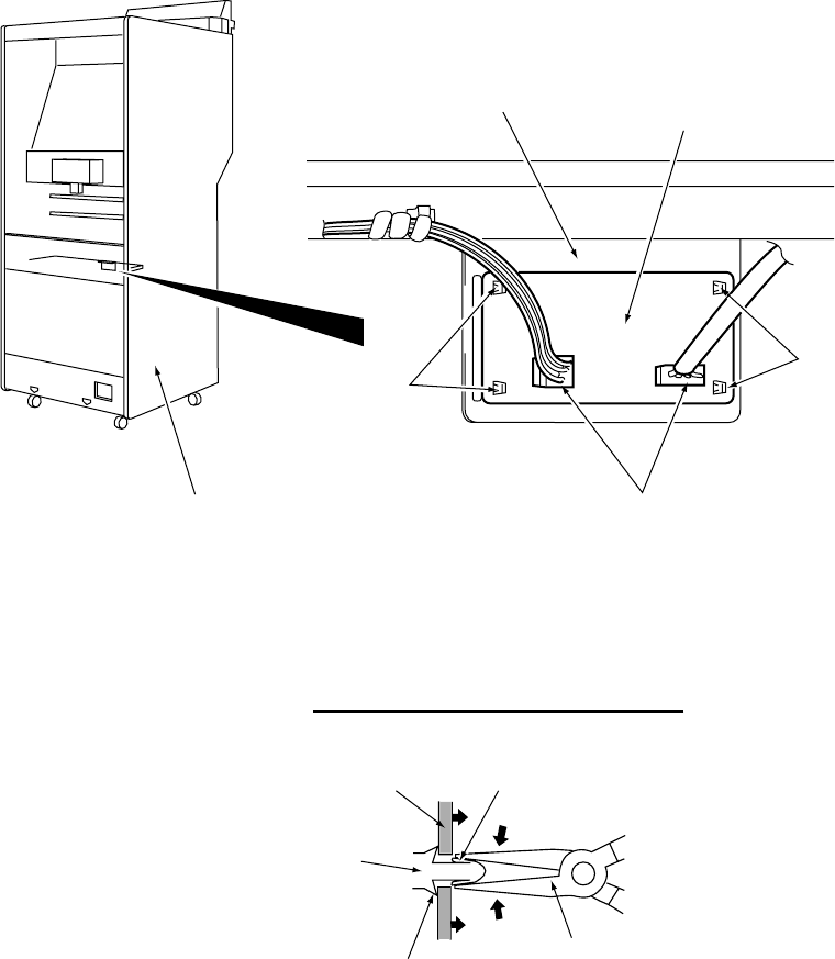
Page 54
7-3 Replacing the Cup Target Sensor PC Board
1. Remove the upper rear maintenance door from the Target Cabinet.
2. Remove the connectors.
3. Using needle nosed pliers, squeeze the locking tabs of the locking supports, one
at a time, to release the PC Board. Remove the Sensor PC Board.
4. Replace the board by gently pushing the board on to the locking supports.
5. Refit the connectors and upper rear maintenance door.
Target Cabinet
Cup Target
Sensor Bracket Cup Target
Sensor PC Board
Locking
Supports
Connectors
Locking
Supports
Tab
Needle Nosed
Pliers
Stopper
Locking Support
PC Board
Releasing the Locking Supports
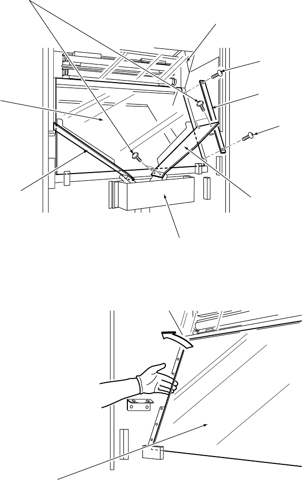
Page 55
7-4 Replacing the Rear Glass
1. Remove the upper rear maintenance door from the Target Cabinet.
2. Remove 4off pozi flange head screws (M5x12) and remove the Chip Slope (L).
3. Remove 4off pozi flange head screws (M5x12) and remove the Chip Slope (R).
4. Remove the 4off Button head screws (M5x35) and remove the window plates.
5. Remove the glass in the direction of the arrow in the diagram below.
6. Reassemble in reverse order.
Pozi flange screws
(M5x12)
Light Guard
Button head screw
(M5x35)
Window Plate
Button head screw
(M5x35)
Chip Slope (L)
Launcher Assy
Chip Slope (R)
Rear Glass
Rear Glass
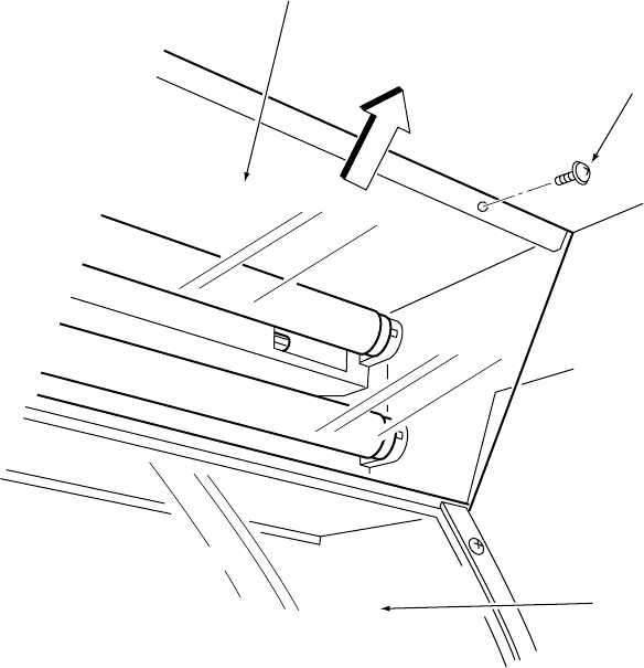
Page 56
7-5 Replacing the Light Guard
1. Remove the Upper Rear Door from the Target Cabinet.
2. Remove 3off Pozi head screws (M4x16) and remove the light Guard in the
direction of the arrow in the diagram below
Note: The Rear Glass is located below the Light Guard. Take care not to drop
anything on it. (Screwdriver etc.).
4. Replace the Light Guard in reverse order.
Light Guard
Pozi head Screw
(M4x16)
Rear Glass
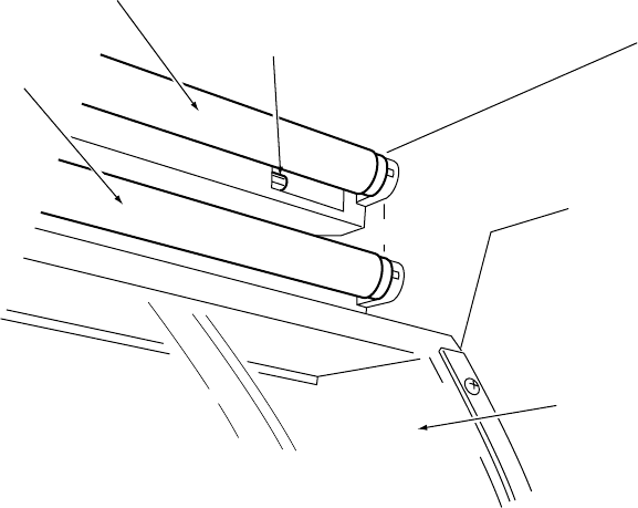
Page 57
7-6 Replacing the Rear Fluorescent Tubes and Starters.
1.Remove the Light Guard. (see section 7-5 page 56).
2. Replace the Fluorescent Lamp or Starter.
Note: The fluorescent lamp has an effect on the appearance of the game field, so
replace only with 20 watt coolwhite fluorescent.
Starter
20watt Coolwhite
Fluorescent Tube
Rear Glass
20watt Coolwhite
Fluorescent Tube
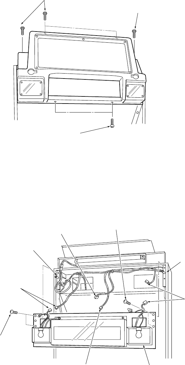
Page 58
7-7 Replacing the Front Acrylic
1. Remove 6off security screw (M5x12) and remove the Header Front Cover.
2. Disconnect the two connectors: CN11 and CN12.
3. Remove 4off Pozi head screws (M5x25) and pull the Header Panel forward a
little to unfasten it from the hooks, and disconnect the connectors: CN45 and
CN46. Remove the Header Panel.
Note: Take care not to strain the wires when unhooking the panel and before
disconnecting the connectors: CN45 and CN46.
Pozi head screw
(M5x25)
Connector
CN46
Hook
Connectors
CN12
Header Panel
Connector
CN45
Hook
Connectors
CN11
Pozi head screw
(M5x25)
Security screw
(M5x12)
Security screw
(M5x12)
Security screw
(M5x12)
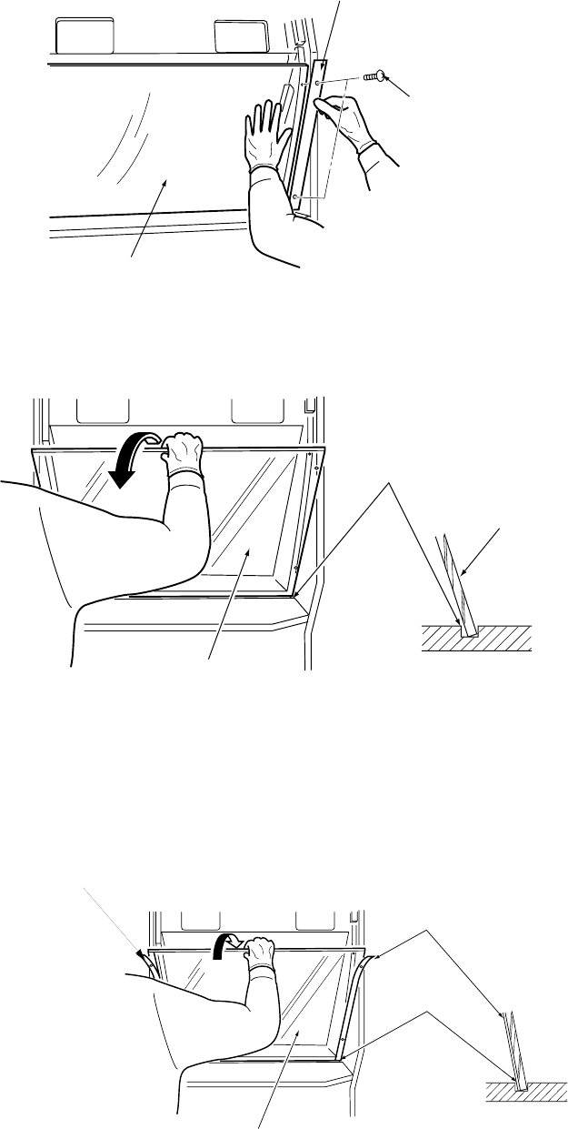
Page 59
4. Remove the 4off Security screws (M5x12) and remove the Front Acrylic Retaining
brackets.
Note: The Front Acrylic will tilt forward when the retaining brackets are moved, so
ensure that the acrylic is being held in place with a hand.
5. The Front Acrylic sits in a groove on the Target Cabinet. Lift the Acrylic in the
direction of the arrow, in the diagram below, to remove it.
6. Refit the Front Acrylic in reverse order.
Note: When refitting, ensure that both the Front Acrylic and the Retaining brackets
are located in the wooden groove before fitting the 4off security screws (M5x12)
Retaining bracket
Security screw
(M5x12)
Front Acrylic
Front Acrylic
Wooden groove
Front Acrylic
Front Acrylic
Groove
Retaining bracket
Retaining bracket
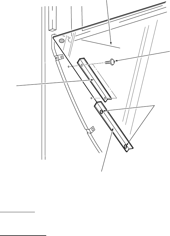
Page 60
7-8 Replacing the Half Mirror
1.Remove the Front Acrylic. (see section 7-7 page 58).
2. Remove the 4off Button head screws (M5x16) and remove the upper Half Mirror
Retaining brackets (left and right).
3. Only loosen the 4off Button head screws (M5x16) retaining the lower Half
Mirror Retaining brackets (left and right).
Note: Do not remove the screws retaining the lower retaining brackets, or the
Half Mirror will fall and may cause damage or injury.
Half Mirror
Button head screw
(M5x16)
Button head screw
(M5x16)
Retaining bracket
(lower)
Retaining bracket
(upper)
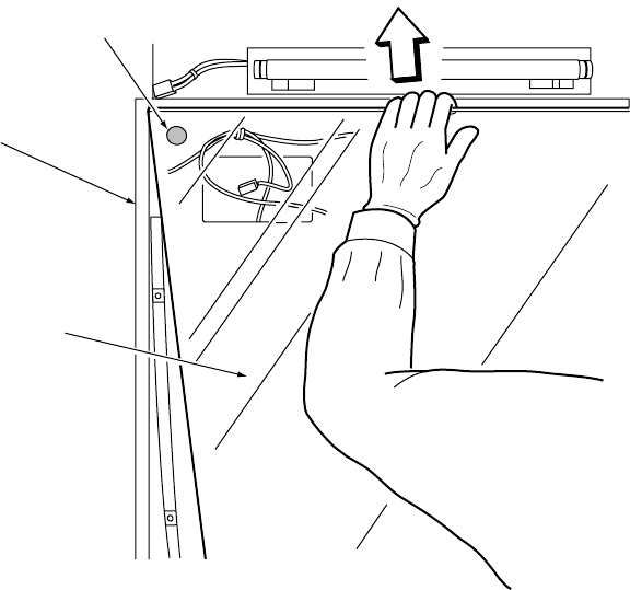
Page 61
Indicator label
Target Cabinet
Half mirror
4. Hold the mirror both top and bottom and remove it in the direction of the arrow, as
shown in the diagram below.
5. Refit the Half Mirror in the reverse order.
Note: There is a small label in the upper left corner of the mirror to indicate the front
surface of the mirror. When refitting the mirror, ensure that the label is in the
upper left corner. If the mirror is fitted the wrong way round, reflected images
may appear double.
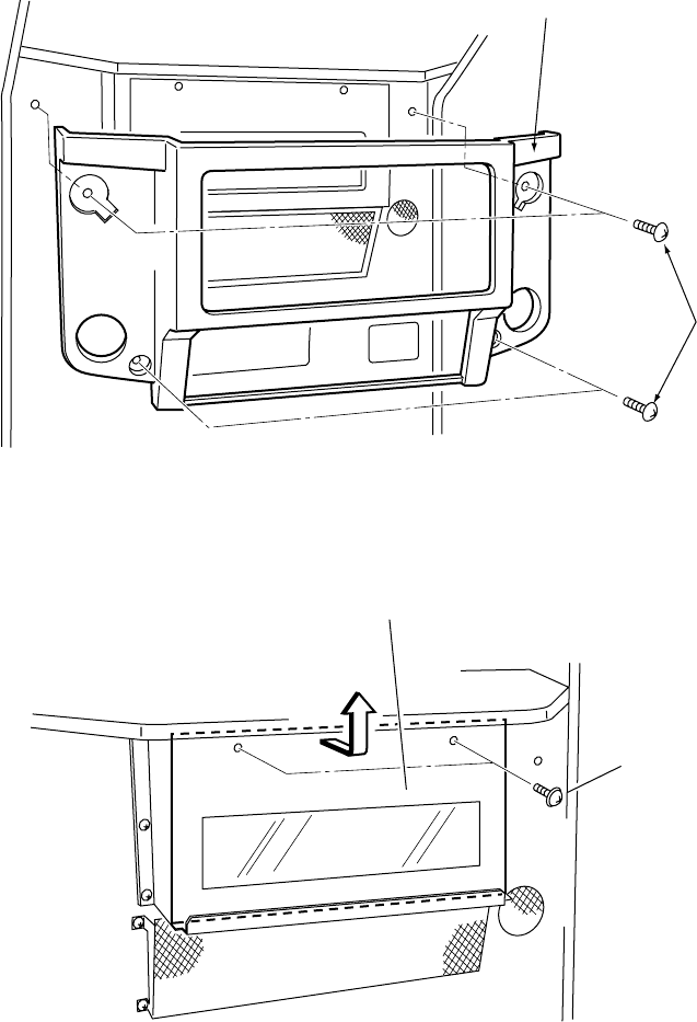
Page 62
7-9 Replacing the 7-Segment PC Board
Note: The 7-Segment PC Board is susceptible to damage from static electricity.
Anti static precautions should be taken when removing, handling and refitting
the 7-Segment PC Board.
1. Remove 4off security screw (M5x30) and remove the Display Cover.
2. Remove 2off pozi head screws (M5x16) and remove the Display Acrylic
Security screw
(M5x30)
Display Cover
Display Acrylic
Pozi head screw
(M5x16)
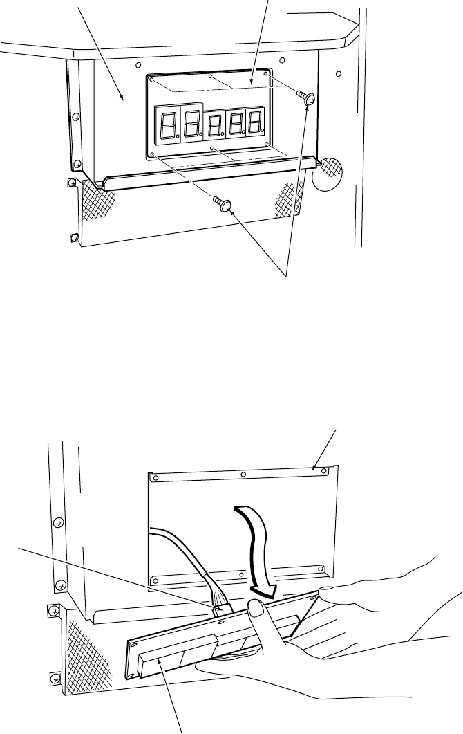
Page 63
3. Remove 6off pozi head screws (M4x12) that retain the 7-Segment Pc Board.
4. Disconnect the connector and remove the 7-Segment Display PC Board.
5. Refit in the reverse order.
Display bracket 7-Segment PC Board
Pozi head screw
(M4x12)
Display bracket
7-Segment PC Board
Connector
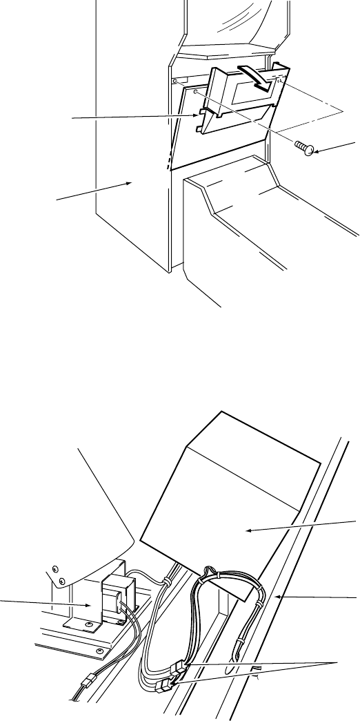
Page 64
7-10 Replacing the Front Fluorescent and Starter
1.Remove the Display Cover. (See section 7-9 page 62)
2. Remove 2off Security screws (M5x35) that retain the front maintenance door. Pull
the front maintenance door forward in the direction of the arrow, as shown in the
diagram below, only sufficiently to disconnect the connectors. Remove the front
maintenance door.
Front
Maintenance Door
Target Cabinet
Security screw
(M5x35)
Shutter Assy
Connectors
Front
Maintenance Door
Speaker Box
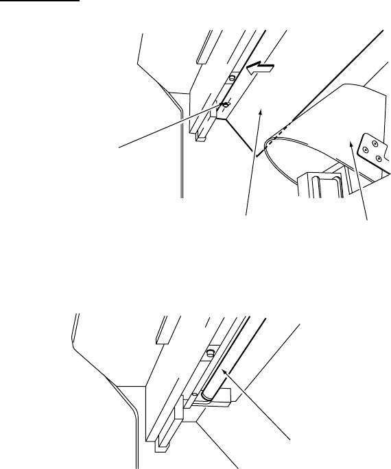
Page 65
3. Only loosen 2off Pozi flange head screws (M4x8) and remove the Cover B.
4. Replace the Fluorescent Tube or Starter.
5. Reassemble in reverse order.
Note: The fluorescent lamp has an effect on the appearance of the game field, so
replace only with 20 watt coolwhite fluorescent.
Pozi flange screw
(M4x8)
Shutter Assy
Cover B
Fluorescent Tube
20watt Coolwhite
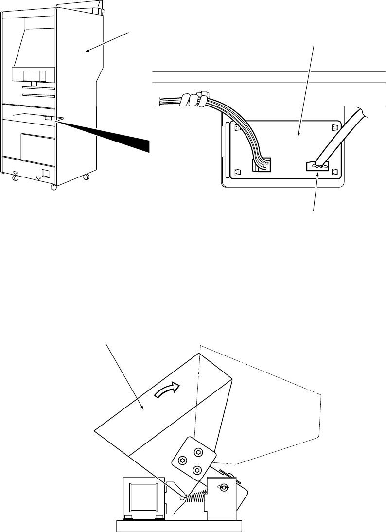
Page 66
7-11 Replacing the Cup Target Sensor Assy
1. Remove the upper rear maintenance door from the Target Cabinet.
2.Remove the Display Cover and Front Maintenance Door. (see section 7-10 page
64).
3. Disconnect connector J301 from the Sensor PC Board and free the harness from
the front of the Target Cabinet.
4. Move the Cup Target cover of the Shutter Assy in the direction of the arrow,
shown in the diagram below, and remove 2off pozi head screws (M4x45),
complete with flat and spring washers, and remove the Cup Target Sensor
complete with sensor bracket
Target Cabinet Sensor PC Board
Connector
J103
Cup Target Cover
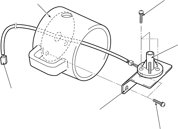
Page 67
5. Remove 3off Pozi head head screws (M4x12) and remove the Cup Target Sensor
from the mounting bracket.
6. Replace the sensor Assy and reassemble in reverse order.
Connector
J301
Cup Target Pozi head screw
(M4x12)
Cup Target
Sensor Assy
Pozi head screw
(M4x45)
(with flat and spring washers)
Cup Target Sensor Bracket
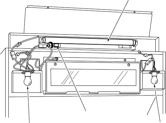
Page 68
7-12 Replacing the Header Fluorescent and Starter.
1.Remove the Header Front Cover. (see section 7-7 page 58)
2. Replace the Fluorescent Tube or Starter.
3. Reassemble in reverse order.
Lamp
24v / 15w
Starter
Fluorescent Tube
(15watt)
Lamp
24v / 15w
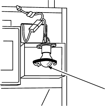
Page 69
Lamp
24v / 15w
7-13 Replacing the Header Lamp
1.Remove the Header Front Cover. (see section 7-7 page 58)
2. Remove the Header Lamp by unscrewing the lamp in the direction of the arrow,
shown in the diagram below.
3. Replace the lamp and reassemble in reverse order.
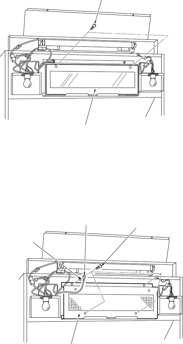
Page 70
7-14 Replacing the Dot Matrix Display.
1.Remove the Header Front Cover. (see section 7-7 page 58)
2. Remove 2off pozi head screws (M4x12) and remove the Dot Matrix Cover.
3. Remove the 4off pozi head screw (M5x25), 1off lock washer and ring tag terminal
and gently pull the display bracket forward taking care not to strain any wires.
Note: When removing the 4off pozi head screws (M5x20) take care that the display
bracket does not fall forward unexpectedly.
Pozi head screw
(M4x12)
Dot Matrix Cover
Lock Washer
(M5)
Ring Tag Pozi Head Screw
(M5x25)
Display Bracket
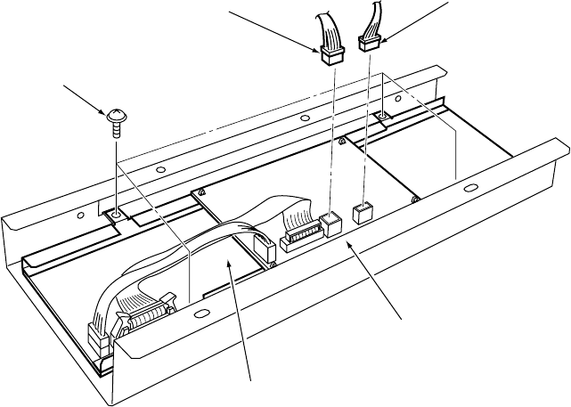
Page 71
4. Disconnect the connectors (CN45 and CN46), remove 4off pozi head screw
(M4x12) and remove the Dot Matrix Display from the Display Bracket.
5. Reassemble in the reverse order.
Display Bracket
Dot Matrix Assy
Pozi head Screw
(M4x12)
Connector
(CN46)
Connector
(CN45)
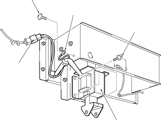
Page 72
7-15 Replacing the Launcher Solenoid
1. Remove the upper rear maintenance door from the Target Cabinet.
2. Remove 1off pozi flange head screw (M4x6) and disconnect the Ring Tag
Terminal and Connector (CN25).
3. Remove 4off socket flange screws (M6x10), with flat and spring washers, and
remove the Launcher Solenoid.
4. Reassemble in reverse order.
Note: After replacing the solenoid, ensure that the solenoid position is adjusted
correctly. (See section 6-4 page 43)
Pozi Flange Screw
(M4x6)
Ring Tag Socket Flange Screw
(M6x10)
(with flat and spring washer)
Launcher Solenoid
Connector
(CN25)
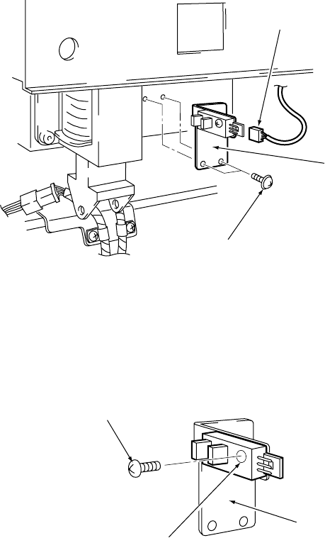
Page 73
7-16 Replacing the Launcher Sensor
1. Remove the upper rear maintenance door from the Target Cabinet.
2. Disconnect the connector (CN26).
3. Remove 2off pozi flange head screws (M4x6) and remove the Launch Sensor
complete with Sensor Bracket.
4. Remove 1off pozi head screw (M4x12) and remove the Launch Sensor from the
Sensor Bracket.
5. Reassemble in reverse order.
Note: It is recommended that loctite 242 is applied to the pozi head screw (M4x12)
when reassembling.
Connector
(CN26)
Sensor Bracket
Pozi flange screw
(M4x6)
Pozi head screw
(M4x12)
Launcher Sensor
Sensor Bracket
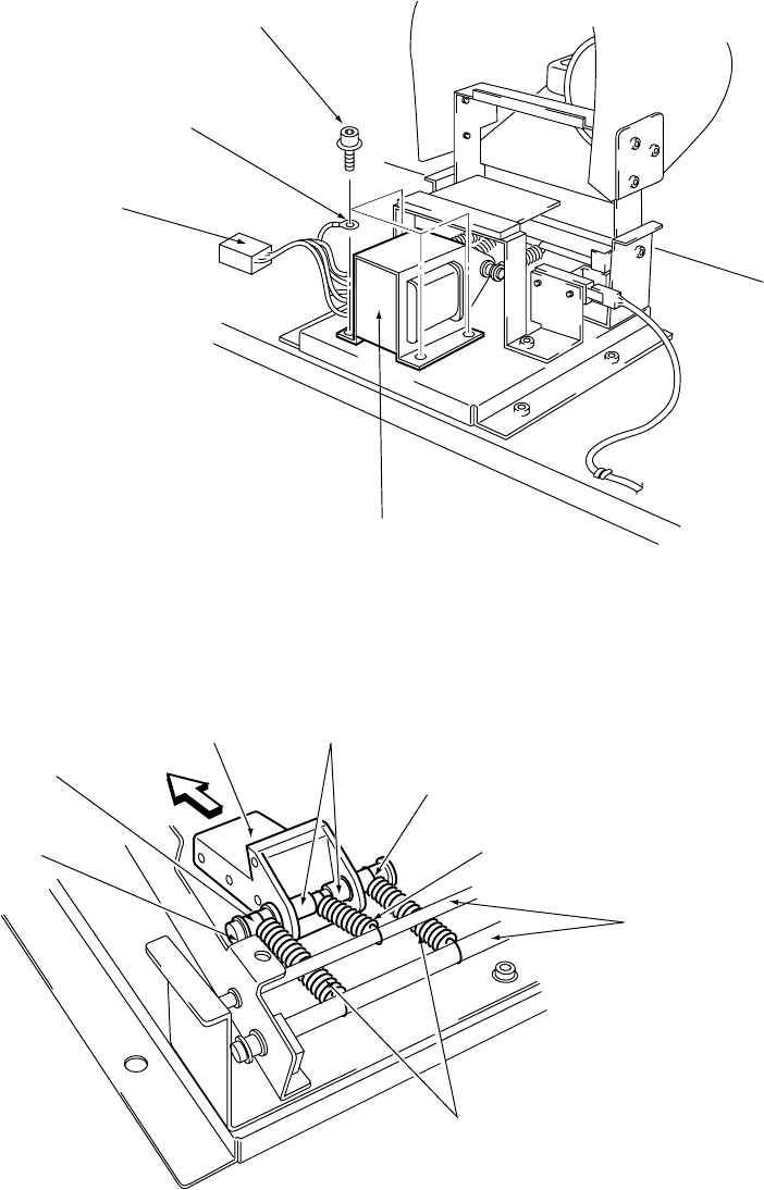
Page 74
7-17 Replacing the Shutter Solenoid
1.Remove the Front Maintenance Door from the Target Cabinet (See section 7-10
page 64).
2. Disconnect connector (CN28).
3. Remove 4off socket flange screws (M5x8) and remove the Shutter Solenoid.
Socket Flange Screw
(M5x8)
Ring Tag
Connector
(CN28)
Shutter Solenoid
Spacer
(6dia x 10)
Solenoid
Plunger
Spacers
(6dia x 5)
Tension Spring
Solenoid
Shaft#2
Spacer
(6dia x 5)
Solenoid Springs
Spring Supports
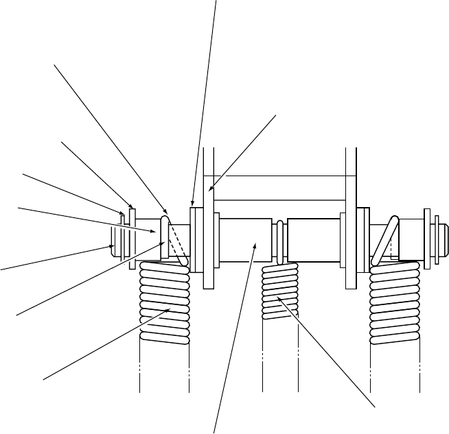
Page 75
Solenoid Plunger
Delrin Washer
Install the solenoid spring (S) so the
spring hook comes in contact with
the side of the spacer (6dia x 5)
Flat Washer (M6)
E-clip
Spacer (6dia x 5)
Solenoid Shaft
Spring Hook
Solenoid Spring
Spacer (6dia x 10)
Tension Spring
4. To remove the solenoid plunger remove one of the E-Clips from the solenoid
shaft#2, the flat washer (M6) and spacer (6dia x 5). Withdraw the solenoid
shaft#2 releasing the solenoid springs, tension spring, spacers (6dia x 10), and
delrin washers.
Note: The solenoid springs are wound in different directions. When refitting the
solenoid springs ensure that the hook of the spring is in contact with the space
(6dia x 5).
After replacing the shutter solenoid, it is recommended that a good quality
Silicone Grease is applied to the solenoid shaft#2 and to the supports for the
solenoid and tension springs.
After replacing the solenoid, ensure that the solenoid position is adjusted
correctly. (See section 6-5 page 44)
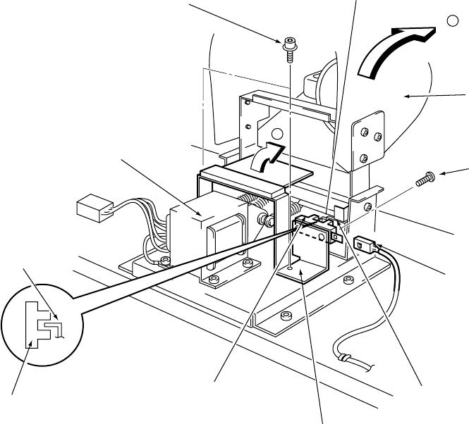
Page 76
7-17 Replacing the Shutter Sensor
1.Remove the Front Maintenance Door from the Target Cabinet (See section 7-10
page 64).
2. Disconnect connector (CN30).
3. Tilt the Cup Target Cover in the direction of arrow (a), shown in the diagram
below. Remove 2off flange socket head screws (M5x8) and remove the stopper
bracket in the direction of arrow (b), shown in the diagram below.
4. Remove 1off pozi head screw (M4x12) and remove the Shutter Sensor from the
stopper bracket.
5. Reassemble in reverse order.
Note: The stopper bracket should be fastened so that the sensor dog of the shutter
bracket is in the centre of the shutter sensor.
It is recommended that ThreeBond 1401 screw lock, (part No 95000006), is
applied to the pozi head screw (M4x12) when refitting the Shutter Sensor.
a
b
Sensor Dog
(shutter bracket)
Cup Target Cover
Pozi head screw
(M4x12)
Connector
(CN30)
Shutter Bracket
Stopper Bracket
Shutter Sensor
Shutter Sensor
Sensor Dog
(shutter bracket)
Shutter Solenoid
Flange Socket Screw
(M5x8)
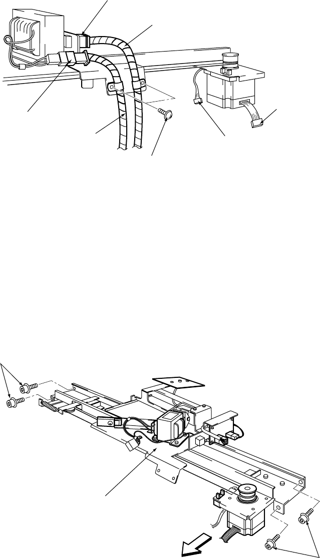
Page 77
7-18 Removing the Flat Target Assembly
1. Remove the upper rear door from the Target Cabinet.
2. Disconnect the connectors (CN20) and (CN22), remove 2off pozi flange head
screws (M4x6) to release the harnesses.
3. Disconnect the connectors (CN21) and (CN29).
4. Remove 4off (2ea left and right) flange socket head screws (M5x8) and remove
the Flat Target Assy.
Note: When removing the Flat Target Assy from the cabinet, slide the motor side of
the Flat Target Assy in the direction of the arrow, as shown in the diagram
below, being careful that it does not come in contact with any other parts of the
Target Cabinet.
5. Reassemble in reverse order.
Connector
(CN22)
Harness
Connector
(CN21)
Connector
(CN29)
Pozi flange screws
(M4x6)
Harness
Connectors
(CN20)
Flange socket head screws
(M5x8)
Flange socket head screws
(M5x8)
Flat Target Assy
Page 78
7-19 Replacing the Flat Target Solenoid
1.Remove the Flat Target Assy. (See section 7-18 page 77)
2. Remove the pozi flange head screw (M4x6) to release the nylon clip retaining the
harness coming from connector (CN20).
3. Remove 4off flange socket head screws (M5x8) and remove the ring tag and Flat
Target Solenoid.
Flange Socket Screws
(M5x8)
Solenoid Plunge
r
Flat Target Solenoid
Ring Tag
Connector (CN20)
Cable Clip
Pozi Flange Screw
(M4x6)
Page 79
E-Clip
Solenoid Shaft
Flat Washer (M6)
Arm Shaft Spacer
Solenoid Spring
Spring Spacer
Flat Washer (M6)
E-Clip
Solenoid Plunger
Flat Target
Solenoid
E-Clip
Solenoid Spring
Spring Spacer
E-Clip
Spring Hook
Arm Shaft Spacer
4. To remove the solenoid plunger, remove one of the E-Clips and flat washer (M6).
Withdraw the Solenoid Shaft releasing the spacers and spring.
5. Reassemble in the reverse order
Note: When refitting the solenoid plunger ensure that the spring hook is in contact
with the side of the spring spacer.
Note: After replacing the Flat Target solenoid, it is recommended that a good quality
Silicone Grease is applied to the solenoid shaft and to the supports for the
solenoid spring.
After replacing the solenoid, ensure that the solenoid position is adjusted
correctly. (See section 6-6 page 45)
Page 80
7-20 Replacing the Flat Target Drive Cable
1. Remove the upper rear maintenance door from the Target Cabinet.
2. Remove 2off flange socket screws (M4x6) and remove the Flat Target Drive
Cable.
3. Reassemble in reverse order.
Note: When refitting the Flat Target Drive Cable ensure that the cable is wound round
the motor pulley twice in a counter-clockwise direction as viewed in the
direction of the arrow shown in the diagram below.
Flange Socket Screw
(M4x6)
Flat Target
Drive Cable
Wire Bracket
Pulley
Wind the drive cable
counterclockwise twice
(as seen from the direction
of the arrow) around the
pulley before fixing
to the wire bracket.
Flat Target Motor
Flat Target
Drive Cable
Page 81
7-21 Replacing the Flat Target Motor
1. Remove the upper rear maintenance door from the Target Cabinet.
2.Remove the Flat Target Drive Cable (See section 7-20 page 80).
3. Disconnect connectors (CN21) and (CN24).
4. Loosen 2off double point screws (M5x6) and remove the pulley in the direction of
the arrow, as shown in the diagram below.
5. Remove 4off flange socket screws (M4x10) and remove the Flat Target Motor.
Pulley
Double Point
(M5x6)
Connector
(CN21)
Flat Target Motor
Connector
(CN24)
Double Point
(M5x6)
Flange Socket Screw
(M4x10)
Flat Target Motor
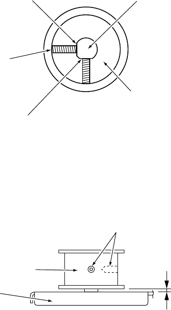
Page 82
6. Replace the motor and reassemble in reverse order.
Note: The shaft of the flat target motor has been ground flat in two places. When
replacing the pulley ensure that the two double point screws are in contact with
these flat faces.
Before tightening the double point screws ensure that the gap between the top
surface of the motor bracket and the pulley is approximately 2mm.
It is recommended that Loctite 242 (part No 95000004) is applied to the double
point screws when refitting the pulley.
Flat Target
Motor Shaft
Pulley
Flat Section
Double Point
(M5x6)
Flat Section
Double Points
(M5x6)
2mm
Pulley
Motor Bracket
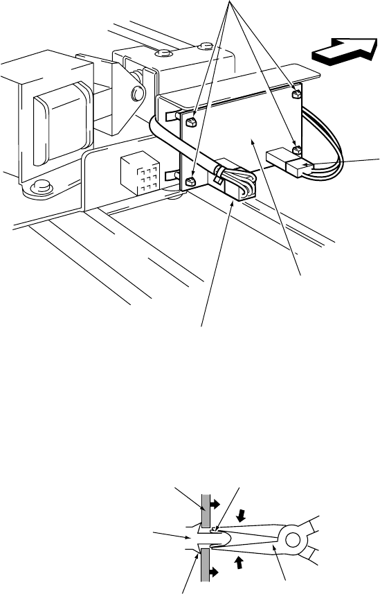
Page 83
7-22 Replacing the Flat Target Sensor PC Board
Note: PC Boards are susceptible to damage from static electricity. Anti static
precautions should be taken when removing, handling and refitting the PC
Board.
1.Remove the Flat Target Assembly. (See Section 7-18 page 77).
2. Disconnect connectors (J301) and (J302).
3. Using needle nosed pliers, squeeze the locking tabs of the locking supports, one
at a time, to release the PC Board. Remove the Sensor PC Board.
4. Replace the board by gently pushing the board on to the locking supports.
Note: When replacing the Sensor Pc Board, ensure that connector (J301) is located at
the front.
Locking Supports
Connector
(J302)
Flat Target
Sensor PC Board
Front
Connecto
r
(J301)
Tab
Needle Nosed
Pliers
Stopper
Locking Support
PC Board
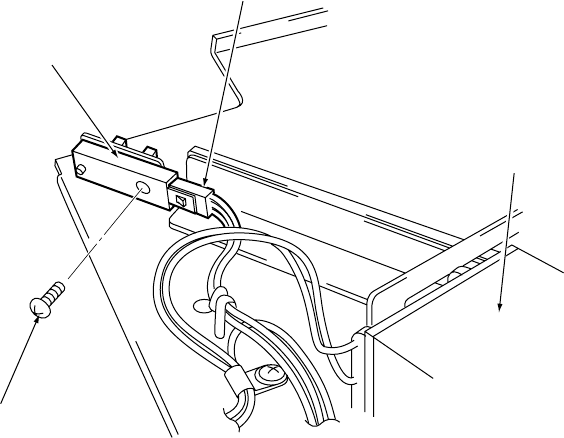
Page 84
7-23 Replacing the Flat Target Position Detection Sensor
1. Remove the upper rear maintenance door from the Target Cabinet.
2. Disconnect connector (CN48)
3. Remove 1off pozi head screw (M4x12) and remove the Flat Target Position
Detection Sensor
4. Reassemble in reverse order.
Note: It is recommended that ThreeBond 1401 screw lock, (part No 95000006), is
applied to the pozi head screw (M4x12) when refitting the Flat Target Position
Detection Sensor.
Flat Target
Positition Detection
Sensor
Connector
(CN48)
Flat Target
Solenoid
Pozi head screw
(M4x12)
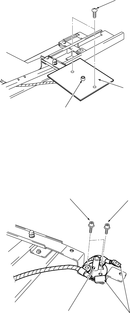
Page 85
Flat Target
Sensor Assy
Target Plate
Pozi flange screw
(M4x6)
Flange Socket Screw
(M4x10)
Flange Socket Screw
(M4x12)
Connectors
(CN50)
Flat Target
Sensor Assy
7-24 Replacing the Flat Target Sensor Assy
1.Remove the Flat Target Assembly. (See Section 7-18 page 77).
2. Remove 2off pozi head screws (M4x6) and remove the Target Plate.
3. Disconnect the connector (CN50).
4. Remove 2off flange socket screw (M4x12), 1off flange socket screw (M4x10) and
remove the Flat Target Sensor Assy.
5. Reassemble in reverse order.
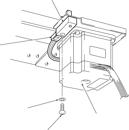
Page 86
7-25 Replacing the Flat Target Origin Sensor
1. Remove the upper rear maintenance door from the Target Cabinet.
2. Disconnect connector (CN24).
3. Remove 1off pozi head screw (M4x12) with flat washer (M4) and remove the Flat
Target Detection Sensor.
4. Reassemble in reverse order.
Note: It is recommended that ThreeBond 1401 screw lock, (part No 95000006), is
applied to the pozi head screw (M4x12) when refitting the Flat Target Origin
Sensor.
Flat Target Origin
Detection Sensor
Connector
(CN24)
Flat Washer (M4)
Pozi head screw
(M4x12)
Flat Target Motor
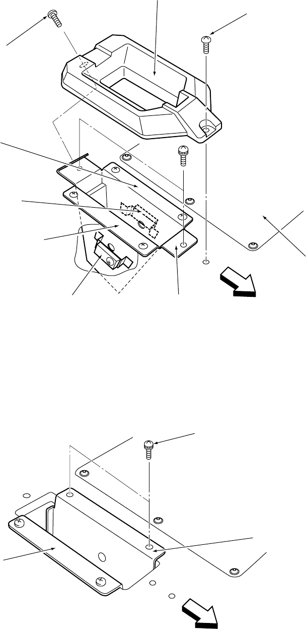
Page 87
7-26 Replacing the Gun Detection Sensor
1. Remove 1off security screw (M5x20), 1off security screw (M5x10) and remove
the Holder Cover.
2. Remove 2off pozi head screws (M4x20) and remove the Holder Bracket (C).
3. Remove 2off pozi head screws (M4x25), with flat and spring washers, and
remove the Holder Bracket (R).
Holder Cover
Security Screw
(M5x20)
Instruction
Panel
Holder Bracket (C)Gun Detection Sensor
(receiving side)
Holder Bracket (L)
Gun Detection Sensor
(projection side)
Holder Bracket (R)
Security Screw
(M5x10)
Front
Holder Bracket (L)
Pozi Head Screw
(M4x25)
Holder Bracket (R)
Front
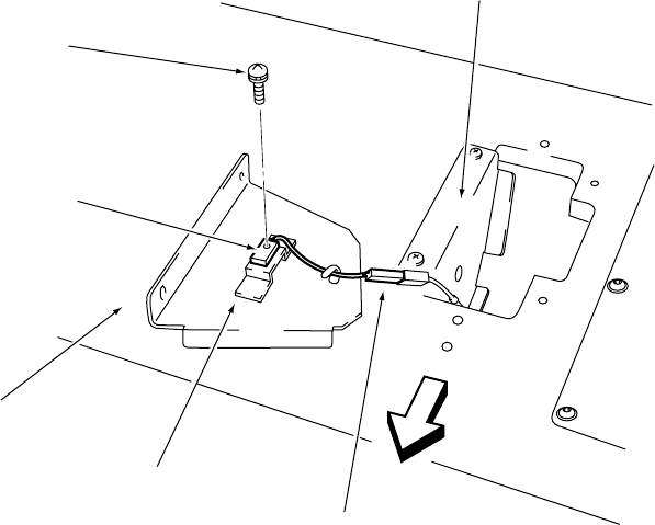
Page 88
4. Disconnect the connector (CN39).
5. Remove the pozi head screw (M3x12) and remove the Gun Detection Sensor
(projection side).
6. Reassemble in reverse order.
Note : Repeat above procedures to remove the Gun Detection Sensor (receiving side).
Holder Bracket (L)
Connector
(CN39)
Holder Bracket (R)
Gun Cabinet
Gun Detection Sensor
(projection side)
Pozi Head Screw
(M3x12)
Front
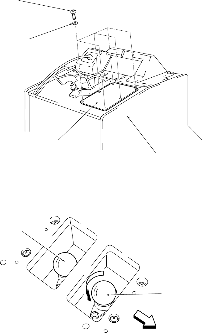
Page 89
7-27 Replacing the [SET] and [START] Lamps
1. Remove 6off security screws (M4x25), with flat washers, and remove the
Set / Start Acrylic.
2. Remove the lamp by turning it in the direction of the arrow, shown in the diagram
below.
3. Reassemble in reverse order.
Security Screw
(M5x25)
Gun Cabinet
Set / Start Acrylic
Washer
(M4)
[SET] Lamp
(24v 15w)
[START] Lamp
(24v 15w)
Front
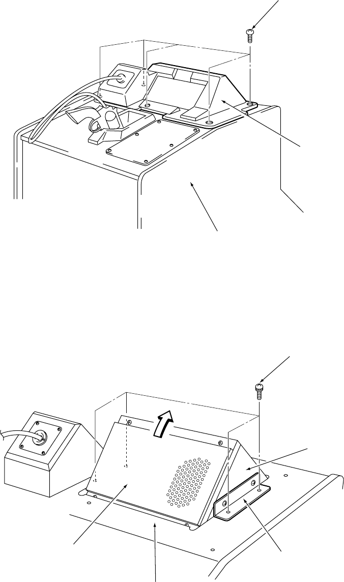
Page 90
7-28 Replacing the Speaker
1. Remove 5off Security screws (M5x20) and remove the Top Cover.
2. Remove 4off pozi head screws (M5x25), with flat and spring washers, and lift the
Speaker Box in the direction of the arrow, as shown in the diagram below.
Security screw
(M5x20)
Top Cover
Gun Cabinet
Pozi head screw
(M5x25)
Speaker Box
Speaker Bracket
Gun Cabinet
Speaker Cover
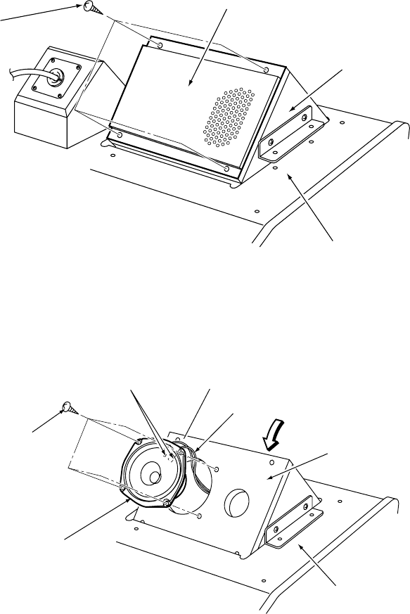
Page 91
3. Remove the 4off Self Tapping screws (No8 x 5/8 ) and remove the Speaker
Cover.
4. Remove the 4off , Self Tapping screws (No8 x 5/8 ) disconnect the Faston
terminals and remove the Speaker.
5. Reassemble in reverse order.
Note: If the wires to the speaker have been disconnected, ensure that the wires are
on the correct terminals when refitting.
Self tapping screw
(N08 x
5/8
")
Speaker Cover
Speaker Box
Gun Cabinet
Faston
Terminals Screen (-)
Core (+)
Speaker Box
Gun Cabinet
Speaker
Self tapping screw
(N08 x 5/8")
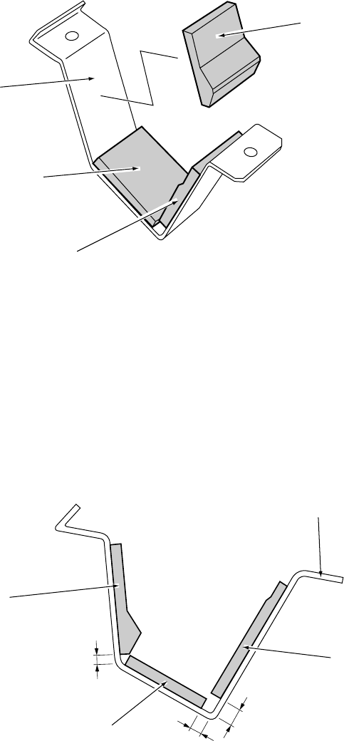
Page 92
7-29 Replacing the Holder Cushions (A) (B) (C)
1.Remove the Holder Cover and Holder Bracket (C). (See section 7-26 page 87)
2. The Holder Cushions (A) (B) (C) are attached using double-sided adhesive tape.
Pull firmly on the cushion and peel it from the holder bracket.
3. Apply the new Holder Cushion in reverse procedure.
Note: The Holder Cushions are supplied with double-sided adhesive tape fitted. Peel
off the backing paper before attaching the Holder Cushion.
Attach the holder cushion (A) (B) or (C) in the position shown in the diagram
below.
Holder Cushion (A)
Holder Cushion (C)
Holder Cushion (B)
Holder Bracket (C)
9
15
7
Holder Bracket (C)
Holder Cushion (C)
Holder Cushion (B)
Holder Cushion (A)
units = mm
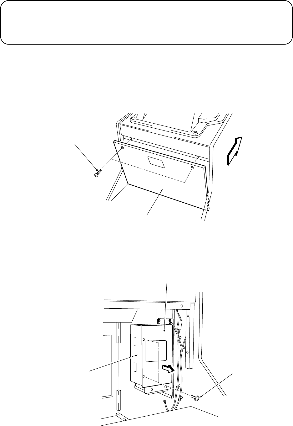
Page 93
7-30 Replacing the Xenon PC Board
Note: PC Boards are susceptible to damage from static electricity. Anti static precautions
should be taken when removing, handling and refitting the PC Board.
1. Remove 2off Button head screws (M5x35) and remove the front maintenance
door from the Gun Cabinet.
2. Remove 2off pozi head screws (M4x12) and remove the Cover in the direction of
the arrow, as shown in the diagram below.
Button head Screw
(M5x35)
Front
Maintenance Door
Front
Cover
Pozi head Screw
(M4x12)
Xenon Assy
CAUTION
The Xenon Assy remains hot and continues to carry a high voltage charge even after
turning the power OFF. Wait at least five minutes after turning the power OFF before
performing any maintenance work (troubleshooting, repairs etc.) on the Xenon Assy.
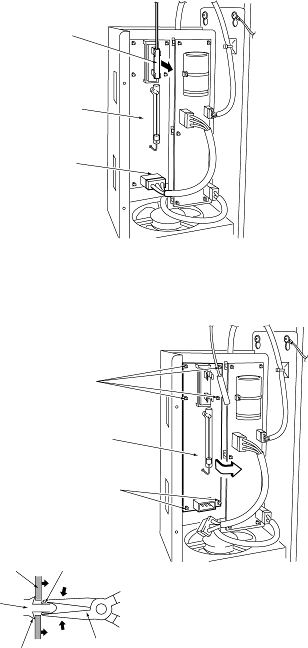
Page 94
Tab
Needle Nosed
Pliers
Stopper
Locking Support
PC Board
3. Disconnect connector (CN41) and the Fibre Optic in the direction of the arrow, as
shown in the diagram below.
4. Using needle nosed pliers, squeeze the locking tabs of the locking supports, one
at a time, to release the PC Board. Remove the Xenon PC Board.
Fibre Optic
Xenon PC Board
Connector
(CN41)
Locking Supports
Xenon PC Board
Locking Supports
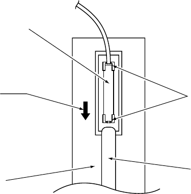
Page 95
Holder
Xenon Tube
Xenon PC Board
Insert the Fibre Optic until
it comes in contact with
the stopper in the holder
and install it so that it is as
close as possible to the
Xenon Tube.
Fibre Optic
5. Reassemble in reverse order.
Note: In order to ensure the correct light output from the gun Assy, the fibre optic
should be fitted as close as possible to the Xenon Tube.
When installing the fibre optic, be careful not to touch the Xenon tube with your
fingers or hands. If the Xenon tube is accidentally touched, clean the area
touched with alcohol. (Part No 95000031)
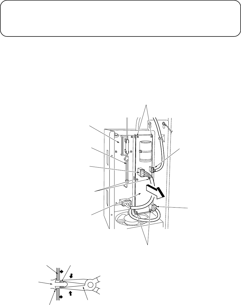
Page 96
Tab
Needle Nosed
Pliers
Stopper
Locking Support
PC Board
7-31 Replacing the Xenon Drive PC Board
Note: PC Boards are susceptible to damage from static electricity. Anti static precautions
should be taken when removing, handling and refitting the PC Board.
1.Remove the Xenon cover. (See section 7-30 page 93)
2. Disconnect connectors (J201), (J202) and (J203).
3. Using needle nosed pliers, squeeze the
locking tabs of the locking supports, one at
a time, to release the PC Board. Remove
the Xenon PC Board.
4. Reassemble in reverse order.
Note: When installing the fibre optic, be careful not to touch the Xenon tube with your
fingers or hands. If the Xenon tube is accidentally touched, clean the area
touched with alcohol. (Part No 95000031)
Locking Supports
Connectors
(J203)
Connectors
(J201)
Locking Supports
Xenon Drive PC Board
Locking Supports
Connector
(J202)
Xenon Tube
Xenon PC Board
CAUTION
The Xenon Assy remains hot and continues to carry a high voltage charge even after
turning the power OFF. Wait at least five minutes after turning the power OFF before
performing any maintenance work (troubleshooting, repairs etc.) on the Xenon Assy.
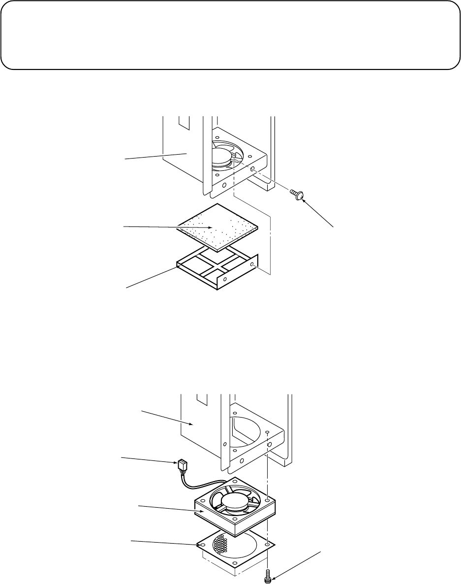
Page 97
7-32 Removing the Xenon Fan and Filter
1. Remove 2off pozi head screws (M4x12) and remove the Filter Bracket.
2. Remove the Filter from inside the Filter Bracket.
3. Disconnect connector (CN37), remove 4off pozi head screws (M4x45), with
spring and toothed lock washers, and remove the Xenon Fan
4. Reassemble in reverse order.
CAUTION
The Xenon Assy remains hot and continues to carry a high voltage charge even after
turning the power OFF. Wait at least five minutes after turning the power OFF before
performing any maintenance work (troubleshooting, repairs etc.) on the Xenon Assy.
Xenon Assy
Filter
Filter Bracket
Pozi head screw
(M4x12)
Xenon Assy
Connector
(CN37)
Xenon Fan
Finger Guard Pozi head screw
(M4x45)
(with spring and
toothed lock washer)
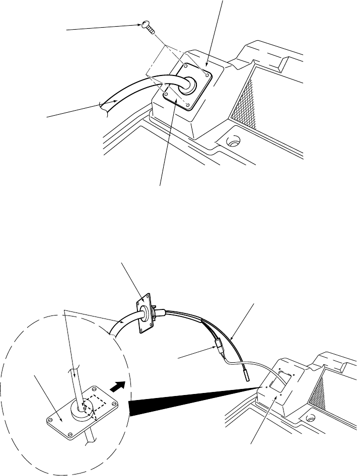
Page 98
7-33 Replacing the Gun Assy
Note: When removing the Gun Assy from the top cover on the Gun Cabinet, take care
not to bend, pull or scratch the harness or fibre optic cable.
1.Remove the Fibre Optic Cable. (See section 7-30 page 93)
2. Remove 4off Security screw (M5x10) that retains the Pipe Bracket, and pull the
Gun Assy out from the Gun Cabinet.
3. Disconnect connector (CN38) and remove the Gun Assy.
4. Reassemble in reverse order.
Note: Install the Top Cover so that the L shaped bracket on the rear of the Pipe
Bracket is at the top.
Top Cover
(gun cabinet assy)
Security Screw
(M5x10)
Gun Assy
Pipe Bracket
Fibre Optic Cable
Top Cover
(gun cabinet )
Connector
(CN38)
Pipe Bracket
Gun Assy
Pipe Bracket
Details of the Pipe Bracket
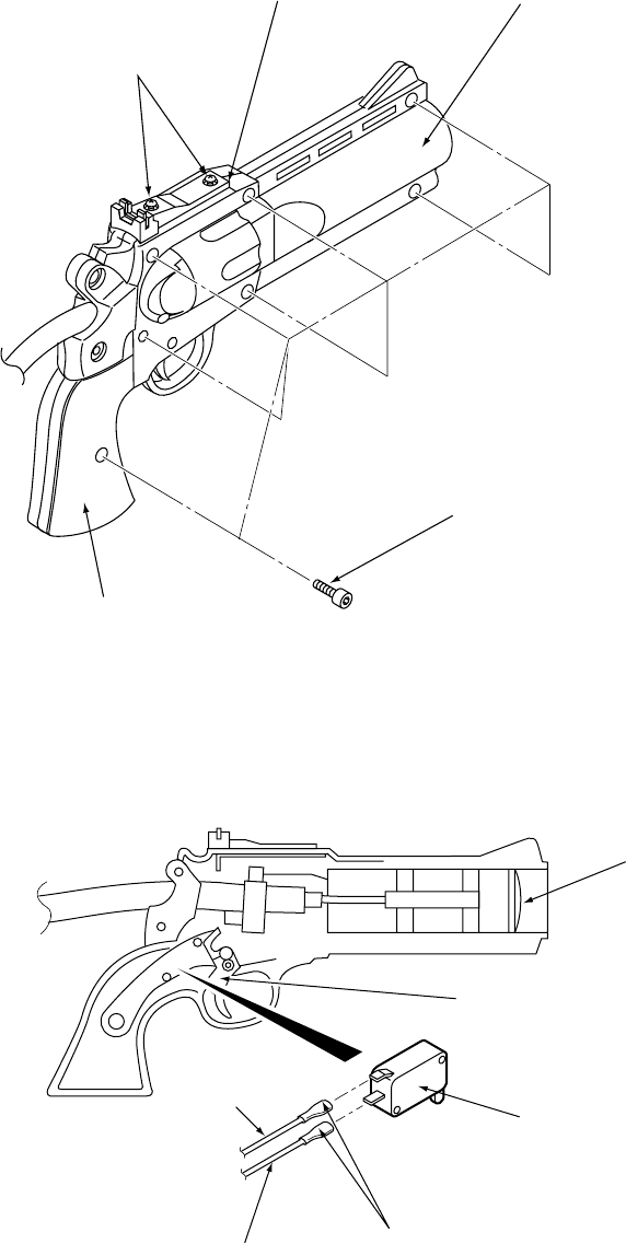
Page 99
7-34 Replacing the Gun Switch, Trigger and Lens
1. Loosen 2off screws (M3x8) retaining the Gun Sight.
2. Remove 7off cap bolts (M3x8) and remove Gun Side (R).
The grip is permanently fixed to the gun side (R).
3. Disconnect the two Faston terminals to remove the Gun Switch, Trigger and
Lens.
Sight Gun Side (R)
Cap Bolts
(M3x8)
Grip
Pozi head screws
(M3x8)
Lens
Gun Switch
Fast-on
Terminals
(Black)
(Yellow)
Trigger
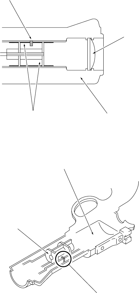
Page 100
4. Replace the Gun Switch, Trigger or Lens and reassemble in reverse order.
Note: If the Fibre Optic Holder has come off, reattach it by aligning the marking on the
Fibre Optic Holder with the marking on the Gun Side (L).
Install the Lens so that the convex (curved) surface is facing outward.
White Marking
Lens
Gun Side (L)
Fibre Optic Holder
Gun Side (L)
White Marking
Fibre Optic Holder
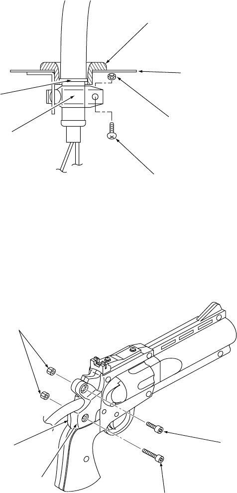
Page 101
7-35 Replacing the Gun Harness Assy
1.Remove the Fibre Optic Cable. (See section 7-30 page 93)
2. Remove 2off cap bolts (M3x6) and remove the Harness Guide from the Pipe
Bracket.
3. Remove 1off Pozi head screw (M5x20), Hex nut (M5) and unfasten the Pipe Clip
and Pipe Bracket.
4. Remove 1off cap bolt (M3x20), 1off cap bolt (M3x8), 2off hex nut (M3) and
remove the Hand Protectors (L) and (R).
Harness Guide
Pipe Bracket
Hex Nut (M5)
Pozi Head Screw
(M5x20)
Pipe Clip
O Ring
Hex Nut (M3)
Hand Protector (L)
Hand Protector (R)
Cap Bolt
(M3x8)
Cap Bolt
(M3x20)
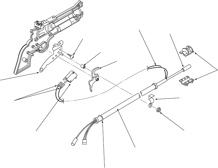
Page 102
5.Remove the Gun Side (R) and Grip (R). (See section 7-34 page 99).
6. Disconnect the 2off Fast-on terminals from the Gun Switch.
7. After removing the Gun Switch and Trigger, remove 1off self tapping screw
(M3x8) and remove the Gun Bracket.
8. Remove 1off flange nut (M3) and remove the Pipe Clip and Sleeve (3dia x 8).
9. Separate the Fibre Optic Holder in two, and remove them from the Fibre Optic
Cable. Remove the Gun Harness, including the O Ring, Fibre Optic and Flexible
Hose.
Self Tapping Screw
(M3x8)
Sleeve
(3dia x 8)
Trigger
Gun Harness Assy Fibre Optic
Fibre Optic
Holder
Pipe Clip
Flange Nut (M3)
Flexible Hose
O Ring
Gun Switch
Fast-on
Terminals
Gun Bracket
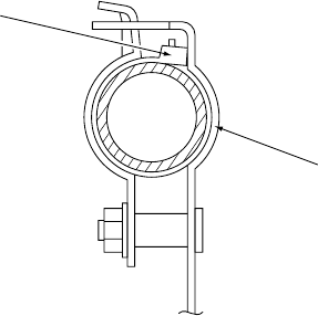
Page 103
Tie Wrap
Gun Bracket
10 Reassemble in reverse order.
Note: The tie wraps on the Gun Harness Assembly should be installed so that they
come in contact with the gun bracket, as shown in the diagram below.
Note: Install the Fibre Optic Holder by aligning the marking on the holder with the
marking on the gun side (L). (see step 4 section 7-34 page 99).
It is recommended that ThreeBond 1401 screw lock, (part No 95000006), is
applied to the cap bolt (M3x20), cap bolt (M3x8), and 2off hex nut (M3) when
reassembling the gun harness assy
Page 104
8. ERROR MESSAGES
This game is constantly monitoring its operation. If an error is detected, a message is
displayed on the Dot Matrix Display, an error code is displayed on the 7 Segment Display
and an audible warning sounded.
For errors to in the table below, the message Please Call Attendant will
be displayed on the Dot Matrix.
For errors to in the table below, the message No More Tickets and Please
Call Attendant will be alternately displayed on the Dot Matrix.
This is an example of the error code displayed on the 7 Segment Display.
7-segment
Display Error Description
System error
Coin switch error
Launcher sensor error
Flat target (U) error
Flat target (L) error
Shutter sensor error
Xenon fan error
Service switch error
Select switch error
Ticket jam error
Tickets out error
Flat target (U) origin
detection error
Flat target (L) origin
detection error
Cause of Error
Faulty game PC board
There is a coin signal error
The flat target (U) origin detection sensor or
the flat target (U) motor is broken.
The flat target (L) origin detection sensor or
the flat target (L) motor is broken.
The launcher sensor or the launcher
solenoid is broken.
The flat target (U) position detection sensor
or the flat target (U) solenoid is broken.
The flat target (L) position detection sensor
or the flat target (L) solenoid is broken.
The shutter sensor or shutter solenoid is
broken.
The gun detection sensor is broken or the
gun was not drawn from the holster for three
games in a row.
The Xenon fan stopped.
The service switch was ON when the power
was turned ON.
The select switch was ON when the power
was turned ON.
There was a ticket jam, or the ticket
dispenser is broken.
There are no more tickets, or the ticket
dispenser is broken.
Gun detection
sensor error
Error Code Table
Page 105
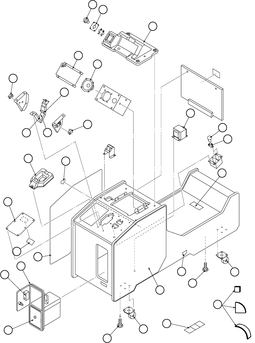
Page 106
9. PARTS
20
15
25
30
45
40
39
24
41
40
39
27
10
11
7
24
17
18
19
22
5
4
12
3
7
12
25
26
27 29
30
31
32
Gun Cabinet

Page 107
metInoitpircseDoNtraP
1gnihsuBgnitnuoMnuG 789-496-CQX
2etalPgnitnuoMnuG 689-496-CQX
3mroF-caVrekaepsduoL 63000074
4hseMrekaepsduoL 73000074
5egnaRlluF"½5rekaepsduoL 60065-CQX
7)gniviecerdnanoitcejorp(teS-rosneSretsloHnuG 704-000-CQX
01)A(rebbuRretsloHnuG 399-396-CQX
11)B(rebbuRretsloHnuG 499-396-CQX
21)C(rebbuRretsloHnuG 599-396-CQX
71remrofsnarTBCPnoneX 04000074
81pmaLralubuTw51/v4241E 52000046
91redlohpmaL41E 30000846
22"-laceDgninraWytefaS "emagnobmilctonoD 85500004
42laceDereHkroF 27000004
52mroF-caVretsloHnuG 53000074
62laceDnoitcurtsnIyalP 83500004
72teS-laceDnoitpOtohS 34500004
92SHL-laceDtenibaCnuG 63500004
03rooDhsaCon-etterehtaeLkcalB-DMFD 50200135
13lennahCelgniS-wolFhsaCsraM 14000089
23etterehtaeLkcalB-kcoL/w-roDruceS 22300135
9359x61M-tooFelbatsujdA 97000388
04mm57-rotsaCleviwS 50000095
14SHR-laceDtenibaCnuG 73500004
54teS-stiBpuC 379-396-CQX
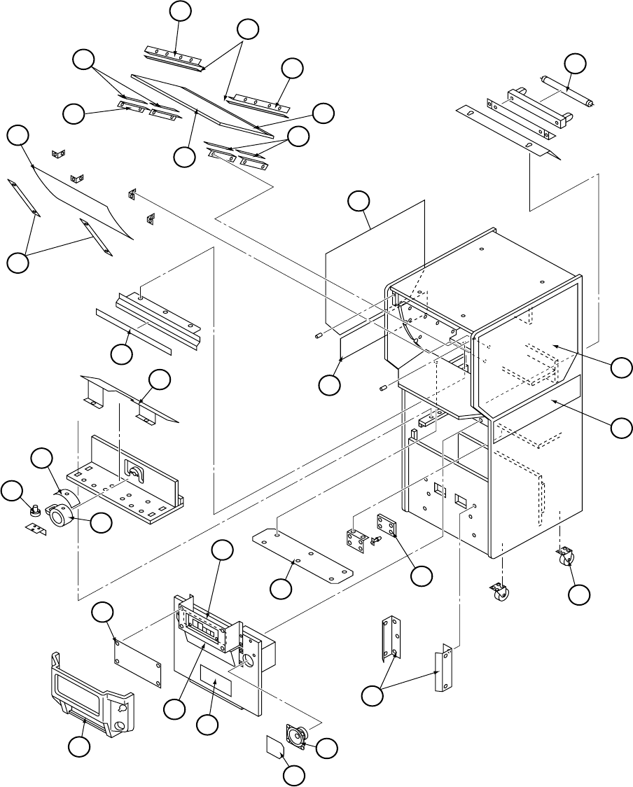
Page 108
15
9
7
9
4
1
2
13
16
19
21
25
23
22
16
15
29
27 40
31
34
35
36
37
38
32
5
5
6
3
14
Target Cabinet 1

Page 109
metInoitpircseDoNtraP
1xepsrePtnorF 26000074
2partSgniniateRxepsrePtnorF 36000074
.3tekcarBpmalCretuOrorriM 86000074
4rorriM 56000074
5tekcarBpmalCrennIrorriM 66000074
6dediSelbuoD-mm5xmm01egnopSkcalB 76000074
7laceDrorriM 74500004
9dediSelbuoD-mm5xmm01egnopSenerpoeNkcalB 96000074
31etihwlooC-ttaw02-"42-ebuTtnecseroulF 21000546
41BCPremiT BCPREMIT-CQX
51rewoL-SHR/SHLlaceDtenibaCtegraT 14500004
61reppU-SHR/SHLlaceDtenibaCtegraT 95500004
91)rewoL(-)B(laceDtegraT 65500004
12)A(neercSeralGitnA 55000074
22puC 780-496-CQX
32laceDpuC 75500004
52rosneSpuC 301-496-CQX
72eliTrorriMebuTtnecseroulFtnorF 98000074
92BCProsneSpuC 142-496-CQX
13hseMtroPrekaepsduoL 45000074
23egnaRlluF"½5rekaepsduoL 60065-CQX
43laceDtnorFtenibaCtegraT 45500004
53hseMrekaepsduoL 35000074
63cilyrcAremiT 24500004
73mroF-caVremiT 15000074
83tekcarBtnioJtenibaCnuG 05000074
04mm57rotsaCleviwS 50000095
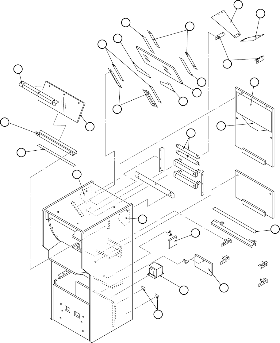
Page 110
42
41
49
50
48
43 47
51
45
43
53
54
56
57
43
63
64
72
66
59
52
44
73
65
67
Target Cabinet - 2

Page 111
metInoitpircseDoNtraP
14revoCxepsrePebuTtnecseroulF 67000074
24reppU-tekcarBgniniateRxepsrePebuTtnecseroulF 77000074
34dediSelbuoD-mm5xmm01egnopSkcalB 76000074
44rewoL-tekcarBgniniateRxepsrePebuTtnecseroulF 87000074
54derepmeT-ssalGraeR 07000074
74pirtSgniruceSraeR-ssalGtenibaCraeR 27000074
84dediSelbuoD-mm5xmm01egnopSenerpoeNkcalB 96000074
94tekcarBgniruceSlanretnIssalGtenibaCraeR 17000074
05SHL-laceDssalGraeR 84500004
15SHR-laceDssalGraeR 94500004
25tekcarBgniniateRyawnuRpuC 57000074
35SHL-yawnuRpuC 37000074
45SHR-yawnuRpuC 47000074
65)A(laceDrooDraeRedisnI-tenibaCraeR 25500004
75)B(laceDrooDraeRedisnI-tenibaCraeR 35500004
95etihwlooC-ttaw02-"42-ebuTtnecseroulF 21000546
36SHL-laceDedisnI-tenibaCraeR 05500004
46SHR-laceDedisnI-tenibaCraeR 15500004
56draoBCPRSSlennahC4 20400054
66)reppU(-)A(laceDtegraT 55500004
76BCPemaG BCP-CQX
27laceD'ereHkroF' 27000004
37remrofsnarTdioneloS 72000776
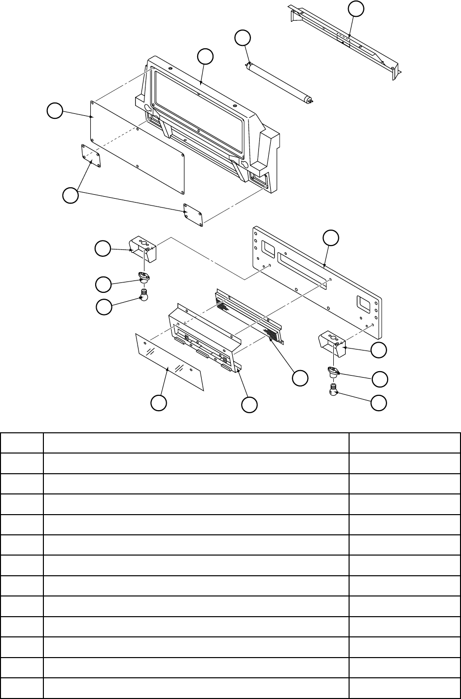
Page 112
metInoitpircseDoNtraP
1mroF-caVredaeH 85000074
2cilyrcAredaeH 44500004
3cilyrcApmaL 64500004
4tekcarBgnitnuoMreppUmroF-caVredaeH 16000074
5ttaw52-"81-ebuTtnecseruolF 00000546
6BCPyalpsiD BCPYALPSID-CQX
8dooWredaeH 97100173
9tekcarBgnitnuoMredloHpmaL 95000074
01redlohpmaL41E 30000846
11w51v42pmaL41E 52000046
21tekcarBgnitnuoMBCPyalpsiD 06000074
31cilyrcAyalpsiD 54500004
4
5
1
3
8
9
10
11
13 12 11
10
9
6
2
Header Assembly
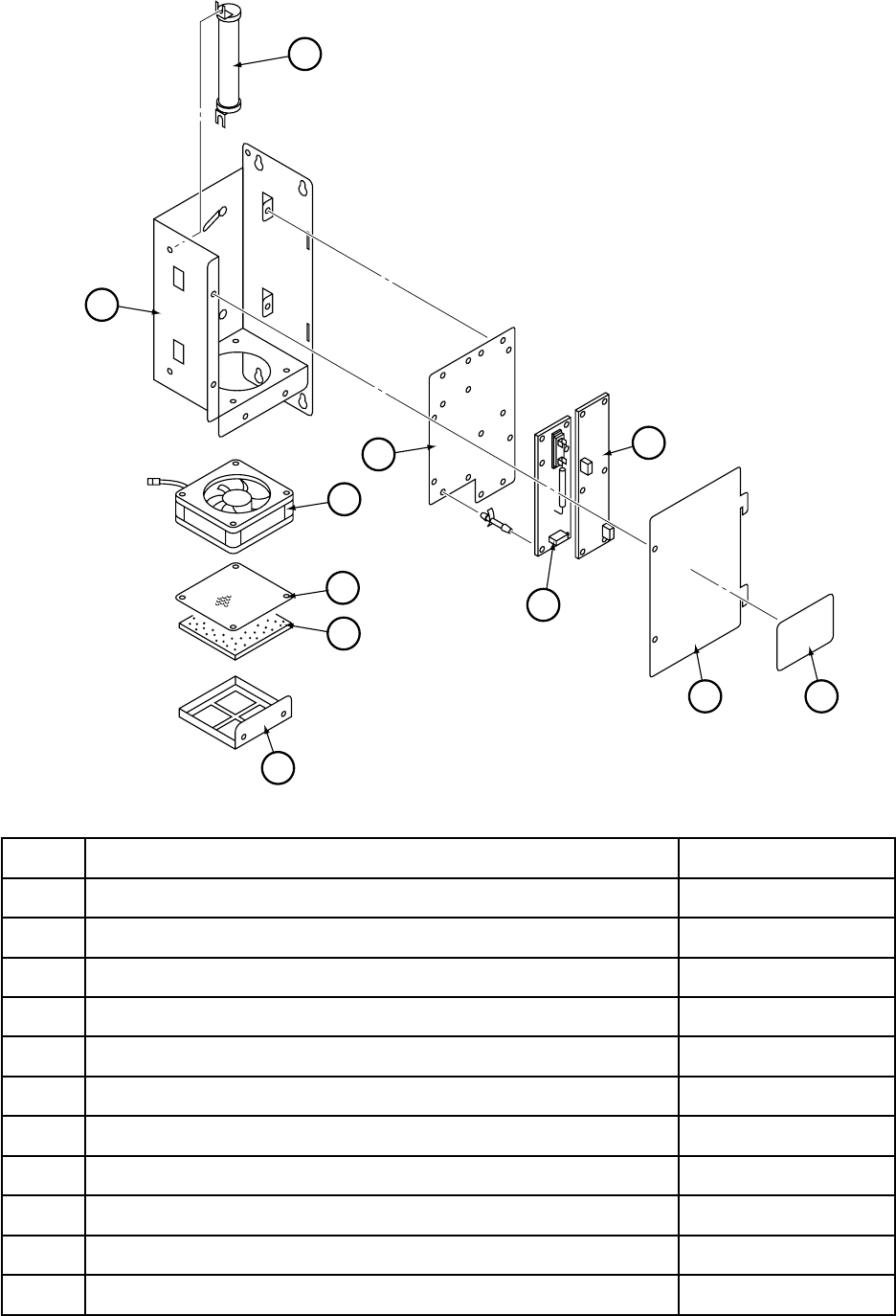
Page 113
metInoitpircseDoNtraP
1sissahC 44000074
2naFnoneX 56035-CQX
3hseMretliFnaF 64000074
4retliF 14000074
5tekcarBgnitnuoMretliF 24000074
6etalPgnitnuoMBCP 34000074
7draoBCPnoneX 950-886-CQX
8draoBCPevirDnoneX 850-886-CQX
9revoC 54000074
01laceDgninraWnoneX 04500004
11)Jmho05v001(HMRw001/mho05rotsiseRrewoP 060-886-CQX
11
1
6
2
3
4
5
7
8
9 10
Xenon Assembly
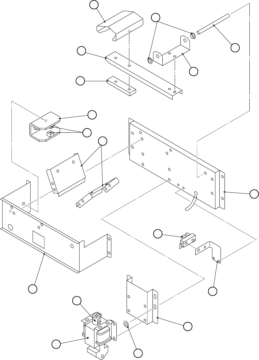
Page 114
1
2
3
5
4
8
9
13
12
14
15
16
17
11
7
6
10
Launcher Assembly

Page 115
metInoitpircseDoNtraP
)yssArehcnuaL(ylbmessAmsinahceMnoisolpxEpuC HCEM-LPXE-C-CQX
1daeH 411-496-CQX
2mrAdioneloS 511-496-CQX
3kcolBmrA 021-496-CQX
4tekcarBmrA 711-496-CQX
5tfahS 221-496-CQX
6)5060-F08(hsuBegnalF 101-522-CQX
7esaBdioneloS 111-496-CQX
8reppotSmrA 611-496-CQX
9rebbuRnoihsuC)81-661-MT(690-601-CQX
01epolS 811-496-CQX
112esaBdioneloS 211-496-CQX
21tekcarBrosneS 911-496-CQX
31)107-120697-JO(rosneS 972-000-CQX
41tekcarBdioneloS 311-496-CQX
51)C(rehsaW 321-496-CQX
61)557-217J(dioneloSrehcnuaL 175-400-CQX
71kcolB 224-886-CQX
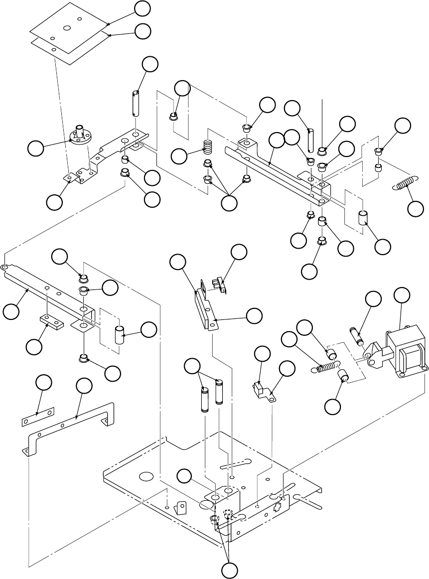
Page 116
A
12
32
31
30
29 14
28
23
25
24
21 13
20
22
19
18
13
12
13
914 17
16
9
813
15
12
9
11
9
5
7
6
1
2
3
9
10
4
27
26
Flat Target (Upper) Assembly - 1

Page 117
metInoitpircseDoNtraP
)yssAtegraTbuS(yssA)reppU(tegraTtalF HCEM-RAT-U-CQX
1)U(tekcarBTS 131-496-CQX
2yssArosneStegraTbuS 401-496-CQX
3etalPtegraT 561-496-CQX
4rekcitStegraTbuS 271-496-CQX
5tfahSTS 651-496-CQX
6recapSediuGtfahSTS 551-496-CQX
7)5060-FFL(hsuBegnalF 720-401-CQX
8)U(mrAniaM 331-496-CQX
9)5040-F08(hsuBegnalF 360-401-CQX
01)6011(gnirpS 621-501-CQX
11tfahSevirD 851-501-CQX
21)5060-F08(hsuBegnalF 101-522-CQX
31)8060-F08(hsuBegnalF 760-401-CQX
41recapStfahSmrA 461-496-CQX
51recapSgnirpS 071-496-CQX
61gnirpSnoisneT 051-496-CQX
711recapSediuGtfahSmrA 351-496-CQX
81mrAbuS 231-496-CQX
912ediuGmrA 661-496-CQX
022recapSediuGtfahSmrA 451-496-CQX
12)U(tekcarBediuGmrA 731-496-CQX
22ediuGmrA 361-496-CQX
32)U(reppotSD 631-496-CQX
42rebbuRreppotSD 861-496-CQX
52)107-120597-JO(rosneS 972-000-CQX
62tfahSmrA 751-496-CQX
72)908-807J(dioneloStegraTbuS 275-400-CQX
82tfahSdioneloS 951-496-CQX
92gnirpSdioneloS 151-496-CQX
032recapSgnirpS 171-496-CQX
13)U(reppotSdioneloS 841-496-CQX
23rebbuRreppotSdioneloS 961-496-CQX
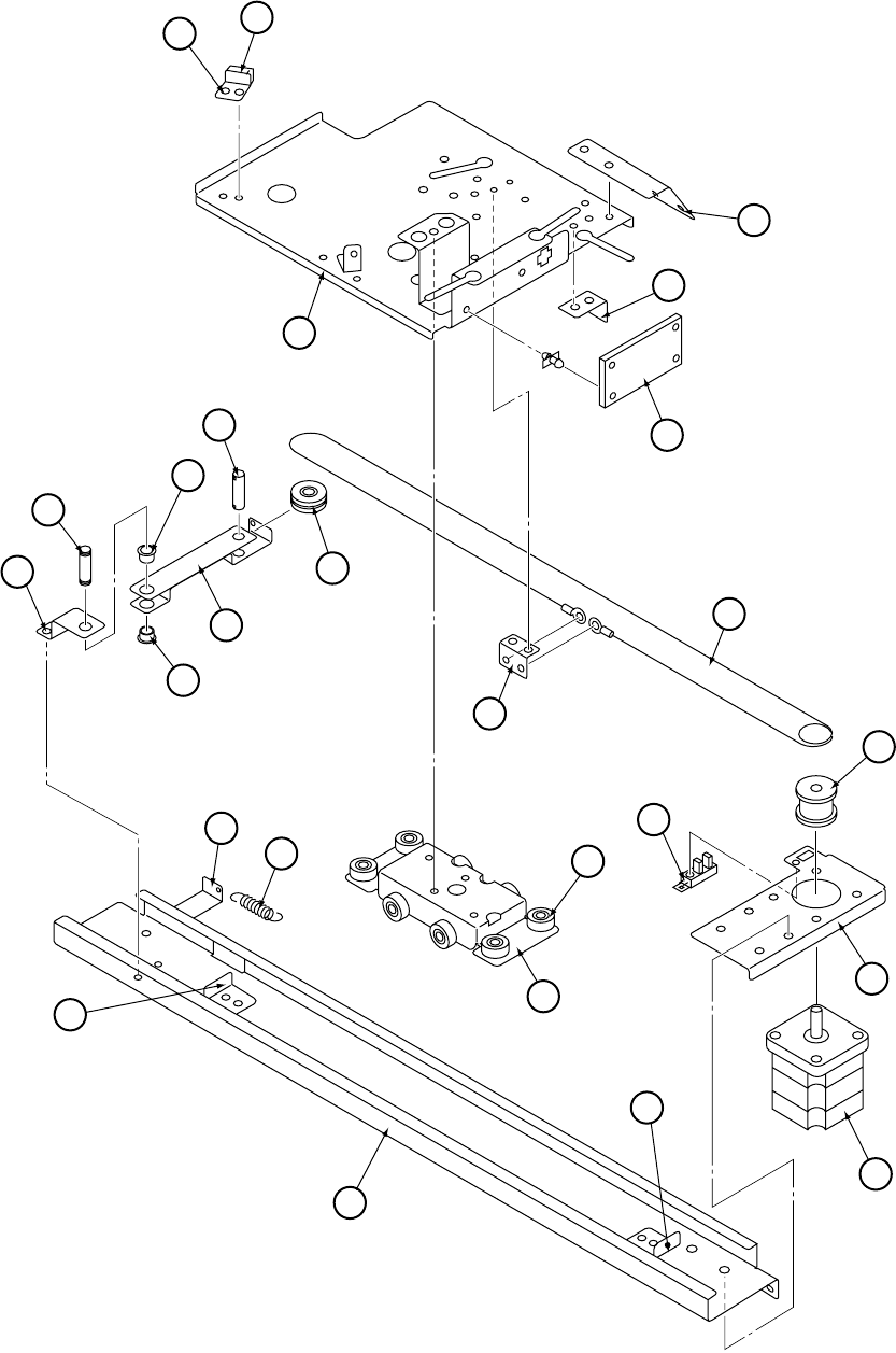
Page 118
34 35
33
36
37
38
41
42
40
43
44
42
39 45
46
55
56
54
53
51
52
49
54
47
48
50
Flat Target (Upper) Assembly - 2

Page 119
metInoitpircseDoNtraP
33)U(esaB 431-496-CQX
43reppotSU 531-496-CQX
53rebbuRreppotSU 761-496-CQX
63tekcarBtnemhcattAseriWdehcnuB 931-496-CQX
73goDrosneS 741-496-CQX
83tegraTbuSrofdraoBCProsneS 142-496-CQX
93)U(1tekcarByelluP 341-496-CQX
04)H-72-HD(gniraeBnirleD 711-301-CQX
142tfahSyelluP 261-496-CQX
24)5060-F08(hsuBegnalF 720-401-CQX
341tfahSyelluP 161-496-CQX
442tekcarByelluP 441-496-CQX
54elbaCevirDtegraTbuS 251-496-CQX
64tekcarBtnemhcattAelbaC 831-496-CQX
74yelluP 061-496-CQX
84)U(tekcarBrotoM 241-496-CQX
94)107-120697-JO(rosneS 972-000-CQX
05)10-013D85-PTS(rotoMtegraTbuS 942-500-CQX
15)U(redilS 041-496-CQX
25)2B-91-RD(gniraeBnirleD 730-301-CQX
35)U(liaR 141-496-CQX
45reppotSliaR 641-496-CQX
55)U(tekcarBgnirpS 541-496-CQX
65gnirpSyelluP 941-496-CQX
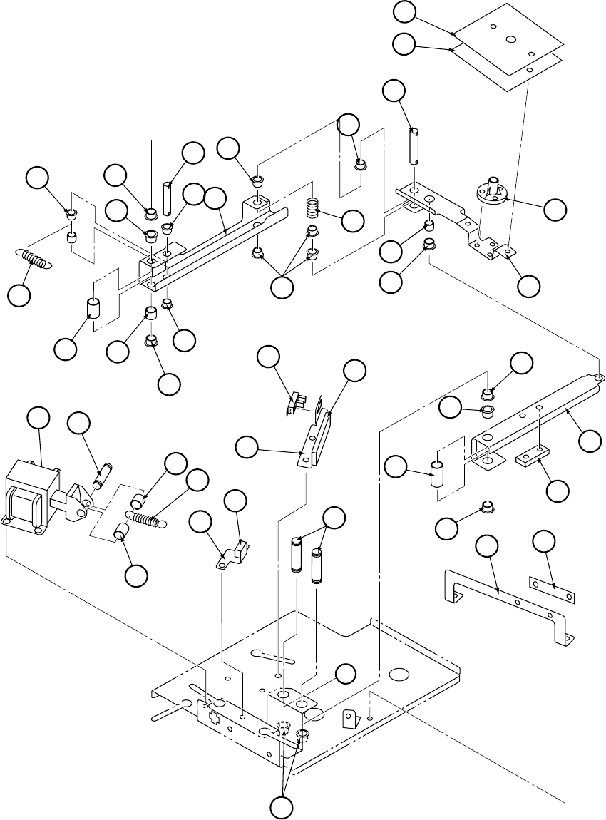
Page 120
A
12
32
31
30
29
14
28
23
25 24
21
13
20
22
19
18
12
13
9
14
17
16 9
8
13
15 12
9
11
9
5
7
6
1
2
3
9
10
4
27 13
26
Flat Target (Lower) Assembly - 1

Page 121
metInoitpircseDoNtraP
)yssAtegraTbuS(yssA)rewoL(tegraTtalF HCEM-RAT-U-CQX
1)L(tekcarBTS 181-496-CQX
2yssArosneStegraTbuS 401-496-CQX
3etalPtegraT 561-496-CQX
4rekcitStegraTbuS 271-496-CQX
5tfahSTS 651-496-CQX
6recapSediuGtfahSTS 551-496-CQX
7)5060-FFL(hsuBegnalF 720-401-CQX
8)L(mrAniaM 381-496-CQX
9)5040-F08(hsuBegnalF 360-401-CQX
01)6011(gnirpS 621-501-CQX
11tfahSevirD 851-496-CQX
21)5060-F08(hsuBegnalF 101-522-CQX
31)8060-F08(hsuBegnalF 760-401-CQX
41recapStfahSmrA 461-496-CQX
51recapSgnirpS 071-496-CQX
61gnirpSnoisneT 051-496-CQX
711recapSediuGtfahSmrA 351-496-CQX
81)L(mrAbuS 281-496-CQX
912ediuGmrA 661-496-CQX
022recapSediuGtfahSmrA 451-496-CQX
12)L(tekcarBediuGmrA 581-496-CQX
22ediuGmrA 361-496-CQX
32)L(reppotSD 981-496-CQX
42rebbuRreppotSD 861-496-CQX
52)107-120597-JO(rosneS 972-000-CQX
62tfahSmrA 751-496-CQX
72)908-807J(dioneloStegraTbuS 275-400-CQX
82tfahSdioneloS 951-496-CQX
92gnirpSdioneloS 151-496-CQX
032recapSgnirpS 171-496-CQX
13)L(reppotSdioneloS 091-496-CQX
23rebbuRreppotSdioneloS 961-496-CQX
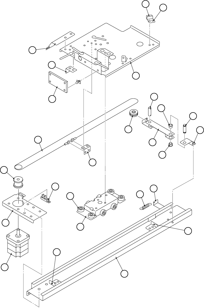
Page 122
35 34
36
37
33
38 41
42
43
44
42
39
40
46
45
47
48
54
49
52 56
55
54
53
50
51
Flat Target (Lower) Assembly - 2

Page 123
metInoitpircseDoNtraP
33)L(esaB 481-496-CQX
43reppotSU 531-496-CQX
53rebbuRreppotSU 761-496-CQX
63)L(tekcarBtnemhcattAseriWdehcnuB 191-496-CQX
73goDrosneS 741-496-CQX
83tegraTbuSrofdraoBCProsneS 142-496-CQX
93)L(1tekcarByelluP 781-496-CQX
04)H-72-HD(gniraeBnirleD 711-301-CQX
142tfahSyelluP 261-496-CQX
24)5060-F08(hsuBegnalF 101-522-CQX
341tfahSyelluP 161-496-CQX
442tekcarByelluP 441-496-CQX
54elbaCevirDtegraTbuS 251-496-CQX
64tekcarBtnemhcattAelbaC 831-496-CQX
74yelluP 061-496-CQX
84)L(tekcarBrotoM 391-496-CQX
94)107-120697-JO(rosneS 972-000-CQX
05)10-013D85-PTS(rotoMtegraTbuS 942-500-CQX
15)L(redilS 291-496-CQX
25)2B-91-RD(gniraeBnirleD 730-301-CQX
35)L(liaR 681-496-CQX
45reppotSliaR 641-496-CQX
55)L(tekcarBgnirpS 881-496-CQX
65gnirpSyelluP 941-496-CQX
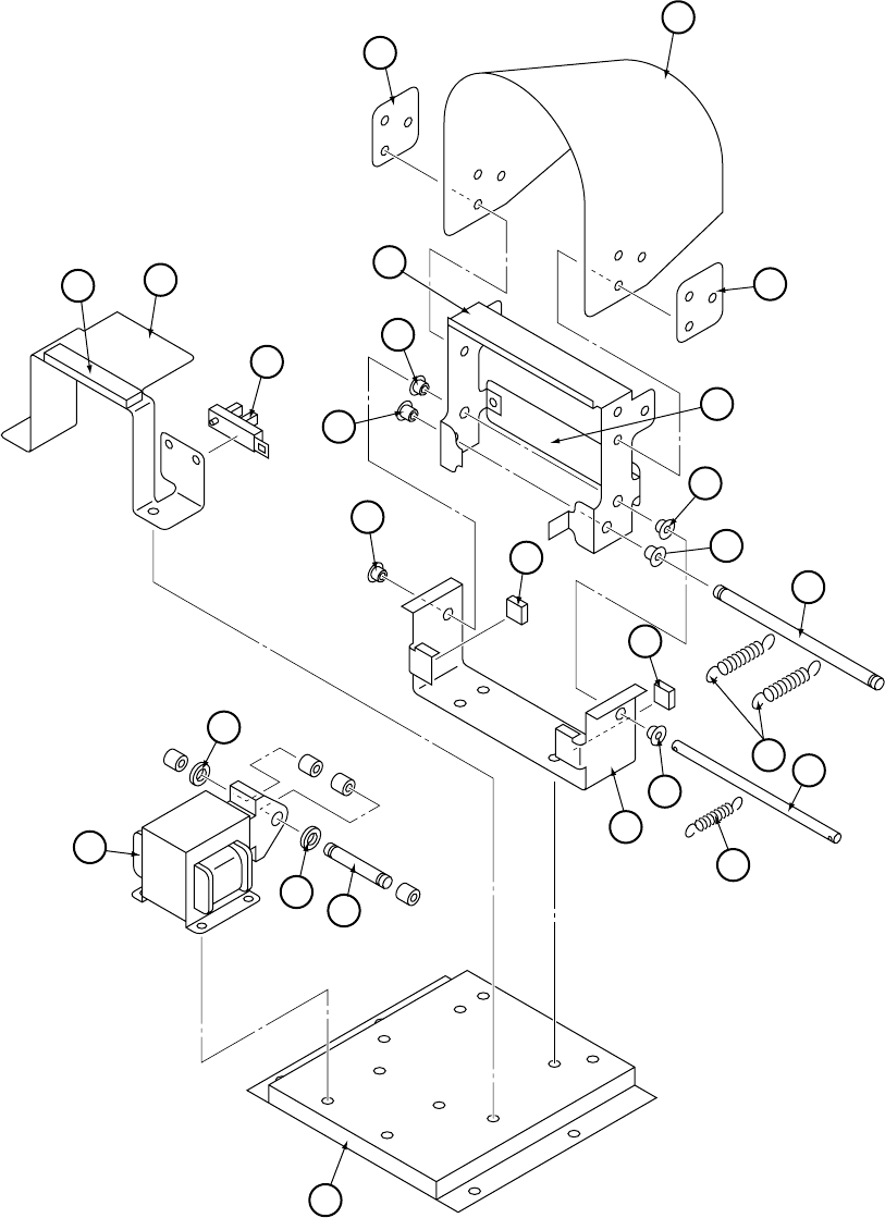
Page 124
2
1
2
4
5
6
15
13
14
5
5
6
3
12
7
12
8
9
5
11
10
17
18
18
16
19
Shutter Assembly

Page 125
metInoitpircseDoNtraP
etelpmoC-ylbmessArettuhS YSSA-TUHS-CQX
1revoCtegraTniaM 212-496-CQX
2tekcarBtnemhcattArevoC 502-496-CQX
32tekcarBrettuhS 102-496-CQX
45tekcarBrettuhS 302-496-CQX
5)6040-F08(hsuBegnalF 110-401-CQX
6)5060-F08(hsuBegnalF 101-522-CQX
72tfahStekcarBrettuhS 802-496-CQX
8gnirpSdioneloS 012-496-CQX
93tekcarBrettuhS 402-496-CQX
011tfahStekcarBrettuhS 702-496-CQX
11gnirpSnoisneT 112-496-CQX
21rebbuRreppotS 312-496-CQX
312tekcarBreppotS 602-496-CQX
412rebbuRreppotS 412-496-CQX
51)107-120697-JO(rosneS 972-000-CQX
61)018-807J(dioneloSrettuhS 375-400-CQX
712tfahSdioneloSrettuhS 902-496-CQX
81rehsaWnirleD 512-496-CQX
91)S(esaB 202-496-CQX
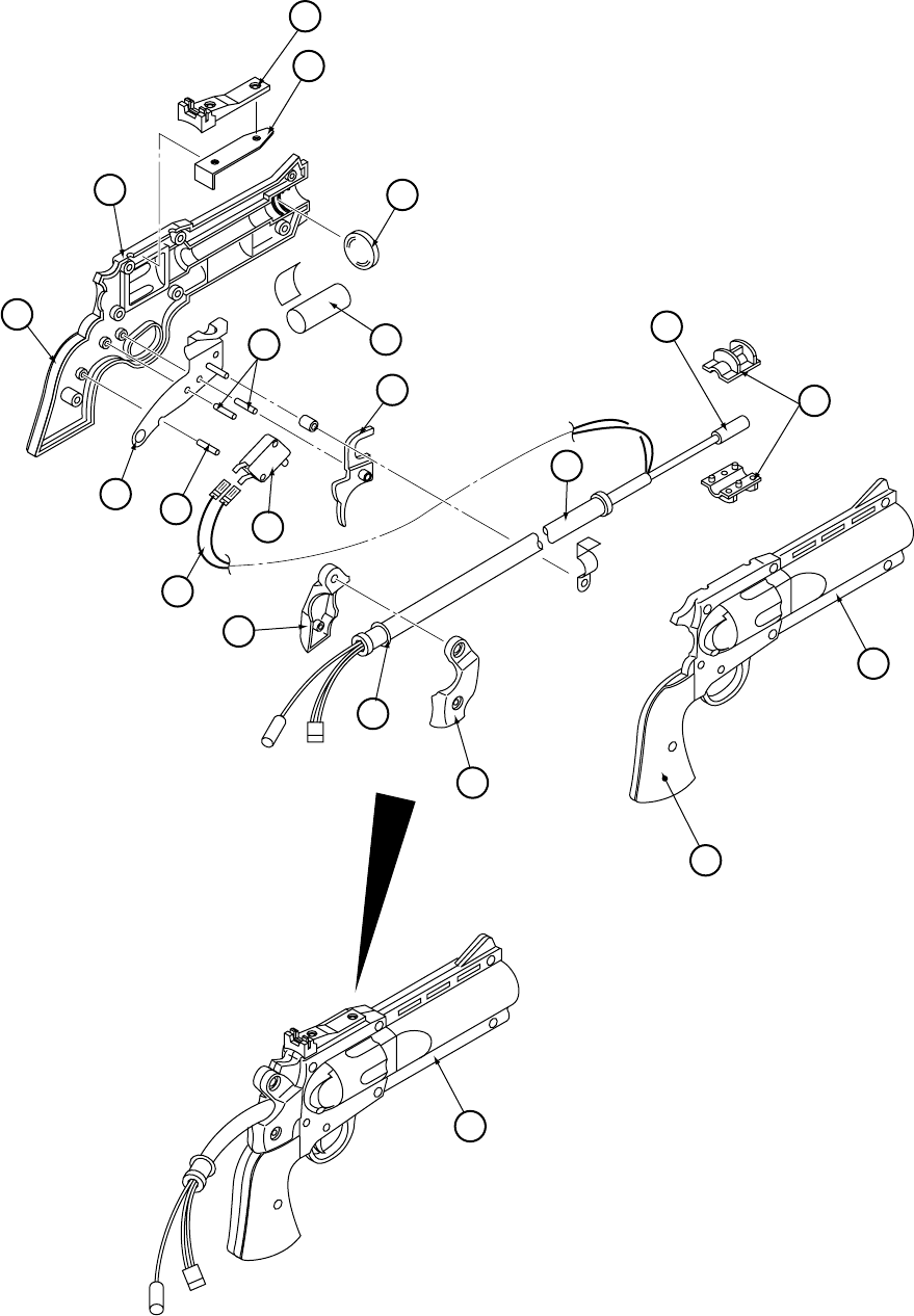
Page 126
17
19
18
20
15
11
12
16
697
3
4
5
2
1
913
14
10
8
Gun Assembly

Page 127
metInoitpircseDoNtraP
1)L(pirG )2metifotraP( ---------
2neerG-)L(ediSnuG 652-496-CQX
3neerG-thgiS 452-496-CQX
4tekcarBthgiS 610-496-CQX
5sneL 510-496-CQX
6tekcarBnuG 116-886-CQX
7)5C06005MA(hctiwSnuG 114-000-CQX
8reggirT 616-886-CQX
9)01fokcap(02x7H3aid-)403SUS(niPlellaraP 480-701-CQX
01thgieWnuG )2metifotraP( ---------
11esoHelbixelF )21metifotraP( ---------
21yssAssenraHnuG 410-496-CQX
31citpOerbiF )21metifotraP( ---------
41redloHerbiF 816-886-CQX
51())RBN(41-P(gniR-O )21metifotraP ---------
61()L(rotcetorPdnaH )3metifotraP ---------
71()R(rotcetorPdnaH )3metifotraP ---------
81neerG-)R(edisnuG 752-496-CQX
91)R(pirG )81metifotraP( ---------
02neerG-yssAnuG 852-496-CQX

Page 128
metInoitpircseDoNtraP
1reteMlenaP 20000056
2dnuoWeriWw01mho001-retemoitnetoP 46100067
bonKdetulF 90000044
3hctiwSedilSOCPD 32000006
4hctiwShsuPONPS 95000006
5redloHesuFtnuoMlenaPmm02nIpanS 74008-CQX
olBkciuQA2-esuFmm02 10500536
6yssAretliFnI-sniaMrenffahcS 61000066
7tooBrenffahcS 71000066
Service Bracket & Mains In Assembly
6
7
1
2
3
4
5
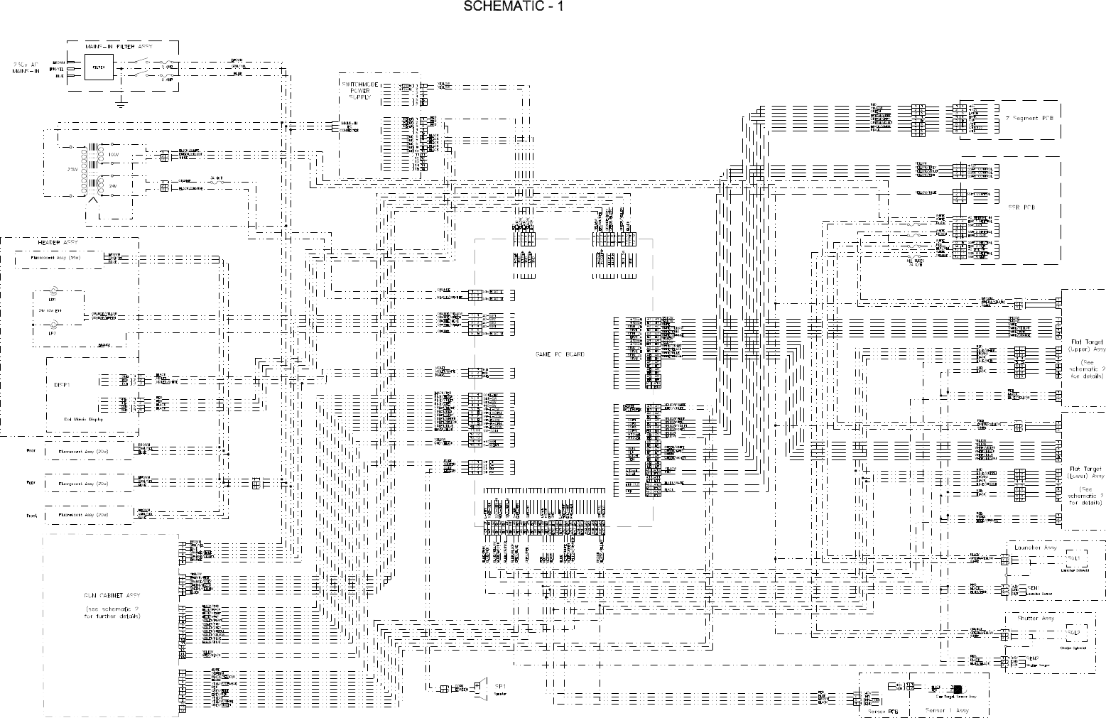
Page 129
10. SCHEMATICS
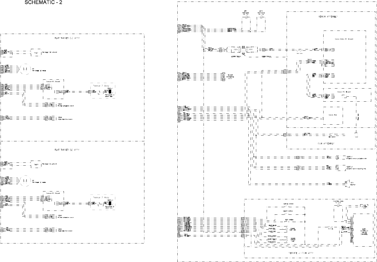
Page 130

For all Parts or Technical Support contact:
Brent Spares,
Namco House,
Units 5-8, Acton Park Estate,
The Vale,
London. W3 7QE
For Technical Support, Warranty and
Advance Replacement Parts: [ +44 (0) 20 8324 6120
For Consumable Parts: [ +44 (0) 20 8324 6102
Fax for both: +44 (0) 20 8324 6126
