QuickGuide_Arduino Quick Guide Arduino
User Manual:
Open the PDF directly: View PDF ![]() .
.
Page Count: 195 [warning: Documents this large are best viewed by clicking the View PDF Link!]

1
Quick Guide: Arduino Driver libraries
Übersicht:
Displays, Bauteile, Sensoren etc. für Arduinos mit passenden Libs und Beispiel-Sourcecodes
Fotos teilw. nur in der Online-Version verfügbar:
http://www.mindstormsforum.de/viewtopic.php?f=78&t=8491
Geschichtlicher Hintergrund:
The Untold History of Arduino (SEHR lehrreich!!) :
https://arduinohistory.github.io/
Lizenz-Hinweise:
für alle hier veröffentlichten Software-Source-Codes gilt:
/*
// (C) Helmut Wunder (HaWe) 2015
// freie Verwendung für private Zwecke
// für kommerzielle Zwecke nur nach Genehmigung durch den Autor.
// Programming language: Arduino Sketch C/C++ (IDE 1.6.1 - 1.6.5)
// protected under the friendly
// Creative Commons Attribution-NonCommercial-ShareAlike 3.0 Unported License
// http://creativecommons.org/licenses/by-nc-sa/3.0/
//
// alle Codes wurden zur Verfügung gestellt in der Hoffnung, dass sie nützlich sind,
// Irrtümer vorbehalten, Benutzung auf eigenes Risiko,
// ohne Anspruch auf Schadenersatz, Garantie oder Gewährleistung
// für irgendwelche eventuellen Schäden, die aus ihrer Benutzung entstehen könnten.
//
// unabhängig hiervon gelten die Lizenz-rechtlichen Besimmungen der Original-Autoren
*/
DONATE / SPENDE:
Gefällt dir dieses Kompendium und möchtest du dafür einen kleinen Betrag über PAYPAL spenden ?
Dann klicke einfach auf diesen Link -
Ab einer Spende ab EUR 5,- kannst du auf Wunsch dieses Kompendium auch als kostenloses
WORD.doc erhalten (per Download-Link als .zip, z.T. ein bisschen weniger Geräte-Fotos aus
urheberrechtlichen Gründen, dafür aber zusätzliche Infos und Code Beispiele):
-> Ja, ich möchte etwas als Anerkennung spenden <-
https://www.paypal.com/cgi-bin/webscr?cmd=_s-xclick&hosted_button_id=Q58RCVK67EM9Q
Ein ganz herzliches Dankeschön!
2
Inhaltsverzeichnis:
Quick Guide: Arduino Driver libraries ....................................................................................1
Übersicht: ...........................................................................................................................1
Geschichtlicher Hintergrund: ..............................................................................................1
Lizenz-Hinweise:....................................................................................................................1
Inhaltsverzeichnis: ..................................................................................................................2
DONATE / SPENDE: ............................................................................................................5
Quick-Links zum diesem Kompendium im Internet: ...............................................................6
Einsteiger- und Installations- Links und Tipps: ...................................................................9
Board-Treiber: ....................................................................................................................9
CH340/CH341 USB Treiber ...........................................................................................9
Arduino ARM Cortec Boards: Zero (M0) und Due (M3) Treiber ....................................9
Links zu gängigen Arduino Tutorials: ............................................................................... 10
sonstige Hilfsmittel: .......................................................................................................... 10
Lötstation: .................................................................................................................... 10
Programmier-Tools............................................................................................................... 11
I2C-Scanner: .................................................................................................................... 11
Arduino-Libraries für Multitasking (für UNO, MEGA, ZERO und DUE) ............................. 13
spezielle unterstützte Boards (non-Arduino): ........................................................................ 14
1) ESP8266 12-E/F ........................................................................................................... 14
2) ESP32 .......................................................................................................................... 15
3) STM32F1 ..................................................................................................................... 15
4) Adafruit Boards (Feather, ItsyBitsy, Metro): ................................................................. 15
digitalWrite: Verbraucher schalten on/off ............................................................................. 17
LED mit Schaltern/Buttons steuern: .................................................................................. 17
stärkere Verbraucher schalten mit Digital Pins: ................................................................. 17
digitalRead: Taster abfragen ................................................................................................. 19
analogRead: Widerstand messen ........................................................................................... 20
TFT Displays:....................................................................................................................... 21
Display: TFT ILI9225 .......................................................................................................... 21
Benchmark-Sketch: ....................................................................................................... 23
Beispiel-Sketch: ............................................................................................................ 25
LCD 1602............................................................................................................................. 32
LCD1602 I2C oder LCD2004_I2C ................................................................................... 35
LCD1602 / LCD2004 mit MCP23017: ............................................................................. 36
7-Segment LED Displays ..................................................................................................... 37
einfache 7-Segment LEDs: ............................................................................................... 37
multi- 7-Segment (8-Segment) und 13 (14)-Segment- Displays ........................................ 37
Vierstellige 7 Segment Anzeige ............................................................................................ 38
Display: OLED 128x64 u.a. (SSD1306, SH1106) ................................................................. 40
Display TFT ILI9341............................................................................................................ 42
a) 2.2" 240x320 ............................................................................................................... 42
b) 2.4" 240x320 mit Touch Screen ................................................................................... 42
Driver-libs ........................................................................................................................ 42
Adafruit TFT_22_ILI9340 : .......................................................................................... 42
alternative, schnellere lib: ILI9341_due ........................................................................ 46
Touch-Library XPST2046 ................................................................................................ 51
weitere ILI9341 Library: ILI9341 ucglib (Oli Kraus) ....................................................... 51
GUIslice GUI Grafik-Lib...................................................................................................... 52
3
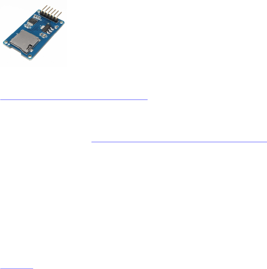
SD Karten-Module und File IO Funktionen: ......................................................................... 53
Header: ......................................................................................................................... 54
Aufruf ........................................................................................................................... 55
Testcode für fprintf_ und fgets_(): ................................................................................ 56
Testcode für fprintf_() und fscanf_(): ............................................................................ 59
komplette ardustdio lib................................................................................................. 63
PS/2 Keyboard ..................................................................................................................... 71
(UART) HC-05 : serielle BT-Module ( als Master oder Slave)............................................. 72
Drahtlosverbindung über zwei HC-05 Module: ............................................................. 72
Bei Problemen mit 5V-Geräten an 3.3V UART Bus - einfacher Spannungsteiler: ........ 75
Serial UART Lib: Kommunikation zwischen 2 Arduinos: ............................................. 76
(UART) GPS Modul GY-NEO-6M V2 ................................................................................. 89
Arduino GPS data to google maps ................................................................................ 93
Infrared Remote Library für Arduino (Baustelle) .................................................................. 94
Arduino-Libs für Lego Mindstorms NXT-Sensoren .............................................................. 95
Lego-Stecker-Pins : .......................................................................................................... 95
NXT Taster (Touch-Sensor) : ........................................................................................... 95
NXT-Lichtsensor (Light-Sensor): ..................................................................................... 96
NXT Geräuschsensor (Sound Sensor): .............................................................................. 97
NXT Ultraschallsensor (Ultrasonic Sensor) ...................................................................... 98
weitere Links zu Arduino-Libs für Lego Mindstorms EV3-Sensoren .............................. 101
Auslesen von Encoderwerten mit einem Arduino: .............................................................. 102
Variante 1: Auslesen der Encoder per Arduino Uno / Mega : ..................................... 102
Variante 2: Quadratur-Encoder auslesen mit Arduino Due (per Due-Timer):.............. 104
Pin-Belegung für die Verwendung von Lego Mindstorms RJ11-Steckern: Encoder auf
pins 5+6 (gelb + blau) ................................................................................................. 107
Ansteuern von DC (Encoder-) Motoren per L293D H-Brücke: ........................................... 108
L293D doppel-H-Bridge chip: ........................................................................................ 108
verfügbare PWM Pins Arduino: ...................................................................................... 109
Steuerlogik: .................................................................................................................... 109
Ansteuern von DC-Motoren per L293D H-Brücke:............................................................. 110
(analog) Sharp IR Distanz-Sensoren GP2D120 ( 4-30cm ) GP2D12 ( 10-80cm )
GP2Y0A21YK0F ( 10-80cm ) ............................................................................................ 113
(analog) Potentiometer-Joystick für Differentialantriebs-Steuerung .................................... 114
Keypad 4x5 ........................................................................................................................ 118
( 1-wire ) DHT11 + DHT22 Humidity & Temperature Sensor Module ............................... 119
a) DHT11 ....................................................................................................................... 119
b) DHT22 ....................................................................................................................... 120
I2C (allgemein) .................................................................................................................. 121
( I2C ) RGB-Farbsensor TCS230 / TCS3200 ..................................................................... 122
( I2C ) RGB-Farbsensor Adafruit TCS34725 ..................................................................... 124
Ultraschall Sensoren (I2C) Devantech SRF-02 und SRF-08 ................................................ 127
(I2C + UART) IMU-Sensor: CMPS11 ................................................................................ 129
CMPS11 Example Code: ............................................................................................ 131
Register-Belegung: ..................................................................................................... 133
Calibration: ................................................................................................................. 135
CMPS11 Dokumentation: ............................................................................................... 136
I2C Communication .................................................................................................... 136
i2c: Calibration of the CMPS11 .................................................................................. 136
i2c: Calibration of the CMPS11 for horizontal only operation ..................................... 137
i2c: Restoring Factory Calibration............................................................................... 137
4
Changing the I2C Bus Address ................................................................................... 137
Serial Communication ................................................................................................ 137
(I2C + UART) IMU-Sensor CMPS12 ................................................................................ 140
(I2C) MPU6050 6D IMU ................................................................................................... 141
Libraries: ........................................................................................................................ 141
1.) Arduino Playground............................................................................................... 141
2.) tockn/MPU6050_tockn .......................................................................................... 141
3.) TKJElectronics/KalmanFilter................................................................................. 141
4.) jrowberg/i2cdevlib ................................................................................................. 142
(I2C) Real Time Clock RTC DS3231 ................................................................................. 143
Real Time Clock RTC DS3231 mit Anzeige auf LCD1602 Display ................................ 145
(I2C) Wäge-Sensor mit Wägebrücke ................................................................................. 149
(I2C) MCP9808 Temperatur-Sensor ................................................................................... 150
(I2C, SPI) Bosch BMP280 Barometric Pressure + Temperature .......................................... 152
(Bosch BME280: dto., + Humidity) .................................................................................... 152
( I2C) LIDAR-Lite v3 + v3HP ............................................................................................ 153
I2C Portexpander (Muxer) .................................................................................................. 155
( I2C ) ADS1115 4x ADC analog Multiplexer ................................................................ 155
(I2C) PCF8591 : 4x ADC & 1x DAC analog Multiplexer ............................................... 157
(I2C) PCF8574 : 8x IO Multiplexer (read/write) ............................................................. 159
weitere Lib: ................................................................................................................ 160
(I2C) MCP23017 : 16x IO-Multiplexer (read/write) ........................................................ 161
Example von tronixstuff.............................................................................................. 161
alternativ: Lib von Adafruit ........................................................................................ 162
(I2C) PCA9685 Servocontroller ........................................................................................ 164
(I2C) I2C Port Splitter PCA9548A / TCA9548A ................................................................ 165
ESP8266 NodeMCU (ESP-12E, ESP-12F) für IoT ............................................................. 167
Übersicht: ....................................................................................................................... 167
NodeMCU Board ESP-12E oder 12F: ......................................................................... 167
GPIO pins: .................................................................................................................. 168
Infos zu Hardware, Libs und Installation des ESP8266 nodeMCU Boards: ................. 169
Beispiel-Projekte: Websites mit Button-Steuerung .......................................................... 170
einfaches Beispiel mit Website und Button: ................................................................ 171
Beispiel-Code: Website plus TimeZone , WiFiUdp , Temperaturanzeige und Steuerung
................................................................................................................................... 174
Pixy Cam (cmuCam5) an Arduino: ..................................................................................... 184
Einrichtung, Installation: ............................................................................................. 184
PixyMon starten: ........................................................................................................ 184
farbiges Objekt anlernen: ............................................................................................ 184
Pixy mit Arduino verbinden: ....................................................................................... 185
Arduino libraries und Sketch examples: ..................................................................... 185
Weitere Interface-/Anschluss-Möglichkeiten (UART, I2C): ........................................ 186
hello-Sketch mit Sortierfunktion für multi-color-codes: .............................................. 186
Beurteilung: ................................................................................................................ 190
(UART) TF Mini LiDAR (Seeedstudio Grove) ................................................................... 192
UART-Protokoll: ........................................................................................................ 192
Sketch: ........................................................................................................................ 192
Sony Playstation 2 (Wireless) PS2 Controller ..................................................................... 194

5
DONATE / SPENDE:
Gefällt dir dieses Kompendium und möchtest du dafür einen kleinen Betrag über PAYPAL spenden ?
Dann klicke einfach auf diesen Link -
Ab einer Spende ab EUR 5,- kannst du auf Wunsch dieses Kompendium auch als kostenloses
WORD.doc erhalten (per Download-Link als .zip, z.T. ein bisschen weniger Geräte-Fotos aus
urheberrechtlichen Gründen, dafür aber zusätzliche Infos und Code Beispiele):
-> Ja, ich möchte etwas als Anerkennung spenden <-
https://www.paypal.com/cgi-bin/webscr?cmd=_s-xclick&hosted_button_id=Q58RCVK67EM9Q
Ein ganz herzliches Dankeschön!
...

6
Quick-Links zum diesem Kompendium im Internet:
(solange bzw. soweit Website(s) verfügbar)
Installation, Einsteiger-Tipps:
http://www.mindstormsforum.de/viewtopic.php?f=78&t=8491&p=66120#p66120
Tutorials: http://www.mindstormsforum.de/viewtopic.php?f=78&t=8491&p=66123#p66123
Tools: http://www.mindstormsforum.de/viewtopic.php?f=78&t=8491&p=66177#p66177
Multitasking :
http://www.mindstormsforum.de/viewtopic.php?f=78&t=8491&p=66188#p66188
Displays: ab
http://www.mindstormsforum.de/viewtopic.php?f=78&t=8491&p=68168#p68168
z.B.
LCD1602: http://www.mindstormsforum.de/viewtopic.php?f=78&t=8491#p69998
LCD1602 i2C::
http://www.mindstormsforum.de/viewtopic.php?f=78&t=8491&start=15#p69999
TFT ILI9225: http://www.mindstormsforum.de/viewtopic.php?f=78&t=8491#p68170
TFT ILI9341:
http://www.mindstormsforum.de/viewtopic.php?f=78&t=8491&start=15#p70266
OLED: http://www.mindstormsforum.de/viewtopic.php?f=78&t=8491&p=70259#p70259
mult. 7-Segm.:
http://www.mindstormsforum.de/viewtopic.php?f=78&t=8491&start=15#p70000
SD-Module:
http://www.mindstormsforum.de/viewtopic.php?f=78&t=8491&start=30#p66429
PS/2 Keyboard:
http://www.mindstormsforum.de/viewtopic.php?f=78&t=8491&p=67455#p67455
UART-Bluetooth HC-05:
http://www.mindstormsforum.de/viewtopic.php?f=78&t=8491&p=67457#p67457
UART-Spannungsteiler:
http://www.mindstormsforum.de/viewtopic.php?f=78&t=8491&start=30#p67459
UART-comm:
http://www.mindstormsforum.de/viewtopic.php?f=78&t=8491&p=67457#p67476
UART-GPS GY-NEO-6M:
http://www.mindstormsforum.de/viewtopic.php?f=78&t=8491&p=69280#p69280
IR Remote Control:
http://www.mindstormsforum.de/viewtopic.php?f=78&t=8491&p=69962#p69962
Lego-Sensoren:
http://www.mindstormsforum.de/viewtopic.php?f=78&t=8491&start=45#p67546
Encoder-Reading:
http://www.mindstormsforum.de/viewtopic.php?f=78&t=8491&start=30#p68839

7
DC-Motoren:
http://www.mindstormsforum.de/viewtopic.php?f=78&t=8491&start=30#p68840
analoge Sharp IR-Distanz-Sensoren
http://www.mindstormsforum.de/viewtopic.php?f=78&t=8491&p=68970#p68970
analoger Joystick:
http://www.mindstormsforum.de/viewtopic.php?f=78&t=8491&p=68971#p68971
Keypad : http://www.mindstormsforum.de/viewtopic.php?f=78&t=8491&p=68975#p68975
digitaler RGB-Farbsensor TCS230/TCS3200:
http://www.mindstormsforum.de/viewtopic.php?f=78&t=8491&p=68975#p68977
i2c RGB-Farbsensor Adafruit TCS34725:
http://www.mindstormsforum.de/viewtopic.php?f=78&t=8491&p=68977#p68978
Ultraschall Sensoren HC-SR04 :
http://www.mindstormsforum.de/viewtopic.php?f=78&t=8491&p=69272#p69272
Ultraschall Sensoren SRF02, SRF08 :
http://www.mindstormsforum.de/viewtopic.php?f=78&t=8491&start=60#p69273
CMPS11: http://www.mindstormsforum.de/viewtopic.php?f=78&t=8491&start=60#p69275
RTC DS3231:
http://www.mindstormsforum.de/viewtopic.php?f=78&t=8491&p=69277#p69277
GPS GY-NEO-6M:
http://www.mindstormsforum.de/viewtopic.php?f=78&t=8491&p=69280#p69280
ADS1115: http://www.mindstormsforum.de/viewtopic.php?f=78&t=8491&start=75#p69282
PCF8591: http://www.mindstormsforum.de/viewtopic.php?f=78&t=8491&start=75#p69283
PCF8574: http://www.mindstormsforum.de/viewtopic.php?f=78&t=8491&start=75#p69285
MCP23017:
http://www.mindstormsforum.de/viewtopic.php?f=78&t=8491&start=75#p69287
I2C Multiplexer/Port Splitter
http://www.mindstormsforum.de/viewtopic.php?f=78&t=8491&p=70084#p70084
DHT11 + DHT22 Temperatur/Luftfeuchtesensor (1-Wire):
http://www.mindstormsforum.de/viewtopic.php?f=78&t=8491&p=70084#p70987
BMP280 / BME280 Temp & Baromet (& Humid) Sensors
http://www.mindstormsforum.de/viewtopic.php?f=78&t=8491&p=71286#p71286
MCP9808 Temperatur-Sensor
http://www.mindstormsforum.de/viewtopic.php?f=78&t=8491&p=71291#p71291

8
DONATE / SPENDE:
Gefällt dir dieses Kompendium und möchtest du dafür einen kleinen Betrag über PAYPAL spenden ?
Dann klicke einfach auf diesen Link -
Ab einer Spende ab EUR 5,- kannst du auf Wunsch dieses Kompendium auch als kostenloses
WORD.doc erhalten (per Download-Link als .zip, z.T. ein bisschen weniger Geräte-Fotos aus
urheberrechtlichen Gründen, dafür aber zusätzliche Infos und Code Beispiele):
-> Ja, ich möchte etwas als Anerkennung spenden <-
https://www.paypal.com/cgi-bin/webscr?cmd=_s-xclick&hosted_button_id=Q58RCVK67EM9Q
Ein ganz herzliches Dankeschön!

9
Einsteiger- und Installations- Links und Tipps:
Geschichtlicher Hintergrund: The Untold History of Arduino (SEHR lehrreich!!) :
https://arduinohistory.github.io/
Download der Arduino-Programmiersoftware (IDE):
https://www.arduino.cc/en/Main/Software
Arduino-IDE auf Windows installieren:
für die Erstinstallation am besten den Windows Installer verwenden, nicht die zip Files (bei
zip Files werden keine Windows-Treiber installiert!)
Arduino-IDE auf Raspberry Pi installieren:
https://www.raspberrypi.org/forums/view ... 1#p1070661
Board-Treiber:
CH340/CH341 USB Treiber
manche Arduino-Klone verwenden statt eines AtMega16U2 USB Chips einen CH340/CH341
USB Chip, der von Windows (und Arduino) nicht automatisch erkannt wird. Hier ist ein
Treiber-Setup-Programm für CH340/CH341:
CH341SER.zip
https://github.com/dsyleixa/Drivers/tree/master/CH341SER
Wird damit ein CH340/1-Board immer noch nicht erkannt, hilft oft ein Zurücksetzen der
USB-Ports mit dem Windows DEVCON-Tool:
http://www.com-magazin.de/tipps-tricks/ ... 91023.html
Arduino ARM Cortec Boards: Zero (M0) und Due (M3) Treiber
Beide Boards werden nicht mehr automatisch mit installiert und müssen nach Installation der
Arduino Software (IDE) über den Board-Manager der IDE nachinstalliert werden (Internet-
Verbindung!)

10
Links zu gängigen Arduino Tutorials:
Arduino Playground
https://www.arduino.cc/en/Tutorial/HomePage
tronixstuff (free tutorials):
http://tronixstuff.com/tutorials/
Sainsmart_Nano-Starter-Kit:
http://www.selloutsoon.com/albums/documents/20-013-120/Nano+kit.rar
Sainsmart_Mega2560-Starter-Kit:
https://www.sainsmart.com/products/mega-2560-r3-starter-kit
http://s3.amazonaws.com/s3.image.smart/download/101-52-
128/SainSmart%2BStater%2BKit%2BTutorals%2BMEGA2560.rar
Arduino-Kochbuch_Magolis_oReilly:
https://docs.google.com/file/d/0BxbayAAcS8IiaTRjVjJoRG8xVHc/edit?pref=2&pli=1
Arduino-Praxisbuch_Sommer_Franzis
https://www.elo-
web.de/electronic/div/common/registration_form.jsp?showLogin=false&downloadID=24556
59&afterLogin=http%253A%252F%252Fwww.elo-
web.de%252Felektronik%252Fangebot%252Fpraxisbuch-arduino-
aktion&downloadMessage=userShouldBeAuthorized
Arduino-Codereferenz in deutsch (Forumslink):
https://www.arduinoforum.de/arduino-Thread-Code-Referenz-komplett-in-
deutsch?pid=32885#pid32885
Funduino Tutorial
http://funduino.de/wp-content/uploads/2016/11/Anleitungen-deutsch-12-2016.pdf
Funduino Anleitung deutsch (Internet):
https://funduino.de/
sonstige Hilfsmittel:
Lötstation:
https://www.reichelt.de/Diverse-Loetstationen/STATION-ZD-
931/3/index.html?ACTION=3&LA=2&ARTICLE=90918&GROUPID=555&artnr=STATIO
N+ZD-931&SEARCH=%252A

11
Programmier-Tools
I2C-Scanner:
http://playground.arduino.cc/Main/I2CScanner
verbesserte Version:
// --------------------------------------
// I2C_scanner
//
// This sketch tests the standard 7-bit addresses
// Devices with higher bit address might not be seen properly.
//
#include <Wire.h>
#define ESP_SDA 4 //GPIO4=D2 SDA ESP8266 default
#define ESP_SCL 5 //GPIO5=D1 SCL ESP8266 default
byte error, address;
int nDevices;
void setup()
{
// Wire.begin(ESP_SDA,ESP_SCL); // only for ESP8266 if not default
Wire.begin(); // AVR, ARM, ESP8266 default
Serial.begin(115200);
while (!Serial); // Leonardo: wait for serial monitor
Serial.println("\nI2C Scanner");
Serial.println("\nScanning...");
}
void loop()
{
nDevices = 0;
for(address = 0; address < 128; address++ ) {
if (address%16 == 0) {
Serial.println();
Serial.print( (address+1)/16);
Serial.print(" ");
}
if(address==0 || address==127) {
Serial.print("** ");
continue;
}
Wire.beginTransmission(address);
error = Wire.endTransmission();
12
if (error == 0)
{
if (address<16) Serial.print("0");
Serial.print(address,HEX); Serial.print(" ");
nDevices++;
}
else if (error==4)
{
Serial.print("?? ");
}
else
{
Serial.print("-- ");
}
}
Serial.println();
Serial.print("found: ");
Serial.print(nDevices); Serial.print(" devices \n");
delay(10000);
}

13
Arduino-Libraries für Multitasking (für UNO, MEGA,
ZERO und DUE)
(1) kooperatives Multitasking für Arduino Due, Zero, MKR1000:
Scheduler lib https://github.com/arduino-libraries/Scheduler
Beispiel : https://www.arduino.cc/en/Tutorial/MultipleBlinks
(2) alternative Scheduler lib von Mikael Patel, kompatibel zu ARMs (Due, Zero) und
AVRs:
Scheduler lib https://github.com/mikaelpatel/Arduino-Scheduler
update:
in der neuesten Variante ist Patel's Scheduler API zwar einigermaßen kompatibel zu
cmaglie's, ABER er ist teilw. noch reichlich verbuggt.
Ich empfehle für den Due die obige Version (1), für AVRs diese Version (2)
(3) alternative Scheduler lib von Mikael Patel, kompatibel zu esp8266 nodeMCU:
Scheduler lib https://github.com/anmaped/esp8266-scheduler
neu: Lib von jensh, kompatibel zu AVRs, ARMs offenbar noch nicht getestet :
[url]github: https://github.com/jensh/CopyThreads[/url]
Beispiele:
https://github.com/jensh/CopyThreads/blob/master/examples/CTBlink/CTBlink.ino
https://github.com/jensh/CopyThreads/blob/master/examples/c/hello_world.c
pre-emptives Multitasking-Libs (!) :
Arduino Due, Zero:
http://forum.arduino.cc/index.php?topic=318084.0
http://perso.ensta-paristech.fr/~pessaux/alius/arduino.html
und dann für die kleineren AVRs (z.B. Arduino Mega):
http://forum.arduino.cc/index.php?topic=347188.0
http://www.rtos48.com/

14
spezielle unterstützte Boards (non-Arduino):
1) ESP8266 12-E/F
ggf. USB-serial Chip CH340/1 installieren (s.o.)
https://github.com/dsyleixa/Arduino/blob/master/CH341SER/CH341SER.zip
in "Datei - Voreinstellungen" unter "Zusätzliche Boardverwalter-URLs" Such-URL eingeben:
http://arduino.esp8266.com/stable/package_esp8266com_index.json
Menü "Werkzeuge – Board: …", "Boardverwalter"
Eingabe im Suchfenster esp8266 Eintrag "esp8266 by ESP8266 Community" auswählen +
installieren
erneut Menü "Werkzeuge – Board: … – "Boardverwalter…",
Auswahl von Eintrag "Generic ESP8266 Module" oder „NodeMCU ESP8266 12-E“:
Einstellungen kontrollieren:
Flashmode: QIO
Flash Frequency: 40 MHz
cpu Frequency: 80 MHz
Flashsize: 4M (3M SPIFFS)
Debug Port: disabled
Debug Level: keine
Reset Method: nodemcu
Upload Speed: 115200
Zu "NodeMCU ESP8266 12-E": Hierin sind bereits weitere Bord-Definitionen enthalten,
auch z.B D* Pin Nummern statt der MCU GPIO Nummern.
spezielle Zusatzbibliotheken über Library Manager je nach Bedarf installieren, z.B
• NTPClientLib (Lib-Manager)
• Time, TimeLib (Lib-Manager)
• JasonStreaming Parser (Lib-Manager)
• Adafruit Unified Sensor, DHT (Lib-Manager)
• esp8266 fs uploader https://github.com/esp8266/arduino-esp8266fs-plugin/releases
• CurrencylayerClient
https://www.brickrknowledge.de/content/uploads/2017/04/BrickESP8266.zip
GPIO-Pin Nummerierung für Arduino nodeMCU :
digital GPIO default
D0 16 WAKE
D1 5 I2C SCL
D2 4 I2C SDA
D3 0 FLASH/LED
D4 2 TX1
D5 14 SPI SCK
D6 12 SPI MISO
D7 13 SPI MOSI
D8 15 MTD0 PWM
D9 3 UART RX0
D10 1 UART TX0

15
2) ESP32
(Arduino-core für ESP32 noch in Entwicklung)
https://github.com/espressif/arduino-esp32
https://www.heise.de/make/artikel/Grosser-Bruder-Espressif-ESP32-3256039.html
3) STM32F1
(Arduino-cores für STM32 noch in Entwicklung)
Hier handelt es sich um einen ARM Cortex M3 ( STM32F103C8T6 ) mit 64 Kbytes Flash, 72
MHz CPU, motor control, USB and CAN.
Eine gute Installationsanleitung findet sich hier in diesem Video:
https://www.youtube.com/watch?v=MLEQk73zJoU
hier noch ein kleines Arduino-STM32 Tutorial dazu:
https://thdarduino.blogspot.de/2016/07/mein-ersten-stm32-projekt-blue-pill.html
4) Adafruit Boards (Feather, ItsyBitsy, Metro):
Additional Boards Manager URLs option: add
https://adafruit.github.io/arduino-board-index/package_adafruit_index.json;
Boards Manager:
Install SAMD Support
https://learn.adafruit.com/adafruit-metro-m4-express-featuring-atsamd51/using-with-arduino-
ide#install-samd-support-6-5
Install Adafruit SAMD:
https://learn.adafruit.com/adafruit-metro-m4-express-featuring-atsamd51/using-with-arduino-
ide#install-adafruit-samd-6-7
Select the matching board, the current options are:
• Feather M0 (for use with any Feather M0 other than the Express)
• Feather M0 Express
• Metro M0 Express
• Circuit Playground Express
• Gemma M0
• Trinket M0
• ItsyBitsy M0
• Hallowing M0
• Crickit M0 (this is for direct programming of the Crickit, which is probably not what
you want! For advanced hacking only)
• Metro M4 Express
• ItsyBitsy M4 Express
• Feather M4 Express
• Trellis M4 Express
• Grand Central M4 Express
Install Drivers (Windows 7 & 8 Only):

16
https://learn.adafruit.com/adafruit-metro-m4-express-featuring-atsamd51/using-with-arduino-
ide#install-drivers-windows-7-and-8-only-6-11
https://github.com/adafruit/Adafruit_Windows_Drivers/releases/download/2.3.4/adafruit_driv
ers_2.3.4.0.exe

17
digitalWrite: Verbraucher schalten on/off
LED mit Schaltern/Buttons steuern:
s. Arduino Tutorials + Playground, z.B.
https://playground.arduino.cc/Main/PushButtonToSwitch
stärkere Verbraucher schalten mit Digital Pins:
Um stärkere Verbraucher als nur wenige mA zu schalten, braucht man dagegen eine H-
Brücke (s.u.) oder ein Relais (als Basiswiderstand R1 für RPi (3.3V) besser ca. 1kOhm
verwenden), welche man über Transistoren oder MOSFETs schalten kann:
Quelle: http://www.elektronik-kompendium.de/sites/slt/1201131.htm
R1
2,2 kOhm
R2
2,2 kOhm
D1
1N4148
T1
BC 337
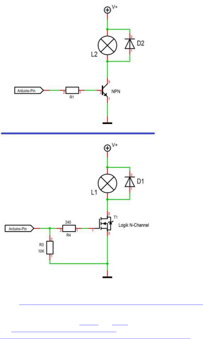
18
NPN Transistor vs. MOSFET
Quelle: https://forum.arduino.cc/index.php?topic=527226.msg3596917#msg3596917
NPN: BC337-40
MOSFET: IRLZ34N oder IRLZ44N
Diode: Gleichrichterdiode, z.B. 1N4001 oder SB560 , oder (?) 1N4148 (s.o.)
s.a.: http://bildr.org/2012/03/rfp30n06le-arduino/
http://www.g7smy.co.uk/2015/02/solenoids-on-the-arduino-with-mosfet-power/
19
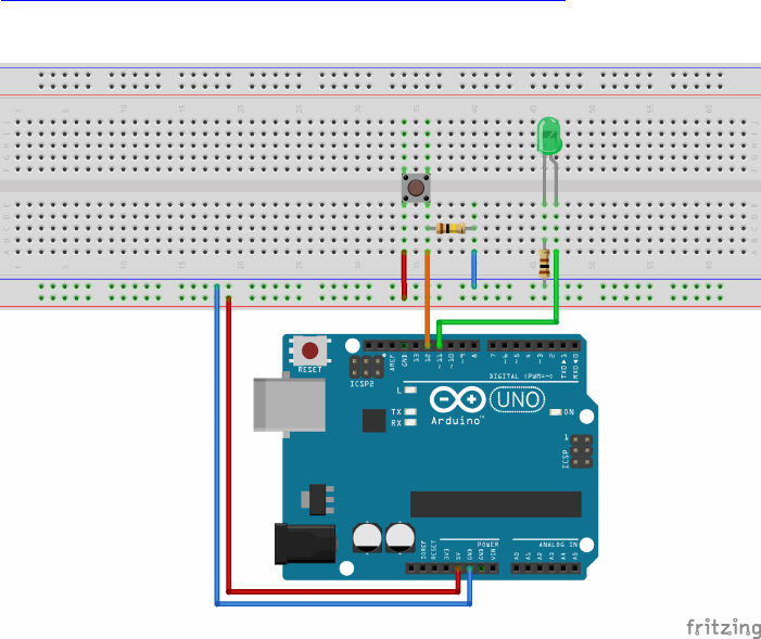
digitalRead: Taster abfragen
https://rotering-net.de/tut/arduino/taster-abfragen.html
20
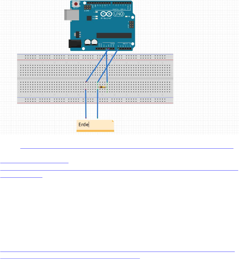
analogRead: Widerstand messen
Widerstandsmessung analog mit 100k Pullup an ADC:
Quelle: https://michaelsarduino.blogspot.com/2015/09/feuchtigkeitsensor-selber-bauen.html
https://2.bp.blogspot.com/-
bqoq50JR7uM/VfLIEcUM6LI/AAAAAAAABeU/gvGwU1qpOLg/s1600/Schaltplan_Feuchti
gkeitssensor.png
Statt "Erde" (Bodenfeuchtemessung) ntl. auch beliebige andere Widerstände.
um die Leitfähigkeit zu messen:
Anschlüsse an +Vc und GND tauschen (100 k Pulldown an ADC)
Anm.:
besserer, kapazitiver Erdfeuchte-Sensor anstelle blanker Metallelektroden:
https://www.dfrobot.com/wiki/index.php/Capacitive_Soil_Moisture_Sensor_SKU:SEN0193
https://www.bjoerns-techblog.de/2018/03/kw-12-2018/

21
TFT Displays:
weitere TFT und OLED s.a. weiter unten
ab viewtopic.php?f=78&t=8491&p=70259#p70259 !
Display: TFT ILI9225
Screen: 2.2" 176x220
2.2" ILI9225 (Foto beispielhaft)
ILI9225 Display hier mit einer lib von Henning Karlsen
und unter Verwendung von 3-6 analogen Pins, auf deren Header man das Display direkt
aufstecken kann;
es funktioniert aber auch mit digitalen Pins.
inkl Software-SPI (50-53 bei Mega, 74-76 bei Due):
Preis: ca. 7-17 EUR
teilw. SD-Card-Slot
teilw. 5V/3.3V-kompatibel
- kein Touchscreen -
Achtung:
- Funktioniert mit der H.K. UTFT-lib nicht gleichzeitig zusammen mit Hardware-SPI-
Geräten auf den SPI-Header-Pins !
- D.h.: auch wenn der SD-Slot funktioniert, muss der SD slot auf Hardware-SPI
angeschlossen werden,
das TFT aber auf komplett anderen Software-SPI-Pins!
- viele Displays haben dabei zwar einen SD-Slot aufgelötet, aber es fehlt auf der Rückseite
der zur Ansteuerung nötige Chip (meist als "U3" bezeichnet), somit ist dieser natürlich
wertlos
Bezugsquelle: z.B. diverse in China ansässige Händler, auch z. B. ähnlich wie (ohne
Gewähr):
http://www.ebay.de/itm/201042408158?_trksid=p2059210.m2749.l2649&ssPageName=STR
K%3AMEBIDX%3AIT
http://eckstein-shop.de/22-ILI9225-SPI-TFT-LCD-Display-Ohne-Touchscreen-mit-Arduino-
Library-C51-STM32

22
// API-call: UTFT myGLCD(Model,SDA,SCL,CS,RST,RS)
// adjust the model parameter to suit the display module!
//--TFT Pin--|--Arduino Pin---| -------------------Note-----------------|-DPIN/SPI--
//---LED-----|-------A0--Vc---|---Backlight Control,Hight level Enable--|---Vc------
//---CLK-----|-------A1-------|-----Serial Interface Clock Signal-------|---38(76)--
//---SDI-----|-------A2-------|-----------Serial Input Signal-----------|---39(75)--
//---RS------|-------A3-------|------Command or Parameter Sellect-------|---40------
//---RST-----|-------A4/RESET-|---------------Reset Signal--------------|---RESET---
//---CS------|-------A5/GND---|----------Chip Sellect Signal------------|---41/GND--
//VCC:5V DC.
//GND:Ground.
//How to save IO pin(see the notes below):
//note1:LED A0 is also can be connected to 3.3V or 5V,So that Backlight will be
always on.
//note2:RST A4 can be connected to MCU reset pin,to save a IO pin.
//note3:CS A5 can be connected to GND,So that Chip Sellect will be always Enable.
SPI-Lib mit analog-Pin-Ansteuerung:
5-pin-Ansteuerung UTFT lib QDtech / Henning Karlsen
Original-UTFT Henning Karlsen: http://henningkarlsen.com/electronics/library.php?id=51
Grafik-Erweiterung: UTFT_Geometry
http://henningkarlsen.com/electronics/library.php?id=59 (Dreieck, Kreissegment,
Tortenstück)
Font-Erweiterung: http://www.henningkarlsen.com/electronics/r_fonts.php
gepatchte QDtech-lib für China-Klon:
QDTech-UTFT-Karlsen.zip
6-pin-analog-Ansteuerung UTFT lib QDtech / Henning Karlsen
(5.58 MiB) 670-mal heruntergeladen

23
Benchmark-Sketch:
// hw brickbench
// version 1.09.0022-KarlsenUTFT
#include <SPI.h>
#include <UTFT.h>
extern uint8_t SmallFont[];
//QD220A is for QDtech 2.2inch SPI LCD Module,Driver IC:ILI9225
//UTFT myGLCD(Model, SDA=MOSI, SCL, CS, RESET, RS)
UTFT myGLCD(QD220A, 41, 40, 43, 0, 42); // adjust model
parameter and pins !
#define TimerMS() millis()
unsigned long runtime[8];
inline void displayValues() {
char buf[120];
myGLCD.clrScr();
sprintf (buf, "%3d %9ld int_Add", 0, runtime[0]); myGLCD.print(buf,
0,10);
sprintf (buf, "%3d %9ld int_Mult", 1, runtime[1]); myGLCD.print(buf,
0,20);
sprintf (buf, "%3d %9ld float_op", 2, runtime[2]); myGLCD.print(buf,
0,30);
sprintf (buf, "%3d %9ld randomize", 3, runtime[3]); myGLCD.print(buf,
0,40);
sprintf (buf, "%3d %9ld matrx_algb", 4, runtime[4]); myGLCD.print(buf,
0,50);
sprintf (buf, "%3d %9ld arr_sort", 5, runtime[5]); myGLCD.print(buf,
0,60);
sprintf (buf, "%3d %9ld TextOut", 6, runtime[6]); myGLCD.print(buf,
0,70);
sprintf (buf, "%3d %9ld Graphics", 7, runtime[7]); myGLCD.print(buf,
0,80);
}
int32_t test_TextOut(){
int y;
char buf[120];
for(y=0;y<20;++y) {
myGLCD.clrScr();
sprintf (buf, "%3d %9d int_Add", y, 1000); myGLCD.print(buf,
0,10);
sprintf (buf, "%3d %9d int_Mult", 0, 1010); myGLCD.print(buf,
0,20);
sprintf (buf, "%3d %9d float_op", 0, 1020); myGLCD.print(buf,
0,30);
sprintf (buf, "%3d %9d randomize", 0, 1030); myGLCD.print(buf,
0,40);
24
sprintf (buf, "%3d %9d matrx_algb", 0, 1040); myGLCD.print(buf,
0,50);
sprintf (buf, "%3d %9d arr_sort", 0, 1050); myGLCD.print(buf,
0,60);
sprintf (buf, "%3d %9d displ_txt", 0, 1060); myGLCD.print(buf,
0,70);
sprintf (buf, "%3d %9d testing...", 0, 1070); myGLCD.print(buf,
0,80);
}
return y;
}
int32_t test_graphics(){
int y;
char buf[120];
for(y=0;y<100;++y) {
myGLCD.clrScr();
sprintf (buf, "%3d", y); myGLCD.print(buf, 0,80); // outcomment for
downwards compatibility
myGLCD.drawCircle(50, 40, 10);
myGLCD.fillCircle(30, 24, 10);
myGLCD.drawLine(10, 10, 60, 60);
myGLCD.drawLine(50, 20, 90, 70);
myGLCD.drawRect(20, 20, 40, 40);
myGLCD.fillRect(65, 25, 20, 30);
//myGLCD.drawEclipse(70, 30, 15, 20); // original test
myGLCD.drawCircle(70, 30, 15); // alternatively, just if no drawEclipse
is avaiable in the Arduino graph libs!
}
return y;
}
int test(){
unsigned long time0, x, y;
double s;
char buf[120];
int i;
float f;
// lcd display text / graphs
time0=TimerMS();
s=test_TextOut();
runtime[6]=TimerMS()-time0;
sprintf (buf, "%3d %9ld TextOut", 6, runtime[6]); Serial.println( buf);
myGLCD.print(buf, 0,70);
time0=TimerMS();
s=test_graphics();
runtime[7]=TimerMS()-time0;
sprintf (buf, "%3d %9ld Graphics", 7, runtime[7]); Serial.println( buf);
myGLCD.print(buf, 0,80);
Serial.println();

25
y = 0;
for (x = 0; x < 8; ++x) {
y += runtime[x];
}
displayValues();
sprintf (buf, "gesamt ms: %9ld ", y);
Serial.println( buf);
myGLCD.print(buf, 0,110);
x=50000000.0/y;
sprintf (buf, "benchmark: %9ld ", x);
Serial.println( buf);
myGLCD.print(buf, 0,120);
return 1;
}
void setup() {
Serial.begin(9600);
// Setup the LCD
myGLCD.InitLCD();
myGLCD.setFont(SmallFont);
myGLCD.setColor(255, 255, 255);
}
void loop() {
char buf[120];
test();
sprintf (buf, "Ende HaWe brickbench");
Serial.println( buf);
myGLCD.print(buf, 0, 140);
while(1);
}
Beispiel-Sketch:
// UTFT_Demo_220x176_Serial (C)2013 Henning Karlsen
// This program is a demo of how to use most of the functions
// of the library with a supported display modules.
//
// This demo was made for serial modules with a screen resolution
// of 220x176 pixels
// This program requires the UTFT library.
//Firstly,you should install the UTFT library.
// UTFT myGLCD(Model,SDA,SCL,CS,RST,RS)
// adjust the model parameter to suit the display module!
/***********************************************************************************
//-----------------Instructions for Hardware IO Connection------------------------|
//-----TFT Pin---|----Arduino Pin-----| -------------------Note--------------------|
//------LED------|---------A0---------|---Backlight Control,Hight level Enable-----|
//------CLK------|---------A1---------|-----Serial Interface Clock Signal----------|
//------SDI------|---------A2---------|-----------Serial Input Signal--------------|
//------RS-------|---------A3---------|------Command or Parameter Sellect----------|
26
//------RST------|---------A4---------|---------------Reset Signal-----------------|
//------CS-------|---------A5---------|----------Chip Sellect Signal---------------|
//VCC:5V DC.
//GND:Ground.
//How to save IO pin(see the notes below):
//note1:LED is also can be connected to 3.3V or 5V,So that Backlight will
be always on.
//note2:RST can be connected to MCU reset pin,to save a IO pin.
//note3:CS can be connected to GND,So that Chip Sellect will be always
Enable.
***************************************************************************
*********/
#include <UTFT.h>
// Declare which fonts we will be using
extern uint8_t SmallFont[];
// QD220A is for QDtech 2.2inch SPI LCD Module,Driver IC:ILI9225
// API call: UTFT myGLCD(Model,SDA,SCL,CS,RST,RS)
// adjust the model parameter to suit the display module!
UTFT myGLCD(QD220A,A2,A1,A5,A4,A3); // Remember to change the model
parameter to suit your display module!
void setup()
{
randomSeed(analogRead(0));
// Setup the LCD
myGLCD.InitLCD();
myGLCD.setFont(SmallFont);
}
void loop()
{
int buf[218];
int x, x2;
int y, y2;
int r;
// Clear the screen and draw the frame
myGLCD.clrScr();
myGLCD.setColor(255, 0, 0);
myGLCD.fillRect(0, 0, 219, 13);
myGLCD.setColor(64, 64, 64);
myGLCD.fillRect(0, 162, 219, 175);
myGLCD.setColor(255, 255, 255);
myGLCD.setBackColor(255, 0, 0);
myGLCD.print("** Universal TFT Library **", CENTER, 1);
myGLCD.setBackColor(64, 64, 64);
myGLCD.setColor(255,255,0);
myGLCD.print("> elec.henningkarlsen.com <", CENTER, 163);
myGLCD.setColor(0, 0, 255);
myGLCD.drawRect(0, 14, 219, 161);
// Draw crosshairs
myGLCD.setColor(0, 0, 255);
myGLCD.setBackColor(0, 0, 0);
myGLCD.drawLine(109, 15, 109, 160);
27
myGLCD.drawLine(1, 88, 218, 88);
for (int i=9; i<210; i+=10)
myGLCD.drawLine(i, 86, i, 90);
for (int i=19; i<155; i+=10)
myGLCD.drawLine(107, i, 111, i);
// Draw sin-, cos- and tan-lines
myGLCD.setColor(0,255,255);
myGLCD.print("Sin", 5, 15);
for (int i=1; i<218; i++)
{
myGLCD.drawPixel(i,88+(sin(((i*1.65)*3.14)/180)*70));
}
myGLCD.setColor(255,0,0);
myGLCD.print("Cos", 5, 27);
for (int i=1; i<218; i++)
{
myGLCD.drawPixel(i,88+(cos(((i*1.65)*3.14)/180)*70));
}
myGLCD.setColor(255,255,0);
myGLCD.print("Tan", 5, 39);
for (int i=1; i<218; i++)
{
myGLCD.drawPixel(i,88+(tan(((i*1.65)*3.14)/180)));
}
delay(2000);
myGLCD.setColor(0,0,0);
myGLCD.fillRect(1,15,218,160);
myGLCD.setColor(0, 0, 255);
myGLCD.setBackColor(0, 0, 0);
myGLCD.drawLine(109, 15, 109, 160);
myGLCD.drawLine(1, 88, 218, 88);
// Draw a moving sinewave
x=1;
for (int i=1; i<(218*20); i++)
{
x++;
if (x==219)
x=1;
if (i>219)
{
if ((x==109)||(buf[x-1]==88))
myGLCD.setColor(0,0,255);
else
myGLCD.setColor(0,0,0);
myGLCD.drawPixel(x,buf[x-1]);
}
myGLCD.setColor(0,255,255);
y=88+(sin(((i*1.6)*3.14)/180)*(65-(i / 100)));
myGLCD.drawPixel(x,y);
buf[x-1]=y;
}
delay(2000);
28
myGLCD.setColor(0,0,0);
myGLCD.fillRect(1,15,218,160);
// Draw some filled rectangles
for (int i=1; i<6; i++)
{
switch (i)
{
case 1:
myGLCD.setColor(255,0,255);
break;
case 2:
myGLCD.setColor(255,0,0);
break;
case 3:
myGLCD.setColor(0,255,0);
break;
case 4:
myGLCD.setColor(0,0,255);
break;
case 5:
myGLCD.setColor(255,255,0);
break;
}
myGLCD.fillRect(44+(i*15), 23+(i*15), 88+(i*15), 63+(i*15));
}
delay(2000);
myGLCD.setColor(0,0,0);
myGLCD.fillRect(1,15,218,160);
// Draw some filled, rounded rectangles
for (int i=1; i<6; i++)
{
switch (i)
{
case 1:
myGLCD.setColor(255,0,255);
break;
case 2:
myGLCD.setColor(255,0,0);
break;
case 3:
myGLCD.setColor(0,255,0);
break;
case 4:
myGLCD.setColor(0,0,255);
break;
case 5:
myGLCD.setColor(255,255,0);
break;
}
myGLCD.fillRoundRect(132-(i*15), 23+(i*15), 172-(i*15), 63+(i*15));
}
delay(2000);
myGLCD.setColor(0,0,0);
myGLCD.fillRect(1,15,218,160);
// Draw some filled circles
29
for (int i=1; i<6; i++)
{
switch (i)
{
case 1:
myGLCD.setColor(255,0,255);
break;
case 2:
myGLCD.setColor(255,0,0);
break;
case 3:
myGLCD.setColor(0,255,0);
break;
case 4:
myGLCD.setColor(0,0,255);
break;
case 5:
myGLCD.setColor(255,255,0);
break;
}
myGLCD.fillCircle(64+(i*15),43+(i*15), 20);
}
delay(2000);
myGLCD.setColor(0,0,0);
myGLCD.fillRect(1,15,218,160);
// Draw some lines in a pattern
myGLCD.setColor (255,0,0);
for (int i=15; i<160; i+=5)
{
myGLCD.drawLine(1, i, (i*1.44)-10, 160);
}
myGLCD.setColor (255,0,0);
for (int i=160; i>15; i-=5)
{
myGLCD.drawLine(218, i, (i*1.44)-12, 15);
}
myGLCD.setColor (0,255,255);
for (int i=160; i>15; i-=5)
{
myGLCD.drawLine(1, i, 232-(i*1.44), 15);
}
myGLCD.setColor (0,255,255);
for (int i=15; i<160; i+=5)
{
myGLCD.drawLine(218, i, 231-(i*1.44), 160);
}
delay(2000);
myGLCD.setColor(0,0,0);
myGLCD.fillRect(1,15,218,161);
// Draw some random circles
for (int i=0; i<100; i++)
{
myGLCD.setColor(random(255), random(255), random(255));
x=22+random(176);
y=35+random(105);
r=random(20);
30
myGLCD.drawCircle(x, y, r);
}
delay(2000);
myGLCD.setColor(0,0,0);
myGLCD.fillRect(1,15,218,160);
// Draw some random rectangles
for (int i=0; i<100; i++)
{
myGLCD.setColor(random(255), random(255), random(255));
x=2+random(216);
y=16+random(143);
x2=2+random(216);
y2=16+random(143);
myGLCD.drawRect(x, y, x2, y2);
}
delay(2000);
myGLCD.setColor(0,0,0);
myGLCD.fillRect(1,15,218,160);
// Draw some random rounded rectangles
for (int i=0; i<100; i++)
{
myGLCD.setColor(random(255), random(255), random(255));
x=2+random(216);
y=16+random(143);
x2=2+random(216);
y2=16+random(143);
myGLCD.drawRoundRect(x, y, x2, y2);
}
delay(2000);
myGLCD.setColor(0,0,0);
myGLCD.fillRect(1,15,218,160);
for (int i=0; i<100; i++)
{
myGLCD.setColor(random(255), random(255), random(255));
x=2+random(216);
y=16+random(143);
x2=2+random(216);
y2=16+random(143);
myGLCD.drawLine(x, y, x2, y2);
}
delay(2000);
myGLCD.setColor(0,0,0);
myGLCD.fillRect(1,15,218,160);
for (int i=0; i<10000; i++)
{
myGLCD.setColor(random(255), random(255), random(255));
myGLCD.drawPixel(2+random(216), 16+random(143));
}

31
delay(2000);
myGLCD.fillScr(0, 0, 255);
myGLCD.setColor(255, 0, 0);
myGLCD.fillRoundRect(40, 57, 179, 119);
myGLCD.setColor(255, 255, 255);
myGLCD.setBackColor(255, 0, 0);
myGLCD.print("That's it!", CENTER, 62);
myGLCD.print("Restarting in a", CENTER, 88);
myGLCD.print("few seconds...", CENTER, 101);
myGLCD.setColor(0, 255, 0);
myGLCD.setBackColor(0, 0, 255);
myGLCD.print("Runtime: (msecs)", CENTER, 146);
myGLCD.printNumI(millis(), CENTER, 161);
delay (10000);
}
Benchmark-Tests:
http://www.mindstormsforum.de/viewtopic.php?f=71&t=8095&p=65463#p65463
Mega:
Text: 80618
Graphic: 224505
Due:
Text: 14808
Graphic: 40159
Anm.:
1. ) die Grafik-Lib ist privat erstellt (Henning Karlsen), von den Funktionen bietet sie 3 Basis-
Schriftgrößen (fixed Fonts) sowie etliche Propotionalfonts und recht brauchbare Grafik-libs
(wünschenswert wären noch Vieleck und Ellipse).
2.) Zeichen-Fonts einwandfrei dimensioniert, Tabellen-Darstellung mit den fixed fonts
einwandfrei!
3.) Display ist ungepuffert, daher mit dieser lib extrem langsam beim Mega - Schreibvorgänge
(Text+Grafik+Bildschirm löschen) brauchen hier ca. 1/2 Sekunde (!), aber auf dem Due
gegenüber dem Mega immerhin ca. 6x schneller!
Im Vergleich dauern Display-Output-Vorgänge aber immer noch bis zu 1000 mal solange wie
beim NXT oder beim EV3 !
4.) Display-Output stoppt dabei merklich die weitere Programmausführung, daher nicht für
Echtzeit-Anzeige geeignet !!
5.) an Hardware-SPI-Headern und DPins (Mega:50-52, Due:74-76) funktioniert es auch,
allerdings ohne jede Geschwindigkeitsänderung,
die Steuerung funktioniert dort wohl auch nach wie vor per Software-SPI und arbeitet am SPI
Header nicht mit anderen SPI Geräten zusammen (z.B. SD-Karten)
(siehe Benchmark: viewtopic.php?p=64772#p64772)
32
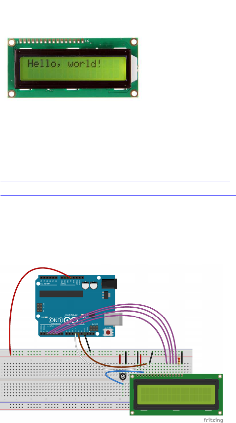
LCD 1602
Quelle:
http://www.arduino-projekte.de/index.php?n=11
https://www.arduino.cc/en/Tutorial/LiquidCrystal
Preis: ca. 2-5 EUR
Anschluss:
Alternativ, einfacher (ausprobieren !):
Pin 3 (Kontrast) statt an Poti: an 2.2kOhm gegen Masse
Pin 15 (LED Hintergrund) statt über 10kOhm:
- über 220 Ohm - 4.7 kOhm gegen +5V
- oder direkt an +3.3V
33
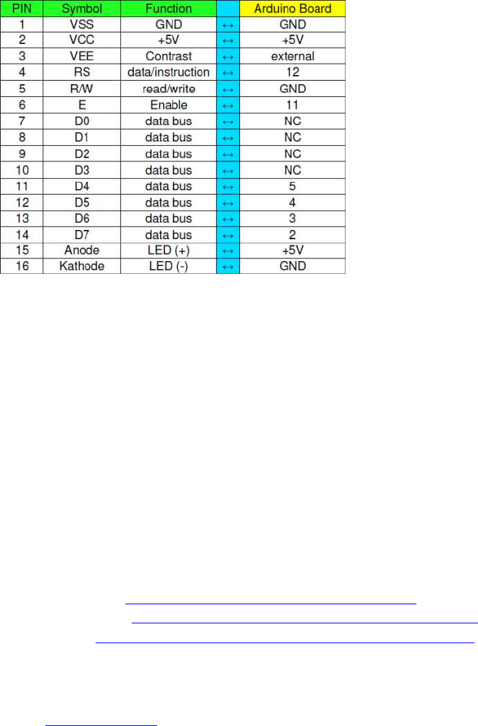
Before wiring the LCD screen to your Arduino we suggest to solder a pin header strip to the
14 (or 16) pin count connector of the LCD screen, as you can see in the image above.
To wire your LCD screen to your Arduino, connect the following pins:
LCD RS pin to digital pin 12
LCD Enable pin to digital pin 11
LCD D4 pin to digital pin 5
LCD D5 pin to digital pin 4
LCD D6 pin to digital pin 3
LCD D7 pin to digital pin 2
Additionally, wire a 10K pot to +5V and GND, with it's wiper (output) to LCD screens VO
pin (pin3).
Arduino Tutorial: http://arduino.cc/en/Tutorial/LiquidCrystal
Arduino Referenz: http://www.arduino.cc/en/Reference/LiquidCrystal
Sketch Code: http://www.arduino-projekte.de/arduino_ ... _world.pde
Code: Alles auswählen
/*
LiquidCrystal Library - Hello World
Demonstrates the use a 16x2 LCD display. The LiquidCrystal
library works with all LCD displays that are compatible with the
Hitachi HD44780 driver. There are many of them out there, and you
can usually tell them by the 16-pin interface.
This sketch prints "Hello World!" to the LCD
and shows the time.
The circuit:
* LCD RS pin to digital pin 12
* LCD Enable pin to digital pin 11
* LCD D4 pin to digital pin 5
* LCD D5 pin to digital pin 4
* LCD D6 pin to digital pin 3
34
* LCD D7 pin to digital pin 2
* LCD R/W pin to ground
* 10K resistor:
* ends to +5V and ground
* wiper to LCD VO pin (pin 3)
Library originally added 18 Apr 2008
by David A. Mellis
library modified 5 Jul 2009
by Limor Fried (http://www.ladyada.net)
example added 9 Jul 2009
by Tom Igoe
modified 22 Nov 2010
by Tom Igoe
This example code is in the public domain.
http://www.arduino.cc/en/Tutorial/LiquidCrystal
*/
// include the library code:
#include <LiquidCrystal.h>
// initialize the library with the numbers of the interface pins
LiquidCrystal lcd(12, 11, 5, 4, 3, 2);
void setup() {
// set up the LCD's number of columns and rows:
lcd.begin(16, 2);
// Print a message to the LCD.
lcd.print("hello, world!");
}
void loop() {
// set the cursor to column 0, line 1
// (note: line 1 is the second row, since counting begins with 0):
lcd.setCursor(0, 1);
// print the number of seconds since reset:
lcd.print(millis()/1000);
}

35
LCD1602 I2C oder LCD2004_I2C
Foto s. z.B.: http://wiki.sunfounder.cc/index.php?title=I%C2%B2C_LCD1602
16x2 Display, aber I2C-Ansteuerung
I2C-chip meist PCF8574, z.B. auch Platine FC 113
Library: LiquidCrystal_I2C.h
Link: https://github.com/fdebrabander/Arduino ... 2C-library
Code: Alles auswählen
#include <Wire.h>
#include <LiquidCrystal_I2C.h>
// Set the LCD address to 0x27 for a 16 chars and 2 line display
LiquidCrystal_I2C lcd(0x27, 16, 2);
void setup()
{
// initialize the LCD
lcd.begin();
// Turn on the blacklight and print a message.
lcd.backlight();
lcd.print("Hello, world!");
}
void loop()
{
// Do nothing here...
}
alternativ, je nach Modell:
Library: LiquidCrystal_I2C.h
Link: http://wentztech.com/radio/arduino/files/LCDI2C.html
Code: Alles auswählen
#include <LiquidCrystal_I2C.h>
LiquidCrystal_I2C lcd (0x20,16,2);
void setup()
{
lcd.init();
lcd.backlight();
}
void loop()
{
lcd.setCursor(0,0);
lcd.print("Hello,world");
lcd.setCursor(0,1);
lcd.print("Hello");
}

36
LCD1602 / LCD2004 mit MCP23017:
http://www.arduino-projekte.de/index.php?n=84
https://github.com/lincomatic/LiquidTWI2

37
7-Segment LED Displays
einfache 7-Segment LEDs:
(Foto z.B.: https://www.hacktronics.com/images/stories/7segmentled.jpg )
https://www.hacktronics.com/Tutorials/arduino-and-7-segment-led.html
http://shelvin.de/eine-7-segment-anzeige-direkt-vom-arduino-ansteuern/
multi- 7-Segment (8-Segment) und 13 (14)-Segment- Displays
(Fotos s. z. B.: https://www.adafruit.com/category/103 )
Übersicht:
teilweise LEDs einzeln angesteuert, teilw. per MAX7219 (I2C):
https://www.adafruit.com/categories/103
https://www.adafruit.com/products/1265
https://learn.adafruit.com/adafruit-led ... phanumeric
Adafruit-Libs:
https://github.com/adafruit/Adafruit-LED-Backpack-Library
7-Segment per einzelne Pins:
http://playground.arduino.cc/Main/SevenSegmentLibrary
https://github.com/DeanIsMe/SevSeg
38
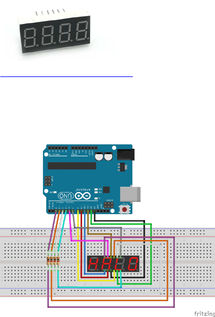
Vierstellige 7 Segment Anzeige
https://funduino.de/nr-12-7-segment-anzeige
Library von Dean Reading:
https://github.com/DeanIsMe/SevSeg
Fritzing:
39
Example Code: https://funduino.de/nr-12-7-segment-anzeige
Code:
#include "SevSeg.h" //Die vorher hinzugefügte Library laden
SevSeg sevseg; //Ein sieben Segment Objekt initialisieren
void setup()
{
byte numDigits = 4;
//Hier wird die Anzahl der Ziffern angegeben
byte digitPins[] = {2, 3, 4, 5};
//Die Pins zu den Ziffern werden festgelegt
byte segmentPins[] = {6, 7, 8, 9, 10, 11, 12, 13}; //Die Pins zu den Segmenten werden
festgelegt
sevseg.begin(COMMON_CATHODE, numDigits, digitPins, segmentPins);
/*
In diesem Abschnitt kann man nun entweder testen welche Art von Display man besitzt
oder wenn man es schon weiß angeben ob es sich um ein COMMON_CATHODE oder
COMMON_ANODE Display handelt.
Das Display funktioniert nur wenn die richtige Art eingetragen ist, ansonsten werden alle
Segmente gleichzeitig leuchten.
*/
}
void loop()
{
sevseg.setNumber(1234,3); //Hier können wir nun die gewünschte Zahl eintragen.
//Wir haben als Beispiel 1234 angegeben. Die Zahl hinter dem Komma steht für den
//Punkt hinter einer Ziffer. Hierbei ist 3 der Punkt neben der ersten Ziffer und
//0 wäre der Punkt ganz rechts neben der letzten Ziffer. Wenn man keinen Punkt
//mit angezeigt haben möcht kann man z.B. 4 angeben.
sevseg.refreshDisplay(); // Dieser Teil lässt die Nummer auf dem Display erscheinen.
sevseg.setBrightness(90);
//Hier kann die Helligkeit des Displays angepasst
//werden. In einem Bereich von 0-100 wobei 100 das Hellste ist. 0 bedeutet
//jedoch nicht dass das Display komplett dunkel ist. Für die Anzeige einer Zahl
//ist allein die "sevseg.refreshDisplay();" Zeile verantwortlich
}
40
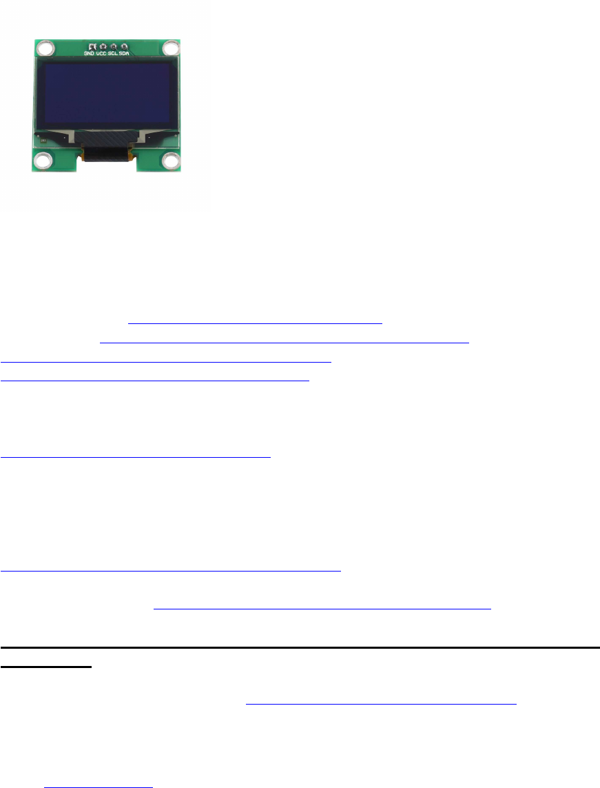
Display: OLED 128x64 u.a. (SSD1306, SH1106)
Schnittstellen: I2C oder SPI
verbaute IC-Typen: z.B. SSD1306 oder SH1106
Beschreibung: u.a. https://www.adafruit.com/product/326
Libraries: z.B. https://learn.adafruit.com/monochrome-o ... d-examples
https://github.com/adafruit/Adafruit-GFX-Library
https://github.com/adafruit/Adafruit_SSD1306
Betr. nodeMCU board: häufig inkompatibel zu Adafruit libs; Patchs funktionieren auch nicht
immer:
https://github.com/somhi/ESP_SSD1306
zus. Änderungen:
#define OLED_RESET 5 // Pin RESET digital signal
+ nach display.begin() hinzufügen: Wire.begin(D4,D5);
variant für SH_1106:
https://github.com/wonho-maker/Adafruit_SH1106
Fonts zu Adafruit libs: https://learn.adafruit.com/adafruit-gfx ... sing-fonts
Tipps zur Adafruit Lib, wenn bei Verwendung von ssd1306-Clonen das Display nicht
funktioniert:
- I2C dev addr kontrollieren: Adafruit verwendet of 0x3D, Clone hingegen 0x3C
- bei Verwendung von nodeMCU: s. https://github.com/somhi/ESP_SSD1306
- wenn nicht das komplette Display angezeigt wird oder die Compilierung abgebrochen mit
Fehlermeldung "Height incorrect, please fix Adafruit_SSD1306.h!", dann dort das korrekte
Display auswählen und den Rest auskommentieren:
Code: Alles auswählen
/*=========================================================================
SSD1306 Displays
-----------------------------------------------------------------------
The driver is used in multiple displays (128x64, 128x32, etc.).
Select the appropriate display below to create an appropriately
sized framebuffer, etc.

41
SSD1306_128_64 128x64 pixel display
SSD1306_128_32 128x32 pixel display
SSD1306_96_16
-----------------------------------------------------------------------
*/
#define SSD1306_128_64 //
<<<<<<<<<<<<<<<<<<<<<<<<<<<<<<<<<<<<<<<<<<<<<<<<
// #define SSD1306_128_32
// #define SSD1306_96_16
alternative Lib:
Daniel Eichhorn squix78
https://github.com/squix78/esp8266-oled-ssd1306
ggf. bei China-Klonen die alternativen SH1106-Treiber per #include "SH1106.h" statt
#include "SSD1306.h" einbinden
42
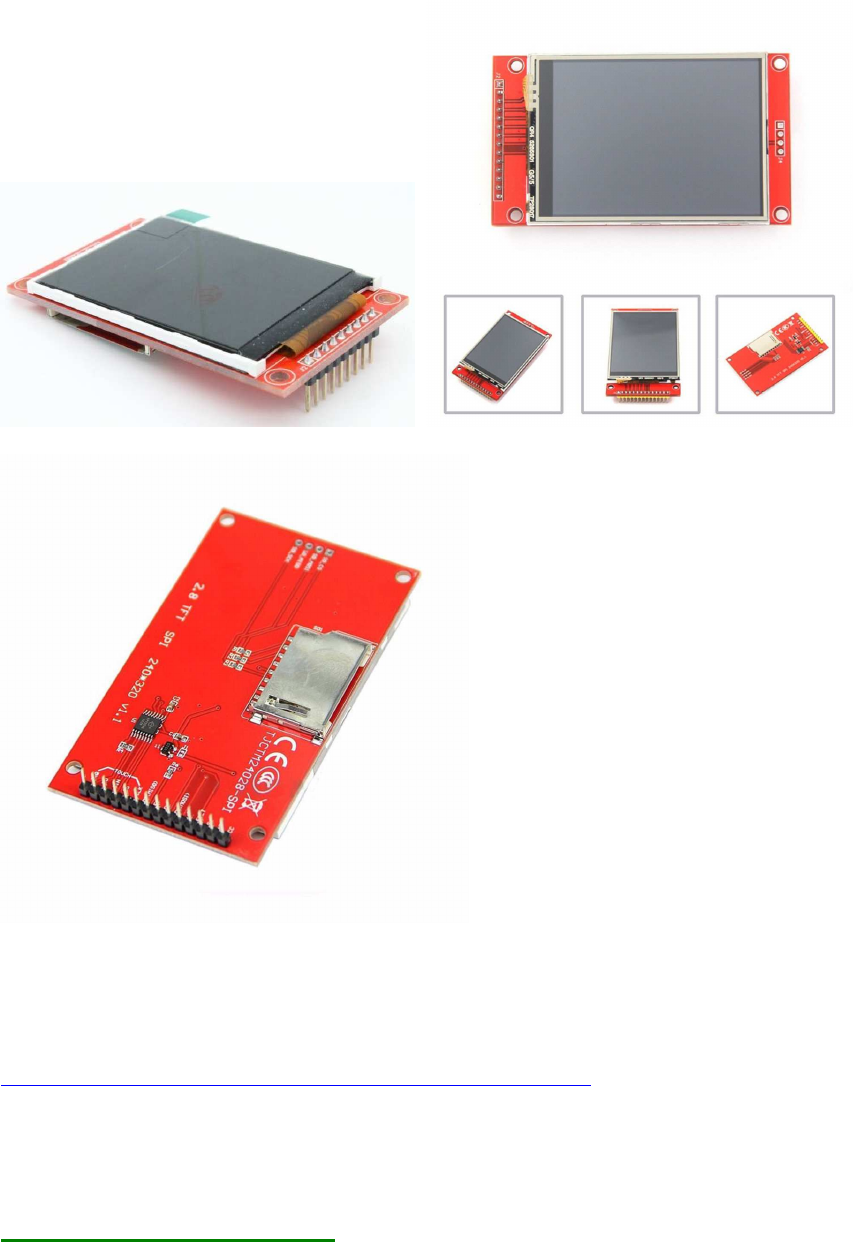
Display TFT ILI9341
a) 2.2" 240x320
b) 2.4" 240x320 mit Touch Screen
Preis: knapp 10 EUR - mit oder ohne Touchscreen
Bezugsquelle: z.B. diverse in China ansässige Händler, auch z. B. ähnlich wie (ohne
Gewähr):
Roboter Bausatz Shop
http://www.ebay.de/itm/171819008028?_tr ... EBIDX%3AIT
Driver-libs
Adafruit TFT_22_ILI9340 :

43
Adafruit_ILI9340 lib https://github.com/adafruit/Adafruit_ILI9340
Adafruit_ILI9340.zip
(71.34 KiB) 147-mal heruntergeladen
plus Adafruit_GFX lib https://github.com/adafruit/Adafruit-GFX-Library
Adafruit_GFX.zip
(81.72 KiB) 136-mal heruntergeladen
empfohlenes SD-Formatier-Tool: https://www.sdcard.org/downloads/formatter_4/
Code: Alles auswählen
// hw brickbench
// Adafruit ILI9340 / ILI9340
#include "SPI.h"
#include "Adafruit_GFX.h"
#include "Adafruit_ILI9340.h"
#if defined(__SAM3X8E__)
#undef __FlashStringHelper::F(string_literal)
#define F(string_literal) string_literal
#endif
#define _DUEMISO_ 74 // Arduino Due SPI Header
#define _DUEMOSI_ 75
#define _DUESCK_ 76
// These are the pins used for the UNO
// for Due/Mega/Leonardo use the hardware SPI pins (which are different)
/*
#define _sclk 13
#define _miso 12
#define _mosi 11
*/
#define _cs 10
#define _dc 9
#define _rst 8
// Using software SPI is really not suggested, its incredibly slow
//Adafruit_ILI9340 tft = Adafruit_ILI9340(_cs, _dc, _mosi, _sclk, _rst,
_miso);
// Use hardware SPI
Adafruit_ILI9340 tft = Adafruit_ILI9340(_cs, _dc, _rst);
#define WHITE ILI9340_WHITE
#define TimerMS() millis()
unsigned long runtime[8];
void TFTprint(char sbuf[], int16_t x, int16_t y) {
tft.setCursor(x, y);
tft.print(sbuf);
}
44
inline void displayValues() {
char buf[120];
tft.fillScreen(ILI9340_BLACK); // clrscr()
sprintf (buf, "%3d %9ld int_Add", 0, runtime[0]); TFTprint(buf,
0,10);
sprintf (buf, "%3d %9ld int_Mult", 1, runtime[1]); TFTprint(buf,
0,20);
sprintf (buf, "%3d %9ld float_op", 2, runtime[2]); TFTprint(buf,
0,30);
sprintf (buf, "%3d %9ld randomize", 3, runtime[3]); TFTprint(buf,
0,40);
sprintf (buf, "%3d %9ld matrx_algb", 4, runtime[4]); TFTprint(buf,
0,50);
sprintf (buf, "%3d %9ld arr_sort", 5, runtime[5]); TFTprint(buf,
0,60);
sprintf (buf, "%3d %9ld TextOut", 6, runtime[6]); TFTprint(buf,
0,70);
sprintf (buf, "%3d %9ld Graphics", 7, runtime[7]); TFTprint(buf,
0,80);
}
int32_t test_TextOut(){
int y;
char buf[120];
for(y=0;y<20;++y) {
tft.fillScreen(ILI9340_BLACK); // clrscr()
sprintf (buf, "%3d %9d int_Add", y, 1000); TFTprint(buf, 0,10);
sprintf (buf, "%3d %9d int_Mult", 0, 1010); TFTprint(buf, 0,20);
sprintf (buf, "%3d %9d float_op", 0, 1020); TFTprint(buf, 0,30);
sprintf (buf, "%3d %9d randomize", 0, 1030); TFTprint(buf, 0,40);
sprintf (buf, "%3d %9d matrx_algb", 0, 1040); TFTprint(buf, 0,50);
sprintf (buf, "%3d %9d arr_sort", 0, 1050); TFTprint(buf, 0,60);
sprintf (buf, "%3d %9d displ_txt", 0, 1060); TFTprint(buf, 0,70);
sprintf (buf, "%3d %9d testing...", 0, 1070); TFTprint(buf, 0,80);
}
return y;
}
int32_t test_graphics(){
int y;
char buf[120];
for(y=0;y<100;++y) {
tft.fillScreen(ILI9340_BLACK);
sprintf (buf, "%3d", y); TFTprint(buf, 0,80); // outcomment for
downwards compatibility
tft.drawCircle(50, 40, 10, WHITE);
tft.fillCircle(30, 24, 10, WHITE);
tft.drawLine(10, 10, 60, 60, WHITE);
tft.drawLine(50, 20, 90, 70, WHITE);
tft.drawRect(20, 20, 40, 40, WHITE);
tft.fillRect(65, 25, 20, 30, WHITE);
45
//tft.drawEclipse(70, 30, 15, 20); // original test
tft.drawCircle(70, 30, 15, WHITE); // alternatively, just if no
drawEclipse is avaiable in the Arduino graph libs!
}
return y;
}
int test(){
unsigned long time0, x, y;
double s;
char buf[120];
int i;
float f;
// lcd display text / graphs
time0=TimerMS();
s=test_TextOut();
runtime[6]=TimerMS()-time0;
sprintf (buf, "%3d %9ld TextOut", 6, runtime[6]); Serial.println( buf);
TFTprint(buf, 0,70);
time0=TimerMS();
s=test_graphics();
runtime[7]=TimerMS()-time0;
sprintf (buf, "%3d %9ld Graphics", 7, runtime[7]); Serial.println( buf);
TFTprint(buf, 0,80);
Serial.println();
y = 0;
for (x = 0; x < 8; ++x) {
y += runtime[x];
}
displayValues();
sprintf (buf, "gesamt ms: %9ld ", y);
Serial.println( buf);
TFTprint(buf, 0,110);
x=50000000.0/y;
sprintf (buf, "benchmark: %9ld ", x);
Serial.println( buf);
TFTprint(buf, 0,120);
return 1;
}
void setup() {
Serial.begin(9600);

46
// Setup the LCD
tft.begin();
tft.setTextColor(ILI9340_WHITE); tft.setTextSize(1);
}
void loop() {
char buf[120];
test();
sprintf (buf, "Ende HaWe brickbench");
Serial.println( buf);
TFTprint(buf, 0, 140);
while(1);
}
HaWe Brickbench TFT benchmark:
Code: Alles auswählen
Mega:
Text: ms
Graphic: ms
Due:
Text: 9110 ms
Graphic: 40675 ms
Summe: 49785 ms
alternative, schnellere lib: ILI9341_due
Video: https://www.youtube.com/watch?v=vnEwzN14BsU
TFT lib: https://github.com/marekburiak/ILI9341_due
Touch lib: https://github.com/ghlawrence2000/ILI9341_due_Buttons
http://marekburiak.github.io/ILI9341_due/
ILI9341_due_config.h
Some of the default settings can be set in ILI9341_due_config.h file.
SPI Mode
// comment out the SPI mode you want to use
//#define ILI9341_SPI_MODE_NORMAL
//#define ILI9341_SPI_MODE_EXTENDED // make sure you use pin 4, 10 or
52 for CS
#define ILI9341_SPI_MODE_DMA
Uncomment the line depending on the SPI mode you want to use. DMA mode
is the default. For AVR, it does not matter which mode you use,
47
ILI9341_SPI_MODE_NORMAL is always going to be used since there is no
Extended SPI or DMA available on AVRs.
geeignet u.a. für Arduino DUE und ebenfalls UNO und MEGA etc.
Vorteil: volle Ausnutzung des Hardware-SPI-Busses mit schneller Taktung!
Testergebnis mit DUE: Text 15x so schnell wie UTFT, Graphics 13x so schnell wie UTFT !
Benchmark für Due:
ILI9341_due tft
TextOut 973
Graphics 3255
gesamt ms: 4228
// UTFT Demo ported to ILI9341_due library by TFTLCDCyg
#include <SPI.h>
// ILI9341_due NEW lib by Marek Buriak
http://marekburiak.github.io/ILI9341_due/
#include "ILI9341_due_config.h"
#include "ILI9341_due.h"
#include "SystemFont5x7.h"
//#include "Streaming.h"
// For the Adafruit shield, these are the default.
/*
#define TFT_RST 8
#define TFT_DC 9
#define TFT_CS 10
// Use hardware SPI (on Uno, #13, #12, #11) and the above for CS/DC
*/
#define tft_cs 49
#define tft_dc 48
#define tft_rst 0
ILI9341_due tft = ILI9341_due(tft_cs, tft_dc); // <<<<<<<<<<<<<<<<<<<< drop
RESET pin !
char textBuff[20];
// Color set
#define BLACK 0x0000
#define RED 0xF800
#define GREEN 0x07E0
//#define BLUE 0x001F
#define BLUE 0x102E
#define CYAN 0x07FF
#define MAGENTA 0xF81F
#define YELLOW 0xFFE0
#define ORANGE 0xFD20
#define GREENYELLOW 0xAFE5
#define DARKGREEN 0x03E0
#define WHITE 0xFFFF
uint16_t color;
48
uint16_t colorFONDO = BLACK;
#define TimerMS() millis()
unsigned long runtime[8];
void TFTprint(char sbuf[], int16_t x, int16_t y) {
tft.cursorToXY(x, y);
tft.printAt(sbuf,x,y);
}
inline void displayValues() {
char buf[120];
tft.fillScreen(BLACK); // clrscr()
sprintf (buf, "%3d %9ld int_Add", 0, runtime[0]); TFTprint(buf,
0,10);
sprintf (buf, "%3d %9ld int_Mult", 1, runtime[1]); TFTprint(buf,
0,20);
sprintf (buf, "%3d %9ld float_op", 2, runtime[2]); TFTprint(buf,
0,30);
sprintf (buf, "%3d %9ld randomize", 3, runtime[3]); TFTprint(buf,
0,40);
sprintf (buf, "%3d %9ld matrx_algb", 4, runtime[4]); TFTprint(buf,
0,50);
sprintf (buf, "%3d %9ld arr_sort", 5, runtime[5]); TFTprint(buf,
0,60);
sprintf (buf, "%3d %9ld TextOut", 6, runtime[6]); TFTprint(buf,
0,70);
sprintf (buf, "%3d %9ld Graphics", 7, runtime[7]); TFTprint(buf,
0,80);
}
int32_t test_TextOut(){
int y;
char buf[120];
for(y=0;y<20;++y) {
tft.fillScreen(BLACK); // clrscr()
sprintf (buf, "%3d %9d int_Add", y, 1000); TFTprint(buf, 0,10);
sprintf (buf, "%3d %9d int_Mult", 0, 1010); TFTprint(buf, 0,20);
sprintf (buf, "%3d %9d float_op", 0, 1020); TFTprint(buf, 0,30);
sprintf (buf, "%3d %9d randomize", 0, 1030); TFTprint(buf, 0,40);
sprintf (buf, "%3d %9d matrx_algb", 0, 1040); TFTprint(buf, 0,50);
sprintf (buf, "%3d %9d arr_sort", 0, 1050); TFTprint(buf, 0,60);
sprintf (buf, "%3d %9d displ_txt", 0, 1060); TFTprint(buf, 0,70);
sprintf (buf, "%3d %9d testing...", 0, 1070); TFTprint(buf, 0,80);
}
return y;
}
int32_t test_graphics(){
int y;
char buf[120];
49
for(y=0;y<100;++y) {
tft.fillScreen(BLACK);
sprintf (buf, "%3d", y); TFTprint(buf, 0,80); // outcomment for
downwards compatibility
tft.drawCircle(50, 40, 10, WHITE);
tft.fillCircle(30, 24, 10, WHITE);
tft.drawLine(10, 10, 60, 60, WHITE);
tft.drawLine(50, 20, 90, 70, WHITE);
tft.drawRect(20, 20, 40, 40, WHITE);
tft.fillRect(65, 25, 20, 30, WHITE);
//tft.drawEllipse(70, 30, 15, 20); // original test
tft.drawCircle(70, 30, 15, WHITE); // alternatively, just if no
drawEclipse is avaiable in the Arduino graph libs!
}
return y;
}
int test(){
unsigned long time0, x, y;
double s;
char buf[120];
int i;
float f
// lcd display text / graphs
time0=TimerMS();
s=test_TextOut();
runtime[6]=TimerMS()-time0;
sprintf (buf, "%3d %9ld TextOut", 6, runtime[6]); Serial.println( buf);
TFTprint(buf, 0,70);
time0=TimerMS();
s=test_graphics();
runtime[7]=TimerMS()-time0;
sprintf (buf, "%3d %9ld Graphics", 7, runtime[7]); Serial.println( buf);
TFTprint(buf, 0,80);
Serial.println();
y = 0;
for (x = 0; x < 8; ++x) {
y += runtime[x];
}
displayValues();
sprintf (buf, "gesamt ms: %9ld ", y);
Serial.println( buf);
TFTprint(buf, 0,110);
x=50000000.0/y;
sprintf (buf, "benchmark: %9ld ", x);
Serial.println( buf);
TFTprint(buf, 0,120);
return 1;
}

50
void setup() {
Serial.begin(115200);
// Setup the LCD
tft.begin();
tft.setRotation(iliRotation270);
tft.fillScreen(colorFONDO);
tft.setFont(SystemFont5x7);
tft.setTextColor(WHITE);
Serial.println("tft started");
}
void loop() {
char buf[120];
test();
sprintf (buf, "Ende HaWe brickbench");
Serial.println( buf);
TFTprint(buf, 0, 140);
while(1);
}
Anm.:
- TFT läuft mit Hardware-SPI-Pins auf AVRs (Uno, Mega) und ARM (Due)
- mit Adafruit libs kaum schneller als das ILI9225 mit Software-SPI und UTFT lib (Henning Karlsen)
- mit <ILI9341_due-lib> bis zu 15x schneller als das ILI9225 mit Adafruit oder <UTFT> lib !!
- Einschränkung: mit <ILI9341_due> lib muss hierzu die <SdFat> lib anstelle der <SD> lib
verwendet werden
(siehe Benchmark: viewtopic.php?p=64772#p64772)
//************************************************************************//

51
Touch-Library XPST2046
https://github.com/spapadim/XPT2046
Anpassung für ESP8266 (oder andere Arduinos) mit Adafruit TFT-Lib:
https://nailbuster.com/?page_id=341
weitere ILI9341 Library: ILI9341 ucglib (Oli Kraus)
https://github.com/olikraus/ucglib/wiki
https://github.com/olikraus/ucglib

52
GUIslice GUI Grafik-Lib
Grafik-Lib für verschiedene Displays und unterschiedlche TFT Treiber
https://github.com/ImpulseAdventure/GUIslice/wiki
https://github.com/ImpulseAdventure/GUIslice/wiki/Configuring-
GUIslice#Configuring_display_hardware_for_AdafruitGFX
https://github.com/ImpulseAdventure/GUIslice/wiki/Installing-GUIslice-on-Arduino
supported devices:
https://www.impulseadventure.com/elec/guislice-gui.html#testing
53
SD Karten-Module und File IO Funktionen:
Treiber-Library:
Arduino-SD-lib <SD.h> (standardmäßig in Sketch enthalten)
http://arduino.cc/en/pmwiki.php?n=Reference/SD
Schnittstelle: SPI <SPI.h>
Update, neu getestet: funktioniert grundsätzlich sowohl mit AVR Arduinos als auch mit
Due.
Bezugsquelle: z.B. über Ebay: http://www.ebay.de/sch/i.html?_odkw=SD+ ... =&_sacat=0
Besonderheiten:
es werden von der Arduino-Sketch-API leider absolut keine stdio.h-File-Funktionen
unterstützt, z.B. gibt es in der SD-Klasse kein fprintf und kein fscanf, sondern nur z.B.
Funktionen wie (myFile).print und (myFile).println zum Schreiben,
und nur (myFile).read zum Byte-weise Lesen, was die Sache sehr umständlich macht
(z.B. noch nicht einmal ein (myFile).readln gibt es, was am ehesten wenigstens einem fgets()
gleichkäme !)
Dann muss man wissen, dass die schlauen Arduino-Entwickler für float viele Formatierungs-
Möglichkeiten einfach weggelassen haben.
Wenn man aber diese Libs installiert, geht es doch (Ordner ins entsprechende
Systemverzeichnis kopieren, z.B:
xcopy *.* C:\Programme\Arduino\hardware\tools\avr\avr\lib /E /Y)
libc_all.zip
lib.c float-Patch
(1 MiB) 152-mal heruntergeladen
Zum Schreiben und Lesen von Strings und formatierter Variablen in SD-Files habe ich daher
eigene Funktionen
fprintf_() , fgets_() und fscanf_()
geschrieben, die praktisch genau so arbeiten wie die Originale in ANSI C, und ein paar
weitere, die die Handhabung vereinfachen.

54
Header:
long fprintf_( File * stream, const char fmtstr[], ... ); // see
ANSI C: fprintf()
long fscanf_ ( File * stream, const char fmtstr[], ... ) ; // see
ANSI C: fscanf()
char * fgets_ ( char * str, int32_t num, File * stream ); // see
ANSI C: fgets()
File fopen_ ( char * filename, const char * mode ); // see
ANSI C: fopen()
int16_t fclose_ ( File file_); // see
ANSI C: fclose()
int16_t remove_ ( char * filename); // see
ANSI C: remove()
char * ftoa(char * str, double f, int16_t precision ); //
converts float to string by precision (digits)
char * strinsert( char * source, char * sub, int pos ); //
insert a substr into a string at pos
char * strdelnpos(char * source, int16_t pos, int16_t sublen); //
delete a substr in string at pos
char * strpatch ( char * source, char * sub, int pos ); //
patch string by substr at pos
char * substr ( char * source, char * sub, int pos, int len ); // get
substring of source string at pos by length
int16_t strchpos( char * str, char ch ); // find
1st occurence of char ch in string str
int16_t strstrpos( char * haystack, char * needle) // find
1st occurance of substr in str
char * stradd(char * s, int n, ...) // "adds strings" s=sumstring ,
n=number_in_list, ... = var string list
kompletter Code siehe ganz unten!
Hier ein paar Erklärungen und der Sourcecode:
int32_t fprintf_ ( File * stream, const char fmtstr[], ... )
arbeitet wie das stdio.h C-Original fprintf(): Es schreibt einen string in ein file, dabei werden
die Variablen/Argumente entsprechend dem formatstring als strings formatiert (gleiche
Funktionsweise wie auch bei printf oder sprintf)
char * fgets_ ( char * str, int32_t num, File * stream )
Liest entsprechend der Original C-stdio.h Funktion einen string aus einem File, bis eine
String-Terminierung oder ein Zeilenumbruch oder eof() oder die max Länge des übergebenen
Puffers erreicht ist (je nachdem, was früher eintritt).
Im Falle dass "mein" fgets_() keine lesbaren Daten findet, kann optional auch ein Leerstring
("") zurückgegeben werden anstelle eines Nullpointers NULL wie bei Original fgets() -
natürlich kann man das individuell anpassen.
int32_t fscanf_ ( File * stream, const char fmtstr[], ... );
liest einen String aus einem File und re-formatiert alle darin enthaltenen Variablen
entsprechend dem Formatstring
(also %d zu int und %f zu float).

55
Eingebundene libs funktionieren u.U. nur auf ARM Plattform, nicht auf AVR (Einschränkung
der Arduino-IDE !)
Achtung: nach C-Standard müssen alle ints 32-Bit sein (int32_t),
und Dezimalpunkte im float-Formatierer sind nicht erlaubt ("%f" und "%08f" erlaubt, "%8.2f"
aber NICHT!);
teilw. Probleme mit double, float funktioniert aber.
Die nötige Compiler-Unterstützung liefert Arduino leider nur für ARM cpus.
Unterschied zum ANSI-C-fscanf():
fscanf_() liest intern immer einen Teilstring ("Block") aus dem stream mindestens bis zum
nächsten Zeilenvorschub '\n',
aus diesem Teilstring werden dann die entsprechenden Variablen laut Formatstring
herausgefiltert und zugewiesen.
wichtig: es dürfen mehrere Variablen in dem gelesenen String stehen,
als Begrenzer zwischen den Variablen dienen Leerzeichen oder spezielle angegebene
Zeichen.
Aber es muss aber im Original-File immer am Schuss des zu lesenden Teilstring-Blocks
mindestens ein '\n' stehen.
Dieser letzte Zeilenvorschub ist automatisch der Schluss-Begrenzer und muss beim Lesen mit
fscanf() dann nicht mehr mit angegeben werden (s.o.).
Aufruf
z.B.:
File myFile;
char sdata[128];
fprintf_(&myFile, "%s\n%d\n%d\n%f\n%f\n", "EinTeststring", 1, 2, PI,
4.567890);
// schreibt die 5 Variablen (1x string, 2x int, 2x float), getrennt durch
Zeilenumbrüche, in ein File.
fprintf_(&myFile, "%s %d %d %f %f\n", "EinTeststring", 1, 2, PI, 4.567890);
// dto, aber getrennt durch Leerzeichen, Zeilenvorschub am Ende des
"Blocks".
fprintf_(&myFile, "%s;%d;%d;%f;%f;\n", "EinTeststring", 1, 2, PI,
4.567890);
// dto, aber getrennt durch Semikolons, am Ende des "Blocks" wieder ein
Zeilenvorschub.
fgets_ ( sdata, 20, &myFile );
// liest und kopiert aus der Datei einen Teilstring in den String-Buffer
"sdata",
// der dann anschließend als string oder umgewandelt zu int oder float
weiterverwendet werden kann.

56
int32_t m, n, cnt;
float x, y;
fscanf_ ( myFile, "%d %d %f %f ", &m, &n, &x, &y );
// oder
cnt = fscanf_ ( myFile, "%d %d %f %f \n", &m, &n, &x, &y );
// liest einen Teilstring ("Block") aus einem File,
// re-formatiert die 4 darin enthaltenen Variablen entsprechend dem
Formatstring (z.B. %d als ints, %f als floats),
// erwartet dabei Leerzeichen als Trennzeichen,
// und weist die einzelnen formatierten Zahlen den übergebenen Variablen
m,n,x,y zu.
Testcode für fprintf_ und fgets_():
/*
SD card: fprintf_() und fgets_()
ver 1.01
*/
#include <SPI.h>
#include <SD.h>
// SD Card
#define SD_CSpin 38 // <<<<<<<<<<<<<<<<<<<<<< adjust !!
File myFile;
char fname[64];
char sdata[128];
char sbuf[128];
int32_t fprintf_ ( File * stream, const char fmtstr[], ... ) {
char str[1024];
va_list args;
int32_t num;
va_start( args, fmtstr );
num = vsnprintf(str, sizeof(str), fmtstr, args);
stream->print(str);
va_end( args );
return num;
}
char * fgets_ ( char * str, int32_t num, File * stream ) {
int32_t i = 0;
57
strcpy(str, "");
while ( (stream->available()) && (i < num-1) ) {
int16_t ch = stream->read();
if (ch < 0) // end of file
break;
str[i++] = ch;
if ('\n' == ch) // end of line
break;
}
if (i) { // room in buffer for terminating null
str[i] = 0;
return str;
}
else
// return NULL; // buffer too small or immediate end of
file
{ strcpy(str, ""); return str; } // alternative: return ""
}
void setup()
{
int16_t p, i, cnt;
float x;
char sval[20];
int16_t ival;
double fval;
pinMode(SD_CSpin, OUTPUT);
Serial.begin(115200);
sprintf(sbuf,"#: SD Initializing... ");
Serial.println(sbuf);
while(!SD.begin(SD_CSpin) ) {
sprintf(sbuf,"#: ...SD init failed ");
Serial.println(sbuf);
delay(1000);
}
sprintf(sbuf,"#: ...SD OK ! ");
Serial.println(sbuf);
strcpy(fname,"test.txt");
if (SD.exists(fname) ) {
sprintf(sbuf,"#: %s exists ",fname);
Serial.println(sbuf);
sprintf(sbuf,"#: Removing %s ",fname);
Serial.println(sbuf);
SD.remove("test.txt");
// removed: success ?
if (SD.exists(fname) ) {
sprintf(sbuf,"#: %s exists ",fname);
Serial.println(sbuf);
}
else {
58
sprintf(sbuf,"#: %s N/A ",fname);
Serial.println(sbuf);
}
}
// open the file. note that only one file can be open at a time,
// so you have to close this one before opening another.
myFile = SD.open(fname, FILE_WRITE);
if (myFile) {
// if the file opened okay, write to it, then close file:
sprintf(sbuf,"#: Writing strings to %s ",fname);
Serial.println(sbuf);
//--------------------------------------------------------------------
// write data to file
fprintf_(&myFile, "%s\n%d\n%d\n%f\n%f\n", "Teststring", 1, 2, PI,
4.567890);
//--------------------------------------------------------------------
// close the file:
myFile.close();
sprintf(sbuf,"#: %s closed. ",fname);
Serial.println(sbuf);
}
else {
// if the file didn't open, print an error:
sprintf(sbuf,"#: error opening %s ",fname);
Serial.println(sbuf);
}
Serial.println();
// re-open the file for reading:
myFile = SD.open(fname);
if (myFile) {
sprintf(sbuf,"#: reading %s ",fname);
Serial.println(sbuf);
// read from the file until there's nothing else in it:
i=0;
cnt=1;
while (myFile.available()) {
strcpy(sdata, "");
fgets_ ( sdata, 20, &myFile );
Serial.print(cnt); Serial.print(": string raw=");
Serial.println(sdata);
Serial.println("rueckformatiert:");
if (cnt==1) {Serial.print("str ="); Serial.println(sdata); }
if (cnt==2) {Serial.print("int ="); Serial.println(atoi(sdata) ); }
if (cnt==3) {Serial.print("int ="); Serial.println(atoi(sdata) ); }
if (cnt==4) {Serial.print("float="); Serial.println(atof(sdata) ); }
if (cnt==5) {Serial.print("float="); Serial.println(atof(sdata) ); }
++cnt;
}
// close the file:
myFile.close();
sprintf(sbuf,"#: %s closed. ",fname);
Serial.println(sbuf);
} else {
// if the file didn't open, print an error:

59
sprintf(sbuf,"#: error opening %s ",fname);
Serial.println(sbuf);
}
}
void loop()
{
// nothing happens after setup
}
Testcode für fprintf_() und fscanf_():
/*
SD card: fprintf_() und fscanf_()
ver 0.04
*/
#include <SPI.h>
#include <SD.h>
#include <stdarg.h>
#include <stdio.h>
// SD Card
#define SD_CSpin 38 // <<<<<<<<<<<<<<<<<<<<<< adjust !!
File myFile;
char fname[64];
char sdata[128];
char sbuf[128];
//*************************************************************************
******************
int32_t fscanf_ ( File * stream, const char fmtstr[], ... ) {
const int32_t MAXSTRSIZE = 1024;
char str[MAXSTRSIZE];
va_list args;
int32_t i=0, cnt=0;
int16_t chr;
va_start(args, fmtstr);
strcpy(str, "");
while ( (stream->available()) && (i < MAXSTRSIZE-1) ) {
chr = stream->read() ;
if (chr>=0 && chr!='\n') {
str[i]=(char)chr;
++i;
}
else break;
}
str[++i] = '\0';
cnt = vsscanf ( str, fmtstr, args );
va_end(args);
60
return cnt;
}
//*************************************************************************
******************
int32_t fprintf_ ( File * stream, const char fmtstr[], ... ) {
char str[1024];
va_list args;
int32_t num;
va_start( args, fmtstr );
num = vsnprintf(str, sizeof(str), fmtstr, args);
stream->print(str);
va_end( args );
return num;
}
//*************************************************************************
******************
void setup()
{
int32_t p, i, cnt;
char sval[20];
int32_t ival, n, m;
float fval, x, y;
// alternativ, ohne jeden Effekt: float fval, x, y;
pinMode(SD_CSpin, OUTPUT);
Serial.begin(9600);
sprintf(sbuf,"#: SD Initializing... ");
Serial.println(sbuf);
while(!SD.begin(SD_CSpin) ) {
sprintf(sbuf,"#: ...SD init failed ");
Serial.println(sbuf);
delay(1000);
}
sprintf(sbuf,"#: ...SD OK ! ");
Serial.println(sbuf);
strcpy(fname,"test.txt");
if (SD.exists(fname) ) {
sprintf(sbuf,"#: %s exists ",fname);
Serial.println(sbuf);
sprintf(sbuf,"#: Removing %s ",fname);
Serial.println(sbuf);
SD.remove("test.txt");
// removed: success ?
if (SD.exists(fname) ) {
sprintf(sbuf,"#: %s exists ",fname);
Serial.println(sbuf);
}
else {
sprintf(sbuf,"#: %s N/A ",fname);
61
Serial.println(sbuf);
}
}
// open the file. note that only one file can be open at a time,
// so you have to close this one before opening another.
myFile = SD.open(fname, FILE_WRITE);
if (myFile) {
// if the file opened okay, write to it, then close file:
sprintf(sbuf,"#: Writing strings to %s ",fname);
Serial.println(sbuf);
//--------------------------------------------------------------------
// write data to file
fprintf_(&myFile, "%d %d %f %f\n", 1, 2, PI, 4.567890);
//--------------------------------------------------------------------
// close the file:
myFile.close();
sprintf(sbuf,"#: %s closed. ",fname);
Serial.println(sbuf);
}
else {
// if the file didn't open, print an error:
sprintf(sbuf,"#: error opening %s ",fname);
Serial.println(sbuf);
}
// re-open the file for reading:
Serial.println();
myFile = SD.open(fname);
if (myFile) {
sprintf(sbuf,"#: reading %s ",fname);
Serial.println(sbuf);
// read from the file until there's nothing else in it:
i=0;
cnt=0;
strcpy(sdata, "");
//--------------------------------------------------------------------
cnt = fscanf_(&myFile, "%d %d %f %f", &m, &n, &x, &y);
//--------------------------------------------------------------------
Serial.println("# nach Aufruf cnt=fscanf_ im Hauptprogramm");
// Testausgabe:
Serial.print("returned cnt="); Serial.println(cnt);
Serial.println();
Serial.println("returned reformatted variables m,n,x,y:");
Serial.println(m);
Serial.println(n);
Serial.println(x);
Serial.println(y);
62
// close the file:
myFile.close();
sprintf(sbuf,"#: %s closed. ",fname);
Serial.println(sbuf);
} else {
// if the file didn't open, print an error:
sprintf(sbuf,"#: error opening %s ",fname);
Serial.println(sbuf);
}
}
void loop()
{
// nothing happens after setup
}

63
Zu guter Letzt hier die
komplette ardustdio lib
die man in eigene Sketche #includen kann:
// Library: ardustdio.h
// kind of stdio.h functionality for files plus extended C-string
manipulation
//
// (C) Helmut Wunder (HaWe) 2015
// freie Verwendung für private Zwecke
// für kommerzielle Zwecke nur nach Genehmigung durch den Autor.
// Programming language: Arduino Sketch C/C++ (IDE 1.6.1 - 1.6.3)
// protected under the friendly Creative Commons Attribution-NonCommercial-
ShareAlike 3.0 Unported License
// http://creativecommons.org/licenses/by-nc-sa/3.0/ //
#ifndef ARDUSTDIO_H
#define ARDUSTDIO_H
/*
long fprintf_( File * stream, const char fmtstr[], ... );
// see ANSI C: fprintf()
long fscanf_ ( File * stream, const char fmtstr[], ... ) ;
// see ANSI C: fscanf()
char * fgets_ ( char * str, int32_t num, File * stream );
// see ANSI C: fgets()
File fopen_ ( char * filename, const char * mode );
// see ANSI C: fopen()
int16_t fclose_ ( File file_);
// see ANSI C: fclose()
int16_t remove_ ( char * filename );
// see ANSI C: remove()
char * ftoa( char * str, double f, int16_t precision );
// converts float to string by precision (digits)
char * strinsert( char * source, char * sub, int pos );
// insert a substr into a string at pos
char * strdelnpos(char * source, int16_t pos, int16_t sublen);
// delete a substr in string at pos
char * strpatch ( char * source, char * sub, int pos );
// patch string by substr at pos
char * substr ( char * source, char * sub, int pos, int len );
// get substring of source string at pos by length
int16_t strchpos( char * str, char ch );
// find 1st occurence of char ch in string str
64
int16_t strstrpos( char * haystack, char * needle);
// find 1st occurance of substr in str
char * stradd(char * s, int n, ...)
// "adds strings" s=sumstring , n=number_in_list, ... = var string list
char * cstringarg( char * sarg, char * haystack, char * vname );
// search variant sarg in haystack and return VALUE as c string
// pattern: &varname=VALUE
char * sprintDouble(char* s, double val, int width, int prec, bool sign);
// substitute to sprintf for floats on AVR
*/
#define fileIO_OK +1
#define fileIO_NO_ERR 0
#define fileIO_ERR_CREATE -1
#define fileIO_ERR_OPEN -2
#define fileIO_ERR_REMOVE -3
#define fileIO_ERR_WRITE -4
#define fileIO_ERR_READ -5
#define fileIO_ERR_IMPLAUS -6
#define fileIO_ERR_NAME -8
#define fileIO_ERR_SDCARD -16
//--------------------------------------------------------------------
#if defined (__arm__) && defined (__SAM3X8E__) // Arduino Due compatible
int32_t fscanf_ ( File * stream, const char fmtstr[], ... ) { //
see ANSI C: fscanf()
const int32_t MAXSTRSIZE = 1024;
char str[MAXSTRSIZE];
va_list args;
int32_t i=0, cnt=0;
int16_t chr, argcnt=0;
char argstart, ch;
va_start(args, fmtstr);
strcpy(str, "");
while ( (stream->available()) && (i < MAXSTRSIZE-1) ) {
chr = stream->read() ;
if (chr>=0 && chr!='\n') { // additionally limit to number of
arguments! <<<<<<<<
ch = (char)chr;
str[i] = ch;
++i;
}
else break;
}
str[++i] = '\0';
cnt = vsscanf( str, fmtstr, args );
va_end(args);
65
return cnt;
}
#endif
//--------------------------------------------------------------------
int32_t fprintf_ ( File * stream, const char fmtstr[], ... ) { //
see ANSI C: fprintf()
const int32_t MAXSTRSIZE = 1024;
char str[MAXSTRSIZE];
va_list args;
int32_t num;
va_start( args, fmtstr );
num = vsnprintf(str, sizeof(str), fmtstr, args);
stream->print(str);
va_end( args );
return num;
}
//--------------------------------------------------------------------
char * fgets_ ( char * str, int32_t num, File * stream ) { //
see ANSI C: fgets()
int32_t i = 0;
strcpy(str, "");
while ( (stream->available()) && (i < num-1) ) {
int16_t ch = stream->read();
if (ch < 0) // end of file
break;
str[i++] = ch;
if ('\n' == ch) // end of line
break;
}
if (i) { // room in buffer for terminating null
str[i] = 0;
return str;
}
else
// return NULL; // buffer too small or immediate end of
file
{ strcpy(str, ""); return str; } // alternative: return ""
}
//--------------------------------------------------------------------
File fopen_(char * filename, const char * mode) { //
see ANSI C: fopen()
int16_t IOresult=0;
File file_ ; // can't be initialized to NULL !
if(mode=="w") { // remove/rewrite
IOresult = SD.remove(filename); // success==TRUE,
failed==FALSE
file_ = SD.open(filename, FILE_WRITE);
66
}
else
if(mode=="a") { // append at EOF
file_ = SD.open(filename, FILE_WRITE);
}
else
if(mode=="r") {
file_ = SD.open(filename, FILE_READ); // open at beginning of
file
}
return file_;
}
//--------------------------------------------------------------------
int16_t fclose_(File file_) { // see
ANSI C: fclose()
file_.close();
return fileIO_NO_ERR ;
}
//--------------------------------------------------------------------
int16_t remove_ (char * filename) { // see
ANSI C: remove()
int16_t IOresult=0;
if (SD.exists(filename) ) {
IOresult=SD.remove(filename);
// removed: success ?
if (IOresult) return fileIO_NO_ERR; // SD file
remove OK
else return fileIO_ERR_REMOVE; // SD file
remove failed
}
else return fileIO_ERR_NAME; // SD file name
not found
}
//--------------------------------------------------------------------
char * ftoa(char * str, double f, int16_t precision) { // convert float to
string by precision (digits)
int32_t p[] = {0,10,100,1000,10000,100000,1000000,10000000,100000000};
int32_t intnum, decimal;
char * sret = str;
if(precision>8) precision=8;
intnum = (long)f;
itoa( intnum, str, 10);
while ( *str != '\0') str++;
*str++ = '.';
decimal = abs( (long)( (f - intnum ) * p[precision]) );
itoa( decimal, str, 10);
return sret;
}
67
//--------------------------------------------------------------------
char * strinsert(char * source, char * sub, int16_t pos) { // insert a
substr into a string at pos
int srclen, sublen;
char * sret = source;
srclen = strlen(source);
sublen = strlen(sub);
if( pos>srclen ) pos=srclen;
memmove( source+pos+sublen, source+pos, sublen+srclen-pos );
memcpy ( source+pos, sub, sublen );
source[srclen+sublen]= '\0';
return sret;
}
//--------------------------------------------------------------------
char * strdelnpos( char * source, int16_t pos, int16_t sublen ) { //
delete a substr in string at pos
int srclen;
char * sret = source;
srclen = strlen(source);
if( pos > srclen ) return sret;
if( sublen > srclen-pos ) sublen = srclen-pos;
memmove( source+pos, source+pos+sublen, srclen+sublen);
source[srclen-sublen]= '\0';
return sret;
}
//--------------------------------------------------------------------
char * strpatch( char * source, char * sub, int16_t pos ) { // patch
string by substr at pos
int16_t srclen, sublen;
char * sret = source;
srclen = strlen(source);
sublen = strlen(sub);
if( pos+sublen > srclen) return sret; // size/position error
memcpy(source+pos, sub, sublen);
return sret;
}
//--------------------------------------------------------------------
char * substr ( char * source, char * sub, int16_t pos, int16_t len ) {
68
// get substr of source at pos by length
char *sret = sub;
if ( (pos+len) > strlen(source) ) len = strlen(source)-pos; // cut
away if too long
sub = strncpy(sub, source+pos, len);
sub[len] = '\0';
return sret;
}
//--------------------------------------------------------------------
int16_t strchpos( char * str, char ch ) { // find 1st occurence of
char ch in string str
int16_t len, i=-1;
len=strlen(str);
if(len==0) return i;
for(i=0; i<len; ++i) {
if(str[i]==ch) break;
}
return i;
}
//--------------------------------------------------------------------
int16_t strstrpos(char * haystack, char * needle) // find 1st occurance
of substr in str
{
char *p = strstr(haystack, needle);
if (p) return p - haystack;
return -1; // Not found = -1.
}
//--------------------------------------------------------------------
char * stradd(char * s, int n, ...) // "adds strings" s=sumstring ,
n=number_in_list, ... = var string list
{
va_list vlst;
int i;
char * bufptr;
char * retptr = s;
va_start(vlst, n);
for (i=1; i<=n; ++i) {
bufptr = va_arg(vlst, char *);
strcat(s, bufptr);
}
va_end(vlst);
return retptr;
}
69
//--------------------------------------------------------------------
//--------------------------------------------------------------------
char * cstringarg( char * sarg, char * haystack, char * vname ) {
int i=0, pos=-1;
char cequ='='; // default
int ch=-2;
char kini[3] = "&"; // &varname=1234
char kequ[3] = "=";
char keyw[MTKLEN]="";
kequ[0] = cequ;
strcpy(sarg,"");
strcpy(keyw, kini);
strcat(keyw, vname);
strcat(keyw, kequ);
pos = strstrpos(haystack, keyw);
if(pos==-1) return sarg;
pos=pos+strlen(vname)+2; // start of value = kini+vname+kequ
while( (ch!='&')&&(ch!=EOF)&&(ch!='\0') ) {
ch=haystack[pos+i];
if( (ch=='&')||(ch==';')||(ch==' ')||(ch=='\0')
||(ch=='\n')||(ch==EOF)
||(i+pos>=strlen(haystack))||(i>MTKLEN-1) ) {
sarg[i]='\0';
return sarg;
}
if( (ch!='&') &&(ch!=EOF)) {
sarg[i]=ch;
i++;
}
}
return sarg;
}
//--------------------------------------------------------------------
char * sprintDouble(char* s, double val, int width, int prec, bool sign) {
char sbuf[20] ="\0";
strcpy(s, "\0");
dtostrf(val, width, prec, s);
if(sign && val>0) {
for (int i=width-1; i>=0; i--) {
if(s[i]==' ') {s[i]='+'; break;}
}
}
return s;
}
#endif
share and enjoy!
70
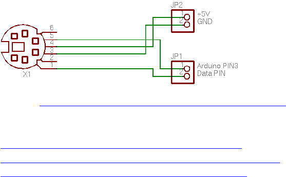
71
PS/2 Keyboard
Quelle: https://playground.arduino.cc/Main/PS2Keyboard
https://github.com/SteveBenz/PS2KeyboardHost
https://github.com/SteveBenz/PS2Keyboar ... rdHost.ino
https://playground.arduino.cc/Main/PS2Keyboard
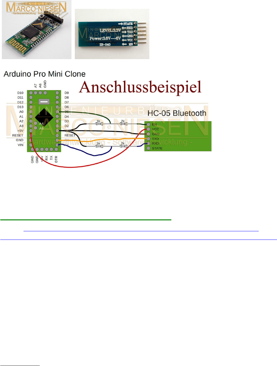
72
(UART) HC-05 : serielle BT-Module ( als Master oder Slave)
baudrate: 9600 - 115200; default-baudrate: 38400
Drahtlosverbindung über zwei HC-05 Module:
Quelle: http://www.ebay.de/itm/Bluetooth-Modul-HC-05-Master-Slave-UART-fur-z-B-
Arduino-inkl-Adapterboard-/291672244026?hash=item43e9053f3a:g:DlwAAOSwabhUVUBi
(Herr Niesen ist sehr hilfsbereit bezüglich Rückfragen und Konfigurationsproblemen!)
Achtung: verträgt nur 3,3V UART Signal-Level, nicht 5V-kompatibel!
Spannungsversorgung dagegen ist immer 5V!
D.h.: mit Raspi und Arduino DUE läuft es direkt, für Arduino MEGA werden 5V -> 3,3V
Levelshifter benötigt!
Durchführung:
1 HC-05 Modul als Master konfigurieren, das andere als Slave.
BAUD Rate richtig konfigurieren (ich verwende durchweg 115200 baud).
Dann diese beiden Module miteinander pairen und die UART-RX/TX Pins über Kreuz mit
Raspi bzw. Arduino verbinden:
HC-05 <-> 5V Vc und GND
Master-Seite:
Arduino GND <-> HC-05 GND
Arduino RX0 <-> HC-05 TX
Arduino TX0 <-> HC-05 RX

73
Slave-Seite:
HC-05 GND <-> Slave GND
HC-05 RX <-> Slave TX
HC-05 TX <-> Slave RX
Keine weiteren Einstellungen nötig - läuft automatisch als wäre ein langes Kabel dazwischen.
Links z.B.:
http://www.ebay.de/itm/Bluetooth-Modul-HC-05-Master-Slave-UART-fur-z-B-Arduino-inkl-
Adapterboard-/291672244026?hash=item43e9053f3a:g:DlwAAOSwabhUVUBi
http://www.brunwinkel.de/elektronik/module/btm400_6b/
http://www.exp-tech.de/serial-port-bluetooth-module-master-slave-hc-05
Konfiguration per AT-Befehle über die serielle Arduino-Konsole (selbe baudrate einstellen
wie HC-05!) ( zit. nach Inka, Roboternetz-Forum )
Enable-Pin an 3.3V > ermöglicht Programmieren im AT Modus :
# at
OK
# at+orgl //auf werkseinstellungen zurück
OK
# at+addr? //adreese?
+ADDR:98d3:31:b1426e
OK
# at+state? //zustand?
+STATE:INITIALIZED
OK
# at+role? //rolle? master=1, slave=0
+ROLE:0
OK
# at+pswd? //password?
+PSWD:1234
OK
# at+name? //name?
+NAME:H-C-2010-06-01
OK
# at+uart?
+UART:38400,0,0
OK
# at+bind?
+BIND:0:0:0
OK
# at+cmode?
+CMOD:0
OK
# -----
master:
#------
# at+name=master_RP6
74
OK
# at+pswd=0000
OK
# at+role=1
OK
# at+reset
OK
# at+init
OK
# at+pair=98d3,31,b1f2b2,20
OK
# at+bind=98d3,31,b1f2b2
OK
#---------
slave
#--------
# at
OK
# at+orgl
OK
# at+addr?
+ADDR:98d3:31:b1f2b2
OK
# at+role?
+ROLE:0
OK
# at+name?
+NAME:H-C-2010-06-01
OK
# at+uart?
+UART:38400,0,0
OK
# at+pswd?
+PSWD:1234
OK
--------------------------------------
--------------------------------------
# at+name=slave_RP6
OK
# at+pswd=0000
OK

75
Bei Problemen mit 5V-Geräten an 3.3V UART Bus -
einfacher Spannungsteiler:
Code: Alles auswählen
Arduino TX --| ( 5V Level )
|
33k
|
|---- DEVICE RX ( 3.3V Level)
|
47k
|
GND

76
Serial UART Lib: Kommunikation zwischen 2 Arduinos:
(die lib wurde auch extra so erstellt, um für die Display-Anzeige mit verschiedensten TFTs zu
arbeiten; der Sketch ist für Mega und Due wegen Hardware-Serial Rx1/Tx1 usw., wird aber
auch per SoftwareSerial auf Unos laufen (von anderem user getestet).
Standardmäßig hier UART-Übertragung mit 115200 baud.
Achtung:
Arduino AVRs (5V) und ARMs (3.3V) nicht ohne Levelshifter untereinander verbinden!
Code: Alles auswählen
/* Tx master
ver 0006.64
IDE 1.6.5
*/
#include <SPI.h>
#include <SD.h>
#include <UTFT.h>
#include <Adafruit_GFX.h>
#include <Adafruit_ILI9340.h>
#define clock() millis()
//=========================================================================
============
// TFT LCD
//=========================================================================
============
#define UTFT_SmallFont 8 // UTFT 8x10
#define UTFT_MediumFont 12 // UTFT ++
#define UTFT_BigFont 18 // UTFT +++
#define _SmallFont_ 1 // 9341 6x9
#define _MediumFont_ 2 // 9341 12x16
#define _BigFont_ 3 // 9341 18x23
int16_t LCDmaxX , LCDmaxY ; // display size
int16_t _curx_, _cury_, // last x,y cursor pos on TFT
screen
_maxx_, _maxy_; // max. x,y cursor pos on TFT
screen
char wspace[128]; // line of white space
// set LCD TFT type
int16_t LCDTYPE = -1;
#define _UTFT_ 4 // Henning Karlsen UTFT 2.2-2.4" 220x176 - 320x240
lib
//
http://henningkarlsen.com/electronics/library.php?id=51 //
#define _ILI9341_ 8 // https://github.com/adafruit/Adafruit_ILI9340
// https://github.com/adafruit/Adafruit-GFX-
77
Library //
//-------------------------------------------------------------------------
--------
#define UTFT_cs 52 // <<<<<<<< adjust!
//UTFT qdUTFT(Model, SDA=MOSI, SCL, CS, RESET, RS) // Due: 3
exposed SS pins: 4,10,52
UTFT qdUTFT(QD220A, A2, A1, A5, A4, A3); // adjust
model parameter and pins!
//UTFT qdUTFT(QD220A, 50, 49, UTFT_cs, 0, 51); // A0->Vc
(LED), A4->BoardReset
extern uint8_t SmallFont[];
//-------------------------------------------------------------------------
--------
#define tft_cs 50
#define tft_dc 49
#define tft_rst 0
Adafruit_ILI9340 tft = Adafruit_ILI9340(tft_cs, tft_dc, tft_rst);
//-------------------------------------------------------------------------
--------
int16_t fontwi= 8; // default
int16_t fonthi=10; // default
void putfonttype(uint8_t fsize) {
if(LCDTYPE==_UTFT_) { fontwi= qdUTFT.getFontXsize();
fonthi=qdUTFT.getFontYsize(); }
else
if(fsize==_SmallFont_) { fontwi= 6; fonthi=9; } // 5x7 + overhead ?
else
if(fsize==_MediumFont_) { fontwi=12; fonthi=16; } // ?
else
if(fsize==_BigFont_) { fontwi=18; fonthi=23; } // ?
_maxx_ = LCDmaxX / fontwi; // max number of letters x>>
_maxy_ = LCDmaxY / fonthi; // max number of letters y^^
memset(wspace, ' ', _maxx_); // line of white space
wspace[_maxx_]='\0';
}
void setlcdorient(int8_t orient) {
if(LCDTYPE==_ILI9341_) {
tft.setRotation(orient);
LCDmaxX=tft.width();
LCDmaxY=tft.height();
}
}
void lcdcls() {
if(LCDTYPE==_UTFT_) { qdUTFT.clrScr(); }
if(LCDTYPE==_ILI9341_) { tft.fillScreen(ILI9340_BLACK); }
_curx_ =0; _cury_ =0;
}
void curlf() {
_curx_=0;
if( _cury_ <=(LCDmaxY-10) ) _cury_+=fonthi;
78
else _cury_=0;
if(LCDTYPE==_ILI9341_) {tft.setCursor(0, _cury_); }
}
void curxy(int16_t x, int16_t y) {
_curx_ = x;
_cury_ = y;
if(LCDTYPE==_ILI9341_) {tft.setCursor(x, y); }
}
void lcdprintxy(int16_t x, int16_t y, char * str) {
if(LCDTYPE==_UTFT_) { qdUTFT.print(str,x,y);
_curx_=x+strlen(str)*fontwi; _cury_=y; }
else if(LCDTYPE==_ILI9341_) {
tft.setCursor(x,y); tft.print(str);
_curx_=tft.getCursorX(); _cury_=tft.getCursorY();
}
}
void lcdprint(char * str) {
if(LCDTYPE==_UTFT_) { qdUTFT.print(str, _curx_, _cury_);
_curx_=_curx_+strlen(str)*fontwi; }
else if(LCDTYPE==_ILI9341_) {
tft.setCursor(_curx_, _cury_); tft.print(str);
_curx_=tft.getCursorX(); _cury_=tft.getCursorY();
}
}
void initlcd(uint8_t orient) { // 0,2==Portrait 1,3==Landscape
if(LCDTYPE==_UTFT_) {
qdUTFT.InitLCD();
LCDmaxX=qdUTFT.getDisplayXSize();
LCDmaxY=qdUTFT.getDisplayYSize();
qdUTFT.setFont(SmallFont);
putfonttype(UTFT_SmallFont);
fontwi=qdUTFT.getFontXsize();
fonthi=qdUTFT.getFontYsize();
}
else
if(LCDTYPE==_ILI9341_) {
tft.begin();
setlcdorient(orient);
tft.setTextSize(_SmallFont_);
putfonttype(_SmallFont_);
}
}
//=========================================================================
============
//=========================================================================
============
const uint8_t MSGSIZE=64;
uint8_t bsync=255;
uint8_t sendbuf[MSGSIZE];
uint8_t recvbuf[MSGSIZE];
79
//=========================================================================
============
const uint32_t UARTclock=115200; //
void setup() {
char sbuf[128];
int32_t i=0;
// Serial
Serial.begin(115200); // USB terminal (UART 0)
Serial1.begin(UARTclock); // RX1-TX1 (UART 1)
while(Serial1.available()) Serial1.read(); // clear output buffer
// TFT LCD
Serial.println();
LCDTYPE = _UTFT_;
Serial.print("init LCD...");
initlcd(1);
Serial.println(" done."); lcdcls();
sprintf(sbuf, "LCD=%d wi%d x hi%d",LCDTYPE,LCDmaxX,LCDmaxY);
Serial.println(sbuf);
Serial.println();
lcdcls(); lcdprint(sbuf);
sprintf(sbuf, "setup(): done.");
Serial.println(); Serial.println(sbuf);
curlf(); curlf(); lcdprint(sbuf);
lcdcls();
sprintf(sbuf, "Tx master, BAUD= %ld", UARTclock );;
lcdprintxy(0, 0, sbuf);
}
//=========================================================================
============
//=========================================================================
============
void displayvalues(int line, char * caption, uint8_t array[]) {
int cnt;
char sbuf[128];
sprintf(sbuf, "%s cks=%-4d", caption, array[1]);
lcdprintxy(0, line, sbuf);
//Serial.println(sbuf);
for(cnt=0; cnt<8; ++cnt) {
sprintf(sbuf, "%3d ", array[cnt]); // print on TFT
lcdprintxy(cnt*3*8, line+10, sbuf);
//Serial.print(sbuf); // Print sendbuffer to the
Serial Monitor
}
//Serial.println();
}
80
//=========================================================================
============
//=========================================================================
============
// serial TCP
uint8_t calcchecksum(uint8_t array[]) {
int32_t sum=0;
for(int i=2; i<MSGSIZE; ++i) sum+=(array[i]);
return (sum & 0x00ff);
}
bool checksumOK(uint8_t array[]){
return (calcchecksum(array)==array[1]);
}
// ================================================================
// addToBuffer and receive function courtesy of chucktodd
bool addToBuffer( uint8_t buf[], uint8_t *cnt, uint16_t timeout){
bool inSync = *cnt>0;
unsigned long start=millis();
while((*cnt<MSGSIZE)&&(millis()-start<timeout)){
if(Serial1.available()){ // grab new char, test for sync char, if so
start adding to buffer
buf[*cnt] = (uint8_t)Serial1.read();
if(inSync) *cnt += 1; // my origional *cnt++ was updating the pointer
address, not
// the pointed to sendbuffer
else{
if(buf[*cnt]==0xFF){
inSync = true;
*cnt +=1;
}
}
}
}
return (*cnt==MSGSIZE);
}
//=========================================================================
============
bool receive(uint8_t * buf, uint16_t timeout, uint8_t *cnt){ // by passing
cnt in and out,
// i can timeout and still save a partial buffer, so a resync costs less
(less data lost)
bool inSync=false;
unsigned long start=millis();
uint8_t * p; // pointer into buf for reSync operation
bool done=false;
do{
done = addToBuffer(buf,cnt,timeout); // if this return false, a timeout
has occured, and the while will exit.
if(done){ // do checksumOK test of buffer;
done=checksumOK(buf);
if(!done){// checksumOK failed, scan buffer for next sync char
p = (uint8_t*)memchr((buf+1),0xff,(MSGSIZE-1)); //forgot to skip the
current sync at 0
81
if(p){ // found next sync char, shift buffer content, refill buffer
*cnt = MSGSIZE -(p-buf); // count of characters to salvage from
this failure
memcpy(buf,p,*cnt); //cnt is now where the next character from
Serial is stored!
}
else *cnt=0; // whole buffer is garbage
}
}
}while(!done&&(millis()-start<timeout));
return done; // if done then buf[] contains a sendbufid buffer, else a
timeout occurred
}
//=========================================================================
============
//=========================================================================
============
void loop()
{
char sbuf[128], resOK;
static uint8_t cnt=0;
uint8_t cbuf[MSGSIZE], chk;
// send to Rx slave Arduino
//Serial.println();
sendbuf[0]=bsync;
sendbuf[1]=calcchecksum(sendbuf);
for(uint8_t i=0; i<MSGSIZE; i++) {
Serial1.write(sendbuf[i]); // Send values to
the Rx Arduino
}
//Serial1.flush(); // clear output
buffer
//displayvalues(20, "Transmitted...: ", sendbuf);
sprintf(sbuf, "%4d %4d", sendbuf[4], sendbuf[6]);
lcdprintxy(0, 20, sbuf);
// Receive from Rx slave Arduino
memset(cbuf, 0, sizeof(cbuf));
resOK = receive ( cbuf, 10000,&cnt);
if( resOK ) { // byte 0 == syncbyte ?
cnt=0;
//displayvalues(60, "Received...:", cbuf);
chk=(byte)calcchecksum(cbuf);
memcpy(recvbuf, cbuf, sizeof(cbuf));
// change values to send back!
memcpy(sendbuf, recvbuf, sizeof(sendbuf)); // copy inbuf to
outbuf
sendbuf[4]+=1; // change [4] to
82
send back
}
}
//=========================================================================
//=========================================================================
/* Rx slave
ver 0006.64
IDE 1.6.5
*/
#include <SPI.h>
#include <SD.h>
#include <UTFT.h>
#include <Adafruit_GFX.h>
#include <Adafruit_ILI9340.h>
#define clock() millis()
//=========================================================================
// TFT LCD
//=========================================================================
#define UTFT_SmallFont 8 // UTFT 8x10
#define UTFT_MediumFont 12 // UTFT ++
#define UTFT_BigFont 18 // UTFT +++
#define _SmallFont_ 1 // 9341 6x9
#define _MediumFont_ 2 // 9341 12x16
#define _BigFont_ 3 // 9341 18x23
int16_t LCDmaxX , LCDmaxY ; // display size
int16_t _curx_, _cury_, // last x,y cursor pos on TFT
screen
_maxx_, _maxy_; // max. x,y cursor pos on TFT
screen
char wspace[128]; // line of white space
// set LCD TFT type
int16_t LCDTYPE = -1;
#define _UTFT_ 4 // Henning Karlsen UTFT 2.2-2.4" 220x176 - 320x240
lib
//
http://henningkarlsen.com/electronics/library.php?id=51 //
#define _ILI9341_ 8 // https://github.com/adafruit/Adafruit_ILI9340
// https://github.com/adafruit/Adafruit-GFX-
Library //
//-------------------------------------------------------------------------
--------
#define UTFT_cs 52 // <<<<<<<< adjust!
83
//UTFT qdUTFT(Model, SDA=MOSI, SCL, CS, RESET, RS) // Due: 3
exposed SS pins: 4,10,52
UTFT qdUTFT(QD220A, A2, A1, A5, A4, A3); // adjust
model parameter and pins!
//UTFT qdUTFT(QD220A, 50, 49, UTFT_cs, 0, 51); // A0->Vc
(LED), A4->BoardReset
extern uint8_t SmallFont[];
//-------------------------------------------------------------------------
--------
#define tft_cs 50
#define tft_dc 49
#define tft_rst 0
Adafruit_ILI9340 tft = Adafruit_ILI9340(tft_cs, tft_dc, tft_rst);
//-------------------------------------------------------------------------
--------
int16_t fontwi= 8; // default
int16_t fonthi=10; // default
void putfonttype(uint8_t fsize) {
if(LCDTYPE==_UTFT_) { fontwi= qdUTFT.getFontXsize();
fonthi=qdUTFT.getFontYsize(); }
else
if(fsize==_SmallFont_) { fontwi= 6; fonthi=9; } // 5x7 + overhead ?
else
if(fsize==_MediumFont_) { fontwi=12; fonthi=16; } // ?
else
if(fsize==_BigFont_) { fontwi=18; fonthi=23; } // ?
_maxx_ = LCDmaxX / fontwi; // max number of letters x>>
_maxy_ = LCDmaxY / fonthi; // max number of letters y^^
memset(wspace, ' ', _maxx_); // line of white space
wspace[_maxx_]='\0';
}
void setlcdorient(int8_t orient) {
if(LCDTYPE==_ILI9341_) {
tft.setRotation(orient);
LCDmaxX=tft.width();
LCDmaxY=tft.height();
}
}
void lcdcls() {
if(LCDTYPE==_UTFT_) { qdUTFT.clrScr(); }
if(LCDTYPE==_ILI9341_) { tft.fillScreen(ILI9340_BLACK); }
_curx_ =0; _cury_ =0;
}
void curlf() {
_curx_=0;
if( _cury_ <=(LCDmaxY-10) ) _cury_+=fonthi;
else _cury_=0;
if(LCDTYPE==_ILI9341_) {tft.setCursor(0, _cury_); }
}
84
void curxy(int16_t x, int16_t y) {
_curx_ = x;
_cury_ = y;
if(LCDTYPE==_ILI9341_) {tft.setCursor(x, y); }
}
void lcdprintxy(int16_t x, int16_t y, char * str) {
if(LCDTYPE==_UTFT_) { qdUTFT.print(str,x,y);
_curx_=x+strlen(str)*fontwi; _cury_=y; }
else if(LCDTYPE==_ILI9341_) {
tft.setCursor(x,y); tft.print(str);
_curx_=tft.getCursorX(); _cury_=tft.getCursorY();
}
}
void lcdprint(char * str) {
if(LCDTYPE==_UTFT_) { qdUTFT.print(str, _curx_, _cury_);
_curx_=_curx_+strlen(str)*fontwi; }
else if(LCDTYPE==_ILI9341_) {
tft.setCursor(_curx_, _cury_); tft.print(str);
_curx_=tft.getCursorX(); _cury_=tft.getCursorY();
}
}
void initlcd(uint8_t orient) { // 0,2==Portrait 1,3==Landscape
if(LCDTYPE==_UTFT_) {
qdUTFT.InitLCD();
LCDmaxX=qdUTFT.getDisplayXSize();
LCDmaxY=qdUTFT.getDisplayYSize();
qdUTFT.setFont(SmallFont);
putfonttype(UTFT_SmallFont);
fontwi=qdUTFT.getFontXsize();
fonthi=qdUTFT.getFontYsize();
}
else
if(LCDTYPE==_ILI9341_) {
tft.begin();
setlcdorient(orient);
tft.setTextSize(_SmallFont_);
putfonttype(_SmallFont_);
}
}
//=========================================================================
============
//=========================================================================
============
const uint8_t MSGSIZE=64;
uint8_t bsync=255;
uint8_t sendbuf[MSGSIZE];
uint8_t recvbuf[MSGSIZE];
//=========================================================================
============
const uint32_t UARTclock=115200
85
void setup() {
char sbuf[128];
int32_t i=0;
// Serial
Serial.begin(115200); // USB terminal (UART 0)
Serial1.begin(UARTclock); // RX1-TX1 (UART 1)
while(Serial1.available()) Serial1.read(); // clear output buffer
// TFT LCD
Serial.println();
LCDTYPE = _UTFT_;
Serial.print("init LCD...");
initlcd(1);
Serial.println(" done."); lcdcls();
sprintf(sbuf, "LCD=%d wi%d x hi%d",LCDTYPE,LCDmaxX,LCDmaxY);
Serial.println(sbuf);
Serial.println();
lcdcls(); lcdprint(sbuf);
sprintf(sbuf, "setup(): done.");
Serial.println(); Serial.println(sbuf);
curlf(); curlf(); lcdprint(sbuf);
lcdcls();
sprintf(sbuf, "Rx slave, BAUD= %ld", UARTclock );;
lcdprintxy(0, 0, sbuf);
}
//=========================================================================
============
//=========================================================================
============
void displayvalues(int line, char * caption, uint8_t array[]) {
int cnt;
char sbuf[128];
sprintf(sbuf, "%s cks=%-4d", caption, array[1]);
lcdprintxy(0, line, sbuf);
//Serial.println(sbuf);
for(cnt=0; cnt<8; ++cnt) {
sprintf(sbuf, "%3d ", array[cnt]); // print on TFT
lcdprintxy(cnt*3*8, line+10, sbuf);
//Serial.print(sbuf); // Print sendbuffer to the
Serial Monitor
}
//Serial.println();
}
//=========================================================================
============
//=========================================================================
============
// serial TCP
86
uint8_t calcchecksum(uint8_t array[]) {
int32_t sum=0;
for(int i=2; i<MSGSIZE; ++i) sum+=(array[i]);
return (sum & 0x00ff);
}
bool checksumOK(uint8_t array[]){
return (calcchecksum(array)==array[1]);
}
// ================================================================
// addToBuffer and receive function courtesy of chucktodd
bool addToBuffer( uint8_t buf[], uint8_t *cnt, uint16_t timeout){
bool inSync = *cnt>0;
unsigned long start=millis();
while((*cnt<MSGSIZE)&&(millis()-start<timeout)){
if(Serial1.available()){ // grab new char, test for sync char, if so
start adding to buffer
buf[*cnt] = (uint8_t)Serial1.read();
if(inSync) *cnt += 1; // my origional *cnt++ was updating the pointer
address, not
// the pointed to sendbuffer
else{
if(buf[*cnt]==0xFF){
inSync = true;
*cnt +=1;
}
}
}
}
return (*cnt==MSGSIZE);
}
//=========================================================================
============
bool receive(uint8_t * buf, uint16_t timeout, uint8_t *cnt){ // by passing
cnt in and out,
// i can timeout and still save a partial buffer, so a resync costs less
(less data lost)
bool inSync=false;
unsigned long start=millis();
uint8_t * p; // pointer into buf for reSync operation
bool done=false;
do{
done = addToBuffer(buf,cnt,timeout); // if this return false, a timeout
has occured, and the while will exit.
if(done){ // do checksumOK test of buffer;
done=checksumOK(buf);
if(!done){// checksumOK failed, scan buffer for next sync char
p = (uint8_t*)memchr((buf+1),0xff,(MSGSIZE-1)); //forgot to skip the
current sync at 0
if(p){ // found next sync char, shift buffer content, refill buffer
*cnt = MSGSIZE -(p-buf); // count of characters to salvage from
this failure
memcpy(buf,p,*cnt); //cnt is now where the next character from
87
Serial is stored!
}
else *cnt=0; // whole buffer is garbage
}
}
}while(!done&&(millis()-start<timeout));
return done; // if done then buf[] contains a sendbufid buffer, else a
timeout occurred
}
//=========================================================================
============
//=========================================================================
============
void loop()
{
char sbuf[128], resOK;
static uint8_t cnt=0;
uint8_t cbuf[MSGSIZE], chk;
uint32_t xtime;
// Receive fromTx master Arduino
memset(cbuf, 0, sizeof(cbuf));
resOK = receive ( cbuf, 10000,&cnt);
if( resOK ) { // byte 0 == syncbyte
?
cnt=0;
//displayvalues(60, "Received...:", cbuf);
chk=(byte)calcchecksum(cbuf);
memcpy(recvbuf, cbuf, sizeof(cbuf));
// change values to send back!
memcpy(sendbuf, recvbuf, sizeof(sendbuf)); // copy inbuf to
outbuf
sendbuf[4]+=1; // change [6] to send
back
sendbuf[6]+=1; // change [6] to send
back
}
// send to Tx master Arduino
//Serial.println();
sendbuf[0]=bsync;
sendbuf[1]=calcchecksum(sendbuf);
for(uint8_t i=0; i<MSGSIZE; i++) {
Serial1.write(sendbuf[i]); // Send value to the
Rx Arduino
}
//Serial1.flush(); // clear output buffer
//displayvalues(20, "Transmitted...: ", sendbuf);
sprintf(sbuf, "%4d %4d", sendbuf[4], sendbuf[6]);
88
lcdprintxy(0, 20, sbuf);
}
//=========================================================================
//=========================================================================

89
(UART) GPS Modul GY-NEO-6M V2
Quelle: Ebay
Anschluss-Protokoll: UART
Spannung/Level: 3-5 V kompatibel
Bezugsquelle: u.a. Ebay, z.B. http://www.ebay.de/itm/311296066259
Preis: ca. 12-14 EUR
Treiber-Library:
Serial-lib (standardmäßig in Arduino-Sketch enthalten, standardmäßig bereits eingebunden)
GPS-lib: TinyGPS++ http://arduiniana.org/libraries/tinygpsplus/
https://github.com/mikalhart/TinyGPSPlus
TinyGPSPlus-master.zip
(43.44 KiB) 148-mal heruntergeladen
Anm.: auch für Raspberry Pi geeignet! https://bigdanzblog.wordpress.com/2015/ ... pberry-pi/
Hinweise:
1.) es lassen sich nicht nur geograf. Daten, sondern auch Datum, Uhrzeit, Geschwindigkeit,
Kurs und Satellitendaten abfragen
2.) Üblicherweise arbeiten die Sketche für Uno und Nano mit SoftwareSerial():
Code: Alles auswählen
SoftwareSerial ss(4, 3);
void loop()
{
while (ss.available() > 0)
gps.encode(ss.read);
//...
Stattdessen lässt sich aber auch Hardware-Serial verwenden, am besten per UART1 oder
UART2 auf Mega oder Due:
Code: Alles auswählen
setup(){
Serial.begin(115200); // UART0 für USB-Serial-Terminal Window
Serial1.begin(9600): // UART1 für das GPS-Modul
}
void loop()
{
while (Serial1.available() > 0)
gps.encode(Serial1.read);

90
//...
}
3.) Liste für die verfügbaren Daten:
Code: Alles auswählen
Serial.println(gps.location.lat(), 11); // Latitude in degrees (double)
Serial.println(gps.location.lng(), 11); // Longitude in degrees (double)
Serial.print(gps.location.rawLat().negative ? "-" : "+");
Serial.println(gps.location.rawLat().deg); // Raw latitude in whole degrees
Serial.println(gps.location.rawLat().billionths);// ... and billionths
(u16/u32)
Serial.print(gps.location.rawLng().negative ? "-" : "+");
Serial.println(gps.location.rawLng().deg); // Raw longitude in whole
degrees
Serial.println(gps.location.rawLng().billionths);// ... and billionths
(u16/u32)
Serial.println(gps.date.value()); // Raw date in DDMMYY format (u32)
Serial.println(gps.date.year()); // Year (2000+) (u16)
Serial.println(gps.date.month()); // Month (1-12) (u8)
Serial.println(gps.date.day()); // Day (1-31) (u8)
Serial.println(gps.time.value()); // Raw time in HHMMSSCC format (u32)
Serial.println(gps.time.hour()); // Hour (0-23) (u8)
Serial.println(gps.time.minute()); // Minute (0-59) (u8)
Serial.println(gps.time.second()); // Second (0-59) (u8)
Serial.println(gps.time.centisecond()); // 100ths of a second (0-99) (u8)
Serial.println(gps.speed.value()); // Raw speed in 100ths of a knot (i32)
Serial.println(gps.speed.knots()); // Speed in knots (double)
Serial.println(gps.speed.mph()); // Speed in miles per hour (double)
Serial.println(gps.speed.mps()); // Speed in meters per second (double)
Serial.println(gps.speed.kmph()); // Speed in kilometers per hour (double)
Serial.println(gps.course.value()); // Raw course in 100ths of a degree
(i32)
Serial.println(gps.course.deg()); // Course in degrees (double)
Serial.println(gps.altitude.value()); // Raw altitude in centimeters (i32)
Serial.println(gps.altitude.meters()); // Altitude in meters (double)
Serial.println(gps.altitude.miles()); // Altitude in miles (double)
Serial.println(gps.altitude.kilometers()); // Altitude in kilometers
(double)
Serial.println(gps.altitude.feet()); // Altitude in feet (double)
Serial.println(gps.satellites.value()); // Number of satellites in use
(u32)
Serial.println(gps.hdop.value()); // Horizontal Dim. of Precision (100ths-
i32)
Einfaches Device Example :
Code: Alles auswählen
/*
This sample sketch demonstrates the normal use of a TinyGPS++
(TinyGPSPlus) object.
It requires the use of SoftwareSerial, and assumes that you have a
9600-baud serial GPS device hooked up on pins 4(rx) and 3(tx).
Alternatively: Serial1 (RX1+TX1, pin 18+19 on Mega/Due)
91
*/
#include <TinyGPS++.h>
#include <LiquidCrystal.h>
// initialize the library with the numbers of the interface pins
LiquidCrystal lcd(22, 23, 24, 25, 26, 27);
static const uint32_t GPSBaud = 9600;
// The TinyGPS++ object
TinyGPSPlus gps;
double frac(double value) {
return (value - (double)trunc(value) );
}
void setup()
{
// setup Serial for USB-Monitor
Serial.begin(115200);
// setup Serial1 for GPS
Serial1.begin(GPSBaud);
// set up the LCD's number of columns and rows:
lcd.begin(16, 2); // init LCD 1602
Serial.println(F("DeviceExample.ino"));
Serial.println(F("A simple demonstration of TinyGPS++ with an attached
GPS module"));
Serial.print(F("Testing TinyGPS++ library v. "));
Serial.println(TinyGPSPlus::libraryVersion());
Serial.println(F("by Mikal Hart"));
Serial.println();
}
void loop()
{
char sbuf[128];
// This sketch displays information every time a new sentence is
correctly encoded.
while (Serial1.available() > 0)
if (gps.encode(Serial1.read()))
displayInfo();
if (millis() > 5000 && gps.charsProcessed() < 10)
{
Serial.println(F("No GPS detected: check wiring."));
while(true);
}
}
void displayInfo()
{
char sbuf[128];
92
double fLatt, fLong, fmin, fdecsec;
uint16_t decdeg, decmin,
dday, dmonth, dyear,
dhour, dmin, dsec, dcsec, nsat;
if (gps.location.isValid())
{
fLatt= (double)gps.location.lat();
fLong= (double)gps.location.lng();
sprintf(sbuf, "Lat:%+012.7f " , fLatt );
Serial.print(sbuf); lcd.setCursor(0, 0); lcd.print(sbuf);
decdeg = (int)fLatt;
fmin = ( fLatt - (float)decdeg) * 60;
decmin = (int)(fmin);
fdecsec= (fmin - (float)decmin) * 60 ;
sprintf(sbuf, "B%+04d:%02d'%7.4f ", decdeg, decmin, fdecsec);
Serial.print(sbuf); lcd.setCursor(0, 0); lcd.print(sbuf);
sprintf(sbuf, " Lng:%+012.7f ", fLong );
Serial.print(sbuf);
decdeg = (int)fLong;
fmin = ( fLong - (float)decdeg) * 60;
decmin = (int)(fmin);
fdecsec= (fmin - (float)decmin) * 60 ;
sprintf(sbuf, "L%+04d:%02d'%7.4f ", decdeg, decmin, fdecsec);
Serial.print(sbuf); lcd.setCursor(0, 1); lcd.print(sbuf);
}
else
{
Serial.print(F("Location: INVALID "));
lcd.setCursor(0, 1); lcd.print("Loc.: INVALID");
}
if (gps.date.isValid())
{
dday=gps.date.day();
dmonth=gps.date.month();
dyear=gps.date.year();
sprintf(sbuf, " Date: %02d/%02d/%04d", dday, dmonth, dyear);
Serial.print(sbuf);
}
else
{
Serial.print(F(" Date: INVALID "));
}
if (gps.time.isValid())
{
dhour=gps.time.hour();
dmin= gps.time.minute();
dsec= gps.time.second();
dcsec=gps.time.centisecond();
nsat =gps.satellites.value();
sprintf(sbuf, " Time: %02d:%02d:%02d,%03d Sat.=%02d", dhour, dmin,
dsec, dcsec, nsat);
Serial.print(sbuf);
}
else

93
{
Serial.print(F(" Time: INVALID "));
}
Serial.println();
}
Arduino GPS data to google maps
https://www.youtube.com/watch?v=dy2iygCZTIM
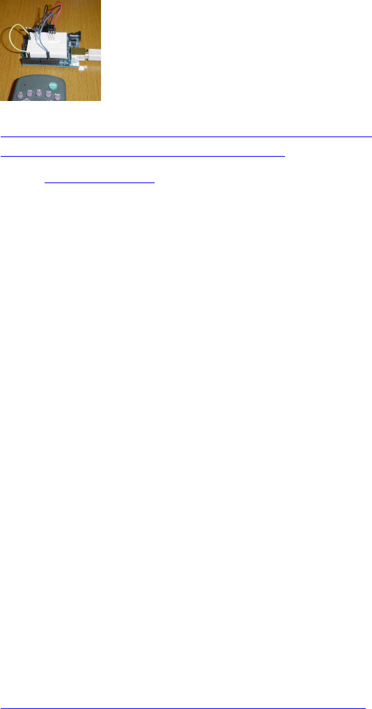
94
Infrared Remote Library für Arduino (Baustelle)
http://www.righto.com/2009/08/multi-pro ... brary.html
https://github.com/z3t0/Arduino-IRremote
Code: Alles auswählen
/*
* IR Remote Receive Test
* Copyright (c) 2016 Philipp Henkel
*/
// https://github.com/z3t0/Arduino-IRremote
// The examples/IRrecvDemo sketch provides a simple example of how to
receive codes:
#include <IRremote.h>
int RECV_PIN = 11;
IRrecv irrecv(RECV_PIN);
decode_results results;
void setup()
{
Serial.begin(9600);
irrecv.enableIRIn(); // Start the receiver
}
void loop() {
if (irrecv.decode(&results)) {
Serial.println(results.value, HEX);
irrecv.resume(); // Receive the next value
}
}
inkl. Lego Power Functions Remote Unterstützung:
https://github.com/z3t0/Arduino-IRremot ... sTests.ino
95
Arduino-Libs für Lego Mindstorms NXT-Sensoren
Lego-Stecker-Pins :
NXT Taster (Touch-Sensor) :
http://www.thecompblog.com/2012/07/hacking-lego-nxt-part-2.html
Code: Alles auswählen
*
This is a program to test the Lego NXT Touch Sensor.
A schematic of the circuit required can be found on TheCompBlog.com.
This code was writen (badly) by Nicolas Weninger, author of
TheCompBlog.com.
--
THIS SOFTWARE COMES WITHOUT ANY WARRANTY, IMPLIED OR EXPLICIT, TO THE
MAXIMUM EXTENT PERMITTABLE BY LAW. THIS INCLUDES
WARRANTY AGAINST DAMAGE TO COMPUTER SYSTEMS OR DATA, LOSS OF PROFIT,
PERSONAL INJURY OR DEATH.
This code is in the public domain.
96
*/
const int button = 2; //connects to pin3 of the sensor
void setup()
{
Serial.begin(9600);
pinMode(13, OUTPUT);
}
void loop()
{
if(digitalRead(button) == 1)
{
digitalWrite(13, HIGH);
}
else
{
digitalWrite(13, LOW);
}
Serial.println(digitalRead(button));
}
NXT-Lichtsensor (Light-Sensor):
http://www.thecompblog.com/2012/07/hacking-lego-nxt-part-2.html
/*
This is a program to test the Lego NXT Light Sensor.
A schematic of the circuit required can be found on TheCompBlog.com.
This code was writen (badly) by Nicolas Weninger, author of
TheCompBlog.com.
THIS SOFTWARE COMES WITHOUT ANY WARRANTY, IMPLIED OR EXPLICIT, TO THE
MAXIMUM EXTENT PERMITTABLE BY LAW. THIS INCLUDES
WARRANTY AGAINST DAMAGE TO COMPUTER SYSTEMS OR DATA, LOSS OF PROFIT,
PERSONAL INJURY OR DEATH.
This code is in the public domain.
*/
97
const int reader = A5; //connects to pin1 of sensor
const int button = 2; //momentary switch
const int light = 3; //connects to pin5 of sensor
int state = LOW;
int previous = LOW;
void setup()
{
Serial.begin(9600);
pinMode(light, OUTPUT);
}
void loop()
{
int reading = digitalRead(button);
if(reading == HIGH && previous == LOW)
{
if(state == HIGH)
{
state = LOW;
}
else
{
state = HIGH;
}
}
digitalWrite(light, state);
previous = reading;
Serial.println(analogRead(reader)); //print the light level reading
delay(10); //good practice after an analogRead. Don't know why though…
}
NXT Geräuschsensor (Sound Sensor):
http://www.thecompblog.com/2012/08/hacking-lego-nxt-part-3.html
/*
This code reads the analog value of the Lego NXT sound sensor.
98
The schematic can be found on thecompblog.com
This code was written (badly) by Nicolas Weninger, auther of TheCompBlog.
THIS SOFTWARE COMES WITHOUT ANY WARRANTY, IMPLIED OR EXPLICIT, TO THE
MAXIMUM EXTENT PERMISSIBLE BY LAW.
THIS INCLUDES WARRANTY AGAINST DAMAGE TO COMPUTER SYSTEMS, LOSS OF
PROFIT, PERSONAL INJURY OR DEATH.
This code is in the public domain.
*/
const int mic = A5;
void setup()
{
Serial.begin(9600);
}
void loop()
{
Serial.println(analogRead(mic));
delay(10);
}
NXT Ultraschallsensor (Ultrasonic Sensor)
http://www.thecompblog.com/2012/08/hacking-lego-nxt-part-3.html
http://blog.tkjelectronics.dk/2011/10/nxt-shield-ver2/
http://blog.tkjelectronics.dk/wp-content/uploads/Appendix-7-LEGO-MINDSTORMS-NXT-
Ultrasonic-Sensor-I2C-communication-protocol.pdf
notwendige I2Cmaster.h library für NXT USS:
I2Cmaster.zip
#include <I2Cmaster.h>
byte clockPin = 4;
byte buf[9];//Buffer to store the received valeus
byte addr = 0x02;//address 0x02 in a 8-bit context - 0x01 in a 7-bit
context
99
byte distance;
void setup()
{
I2C_init();//I2C frequency = 11494,253Hz
Serial.begin(115200);
printUltrasonicCommand(0x00);//Read Version
printUltrasonicCommand(0x08);//Read Product ID
printUltrasonicCommand(0x10);//Read Sensor Type
printUltrasonicCommand(0x14);//Read Measurement Units
}
void loop()
{
// printUltrasonicCommand(0x42);//Read Measurement Byte 0
distance = readDistance();
if(distance == 0xFF)
Serial.println("Error Reading Distance");
else
Serial.println(distance, DEC);
}
byte readDistance()
{
delay(100);//There has to be a delay between commands
byte cmd = 0x42;//Read Measurement Byte 0
pinMode(clockPin, INPUT);//Needed for writing to work
digitalWrite(clockPin, HIGH);
if(I2C_start(addr+I2C_WRITE))//Check if there is an error
{
Serial.println("ERROR I2C_start");
I2C_stop();
return 0xFF;
}
if(I2C_write(cmd))//Check if there is an error
{
Serial.println("ERROR I2C_write");
I2C_stop();
return 0xFF;
}
I2C_stop();
delayMicroseconds(60);//Needed for receiving to work
pinMode(clockPin, OUTPUT);
digitalWrite(clockPin, LOW);
delayMicroseconds(34);
pinMode(clockPin, INPUT);
digitalWrite(clockPin, HIGH);
delayMicroseconds(60);
if(I2C_rep_start(addr+I2C_READ))//Check if there is an error
{
Serial.println("ERROR I2C_rep_start");
I2C_stop();
return 0xFF;
}
for(int i = 0; i < 8; i++)
buf[i] = I2C_readAck();
buf[8] = I2C_readNak();
I2C_stop();
return buf[0];
100
}
void printUltrasonicCommand(byte cmd)
{
delay(100);//There has to be a delay between commands
pinMode(clockPin, INPUT);//Needed for writing to work
digitalWrite(clockPin, HIGH);
if(I2C_start(addr+I2C_WRITE))//Check if there is an error
{
Serial.println("ERROR I2C_start");
I2C_stop();
return;
}
if(I2C_write(cmd))//Check if there is an error
{
Serial.println("ERROR I2C_write");
I2C_stop();
return;
}
I2C_stop();
delayMicroseconds(60);//Needed for receiving to work
pinMode(clockPin, OUTPUT);
digitalWrite(clockPin, LOW);
delayMicroseconds(34);
pinMode(clockPin, INPUT);
digitalWrite(clockPin, HIGH);
delayMicroseconds(60);
if(I2C_rep_start(addr+I2C_READ))//Check if there is an error
{
Serial.println("ERROR I2C_rep_start");
I2C_stop();
return;
}
for(int i = 0; i < 8; i++)
buf[i] = I2C_readAck();
buf[8] = I2C_readNak();
I2C_stop();
if(cmd == 0x00 || cmd == 0x08 || cmd == 0x10 || cmd == 0x14)
{
for(int i = 0; i < 9; i++)
{
if(buf[i] != 0xFF && buf[i] != 0x00)
Serial.print(buf[i]);
else
break;
}
}
else
Serial.print(buf[0], DEC);
Serial.println("");
}
/*
' Wires on NXT jack plug.
' Wire colours may vary. Pin 1 is always end nearest latch.
' 1 White +9V
' 2 Black GND
' 3 Red GND

101
' 4 Green +5V
' 5 Yellow SCL - also connect clockpin to give a extra low impuls
' 6 Blue SDA
' Do not use I2C pullup resistor - already provided within sensor.
*/
verwendete I2Cmaster-Library:
I2Cmaster.zip
(6.25 KiB) 103-mal heruntergeladen
weitere Links zu Arduino-Libs für Lego Mindstorms EV3-
Sensoren
Driver und Source Code, um EV3-Sensoren an Arduinos zu betreiben:
https://lejosnews.wordpress.com/2014/05 ... t-sensors/
https://github.com/lawrie/EV3_Dexter_In ... V3_arduino
https://github.com/lawrie/EV3_Dexter_In ... UARTSensor
(danke an Andy Shaw (leJOS) und Lawrie Griffiths (Dexter Industries) !

102
Auslesen von Encoderwerten mit einem Arduino:
Fehler! Datei kann nicht gelesen oder angezeigt werden.
Pin-Belegung für die Verwendung von Lego Mindstorms RJ11-Steckern:
Encoder-Anschlüsse an Pins 5+6 (gelb/blau)
Pin3=GND (Lego-Farbcodierung=rot!!), Pin4=+Vc (+3,3...+5V, Lego-Farbcodierung=grün!!)
Code: Alles auswählen
#define encoderA 2
#define encoderB 3
pinMode(encoderA, INPUT_PULLUP);
pinMode(encoderB, INPUT_PULLUP);
Variante 1:
Auslesen der Encoder per Arduino Uno / Mega :
/************************************************************
*
* Demo-Programm zur Auswertung eines manuell betriebenen
* Drehencoders (Quadraturencoder) mit dem Arduino im
* Timer-Interrupt mit einer Abfragefrequenz von rd. 1kHz
*
* Kann von jederman frei verwendet werden, aber bitte den
* Hinweis: "Entnommen aus http://www.meinDUINO.de" einfügen
*
************************************************************/
// An die Pins 2 und 3 ist der Encoder angeschlossen
#define encoderA 2
#define encoderB 3
// Globale Variablen zur Auswertung in der
// Interrupt-Service-Routine (ISR)
volatile int8_t altAB = 0;
volatile int encoderWert = 0;
// Die beiden Schritt-Tabellen für volle oder 1/4-Auflösung
// 1/1 Auflösung
int8_t schrittTab[16] = {0,-1,1,0,1,0,0,-1,-1,0,0,1,0,1,-1,0};
// alternativ:
// 1/2 Auflösung ergibt bei Lego-Motoren 1 tick pro Grad (wie bei Lego)
// int8_t schrittTab[16] = {0, 0,0,0,1,0,0,-1, 0,0,0,1,0,0,-1,0};
// 1/4 Auflösung
//int8_t schrittTab[16] = {0,0,0,0,0,0,0,-1,0,0,0,0,0,1,0,0};
103
/*************************************************************
*
* Interrupt Service Routine
*
* Wird aufgerufen, wenn der entsprechende Interrupt
* ausgelöst wird
*
*************************************************************/
ISR(TIMER1_COMPA_vect) {
altAB <<= 2;
altAB &= B00001100;
altAB |= (digitalRead(encoderA) << 1) | digitalRead(encoderB);
encoderWert += schrittTab[altAB];
}
/*************************************************************
*
* void setup()
*
* Wird einmal beim Programmstart ausgeführt
*
*************************************************************/
void setup() {
pinMode(encoderA, INPUT);
pinMode(encoderB, INPUT);
noInterrupts(); // Jetzt keine Interrupts
TIMSK1 |= (1<<OCIE1A); // Timer 1 Output Compare A Match Interrupt
Enable
TCCR1A = 0; // "Normaler" Modus
// WGM12: CTC-Modus einschalten (Clear Timer on Compare match)
// Stimmen OCR1A und Timer überein, wird der Interrupt
// ausgelöst
// Bit CS12 und CS10 setzen = Vorteiler: 1024
TCCR1B = (1<<WGM12) | (1<<CS12) | (1<<CS10);
// Frequenz = 16000000 / 1024 / 15 = rd. 1kHz Abtastfrequenz;
// Überlauf bei 14, weil die Zählung bei 0 beginnt
OCR1A = 14; // OCR1A = 7 für 2kHz = alle 500µs
interrupts(); // Interrupts wieder erlauben
Serial.begin(115200);
}
/*************************************************************
*
* void loop()
*
* Wird immer wieder durchlaufen
*
*************************************************************/
void loop() {
while(true) {
Serial.println(encoderWert);
delay(100);
}

104
}
////////////////////////////////////////////////////////////////////////////////////////////////////////////////////
////////////////////////////////////////////////////////////////////////////////////////////////////////////////////
Variante 2:
Quadratur-Encoder auslesen mit Arduino Due (per Due-Timer):
/************************************************************
* Programm zur Auswertung eines manuell betriebenen
* Drehencoders (Quadraturencoder) mit dem Arduino Due
* per Due-Timer mit einer Abfragefrequenz von rd. 4-10kHz
* Entlehnt an http ://www.meinDUINO.de
************************************************************/
#include <DueTimer.h>
char sbuf[100];
#define MAXMOTORS 6 // max number of encoder motors at Arduino Uno=2 //
Due=6 // Mega=8
// motor 0
#define pinenc0A 22 // enc0A yellow
#define pinenc0B 23 // enc0B blue
#define pinmot0d1 24 // dir0-1 <<
#define pinmot0d2 25 // dir0-2
#define pinmot0pwm 10 // pwm enable0
// motor 1
#define pinenc1A 26 // enc1A yellow
#define pinenc1B 27 // enc1B blue
#define pinmot1d1 28 // dir1-1 <<
#define pinmot1d2 29 // dir1-2
#define pinmot1pwm 9 // pwm enable1
// motor 2
#define pinenc2A 30 // enc2A yellow
#define pinenc2B 31 // enc2B blue
#define pinmot2d1 32 // dir2-1 <<
#define pinmot2d2 33 // dir2-2
#define pinmot2pwm 8 // pwm enable2
// motor 3
#define pinenc3A 34 // enc3A yellow
#define pinenc3B 35 // enc3B blue
#define pinmot3d1 36 // dir3-1 <<
#define pinmot3d2 37 // dir3-2
#define pinmot3pwm 7 // pwm enable3
// motor 4
#define pinenc4A 38 // enc4A yellow
#define pinenc4B 39 // enc4B blue
#define pinmot4d1 40 // dir4-1 <<
#define pinmot4d2 41 // dir4-2
#define pinmot4pwm 6 // pwm enable4
// motor 5
#define pinenc5A 42 // enc5A yellow
105
#define pinenc5B 43 // enc5B blue
#define pinmot5d1 47 // dir5-1 <<
#define pinmot5d2 48 // dir5-2
#define pinmot5pwm 5 // pwm enable5
volatile long motenc[MAXMOTORS] = {0, 0, 0, 0, 0, 0},
oldenc[MAXMOTORS] = {0, 0, 0, 0, 0, 0};
byte pinmotdir[MAXMOTORS][ 2] = {
{pinmot0d1, pinmot0d2}, // motor direction pin array
{pinmot1d1, pinmot1d2},
{pinmot2d1, pinmot2d2},
{pinmot3d1, pinmot3d2},
{pinmot4d1, pinmot4d2},
{pinmot5d1, pinmot5d2},
};
int pinmotpwm[MAXMOTORS] = {pinmot0pwm, pinmot1pwm, pinmot2pwm, // motor pwm
pin array
pinmot3pwm, pinmot4pwm, pinmot5pwm,
};
volatile int8_t ISRab[MAXMOTORS] = {0, 0, 0, 0, 0, 0};
// 1/1 Auflösung
//int8_t schrittTab[16] = {0,-1,1,0,1,0,0,-1,-1,0,0,1,0,1,-1,0};
// 1/2 Auflösung ergibt bei Lego-Motoren 1 tick pro Grad (standard wie bei Lego)
int8_t schrittTab[16] = {0, 0,0,0,1,0,0,-1, 0,0,0,1,0,0,-1,0};
// 1/4 Auflösung
//int8_t schrittTab[16] = {0,0,0,0,0,0,0,-1,0,0,0,0,0,1,0,0};
/*************************************************************
* Interrupt Handler Routine
*************************************************************/
void encHandler() {
ISRab [ 0] <<= 2;
ISRab [ 0] &= B00001100;
ISRab [ 0] |= (digitalRead(pinenc0A) << 1) | digitalRead(pinenc0B);
motenc[ 0] += schrittTab[ISRab[0]]; //
ISRab [ 1] <<= 2;
ISRab [ 1] &= B00001100;
ISRab [ 1] |= (digitalRead(pinenc1A) << 1) | digitalRead(pinenc1B);
motenc[ 1] += schrittTab[ISRab[1]]; //
ISRab [ 2] <<= 2;
ISRab [ 2] &= B00001100;
ISRab [ 2] |= (digitalRead(pinenc2A) << 1) | digitalRead(pinenc2B);
motenc[ 2] += schrittTab[ISRab[2]]; //
ISRab [ 3] <<= 2;
ISRab [ 3] &= B00001100;
ISRab [ 3] |= (digitalRead(pinenc3A) << 1) | digitalRead(pinenc3B);
motenc[ 3] += schrittTab[ISRab[3]]; //
ISRab [ 4] <<= 2;
ISRab [ 4] &= B00001100;
ISRab [ 4] |= (digitalRead(pinenc4A) << 1) | digitalRead(pinenc4B);
motenc[ 4] += schrittTab[ISRab[4]]; //
106
ISRab [ 5] <<= 2;
ISRab [ 5] &= B00001100;
ISRab [ 5] |= (digitalRead(pinenc5A) << 1) | digitalRead(pinenc5B);
motenc[ 5] += schrittTab[ISRab[5]]; //
}
void setup() {
// motor pin settings
// setup for L293D motor driver
// motor 0
pinMode(pinenc0A, INPUT_PULLUP); // enc0A yellow
pinMode(pinenc0B, INPUT_PULLUP); // enc0B blue
pinMode(pinmot0d1, OUTPUT); // dir0-1
pinMode(pinmot0d2, OUTPUT); // dir0-2
pinMode(pinmot0pwm ,OUTPUT); // enable0
// motor 1
pinMode(pinenc1A, INPUT_PULLUP); // enc1A yellow
pinMode(pinenc1B, INPUT_PULLUP); // enc1B blue
pinMode(pinmot1d1, OUTPUT); // dir1-1
pinMode(pinmot1d2, OUTPUT); // dir1-2
pinMode(pinmot1pwm, OUTPUT); // enable1
// motor 2
pinMode(pinenc2A, INPUT_PULLUP); // enc2A yellow
pinMode(pinenc2B, INPUT_PULLUP); // enc2B blue
pinMode(pinmot2d1, OUTPUT); // dir2-1
pinMode(pinmot2d2, OUTPUT); // dir2-2
pinMode(pinmot2pwm, OUTPUT); // enable2
// motor 3
pinMode(pinenc3A, INPUT_PULLUP); // enc3A yellow
pinMode(pinenc3B, INPUT_PULLUP); // enc3B blue
pinMode(pinmot3d1, OUTPUT); // dir3-1
pinMode(pinmot3d2, OUTPUT); // dir3-2
pinMode(pinmot3pwm, OUTPUT); // enable3
// motor 4
pinMode(pinenc4A, INPUT_PULLUP); // enc4A yellow
pinMode(pinenc4B, INPUT_PULLUP); // enc4B blue
pinMode(pinmot4d1, OUTPUT); // dir4-1
pinMode(pinmot4d2, OUTPUT); // dir4-2
pinMode(pinmot4pwm, OUTPUT); // enable4
// motor 5
pinMode(pinenc5A, INPUT_PULLUP); // encA5 yellow
pinMode(pinenc5B, INPUT_PULLUP); // encB5 blue
pinMode(pinmot5d1, OUTPUT); // dir5-1
pinMode(pinmot5d2, OUTPUT); // dir5-2
pinMode(pinmot5pwm, OUTPUT); // enable5
Timer1.attachInterrupt(encHandler);
Timer1.start(100); // Calls every ...µs
Serial.begin(115200);
Serial.println( "safety delay before start");
delay(1000); // safety delay before start
Serial.println();
}
void loop() {
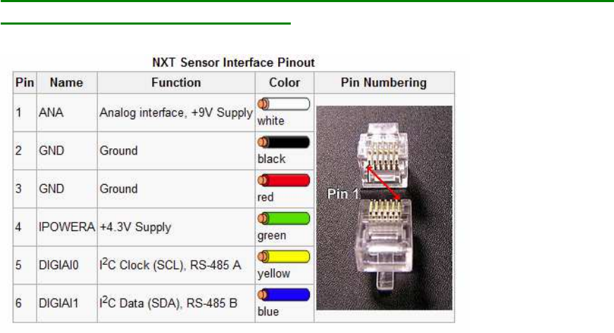
107
while(true) {
sprintf(sbuf, " 0=%6d, 1=%6d, 2=%6d, 3=%6d, 4=%6d, 5=%6d",
motenc[ 0], motenc[ 1], motenc[ 2], motenc[ 3], motenc[ 4], motenc[
5]);
Serial.println(sbuf);
delay(100);
}
}
Pin-Belegung für die Verwendung von Lego Mindstorms RJ11-Steckern:
Encoder auf pins 5+6 (gelb + blau)
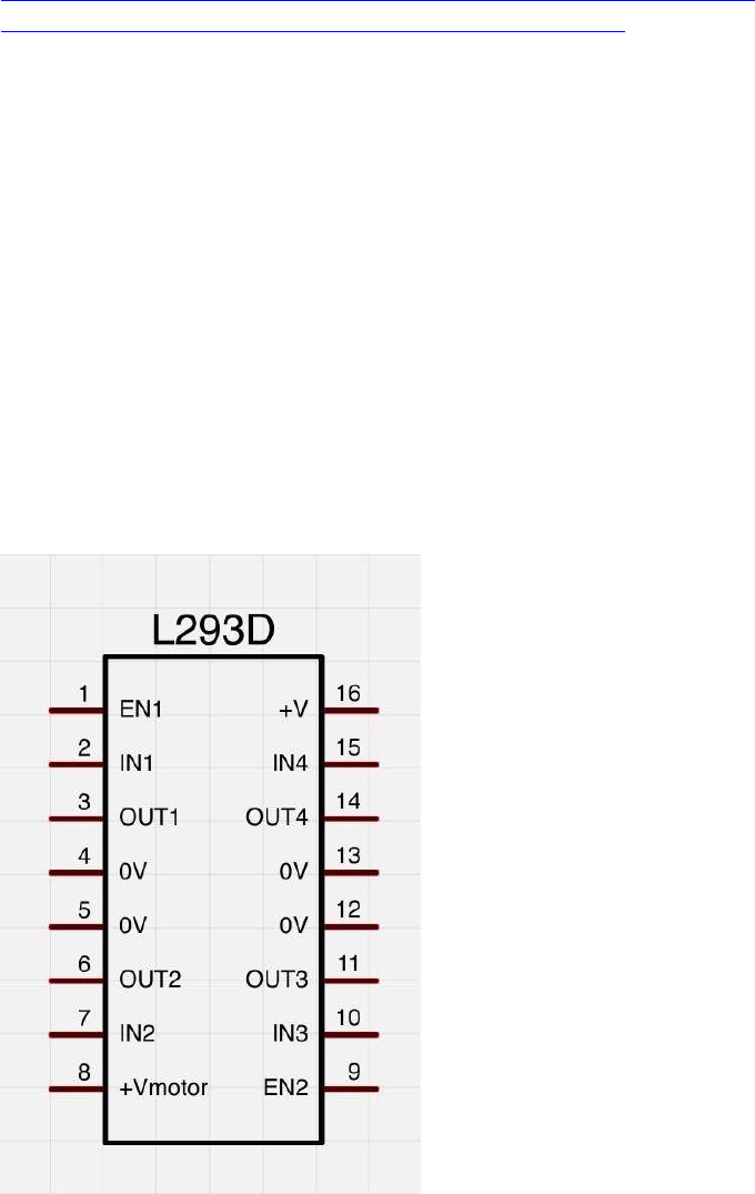
108
Ansteuern von DC (Encoder-) Motoren per L293D H-
Brücke:
L293D doppel-H-Bridge chip:
Die Dokus zu den L293D sind oft ziemlich durcheinander im WeLink s.z.B.
http://www.arduino-tutorial.de/motorsteuerung-mit-einem-h-bridge-ic/
http://microcontrollerslab.com/dc-motor-interfacing-8051/
enable1: pwm Signal Motor1
in1, in2: dig Richtungs-Pins für Motor1
out1, out2: Ausgänge für Motor1
enable2: pwm Signal Motor2
in3, in4: digit. Richtungs-Pins für Motor2
out3, out4: Ausgänge für Motor2
Vcc: 5V vom Arduino
Vc: (V Motor, Borne +): +9...12V von Batterie
GND: Arduino-GND (-) mit Leistungs-Batterie (Borne (-)) verbinden;
im L293D sind alle 4 GND Leitungen bereits intern verbunden, es reicht auf dem Steckbrett
also 1 einziges GND-Verbindungskabel
(verändert, ergänzt)
Quelle: http://img.gunook.com/upload/5/d7/5d79ba256e128ba594184b2b1c6c6ffc.jpg
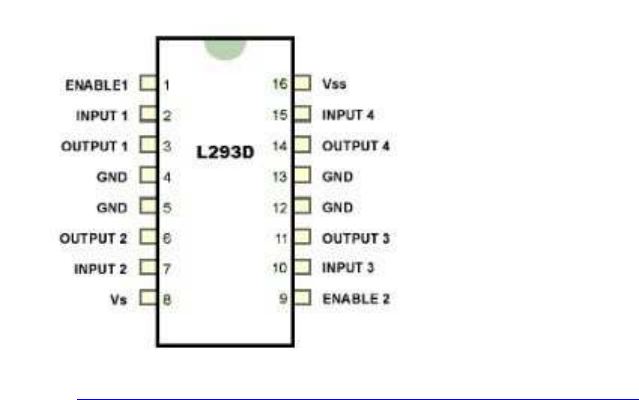
109
Quelle: http://microcontrollerslab.com/dc-motor-interfacing-8051/
IC-Spannungsquelle Vss(Vcc)=5V Leistungsspannungsquelle Vs=z.B. 9-12V
MotorA: Inputs1+2, enable1 pwm, outputs 1+2
MotorB: Inputs 3+4 ,enable2 pwm, outputs 3+4
verfügbare PWM Pins Arduino:
Nano: 3; 5; 6; 9; 10; 11
Uno: 3; 5; 6; 9; 10; 11
Due: 2; 3; 4; 5; 6; 7; 8; 9; 10; 11; 12; 13
Mega 2560: 2; 3; 4; 5; 6; 7; 8; 9; 10; 11; 12; 13
Steuerlogik:
in1(3) in2(4) en1(2)==pwm Funktion
==========================================================
LOW LOW LOW coast
LOW HIGH pwm rechts pwm
HIGH LOW pwm links pwm
HIGH HIGH pwm brake pwm
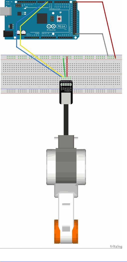
110
Ansteuern von DC-Motoren per L293D H-Brücke:
http://www.arduino-tutorial.de/2010/06/ ... bridge-ic/
// motor Pins motor1
#define motor1_A 11
#define motor1_B 10
#define motor1_Speed 9
// motor Pins motor2
#define motor2_A 5
#define motor2_B 4
#define motor2_Speed 3
111
void setup(){
pinMode(motor1_A, OUTPUT);
pinMode(motor1_B, OUTPUT);
pinMode(motor1_Speed, OUTPUT);
pinMode(motor2_A,OUTPUT);
pinMode(motor2_B,OUTPUT);
pinMode(motor2_Speed, OUTPUT);
}
void loop(){
// motor1
for (int i=0; i>256; i+=5){
digitalWrite(motor1_A,HIGH); // A = HIGH and B = LOW means the motor will turn
right
digitalWrite(motor1_B,LOW);
analogWrite(motor1_Speed,i); // speed counts from 0 to 255
delay(20);
}
for (int i=255; i>0; i-=5){
digitalWrite(motor1_A,HIGH); // A = HIGH and B = LOW means the motor will turn
right
digitalWrite(motor1_B,LOW);
analogWrite(motor1_Speed,i); // speed counts from 0 to 255
delay(20);
}
// motor2
for (int i=0; i<256; i+=5){
digitalWrite(motor2_A,HIGH); // A = HIGH and B = LOW means the motor will turn
right
digitalWrite(motor2_B,LOW);
analogWrite(motor2_Speed,i); // speed counts from 0 to 255
delay(20);
}
for (int i=255; i>0; i-=5){
digitalWrite(motor2_A,HIGH); // A = HIGH and B = LOW means the motor will turn
right
digitalWrite(motor2_B,LOW);
analogWrite(motor2_Speed,i); // speed counts from 0 to 255
delay(20);
}
// turn vice versa
// motor1
for (int i=0; i<256; i+=5){
digitalWrite(motor1_A,LOW); // A = LOW and B = HIGH means the motor will turn
left
digitalWrite(motor1_B,HIGH);
analogWrite(motor1_Speed,i); // speed counts from 0 to 255
delay(20);
}
for (int i=255; i>0; i-=5){
digitalWrite(motor1_A,LOW); // A = LOW and B = HIGH means the motor will turn
left
digitalWrite(motor1_B,HIGH);
analogWrite(motor1_Speed,i); // speed counts from 0 to 255
delay(20);
}
// motor2
for (int i=0; i<256; i+=5){
digitalWrite(motor2_A,LOW); // A = LOW and B = HIGH means the motor will turn
left
digitalWrite(motor2_B,HIGH);
analogWrite(motor2_Speed,i); // speed counts from 0 to 255
delay(20);
}
for (int i=255; i>0; i-=5){

112
digitalWrite(motor2_A,LOW); // A = LOW and B = HIGH means the motor will turn
left
digitalWrite(motor2_B,HIGH);
analogWrite(motor2_Speed,i); // speed counts from 0 to 255
delay(20);
}
}
Pin-Belegung für die Verwendung von Lego Mindstorms RJ11-Steckern:
Motor-Anschlüsse an Pins 1+2 (weiß/schwarz):
Steuer-Logik:
dir 1 dir 2 en/pwm Funktion
===========================================================
LOW LOW ??? coast
LOW HIGH pwm rechts pwm
HIGH LOW pwm links pwm
HIGH HIGH pwm brake pwm
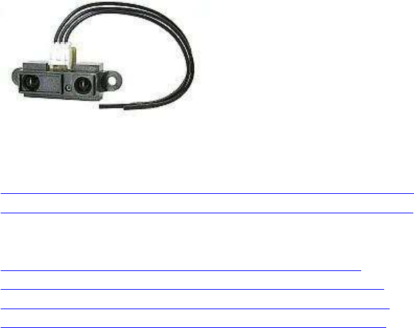
113
(analog) Sharp IR Distanz-Sensoren
GP2D120 ( 4-30cm )
GP2D12 ( 10-80cm )
GP2Y0A21YK0F ( 10-80cm )
Bezugsquellen z.B.
http://www.roboter-teile.de/Oxid/Entfernungsmesser/Infrarot-
Entfernungsmesser/Entfernungsmesser-GP2D12-Analog.html
Quellen:
http://techdelivers.com/index.php?route ... arch=sharp
http://www.trossenrobotics.com/productd ... 21YK0F.pdf
http://www.trossenrobotics.com/productdocs/GP2D12.pdf
http://www.picbasic.co.uk/forum/showthread.php?t=7705
Berechnung der Entfernung
(1) Vs = 1 / ( Dcm + k )
Vs ist die Sensor-Ausgabespannung
Dcm ist die Distanz des Objektes in cm
k sind Konstanten für die jew. Sensoren:
GP2D120: k = 0,42
GP2D12 : k = 4,0
GP2Y0A21YK0F: k = 2,0
<=>
(2) Dcm = (1 / Vs) - k
bei ADC Messung 10bit (ADv = 0...1023) gilt:
(3) Vs = ADv * (Vref/1023) = (ADv*Vref) / 1023
Vs ist die Sensor-Spannung,
Vref die Referenzspannung der MCU (5V oder 3,3V)
ADv ist der ermittelte analoge Sensor-ADC-Wert.
Setzt man (3) in (2) ein, erhält man zur Entfernungsberechnung aus dem
ADC-Wert:
(4) Dcm = ( (1/ADv) * (1023/Vref) ) - k
zum Nacheichen lässt sich optional ein Eichfaktor c gut verwenden:
(5) Dcm = c * ( (1/ADv) * (1023/Vref) ) - k
mit c meist im Bereich 1,0 (+/- 0,3)

114
(analog) Potentiometer-Joystick für
Differentialantriebs-Steuerung
Quelle: http://electronics.stackexchange.com/qu ... otor-drive
Code, um mit einem Potentiometer-Joystick (2 im 90° Winkel übereinandergesetzte Potis)
Roboter mit Differentialantrieb ("Tribot", "Panzer") zu steuern, wobei bei vollem Seiten-
Ausschlag beide Räder/Ketten un entgegengesetzte Richtung drehen (=> drehen auf der
Stelle).
Fehler! Datei kann nicht gelesen oder angezeigt werden.
Code: Alles auswählen
// program Joystick tank-control
//
// ver 0001
// Atmega328p (UNO) based Arduino code,
// tested on:
// - RBBB Arduino clone by Modern Device
// - also works for Arduino Due Clone (ARM Cortex M3, 3.3V reference
voltage)
const byte joysticYA = A0; //Analog Jostick Y axis
const byte joysticXA = A1; //Analog Jostick X axis
const byte controllerFA = 10; //PWM FORWARD PIN for OSMC Controller A (left
motor)
const byte controllerRA = 9; //PWM REVERSE PIN for OSMC Controller A (left
motor)
const byte controllerFB = 6; //PWM FORWARD PIN for OSMC Controller B
(right motor)
const byte controllerRB = 5; //PWM REVERSE PIN for OSMC Controller B
(right motor)
const byte disablePin = 2; //OSMC disable, pull LOW to enable motor
controller
int analogTmp = 0; //temporary variable to store
int throttle, direction = 0; //throttle (Y axis) and direction (X axis)
int leftMotor,leftMotorScaled = 0, oldleftMotorScaled; //left Motor helper
variables
float leftMotorScale = 0;
int rightMotor,rightMotorScaled = 0, oldrightMotorScaled; //right Motor
helper variables
float rightMotorScale = 0;
float maxMotorScale = 0; //holds the mixed output scaling factor
115
int deadZone = 10; //jostick dead zone
void setup() {
//initialization of pins
Serial.begin(115200);
pinMode(controllerFA, OUTPUT);
pinMode(controllerRA, OUTPUT);
pinMode(controllerFB, OUTPUT);
pinMode(controllerRB, OUTPUT);
pinMode(disablePin, OUTPUT);
digitalWrite(disablePin, LOW);
oldleftMotorScaled = 0;
oldrightMotorScaled = 0;
}
void loop() {
//aquire the analog input for Y and rescale the 0..1023 range to -
255..255 range
analogTmp = analogRead(joysticYA);
throttle = (512-analogTmp)/2;
delayMicroseconds(100);
//...and the same for X axis
analogTmp = analogRead(joysticXA);
direction = -(512-analogTmp)/2;
//mix throttle and direction
leftMotor = throttle + direction;
rightMotor = throttle - direction;
//print the initial mix results
Serial.print("LIN:"); Serial.print( leftMotor, DEC);
Serial.print(", RIN:"); Serial.print( rightMotor, DEC);
//calculate the scale of the results in comparision base 8 bit PWM
resolution
leftMotorScale = leftMotor/255.0;
leftMotorScale = abs(leftMotorScale);
rightMotorScale = rightMotor/255.0;
rightMotorScale = abs(rightMotorScale);
Serial.print("| LSCALE:"); Serial.print( leftMotorScale,2);
Serial.print(", RSCALE:"); Serial.print( rightMotorScale,2);
//choose the max scale value if it is above 1
maxMotorScale = max(leftMotorScale,rightMotorScale);
maxMotorScale = max(1,maxMotorScale);
//and apply it to the mixed values
leftMotorScaled = constrain(leftMotor/maxMotorScale,-255,255);
rightMotorScaled = constrain(rightMotor/maxMotorScale,-255,255);
// apply low-pass filter;
leftMotorScaled = 0.9*leftMotorScaled + 0.1*oldleftMotorScaled;
rightMotorScaled = 0.9*rightMotorScaled + 0.1*oldrightMotorScaled;
Serial.print("| LOUT:"); Serial.print( leftMotorScaled);
Serial.print(", ROUT:"); Serial.print( rightMotorScaled);
116
oldleftMotorScaled = leftMotorScaled;
oldrightMotorScaled = rightMotorScaled;
Serial.print(" |");
//apply the results to appropriate uC PWM outputs for the LEFT motor:
if(abs(leftMotorScaled)>deadZone)
{
if (leftMotorScaled > 0)
{
Serial.print("F");
Serial.print(abs(leftMotorScaled),DEC);
analogWrite(controllerRA,0);
analogWrite(controllerFA,abs(leftMotorScaled));
}
else
{
Serial.print("R");
Serial.print(abs(leftMotorScaled),DEC);
analogWrite(controllerFA,0);
analogWrite(controllerRA,abs(leftMotorScaled));
}
}
else
{
Serial.print("IDLE");
analogWrite(controllerFA,0);
analogWrite(controllerRA,0);
}
//apply the results to appropriate uC PWM outputs for the RIGHT motor:
if(abs(rightMotorScaled)>deadZone)
{
if (rightMotorScaled > 0)
{
Serial.print("F");
Serial.print(abs(rightMotorScaled),DEC);
analogWrite(controllerRB,0);
analogWrite(controllerFB,abs(rightMotorScaled));
}
else
{
Serial.print("R");
Serial.print(abs(rightMotorScaled),DEC);
analogWrite(controllerFB,0);
analogWrite(controllerRB,abs(rightMotorScaled));
}
}
else
{
Serial.print("IDLE");
analogWrite(controllerFB,0);
analogWrite(controllerRB,0);
}
Serial.println("");
117
//To do: throttle change limiting, to avoid radical changes of direction
for large DC motors
delay(10);
}

118
Keypad 4x5
Fehler! Datei kann nicht gelesen oder angezeigt werden.
Preis: ca. 2-3 EUR (Ebay)
Lib: Keypad
http://playground.arduino.cc/Code/Keypad#Download
http://playground.arduino.cc/uploads/Code/keypad.zip
Test-Sketch:
(Achtung! Reihen / Spalten hier bei diesem Verkabelungsplan zu diesem Modell vertauscht
(quasi um 90° verdreht) !
Vorteil: die Kabel-Litzen können in derselben Reihenfolge angeklemmt werden, wie sie
herausgeführt werden )
Code: Alles auswählen
#include <Keypad.h>
const byte ROWS = 4; //four rows
const byte COLS = 5; //five columns
char keys[ROWS][COLS] = {
{'L','7','4','1','F' }, // L=Left, F=F1
{'0','8','5','2','G' }, // G=F2
{'R','9','6','3','#'}, // R=Right
{'E','X','D','U','*'} // E=Enter, X=ESC, D=Down, U=Up,
};
byte rowPins[ROWS] = {22, 24, 26, 28}; //connect to the row pinouts of the
keypad
byte colPins[COLS] = {30, 32, 34, 36, 38}; //connect to the column pinouts
of the keypad
Keypad keypad = Keypad( makeKeymap(keys), rowPins, colPins, ROWS, COLS );
void setup(){
Serial.begin(115200);
}
void loop(){
char key = keypad.getKey();
if (key != NO_KEY){
Serial.println(key);
}
}

119
( 1-wire ) DHT11 + DHT22 Humidity & Temperature
Sensor Module
a) DHT11
Lit.:
https://playground.arduino.cc/Main/DHT11Lib
http://www.uugear.com/portfolio/dht11-h ... or-module/
Libraries: u.a.
https://github.com/adafruit/DHT-sensor-library
https://github.com/RobTillaart/Arduino/ ... /DHTstable (AVR, ARM, ESP)
https://github.com/RobTillaart/Arduino/ ... ies/DHTlib (AVR)
Preis: ab 1 EUR (z.B. Ebay)
Power Supply: 3.3~5.5V DC
Output: 3 (4) pin single row
Measurement Range: Humidity 20-90%RH, Temperature 0~50℃
Accuracy: Humidity +-5%RH, Temperature +-2℃
Resolution: Humidity 1%RH, Temperature 1℃
Interchangeability: Fully Interchange
Anschluss-Schema:
Arduino —————————– DHT11 Module
3-5V ———————————– VCC (V)
GND ———————————- GND (G)
Arduino DPin ——————– DATA (S)
Test-Codes:
Adafruit: https://github.com/adafruit/DHT-sensor- ... r/examples
Library: RobTillaart/Arduino: https://github.com/RobTillaart/Arduino/ ... e/examples
dht11_test.ino

120
b) DHT22
Die selben Libs unterstützen auch den DHT22, der einen größeren Messbereich hat:
http://www.mikrocontroller-elektronik.d ... tursensor/
Accuracy resolution: 0.1
Humidity range: 0-100%RH
Temperature range:-40~80°C
Humidity measurement precision:±2%RH
Temperature measurement precision:±0.5℃
Preis: ca. 3 EUR (Ebay)
HINWEIS:
Alternative für DHT11/22:
Adafruit BME280 Humidity + Barometric Pressure + Temperature (i2c) :
https://learn.adafruit.com/adafruit-bme280-humidity-barometric-pressure-temperature-sensor-
breakout/arduino-test

121
I2C (allgemein)
Arduino I2C Internals:
http://www.gammon.com.au/i2c

122
( I2C ) RGB-Farbsensor
TCS230 / TCS3200
Arbeits-/Signalspannung: 3-5 V DC
Preis: ca. 7-10 EUR
Bezugsquellen z.B.:
https://www.google.de/search?q=RGB-Sensor+%22TCS3200%22+&ie=utf-8&oe=utf-
8&gfe_rd=cr&ei=vDRgWJfZE-Sv8wfOwIPIAg#q=RGB-
Sensor+%22TCS3200%22&tbm=shop
http://www.ebay.de/sch/i.html?_odkw=TCS3200+(Farb%2C+Color%2C+Sensor)&_osacat=0
&_nkw=TCS3200+(Farb%2C+Color%2C+Sensor)
Infos + Tutorials:
https://www.sunfounder.com/wiki/index.php?title=Color_Sensor_Module
http://howtomechatronics.com/tutorials/arduino/arduino-color-sensing-tutorial-tcs230-
tcs3200-color-sensor/
https://www.dfrobot.com/wiki/index.php/TCS3200_Color_Sensor_(SKU:SEN0101)
https://arduinoplusplus.wordpress.com/2015/07/15/tcs230tcs3200-sensor-calibration/
123
Code:
/* Arduino Color Sensing Tutorial
*
* by Dejan Nedelkovski, www.HowToMechatronics.com
*
*/
#define S0 4
#define S1 5
#define S2 6
#define S3 7
#define sensorOut 8
int frequency = 0;
void setup() {
pinMode(S0, OUTPUT);
pinMode(S1, OUTPUT);
pinMode(S2, OUTPUT);
pinMode(S3, OUTPUT);
pinMode(sensorOut, INPUT);
// Setting frequency-scaling to 20%
digitalWrite(S0,HIGH);
digitalWrite(S1,LOW);
Serial.begin(9600);
}
void loop() {
// Setting red filtered photodiodes to be read
digitalWrite(S2,LOW);
digitalWrite(S3,LOW);
// Reading the output frequency
frequency = pulseIn(sensorOut, LOW);
// Printing the value on the serial monitor
Serial.print("R= ");//printing name
Serial.print(frequency);//printing RED color frequency
Serial.print(" ");
delay(100);
// Setting Green filtered photodiodes to be read
digitalWrite(S2,HIGH);
digitalWrite(S3,HIGH);
// Reading the output frequency
frequency = pulseIn(sensorOut, LOW);
// Printing the value on the serial monitor
Serial.print("G= ");//printing name
Serial.print(frequency);//printing RED color frequency
Serial.print(" ");
delay(100);
// Setting Blue filtered photodiodes to be read
digitalWrite(S2,LOW);
digitalWrite(S3,HIGH);
// Reading the output frequency
frequency = pulseIn(sensorOut, LOW);
// Printing the value on the serial monitor
Serial.print("B= ");//printing name
Serial.print(frequency);//printing RED color frequency
Serial.println(" ");
delay(100);
}

124
( I2C ) RGB-Farbsensor
Adafruit TCS34725
Hersteller: Adafruit
https://www.adafruit.com/product/1334
Interface: I2C
Arbeits-/Signalspannung: 3-5 V DC
Preis:: Original Adafruit ca. 10 EUR, China-Klone ab ca. 4 EUR
Tutorial: https://learn.adafruit.com/adafruit-col ... s/overview
Arduino Library: https://github.com/adafruit/Adafruit_TCS34725

125
Ultraschall Sensoren
HC-SR04
Achtung:
VCC: +5V DC !
Lit.:
https://create.arduino.cc/projecthub/Isaac100/getting-started-with-the-hc-sr04-ultrasonic-
sensor-036380
https://www.mikrocontroller-elektronik.de/ultraschallsensor-hc-sr04/
https://funduino.de/nr-10-entfernung-messen
/*
* hc-sr04 example sketch
*
* https://create.arduino.cc/projecthub/Isaac100/getting-started-with-the-
hc-sr04-ultrasonic-sensor-036380
*
* by Isaac100
* verändert + ergänzt: 2018-08-22 by HaWe
*
*/
const int trigPin = 9;
const int echoPin = 10;
float duration, distance;
void setup() {
pinMode(trigPin, OUTPUT);
pinMode(echoPin, INPUT);
Serial.begin(9600);
}
void loop() {
double dTemp = 0.0;
double Temp = 20.0;
double sonicspeed;
dTemp = Temp - 20.0 ; // optional: temperat. by thermometer
<<<<<<<<<<
sonicspeed = 343.421 + (dTemp * 0.576); // optional: temperat. compens.
digitalWrite(trigPin, LOW);
delayMicroseconds(2);
digitalWrite(trigPin, HIGH);
126
delayMicroseconds(10);
digitalWrite(trigPin, LOW);
duration = pulseIn(echoPin, HIGH);
distance = (duration * sonicspeed) / 20000.0;
Serial.print("Distance: ");
Serial.println(distance);
delay(100);
}

127
Ultraschall Sensoren
(I2C) Devantech SRF-02 und SRF-08
Interface: I2C
Bezugsquellen:
z.B.:
http://www.exp-tech.de/srf02-ultrasonic-ranger
http://www.exp-tech.de/srf08-high-perfo ... ger-finder
Source Codes und Treiber :
http://playground.arduino.cc/Main/SonarSrf08
https://github.com/LeoColomb/Arduino-SRF
SRF02 : http://www.robot-electronics.co.uk/htm/srf02tech.htm
SRF08 : http://www.robot-electronics.co.uk/htm/srf08tech.html
Link zu Arduino sources: http://www.robot-electronics.co.uk/htm/ ... amples.htm
Link zu Raspberry Pi sources: http://www.robot-electronics.co.uk/htm/ ... amples.htm
Beispiel für SRF-08 mit der oben verlinkten github-Lib:
Code: Alles auswählen
//
// SonarSRF08
// Arduino Library for controlling SRF sonar sensors
// http://www.arduino.cc/playground/Main/SonarSrf08
//
// MIT License
// Copyright(c) 2009 Zach Foresta
// Copyright(c) 2012 Philipp A. Mohrenweiser
// Copyright(c) 2012-2016 Leo Colombaro
//
#include <Wire.h>
#include <SonarSRF08.h>
#define MAIN_08_ADDRESS (0xF8 >> 1)
// Setup Analogue Gain
128
// http://www.robot-electronics.co.uk/htm/srf08tech.html section "Analogue
Gain"
#define GAIN_REGISTER 0x09
// Setup Range Location
// http://www.robot-electronics.co.uk/htm/srf08tech.html section "Changing
the Range"
#define LOCATION_REGISTER 0x8C
SonarSRF08 MainSonar(MAIN_08_ADDRESS, GAIN_REGISTER, LOCATION_REGISTER);
char unit = 'c'; // 'i' for inches, 'c' for centimeters, 'm' for micro-
seconds
void setup() {
Serial.begin(9600);
MainSonar.begin();
isConnected("SRF08", MainSonar.readVersion());
}
void loop() {
distance("SRF08", MainSonar.readRange(unit));
}
// Print out distance
void distance(String reference, int sensorReading) {
Serial.print("Distance from " + reference + ": ");
Serial.print(sensorReading);
Serial.println(unit);
}
// Print out distance
void isConnected(String reference, int sensorSoft) {
if (sensorSoft >= 0) {
Serial.print("Sensor " + reference + " connected (");
Serial.print(sensorSoft);
Serial.println(")");
}
else {
Serial.println("Sensor " + reference + " not detected...");
}
}

129
(I2C + UART) IMU-Sensor: CMPS11
Protokoll: I2C, alternativ auch UART
Spannung/Level: 3-5 V kompatibel
Preis: ca. 25 - 30 EUR
Bezugsquellen z.B.:
Roboter-Teile Jörg Pohl, http://www.roboter-teile.de
http://de.manu-systems.com/CMPS11.shtml
http://www.hobbytronics.co.uk/cmps11-tilt-compass
http://www.roboter-teile.de/Oxid/Navigation/Kompassmodul-CMPS11.html
Treiber-Library:
Arduino-I2C-lib: einbinden per #include <Wire.h>
bzw Serial() für UART (standardmäßig bereits immer eingebunden)
Example: http://www.robot-electronics.co.uk/file ... 11_I2C.ino
Datenblatt:
http://www.robot-electronics.co.uk/htm/cmps11I2C.htm
(Inzwischen a.V., Nachfolger: CMPS12 :
http://www.hobbytronics.co.uk/cmps-12-tilt-compass?keyword=CMPS12 )
Besonderheiten:
IMU Sensor mit 3D-Gyro, 3D-Kompass, 3D-Accelerometer, Temperatur-kompensiert
Integrierte Sensor-Fusion per eingebautem Kalman-Filter
Ausgabe des gefilterten Kurses oder auch aller einzelnen Sensor-raw-Daten
einfaches Auslesen von I2C-Registern für Kurs (Kompasskurs, heading), Neigung (pitch) und
Schräglage (roll).
Keine komplizierten Umrechnungen mehr nötig!
130

131
CMPS11 Example Code:
http://www.robot-electronics.co.uk/htm/cmps11i2c.htm
Beispiel-Sketch für CMPS10 und CMPS11, Ausgabe auf UTFT-Display:
/******************************************************************
* Arduino CMPS11 example code *
* CMPS11 running I2C mode *
* by James Henderson, 2012 *
*******************************************************************/
// verändert & angepasst für UTFT-Displays von Helmut Wunder, 2015
// (C) CMPS10/CMPS11 code by James Henderson
// (C) UTFT Display Driver Lib by Henning Karlsen
// keine freie Verwendung für kommerzielle Zwecke,
// Code frei zur privaten Nutzung gemäss
// Creative Commons Attribution-NonCommercial-ShareAlike 3.0 Unported
License
// http://creativecommons.org/licenses/by-nc-sa/3.0/
// Urheberrechte von J. Henderson und H. Karlsen bleiben unberührt
#include <UTFT.h>
#include <Wire.h>
#define ADDR_CMPS11 0x60 // Defines
address of CMPS11
//=========================================================================
// TFT LCD
//=========================================================================
#define UTFT_CSpin 52 // <<<<<<<< adjust!
// set LCD TFT type
int16_t LCDTYPE = -1;
#define __UTFT__ 4 // Henning Karlsen UTFT 2.2-2.4" 220x176 -
320x240 lib
//
http://henningkarlsen.com/electronics/library.php?id=51
//-------------------------------------------------------------------------
//UTFT myGLCD(Model, SDA=MOSI, SCL, CS, RESET, RS) // Due: 3
exposed SS pins: 4,10,52
UTFT myGLCD(QD220A, 50, 49, UTFT_CSpin, 0, 51); // A0->Vc
(LED), A4->BoardReset
extern uint8_t SmallFont[];
//-------------------------------------------------------------------------
int16_t fontwi= 8, fonthi=10;
int16_t _curx_, _cury_; // last x,y cursor pos on TFT
screen
void lcdcls() {
if(LCDTYPE==__UTFT__) { myGLCD.clrScr(); _curx_ =0; _cury_ =0; }
}
void lcdprintxy(int16_t x, int16_t y, char * str) {
if(LCDTYPE==__UTFT__) { myGLCD.print(str,x,y);
_curx_=x+strlen(str)*fontwi; _cury_=y; }
}
132
//=========================================================================
void setup() {
char sbuf[128];
Serial.begin(115200);
Wire.begin(); // Conects I2C
// TFT LCD
Serial.println();
LCDTYPE = __UTFT__ ; // set LCD-Type
Serial.println("init LCD...");
myGLCD.InitLCD();
myGLCD.setFont(SmallFont);
lcdcls();
sprintf(sbuf, "CMPS11 Example V: %d", soft_ver()); // Display software
version of the CMPS11
lcdprintxy( 0, 0, sbuf);
}
//=========================================================================
int soft_ver(){
int data; // Software version of
CMPS11 is read into data and then returned
Wire.beginTransmission(ADDR_CMPS11);
// Values of 0 being sent with write masked as a byte to be not
misinterpreted as NULL
// (bug in arduino 1.0)
Wire.write((byte)0); // Sends the register we
wish to start reading from
Wire.endTransmission();
Wire.requestFrom(ADDR_CMPS11, 1); // Request byte from
CMPS11
while(Wire.available() < 1);
data = Wire.read();
return(data);
}
//=========================================================================
void display_data(float b, int p, int r){ // pitch and roll (p, r) are
recieved as ints (signed values)
char sbuf[128];
sprintf(sbuf, "heading = %6.2f", b);
lcdprintxy( 0,20, sbuf);
sprintf(sbuf, "Pitch = %6d", p);
lcdprintxy( 0,30, sbuf);
sprintf(sbuf, "Roll = %6d", r);
lcdprintxy( 0,40, sbuf);

133
}
//=========================================================================
void loop(){
uint8_t HdgHibyte, HdgLobyte; // HdgHibyte and HdgLobyte
store high and low bytes of the heading
int8_t pitch, roll; // Stores pitch and roll values
of CMPS11 (signed char value)
float fheading; // Stores full heading (float)
char sbuf[128];
Wire.beginTransmission(ADDR_CMPS11); //starts communication with
CMPS11
Wire.write(2); //Sends the register we wish to
start reading from
Wire.endTransmission();
Wire.requestFrom(ADDR_CMPS11, 4); // Request 4 bytes from CMPS11
while(Wire.available() < 4); // Wait for bytes to become
available
HdgHibyte = Wire.read();
HdgLobyte = Wire.read();
pitch = Wire.read();
roll = Wire.read();
fheading = ( (float)(HdgHibyte<<8) + (float)HdgLobyte )/10.0; //
heading (float)
display_data(fheading, pitch, roll); // Display data to the LCD
delay(10);
}
//=========================================================================
//=========================================================================
Register-Belegung:
Register Function
0 Command register (write) / Software version (read)
1 Compass Bearing 8 bit, i.e. 0-255 for a full circle
2,3 Compass Bearing 16 bit, i.e. 0-3599, representing 0-359.9 degrees.
register 2 being the high byte
4 Pitch angle - signed byte giving angle in degrees from the horizontal plane,
Kalman filtered with Gyro
5 Roll angle - signed byte giving angle in degrees from the horizontal plane,
Kalman filtered with Gyro
6,7 Magnetometer X axis raw output, 16 bit signed integer with register 6 being
the upper 8 bits
8,9 Magnetometer Y axis raw output, 16 bit signed integer with register 8 being
the upper 8 bits
134
10,11 Magnetometer Z axis raw output, 16 bit signed integer with register 10 being
the upper 8 bits
12,13 Accelerometer X axis raw output, 16 bit signed integer with register 12
being the upper 8 bits
14,15 Accelerometer Y axis raw output, 16 bit signed integer with register 14
being the upper 8 bits
16,17 Accelerometer Z axis raw output, 16 bit signed integer with register 16
being the upper 8 bits
18,19 Gyro X axis raw output, 16 bit signed integer with register 18 being the
upper 8 bits
20,21 Gyro Y axis raw output, 16 bit signed integer with register 20 being the
upper 8 bits
22,23 Gyro Z axis raw output, 16 bit signed integer with register 22 being the
upper 8 bits
24,25 Temperature raw output, 16 bit signed integer with register 24 being the
upper 8 bits
26 Pitch angle - signed byte giving angle in degrees from the horizontal plane
(no Kalman filter)
27 Roll angle - signed byte giving angle in degrees from the horizontal plane
(no Kalman filter)

135
Calibration:
https://forum.sparkfun.com/viewtopic.php?f=42&t=43026&sid=c52d771f187393e61a47741576fa1eca&start=15
#p197341
http://www.robot-electronics.co.uk/htm/cmps11i2c.htm
Full calibration:
First of all you need to enter the calibration mode by sending a 3 byte sequence of
0xF0, 0xF5 and then 0xF6
to the command register
Horizontal calibration:
First of all you need to enter the calibration mode by sending a 3 byte sequence of
0xF0, 0xF5 and then 0xF7
to the command register
Calibration example code:
// CMPS11 calibration example
#include <Wire.h>
#define ADDRESS 0x60
void setup(){
Wire.begin();
Serial.begin(9600);
calibrate();
}
void loop(){
}
void calibrate(){
Serial.println("Calibration Mode");
delay(2000); //2 second before starting
Serial.println("Start");
Wire.beginTransmission(ADDRESS);
Wire.write(0); //command register
Wire.write(0xF0);
Wire.endTransmission();
delay(25);
Wire.beginTransmission(ADDRESS);
Wire.write(0); //command register
Wire.write(0xF5);
Wire.endTransmission();
delay(25);
Wire.beginTransmission(ADDRESS);
Wire.write(0); //command register
Wire.write(0xF6); //
Wire.endTransmission();
delay(20000);
Wire.beginTransmission(ADDRESS);
Wire.write(0); //command register
Wire.write(0xF8);
Wire.endTransmission();
Serial.println("done");
}

136
CMPS11 Dokumentation:
http://www.hobbytronics.co.uk/cmps11-tilt-compass
http://www.robot-electronics.co.uk/htm/cmps11i2c.htm
I2C Communication
I2C communication protocol with the compass module is the same as popular eeprom's such as the 24C04. First
send a start bit, the module address with the read/write bit low, then the register number you wish to read. This is
followed by a repeated start and the module address again with the read/write bit high. You now read one or two
bytes for 8bit or 16bit registers respectively. 16bit registers are read high byte first. The compass has a 28 byte
array of registers. organized as below:
Register Function
0 Command register (write) / Software version (read)
1 Compass Bearing 8 bit, i.e. 0-255 for a full circle
2,3 Compass Bearing 16 bit, i.e. 0-3599, representing 0-359.9 degrees. register 2 being the high byte
4 Pitch angle - signed byte giving angle in degrees from the horizontal plane, Kalman filtered with
Gyro
5 Roll angle - signed byte giving angle in degrees from the horizontal plane, Kalman filtered with
Gyro
6,7 Magnetometer X axis raw output, 16 bit signed integer with register 6 being the upper 8 bits
8,9 Magnetometer Y axis raw output, 16 bit signed integer with register 8 being the upper 8 bits
10,11 Magnetometer Z axis raw output, 16 bit signed integer with register 10 being the upper 8 bits
12,13 Accelerometer X axis raw output, 16 bit signed integer with register 12 being the upper 8 bits
14,15 Accelerometer Y axis raw output, 16 bit signed integer with register 14 being the upper 8 bits
16,17 Accelerometer Z axis raw output, 16 bit signed integer with register 16 being the upper 8 bits
18,19 Gyro X axis raw output, 16 bit signed integer with register 18 being the upper 8 bits
20,21 Gyro Y axis raw output, 16 bit signed integer with register 20 being the upper 8 bits
22,23 Gyro Z axis raw output, 16 bit signed integer with register 22 being the upper 8 bits
24,25 Temperature raw output, 16 bit signed integer with register 24 being the upper 8 bits
26 Pitch angle - signed byte giving angle in degrees from the horizontal plane (no Kalman filter)
27 Roll angle - signed byte giving angle in degrees from the horizontal plane (no Kalman filter)
Register 0 is a dual action register, in the event of a read the CMPS11 will reply with the software version, for a write it acts
as the command register and is used to calibrate the compass, change address and if necessary restore the factory default
calibration.
Register 1 is the bearing converted to a 0-255 value, this may be easier for some applications than 0-3599 which requires two
bytes.
For those who require better resolution registers 2 and 3 (high byte first) form a 16 bit unsigned integer in the range 0-3599.
This represents 0-359.9°.
Register 4 is the pitch angle, giving an angle of 0 when the board is flat and up to +/- 85° at maximum tilt in either direction
and also features a Kalman filter that uses the gyro sensor to reduce errors caused by unwanted acceleration effects (such as
shake).
Register 5 works the same way but with results for the Roll angle.
There is then an array of registers (6-25) providing all the raw sensor data from the magnetic and acceleration sensors.
Finally we have included the pitch and roll angle with no Kalman filter in registers 26 and 27.
The raw output values in registers 6-25 are exactly what we get from the LSM9DS0 sensor chip, customers wishing to make
use of these should consult the ST data sheet for further information.
i2c: Calibration of the CMPS11
Please do not do this until you have I2C communication fully working.
I would recommend evaluating the CMPS11 performance first before implementing this function.
Its purpose is to remove sensor gain and offset of both magnetometer and accelerometer
and achieves this by looking for maximum sensor outputs.
First of all you need to enter the calibration mode by sending a 3 byte sequence of
0xF0,0xF5 and then 0xF6
to the command register, these MUST be sent in 3 separate I2C frames,
you cannot send them all at once. There MUST be a minimum of 20ms between each I2C frame.
An I2C frame is [start sequence] [I2C address] [register address] [command byte] [stop sequence].
The LED will then extinguish and the CMPS11 should now be rotated in all directions in 3 dimensions,
if a new maximum for any of the sensors is detected then the LED will flash,
when you cannot get any further LED flashes in any direction then exit the calibration mode
with a command of 0xF8.
Please make sure that the CMPS11 is not located near to ferrous objects as this will distort
the magnetic field and induce errors in the reading. While calibrating rotate the compass slowly.
Remember the axis of the magnetic field is unlikely to be horizontal, it dips into the earth

137
at an angle which varies depending on your location. At our offices in the UK it dips into the earth
at 67 degrees and that is the orientation each axis of the compass needs to be to find the maximums.
You need to find both positive and negative maximums for each axis so there are 6 points to calibrate.
The accelerometer is also calibrated at the same time, so the module should also be positioned horizontal,
inverted, and on all 4 sides to calibrate the 6 accelerometer points. Each accelerometer point needs
to be stable for 200mS for its reading to be used for calibration.
This delay is deliberate so that light taps to the module do not produces disruptive accelerometer readings
which would mess up the pitch and roll angles. There is no delay for the magnetic points.
The performance of the module is directly related to how well you perform calibration
so do this slowly and carefully.
i2c: Calibration of the CMPS11 for horizontal only operation
If the compass does not require the tilt compensation then a simple calibration may be used that can be
implemented by a rotation on the horizontal plane only.
First of all you need to enter the horizontal calibration mode by sending a 3 byte sequence of
0xF0,0xF5 and then 0xF7
to the command register, these MUST be sent in 3 separate I2C frames, you cannot send them all at once. There
MUST be a minimum of 20ms between each I2C frame. The LED will then extinguish and the CMPS11 should
now be rotated in all directions on a horizontal plane, if a new maximum for any of the sensors is detected then
the LED will flash, when you cannot get any further LED flashes in any direction then exit the calibration mode
with a command of 0xF8. Please make sure that the CMPS11 is not located near to ferrous objects as this will
distort the magnetic field and induce errors in the reading. While calibrating rotate the compass slowly. Only the
X and Y magnetometer axis are calibrated in this mode.
i2c: Restoring Factory Calibration
Should you need to revert to the factory calibration then write the following to the command register in 3
separate transactions with 20ms between each transaction: 0x20,0x2A,0x60. These commands must be sent in
the correct sequence to restore the calibration, additionally, No other command may be issued in the middle of
the sequence. The sequence must be sent to the command register at location 0, which means 3 separate write
transactions on the I2C bus. (A write transaction is [start sequence] [I2C address] [register address] [command
byte] [stop sequence] then a 20mS delay).
Changing the I2C Bus Address
To change the I2C address of the CMPS11 you must have only one module on the bus. Write the 3 sequence
commands in the correct order followed by the address with 100ms between writes. Example; to change the
address of a compass currently at 0xC0 (the default shipped address) to 0xC2, write the following to address
0xC0; (0xA0, 0xAA, 0xA5, 0xC2 ) with a 100ms delay after each of the first three bytes. These commands must
be sent in the correct sequence to change the I2C address, additionally, No other command may be issued in the
middle of the sequence. The sequence must be sent to the command register at location 22, which means 4
separate write transactions on the I2C bus. When done, you should label the CMPS11 with its address, however
if you do forget, just power it up without sending any commands. The CMPS11 will flash its address out on the
LED, one long flash followed by a number of shorter flashes indicating its address. The flashing is terminated
immediately on sending a command the CMPS11.
Address Long Flash Short flashes
Decimal Hex
192 C0 1 0
194 C2 1 1
196 C4 1 2
198 C6 1 3
200 C8 1 4
202 CA 1 5
204 CC 1 6
206 CE 1 7
Take care not to set more than one device to the same address, there will be a bus collision and very
unpredictable results.
Serial Communication
The Serial mode operates over a link with a default baud rate of 9600 bps (no parity, 2 stop bits) and 3.3v-5v
signal levels.
138
This is not RS232. Do not connect RS232 to the module, the high RS232 voltages will irreversibly damage the
module.
Serial Commands
Below is a table describing commands that can be sent to the CMPS11 and the data it will respond with.
Command Name Bytes returned
Returned data description
0x11 GET VERSION 1 Software version
0x12 GET ANGLE 8 BIT 1 Angle as a single byte 0-255
0x13 GET ANGLE 16 BIT 2 Angle as two bytes, high byte first 0-3599
0x14 GET PITCH 1 Pitch angle +/- 0-85° Kalman filtered
0x15 GET ROLL 1 Roll angle +/- 0-85° Kalman filtered
0x16 GET PITCH NO KAL 1 Pitch angle +/- 0-85° no Kalman filter
0x17 GET ROLL NO KAL 1 Roll angle +/- 0-85° no Kalman filter
0x19
GET MAG RAW 6 Raw magnetic data, 16 bit signed: X high, X low, Y high, Y low, Z high, Z
low
0x20 GET ACCEL RAW 6 Raw accelerometer data, 16 bit signed: X high, X low, Y high, Y low, Z
high, Z low
0x21 GET GYRO RAW 6 Raw gyro data, 16 bit signed: X high, X low, Y high, Y low, Z high, Z low
0x22 GET TEMP 2 Temperature as two bytes, high byte first 0. Typical resolution 8 LSB/°C
0x23 GET ALL 4 angle high, angle low (0-3599), pitch (+/- 0-85), roll (+/- 0-85)
0xF0 CALIBRATE BYTE 1 1 returns ok (0x55)
0xF5 CALIBRATE BYTE 2 1 returns ok (0x55)
0xF6 CALIBRATE BYTE 3 FULL 1 returns ok (0x55)
0xF7 CALIBRATE BYTE 3 FLAT 1 returns ok (0x55)
0xF8 CALIBRATE EXIT 1 returns ok (0x55)
0x6A RESTORE 1 1 returns ok (0x55)
0x7C RESTORE 2 1 returns ok (0x55)
0x81 RESTORE 3 1 returns ok (0x55)
0xA0 BAUD 19200 1 returns ok (0x55)
0xA1 BAUD 38400 1 returns ok (0x55)
Serial calibration of the CMPS11
Please do not do this until you have serial communication fully working. I would recommend evaluating the
CMPS11 performance first before implementing this function. Its purpose is to remove sensor gain and offset of
both magnetometer and accelerometer and achieves this by looking for maximum sensor outputs. First of all you
need to enter the calibration mode by sending a 3 byte sequence of 0xF0,0xF5 and then 0xF6 (reading the
acknowledge byte after each one). The LED will then extinguish and the CMPS11 should now be rotated in all
directions in 3 dimensions, if a new maximum for any of the sensors is detected then the LED will flash, when
you cannot get any further LED flashes in any direction then exit the calibration mode with a command of 0xF8.
Please make sure that the CMPS11 is not located near to ferrous objects as this will distort the magnetic field and
induce errors in the reading. While calibrating rotate the compass slowly. Remember the axis of the magnetic
field is unlikely to be horizontal, it dips into the earth at an angle which varies depending on your location. At
our offices in the UK it dips into the earth at 67 degrees and that is the orientation each axis of the compass
needs to be to find the maximums. You need to find both positive and negative maximums for each axis so there
are 6 points to calibrate. The accelerometer is also calibrated at the same time, so the module should also be
positioned horizontal, inverted, and on all 4 sides to calibrate the 6 accelerometer points. Each accelerometer
point needs to be stable for 200mS for its reading to be used for calibration. This delay is deliberate so that light
taps to the module do not produces disruptive accelerometer readings which would mess up the pitch and roll
angles. There is no delay for the magnetic points. The performance of the module is directly related to how well
you perform calibration so do this slowly and carefully.
Serial calibration of the CMPS11 for horizontal only operation
If the compass does not require the tilt compensation then a simple calibration may be used that can be
implemented by a rotation on the horizontal plane only. First of all you need to enter the calibration mode by
sending a 3 byte sequence of 0xF0,0xF5 and then 0xF7 (reading the acknowledge byte after each one). The LED
will then extinguish and the CMPS11 should now be rotated in all directions on a horizontal plane, if a new
139
maximum for any of the sensors is detected then the LED will flash, when you cannot get any further LED
flashes in any direction then exit the calibration mode with a command of 0xF8. Please make sure that the
CMPS11 is not located near to ferrous objects as this will distort the magnetic field and induce errors in the
reading. While calibrating rotate the compass slowly. Only the X and Y magnetometer axis are calibrated in this
mode.
Restore of factory Serial calibration of the CMPS11
To perform a restore of the factory calibration write a sequence of 3 commands in the correct order. The
sequence is 0x6A,0x7C,0x81 (reading the acknowledge byte after each one).
Changing the baud rate
The default serial baud rate of 9600 can be changed. There are two other baud rates that can be used, for 19200
just send 0xA0 or alternatively for 38400 send 0xA1. Please note that the CMPS11 will always default to its
9600 bps rate after power cycling and after setting a new baud rate the ok response (0x55) will be sent at the
newly selected speed.
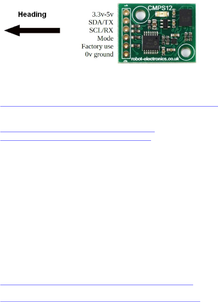
140
(I2C + UART) IMU-Sensor CMPS12
(Nachfolger des CMPS11 )
http://www.hobbytronics.co.uk/cmps-12-tilt-compass?keyword=CMPS12
Dokumentation:
http://www.robot-electronics.co.uk/files/cmps12.pdf
https://de.manu-systems.com/DEV-CMPS12.shtml
CMPS12
Versorgungsspannung 3,3V - 5V
Stromstärke 18mA Typ.
Auflösung 0,1 Grad
Genauigkeit Nach Kalibrierung besser als 1%
Signalspannungen 3,3V und 5V tolerant
I2C Modus bis 400khz
Serieller Modus 9600, 19200, 38400 baud
Beim Startenn des CMPS12 wird anhand des Modus-Pins festgelegt, ob das Modul im
seriellen oder I2C-Modus arbeiten soll. Wenn das Pin mit Masse verbunden ist, wird der
serielle Modus ausgewählt, falls es offen oder mit der Versorgungspannung verbunden ist,
wird I2C-Modus ausgewählt.
Beispiel-Code I2C:
http://www.robot-electronics.co.uk/files/arduino_cmps12_i2c.ino
Beispiel-Code UART:
http://www.robot-electronics.co.uk/files/arduino_cmps12_serial.ino
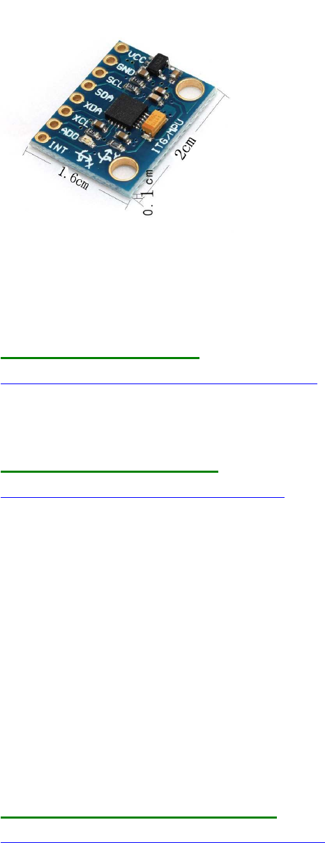
141
(I2C) MPU6050 6D IMU
Libraries:
1.) Arduino Playground
https://playground.arduino.cc/Main/MPU-6050
Code / Features: Kein yaw, pitch, roll, nur Basics
2.) tockn/MPU6050_tockn
https://github.com/tockn/MPU6050_tockn
Code / Features: Kein yaw, pitch, roll
Serial.print("temp : ");Serial.println(mpu6050.getTemp());
Serial.print("accX : ");Serial.print(mpu6050.getAccX());
Serial.print("\taccY : ");Serial.print(mpu6050.getAccY());
Serial.print("\taccZ : ");Serial.println(mpu6050.getAccZ());
Serial.print("gyroX : ");Serial.print(mpu6050.getGyroX());
Serial.print("\tgyroY : ");Serial.print(mpu6050.getGyroY());
Serial.print("\tgyroZ : ");Serial.println(mpu6050.getGyroZ());
Serial.print("accAngleX : ");Serial.print(mpu6050.getAccAngleX());
Serial.print("\taccAngleY : ");Serial.println(mpu6050.getAccAngleY());
Serial.print("gyroAngleX : ");Serial.print(mpu6050.getGyroAngleX());
Serial.print("\tgyroAngleY : ");Serial.print(mpu6050.getGyroAngleY());
Serial.print("\tgyroAngleZ : ");Serial.println(mpu6050.getGyroAngleZ());
Serial.print("angleX : ");Serial.print(mpu6050.getAngleX());
Serial.print("\tangleY : ");Serial.print(mpu6050.getAngleY());
Serial.print("\tangleZ : ");Serial.println(mpu6050.getAngleZ());
3.) TKJElectronics/KalmanFilter
https://github.com/TKJElectronics/KalmanFilter
Code / Features: Kalman Filer opt., kein yaw, aber roll + pitch
Serial.print(accX); Serial.print("\t");

142
Serial.print(accY); Serial.print("\t");
Serial.print(accZ); Serial.print("\t");
Serial.print(gyroX); Serial.print("\t");
Serial.print(gyroY); Serial.print("\t");
Serial.print(gyroZ); Serial.print("\t");
Serial.print(roll); Serial.print("\t");
Serial.print(gyroXangle); Serial.print("\t");
Serial.print(compAngleX); Serial.print("\t");
Serial.print(kalAngleX); Serial.print("\t");
Serial.print(pitch); Serial.print("\t");
Serial.print(gyroYangle); Serial.print("\t");
Serial.print(compAngleY); Serial.print("\t");
Serial.print(kalAngleY); Serial.print("\t");
4.) jrowberg/i2cdevlib
MPU6050 lib https://github.com/jrowberg/i2cdevlib/tree/master/Arduino/MPU6050
example
https://github.com/jrowberg/i2cdevlib/blob/master/Arduino/MPU6050/examples/MPU6050_
DMP6/MPU6050_DMP6.ino
Code / Features: Compile error
MPU6050_DMP6_002:279: error: '_BV' was not declared in this scope

143
(I2C) Real Time Clock RTC DS3231
Quelle: http://tronixstuff.com/2014/12/01/tutorial-using-ds1307-and-ds3231-real-time-clock-
modules-with-arduino/
Protokoll: I2C
Spannung/Level: 3-5 V kompatibel
Preis: ca. 1,00 - 4,00 EUR
Treiber-Library:
Arduino-I2C-lib: ausschließlich <Wire.h> (standardmäßig in Arduino-Sketch enthalten)
Beispielsketch s.u.! (aus http://tronixstuff.com/2014/12/01/tutor ... h-arduino/ )
Bezugsquellen z.B.:
div. chinesische Anbieter (Ebay), Eckstein u.a.m.
Besonderheiten:
Beim 1. Aufruf muss die Zeit aktuell gesetzt werden (s. im Code, in Setup():
Code: Alles auswählen
setDS3231time(0,42,20,2,13,07,15); // Montag, 20:42:00 Uhr 13.07.15
bei den folgenden Aufrufen bleibt die Startzeit im EEPROM Batterie-gepufert gespeichert
und braucht dann natürlich nicht mehr neu gesetzt werden
(Zeile wieder auskommentieren und dann ein 2. Mal hochladen!)
Beispiel-Sketch zum Initialisieren und Auslesen, Ausgabe über USB-Serial():
Code: Alles auswählen
#include "Wire.h"
#define ADDR_RTCDS3231 0x68
//=========================================================================
// Convert normal decimal numbers to binary coded decimal
//=========================================================================
byte decToBcd(byte val) { return( (val/10*16) + (val%10) ); }
//=========================================================================
// Convert binary coded decimal to normal decimal numbers
//=========================================================================
byte bcdToDec(byte val) { return( (val/16*10) + (val%16) ); }
//=========================================================================
144
void displayTime()
{
byte second, minute, hour, dayOfWeek, dayOfMonth, month, year;
// retrieve data from DS3231
readDS3231time(&second, &minute, &hour, &dayOfWeek, &dayOfMonth, &month,
&year);
// send it to the serial monitor
Serial.print(hour, DEC);
// convert the byte variable to a decimal number when displayed
Serial.print(":");
if (minute<10)
{
Serial.print("0");
}
Serial.print(minute, DEC);
Serial.print(":");
if (second<10)
{
Serial.print("0");
}
Serial.print(second, DEC);
Serial.print(" ");
Serial.print(dayOfMonth, DEC);
Serial.print("/");
Serial.print(month, DEC);
Serial.print("/");
Serial.print(year, DEC);
Serial.print(" Day of week: ");
switch(dayOfWeek){
case 1:--

145
Real Time Clock RTC DS3231 mit Anzeige auf LCD1602 Display
hier ein Codebeispiel für alle, die sich mit der RTC und dem LCD1602 schwer tun (so wie ich
bis jetzt)
(s.a. viewtopic.php?f=78&t=8491&p=66090#p69998 ) :
Uhrzeit und Datum per RTC DS3231
Anzeige auf LCD1602
MCU: Arduino Mega,
Hinweis: besonderer LCD Verkabelungsplan (hält Pins 0-13 und SPI pins frei!) !
share and enjoy!
Code: Alles auswählen
/*
Display LiquidCrystal Library
plus
real-time clock RTC-DS3231
Demonstrates the use a 16x2 LCD 1602
to display the values of a real-time clock RTC-DS3231
The circuit:
* LCD pin 1 (VSS) to +5V
* LCD pin 2 (VDD) to GND
* LCD pin 3 (V0) to 2.2k to GND
* LCD pin 4 (RS) to Dpin 22
* LCD pin 5 (R/W) to GND
* LCD pin 6 (E) to Dpin 23
* LCD pin 7 (D0) to N/A
* LCD pin 8 (D1) to N/A
* LCD pin 9 (D2) to N/A
* LCD pin 10 (D3) to N/A
* LCD pin 11 (D4) to Dpin 24
* LCD pin 12 (D5) to Dpin 25
* LCD pin 13 (D6) to Dpin 26
* LCD pin 14 (D7) to Dpin 27
* LCD pin 15 (A) to +5V (or via 2.2...10k)
* LCD pin 16 (K) to GND
This example code is in the public domain.
// http://www.arduino.cc/en/Tutorial/LiquidCrystal //
146
*/
#include <LiquidCrystal.h>
#include "Wire.h"
#define ADDR_RTCDS3231 0x68
// initialize the library with the numbers of the interface pins
LiquidCrystal lcd(22, 23, 24, 25, 26, 27);
//=========================================================================
// Convert normal decimal numbers to binary coded decimal
//=========================================================================
byte decToBcd(byte val) { return( (val/10*16) + (val%10) ); }
//=========================================================================
// Convert binary coded decimal to normal decimal numbers
//=========================================================================
byte bcdToDec(byte val) { return( (val/16*10) + (val%16) ); }
//=========================================================================
char sdofweek[8][10] = {" ","Monday ","Tuesday
","Wednesday","Thursday ","Friday ","Saturday ","Sunday "};
void displayTime()
{
byte second, minute, hour, ndofweek, dday, dmonth, dyear;
char sbuf[50];
// retrieve data from DS3231
readDS3231time(&second, &minute, &hour, &ndofweek, &dday, &dmonth,
&dyear);
// send it to the serial monitor
sprintf(sbuf, "%02d:%02d:%02d %02d/%02d ",hour, minute, second, dday,
dmonth );
Serial.print(sbuf);
lcd.setCursor(0, 0);
lcd.print(sbuf);
sprintf(sbuf, "20%02d, %s", dyear, sdofweek[ndofweek]);
Serial.print(sbuf);
Serial.println();
lcd.setCursor(0, 1);
lcd.print(sbuf);
}
//=========================================================================
//=========================================================================
void setDS3231time(byte second, byte minute, byte hour, byte ndofweek, byte
dday, byte dmonth, byte dyear)
{
// sets time and date data to DS3231
Wire.beginTransmission(ADDR_RTCDS3231);
Wire.write(0); // set next input to start at the seconds register
Wire.write(decToBcd(second)); // set seconds
Wire.write(decToBcd(minute)); // set minutes
Wire.write(decToBcd(hour)); // set hours
147
Wire.write(decToBcd(ndofweek)); // set day of week (1=Sunday, 7=Saturday)
Wire.write(decToBcd(dday)); // set date (1 to 31)
Wire.write(decToBcd(dmonth)); // set dmonth
Wire.write(decToBcd(dyear)); // set dyear (0 to 99)
Wire.endTransmission();
}
//=========================================================================
void readDS3231time(byte *second,
byte *minute,
byte *hour,
byte *ndofweek,
byte *dday,
byte *dmonth,
byte *dyear)
{
Wire.beginTransmission(ADDR_RTCDS3231);
Wire.write(0); // set DS3231 register pointer to 00h
Wire.endTransmission();
Wire.requestFrom(ADDR_RTCDS3231, 7);
// request seven bytes of data from DS3231 starting from register 00h
*second = bcdToDec(Wire.read() & 0x7f);
*minute = bcdToDec(Wire.read());
*hour = bcdToDec(Wire.read() & 0x3f);
*ndofweek = bcdToDec(Wire.read());
*dday = bcdToDec(Wire.read());
*dmonth = bcdToDec(Wire.read());
*dyear = bcdToDec(Wire.read());
}
//=========================================================================
//=========================================================================
void setup() {
// start USB serial
Serial.begin(115200);
// set up the LCD's number of columns and rows:
lcd.begin(16, 2); // init LCD 1602
// start I2C
Wire.begin();
// set the initial time here ONCE:
<<<<<<<<<<<<<<<<<<<<<<<<<<<<<<<<<<<<<<<<<<<<<< !!!
// DS3231 seconds, minutes, hours, day, date, dmonth, dyear
// setDS3231time(00,00,20, 3, 22,07,15); // (3 == )Mittwoch, 20:00:00
Uhr 22.07.15
}
//=========================================================================
void loop() {
displayTime(); // display the real-time clock data on Monitor + LCD,
delay(1000); // every second
}
//=========================================================================
// end of file
//=========================================================================
148

149
(I2C) Wäge-Sensor mit Wägebrücke
Wägezelle:
https://www.ebay.de/itm/0-100g-Aluminum-electronisch-Wagezelle-Wiegen-Sensor-
Gewichtung-Sensor-/351820260594?hash=item51ea1f24f2
und einer HX711 Messbrücke
http://www.ebay.de/itm/HX711-Wagesensor-Drucksensor-Messbrucke-resistiv-dual-Arduino-
Raspberry-Pi-S63-/172359176286?hash=item282168505
Hier hat jemand damit sogar eine Waage im Bereich bis 100g mit relativ hoher Auflösung
gebaut - die Genauigkeit ist zwar nicht berauschend, aber in dem Bereich, der dir
vorschwebt, ist's evt brauchbar:
[video=youtube;GjNk2_j021g]https://www.youtube.com/watch?v=GjNk2_j021g[/video]
ps,
hier ist ein Link zu einem Tutorial mit dieser Messbrücke (es sind verschiedene Sensoren mit
unterschiedlichen Messbereichen erhältlich):
[url]https://learn.sparkfun.com/tutorials/load-cell-amplifier-hx711-breakout-hookup-
guide[/url]

150
(I2C) MCP9808 Temperatur-Sensor
Lit.:
https://learn.adafruit.com/adafruit-mcp9808-precision-I2C-temperature-sensor-guide/wiring
https://github.com/adafruit/Adafruit_MCP9808_Library
151
Test Code von Adafruit:
/**************************************************************************/
/*!
This is a demo for the Adafruit MCP9808 breakout
----> http://www.adafruit.com/products/1782
Adafruit invests time and resources providing this open source code,
please support Adafruit and open-source hardware by purchasing
products from Adafruit!
...
A0 sets the lowest bit with a value of 1,
A1 sets the middle bit with a value of 2
and A2 sets the high bit with a value of 4.
The final address is 0x18 + A2 + A1 + A0 (wired to VDD)
*/
/**************************************************************************/
#include <Wire.h>
#include "Adafruit_MCP9808.h"
// Create the MCP9808 temperature sensor object
Adafruit_MCP9808 tempsensor = Adafruit_MCP9808();
void setup() {
Serial.begin(9600);
Serial.println("MCP9808 demo");
// Make sure the sensor is found, you can also pass in a different I2C
// address with tempsensor.begin(0x19) for example
if (!tempsensor.begin()) {
Serial.println("Couldn't find MCP9808!");
while (1);
}
}
void loop() {
//Serial.println("wake up MCP9808.... "); // wake up MSP9808 - power consumption
~200 mikro Ampere
//tempsensor.wake(); // wake up, ready to read!
// Read and print out the temperature, then convert to *F
float c = tempsensor.readTempC();
float f = c * 9.0 / 5.0 + 32;
Serial.print("Temp: "); Serial.print(c); Serial.print("*C\t");
Serial.print(f); Serial.println("*F");
//Serial.println("Shutdown MCP9808.... ");
//tempsensor.shutdown(); // shutdown MSP9808 - power consumption ~0.1 mikro
Ampere
delay(1000);
}

152
(I2C, SPI) Bosch BMP280 Barometric Pressure +
Temperature
(Bosch BME280: dto., + Humidity)
Quelle: Watterott.com
Bezugsquelle z.B. Watterott: http://www.watterott.com/de/BME280-Breakout-
Luftfeuchtigkeits-Druck-Tempertursensor
BMP280 ohne Humidity:
Lit.:
https://www.adafruit.com/product/2651
https://learn.adafruit.com/adafruit-bmp280-barometric-pressure-plus-temperature-sensor-
breakout/overview
Driver Source Code:
https://github.com/adafruit/Adafruit_BMP280_Library
für Adafruit: default Adresse 0x77 => SDO-pin HIGH! (CS nicht verbunden!)
BME280 mit Humidity:
Lit.:
https://www.adafruit.com/product/2652
Driver Source Code:
https://github.com/adafruit/Adafruit_BME280_Library
für Adafruit: default Adresse 0x77 => SDO-pin HIGH + CS-pin HIGH !

153
( I2C) LIDAR-Lite v3 + v3HP
https://learn.sparkfun.com/tutorials/lidar-lite-v3-hookup-guide
https://learn.sparkfun.com/tutorials/lidar-lite-v3-hookup-guide#software
i2c, Vcc: nur 5V kompatibel!
Arduino Lib.:
https://github.com/garmin/LIDARLite_v3_Arduino_Library/archive/master.zip
Beispiel-Code:
#include <Wire.h>
#include <LIDARLite.h>
// Globals
LIDARLite lidarLite;
int cal_cnt = 0;
void setup()
{
Serial.begin(9600); // Initialize serial connection to display distance readings
lidarLite.begin(0, true); // Set configuration to default and I2C to 400 kHz
lidarLite.configure(0); // Change this number to try out alternate configurations
}
void loop()
{
int dist;
// At the beginning of every 100 readings,
// take a measurement with receiver bias correction
if ( cal_cnt == 0 ) {
dist = lidarLite.distance(); // With bias correction
} else {
dist = lidarLite.distance(false); // Without bias correction
}
// Increment reading counter
cal_cnt++;
154
cal_cnt = cal_cnt % 100;
// Display distance
Serial.print(dist);
Serial.println(" cm");
delay(10);
}

155
I2C Portexpander (Muxer)
( I2C ) ADS1115 4x ADC analog Multiplexer
Bildernachweis:
https://cdn-shop.adafruit.com/1200x900/1085-02.jpg
http://henrysbench.capnfatz.com/henrys-bench/arduino-voltage-measurements/arduino-
ads1115-module-getting-started-tutorial/
Bezugsquellen:
Adafruit https://www.adafruit.com/product/1085
ähnliche auch per Ebay, Preis: ca. 4-10 EUR
I2C modes: Standard 100kHz, Fast 400kHz, Highspeed 4,4MHz
Resolution: 16-bit ADC
Lit.:
https://cdn-shop.adafruit.com/datasheets/ads1115.pdf
http://henrysbench.capnfatz.com/henrys-bench/arduino-voltage-measurements/arduino-
ads1115-module-getting-started-tutorial/
Arduino-Treiber, Examples:
https://learn.adafruit.com/adafruit-4-c ... rogramming
https://github.com/adafruit/Adafruit_AD ... eended.pde
Code: Alles auswählen
#include <Wire.h>
#include <Adafruit_ADS1015.h>
// Adafruit_ADS1115 ads; /* Use this for the 16-bit version */
Adafruit_ADS1015 ads; /* Use thi for the 12-bit version */
void setup(void)
{
Serial.begin(9600);
Serial.println("Hello!");
Serial.println("Getting single-ended readings from AIN0..3");
Serial.println("ADC Range: +/- 6.144V (1 bit = 3mV/ADS1015,
0.1875mV/ADS1115)");
// The ADC input range (or gain) can be changed via the following
// functions, but be careful never to exceed VDD +0.3V max, or to
// exceed the upper and lower limits if you adjust the input range!
// Setting these values incorrectly may destroy your ADC!
//
ADS1015 ADS1115
// -------
156
-------
// ads.setGain(GAIN_TWOTHIRDS); // 2/3x gain +/- 6.144V 1 bit = 3mV
0.1875mV (default)
// ads.setGain(GAIN_ONE); // 1x gain +/- 4.096V 1 bit = 2mV
0.125mV
// ads.setGain(GAIN_TWO); // 2x gain +/- 2.048V 1 bit = 1mV
0.0625mV
// ads.setGain(GAIN_FOUR); // 4x gain +/- 1.024V 1 bit = 0.5mV
0.03125mV
// ads.setGain(GAIN_EIGHT); // 8x gain +/- 0.512V 1 bit = 0.25mV
0.015625mV
// ads.setGain(GAIN_SIXTEEN); // 16x gain +/- 0.256V 1 bit =
0.125mV 0.0078125mV
ads.begin();
}
void loop(void)
{
int16_t adc0, adc1, adc2, adc3;
adc0 = ads.readADC_SingleEnded(0);
adc1 = ads.readADC_SingleEnded(1);
adc2 = ads.readADC_SingleEnded(2);
adc3 = ads.readADC_SingleEnded(3);
Serial.print("AIN0: "); Serial.println(adc0);
Serial.print("AIN1: "); Serial.println(adc1);
Serial.print("AIN2: "); Serial.println(adc2);
Serial.print("AIN3: "); Serial.println(adc3);
Serial.println(" ");
delay(1000);
}

157
(I2C) PCF8591 : 4x ADC & 1x DAC analog Multiplexer
Resolution: 10 bit
Der IC arbeitet bei 2,5-6,0V, ist also auch für ARM cpus geeignet; max Bustakt ist 100kHz.
https://www.mikrocontroller.net/part/PCF8591
http://we.easyelectronics.ru/AVR/easy_i2c-avr-asm-praktikum-pcf8591-ds1307.html
http://tronixstuff.com/2013/06/17/tutorial-arduino-and-pcf8591-adc-dac-ic/
Code für 4x ADC:
Code: Alles auswählen
// http://tronixstuff.com/tutorials Chapter 52
// John Boxall June 2013
#include "Wire.h"
#define PCF8591 (0x90 >> 1) // I2C bus address
byte value0, value1, value2, value3;
void setup()
{
Wire.begin();
Serial.begin(9600);
}
void loop()
{
Wire.beginTransmission(PCF8591); // wake up PCF8591
Wire.write(0x04); // control byte - read ADC0 then auto-increment
Wire.endTransmission(); // end tranmission
Wire.requestFrom(PCF8591, 5);
value0=Wire.read();
value0=Wire.read();
value1=Wire.read();
value2=Wire.read();
value3=Wire.read();
Serial.print(value0); Serial.print(" ");
Serial.print(value1); Serial.print(" ");
Serial.print(value2); Serial.print(" ");
Serial.print(value3); Serial.print(" ");
Serial.println();
}
158

159
(I2C) PCF8574 : 8x IO Multiplexer (read/write)
Arduino Playground:
http://playground.arduino.cc/Main/PCF8574Class
eigener Code zum Lesen von Pinzuständen (Taster lesen): es wird 1 Byte gelesen, darin
befinden sich die 8 Pinzustände als Bitmuster.
Alternativ kann auch 1 Byte für 8 Pinzustände geschrieben werden, um damit z.B. 8 LEDs
einzeln zu schalten.
Code: Alles auswählen
#include <Wire.h>
#define ADDR_PCF8574 0x30
void setup() {
Wire.begin();
writeI2Cbyte(ADDR_PCF8574, 0xff);
//...
}
void writeI2Cbyte(int addr, byte data) {
Wire.beginTransmission(addr);
Wire.write(data);
Wire.endTransmission();
delay(5);
}
uint8_t readI2Cbyte(uint8_t addr) {
uint8_t data;
Wire.beginTransmission(addr);
Wire.write(1);
Wire.endTransmission();
Wire.requestFrom(addr, 1); // Request 1 byte from PCF8574
while(Wire.available() < 1); // Wait for byte to become
available
data = Wire.read(); // then get it!
return(data);
}
void writeI2CBit(uint8_t addr, uint8_t pin, uint8_t value)
{
uint8_t data;
data = readI2Cbyte( addr );

160
if (value == LOW)
{ data &= ~(1<<pin); }
else
{ data |= (1<<pin); }
writeI2Cbyte(addr, data);
}
void loop() {
//...
uint8_t bitmask;
bitmask = readI2Cbyte(ADDR_PCF8574); // read all btn states (bitmask) =
1 Byte
if( bitRead(bitmask,1) ) { }
else
if( bitRead(bitmask,2) ) { }
//...
}
weitere Lib:
http://arduino-projekte.webnode.at/projekte/portexpander-pcf8574/

161
(I2C) MCP23017 : 16x IO-Multiplexer (read/write)
super Tutorial:
http://tronixstuff.com/2011/08/26/tutorial-maximising-your-arduinos-io-ports/
Example von tronixstuff
/*
Example 41.3 - Microchip MCP23017 with Arduino
http://tronixstuff.wordpress.com/tutorials > chapter 41
John Boxall | CC by-sa-nc
*/
// pins 15~17 to GND, I2C bus address is 0x20
#include "Wire.h"
byte inputs=0;
void setup()
{
Serial.begin(9600);
Wire.begin(); // wake up I2C bus
Wire.beginTransmission(0x20);
Wire.write(0x00); // IODIRA register
Wire.write(0x00); // set all of bank A to outputs
Wire.endTransmission();
}
void loop()
{
// read the inputs of bank B
Wire.beginTransmission(0x20);
Wire.write(0x13);
Wire.endTransmission();
Wire.requestFrom(0x20, 1);
inputs=Wire.read();
// now send the input data to bank A
Wire.beginTransmission(0x20);
Wire.write(0x12); // GPIOA
Wire.write(inputs); // bank A
Wire.endTransmission();
delay(200); // for debounce
}

162
alternativ: Lib von Adafruit
https://github.com/adafruit/Adafruit-MCP23017-Arduino-
Library/blob/master/Adafruit_MCP23017.h
public Funktionen der Lib:
Code:
class Adafruit_MCP23017 {
public:
void begin(uint8_t addr);
void begin(void);
void pinMode(uint8_t p, uint8_t d);
void digitalWrite(uint8_t p, uint8_t d);
void pullUp(uint8_t p, uint8_t d);
uint8_t digitalRead(uint8_t p);
void writeGPIOAB(uint16_t);
uint16_t readGPIOAB();
uint8_t readGPIO(uint8_t b);
void setupInterrupts(uint8_t mirroring, uint8_t open, uint8_t polarity);
void setupInterruptPin(uint8_t p, uint8_t mode);
uint8_t getLastInterruptPin();
uint8_t getLastInterruptPinValue();
Example Sketch:
Code:
https://github.com/adafruit/Adafruit-MCP23017-Arduino-
Library/blob/master/examples/button/button.ino
Code:
#include <Wire.h>
#include "Adafruit_MCP23017.h"
// Basic pin reading and pullup test for the MCP23017 I/O expander
// public domain!
// Connect pin #12 of the expander to Analog 5 (i2c clock)
// Connect pin #13 of the expander to Analog 4 (i2c data)
// Connect pins #15, 16 and 17 of the expander to ground (address
selection)
// Connect pin #9 of the expander to 5V (power)
// Connect pin #10 of the expander to ground (common ground)
// Connect pin #18 through a ~10kohm resistor to 5V (reset pin, active low)
// Input #0 is on pin 21 so connect a button or switch from there to ground
Adafruit_MCP23017 mcp;
void setup() {
mcp.begin(); // use default address 0
163
mcp.pinMode(0, INPUT);
mcp.pullUp(0, HIGH); // turn on a 100K pullup internally
pinMode(13, OUTPUT); // use the p13 LED as debugging
}
void loop() {
// The LED will 'echo' the button
digitalWrite(13, mcp.digitalRead(0));
}

164
(I2C) PCA9685 Servocontroller
s. z.B. von Adafruit:
https://learn.adafruit.com/16-channel-pwm-servo-driver?view=all
Driver-Libs: https://learn.adafruit.com/16-channel-pwm-servo-
driver?view=all#using-the-adafruit-library
github: https://github.com/adafruit/Adafruit-PWM-Servo-Driver-Library
Beispiel-Sketch:
https://learn.adafruit.com/pages/643/elements/848850/download

165
(I2C) I2C Port Splitter PCA9548A / TCA9548A
https://www.bitwizard.nl/wiki/File:Dsc05850_edit.jpg
Lieferant: z.B. http://bitwizard.nl/shop/I2C-Splitter-Switch-with-PCA9548A-TCA9548A
Lit.: https://www.bitwizard.nl/wiki/I2C_splitter
Below is a sample sketch that will control TWO digital potentionmeters
having the same address, that live on two busses off the I2C splitter
board (BUS1, the second one, and BUS3, the fourth).
It is based on the I2C / "wire" library example that used to control
just ONE of those digital potentiometers.
Instead of
Wire.beginTransmission (addr);
you now have to do:
busBeginTransmission(byte bus,byte addr)
to start communicating with an I2C device on a specific bus. (the chip
allows you to select multiple busses at once, but you don't need that.
On the other hand, with two digital potentiometers at the same
address, you should be able to set them to the same value by selecting
both busses at the same time....busBeginTransmission (BUS1|BUS3, ...) )
Code: Alles auswählen
// I2C Digital Potentiometer
// by Nicholas Zambetti <http://www.zambetti.com>
// and Shawn Bonkowski <http://people.interaction-ivrea.it/s.bonkowski/>
// Demonstrates use of the Wire library
// Controls AD5171 digital potentiometer via I2C/TWI
// Created 31 March 2006
// This example code is in the public domain.
// This example code is in the public domain.
166
#include <Wire.h>
void setup()
{
Wire.begin(); // join I2C bus (address optional for master)
}
// How are the jumpers set? 0 - 7
#define PCA_JUMPERS 0
#define ADDR_PCA (0x70+PCA_JUMPERS)
void selectBus (byte bus)
{
Wire.beginTransmission(44); // transmit to device #44 (0x2c)
Wire.write(bus); // sends control register byte
Wire.endTransmission(); // stop transmitting
}
// Use these values to select a bus. You COULD enable multiple
// busses at the same time, but normally that is not necessary.
#define BUS0 0x01
#define BUS1 0x02
#define BUS2 0x04
#define BUS3 0x08
#define BUS4 0x10
#define BUS5 0x20
#define BUS6 0x40
#define BUS7 0x80

167
ESP8266 NodeMCU (ESP-12E, ESP-12F) für IoT
Übersicht:
http://www.mikrocontroller-elektronik.de/wp-content/uploads/2017/02/ESP12E-Pinbelegung-
1-768x537.png
http://www.mikrocontroller-elektronik.de/wp-content/uploads/2017/01/NodeMCU-
pinbelegung.png
http://i.ebayimg.com/images/g/hXwAAOSwal5YGaIT/s-l1600.jpg
Preis: etwa 3-8 EUR (Amazon, Ebay)
Der ESP8266-12E/F nodeMCU besitzt eine 32-bit cpu, 80MHz cpu-Takt, 64kB RAM ,
eingebautes Wifi-Modul.
Er hat daher etwa 30x soviel Speicher zur Programmierung wie ein Arduino Uno, Micro oder
Nano, 8x soviel Speicher wie ein Arduino Mega, und eine 5x so schnelle Taktfrequenz, und
liegt demnach speicher- und leistungsmäßig zwischen einem Arduino M0/Zero und einem
Arduino Due, aber eben inklusive zusätzlich eingebautem WFi-Modul.
Bezugsquelle:
z.B. Ebay : https://www.ebay.de/sch/i.html?_odkw=ES ... d&_sacat=0
NodeMCU Board ESP-12E oder 12F:
Quellen:
http://www.mikrocontroller-elektronik.de/wp-content/uploads/2017/01/NodeMCU-
pinbelegung.png
http://www.mikrocontroller-elektronik.d ... duino-ide/

168
Literatur:
https://frightanic.com/iot/comparison-of-esp8266-nodemcu-development-boards/
http://www.mikrocontroller-elektronik.de/nodemcu-esp8266-tutorial-wlan-board-arduino-ide/
https://www.golem.de/news/mitmachprojekt-temperatur-messen-und-versenden-mit-dem-
esp8266-1604-120378.html
http://www.instructables.com/id/Quick-Start-to-Nodemcu-ESP8266-on-Arduino-IDE/
Der ESP8266-12E/F nodeMCU besitzt eine 32-bit cpu, 80MHz cpu-Takt, 64kB RAM ,
eingebautes Wifi-Modul
Er hat daher etwa 30x soviel Speicher zur Programmierung wie ein Arduino Uno, Micro oder
Nano, 8x soviel Speicher wie ein Arduino Mega, und eine 5x so schnelle Taktfrequenz, und
liegt demnach speicher- und leistungsmäßig zwischen einem Arduino M0/Zero und einem
Arduino Due, aber eben inklusive zusätzlich eingebautem WFi-Modul.
Programmierbar ebenfalls über die Arduino-IDE.
GPIO pins:
11 digitale Pins + 1 analoger (10bit ADC) (optional auch pwm):
--------------------------
11 digitale Pins (pwm und I2C frei konfigurierbar):
--------------------------
D.Nr. GPIO PROG
D0 16 WAKE -> blaue LED
D1 5 I2C SCL
D2 4 I2C SDA
D3 0 FLASH Low beim Start aktiviert Firmware-Upload
D4 2 TX1 muss beim Start high sein
D5 14 SPI SCK
D6 12 SPI MISO
D7 13 SPI MOSI
D8 15 MTD0 PWM muss beim Start Low sein
D9 3 UART RX0
D10 1 UART TX0 darf beim Start nicht Low sein
1 analoger Pin (ADC):
A0 ADC(10-bit)
intern:
SCLK
MOSI
MISO
CS0
SPIWP
SPIHD
die übrigen pins sind meist nur für internen Gebrauch, nicht für Programmierzwecke.
Hier eine genauere Beschreibung von Stefan Frings:
Quelle: http://stefanfrings.de/esp8266/
wer zusätzliche digitale oder analoge Pins benötigt, kann dies über I2C oder SPI Port-
Expander erreichen
(MCP23017, MCP23S17, MCP3008, PCF8574, PCF8591, ADS1115), alternativ auch einen
weiteren Arduino als I2C-Slave oder per UART.

169
Infos zu Hardware, Libs und Installation des ESP8266 nodeMCU Boards:
http://www.mindstormsforum.de/viewtopic.php?f=78&t=8491#p66189
http://www.mindstormsforum.de/viewtopic.php?f=78&t=8953&p=70985#p70985
http://www.instructables.com/id/Quick-Start-to-Nodemcu-ESP8266-on-Arduino-IDE/
https://github.com/esp8266/Arduino
https://github.com/esp8266/Arduino/tree/master/libraries
IoT Libs:
UDP-Einführung: https://arduino-esp8266.readthedocs.io/en/latest/esp8266wifi/udp-
examples.html
die meisten libs werden schon bei der Board-Installation oder anschließend über den Arduino
IDE Bibliothek-Manager installiert
(ESP8266WiFi, Time, TimelLib, TimeZone, Ethernet, WiFiUdp,...); s.a.:
https://github.com/esp8266/Arduino/tree/master/libraries
https://github.com/esp8266/Arduino/tree/master/libraries/ESP8266WiFi/src
https://github.com/PaulStoffregen/Time
https://github.com/afch/NixieClock/blob/master/Libraries/Time/examples/TimeNTP_ESP826
6WiFi/TimeNTP_ESP8266WiFi.ino
DHT:
http://www.mindstormsforum.de/viewtopic.php?f=78&t=8491&p=70084#p70987
https://github.com/adafruit/DHT-sensor-library
OLED:
https://learn.adafruit.com/monochrome-oled-breakouts/arduino-library-and-examples
https://github.com/somhi/ESP_SSD1306
File Uploader (z.B. Daten für Website-Erstellung: https://github.com/esp8266/arduino-
esp8266fs-plugin/)

170
Beispiel-Projekte: Websites mit Button-Steuerung
(Nur als Demo und als Anregung und Basis für eigene Ideen)
Hier in diesem Beispielprojekt zusätzlich am nodeMCU angeschlossen:
ein OLED Display, 1 I2C-Steckerbuchse (wie Quick2Wire), 2 LEDs, DHT Sensoren, einige
Taster zu Testzwecken, weitere IOs folgen.

171
einfaches Beispiel mit Website und Button:
Quelle: https://www.instructables.com/id/Quick-Start-to-Nodemcu-ESP8266-on-Arduino-
IDE/
#include <ESP8266WiFi.h>
const char* ssid = "Magesh";
const char* password = "jayakumar";
int ledPin = 13; // GPIO13
WiFiServer server(80);
void setup() {
Serial.begin(115200);
delay(10);
pinMode(ledPin, OUTPUT);
digitalWrite(ledPin, LOW);
// Connect to WiFi network
Serial.println();
Serial.println();
Serial.print("Connecting to ");
Serial.println(ssid);
WiFi.begin(ssid, password);
while (WiFi.status() != WL_CONNECTED) {
delay(500);
Serial.print(".");
}
Serial.println("");
Serial.println("WiFi connected");
// Start the server
server.begin();
Serial.println("Server started");
// Print the IP address
Serial.print("Use this URL to connect: ");
Serial.print("http://");
Serial.print(WiFi.localIP());
Serial.println("/");
}
void loop() {
// Check if a client has connected
WiFiClient client = server.available();
if (!client) {
172
return;
}
// Wait until the client sends some data
Serial.println("new client");
while(!client.available()){
delay(1);
}
// Read the first line of the request
String request = client.readStringUntil('\r');
Serial.println(request);
client.flush();
// Match the request
int value = LOW;
if (request.indexOf("/LED=ON") != -1) {
digitalWrite(ledPin, HIGH);
value = HIGH;
}
if (request.indexOf("/LED=OFF") != -1) {
digitalWrite(ledPin, LOW);
value = LOW;
}
// Set ledPin according to the request
//digitalWrite(ledPin, value);
// Return the response
client.println("HTTP/1.1 200 OK");
client.println("Content-Type: text/html");
client.println(""); // do not forget this one
client.println("<!DOCTYPE HTML>");
client.println("<html>");
client.print("Led pin is now: ");
if(value == HIGH) {
client.print("On");
} else {
client.print("Off");
}
client.println("<br><br>");
client.println("<a href=\"/LED=ON\"\"><button>Turn On </button></a>");
client.println("<a href=\"/LED=OFF\"\"><button>Turn Off </button></a><br />");
client.println("</html>");
delay(1);
Serial.println("Client disonnected");
Serial.println("");
173
}

174
Beispiel-Code: Website plus TimeZone , WiFiUdp , Temperaturanzeige und Steuerung
Quelle: u.a. https://www.instructables.com/id/Quick-Start-to-Nodemcu-ESP8266-on-
Arduino-IDE/
Das Beispielprogramm zeigt Datum und Uhrzeit nach CEST/CET (mitteleurop.
Sommer/Winterzeit, per Internet-Time Server),
zeigt ein paar überwachte Sensorwerte (z.B. Temp., Luftfeuchte, Bodenfeuchte folgt)
und kann 2 Verbraucher per Website-Buttons übers Internet steuern (als Demo: 2 LEDs, per
Relais oder Motor-H-Brücken aber auch Motoren für Ventilatoren, Fensteröffner, Jalousien
oder Bewässerungspumpen)
Nur als Demo und als Anregung und Basis für eigene Ideen:
/* Beispiel
* "WLAN CLient und Web Server mit OLED und Seriell Ausgabe"
* Ref.: http://www.instructables.com/id/Quick-Start-to-Nodemcu-ESP8266-
on-Arduino-IDE/,
* verändert und ergänzt
* ver 0.3.4 (neu verkabelt!)
*/
//--------------------------------------------------------------------
#include <Wire.h>
// #include <SPI.h>
#include <ESP_SSD1306.h> // Modification of Adafruit_SSD1306 for ESP8266
compatibility
#include <Adafruit_GFX.h> // Needs a little change in original Adafruit
library (See README.txt file)
#define ESPSDA D2 //GPIO4 SDA
#define ESPSCL D1 //GPIO5 SCL
#define OLED_RESET D0 // pin reset signal; altern.: try 10 instead of
D0
ESP_SSD1306 display(OLED_RESET);
//--------------------------------------------------------------------
#include <DHT.h>
// DHT sensor defs
#define DHT_1_PIN D5 // Datenleitung des Sensors
#define DHT_2_PIN D7 // Datenleitung des Sensors
DHT DHT_1(DHT_1_PIN, DHT11), // 1.DHT Typ definieren
DHT_2(DHT_2_PIN, DHT22); // 2.DHT Typ definieren
char tempc1[20];
char humid1[20];
char tempc2[20];
char humid2[20];
//--------------------------------------------------------------------
// actuators (LED, relays, motors)
175
#define LED1 D3 // LED Pin
#define LED2 D4 // LED Pin
//--------------------------------------------------------------------
#include <ESP8266WiFi.h>
// WiFi settings
const char* ssid = "WiFi-ssd"; // WiFi-Name einsetzen!
<<<<<<<<<<<<<<<<<
const char* password = "WiFi-pwd"; // WiFi-Passwort einsetzen!
<<<<<<<<<<<<<
IPAddress ip(192,168,111,211); // IoT ESP8266 Server IP wählen!
<<<<<<<<
IPAddress gateway(192,168,111,222); // Internet Gateway IP einsetzen!
<<<<<<<
IPAddress subnet(255,255,255,0); // Subnet Mask
<<<<<<<<<<<<<<<<<<<<<<<<<<
WiFiServer server(80);
//--------------------------------------------------------------------
#include <TimeLib.h>
#include <Timezone.h>
#include <WiFiUdp.h>
//--------------------------------------------------------------------
// NTP Servers
// NIST Internet Time Servers: http://tf.nist.gov/tf-cgi/servers.cgi
// IPAddress timeServer(129, 6, 15, 28); // 129.6.15.28 NIST, Gaithersburg,
Maryland
IPAddress timeServer(132, 163, 4, 101); // time-a.timefreq.bldrdoc.gov
// IPAddress timeServer(132, 163, 4, 102); // time-b.timefreq.bldrdoc.gov
// IPAddress timeServer(132, 163, 4, 103); // time-c.timefreq.bldrdoc.gov
WiFiUDP Udp;
unsigned int localPort = 8888; // local port to listen for UDP packets
// manual time zone settings
const int timeZone = 0; // UTC=GMT, auto mode (CE, CET, CEST via
timezone lib)
//const int timeZone = 1; // Central European Time (Berlin, Paris)
//const int timeZone = -4; // Eastern Daylight Time (USA)
//const int timeZone = -5; // Eastern Standard Time (USA)
//const int timeZone = -6; // Central Standard Time (USA)
//const int timeZone = -7; // Pacific Daylight Time (USA)
//const int timeZone = -8; // Pacific Standard Time (USA)
//Timezone
//Central European Time (Berlin, Frankfurt, Paris)
TimeChangeRule CEST = { "CEST", Last, Sun, Mar, 2, 120 }; //Central
European Summer Time
TimeChangeRule CET = { "CET ", Last, Sun, Oct, 3, 60 }; //Central
European Standard Time
Timezone CE(CEST, CET);
TimeChangeRule *tcr; //pointer to the time change rule, use to get
the TZ abbrev
176
//--------------------------------------------------------------------
// strings and symbols for IO display
String timestr= "--:--:--", datestr="--.--.----";
#define CHR_DEGREE (unsigned char)247 // ° symbol for OLED
font
char STR_DEGREE[] = {247, 0, 0}; // ° OLED font specimen
(°,°C,°F,K)
//--------------------------------------------------------------------
char * sprintDouble(char* s, double val, int width, int prec, bool sign)
{
char sbuf[20] ="\0";
strcpy(s, "\0");
dtostrf(val, width, prec, s);
if(sign && val>0) {
for (int i=width-1; i>=0; i--) {
if(s[i]==' ') {s[i]='+'; break;}
}
}
return s;
}
//--------------------------------------------------------------------
void dashboard(int mode) {
if(digitalRead(D0)==HIGH) display.setRotation(2);
else display.setRotation(0);
display.clearDisplay();
if(mode==1) {
//String cx_oled = "WiFi connected: " + (String)WiFi.RSSI() + "
dBm";
//display.drawString( 0, 0, cx_oled );
String gw_oled= "Gtw: " + (String)WiFi.gatewayIP()[0] + "." +
(String)WiFi.gatewayIP()[1]
+ "." + (String)WiFi.gatewayIP()[2] + "." +
(String)WiFi.gatewayIP()[3]
+ "-" + (String)WiFi.RSSI() ;
display.setCursor( 0, 0); display.print(gw_oled );
// Print the IP address
String lip_oled = "http://" + (String)WiFi.localIP()[0] + "." +
(String)WiFi.localIP()[1]
+ "." + (String)WiFi.localIP()[2] + "." +
(String)WiFi.localIP()[3] + "/";
display.setCursor( 0,10); display.print( lip_oled);
display.setCursor( 0,20); display.print( timestr+" "+datestr );
display.setCursor( 0,30); display.print("1." + (String)tempc1 +
STR_DEGREE + "C");
display.setCursor(78,30); display.print("F:"+(String)humid1 );
display.setCursor( 0,40); display.print("2." + (String)tempc2 +
STR_DEGREE + "C" );
display.setCursor(78,40); display.print("F:"+(String)humid2 );
display.display();
}
177
}
//--------------------------------------------------------------------
void buildDateTimeString(){
char sbuf[20];
// digital clock display of the time
timestr ="";
sprintf(sbuf, "%02d:%02d:%02d", (int)hour(),(int)minute(),(int)second());
timestr = sbuf;
//Serial.println(timestr);
datestr="";
sprintf(sbuf, "%02d.%02d.%4d", (int)day(),(int)month(),(int)year());
datestr = sbuf;
//Serial.println(datestr);
//Serial.println();
}
//--------------------------------------------------------------------
//--------------------------------------------------------------------
void setup() {
int progress = 0;
strcpy(tempc1, "------");
strcpy(humid1, " --");
strcpy(tempc2, "------");
strcpy(humid2, " --");
Serial.begin(115200);
delay(10);
pinMode(D0, INPUT_PULLUP);
pinMode(LED1, OUTPUT);
digitalWrite(LED1, LOW);
pinMode(LED2, OUTPUT);
digitalWrite(LED2, LOW);
// OLED + I2C
Wire.begin(ESPSDA,ESPSCL);
delay(10);
display.begin(SSD1306_SWITCHCAPVCC, 0x3C); // initialize with the I2C
addr 0x3C (for the 128x64)
if(digitalRead(D0)==HIGH) display.setRotation(2);
else display.setRotation(0);
display.setFont();
display.setTextSize(1);
display.setTextColor(WHITE);
display.clearDisplay();
display.setCursor( 0, 0); display.print("OLED TEST OK");
display.display();
178
// Connect to WiFi network
Serial.println();
Serial.println();
Serial.print("Connecting to ");
Serial.println(ssid);
WiFi.begin(ssid, password);
WiFi.config(ip, gateway, subnet); // feste IP
while (WiFi.status() != WL_CONNECTED) {
delay(500);
Serial.print(".");
display.clearDisplay();
display.setCursor( 0,20); display.print(" WiFi connecting...");
drawHorizontalBargraph( 0,30, (int16_t) display.width(),10,1,
progress);
display.setCursor( 0,50); display.print(progress);
if(progress>=98) progress=80;
display.display();
if(progress<10) progress+=5;
else
if(progress<50) progress+=2;
else
if(progress<98) progress+=1;
}
display.clearDisplay();
progress = 100;
display.setCursor( 0,20); display.print(" WiFi connecting...");
drawHorizontalBargraph( 0,30, (int16_t) display.width(), 10, 1,
progress);
display.setCursor( 0,50); display.print(progress);
display.display();
delay(500);
Serial.println("");
Serial.print("WiFi connected: ");
Serial.println(WiFi.gatewayIP());
// Start the server
server.begin();
Serial.println("Server started");
// Print the IP address
Serial.print("Use this URL to connect: ");
Serial.print("http://");
Serial.print(WiFi.localIP());
Serial.println("/");
// Start UDP
Serial.println("Starting UDP");
Udp.begin(localPort);
Serial.print("Local port: ");
Serial.println(Udp.localPort());
Serial.println("waiting for sync");
setSyncProvider(getNtpTime);
dashboard(1);
}
179
//--------------------------------------------------------------------
//--------------------------------------------------------------------
void loop() {
static float t, h;
static unsigned long tms=0;
static unsigned long dtms=0, dt_t1=0, dt_h1=0, dt_t2=0, dt_h2=0;
if ( millis() - dtms >= 1000 ) {
dtms=millis();
//---------------------------------------
// build date + time strings
buildDateTimeString();
Serial.println(timestr+" "+datestr);
//---------------------------------------
// read DHT Sensor
if(millis()-dt_t1>60000) strcpy(tempc1, "------"); // 60sec timeout
string reset
if(millis()-dt_h1>60000) strcpy(humid1, " --");
if(millis()-dt_t2>60000) strcpy(tempc2, "------");
if(millis()-dt_h2>60000) strcpy(humid2, " --");
delay(1);
t = DHT_1.readTemperature(); // 1. Temperatur auslesen (Celsius)
delay(1);
if (!(isnan(t))) {
sprintDouble(tempc1,t,6,1,true); // Temperatur mit 2
Nachkommastellen in String konvertieren
dt_t1=millis();
}
h = DHT_1.readHumidity(); // 1. Feuchtigkeit auslesen
(Prozent)
delay(1);
if (!(isnan(h))) {
sprintDouble(humid1,h,3,0,false); // Feuchtigkeit ohne
Nachkommastelle in String konvertieren
strcat(humid1," %"); //String mit %-Zeichen ergänzen
dt_h1=millis();
}
t = DHT_2.readTemperature(); // 2. Temperatur auslesen
(Celsius)
delay(1);
if (!(isnan(t))) {
sprintDouble(tempc2,t,6,1,true); // Temperatur mit 2
Nachkommastellen in String konvertieren
dt_t2=millis();
}
h = DHT_2.readHumidity(); // 2. Feuchtigkeit auslesen
(Prozent)
delay(1);
if (!(isnan(h))) {
sprintDouble(humid2,h,3,0,false); //Feuchtigkeit ohne
Nachkommastelle in String konvertieren
strcat(humid2," %"); //String mit %-Zeichen ergänzen
dt_h2=millis();
180
}
Serial.print("DHT Sensor 1: ");
Serial.print(tempc1); Serial.print(" "); Serial.print(humid1);
Serial.println(" rH");
Serial.print("DHT Sensor 2: ");
Serial.print(tempc2); Serial.print(" "); Serial.print(humid2);
Serial.println(" rH");
//---------------------------------------
// display on OLED
dashboard(1);
}
//---------------------------------------
// Check if a client has connected
// Read the request:
handleWebsite();
delay(1);
//Serial.println("Client disconnected");
//Serial.println("");
}
//--------------------------------------------------------------------
//--------------------------------------------------------------------
void drawHorizontalBargraph(int16_t x, int16_t y, int16_t w, int16_t h,
uint16_t color, uint16_t percent)
{
uint16_t hsize;
// Create rectangle
display.drawRect(x,y, w, h, color) ;
// Do not do stupid job
if ( h>2 && w>2 )
{
// calculate pixel size of bargraph
hsize = ( ( w - 2) * percent ) / 100 ;
// Fill it from left (0%) to right (100%)
display.fillRect(x+1 , y+1 , hsize, h - 2, color);
}
}
//--------------------------------------------------------------------
void handleWebsite(){
volatile static int valD7=-1, valD8=-1;
//---------------------------------------
// Check if a client has connected
WiFiClient client = server.available();
if (!client) {
return;
181
}
//---------------------------------------
// Read the first line of the request
String request = client.readStringUntil('\r');
Serial.println(request);
client.flush();
// Match the request
if (request.indexOf("/LED1=ON") != -1) {
digitalWrite(LED1, HIGH);
valD7 = HIGH;
}
if (request.indexOf("/LED1=OFF") != -1) {
digitalWrite(LED1, LOW);
valD7 = LOW;
}
if (request.indexOf("/LED2=ON") != -1) {
digitalWrite(LED2, HIGH);
valD8 = HIGH;
}
if (request.indexOf("/LED2=OFF") != -1) {
digitalWrite(LED2, LOW);
valD8 = LOW;
}
//---------------------------------------
// Return the response
String script = "";
script += "HTTP/1.1 200 OK \n";
script += "Content-Type: text/html \n";
script += "\n"; // do not forget this one
script += "<!DOCTYPE HTML> \n";
script += "<html> \n";
script += "<head> \n";
// autom. Aktualisierung alle 30 sec.
script += "<meta http-equiv=\"refresh\" content=\"30;
URL=http://192.168.xxx.yyy\"> \n";
// utf-8 für "°" Zeichen
script += "<meta http-equiv=\"Content-Type\" content=\"text/html;
charset=utf-8\"> \n";
script += "<title>mysite</title> \n";
script += "</head> \n";
script += "<body> \n";
script += "<h1><p style=""color:rgb(255,0,191);""> hello World!</p> </h1>
\n";
script += "<h1><p style=""color:rgb(255,0,191);""> Welcome to my IoT
website! </p> </h1> \n";
script += "<h2><p style=""color:rgb(0,204,102);""> ";
script += datestr + " <wbr> <wbr> <wbr> " + timestr + "</p>
</h2>";
script += "<br><br> \n";
script += "LED1 is now: ";
if(valD7 == HIGH) { script += "On <wbr> <wbr> <wbr> "; }
else { script += "Off <wbr> <wbr> <wbr> "; }
script += "<a href=\" /LED1=ON\"\"><button>Turn On </button></a>";
182
script += "<a href=\" /LED1=OFF\"\"><button>Turn Off </button></a><br
/>";
script += "<br><br> \n";
script += "LED2 is now: ";
if(valD8 == HIGH) { script += "On <wbr> <wbr> <wbr> "; }
else { script += "Off <wbr> <wbr> <wbr> "; }
script += "<a href=\" /LED2=ON\"\"><button>Turn On </button></a> \n";
script += "<a href=\" /LED2=OFF\"\"><button>Turn Off </button></a><br />
\n";
script += "<br><br> \n";
script += "<p><font face=""courier""> \n";
script += "<h2>DHT Sensor 1: Temperat.: "+(String)tempc1 + "°C ";
script += " <wbr> <wbr> <wbr> Feuchtigk.: "+(String)humid1+"
</h2> \n";
script += "<h2>DHT Sensor 2: Temperat.: "+(String)tempc2 + "°C ";
script += " <wbr> <wbr> <wbr> Feuchtigk.: "+(String)humid2+"
</h2> \n";
script += "</font></p> \n";
script += "</body> \n";
script += "</html> \n";
client.print(script);
delay(1);
}
//--------------------------------------------------------------------
/*-------- NTP code ----------*/
const int NTP_PACKET_SIZE = 48; // NTP time is in the first 48 bytes of
message
byte packetBuffer[NTP_PACKET_SIZE]; //buffer to hold incoming & outgoing
packets
time_t getNtpTime()
{
time_t timebuf;
while (Udp.parsePacket() > 0) ; // discard any previously received
packets
Serial.println("Transmit NTP Request");
sendNTPpacket(timeServer);
uint32_t beginWait = millis();
while (millis() - beginWait < 1500) {
int size = Udp.parsePacket();
if (size >= NTP_PACKET_SIZE) {
Serial.println("Receive NTP Response");
Udp.read(packetBuffer, NTP_PACKET_SIZE); // read packet into the
buffer
unsigned long secsSince1900;
// convert four bytes starting at location 40 to a long integer
secsSince1900 = (unsigned long)packetBuffer[40] << 24;
secsSince1900 |= (unsigned long)packetBuffer[41] << 16;
secsSince1900 |= (unsigned long)packetBuffer[42] << 8;
183
secsSince1900 |= (unsigned long)packetBuffer[43];
timebuf = secsSince1900 - 2208988800UL + timeZone * SECS_PER_HOUR;
// timezone=0 for auto sync (CEST)
timebuf = CE.toLocal(timebuf, &tcr);
return timebuf;
}
}
Serial.println("No NTP Response :-(");
return 0; // return 0 if unable to get the time
}
// send an NTP request to the time server at the given address
void sendNTPpacket(IPAddress &address)
{
// set all bytes in the buffer to 0
memset(packetBuffer, 0, NTP_PACKET_SIZE);
// Initialize values needed to form NTP request
// (see URL above for details on the packets)
packetBuffer[0] = 0b11100011; // LI, Version, Mode
packetBuffer[1] = 0; // Stratum, or type of clock
packetBuffer[2] = 6; // Polling Interval
packetBuffer[3] = 0xEC; // Peer Clock Precision
// 8 bytes of zero for Root Delay & Root Dispersion
packetBuffer[12] = 49;
packetBuffer[13] = 0x4E;
packetBuffer[14] = 49;
packetBuffer[15] = 52;
// all NTP fields have been given values, now
// you can send a packet requesting a timestamp:
Udp.beginPacket(address, 123); //NTP requests are to port 123
Udp.write(packetBuffer, NTP_PACKET_SIZE);
Udp.endPacket();
}
//--------------------------------------------------------------------
// END OF FILE
//--------------------------------------------------------------------

184
Pixy Cam (cmuCam5) an Arduino:
(Die Original-Websites sind IMO extrem unübersichtlich strukturiert und quer-verlinkt.
Hier die entsprechenden Schritte in einer mehr oder weniger geradlinigen Reihenfolge:)
Einrichtung, Installation:
Start:
Übersicht: http://cmucam.org/projects/cmucam5
Wiki Startseite:
http://cmucam.org/projects/cmucam5/wiki/Hooking_up_Pixy_to_a_Microcontroller_(like_an
_Arduino)
Treiber- und Lib-Download & Installation:
Website:http://cmucam.org/projects/cmucam5/wiki/Latest_release
Pixy noch nicht anschließen.
Download PixyMon version (Installer) :
http://cmucam.org/attachments/download/1246/pixymon_windows-2.0.9.exe
Docs:
http://cmucam.org/projects/cmucam5/wiki/Installing_PixyMon_on_Windows_Vista_7_or_8
Start Installer.
Nach Installation: Pixy per USB an Computer anschließen
PixyMon starten:
lokales Startmenü->Programme->PixyMon
Versionen unter Help->About:
PixyMon version 2.0.9
Pixy firmware version 2.0.19 general build (queried)
Falls neue FW benötigt:
Pixy firmware 2.0.19 : http://cmucam.org/attachments/download/1317/pixy_firmware-2.0.19-
general.hex
Docs: Pixy firmware installation docs:
http://cmucam.org/projects/cmucam5/wiki/Uploading_New_Firmware
farbiges Objekt anlernen:
http://cmucam.org/projects/cmucam5/wiki/Teach_Pixy_an_Object_2
Wähle ein farbiges Objekt zum Farben-Anlernen.
(Nach Anschließen warten, bis vordere LED aus ist.)
Button oben an der Pixy gedrückt halten
Nach ~1sec leuchtet die vordere LED in verschiedenen Farben - wenn sie rot leuchtet, dann
Button loslassen.

185
Das farbige Objekt ca. 15-25 cm zentral vor die Linse halten. Erkennung im PixyMon
kontrollieren. Wenn Region erkannt, erneut kurzer Button-Klick.
Anm:
Im "Raw Mode" (Fleisch-Symbol) oder "Cooked mode" (Koch-Symbol) werden Farben
trainiert (am besten: Action->set Signature 1..7 mit Zeichenwerkzeug zum Markieren der
exakten Farbbereiche)
Helligkeit oder Farben können eingegrenzt oder erweitert werden über Einstellungen (File-
>Configure oder Zahnrad) -> Schieberegler
Farbcodes speichern/laden unter File->save/load Pixy parameters
Nur über mode "default program" (Haus-Symbol) werden die Daten an Arduino gesendet,
sonst nicht!
Man kann im laufenden Betrieb beliebig zwischen den modes umschalten!
Besonderheiten zu "color codes" (Farb-Gruppen):
http://cmucam.org/projects/cmucam5/wiki/Using_Color_Codes
Training im "Raw Mode" (Fleisch-Symbol)!
Pixy mit Arduino verbinden:
wieder hier:
http://cmucam.org/projects/cmucam5/wiki/Hooking_up_Pixy_to_a_Microcontroller_(like_an
_Arduino)
Standard-Methode ist Anschluss des Steckers am 6-poligen Arduino-SPI-Header.
weitere Anschlussmöglichkeiten: http://cmucam.org/projects/cmucam5/wiki/Porting_Guide
Arduino libraries und Sketch examples:
Download Arduino libraries+examples:
http://cmucam.org/attachments/download/1157/arduino_pixy-0.1.7.zip
docs:
http://cmucam.org/projects/cmucam5/wiki/Hooking_up_Pixy_to_a_Microcontroller_(like_an
_Arduino)
(Anm.: auf dieser Seite finden sich auch die links zu lego-, Raspi- und Python-Treiber/Libs)
Lib installieren wie bei Arduino üblich.
Arduino Sketch Programm laden
Example code auswählen (hello_world.ino ist Standard für SPI).
Pixy in "default program mode" umschalten.
Upload + Serial Monitor öffnen.
Jetzt werden die erkannten Farb-Blöcke nacheinander nach Farb-Signatur ausgegeben:
Detected (Anzahl ges.):
block 0: sig: 1(-7) x:... y:... width:... height:...

186
block 1: sig: 1(-7) x:... y:... width:... height:...
block 2: sig: 1(-7) x:... y:... width:... height:...
...
Weitere Interface-/Anschluss-Möglichkeiten (UART, I2C):
http://cmucam.org/projects/cmucam5/wiki/Porting_Guide
Interface-Header: 10-polig - die letzten 4 Pins sind per Standardkabel nicht verbunden
Anschlussstecker an Arduino-SPI Header nur 6-polig
SPI und UART lassen sich mit dem mitgelieferten 6-poligen Flachbandkabel verwenden (SPI
allerdings auch nur eingeschränkt),
für I2C benötigt man ein neues, spezielles, 10-poliges Kabel
(nicht im Lieferumfang, keine Bezugsquelle angegeben!
Interface-Header:
1 2
3 4
5 6
7 8
9 10
SPI und UART lassen sich also mit dem mitgelieferten 6-poligen Flachbandkabel verwenden,
für I2C benötigt man ein neues, spezielles, 10-poliges Kabel
(nicht im Lieferumfang!)
hello-Sketch mit Sortierfunktion für multi-color-codes:
// hello_spi.ino
//
//
//----------------------------------------------------------------------------
// Pixy defs
//----------------------------------------------------------------------------
#include <SPI.h>
#include <Pixy.h>
// This is the main Pixy object
Pixy pixy;
187
#define MAXBLOCKS 100
struct tpixyblock {
uint16_t signature = 0; // Nr of signature
int16_t x = 0; // position x axis
int16_t y = 0; // position y axis
int16_t width = 0; // object's width
int16_t height = 0; // object's height
int16_t angle = 0; // object's angle (color codes only)
int16_t cx = 0; // object's x-center (to be calculated)
int16_t cy = 0; // object's y-center (to be calculated)
int16_t area = 0; // object's angle (to be calculated)
} ;
tpixyblock pxbarr[MAXBLOCKS];
//----------------------------------------------------------------------------
// output pins (LED, motors)
//----------------------------------------------------------------------------
// input pins (btns, switches)
//----------------------------------------------------------------------------
// i2c devs
//----------------------------------------------------------------------------
// tools
//----------------------------------------------------------------------------
void initpxbocks() {
memset(pxbarr, 0, sizeof(pxbarr));
for (int i = 0; i < MAXBLOCKS; i++) {
pxbarr[i].signature = 65535; // USHRT_MAX=65535;
}
}
//--------------------------------------------
// shell sort
//--------------------------------------------
int shellSort(int arrsize)
{
int g, i, j;
tpixyblock Ajg, temp;
int bsize=sizeof(temp);
188
// Start with a big gap, then reduce the gap
for (g = arrsize/2; g > 0; g /= 2)
{
// Do a gapped insertion sort for this gap size.
// The first gap elements [0..gap-1] are already in gapped order
// keep adding one more element until the entire array is
// gap sorted
for (i = g; i<arrsize; i++)
{
// add a[i] to the elements that have been gap sorted
// save a[i] in temp and make a hole at position i
memcpy(&temp, &pxbarr[i], bsize);
// shift earlier gap-sorted elements up until the correct
// location for a[i] is found
for (j = i; ( (j>=g)
&& (
(pxbarr[j-g].signature > temp.signature)
|| (pxbarr[j-g].signature==temp.signature && pxbarr[j-g].area<temp.area) ) ) ;
j=j-g)
{
memcpy(&pxbarr[j], &pxbarr[j-g], bsize);
}
// put temp (the original a[i]) in its correct location
memcpy(&pxbarr[j], &temp, bsize);
}
}
return 0;
}
//----------------------------------------------------------------------------
// setup
//----------------------------------------------------------------------------
void setup()
{
Serial.begin(115200);
Serial.print("Starting...\n");
pixy.init();
initpxbocks();
Serial.println("\Setup done! \n");
}
189
//----------------------------------------------------------------------------
// loop
//----------------------------------------------------------------------------
void loop()
{
int16_t i;
uint16_t nblocks = 0;
uint16_t nsig = 0;
uint16_t oldsig = 0;
char sbuf[100];
// grab nblocks!
nblocks = pixy.getBlocks();
// If there are detect nblocks, print16_t them!
if (nblocks)
{
sprintf(sbuf, "Detected %d:\n", nblocks);
Serial.print(sbuf);
initpxbocks();
sprintf(sbuf, "--------------- raw ---------------------");
for (i = 0; i < nblocks && i < MAXBLOCKS; i++)
{
sprintf(sbuf, " block %d: ", i);
Serial.print(sbuf);
pxbarr[i].signature = pixy.blocks[i].signature; // get object's signature
pxbarr[i].x = pixy.blocks[i].x; // get x position
pxbarr[i].y = pixy.blocks[i].y; // get y position
pxbarr[i].width = pixy.blocks[i].width; // get width
pxbarr[i].height = pixy.blocks[i].height; // get height
pxbarr[i].angle = pixy.blocks[i].angle; // get angle (color codes only)
pxbarr[i].cx = (pxbarr[i].x + pxbarr[i].width) / 2; // calculate center x
pxbarr[i].cy = (pxbarr[i].y + pxbarr[i].height) / 2; // calculate center y
pxbarr[i].area = (pxbarr[i].width + pxbarr[i].height); // calculate area
pixy.blocks[i].print();
sprintf(sbuf, "center=(%3d,%3d)\n", pxbarr[i].cx, pxbarr[i].cy);
Serial.println(sbuf);
Serial.print("area: "); Serial.println(pxbarr[i].area);
Serial.println();
}
Serial.println(sbuf);
shellSort(nblocks);
Serial.println();

190
Serial.println("############# sorted #############");
for (i=0; i<nblocks; i++) {
Serial.print("sign: "); Serial.println(pxbarr[i].signature);
Serial.print("area: "); Serial.println(pxbarr[i].area);
Serial.print("x: "); Serial.println(pxbarr[i].x);
Serial.print("y: "); Serial.println(pxbarr[i].y);
Serial.print("width: "); Serial.println(pxbarr[i].width);
Serial.print("area: "); Serial.println(pxbarr[i].height);
Serial.print("height:"); Serial.println(pxbarr[i].angle);
Serial.print("cx: "); Serial.println(pxbarr[i].cx);
Serial.print("cy : "); Serial.println(pxbarr[i].cy);
Serial.println();
}
Serial.println();
}
}
Beurteilung:
Unsinnig und kritisch:
- die Pixy wird per i2c als Slave betrieben, trotzdem hat sie eingebaute Pullups auf +5V:
Pullups aber hat üblicherweise nur der i2c Master, nicht irgendein Slave (wichtig bei 3.3V
MCU sowie ohne oder mit eingebauten, insb. hochohmigen Master-MCU-Pullups)!
- SPI läuft ohne SS-Pin, daher Konflikte und Störungen mit weiteren SPI-Geräten (TFT, SD).
- Kein Beispielcode verfügbar, wie man Pixy mit SPI und SS-Pin verwendet, um weitere SPI
Geräte zusätzlich anschließen zu können.
- mit längeren SPI-Kabeln als dem kurzen, mitgelieferten, erhält man zunehmend mehr
Übertragungsfehler (erkennbar an Checksum errors).
- die Pixy-SPI-Libs takten offenbar den SPI-Bustakt herunter, per SPI clock divider, was die
Übertragungsrate zusammen mit weiteren SPI-Geräten am selben Bus zusätzlich
unnützerweise verlangsamt.
- es geht prinzipiell zwar auch per UART, führt aber sogar zu noch viel mehr
Übertragungsfehlern als SPI, sodass rund 50% aller Pixy-Daten unleserlich sind (corrupted:
Checksum errors! - bei längeren UART-Kabeln sogar noch zunehmend mehr).
- I2c ist sogar noch empfindlicher und fehleranfälliger als UART.
- Checksum errors bei Übertragungsfehlern lassen sich generell nicht programm-mäßig
erfassen, z.B. zählen und auswerten:
- Checksum errors tauchen nur als sporadische Meldung im Serial-Monitor auf, wenn der PC
zusätzlich per USB am Arduino angeschlosssen wird und der Serial-Monitor aktiviert wurde,
das geht aber natürlich nicht bei autonomem Betrieb.
Beurteilung der Detektions-Leistung:
- Farbenerkennung nur in der Nähe in farbneutraler Umgebung, ansonsten extreme Störung
durch "ähnliche" Hintergrund- oder Umgebungsfarben
(Beispiel: orange, pink oder magenta gegenüber rot, violett gegen blau, cyan gegen grün,
beige oder hautfarben gegen gelb oder orange)
- Farben wie die Lego-Standard-Farben blau + grün werden extrem schlecht erkannt, wenn
die Beleuchtung nicht absolut optimal ist (keine Spiegelungen und indirektes, sehr helles
191
Licht von allen Seiten)
- Farbobjekte in Entfernung von über 2m werden ebenfalls sehr schlecht und unzuverlässig
erkannt, ganz besonders gilt das für Color Code-Erkennung
- sehr schlecht detektierte+selektierte Color Code Labels, extrem verrauscht: Farbcode Labels
wie 1-2-3 werden häufig als 1-2 oder 2-3 verstümmelt, verschwinden komplett, oder
erscheinen auch als 1-2-3-1 Artefakte, daher können sie im Programm dann überhaupt nicht
zugeordnet werden (im Cooked Mode scheinbar OK, im Default Programm per Arduino dann
aber völlig fehlerhaft)
- sehr schlechte Trennung nebeneinander stehender Color Code Labels, oft fälschlich als nur 1
großer Block fehlinterpretiert statt 2er getrennter
- keine Möglichkeit, die "Farben" schwarz und/oder weiß anzutrainieren, daher keine Chance
für weiße Rubik's Cube Flächen oder Verfolgung schwarzer Linien
- keine Möglichkeit, Barcodes oder April-Tags zu erkennen
- keine Formenerkennung (Rechtecke vs. Kreise, Dreiecke, Pfeile etc. oder sogar Gesichter)
- völlig ungeeignet, um Altagsgegenstände in einer normalen Wohn-Umgebung eindeutig zu
detektieren (Cocacola-,Fanta-, Bier- oder Wein-Flaschen, Tassen, Gläser, Stuhl- oder
Tischbeine, und z.B. ein diagonal liegender Buntstift erscheint nicht als schmales Rechteck
sondern als großes Quadrat, genau wie ein Buch, ein Karton oder ein Ball).
Bleibt zu ergänzen, dass der Kundensupport von Pixy extrem miserabel ist: Steht irgend etwas
nicht in den Übersichtsseiten und man fragt nach, bekommt man zunächst tagelang überhaupt
keine Antwort, und wenn man nochmal nachfragt, kommt als Antwort nur ein Link zu dieser
Übersichtsseite (wo ja bekanntermaßen die Frage nicht gelöst wurde), oder man bekommt als
Antwort: es wäre absolut simpel, man solle es gefälligst selber lösen. "Guter" Kundensupport
sieht IMO anders aus.

192
(UART) TF Mini LiDAR (Seeedstudio Grove)
http://wiki.seeed.cc/Grove-TF_Mini_LiDAR/
https://www.seeedstudio.com/Seeedstudio-Grove-TF-Mini-LiDAR-p-2996.html
https://github.com/SeeedDocument/Grove-TF_Mini_LiDAR
https://www.youtube.com/watch?time_continue=58&v=orBNZnfp9Ik
UART-Protokoll:
Software
The Grove-TF Mini LiDAR is a hexadecimal output data. Each frame data is encoded with 9
bytes, including 1 distance data (Dist). Each distance data has corresponding signal strength
information (Strength). The frame end is the data parity bit.
Byte
Data encoding interpretation
Byte1
0x59, frame header, all frames are the same
Byte2
0x59, frame header, all frames are the same
Byte3
Dist_L distance value is a low 8
-
bit.
Byte4
Dist_H distance value is a high 8-bit.
Byte5
Strength_L is a low 8
-
bit.
Byte6
Strength_H is a high 8-bit.
Byte7
Integration time.
Byte8
Reserved bytes.
Byte9
Checksum parity.
Sketch:
unsigned char dta[100];
unsigned char len = 0;
void setup()
{
Serial1.begin(115200);
Serial.begin(115200);
}
void loop()
{
while(Serial1.available()>=9)
{
if((0x59 == Serial1.read()) && (0x59 == Serial1.read()))
// Startbytes ok: Byte1 & Byte2
{
unsigned int t1 = Serial1.read(); //Byte3 low dist
unsigned int t2 = Serial1.read(); //Byte4 high dist
t2 <<= 8;
193
t2 += t1;
Serial.print(t2);
Serial.print('\t');
t1 = Serial1.read(); //Byte5 low strength
t2 = Serial1.read(); //Byte6 high strength
t2 <<= 8;
t2 += t1;
Serial.println(t2);
for(int i=0; i<3; i++)
{
Serial1.read(); ////Byte7,8,9: drop!
}
}
}
}
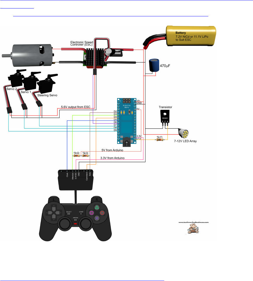
194
Sony Playstation 2 (Wireless) PS2 Controller
Schaltbild und Beschreibung:
http://www.techmonkeybusiness.com/using-a-playstation-2-controller-with-your-arduino-
project.html
pdf: http://www.techmonkeybusiness.com/pdfs/PS2_to_Arduino_V1b.pdf
PS2X._Lib download:
http://www.techmonkeybusiness.com/Code/PS2X_Lib.zip

195
DONATE / SPENDE:
Gefällt dir dieses Kompendium und möchtest du dafür einen kleinen Betrag über PAYPAL spenden ?
Dann klicke einfach auf diesen Link -
Ab einer Spende ab EUR 5,- kannst du auf Wunsch dieses Kompendium auch als kostenloses
WORD.doc erhalten (per Download-Link als .zip, z.T. ein bisschen weniger Geräte-Fotos aus
urheberrechtlichen Gründen, dafür aber zusätzliche Infos und Code Beispiele):
-> Ja, ich möchte etwas als Anerkennung spenden <-
https://www.paypal.com/cgi-bin/webscr?cmd=_s-xclick&hosted_button_id=Q58RCVK67EM9Q
Ein ganz herzliches Dankeschön!
