MECHANICAL ADJUSTMENTS Quick Service Manual V2.2
User Manual:
Open the PDF directly: View PDF ![]() .
.
Page Count: 42

SERVICE MANUAL ver 2.2
Hospitex Diagnostics 1
Quick Reference Manual
Firmware release 3.4 Software release 3.6
SERVICE MANUAL ver 2.2
1 SERVICE PROGRAM
INTRODUCTION
The following paragraphs describe how to use Service program. Service functions allow to
set all calibrations for instrument (offsets), to check photometer unit, to control pumps and
hydraulic circuit, to set barcode reader, to monitor temperature level and to create your
printing format.
When you set a new calibration, all offsets and permanent data are stored in EEPROM
memory on main CPU board.
uP
Eeprom
memory
W
R
/C
At start up, eprom data are uploaded in CPU RAM memory so that instrument can work
properly.
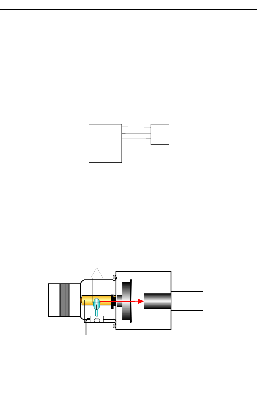
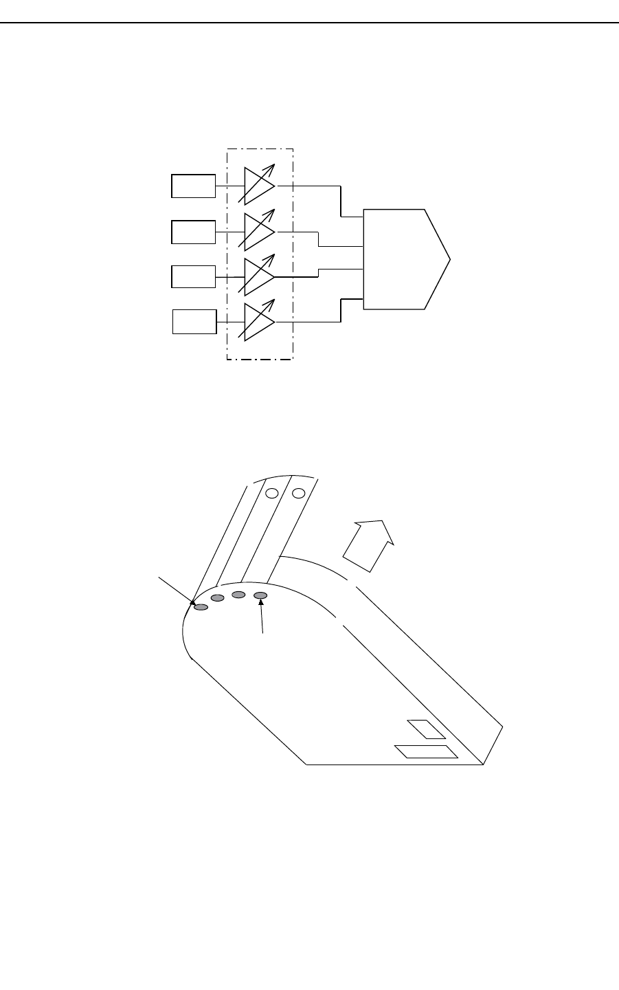
1 ADJUST LAMP
Lamp adjustment has been done at Hospitex Diagnostics factory. The correct lamp position
is achieved by producer. Only when the lamp has been defective, it’s necessary to replace it
with a new lamp, in this occasion it is very important to test lamp filament before to insert
the new lamp.
+12V
Optical fibers
Light beam
Lamp
Pull out
Figure 1 Optical group
Hospitex Diagnostics 2
SERVICE MANUAL ver 2.2
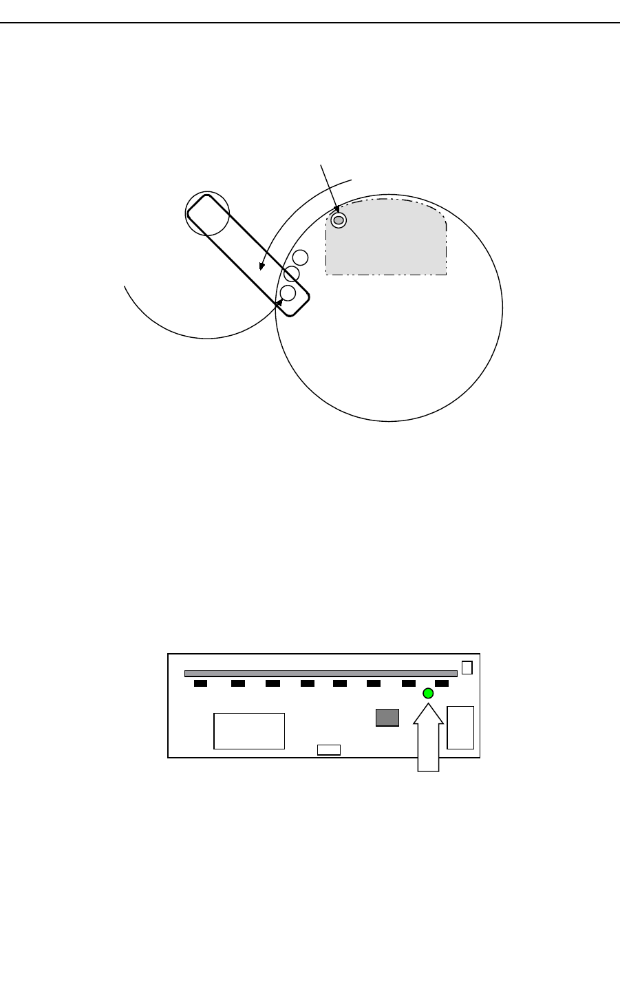
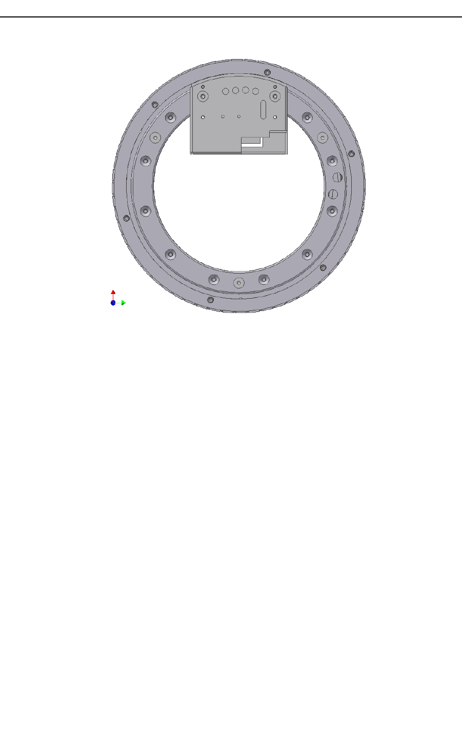
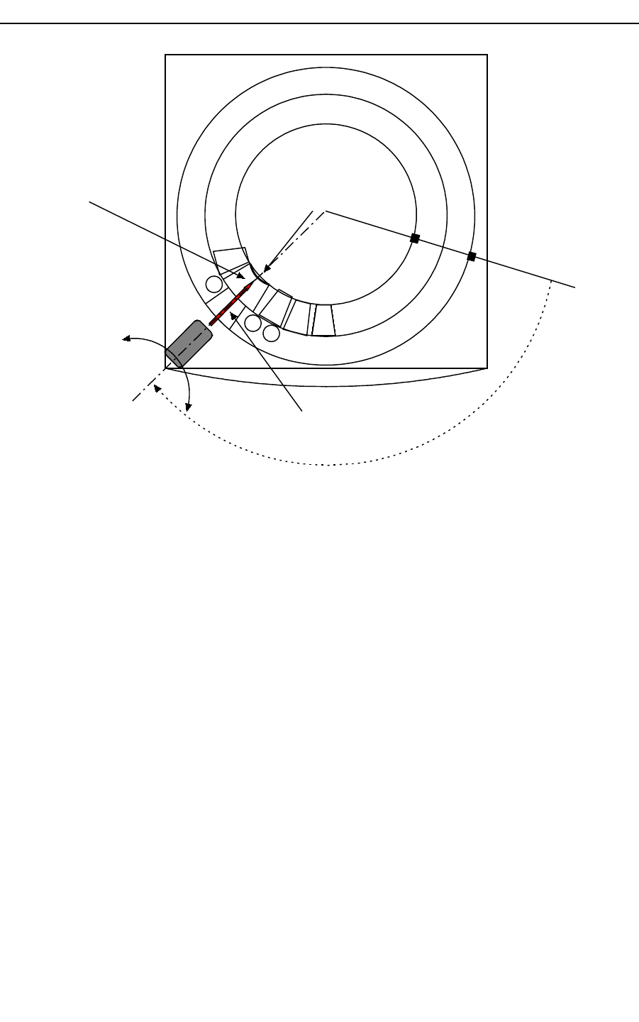
1.1 NEEDLE ARM ADJUSTMENT
Needle adjustment has been done at Hospitex Diagnostics factory. After needle
disassembly, you have to control vertical and horizontal needle positions.
Needle arm must be adjusted in such a way that the needle position is in the centre of
washing well, see Figure 2:
1. Shut down instrument;
2. To loosen screw A and B, see figure 2, in such a way you can move by hand needle
arm can freely ;
A
B
washing well
Figure 2: needle arm
3. Moving by hand, adjust needle arm length so that the needle is in the centre of the
wash position;
4. Tighten screw A and B;
Hospitex Diagnostics 3
SERVICE MANUAL ver 2.2
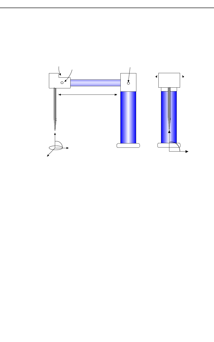
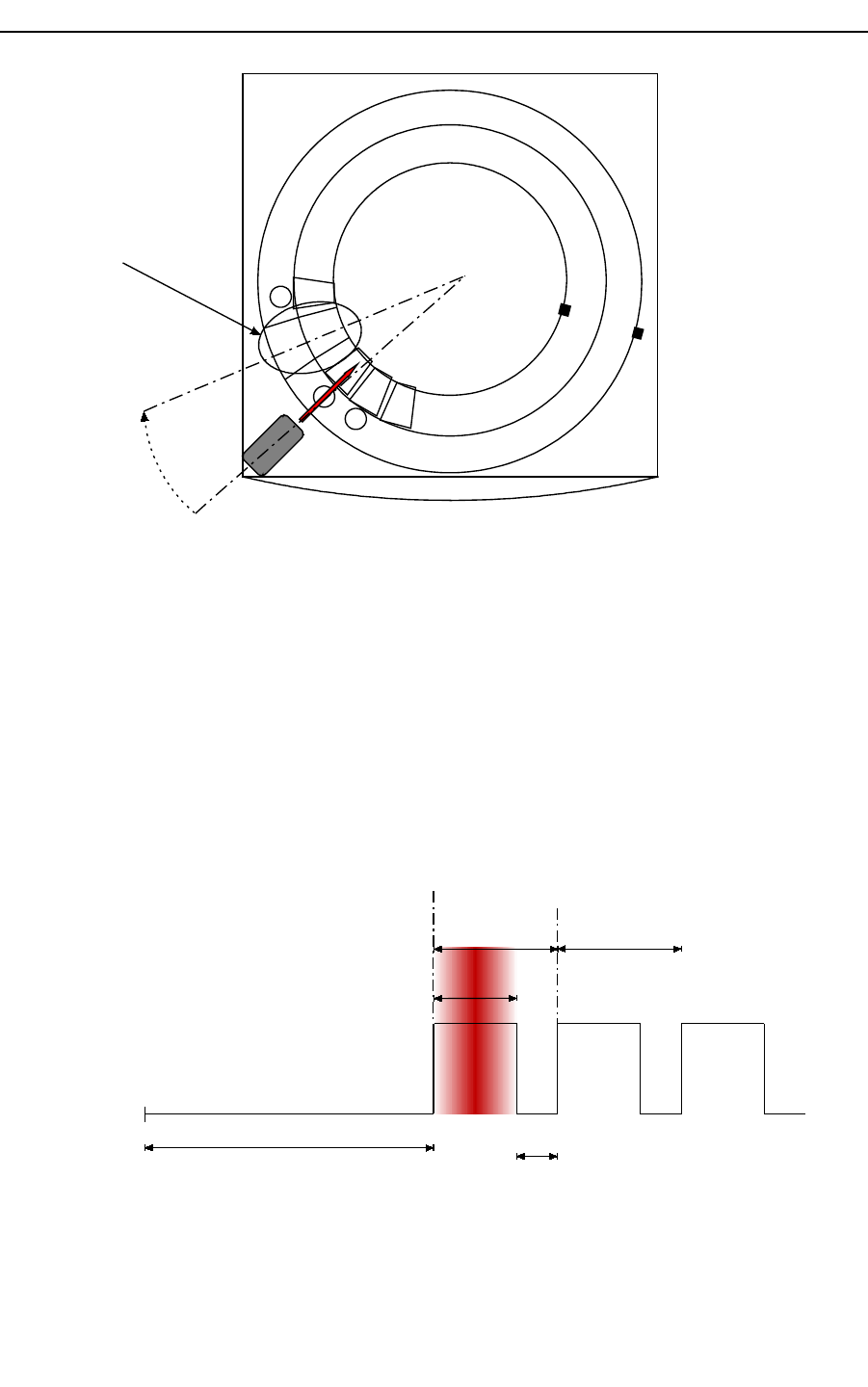
1.1.1 Small vertical arm adjustment
Check if the needle vertical axis is set perpendicularly to the plate below, Figure 3:
1. Loosen screw C and D, see Figure 3, in such a way that the needle can be moved
freely;
5. Figure 3: needle settings
6. Turn the needle by little movement and set it in perpendicular position;
7. Tighten screw C and D;
Hospitex Diagnostics 4
90°
washing well
CD A
90°
SERVICE MANUAL ver 2.2
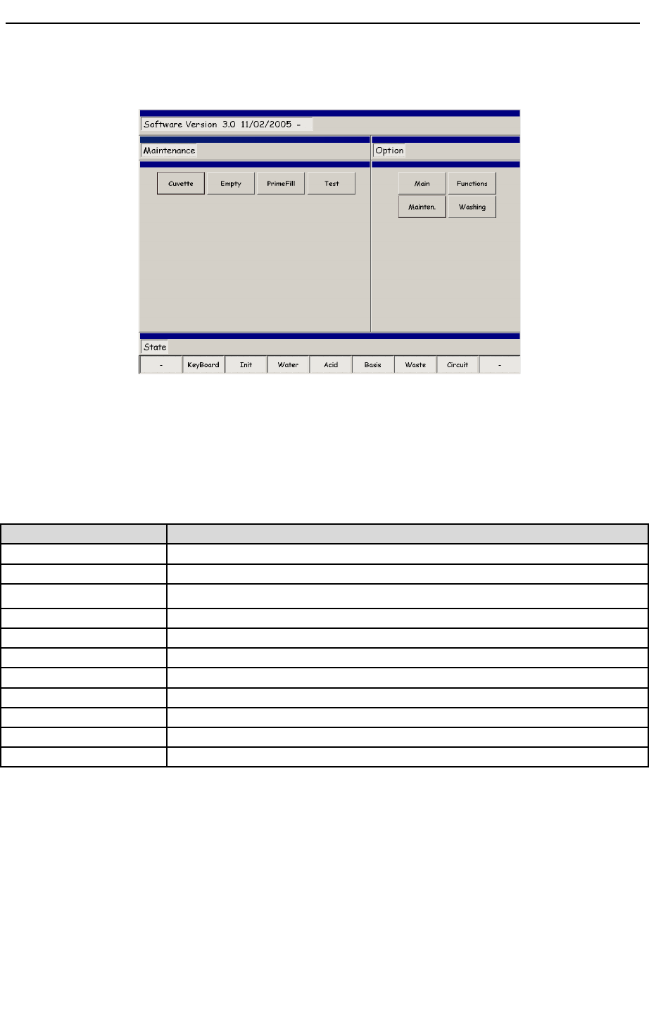
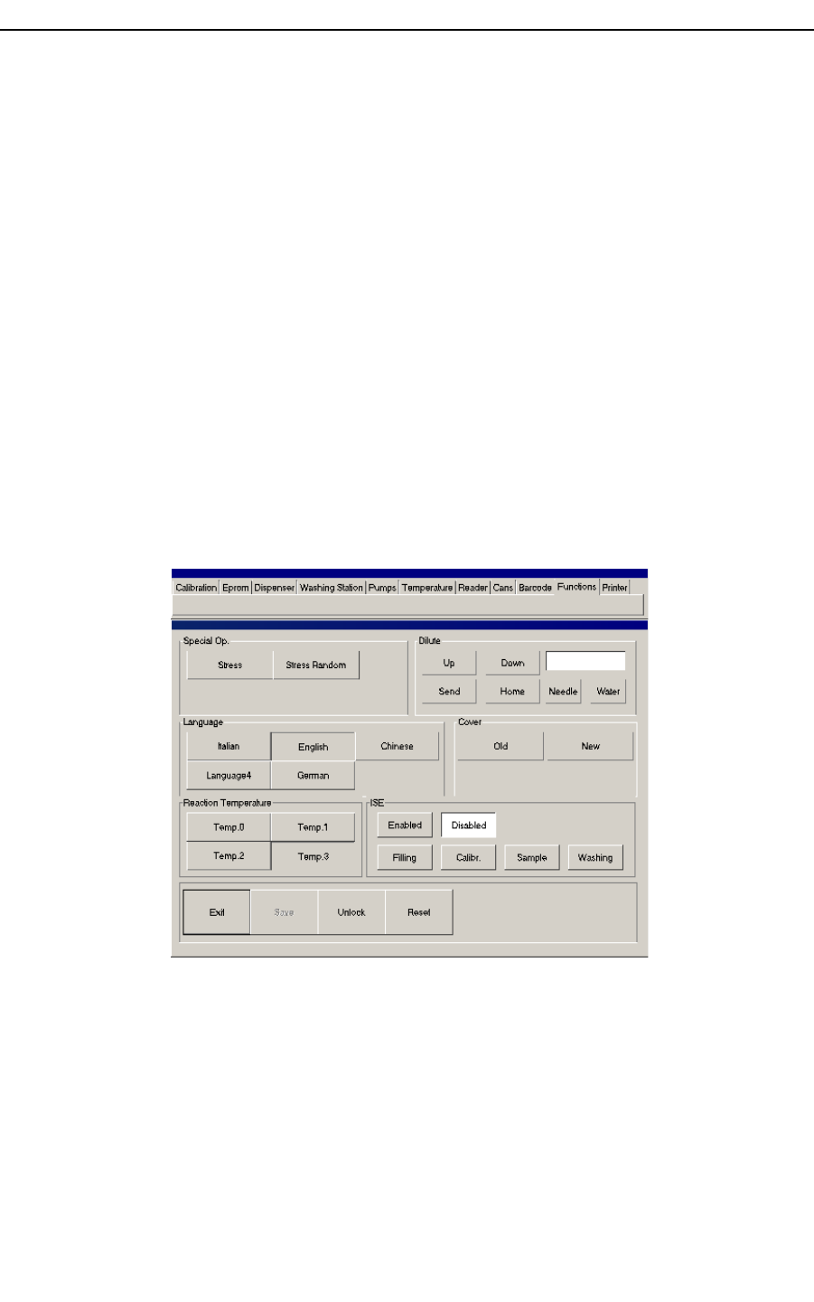
1.2 Service program
Figure 4 maintenance menu
To enter in Service program, from “Option” sub menu select “Mainten.” button and then
press “Test” button, see Figure 4.
Service program is divided in 11 menus listed here below:
Item Description
Calibration By this menu you can set all the mechanical calibrations for the instrument
Eprom By this menu you can display Eeprom memory configurations
Dispenser By this menu you can run preparations
Washing station By this menu you can check washing station unit
Pumps By this menu you can check washing well pumps
Temperature By this menu you can set and monitor temperature level on instrument
Reader By this menu you can check photometer unit
Cans Only for producer
Barcode By this menu you can calibrate barcode unit
Functions By this menu you can change language interface
Printer By this menu you can edit and customize your printer setup
To come back in main program press “Exit” button. Note that after Exit instrument will
reset itself.
Hospitex Diagnostics 5
SERVICE MANUAL ver 2.2
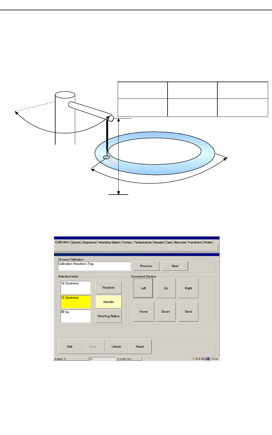
1.2.1Calibration menu
Using calibration menu is possible to set or modify mechanical calibrations.
The calibration procedure means: to find the offset for tray first position under needle and
the offsets for vertical and radial needle arm positions in order to found a correct aspiring
and dispensing action.
1
Tray home position
Needle home
position
Tray offset,
l
Needle arm
radial offset,
m
Needle arm
vertical offset,
n
Tray offset
Nee dle radial
offset
Needle vertical
offset
l: steps to have tray
position 1 under needle
m: steps to turn needle
arm over tray position 1
n: steps to found
tube/bottle bottom
Figure 5: mechanical calibration
Every offset are expressed in steps and are not a physical measure. Calibration menu has
the following graphical interface, see figure Figure 6:
Figure 6 calibration menu
Hospitex Diagnostics 6
SERVICE MANUAL ver 2.2
By “Previous”/”Next” buttons you can select calibration for all the parts, Figure 6 shows
calibration for reaction tray.
The upper button in “Selection Motor” sub menu select tray motor, “Needle” button select
needle arm motors.
In “Command section” pressing “Left/Right” buttons you can choose direction movement
and how many steps to move the selected motor. The same is for “Up/Down” buttons, they
are used for up and down needle arm movement.
Note that the actual motor selected is yellow highlighted.
“Send” button dispatches the command to the instrument. “Home” button recover the home
position for the selected motor.
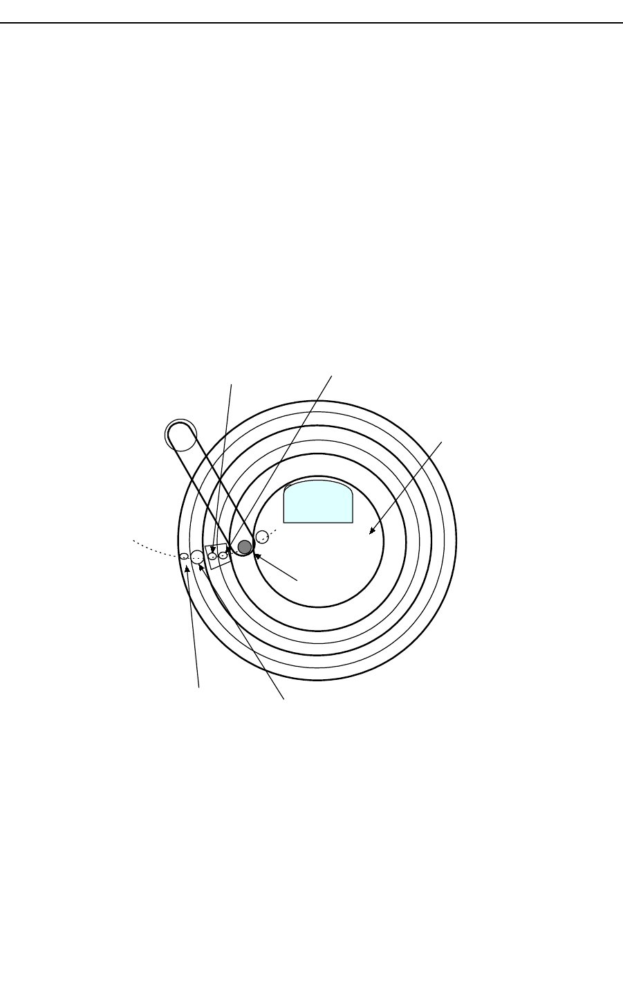
Instrument has 3 main trays to calibrate, however consider that serum and reagent trays
have two different position to calibrate one for the external ring and the other one for inner
ring, see Figure 7, this means that instrument needs 5 logical calibration points for trays +
1 for washing well.
1
Serum tray 1
Serum tray 2
Reagent tray 1
Reagent tray 2
Washing well
Reaction tray
Figure 7 trays map
Hospitex Diagnostics 7
SERVICE MANUAL ver 2.2
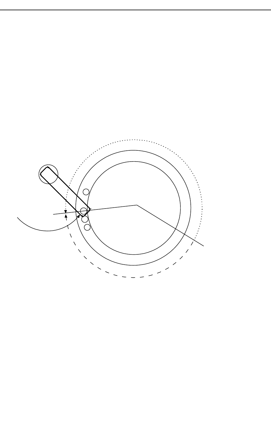
How to calibrate
The first tray to calibrate is Serum tray 1 (inner ring). You can skip to another calibration
using “Next” and “Previous” buttons. The procedure to perform are the following.
Serum and reagent trays calibration
1. Move serum tray so that the first position is under needle arm: press “Serum” button
for selecting the tray motor and move it by “Left/Right” and “Send” buttons, see
Figure 8;
2. Turn needle arm to match the centre of first serum tray position: press “Needle”
button for selecting the arm motor and move it by “Left/Right” and “Send” buttons;
1
59
Serum tray 1
Needle arm
start point
Figure 8 sample tray calibration
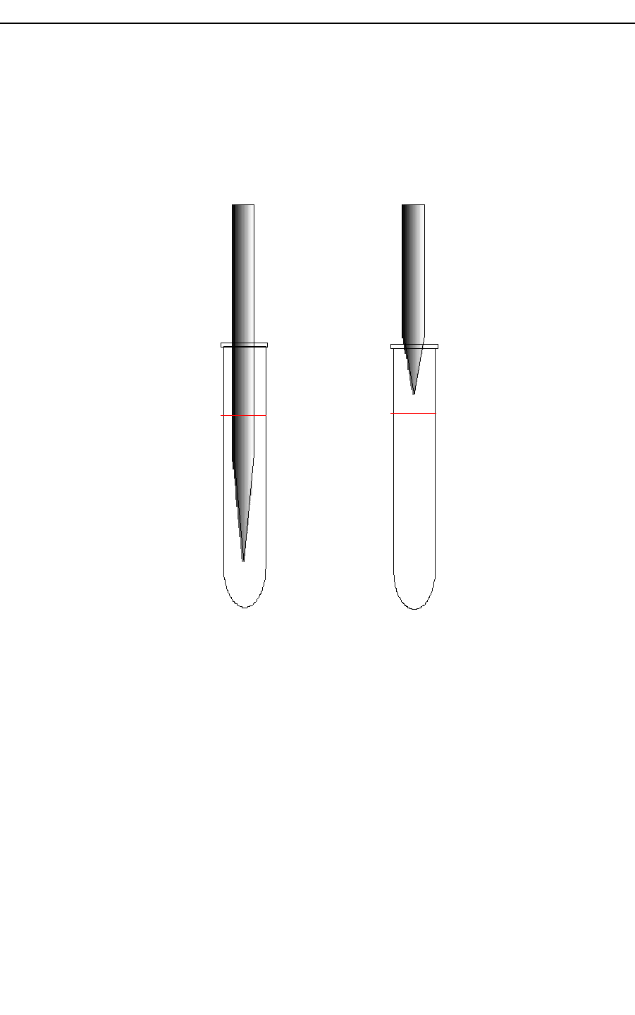
3. Move needle inside the first serum position up to find the bottom. To acting in this
way press “Needle” button for selecting the motor and move it by “Up/Down” and
“Send” buttons. Note that needle height inside the serum tube must be 1 mm over
bottom level.
4. Press “Save” button to save offsets configuration in eeprom memory, (see Figure 6).
5. Press “Home” to recover needle in home position.
Hospitex Diagnostics 8
SERVICE MANUAL ver 2.2
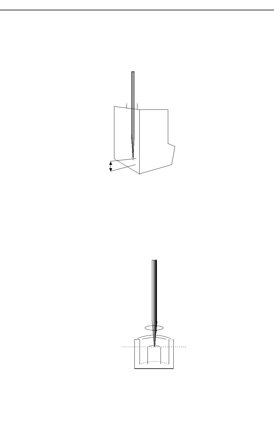
After Serum tray calibration press “Next” to skip the next calibration. Reagent tray 1
(external) and 2 (inner) and Serum tray 2 calibration procedure are similar to Serum tray 1
calibration.
Note that when you move the needle inside the reagent bottle the maximum distance
between needle edge and bottle bottom should be 2-3 mm, see Figure 9:
Figure 9 needle height
Needle calibration on washing well
1. Turn the needle arm on washing well and bring the needle in the centre of washing
well: press “Needle” button for selecting the motor and move it by “Left/Right” and
“Send” buttons;
2. By “Up” and “Send” button move down the needle to find the height as in the
following drawing:
Needle
washing well
calibration
height
ring hole
Figure 10 washing well needle height
Hospitex Diagnostics 9
2 mm
reagent bottle
Needle
SERVICE MANUAL ver 2.2
3. Press “Save” button to freeze needle offset in eeprom memory.
4. Press “Home” to recover needle home position.
Reaction tray calibration
Figure 11 reaction tray calibration
1. Press “Reaction”, using “Left/Right” and “Send” buttons move reaction tray
bringing cuvette position number 10 under dry needle, see Figure 11.
2. Press “Needle”, using “Left/Right” and “Send” buttons turn needle arm to adjust
needle position over cuvette number 1 centre as in Figure 11.
3. With cuvette number 10 under dry needle, control that led D78 on instrument CPU
board is lighted ON. If not, move step by step reaction tray in order to have led D78
lighted ON, Figure 12
P82
D78
P48
CPU Board
Figure 12 CPU Board
4. Using “Up” and “Send” buttons move down the arm to find the needle height, see
Figure 13
Hospitex Diagnostics 10
1
2
10
Reaction tray
Needle
arm
Washing station
Dry needle
SERVICE MANUAL ver 2.2
Needle
Cuvette
Reaction tray
surface
Figure 13 needle height inside cuvette
5. Press “Save” button to freeze needle offset in eeprom memory.
6. Press “Home” to recover needle home position.
When you have finished all calibrations or changed some of them press “Reset”. In this
way the new offsets stored in eeprom memory will be charged in micro controller RAM
memory.
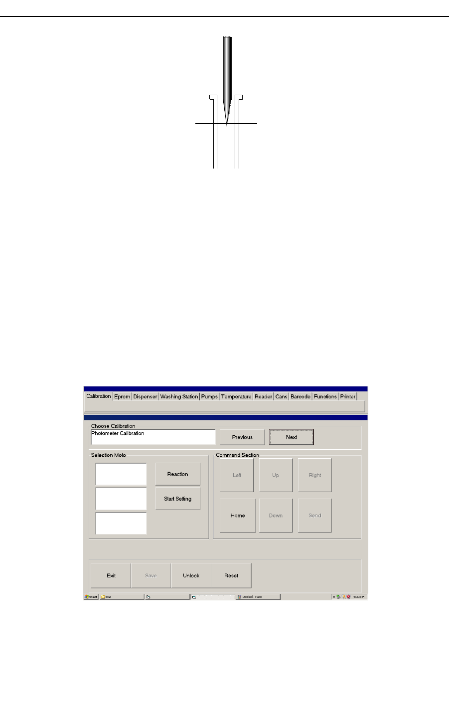
1.2.2 Photometer calibration
Photometer unit is composed by 4 independents reading channels. This means that a set of
4 cuvette are read at the same time. After reaction tray calibration it needs to calibrate
cuvette reading position aligned with photo battery cells. Photometer calibration, means to
find the best reaction tray position to obtain the highest energy level for cuvette reading.
Figure 14 photometer calibration
Hospitex Diagnostics 11

SERVICE MANUAL ver 2.2
Calibration procedure is fully automatic and it is composed by the following steps:
1. Fill with water cuvette number 1, 60, 59, 58.
2. Select “Reaction” button and align reaction tray so that the filled cuvettes are
behind photometer channels. To obtain this, bring reaction tray cuvette position
number 25 as shown in Figure 15, half covered by tray cover.
Figure 15 photometer calibration
3. Press “Start Setting” as shown in Figure 14. The automatic procedure will start
displaying a message. At the end the found offset is stored in eeprom.
4. Press “Reset”.
The photometer calibration is completed. Note that if you change reaction tray calibration
(only physical tray position) you have to recalibrate photometer reading point also.
1.3 Eprom
During calibration procedures all information are stored in a permanent memory on CPU
board: eeprom.“Eprom” menu window is shown in Figure 16. Using Eprom menu you can:
1. Write instrument serial number using “Write S/N” button
2. Store actual eeprom information (offsets) in a local PC file
(C:\EOSBF\FILE\LastEprom.PEP), using “Save Eprom on File” button
3. Download PC offsets file (LastEprom.PEP) in eeprom memory to recover the last
eeprom memory configuration, using “Load Eprom from File” button
4. To display actual eeprom offsets , using “Eprom configuration” button
5. To display a complete instrument report, using “Calibration report” button
6. Erase eeprom information by “Clear Eprom” button
Hospitex Diagnostics 12
SERVICE MANUAL ver 2.2
7. Erase AD channels offset to disable reaction tray temperature control by
environment temperature sensor (Clear AD Offset)
Figure 16 Eprom menu
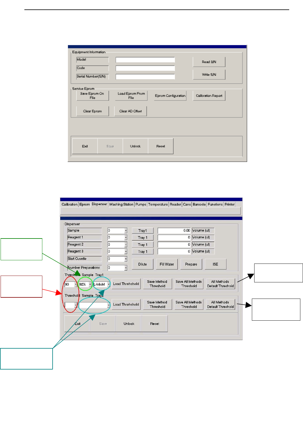
1.4 Dispenser
Figure 17 dispenser
Hospitex Diagnostics 13
B Serum tray 2
sensitivity
controls
A Serum tray 1
sensitivity
controls
Sensitivity
threshold, n
Deeping
threshold, d
Method selection,
m

SERVICE MANUAL ver 2.2
Using Dispenser menu you can perform one or more preparations. During preparation the
needle aspires reagent and serum volumes from their own trays positions and dispenses
them in reaction cuvette. As shown in Figure 17, from “Sample” combo box you can select
sample position from serum tray. Selecting “Tray1” button, sample position is on the inner
ring. With “Tray2”, sample position is on external ring.
To define how many sample volume to aspire, write it in “Volume” edit box.
During the same preparation you can add up to 3 different reagents, choose reagent
positions from combo box “Reagent 1”, “Reagent 2”, “Reagent 3” and define their volumes
in “Volume” edit box (Figure 17, right side).
Selecting “Tray1” button, reagent position is on external ring, with “Tray2” is on inner
ring.
To select the cuvette to dispense in, use “Start cuvette” combo box. To choose how many
preparations to perform use “Number Preparations” combo box.
As shown in Figure 17, there are 3 buttons:
1. “Dilute”, to perform dilutions. During dilution, needle will dispense in serum tray
external ring. To select cup position, use “Start cuvette” combo box.
2. “Fill water”, to fill with water reaction cuvette. To select the first cuvette to fill use
“Start cuvette” combo box, to select how many cuvettes to fill use and “Number
Preparations” combo box.
3. “Prepare” to execute a preparation.
4. “ISE” to push samples inside ISE module position
Needle sensor thresholds
From firmware version 1.7 it is implemented a new function that allows to adjust needle
sensor sensitivity threshold for one specific reagent when the needle are detecting the
sample on serum tray 1 or serum tray 2 positions.
In this way it will be possible to set a specific sensitivity threshold for every different type
of reagent. If adjustment sensitivity is not needed, the instrument works with default
parameters.
In Dispenser menu, see Figure 17, there are A controls to set and modify threshold on
serum tray 1 and B controls to set and modify sensitivity threshold on serum tray 2.
To modify sensitivity threshold for serum tray follow this steps:
1. From combo box m select the method (reagent) that needs threshold adjustment;
2. From combo box n, select sensitivity threshold level for relevant method indicated
at point 1. The available threshold range is [70 –100], with threshold = 100 needle
sensor has the highest sensitivity;
3. From combo box d, select Deeping threshold level in the range [70%-99%].
Percentages is referred to the fMax frequency, see Figure 19. The default value is
92%. If in your test the level sensor doesn't sense the sample level, sinking deeply
into the test tube, increase the deeping threshold value.
4. Use “Load Threshold” button to activate the new threshold level indicated at point
2. Use Dispenser controls to run preparations and test threshold sensitivity level.
Hospitex Diagnostics 14
SERVICE MANUAL ver 2.2
5. Use “Save Method Threshold” button to save the new threshold level selected from
combo box n for method indicated in combo box m.
6. Use “Save All Methods Threshold” to set every method with sensitivity threshold
level shown in combo box n.
7. Use “All Methods Default Threshold” button to recover all methods with default
threshold sensitivity level. Default sensitivity level is 90 for serum tray 1 and 94 for
serum tray 2.
How to adjust thresholds
When the level sensor doesn't sense correctly the sample in serum tray 1 you have to adjust
the following parameters: Deeping threshold and sensitivity threshold. The first parameter
defines the percentage of maximum frequency fMax from which the detection starts
(maximum frequency is on needle home position, see Figure 19), sensitivity threshold is
linked with the frequency variation from air to liquid.
If the level sensor fault condition is like in the case 1 of Figure 18 it means that the deeping
threshold value is under the fMin and you need to increase it, see Figure 19. When you
modify deeping threshold move by 5% step units across the range.
If the level sensor fault condition is like in the case 2 of Figure 18 you have to make the
following :
Hospitex Diagnostics 15
1 2
sample level
Figure 18
SERVICE MANUAL ver 2.2
1. Decrease the deeping threshold until the needle goes down in the sample (case1) it
means you have found the fMin frequency. Then, increase the deeping threshold
value fDTh, it must be in the range of fMax and fMin.
2. After that you have fixed the deeping threshold decrease the sensitivity threshold
(see point 2 page 14)
Rem 1: fMax, fMin parameters are connected with the reagent that you are using and have not
absolute values. You can only estimate fMax and fMin by test.
Rem 2: Let be THs the sensitivity threshold value, THs depends by reagent type Rx that
you are using: THs(Rx). The level sensor stops the needle when:
where f is the frequency and s is the space
To modify sensitivity threshold level for serum tray 2 use B controls, the way to follow are
same exposed for serum tray 1 ( A controls). Deeping threshold are not available for serum
tray 2.
Hospitex Diagnostics 16
s am ple probe
f
Max
Frequency
Liquid interface
d
0
space
f
0
f
deeping Th
ins ide the liquidout the liquid
f
Min
f
DTh
Figure 19:
f/ sTHsRx
SERVICE MANUAL ver 2.2
2 Washing station
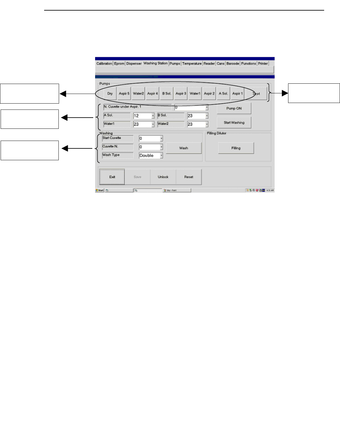
Figure 20 washing station menu
Use washing station menu to check all the hydraulic pumps. In “Pumps” sub menu (A)
there are 10 buttons to select the washing station needles pump, see Figure 20.
A pump check
To switch on one of the pumps:
1. press one button from A section to choose the pump;
2. press “Pump ON” to activate the pump
To stop the pump, press “Pump OFF” button (it is “Pump ON” toggled button). The
relation between buttons in A (Figure 20) section and washing tower needles is shown in
Figure 21
Hospitex Diagnostics 17
A selection buttons
for pumps
B washing
parameters
C washing test
D Washing steps
evaluation

SERVICE MANUAL ver 2.2
Aspir.1
A.Sol
Aspir.2
B.Sol
Aspir.3 Aspir.4 Aspir.5
Drywater 1 water 2
Figure 21 washing tower
B washing parameters
To test one washing cycle:
1. select the cuvette to bring under Aspr1 needle from “N. cuvette number under
Aspir. 1” combo box
2. in “A sol”, “B sol”, “water1”, “water2” combo boxes set the liquid volume for
washing (remark: the default values are fixed by producer, it is recommended don
not change them)
3. from A section button select the pumps that you want to test
4. press “Start Washing” button to start washing cycle
After this, reaction tray will bring under Aspr 1 needle the selected cuvette and the washing
station moves down with selected pumps opened.
C washing test
Using “Washing” sub menu you can test a washing cuvettes:
1. From “Start Cuvette” combo box select the first cuvette to wash;
2. From “Cuvette N.” combo box select how many cuvettes to wash;
3. From “Type” combo box select washing type, washing type is shown in Table 1.
4. To start washing press “Wash” button.
Press “Filling” button to fill with water needle hydraulic circuit or to wash needle.
Hospitex Diagnostics 18
SERVICE MANUAL ver 2.2
Washing
Type
Description
Neutral Only with H2O
A Solution A sol + H2O
B Solution B sol + H2O
Double A sol + B sol + H2O
Table 1
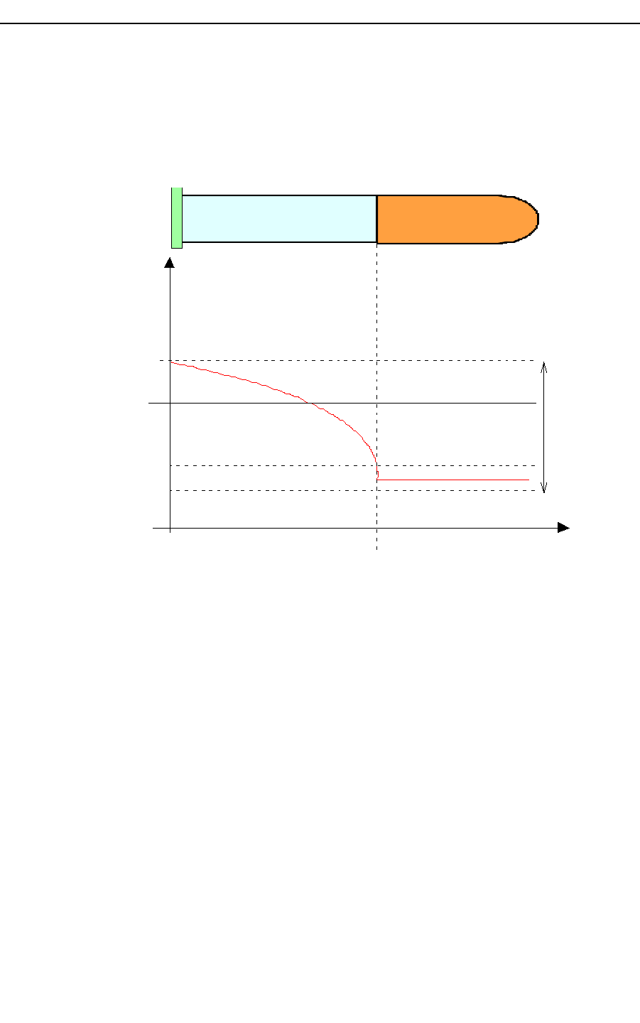
D washing steps evaluation
“Test” command allows to evaluate each single washing steps
The whole washing cycle can be divided in 6 steps (see Figure19) :
1. Aspir.1 + A.Sol + Aspir.2
2. Aspir.2 + Water 1 + Aspir.3
3. Aspir.3 + B.Sol + Aspir.4
4. Aspir.4 + Water 2 + Aspir.5
5. Aspir.4 + Water 2 + Aspir.5 + Dry
6. Dry
Steps 1,2,3,4,5 are evaluated by calculating the ABS of remaining coloured drops , left by
washing step
Step 6 is evaluated by calculating the effect of water drops , left by dryer , towards ABS of
a coloured solution
In order to use this procedure you have to :
Fill position 1 of serum tray 1 with concentrate potassium bichromate (K2Cr2O7)
Fill position 1 of reagent tray with a bottle full of water
Insert on position 1 of serum tray 2 an empty cup
After automatic procedure results are shown in the following form:
An error on results is shown by colouring red the cell with wrong result .
Hospitex Diagnostics 19
SERVICE MANUAL ver 2.2
Moreover form can be saved on file”.bmp” by pressing F1 on keyboard ( optional: user will
be able to input a note in the file name), all files will be saved in “C:\EosBF\File” folder.
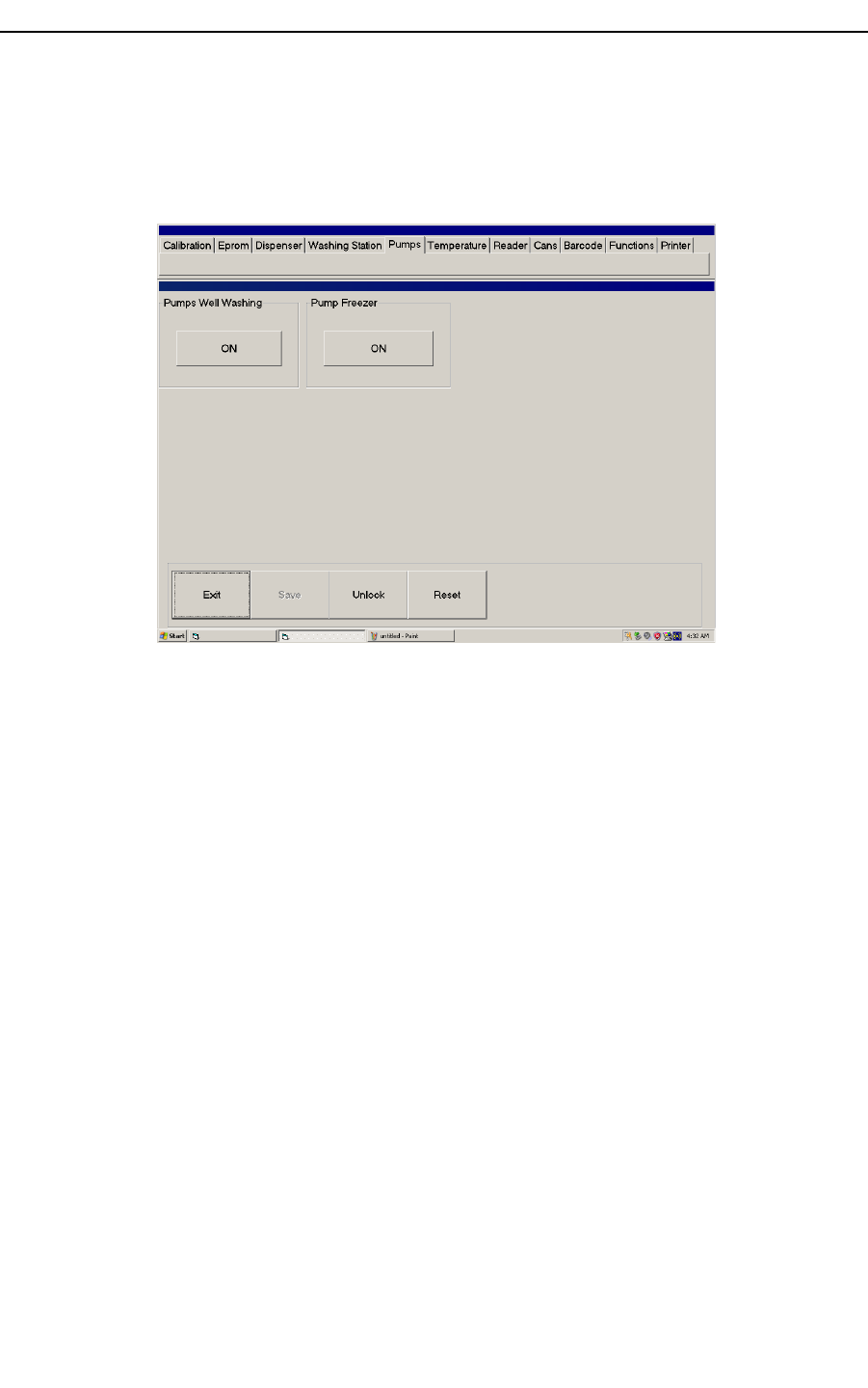
2.1 Pumps
Figure 22 pumps menu
Using “Pumps” menu, shown in Figure 22, you can check all the washing well pumps and
refrigerator pump:
1. Press “ON” button (toggle) in “Pumps Well washing” sub menu to turn on all the
well pumps.
2. Press “ON” button (toggle) in “Pump Freezer” sub menu to turn on the refrigerator
pump connected with reagent tray.
Washing well is connected with 3 peristaltic pumps: one to wash needle, the other ones to
get out waste.
Hospitex Diagnostics 20
SERVICE MANUAL ver 2.2
Figure 23 washing well
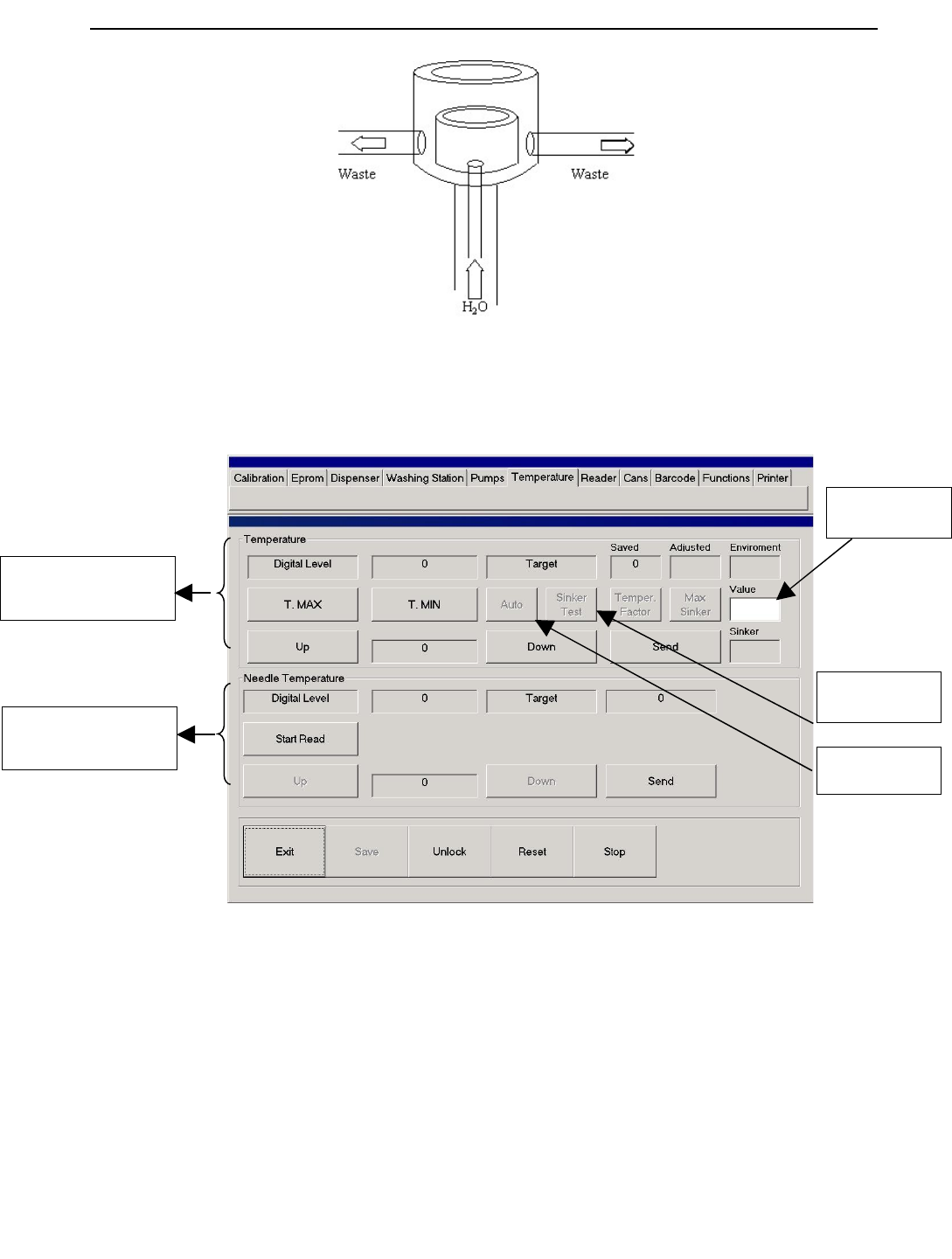
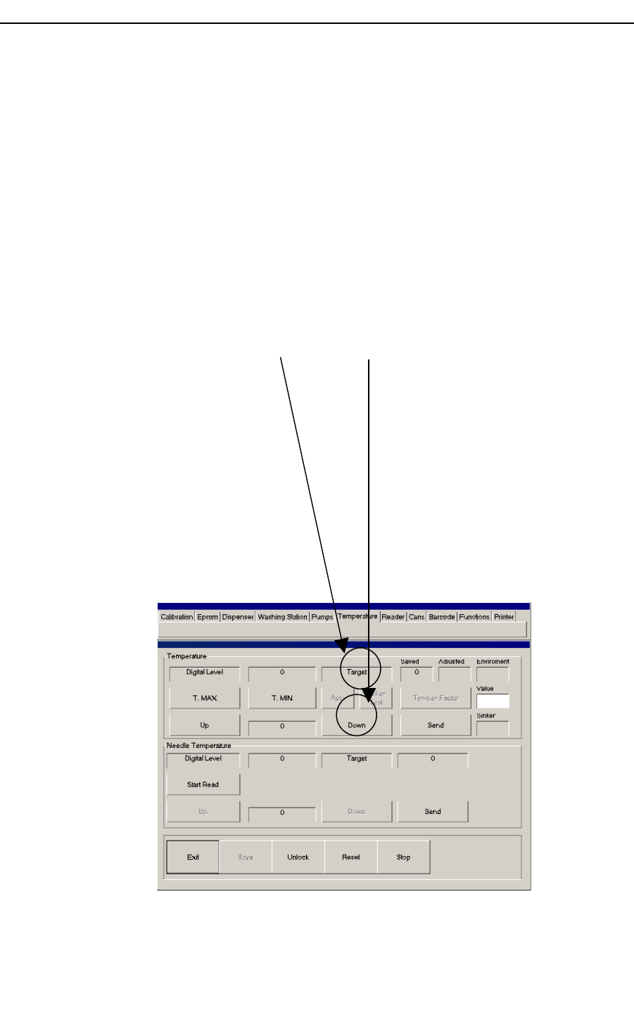
2.2 Temperature
Figure 24 temperature menu
Using Temperature menu, Figure 24, you can monitor and calibrate temperature levels on
reaction tray and needle arm preheater. “Temperature” sub menu controls reaction tray
temperature. “Needle Temperature” sub menu controls preheater needles arm, see Figure
25.
Hospitex Diagnostics 21
A Reaction tray
temperature controls
B Needle preheater
temperature controls
C Auto
Calibration
D Sinker Test
E Temperature
Factor
SERVICE MANUAL ver 2.2
Preheater
Figure 25 preheater
A Reaction tray temperature controls
To display actual reaction tray temperature press “T.MAX” button, software will show
temperature digital level in “Digital level” edit box. To calibrate reaction tray temperature
you have to define a digital level Target. To change “Target” level use “Up” button (to
increase) “Down” (to reduce) and “Send” to modify the displayed target value. Actual
“Digital Level” and “Target” values are expressed in digital units and are not physical
degrees (°C).
Note : When environment temperature sensor is set up on equipment (see 1.5 )
When user press “Save” button , equipment will also store environment temperature and
Reaction tray temperature target will be automatically modified according to that
environment .During temperature calibration , by pressing F1 on keyboard , environment
temperature , sinker temperature(if present) and adjusted target can be shown .
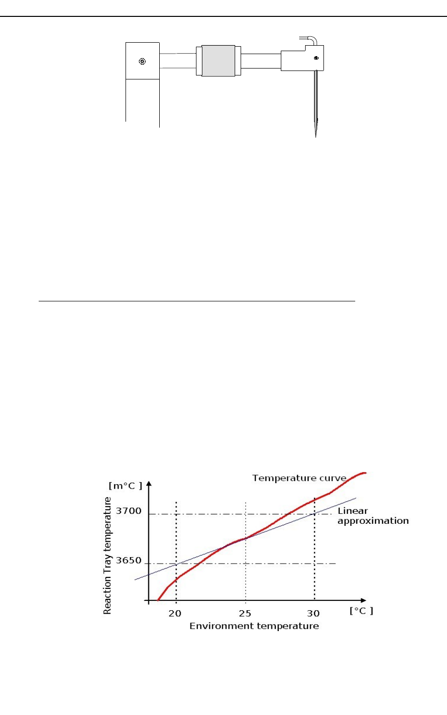
The automatic correction of target temperature is controlled by a temperature factor
(default: 65 m°C/°C) that makes target decrease when environment temperature increase.
The automatic correction uses a linear model , so, in order to perform good corrections,
it’s strongly recommended to calibrate reaction tray temperature with an
environment temperature from 22°C to 26.5°C .
That’s because the linear model is working good only with small variation (positive or
negative) around a medium point , so it’s recommended to fix this medium point not with
too low temperature and not with too high temperature
Hospitex Diagnostics 22

SERVICE MANUAL ver 2.2
Moreover in order to assure a right working of temperature control sinker temperature
must be around 30°C/40°C.
In order to disable reaction tray temperature control by environment temperature ,
command “Clear AD Offset” on “Eprom” menu has to be used.
B Needle preheater temperature controls
To find the target value corresponding at 37,5 °C, fill with water a cuvette and insert inside
a thermometer probe. You have to wait that reaction tray temperature reaches the target
value, after this, control the Celsius degrees on tray with thermometer. If temperature is not
37,5°C you have to modify target value using “Up/Down” buttons.
When you have found the right target value save it in eeprom memory pressing “Save”
button.
37°
Reaction tray
Figure 26 reaction tray temperature test
Press “Start Read” to monitor actual digital level on preheater and target value. About
calibration you have to follow this procedure:
1. turn on reagent tray refrigerator and wait for a low temperature.
2. Wait for 37,5°C on reaction tray.
3. Using “Dispenser” menu, you have to run a preparation in which needle aspires
400 ul of water from reagent tray and 4 ul from serum tray and dispense it in a
reaction tray cuvette. Repeat this operation 3 times.
4. Insert inside the last dispensed cuvette a thermometer probe.
5. For a good preheater target, water should reach 37 °C in 3 minutes
6. Using “Up” and “Down” buttons, modify target value if is not as point 5
7. Press “Save” button to save new target value.
Hospitex Diagnostics 23
SERVICE MANUAL ver 2.2
Figure 27 temperature rate
To exit from “Temperature” menu, press “Stop” button.
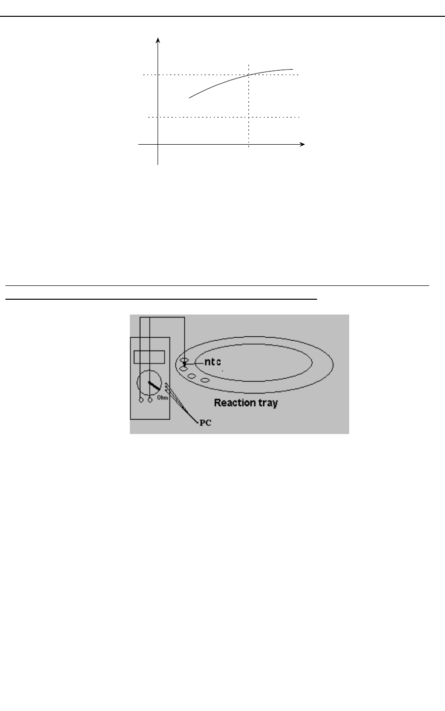
C Temperature auto calibration
In order to perform this procedure it’s necessary to use tester “Lafayette MAS-345” with
communication serial port RS232 connected with an NTC sensor.
Fill a cuvette with 500uL of water
Put this cuvette on reaction tray position under photometer mask
Switch tester on Ohm mode
Connect NTC with tester probes
Connect Tester on PC Com1
Push “Auto” on “Temperature” menu
Wait for end of procedure ( it can last from 40 min to 60 min)
During procedure, calibration can be stopped by pressing ESC on keyboard , note that in
this case current level and environment temperature will be saved.
Moreover environment temperature and sinker temperature can be shown by pressing F1 on
keyboard and current cuvette temperature is shown on a message.
Hospitex Diagnostics 24
Temperature [°C]
Time
3 min
0
37°
30°

SERVICE MANUAL ver 2.2
If temperature calibration end with no error software will show :
TEMPERATURE ON CUVETTE + SAVED DIGITAL TARGET
If temperature calibration end with error software will show an error code :
TEMPERATURE CAN NOT BE CONTROLLED : after first correction
temperature is not reaching for target
TEMPERATURE CAN NOT REACH PLATEAU : after a correction temperature
doesn’t become stable but keeps on drift
TEMPERATURE CAN NOT REACH TARGET : after maximum number of
corrections target is not reached
TEMPERATURE CAN NOT STAND BY ON TARGET: after target is reached
temperature keeps on changing around target
D Sinker test
Sinker efficacy can be controlled with an automatic procedure.
Some temperature cycles are performed on sinker and the rising temperature time is
monitored.
This procedure may last several minutes( from 40 to 60) and it’s recommended to perform
it when equipment has been just switched on.
Procedure can be stopped by pressing ESC on keyboard.
If sinker temperature test end with no error software will show :
RISING TEMPERATURE SPEED+ LAST TEMPERATURE
If sinker temperature end with error software will show an error code :
FREEZE ERROR+ LAST TEMPERATURE : sinker can not get cold
WARM ERROR+ LAST TEMPERATURE : sinker can not get hot
RISING TEMPERATURE SPEED+ LAST TEMPERATURE : the rising speed is
too low
E Temperature factor
Temperature factor (m°C/°C) is the variation of reaction tray temperature (m°C) according
to a 1°C variation of environment temperature.
The default factory value is 65 m°C/°C
Hospitex Diagnostics 25

SERVICE MANUAL ver 2.2
It’s possible to change temperature factor on software by command on menu temperature
If command is pressed when text box is cleared , current factor will be shown
If command is pressed when text box is filled , written factor will be saved on
board
It’s strongly recommended to not change this factor .
This factor may be changed only in some particular cases :
Special environment
Special working conditions
Special equipment configurations
………………..
Hospitex Diagnostics 26
SERVICE MANUAL ver 2.2
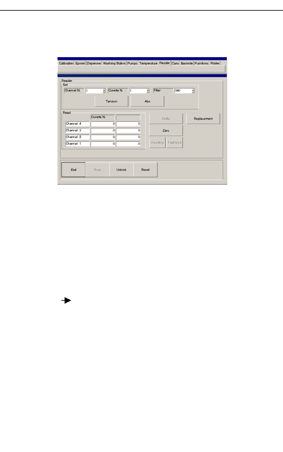
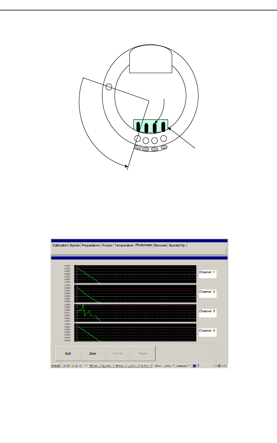
2.3 Reader
Using “Reader” menu you can check photometer channels and all the filters.
Figure 28 reader menu
In the “Set” sub menu you have the following input boxes and buttons:
1. “Channel N.” to select the channel [1 ÷ 4] .
2. “Cuvette N.” to select the cuvette [1 ÷ 60]. Reaction try will bring the cuvette
aligned with selected channel (point 1).
3. “Filter” to select the actual reading filter (340 nm, 405 nm, 492 nm, 505 nm, 546
nm, 578 nm, 630 nm, 700 nm).
4. Select “Tension” button to display reading results in voltage levels (mV) or “Abs”
button to display absorbance reading results
5. Press “Reading” (toggle mode) button to run reading operation and start monitoring.
6. Press “Stop” to end reading operation.
If you select “Channel N” = 1 and “Cuvette N.” = 1, after press “Reading” button
(“Reading” toggle “Stop”), reaction tray position will be as in Figure 29. For a
coherent reading operation cuvettes must be filled with water. Photometer unit reads 4
cuvettes at the same time, this means that you have to fill cuvette numbers 1, 60, 59, 58, see
Figure 29.
During reading operation channels results will display in “Read” sub menu edit boxes.
Hospitex Diagnostics 27
SERVICE MANUAL ver 2.2
Figure 29 reading position alignment
If you select “Abs” button, software will display absorbance reading results. Selecting
“Abs” mode, if you press “Zero” button and then “Graphic”, software will open a graphical
display to control photometer channels reading rate, Figure 30.
Figure 30 reading graphical display
Hospitex Diagnostics 28
158
Photo battery
Ch1 Ch2 Ch3 Ch4
Reaction tray
washe r
1
Photometer
Optical fibers

SERVICE MANUAL ver 2.2
2.3.1 Replacement function
In order to test replacement error effect on photometer performance , an automatic
procedure can be performed.
This procedure needs diluted 1/100 potassium bichromate K2Cr2O7 (ABS around 1.700)
Fill bottle on reagent tray position 1 with diluted 1/100 potassium bichromate
Start procedure with “Replacement” command
Wait for end procedure
At the end of procedure results are shown in a form :
By pressing buttons 1, 2, 3... and so on a graphic of reading can be shown:
Hospitex Diagnostics 29

SERVICE MANUAL ver 2.2
Each of 12 cuvette are filled with solution and they are read 5 times after moving reaction
tray.
The procedure can estimate:
Replacement reading error between each reading of a cuvette: if some cuvette
reading are too different the label under Error column becomes red
Accuracy error between each channel of photometer : if then mean reading of
each channel is too different in comparison with the other the results labels
becomes red
Drift rate between each reading of a cuvette : if cuvette reading drift is too high
the label under Drift column becomes yellow
Moreover form can be saved on file”.bmp” by pressing F1 on keyboard ( optional: user will
be able to input a note in the file name), all files will be saved in “C:\EosBF\File” folder.
2.3.2 Photometer adjustment
In order to realize a photometer adjustment it is necessary that the photometric calibration
has been executed first as described before.
Photometer check is as follows:
1. Ensure that photometric calibration is OK, then read the voltage level;
8. At 340 nm wavelength the average voltage level must be in the range of [400 ÷
1000] mV;
9. Maximum variance for each channel from average energy level must be ± 20%;
10. For all the other filters, maximum energy level must be under 4100 mV, consider
that 5000 mV energy level is the photometer saturation;
To change channel energy levels :
Open instrument on lateral side, below photometer unit there are 4 screw
for gain trimming, Figure 32 .
Hospitex Diagnostics 30
SERVICE MANUAL ver 2.2
Select the channel out of range and turn the screw to adjust the gain so
that channel voltage level will be in the optimal range (for this operation
you have to run photometer reading with filled cuvette and control
channels monitor), Figure 31.
G
G
G
G
ADC
CH1
CH2
CH3
CH4
Trimmer gain
Figure 31 trimming
Ch1 screw hole
Ch4 screw hole
connectors
Photometer unit lower view
Reaction tray
Photo battery
Hospitex Diagnostics 31
SERVICE MANUAL ver 2.2
Figure 32: photometer below layer
Hospitex Diagnostics 32
SERVICE MANUAL ver 2.2
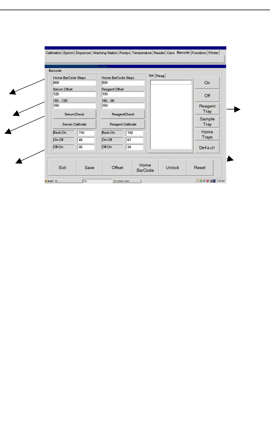
2.4 Barcode
Figure 33 barcode menu
Figure 33 shows Barcode calibration menu. In right side, you have some general buttons:
1. “On” button to start barcode reading.
2. “Off” button to stop barcode reading.
3. “Reagent Tray” button to move one position in reagent tray.
4. “Serum Tray” button to move one position in serum tray.
5. “Home Tray” button to recover reagent and serum tray home positions.
Reference label is on reagent tray, before barcode reader. With empty reagent tray, if you
press “On” button barcode reads reference label and a message with the read value should
appears (reference label value is “0000”). If the message doesn’t appear, it means that
barcode has some reading problems and you have to adjust its physical position, see Figure
34:
Hospitex Diagnostics 33
Serum controls
sub menu
Reagent controls
sub menu
General control
buttons
Display window
Time parameters
Trays speeds
SERVICE MANUAL ver 2.2
1
2
Reagent reading window
59
R1
R35
R2
Serum reading window
Barcode reader
Reference label
"0000"
radial offset
Home positions
Home Barcode steps
offsets for reagent and
serum trays
Figure 34 barcode reader
To calibrate barcode, open lateral and front cover.
Barcode calibration procedure:
1. Insert offsets values (steps) in “Home Barcode Steps” edit boxes (Figure 33) to have
windows reading position aligned with barcode reader, see Figure 34. Then, press
“Home Barcode” button to test the new offsets: reagent and serum trays will move
them self to bring reading windows in front of barcode. Repeat this operation to find
the best offsets, thus press “Save” button.
2. “Serum Offset” and “Reagent Offset” are steps distances to have sample and
reagent first positions in front of barcode reader, see Figure 35. To test offsets, first
insert tube and bottle in their relevant position with barcode label, then press
“Offsets” button: reagent tray will bring the bottle in reading position. If you have
chosen a good offset a message will appear to display the read code, then press
“OK” message button. The same operation is for serum tray. Repeat this operation
to find the best offsets, thus press “Save” button.
Hospitex Diagnostics 34
SERVICE MANUAL ver 2.2
1
2
Reading windows
59
R1
R35
R2
Barcode reader
Offsets
Figure 35 offsets calibration
3. Tray speed edit box: you can select tray speed in the range [190 – 90] rpm, the
default values is 150 rpm, see Figure 33.
4. Time parameters: “Back-On”, “On-Off” and “Off-On” values, to calculate them
press “Reagent Calibrate” button for reagent tray and “Serum Calibrate” for serum
tray.
A fully automatic procedure will start to compute time parameters. It’s necessary to
have serum tube and reagent bottle with calibration code. Calibration code is
defined in Main program: press “Functions” button, then open “Barcode” menu,
here you can edit or modify calibration code. Physical meaning of time parameters:
T
start
T
Off-On
T
Back-On
Second position
reading time
First position
reading time
T
On-Off
T
On-Off
+ T
Off-On
= K
Hospitex Diagnostics 35
SERVICE MANUAL ver 2.2
TBack-On: time to wait first label in reading position from starting point
TOn-Off: time to read one label
TOff-On: delay for the next reading
If you change some computed values, remember that TOn-Off and TOff-On sum
must be a constant
5. Insert some labelled bottles in reagent tray, then press “ReagentCheck” button for a
complete barcode scan. In Display window “Reag” will appear scan results, thus
control them with physical dispositions. If the test is not OK, repeated reagent
calibration as previous point 4 or modify time parameters. Otherwise press “Save”
button.
6. Insert some labelled tubes in serum tray, then press “SerumCheck” button for a
complete barcode scan. In Display window “Ser” will appear scan results, thus
control them with physical dispositions. If the test is not OK, repeated serum
calibration at previous point 4 or modify time parameters. Otherwise press “Save”
button.
2.5 Functions
Figure 36 functions menu
Use “Functions” menu
To select interface language in “Language” sub menu.
To pilot ISE module in “ISE” sub menu.
To move dilutor in “Dilute” sub menu.
To set start up temperature in “Reaction Temperature” sub menu
Hospitex Diagnostics 36
SERVICE MANUAL ver 2.2
To perform stress procedure in “Special Op.” sub menu
To set cover type of equipment in “Cover.” sub menu
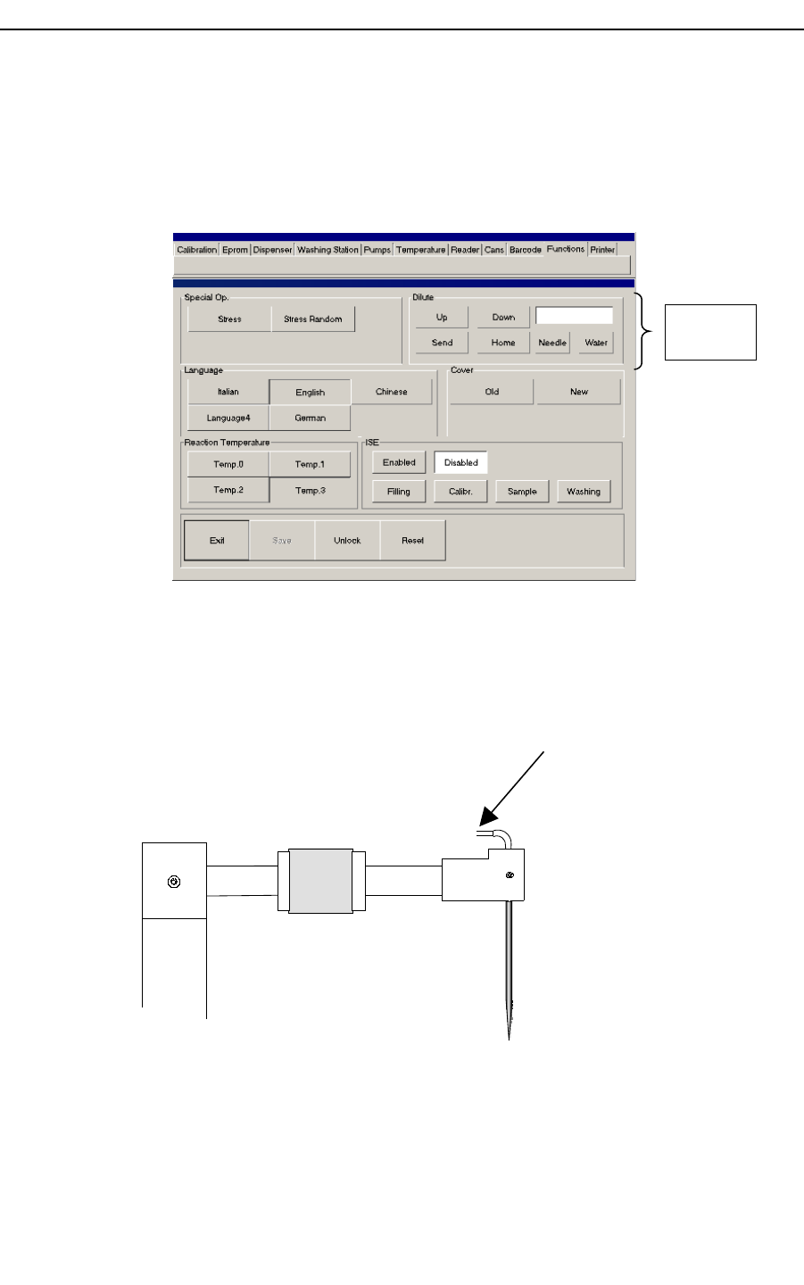
2.5.1 Testing Tubes with Dilutor
Using Dilute menu on “Functions” menu It’s possible to test heater Teflon tubes and needle
volumes.
Needle Test
Perform filling on “Washing Station” menu until hydraulic is
completely filled
On submenu “Dilute” select “Down” and input 450 on text box ,
select “Needle” and press “Send”
Verify that water column is nearly outside needle.
If not, needle has not right volume
Press “Home”
Preheater
Heater Teflon hydraulic Test
Hospitex Diagnostics 37
Testing
Tubes

SERVICE MANUAL ver 2.2
Perform filling on “Washing Station” menu until hydraulic is
completely filled
On submenu “Dilute” select “Down” and input 1900 on text box ,
select “Needle” and press “Send”
Select “Water”, select “Up” and press ”Send”
Select “Needle”, select “Down” and press ”Send”
Selezionare NEEDLE, selezionare DOWN e premere SEND.
Verify that water column is nearly outside heater.
If not, heater Teflon hydraulic has not right volume
Press “Home”
Preheater
Hospitex Diagnostics 38
SERVICE MANUAL ver 2.2
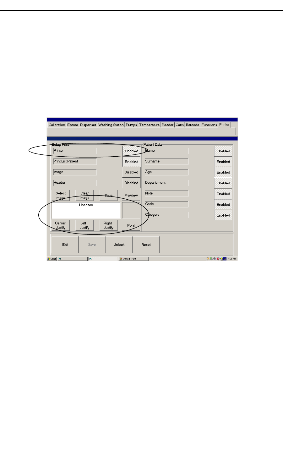
2.6 Printer
You can edit your printing format using Printer menu, see Figure 37. Before to enable
printer option, install your printer on PC instrument. In default option, printer is not
enabled.
After printer general enable, you can add logo to your format by “Image” selection and a
printing header by “Header” function.
Common printing functions are available in Options area.
In patient data you can select different features.
Figure 37 printer menu
Hospitex Diagnostics 39
General enable
Options
SERVICE MANUAL ver 2.2
3 PUMP SUBSTITUTION
To replace one of the peristaltic pumps on the side of instrument pull out the pump head
and unscrew the two tubes, see the below figure:
x x
HEAD
TUBE
Figure 38: Peristaltic pump
Note: do not intertwine the lateral tubes when you reinsert the pump.
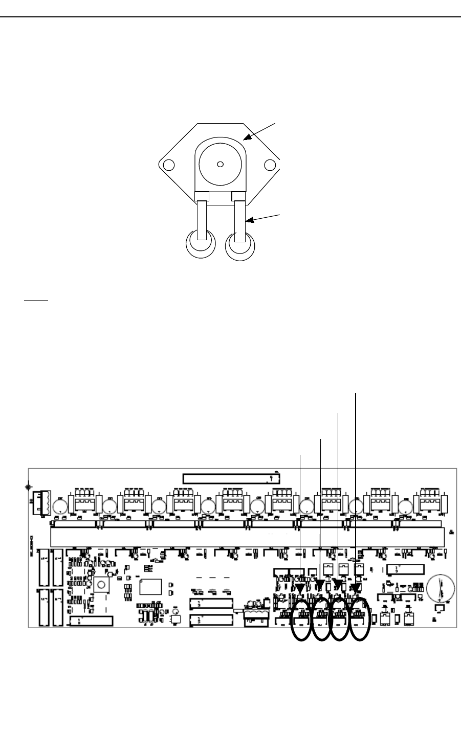
4 AD lines
Equipment main board has 4 AD lines :
1. Reaction Tray temperature……………………………………P42
2. Needle Heater temperature……………………………….P43
3. Environment temperature……………………………P44
4. Sinker temperature…………………………P45
Hospitex Diagnostics 40
SERVICE MANUAL ver 2.2
Lines 1 and 2 are used to control temperature , that’s because they have a gain(around
10) that makes reading very accurate.
Lines 3 and 4 are used just to monitor temperature(environment and sinker) , so they
have no gain. In order to have good reading on these lines it’s necessary to calculate
offset. Software uses an automatic procedure to evaluate offset on line 3 and 4
Be sure that sensor is connected on P44
Be sure that sensor is connected on P45
Switch on equipment
Use Service program on menu “Temperature”
Push “TMAX”button
Press F1 on keyboard (environment and sinker temperature will appear)
Disconnect sensor on P44 and wait for environment temperature monitor
becomes zero
Connect sensor on P44 again and wait temperature monitor reaches real value
starting from zero
Disconnect sensor on P45 and wait for sinker temperature monitor becomes
zero
Connect sensor on P45 again and wait temperature monitor reaches real value
starting from zero
Hospitex Diagnostics 41
SERVICE MANUAL ver 2.2
Notes :
Reaction tray temperature control according to environment temperature is
disabled if this procedure is not properly performed .
In order to clear current offsets use “Clear AD Offset” button on “Eprom”
menu
4.1 Hidden Keys
ESC : Reaction tray temperature auto calibration and sinker test can be suddenly
stop , by pressing ESC key ( see 1.3.7 section ) . Note that during auto calibration
current level and environment temperature will be saved.
F1 : During reaction tray temperature auto calibration and manual calibration ,
environment and sinker test can be shown by pressing F1 key ( see 1.3.7 section).
F11 : Service software allows user to monitor equipment working time by
pressing F11 key on each menu
F12 : Service software allows user to “reset & start again program” time by
pressing F12 key on each menu . This function is very important to unlock software
any time it’s necessary.
Hospitex Diagnostics 42
