5580522 01C Quicksyn FSL0010 Synthesizer Programming Manual
User Manual:
Open the PDF directly: View PDF ![]() .
.
Page Count: 17
DOC. NO. 5580522-01 | REV. C | ECN 001641
COMMUNICATIONS SPECIFICATIONS
QuickSyn Lite
Frequency Synthesizer

1
QuickSyn Lite Series of Synthesizers
Communications Specifications
ni-microwavecomponents.com
Notices
© 2016 National Instruments
No part of this document may be
copied, duplicated, or reproduced in
any form or by any means (including
electronic storage and retrieval or
translation into a foreign language)
without prior agreement and written
consent from National Instruments as
governed by United States and
international copyright laws.
National Instruments
4600 Patrick Henry Drive
Santa Clara CA 95054
Software Copyright
Original National Instruments software
may be distributed without consent
from National Instruments only if all
software and associated files are
included in the distribution and remain
unmodified.
Microsoft®, Windows®, Vista®, XP®,
and 2000® are registered trademarks of
Microsoft Corporation.
1
QuickSyn Lite Series of Synthesizers
Communications Specifications
ni-microwavecomponents.com
Introduction
In this document...
The scope of this document is to define the communication between
the QuickSyn Lite series of frequency synthesizers (Models FSL-0010,
FSL-0020, FSL-2740, FSL-5067, FSL-7682, and FSL-E020) and the
controlling system. This document describes the QuickSyn control and
query commands. The commands listed in this document may be sent
through the SPI and USB.
Goals
The primary goal for command communication is to allow fast, easy
setup for basic operations. In particular, it should permit easy
establishment of a new frequency setting. The commands must support
frequency specifications up to 20 GHz in 0.001 Hz steps.
Secondary goals include: support for very fast change to pre-computed
settings, support for traversal of a list of pre-computed settings with a
specified dwell, and support for computed sweeps of frequency with a
specified dwell.

2
QuickSyn Lite Series of Synthesizers
Communications Specifications
ni-microwavecomponents.com
Hardware Interface
The hardware includes a multi-purpose SPI connector and a USB
connector located on the front panel.
SPI Interface
The SPI hardware interface consists of a standard SPI interface plus
additionally assigned lines as defined in Table 1.
Table 1 Synthesizer Interface
Signal Description Connector
SPI_CLK
SPI clock, supplied by the controlling computer
(not the synthesizer). The controlling computer is
the SPI master, the synthesizer is the SPI slave.
Pin 20
SPI_SS
SPI Slave Select. This signal is an active low
input to the synthesizer. It frames command
communications. For each command, SPI_SS
goes low before the first bit is sent and goes
high after the last bit is sent.
Pin 18
SPI_MISO Master in, Slave out. Status and other returned info.
from the synthesizer to the controlling computer. Pin 24
SPI_MOSI Master out, Slave in. Command data from the
controlling computer to the synthesizer. Pin 22
TRIGGER
Rising edge active input. When enabled, the
trigger signal can initiate frequency change or
step through lists or sweeps.
Pin 14
LOCK Output indicating that the synthesizer is locked on
its current setting (+3.3V - locked, 0 V - unlocked). Pin 16
REF_LOCK
Output indicating that the synthesizer has
detected an external reference signal and locked
on that signal (+3.3V - locked, 0 V - unlocked).
Pin 13
PWR_+12V External +12V DC Supply. Pin 26, 28, 30
NOTE: The QuckSyn synthesizer requires a 15-second delay to reboot before it is
ready to accept commands.
RESET
Internally pulled-up to +3.3V with 100 kOhm
resistor. Active “LOW” signal will reset the
synthesizer to a default state.
Pin 1
GND Ground. Pin 2, 15,
25, 27, 29
N/C Not connected.
Pin 3, 4, 5, 6,
7
8, 9, 10, 11, 12
17, 19, 21, 23
3
QuickSyn Lite Series of Synthesizers
Communications Specifications
ni-microwavecomponents.com
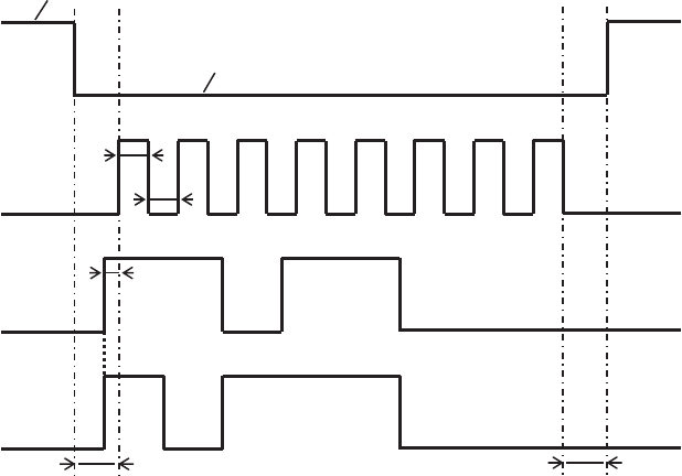
SPI SS
SPI CLK
SPI MISO
SPI MOSI
TCH
TCL
TSU
TSC TCS
+3.3 V
0 V
SPI is a standard first introduced by Motorola (now Freescale) for low-
cost communications among semiconductor devices. It allows for four
different possible clocking schemes defined by the polarity and phase
of the clock. SPI mode 0 is used to communicate to the QuickSyn
synthesizer. The synthesizer expects the CLK signal to be low at the
time that the SPI_SS signal is asserted. At this time, the first MOSI bit
will be set up. The synthesizer will sample incoming MOSI data at the
rising edge of the CLK and expects that the controlling computer will
also sample MISO at that edge. Subsequent MISO transitions will
occur on the falling edges of the CLK signal.
Transfers are always initiated with the most significant bit of the full
transfer and are ended with the least significant bit. The SPI_SS signal
is expected to remain asserted for the duration of the transfer. After
the last bit is transferred, the SPI_SS signal will go high.
Figure 1 SPI Timing
TSC > 25 nSec – select low before first clock
TCS > 25 nSec – clock low before slave select high
TSU > 15 nSec – data stable before rising edge of clock
TCH > 25 nSec – minimum clock high time
TCL > 25 nSec – minimum clock low time
FCLK ≤ 12 MHz – maximum clock frequency

4
QuickSyn Lite Series of Synthesizers
Communications Specifications
ni-microwavecomponents.com
USB Interface
The USB hardware interface consists of a standard female mini USB
B-type connector. This port is USB 2.0 compatible and is utilized as a
standard COM port (serial port) on the host PC. The serial data buffer
for this port is 64-bytes long (including the terminator); thus, it is
important not to exceed this length on any command data. All
commands must be terminated by a termination character (13, 0X0D).
The serial port parameters on the host PC must be set as 8 bits, no
parity, 1 stop bit, 115200 baud, no flow control.
Main Commands
Two command sets are available for controlling the QuickSyn
synthesizer—QuickSyn native commands and SCPI commands. The
SPI interface will only accept the native command set while the USB
interface will accept both the native commands and SCPI commands.
The synthesizer’s operation modes, output frequency, and power are
controlled by the main commands listed in Tables 2a, 2b, 2c, 2d, and 5.
Query commands are listed in Table 3 (SPI), Table 4 (other interfaces),
and Table 5 (SCPI).
Native commands for the USB interface are formatted the same as SPI
commands. However, these commands are formatted as ASCII
representations of hexadecimal values (i.e., each hexadecimal character
is one ASCII character). Thus, twice as many bytes are sent for each
command. Note that only single-byte characters may be used for these
commands because double-byte characters will not be interpreted
correctly by the QuickSyn module. Furthermore, these commands
must be sent separately with each command terminated by a
termination character (13, 0x0D). The query commands differ from
SPI query commands; therefore, refer to the applicable query
command table in this document.
Install software driver first to control the QuickSyn synthesizer via the USB connector.
Device drivers are available from the NI Microwave Components website
(ni-microwavecomponents.com). Instructions for installing the device drivers are in
the QuickSyn user guide, which is also available from the website.
NOTE

5
QuickSyn Lite Series of Synthesizers
Communications Specifications
ni-microwavecomponents.com
Table 2a Control Commands (no return data)
Description Size
(Bytes)
-----Header----- --------------------------Parameter---------------------------
Code Bits Bytes Bits Values
Set Output
Frequency 7 0C [55:48] 6 [47:0] Units of 0.001Hz
This commands sets the frequency with no change in power or other parameters.
Reset 1 0E
[7:0]
The Reset command sets the unit to one of the following three states:
1. Factory default
a. Frequency: center freq.
b. Power: ON
c. Reference source: internal
d. Reference output: ON
e. Triggering: disabled
2. User defined default 1
See command Save Current State in Flash below
3. User defined default 2
See command Save Current State in Flash below
Note: A delay or wait period of 2 ms is required after the Reset command is sent.
Select Ref.
Source: 2 06 [15:8] 1 [7:0] Int(0) / Ext(1)
Reference
Output 2 08 [15:8] 1 [7:0] OFF(0) / ON(1)
RF Output 2 0F [15:8] 1 [7:0] OFF(0) / ON(1)
Adjust Internal
Ref. 3 1B
[23:16]
2 [15:0] Units from 0 to FFFF
This requires a few seconds for hardware to update.
Save current
state in Flash 2 26
[15:8] 1 [0:7] 1 or 2 only
This command saves current settings as user-defined default 1 or 2 (see Reset command) and
requires a 100 ms wait delay. When unit is power cycled, the last saved default settings will be
used to initialize.
Restore current
state from Flash 2 27
[15:8] 1 [0:7] 0, 1 or 2 only. 0 - default
This command restores settings to the factory default 0, user-defined default 1, or user-defined
default 2 and requires a 50 ms wait delay. When unit is power cycled, the last restored default
settings will be used to initialize the unit.
Lock Recovery 2 28 [15:8] 1 [0:7] OFF(0) / ON(1)
This command allows/disallows retry if lock fails. Only one retry per frequency is allowed
GHz Model
10 FSL-0010
10 FSL-0020
10 FSL-E020
33.5 FSL-2740
58.5 FSL-5067
79 FSL-7082

6
QuickSyn Lite Series of Synthesizers
Communications Specifications
ni-microwavecomponents.com
The Synthesizer Reset command executes a full instrument re-initialization, which is functionally
equivalent to a power up. All commands in progress will be aborted. The synthesizer will reset to a
default state.
If the SPI interface is used, each query command needs to be executed twice.
Examples:
1. Set Output Frequency to 9.876543210 GHz
Convert 9.876543210 GHz to milliHertz: 9,876,543,210,000.
Convert 9,876,543,210,000 to 48-bit Hex: 08 FB 8F D9 82 10
Append Command Header (0C) in front of the Frequency:
0C 08 FB 8F D9 82 10
Send command: 0C 08 FB 8F D9 82 10
NOTE
NOTE

7
QuickSyn Lite Series of Synthesizers
Communications Specifications
ni-microwavecomponents.com
Table 2b Control Commands
Description Size
(Bytes)
-----Header----- --------------------------Parameter---------------------------
Code Bits Bytes Bits Values
List Point
Setup and
Write to
Flash
16 13 [127:120]
2
6
2
4
1
[119:104]
[103:56]
[55:40]
[39:08]
[0]
List point # (1 to 32767)
Freq in milliHertz
Reserved! Must be 0
Dwell time in usec (5 to
4,294,967,295(~1hr)) in 5us
increments.
RF Output: On(1)/Off(0)
This command places each point in temporary and permanent memory and requires a 300 ms wait
delay.
List Point
Setup and
Write to
RAM only -
Fast
16 4A
[127:120] 2
6
2
4
1
[119:104]
[103:56]
[55:40]
[39:08]
[0]
List point # (1 to 32767)
Freq in milliHertz
Reserved! Must be 0
Dwell time in usec (5 to
4,294,967,295(~1hr)) in 5us
increments.
RF Output: On(1)/Off(0)
This command only places each point in temporary memory and requires 100 μs wait delay.
Save List
Table 1 4B [07:00] Saves the entire List Table
This command saves the list to permanent memory. A delay of at least 50 ms plus 2.5 ms per
list_point is required before sending next command.
Run List
Point 3 14 [23:16] 2 [15:0] List point # (1 to 32767)
List Setup
And Run 8 15 [63:56]
4
2
1
[55:24]
[23:08]
[03:02]
[01:00]
Dwell time in usec (5 to
4,294,967,295(~1hr)) in 5us
increments. If 0, List Point
Dwell Time is used
# of times to run list
1 to 32767, 0 - infinite
Enable List Trigger(1)
Enable List Point Trig(2)*
Software Trigger (0)
Direction Up(0) – Lo to Hi
Down(1) – Hi to Lo
Up & Down(2)
List points must be loaded first. A list command cannot be executed with FM on.
*The minimum period of pulses in list-point-trigger mode is 150 μs
Stop List 1 20 [07:00]
Erase List 1 22 [07:00]
This command requires a wait delay of 200 ms. Always send the Stop List command before
sending Erase List.

8
QuickSyn Lite Series of Synthesizers
Communications Specifications
ni-microwavecomponents.com
Examples:
1. Set List Point 1 with Output Frequency of 9.111222333 GHz,
Dwell Time 3 sec, RF Output ON, Pulse Modulation OFF
Field List Point Frequency Reserved Dwell time
Units No. milliHertz microseconds
Decimal 1 9111222333000 0 3000000
Hex 0001 08495F2BAE48 0000 002DC6C0
Command 13 00 01 08 49 5F 2B AE 48 00 00 00 2D C6 C0 01
2. Run List Point 2: 14 00 02
3. List Setup and Run applies to entire list. The List parameters are:
Dwell Time: 10sec, Number of times to execute list: 3, List Point
Trigger: ON, Direction: UP.
4. Wait 100 μs.
After this command is executed, external trigger signals should be
applied for each List Point.
5. List Setup and Run applies to the entire list. The list parameters are:
Dwell Time: 5sec, Number of times to execute list: 1, List Trigger:
ON, List Point Trigger: OFF, Direction: Down.
Field Dwell time
Times to
Execute
List Point
Trigger Direction
Units μs No. Boolean No.
Decimal 10000000 3 Yes Up
Hex 00989680 0003 ————08————
Command 15 00 98 96 80 00 03 08
Field Dwell time
Times to
Execute List Trigger Direction
Units μs No. Boolean No.
Decimal 50000000 1 Yes
Hex 004C4B40 0001 ————05————
Command 15 00 4C 4B 40 00 01 05
NOTE
Before re-programming List Points, execute Erase List Command (0x22). Send a Reset command
followed by an RF Output On command upon exiting List Mode to return to normal mode.

9
QuickSyn Lite Series of Synthesizers
Communications Specifications
ni-microwavecomponents.com
Table 2c Control Commands (fast sweep)
Description Size
(Bytes)
-----Header---- --------------------------Parameter---------------------------
Code Bits Bytes Bits Values
Fast
Frequency
Sweep Setup
and Run
24 17 191:184
6
6
2
2
4
2
1
[183:136]
[135:88]
[87:72]
[71:56]
[55:24]
[23:08]
[03:02]
[01:00]
Start Freq in mlHz
Stop Freq in mlHz
# of points (1 to 32767)
Reserved! Must be 0
Dwell time in usec (0 to
4,294,967,295(~1hr))
In 5us increments
# of times to run sweep
1 to 32767, 0 - infinite
Enable Sweep trigger(1)
Enable Sweep Point trg(2)*
Software Trigger (0)
Direction Up(0) – Lo to Hi
Down(1) – Hi to Lo
Up & Down(2)
*The minimum period of pulses in sweep-point-trigger mode is 150 μs.
Example:
1. Fast Frequency Sweep Setup and Run command.
Settings:
Start Frequency: 5 GHz
Stop Frequency: 8 GHz
Number of Points Between Frequencies (inclusive): 30
Power: 18 dBm
Dwell Time: 3 sec
Number of times to run sweep: 2
Enable Sweep Trigger: Yes
Enable Sweep Point Triggers: No
Direction: Up
Field
Start
Frequency
Stop
Frequency
Num
points Reserved
Dwell
time
Num
RunsTrig Dir
Units milliHertz milliHertz μs Bool
Decimal 5000000000000 8000000000000 30 0 3000000 2 Yes Up
Hex 048C27395000 0746A5288000 001E 0000 002DC6C0 0002
—04—
17 04 8C 27 39 50 00 07 46 A5 28 80 00 00 1E 00 00 00 2D C6 C0 00 02 04
After this command is executed, ONE Sweep trigger signal should
be applied.

10
QuickSyn Lite Series of Synthesizers
Communications Specifications
ni-microwavecomponents.com
Table 2d Control Commands (normal sweep)
Description Size
(Bytes)
-----Header----- --------------------------Parameter---------------------------
Code Bits B
y
tes Bits Values
Normal
Frequency
Sweep Setup
and Run
28
1C
223:216
6
6
6
2
4
2
1
[215:168]
[167:120]
[119:72]
[71:56]
[55:24]
[23:08]
[03:02]
[01:00]
Start Freq in mlHz
Stop Freq in mlHz
Step Freq in mlHz *
Reserved! Must be 0
Dwell time in usec (0 to
4,294,967,295(~1hr))
In 5us increments
# of times to run sweep
1 to 32767
Enable Sweep trigger(1)
Enable Sweep Point trg(2)
Software Trigger (0)
Direction Up(0) – Lo to Hi
Down(1) – Hi to Lo
Up & Down(2)
Stop Sweep 1 21 [07:00]
* The frequency span between start and stop frequencies must be evenly divisible by step frequency
;
otherwise, the sweep will never reach stop frequency.
11
QuickSyn Lite Series of Synthesizers
Communications Specifications
ni-microwavecomponents.com
Table 3 SPI Query Commands (with return data)
Description ------------Command--------------
----------------------Return Data----------------------
Size
(Bytes)
Header Don’t
care
Code Bits Bits Total
Bytes Bytes Data
bits Values
Get ID
12 01 [95:88] [87:0] 12 1
2
2
2
5
[95:88]
[87:72]
[71:56]
[55:40]
[39:00]
‘Don’t Care’
Model#
Option#
Soft.ver.
Serial#
Get Status 2 02 [15:8] [7:0] 2 1
1
[15:8]
[0]
[1]
[2]
[3]
[4]
[5]
[6]
[7]
‘Don’t Care’
No Ext Ref Detected(0)*
Ext Ref Detected(1)*
RF locked(0)
RF unlocked(1)
Ref locked(0)
Ref unlocked(1)
RF Outp On(1)
Voltage OK(0)
Voltage Err(1)
REF outp off(0)
REF outp on(1)
Not used
Lock recovery on(1)/off(0
)
* Only valid when Ext Ref is selected.
Get Freq 7 04 [55:48] [47:0] 7 1
6
[55:48]
[47:0]
‘Don’t Care’
mlHz
Ref Source
Query
2 07 [15:8] [7:0] 2 1
1
[
15:8]
[
0:7]
‘Don’t Care’
Int(0)/Ext(1)
Get
Temperature
3 10 [23:16] [15:0] 3 1
2
[23:16]
[15:0]
‘Don’t Care’
Temper. x10
Example:
Get Output Frequency
Send command: 04 00 00 00 00 00 00
Send command: 04 00 00 00 00 00 00
Read Data: 00 08 FB 8F D9 82 10
Disregard ‘Don’t Care’ bits [55:48] - 00. Convert 08 FB 8F
D9 82 10 to decimal to get frequency in milliHertz:
9,876,543,210,000
NOTE
All query commands must be sent twice. Data output from the unit can be read back after
the second query command.

12
QuickSyn Lite Series of Synthesizers
Communications Specifications
ni-microwavecomponents.com
Table 4 Query Commands (with return data) for Native USB
----------------------Command--------------------
-
-
---------
-
---------------Return Data--------------------------
Description Size
(Bytes) Code Total
Bytes Bytes
D
ata
b
its Values
Get ID
2 01 22 2
2
2
5
[87:72]
[71:56]
[55:40]
[39:00]
Model#
Option#
Soft.ver.
Serial#
Get Status 2 02 2
1
[0]
[1]
[2]
[3]
[4]
[5]
[6]
[7]
No Ext Ref Detected(0)*
Ext Ref Detected(1)*
RF locked(0)
RF unlocked(1)
Ref locked(0)
Ref unlocked(1)
RF Outp Off(0)
RF Outp On(1)
Voltage OK(0)
Voltage Err(1)
REF outp off(0)
REF outp on(1)
Not used
Lock recovery
on(1)/off(0)
* Only valid when Ext Ref is selected.
Get Freq 2 04 12 6 [47:0] mlHz
Ref Source
Query
2 07 2 1
[
0:7] Int(0)/Ext(1)
Get
Temperature
2 10 4 2 [15:0] Temper. x10
Example:
Get Output Frequency
Send command: 04
Read Data: 08 FB 8F D9 82 10
Convert 08 FB 8F D9 82 10 to decimal to get frequency in
milliHertz: 9,876,543,210,000
NOTE
Only the Get Temperature command must be sent twice. All other data output from the unit
can be read back after the first query command.

13
QuickSyn Lite Series of Synthesizers
Communications Specifications
ni-microwavecomponents.com
Table 5 SCPI Commands for USB
Command Parameter Result Description Example
FREQ Value GHz, MHz, KHz,
mlHz[default]
Set Output
Frequency
FREQ 2.2GHz
FREQ? Value in mlHz Get Output
Frequency
FREQ?
2200000000000
*RST
N
ONE Reset *RST
ROSC:SOUR EXT/INT Select Ref.
Source
ROSC:SOUR
EXT
ROSC:SOUR? EXT/INT Get Ref. Source ROSC:SOUR?
EXT
OUTP:ROSC:
STAT
ON/OFF Reference
Output
Enable/Disable
OUTP:ROSC:S
T
AT ON
OUTP:ROSC:
STAT?
1(ON)/0(OFF) Get Reference
Output Status
OUTP:ROSC:S
T
AT?
1
OUTP:STAT ON/OFF RF Output
Enable/Disable
OUTP:STAT
ON
OUTP:STAT? 1(ON)/0(OFF) OUTP:STAT
1
DIAG:CAL:R
EF:DAC
0 TO 65535 – DAC
Value
Adjust Internal
Ref. DAC
Value
DIAG:CAL:RE
F
:DAC 30000
DIAG:CAL:R
EF:DAC?
0 TO 65535 – DAC Value Get Internal
Ref. DAC
Value
DIAG:CAL:RE
F
:DAC?
30000
*SAV 1,2 - States Save current
state in Flash
*SAV 1
*RCL 0 – factory default
1 – setting 1
2 – setting 2
Restore current
state from
Flash
*RCL 0
FREQ:LRSTAT ON/OFF Lock Recovery
Enable/Disable
FREQ:LRSTAT
ON
FREQ:LRSTAT? 1(ON)/0(OFF) Get Lock
Recovery
Status
FREQ:LRSTAT
?
1
LIST:PVEC 1) List point # (1 to 32767),
2) Freq,
3) Reserved! Must be 0
4) Dwell time in us, ms, s
(from 5us to 4,294 s (~1hr)),
default - us
5) Pulse Mod (On/OFF)
6) RF Output (On/Off)
7) Save to Flash (F or f) –
Optional field
List Point
Setup
LIST:PVEC
1,3GHz,0,1s,
OFF,ON,F
LIST:SAV
N
one Save List
Table to Flash
LIST:SAV
LIST:PVEC:R
UN
List point # (1 to 32767)
Run List
Point
LIST:PVEC:RU
N 1
NOTE
SCPI commands can only be used with QuickSyn synthesizers that have version 100 or
higher firmware.

14
QuickSyn Lite Series of Synthesizers
Communications Specifications
ni-microwavecomponents.com
Table 5 SCPI Commands for USB (continued)
Command Parameter Result Description Example
LIST:SETUP 1) Dwell time in us, ms, s
(from 5us to 4,294 s (~1hr)) ,
default - us
2) # of times to run list (1 to
32767), 0 - infinite
3) Trigger:
0 – Software Trig
1 – List Trig
2 – List Point Trig
4) Direction:
0 – Lo to Hi
1 – Hi to Lo
2 – Up & Down
5) Optional field
‘RUN’ – run list,
Don’t otherwise
List Setup
(And Run –
Opt)
LIST:SETUP
2s,0,2,2,RUN
LIST:STAR(T) # of times to run list (1
to 32767), 0 - infinite
Start List
Execution
LIST:STAR 5
LIST:STOP
N
one Stop List LIST:STOP
LIST:ERAS
N
one Erase List LIST:ERAS
SWE:FAST:F
REQ:SETUP
1) Start Freq
2) Stop Freq
3) # of points (1 to 32767) in
the sweep
4) Reserved! Must be 0
5) Dwell time in us, ms, s
(from 5us to 4,294 s (~1hr)) ,
default - us
6) # of times to run sweep
1 to 32767, 0 – infinite
7) Trigger:
0 – Software Trig
1 – Sweep Trig
2 – Sweep Point Trig
8) Direction:
0 – Lo to Hi
1 – Hi to Lo
2 – Up & Down
9) Optional field
‘RUN’ – run sweep, Don’t
otherwise
Fast
Frequency
Sweep Setup
(and Run –
Opt)
SWE:FAST:FR
E
Q:SETUP
2GHz,10GHz,80
0,1s,
10,0,0
SWE:FAST:FR
EQ:STAR(T)
# of times to run sweep
1 to 32767, 0 - infinite
Start FF Sweep SWE:FAST:FR
E
Q:STAR 0

15
QuickSyn Lite Series of Synthesizers
Communications Specifications
ni-microwavecomponents.com
Table 5 SCPI Commands for USB (continued)
Command Parameter Result Description Example
SWE:NORM:
FREQ:SETUP
1) Start Freq
2) Stop Freq
3) Step Freq
4) Reserved! Must be 0
5 Dwell time in us, ms, s
(from 5us to 4,294 s (~1hr)),
default - us
6) # of times to run sweep
1 to 32767, 0 – infinite
7) Trigger:
0 – Software Trig
1 – Sweep Trig
2 – Sweep Point Trig
8) Direction:
0 – Lo to Hi
1 – Hi to Lo
2 – Up & Down
9) Optional field
‘RUN’ – run sweep, Don’t
otherwise
Normal
Frequency
Sweep Setup
(and Run –
Opt)
SWE:NORM:F
R
EQ:SETUP
2GHz,8GHz,1G
Hz,0,5ms,
200,2,2,RUN
SWE:NORM:F
REQ:STAR(T)
# of times to run sweep
1 to 32767, 0 - infinite
Start NF Sweep SWE:NORM:F
R
EQ:SETUP 1
SWE:NORM:P
OW:STAR(T)
# of times to run sweep
1 to 32767, 0 - infinite
Start NP Sweep SWE:NORM:P
O
W:STAR 3
SWE:STOP
N
one Stop Sweep SWE:STOP
*IDN? Character String Get ID *IDN?
Phase
Matrix,FSW-
0010,
0000007f,0,300a
STAT? [15:8] - ‘Don’t Care’
[0] - No Ext Ref Detected(0)*
Ext Ref Detected(1)*
[1] - RF locked(0)
RF unlocked(1)
[2] - Ref locked(0)
Ref unlocked(1)
[3] - RF Outp Off(0)
RF Outp On(1)
[4] - Voltage OK(0)
Voltage Err(1)
[5] - REF outp off(0)
REF outp on(1)
[6] - Not used
[7] - Lock recovery
on(1)/off(0)
Get Status
STAT?
00A8
* Only valid when Ext Ref is selected.
DIAG:MEAS? 21 Value Deg. C Get
Temperature
DIAG:MEAS
? 21
38.9
