R 21_Time Sharing_System_Reference_Oct68 21 Time Sharing System Reference Oct68
R-21_Time-Sharing_System_Reference_Oct68 R-21_Time-Sharing_System_Reference_Oct68
User Manual: R-21_Time-Sharing_System_Reference_Oct68
Open the PDF directly: View PDF ![]() .
.
Page Count: 106 [warning: Documents this large are best viewed by clicking the View PDF Link!]
REFERENCE
MANUAL
TJME-
SHARING
SYSTDi
L.
Peter
Deutsch
Larry
Durham
Butler
W.
Lampson
t'fn1versity
of
California,
Berkeley
Document No.
R-2l
Revised October 22,
1968
Office
of
Secretary
of
Defense
Advanced Research
Projects
Agency
Washington,
D.
C.
20325

1.0
Introductory.
.
2.0
The
Scheduler.
.
PAC
TABLE
..
TABLE
OF
CONTENTS
. . . .
Phantom
user
queue
entry
••
3.0 Forks and Jobs . •
3.1
Creation
of
Forks •
Hierarchy
of
Processes
• •
3.2
Memory
Acquisition.
• •
3.3
Panic
Conditions.
•
. . . . . .
3.4 Jobs
••.••••
Job Tables •
4.0 Program
Interrupts
• • . . .
5.0
The
Swapper and
Memory
Allocation
••
6.0 Miscellaneous
Featur~s
.
7.0
Teletype
Input-Output.
• • ·
TELETYPE
SYSTEM
POINTERS
TElETYPE
TABLE
•
TELETYPE
BUFFERS
•
. . .
8.0
Drum
and
Buffer
Organization;
Devices.
8.1
File
Storage
on
the
Drum.
• . • • •
8.2
File
Buffers
•.•.•.
8.3
Devices.
• • • • •
Layout
of
a
File
Buffer.
Forma~
of
an Index Block • .
Device Indexed Tables • • • • •
9.0
Sequential
Files
. . . • • .
9.1
Sequential
Drum
Files
.
9.2 Other
Sequential
Files.
9.3
File
Control
Blocks
.•
9.4 Permanently
Open
Files.
10.0
Random
Drum
Files
•.••.
10.1
Direct
Drum
Access
11.0
Subroutine
Files
. • • •
.
".
1-1
2-1
2A
2B
3-1
3-1
3A
3-4
3-5
3-7
3B
4-1
5-1
6-1
7-1
7A
7B
7C
8-1
8-1
8-2
8-3
8A
8A
8B
9-1
9-1
9-7
9-11
9-11
10-1
10-3
11-1
12.0
File
Naming
System . . . • . •
12-1
13·0
14.0
12.1
File
Naming. . . . • • • .
12-2
12.2
Accessing
Other
Users'
Files,
Special
Groups
12-4
12.3
Pseudonyms.
. . . . • • . • • . . . . .
12-5
12.4
Doing I/O
to
Files,
File
Numbers
12-5
12.5
Opening
Input
Files
•.
TAPE
or
PERMANENT
FILES.
SCRATCH
FII~S.
.
BUILT-IN
FILES
.
SPECIAL
GROUPS
.
PSEUDONYMS.
. .
FILE
DIRECTORY
DESCRIPTION
USER
DIRECTORY
DESCRIPTION
.
.
12.6
Opening
Output
Files
•
12-6
12A-l
12A-l
12A-1
12A-2
12A-2
l2A-3
l2A-4
12-8
12.7
Miscellaneous
File
Operations.
.
12-10
12.8
Opening
Scratch
Files.
. . . • .
.•
. .
12-12
12.9
Format
of
the
File
Directory,
Some
Implementation
Details
. . .
~
. . . . • . . . .
12-13
12.10
Miscellaneous
Services
...
Miscellaneous
Executive
Features
.
StrinG
Processing
System .
14.1
Strine
Pointer
Load
and
Store
Operations.
14.2
String
Read and
Write
Operations
•....•.
14.3
String
Compare
Operations
14.4
String
Input/Output
.••.•
14.5
Hash Table
J~okup
Instructions
.
15.0
Floating
Point
Instructions
••••.••.
15.1
Floating
Point
Representation
•.
15.2
Floating
Point
Arithmetic
•.•
12-14
13-1
14-1
14-1
14-1
14-3
14-3
14-4
15-1
15-1
15-2
15-3
15-4
A-I
B-1
15.3
Input/Output
Formats and Conventions
15.4
Input/Output
Operations..
•
••.
BRS
TABLE.
SYSTEM
PROGRAMMED
OPERATORS.
.
1-1
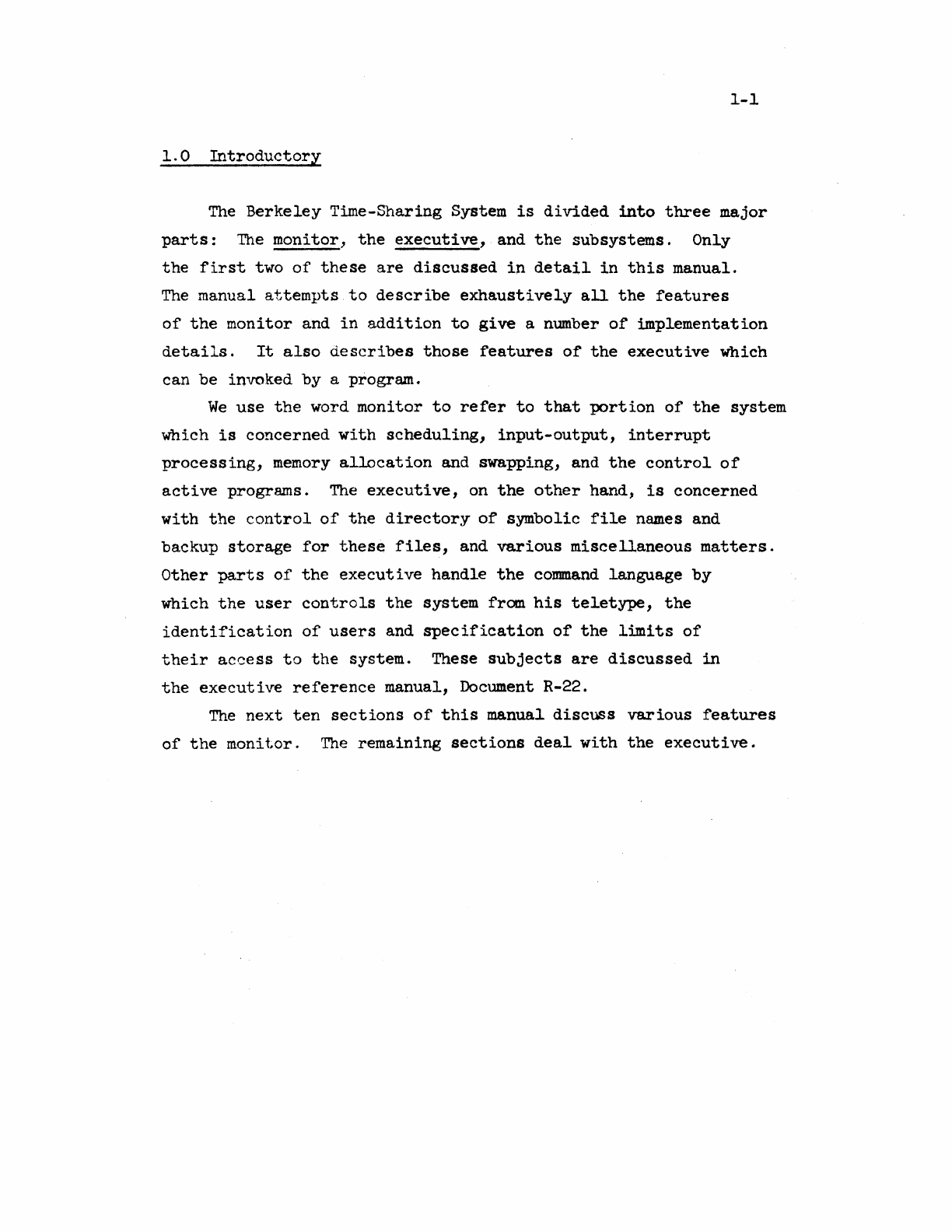
1.0
Introductory
The
Berkeley
Time-Sharing System
is
divided
into
three
major
parts:
The
monitor,
the
executive,
and
the
subsystems.
Only
the
first
two
of
these
are
discussed
in
detail
in
this
manual.
The
manual
attempts
to
describe
exhaustively
all
the
features
of
the
monitor
and
in
addition
to
give
a number
of
implementation
details.
It
also
describes
those
features
of
the
executive
which
can be invoked by a program.
We
use
the
word
monitor
to
refer
to
that
portion
of
the
system
which
is
concerned
with
scheduling,
input-output,
interrupt
processing,
memory
allocation
and swapping, and
the
control
of
active
programs.
The
executive,
on
the
other
hand,
is
concerned
with
the
control
of
the
directory
of
symbolic
file
names and
backup
storage
for
these
files,
and
various
miscellaneous
matters.
Other
parts
of
the
executive
handle
the
command
language
by
which
the
user
controls
the
system fram
his
teletype,
the
identification
of
users
and
specification
of
the
limits
of
their
access
to
the
system. These
subjects
are
discussed
in
the
executive
reference
manual, Document R-22.
The
next
ten
sections
of
this
manual
discuss
various
features
of
the
monitor.
The
remaining
sections
deal
with
the
executive.
2-1
2.0
The
Scheduler
The
primary
entities
with
which
the
time-sharing
system
is
concerned
are
called
active
programs.
Each
active
program
is
an
abstract
object
capable
of
executing
machine
instructions.
At
least
one
active
program
is
associated
with
each
active
user,
but
a
user
may
have
many
programs,
each
computing
independently
under
his
control.
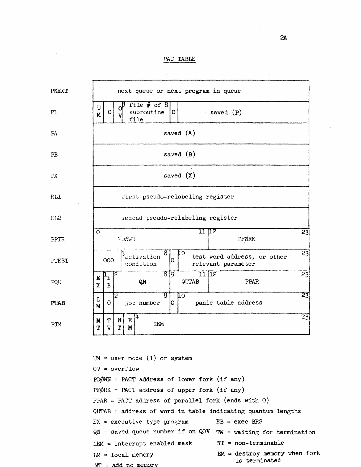
An
active
program
is
defined
by
its
entry
in
the
program
active
table
(PAC
table
or
PACT).
This
table
contains
all
of
the
information
required
to
specify
the
instantaneous
state
of
the
extended
computer which
the
user
is
programming,
except
for
that
contained
in
the
user's
memory
or
in
the
system's
permanent
tables.
The
structure
of' a
PACT
entry
is
displayed
on
the
following
page,
together
with
brief
notes
about
the
significance
of
the
various
items.
These
matters
will
be
explained
in
more
detail
in
the
following
few
sections.
It
will
be
observed
that
PACT
contains
locations
for
saving
the
program
counter
and
the
contents
of
the
active
A,
B and X
registers.
It
also
contains
two
pseudo-relabeling
registers
for
the
user.
A
third
one,
which
specifies
the
monitor
map,
is
kept
in
the
job
tables.
The
matter
of
pseudo-relabeling
is
discussed
in
detail
in
Section
5.
There
is
a word
called
PTEST
which
determines
the
conditions
under
which
the
program
should
be
reactivated
if
it
is
not
currently
running.
The
panic
table
address
in
PTAB
and
the
three
pointers
called
PFORK,
PDOWN
and
PPAR
are
discussed
in
Section
3 on
forks.
The word
called
PTAB
contains
in
bits
2
through
8
the
number
of
the
job
to
which
this
program
belongs.
The
top
of
PQU
contains
information
about
the
amount
of
time
for
which
the
program
is
allowed
to
compute
before
it
is
dismissed.
A
job
table
called
QUR
counts
the
number
of
clock
cycles
remaining
before
the
program
is
dismissed,
and
three
bits
of
QUTAB
point
to
a
table
which
specifies
the
length
of
time
which
the
program
should
be
allowed
to
run
when
it
is
activated.
All
times
1n
the
discussion
are
measured
in
periods
of
the
60-cycle
computer
clock.
PNEXT
PL
PA
PB
PX
RLl
RL2
PPTR
prEST
PQU
PTAB
PIM
2A
PAC
TABLE
next
queue
or
next
program
in
queue
U 0
~
file
if
of
8
(p)
M 0 V
subroutine
0
saved
file
saved
(A)
saved
(B)
saved
(X)
l'i.rst
pseudo-relabeling
register
sec()nd
pseudo-relabeling
register
0
11
12
pj6w~r
PF¢RK
13
. . 8
000
I
~ctl~a~lon
0
~o
test
word
address,
or
other
~:ondltlon
relevant
parameter
E ~2 8 9
11
12
X B
Q,N
GlJrAB
PPAR
2 8
0-0
L
M 0
Job
number 0
panic
table
address
~--
M T N
~I
rEM
T w T
UM
=
user
mode
(l)
or
system
OV
=
overflow
pn¢WN
=
PACT
address
of
lower
fork
(if
any)
PFPRK
=
PACT
address
of
upper
fork
(if
any)
FPAR
:=
PACT
address
of
pa.rallel
fork
(ends
with
0)
QUTAB
=
address
of
word
in
table
indicating
quantum
lengths
EX
=
executive
type
program
EB
=
exec
BRS
I
I
j
1
I
r
I
I
I
I
23
I
231
I
23
1
23
23
Q~
=
saved
queue
number
i~
on
QOV
TW
=
waiting
for
termination
rEM
=
interrupt
enabled
mask
1M
=
local
memory
MT
=
add
no
memory
NT
=
non-terminable
EM
=
destroy
memory when
fork
is
terminated
2-2
A program
is
a.lloT..red
to
run
for
a
fixed
period
of
time,
after
which
it
is
dismissed
if
any
other
programs
are
ready
to
run.
This
time
is
called
a
long
quanttun.
It
may
be
different
for
different
programs.
In
fact,
the
size
of
the
long
quantum
is
determined
by
the
entry
in
QTAB
which
is
pointed
to
by
the
program's
QUTAB
in
PACT.
When
a program
is
activated,
it
is
first
allowed
to
run
for
a
short
quantum. During
this
time
it
cannot
be
dismissed
except
by
its
own
request.
The
length
of
the
short
quantum
is
tentatively
going
to
be
the
same
for
all
users.
It
is
put
into
a word
called
TlME;
the
long
quantum
is
also
put
into
a word
called
TTlME
at
this
time.
Both
are
decremented
at
every
clock
cycle.
When
TIME goes
negative,
a word
called
ACTR
is
checked
to
determine
whether
any program which
is
dismissed
for
I/O
can
be
run.
If
not,
the
program
is
allowed
to
continue.
At
each
subsequent
clock
cycle
the
program
may
be
dismissed
if
any programs
dismissed
for
I/O
are
ready
to
run.
It
may
also
be
dismissed
when
the
long
quantum
is
exhausted
if·
any
other
programs
are
waiting
to
run.
In
either
case
it
is
said
to.
be
dismissed
for
quantum
overflow.
If
ACTR
indicates
that
another
program
dismissed
for
I/O
is
ready
to
run
at
the
end
of
the
short
quantum,
the
program
is
also
dismissed
for
quantum
overflow.
In
order
to
allow
an
efficient
~plementation
of
this
scheme,
ACTR
is
incremented
by
every
interrupt
routine
which
takes
action
allowing
a program which
is
waiting
for
I/O
to
run.
ACTR
is
set
to
-1
when
a program
is
activated.
When
a program
is
dismissed
for
I/O,
TT:mE
is
put
into
QUR.
When
the
program
is
reactivated,
TTIME
is
set
from
QUR.
TIME
is
reset
to
the
full
short
quantum. That
is,
the
long
quantum
is
allowed
to
run
down
while
a program computes,
regardless
of
whether
it
has
to
wait
for
I/O
between compute,tions. On
the
other
hand, a program
is
always
given
a
full
short
quantum.
If
a program
is
dismissed
for
quantum
overflow,
it
is
given
a
new
long
quantum
when
it
is
reactivated.
There
are
two
operations
available
to
the
user
which
are
connected
with
the
quantum
overflow
machinery.
BRS
45
causes
the
user
to
be
dismissed
as
though he had overflowed
his
quantum.
BRS
57
guarantees
to
the
user
upon
return
at
least
16
msec
of
2-3
uninterr~pted
computation.
This
feature
is
implemented
by
dismissing
the
user
if
less
tha.n 16
;TI~;ec
remain
in
his
quantum.
Ordinarily,
the
code which
is
being
executed
at
any
particular
instant
is
that
belonging
to
the
program which
is
currently
active.
This
situation
may
be
disturbed,
however, by
the
occurrence
of
interrupts
from I/O
devices.
These
interrupts
cause
the
computer
to
enter
system
mode
and
are
processed
entirely
independently
of
the
currently
running
program. They
never
take
direct
action
to
disturb
the
running
of
this
program,
although
they
may
set
up
conditions
in
memory
which
will
cause
some
other
program
to
be
activated
when
the
presently
running
one
is
dismissed.
Interrupt
routines
always
run
in
system mode.
Other
code which
may
be
running
which
may
not
belong
to
the
program
currently
active
is
the
code
of
system
programmed
operators
or
BRS
routines.
These
routines
s.re
not
re-entrant
and
therefore
should
not
be
dismissed
by
the
clock.
To
ensure
that
they
will
not
be,
the
convention
is
established
that
the
clock
will
not
dismiss
a program
running
in
system mode.
In
order
to
~larantee
that
a·user
program
will
not
monopolize
the
machine by
executing
a
large
number
of
SYSPOPs,
the
user
mode
trap
is
turned
on
when
the
clock
indicates
that
a program
is
to
be
dismissed.
The
trap
will
occur
and
cause
dismissal
as
soon
as
the
program
returns
to
user
mode.
The
PACT
word
called
PTEST
contains
the
activation
condition
for
a
currently
inactive
program.
The
condition
for
activation
is
contained
in
the
6 opcode
bits
of
this
word,
while
the
address
field
normally
contains
the
absolute
address
of
a word
to
be
tested
for
the
~pecified
condition.
(ThiS
word
is
usually
something
like
TTYBRK
for
a
user's
teletype~
It
is
possible,
however,
for
the
address
to
contain
a
time
count,
in
the
case
where
the
activation
condition
is
that
a
certain
amount
of
time
should
elapse.
It
is
also
possible
for
the
address
to
hold
a mask
indicating
which program
interrupt
has
occurred.
The
following
activation
conditions
are
possible:
o
Word
greater
than
0
I
Word
less
than
or
equal
to
0
2
Word
greater
than
or
equal
to
0
3
Word
less
than
or
equal
to
teletype
early
warning
4
Special
test.
The
address
points
to
a
special
activation
test
routine.
5
Interrupt
occurred.
The
address
contains
the
number
of
the
interrupt
which
occurred.
2-4
a
dead
1
running
2
BRS
31
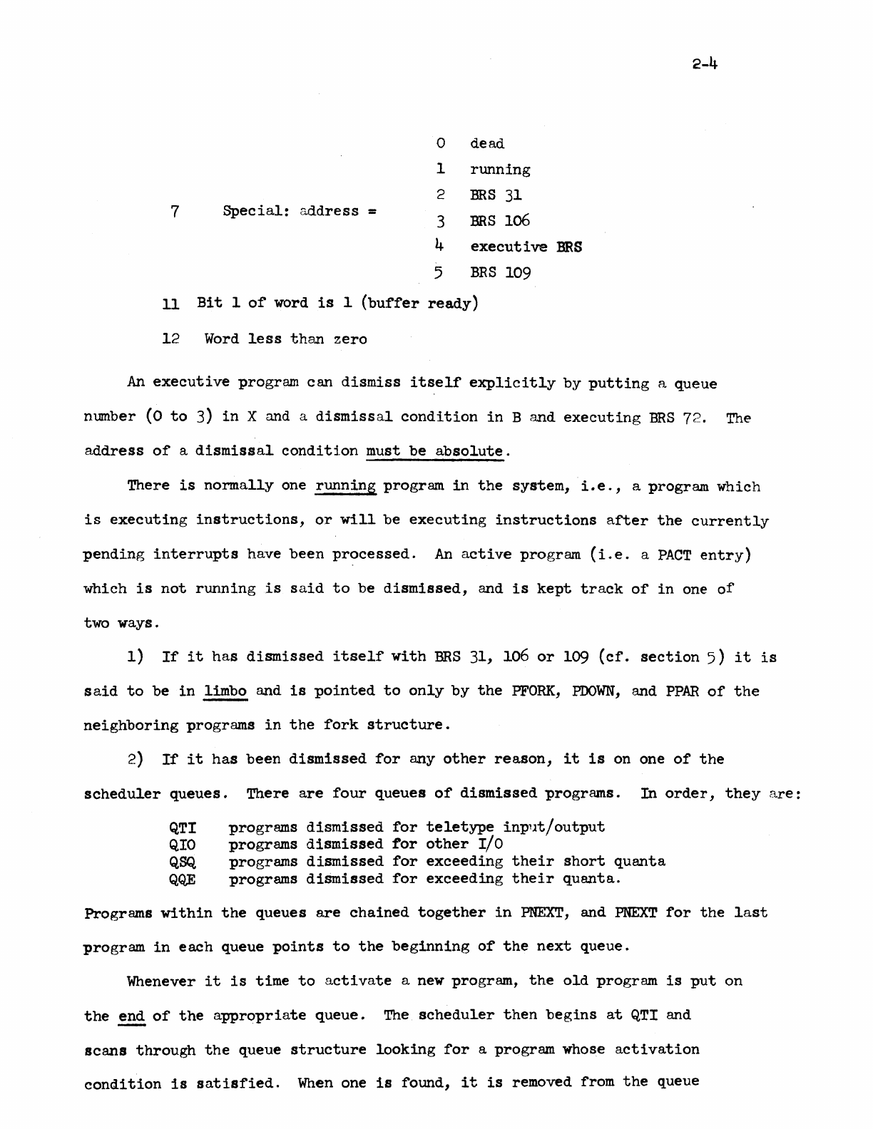
7
Special:
address
= 3
BRS
106
4
executive
BRS
5
BRS
109
11
Bit
1
of
word
is
1
(buffer
ready)
12
Word
less
than
zero
An
executive
program
can
dismiss
itself
explicitly
by
putting
a queue
number
(0
to
3)
in
X and a
dismissal
condition
in
B and
executing
BRS
72.
The
address
of
a
dismissal
condition
must
be
absolute.
There
is
normally
one
running
program
in
the
system,
i.e.,
a program which
is
executing
instructions,
or
will
be
executing
instructions
after
the
currently
pending
interrupts
have
been
processed.
An
active
program
(i.e.
a
PACT
entry)
which
is
not
running
is
said
to
be
dismissed,
and
is
kept
track
of
in
one
of
two ways.
1)
If
it
has
dismissed
itself
with
BRS
31,
106
or
109
(cf.
section
5)
it
is
said
to
be
in
limbo and
is
pointed
to
only
by
the
PFORK,
PDOWN,
and
PPAR
of
the
neighboring
programs
in
the
fork
structure.
2)
If
it
has
been
dismissed
for
any
other
reason,
it
is
on one
of
the
scheduler
queues.
There
are
four
queues
of
dismissed
programs.
In
order,
they
are:
QTI programs
dismissed
for
teletype
inp
1
1t/output
QIO
programs
dismissed
for
other
I/O
QSQ
programs
dismissed
for
exceeding
their
short
quanta
QQE
programs
diSmissed
for
exceeding
their
quanta.
Programs
within
the
queues
are
chained
together
in
PNEXT,
and
PNEXT
for
the
last
program
in
each
queue
points
to
the
beginning
of
the
next
queue.
Whenever
it
is
time
to
activate
a new program,
the
old
program
is
put
on
the
~
of
the
appropriate
queue.
The
scheduler
then
begins
at
QTI
and
scans
through
the
queue
structure
looking
for
a program whose
activation
condition
is
satisfied.
When
one
is
found,
it
is
removed from
the
queue
2-5
structure
antI
t;.~l";~C'(J
(~"ICl'
tc
tJ}C s",rap:pcr
to
be
read
in
and
run.
If
there
are
no
prograr:_s ,'Thich
ca.!,
be
act:i
vated
the
scheduler
simply
cont
inues
scanninG
the
queue
strl._:t~ture.
Programs
reactivated
for
various
r.easons
having
to
do
with
forks
(interrupts,
rubouts,
panics)
are
put
onto
QIO
with
an immediate
activation
condition.
They
therefore
take
priority
over
all
progrfu~s
dismissed
for
quantum
overflow.
There
is
a
permanent
entry
on
the
-teletype
queue
for
an
entity
called
the
phantom
user.
The
activation
condition
for
this
entry
is
a
type
4
condition
which
tests
for
two
possibilities:
a)
the
cell
PUCTR
is
non-zero
b )
three
seconds
have
elapsed
since
the
last
activation
of
the
phantom
user
for
this
condition.
\'lhen
the
phantom
user
is
act
i
vated
by
(b)
,
it
runs
around
the
system
checkinF~
that
everything
is
functioning
properly.
In
particular,
it
checks
that
the
W-buffer
has
not
been
waiting
for
an
interrupt
for
an
unusual
length
of
time,
and
that
all
teletype
output
is
pItteeding
normally.
Details
of
this
procedure
are
described
in
sections
9 and 7.
If
the
phrultom
user
is
activated
by
(a),
it
runs
down
the
phantom
user
queue
looking
for
things
to
do.
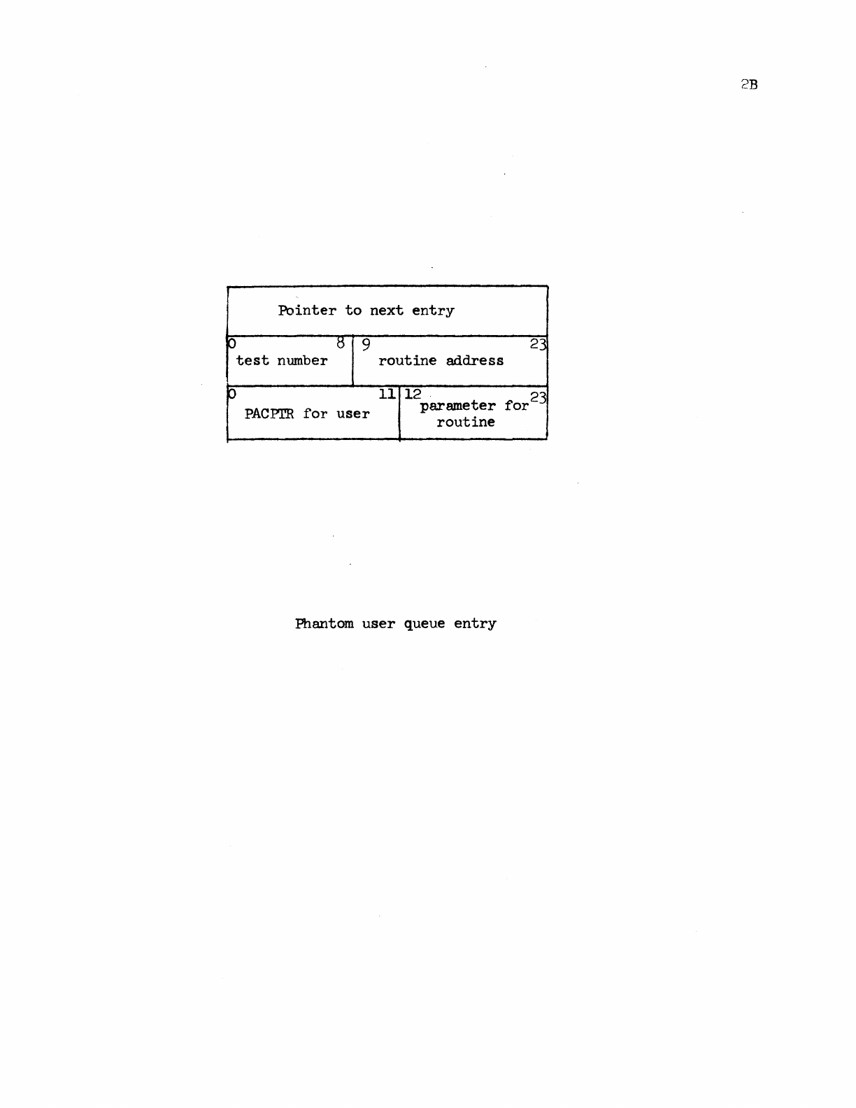
A phantom
user
queue
entry
is
drawn on
page
2B;
it
is
essentially
a
very
abbreviated
PAC
table
entry.
Such an
entry
is
made
when
the
system
has
some
activity
which
it
wants
to
carry
out
more
or
less
independently
of
any
user
PAC
table
entry:
testa
for
tape
ready
(on
rewind)
and
card
reader
ready,
and
processing
of
rubouts
(an
interrupt
routine
kind
of
activity,
but
too
time-consuming).
The
second
word
of
the
entry
is
the
activation
condition.
PUCTR
contains
the
number
of
entries
on
the
phantom
user
queue.
2B
Pointer
to
next
entry
p 5 9
23
test
number
routine
address
p
11
12
for
23
PACPrR
for
user
parameter
routine
Phantom
user
queue
entry
3-1
3.0
Forks
and
Jobs
3.1
Creation
of
Forks
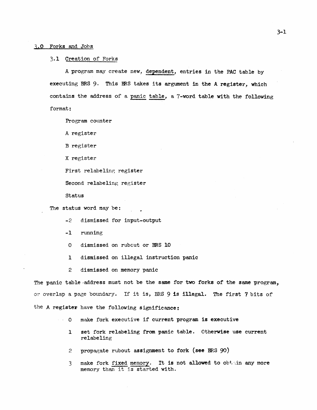
A program
m~v
create
new,
dependent,
entries
in
the
PAC
table
by
executing
BRS
9·
This
BRS
takes
its
argument
in
the
A
register,
which
contains
the
address
of
a
panic
table,
a 7-word
table
with
the
following
format:
Program COlmter
A
register
B
register
X
register
First
relabelin~
register
Second
relabeling
re~ister
status
The
status
word
may
be:
-2
dismissed
for
input-output
-1
running
0
dismissed
on
rub
cut
or
BRS
10
1
dismissed
on
illegal
instruction
panic
2
dismissed
on
memory
panic
The
panic
table
-address
must
not
be
the
same
for
two
forks
of
the
same
program,
or
overlap
a
pru~e
boundary.
If
it
is,
BRS
9
is
illegal.
The
first
7
bits
of
the
A
register
have
the
following
significance:
o
make
fork
executive
if
current
program
is
executive
1
set
fork
relabeling
from
panic
table.
Otherwise
use
current
relabeling
2
propagate
rubout
assignment
to
fork
(see
ERS
90)
3
make
fork
fixed
memor.l..
It
is
not
allowed
to
obt~
":.in
any more
memory
than
it
is
started
with.
. )
.J'
1.
0
UP
l-
I-
DOHl'J·
~
)
ACROSS
-:--
.
J
1-
1-
I.~.,....
1
t-
O
1,
"r
)
b
::-----------.---
..
-
...
-
..
--,
~
C)
o
8.
~
---
c
o
Hierarchy
of
Processes
5 .
6 .
10.
1
~
1
.-
6
0
I L
l
"...
')
I-
10
0
t.
6
~
r---
o
!-
(j
~.
. ,
I
r~l
9·
r'
l)
~
o
f'
V
"----
3-2
4.
make
fork
local
memory.
New
memory
will
be
assigned
to
it
independently
of
the
controlling
fork.
5.
make
fork
ephemeral
memory.
Memory
that
it
acquires
will
be
released
when
the
fork
terminates.
6.
set
interrupt
mask from
seventh
word
of
panic
table.
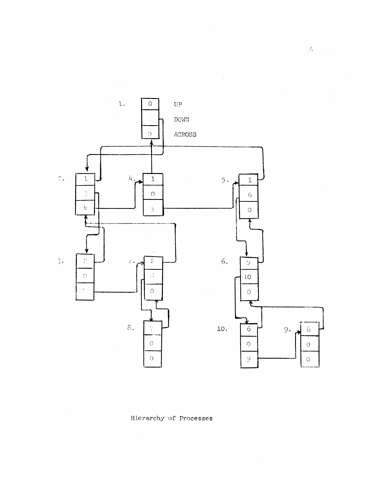
When
BRS
9
is
executed,
a
new
entry
in
the
PAC
table
is
created.
This
new
program
is
said
to
be a
fork
of
the
program
creating
it,
which
is
called
the
controlling
program.
The
fork
is
said
to
be
lower
in
the
hierarchy
of
forks
than
the
controlling
program. The
latter
may
itself
be a
fork
of
some
still
higher
program.
The
A,
B and X
registers
for
the
fork
are
set
up from
the
current
contents
of
the
p~~ic
table.
The
address
at
which
execution
of
the
fork
is
to
be
started
is
also
taken
from
the
panic
table.
The
relabeling
registers
are
set
up
either
from
the
current
contents
of
the
panic
table
or
from
the
relabeling
registers
of
the
currently
running
program.
An
executive
program
may
change
the
relabeling
as
it
pleases.
A
user
program
is
restricted
to
changing
relabeling
in
the
manner
permitted
by
BRS
44.
The
status
word
is
set
to
-1
by
BRS
9.
The
fork
structure
is
kept
tract
of
by
pointers
in
PACT.
For
each
program
PFORK
points
to
the
controlling
fork,
PDOWN
to
one
of
the
subsidiary
forks,
and
PPAR
to
a
fork
on
the
same
level.
All
the
subsidiary
forks
of
a
single
fork
are
chained
in
a
list.
A complex
situation
is
shown
on
the
previous
page.
The
arrows
indicate
the
various
pointers.
The
program
executing
a
BRS
9
continues
execution
after
the
instruction.
The
fork
established
by
the
BRS
9
begins
execution
at
the
location
specified
in
the
panic
table
and
continues
independently
until
it
is
terminated
by
a
panic
as
described
below.
It
is
connected
to
its
controlling
program
in
the
following
three
ways:
1)
The
controlling
program may examine
its
state
and
control
its
operation
with
the
following
six
instructions:
BRS
30
BRS
31
BRS
32
read.s
the
current
status
of
a
subsidiary
fork
into
the
panic
table.
It
does
not
influence
the
operation
of
the
fork
in
any way.
causes
the
controlling
program
to
be
dismissed
until
the
subsidiary
fork
causes
a
panic.
When
it
does,
the
controlling
program
is
reactivated
at
the
instruction
following
the
BRS
31, and
the
panic
table
contains
the
status
of
the
fork
on
its
dismissal.
The
status
is
also
put
into
x.
causes
a
subsidiary
fork
to
be
unGondi
tionally
terminated
and
its
status
to
be
read
into
the
panic
table.
All
of
these
instructions
require
the
panic
table
address
of
the
fork
in
A.
They
are
illegal
if
this
address
is
not
that
of
a
panic
table
for
some
fork.
ERS
31 and
BRS
32
return
the
status
word
in
the
X
register,
as
well
as
leaving
it
in
the
panic
table.
This
makes
it
convenient
to
do an
indexed
,jump
,.,i
th
the
contents
of
the
status
word.
BRS
31
returns
the
paniC
table
address
in
A.
BRS
106
BRS
107
BRS
loB
causes
the
controlling
program
to
be
dismissed
until
any
subsidiary
fork
causes
a
panic.
When
it
does,
the
controlling
program
is
reactivated
at
the
following
instruction
with
the
panic
table
address
in
A,
and
the
panic
table
contains
the
status
of
the
fork
at
its
dismissal.
causes
ERS
30
to
be
executed
for
all
subsidiary
forks.
causes
BRS
32
to
be
executed
for
all
subsidiary
forks.
3-4
2)
If
interrupt
3
is
armed
in
the
controlling
fork,
the
termination
of
any
subsidiary
fork
will
cause
that
interrupt
to
occur.
The
interrupt
takes
precedence
over
a
BRS
31.
If
the
interrupt
occurs
and
control
is
returned
to
a
BRS
31
after
processing
the
interrupt,
the
fork
will
be
dismissed
until
the
subsidiary
fork
specified
by
the
restored
(A)
terminates.
3)
The
forks
can
share
memory.
The
creating
fork
can,
as
already
indicated,
set
the
memory
of
the
subsidiary
fork
when
the
latter
is
started.
In
addition,
there
is
some
interaction
when
the
subsidiary
fork
attempts
to
acquire
memory.
3.2
Memory
Acquisition
If
the
fork
addresses
a
block
of
memory
which
is
not
aSSigned
to
it,
the
following
action
is
taken:
a
check
is
made
to
determine
whether
the
machine
size
specified
by
the
user
(cf
..
Document R-22)
has
been
exceeded.
If
so,
a
memory
panic
(see
below)
is
generated.
If
the
fork
is
fixed
memory, a
memory
panic
is
also
generated.
Otherwise
a
new
block
is
assigned
to
the
fork
so
that
the
illegal
address
becomes
legal.
For
a
local
memory
fork,
a
new
block
is
always
assigned.
Otherwise,
the
following
algorithm
is
used.
The
number,
n,
of
the
relabeling
byte
for
the
block
addressed
by
the
instruction
causing
the
memory
trap
is
determined.
A
scan
is
made upwards
through
the
fork
structure
to
(and
including)
the
first
local
memory
fork.
If
all
the
forks
encountered
during
this
scan
have
Rn
(the
Nth
relabeling
byte)
equal
to
0,
a new
entry
is
created
in
PMT
for
a new
block
of
user
memory.
The
address
of
this
entry
is
put
into
Rn
for
all
the
forks
encountered
during
the
scan.
If
a
fork
with
non-zero
Fin
is
encountered,
its
Rn
is
propagated
downward
to
all
the
forks
between
it
and
the
fork
causing
the
trap.
If
any
fixed
memory
fork
is
encolJ.ntered
before
a
non-zero
Rn
is
found,
a
memory
panic
occurs.
This
arr&"1gement
permits
a
fork
to
be
started
with
less
memor;!
than
its
controlling
fork
in
order
to
minimize
the
amount
or
drum swapping
required
during
its
execution.
If
the
fork
later
proves
to
require
more
memory,
it
can
be
reassi[~ed
the
memory
of
the
controlling
fork
in
a
natural
way.
It
is,
of
course,
possible
to
use
this
machinery
in
other
ways,
for
instance
to
permit
the
user
to
acqutre
more
than
16K
of
memory,
and
to
run
different
forks
with
non-overlapping
or
almost
non-overlapping
memory.
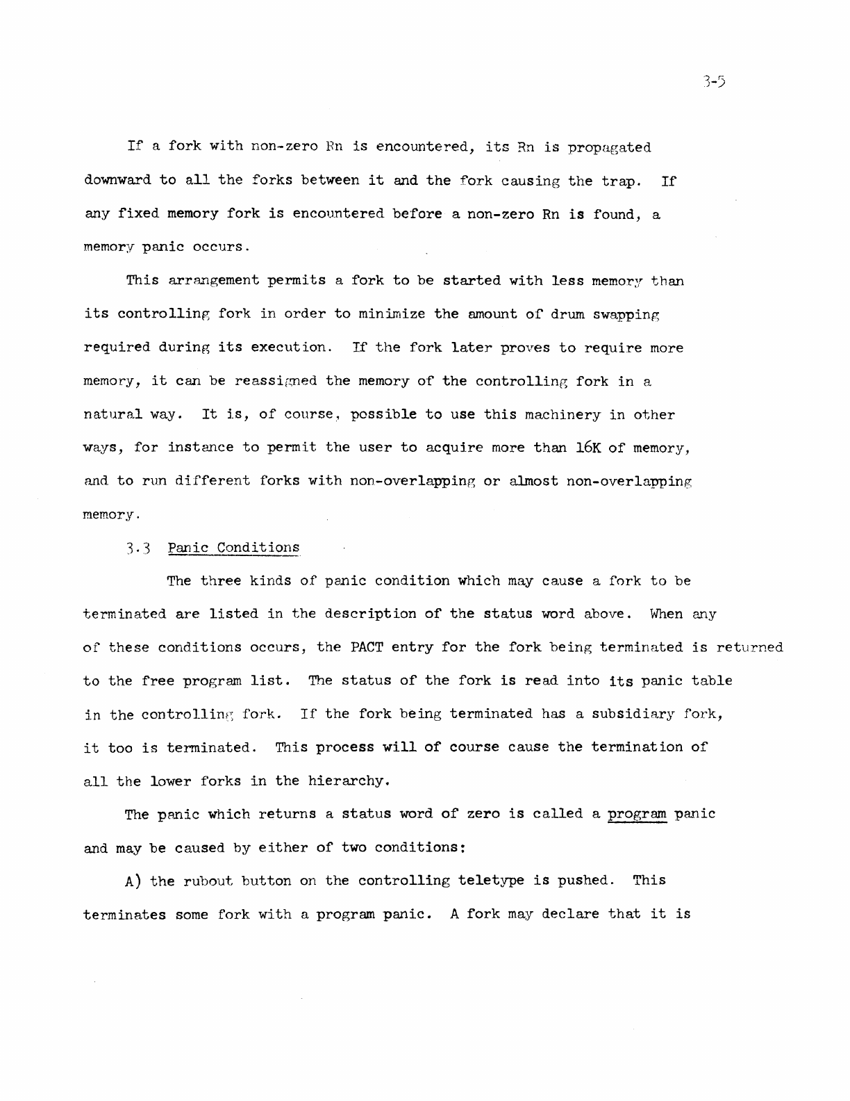
3.3
Panic
Conditions
The
three
kinds
of
panic
condition
which
may
ca.use a
fork
to
be
terminated
are
listed
in
the
description
of
the
status
word
above.
When
e~y
of
these
conditions
occurs,
the
PACT
entry
for
the
fork
being
terminated
is
returned
to
the
free
program
list.
The
status
of
the
fork
is
read
into
its
panic
table
in
the
control1int~
fork.
If
the
fork
being
terminated
has
a
subsidiary
fork,
it
too
is
terminated.
This
process
will
of
course
cause
the
termination
of
all
the
lower
forks
in
the
hierarchy.
The
pRnic
which
returns
a
status
word
of
zero
is
called
a
program
panic
and
may
be
caused
by
either
of
two
conditions:
A)
the
rubout
button
on
the
controlling
teletype
is
pushed.
This
terminates
some
fork
with
a
program
panic.
A
fork
may
declare
that
it
is
3-6
the
one
to
be
terminated
by
executing
BRS
90.
In
the
absence
of
such
a
declaration
the
highest
user
fork
is
terminated
..
~~en
a
fork
is
terminated
in
this
way
its
controlling
fork
becomes
the
one
to
be
terminated.
If
a
user-
fork
is
terminated
by
rubout
the
teletype
input
huffer
is
cleared.
If
the
controlling
fork
of
the
one
terminated
is
executive,
the
output
buffer
is
f.tlso
cleared..
If
the
fork
which sl1ou1d
be
terminated
by
rubout
has
armed
interrupt
1,
this
interrupt
will
occur
instead
of
a
termination.
The
teletype
buffers
will
not
be
af'fected.
If
there
is
only
one
fork
active,
control
goes
to
the
location
EXECP
in
the
executive.
This
consideration
is
of
no
concern
to
the
user.
Executive
programs
can
turn
the
rubout
button
off
with
BRS
46 and
turn
it
back
on
with
BRS
4'7.
A
rubout
occurring
in
the
meantime
will
be
stacked.
A
second
one
will
be
ignored.
A
program
which
is
running
with
rubout
turned
off
is
said
to
be
non-terminable
and
cannot
be
terminated
by
a
higher
fork.
BRS
26
skips
if
there
is
a
rubout
pending.
If
two
rubouts
occur
within
about
.12
second.s,
the
entire
fork
structure
will
be
cleared
and
the
job
left
executing
the
top
level
executive
fork.
This
device
permits
a
user
trapped
in
a
malfunctioning
lower
fork
to
escape.
Closely
spaced
rubouts
can
be
conveniently
generated
with
the
repeat
button
on
the
teletype.
B)
A
BRS
10
may
be
executed
in
the
lower
fork.
This
condition
can
be
distinguished
from a paniC
caused
by
the
rubout
button
only
by
the
fact
that
in
the
former
case
the
program
counter
in
the
panic
table
points
to
a word
containing
BRS
10.
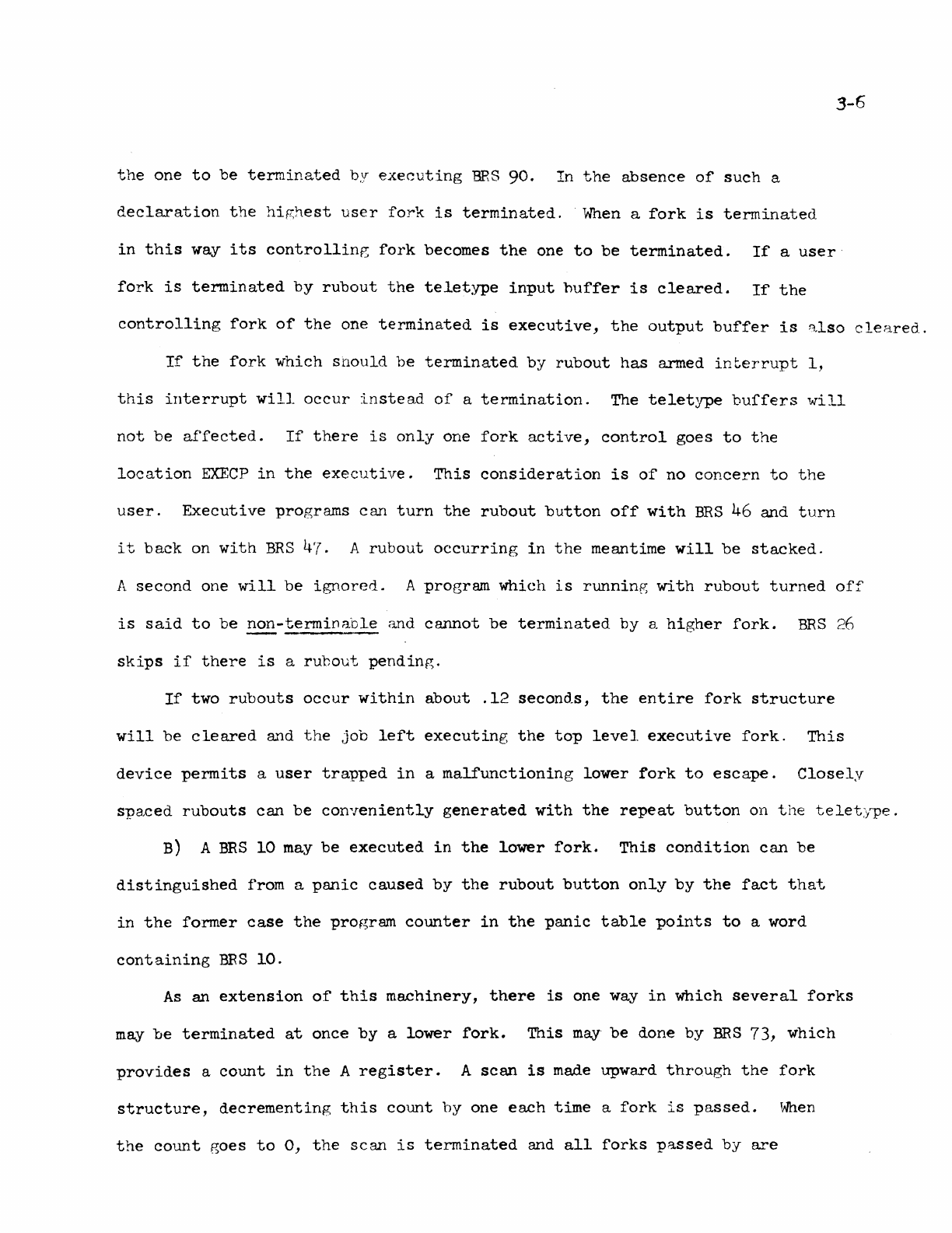
As
an
extension
of
this
machinery,
there
is
one
way
in
which
several
forks
may
be
terminated
at
once
by
a
lower
fork.
This
may
be
done
by
BRS
73,
which
provides
a
count
in
the
A
register.
A
scan
is
made
upward
through
the
fork
structure,
decrementing
this
count
by
one
each
time
a
fork
is
passed.
When
the
count
goes
to
0,
the
scan
is
terminated
and
all
forks
passed
by
are
3-7
terminated.
If
an
executive
program
is
reached
before
the
count
is
0,
then
all
the
user
programs below
it
are
terminated.
An
executive
program
can
clear
the
fork
structure
of
a
job
by
putting
the
job
number
in
A and
executing
BRS
22.
The
effect
is
as
though enough
rubouts
had
occurred
to
send
the
job
back
to
the
top-level
executive
fork.
The
panic
Which
returns
a
status
word
of
1
is
caused
by
the
execution
of
an
illegal
instruction
in
the
fork.
Illegal
instructions
are
of
two
kinds:
1)
Machine
instructions
which
are
privileged
2)
SYSPOPs
which
are
forbidden
to
the
user
or
which have
been
provided
with
unacceptable
arguments.
If
interrupt
2
is
armed and
the
fork
is
executive,
interrupt
2
will
occur
instead
of
an
illegal
instruction
panic.
A
status
word
of
2
is
returned
by a
memory
panic.
This
may
be
caused
by
an
attempt
to
address
more
memory
than
is
permitted
by
the
machine
size
which
the
user
has
set,
or
by
an
attempt
to
store
into
a
read-only
block.
If
interrupt
2
is
armed,
it
will
occur
instead
of
the
memory
panic.
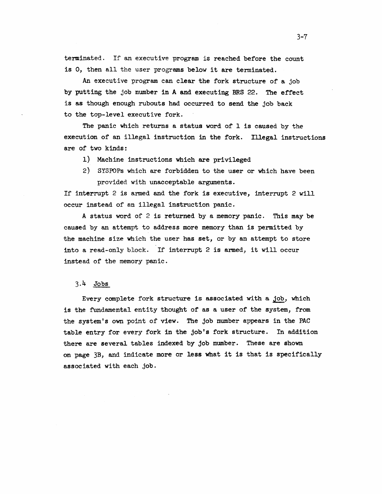
Every complete
fork
structure
is
associated
with
a
job,
which
is
the
fundamental
entity
thought
of
as
a
user
of
the
system,
from
the
system's
own
point
of
view.
The
job
number
appears
in
the
PAC
table
entry
for
every
fork
in
the
job's
fork
structure.
In
addition
there
are
several
tables
indexed
by
job
number. These
are
shown
on page
3B,
and
indicate
more
or
less
what
it
is
that
is
specifically
associated
with
each
job.
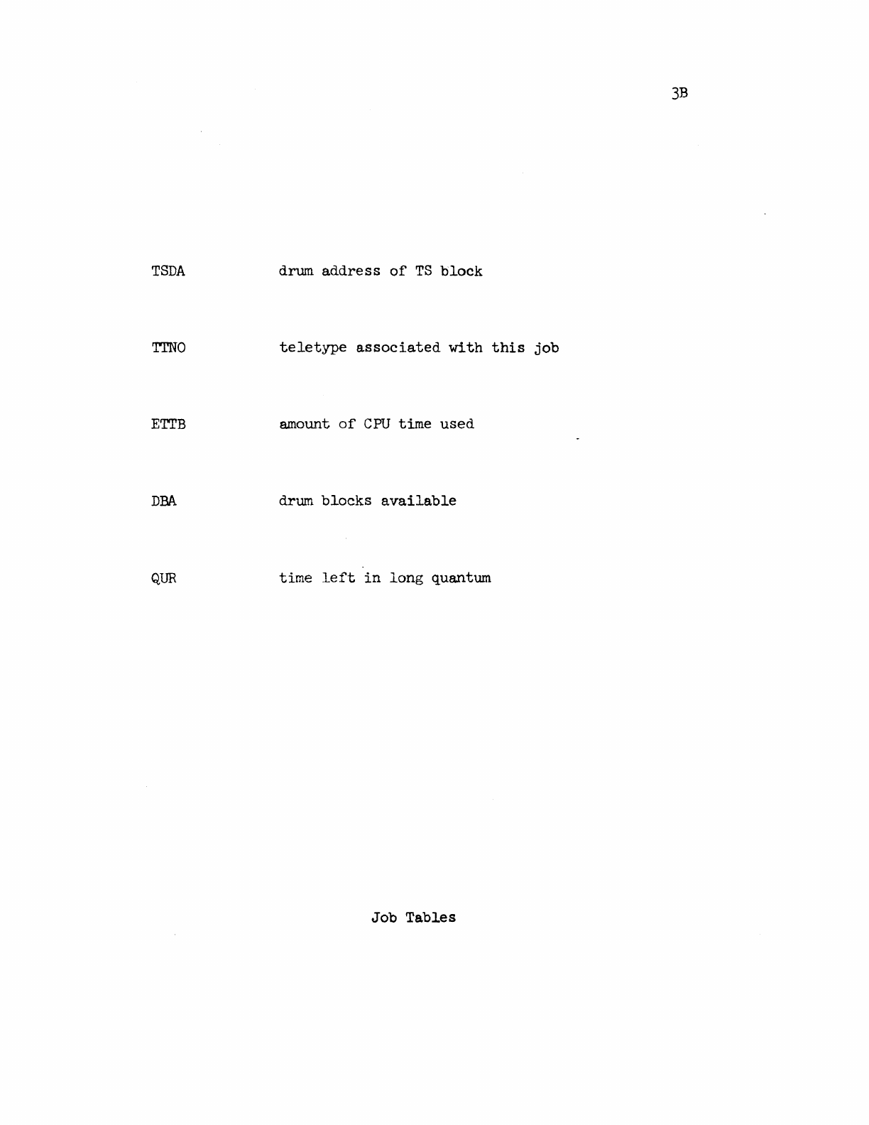
3B
TSDA
drum
address
of
TS
block
TTNO
teletype
associated
with
this
job
ETI'B amount
of
CPU
time
used
DBA
drum
blocks
available
QUR
time
left
in
long
quantum
Job
Tables
4-1
4.0 Program
Interrupts
A
facility
isprovideci
in
the
monitor
to
simulate
the
existence
of
hardware
interrupts.
There
are
20
possible
interrupts;
four
are
reserved
for
special
purposes
and
16
are
available
to
the
programmer
for
general
use.
A
,fork
may
arm
the
interrupts
by
executing
BRS
78
with
a
2O-bit
mask
in
the
A
register.
This
causes
the
appropriate
bits
in
PTh1
to
be
set
or
cleared
according
to
whether
the
corresponding
bit
in
the
mask
is
1
or
O.
Bit
4
of
A
corresponds
to
interrupt.
number
1,
etc.
No
other
action
is
taken
at
this
time.
When
an
interrupt
occurs
(in
a manner
to
be
described)
the
execution
of
an
SBRM*
to
location
200
plus
the
interrupt
number
is
simulated
in
the
fork
which armed
the
interrupt.
Note
that
the
program
counter
which
is
stored
in
the
case
is
the
location
of
the
instruction
being
executed
by
the
fork
which
is
interrupted,
not
the
location
in
the
fork
which
causes
the
interrupt.
The
proper
return
from an
interrupt
is
a
BRU
to
the
location
from which
the
interrupt
occurred.
This
will
do
the
right
thing
in
all
cases
including
interrupts
out
of
input-
output
instructions.
A
fork
rnay
generate
an
interrupt
by
executing
ERS
79
with
the
number
of
the
desired
interrupt
in
the
A
register.
This
number
may
not
be
one,
two,
three
or
four.
The
effect
is
that
the
fork
structure
is
scanned,
starting
with
the
forks
parallel
to
the
one
causing
the
interrupt
and
proceeding
to
those
above
it
in
the
hierarchy
(i.e.,
to
its
ancestors)
. The
first
fork
encountered
during
this
scan
vlith
the
appropriate
interrupt
mask
bit
set
is
interrupted.
Execution
of
the
program
in
the
fork
causing
the
interrupt
continues
without
disturbance.
If
no
interruptable
fork
is
found,
the
interrupt
instruction
is
treated
as
a
NOP;
otherwise,
it
skips
on
return.
Interrupts
1
and
2
are
handled
in
a
special
way.
If
a
fork
arms
interrupt
1,
a program
panic
(ERS
10
or
rubout
button)
which
would
normally
terminate
the
fork
which
has
armed
interrupt
1,
will
instead
cause
interrupt
1
to
occur,
that
is,
will
cause
4-2
the
execution
of
an
SBRM*
to
location
201.
This
permits
the
programmer
to
control
the
action
taken
when
the
rub
out
button
is
pushed
without
establishing
a
fork
specifically
for
this
purpose.
If
pushinG
the
rubout
button
causes
an
interrupt
to
occur
rather
than
terminating
a
fork,
the
input
buffer
will
not
be
cleared.
If
a memory
panic
occurs
in
a
fork
which
has
anned
interrupt
2,
it
will
cause
interrupt
2
to
occur
rather
tha.n
terminatin;;
the
fork.
If
an
illeF.'-al
instruction
panic
occurs
in
an
executive
fork
which
has
armed
interrupt
2,
it
will
cause
interrupt
2
to
occur
rather
than
terminating
the
fork.
Interrupt
3
is
caused,
if
armed, \·,hen
any
subsidiary
fork
terr:1inates.
Interrupt
4
is
caused,
if
armed, \{hen
any
input-
output
condition
occurs
1<[hich
sets
a
flag
bit
(end
of
record,
end
of
file
and
error
conditions
can
do
this).
vfuenever any
interrupt
occurs,
the
corresponding
bit
in
the
interrupt
mask
is
cleared
and
must
be
reset
explicitly
if
it
is
desired
to
keep
the
interrupt
on.
Note
that
there
is
no
restriction
on
the
number
of
forks
which
may
have
an
interrupt
on.
To
read
the
interrupt
mask
into
A,
the
proGram
may
execute
BRG
49.
5.0
The Swapner
arid
Memory
Allocation
Pseudo-re~abeling
The
940
hardware
allows
the
user's
address
space
to
be
fragmented
into
eight
pages
of
2048
words
each.
This
means
that
the
monitor
must
keep
track
of
eight
drum
addresses
for
each
process.
This
is
done by means
of
eight
six-bit
pseudo-
relabeling
registers.
Each
of
these
registers
is
an
index
to
a
table
which
contains
the
drum
address
of
the
user's
page.
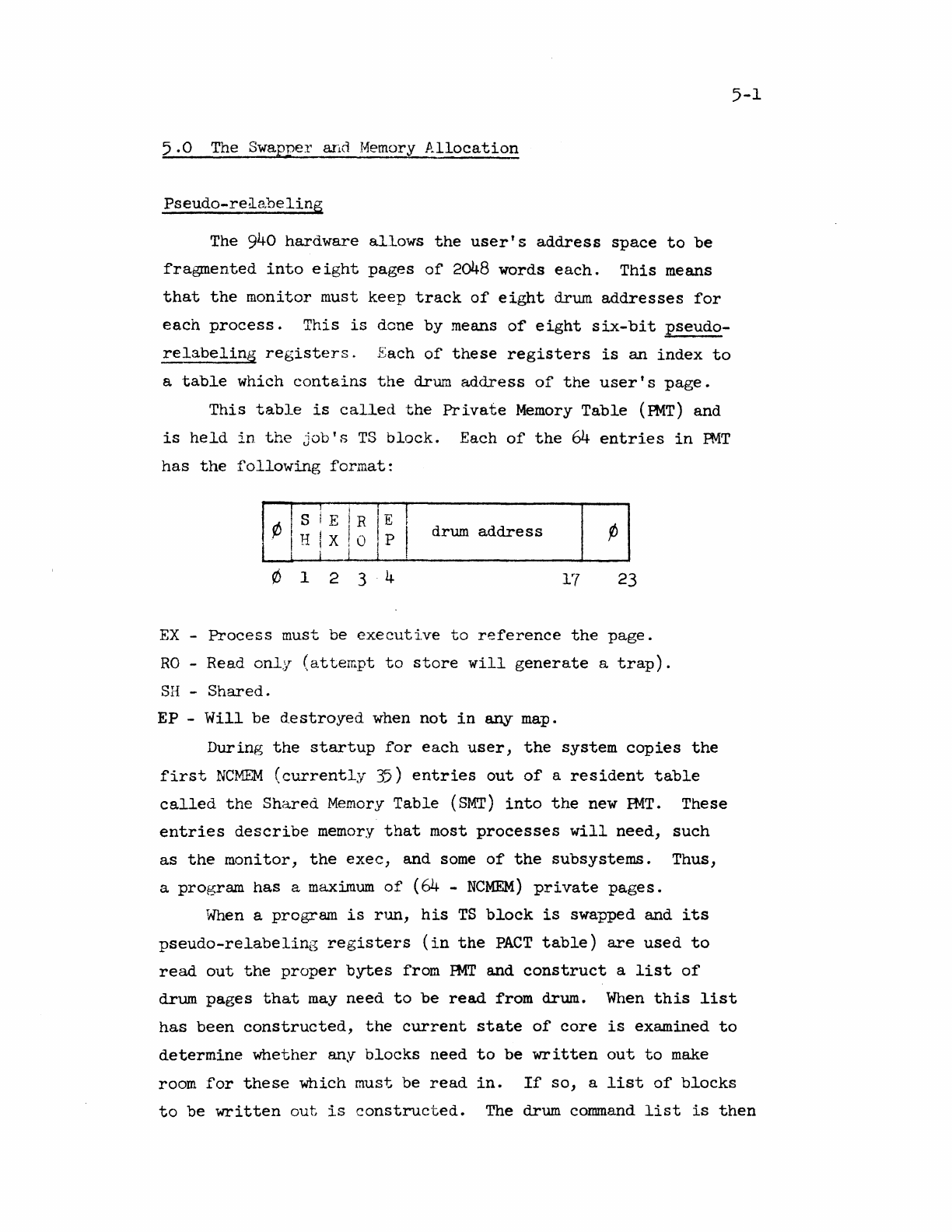
This
table
is
called
the
Private
Memory
Table
(PMT)
and
is
held
in
the
job's
TS
block.
Each
of
the
64
entries
in
RvlT
has
the
following
format:
¢ s I E I R
IE
I
H I X ! 0 P I
I j 1 . drum
address
¢
o 1 2
3·4
17
23
EX
-
Process
must be
executi.ve
to
reference
the
page.
RO
-Read
only
(attempt
to
store
will
generate
a
trap).
SH
-
Shared.
EP -
Will
be
d.estroyed
when
not
in
any
map.
During
the
startup
for
each
user,
the
system
copies
the
first
NCMEM
(currently
35)
entries
out
of
a
resident
table
called
the
Shared
Memory
Table
(SMT)
into
the
new
PMT.
These
entries
describe
memory
that
most
processes
will
need,
such
as
the
monitor,
the
exec,
and
some
of
the
subsystems.
ThUS,
a
program
has
a
max:im.um
of
(64 -
NCMEM)
private
pages.
When
a program
is
run,
his
TS
block
is
swapped and
its
pseudo-relabeling
registers
(in
the
PACT
table)
are
used
to
read
out
the
proper
bytes
from
PMT
and
construct
a
list
of
5-1
drum
pages
that
may
need
to
be
read
from drum.
When
this
list
has
been
constructed,
the
current
state
of
core
is
examined
to
determine
whether
any
blocks
need
to
be
written
out
to
make
room
for
these
which must
be
read
in.
If
so,
a
list
of
blocks
to
be
written
out
is
constructed.
The drum
command
list
is
then
5-2
set
up
with
the
appropriate
commands
to
write
out
and
read
in
the
necessary
blocl\:s.
In
the
course
of
optimizing
the
drum
commands,
the
swapper
may
skip
a
sector.
If
this
is
the
case,
it
searches
through
the
~mory
tables
and
writes
out
a
dirty
page
in
that
sector.
The
scheduler
then
simply
hangs up
until
the
swapping
is
complete.
In
the
scan
which
sets
up
the
drum
read
commands,
the
swapper
collects
from
DHT
the
actual
absolute
memory
addresses
of
the
page
called
for
by
the
pseudo-
relabeling
and
constructs
a
set
of
real
relabeling
registers
which
it
puts
in
two
fixed
locations
in
the
monitor.
It
then
outputs
these
relabeling
registers
to
the
hardware
and
activates
the
program.
There
are
two BRS's which
permit
the
user
to
read
and
write
his
pseudo-relabeling.
BRS
43
reads
the
current
pseudo-
relabelin(~
registers
into
A and
B.
BRS
44
takes
the
contents
of
A and B and
puts
then:
into
the
current
pseudo-relabeling
registers.
An
executive
program
may
set
the
relabeling
registers
in
arbitra.ry
fashion
b~{
using
this
instruction.
A
user
program,
however,
may
add
or
delete
only
blocks
which do
not
have
the
executive
bit
set
tn
FMT.
This
prevents
the
user
from
gaining
access
to
executive
blocks
whose
destruction
may
cause
damage
to
the
system.
Note
that
the
user
is
doubly
restricted
in
his
access
to
real
memory,
firstly,
because
he can
only
access
real
memory which
is
pointed
to
by
his
pseudo-relabeling,
and
secondly,
because
he
is
only
nllo
.....
,ed
to
adjust
those
portions
of
his
pseudo-
relabeling
which
are
not
executive
type.
The
user
can
also
set
the
relabeling
of
a
fork
when
he
creates
it.
See
Section
3.
The same
restrictions
on
manipulation
of
executive
blocks
of
course
apply.
The
system
maintains
a
pair
of
relabeling
registers
which
the
executive
and
various
subsystems
think
of
as
the
user's
program
relabeling.
For
the
convenience
of
subsystems,
any
program
can
read
these
registers
with
BRS
116 and
set
them
with
BRS
117.
5-3
The
memory
allocation
a.lgorithm
is
described
on
page
3-2.
A
user
can
release
a
block
which
is
in
his
current
relabeling
by
putting
any
address
in
that
block
into
A and
executing
BRS
!t.
The
PMT
entry
for
the
block
is
removed and
in
any
other
fork
which
has
this
PMT
byte
in
its
relabeling,
the
byte
is
cleared
to
o.
Equivalent
to
BRS
4
is
BRS
121,
which
takes
a
pseudo-
relabeling
byte
in
A
rather
than
an
address.
An
inverse
operation
is
BRS
120,
which
takes
a
pseudo-relabeling
byte
in
A,
generates
an
illegal
instruction
trap
if
the
corresponding
PMT
entry
is
occupied,
and
otherwise
obtains
a
new
page
and
puts
it
in
that
entry.
This
is
an
exec-only
operation
and
is
implemented
parti-
cularly
for
the
Exec
'RECOVER
FROM
FILE'
operation.
If
A
is
0,
BRS
120
assigns
a
2K
page
and
skips;
this
operation
is
not
exec-
only.
Shared
Memory.
The
system
maintains
a
table
called
the
shared
memory
table
(SMT)
which
describes
all
the
memory
which
can
be
shared
between
jobs
in
the
system.
All
the
cornmon
subsystems
occupy
positions
in
SMT,
and
some
part
of
SMT
is
copied
into
each
job's
FMT
permanently.
To
run
a
subsystem,
the
exec
must
determine
if
the
subsystem
map
is
already
in
PMT
(which
it
will
be
if
all
the
bytes
are
below
NCMEM)
and,
if
not,
arrange
for
the
bytes
to
be
put
into
PMT.
The
exec
makes an
entry
in
SMT
by
executing
BRS
68
with
a
byte
ntunber
in
A.
The
block
addressed
by
the
specified
byte
in
the
pseudo-relabeling
registers
is
put
into
SMT
and
the
pointer
in
SMT
of
this
byte
is
returned.
By
putting
an
index
in
SMT
in
A and
executing
BRS
69,
the
SMT
entry
is
copied
into
the
first
free
byte
of
a
userts
PMT
and
the
byte
number
is
returned
in
A.
The
read-only
bit
in
the
SMT
entry
is
propagated
to
the
PMT
entry
thus
created.
To
delete
an
entry
in
SMT,
the
exec
may
deliver
its
index
in
A
and
execute
BRS
70.
The
user
may
declare
a
block
read-only
by
executing
BRS
80
with
the
pseudo-relabeling
byte
number
of
the
block
in
A and
with
bit
0
of
A
set.
To
make
a
block
read-write,
bit
°
of
A
5-4
should
be
clear.
Bit
0
of
A
will
be
reset
if
the
block
was
formerly
read-write
or
set
if
it
was
formerly
read-only.
If
the
program
doing
this
is
not
an
executive
program,
then
the
block
must
not
be
an
executive
block.
Only
executive
programs
may
make
a
shared
page
read-write.
The drum
is
divided
into
84
bands,
each
containing
16,000
words
arranged
in
8
blocks
of
2K
each.
Up
to
'72
of
these
bands
may
be
used
by
the
swapper
for
program
storage.
A
bit
table
is
maintained
to
indicate
the
availability
of
2K
blocks
in
these
bands.
The
table
consists
of
8 words,
each
containing
24
bits,
one
for
each
band.
If
a
bit
is
zero,
it
indicates
that
the
block
is
in
use.
If
it
is
set,
the
block
is
available.
wllen
the
user's
memory
is
acquired,
it
is
written
as
nearly
as
possible
in
adjacent
blocks,
so
that
it
rnay
be
read
in
without
undue drum
latency
time.
Rotational
positions
are
chosen
by
adding,
mod
8,
the
user's
job
number
to
the
PMT
byte
number
of
the
new
block.
It
should
be
noted
that
whenever a
user
is
activated,
all
of
the
memory
in
his
current
relabeling
registers
is
brought
in.
The
user
does,
however, have
considerable
control
over
precisely
what memory
will
be
brought
in,
because
he
can
read
and
set
his
own
relabeling
registers.
He
may
therefore
establish
a
fork
with
a
minimal
amount
of
memory
in
order
to
speed
up
the
swapping
process
if
this
is
convenient.
To
make
a
block
executive,
execute
BRS
56
with
the
same
argument
as
for
BRS
80,
make
block
read-only.
This
instruction
is
legal
only
for
executive
type
programs.
Real
memory
is
housekept
by
means
of
several
tables.
The
most
important
of
these
is
a
table
(hash)-indexed
by
drum
address
which
describes
all
those
drum
pages
which
are
currently
in
core.
The
Drum
Hash
Table
(DHT)
has
more
entries
than
core
pages.
An
entry
has
the
following
format:
IF
Drum
Core
Address
Address
¢
18
27
F
==
Free
entry
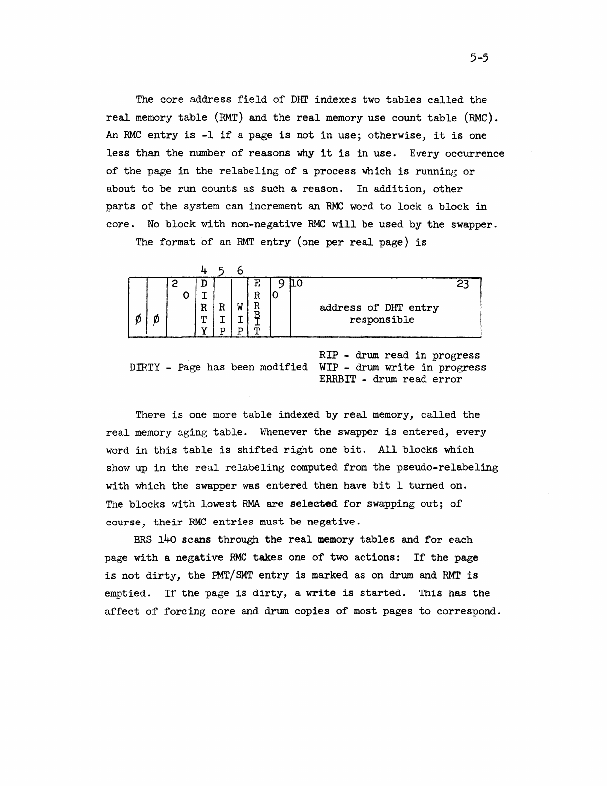
5-5
The
core
address
field
of
DHT
indexes
two
tables
called
the
real
memory
table
(RMT)
and
the
real
memory
use
count
table
(RMe).
An
RMC
entry
is
-1
if
a
page
is
not
in
use;
otherwise,
it
is
one
less
than
the
number
of
reasons
why
it
is
in
use.
Every
occurrence
of
the
page
in
the
relabeling
of
a
process
which
is
running
or
about
to
be
run
counts
as
such
a
reason.
In
addition,
other
parts
of
the
system
can
increment
an
RMC
word
to
lock
a
block
in
core.
No
block
with
non-negative
RMC
will
be
used
by
the
swapper.
The
format
of
an
RMT
entry
(one
per
real
page)
is
4 5 6
2 D E 9
0-0
23
0 I R 0
R R W R
address
of
DHT
entry
¢ ¢ T I I
~
responsible
y p P T
RIP -drum
read
in
progress
DIRTY
-Page
has
been
modified
WIP
-drum
write
in
progress
ERRBIT
-drum
read
error
There
is
one more
table
indexed
by
real
memory,
called
the
real
memory
aging
table.
Whenever
the
swapper
is
entered,
every
word
in
this
table
is
shifted
right
one
bit.
All
blocks
which
show up
in
the
real
relabeling
computed from
the
pseudo-relabeling
with
which
the
swapper
was
entered
then
have
bit
I
turned
on.
The
blocks
with
lowest
RMA
are
selected
for
swapping
out;
of
course,
their
RMC
entries
must
be
negative.
BRS
140
scans
through
the
real
memory
tables
and
for
each
page
with
a
negative
RMC
takes
one
of
two
actions:
If
the
page
is
not
dirty,
the
PMT/SMT
entry
is
marked
as
on drum and
RMT
is
emptied.
If
the
page
is
dirty,
a
write
is
started.
This
has
the
affect
of
forcing
core
and drum
copies
of
most
pages
to
correspond.
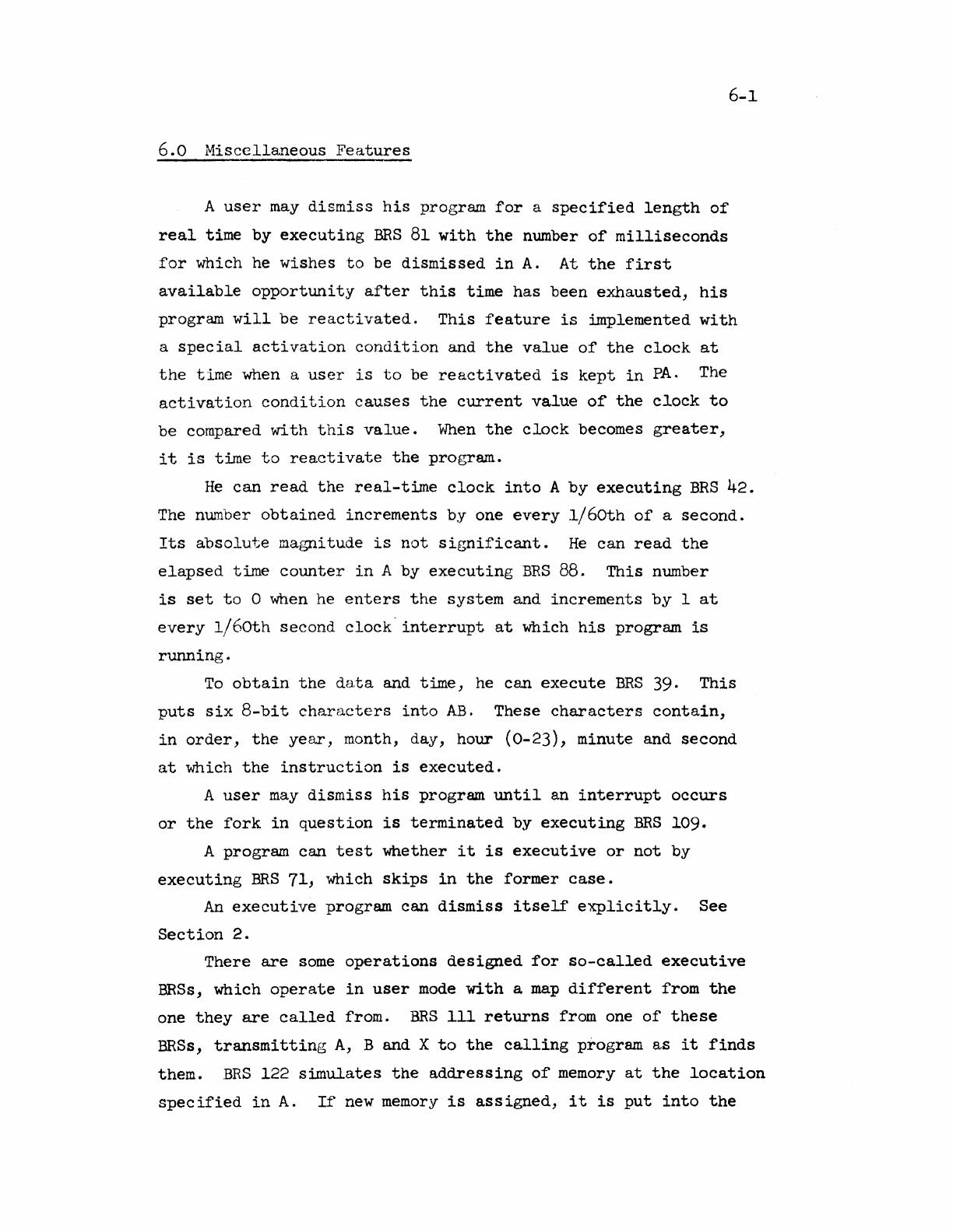
6-1
6.0
Miscellaneous
Features
A
user
may
dismiss
his
program
for
a
specified
length
of
real
time
by
executing
BRS
81
with
the
number
of
milliseconds
for
which he
wishes
to
be
dismissed
in
A.
At
the
first
available
opportunity
after
this
time
has
been
exhausted,
his
program
will
be
reactivated.
This
feature
is
implemented
with
a
special
activation
condition
and
the
value
of
the
clock
at
the
time
when a
user
is
to
be
reactivated
is
kept
in
PA.
The
activation
condition
causes
the
current
value
of
the
clock
to
be
compared
with
this
value.
When
the
clock
becomes
greater,
it
is
time
to
reactivate
the
program.
He
can
read
the
real-time
clock
into
A
by
executing
BRS
42.
The number
obtained
increments
by
one
every
1/6Oth
of
a
second.
Its
absolute
magnitude
is
not
significant.
He
can
read
the
elapsed
time
counter
in
A
by
executing
BRS
88.
This
number
is
set
to
0 when he
enters
the
system
and
increments
by
I
at
every
1/60th
second
clock
interrupt
at
which
his
program
is
running.
To
obtain
the
da,ta and
time,
he
can
execute
BRS
39.
This
puts
six
8-bit
characters
into
AB.
These
characters
contain,
in
order,
the
year,
month, day,
hour
(0-23),
minute
and
second
at
which
the
instruction
is
executed.
A
user
may
dismiss
his
program
until
an
interrupt
occurs
or
the
fork
in
question
is
terminated
by
executing
BRS
109.
A
program
can
test
whether
it
is
executive
or
not
by
executing
BRS
71,
which
skips
in
the
former
case.
An
executive
program
can
dismiss
itself
explicitly.
See
Section
2.
There
are
some
operations
designed
for
so-called
executive
BRSs, which
operate
in
user
mode
with
a
map
different
from
the
one
they
are
called
from.
BRS
111
returns
from one
of
these
BRSs,
transmitting
A,
B and X
to
the
calling
program
as
it
finds
them.
BRS
122
simulates
the
addreSSing
of
memory
at
the
location
specified
in
A.
If
new
memory
is
assigned,
it
is
put
into
the
relabeling
of
the
calling
program. A
memory
panic
can
occur,
in
which
case
it
appears
to
the
calling
program
that
it
comes
from
the
BRS
instruction.
BRS
141
reads
the
panic
table
of
the
caller,
and
BRS
142
sets
the
state
from a
table
specified
by
X.
6-2
An
executive
program can
cause
an
instruction
to
be
executed
in
system
mode
by
addressing
it
with
EXS.
7-1
7.0
Teletype
Input-Output
We
begin
with
an
outline
of
the
implementation
of
the
teletype
operations.
This
may
serve
to
clarify
the
exact
disposal
of
the
characters
which
are
being
read
and
written.
Every
teletype
has
attached
to
it
a
table
which
is
shown
in
Figures
7A
and 7B.
No
buffers
are
attached
to
the
teletype
unless
input
from
or
output
to
the
teletype
is
taking
place.
As
characters
are
output
by
the
program,
buffers
are
attached
to
the
teletype.
These
buffers
are
released
as
soon
as
they
are
emptied
by
the
teletype
interface.
On
input
buffers
are
attached
to
the
teletype
as
characters
are
received
from
the
teletype,
and
they
are
released
as
soon
as
the
program
empties
them.
Input
and
output
buffers
are
logically
and
physically
independent,
although
they
come
out
of
the
same
buffer
pool.
When
a
character
is
typed
in
on a
teletype)
it
is
converted
to
internal
form and added
to
the
input
buffer
unless
it
is
rubout
on a
controlling
teletype.
The
treatment
of
rubouts
is
discussed
in
Section
3. The
echo
routine
address
is
then
obtained
from
TTYTBL
and
called.
It
figures
out
what
to
echo
and
whether
or
not
the
character
is
a
break
character.
The
available
choices
of
echos
and
break
characters
are
listed
below.
If
the
character
is
a
break
character,
and
if
a
user's
program
has
been
dismissed
for
teletype
input,
it
will
be
reactivated
regardless
of
the
number
of
words
in
the
input
buffer.
In
the
absence
of
a
break
character,
the
user's
program
is
reactivated
only
when
the
input
buffer
is
nearly
full.
If
the
teletype
is
in
the
process
of
outputting
(TOS2
>
-1)
then
the
character
to
be
echoed
is
put
into
the
last
byte
of
the
buffer
word which
contains
the
input
character.
When
the
character
is
read
from
the
buffer
by
the
program,
the
echo,
if
any,
will
be
generated.
This
mechanism,
called
deferred
echoing,
permits
the·
user
to
type
in
while
the
teletype
is
outputting
without
having
his
input
mixed
with
the
teletype
output.
7-2
There
are
four
standard
echo
routines
in
the
system,
referred
to
by
the
numbers
0,
1,
2 and 3. a
is
a
routine
in
which
the
echo
for
each
character
is
the
character
itself,
and
all
cha.racters
are
break
characters.
Routine
1
has
the
same
echoes,
but
all
characters
except
letters,
digits,
and
space
are
break
characters.
Routine
2
again
has
the
same
echoes,
but
the
only
break
characters
are
control
characters
(including
carriage
return
and
line
feed).
Routine
3
specifies
no
echo
for
any
character,
and
all
characters
are
break
characters.
This
routine
is
useful
for
a
program
which
wishes
to
compute
the
echo
itself.
To
set
the
echo
routine,
put
the
teletype
number
in
X and
the
echo
routine
number
in
A and
execute
BRS
12.
Note
that
BRS
12
is
also
used
to
turn
on
8-level
mode
(see
below).
To
read
the
echo
routine
number
into
A,
put
the
teletype
number
in
X and
execute
BRS
40.
This
operation
returns
in
A
the
word
listed
as
TTYTBL
on
page
7A.
To
input
a
character
from
the
controlling
teletype
(the
teletype
on which
the
user
of
the
program
is
entered)
into
location
M
in
memory
the
SYSPOP
Tel
M
(teletype
character
input)
is
used.
This
SYSPOP
reads
the
character
from
the
teletype
input
buffer
and
places
it
into
the
8
rightmost
bits
of
location
M.
The
remainder
of
location
M
is
cleared.
The
character
is
also
placed
in
the
A
register,
whose
former
contents
are
destroyed.
The
contents
of
the
other
internal
registers
are
preserved
by
this
and
all
the
other
teletype
SYSPOPs
and
BRS's.
To
output
a
character
from
location
M,
the
SYSPOP
TCO
M
(teletype
character
output)
is
used.
This
instruction
outputs
a
character
from
the
rightmost
8
bits
of
location
M.
In
addition
to
the
ordinary
ASCII
characters,
7-3
all
teletype
output
operations
will
accept
135
(octal)
as
a
multiple
blank
character.
The
next
character
will
be
taken
as
a
blank
count,
and
that
many
blanks
will
be
typed.
The
TTYTIM
cell
in
the
teletype
table
is
set
to
the
current
value
of
the
clock
whenever
any
teletype
activity
(interrupt
or
output
SYSPOP)
occurs.
The
top
bit
is
left
clear
unless
the
activity
is
a
rubout
input.
This
cell
is
checked
by
the
rubout
processor
to
determine
whether
the
rubout
should
reset
the
job
to
the
exec.
See
p.
3-6.
Every
teletype
in
the
system
is
at
all
times
in
one
of
three
states:
a)
It
may
be
the
controlling
teletype
of
some
user's
program.
It
gets
into
this
state
when
a
user
enters
on
it.
b)
It
may
be
attached
to
some
user
in
a manner
about
to
be
described.
c)
It
may
be
completely
free.
The
status
of
the
teletype
is
reflected
by
the
contents
of
TTYASG.
There
are
mechanisms
to
be
described
by
which
the
user
may
direct
output
to
any
teletype
in
the
system which
is
willing
to
a.ccept
it
and
receive
input
from
any
teletype
which
is
not
free.
If,
however, he wishes
to
have
better
control
over
a
teletype
(for
instance,
to
prevent
other
users
from
accessing
it)
he
may
attach
it
by
executing
the
instructions
LDA
=teletype
number
BRS
27
If
the
indicated
teletype
is
free,
it
is
attached
to
the
user
whose
program
executes
the
instruction,
and
the
BRS
will
skip.
Otherwise
the
teletype
status
is
not
affected,
and
the
BRS
does
not
skip.
In
the
following
discussion
we
will
say
that
a
teletype
is
attached
to
a
user
even
if
it
is
the
controlling
teletype.
To
release
an
already
attached
teletype,
execute
the
instructions
LDA
=teletype
number
BRS
26
If
the
specified
teletype
is
not
already
attached
to
the
user,
this
is
an
illegal
instruction
and
causes
a
panic.
All
attached
teletypes
are,
of
course,
released
when
the
user
logs
out.
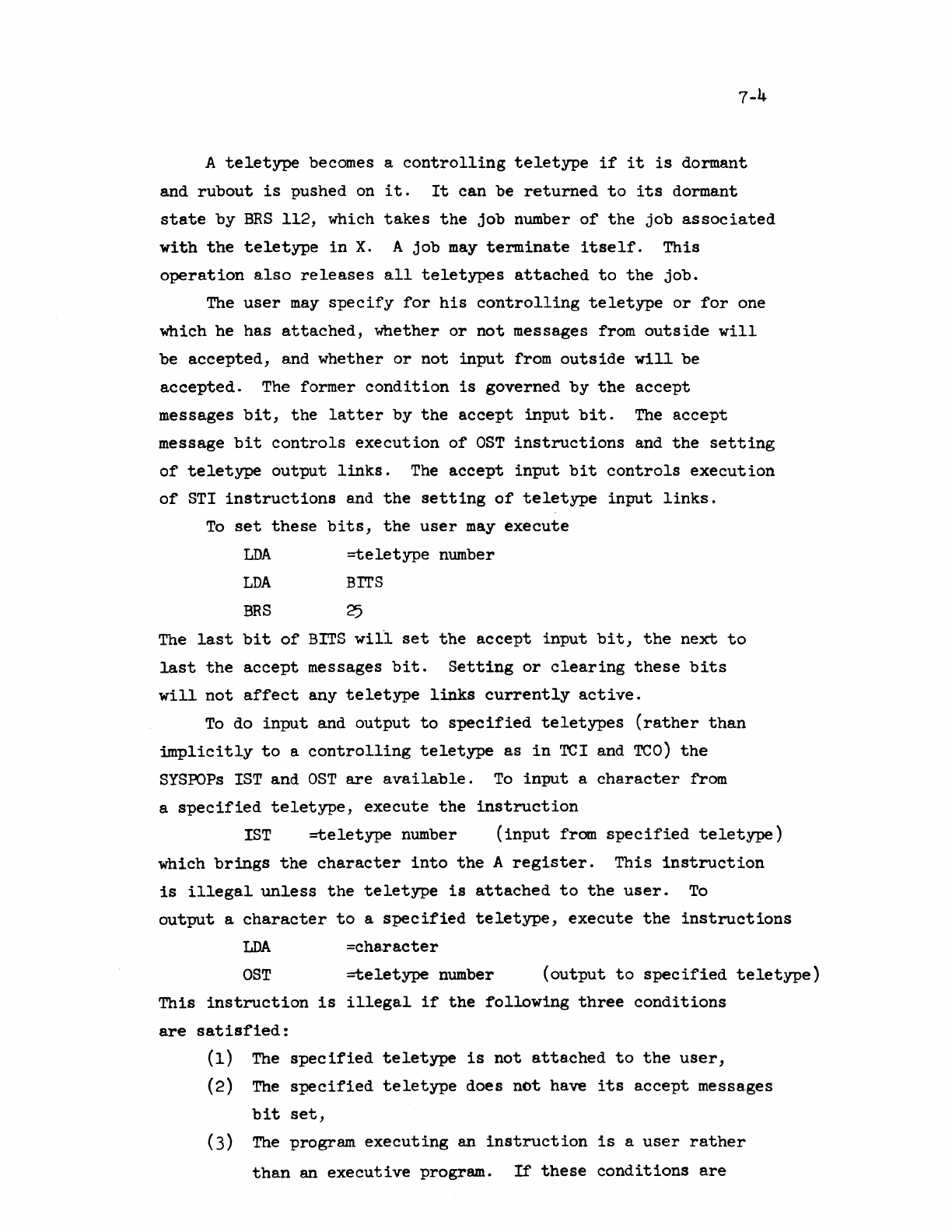
7-4
A
teletype
becomes a
controlling
teletype
if
it
is
dormant
and
rubout
is
pushed on
it.
It
can
be
returned
to
its
dormant
state
by
BRS
112,
which
takes
the
job
number
of
the
job
associated
with
the
teletype
in
X.
A
job
may
terminate
itself.
This
operation
also
releases
all
teletypes
attached
to
the
job.
The
user
may
specify
for
his
controlling
teletype
or
for
one
which he
has
attached,
whether
or
not
messages from
outside
will
be
accepted,
and
whether
or
not
input
from
outside
will
be
accepted.
The former
condition
is
governed
by
the
accept
messages
bit,
the
latter
by
the
accept
input
bit.
The
accept
message
bit
controls
execution
of
OST
instructions
and
the
setting
of
teletype
output
links.
The
accept
input
bit
controls
execution
of
STI
instructions
and
the
setting
of
teletype
input
links.
To
set
these
bits,
the
user
may
execute
LDA
=teletype
number
LDA
BrrS
BRS
25
The
last
bit
of
BITS
will
set
the
accept
input
bit,
the
next
to
last
the
accept
messages
bit.
Setting
or
clearing
these
bits
will
not
affect
any
teletype
links
currently
active.
To
do
input
and
output
to
specified
teletypes
(rather
than
implicitly
to
a
controlling
teletype
as
in
TCI
and
TCO)
the
SYSPOPs
1ST
and
OST
are
available.
To
input
a
character
from
a
specified
teletype,
execute
the
instruction
IST
=teletype
number
(input
from
specified
teletype)
which
brings
the
character
into
the
A
register.
This
instruction
is
illegal
unless
the
teletype
is
attached
to
the
user.
To
output
a
character
to
a
specified
teletype,
execute
the
instructions
LDA
=cha.racter
OST
=teletype
number
(output
to
specified
teletype)
This
instruction
is
illegal
if
the
following
three
conditions
are
satisfied:
(1)
The
spec
ified
te
letype
is
not
atta.ched
to
the
user,
(2)
The
specified
teletype
does
not
have
its
accept
messa.ges
bit
set,
(3)
The
program
executing
an
instruction
is
a
user
rather
than
an
executive
program.
If
these
conditions
are
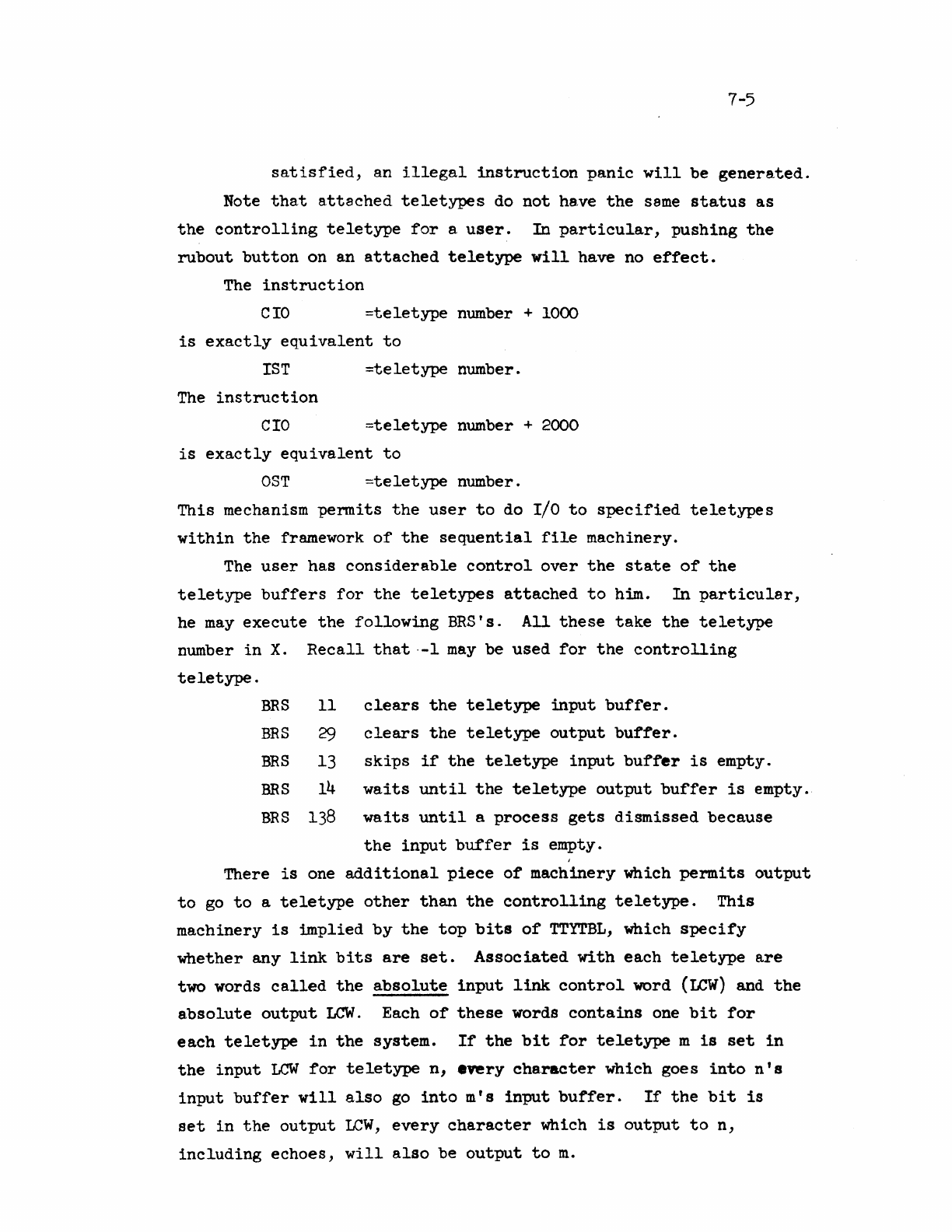
7-5
satisfied,
an
illegal
instruction
panic
will
be
generated.
Note
that
attached
teletypes
do
not
have
the
same
status
as
the
controlling
teletype
for
a
user.
In
particular,
pushing
the
rub
out
button
on an
attached
teletype
will
have no
effect.
The
instruction
eIO
=teletype
number +
1000
is
exactly
equivalent
to
IST
=teletype
number.
The
instruction
eIO
=teletype
number +
2000
is
exactly
equivalent
to
OST
=teletype
number.
This
mechanism
permits
the
user
to
do
Ilo
to
specified
teletypes
within
the
frrumework
of
the
sequential
file
machinery.
The
user
has
considerable
control
over
the
state
of
the
teletype
buffers
for
the
teletypes
attached
to
him.
In
particular,
he
may
execute
the
following
BRS's.
All
these
take
the
teletype
number
in
X.
Recall
that
·-1
may
be
used
for
the
controlling
teletype.
BRS
11
BRS
29
BRS
13
BRS
14
BRS
138
clears
the
teletype
input
buffer.
clears
the
teletype
output
buffer.
skips
if
the
teletype
input
buffer
is
empty.
waits
until
the
teletype
output
bu~fer
is
empty.
waits
until
a
process
gets
dismissed
because
the
input
buffer
is
empty.
There
is
one
additional
piece
of
machinery which
permits
output
to
go
to
a
teletype
other
than
the
controlling
teletype.
This
machinery
is
~plied
by
the
top
bits
of
TTYTBL,
which
specify
whether
any
link
bits
are
set.
Associated
with
each
teletype
are
two words
called
the
absolute
input
link
control
word
(LeW)
and
the
absolute
output
LCW.
Each
of
these
words
contains
one
bit
for
each
teletype
in
the
system.
If
the
bit
for
teletype
m
is
set
in
the
input
LCW
for
teletype
n,
every
chs.racter
which goes
into
n'
s
input
buffer
will
also
go
into
m's
input
buffer.
If
the
bit
is
set
in
the
output
LCW,
every
character
which
is
output
to
n,
including
echoes,
will
also
be
output
to
m.

7-6
Also
associated
with
each
teletype
are
relative
LCW's
for
input
and
output.
The
bits
in
these
LCW's
are
set
by
BRS
23. Each
time
any
relative
WW
is
changed,
the
absolute
LCW'
s
are
all
recomputed.
The
Boolean
matrix
formed
by
the
absolute
input
(output)
LeW's
is
the
infinite
product
of
the
matrix
of
the
relative
input
(output)
LCW's.
The
instructions
LDX
=teletype
number
LDA
=TABLE
LDB
CTL
BRS
23
will
set
one
of
the
relative
LCW'
s
for
the
indicated
teletype.
TABLE
is
the
address
of
a
list
of
teletype
numbers
terminated
with
-2.
The
bits
of
CTL
are
interpreted
as
follows:
o O=output
LCW
l=input
ICW
1
2
O=clear
all
links
first
l=do
not
clear
links
first
O=set
link
bits
for
teletypes
whose numbers
are
in
the
table.
l=clear
link
bits
for
teletypes
whose numbers
are
in
the
table.
Fran
the
old
relative
LCW
and
the
information
supplied
by
BRS
23
a
new
relative
LCW
is
created.
New
absolute
LCW's
for
all
teletypes
are
then
computed.
An
output
link
can
be
set
up between two
teletypes
only
if
each
of
the
teletypes
satisfies
at
least
one
of
the
following
conditions:
a)
It
is
the
controlling
teletype
of
the
program
executing
BRS
23
b)
It
is
attached
to
the
program
c)
Its
accept
messages
bit
is
on
(destination
only)
d)
The
fork
executing
the
ERS
is
executive.
An
input
link
can be
set
only
if
the
same
conditions
are
satisfied
for
the
accept
input
bit.
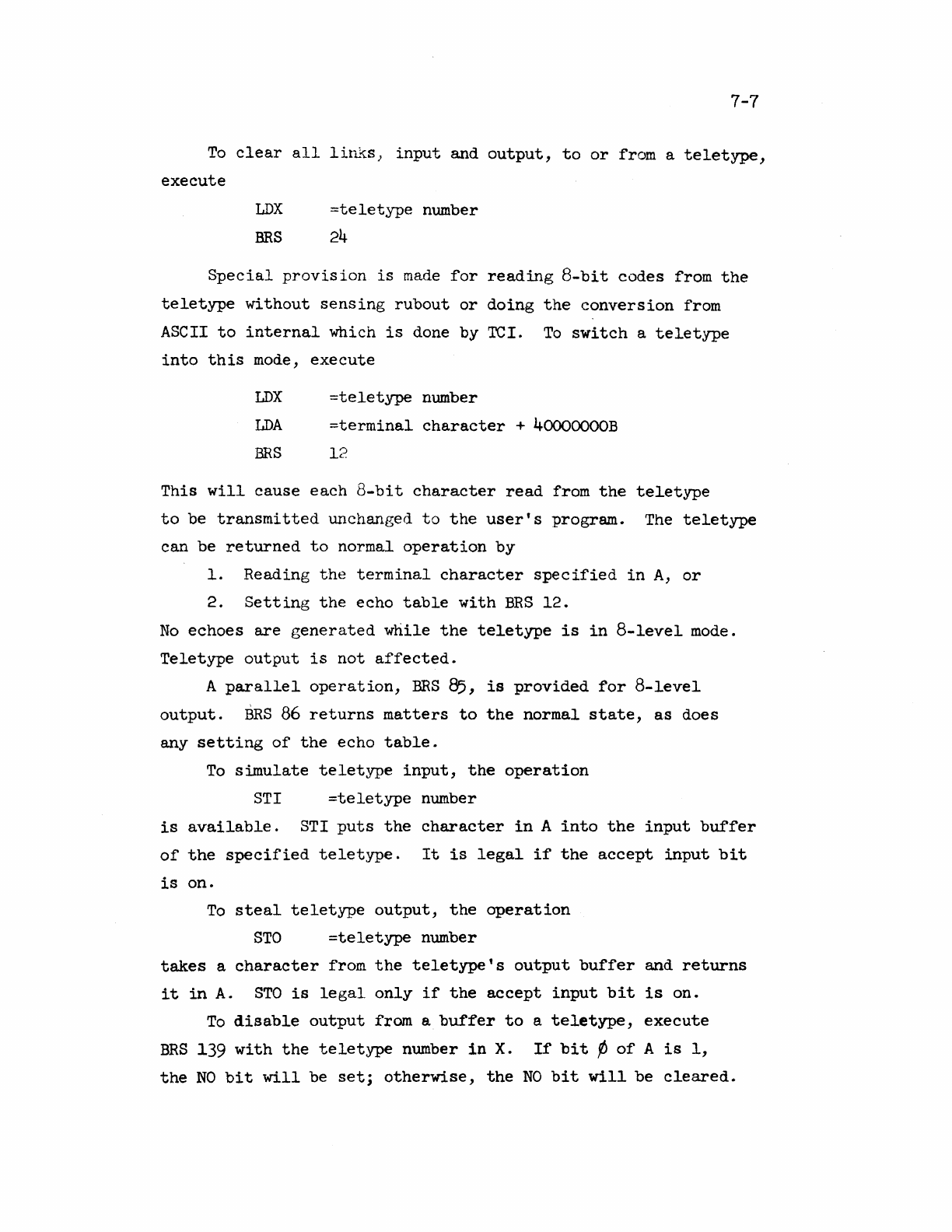
7-7
To
clear
all
liIL~S}
input
and
output,
to
or
from a
teletype,
execute
LDX
=teletype
number
BRS
24
Special
provision
is
made
for
reading
8-bit
codes
from
the
teletype
without
sensing
rub
out
or
doing
the
conversion
from
ASCII
to
internal
which
is
done
by
TCI.
To
switch
a
teletype
into
this
mode,
execute
LDX
=teletype
number
LDA
=terminal
character
+
40000000B
BRS
12
This
will
cause
each
8-bit
character
read
from
the
teletype
to
be
transmitted
lli~changed
to
the
user's
program.
The
teletype
can
be
returned
to
normal
operation
by
1.
Reading
the
terminal
character
specified
in
A,
or
2.
Setting
the
echo
table
with
BRS
12.
No
echoes
are
generated
while
the
teletype
is
in
8-level
mode.
Teletype
output
is
not
affected.
A
parallel
operation,
BRS
85,
is
provided
for
8-level
output.
BRS
86
returns
matters
to
the
normal
state,
as
does
any
setting
of
the
echo
table.
To
simulate
teletype
input,
the
operation
STr
=teletype
number
is
available.
STI
puts
the
character
in
A
into
the
input
buffer
of
the
specified
teletype.
It
is
legal
if
the
accept
input
bit
is
on.
To
steal
teletype
output,
the
operation
STO
=teletype
number
takes
a
character
from
the
teletype's
output
buffer
and
returns
it
in
A.
STO
is
legal
only
if
the
accept
input
bit
is
on.
To
disable
output
from a
buffer
to
a
teletype,
execute
BRS
139
with
the
teletype
number
in
X.
If
bit
¢
of
A
is
1,
the
NO
bit
will
be
set;
otherwise,
the
NO
bit
will
be
cleared.
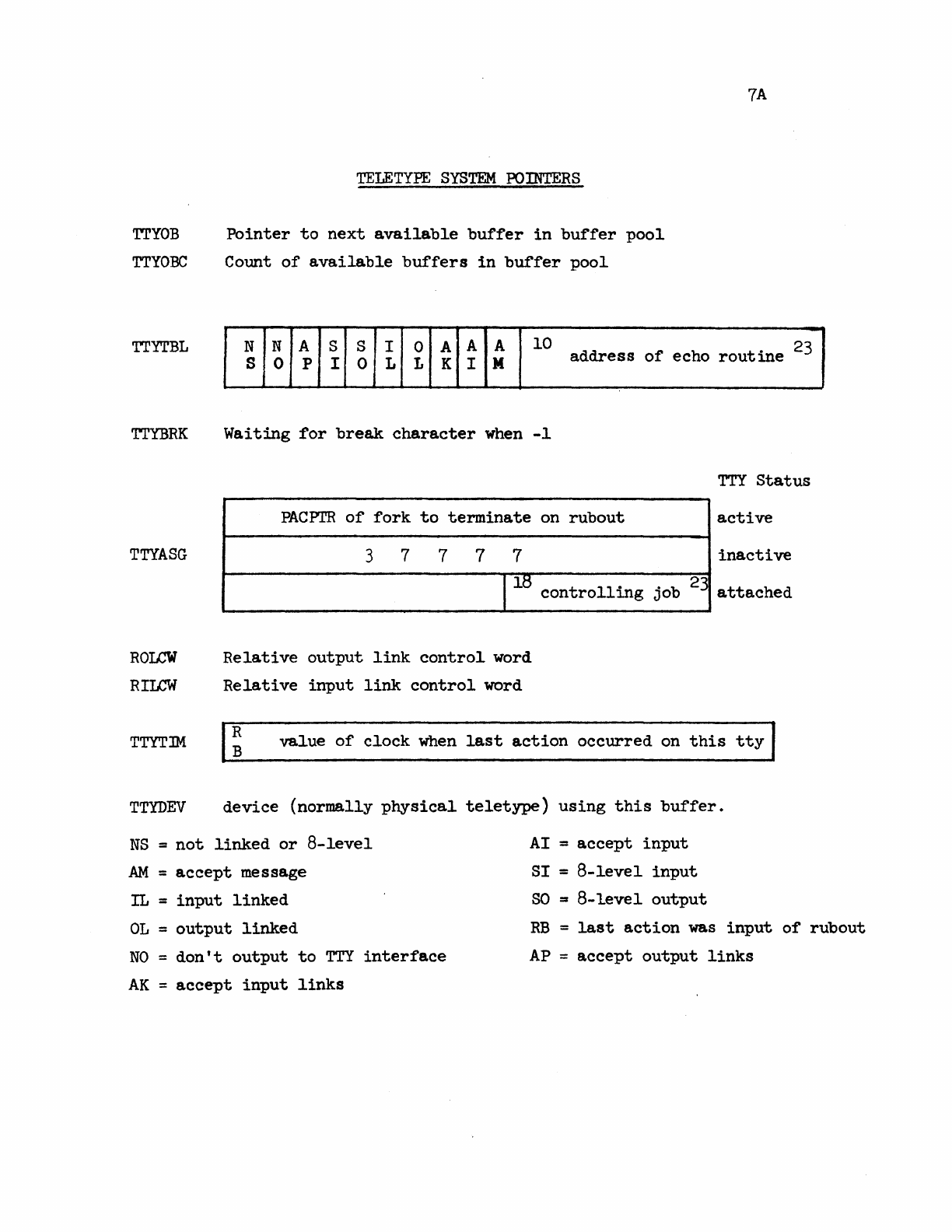
TTYOB
TTYOBC
TELETYPE
SYSTEM
POINTERS
Pointer
to
next
available
buffer
in
buffer
pool
Count
of
available
buffers
in
buffer
pool
7A
TTYTBL
N N A S S I 0 A A A
10
address
of
echo
routine
23
S 0 P I 0 L L K I M
TTYBRK
TTYASG
ROLCW
RILCW
Waiting
for
break
character
when
-1
PACPl'R
of
fork
to
terminate
on
rub
out
3 7 7 7 7
1
18
controlling
Relative
output
link
control
word
Relative
input
link
control
word
TTY
Status
active
inactive
. b 23
JO
attached
TTYTIM
R
B
value
of
clock
when
last
action
occurred
on
this
tty
TTYDEV
device
(normally
physical
teletype)
using
this
buffer.
NS
=
not
linked
or
8-level
AM
=
accept
message
IL =
input
linked
OL
=
output
linked
NO
=
don't
output
to
TTY
interface
AK
=
accept
input
links
AI =
accept
input
8I
=
8-level
input
SO
=
8-level
output
RB
=
last
action
was
input
of
rubout
AP
=
accept
output
links
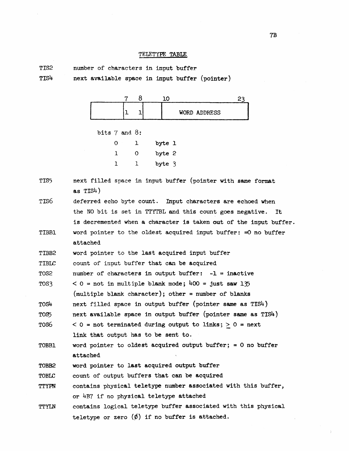
7B
TELETYPE
TABLE
TIS2 number
of
characters
in
input
buffer
TIS4
next
available
space
in
input
buffer
(pointer)
7 8
bits
'7
and
8:
o 1
1 0
1 1
10
I
WORD
ADDRESS
byte
1
byte
2
byte
3
23
TIS5
next
filled
space
in
input
buffer
(pointer
with
same
format
as
TIS4)
TIS6
deferred
echo
byte
count.
Input
characters
are
echoed
when
the
NO
bit
is
set
in
TTYTBL
and
this
count
goes
negative.
It
TIBBl
TIBB2
TIBLC
TOS2
TOS3
TOs4
TOS5
Tos6
TOBBl
TOBB2
TOBIC
TTYPN
TTYLN
is
decremented
when
a
character
is
taken
out
of
the
input
buffer.
word
pointer
to
the
oldest
acquired
input
buffer:
=0 no
buffer
attached
word
pointer
to
the
last
acquired
input
buffer
count
of
input
buffer
that
can
be
acquired
number
of
characters
in
output
buffer:
-1
=
inactive
< 0 =
not
in
mult
iple
blank
mode; 400 =
just
saw 135
(multiple
blank
character);
other
= number
of
blanks
next
filled
space
in
output
buffer
(pointer
same
as
TIS4)
next
available
space
in
output
buffer
(pointer
same
as
TIS4)
< 0 =
not
terminated
during
output
to
links;
> 0 =
next
link
that
output
has
to
be
sent
to.
word
pointer
to
oldest
acquired
output
buffer;
= 0 no
buffer
attached
word
pointer
to
last
acquired
output
buffer
count
of
output
buffers
that
can
be
acquired
contains
physical
teletype
number
associated
with
this
buffer,
or
4B7
if
no
physical
teletype
attached
contains
logical
teletype
buffer
associated
with
this
physical
teletype
or
zero
(¢)
if
no
buffer
is
attached.
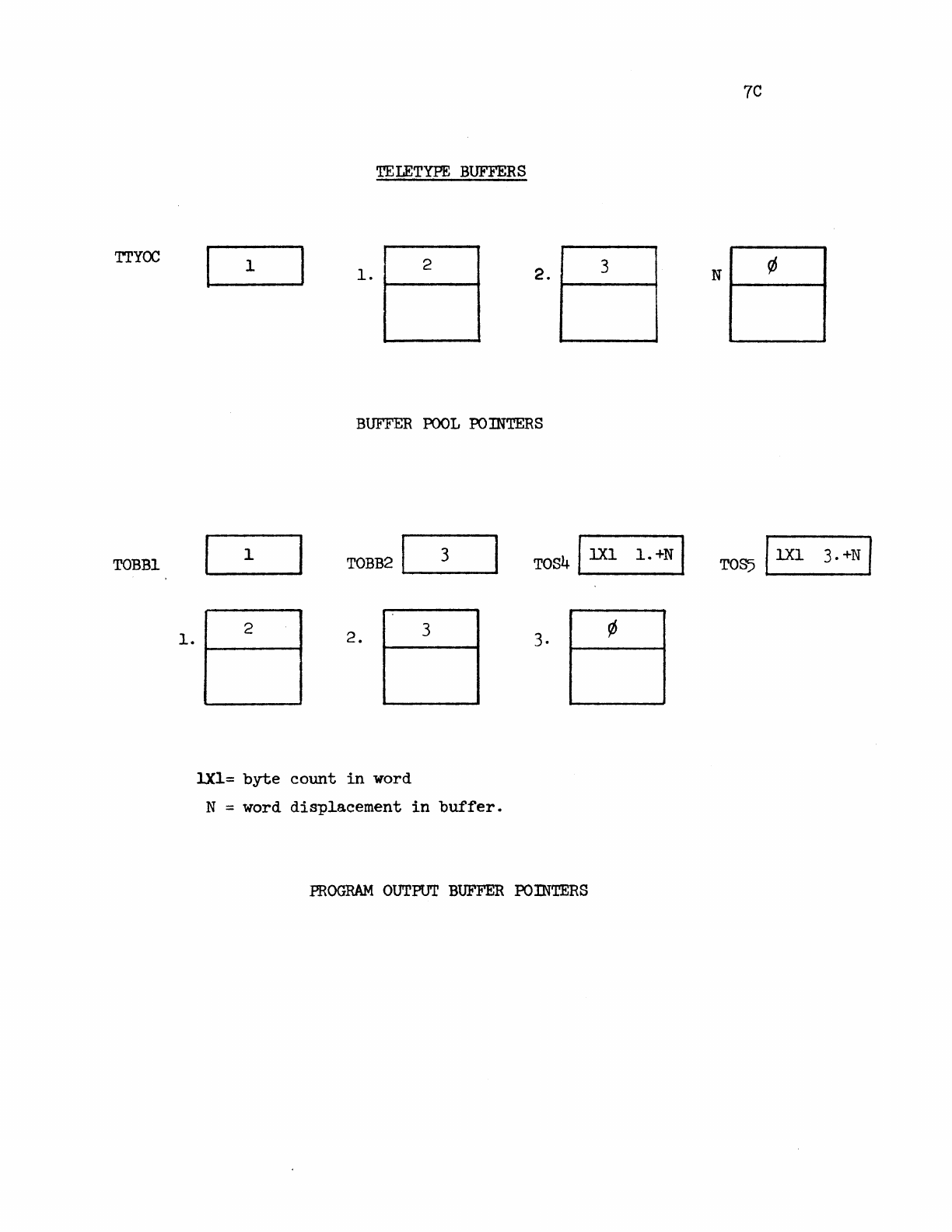
7C
TELETYPE
BUFFERS
TTYOC
1
1.
2 3
2.
1-----0004
N
1-----
....
BUFFER
POOL
POINTERS
TOBBl
1
TOBB2IL--_3_~
TOS41
lX1
1.
+N
I
1.
2
1-----
....
2.
3 3·
lXl=
byte
count
in
word
N = word
displacement
in
buffer.
PROGRAM
OUTPUT
BUFFER
PO:rnTERS
8-1
8.0
Drum
and
Buffer
Organization;
Devices
8.1
File
Storage
on
the
Drum
The drum
is
divided
into
two
major
sections,
program
swapping
and
file
storage.
The
organization
of
the
program swapping
area
is
discussed
in
Section
5.
The
file
storage
area
is
divided
into
256 word
blocks
which form
the
physical
records
for
storage
of
files.
Every
file
has
one
or
more
index
blocks
which
contain
pointers
to
the
data
blocks
for
the
file.
An
index
block
is
a
256 word
block,
as
are
all
other
physical
blocks
in
the
file
area.
Only
the
first
141 words
of
the
index
block
are
used,
however,
for
data
storage.
A
couple
of
additional
words
are
used
to
chain
the
index
blocks
for
any
particular
file,
both
forward
and backward. The
index
blocks
for
a
file
contain
the
addresses
for
all
the
physical
blocks
used
to
hold
information
for
the
file.
Available
storage
in
the
file
area
of
the
drum
is
kept
track
of
with
a
bit
table
similar
to
the
table
used
to
keep
track
of
program swapping
storage.
Since
there
are
sixty-four
256-word
blocks
around
the
circumference
of
the
drum and a
maximum
of
72 drum bands
(out
of
the
84
available)
may
be
used
for
file
storage,
a 192-word
bit
table
which
contains
3 words
of
72
bits
for
each
row
of
physical
blocks
suffices.
If
a
bit
in
this
table
is
set,
it
indicates
that
the
corresponding
block
on
the
drum
is
in
use.
Again,
as
with
program
swapping
storage,
the
organization
of
this
table
makes
it
easy
to
optimize
the
writing
of
files.
This
is
done
by
putting
consecutive
physical
blocks
in
the
file
in
alternating
rows on
the
drum.
The
intervening
row
between
each
two
physical
blocks
provides
the
time
for
the
channel
to
fetch
a
new
command
and
the
heads
to
switch.
The
result
of
this
organization
is
that
information
may
be
transferred
from a
file
on
the
drum
into
core
at
one-
half
core
memory
speed
if
conditions
are
right.
8-2
8.2
File
Buffers
Every open
file
in
the
system
with
the
exception
of
purely
character-oriented
files
such
as
the
teletype
has
a
file
buffer
associated
with
it.
The
form
of
this
buffer
is
shown on page
BA.
Part
(a)
of
this
figure
shows
the
buffer
proper,
and
part
(b)
shows
the
index
block
buffer
and
pointers
associated
with
it.
Part
(b)
is
not
used
only
by drum
files,
but
is
present
in
all
cases.
Each
job
has
associated
with
it
a
temporary
storage
block,
which
is
always
the
first
entry
in
the
job's
FMT.
This
block
is
used
to
hold
information
about
the
user
and
for
the
system's
temporary
storage.
It
also
has
room
for
three
buffers.
An
additional
block
may
be
assigned
with
room
for
five
more
buffers
if
more
than
three
file
s
are
open
at
one
time.
The
pseudo-
relabeling
for
the
extra
buffer
block
and
the
TS
block
is
held
in
a
table
called
RL3
which
is
indexed
by
job
number, and
is
put
into
the
monitor
map
whenever
any
fork
belonging
to
that
job
is
run.
Note
that
the
amount
of
buffer
space
actually
used
is
a
fuu~ction
of
the
device
attached
to
the
file.
In
all
cases
the
two
pointer
words
at
the
head
of
the
buffer
indicate
the
location
of
the
data.
The
first
word
points
to
the
beginning
of
the
relevant
data
and
is
incremented
as
data
are
read
from an
input
buffer.
The
second word
points
to
the
end
of
the
data
on
input
or
end
of
the
buffer
on
output
or
written
in
an
output
buffer.
When
the
buffer
is
in
its
dormant
state,
both
words
point
to
the
first
data
word
of
the
buffer.
Whenever any
physical
I/O
operation
is
completed,
the
first
pointer
contains
the
address
of
this
word.
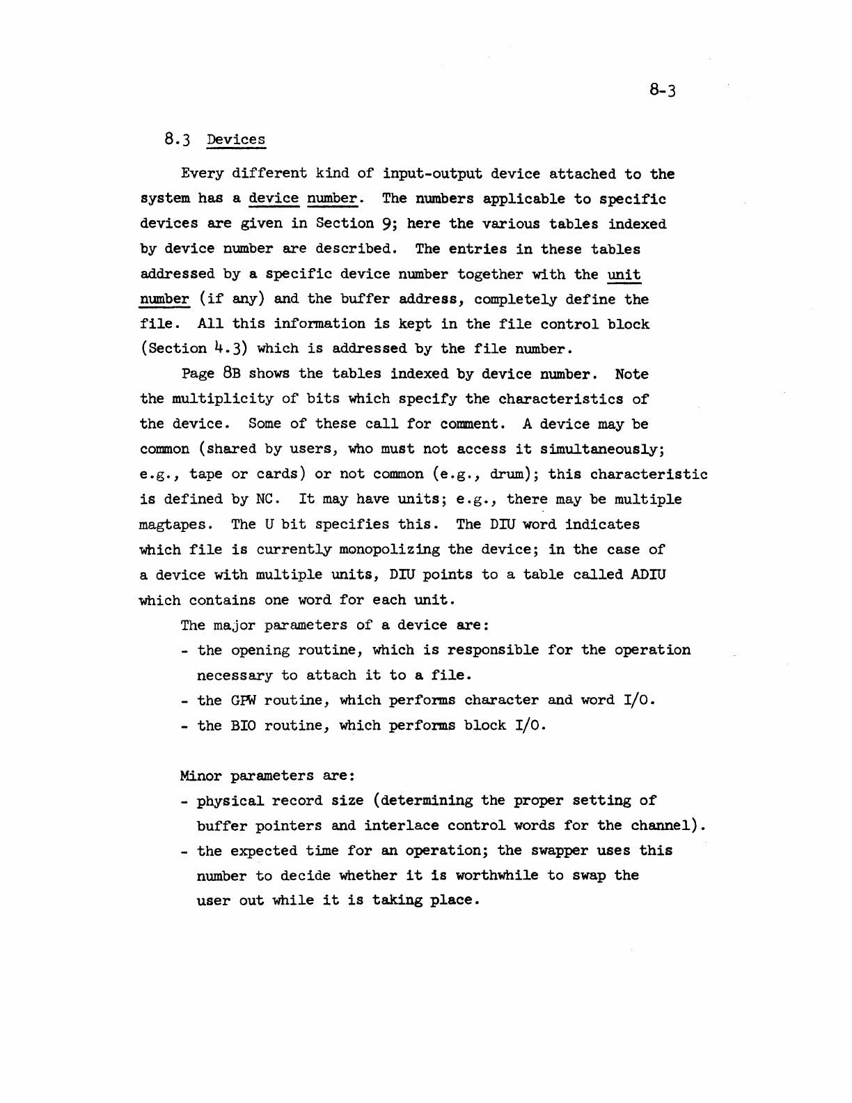
B-3
8.3 Devices
Every
different
kind
of
input-output
device
attached
to
the
system
has
a
device
number.
The
numbers
applicable
to
specific
devices
are
given
in
Section
9;
here
the
various
tables
indexed
by
device
number
are
described.
The
entries
in
these
tables
addressed
by
a
specific
device
number
together
with
the
unit
number
(if
any) and
the
buffer
address,
completely
define
the
file.
All
this
information
is
kept
in
the
file
control
block
(Section
4.3) which
is
addressed
by
the
file
number.
Page
8B
shows
the
tables
indexed
by
device
number. Note
the
multiplicity
of
bits
which
specify
the
characteristics
of
the
device.
Some
of
these
call
for
comment. A
device
may
be
common
(shared
by
users,
who
must
not
access
it
simultaneously;
e.g.,
tape
or
cards)
or
not
common
(e.g.,
drum);
this
characteristic
is
defined
by
NC.
It
may
have
units;
e.g.,
there
may
be
multiple
magtapes.
The
U
bit
specifies
this.
The
DIU
word
indicates
which
file
is
currentLy
monopolizing
the
device;
in
the
case
of
a
device
with
multiple
units,
DIU
points
to
a
table
called
ADIU
which
contains
one word
for
each
unit.
The
major
parameters
of
a
device
are:
-
the
opening
routine,
which
is
responsible
for
the
operation
necessary
to
attach
it
to
a
file.
-
the
GPW
routine,
which
performs
character
and word
I/O.
-
the
BIO
routine,
which
performs
block
I/O.
Minor
parameters
are:
-
physical
record
size
(determining
the
proper
setting
of
buffer
pointers
and
interlace
control
words
for
the
channel).
-
the
expected
t~e
for
an
operation;
the
swapper
uses
this
number
to
decide
whether
it
is
worthwhile
to
swap
the
user
out
while
it
is
taking
place.
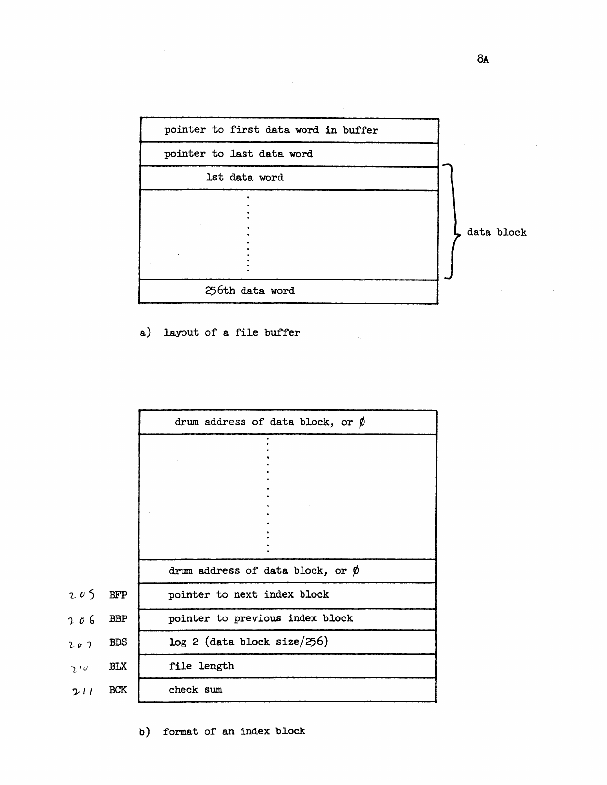
8A
pointer
to
first
data
word
in
buffer
pointer
to
last
data
word
1st
data
word
·
·
·
data
block
·
256th
data
word
a)
layout
of
a
file
buffer
drum
address
of
data
block,
or
¢
·
·
·
·
drum
address
of
data
block,
or
'/J
'Z..O)
BFP
pointer
to
next
index
block
1-
()
G BBP
pointer
to
previous
index
block
1
,,7
BDS
log
2
(data
block
size!256)
L'v
BLX
file
length
?- I I
BCK
check
sum
b)
format
of
an
index
block
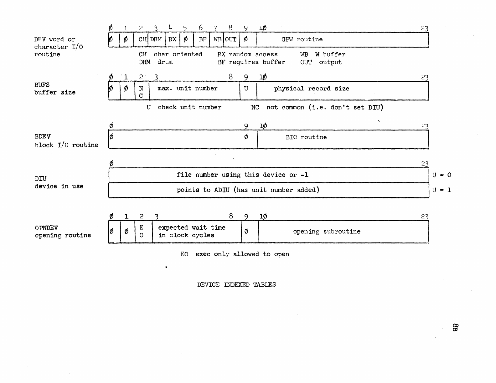
DEV word
or
character
I/O
routine
BUFS
buffer
size
BDEV
block
r/o
routine
DID
device
in
use
OPNDEV
opening
routine
¢ 1
~
1 ¢
0
I¢
t/J
t/J
1
(/) (/)
GPW
routine
CH
char
oriented
DRM
dru.rn
RX
random
access
BF
requires
buffer
WB
W
buffer
OUT
output
2 ' 3 8 9
l¢
~
I
max.
unit
number U I
physical
record
size
U
check
unit
number
NC
not
common
(i.e.
don't
set
DID)
9
BIO
routine
file
number
using
this
device
or
-1
points
to
ADN
(has
unit
number added)
2 3 8 9
l~
\
~
expected
wait
time
0
opening
subroutine
in
clock
C:lC
Ie
s
EO
exec
only
allowed
to
open
•
DEVICE
INDEXED
TABLES
23
23
23
U = 0
u = 1
23
9-1
9.0
Sequential
Files
9.1
Sequential
Drum
Files
1.94
includes
a
major
revision
to
the
drum
file
system.
Basically,
a
file
appears
as
an
address
space
with
an
arbitrary
upper
bound
called
its
"length."
The
maximum
possible
length
is
around
four
million
words
(22
bits).
The
file
is
internally
paged
into
an
arbitrary
number
of
data
blocks
whose
size
may
be
any power
of
two
larger
than
256
words.
The
following
discussion
will
be
of
interest
to
those
who
need
to
make
efficient
use
of
large,
randomly
accessed
files:
1.
The
data
blocks
are
kept
track
of
by
the
use
of
index
blocks
chained
together.
Each
index
block
can
describe
about
14¢
data
blocks.
Random
access
will
be
slow
if
there
are
several
index
blocks
to
chain
through.
A
large
data
block
size
will
minimize
this
source
of
inefficiency.
2.
Block
transfers
are
implemented
in
the
most
efficient
manner,
with
as
much
as
possible
of
the
data
requested
transferred
directly
into
the
user's
memory.
The
slop
on
either
end
is
buffered
in
256-word
blocks.
Programs
cognizant
of
the
structure
of
their
files
can
avoid
all
buffering.
All
word
operations
use
the
256-word
buffer.
The
user's
access
to
an
open
file
is
housekept
by
means
of
a
position
pointer
to
the
file.
This
pointer
may
be moved
explicit~
by
the
user
or
implicitly
by any
of
the
I/O
operations.
The
I/O
operations
always
leave
the
pointer
pointing
at
the
word
following
the
last
transfer.
eIO
is
a
confusion
factor.
When
a
file
is
opened,
any
of
three
types
of
access
to
that
file
may
be
given
to
the
user:
read,
write,
or
position.
Position
ac~ess
is
intended
to
implement
append-only
files.
You
may
not
move
the
pointer
or
perform
random
operations
unless
you have
position
access
to
the
file.
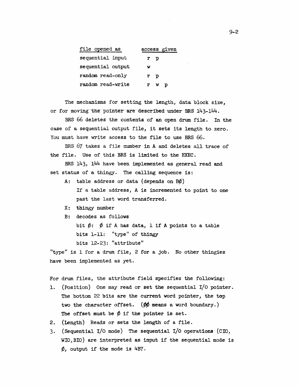
file
o12ened
as
access
given
sequential
input
r p
sequential
output
w
random
re
ad-only
r p
random
read-write
r w p
The
mechanisms
for
setting
the
length,
data
block
size,
or
for
moving-----ene-po~nter_are
described
undeI
BRS
143-144.
9-2
BRS
66
deletes
the
contents
of
an
open
drum
file.
In
the
case
of
a
sequential
output
file,
it
sets
its
length
to
zero.
You
must have
write
access
to
the
file
to
use
BRS
66.
BRS
67
takes
a
file
number
in
A and
deletes
all
trace
of
the
file.
Use
of
this
BRS
is
limited
to
the
EXEC.
ERS
143, 144 have
been
implemented
as
general
read
and
set
status
of
a
thingy.
The
calling
sequence
is:
A:
table
address
or
data
(depends on
B¢)
If
a
table
address,
A
is
incremented
to
point
to
one
past
the
last
word
transferred.
X:
thingy
number
B:
decodes
as
follows
bit
¢:
~
if
A has
data,
1
if
A
points
to
a
table
bits
1-11:
"type"
of
thingy
bits
12-23:
"attribute"
"type"
is
I
for
a drum
file,
2
for
a
job.
No
other
thingies
have
been
implemented
as
yet.
For
drum
files,
the
attribute
field
specifies
the
following:
1.
(Position)
One
may
read
or
set
the
sequential
I/O
pointer.
The
bottom 22
bits
are
the
current
word
pointer,
the
top
two
the
character
offset.
('/IIJ
means a word
boundary.)
The
offset
must be ¢
if
the
pointer
is
set.
2.
(Length) Reads
or
sets
the
length
of
a
file.
3.
(Sequential
I/O
mode)
The
sequential
I/O
operations
(CIO,
WIO,BIO)
are
interpreted
as
input
if
the
sequential
mode
is
¢,
output
if
the
mode
is
4B7.
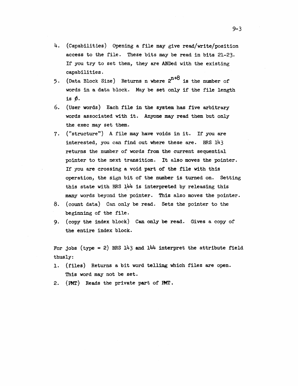
9-3
4.
(Capabilities)
Opening a
file
may
give
read/write/position
access
to
the
file.
These
bits
may
be
read
in
bits
21-23.
If
you
try
to
set
them,
they
are
~d
with
the
existing
capabilities.
5.
(Data Block
Size)
Returns
n where 2n+8
is
the
number
of
words
in
a
data
block.
May
be
set
only
if
the
file
length
is
(1.
6. (User words) Each
file
in
the
system
has
five
arbitrary
words
associated
with
it.
Anyone
may
read
them
but
only
the.
exec
may
set
them.
7 . (
"structure")
A
file
may
have
voids
in
it.
If
you
are
interested,
you can
find
out
where
these
are.
BRS
143
returns
the
number
of
words from
the
current
sequential
pointer
to
the
next
transition.
It
also
moves
the
pointer.
If
you
are
crossing
a
void
part
of
the
file
with
this
operation,
the
sign
bit
of
the
number
is
turned
on.
Setting
this
state
with
BRS
144
is
interpreted
by
releasing
this
many
words beyond
the
pointer.
This
also
moves
the
pointer.
8.
(count
data)
Can
only
be
read.
Sets
the
pointer
to
the
beginning
of
the
file.
9. (copy
the
index
block)
Can
only
be
read.
Gives a copy
of
the
entire
index
block.
For
jobs
(type
= 2)
BRS
143 and
144
interpret
the
attribute
field
thusly:
1.
(files)
Returns
a
bit
word
telling
which
files
are
open.
This
word
may
not
be
set.
2.
(mT)
Reads
the
private
part
of
Ht1T.
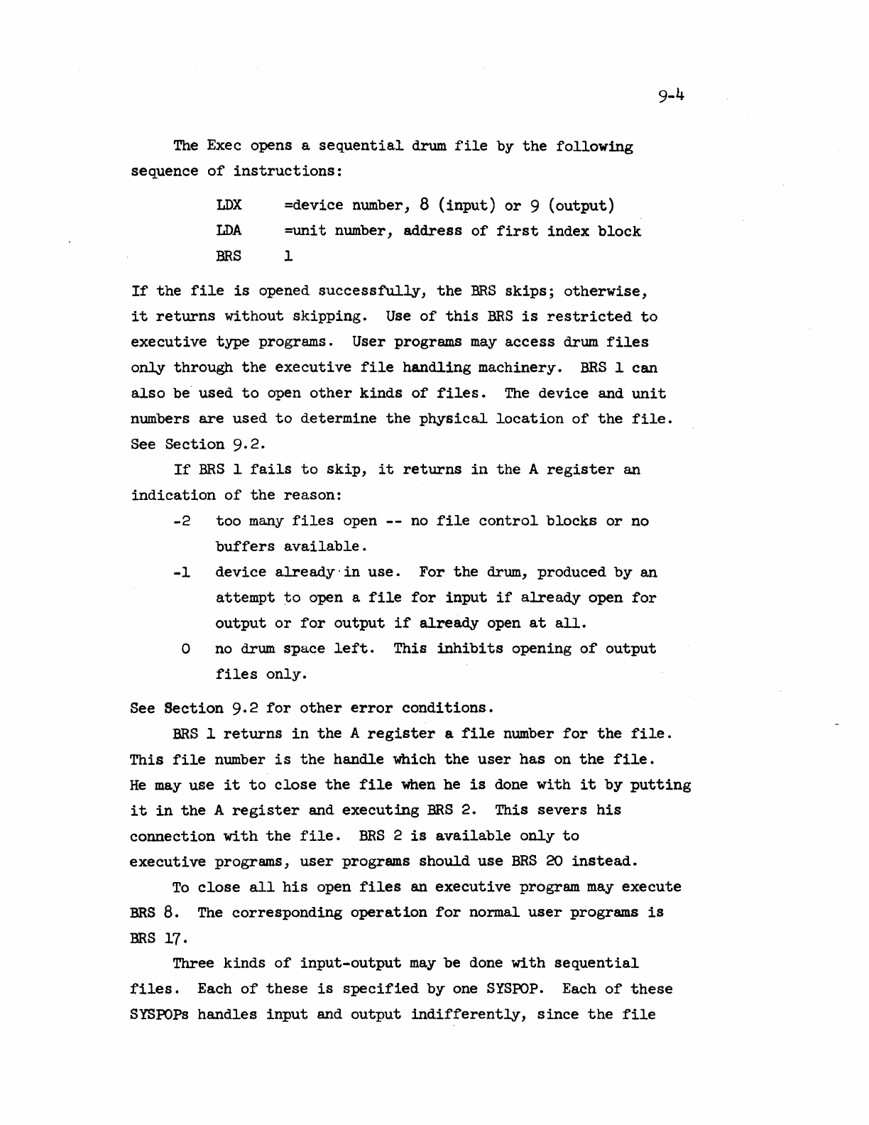
The
Exec opens a
sequential
drum
file
by
the
following
sequence
of
instructions:
LDX
=device number, 8
(input)
or
9
(output)
LDA
=unit
number,
address
of
first
index
block
BRS
I
If
the
file
is
opened
successfully,
the
BRS
skips;
otherwise,
9-4
it
returns
without
skipping.
Use
of
this
BRS
is
restricted
to
executive
type
programs. User programs
may
access
drum
files
only
through
the
executive
file
handling
machinery.
BRS
I
can
also
be
used
to
open
other
kinds
of
files.
The
device
and
unit
numbers
are
used
to
determine
the
physical
location
of
the
file.
See
Section
9.2.
If
BRS
I
fails
to
skip,
it
returns
in
the
A
register
an
indication
of
the
reason:
-2
too
many
files
open
--
no
file
control
blocks
or
no
buffers
available.
-1
device
already'
in
use.
For
the
drum,
produced
by
an
attempt
to
open a
file
for
input
if
already
open
for
output
or
for
output
if
already
open
at
all.
o
no
drum
space
left.
This
inhibi
ts
opening
of
output
files
only.
See
Section
9.2
for
other
error
conditions.
BRS
I
returns
in
the
A
register
a
file
number
for
the
file.
This
file
number
is
the
handle
which
the
user
has
on
the
file.
He
may
use
it
to
close
the
file
when
he
is
done
with
it
by
putting
it
in
the
A
register
and
executing
BRS
2.
This
severs
his
connection
with
the
file.
BRS
2
is
available
only
to
executive
progrwms,
user
programs
should
use
BRS
20
instead.
To
close
all
his
open
files
an
executive
program
may
execute
BRS
8.
The
corresponding
operation
for
nor.mal
user
programs
is
BRS
17.
Three
kinds
of
input-output
may
be done
with
sequential
files.
Each
of
these
is
specified
by
one
SYSPOP.
Each
of
these
SYSPOPs
handles
input
and
output
indifferently,
since
the
file
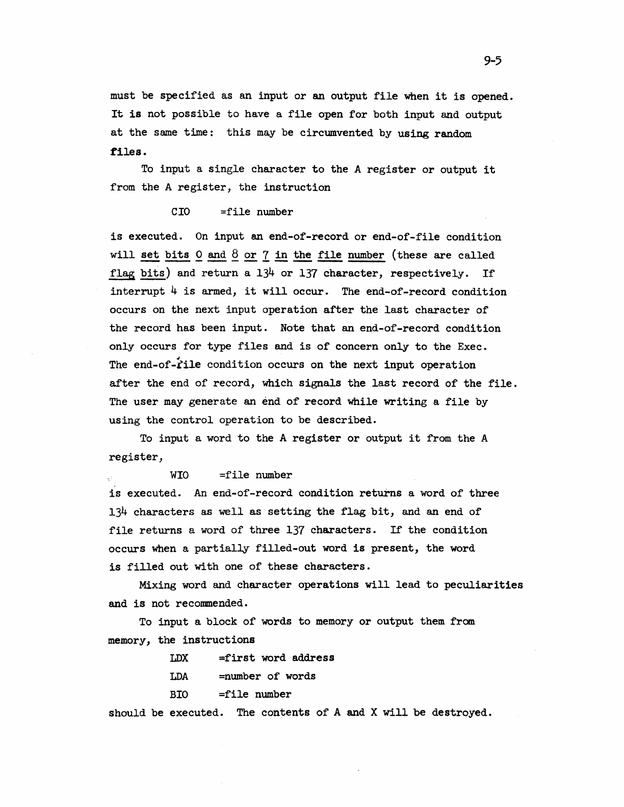
9-5
must be
specified
as
an
input
or
an
output
file
when
it
is
opened.
It
is
not
possible
to
have a
file
open
for
both
input
and
output
at
the
same
time:
this
may
be
circumvented
by
using
random
:tiles.
To
input
a
single
character
to
the
A
register
or
output
it
from
the
A
register,
the
instruction
CIO
=file
number
is
executed.
On
input
an
end-of-record
or
end-of-file
condition
will
set
bits
.Q.
and Q
~
I
in
the
file
number
(these
are
called
~
bits)
and
return
a
134
or
137
character,
respectively.
If
interrupt
4
is
armed,
it
will
occur.
The
end-of-record
condition
occurs
on
the
next
input
operation
after
the
last
character
of
the
record
has
been
input.
Note
that
an
end-of-record
condition
only
occurs
for
type
files
and
is
of
concern
only
to
the
Exec.
~
The
end-of-file
condition
occurs
on
the
next
input
operation
after
the
end
of
record,
which
signals
the
last
record
of
the
file.
The
user
may
generate
an
end
of
record
while
writing
a
file
by
using
the
control
operation
to
be
described.
To
input
a word
to
the
A
register
or
output
it
from
the
A
register,
WIO
=file
number
is
executed.
An
end-of-record
condition
returns
a word
of
three
134
characters
as
well
as
setting
the
flag
bit,
and an end
of
file
returns
a word
of
three
137
characters.
If
the
condition
occurs
when
a
partially
filled-out
word
is
present,
the
word
is
filled
out
with
one
of
these
characters.
Mixing word and
character
operations
will
lead
to
peculiarities
and
is
not
recommended.
To
input
a
block
of
words
to
memory
or
output
them from
memory,
the
instructions
LOX
=first
word
address
LDA
=number
of
words
BIO
=file
number
should
be
executed.
The
contents
of
A and X
will
be
destroyed.
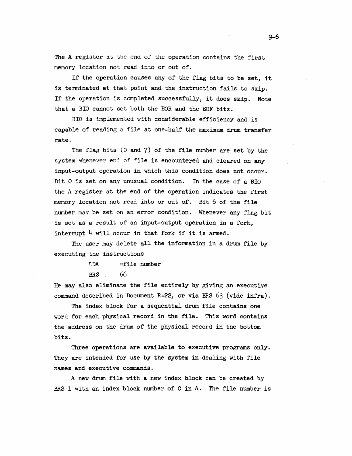
The A
register
at
the
end
of
the
operation
contains
the
first
memory
location
not
read
into
or
out
of.
9-6
If
the
operation
causes
any
of
the
flag
bits
to
be
set,
it
is
terminated
at
that
point
and
the
instruction
fails
to
skip.
If
the
operation
is
completed
successfully,
it
does
skip.
Note
that
a
BIO
cannot
set
both
the
EOR
and
the
EOF
bits.
BIO
is
implemented
with
considerable
efficiency
and
is
capable
of
reading
a
file
at
one-half
the
maximum
drum
transfer
rate.
The
flag
bits
(0 and 7)
of
the
file
number
are
set
by
the
system
whenever end
of
file
is
encountered
and
cleared
on any
input-output
operation
in
which
this
condition
does
not
occur.
Bit
0
is
set
on any
unusual
condition.
In
the
case
of
a
BIO
the
A
register
at
the
end
of
the
operation
indicates
the
first
memory
location
not
read
into
or
out
of.
Bit
6
of
the
file
number
may
be
set
on an
error
condition.
Whenever any
flag
bit
is
set
as
a
result
of
an
input-output
operation
in
a
fork,
interrupt
4
will
occur
in
that
fork
if
it
is
armed.
The
user
may
delete
all
the
information
in
a drum
file
by
executing
the
instructions
LDA
=file
number
BRS
66
He
may
also
eliminate
the
file
entirely
by
giving
an
executive
command
described
in
Document R-22,
or
via
ERS
63
(vide
infra).
The
index
block
for
a
sequential
drum
file
contains
one
word
for
each
physical
record
in
the
file.
This
word
contains
the
address
on
the
drum
of
the
physical
record
in
the
bottom
bits.
Three
operations
are
available
to
executive
programs
only.
They
are
intended
for
use
by
the
system
in
dealing
with
file
names and
executive
commands.
A
new
drum
file
with
a
new
index
block
can
be
created
by
BRS
1
with
an
index
block
number
of
0
in
A. The
file
number
is
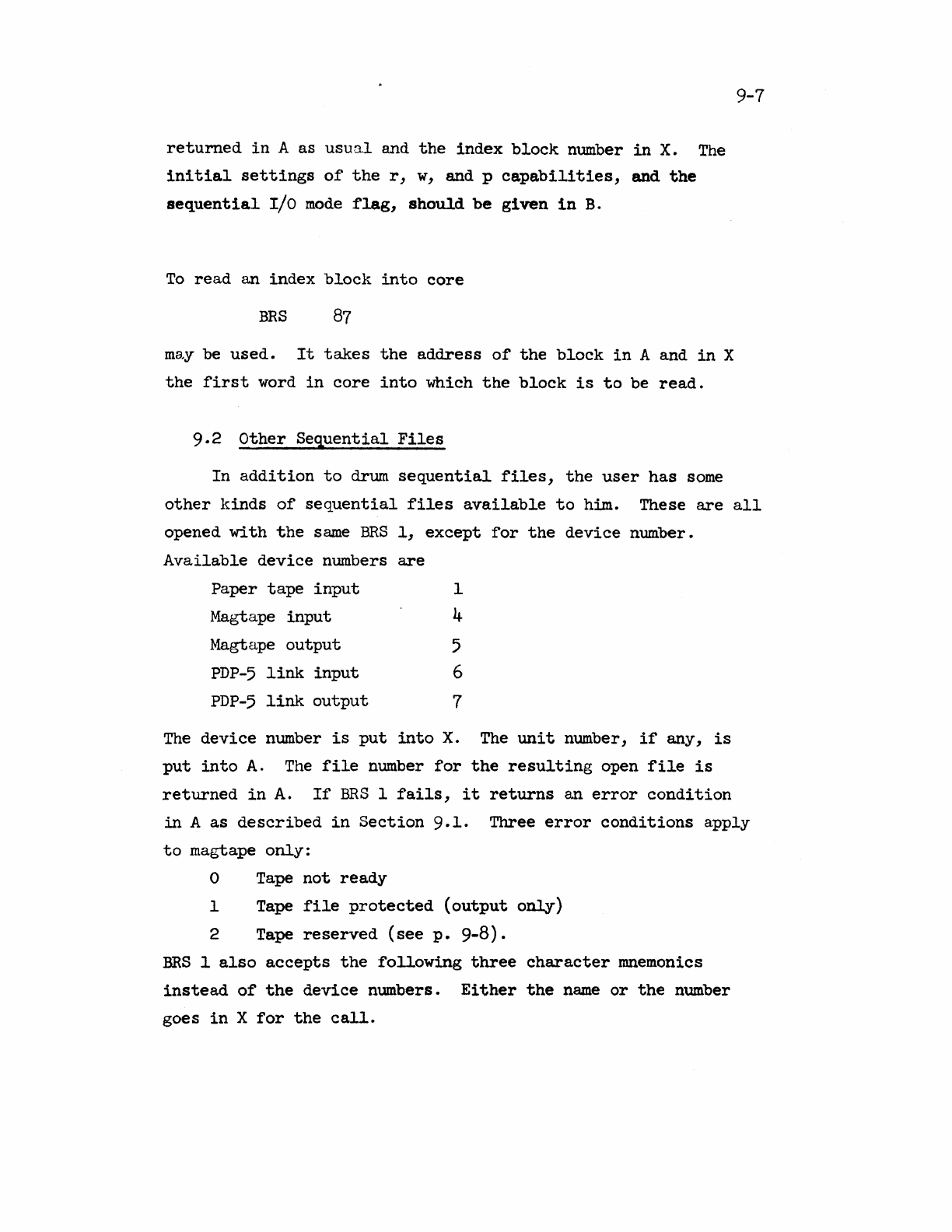
returned
in
A as
usual
and
the
index
block
number
in
X.
The
initial
settings
of
the
r,
w,
and p
capabi~ities,
and
the
sequential
I/O
mode
flag,
should
be
given
in
B.
To
read
an
index
block
into
core
BRS
87
ma.y
be
used.
It
takes
the
address
of
the
block
in
A and
in
X
the
first
word
in
core
into
which
the
block
is
to
be
read.
9.2
other
Sequential
Files
9-7
In
addition
to
drum
sequential
files,
the
user
has
some
other
kinds
of
sequential
files
available
to
him. These
are
all
opened
with
the
same
ERS
1,
except
for
the
device
number.
Available
device
numbers
are
Paper
tape
input
1
Magtape
input
4
Magtape
output
5
PDP-5
link
input
6
PDP-5
link
output
7
The
device
number
is
put
into
X.
The
unit
number,
if
any,
is
put
into
A.
The
file
number
for
the
resulting
open
file
is
returned
in
A.
If
BRS
1
fails,
it
returns
an
error
condition
in
A
as
described
in
Section
9.1. Three
error
conditions
apply
to
magtape
only:
o Tape
not
ready
1 Tape
file
protected
(output
only)
2 Tape
reserved
(see
p.
9-8).
ERS
1
also
accepts
the
following
three
character
mnemonics
instead
of
the
device
numbers.
Either
the
name
or
the
number
goes
in
X
for
the
call.
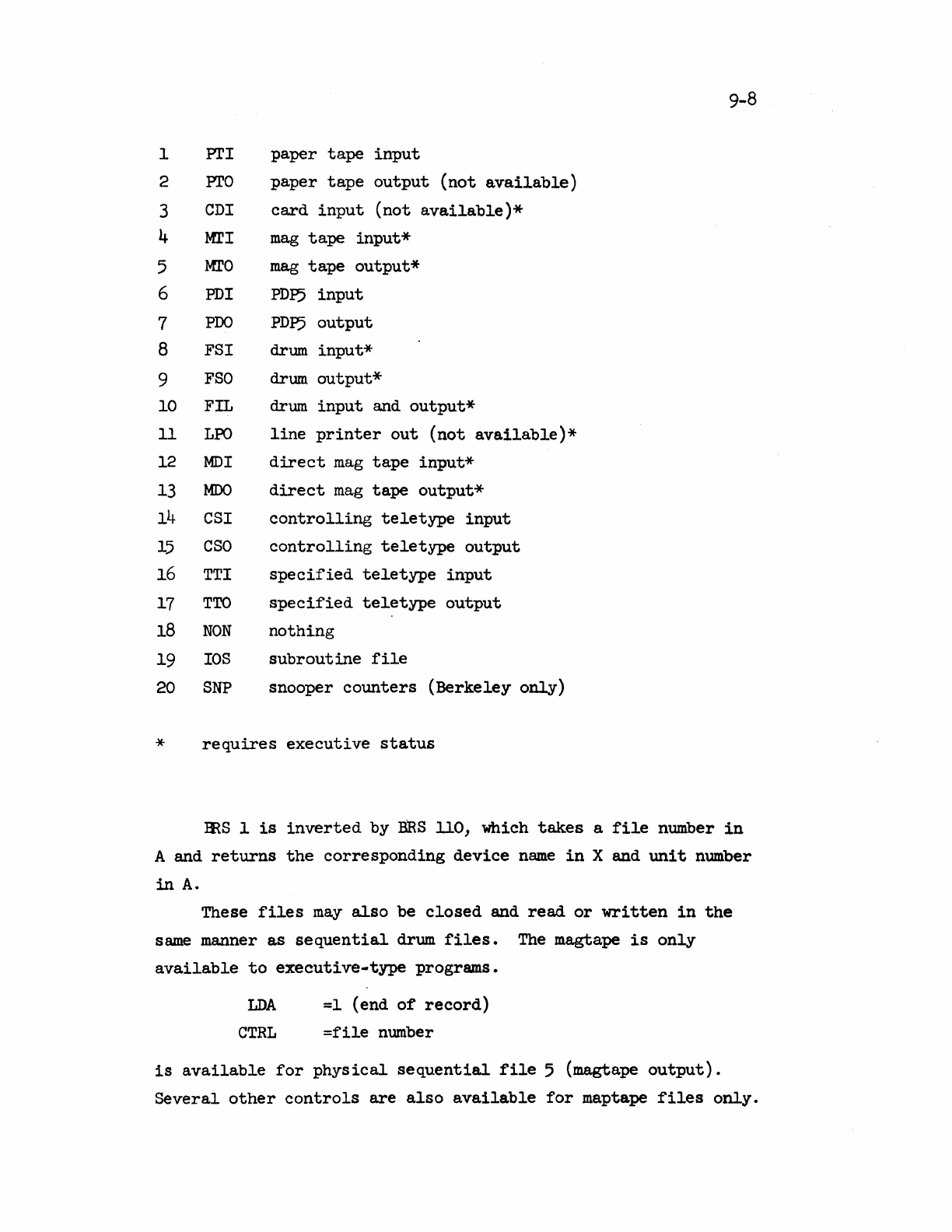
1
PrI
2 PrO
3 eDI
4
MrI
5
MfO
6 PDI
7
PDQ
8 FSI
9
FSO
10 FIL
11
LPO
12
MDI
13
MOO
14
eSI
15
eso
16 TTl
17
TTO
18
NON
19
lOS
20
SNP
paper
tape
input
paper
tape
output
(not
available)
card
input
(not
available)*
mag
tape
input*
mag
tape
output*
PDl:5
input
PDl:5
output
drum
input*
drum
output*
drum
input
and
output*
line
printer
out
(not
available)*
direct
mag
tape
input*
direct
mag
tape
output*
controlling
teletype
input
controlling
teletype
output
specified
teletype
input
specified
teletype
output
nothing
subroutine
file
snooper
counters
(Berkeley
only)
*
requires
executive
status
9-8
ERS
1
is
inverted
by
ERS
110, which
takes
a
file
number
in
A and
returns
the
corresponding
device
name
in
X and
unit
number
in
A.
These
files
may
also
be
closed
and
read
or
written
in
the
same
manner
as
sequential
drum
files.
The magtape
is
only
available
to
executive·type
programs.
LDA
=1
(end
of
record)
eTRL
=file
number
is
available
for
physical
sequential
file
5 (magtape
output).
Several
other
controls
are
also
available
for
maptape
files
only.
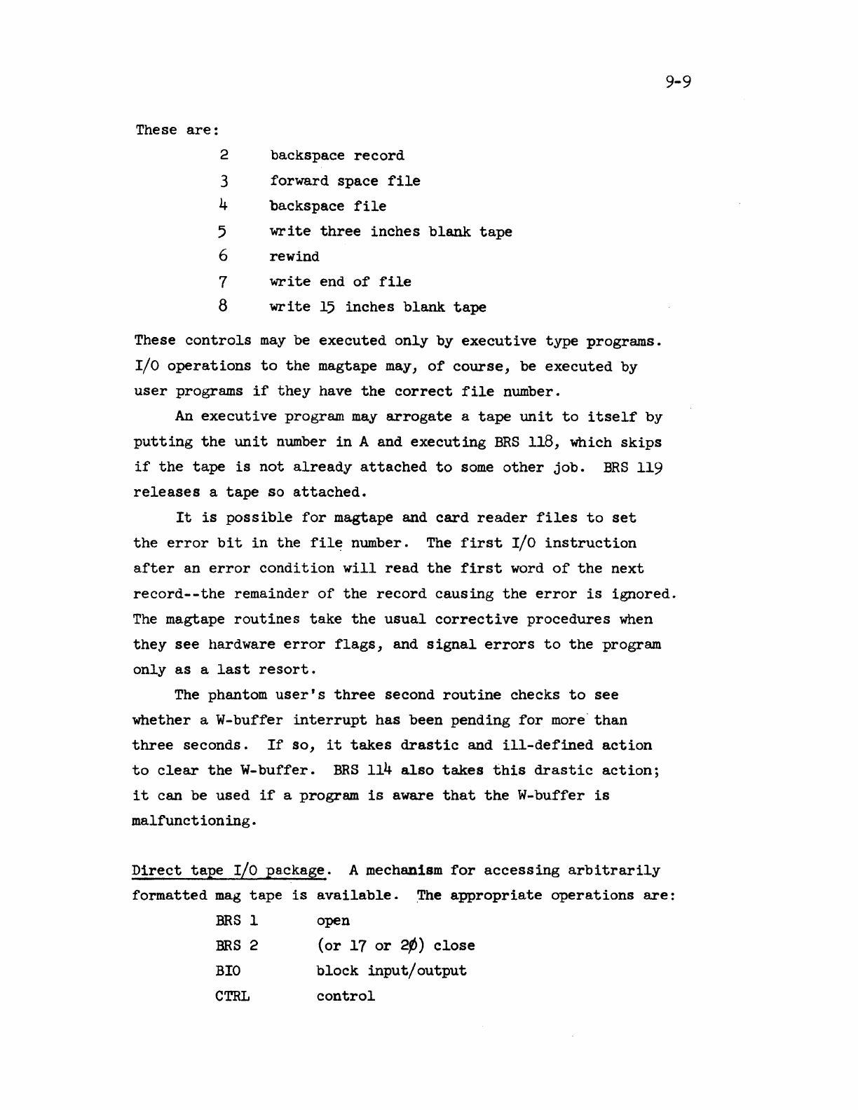
These
are:
2
backspace
record
3
forward
space
file
4
backspace
file
5
write
three
inches
blank
tape
6
rewind
7
write
end
of
file
8
write
15
inches
blank
tape
These
controls
may
be
executed
only
by
executive
type
programs.
I/O
operations
to
the
magtape may,
of
course,
be
executed
by
user
programs
if
they
have
the
correct
file
number.
An
executive
program
may
arrogate
a
tape
unit
to
itself
by
putting
the
unit
number
in
A and
executing
BRS
118,
which
skips
if
the
tape
is
not
already
attached
to
some
other
job.
BRS
119
releases
a
tape
so
attached.
It
is
possible
for
magtape and
card
reader
files
to
set
9-9
the
error
bit
in
the
file
number. The
first
I/O
instruction
after
an
error
condition
will
read
the
first
word
of
the
next
record--the
remainder
of
the
record
causing
the
error
is
ignored.
The
magtape
routines
take
the
usual
corrective
procedures
when
they
see
hardware
error
flags,
and
Signal
errors
to
the
program
only
as
a
last
resort.
The phantom
user's
three
second
routine
checks
to
see
whether
a W-buffer
interrupt
has
been
pending
for
more
than
three
seconds.
If
so,
it
takes
drastic
and
ill-defined
action
to
clear
the
W-buffer.
BRS
114
also
takes
this
drastic
action;
it
can
be
used
if
a program
is
aware
that
the
W-buffer
is
malfunctioning.
Direct
tape
I/O pa.ckage. A mechanism
for
accessing
arbitrarily
formatted
mag
tape
is
available.
~he
appropriate
operations
are:
~Sl
~n
BRS
2
(or
17
or
2p)
close
BrO
block
input/output
CTRL
control
9-10
BIO
is
used
in
the
normal way,
with
a word
count
in
A and
core
address
in
X.
BIO
will
not
give
you more
data
than
specified
by
A.
In
no
case
may
the
block
requested
cross
a page boundary.
On
input,
BIO
will
skip
if
the
word
count
presented
is
exactly
right;
otherwise,
it
will
not
skip,
and
will
leave
the
number
of
words
actually
transferred
in
A and
the
next
core
address
in
X.
The
flag
bits
(EOR
and
EOF)
in
the
user's
file
number
are
set
as
with
the
normal
BIO
for
tapes.
In
addition
to
controls
3-8
for
tape
in
the
CTRL
operation,
CTRL
9 has been
~plemented
to
allow
the
user
to
set
the
mode
for
the
tape.
This
operation
takes
a ¢
or
1
in
B2l
for
setting
the
tape
in
odd
or
even
parity.
(TSS
tapes
use
odd
parity.)
B22
and
B23
contain
the
"frame
count,"
a
mysterious.
feature
of
the
W-buffer.
Use
one
less
than
the
number
of
6-bit
characters
per
word
to
be
shipped.
On
reading
the
characters
are
stored
right-justified
in
memory.
On
writing
they
are
taken
out
left-
justified.
The
word
count
for
transfers
covers
the
numbers
of
words
in
core
actually
used.
When
the
tape
1s
opened,
the
mode
is
set
to
odd
parity,
four
characters
per
word.
Snooper
Counters.
The
Berkeley
system
has
a
collection
of
hardware
counters
which
monitor
external
signals.
These
may
be opened
as
a
file
with
ERS
1.
In
addition,
two
operations
are
provided.
CTRL
fn
requires
a 1
in
A,
and
1/32
of
the
number
of
machine
cycles
to
be
monitored
in
B.
BIO
fn
reads
in
the
counters.
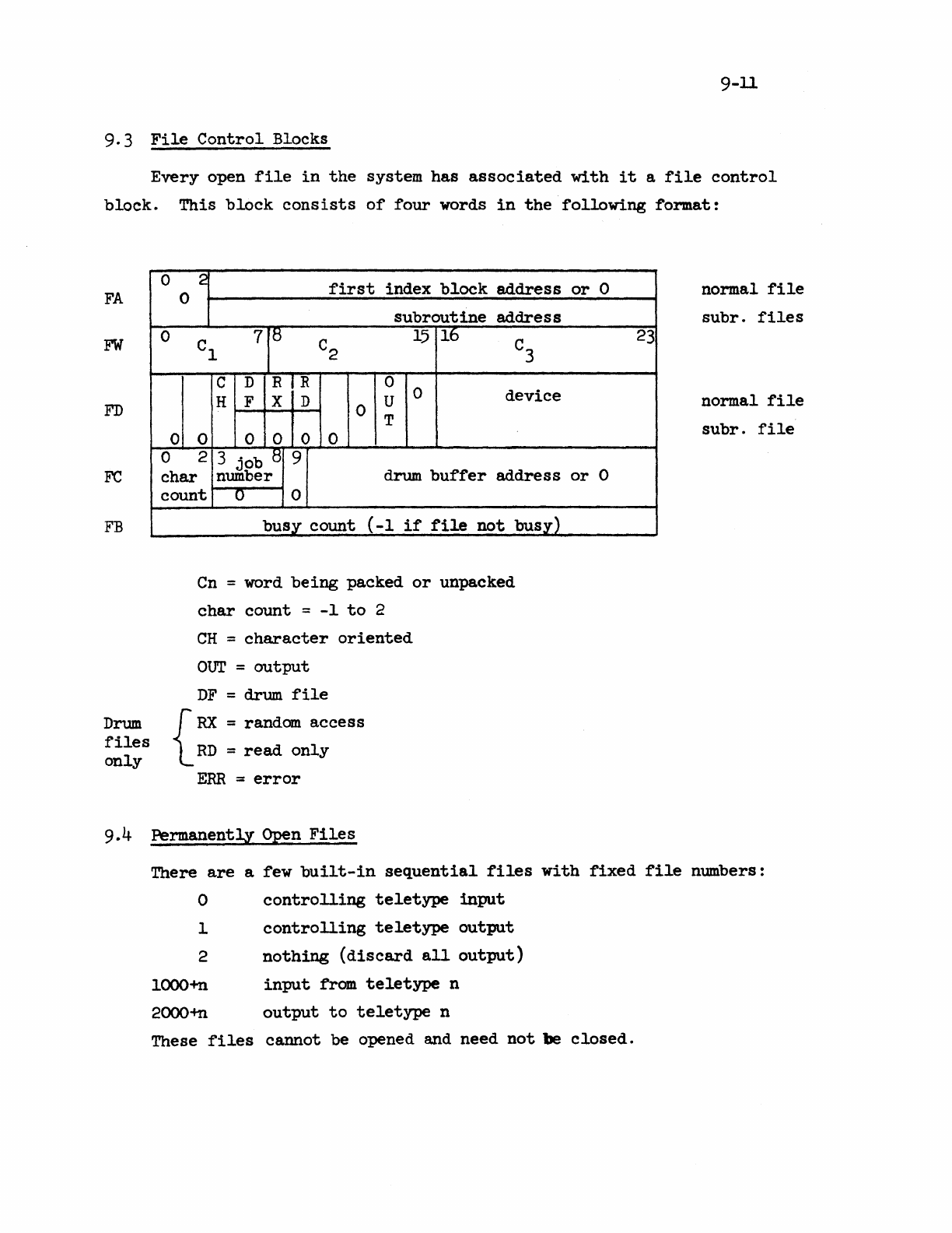
9-11
9.3
File
Control
Blocks
Every
open
file
in
the
system
has
associated
with
it
a
file
control
block.
This
block
consists
of
four
words
in
the
following
format:
FA
FW
FD
Fe
FB
Drum
files
only
0 2
first
index
block
address
or
0
0
subroutine
address
0 Cl 7i5 C2
15
16 C3
c D R R 0
H F X D U 0
device
0 T
0 0 0 0 0 0
0 2 9
char
3
job
8
number
drum
buffer
address
or
0
count
0 0
busy
count
(-1
if
file
not
busy)
Cn
= word
being
packed
or
unpacked
char
count
=
-1
to
2
CH
=
character
oriented
OUT
=
output
DF
=
drum
file
{
RX
= random
access
RD
=
read
only
ERR
:::
error
23
normal
file
subr.
files
normal
file
subr.
file
9.4 PermanentlY Open
Files
There
are
a few
built-in
sequential
files
with
fixed
file
numbers:
o
controlling
teletype
input
1
2
looo+n
2000-+n
controlling
teletype
output
nothing
(discard
all
output)
input
from
teletype
n
output
to
teletype
n
These
files
cannot
be opened and need
not
be
closed.
10-1
10.0
Random
Drum
Files
A random drum
file
is
identical
in
physical
structure
on
the
drum
to
a
sequential
drum
file.
The
only
major
difference
is
that
the
non-zero
words
of
the
index
block
are
not
necessarily
compact.
Th~
reason
for
this
is
that
information
is
extracted
from
or
written
into
a random
file
by
addressing
the
specific
word
or
block
of
words which
is
desired.
From
the
address
which
the
user
supplies,
the
system
extracts
a
physical
block
number
by
dividing
by
the
data
block
size
and a
location
of
the
word
within
the
block
which
is
the
remainder
of
this
diviSion.
Further
division
by
144
yields
the
appropriate
index
block.
A
file
may
have any number
of
index
blocks.
A random
file
may
be opened by
using
BRS
1
with
a
device
number
of
10.
No
distinction
is
made
between
input
and
output
to
a random drum
file.
A random
file
may
also
be
closed
by
BRS
2,
like
any
sequential
file,
and CIO,
WIO,
and
BIO
may
be
used
for
input-output
to
random
files.
The
sequential
Ilo
mode
(input
or
output)
is
controlled
with
BRS
143
and 144.
The
following
additional
operations
are
available:
To
read
a word from a random
file,
execute
the
instructions
LDB
=address
DWI
=file
number
The
word
is
returned
in
A.
To
write
a word on a random
file,
put
the
word
in
A and
execute
the
instructions:
LDB
=address
DWO
=file
number
Block
input-output
to
random
files
is
also
possible.
To
input
a
block,
execute
the
instructions:
LDX
=first
word
address
LOA
=number
of
words
LDB
=first
address
in
file
DBI
=file
number
To
output
a
block
of
words
to
a random
file,
execute
the
instruction
DBO
=file
number
10-2
with
the
same
parameters
in
the
central
registers.
These
block
input-output
operations
are
done
directly
to
and from
the
user's
memory,
as
is
BIO.
Drum
buffers
are
not
involved
and
the
operation
can
go
very
quickly.
It
is
possible
to
define
a random
file
which
has
been
previously
opened
as
the
secondary
memory
file.
To
do
this,
execute
the
instructions
LilA
=file
number
BRS
58
The
specified
file
remains
the
secondary
file
until
another
secondary
memory
file
is
defined
or
until
the
file
is
closed.
To
access
information
in
the
secondary
memory,
two
SYSPOPs
are
provided.
These
POPs
work
exactly
like
DWI
and
DWO
except
that
they
take
the
drum
address
from
memory
instead
of
requiring
it
to
be
in
B.
To
read
a word
of
secondary
memory
into
the
A
register,
the
instruction
LAS
address
should
be
executed.
To
store
a word from A
into
the
secondary
memory,
the
instruction
SAS
address
should
be
executed.
The
word
addressed
by
either
one
of
these
SYSPOPs
should
contain
the
drum
address
which
is
to
be
referenced.
This
word
may
also
have
the
index
bit
set,
in
which
case
the
contents
of
the
index
register
will
be added
to
the
contents
of
the
word
to
form
the
effective
address
which
is
actually
used
to
perform
the
input-output
operation.
The
mechanism
for
acquiring
and
releasing
random drum
file
space
is
very
s~ilar
to
the
mechanism
for
allocation
of
core
memory. Whenever
the
user
addresses
a
section
of
a random
drum
file
which he
has
not
previously
used,
the
necessary
blocks
are
created
and
cleared
to
O.
Note
that
the
user
should
avoid
unnecessarily
large
random drum
addresses,
since
they
may
result
in
the
creation
of
an
unnecessary
number
of
index
blocks.
To
release
random
drum
memory,
use
BRS
144.
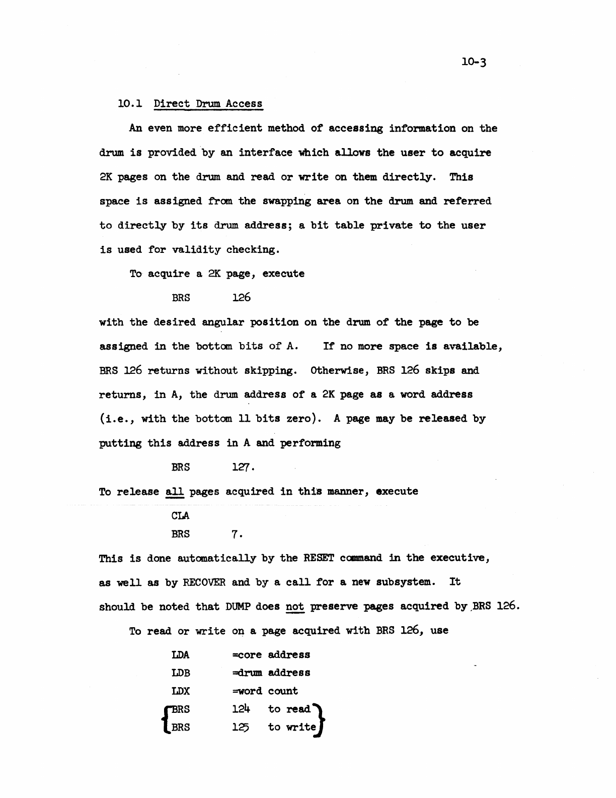
10-3
10.1
Direct
Drum Access
An
even
more
efficient
method
of
acceSSing
information
on
the
drum
is
provided
by
an
interface
Which
alloys
the
user
to
acquire
2K
pages on
the
drum
and
read
or
write
on
them
directly.
This
space
is
ass
igned
fran
the
swapping
area
on
the
drum
and
referred
to
directly
by
its
drum
address;
a
bit
table
private
to
the
user
is
used
for
validity
checking.
To
acquire
a
2K
page,
execute
BRS
126
with
the
desired
angular
position
on
the
drum
of
the
page
to
be
assigned
in
the
bottom
bits
of
A.
If
no
more
space
is
available,
BRS
126
returns
without
skipping.
otherwise,
BRS
126
skips
and
returns,
in
A,
the
drum
address
of
a
2K
page
as
a word
address
(i.e.,
with
the
bottom 11
bits
zero).
A page
may
be
released
by
putting
this
address
in
A and performing
BRS
1~.
To
release
~
pages
acquired
in
this
manner,
execute
CLA
BRS
7.
This
is
done
automatically
by
the
RESET
cClllllland
in
the
executive,
as
well
as
by
RECOVER
and
by
a
call
for
a
new
subsystem.
It
should be
noted
that
DUMP
does
~
preserve
pages
acquired
by
,BRS
126.
To
read
or
write
on a page
acquired
with
BRS
126,
use
LDA =core
address
LDB
=drum
address
LDX
=word
count
bS
124
to
readJ-
BRS
125
to
write
10.4
These BRS's
preserve
all
the
central
registers
and normally
skip.
A
no-skip
return
indicates
an
uncorrectable
transmission
error.
The
following
restrictions
are
checked by
the
monitor and
will
result
in
an
illegal
instruction
trap
if
violated:
1)
The
drum
address
must be a
multiple
of
256
(decimal)
and
lie
within
some
page
assigned
to
the
user
via
BRS
126.
(The
latter
restriction
does
not
apply
to
executive
programs.)
2)
The
transfer
must
not
cross
a
2K
page boundary
either
in
core
or
on
the
drum.
3)
It
is
illegal
to
attempt
to
read
into
a
read-only
page
with
BRS
124
(this
produces a
memory
trap
if
violated).
11-1
11.0
Subroutine
Files
An
addition
to
the
above-mentioned
machinery
for
performing
input-output
through
physical
files,
a
facility
is
provided
in
the
system
for
making a
subroutine
call
appear
to
be an
input-
output
request.
This
facility
makes
it
possible
to
write
a
program which does
input-output
from a
file
and
later
to
cause
further
processing
to
be
performed
before
the
actual
input-
output
is
done,
simply
by
changing
the
file
from a
physical
to
a
subroutine
file.
A
subroutine
file
is
opened
by
executing
the
instructions
LOX
parameter
word +
subroutine
address
BRS
1
This
instruction
skips
or
returns
an
error
code,
as
for
sequential
files.
The
opcode
field
of
the
parameter
word
indicates
the
characteristics
of
the
file.
It
may
be
one
of
the
following
combinations:
11000000
1ll0ooo0
01000000
01100000
CharOacter
input
subroutine
Character
output
subroutine
Word
input
subroutine
Word
output
subroutine
I/O
to
the
file
may
be
done
with
CIO
or
WIO,
regardless
of
whether
it
is
a word
or
a
character-oriented
subroutine.
The
system
will
take
care
of
the
necessary
packing
and
unpacking
of
characters.
BIO
is
also
acceptable.
The
opening
of
a
subroutine
file
does
nothing
except
to
create
a
file
control
block
and
return
a
file
number
in
the
A
register.
When
an
I/O
operation
on
the
file
is
performed,
the
subroutine
will
be
called.
This
is
done
by
s~ulating
run
SBRM
to
the
location
given
in
the
address
field
of
the
X
register
given
to
the
BRS
1 which opened
the
file.
The
contents
of
the
B and X
registers
are
transmitted
from
the
I/O Syspop
to
the
subroutine
unchanged.
The
contents
of
the
A
register
may
be
changed
by
the
packing
and
unpacking
operations
necessary
to
convert
from
character-oriented
to
word-oriented
operations
or
vice
versa.
The
I/O
subroutine
may
do
an
arbitrary
amount
of
11-2
computation
any
may
calIon
any
number
of
other
I/O
devices
or
other
I/O
subroutines.
A
subroutine
file
should
not
call
itself
recursively.
When
the
subroutine
is
ready
to
return,
it
should
execute
BRS
41.
This
operation
replaces
the
SBRR
which would
normally
be
used
to
return
from a
subroutine
call.
The
contents
of
B
and X when
the
BRS
41
is
executed
are
transmitted
unchanged buck
to
the
calling
program. The
contents
of
A
may
be
altered
by
packing
and
unpacking
operations.
A
subroutine
file
is
closed
with
BRS
2
like
any
other
file.
In
order
to
implement
BRS
41,
it
is
necessary
to
keep
track
of
which I/O
subroutine
is
open.
This
information
is
kept
in
six
bits
of
the
PAC
table.
The
contents
of
these
six
bits
is
transferred
into
the
opcode
field
of
the
return
address
when an
I/O
subroutine
is
called,
and
is
recovered
from
there
when
the
BRS
41
is
executed.
The
user
should
be
warned
that
a
subroutine
file
should
not
be
used
by
a progrrum
in
a
different
address
space
from
the
subroutine
itself.
In
particular,
subroutine
files
may
not
be
given
to
the
BRSs
which
involve
acccess
to
nwned
files
(described
in
the
next
section).
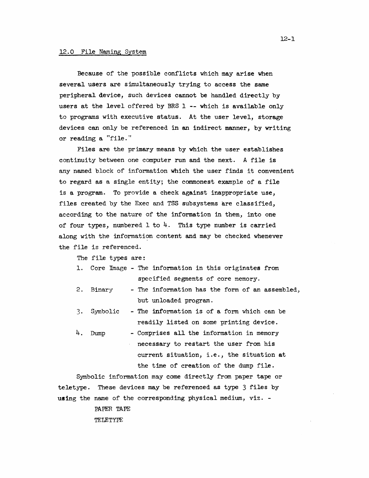
12-1
12.0
File
Naming System
Because
of
the
possible
conrlicts
which
may
arise
when
several
users
are
s~ultaneously
trying
to
access
the
same
peripheral
device,
such
devices
cannot
be
handled
directly
by
users
at
the
level
offered
by
BRS
1
--
which
is
available
only
to
programs
with
executive
status.
At
the
user
level,
storage
devices
can
only
be
referenced
in
an
indirect
manner,
by
writing
or
reading
a
"file."
Files
are
the
primary
means
by
which
the
user
establishes
continuity
between
one computer
run
and
the
next.
A
file
is
any
named
block
of
information
which
the
user
finds
it
convenient
to
regard
as
a
single
entity;
the
commonest example
of
a
file
is
a
program.
To
provide
a
check
against
inappropriate
use,
files
created
by
the
Exec and
TSS
subsystems
are
classified,
according
to
the
nature
of
the
information
in
them,
into
one
of
four
types,
numbered I
to
4.
This
type
number
is
carried
along
with
the
information
content
and
may
be
checked
whenever
the
file
is
referenced.
The
file
types
are:
1.
Core Image -
The
information
in
this
originates
from
specified
segments
of
core
memory.
2.
Binary
3. Symbolic
4.
Dump
-
The
information
has
the
form
of
an
assembled,
but
unloaded
program.
-
The
informa.t
ion
is
of
a
form.
which can be
readily
listed
on
some
printing
device.
-Comprises
all
the
information
in
memory
necessary
to
restart
the
user
from
his
current
situation,
i.e.,
the
situation
at
the
time
of
creation
of
the
dump
file.
Symbolic
information
may
come
directly
from
paper
tape
or
teletype.
These
devices
may
be
referenced
as
type
3
files
by
using
the
name
of
the
corresponding
physical
medium,
viz.
-
PAPER
TAPE
TELETYPE
12-2
These names
are
built
into
the
system
and
are
always
appropriately
recognized.
Another
built-in
file
name
is
NOTHING
which always
contains
precisely
nothing
and whose
function
is
to
act
as
an
infinite
sink
in
which
limitless
unwanted
output
can
be
lost.
A
commoner
source
for
symbolic
files
is
the
output
from
some
subsystems,
notably
the
text
editor,
QED.
Type
2,
binary
files
normal~y
arise
as
the
output
from
the
machine-language
a,ssembler ARPAS.
Until
the
actual
process
of
output
from
the
subsystem
occurs,
identification
of
the
information
is
handled
by
the
subsystem
and
is
usually
implicit
since
the
subsystems
can
handle
only
one
file
at
a
time.
However,
when
the
information
is
ejected
into
a
context
involving
many
other
blocks
of
information
of
a
similar
kind,
some
explicit
identification
must be
attached
to
it.
12.1
File
Naming
The
names which
the
user
is
free
to
invent
and
assign
to
files
are
of
two
types:
1.
Permanent
name
s
2.
Scratch
names
Scratch
names
differ
from permanent names
in
that
they
and
the
files
associated
with
them
are
lost
when
the
user
leaves
the
system,
USing
the
LOGOUT
command;
they
are
otherwise
treated
identically.
A permanent
name
is
an
arbitrary
string
of
characters
not
beginning
with
/
or:.
A
scratch
name
is
an
arbitrary
string
of
characters
beginning
with
/
or:.
To
those
users
who
have drum
file
privileges,
a /
identifies
a
drum
file,
: a
disk
file.
As
permanent names
we
have -
ABC
PROGRAM
1
124
while
as
scratch
names
we
have -
/ABC
:421/
12-3
Any
permanent
or
scratch
file
name
may
be
quoted
by
surrounding
it
with
single
quote
marks.
Thus,
'ABC'
and
'/001/'
are
quoted
file
names. The
quoted
name
refers
to
exactly
the
same
file
as
the
unquoted
one;
it
differs
only
in
the
way
it
is
recognized
by
the
exec.
Control
A
(backspace)
is
legal
on any
name
being
typed
to
the
file
system
unless
command
recognition
is
taking
place.
When
reference
is
made
to
an
unquoted
name,
the
exec
will
anticipate
the
user
and
consider
the
name
to
be
fully
delivered
as
soon
as
it
has
received
sufficient
characters
to
distinguish
the
name
from
all
others
currently
defined
by
the
user.
This
means
that
a
new
name
can
~
be
introduced
in
its
unquoted
form. A
quoted
name, on
the
other
hand,
is
always
accepted
in
its
entirety
from
the
user.
The
initial
and
terminal
quotes
are
then
removed
and
the
name
compared
with
the
directory
of
nwmes
currently
defined
by
the
user.
If
it
matches one
of
them,
it
is
taken
to
refer
to
that
file,
just
as
though
it
had
been
presented
in
unquoted
form.
If
it
is
new, however,
it
will
normally
give
rise
to
an
error
message
unless
it
appears
in
one
of
the
following
contexts:
a)
In
the
DEFINE
NAME
command
(c.f.
Doc. R-22,
Section
5.5)
b)
As
an
output
file
name,
in
which
case
a
new
file
with
the
specified
name
will
be
created
to
hold
the
output.
For
example,
let
XYZ
be
the
name
of
an
existing
file
and
/123
be a new
unattached
file
name. Then
the
exec
command
~Opy
XYZ
TO
'/123'.
has
the
effect
of
creating
a new
scratch
file,
called
/123,
having
the
same
information
content
as
XYZ.
If
/123
is,
however,
already
attached
to
some
existing
file,
then
the
information
content
of
that
file
is
replaced
by
that
of
XYZ.
In
summary,
it
will
be
seen
that
the
exec's
file
name
recognition
apparatus
works
in
two ways,
depending
essentially
on
whether
the
name
is
quoted
or
not.
Quoted names must always
be
given
in
entirety;
the
exec
waits
for
the
terminating
quote
before
attempting
to
recognize
the
name. Unquoted names
are
anticipated;
the
exec
recognizes
or
rejects
them
as
soon
as
it
can,
inSisting
that
they
match
some
name
already
in
the
user's
directory
of
file
names. Note
tha.t
the
BEGINNER,
NOVICE
and
EXPERT
commands
apply
to
file
name
recognition
(see
R-22,Section
5.7).
12-4
12.2
Accessing
Other
Users'
Files,
Special
Groups
The naming
system
described
is
adequate
to
reference
all
the
files
belonging
to
the
current
user,
in
whose
name
the
exec
was
entered.
However,
to
refer
to
files
belonging
to
another
user,
it
is
possible
to
augment
the
file
name
by
that
user's
name
together
with,
optionally,
a
special
accessing
code
called
the~~.
or
To
do
this
the
basic
file
name
must
be
prefixed
by
one
of:
( <
user
name
> )
( <
user
name
>,
<
group
name
> )
Thus
for
example:
(JONES)
'FIIEl'
or
(JONES,GROUP1)
'FILE1'
When
such
a
string
as
the
last
is
collected
from a
teletype
by
BRS
15
or
16,
the
characters
II,
GROUPl"
are
not
echoed
to
the
teletype
so
that
the
secrecy
of
the
special
group
name
is
preserved.
The
access
that
any
other
user
may
have
to
each
of
Jones'
files
is
in
the
hands
of
Jones
.himself.
Jones
may
declare
that
a
member
of
the
public
at
large
who
tries
to
access
his
'FILEl'
using
(JONES)'FII£l'
has
entire
(read-write)
access,
read-only
access,
or
no
access
at
all.
It
is
also
open
to
Jones
to
define
independently
a
greater
degree
of
accessibility
to
a
user
who
supplies
the
group
name.
Special
groups
can
be
created
by
BRS
61
and
the
command
SET
MODES
FOR
FILE
(R-22,
Section
5.5)
or
deleted
by
BRS
62
and
the
same command.
ERS
61
-
Define
Special
Group
Takes a
string
pointer
in
AB.
The
string
is
an
arbitrary
string
of
characters
and
is
taken
to
define
a
new
special-group
name. The
BRS
assoctates
with
it
a
number,
n,
in
the
range
IS
~
15, which
it
skip
returns
in
A.
A
file
may
then
be
placed
in
that
special
group
by
setting
this
number
in
the
appropriate
bits
of
the
file
mode
word
(see
BRS
48).
A
user
may
have up
to
15
currently
defined,
distinct
special
groups;
an
attempt
to
define
more
results
in
a no
skip
return
with
A=O.
An
attempt
to
define
an
already
existing
special
group
name
also
results
in
a
no
skip
return,
but
with
the
group
number
in
A.
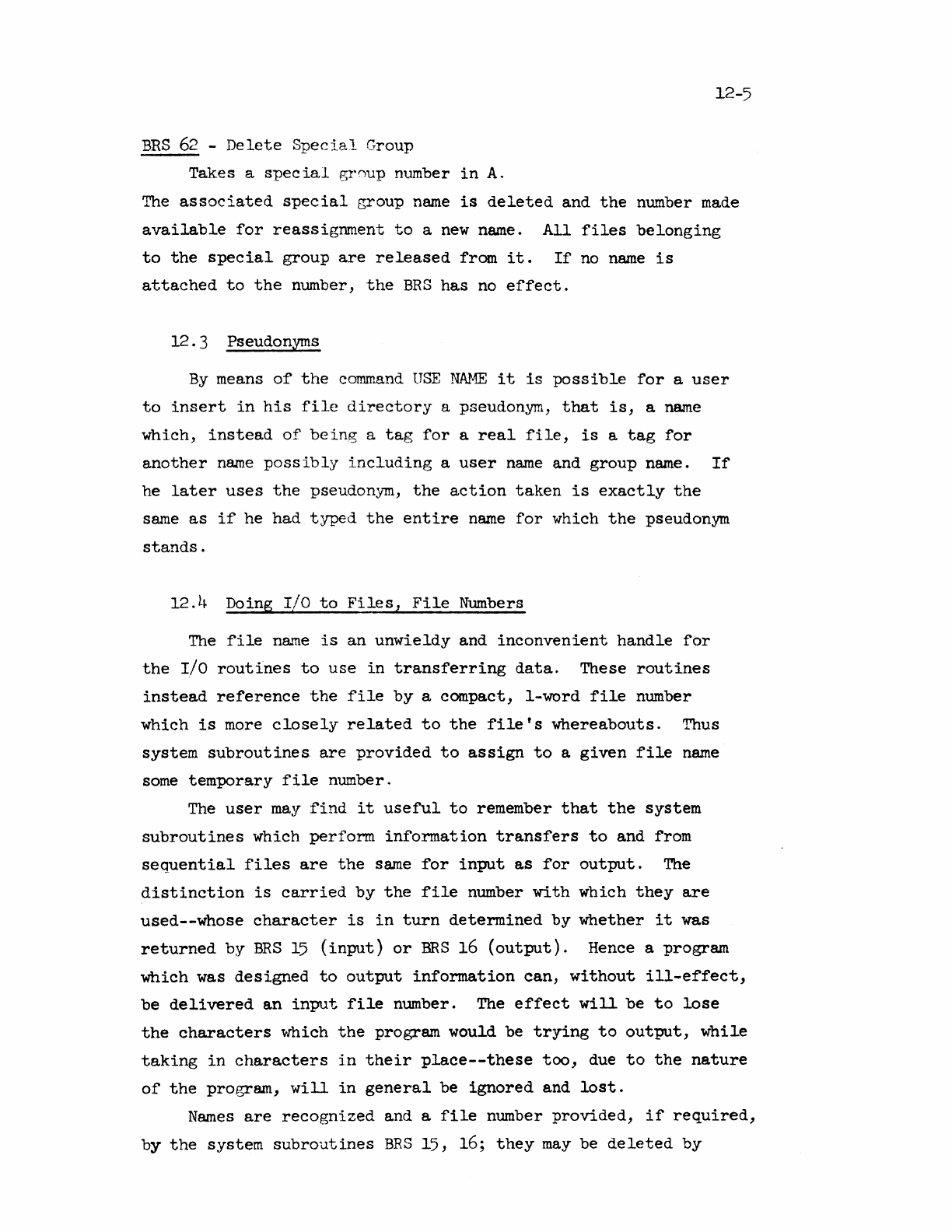
12-5
BRS
62
-
Delete
Special
Group
Takes a
special
group
number
in
A.
The
associated
special
group
name
is
deleted
and
the
number
made
available
for
reassignment
to
a
new
name.
All
files
belonging
to
the
special
group
are
released
from
it.
If
no
name
is
attached
to
the
number,
the
BRS
has
no
effect.
12 . 3 Pseudonyms
By
means
of
the
command
USE
NAME
it
is
possible
for
a
user
to
insert
in
his
file
directory
a pseudonym,
that
is,
a
name
which,
instead
of
being
a
tag
for
a
real
file,
is
a
tag
for
another
name
possibly
including
a
user
name
and
group
name.
If
he
later
uses
the
pseudonym,
the
action
taken
is
exactly
the
same
as
if
he
had
typed
the
entire
name
for
which
the
pseudonym
stands.
12.
t~
Doing r/o
to
Files,
File
Numbers
The
file
name
is
an
unwieldy
and
inconvenient
handle
for
the
I/O
routines
to
use
in
transferring
data.
These
routines
instead
reference
the
file
by
a compact,
I-word
file
number
which
is
more
closely
related
to
the
file's
whereabouts.
Thus
system
subroutines.
are
provided
to
assign
to
a
given
file
name
some
temporary
file
number.
The
user
may
find
it
useful
to
remember
that
the
system
subroutines
which
perform
information
transfers
to
and from
sequential
files
are
the
same
for
input
as
for
output.
The
distinction
is
carried
by
the
file
number
with
which
they
are
used--whose
character
is
in
turn
determined
by
whether
it
was
returned
by
BRS
15
(input)
or
BRS
16
(output).
Hence a program
which
was
designed
to
output
information
can,
without
ill-effect,
be
delivered
an
input
file
number. The
effect
will
be
to
lose
the
characters
\'Thich
the
program would be
trying
to
output,
while
taking
in
characters
in
their
place--these
too,
due
to
the
nature
of
the
program,
will
in
general
be
ignored
and
lost.
Names
are
recognized
and a
file
number
provided,
if
required,
by
the
system
subroutines
BRS
15, 16;
they
may
be
deleted
by
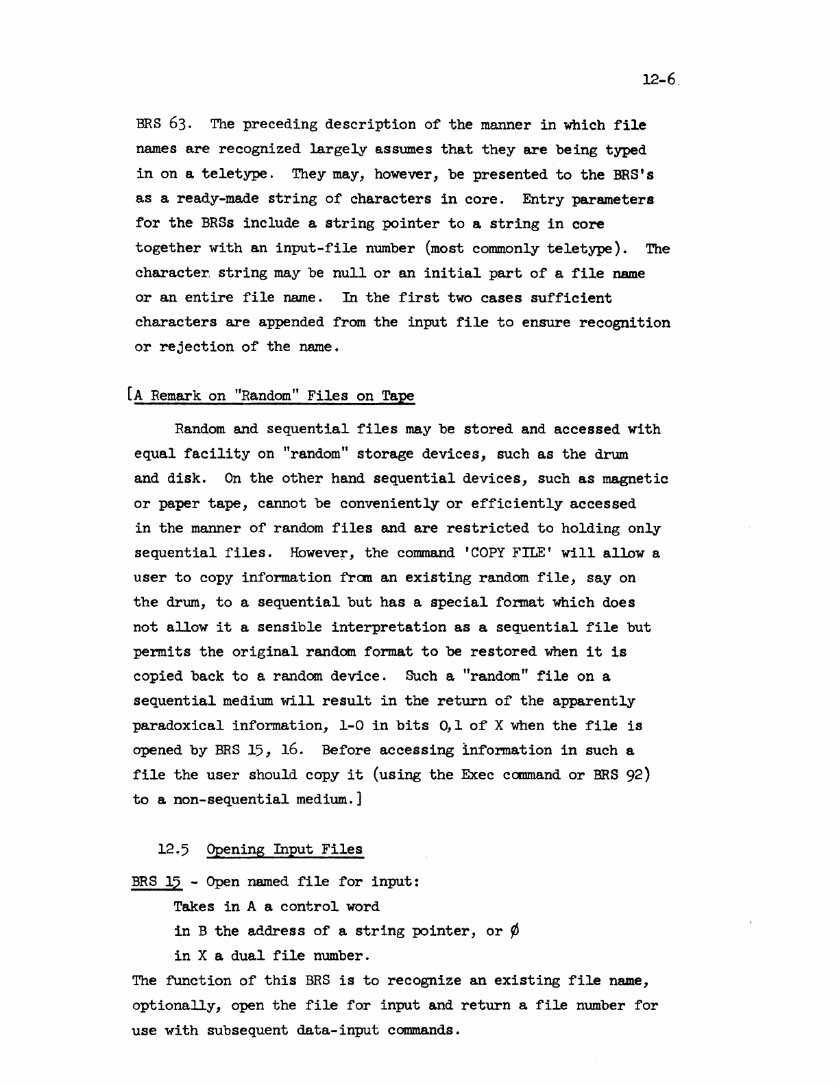
12-6.
ERS
63.
The
preceding
description
of
the
manner
in
which
file
names
are
recognized
largely
assumes
that
they
are
being
typed
in
on a
teletype.
They may, however,
be
presented
to
the
BRS'
s
as
a ready-made
string
of
characters
in
core.
Entry
parameters
for
the
BRSs
include
a
string
pointer
to
a
string
in
core
together
with
an
input-file
number (most commonly
teletype).
The
character,
string
may
be
null
or
an
initial
part
of
a
file
name
or
an
entire
file
name.
In
the
first
two
cases
sufficient
characters
are
appended from
the
input
file
to
ensure
recognition
or
rejection
of
the
name.
[A
Remark on
"Random"
Files
on Tape
Random
and
sequential
files
may
be
stored
and
accessed
with
equal
facility
on "random"
storage
devices,
such
as
the
drum
and
disk.
On
the
other
hand
sequential
devices,
such
as
magnetic
or
paper
tape,
cannot
be
conveniently
or
efficiently
accessed
in
the
manner
of
random
files
and
are
restricted
to
holding
only
sequential
files.
However,
the
command
'COPY
FILE'
will
allow
a
user
to
copy
information
from
an
existing
random
file,
say
on
the
drum,
to
a
sequential
but
has
a
special
format
which does
not
allow
it
a
sensible
interpretation
as
a
sequential
file
but
permits
the
original
random
format
to
be
restored
when
it
is
copied
back
to
a random
device.
Such a "random
tf
file
on a
sequential
medium
will
result
in
the
return
of
the
apparently
paradoxical
information,
1-0
in
bits
0,1
of
X when
the
file
is
opened
by
BRS
15,
16.
Before
accessing
information
in
such a
file
the
user
should
copy
it
(using
the
Exec
command
or
BRS
92)
to
a
non-sequential
medium.]
12.5
Qpening
Input
Files
BRS
15 -
Open
named
file
for
input:
Takes
in
A a
control
word
in
B
the
address
of
a
string
pointer,
or
~
in
X a
dual
file
number.
The
function
of
this
BRS
is
to
recognize
an
existing
file
name,
optionally,
open
the
file
for
input
and
return
a
file
number
for
use
with
subsequent
data-input
commands.
12-7
Designation
of
the
File
The
string
addressed
by
B must be
the
complete
or
incomplete
name
of
a
predefined
file.
If
the
name
is
incomplete,
characters
will
be appended from
the
input
file
whose number
is
given
in
the
least
significant
12
bits
of
X
--
until
sufficient
characters
are
available
to
detennine
uniquely
a
file
name
(or
no such name).
If
the
file
name
is
unquoted
so
that
prerecognition
occurs,
the
"tail"
of
the
name
is
echoed
back
to
the
output
file
whose number
is
given
in
the
most
significant
12
bits
of
X.
If
B=O
on
entry
a
null
string
is
assumed and
characters
collected
from
the
input
file
are
not
transmitted
to
the
caller's
memory.
If
bit
a
of
B
is
set,
the
string
delivered
is
considered
null--its
position
being
defined
by
the
first
word
of
the
string
pointer.
Unless
B=O
on
entry
the
completed
or,
in
the
case
of
non-recognition,
partially
completed
file
name
will
be
transmitted
to
the
caller's
memory.
If
a pseudonym was
delivered,
it
will
be
replaced
by
the
string
for
which
it
stands.
Unless
the
file
name
·was
complete on
entry
(i.e.,
no
charac-
ters
need
be
taken
from
the
input
file),
a
tenninating
character
must be
delivered
to
confirm
or
abort
the
file
name. Confirming
characters
are
those
with
an
internal
code
representation
0
to
16
8,
also
semicolon,
tab,
line
feed
and
carriage
return;
the
aborting
character
is
7.
All
other
characters
cause
7
to
be
output
and
are
other\vise
ignored.
Action:
This
is
dependent on
options
which
are
specified
by
bits
1
and 2
of
A on
entry.
These
are:
Bit
1,
if
set,
$uppresses
opening
the
file
(no
file
number
is
returned)
Bit
2,
if
set,
suppresses
the
need
for
a
terminating
character;
when
these
bits
are
not
set,
the
action
is
as
follows:
If
the
name
is
recognized
and a
valid
terminating
character
is
received,
the
file
is
opened
for
input.
There
is
a
skip
return
with
In
A,
a
file
number
In
B,
the
terminating
character
In
X,
is
a composite word
comprising
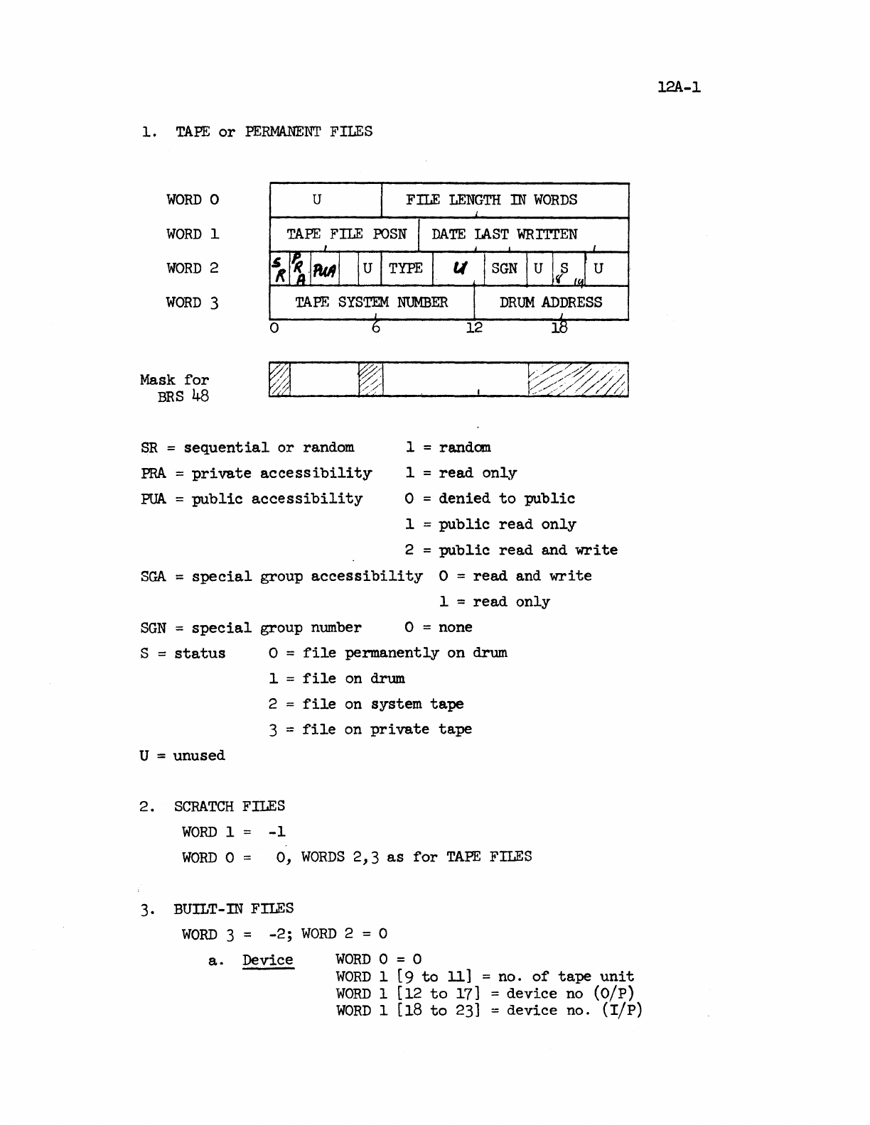
1.
TAPE
or
PERMANENT
FILES
WORD
a
WORD
1
WORD
2
WORD
3
Mask
for
BRS
48
SR
=
sequential
or
random
W?1
PRA
=
private
accessibility
PUA
=
public
accessibility
1 = random
1 =
read
only
o =
denied
to
public
1 =
public
read
only
2 =
public
read
and
write
SGA
=
special
group
accessibility
a =
read
and
write
SGN
=
special
group number
1 =
read
only
o = none
S =
status
U = unused
o =
file
permanently
on
drum
1 =
file
on
drum
2 =
file
on system
tape
3 =
file
on
private
tape
2.
SCRATCH
FILES
WORD
1 =
-1
WORD
0 =
0,
WORDS
2,3
as
for
TAPE
FILES
3. BUILT-
IN
FILES
WORD
3 =
-2;
WORD
2 = 0
a.
Device
WORD
0 = 0
WORD
1 (9
to
11]
= no.
of
tape
unit
WORD
1 [12
to
17] =
device
no (O/p)
WORD
1 [18
to
23] =
device
no. (lip)
12A-l
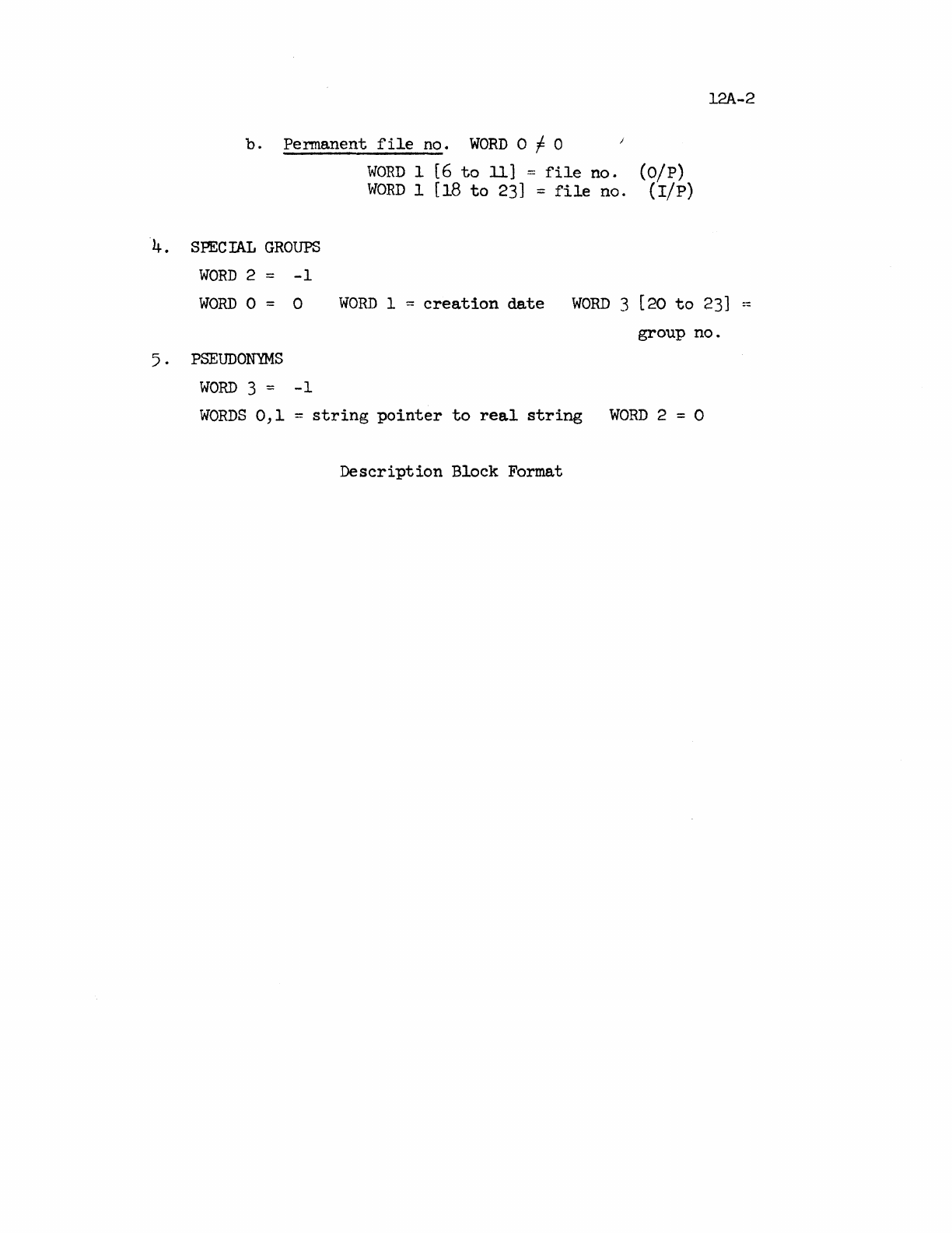
b.
Permanent
file
no.
WORD
0 f 0
4. SPECIAL
GROUPS
WORD
2 =
-1
WORn
1 (6
to
11] =
file
no.
(O/P)
WORn
1 [18
to
23]
=
file
no. (rip)
12A-2
WORD
0 = 0
WORD
1 =
creation
date
WORD
3
[20
to
23]
--
5 .
PSEUDONYMS
WORD
3 =
-1
group
no.
WORDS
0,1
=
string
pointer
to
real
string
WORD
2 = 0
Description
Block Format
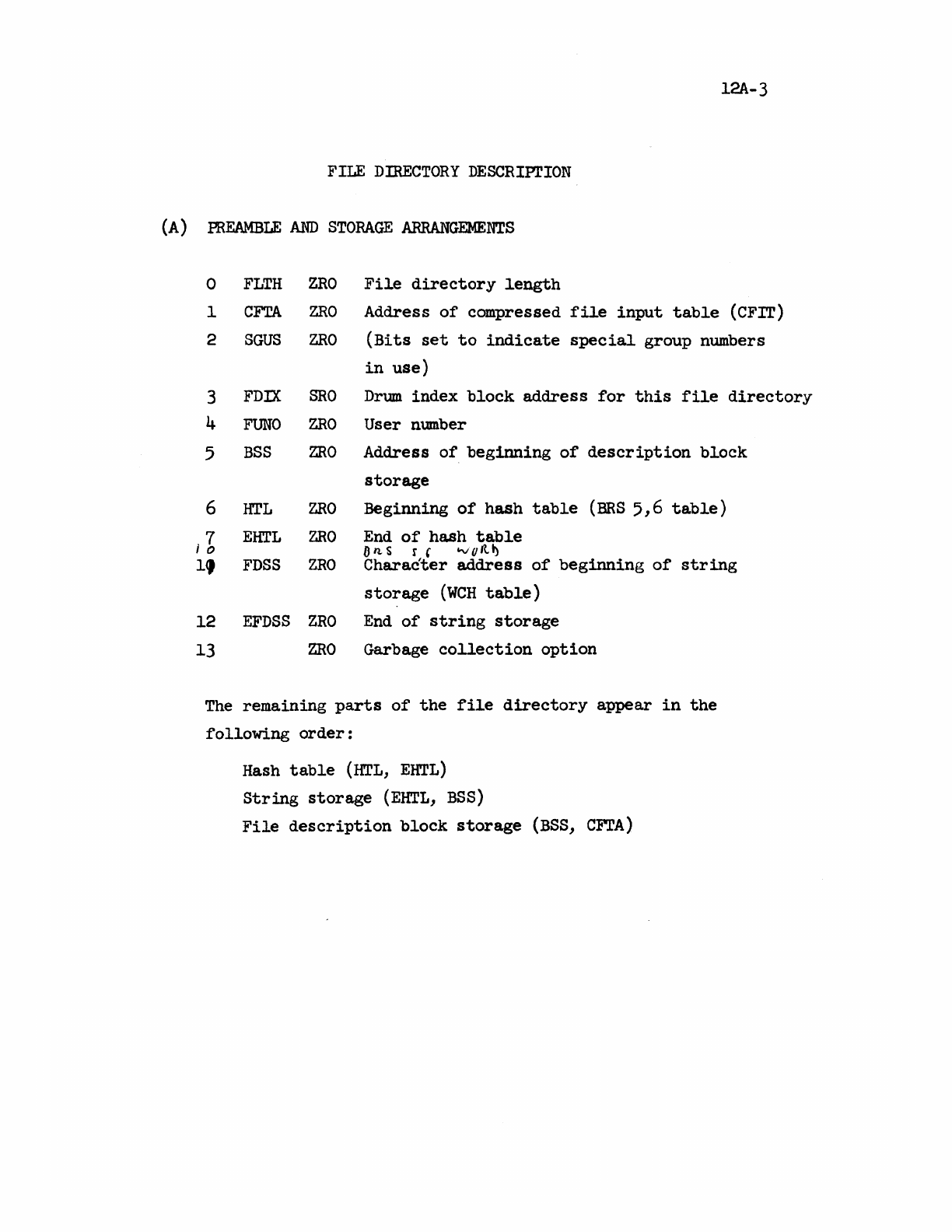
(A)
12A-3
FILE
DIRECTORY
DESCRIPTION
PREAMBLE
AND
STORAGE
ARRANGEMENTS
0
FLTH
ZRO
File
directory
length
1
eFTA
ZRO
Address
of
compressed
file
input
table
(eFIT)
2
SGUS
ZRO
(Bits
set
to
indicate
special
group numbers
in
use)
3
FDIX
SRO
Drum
index
block
address
for
this
file
directory
4
FUNO
ZRO
User number
5
BSS
ZRO
Address
of
beginning
of
description
block
storage
6
HTL
ZRO
Beginning
of
hash
table
(BRS
5,6
table)
II,
EHTL
ZRO
End
of
hash
table
On.S
r,
IoVQItt)
1,
FDSS
ZRO
Character
address
of
beginning
of
string
storage
(WCH
table)
12
EFDSS
ZRO
End
of
string
storage
13
ZRO
Garbage
collection
option
The
remaining
parts
of
the
file
directory
appear
in
the
following
order:
Hash
table
(HTL,
EHTL)
String
storage
(EHTL,
BSS)
File
description
block
storage
(BSS,
eFTA)
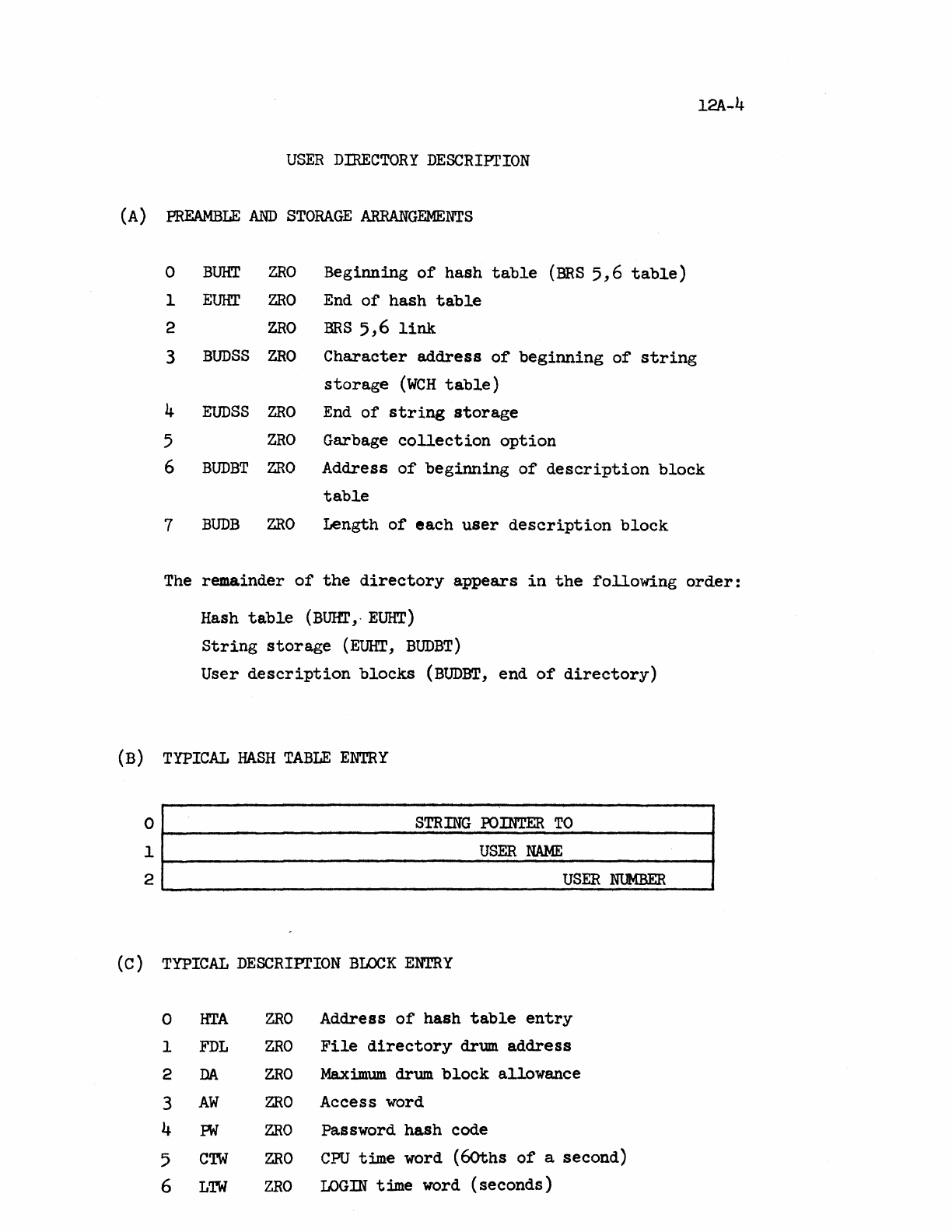
l2A-4
USER
DIRECTORY
DESCRIPTION
(A)
PREAMBLE
AND
STORAGE
ARRANGEMENTS
0
BURT
ZRO
Beginning
of
hash
table
(BRS
5,6
table)
1
EUHT
ZRO
End
of
hash
table
2
ZRO
BRS
5,6
link
3
BUDSS
ZRO
Character
address
of
beginning
of
string
storage
(WCH
table)
4
EUDSS
ZRO
End
of
string
storage
5
ZRO
Garbage
collection
option
6
BUDBT
ZRO
Address
of
beginning
of
description
block
table
7
BUDB
ZRO
Length
of
each
user
description
block
The
remainder
of
the
directory
appears
in
the
following
order:
Hash
table
(BUHl',·
EUHT)
String
storage
(EUHT,
BUDBT)
User
description
blocks
(BUDBT,
end
of
directory)
(B)
TYPICAL
HASH
TABLE
ENTRY
~2~
______________________
S_TR
__
IN_G
__
~_S_~
__
~
___
TO
____________
~
.
USER
NUMBER
(c)
TYPICAL
DESCRIPI'ION
BLOCK
ENTRY
0
HTA
ZRO
Address
of
hash
table
entry
1
FDL
ZRO
File
directory
drum
address
2
DA
ZRO
Maximum.
drum
block
allowance
3
AW
ZRO
Access word
4
PW
ZRO
Password hash code
5
CTW
ZRO
CPU
time word
(6oths
of
a second)
6
LTW
ZRO
LOGIN
time word (seconds)
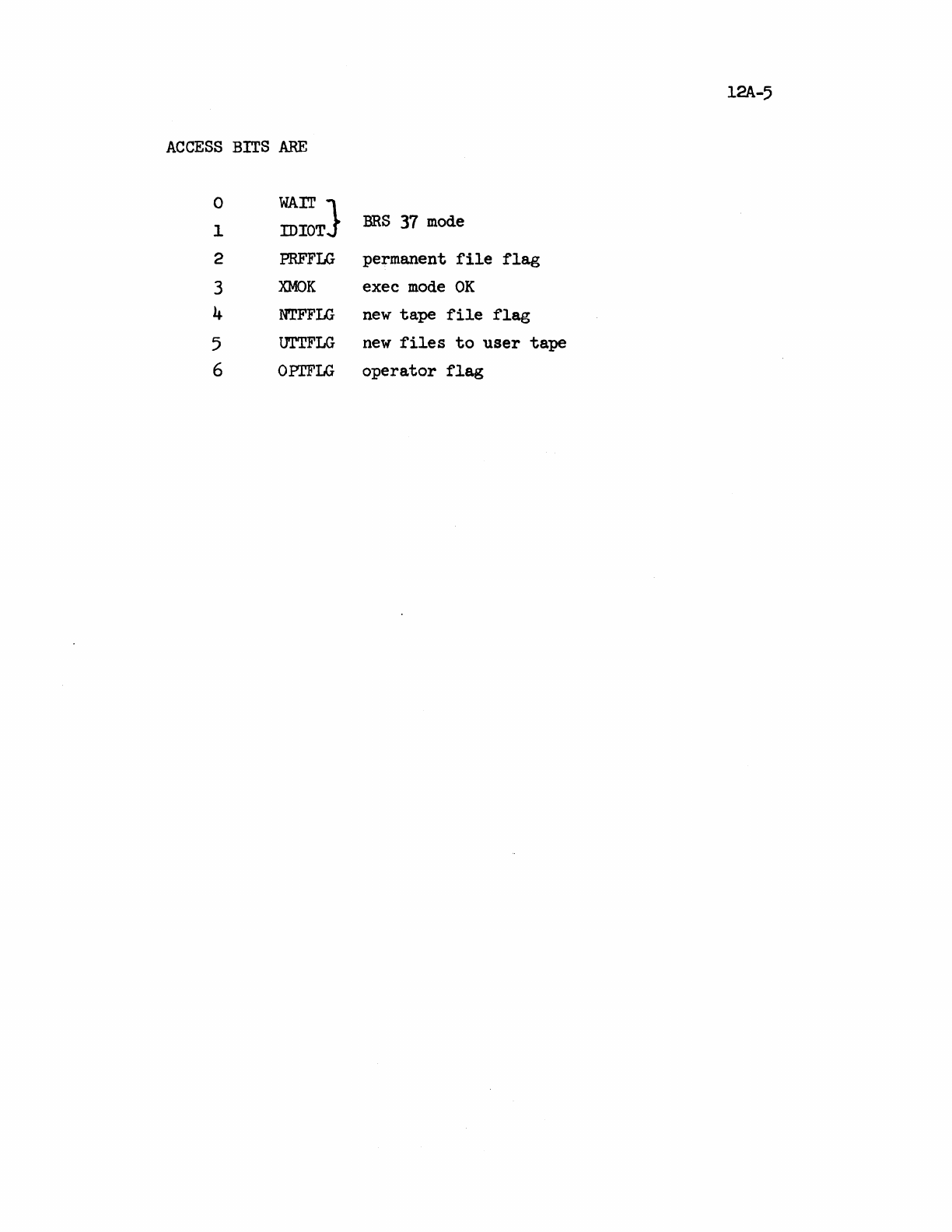
l2A-5
ACCESS
BITS
ARE
0
WAr!'
}
1
IDIOT
BRS
37
mode
2
PRFFLG
permanent
file
flag
3
XMOK
exec
mode
OK
4
NTFFLG
new
tape
file
flag
5
UTTFLG
new
files
to
user
tape
6 OPI'FLG
operator
flag
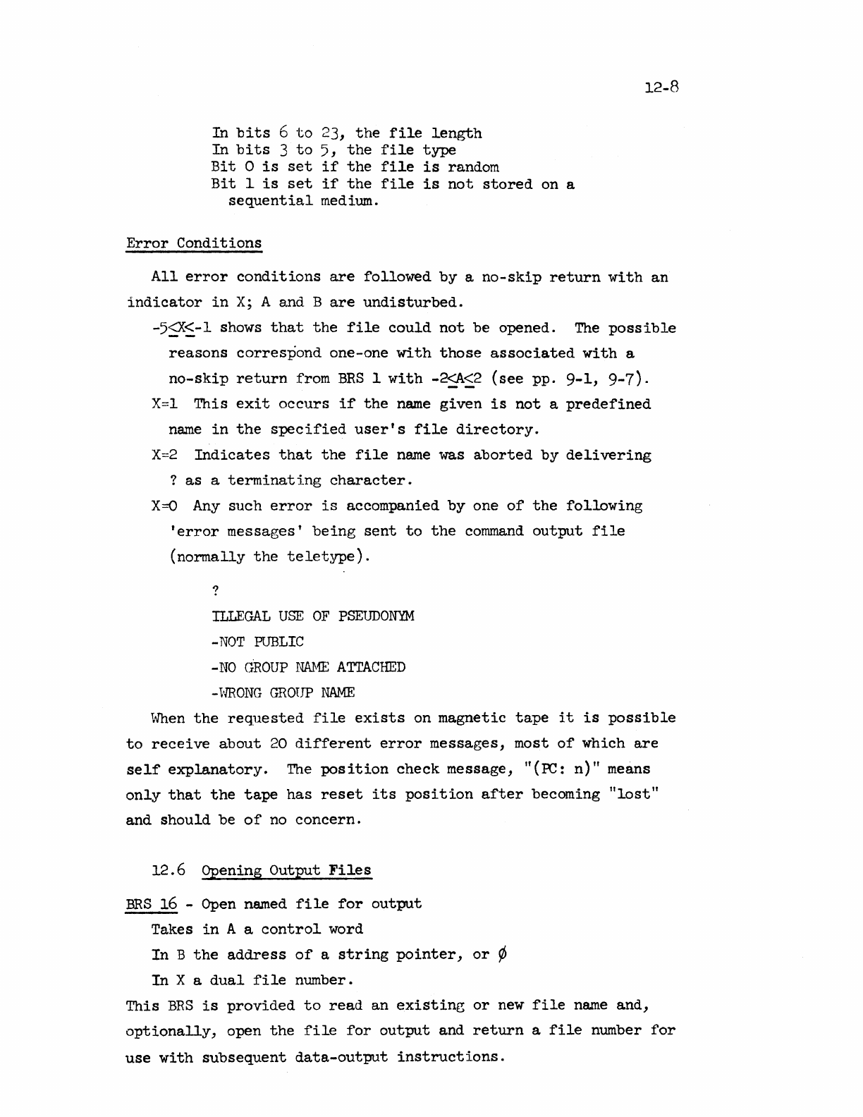
In
bits
6
to
23,
the
file
length
In
bits
3
to
5,
the
file
type
Bit
0
is
set
if
the
file
is
random
Bit
1
is
set
if
the
file
is
not
stored
on a
sequential
medium.
Error
Conditions
12-8
All
error
conditions
are
followed
by
a
no-skip
return
with
an
indicator
in
X;
A and B
are
undisturbed.
-5~~-1
shows
that
the
file
could
not
be opened.
The
possible
reasons
correspond
one-one
with
those
associated
with
a
no-skip
return
from
BRS
1
with
-2~~2
(see
pp.
9-1, 9-7).
X=l
This
exit
occurs
if
the
name
given
is
not
a
predefined
name
in
the
specified
user's
file
directory.
X=2
Indicates
that
the
file
name
was
aborted
by
delivering
?
as
a
terminating
character.
X=O
Any
such
error
is
accompanied
by
one
of
the
following
'error
messages'
being
sent
to
the
command
output
file
(normally
the
teletype).
?
ILLEGAL
USE
OF
PSEUDONYM
-NOT
PUBLIC
-NO
GROUP
NAHE
ATTACHED
-VlRONG
GROUP
NAME
When
the
requested
file
exists
on
magnetic
tape
it
is
possible
to
receive
about
20
different
error
messages,
most
of
which
are
self
explanatory.
The
pcs
ition
check
message,
"(
~:
n)"
means
only
that
the
tape
has
reset
its
position
after
becoming
"lost"
and
should
be
of
no
concern.
12.6
Opening
Output
Files
BRS
16 -
Open
named
file
for
output
Takes
in
A a
control
word
In
B
the
address
of
a
string
pointer,
or
~
In
X a
dual
file
number.
This
BRS
is
provided
to
read
an
existing
or
new
file
name
and,
optionally,
open
the
file
for
output
and
return
a
file
number
for
use
with
subsequent
data-output
instructions.
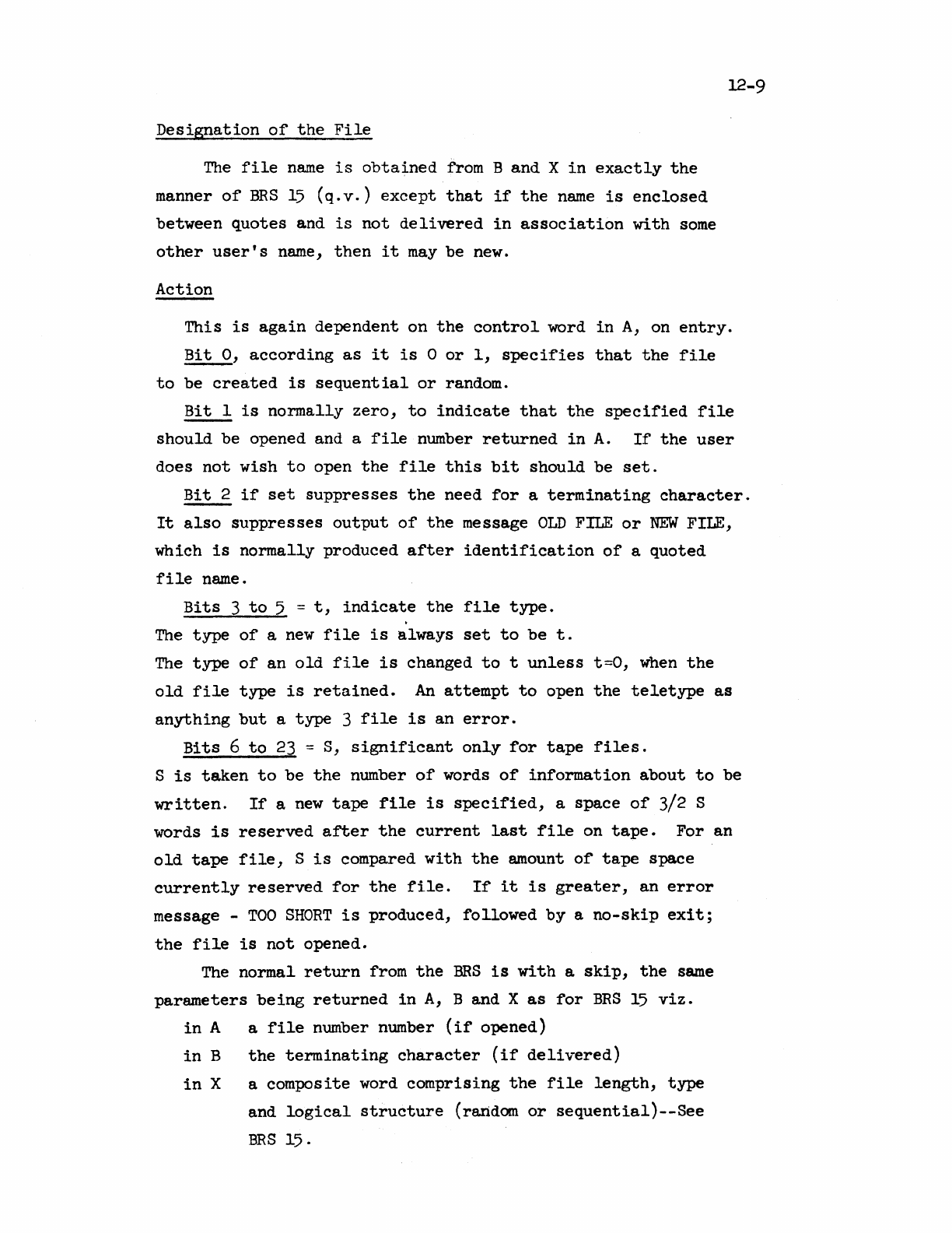
Designation
of
the
File
The
file
name
is
obtained
from B and X
in
exactly
the
manner
of
BRS
15
(q.v.)
except
that
if
the
name
is
enclosed
between
quotes
and
is
not
delivered
in
association
with
some
other
user's
name,
then
it
may
be new.
Action
12-9
This
is
again
dependent on
the
control
word
in
A,
on
entry.
Bit
0,
according
as
it
is
°
or
1,
specifies
that
the
file
to
be
created
is
sequential
or
random.
Bit
1
is
normally
zero,
to
indicate
that
the
specified
file
should
be opened and a
file
number
returned
in
A.
If
the
user
does
not
wish
to
open
the
file
this
bit
should
be
set.
Bit
2
if
set
suppresses
the
need
for
a
terminating
character.
It
also
suppresses
output
of
the
message
OLD
FILE
or
NEW
FILE,
which
is
normally
produced
after
identification
of
a
quoted
file
name.
Bits
3
to
5 =
t,
indicate
the
file
type.
The
type
of
a
new
file
is
always
set
to
be
t.
The
type
of
an
old
file
is
changed
to
t
unless
t=O,
when
the
old
file
type
is
retained.
An
attempt
to
open
the
teletype
as
anything
but
a
type
3
file
is
an
error.
Bits
6
to
23
= S,
significant
only
for
tape
files.
S
is
taken
to
be
the
number
of
words
of
information
about
to
be
written.
If
a
new
tape
file
is
specified,
a space
of
3/2 S
words
is
reserved
after
the
current
last
file
on
tape.
For an
old
tape
file,
S
is
compared
with
the
amount
of
tape
space
currently
reserved
for
the
file.
If
it
is
greater,
an
error
message -
TOO
SHORT
is
produced,
followed
by
a
no-skip
exit;
the
file
is
not
opened.
The
normal
return
from
the
BRS
is
with
a
skip,
the
same
parameters
being
returned
in
A,
B and X
as
for
BRS
15
viz.
in
A a
file
number number
(if
opened)
in
B
the
terminating
character
(if
delivered)
in
X a composite word
comprising
the
file
length,
type
and
logical
structure
(random
or
sequential)--See
BRS
15.
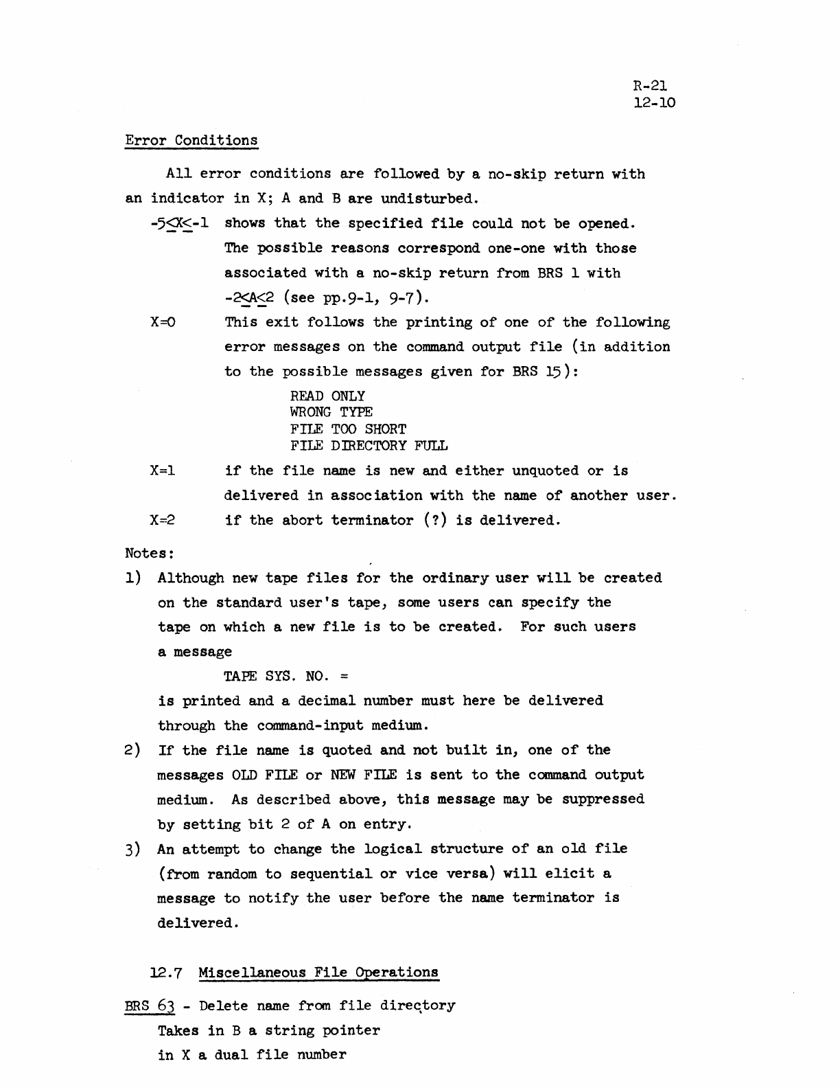
Error
Conditions
R-21
12-10
All
error
conditions
are
followed
by
a
no-skip
return
with
an
indicator
in
X;
A and B
are
undisturbed.
-5~~-1
shows
that
the
specified
file
could
not
be
opened.
The
possible
reasons
correspond
one-one
with
those
associated
with
a
no-skip
return
from
BRS
I
with
-~~2
(see
pp.9-1,
9-7).
X=O
This
exit
follows
the
printing
of
one
of
the
following
error
messages on
the
command
output
file
(in
addition
to
the
possible
messages
given
for
BRS
15):
READ
ONLY
WRONG
TYPE
FILE
TOO
SHORT
FILE
DIRECTORY
FULL
X=l
if
the
file
name
is
new
and
either
unquoted
or
is
delivered
in
association
with
the
name
of
another
user.
X=2
if
the
abort
terminator
(?)
is
delivered.
Notes:
1)
Although
new
tape
files
for
the
ordinary
user
will
be
created
on
the
standard
user's
tape,
same
users
can
specify
the
tape
on which a
new
file
is
to
be
created.
For
such
users
a message
TAPE
SYS.
NO.
=
is
printed
and
a
decimal
number must
here
be
delivered
through
the
command-input medium.
2)
If
the
file
name
is
quoted
and
not
built
in,
one
of
the
messages
OLD
FILE
or
NEW
FILE
is
sent
to
the
command
output
medium.
As
described
above,
this
message
may
be
suppressed
by
setting
bit
2
of
A on
entry.
3)
An
attempt
to
change
the
logical
structure
of
an
old
file
(from random
to
sequential
or
vice
versa)
will
elicit
a
message
to
notify
the
user
before
the
name
terminator
is
delivered.
12.7
Miscellaneous
File
Operations
ERS
63
-
Delete
name
from
file
dire~tory
Takes
in
B a
string
pointer
in
X a
dual
file
number
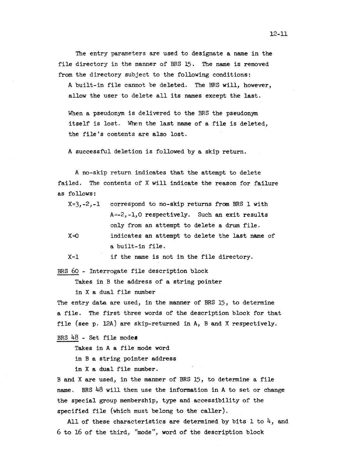
12-11
The
entry
parameters
are
used
to
designate
a
name
in
the
file
directory
in
the
manner
of
BRS
15.
The
name
is
removed
from
the
directory
subject
to
the
following
conditions:
A
built-in
file
cannot
be
deleted.
The
BRS
will,
however,
allow
the
user
to
delete
all
its
names
except
the
last.
When
a pseudonym
is
delivered
to
the
BRS
the
pseudonym
itself
is
lost.
When
the
last
name
of
a
file
is
deleted,
the
file's
contents
are
also
lost.
A
successful
deletion
is
followed
by
a
skip
return.
A
no-skip
return
indicates
that
the
attempt
to
delete
failed.
The
contents
of
X
will
indicate
the
reason
for
failure
as
follows:
X=3,-2,-1
correspond
to
no-skip
returns
from
BRS
1
with
A=-2,
-1,0
re
spect
i ve
ly
. Such
an
exit
results
only
from
an
attempt
to
delete
a drum
:file.
X=O
indicates
an
attempt
to
delete
the
last
name
a
built-in
file.
X=l
if
the
name
is
not
in
the
file
directory.
BRS
60
-
Interrogate
file
description
block
Takes
in
B
the
address
of
a
string
pointer
in
X a
dual
file
number
of
The
entry
data
are
used,
in
the
manner
of
BRS
15,
to
determine
a
file.
The
first
three
words
of
the
description
block
for
that
file
(see
p.
l2A)
are
Skip-returned
in
A,
B and X
respectively.
BRS
48
-
Set
file
modes
Takes
in
A a
file
mode
word
in
B a
string
pointer
address
in
X a
dual
file
number.
B and X
are
used,
in
the
manner
of
BRS
15,
to
determine
a
file
name.
BRS
48
will
then
use
the
information
in
A
to
set
or
change
the
special
group membership,
type
and
accessibility
of
the
specified
file
(which must
belong
to
the
caller).
All
of
these
characteristics
are
determined
by
bits
1
to
4, and
6
to
16
of
the
third,
"mode", word
of
the
description
block
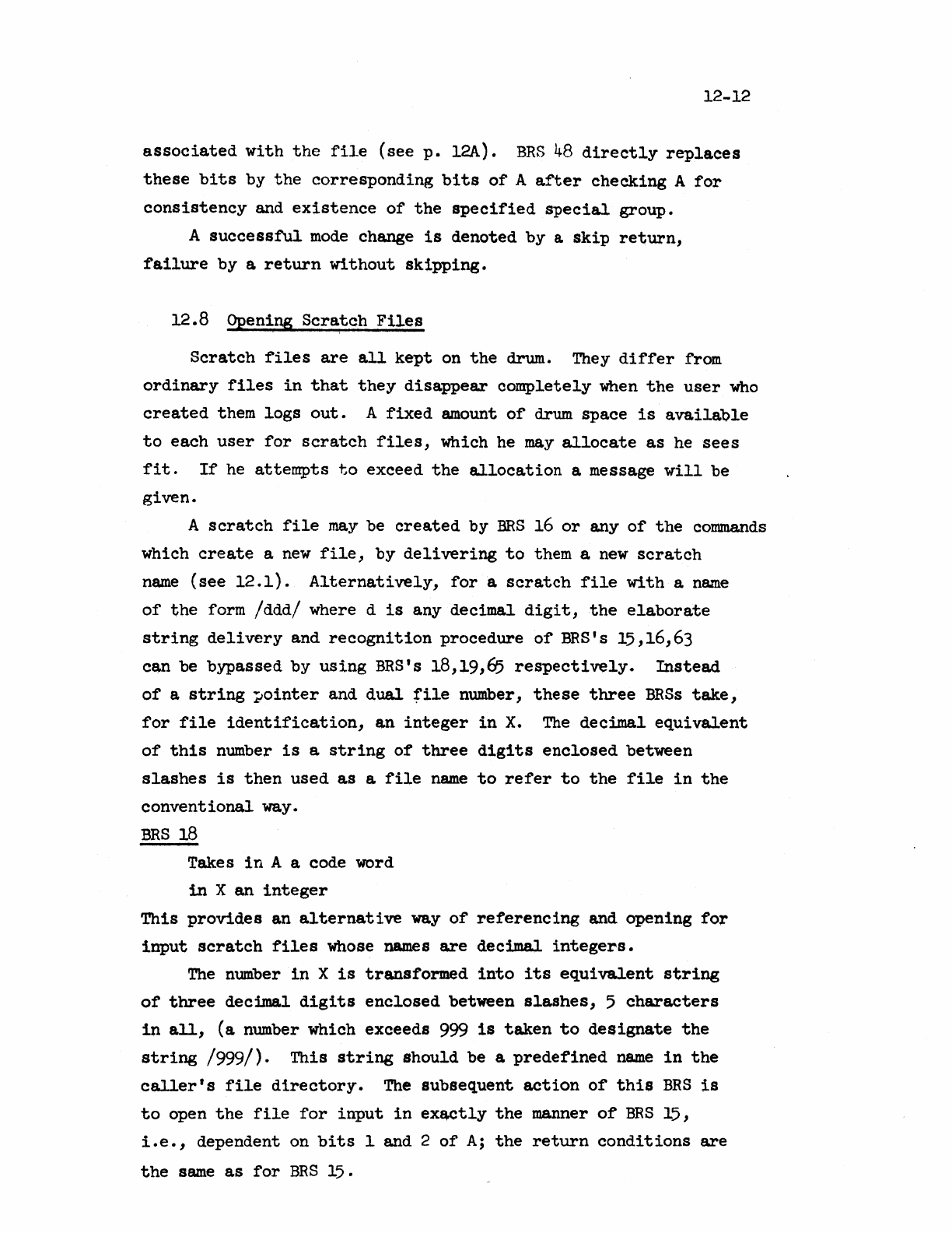
12-12
associated
with
the
file
(see
p.
l2A).
BRS
48
directly
replaces
these
bits
by
the
corresponding
bits
of
A
after
checking
A
for
consistency
and
existence
of
the
specified
special
group.
A
successful
mode
change
is
denoted
by
&
skip
return,
failure
by
a
return
without
skipping.
12.8 Opening
Scratch
Files
Scratch
files
are
all
kept
on
the
drum. They
differ
from
ordinary
files
in
that
they
disappear
completely
when
the
user
who
created
them
logs
out.
A
fixed
amount
of
drum
space
is
available
to
each
user
for
scratch
files,
which he
may
allocate
as
he
sees
fit.
If
he
attempts
to
exceed
the
allocation
a message
will
be
given.
A
scratch
file
may
be
created
by
BRS
16
or
any
of
the
commands
which
create
a
new
file,
by
delivering
to
them a
new
scratch
name
(see
12.1).
Alternatively,
for
a
scratch
file
with
a
name
of
the
form
/ddd/
where d
is
any
decimal
digit,
the
elaborate
string
delivery
and
recognition
procedure
of
BRS's 15,16,63
can
be
bypassed
by
using
BRS's 18,19,65
respectively.
Instead
of
a
string
~ointer
and
dual
file
number,
these
three
BRSs
take,
for
file
identification,
an
integer
in
X.
The
decimal
equivalent
of
this
number
is
a
string
of
three
digits
enclosed
between
slashes
is
then
used
as
a
file
name
to
refer
to
the
file
in
the
conventional
way.
BRS
18
Takes
in
A a code word
in
X
an
integer
This
provides
an
alternative
way
of
referencing
and
opening
for
input
scratch
files
whose names
are
decimal
integers.
The
number
in
X
is
transformed
into
its
equivalent
string
of
three
decimal
digits
enclosed
between
slashes,
5
characters
in
all,
(a
number which
exceeds
999
is
taken
to
de$ignate
the
string
/999/).
This
string
should
be a
predefined
name
in
the
caller's
file
directory.
The
subsequent
action
of
this
BRS
is
to
open
the
file
for
input
in
exactly
the
manner
of
BRS
15,
i.e.,
dependent on
bits
1 and 2
of
A;
the
return
conditions
are
the
same
as
for
BRS
15.
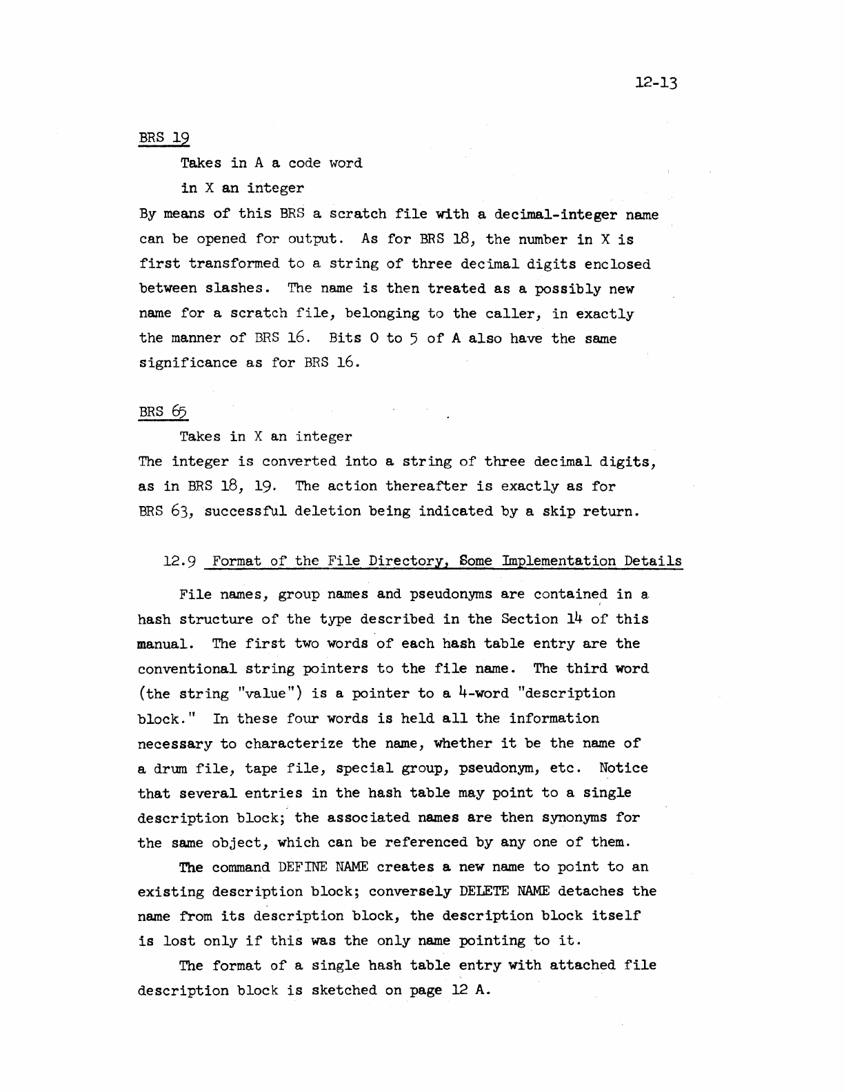
BRS
19
Takes
in
A a code word
in
X
an
integer
12-13
By
means
of
this
BRS
a
scratch
file
with
a
decimal-integer
name
can
be opened
for
output.
As
for
BRS
18,
the
number
in
X
is
first
transformed
to
a
string
of
three
decimal
digits
enclosed
between
slashes.
The
name
is
then
treated
as
a
possibly
new
name
for
a
scratch
file,
belonging
to
the
caller,
in
exactly
the
manner
of
BBS
16 .
Hits
0
to
5
of
A
also
have
the
same
Significance
as
for
BRS
16.
BRS
&5
Takes
in
X an
integer
The
integer
is
converted
into
a
string
of
three
decimal
digits,
as
in
BRS
18, 19. The
action
thereafter
is
exactly
as
for
BRS
63,
successfUl
deletion
being
indicated
by
a
skip
return.
12.9
Format
of
the
File
Directory,
Some
Implementation
Details
File
names,
group
names and pseudonyms
are
contained
in
8.
hash
structure
of
the
type
described
in
the
Section
14
of
this
manual.
The
first
two words
of
each
hash
table
entry
are
the
conventional
string
pointers
to
the
file
name. The
third
word
(the
string
"value")
is
a
pointer
to
a 4-word
"description
block."
In
these
four
words
is
held
all
the
information
necessary
to
characterize
the
name,
whether
it
be
the
name
of
a drmn
file,
tape
file,
special
group,
pseudonym,
etc.
Notice
that
several
entries
in
the
hash
table
may
point
to
a
Single
description
block;
the
associated
names
are
then
synonyms
for
the
same
object,
which
can
be
referenced
by
anyone
of
them.
The
conunand
DEFINE
NAME
creates
a
new
name
to
point
to
an
existing
description
block;
conversely
DELETE
NAME
detaches
the
name
from
its
description
block,
the
description
block
itself
is
lost
only
if
this
was
the
only
name
pointing
to
it.
The
format
of
a
single
hash
table
entry
with
attached
file
description
block
is
sketched
on page 12
A.
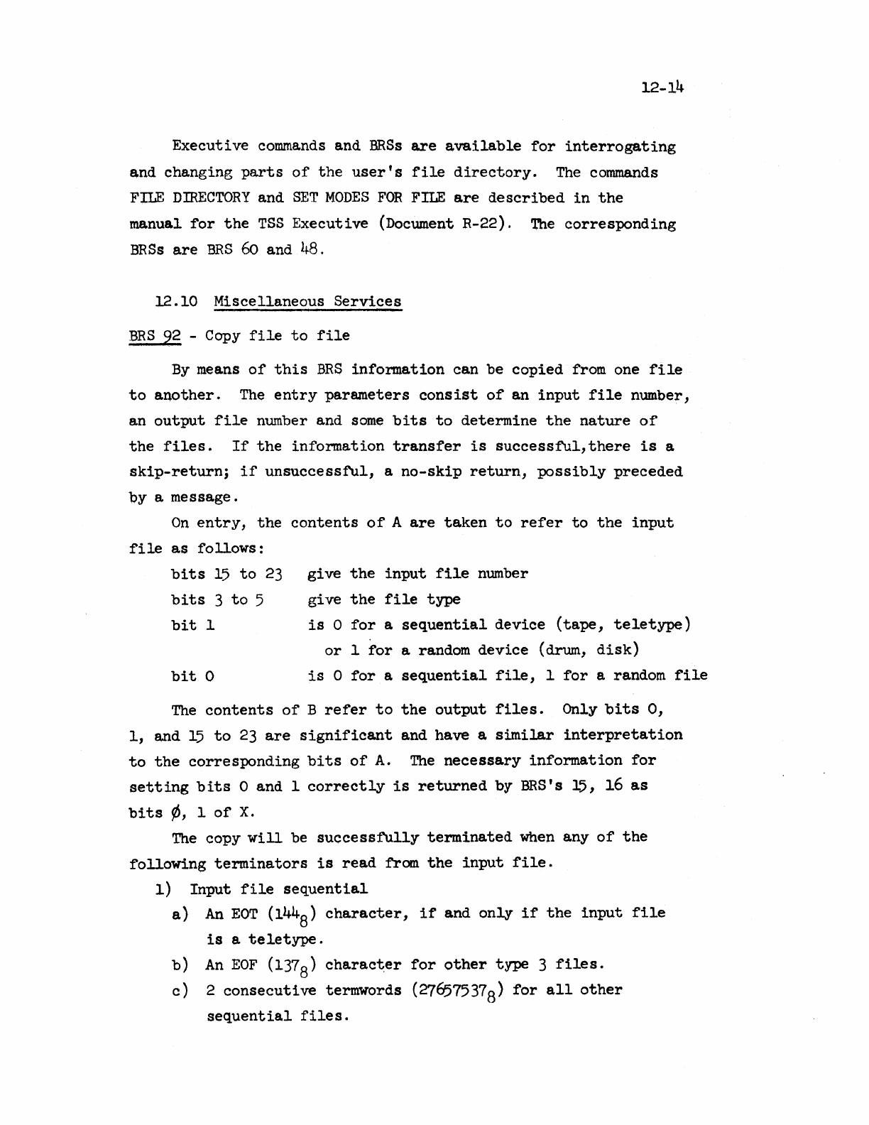
12-14
Executive
commands
and
BRSs
are
available
for
interrogating
and changing
parts
of
the
user's
file
directory.
The
commands
FILE
DIRECTORY
and
SET
MODES
FOR
FILE
are
described
in
the
manual
for
the
TSS
Executive
(Document R-22).
The
corresponding
BRSs
are
BRS
60
and
48.
12.10
Miscellaneous
Services
BRS
92 -Copy
file
to
file
By
means
of
this
BRS
infor.mation can be
copied
from one
file
to
another.
The
entry
parameters
consist
of
an
input
file
number,
an
output
file
number and
some
bits
to
determine
the
nature
of
the
files.
If
the
information
transfer
is
successfUl,there
is
a
skip-return;
if
unsuccessful,
a
no-skip
return,
possibly
preceded
by
a message.
On
entry,
the
contents
of
A
are
taken
to
refer
to
the
input
fi
Ie
as
fo
llows
:
give
the
input
file
number
give
the
file
type
bits
15
to
23
bits
3
to
5
bit
1
is
0
for
a
sequential
device
(tape,
teletype)
or
1
for
a random
device
(drum,
disk)
bit
0
is
0
for
a.
sequential
file,
1
for
a random
file
The
contents
of
B
refer
to
the
output
files.
Only
bits
0,
1,
and
15
to
23
are
significant
and have a
similar
interpretation
to
the
corresponding
bits
of
A.
The
necessary
information
for
setting
bits
0 and 1
correctly
is
returned
by BRS's 15,
16
as
bits
'/J,
1
of
X.
The
copy
will
be
successfully
terminated
when
any
of
the
following
terminators
is
read
from
the
input
file.
1)
Input
file
sequential
a)
An
EOT
(144
8)
character,
if
and
only
if
the
input
file
is
a
teletype.
b)
An
EOF
(1378)
character
for
other
type 3
files.
c)
2
consecutive
termwords (276575378)
for
all
other
sequential
files.
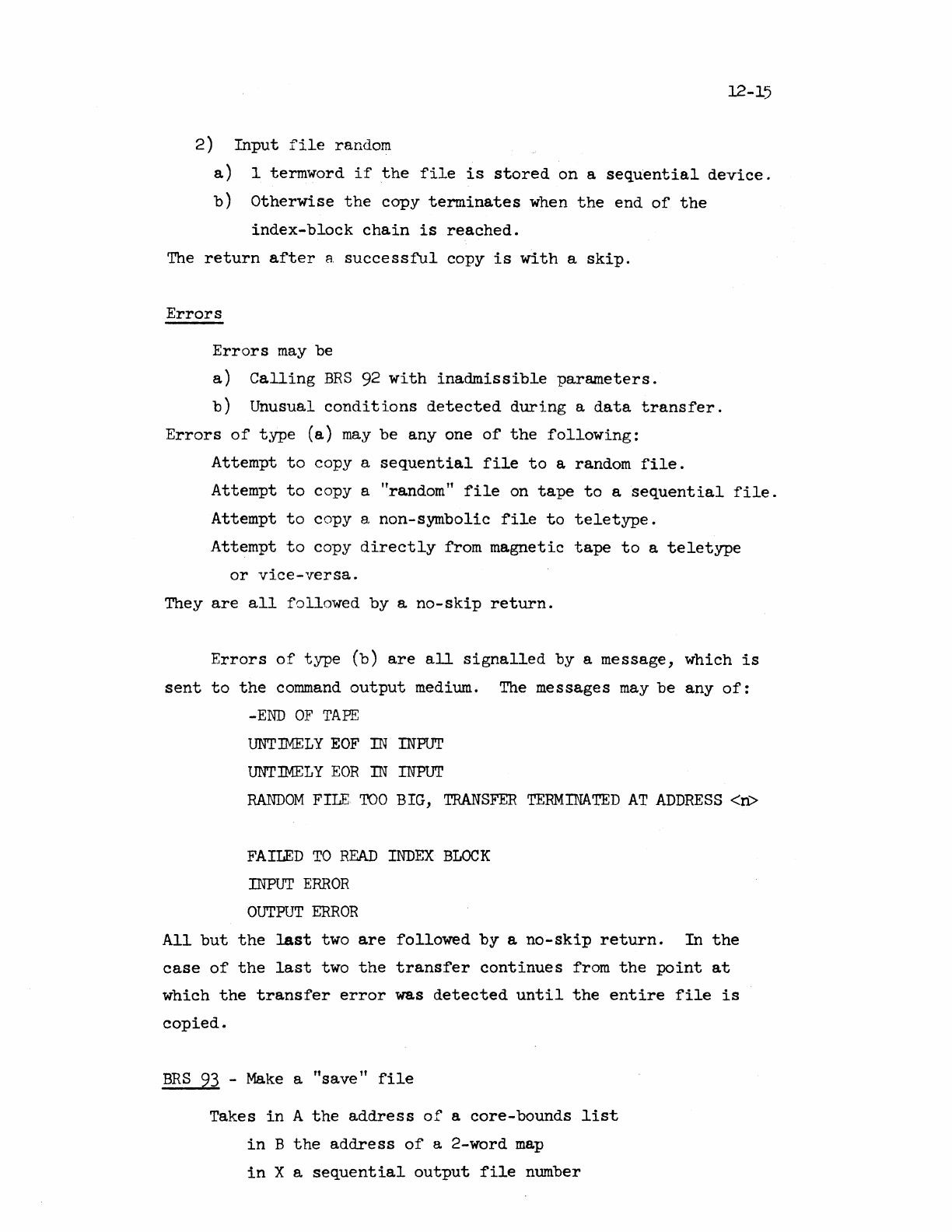
12-15
2)
Input
file
random
a)
1 termword
if
the
file
is
stored
on
a
sequential
device.
b)
Otherwise
the
copy
terminates
when
the
end
of
the
index-block
chain
is
reached.
The
return
after
a
successful
copy
is
with
a
skip.
Errors
Errors
may
be
a)
Calling
BRS
92
with
inadmissible
parameters.
b)
Unusual
conditions
detected
during
a
data
transfer.
Errors
of
type
(a)
may
be
anyone
of
the
following:
Attempt
to
copy a
sequential
file
to
a random
file.
Attempt
to
copy
a "random"
file
on
tape
to
a
sequential
file.
Attempt
to
copy a
non-symbolic
file
to
teletype.
Attempt
to
copy
directly
from
magnetic
tape
to
a
teletype
or
vice-versa.
They
are
all
followed
by
a
no-skip
return.
Errors
of
type
(b)
are
all
signalled
by
a
message,
which
is
sent
to
the
command
output
medium. The messages
may
be
any
of:
-END
OF
TAPE
UNTIMELY
EOF
IN
INPUT
UNT:wELY
EOR
IN
INPUT
RANDOM
FILE
TOO
BIG,
TRANSFER
TERMINATED
AT
ADDRESS
<n>
FAILED
TO
READ
INDEX
BLOCK
INPUT
ERROR
OUTPUT
ERROR
All
but
the
last
two
are
followed
by
a
no-skip
return.
In
the
case
of
the
last
two
the
transfer
continues
from
the
point
at
which
the
transfer
error
was
detected
until
the
entire
file
is
copied.
BRS
93
-
Make
a
"save"
file
Takes
in
A
the
address
of
a
core-bounds
list
in
B
the
address
of
a 2-word
map
in
X a
sequential
output
file
number
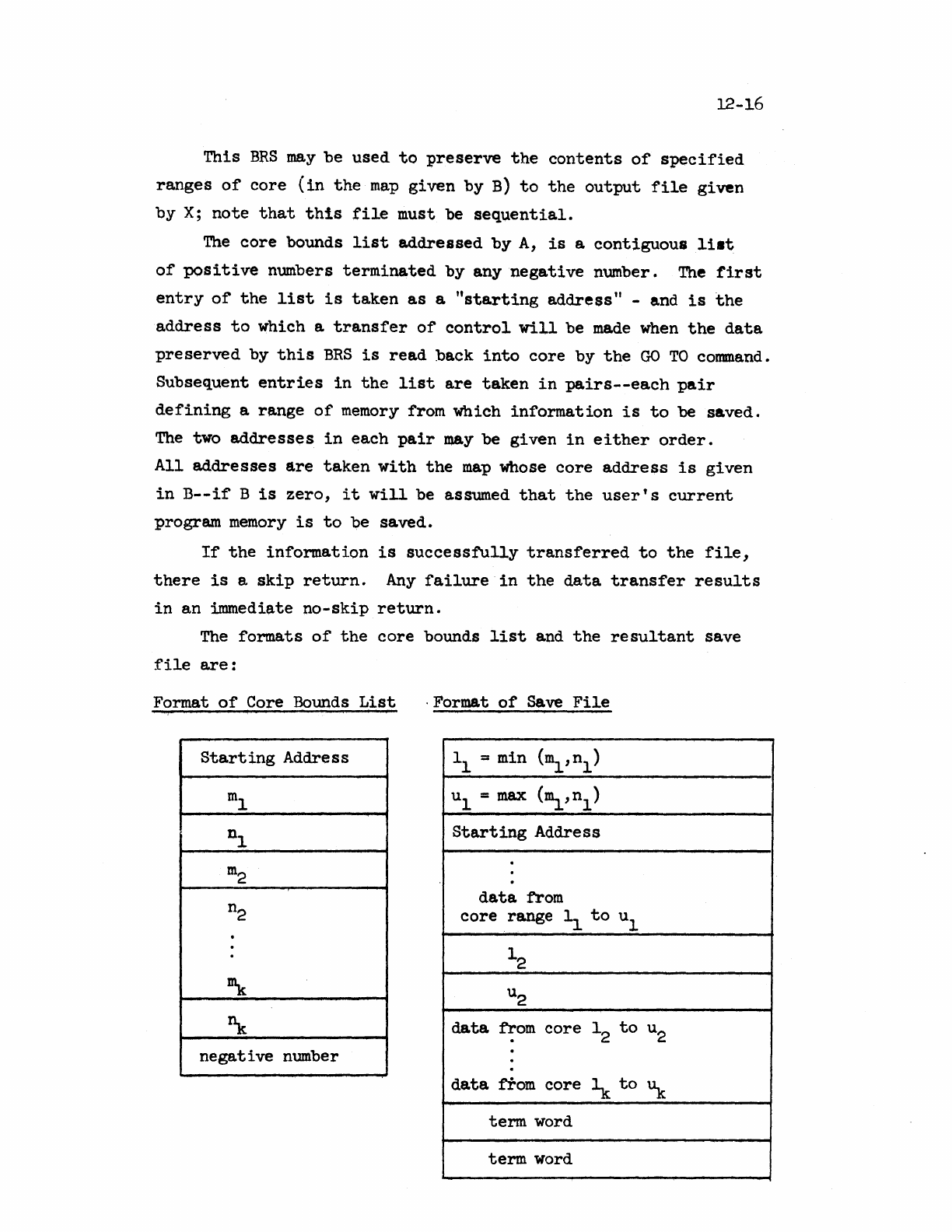
12-16
This
BRS
may
be
used
to
preserve
the
contents
of
specified
ranges
of
core
(in
the
map
given
by
B)
to
the
output
file
given
by
X;
note
that
this
file
must be
sequential.
The
core
bounds
list
addressed
by
A,
is
a
contiguous
li.t
of
positive
numbers
terminated
by
any
negative
number.
The
first
entry
of
the
list
is
ta.ken
as
a
"starting
address"
-and
is
the
address
to
which a
transfer
of
control
will
be
made
when
the
da.ta
preserved
by
this
BRS
is
read
back
into
core
by
the
GO
TO
command.
Subsequent
entries
in
the
list
are
taken
in
pairs--each
pair
defining
a
range
of
memory
from which
information
is
to
be
saved.
The
two
addresses
in
each
pair
may
be
given
in
either
order.
All
addresses
are
taken
with
the
map
whose
core
address
is
given
in
B--if
B
is
zero,
it
will
be assumed
that
the
user's
current
program
memory
is
to
be
saved.
If
the
information
is
successfully
transferred
to
the
file,
there
is
a
skip
return.
Any
failure
in
the
data
transfer
results
in
an
~ediate
no-skip
return.
The
formats
of
the
core
bounds
list
and
the
resultant
save
file
are:
Format
of
Core Bounds
List
. Format
of
save
File
i
Starting
Address 11 = min
(m
1
,n
l)
m
l u
=max
1
(~,nl)
nl
Starting
Address
·
m
2 ·
data
from
n2
core
range 11
to
ul
.
. 12
~
u2
~
data
from
core
12
to
u2
·
negative
number ·
·
·
data
from
core
~
to
'1t
term
word
term
word
12-17
BRS
94
-
Restore
a save
file
to
core
Entry
A,B =
relabeling
X =
file
no.
of
sequential
save
(type
1)
file
The
save
file,
which
should
have
the
format
described
in
BRS
93,
is
transferred
to
the
memory
given
by
the
map
in
A,B.
If
the
transfer
is
successful,
there
is
a
skip
return
with
the
starting
address
(see
BRS
93)
in
A and
the
file
number
in
X.
An
unsuccessful
data
transfer
results
in
a nO-Skip
return.
BRS
131/132 -(open
tape
for
input/output)
[privileged]
Given
in:
A =
the
desired
tape
position
(0<A<256)
B =
the
user
number
of
the
file
o~mer
(BRS
132
only)
X =
the
tape
system number
or
the
tape
unit
number
with
bit
0
set.
Return
No
Skip:
A =
error
flag
(-2<A<18)
All
errors
result
in
a
typed
message
Skip:
A =
file
number
B =
user
number
of
file
owner
X =
tape
unit
number
The
tape
can be open
for
input
(BRS
131)
without
executivity
being
set.
In
fact,
BRS
131
can
be
executed
by
users
with
operator
privileges
even
if
they
do
not
have
executive
privileges.
If
the
desired
tape
is
not
logically
mounted,
it
can
still
be
accessed
by
loading
the
unit
number
in
X and
setting
XO.
This
will
cause
the
tape
status
vector
to
record
the
tape
system
and
reel
numbers.
No
new
files
can
be
created
with
BRS
132.
A more complete
description
can
be found
in
M-l7.
13-1
13.0
Miscellaneous
Executi-..rc
Features
The
executive
provides
a number
of
BRS's which
are
services
for
the
user.
Many
of
these
are
incorporated
in
the
string
processing
system
or
in
the
floating
point
package and
are
described
in
the
next
t"TO
sections.
To
input
an
integer
to
any
radix
the
instructions
LDB =
radix
LDX
==
file
BRS
38
may
be
executed.
The
number, which
may
be
preceded
by
a
plus
or
minus
sign,
is
returned
in
the
A
register
and
the
non-numeric
character
which
terminated
the
number
in
the
B
register.
The
number
is
computed
by
multiplying
the
number
obtained
at
each
stage
by
the
radix
and
adding
the
new
digit.
It
is
therefore
unlikely
that
the
right
thing
will
happen
if
the
number
of
digits
is
too
large.
If
no
digits
are
typed,
the
Sign
bit
of
B
is
set.
To
output
a number
to
arbitrary
radix
the
instructions
LDB
-=
radix
LDX -
file
LDA
number
BRS
36
may
be
executed.
The
number
will
be
output
as
an
unsigned
24-bit
integer
unless
the
sign
bit
of
B
is
set,
in
which
case
it
will
be
signed.
If
the
magnitude
of
the
radix
is
less
than
2,
an
error
will
be
indicated.
To
get
the
date
and time
into
a
string,
the
operations
LDP
PTR
BRS
91
may
be
executed.
The
current
date
and
time
are
appended
to
the
string
provided
in
AB
and
the
resulting
string
is
returned.
The
characters
appended have
the
form:
rnm/dd/YY
hhmm:ss
Hours
are
counted
from 0
to
23.
BRS
39
returns
the
date
and
time
in
AB
as
six
8-bit
bytes
giving
year,
month, day,
hour,
minute,
second,
respectively.
BRS
123 Read
teletype
and
user
number
Entry
X =
-lor
teletype
number
Exit
A =
user
number or
O.
B =
job
number
or
O.
X
~
teletype
number
BRS
97
Find
user's
teletype
Entry
A =
-lor
teletype
number
X
==
user
number
Exit
No
skip:
user
not
entered;
A,B,X
undefined
Skip:
A
teletype
number
X
user
number
This
BRS
may
be
used
to
find
on
which
teletypes
a
user
is
entered.
A
search
is
made
to
see
if
the
user
whose
user
number
is
given
in
X
is
entered
on any
teletype
with
a number
higher
than
that
given
in
A.
If
no
such
teletype
is
found,
the
BRS
does
not
skip
on
return.
Otherwise,
there
is
a
skip
return
with
the
next
higher
such
teletype
number
in
A.
BRS
10!}
Find
user
number from
user
name
Entry
B
X
string
pointer
address
dual
file
number
Exit
No
skip:
A,B,X
undefined,
illegal
user
name
S](ip:
A:-.:
X =
user
number
BRS
104
uses
B and X
to
collect
a
user
name
in
the
same
manner
as
BRS
15.
If
an
illegal
name
is
typed,
there
is
a no-
skip
return
from
the
BRS.
The
characters
typed
are
appended
to
the
string
(if
any)
given
on
entry.
Otherwise,
there
is
a
skip
return
with
the
required
user
number
in
both
A
and
X.
13-2
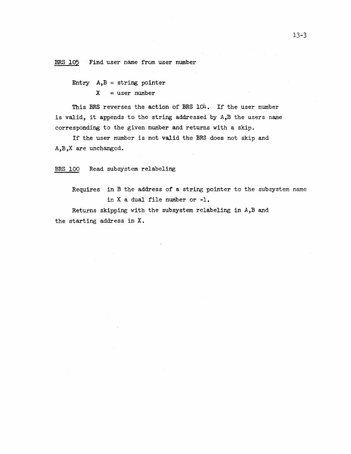
BRS
195
Find
user
name
from
user
number
Entry
A,B
~
string
pointer
X =
user
number
This
BRS
reverses
th~
action
of
BRS
104.
If
the
user
number
is
valid,
it
appends
to
the
string
addressed
by
A,B
the
users
name
corresponding
to
the
given
number and
returns
with
a
skip.
If
the
user
number
is
not
valid
the
BRS
does
not
skip
and
A,B,X
are
unchanged.
BRS
100 Read subsystem
relabeling
13-3
Requires
in
B
the
address
of
a
string
pointer
to
the
subsystem
name
in
X a
dual
file
number
or
-1.
Returns
skipping
with
the
subsystem
relabeling
in
A,B and
the
starting
address
in
X.
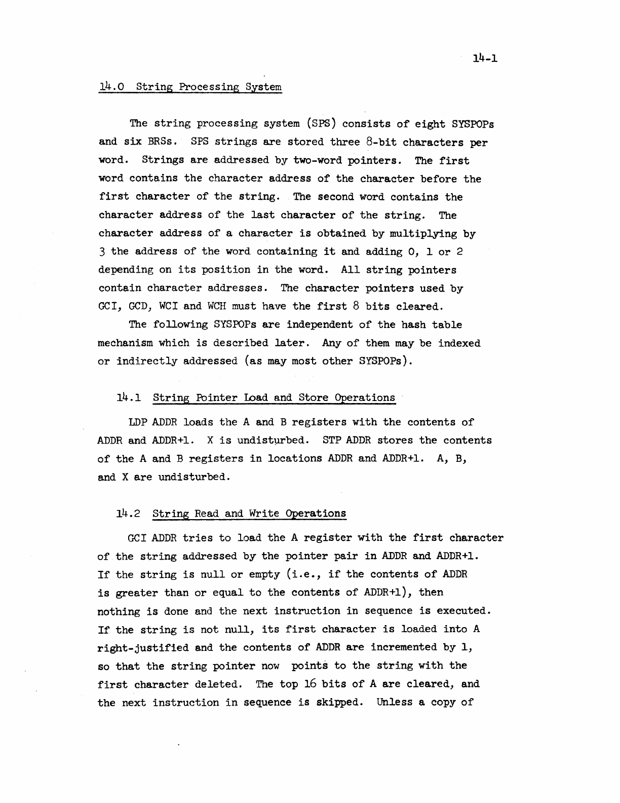
14-1
14.0
String
Processing
System
The
string
processing
system
(Sps)
consists
of
eight
SYSPOPs
and
six
BRSs.
SPS
strings
are
stored
three
8-bit
characters
per
word.
Strings
are
addressed
by
two-word
pointers.
The
first
word
contains
the
character
address
of
the
character
before
the
first
character
of
the
string.
The
second word
contains
the
character
address
of
the
last
character
of
the
string.
The
character
address
of
a
character
is
obtained
by
multiplying
by
3
the
address
of
the
word
containing
it
and
adding
0,
1
or
2
depending on
its
position
in
the
word.
All
string
pointers
contain
character
addresses.
The
character
pointers
used
by
GCI,
GCD,
WCI
and
WCH
must have
the
first
8
bits
cleared.
The
following
SYSPOPs
are
independent
of
the
hash
table
mechanism which
is
described
later.
Any
of
them
may
be
indexed
or
indirectly
addressed
(as
may
most
other
SYSPOPs).
14.1
String
Pointer
Load and
Store
Qperations
LDP
ADDR
loads
the
A and B
registers
with
the
contents
of
ADDR
and
ADDR+l.
X
is
undist~bed.
STP
ADDR
stores
the
contents
of
the
A and B
registers
in
locations
ADDR
and
ADDR+l.
A,
B,
and X
are
undisturbed.
14.2
String
Read and
Write
Operations
GCI
ADDR
tries
to
load
the
A
register
with
the
first
character
of
the
string
addressed
by
the
pointer
pair
in
ADDR
and
ADDR+l.
If
the
string
is
null
or
empty
(i.e.,
if
the
contents
of
ADDR
is
greater
than
or
equal
to
the
contents
of
ADDR+l),
then
nothing
is
done and
the
next
instruction
in
sequence
is
executed.
If
the
string
is
not
null,
its
first
character
is
loaded
into
A
right-justified
and
the
contents
of
ADDR
are
incremented
by
1,
so
that
the
string
pointer
now
points
to
the
string
with
the
first
character
deleted.
The
top
16
bits
of
A
are
cleared,
and
the
next
instruction
in
sequence
is
skipped.
Unless a copy
of
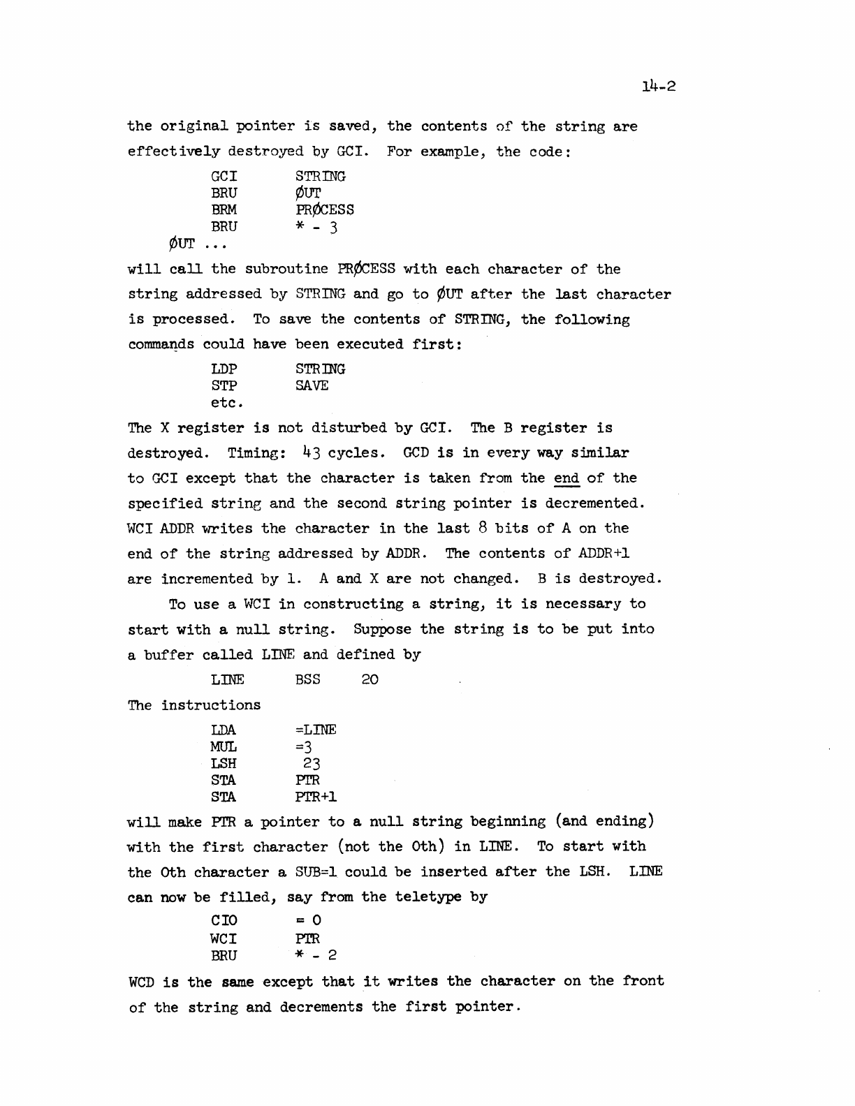
the
original
pointer
is
saved,
the
contents
of
the
string
are
effectively
destroyed
by
GCT.
For
example,
the
code:
GCl
STRrnG
BRU
¢UT
BRM
PR¢CESS
BRU
* - 3
~ur
14-2
will
call
the
subroutine
PR¢CESS
with
each
character
of
the
string
addressed
by
STRING and
go
to
¢UT
after
the
last
character
is
processed.
To
save
the
contents
of
STRING,
the
following
comma~ds
could
have been
executed
first:
LDP STR:mG
STP
SAVE
etc.
The
X
register
is
not
disturbed
by
Gel.
The
B
register
is
destroyed.
Timing:
43
cycles.
GCD
is
in
every
way
similar
to
GCl
except
that
the
character
is
taken
from
the
end
of
the
specified
string
and
the
second
string
pointer
is
decremented.
WeI
ADDR
~~ites
the
character
in
the
last
8
bits
of
A on
the
end
of
the
string
addressed
by
ADDR.
The
contents
of
ADDR+l
are
incremented
by
1.
A and X
are
not
changed. B
is
destroyed.
To
use
a
WeI
in
constructing
a
string,
it
is
necessary
to
start
with
a
null
string.
Suppose
the
string
is
to
be
put
into
a
buffer
called
LINE
and
defined
by
LINE
BSS
20
The
instructions
LDA
=LINE
MUL
=3
LSH
23
STA
PI'R
STA
PTR+l
will
make
PTR
a
pointer
to
a
null
string
beginning
(and
ending)
with
the
first
character
(not
the
oth)
in
LINE.
To
start
with
the
oth
character
a
SUB=l
could
be
inserted
after
the
LSH.
LINE
can
now
be
filled,
say
from
the
teletype
by
CIO
r::
0
WeI
Pm
BRU
* - 2
weD
is
the
same
except
that
it
writes
the
character
on
the
front
of
the
string
and decrements
the
first
pointer.
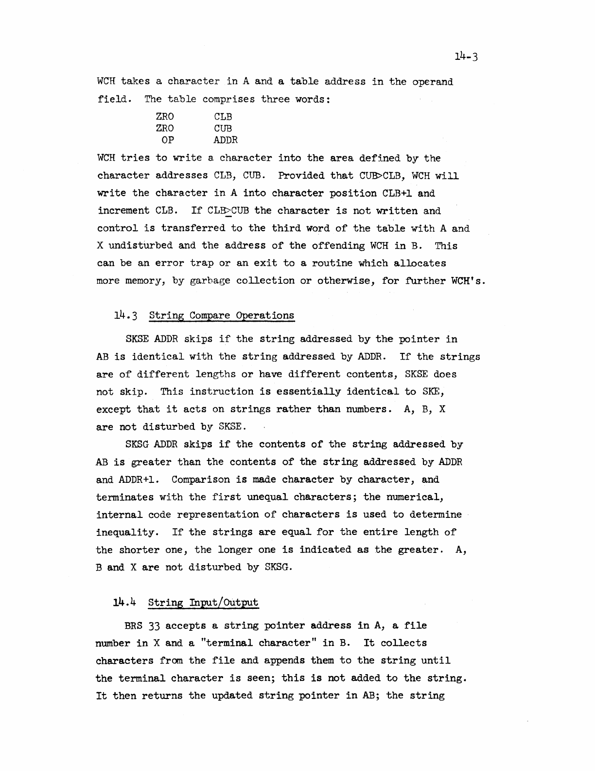
WCH
takes
a
character
in
A and a
table
address
in
the
operand
field.
The
ta.ble
comprises
three
words:
ZRO
CLB
ZRO
CUB
OP
ADDR
14-3
WCH
tries
to
write
a
character
into
the
area
defined
by
the
character
addresses
CLB,
CUB.
Provided
that
CUB>CLB,
WCH
will
write
the
character
in
A
into
character
position
CLB+l
and
increment
CLB.
If
CLB>CUB
the
character
is
not
written
and
control
is
transferred
to
the
third
word
of
the
table
with
A and
X
undisturbed
and
the
address
of
the
offending
WCH
in
B. This
can be
an
error
trap
or
an
exit
to
a
routine
which
allocates
more memory,
by
garbage
collection
or
otherwise,
for
further
WCH's.
14.3
String
Compare
Operations
SKSE
ADDR
skips
if
the
string
addressed
by
the
pointer
in
AB
is
identical
with
the
string
addressed
by
AnDR.
If
the
strings
are
of
different
lengths
or
have
different
contents,
SKSE
does
not
skip.
This
instruction
is
essentially
identical
to
SKE,
except
that
it
acts
on
strings
rather
than
numbers.
A,
B,
X
are
not
disturbed
by
SKSE.
SKSG
ADDR
skips
if
the
contents
of
the
string
addressed
by
AB
is
greater
than
the
contents
of
the
string
addressed
by
ADDR
and
ADDR+l.
Comparison
is
made
character
by
character,
and
terminates
with
the
first
unequal
characters;
the
numerical,
internal
code
representation
of
characters
is
used
to
determine
inequality.
If
the
strings
are
equal
for
the
entire
length
of
the
shorter
one,
the
longer
one
is
indicated
as
the
greater.
A,
B and X
are
not
disturbed
by
SKSG.
14.4
String
Input/Output
BRS
33
accepts
a
string
pointer
address
in
A,
a
file
number
in
X and a
"terminal
character"
in
B.
It
collects
characters
from
the
file
and appends them
to
the
string
until
the
terminal
character
is
seen;
this
is
not
added
to
the
string.
It
then
returns
the
updated
st.ring
pointer
in
AB;
the
string
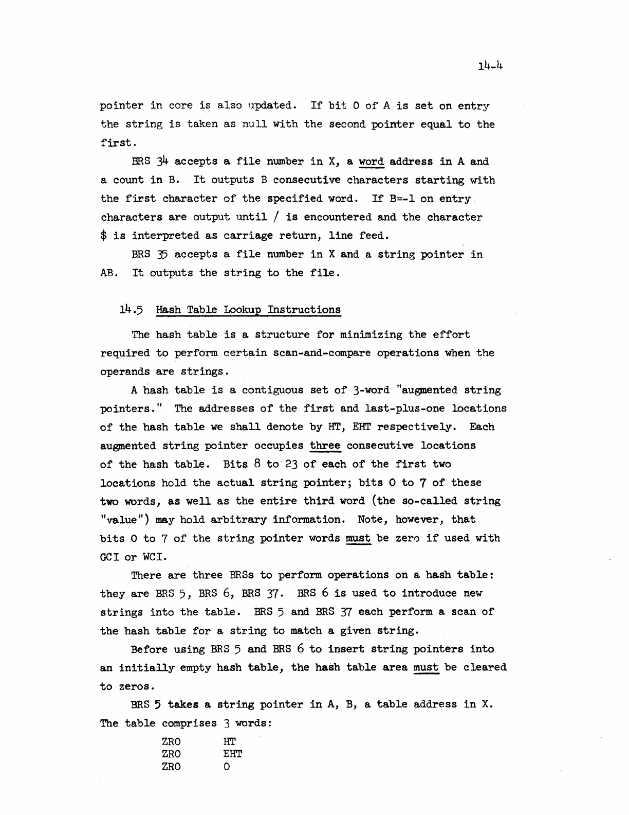
14-4
pointer
in
core
is
also
updated.
If
bit
0
of
A
is
set
on
entry
the
string
is
taken
as
null
with
the
second
pointer
equal
to
the
first.
BRS
34
accepts
a
file
number
in
X,
a word
address
in
A and
a
count
in
B.
It
outputs
B
consecutive
characters
starting
with
the
first
character
of
the
specified
word.
If
B=-l
on
entry
characters
are
output
until
I
is
encountered
and
the
character
$
is
interpreted
as
carriage
return,
line
feed.
ERS
35
accepts
a
fi~e
number
in
X and a
string
pointer
in
AB.
It
outputs
the
string
to
the
fi1e.
14.5 Hash Table Lookup
Instructions
The
hash
table
is
a
structure
for
minimizing
the
effort
required
to
perform
certain
scan-and-compare
operations
when
the
operands
are
strings.
A
hash
table
is
a
contiguous
set
of
3-word "augmented
string
pointers."
The
addresses
of
the
first
and
last-pIus-one
locations
of
the
hash
table
we
shall
denote
by
HT,
EHT
respectively.
Each
augmented
string
pointer
occupies
three
consecutive
locations
of
the
hash
table.
Bits
8
to"23
of
each
of
the
first
two
locations
hold
the
actual
string
pointer;
bits
0
to
7
of
these
two
words,
as
well
as
the
entire
third
word
(the
so-called
string
"value")
may
hold
arbitrary
information.
Note, however,
that
bits
0
to
7
of
the
string
pointer
words
~
be
zero
if
used
with
GCI
or
WeI.
There
are
three
BRSs
to
perform
operations
on a
hash
table:
they
are
BRS
5,
BRS
6,
BRS
37.
BRS
6
is
used
to
introduce
new
strings
into
the
table.
BRS
5 and
BRS
37
each
perform
a
scan
of
the
hash
table
for
a
string
to
match a
given
string.
Before
using
BRS
5
and
BRS
6
to
insert
string
pointers
into
an
initially
empty
hash
table,
the
hash
table
area
must
be
cleared
to
zeros.
BRS
;
takes
a
string
pointer
in
A,
B,
a
table
address
in
X.
The
table
comprises 3 words:
ZRO
HT
ZRO
EHT
ZRO
0
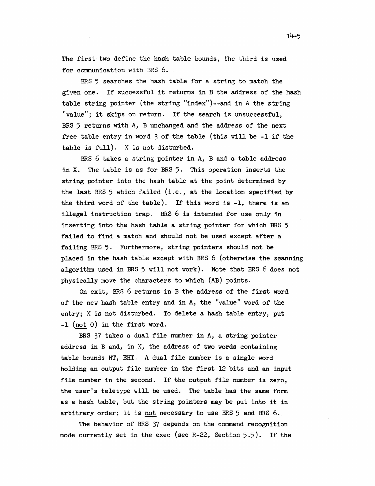
14-5
The
first
two
define
the
hash
table
bounds,
the
third
is
used
for
communication
with
BRS
6.
BRS
5
searches
the
hash
table
for
a
string
to
match
the
given
one.
If
successful
it
returns
in
B
the
address
of
the
hash
table
string
pointer
(the
string
"indextl)--and
in
A
the
string
"value";
it
skips
on
return.
If
the
search
is
unsuccessf'ul,
BRS
5
returns
with
A,
B unchanged and
the
addre s s
of
the
next
free
table
entry
in
word 3
of
the
table
(this
will
be
-1
if
the
table
is
full).
X
is
not
disturbed.
BRS
6
takes
a
string
pointer
in
A,
B and a
table
address
in
X.
The
table
is
as
for
BRS
5.
This
operation
inserts
the
string
pointer
into
the
hash
table
at
the
point
determined
by
the
last
BRS
5 which
failed
(i.e.,
at
the
location
specified
by
the
third
word
of
the
table).
If
this
word
is
-1,
there
is
an
illegal
instruction
trap.
BRS
6
is
intended
for
use
only
in
inserting
into
the
hash
table
a
string
pointer
for
which
BRS
5
failed
to
find
a match and
should
not
be
used
except
after
a
failing
BRS
5.
Furthermore,
string
pointers
should
not
be
placed
in
the
hash
table
except
with
BRS
6
(otherwise
the
scanning
algorithm
used
in
ERS
5
will
not
work). Note
that
BRS
6 does
not
physically
move
the
characters
to
which
(AB)
points.
On
exit,
BRS
6
returns
in
B
the
address
of
the
first
word
of
the
new
hash
table
entry
and
in
A,
the
"value"
word
of
the
entry;
X
is
not
disturbed.
To
delete
a
hash
table
entry,
put
-1
(not
0)
in
the
first
word.
BRS
37
takes
a
dual
file
number
in
A,
a
string
pointer
address
in
B and,
in
X,
the
address
of
two words
conta.ining
table
bounds
HT,
EHT.
A
dual
file
number
is
a
single
word
holding
an
output
file
number
in
the
first
12
bits
and an
input
file
number
in
the
second.
If
the
output
file
number
is
zero,
the
user's
teletype
will
be
used.
The
table
has
the
same
form
as
a
hash
table,
but
the
string
pointers
may
be
put
into
it
in
arbitrary
order;
it
is
~
necessary
to
use
ERS
5 and
BRS
6.
The
behavior
of
BRS
37 depends on
the
command
recognition
mode
currently
set
in
the
exec
(see
R-22,
Section
5.5).
If
the
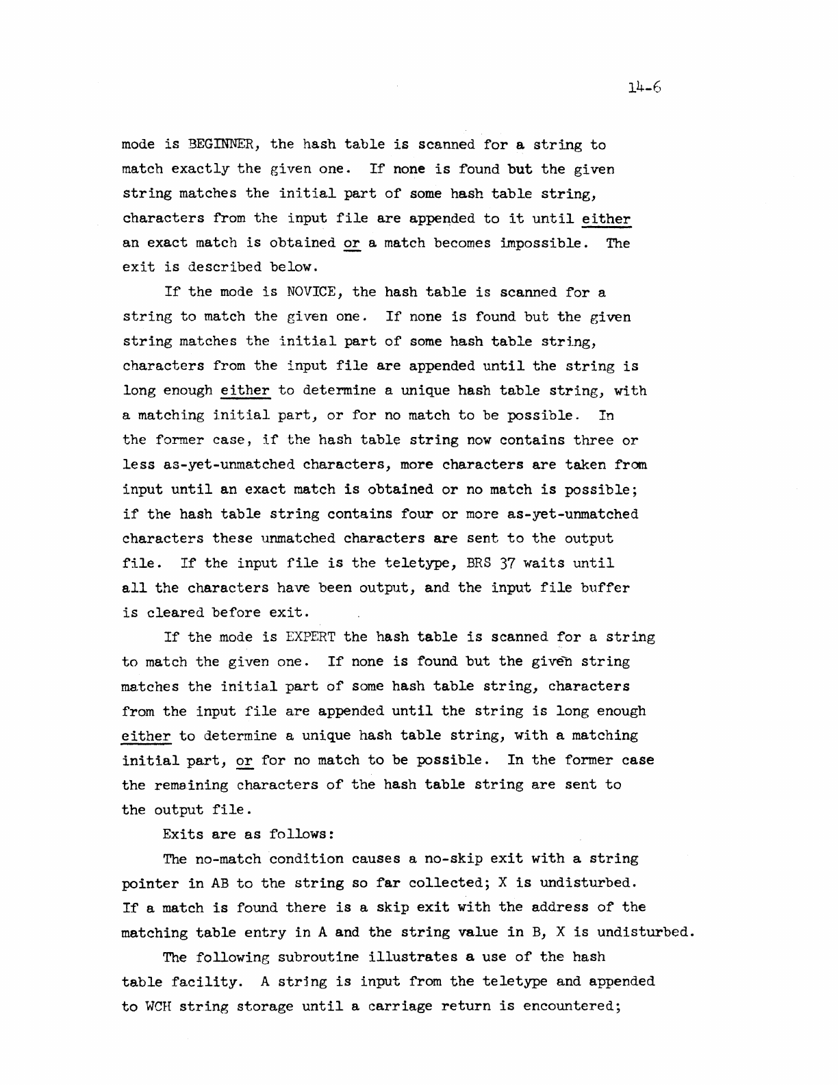
14-6
mode
is
BEGINNER,
the
hash
table
is
scanned
for
a
string
to
match
exactly
the
given
one.
If
none
is
round
but
the
given
string
matches
the
initial
part
of
some
hash
table
string,
characters
from
the
input
file
are
appe~ded
to
it
until
either
an
exact
match
is
obtained
or
a match becomes
impossible.
The
exit
is
described
below.
If
the
mode
is
NOVICE,
the
hash
table
is
scanned
for
a
string
to
match
the
given
one.
If
none
is
found
but
the
given
string
matches
the
initial
part
of
some
hash
table
string,
characters
from
the
input
file
are
appended
until
the
string
is
long
enough
either
to
determine
a
unique
hash
table
string,
with
a
matching
initial
part,
or
for
no
match
to
be
possible.
In
the
former
case,
if
the
hash
tabl~
string
now
contains
three
or
less
as-yet-unmatched
characters,
more
characters
are
taken
from
input
until
an
exact
match
is
obtained
or
no
match
is
possible;
if
the
hash
table
string
contains
four
or
more
as-yet-unmatched
characters
these
unmatched
characters
are
sent
to
the
output
file.
If
the
input
file
is
the
teletype,
BRS
37
waits
until
all
the
characters
have
been
output,
and
the
input
file
buf"fer
is
cleared
before
exit.
If
the
.mode
is
EXPERT
the
hash
table
is
scanned
for
a
string
to
match
the
given
one.
If
none
is
found
but
the
given
string
matches
the
initial
part
of
some
hash
table
string,
characters
from
the
input
file
are
appended
until
the
string
is
long
enough
either
to
determine
a
unique
hash
table
string,
with
a
matching
initial
part,
££
for
no match
to
be
possible.
In
the
former
case
the
rema.ining
characters
of
the
hash
table
string
are
sent
to
the
output
file.
Exits
are
as
follows:
The
no-match
condition
causes
a
no-skip
exit
with
a
string
pointer
in
AB
to
the
string
so
far
collected;
X
is
undisturbed.
If
a match
is
found
there
is
a
skip
exit
with
the
address
of
the
matching
table
entry
in
A and
the
string
value
in
B,
X
is
undisturbed.
The
following
subroutine
illustrates
a
use
of
the
hash
table
facility.
A
string
is
input
from
the
teletype
and appended
to
WCH
string
storage
until
a
carriage
return
is
encountered;
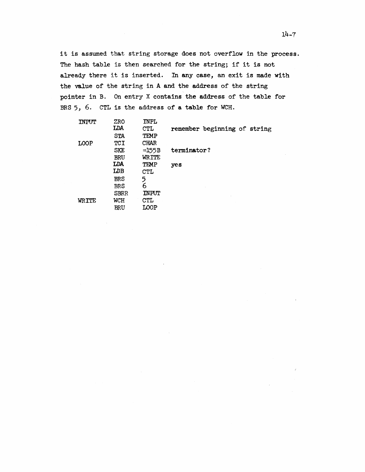
14-7
it
is
assumed
that
string
storage
does
not
overflow
in
the
process.
The
hash
table
is
then
searched
for
the
string;
if
it
is
not
already
there
it
is
inserted.
In
any
case,
an
exit
is
made
with
the
value
of
the
string
in
A
and
the
address
of
the
string
pointer
in
B.
On
entry
X
contains
the
address
of
the
table
for
BRS
5, 6.
CTL
is
the
address
of
a
table
for
WCH.
INPUT
LOOP
WRITE
ZRO
LDA
STA
TCl
SKE
BRU
LDA
LDB
BRS
BRS
SBRR
WCH
BRU
INPL
CTL
remember
beginning
of
string
TEMP
CHAR
=l55B
terminator?
WRITE
TEMP
yes
CTL
5
6
INPUT
CTL
LOOP
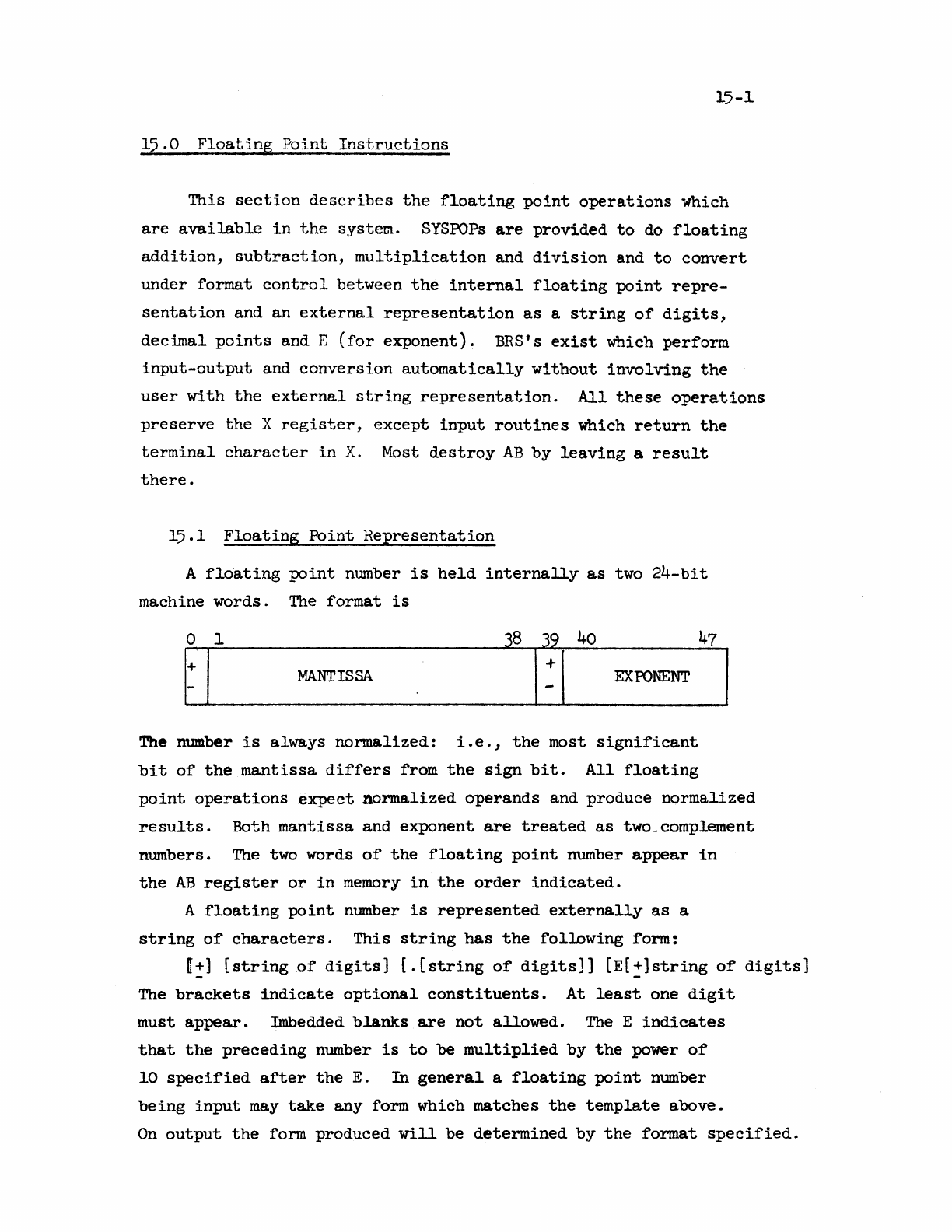
15-1
15.0
Floating
Point
Instructions
This
section
describes
the
floating
point
operations
which
are
available
in
the
system.
SYSPOPs
are
provided
to
do
floating
addition,
subtraction,
multiplication
and
division
and
to
convert
under
format
control
between
the
internal
floating
point
repre-
sentation
and an
external
representation
as
a
string
of
digits,
decimal
points
and E
(for
exponent).
BRS's
exist
which
perform
input-output
and
conversion
automatically
without
involving
the
user
with
the
external
string
representation.
All
these
operations
preserve
the
X
register,
except
input
routines
which
return
the
terminal
character
in
X.
Most
destroy
AB
by
leaving
a
result
there.
15.1
Floating
Point
Representation
A
floating
point
number
is
held
internally
as
two
24-bit
machine
words.
The
format
is
MANTISSA
3813_:140
471
_ _
EXPONENT
o 1
The number
is
always
normalized:
i.e.,
the
most
significant
bit
of
the
mantissa
differs
from
the
sign
bit.
All
floating
point
operations
expect
normalized
operands
and produce
normalized
results.
Both
mantissa
and exponent
are
treated
as
two_complement
numbers.
The
two words
of
the
floating
point
number
appear
in
the
AB
register
or
in
memory
in
the
order
indicated.
A
floating
point
number
is
represented
externa~
as
a
string
of
characters.
This
string
has
the
following
form:
[!]
[string
of
digits]
[.[string
of
digits]]
[E[~]string
of
digits)
The
brackets
.indicate
optional
constituents.
At
least
one
digit
must
appear.
Imbedded
blanks
are
not
allowed.
The
E
indicates
that
the
preceding
number
is
to
be
multiplied
by
the
power
of
10
specified
after
the
E.
In
general
a
floating
point
number
being
input
may
take
any form which matches
the
template
above.
On
output
the
form produced
will
be
determined
by
the
format
specified.
15-2
15.2
Floating
Fbint
Arithmetic
There
are
four
SYSPOPs
to
perform
floating
point
arithmetic.
Each
of
these takes
one
operand
from
AB
and
the
other
from M and
M+l
where M
is
the
effective
address
of
the
instruction.
The
result
is
left
in
AB
in
normalized
form.
If
its
magnitude
is
greater
than
5.7896044E+76,
the
overflow
indicator
will
be
turned
on and
this
value
will
be
returned.
The
overflow
indicator
is
not
cleared
by
any
of
these
instructions.
In
this
respect
the
floating
point
POPs
behave
exactly
like
the
integer
machine
instructions:
a sequence
of
operations
can
be performed
before
the
overflow
bit
is
tested.
The
bit
will
be on
if
any
operation
caused
an
overflow.
If
the
r.esult
is
less
than
O.8036l6E-77,
it
will
be
set
to
O.
No
indication
will
be
given.
The
four
operations
are:
FAD
Floating
add
FSB
Floating
subtract
FMP
Floating
multiply
FDV
Floating
divide
An
attempt
to
divide
by
0
will
produce
an
overflow.
Two
SYSPOPs
are
provided
for
loading
and
storing
double
words.
The
words
involved
need
not
be
floating
point
numbers,
of
course.
wad
pbinter:
LDP
M
puts
the
contents
of
M and
M+
1
into
AB.
Store
pointer:
STP
M
puts
the
contents
of
AB
into
M and
M+l.
Three BRS's
provide
for
unary
operations
involving
floating
point
numbers.
Floating
negate:
BRS
21
returns
in
AB
the
negative
of
the
floating
point
number
supplied
in
AB.
Fix:
BRS
50
converts
into
a double
precision
fixed
point
number.
The
integer
part
appears
in
A.
The
fraction
part
appears,
left
justified,
in
B.
If
the
integer
is
too
large,
the
most
significant
bits
will
be
lost.
The
integer
part
is
the
next
smaller
integer.
I.e.,
IP(-1.2)=-2.
Float.
BRS
51
converts
the
integer
in
A
to
a
normalized
floating
point
number
in
AB.
15-3
15.3
Input/Output
Formats
and
Conventions
Every
1/0
operation
allows
the
user
to
specify
a
format
in
the
X
register.
Format
specifications
are
based
on
Fortran
conventions,
and
are
specified
as
follows:
Bit
of
X
Field
Name
0-2
T
3-8 D
9-14 w
15
0
16-23 N
Examples:
F6.3
E17·9
15
Significance
Format
types:
1
integer.
2 E
format
with
the
number
right
justified
within
the
specified
field.
3 F
format
with
the
number
right
justified
within
the
specified
field.
4 E
format
with
the
number
left
justified
within
the
specified
field.
5 F
format
with
the
number
left
justified
within
the
specified
field.
Number
of
digits
following
the
decimal
point.
Total
field
width
If
the
field
width
is
0,
the
1/0
will
be done
in
free
format.
Overflow
action.
1/0
file
number. 0
always
refers
to
the
teletype.
ISC
and
SIC
ignore
this
field.
30306000
21121000
1000)000
On
input
only
the
Wand
N
fields
are
significant.
Note
that
exactly
W
characters
w111
be
read
on
input
(unless
W=O).
Leading
blanks
and
any
trailing
characters
are
ignored.
Free
format
input
will
accept
as
many
characters
as
it
can
in
constructing
a
number which
fits
the
external
representation
described
above.
The
input
operations
always
return
a
floating
point
result.
They
skip
unless
overflow
occurs,
in
which
case
they
return
the
largest
possible
nwnber and do
not
skip.
Any number
of
digits
may
be
provided:
the
first
11
digits
after
any
leading
zeros
will
be
the
ones
used.
On
output
the
W
field
should
be
made
large
enough
to
accommodate
Sign,
dec~al
point,
E,
sign
of
exponent
and
exponent
(if
the
format
type
requires
any
of
these
elements)
as
well
as
the
digits
of
the
number
it.self.
Sec
the
discussion
01
error
conditions
belOi'T.
Tht:
sign
is
printed
only
if
the
number
is
negative.
There
are
two
ways
to
output
an
integer:
(1)
integer
format,
or
(2)
F
format
with
0
in
the
D
field.
The
former
requires
that
the
number
in
the
A
register
be
in
integer
form;
the
latter
expects
a
floating
point
number
in
AB.
Free
format
output
generates
between 11 and
16
chara.cters.
If
the
magnitude
of
the
number
is
between
lEO
and lE9,
ten
digits
are
output
with
the
decimal
point
properly
placed.
Otherwise,
exponential
format
is
used;
in
particular,
the
format
E15.9.
For
example,
the
following
numbers
might
be
generated
by
the
free
format
output.
5.379605400 -145362.59h7 5.789604462E+76
15.4
Input/Output
Operations
Two
SYSPOPs
are
available
to
convert
between
the
internal
binary
representation
of
a
floating
point
n1h~ber
and
its
external
decimal
representation
as
s.
string
of
characters.
The
string
is
stored
nnd
addressed
according
to
the
standard
system
conventions.
String
to
internal
conversion
(SIC):
Characters
are
read
from
the
string
pointer
addressed
by
the
pop
under
control
of
the
format
in
X.
The
internal
representation
of
the
number
is
returned
in
AB.
The
first
character
after
the
number
is
returned
in
X
if
free
format
was
specified.
Internal
to
string
conversion
(ISC):
The
number
in
AB
is
converted
according
to
the
format
in
X and
the
resulting
external
represen-
tation
is
written
onto
the
end
of
the
string
addressed
by
the
POP.
The
string
pointer
is
updated.
Two
BRS's
are
available
to
do
input/output
and
conversion
at
the
same
time:
Floating
input:
BRS
52.
Input
takes
ple.ce
according
to
the
format
word
in
X.
The
operation
of
this
BRS
is
identical
to
that
of
SIC.
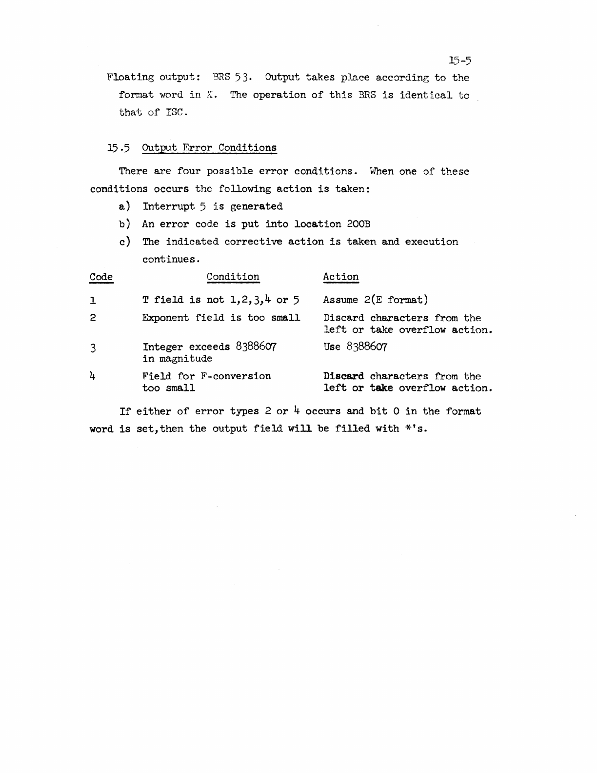
15-5
Floating
output:
"BRS
53. Output
takes
place
according
to
the
format
word
in
X.
The
operation
of
this
BRS
is
identical
to
that
of
ISC.
15.5 Output
Error
Conditions
There
are
four
possible
error
conditions.
~Vhen
one
of
these
conditions
occurs
the
following
action
is
taken:
Code
1
2
3
4
a)
Interrupt
5
is
generated
b)
An
error
code
is
put
into
location
200B
c)
The
indicated
corrective
action
is
taken
and
execution
continues.
Condition
T
field
is
not
1,2,3,4
or
5
Exponent
field
is
too
small
Integer
exceeds
8388607
in
magnitude
Field
for
F-conversion
too
small
Action
Assume
2(E
format)
Discard
characters
from
the
left
or
take
overflow
action.
Use
8388607
Discard
characters
from
the
left
or
take
overflow
action.
If
either
of
error
types
2
or
4
occurs
and
bit
0
in
the
format
word
is
set,
then
the
output
field
will
be
filled
with
*'s.
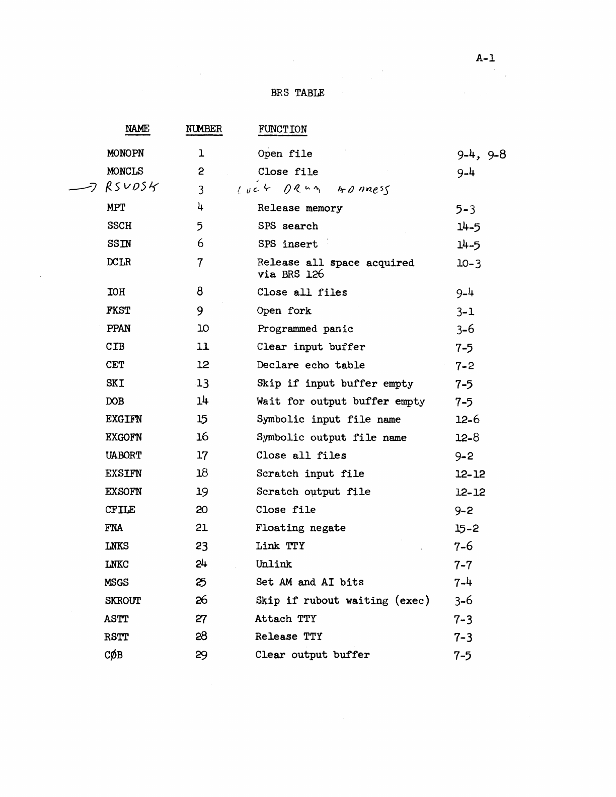
A-I
BRS
TABLE
NAME
NUMBER
FUNCTION
---
MONOPN
I
Open
file
9-4, 9-8
MONCLS
2 Close
file
9-4
---7
{<.svD5Jf 3 (
IJ
c.-
Iy-.
O~fA"1
t.r
IJ
'}~e
~S
MPl' 4
Release
memory
5-3
SSCH
5
SPS
search
14-5
SSIN
6
SPS
insert
14-5
DCLR
7
Release
all
space
acquired
10-3
via
BRS
126
IOH
8 Close
all
files
9-4
FKST
9
Open
fork
3-1
PPAN
10
Progrwmmed
panic
3-6
CIB
11
Clear
input
buffer
7-5
CET
12
Declare
echo
table
7-2
SKI
13
Skip
if
input
buffer
empty 7-5
OOB
14
Wait
for
output
buffer
empty 7-5
EXGIFN
15
Symbolic
input
file
name
12-6
EXGOFN
16
Symbolic
output
file
name
12-8
UABORT
17
Close
all
file
s 9-2
EXSIFN
18
Scratch
input
file
12-12
EXSOFN
19
Scratch
o~tput
file
12-12
CFILE
20
Close
file
9-2
FNA
21
Floating
negate
15-2
LNKS
23
Link
TTY
7-6
LNKC
24
Unlink 7-7
MSGS
25
Set
AM
and AI
bits
7-4
SKROUT
26
Skip
if
rubout
waiting
(exec)
3-6
ASTT
'Z7
Attach
TTY
7-3
RSTT
28
Release
TTY
7-3
C~B
29
Clear
output
buffer
7-5
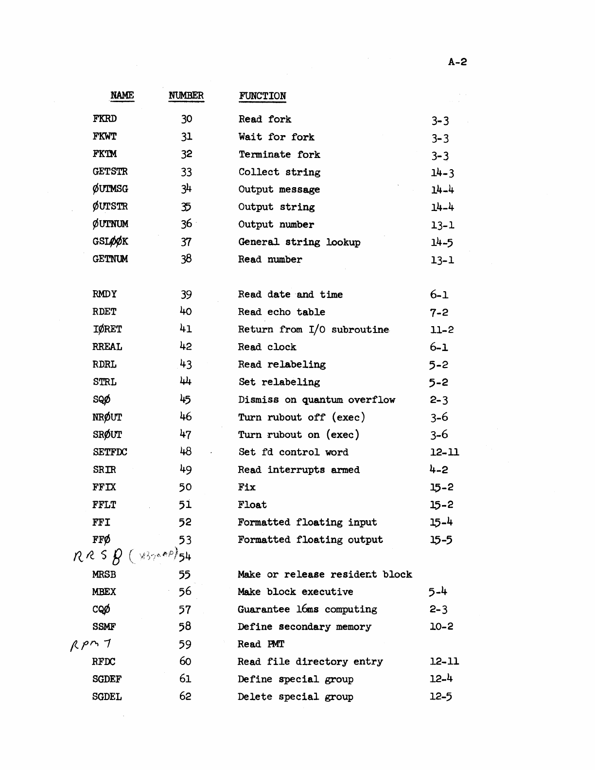
A-2
NAME
NUMBER
FUNCTION
FKRD
30
Read
fork
3-3
FKWT
31
Wait
for
fork
3-3
FK'lM
32
Terminate
fork
3-3
GETSTR
33
Collect
string
14-3
~t11'MSG
34
Output message 14-4
¢urSTR
35
Output
string
14-4
¢UTNUM
36
. Output number 13-1
GSI.¢¢K
37
General
string
lookup
14-5
GETNUM
38
Read number 13-1
RMDY
39
Read
date
and time 6-1
RDET
40
Read echo
table
7-2
I¢RET
41
Return from I/O subroutine·
11-2
RREAL
42
Read
clock
6-1
RDRL
43
Read
relabeling
5-2
STRL
44
Set
relabeling
5-2
SQ~
45
Dismiss on quantum
overflow
2-3
NR~UT
46
Turn
rubout
off
(exec) 3-6
SR~UT
47
Turn
rubout
on (exec) 3-6
SETFDC
48
Set
fd
control
word 12-11
SRIR
49
Read
interrupts
armed 4-2
FFIX
50
Fix
15-2
FFLT
51
Float
15-2
FFI
52
Formatted
floating
input
15-4
FF¢
53
Formatted
floating
output
15-5
((I(
S B (
~P)54
MRSB
55
Make
or
release
resider.t
block
MBEX
56
Make
block
executive
5-4
C~
57
Guarantee
16ms
computing 2-3
SSMF
58
Define secondary
memory
10-2
f'..pA 1
59
Read
mT
RFDC
60
Read
file
directory
entry
12-11
SGDEF
61
Define
special
group 12-4
SGDEL
62
Delete
special
group
12-5
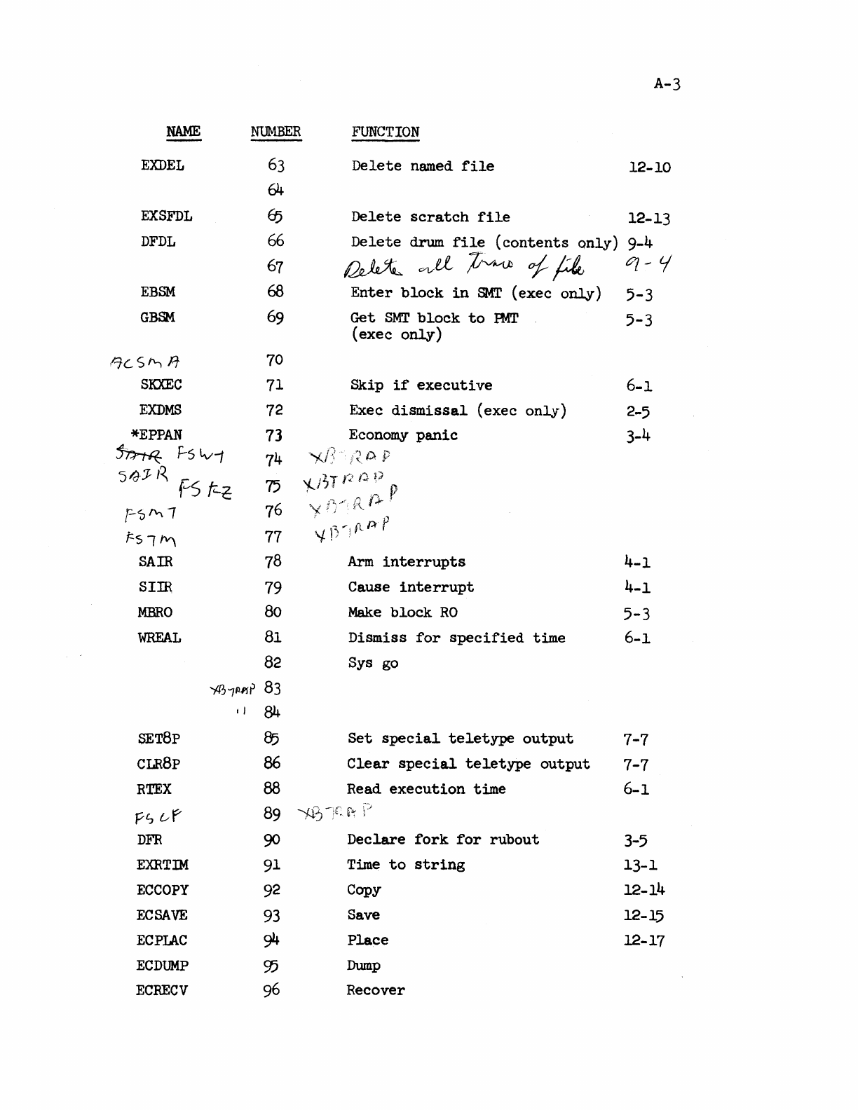
NAME
NUMBER
EXDEL
63
64
EXSFDL
65
DFDL
66
67
EBSM
68
GBSM
69
/::;c
S
""
A
70
SKXEC
71
EXDMS
72
*EPPAN
73
~
t:-s
Lvi
74
S/J:J
I~
-
f"S
fr-~
75
f-'5
""
-,
76
f:.sl~
77
SAIR
78
SIm
79
MBRO
80
WHEAL
81
82
'f.0~/AAr
83
.,
84
SET8p
85
CLR8p 86
A-3
FUNCTION
Delete
named
file
12-10
Delete
scratch
file
12-13
Delete
drum
file
(contents
only)
9-4
~
V'l/d
;C~
of
~
q -tj'
Enter
block
in
SMT
(exec
only)
5-3
Get
SMT
block
to
PMT
5-3
(exec
only)
Skip
if
executive
6-1
Exec
dismissal
(exec
only)
2-5
Economy
panic
3-4
'Ai]
OP
'/...J~JP()~)
""
r:r
P
't
1)
':
fl/)-
f
Arm
interrupts
Cause
interrupt
Make
block
RO
Dismiss
for
specified
time
Sys
go
Set
special
teletype
output
Clear
special
teletype
output
4-1
4-1
5-3
6-1
RTEX
FS
uf
DFR
88
Read
execution
time
7-7
7-7
6-1
EXRTIM
ECCOPY
ECSAVE
ECPIAC
ECDUMP
ECRECV
89
;4?) -;r
f~
90
Declare
fork
for
rubout
91
92
93
94
95
96
Time
to
string
Copy
Save
Place
Dump
Recover
3-5
13-1
12-14
12-15
12-17
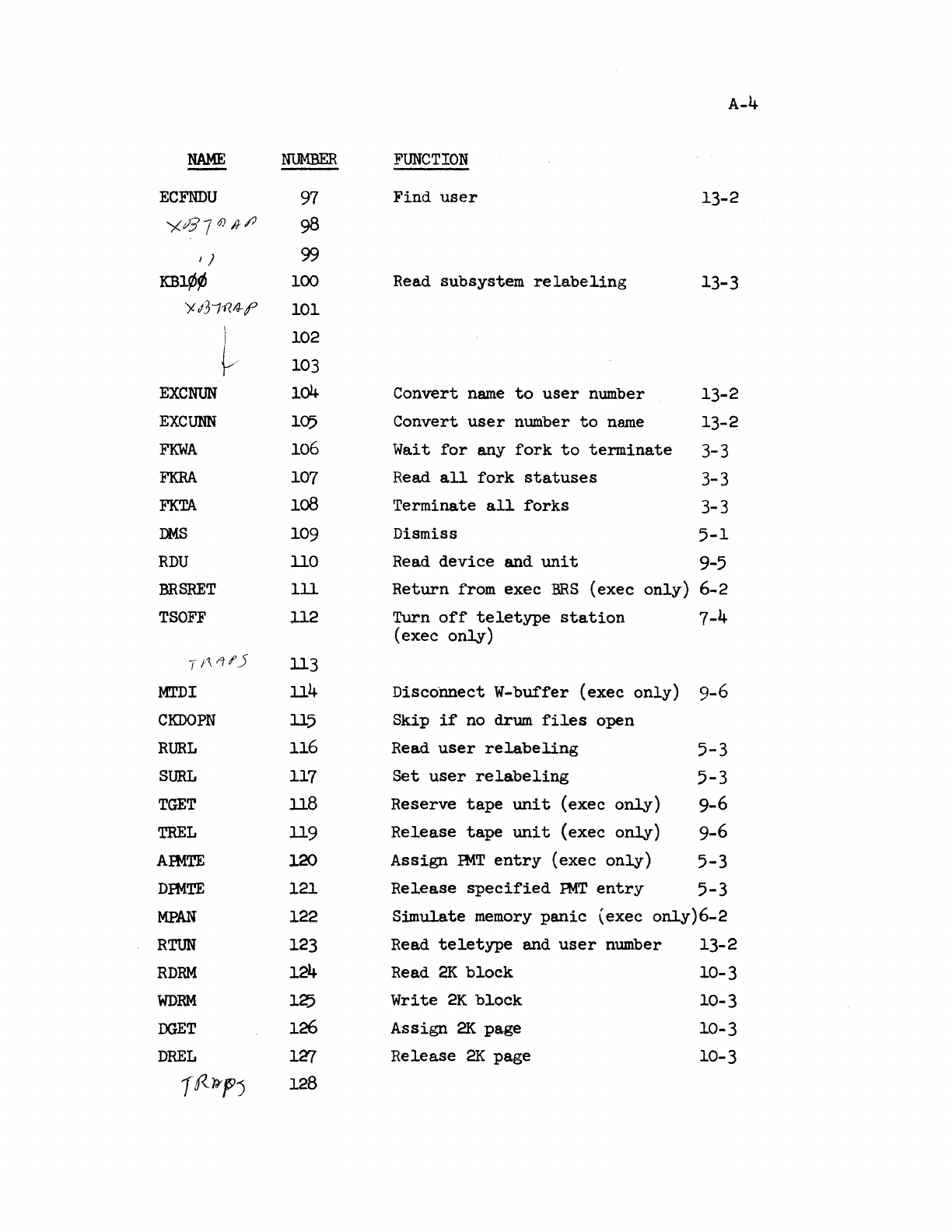
NAME
I J
KB1¢¢
EXCNUN
EXCUNN
FKWA
FKRA
FKTA
DMS
RDU
BRSRET
TSOFF
MTDI
CKDOPN
RURL
SURL
TGET
TREL
AIMTE
DmTE
MPAN
RTUN
RDRM
WDRM
DGET
DREL
)
~/
f«.~f)
NUMBER
97
98
99
100
102
103
104
105
106
107
loB
109
110
III
112
113
114
115
116
117
118
119
120
121
122
123
124
125
126
1'Zl
128
A-4
FUNCTION
Find
user
13-2
Read subsystem
relabeling
Convert
name
to
user
number
Convert
user
number
to
n~e
Wait
for
any
fork
to
terminate
Read
all
fork
statuses
Terminate
all
forks
13-3
13-2
13-2
3-3
3-3
3-3
Dismiss
5-1
Read
device
and
unit
9-5
Return
from exec
BRS
(exec
only)
6-2
Turn
off
teletype
station
7-4
(exec
only)
Disco"nnect W-buffer
(exec
only)
9-6
Skip
if
no drum
files
open
Read
user
relabeling
5-3
Set
user
relabeling
5-3
Reserve
tape
unit
(exec
only)
9-6
Release
tape
unit
(exec
only)
9-6
Assign
PMT
entry
(exec
only)
5-3
Release
specified
PMT
entry
5-3
S~ulate
memory
panic
{exec
only)6-2
Read
teletype
and
user
number
13-2
Read
2K
block
10-3
Write
2K
block
Assign
2K
page
Release
2K
page
10-3
10-3
10-3
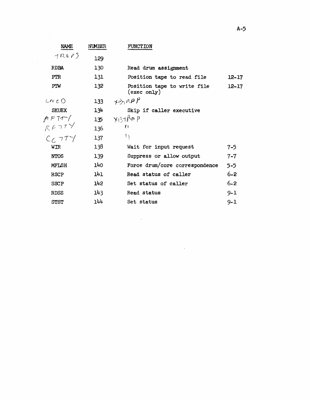
A-5
NAME
NUMBER
FUNCTION
,RQ--
fl5
129
RDBA
130
Read drum
assignment
Pm
131
Position
tape
to
read
file
12-17
PTW
132
Position
tape
to
write
file
12-17
(exec
only)
LfV
e:
[)
133
jJ1-1
i\P
f
SKUEX
134-
Skip
if
caller
executive
fr
Pl
cJ
/
fl
135
'i
!1:,1
"R-
P
/(--TY
I .
~~I
F,
/'
I.
136
fl
Celli
137
'l
'J
WIR
138
Wait
for
input
request
7-5
NTOS
139
Suppress
or
allow
output
7-7
MFLSH
140
Force drum/core
correspondence
5-5
RSCP
141
Read
status
of
caller
6-2
SSCP
142
Set
status
of
caller
6-2
RDSS
143
Read
status
9-1
STST
144
Set
status
9-1
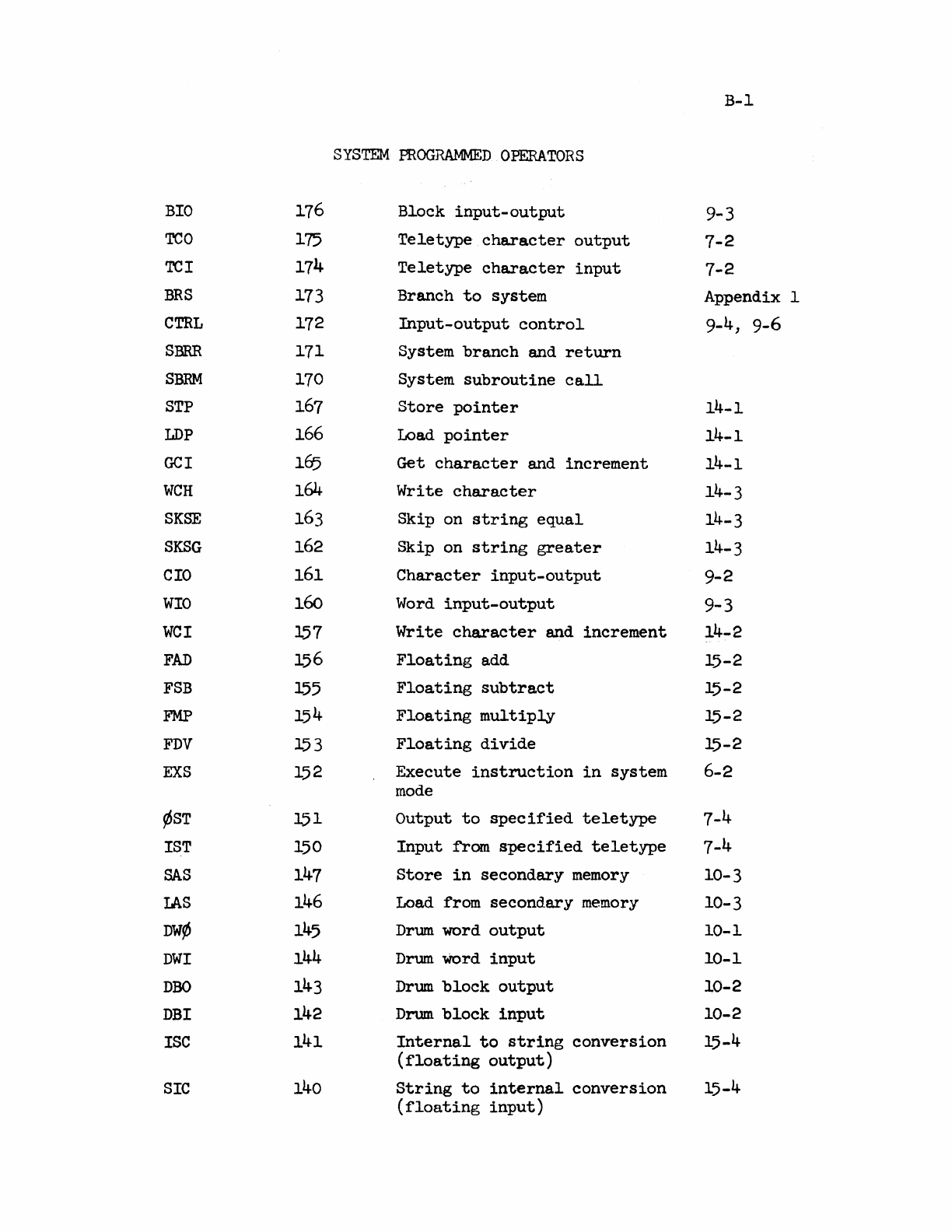
BIO
TCO
TCI
BRS
CTRL
SBRR
SBRM
STP
LDP
GCl
WCH
SKSE
SKSG
CIO
WIO
WCI
FAD
FSB
FMP
FDV
EXS
~ST
1ST
SAS
LAS
DW¢
DWI
DBC
DBI
ISC
SIC
116
175
114
173
172
171
170
167
166
165
164
163
162
161
160
157
156
155
154
153
152
151
150
147
146
145
144
143
142
141
140
SYSTEM
PROGRAMMED
OPERATORS
Block
input-output
Teletype
character
output
Teletype
character
input
Branch
to
system
Input-output
control
System
branch
and
return
System
subroutine
call
Store
pointer
Load
pointer
Get
character
and
increment
Write
character
Skip on
string
equal
Skip on
string
greater
Character
input-output
Word
input-output
Write
character
and
increment
Floating
add
Floating
subtract
Floating
multiply
Floating
divide
Execute
instruction
in
system
mode
Output
to
specified
teletype
Input
from
specified
teletype
Store
in
secondary
memory
Load from
secondary
memory
Drum
word
output
Drum
Word
input
Drum
block
output
Drum
block
input
Internal
to
string
conversion
(floating
output)
String
to
internal
conversion
(floating
input)
B-1
9-3
7-2
7-2
Appendix 1
9-4,
9-6
14-1
14-1
14-1
14-3
14-3
14-3
9-2
9-3
14-2
15-2
15-2
15-2
15-2
6-2
7-4
7-4
10-3
10-3
10-1
10-1
lO-2
10-2
15-4
15-4
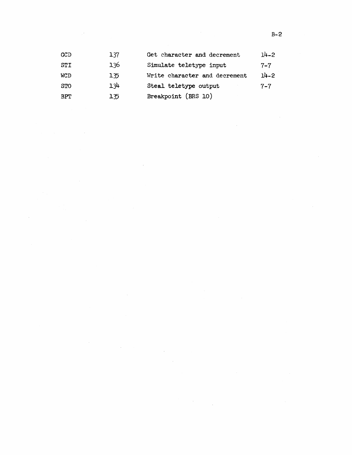
B-2
GCD
137
Get
character
and decrement
14-2
STr
136
S~ulate
teletype
input
7-7
weD
135
\'lri
te
character
and decrement
14-2
STO
134
Steal
teletype
output
7-7
BPI'
135
Breakpoint
(BRS
10)
