SELF CONTAINED CRESCENT CUBER KM 250BWF R404Aguide
User Manual: SELF-CONTAINED CRESCENT CUBER KM-250BWF
Open the PDF directly: View PDF ![]() .
.
Page Count: 214 [warning: Documents this large are best viewed by clicking the View PDF Link!]

This technicians pocket guide covers all mod-
els using R-404A refrigerant. For additional
technical information, full parts and service
manuals are available for review and download
on the Tech Support page of the Hoshizaki web
site.
See “www.hoshizaki.com” for manuals, Tech-
Tips and additional technical information on
Hoshizaki products.
See Tech-Spec’s # 80024 purple pocket guide
for older models using R-12/502.
TECH - SPEC’S
Technician’s Pocket Guide
# 80045
See Tech-Spec’s # 80021 green pocket guide
for newer models using R-22.
These guides can be downloaded from the
Hoshizaki web site or purchased through your
local Hoshizaki Distributor.
1
2/20/03

12/01/02
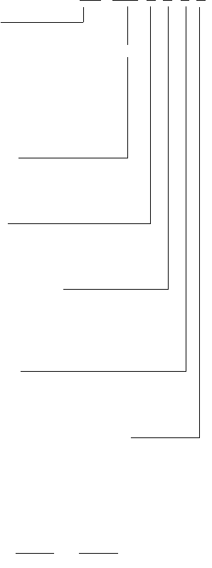
TABLE OF CONTENTS
....................................................................... PAGE
Model Identification Code ........................................ 5
Nameplate .................................................................. 6
Warranty Information, Registration, Coverage ....... 7
KM Installation - General .......................................... 8
Plumbing Requirements (All) ............................. 8
Condensate Drain ............................................. 9
Water Flow Rates (All) ..................................... 9
Electrical Connections ...................................... 10
Optional Transformer Application .................... 11
Remote Applications
Condenser Application Chart R-404A ............. 12
Remote Lines R-404A ...................................... 12
Installation Diagram .......................................... 13
Lineset Installation ............................................ 14
Refrigerant System Information
System Charge R-404A ................................... 15
Cuber Charge Chart R-404A ........................... 16
Condenser Charge Chart ................................. 17
Refrigerant Oil .................................................. 17
Flaker/DCM Charge Chart R-404A ................... 18
Heat Load for AC & Cooling Tower R-404A .... 18
Component Technical Data
“E” Board Setting Guide ................................... 19
Control Board Settings for R-404A................. 20
“E” Control Board Functions ............................ 21
“E” Board Label ................................................ 22
Manual Reset Safeties ..................................... 23
Automatic Voltage Protection ........................... 23
Compressor Data R-404A................................ 24
Head Pressure Controls R-404A ..................... 26
Remote Head Pressure Control ....................... 27
High Pressure Switch Chart ............................ 28
Bin Control (Thermostatic) ............................... 28
Mechanical Control ........................................... 29
Capacitive Control ............................................ 30
F/DCM Control ................................................... 31
KM Sequence of Operation ................................... 32
Sequence Flow Chart ...................................... 34
KM 10 Minute Check Out ................................. 35
Reservoir Flush System ................................... 37
Pumpout Check Valve ...................................... 37
KML Pumpout .................................................... 37
KM Control Switch ........................................... 37
Control Board Fuse .......................................... 38
Component Checks
Float Switch ..................................................... 40
Thermistor ........................................................ 41
2
12/20/03
2/20/03

12/01/02
Component Checks PAGE
Control Board ................................................... 42
Thermostatic Bin Control .................................. 44
Mechanical Bin ................................................. 44
Capacitive Bin Control ...................................... 45
F/DCM Bin Control ............................................ 46
KM Control Transformer ................................... 47
KM Pump Assembly .......................................... 48
Inlet Water Valve .............................................. 50
Diagnosing Water Problems ................................. 52
Freeze Up Check List ....................................... 55
Preventative Maintenance................................ 57
Cleaning/Sanitizing Procedure ......................... 58
KM Production Check ....................................... 59
Cuber Water/Refg Circuit Reference Chart .......... 60
Performance Data KM-150BAF ............................. 73
KM-150BAF-E ................................................... 74
KM-250B_F ....................................................... 75
KM-280M_F/H ................................................... 76
KM-280M_F-E, KM-280MAH ............................ 77
KML250M_H ..................................................... 78
KML-350M_F/H ................................................. 79
KM-350MWH Serial M3~ ................................... 80
KML-450M_F/H ................................................. 81
KML-450MWH Serial M2~ ................................. 82
KM-500M_F/H ................................................... 83
KM-500MWH Serial M30961D~ ........................ 84
KM-500MAF-E/H-E ........................................... 85
KML-600M_F/H ................................................. 86
KM-630M_F/H ................................................... 87
KM-630MWH Serial M2 ..................................... 88
KM-630M_F-E, KM-630MAH-E ......................... 89
KM-900M_F/H ................................................... 90
KM-900MWH Serial M3~ ................................... 91
KM-900MRF3/H3 ............................................... 92
KM-1300S_F/H ................................................. 93
KM-1300S_F3/H3 ............................................. 94
KM-1300NRF/H ................................................. 95
KM-1300M_F/H ................................................. 96
KM-1300S_F-E ................................................. 97
KM-1600MRF/H ................................................. 98
KM-1600MRF3/H3 ............................................ 99
KM-1600SRF/H ................................................ 100
KM-1600SRF3/H3 ............................................ 101
KM-1800SAH ................................................... 102
KM-1800SAH3 ................................................. 103
KM-2000S_F3 .................................................. 104
KM2400SRF3 ................................................... 105
3
12/20/03
2/20/03

12/01/02
PAGE
KM Wiring Diagram
10-Pin Connector ............................................ 106
Reference Chart R-404A ............................... 107
Flaker/DCM
Installation - General ....................................... 141
Internal Auger Design ...................................... 142
Component Technical Data
Control Transformer ........................................ 143
Gear Motor Protection & Checkout ................. 143
Auger Bearings & Inspection .......................... 146
Auger inspection & Bearing Replacement ...... 147
Flaker Safety’s ........................................................ 148
Dual Float Switch ............................................ 149
Flaker Water FIll System .................................. 151
Flaker Timer Board .......................................... 152
Flaker Sequence of Operation ........................ 153
Flaker Sequence Flow Chart .......................... 154
Flaker Periodic Flush ....................................... 155
DCM Sequence of Operation .......................... 155
F/DCM Production Check ................................. 155
Flush /Low Water Safety Flow Chart ............ 156
F/DCM Water/Refg Circuit Referance Chart.. ....... 157
Performance Data Flaker/DCM
F-300BAF ........................................................ 167
F-450MAF/H, MAF-C/H-C ................................ 168
F-500BAF, BAF-C ........................................... 169
F-800M_F/H ..................................................... 170
F-800M_F-C/H-C .............................................. 171
F-1000M_F ...................................................... 172
F-1000M_F-C ................................................... 173
F-1000MLF/MLF-C ........................................... 174
F-1000MAF-22 ................................................ 175
F-1000M_F-50 ................................................. 176
F-1001M_H ...................................................... 177
F-1001M_H-C .................................................. 178
F-1001MLH/MLH-C .......................................... 179
F-2000M_F/H ................................................... 180
F-2000M_F-C/H-C ........................................... 181
F-2000MRF3/H3, MRF3-C/H3-C ...................... 182
F-2000MLF/H, MLF-C/H-C ............................... 183
DCM-240BAF ................................................... 184
DCM-270BAH .................................................. 185
DCM-500BAF/H ............................................... 186
DCM-750B_F/H ................................................ 187
F/DCM Wiring Diagram Reference Chart ........... 188
4
12/20/03
2/20/03
12/01/02
KM
1300 S A F-E
5
HOSHIZAKI MODEL NUMBER
IDENTIFICATION CODE
UNIT TYPE
KML - Low Profile Crescent Cuber
KM - Crescent Cuber
F - Flaker
DCM - Dispenser Cubelet Maker
DB - Dispenser Bin
B- Bin
DM - Countertop Dispenser
PRODUCTION
Approximate production/24 Hours
@70°F Air/50°F Water
UNIT STYLE
M- Modular
S- Stackable
B - Self contained with bin
CONDENSER STYLE
A - Air cooled
W - Water cooled
R - Remote air cooled
GENERATION
Model designation
F= R404A refrigerant unit
H= R404A and rounded front
SPECIAL MODEL DESIGNATION
C- Cubelet
E - European
50- 50 HZ.
The model number, serial number, electrical
specifications and refrigerant data are found on
the unit name plate. (See name plate)
12/20/03
2/20/03
12/01/02
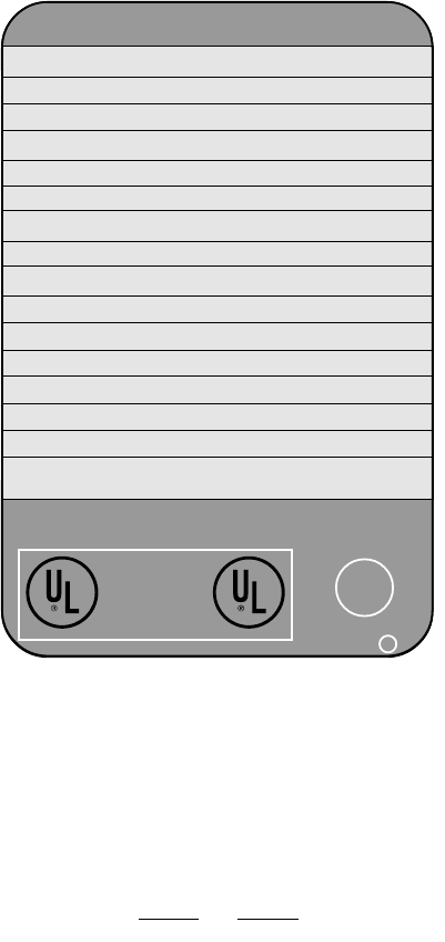
NAMEPLATE
HOSHIZAKI ICE MAKER
MODEL NUMBER
SERIAL NUMBER
AC SUPPLY VOLTAGE
COMPRESSOR
FAN
MAXIMUM FUSE SIZE
MAX. HACR BREAKER (USA ONLY)
MAX. CIRC. BREAKER (CANADA ONLY)
MINIMUM CIRCUIT AMPACITY
DESIGN PRESSURE
REFRIGERANT
MOTOR-COMPRESSOR THERMALLY PROTECTED
See the Nameplate for electrical and refrigeration specifi-
cations. This Nameplate is located on the upper right hand
side of rear panel. Since this Nameplate is located on the
rear panel of the icemaker, it cannot be read when the back
of the icemaker is against a wall or against another piece of
kitchen equipment. Therefore, the necessary electrical and
refrigeration information is also on the rating label, which
can be easily seen by removing only the front panel of the
icemaker. We reserve the right to make changes in speci-
fications and design without prior notice.
LISTED
ICE MAKER
WITHOUT
STORAGE MEANS
946Z
NSF
®
COMPONENT
v
C
HOSHIZAKI AMERICA, INC.
Peachtree City, GA
6
12/20/03
2/20/03

12/01/02
WARRANTY INFORMATION
REGISTRATION-
Two warranty registration cards are supplied with the
equipment. They must be completed and sent in to initiate
warranty. The warranty begins on the date of installation if
registration procedures are followed. If registration is not
completed, the warranty date will be the date of sale or
date of shipment from the factory, respectively.
WARRANTY COVERAGE-
The warranty will cover defects in material or workman-
ship under normal and proper use and maintenance
service as specified by Hoshizaki. Coverage for parts and
labor is limited to the repair or replacement of parts or
assemblies that in Hoshizaki's opinion are defective.
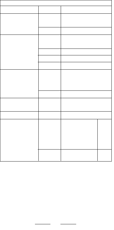
COVERAGE CHART-
ITEM PRODUCT PARTS LABOR
Total Unit KM Cuber 3 Years 3 Years
F/DCM 1 Year 1 Year
B/DB/DM 2 Years 2 Years
Bev. Valves 1 Year 1 Year
Compressor & Air- KM Cuber 5 Years 3 Years
Cooled Condenser F/DCM 5 Years 2 Years
Evaporator Plate KM Cuber 5 Years 5 Years
Evaporator, Auger
Gear Motor Assy. F/DCM 2 Years 2 Years
Effective January 1, 1991
See Warranty Statement supplied with the unit for details.
Warranty valid in United States, Canada, Mexico, Puerto
Rico, and U. S. Virgin Islands.
Contact factory for warranty in other countries, territories,
or possessions.
7
12/20/03
2/20/03

12/01/02
KM INSTALLATION
GENERAL -
The ice machine is not intended for outdoor use.
OPERATING CONDITIONS - ALL MODELS
ITEM MODEL RANGE
Voltage Range 115V units 104 - 127V.
208-230 V units 187 - 264 V.
220-240 or 230V 198 - 254V.
Ambient Temperature All 45 - 100 Deg. F.
Remote Condenser -20 - 122 Deg. F.
Water Supply Temperature All 45 - 90 Deg. F.
Water Supply Pressure All 10 -113 PSIG
Allow 6" clearance at rear, sides, and top for proper air
circulation and ease of maintenance or service. 20" top
clearance for F/DCM.
PLUMBING REQUIREMENTS -
Water Supply:
On KM units the water supply line size is critical due to
the water assisted harvest and the use of a ported inlet
water valve solenoid.
MODEL Line Size Fitting Size
KM-150 - KM-900 3/8" OD 1/2 FPT
KM-1300 - KM-2400 1/2" OD 1/2 FPT
All F/DCM 3/8" OD 1/2 FPT
*Water cooled condenser units require two separate
supplies sized as per list above.
Drain:
MODEL Line Size Fitting Size
All Bins 3/4" OD 3/4 FPT
All KM/KML’s 3/4" OD 3/4 FPT
Flakers 3/4" OD 3/4 FPT*
DCM 3/4" OD 3/4 FPT*
*Some models have 2 drain outlets.
Water Cooled Condenser outlet:
KM-150BWF, KM-250BWF, KM-1600SWH,
KM-1600SWH3, KM-2000SWH3 have 1/2” FPT outlet.
All other KM models, All KML, All Flaker, All DCM have 3/8”
FPT outlet.
8
12/20/03
2/20/03
12/01/02
Hoshizaki recommends that the ice machine drain and
bin drain be piped separately to the drain connection point
allowing 1/4" per foot fall.
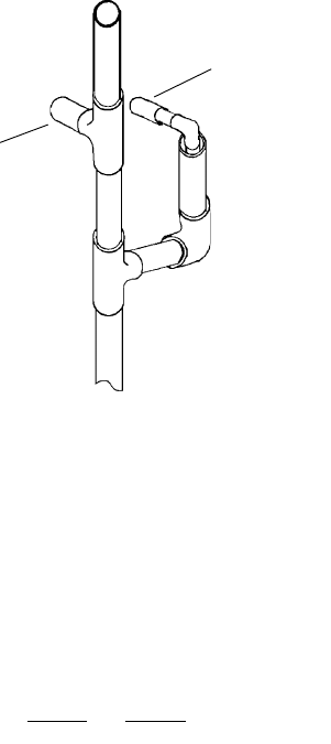
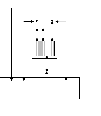
CONDENSATE DRAIN -
The condensate drain is generally connected to the ice
machine drain for simplicity. It can be piped separately to
the drain exit if desired.
A 6" vent tee is recommended as per drawing:
FLOW RATES -
The minimum flow rate requirements for Hoshizaki ice
maker units are as follows:
KM-150/250/280/AII Flakers 1.05 GPM
KM-500 1.58 GPM
KM-630/900/AII DCM's 2.11 GPM
KM-1300/1600 3.96 GPM
KM-2000/2400 4.23 GPM
Use this information when sizing a filter system for the ice
machine application.
NOTE: A good rule of thumb is to utilize a 3 GPM flow rate
filter for KM-150 through 900 and a 5 GPM flow rate filter
for KM-1300 or larger.
Reservoir
Drain
Condensate
Drain
9
12/20/03
2/20/03
12/01/02
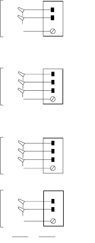
GND
GND
GND
Brown
White
Brown
Black
Red
Brown
White
208-230 VOLT/1PHASE
208-230V/1 Phase units require a dedicated neutral due
to the use of 115V components.
GND
White
Brown
Black
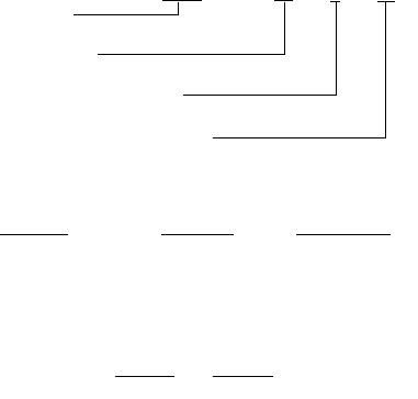
ELECTRICAL CONNECTIONS -
115 VOLT/1 PHASE
115V.
(2 wire
w/gnd)
208-230 VOLT/3 PHASE
If high leg is present connect to black wire.
A transformer can be used to provide 115v control
circuit.
The dedicated
neutral
requires an
insulated
conductor
which runs
directly to the
panel.
208-230V.
(3 wire
w/gnd)
208-230V.
3 phase
(3 wire
w/gnd)
Fan
Control
Circuit
From
Unit
115V.
115V.
115V.
REMOTE CONDENSER CONNECTIONS
115V.
Neutral
115V.
Neutral
115V.
Neutral
115V.
10
12/20/03
2/20/03
12/01/02
Note:
All Electrical connections must be made in accordance
with all national and local electrical codes.
Transformer Application
All 208-230V models include a 115V transformer with a
208/230V selector switch. Be sure to select the position
that best matches the incoming voltage prior to supplying
power to the unit. (Voltage from the center tap to case
ground will be 67.5V due to the transformer circuit.)
208/230V models include 115V controls. They require a
115 / 208-230V circuit which has 4 wires including L1, L2,
dedicated neutral, and ground.
If a dedicated neutral is not available or the previous unit
used a 3 wire circuit, (L1,L2, & gnd.) a step-down trans-
former can be used at the unit to provide power to the
115V components. This will save on installation time and
cost if a dedicated neutral is not present.
Transformer # 4A0817-01 or equivalent can be used for
KM models. Transformer # 446240-01 or equivalent can
be used for F-1000 models. The transformer should be
mounted inside the compressor compartment and wired
using the following generic diagram.
11
L1 N L2
BK W BN
Θ
GND. L1 L2
230V 208V
UNIT
12/20/03
2/20/03
12/01/02
REMOTE APPLICATIONS
CONDENSER CHART
CONDENSER MODEL MODEL NUMBERS
URC-6F KM-500/630MRF, F-1000MRF
URC-7F KML-600MRF
URC-12F KM-900/1300MRF, KM-1300SRF
URC-20F
KM-1600MRF, KM-1600/2000SRF,
F-2000MRF
URC-24F KM-2400SRF
Note: F condensers will be used on either F or H series
units as listed above.
When installing a remote application the unit/condenser
combination must match with the above chart. A non-OEM
multi-pass condenser can be used with prior written factory
approval.
REMOTE LINES-
Hoshizaki has 3 precharged line set lengths. 20 foot, 35
foot, and 55 foot sets are available. The line sets are
available in different line sizes for different models.
LINE SET IDENTIFICATION CODE
R404 -
35 6 10
Refrigerant
Length In Feet
Liquid Line Size in 16th’s
Discharge Line Size in 16th’s
LINE SET APPLICATIONS
MODELS LINE SET LL (SIZE) DL
KML-600,
KM-500/630, F-1000 R404-__46-2 1/4" OD 3/8" OD
KM-900/1300 R404-__68-2 3/8" OD 1/2" OD
KM-1600/2000/2400 R404-__610 3/8" OD 5/8" OD
F-2000 R404-__610 3/8" OD 5/8" OD
12
12/20/03
2/20/03
12/01/02
13
2/20/03

12/01/02
LINE SET INSTALLATION
A universal line set adapter kit, part number OS-QUICK, is
available if you need to field engineer your line set. Both
lines should be insulated separately the entire length of run.
The refrigerant charge for a new unit is distributed between
the unit head and the URC condenser. The line set has a
minimal holding charge of 15 to 30 psig refrigerant vapor.
If you need to field engineer your line set or shorten/
lengthen a precharged line set you can do so by following
these steps:
1. Using the OS-QUICK kit, braze the line set connec-
tions. (If you shorten or lengthen a precharged line
set, recover the holding charge, cut or lengthen and
braze the connections.)
2. Pressurize the lines and leak check all braze joints.
3. Evacuate the lines through the service ports on the
Aeroquip quick connect fittings.
4. Charge both lines with 15 to 30 psig R-404A vapor.
To make Aeroquip connection to the unit head and
condenser:
1. Lubricate the threads and O-ring with clean
refrigerant oil.
2. Tighten the female connector until it bottoms out.
Note: Always use a back up wrench when tightening
these fittings.
3. Then turn an additional 1/4 turn to assure a good
brass to brass seal. Leak check the joints with soap
bubbles or an electronic leak detector.
14
12/20/03
2/20/03

12/01/02
SYSTEM CHARGE - R-404A
The ice machine head and URC condenser are shipped
with enough refrigerant charge for up to 66 feet of line set
length. The maximum line set length is 100 equivalent feet
from the head to the condenser.
For applications longer than 66 ft. up to the maximum 100 ft.
Length, additional refrigerant must be added. For units uti-
lizing 1/4" L.L. and 3/8" D.L., the line size should be in-
creased to 3/8"L.L. and 1/2"D.L. for the entire length of the
run. Add 16.5 ounces plus 0.4 oz. per foot over 66 feet. For
units utilizing 3/8"L.L., add 0,4 oz. per foot over 66 feet.
NOTE:
(1) Recommended line sizes are same as listed in
the line set application chart.
(2) Older models utilize R-502 refrigerant or R-22
refrigerant. Always check the unit nameplate for
the correct refrigerant type.
Do not connect components using different type
refrigerants!
(3) If refrigerant is added due to extended line set
length, mark the correct total charge on the unit
nameplate for future reference.
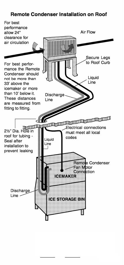
(4) When routing and installing remote lines, always
use standard refrigerant piping practices.
(5) Hoshizaki recommends eliminating any excess
loops in a pre-charged line set application before
making the unit connections. This will eliminate oil
traps and possible crimps in the excess tubing.
(6) A service loop should be included behind the unit
as shown in the illustration on page 13 to allow
the unit to be moved away from the wall if
needed.
CRITICAL CHARGE AMOUNT
The total system charge is critical for proper operation
according to Hoshizaki specification. Always weigh in the
proper charge per the following charge chart. (Remote
units show standard charge good for up to 66 feet.) Unit
charge information is also found on the unit Name Plate.
FOR FACTORY SUPPORT
CONTACT HOSHIZAKI TECHNICAL SUPPORT AT:
1 -800-233-1940
E-Mail: techsupport@hoshizaki.com
15
12/20/03
2/20/03

12/01/02
16
HOSHIZAKI CUBER
REFRIGERANT R-404A CHARGE CHART
NOTE: This Chart represents both F and H series models.
MODEL TOTAL CHARGE REFRIGERANT
KM-150 BAF 10.6 oz. R-404A
BAF-E 11.1 oz. “
BWF 12.7 oz. “
BWF-E 11.6 oz. “
KM-250 BAF 12.7 oz. “
BWF 11 oz. “
KM-280 MAF / MWF & -E 12 oz. “
KML-250 MAH 1 lb. 2 oz. “
MWH 14.1 oz. “
KML-350 MAF 1 lb. 2 oz. “
MWF 13.6 oz. “
KML-450 MAF 1 lb. 5 oz. “
MWF 15 oz. “
KM-500 MAF 1 lb. 10 oz. “
MAF-E 1 lb. 10 oz. “
MWF 13.4 oz. “
MWF-E 13.2 oz. “
MRF 3 lb. 15 oz. “
KML-600 MAF 2 lb. 4 oz. “
MAF-E 1 lb. 6 oz. “
MWF &-E 1 lb. 5 oz. “
MRF 10 lb. 6 oz. “
KM-630 MAF 1 lb. 7.6 oz. “
MWF 1 lb. 3 oz. “
MRF 4 lb. 4 oz. “
KM-900 MAF 3 lb. 7 oz. “
MWF 1 lb. 7 oz. “
MRF1/3 9 lb. 14 oz. “
KM-1300 SAF1/3 & -E 3 lb. 14 oz. “
SWF1/3 & -E 2 lb. 2 oz. “
SRF1/3 & -E 11 lb. 7 oz. “
KM-1300 MAF 4lb. “
MWF 2lb. 3 oz. “
MRF 9lb. 15 oz. “
KM-1300 NRF 11 lb. 7 oz. “
KM-1600 MRF1/3 14 lb. 12 oz. “
KM-1600 SWF1/3 3 lb. 1 oz. “
SRF1/3 14 lb. 12 oz. “
KM-1800 SAH1/3 4 lb. 7 oz. “
KM-2000 SWF3 3 lb. 7 oz. “
SRF3 16 lb. 2 oz. “
KM-2400 SRF3 24 lb. “
NOTE: To convert to grams multiply oz. X 28.35.
12/20/03
2/20/03

12/01/02
17
R-404A URC REMOTE CONDENSERS
(Condenser charge is included in total charge.)
MODEL FACTORY CHARGE REFRIGERANT
URC-6F 1 Lb. 14 Oz. R-404A
URC-7F 2 Lbs. 5 Oz. “
URC-12F 4 Lbs. 7 Oz. “
URC-20F 7 Lbs. 11 Oz “
URC-24F 11 Lbs “
Note: F series condensers are used for both F and H
series remote units.
REFRIGERANT OIL
All R-404A models use Polyol Ester (POE-EAL) oil. POE oil
absorbs moisture easily. Extra care must be taken to re-
duce the possibility of moisture entering the system during
service. If moisture contamination is suspected, the oil
should be changed and the liquid line drier must be re-
placed. Changing the oil requires removal of the compres-
sor so that the oil can be drained and replaced with the
correct amount. See compressor data chart for oil amount.
Replacement compressors are shipped with POE oil.
HOSHIZAKI FLAKERS/DCM’S
REFRIGERANT R-404A CHARGE CHART
NOTE: This Chart represents both F and H series models.
MODEL TOTAL CHARGE REFRIGERANT
F-300 BAF 10.5 oz. R-404A
F-450 MAF 1 lb. “
MWF 12 oz. “
F-500 BAF 1 lb. “
F-800 MAF 1 lb. 10 oz. “
MWF 13 oz. “
F-1000 MAF 1 lb. 12 oz. “
MWF 15 oz. “
MRF 4 lb. 1 oz. “
F-1001 MAF 1 lb. 12 oz. “
MWF 15 oz. “
MRF 4 lb. 1 oz. “
F-2000 MWF 2 lb. “
MRF 14 lb. 9 oz. “
DCM-240 BAF 15.5 oz “
DCM-500 BAF 1 lb. 4.1 oz. “
BWF 13.4 oz. “
DCM-750 BAF 1 lb. 1.7 oz. “
BWF 1 lb. 1.7 oz. “
12/20/03
2/20/03

12/01/02
18
HEAT LOAD - R-404A FLAKERS/DCM’S
MODEL AIR WATER-COOLED
COOLED (CONDENSER ONLY)
F-300B 3178 —-
F-450M 5090 —-
F-500B 4683 —-
F-800M 7500 6270
F-1000M 9050 7110
F-1000M/50 9000 7000
F-1001M 9050 7110
F-2000M —- 15530
DCM-240B 3800 —-
DCM-270B 3532 —-
DCM-500B 6300 5575
DCM-750B 8314 5130
Figures shown are at 90° F air temp. 70° F water temp.
Allow for a pressure diffenential of 7 psi across the
water cooled condenser.
HEAT LOAD FOR R-404A MODELS
The heat of rejection information listed below by model
number should be used for sizing air conditioning equip-
ment or water-cooled cooling tower applications.
CUBERS: AIR WATER-COOLED
MODEL COOLED (CONDENSER ONLY)
KM-150B 3100 2800
KM-150B -E 3400 2900
KM-250BAF 5064 5707
KML-250M 5560 5000
KML-350M 6550 5370
KM-280M & -E 8159 6773
KML-450M 7480 6180
KM-500M 8206 6663
KM-500M -E 7371 6876
KML-600M 11580 12635
KM-630M -E 10375 12635
KM-900M 14800 14400
KM-1300S/M 19800 17150
KM-1300S3 18130 15450
KM-1300S -E 20400 17925
KM-1600SWF —- 18000
KM-1600SWF3 —- 17560
KM-1800SAH 24720 —-
KM-1800SAH3 24150 —-
KM-2000SWF3 —- 22700
12/20/03
2/20/03
12/01/02
“E” Control Board Adjustment Chart
The early “E” boards have 8 dip switches. The latest “E”
boards have 10 dip switches.
NOTE:
1. TO IMPROVE BUILT-IN CLEANING Adjust switches 1&2 to
provide for longer flush and switches 5&6 to every cycle
pump-out 1/1. Do not adjust 1&2 on KM150/250 in high
ambient area.
2. DO NOT ADJUST 3, 4, 7, 8, 9 &10 from factory setting.
3. DO NOT MAKE CONNECTION to the red K-4 terminal
unless a special bin control / red connector is provided.
4. Dip-switches 9&10 are on improved “E” board only. If
original board has 8 dip-swithes, use default setting of
OFF/OFF for 9 & 10. If original board has 10 dip-switches,
match original “E” board settings.
“E” BOARD DIP SWITCH SETTING GUIDE
ADJUSTMENTS DIP # Switch Code
10101
20011
seconds 60 90 120 180
PUMP OUT 3 0 1 0 1
TIME 4 0 0 1 1
seconds 10 10 10 20
seconds 150 180 120 180
status OFF OFF ON OFF
PERIODIC 5 0 1 0 1
PUMP OUT
FREQUENCY 6 0 0 1 1
cycles 1/1 1/2 1/5 1/10
BIN CONTROL 7 OFF for thermostatic contol
SWITCH ON for mechanical control
TEST 8
MAX. FREEZE 9 1 1 0 0
TIME
10 1 0 1 0
(Improved E
board only.) minutes 75/50hz 70 50 60
ALWAYS OFF
1=ON 0=OFF
Length of pump out
Min Defrost Time
Inlet Water Valve
Default
DEFROST
COMPLETION
TIMER
60/60hz
19
12/20/03
2/20/03
12/01/02
MODEL: 1 2 3 4 5 6 7 8 9 10
KM-150BA/W/A-E/W-E 0101000000
KML-250MA0001110010
KM-280MA 1 0 0 1 1 1 0 0 0 0
KM-280MA-E 1 0 0 0 0 0 0 0 1 0
KML-250MW, KML-
350/450/600MA/W 0 0 0 1 1 1 0 0 0 1
KM-280/500MW-E 0 0 0 0 0 0 0 0 0 0
KM-280MWF, 0 0 0 1 1 1 0 0 0 0
KML-350MAF/MWF 0 0 0 1 1 1 0 0 0 1
KM-500MAF,
KM630MAF/MRF 0 0 0 0 1 1 0 0 1 0
KM-500MWF/MRF,
KM-630MWF 0 0 0 0 1 1 0 0 0 0
KM-500MAF-E,
KM-630MAF-E/MWF-E 0000000010
KML-600MRF 1 0 0 0 1 1 0 0 0 1
KM-1300S_F/SWF3,
KM-2000SWF3/SRF3 0 0 1 1 1 1 0 0 0 0
KM-1300SAF-E/SRF-E 0 0 1 1 0 0 0 0 1 0
KM-1300SWF-E 0 0 1 1 0 0 0 0 0 0
KM-1300MAF/MRF 0 0 1 0 1 1 0 0 0 0
KM-1300NRF 0 0 1 1 1 1 1 0 0 0
KM-900M_F/MRF3,
KM-1300MWF,
KM-1600MRF/MRF3 0 0 1 0 1 1 0 0 0 1
KM-1600SRF/SRF3 1 0 1 1 1 1 0 0 0 0
KM-1600SWF3 0 0 1 1 1 1 0 0 0 1
KM-1800SAH 0 0 1 1 1 1 0 0 1 0
KM-2400SRF3 0 0 1 0 0 0 0 0 0 1
SETTING CHART FOR R-404A (F/H) MODELS
Note: The above chart reflects the factory dip-switch set-
tings for models using R-404A refrigerant. Adjustments
may be made to switches 1, 2, 5, & 6 to improve the built-in
cleaning ability as per the DIP SWITCH SETTING GUIDE. If
you replace the control board, match the cleaning settings
with the original board. Switches 3, 4, 7, 8, 9, & 10 must
remain in the factory position.
FACTORY DIP
SWITCH SETTINGS: SWITCH CODE 1=ON 0=OFF
20
KM-250B,
12/20/03
2/20/03

12/01/02
“E” Control Board Functions
An instruction label explaining the “E” board features is in-
cluded somewhere on the unit. You should find it either on
the control box cover, on the inside of the front panel, or
under the top panel. A stick on label is also included with the
service replacement board. If you are replacing an “E” board,
be sure to place the new label over the original label. This
will advise anyone performing future service that the origi-
nal board has been replaced and explain the application
switch as outlined below.
The #2A1410-02 universal replacement board has an appli-
cation switch between relays X3 & X4 that is not included on
the original factory board supplied with the unit. This applica-
tion switch allows this replacement board to be used on older
C and Alpine control board models. The application switch
has 2 positions (C & ALP). On R-404A models, this switch
must be in the ALP position. If the switch is left in the C
position, the compressor contactor will energize as soon as
power is supplied to the unit whether the power switch is ON
or OFF.
There are 4 green LED’s which light in sequence throughout
the unit operation. It is important to note that the green LED’s
are not numbered consecutively. LED1 is located at the edge
of the board beside the K-2 transformer connection. The num-
bering sequence from the outside edge of the board is 1, 4, 3,
and 2.
The green LED’s are also used for a built-in output test which
can be conducted to diagnose a bad board. The label ex-
plains the output test procedure. The correct lighting sequence
for the output test is as follows. When the control switch is
switched ON with the output test switch S-3 ON, after a 5
second delay, LED2 lights. 5 seconds later LED2 goes out
and LED3 lights. 5 seconds later LED3 goes out and LED4
lights. 5 seconds later LED4 goes out and LED1 lights. 5
seconds later LED1 goes out and LED4 lights to begin the
normal sequence of operation. If the LED’s follow this se-
quence, the board is OK. If any other lighting sequence oc-
curs, the board is bad.
A copy of the “E” board label is included on the next page.
Review the board label thoroughly to understand the “E” board
functions.
21
{
12/20/03
2/20/03

12/01/02
22
ATTENTION !
THIS UNIT HAS A CONTROL PRODUCTS IMPROVED “E” CONTROL
BOARD INSTALLED. HOSHIZAKI PART NUMBER 2A1410-01.
The improved “E” board includes LED lights and audible alarm safeties. The
red LED indicates proper control voltage and will remain on unless a control
voltage problem occurs. At startup a 5 second delay occurs while the board
conducts an internal timer check. A short beep occurs when the power
switch is turned “ON” or “OFF”.
The green LED’s 1~4 represent the corresponding relays and energize and
sequence 5 seconds from initial startup as follows:
Sequence Step LED’s on: Length:Min. Max. Avg.
1 Minute Fill Cycle LED 4 60 sec.
Harvest Cycle LED 1, 4, & 2 2 min. 20 min. 3-5 min.
Freeze Cycle LED 1 5 min. 60 min. 30-35 min.
Reverse Pump Out LED 1, 3, & 2 10 sec. 20 sec. Factory set.
{With light on, LED 1 = Comp/RFM; LED 2 = HGV; LED 3 = PM; LED 4 = WV}
Note: LED’s are not numbered consecutively. They are # 1,4,3,2 from board edge.
The built in safeties shut down the unit and have alarms as follows:
1 beep every 3 sec. = High Evaporator Temperature >127° F.
Check for defrost problem (stuck HGV or relay), hot water entering
unit, stuck headmaster, or shorted thermistor.
2 beeps every 3 sec. = Defrost Back Up Timer. Defrost >20 minutes.
Orange LED marked “H Timer” energizes. Check for open
thermistor, HGV not opening, TXV leaking by, low charge, or
inefficient compressor.
3 beeps every 3 sec. = Freeze Back Up Timer. Freeze > Specified Setting
Yellow LED marked “F Timer” energizes. Check for F/S stuck
closed (up), WV leaking by, HGV leaking by, PM not pumping, TXV
not feeding properly, low charge, or inefficient comp. Dip switches 9
& 10 allow for factory adjustment of this back up timer feature.
Note: 2 & 3 beep alarms represent 2 consecutive occurrences.
Additional alarms for mechanical bin switch:
4 beeps every 3 sec. = Short Circuit between the K4 connection on the
control board and the bin control. Check connections and replace
wire harness if necessary.
5 beeps every 3 sec. = Open Circuit between the K4 connection on the
control board and the bin control. Check connections and replace
wire harness if necessary.
Note: Units with mechanical bin switch installed, dip switch No.7 must be
in the “ON” position. If thermostatic control is used No. 7 must be “OFF”.
To manually reset the above safeties, depress white alarm reset button
with the power supply “ON”.
6 beeps every 3 sec. = Low Voltage. Control voltage < 92 Vac ±5%.
The red LED will de-energize if voltage protection operates.
7 beeps every 3 sec. = High Voltage. Control voltage > 147 Vac ±5%.
The red LED will de-energize if voltage protection operates.
Note: The voltage safety automatically resets when voltage is corrected.
The Output Test switch “S3” provides a relay sequence test. With power
OFF, place S3 on and switch power to ICE. The correct lighting sequence
should be none, 2, 3, 4, 1, & 4, in 5 second intervals, then normal sequence.
Components will cycle during test. S3 should remain in the “OFF” position for
normal operation.
The dip switches should be adjusted per the adjustment chart published in the
Tech Specs book. No. 8 must remain in the “OFF” position.
12/20/03
2/20/03

12/01/02
23
MANUAL RESET SAFETIES:
The Alpine control board has one manual reset safety. It is
the 127°F high evaporator temperature safety. There is no
indication that the Alpine board is off on this safety. You
will only notice that the unit will restart in the 1 minute fill
cycle when the power switch is shut OFF and Back ON.
This is the only way to reset this safety. If this occurs
check for a hot gas circuit or valve problem, a headmaster
stuck in bypass, hot water entering the unit, or a shorted
thermistor. In case of a shorted thermistor, the unit will not
restart. You will hear a relay click after approximately 2
seconds and the unit will remain off.
The “E” control board can have up to 5 manual reset safe-
ties. They are outlined in the control board function label.
These safeties shut the unit down and assist the service
technician in diagnosing the problem.
The safeties include audible and visual alarms as follows:
1 Beep = 127ºF (52.8ºC) high evaporator temp. safety.
2 Beeps & orange LED = 2 consecutive 20 minute harvest
cycles.
3 Beeps & yellow LED = 2 consecutive maximum freeze
cycles.
4 Beeps = Short circuit on mechanical bin control circuit.
5 Beeps = Open circuit on mechanical bin control circuit.
To reset either safety, press the white reset button
on the control board with the power ON. Next, pro-
ceed to check the items outlined on the function label.
The items listed on the function label represent the most
common reasons that the safety would function. There
may be other remote possibilities however, the items listed
should be checked first.
VOLTAGE PROTECTION:
Built-in voltage protection for the “E” board will automati-
cally shut the unit down and beep if either a high or low
voltage problem occurs as follows:
6 Beeps = Low voltage condition.
7 Beeps = High voltage condition.
The high and low voltage protections are the only board
alarms that will automatically restart the unit when the volt-
age returns to normal. If constant voltage fluctuation oc-
curs, additional external voltage protection will be required.
12/20/03
2/20/03
12/01/02
(Ohms) (Ohms) OIL CHARGE
MODEL PART # MANUFACTURER # LRA SWR RWR TYPE fl. oz. / cc.
KM-150B, DCM-240B, F-300B 4A1177-01 Copeland / JS25C1E-IAA-252 37 6.010 0.902 POE EAL 20 / 568
DCM-270B 4A2272-01 Copeland / ASE24C3E-1AA-252 39 7.3 1.2 ICI 224B 15 / 426
KM-150B -E 4A1845-01 Danfoss / SA10CL 13 11.8 6.7 RL 32DR 20 / 568
KML-250M 4A2456-01 Copeland / ASE32C3E-CAA-202 33.6 7.3 1.2 ICI 224B 12 / 341
KM-280M 4A1812-01 Tecumseh / AKA9438ZXA 59 4.22 0.590 POE EAL 18 / 512
KM-280M -E 4A1924-01 Tecumseh / AKA9438ZXC 26.3 7.149 2.746 “18 / 511
KM-250B_F, KML-350M 4A2300-01 Copeland / RS43C1E-CAA-219 51 4.08 O.59 “24 / 682
KML-450M, 4A1843-01 Copeland / RS55C2E-CAA 60 3.906 – 4.494 0.614 – 0.706 “24 / 682
KM-500M 4A1820-01 Tecumseh / AKA9455ZXA 50 5.95 0.690 “18 / 511
KM-500M -E 4A1925-01 Tecumseh / AKA9455ZXC 26.3 7.149 2.746 “18 / 512
KML-600M 4A1539-01 Copeland / CS10K6E-PFV 56 2.883 – 3.317 1.079 1.241 “45 / 1279
KM-630M 4A1683-01 Copeland / RS64C1E-CAV 37 7.366 – 8.474 1.442 – 1.659 “24 / 682
KM-630M -E 4A1839-01 Copeland / RS64C1E-IAZ-219 33 6.512 – 7.492 1.692 – 1.947 “24 / 682
KM-900M, KM-1300S/M 4A1412-01 Copeland / CS14K6E-PFV 61 2.474 – 2.846 1.004 – 1.156 “45 / 1279
KM-900M/3, KM-1300S/3 4A1484-01 Copeland / CS14K6E-TF5 55 Line to line 1.496 – 1.722 “45 / 1279
KM-1300S -E 4A1749-01 Copeland / CS14K6E-PFJ 58 2.455 – 2.836 1.302 – 1.498 “45 / 1279
KM-1600M/S, F-2000M 4A1420-01 Copeland / CS20K6E-PFV 96 2.204 – 2.536 0.605 – 1.498 “45 / 1279
* Remote units use –02 compressor which has crankcase heater. LRA = Lock Rotor Amperage
-E = European model / 50 hz. SWR = Start Winding Resistance
Resistance is measured with Wheatstone bridge under RWR = Run Winding Resistance
Controlled ambient conditions. RLA = Running Load Amperage (see performance data)
COMPRESSOR DATA
24 12/20/03
2/20/03
12/01/02
(Ohms) (Ohms) OIL CHARGE
MODEL PART # MANUFACTURER # LRA SWR RWR TYPE Fl. oz. / cc.
KM-1300NRF 4A1412-02 Copeland / CS14K6E-PFV 61 2.474~2.846 1.004~1.156 POE EAL 45 / 1279
KM-1600M3/S3, 4A1419-01 Copeland / CS20K6E-TF5 75 Line to line 0.984 – 1.132 POE EAL 45 / 1279
KM-1800SAH 4A2334-01 Copeland / CS18K6E-PFV-237 82 2.623~3.017 0.688~0.792 POE EAL 45 / 1279
KM-1800SAH3 4A2330-01 Copeland / CS18K6E-TF5-237 65.5 Line to line 1.168 - 1.344 POE EAL 45 / 1279
KM-2000S3,F-2000M3 4A1419-01 Copeland / CS20K6E-TF5 75 Line to line 0.984 – 1.132 POE EAL 45 / 1279
KM-2400SRF3 4A2043-01 Maneurop / MTZ-56-HL3T 125 Line to line 0.62 “POE EAL 78 / 2216
DCM-230FE-UK 4A1462-01 Danfoss / SC12DL 19 14.6 3.17 POE EAL 21 / 600
DCM-500B,F-450M, F-500B 4A1272-01 Copeland / RS43C1E-CAA-219 51 4.08 0.59 POE EAL 24 / 682
DCM-750B 4A1387-01 Copeland / RS55C1E-PAA 60 4.464 - 5.136 0.512 - 0.560 POE EAL 24 / 682
F-800M 4A1843-01 Copeland / RS55C2E-CAA 3.906 - 4.494 0.614 - 0.706 POE EAL
F-1000M, F-1001M 4A1322-01 Copeland / RS70-C1E-PFV 34 4.584 - 5.232 1.823 - 2.097 POE EAL 24 / 682
F-1000M-22 (Special R-22) 434209-01 Copeland / REK3-0125-PFV 31 4.68 - 5.38 0.387 - 0.445 POE EAL 24 / 682
F-1000M-50 4A1581-01 Copeland / RS80-C1E-CAZ 31 8.175 - 9.405 1.990 - 2.290 POE EAL 45 / 1279
* Remote units use –02 compressor which has crankcase heater. LRA = Lock Rotor Amperage
-E = European model / 50 hz. -C = Cubelet model is same as standard Flaker SWR = Start Winding Resistance
Resistance is measured with wheatstone bridge under RWR = Run Winding Resistance
Controlled ambient conditions. RLA = Running Load Amperage
(see performance data)
COMPRESSOR DATA
(Early models)
(Late models)
25
12/20/03
2/20/03
12/01/02
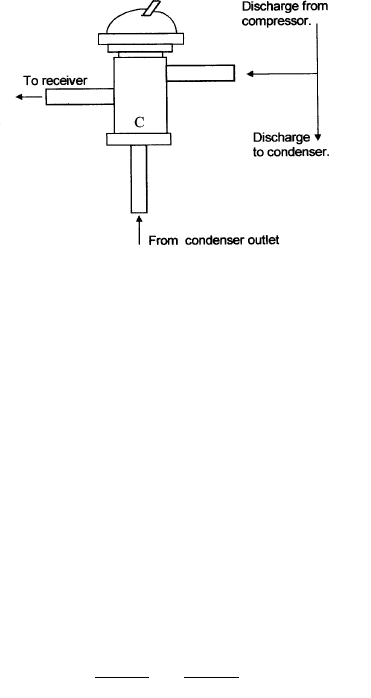
PENN VALVE
HEAD PRESSURE CONTROLS
WATER-COOLED
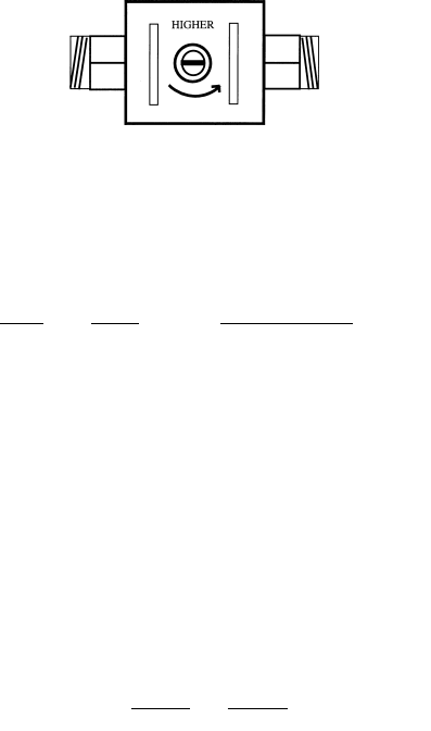
An adjustable (Pressure Modulated) water-regulating valve
is installed on the water-cooled condenser outlet. A # V46
Johnson Controls Penn valve is used. A label on the valve
housing identifies the Penn valve.
Adjust:
CW - for lower pressure and outlet water temperature with
higher water flow.
CCW – for higher pressure and outlet water pressure
with lower water flow.
CONDENSER OUTLET WATER TEMPERATURE RANGE.
Model Range High side pressure
All KM 104 ~ 115 ºF 270 psig.
All DCM 100 ~ 104 ºF 260 psig.
All F 100 ~ 104 ºF 260 psig.
In some cases, if the water-cooled unit has been in opera-
tion for a long period of time, adjusting the water- regulating
valve does not allow proper pressures. In this case the wa-
ter-cooled condenser is likely scaled and requires cleaning.
An acid based condenser cleaner should be circulated through
the coil using an acid pump, until the inner tube is free of
scale. Once the scale is removed, the water-regulating valve
should be adjusted to maintain the range and pressure listed
above.
26
12/20/03
2/20/03
12/01/02
REMOTE HEAD PRESSURE CONTROL
All remote condenser units utilize a condensing pressure regu-
lating (CPR/Headmaster) valve to maintain head pressure in
low ambient conditions. You will find a Sporland LAC-4 210
psig. valve mounted in the condenser of all R-404A remote
units with the exception of the KM-2400SRF3. The KM-
2400SRF3 model uses a Sporland LAC-5 210 psig valve
which is mounted in the unit head.
The symptoms of a bad headmaster are similar to an under-
charged unit. To diagnose a bad headmaster, add additional
refrigerant in 2 lb. increments and watch the pressures. If
the pressures begin to look normal, the unit was undercharged.
In this case, leak check the system to find the leak and use
normal refrigeration practices to recover, repair, evacuate and
recharge the unit. If not, a bad headmaster is a possibility.
Check to see if the valve is stuck open by conducting tem-
perature checks at the outlet of the headmaster. Replace the
headmaster as necessary. Use safe refrigeration practices
when removing the valve and protect the valve from over-
heating.
HIGH PRESSURE SAFETY SWITCH
An automatic reset high pressure safety switch is utilized on
all Hoshizaki “F” series ice makers. The pressure switch part
numbers and settings are as follows:
27
R
D
12/20/03
2/20/03

12/01/02
Pressure switch chart for R-404A models:
Models part number cut out cut in
(psig.) (psig.)
DCM-240B 3A0740-01 400 ±10 270 ±10
All KM & DCM water-cooled,
All F models 433441-05 384 ± 21.3 284± 21.3
DCM-500/750BAF All KM
air & remote, 433441-07 412 ± 21. 327 ± 21.3
BIN CONTROL
KM BIN CONTROLS:
KM/KML cubers will use one of three types of bin controls.
The type of bin control will vary depending on the unit style,
or model and serial number.
1. THERMOSTATIC BIN CONTROL:
The thermostatic bin control is the primary control that sup-
plies 115 volts to all major components in the unit except the
compressor. When this control is closed, 115V is supplied
to the control transformer and to the K1 control board
connector which switches 115 volts to the components as
the sequence dictates. A thermostatic capillary bulb is
mounted in the ice drop zone area or on a drop down
bracket which extends into the bin cavity.
The Thermostatic control is normally closed. (It opens on
temperature drop and closes on temperature rise.) When
ice touches the thermostatic bulb, the bulb pressure opens
the bin control switch to shut the unit down. The thermo-
static bin control will shut the unit down at any point in the
sequence of operation if ice contacts the control bulb. The
shut down time will depend on the control adjustment. This
adjustment is factory set however it should always be
checked at start-up to assure proper operation.
High
altitude areas require adjustment.
When ice is moved
away from the bulb, the unit will always restart in the 1-
minute fill cycle.
Note: The unit will not operate in either ICE or WASH un-
less the thermostatic bin control switch is closed.
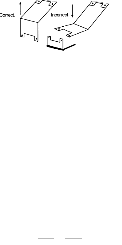
Larger M models and S models include a drop down bulb
bracket. This bracket should be secured to the unit base
and the control plug connection must be made before
the unit will operate. A bin control extension bracket is
included with all S models. Be sure to install the extension
28
12/20/03
2/20/03
12/01/02
When replacing a thermostatic bin control, check the op-
eration by holding ice against the thermostatic bulb with the
control switch in the wash position. The pump should stop
within 6 to 10 seconds. Adjustment up to 30~45 seconds
could be acceptable depending on the application. Adjust
the control “CCW” for a faster shut down.
Note: Control board dip switch number 7 must be OFF for
this control to operate the unit. A thermostatic bin control
may be used on KML models and is required for some
dispenser application.
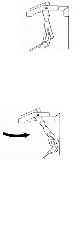
2.MECHANICAL BIN CONTROL:
KML and some M models use a mechanical bin control.
This control includes a proximity switch and actuator paddle
assembly. The mechanical bin control assembly mounts in
the ice drop zone area and will shut the unit dowm within 3
seconds when ice pushes the actuator paddle to the full
right position, away from the proximity switch. Shut down
will only occur during the first 5 minutes of the freeze cycle
when the paddle is moved away from the proximity switch.
If the paddle is moved away from the proximity switch and
held at any other time during the sequence, the unit will
continue to run until the next freeze cycle occurs. This
feature allows for a full batch of ice every cycle so that
there are no small cubes in the bin.
A resistor wireing harness connects the mechanical bin
control to the red K4 connector on the control board. As the
proximity switch opens and closes, the resistance value
will change to either start up or shut down the unit.
___
bracket. When installing, make sure the bracket points
downward so that the cubes will easily fall away from the
bin control bulb.
29
12/20/03
2/20/03
12/01/02
b) When the unit is held to the right, the resistance at the
K4 red connector will be 15.8 K ohms and the unit will shut
down within 3 seconds during the first 5 minutes of the
freeze cycle or at the beginning of the next freeze cycle at
any other time in the sequence of operation.
Mechanical control in the normal position supplies 7.9 K
ohms at red K4 connector to start unit.
Mechanical bin control in the full right position supplies
15.8 K ohms at connector red K4 to shut unit down.
Note: Control board dip switch number 7 must be ON for
this control to operate the unit.
3. CAPACATIVE PROXIMITY SWITCH: KM-1300NRF
This control is used only on the KM-1300NRF model which
was designed tor 42 inch beverage dispenser applica-
tions. You will find it only on this specific model. The control
works by sencing mass (in this case, ice) within 1/2 to 1
BIN EMPTY
BIN FULL
a) When the control paddle is hanging in the normal posi-
tion, the resistance at the red K4 connector will be 7.9 K
ohms and the unit will start.
30
Priximity switch
closed.
Proximity switch
open.
12/20/03
2/20/03

12/01/02
F/DCM Bin Control
Flaker / DCM units use a mechanical bin control. A paddle
pivots on a hinge pin to operate either a micro- switch or
magnetic proximity switch. For proper operation, make sure
that the paddle swings freely. The F-450MAF-C cubelet
unit uses an Infrared eye control since it is designed for
dispenser applications. This control has a seperate DC
power supply and an infrared sensor which is mounted
to the base of the ice chute.
CAPACITORS
See wiring diagram reference chart for capacitor ratings.
Check capacitors with an ohm meter for a short or open
circuit. A capacitor checker can be used to check the
capacitance however, it is a good common practice to
change a run capacator any time a PSC motor is replaced.
Always check the run capacitor if a PSC motor will not
start, is running slow, overamping, or overheating.
inch of the sensor. It also connects to the K4 red connec-
tor on the control board and has the same operating se-
quence as the mechanicam bin control.
The capacitive proximity control has 4 components includ-
ing a sensor, bin control relay, 24VDC power supply and
resistor harness. This resistor harness is slightly different
from the harness used for the mechanical control. It will
supply either 15.8 K ohms or 5.6 K ohms to the red K4
connector to control the unit.
As the sensor switches, the resistance value will change
to either start up or shut down the unit through the control
board K4 connector.
a) When no ice is present within 1/2~1 inch of the sensor
end, the resistance at the K4 connector will be 5.6 K ohms
and the unit will start. This is the bin empty signal.
b) When ice is present within 1/2~1 inch of the sensor, the
resistance at the K4 connector will be 15.8 K ohms and the
unit will shut down within the first 5 minutes of the freeze
cycle. This is the bin full signal.
Note: Control board dip switch number 7 must be ON for
this control to operate the unit.
31
12/20/03
2/20/03

12/01/02
HOSHIZAKI KM CUBER
SEQUENCE OF OPERATION
THE STEPS IN THE SEQUENCE ARE AS FOLLOWS:
NOTE: When power is supplied to the “E” Control board,
a 5 second delay occurs at start-up.
1. 1 Minute Fill Cycle
The unit always starts in the 1 minute fill cycle. When
power is applied to the unit the water valve is ener-
gized and the fill period begins. After 1 minute the
board checks for a closed float switch. If the float
switch is closed the harvest cycle begins. If not, the
unit will not start without adequate water in the sump.
This serves as a low water safety shut off. The water
valve will remain energized through additional 1 min-
ute cycles until water enters the sump and the float
switch closes.
2. 1st Harvest Cycle
The compressor starts, hot gas valve opens, water
valve remains open and harvest begins. As the evap-
orator warms, the thermistor located on the suction
line checks for a 48° F. temperature. When 48° F. i s
reached, the harvest is turned over to the adjustable
control board defrost timer which is factory set for
normal conditions. This adjustment can vary the de-
frost timer from 1 to 3 minutes.
3. Freeze Cycle
After the timer terminates the harvest cycle, the hot
gas and water valves close, and the ice production
cycle starts. For the first 5 minutes the controller
board will not accept a signal from the float switch.
This 5 minute minimum freeze acts as a short cycle
protection. At the end of 5 minutes the float switch
assumes control. As ice builds on the evaporator the
water level in the sump lowers. Thefreeze continues
until the float switch opens and terminates ice
production.
32
12/20/03
2/20/03

12/01/02
4. Harvest Pump Out
When the float switch opens and signals the completion
of the freeze cycle, the harvest cycle begins. The hot
gas valve opens and the compressor continues to run.
The drain timer starts counting the 10/20 second pump
out.
The water pump stops for 2 seconds and reverses,
taking water from the bottom of the sump and forcing
pressure against the check valve seat allowing water
to go through the check valve and down the drain. At
the same time water flows through the small tube to
power flush the float switch. When the drain timer
stops counting, the pump out is complete.
Pump out always occurs on the 2nd harvest after
startup. The Alpine control board allows for adjustment
for pump out to occur every cycle, or every 2nd, 5th or
10th cycle from this point.
5. Normal Harvest Cycle
The water valve opens to allow water to assist the
harvest. As the evaporator warms, the thermistor
reaches 48° F. The control board receives the
thermistor signal and starts the defrost timer. The
watervalve is open during harvest (defrost) for a
maximum of 6 minutes or the length of harvest,
whichever is shorter. When the defrost timer completes
its count down, the defrost cycle is complete and the
next freeze cycle starts.
The unit continues to cycle through 3 , 4 and 5
sequence until the bin control senses ice and shuts
the unit down.
33
12/20/03
2/20/03

12/01/02
34
12/20/03
2/20/03

12/01/02
KM CHECK OUT PROCEDURE
The following is a detailed explanation of the KM 10
Minute Check Out procedure.
The 10 minute check out procedure is basically a
sequence check which can be used at unit start-up or
for system diagnosis. Using this check out procedure
will allow you to diagnose electrical system and
component failures in approximately 10 minutes under
normal operating conditions of 70°F or warmer air and
50°F or warmer water temperatures. Before conducting
a 10 minute checkout, check for correct installation,
proper voltage per unit nameplate and adequate water
supply. As you go through the procedure, check to
assure the components energize and de-energize
correctly. If not, those components and controls are
suspect.
10 MINUTE CHECK OUT PROCEDURE
1. Turn power OFF - gain access to unit control box.
2. Turn power ON – place control switch in ice position.
Note: A 5 second delay occurs for units with “E” control
board.
A) 1 Minute Fill Cycle begins – WV energized.
After 1 minute, control board checks FS. If FS is
closed…unit cycles to Harvest. Continue to (B).
If FS is open, unit repeats 1 minute fill cycle until
water enters and FS closes (low water safety
protection during initial start up and at the end of
each harvest)
Diagnosis: If WV does not open, check for no supply
voltage at WV terminals, bad coil, or plugged screen
or external filter (no water flow). If unit fails to start
harvest, check for open FS or bad 1 minute timer in
board.
B) Initial Harvest Cycle – WV remains energized,
CC energizes to start C, HGV, & (FM on RS
model) energize. Evaporator warms…thermistor
senses 48°F…turns operation of harvest to
control board defrost completion timer. Timer
completes counting (1 ~3 minutes)…Unit cycles
to freeze.
Diagnosis: Check if C is running, HGV is open, WV
still open. Avg. harvest cycle at factory setting is 2
~ 3 minutes. How long does initial harvest last? 1.5
minutes after initial harvest begins, touch C
discharge line. Is it hot? If not check refrigerant
pressures and C operation. If it is hot, touch inlet
line to the evaporator. Is it hot? If it is hot and unit is
35
12/20/03
2/20/03

12/01/02
not starting freeze cycle, check defrost
completion timer adjustment, thermistor for open
circuit, discharge line temperature, C efficiency,
and if HGV is fully open.
C) Freeze cycle – C remains energized, PM, (LV
on RS model), and FM energize…WV & HGV
de-energize. Unit is held in freeze by 5 minute
short cycle protection timer. After 5 minutes
freeze cycle operation to transferred to FS for
freeze termination. During first 5 minutes of
freeze, confirm that evaporator temperature
drops. After 7 minutes in freeze, remove black
FS lead from K5 connector…Unit should
immediately switch to pump out cycle.
Diagnosis: If evaporator is not cold, check for HGV
still open, TXV not opening properly, WV
continuing to fill reservoir, improper unit pres
sures, and inoperative C. If unit remains in freeze
with FS removed replace board. * Normal freeze
cycle will last 20 ~ 40 minutes depending on
model and conditions. Cycle times and
pressures should follow performance data
provided in Tech –Specs.
D) Pump Out Cycle – (10/20 second pump out)
C remains energized, HGV energizes, FM de-
energizes, PM stops for 2 seconds and starts in
reverse rotation for 10/20 seconds.( This
removes contaminants from the water reservoir
through check valve and down the drain and
allows for power flush of FS.) Check clear
tubing at check valve housing or unit drain for
water flow.
Diagnosis: If PM does not reverse, check PM circuit
and capacitor. If water does not pump out,
remove housing and check/clean valve
assembly.
E) Normal Harvest Cycle –same as Initial Harvest
Cycle – Return to B)…* Unit continues to cycle
through B)…C)…& D) (Setting can be adjusted
to skip D until every 2, 5, of 10 cycles)…until bin
control is satisfied or power is switched OFF.
• Unit always restarts at A).
Legend:
C – Compressor CC – Contactor Coil FM – Condenser Fan Motor
FS – Float Switch HGV – Hot Gas Valve LV – Line Valve
PM – Pump Motor RS – Remote System WV – Inlet Water Valve
36
12/20/03
2/20/03

12/01/02
37
RESERVOIR FLUSH SYSTEM
A displacement device ( cap or assembly ) is positioned
over the top of the overflow stand pipe. This device al-
lows sediment to be pulled from the bottom of the reservoir
and flush down the drain when overflow occurs. Water
should always overflow the stand pipe for a short period
towards the end of harvest to allow this flushing action. To
extend this flushing action, adjust dip switches 1 & 2 for
longer harvest. If overflow does not occur, you likely have
restricted water flow into the unit. Check the inlet water
valve screen, incoming water line size, or the external filter
system. The displacement device must be in position for
proper operation. If not, water goes down the drain during
freeze and short cycling occurs.
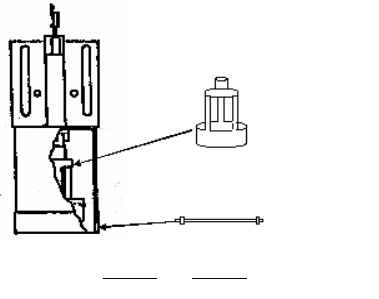
PUMP-OUT CHECK VALVE
A mechanical spring & seat check valve is located in
the pump-out housing. If this check valve sticks open,
water flows down the drain during freeze and a 5 minute
freeze cycle occurs. In this case, check for a displaced
seat, trash or a weak spring. Replace the spring if it is
weak. When reinstalling the check valve, the seat always
faces the pump supply.
KML PUMP OUT
The Standard KM series has a dual winding pump motor
that reverses direction during the pump-out cycle. The
reverse rotation pumps sediment down the drain. The KML
models have a single winding pump motor that does not
reverse. Instead of a pump-out check valve and reversing
pump, a drain solenoid and the pump motor are energized
by a relay so that sediment is pumped out.
KM CONTROL SWITCH
The standard KM models have a three position control
switch. The switch positions are “ICE-OFF-WASH”. Also, a
manual cleaning valve includes a micro-switch which opens
the control transformer circuit to the control board during
the cleaning process. This cleaning valve must be in the
horizontal position to make ice.
The KML models have 2 switches. The control switch po-
sitions are “ICE- OFF-SERVICE”. With the control switch in
the SERVICE position, the SERVICE switch is energized.
12/20/03
2/20/03

12/01/02
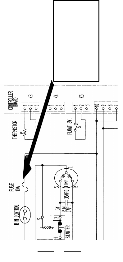
CONTROL BOARD FUSE
Beginning in May 2002 Hoshizaki began including a 10 Amp
control fuse on KM models. This new feature was added
to specific models as they were produced. The fuse is
located in a fuse holder that is mounted on the control box
and connected in the circuit supplying 115V to the control
board 10-pin connector through pins 10 & 7.
The purpose of this fuse is to protect the control board
from damage in case of a short circuit in one of the compo-
nents. This fuse will also offer some protection against
external wiring problems, voltage spikes, and surges.
If the fuse is blown, you should isolate each individual
component and check for shorts and grounded conditions.
It is important that any external wiring connections, includ-
ing the remote condenser circuit be checked before re-
placing this fuse. If the problem is not corrected, the fuse
will blow again.
In general, you should check the component that connects
to the pin that has a burnt trace on the back side of the
board first. The fuse is a Bussman AGC 10 Amp 250VAC
slow blow fuse, Hoshizaki part # 4A0893-07 and should
only be replaced with one of identical size and type. A
replacement fuse is taped to the control box.
Should you want to add this feature to an existing KM unit
in the field, you can order fuse holder # 4A0892-01, fuse
label # 4A2817-01 and fuse # 4A0893-07, through your
local distributor. You should also make a note on the wiring
diagram indicating the fuse addition, fuse size and type.
On the following page, you will find a typical wiring dia-
gram showing where the fuse is wired in the circuit and
the label that is included on the control box.
38
The service switch also has three positions, “DRAIN-
CIRCULATE-WASH”. With the control switch in SERVICE
and the service switch in DRAIN, the pump starts and drain
valve solenoid opens to automatically drain the reservoir.
In the CIRCULATE position, the pump motor circulates cleaner
to the outside of the evaporator. In WASH, the cleaning
solenoid energizes and the pump circulates cleaner to the
inside and outside of the evaporator.
12/20/03
2/20/03
12/01/02
39
(Fuse Label)
CONTROL FUSE (10A)
If fuse blows, look for shorted
component before replacing.
4A2817-01
2/20/03
12/01/02
40
COMPONENT CHECKS:
1.FLOAT SWITCH:
Check out the float switch with an ohm meter. When the
float is up, the switch is closed. When the float is down,
the switch is open.
STICKING FLOAT SWITCH:
It is important to remember that the float switch is in the
water circuit and is susceptible to scale buildup. This can
cause the float to stick either up or down. If the float
switch is sticking, it should be cleaned thoroughly with ice
machine cleaner and checked for proper operation. If the
float switch is defective, it should be replaced however, a
dirty float switch is not considered a warranty item.
The symptoms of a sticking float are:
UP/CLOSED: 60 minute freeze cycle, larger cubes,
and pump cavitates prior to harvest.
After 2 consecutive maximum freeze cycles, the
unit will shut down on a 3 beep safety.
To reset this alarm, press the Alarm Reset but
ton on the board with power ON.
DOWN/OPEN: Unit shuts down on low water
safety and water runs continuously.
Heavy scale can be difficult to remove from the float. The
float is available as a replacement part as well as the float
pin. If the housing is defective, replace the complete float
switch assembly.
Replacement Float
# 4A0886F02
Replacement pin
# 4A1141-01
12/20/03
2/20/03

12/01/02
2. THERMISTOR: Check out the thermistor mounting and
check resistance versus temperature per this chart:
THERMISTOR TEMPERATURE / RESISTANCE
SENSOR TEMP (F°) RESISTANCE (K OHMS)
0 14.4
10 10.6
32 6.0
50 3.9
70 2.5
90 1.6
The symptoms of a bad thermistor are:
OPEN: 20 minute harvest cycle. The unit will shut
down on a 2 beep safety after 2 consecutive 20
minute harvest cycles.
SHORTED: Unit locks out on manual reset high temp-
erature 1 beep safety in this case.
High Temperature Safety: If evaporator reaches 127°F
the thermistor signal (500 ohms) shuts down the unit on
this manual reset. A 1 beep alarm will occur.
To reset this
alarm, press the Alarm Reset button on the board
with power ON.
Then check the items listed on the control
board label for a 1 beep alarm.
UNIVERSAL REPLACEMENT FLOAT SWITCH:
There are two styles of KM float switches. One has no
hole in the outside pipe and one has a hole in the outside
pipe. Float switch number 4A0886-02 can be used as a
universal replacement on any KM unit. Simply seal off the
small hole in the outside tube with silicone or a seal cap
from 3/8” refrigeration tubing if it is not needed.
CONNECTOR BOOT:
The float switch boot will sometimes collect scale deposits
since it is in a low area of the water circuit. The boot should
be cleaned thoroughly during scheduled maintenance. Due
to age and high amounts of chlorine in the local water
supply, it can also deteriorate and may cup upward in the
middle holding the float up . In this case, the boot should be
replaced. Order part number 426799-01 as universal re-
placement part and cut the tube to length as needed.
Universal float boot
# 426799-01
(Cut tube to length)
41
12/20/03
2/20/03

12/01/02
Note: The Thermistor must be mounted using a heat
sink compound to assure good heat transfer and ac-
curate sensing. Use Hoshizaki Part Number 4AO683-
01 or equivalent. (Radio Shack #276-1372 or GE Elec-
tronics #10-8108, ect.)
3. CONTROL BOARD: The electronic control board
maintains the sequence of operation. There are 3
input connections to the board.
1. The Float switch connects to the control board
through the black K5 connector.
2. The thermistor connects to the control board
through the white K3 connector.
3. If a mechanical bin control is used, it will connect
to the K4 Red connector. ( In this case, dip switch
#7 must be set to the ON position.)
The control transformer supplies 10.5 VAC control
voltage to the K2 connection. The control board will
not operate unless control voltage is present at K2.
Proper control voltage is indicated by the Power
OK red LED ON.
The final connector on the control board is the K1
10-pin connector. This connector supplies 115 VAC
into the control board switchin components or
relay contacts and powers the individual com-
ponents during the sequence of operation.
The control board also has 10 dip switches that
allow for board adjustments. These switches are
set from the factory for proper operation and maxi-
mum efficiency. See control board adjustment chart
for factory settings and adjustments.
BOARD CHECKOUT: Before replacing a control
board that does not show a visable defect and
that you suspect is bad, always conduct the fol-
low checkout procedure. This procedure will help
you verify your diagnosis.
1. Check the dip switch settings to assure that
#3,4, 7, 8, 9, & 10 are in the factory setting. Out-
put test switch S3 should also be OFF. Switches
1, 2, 4, & 5 are cleaning adjustments and the set-
tings are flexible.
42
12/20/03
2/20/03

12/01/02
2. Turn the control switch to ICE and check for proper
control voltage. If the Red LED is ON, the control volt-
age is good. If the Red LED is OFF, check the control
transformer circuit. See checking control transformer.
3. Next, check the 115 volt input at the 10-pin connector.
Check the brown wire at pin #10 to a white neutral
wire for 115 volts. (Always choose a white neutral
wire to establish a good neutral connection when
checking voltages.) A jumper also feeds 115 volts
into pin # 7. If no voltage is present, check the 115
volt supply circuit.
4. Check the board sequence using the S3 output test.
a) Turn the control switch to OFF and switch S3 ON.
b) Turn the Control switch to ICE and watch the light-
ing sequence of the 4 green LED’s numbered 1, 4, 3,
2 from the board edge. The Red LED should light in
about 3 seconds.
About 3 seconds later, LED 2 should light.
5 seconds later, Led 2 will go out and LED 3 will light.
5 seconds later, Led 3 will go out and LED 4 will light.
5 seconds later, Led 4 will go out and LED 1 will light.
5 seconds later, Led 1 will go out and LED 4 will light.
This sequence completes the output test and the unit
is now in the 1 minute fill cycle.
Note: If the LED’s light in a different sequence or the 5-
second interval does not occur as explained, the control
board is bad and should be replaced. If the test sequence
is correct, turn the control switch OFF and switch S3 OFF.
The S3 switch must remain in the OFF position during nor-
mal operation. The components will cycle during this test.
5. You have checked the board sequence and now
need to check the output to each component through
the K1 10-pin connector for 115 volts. Follow the wir-
ing color code on the wiring diagram or use the generic
drawing in the wiring diagram section to check each
component for 115 volts through out the sequence and
check from each pin to a white wire.
Note: Checking from pin to case ground can give a false
reading in some instances. Always choose a white neu-
tral wire to establish a good neutral connection when
checking voltages.
43
12/20/03
2/20/03

12/01/02
4. BIN CONTROL:
Checkout for the bin control will vary depending on the
model and control that is used.
a) THERMOSTATIC BIN CONTROL: The thermostatic
bulb is mounted in the ice drop area to sense the ice
buildup. To adjust the bin control, hold ice against the
bulb while the unit is operating. You will find it easier to
place the control switch to the wash position to check
the bin control operation. It is easy to hear the pump
motor stop when the bin control opens. The unit should
shut down within a 10 second window when the
control is adjusted properly. If this does not occur,
adjust the thermostatic control by turning the screw-
driver slot. Adjusting towards warmer will allow the
unit to shut down quicker. This adjustment should be
checked at installation, when diagnosing a bin control
problem, or if a replacement bin control is installed.
KM 150 / 250 / 280 / 500 / 630 /900 units have a bin
control mounted in the ice drop zone area. KM-1300M /
S and larger units have a drop down bracket that must
be dropped down, secured, and plugged in at installa-
tion. The ice must contact the bulb to operate the
bin control. Some bin applications require an exten-
sion bracket or relocation of the bulb mounting to allow
for proper shut down. Check this positioning if the
control is adjusted properly and ice continues to back
up into the evaporator section. Assure that the exten-
sion bracket is installed.
The symptoms of a bad thermostatic control are:
STUCK CLOSED: The unit continues to operate when the
bin is full. This allows ice to back up in the evaporator
compartment and generally causes a freeze up condition.
This will also occur if the bin control is adjusted too cold or
fully “CW”. Check the adjustment and bulb location before
you diagnose a stuck bin control.
STUCK OPEN: The unit will not start in the ice position. An
easy method to check for an open bin control is to flip the
control switch to WASH. If the pump starts, the bin control
is closed.
b) MECHANICAL BIN CONTROL: The mechanical bin
control uses a moving actuator paddle to open and
44
12/20/03
2/20/03

12/01/02
closes a magnetic proximity switch. The control is con-
nected to the red K5 connector on the control board
through a resistor harness. As the proximity switch
opens or closes, the resistance will change to signal
the control board to start up or shut down. The control
board will only respond to this change in resistance
during the first 5 minutes of each freeze cycle.
Note: Dip switch # 7 must be in the ON position for
this control. When dip switch # 7 is ON, the following
2 safeties will occur if the mechanical control fails:
4 Beeps = Short circuit on K5 bin control circuit.
5 Beeps = Open circuit on K5 bin control circuit.
To reset either safety, press the white reset
button on the control board with the power ON.
CHECKOUT: To check this control with the unit running,
you must be in the first 5 minutes of the freeze cycle.
Turn the control switch to OFF and back to ICE. Allow
the unit to cycle through the 1 minute fill cycle and the
initial harvest cycle. Once the freeze cycle begins
(LED 1 ON and when you hear the pump motor start
you will know that the freeze cycle has begun), push
the control paddle to the full right position and the unit
should shut down within 3 seconds.
Another method to check this control is to unplug the
wiring harness from the K5 Red connector and check
the resistance at the end of the harness with an ohm-
meter as the proximity switch opens and closes.
1) When the control paddle is hanging in the normal
position, (Bin Empty) the resistance at the red K4
connector will be 7.9 K ohms.
2) When the control paddle is held to the full right
position, (Bin Full) the resistance at the red K4
connector will be 15.8 K ohms.
c) CAPACITIVE PROXMITY SWITCH: This control is
used on the KM-1300NRF model only. It operates with
the same sequence as the mechanical control and has
the same safeties. The difference is that this control
has a separate 24VDC power supply and operates
through a bin control relay.
45
12/20/03
2/20/03

12/01/02
CHECKOUT:
To check the operation of this control follow the same check
out procedure as with the mechanical control. Instead of
moving a paddle, you will place your hand within 1/2~1
inch of the sensor end. With the control switch in ICE, you
should hear the bin control relay switch when you move
your hand away from the sensor end and back again.
Check the resistance supplied at the Red K4 connector as
you move your hand back and forth at the sensor end.
Unplug the harness and use an ohmmeter to check the
resistance. As the sensor switches, the resistance value
will change as follows:
a) When your hand is away from the sensor end, the
resistance at the K4 connector will be 5.6 K ohms. This is
the bin empty signal.
b) When your hand is within 1/2~1 inch of the sensor, the
resistance at the K4 connector will be 15.5 K ohms. This is
the bin full signal.
If the relay does not switch or the resistance does not
change, check the control wiring, relay operation, and the
control power supply for 115 VAC input / 24 VAC output.
Note: Remember that dip switch # 7 must be ON and the
control will have these safeties.
4 Beeps = Short circuit on K5 bin control circuit.
5 Beeps = Open circuit on K5 bin control circuit.
F/DCM BIN CONTROL:
DCM bin controls may be a mechanical flapper with a mag-
netic proximity switch or a micro-switch assembly. Since
these controls have moving parts, make sure that all parts
move freely. Sticking can occur if scale builds up at the
pivot points. All flakers except the F-450MAF-C use the
mechanical/proximity switch control. If the bin control fails,
the spout will fill with ice causing higher gear motor current
and the gear motor protect fuse will blow.
The F-450MAF-C has an infrared eye bin control. A sepa-
rate power supply provides 24 VDC to the infrared eye.
This power supply is mounted in a separate control box
along with the bin control relay. The IR sensor is mounted
on the outside of the chute base in a molded indentation.
Two mounting holes mount the sensor to the chute base.
46
12/20/03
2/20/03

12/01/02
47
The sensor has two LED lamps that light to show that
power is supplied. Since the voltage is DC, the sensor is
polarity sensitive. The sensor has four wires. The orange
wire is capped off and not used. The black wire connects
to the coil of relay X7. The brown wire is the positive lead
and connects to terminal J2-1 on the power supply. The
blue wire is the negative lead and connects to terminal J2-
2. If these wires are crossed, the sensor will not shut the
unit down. The result will be that the spout will fill with ice
causing higher gear motor current and the gear motor pro-
tect fuse will blow. In this case, the bin control is the first
component to check.
The sensor has two adjustments that are factory set. The
first adjustment sets the operation mode of the sensor. It
must be in the D position. The second adjust the operating
distance of the infrared beam at approximately 4”. It should
be set so that the white dot on the dial is at 12 o’clock (top
dead center). These settings should not be altered.
5. KM CONTROL TRANSFORMER: The KM control trans-
former supplies 10.5 VAC to the control board through the
K2 connector. This 115V/10.5V stepdown transformer is a
heavy duty component with an internal thermal overload.
The primary winding of this transformer will handle higher
voltage without damage because the thermal overload will
open to protect the winding in the case of improper supply
voltage. The control board monitors the output voltage of
this control transformer and provides automatic reset high
and low voltage protection.
The red LED on the control board will not light if no control
voltage is supplied. The 115V transformer primary circuit is
supplied through the thermostatic bin control, control switch,
high pressure switch, and low pressure switch if included.
If either of these switches are open, there is not control
voltage at the K2 connector and the unit will not operate.
The transformer secondary circuit includes the cleaning
valve interlock switch. If this switch is open, no control
voltage is supplied to the K2 connector so the unit will not
operate. Always check the cleaning valve position and
interlock switch if the red LED is off.
Because of the voltage protection, if the control trans-
former fails, it is important to use the correct OEM part.
12/20/03
2/20/03
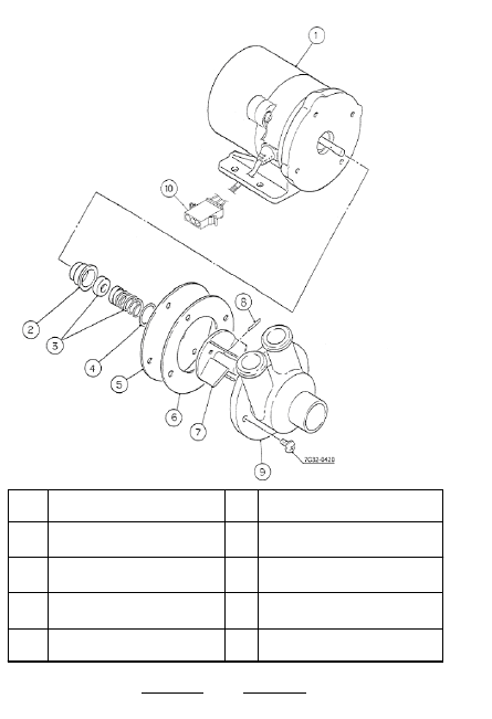
12/01/02
6. KM PUMP MOTOR ASSEMBLY:
The KM pump assembly has a dual winding PSC motor with
an internal overload. The motor has a cast housing and
sealed stainless steel roller bearings. No lubrication is
required for these roller bearings.
If the pump motor fails, always repalce the pump motor
capacitor. If other failures occur, the front end of the pump
assembly is rebuildable. The mechanical seal is the most
common failure part and can be replaced.
Following, are the assembly breakdown’s for two generic
pump assemblies. Use these drawings as a guide to reas-
semble a pump assembly that you are rebuilding.
48
1
2
3
4
5
Motor
Retainer
Mechanical Seal
“O” Ring
Plate
6
7
8
9
Pump Gasket
Impeller
Pin
Pump Gasket
PUMP ASSEMBLY BREAKDOWN:
SMALLER STYLE KM’s
12/20/03
2/20/03
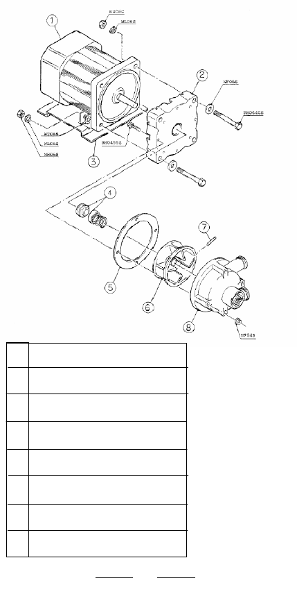
12/01/02
1
2
3
4
5
6
7
8
Motor
Pump Flange
Bracket
Mechanical Seal
Packing
Impeller
Pin
Pump Housing
LARGER STYLE KM’s
49
12/20/03
2/20/03
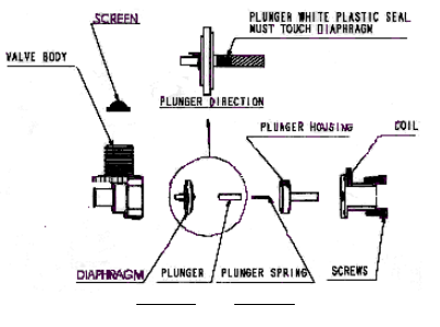
12/01/02
7. INLET WATER VALVE: Hoshizaki uses inlet water valve
solenoid to fill the reservoir for ice making. This constant
duty solenoid valve is very reliable however, in areas of
hard water and high levels of chlorine, the diaphragm is
susceptible to failure.
Water quality is constantly changing and local municipali-
ties are now adding higher levels of chlorine, chloramine,
and chlorine dioxides to the water. These agents can dam-
age rubber parts and effect the diaphragm life.
The diaphragm is made of rubber and ABS and has a bleed
port on the inside ABS piece. This port allows the pressure
to balance on the top and bottom of the diaphragm so that
the valve will open and close properly with the spring
pressure. If the rubber becomes dry and brittle or the
bleed port is plugged with trash or debris, the valve will
leak by. In this case the valve can be disassembled for
cleaning and the diaphragm and inlet screen can be cleaned
or replaced. It is important to remember that the warranty
covers repair of defects and not cleaning. Should the valve
be scaled or dirty, it should be cleaned and bill to the cus-
tomer.
Below you will find an exploded view of the valve assem-
bly and instructions for reassembly of the valve. When
replacing the diaphragm and re-assembling the
valvereplacing the diaphragm, it is important that the plunger
is in the correct position. This plunger has a white plastic
seal on one end and is metal on the other end. The white
seal end of the plunger must be in contact with the dia-
phragm in order for the valve to work correctly.
50
12/20/03
2/20/03

12/01/02
Because of the different flow rates, it is important to use
the correct OEM water valve when servicing a Hoshizaki
ice maker. Use the following chart to identify the correct
valve, diaphragm or inlet screen.
CKD VALVES
Replacement screen for all CKD valves # SP9200010
Part # Vender # Diaphragm # Model #’s
3U0111-01 J248-030 SP8802237 KM-1200/1300/1600
3U0111-02 J248-032 “ KM-630/632/800/900
3U0111-03 J248-033 “ KM-450/452/500
KML-600
3U0111-04 J248-072 “ KM-250B_B
KML-350/400/450
3U0150-01 J248-647 “ KM-280, KML-200
3U0145-01 J248-126 “ KM-250B_C/E/F/H
3U0152-01 J248-662 “ KM-150BAF
3U0133-01 J248-096 “ KM-250M_E/F
3U0136-01 J248-106 “ KM-1800/2000/2400
3U0085-01 J246-379 0000-0264 KM-451/1201
3U0070-02 J246-354 “ KM-601/631
3U0065-01 J246-086 “ F-251/250/441/450
F-650/1101/1001,
F-1000M_B, F-2000M-E
F-1000M_E >>Serial
code F-0
DCM-231/230/240,
DCM-451/450/701/700
EATON VALVE
Replacement screen # SA0019
Part # Vender # Diaphragm # Model #’s
4A0865-01 K-63310-01 SA0020 F-650/800, F-1000M_E
F-1001, F-2000M_F
DCM-270/500/750,
DCM-450 Serial
code F-1>>>
8. Check other components using a good quality multimeter
normal electrical diagnostic procedures.
51
12/20/03
2/20/03
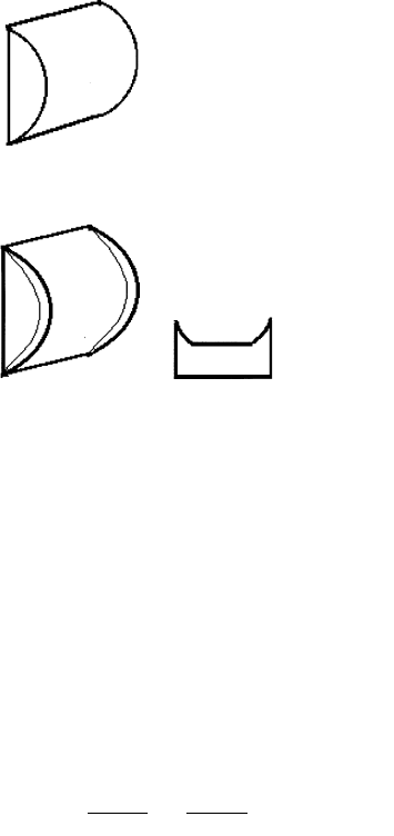
12/01/02
Diagnosing water problems.
Many common water related problems will cause cubes to
look unnatural. Looking at the ice in the bin will point you
towards the problem area. Study these shapes and causes
to help you diagnose water related problems.
1. Normal cube, No problem.
Average cube size 1/2” thick x
1 1/8” wide x 1 1/2” high.
2. Larger than normal cube with heavy
saddled edges.
Note: Normal cube may have slight saddled edge.
If the float switch sticks in the up position, (closed ) the
unit will have a consistent 60 minute freeze cycle. This
will result in heavy saddled edges and may cause pump
cavitation and ice to stick on the evaporator or ice pos-
sible bridging.
A FREEZE UP MAY OCCUR IF ICE STICKS DUE TO
THE LARGER EDGES.
52
12/20/03
2/20/03
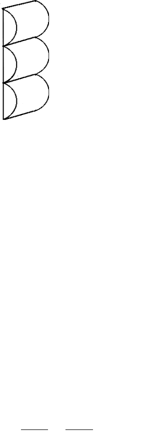
12/01/02
3. Bridging or ice strips
a) Bridging that occurs on all ribs of all evaporator plates
is the result of excessive water in the reservoir. This is
caused by the inlet water valve leaking by. Check for a
plugged bleed port in the water valve diaphragm or a
defective water valve.
b) May be the result of # 2.
c) Bridging can occur on a few ribs if some of the holes in
the water distribution tubes are plugged. An inspection
of the ice build up on the evaporator will show some ribs
with no ice and others with strips. Clean the water
distribution system.
d) Bridging on 1 or 2 plates of a multiple evaporator unit
can result from water distribution problems or a refrig-
eration system problem. Eliminate water problems first
then check TXV, hot gas valve, charge, etc....
BRIDGING WILL GENERALLY CAUSE A FREEZE UP.
53
12/20/03
2/20/03
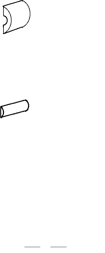
12/01/02
4. Melt away of back of cube
a) This can occur if the evaporator plate is scaled up.
De-scaling is required.
b) Insufficient water flow during harvest can also cause
the flat side of the cube to melt away. Check for a
plugged inlet water valve screen, plugged external
filter, low water pressure, or a small water line size.
EITHER OR BOTH OF THESE ITEMS CAN CAUSE
THIS SYMPTOM.
5. Small cube
a) Can be caused by a low volume of water at the begin-
ning of freeze. Check for adequate water flow during
harvest. See item 4 b)
b) If the pump out check valve is stuck open or has a
weak spring, the water left in the reservoir will be
pumped out during the first five minutes of freeze.
This results in a short cycle and slivers of ice or small
cubes.
c) Any loss of water, whether by leak, water trail, or
loose stand pipe can cause this problem.
6. Freeze ups can be caused by 2, 3, or 4 above in any
combination. The major cause however is a dirty
(scaled up ) water system or evaporator. A thorough
cleaning will eliminate most freeze ups. The second
most common reason for freeze up is low water flow.
Always check the evaporator, and water flow first,
then go to other checks when diagnosing freeze ups.
(Size will depend on how much water is
in the reservoir.)
54
12/20/03
2/20/03

12/01/02
PLEASE COMPLETE WHEN DIAGNOSING A FREEZE-
UP, REFRIGERANT LEAK, OR LOW CHARGE.
MODEL#_________________SERIAL#_________________
INSL DATE ______________FAIL DATE____________
Single Stacked
1. Single unit or stacked equipment? [ ] [ ]
YES NO
2. Condition of float switch - Dirty float? [ ] [ ]
Are contacts opening? [ ] [ ]
3. Is water pump always running during
freeze? [ ] [ ]
4. Is thermistor properly mounted? [ ] [ ]
5. Is the TXV bulb tight and insulated? [ ] [ ]
6. Does water sump fill to overflow in 60 –90
secs. or less when empty? [ ] [ ]
7. Is the water line size 1/2”?If not ______” [ ] [ ]
8. Is water flow 3 GPM for KM-150~KM-900?[ ] [ ]
9. Only one water line per unit? If not _____ [ ] [ ]
10. Is water flow 5GPM for KM-1300 ~
KM-2400? [ ] [ ]
11. Will bin control cycle OFF within 6-10
seconds when in contact with ice? [ ] [ ]
12. Have you checked that the bin control
capillary is not touching a heated source?[ ] [ ]
13. Are the evaporator separators
positioned properly? [ ] [ ]
14. Is the cube guide positioned correctly? [ ] [ ]
15. Date evaporators were last cleaned
_____________
16. Does the unit have any water filtration? [ ] [ ]
If so, please list the following:
Brand filter_________________________________
Filter model________________________________
Water filter pressure gauge reading _________psig
Date filter last replaced ______________________
55
12/20/03
2/20/03

12/01/02
_______________________
17. Date screen on water solenoid was
last cleaned ________
Does water valve close completely when
de-energized? [ ] [ ]
18. What is the water pressure? _________ psig
Temperature? ________°F
19. Please list the control board dip switch settings.
1 _______ 2 _______ 3 _______ 4 _______
5 _______ 6 _______ 7 _______ 8 _______
20. Is cube size consistent from inlet to YES NO
outlet of evaporator? (full freeze pattern) [ ] [ ]
21. Is ice still dropping when unit cycles into
the freeze mode? [ ] [ ]
22. After defrosting, was the unit leak
checked? [ ] [ ]
Were any leaks found? [ ] [ ]
If so, where? (Be specific)
____________________________________________
23. Was any refrigerant added to the unit? [ [ [ ]
If so, how much?
___________________________________________
24. What is the head pressure?
Freeze ___________ Harvest _____________
25. What is the suction pressure?
Freeze ____________Harvest _____________
26. What is length of Freeze cycle______________
Harvest cycle? _______________
27. Ambient temperature? _______________ ° F
28. Water-cooled condenser outlet water
temp._________°F
29. Is the hot gas valve opening? [ ] [ ]
30. List model and manufacturer of bin
________________________________________
31. If non-Hoshizaki bin, what modifications have been
made to bin control mounting? [ ] [ ]
32. Has extension bracket been added to the bin
control bracket? [ ] [ ]
33. Check ice drop weight. ________________________
56
12/20/03
2/20/03

12/01/02
PREVENTATIVE MAINTENENCE: Perventative Maintenance
is the key to long equipment life and maximum efficiency.
Hoshizaki recommends preforming the following mainte-
nance steps at least annually. The PM frequency will de-
pend on the local water quality and operating conditions.
PREVENTATIVE MAINTENANCE STEPS:
1. Clean the removable air filter. Hoshizaki air-cooled units
include a front accessible, cleanable air filter. This filter
collects dirt, dust, and grease can be cleaned with warm
soapy water. Hoshizaki recommends cleaning the air filter
twice a month or more as conditions dictate.
2. Service the external water filter system (if equipped)
and check and clean inlet water valve screen.
3. Clean and sanitize the water system and bin. A cleaning
label with detailed instructions is usually located on the
inside of the front panel.
4.
Check bearings for wear annually on Flaker/DCM.
Pull the auger and inspect evaporator, auger, and bearing
surfaces for wear.
More frequently bearing inspections
may be needed in areas with poor water quality.
5. Visually inspect the unit for loose wires, oil spots, water
drips, etc.
6. Clean & wipe exterior with a soft cloth and neutral cleaner.
STAINLESS STEEL CLEANING:
Water quality is constantly changing and local municipali-
ties are now adding higher levels of chlorine, chloramine,
and sometimes, chlorine dioxides to reduce bacteria in the
water. Stainless steel is a durable metal however it can be
suseptable to corrosion from exposure to chlorine gas.
As ice forms on a cuber evaporator, chlorine outgases and
the chlorine gas settles in the lowest point in the bin. This
gas sticks to wet surfaces and around the mouth of the bin
and forms hydrochloric acid. If this acid remains on the
stainless steel, rust colored corrosion occurs. With enough
exposure, the corrosion can pit and damage the stainless.
If rust colored corrosion is found, it should be cleaned
throughly with a non-abrasive cleaner and protected with
a stainless steel polish. Heavy corrosion will require some
effort to remove and may require the use of a cleaning
agent like “Brasso” or non-abrasive powdered cleaner like
“Zud” or “Bon Ami”. Care should be taken so as not to
scratch the stainless during the cleaning process.
57
12/20/03
2/20/03

12/01/02
CLEANING/SANITIZING PROCEDURE
A label which details the step by step cleaning/sanitizing
procedure is located on the inside front panel of the ice
machine. These instructions are also provided in the In-
struction Manual shipped with each unit. Follow these in-
structions to conduct a thorough cleaning and sanitizing of
the water system.
Annual cleanings are recommended. More frequent
cleanings may be required in bad water areas.
INLET WATER VALVE
The inlet water valve includes an 80 mesh screen to pro-
tect the water system from debris. Always check and
clear this screen during the cleaning procedure.
CLEANERS:
Hoshizaki recommends "Hoshizaki Scale Away' or "Lime-
A-Way" (by Economics Laboratory, Inc.) however any FDA
approved ice machine cleaner is acceptable. If you carry a
nickel safe cleaner, the acidic solution is weaker than nor-
mal cleaners to protect plated surfaces. You may need to
use a heavier mixture of nickel safe to cut heavier scale
deposits.
RECOMMENDED CLEANING SOLUTION MIXTURE
MODEL CLEANER WATER
KM-150 5 Fl. Oz. 1 Gal.
DCM-240 6 Fl. Oz. 1 Gal.
KM-250B 7 Fl. Oz. 1.3 Gal.
KML-250/450 10.5 Fl. Oz. 2.0 Gal.
KM-280/500/630/900
KML-600 16 Fl. Oz. 3.0 Gal.
KM-1300/1600 27 Fl. Oz. 5.0 Gal.
KM-2000/2400 38Fl. Oz. 7.0 Gal.
All Flakers &
DCM-500/750 9.6 Fl. Oz. 1.6 Gal.
The system should be sanitized using a solution of water
and 5.25% sodium hypochlorite (chlorine bleach). Any
commercial sanitizer recommended for ice machine appli-
cation is acceptable.
58
12/20/03
2/20/03

12/01/02
RECOMMENDED SANITIZING SOLUTION MIXTURE
MODEL SANITIZER WATER
KM-150 .5 Fl. Oz. 1 Gal.
KM-250B .65 Fl. Oz. 1.3 Gal.
DCM-500/750 .82 Fl. Oz. 1.6 Gal.
KML-250/450 1 Fl. Oz. 2.0 Gal.
KM-280/500/630/900,
KML-600,DCM-240 1.5 Fl. Oz. 3.0 Gal.
KM-1300/1600 3.5 Fl. Oz. 5.0 Gal.
KM-2000/2400 3.7 Fl. Oz. 7.0 Gal.
All Flakers 2.5 Fl. Oz. 5.0 Gal.
KM PRODUCTION CHECK
The steps for a cuber production check are as follows:
1. Time a complete cycle from the beginning of one
freeze cycle to the beginning of the next freeze
cycle.
2. Catch all of the ice from this freeze cycle and
weigh the total batch.
3. Divide the total minutes in a 24 hour day (1440
minutes) by the complete cycle time in minutes to
obtain the number of cycles per day.
4. Multiply the number of cycles per day by the cycle
batch weight for the cuber production per 24
hours.
(1440 • Total Cycle Time) x Ice Batch Weight=
24 Hour Production
Once you calculate the production, check the incoming wa-
ter temperature, and ambient condensing temperature at the
cuber and cross reference to performance data included in
this manual to see if the calculation falls within 10% of the
specification.
For the most accurate production check, a normal freeze
cycle should be checked. If the evaporator compartment has
been opened for service or if the unit has been cut off for a
long period of time, the first freeze cycle will be longer than
normal. Timing this cycle can result in an inaccurate produc-
tion check. To avoid this, start the unit and allow it to operate
for 10 minutes in the freeze cycle, unplug the float switch
lead and cause the unit to cycle into harvest mode. Replug
the float switch and start timing as soon as the next freeze
begins. Also remember that the evaporator compartment must
be closed during the production check. Removing the front
cover to check the ice buildup during a production check will
allow heat into the evaporator and will affect the total cycle
time and actual production.
59
12/20/03
2/20/03

12/01/02
WATER AND REFRIGERATION CIRCUIT
DRAWING REFERENCE CHART
MODEL PAGE
KM-150BAF/F-E ......................................................... 61
KM-280MAF/H, MWF/H .............................................. 62
KM-280MAF/H-E, MWF/H-E ....................................... 62
KML-250MAH, MWH .................................................. 63
KML-350MAF/H, MWF/H ............................................ 63
KML-450MAF/H, MWF/H ............................................ 63
KML-600MAF/H, MWF/H ............................................ 63
KML-600MRF/H .......................................................... 64
KM-500MAF/H, MWF/H .............................................. 65
KM-500MRF/H ............................................................ 66
KM-630MAF/H,F/H-E, MWF/H, F/H-E ........................ 65
KM-630MRF/H ............................................................ 66
KM-900MAF/H, MWF/H .............................................. 65
KM-900MRF/H ............................................................ 66
KM-1300SAF/H,F/H-E, SWF/H, F/H-E ....................... 67
KM-1300SRF/H .......................................................... 68
KM-1300MAF/H, MWF/H ............................................ 69
KM-1300NRF .............................................................. 68
KM-1600MRF/H .......................................................... 70
KM-1600SWF/H ......................................................... 67
KM-1600SRF/H .......................................................... 68
KM-1800SAH ............................................................. 71
KM-2000SWF/H, SRF/H ............................................. 71
KM-2400SRF/H .......................................................... 72
NOTE: Some drawings have been combined to
represent more than one model.
60
12/20/03
2/20/03
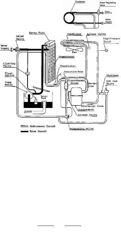
12/01/02
KM-150BAF, BWF
KM-150BAF-E, BWF-E
61
12/20/03
2/20/03
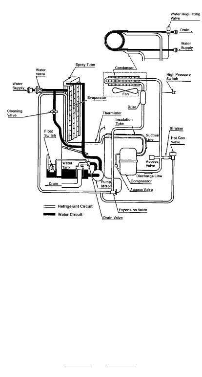
12/01/02
KM-280MAF/H, KM-280MWF/H
KM-280MAF/H-E, KM-280MWF/H-E
62
12/20/03
2/20/03
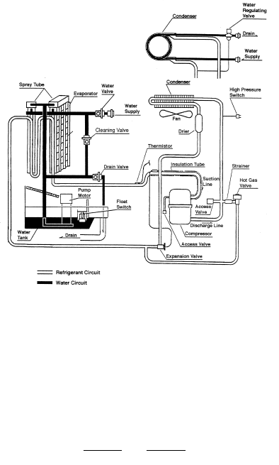
12/01/02
KML-250MAF/H, KML-250MWF/H
KML-350MAF/H, KML-350MWF/H
KML-450MAF/H, KML-450MWF/H
KML-600MAF/H, KML-600MWF/H
63
12/20/03
2/20/03
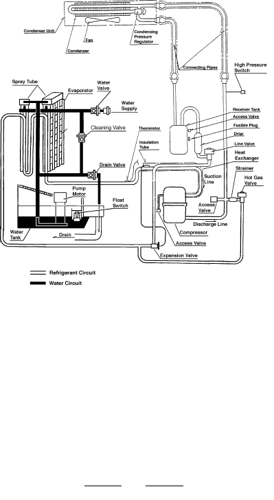
12/01/02
KML-600MRF/H
64
12/20/03
2/20/03
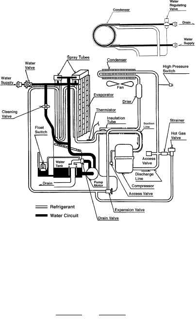
12/01/02
KM-500MAF/H, KM-500MWF/H
KM-500MAF/H-E, KM-500MWF/H-E
KM-630MAF/H, KM-630MWF/H
KM-630MAF/H-E, KM-630MWF/H-E
KM-900MAF/H, KM-900MWF/H
65
12/20/03
2/20/03
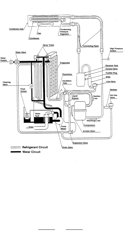
12/01/02
KM-500 MRF/H
KM-630 MRF/H
KM-900 MRF/H
66
12/20/03
2/20/03
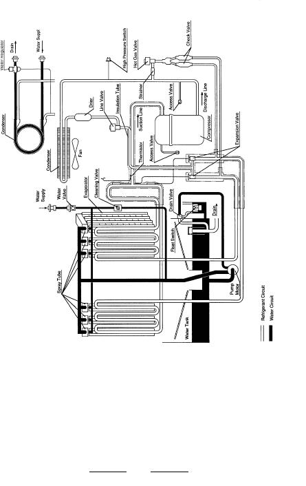
12/01/02
67
KM-1300SAF/H, SAF/H-E
KM-1300SWF/H, SWF/H-E
KM-1600SWF/H
12/20/03
2/20/03
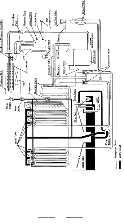
12/01/02
KM-1300 NRF
KM-1300SRF/H
KM-1600SRF/H
68
12/20/03
2/20/03
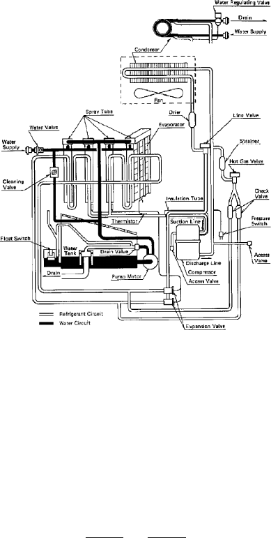
12/01/02
KM-1300MAF/H, MWF/H
69
12/20/03
2/20/03
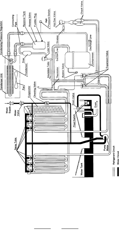
12/01/02
KM-1600MRF/H
70
12/20/03
2/20/03
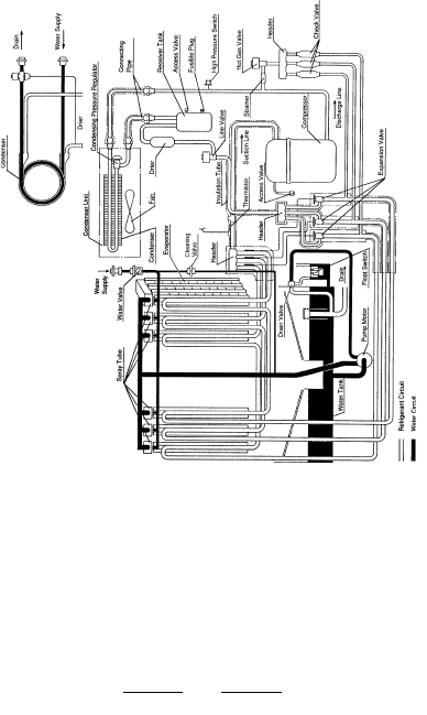
12/01/02
KM-1800SAH, SAH3
KM-2000SWF/H, KM-2000SRF/H
71
12/20/03
2/20/03
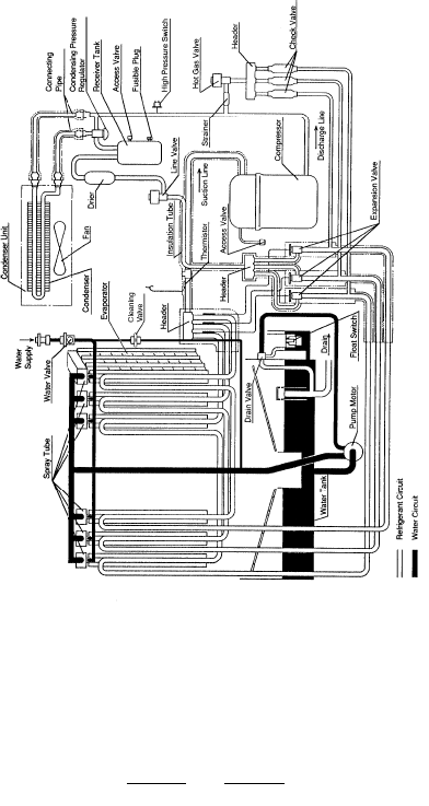
12/01/02
KM-2400 SRF/H
72
12/20/03
2/20/03

12/01/02
MODEL: KM-150B_F Supply Voltage: 115-120/60/1
Total Amperage (Compressor RLA): BAF 8A (6A) BWF: 7.5A (6A) Ice Production per cycle: 2.6 Lbs, 130 pcs.
Water Consumption for water cooled Condenser: 70/50 (21/9) 134 Gal/24 hr: 90/70 (32/21) 326 Gal/24 hr.
NOTE: Total Cycle Time = Freeze + Harvest. Pressure data is recorded 5 minutes into the freeze
cycle.
R-404A PERFORMANCE DATA
70 / 21 80 / 27 90 / 32 100 / 38
Air Water Air Water Air Water Air Water
150
137
124
25
26
28
3.5
3
3
215
230
230
35
37
38
141
129
122
25
26
29
3.3
3
3
278
279
282
48
48
49
135
122
108
30
32
35
3
3
3
245
250
265
36
38
38
134
113
112
26
29
32
3
3
3
278
279
284
48
49
50
124
114
100
35
34
40
3
3
3
260
254
275
37
38
38
130
100
96
26
31
33
3
3
3
279
280
284
48
49
50
100
97
95
38
39
43
3
3
3
305
315
310
38
38
39
Kg=lbs.
x .454
Production
24 hours
(lbs.)
Cycle Time
Freeze
Cycle Time
Harvest
Pressure
High Side
Pressure
Suction
Ambient Temp (F°)
50 / 9
70 / 21
90 / 32
50 / 9
70 / 21
90 / 32
50 / 9
70 / 21
90 / 32
50 / 9
70 / 21
90 / 32
50 / 9
70 / 21
90 / 32
Water
Temp (F°)
73
128
99
93
27
31
36
3
3
2.8
280
281
288
49
49
51
12/20/03
2/20/03

12/01/02
Ambient Temp (F°)
MODEL: KM-150B_F- E Supply Voltage: 220-240/50/1
Total Amperage (Compressor RLA): BAF-E 5A (3.8A) BWF-E: 5.5A (3.8A) Ice Production per cycle: 2.6 Lbs, 130 pcs.
Water Consumption for water cooled Condenser: 70/50 (21/9) 132 Gal/24 hr: 90/70 (32/21) 243 Gal/24 hr.
NOTE: Total Cycle Time = Freeze + Harvest. Pressure data is recorded 5 minutes into the freeze cycle.
R-404A PERFORMANCE DATA
50 / 9
70 / 21
90 / 32
50 / 9
70 / 21
90 / 32
50 / 9
70 / 21
90 / 32
50 / 9
70 / 21
90 / 32
50 / 9
70 / 21
90 / 32
Water
Temp (F°)
70 / 21 80 / 27 90 / 32
Air Water Air Water Air Water
138 / 63
127 / 58
114 / 52
25
28
33
3
3
3
260 / 18.3
281 / 19.7
303 / 21.3
45 / 3.2
46 / 3.2
47 / 3.3
150 / 68
141 / 64
129 / 59
22
24
26
3.2
3
3
280 / 19.7
281 / 19.8
284 / 20.0
45 / 3.2
46 / 3.2
48 / 3.4
130 / 59
113 / 51
101 / 46
27
32
37
3
3
3
276 / 19.4
308 / 21.6
326 / 23.0
46 / 3.2
47 / 3.3
48 / 3.4
143 / 65
129 / 59
118 / 54
23
26
29
3
3
3
46 / 3.2
47 / 3.3
49 / 3.5
127 / 58
101 / 46
88 / 40
28
35
41
3
3
2.5
281 / 19.7
330 / 23.2
351 / 24.7
46 / 3.2
47 / 3.4
49 / 3.4
141 / 64
119 / 54
108 / 49
24
28
30
3
3
3
281 / 19.8
285 / 20.0
288 / 20.2
46 / 3.2
48 / 3.4
50 / 3.5
281 / 19.8
283 / 19.9
286 / 20.1
Kg=lbs.
x .454
Production
24 hours
(lbs./kg.)
Cycle Time
Freeze
Cycle Time
Harvest
Pressure
High Side
Pressure
Suction
100 / 38
Air Water
74
125 / 57
98 / 44
76 / 34
29
36
46
3
3
2.5
282 / 19.9
335 / 23.2
370 / 26.0
46 / 3.2
47 / 3.4
50 / 3.5
139 / 63
116 / 53
97 / 44
25
29
33
3
3
2.7
282 / 19.8
286 / 20.1
290 / 20.4
46 / 3.2
48 / 3.4
52 / 3.7
psig / kg/cm2G
psig / kg/cm2G
12/20/03
2/20/03

12/01/02
MODEL: KM-250BM_F Supply Voltage: 115/60/1
Total Amperage (Compressor RLA): Air: 10.6A (9.2A) Water: 9.5A (8.5A) Ice Production per cycle: 3.98Lbs, 200 pcs.
Water Consumption for water cooled Condenser: 70/50 (21/9) 321 Gal/24 hr: 90/70 422.5 Gal/24 hr.
NOTE: Total Cycle Time = Freeze + Harvest. Pressure data is recorded 5 minutes into the freeze cycle.
PERFORMANCE DATA
70 / 21 80 / 27 90 / 32 100 / 38
Air Water Air Water Air Water Air Water
21
22
26
3.3
2.9
2.8
261
279
301
43
44
46
222
211
199
22
23
24
4.5
4.1
3.8
260
266
270
47
47
48
226
204
176
22
24
29
3.0
2.4
2.3
275
303
324
44
45
47
214
197
186
22
24
26
4.2
3.6
3.5
264
274
275
47
48
49
222
189
161
22
26
30
2.9
2.0
2.0
279
323
345
44
46
48
211
185
173
23
25
27
4.1
3.1
3.0
266
280
283
47
48
49
215
183
136
23
27
34
2.6
2.0
2.0
283
328
365
44
46
50
Kg=lbs.
x .454
Production
24 hours
(lbs.)
Cycle Time
Freeze
Cycle Time
Harvest
Pressure
High Side
Pressure
Suction
Ambient Temp (F°)
50 / 9
70 / 21
90 / 32
50 / 9
70 / 21
90 / 32
50 / 9
70 / 21
90 / 32
50 / 9
70 / 21
90 / 32
50 / 9
70 / 21
90 / 32
Water
Temp (F°)
75
210
182
163
23
25
29
3.6
3.1
2.8
270
281
285
48
48
50
236
222
197
12/20/03
2/20/03

12/01/02
MODEL: KM-280M_F & H Supply Voltage: 115/60/1
Total Amperage (Compressor RLA): Air: 11.6A (10.2A) Water: 10A (9.2A) Ice Production per cycle: 4.7 Lbs, 240 pcs.
Water Consumption for water cooled Condenser: 70/50 (21/9) 418 Gal/24 hr: 90/70 396 Gal/24 hr.
NOTE: Total Cycle Time = Freeze + Harvest. Pressure data is recorded 5 minutes into the freeze cycle.
PERFORMANCE DATA
70 / 21 80 / 27 90 / 32 100 / 38
Air Water Air Water Air Water Air Water
269
245
219
22
25
30
3.0
2.7
2.6
236
259
285
45
50
54
252
240
226
22
24
25
3.5
3.2
3.0
279
279
283
46
48
52
251
214
192
24
28
34
2.8
2.3
2.4
254
290
312
49
56
60
243
225
211
23
25
27
3.3
2.8
2.8
279
280
286
48
51
55
245
188
164
25
31
37
2.7
2.0
2.0
259
316
339
50
61
65
240
212
197
24
26
28
3.2
2.6
2.4
279
280
285
48
53
57
242
182
141
26
32
42
2.5
2.0
2.0
262
321
361
50
62
69
Kg=lbs.
x .454
Production
24 hours
(lbs.)
Cycle Time
Freeze
Cycle Time
Harvest
Pressure
High Side
Pressure
Suction
Ambient Temp (F°)
50 / 9
70 / 21
90 / 32
50 / 9
70 / 21
90 / 32
50 / 9
70 / 21
90 / 32
50 / 9
70 / 21
90 / 32
50 / 9
70 / 21
90 / 32
Water
Temp (F°)
76
238
209
184
24
27
30
3.2
2.5
2.4
281
281
290
49
54
61
12/20/03
2/20/03

12/01/02
Ambient Temp (F°)
MODEL: KM-280M_F-E & KM-280MAH-E Supply Voltage: 220-240/50/1
Total Amperage (Compressor RLA): MAF-E / H-E 5.1A (4.3A) MWF-E: 5A (3.8A) Ice Production per cycle: 4.7 Lbs, 240 pcs.
Water Consumption for water cooled Condenser: 70/50 (21/9) 163 Gal/24 hr: 90/70 (32/21) 290 Gal/24 hr.
NOTE: Total Cycle Time = Freeze + Harvest. Pressure data is recorded 5 minutes into the freeze cycle.
PERFORMANCE DATA
50 / 9
70 / 21
90 / 32
50 / 9
70 / 21
90 / 32
50 / 9
70 / 21
90 / 32
50 / 9
70 / 21
90 / 32
50 / 9
70 / 21
90 / 32
Water
Temp (F°)
70 / 21 80 / 27 90 / 32
Air Water Air Water Air Water
258 / 117
231 / 105
204 / 93
20
23
30
3.1
3.1
3.0
245 17.2
267 / 18.8
290 / 20.4
55 / 3.9
58 / 4.1
61 / 4.3
230 / 104
219 / 99
201 / 91
22
23
25
3.2
3.1
3.1
275 / 19.3
279 / 19.6
289 / 20.3
50 / 3.5
53 / 3.7
57 / 4.0
237 / 108
196 / 89
175 / 79
22
28
35
3.1
3.0
2.5
262 / 18.4
296 / 20.8
315 / 22.1
57 / 4.0
62 / 4.3
64 / 4.5
222 / 100
204 / 93
185 / 84
23
24
27
3.2
3.0
3.0
52 / 3.7
57 / 4.0
61 / 4.3
231 / 105
166 / 75
142 / 64
23
31
39
3.1
2.9
2.9
267 / 18.8
320 / 22.5
341 / 24.0
58 / 4.1
65 / 4.6
68 / 4.8
219 / 99
192 / 87
173 / 79
23
25
28
3.1
2.9
2.9
279 / 29.6
290 / 20.4
300 / 21.1
53 / 3.7
60 / 4.2
64 / 4.5
278 / 19.6
285 / 20.1
296 / 20.8
Kg=lbs.
x .454
Production
24 hours
(lbs./kg.)
Cycle Time
Freeze
Cycle Time
Harvest
Pressure
High Side
Pressure
Suction
100 / 38
Air Water
77
229 / 104
160 / 73
120 / 54
25
33
45
3.0
2.9
2.9
269 / 18.9
325 / 22.8
360 / 25.3
58 / 4.1
66 / 4.6
70 / 4.9
215 / 97
188 / 85
156 / 71
24
26
30
3.1
2.9
2.9
282 / 19.8
292 / 20.6
30 / 21.8
54 / 3.8
61 / 4.3
68 / 4.8
psig / kg/cm2G
psig / kg/cm2G
12/20/03
2/20/03

12/01/02
Ambient Temp (F°)
MODEL: KML-250M_H Supply Voltage: 115/60/1
Total Amperage (Compressor RLA): Air 8.2A (7A) Water 7.5A (6.5A) Ice Production per cycle: 6.6 Lbs, 360 pcs.
Water Consumption for water cooled Condenser: 70/50 398 Gal/24 hr: 90/70 511 Gal/24 hr.
NOTE: Total Cycle Time = Freeze + Harvest. Pressure data is recorded 5 minutes into the freeze
cycle.
PERFORMANCE DATA
50 / 9
70 / 21
90 / 32
50 / 9
70 / 21
90 / 32
50 / 9
70 / 21
90 / 32
50 / 9
70 / 21
90 / 32
50 / 9
70 / 21
90 / 32
Water
Temp (F°)
70 / 21 80 / 27 90 / 32
307
284
267
27
29
32
4.7
4.0
3.7
247
266
293
58
59
60
314
304
290
28
29
31
4.1
3.6
3.3
280
280
284
61
61
63
289
253
245
29
32
35
4.1
3.0
3.1
261
290
319
59
61
62
306
290
277
29
30
32
3.7
3.0
2.8
280
280
286
61
62
63
284
227
215
29
35
38
4.0
2.2
2.1
266
311
340
59
62
63
304
279
265
29
31
33
3.6
2.5
2.2
280
280
285
61
62
64
Cycle Time
Freeze
Cycle Time
Harvest
Pressure
High Side
Pressure
Suction
100 / 38
255
224
204
33
36
41
3.2
2.2
2.0
295
318
366
61
62
64
301
276
252
29
31
35
3.4
2.4
2.0
282
284
290
62
62
65
78
Kg=lbs.
x .454
Production
24 hours
(lbs.)
Air Water
Air Water
Air Water
Air Water
12/20/03
2/20/03

12/01/02
Ambient Temp (F°)
MODEL: KML-350M_F & H *MWH with SN up to M20060C Supply Voltage: 115/60/1
Total Amperage (Compressor RLA): Air 11A (9A) Water 10.5A (9A) Ice Production per cycle: 7.3 Lbs, 360 pcs.
Water Consumption for water cooled Condenser: 70/50 240 Gal/24 hr: 90/70 469 Gal/24 hr.
NOTE: Total Cycle Time = Freeze + Harvest. Pressure data is recorded 5 minutes into the freeze cycle.
R-404A PERFORMANCE DATA
50 / 9
70 / 21
90 / 32
50 / 9
70 / 21
90 / 32
50 / 9
70 / 21
90 / 32
50 / 9
70 / 21
90 / 32
50 / 9
70 / 21
90 / 32
Water
Temp (F°)
70 / 21 80 / 27 90 / 32
383
364
329
25
27
30
4.0
3.4
3.2
240
261
285
48
50
53
358
349
324
28
29
31
2.8
2.6
2.5
280
280
284
57
58
45
368
338
300
26
29
33
3.6
2.6
2.8
256
288
310
50
53
56
351
336
305
29
30
33
2.6
2.3
2.3
280
280
286
57
58
59
364
317
279
27
31
35
3.4
2.0
2.0
261
310
333
50
55
59
349
326
297
29
31
34
2.6
2.0
2.0
280
280
290
58
59
60
Cycle Time
Freeze
Cycle Time
Harvest
Pressure
High Side
Pressure
Suction
100 / 38
354
308
245
28
32
38
2.6
2.0
2.0
284
315
355
51
56
62
340
319
271
30
32
37
2.6
2.0
2.0
282
284
290
58
59
60
79
Kg=lbs.
x .454
Production
24 hours
(lbs.)
Air Water
Air Water
Air Water
Air Water
12/20/03
2/20/03

12/01/02
70 / 21 80 / 27 90 / 32
Water
Water Water
NOTE: Total Cycle Time = Freeze + Harvest. Pressure data is recorded 5 minutes into the freeze cycle.
R-404A PERFORMANCE DATA
MODEL: KML-350MWH With SN M30061E and after Supply Voltage: 115/60/1
Total Amperage (Compressor): 10A (9A) Ice Production per cycle: 7.3 lbs. 360 pcs.
Water Consumption for water cooled Condenser: 70/50 (21/9) 397 Gal/24 hr: 90/70 489 Gal/24 hr.
25
26
27
3.1
2.8
2.7
280
280
284
54
55
56
25
26
29
2.9
2.4
2.4
280
280
287
55
56
57
26
27
29
2.8
2.0
2.0
280
280
290
55
57
58
100 / 38
26
27
31
2.4
2.0
2.0
282
284
291
55
57
59
50 / 9
70 / 21
90 / 32
Water temp
F°C°
50 / 9
70 / 21
90 / 32
50 / 9
70 / 21
90 / 32
50 / 9
70 / 21
90 / 32
Kg=lbs.
x .454
Production
24 hours
(lbs.)
Ambient Temp (F°)
Pressure
High Side
Water
Cycle Time
Freeze
Cycle Time
Harvest
Pressure
Suction
50 / 9
70 / 21
90 / 32
80
354
345
330
347
334
326
341
320
291
345
324
207
12/20/03
2/20/03

12/01/02
Ambient Temp (F°)
MODEL: KML-450M_F & H *MWH with SN up to M10530 76D Supply Voltage: 115/60/1
Total Amperage (Compressor RLA): Air 13.3A (11.6A) Water 12A (10.6A) Ice Production per cycle: 6.6 Lbs, 360 pcs.
Water Consumption for water cooled Condenser: 70/50 398 Gal/24 hr: 90/70 694 Gal/24 hr.
NOTE: Total Cycle Time = Freeze + Harvest. Pressure data is recorded 5 minutes into the freeze cycle.
PERFORMANCE DATA
50 / 9
70 / 21
90 / 32
50 / 9
70 / 21
90 / 32
50 / 9
70 / 21
90 / 32
50 / 9
70 / 21
90 / 32
50 / 9
70 / 21
90 / 32
Water
Temp (F°)
70 / 21 80 / 27 90 / 32
432
400
381
20
22
23
3.0
2.7
2.6
250
276
293
42
46
49
447
430
406
19
24
28
2.8
2.6
2.5
280
280
286
40
42
45
408
359
353
21
24
25
2.8
2.3
2.4
270
311
316
45
52
52
434
408
384
23
31
32
2.6
2.3
2.3
280
280
289
41
43
48
400
324
313
22
26
27
2.7
2.0
2.0
276
340
350
46
56
58
430
390
365
24
36
39
2.6
2.0
2.0
280
280
290
41
45
50
Cycle Time
Freeze
Cycle Time
Harvest
Pressure
High Side
Pressure
Suction
100 / 38
390
321
302
23
26
28
2.6
2.0
2.0
284
342
360
46
56
59
425
384
342
24
37
41
2.6
2.0
2.0
283
284
295
43
46
54
81
Kg=lbs.
x .454
Production
24 hours
(lbs.)
Air Water
Air Water
Air Water
Air Water
12/20/03
2/20/03
12/01/02
70 / 21 80 / 27 90 / 32
Water
Water Water
NOTE: Total Cycle Time = Freeze + Harvest. Pressure data is recorded 5 minutes into the freeze cycle.
R-404A PERFORMANCE DATA
MODEL: KML-450MWH With SN M20531D and after Supply Voltage: 115/60/1
Total Amperage (Compressor): 12A (10.6A) Ice Production per cycle: 6.6 lbs. 360 pcs.
Water Consumption for water cooled Condenser: 70/50 (21/9) 547 Gal/24 hr: 90/70 728 Gal/24 hr.
20
21
22
3.5
3.1
2.9
280
280
286
47
48
52
20
21
23
3.2
2.5
2.6
280
280
289
47
48
55
21
22
24
3.1
2.0
2.0
280
280
290
48
49
55
100 / 38
21
22
25
3.2
2.0
2.0
283
284
295
50
50
60
50 / 9
70 / 21
90 / 32
Water temp
F°C°
50 / 9
70 / 21
90 / 32
50 / 9
70 / 21
90 / 32
50 / 9
70 / 21
90 / 32
Kg=lbs.
x .454
Production
24 hours
(lbs.)
Ambient Temp (F°)
Pressure
High Side
Water
Cycle Time
Freeze
Cycle Time
Harvest
Pressure
Suction
50 / 9
70 / 21
90 / 32
82
433
426
402
428
417
385
417
402
354
426
409
380
12/20/03
2/20/03

12/01/02
50 / 9
70 / 21
90 / 32
50 / 9
70 / 21
90 / 32
50 / 9
70 / 21
90 / 32
50 / 9
70 / 21
90 / 32
50 / 9
70 / 21
90 / 32
Water
Temp (F°)
Cycle Time
Freeze
Cycle Time
Harvest
Pressure
High Side
Pressure
Suction
Ambient Temp (F° / C°) 70 / 21 80 / 27 90 / 32
PERFORMANCE DATA
MODEL: KM-500M_F & H *MWH with SN up to M30961D Supply Voltage: 115/60/1
Total Amperage (Compressor RLA): Air: 15A (11A) Water: 12A (10.5A) Remote: 16A (11A) Ice Production per cycle: 9.5 Lbs, 480 pcs.
Water Consumption for MWE Condenser: 70 / 50 (21/9) 380 Gal/24 hr: 90 / 70 (32/21) 723 Gal/24 hr.
NOTE: Total Cycle Time = Freeze + Harvest. Pressure data is recorded 5 minutes into the freeze cycle
Kg=lbs.
x .454
Production
24 hours
(lbs.)
49
52
54
244
263
285
3.9
3.3
3.1
27
29
33
499
468
428
53
54
55
280
281
287
3.9
3.5
3.2
29
30
32
463
448
423
51
56
57
259
289
308
3.5
2.6
2.5
30
32
34
451
428
401
54
56
57
280
281
291
3.6
2.9
2.8
30
32
34
451
428
401
517
493
449
3.4
3.0
2.8
230
245
265
47
50
52
499
462
411
27
29
33
3.1
2.5
2.5
241
264
284
47
53
55
52
59
61
263
310
331
3.3
2.0
2.0
29
33
38
468
393
353
100 / 38
Air
54
57
58
281
282
290
3.5
2.5
2.3
30
33
35
448
411
385
493
436
387
27
31
34
3.0
2.1
2.0
245
280
300
50
56
58
52
59
62
266
315
350
3.3
2.0
2.0
30
35
43
461
384
314
54
57
59
284
284
298
3.5
2.4
2.1
31
33
37
442
405
361
480
425
342
28
32
38
3.0
2.0
2.0
249
285
319
50
56
60
83
26
27
31
Remote
Water
Air Remote
Water
Air Remote
Water
Air Remote
Water
12/20/03
2/20/03
12/01/02
70 / 21 80 / 27 90 / 32
Water
Water Water
NOTE: Total Cycle Time = Freeze + Harvest. Pressure data is recorded 5 minutes into the freeze cycle.
R-404A PERFORMANCE DATA
MODEL: KM-500MWH With SN M30961D and after Supply Voltage: 115/60/1
Total Amperage (Compressor): 12A (10.5A) Ice Production per cycle: 9.5 lbs. 480 pcs.
Water Consumption for water cooled Condenser: 70/50 (21/9) 661 Gal/24 hr: 90/70 832 Gal/24 hr.
27
28
30
3.9
3.3
3.2
280
281
288
50
52
54
27
28
31
3.5
2.6
2.8
281
283
293
51
54
56
28
29
32
3.3
2.0
2.0
281
285
293
52
56
58
100 / 38
28
30
34
2.8
2.0
2.0
286
285
301
52
56
60
50 / 9
70 / 21
90 / 32
Water temp
F°C°
50 / 9
70 / 21
90 / 32
50 / 9
70 / 21
90 / 32
50 / 9
70 / 21
90 / 32
Kg=lbs.
x .454
Production
24 hours
(lbs.)
Ambient Temp (F°)
Pressure
High Side
Water
Cycle Time
Freeze
Cycle Time
Harvest
Pressure
Suction
50 / 9
70 / 21
90 / 32
84
480
471
439
473
458
417
458
439
375
471
448
410
12/20/03
2/20/03
12/01/02
NOTE: Total Cycle Time = Freeze + Harvest. Pressure data is recorded 5 minutes into the freeze cycle.
MODEL: KM-500MAF-E / H-E Supply Voltage: 220-240/50/1
Total Amperage (Compressor RLA): 5.5A (4A) Ice Production per cycle: 9.5 Lbs, 480 pcs.
PERFORMANCE DATA
70 / 21 80 / 27 90 / 32
Air Air Air
29
32
37
480 / 218
446 / 202
403 / 183
50 / 3.5
53 / 3.7
55 / 3.8
250 / 17.6
268 / 18.8
293 / 20.6
3
3
3
31
36
41
454 / 206
402 / 182
360 / 163
52 / 3.7
56 / 3.9
57 / 4.0
263 / 18.5
291 / 20.4
316 / 22.3
3
3
3
32
39
44
446 / 202
365 / 166
321 / 146
53 / 3.7
59 / 4.1
61 / 4.3
268 / 18.8
310 / 21.8
336 / 23.6
3
2.9
2.9
Ambient Temp F°/C°
50/9
70/21
90/32
50/9
70/21
90/32
50/9
70/21
90/32
50/9
70/21
90/32
50/9
70/21
90/32
Water
Temp (F°)
Kg=lbs.
x .454
Production
24 hours
(lbs.)
Cycle Time
Freeze
Cycle Time
Harvest
Pressure
High Side
Pressure
Suction
100 / 38
Air
33
40
50
438 / 199
355 / 161
281 / 127
53 / 3.7
59 / 4.2
62 /4.4
273 / 19.2
316 / 22.2
360 / 25.3
3
2.8
2.8
85
12/20/03
2/20/03
12/01/02
MODEL: KML-600M_F / H Supply Voltage: 208-230/60/1 (3 wire with neutral for 115V)
Total Amperage (Compressor RLA.): Air 11A (9.5A), Water 9A ( 8.3 A), Remote: 11. 9A (9.8 A) Production per cycle: 10lbs. 480 pcs.
Water consumption for water cooled cond: 70/50 (21/ 9) 458 Gal/24 hr. 90/70 (32/21) 844 Gal/24 hr.
70 / 21 80 / 27 90 / 32
NOTE: Total Cycle Time = Freeze + Harvest. Pressure data is recorded 5 minutes into the freeze cycle
38
41
47
250
271
302
3.5
3.1
2.9
20
21
24
631
596
542
35
36
42
270
272
280
3.9
3.5
3.2
21
22
23
572
547
534
40
45
51
266
298
332
3.2
2.5
2.6
21
23
26
605
551
492
36
37
46
272
275
285
3.6
2.9
2.8
21
22
24
553
515
513
635
610
574
3.5
3.2
2.9
220
232
255
32
35
41
616
577
540
20
21
23
3.3
2.8
2.6
229
247
274
34
39
46
41
48
54
280
320
354
2.9
2.0
2.0
22
24
27
575
513
455
36
38
46
272
278
287
3.5
2.5
2.2
22
23
25
547
488
481
610
550
512
20
21
23
3.2
2.5
2.2
232
260
286
35
42
49
310
328
385
20
20
21
50 / 9
70 / 21
90 / 32
50 / 9
70 / 21
90 / 32
50 / 9
70 / 21
90 / 32
50 / 9
70 / 21
90 / 32
50 / 9
70 / 21
90 / 32
Water
Temp (F°)
Cycle Time
Freeze
Cycle Time
Harvest
Pressure
High Side
Pressure
Suction
Ambient Temp (F° / C°)
Kg=lbs.
x .454
Production
24 hours
(lbs.)
100 / 38
43
49
60
2.5
2.0
2.0
24
25
30
540
499
401
39
40
53
275
280
295
3.5
2.4
2.0
22
23
26
535
486
475
602
541
478
21
21
25
3.2
2.4
2.0
239
266
310
37
44
55
86
PERFORMANCE DATA
Air Remote
Water
Air Remote
Water
Air Remote
Water
Air Remote
Water
12/20/03
2/20/03

12/01/02
70 / 21 80 / 27 90 / 32
NOTE: Total Cycle Time = Freeze + Harvest. Pressure data is recorded 5 minutes into the freeze cycle
43
43
46
232
240
263
4.1
3.6
3.3
31
33
37
630
573
531
43
44
46
280
280
288
4.2
3.7
3.3
31
32
35
619
596
563
43
42
47
238
251
281
3.7
2.9
2.8
33
36
40
580
532
491
44
46
47
280
280
292
3.8
3.0
2.9
32
34
37
602
566
533
600
562
514
4.4
3.8
3.5
245
267
296
43
44
46
571
512
466
33
37
41
4.0
3.0
2.9
262
267
296
44
46
47
43
42
46
240
260
288
3.6
2.4
2.2
33
39
43
573
499
457
44
47
49
280
280
290
3.7
2.5
2.2
32
36
39
596
541
507
562
470
422
34
40
44
3.8
2.4
2.2
267
320
349
44
47
49
31
34
38
MODEL: KM-630M_F & H *MWH with SN up to M10961D Supply Voltage: 208-230/60/1 (3 wire with neutral for 115V)
Total Amperage (Compressor RLA.): Air: 7.5A (6A), Water: 6.5A (6A), Remote: 9.5A (6A) Production per cycle: 14.3 lbs. 720 pcs.
Water consumption for water cooled cond: 70/50 (21/ 9) 458 Gal/24 hr. 90/70 (32/21) 844 Gal/24 hr.
249
266
313
50 / 9
70 / 21
90 / 32
50 / 9
70 / 21
90 / 32
50 / 9
70 / 21
90 / 32
50 / 9
70 / 21
90 / 32
50 / 9
70 / 21
90 / 32
Water
Temp (F°)
Cycle Time
Freeze
Cycle Time
Harvest
Pressure
High Side
Pressure
Suction
Ambient Temp (F° / C°)
Kg=lbs.
x .454
Production
24 hours
(lbs.)
100 / 38
44
43
50
3.7
2.4
2.0
34
39
47
564
489
418
44
47
50
284
282
300
3.7
2.4
2.0
33
37
41
589
533
476
554
459
378
35
41
48
3.9
2.4
2.0
272
327
375
44
47
50
87
PERFORMANCE DATA
Air Remote
Water
Air Remote
Water
Air Remote
Water
Air Remote
Water
12/20/03
2/20/03

12/01/02
70 / 21 80 / 27 90 / 32
Water
Water Water
NOTE: Total Cycle Time = Freeze + Harvest. Pressure data is recorded 5 minutes into the freeze cycle.
R-404A PERFORMANCE DATA
MODEL: KM-630MWH With SN M20301E and after Supply Voltage: 208-230/60/3
Total Amperage (Compressor): 6.5A (6A) Ice Production per cycle: 14.3 lbs. 720 pcs.
Water Consumption for water cooled Condenser: 70/50 (21/9) 653 Gal/24 hr: 90/70 745 Gal/24 hr.
31
32
35
3.8
3.4
3.1
280
280
286
47
47
48
32
34
37
3.5
2.8
2.7
280
280
288
47
48
49
32
35
38
3.4
2.3
2.1
280
280
288
52
56
58
100 / 38
33
36
41
3.4
2.3
2.0
282
285
295
48
48
50
50 / 9
70 / 21
90 / 32
Water temp
F°C°
50 / 9
70 / 21
90 / 32
50 / 9
70 / 21
90 / 32
50 / 9
70 / 21
90 / 32
Kg=lbs.
x .454
Production
24 hours
(lbs.)
Ambient Temp (F°)
Pressure
High Side
Water
Cycle Time
Freeze
Cycle Time
Harvest
Pressure
Suction
50 / 9
70 / 21
90 / 32
88
621
599
563
604
570
532
590
537
473
599
546
508
12/20/03
2/20/03

12/01/02
Ambient Temp (F°)
NOTE: Total Cycle Time = Freeze + Harvest. Pressure data is recorded 5 minutes into the freeze cycle.
PERFORMANCE DATA
50 / 9
70 / 21
90 / 32
50 / 9
70 / 21
90 / 32
50 / 9
70 / 21
90 / 32
50 / 9
70 / 21
90 / 32
50 / 9
70 / 21
90 / 32
Water
Temp (F°)
70 / 21 80 / 27 90 / 32
Air Water Air Water Air Water
624 / 283
576 / 261
420 / 236
32
35
42
3
3
3
270
291
309
50
51
52
541 / 245
520 / 236
483 / 219
37
38
42
3.4
3.3
3.2
280
280
284
48
48
49
587 / 266
513 / 233
463 / 210
35
40
47
3
3
3
286
318
330
50
51
53
525 / 238
492 / 223
452 / 195
38
40
45
3.3
3.1
3.1
280
280
286
48
49
50
576 / 261
460 / 209
406 / 184
35
44
51
3
2.9
2.9
291
340
356
51
52
54
Cycle Time
Freeze
Cycle Time
Harvest
Pressure
High Side
psig / kg/cm2G
Pressure
Suction
psig / kg/cm2G
Kg=lbs.
x .454
Production
24 hours
(lbs.)
MODEL: KM-630M_F-E & KM-630MAH-E Supply Voltage: 220-240/50/ 1
Total Amperage (Compressor RLA): MAF-E / H-E 8.7A (7.1A) MWF-E 6.5A (5.9A) Ice Production per cycle: 14.3 lbs. 720 pcs.
Water consumption for water cooled condenser: 70/50 (21/ 9) 368 Gal/24 hr. 90/70 (32/21) 586 Gal/24 hr.
520 / 236
469 / 213
429 / 195
38
42
46
3.3
2.9
2.9
280
280
285
48
49
50
100 / 38
Air Water
568 / 258
447 / 203
357 / 162
37
45
57
3
2.8
2.8
391
344
370
51
52
55
510 / 231
460 / 209
393 / 178
40
43
50
3.3
2.9
2.9
282
282
290
49
49
51
89
12/20/03
2/20/03

12/01/02
70 / 21 80 / 27 90 / 32
NOTE: Total Cycle Time = Freeze + Harvest. Pressure data is recorded 5 minutes into the freeze cycle
33
36
40
245
267
296
4.5
3.9
3.5
21
22
25
838
804
759
37
38
41
278
280
290
3.5
3.2
2.9
21
22
23
853
836
787
35
39
43
262
296
324
4.1
3.1
3.0
22
24
27
812
659
715
38
40
43
280
283
297
3.3
2.8
2.6
21
22
25
840
813
750
835
817
786
4.5
3.9
3.5
220
233
255
32
34
37
821
792
758
22
23
25
4.1
3.1
3.0
230
251
274
34
37
40
36
42
46
267
320
349
4.0
2.5
2.2
22
26
29
804
721
676
21
22
24
PERFORMANCE DATA
50 / 9
70 / 21
90 / 32
50 / 9
70 / 21
90 / 32
50 / 9
70 / 21
90 / 32
50 / 9
70 / 21
90 / 32
50 / 9
70 / 21
90 / 32
Water
Temp (F°)
Cycle Time
Freeze
Cycle Time
Harvest
Pressure
High Side
Pressure
Suction
Ambient Temp (F° / C°)
Kg=lbs.
x .454
Production
24 hours
(lbs.)
MODEL: KM-900M_F & H With SN M20500D and after Supply Voltage: 208-230/60/1 (3 wire with neutral for 115V)
Total Amperage (Compressor RLA.): Air: 11.7A (10.2A), Water: 10.3A (9.7A), Remote: 12A (10A) Production per cycle: 14.3 lbs. 720 pcs.
Water consumption for water cooled cond: 70/50 (21/ 9) 580 Gal/24 hr. 90/70 (32/21) 1024 Gal/24 hr.
38
42
45
280
285
298
3.2
2.5
2.2
22
23
25
836
794
736
817
772
739
22
24
26
3.9
2.5
2.2
233
265
288
34
40
43
272
327
375
100 / 38
37
43
50
3.9
2.4
2.0
23
27
31
795
710
634
39
43
47
285
288
310
3.2
2.4
2.0
22
23
27
818
780
683
808
764
708
22
24
28
22
24
28
239
270
310
35
41
45
90
Air Remote
Water
Air Remote
Water
Air Remote
Water
Air Remote
Water
12/20/03
2/20/03
12/01/02
70 / 21 80 / 27 90 / 32
Water
Water Water
NOTE: Total Cycle Time = Freeze + Harvest. Pressure data is recorded 5 minutes into the freeze cycle.
R-404A PERFORMANCE DATA
MODEL: KM-900MWH With SN M30501E and after Supply Voltage: 208-230/60/3
Total Amperage (Compressor): 10.3A (9.7A) Ice Production per cycle: 14.3 lbs. 720 pcs.
Water Consumption for water cooled Condenser: 70/50 (21/9) 909 Gal/24 hr: 90/70 1185 Gal/24 hr.
21
22
23
3.9
3.5
3.2
280
280
288
36
38
39
21
22
25
3.6
2.9
2.8
280
280
292
38
41
41
22
23
25
3.5
2.4
2.2
280
280
290
38
43
44
100 / 38
22
23
27
3..5
2.4
2.0
284
284
300
38
43
44
50 / 9
70 / 21
90 / 32
Water temp
F°C°
50 / 9
70 / 21
90 / 32
50 / 9
70 / 21
90 / 32
50 / 9
70 / 21
90 / 32
Kg=lbs.
x .454
Production
24 hours
(lbs.)
Ambient Temp (F°)
Pressure
High Side
Water
Cycle Time
Freeze
Cycle Time
Harvest
Pressure
Suction
50 / 9
70 / 21
90 / 32
91
846
830
787
833
808
754
814
778
694
830
790
740
12/20/03
2/20/03
12/01/02
70 80 90
842 830 826 811
826 806 789 777
784 753 739 694
NOTE: Total Cycle Time = Freeze + Harvest. Pressure data is recorded 5 minutes into the freeze cycle.
22` 22 23 23
23 23 24 24
24 26 26 28
4.5 4.1 3.9 4.0
3.9 3.1 2.5 2.4
3.5 3.0 2.2 2.0
225 233 235 241
235 249 260 265
254 270 281 300
30 32 32 33
32 35 38 39
35 38 41 44
PERFORMANCE DATA
MODEL: KM-900MRF3 / H3 Supply Voltage: 208-230/60/3
Total Amperage (Compressor): 10A (7A) Ice Production per cycle:14.3 lbs. 720 pcs.
50 / 9
70 / 21
90 / 32
50 / 9
70 / 21
90 / 32
50 / 9
70 / 21
90 / 32
50 / 9
70 / 21
90 / 32
Water Temp
°F/°C
Kg=lbs.
x .454
Production
24 hours
(lbs.)
Ambient Temp (F°) 100
Pressure
High Side
Cycle Time
Freeze
Cycle Time
Harvest
Pressure
Suction
50 / 9
70 / 21
90 / 32
92
Remote
Remote
Remote
Remote
12/20/03
2/20/03
12/01/02
70 / 21 80 / 27 90 / 32
NOTE: Total Cycle Time = Freeze + Harvest. Pressure data is recorded 5 minutes into the freeze cycle
45
47
49
255
273
296
4.5
4
4
30
32
36
1283
1238
1135
47
48
49
275
278
288
4.3
4
3
32
32
35
1252
1233
1176
46
49
51
268
296
318
4
3
3
32
35
39
1249
1178
1053
47
48
49
277
282
295
4
3
3
32
33
36
1238
1209
1134
1296
1248
1173
5
4
4
220
232
247
45
46
49
1260
1185
1105
30
31
35
4
3
3
229
247
262
46
48
51
47
51
53
273
315
338
4
2.2
2
32
37
41
1238
1129
1011
29
30
33
PERFORMANCE DATA
50 / 9
70 / 21
90 / 32
50 / 9
70 / 21
90 / 32
50 / 9
70 / 21
90 / 32
50 / 9
70 / 21
90 / 32
50 / 9
70 / 21
90 / 32
Water Temp
°F/°C
Ambient Temp (F° / C°)
48
49
50
278
285
297
4
2.25
2
32
33.6
36
1233
1188
1119
1248
1133
1053
30
32
36
4
2.2
2
232
260
276
47
50
53
MODEL: KM-1300S_F & H Supply Voltage: 208-230/60/1 (3 wire with neutral for 115V)
Total Amperage (Compressor RLA.): SAF 12.6A (10.2A), SWF 10.2A (9.7A), SRF 12.8A (10A) Production per cycle: 30.1 lbs.1440 pcs.
Water consumption for water cooled cond: 70/50 (21/ 9) 964 Gal/24 hr. 90/70 (32/21) 1521 Gal/24 hr.
Cycle Time
Freeze
Cycle Time
Harvest
Pressure
High Side
Pressure
Suction
Kg=lbs.
x .454
Production
24 hours
(lbs.)
277
320
360
100 / 38
47
51
55
4
2
2
33
38
44
1203
1101
902
48
49
51
282
288
308
4
2
2
33
34
39
1211
1172
1056
1230
1114
980
31
33
40
4
2
2
235
264
290
47
51
55
93
Air Remote
Water
Air Remote
Water
Air Remote
Water
Air Remote
Water
12/20/03
2/20/03

12/01/02
70 / 21 80 / 27 90 / 32
NOTE: Total Cycle Time = Freeze + Harvest. Pressure data is recorded 5 minutes into the freeze cycle
47
48
50
255
274
296
4
3
3
30
32
36
1320
1257
1153
48
49
50
270
274
284
4.2
4
3
30.2
31
33
1301
1273
1205
48
50
52
270
299
318
4
3
3
32
35
39
1272
1174
1060
49
50
51
273
280
291
4
3
3
31
32
34
1279
1235
1152
1308
1282
1203
4.8
4
4
230
242
259
50
51
53
1288
1247
1145
30
32
35
4
3
3
239
257
275
51
52
55
48
52
54
274
320
341
4
2.1
2
32
37.4
41
1257
1105
993
30
31
33
PERFORMANCE DATA
50 / 9
70 / 21
90 / 32
50 / 9
70 / 21
90 / 32
50 / 9
70 / 21
90 / 32
50 / 9
70 / 21
90 / 32
50 / 9
70 / 21
90 / 32
Water Temp
°F/°C
Ambient Temp (F° / C°)
49
51
52
274
285
295
4
2.2
2
31
32.75
35
1273
1204
1126
1282
1218
1125
31
33
36
4
2.2
2
242
270
288
51
53
56
MODEL: KM-1300S_F3 & H3 Supply Voltage: 208-230/60/3
Total Amperage (Compressor RLA.): SAF3 8.4A (6.1A), SWF3 7.3A (5.8A), SRF3 9.8A (7A) Production per cycle: 30.1 lbs.1440 pcs.
Water consumption for water cooled cond: 70/50 885 Gal/24 hr. 90/70 1372 Gal/24 hr.
Cycle Time
Freeze
Cycle Time
Harvest
Pressure
High Side
Pressure
Suction
Kg=lbs.
x .454
Production
24 hours
(lbs.)
277
325
360
100 / 38
49
52
55
4
2
2
33
38
44.75
1230
1079
890
49
51
53
277
287
305
4
2
2
32
33
36.5
1250
1186
1055
1252
1196
1039
31
34
39
4
2
2
246
274
305
52
54
58
94
Air Remote
Water
Air Remote
Water
Air Remote
Water
Air Remote
Water
12/20/03
2/20/03
12/01/02
70 / 21 80 / 27 90 / 32
NOTE: Total Cycle Time = Freeze + Harvest. Pressure data is recorded 5 minutes into the freeze cycle.
MODEL: KM-1300NRF & H Supply Voltage: 208-230/60/1 (3 wire with neutral for 115V)
Total Amperage (Compressor): 18A (14A) Ice Production per cycle: 30.9 lbs. 1440 pcs.
31
32
35
5.0
4.3
3.8
230
242
261
49
50
51
32
34
37
4.4
3.3
3.2
239
257
278
49
50
53
32
35
38
4.3
2.5
2.2
242
270
291
50
51
53
Water Temp
°F/°C
100 / 38
33
36
41
4.2
2.4
2.0
247
275
310
50
51
55
50 / 9
70 / 21
90 / 32
50 / 9
70 / 21
90 / 32
50 / 9
70 / 21
90 / 32
50 / 9
70 / 21
90 / 32
Kg=lbs.
x .454
Production
24 hours
(lbs.)
Ambient Temp (F°)
Pressure
High Side
Cycle Time
Freeze
Cycle Time
Harvest
Pressure
Suction
50 / 9
70 / 21
90 / 32
95
PERFORMANCE DATA
Remote
Remote
Remote
Remote
1252
1229
1149
1234
1198
1091
1229
1172
1075
1196
1149
986
12/20/03
2/20/03

12/01/02
50 / 9
70 / 21
90 / 32
50 / 9
70 / 21
90 / 32
50 / 9
70 / 21
90 / 32
50 / 9
70 / 21
90 / 32
50 / 9
70 / 21
90 / 32
Water Temp
°F/°C
Ambient Temp (F° / C°) 70 / 21 80 / 27 90 / 32
PERFORMANCE DATA
MODEL: KM-1300M_F & H Supply Voltage: 208-230/60/1 (3 wire with neutral for 115V)
Total Amperage (Comp. RLA): Air: 12.6A (10.2A) Water: 10.2A (9.7A) Remote: 12.8A (10A) Production per cycle: 28.6 Lbs, 1440 pcs.
Water Consumption for MWE Condenser: 70 / 50 (21/9) 380 Gal/24 hr: 90 / 70 (32/21) 723 Gal/24 hr.
NOTE: Total Cycle Time = Freeze + Harvest. Pressure data is recorded 5 minutes into the freeze cycle
49
50
52
247
269
293
4.5
4
3.6
28
30
33
1289
1216
1120
49
49
51
275
277
287
4
3.6
3.3
29
30
32
1283
1252
1182
50
52
53
264
297
318
4.2
3.3
2.5
29
33
37
1233
1120
1026
49
50
51
277
280
294
3.7
3
3
29
31
33
1259
1211
1126
1322
1273
1193
4.4
3.9
3.5
227
239
256
47
48
49
1285
1209
1121
28
31
34
4
3.2
3
236
255
271
48
49
51
50
53.2
55
269
321
344
4
2.6
2.3
30
35
39
1216
1040
943
49
50.4
52
278
285
297
3.6
2.6
2.4
30
32
34
1252
1177
1097
1273
1155
1068
29
32
35
3.9
2.6
2.3
239
268
285
48
50
52
27
29
31
Cycle Time
Freeze
Cycle Time
Harvest
Pressure
High Side
Pressure
Suction
Kg=lbs.
x .454
Production
24 hours
(lbs.)
100 / 38
50
54
56
272
326
365
3.3
2.5
2
31
36
43
1198
1017
853
50
51
53
282
285
307
3.6
2.5
2.3
30
32
36
1229
1158
1046
1252
1135
989
30
33
38
3
2.5
2
243
272
300
48
50
53
96
Air Remote
Water
Air Remote
Water
Air Remote
Water
Air Remote
Water
12/20/03
2/20/03

12/01/02
70 / 21 80 / 27 90 / 32
NOTE: Total Cycle Time = Freeze + Harvest. Pressure data is recorded 5 minutes into the freeze cycle
50
51
54
240
268
287
5
4
4
26
29
35
1200
1106
988
52
53
55
280
281
292
5
5
4
30
31
34
1145
1096
1004
51
53
56
261
304
313
4
4
4
28
33
40
1129
983
871
53
54
57
281
283
298
5
4
4
31
33
37
1107
1031
926
1129
1077
987
5
5
4
230
242
255
50
51
53
1089
1008
908
31
35
39
5
4
4
239
257
269
50
51
54
51
55
58
268
335
348
4
3.5
4
29
37
43
1106
880
763
30
32
36
PERFORMANCE DATA
53
55
58
281
285
298
5
3.6
4
31
34
38
1096
977
875
1077
950
853
32
37
41
5
3.5
4
242
270
283
51
52
55
97
MODEL: KM-1300S_F-E Supply Voltage: 220-240/50/1
Total Amperage (Compressor RLA.): SAF-E 10.3A (8.6A), SWF-E 9.5A (7.7A), SRF-E 10A (9A)
Water consumption for water cooled cond:70/50 964 Gal/24 hr. 90/70 1521 Gal/24 hr. Production per cycle: 30.1 lbs.1440 pcs.
50 / 9
70 / 21
90 / 32
50 / 9
70 / 21
90 / 32
50 / 9
70 / 21
90 / 32
50 / 9
70 / 21
90 / 32
50 / 9
70 / 21
90 / 32
Water Temp
°F/°C
Ambient Temp (F° / C°)
Cycle Time
Freeze
Cycle Time
Harvest
Pressure
High Side
Pressure
Suction
Kg=lbs.
x .454
Production
24 hours
(lbs.)
265
338
360
100 / 38
52
56
60
4
4
3.5
31
38
49
1086
853
655
54
56
60
286
288
310
5
4
3.6
32
35
42
1069
953
782
1053
927
763
33
38
45
5
4
3.5
244
273
295
51
53
57
Air Remote
Water
Air Remote
Water
Air Remote
Water
Air Remote
Water
12/20/03
2/20/03
12/01/02
70 / 21 80 / 27 90 / 32
NOTE: Total Cycle Time = Freeze + Harvest. Pressure data is recorded 5 minutes into the freeze cycle.
PERFORMANCE DATA
MODEL: KM-1600MRF & H Supply Voltage: 208-230/60/1 (3 wire with neutral for 115V)
Total Amperage (Compressor): 21A (18.6A) Ice Production per cycle: 28.6 lbs. 1440 pcs.
50 / 9
70 / 21
90 / 32
Water Temp
°F/°C
1486
1438
1347
23
24
26
4.5
4.1
3.5
227
229
259
40
42
44
1450
1375
1270
24
26
28
4.2
3.5
3.0
236
254
277
41
44
46
1438
1323
1221
24
27
29
4.1
3.0
2.5
239
267
289
42
46
48
50 / 9
70 / 21
90 / 32
50 / 9
70 / 21
90 / 32
50 / 9
70 / 21
90 / 32
Kg=lbs.
x .454
Production
24 hours
(lbs.)
Ambient Temp (F°) 100 / 38
Pressure
High Side
Cycle Time
Freeze
Cycle Time
Harvest
Pressure
Suction
50 / 9
70 / 21
90 / 32
1411
1299
1128
25
27
31
4.0
2.9
2.0
244
272
310
42
46
50
98
Remote
Remote
Remote
Remote
12/20/03
2/20/03
12/01/02
70 / 21 80 / 27 90 / 32
Remote
Remote Remote
NOTE: Total Cycle Time = Freeze + Harvest. Pressure data is recorded 5 minutes into the freeze cycle.
PERFORMANCE DATA
MODEL: KM-1600MRF3 & H3 Supply Voltage: 208-230/60/3
Total Amperage (Compressor): 13.8A (11.4A) Ice Production per cycle:28.6 lbs. 1440 pcs.
1524
1467
1392
23
24
26
4.5
4.1
3.5
225
237
260
35
37
40
1480
1391
1319
24
26
28
4.2
3.5
3.0
234
252
279
37
40
42
1467
1328
1253
24
27
29
4.1
3.0
2.5
237
265
291
37
42
45
100 / 38
1453
1311
1185
25
27
31
4.0
2.9
2.0
244
271
315
38
43
47
50 / 9
70 / 21
90 / 32
Water temp
F°C°
50 / 9
70 / 21
90 / 32
50 / 9
70 / 21
90 / 32
50 / 9
70 / 21
90 / 32
Kg=lbs.
x .454
Production
24 hours
(lbs.)
Ambient Temp (F°)
Pressure
High Side
Remote
Cycle Time
Freeze
Cycle Time
Harvest
Pressure
Suction
50 / 9
70 / 21
90 / 32
99
12/20/03
2/20/03
12/01/02
70 / 21 80 / 27 90 / 32
NOTE: Total Cycle Time = Freeze + Harvest. Pressure data is recorded 5 minutes into the freeze cycle.
MODEL: KM-1600SRF & H upply Voltage: 208-230/60/1 (3 wire with neutral for 115V)
Total Amperage (Compressor): 18A (14A) Ice Production per cycle: 30.9 lbs. 1440 pcs.
1430
1415
1343
25
26
28
5.5
4.8
4.3
225
235
256
38
39
41
1419
1396
1295
26
27
29
4.9
3.8
3.7
233
249
273
39
41
43
1415
1380
1290
26
28
30
4.8
3.0
2.7
235
260
283
39
41
43
Water Temp
°F/°C
100 / 38
1383
1359
1207
26
28
32
4.9
2.9
2.5
242
265
305
40
43
47
50 / 9
70 / 21
90 / 32
50 / 9
70 / 21
90 / 32
50 / 9
70 / 21
90 / 32
50 / 9
70 / 21
90 / 32
Kg=lbs.
x .454
Production
24 hours
(lbs.)
Ambient Temp (F°)
Pressure
High Side
Cycle Time
Freeze
Cycle Time
Harvest
Pressure
Suction
50 / 9
70 / 21
90 / 32
100
PERFORMANCE DATA
Remote
Remote
Remote
Remote
12/20/03
2/20/03

12/01/02
NOTE: Total Cycle Time = Freeze + Harvest. Pressure data is recorded 5 minutes into the freeze cycle.
R-404A PERFORMANCE DATA
50 / 9
70 / 21
90 / 32
70 / 21 80 / 27 90 / 32
Remote
1500
1495
1451
24
25
26
4.0
4.3
4.0
270
271
274
40
41
43
1430
1415
1343
25
26
28
5.5
4.8
4.3
225
235
256
38
39
41
1496
1489
1423
24
25
26
4.4
3.3
3.2
271
273
276
41
42
45
1434
1380
1311
25
26
29
4.9
3.8
3.7
233
249
267
38
39
43
1495
1484
1426
25
26
27
4.3
2.5
2.2
271
275
278
41
43
46
MODEL
: KM-1600S_F3 / H3 Supply Voltage: 208-230/60/3
Total Amperage (Compressor): SWF3 10.3A (9A), SRF3/H3 13.6A (9.5A) Ice Production per cycle: 30.9 lbs. 1440 pcs.
Water consumption for SWF3 Condenser: 70 / 50 (21/9) 2563 Gal/24 hr. 90 / 70 (32/21) 2597 Gal/24 hr.
1426
1341
1274
26
27
29
4.8
3.0
2.7
235
260
278
38
40
44
Water Temp
°F/°C
Ambient Temp (F°)
50 / 9
70 / 21
90 / 32
50 / 9
70 / 21
90 / 32
50 / 9
70 / 21
90 / 32
50 / 9
70 / 21
90 / 32
Cycle Time
Freeze
Cycle Time
Harvest
Pressure
High Side
Pressure
Suction
Kg=lbs.
x .454
Production
24 hours
(lbs.)
100 / 38
1473
1470
1373
25
26
28
4.0
2.4
2.0
272
276
280
42
44
48
1409
1325
1213
26
27
31
4.9
2.9
2.5
240
264
195
39
41
47
101
Water Remote
Water Remote
Water Remote
Water
12/20/03
2/20/03

12/01/02
70 / 21 80 / 27 90 / 32
NOTE: Total Cycle Time = Freeze + Harvest. Pressure data is recorded 5 minutes into the freeze cycle.
MODEL: KM-1800SA H Supply Voltage: 208-230/60/1 (3 wire with neutral for 115V)
Total Amperage (Compressor): 18A (14.5A) Ice Production per cycle: 42.9 lbs. 2160 pcs.
31
33
36
6.0
5.3
4.6
230
251
277
50
51
54
33
36
39
5.4
4.3
3.9
246
278
303
51
53
56
33
39
42
5.3
3.5
3.0
251
300
326
51
55
58
Water Temp
°F/°C
100 / 38
37
40
45
4.2
3.4
2.5
255
306
350
52
56
60
50 / 9
70 / 21
90 / 32
50 / 9
70 / 21
90 / 32
50 / 9
70 / 21
90 / 32
50 / 9
70 / 21
90 / 32
Kg=lbs.
x .454
Production
24 hours
(lbs.)
Ambient Temp (F°)
Pressure
High Side
Cycle Time
Freeze
Cycle Time
Harvest
Pressure
Suction
50 / 9
70 / 21
90 / 32
102
PERFORMANCE DATA
Air
Air
Air
Air
1756
1685
1589
1702
1592
1496
1685
1514
1416
1579
1491
1326
12/20/03
2/20/03

12/01/02
70 / 21 80 / 27 90 / 32
NOTE: Total Cycle Time = Freeze + Harvest. Pressure data is recorded 5 minutes into the freeze cycle.
MODEL: KM-1800SAH3 Supply Voltage: 208-230/60/3
Total Amperage (Compressor): 11A (7.5A) Ice Production per cycle: 42.9 lbs. 2160 pcs.
32
34
37
6.0
5.1
4.6
240
262
283
52
53
55
34
37
40
5.3
4.0
3.9
257
291
306
53
54
57
34
40
43
5.1
3.0
2.7
262
315
333
53
55
58
Water Temp
°F/°C
100 / 38
38
41
45
4.1
2.9
2.5
291
319
350
54
56
60
50 / 9
70 / 21
90 / 32
50 / 9
70 / 21
90 / 32
50 / 9
70 / 21
90 / 32
50 / 9
70 / 21
90 / 32
Kg=lbs.
x .454
Production
24 hours
(lbs.)
Ambient Temp (F°)
Pressure
High Side
Cycle Time
Freeze
Cycle Time
Harvest
Pressure
Suction
50 / 9
70 / 21
90 / 32
103
PERFORMANCE DATA
Air
Air
Air
Air
1757
1683
1597
1701
1587
1507
1683
1506
1422
1579
1486
1344
12/20/03
2/20/03

12/01/02
NOTE: Total Cycle Time = Freeze + Harvest. Pressure data is recorded 5 minutes into the freeze cycle.
PERFORMANCE DATA
50 / 9
70 / 21
90 / 32
70 / 21 80 / 27 90 / 32
Remote
1907
1899
1826
29
30
31
4.5
4.1
3.7
265
266
277
46
47
48
1865
1821
1746
30
31
33
5
4
4
233
243
263
45
46
47
1901
1887
1781
29
30
33
4.2
3.5
3.3
266
268
283
46
47
48
1832
1764
1679
31
33
35
5
4
3
241
257
280
45
46
48
1899
1878
1784
30
31
33
4.1
3.0
2.7
266
270
283
47
48
49
MODEL: KM-2000S_F3 & H3 Supply Voltage: 208-230/60/3
Total Amperage (Compressor): Water: 10.1A (9A), Remote: 11.4A (9A) Ice Production per cycle: 46.3 lbs. 2160 pcs.
1821
1716
1634
31
34
36
4
3
2
243
268
290
46
47
49
Water Temp
°F/°C
Ambient Temp (F°)
50 / 9
70 / 21
90 / 32
50 / 9
70 / 21
90 / 32
50 / 9
70 / 21
90 / 32
50 / 9
70 / 21
90 / 32
Cycle Time
Freeze
Cycle Time
Harvest
Pressure
High Side
Pressure
Suction
Kg=lbs.
x .454
Production
24 hours
(lbs.)
100 / 38
1863
1856
1698
30
31
35
4.1
2.9
2.5
271
273
295
47
48
50
1801
1697
1558
32
34
38
4
3
2
249
273
310
46
47
50
104
Water Remote
Water Remote
Water Remote
Water
12/20/03
2/20/03
12/01/02
70 /21 80 / 27 90 / 32
PERFORMANCE DATA
MODEL: KM-2400SRF3 & H3 Supply Voltage: 208-230/60/3
Total Amperage (Compressor): SRF3 19.7A (15A) Ice Production per cycle: 45 lbs. 2160 pcs.
NOTE: Total Cycle Time = Freeze + Harvest. Pressure data is recorded 5 minutes into the freeze cycle.
2294
2249
2107
23
24
26
5.6
5.0
4.7
250
259
279
50
50
50
2260
2190
2003
24
26
28
5.1
4.1
4.1
50
50
51
257
270
295
2249
2141
1970
24
27
29
5.0
3.4
3.3
50
50
51
259
280
303
50 / 9
70 / 21
90 / 32
50 / 9
70 / 21
90 / 32
50 / 9
70 / 21
90 / 32
50 / 9
70 / 21
90 / 32
Water Temp
°F/°C
Kg=lbs.
x .454
Production
24 hours
(lbs.)
Ambient Temp (F°) 100 / 38
Pressure
High Side
Cycle Time
Freeze
Cycle Time
Harvest
Pressure
Suction
50 / 9
70 / 21
90 / 32
2194
2101
1813
25
27
31
3.0
3.4
3.2
50
50
51
266
285
325
105
Remote
Remote
Remote
Remote
12/20/03
2/20/03
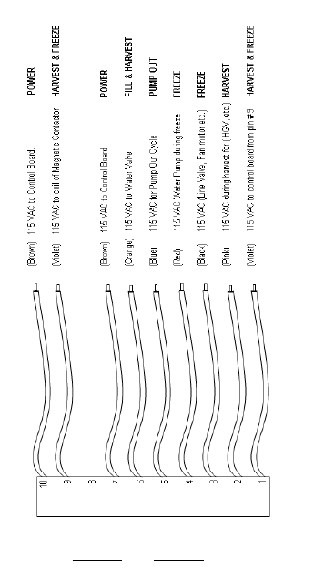
12/01/02
WIRING DIAGRAMS:
The wiring diagrams provide on the following pages are
generic in some cases because they can represent sev-
eral models. Hoshizaki provides a specific wiring label on
every unit for electrical diagnosis. See the following wiring
diagram chart for your model and capacitor information.
MECHANICAL BIN CONTROL DIAGRAM..............110
CAPACITIVE BIN CONTROL DIAGRAM ................111
10 - PIN CONNECTOR:
This connector diagram shows the standard color code and
component layouts. Use it as a guide for circuit diagnosis.
106
12/20/03
2/20/03

12/01/02
Mechanical Bin Control 110
Capacitive Bin Control 111
KM-150BAF, BWF A112 145~174 MFD None 2 MFD None
KM-150BAF-E, BWF-E B113 80 MFD None 2.MFD None
KM-250BAF, BWF A112 243~292 MFD 15 MFD 5.5 MFD 5MFD
KM-280MAF, MWF C114 378~445 MFD None 5.5 MFD 5 MFD
KM-280MAF-E, MWF-E D 115 72~86 MFD 15 MFD 5.5 MFD 2.5 MFD
KML-250MAF/H,MWF/H E116 72~86 MFD 20 MFD None
KML-350MAF/H, MWF/H F117 243~292 MFD 15 MFD None 5 MFD
KML-450MAF/H, MWF/H G118 189~227 MFD 25 MFD None 5 MFD
KM-500MAF/H, MWF/H H119 72~88 MFD 25 MFD 5.5 MFD 5 MFD
KM-500MRF/H I120 72~88 MFD 25 MFD 5.5 MFD 10 MFD
KM-500MAF-H/H-E J121 72~86 MFD 15 MFD 5.5 MFD 2.5 MFD
KML-600MAF/H, MWF/H K122 145~174 MFD 30 MFD None 5 MFD
KML-600MRF/H K122 145~174 MFD 30 MFD None 10 MFD
KM Wiring Diagram Reference Chart for R-404A Models
Fan
Capacitor
Start
Capacitor
Run
Capacitor
Pump
Capacitor
Model Page
Wiring Diagram
107
12/20/03
2/20/03

12/01/02
KM Wiring Diagram Reference Chart
Start
Capacitor
Run
Capacitor
Pump
Capacitor
Fan
Capacitor
Model Page
Wiring
Diagram
KM-630MAF/H, MWF/H L 123 88~108 MFD 15 MFD 5.5 MFD 5 MFD
KM-630MRF/H M 124 88~108 MFD 15 MFD 5.5 MFD 10 MFD
KM-630MAF-E/H-E, MWF-E/H-E N 125 88~108 MFD None 5.5 MFD 2.5 MFD
KM-900MAF/H, MWF/H O 126 145~174 MFD 35 MFD 10 MFD 5 MFD
KM-900MRF/H P 127 145~174 MFD 35 MFD 5.5 MFD 10 MFD
KM-900MRF3/H3 Q128 None None 5.5 MFD 10.MFD
KM-1300SAF/H, SWF/H, R129 145~174 MFD 35 MFD 10 MFD 5 MFD
KM-1300MAF/H, MWF/H R129 145~174 MFD 35 MFD 10 MFD 5 MFD
KM-1300SRF/H, MRF/H S130 145~174 MFD 35 MFD 10 MFD 10 MFD
KM-1300SAF3/H3, SWF3/H3 T131 None None 10 MFD 5 MFD
KM-1300SRF3/H3 U132 None None 10 MFD 10 MFD
KM-1300SAF-E/H-E, SWF-E/H-E V133 160 MFD 35 MFD 15 MFD 5 MFD
KM-1300SRF-E/H-E W134 160 MFD 35 MFD 15 MFD 10 MFD
KM1600SWF/H, SRF/H, MRF/H X135 189~227 MFD 40 MFD 10 MFD 10 MFD
KM-1600SWF3/H3, SRF3/H3 Y136 None None 10 MFD 10 MFD
108
12/20/03
2/20/03

12/01/02
KM Wiring Diagram Reference Chart
Start
Capacitor
Run
Capacitor
Pump
Capacitor
Fan
Capacitor
Model Page
Wiring
Diagram
KM-1600MRF3/H3 Z137 None None 10 MFD 10 MFD
KM-1800SAH3 AA 138 145~174 MFD 35 MFD 10 MFD 2 - 5 MFD
KM-1800SAH3 BB 139 None None 10 MFD 2 - 5 MFD
KM-2000SWF3, SRF3 AA 140 None None 10 MFD 10 MFD
KM-2400SRF3 CC 141 None None 15 MFD 15 MFD
URC-6F 10 MFD
URC-7F 10 MFD
URC-12F 10 MFD
URC-20F 10 MFD
URC-24F 15 MFD
URC-6F-E, 12F-E 10 MFD
109
12/20/03
2/20/03
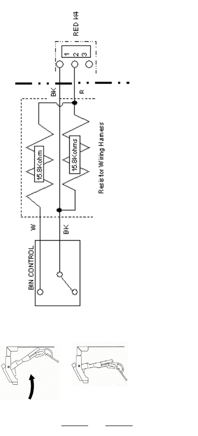
12/01/02
MECHANICAL BIN CONTOL OPERATION:
The mechanical bin control is included on some modelsproduced in 2002. The mechanical assembly is located in the ice drop zone area .
When the actuator paddle is in the normal (Bin Empty) position, the bin control proximity switch will close.
1. When the switch contacts close, 7.6 K Ohms of resistance is supplied to the K4 board connector.
When ice pushes the paddle to the full right position (Bin Full), the proximity switch opens as shown above.
2. Bin control proximity switch is shown in the Bin Full position and will supply 15.8 K Ohms to the K4 board connector.
110
BIN FULL
BIN EMPTY
12/20/03
2/20/03
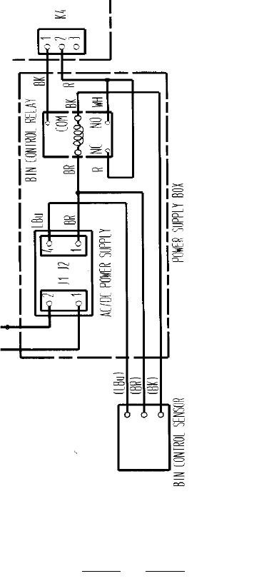
12/01/02
111
CAPACITIVE PROXIMITY BIN CONTROL: (Used on KM-1300NRF/H only)
The capacitive bin control requires DC voltage to operate. It has a seperate 24VDC power supply and switches a control relay to supply
resistance to the K4 connector. The relay contacts isolates the 24VDC from the control board which switches by resistance.
1. When the bin is empty, the resistance at K4 is 5.6 K Ohms.
2. When ice is within 1/2 to 1 inch of the sensor end, the resistance at K4 is 15.8 K Ohms to shut the unit down.
115 VAC
24 VDC
12/20/03
2/20/03
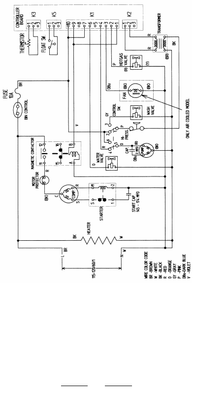
12/01/02
A
KM-150BAF, BWF,
KM-250BAF, BWF
112
Note:
1. Fuse was added to H model on late 2002 production.
2. See wiring diagram chart for KM-250B capacitor
sizes.
12/20/03
2/20/03
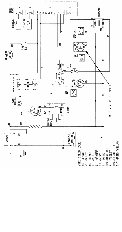
12/01/02
B
KM-150BAF-E, BWF-E
113
Note: Fuse was added to H model on late 2002
production
12/20/03
2/20/03
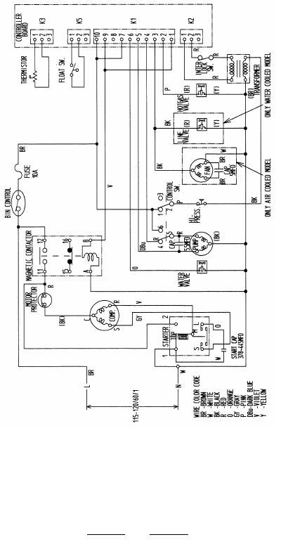
12/01/02
C
KM-280 MAF/H, MWF/H
114
Notes:
1.Some H series unit have mechanical bin control.
2.Fuse was added to H series in mid 2002.
12/20/03
2/20/03
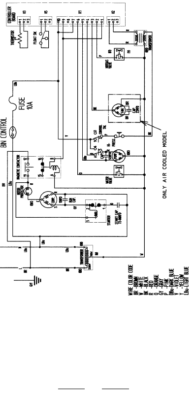
12/01/02
115
D
KM-280 MAF-E/H-E, MWF-E/H-E
Notes:
1.Some H series unit have mechanical bin control.
2.Fuse was added to H series in mid 2002.
12/20/03
2/20/03
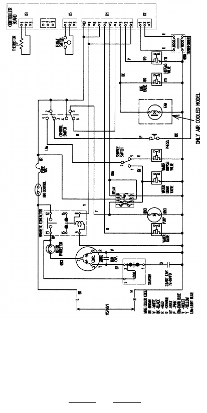
12/01/02
E
KML-250MAH, MWH
116
Notes:
1.Some H series unit have mechanical bin control.
2.Fuse was added to H series in mid 2002.
12/20/03
2/20/03
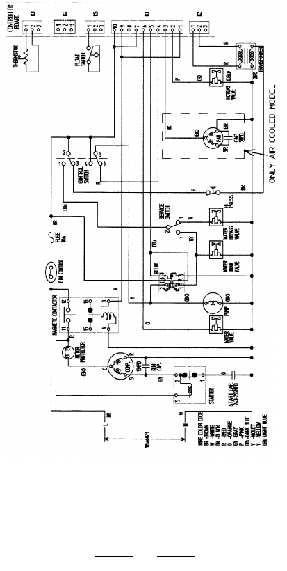
12/01/02
F
KML-350MAF/H, MWF/H
117
Notes:
1.Some H series unit have mechanical bin control.
2.Fuse was added to H series in mid 2002.
12/20/03
2/20/03
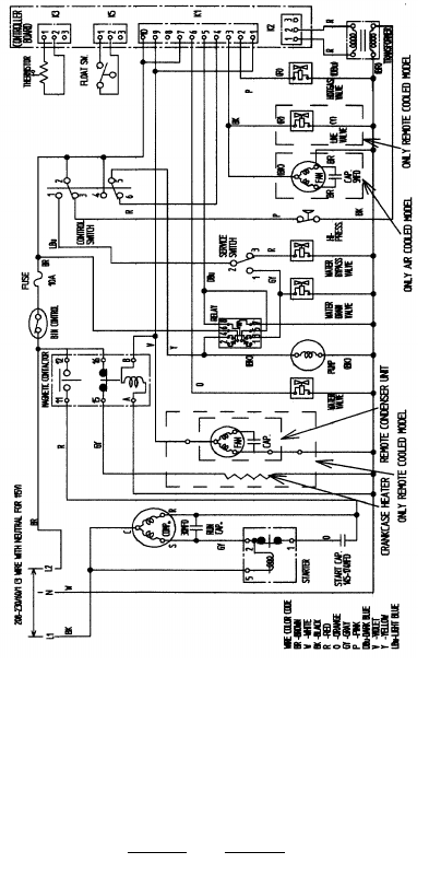
12/01/02
118
G
KML-450 MAF/H, MWF/H
Notes:
1. Some H series unit have mechanical bin control.
2. Fuse was added to H series in mid 2002.
3. This is a universal diagram, there is no KML-450
RR
remote model.
12/20/03
2/20/03
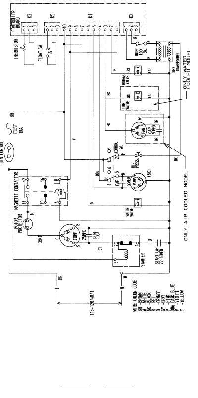
12/01/02
H
KM-500 MAF/H, MWF/H
119
Notes:
1.Some H series unit have mechanical bin control.
2.Fuse was added to H series in mid 2002.
12/20/03
2/20/03
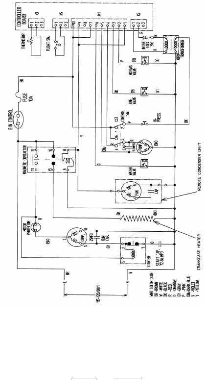
12/01/02
I
KM-500 MRF/H
120
Notes:
1.Some H series unit have mechanical bin control.
2.Fuse was added to H series in mid 2002.
12/20/03
2/20/03
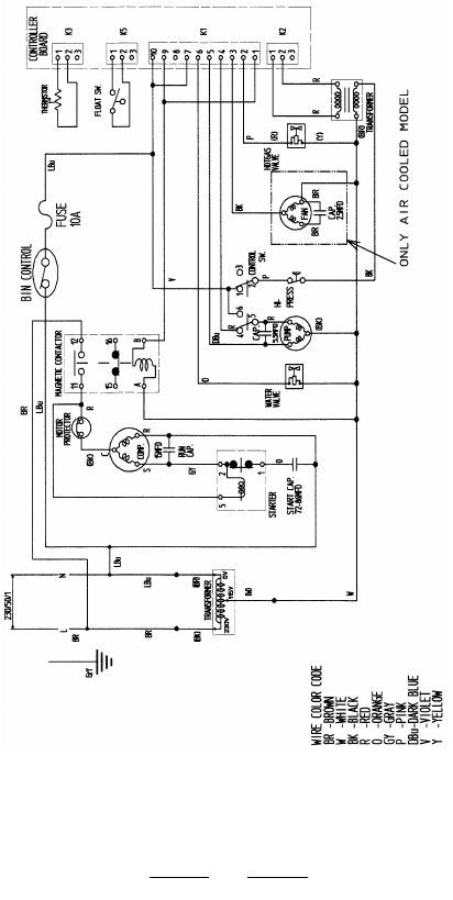
12/01/02
J
KM-500 MAF-E
121
Notes:
1.Some H series unit have mechanical bin control.
2.Fuse was added to H series in mid 2002.
12/20/03
2/20/03
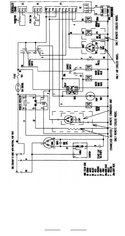
12/01/02
122
K
KML-600 MAF/H, MWF/H, MRF/H
Notes:
1.Some H series unit have mechanical bin control.
2.Fuse was added to H series in mid 2002.
12/20/03
2/20/03
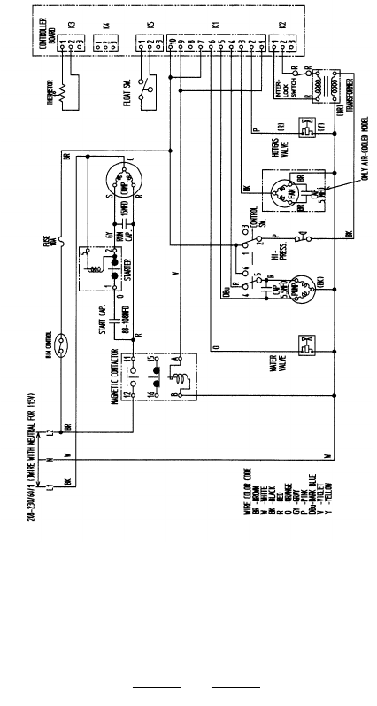
12/01/02
123
L
KM-630 MAF/H, MWF/H
Notes:
1.Some H series unit have mechanical bin control.
2.Fuse was added to H series in mid 2002.
12/20/03
2/20/03
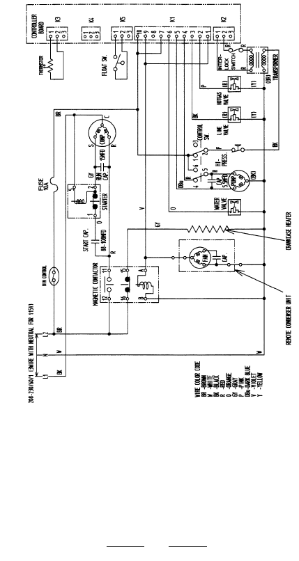
12/01/02
M
KM-630 MRF/H
124
Notes:
1.Some H series unit have mechanical bin control.
2.Fuse was added to H series in mid 2002.
12/20/03
2/20/03
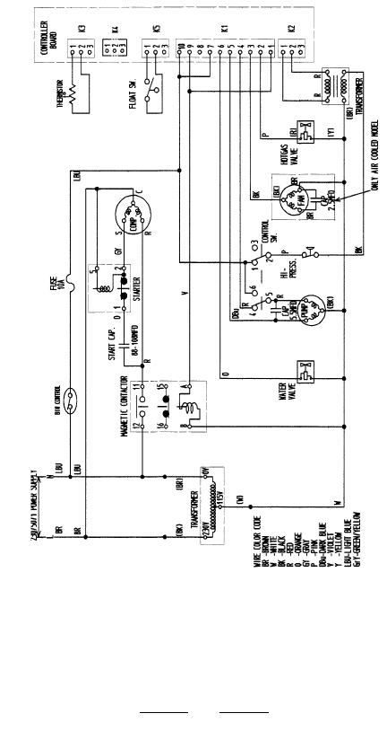
12/01/02
N
KM-630 MAF-E/H-E, MWF-E/H-E
125
Notes:
1.Some H series unit have mechanical bin control.
2.Fuse was added to H series in mid 2002.
12/20/03
2/20/03
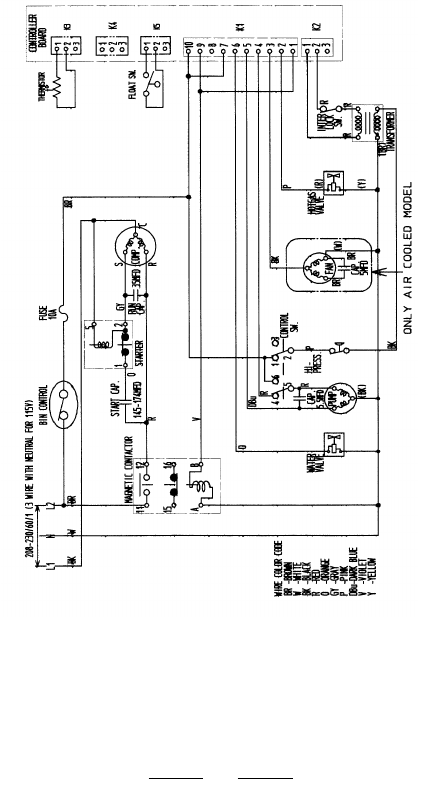
12/01/02
O
KM-900 MAF/H, MWF/H
126
Notes:
1.Some H series unit have mechanical bin control.
2.Fuse was added to H series in mid 2002.
12/20/03
2/20/03
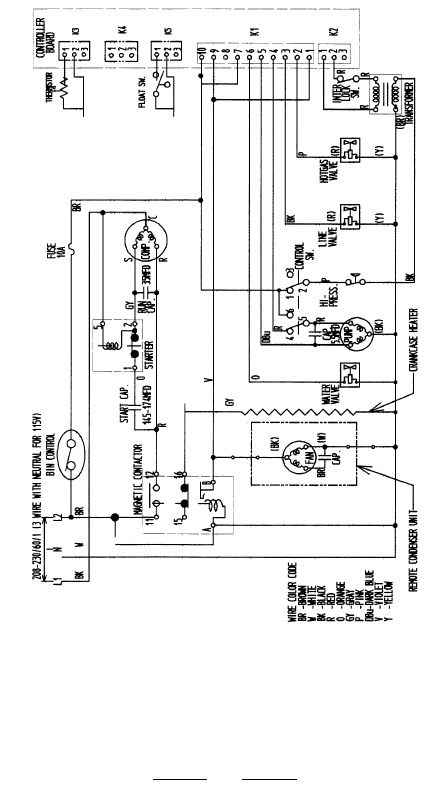
12/01/02
P
KM-900 MRF/H
127
Notes:
1.Some H series unit have mechanical bin control.
2.Fuse was added to H series in mid 2002.
12/20/03
2/20/03
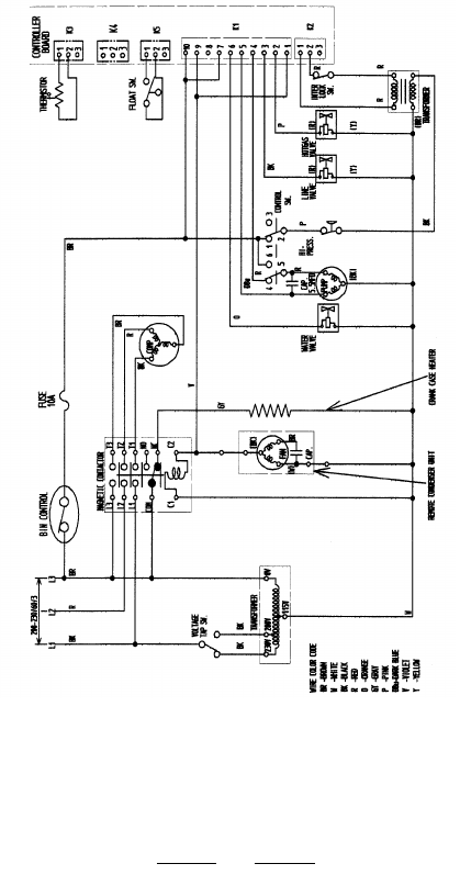
12/01/02
Q
KM-900 MRF 3/H 3
128
Notes:
1.Some H series unit have mechanical bin control.
2.Fuse was added to H series in mid 2002.
12/20/03
2/20/03
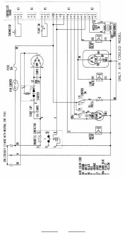
12/01/02
R
KM-1300 SAF/H, SWF/H
KM-1300 MAF/H, MWF/H
129
Note:
1. Fuse was added to H models on mid 2002
production.
2. M Series model has 2 condenser fan motors.
12/20/03
2/20/03
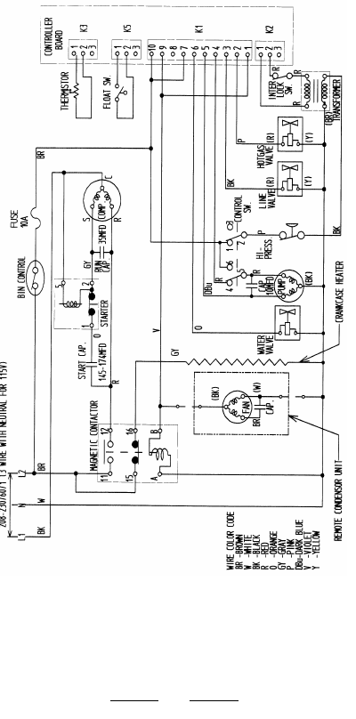
12/01/02
S
KM-1300 SRF/H, MRF/H
130
Note:
1. Fuse was added to H models on mid 2002
production.
12/20/03
2/20/03
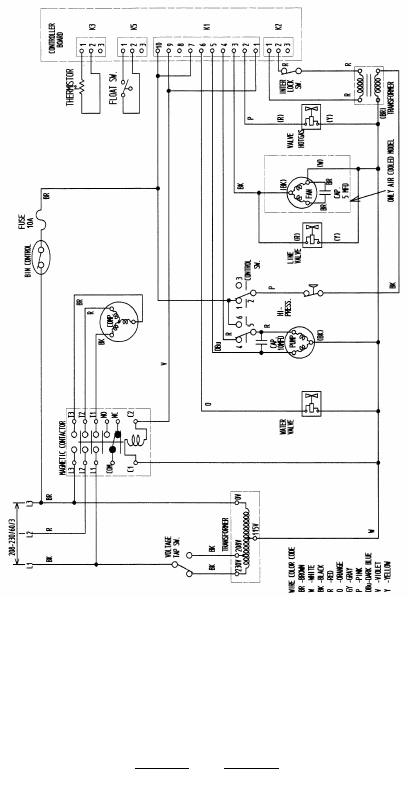
12/01/02
T
KM-1300 SAF3/H3, SWF3/H3
131
Note:
1. Fuse was added to H models on mid 2002
production.
12/20/03
2/20/03
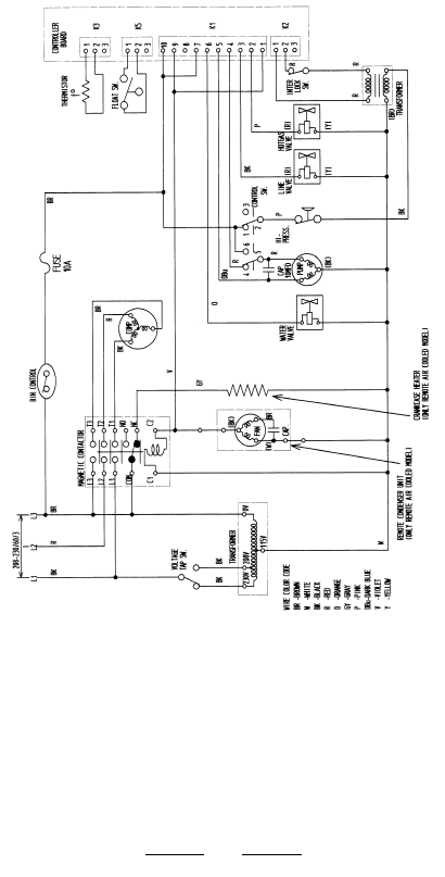
12/01/02
U
KM-1300 SRF3/H3
132
Note:
1. Fuse was added to H models on mid 2002
production.
12/20/03
2/20/03
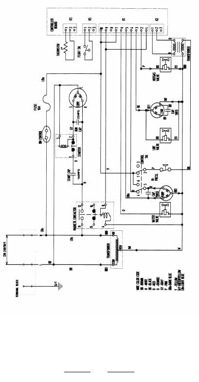
12/01/02
V
KM-1300 SAF-E, SWF-E
133
Note:
1. Fuse was added to H models on mid 2002
production.
12/20/03
2/20/03
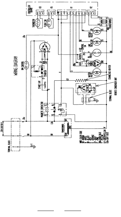
12/01/02
W
KM-1300 SRF-E
134
12/20/03
2/20/03
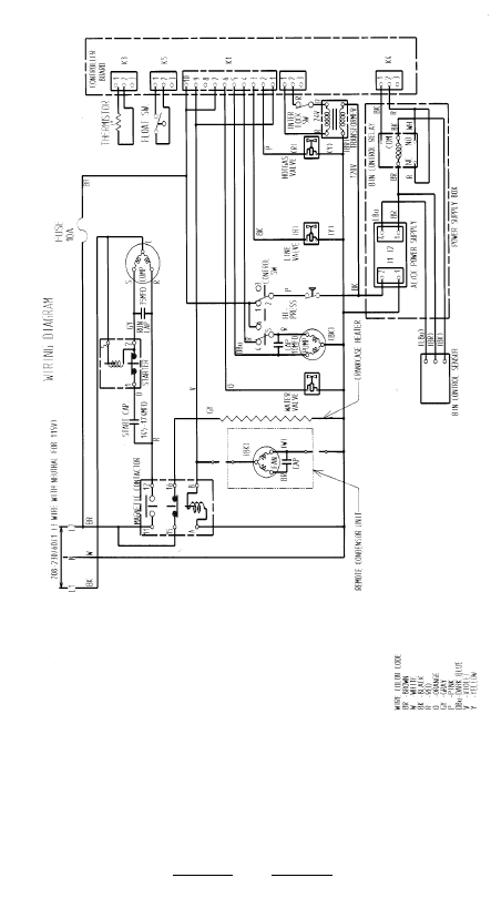
12/01/02
X
KM-1300 NRF / H
135
12/20/03
2/20/03
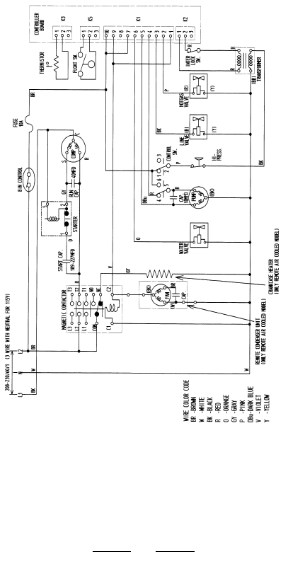
12/01/02
Y
KM-1600 SWF/H, SRF/H, MRF/H
136
Note:
1. Fuse was added to H models on mid 2002
production.
12/20/03
2/20/03
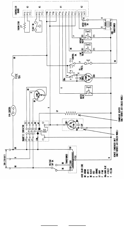
12/01/02
Z
KM-1600SWF3/H3, SRF3/H3
KM-1600MRF3/H3,
KM-2000SWF3/H3, SRF3/H3
137
Note:
1. Fuse was added to H models on mid 2002
production.
12/20/03
2/20/03
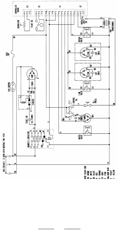
12/01/02
Note:
1. Fuse was added to H models on mid 2002
production.
138
AA
KM-1800 SAH
12/20/03
2/20/03
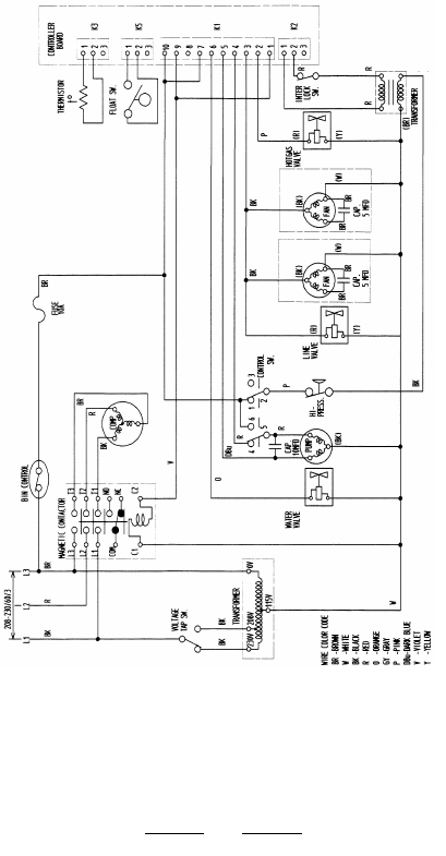
12/01/02
BB
KM-1800 SAH3
139
Note:
1. Fuse was added to H models on mid 2002
production.
12/20/03
2/20/03
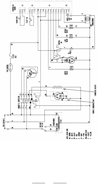
12/01/02
CC
KM-2400 SRF3/H3
140
Note:
1. Fuse was added to H models on mid 2002
production.
12/20/03
2/20/03

12/01/02
FLAKER/DCM
INSTALLATION - GENERAL
As always, you should follow the installation instructions
that are provided in the instruction manual supplied with
the unit. You will also find a yellow instruction sheet at-
tached to the top of a new unit. This sheet highlights the
installation steps. Three things are critical for a proper F/
DCM installation:
1. The water temperature should fall within the 45° F
to 90° F range.
Colder water can cause excess stress on the
auger gear motor which may activate the gear
motor overload.
2. A filter system is very important in poor water
quality areas as high mineral content can cause
premature bearing wear.
3. The unit should be level, front to back, side to
side to assure proper evaporator water level and
maximum production.
CUBELET MODELS
The DCM product produces Cubelet ice. Certain flaker mod-
els can also be converted to produce cubelet ice. This
requires changing the extruding head and cutter at the top
of the evaporator assembly. The F-450M, F-800M, and F-
2000M models are produced as cubelet models and are
designated by a - C at the end of the model number.
Converting a flaker to a cubelet maker reduces the overall
production by around 8 %. The flaker gear motor is sized to
handle the extra load of producing cubelet ice with only a
slight increase in the running amperage. The evaporator
outlet temperature and operating pressures will be similar
to the standard flaker model. Use the temperature and
pressure information provided on the standard flaker per-
formance data provided as a bench mark when diagnosing
a converted cubelet (- C) unit.
141
12/20/03
2/20/03
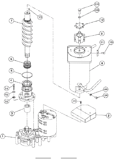
12/01/02
INTERNAL AUGER DESIGN
Hoshizaki Flakers and DCM’s use an internal auger system
to provide high quality crisp flakes and cubelet ice. The
evaporator cylinder and auger are made of anti-magnetic
stainless steel. This higher quality stainless steel elimnates
pitting caused by harmful minerals in the water. This main-
tains a smooth surface to reduce ristriction to ice flow
providing consistant production and quality.
The picture below is a generic breakdown of the F/DCM
evaporator assembly. The extruding head # 9 and cutter
#12 can be exchanged so that this Flaker assembly will
produce Cubelet style (chunklet) ice like the DCM applica-
tion. The sleeve type alignment bearings are pressed into
the housing # 4 and extruding head # 9. The mechanical
seal # 6 and “O” ring # 5 seal the lower end of the evapo-
rator system.
142
12/20/03
2/20/03

12/01/02
COMPONENT TECHNICAL DATA
CONTROL TRANSFORMER
Hoshizaki Flaker units include a 24 volt control transformer.
This transformer has a 115 volt primary and 24 volt
secondary and is protected by a 1Amp control fuse. (The
DCM has a dual output secondary of 10.5/24V) The 24 volt
secondary supplies power to the solid state timer board,
relay coils, inlet water valve and flush timer circuit. The
flush valve will be either 24 volts AC or DC, depending on
the model. A rectifier is provide in the flush valve circuit to
convert to DC. Without control voltage on pins 1 and 2, the
timer board will not allow the unit to start.
GEAR MOTOR PROTECTION
The auger gear motor circuit includes two overload safe-
ties. The primary safety is a manual reset, current type
protector or slow blow fuse located in the control box. This
is a time delay protection which operates if high amp draw
occurs. The secondary safety is a thermal protector which
is incorporated into the gear motor windings.
The current type gear motor safety has been replaced
with a slow blow fuse on most models. The Fuse provides
more consistant protection in low voltage applications.
GEAR MOTOR PROTECTION:
MODEL PROTECTION
F-300B & F-500B Current type protector
Later production uses a 1.5 amp fuse.
F-450M, F-800 1.5 Amp fuse
F-1000M Current type protector
Later production uses a 1.5 amp fuse.
F-1000M_F-C 2 amp fuse.
F-1001M_H 3 amp fuse.
F-2000M_F Current type protector.
F-2000M_H 10 amp fuse.
Note: Some cases require a 2 amp fuse for the F-1000M.
Gear motor failure can be expensive and it is very impor-
tant to find the cause of the failure when it is replaced.
There are several possibilities for the cause of gear motor
failure. The following check list is designed to help you find
the reason your failure occurred.
143
12/20/03
2/20/03

12/01/02
144
F-1000M GEAR MOTOR CHECKOUT
NORMAL AMPERAGE: The amperage for the F-1000M
gear motor should be 0.6~1.0 amps with no load and 1.0~1.4
amps when making ice.
Answer the following questions to discover the possible
cause for your failure:
1. Is Ambient Temperature above 45 degrees F.
2. Does the unit have the
Wrong Extruding Head
. Check
the Extruder Type. Is it a Flaker or Cubelet style. (The
cubelet style head will have smaller openings for the ice to
extrude.)
3. Does the unit have the
Wrong Cutter.
The cutter should
match the extruding head style. Flake or Cubelet.
4. Do you have a
Damaged Extruder.
Look for following
imperfections. A. Dents B. Fins Bent
C. Scale D. Other Resistance
5. Does the unit have the
Correct Auger
. Is the auger a
dual flight auger? (Double Spirals) Check the parts break-
down for the correct auger style.
6. Check the
Voltage Supply
and circuit amperage. Is this
unit on it’s own dedicated circuit? The supply voltage
should be within +/- 10% of the rated voltage when the unit
is making ice.
7. Check the
Running Voltage
at the gear motor. (While
the unit is making Ice.)
8. Inspect bearings for wear. ( Use bearing gauge ) Are
the
Bearings
OK? If the upper bearing is worn, both bear-
ings should be replaced.
9. Check Evaporator Cylinder/ Barrel for signs of scoring.
10. Is there any condensation dripping onto the Gear Mo-
tor windings? If yes, find the source and take action to
stop the moisture.
11. Is the galvanized shield mounted over the motor as-
sembly?
12. Verify that you have the proper Gear Motor Capacitor.
13. Is the
Gear Motor Locked
. Check motor winding resis-
tance.
2. WRONG GEAR MOTOR OVERLOAD / FUSE:
Check fuse size. Has the original overload reset been re-
placed with the fuse kit? The M_F Flaker requires Bussman
GMD 1.5A Fuse P/N 4A0893-04. The M_F-C Cubelet
requires Bussman GMD 2.0A Fuse P/N 4A0893-05. This
fuse is a slow blow type. Replacing it with a standard fuse
will cause the fuse to blow again.
12/20/03
2/20/03

12/01/02
Although it is common practice to install a larger fuse dur-
ing service diagnosis, you should not leave a larger fuse in
the unit when you leave the site. This could cause a seri-
ous unit failure.
3. MISWIRING
Is gear motor wired correctly and wire connections tight.
Check the wiring diagram for the proper wiring.
4. BIN CONTROL SWITCH DOES NOT OPERATE
Check the bin control operation. A bad or miswired bin
control can cause ice to back up in the spout and chute and
cause higher gear motor amperage. Is Bin Control wired
correctly and are the wire connections tight.
Make sure there are no metallic components interfering
with the magnetic bin control. Verify top panel is non-mag-
netic. Assure that the proximity switch is mount properly.
The switch must be secure and mounted level to the chute
top. Does the
Bin Control Paddle
move freely and is it
unobstructed?
As you can see, there are many factors that can cause a
gear motor to fail. A gear motor check list comes with a
service replacement part. The check list can be used as a
diagnostic tool. If the gear motor is under warranty, the
checklist should be completed and submitted with the war-
ranty claim.
GEAR MOTOR STRESS
When looking for the cause of a gear motor failure, you
should consider anything that will add stress to the assem-
bly. Stress on the gear motor will increase the gear motor
amperage and torque. The most common causes for stress
is scale on the auger surface and evaporator walls. Scale
nsulates the evaporator walls and causes reduced heat
transfer. As a result, the ice will be wet and mushy. This
poor quality ice does not extrude well and tends to pack in
the evaporator outlet.
Heavy scale build up must be removed using an acid based
cleaner which will loosen the scale. Follow the cleaning
instructions provided on the cleaning label to preform a
maintenance cleaning. If the unit has not been cleaned and
maintained frequently, it may require you to pull the auger
145
12/20/03
2/20/03

12/01/02
and clean the cylinder wall with a Scotchbrite pad & cleaner.
The extruding head surface may also have heavy scale
and can be cleaned with Scotchbrite & cleaner as well.
AUGER BEARINGS:
Bearing Type: Sleeve/Alignment,
Bearing Material: Poly/Carbon
The bearings are pressed into the top extruding head and
lower brass housing. A repress program is available
through the local Hoshizaki Distributor for undamaged ex-
truding heads and housings. The bearings should always
be replaced as a set. Return the extruding head and hous-
ing to your distributor for an exchange set or to be returned
for repressing.
BEARING INSPECTIONS:
Annual bearing inspections are recommended. More fre-
quent inspections may be necessary in poor water quality
areas. The steps for bearing inspections are as follows:
(1 ) Gain access to the ice chute head by removing the top
panel and spout connectors as necessary.
(2) Remove the thumbnuts which hold the ice chute head in
place and lift it up and off of the evaporator (take care to
place the O-ring in a safe location until you replace the
head.)
(3) Remove the stainless steel bolt holding the cutter or
breaker in place and lift off to access the extruding head
and auger shaft.
(4) Replace the bolt into the auger shaft and use it to push
the auger back and forth from left to right to check for
excessive movement.
(5) Pull the auger towards you and try to insert a .02” round
stock or pin gauge in between the back side of the auger
shaft and bearing surface. Check several locations around
the auger shaft. If the gauge will go in between the shaft
and bearing, it is time to install new bearings. Both top and
bottom bearings should be replaced if the top bearing is
worn. If there is no excessive movement in the auger shaft
and the gauge does not fit, the bearings are okay. Replace
the cutter, O-ring, ice chute head and connectors.
146
12/20/03
2/20/03

12/01/02
AUGER INSPECTION / BEARING
REPLACEMENT
A visual inspection of the auger bearing shaft surface is
also recommended annually in poor water areas. The steps
for this inspection is as follows:
Note: Clean the evaporator prior to removing the auger.
This will loosen scale around the extruding head
and allow for easier removal.
(1) Follow steps 1 through 5 of the bearing inspection pro-
cedure above.
(2) Remove the (metric) Allen head cap screws that se-
cure the extruding head in place.
(3) Thoroughly drain the water supply system.
4) Turn the cutter up-side down, replace the bolt and use
the cutter to lift the auger out of the evaporator. If heavy
scale is present the auger may be difficult to remove. In this
case, you will find it helpful to clean the evaporator system
following the instructions located on the Inside front panel,
before you attempt to remove the auger.
(5) With the auger removed, remove the cutter and slide
the extruding head from the top of the auger. Visually in-
spect the bearing surface at the top and bottom of the
auger. Also inspect the auger flight and mechanical seal for
any damage. The extruding head contains the top bearing,
the bottom bearing is pressed into the brass housing at the
bottom of the evaporator. To remove the housing:
(6) Remove the Allen screws that secure the evaporator to
the housing.
(7) Loosen the belly band screw and lift the evaporator up
147
12/20/03
2/20/03

12/01/02
Flaker Safety’s
Mechanical failures in an auger style ice machine can be
time consuming and expensive repairs. Hoshizaki has in-
corporated several safety’s in our Flaker and DCM units
which add protection against this type of failure.
The following safety’s are included in all Hoshizaki F and
DCM units:
1. Low water safety: Designed to protect against dry
operation or possible freeze up in the evaporator due to
low water flow. This safety utilizes the dual float switch
and a 90 second timer to shut down the unit when water
flow is interrupted. The unit will automatically restart when
water flow is resumed.
2. Protect relay safety: This safety incorporates a relay in
the gear motor circuit and will not allow the refrigeration
system to operate unless the gear motor is running. If the
gear motor fails during normal operation, the protect relay
shuts down the compressor to protect against evaporator
freeze-up.
3. Gear motor circuit safety’s: The gear motor has 2
additional safety’s which will operate if the gear motor is
subjected to excessive load or improper voltage. A current
type manual reset safety or slow blow fuse is located in
the control box and will trip when the gear motor amperage
exceeds normal amp draw. This acts as a primary safety
for the gear motor. A secondary internal thermal overload
and off of the housing. Holding the evaporator up, re-tighten
the belly band. This will hold the evaporator up so that you
can remove the housing.
(8) Remove the bolts that secure the housing to the gear
motor assembly and remove the brass housing. The me-
chanical seal ceramic disk and boot are pressed into the
top of the housing. Remove these parts before you ex-
change the bearings. The extruding head and brass hous-
ing will be exchanged for a repressed set at your local
distributor. When you replace the new parts, reverse the
order above. Use a light coat of food grade lubricant around
the bottom of the evaporator and on the o-ring portion of
the housing to the seal o-ring and help keep it in place as
you lower the evaporator. Inspect the mechanical seal thor-
oughly and reuse it, if it is in good shape.
148
12/20/03
2/20/03

12/01/02
is included in the motor windings. Both will work in con-
junction with the protect relay to shut the unit down.
4. Voltage protect relay: This relay will shut the unit off in
case of a voltage surge and automatically restart the unit
when the voltage is correct.
5. High pressure switch: All Hoshizaki ice machines in-
clude an automatic reset high pressure safety switch to
shut down the unit in case of high head pressures.
6. Fuse protection: A lamp buss-type fuse is utilized in the
control circuit. Smaller units like the DCM-240 and F-300
have a fuse in the incoming power circuit.
7. Short cycle protection timer: A 1 minute time delay is
included in the start-up sequence to protect against short
cycling the gear motor or compressor.
8. Compressor protection is provided either internally or by
means of an external motor circuit protector. This is an
automatic reset thermal type circuit breaker.
9. The F-2000 has a spout safety control to shut down the
unit if the bin control fails for any reason. This is a manual
reset safety and will notify the technician by means of a
indicator light on the control box. To reset this safety, turn
the control switch OFF and back ON. This re-sets the hold-
ing relay circuit and turns off the light.
The gear motor current protector serves as a back-up for
the bin control on other models. These safety’s protect the
Flaker or DCM models from internal failures.
DUAL FLOAT SWITCH
Hoshizaki float switch, part number 435490-01 can be used
as a universal replacement on any Hoshizaki Flaker or DCM
model in the field. It now subs for all previous float switch
numbers in our parts system.
Since the float switch is mounted into the water reservoir,
it is susceptible to scale build-up. The amount of scale
build-up will depend on the local water quality. Scale on
149
12/20/03
2/20/03
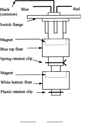
12/01/02
the switch shaft can cause the floats to stick. This will
effect the unit operation. In this case, the float switch
should be cleaned and checked.
The float switch is held in place on the top cover by a twist
lock bracket. To remove it, twist the switch flange and lift.
Soak the switch assembly in ice machine cleaner. While it
is not necessary to do so, some technicians remove the
floats from the shaft during cleaning. If you remove them,
note that the blue float is on top. Also it is important to
clearly mark the top of the floats so that they can be re-
placed correctly. (See drawing below). Installing the floats
upside down will effect the timing of the float switch op-
eration. Once clean, rinse and wipe the cleaner off and
check the switch with a good quality ohm meter.
This float switch has three wires (the black wire is com-
mon) and two separate switches. Check the top switch
by ohming out the black and red wires. When the float is up
the switch should be closed. Check the bottom switch by
ohming out the black and blue wires in the same manner. If
either switch fails, the assembly should be replaced.
150
(bottom) (top)
12/20/03
2/20/03

12/01/02
FLAKER WATER FILL SYSTEM
The reservoir in a Hoshizaki auger type ice maker feeds
water by gravity flow to the evaporator cylinder. The level
of water in the reservoir is maintained by the operation of
the dual float switch.
The dual float switch assembly is made up of two reed
switches inside of a sealed shaft. The reed switch con-
tacts are operated by individual magnets attached inside of
the two separate floats.
As ice is made and extruded from the evaporator cylinder,
the water level in the reservoir drops. When the level drops,
the top float opens the top switch contacts (considered a
latching circuit). Opening these contacts allows the bot-
tom float switch control of the water control relay in the
control circuit. As the water level continues to drop, the
bottom float contacts open to de-energize the water con-
trol relay.
De-energizing the water control relay closes a circuit to
supply 24 volts to the inlet water valve solenoid. This al-
lows water to fill the reservoir. It also opens a circuit to the
timer board which starts a 90 second low water safety
shutdown timer.
When the water supply is available, the reservoir refills.
As the reservoir level rises, these two switches swap
jobs. The bottom float is now the latching circuit and thetop
float re-energizes the water control relay. This will stop
the safety timer and shut off the water flow.
If no water is available, i.e. the filter is stopped up or the
water supply is turned off, the unit cycles down and the
water valve remains energized. When the water supply is
restored, the reservoir fills and the top float switch re-
energizes the water control relay to automatically restart
the unit. This system provides a consistent water level in
the reservoir and an automatic reset low water safety
protection.
Since the float switch is mounted into the water reservoir,
it is susceptible to scale build-up. The amount of scale
build-up will depend on the local water quality. Scale on
the switch shaft can cause the floats to stick. This will
effect the unit operation. In this case, the float switch
should be cleaned and checked.
151
12/20/03
2/20/03

12/01/02
FLAKER TIMER BOARD
The solid state timer board used in Hoshizaki Flakers is a
simple electronic sequence timer. In order for the board to
sequence, certain circuits must be closed. In order to diag-
nose a bad timer board, it is necessary to check these
circuits to assure they are operating properly. If you are
trouble-shooting a timer, the first thing you should check is
the in coming control voltage. All Hoshizaki flakers have a
24 volt control transformer. The output of this transformer
is protected by a 1 amp buss type fuse. Control voltage
comes in the timer on pins 1 & 2. If you do not have 24 volts
at pins 1 & 2, check the transformer and fuse.
Now check for 24 volts across pins 7 & 8. If voltage is
present, the timer board has cycled up which indicates
there is not a problem in the timer board. The problem is in
the gear motor relay circuit. remember that there is a time
delay from the time you turn the unit on to the time it cycles
up completely. this time will be from 1 ~ 2.5 minutes, de-
pending on the model of flaker.
In order for the flaker to start up, the reservoir must be full
and both float switches must be closed. This closes the
control circuit to pins 3 & 4. Do not confuse these pins with
the line voltage terminals marked 3 & 4 on the compressor
relay located on the board. You can check this circuit with
a volt meter across the pins or by placing a jumper across
them. If the unit cycles up with the jumper in place, the
board is good and your problem is in the water relay con-
trol circuit.
Next, you should check the bin control circuit at pins 5 & 6.
Check for a closed circuit with a volt meter or place a
jumper across them. If the unit cycles up with the jumper
in place, the board is good and the bin control circuit is the
problem.
The last circuit check is across pins 10 & 11. These pins
connect to the gear motor protect relay and will shut down
the unit if the gear motor fails. Check for a closed circuit
with a volt meter or place a jumper across them. If the unit
cycles up with the jumper in place, the board is good and
the gear motor protect circuit is suspect.
152
12/20/03
2/20/03

12/01/02
Flaker Sequence of Operation
The Hoshizaki Flaker utilizes a solid state sequence timer
board to switch the components on and off as needed.
The sequence is as follows:
With proper voltage and water supplied to the Flaker and
the flush and ice switch is in the ice position, power is
supplied to the inlet water valve. The unit will not start
unless the reservoir is full and both floats on the dual float
switch are closed (in the up position). The operation is
then turned over to the bin control. If the bin control is
closed and calling for ice, the gear motor and condenser
fan motor are energized. One minute later, the compressor
starts. As the refrigeration systems cools the water in the
evaporator, ice will start to form within 2 to 5 minutes. This
depends on the inlet water temperature and ambient condi-
tions. Ice production will continue until the bin control is
satisfied (opens). The shut down process is very simple.
On the F-450, F-800, F-1000, and F-2000 units, the entire
unit shuts down within 6 seconds after the bin control
switch opens. On the F-300 and F-500, approximately 90
seconds after the bin control switch opens, the compres-
sor stops, on minute later the gear motor and condenser
fan motor stop. This sequence of operation is accom-
plished through a series of timers within the solid state
timer board.
153
FOR FACTORY SUPPORT
CONTACT HOSHIZAKI TECHNICAL SUPPORT AT:
1 -800-233-1940
E-Mail: techsupport@hoshizaki.com
12/20/03
2/20/03
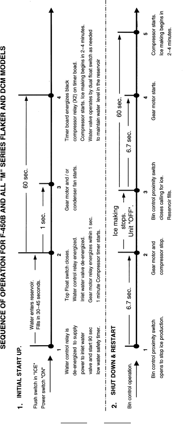
12/01/02
154
12/20/03
2/20/03

12/01/02
DCM SEQUENCE OF OPERATION
DCM sequence for the ice making unit is similar to the F-
500, with a delay of the compressor at start up and a delay
of the gear motor at shut down.
A periodic flush is also incorporated in the DCM units. All
DCM models have periodic agitation in the bin to eliminate
ice bridging. The DCM- 240 model uses a solid state relay to
turn the gear motor for .2 seconds every 90 minutes. On
DCM-500 and 750 models, the solid state timer board will
start the agitation motor for .6 seconds every 12 seconds
of accumulated dispensing time.
FLAKER/DCM PRODUCTION CHECK
Checking the production on a F/DCM is a simple process.
To check the production you will need a bucket or pan to
catch the ice and a set of scales to weigh the ice. After the
unit has operated for 10 to 20 minutes, catch the ice pro-
duction for 10 full minutes. Weigh the ice to establish the
batch weight. Multiply the batch weight by 144 for the total
production in 24 hours. Some prefer to catch the ice for 20
minutes and multiply the weight by 72 for a more realistic
production check. It is true that a longer catch is more
accurate, however, it doubles your test time and may only
show a 1 to 2% difference in production. Performing a
production check is an excellent way to prove proper F/
DCM operation.
FLAKER PERIODIC FLUSH
Beginning with the F-450M and larger flakers, a periodic
flush cycle is included. A 12 hour timer will cycle the unit
down and open the flush valve which allows the complete
water system to drain. The unit will remain off for 20 min-
utes which allows any ice remaining in the evaporator to
melt and flush the evaporator walls and mechanical seal
out. The inlet water valve is not energized during this flush
period. The unit will automatically restart after 20 minutes
on the flush timer.
The F-500 will flush when the bin control is open.
155
12/20/03
2/20/03
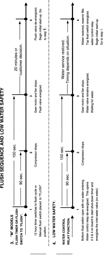
12/01/02
156
12/20/03
2/20/03

12/01/02
WATER AND REFRIGERATION CIRCUIT
DRAWING REFERENCE CHART FOR R-404A
MODELS
MODEL DRAWING P
AGE
F-300B ....................................... A .................... 158
F-450MAF/H, F-500BAF ............ B .................... 159
F-800MAF/H, MWF/H ................. C.................... 160
F-1000MAF, MWF ...................... C.................... 160
F-1001MAH, MWH ..................... C.................... 160
F-1000MRF, F-1001MRH ........... D.................... 161
F-1000MLF ................................. E .................... 162
F-2000MRF/H ............................. F .................... 163
F-2000MLF/H ............................. G .................. 164
DCM-240B, DCM-270 ................. H.................... 165
DCM-450B ................................... I .................... 166
DCM-700B ................................... I .................... 166
NOTE: Some drawings have been combined to
represent more than one model.
157
12/20/03
2/20/03
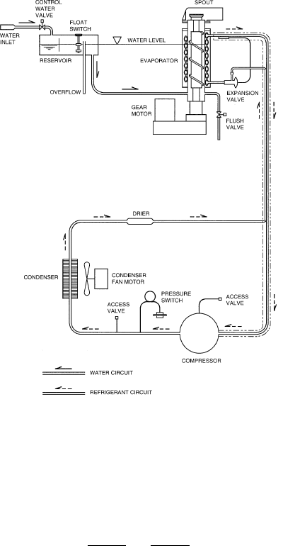
12/01/02
158
A
F-300 BAF
12/20/03
2/20/03
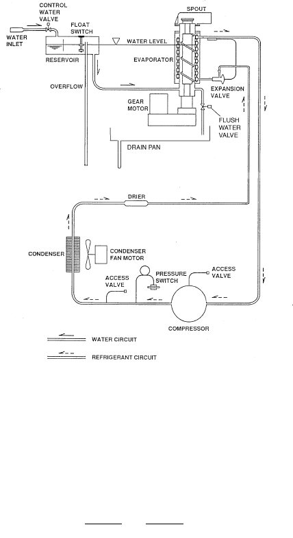
12/01/02
159
B
F-450 MAF/H
F-500 BAF
12/20/03
2/20/03
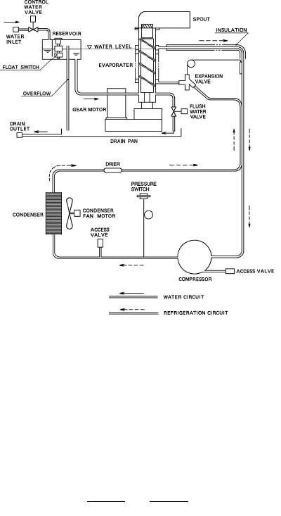
12/01/02
C
F-800MAF/H, MWF/H
F-1000 MAF, MWF
F-1001MAH, MWH
160
12/20/03
2/20/03
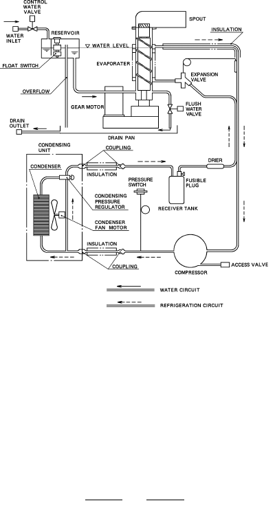
12/01/02
D
F-1000 MRF
F-1001 MRH
161
12/20/03
2/20/03
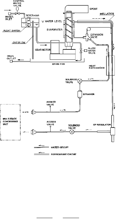
12/01/02
E
F-1000 MLF
F1001 MLH
124
162
12/20/03
2/20/03
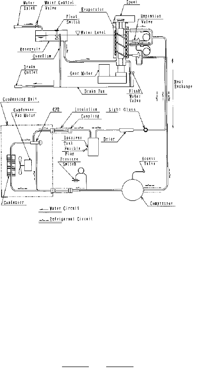
12/01/02
F
F-2000 MRF
F-2000 MRH
163
12/20/03
2/20/03
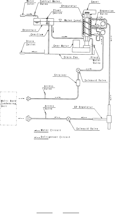
12/01/02
G
F-2000 MLF
F-2000 MLH
126
164
12/20/03
2/20/03
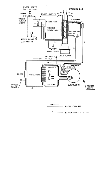
12/01/02
H
DCM-240 BAF
DCM-270 BAH
165
12/20/03
2/20/03
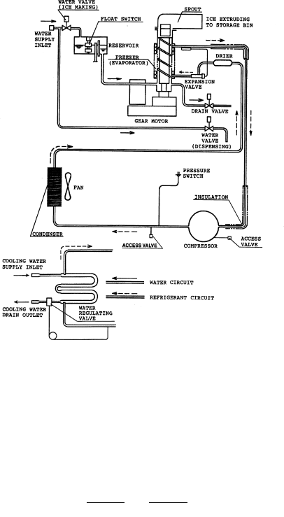
12/01/02
I
DCM-500 BAF/H, BWF/H
DCM-750 BAF/H, BWF/H
166
12/20/03
2/20/03
12/01/02
Kg=lbs.
x .454
Production
24 hours
(lbs.)
Evaporator
Outlet temp.
(°F)
Pressure
High Side
Pressure
Suction
Ambient Temp F°/C°
R-404A PERFORMANCE DATA
50/9
70/21
90/32
50/9
70/21
90/32
50/9
70/21
90/32
50/9
70/21
90/32
WaterTemp
(F°/C°)
70 / 21 80 / 27
Air Air
19
19
19
303
290
278
35
35
35
250
250
250
19
22
22
267
256
246
37
37
37
280
280
280
MODEL: F-300BAF
Total Amperage (Compressor RLA): 9A (7.6A) Supply Voltage: 115/60/1
43
43
43
90 / 32 100 / 38
Air Air
22
22
22
236
232
218
39
39
39
26
26
26
209
201
188
351
351
351
311
311
311
167
12/20/03
2/20/03

12/01/02
MODEL: F-450MAF/H & MAF -C/H-C (cubelet)
Total Amperage (Compressor RLA): 11.25A (8.5A) Supply voltage: 115/60/1
Ambient Temp (F°/C°)
R-404A PERFORMANCE DATA
50 / 9
70 / 21
90 / 32
50 / 9
70 / 21
90 / 32
50 / 9
70 / 21
90 / 32
50 / 9
70 / 21
90 / 32
Water Temp
(F°/C°)
70 / 21 80 / 27 90 / 32
Air -C Air -C Air -C
476
456
435
16
16
16
235
235
235
29
29
29
426
407
387
16
16
16
236
236
236
30
30
30
416
397
379
16
16
16
272
272
272
33
33
33
368
350
333
34
34
34
362
355
330
16
16
16
308
308
308
36
36
36
Evaporator
Outlet temp.
(°F)
Pressure
High Side
Pressure
Suction
Kg=lbs.
x .454
Production
24 hours
(lbs.)
317
310
287
16
16
16
310
310
310
37
37
37
100 / 38
Air -C
315
301
282
16
16
16
348
348
348
39
39
39
273
260
244
16
16
16
351
351
351
41
41
41
16
16
16
273
273
273
168
12/20/03
2/20/03
12/01/02
MODEL: F-500BAF & BAF -C (cubelet)
Total Amperage (Compressor RLA): 9.95A (7.9A) Supply voltage: 115/60/1
Ambient Temp (F°/C°)
R-404A PERFORMANCE DATA
50 / 9
70 / 21
90 / 32
50 / 9
70 / 21
90 / 32
50 / 9
70 / 21
90 / 32
50 / 9
70 / 21
90 / 32
Water
Temp (F°/C°)
70 / 21 80 / 27 90 / 32
Air Air -C Air Air -C Air Air -C
478
458
438
8
8
8
221
221
221
26
26
26
431
315
398
9
9
9
225
225
225
27
27
27
419
400
383
8
12
12
253
253
253
28
28
28
381
365
350
30
30
30
366
359
335
12
13
15
285
285
285
31
31
31
Evaporator
Outlet temp.
(°F)
Pressure
High Side
Pressure
Suction
Kg=lbs.
x .454
Production
24 hours
(lbs.)
336
333
308
12
12
15
292
292
292
32
32
32
100 / 38
Air Air-C
320
306
287
15
15
15
327
327
327
34
34
34
295
283
263
15
15
15
332
332
332
35
35
35
9
12
12
258
258
258
169
12/20/03
2/20/03

12/01/02
Ambient Temp °F/°C
PERFORMANCE DATA
Evaporator
Outlet temp.
(°F)
Pressure
High Side
Pressure
Suction
Kg=lbs.
x .454
Production
24 hours
(lbs.)
MODEL: F-800M _F / H
Total Amperage (Compressor RLA): MAF 11.95A (9.2A), MWF 10.2A (8.3A) Supply voltage: 115/60/1
Water consumption for water cooled cond: 70/50 (21/9) 318 Gal/24 hr. 90/70 (32/21) 539 Gal/24 hr.
50 / 9
70 / 21
90 / 32
50 / 9
70 / 21
90 / 32
50 / 9
70 / 21
90 / 32
50 / 9
70 / 21
90 / 32
WaterTemp
°F/°C
70 / 21 80 / 27 90 / 32
Air Water Air Water Air Water
800
765
735
17
18
18
223
239
255
35
37
38
720
695
680
21
22
21
265
267
266
37
37
37
710
680
655
19
21
20
270
287
287
39
41
41
670
660
650
38
37
38
630
615
585
21
20
21
286
287
306
41
41
43
640
625
620
21
22
22
266
266
265
38
38
38
100 / 38
Air Water
560
540
505
22
23
22
315
325
325
44
45
45
605
595
555
23
23
22
267
269
268
39
39
39
22
22
22
267
266
265
170
R-404A
12/20/03
2/20/03

12/01/02
Ambient Temp °F/°C
R-404A PERFORMANCE DATA
Evaporator
Outlet temp.
(°F)
Pressure
High Side
Pressure
Suction
Kg=lbs.
x .454
Production
24 hours
(lbs.)
MODEL: F-800M _F-C / H-C (cubelet)
Total Amperage (Compressor RLA): MAF-C 11.95A (9.2A), MWF-C 10.2A (8.3A) Supply voltage: 115/60/1
Water consumption for water cooled cond: 70/50 (21/9) 318 Gal/24 hr. 90/70 (32/21) 553 Gal/24 hr.
50 / 9
70 / 21
90 / 32
50 / 9
70 / 21
90 / 32
50 / 9
70 / 21
90 / 32
50 / 9
70 / 21
90 / 32
Water temp
°F/°C
70 / 21 80 / 27
Air Water Air Water
760
730
700
16
17
17
221
221
221
35
35
35
670
650
640
21
22
21
265
267
266
37
37
37
665
640
610
18
18
19
254
254
254
38
38
38
625
615
605
38
37
38
22
22
22
267
266
265
90 / 32
Air Water
585
575
535
21
29
21
286
286
286
41
41
41
590
590
570
21
23
22
266
266
265
38
38
38
100 / 38
Air Water
510
490
455
22
23
23
325
325
325
45
45
45
560
550
505
23
23
23
267
269
268
39
39
39
171
12/20/03
2/20/03

12/01/02
50 / 9
70 / 21
90 / 32
50 / 9
70 / 21
90 / 32
50 / 9
70 / 21
90 / 32
50 / 9
70 / 21
90 / 32
Water Temp
F°/C°
Evaporator
Outlet temp.
(F°)
Pressure
High Side
Pressure
Suction
Ambient Temp (F° / C°) 70 / 21 80 / 27
R-404A PERFORMANCE DATA
MODEL: F- 1000M_F Supply Voltage: 208-230/60/1 ( 3 wire with neutral for for 115V)
Total Amperage (Compressor RLA): MAF 6.85A (4.2A) MWF: 5.83A(4.2A), MRF: 8.9A (4.2A)
Water Consumption for water cooled cond. 70 / 50 (21/9) 303 Gal/24 hr: 90 / 70 (32/21) 480 Gal/24 hr.
Air Water Remote Air Water Remote
Kg=lbs.
x .454
Production
24 hours
(lbs.)
32
32
32
213
213
213
19
19
19
970
930
890
33
34
35
263
266
269
23
23
25
890
855
840
35
35
35
244
244
244
19
23
23
855
820
785
33
34
35
263
266
269
23
23
25
820
805
785
930
895
865
221
221
221
33
33
33
835
805
780
25
26
26
239
239
239
35
35
35
23
24
25
90 / 32
Air Water Remote
38
38
38
274
274
274
23
23
25
755
740
695
100 / 38
Air Water Remote
33
34
35
263
266
269
23
23
25
770
755
735
750
745
700
26
27
28
256
256
256
36
36
36
41
41
41
315
315
315
25
25
25
665
635
595
33
34
35
263
266
269
23
23
25
720
705
655
675
650
605
28
28
28
295
296
295
39
39
39
172
12/20/03
2/20/03

12/01/02
50 / 9
70 / 21
90 / 32
50 / 9
70 / 21
90 / 32
50 / 9
70 / 21
90 / 32
50 / 9
70 / 21
90 / 32
Water Temp
F°/C°
Evaporator
Outlet temp.
(F°)
Pressure
High Side
Pressure
Suction
Ambient Temp (F° / C°) 70 / 21 80 / 27
Air Water Remote Air Water Remote
Kg=lbs.
x .454
Production
24 hours
(lbs.)
32
32
32
209
209
209
18
18
18
860
820
790
33
34
35
263
266
269
23
23
25
790
760
750
35
35
35
243
243
243
18
23
23
765
735
710
33
34
35
263
266
269
23
23
25
735
720
710
840
810
790
220
220
220
34
34
33
23
24
25
765
745
720
25
26
26
238
238
238
36
36
36
90 / 32
Air Water Remote
38
38
38
277
277
277
23
23
27
680
665
635
100 / 38
Air Water Remote
33
34
35
263
266
269
23
23
25
695
685
670
700
695
660
26
25
28
256
256
256
37
37
37
41
41
41
217
317
217
27
27
27
610
585
550
33
34
35
263
266
269
23
23
25
660
645
600
640
620
575
28
28
28
295
295
295
40
40
40
173
R-404A PERFORMANCE DATA
MODEL: F- 1000M _F -C (cubelet) Supply Voltage: 208-230/60/1 ( 3 wire with neutral for for 115V)
Total Amperage (Compressor RLA): MAF -C 6.85A (4.2A), MWF: 5.83A (4.2A), MRF: 8.9A (4.2A)
Water Consumption for water cooled cond. 70 / 50 (21/9) 303 Gal/24 hr. 90 / 70 (32/21) 492 Gal/24 hr.
12/20/03
2/20/03

12/01/02
Ambient Temp °F/°C
R-404A PERFORMANCE DATA
Evaporator
Outlet temp.
(°F)
Pressure
High Side
Pressure
Suction
Kg=lbs.
x .454
Production
24 hours
(lbs.)
MODEL: F-1000MLF & MLF-C (cubelet)
Total Amperage 1.63A Supply voltage: 115/60/1
This unit is designed for connection to a Rack System using R-404A refrigerant. The data below is calculated.
50 / 9
70 / 21
90 / 32
50 / 9
70 / 21
90 / 32
50 / 9
70 / 21
90 / 32
50 / 9
70 / 21
90 / 32
Water Temp
°F/°C
70 / 21 80 / 27
Low side -C Low side -C
1150
1035
1005
21
21
21
106
106
106
26
26
26
1020
945
915
21
21
21
106
106
106
26
26
26
980
950
925
21
21
21
125
125
125
30
30
30
885
860
835
30
30
30
21
21
21
125
125
125
90 / 32
Low side -C
900
885
805
21
21
23
143
143
143
33
33
33
805
795
760
21
21
23
143
143
143
33
33
33
100 / 38
Low side -C
830
805
690
23
23
23
166
166
166
35
35
35
735
710
640
23
23
23
166
166
166
35
35
35
174
Note: The data provided is calculated by using a refrigeration capacity of 5700 BTU/h with a high side pressure of 213 PSIG and suction
pressure of 31.2 PSIG. The actual production and system operating pressures will vary depending on the specific R-404A rack system
setup.
Factory setting for the Evaporator Pressure Regulating Valve (EPR) is 32 PSIG. for evaporator temperature no less than 0 °F (-17.7°C).
12/20/03
2/20/03
12/01/02
34
34
34
Kg=lbs.
x .454
Production
24 hours
(lbs.)
Evaporator
Outlet temp.
(°F)
Pressure
High Side
Pressure
Suction
Ambient Temp F°/C°
NOTE: R-22 refrigerant charge 1 lb. 7oz. (660g.).
R-22 “ SPECIAL MODEL” PERFORMANCE DATA
50/9
70/21
90/32
50/9
70/21
90/32
50/9
70/21
90/32
50/9
70/21
90/32
Water Temp
°F/°C
70 / 21 80 / 27 90 / 32 100 / 38
Air Air Air Air
14
14
14
860
820
790
28
28
28
170
170
170
14
18
18
680
720
710
30
30
30
199
199
199
680
670
635
32
32
32
228
228
228
21
21
21
615
585
555
258
258
258
MODEL: F-1000MAF-22 (Special production using R-22 refrigerant)
Total Amperage (Compressor RLA): MAF 7.25A (4.5A) Supply Voltage: 115/60/1
18
18
21
175
12/20/03
2/20/03
12/01/02
Ambient Temp °F /°C
R-404A PERFORMANCE DATA
50 / 9
70 / 21
90 / 32
50 / 9
70 / 21
90 / 32
50 / 9
70 / 21
90 / 32
50 / 9
70 / 21
90 / 32
Water Temp
°F /°C
70 / 21 80 / 27 90 / 32
Air Water Air Water Air Water
935 / 424
895 / 404
865 / 393
14 / -10
14 / -10
14 / -10
224
224
224
33
33
33
860 / 390
855 / 388
840 / 383
16 / -9
16 / -9
16 / -9
260
260
261
35
37
39
835 / 383
805 / 373
780 / 363
14 / -10
16 / -9
16 / -9
257
257
257
36
36
36
820 / 379
805 / 374
785 / 370
16 / -9
16 / -9
16 / -9
260
260
261
35
37
39
750 / 353
750 / 353
737 / 334
16 / -9
16 / -9
17 / -9
289
289
289
39
39
39
Evaporator
Outlet temp.
°F /°C
Pressure
High Side
Pressure
Suction
Production
24 hours
(lbs.)
770 / 365
840 / 381
735 / 357
16 / -9
16 / -9
16 / -9
260
260
261
35
37
39
100 / 38
Air Water
717 / 325
650 / 316
655 / 297
17 / -9
17 / -9
17 / -9
329
329
329
43
43
43
777 / 352
768 / 348
690 / 313
16 / -9
16 / -9
16 / -9
260
260
261
35
37
39
MODEL: F-1000M_F-50
Total Amperage (Compressor RLA): MAF 6.8A (5.9A), MWF 6.3A (5.4A) Supply Voltage: 220-240 50/ 1
Water consumption for water cooled cond: 70/50 (21/9) 326 Gal/24 hr. 90/70 (32/21) 503 Gal/24 hr.
176
12/20/03
2/20/03

12/01/02
50 / 9
70 / 21
90 / 32
50 / 9
70 / 21
90 / 32
50 / 9
70 / 21
90 / 32
50 / 9
70 / 21
90 / 32
Water Temp
F°/C°
Evaporator
Outlet temp.
(F°)
Pressure
High Side
Pressure
Suction
Ambient Temp (F° / C°) 70 / 21 80 / 27
R-404A PERFORMANCE DATA
MODEL: F- 1001M_H Supply Voltage: 208-230/60/1 ( 3 wire with neutral for for 115V)
Total Amperage (Compressor RLA): MAH 6.85A (4.2A) MWH: 5.83A(4.2A), MRH: 8.9A (4.2A)
Water Consumption for water cooled cond. 70 / 50 (21/9) 303 Gal/24 hr: 90 / 70 (32/21) 480 Gal/24 hr.
Air Water Remote Air Water Remote
Kg=lbs.
x .454
Production
24 hours
(lbs.)
32
32
32
213
213
213
970
930
890
33
34
35
263
266
269
23
23
25
890
855
840
35
35
35
244
244
244
835
805
780
33
34
35
263
266
269
23
23
25
820
805
785
930
895
865
221
221
221
33
33
33
835
805
780
25
26
26
239
239
239
35
35
35
23
24
25
90 / 32
Air Water Remote
38
38
38
274
274
274
23
23
25
755
740
695
100 / 38
Air Water Remote
33
34
35
263
266
269
23
23
25
770
755
735
750
745
700
26
27
28
256
256
256
36
36
36
41
41
41
315
315
315
25
25
25
665
635
595
33
34
35
263
266
269
23
23
25
720
705
655
675
650
605
28
28
28
295
296
295
39
39
39
177
19
23
23
19
19
19
12/20/03
2/20/03
12/01/02
50 / 9
70 / 21
90 / 32
50 / 9
70 / 21
90 / 32
50 / 9
70 / 21
90 / 32
50 / 9
70 / 21
90 / 32
Water Temp
F°/C°
Evaporator
Outlet temp.
(F°)
Pressure
High Side
Pressure
Suction
Ambient Temp (F° / C°) 70 / 21 80 / 27
Air Water Remote Air Water Remote
Kg=lbs.
x .454
Production
24 hours
(lbs.)
32
32
32
860
820
790
33
34
35
263
266
269
23
23
25
790
760
750
35
35
35
243
243
243
765
735
710
33
34
35
263
266
269
23
23
25
735
720
710
840
810
790
220
220
220
34
34
33
23
24
25
765
745
720
25
26
26
238
238
238
36
36
36
90 / 32
Air Water Remote
38
38
38
277
277
277
23
23
27
680
665
635
100 / 38
Air Water Remote
33
34
35
263
266
269
23
23
25
695
685
670
700
695
660
26
25
28
256
256
256
37
37
37
41
41
41
217
317
217
27
27
27
610
585
550
33
34
35
263
266
269
23
23
25
660
645
600
640
620
575
28
28
28
295
295
295
40
40
40
178
R-404A PERFORMANCE DATA
MODEL: F- 1001M _H -C (cubelet) Supply Voltage: 208-230/60/1 ( 3 wire with neutral for for 115V)
Total Amperage (Compressor RLA): MAH -C 8.08A (4.2A), MWH-C: 5.83A (4.2A), MRH-C: 10.23A (4.2A)
Water Consumption for water cooled cond. 70 / 50 (21/9) 303 Gal/24 hr. 90 / 70 (32/21) 492 Gal/24 hr.
18
18
18
209
209
209
18
23
23
12/20/03
2/20/03

12/01/02
Ambient Temp °F/°C
R-404A PERFORMANCE DATA
Evaporator
Outlet temp.
(°F)
Pressure
High Side
Pressure
Suction
Kg=lbs.
x .454
Production
24 hours
(lbs.)
MODEL: F-1001MLH & MLH-C (cubelet)
Total Amperage: 3.03A Supply voltage: 115/60/1
This unit is designed for connection to a Rack System using R-404A refrigerant. The data below is calculated.
50 / 9
70 / 21
90 / 32
50 / 9
70 / 21
90 / 32
50 / 9
70 / 21
90 / 32
50 / 9
70 / 21
90 / 32
Water Temp
°F/°C
70 / 21 80 / 27
Low side -C Low side -C
21
21
21
106
106
106
26
26
26
21
21
21
106
106
106
26
26
26
980
950
925
21
21
21
125
125
125
30
30
30
885
860
835
30
30
30
21
21
21
125
125
125
90 / 32
Low side -C
900
885
805
21
21
23
143
143
143
33
33
33
805
795
760
21
21
23
143
143
143
33
33
33
100 / 38
Low side -C
830
805
690
23
23
23
166
166
166
35
35
35
735
710
640
23
23
23
166
166
166
35
35
35
179
Note: The data provided is calculated by using a refrigeration capacity of 5700 BTU/h with a high side pressure of 213 PSIG and suction
pressure of 31.2 PSIG. The actual production and system operating pressures will vary depending on the specific R-404A rack system setup.
Factory setting for the Evaporator Pressure Regulating Valve (EPR) is 32 PSIG. for evaporator temperature no less than 0 °F (-17.7°C).
12/20/03
2/20/03
12/01/02
180
80 / 27 90 / 32
1875
1836
1797
11
11
11
262
263
265
26
27
28
1827
1777
1729
12
12
12
230
230
230
26
26
26
1759
1730
1686
11
11
11
262
263
265
26
27
28
MODEL: F-2000M_F/H Supply Voltage: 208-230/60/1
Total Amperage (Compressor RLA): Water 16.9 (10.8A), Remote 19.4A (10.8A)
Water consumption for water cooled cond: 70/50 (21/9) 735 Gal/24 hr. 90/70 (32/21) 1165 Gal/24 hr.
1683
1676
1593
12
12
14
238
238
238
26
26
26
100 / 38
1651
1616
1500
11
11
11
262
263
265
26
27
28
1550
1508
1393
14
14
14
274
274
274
29
29
29
Water
50 / 9
70 / 21
90 / 32
70 / 21
2030
1957
1916
11
11
11
262
263
265
26
27
28
1992
1930
1878
12
12
12
221
221
221
25
25
25
Water
temp F°/C°
Ambient Temp (F°)
50 / 9
70 / 21
90 / 32
50 / 9
70 / 21
90 / 32
50 / 9
70 / 21
90 / 32
Evaporator
Outlet temp.
(°F)
Pressure
High Side
Pressure
Suction
Kg=lbs.
x .454
Production
24 hours
(lbs.)
R-404A PERFORMANCE DATA
Remote
Water Remote
Water Remote
Water Remote
12/20/03
2/20/03

12/01/02
80 / 27 90 / 32
1669
1641
1614
10
10
12
262
263
266
27
27
28
1595
1562
1530
12
14
14
227
227
227
26
26
26
1587
1560
1534
10
10
12
262
263
266
27
27
28
MODEL: F-2000M_F-C/H-C (cubelet) Supply Voltage: 208-230/60/1
Total Amperage (Compressor RLA): Water 16.9 (10.8A), Remote 19.4A (10.8A)
Water consumption for water cooled cond: 70/50 (21/9) 765 Gal/24 hr. 90/70 (32/21) 1190 Gal/24 hr.
1498
1491
1437
14
14
14
233
233
233
27
27
27
70 / 21
1790
1727
1698
10
10
12
262
263
266
27
27
28
1714
1662
1628
12
12
12
220
220
220
26
26
26
R-404A PERFORMANCE DATA
100 / 38
1508
1483
1375
10
10
12
262
263
266
27
27
28
1408
1379
1272
14
14
14
266
266
266
29
29
29
50 / 9
70 / 21
90 / 32
Water
temp F°/C°
Ambient Temp (F°)
50 / 9
70 / 21
90 / 32
50 / 9
70 / 21
90 / 32
50 / 9
70 / 21
90 / 32
Evaporator
Outlet temp.
(°F)
Pressure
High Side
Pressure
Suction
Kg=lbs.
x .454
Production
24 hours
(lbs.)
181
RemoteWater RemoteWater Remote
Water RemoteWater
12/20/03
2/20/03

12/01/02
80 / 27 90 / 32
1845
1796
1748
14
14
14
230
230
230
26
26
26
1613
1579
1546
-1
0
0
225
225
225
25
25
25
1701
1693
1612
14
14
16
241
241
241
27
27
27
1526
1513
1450
0
0
3
228
228
228
26
26
26
70 / 21
2011
1948
1897
14
14
14
219
219
219
25
25
25
1725
1684
1648
-1
-1
-1
222
222
222
25
25
25
R-404A PERFORMANCE DATA
Remote -C
Remote -C
Remote -C
100 / 38
1569
1527
1411
16
16
16
271
271
271
29
29
29
1420
1390
1274
3
3
3
262
262
262
29
29
29
Remote -C
50 / 9
70 / 21
90 / 32
Water
temp F°/C°
Ambient Temp (F°)
50 / 9
70 / 21
90 / 32
50 / 9
70 / 21
90 / 32
50 / 9
70 / 21
90 / 32
Evaporator
Outlet temp.
(°F)
Pressure
High Side
Pressure
Suction
Kg=lbs.
x .454
Production
24 hours
(lbs.)
182
MODEL: F-2000MRF/H3 & MRF3-C/H3-C (cubelet)
Total Amperage (Compressor RLA): Remote 17.6A (9A) Supply Voltage: 208-230/60/3
12/20/03
2/20/03
12/01/02
80 / 27
2010
1835
1795
12
12
12
190
256
297
16
21
22
1755
1615
1585
12
12
12
190
256
297
16
21
22
MODEL: F-2000MLF/H & MLF-C/H-C (cubelet)
Total Amperage: 6.14A Supply Voltage: 115/60/1
This unit is designed for connection to a Rack System using R-404A refrigerant. The data below is calculated.
70 / 21
2280
1955
1915
12
12
12
190
256
297
16
21
22
1965
1680
1660
12
12
12
190
256
297
16
21
22
R-404A PERFORMANCE DATA
Remote -C
Remote -C
50 / 9
70 / 21
90 / 32
Water
temp F°/C°
Ambient Temp (F°)
50 / 9
70 / 21
90 / 32
50 / 9
70 / 21
90 / 32
50 / 9
70 / 21
90 / 32
Evaporator
Outlet temp.
(°F)
Pressure
High Side
Pressure
Suction
Kg=lbs.
x .454
Production
24 hours
(lbs.)
90 / 32
1760
1730
1685
12
12
14
190
256
297
16
21
22
1565
1540
1515
12
12
14
190
256
297
16
21
22
Remote -C
100 / 38
1650
1615
1370
14
14
14
190
256
297
16
21
22
1500
1475
1245
14
14
14
190
256
297
16
21
22
Remote -C
183
Note: The data provided is calculated by using a refrigeration capacity of 11600 BTU/h with a high side pressure of 221 PSIG and suction
pressure of 22 PSIG. The actual production and system operating pressures will vary depending on the specific R-404A rack system setup.
Factory setting for the Evaporator Pressure Regulating Valve (EPR) is 22 PSIG for evaporator temperature no less than -14 °F (-25 °C).
12/20/03
2/20/03
12/01/02
MODEL: DCM-240BAF
Total Amperage (Compressor RLA): 8.5A (6.5A) Supply Voltage: 115/60/1
R-404A PERFORMANCE DATA
184
Ambient Temp F°/C°
50/9
70/21
90/32
50/9
70/21
90/32
50/9
70/21
90/32
50/9
70/21
90/32
Water Temp
°F/°C
70 / 21 80 / 27 90 / 32
Air Air Air
21.2
21.2
21.2
275
265
250
38.5
38.5
38.5
215
230
230
24.8
24.8
24.8
240
230
215
40.0
40.0
40.0
245
250
265
215
210
200
43.5
43.5
43.5
260
254
275
24.8
24.8
24.8
46.3
46.3
46.3
Kg=lbs.
x .454
Production
24 hours
(lbs.)
Evaporator
Outlet temp.
(°F)
Pressure
High Side
Pressure
Suction
100 / 38
Air
25.7
25.7
25.7
190
190
175
305
315
310
12/20/03
2/20/03
12/01/02
MODEL: DCM-270BAH
Total Amperage (Compressor RLA): 8.5A (6.5A) Supply Voltage: 115/60/1
R-404A PERFORMANCE DATA
185
Ambient Temp F°/C°
50/9
70/21
90/32
50/9
70/21
90/32
50/9
70/21
90/32
50/9
70/21
90/32
Water Temp
°F/°C
70 / 21 80 / 27 90 / 32
Air Air Air
20
20
20
37
37
37
217
217
217
20
23
23
40
40
40
251
251
251
219
215
201
43
43
43
285
285
285
23
23
24
46
46
46
Kg=lbs.
x .454
Production
24 hours
(lbs.)
Evaporator
Outlet temp.
(°F)
Pressure
High Side
Pressure
Suction
100 / 38
Air
23
22
21
192
184
172
327
327
327
282
271
259
248
238
228
12/20/03
2/20/03
12/01/02
43
43
43
Kg=lbs.
x .454
Production
24 hours
(lbs.)
Evaporator
Outlet temp.
(°F)
Pressure
High Side
Pressure
Suction
Ambient Temp F°/C°
50/9
70/21
90/32
50/9
70/21
90/32
50/9
70/21
90/32
50/9
70/21
90/32
Water Temp
°F/°C
70 / 21 80 / 27 90 / 32 100 / 38
Air Air Air Air
23
23
23
535
510
485
33
33
33
230
230
230
23
26
26
461
438
416
35
35
35
264
264
264
396
385
358
37
37
37
297
297
297
28
28
28
340
323
304
335
335
335
MODEL: DCM-500BAF/H
Total Amperage (Compressor RLA): 11.2A (7.9A) Supply Voltage: 115/60/1
26
26
28
186
R-404A PERFORMANCE DATA
12/20/03
2/20/03

12/01/02
Ambient Temp °F /°C
50 / 9
70 / 21
90 / 32
50 / 9
70 / 21
90 / 32
50 / 9
70 / 21
90 / 32
50 / 9
70 / 21
90 / 32
Water Temp
°F /°C
70 / 21 80 / 27 90 / 32
Water
803
770
726
30
30
30
249
249
249
44
44
44
879
851
830
30
30
30
255
255
255
44
44
44
684
645
608
30
32
32
280
280
280
47
47
47
809
789
770
30
30
30
256
256
256
45
45
45
573
567
509
32
32
33
310
310
310
49
49
49
Evaporator
Outlet temp.
(°F )
Pressure
High Side
Pressure
Suction
Kg=lbs.
x .454
Production
24 hours
(lbs.)
751
746
714
30
30
32
256
256
256
45
45
45
100 / 38
480
452
423
33
33
33
346
346
346
52
52
52
697
679
628
32
32
32
614
614
614
47
47
47
MODEL: DCM-750B_ F/H
Total Amperage (Compressor RLA): BAF 16.4 (11A), BWF 14.5A (10A) Supply Voltage: 115/60/1
Water consumption for water cooled cond: 70/50 (21/9) 421 Gal/24 hr. 90/70 (32/21) 624 Gal/24 hr.
187
Air WaterAir Water
Air WaterAir
R-404A PERFORMANCE DATA
12/20/03
2/20/03
12/01/02
DCM-240BAF (A) 189 145~174 MFD None None 10 MFD
DCM-270BAH (B) 190 145~174 MFD None None 10 MFD
DCM-500BAF, BWF (C)/(D) 191/192 243~292 MFD 15 MFD 5 MFD 12 MFD
DCM-500BAH, BWH (E) 193 243~292 MFD 15 MFD 5 MFD 12 MFD
DCM-750BAF, BWF (F)/(G) 194/195 88~108 MFD 15 MFD 5 MFD 24 MFD
DCM-750BAH. BWH (H) 196 189~227 MFD 25 MFD 5 MFD 24 MFD
F-300BAF (I) 197 145~174 MFD None None 10 MFD
F-450MAF/H (J) 198 243~292 MFD 15 MFD 5 MFD 12 MFD
F-450MAF-C/H-C (K) 199 243~292 MFD 15 MFD 5 MFD 12 MFD
F-500BAF (L) 200 270~324 MFD 15 MFD 5 MFD 12 MFD
F-800MAF/H, MWF/H (M) 201 124~149 MFD 25 MFD 5 MFD 12 MFD
F-1000MAF, MWF, MRF (N) 202 108~130 MFD 25 MFD 5 MFD 12 MFD
F-1000MAF-22 (O) 203 108~130 MFD 25 MFD 5 MFD 12 MFD
F-1000MAF-50 (P) 204 64~77 MFD 20 MFD 2.5 MFD 12 MFD
F-1000MLF (Q) 205 145~174 MFD 30 MFD 10 MFD 12 MFD
DCM/Flaker Wiring Diagram Reference Chart for R-404A Models
Start
Capacitor Run
Capacitor Fan
Capacitor
Page
Wiring Diagram Gear Motor
Capacitor
Model Number
188
12/20/03
2/20/03
12/01/02
F-1001M_H (R) 206 108~130 MFD 25 MFD 5 MFD 24 MFD
F-1001MLH (S) 207 None None None 24 MFD
F-2000MRF/H, MWF/H (T) 208 189~227 MFD 40 MFD 10 MFD 65 MFD
F-2000MRF3/H3 (U) 209 None None 10 MFD 65 MFD
F-2000MLF/H (V) 210 None None 10 MFD 65 MFD
URC-6F,F 10 MFD
URC-6F-E 10 MFD
URC-20F 10 MFD
DCM/Flaker Wiring Diagram Reference Chart for R-404A Models
Start
Capacitor Run
Capacitor Fan
Capacitor
Page
Wiring Diagram Gear Motor
Capacitor
Model Number
189
12/20/03
2/20/03
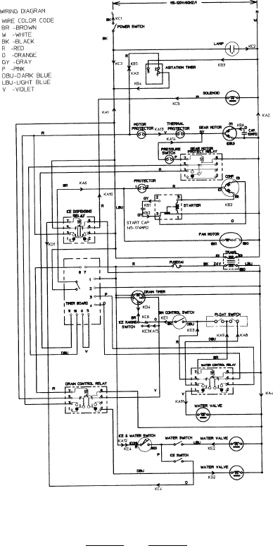
12/01/02
(A)
DCM-240 BAF
190
12/20/03
2/20/03
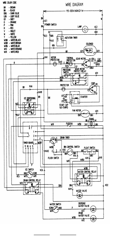
12/01/02
(B)
DCM-270 BAH
191
12/20/03
2/20/03
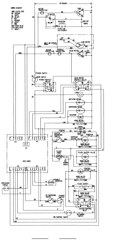
12/01/02
192
(C)
DCM-500 BAF, BWF
Serial numbers H0 & J0
12/20/03
2/20/03
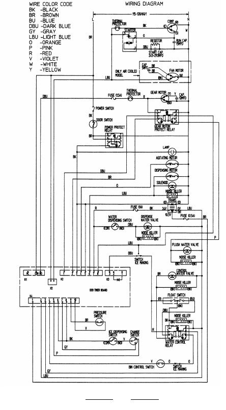
12/01/02
(D)
DCM-500 BAF, BWF
Serial numbers J1 & after.
193
12/20/03
2/20/03
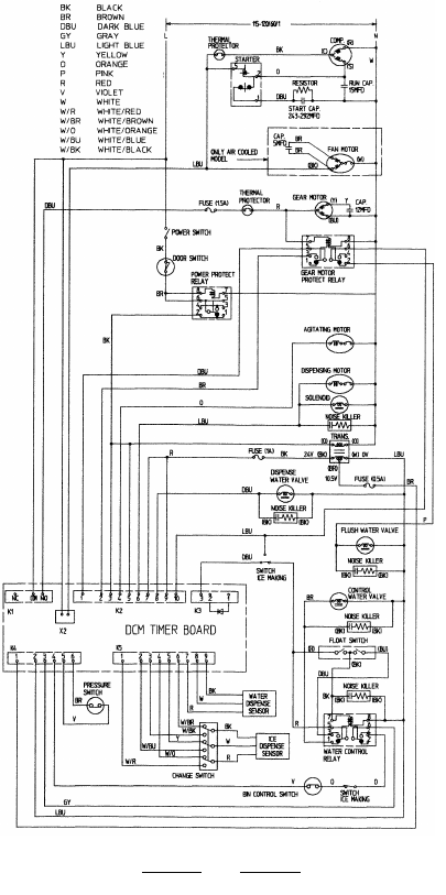
12/01/02
(E)
DCM-500 BAH, BWH
194
12/20/03
2/20/03
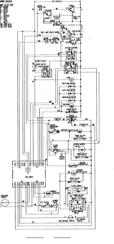
12/01/02
(F)
DCM-750 BAF, BWF
Serial numbers H0 & J0
195
12/20/03
2/20/03
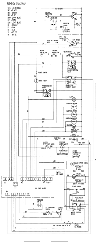
12/01/02
196
(G)
DCM-750 BAF, BWF
Serial numbers J1 & after.
12/20/03
2/20/03
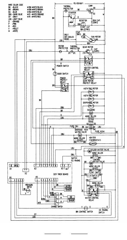
12/01/02
197
(H)
DCM-750 BAH, BWH
12/20/03
2/20/03
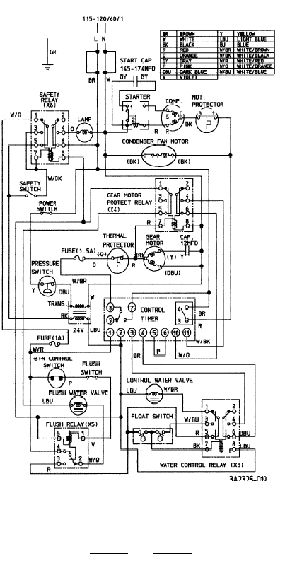
12/01/02
(I)
F-300 BAF
198
12/20/03
2/20/03
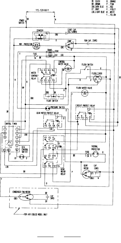
12/01/02
(J)
F-450 MAF/H
199
12/20/03
2/20/03
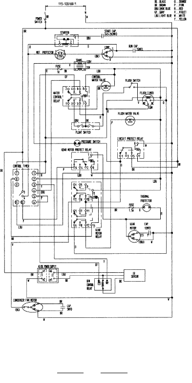
12/01/02
(K)
F-450 MAF-C/H-C
200
Note: Later Production will have proximity switch bin
control like F-450MAF.
12/20/03
2/20/03
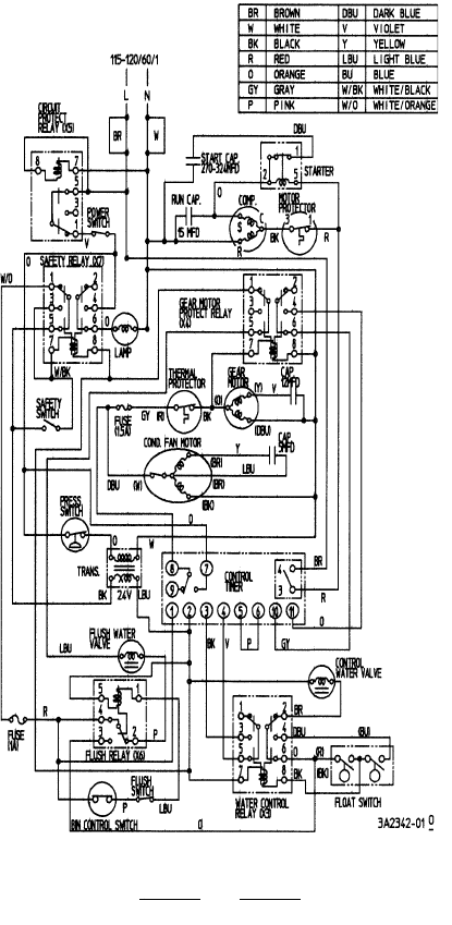
12/01/02
(L)
F-500 BAF
201
12/20/03
2/20/03
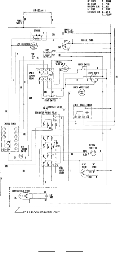
12/01/02
(M)
F-800 MAF/H, MWF/H
Note: Capacitors vary with compressor number
#RS55C1E
Start - 124~149 MFD
Run - 25 MFD
#RS55C2E
Start - 243~292 MFD
Run - 15 MFD
202
12/20/03
2/20/03
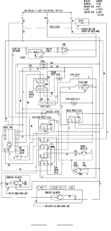
12/01/02
(N)
F-1000 MAF, MWF, MRF
203
12/20/03
2/20/03
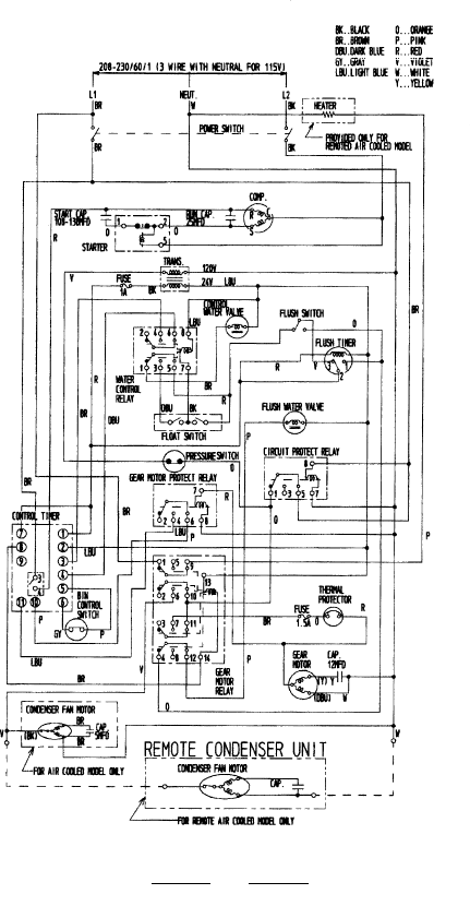
12/01/02
(O)
F-1000 MAF-22
204
12/20/03
2/20/03
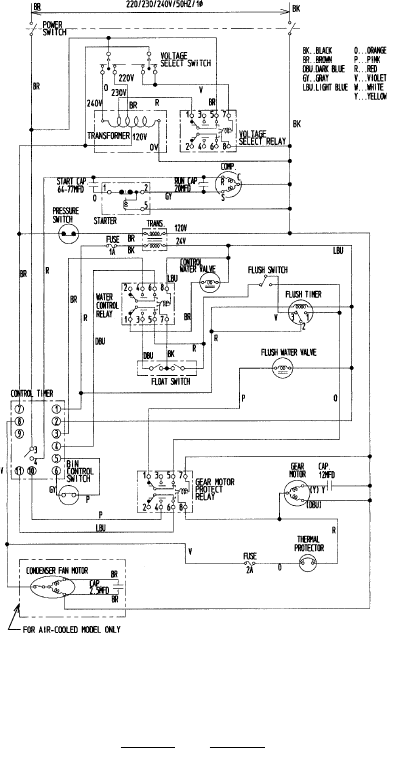
12/01/02
(P)
F-1000 MAF-50
205
12/20/03
2/20/03
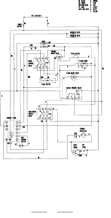
12/01/02
(Q)
F-1000 MLF
206
12/20/03
2/20/03
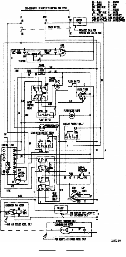
12/01/02
(R)
F-1001 MAH, MWH, MRH
207
12/20/03
2/20/03
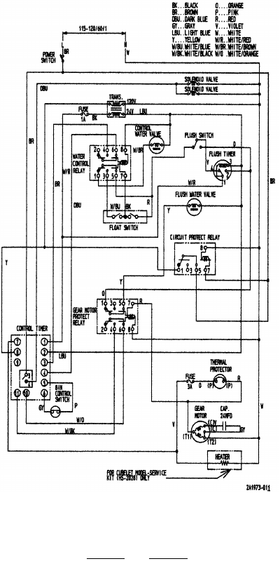
12/01/02
(S)
F-1001 MLH
208
12/20/03
2/20/03
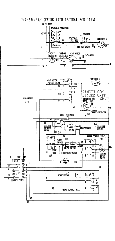
12/01/02
(T)
F-2000 MRF/H, MWF/H
209
12/20/03
2/20/03
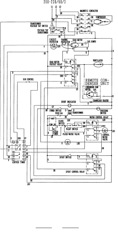
12/01/02
(U)
F-2000 MRF3/H3
210
12/20/03
2/20/03
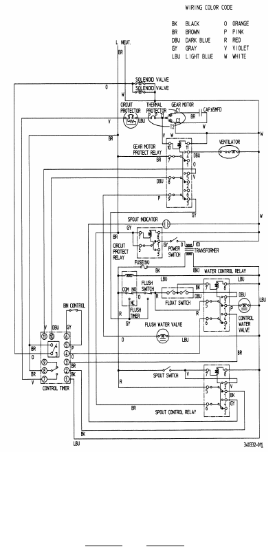
12/01/02
(V)
F-2000 MLF/H
211
12/20/03
2/20/03

12/01/02
NOTES
212
12/20/03
2/20/03

12/01/02
NOTES
213
12/20/03
2/20/03

12/01/02
NOTES
214
12/20/03
2/20/03
