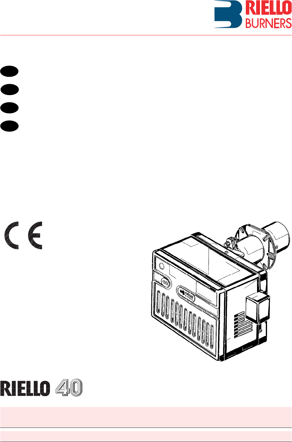
Technical & Sales CD V3_8 R40GS10 Riello Gas Burner
User Manual: R40GS10 Riello Gas Burner
Open the PDF directly: View PDF ![]() .
.
Page Count: 11
Manuel d’entretien
Installation, use and maintenance instructions
Instrucciones para la instalación, uso y mantenimiento
Montage und Bedienungsanleitung
2902721 (0)
Gas-Gebläsebrenner
Brûleur gaz à air soufflé
Forced draught gas burner
Quemador de gas de aire soplado
CODE - CÓDIGO MODELL - MODELE - MODEL - MODELO TYP - TYPE - TIPO
3755426 GS10 554T1
D
F
GB
E
Einstufiger Betrieb
Fonctionnement à 1 allure
One stage operation
Funcionamiento de una llama
2721
1GB
INDEX
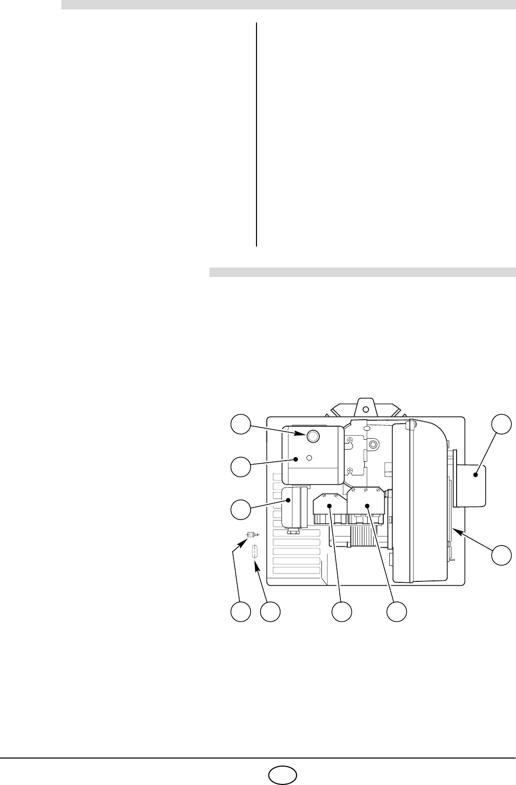
1. BURNER DESCRIPTION
Gas burner with one stage working.
1.1 BURNER EQUIPMENT
Insulating gasket . . . . . . . . . . . . . No. 1 Screws and nuts for flange to be fixed to boiler. . . No. 4
Cable grommet . . . . . . . . . . . . . . No. 1 Screw for fixing the cover . . . . . . . . . . . . . . . . . . . No. 1
Hinge . . . . . . . . . . . . . . . . . . . . . . No. 1 7 pin plug . . . . . . . . . . . . . . . . . . . . . . . . . . . . . . . No. 1
1. BURNER DESCRIPTION . . . . . . . . . . . 1
1.1 Burner equipment . . . . . . . . . . . . . . . . . 1
2. TECHNICAL DATA . . . . . . . . . . . . . . . . 2
2.1 Technical data . . . . . . . . . . . . . . . . . . . . 2
2.2 Overall dimensions . . . . . . . . . . . . . . . . 2
2.3 Working field . . . . . . . . . . . . . . . . . . . . . 2
3. INSTALLATION. . . . . . . . . . . . . . . . . . . 3
3.1 Boiler fixing . . . . . . . . . . . . . . . . . . . . . . 3
3.2 Probe-electrode positioning. . . . . . . . . . 4
3.3 Gas feeding line . . . . . . . . . . . . . . . . . . 4
3.4 Electrical wiring . . . . . . . . . . . . . . . . . . . 5
3.4.1 Standard electrical wiring . . . . . . . . . . . 5
3.4.2 Electrical wiring with gas leak control
device . . . . . . . . . . . . . . . . . . . . . . . . . . 6
4. WORKING . . . . . . . . . . . . . . . . . . . . . . . 6
4.1 Combustion adjustment. . . . . . . . . . . . . . 6
4.2 Combustion head setting. . . . . . . . . . . . . 6
4.3 Air damper setting . . . . . . . . . . . . . . . . . . 7
4.4 Combustion check . . . . . . . . . . . . . . . . . . 7
4.5 Air pressure switch . . . . . . . . . . . . . . . . . 7
4.6 Burner start-up cycle. . . . . . . . . . . . . . . . 8
4.7 Start-up cycle diagnostics . . . . . . . . . . . . 8
4.8 Operating fault diagnostics . . . . . . . . . . . 9
5. MAINTENANCE . . . . . . . . . . . . . . . . . . . 9
6. FAULTS / SOLUTIONS . . . . . . . . . . . . . . 10
1– Air damper actuator
2– Air dampers
3– 7 pole socket for electrical supply
and control
4– 6 pole socket for gas train
5– Cable grommet
6– Screw for fixing the cover
7– Air pressure switch
8– Control box
9– Reset button with lock-out lamp
■The burner meets protection level of IP 40, EN 60529.
■CE marking according to Gas Appliance directive 90/396/EEC; PIN 0063AP6680.
According to directives: EMC 89/336/EEC, Low Voltage 73/23/EEC, Machines 98/37/EEC and
Efficiency 92/42/EEC.
■Gas train according to EN 676.
NOTE
The cable grommet (5) and the screw for fixing the cover (6) supplied with the
burner, must be fitted to the same side of the gas train.
Fig. 1
D4181
65 3
2
19
8
7
4
2721
2GB
2. TECHNICAL DATA
2.1 TECHNICAL DATA
For gas family 3 (LPG) ask for separate kit.
2.2 OVERALL DIMENSIONS
2.3 WORKING FIELD (as EN 676)
Thermal power (1) 42 – 116 kW - 36,000 – 100,000 kcal/h
Natural gas (Family 2) Net heat value: 8 – 12 kWh/Nm3-7,000 – 10,340 kcal/Nm3
Pressure: min. 16 mbar - max. 100 mbar
Electrical supply Single phase, 230 V ± 10% ~50Hz
Motor 230V / 0.7 A
Capacitor 2
µF
Ignition transformer Primary 230V / 1.8 A - Secondary 8 kV / 30 mA
Absorbed electrical power 0.13 kW
(1) Reference conditions: Temp. 20°C - Barometric pressure 1013 mbar – Altitude 0 m above sea level.
COUNTRY FR DK - AT - GR - SE - IT LU DE GB - IE - ES - PT NL
GAS CATEGORY II2Er3P II2H3B/P II2E3B/P II2ELL3B/P II2H3P II2L3B/P
■ Combustion head extension, supplied separately.
FlangeBurner
305 110 346 185
33 61
45°
36
ø105
262
160
Rp 3/4
204
142
■ 170
D4201 130
11
45°
Thermal power
D5256
0.8
0
0.2
0.4
0.6
40,000 50,000 60,000 70,000 kcal/h
1206050 70 80 kW
1.0
110
80,000
1.2
90 100
90,000
1.4
40
1.6
100,000
Pressure in the combustion
chamber – mbar
2721
3GB
TEST BOILER
The working field has been defined according to EN 676 standard.
COMMERCIAL BOILERS
The burner-boiler matching is assured if the boiler conforms to EN 303 and the combustion chamber dimen-
sions are similar to those shown in the diagram EN 676. For applications where the boiler does not conform to
EN 303, or where the combustion chamber is much smaller than the dimensions given in EN 676, please con-
sult the manufacturers.
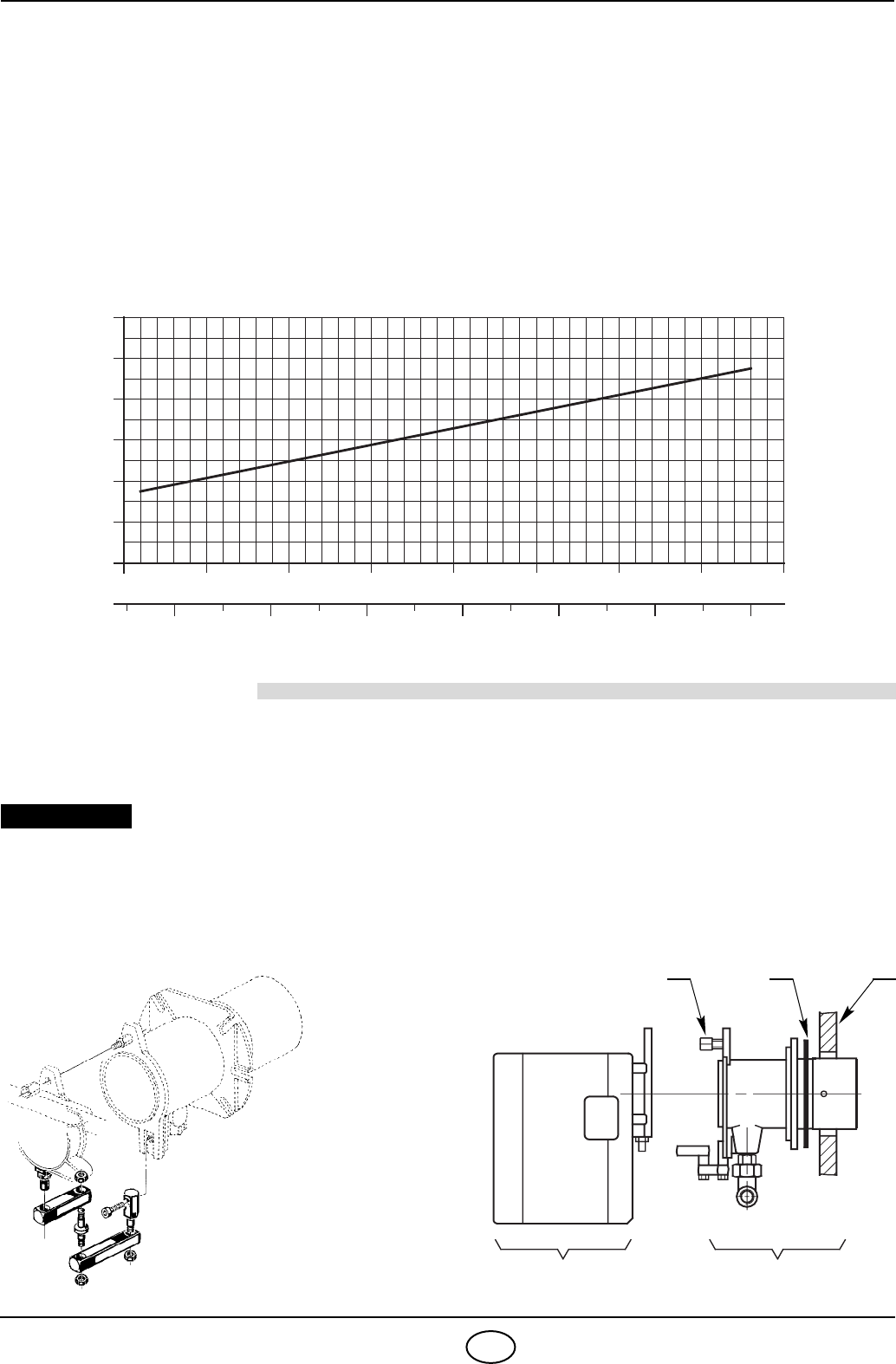
CORRELATION BETWEEN GAS PRESSURE AND BURNER OUTPUT
To obtain the maximum output, a gas head pressure of 5.8 mbar is measured (M2, see chapter 3.3, page 4) with
the combustion chamber at 0 mbar using gas G20 with a net heat value of 10 kWh/Nm3(8,570 kcal/Nm3).
3. INSTALLATION
THE BURNER MUST BE INSTALLED IN CONFORMITY WITH LEGISLATION AND LOCAL STANDARDS.
3.1 BOILER FIXING
4
1
2
3
5
6
7
Gas pressure in the
combustion head – mbar
40,000 50,000 60,000 70,000 kcal/h
1206050 70 80 kW
Thermal power
D5257
110
80,000
90 100
90,000
40
100,000
S7392
1 3 2
A B
D6323
HINGE
ASSEMBLY
Boiler door must have a max. thickness of 90 mm,
refractory lining included.
If thickness is greater (max. 150 mm), a combustion
head extension must be fitted, which is supplied
separately.
IMPORTANT ■Separate the combustion-head assembly
from the burner body by removing nut (1) and
removing group (A).
■Fix the head assembly group (B) to the boiler
(2) insert the supplied insulating gasket (3).
2721
4GB
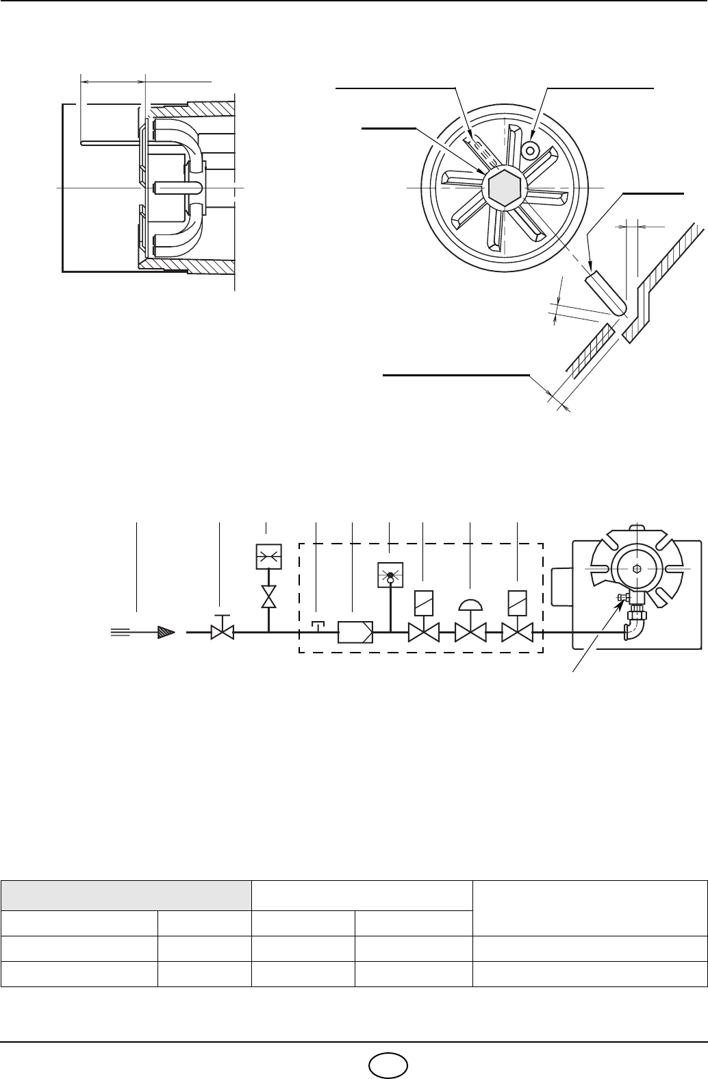
3.2 PROBE - ELECTRODE POSITIONING
3.3 GAS FEEDING LINE
GAS TRAIN ACCORDING TO EN 676
The gas train is supplied separately, for its adjustment see the enclosed instructions.
GAS TRAIN CONNECTIONS USE
TYPE CODE INLET OUTLET
MBDLE 405 B01 3970530 Rp 1/2 Rp 3/4 Natural gas
≤ 80 kW and LPG
MBDLE 407 B01 3970531 Rp 3/4 Rp 3/4 Natural gas and LPG
D5104
Ignition electrode
WARNING 2– 3mm
Ionization probe
Probe
Electrode
2.2
~40 mm
Diffuser
=
=
1 – Gas supply pipe
2 – Manual cock
(supplied by the installer)
3 – Gas pressure gauge
(supplied by the installer)
4 – Filter
5 – Gas pressure switch
6 – Safety valve
7 – Pressure governor
8 – Adjustment valve
M1 –Gas-supply pressure test point
M2 – Pressure coupling test point
1
D5050
2 3 M1 4 5 6 7 8
M2
2721
5GB
3.4 ELECTRICAL WIRING
NOTES:
–
Do not exchange the neutral with the phase and connect exactly the
above wiring.
– Wires of min. 1 mm2 section.
(Unless requested otherwise by local stand-
ards and legislation).
– Carry out a safe earth connection.
– Verify that the burner stops by operating the boiler control thermostats and
that the burner locks out by separating the red ionisation probe lead con-
nector.
– The electric wiring carried out by the installer must be in compliance with
regulations in force in the Country.
Ionization probe
Electrode
Motor
Capacitor
Burner earth
230V ~50Hz
CARRIED-OUT
Air pressure switch
Blue
White
Black
BY THE INSTALLER
Control box
RMG 88.620A2
Suppressor
D4198
Connector
Ignition transformer
3.4.1 STANDARD ELECTRICAL WIRING
LEGEND
XP6 – 6 pole socket
XP7 – 7 pole socket
X6 – 6 pin plug
X7 – 7 pin plug
B4 – Working signal
h1 – Hour counter
PG – Minimum gas pressure
switch
S3 – Remote lock-out signal
(230V - 0.5 A max.)
T6A – Fuse
TL – Limit thermostat
TS – Safety thermostat
V10 – Safety valve
V11 – Adjustment valve
Air damper actuator
Blue
Black
Brown
In the case of phase-phase
feed, a bridge must be fit-
ted on the control box ter-
minal board between
terminal 6 and the earth
terminal.
ATTENTION
2721
6GB
3.4.2 ELECTRICAL WIRING WITH GAS LEAK CONTROL DEVICE (DUNGS VPS 504)
4. WORKING
4.1 COMBUSTION ADJUSTMENT
In conformity with Efficiency Directive 92/42/EEC the applica-
tion of the burner on the boiler, adjustment and testing must be
carried out observing the instruction manual of the boiler,
including verification of the CO and CO2 concentration in the
flue gases, their temperatures and the average temperature of
the water in the boiler.
To suit the required appliance output, choose the proper set-
ting of the combustion head, and the air damper opening.
4.2 COMBUSTION HEAD SETTING
Loose the screw (A), move the elbow (B) so that the rear
plate of the coupling (C) coincides with the set point.
Tighten the screw (A).
Example:
The burner is installed on a 81 kW
boiler with an efficiency of 90%, the
burner input is about 90 kW using the
diagram, the combustion set point is 3
.
The diagram is to be used only for initial
settings, to improve air pressure switch
operation or improve combustion, it
may be necessary to reduce this set-
ting
(set point toward position 0).
CARRIED-OUT
BY THE INSTALLER
LEGEND
X6 – 6 pin plug
X7 – 7 pin plug
B4 – Working signal
h1 – Hour counter
PG – Minimum gas pressure
switch
S3 – Remote lock-out signal
(230V - 0.5 A max.)
T6A – Fuse
TL – Limit thermostat
TS – Safety thermostat
V10 – Safety valve
V11 – Adjustment valve
230V ~50Hz
D4199
S7015
C
A
B
0 1 32
120
90
80
70
60
50
100
80,000
70,000
60,000
50,000
40,000
kcal/h kW
D5258
4 5
40
110
90,000
100,000
Set point
2721
7GB
4.3 AIR DAMPER SETTING
The air damper (1) is operated by the actuator (2) and assures that
the air damper is fully open before the burner start cycle begins .
The regulation of the air-rate is made by adjusting the fixed air
damper (3), after loosing the screws (4).
When the optimal regulation is reached, screw tight the screws
(4) to assure a free movement of the mobile air damper (1).
4.4 COMBUSTION CHECK
It is advisable to set the burner according to the type of gas used and following the indications of the table:
IONIZATION CURRENT
The minimum current necessary for the control box operation is 3 µA.
The burner normally supplies a higher current value, so that no check is needed. However, if you want to meas-
ure the ionization current, you must open the connector fitted to the red wire and insert a microammeter.
4.5 AIR PRESSURE SWITCH
The air pressure switch is set after all other adjustments have been made. Begin with the switch at the low-
est setting. With the burner working at the minimum output, adjust the dial clockwise, increasing its value
until the burner shuts down. Now reduce the value by one set point, turning the dial anti-clockwise.
Check for reliable burner operation, if the burner shuts down, reduce the value by a half set point.
Attention:
To comply with the EN 676 standard, the air pressure switch must operate when the CO value exceeds 1%
(10,000 ppm).
To check this, insert a combustion analyser in the flue, slowly reduce the burner air setting and verify that
the burner shuts down by the action of the air pressure switch before the CO value exceeds 1%.
EN 676 AIR EXCESS:
max. output λ ≤ 1.2 – min. output λ ≤ 1.3
GAS Theoretical max. CO2
0 % O2
Setting CO2 % CO
mg/kWh
NOx
mg/kWh
λ = 1.2 λ = 1.3
G 20 11.7 9.7 9.0 ≤100 ≤170
G 25 11.5 9.5 8.8 ≤100 ≤170
G 30 14.0 11.6 10.7 ≤100 ≤230
G 31 13.7 11.4 10.5 ≤100 ≤230
D5036
4
1
2
3
4
Probe
Connector
Terminal board
of control-box
D5006
10
2721
8GB
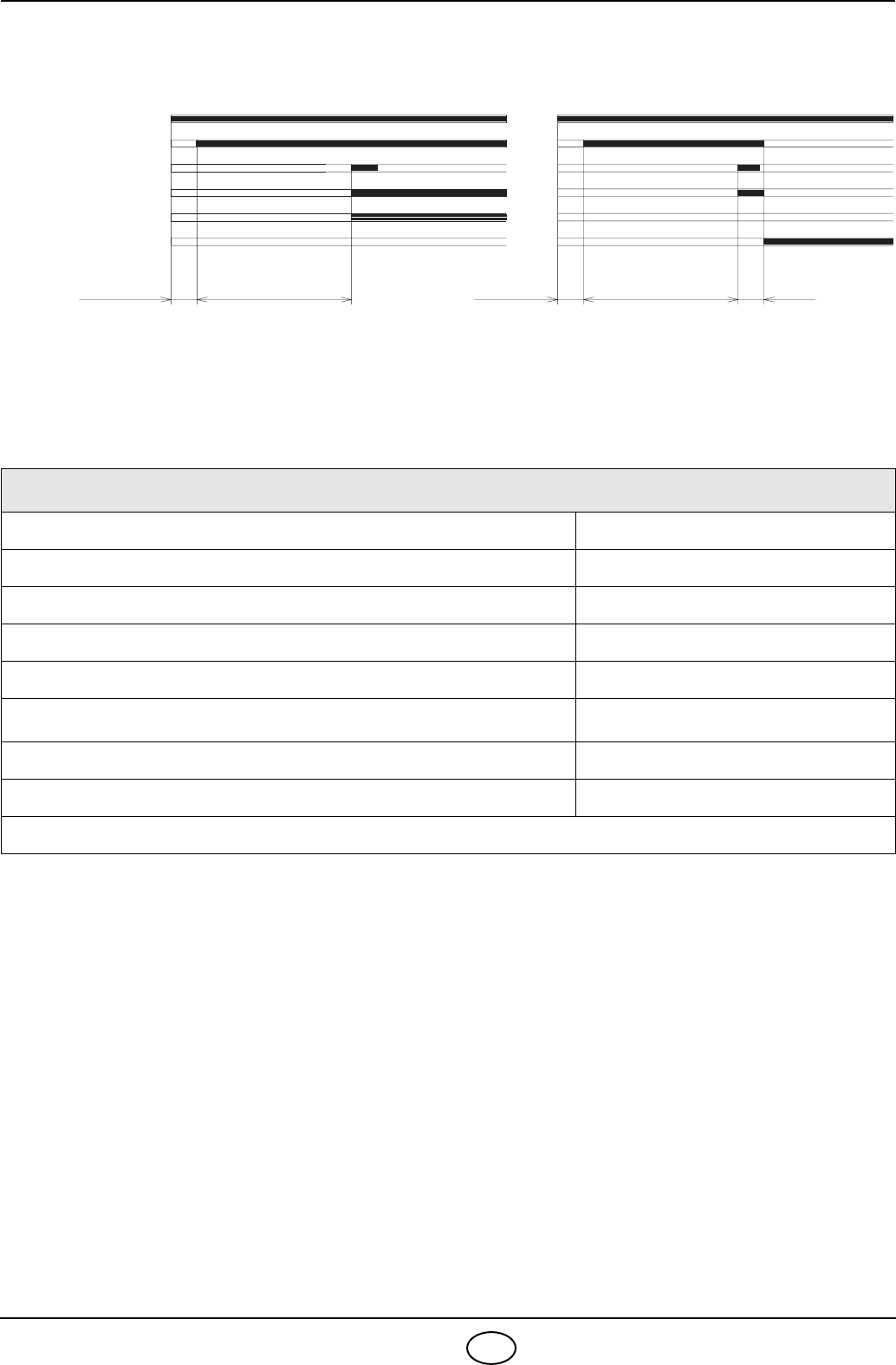
4.6 BURNER START-UP CYCLE
When flame-failure occurs during working, shut down takes place within one second.
4.7 START-UP CYCLE DIAGNOSTICS
During start-up, indication is according to the followin table:
COLOUR CODE TABLE
Sequences Colour code
Pre-purging ● ● ● ● ● ● ● ● ● ● ●
Ignition phase ● ❍ ● ❍ ● ❍ ● ❍ ● ❍ ●
Operation, flame ok ❑ ❑ ❑ ❑ ❑ ❑ ❑ ❑ ❑ ❑ ❑ ❑
Operating with weak flame signal. ❑ ❍ ❑ ❍ ❑ ❍ ❑ ❍ ❑ ❍
Electrical supply lower than ~ 170V ● ▲ ● ▲ ● ▲ ● ▲ ● ▲ ●
Lock-out ▲ ▲ ▲ ▲ ▲ ▲ ▲ ▲ ▲ ▲
Extraneous light ▲ ❑ ▲ ❑ ▲ ❑ ▲ ❑ ▲ ❑ ▲
Index: ❍ Off ● Yellow ❑Green ▲ Red
3s40s40smax. 2s max. 2s
D4172
Lock-out, due to ignition failureNormal
Thermostat
Motor
Ignition transformer
Valves
Flame
Lock-out

2721
9GB
4.8 OPERATING FAULT DIAGNOSTICS
The control box has a self-diagnostic system, which easily allows identifying the operating faults (RED LED
signal).
To use this function, wait at least ten seconds from the safety lock out, and then press the reset button for a
minimum of 3 seconds.
After releasing the button, the RED LED starts flashing as shown in the diagram below.
The LED gives of a blink code every 3 seconds.
The blink codes give the information about the possible faults, as follows:
5. MAINTENANCE
The burner requires periodic maintenance carried out by a qualified and authorised technician in conformity
with legislation and local standards.
Maintenance is essential for the reliability of the burner, avoiding the excessive consumption of fuel and
consequent pollution.
Before carrying out any cleaning or control always first switch off the electrical supply to the
burner acting on the main switch of the system.
THE BASIC CHECKS ARE:
Leave the burner working without interruption for 10 min., checking the right settings of all the components
stated in this manual. Then carry out a combustion check verifying:
●CO2(%) content ● Smoke temperature at the chimney ● CO content (ppm).
SIGNAL PROBABLE CAUSE
2 flashes
==
The flame does not stabilise at the end of the safety time:
– faulty ionisation probe;
– faulty or soiled gas valves;
– neutral/phase exchange;
– faulty ignition transformer
– poor burner regulation (insufficient gas).
3 flashes
===
Min. air pressure switch does not close:
– air pressure switch faulty;
– air pressure switch incorrectly regulated;
– max. air pressure switch triggered (if installed).
4 flashes
====
Min. air pressure switch does not open or light in the chamber before firing:
– air pressure switch faulty;
– air pressure switch incorrectly regulated.
7 flashes
=======
Loss of flame during operations:
– poor burner regulation (insufficient gas);
– faulty or soiled gas valves;
– short circuit between ionisation probe and earth.
10 flashes
=====
=====
– Wiring error or internal fault.
= = = = = = = = = =
Press reset
for > 3s intervalBlink code Blink code
RED LED on
wait at least 10s
3s
2721
10 GB
6. FAULTS / SOLUTIONS
Here below you can find some causes and the possible solutions for some problems that could cause a fail-
ure to start or a bad working of the burner. A fault usually makes the lock-out lamp light which is situated
inside the reset button of the control box (9, fig. 1, page 1).
When lock out lamp lights the burner will attempt to light only after pushing the reset button. After this if the
burner functions correctly, the lock-out can be attributed to a temporary fault.
If however the lock out continues the cause must be determined and the solution found.
BURNER STARTING DIFFICULTIES
N.B.: If problems still occur after all of the above checks have been made, check the electrical connec-
tions on the plug and sockets, the damper and burner motor, gas control wiring ignition transformer
and external interlocks, if the burner still fails to function, replace the control box.
FAULTS SOLUTIONS
The burner does not start at
the limit thermostat closing.
Gas is not supplied.
The actuator is faulty. Replace.
The gas pressure switch does not close its contact due to incorrect setting
or a faulty switch.
The air pressure switch has changed over to the operational position.
The burner does not pass
through the pre-purge and
locks out.
The air pressure switch does not change over: it has failed or the air pres-
sure is too low
(combustion head incorrectly set).
Flame simulation exists
(or the flame really lights).
The burner locks out, after the
pre-purge period, because the
flame does not ignite.
The gas valve pass too little gas
(low pressure in the gas pipework).
The valves are faulty.
The ignition arc is irregular or not present.
The air has not been purged from the pipe.
The burner goes through the
normal pre-purge, the flame ig-
nites but the burner locks out
within 3 seconds after ignition.
The ionization probe is earthed or not in contact with the flame, or its wiring
to the control box is broken, or there is a fault on its insulation to earth.
The ionization current is weak
(lower than 3 µA).
(See chapter 4.7).
The gas pressure switch is set too close to its working-pressure.
The burner continues to re-
peat the starting cycle without
locking out.
This concerns a very particular irregularity, caused by the fact that the
pressure in the gas mains is very close to the value to which the gas pres-
sure switch has been set.
Consequently, the sudden falling off in pressure at the opening of the valves
causes the pressure switch to open, the valves immediately close and the
motor stops.
The pressure then increases, the pressure switch closes and the starting
cycle can be repeated, and so on.
This can be remedied by lowering the setting of the pressure switch.
