69 2467EFS—03 R7284B,P,U,G Electronic Oil Primary, EnviraCOM™ Enabled R7184B R7284U1004
User Manual: R7184B
Open the PDF directly: View PDF ![]() .
.
Page Count: 14
- Application
- Features
- Specifications
- Installation
- Wiring
- Checkout
- ADVANCED User Interface
- Basic User Interface
- Troubleshooting and Maintenance
- Application
- CARACTÉRISTIQUES
- CARACTÉRISTIQUES
- INSTALLATION
- CÂBLAGE
- VÉRIFICATION
- INTERFACE UTILISATEUR AVANCÉE
- INTERFACE UTILISATEUR DE BASE
- DÉPANNAGE ET ENTRETIEN
- APLICACIÓN
- CARACTERíSTICAS
- ESPECIFICACIONES
- INSTALACIóN
- CABLEADO
- VERIFICACIóN
- INTERFAZ DE USUARIO AVANZADA
- INTERFAZ DE USUARIO BáSICA
- LOCALIZACIÓN Y SOLUCIÓN DE PROBLEMAS, Y MANTENIMIENTO
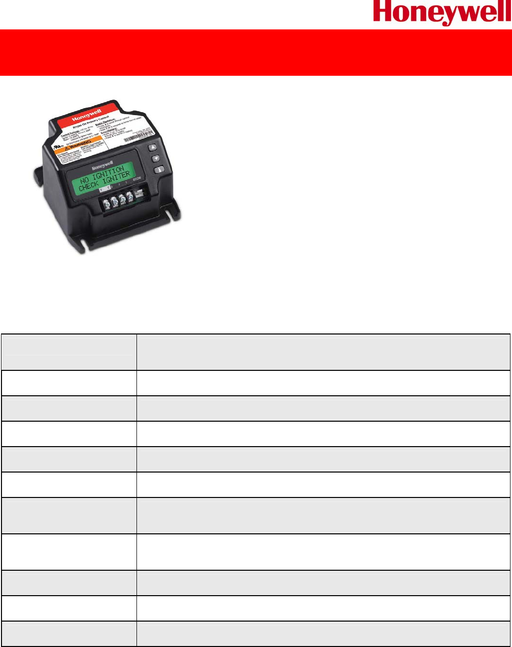
R7284U1004 Universal Electronic Oil Primary
Electronic Oil Primary with 15 second lock out timing and selectable valve and blower delays
The R7284B,P,U,G Electronic Oil Primary is a line voltage,
safety rated, interrupted and intermittent ignition oil primary
control for residential oil fired burners used in boilers, forced
air furnaces and water heaters.
The R7284U when used with a cad cell flame sensor operates
an oil burner, spark igniter and optional oil valve. The control
works with a low voltage and optional high voltage thermostat.
The primary controls fuel oil, senses flame, controls ignition
spark (either interrupted or intermittent) and notifies through
the EnviraCOM™ bus a remote alarm circuit when in lockout.
The R7284 Series of Oil Primary Controls can be used with both hydronic and forced air systems.
When used with hydronic systems, line voltage switching Aquastat® Controllers normally provide for
the starting and stopping of the combustion sequences. With forced air systems, both mechanical
and electronic low voltage thermostats control the starting and stopping of the combustion process.
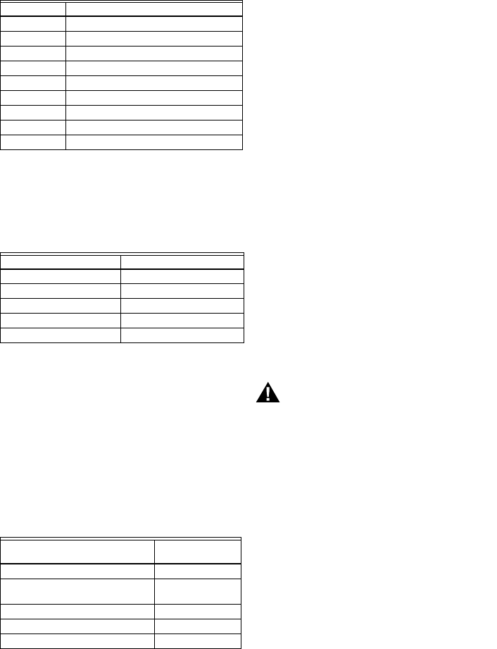
PRODUCT SPECIFICATIONS
Description Electronic Oil Primary with selectable 15, 30 or 45 second lock out timing,
selectable valve and blower delays and two line LCD display
Ignition Type Interrupted and Intermittent
Timing, Safety Switch Settable 15, 30 or 45 sec.
Diagnostics Display 2 Line LCD display
Mounting Bracket Junction box on main burner
Electrical Connections Burner motor, oil valve, ignition, cad cell, limit, thermostat, alarm
Electrical Rating;
Contacts (full load)
7.4 A @ 120 Vac; 3.7 a @ 240 Vac
Electrical Rating;
Contacts (locked rotor)
44.4 A @ 120 Vac; 22.2 A @ 240 Vac
Dimensions 4-5/32” L x 4-11/32” W x 2 ½” H
Temperature Range -40°F to +147°F
Approvals UL and cUL Component Recognized
1 OF 2 − ISSUED 12/2010
Leading The Way With Legendary Quality
For decades, Honeywell has set the standard for quality, control and
compatibility. Now we introduce the next generation of oil primaries –
the R7284.
We did the research. We asked owners, managers and technicians how we
could improve our oil primaries and we listened. The result is a digital,
universal primary control engineered to address and anticipate every
industry need, designed to deliver a host of new benefits – it’s the right
part straight out of the back of a truck.
Every setting and diagnostic is on display, in easy-to-read text, on a user-
friendly screen. And the diagnostics offer more than mere data. Users will
benefit from actionable information available in multiple languages,
including English, Spanish and French.
Detailed Diagnostic Information
The “quick-fix” digital display delivers clear data designed to lead you
to any problem, fast. Patent-pending technology determines and
displays why a lockout has occurred, including lack of spark at the
electrode, partially-functioning flame sense, line voltage dips and
more.
Simple, Streamlined Set-Up
We've made this model incredibly easy to operate. Set-up is simpler
than ever, requiring no external tools to access the set-up and
diagnostic features, saving you additional costs. Everything is fully
operational out of the package.
Multi-Faceted Monitoring
The R7284 offers a display that monitors a variety of components
outside of your controller. From cad cell and flame check to the
voltage and the spark of the igniter, you can quickly tell how
everything is functioning and, in case of a failure, which component is
faulty ensuring the right part is fixed the first time.
The Expertise You Trust, The Innovation You Need
There's a reason Honeywell has been an industry standard for oil primary controls. We deliver dependability through
decades of front-line knowledge that result in better design and unmatched support. We're continuing to lead the way
because our engineers keep forging ahead with innovative solutions that bring real-world, day-to-day benefits to every
job. Imagine more control – this model allows you to select 15, 30 or 45-second safety timings. And you can field adjust
valve-on and blower-off delays. Imagine more universality – this model is compatible with virtually all oil-fired appliances
manufactured today. Imagine more ease – every diagnostic and setting is as simple as pushing a button.
Memory and Error History
The R7284 lets you keep track of system quality by accessing memory data that gives a clear picture of day-to-day
performance. The error history capability defines when and how the controller encountered problems, and helps
maintain knowledge when there is more than one technician involved in servicing the unit. There is also a baseline
feature that uses a cycle-trend reading to determine if something is out of the norm, allowing troubleshooting during
service check-ups before a no heat call occurs.
EnviraCOM™ Connection
Honeywell oil primary controls can fully integrate into any EnviraCOM communications system, which allows for remote
monitoring with a simple 3-wire connection.
Additional Features
We've designed this unit with several unique capabilities and features like recessed wiring pocket to allow more space in
tight junction box installations. It's engineered to be unmatched in its compatibility, including working seamlessly with
power venters without integral timers.
2 OF 2 − ISSUED 12/2010

INSTALLATION INSTRUCTIONS
69-2467EFS-03
R7284B,P,U,G
Electronic Oil Primary,
EnviraCOM™ Enabled
APPLICATION
The R7284B,P,U,G Electronic Oil Primary is a line
voltage, safety rated, interrupted and intermittent ignition
oil primary control for residential oil fired burners used in
boilers, forced air furnaces and water heaters. The
R7284B,P,U,G used with a cad cell flame sensor
operates an oil burner, spark igniter, and optional oil
valve. The control works with a low voltage and optional
high voltage thermostat. The primary controls fuel oil,
senses flame, controls ignition spark (either interrupted
or intermittent) and notifies through the EnviraCOM™
bus a remote alarm circuit when in lockout.
The R7284 Series of Oil Primary Controls can be used
with both hydronic and forced air systems. When used
with hydronic systems, line voltage switching Aquastat®
Controllers normally provide for the starting and stopping
of the combustion sequences. With forced air systems,
both mechanical and electronic low voltage thermostats
control the starting and stopping of the combustion
process.
Some hydronic and forced air systems require a delayed
valve-on and burner motor-off delay. The R7284
operates an oil valve that prevents the flow of oil when
the burner motor is running prior to combustion (delayed
valve-on) and when the burner motor is running after
combustion (burner motor-off delay).
The R7284 models are intended for use only on oil
burning appliances which do not require prepurge and
post-purge as a safety related function as defined in
UL296. The valve-on delay and burner motor-off delay in
this control are intended only to help establish draft and
reduce oil after-drip related problems.
EnviraCOM™ enabled R7284’s can be used with
EnviraLink® remote monitoring systems and hand-held
diagnostics. Use only R7284P and U models for
networking with other EnviraCOM™ enabled devices.
FEATURES
User Interface
There are two user interfaces: basic and advanced. Both
interfaces consist of three buttons: , , and “i.”
The advanced interface has a two-line display used to
configure device parameters, retrieve diagnostic
information, and display system status.
The basic interface has a single LED used to display
error codes and system status.
In general, the “i” button cycles through the display
options and acts as an “enter” key (in setup modes).
Thermostat(s)
The oil primaries are compatible with both standard
thermostats and EnviraCOM™ communicating
thermostats.
Limited Recycle
This feature limits the number of recycle trials (for each
call for heat) to a maximum of three trials. If the flame is
lost three times and does not successfully satisfy a call
for heat, the R7284 locks out.
Pump Priming Cycle
To facilitate purging air from the oil lines and filters, the
R7284 can be placed in a purge routine by pressing and
releasing the up arrow button during the Trial For
Ignition.
In the advanced interface “PUMP PRIME” is displayed
on the display along with the time left on the Trial for
Ignition (TFI). Pressing the up arrow button adds a
minute to the TFI time for a maximum of 10 additional
minutes (press the up arrow button 10 times). Pressing
the down arrow button subtracts a minute from the TFI
time.
There is no visual indication for the basic interface
control and the purge timing is limited to five minutes.
Disable Function
Pressing and holding the “i” button will disable all control
functions until 3 seconds after the button is released.
Lockout Modes
The R7284 has three types of lockout modes that are
entered when an error is encountered:
R7284B,P,U,G ELECTRONIC OIL PRIMARY, ENVIRACOM™ ENABLED
69-2467EFS—03 2
•Soft Lockout: Caused by a temporary internal error
such as low voltage. The control recovers
automatically after the error is no longer detected.
•Hard Lockout: Caused by a failure internal to the
control or by a system fault such as flame out of
sequence. A Hard Lockout will result in a no heat
condition. To reset from Hard Lockout press and hold
the “i” button for 2 seconds.
•Restricted Lockout: Caused by a number of
consecutive hard lockouts on the same heat cycle. To
reset from a Restricted Lockout press and hold the “i”
button for ten seconds.
Cad Cell Resistance
Cad cell resistance can be checked without using an ohm
meter.
Basic Interface:
Press and release the “i” button. The resulting flashes
indicate the resistance. See Table 3.
Advanced Interface:
The cad cell resistance is shown on the display.
Valve-on Delays/Blower Motor-off
Delays
Select models may have fixed or adjustable delays for
valve open or blower motor off. The safety circuits will
check for flame during these delays and, if a flame is
present, will switch the control to lockout.
SPECIFICATIONS
Models:
Table 1 lists the major features for the R7284.
Timing:
Valve-on Delay: 0–30 seconds
Burner Off Delay: 0–8 minutes
Lockout: 15, 30 or 45 seconds.
Recycle: 60 seconds (fixed).
Ignition Carryover: 10 seconds (fixed).
NOTE: Some models have adjustable Valve-on Delay,
Burner Off Delay, and Lockout timings.
Electrical Ratings:
Inputs:
Voltage: 102 to 132 Vac, 120 Vac nominal.
Current: 0.5A plus burner motor, valve and igniter
loads.
Frequency: 60 Hz.
Outputs:
Relay Contacts:
Burner: 120 Vac, 10 full load amperes (FLA), 60 locked
rotor amperes (LRA).
Valve: 120 Vac, 1A.
Igniter: 120 Vac, 3 A.
Low Voltage Shutdown: 80 Vac
Thermostat Current Available: 100 mA.
EnviraCOM™ Current Available: 150 mA.
NOTE: Reduce burner FLA rating by igniter load. For
example, if the igniter draws 3A (120 Vac, 360
VA), reduce the burner motor FLA to 7A.
Typical Component Wire Color Code:
White: Neutral.
Black: Line.
Orange: Motor.
Blue or Blue w/White Stripe: Igniter.
Violet: Valve.
Red: Limit.
NOTE: The R7284 is provided with 1/4” quick-connect
terminals.
Environmental Ratings:
Operating/Shipping Temperature: -40°F to +150°F
(-40°C to +66°C).
Display text may not be visible below -4°F (-20°C)
Humidity: 0% to 95% relative humidity at 104°F (40°C),
noncondensing.
Accessories:
W8735S3000 Alarm Module
Approvals:
Underwriters Laboratories Inc.: Recognized (File MP268).
Canadian Underwriters Laboratories Inc.
Table 1. R7284 Models.
INSTALLATION
When Installing This Product…
1. Read these instructions carefully. Failure to follow
instructions can damage the product or cause a
hazardous condition.
2. Check ratings given in these instructions and on the
product to make sure the product is suitable for your
application.
3. Make sure the installer is a trained, experienced
service technician.
4. Use these instructions to check out the product
operation after installation.
WARNING
Electrical Shock Hazard.
Can cause severe injury, death or property
damage.
Disconnect power supply before beginning
installation to prevent electrical shock or
equipment damage. More than one disconnect
may be involved.
Model Limit Valve Notes
R7284B No Yes Valve on delay only
R7284G No No No on/off delays, intermittent ignition (wire igniter together with motor)
R7284P Yes Yes On and off delays
R7284U Yes Yes On and off delays
R7284B,P,U,G ELECTRONIC OIL PRIMARY, ENVIRACOM™ ENABLED
3 69-2467EFS—03
Location
1. Mount on a 4 in. by 4 in. junction box, directly on the
main burner, or inside the appliance cabinet. In
replacement applications, mount in the same
location as the old control. See Fig. 1. Make sure
the operating temperatures are within the ambient
temperature range (see Specifications section).
2. Before mounting the control, make line voltage con-
nections as shown in Fig. 2 through 10. Splice lines
with solderless connectors. Do not exceed load rat-
ings shown on the device label.
3. If necessary, use the control as a template to mark
and drill new mounting holes.
4. Mount the device using No. 6 screws (not included).
WIRING
WARNING
Electrical Shock Hazard.
Can cause severe injury, death or property
damage.
Disconnect power supply before beginning wiring
to prevent electrical shock or equipment damage.
More than one disconnect may be involved.
1. Make sure wiring complies with all local codes and
ordinances.
2. Check to make sure that line voltage wiring is
properly connected. Refer to oil primary label and
appliance wiring diagram for color codes.
3. After mounting make low voltage connections to the
screw terminals (see Fig. 2 through 10).
4. Strip leads 3/8 in. (10 mm) and insert under terminal
screw.
5. Connect thermostat leads to T-T (or 1, 2, 3 if
EnviraCOM™ is present), if required by installation.
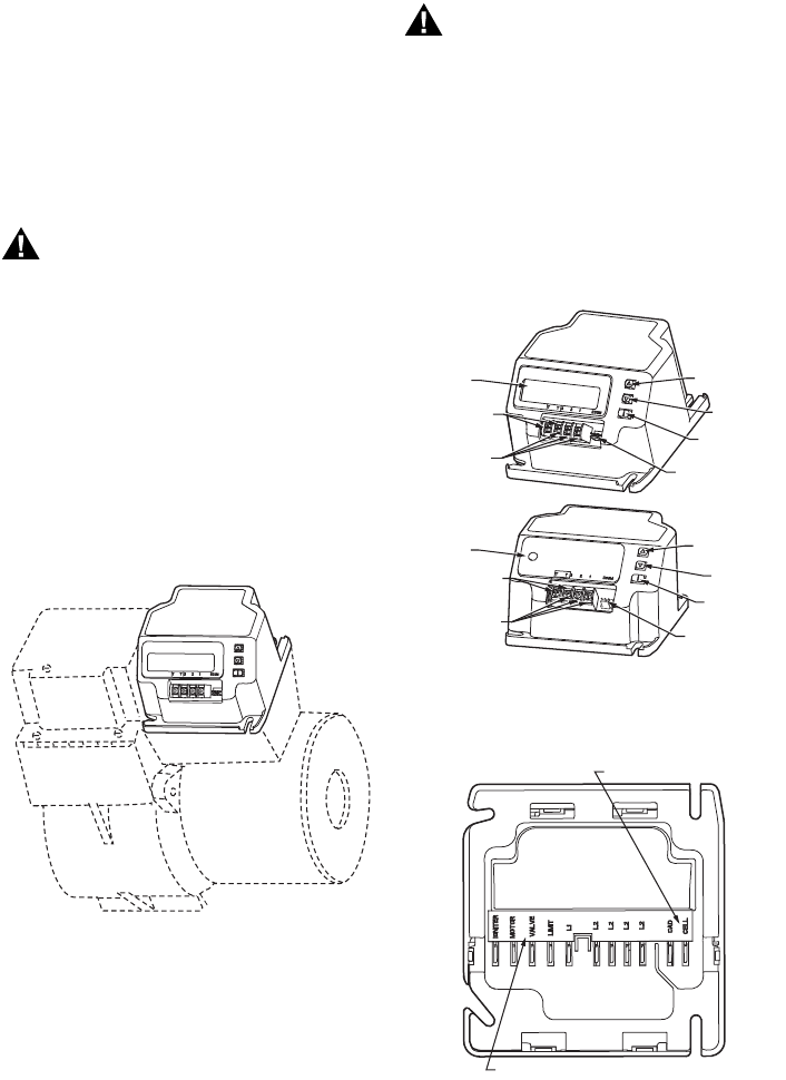
Fig. 1. Mounting R7284 on junction box.
CHECKOUT
Start System
WARNING
Fire or Explosion Hazard.
Can cause severe injury, death or property
damage.
Make sure the combustion chamber is free of oil
and/or oil vapor before starting system.
1. Open hand valve in oil supply line.
2. Make sure system is powered. Check circuit
breaker or fuse and close system switch, if
provided.
3. Set thermostat to call for heat.
4. Make sure burner lights and operates until call for
heat ends. Note cad cell resistance while running.
5. Verify that burner turns off when thermostat call for
heat is satisfied.
Fig. 2. R7284 terminals, connectors, LED, reset button
and DIP switch locations.
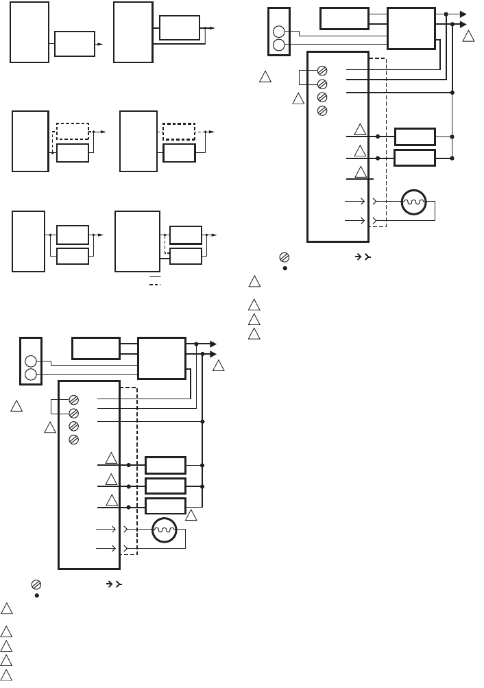
Fig. 3. R7284 wiring connections.
R7284
BURNER
M32085
M32146
DISPLAY
DISPLAY
ENVIRACOM
TERMINALS
THERMOSTAT
TERMINALS
ENVIRACOM
DIAGNOSTIC
PLUG
i BUTTON
DOWN
BUTTON
UP BUTTON
ENVIRACOM
TERMINALS
THERMOSTAT
TERMINALS
ENVIRACOM
DIAGNOSTIC
PLUG
i BUTTON
DOWN
BUTTON
UP BUTTON
M32178
CAD CELL CONNECTION
LINE VOLTAGE CONNECTIONS
R7284B,P,U,G ELECTRONIC OIL PRIMARY, ENVIRACOM™ ENABLED
69-2467EFS—03 4
Fig. 4. R7284 Limit wiring for line voltage thermostat,
Aquastat, or other Limit.
Fig. 5. R7284 wiring for optional oil valve.
Fig. 6. R7284 igniter wiring.
Fig. 7. Wiring R7284P,U without EnviraCOM™, for
typical oil-fired boiler.
Fig. 8. Wiring R7284U without EnviraCOM™, for
typical oil-fired boiler.
R7284P, U
L1
L1
LIMIT
R7284B, G
L1 AQUASTAT
OR OTHER
LIMIT
L1
……
……
AQUASTAT
OR OTHER
LIMIT
M32179
VALVE
R7284B, P, U
BURNER
MOTOR
L2
R7284A, G
BURNER
MOTOR
L2
……
……
BURNER
MOTOR
BURNER
MOTOR
VALVE VALVE
M32180
R7284B, P, U
L2
IGNITER
IGNITER
INTERRUPTED IGNITION
INTERMITTENT IGNITION
R7284G
BURNER
MOTOR
L2
IGNITER
INTERMITTENT
IGNITION
……
……
BURNER
MOTOR BURNER
MOTOR
BURNER
MOTOR
M32181
L2
POWER SUPPLY. PROVIDE DISCONNECT MEANS
AND OVERLOAD PROTECTION AS REQUIRED.
REFER TO DEVICE LABEL FOR WIRE COLOR CODE.
VALVE IS OPTIONAL ON SPECIFIC MODELS.
ENVIRACOM™ TERMINAL 3 IS ALSO THE FIRST THERMOSTAT TERMINAL.
THE JUMPER MAY BE OMITTED IF THE R7284 IS CONFIGURED TO IGNORE
THE TT TERMINALS.
1
R7284
IGNITER
M32182
L1
1
CAD
CELL
2
3
4
5
3
4
5
2
2
2
BURNER
MOTOR
CIRCULATION
PUMP
L2
B2
C2
C1
BURNER
MOTOR
IGNITER
VALVE
VALVE
CAD
CELL
L1
B1
LIMIT
JUNCTION
BOX
T
T
3
2
1
T
T
LEGEND: SCREW TERMINAL 1/4 IN. QUICK CONNECT TERMINAL
SOLDERLESS WIRE CONNECTOR
THERMOSTAT
L8148A,C
JUMPER
AQUASTAT®
CONTROLLER
R
W
ENVIRACOM™
TERMINAL
L2
POWER SUPPLY. PROVIDE DISCONNECT MEANS
AND OVERLOAD PROTECTION AS REQUIRED.
REFER TO DEVICE LABEL FOR WIRE COLOR CODE.
ENVIRACOM™ TERMINAL 3 IS ALSO THE FIRST THERMOSTAT TERMINAL.
THE JUMPER MAY BE OMITTED IF THE R7284 IS CONFIGURED TO IGNORE
THE TT TERMINALS.
1
R7284
IGNITER
M32191
L1
1
CAD
CELL
2
3
4
3
4
2
2
2
BURNER
MOTOR
CIRCULATION
PUMP
L2
B2
C2
C1
BURNER
MOTOR
IGNITER
VALVE
CAD
CELL
L1
B1
LIMIT
JUNCTION
BOX
T
T
3
2
1
T
T
LEGEND: SCREW TERMINAL 1/4 IN. QUICK CONNECT TERMINAL
SOLDERLESS WIRE CONNECTOR
THERMOSTAT
L8148A,C
JUMPER
AQUASTAT®
CONTROLLER
R
W
ENVIRACOM™
TERMINAL
R7284B,P,U,G ELECTRONIC OIL PRIMARY, ENVIRACOM™ ENABLED
5 69-2467EFS—03
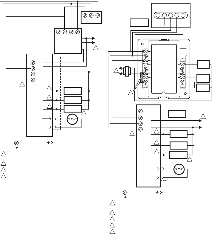
Fig. 9. Wiring R7284P,U with EnviraCOM™
connections, for typical oil-fired boiler.
Fig. 10. Typical wiring diagram for EnviraCOM™
enabled thermostat and R7284P,U for an
oil-fired forced-air system.
IMPORTANT
System as shown in Fig. 10 is phase/polarity
sensitive. Make sure all input power is in the
same phase.
L2
POWER SUPPLY. PROVIDE DISCONNECT MEANS AND OVERLOAD
PROTECTION AS REQUIRED.
REFER TO DEVICE LABEL FOR WIRE COLOR CODE.
VALVE IS OPTIONAL ON SPECIFIC MODELS.
ENVIRACOM™ TERMINAL 3 IS ALSO THE FIRST THERMOSTAT TERMINAL.
1
R7284
IGNITER
M32183
L1
1
CAD
CELL
2
3
3
4
4
2
2
2
BURNER
MOTOR
L2
B2
BURNER
MOTOR
IGNITER
VALVE
VALVE
CAD
CELL
L1
B1
LIMIT
JUNCTION
BOX
T
T
3
2
1
12T/3
1 2 3
LEGEND: SCREW TERMINAL 1/4 IN. QUICK CONNECT TERMINAL
SOLDERLESS WIRE CONNECTOR
L7224/48
TH9421C
VisionPRO IAQ
AQUASTAT®
CONTROLLER
ENVIRACOM™
TERMINAL
T
POWER SUPPLY. PROVIDE DISCONNECT MEANS
AND OVERLOAD PROTECTION AS REQUIRED.
REFER TO DEVICE LABEL FOR WIRE COLOR CODE.
VALVE IS OPTIONAL ON SPECIFIC MODELS.
FACTORY INSTALLER JUMPERS.
ENVIRACOM™ TERMINAL 3 IS ALSO THE FIRST THERMOSTAT TERMINAL.
1
M32184
2
3
4
5
LEGEND: SCREW TERMINAL 1/4 IN. QUICK CONNECT TERMINAL
SOLDERLESS WIRE CONNECTOR
L2
R7284
IGNITER
L1
HOT
1
2
2
CAD
CELL
BURNER
MOTOR
L2
BURNER
MOTOR
IGNITER
CAD
CELL
L1
JUNCTION
BOX
T
T3
2
1
LIMIT
LIMIT
VALVE
L1
(HOT)
L2
COOL 1
RELAY
FAN
RELAY
OT
OT 2
1 3
C7089B
OUTDOOR
TEMPERATURE
SENSOR
T
863
5L
W8635A
C
R
RH
RC
1
2
3
Y2
W2
Y1
G
W1
COOL 2
RELAY
4
SYSTEM
TRANSFORMER
1
3
5
ENVIRACOM™
TERMINAL
VALVE
2
R7284B,P,U,G ELECTRONIC OIL PRIMARY, ENVIRACOM™ ENABLED
69-2467EFS—03 6
ADVANCED USER INTERFACE
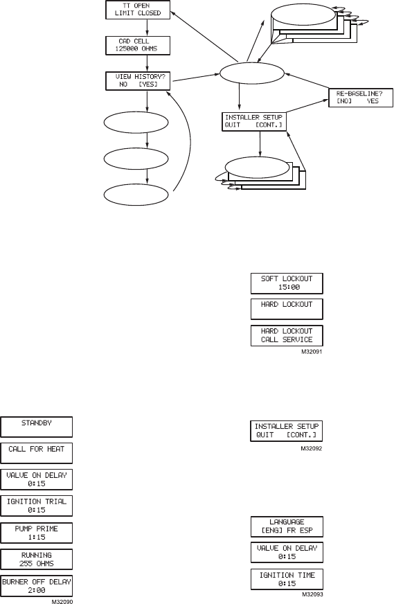
Fig. 11. User interface overview.
Home Screens
Pressing the “i” button longer than 2 seconds in states
other than Standby Interrupts control operation.
Once the held key is released the count down begins.
• Holding all 3 buttons longer than 2 seconds in any
state goes to Installer Setup (ISU).
• Pressing “i” in any state enters the Diagnostic screen
(if diagnostics are enabled).
• Pressing up or down in any screen enters Error History
(if diagnostics are enabled).
Below is a typical progression of screens through a
normal cycle.
Pressing up or down during the
Ignition Trial enters pump prime.
Each press of the up button adds a
minute, each press of the down
button subtracts a minute from the
pump prime time.
If at any point there is an event generating a lockout, one
of the following screens will be displayed.
Control is in Soft Lockout. Control will
recover when error clears or after
specified time.
Control is in Hard Lockout. Hold “i” for
at least 2 seconds to reset.
Hold the “i” button longer than 10
seconds to return to Standby.
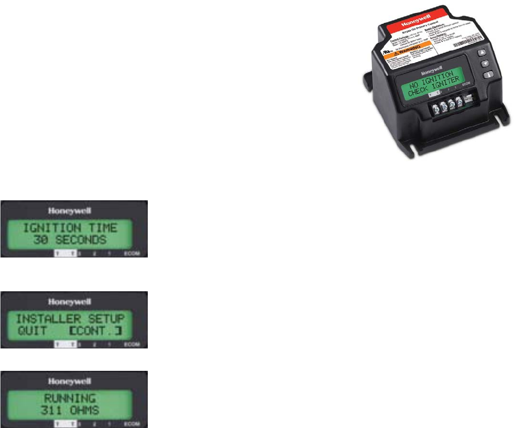
Installer Setup
Installer setup is entered by pushing all three buttons
simultaneously for 2 seconds.
If QUIT is selected, an “i” button press
displays the Re-baseline option.
If CONT is selected, an “i” button
press goes to “Installer Setup”.
NOTE:Not all parameters are adjust-
able in all models. Parameters not available for
adjustment will display “Locked” when an
attempt is made to modify them.
Select between English, French, or
Spanish by using the up or down
buttons and the “i” button to select
Adjustment of the Valve On Delay in
five second increments.
Ignition (lockout) Time adjustment.
NOTE: The Ignition Time is only available for adjustment
during the first 100 cycles of operation. After 100
cycles the Ignition Time is locked in and can no
longer be adjusted.
M32103A
i
i
i
i
i
i
i
i
i
i
UP/DOWN
UP/DOWN
i
(EXIT SELECTED)
HOLD ALL
3 BUTTONS
ERROR HISTORY
HOME SCREEN
CAD CELL HISTORY
CYCLE COUNTS
IGNITION TIME
HISTORY INSTALLER SETUP
SCREENS
i
(CONT. SELECTED)
i
(NO SELECTED)
i
(YES SELECTED)
R7284B,P,U,G ELECTRONIC OIL PRIMARY, ENVIRACOM™ ENABLED
7 69-2467EFS—03
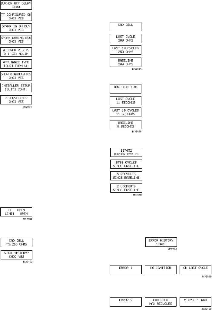
Adjustment of the Burner Off Delay.
Configuration of the TT terminals vs.
an “internal jumper.”
Controls sparking during On Delay
period.
Controls sparking during Run mode
(Interrupted vs. Intermittent ignition).
Number of resets allowed before
Restricted Lockout
Appliance configuration (boiler,
furnace, water heater) for
EnviraCOM™.
Enable advanced diagnostics mode
and error history.
Exit installer setup
If “QUIT” is selected, the user is
prompted with a screen asking if it is
desired to re-baseline the control.
Baselining the control is intended as a means to save
performance data at the time when the control is
operating optimally. The baseline values are a “trend” of
the first 500 cycles following an installation or a command
to “re-baseline” and is provided as a method to compare
present burner performance to that when the burner was
initially installed or serviced. Using the baseline data, it is
possible to monitor the burner system for degradation and
allow a service person to address any issues before they
result in a no-heat situation. After performing the service it
may be desired to reset the baseline through the installer
setup menu.
NOTE: Re-baselining will establish new baseline values
for CAD cell and Ignition Time going forward. It
will also reset the “Cycles Since Baseline”,
“Lockouts Since Baseline”, and “Recycles Since
Baseline” counters back to zero.
Displays the status of the TT and
Limit inputs. Note that “TT Remote”
means EnviraCOM™ is commanding
the R7284 to behave opposite the
status of the TT terminals.
Press “i” to go to the next screen
Current value of the CAD cell. Press
“i” to go to the next screen
If NO is selected, “i” returns to the
home screen
If YES is selected, “i” continues
through diagnostic screens.
The history screens can provide useful information about
the controls past performance, including its recent history
such as cycle trends (using the baseline function) and
total cycles since installation.
View History
From the Diagnostic screen scroll to the View History
screen and select YES. Scroll through the performance
data by using the up or down buttons.
The CAD Cell screen automatically
scrolls 4 screens.
Average CAD cell value during last
cycle
CAD cell trend over the last 10 cycles.
CAD cell trend over the first 500
cycles
Pressing “i” during any of the CAD cell screens moves to
the Ignition Time screens below.
The Ignition Time screen
automatically scrolls through 4
screens.
Last Ignition Time.
Ignition Time trend over the last 10
cycles. Ignition
Time trend over the first 500 cycles.
Pressing “i” during any of the ignition time screens moves
to the Cycle Count screen below.
Total burner cycles.
Burner cycles since last service
(baseline reset).
Flame losses since last service
(baseline reset).
Ignition failures since last service
(baseline reset).
The next press goes back to the View History screen
where the user can exit to the home screen or loop back
through the performance history again.
Error History Screens
For all Error History screens, pressing “i” returns to the
Normal Screen.
From the home screen, press the up button to display
most recent error.
Press the up button again to proceed to the next most
recent error or the down button to return to the previous
error screen.
These three screens transition every 3 sec.
If no more errors are logged, the display shows “Error
History End.”
R7284B,P,U,G ELECTRONIC OIL PRIMARY, ENVIRACOM™ ENABLED
69-2467EFS—03 8
BASIC USER INTERFACE
The basic user interface consists of 3 buttons and an
LED. Simple diagnostic information can be obtained
through the interaction of the buttons and LED.
R7284 Status (Basic Interface)
R7284 Flame Strength
(Basic Interface)
During normal operation and when the R7284 is in the
Running state, the LED will show CAD cell resistance.
See Table 3.
Error History (Basic Interface)
The last two errors are available for display on the LED:
• Pressing the up arrow button displays the most recent
error.
• Pressing the down arrow button displays the next most
recent error.
Once the up or down arrow is pushed, the LED will
display the most recent or next most recent alarm by
blinking the error code. See Table 4.
R7284 Error Codes
(Basic Interface)
TROUBLESHOOTING AND
MAINTENANCE
IMPORTANT
Due to the potential hazard of line voltage, only a
trained, experienced service technician should
preform the troubleshooting procedures.
This control contains no field-serviceable parts.
Do not attempt to take it apart. Replace entire
control if operation is not as described.
To completely troubleshoot an oil burner installation,
check the burner and oil primary control for proper
operation and condition.
Cad Cell Resistance Check
For proper operation, it is important that the cad cell
resistance is below 1600 ohms. On the basic model with
LED interface, during a normal call for heat, once the
control has entered the Run mode, press and release the
“i” button.
On the advanced model with display, follow the screen
diagnostic procedure to read the cad cell resistance.
Preliminary Steps
1. Check wiring connections and power supply.
2. Make sure power is on to controls.
3. Make sure limit control is closed.
4. Check contacts between igniter and the electrodes.
5. Check the oil pump pressure.
6. Check the piping to the oil tank.
7. Check the oil nozzle, oil supply and oil filter.
Check Oil Primary Control
If the trouble is not in the burner or ignition hardware,
check the oil primary control by using the following
equipment:
1. Screwdriver.
2. Voltmeter (0 to 150 Vac range).
3. Insulated jumper wire with both ends stripped.
WARNING
Electrical Shock Hazard.
Can cause severe injury, death or property
damage.
Troubleshoot with the system powered. Be careful
to observe all precautions to prevent electrical
shock or equipment damage.
Table 2. LED Codes.
Description LED Code
Standby Pulse (1/4 sec. ON, 4 sec OFF)
Call for Heat Heartbeat (1/2 sec bright, 1/2 sec dim)
Flame proven On solid
Recycle 2 second ON, 2 second OFF flashing
Lockout 1/2 second on, 1/2 second OFF flashing
Interrupt OFF
“i” button Flame Strength Indication
Up button Most recent error
Down button Next most recent error
Table 3. Flame Strength Indication.
Flame Strength Indication Number of 1/2 sec flashes
Cad Cell less than 400Ω1
400Ω < Cad Cell < 800Ω2
800Ω < Cad Cell < 1600Ω3
1600Ω < Cad Cell < 6100Ω4
Cad Cell > 6100ΩNone
Table 4. Error Codes.
Error Codes
Number of 1/4 sec
flashes
No ignition / Late ignition 1
Max flame losses / Cad Cell high
while running
2
Flame out of sequence 3
Low Voltage / EnviraCOM™ error 4
Internal Error 5

R7284B,P,U,G ELECTRONIC OIL PRIMARY, ENVIRACOM™ ENABLED
9 69-2467EFS—03
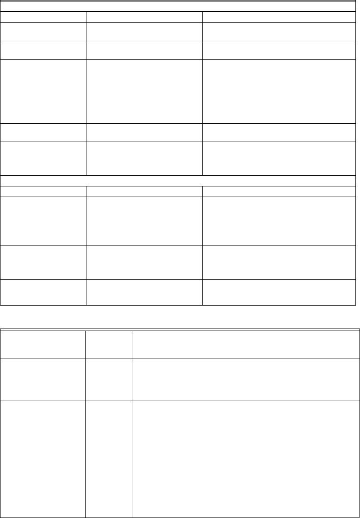
Table 5. R7284 Operation.
External Action R7284 Action
Power applied to control. Internal safety check conducted. If no light or flame is detected and all internal
conditions are correct, control enters Standby Mode.
Thermostat or Aquastat® Control
calls for heat.
1. Safety Period (5 seconds) internal and external check for flame or light. If
flame or light is detected, control remains in the Standby Mode.
2. When flame or light is not present:
a. R7284G will apply power to the burner motor and igniter.
b. R7284B,P,U (if valve-on delay is enabled) will apply power to the burner
motor and igniter, (if configured) enter/complete valve-on delay period
and then apply power to the valve.
3. Control enters Trial for Ignition period.
a. Monitors burner for flame.
b. When flame is not detected:
(1) Enters lockout mode (after lockout time of 15, 30, or 45 seconds).
(2) Shuts off valve, igniter and burner motor.
(3) Display models: display Lockout mode. LED models: flash LED 1/2
sec ON, 1/2 sec OFF.
(4) Depress “i” button for 2 seconds to return to power-up sequence.
c. When flame is detected, Carry-Over period begins:
4. Control enters Ignition Carry-Over period (continues to spark for 10 seconds
in interrupted mode).
a. Display models: display “Flame Proven.” LED models: turns on LED
b. If flame is lost and lockout time has not expired, R7284 returns to Trial for
Ignition period.
c. If flame is lost and lockout time has expired, R7284 enters Recycle Mode.
5. Carry-Over time expires; igniter turns off if interrupted ignition.
6. Enters Run Mode:
a. Flame is monitored until call for heat ends or flame is lost. If flame is lost:
(1) Control enters Recycle Mode.
(2) Recycle time starts (60 seconds).
(3) Burner and valve are turned off.
(4) Display models: display “Recycle.” LED models: flash LED 2 sec ON,
2 sec OFF.
(5) Returns to Idle Mode at end of Recycle Mode.
Call for heat is satisfied. 1. R7284B,G,P,U (if burner motor-off delay is disabled):
a. Burner motor and optionally oil valve and igniter shut off.
b. Display models: display “Standby”
LED models: LED turns OFF
c. Indicator light turns off.
2. R7284P,U (if burner motor-off delay is enabled):
a. Oil valve shuts off.
b. Burner motor runs for selected burner motor-off delay time.
c. Burner motor turns off.
d. Device returns to Idle Mode.
Reset control three times without
completing a call for heat
(number of resets is adjustable in
some controls)
1. R7284 enters Restricted Mode.
2. Indicator light flashes and 1/2 second on, 1/2 second off.
3. Display models: display “Hard Lockout Call Service”
LED models: flash LED 1/2 second ON, 1/2 second OFF
4. Reset device by pressing and holding reset button for a minimum of 10
seconds.
R7284B,P,U,G ELECTRONIC OIL PRIMARY, ENVIRACOM™ ENABLED
69-2467EFS—03 10
Table 6. Troubleshooting Information.
Condition: Burner does not start with a call for heat
Procedure Control Status Corrective Action
Review error history if
control in lockout
-- Refer to Error Codes table of this section
Check that limit switches
are closed
Display models: display shows status
of limit switch.
Replace limit switch or clean contacts.
Check TT status Display models: display shows status
of TT.
•Most hydronic systems require TT to be
jumpered. Display models can be configured
to behave as though the TT terminals are
jumpered. LED models require a jumper be
added.
•Warm air systems will short TT terminals
during a call for heat. Check that TT is really
shorted during the call for heat.
Check for line voltage
power at R7284
-- Check breaker and investigate appliance wiring
Check status of cad cell Display models: display shows cad
cell resistance.
LED models: LED is on if cad cell is
too low to start.
•Replace cad cell
•If operation does not resume, remove
leadwires from R7284.
•If operation does not resume, replace control.
Condition: Burner does not stop when call for heat ends
Procedure Control Status Corrective Action
Check TT status Display models: display shows status
of TT.
•Check if a TT jumper is installed.
•Check if the R7284 is configured to ignore the
TT terminals.
•Verify thermostat contacts have opened.
There should be 24VAC across TT terminals
when there is not call for heat.
Check limit status Display models: display shows status
of limit.
Measure voltage on Limit terminal. There should
be no voltage between Limit and Neutral when
the contacts are open. Replace limit switch if
necessary.
Check if other EnviraCOM
devices are commanding
the R7284 to run
Display models: display shows "TT
Remote" if an EnviraCOM device is
commanding it to run.
Unplug all EnviraCOM devices from R7284. It
should turn off within 5 minutes.
Table 7. Display Alarm Information.
Display Alarm
EnviraCOM™
Alarm
Number Corrective Action
No Ignition
Check Igniter
10 •The burner was not lit and spark was not detected. Check the
electrodes, spring contacts (or high voltage wires), and ignition
transformer for proper operation.
•If spark ignition is functioning acceptably, proceed to “No Ignition”
corrective action.
No Ignition
Check Cad Cell
5•The cad cell detected some amount of light during the ignition trial, but
not enough to enter run mode. Check the cad cell positioning and clean
the eye.
•Set the display to show the cad cell resistance.
•Shield the cad cell from light.
•If the display shows is less than 20,000 ohms, unplug the cad cell.
— If the display does not read 999999 ohms, replace control
— If it does read 999999 ohms, replace cad cell.
•Expose the cad cell to ambient light (generally enough light to read by
is adequate)
•If the display shows more than 2000 ohms, short the cad cell terminals.
— If the display shows more than 5 ohms, replace control
— If less than 5 ohms, replace cad cell.
•If the burner still does not light, proceed to “No Ignition” corrective
action.

R7284B,P,U,G ELECTRONIC OIL PRIMARY, ENVIRACOM™ ENABLED
11 69-2467EFS—03
No Ignition 20 •Check that the manual shut off valve is open.
•Check that the burner motor is spinning and the pump is generating
adequate pressure.
•Check the condition of the nozzle and replace if necessary.
•If a valve is present, check for proper operation.
•Check burner adjustments (refer to burner manufacturers instructions)
Low Voltage
XX% low
59 •Supply voltage is low to the control.
•Measure the voltage across screw terminals “2” and “3”
— If it's greater than 22VAC and the error does not clear, replace
control.
— If it's less than 22VAC, review appliance wiring.
Internal Error 18, 58 •An error has been detected inside the control. Replace control if the
error persists.
Flame Proven
Out of Sequence
34 •The cad cell is permanently in a low resistance state. It should typically
read much higher than 20,000 ohms when no flame is present.
•Set the display to display cad cell resistance.
•Shield the cad cell from light.
•If the display shows less than 20,000 ohms, unplug the cad cell,
— If display does not read 999999 ohms, replace control.
— If it does read 999999 ohms, replace cad cell.
Flame Proven
During On Delay
23 •Flame was proven during the valve on delay period. Check the oil valve
for proper operation.
•If the system does not have an oil valve, set the valve on delay to 0.
Flame Proven
During Off Delay
24 •Flame remained lit during the burner off delay. Check the oil valve for
proper operation.
•If the system does not have an oil valve, set the burner off delay to 0.
Exceeded Max Recycles 22 •Flame was lost more than the allowed number of times. The burner
lights, but does not remain lit.
•Check that the fuel tank is not empty.
•Check the fuel supply lines (and filter) for obstructions or air
— Use the pump priming feature to purge the system of airCheck
•Check that the burner motor is spinning and the pump is generating
adequate pressure.
•If present, check operation of the oil valve.
•If the problem persists, proceed to the “Cad Cell, High During Run”
corrective action.
EnviraCOM™ Error 91 •Communications error has been detected.
•Remove all devices from the EnviraCOM™ connections, 3-pin plug
and screw terminals “1-2-3”.
— If the error does not clear within one minute, measure the voltage on
terminals “2” and “3”.
— If the voltage across terminals “2” and “3” is between 20VAC and
30VAC, replace control.
— If it is outside of that range, review appliance wiring. There should
be approximately 24VAC across “2” and “3”.
Cad Cell
High During Run
4•The cad cell resistance is higher than normal while running, the system
is in need of a tune up.
•Check for proper alignment of the cad cell and clean the eye if
necessary.
•Check if the pump is generating adequate pressure.
•Check burner adjustments (refer to burner manufacturers instructions).
•Check for excessive soot build up in the burner and flue.
•Check for flue blockage.
Flame Proven
Late in Trial
9•The burner lit very late during the trial for ignition and is susceptible to
not lighting.
•Check cad cell for proper alignment and clean if necessary.
•Check burner adjustments (refer to burner manufacturers instructions)
•Check electrodes and spring contacts (if equipped) and adjust per
manufacturers recommendations.
•Check if the pump is generating adequate pressure.
•Check the fuel supply lines and filter for obstructions.
Table 7. Display Alarm Information.

R7284B,P,U,G ELECTRONIC OIL PRIMARY, ENVIRACOM™ ENABLED
Automation and Control Solutions
Honeywell International Inc.
1985 Douglas Drive North
Golden Valley, MN 55422
Honeywell Limited-Honeywell Limitée
35 Dynamic Drive
Toronto, Ontario M1V 4Z9
customer.honeywell.com
® U.S. Registered Trademark
© 2010 Honeywell International Inc.
69-2467EFS—03 M.S. Rev. 09-10
Printed in U.S.A.
Table 8. LED Flash Codes.
LED
Flash
Code
EnviraCOM™
Alarm
Number Corrective Action
1 10,5,20,59,9 The burner was not lit or lit near the end of the trial time.
•Check that the manual shut off valve is open.
•Check that the burner motor is spinning and the pump is generating adequate pressure.
•Check the condition of the nozzle and replace if necessary.
•Check the fuel supply lines and filter for obstructions or air.
•Check the electrodes, spring contacts (or high voltage wires), and ignition transformer for
proper operation.
•If a valve is present, check for proper operation.
•Check burner adjustments (refer to burner manufacturers instructions) and spark was not
detected.
•Check the cad cell positioning and clean the eye.
•Expose the cad cell to ambient light (generally enough light to read by is adequate)
— If the LED does not turn on, short the cad cell terminals,
— If the LED does not turn on, replace the control,
— If the LED turns on, replace the cad cell.
•Shield the cad cell from light.
— If the LED does not turn off, unplug the cad cell,
— If the LED does not turn off, replace the control,
— If the LED turns off, replace the cad cell.
2 22,4 Flame was lost more than the allowed number of times. The burner lights but does not remain
lit, or the cad cell is unusually high during a run cycle.
•Check that the fuel tank is not empty.
•Check the fuel supply lines (and filter) for obstructions or air
use the pump priming feature to purge the system of air
•Check for proper alignment of the cad cell and clean the eye if necessary.
•Check the burner motor is spinning and the pump is generating adequate pressure.
•If present, check operation of the oil valve.
•Check burner adjustments (refer to burner manufacturers instructions).
•Check for excessive soot build up in the burner and flue.
•Check for flue blockage.
3 23,24,34 Flame was detected out of sequence.
•Check the oil valve for proper operation (if equipped).
•Expose the cad cell to ambient light (generally enough light to read by is adequate)
— If the LED does not turn on, short the cad cell terminals,
— If the LED does not turn on, replace the control,
— If the LED turns on, replace the cad cell.
•Shield the cad cell from light.
— If the LED does not turn off, unplug the cad cell,
— If the LED does not turn off, replace the control,
— If the LED turns off, replace the cad cell.
4 59,91 •Supply voltage was low to the control or a communication error has occurred.
•Remove all devices from the EnviraCOM™ connections, 3-pin plug and screw terminals
“1-2-3”.
— Measure the voltage across screw terminals “2” and “3”
If it's between 22VAC and 30VAC and the error does not clear, replace control.
— If it's outside that range, review appliance wiring. There should be approximately 24VAC
across “2” and “3”.
5 18, 58 An error has been detected inside the control. Replace control if the error persists.
