R980XR_Manual R980XR Manual
User Manual: R980XR_Manual
Open the PDF directly: View PDF ![]() .
.
Page Count: 52
1
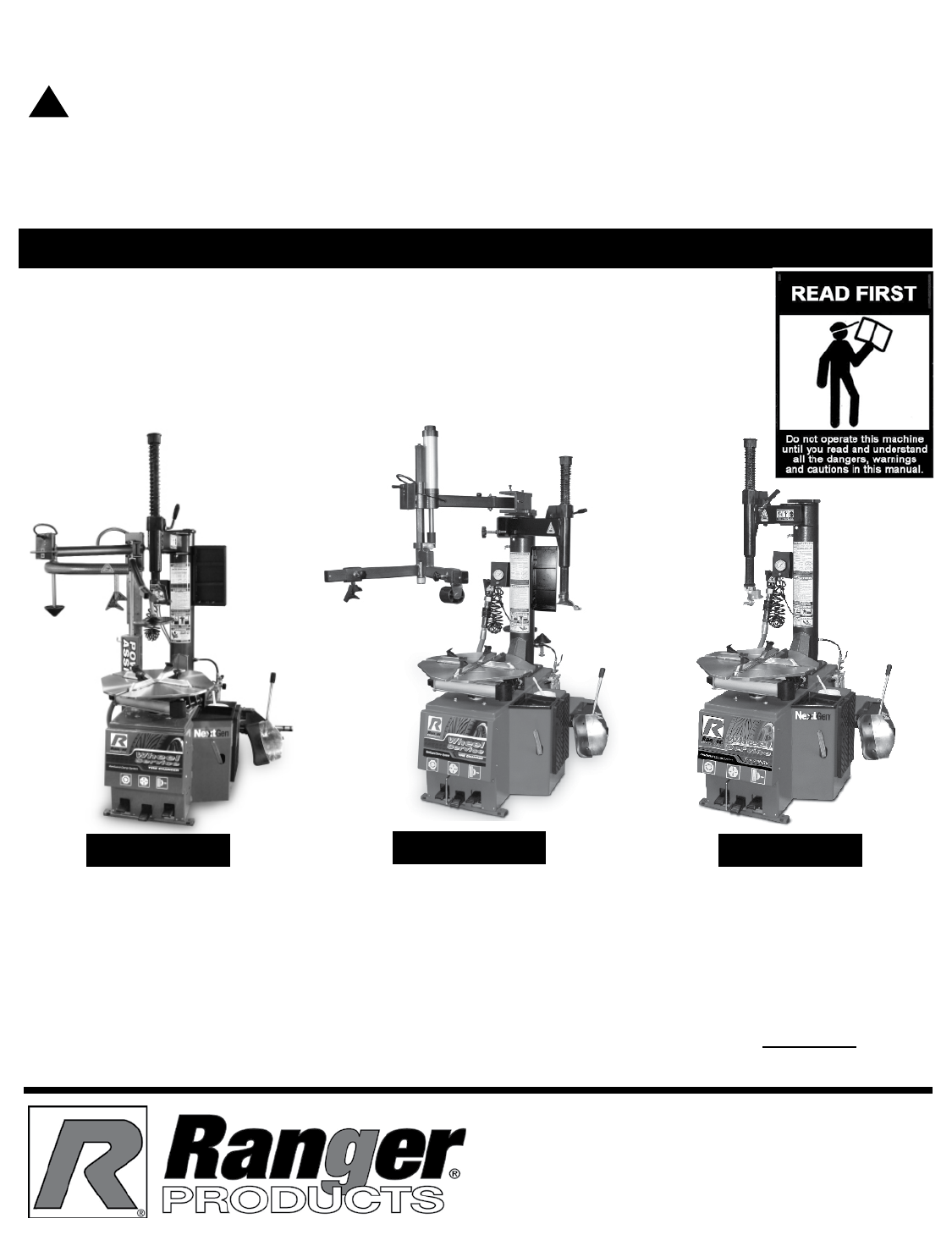
INSTALLATION AND OPERATION MANUAL
RECEIVING
The shipment should be thoroughly inspected as soon as it
is received. The signed Bill of Lading is acknowledgement
by the shipping carrier as receipt of this product as listed
in your invoice as being in a good condition of shipment. If
any of these goods listed on this Bill of Lading are missing
or damaged, do not accept goods until the shipping carrier
makes a notation on the freight bill of the missing or dam-
aged goods. Do this for your own protection.
BE SAFE
Your new tire changer was designed and built with safety
in mind. However, your overall safety can be increased with
proper training and thoughtful operation on the part of the
operator. DO NOT operate or repair this equipment without
reading this manual and the important safety instructions
shown inside. Keep this operation manual near the tire
changer at all times. Make sure that ALL USERS read and
understand this manual.
1645 Lemonwood Dr.
Santa Paula, CA. 93060, USA
Toll Free 1-800-253-2363
Tel: 1-805-933-9970
Fax: 1-805-933-9160
www.bendpak.com
IMPORTANT SAFETY INSTRUCTIONS
SAVE THESE INSTRUCTIONS
PLEASE READ THE ENTIRE CONTENTS OF THIS MANUAL PRIOR TO INSTALLATION
AND OPERATION. BY PROCEEDING WITH TIRE CHANGER INSTALLATION AND
OPERATION YOU AGREE THAT YOU FULLY UNDERSTAND AND COMPREHEND
THE FULL CONTENTS OF THIS MANUAL. FORWARD THIS MANUAL TO ALL
OPERATORS. FAILURE TO OPERATE THIS EQUIPMENT AS DIRECTED MAY CAUSE
INJURY OR DEATH. MAN REV B 01-09-15
P/N 5900158
MODELS:
R980XR/XRF
R980NXT/NXTF
R980AT/ATF
R980AT/ATF R980XR/XRF
R980NXT/NXTF
WARNING
!
2
This instruction manual has been prepared specifically for you. Your new Ranger Tire Changer is the product of over 40
years of continuing research, testing and development; it is the most technically advanced tire changer on the market
today. The manner in which you care for an maintain your tire changer will have a direct effect on its overall
performance and longevity.
READ THIS ENTIRE MANUAL BEFORE INSTALLATION & OPERATION BEGINS
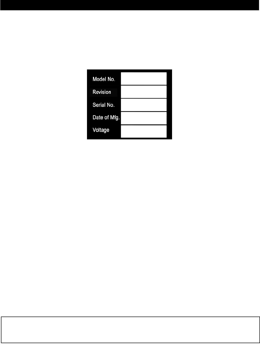
RECORD HERE YOUR TIRE CHANGER INFORMATION HERE WHICH IS
LOCATED ON THE SERIAL NUMBER DATA PLATE.
This information will be required when calling for parts or warranty issues.
Only replace parts with Ranger approved parts.
PRODUCT WARRANTY
Your new tire changer is covered under warranty for one year on equipment structure; one year on all operating
components and tooling/accessories, to the original purchaser, to be free of defects in material and workmanship. The
manufacturer shall repair or replace at their option for this period those parts returned to the factory freight prepaid which
prove upon inspection to be defective. The manufacturer will pay labor costs for the first 12 months only on parts returned
as previously described.
The warranty does not extend to...
t defects caused by ordinary wear, abuse, misuse, negligence, shipping damage, improper installation, voltage or
lack of required maintenance;
t damages resulting from purchaser’s neglect or failure to operate products in accordance with instructions
provided in the owner’s manual(s) and/or other accompanying instructions supplied;
t normal wear items or service normally required to maintain the product in a safe operating condition;
t any component damaged in shipment;
t other items not listed but may be considered general wear parts;
t damage caused by rain, excessive humidity, corrosive environments or other contaminants.
THESE WARRANTIES DO NOT EXTEND TO ANY COSMETIC DEFECT NOT INTERFERING WITH EQUIPMENT
FUNCTIONALITY OR ANY INCIDENTAL, INDIRECT, OR CONSEQUENTIAL LOSS, DAMAGE, OR EXPENSE THAT
MAY RESULT FROM ANY DEFECT, FAILURE, OR MALFUNCTION OF A BENDPAK INC. / RANGER PRODUCT OR
THE BREACH OR DELAY IN PERFORMANCE OF THE WARRANTY.
WARRANTY IS NOT VALID UNLESS WARRANTY CARD IS RETURNED
RANGER R980 SERIES
NOTE:
Although every effort has been taken to ensure the accuracy of this manual, some information may contain technical
incorrectness or typographical errors. BendPak/Ranger assumes no responsibility or liability for damages incurred directly
or indirectly as a result of any imprecisions, omissions or discrepancies. Information and specications are subject to
change without notice.
3
BEFORE YOU BEGIN
NOTIFY THE CARRIER AT ONCE if any hidden loss or
damage is discovered after receipt and request the carrier
to make an inspection. If the carrier will not do so, prepare
a signed statement to the effect that you have notified the
carrier (on a specific date) and that the carrier has failed to
comply with your request.
IT IS DIFFICULT TO COLLECT FOR LOSS OR DAMAGE
AFTER YOU HAVE GIVEN THE CARRIER A CLEAR
RECEIPT. Support claim with copies of the bill of lad-
ing, freight bill, invoice, and photographs, if available.
BendPak’s willingness to assist in helping you process your
claim does not make BendPak responsible for collection of
claims or replacement of lost or damaged materials.
IMPORTANT NOTICE
Do not attempt to install this tire changer if you have never
been trained on basic automotive service equipment
installation procedures. Never attempt to lift components
without proper lifting tools such as a forklift or cranes.
Stay clear of any moving parts that can fall and cause
injury. These instructions must be followed to ensure
proper installation and operation of your tire changer.
Failure to comply with these instructions can result in seri-
ous bodily harm and void product warranty. Manufacturer
will assume no liability for loss or damage of any kind,
expressed or implied resulting from improper installation
or use of this product.
SECTION 1
PLEASE READ ENTIRE MANUAL
PRIOR TO INSTALLATION
OWNER’S RESPONSIBILITY
To maintain the equipment and user safety, the responsi-
bility of the owner is to read and follow these instructions:
tFollow all installation and operation instructions.
tMake sure installation conforms to all applicable Local,
State, and Federal Codes, Rules, and Regulations;
such as State and Federal OSHA Regulations and
Electrical Codes.
t Carefully check the equipment for correct initial function.
t Read and follow the safety instructions. Keep them
readily available for machine operators.
t Make certain all operators are properly trained, know
how to safely and correctly operate the unit, and are
properly supervised.
tAllow unit operation only with all parts in place and
operating safely.
t Carefully inspect the unit on a regular basis and
perform all maintenance as required.
tService and maintain the unit only with authorized or
approved replacement parts.
tKeep all instructions permanently with the unit and
all decals on the unit clean and visible.
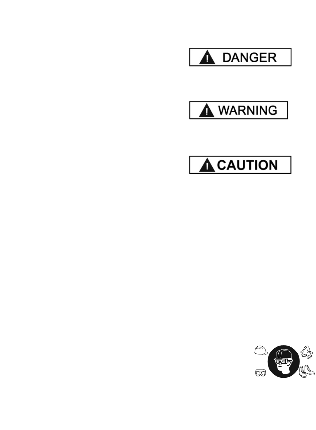
DEFINITIONS OF
HAZARD LEVELS
Identify the hazard levels used in this manual with the
following definitions and signal words:
Watch for this symbol as it means: Immediate hazards
which will result in severe personal injury or death.
Watch for this symbol as it means: Hazards or unsafe
practices which could result in severe personal injury or
death.
Watch for this symbol as it means: Hazards or unsafe
practices which may result in minor personal injury,
product or property damage.
INSTALLER / OPERATOR
PROTECTIVE EQUIPMENT
Personal protective equipment helps makes installation
and operation safer, however, it does not take the place
of safe operating practices. Always wear durable work
clothing during any installation and/or service activity.
Shop aprons or shop coats may also be worn, however
loose-fitting clothing should be avoided.
Tight-fitting leather gloves are recommended to protect
the technician’s hands when handling parts. Sturdy
leather steel-toe work shoes and oil resistant soles should
be used by all service personnel to help prevent injury
during typical installation and operation activities.
Eye protection is essential during
installation and operation
activities. Safety glasses with
side shields, goggles, or face
shields are acceptable. Back
belts provide support during
lifting activities and are also helpful in providing worker
protection. Consideration should also be given to the use
of hearing protection if service activity is performed in an
enclosed area, or if noise levels are high.
4
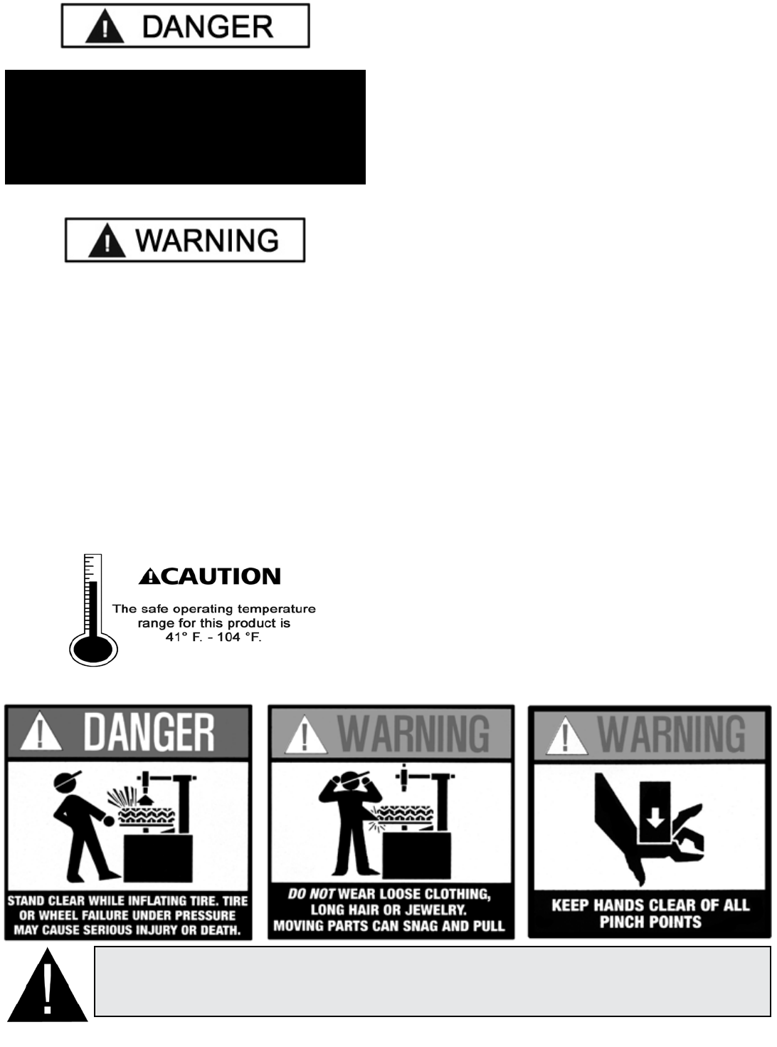
THIS SYMBOL POINTS OUT IMPORTANT SAFETY INSTRUCTIONS WHICH IF NOT FOLLOWED
COULD ENDANGER THE PERSONAL SAFETY AND/OR PROPERTY OR YOURSELF AND OTHERS
AND CAN CAUSE PERSONAL INJURY OR DEATH. READ AND FOLLOW ALL INSTRUCTIONS IN
THIS MANUAL BEFORE ATTEMPTING TO OPERATE THIS MACHINE.
FAILURE TO FOLLOW DANGER, WARNING, AND
CAUTION INSTRUCTIONS MAY LEAD TO SERIOUS
PERSONAL INJURY OR DEATH TO OPERATOR
OR BYSTANDER OR DAMAGE TO PROPERTY.
PLEASE READ THE ENTIRE MANUAL PRIOR TO
INSTALLATION.
TABLE OF CONTENTS
Warranty. . . . . . . . . . . . . . . . . . . . . . . . . .. . . . . . . . . . . . . . . . 2
Section 1: Owner’s Responsibility . . . . . . . . . . . . . . . . . . . . .3
Definitions of Hazard Levels . . . . . . . . . . . . . . . . .3
Operator Protection . . . . .. . . . . . . . .. . . . . . .. . . .3
Section 2: Safety Instructions . . . . . . . . . . . . . . . . . . . . . . . .5
Section 3: Tire and Wheel Service Safety Instructions . . . . 6
Section 4: Description of Parts . . . . . . . . . . . . . . . . . . . ...7-8
Section 5: Specifications / Tools Required . . . . . . . . .. . . . . .9
Section 6: Lifting / Un-crating Instructions . . . . . . . . . . . .10-11
Section 7: Installation Location . . . . . . . .. . . . . . . . . . . . . . 12
Section 8: R980XR/NXT/AT/F Assembly/ Anchoring .. . . .13
Section 9: Air Source/ Oiler Adjustment . . . . . . .. . . . . . . ...14
Section 10: Electrical / Wiring Instructions . . . . . .. . . . . . . 14-15
Section 11: Demounting . . . . . . . . . . . . . . . . . .. . . . . . . . .15-21
Bead Loosening . . . . . . . . . . . . . . . . . . .. . . .. . .16
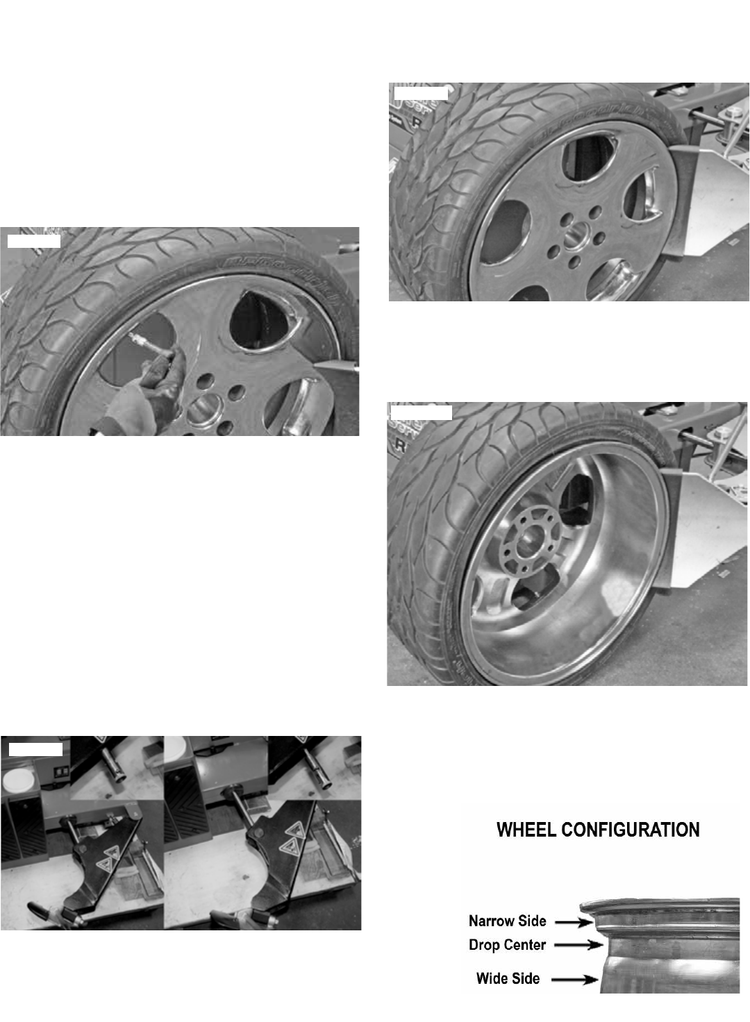
Important Wheel Mounting Instructions . . . . . . . 17
Wheel Clamp Adjustments . .. . . . . . . . . . . . . . . .18
Demounting . . . . . . . . . . . . . . . . . . . . . . . . 18-21
Section 12: Custom and Special Wheels . . . . . . .. . . . . . . .21
Demounting Tube Tires . . . . . . . . . . . . .. . . . . . 22
Section 13: Mounting . . .. . . . . . . . . . . . . . .. . . . . . . . . . .22-25
Mounting Tube Tires . .. . . . . . . . .. . . .. . . . . . . 25
Section 14: Inflation . . . . . . . . . . . . . . . . . . . . . . . . . .. . . . 25-32
Stages Of Inflation . . . . . . . . . . . . . . . . . . .. . . 27
Stage One: Wheel Restraint . . . . . . . .. . . . . . . . . . . . . . . . . 27
Stage Two Bead Sealing . . . . . . . . . . . . . . . 27-28
Stage Three: Bead Seating . . .. . . . . . . . . .28-29
Stage Four: Tire Inflation . . .. . . . . . . . . . . . . . .30
Section 15: Maintenance Instructions . . . . . . . . . . . . . . . . 31
Mount/Demount Head . . . . . . . . . . . . . . . . . . 31
Air Drier / Oiler Maintenance .. . . . . . . . . . . . . . 32
Inflation Pedal Pressure Limiter . . . . . . . . . . . . 33
Turntable Drive Belt . . . . . . . . . . . . . . . .. . .. . .34
Inflation Valve Lubrication . . . . . ... . . . . . .. 34-35
Transmission Oil Inspection/Lubrication . . ... . 35
Critical Safety Warnings / Instructions . .. . . . . . . . . . .. . . . 36
Service Parts . . . . . . . . . . . . . . . . . . . . . . . . . . . . .. . . . . 37-50
Tire and Wheel Data .. . . . . . . . . . . . . . . . . . . . . . . . . . . . . 51
DO NOT OPERATE THIS MACHINE UNTIL YOU
HAVE READ AND HAVE UNDERSTOOD ALL OF THE
DANGER, WARNING AND CAUTION ALERTS IN THIS
MANUAL. FOR ADDITIONAL COPIES
OR FURTHER INFORMATION, CONTACT:
Bendpak Inc.
1645 Lemonwood Dr.
Santa Paula, CA. 93060
1-805-933-9970
www.bendpak.com
5
SECTION 2- IMPORTANT SAFETY INSTRUCTIONS
Read these safety instructions entirely. Do not attempt to install this machine if you have never been trained
on basic garage equipment installation procedures. Never attempt to lift components without proper lifting tools such as
forklifts or cranes. Stay clear of any moving parts that may fall and cause injury. When using your garage equipment,
basic safety precautions should always be followed, including the following:
1. Read and understand all instructions and all safety
warnings before operating service equipment.
2. Care must be taken as burns can occur from touching hot
parts.
3. Do not operate equipment with a damaged cord or if the
equipment has been dropped or damaged until it has been
examined by a qualified service person.
4. Do not let a cord hang over the edge of the table, bench,
or counter or come in contact with hot manifolds or moving fan
blades.
5. If an extension cord is necessary, a cord with a current
rating equal to or more than that of the equipment should be
used. Cords rated for less current than the equipment may
overheat. Care should be taken to arrange the cord so that it
will not be tripped over or pulled.
6. Always unplug equipment from electrical outlet when not in
use. Never use the cord to pull the plug from the outlet. Grasp
plug and pull to disconnect.
7. Let equipment cool completely before putting away. Loop
cord loosely around equipment when storing.
8. To reduce the risk of fire, do not operate equipment in
the vicinity of open containers of flammable liquids (gasoline).
Keep exterior of motor free of oil, solvent, or excessive grease.
9. Keep hair, loose clothing, fingers, and all parts of body
away from moving parts. Avoid pinch points.
10. DANGER! To reduce the risk of electric shock, do not use
on wet surfaces or expose to rain. The electronics used on
this equipment contain high voltage. Disconnect power at the
receptacle or at the circuit breaker switch before performing
any electrical repairs. Secure plug so that it cannot be
accidentally plugged in during service. Or mark circuit breaker
switch so that it cannot be accidentally switched on during
service.
11. DANGER! The motor on this machine
contains high voltage. Disconnect power at
the receptacle before performing any electrical
repairs. Secure plug so that it cannot be
accidentally plugged in during service.
12. Use only as described in this manual. Use only
manufacturer’s recommended attachments.
13. Do not attempt to operate this equipment if you have never
been trained on basic tire service and mounting / demounting
procedures.
14. ALWAYS WEAR SAFETY GLASSES.
Everyday eyeglasses only have impact resistant
lenses, they are not safety glasses.
15. Consider work environment. Keep work area clean.
Cluttered work areas invite injuries. Keep areas well lit.
16. Guard against electric shock. This equipment must be
grounded while in use to protect operator from electric shock.
Never connect the green power cord wire to a live terminal.
This is for ground only.
17. Only trained operators should operate this machine. All
non-trained personnel should be kept away from the work
area. Never let non-trained personnel come in contact with, or
operate machine.
18. WARNING! RISK OF EXPLOSION. This
equipment has internal arcing or sparking parts
which should not be exposed to flammable
vapors. This machine should not be located in a
recessed area or below floor level.
19. MAINTAIN WITH CARE. Keep equipment clean for better
and safer performance. Follow manual for proper lubrication
and maintenance instructions. Keep control handles and/or
buttons dry, clean and free from grease and oil.
20. Check for damaged parts. Check for alignment of
moving parts, breakage of parts or any condition that may
affect operation of machine. Do not use machine if any
component is broken or damaged.
21. NEVER remove safety related components from the
equipment. Do not use machine if safety related components
are missing or damaged.
22. DRESS PROPERLY. Non-skid steel-toe footwear is
recommended when operating machine.
23. Illegible and missing warning labels must be replaced
immediately. Do not use the tire changer if one or more labels
are missing. Do not add any object that could prevent the
operator from seeing the labels.
24. STAY ALERT. Use common sense and watch what you
are doing. Remember, SAFETY FIRST.
SAVE THESE INSTRUCTIONS
IMPORTANT
SAFETY INSTRUCTIONS

6
SECTION 3
TIRE AND WHEEL SERVICE
SAFETY INSTRUCTIONS
ALWAYS wear durable personal protective work clothing
and safety gear during tire service activity. Refer to page
three for Operator Protective Equipment.
ALWAYS remove all wheel weights and the valve core to
deflate the tire before servicing.
ALWAYS keep all working surfaces clean and free of
debris.
ALWAYS be aware of what each person is doing - and
what they will do before attempting any two-person opera-
tion.
ALWAYS cover the electric motor and all electrical
components before cleaning the tire changer. Be sure
water or cleaner does not enter the motor or electrical
components or come in contact with electrical connections.
ALWAYS disconnect the electric power and air supply
before attempting any maintenance.
DEMOUNTING & MOUNTING
ALWAYS clean and inspect the wheel prior to any service.
NEVER stand on the sliding carriage, frame or work table
while demounting or mounting a tire.
ALWAYS keep hands, feet, and other objects away from
moving parts while the machine is turned on.
ALWAYS place the narrow bead seat to the outside when
clamping. Failure to demount the tire from the narrow bead
seat side may cause damage to the tire beads.
ALWAYS apply an approved rubber lubricant to rim flanges
and both tire beads before demounting or mounting and
seating the beads.
NEVER mount a tire on a damaged or rusty wheel as tire
or wheel failure may result during inflation. Explosion from
failure may result in severe injury or death of the operator
and bystanders.
INFLATION
ALWAYS be sure the bead opposite the tool is in the drop
center before rotating the tire when demounting or
mounting to avoid damage to the tire beads.
ALWAYS follow all applicable Local, State, and Federal
Codes, Rules, and Regulations; such as the Federal OSHA
Standard Number 1910.177.
ALWAYS use an approved inflation chamber or inflation
cage equipped with a self-gripping chuck and remote
inflation gauge and valve.
ALWAYS inflate the tire to manufacturer’s recommended
cold operating pressure.
DO NOT OVER INFLATE! Tire or wheel failure during and
after inflation may result in an explosion capable of causing
severe injury or death.
NEVER reinflate a tire that has been run under inflated or
flat without first demounting the tire and checking for wheel
and tire damage.
ALWAYS inspect the tire interior for loose or broken cords,
cuts, penetrating objects, and other damage. Discard tires
that cannot be properly repaired.
NEVER rework, weld, heat or braze wheels.
NEVER strike the tire or wheel with a hammer.
ALWAYS be sure the tire diameter exactly matches the
wheel diameter.
TIRE FAILURE UNDER PRESSURE CAN BE
HAZARDOUS. WHEN POSSIBLE, ALWAYS PLACE
WHEELS INSIDE AN APPROVED INFLATION
CHAMBER OR CAGE BEFORE INFLATING. USE AN
APPROVED REMOTE INFLATION VALVE, HOSE, AND
GAUGE. ALWAYS WEAR SAFETY GOGGLES FOR EYE
PROTECTION. DO NOT STAND BESIDE THE WHEEL
OR CAGE DURING INFLATION. KEEP HANDS AND
OTHER PARTS OF THE BODY OUT OF THE CAGE
DURING INFLATION.
OBSERVE THE TIRE PRESSURE FREQUENTLY.
DO NOT EXCEED THE MANUFACTURER’S
RECOMMENDED MAXIMUM INFLATION PRESSURE.
FAILURE TO FOLLOW THESE INSTRUCTIONS MAY
CAUSE THE TIRE AND RIM TO SEPARATE WITH
TREMENDOUS FORCE, RESULTING IN SERIOUS
PERSONAL INJURY OR DEATH.
ONLY PROPERLY TRAINED PERSONNEL SHOULD
SERVICE TIRES AND WHEELS ON THE R980XR/NXT.
READ ALL SAFETY AND OPERATING INSTRUCTIONS
THOROUGHLY BEFORE USE. THE FOLLOWING
SAFETY INSTRUCTIONS ARE FOR ONE PIECE
WHEELS ONLY. ALWAYS REFER TO THE
MANUFACTURER’S PROCEDURES FOR MULTI-PIECE
WHEELS.
7
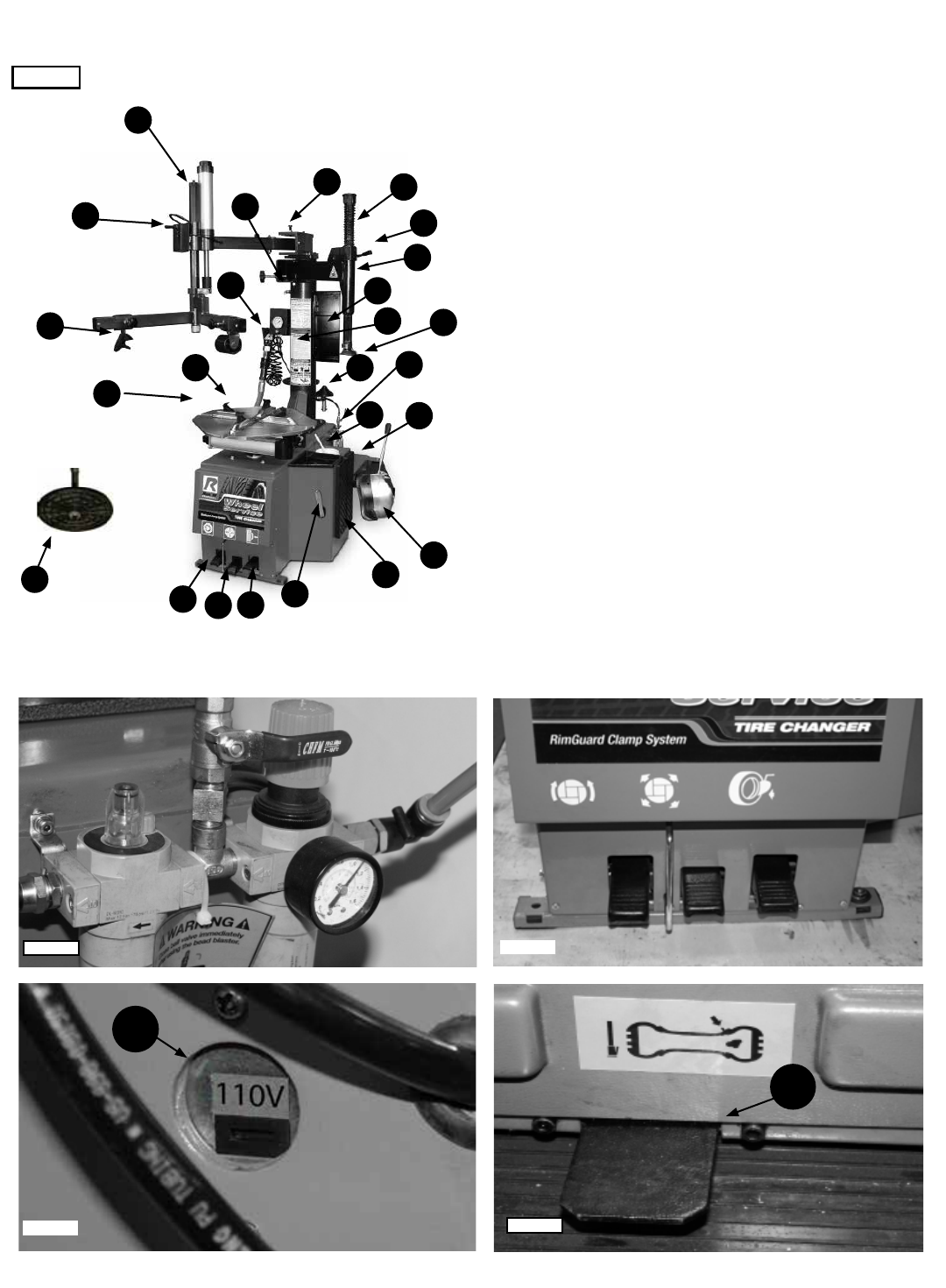
SECTION 4 - DESCRIPTION OF PARTS / R980XR/XRF - R980NXT/NXTF
1. Tank Pressure Relief Valve
2. Tower (Air Tank)
3. Tool Tray
4. Air Drier / Oiler (See Fig 4.2)
5. Bead Breaker Arm
6. Bead Breaker Blade
7. Bead Breaker Pad
8. Bead Lifting Tool
9. Turntable Foot Pedal (See Fig 4.3)
10. Bead Breaker Foot Pedal (See Fig 4.3)
11. Wheel Clamp Foot Pedal (See Fig 4.3)
12. Soap Bucket
13. Turntable
14. Wheel Clamps
15. Mount /Demount Head
16. Turbo Blast Hose Assembly
17. Helper Disc (Not included on R980XR)
18. Assist Tower Pusher Block (Not included on R980XR)
19. Assist Tower Controls (Not included on R980XR)
20. Assist Tower (Not included on R980XR)
21. Vertical Shaft
22. Vertical Assist Arm Assembly
23. Vertical Shaft Lock Handle
24. Vertical Shaft Spring
25. Voltage Selector Switch. (Located on Rear of Cabinet.
(See Fig 4.4) *F Models have a 220-Voltage only.
26. Inflation Pedal
(Located on Left of Cabinet. See Fig 4.5)
27. Inflation Restraint Device
Fig 4.4
Turntable
Foot Pedal
Wheel Clamp
Foot Pedal
Bead Breaker
Foot Pedal
Fig 4.3
Fig 4.1
1
2
17
4
5
6
27
7
8
910
11
12
13
14
15
16
18
19
3
20
21
22
24
23
25
26
Air Oil Regulator
Fig 4.2
Fig 4.5
Voltage Selector Switch Ination Pedal
8
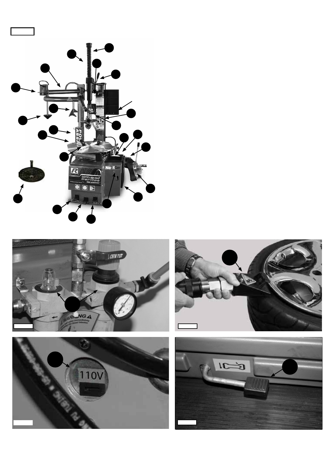
SECTION 4 - DESCRIPTION OF PARTS / R980AT/ATF
1. Tank Pressure Relief Valve
2. Tower (Air Tank)
3. Tool Tray
4. Air Drier / Oiler (See Fig 4.2)
5. Bead Breaker Arm
6. Bead Breaker Blade
7. Bead Breaker Pad
8. Bead Lifting Tool
9. Turntable Foot Pedal
10. Bead Breaker Foot Pedal
11. Wheel Clamp Foot Pedal
12. Soap Bucket
13. Turntable
14. Wheel Clamps
15. Mount /Demount Head
16. Turbo Blast Hose Assembly (See Fig. 4.3)
17. Helper Disc
18. Assist Tower Pusher Block
19. Assist Tower Controls
20. Assist Tower
21. Vertical Shaft
22. Vertical Assist Arm Assembly
23. Vertical Shaft Lock Handle
24. Vertical Shaft Spring
25. Voltage Selector Switch. (Located on Rear of Cabinet.
(See Fig 4.4)
26. Inflation Pedal. (Located on Left of Cabinet. See Fig 4.5)
27. Inflation Restraint Device
Fig 4.4
Fig 4.1
1
2
17
5
6
27
7
8
9
10
11
12
13
14
15
18
19
3
20
21
22
24
23
25
26
Air Oil Regulator
Fig 4.2
Fig 4.5
Turbo Blast
Voltage Selector Switch Ination Pedal
Fig 4.3
26
4
16

9
t Pallet jack or forklift for moving crate
t Forklift or Shop crane
tUtility knife
t Crow bar or pry bar.
t Tin Snips or Sheet Metal Snips
t Hammer
t Open end metric wrenches and/or socket set
t Phillips and Slot head screw drivers
t Metric Allen Key set
PARTS REQUIRED BUT NOT SUPPLIED:
t Teon Tape
t Air tting to match shop Air Supply line
t Tool Oil
t Anchor Bolts and Shims (if Anchoring)
SECTION 5 - FEATURES / SPECIFICATIONS
FEATURES / SPECIFICATIONS MODELS R980XR/XRF
R980NXT/NXTF
MODELS R980AT/ATF
Type of Drive System
Electric /
Air
Electric / Air
Motor R980XR - R980NXT
All F Models have Variable Speed
2
HP (110/208‐240VAC 50‐60 HZ)
2 HP (208‐240V, 50‐60 HZ, 1 P)
2
HP (110/208‐240VAC 50‐60 HZ) R980AT
2 HP (208‐240VAC 50‐60 HZ, 1 P) R980ATF
Air Requirement
140‐165 PSI (10‐11 BAR)
140‐165 PSI (10‐11 BAR)
Wheel Clamping Method (Adjustable
4 Clamps ‐ Internal / External
4 Clamps ‐ Internal / External
Adj. RimGuard™ Wheel Clamps
Standard
Standard
Table Clamping System
Dual Pneumatic Cylinders
Dual Pneumatic Cylinders
Bead Breaking System
Pneumatic Blade / Dual Settings
Pneumatic Blade / Dual Settings
Power Assist Towers
R980XR:None
R980NXT:Standard
Single Assist Tower
Tool Holder
Manual Lock
Manual Lock
Inflation Gauge w/ Integrated Air
Standard
Standard
Inflation Pressure Regulator/Limiter
Standard
Standard
Water Filter
Standard
Standard
Oiler / Lubricator
Standard
Standard
Air Regulator
Standard
Standard
Breaker Bar
Standard
Standard
Large Soap / Lubricator Bucket
Standard
Standard
Brush
Standard
Standard
Alloy‐Steel Mount/Demount Head
Standard
Standard
Plastic‐Polymer Mount/Demount Head
Standard
Standard
Tower Design
R980XR
:Rigid Fixed / Swing Arm
R980NXT:Assist Tower/Swing Arm
Rigid Fixed / Swing Arm
Bead Lifting Roller(s)
None
Single Lifting Roller
Upper Bead Assist Roller
None
Standard
Traveling Drop‐Center Hold Down
None
Standard
Inflation Restraint Device
None
Standard
Bead Seating System
Turbo Blast / Bead Seating
Turbo Blast / Bead Seating
Tool Tray / Bin Storage
Standard
Standard
Motorcycle Turntable Clamps
Optional
Optional
Internal Rim Clamping Capacity
10" – 30” ( 254 mm ‐ 762
10" – 30” ( 254 mm ‐ 762 mm)
External Rim Clamping Capacity
9" – 28" (229 mm ‐ 711
9" – 28" (229 mm ‐ 711 mm)
Turntable Tire Width Capacity
4" – 18" (102 mm – 457
4" – 18" (102 mm – 457 mm)
Bead Breaker Tire Width Capac.
1.5" – 16" (38 mm – 406
1.5" – 16" (38 mm – 406 mm)
Maximum Tire Diameter
50" (1270 mm)
50" (1270 mm)
Shipping Weight
R980XR:
742 lbs. (336 Kg)
R980XRF:
751 lbs. (341 Kg)
R980NXT:
868 lbs. (394 Kg)
R980NXTF: 877 lbs. (398 Kg)
R980AT
:800 lbs. (363 Kg)
R980ATF
:809 lbs. (367 Kg)
*Specifications
are subject to change without notice. *NOTE: Internal and External Wheel Clamping dimensions do not
translate directly to rim or tire sizes as wheel clamping points may vary by wheel manufacturer.
TOOLS REQUIRED FOR ASSEMBLY AND INSTALLATION
10
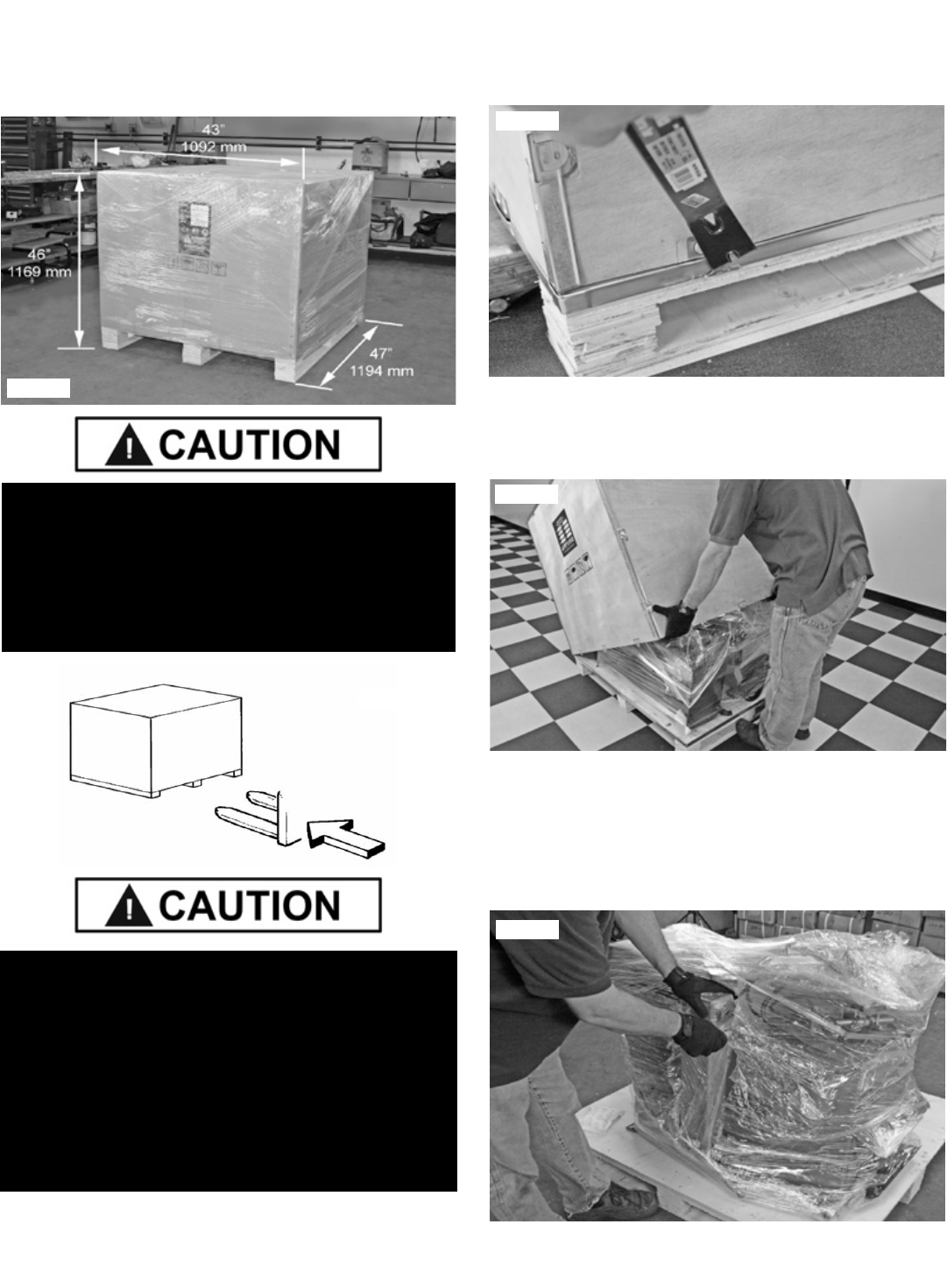
SECTION 6
LIFTING/ UN-CRATING
1. The unit is shipped on a pallet. Approximate shipping
dimensions are shown below. (See Fig 6.1)
Remember to report any shipping damage to the carrier
and make a notation on the delivery receipt.
UN-CRATING INSTRUCTIONS
1. Using a crow bar or pry bar, locate the metal tabs and
pry open the tabs and or staples. (See Fig 6.3)
2. The entire wooden frame/box can be lifted off after
prying the tabs/staples at the base of the crate.
(See Fig 6.4)
3. Carefully cut the Tire Changer free of the plastic
wrapping securing it to the Tire Changer base. Do not
unwrap the Assist Tower and Tower Tank at this time. The
wrapping helps keep the Swing Arms from moving during
lifting and assembly. (See Fig 6.5 - 6.6)
Fig 6.3
Fig 6.4
Fig 6.5
HANDLING OF THE MACHINE MUST BE PERFORMED
ONLY WITH AN APPROPRIATE LIFTING DEVICE
SUCH AS A FORKLIFT OR PALLET JACK. ONLY
PERSONNEL WHO ARE EXPERIENCED AND
QUALIFIED ON MATERIAL HANDLING PROCEDURES
SHOULD HANDLE ANY TRANSPORTATION OR
MOVING OF MACHINE.
BE CAREFUL WHEN CUTTING STEEL BANDING
MATERIAL AS ITEMS MAY BECOME LOOSE AND FALL
CAUSING PERSONAL HARM OR INJURY. ALWAYS
WEAR GLOVES WHEN UN-CRATING THE MACHINE
TO PREVENT SCRATCHES, ABRASIONS, OR CUTS
DUE TO THE CONTACT WITH PACKING MATERIALS.
EYE PROTECTION IS ESSENTIAL DURING
UN-CRATING SERVICE ACTIVITY. SAFETY GLASSES
WITH SIDE SHIELDS, GOGGLES, OR FACE SHIELDS
ARE ACCEPTABLE.
Fig 6.1
Fig 6.2
11
5. Either cut or unscrew the metal strapping holding
the Air Tank / Assist Tower to the pallet. Using a fork
lift or shop crane, remove tank from the pallet and set
aside. Secure tank so it can not fall. (See Fig 6.7)
6. Remove the two front and rear bolts and nuts fasten-
ing the tire changer to the pallet, as indicated in the images
below. (See Fig 6.8 - 6.9)
7. Using a shop crane or fork lift, remove the Tire Changer
from the wooden pallet, making sure to follow safe material
handling procedures. (See Fig 6.10)
Fig 6.7
Fig 6.6
HANDLING OF THE MACHINE MUST BE PERFORMED
ONLY WITH AN APPROPRIATE LIFTING DEVICE SUCH
AS A FORKLIFT OR SHOP CRANE. ONLY PERSONNEL
WHO ARE EXPERIENCED AND QUALIFIED ON
MATERIAL HANDLING PROCEDURES SHOULD HANDLE
ANY TRANSPORTATION OR MOVING OF MACHINE.
SECURE THE AIR TANK / ASSIST TOWER WITH
SHOP CRANE/FORKLIFT OR PERSONNEL PRIOR TO
CUTTING METAL STRAPPING AS AIR TANK / ASSIST
TOWER MAY HAVE SHIFTED DURING SHIPPING. BE
CAREFUL AS BANDING MAY SNAP OR FLY WHEN
TENSION IS RELEASED.
Fig 6.8
Fig 6.9
ONLY PERSONNEL WHO ARE EXPERIENCED AND
QUALIFIED ON MATERIAL HANDLING PROCEDURES
SHOULD HANDLE ANY TRANSPORTATION OR MOVING
OF MACHINE.
Fig 6.10
12
SECTION 7
INSTALLATION LOCATION
Disconnect tag and lock out power source before
attempting to install, service, relocate or perform any
maintenance. Do not lift or move unit without
appropriately rated equipment. Be sure the unit is securely
attached to any lifting device used.
NEVER use the wood shipping skid for mounting the unit.
Select a location using Figures 7.1 and 7.2. The area
should provide the operator with enough space to use the
equipment in a safe manner. The area selected should be
well lit, easy to clean and should be away from oil, grease,
brake lathe chips, etc. Avoid areas where bystanders and
customers may be present.
R980XR size is approximately:
43” W x 51” D X 80”H
R980NXT size is approximately:
52” W x 44” D X 84”H
R980AT size is approximately:
51” W x 45” D X 73”H
These measurements are the tire changer’s working
range. Persons other than specially trained and
authorized operators are expressly forbidden to enter this
area. Choose a safe location that is in compliance with
current work place safety regulations. Failure to properly
install the tire changer can lead to improper and unsafe
operation.
PROPER UNIT INSTALLATION IS NECESSARY FOR
SAFE USE AND EFFICIENT OPERATION. PROPER
INSTALLATION ALSO HELPS PROTECT THE UNIT
FROM DAMAGE AND MAKES SERVICE EASIER.
ALWAYS KEEP THIS MANUAL WITH UNIT.
Fig 7.1
Fig 7.2
44”
84”
52”
R980NXT R980AT
73”
45”
51”
13
SECTION 8
AIR TANK/ TOWER ASSEMBLY
1. Using a fork lift or other lifting device, lower the Tank/
Tower onto the base and align the holes.
2. Attach the Tank / Tower assembly to the Base using the
four bolts on the Tower Base Plate. (See Fig 8.1)
3. Connect the other end of the Air Inflation Hose to the
Push to Connect Fitting underneath the Air Inflation Box As-
sembly. (See Fig 8.2)
SWING ARM / VERTICAL SHAFT /
MOUNT-DEMOUNT HEAD ASSEMBLY
1. Raise the Vertical Shaft / Mount-demount head assem-
bly to the highest position and lock it in place by pushing the
Locking Handle up.
2. Check the Socket Head Cap Screw on the Cap, tighten
if necessary. (See Fig 8.3)
3. Check the operation of the Vertical Shaft and the Lock-
ing Handle. (See Section 15, Page 31 for Lock adjustment
details)
4. Check that the Mount/Demount Head bolt and set screws
are tightened. (See Fig. 8.4)
ANCHORING
It is not essential to anchor the machine to the floor,
however, the floor must be smooth and level. When anchor-
ing to a concrete floor use the mounting holes that are pro-
vided in the frame. Make sure the machine is solid and level
and supported evenly on all anchor points. Solid shims may
be used if necessary. (See Fig 8.5)
Fig 8.1
Fig 8.3
Fig 8.2
Fig 8.5
Socket Head
Cap Screw
Vertical
Shaft to
Highest
Position
Cap
Locking
Handle
Fig. 8.4
Tightened bolt
and set screws
14
SECTION 9
AIR SOURCE
This model requires a 14 to 15 CFM air source at 175
PSI maximum pressure. The safe operating pressure
range for this model is between 110 PSI and 175 PSI
at the machine. A 1/4” ID hose (or pipe) for connection
to the machine is satisfactory. Sufficient air pressure
assures good performance.
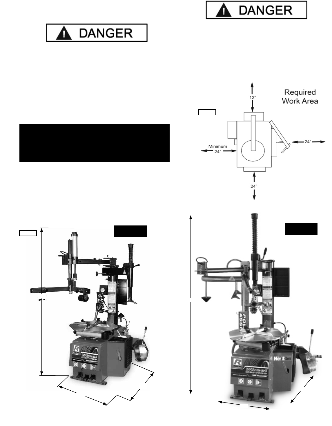
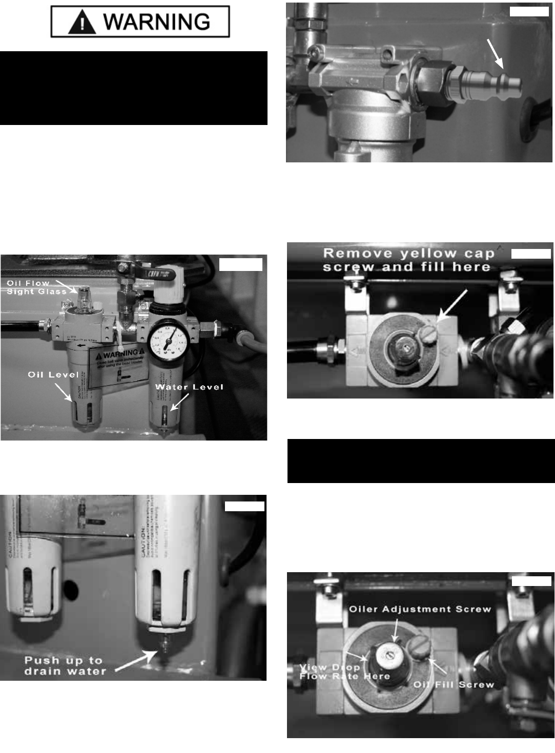
1. Connect the Air Supply to the Air Drier / Oiler. A proper
fitting (not included) to match the supply line of the air
supply connection is required. Use Teflon tape on the NPT
thread of the fitting. This connection is located on the right
side of the rear of the machine. (See Fig 9.1)
OILER ADJUSTMENT
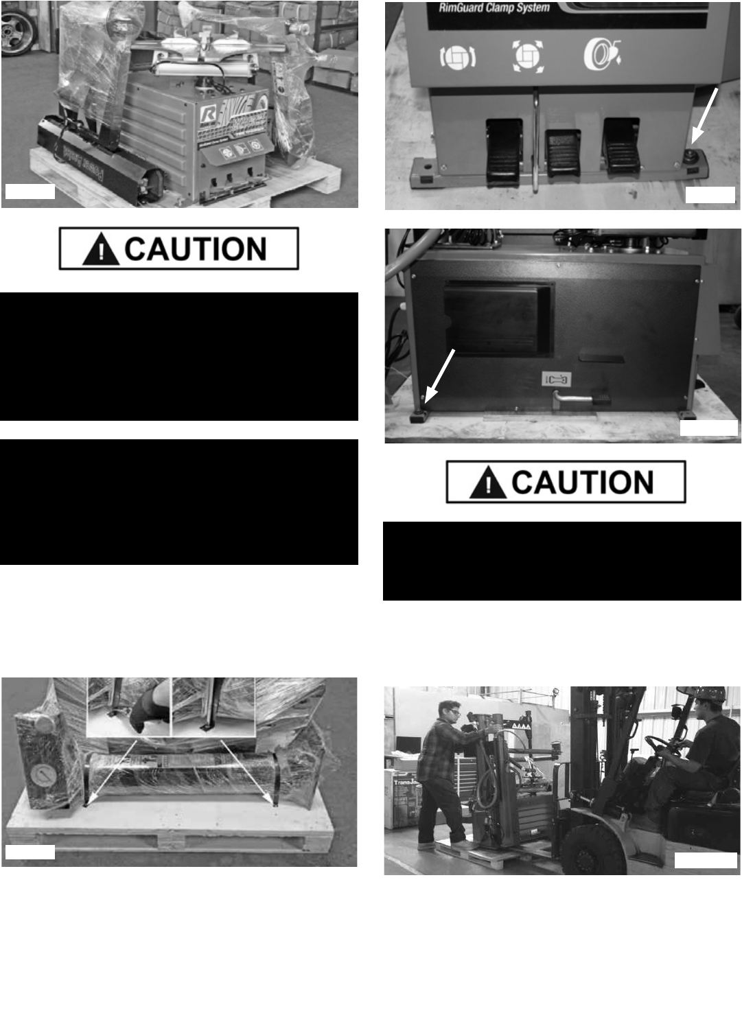
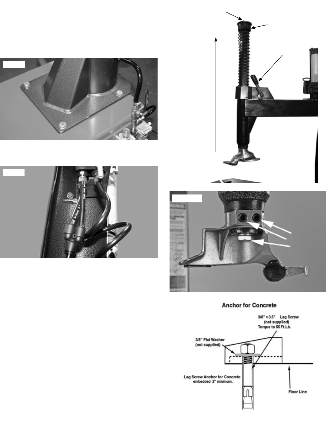
1. Check Oil Level on Oil Level Gauge. (See Fig. 9.2)
If Oil level is low refer to Section 15, for filling instructions.
2. With the air source connected, depress the Bead
Breaker Pedal to operate the Bead Breaker.
3. Observe the sight glass and adjust the oil flow of the
oiler by turning the Oiler Adjustment Screw by using a small
screwdriver so that 2-3 drops of oil drip through the sight
glass for each operation of the Bead Breaker Pedal. (See
Fig 9.3)
SECTION 10
ELECTRICAL SOURCE
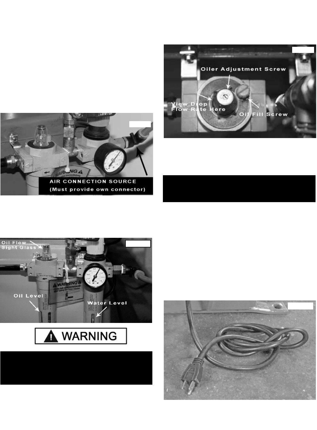
1. This unit requires power from a 15 amp electrical circuit.
The unit is supplied standard with a 110 Volt power cord
and plug. (See Fig 10.1). Please remember that ALL F
models are standard 220 V only.
2. Refer to the serial tag of the machine for specific
electrical requirements. Have a licensed electrical techni-
cian perform any necessary changes to the power source
and power cord before plugging in the unit. The electrical
source must have a solid connection between ground and
building ground.
FAILURE TO PROPERLY MAINTAIN PROPER OIL
LEVEL AND ADJUST THE OIL FLOW MAY VOID THE
WARRANTY AND DAMAGE THE BEAD BREAKER
CYLINDER AND OTHER AIR COMPONENTS.
NOTE:
THIS ADJUSTMENT WILL REQUIRE AT LEAST TWO
OPERATORS TO PERFORM.
Fig 10.1
Fig 9.1
Fig 9.2
Fig 9.3
15
WIRING INSTRUCTIONS
SECTION 11
DEMOUNTING
uRemember to remove all weights from both sides of the
wheel. Weights left on the back side of the wheel may cause
THIS EQUIPMENT MUST BE GROUNDED WHILE IN
USE TO PROTECT THE OPERATOR FROM ELECTRIC
SHOCK. NEVER CONNECT THE GREEN POWER
CORD WIRE TO A LIVE TERMINAL. THIS IS FOR
GROUND ONLY.
THE MOTOR ON THIS MACHINE CONTAINS HIGH
VOLTAGE. DISCONNECT POWER AT THE RECEPTACLE
BEFORE PERFORMING ANY ELECTRICAL
REPAIRS. SECURE PLUG SO THAT IT CANNOT BE
ACCIDENTALLY PLUGGED IN DURING SERVICE.
RISK OF EXPLOSION! THIS EQUIPMENT HAS
INTERNAL ARCING OR SPARKING PARTS WHICH
SHOULD NOT BE EXPOSED TO FLAMMABLE VAPORS.
THIS MACHINE SHOULD NOT BE LOCATED IN A
RECESSED AREA OR BELOW FLOOR LEVEL.
1. Check the voltage, phase and proper amperage
requirements for the motor shown on the motor plate.
Wiring should be performed by a certified electrician only.
2. Overheating, short circuits and fire damage will result
from inadequate wiring. Wiring must be installed in
accordance with National Electric Code and local codes and
standards covering electrical apparatus and wiring.
3. Be certain that adequate wire sizes are used, and that:
t Service is of adequate amp rating.
t Supply line has the same electrical characteristics
(voltage, cycles and phase) as the motor.
t The line wire is the proper size and that no other
equipment is operated from the same line.
CHECK THE VOLTAGE, PHASE, AND PROPER
AMPERAGE REQUIREMENTS FOR THE MOTOR
SHOWN ON THE MOTOR PLATE. WIRING SHOULD BE
PERFORMED BY A CERTIFIED ELECTRICIAN ONLY.
IMPORTANT NOTE:
YOUR MACHINE HAS A DUAL VOLTAGE MOTOR
AND CAN BE RUN ON EITHER 110 OR 220 VOLTS.
STANDARD WIRING IS 110 VOLTS.
See below before connecting 220 volts to your machine or
serious damage to the motor/electronics will result. Have
a licensed electrical technician perform any necessary
changes to the power source and power cord before plug-
ging in the unit. The electrical source must have a solid
connection between ground and building ground.
Confirm voltage selector switch is positioned correctly before
connecting power to your machine or serious damage to the
motor/electronics will result. (See Fig 10.2)
Fig 10.2
NOTE:
THIS UNIT MUST BE PROPERLY OPERATED AND
MAINTAINED TO HELP AVOID ACCIDENTS THAT
COULD DAMAGE THE UNIT AND INJURE THE
OPERATOR OR BYSTANDERS. THIS SECTION OF THE
EQUIPMENT MANUAL REVIEWS BASIC OPERATION
AND USE OF CONTROLS. THESE INSTRUCTIONS
SHOULD BE REVIEWED BY ALL OPERATORS BEFORE
THEY ARE ALLOWED TO WORK WITH THE MACHINE.
KEEP THESE INSTRUCTIONS NEAR THE MACHINE
FOR EASY REFERENCE.
THIS MACHINE MAY OPERATE DIFFERENTLY FROM
OTHER TIRE CHANGER MACHINES. PRACTICE WITH
A REGULAR STEEL WHEEL AND TIRE COMBINATION
TO FAMILIARIZE YOURSELF WITH THE MACHINE’S
OPERATION AND FUNCTION.
16
the wheel to be clamped un-level. This may result in the
combination mount/demount head contacting the rim causing
scratches. On alloy wheels, always rotate the wheel one turn
after setting the head to ensure proper wheel chucking.
u Always review nicks and scratches with owners of
expensive wheel and tire combinations prior to servicing.
u Review the performance wheel section of this manual
prior to servicing performance tire/wheel combinations.
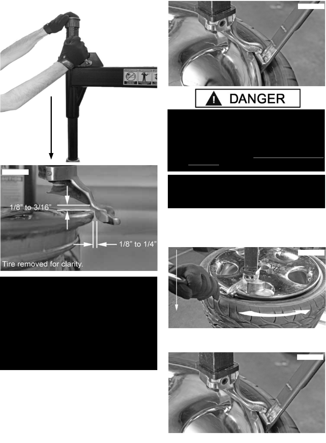
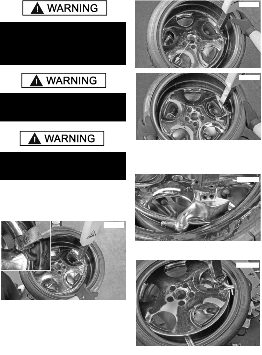
BEAD LOOSENING
1. Deflate tire completely by removing the valve core from
the valve stem. (See Fig 11.1)
2. The clamps on the table top may extend beyond the
table top itself. To avoid damaging the clamps and/or
wheel, move the clamps to their full inward position before
positioning a tire for bead loosening.
3. Always loosen the bead on the narrow side of the wheels
drop center first. (See Fig. 11.5 for description of the drop
center)
4. Pull the bead breaker blade away from the machine and
roll the wheel into position. If servicing a performance wheel
or any other wheel with Tire Pressure Sensor (see section
12), make sure that the valve stem is either in the 12 o’clock
or 6 o’clock position.
5. The Bead Breaker Arm Adjustment Rod limits or extends
the movement of the arm. Set the Rod as appropriate to the
tire and wheel being serviced. (See Fig. 11.2)
6. Position the bead breaker blade against the tire next
to, but not on, the rim or the sidewall of the tire. Press the
breaker pedal to actuate the blade and loosen the bead. It
may be necessary to loosen the bead in multiple locations
around the tire. Use extra care in positioning the bead
breaker blade on larger wheels/tires, and on alloy wheels.
(See Fig. 11.3)
7. Turn wheel around and repeat procedure on the other
side of the wheel. This should be the long side of the drop
center. It will be easier to clamp the wheel to the table top if
the lower bead is loosened last. (See Fig. 11.4)
8. Determine the mounting side of the wheel. The mounting
side is the narrow side of the drop center. (See Fig. 11.5)
Fig 11.1
Fig 11.3
Fig 11.4
Fig 11.2
Fig 11.5
17
Fig 11.5
18
WHEEL CLAMPING
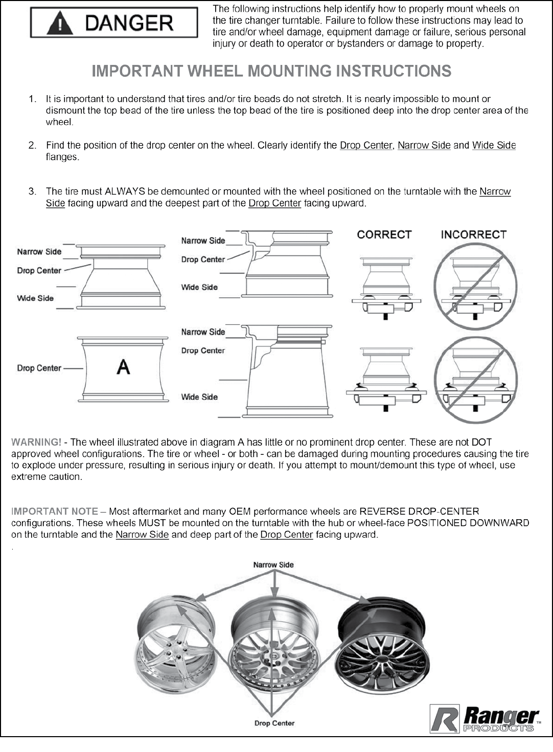
1. Place the Wheel Protector pads on the Wheel Clamps if
desired when clamping from the outside. (See Fig 11.6)
2. Place tire/wheel assembly on Table Top with mounting
side up. (See Fig 11.7)
3. Use the Wheel Clamp Foot Pedal to move the Clamps
inward (pedal down) or outward (pedal up). (See Fig 11.8)
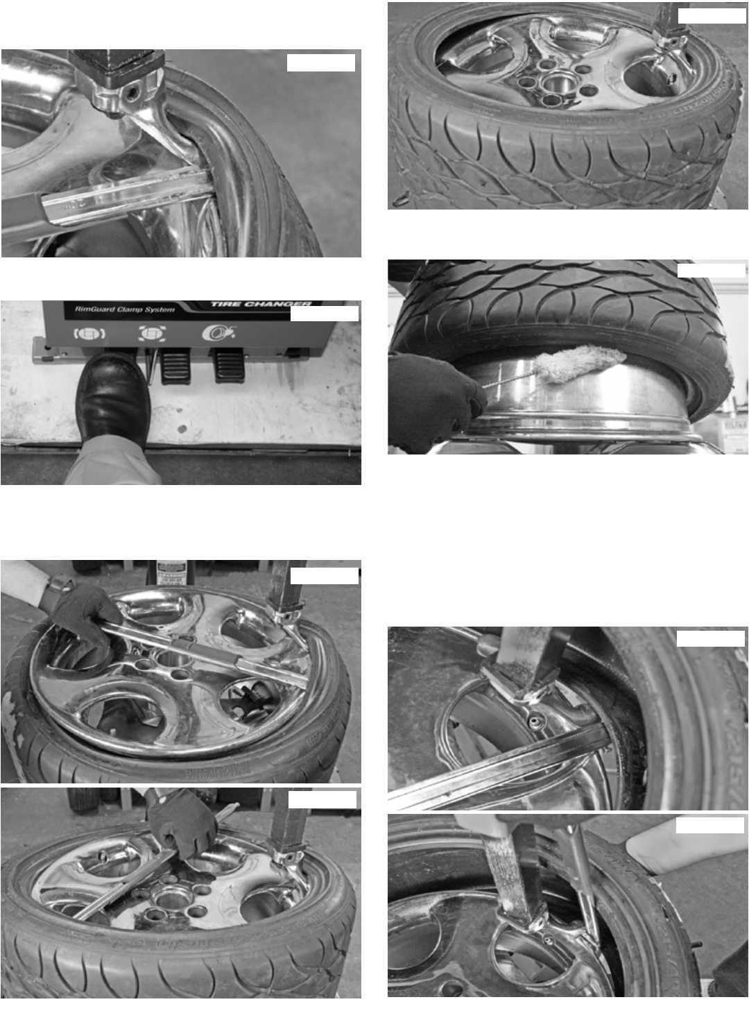
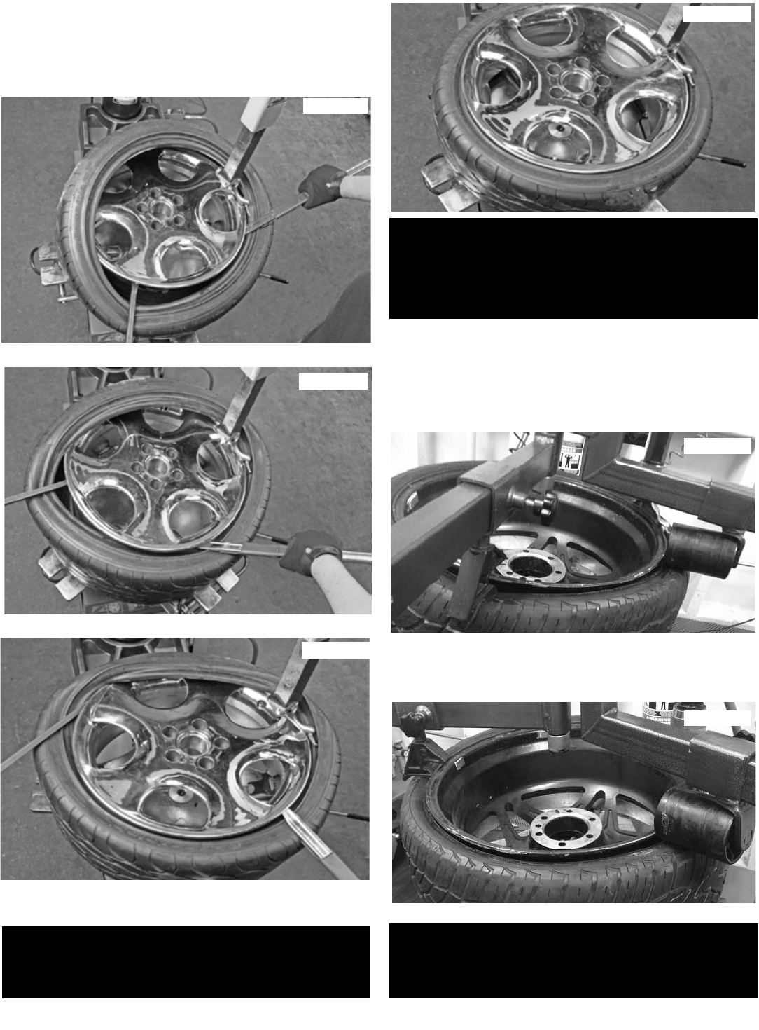
DEMOUNTING
1. Apply tire manufacturer’s approved rubber lubricant
liberally to entire circumference of both upper and lower
beads after loosening bead and placing on table top. (See
Fig 11.9)
2. After the wheel is secured to the Turntable, swing the
Vertical Arm into position. Use the large adjusting Knob to
position the Mount/Demount Head directly over the edge of
the rim. (See Fig 11.10)
3. Push the Vertical Shaft down and position the Mount/
Demount Head into contact with the rim edge. (See Fig.
11.11)
4. Pull the locking handle towards you to lock the Vertical
Shaft into position. As the slide is locked, the Mount/
Demount Head will move upward approximately 1/8 inch
and backward 1/8 inch from the rim edge.
The Mount/Demount head roller should not be in contact
with the rim edge. (See Fig 11.11 - 11.12)
NOTE:
CLAMP STEEL WHEELS FROM THE INSIDE (CLAMPS
PUSH OUTWARD AGAINST WHEEL). CLAMP MAG
AND CUSTOM WHEELS FROM THE OUTSIDE
(CLAMPS PUSH INWARD AGAINST THE OUTSIDE
RIM EDGE). REFER TO SECTION 12: CUSTOM AND
SPECIAL WHEELS.
Fig 11.7
Fig 11.9
Fig 11.10
THE RIM AND BEAD MUST BE LIBERALLY
LUBRICATED. FAILURE TO USE AN ADEQUATE
LUBRICANT CAN LEAD TO THE BEAD BINDING ON
THE RIM AND DAMAGE TO THE MOTOR AND OR
VOID THE WARRANTY.
Fig 11.6
Fig 11.8
19
5. Rotate the wheel using the Turntable Pedal until the
valve stem is at the 3 o’clock position in relation to the
Mount/Demount Head.
6. Insert the smooth curved end of the Bead Lifting Tool
over the tab side of the Mount/Demount Head and below
the top bead of the tire. (Fig 11.13)
7. Push the Bead Lifting Tool down and away from the
wheel to lower the bead into the Drop Center while lifting
up on the Table Top Pedal to rotate the turnable counter
clockwise. (See Fig 11.14)
8. Insert the smooth curved end of Bead Lifting Tool over
the right end knob of the mount/demount head and below
the top bead of the tire. (See Fig 11.15)
NOTE:
THIS CLEARANCE WILL BE MAINTAINED AS LONG
AS THE VERTICAL SHAFT REMAINS LOCKED. THE
OPERATOR MAY SWING THE ARM OUT OF THE WAY
AND BACK INTO PLACE AGAIN WITHOUT NEEDING TO
REPOSITION THE HEAD WHEN CHANGING A LIKE SET
OF WHEELS. THE TOOL CLEARANCE MAY CHANGE
WITH MACHINE USE AND SHOULD BE INSPECTED
OFTEN. FAILURE TO MAINTAIN PROPER CLEARANCE
MAY RESULT IN DAMAGE TO THE WHEEL RIM OR TIRE.
SEE PAGE 29 FOR ADJUSTMENT PROCEDURE.
THE BEAD LIFTING TOOL AND DEMOUNT HEAD MAY
ENCOUNTER RESISTANCE OR COME UNDER LOAD
AT TIMES DURING THE MOUNT AND DEMOUNT
PROCEDURES. KEEP ONE HAND FIRMLY ON THE
TOOL TO AVOID POSSIBLE TOOL KICK BACK. USE
THE REVERSING FEATURE (LIFT TABLE TOP PEDAL
UPWARDS) TO BACK OUT OF JAM UPS.
NOTE:
FOR LOW PROFILE TIRES, PERFORM STEP 9 TO
GET THE UPPER BEAD INTO THE DROP CENTER OF
THE WHEEL.
Fig 11.12
Fig 11.11 Fig 11.13
Fig 11.14
Fig 11.15
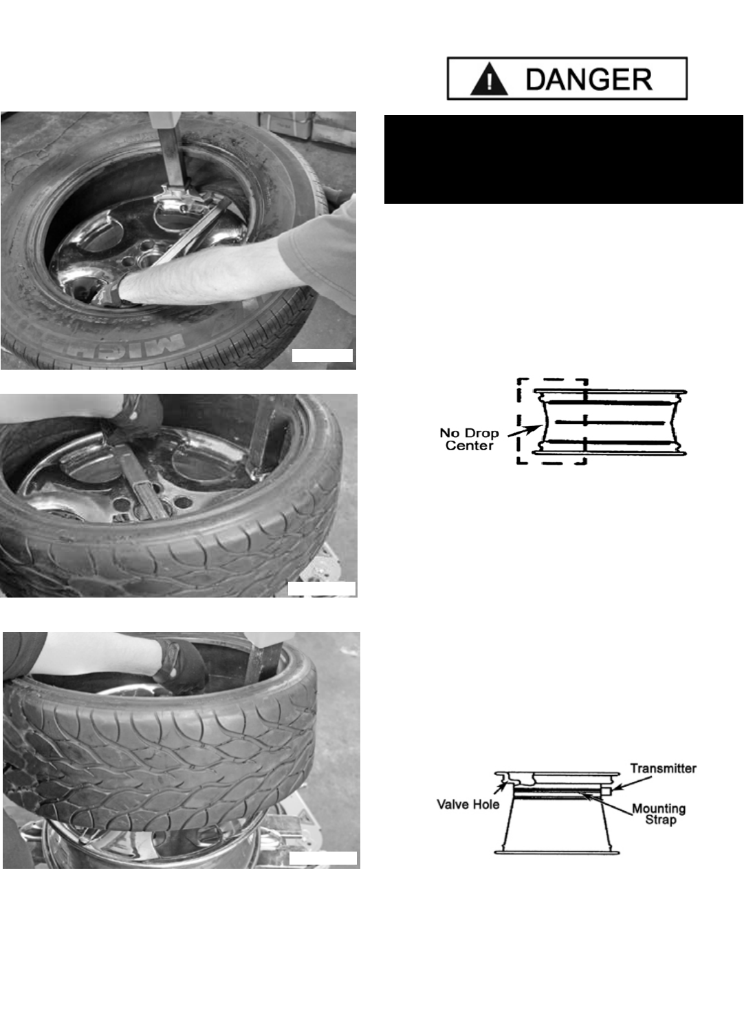
20
9. Push the Bead Lifting Tool down toward the wheel to lift
the tire bead up and over the tab of the demount head. Hold
the Bead Lifting Tool in this position. (See Fig 11.16)
10. Depress the Table Top Foot Pedal to rotate the wheel
clockwise. (See Fig 11.17)
11. Hold the Bead Lifting Tool down until the upper bead is
solidly above the rim. Continue rotating the wheel clockwise
until the upper bead is completely demounted. (See Fig
11.18 - 11.20)
12. Liberally lubricate the lower bead again, if there was any
difficulty lubricating the lower bead earlier. (See Fig 11.21)
13. Lift and hold the tire so it is positioned with the lower
bead in the drop-center portion of the wheel.
14. Insert the smooth curved end of the Bead Lifting Tool
over the tab end of Mount / Demount Head and below the
lower bead of the tire. Push the Bead Lifting Tool down
toward the wheel to lift the tire bead up and over the left tab
side knob portion of the Mount/ Demount Head. Hold the
Bead Lifting Tool in this position. (See Fig 11.22 - 11.23)
Fig 11.16
Fig 11.17
Fig 11.18
Fig 11.19
Fig 11.20
Fig 11.21
Fig 11.22
Fig 11.23
21
15. Depress the Table Top Pedal to rotate the wheel.
16. The Mount / Demount Head will guide the bead up and
over the edge of the wheel. Continue rotation until the lower
bead is demounted. (See Fig 11.24 -11.26)
SECTION 12
CUSTOM AND SPECIAL WHEELS
ALLOY WHEELS
Some manufacturers offer wheels with little or no drop
center. These are not DOT approved. The tire or wheel - or
both - can be damaged and the tire could explode under
pressure, resulting in serious injury or death. If you attempt
to mount/demount this type of wheel, use extreme caution.
(See Fig 12.1)
EUROPEAN PERFORMANCE WHEELS
(ASYMMETRICAL HUMP)
Some European wheels have very large humps except
near the valve hole. On these wheels, the beads should be
loosened at the valve hole on both the upper and lower
sides first.
WHEELS WITH TIRE PRESSURE
WARNING SENSORS
Most wheels today have a TPS incorporated into the valve
stem. Some are strapped to the wheel opposite the valve
hole. (See Fig 12.2)
Fig 11.24
Fig 11.26
Fig 11.25
IF A CUSTOM WHEEL IS DAMAGED WHILE
DEMOUNTING, STOP, AND AVOID DAMAGING THE
OTHER WHEELS. CONTINUE ONLY WHEN THE
CAUSE IS IDENTIFIED AND CORRECTED.
Fig 12.1
Fig 12.2
22
DEMOUNTING TUBE TYPE TIRES
1. After both tire beads are loosened, try to remove the
tube. If you can not remove the tube lubricate the beads
and rim liberally.
2. Position the demount head and bead lifting tool as
described earlier paying careful attention not to pinch the
tube. Depress the table top pedal and rotate only a short
distance at a time. This allows you to stop the process
should you suspect the tube is getting pinched.
3. After upper bead is demounted, remove tube and
demount lower bead.
SECTION 13
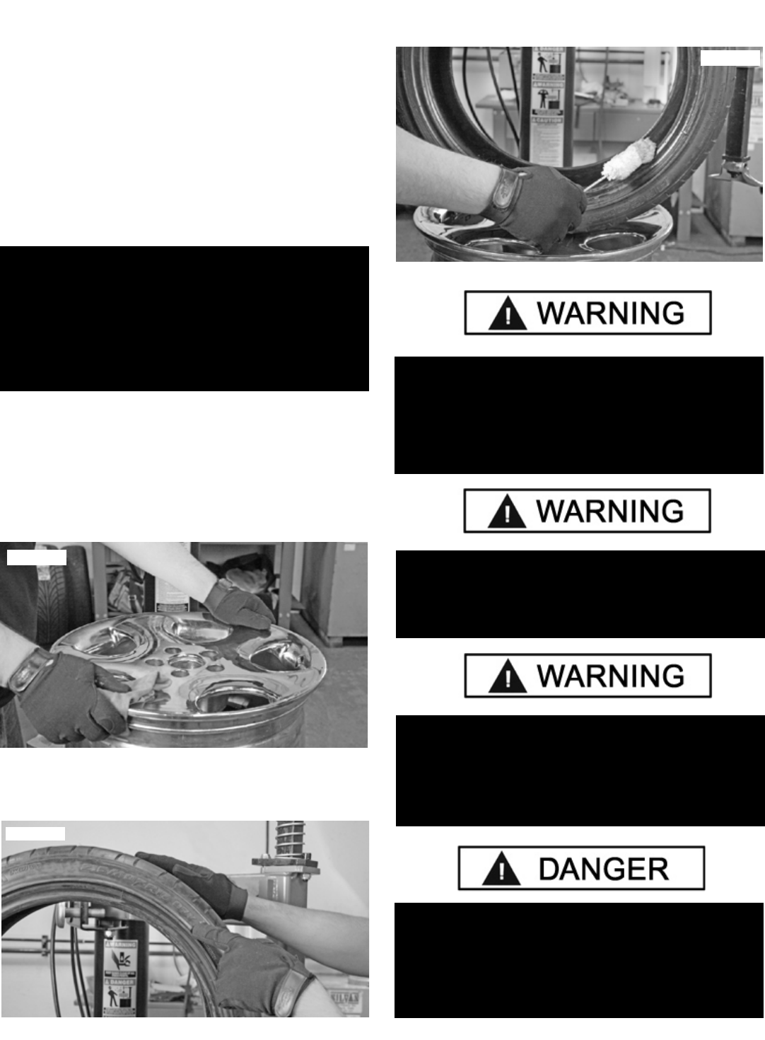
MOUNTING
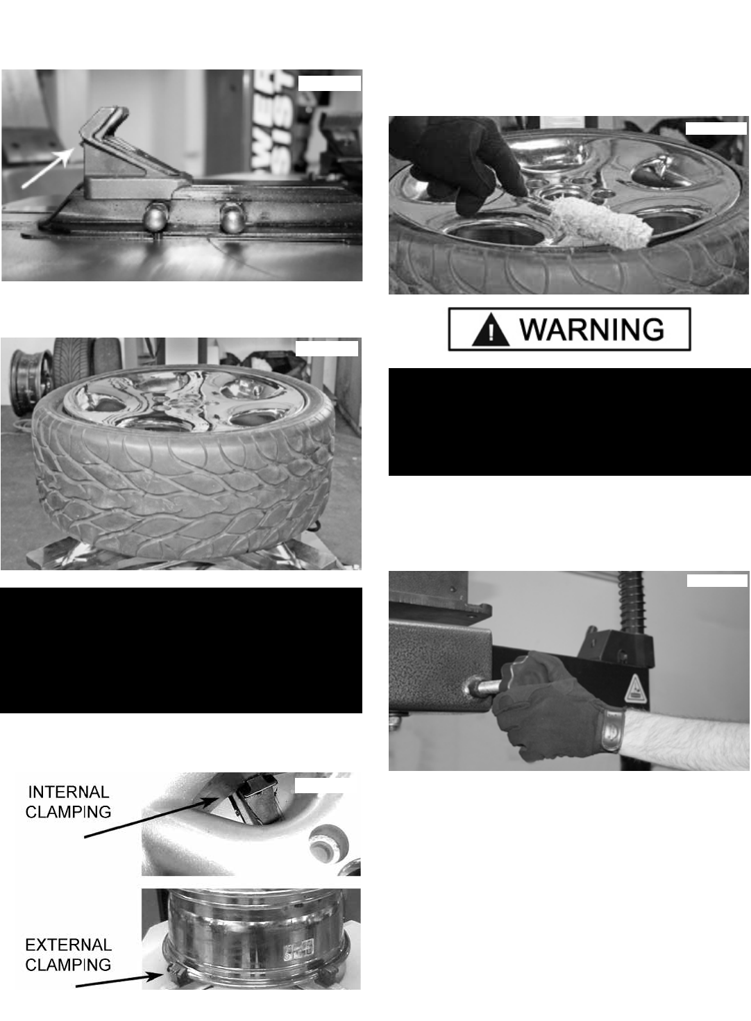
1. Inspect the wheel closely for damage. Clean the wheel
and remove any light corrosion or rubber residue. Do not
attempt to service heavily corroded wheels. (See Fig 13.1)
2. Inspect tire for damage, paying close attention to the
beads. Verify size match between tire and wheel. (See Fig
13.2)
3. Lubricate both tire beads liberally with tire manufacturer’s
approved lubricant. (See Fig 13.3)
REMEMBER:
TABLE TOP ROTATION CAN BE STOPPED AT ANY
TIME BY REMOVING YOUR FOOT FROM THE ROTA-
TION PEDAL. NORMAL TABLE TOP ROTATION
FOR DEMOUNTING IS CLOCKWISE. DEPRESS THE
TABLE TOP PEDAL TO ROTATE THIS DIRECTION.
TO ROTATE THE TABLE TOP COUNTERCLOCKWISE,
LIFT THE PEDAL UP WITH YOUR TOE.
Fig 13.1
Fig 13.3
Fig 13.2
THE RIM AND BEAD MUST BE LIBERALLY
LUBRICATED. FAILURE TO USE AN ADEQUATE
LUBRICANT CAN LEAD TO THE BEAD BINDING ON
THE RIM AND LEAD TO DAMAGE TO THE MOTOR
AND OR VOID THE WARRANTY.
CHECK TIRE AND WHEEL CAREFULLY BEFORE
MOUNTING. MAKE SURE THE TIRE BEAD DIAMETER
AND WHEEL DIAMETER MATCH EXACTLY. CONSULT
THE RUBBER MANUFACTURER’S ASSOCIATION FOR
APPROVED RIM WIDTHS FOR TIRE SIZES.
ATTEMPTS TO FORCE A BEAD SEAT ON MIS-
MATCHED TIRES AND WHEELS CAN CAUSE THE
TIRE TO VIOLENTLY EXPLODE, LEADING TO SERI-
OUS PERSONAL INJURY OR DEATH TO OPERATOR
AND/OR BYSTANDERS.
THE INFORMATION IN THIS SECTION MUST BE
READ AND FOLLOWED CAREFULLY TO PREVENT
ACCIDENTS AND INJURIES DURING MOUNTING.
23
4. Place tire over wheel and move Vertical Arm and Mount/
Demount Head into position as described earlier. Position
tire so that the lower bead is above the left side of the
Mount/ Demount Head and below the right front knob. (See
Fig 13.4)
5. Manually push the tire down into the drop center of the
wheel directly across from the Mount/ Demount Head to
reduce the tensional force on the bead. Depress the Table
Top Pedal and rotate the wheel to begin mounting the lower
bead. Rotate the Table Top until the lower bead is fully
mounted. (See Fig 13.5 - 13.6)
6. For the top bead, rotate the Table Top until the valve
stem is at the 3 o’clock position in relation to the Mount/
Demount Head. Lift the upper bead above the right side of
the Mount/ Demount Head and below the knob.
(See Fig 13.7)
7. With the Bead Lifting Tool, press down on the tire to hold
the upper bead in the drop center. (See Fig. 13.8)
NEVER MOUNT A TIRE AND WHEEL HANDED TO
YOU BY ANYONE WITHOUT CHECKING BOTH TIRE
AND WHEEL FOR DAMAGE AND COMPATIBILITY. BE
EXTRA CAUTIOUS OF PERSONS WITHOUT KNOWL-
EDGE OF TIRE SERVICE. KEEP BYSTANDERS OUT
OF SERVICE AREA.
NEVER MOUNT A DAMAGED TIRE. NEVER MOUNT A
TIRE ON A RUSTY OR DAMAGED WHEEL. DAMAGED
TIRES AND/OR WHEELS MAY EXPLODE.
IF YOU DAMAGE THE TIRE BEAD DURING
MOUNTING, STOP! REMOVE THE TIRE AND MARK IT
AS DAMAGED. DO NOT MOUNT A DAMAGED TIRE.
Fig 13.4
Fig 13.5
Fig 13.6
Fig. 13.8
Fig. 13.7
24
8. Stand firmly in place and be prepared to hold the Bead
Lifting Tool down as the tire/ Turntable rotates. Depress
the Table Top Pedal and rotate the tire until the bead is
mounted. (See Fig. 13.9 - 13.12)
9. Swing the Assist Tower into position and lower the Roller
Arms so that they press down on the tire to hold the upper
bead in the drop center. The Upper Arm must be locked
and positioned next to the Mount-demount Head. (See Fig
13.13)
10. Depress the Table Top Pedal. As the Turntable rotates
the Lower Arm will follow the tire around. Keep rotating the
table until the bead is mounted. (See Fig 13.14 - 13.16)
NOTE:
THE FOLLOWING PROCEDURES SHOW THE ASSIST
TOWER BEING USED; THE TIRE CHANGER YOU
ARE USING MAY NOT HAVE THE ASSIST TOWER
INSTALLED.*
*NOTE:
ASSIST TOWER IS STANDARD EQUIPMENT
INCLUDED ON THE R980NXT MODEL.
Fig 13.13
Fig 13.14
Fig. 13.9
Fig. 13.10
Fig. 13.11
NOTE:
LOW PROFILE TIRES MAY REQUIRE USE OF THE
BEAD LIFTING TOOL.
Fig. 13.12

25
MOUNTING TUBE TYPE TIRES
1. Lubricate the beads and rim liberally.
2. Position the Mount/Demount Head as described earlier.
Mount the botton bead first.
3. Apply rubber lubricant to the tube. Insert the tube
into the tire paying careful attention not to pinch the tube.
Round out the tube with a small amount of air.
4. Lower the Arm Rollers onto the tire as described earlier.
5. Round out the tube with a small amount of air. Apply
rubber lubricant to the tube.
6. Depress the Table Top Pedal and rotate only a short
distance at a time.
7. Mount the top bead.
DO NOT FORCE THE TIRE ONTO THE RIM.
BEAD DAMAGE COULD RESULT MAKING THE TIRE
UNSAFE AND/OR CREATING THE RISK OF INJURY.
Ination Pedal
CHECK INFLATION GAUGE FOR PROPER
OPERATION. ACCURATE PRESSURE READINGS ARE
IMPORTANT TO SAFE TIRE INFLATION. REFER TO
THE OPERATING MAINTENANCE SECTION OF THIS
MANUAL FOR INSTRUCTIONS. IF THE RIM HAS BEEN
CLAMPED FROM THE OUTSIDE FOR TIRE MOUNT-
ING, RELEASE THE CLAMPS ONCE BEAD SEAL IS
OBTAINED, LIFT THE TIRE, AND MOVE THE CLAMPS
TO THE CENTER OF THE TABLE TOP.
THE CLIP-ON AIR CHUCK ON THE END OF THE
INFLATION HOSE AND ALL INFLATION RELATED
COMPONENTS SHOULD BE CHECKED WEEKLY FOR
PROPER OPERATION. DO NOT USE THIS MACHINE
FOR TIRE INFLATION IF ANY PARTS ARE DAMAGED
OR APPEAR NOT IN PROPER WORKING ORDER.
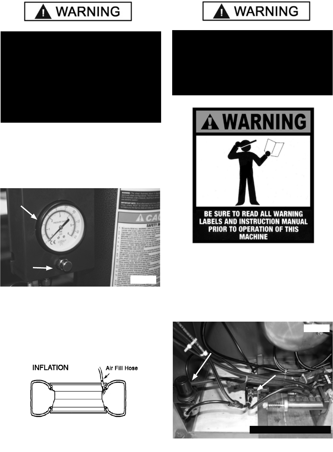
SECTION 14
INFLATION
The Inflation Pedal located at the center of the left side of
the machine serves two different functions. It checks air
pressure in the tire and controls the flow of air through the
Inflation Hose. (See Fig 14.1)
Fig 14.1
Fig 13.15
Fig 13.16
26
TIRE INFLATION
The unit is equipped with a Pressure Limiter/Regulator to
assist the operator with proper tire inflation. The Pressure
Limiter will keep most car and light truck tires from inflat-
ing beyond 60 PSI. It is the operators responsibility to
follow all instructions and to control inflation pressure as
specified in these instructions. (See Fig 14.4)
CHECK THE FUNCTION OF THE PRESSURE LIMITER
REGULARLY. MAINTAIN IT ACCORDING TO THE
INSTRUCTIONS PROVIDED IN THIS MANUAL FOR
SAFE AND PROPER OPERATION. DO NOT TAMPER
WITH OR ATTEMPT TO ADJUST THE PRESSURE LIM-
ITER. TIRES REQUIRING INFLATION BEYOND 60 PSI
SHOULD ONLY BE INFLATED IN A SAFETY CAGE.
Fig 14.2
Position One - Tire Pressure - With the Ination Hose
attached to the tire valve and the pedal in this position, the
air gauge will register the air pressure in the tire.
Whenever your foot is removed from the pedal, it will
return to this position. (See Fig 14.2)
Position Two - Tire Ination - With the Ination Hose at-
tached to the tire valve and the pedal depressed, line
pressure is allowed to ow through the valve and into
the tire for ination. Tire pressure is not indicated on the
gauge in this position. (See Fig 14.3)
TIRE FAILURE UNDER PRESSURE IS HAZARDOUS.
THIS TIRE CHANGER IS NOT INTENDED TO BE A
SAFETY DEVICE TO CONTAIN EXPLODING TIRES,
TUBES, WHEELS, OR BEAD SEALING EQUIPMENT.
INSPECT TIRE AND WHEEL CAREFULLY FOR MATCH,
WEAR, OR DEFECTS BEFORE MOUNTING. ALWAYS
USE APPROVED TIRE BEAD LUBRICANT DURING
MOUNTING AND INFLATION. THE INFLATION PEDAL,
LOCATED AT THE CENTER OF THE LEFT SIDE OF THE
MACHINE, CONTROLS THE FLOW OF AIR THROUGH
THE INFLATION HOSE.
Pressure Gauge
Pressure Relief
Valve
Fig 14.3
Fig 14.4
Assist Tower
Pressure Limiter
Inflation Pedal
Pressure Limiter
Note: Side Panel Removed
27
STAGES OF INFLATION
Tire inflation is performed in four steps: Restraint, Bead
Seal, Bead Seat, and Inflation. Read the explanation of
each step and understand them thoroughly before
proceeding and refer to them as necessary to verify that
you are proceeding properly and safely.
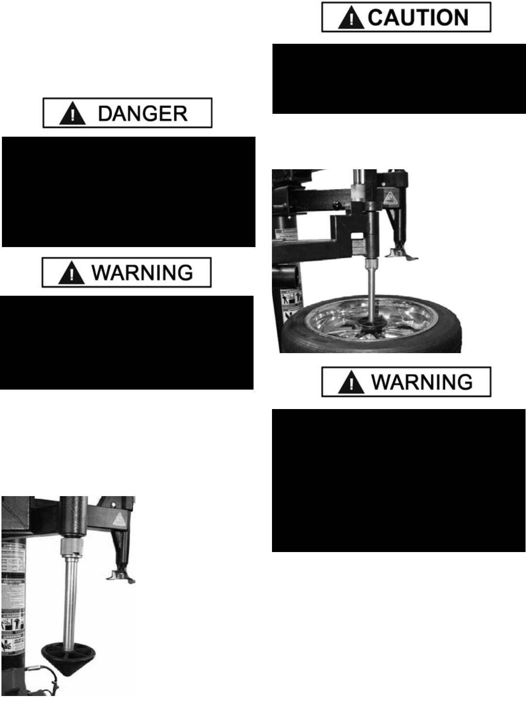
STAGE ONE / WHEEL RESTRAINT
As an added safety precaution, a wheel restraint device has
been added to protect operators during tire inflation.
1. Swing the Assist Tower to the side of the wheel and
insert the restraint device as shown. (See Fig 14.5)
Fig 14.5
2. Make sure the restraint tool is centered in the center hub
of the wheel then press down on the left hand control valve.
(See Fig 14.6).
STAGE TWO / BEAD SEALING
1. Position valve stem in front of operator and connect the
inflation hose after removing the valve core. (see Fig 14.7)
OPERATOR SHOULD KEEP HANDS, ARMS, AND
ENTIRE BODY AWAY FROM THE TIRE DURING THE
FOLLOWING BEAD SEAT AND INFLATION PROCE-
DURES. DO NOT STAND OVER TIRE, AS PERSONAL
INJURY COULD RESULT FROM INFLATING TIRE.
AVOID DISTRACTION DURING INFLATION. CHECK
TIRE PRESSURE FREQUENTLY TO AVOID OVER
INFLATION. EXCESSIVE PRESSURE CAN CAUSE
TIRES TO EXPLODE, CAUSING SERIOUS INJURY OR
DEATH TO OPERATOR OR BYSTANDER.
THIS MACHINE IS NOT INTENDED TO BE A
RESTRAINING DEVICE FOR EXPLODING TIRES,
TUBES, OR RIMS. KEEP HANDS AND BODY CLEAR
AT ALL TIMES AND AS FAR BACK AS POSSIBLE
DURING INFLATION. DO NOT LEAN OVER THE TIRE
WHILE INFLATING. AN EXPLODING TIRE, RIM OR
OTHER WHEEL COMPONENT CAN CAUSE DEATH TO
OPERATOR AND/OR BYSTANDER. REMAIN CLEAR
AT ALL TIMES.
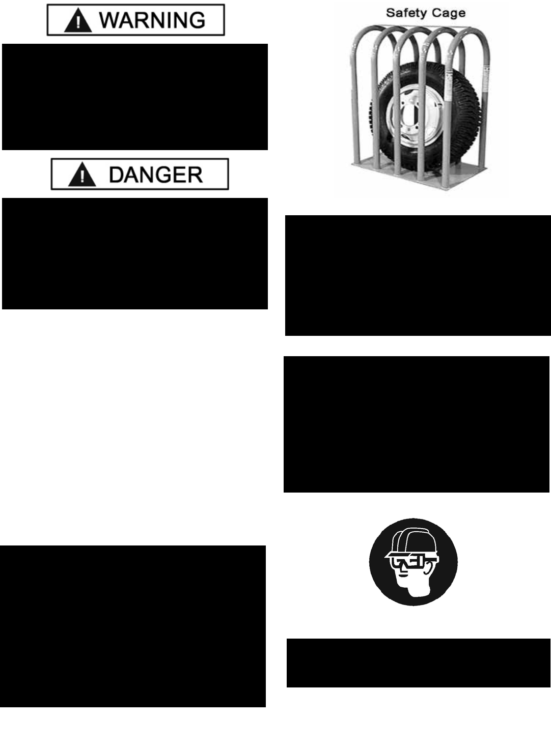
THIS OBJECT IS A RESTRAINT DEVICE ONLY. IT
WILL NOT PROTECT OPERATORS IN THE EVENT OF
CATASTROPHIC TIRE/WHEEL RUPTURE OR FAILURE.
ALWAYS USE EXTREME CAUTION DURING THE INFLA-
TION PROCEDURE. AS AN ADDED SAFETY PRECAU-
TION, SAFETY CAGES THAT CONFORM TO OSHA
STANDARD 1910.177 ARE RECOMMENDED.
HOLD THE RESTRAINT TOOL FIRMLY IN PLACE WHEN
INSTALLING AND/OR REMOVING FROM THE LEFT
HELPER ASSEMBLY. THE UNIT CAN DROP SUDDENLY
TO THE FLOOR. BE SURE TO KEEP FEET CLEAR AT
ALL TIMES.
Fig 14.6
28
2. Step on the inflation pedal to allow air to flow into the tire
and seal the beads. (see Fig 14.8)
TO SEAL LOW PROFILE OR DIF-
FICULT BEADS, USE THE TURBO
BLAST TO SEAL THE BEAD
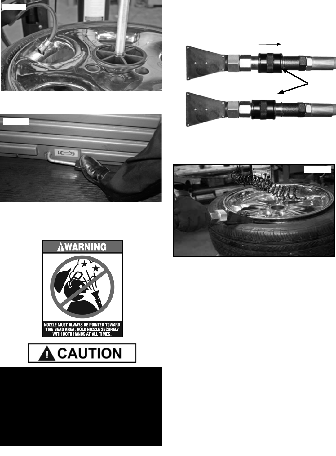
1. To Open the Slide Valve, PUSH the Slide Valve Forward.
2. To Close PULL the Slide Valve closed. (See Fig 14.10)
3. Position the Turbo-Blast Nozzle to direct air towards
the Rim Center just under the Rim lip. (See Fig. 14.11)
4. Depress inflation pedal and open the Turbo-Blast Valve
for less than one full second. The blast of air from the Turbo
Blat Nozzle will expand tire and seal the beads.
5. Repeat these steps if beads have not sealed. It will be
necessary to wait a few seconds for the air storage tank to
recover before attempting again. If tire and wheel are properly
lubricated and operator cannot achieve bead seal after a few
attempts, check to see if the valve core has been be removed
from the valve stem to allow more air flow into the tire to assist
with bead seal. After bead seal is achieved, remove the chuck
and reinstall the valve core.
STAGE THREE / BEAD SEATING
Bead seating usually occurs on the long tapered side of the
wheel first and the shorter side last. Bead seating will
usually require at least 7 PSI in the tire. 40 PSI is the
maximum safe pressure at this stage regardless of tire
operating pressure. Most European import cars and many
aftermarket alloy wheels are very tight and can be difficult
to bead seat. Also note that asymmetrical hump and run-flat
tires are extremely difficult to bead seat. Follow tire
manufacturer’s recommended procedure for bead seating.
Fig 14.7
Fig 14.8
NEVER POINT NOZZLE TOWARDS YOURSELF OR
OTHER PERSONS. INSPECT NOZZLE, TIRE AND
WHEEL FOR DEBRIS. NOZZLE MUST BE POINTED
TOWARD TIRE BEAD AREA. HOLD NOZZLE
SECURELY WITH BOTH HANDS AT ALL TIMES.
NEVER OPERATE THE NOZZLE WITHOUT A TIRE
AND WHEEL POSITIONED ON THE TABLE. DIRT AND
DEBRIS COULD BE BLOWN INTO THE AIR WITH
ENOUGH FORCE TO INJURE THE OPERATOR OR
BYSTANDERS.
Fig 14.10
Slide
Valve
Turbo Blast Nozzle
“Closed”
“Open”
Fig 14.11
29
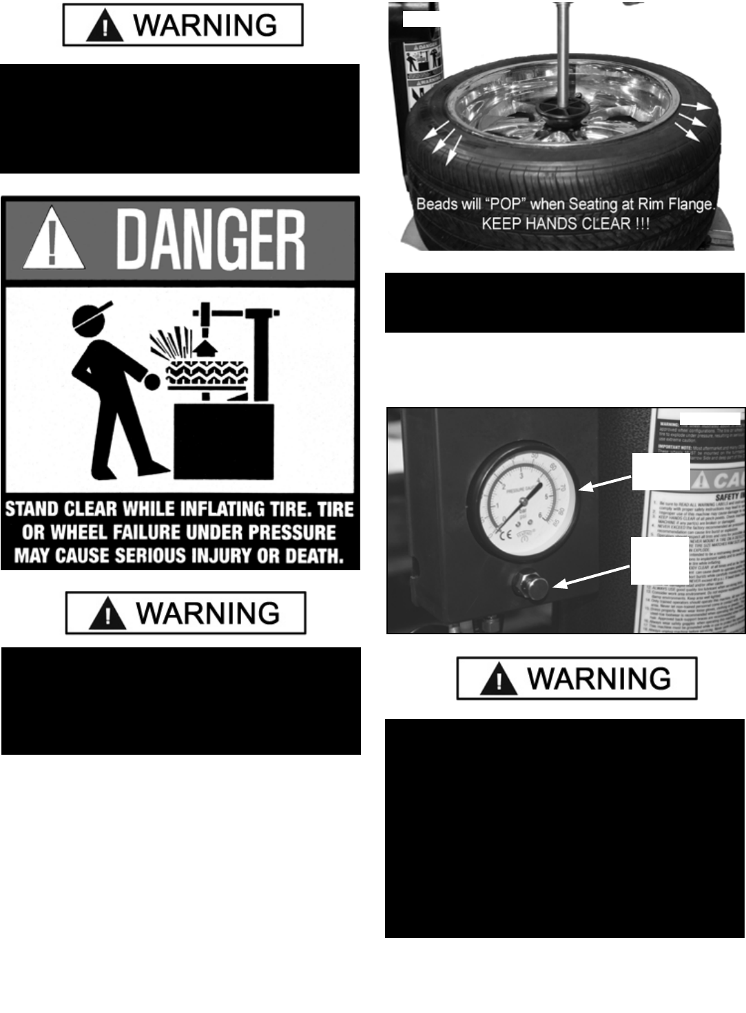
1. Once tire pressure is indicated on the pressure gauge
continue to inject air into the tire in short instervals. Check
the pressure frequently. Stand back during bead seat. Keep
hands, arms and entire body away from tire during this
procedue. Tire beads should move outward and “pop” into
their bead seat position as pressure inside the tire increases.
If this does not happen, a problem exists. Investigate
carefully. (see Fig 14.12
2. Release air pressure from the tire by pressing the manual
Pressure Relief Valve. (See Fig 14.13)
OPERATOR SHOULD KEEP HANDS, ARMS, AND ENTIRE
BODY AWAY FROM THE TIRE DURING THE FOLLOW-
ING BEAD SEAT AND INFLATION PROCEDURES. DO
NOT STAND OVER TIRE, AS PERSONAL INJURY COULD
RESULT FROM INFLATING TIRE.
AVOID DISTRACTION DURING INFLATION. CHECK TIRE
PRESSURE FREQUENTLY TO AVOID OVER INFLATION.
EXCESSIVE PRESSURE CAN CAUSE TIRES TO EXPLODE,
CAUSING SERIOUS INJURY OR DEATH TO OPERATOR OR
BYSTANDER.
Fig 14.12
NOTE:
THE INFLATION HOSE MUST BE ATTACHED TO THE
VALVE STEM DURING THIS PROCEDURE.
Fig 14.13
Pressure
Gauge
Pressure
Relief
Valve
CHECK TIRE PRESSURE FREQUENTLY. NEVER
EXCEED 40 PSI WHILE SEATING BEADS. ONCE
SEATED, NEVER EXCEED TIRE MANUFACTURER’S
RECOMMENDED AIR PRESSURE. TIRES CAN
EXPLODE, ESPECIALLY IF THEY ARE INFLATED
BEYOND THEIR LIMITS. AT ALL PRESSURE LEVELS
WHEN INFLATING THROUGH THE VALVE STEM,
KEEP HANDS, ARMS, AND ENTIRE BODY AWAY
FROM INFLATING TIRE. AN EXPLODING TIRE,
WHEEL, OR BEAD SEALING EQUIPMENT MAY
PROPEL UPWARD AND OUTWARD WITH SUFFICIENT
FORCE TO CAUSE SERIOUS INJURY OR DEATH TO
OPERATOR OR BYSTANDER.
30
STAGE FOUR / TIRE INFLATION
1. Make sure both beads are seated. When both beads are
seated, the tire is ready for inflation.
2. Replace the valve core if it was removed.
3. Depress the Inflation Pedal to inflate the tire. DO NOT
STAND OVER TIRE DURING INFLATION.
4. Do not inflate the tire above the manufacturer’s recom-
mended pressure as stamped on the tire sidewall. The
typical inflation pressure for automobile tires is between 24
and 45 PSI. Light truck inflation pressure typically covers a
wider range. Release air pressure from the tire by pressing
the manual Pressure Relief Valve.
NEVER ATTEMPT TO MOUNT AND INFLATE
MISMATCHED TIRES AND WHEELS. MISMATCHED
TIRE AND WHEEL COMBINATIONS CAN EXPLODE,
CAUSING PERSONAL INJURY OR DEATH TO
OPERATOR AND BYSTANDERS. FOR SAFETY,
DO NOT ATTEMPT TO MOUNT AND INFLATE MIS-
MATCHED TIRES AND WHEELS.
CHECK TIRE PRESSURE FREQUENTLY. NEVER
EXCEED 40 PSI WHILE SEATING BEADS. ONCE
SEATED, NEVER EXCEED TIRE MANUFACTURER’S
RECOMMENDED AIR PRESSURE. TIRES CAN
EXPLODE, ESPECIALLY IF THEY ARE INFLATED
BEYOND THEIR LIMITS. AT ALL PRESSURE LEVELS
WHEN INFLATING THROUGH THE VALVE STEM,
KEEP HANDS, ARMS, AND ENTIRE BODY AWAY
FROM INFLATING TIRE. AN EXPLODING TIRE,
WHEEL, OR BEAD SEALING EQUIPMENT MAY
PROPEL UPWARD AND OUTWARD WITH SUFFICIENT
FORCE TO CAUSE SERIOUS INJURY OR DEATH TO
OPERATOR OR BYSTANDER.
IF OPERATOR IS UNABLE TO OBTAIN BEAD SEAT,
SOMETHING IS WRONG. DEFLATE TIRE
COMPLETELY, INSPECT TIRE AND WHEEL,
CORRECT ANY PROBLEMS FOUND, RE-LUBRICATE
BOTH TIRE BEADS, AND REATTEMPT BEAD SEAL
AND SEAT PROCEDURES. FOLLOW ALL SAFETY
INSTRUCTIONS IN THIS MANUAL AND ON MACHINE.
NOTE:
WHEN INFLATING TIRES THAT REQUIRE MORE
THAN 60 PSI, ALWAYS USE A SAFETY CAGE AND
AIR HOSE WITH A CLIP-ON AIR CHUCK AND IN-LINE
VALVE. THE HOSE MUST HAVE ENOUGH LENGTH
BETWEEN THE CHUCK AND THE
OPERATION/IN-LINE VALVE TO ALLOW THE
TECHNICIAN TO STAND OUTSIDE THE
TRAJECTORY.
t BEFORE MAKING ANY INSPECTION,
ADJUSTMENT, OR REPAIR, DISCONNECT THE
POWER SOURCE AND OR AIR SUPPLY AND BLOCK
OUT ALL MOVING PARTS TO PREVENT INJURY.
t KEEP THE MACHINE AND THE IMMEDIATE
WORK AREA CLEAN. DO NOT USE COMPRESSED
AIR TO REMOVE DIRT AND DEBRIS FROM THE
MACHINE. FOREIGN MATERIAL MAY BE PROPELLED
INTO THE AIR AND INTO OPERATOR OR
BYSTANDER CAUSING PERSONAL INJURY.
t WEAR PROTECTIVE CLOTHING AND USE EYE
PROTECTION WHEN MAKING ANY ADJUSTMENTS
OR REPAIRS TO THE MACHINE.
31
SECTION 15
MAINTENANCE INSTRUCTIONS
Read and follow all the maintenance instructions provided
in this manual to keep the machine in good operating
condition. Regular inspections and proper maintenance
are essential to preventing accidents and injuries. These
instructions will help you service the unit. Instructions are
for a person with some mechanical ability and training. No
attempt has been made to describe all basic steps such
as how to loosen or tighten fasteners. Basic procedures
such as cycling systems and checking operation of the
equipment are not fully described since they have been
described previously in this manual. Do not attempt to
perform work beyond your ability or at which you have no
experience. If you need assistance, call an authorized ser-
vice center or contact the factory.
DAILY
tCheck the tire pressure gauge function, and check the
accuracy monthly. Use a pressurized tire and a high quality
pressure gauge. If the gauge is defective, replace it imme-
diately.
tMake sure all fasteners are securely tightened and all
guards and covers are in place.
tCheck for worn, damaged or missing parts including
grips and protective covers. Replace them before allowing
the unit to be used.
tCheck oil level and remove water from the separator.
tInspect the unit and check to be certain that all systems
are operating normally. Follow detailed inspection and
testing procedures as specified for various components at
regular intervals.
MONTHLY
t Pivot Points, assist tower vertical shaft should be
cleaned with a vaporizing solvent and then lubricated with
chassis grease. (See Fig 15.1)
tCheck adjustment of the mount/demount head.
tCheck the condition and adjustment of the turntable
drive belt.
tCheck function of the Inflation Pedal pressure
limiter/ regulator. The pressure regulator should never
be adjusted to exceed 60 PSI.
tClean the table top, clamps, steel mount/demount
head, and other working surfaces with a vaporizing solvent.
tReplace any damaged or missing safety decals, avail-
able from the factory.
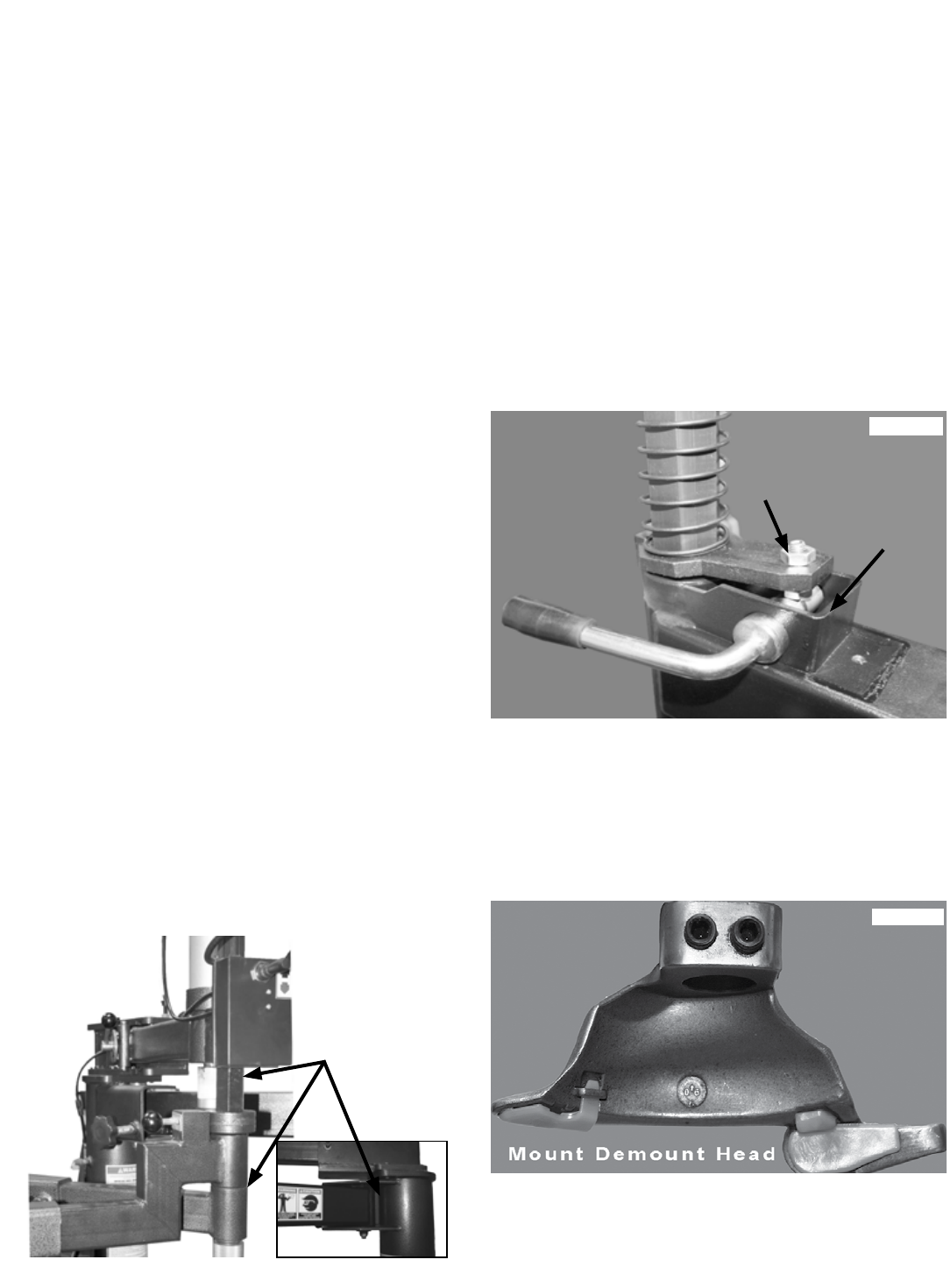
Mount/Demount Tool Head Adjustment
To adjust tool head clearance, adjust locking nut up or
down until lift clearance is 1/8” to 3/16”. Recheck clearance.
(See Fig 15.2)
Mount/Demount Head Cleaning
Clean dirt and debris from the mount/demount tool roller
with small screw driver or pick. Lubricate with light
penetrating oil. (See Fig. 15.3)
Fig 15.2
Adjusting
Nut
Locking
Nut
Fig 15.1
Lubricate
Here
Lubricate
Here
Fig 15.3
32
AIR DRIER/OILER MAINTENANCE
AIR/WATER MAINTENANCE
Check oil and water levels regularly, and perform these
maintenance items daily:
1. Observe through the clear sight glass the oil and water
levels. (See Fig 15.4)
2. If any amount of water is observed, drain by pushing up
on the drain plug at the bottom of the reservoir. (See Fig
15.5)
OILER MAINTENANCE
1. Disconnect air supply from machine. (See Fig 15.6)
2. Reservoir Cup may be removed for cleaning by turning
the reservoir counter-clockwise and pulling down. Add oil
to the lubricator if the fluid level is below the middle of the
gauge. Unscrew the Oil Reservoir Cup, add SAE 10W non-
detergent oil or an air tool oil if necessary. (See Fig 15.7)
3. Replace the Cup and reconnect the air supply when
service/adjustments are complete.
4. With the air source connected, depress the Bead
Breaker Pedal to operate the Bead Breaker. Observe the
sight glass and adjust the oil flow of the oiler by turning the
Oiler Adjustment Screw counter clockwise so that 2-3 drops
of oil drip through the sight glass for each operation of the
Bead Breaker Pedal. (See Fig 15.8)
FAILURE TO MAINTAIN THE WATER SEPARATOR/
AIR OIL IN PROPER CONDITION MAY VOID WAR-
RANTY. DRAIN WATER OUT OF THE SYSTEM REGU-
LARLY AND KEEP THE OIL RESERVOIR FILLED.
Fig 15.4
Fig 15.5
Fig 15.6
Disconnect
Air Supply
Fig 15.7
NOTE:
THIS ADJUSTMENT WILL REQUIRE TWO PERSONS
TO PERFORM.
Fig 15.8
33
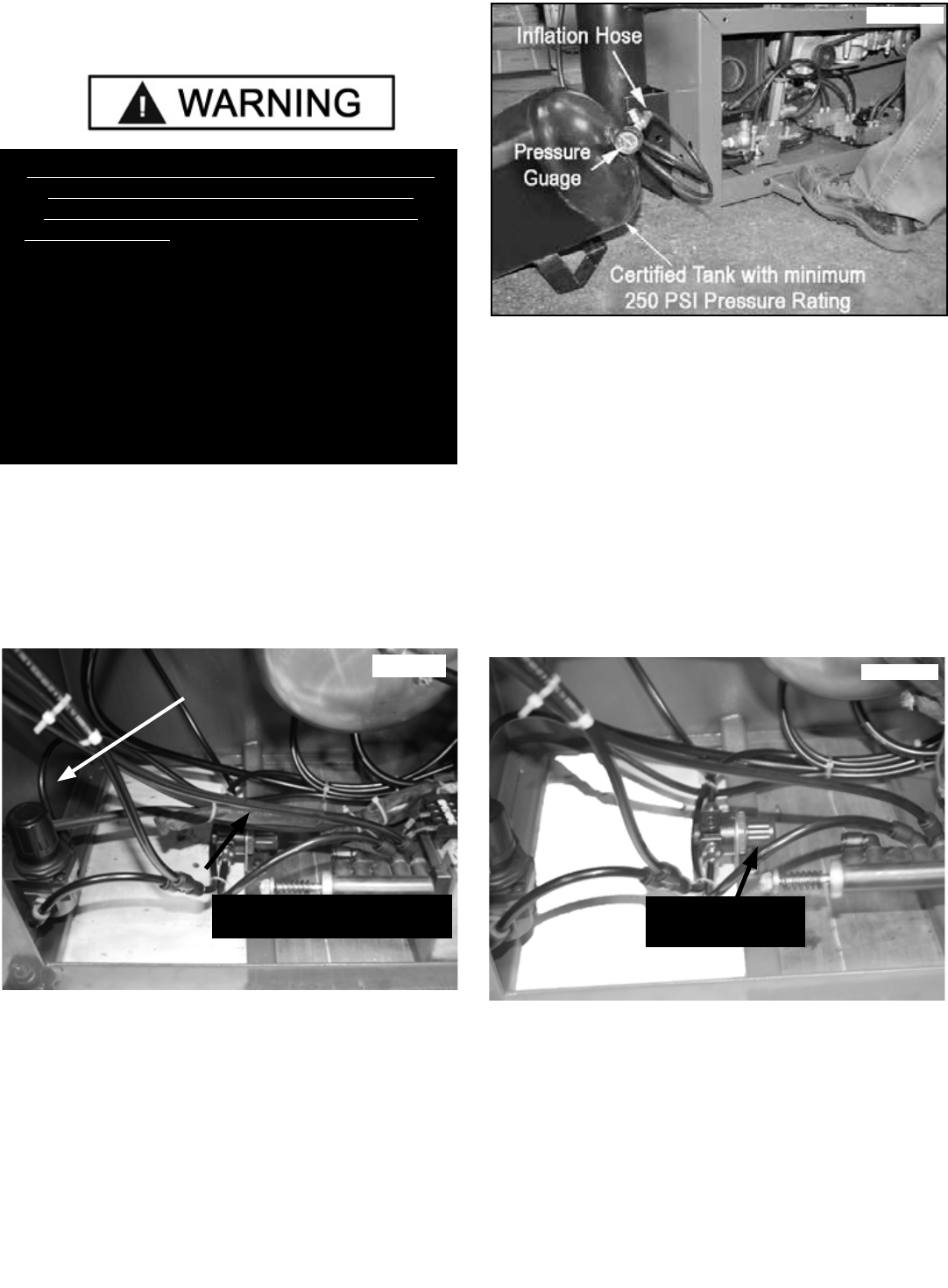
Inflation Pedal Pressure Limiter
Maintenance
The Inflation Pedal pressure limiter helps prevent inflation
of standard size or larger tires or tubes beyond 60 PSI to
minimize risk of explosion. This device is for the safety of
the operator and bystanders. Proper operation of the pres-
sure limiter is essential to safe operation of the machine.
(See Fig 15.9)
Check operation of the pressure limiter as follows at least
once a month:
1. Remove tires and/or wheels from the machine.
2. Connect the Inflation Hose to an empty service tank with
a pressure gauge (the gauge should read 0). Use a certified
tank with at least 250 PSI pressure rating. (See Fig 15.10)
3. Depress Inflation Pedal to start air flow through the
hose and into the tank. Maintain a steady pressure for
constant flow.
4. Watch the rising pressure on the tank gauge and the
gauge on the machine. As tank pressure reaches 60 PSI,
the pressure limiter should stop the air flow automatically.
Both gauges should read 60 PSI ± 5 PSI.
5. If the pressure exceeds 60 PSI, adjust the knob on
the regulator by lifting the locking cover and turning
COUNTERCLOCKWISE. After adjustment is made, secure
cover in the locked position. (See Fig 15.11)
6. Repeat steps 1-6. Readjust if necessary.
7. After pressure limit has been set, check the manual
release valve function by pressing the button and releasing
pressure from the tank until it reaches 50 PSI. Release air
inside tank and disconnect Inflation Hose. (See Fig 15.12)
THE INFLATION PRESSURE LIMITER IS PRESET
AT THE FACTORY AND SHOULD NEED NO
ADJUSTMENT. MODIFY ONLY IF PRESSURE
EXCEEDS 60 PSI. OPERATING A TIRE CHANGER
WITH A DEFECTIVE,IMPROPERLY ADJUSTED, OR
BYPASSED PRESSURE LIMITER COULD RESULT IN A
TIRE EXPLOSION WITH SEVERE INJURY OR DEATH
TO OPERATOR OR BYSTANDERS. ALWAYS BE SURE
THAT THE PRESSURE LIMITER IS OPERATING
PROPERLY ON THE MACHINE AT ALL TIMES.
PRESSURE LIMITER IS SET AT 60 PSI. ANY
REQUIRED INFLATION ABOVE 60 PSI SHOULD BE
PERFORMED IN AN INFLATION CHAMBER/SAFETY
CAGE.
Fig 15.9
Inflation Pedal
Pressure Limiter
Assist Tower
Pressure Limiter
Note: Side Panel Removed
Fig 15.10
Fig 15.11
Pressure Limiter
Adjustment Knob
34
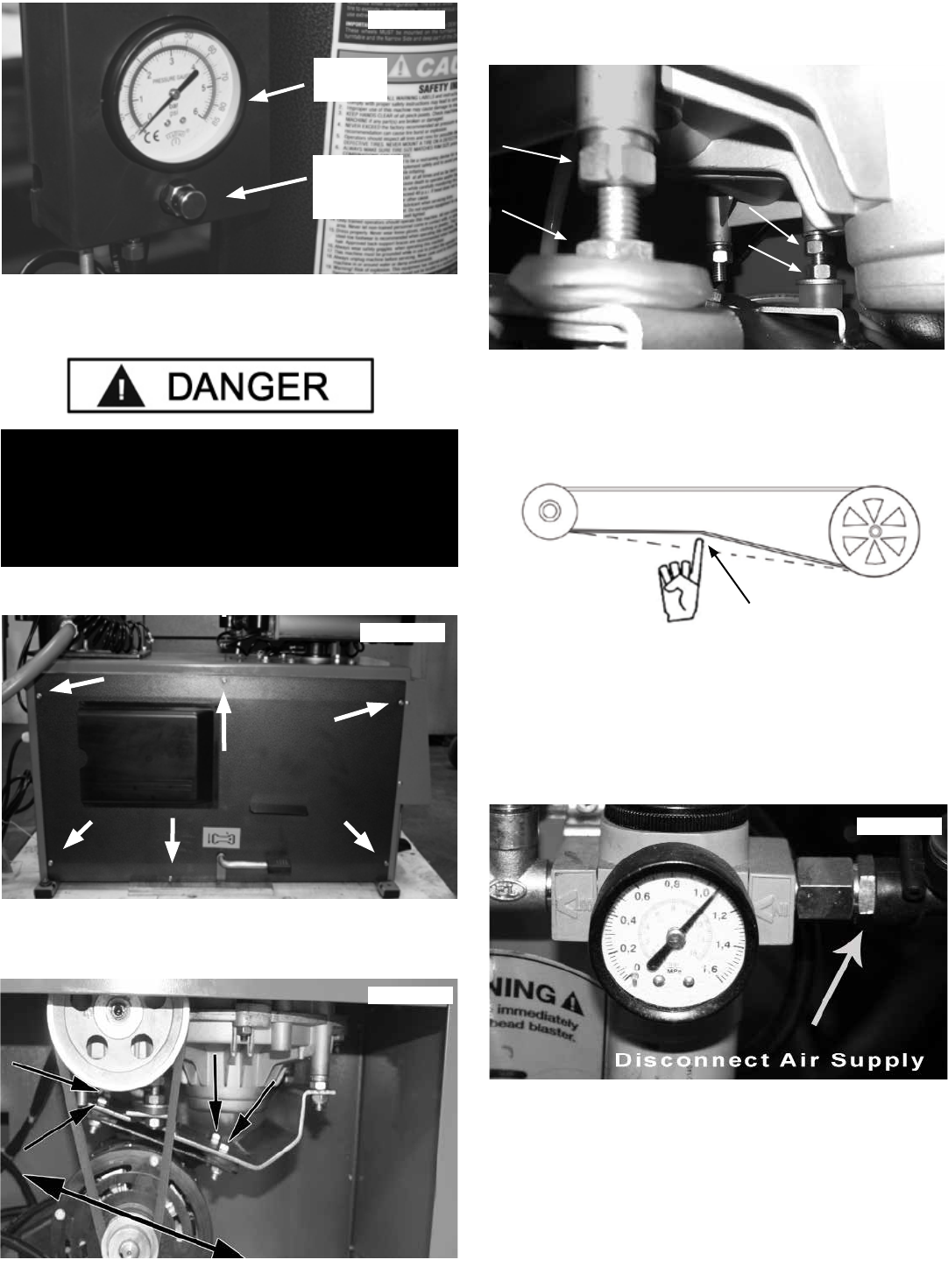
TURNTABLE DRIVE BELT
INSPECTION / ADJUSTMENT
1. Remove the Side Panel. (See Fig 15.13)
2. Inspect the Drive Belt for cracking and wear and replace
as necessary. (See Fig 15.14)
3. Loosen the four Motor mounting bolts and nuts. (See
Fig 15.15)
4. Adjust the Belt deflection to 3/8” - 1/2”. (See Fig 15.16)
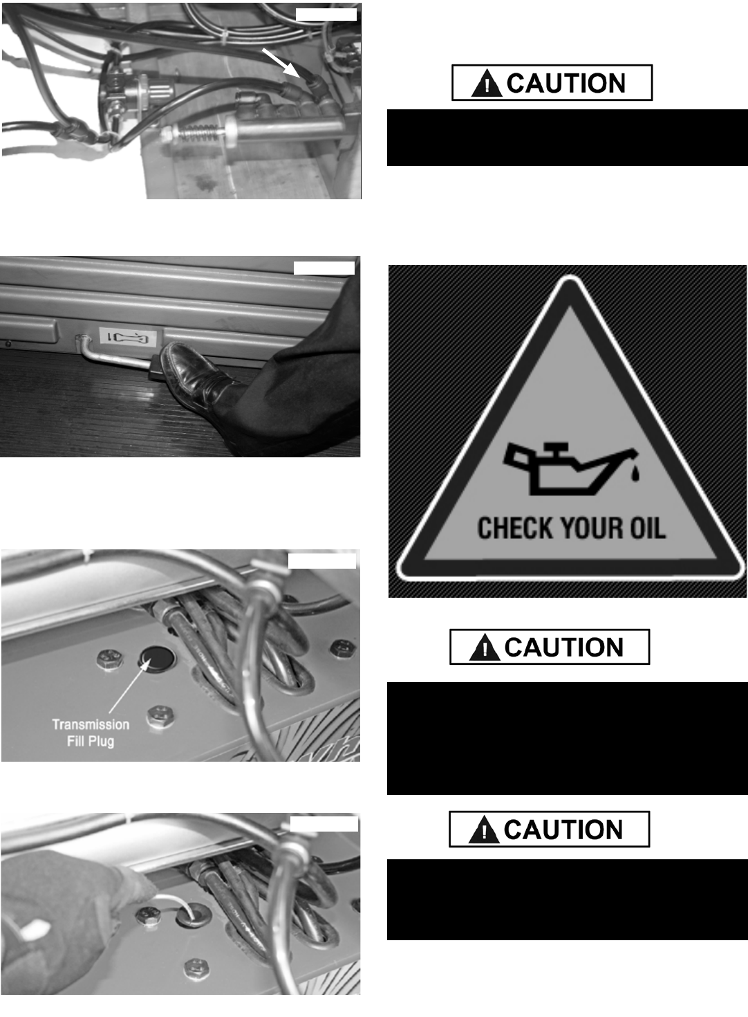
INFLATION VALVE LUBRICATION
1. Disconnect Air Supply from the machine. (See Fig 15.17)
2. Disconnect the Air Line going to the left port on the
Inflation/Bead Blast Pedal. Place 1/2 oz. of SAE 10W
non-detergent oil or an air tool oil into the open port. (See
Fig 15.18).
Fig 15.12
Pressure
Gauge
Pressure
Relief
Valve
Fig 15.13
Fig 15.15
Fig 15.14
THE MOTOR ON THIS MACHINE CONTAINS HIGH
VOLTAGE. DISCONNECT POWER AT THE RECEP-
TACLE BEFORE PERFORMING ANY ELECTRICAL
REPAIRS. SECURE PLUG SO THAT IT CANNOT BE
ACCIDENTALLY PLUGGED IN DURING SERVICE.
Fig 15.17
3/8”
Adjusting
Belt Tension
Fig 15.16
35
4. Press the Inflation Pedal six times to work the oil into
the Valve. (See Fig 15.19)
TRANSMISSION INSPECTION / LUBRICATION
1. Rotate the Turntable so that the Transmission fill plug is
visible and remove plug. (See Fig. 15.20)
2. Put a flexible wire into the Transmission Oil Fill Hole until
the wire hits the bottom of the well. (See Fig 15.21)
3. Remove the wire and check the capacity level of the
Transmission fluid. The oil should cover no more than 1”
( 25 mm) of the wire.
NOTE:
Gearbox Requires
90 Plus Viscosity Gear Oil
FILLING OIL LEVEL HIGHER WILL RESULT IN
LEAKAGE OF THE TRANSMISSION SEALS.
BE SURE TO READ ALL WARNING LABELS AND
INSTRUCTION MANUAL PRIOR TO OPERATION OF
THIS MACHINE. FAILURE TO COMPLY WITH PROPER
SAFETY INSTRUCTIONS MAY LEAD TO SERIOUS
HARM OR EVEN DEATH OF OPERATOR AND/OR
BYSTANDERS.
ALWAYS INSPECT TIRES BEFORE MOUNTING.
DEFECTIVE OR DAMAGED TIRES MAY BURST OR
EXPLODE WHEN INFLATING AND MAY LEAD TO
SERIOUS HARM OR INJURY.
Fig 15.20
Disconnect Tube
and Lubricate in Port
Fig 15.18
Fig 15.19
Fig 15.21

36
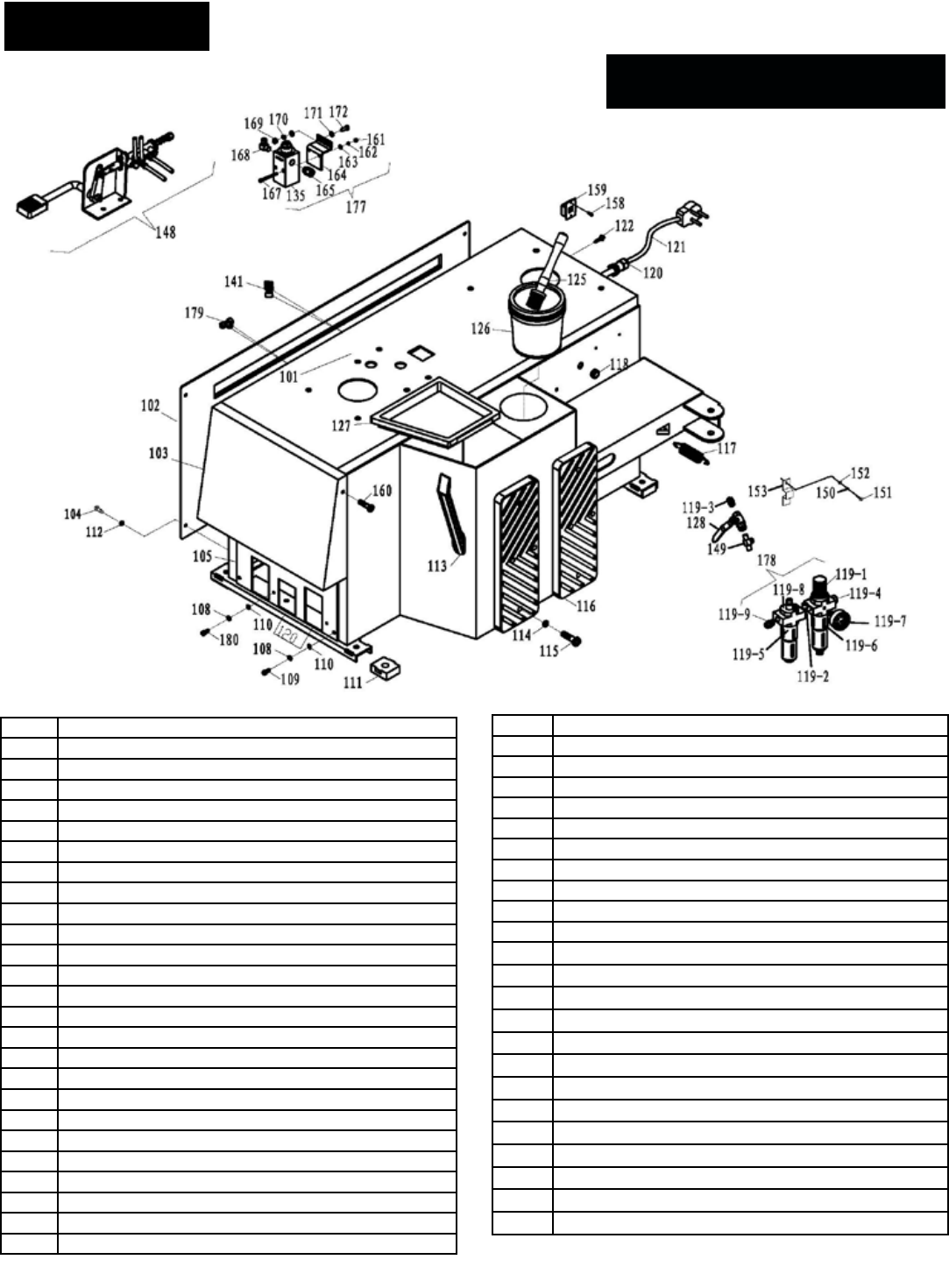
37
101 Chassis Weldment
102 Chassis Side Cover
103 Foot Pedal Hood
104 PHPS M6 x 1.0 x 20
105 Chassis Front Board
106 Hex Nut M8 x 1.25
107 Pedal Divider
108 Washer M6 x 12 Flat
109 SHCS M6 x 1.0 x 16
110 Washer M6 Flat
111 Plastic Foot Pad
112 Washer M6 Flat
113 Pry Bar
114 Washer Ø6mm
115 PHPS M6 x 25
116 Wheel Support Pad
117 Bead Breaker Return Spring
118 Rubber Grommet Ø12
119 Air Drier / Oiler
119-1 Air Filter with Regulator
119-2 Tee Fitting ¼ NPT x ¼ Female NPT
119-3 FTG NPL 1/4 NPT x Ø8mm
119-4 Barbed Tube Fitting 1/4”
119-5 Oiler Cup
119-6 Filter Cup
119-7 Air Pressure Gauge
119-8 Air Regulator w/Gauge; I Models
119-9 Fitting G1/4” Ø12 Straight
120 Power Cord Grip
121 Power Cord
122 STS M5.5 x 1.0 x 25
125 Soap Brush
126 Soap Bucket
127 Tool Tray
128 ¼" Ball Valve
135 Full Flow Ination Regulator
141 Y-branch Air Fitting Ø8mm
148 Ination Foot Pedal
158 Cross Recessed Round Head Screw M4x16
159 Voltage Switch 110/120V
161 Nut M4
164 Full Flow Ination Kit Bracket
165 Fitting G 1/4” Ø8
167 Socket Head Cap Screw M4x50 and M4x45
168 Fitting 90º Ø8-G1/4”
169 Nut M6
170 Washer, Ø6 Spring
171 Washer, Ø6 at
172 Hexagon Headed Bolt M6x20 and M6x16
177 Wire/hub terminal block assembly
SERVICE PARTS
R980 ALL MODELS Chassis
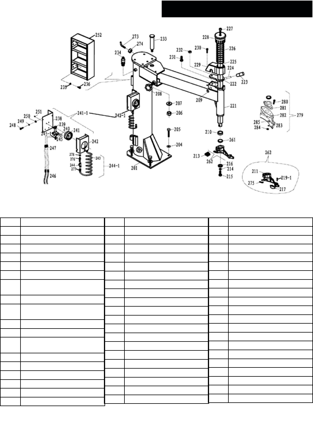
38
201 Tower Unit Weldment
204 Washer Ø12
205 Hex Head Bolt M12 x60
206 Locknut M16
207 Lock pad
208 Position Fixing Handle
209 M18 Snap Ring
210 Mount / Demount Head
Bushing Ø46x34x12
211 Metal Mount-Demount Head
213 M12 X 16 Mount-demount
Head Set Screw
214 Washer Ø10
215 Hex Bolt M10 x 20
216 Mount-demount Head
Retaining Washer
217 Roller Insert
218 Mount-demount Head Roller
219-1 Innner Hexangular Set Screw
221 Swing Arm Unit Weldment
222 Hex Shaft Locking Plate
223 Locking Handle Cover
224 Locking Handle
225 Vertical Shaft
226 Hex Shaft Spring
227 SHCS M8x1.25 x 25
228 Hex Shaft Cap
229 Hex Shaft Lock Cover
230 SHCS M6x30
231 SHCS M12 x 1.75 x 25
232 Thin Nut M12 x 1.75
233 Swing Arm Pivot Pin
234 Pressure Release Valve
235 Washer M6 Flat
236 SHCS M6 x 16
239 Tire Inator Relief Valve
240 Air Release Valve
241 Inating Gauge
242 Ination System Plastic Cover
242-1 Tire Inator Box Assy
243 Coiled Air Hose Ø8mm (9ft)
244-1 Ination Hose Assy
245 Gauge Block ⅛″
245-1 Air Chuck
246 Y-branch Air Fitting Ø8mm
247 Union Fitting 8mm x ⅛ NPT
248 SHCS M6 x 10
249 Washer M6
250 Washer M6 Flat
251 PHPS M3 x 10
252 Tool Box
261 M-demount head Adjust Pad
262 M-demount head Adjust Assy
273 Turbo Blast Hook
274 Nut M8
275 Nut M6
276 Ination Hose Plug
277 Fitting G1/8″φ8
279 Plastic MDH assembly
280 SHCS M8x40
281 Plastic MDH Flange
282 Plastic Flange Adapter
283 Lock Washer
284 Nut M8
R980 ALL MODELS Tower / Horizontal Arm
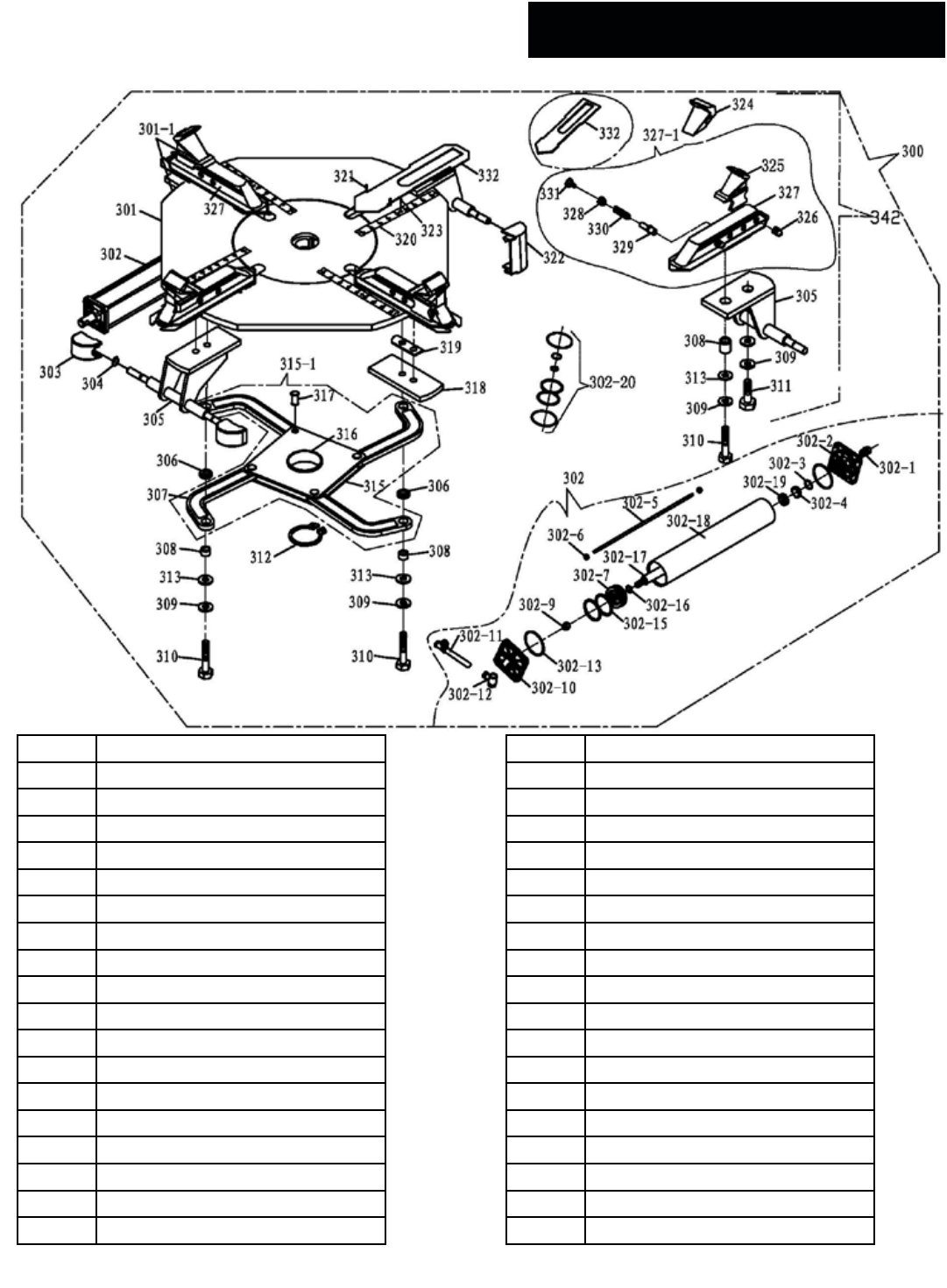
39
300 Turntable Assembly
301 Turntable Plate
301-1 Plate Assembly
302 Jaw Clamp Cylinder
302-1 Fitting; 1/8 8mm Straight
302-2 Small Front Cylinder Cover
302-3 O-ring Ø16x2.4
302-4 Jaw Clamp Cylinder
302-18 Jaw Clamp Cylinder Body
303 Small Cylinder Cover
304 Snap ring Ø12
305 Slide Guide
306 Square Turntable Slide Rod Pad
307 Square Turntable Link
308 Metal Bushing 18 x 12 x 11
309 Washer Ø12
310 HHB Ø12 x 50
311 HHB Ø12x25
312 Snap ring Ø65
313 Washer Ø12 Flat
315-1 Square Turntable Assembly
316 Square Turntable Spacer
317 Square Turntable Press Pin
318 Slide Guide Board
319 Slide Shim Adjustment
320 Turntable Ruler
321 Split Pin
322 Small Cylinder Back Cover Guard
323 Turntable Ruler Screw; M4x6
324 Jaw Clamp Cover Set (QTY 4)
325 Jaw Clamp
326 Special Screw M10x1
327 Jaw Clamp Support
328 Jaw Clamp Inner Adjustment Knob
329 Jaw Clamp Inner Adjustment Pin
330 Jaw Clamp Pin Spring
331 Jaw Clamp Locking Pin
342 Complete Turntable
R980 ALL MODELS Turntable Assembly
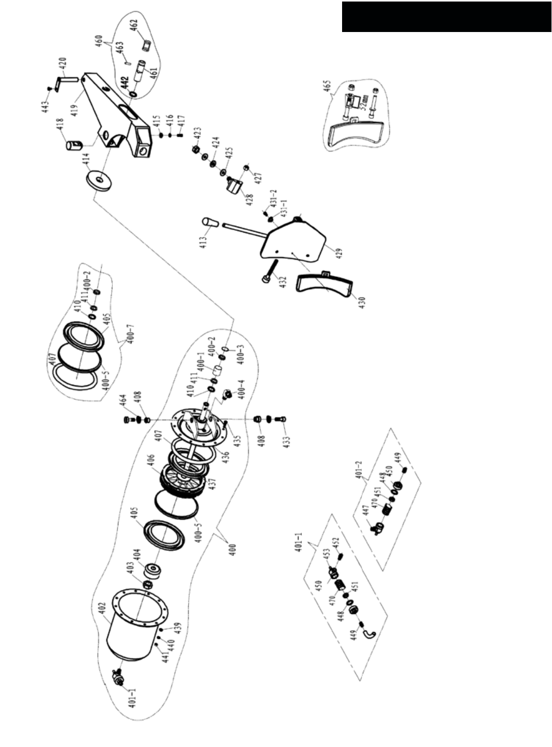
40
R980 ALL MODELS Bead Breaker

41
400 Bead Breaker Cylinder Assy
400-1 Bearing B3025
400-2 Seal Ring Ø30x20x7
400-3 Type I Hole With Elastic Ring
400-4 Fitting; 90º G1/4” Ø10
400-5 Guide Ring
400-7 Pairs of Large Cylinder Seal Hair Accessories
401-1 Quick Release Valve Assembly (B)
401-2 Quick Release Valve Assembly (A)
402 Large Cylinder Tube
403 Thin Nut M18 x 2.5 x 1.5
404 Piston Spacer
405 Wiper Seal Ø200 x 12 x 6mm
406 Cylinder Piston
407 O-ring Ø193 x 5.7
408 Eccentric Bushing
409 Cylinder Wear Ring Ø25
410 O-ring Ø25 x 3.1
411 Wiper Seal Ø25
412 Brass 90° Fitting ¼ NPT x 10mm
413 Bead Breaker Blade Handle
414 BB Rubber Disk
415 Worm pressure pad
416 Washer Ø8mm
417 SHCS M8 x 1.25 x 16
418 BB Arm Slide
419 Bead Breaker Arm
420 BB Arm Pivot Pin
421 Snap Ring Ø16
422 BB Blade Adjustment Rod
423 Locknut M16 x 2.0
424 Wave Washer Ø16
425 Washer Ø16
427 Locknut M12 x 1.75
428 BB Blade Hinge
429 Bead Breaker Blade
430 Bead Breaker Blade Cover
431 Bead breaker Cover Plug
432 SHCS M12 x 1.75 x 90
433 SHCS M14 x 2.0 x 30
434 Metal Bushing Ø18 x Ø12 x 11
435 Hex Bolt M6 x 1.0 x 16
436 Cylinder Head Cap
437 Cylinder Rod
438 Piston Spacer Pad
439 Washer M6 Flat
440 Washer M6 x 12mm Flat
441 Nut M6 x 1.0
442 BB Blade Adjustment Rod Pin
443 Cross Recessed Round Head Screw
447 Fitting G1/4” 12mm
448 Metal Quick Exhaust Valve
449 Quick Exhaust Valve Metal Cup
450 Metal Quick Exhaust Valve
451 Quick Exhaust Valve Metal Cup
452 Fitting: G1/4” - G 1/4”
453 Silencer 1/4” NPT
460 Adjust the set of assembly
461 BB Blade Adjustment Rod Pin R30XLT
462 Adjust the collection
463 BB Blade Adjustment Rod Pin, R30XLT
464 Washer Ø14
465 Upgraded Shovel Kit
470 Metal Quick Exhaust Valve Spring
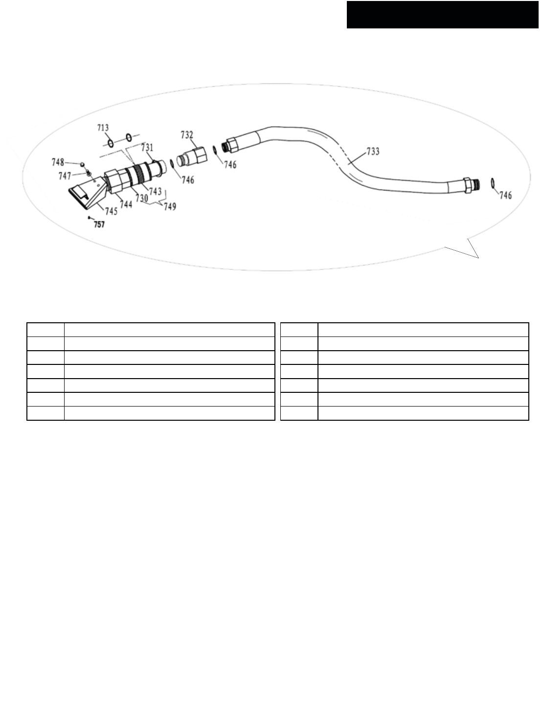
42
R980 ALL MODELS Turbo Blast
713 O-ring Ø40x3.55
730 Turbo Blast Nozzle Adapter
730-1 Turbo Blast Complete
731 Snap Ring Ø40
732 1” Connector
733 Turbo Blast 1” Hose
743 Turbo Blast Valve
744 Turbo Blast Handle/Connector
745 Jet Blast Nozzle
746 O-ring Ø28x3.55
747 CRRH Screw M6x12
748 Acorn Nut M6
749 Turbo Blast Valve Assembly
757 CRH Tapping Screw 4.2x13
730-1
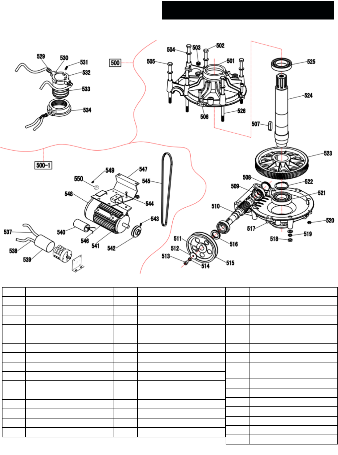
43
500 Transmission Assembly
500-1 Rotary Joint Block
501 Gearbox Top Flange
502 Hex Bolt M10 x 1.5 x 200
503 Oil Plug
504 Washer Ø10
505 Hex Bolt M10 x 1.5 x 180
506 SHCS M8 x 1.25 x 30
507 Turntable Key 12 x 8 x 35
508 Oil Block 45 x 8
509 Cone Roller Bearing 7205
510 Gear Stud M2
511 Tab 6 x 6 x 20
512 Gear Stud Pad
513 SHCS M8 x 1.25 x 16
514 Washer Ø8
515 Large Belt Pulley
516 Oil Seal Ø45 x 25 x 10
517 Gearbox Bottom Flange
518 Nut M10 x 1.5
519 Washer Ø10
520 Nut M8 x 1.25
521 Bearing 80208
522 Snap Ring Ø50
523 Helical Gear M2(Al)
524 Turntable Shaft
525 Bearing 80110
526 Hex Bolt M10 x 1.5 x 170
529 90° Fitting ⅛″ NPT x Ø8mm
530 PHPS M3 x 0.5 x 6
531 SHCS M6 x 1.0 x 8
532 Rotary Joint Block
533 O-ring Ø60 x 2.65
534 Rotary Joint Block Collar
537 Electrical Line
538 Power Lline
539 Directional Switch Cover
540 Electric Capacitor
541 Locknut M8 x 1.25
542 Motor Pulley
543 SSS with at point M8 x 1.25
x 16
544 Hex Bolt M8 x 1.25 x 40
545 V Belt
546 Rubber Washer
547 Motor Mounting Weldment
548 Electric Motor
549 Washer Ø10
550 Transmission Bracket Bushing
R980 Standard Transmission Motor Assem-
bly
R980 Standard Transmission Motor Assembly
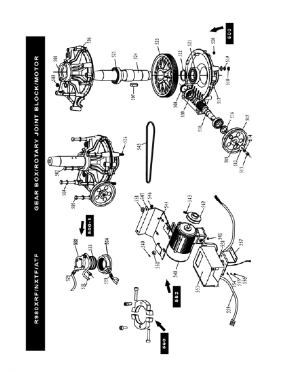
44
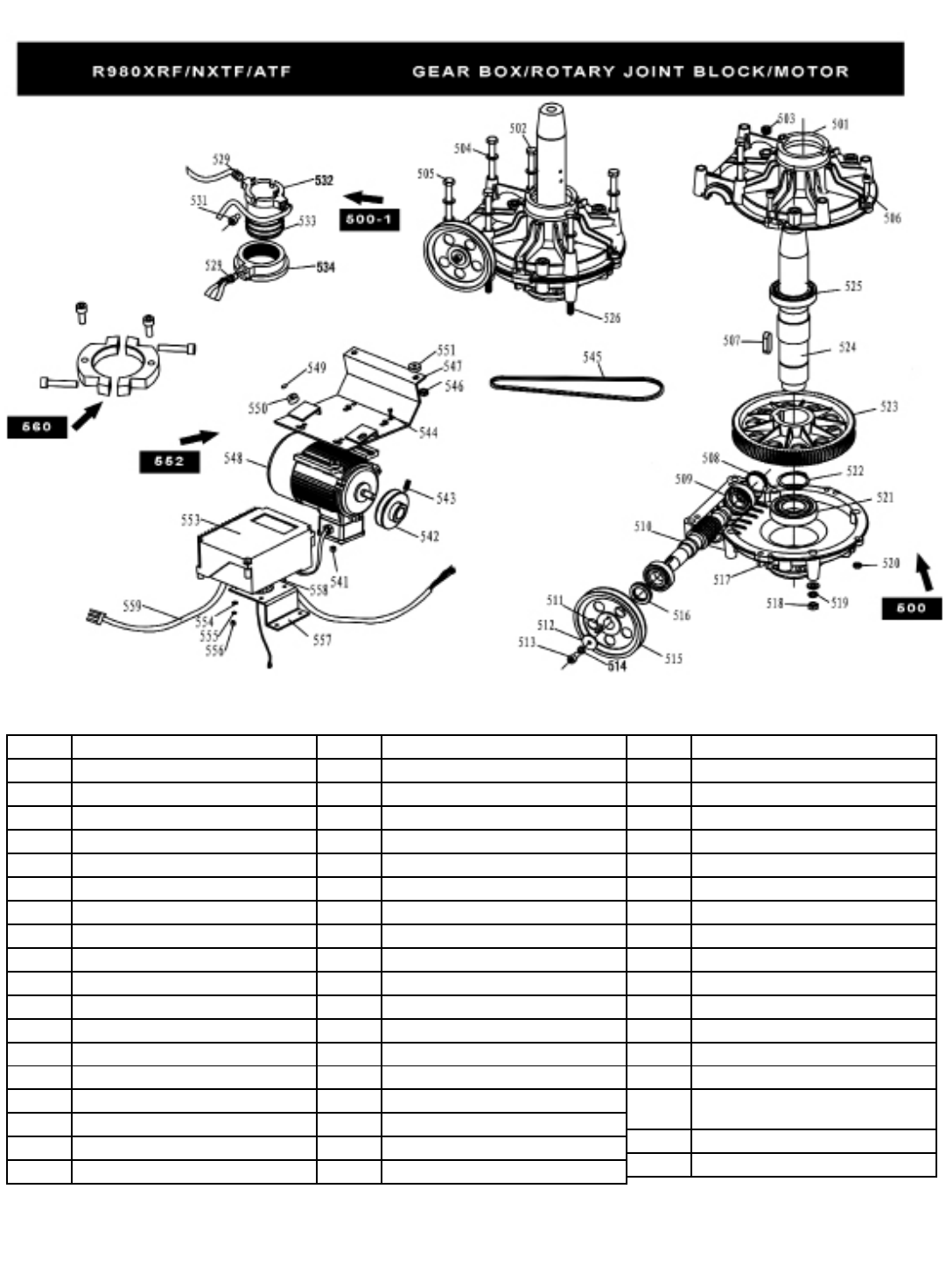
45
500 Transmission Assembly
500-1 Rotary Joint Block
501 Gearbox Top Flange
502 Hex Bolt M10 x 1.5 x 200
503 Oil Plug
504 Washer Ø10
505 Hex Bolt M10 x 1.5 x 180
506 SHCS M8 x 1.25 x 30
507 Large Gear Key 12 x 8 x 35
508 Oil Block 45 x 8
509 Cone Roller Bearing 6205
510 Gear Stud M2
511 Tab 6 x 6 x 20
512 Gear Stud Pad
513 SHCS M8 x 1.25 x 16
514 Washer Ø8
515 Big Size Belt Pulley
516 Oil Seal Ø45 x 25 x 10
517 Gearbox Bottom Flange
518 Nut M10
519 Washer Ø10
520 Nut M8
521 Bearing 80208
522 Snap Ring Ø50
523 Helical Gear M2(Al)
524 Turntable Shaft
525 Bearing 6010
526 Hex Bolt M10 x 170
529 Fitting G⅛″ x Ø8mm
531 Inner Hexangular Screw M6x20
532 Rotary Joint Block Inner Piece
533 O-ring Ø60 x 2.75
534 Rotary Joint Block Inner Piece
537 Linear Motor
540 Motor Run
540-1 Starting Capacitance
541 Locknut M8
542 Motor Pulley
543 SSS with at point M8 x 16
544 Hex Bolt M8 x 40
545 V Belt
546 Nut M10
547 Motor Mounting Weldment
548 Integrated Co
549 Washer Ø10
550 Transmission Bracket Bushing
551 Rubber Washer
552 Motor with Support B
553 Frequency Converter
554 Washer; Φ5at
555 Washer; Φ5
556 Nut M5
557 Inverted Fixed Plate
558 Cross Recessed Round Head Screw
M5X20
559 Power Cord
560 Rotary Valve Fixed Set

46
148-1 Ination Pedal
148-2 Ination Pedal Lever
148-3 PHPS M6 x 1.0 x 16
148-4 Pedal / Valve Bracket Weldment
148-5 Bead Blaster Valve Assembly
148-5-1 O-ring Ø15.4 x 3.9
148-5-2 Washer
148-5-3 Air Valve O-ring Spacer
148-5-4 Bead Blaster Valve Rod
148-5-5 Air Valve Body
148-6 Air Valve Reforce Pad
148-7 Pressing Spring
148-8 Locknut M8 x 1.25
148-9 Washer Ø8
148-10 Washer M6 x 12mm Flat
148-11 FTG 90° ⅛″ NPT x Ø8mm
148-12 ⅛ NPT Plug
148-13 FTG 90° ⅛″ NPT x Ø8mm
148-14 FTG 90° ¼″ NPT x Ø8mm
148-15 Nut M8 x 1.25
148-16 Pedal Valve Link
148-17 Pedal Spring
148-18 Cotter pin
148-19 Pin Ø8
148-20 Pedal Link Lever
148-21 Locknut M10 x 1.5
148-22 Washer Ø8
148-23 Pedal Link
148-24 Roll Pin Ø4 x 18
148-25 Washer Ø10
148-26 Washer Ø8
148-27 SHCS M8 x 1.25 x 20
148-28 Washer Ø8
148-29 SSS M6 x 1.0 x 10
R980XRF Ination Pedal Assembly
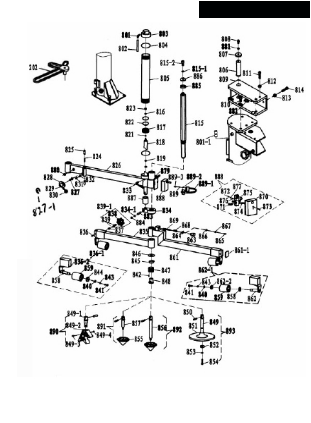
47
R980 NXT/NXTF Assist Tower

48
801
801-1
90° Fitting ⅛ NPT
8mm to 6mm union
802 PU Air Compressor Hose Ø6mm
803 Assist Tower Rear Cylinder Plate
804 O-ring Ø85 x 3.6mm
805 Cylinder Body Ø75 x 360mm
806 Assist Tower Pivot Pin
807 Gland
808 SHCS M10 x 1.5 x 25
809 Assist Tower Arm Bracket
810 SHCS M12 x 1.75 x 25
811 SHCS M12 x 1.75 x 25
812 Nut M12 x 1.75
813 Nut M10 x 1.5
814 SHCS M10 x 1.5 x 35
815
815-1
815-2
Guide Pin
Washer, Ø10; Spring
SHCS M10x25
816 Washer M10x40
817 Small Cylinder Piston
818 Assist Cylinder Rod Ø30 x 533mm
819 O-Ring Ø35 x 3.1; R30XLT (10)
820 Assist Tower Cylinder Wear Ring
821 O-ring Ø16 x 2.4mm
822 O-ring Ø75 x 5.7mm
823 Locknut M10 x 1.5 NL
824 Assist Tower Lock Spring
825 Assist Tower Lock Pin
826 Assist Arm Weldment
827
827-1
Assist Tower Lock Shaft
Snap ring Φ8
828 Assist Tower Lock Cam
829 Assist Tower Lock Handle
830 Assist Tower Lock Knob
831 Assist Tower Lock Roller
832 Assist Tower Lock Link
833
833
Quick union Φ6 G1/8″
Fitting Φ6-G1/8” 90º
834
834-1
Connect plate
Washer, Φ12 at
835 Lower small arm unit weldment
836
836-1
836-2
836-3
PHPS Screw M6x12
Fixed Roller Assy
Assist Arm Side Roller Weldment (A)
Free Roller Assy
837 AT Roller Lock Nylon Insert
838
839
839-1
Club Hand Shank M12
Sliding Sleeve Fasten Lead Screw
Assist Tower Roller Lock Knob
840 washer Ø10
841 SHCS M10X15(levo)
842 straight pin Ø3X18
843 washer Ø10 spring
844 Assist Tower Roller Lock Spacer
845 Snap Ring Ø35
846 clout
847 Assist Tower Quick Chuck, Outer
848 Assist Tower Quick Chuck, Inner
849 tray lever
850 straight pin Ø10X45
851 Plastic Disk
852 big arm pin roll clout
853 washer Ø10
854 SHCS M10X20
855 Assist Arm Cone
856 Long Cone Shaft
857 Short Cone Shaft
858 Friction Roller Washer
859 Assist Tower Roller
861
861-1
upper small arm unit weldment
block
862
862-1
862-2
Assist Tower Roller Slide
Free Roller Assembly
Roller Pad
863 Roller Arm Lock Knob
864 Roller Arm Lock Knob Catch
865 PHPS M5X10
866 washer Ø5; at; spring
867 washer Ø5
868 Roller Arm Lock Knob Spring
869 Roller Arm Lock Knob Pin
870 L/R Assist Arm Valve Cover
871 quick union G1/4″
872 PHPS screw M4X12
873 PHPS screw M4X30
874 adjustment silencer G1/8″
875 Assist Arm Control Valve
876 washer Ø4; at
877 washer Ø4
879 cross recessed tapping screws M4 2x13
880 cable holder Ø16
881 washer Ø10
882 SHCS M12X20
883 cylinder pin
884 seeger ringØ12
885 upper cushion pad
886 upper cushion plate
887 lower cushion pad
888 Assist Arm Control Valve Cover
889 Washer Ø5; Spring
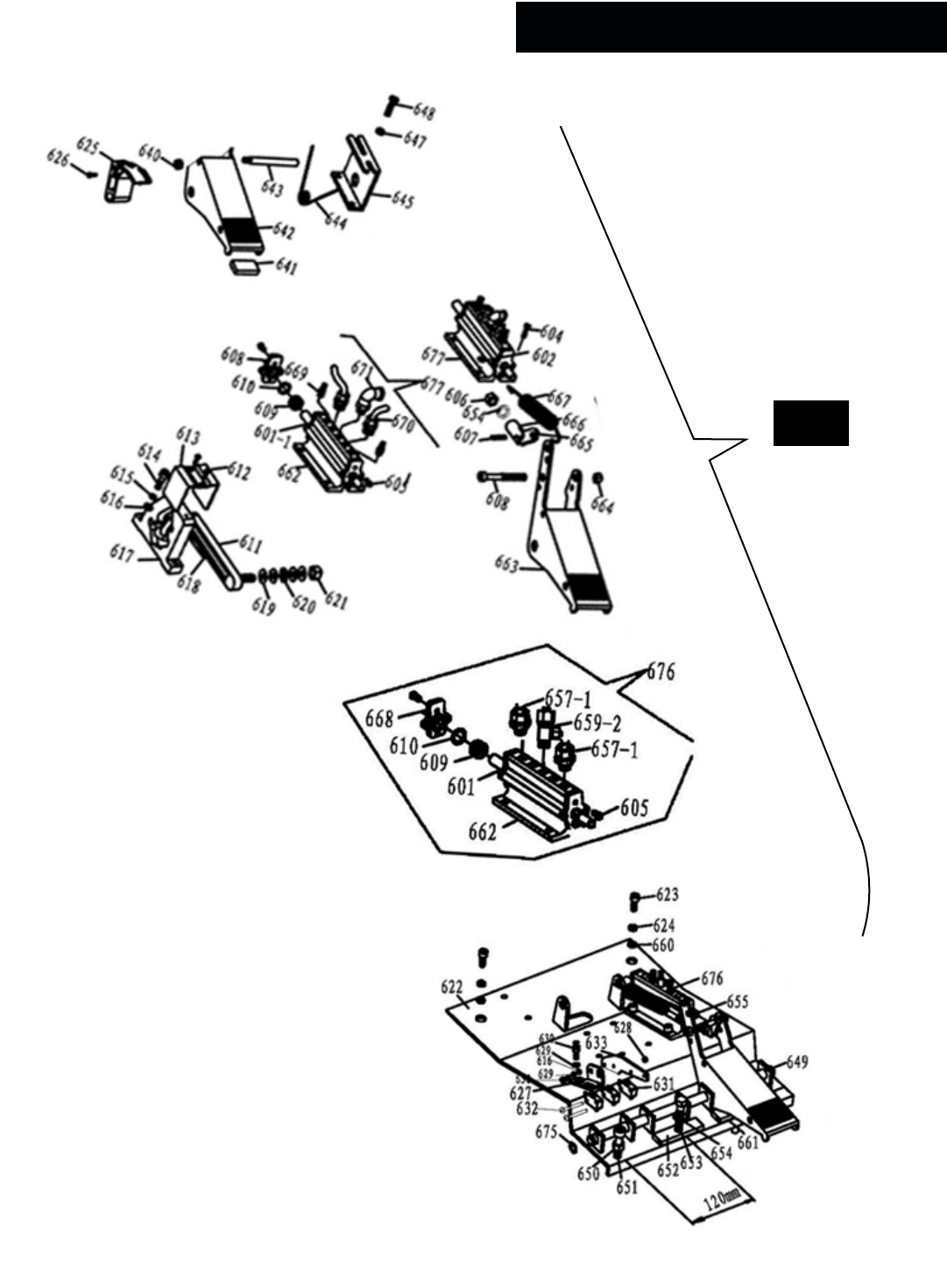
49
R980 ALL F Models Foot Pedal Assembly
678

50
601 Air Valve Spool
602 Washer M6 x 12mm Flat
603 Washer M6 Flat
604 PHPS M6 x 1.0 x 12
605 PHPS M4 x 0.7 x 10
606 Nut M8 x 1.25
607 Roll Pin Ø4 x 18
608 SHCS M6 x 1.0 x 55
609 Air Valve O-ring Spacer
610 O-ring Ø17 x 4
611 Foot Pedal Cam Link
612 PHPS M3 x 0.5 x 10
613 Foot Pedal Cam Cover
614 SHCS M6 x 1.0 x 20
615 Washer M6 x 12mm Flat
616 Washer M6 Flat
617 Foot Pedal Cam
618 Cam Arc Washer
619 Washer Ø8mm
620 Wave Washer Ø8mm
621 Locknut M8 x 1.25
622 Foot Pedal Mounting Weldment
623 SHCS M8 x 1.25 x 20
624 Washer Ø8
625 Turntable Directional Switch
626 SHCS M6 x 1.0 x 16
627 Washer M6 x 12mm Flat
628 Washer M6 Flat
629 Washer Ø5
630 Washer Ø5
631 PHPS M5 x 0.8 x 16
632 Turntable Direction Switch Cam
633 Directional Switch Cam Linkage
634 PHPS M4 x 0.7 x 16
635 Washer Ø4
636 Washer Ø4
637 Washer Ø6
638 Cotter Pin Ø3 x 25
639 Directional Switch Bracket
640 Locknut M6 x 1.0
641 Foot Pedal Rubber Insert
642 Foot Pedal (Left)
643 Foot Pedal Limit Rod
644 Foot Pedal Torsion Spring
645 Torsion Spring Bracket
646 Washer M6 Flat
647 Washer M6 x 12mm Flat
648 PHPS M6 x 1.0 x 12
649 Foot Pedal Shaft
650 Nut M8 x 1.25
651 SHCS M8 x 1.25 x 50
652 Foot Pedal Adjustment Pad (thin)
653 Hex Bolt M8 x 1.25 x 16
654 Spring Lock Washer Ø8
655 big cylinder locating coat
656 Silencer ¼″
657 Barbed Tube Fitting ¼″
658 FTG NPL ¼ NPT
659 Tee Fitting ¼ Female NPT x ¼ NPT
660 Washer Ø8
661 Foot Pedal Adjustment Pad (thick)
662 Air Valve
663 Foot Pedal (Center/Right)
664 Locknut M6 x 1.0
665 Air Valve Connecting Link
666 Foot Pedal Link
667 Foot Pedal Return Spring
668 Air Valve End Cap
669 Silencer ⅛″
670 FTG NPL ⅛″ NPT x Ø8mm
671 FTG 90° ⅛″ NPT x Ø8mm
672 FTG NPL ¼ NPT x ¼ Female NPT
673 FTG 90° ¼ NPT x ¼ Female NPT
675 Seeger Ring Ø12
676 BB Cylinder Air Valve Assembly
678 Foot Pedal Assembly

51
TIRE AND WHEEL DATA

52
For Parts Or Service Contact:
BendPak Inc. / Ranger Products
1645 Lemonwood Dr.
Santa Paula, CA. 93060
Tel: 1-805-933-9970
Toll Free: 1-800-253-2363
Fax: 1-805-933-9160
www.bendpak.com
www.rangerproducts.com
P/N 5900158
NOTE:
Although every effort has been taken to ensure the accuracy of this manual, some information may contain technical
incorrectness or typographical errors. BendPak/Ranger assumes no responsibility or liability for damages incurred directly
or indirectly as a result of any imprecisions, omissions or discrepancies. Information and specications are subject to
change without notice.
